UM-SJTU JI
84
-
Upload
khangminh22 -
Category
Documents
-
view
1 -
download
0
Transcript of UM-SJTU JI


PROJECT LIST of UM-SJTU JI DESIGN EXPO
Subject Team Project Name Page
VM450 &
VE450
1 Rechargeable and Detachable Coil Delivery System 1
2 Photoacoustic Ultrasound (PA-US) for Co-Registered Imaging of Bone Structure and Vasculature
2
3 Design Upgrade of Consumable (Cartridge) Filling Device 3
4 Smart Monitoring for Obstructive Sleep Apnea(OSA) 4
5 Integrative Android/Hardware Design for Wireless Blood Pressure Meter
5
6 Automatic Cooking Machine Software Design Based on Android 6
7 Automatic Cooking Machine Hardware Design 7
8 Portable Reverse Osmosis Machine 8
9 One-Page Mode Scan Solution for HP AiO LaserJet ADF 9
10 Scanning Noise Recognition and Filter Solution for HP AiO LaserJet 10
11 Scan Tilt Auto-Correction Solution for HP All-in-One (AiO) LaserJet 11
12 Enablement and Revision of Portable Path in Android Complier 12
13 OpenCL Based Face Detection and Recognition Algorithm Tuning (Phase 3)
13
14 Adaptive Video Encoding Based on OpenCL Face Recognition
14
15 Showcase Sales Mobile Contact Management Module 15
16 Multi-Specimen Creep Test Rig 16
17 Laser Engraving of Micro-Nano Structure to Enhance Coating Interface Strength for GT Component
17
18 IGV Actuation Control System Integration 18
19 Compressor IGV Vane Sealing Component Design 19

VM450
& VE450
20 Innovative Clutch Solution for Electronic Seat Belt 20
21 Auto-Pilot Control System for Small Unmanned Aerial Vehicle Quad-Rotor
21
22 Auto-Pilot Control System for Small Unmanned Aerial Vehicle ( Fix-Wing Model)
22
23 A Small-Scale Maglev Train System-Linear Induction Motor 23
24 First Metatarsophalangeal Joint Range of Motion and Stiffness Test Method
24
VG100
1 Unmanned Indoor Searching Vehicle 25
2 Intelligent Blimp 26
3 Automatic Rescue Aircraft 27
4 Untouchable Touch Sceen 28
5 StepStone 29
6 Wonder Tap 30
7 Ultra Climber 31
8 Hercules 32
9 Unmanned Indoor Searching Vehicle 33
10 Driving Simulator 34
11 TrackBot 35
12 Unmanned Indoor Searching Vehicle 36
13 Pisces 37
14 Xplore 38
15 The Tips 39
16 3D Everything 40
17 Multifunctional Climber 41
18 Rozbot 42

VG100
19 U-Laz -- The Laser Projector 43
20 Portable Laser Guitar 44
21 Personal Urine Rapid-analyze System 45
22 Rescuing Quadcoptor 46
23 Burst Rescue Blimp 47
24 Rescuing Blimp 48
25 Indoor Searching Blimp 49
26 Smart Baby System 50
27 Searching UISV 51
28 Mobile Sakai 52
29 Unmanned Indoor Searching Vehicle 53
30 AutoBMT 54
31 Automatic Mixed-Rice Producer 55
32 Hope Rabbit 56
33 Silhouette Advertising Blimp 57
34 Flying Fish 58
35 Multipurpose Quadcopter 59
36 Event Horizion 60
37 Flying Photographer 61
38 Intelligent Crib 62
39 Smart Express 63
VX420
1 City Hunter 64
2 Mental Care Courses 65
3 Showup 66
4 uFit 67

VX420
5 Cluffee 68
6 Alpaca Help 69
7 Beleaf 70
8 Greenberry 71
VM495
1 Evaluation of Novel Bladeless Fan 73
2 Effects of Rotation on Fluid Surface 73
3 A Study of the Performance of the Common Bicycle Brake 74
4 Study of Sloshing Waves 74
5 Characterization of Air Flow in Pipes 75
6 Evaluations on Blades Distortion with respect to Vibration Frequency of Unbalanced Propellers
75
IPP7 1 Brushless Gimbal 76
Expo Course Sponsors VG100 Introduction to Engineering
VM450 Design and Manufacturing III
VE450 Major Design Experience
VX420 Business Basics for Entrepreneurs
VM495 Mechanical Engineering Lab II
IPP Innovative Practice Program

VM450 • Design and Manufacturing III & VE450 • Major Design Experience
University of Michigan - Shanghai Jiao Tong University Joint Institute
Problem Statement Endovascular coiling is a treatment for cerebral aneurysms. About 20 coils are delivered to an aneurysm through micro-catheter to prevent the aneurysm from rupturing. For the current design of the coil delivery system, the coil has to be loaded to the micro-catheter during the manufacturing process. Therefore, each coil delivery requires a new micro-catheter. The project is to design a rechargeable and detachable coil delivery system.
Fig. 1 Endovascular coiling [1]
Design Description The design is composed of three subsystems: net structure, pusher, and the control handle. In the net structure, the net which is a stainless steel braided hose is connected to a stainless steel tube.
Fig. 2 3D CAD Model
Fig. 3 3D CAD Control Handle
Validation Validation Process: The mockup coil was reloaded to the prototype of the coil delivery system. The time of the recharge process was recorded to verify that doctors using this device can reload the coil within 90 seconds. The device was operated in a room with temperature at 37 to prove that it can function well under body temperature. The weight and dimensions of the device was measured. A glass tube will be used to mimic human artery and the coil will be delivered in the tube to prove that the device can smoothly deliver the coil into specified position. Validation Results: According to validation part, the following specifications can be met.
Working Temperature = 37 1D-Sping Outer Diameter = 3mm Reload Time <= 90s Weight <= 500g Cost <= 500RMB
Conclusion The micro-catheter used to deliver coils in endovascular coiling treatment is theoretically reusable. The key step to reuse micro-catheter is reloading coils. A braided hose structure could be used for the reload mechanism. In the meantime, detach method and source of the force to push coils out are also very important for the whole coil delivering system.
Acknowledgement Sponsor: Dong Wu & Young Peng from CovidienKai Xu & Chengbin Ma from UM-SJTU Joint Institute Zhengchen Dai from UM-SJTU Joint Institute
Reference [1] http://www.mayfieldclinic.com/PE-Coiling.htm#.U6GSI42Swk8
The pusher is made of a stainless steel capillary and a ball. Control handle is the operating terminal of the whole system. Doctors use it to control the movement of the net and the pusher in order to release and reload coils. The handle has three main components: handle body (blue in Fig. 3, connected to micro-catheter), 1st degree push button (green in Fig. 3, used to push and pull the net), and 2nd degree push button (red in Fig. 3, used to push the pusher).
Fig. 4 Prototype
When the coil is reloaded from the distal end of the device, doctors push the net out of the micro-catheter. Due to the material and manufacturing method of the net, it will automatically expand to a net with a larger diameter when it is outside the tube. So it can form a filter-like shape. The small metal ball in the proximal end of the coil is put in the range of the net. Then when doctors pull the net back inside the tube, it will shrink to a net with narrower diameter and thus capture the small ball. When releasing the coil, doctors need first push the coil and the net approximate to the opening of the tube, and then push the coil pusher to release the coil from the capture of the net and micro-catheter. Therefore this coil delivery system can be reused multiple times.
Rechargeable and Detachable Coil Delivery System Sponsor: Dong Wu & Young Peng, Covidien Team Members: Mingrui Liu, Jingcheng Wang, Zhehui Wang, Dike Zhou, Yuxuan Zhou Faculty Advisor: Prof. Kai Xu Instructor: Prof. Chengbin Ma
1

VM450 • Design and Manufacturing III & VE450 • Major Design Experience
University of Michigan - Shanghai Jiao Tong University Joint Institute
INTRODUCTION Cancer and vascular diseases have raised public attention due to high mortality. Bones and vasculature with complicated structure usually become habitat for diseases vectors and hosts. To achieve early detection and correct diagnosis of diseases, imaging technique with high visual quality and quantitative precision are in urgent need. Current existing single-modality imaging systems fail to perform satisfyingly. A noninvasive dual-modality imaging system which facilitated correlation between both the bone and 3D vasculature is required.
ENEINEERING SPECIFICATIONConvenient OperationIntegrated Control Panel Synchronized Scanning Flexible Backend Adjustment
VALIDATION Signal Synchronization
The motored track’s driven current was used to set up the trigger to synchronize the US signal with track movement.
Image Reconstruction Signal is retrieved through Labview. C-mode data was processed by Matlab. 3D image was reconstructed with Geomagic.
CONCLUSION Ultrasound imaging is able to identify the location of disease. Photoacoustic imaging can provide
detailed information about diseases. The PAUS dual-modality system will offer advantages over any single modality.
ACKNOWLEDGEMENT Dr. Shane JohnsonPro. Sung-Liang
Chen from UM-SJTU Joint Institute ; East China Normal University for PA
testing REFERENCE
[1] Aguirre, Andres, et al. "Coregistered three-dimensional ultrasound and photoacoustic imaging system for ovarian tissue characterization." Journal of biomedical optics 14.5 (2009): 054014-054014.
DESIGN DESCRIPTION In order to solve the stated problems and fulfill the stated needs, we designed a photoacoustic ultrasound (PAUS) dual-modality system, taking the advantage of good acoustic resolution of US with high optical contrast of PA. The image system is capable of providing co-registered images of bone structures and vasculature. Samples will remain on the scanner stage when undergoing both ultrasound and photoacoustic imaging.
SYSTEM SET-UP
A 3D scanning stage was built to hold samples. User panel was optimized to stimulate and acquire PA and US signal from samples. US transducer was used to generate ultrasound pulses. US detector was used to pick up PA signals.
Photoacoustic Ultrasound (PA-US) for Co-Registered Imaging of Bone Structure and Vasculature Company Sponsor: Dong Wu, Ph.D & Young Peng, Ph.D, Covidien Instructor: Shane J, Ph.D Faculty Advisor: Sung-Liang Chen, Ph.D Team Members: Jun Ma, Xingyi Chen, Shuo Han, Lingyi Lin, Jun Zhang
Figure 2: Concept Diagram
Figure1:Superimposed photoacoustic and ultrasound image of an abnormal ovary [1]
Parameter Value Image Quality
Spatial Accuracy 1mm Spatial Precision 1mm
Resolution 1mm Scanning Depth 2mm Scanning Area 1cm*1cm
Laser System Wavelength 532nm
Pulse Duration 8ns Pulse Repetition 20Hz
Pulse Energy 25mJ/pulse Ultrasound System
Central frequency 10MHz 3D Track System
Step Length 0.5mm Step Frequency 0.2Hz
Figure 4: (a) Original ultrasound signal data; (b) Envelope and peak of signal
(a) (b)
Table1: Table of engineering specifications
Figure 3: Set up of the scanning stage
Sample Container
Ultrasound Probe
Stage for Height
Adjustment
2D Scanning Motored Track
Figure6: Reconstructed 3D image of a phantom with star shape
PAWS
2

VM450 • Design and Manufacturing III & VE450 • Major Design Experience
University of Michigan - Shanghai Jiao Tong University Joint Institute
Problem Statement The current filling device is based on a turntable. The cartridge is first filled and the volume is inaccurately controlled by workers’ observation. Then it’s sent to the next position by rotating the turntable. The cartridge is then sealed manually by pressing the capping device, which results in shifty sealing forces and lowers the throughput. The project aims to design a system that controls both ink volume filled and cap sealing forces automatically and accurately.
Fig. 1 Current filling device
Concept Generation The whole system can be divided into three parts: filling part controlling the volume of the ink, conveyer which transfers cartridges from filling position to capping position and sealing part controlling constant pressure applied.
Fig. 2 Detailed structure function
Table 1 Morphological Chart
Validation Validation Process: For filling flexibility and accuracy, 200 cartridges were filled ranging from 0.4L to 1.1L for testing. Each cartridge was filled with a volume in that range including the thresholds and then weighed to check for accuracy. For sealing accuracy, 200 cartridges were capped and compared to the standard sealing model. For efficiency, the time of finishing 20 sample cartridges were recorded. In final design two cartridges can be filled at the same time, which will largely enhance the efficiency. Validation Results: According to validation part, most specifications can be met.
Filling flexibility: 0.6L- 1.0L Volume error: +3%/-2% Capping error: <1% Cycle time: <50s Size: < 0.8m*0.65m*0.93m
• Safety: Exib IICT4/T5 Prototype cost<=8000RMB
√ means having been verified and · means to be determined.
Conclusion The original design can be upgraded by replacing the turntable design with vertical chain, utilizing weight sensor and programmable logic controller (PLC) to accurately control volume and air cylinder and air pump to maintain constant pressure applied. This prototype just represents an idea due to the issue of time and budget.
Acknowledgement Sponsor: MI, China & DoverMentor: Jimmy Wang, Mi China Prof. Mian Li and Prof. Vincent Chang from UM-SJTU Joint Institute
Reference [1] ]Harold O Knutson,”Bottle capping device,” U.S Patent US2760391 A, Aug 28, 1956.
Design Description The final design consists of four basic sections including filling, transmission, capping, and the electrical control system. They are connected and controlled by PLC. Weight sensor is used to control the filling , together with a fixed box. Horizontal slide rail is used to convey the cartridge from filling position to capping position. Air cylinder and air pump are used for semiautomatic sealing. One Cartridge should be filled with ink of precise volume and sealed perfectly after all processes done. .
Fig.3 Cad of prototype
Recommended Design The recommended design includes a PLC controlled chain conveyor with four fixers. The conveyor is powered by a motor together with a reducer. The filling station is off the conveyor while the sealing one is on the conveyor. Four fixtures are fixed on the conveyor with same distance between.
Design Upgrade of Consumable (Cartridge) Filling Device Sponsor: Dover & MI, China Mentor: Jimmy Wang, MI, China Team Members: Yiqian Gan, Huijiao Guan, Chuyi Jiang, Yongyi Lu, Zijia Lu Instructor: Prof. Mian Li
Energy
Ink
Material
Measure Volume
Filled Cartridge
Inputs System Outputs
Cap
Empty Cartridge
Tag
Energy
Fix Fill Control
Clamp
Label
Seal
Measure Weight
Convey
Option 1
Option 2
Option 3
Option 4
Filling Control
Weight sensor
Flow- meter
Level Meter
Laser Sensor
Conveyer Method
Vertical Chain
Turntable (Radial)
Turntable (tangential)
Track-type conveyer
Sealing Control
Air cylinder
Pressure sensor
Spring Baffle Plate
Fig. 4 Cad of recommended Design
Coupling
3

VM450 • Design and Manufacturing III & VE450 • Major Design Experience
University of Michigan - Shanghai Jiao Tong University Joint Institute
Problem StatementObstructive sleep apnea (OSA) is a sleep disorder that involves cessation or significant decrease in airflow during the sleep. The blocked airflow will cause snoring cessation and decrease in oxygen saturation (SpO2) level, leading to the permanent damage to cardiovascular disease among adults and elderly people.
Fig. 1 Obstructive sleep apnea among adults and elder people
Concept GenerationSub-system concepts implement our functionality of the device into hardware and software parts. The hardware is divided into mechanical and electronic part and the software part is separated by the programs on MCU and on the smartphone .
Fig. 2 Subsystem Decomposing
Fig. 3 Concept Diagram
ValidationValidation Process: For the hardware part, since either snoring or SpO2 signal can be displayed on the screen of oscilloscope. Thus, for each functionality of the hardware or circuit, we need to be assisted by the oscilloscope. To measure the cycle time or average life of failure, we need the stopwatch or even a clock. For the software part, the user feedback is very important for us to modify and validate the accuracy of our detection and diagnosis.Some other specifications can also be verified using easy experiments.Validation Results:According to validation part, most specifications can be met.
Snoring DetectionSpO2 measurementData storage resolutionStep of operation Average life of failure
• OSA diagnosis• Cycle time• Flexibly of clip√ means having been verified and · means to be determined.
ConclusionOur OSA system consists of SpO2 measurement, microphone, Bluetooth Module , and iOS App design. The weight of our product is about 60g and it costs 168 RMB. Energy reduction and comfort are important during our final design.
AcknowledgementSponsor: Peter Li & Bing Zhang from GE. Mentor: Yu Ru from GE.Faculty Advisor Shane Johnson, Kai Xu and from UM-SJTU Joint Institute
Reference [1] Epstein L., Krsto, D. and Strollo, Patrick. C.2009. Clinical Guideline for the Evaluation, Management and Long-term Care of Obstructive Sleep Apnea in Adults. Journal of Clinical Sleep Medicine
Design DescriptionThe mechanical design mainly focuses on SpO2 sensor clip. The clip is designed to use adhesive tape to secure the sensor position on earlobe.The gap between the clips is adjustable to different people.
Fig. 4 Main circuit prototype and SpO2 sensor clip CAD
The electronic design focuses on functionalities. Filters and amplifiers are design to improve data quality. Bluetooth 4.0 core module carrier board is also designed for the communication.The software design includes UI design and OSA algorithm.
Fig. 2 User interface
Modeling and AnalysisThe engineering fundamentals involved in developing the project can be categorized into the following sections, as peripherals control and communication in embedded system, analog signal processing and mobile application development
Fig. 5 Matlab for SpO2 measurement
Smart Monitoring for Obstructive Sleep Apnea (OSA)Sponsor: Peter Li & Bing Zhang, GETeam Members: Yitian Chen, Xiang Gao, Xiang Gao,
Chenyu Wang, Yunyan ZhangFaculty Advisor: Prof. Kai Xu Instructor: Prof. Shane Johnson
4

VM450 • Design and Manufacturing III & VE450 • Major Design Experience
University of Michigan - Shanghai Jiao Tong University Joint Institute
Problem StatementHigh blood pressure is widespread among people. It damages many parts of body without obvious symptoms and can be fatal[1]. Thus, it is important to detect it early by keeping track of the blood pressure. Most current products can record measurement data but cannot show it visually to indicate the trend of the blood pressure. This project is to design a blood pressure meter that can present the measurement data visually on a self-designed APP.
Concept GenerationAn energy source is needed to provide power for our design. Oscillometric method is used to analyze the blood pressure. The CPU receives voltage data representing the pressure inside the cuff, and sends the data to the APP through Bluetooth module. The APP then calculates the blood pressure based on the data, and presents the measurement data in both table and line chart.
Fig. 1 Detailed structure function
Fig. 2 Concept Diagram
ValidationValidation Tasks: - Compare the measurement result of our design with the traditional blood pressure meter to check the accuracy.- Time the entire measurement time.- Calculate the cost of the entire design.- Measure the weight and size of the protective box.Validation Results:According to validation part, most specifications can be met.
Sampling rate>= 20HzDensity<= 1.07g/cm3
Shock resistance > 10J/mShell volume <= 200cm3
Shell mass <= 150gCost<= $80
• Time for measurement <= 20s √ means having been verified and · means to be determined.
ConclusionOur wireless blood pressure can get accurate measurement results by applying oscillometric method. It can also well communicate with the Android APP. The protective box is compact and light. The cost of our design is also reasonable compared with the market competitors.
AcknowledgementSponsor: Horace Xu and Li Weng from GEVincent Chang from UM-SJTU Joint Institute
Reference [1]http://www.nhlbi.nih.gov/health/health-topics/topics/hbp/
Design DescriptionThe design uses a 7.4V rechargeable Lion battery to provide energy for the Arduino Nano board. As the CPU, the Arduino Nano board can provide 5V for Bluetooth module, LM358 amplifier, and US9111 air pressure sensor. When it receives messages from the APP through the Bluetooth module, it controls the electrical pump and electromagnetic valve according to the program inside the CPU in order to realize inflation and deflation. The air pressure sensor can sense the change in the pressure inside the cuff, and sends voltage signal to the CPU. The CPU then sends the data collected to the Android phone, and the APP would calculate the blood pressure.
Fig.3 The whole set-up system
Modeling and AnalysisThe voltage data sent from the air pressure sensor is collected and forms the pressure plot (Fig. 4). It shows the inflation and the pulse due to the blood flow during deflation.
Fig. 4 Cuff Pressure Change
Integrative Android/Hardware Design for Wireless Blood Pressure MeterSponsor: Horace Xu, Li Weng, GETeam Members: Yuan Gao, Zan Li, Shaoxiang Su, Xiaobai Tong, Sizheng YuFaculty Advisor: Prof. Vincent Chang Instructor: Prof. Vincent Chang
0
50
100
150
200
250
300
1 95 189
283
377
471
565
659
753
847
941
1035
1129
1223
1317
1411
1505
1599
1693
1787
1881
1975
2069
2163
2257
2351
2445
2539
2633
2727
2821
2915
3009
3103
3197
3291
3385
3479
3573
3667
3761
3855
3949
5

VM450 • Design and Manufacturing III & VE450 • Major Design Experience
University of Michigan - Shanghai Jiao Tong University Joint Institute
Problem StatementIn metropolis of China, most young people, especially white-collar employee, are incapable and lack time in weekday to cook by themselves. A cooking machine that can cook delicious Chinese dishes automatically will resolve the problem. This project is to develop a user-friendly control system for automatic cooking machine with function of remote control and recipe sharing.
Concept GenerationBy analyzing the problem, three needs are summarized, and corresponding solutions are provided.
To meet three customer requirements, the control system is divided into three main modules:• Control Panel module• Remote Control module• Recipe Sharing moduleOther two subsidiary module involved to support the coherence of control system.• Interface module• Wireless communication module
Remote Control moduleAn android app is developed. The screen display and functions of this app is alike the one on control panel.
Recipe Sharing moduleWeChat, most popular SNS in China, is selected as platform to share recipes. Sharing button is attached in history page of app on smart phone to implement on-click sharing.
Fig.5 Screenshot of android phone app and WeChat sharing
ValidationThe project is to implement a user-friendly control system for automatic cooking machine. All functions have to pass validation test and pressure test. Meanwhile, tens of users are invited to use the control system and give feedback.
ConclusionThe final design have accomplished a comprehensive control system for automatic cooking machine, which allow users to order dishes just like in restaurant, to remotely order, and to share recipes through WeChat.
Acknowledgement Sponsor: Peter Li & Bing Zhang, GEInstructor: Prof. Vincent Chang from UM-SJTU Joint Institute Faculty Advisor: Prof. Kwee-Yan The from UM-SJTU Joint Institute
Reference [1] http://tkarm.tmall.com/index.htm?spm =a220o.1000855.w50023120353898.2.7XE7DE
Design DescriptionThe whole design is divided according to various modules.
Fig. 1 Concept Diagram
Interface moduleAccording to default recipes, different output signals will be provided by developing board to control mechanical cooking procedure.
Control Panel module:The developing board “FriendlyARMtiny 4412” is selected as device for control panel. An android app is developed with beautiful display and functions of ordering through picture, adjusting ingredients, and monitoring current cooking process. Default recipes describing detail cooking steps and corresponding time are stored in database.
Fig.2 Developing board & screenshot [1]
Wireless communication moduleA open source and free server, “Mosquitto”, is selected to transmit information with control panel and app on smartphone.
Fig.3 Schematic for server
Automatic Cooking Machine Software Design Based on AndroidSponsor: Peter Li & Bing Zhang, GECompany Mentor: Jianrong Xiao, GE Appliance & LightingTeam Members: Yijie Hong, Yixiong Tang, Yuzhe Shen, Tangzhi Ye, Siyi FanFaculty Advisor: Prof. Kwee-Yan Teh Instructor: Prof. Vincent Chang
Problem Need Solution
Do not know how to cook
Default Recipes
Automatic cooking machine+ With default recipes included+ Ordering likein restaurant
+ Flavor adjustable
Have no time to Cook and to wait for
cook process
Remote Control
Ordering app on smartphone+ server to connect control panel and phone
Demand to share recipes
Recipe Sharing System
One-click recipe sharing through SNS like WeChat
6

VM450 • Design and Manufacturing III & VE450 • Major Design Experience
University of Michigan - Shanghai Jiao Tong University Joint Institute
Automatic Cooking Machine Hardware DesignSponsor: Peter Li, Bing Zhang, General Electric Company Mentors: Jianrong Xiao, Lijing Hao, Jie Zhou, Dingfu OuTeam Members: Xueyang Li, Yuxiao Wu, Yanran Yang, Chenyi Yi, Jiazhen Zheng Instructor: Dr. Mian Li, UM-SJTU Joint Institute
The temperature feedback system contains four temperature sensors and outputs a voltage between 0 and 1.5 V to reflect real-time temperature measurement.
The condiment feeding drive is designed to drive solenoid valves. AC drive system uses relays to connect between DC (Direct Current) and AC source for heaters and motors. The control circuit is implemented on a PCB (Printed Circuit Board, Fig. 6).
ConclusionsOur design can automatically cook
food based on inputs from software. It also realizes automatic condiment feeding and ingredient feeding.
The Feedback system still needs improvements in the future to achieve higher accuracy in control.
AcknowledgementsSpecial thanks to:• P. Li, B. Zhang• J. Xiao, L. Hao, J. Zhou, D. Ou• Dr. M. Li, Dr. V. Chang• Mr. Sun, Mr. T. Chen
Problem StatementYoung people with fast life pace
usually don’t have enough time and experience to cook food by their own. Also traditional cooking method limits sharing of receipts and tastes because of its irreplicability and tough condition requirement. The automatic cooking machine saves time in cooking, and is controlled remotely by pressing a button.
Structure DesignTo cook, people need to input the
ingredient and condiment at the right time, and heat for an appropriate duration and mix sufficiently. Based on this idea, our design is built into the prototype consisting of• Condiment feeding system• Ingredient feeding system• Heating and mixing system
Ingredient feeding systemThe ingredient container (Fig. 3) is
connected to six rotational blades driven by a motor, which sweeps ingredients through the gate into the pot.
Heating and mixing systemThe pot, heater, and mixer, which
consists of a motor and two blades, are products from Tianshan ( ). We constructed our own driver to control the heater and mixer (Fig. 4).
Control Circuit DesignControl system (Fig. 5) serves as a
bridge between software inputs and mechanical outputs, consisting of• Interface design• Temperature feedback• Condiment feeding drive• AC (Alternating Current) drive
The Interface design expands 8 GPIO ports to 24 outputs to the structure part, which is composed of• 8 register files• One 3-to-8 decoder
Fig. 4. Heating (left) and mixing (right) system
Heater Mixer blades
Fig. 3. Ingredient feeding system
Gate Connected to motor
Rotational blades x 6
Fig. 2. Condiment feeding system
Pot
Fig. 1. Automatic Cooking Machine prototype
Condimentboxes Ingredient box
Liquid condiment flows from the condiment boxes into the pot, through pipes and solenoid valves (Fig. 2).
Condiment feeding system
Fig. 6. PCB layout
Fig. 5. Control system circuit schematic
Solenoid valves
7

VM450 • Design and Manufacturing III & VE450 • Major Design Experience
University of Michigan - Shanghai Jiao Tong University Joint Institute
Problem StatementAccording to China Environment Quality Report in 2013[1], over 59.6% of river water in China is polluted and not suitable for direct drinking.Therefore, for outdoor hikers and emergency injection groups who need to get clean water, a portable water filter is needed in China. Since reverse osmosis membrane can filter out almost all harmful particles from water and is quite cheap, our customer, GE Company, requires a portable and manually operable RO machine to produce pure water
Fig. 1 Mechanism of Reverse Osmosis
Concept GenerationWe did a weighted decision matrix for each divided parts of the system and got an optimal solution for each part, i.e., consecutive water flow, vapor pressure generator, cumulative pressure collection, vertical pre-processing, AK2540 or PRO-RO-365 RO membrane, no post-processing and detachable connection.
Design DescriptionIn the previous section, we have determined optimal solution for each part. Figure 5 below shows our final design. Three major components are constructed, they are: Hand water-pump, Pressure Accumulator and Reverse Osmosis Membrane. Hand Water-pump is built to generate vapor pressure. Pressure accumulator
Validation
ConclusionOur Reverse Osmosis system is capable to process polluted water at a rate of 50ml/min. For heavily polluted water, reverse osmosis membrane had a lifespan of processing 3L water. For fresh surface water and ground water, our system has a lifespan of processing 20L water. Figure 4 showsthe difference between new and used reverse osmosis.
Fig.4 New and Used R/O Membrane
AcknowledgementPeng Wang and Cheng Wang from GEProfessor Vincent Chang, Professor Chengbin Ma, Professor Shane Johnson and Professor Mian Li form UM-SJTU Joint Institude.
Reference [1] China Environment Quality Report, China Environment Department 2013.
is used to collect pressure cumulatively. A special piping system is constructed to connect those components. Piping system is constructed using PE pipe with a diameter of 1/2 inch (those pipes are connected using connector that are detachable).Our design could generate a pressure of about 45psi and purify polluted water at a rate of 50ml/min.
Fig.2 RO Machine Setup
Modeling and AnalysisFigure 3 is our CAD model for the system. Figure 4 shows that the system could be inserted into a suitcase whose length, height and thickness is 360, 190 and 150mm respectively.
Fig 3 (upper) Fig 4 (below)
Portable Reverse Osmosis MachineSponsor: Peng Wang, General ElectricTeam Members: Bo Bi , Shuangquan Xu , Jiayi Yan , Jin Zhao , Yuanfan
ZhangInstructor: Prof. Chengbin Ma
8

VM450 • Design and Manufacturing III & VE450 • Major Design Experience
University of Michigan - Shanghai Jiao Tong University Joint Institute
Problem StatementManual testing of Automatic Document Feeder (ADF) feeding one piece of paper each time is costly, inefficient and unfriendly, especially under harsh conditions. The project expects to implement an Automatic Paper Feeder (APF) that realizes one-page Mode scan for testing ADF.
Fig. 1 Problem concept demonstrations
Concept GenerationSub-systems are defined as paper stacking and separation, paper pick-up and transportation and computer scan trigger. These systems ensures that a single piece of paper is separated from a pile of it, transported to input tray of ADF and then scanned. Also that the process repeats automatically. A control panel embedded communicates between the mechanical APF system and the computer to cooperate the feeding and scanning job consecutively.
Fig. 2 Concept Diagram
Design DescriptionThe design is a mechatronics system with software control on Mac OSX. The following figure depicts the mechanical overview of APF by CAD design.
to input tray. After receiving feedback from sensor, computer will trigger the ADF with a scan job for the paper.
Fig.7 Application Software UI
ValidationValidation Process: Error rate is the primary specification that requires validation test. The tester will place 500 pieces of paper into the stacking platform and start the APF control application. The APF repeats testing cycle by placing the top piece from the stack to input tray of ADF and scan it. If APF fails to pick a single piece of paper or to scan it, the cycle counts as an error. Repetition of the validation test helps to obtain average error rate.Other validation tests are performed for corresponding specifications.Validation Results:
Automated with software controlTest Cycle time <=45sCost <=5000RMB
• Average error rate <= 1%• Durability >= Life time of ADF √ means verified and · means to be tested.
ConclusionThe automatic paper feeder (APF) could successfully implement one-page scan task with little human work involved. The device is low-cost, efficient, accurate, endurable and adaptive to various ADF and paper types. The test duration will thus shrunk dramatically and results in economic proficiency for HP.
AcknowledgementSponsor: Fox Zhu, Fliming Yang from HP
Fig.3 CAD Design of APF
Before a test cycle starts, a pile of paper is placed on stack platform. The vertical ball-screw transportation lifts up a tiny distance after each testing cycle so that the top piece is always placed at identical initial position.
Fig.4 CAD Design of Stacking Unit
Four fans installed upon the paper carrier provides vacuum suction power large enough to draw the top piece of paper to attach to the paper carrier. When the photogate sensors have detect the existence of the paper, the horizontal ball-screw will move towards ADF with stable speed.
Fig.5 CAD Design of Delivery Unit
During the delivery process, two front fans shut down at proper timing allowing one narrow end of the paper falling off as shown in the figure below.
Fig.6 Snapshot for Paper Delivery
Two back fans shut down at the final position ensures that the paper drops
One-Page Mode Scan Solution for HP AiO LaserJet ADFSponsor: Fliming Yang, HP, UM-SJTU Joint Institute Team Members: Yujie An, Jiahao Huang, Tie Chen, Jie Song, Yichen WangInstructor: Prof. Mian Li
g.555555555555555 CACACACCACACACCACCACACCACACACACACADDDDDDDDDDDDDDD DDDDDDDeDeDeDeDeDeDeDeDe iiiiisisisisisisisigngngngngngngngngn ooooooooofffffffffffff DDDDDDDeDeDeDeDeDeDeDeDellilililililililililililiveveveveveveveveveryryryryryryryryryryry UU
ppppp innitial poppppp sition.
9

VM450 • Design and Manufacturing III & VE450 • Major Design Experience
University of Michigan - Shanghai Jiao Tong University Joint Institute
Problem StatementScanning noises refer to unexpected plots produced during the scanning process. It is unavoidable and decreases the quality of scanning documents. Among different kinds of noises, background noise makes documents look gray, which is shown in Fig.1 as an example. The reason is that the local grayscale of background is between 210-240, while white refers to 255 grayscale. This project is to find a MATLAB program to remove background noise and get white background scanning documents.
Fig. 1 Sample document after scanning
Concept GenerationScanning documents with both images and background can not be treated using the same filter solutions because the grayscale distributions of them are different. So the image and background should be treated separately. For every scanning document, the grayscale has normal distribution. The normal distribution of grayscale of background helps to find critical value . In the background, any grayscale that larger than will be increased to 255.
Fig. 2 Concept Diagram
than 200, which is caused by poor quality of paper. The other is that sample standard deviation is larger than 10. In order to decrease information, the value of should be set to 225 for both two situations.
The limitation of this project is the algorithm of black-and-white images can not be applied to color pictures directly. (Fig.5)
Fig.5 Color picture using directly
Color pictures with independent R,G,B value while black-and-white image only has grayscale value. The
algorithm only available in black-and-white image but in other hand if R,G,B value of color pictures are separated, the mean and variance of them can help to filter the noise of color pictures by fitting them into some distributions.
ConclusionThe solution separates the content and background of scanning documents and removes background noises. The information lose is controlled and the image quality is guaranteed. Moreover, the printed material has a clean background to meet the customer expectation.
AcknowledgementFox Zhu, Justin Tang from HP companyShane Johnson from UM-SJTU Joint Institute
Reference [1]Digital Image Processing Using MATLAB, Gonzalez, R.C. and Woods, R.E. [2002], Prentice Hall, Upper Saddle River, NJ.
Design DescriptionBackground noise solution has a key word “ ”. is a parameter depends on the grayscale distribution of scanning documents. Some areas are taken as samples to determine the sample mean, , and sample standard deviation, . Calculations are done by MATLAB solution.Usually, . for 95% confidence level.
Fig.3 Grayscale distribution for one sample scanning document
After scanning, the digital image is sent to MATLAB solution. The solution firstly separate the background and content. Then it choose four corner areas to determine statistic of background grayscale, as well as . Next, it finds the pixels of background with grayscale higher than and increases them to 255. Finally, the solution combine content and new background together and show the new scanning result.
Fig.4 Sample scanning document before background filtering (left) and after (right)
DiscussionThe MATLAB solution can deal with many scanning documents. However, there are two extreme situations. One is that sample mean is smaller
Scanning Noise Recognition and Filter Solution for HP AiO LaserJetSponsor: Fox Zhu, HPTeam Members: Qiru Tao, Yanxun Mao, Yongcai Xu, Haoyu Xie, Yifan HeFaculty Advisor: Justin Tang Instructor: Dr. Shane Johnson
10

VM450 • Design and Manufacturing III & VE450 • Major Design Experience
University of Michigan - Shanghai Jiao Tong University Joint Institute
Problem StatementIn real life, the output result of low end AiO LaserJet usually has a tilt angle caused by users misplacing documents or some mechanical error in rolling machine. A4/Letter size paper and ID card are two most common issues. This project is to develop an algorithm which could be embedded into HP AiO LaserJet to correct the tilt angle automatically and output vertically straight image.
a bFig. 1 A4/Letter size paper (a) and ID card
(b) output result with tilt angle
Concept GenerationAn algorithm should be designed to meet the time cost and the space cost limited by HP AiO LaserJet. The decomposed functions includes input method, angle detection and rotation. The design for A4/Letter size paper and ID card has huge difference since ID card has content orientation.
Fig. 2 Detailed structure function blue arrow is for A4/Letter size paper and green
arrow is for ID card
Fig. 3 Concept Diagram
ValidationValidation Process: Matlab and task manager are used to record time and space which are needed to run the whole process. To record crash rate, 100 test cases given by HP are run by our algorithm. Every time the output fails but the program runs successfully, it is taken as a crash case. The tilt angle of the test case is alternated to test the maximum tilt angle the algorithm is able to tolerate. After the program is finished, the result’s tilt angle is measured to obtain the post-correction angle. If the result meets the requirements made by HP, it is taken as a successful case. The number of test cases which are successful out of 100 are recorded to gain the confidence level of our algorithm.Validation Results:According to validation part, most specifications can be met.
Memory Occupation <=100MBTime for A4/Letter Size <=0.4s/page
• Time for ID Card <= 2s/pageCrash Rate < 1%Max Tilt Angle(A4/Letter size) <= 5Max Tilt Angle(ID Card) =180Post-correction Tilt Angle <= 0.2Confidence Level > 95%
√ means having been verified and · means to be determined.
ConclusionThe algorithm is able to auto-correct the tilt angle for A4/Letter size paper or ID card scan result. More importantly, this algorithm saves considerable time and space than common ways like OCR. Thus it can be embedded into low-end HP AiOlaserJet.
AcknowledgementFox Zhu and Justin Tang from HPDr. Vincent Chang, Dr. Kweeyan Teh, Dr. Shane Johnson, Dr. Chengbin Ma and Dr. Mian Li from UM-SJTU Joint Institute
Design DescriptionA4/Letter: The design firstly uses matlab build-in function “edge()” to transform the edge part of the input image into binary mode. Then the program scans the area and implements Hough Transform method to find out the line segment which passes the most number of dots in the image. After that tilt angle is calculated based on the tangent of this line segment. At last the program rotates the image back to its right position and crops the extra area.ID Card: The design firstly scans the whole image and crops the ID card out of the image. Then the program searches for the vertices of the card and implements linear fitting around the vertex area to find out the tilt angle. Finally it calculates the average gray scale of the image to determine the card’s orientation and rotates.
a bFig.4 The edge of A4/Letter size paper(a)
and the vertices of ID card(b).
Graphical User InterfaceGUI is designed to demonstrate the project. The software is able to change input mode between A4/Letter size paper and ID card. After that it will implement the above algorithms to finish auto-correction.
Fig. 5 Graphical User Interface
Scan Tilt Auto-Correction Solution for HP All-in-One(AiO) LaserJetSponsor: Fox Zhu(HP), UM-SJTU Joint InstituteTeam Members:Ruifu Zhang, Junming Liu, Qiwen Weng, Shuo Yang, Yuhao YangCompany Mentor: Justin TangFaculty Advisor: Dr. Kwee-Yan Teh Instructor: Dr. Vincent Chang
11

VM450 • Design and Manufacturing III & VE450 • Major Design Experience
University of Michigan - Shanghai Jiao Tong University Joint Institute
BackgroundAndroid is currently the most
popular mobile operating system. It was designed to be truly compatible, so at first Android apps were required to be written purely in Java.
However the Java-only rule caused relatively poor performance. Android then introduced NDK (Native Development Kit) to allow usage of C/C++ libraries, which translates the non-Java part into binary libraries. But NDK is architecture dependent, which limits the compatibility of Android.
In the newest release of Android, there are two compile paths in ART(Android Runtime) specifying certain process of compilation and execution, Quick Path and Portable Path.
Problem StatementPortable Path, by adopting LLVM,
returns Android to its root, universally compatible. However, binary compiled through Portable Path have relatively poor performance. Our goal is to identify its problem and try to improve it.
Portable Path posses significant meaning for the mobile processor market. ARM processors currently dominates the market so most apps only support them. With the
Fig. 3 CPU Usage Histogram of ART Quick Path (left)
CPU Usage Histogram of VMKit (right)
VMKit leveraging 1 CPU. This explains the chart of CPU time and elapsed time.
Fig. 5 CPU Occupation for dalvikvm threadSince dalvikvm is the main thread of Quick Path, and j3 is the main thread of VMKit, Figure 5 above shows where the computation power is used. Quick Path uses one thread for main operation execution, and another thread for garbage collection. This makes Quick Path run faster. According to the documentation of MMTK, it combines the memory allocation and the garbage collection into one package. Thus, it cannot leverage multiple CPUs.
ConclusionWe used performance profiling tool and method of assembly inspection to analyze several benchmarks and identify several weakness of ART-Portable Path. For example, the Create::Array benchmark exposed its mark-and-sweep garbage collection algorithm is not concurrent. And the Loop::While benchmark showed its JIT compiler does not optimize useless loops.
AcknowledgementSponsor: Fleming Feng, Xiaofei Wan, IntelDr. Vincent Chang , UM-SJTU Joint Institute
Reference [1] LLVM: llvm.org[2] Java Grande Forum Benchmark: http://www2.epcc.ed.ac.uk/computing/research_activities/java_grande/index_1.html
feasibility of Portable Path, development of apps won’t have to depend on architectures. Therefore this research project will open profit-rich market to all the processor manufacturers, including Intel.
Research MethodologyTo find reasons behind Portable
Path’s poor performance, we need to compare performance of the two paths. The generated concepts of this research project is composed of selection of computing platforms, simulation tools and benchmarks.
Generally, we ran five valuable benchmarks selected from Java Grande Forum Benchmarks on anUbuntu 12.04 LTSlocal machine through two paths. Instead of using ART-Portable Path, we used VMKit as an alternative. Because Portable Path is basically an adaption of VMKit. The analysis of those benchmarks relied on Intel® VTune™ Amplifier XE 2013, a professional performance analysis tool from Intel, and also by us looking into assembly code.
Analysis ProcessOur analysis on JGFCreateBench:arrayis shown here as an example.
Table. 2 Time usage of two paths
We can see from Table 2 that the performance of Android Runtime Quick Path is relatively faster than VMKit. According to Figure 3, ART Quick Path used 1.93 CPUs in average, so it can accomplish 1.93 times work than
Enablement and Revision of Portable Path for Android CompilerSponsor: Fleming Feng, Xiaofei Wan, IntelTeam Members: Yiping Kang, Siyuan Zhou, Yuchen Wen, Yu Xing, Di ChenSection Instructor: Dr. Vincent Chang
ART Quick Path
VMKit(Alternative of Portable Path)
Elapsed Time 9.441s 10.663sCPU Time 15.370s 10.686s
Fig. 1 Android in its early years
BenchmarksException::NewCreate::ArrayLoop::WhileMath::RandomSerial::LinkedList
Fig.2 Android Nowadays
12
VM450 • Design and Manufacturing III & VE450 • Major Design Experience
University of Michigan - Shanghai Jiao Tong University Joint Institute
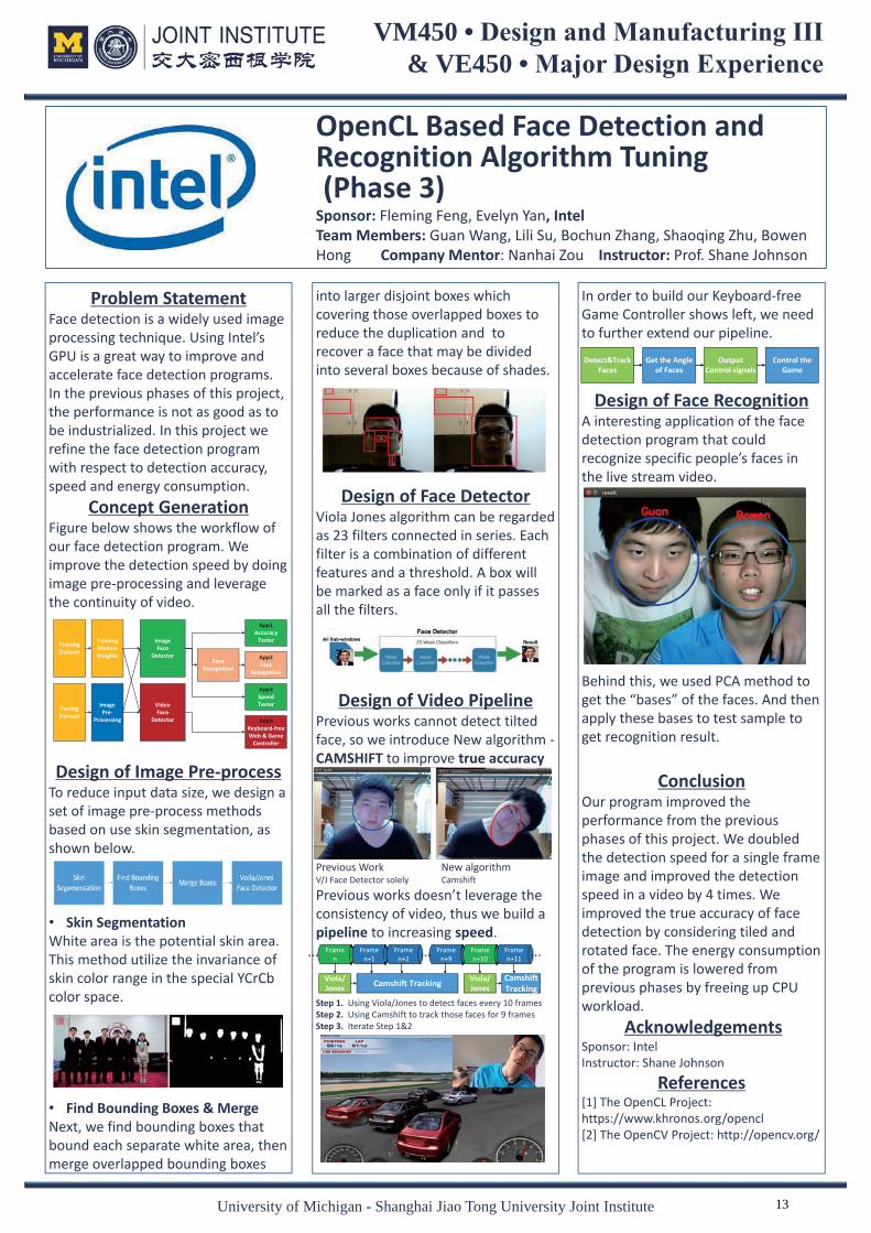
Problem Statement Face detection is a widely used image processing technique. Using Intel’s GPU is a great way to improve and accelerate face detection programs. In the previous phases of this project, the performance is not as good as to be industrialized. In this project we refine the face detection program with respect to detection accuracy, speed and energy consumption.
Concept Generation Figure below shows the workflow of our face detection program. We improve the detection speed by doing image pre-processing and leverage the continuity of video. Design of Image Pre-process
To reduce input data size, we design a set of image pre-process methods based on use skin segmentation, as shown below. • Skin Segmentation White area is the potential skin area. This method utilize the invariance of skin color range in the special YCrCb color space.
• Find Bounding Boxes & Merge Next, we find bounding boxes that bound each separate white area, then merge overlapped bounding boxes
In order to build our Keyboard-free Game Controller shows left, we need to further extend our pipeline.
Design of Face Recognition A interesting application of the face detection program that could recognize specific people’s faces in the live stream video. Behind this, we used PCA method to get the “bases” of the faces. And then apply these bases to test sample to get recognition result.
Conclusion
Our program improved the performance from the previous phases of this project. We doubled the detection speed for a single frame image and improved the detection speed in a video by 4 times. We improved the true accuracy of face detection by considering tiled and rotated face. The energy consumption of the program is lowered from previous phases by freeing up CPU workload.
Acknowledgements Sponsor: IntelInstructor: Shane Johnson
References [1] The OpenCL Project: https://www.khronos.org/opencl [2] The OpenCV Project: http://opencv.org/
into larger disjoint boxes which covering those overlapped boxes to reduce the duplication and to recover a face that may be divided into several boxes because of shades.
Design of Face Detector Viola Jones algorithm can be regarded as 23 filters connected in series. Each filter is a combination of different features and a threshold. A box will be marked as a face only if it passes all the filters.
Design of Video Pipeline Previous works cannot detect tilted face, so we introduce New algorithm -CAMSHIFT to improve true accuracy Previous Work New algorithm V/J Face Detector solely Camshift
Previous works doesn’t leverage the consistency of video, thus we build a pipeline to increasing speed. Step 1. Using Viola/Jones to detect faces every 10 frames Step 2. Using Camshift to track those faces for 9 frames Step 3. Iterate Step 1&2
OpenCL Based Face Detection and Recognition Algorithm Tuning (Phase 3) Sponsor: Fleming Feng, Evelyn Yan, Intel Team Members: Guan Wang, Lili Su, Bochun Zhang, Shaoqing Zhu, Bowen Hong Company Mentor: Nanhai Zou Instructor: Prof. Shane Johnson
TrainingDataset
TrainingModuleWeights
TestingDataset
ImagePre-
Processing
ImageFace
Detector
VideoFace
Detector
FaceRecognition
App1Accuracy
Tester
App2Face
Recognition
App3SpeedTester
App4Keyboard-freeWeb & Game
Controller
Framen
Framen+1
Framen+2
Framen+9
Framen+10
Framen+11
... ......
Viola/Jones Camshift Tracking Viola/
JonesCamshift Tracking
Detect&Track Faces
Get the Angle of Faces
Output Control signals
Control the Game
13

VM450 • Design and Manufacturing III & VE450 • Major Design Experience
University of Michigan - Shanghai Jiao Tong University Joint Institute
Adaptive Video Encoding Based on OpenCL Face Recognition Sponsor: Jackson He, Fleming Feng & Evelyn Yan, Intel Team Members: Jiarui Lei, Wei Miao, Fengwen Song, Yuanlang Song, Jingyuan Sun Company Mentor: Nanhai Zou, Intel Faculty Instructor: Dr. Vincent Chang
Problem Statement People are using video chats intensively to communicate with their family and friends. However, high-quality video chats require a high-speed network connection to deliver the video stream. Though the transmission rate is limited, faces are still the most essential element for the speakers. Thus, the team’s primary goal is to identify the human faces in a video stream and reduce the size of the video by sacrificing the video quality of the background.
Relative Background Encoding Encoding is the essential step in video production. It is a method of compression to reduce the volume of video. Programs to achieve this process are codecs. We adopted X.264 codec in our design. QP Quantization Parameter (QP) is the key factor to control the compression ratio and quality loss. The larger it is, the poorer the quality will be. Macro-block Macro-block is the basic unit in video encoding rather than pixels. It is usually part of the frame picture of 16 by 16 pixels. Each macro-blocks can have its own QP in X.264 codec forming a matrix.
Design Details
Face Detection Frame captured by the camera will go through the face detection algorithm first, which was implemented by previous group of Capstone Design. Haar Classifier with OpenCL optimization on Intel GPU was adopted to guarantee both the accuracy and speed of detection.
QP Offset Matrix QP offset matrix is our solution to achieve differentiated quality within one frame.
Matrix is passed into the codec and apply to the original QP matrix. The codec was adjusted to interface with our design as well.
User Interface User can choose the background quality by the bottoms on the left.
Figure 1: Examples of (a) ideal and (b) poor quality during video chatting
Figure 2: Examples to show how QP works
Figure 3: Concept Diagram
OUR INNOVATION
Figure 4: Translation from frame to QP offset matrix
Tests and Validation
Reduction in Video Volume Encoded frame will be stored in a structure called “AVPacket” [1]. By reading its size we can get the encoded frame volume. Our algorithm involves at around 16 seconds and the average size reduction is 47.15%, much larger than the target value 20%.
Conclusion It is proved feasible to reduce video volume by applying lower quality to background. In the future, the algorithm can be optimized to work for 1080p resolution and frame rate greater than 30 fps.
Acknowledgement Xiuli Pan UM-SJTU Joint Institute
Reference [1] FFmpeg, "FFmpeg Doxygen Documentation AVPacket Struct Reference," 2014. [Online]. Available: https://www.ffmpeg.org/doxygen/trunk/structAVPacket.html.
Table 1: Engineering Specification and corresponding test results
47.15%
No optimization
With optimization
Figure 6: Frame size over time with and without optimization
Figure 5: User Interface
14

VM450 • Design and Manufacturing III & VE450 • Major Design Experience
Problem StatementShowcase Sales is a catalog, order and file management iOS applicationdesigned for sales and professional marketing by Logic Solutions[1]. Current contacts management module of Showcase Sales is simple and not powerful. Thus, our purpose is to develop basic CRM(Customer Relationship Management) features and design humanized functions for contact management module.
Fig. 1 Current CRM module of Showcase
Concept GenerationThe CRM module is further divided into two parts which are input and activity. GPS, OCR (optical character recognition), and import are considered to facilitate input of data. The dimensions of activity are expanded to contact, company, project, and event.
Fig. 2 ER Diagram
Fig. 3 Concept Diagram[2]
ValidationValidation Process: First, we need to perform some basictests to guarantee that the basicfunctionality works. We will firstvalidate that the CRM module works.These functionality needs to be validated: create/edit/delete company, create/edit/delete contact in the company, create/edit/delete addresses, search by name, contact import/export. Basically what needsto be done are performing the testsand checking whether we can getexpected results. Then we will needto validate the GPS module bychecking whether check-in and routeplanning work. Then some extremetest cases should be applied to makesure that the program will not crash.The extreme test cases includestesting some abnormal inputs to the forms, or some invalid address to theGPS.
ConclusionIn this project, we are expected toimprove an iOS-based businessapplication--Showcase Sales designedfor salesmen to help them bettermanage their business. We developan entirely new application modulewith a more powerful CRM systemand an embedded GPS system to helpsalesmen visit their customers moreconveniently.
AcknowledgementSponsor: George Shen from Logic SolutionsMentor: Sean Zeng from Logic SolutionsInstructor: Prof. Vincent Chang from UM-SJTU Joint Institute
Reference [1] Showcase Sales App | Catalog, Order,Management App. Access June 1, 2014, athttp://www.showcasecloud.com/[2]iCloud for Developers. Accessed June 8,2014, athttps://developer.apple.com/icloud/index.html
Design DescriptionBasically we develop an entirely new iOS application module using Xcode. The new contact management module consisting of two main parts--CRM and GPS. As for CRM part, many useful functional items like project progress, event history and local contact information import/export are brought in to make it a great assistant for salemen to manage their contact information and projects. While GPS part is a special embedded design according with salemen's business——selling products door to door. The contacts in the CRM part can be directly located on the map, so it's very convenient for salesmen to visit their customers. Also the GPS system can generate an optimal visiting route in case of visiting multiple customers at a time.
Fig. 4 New CRM module
Fig.5 CRM contact on the map
Showcase Sales Contact Management ModuleSponsor: George Shen, Logic SolutionsTeam Members: Linfeng Shi, Jianxian Wu, Peizhou Zhao,
Xishen Yao, Yixing JiangMentor: Sean Zeng, Logic Solutions Instructor: Vincent Chang
University of Michigan - Shanghai Jiao Tong University Joint Institute 15

The design also consists of an electrical control system including a controller group (blue), a sensor group (orange) and a actuator group (green). The controller group drives the actuator based on Ladder Logic program and the feedback signals aresent from the sensor group.
Fig.3 ECS Flow Chart
Modeling and AnalysisIn order to determine if the structure is able to hold the large loading condition, Finite Element Analysis is applied using Solidworks. Figure 3 shows the FEA for the final design. The max deformation is 0.08 mm, which meets the design requirement.
Fig.4 Final Design FEAWe validate our design using MATLAB Simulink® in advance. The hydraulic system is built based on the following Simulink® model.
Fig.5 Simulink® model
VM450 • Design and Manufacturing III & VE450 • Major Design Experience
University of Michigan - Shanghai Jiao Tong University Joint Institute
Problem StatementCreep occurs to solid materials whenstress applied under long working conditions with high temperature.Creep test are carried out to evaluate the performance of the selected material. A creep test typically takes 3000 hours and current test machinescan only test one at a time, which makes creep testing to be time-consuming and expensive. This project is to design a new multi-specimen creep test rig that enables over 20 specimens to be testedsimultaneously, which significantlysaves the time and cost.
Concept Generation
Fig.1 Concept Diagram
Design DescriptionThe test rigs are directly placed on each side of the hexagon and the hydraulic reservoir is placed at the center. This allocation enables better pipe arrangements. There will be four test rigs on each side and in total there will be 24 testing setup. The furnaces are anchored on the frame by hanging down from the upper crossbeams. Every two specimens are put inside the same furnace, which is called a single unit. Figure 2 shows the final design.
Fig.2 Final Design CAD Overview
Prototype The prototype consists of hydraulic system, electrical control system and test frame. Test frame represents a single unit (two specimen) in our final CAD design.
Fig. 6 Hydraulic System and PLC
ValidationMost specifications can be satisfied as expected by engineering analysis.
Load capacity > 2 kNForce output number = 24Power input number < 4Max Frame deformation < 0.1 mm
Validation Process: For the other specifications that cannot be verified by analysis, validation plans are conducted. The load cells will be calibrated to meet the accuracy criterion. The minimum resolution for the sensor is 0.1 N. The precise control of the output tensile load will be examined.
ConclusionIn this project, we aim to design a multi-specimen creep testing machine that is capable of testing over twenty specimens simultaneously. We finalized the design of structure using FEA, the hydraulic system using Simulink® and ECS by testing on a PLC. A prototype is made to verify the theoretical design.
AcknowledgementSponsor: Chao Ren, Xu Hua from SiemensMian Li, Kwee-yan Teh, Yu Sun and TianhuaChen from UM-SJTU Joint Institute
Reference [1] “Metallic materials — Uninterrupted uniaxial creep testing in tension — Method of test.” ISO 204, ISO, 2009.
Multi-specimen Creep Test RigSponsors: Chao Ren, Siemens
Xu Hua, SiemensTeam Members: Taoxi Li, Hongshen Zhao, Jingxuan Liu, Jie Wu, Jiacheng Li Instructor: Prof. Mian Li, UM-SJTU Joint InstituteFaculty Advisor: Dr. Kwee-yan Teh, UM-SJTU Joint Institute
16

VM450 • Design and Manufacturing III & VE450 • Major Design Experience
University of Michigan - Shanghai Jiao Tong University Joint Institute
Problem Statement Gas turbine blade, made of superalloy, is a significant component in gas turbine (GT) system. To obtain high working efficiency, GT needs to work under extremely high temperature(1200 oC), which will result in creep and even melting of the superalloy. In recent thirty years, thermal barrier coating is used to protect the GT blade from external heat attack, reduce surface temperature and avoid melting of the superalloy. However, the spallation of TBC will lead to problems such as oxidation, thermal fatigue and creep. The reduction of TBC spallation becomes a severe problem.
Fig.1 Spallation of thermal barrier coating[1]
Concept Generation TBC deposition and surface treatment method are the two processes that can be modified to improve the coating interface strength.
Table 1 TBC deposition method[2][3]
For surface treatment, sand blasting and laser engraving are the two options. Sand blasting has low precision and stableness. It can also bring external flaws. Laser engraving is controlled by machine and computer, is precise and stable.
number of cycles, once the energy release rate goes beyond the critical value, the system is defined as failed.
Fig. 4 Von Mises stress calculated by ANSYS
Validation Surface texture validation: Optical microscopy and laser scanning microscopy should be used to characterize the experimental value of width, depth and spacing. These should be compared to the designed value. When the difference is larger than 5%, laser parameters should be modified to make new prototypes.
Fig 5 LSM and optical image of samplesCoating lifetime validation: This will be conveyed by Siemens. All samples will go through thermal cycles and the pattern with largest number of cycles at 20% spallation should be the optimized design.
Conclusion Coating bond strength enhancieng by laser engraving method is stuied both analytically and experimentally. Prototypes manufactured and analytical model have been prepared. Siemens will hold further evaluation.
Acknowledgement IPG Photonics, SPI Lasers, Delphilasers, Zeiss, Prof. Huan Qi, Prof. Shane Johnson
Reference [1]Shillington, E. A. G., & Clarke, D. R. (1999). Spalling failure of a thermal barrier coating associated with aluminum depletion in the bond-coat. Acta Materialia, 47(4), 1297-1305. [2]Meier, S. M., & Gupta, D. K. (1994). The evolution of thermal barrier coatings in gas turbine engine applications. Journal of engineering for gas turbines and power, 116(1), 250-257. [3]Beele, W., Marijnissen, G., & Van Lieshout, A. (1999). The evolution of thermal barrier coatings—status and upcoming solutions for today's key issues. Surface and Coatings Technology, 120, 61-67. [4]Chen, X., Hutchinson, J. W., He, M. Y., & Evans, A. G. (2003). On the propagation and coalescence of delamination cracks in compressed coatings: with application to thermal barrier systems. Acta materialia, 51(7), 2017-2030.
Design Description Our design aims at optimizing coating performance by developing different patterns using laser-engraving. Air plasma spraying was used as the TBC deposition method in our design. In our design, experiments were set up to manufacture and analyze the engraved microstructures, and analytical review and computation were conducted for further analysis. Two phases for our experiments: • Control the depth of
microstructures with laser parameters
• Develop different patterns by varying depth, spacing and width
Fig. 2 Control factors of the microstructures
Modeling & Analysis A 2-D model contains substrate, bond coat and TBC is built with ANSYS. By setting temperature variation cycles and corresponding mechanical parameters, thermal loading is implemented. Stress profile generated on each layer is therefore calculated.
Fig.3 Energy release rate vs. number of cycles[4] With the normal and shear stress data, stress intensity factors can be found by numerical integration. Then energy release rate can be solved and used as a criterion. By repeating this procedure for stress data after each thermal cycle, energy release rate is plotted as a function of
1 mm
Air Plasma Spraying (APS)
Electron beam physical vapor deposition (EB-PVD)
Laminar structure, cracks parallel to surface
Columnar structure, matches CTE difference
Physical bonds at interface
Chemical bonds at interface
Laser Engraving of Micro-nano Structure to Enhance Coating Interface Strength for GT Component Sponsor: Zhou Yetao & Yucheng Tang, Siemens Team Members: Jingyi Li, Haocheng Pan, Yining Shi, Xiaomi Zhang, Haining Zhou Faculty Advisor: Prof. Huan Qi Instructor: Prof. Shane Johnson
depth
width
spacing
Depth= ƒ (frequency, power, times)
Critical energy release rate
17

VM450 • Design and Manufacturing III & VE450 • Major Design Experience
University of Michigan - Shanghai Jiao Tong University Joint Institute
Problem Statement Gas turbines are critical components of numerous industrial and commercial applications. Inlet Guide Vanes (IGVs) in a gas turbine control the amount of air flowing into the gas turbine, and therefore precise and steady control of IGVs are key to safe and efficient operations of the gas turbines. However, it is very difficult to measure and control the angle of incidence of each vane individually, due to impractical manufacturing and maintenance costs, hence there is need to improve the balance between performance and cost.
Fig. 1 A turbine engine and its inlet guide vanes (IGVs) [1]
Concept Generation Sub-systems of our design must be tailored towards core customer requirements.
Fig. 2 Core customer requirements
Fig. 3 Concept flow chart
Validation Plan Our main goal is to validate that the IGV angles that are mathematically derived meet their actual values within reasonable tolerance. Precise control of IGVs is our major customer requirement along side with the total cost of the design. We also need to make sure that the total cost is kept below budget, and our mechanisms can operate smoothly without conspicuous glitches and errors. We measure the angles of incidence of each IGV using detachable angle transducers that can be mounted at pre-defined locations on the shell of our prototype. The measured values are then compared against the values from math model.
Conclusion Precise control of the IGVs is a very fundamental requirement in most applications involving turbines, but it could be a challenging task given limited sensor inputs and minimalistic actuation schemes. Our work shows that some of these limitations can be compensated by control algorithms, and it’s possible to design and manufacture a system with good precision with very limited funds and resources.
AcknowledgementsSponsors: Mr. Law Ow and Mr. Pan Wenyong, SIEMENS Instructor: Prof. Xu Kai, UM-SJTU Joint Institute Recycled designs: Actuator; AC motor control module (VFD); Turbine shell; Transmission mechanisms The 1st team in the project series won the design championship title.
Reference [1] https://en.wikipedia.org/wiki/Turbine
Design Description Since we are the 4th team working on the project series, we base our design largely on the work done by previous groups. Our contributions include: 1. Redesigned the support
mechanism and the ring; 2. Redesigned the sensing
mechanism and algorithm used to derive individual vane angles;
3. Improved the human-machine interface (HMI) of the system.
Fig. 4 Improvements to the mechanical system (in
black) and reused designs (in grey)
Fig. 5 Screen-shot of the new HMI We have derived and analyzed a math model in detail predicting the performance of our mechanical design. The algorithm requires only five sensor inputs (4 displacement readings and 1 angle reading) to calculate the angles of incidence of all 10 IGVs. The outputs of the algorithm are used by the PI controller as feedback.
Fig. 6 Derivation and analysis of the math model
IGV Actuation Control System Integration Sponsors: Law Ow, Pan Wenyong, SIEMENS Team Members: Wu Jiayi, Shan Zhengdong, Huang Yihe, Yu Zhaolin, Zhu Qinzhou Faculty Advisor: Prof. Xu Kai
IGV
Inexp-ensive
Flexible
User-friendly (HMI)
Precise
Mechanism Design of Linkages
Actuation Control System
HMI (Human Machine Interface)
Linkage with certain DOF
Roller/bearing + spring + sensor
Algorithm of Vane Angle
PI control
Prevent axial moving
Measure and verify the angle
deviation IGV Control System
Transmissions
Ring
Shell
Support
18

VM450 • Design and Manufacturing III & VE450 • Major Design Experience
University of Michigan - Shanghai Jiao Tong University Joint Institute
Problem Statement Gas turbine Inlet Guide Vane (IGV) enables accurate control of compressor inlet mass flow. Sealing components are used to prevent leakage of inlet gas. Rubber O-rings are currently used by Siemens, which are designed for statistic sealing and therefore have disadvantages such as large friction, large wearing and poor durability. Our project is to design and select a new sealing component and design a test rig which can facilitate both rotary sealing component test and sliding test.
Fig. 1 Inlet guide vane and cutaway view of sealing component installed on IGV [1]
Concept GenerationSub-system concepts includes motion transformation from rotating to sliding, friction test, leakage test and mechanical load.
Fig. 2 Morphological chart Friction test is based on Eq. 1, where T is torque, k is torque constant for DC motor and I is current. Leakage test is calculated by Eq. 2, where Q is leakage, P is pressure , V is available capacity and t is time. (Eq. 1) (Eq. 2)
Validation Validation Process: First, several calibration tests need to be conducted. In order to calibrate mechanical load, spring ergometer is used to generate 2 kg force and record the elongation of the spring. The torque constant of the DC motor need to be calibrated by torque spring. For the measurement, sealing component is first installed on the rod, and the position is adjusted by lifting platform. Then air needs to be pumped into the sealed cabin. For the friction test, current sensor sent the data measured to LabVIEW, a program can be written on LabVIEW to transfer current into torque and friction based on Eq. 1. While estimating the friction of sealing component, the leakage test can also be conducted. Pressure sensor measures the pressure inside the sealed cabin, and leakage rate can be measured according to Eq. 2.
Conclusion Glide ring and silicon ring are chosen for the new sealing component. The test rig was designed and manufactured, which can facilitate both rotary sealing component test (leakage test & friction test) and sliding test (friction test).
Acknowledgement Chao Ren and Haoliang Zhou from Siemens Mian Li, Roberto Dugnani and Olivier Bauchau from UM-SJTU Joint Institute
Reference [1]http://www.damper-designs.co.uk/ivc. html [2] http://fietz.com/fietz/en/glide-rings http://www.sisweb.com/vacuum/o-rings/silicone.htm
Design Description The design can be separated into two parts: mechanical part and electrical part. For the mechanical part, a sealed cabin is on the top of the structure, which is used to detect leakage by pressure difference; a lifting platform is fixed on the bottom of the structure. The DC motor is fixed on the lifting platform, which drives the rotating rod with a coupler. On the rod, one bearing connected a spring to provide mechanical load. The block-on-ring is used to meet the function of sliding test.
Fig.3 CAD model and whole set-up system For electrical part, a motor control feedback system is designed to control the DC motor. PID control is applied in our design.
Fig. 4 Motor Control Feedback System
Fig. 5 Glide ring and silicon ring [2]
Compressor IGV Vane Sealing Component Design Sponsor: Dr. Chao Ren, Siemens Mr. Haoliang Zhou , Siemens Team Members: Chenyu Xu, Li Gao, Congyi Mao, Luyi Chen, Weijia Zhou Instructor: Prof. Mian Li
matme tPVPQ /T kI
19

VM450 • Design and Manufacturing III & VE450 • Major Design Experience
University of Michigan - Shanghai Jiao Tong University Joint Institute
Problem StatementPassive protection pattern, which is mainly used by traditional car safety seat belt, is not reliable enough to protect passengers. This project is about an electronic seat belt systemwhich can be activated prior to a crash and restrain passengers and drivers. In this system, a clutch is needed to transmit the power of themotor to the seat belt. Our team is responsible for this clutch design.
Fig. 1 Clutch position in an automobile (left)and a closer look (right) [1]
Concept GenerationThe clutch needs to engage with theretractor when the motor rotates forward and disengage when the motor rotates backward or stops. This is a typical function of a one-way clutch. A lot of raw ideas came from brainstorming process and were filtered by company’s requirement.
Fig. 2 Raw idea selection
Fig. 3 Final Selection
Material and ManufacturingTo satisfy the force requirement, we introduced Kirsite to build these parts because of its good strength and light weight. POM would be used for parts requiring less strength (base plate).The manufacturing of the POM part would be injection molding; the metal forging would be die-casting. Mass production is available for these manufacturing methods.
ValidationFuture tests will be conducted onclutch built of POM and kirsite atfollowing aspects:1. Stability of clutch under motor
torque (10160 mN-m)2. Functionality at extreme
temperature (-40 C to 85 C)and relative humidity (10% to100%)
3. Operating noise (less than 55dB)4. Durability (function more than
65000 cycles)
ConclusionThe clutch design is based on the engagement between jaws and retractor. If the clutch is installed in anautomobile, the seat belt can becontrolled by the motor through theclutch and the retractor. This clutchprovides a solution of the new generation of automotive seat belt.
AcknowledgementSponsor: Ye Chen, Jun Xu from Yanfeng KSSMentor: Fei Wang from Yanfeng KSSInstructor: Mian Li, Kai Xu, Vincent Chang from UM-SJTU Joint Institute Chenyan Feng from UM-SJTU Joint Institute
Reference[1]www.autoliv.com/ProductsAndInnovations/PassiveSafetySystems/Pages/Seatbelts/ActiveSeatbelts.aspx
Design DescriptionThe final design was based on the principle of the lock on normal door knobs. One back plate is used to fix allparts of clutch on it. Two jaws, whosetooth shape is complementary with the retractor, are constrained by abase plate, so that they can only move in tangential direction of theclutch. A trigger can transmit thepower of the motor to the jaws. Therefore, the motor can control theseat belt through the clutch and theretractor.
Fig.4 Final Design
Fig.5 Exploded View
Force AnalysisForce analysis is carried out in order to determine material selection for the design. The calculation is based on torque and force balance at steady state. The force on the tip of thetrigger (F1) is critical.
Fig. 6 Force analysis
Innovative Clutch Solution for Electronic Seat BeltSponsor: Ye Chen & Jun Xu, Yanfeng KSSTeam Members: Yuting Gao, Jia Li, Mingyang Li, Jiawen Wei, Wenxin LaoCompany Mentor: Fei Wang, Yanfeng KSS Instructor: Prof. Mian Li
ClutchPosition
20

VM450 • Design and Manufacturing III & VE450 • Major Design Experience
University of Michigan - Shanghai Jiao Tong University Joint Institute
Problem Statement An unmanned aerial vehicle (UAV)
is an aircraft capable of flying without pilot on board. UAV’s navigation trajectory is either decided by program in their on-board controller system or remotely controlled by a pilot on ground. Quad-rotor UAV is a unique kind of UAV that has four motors separately powering the rotors as driving force for taking off and direction control [1].
Quad-rotor UAV is applied in many areas: disaster search and rescue, package delivery, land scope detection and so on. This project is to conduct further research on quad-rotor navigation, safety and stable flying and target following.
Concept Generation In our quad-rotor system, three
major modes are defined. In navigation mode, a flight plan is uploaded into the UAV, and the quad-rotor will navigate according to commands in the flight plan. In manual mode, the quad-rotor will be fully controlled by the radio-controller. In following mode, the ground station will get GPS position signal from both quad-rotor and the moving target. It will then do calculation, send signal back to the plane through Zigbee and let it follow the moving target.
Figure 1. Concept diagram In order to let the plan balance
itself in the air, stabilization control loop is implemented. It control the rotation speed of motors according its detected orientation and status.
Validation Validation Process: • Examine the stability of quad-rotor
with original PID index and our improve PID control loop.
• Compare the routine of quad-rotor in executing flight plan and the result in simulation.
• Compare the falling loss before and after installing the protective shell.
• Measure the basic engineering specifications including size, weight, accuracy and response time.
According to validation part, most specifications can be met.
Figure 4. Quad-rotor prototype in validation
MCU Response time <= 125ms Control accuracy >= 85% Weight <= 800g Weight<=100kg Cost <= 3000RMB Hovering ability Flight plan execution
• Target following ability √ means having been verified and · means to be determined by 7/21.
Conclusion Quad-rotor can be controlled
either in manual mode and self navigation mode. We can simulate complicated flying path on the GCS and realize the routine on the sky.
It is very important to optimize PID control and update components regularly for stable flying. Protective shell is a necessity for safety.
Acknowledgement Chengbin Ma, Shane Johnson and Roger Han from UM-SJTU Joint Institute
Reference [1] (2014, 5 30). Retrieved from The UAV: http://www.theuav.com/
Also, orientation and positioning system is implemented to record the horizontal position of the quad-rotor and make navigation possible.
Design Description The whole system of autopilot
quad-rotor consists of four main parts: framework, electrical components, protective shell, and battery. Electrical components is the central part of the whole system.
Figure 2. Overview of quad-rotor Our quad-rotor project is run on
Linux/Ubuntu. A MCU called Lisa/M2 provides connection ports to all the peripherals needed. MEMS Sensors including gyroscope, accelerometer, magnetometer and barometer are embedded within the board to fetch important parameters including acceleration, tilted angle. A GPS receiver and a Zigbee receiver are connected to the MCU to provide GPS location information and instructions fetched through Zigbee channel.
Flight Plan and SimulationFlight plan is an xml file used to
control the flight path of the quad-rotor. Below is an example of the complicated flight plan that we wrote. This example will make quad-rotor take off, go to point p3, and then fly an "8" shape and finally land.
Figure 3. Simulation result of “ ” flight plan
Auto-Pilot Control System for Small Unmanned Aerial Vehicle Quad-Rotor Sponsor & Instructor: Prof. Chengbin Ma, UM-SJTU Joint Institute Team Members: Xiangyu Ni, Xuexiu Han, Chongguang Feng, Xiao Wu, Rui Cao
Auto Pilot Control SystUnmanned Aerial VehiSponsor & Instructor: Prof. ff Chengbin Ma, UMTeam Members: Xiangyu Ni, Xuexiu Han, Cho
21

VM450 • Design and Manufacturing III & VE450 • Major Design Experience
University of Michigan - Shanghai Jiao Tong University Joint Institute
Auto-Pilot Control System for Small Unmanned Aerial Vehicle (Fix-Wing Model) Sponsor: Prof. Chengbin Ma, UM-SJTU Joint Institute Team Members: Shuyue Lai, Zhuoyi Tang, Hui Zeng, Yingshi Zheng Instructor: Prof. Chengbin Ma
Flight Plan Flight plan is a predefined routine programed into the control board. It is composed of GPS waypoints and action functions. The UAV will follow flight plans when switched to auto mode. For example, as shown in Figure 5, the UAV is programed to first circle around home point, then go and circle around another point.
To validate that the UAV will fly according to flight plan, the camera will record corresponding scenery during the flight.
Conclusion Based on the problems and needs of the project, we improved some subsystems to meet the engineering specifications. An additional camera system is planted on the head of the UAV to achieve a better view. A complicated routine should be made to show its ability of auto-piloting.
AcknowledgementChengbin Ma, Assistant Professor at Shanghai Jiao Tong University Rongsheng Xu, team leader from last semester’s UAV team, JI student Tingyang Meng, UAV amateur, JI student
Reference [1]http://wiki.paparazziuav.org/wiki/
Problem Statement Unmanned Aerial Vehicles (UAVs) are playing a more important role in both military and commercial industry recently. The sponsor wants to develop an fixed-wing autopilot UAV system. Our task and problem are • Auto-pilot through designed path • Stable flight status • Accurate position locating • Stable video recording
UAV Platform
The UAV platform is Skywalker 1900. The size of the plane meets the engineering specification and it has enough payload to carry all the additional components. The following figure shows the plane with our customized camera platform.
Flight System The flight control system is supported by control system on UAV platform and monitoring system on the ground. The core control hardware is Lisa/M2.0 with Aspirin IMU.
It is equipped with 32-bit CPU. The Aspirin IMU measures yaw, pitch, roll and accelerations of the UAV. The ground station control system uses an open-source software called Paparazzi, which helps us monitoring the flight status and send commands to UAV. Apart from that, other peripherals are shown in Figure 2 • GPS module at accuracy of 2.8m • XBee module for data
communication at a range of 3km • 2.4 GHz & PPM module for manual
remote control at a range of 500m
Camera System
To achieve a better video effect, we fix the camera onto a two-axis cradle head. It can ensure the camera to be stationary on pitch and roll axis. As a result, the video captured by the camera will be the horizontal view without vibration, which ensures us a fantastic demonstration effect. From Figure 4, the right side(with cradle head) shows a better view.
Figure 1. Skywalker 1900 model with customized camera platform
Figure 3. Cradle head with camera.
Figure 4. Different camera views without/with cradle head
Figure 5. Flight plan in GCS
Figure 2. Concept diagram of our project
Camera System
22

Design DescriptionThe final prototype is a short-secondary LIM. The whole system consists of three major components: the primary, the secondary and the drive unit and power source. The primary consists of six electro-magnets as a four-pole three-phase linear motor. The secondary is a piece of thin aluminum plate attached to the bottom of a model car.
Fig.2 Schematic model of the final design
The drive unit is connected to the electromagnets and provides three-phase sinusoidal PWM waveforms for the motor. A DC power source is connected to the drive unit. When the power is on, the model car could move fast along the track.
Fig.3 The drive unit
Modeling and AnalysisA Simulink model is built to simulate the levitation system of the maglev train.
Fig. 4 Simulation of levitation in Simulink
VM450 • Design and Manufacturing III & VE450 • Major Design Experience
University of Michigan - Shanghai Jiao Tong University Joint Institute
Problem StatementMass growth in demand for intercity transportation in China has led to traffic congestion, excessive time delays, and environmental issues. Medium-low speed maglev trains have many advantages over conventional rail system, such as low noise, strong climbing capacity and short turning radius to easily run in residential communities or on hilly slopes. China is the second country, after Japan, to have this technology.This project is to design and build a Linear Induction Motor (LIM) as a propulsion system of a small-scale medium-low speed maglev train, which can be used as a platform for both demonstration and experiment.
Fig. 1 Chinese medium-low speed maglev train [1]
Engineering SpecificationAccording to the requirement of our sponsor, we create a list of expected engineering specification on the propulsion system as shown in the following table.
Table 1 Engineering specifications onthe propulsion system
Another equivalent circuit model [2] is used to calculate and evaluate the performance of the LIM.
Fig. 5 Equivalent circuit of LIM
ValidationValidation Process: 1) The output PWM waveforms of the drive unit is validated through oscilloscope. 2) The drive power, the distance between electromagnets, thickness of aluminum plate is tested via the speed performance of the LIM.3) Thrust and actual speed is calculated via theoretical equations.
ConclusionMedium-low speed maglev train is an ideal intercity mass transportation in China. The team design and build a small-scale linear induction motor as a platform of demonstrating the propulsion system of the medium-low speed maglev train and future studying the maglev technologies.
AcknowledgementProf. Chengbin Ma from UM-SJTU Joint Institute Ming Liu and Zheng Gong from UM-SJTU Joint Institute
Reference [1]http://www.ebeijing.gov.cn/Culture/EnjoyBJ/t1192828.htm
[2] Design of a Single Sided Linear Induction Motor (SLIM) Using a User Interactive Computer Program, SarveswaraPrasad Bhamidi, University of Missouri-Columbia.
A Small-Scale Maglev Train System─ Linear Induction MotorSponsor: Prof. Chengbin Ma, UM-SJTU Joint InstituteTeam Members: Danyang Cui, Hui Lin, Siyi Lu, Miao YangInstructor: Prof. Chengbin Ma
http://news.xinhuanet.com/tech/2009-06/16/content_11549011.htm
23

VM450 • Design and Manufacturing III & VE450 • Major Design Experience
University of Michigan - Shanghai Jiao Tong University Joint Institute
Problem Statement Accurate measurement systems for the rotational stiffness of the first Metatarsophalangeal Joint(1st MTPJ) can help doctor a lot in diagnosis of foot disorders. However the existing test method cannot fulfill the need of doctors. This project aim to design a device to measure the stiffness accurately and professionally.
Fig. 1 A human foot X-ray
Concept GenerationOur system mainly have three function parts. We first measure the stiffness and output the signal, then we receive, process and output the result, at last we display final result on different terminals.
Fig. 2 Detailed structure function
Fig.3 Concept diagram
Validation Validation Process: To make sure we can measure the stiffness accurately enough, we mainly focus on force range, accuracy of force sensor and accuracy of angle sensor. We attach the angle sensor to a rule to simulate the prototype and use a protractor to measure the real angle. We find that the value of measured angle and real angle are quite close in every 10 degree, and the mean error of all the data is only about 1.32% We put multiple size of weights on the force sensor and read the output voltage. We find that when the force is bigger than 200grams, the slope of V-G curve become stable. Also, the force sensitivity we get through test is only 0.02N.
Force range>=15N Force range<=5N Force sensitivity <=0.5N Rotation sensitivity <=1 degree
√ means having been verified and · means to be determined.
Conclusion Comparing with the measuring device which is built by Heng [1], using a quantitative approach to measure joint stiffness using a tactile pressure sensing system together with simple video analysis, our design is more accurate, more portable as a whole device, cheaper with the use of microcontroller instead use of any video devices. In general, it can meet the needs of foot doctors better.
Acknowledgement Sponsor: Shane Johnson, Vincent Chang, Chengbin Ma and Mian Li from UM-SJTU Joint Institute
Reference [1] Heng M L, Kong P W. A novel technique of quantifying first metatarsophalangeal (1st MPJ) joint stiffness[J]. Journal of Foot and Ankle Research, 2014, 7 (Suppl 1): A32.
Design Description The design uses a 3-axis accelerometer and a thin film pressure sensor to measure the force and angel of 1st MTPJ. Three sliders can be adjusted to fit multiple size of foot. The microcontroller receives the signal from sensors and send signal to multiple terminals. Using Arduino Uno, the signal can be transformed into data in computer. Through a Bluetooth module, the data can be shown on a Android Phone.
Fig.4 Isometric view of our prototype
Finite Element Analysis Finite element analysis (FEA) was used to simulate the pressure distribution of pressure and establish the moment curve to theoretically calculate the 1st MTPJ stiffness.
Fig.5 von Mises stress distribution Fig.6 moment-angular displacement curve The curve shows an approximately constant stiffness value between a dorsiflexion angle from 10 degrees to 25 degrees. Then the stiffness value decreases as the angle exceeds 25 degrees.
First Metatarsophalangeal Joint Range of Motion and Stiffness Test Method Sponsor: Prof. Shane Johnson Team Members: Haotian Wang, Chenghao Wang, Zifan Yang, Guanzhe Wang Instructor: Prof. Shane Johnson
0
20
40
60
80
100
120
0 5 10 15 20 25 30 35 40 45 50
Mom
ent(
Nm
m)
angular displacement (degree)
1st MTPJ
24

University of Michigan - Shanghai Jiao Tong University Joint Institute
VG100 • Introduction to Engineering
25

University of Michigan - Shanghai Jiao Tong University Joint Institute
VG100 • Introduction to Engineering
ProblemsAfter an earthquake, many people trapped in the ruins die for lack of water and food. It is difficult and dangerous for rescuers to find and save people in ruins.There are two serious problems in the rescue of survivors in earthquakes:•People in ruins need water and food, but it is dangerous and difficult for rescuers to get into the ruins to save people.•Rescuers do not have enough information about the situation, so it is difficult for rescuers to find people in ruins.
Needs•A blimp to send water and food to the victims.•A streaming video module to provide video information about the disaster areas to help rescuers find people in ruins.
Design Description
Fig.1 3D Plot of Our BlimpWe use a 36-inch balloon to make the body part of the blimp and fill the balloon with helium to provide the lifting force. We use a coreless motor with a blade to adjust the balance and help the blimp take off and land. We use two coreless motors to propel and turn our blimp. The ultrasonic distance sensor in the front can detect the distance to obstacles. The blimp will turn automatically if
last for 1 hour. According to the testing data, the states of all components meet our need. One problem is that the speed of the motors is high and it is difficult to control the speed of our blimp. We have solved the problem by improving our program.
Fig.3 The prototype of Intelligent Blimp
ConclusionOur blimp uses the helium, the Bluetooth control, distance sensors, and stream video module to achieve the functions we need. The blimp can send supplies and avoid obstacles. Also it can take videos of the disaster areas, which is significant for the rescue in an earthquake. Our blimp is useful in the rescue of the earthquake. The rescuers do not need to risk their lives to save the trapped people, and the people in ruins can get water and food supply to support their lives and wait for rescue.
AcknowledgementsDr. Roberto Dugnani, Lecturer at UM-SJTU Joint Institute;Nicholas Welch-Belon, Lecturer at UM-SJTU Joint Institute;Cai Yusheng, Huang Jiannan, Zhao Yuyue, Teaching Assistance of UM-SJTU.
the distance is short so that it can avoid the obstacles. We assemble a wireless video module in the front to take the video.
Fig.2 Core Control System
Significance of the SolutionFirst, we use a blimp instead of rescuers to send water and food to the ruins. The blimp can avoid obstacles automatically, so it can find its way and avoid being damaged. We use the Bluetooth to control the blimp in case of an emergency. So we have solved the first problem using our blimp.Second, we add a stream video module to the blimp. When the blimp gets into the ruins, the module will take a video of the ruins and send the video to the rescuers’ computer. Then rescuers get more information so that they can come up with efficient ways to rescue the survivors. The video will also make it possible for the rescuers to contact people in ruins. So we solved the second problem.ValidationWe test all parts of our blimp to make sure it works. The data is as follows:The angular speed of the coreless motor is 30000 rad/min. The valid distance of the Bluetooth controller is less than 20 meters. The volume of the balloon is 260 L. The accuracy of the ultrasonic sensor is within 1 cm. The stream video and the battery can
Intelligent BlimpInstructors: Dr. Roberto Dugnani, Mr. Nick Welch-BelonTeam MembersWang Zexu, Zhu Hua, Xu Zilin, Liu Bisheng, Geng Yajie
Battery
MotorDriver
Arduino
Bread-board
Bluetooth
Motor
CorelessMotor
Core control System
balloon
Stream video
Distance sensor
26

University of Michigan - Shanghai Jiao Tong University Joint Institute
VG100 • Introduction to Engineering
Problems Earthquake ruins are unstable and narrow. It is difficult and dangerous for rescue teams to enter and search for survivors in the ruins. The rescue efforts has following problems:
Rescuers cannot find the position of the survivor.
People stuck in ruins cannot get aid or food.
NeedsAn aircraft that can fly into the ruins and search for survivors.An aircraft that can bring aid to
survivors and send back information.
Design Description
Fig.1 3D sketch of the aircraftOur solution is an auto-pilot quad rotor aircraft. We use four brushless motors to fly the aircraft. A ultrasonic sensor tells the control module about the distance between the aircraft and the obstacles. A servo rotates the sensor to detect the distances on different sides. The control module includes a receiver, an Arduino Uno, and a Flight-control Module. The receiver receives signals from the remote control; the Arduino Uno processes signals and carries out auto-pilot missions; the Flight-control module receives signals from Arduino and adjusts flight attitudes. When the aircraft flies near a survivor, the infrared sensor can detect his heat, and send signals to the receiver; the camera creates stream video and inspects the situation inside the ruins.
On both sides, the sensor will stop for 3 seconds for measurement. The Arduino compares the sensor readings on both sides, and turns to the side with larger distance. The sensor will then measure the distance again to recheck; if the reading is greater than 30cm, the aircraft will move on.
Fig.4 Avoiding obstaclesAs searching for survivors, we applied an infrared temperature sensor on the aircraft. When a survivor is in sight, the sensor will detect the heat that he or she gives out, and send signals to the Arduino. The Arduino then stops the aircraft for several seconds, and makes a beeping noise to alarm the rescue team.
ConclusionOur aircraft can auto-pilot into the ruins and enter narrow or unstable places with the help of the distance sensor. Also, we can control the aircraft remotely when necessary. The infrared sensor can find survivors and send aid to them. The camera creates streaming video to inform the rescuers outside.
AcknowledgementsDr. Roberto Dugnani, Lecturer at UM-SJTU Joint Institute;Prof. Nick Welch-Bolen, Lecturer at UM-SJTU Joint Institute;Cai Yusheng, Huang Jiannan, Zhao Yuyue, Teaching Assistants for VG100 at UM-SJTU Joint Institute.
Fig.2 3D sketch of the control part
Significance of the SolutionThe brushless motors can help the aircraft lift weight up to 300g. This is sufficient for the aircraft to carry water or first-aid packs. It can deliver aid to people in need. The Infrared sensor can detect heat within 4m around it. We installed a sensor at the bottom so that rescuers are able to find survivors in time.The servo can rotate the distance sensor, so our aircraft can measure distances in three directions in a short time with only one sensor. This saves costs.
Fig.3 Photo of the prototype
ValidationTo avoid obstacles, we installed an ultrasonic distance sensor in the front of the aircraft. If the aircraft flies too close to an obstacle, the sensor will recognize the distance between the aircraft and the obstacle, and send it to Arduino. If the distance is less than 30cm, the Arduino board will send signals to the motor and stop theaircraft. At the same time, the servo will turn 90o left and then 180o right.
Automatic Rescue AircraftInstructors: Dr. Roberto Dugnani, Mr. Nick Welch-BolenTeam Members: Shi Yuming, Ye Chenjun, Yu Chengyun, Zhang Mengxuan, Zhang Yunhao
27

University of Michigan - Shanghai Jiao Tong University Joint Institute
VG100 • Introduction to Engineering
Problems
Touch screens now are tangible, but they cannot satisfy people’s growing demands. A steam screen is untouchable, but it has four problems:
The steam producer and the projecting system are expensive.
The image is vague on the steam screen.
People can’t interact with the steam screen.
Needs Low-cost materials. A stable steam screen An interactive system.
Design Description
Fig.1 Concept Diagram of the Screen
We use an ultrasonic steamer to produce steam in a wooden box, and fans to make the steam move in the pipe. The gap on the pipe makes a steam screen. We also use the fan as a collector at the end of the steam screen, thus recycling the steam. We use the Kinect system to catch the movement of the user’s hand, and send the data to the computer. Then we use a projector to show the feedback on the steam screen, and this completes the interaction with the untouchable touch screen.
position of the projector to about 108cm in height and 102cm away from the steam producer. Connect the Kinect and the projector with PC. Turn on the ducted fan to produce the steam screen. Turn on the projector and the KINECT to produce the image and interact with it. The water can be restored in the steam producer for some time. In case the user may want to release the restored water, open the cap in the bottom of the steam producer to pour the water out.
Fig.5 Untouchable Touch Screen
Conclusion
Our system succeeds in producing a stable steam screen. There is a clear image on the screen, and even small characters are recognizable. We also completed the interactive function. You can do anything that is applicable on computers on the untouchable touch screen.
Acknowledgements
Dr. Roberto Dugnani, Lecturer at UM-SJTU Joint Institute; Mr. Nick Welch-Bolen, Lecturer at UM-SJTU Joint Institute; Huang Jiannan, Cai Yusheng, Zhao Yuyue, Teaching Assistants for VG100 at UM-SJTU Joint Institute.
Fig.2 User and Projector are at different sides
Significance of the Solution
Our untouchable touch screen is cost-effective. It’s only 1516 RMB. We use cheap materials to build the device so that it can be affordable to ordinary people.
Fig.3 Overview
We put the projector behind the screen to produce clearer image on the steam screen. By programming the KINECT, it can work with PC instead of a specific device like a Xbox. Our product fulfills the interaction function. The user can interact with the images on the steam screen.
Fig.4 Kinect
Validation
Pour the water into the steam producer through the pipe until the water level reaches the marked line, which is about 6.5 cm high. Adjust the position of the KINECT to about 130cm in height and 120cm away from the steam producer. Adjust the
Untouchable Touch Screen Instructors: Dr. Roberto Dugnani, Mr. Nick Welch-Bolen Team Members: Chen Jinlei, Gu Zuguang, Pan Yang, Tang Yihao, Xu Zhipeng
Ultrasonic Steamer
Ducted Fan
Steam
Water
Steam Screen
Steam out
Steam in
Wheel Wheel
Create steam
28

University of Michigan - Shanghai Jiao Tong University Joint Institute
VG100 • Introduction to Engineering
Problems Millions of earthquakes happen every year. One main reason for death in earthquakes is the lack of essentials such as water, food, and medicine for the people trapped in the collapsed buildings. To send essentials to the trapped people, there are two problems.
Some collapsed buildings are hard to approach for rescuers.
Aftershocks threaten rescuers’ lives.
NeedsAn unmanned flying vehicle that
automatically avoids obstacles and sends essentials to the trapped people.
A camera to stream video and a GPS module to locate trapped people.
Design Description
Fig.1 Side view of the quadricopter
Our quadricopter, the Stepstone, has four pairs of propellers and brushless motors to control its flying. By adjusting their rotating speeds, thequadricopter can move in alldirections. Also we add five infrared sensors to detect the distances between the quadricopter and the obstacles around it. When the distances are shorter than the safety distance, the quadricopter will stop and change its direction automatically. A camera and a cloud
avoids the wall automatically. While flying, the quadricopter streams video to the controlling computer so we can know the situation around it. After the quadricopter arrives at the target, it pinpoints the location with GPS and sends the information back to the computer.
Fig.3 Prototype of the quadricopter
ConclusionOur quadricopter, the Stepstone, has achieved the functions of carrying a payload of no more than 500 grams, illuminating the disastrous area, streaming video under normal light conditions and at night, sending GPS signals to the computer, and preventing itself from bumping into the walls and ceilings. With the experience gained from the Stepstone, we now have the ability to build a better quadricopter in the future.
AcknowledgementsDr.Roberto Dugnani, Lecturer at UM-SJTU Joint Institute;Mr.Nick Welch-Bolen, Lecturer at UM-SJTU Joint Institute;Cai Yusheng, Huang Jiannan, ZhaoYuyue, Teaching Assistants for VG100 at UM-SJTU Joint Institute.
terrace are added at the bottom of the quadricopter to stream video to our controlling computer so that the rescuers can know the situation around it. Two LEDs are attached to the cloud terrace to lighten the ruins. Finally, the GPS module can locate the position of trapped people.
Significance of the SolutionFirst, our quadricopter is stable and prompt. So in the rescue, the quadricopter can provide quick support as soon as possible.We designed a fly-controlling system to keep the quadricopter stable in different situations. We use fourpowerful motors to lift the machine and keep it stable against the wind. The four powerful motors offer the flying machine stronger acceleration.Second, our design is user-friendly. We designed a bumper around fourmotors to protect the user and thetrapped people. The bumper is made of acrylic board so that it is light enough to carry.
Fig.2 AutoCAD drawing of the bumper
ValidationFirst, we put a bottle of water in the container. The quadricopter takes off and flies straight to a simulated area of ruin. The infrared sensors detect the distance between the obstacles and the quadricopter. When the quadricopter encounters a wall, it
Stepstone – Water Supply UISV
Instructors: Dr. Roberto Dugnani, Prof. Nick Welch-BolenTeam MembersXu Kejia, Lu Siyi, Wei Chuxi, Zhang Wenyuan, Li Siying
29

University of Michigan - Shanghai Jiao Tong University Joint Institute
VG100 • Introduction to Engineering
ProblemsTaps are common tools in our lives. However, there exist two problems when we use the tap:
Light is not sufficient when people use the tap, especially in poor areas, so people cannot see the things being washed clearly.People in many big cities forget to turn off the tap, which is a waste of water.
NeedsAn efficient lighting systemA warning system that can remind people to save waterA faucet connector suiting different sizes of taps
Design DescriptionFirst, we connect our device to the tap with the adjustable faucet connector. The connector is made of a wire ferrule and a rubber ring with a food-grade coat. It can be tightened by twisting the knob of the ferrule. Inside our device, a vane connects to the motor to generate electricity when water flows through. The electricity will power the LED, the Arduino (CPU of the device), and the buzzer. The LED will be lit up and the Arduino will control the buzzer to alert. When the tap is closed, the device will turn off automatically. The shell of our device separates water and electronic components perfectly, which ensures user safety.
Fig.1 Concept Diagram
After we turned off the tap, the product stopped sounding. It proves the usability of the lighting and warning systems. After that, we kept testing the adjustable connector in the JI building and other teaching buildings in SJTU. According to our tests, the connector fits the diameter from 1cm to 2cm of the tap and no water is spilled out.
Fig.3 Working Scene of Wonder Tap
ConclusionWonder Tap is efficient, safe, cheap, and sustainable. Using the principle of the hydroelectric generation, it can provide light and make a noise without consuming outside energy. It is safe because of its appropriate structure and materials. The size of Wonder Tap is small and it has an adjustable connector, which makes the product more applicable. Thus, we believe Wonder Tap will help people in both poor areas and big cities.
AcknowledgementsDr. Roberto Dugnani, Lecturer at UM-SJTU Joint InstituteProf. Nick Welch-Bolen, Lecturer at UM-SJTU Joint InstituteMiss Iris Pu, Multimedia Designer at UM-SJTU Joint InstituteMiss Li Li, Librarian at SJTUMr. Sun Yu, Lab Administrator at UM-SJTU Joint InstituteCai Yusheng, Huang Jiannan, Zhao Yuyue, Teaching Assistants for VG100 at UM-SJTU Joint Institute
Fig.2 Final Prototype (4th Version)
Significance of the SolutionThe lighting system of Wonder Tap can light up the LED automatically. It is very useful in places where light is not sufficient, especially in poor areas in China. People can also use taps at night.The warning system of Wonder Tap can remind people to save water. Once people use water for more than a specific period of time, it will make a noise to remind people to reduce water loss.The adjustable connector guarantees that Wonder Tap suits most common sizes of taps, which makes the product more applicable.The appropriate structure and materials ensure its tightness and safety. Water will not damage the electronic parts and the water coming out from Wonder Tap is safe and drinkable.
ValidationFirst we tested our product in the dormitory. By adjusting the size of the connector, we installed the product on the tap. Once we opened the tap, Wonder Tap began to give out strong light automatically. We found that Wonder Tap was fixed on the tap tightly and that water flowed through it smoothly. After one minute, Wonder Tap began sounding to remind people to save water.
Wonder TapInstructors: Dr. Roberto Dugnani, Prof. Nick Welch-BolenTeam MembersGuo Ziqi, Chen Jin, Dong Zheng, Hou Yijun
Fig.1 Concept Diagram
30

University of Michigan - Shanghai Jiao Tong University Joint Institute
VG100 • Introduction to Engineering
Problems Lots of accidents, like the fire, the tornados or the earthquake, occur every year. When such accidents happen, many people get trapped in the collapsed buildings.
Although rescuers want to save them, several problems make the searching dangerous and lower the success rate of the rescue:
Rescuers are in danger when searching for survivors. Survivors lack food, water and medicine. Rescuers cannot have a clear view in the collapsed buildings. Rescuers cannot detect and locate the survivors.
Needs So what we need are:
A robot to climb stairs. A robot to carry first-aid materials. A robot to brighten the dark areas. A robot to detect and locate the survivors.
Design Description
Fig.1 3D plot of the Ultra Climber
We divide our searching vehicle into two parts. We connect two parts by a board. We use continuous tracks to enclose the wheels of the vehicle. As a result, the continuous tracks can help the vehicle climb stairs steadily. At the back of each part, two motors are fixed to drive the related driving wheels. Then the driving wheels make the continuous track rotating. Accordingly, the searching vehicle can move forward.
We fix two rotatable rods in the front of the vehicle. By rotating them, the front part of our vehicle can form an angle with the ground. Then it can climb stairs.
When the vehicle comes near the stairs, two rods on the front of the vehicles will fold. The front part of the vehicle forms an angle to the stairs. Then the vehicle starts climbing.
Fig. 3 Climbing stairs
When in the dark, the LED lights turn on automatically. The brightness of the lights is in striking contrast with the dark background.
Fig. 4 The LED light
When there exist people near the vehicle, the LED connected to the human sensor(an infrared sensor) emits light. When the camera works, we can see what is happening from the computer. Also, we can see what our vehicle locates.
Conclusion Our searching vehicle can climb stairs carrying first-aid materials. Moreover, it can emit lights to brighten dark areas, shoot videos and locate survivors. With the accurate information provided by the Ultra Climber, rescuers can save more life.
Acknowledgements Dr. Roberto Dugnani, Lecturer at UM-SJTU Joint Institute; Mr. Nick Welch-Bolen, Lecturer at UM-SJTU Joint Institute; Huang Jiannan, Cai Yusheng, Zhao Yuyue, Teaching Assistants for VG100 at UM-SJTU Joint Institute.
We place a WiFi camera in the front to shoot streaming videos. We also install several LED lights behind the camera to provide the light for it.
The human sensor can emit light if there are people nearby. A GPS module is fixed at the back to locate the survivor.
Significance of the Solution A vehicle which can climb stairs helps rescuers find survivors in a collapsed building.
The vehicle can carry first-aid materials. With such materials, survivors maintain their lives when waiting for help.
We install a LED light in the front of our searching vehicle. In dark area, these lights can emit intense light. Rescuers can have clearer images in dark environments. The light can also bring hope to survivors.
The Wi-Fi camera in the front of the vehicle can shoot videos of what happens in the collapsed buildings. Then the camera sends videos to the remote computer. If the survivors wave their hands, rescuers can see them clearly in the remote computer.
The GPS module fixed at the back of the vehicle can locate the position and send information to the remote computer. When rescuers find some survivors waving their hands, they can obtain the location with the GPS module. Then they can come into the building and save the survivors as soon as possible.
Validation When we put the vehicle on the flat ground, it goes forward with the rotation of the continuous tracks.
Fig.2 Driving on the flat
Ultra Climber Instructors: Dr. Roberto Dugnani, Mr. Nick Welch-Bolen Team Members: Huang Guanglong, Wei Chenghao, Qi Enping, Chu Tianyi, Chen Shuo
31

VG100 • Introduction to Engineering
Problems
When disasters happen, damaged buildings will trap people inside. The buildings can collapse at any moment. The two problems are:
Rescuers are unsafe while searching for survivors in damaged buildings.
Human rescuers cannot enter some places.
Needs A robot which can replace human
rescuers. A robot which can go everywhere.
Design Description The robot Hercules consists of three parts. The first part is the climbing part. The second part is the part for sensors and loads. The third part is the part for users’ refitting.
Fig.1 The 3D diagram of the climbing part of Hercules (bottom view)
In the first part, the robot uses tracks to move on floors and climb stairs. The robot has tracks on the two sides of its body, and on the two lifting arms. The motors rotate the tracks, and the servos lift the arms. When the robot moves on flat floors, the two arms are lifted. When the robot climbs stairs, the arms and the body form a plane. In the second part, streaming videos help users search for survivors. The microphone can collect survivors’ voices. It has LED lights to light up dark places. It can carry loads of food and water to help survivors.
arms in the middle stage.
Fig.3 Hercules
Validation
We tested Hercules on flat floors, inclined tables, and three kinds of stairs in the JI building. The first kind of stairs is in the 4th floor lab, the second place is the stairs in front of the lab, and the third place is the stairs in the Moot Court. Hercules finished moving forward, back ward, and turning in all the situations. It spent about 2 minutes going up one story. In all the tested situations, Hercules managed to carry 5 cans of drinks. That is equal to a load of 1.5kg. The streaming video camera and the microphone captured the teaching assistants’ motions and voices.
Conclusion
Our robot Hercules can replace humans to search for and rescue survivors in damaged buildings. The rescuing method is efficient because Hercules can climb stairs, transmit real-time videos, carry loads, and even finish many other tasks if it is refitted.
Acknowledgements
Dr. Roberto Dugnani, Lecturer at UM-SJTU Joint Institute;
Mr. Nick Welch-Bolen, Lecturer at UM-SJTU Joint Institute;
Cai Yusheng, Huang Jiannan, Zhao Yuyue, Teaching Assistants for VG100 at UM-SJTU Joint Institute.
Fig.2 The 3D diagram of Hercules (top view)
In the third part, the robot has four cylindrical slots and the middle stage for users’ refitting.
Significance of the Solution
Table.1 Hercules’ features
First, the climbing function of Hercules is powerful. It can handle many landscapes. The strong motors enable it to move on inclined floors. It can climb any kind of stairs as long as the height of one step is not larger than the height of the arm. The robot can stop on stairs and change its direction on stairs. Second, the way Hercules searches for and rescues survivors is efficient. It is small and light enough to enter places that people cannot. Real-time streaming video helps locate survivors. Twinkling LED lights can wake up the unconscious survivors. Loads such as water and food can save survivors from thirst and hunger. Third, users can refit Hercules so that they can use it in many other fields. Users can install different sensors into the four slots and set up mechanical
Hercules Instructors: Dr. Roberto Dugnani, Mr. Nick Welch-Bolen Team Members Cen Guangyi, Shen Shikun, Tong Wenqian, Xie Yue, Yao Mingjun
iiii lll
Length 29 cm Weight 6 kilograms Payload Up to 2 kilograms Maximum angle of inclination
35 degrees (depends on floor roughness)
Maximum stair height
20 cm
ProblemsWhen disasters happen, damaged
University of Michigan - Shanghai Jiao Tong University Joint Institute 32

University of Michigan - Shanghai Jiao Tong University Joint Institute
VG100 • Introduction to Engineering
Problem The first 72 hours after an earthquake are considered to be the “golden period” for the search-and-rescue mission. People trapped down in the building need help as soon as possible. However, sending people into a collapsed building to search for survivors is dangerous. Aftershocks and collapses could happen anywhere, anytime.
NeedsA quad copter that can carry water.A system that avoids obstacle
automatically.A system that provides live video
and GPS feedback.
Design Description
Fig.1 concept diagram of the whole system
The whole structure is our quad copter, and the flight control stabilizes the quad copter in the air or move the copter in multiple directions. The Arduino board is a small computer where we can write programs to control the quad copter. The Arduino board will receive signals from the remote control and pass them to the flight control, so we can control the copter manually. A smartphone will be sending live data via a wireless network. The battery is placed in the center and a load of water is located at the bottom.
The distance sensors are installed around the quad copter. They return the distance data to the Arduino board and the flight control can make the corresponding evasive action.
Fig.3 Prototype of the quad copter
The iPhone installed in front of the quad copter can receive the video and GPS feedback.
Fig.4 The GPS data received during one test
ConclusionOur system consists of three parts:Flight control with Arduino signal simulation handles in air stabilization and mobility, distance sensors enables obstacle avoidance and a smartphone provides live video and GPS feedback. It has already worked steadily and effectively.
AcknowledgementsProf. Roberto Dugnani, Lecturer at UM-SJTU Joint Institute;Mr. Nick Welch-Bolen, Lecturer at UM-SJTU Joint Institute;Huang Jiannan, Cai Yusheng, Zhao Yuyue, Teaching Assistants for VG100 at UM-SJTU Joint Institute.
Fig.2 3D plot of the quad copter
Significance of the SolutionFirstly, we send the signal to the receiver and the Arduino board passes it to the flight control, then the flight control does all the calculation to arrange the speed difference in four motors in such a way that balances the copter. If the copter is tilted to the left, the flight control will notice it and increase the speed of the two left motors, vice versa.The sensors will keep track of the distance to the surroundings. Once the distance in one direction is less than the safe distance, which is 50cm in our project, it will send a signal to the controller and the controller will pull the copter back from the obstacle.Finally, we place a smartphone to send video. The built-in FaceTime app enables people to have video calls to each other. We dial on the computer to establish video connection to the phone. Each iPhone is shipped with a GPS sensor. We use a smartphone app to send the GPS data to the computer.
ValidationWe tested the quad copter going straight, going left and right, so now it can move freely and steadily in the air.
Unmanned Indoors Searching VehiclesInstructors: Prof. Roberto Dugnani, Nick Welch-BolenTeam Members:Chen Haoyang, Dong Wanting, Gao Junlong, Wu Bochang
33

University of Michigan - Shanghai Jiao Tong University Joint Institute
VG100 • Introduction to Engineering
Problems
Driving has become an indispensible skill. Lacking driving experience can cause great danger. The problems with the existing driving simulating applications are:
Actual road conditions are much more complicated. Accident rates remain high. Some drivers lack practice
Needs
Complicated road condition modeling. A system simulating the actual driving. A model car.
Design Description
Fig1. Concept Diagram
The Driving Simulator consists of three parts, a model car, a video transmission module and a control system. We installed a camera on the car, and connected the camera with the computer by a router so that the user can see the scene as a driver. We simulated the controlling system of an actual car with a model steering wheel, gears, an acceleration pedal and a brake pedal. The computer controls the model car by a Bluetooth module. After the Arduino Board receives the commands, it analyzes them and sends them to the four motor drivers.
Validation After linking the computer with the operating machine and turning on the Bluetooth module, the user can “drive” the model car. By shifting the gears and pressing the pedals, the user can run the car smoothly. The reversing function is available. Since the range of the Bluetooth module is limited, the user should run the car within a certain area in case the car is out of control.
Fig4. The Prototype
Conclusion
Our Driving Simulating system successfully simulates an actual car so that the user can practice their driving skills. Furthermore, we can also simulate some complicated roads, which help the user accommodate the unpredictable conditions and accumulate the experience of dealing with emergencies. Thus, we believe that our Driving Simulator can help those new drivers who are in need of driving practice.
Acknowledgements
Dr. Roberto Dugnani, Lecturer at UM-SJTU Joint Institute; Mr. Nick Welch-Bolen, Lecturer at UM-SJTU Joint Institute; Cai Yusheng, Huang Jiannan, Zhao Yuyue, Teaching Assistants for VG100 at UM-SJTU Joint Institute.
Fig2. The Logic Flow
Significance of the Solution
Our driving simulator can help the player get familiar with the driving equipment as soon as possible. Since the manipulation system is similar with the one on the actual car, the player, especially those new drivers, can acquaint themselves with the operation machines by practicing without any danger. It will help prevent some mistakes such as mistaking the acceleration pedal for the brake pedal when the drivers are dealing with emergencies. In addition, our simulator can help the player practice parking the car. Just some small obstacles can simulate a parking plot. Therefore, players can practice parking wherever they want. Next time they need to park an actual car, they will be much more experienced.
Fig3. The Operation Machines
Driving Simulator Instructors: Dr. Roberto Dugnani, Mr. Nick Welch-Bolen Team Members: Liu Zeyang, Wang Jiachen, Wang Zilu, Zhao Li, Zhou You Alpaca
34

VG100 • Introduction to Engineering
Problems
Carrying objects is a common issue in everyday life.
However, it is tiring and boring to carry all the objects by hand.
There exists three problems:Carrying heavy objects is
inconvenient.Common tools, such as bags and
shopping carts, rely on people’s strength and control.
The common tools, such as cart do not ensure the safety of the objects.
Needs
What we need is a device that can:Carry objects.Follow the user and avoid possible
obstacles.Keep the objects safe.
Design Description
Fig. 1 Hardware Diagram
Our basic design is a 40 cm x 40 cm x 40cm vehicle.
The vehicle – the TrackBot, is equipped with an Arduino board, various sensors, and two stepper motors to implement the tracking, obstacle-avoiding, and anti-theft functions.
Validation
Connect the cell phone to the TrackBot by Bluetooth. Turn on thetracking function and put someobjects onto it. It follows the userwithin 1 meter. If we put something inits way, it will automatically avoid theobstacles. If we take the object in basket away, it will alarm immediately.Even in complex circumstances, suchas other people walking into its way, itwill not lose the user.
Our validation proves that theTrackBot works very well, and itreaches all of our needs.
Fig.3 Prototype of TrackBot
Conclusion
Our TrackBot is a perfect solution toour problems. We believe it will beuseful for most people.
Acknowledgements
Dr. Roberto Dugnani, Lecturer at UM-SJTU Joint Institute;
Mr. Nick Welch-Bolen, Lecturer atUM-SJTU Joint Institute;
Cai Yusheng, Huang Jiannan, ZhaoYuyue, Teaching Assistants for VG100at UM-Joint Institute.
Fig.2 Android User-Interface
The Android control software enables the user to control all these functionsby touch. It is installed on the user’scell phone.
Significance of The Solution
Our TrackBot uses the intensity of theBluetooth signals of the user’s cellphone to locate the user. There is no previous example of using Bluetooth to locate, so it demands a lot of work.Every Android device has Bluetooth.Anyone who owns an Android devicecan use the TrackBot easily.
The obstacle-avoiding function isbased on six ultrasonic sensors andcomplex algorithms written byourselves. We have also made thebest balance between accuracy, range,and price.
The pressure sensor can judge the change of weight of the objects in the basket, and the Arduino board willring the buzzer if the object is taken by others
In conclusion, the TrackBot is aperfect solution to all the problems.
TrackBotInstructors: Dr. Roberto Dugnani, Mr. Nick Welch-BolenTeam MembersCui Shuoyang, Ding Yijie, Wang Yuchen, Ying Te’er, Yu Jiyong
Designed by Wang Yuchen
University of Michigan - Shanghai Jiao Tong University Joint Institute 35

Problems When an earthquake happens, it
is dangerous and inconvenient forrescuing survivors . We needa drivable unmanned indoorsearching vehicle to search forsurvivors. There exists threeproblems :1.It’s hard to climb a set of stairs.2.It’s hard to carry payloads.3.It’s hard to brighten dark areas and locate survivors.
NeedsA body with two mechanical
arms to climb the stairs.A enough space on vehicle’s
back to carry a payload.A control system to make the
vehicle move and climb the stairs automatically.
Design Description
Fig.1 3D plot of the whole vehicleThe vehicle consists of two parts,
the front arms and the body. Thebody has a motor to drive the crawler belt and drive the vehicle forward. Two mechanical arms make up the climbing part, which lifts up when there is a set of stairs forward.
There is an ultrasonic sensor on the front arms. It is used to easure thedistance between the vehicle and the stair.
If there are stairs forward, the servos lift up the front arm to climb the stairs.
We put our smart phone on thevehicle. The smart phone implements the streaming video and records the GPS data of our vehicle. We see this on the computer.
If we find the video is too dark, we turn on the LED light on our vehicle to brighten the dark area.
ConclusionOur unmanned indoor searching
vehicle can climb stairs, carry 1kgpayload, brighten the dark area, and locate the survivorssuccessfully. Its mechanical part has a perfect connection with our control system.
The vehicle has strong stability.It is useful in rescuing and it will avoid rescuers’ injury. We believe it will be helpful to the rescue work .
Fig.3 Prototype
AcknowledgementDr.Roborto Dugnani, Lecturer at UM-SJTU Joint Institute;Mr.Nick Welch-Bolen, Lecturer at UM-SJTU Joint Institute;Huang Jiannan, Cai Yusheng, Zhao Yuyue, Teaching Assistants for VG100 at UM-SJTU Joint Institute.
The CPU is on the body of thevehicle.There is a GPS module on the
body of the vehicle. We put hot melt glue on the crawler belt to give it a greater friction so it will not slide down the stairs .
Significance of the SolutionThe LEDs on vehicle’s body and
arms will brighten the dark areas. The lights will deliver hope to survivors. The camera on the vehicle's arms and body will let rescuers know the real conditions in collapsed buildings. Therescuers' work will be more effective.
Our unmanned indoor searchvehicle can climb the stairs incollapsed buildings. The vehicle can search for survivors automatically , so it can save rescuers time and effort.
Once the vehicle finds the survivor, the GPS system will send the data of the accurate position to the computer. The vehicle delivers food, water and medicine to the survivors to save their lives.
Validation
Fig.2 Climb the stairsWhen the vehicle is working,
the CPU turns on the ultrasonic sensor to get the data of the distance between the stairs and the vehicle.
Unmanned Indoor Searching VehicleInstructors: Dr. Roberto Dugnani, Nick Welch-BolenTeam Members :Chen Guanhua, Zhang Congfei, Zhou Yiren, Yang Yunlu, Yang Ningfeng
escuicuers’ injury
be helpful to the r
Fig.3 Prototype
owledg
University of Michigan - Shanghai Jiao Tong University Joint Institute
VG100 • Introduction to Engineering
36

University of Michigan - Shanghai Jiao Tong University Joint Institute
VG100 • Introduction to Engineering
Problems
When people get together to hold a party or a ceremony, they need a photographer to record memorable moments.
Photographers cannot enjoy the party.
Photographers have limited view angles.
Needs So what we need are:
A robot photographer. More kinds of view angles, such as
high-angle shots. Avoidance of the obstacles
automatically.
Design description Materials
√ Air Sac*2 √ 3.7V Battery √ Motor*2 √ 7.4V Battery √ MOS*2 √ Filming module √ Servo*2 √ Foam board √ Arduino NANO (5cm*40cm) √ Gyroscope √ Remote control √ LED*4 √ Receiver √ Distance sensor*3
Concept Diagram
Fig.1 3D plot of the whole system
Fig.2 Enlargement of the main board
two motors blow air forward and backward respectively. Both ways can generate a torque and turn the blimp.
How the blimp avoids obstacles
The blimp has three distance sensors, one on the top and two in the front. If there is an obstacle upwards, the motors stop rotating, and the blimp will descend. If there is an obstacle in the front, it will fly backwards and then turn at an angle. The automatic cruise program is based on these functions.
Fig.3 Our product
Conclusion
Our blimp successfully realizes the functions we need. It can play the role of a photographer since it has a camera module on the main board. It enriches view angles since it can fly automatically and avoid obstacles. The blimp is also easy to operate with a remote control. Thus, we believe it would solve the problems.
Acknowledgements
Dr. Roberto Dugnani, Lecturer at UM-SJTU Joint Institute; Mr. Nick Welch-Bolen, Lecturer at UM-SJTU Joint Institute; Cai Yusheng, Huang Jiannan, Zhao Yuyue, Teaching Assistants for VG100 at UM-SJTU Joint Institute.
Significance of the solution In our system, there are two big air sacs filled with helium to lift the weight. Under the sacs is the main controlling board, which gathers the mass of most functional components. The whole system is like a tumbler, and the main board is always at the lowest position, so it is very stable. On the main controlling board, we attach the camera module for photographing and streaming video. We attach two motors with propellers to two servos so that the blimp can fly and adjust its direction. The gyroscope helps avoid spinning, and the distance sensors help avoid obstacles. The Arduino board in the middle is the brain of our blimp. It reads from the gyroscope and the sensors, and outputs to control the servos and motors to realize automatic cruise. The receiver works when we use a remote control. We also attach LED lights to brighten the surroundings.
Validation
How the blimp flies The total mass of our blimp is about 160g, which is slightly larger than the buoyancy. So the blimp descends when the motors stop working, rises when the motors blow air downwards, and floats steadily when the forces are at equilibrium. When the servos turn the motors to blow air to the back or front, the blimp will fly forward or backward, respectively. We applied a gyroscope to avoid spinning and ensure that the blimp flies in a straight trajectory.
How the blimp turns The blimp can turn in two ways. One way is through the two motors’ speed difference. The other way is to let the
Pisces Instructors: Dr. Roberto Dugnani, Mr. Nick Welch-Bolen Team Members: Cheng Keyu, Tan Wenting, Zhang Lanruo, Zhang Xiu, Zhang Yetong
Sac
Main board
37

VG100 • Introduction to Engineering
Problems We need a robot to replace humansfor rescue operations. It can locate the survivors’ positions and carry water.
Few traditional robots can climb stairs while carrying loads.
Robots cannot recognize and locate survivors accurately.
NeedsA special structure to help the
vehicle climb stairsSensors and streaming video
devices for searching
Design Description
Fig.1 3D Figure of the Xplore
In Xplore, motors drive the wheels and tracks. The Xplore will turn right or left with the motors running at different speeds. The support arm consists of a servo motor, a rod and three wheels. When Xplore is climbing stairs, the support armrotates clockwise against the ground, raises the front of the Xplore onto the next stair, and reverse to prop up the rear part of the vehicle.
The GPS module returns longitude and latitude of the Xplore. The electrical compass detects the orientation. The ultrasonic sensor gauges the distance.
ValidationThe total weight of the Xplore is around 2kg. The servo motor in the support arm can bear a weight of more than 3 kg. This is sufficient for propping up the vehicle. While the average length of a step on stairs is 30cm and the mean height is 17cm, Xplore is 29cm in length. Provided that the friction between the track and the ground is considerable, the Xplore can reach the next stair without slipping.
Fig.4 The Prototype
ConclusionThe Xplore can climb stairs steadily and carry loads. Different sensors improve the efficiency of searching and exploring via offering adequate data for analysis. The streaming media devices and IR LEDs provide direct, visual information. The user interface simplifies the operation and realizes remote control. We believeour Xplore will assist rescuers to search for and save the survivors after disasters.
AcknowledgementsDr. Roberto Dugnani, Lecturer at UM-SJTU Joint Institute;Mr. Nick Welch-Bolen, Lecturer at UM-SJTU Joint Institute;Huang Jiannan, Cai Yusheng, Zhao Yuyue, Teaching Assistants for VG100 at UM-SJTU Joint Institute.
Fig.2 The Sensors and IR LEDs
Infrared LEDs can provide extra light for the camera while the light strength can adapt to the external light conditions. The smart phone acts as the camera and the microphone for streaming media.
Fig.3 The User Interface
For the convenience of the operators, we develop a unique user interface, incorporating all the functions and data collected.
Significance of the SolutionIn the mechanical structure, the tracks increase the friction while the support arm offers extra lifting force to push the Xplore. This improves the efficiency and stability of climbing stairs.
In terms of the electrical components, compared to a simple climbing-stair robot, we add various sensors. These sensors offer sufficient information about the surroundings of Xplore and the status of Xplore itself. And the information received are processed and presented in the corresponding user interface, which simplifies the operating procedures.
XploreInstructors: Dr. Roberto Dugnani, Mr. Nick Welch-BolenTeam Members:Zhao Xiangyu, Wang Wenhao, Huang Yi, Wu Hao, Jin Shen
The GPS Antenna
The GPS Chip
The Electrical Compass
IR LEDs
The Motor
TheTrack
Motor Drivers
The Battery
The Arduino Mega Board
VoltageRegulators
The Support Arm
University of Michigan - Shanghai Jiao Tong University Joint Institute 38

University of Michigan - Shanghai Jiao Tong University Joint Institute
VG100 • Introduction to Engineering
Problems Engineers have never stopped improving mice, the input devices for computers. However, mice and other alternative products still cause inconveniences:
Users are bound to the mice and cannot move elsewhere.
There are inaccuracies in using mice on curved surfaces.
Touchpads are insensitive when users make consecutive clicks.
Alternative products on the market have high costs and low efficiency.
NeedsA product that allows users to move
freely when using their computersA product that works for any kind of
surfaceA product that provides the same
user experience as a well-functioning mouse
A product that is cheap and efficient.
Design Description
Figure 1:Components of the TIPs
The TIPs has three ring-like components for users to wear on their fingertips. Two of them contain micro switches that sense click actions, and the third one contains a mouse sensor that detects movements. There is also a component similar to a wristband. This component contains a battery that supplies power, an
ValidationWhen users move the TIPs, the track of the arrow pointer matches the user’s action. People can use our product on flat surfaces, and they can also use it on uneven surfaces like laps and faces. When pressing the micro switches, users can effectively click into the interface they want. Because of the compact size and flexible usage of our product, the users will be comfortable using the TIPs.
Fig.3 Prototype of the TIPs
ConclusionOur product performs well on anysurface. It brings the users the sameexperience as a well-functioningmouse. The TIPs also has a compactsize compared to normal mice, and itis cheaper than the alternativeproducts on the market. The TIPssolves the problems in mice and otheralternative devices, and we believe itcan bring a better experiencewhen using computers.
AcknowledgementsDr. Roberto Dugnani, Associate Researcher & Lecturer at UM-SJTU Joint Institute;Mr. Nick Welch-Bolen, Lecturer at UM-SJTU Joint Institute;Cai Yusheng, Huang Jiannan, Zhao Yuyue, Teaching Assistants for VG100 at UM-SJTU Joint Institute;Mr. Xu Wei, Teacher at SJTU Engineering Training Center.
Arduino that reads data from the mouse sensor and the micro switches, and a Bluetooth module. Our product has another component that is the receiver. It contains another Arduino that receives signals from the first Arduino through the Bluetooth module. The receiver is connected to the PC.
Fig.2 Concept diagram of the TIPs
Significance of the SolutionUsers wear the ring-like component on fingertips, which enables them to use the TIPs at any place with any posture. The micro switches and mouse sensor capture the click actions and movements, which fulfills the functions of a mouse. Since users wear the product on their fingertips and fingertips fit any surface, our product works well on uneven surfaces. The receiver is connected to the computer and contains an algorithm that can control the computer’s mouse pointer.All the sensors and materials used above are cheap, and they make the TIPs affordable to the public.
Data Table: Total cost of the TIPs
The TIPsInstructors: Dr. Roberto Dugnani, Mr. Nick Welch-BolenTeam MembersDiao Zihuan, Ding Yifan, Huang Lixing, Huang Zijing, Ren Xin
Materials Price/RmbArduino micro 30
Arduino Leonardo 30Bluetooth
module50
Micro switch 0.5 2Mouse sensor 53D print case 80DuPont wire 4
Total 200
Battery
Arduino & Bluetooth module(Transmitter)
Ace Quintet
Micro Switches
39

VG100 • Introduction to Engineering
ProblemsDIY fans around the world have been craved for a homemade holography projector for years. The real holography device is expensive, so people turn to the cheap solution – the projection pyramid. However, the video sources are rare because the pyramid calls for pictures arranged in special patterns. Besides, the image projected in the pyramid fades away under the strong light. Three problems exist:
High-cost holography technologyDifficulty in processing the videoBlurriness of the projection
NeedsWe need:
An affordable 3D projectorA software that processes the videoA pyramid that creates a clear
projectionDesign Description
Fig. 1 3D plot of the rotation plate
Our project consists of three parts: the rotation plate, the photo-processing software, and the projection pyramid. The motor can rotate the plate at a constant rate. We build a mini-photo studio to improve the quality of pictures. The software has a user-friendly interface, and it outputs the video file ready to be projected. The projection pyramid consists of a supporting structure and a pyramid-shaped acrylic board. The surface of the board is flat to ensure the effect of projection.
The plate starts rotating once the users click the “record” button. The rotation lasts about 20 seconds. When the plate stops, the Arduino board sends the signal to the computer, cutting off the video stream. Then the images are resized, rotated, and combined to achieve the desired symmetry. The whole process lasts about 30 seconds, and an output file is generated on the desktop. Users are free to choose their projecting screens. The size of the screen should fit the size of the pyramid. Then the pyramid reflects the images off the surfaces to create an illusion of a floating object in the center.
Fig. 4 The user interface of the videoprocessing software
ConclusionOur project is successful. Its effect is good under strong light. The processof video lasts about one minute. Itmeans we can project everything inour daily life in less than two minutes.We believe our product will make lifemore interesting.
AcknowledgementsDr. Roberto Dugnani, AssociateResearcher & Lecturer at UM-SJTUJoint Institute;Mr. Nick Welch-Bolen, Lecturer atUM-SJTU Joint Institute;Cai Yusheng, Huang Jiannan, ZhaoYuyue, Teaching Assistants forVG100 at UM-SJTU Joint Institute.
Fig. 2 3D plot of the Pyramid
Significance of the SolutionOur project realizes DIY fans’ dreams of projecting everything in their daily lives because it solves the problem of generating video sources for the 3D projection. Our product is affordable to most people. The cost of our project is 500 RMB. It is much lower than the cost of the holography projector, which is 50,000 RMB. More people can enjoy the fun of 3D projection because of our project.
Fig. 3 The real effect of the projection
ValidationPlace the object at the center of the plate. Open the software and switch on the camera view. The object should stay within the red rectangle on the screen to avoid cut-off during processing.
3D EverythingInstructor: Dr. Roberto Dugnani, Mr. Nick Welch-bolenTeam Members: Lu Yuchen, Zhou Ruilin, Wang Ting, Gao Lingyun, Chen Zhiyi
University of Michigan - Shanghai Jiao Tong University Joint Institute 40

University of Michigan - Shanghai Jiao Tong University Joint Institute
VG100 • Introduction to Engineering
ProblemsHundreds of earthquakes happen every year. Many people die in these disasters without any help. Although we want to help to save victims, there are still three problems remaining. during the rescue:
Rescuers are in danger in the ruins.The space in the house is limited.The rescue is inefficient.
NeedsA climber that can move into ruins
and climb up stairs to replace rescuers.
The mass and volume of climber are not very big.
The climber can find victims and send information to rescuers.
Design Description
Fig.1 3D plot of the whole climberIn our climber, there are two main parts. One is the walking part with six wheels on the each side. The other part is the climbing part which has three wheels on the each side. We use tracks to cover every wheel to increase the friction. We equip two motors to push the climber for the each part. Because the walking part is larger and heavier, the motors on this part are more powerful and we use two motor drivers to control them. On the climbing part, we select two less powerful motors with only one motor driver. To climb the stairs, we use two servos to connect the two parts and
ValidationThe climber first moves towardsthe stairs. It places its front legs on the first stair with the servos on the front legs. Then the servos work and lift the base board to make the whole climber in the same plane. After that the four motors drive the caterpillar to send the climber upstairs. When the obstacles are close to the climber, the sensors will return the information to the rescuers and the rescuers from a distance control the climber to avoid.
Fig.4 prototype of Multifunctional Climber
ConclusionAs a mechanical device, our Multifunctional Climber can drive on flat ground and climb up stairs smoothly and quickly. As a tool for rescuing people during the disaster, it can illuminate the surroundings, take pictures of the ruins, and achieve real-time communication.
AcknowledgementsDr. Roberto Dugnani, Lecturer at UM-SJTU Joint Institute;Mr.Nick Welch-Bolen, Lecturer at UM-SJTU Joint Institute;Huang Jiannan , Cai Yusheng, Zhao Yuyue, Teaching Assistants for VG100 at UM-SJTU Joint Institute.
rotate the climbing part. For the additional functions, we installed a smart phone to communicate with victims or send their positions to rescuers. The climber has infrared sensors to detect obstacles as well.
Fig.2 3D plot of the walking partSignificance of the Solution
We choose rubber as the material of our caterpillar. In comparison to plastic caterpillar, the rubber caterpillar can provide more friction. Hence, it will not skid while climbing up the stairs. The length of our climber is also well-designed. We measured the length of two stairs and made our climber 2cm longer. In that case, we can ensure that our climber will have at least two pieces of caterpillar contacting with the surface of the stairs to support more power to climb and make the movement smoother.
Fig.3 3D plot of the climbing part
Multifunctional Climber Instructors: Dr. Roberto Dugnani, Mr. Nick Welch-Bolen Team Members : An Yilei, Bao Wenbo, Hu Tianheng,
Liu Kaiwen
Distance sensorMotorServo
Battery
Arduino boardMotor driver
Voltage regulator module
41

University of Michigan - Shanghai Jiao Tong University Joint Institute
VG100 • Introduction to Engineering
ProblemsAfter an earthquake or a fire, it is difficult to rescue the survivors stuck in a collapsed building. Many people may die because of the delay of rescue and emergency supplies.Therefore, the existing problems are:
Rescuers and emergency supplies cannot enter the collapsed building
There is no light in the ruinsThe rescuers cannot get
information from the ruins and the survivors
NeedsWhat we need is a robot:
To move on floors and climb up stairs under remote control
To carry emergency suppliesTo provide lightTo provide information of the
survivors to the rescuers
Design Description
Fig.1 3D overview of RozbotRozbot consists of four cross-shaped wheels and a rectangular body. The four wheels are designed to climb up stairs. A camera and two LED lights are attached to the front of the body. The body contains two layers. The bottom layer contains the control circuit of the Rozbot, and the upper layer acts as a container for emergency supplies. The control circuit includes three Arduino boards,
Then, to provide the information of the survivors to the rescuers, we attach a camera, a Wi-Fi module, a GPS module, and a Bluetooth module to Rozbot. The camera and the Wi-Fi module can stream video to the computer. The GPS module and the Bluetooth module can send the position and speed of Rozbot to the computer. The camera also supports night vision.
ValidationAfter the first testing, we adjusted the size of the wheels, and the center of mass to avoid the prototype from falling. To avoid skidding, we attached rubber “shoes” to the end of the wheels, which proved to work well in the further testing.
Fig 4. The prototype of Rozbot
ConclusionRozbot can move on both flat floors and stairs, carry emergency supplies, provide lighting, and send live video and position of the survivors to the rescuers. The materials required are cheap and easy to obtain. The structure is simple and easy to repair.
AcknowledgementsDr. Roberto Dugnani, Lecturer at UM-SJTU Joint Institute; Mr. Nicholas Welch-bolen,Lecturer at UM-SJTU Joint Institute; Cai Yusheng, Huang Jiannan, Zhao Yuyue, Teaching Assistants for VG100 at UM-SJTU Joint Institute.
Fig.2 Concept diagram of Rozbot (Planform)
five lithium batteries, four motors, two motor drivers, a wireless controller module, a Wi-Fi module, a GPS module, and a Bluetooth module. The night-vision camera, Wi-Fi module, GPS module, and Bluetooth module send live video and the position information of the survivors to the rescuers. The rescuers can watch the video sent from Rozbot and use a wireless controller to operate Rozbot.
Significance of the SolutionFirst, to move on both flat floors and stairs, we designed the four cross-shaped wheels. Compared with the design of track, the cross-shaped design can solve the problem of falling down due to little friction. The length of the crossed legs is calculated from the average height and width of the stairs. The length of the body is calculated to make the front and rear wheel fit to the distance of two stairs.
Fig. 3 Simulating diagram of Rozbot
RozbotInstructors: Dr. Roberto Dugnani, Mr. Nicholas Welch-bolen Team Members:Liu Yuxuan, Mao Chongzhao, Xie Yulin, Xu Dapeng, Zhang Yang
42

University of Michigan - Shanghai Jiao Tong University Joint Institute
VG100 • Introduction to Engineering
Problems
People have plenty of tasks on their to-do list. In the morning when people wake up, they want to know their following schedules. However, the problem appears now:
It is inconvenient for people to check their schedules in bed.
The images projected by the common projectors become opaque when they are projected onto the walls instead of the projecting screen.
The common projectors are expensive but single-functional.
Need So what we need is: a laser projector which can project the letters onto the ceiling and help people finish their own laser show for entertainment.
Design Description
Fig.1 Concept Diagram of U-Laz
In our design, the key components are the laser module and the X-Y scanner. The laser module produces a highly energy-concentrated laser beam. The X-Y scanner changes the terminal positions of the laser dots. It consists of an Arduino UNO board two pieces of mirrors and two speakers. The Arduino board sends different Pulse Width Modulation signals to the speakers and changes the current flow. Then the speakers vibrate with different frequencies and different amplitudes. The mirrors are Sticked on the speakers, revolving different degrees. The rotation of the mirrors contributes to the
Validation We input the memos into the
projector for preparation. When we wake up and stay in the bed, we turn on the “U-Laz”. Actually, it greets us at the first place and then projects the course information onto the ceiling.
We project the image “I U” onto the walls of the dormitory, people’s clothes and the trees. “U-Laz” has no strict requirements for the projecting screen and people can use it to project the memos and other images wherever they want.
The total cost for the U-Laz is about 350 RMB. It is cheap but it projects the images successfully.
Fig.3 “U-Laz” projects the images onto our teammate’s clothes.
Conclusion
Our projector—”U-Laz” projects the memos onto the ceiling and achieves the goal to remind people of their agenda when they are still in bed. Moreover, “U-Laz” helps people project the combined images at their will. People can also make their own laser show for entertainment. In all, “U-Laz” is designed to help people feel comfortable and have fun.
Acknowledgements
Dr. Roberto Dugnani, Lecturer at UM-SJTU Joint Institute; Mr. Nick Welch-Bolen, Lecturer at UM-SJTU Joint Institute; Cai Yusheng, Huang Jiannan, Zhao Yuyue, Teaching Assistants for VG100 at UM-SJTU Joint Institute.
displacement of the laser dots on the plane.
We utilize the persistence of the vision by vibrating the speakers at the large speed to moving the laser dots quickly. Thus, people will “see” the connected curves instead of the separated dots.
For the algorithm part, we use the “one-touch-drawing” design. Considering the shape of the images, we determine the initial position and different turning points of the laser dots by programming. The speakers will vibrate accordingly and lead the laser dots through the lines that “connect” these points. Then the corresponding images come out.
Significance of Solution
First, U-Laz provides people with a comfortable way to check the memos while still in bed. People don’t need to fetch out the cell phones and stare at the small screen. All they need to do is to turn on “U-Laz” and check their appointments projected onto the ceiling or walls.
Fig.2 Prototype of “U-Laz” Second, U-Laz can help people combine the simple images (such as letters) together at their will. The projector can not only help people create the interesting expressions for their ideas, but also enable people to make their own laser show for entertainment at a low cost.
U-Laz -- The Laser Projector Instructors: Dr. Roberto Dugnani, Mr. Nick Welch-Bolen Team Members Hou Yuechao, Cao Yulong, Xia Dongqing, Mao Tianyu, Huang Yanda
e cecceililining g gggg oror wwalallslsls...
Fig 2 Prototype of “U Laz”
g y
ig 333 “U“U LLaz”” pr jojects thhe iimage
ProblemsPeople have plenty of tasks on theirto-do list. In the morning when people wake up, they want to knowtheir following schedules. However, the problem appears now:
It i i i t f l t
43

University of Michigan - Shanghai Jiao Tong University Joint Institute
VG100 • Introduction to Engineering
Problems The guitar is popular, but some problems about the ordinary guitar have existed since its invention:
The guitar is too heavy and big to carry.
The strings are easy to break.The guitar has to be tuned every
time before performance.Playing the guitar for a long time
hurts the musician’s fingers.Needs
A portable design. Strings that never break or hurt
fingers.A tuning-free technology.
Design Description
Fig.1 Main BodyThere are three main components in our guitar: the laser strings , the retractable fret board and the built-in audio system. We use the laser generators to shoot green laser beams onto the photo sensitive resistors. When the user’s fingers block some laser beams, the corresponding photo sensitive resistor will change its resistance significantly, which tells the built-in program which string has been played. On the retractable fret board, we use conductors to short out certain pins of the resistors to generate certain values of partial voltage. These certain values will inform the built-in program which “fret” has been pressed. We use the built-in audio system to generate the sound
on the fret board, certain values of partial voltage in the circuit will change. This informs the program which fret has been pressed. Simultaneously, we use our fingers to block certain laser beams, the corresponding photo sensitive resistor will change its resistance significantly, which informs the program which string has been played. Based on these two types of information, the program will automatically play the tones out via the WAV module.
Fig.4 Strumming Strings
ConclusionOur product successfully reduces the size and the weight of the guitar to a portable level. We stored all the standard tones in the built-in audio system so that tone tuning would no longer be necessary. The laser “strings” will not break or hurt fingers. Moreover, the flashy laser beams will take the stage performance to a higher level. We believe that this product is attractive to both the guitar performers and the audience.
AcknowledgementsDr. Roberto Dugnani, Lecturer at UM-SJTU Joint Institute;Mr. Nick Welch-Bolen, Lecturer at UM-SJTU Joint Institute;HUANG Jiannan, CAI Yusheng, ZHAO Yuyue, Teaching Assistants for VG100 at UM-SJTU Joint Institute.
of the guitar. We have recorded all the standard tones of an acoustic guitar in the SD card. The built-in program will automatically play the tones out via the WAV module according to which string and fret is played and pressed. You can plug in whatever amplifier you like to the WAV module to make the sound aloud.
Significance of the Solution
Fig2. Fret Board
Fig.3 Circuit Diagram of the Fret Board
First, to simulate how a real guitar works, the circuit of the fret board is designed to guarantee that if two “frets” on the same string are pressed simultaneously, for instance, the 3rd
and the 7th fret, only the 7th fret will be recorded by the program.Second, we use the file allocation table of the SD card to locate the tone file. This will significantly shorten the time used to locate the file in the SD card compared with checking the names of the files one by one. This will make the performance much more fluent.
ValidationEach time we use conductors to short out certain pins of the resistors
Portable Laser GuitarInstructors: Dr. Roberto Dugnani, Mr. Nick Welch-Bolen Team Members:LIU Xieyang, PENG Junda, YU Tong, YU Zhiwei
44

University of Michigan - Shanghai Jiao Tong University Joint Institute
VG100 • Introduction to Engineering
45

University of Michigan - Shanghai Jiao Tong University Joint Institute
VG100 • Introduction to Engineering
Problem
Earthquake is a disaster for human beings wherever they are, so present problems are that:
Victims may have an amputation or turn to death if not be rescued timely.
Rescuers risk their lives when entering the ruins for search work. In this project, we are motivated to design a modularized rescuing quadcopter substituting for people to search survivals quickly in the ruins.
Need We need a modularized rescuing quadcopter which can stably fly, automatically avoid walls and ceiling, transmit video of indoor conditions, has intercom, and be able to lighting.
Design Description
Modularized rescuing quadcopter has 3 important parts, control & flight & searching systems, which are mounted on the base shown in Fig.1:
Fig. 1 Base to Mount All the Systems 1. Control system: Rescuer uses PS2 controller to manipulate the motion of quadcopter through Arduino UNO control board on the quadcopter. 2. Flight system: When quadcopter is flying, gyroscope keeps it in balance and ultrasonic sensors enable it to automatically avoid obstacles. 3. Searching system: Night vision camera and WIFI module transmit video to rescuer’s PC; radio module enables survival to talk to rescuer; LED light lightings the dim condition.
Validation We tested formed quadcopter to see if it meets our design. Tests were made three times each and average data of tests are shown in Tab. 1.
Tab. 1 Testing Data of Quadcopter As shown in Tab. 1, the data basically met our design. The main problem was program of gyroscope, but we finally made it work with many tries. Forming a structure was another problem, but we made a most proper one after trying several materials. The limitation is that this product may not be able to be applied in ruins because of the unstable air flow it produced, which may cause further collapse and inflict damage on survivals.
Conclusion
Our quadcopter can basically solve our problems as a controllable flyer which detects indoor situation for rescuer and is the medium between survival and rescuer. We will improve its structure to make the air flow it produced stable. It can also be further applied to detecting mountain road for mountain climbers. All in all, this project enables us to use knowledge & skills we got from VG100 course.
Acknowledgement
Prof. Shane Johnson, Instructor of Introduction to Engineering Prof. Andrew Yang, Instructor of Technical Communication Teaching assistants of VG100 course [email protected]
Through some programs, control system gives power to flight system and searching system, which work independently. Overall, as seen in Fig.2, our quadcopter is able to stably fly in the ruins, detect the situation with live camera, and be the medium between the survival and the rescuer.
Fig. 2 Prototype of Modularized
Rescuing Quadcopter
Significance of Solution
To solve searching problem efficiently without people, we brainstormed and came up with an idea of modularized rescuing quadcopter with objectives listed as below: 1. Wirelessly controlled by rescuers 2. Stably and safely fly in the ruins 3. Detect indoor condition 4. Function as an intercom 5. Can be noticed by survivals The corresponding design stages are listed as below: 1. By connecting a receiver to Arduino board, rescuers can send orders to it by PS2 controller. 2. We kept programming and testing the gyroscope until it made quadcopter fly stably. Along with two ultrasonic sensors, quadcopter can avoid walls and ceiling. 3. We used a night vision camera to take video and transmit video to PC through a WIFI module. 4. We programmed radio module to let survival talk to rescuer without pushing ON/OFF on the intercom. 5. We attached a large LED light to quadcopter so that it can be easily noticed by survival in dim condition.
Rescuing Quadcopter Instructors: Prof. Shane Johnson, Prof. Andrew Yang Team Members Chen Yutian, Gu Nan, Yang Yichao, Ye Chu’nan, Yuan Yifei
mounted on the base shown in Fig.1
Fi 1 B M All h S
between the survival and the rescue
Fig. 2 Prototype of Modularized Rescuing Quadcopter
Component Testing Result Motor 10000 rad/min PS2 Controller < 20 m (can work) Gyroscope 100Hz Ultrasonic Sensors 1cm (can be exact to) Radio Module <3 km (can be heard) Battery <5 minutes
46

University of Michigan - Shanghai Jiao Tong University Joint Institute
VG100 • Introduction to Engineering
47

Problem Our team built a rescuing blimp to search for survivors in the ruins and send back valuable information. This project aims to solve the following problems:
Many disaster areas are unreachable.Searching for survivors by human is time-consuming.
Making rescuing plans is difficult because of lacking information like GPSlocation.
NeedWe solve the problems in the following ways:
Build a blimp which can fly overdisaster areas and automatically avoid obstacles.
Put an infrared sensor on the blimp to detect survivors.
Use a video camera with night vision to transmit real-time image.
Use a GPS module to send back exact location.
Fig. 1 Full view of the rescuing blimp
Design DescriptionIn general, our rescuing blimp consists of three balloons and one nacelle with electronic components. A latex balloon and two Aluminium foil balloons are used to provide lifting force. And the electrical components on the nacelle include an infrared sensor to detect survivors, two ultrasonic sensors to detect obstacles, a buzzer to give warning sound, a video camera to transmit real-time image, and a GPS module to send back exact location. Two propellers are also fixed on the
of the survivors given by the blimp are not accurate enough. The error can be up to 20 meters. We cannot improve this now through adjustments. However, if we are permitted to build a larger system, we will be able to solve this problem by using larger but more accurate GPS module.
Table 1. Average test results
ConclusionOur final prototype can fly stably over large areas, effectively control its height, transmit live image, detect survivors and send back the GPS location. Through realizing the functions above, the blimp can now solve all the stated problems. Because of lacking resources, our project has many limitations. Further improvements may include enlarging the size and using materials of higher strength, adding GPS module of higher accuracy, and developing a better way of controlling the vertical speed. We believe a rescuing blimp like this will be of great practical value in the future, especially for countries in which earthquakes happen frequently.
AcknowledgementVG100 faculty at UM-SJTU Joint Institute in Shanghai Jiaotong University:o Instructors:• Prof. Shane Johnson
Email: shane. [email protected]• Prof. Andrew Yang
Email: [email protected] Teaching Assistants• Dong Tianlai
Email: [email protected]• Xu Zhantao
Email: [email protected]• Zhang Yunyan
Email: [email protected]
nacelle (shown in Fig. 2). The speed difference between the propellers can make the blimp turn. A tail fin fixed at the back of the blimp can rotate flexibly, making the blimp fly upward and downward. With all these components, our rescuing blimp is able to fly automatically, and send back valuable information to the rescuing teams.
Fig. 2 Basic structure of the nacelle
Significance of SolutionFirstly, an automatic aircraft requires high stability and endurance. To fulfil the objective of flying stably, we have to choose airbags to provide enough lifting force and also keep the entire blimp in balance. So we combine two kinds of air bags: latex balloon which can provide large lifting force, and aluminium foil balloon which is extremely durable. Secondly, although we have to put many electrical components on the blimp, the weight of the whole system has to be small enough. So we use light MOS transistors to drive the motors, and connect the tail fin directly to the servo to simplify its structure. Through analysis and adjustments, the final prototype can now well balance itself, fly flexibly, and fulfil our objectives of helping rescue survivors.
ValidationTo make sure that our blimp can perform well by the symposium, our team went through a testing process. We designed several different conditions for the blimp. Under each condition, the blimp was required to avoid different kinds of obstacles, and detect survivors from different heights and angles. We recorded the results and made adjustments on the programs accordingly. However, due to the limitation of the GPS module, the locations
University of Michigan - Shanghai Jiao Tong University Joint Institute
nsmit real-time image.Use a GPS module to send back exacation.
Fig. 1 Full view of the rescuing blimp
D i D i ti
Success ratio of avoiding obstacles
Error of GPS location
Test 1 50% 17.3 mTest 2 67% 14.2 mTest 3 75% 19.8 mTest 4 87% 16.5 m
Rescuing BlimpInstructors: Prof. Shane Johnson, Prof. Andrew Yang
Team MembersDong Junjie, Zhong Ziyang, Zhang Yujin, Yang Fan, Xu Liang
VG100 • Introduction to Engineering
48

University of Michigan - Shanghai Jiao Tong University Joint Institute
VG100 • Introduction to Engineering
49

University of Michigan - Shanghai Jiao Tong University Joint Institute
VG100 • Introduction to Engineering
50

University of Michigan - Shanghai Jiao Tong University Joint Institute
VG100 • Introduction to Engineering
51

University of Michigan - Shanghai Jiao Tong University Joint Institute
VG100 • Introduction to Engineering
Problem StatementSakai enables users to check for dues, assignments, grades, and schedules. However, the current Sakai website is not satisfactory because it does not have a sign-up function and no due-reminding. Therefore, instructors have to record their schedules on paper or on other planning applications manually such as Google Planner. Though the automatic e-mail notification exists, users do not check their e-mail so frequently. So they are likely to miss the dues.
Concept GenerationSoftware such as Maven, Android studio generates the reminding functions of the application. Building the server with Sakai 10 version integrates the sign-up function.
Design DescriptionAccording to the data flow shown in Figure 1, we go through three major steps to achieve the basic functions:• Set up the Sakai server• Integrate the sign - up function• Make the Android application
Figure 1. Data Flow Chart
We build the Sakai 10 server on our own laptops. Additional memory chips are added to the laptops. Sakai 10. We use URL to connect our App.
ValidationWe implement the tests first on the Android Virtual device, and then on real device with a 4.1.1 Android Jellybean system. After testing and debugging, the app functions:√ Sign - up√ Due Reminder√ Announcement Reminder
Difficulties centered on building the server and developing the application because they are compiled in different language. Gao Jun helped us make the server available.
The limitation of our application includes: • The lack of interactive calendar
with deadlines • Not available on IOS yet.
ConclusionOur app enables users to make appointments and remind users of dues and announcements. Future improvements include integration of functions such as resource uploading and PDF reading. This app may further apply to Sakai users in other universities such as Fudan University.
AcknowledgementProf. Andrew Yang, Instructor of Intro. to Technical CommunicationProf. Shane Johnson, Instructor of Intro. to EngineeringAssistant Dong Tianlai, Xu Zhengtao, Zhang Yunyan of Joint Institute of Shanghai Jiao Tong University
Contact InformationEmail:
[email protected] chat:
SakaiVedfolnir
Modeling and AnalysisSince Sakai website does not have the function of sign-up, we have to first add the function of sign-up on Sakai website and then develop the app.
First, we have sign-up on the website:
Figure 2. Due Interface on Sakai Website
Second, the interface of the Android app are as follows:
Figure 3. Sakai App Interface on Android Phones
We've developed well-ordered login interface. Users may execute the following steps to execute the application:1. Login with J-Account2. Choose the functionThe Sakai web-edition needs your J-Account to login. As our Sakai app skips this step, the login system will be much easier. It is also easy to check the announcements, resources, dues with a simple touch on the button.
Mobile SakaiInstructors: Prof. Shane Johnson, Prof. Andrew YangTeam MembersHao Yuxuan, Guo Yilin, Wang Yichuan, Wang Yuanfu, Xue Tianju
52

VG100 • Introduction to Engineering
Problem StatementRescue personnel often risk their lifewhen undertaking the search andsupport mission in the rubble ofbuildings after the earthquake. Therough terrain and small space alsohinder their work.
Concept GenerationThe vehicle should be able to driven both on the flat and stairs. Referring to some wheels of labor stairs-climbing vehicle in the market, we adopt the triangular wheel for thevehicle and use the large torque motor to provide it with more force.
Design DescriptionThe main function of our vehicle is tosearch the wounded people andclimb the stairs to pass goods. Asfigure 1 and 2 shows, we use two triangle wheels as the front wheels and two small wheels as the back wheels. When the vehicle works on the flat ground, only the back wheels driven by motors rotate to push the whole structure, and they can rotate at different speed controlled by the wire -less Play Station two gamepad to make the vehicle swerve. When the vehicle goes upstairs, the ultrasonic sensor will drive the large torque motors to rotate the two triangle wheels forcefully and thus realize the function of climbing stairs. Besides, a LED module is on the vehicle for automatical illumination in any dark circumstance.
Fig.1 Prototype of UISV
ValidationWe test our prototype on the smooth tile floor and stairs with height of six inches. In our test, the vehicle can run quickly on the floor and swerves smoothly. When thevehicle approaches the stairs, the trianglewheels begin to rotate automatically at the speed of 30 rounds per minute. One of the problems we face is that there is no enoughpins on the arduino board, which is a board that storages programs and control all theelectrical components. We solve this problem by changing the original arduino uno board into a mega board, which is larger with more pins. The main limitation of our vehicle is that the weight it can bear is small.Usually the weight cannot over 1 kg, because the power of the motors output is limited.
ConclusionOur project provides an effective wayfor the rescue work. The vehicle canachieve its functions of driving on theflat and stairs, lighting up, and switch -ing modes automatically. By replacing with lighter materials and raising power, moreefficiency can be reached. After improving of automation, the vehicle can also be applied to logistics activities. All of our team members learn the ways engineers act and enhance cooperation ability during the work process.
AcknowledgementDr. Shane Johnson, Instructor of Introto Engineering.Dr. Andrew Yang, Instructor ofTechnical Communication.Dong Tianlai, Xu Zhentao, Zhang Yunyan, Teaching Assistants at Joint Institute in Shanghai Jiao TongUniversityEmail address: [email protected]
Fig.2 Concept Diagram
Modeling and AnalysisThe core problem in the reality is thatall the vehicles are difficult to climbup the stairs automatically. So ourprinciple objective is to enable avehicle to search the stairs by them-selves and climb the stairs steadily and quickly. Therefore, we select the triangle wheels because they are steady and simple. Our special points differing from the labor vehicle are: (1)We use large torque motor to supplyenough power to the triangle wheels for their rotating and climbing. (2) Wedesign an plate for each small wheel of the triangle wheels to prevent theirreverse rotation, which increase the stability of the vehicle when climbing the stairs.
Fig.3 Large Torque Motor
Fig.4 Antiskid Design
Unmanned Indoor Searching VehicleInstructors: Prof. Shane Johnson, Prof. Andrew YangTeam Members Hu Zhongnan, Meng Lingxi, Wang Chunpeng, Yang Suli, Ran Haoyue
28 inches
5 inches 5 inches
Two triangle wheels Two wheels for drivingThe ultrasonic sensorThe control module
T t i l h l Large torque motorThe loading frameThe propulsive motorLED module
Fi 3 L T M t
University of Michigan - Shanghai Jiao Tong University Joint Institute 53

Problem Statement Global bubble milk tea enthusiasts buy this delicious drink at milk tea stores. But the store only opens at limited hours. And various chemicals added to improve the taste impose a serious food safety concern. People who try to DIY bubble milk tea at home often find the receipt confusing and the process lasting for hours.
Concept Generation To fix the problem, we are building an Automatic Bubble Milk Tea (AutoBMT) machine. It is small enough (45*45*45 cm3) to fit in a home kitchen, available to you anytime you want. Organic ingredients plus food standard equipments guarantee a cup of clean, organic bubble milk tea. All you need to do is to push the start button. And everything else will be taken care of.
Design Description As you can see in FIGURE I, there are two containers. The left container boils raw bubbles while the right one boils tea and mixes it with milk. Heater is used to boil water, and we have timer to control exactly when to heat up and when to slow down. The bubble valve on the left releases boiled bubble with water upon receiving control signal. The pipe connected to it has holes to drop all water down to the waste tank, while making sure all the delicious bubbles land safely into
Fig. I Interior Design of AutoBMT
Fig. III AutoBMT Prototype Like all devices, AutoBMT is not free of limitations. Since it relies on the rush flow of water to flush boiled bubbles out of the container, if the water is slowed down, bubbles won’t be flushed out. The difficulty in slowing this down causes all bubbles dropping into one single cup, instead of distributing itself over several cups.
Conclusion As shown in FIGURE III, AutoBMT solves the problems perfectly by producing healthy, organic bubble milk tea in an easy and convenient manner. For further improvements, we could use some other food standard material other than stainless steel to smooth up the surface. This way the bubbles can be flushed out in a much slower fashion, allowing them to be distributed among several cups. Besides for home use, AutoBMT also has potential in a bubble milk tea shop. The convenience it offers makes AutoBMT an ideal bubble milk tea machine for small business owners.
Acknowledgement Special thanks go to Prof. Shane Johnson, Prof. Andrew Yang, TA Jackie Zhang, TA Tianlai Dong and TA Frank Xu. The accomplishments of this project would’ve been impossible without your valuable instruction and assistance. For further info, please contact [email protected]
Fig. II Exterior Design of AutoBMT
Modeling and Analysis The primary goals of AutoBMT are food safety and simple control. To make sure we boil clean and healthy milk tea, food standard stainless steel is used as main structure, and edible glue is used as adhesives. To make sure it is easy to use, we prepare ingredient receipts for milk tea beginners. In addition, timer controls every step after the switch is on, relieving customers of all complicated cooking details.
Validation At first, raw bubbles are added to the water before it is heated. During the first test run, all electrical parts work perfectly smooth. However, boiled bubbles become sticky. The bubbles stick to the container, to the heater and won’t come through the bubble pipe. The team tests several methods and tries adding bubbles after water is boiled. It finally works on the 5th
test run. And most bubbles are flushed out as water pours itself through the bubble pipe.
100
drinking cups. The valve on the right releases mixed-up milk tea manually into the cups. FIGURE II shows how AutoBMT looks when finished. You can pour all the raw ingredients inside, flip on a switch, wait for 20 minutes, and then you can have a perfect cup of organic homemade bubble milk tea.
AutoBMT Instructors: Prof. Shane Johnson, Prof. Andrew Yang,
Team Members Hua Xing, Yuxin Chen, Xiangyu Wang, Xinwei Zhang and Xiaochen Yu
54

Fig. 2 Prototype of Storing Room System
Modeling and AnalysisSince our producer is based on an electronic cooker, we still need to make the food storing and cooking room by ourselves. By using material of acrylic boards- an kind of organic glass, we get the one base turntable with gears, eight small side walls and hinges by laser cutter in the Department s laboratory. They are the elements of storing room. We assemble them by super glue and some linkages. One step motor and one GPRS module used to receive cell phone message are bought from Taobao online store. After programming them, base turntable can rotate and drop foods according to the message. Fig. 2 shows the final version of storing room.
Fig. 3 Picture of Real ProductValidation
Before the expo, we have tested our machine s function. Mostly, our testing machine can receive messages from cellphones and do its corresponding work automatically. However, we encountered a problem that the GPRS module may be out of order, which means the machine will sometimes can t work as expected. To make sure that the module can always receive messages, we debugged its antenna. After this, the machine can work successfully every time. One limitation of our machine is that people can add food in each part of the storing box for only one meal. We don t have a proper mechanical structure to control the amount of food dropping to the steaming plate.
ConclusionOur mixed-rice producer can finally be remotely controlled by cell phone. Then it will automatically cook according to the recipe, thus providing the busy people a better choice for dinner. With this producer, They don t need to worry about their dinner any more when they have to work late at night. It can be improved in its refrigerating system so that food may be stored for a longer time. It maybe further used for kids who are alone at home.
AcknowledgementDr. Shane Johnson, Lecturer at UM-SJTU Joint Institute;Dr. Andrew Young, Lecturer at UM-SJTU Joint Institute;Dong Tianlai, Xu Zhengtao, Zhang Yunyan, Teaching Assistants for VG100 at UM-SJTU Joint Institute.
Problem Nowadays, many engineers and staff members are too busy to cook healthy and clean foods by themselves, so they have unhealthy instant food instead. Otherwise, they go outside to have dinner in restaurants, but it is an expensive choice.
NeedWe redesign the rice cooker to make an an Automatic Mixed Rice Cooking Machine. We can use it to store ingredients and cook foods automatically which can be controlled by a cell phone so that users can save their time and energy.
Fig. 1 Concept DiagramDesign Description
Our machine s design consists of the mechanical system and the electric system. In the mechanical system, we design a food storing box separated into eight parts. The box is rotated by a stepper motor through gear system so that the machine can choose food automatically. We use baseboards with hinges to let the food drop to the pan. The baseboard is controlled open and closed through a servo motor. Finally, we use an electric cooker switched through a solid relay to heat the food. In the electric system, we use a GPRS module to realize long-range control and an Arduino board to control all the electronic equipment.
VG100 • Introduction to Engineering
Automatic Mixed-Rice ProducerInstructors: Dr. Shane Johnson, Dr. Andrew YoungTeam Members Yang Yi, Jiang Rong, Cui Zhenglin,Diao Zhuoran, Ni Yanchao
their time and energy.
Fig. 1 Concept DDDDDDDDDDDDDDDDDDDDDDDDDDDDDDDDDDDDDDDDDDDDDDDDDDDDDDDDDDDDDDDDDDDDDDDDDDDDDDDDDDDDDDDDDDDDDDDDDDDDDDDDDDDDDDDDDDDiaiaiaiaiiaiaiaiaiaaiaiaiaiaaiaiaiaiaaaiaaiaiaiaiaaiaaiiaaaaaiaaaaiaaaaaaaaiaaaiaiaiaiiaiaiaiiiiiiaiaaaaaaaaaaagrggrgrgrgrgrgrgrgrgrrrgrgrgrgrrrrrgrgrgrrgrgrgrggrgrggrgrgrgrgrgrgrrgrggggrggrgrrggggggrgrrgrggggrrrrrrgrgrgrgrrgrgrrrrgrgrrrrrrrrrrgrgrrgrrrggggggggggggggggggggggggggggggg aaaaaaaaaaaaaaaaaaaaamaaaaaaaaaaaaaaaaaaaaaaaaaaaaaaaaaaaaaaaaaaaaaaaaaaaaaaaaaaaaaaaaaaaaaaaaaaaaaaaaaDesign Descripttttttion
University of Michigan - Shanghai Jiao Tong University Joint Institute 55

University of Michigan - Shanghai Jiao Tong University Joint Institute
VG100 • Introduction to Engineering
Problem Imagine the scene of sodden gloom after an earthquake (Fig.1). People are dying! The time for rescuing victims is limited. The problem is that the disaster area is not easily accessible and it is hard to find victims buried under ruins.
Fig. 1 After an earthquake
Concept GenerationTherefore, our team Antinomi plans to build a multifunctional blimp. It should be able to avoid obstacles automatically, search for victims by following their screaming, deliver water and medicines and realize video streaming back to the controlling center.
Design DescriptionOur design is a blimp called Hope Rabbit. It is a life-support rescuing system (Fig. 2). The main function of Hope Rabbit is to follow the screaming sound of the victim, deliver water and necessary medicines and return video streams back to the computer.The lifting force is provided by the big latex balloon with two small aluminum coating balloons. Balloons are filled with helium gas. Water and medicines are fastened below the balloon by steel wire. A foam platform holding all the electrical components is fixed under the balloon. Two motors with propellers are set on the two sides of the main balloon. They propels at different speed to change the direction of the blimp.
Fig. 2 CAD plot of Hope Rabbit (Front View)
Fig. 4 shows the prototype of our Hope Rabbit.
Fig. 4 Prototype of Hope Rabbit
ValidationWe conduct several tests to make sure our prototype is able to work. A problem occurs that the sound sensor doesn’t perform as we wish. When sound emerges, the sound sensor can not detect the sound source. After adjusting the algorithm to get continuous analogue values, the sound sensor starts to work. Finally, we assemble all the components on the blimp and test the whole system. We keep testing to keep the blimp for a better performance. All the test goes well then.One of the limitations of our blimp is the load-carrying capacity is limited. If Hope Rabbit can be put into manufacturing, we can increase the load-carrying capacity by designing specific aluminum coating balloons to support greater lifting force.
ConclusionIn a conclusion, Hope Rabbit meets the requirement of our initial expectation. We need to keep working on improving the accuracy of sensors to achieve better performance. Hope Rabbit has a great potential to be used in military field to help rescuing work. It also shows a broad prospect in sound-following function.
AcknowledgementDr. Shane Johnson, Lecturer at UM-SJTU Joint Institute;Dr. Andrew Yang, Lecturer at UM-SJTU Joint Institute;Dong Tianlai, Xu Zhentao, Zhang Yunyan, Teaching Assistants for VG100 at UM-SJTU Joint Institute.
The platform contains all the electronic components we need (Fig. 3):• Arduino Board:
Controlling center• Two sound sensors:
Detecting screaming sound• Two ultrasonic displacement sensors:
Measuring the distance• Motor driver board:
Controlling the motors• Battery:
Power supply• Wireless camera:
Taking videos
Fig. 3 CAD plot of platform
Modeling and AnalysisFor the sake of an effective controlling system, we have the following principle objectives:• Test the dynamic system• Realize automatically controlling
system• Achieve screaming locating system• Accomplish video streaming• Assemble the final blimp and testTo test the dynamic system, we first construct our prototype. From calculation, we expect a lifting force to hold 150g loads. Aluminum coating balloon was the best choice, because it is light. But the size of aluminum coating balloon is limited. Latex balloon has a larger volume, while it is heavy. Hence we use a 36-inch latex balloon as the main body with two aluminum coating balloon as “ears”.To realize the functions stated in Objectives 2-4, we buy electrical components like motors, sensors from Taobao. We program on Arduino board. We test the sensors on computers to study their function and to determine the appropriate sensitivity.Finally, we assemble the final version of our blimp with electrical components and test its functions in the air.
Hope RabbitInstructors: Dr. Shane Johnson, Dr. Andrew YangTeam MembersChen Hanqing, Guo Yifu, Wang Yanqi, Sheng Siyuan, Zeng Yi
Taking videos
Fig 3 CAD plot of platform
p ghe blimp.
2 CAD plot of Hope Rabbit (Front View)
56

University of Michigan - Shanghai Jiao Tong University Joint Institute
VG100 • Introduction to Engineering
57

University of Michigan - Shanghai Jiao Tong University Joint Institute
VG100 • Introduction to Engineering
58

University of Michigan - Shanghai Jiao Tong University Joint Institute
VG100 • Introduction to Engineering
Problem Statement
When buildings are damaged during earthquakes, or When the rescuers have to implement the searching work in the foreign and strange environment, it is unsafe for humans to do the Investigation. A searching vehicle is required.
Concept Generation Multipurpose quadcopter may be helpful to solve the problem, which is unmanned and remotely controlled.
Design Description We decide to have four main parts: body construction, controlling system, auto-avoiding system and camera module. Main body must be firm and stable. We choose the acrylic board and the carbon fiber tube to improve the stability. The Arduino board, a micro processor, and a gyroscope, a balance keeper, are In the middle of acrylic board on which there is a battery and an electronic speed controller, which can change the direct current into alternating current for the motor. For auto-avoiding parts, we use five sonic sensors to enable it adjust itself when it is too close to the obstacle. Finally, we install a camera module under the acrylic board to take photos.
Fig.1 four working states
According to our experiment, they work well. The most important part is the flight control. For safety, we test the flight by tying the quadcopter to tables and surround the work space by sheet. Our test shows our quadcopter is stable. The limitation of our project is the short single running time. It only flight 7 minutes by a fully charged battery (2200mAh). Therefore, it cannot perform a long-distance-flying task.
Fig.3 photo of quadcopter
Conclusion
Our final design can successfully fulfill the tasks. It could fly freely, avoid obstacles automatically and take the photos as well as send it back to our receiver. However, it could only works for about 7 minutes which is rather short. In the future, we want to make it lighter and improve the electronic system. Then it will be qualified for more tasks. It can not only be used in the bird viewing in our daily life, but also can take aerial photos and be used as robotic explorer. Thus it is a really helpful machine.
Acknowledgement
Dr. Shane Johnson, Lecturer at UM-SJTU Joint Institute; Prof. Andrew Yang, Lecturer at UM-SJTU Joint Institute; Zhang Yunyan, Xu Zhentao, Dong Tianlai, Teaching Assistants for VG100 at UM-SJTU Joint Institute.
Fig.2 3D plot of Multipurpose Quadcopter
Modeling and Analysis
A desirable aircraft should has high mobility Hence, it should be in a rather small size and the weight should be as low as possible. For that reason, we choose two layers of acrylic board to make the deck so that it can be light while stable enough. We use the carbon fiber tubes as the four branches of the quadcopter to minimize its weight. We choose four brushless motors to provide the lift power and use a “four in one” electric speed controller to simplify the structure. To realize the mission about searching for survivors, we attach a micro-camera to our quad copter which allow it to have the function of streaming video. We also use a GPS module to provide the location and use five ultrasonic sensor to avoid the particles automatically.
Validation
Before the expo, we test all functions of our quadcopter. To realize the avoiding automatically obstacle, we test the ultrasonic sensors. At first, we failed to avoid the obstacle. Then, we consulted the professionals and fixed it. In order to take the photos, we use a wireless camera and a GPS locator with an SIM card which can send its location to us and it has an assist function for sound monitoring.
Multipurpose Quadcopter Instructors: Dr. Shane Johnson, Prof. Andrew Yang Team Members: Shao Yifan, Zheng Huan, Zhao Yu, Lu Zhenyu
59

University of Michigan - Shanghai Jiao Tong University Joint Institute
VG100 • Introduction to Engineering
• • •
•
•
•
60

University of Michigan - Shanghai Jiao Tong University Joint Institute
VG100 • Introduction to Engineering
Problem Statement In the rescue missions after an earthquake, the rescue teams encounter some critic problems:
A limited number of helicopters cannot scan the whole affected area in time
Helicopters cannot enter narrow spaces.
The rescue teams are shorthanded. Rescue teams may be hurt by the
collapsed ruins. Concept Generation
An aerial photographing blimp that can be transported in large amount, scan an area and search for survivors in dangerous ruins.
Design description The holistic design of the blimp is to place all electrical components on a main board and lift the main board by helium gas.
Motors. In order to choose proper motors, experiments focused on air drag and motor efficiency are conducted in the laboratory.
flying test is conducted again till the flight is satisfying. The main problem was the balance of the blimp. To balance the blimp we changed the positions of the components on the main board and adjusted the power of the motors ceaselessly till they reached the balance. Still the blimp has some unavoidable defects. The gas bag is tender and easy to destroy so it has to be maintained at a safe height. The speed of it is relatively slow due to the large air drag so it takes time to scan a large area.
Conclusion We are trying to solve the problems derived by the limitation of helicopters and lack of rescue crews after an earthquake. Our design is able to enter narrow spaces where a helicopter cannot; it can be applied in large scale to make up for the lack of helicopters. It can work as a substitution of rescue crews in many situations. We can say that the problems are solved, though there could be some improvements. The gas bags are weak so stronger material can be applied in the future. Besides, better cameras of course.
Acknowledgement Dr. Shane Johnson, Dr. Andrew Yang Professors of Summer VG100, 2014 at Joint Institute, Shanghai Jiao Tong University Contact: +86 18016392021 Wang Yiyi +86 13166228615 Xu Haining +86 13817167762 Xu Dahan +86 13774212802 Shen Jiaqi
According to our results, we choose proper motors that are able to drive the aircraft in a safe scale.
Cameras. In order to enable our photographer to work under various conditions, a normal camera, an infrared camera and a flash light are installed together on the aircraft.
Control. Our flying photographer can either be controlled remotely or automatically. We use blue tooth to receive remote commands. When using auto-piloting, our flying photographer avoid obstacles automatically according to the distances to the obstacles measured by the distance sensors.
Locating. There is a GPS locator installed on our flying photographer which traces the position of the photographer continuously. Once a survivor is found, the GPS can be used to locate the survivor.
Modeling and Analysis To solve the problems, our product must be applicable under various conditions and search for survivors as a substitution of rescue crews. In more specific words, the process of building our flying photographer obtains objectives including take off and land conveniently, fly either under control or automatically, take streaming videos and locate itself. Our current proto type has fulfilled these objectives. It carries cameras to take videos, blue tooth module to receive commands, distance sensors to realize auto-driving and GPS locator to feedback the position.
Validation Flying test is firstly conducted after the motors are installed and the helium is filled into the gas bags to see if the blimp is able to fly. The electrical components and circuit are tested and adjusted off the blimp till they work properly. Then the components are attached to the main board and the
Flying Photographer Instructors: Dr. Shane Johnson, Dr. Andrew Yang Team Members Wang Yiyi, Xu Haining, Shen Jiaqi, Xu Dahan
InTW
61

University of Michigan - Shanghai Jiao Tong University Joint Institute
VG100 • Introduction to Engineering
62

ProblemChinese express industry lacks of regulation. Once the parcel is broken during the express journey, it is difficult to determine who should be responsible for the loss because there are lots of steps in express. Bullet list of the major problems●Difficult to get the instantaneous status of the package●Unknown treatment to the package in delivery●No standard and professional qualification for express company
Need So what we need are:●Crash and pierce dection●GPS location system●Feedback system
Design DescriptionThe acceleration sensor and the pierce sensor can help us detect the situation of the parcel. The data will be transmitted to the controller chip and the chip will analyze the data and judge whether the parcel suffered damage according to the program we wrote. It will send the messages to both the customer and the website. Customers can also search for information on the website.
Fig1: Flow Diagram of Smart Express
If the parcel is wet with water or is squeezed by force, our product can hardly handle it. Besides, it is a pity for us not to take a realest experiment --make a real express. If time had permitted, we would have used this way to get more useful data and improved our product.
ConclusionOur final product can successfully detect the situation that the parcel is pierced or suffer a collision and send the message to customers just in time. The website we designed can save the express information for customers to search for. In future, we consider adding more sensors into our product so that it can deal with more complex and changeable situations. Our product has a wide foreground. What's more, we can cooperate with the express companies, which can attract more customers and make great contributions to regulating the express market.
AcknowledgmentProf. Shane Johnson (Section 1)UM-SJTU Joint InstituteShanghai Jiao Tong UniversityRoom 220 North Law School BuildingE-mail: [email protected]. Andrew Yang (Section 1)UM-SJTU Joint InstituteShanghai Jiao Tong UniversityRoom 407 North Law School BuildingE-mail:[email protected]
The final prototype is shown in the picture below.
Fig 2: Prototype of Smart Express
Significance of Solution
When the parcel suffers a collision, it will receive a sudden force and its speed will change quickly, then we can detect an acceleration. Different with the lasting and smaller acceleration the sensor may detect when the car accelerates, it will be a large acceleration in an instant. After that, we design a paper sheet attached to the wall of the box, on which there are a circuit. If the parcel is pierced, the circuit will be destroyed and the current will change, so that our chip will know the piercing and make the decision.
ValidationWe tried to solve the problem how to identify an acceleration magnitude which can judge whether the parcel suffer a several collision by doing experiments. We imitated the collision by releasing the box from different height and recorded the acceleration of the box when it hit the ground. Then, we analyzed the data we got. Finally, we got the proper magnitude of the acceleration to be the criterion. The experiment data is shown in the picture below. However, our product has some limitations in fact. Specifically, the kinds situations our product can deal with are too few.
Smart ExpressInstructors: Prof. Shane Johnson, Prof. Andrew YangTeam Members:Ye Xiaoyu, Chen Zhengxu, Li Chenhao, Jiang Lu
Fig 3: Experiment data collected
VG100 • Introduction to Engineering
University of Michigan - Shanghai Jiao Tong University Joint Institute 63

VX420 • Business Basics for Entrepreneurs
University of Michigan - Shanghai Jiao Tong University Joint Institute 64

Needs StatementPeople today are facing more pressure than ever before, especially the white collars. The competition is fierce, the working pace is fast, their life are stressed up. Employees are troubled with problems such as insomnia and sub-health. In these case, they are need mental care badly, but usually they don't have access to psychological assistance.
Business idea So what we do is to combine the new technology and the personnel together. We introduce the brain wave detector that can measure the psychological status such as meditation to this field. We also invite a group of professional psychologists to our program. They will design the course with our team and give lectures to the employees. In conclusion, our project is develop the course for employees and sell it to big companies.
Fig.1 Our Brain Wave Detector
Winning StrategyAs can be seen from the diagram, the number of registered psychological service corporation is increasing yearly. From 2006 there are only about 0.8 thousand corporations, and now there are about 4.8 thousand. This is a booming field, and it is quite profitable.
Fig.3 How Our Brain Detector Work
- Reputation EstablishmentThe psychiatrical and the Fortune 500 world is about reputation and trust. We plan to establish industry reputation by gaining one or two stable contract through personal relationships and do really good for these companies. The establishment of reputation can pull the company out of its startup status.
ConclusionOur project is a combination of high-technology device and traditionalmental care courses for employees.Our brain wave detector can help usdetect the mental conditions aboutour customers, which will largelyimprove the effect of our mentaltreatment. It is the great advantagewe have over our competitors.Moreover, the market for mental carehas just been started up and there isfew “giant” in this field. We havegreat chance to occupy the market ina short time with the help of ourtechnology and our winning move.
AcknowledgementVincent Chang, Professor at Shanghai Jiaotong University.Jiannan Huang Teaching Assistant of VX420.
There are millions of companies inChina, the number of psychological corporations is far away from full.
Fig.2 Market Analysis
Our AdvantagesAlthough the brain wave testing has already existed, what we want to do is to develop a new application of it into the psychology field.This will be a brand new experience for the customers so that they will be curious to use it. We will let the listeners wear this belt during the course. And then by analyzing the data after the course, experts can give a personal feedback for every user. That may include a record of the state of mind and a series of method we recommend the user to do in order to increase the working efficiency. We will also give the company a general feedback to let them know the employees state and shows that our course is useful. All the serviceabove cannot be provided by ourcompetitors.
Winning Move- Keep Tech Details ConfidentialAs good as patent protection sounds, a startup cannot afford the enormous capital and time consumption by suing anyone infringing patent rights. A smarter path would be not filing for a patent, and keeping technology details confidential while we expand market share. This way we can avoid messy intellectual property lawsuit while capitalizing on the idea.
VX420 • Business Basics for Entrepreneurs
University of Michigan - Shanghai Jiao Tong University Joint Institute
Mental Care CoursesTeam Members: Ye Xiaoyu, Xing Hua, Liang Muxin,Li SiyingInstructor: Vincent Chang
65

Needs StatementNowadays people, especially the young college students, are having an increasingly crazy enthusiasm for fashion. The market for fashion now is really huge and it is expanding at an incredible speed. However, the price of pursuing fashion is really high so that college students without income can hardly afford. On the other hand, there’re lots of young designers in China, but their talents are buried and most of their designs are wasted. So what we want to do is to create a brand that collects designs from young designers and provide fashion with acceptable price to the young customers. Thus we could build a win-win situation.
Business idea “ShowUp!” is a platform bring great clothes design of young students into market and sell this fashion to young people with acceptable price. We will have both a professional group and the public analyzing designs, determining which design is great and where can be improved. Then we manufacture the clothes and sell them to the young generation.
Fig.1 Professional design vs. anonymous design
Winning StrategyShowUp! offers a link between young customers and designers. Young customers want fashion, which is
Financial ForecastIt will be difficult for the first two years since we need investment in advertising and human resources. We also need funds for website and maintenance. Starting from the third year, with growing customer group and stable income, we are able to make profits since then. At this stage, cost of manufacturing and operation will be in the prime position for our expense. From the fifth year, we are able to make around 6.2 million dollars net profit every year and we can expect more in future.
fig.3 Financial Forecast of ShowUp!
ConclusionOur project “ShowUp!” is a fashion brand along with its customer-oriented value and attractive online platform. In spite of making profits, we wish to create a online forum that collects all new and fresh ideas from everyone and spread them to all that have interests. We are assure that there’s huge space for us in the current playing field, and we all believe our brand has great market potential among those fashion-pursuing Chinese college students and it will be a great hit in the existing market for clothes and fashion.
AcknowledgementVincent Chang, Professor at Shanghai Jiaotong University.Jiannan Huang Teaching Assistant of VX420.
unaffordable now; young designers need a platform to show their talents, but such platform is rare. So, we believe we are to fulfill their dreams. We would create a brand ShowUp! with a online forum to collect designs from all excellent designers and produce affordable fashion to young customers. The customers can even directly contact the designers through our website. The core of our business is people ---young customers looking for fashion and designers awaiting for chances.
Fig.2 Sample design from a young designer
Winning MoveTo compete with other famous brands, our advantages are young designers and customers. Therefore, we will first concentrate on campus advertisement. First, we will hold design competitions in universities. The awards will be decided by the college students, who are our potential customers. Through this competition, we can find more designers and make more people know our brand. Second, we will hold catwalk shows on campus. College students, instead of models, will wear the winning designs in the competitions. This new form of catwalk show would definitely attract more audience and orders. Therefore we can advertise our brand and sell clothes at the same time. Through these advertisement, we will gradually attract more designers and customers to our brand.
VX420 • Business Basics for Entrepreneurs
University of Michigan - Shanghai Jiao Tong University Joint Institute
ShowUp!Team Members: Yuan Yiming, Zhang Mingchen, Cao Yulong, Dong Zheng, Xu ZilinInstructor: Vincent Chang
66

Needs StatementIn 2012, there are almost 300 billion RMB online cloth trading volume in China, which indicate a huge market.However, about 73% people still doubt buying cloth online because they worry that the clothes look different from their expectations. The problem lies in the fact that consumers can not see how the clothes look on them just like in real fitting rooms. In order to solve the problem, we are determined to promote a revolutionary online fitting room, uFit.
Business idea uFit combines the advantages of online shopping and conventional fitting rooms. Besides, It has three features that are better than exited online clothes fitting software. Firstly, it applies 3D technology to its visualization function, which shows you a real effect. Secondly, it will demonstrates the exact figure and face of yours as long as you input your own data. Thirdly, it highlights user experience. Consumers only need click whatever cloth they’d like to try, then the screen shows every detail.
Fig.1 Interface of uFit
Table 1 Parameters for Online Clothes Market
Table 2 Calculations for Expected Profit
Taking the diffusion laws into considering, we derive a financial forecast based on the current market.
Fig.2 Financial Forecast of uFit
ConclusionAs a revolutionary online fitting room, uFit is meant to provide a better shopping experience for consumers. Apart from the development of the our product, we also expect to explore the huge potentials of online trade.
AcknowledgementVincent Chang, Professor at Shanghai Jiao Tong University.Huang Jiannan, Teaching Assistant of VX420.
ParanoiaAs a new entrant into this online fitting filed, we will encounter several difficulties. Here are three main potential problems. Firstly, consumers get used to traditional shopping ways and they are unwilling to try the new online shopping helpers. Secondly, large companies desire to acquire this project instead of cooperation. Thirdly, similar products derive from this revolutionary design.
Winning MoveWinning moves are based on the paranoia. First of all, since uFit is associated with online shopping, we will promote uFit by cooperation with social networks. Secondly, as for online services, consumers are the fundamental basis for products. Hence, we will provide high-quality free service for consumers, which wins the reputation for uFit. Thirdly, we will maintain long-tem cooperation with apparel manufactures and shopping websites. As a result, we can make full use of these platforms. Finally, in order to improve consumers’ loyalty, we will record consumers’ data, thus allowing us to offer specific service. In this way, we can help consumers’ to form their shopping habits.
Financial ForecastWe make profit from sellers mainly through three ways: taking commissions from deals, providing platforms for advertisements and offering recommendations for consumers. We charge no fees for consumers directly.
VX420 • Business Basics for Entrepreneurs
University of Michigan - Shanghai Jiao Tong University Joint Institute
uFitTeam Members: Li Chenhao, Shen Yisong, Zhang Chi, Zhou TiantongInstructor: Vincent Chang
-1
-0.5
0
0.5
1
1.5
2
2.5
3Income
Expense
Net Profit
2014 2015 2016 2017 2018 2019 2020 Year
(100M)
67

•
•
• • •
• •
•
•
•
VX420 • Business Basics for Entrepreneurs
University of Michigan - Shanghai Jiao Tong University Joint Institute
55 500 0,000 00050,00 RMB= s+ 0 /bu
4=2 65% / day250
=327,400 / /Year bus
68

VX420 • Business Basics for Entrepreneurs
University of Michigan - Shanghai Jiao Tong University Joint Institute
Alpaca HelpTeam Members: Zhai Zimu, Liu Hongzhao, Wang Yijia,
Wei Chenghao, Zhang XutongInstructor: Vincent Chang
Needs StatementAssume that your car was broken
in a wilderness place. The owner of a repairing store ask you to pay a lot of money, or he won t fix it for you. At this time, you will need ALPACA. According to the evaluation, Drivers in China have two main pain points, the one is the high cost of repairing, the other is waste a lot of time. Now, if you have ALPACA, you can change this situation.
Product Design Alpaca is a mobile app to
connect garages and drivers, which is like Da Zhong Dian Ping (
) in car-repairing industry. Alpaca offers access to a wide
range of services. With the help of Alpaca , car owners can solve
problems of their cars in a convenient and economical way, which is also our goal to make this app.
Fig. 1 user interface There are a wide range of services offered. Customers can search for the nearest garages in Map function. In Data Record Function, basic data are recorded, including the maintenance record, mileage and so on.
Financial ForecastThe following is an estimate of our finance. Our revenue mainly comes from advertisement fees and brokerage car repairing stores pay to us. The following is the pie chart of our monthly budget.
Fig.2 Monthly BudgetThere are four main parts of expense: salary, marketing cost, fixed cost and others. The total monthly cost will be about 105,000. Our project is a long-term project, it will be difficult to make profit within the first two or three years, because we have to spend much on promotion and advertisement. So, we need at least
2,500,000 for our start-up capital. After two or three years, once our project is accepted by massive users, we can acquire enough steady clients. Then our company will obtain stable income, and begin profiting.
Conclusion"Alpaca Help" is an app to help car users find the best place to fix and maintainance their cars. We believe this will build a totally new relation between customers and car reparingstore and against arbitrary charges in car fixing field.
AcknowledgementVincent Chang, Professor at Shanghai Jiaotong University.Jiannan Huang,TAof VX420.
The two most important functions are the info-list and search function.
In the info page, detail informations of garages are listed, including the location, the distance from the garage, the place of fixing they are good at, and the former evaluation from other customers. In this way, the garages are clearly listed to help customers choose the most suitable one.
The second function is the search function. When cars are in trouble, drivers can put their question in our search page. Our system can not only guess what question they what to ask but also list most frequently-asked question to help them get answers in shortest time. If the question is hard to describe or the answer cannot solve the problem, there is a magic key: the Q&A page, in which an expert, selected by our system according to the brand and model of the car, will answer the questions in details. After consultation, drivers can decide whether they should go to the garage or they can fix it by themselves.
Market AnalysisAs we all know, car fixing is an extremely big market. In China, there are over 140 milion cars, which is able to produce over a ¥50 Billion overcharge. If we can take 5% of this overcharge, then our revenue is considerable. On the other hand, the behavior of like product in China is not good. Although there are some exisiting apps. now, most of them does not have a big download number and only few are still running. Therefore, the competitors in this field for us is quite limited.
69

VX420 • Business Basics for Entrepreneurs
University of Michigan - Shanghai Jiao Tong University Joint Institute 70

Needs StatementNowadays, keeping good figure is a big trend in our society. However, diet pills are bad for health and ordinary diet plans are unsavory. Have you ever imagined that you can eat delicious food to lose weight? Our slim restaurant, “Green Berry” can give you the solution!
Business idea Green Berry is a professional slim restaurant. Green Berry introduces a green and healthy lifestyle. We offer delicious but low calorie diet. We aim to help our customer eat to lose weight. For customers who are worried about keeping fit, we design personalized diet plan according to their health condition. We build health archives for members and adjust their diet plan dynamically to help them keep fit.
Playing FieldThe increasing number of obese people all over the world increases the potential market of our business. Our major competitors are the fat farms and the diet canteens. However, the cost of the fat farms is huge, and the traditional diet canteens cannot provide long-term service.
Fig.1 Competitors Analysis
Financial Forecast
Fig.3 Financial Forecast
At the beginning, the expense will be huge. Purchasing cooking equipment, renting places, and decorating the restaurant are the main expenses in the first few months. Then promotion will be a permanent payment to attract more customers. As a restaurant with membership, the restaurant’s biggest profit comes from the group of regular customers. After three years, we expect that 40~50% profits is contributed by our members.
Conclusion“Green Berry” is not only a slim restaurant, but also a diet counselor. Also, our company not only aims at making profit, but also wants to express the idea of healthy diet. We start from campus, and then spread to the whole city. With the growing demand for healthy diet, our business has great potential market and therefore, good outlook.
AcknowledgementVincent Chang, Professor at Shanghai Jiaotong University.Jiannan Huang Teaching Assistant of VX420.
ParanoiaThe first paranoia is that why people believe that our food is healthy. To solve this problem, we provide open kitchen so that the customers can see each step of food making. The second paranoia is the worry about the bad taste. We want to change their mind, and deliver a new concept that losing weight is not equal to unsavory food but to change the diet structure.
Fig.2 Working Model
Winning Move
Start from campusFirst, campus provides a huge customer bases. On “ele.me”, even a normal restaurant can usually has 1000~20000 orders per month. Second, we know the need of our customers, students like us. Third, there is a strong demand in students to have healthy or diet food, but no corresponding service. That means, we have no direct competitors. The three reasons minimize our risks to start from campus.
MembershipWe will record you healthy condition with an app or through the member card. Based on your healthy condition, we will dynamically design your diet plan. What’s more, for those who has no time to come to our restaurant, we deliver healthy takeout for you by appointment.
VX420 • Business Basics for Entrepreneurs
University of Michigan - Shanghai Jiao Tong University Joint Institute
Green BerryTeam Members: Dai Tao, Zhang Lanruo, Hu Xuefeng, Wang Yanqi, Yao MoInstructor: Vincent Chang
Competitors Fat Farm Diet Canteen
Money cost 20000RMB/month 900 RMB/month
Effectiveness High Low
Other strength New &high-tech Healthy
Other shortage Time-consuming Lack tasty
71

Laboratory assignment Choose Your Own Experiment –
Analyze, Build, Conduct and Design
Project duration and budgetThis is a seven-week project, and each team is allocated a budget of 500 RMB.
Deliverables• Project proposal (written and oral presentation)• Team progress memorandum and presentation• Project poster (in conjunction with the JI Design Expo)• Team final presentation and final laboratory report
InstructorsProf. David L. S. HUNG and Dr. Kwee-Yan TEH
Teaching assistantsLV Xiangxing, LIU Yang and ZHUANG Hanyang
AcknowledgementLicenses for the LabVIEW data acquisition software and additional units of myDAQ portable data acquisition hardware used in VM495 are kindly donated by National Instruments (NI).
In VM495, students gain valuable hands-on experience in proposing, planning and executing an extended experimental and analysis program in a mechanical-engineering related topic of their own choosing.
The course involves key areas of scientific investigation and engineering experimentation, including the review of literature, writing and planning of technical proposal, design and set up of experiments, development of experimental techniques, analysis of the test results, and writing of high-quality laboratory reports.
The technical communication component of the course trains students to become more proficient in communi-cating ideas and presenting results in different scientific and industrial formats, including (a) orally—through a series of project presentations, and (b) in writing—via a sequence of written proposal, progress report (memo-randum), project poster, and final laboratory report.
The course also emphasizes team-building skills, necessary for each group of students to work effectively towards a common project goal.
List of Projects
VM495 • Mechanical Engineering Lab II
1. Evaluation of the Dyson® AM05 Bladeless Fan PAN Haocheng, LI Mingyang, LI Jia, and GAO Yuting
2. Effects of Rotation on Fluid Surface Yuxiao WU, Mengyang XU, Zifan YANG, and Chenyu YI
3. Performance of the Common Bicycle Brake HUANG Jiahao, SUN Jianwei, and SHEN Hui
4. Sloshing Waves LI Yangtian, LIU Yibin, LYU Mei, and QIAN Xin
5. Characterization of Air Flow in Pipes HAN Zheyan, SHI Yining, CHENG Cheng, and Nima Jowkar DERIS
6. Blade distortion and vibration of unbalanced propeller CAI Yusheng, LEI Jiarui, LIU Yunchang, and ZHANG Zhichao
University of Michigan - Shanghai Jiao Tong University Joint Institute 72

Evaluation of Novel Bladeless FanPAN Haocheng, LI Mingyang, LI Jia, GAO Yuting
Dyson® has recently developed a new series of bladeless fans. Compared with traditional fans, they are safer while capable of amplifying the airflow and generating a uniform and constant breeze (http://www.dyson.com/fans/heaters/am05/).
Our objective of this experiment is to evaluate the performance of the Dyson® AM05 bladeless fan. We designed four tasks in our experiment: (1) Flow profile; (2) Influence of inlets and back of airflow area on flow rate of the airflow area; (3) Ratio of volumetric flow rate of the airflow area and the inlets; (4) Relationship between power consumption and flow rate at the airflow area.
A test frame was designed and built to measure the pressure difference and calculate corresponding wind speed of the airflow from the fan, using the sensors and pressure transducers. Wind speed at different positions, different levels, and under different conditions, including blocking parts of the inlets or the back of airflow area, was measured by positioning the sensors on the frame. Power consumption was measured at various levels of the fan. Relationship between power consumption and volumetric flow rate was determined, in order to find the most efficient working level.Three-dimensional wind profile and 2D contour plot show thatairflow comes out from the whole airflow area rather than only the oval outlet slit.
Oval of the Fan
Dyson® Bladeless Fan
Frame
Pressure Transducer
Sensors fixed on a Ruler
Effects of Rotation on Fluid SurfaceYuxiao Wu, Mengyang Xu, Zifan Yang, Chenyu Yi
Everyone may have the experience of spinning a bottle of water for fun. When water is spinning, a vortex appears on the surface. Different bottles or different forces would lead to different fluid surface shapes. Our team was inspired by this phenomenon, and designed this experiment to explore the effects of rotation on fluid surface.
The objectives of our experiment are to investigate how rotational motions affect the shape of fluid surface, and how fluid properties influence the steady state and transient characteristics of the surface shape. The experiment consists of three portions: • Investigate the effects of rotational speed on fluid surface shape• Establish the relationship between fluid viscosity/density and steady state
and transient characteristics of the fluid surface shape• Investigate the effects of container size (diameter) on fluid surface
The experiments are conducted in a cylindrical container that is attached to the shaft of a DC motor via a platform fixture. Rotational motions are generated by the DC motor, which is controlled by a LabVIEW program. The steady state of rotating fluid is captured by a camera, and the transient process of fluid shape changing is recorded using the video mode. By assuming surface shape is axisymmetric, all pictures are taken from one fixed direction. The pictures and video clips are processed using MATLAB to determine the surface shape characteristics. One example of fluid surface curve fit compared with theoretical calculations is shown on the right.
Container
Fixture
Motor
-40 -30 -20 -10 0 10 20 30 4010
20
30
40
50
60
70
80
Distance from center (mm)
Hei
ght (
mm
)
surface - measuredsurface - curve fitsurface - theoretical
VM495 • Mechanical Engineering Lab II
University of Michigan - Shanghai Jiao Tong University Joint Institute 73

A Study of the Performance of the Common Bicycle BrakeHuang Jiahao Sun Jianwei and Shen Hui
The bicycle is an efficient mode of transport that promotes energy saving and environmental protection. After prolonged use, however, the bicycle brake will respond more slowly due to deformation of the brake cable connections and creepwithin the brake system. Steady-state brake force that applies to the bike rim willdecrease, which also leads to poorer brake performance.
The objectives of our experiment is to study how the performance of thecommon bicycle brake system varies within prolonged use. The results would be useful information for bike riders to decide when to inspect and maintain their bicycle brakes. Our experiment consists of three parts: (a) to investigate the variation of the output brake force vs. input travel,(b) to investigate the cable efficiency for four different kind of materials,(c) to determine the relative brake distance responding to each input travel.
The experiments are conducted on a bicycle frame. Four parameters, including input force, input displacement, output force on the wheel rim, and output displacement, are measured by force and displacement sensors. The output force sensor is inserted within the arm of the brake caliper. Sinceonly half of the brake caliper can move and rotate about a joint, while the other half is fixed to the bicycle frame, an encoder can be used to record the angle about which the moving half of the caliper rotates. The brake (output)work can then be calculated by the equation ,where stands for the brake cable spring constant, stands for the cable (output) displacement, is the brake output force, and is the distance between the brake pad and the joint (axis of rotation).
Study of Sloshing WavesLI Yangtian, LIU Yibin, LYU Mei, and QIAN Xin
Tanker ships have been an important mode of transport to carry fuels such as liquefied natural gas all over the world. However, problems appear when the liquids carried in the ship tank experience oscillations from the ocean surface. Sloshing waves may be induced and cause severe damage to the body of the ship.
Intrigued by the sloshing phenomenon and the reasons behind it, we designed our experiment with the objectives to simulate such sloshing waves, find out how the variables that influence the phenomenon, and whether it can be mitigated by inserting baffles in the tank. Three approaches were taken to fulfill our objectives:(a) Wave amplitude and frequency were tested under different tank excitation
conditions,(b) Laser sensors detected the depth near the edge of the tank to
detect wave's frequency,(c) Beads were placed on the sloshing wave surface and tracked.
In the experiment, a tank filled with water was excited by a shaker with frequency and amplitude input control to produce the sloshing wave. A high-speed camera was used to record the motion of the wave or beads. Videos of the motion were analyzed by Matlab for output amplitude and frequency of the wave. Results show that the oscillation frequency of the sloshing wave is affected by both the natural frequency of the setup and the excitation frequency of the tank. The output amplitude is influenced by the depth of water and the excitation frequency and amplitude. The baffle with small holes mitigates the sloshing wave most effectively.
ShakerWater Tank
High-SpeedCamera
0 1 2 3 4
4
6
8
10
12
14
Time (s)
Ampl
itude
(cm
)
VM495 • Mechanical Engineering Lab II
University of Michigan - Shanghai Jiao Tong University Joint Institute 74

Characterization of Air Flow in Pipes Han Zheyan, Shi Yining, Cheng Cheng, and Nima Jowkar Deris
Exhaust system consists of piping used to guide combustion productgases away from the engine. The exhaust system plays an important roleon the performance of an automobile. Our experiment was inspired by the mechanism of exhaust system. The objectives of our experiment areto characterize the effects of exhaust pipe geometry and the use of noisereduction material on the air flow within the pipe. The experiment is conducted by flowing compressed air through different 70 cm-long pipes:(a) Straight pipes with diameters of 1.6 cm, 1.8 cm and 2.4 cm, (b) Pipe with increased diameter in the middle, (c) Pipe with decreased diameter in the middle.
Pressure transducer and microphone are used to measure the air flow pressure and noise, respectively, at the end of each pipe. Compressed air is directed into the pipe by a custom-made pipe joint. Measurements are taken at the outlet of the pipe. Iron stands are used to fix the pipe and all the sensors. Compressor pressure is regulated to create different air flow velocity inside the pipe. Different pipes are tested in our experiment.
We expect to observe an increase in air flow velocity at the pipe outlet when the pressure provided by the compressor increases for each pipe. We also hope to determine the relationship between airflow velocity and the amplitude and frequency of the noise generated by the airflow. Further-more, we hope to study the influence of different pipe geometry on both theairflow velocity and the noise that is generated.
Figure 1. Experimental Setup
Evaluations on Blades Distortion with respect to Vibration Frequency of Unbalanced PropellersCAI Yusheng, LEI Jiarui, LIU Yunchang, and ZHANG Zhichao
Helicopters can fly freely in the sky with rotating blades. However, as time goes by, it is very likely that the blades are no longer in good condition. More or less, the blades will be worn and unbalanced. Due to the unbalanced rotation, blade distortion and unexpected vibrations may occur, leading to serious mechanical damage. For example, propeller shaft or other important structures will end up in fatigue if working at unbalanced condition for a long time.
The effects of vibration/distortion, however, are hard to monitor. Thus, our experiment is inspired and three test objectives of the project are set:(a) Explore the effect of level of unbalance on the frequency of vibration. (b) Explore the relationship of frequency of vibration and the level of distortion of blades during rotation.(c) Find a way to monitor the level of wear on the blade due to vibration detected on the power supply.
An experimental setup is constructed. A pair of unbalanced propellers driven by brushless motor is fixed on one end of an aluminum pole. Vibration caused by unbalanced rotation will be transmitted to a set of aluminum rulers which are connected to the pole, and measured with strain gages attached on the rulers. A full-bridge strain gage circuit is used to amplify the signal generated by the voltage change due to vibration. The rotating speed of the propeller is monitored by the photo-gate; the distortion is recorded by high-speed camera. Data from these three sources are evaluated to identify the relationships between them.
�hoto-gate�otored�ro�eller
D�� receiver
�otor controller
�luminum rulers
�luminum �ole
3
2.5
2
1.5
1
0.5
00 0.5 1 1.5 2 2.5 3 3.5 4 4.5
Time (s)
Volta
ge (m
V)
Vibration response of strain gages
VM495 • Mechanical Engineering Lab II
University of Michigan - Shanghai Jiao Tong University Joint Institute 75

Problem StatementWith the popularization of commercial unmanned aerial vehicle (UAV), aerial photography is becoming a more and more popular way to collect information. Aerial photography can cover a large area in a very short time and it allows us to shoot from a place where we can never set a camera without the help of a plane. It can be applied in many fields.
However, due to the vibration of the motors, the shake of the UAV as well as the disturbance of the airflow, the image we get are always of low quality.
So we want to find something that can acts as a perfect camera stabilizer to overcome the limitation of aerial photography and make it a even more powerful tool.
Concept GenerationGyroscope can sense the posture change of the camera. And based on this, the control board will control the brushless motor to rotate and counteract the change.
Design DescriptionThe brushless gimbal we designed have three brushless motors which controls pitch, roll and yaw direction respectively (Fig.1). A Gyroscope is mounted on the camera, so when the camera changes its posture, the gyroscope changes just in the same way. Then, the data gathered by the gyro will be sent to the control board, the control board will calculate the angle the motors should rotate. Finally, the rotation of the motors will counteract the posture change of the camera.
Aerial photography testsWe have carried out 3 aerial photography tests in total. The UAV we used to carry our brushless gimbal was a quadrotor (Fig.3).
Fig.3Videos were taken during the tests, and we can see from the videos that our brushless gimbal worked pretty well.
Note that there was strong wind during two of the tests. These two tests proved that our brushless gimbal can work under bad weather.
ConclusionIn conclusion, we finished the project as we planned, we have built a tri-axis brushless gimbal and the gimbal works well. It can be remotely controlled and can send the image back to the base synchronously.
We also designed the key structure of a brushless gimbal that can carry single lens digital camera.
AcknowledgementDr. Roberto Dugnani, Instructor of IAP6082.Dr. Wu Junqi, technical supporter of IAP6082.
Fig.1The brushless gimbal we made can also be remotely controlled and it can send the image back the base synchronously, so we can even realize the beyond visual range (BVR) control of the UVA with our brushless gimbal.
ControlThe control of the Brushless gimbal is realized by Arduino, the programing of the source code is based on the open source project Simple BGC.
ModelWe have modeled the key structure we designed for a brushless gimbal that can carry a single lens digital camera with NX UG (Fig.2).
Fig.2
Brushless GimbalInstructors: Prof. Roberto DugnaniTeam MembersDu Yue, Zhu Danbing, Zhu Yetian
IPP7 • Innovative Practice Program
University of Michigan - Shanghai Jiao Tong University Joint Institute 76