UGVCL/SP/I/1016/11 KV, 30/1 Amp.CT suitable for SDT ...
13
UGVCL/SP/I/1016/11 KV, 30/1 Amp.CT suitable for SDT system Signature Of Bidder Company’s Round Seal Place Date :- 1 UTTAR GUJARAT VIJ COMPANY LTD MEHSANA TECHNICAL SPECIFICATION OF 11 KV CT IMPORTANT NOTES : 01 Supplier should submit their offer in Annexure – I and I-A & I-B only. 02 No offer will be considered if it submitted other than above Annexure – I, I-A, and I-B in case of 11 KV. 03 Annexure – I is UGVCL’s requirement. If any deviation in UGVCL’s requirement, same should be brought out in Annexure: I-B only with detailed reason. If no deviation, then also put this Annexure: I-B with tender indicating no division. 04 Though Annexure: I–A is design parameters, supplier has to submit compulsorily for our reference. 05 No subsequent correspondence or any submissions made after opening of Technical Bid will be entertained. The offer will be disqualified if; any such attempt is made by the bidder. SPECIFICATION FOR 11 KV COPPER WOUND PROTECTION CLASSE CTs. 01 SCOPE : This specification covers design, manufacture, testing at manufacture’s works and inspection, supply and delivery of oil filled conventional type outdoor type pole mounted 11 KV copper wound protection class single phase CT unit. 02 OPARATION CONDITION : The CT units to be supplied against this specification shall be suitable for satisfactory continuous operations under the following tropical conditions. 2.1 1 AMBIENT CONDITIONS : (a) Maximum ambient air temperature not exceeding: 55 0 C (b) Maximum daily average ambient air temperature not 35 0 C Exceeding: (c) Maximum yearly average ambient air temperature not 30 0 C Exceeding: 2.2 ALTITUDE : Up to 1000 meters above Mean Sea Level. 2.3 INSTALLATION : Outdoor pole mounted in atmosphere normally polluted. The CT units shall also function satisfactory if installed in Sea Shore area having saline atmosphere and in chemically polluted areas. 2.4 SYSTEM: 1 Phase, Frequency 50 Hz + 10% Voltage = 11 KV It is also pertinent to state that the system commonly may contain of various type and order of Harmonics generated by consumers. In view of which adequate care shall be taken in design and manufacturing of unit. The remedial measures taken or proposed to be taken shall be intimated in detail with technical write up.
-
Upload
khangminh22 -
Category
Documents
-
view
2 -
download
0
Transcript of UGVCL/SP/I/1016/11 KV, 30/1 Amp.CT suitable for SDT ...

UGVCL/SP/I/1016/11 KV, 30/1 Amp.CT suitable for SDT system
Signature Of Bidder Company’s Round Seal Place Date :-
1
UTTAR GUJARAT VIJ COMPANY LTD MEHSANA
TECHNICAL SPECIFICATION OF 11 KV CT
IMPORTANT NOTES: 01 Supplier should submit their offer in Annexure – I and I-A & I-B only. 02 No offer will be considered if it submitted other than above Annexure – I, I-A,
and I-B in case of 11 KV. 03 Annexure – I is UGVCL’s requirement. If any deviation in UGVCL’s requirement,
same should be brought out in Annexure: I-B only with detailed reason. If no deviation, then also put this Annexure: I-B with tender indicating no division.
04 Though Annexure: I–A is design parameters, supplier has to submit compulsorily for our reference.
05 No subsequent correspondence or any submissions made after opening of Technical Bid will be entertained. The offer will be disqualified if; any such attempt is made by the bidder. SPECIFICATION FOR 11 KV COPPER WOUND PROTECTION CLASSE CTs.
01 SCOPE: This specification covers design, manufacture, testing at manufacture’s works and inspection, supply and delivery of oil filled conventional type outdoor type pole mounted 11 KV copper wound protection class single phase CT unit.
02 OPARATION CONDITION: The CT units to be supplied against this specification shall be suitable for satisfactory continuous operations under the following tropical conditions.
2.1 1 AMBIENT CONDITIONS: (a) Maximum ambient air temperature not exceeding: 550 C (b) Maximum daily average ambient air temperature not 350 C Exceeding: (c) Maximum yearly average ambient air temperature not 300 C Exceeding: 2.2 ALTITUDE: Up to 1000 meters above Mean Sea Level. 2.3 INSTALLATION:
Outdoor pole mounted in atmosphere normally polluted. The CT units shall also function satisfactory if installed in Sea Shore area having saline atmosphere and in chemically polluted areas.
2.4 SYSTEM: 1 Phase, Frequency 50 Hz + 10% Voltage = 11 KV It is also pertinent to state that the system commonly may contain of various type and order of Harmonics generated by consumers. In view of which adequate care shall be taken in design and manufacturing of unit. The remedial measures taken or proposed to be taken shall be intimated in detail with technical write up.

UGVCL/SP/I/1016/11 KV, 30/1 Amp.CT suitable for SDT system
Signature Of Bidder Company’s Round Seal Place Date :-
2
03 APPLICABLE STANDARDS: Unless otherwise specifically stated in these specifications of CT Units shall
confirm latest version to the following standards: IS-2705 Current transformers IS-5621 Hollow porcelain isolator or bushing IS-3347 Dimensions for bushings IS-335 New insulation Oil IS-2062 Structural Steel (Std. quality) IS- 5 Colors for ready mix paints IEC-185 Current Transformers IS-2629 Galvanizing 04 RATING AND PERFORMANCE:
Sr No Description Requirement for CT
(a) Type Single phase CTs (b) Accuracy Class 5P10 (c) Rated frequency Hz 50 Hz (d) Rated primary / current Amp. for: 11
KV:-
30 Amp.
(e) Rated Secondary current Amp. 1 Amp. (f) Rated burden 15 VA at 0.8 P.F. (Lag) (g) Short time current rating (i) a. Thermal rating
(i) b. Current density at rated current (max)
STC 16 KA for 1 second 1.5 Amp. Per Sq. mm
(h) One minute high voltage power frequency withstand voltage On primary win ding KV rms On secondary winding KV rms.
28KV(rms) for 1 minute for 11KV class and 3KV(rms) for 1 minute
(i) 1.2/50 impulse withstand voltage 75 KV (Peak) for 11KV Class (j) Winding materials Copper (k) Class of insulation A (l) Max. Allowable Temp. rise for
winding 55o C
UGVCL/SP/I/1016/11 KV, 30/1 Amp.CT suitable for SDT system
Signature Of Bidder Company’s Round Seal Place Date :-
3
05 BUSHING: (a) Brown glazed HV bushing of approved make shall mounted as stated in 4 (e)
of Annexure-I on top cover of tank. The list of approved suppliers for Porcelain insulators may be obtained from this office. The hollow porcelain bushings shall be confirming to IS-5621. The metal parts of the bushings shall be tinned copper with minimum tinning with 50 micron with spring washer and plain washer (minimum 2.0 mm thick electroplated) with 3 (three) nos. nuts, one lock nut and two nuts for terminal connections.
(b) Bushing clamping and accessories together with the connected bolts/studs shale b hot dip galvanized. However, nuts and washers shall be SS-304.
06 TRNASFORMER OIL: 6.1 The transformer oil to be supplied in the CT tank shall be new oil conforming to
requirements as stated in Annexure-II when tested according to IS-335/1983. 6.2 The current transformer shall be so constructed as to ensure that the oil does
not flow or leak out even when the current transformer is used continuously at the maximum allowable temperature; similarly the potential transformer shall be so constructed as to ensure that the oil does not flow or leak out.
07 TANK: The tank shall be fabricated from fresh MS Sheet of 4mm, thickness for top
cover, flange and bottom of the tank and of 2.5mm thickness for side walls so as to withstand pressure built in during the expansion of oil during temperature rise or forces generated during short circuit. The expose fabricated tank with over and other ferrous fittings shall be thoroughly cleaned, scrapped process and hot dip galvanized as per relevant IS-2629. All nuts, bolts, washers, screws, etc. exposed to the atmosphere shall be of 304 grade of stainless steel.
The curb of the tank shall be minimum 40mm wide. The top cover shall have slope of minimum 10 degree to drain off water in rainy season. The oil resistant gasket of neoprene rubber or nitral or synthetic rubberized cork of minimum 5mm thickness shall be provided. Adequate number of SS-304 grade bolts of M12 x 35mm (length) size bolts at maximum 85mm (with tolerance of mm) C/C apart with 2 mm thick washer of 304 grade SS shall be provided. Four numbers of lifting lugs of 5mm thickness shall be provided on tank sides and two nos. on top cover. The top cover of the CT unit shall be welded with Four nos. of clamps fabricated from MS flat of 4mm x 35mm size after assembly. The method of the same shall be explained at the time of inspection of Proto unit by UGVCL.
Note: - No inspection cover on any side / face of the CT top or base shall be
provided. 7.1 TERMINAL BOX: The terminal box shall be closed box type, water/vermin proof with tinned
copper terminals of minimum 6mm dia x 35mm with electroplated spring washers and three numbers nuts. The terminal marking and polarity marking shall be done by etched aluminum square plated duly fixed in irremovable manner. The terminal box shall have cable entry hole to accommodate metallic gland (approx of 1.1/4” size) suitable to termination of 2 core, 2.5 Sq. mm PVC
UGVCL/SP/I/1016/11 KV, 30/1 Amp.CT suitable for SDT system
Signature Of Bidder Company’s Round Seal Place Date :-
4
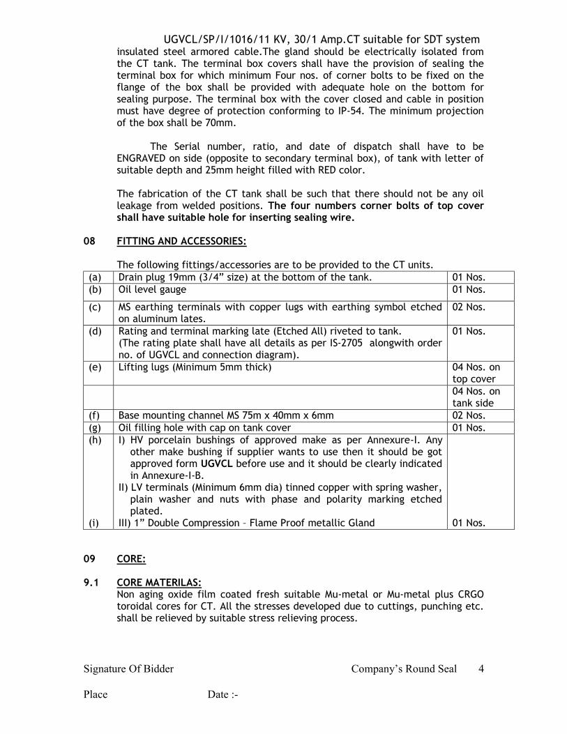
insulated steel armored cable.The gland should be electrically isolated from the CT tank. The terminal box covers shall have the provision of sealing the terminal box for which minimum Four nos. of corner bolts to be fixed on the flange of the box shall be provided with adequate hole on the bottom for sealing purpose. The terminal box with the cover closed and cable in position must have degree of protection conforming to IP-54. The minimum projection of the box shall be 70mm.
The Serial number, ratio, and date of dispatch shall have to be
ENGRAVED on side (opposite to secondary terminal box), of tank with letter of suitable depth and 25mm height filled with RED color.
The fabrication of the CT tank shall be such that there should not be any oil
leakage from welded positions. The four numbers corner bolts of top cover shall have suitable hole for inserting sealing wire.
08 FITTING AND ACCESSORIES: The following fittings/accessories are to be provided to the CT units. (a) Drain plug 19mm (3/4” size) at the bottom of the tank. 01 Nos. (b) Oil level gauge 01 Nos.
(c) MS earthing terminals with copper lugs with earthing symbol etched on aluminum lates.
02 Nos.
(d) Rating and terminal marking late (Etched All) riveted to tank. (The rating plate shall have all details as per IS-2705 alongwith order no. of UGVCL and connection diagram).
01 Nos.
(e) Lifting lugs (Minimum 5mm thick) 04 Nos. on top cover
04 Nos. on tank side
(f) Base mounting channel MS 75m x 40mm x 6mm 02 Nos. (g) Oil filling hole with cap on tank cover 01 Nos. (h) (i)
I) HV porcelain bushings of approved make as per Annexure-I. Any other make bushing if supplier wants to use then it should be got approved form UGVCL before use and it should be clearly indicated in Annexure-I-B.
II) LV terminals (Minimum 6mm dia) tinned copper with spring washer, plain washer and nuts with phase and polarity marking etched plated.
III) 1” Double Compression – Flame Proof metallic Gland
01 Nos.
09 CORE: 9.1 CORE MATERILAS: Non aging oxide film coated fresh suitable Mu-metal or Mu-metal plus CRGO
toroidal cores for CT. All the stresses developed due to cuttings, punching etc. shall be relieved by suitable stress relieving process.

UGVCL/SP/I/1016/11 KV, 30/1 Amp.CT suitable for SDT system
Signature Of Bidder Company’s Round Seal Place Date :-
5
9.2 CORE CONSTRUCTION AND DESIGN: Core is supporting steel and insulation shall be such that harmful changes in
electrical and physical properties shall not occur during the life time of the CT unit.
Core winding shall be strongly braced so that it shall not get displaced in operation due to shrinkage on short circuit forces. Core assembly shall be rigidly clamped with M.S. Channel and mounted to the tank.
9.3 CORE OF CT: The tenderer shall provide toroidal core only. It should be same as given in
type tested unit. Core / Winding assembly of CT shall be rigidly mounted in the tank. 10 WINDING: 10.1 It shall be of electrolytic grade copper conductor with super enameled
Insulation, conforming to relevant ISS. The winding design and contraction shall be such that it shall withstand impulse voltage. The details as per Guaranteed Technical Particulars shall be provided. The winding shall be preferable in two sections.
10.2 CT WINDING :
It shall be of electrolytic grate copper conductor with DPC/DCC and super enameled insulation conforming relevant ISS. The winding desing and construction shall be such that it shall withstand impulse voltage and short circuit currents. The winding shall be provided with rigid insulating supporting hylum sheets of minimum 3 mm thickness on both the sides duly tightened by insulating fasteners only and by cotton cord etc. (a) Each coil shall be wound of paper insulated, continuously, smooth high
grade, electric copper conductor. (b) The materials used in the insulation and assembly of the winding shall be
in-soluble, non-catalytic and chemically in active in the transformer oil. (c) Winding assembling shall be dried in vacuum thoroughly shrunk to final
alignment and vacuum impregnated with tested transformer oil. (d) Design arrangement, insulated and assembly of the winding on the core
shall be so as to ensure uniform distribution of voltage amongst all coils. 11 CONNCTIONS: No joints in the primary winding of CT shall be acceptable. The connections to
bushing terminals shall be with flexible copper strip / rope of adequate current carrying capacity. The leads shall be properly terminated with a crimped lug only.
12 ASEMBLY: Single CT units having specification / construction as referred above shall be
rigidly fixed in the tank. The core and coil assembly shall be supported rigidly with suitable M.S.
Channels. Suitable guides shall be provided to avoid displacement of active parts.
UGVCL/SP/I/1016/11 KV, 30/1 Amp.CT suitable for SDT system
Signature Of Bidder Company’s Round Seal Place Date :-
6
The inner clearance between live parts to tank shall be minimum 40mm for 11KV CT. The drawings shall clearly indicate the inner clearance in detail. General Arrangement Drawing should be sent with offer for approval.
13 CABLE DETAILS: The terminal box shall have cable entry hole of size 22mm dia. with 1.1/4 inch
double compression flame proof metal cable glands to avoid cutting of cable sheath. The terminal box shall have provision to seal the terminal box.
14 CLEARANCE: The minimum air clearance for HV shall be as per IS-3347.
15 DRAWINGS: The detailed dimensional drawings – 3copies as listed below shall be furnished
along with the offer. (a) Overall General arrangement drawing showing bushings arrangement with
their clearance, terminal box, etc. as per design shown with front side and top views along with list of fittings, material and its composition, nos., make and electrical clearance and creepage distance etc.
(b) Drawing showing internal exposition of CT’s inside tank with cross sectional view of CTs with dimensions, clearances, mounting arrangement details including details of electric and magnetic circuits.
(c) Diagram showing LT terminal arrangement with polarity marking and clearances.
(d) Drawing of name plate showing details of CT ratings, wiring diagram with terminal / polarity marking.
16 TESTS & INSPECTION: 16.1 QUALIFICATION: The tenderer shall have to furnish to following test certificates and documents
(I) All type tests certificates as listed under Annexure-III for 11KV units carried out on ONE single sample unit. The above test should be carried out in any Govt. approved Test Lab as indicated above.
(II) The copy / proof of bill / in voice of purchase of core material. (III) The copy of BH curve for the core material intended to be used in
regular supply of CT units.
If above test certificates are not submitted the offer will not be considered as “Qualified”.
16.1.1 TYPE TEST CERTIFICATE: The supplier has to submit Test Certificates for all the Type Tests as
prescribed under Annexure-III for 11KV CT with ratio as specified under 16.1 above i.e. 30/1 Amp. for 11KV class of supply voltage.
16.1.2 The Company also reserves the right to carry out al or any type tests on any CT
unit from the lot offered for inspection by the firm at CPRI / ERDA or Govt. Recognized Lab. in presence of UGVCL officers and representative of firm at Company’s cost. Any decision based on this testing shall be applied to the full
UGVCL/SP/I/1016/11 KV, 30/1 Amp.CT suitable for SDT system
Signature Of Bidder Company’s Round Seal Place Date :-
7
ordered quantity. However, if the unit fails in test, then the test charges shall have to be borne by the supplier.
16.2 ACCEPTANCE TESTS: The tests shall be carried out at manufacturer’s work as “Acceptance Tests”
on all CT units offered for inspections as per applicable is of individual units and this specification as per Annexure-IV.
16.3 ROUTINE TESTS: The firm shall carry out the routine tests on each CT set being offered for
inspection and submit the routine test certificate to the inspector deputed for inspection of CT sets and acceptance of the lot. Routine tests shall be carried out as per Annexure-V.
17 PROTO TYPE UNITS” The successful tenderer shall have to prepare minimum 2 nos. of proto type
units , conforming to this specification prior to manufacturing of bulk supply. The proto type units shall be subjected to (i) all Acceptance Tests as per clause no. 16.2 of this specification at the firm’s work and (ii) All type tests as per Annexure-III at any Govt. Testing Lab (the name of which shall be decided by Company) in the presence of Company’s representative.
The testing fees shall have to be borne by the supplier. NOTE: The TWO Nos. of CT – Proto Type units are required to be prepared only to
continue testing work on second unit at either supplier’s work or Govt. Testing Lab., whichever the case may be, in event of NOT passing through any Type test. However all Type Tests shall have to be conducted successfully on ONE single Proto unit.
The prototype units shall be sealed and kept at firm’s premises. During subsequent inspection of CT units, any unit may be opened for comparison with prototype for internal design detail, if required. The prototype unit having passed all Type test / selected tests successfully shall be dispatched along with last lot only.
The detailed drawings as mentioned at clause no. 15 of these tender specifications are submitted by the firm along with offer and only after approval of prototype unit and detailed drawings, the firm shall start bulk supply conforming to approved proto type units.
The prototype units shall be dispatched along with last lot only. 18 GUARANTEE: The CT unit offered shall have guarantee for good design, materials and
workmanship. The defective units shall have to be repaired / replaced free of cost if reported within 60 months from the date of dispatch or 54 months from the date of commissioning whichever is earlier. The firm shall be responsible for proper performance of the equipment for 60 months from the date of dispatch or 54 months after commissioning whichever is earlier.

UGVCL/SP/I/1016/11 KV, 30/1 Amp.CT suitable for SDT system
Signature Of Bidder Company’s Round Seal Place Date :-
8
Reported failed units under guarantee period as above shall be repaired / replaced as early as possible. In any case, it should be repaired / replaced within 30 days. The failed units are to be collected by the supplier from our field offices within 15 days of reporting. If immediate arrangement for collection of failed unit is not uncollected by you and if the units are not repaired within two months time, the Company will deduct full cost of CTunit from the bill. All the suppliers have to give 10% Performance Bank Guarantee in advance as security deposit.
UGVCL/SP/I/1016/11 KV, 30/1 Amp.CT suitable for SDT system
Signature Of Bidder Company’s Round Seal Place Date :-
9
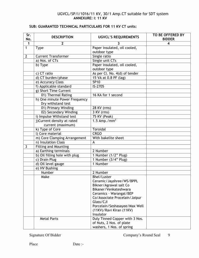
ANNEXURE: I: 11 KV SUB: GUARANTED TECHNICAL PARTICULARS FOR 11 KV CT units:
Sr. No. DESCRIPTION UGVCL’S REQUIREMENTS TO BE OFFERED BY
BIDDER 1 2 3 4
1 Type Paper insulated, oil cooled, outdoor type
2 Current Transformer Single ratio a) Nos. of CTs Single unit CTs b) Type Paper insulated, oil cooled,
outdoor type
c) CT ratio As per Cl. No. 4(d) of tender d) CT burden/phase 15 VA at 0.8 PF (lag) e) Accuracy Class 5P10 f) Applicable standard IS-2705 g) Short Time Current 01) Thermal Rating 16 KA for 1 second h) One minute Power Frequency
Dry withstand test
01) Primary Winding 28 KV (rms) 02) Secondary Winding 3 KV (rms) i) Impulse Withstand test 75 KV (Peak) j)Current density at rated
current (maximum) 1.5 Amp./mm2
k) Type of Core Toroidal l) Core material CRGO m) Core Clamping Arrangement With bakelite sheet n) Insulation Class A 3 Fitting and Mounting a) Earthing terminals 2 Number b) Oil filling hole with plug 1 Number (1/2” Plug) c) Drain Plug 1 Number (3/4” Plug) d) Oil level gauge 1 Number e) HV Bushing Number 2 Number Make Bhel/Luster
Ceramic/Jayshree/WS/BPPL Bikner/Agrawal salt Co Bikaner/Venkateshwara Ceramics – Warangal/BEP Co/Associate Procelain/Jaipur Glass/CJI Porcelain/Seshasayee/Max Well (11KV)/Ravi Kiran (11KV) Insulator
Metal Parts Duly Tinned Copper with 3 Nos. of Nuts, 2 Nos. of plate washers, 1 Nos. of spring
UGVCL/SP/I/1016/11 KV, 30/1 Amp.CT suitable for SDT system
Signature Of Bidder Company’s Round Seal Place Date :-
10
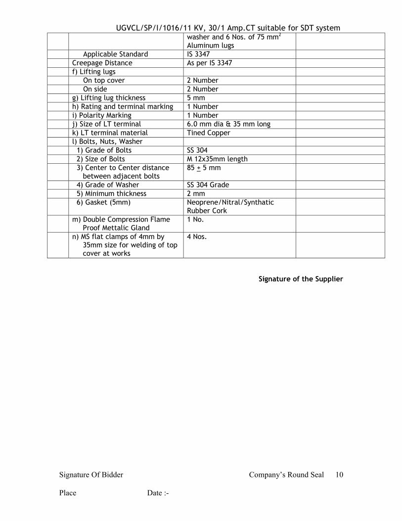
washer and 6 Nos. of 75 mm2 Aluminum lugs
Applicable Standard IS 3347 Creepage Distance As per IS 3347 f) Lifting lugs On top cover 2 Number On side 2 Number g) Lifting lug thickness 5 mm h) Rating and terminal marking 1 Number i) Polarity Marking 1 Number j) Size of LT terminal 6.0 mm dia & 35 mm long k) LT terminal material Tined Copper l) Bolts, Nuts, Washer 1) Grade of Bolts SS 304 2) Size of Bolts M 12x35mm length 3) Center to Center distance
between adjacent bolts 85 + 5 mm
4) Grade of Washer SS 304 Grade 5) Minimum thickness 2 mm 6) Gasket (5mm) Neoprene/Nitral/Synthatic
Rubber Cork
m) Double Compression Flame Proof Mettalic Gland
1 No.
n) MS flat clamps of 4mm by 35mm size for welding of top cover at works
4 Nos.
Signature of the Supplier

UGVCL/SP/I/1016/11 KV, 30/1 Amp.CT suitable for SDT system
Signature Of Bidder Company’s Round Seal Place Date :-
11
ANNEXURE: I-A: 11KV
Sub: Technical Design parameters for 11 KV CT unit. Sr. No. Description Offered by supplier
01 02 03 1 C.T.
(a) CT primary conductor size (b) Nos. of turns of Primary Winding (c) CT secondary conductor size (d) Nos. of turns of secondary winding (e) Nos. of parallel paths used in
secondary winding
2 Qty. of first filling of transformer oil
3 Tank (a) Tank sheet size
(i) Top and bottom thickness
(ii) Side wall thickness
(b) Tank Size
(i) Overall Dimension
(ii) Inside Dimension
N.B. Please offer Technical Particulars in this sheet only.
Signature of Supplier
UGVCL/SP/I/1016/11 KV, 30/1 Amp.CT suitable for SDT system
Signature Of Bidder Company’s Round Seal Place Date :-
12
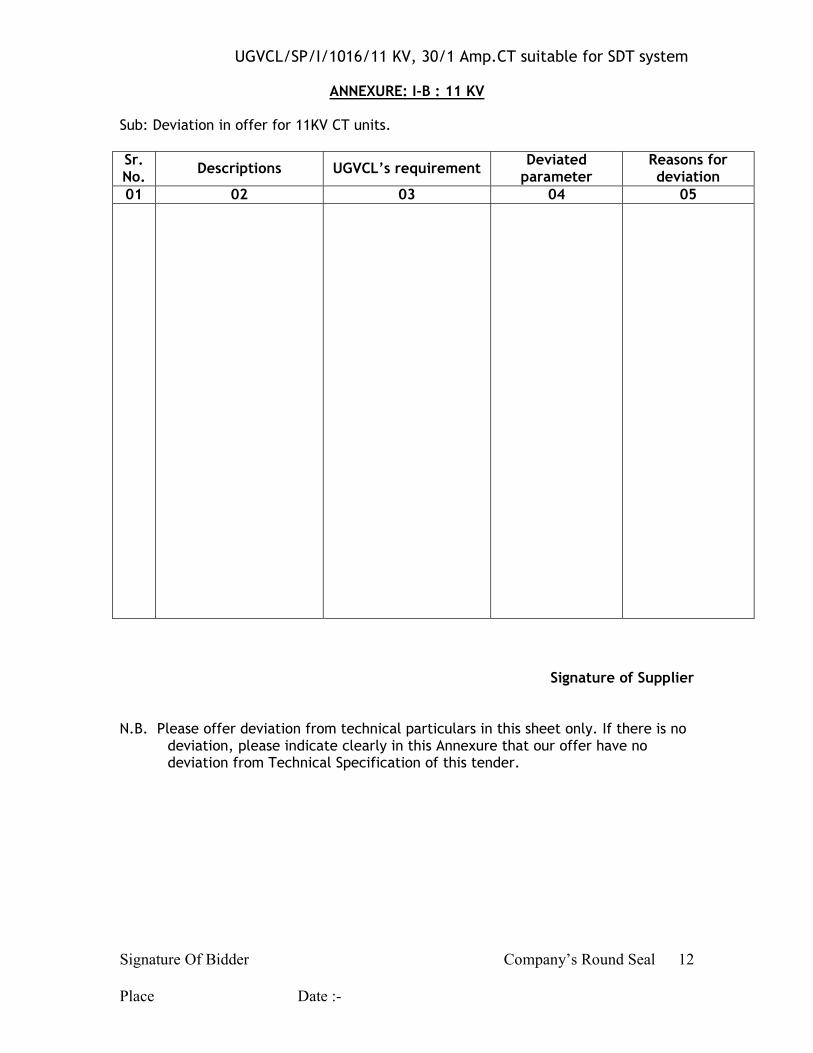
ANNEXURE: I-B : 11 KV
Sub: Deviation in offer for 11KV CT units. Sr. No. Descriptions UGVCL’s requirement
Deviated parameter
Reasons for deviation
01 02 03 04 05
Signature of Supplier N.B. Please offer deviation from technical particulars in this sheet only. If there is no
deviation, please indicate clearly in this Annexure that our offer have no deviation from Technical Specification of this tender.
UGVCL/SP/I/1016/11 KV, 30/1 Amp.CT suitable for SDT system
Signature Of Bidder Company’s Round Seal Place Date :-
13
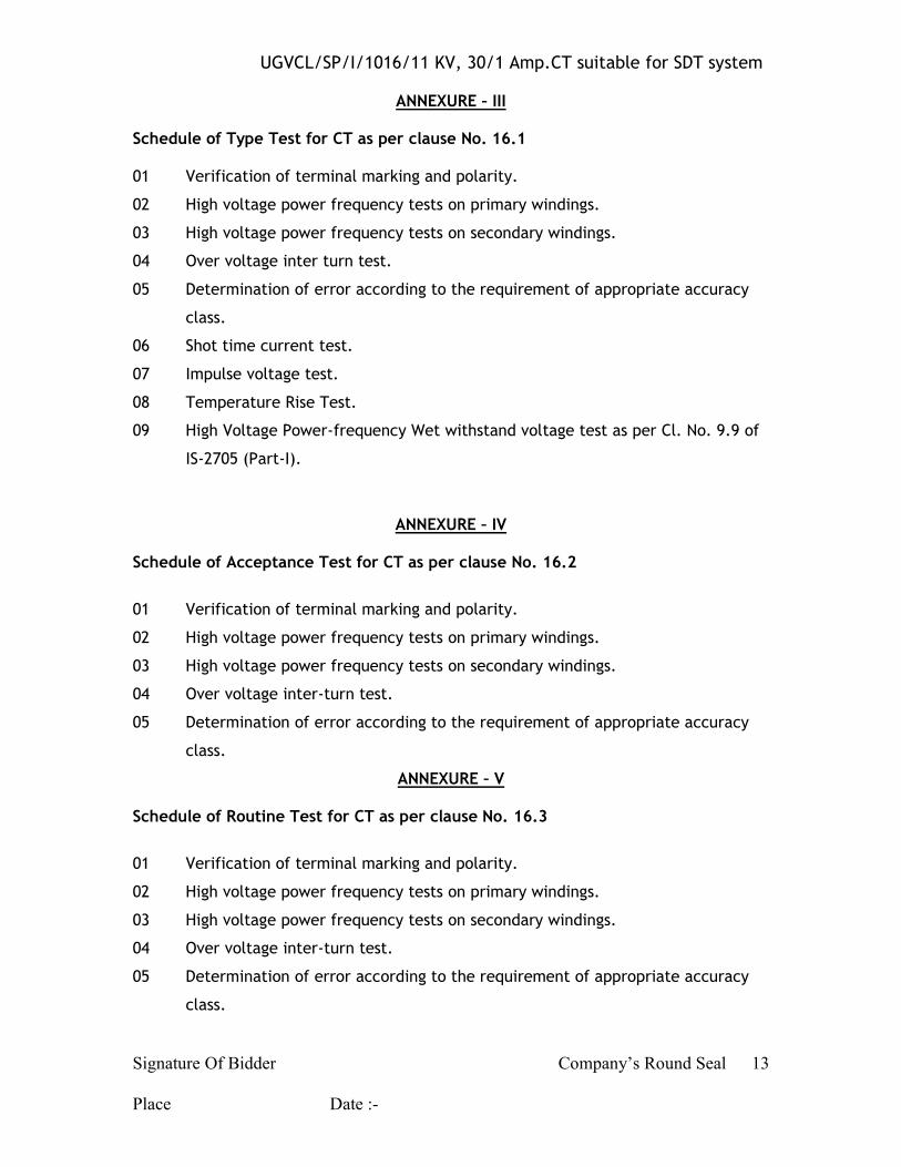
ANNEXURE – III
Schedule of Type Test for CT as per clause No. 16.1 01 Verification of terminal marking and polarity.
02 High voltage power frequency tests on primary windings.
03 High voltage power frequency tests on secondary windings.
04 Over voltage inter turn test.
05 Determination of error according to the requirement of appropriate accuracy
class.
06 Shot time current test.
07 Impulse voltage test.
08 Temperature Rise Test.
09 High Voltage Power-frequency Wet withstand voltage test as per Cl. No. 9.9 of
IS-2705 (Part-I).
ANNEXURE – IV Schedule of Acceptance Test for CT as per clause No. 16.2
01 Verification of terminal marking and polarity.
02 High voltage power frequency tests on primary windings.
03 High voltage power frequency tests on secondary windings.
04 Over voltage inter-turn test.
05 Determination of error according to the requirement of appropriate accuracy
class.
ANNEXURE – V Schedule of Routine Test for CT as per clause No. 16.3
01 Verification of terminal marking and polarity.
02 High voltage power frequency tests on primary windings.
03 High voltage power frequency tests on secondary windings.
04 Over voltage inter-turn test.
05 Determination of error according to the requirement of appropriate accuracy
class.