Type QD75P/QD75D Positioning Module User's Manual ...
18
Type QD75P/QD75D Positioning Module User’s Manual (Hardware) QD75P1, QD75D1 QD75P2, QD75D2 QD75P4, QD75D4 Thank you for buying the Mitsubishi general-purpose programmable logic controller MELSEC-Q Series Prior to use, please read both this manual and detailed manual thoroughly and familiarize yourself with the product. 1999 MITSUBISHI ELECTRIC CORPORATION
-
Upload
khangminh22 -
Category
Documents
-
view
0 -
download
0
Transcript of Type QD75P/QD75D Positioning Module User's Manual ...
Type QD75P/QD75DPositioning Module
User’s Manual(Hardware)
QD75P1, QD75D1QD75P2, QD75D2QD75P4, QD75D4
Thank you for buying the Mitsubishi general-purpose programmable
logic controller MELSEC-Q Series
Prior to use, please read both this manual and detailed manual
thoroughly and familiarize yourself with the product.
1999 MITSUBISHI ELECTRIC CORPORATION
A-1
DANGER
CAUTION
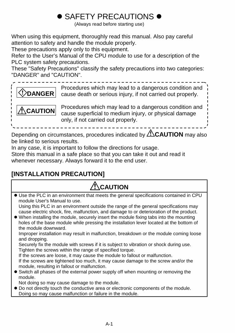
! SAFETY PRECAUTIONS !(Always read before starting use)
When using this equipment, thoroughly read this manual. Also pay carefulattention to safety and handle the module properly.These precautions apply only to this equipment.Refer to the User’s Manual of the CPU module to use for a description of thePLC system safety precautions.These "Safety Precautions" classify the safety precautions into two categories:"DANGER" and "CAUTION".
Procedures which may lead to a dangerous condition andcause death or serious injury, if not carried out properly.
Procedures which may lead to a dangerous condition andcause superficial to medium injury, or physical damageonly, if not carried out properly.
Depending on circumstances, procedures indicated by CAUTION may alsobe linked to serious results.In any case, it is important to follow the directions for usage.Store this manual in a safe place so that you can take it out and read itwhenever necessary. Always forward it to the end user.
[INSTALLATION PRECAUTION]
CAUTION! Use the PLC in an environment that meets the general specifications contained in CPU
module User's Manual to use.Using this PLC in an environment outside the range of the general specifications maycause electric shock, fire, malfunction, and damage to or deterioration of the product.
! When installing the module, securely insert the module fixing tabs into the mountingholes of the base module while pressing the installation lever located at the bottom ofthe module downward.Improper installation may result in malfunction, breakdown or the module coming looseand dropping.Securely fix the module with screws if it is subject to vibration or shock during use.Tighten the screws within the range of specified torque.If the screws are loose, it may cause the module to fallout or malfunction.If the screws are tightened too much, it may cause damage to the screw and/or themodule, resulting in fallout or malfunction.
! Switch all phases of the external power supply off when mounting or removing themodule.Not doing so may cause damage to the module.
! Do not directly touch the conductive area or electronic components of the module.Doing so may cause malfunction or failure in the module.

A-2
[WIRING PRECAUTION]
DANGER! Switch all phases of the external power supply off when installing or placing wiring.
Not doing so may cause electric shock or damage to the product.
CAUTION! Check the layout of the terminals and then properly route the wires to the module.! Solder connectors for external device properly.
Insufficient soldering may cause malfunction.! Be careful not to let foreign matter such as sawdust or wire chips get inside the module.
These may cause fires, failure or malfunction.! The top surface of the module is covered with protective film to prevent foreign objects
such as cable offcuts from entering the module when wiring.Do not remove this film until the wiring is complete.Before operating the system, be sure to remove the film to provide adequate ventilation.
! Securely connect the connectors for the drive module to the connectors on the moduleand firmly tighten the two screws.
! Be sure to fix cables leading from the module by placing them in a duct or clampingthem.Cables not placed in the duct or without clamping may hang or shift, allowing them to beaccidentally pulled, which may cause a module malfunction and cable damage.
! When removing the cable or power supply cable from the module, do not pull the cable.When removing the cable with a connector, hold the connector on the side that isconnected to the module.Pulling the cable that is still connected to the module may cause malfunction or damageto the module or cable.
! The cable used for connecting the QD75 external input/output signal and the drivemodule should not be routed near or bundled with the main circuit cable, power cableand/or other such load-carrying cables other than those for the PLC. These cablesshould be separated by at least 100 mm (3.94 in.). They can cause electricalinterference, surges and inductance that can lead to mis-operation.
A-3
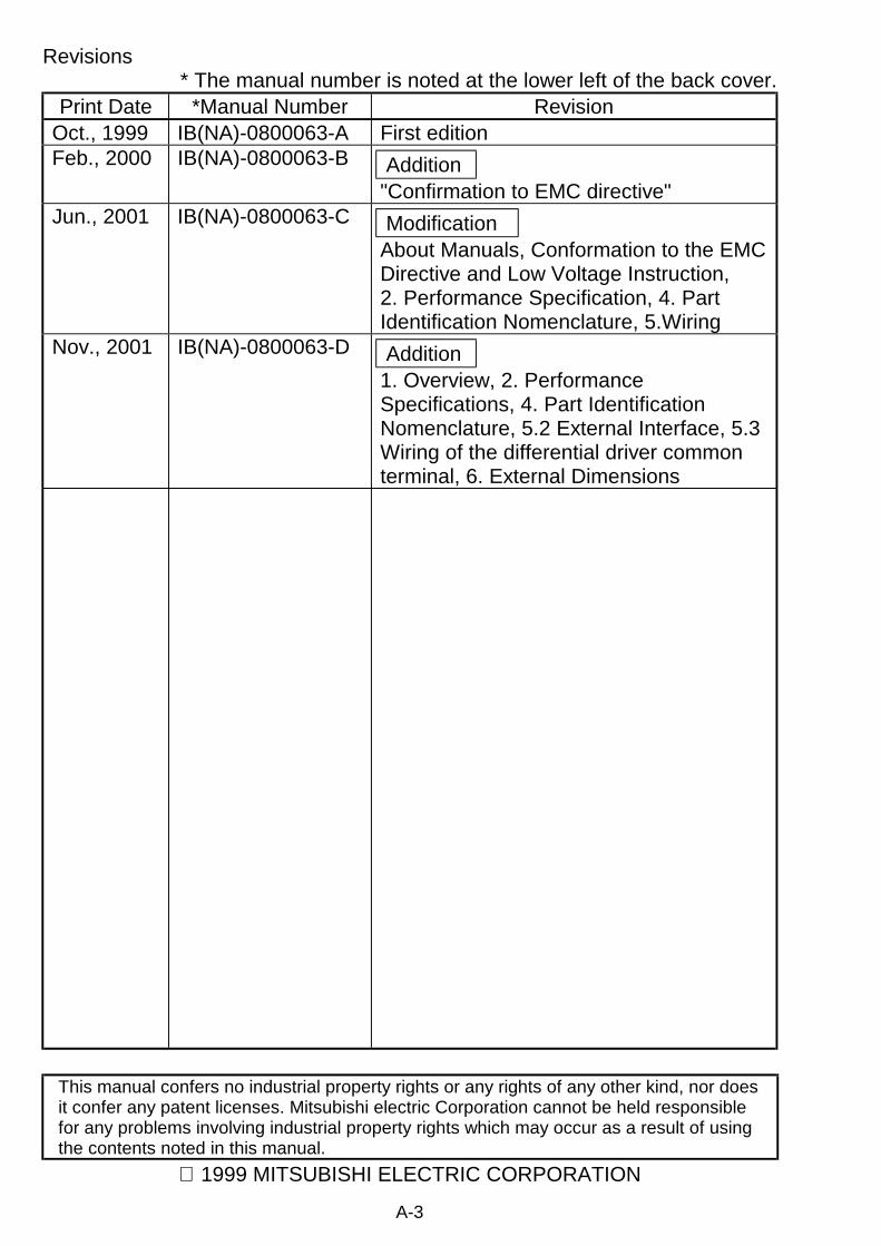
Revisions* The manual number is noted at the lower left of the back cover.
Print Date *Manual Number RevisionOct., 1999 IB(NA)-0800063-A First editionFeb., 2000 IB(NA)-0800063-B Addition
"Confirmation to EMC directive"Jun., 2001 IB(NA)-0800063-C Modification
About Manuals, Conformation to the EMCDirective and Low Voltage Instruction,2. Performance Specification, 4. PartIdentification Nomenclature, 5.Wiring
Nov., 2001 IB(NA)-0800063-D Addition1. Overview, 2. PerformanceSpecifications, 4. Part IdentificationNomenclature, 5.2 External Interface, 5.3Wiring of the differential driver commonterminal, 6. External Dimensions
This manual confers no industrial property rights or any rights of any other kind, nor doesit confer any patent licenses. Mitsubishi electric Corporation cannot be held responsiblefor any problems involving industrial property rights which may occur as a result of usingthe contents noted in this manual.
1999 MITSUBISHI ELECTRIC CORPORATION
A-4
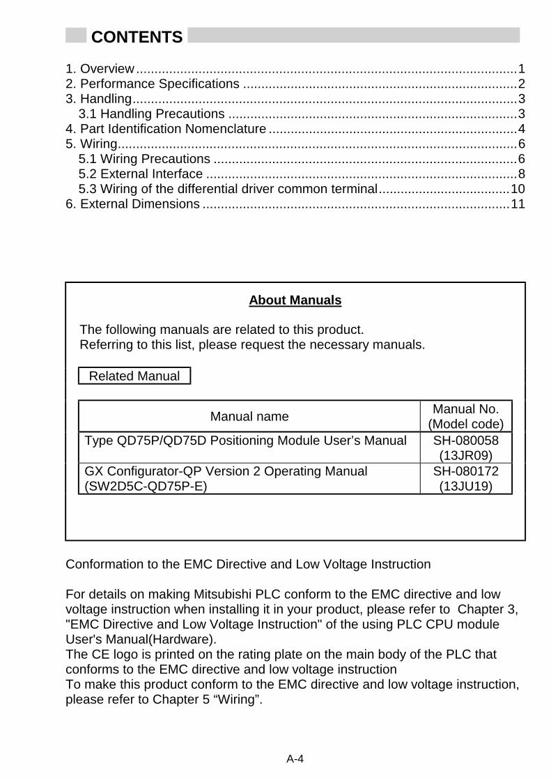
CONTENTS
1. Overview ........................................................................................................12. Performance Specifications ...........................................................................23. Handling.........................................................................................................3
3.1 Handling Precautions ...............................................................................34. Part Identification Nomenclature ....................................................................45. Wiring.............................................................................................................6
5.1 Wiring Precautions ...................................................................................65.2 External Interface .....................................................................................85.3 Wiring of the differential driver common terminal....................................10
6. External Dimensions ....................................................................................11
About Manuals
The following manuals are related to this product.Referring to this list, please request the necessary manuals.
Related Manual
Manual nameManual No.
(Model code)Type QD75P/QD75D Positioning Module User’s Manual SH-080058
(13JR09)GX Configurator-QP Version 2 Operating Manual(SW2D5C-QD75P-E)
SH-080172(13JU19)
Conformation to the EMC Directive and Low Voltage Instruction
For details on making Mitsubishi PLC conform to the EMC directive and lowvoltage instruction when installing it in your product, please refer to Chapter 3,"EMC Directive and Low Voltage Instruction" of the using PLC CPU moduleUser's Manual(Hardware).The CE logo is printed on the rating plate on the main body of the PLC thatconforms to the EMC directive and low voltage instructionTo make this product conform to the EMC directive and low voltage instruction,please refer to Chapter 5 “Wiring”.

1
1. Overview This manual explains how to handle the Positioning Module, model numbersQD75P1, QD75P2, QD75P4, QD75D1, QD75D2 and QD75D4 (hereinaftercollectively referred to as the QD75).After unpacking the QD75, please verify that the corresponding product aslisted below is enclosed in the package.Model name Description QuantityQD75P1 QD75P1 Positioning Module (1-axis open-collector output system) 1QD75P2 QD75P2 Positioning Module (2-axes open-collector output system) 1QD75P4 QD75P4 Positioning Module (4-axes open-collector output system) 1
QD75D1 Positioning Module (1-axis differential driver output system) 1QD75D1
Differential driver common terminal 1QD75D2 Positioning Module (2-axes differential driver output system) 1
QD75D2Differential driver common terminal 1QD75D4 Positioning Module (4-axes differential driver output system) 1
QD75D4Differential driver common terminal 1
A differential driver common terminal is packed with the QD75D1, QD75D2 andQD75D4.The user should arrange for a connector for external wiring since it is notprovided in the package.* Connector type
" A6CON1 (Soldering type, straight out)" A6CON2 (Crimping type, straight out)" A6CON4 (Soldering type, usable for straight out and diagonal out)
* A6CON2 crimping tool" Model name: FCN-363T-T005/H" Supplier’s offices :
" FUJITSU TAKAMISAWA AMERICA,INC.250E Caribbean Drive Sunnyvale, CA 94089 U.S.ATel: (1-408)745-4900
" FUJITSU TAKAMISAWA EUROPE B.V.Jupiterstaat 13-15, our 2132 Hoofddorp, The NetherlandTel: (31)23-5560910
" FUJITSU TAKAMISAWA EUROPE B.V. Zweiniederlassung DeutschlandSchatzbogen 86 D-81829 Munchen GermanyTel: (49)89-42742320
" FUJITSU TAKAMISAWA EUROPE (UK)Network House, Morres Drive, Maidenhead, Berkshire, SL6 4FHUnited KingdomTel: (44)1628-504600
" FUJITSU TAKAMISAWA EUROPE B.V.127 Chemin Des Bassins, Europarc, Cleteril 94035 Cleterll 94035FranceTel: (33)145139940
" FUJITSU TAKAMISAWA ASIA PACIFIC PTE LIMITED102E Pasir Panjang Road, #04-01 Citilink Warehouse Complex,Singapore 118529Tel: (65)375-8560
" FUJITSU TAKAMISAWA HONG KONG CO., LTD.Suite 913 Ocean Centre, 5 Canton Road, TST, Kowloon, Hong KongTel: (852)2881-8495
2
2. Performance Specifications
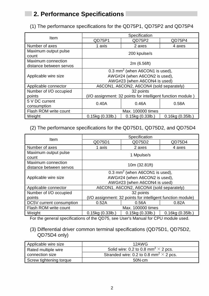
(1) The performance specifications for the QD75P1, QD75P2 and QD75P4
SpecificationItem
QD75P1 QD75P2 QD75P4Number of axes 1 axis 2 axes 4 axesMaximum output pulsecount
200 kpulse/s
Maximum connectiondistance between servos
2m (6.56ft)
Applicable wire size0.3 mm2 (when A6CON1 is used),AWG#24 (when A6CON2 is used),AWG#23 (when A6CON4 is used)
Applicable connector A6CON1, A6CON2, A6CON4 (sold separately)Number of I/O occupiedpoints
32 points(I/O assignment: 32 points for intelligent function module )
5 V DC currentconsumption
0.40A 0.46A 0.58A
Flash ROM write count Max. 100000 timesWeight 0.15kg (0.33lb.) 0.15kg (0.33lb.) 0.16kg (0.35lb.)
(2) The performance specifications for the QD75D1, QD75D2, and QD75D4
SpecificationItem
QD75D1 QD75D2 QD75D4Number of axes 1 axis 2 axes 4 axesMaximum output pulsecount
1 Mpulse/s
Maximum connectiondistance between servos
10m (32.81ft)
Applicable wire size0.3 mm2 (when A6CON1 is used),AWG#24 (when A6CON2 is used),AWG#23 (when A6CON4 is used)
Applicable connector A6CON1, A6CON2, A6CON4 (sold separately)Number of I/O occupiedpoints
32 points(I/O assignment: 32 points for intelligent function module)
DC5V current consumption 0.52A 0.56A 0.82AFlash ROM write count Max. 100000 timesWeight 0.15kg (0.33lb.) 0.15kg (0.33lb.) 0.16kg (0.35lb.)
For the general specifications of the QD75, see User's Manual for CPU module used.
(3) Differential driver common terminal specifications (QD75D1, QD75D2,QD75D4 only)
Applicable wire size 12AWGSolid wire: 0.2 to 0.8 mm2 2 pcs.Rated multiple wire
connection size Stranded wire: 0.2 to 0.8 mm2 2 pcs.Screw tightening torque 50N·cm

3
3. Handling
CAUTION! Use the PLC in an environment that meets the general specifications
contained in CPU module User's Manual to use.Using this PLC in an environment outside the range of the generalspecifications may cause electric shock, fire, malfunction, and damage toor deterioration of the product.
! When installing the module, securely insert the module fixing tabs into themounting holes of the base module while pressing the installation leverlocated at the bottom of the module downward.Improper installation may result in malfunction, breakdown or dropping outof the module.Securely fix the module with screws if it is subject to vibration or shockduring use.Tighten the screws within the range of specified torque.If the screws are loose, it may cause fallout or malfunction.If the screws are tightened too much, it may cause damage to the screwand/or the module, resulting in fallout or malfunction.
! Switch all phases of the external power supply off when mounting orremoving the module.Not doing so may cause damage to the module.
! Do not directly touch the conductive area or electronic components of themodule.Doing so may cause malfunction or failure in the module.
3.1 Handling Precautions(1) Since the module case is made of resin, do not drop it or subject it to
strong impact.(2) The module can easily be secured to the base unit using the hooks
located at the top of the module. However, if the module is to be placed inan area that is subject to strong vibration or impact, we recommend that itis secured with module mounting screws (to be provided by the user). Inthis case, tighten the module mounting screws within the following torquerange.Module mounting screws (M3 × 12): Tightening torque range is from 36 to48 N⋅cm.

4
4. Part Identification Nomenclature (1) Part identification nomenclature
(a) For QD75P4 (b) For QD75D4
QD75P4RUN
ERR
AX1
AX1
AX2AX3AX4
AX2AX3AX4
1)
2)
QD75D4RUN
ERR
AX1
AX1
AX2AX3AX4
AX2AX3AX4
1)
2)
3)
Number Name Number Name
1) LED Display
3) Differential driver common terminal2)
External device connector(The QD75P1, QD75P2, QD75D1and QD75D2 have the right-handside connector only.)
(2) LED display contentsDetails ofindication Points to be confirmed Error
RUN # #AX1#AX2#AX3
ERR.# #AX4
Extinguishment of RUN LED The hardware isfaulty or watch dogtimer error occurs.
RUN $ #AX1#AX2#AX3
ERR.# #AX4
Lighting of RUN LED,Extinguishment of ERR. LED
The module isnormal.
RUN $ #AX1#AX2#AX3
ERR.$ #AX4
Lighting of ERR. LED System error
RUN $ #AX1#AX2#AX3
ERR.# #AX4
Extinguishment of AX1 to AX4 LEDs During axis stop,during axisstandby
RUN $ $AX1#AX2#AX3
ERR.# #AX4
Lighting of AX1 (Same even if theother axis is lit)
During axisoperation
RUN $ %AX1#AX2#AX3
ERR.% #AX4
Flashing of ERR. LEDFlashing of AX1 LED(Same even if the other axis flashes)
Axis error
QD75 4RUN
ERR. AX4AX3AX2AX1
RUN $ $AX1$AX2$AX3
ERR.$ $AX4
Lighting of all LEDs The hardware isfaulty
The symbols in the Display column indicate the following statuses: : Turns OFF, : Illuminates, : Flashes
5
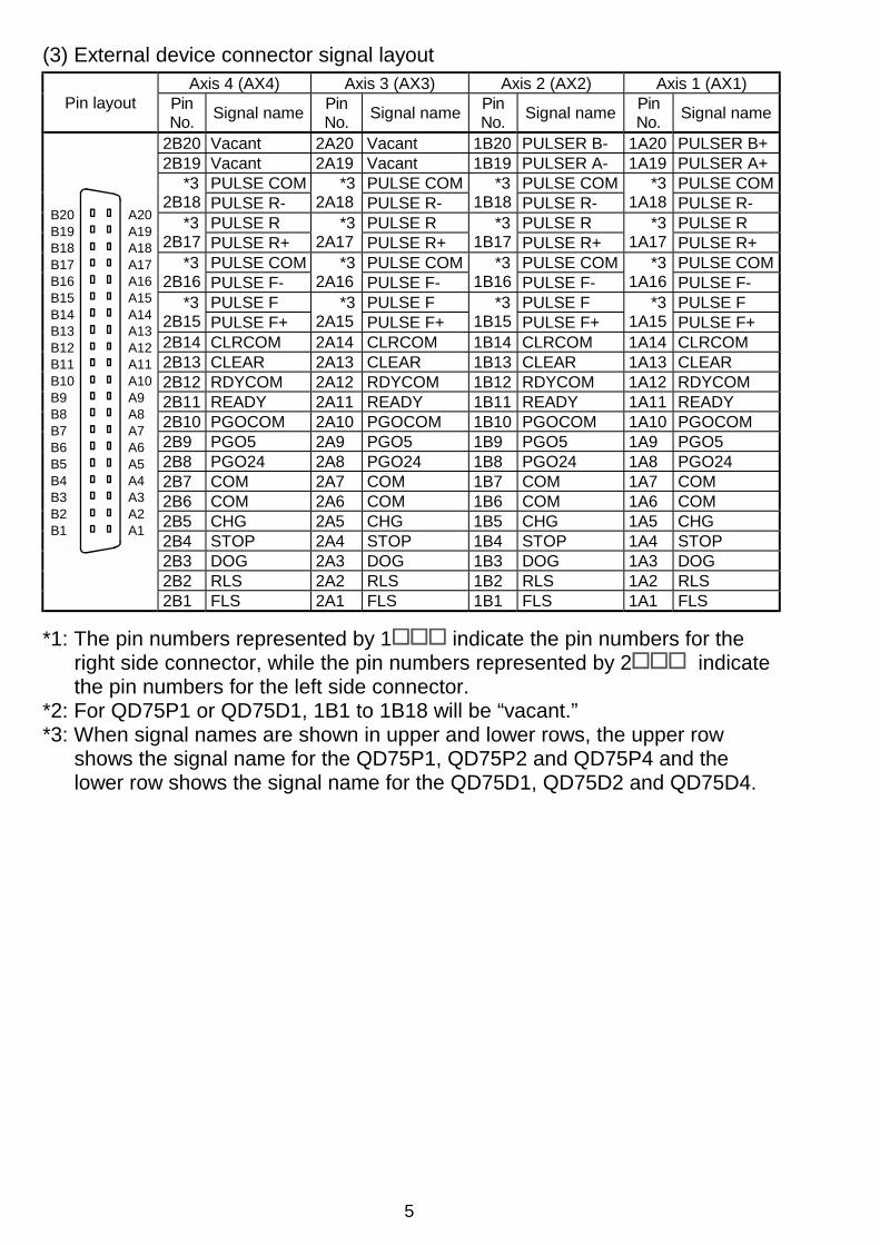
(3) External device connector signal layoutAxis 4 (AX4) Axis 3 (AX3) Axis 2 (AX2) Axis 1 (AX1)
Pin layout PinNo.
Signal namePinNo.
Signal namePinNo.
Signal namePinNo.
Signal name
2B20 Vacant 2A20 Vacant 1B20 PULSER B- 1A20 PULSER B+2B19 Vacant 2A19 Vacant 1B19 PULSER A- 1A19 PULSER A+
PULSE COM PULSE COM PULSE COM PULSE COM*32B18 PULSE R-
*32A18 PULSE R-
*31B18 PULSE R-
*31A18 PULSE R-
PULSE R PULSE R PULSE R PULSE R*32B17 PULSE R+
*32A17 PULSE R+
*31B17 PULSE R+
*31A17 PULSE R+
PULSE COM PULSE COM PULSE COM PULSE COM*32B16 PULSE F-
*32A16 PULSE F-
*31B16 PULSE F-
*31A16 PULSE F-
PULSE F PULSE F PULSE F PULSE F*32B15 PULSE F+
*32A15 PULSE F+
*31B15 PULSE F+
*31A15 PULSE F+
2B14 CLRCOM 2A14 CLRCOM 1B14 CLRCOM 1A14 CLRCOM2B13 CLEAR 2A13 CLEAR 1B13 CLEAR 1A13 CLEAR2B12 RDYCOM 2A12 RDYCOM 1B12 RDYCOM 1A12 RDYCOM2B11 READY 2A11 READY 1B11 READY 1A11 READY2B10 PGOCOM 2A10 PGOCOM 1B10 PGOCOM 1A10 PGOCOM2B9 PGO5 2A9 PGO5 1B9 PGO5 1A9 PGO52B8 PGO24 2A8 PGO24 1B8 PGO24 1A8 PGO242B7 COM 2A7 COM 1B7 COM 1A7 COM2B6 COM 2A6 COM 1B6 COM 1A6 COM2B5 CHG 2A5 CHG 1B5 CHG 1A5 CHG2B4 STOP 2A4 STOP 1B4 STOP 1A4 STOP2B3 DOG 2A3 DOG 1B3 DOG 1A3 DOG2B2 RLS 2A2 RLS 1B2 RLS 1A2 RLS
B20B19B18B17B16B15B14B13B12B11B10B9B8B7B6B5B4B3B2B1
A20A19A18A17A16A15A14A13A12A11A10A9A8A7A6A5A4A3A2A1
2B1 FLS 2A1 FLS 1B1 FLS 1A1 FLS
*1: The pin numbers represented by 1 indicate the pin numbers for theright side connector, while the pin numbers represented by 2 indicatethe pin numbers for the left side connector.
*2: For QD75P1 or QD75D1, 1B1 to 1B18 will be “vacant.”*3: When signal names are shown in upper and lower rows, the upper row
shows the signal name for the QD75P1, QD75P2 and QD75P4 and thelower row shows the signal name for the QD75D1, QD75D2 and QD75D4.

6
5. Wiring
DANGER! Switch all phases of the external power supply off when installing or placing wiring.
Not doing so may cause electric shock or damage to the product.
5.1 Wiring Precautions(1) If cables to connect to QD75 absolutely must be positioned near (within
100 mm) the power line, use a general shielded cable. The shield mustbe grounded on the QD75 side.
Connector (A6CON1/A6CON2)
Use the shortest possible length to ground the 2mm2 or more FG wire.(The shield must be grounded on the QD75 side.)
To external devices
Connector
The length between the connector and the shielded cables should be the shortest possible.
Shielded cable
Drive unit
To external device
To QD75
To drive unit
[Processing example of shielded cables]
Coat the wire with insulaing tape.
Remove the covering from all shielded cables and bind the appeared shield with a conductive tape.
Solder the shield of any one of the shielded cables to the FG wire.

7
Wrap the coated parts with a heat contractile tube.
(2) The shielded cable for connecting QD75 can be secured in place.If the shielded cable is not secured, unevenness or movement of theshielded cable or careless pulling on it could result in damage to theQD75 or drive unit or shielded cable or defective cable connections couldcause mis-operation of the unit.
(3) To make this product conform to the EMC directive and low voltageinstruction, be sure to use of a AD75CK type cable clamp (manufacturedby Mitsubishi Electric) for grounding to the control box.
QD
75
AD75CK
20cm(7.88inch) to 30cm(11.82inch)
Inside control box
Using the AD75CK, you can tie four cables of about 7mm outsidediameter together for grounding.
8
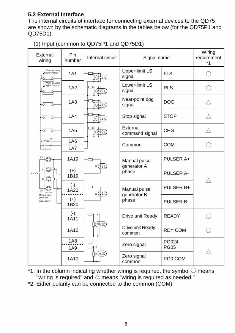
5.2 External InterfaceThe internal circuits of interface for connecting external devices to the QD75are shown by the schematic diagrams in the tables below (for the QD75P1 andQD75D1).
(1) Input (common to QD75P1 and QD75D1)
Externalwiring
Pinnumber
Internal circuit Signal nameWiring
requirement*1
1A1Upper-limit LSsignal
FLS
1A2Lower-limit LSsignal
RLS
1A3Near-point dogsignal
DOG
1A4 Stop signal STOP
1A5Externalcommand signal
CHG
1A6
1A7Common COM
1A19 PULSER A+
(+)1B19
Manual pulsegenerator Aphase PULSER A-
(-)1A20
PULSER B+
(+)1B20
Manual pulsegenerator Bphase PULSER B-
(-)1A11
Drive unit Ready READY
1A12Drive unit Readycommon
RDY COM
1A8
1A9Zero signal
PG024PG05
When not using higher limit LS
5 V
A
B
0V
Manual pulse generator
(MR-HDP01)
24 V DC
5 V DC
When not usinglower limit LS
*2
1A10Zero signalcommon
PG0 COM
*1: In the column indicating whether wiring is required, the symbol means"wiring is required" and means "wiring is required as needed."
*2: Either polarity can be connected to the common (COM).

9
(2) Output (for QD75P1)
External wiringPin
numberInternal circuit Signal name
Wiringrequirement *
1A13Deviationcounter clear
CLEAR
1A14 Common CLEAR COM
1A15 PULSE F
1A16
CWA phasePULSE PULSE COM
1A17 PULSE R
1A18
CCWB phaseSIGN PULSE COM
(3) Output (for QD75D1)
External wiringPin
numberInternal circuit Signal name
Wiringrequirement *
1A13Deviationcounter clear
CLEAR
1A14 Common CLEAR COM
1A15 PULSE F+
1A16
CWA phasePULSE PULSE F-
1A17 PULSE F+
1A18
CCWB phaseSIGN PULSE F-
—
—
Differentialdrivercommonterminal
—
*: In the column indicating whether wiring is required, the symbol means"wiring is required" and means "wiring is required as needed."

10
5.3 Wiring of the differential driver common terminalWhen the differential driver output type (QD75D1/QD75D2/QD75D4) is used,an inter-common potential difference may occur between the differential drivercommon terminal and the differential receiver common terminal of the driveunit.To eliminate an inter-common potential difference, connect between thedifferential driver common terminal of the QD75D1/QD75D2/QD75D4 and thedifferential receiver common terminal of the drive unit.When the common terminal of the drive unit is a photocoupler connection type,it need not be connected to the differential driver common terminal of theQD75D1/QD75D2/QD75D4 since an inter-common potential difference doesnot exist. (For the driver unit specifications, refer to the manual of the drive unitused.)The following gives an example of wiring the differential driver common terminalof the QD75D1/QD75D2/QD75D4.Up to two wires can be connected to one differential driver common terminal.(Refer to "2. Performance Specifications" for details.)
To differential receiver commonterminal of drive unit.
Module front
Differential driver common terminal
Module bottom
Module front
Module bottom
Insert until hookengages
Module side

11
6. External Dimensions
(1) QD75P1/QD75P2/QD75P4
QD75P1 QD75P2 QD75P4QD75P2 QD75P4
AX1AX2
AX3AX4
QD75P1
AX1AX2
AX1
RUN
ERR. AX4AX3AX2AX1RUN
ERR.
AX2AX1RUN
ERR.
AX1
27.4(1.08)
90 (3.54)
136 (5.35)
46 (1.81)
98
(3.8
6)
Unit : mm (inch)
12
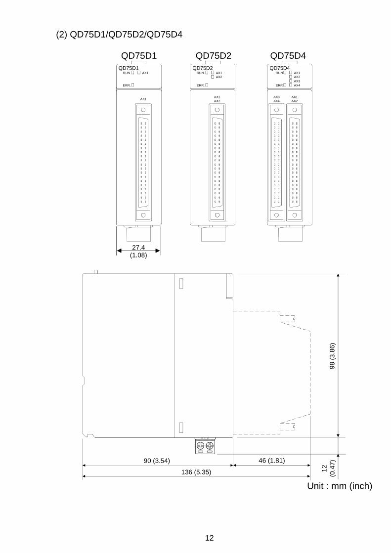
(2) QD75D1/QD75D2/QD75D4
QD75D1 QD75D2 QD75D4QD75D2 QD75D4
AX1AX2
AX3AX4
QD75D1
AX1AX2
AX1
RUN
ERR. AX4AX3AX2AX1RUN
ERR.
AX2AX1RUN
ERR.
AX1
27.4(1.08)
90 (3.54)
136 (5.35)
46 (1.81)
98 (
3.8
6)
12
(0.4
7)
Unit : mm (inch)
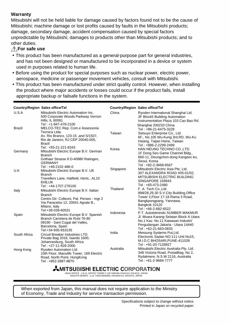
WarrantyMitsubishi will not be held liable for damage caused by factors found not to be the cause ofMitsubishi; machine damage or lost profits caused by faults in the Mitsubishi products;damage, secondary damage, accident compensation caused by special factorsunpredictable by Mitsubishi; damages to products other than Mitsubishi products; and toother duties.
For safe use " This product has been manufactured as a general-purpose part for general industries,
and has not been designed or manufactured to be incorporated in a device or systemused in purposes related to human life.
" Before using the product for special purposes such as nuclear power, electric power,aerospace, medicine or passenger movement vehicles, consult with Mitsubishi.
" This product has been manufactured under strict quality control. However, when installingthe product where major accidents or losses could occur if the product fails, installappropriate backup or failsafe functions in the system.
U.S.A Mitsubishi Electric Automation Inc. 500 Corporate Woods Parkway Vernon Hills, IL 60061 Tel : +1-847-478-2100Brazil MELCO-TEC Rep. Com.e Assessoria Tecnica Ltda. Av. Rio Branco, 123-15 ,and S/1507, Rio de Janeiro, RJ CEP 20040-005, Brazil Tel : +55-21-221-8343Germany Mitsubishi Electric Europe B.V. German Branch Gothaer Strasse 8 D-40880 Ratingen, GERMANY Tel : +49-2102-486-0U.K Mitsubishi Electric Europe B.V. UK Branch Travellers Lane, Hatfield, Herts., AL10 8XB,UK Tel : +44-1707-276100Italy Mitsubishi Electric Europe B.V. Italian Branch Centro Dir. Colleoni, Pal. Perseo - Ingr.2 Via Paracelso 12, 20041 Agrate B., Milano, Italy Tel:+39-039-60531Spain Mitsubishi Electric Europe B.V. Spanish Branch Carretera de Rubi 76-80 08190 - Sant Cugat del Valles, Barcelona, Spain Tel:+34-935-653135South Africa Circuit Breaker Industries LTD. Private Bag 2016, Isando 1600, Johannesburg, South Africa Tel : +27-11-928-2000Hong Kong Ryoden Automation Ltd. 10th Floor, Manulife Tower, 169 Electric Road, North Point, HongKong Tel : +852-2887-8870
China Ryoden International Shanghai Ltd. 3F Block5 Building Automation Instrumentation Plaza 103 Cao Bao Rd. Shanghai 200233 China Tel : +86-21-6475-3228Taiwan Setsuyo Enterprise Co., Ltd. 6F., No.105 Wu-Kung 3rd.RD, Wu-Ku Hsiang, Taipei Hsine, Taiwan Tel : +886-2-2299-2499Korea HAN NEUNG TECHNO CO.,LTD. 1F Dong Seo Game Channel Bldg., 660-11, Deungchon-dong Kangsec-ku, Seoul, Korea Tel : +82-2-3668-6567Singapore Mitsubishi Electric Asia Pte, Ltd. 307 ALEXANDRA ROAD #05-01/02, MITSUBISHI ELECTRIC BUILDING SINGAPORE 159943 Tel : +65-473-2480Thailand F. A. Tech Co.,Ltd. 898/28,29,30 S.V.City Building,Office Tower 2,Floor 17-18 Rama 3 Road, Bangkpongpang, Yannawa, Bangkok 10120 Tel : +66-2-682-6522Indonesia P.T. Autoteknindo SUMBER MAKMUR Jl. Muara Karang Selatan Block A Utara No.1 Kav. No.11 Kawasan Industri/ Pergudangan Jakarta - Utara 14440 Tel : +62-21-663-0833India Messung Systems Put,Ltd. Electronic Sadan NO:111 Unit No15, M.I.D.C BHOSARI,PUNE-411026 Tel : +91-20-7128927Australia Mitsubishi Electric Australia Pty. Ltd. 348 Victoria Road, PostalBag, No 2, Rydalmere, N.S.W 2116, Australia Tel : +61-2-9684-7777
Country/Region Sales office/Tel Country/Region Sales office/Tel
When exported from Japan, this manual does not require application to the Ministry of Economy, Trade and Industry for service transaction permission.
Specifications subject to change without notice.Printed in Japan on recycled paper.
HEAD OFFICE : 1-8-12, OFFICE TOWER Z 14F HARUMI CHUO-KU 104-6212, JAPANNAGOYA WORKS : 1-14, YADA-MINAMI5, HIGASHI-KU, NAGOYA, JAPAN