Tutorial on Estelle and Early Testing - UMass Boston CS
36
Tutorial on Estelle and Early Testing Richard L. Tenney *† University of Massachusetts Boston, MA 02125-3393 Abstract This paper presents a tutorial introduction to Estelle, a formal description tech- nique developed within ISO for specifying OSI. It explains the Estelle description of the Abracadabra protocol found in Guidelines for the Application of Estelle, LOTOS, and SDL and then discusses some initial tests that should be performed for protocols. These tests expose some weaknesses of the Abracadabra protocol as presented. 1 Introduction Estelle [ISO, IS9074] and LOTOS [ISO, IS8807] are the two Formal Description Tech- niques developed within the International Organization for Standardization (known as “ISO”) Open Systems Interconnection (OSI) project during the 1980’s. Estelle is based on communicating finite automata, while LOTOS is based on communicating processes. These were both designed to be used to specify the services and protocols of OSI, but each has found wider application in specifying more general distributed systems as well. In deciding to base Estelle on extended finite automata, its designers observed that much communications software is written with this model at its base. Thus as events are re- ceived, a dispatch table based on the current state is consulted to determine the actions to be performed and the state to enter next. Even before formal descriptions were com- monly regarded as necessary, informal descriptions of protocols usually included a state diagram and sometimes even a state table to make their descriptions more precise (see e.g. [Postel, 1980].) Even today when protocols are discussed without formal descriptions one often finds finite state descriptions (see e.g. [Rose, 1991, page 62] or [Schwartz, 1987, page 349]). Extensive finite state descriptions appear in various ISO OSI protocols (e.g. [ISO, IS8073]). * Although the author was the editor for Estelle [ISO, IS9074] and remains the maintenance editor for that International Standard, the views expressed in this paper are strictly personal views and do not represent an official position of the International Organization for Standardization nor of any of its members. † The software to produce figure 3 and to do much of the testing reported in section 5 was contributed by Tom Blumer of Phoenix Technologies, Ltd. 1
-
Upload
khangminh22 -
Category
Documents
-
view
2 -
download
0
Transcript of Tutorial on Estelle and Early Testing - UMass Boston CS

Tutorial on Estelle and Early Testing
Richard L. Tenney∗†
University of MassachusettsBoston, MA 02125-3393
Abstract
This paper presents a tutorial introduction to Estelle, a formal description tech-nique developed within ISO for specifying OSI. It explains the Estelle descriptionof the Abracadabra protocol found in Guidelines for the Application of Estelle,LOTOS, and SDL and then discusses some initial tests that should be performedfor protocols. These tests expose some weaknesses of the Abracadabra protocol aspresented.
1 Introduction
Estelle [ISO, IS9074] and LOTOS [ISO, IS8807] are the two Formal Description Tech-niques developed within the International Organization for Standardization (known as“ISO”) Open Systems Interconnection (OSI) project during the 1980’s. Estelle is basedon communicating finite automata, while LOTOS is based on communicating processes.These were both designed to be used to specify the services and protocols of OSI, buteach has found wider application in specifying more general distributed systems as well.
In deciding to base Estelle on extended finite automata, its designers observed that muchcommunications software is written with this model at its base. Thus as events are re-ceived, a dispatch table based on the current state is consulted to determine the actionsto be performed and the state to enter next. Even before formal descriptions were com-monly regarded as necessary, informal descriptions of protocols usually included a statediagram and sometimes even a state table to make their descriptions more precise (seee.g. [Postel, 1980].) Even today when protocols are discussed without formal descriptionsone often finds finite state descriptions (see e.g. [Rose, 1991, page 62] or [Schwartz, 1987,page 349]). Extensive finite state descriptions appear in various ISO OSI protocols (e.g.[ISO, IS8073]).
∗Although the author was the editor for Estelle [ISO, IS9074] and remains the maintenance editorfor that International Standard, the views expressed in this paper are strictly personal views and donot represent an official position of the International Organization for Standardization nor of any of itsmembers.†The software to produce figure 3 and to do much of the testing reported in section 5 was contributed
by Tom Blumer of Phoenix Technologies, Ltd.
1

Estelle is based on several earlier techniques but also contains several features found innone of them. A summary of the status of formal description techniques at the time thework on Estelle began can be found in [Bochmann and Sunshine, 1980].
This paper is a tutorial on Estelle, with some discussion about how one would begin toexperiment with a protocol using Estelle. It is organized into three major portions, thefirst giving the fundamental notions underlying Estelle, the second covering a rather com-plete (and, for a tutorial, complex) protocol expressed in Estelle, explaining the languagefeatures as they are encountered, and the third presenting some analysis of the protocol.
2 Estelle Fundamentals
Specifications in Estelle comprise systems of structured, extended finite automata commu-nicating through channels. Finite automata are well-established abstract mathematicalmodels of computation devices. (See [Moore, 1964] for a collection of some early papersand a bibliography of additional early papers.)
Any interesting protocol uses some data. Even simple protocols may include sequencenumbers that range up to (say) 128. In a finite automaton, each possible value of eachvariable must be accounted for in all possible configurations. With a connection that un-dergoes just four states (e.g., Idle, Opening, Established, Closing) and just two sequencenumbers modulo 128 (one for transmitting and another for receiving), a pure finite au-tomaton approach would require at least 4 × 128 × 128 = 65536 states. Clearly this isunacceptable. Estelle, by extending finite automata to include variables, reduces this tofour states and two variables.
One of the key observations to make is that although the finite automaton descriptionsof protocols mentioned above are informative, they are not complete. Without furtherinformation, it is not possible either to check or to implement the protocols. Estelleprovides a way to add this necessary information.
There are three major components to a system described using Estelle: (i) channels, (ii)extended finite automata, called modules , and (iii) structure of the system. We brieflydescribe each of these in turn. We shall examine these in more detail in section 4, where weshall also introduce the language constructs used to specify these components of Estelle.
2.1 Channels
Channels are thought of as connecting modules. A message (called an interaction) placedin one end of a channel ends up in an input queue of the module at the other end ofthe channel. As discussed below (section 4.6), there are some subtle interactions betweenthis simple concept and the structuring of modules allowed in Estelle. Channels arereliable: any message sent is delivered immediately,1 once, unchanged, to the correct
1Since this is a tutorial, we take the liberty of deviating slightly from the truth — the actual mechanismdescribed in formal semantics of Estelle is quite complicated in order to guarantee certain desirableproperties about the interleaving of interactions that arrive at a module from disparate modules, but
2

recipient. Only those kinds of interactions that are named when the channel is declaredare permitted to pass in each direction through a channel.
As interactions are received by a module, they are placed at the end of a queue that cangrow arbitrarily long; thus there is always room to add another interaction. Dependingon the specification, this queue may be associated with only a single channel, or it maybe the module’s common queue, which may be shared by several channels. The queuesare well-behaved: they neither corrupt nor re-order the data in them.
2.2 Extended Finite Automata
As noted above, finite automata are inadequate succinctly to capture all the details of evenmost simple protocols. It is thus necessary to extend the notion of a finite automaton.The first step is to add the ability to store values for variables. These variables canbe used to store data to be sent, sequence numbers of numbered interactions, partiallyformed interactions, etc.
Although there are several variants of finite automata in the literature, they differ only insome of their details. For our purposes we say that an ordinary finite automaton begins ina specified state and whenever it receives an input it makes a transition from its currentstate to the next state, possibly making an output as it does so. The choice of transitionto make is determined by the specification of the automaton. In general, the choice oftransition is non-deterministic, because a well-formed specification of a finite automatonmay allow any of several transitions to be used under a given circumstance. However,each time there is a choice to be made, randomly one of the allowable choices will bemade.
Estelle modules begin with this same notion and go further by allowing for multiple inputopportunities (interaction points) and by allowing the choice of transition to depend onthe values associated with some of the stored variables. In addition, Estelle modules mayhave transitions that do not depend on any inputs (spontaneous transitions), and thesespontaneous transitions may have delays associated with their applicability. This notionof a delay transition is explained in more detail below in section 4.4.1.
An Estelle module must be able to examine and manipulate the values associated withits variables. It must also be able to cause outputs to be sent through any interactionpoint. Finally, it must also be able to manage the structure and interconnection of thesystem of modules.
The selection and firing of a transition form a single atomic act, so intermediate valuesassumed by variables, even if exported to other modules, are never available, and possiblealteration of external conditions cannot intervene.
this is too high a level of sophistication to be interesting in a tutorial, so we suppress it. We beg theindulgence of the cognoscenti .
3
2.3 System Structure
An Estelle specification comprises a collection of systems of nested modules. These maybe written in such a way that they model several independent systems or so that theymodel a single, tightly coupled system, or almost any situation between these extremes.
From the outside, it is not possible to tell anything about the internal structure of anEstelle module by its observed behavior. However any module may contain submodules.A module and any of its submodules are referred to as parent and child respectively. Nat-urally, the transitive closures of these two relations give rise to ancestor and descendant .A parent may create and destroy children modules, so the structure of a system may bedynamic. A parent is responsible for the connection of channels to its children, both witheach other and to its own internal interaction points.
To facilitate the structuring of modules into submodules there is an attachment mechanismthat causes interactions directed from outside a parent module to be processed by one ofits child modules without intervention by the parent. This mechanism is distinct fromthe connection mechanism, but both are forms of binding . They will be discussed belowin section 4.6.
A parent module is separate from its children modules; they do not share variables, exceptthat a parent has access to those variables of a child module that the child chooses toexport. In part to prevent possible race conditions that might occur because of thissharing, a parent/child priority is imposed, whereby a child is prevented from making atransition if any of its parent’s transitions is enabled.
Some modules may have only initialization transitions that serve to create and bindchildren. After that they must necessarily remain dormant, because they have no othertransitions. Such a module is called inactive. By contrast, a module that does havetransitions in addition to its initialization is called active.
A major use of inactive modules is to set up the overall structure of the system beingspecified. If all the antecedents of a module are inactive, then the module cannot beremoved nor its bindings altered after it is created. Such a module may be designated asystem module (unless one of its antecedents has already been designated to be a systemmodule). Because of parent/child priority, a system’s descendants are sometimes thoughtof as being tightly coupled, while systems themselves are only loosely coupled. Systemsmay communicate only by exchanging interactions through channels.
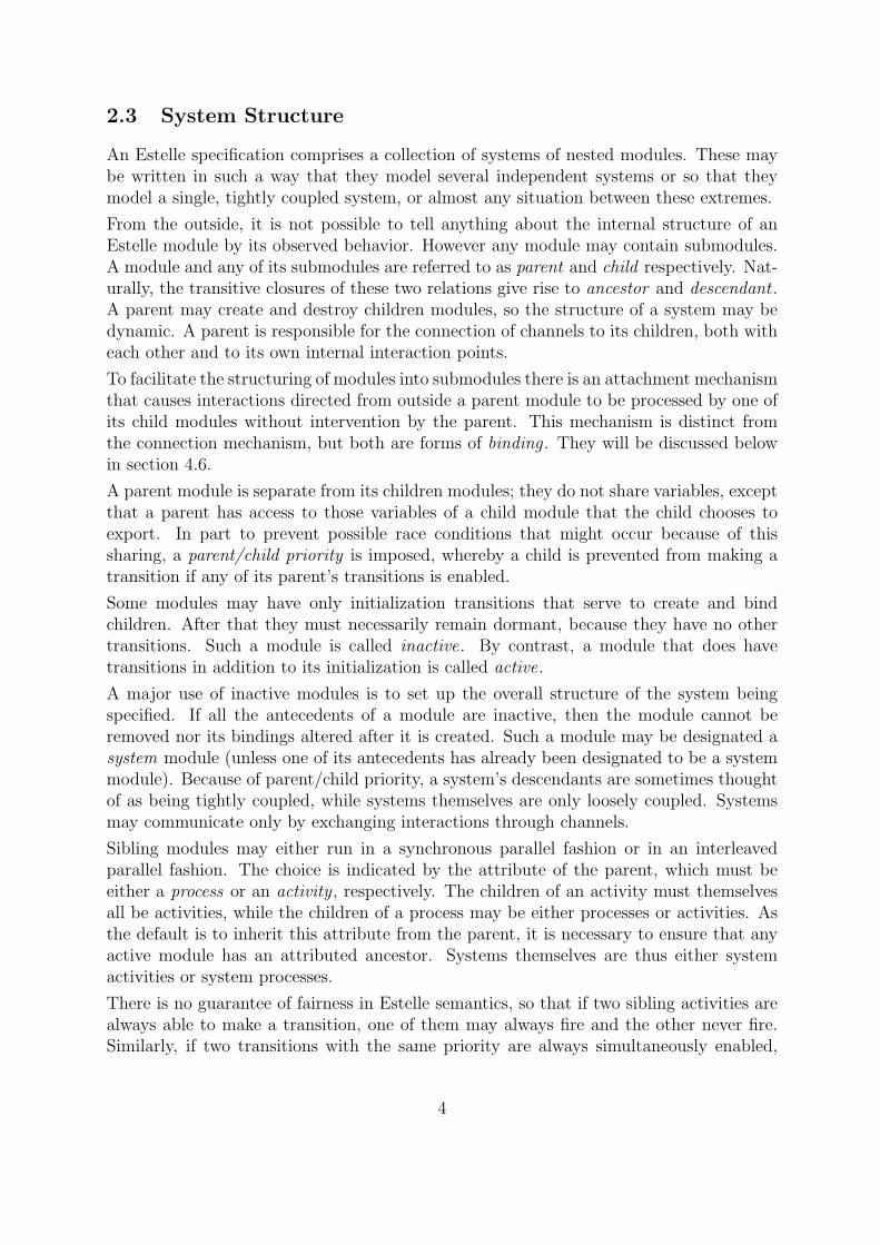
Sibling modules may either run in a synchronous parallel fashion or in an interleavedparallel fashion. The choice is indicated by the attribute of the parent, which must beeither a process or an activity , respectively. The children of an activity must themselvesall be activities, while the children of a process may be either processes or activities. Asthe default is to inherit this attribute from the parent, it is necessary to ensure that anyactive module has an attributed ancestor. Systems themselves are thus either systemactivities or system processes.
There is no guarantee of fairness in Estelle semantics, so that if two sibling activities arealways able to make a transition, one of them may always fire and the other never fire.Similarly, if two transitions with the same priority are always simultaneously enabled,
4
one of them may always fire and the other one may never fire. It is therefore the taskof the specifier to guarantee that the system specified performs as required even in theseextreme cases.
3 Abracadabra Example
To make the discussion of Estelle more concrete, we shall make use of an example. Ourexample will be a version of the alternating bit protocol [Bartlett et al., 1969], a datatransfer protocol that uses a single-bit sequence number (that alternates between 0 and 1,hence the name). This is often used as a didactic protocol (see e.g.[Merlin, 1979], [Blumerand Tenney, 1982] and [Tarnay, 1991]). It is interesting to note that its original publisheddescription is a pair of symmetric finite automata. By itself, however, it is too simpleto exhibit many interesting features of modern protocols, so we use a version that addsretransmission on timeouts and simple connection and disconnection procedures. Theresultant protocol is described fully in Guidelines for the Application of Estelle, LOTOS,and SDL [ISO, TR10167, clause 10], where it is called “Abracadabra”. Although it issimpler than most actual protocols, it is nevertheless complex enough to be interesting.An updated version of this protocol and description appears in [Turner, 1993].
3.1 Abracadabra Service
In many respects Abracadabra is like a data link or a transport protocol: it provides areliable, connection-oriented service between a pair of users. A full data link or transportprotocol would have to handle addressing, communication failures, multiplexing, man-agement functions, etc., but the structure of its specification could easily follow that ofthe Abracadabra specification below. The difference in specification would mainly be adifference in amount not in kind.
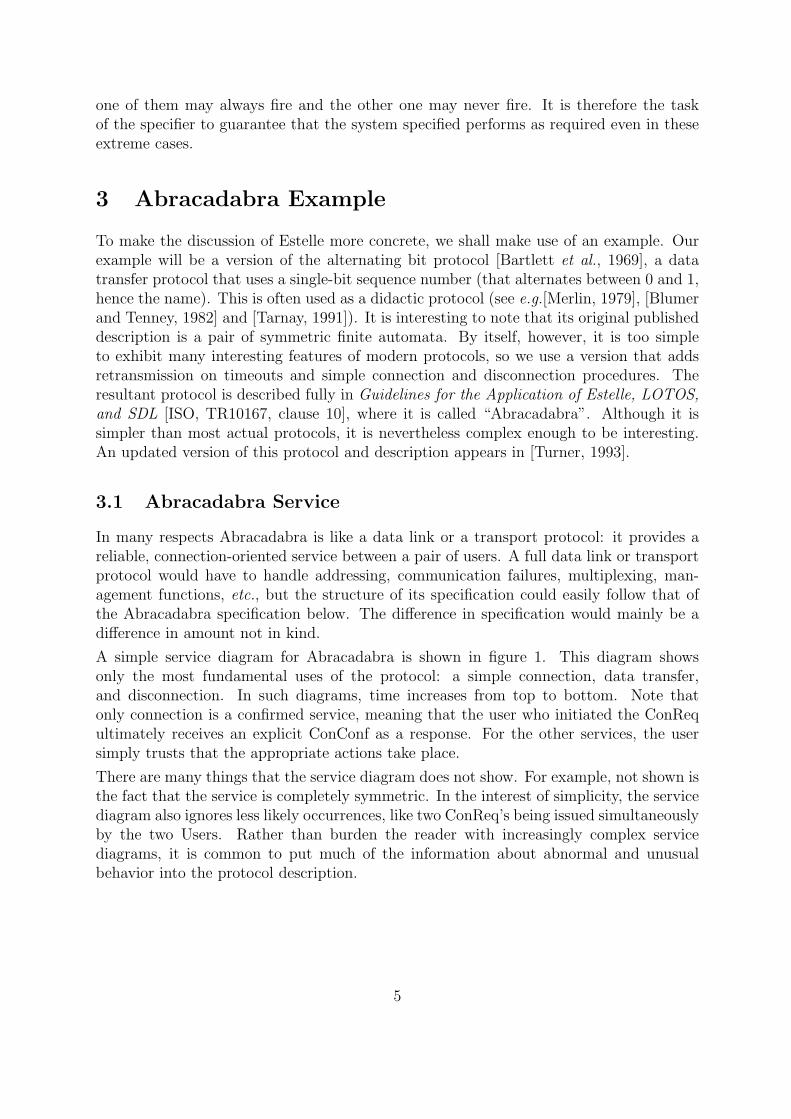
A simple service diagram for Abracadabra is shown in figure 1. This diagram showsonly the most fundamental uses of the protocol: a simple connection, data transfer,and disconnection. In such diagrams, time increases from top to bottom. Note thatonly connection is a confirmed service, meaning that the user who initiated the ConRequltimately receives an explicit ConConf as a response. For the other services, the usersimply trusts that the appropriate actions take place.
There are many things that the service diagram does not show. For example, not shown isthe fact that the service is completely symmetric. In the interest of simplicity, the servicediagram also ignores less likely occurrences, like two ConReq’s being issued simultaneouslyby the two Users. Rather than burden the reader with increasingly complex servicediagrams, it is common to put much of the information about abnormal and unusualbehavior into the protocol description.
5

USER A USER BAbracadabra
.............................................................................................................................................................................................................. ............
.............................................................................................................................................................................................................. ............
ConReq
ConInd
............. ............. ............. ............. ............. ............. ............. ............. .....
..........................................................................................................................................................................................................................
..........................................................................................................................................................................................................................
ConResp
ConConf
.............................................................................................................
.............................................................................................................................................................................................................. ............
.............................................................................................................................................................................................................. ............
DatReq
DatInd
............. ............. ............. ............. ............. ............. ............. ............. .....
.............................................................................................................................................................................................................. ............
.............................................................................................................................................................................................................. ............
DisReq
DisInd
............. ............. ............. ............. ............. ............. ............. ............. .....
Figure 1: Abracadabra Service Diagram
6

3.2 Abracadabra Protocol
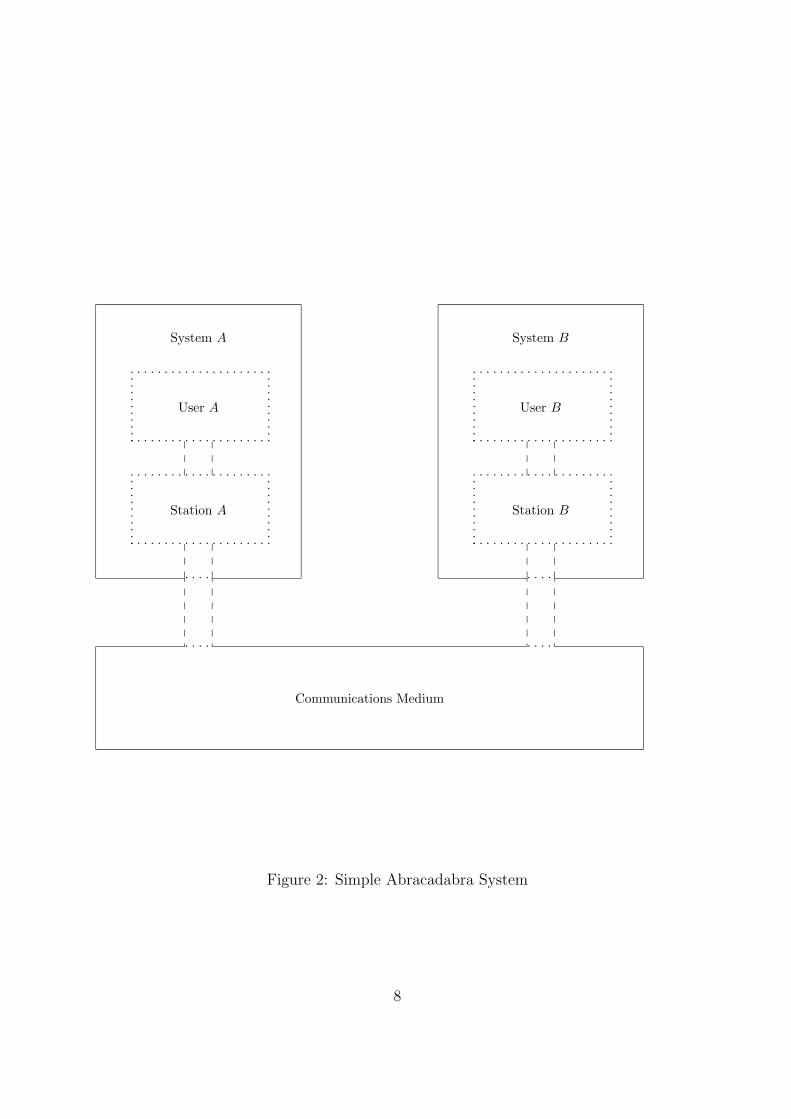
The protocol to implement the Abracadabra service is relatively straightforward. Weassume that there are two users, A and B, and that each of them communicates with anAbracadabra protocol entity (which we will call a Station) that implements the service.These two stations are considered to be peers. They communicate by sending ProtocolData Units (PDU s) through a full-duplex, unreliable communications medium that maylose or delay messages. However, we assume the medium will never corrupt, reorder,duplicate, or originate messages. This system is shown in figure 2.
User A requests a connection with User B by initiating a ConReq. Station A sends a CR(Connect Request) PDU to Station B. When this arrives, Station B issues a ConInd toUser B, who (assuming a willingness to connect) replies with a ConResp to Station B.Station B sends a CC (Connect Confirm) back to Station A, which issues a ConConf toUser A. After this, either user may send data. A user’s DatReq is conveyed as part of aDT (DaTa) PDU, and a DisCon is conveyed as a DR (Disconnect Request) PDU.
If everything always worked as desired, this would be the end of it!
However, even the connection phase of the exchange can become complicated. What is tohappen if the CR is lost due to a fault in the communications medium? What if the CCis lost? What if User B is not willing to accept the connection. What if User A decidesto abandon the connection before it has been completed? What if User A tries to senddata before being informed that the connection exits?
Furthermore, the User trusts that data are transferred without requiring an explicit con-firmation, but the communications medium is not assumed reliable, so the Stations mustarrange some kind of confirmation between themselves and recovery mechanisms for thecases where messages are lost by the medium.
Rather than explain the full protocol in English, it will be more instructive to describe itin Estelle, with English explanations. This is done in the next section. We remark thatthe Estelle description closely follows the English description of [ISO, TR10167], both incontent and in order.
4 Estelle Specification
To express the portions of an Estelle specification that rely on traditional programming(e.g., manipulation of variables and flow of control), Estelle uses a language that is basedon level 0 ISO Pascal [ISO, IS7185]. Estelle enhances Pascal in various ways. The integersand real numbers of Estelle are the usual mathematical ones; implementation detailslike a maximum largest integer and precision of real numbers are not considered. Also,functions are allowed to return arbitrary types.2 The goto statement is restricted to makeit act like a return. Since ordinary file input and output are not part of communicationsspecification, all those features of Pascal that relate to I/O were removed from Estelle.Finally, the keyword specification was substituted for program.
2But note that the syntax of an expression was not changed, so the returned value of a function canbe used in only very simple ways.
7
. . . .
. . . .
. . . . . . . . . . . . . . . . . . . .
. . . . . . . . . . . . . . . . . . . . .
..
..
..
..
..
..
..
..
..
..
. . . . . . . . . . . . . . . . . . . .
. . . . . . . . . . . . . . . . . . . . .
..
..
..
..
..
..
..
..
..
..
System A
User A
Station A
. . . .
. . . .
. . . . . . . . . . . . . . . . . . . .
. . . . . . . . . . . . . . . . . . . . .
..
..
..
..
..
..
..
..
..
..
. . . . . . . . . . . . . . . . . . . .
. . . . . . . . . . . . . . . . . . . . .
..
..
..
..
..
..
..
..
..
..
System B
User B
Station B
Communications Medium
Figure 2: Simple Abracadabra System
8

Other language constructs were created to deal with the aspects of OSI specification.These will be discussed as needed in going through the Abracadabra protocol specification.
The version of the Abracadabra protocol given here was taken with only a few cosmeticchanges from [ISO, TR10167, clause 10.3.4]. The entire description is appended to thispaper.
4.1 Global Parameters
We begin with the beginning of the specification.3 One of the interesting things to noteis that the two communicating systems are completely symmetric: there is but one de-scription of them and two instantiations. This is in contrast to the original description ofthe simpler alternating bit protocol in [Bartlett et al., 1969] where two different automataare given.
1 specification Abracadabra;
23 default individual queue;
4 timescale seconds;
Line 1 merely names the specification, much like the program statement of a Pascalprogram. There is no semantic meaning attached to the identifier Abracadabra except topreclude its use elsewhere in the specification.
The default queueing discipline given at the specification level, as in line 3 , applies to eachinteraction point in each module that does not have its own queueing discipline explicitlygiven. If no specification-wide default is given, then each interaction point must have anexplicit discipline. The two choices are common queue and individual queue. Theremay be at most one common queue in each module, but there may be many individualqueues.
The timescale, line 4 , is intended to work with delay transitions (see section 4.4.1), butit is technically a comment, with no semantic meaning. However, as an aside, we notethat the formal meaning of an Estelle specification may be thought of as a tree of globalinstantaneous descriptions, where paths through the tree represent possible executionsequences. Outside constraints remove branches from this tree, and the time scale canprovide such a constraint.
6 const
7 N = any integer; { number of transmission attempts }
8 P = any integer; { delay amount for timers }
Two constant parameters characterize any instance of the Abracadabra protocol. Thefirst of these, N, the maximum number of times a PDU may be sent before the Stationgives up, is specified in line 7 . The second, P, the amount of time (in seconds, subject tothe discussion of timescale above) between retransmission attempts, is given in line 8 .
Although the specification here forces the values ultimately associated with N and P to be
3The line numbers in italics at the beginning of the lines are not part of the specification itself, butare added to facilitate talking about the specification.
9
integers, Estelle does not have a way to restrict the value of these constants here, so theycould even take negative values. However in line 580 , where the body of the specification isinitialized, the transition cannot fire unless N and P are both positive. This unfortunatelylarge distance between the declarations and the checking of their values is one of the costsof basing Estelle on Pascal. Again in passing we note that the formal semantics of Estellerequire that some value be assigned to each constant that is declared using any, so thatthe specification actually determines a collection of specifications, one for each possiblevalue of N and P.
Lines 7 and 8 both contain comments. These may be inserted at any place that a spacecould be inserted into the text. The alternate forms available in Pascal, using (* for {and *) for }, are also acceptable in Estelle.
Also in keeping with Pascal conventions, the representation (upper- versus lower-case,font, etc.) of a character is insignificant except within character-string constants, andspacing on the page, while potentially helpful to human readers, is of no importance tothe meaning of the specification.
10 type
11 SeqType = 0..1; { sequence number type }
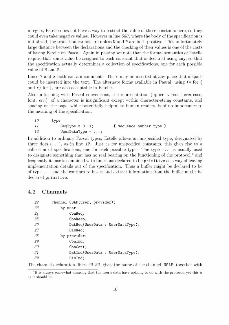
12 UserDataType = ...;
In addition to ordinary Pascal types, Estelle allows an unspecified type, designated bythree dots (...), as in line 12 . Just as for unspecified constants, this gives rise to acollection of specifications, one for each possible type. The type ... is usually usedto designate something that has no real bearing on the functioning of the protocol,4 andfrequently its use is combined with functions declared to be primitive as a way of leavingimplementation details out of the specification. Thus a buffer might be declared to beof type ... and the routines to insert and extract information from the buffer might bedeclared primitive.
4.2 Channels
22 channel USAP(user, provider);
23 by user:
24 ConReq;
25 ConResp;
26 DatReq(UserData : UserDataType);
27 DisReq;
28 by provider:
29 ConInd;
30 ConConf;
31 DatInd(UserData : UserDataType);
32 DisInd;
The channel declaration, lines 22–32 , gives the name of the channel, USAP, together with
4It is always somewhat amusing that the user’s data have nothing to do with the protocol; yet this isas it should be.
10
the names associated with the two roles associated with the channel. When two modulesare connected through a USAP channel, one must assume the role of user, and the other therole of provider. The user can initiate ConReq, ConResp, DatReq and DisReq interactionsthat will be received by the provider, and the provider can initiate ConInd, ConConf,DatInd, DisInd interactions that will be received by the user. The DatReq and DatInd
interactions each have a parameter called UserData, which is of type UserDataType.
The USAP channel declaration should be compared with the service diagram in figure 1 asthese two contain some of the same information. Both indicate the direction (i.e., whichside is the initiator and which the recipient) of each interaction. The channel declarationprovides additional information, because it shows which interactions admit parameters.In particular the DatReq and DatInd interactions each carry UserData. However, a servicediagram provides information that is not contained in a channel declaration, because itshows causal relationships.
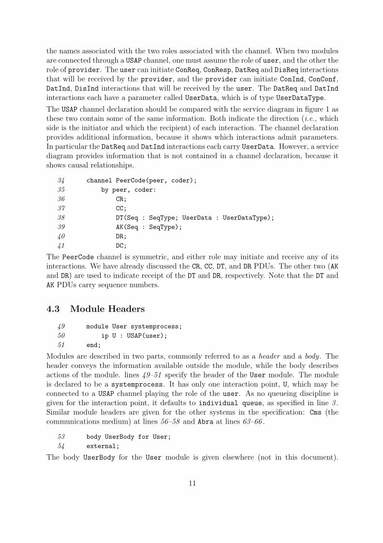
34 channel PeerCode(peer, coder);
35 by peer, coder:
36 CR;
37 CC;
38 DT(Seq : SeqType; UserData : UserDataType);
39 AK(Seq : SeqType);
40 DR;
41 DC;
The PeerCode channel is symmetric, and either role may initiate and receive any of itsinteractions. We have already discussed the CR, CC, DT, and DR PDUs. The other two (AKand DR) are used to indicate receipt of the DT and DR, respectively. Note that the DT andAK PDUs carry sequence numbers.
4.3 Module Headers
49 module User systemprocess;
50 ip U : USAP(user);
51 end;
Modules are described in two parts, commonly referred to as a header and a body . Theheader conveys the information available outside the module, while the body describesactions of the module. lines 49–51 specify the header of the User module. The moduleis declared to be a systemprocess. It has only one interaction point, U, which may beconnected to a USAP channel playing the role of the user. As no queueing discipline isgiven for the interaction point, it defaults to individual queue, as specified in line 3 .Similar module headers are given for the other systems in the specification: Cms (thecommunications medium) at lines 56–58 and Abra at lines 63–66 .
53 body UserBody for User;
54 external;
The body UserBody for the User module is given elsewhere (not in this document).
11

Similarly, lines 60–61 specify that the body for Cms is given elsewhere.
4.4 Station Body
68 body AbraBody for Abra;
6970 module Station process;
71 ip USER : USAP(provider);
72 PEER : PeerCode(peer);
73 end;
Simply nesting the definition of the Station module within the body for Abra makesStation a child of Abra. It is important to note that unlike Pascal, any variables thatmay be defined for a module body are not inherited by its children; i.e., the scope of avariable is restricted to the module in which it is declared.
75 body StationBody for Station;
There may be more than one body for a module header; which body should be used isdecided when the module is instantiated (see section 4.7). In this specification, however,there is at most one body given for any module.
To help follow the specification of the Station, a finite state diagram of the AbracadabraProtocol is shown in figure 3.
77 state
78 CLOSED, CRSENT, CRRECV, ESTAB, DRSENT;
The Station module has five states. This state is sometimes referred to as the controlstate to distinguish it from the total state of the module, which includes the values of thevariables, contents of the queues, etc. In the Station, as often happens, the control statecorresponds to the progress of the connection as seen by the Station.
80 stateset
81 CRignore = [CRRECV];
82 CCignore = [CLOSED, CRRECV, DRSENT];
83 DTignore = [CLOSED, CRSENT, CRRECV, DRSENT];
84 AKignore = [CLOSED, CRSENT, CRRECV, DRSENT];
85 DCignore = [CLOSED, CRSENT, CRRECV];
8687 ConReqIgnore = [CRSENT, CRRECV, ESTAB, DRSENT];
88 ConRespIgnore = [CLOSED, CRSENT, ESTAB, DRSENT];
89 DatReqIgnore = [CLOSED, CRSENT, CRRECV, DRSENT];
90 DisReqIgnore = [CLOSED, DRSENT];
Estelle permits the definition of a set of states, called a stateset. This is used as aconvenience to collapse several actual transitions into one text that is more succinct andeasier to read. For example, a transition that is specified as applying to AKignore (seeline 414 ) may fire if the control state of the module is any of the states listed in line 84 .
12

CL
OSE
D
CR
SEN
TC
RR
EC
V
EST
AB
DR
SEN
T
whe
n U
.Con
Req
/ out
put C
R
whe
n C
C /
outp
ut U
.Con
Con
f
whe
n C
R / o
utpu
t U.C
onC
onf
whe
n D
R / o
utpu
t U.D
isIn
d
whe
n U
.Dis
Req
/ ou
tput
DR
CR
tim
er /
outp
ut C
R
CR
tim
er la
st /
outp
ut D
R &
U.D
isIn
d
when C
R / outp
ut U.C
onIn
d
when U
.Con
Resp /
outpu
t CC
when U
.DisR
eq / o
utput
DR
when D
R / outp
ut DC &
U.D
isInd w
hen
U.D
atR
eq /
outp
ut D
Tw
hen
AK
when AK / output U
.DisI
nd
whe
n D
T / o
utpu
t AK
& U
.Dat
Ind
whe
n C
R /
outp
ut C
Cwhen CR / output D
R & U
.DisI
nd
when CC / output D
R & U
.DisI
nd
when DC / o
utput DR &
U.D
isInd
DT
timer
/ ou
tput
DT
DT timer
last / output D
R & U
.DisI
nd
when U.D
isReq / o
utput DRwhen D
C
when DR
when DR
whe
n D
R /
outp
ut D
C
DR
tim
er /
outp
ut D
R
DR timer
last
Figure 3: Abracadabra Station Automaton
13

As used here, each state set is intended to list the various control states in which a specificinteraction is to be ignored. This is accomplished by a series of transitions ({ 30 } – { 38 })that simply consume the interaction to be ignored and make no other changes.
92 var
93 Sending : boolean;
94 SendSeq, RecvSeq : SeqType;
95 OldSendSeq : SeqType;
96 CRRetranRemaining : integer;
97 DTRetranRemaining : integer;
98 DRRetranRemaining : integer;
99 OldData : UserDataType;
100 DTorAK : boolean;
Variables are defined in the same way they are in Pascal. The meanings of most of thevariables above should be obvious when they are used. However, two of these variablesare of special interest because they represent a conscious trade off between more controlstates and values of variables.
Consider DTorAK. Once the Station has established a connection, its response to a CR
depends on whether or not it has previously received a DT or an AK. If not, it responds bysending a CC; if so, it enters the error phase. This is discussed in more detail below whenconsidering transitions { 17 } and { 18 }. The specifier could attempt to deal with this bycreating two control states, say ESTAB1 and ESTAB2, that behave like ESTAB except fortheir handling of a CR. It was felt that it would be clearer to indicate the special caseby a flag than to create an essentially redundant state. Similarly, ESTAB could have beensplit into two states to reflect whether or not it was free to accept a new message to send.Instead, the flag Sending was used. These are matters of intent and style, decisions basedwhat information it is important to convey and how best to express it.
102 procedure InitVar;
103 begin
104 Sending := false;...
114 end;
Procedures and functions in Estelle are used just like procedures and functions in Pascal.
Functions are assumed to be demonstrably pure and thus to have no side effects. Thisis accomplished by allowing them to alter only local variables, to have neither var pa-rameters nor parameters containing pointers, and to invoke only pure procedures andfunctions. Procedures are not presumed to be pure unless they are declared with the key-word pure. Unlike pure functions, pure procedures are allowed var parameters. Exceptfor procedures and functions that are primitive, which have global scope, the scope ofa procedure or function is restricted to the module body in which it is defined and doesnot include the descendants of that module. Procedures and functions may not referencethe non-Pascal objects such as modules, interaction points, states, interactions etc. intro-duced into Estelle. The intent of this restriction is to make those operations that affect
14

the underlying finite automaton more visible by ensuring that they remain in the bodiesof transitions.
116 initialize
117 to CLOSED
118 begin { 1 }
119 { Variables are initialized when leaving
120 CLOSED state, since the protocol module
121 may cycle through CLOSED repeatedly. }
122 end;
The initialization transition, indicated by the keyword initialize in line 116 may ini-tialize the control state and any variables of the module. In the one shown here, only thestate is initialized, but a comment informs the reader that variables are initialized whenthe automaton leaves the CLOSED state, since the reader presumably expected to see theminitialized here.
The format of the initialization section is the same as that of the transition section, whichwill be discussed immediately below, but only those portions of a transition that makesense are permitted (namely, a provided-clause and a to-clause).
4.4.1 Connection Phase
124 trans
125126 { *** Connection Phase *** }
127128 { user requests connection }
129 from CLOSED to CRSENT
130 when USER.ConReq
131 begin { 2 }
132 { initialize module variables whenever
133 leaving CLOSED }
134 InitVar;
135 output PEER.CR;
136 CRRetranRemaining := N-1;
137 end;
Here we come to the first transition of the Station automaton, indicated by the keywordtrans. A transition comprises two parts: the enabling condition and the actions. Theenabling condition specifies the conditions that must be met before the transition may befired. Note that even when these conditions have been met, however, the transition maynot fire for a number of reasons, including parent/child priority and non-determinism.The actions indicate what will happen as a result of firing the transition.
Line 129 indicates that the transition may take place only when the control state isCLOSED and that after the transition fires, the control state will be CRSENT. The transitionmay fire only when the head of the queue associated with the USER interaction point is a
15

ConReq. Except for scoping rules as discussed below (section 4.4.2) and the nesting rules(section 4.4.2), the order of the clauses — from, to, when, etc. — is immaterial to themeaning of the specification.
The actions of this transition are given in lines 131–137 . First, since the control state willleave CLOSED, the procedure InitVar is invoked to initialize the variables of the moduleas was promised in the comment in lines 119–121 . Next a CR destined for the peer Stationmodule is output through the PEER interaction point. The retransmission timer for CRs isinitialized to N-1, because at most N transmissions of a CR are allowed, and one has justbeen made.
139 { other user accepted connection }
140 from CRSENT to ESTAB
141 when PEER.CC
142 begin { 3 }
143 output USER.ConConf;
144 CRRetranRemaining := -1;
145 end;
The system that sends the CR is usually referred to as the initiator , and the system thatreceives it is usually referred to as the responder . Transition { 2 } begins the attempt toestablish a connection from the initiator’s side. Transition { 3 } completes the connectionestablishment on the initiator’s side, if all went well: it informs the user by outputtinga ConConf through the USER, and it cancels the possible retransmission of CRs by settingCRRetranRemaining to -1. The effect of this is reflected in transitions { 7 } and { 8 }.
147 { colliding CRs }
148 from CRSENT to ESTAB
149 when PEER.CR
150 begin { 4 }
151 output USER.ConConf;
152 CRRetranRemaining := -1;
153 end;
Transition { 4 } is to take care of the case when the two users decide to try to open aconnection at the same time.5 Instead of receiving a CC, the initiator receives a CR, whichis treated exactly as though it were a CC. This corresponds to the service diagram shownin figure 4.
155 { other user rejected connection }
156 from CRSENT to CLOSED
157 when PEER.DR
158 begin { 5 }
159 output USER.DisInd;
160 CRRetranRemaining := -1;
161 end;
Of course it is always possible for the responding user to refuse the connection. If so,
5Apologies to Albert Einstein.
16
Abra A Abra BCms
.............................................................................................................................................................................................................. ............
.............................................................................................................................................................................................................. ............
ConReq
ConConf
..........................................................................................................................................................................................................................
..........................................................................................................................................................................................................................
ConReq
ConConf
............. ............. ............. ............. ............. ............. ............. ............. ............. ...................................................................................................................................................................................................
Figure 4: Simultaneous Connection Request Service Diagram
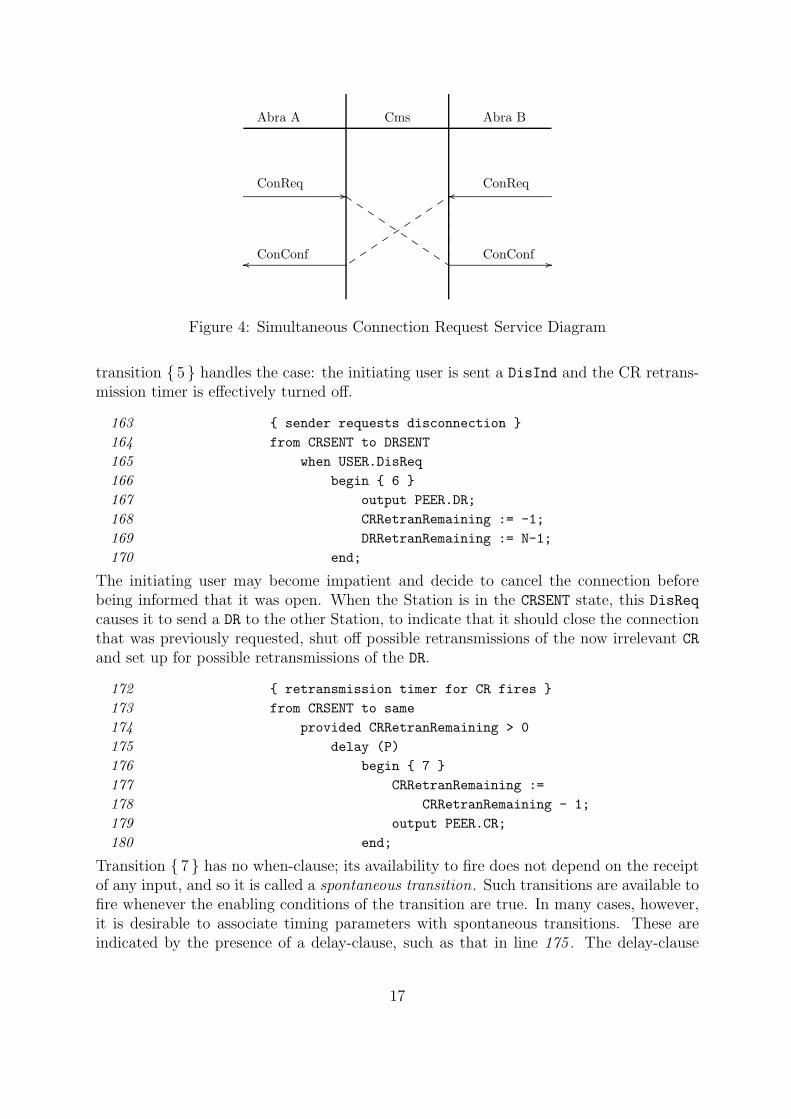
transition { 5 } handles the case: the initiating user is sent a DisInd and the CR retrans-mission timer is effectively turned off.
163 { sender requests disconnection }
164 from CRSENT to DRSENT
165 when USER.DisReq
166 begin { 6 }
167 output PEER.DR;
168 CRRetranRemaining := -1;
169 DRRetranRemaining := N-1;
170 end;
The initiating user may become impatient and decide to cancel the connection beforebeing informed that it was open. When the Station is in the CRSENT state, this DisReq
causes it to send a DR to the other Station, to indicate that it should close the connectionthat was previously requested, shut off possible retransmissions of the now irrelevant CR
and set up for possible retransmissions of the DR.
172 { retransmission timer for CR fires }
173 from CRSENT to same
174 provided CRRetranRemaining > 0
175 delay (P)
176 begin { 7 }
177 CRRetranRemaining :=
178 CRRetranRemaining - 1;
179 output PEER.CR;
180 end;
Transition { 7 } has no when-clause; its availability to fire does not depend on the receiptof any input, and so it is called a spontaneous transition. Such transitions are available tofire whenever the enabling conditions of the transition are true. In many cases, however,it is desirable to associate timing parameters with spontaneous transitions. These areindicated by the presence of a delay-clause, such as that in line 175 . The delay-clause
17

may have two arguments t0 and t1. The corresponding condition may be regarded astrue provided the other parts of the enabling conditions have been true continuously forat least t0 time units; it must be regarded as true if the other parts of the enablingconditions remain true for t1 time units. The difference is this: between times t0 andt1 the choice is not determined by the specification: the transition may fire or not; thedecision is left to the implementor. After time t1, the transition must fire unless someother transition is also available, in which case the usual Estelle rules of non-determinismapply. In other words, if it is the only one available transition, it must fire. One possibleuse for such a scheme is when a protocol uses “piggy-backed” acknowledgments, whereacknowledgments accompany data, if any are available. An acknowledgment may berequired to wait t0 time to allow data to accumulate, but if none have appeared by timet1, then the acknowledgment will be sent without data.
Two special conventions exist for delay-clauses. If t1 may be arbitrarily long, meaning“forever”, it may be indicated as an asterisk (*). A transition that is marked delay(0,*)
may fire at any time that the other conditions are met, but it need not fire. One use ofthis might be to indicate that a connection that becomes unused may remain open or beclosed, with the decision left to the implementor. The other special convention is usedwhere t0 and t1 are the same. The form delay(t) is used to indicate that t= t0 = t1.
It is not possible to use a delay-clause in a transition with a when-clause.
The conditions in lines 173–175 together with the actions in lines 176–180 and the ini-tialization in line 136 allow the Station to retransmit at most N − 1 CRs, with a delay ofP time units (presumably seconds, according to line 4 ) between them.
182 { terminate retransmission of CR }
183 from CRSENT to DRSENT
184 provided CRRetranRemaining = 0
185 delay (P) { allow time for last CR }
186 begin { 8 }
187 { enter error phase }
188 output USER.DisInd;
189 output PEER.DR;
190 CRRetranRemaining := -1;
191 DRRetranRemaining := N-1;
192 end;
After N attempts to send a CR with no appropriate reply, the initiating Station gives up:it sends its user a DisInd and tries to tear down the connection, in case the respondingStation actually thought one existed. It is important to realize that although the initiatingStation received no CC, the responding Station may have sent several and may believe thata connection has been established.
The obverse situation of the responder is handled by transitions { 9 } – { 12 }. Note thatCCs are not retransmitted. The initiator will resend CRs if necessary, and each one receivedwill result in a CC’s being sent in reply (line 208 and line 284 ).
18

4.4.2 Data Transfer Phase
226 { *** Data Transfer Phase *** }
227228 { send data in DT PDU }
229 from ESTAB to same
230 when USER.DatReq
231 provided not Sending
232 begin { 13 }
233 OldData := UserData;
234 output PEER.DT(SendSeq, OldData);
235 OldSendSeq := SendSeq;
236 SendSeq := (SendSeq + 1) mod 2;
237 Sending := true;
238 { turn on retransmission timer }
239 DTRetranRemaining := N-1;
240 end;
Transition { 13 } is responsible for sending data. Line 229 indicates that after it fires, thecontrol state will remain ESTAB. It cannot fire if Sending is true. However, the user maynevertheless place data to be sent into the queue associated with the USER interactionpoint during that time. When Sending eventually becomes true, the data will be sent.
The identifier UserData is defined in line 26 as the parameter of the DatReq interaction.The presence of DatReq in line 230 opens a region that extends through the end of thetransition in which the identifier UserData is defined. Its value is the value that wasassociated with it when the interaction was sent by the user. It must be copied (line 233 )because the value will be needed after the transition has executed if it is necessary toretransmit the PDU. Similarly, OldSendSeq will be used if it is necessary to retransmitthe PDU. SendSeq is then updated to the other bit, to be used for comparison with theacknowledgment.
242 { receive ack with correct sequence number in AK PDU }
243 from ESTAB to same
244 when PEER.AK
245 provided Seq = SendSeq
246 begin { 14 }
247 Sending := false;
248 { turn off retransmission timer }
249 DTRetranRemaining := -1;
250 DTorAK := true;
251 end;
In line 245 , the parameter of the AK interaction, Seq, is compared with SendSeq. Becauseof the scoping rule discussed above, this is one of those cases where the order of theenabling clauses is important: if the provided-clause preceded the when-clause, Seq wouldbe undefined. The convention for acknowledgment used here is a common one; the peerStation acknowledges receipt of a PDU by sending the sequence number of the next PDU
19

it expects to receive.
The data have successfully been sent, so the Sending flag is turned off. This allows thenext PDU to be sent as soon as there is one. The DT retransmit counter is set to -1
so that no more retransmissions of the PDU may be made. As discussed in section 4.4,DTorAK is set to true to control the reaction of the Station to receiving another CR. Theactual effect of this may be observed in transitions { 17 } and { 18 }.
253 { receive acknowledgement with incorrect sequence number }
254 from ESTAB to DRSENT
255 when PEER.AK
256 provided Seq <> SendSeq
257 begin { 15 }
258 { enter error phase }
259 output USER.DisInd;
260 output PEER.DR;
261 DTorAK := true;
262 DTRetranRemaining := -1;
263 DRRetranRemaining := N-1;
264 end;
Transition { 15 } takes care of the case where the AK has the wrong sequence number byentering the error phase. Note that there are two outputs made in this transition, one tothe user to indicate that the connection will be broken and the other to the peer to breakthe connection. Since an AK has been received, DTorAK is set to true. Note, however,that the control state after this transition fires will be DRSENT, and the only transitionsthat test DTorAK are from ESTAB. Figure 3 shows that the only transition from DRSENT toa different control state is a transition to CLOSED, and whenever the control state leavesCLOSED, DTorAK is reset to false in InitVar. Thus line 261 could be removed from thespecification without changing its behavior.6
266 { receive data in DT PDU }
267 from ESTAB to same
268 when PEER.DT
269 begin { 16 }
270 if Seq = RecvSeq then
271 begin
272 output USER.DatInd(UserData);
273 RecvSeq := (RecvSeq + 1) mod 2;
274 end;
275 { send AK with next expected sequence number }
276 output PEER.AK(RecvSeq);
277 DTorAK := true;
278 end;
Transition { 16 } handles receipt of data. If the sequence number in the PDU is the
6But should it be?
20

expected one, then the data are presented to the user because this is the first time theyhave been received and the sequence number is advanced to the next one. Even if thesequence number is not the expected one, the PDU is acknowledged in case previousacknowledgments were lost. As in transition { 14 }, DTorAK is set to true.
280 from ESTAB to same
281 when PEER.CR
282 provided not DTorAK
283 begin { 17 }
284 output PEER.CC;
285 end;
286287 from ESTAB to DRSENT
288 when PEER.CR
289 provided DTorAK
290 begin { 18 }
291 { enter error phase }...
296 end;
Transitions { 17 } and { 18 } select the actions to perform if a CR is received. Presumablyif a DT or an AK has already been received, then the peer Station must be in the ESTAB
state, so it should not be sending CRs any more. Thus a CR represents a protocol error.On the other hand, if neither a DT nor an AK has yet been received, then the peer Stationmay retransmit several CRs until it receives a CC in response.
298 from ESTAB to DRSENT
299 when PEER.CC
300 begin { 19 }
301 { enter error phase }...
306 end;
307 when PEER.DC
308 begin { 20 }
309 { enter error phase }...
314 end;
Here use is made of the Estelle’s transition nesting facility, which allows the specifier totelescope transitions.
Repeating the keyword when in line 307 causes the enabling clauses preceding the when
in line 299 to apply to transition { 20 } in addition to the effect they have on transition{ 19 }. Thus transition { 20 }, like transition { 19 } may fire only if the control state isESTAB, and if it fires, the control state will become DRSENT. This facility is not unique tothe when-clause. Any of the enabling clauses may be handled in this way. If any clausein the series of enabling clauses of a transition (say T0) is repeated immediately following
21

the body of the transition (thus indicating the enabling clauses of the next transition,T1), then the clauses of T0 before that repeated clause apply to the successor transitionT1. Making use of this facility is one way to write well-structured specifications. In thecase only of a sequence of nested provided-clauses, a special form, provided otherwise,may be used at the end of the sequence to represent the negation of the conditions of theother provided-clauses. For example, in
from S1 provided C1 to T1 begin - - - end;provided C2 to T2 begin - - - end;provided C3 to T3 begin - - - end;provided otherwise to T4 begin - - - end
provided otherwise means (not (C1 or C2 or C3)).
Using the keyword trans between two transitions prevents nesting; the presence of transprevents the enabling clauses of the transition before it from applying to those of thetransition after it.
Like transition { 18 }, transitions { 19 } and { 20 } represent reactions to protocol errors.
The handling of retransmissions of DT PDUs in transitions { 21 } and { 22 } is very similarto the handling of retransmissions of CR PDUs in transitions { 7 } and { 8 }.
4.4.3 Disconnection Phase
338 { *** Disconnection Phase *** }
339340 { receive disconnect request from user }
341 from ESTAB to DRSENT
342 when USER.DisReq
343 begin { 23 }
344 output PEER.DR;
345 DTRetranRemaining := -1;
346 DRRetranRemaining := N-1;
347 end;
The user indicates that the connection should be broken by issuing a DisReq. This ishandled in transition { 23 }. It has the effect of an abrupt disconnection: because the DT
retransmission counter is reset to -1, if the last message sent on behalf of the user wasnot received, it will be lost, and the user will not be informed of this. This is unique tothe last message; for other messages, transition { 22 } presents the user with a DisInd ifit was unable to deliver the message.
349 { receive DC }
350 from DRSENT to CLOSED
351 when PEER.DC
352 begin { 24 }
353 DRRetranRemaining := -1;
354 end;
22

If all goes as planned, the DR sent on line 344 will be cause a DC to be sent in reply. Asdisconnection is not a confirmed service, the user is not informed that the disconnectiontook place, so the Station simply resets the DR retransmission counter and returns to theCLOSED state. An argument similar to that regarding line 261 could be made here as well;line 353 is unnecessary.
356 { receive DR }
357 from DRSENT to CLOSED
358 when PEER.DR
359 begin { 25 }
360 DRRetranRemaining := -1;
361 end;
If a DR is received instead of a DC, presumably both users decided to end the connectionat the same time. The Station treats the DR just as it did the DC in transition { 24 }.
363 { receive DR }
364 from ESTAB to CLOSED
365 when PEER.DR
366 begin { 26 }
367 output USER.DisInd;
368 output PEER.DC;
369 DTRetranRemaining := -1;
370 end;
On the other side, when a DR arrives, the user is informed via a DisInd, the peer Stationis sent a DC, and the connection is abruptly broken.
372 { reply to retransmitted DR }
373 from CLOSED to same
374 when PEER.DR
375 begin { 27 }
376 output PEER.DC;
377 end;
If the DC was not received by the peer, it will retransmit the DR after this Station hasentered the CLOSED state. Transition { 27 } takes care of replying to such a DR.
Transitions { 28 } and { 29 } take care of retransmitting the DR if necessary. The aresimilar to transitions { 7 } and { 8 } or transitions { 21 } and { 22 }, except that if the DR
retransmission counter reaches zero there is no point in entering the disconnection phaseagain, so the Station merely goes to the CLOSED state.
Transitions { 30 } to { 38 } are to take care of possible interactions that should either notarise or should be ignored. The arrival of an interaction for which no transition is appli-cable is sometimes called an unspecified reception. The presence of such an unexpectedinteraction at the head of a queue causes the queue to remain blocked until something(e.g., the arrival of an interaction in another queue or the firing of a spontaneous transi-tion) changes the state of the automaton. Unspecified reception often is the result of aservice violation. For example, if the user could be relied on not to make a DisReq when
23

Abra A Abra BCms
.............................................................................................................................................................................................................. ............
.............................................................................................................................................................................................................. ............
UnitReq
UnitInd
............. ............. ............. ............. ............. ............. ............. ............. .....
Figure 5: Communications Medium Service Diagram
there is no connection, then transition { 38 } would be unnecessary. Protocol specifierstake differing attitudes toward this situation: some would leave out those transitions thatshould not arise if the other modules behave as expected; others, recognizing the foiblesof human beings and their systems, explicitly deal with these unspecified receptions. Thiscompletes the specification of the Station.
4.5 TransCode
It is now time to confess that we have purposely hidden the actual structure to be usedin this specification. The ISO OSI Reference Model [ISO, IS7498, clause 5.3] definescommunication between peer-entities in such a way that one would not expect two peerStation modules to exchange PDUs directly. Entities at layer N make use of the servicesprovided by layer (N − 1). The actual communication in this case is thus between theAbra module and the Cms communications medium module. The PDUs of the Stationare to be wrapped in a UnitReq which is delivered as a UnitInd. The service of theCommunications Medium is shown in figure 5.
We introduce a module named TransCode to deal with this. Like the Station, it is achild of Abra. Its functions are to accept a PDU from the Station and wrap it into aUnitReq that it presents to the Cms, and vice-versa, to accept a UnitInd from the Cmsand unwrap it and present it to the Station as an appropriate PDU. This behavior allowseach Station module to maintain the fiction that it communicates directly with its peer.
449 module TransCode process;
450 ip Up : PeerCode(coder);
451 Down : MSAP(user);
452 end;
The TransCode module has two interaction points, Up and Down. Up will be connectedto the Station while Down will ultimately be connected to the communications medium.There are a dozen transitions, six to deal with encoding the six PDU types (see line 14 )into UnitReq PDUs and six to deal with decoding them.
24

The TransCode module is so simple that it has no control state, so the transitions haveneither a from- nor a to-clause. Alternatively, one could supply a single state, say S,initialize the control state to S, and add from S to S to each transition. This seemsartificial and unnecessary, so Estelle does not insist on it. Other than that, there isnothing new about Estelle in the specification of the TransCode module body, so we donot deal with it further.
The actual structure of the system is that found in figure 6.
4.6 Binding
This new structure does add a level of complexity. The inner structure of the Abra moduleis not supposed to be known to the rest of the specification. Thus the User module willbe connected to the Abra module, but the interactions that the User generates shouldbe handled by the Station module. This is cared for by an operation in Estelle calledattach. After a parent module attaches one of its external interaction points to the externalinteraction point of a child, the interactions that arrive at the parent’s interaction pointare transparently7 passed to the child’s interaction point. If the attachment is brokenby a detach operation, any unprocessed interactions that were passed to the child as aconsequence of the attach operation are returned to the parent.8 In the other direction,an interaction that is output through an interaction point that has been attached willtransparently be forwarded to the appropriate recipient.
4.7 Main Bodies
556 { main body for AbraBody }
557 modvar
558 S : Station;
559 XC : TransCode;
560 initialize
561 begin
562 { instantiate the modules }
563 init S with StationBody;
564 init XC with TransCodeBody;
565566 { make connections }
567 attach USER to S.USER;
568 connect S.PEER to XC.Up;
569 attach MEDIUM to XC.Down;
570 end;
571 end; { AbraBody }
7No pun intended.8In some cases, there may be interactions in a queue that resulted from connection operations, and
these will not be returned to the parent, nor will interactions in a common queue that were not receivedthrough the detached interaction point be delivered to the parent.
25

. . . .
. . . .
. . . . . . . . . . . . . . . . . . . .
. . . . . . . . . . . . . . . . . . . . .
..
..
..
..
..
..
..
..
..
..
. . . . . . . . . . . . . . . . . . . .
. . . . . . . . . . . . . . . . . . . . .
..
..
..
..
..
..
..
..
..
..
..
..
.
..
..
..
..
..
..
..
..
..
..
..
..
.
. . . . . . . . . . . . . .
. . . . . . . . . . . . . . .
..
..
..
.
..
..
..
.
. . . . . . . . . . . . . .
. . . . . . . . . . . . . . .
..
..
..
.
..
..
..
.
System A
User A
Abra A
Station A
TransCode A
. . . .
. . . .
. . . . . . . . . . . . . . . . . . . .
. . . . . . . . . . . . . . . . . . . . .
..
..
..
..
..
..
..
..
..
..
. . . . . . . . . . . . . . . . . . . .
. . . . . . . . . . . . . . . . . . . . .
..
..
..
..
..
..
..
..
..
..
..
..
.
..
..
..
..
..
..
..
..
..
..
..
..
.
. . . . . . . . . . . . . .
. . . . . . . . . . . . . . .
..
..
..
.
..
..
..
.
. . . . . . . . . . . . . .
. . . . . . . . . . . . . . .
..
..
..
.
..
..
..
.
System B
User B
Abra B
Station B
TransCode B
Communications Medium
Figure 6: Actual Abracadabra System
26

572573 { main body for Specification Abracadabra }
574 modvar
575 A, B : Abra;
576 UA, UB : User;
577 CM : Cms;
578579 initialize
580 provided (N > 0) and (P > 0)
581 begin { 1 }
582 init UA with UserBody;
583 init UB with UserBody;
584 init A with AbraBody;
585 init B with AbraBody;
586 init CM with CmsBody;
587 connect UA.U to A.USER;
588 connect UB.U to B.USER;
589 connect A.MEDIUM to CM.CMA;
590 connect B.MEDIUM to CM.CMB;
591 end;
592593 end. { Specification Abracadabra }
The main body of each module (and of the specification itself) occurs at the end of thebody (or specification). Lines 557–559 and lines 574–577 declare module variables tobe used to instantiate the modules necessary to make the system. The behavior of thespecification begins with the initialization of the main module, which as noted above(section 4.1) may only fire if both N and P are positive. Lines 582–586 instantiate themodule variables with their bodies. A module may be instantiated with any body that isdefined for it. As a module is instantiated, it is initialized. This may cause other modulesto be instantiated, as in the case of line 584 , which causes the initialization beginning atline 560 to take place. In turn, this causes the initialization at line 116 to take place.Thus at the end of the initialization transition of the main body (lines 581–591 ), the entiresystem will exist. In this specification there are not transitions outside the initializationsections that alter the structure in any way, so it is static. Other specifications createand delete module instances (e.g., when opening or closing a connection) and thus havea dynamic structure.
When an Abra module is initialized, creates its two children modules, a Station moduleS and a TransCode module XC, and in line 568 it connects the PEER interaction point ofthe Station to the Up interaction point of the TransCode. And it attaches its own USER
interaction point to the USER interaction point of the Station S. Thus when the User
initiates an interaction, it will appear in the queue of the Station module, not the queueof the Abra module, even though in line 587 and line 588 the User modules are connectedto the Abra modules, and when the Station module outputs an interaction, it will end upin the queue of the User module. Similarly, the Down interaction point of the TransCode
27

module is attached to the MEDIUM interaction point of the Abra module, so that UnitReqand UnitInd interactions will be occur between TransCode and Medium modules withoutintervention of the Abra modules.
4.8 Other Features
Naturally not all features of Estelle will appear in every specification. Some of those thatdo not appear in this specification are discussed briefly below.
• disconnect — to undo the effect of connect. There are no consequences to thecontents of the queue of the interaction point that is disconnected.
• detach — to undo the effect if attach. Any interactions in the queue of the detachedinteraction point that were placed there as a consequence of the parent’s prior attachare returned to the parent by the detach.
• exported variables — to allow a module to share specified variables with its parent.Siblings may not share variables with each other.
• release and terminate — two ways of deleting a module instance. A module maydelete its children but not itself nor its siblings. Release and termination are recur-sive; i.e., a module that is being released first releases its children. The interactionpoints of a module being released are disconnected or detached, as appropriate. Asa consequence, queues of the parent will receive unprocessed interactions from de-tached interaction points, as discussed above (section 4.6). The contents of queuesof a module being terminated are simply discarded.
• all, exist, and forone — techniques for dealing with ordinal types or sets of modules.The all construct permits statements to be iterated over each member of a finiteordinal type or over each module in a domain. The exist construct tests if thereis a value or module satisfying a given criterion. The forone construct executes a(compound) statement for a value or module that satisfies a given criterion.
• arrays of interaction points — to handle multiple users or providers, each capableof the same kinds of interactions.
• priority — to control which transitions may fire when more than one is enabled.
The interested reader may wish to read other tutorials ([Dembinski and Budkowski, 1989],[Linn, 1987], [Turner, 1993, chapter 2], [ISO/IEC JTC 1/SC 21, N5710]) for furtherinsights into Estelle and to the Estelle International Standard itself for authoritativeanswers to questions.
28

5 Testing
Whenever complex software is considered — and communications software is certainlycomplex — questions of correctness must arise. One way of increasing reliability of soft-ware is to specify it formally. For international standards specifying communicationsprotocols, this is especially important, as the implementations are frequently providedby vendors from around the world who are not in direct contact with one another butwhose software products must work together. Given the sums of money involved and theconsequences of failure, it is certain that eventually questions of correctness will have tobe considered in courts of law.
There is a large literature concerning conformance of implementations to their specifica-tions. Specification techniques based on extended finite automata admit generation oftest suites via state space exploration techniques, and Estelle is no exception (see e.g.,[Favreau and Linn, 1987]). For general overviews of available testing methods, see [Sidhu,1990], [Miller, 1990] and [Hogrefe, 1991].
In this paper, however, we shall focus on a narrower question: how can one begin totest a specification? This should take place long before the more formal tests and theconformance tests are done. Under ideal circumstances this testing goes along with de-veloping the protocol. We call this early testing to differentiate it from the more formaltests generally performed later in the development cycle.
Even though the Abracadabra protocol has been presented here as a completed protocol,we can nevertheless begin to do some testing with it, the kind of testing that is usuallydone during and immediately after designing the protocol. We shall discover that it hassome defects that are not well known. Much of this analysis comes from [Blumer andParker, 1990].
The first test of an Estelle specification is simply syntactic. Estelle compilers obviouslymust spot undeclared identifiers and the usual range of errors detected by compilers. Theycan warn of variables that are declared but never referenced, etc.
One of the next things to check for is unspecified receptions (discussed on section 4.4.3).This is one of the earliest tests partly because it is one of the easiest: one need merelyproduce a table of the transitions applicable to each state and input pair. Many toolsproduce this information as an option (see e.g., the xref program or the fsm structureproduced by the Phoenix software [Blumer, 1986], or the information file fsm.inf producedby the NBS (now NIST) compiler [NBS, 1987].)
Such a table is found in table 1. This shows the transition number for each possible inputand control state of the finite automaton that underlies the Station module. As can beseen, there is indeed an unspecified reception in the Abracadabra protocol. If a CR PDUis received in the state DRSENT, there is no transition to handle it.
It is reasonable to ask if this situation may arise. It does indeed, and in many differentways. Here is the way shown by Blumer and Parker: Assume User B has attempted toopen a connection and that all N transmissions of a CR have failed, so transition { 8 } fires,and the control state of Station B is DRSENT. Now User A attempts to open a connection,so Station A fires transition { 2 } and enters the control state CRSENT. Station B receives
29

TransitionNumber CLOSED CRSENT CRRECV ESTAB DRSENTConReq 2 35 35 35 35ConResp 36 36 10 36 36DatReq 37 37 37 13 37DisReq 38 6 11 23 38CR 9 4 30 17, 18CC 31 3 31 19 31DT 32 32 32 16 32AK 33 33 33 14, 15 33DR 27 5 12 26 25DC 34 34 34 20 24
Table 1: Transition table for Station
the CR from Station A but has no transition to deal with it. Station B will retransmitits DRs and Station A will retransmit its CRs. Ultimately, Station B will fire transition{ 29 } and enter the CLOSED state. It processes the CR in its queue, outputting a ConInd
to User B and entering the CRRECV state. One version of this sequence of events is shownin figure 7.
From this point, there are several possible scenarios, depending on events and their order.Although investigating these possibilities is actually quite interesting, all we need notehere is that this does represent an error in the protocol specification, one that can beexpected to occur. Blumer and Parker suggest enlarging the set CRignore (line 81 ) toinclude the state DRSENT. Transition { 30 } will then discard any CR that arrives in thestate CRignore.
One of the next things to check for is that each of the transitions can be executed. Thisentails checking that each state is reachable from an initial state and that there are noincompatible requirements to executing any transition. For example, it might happenthat every possible way of reaching state S somehow entails setting a variable v to anegative value, but that to execute the transition in question, v must be positive. In thiscase, the transition cannot ever fire.
Technically, like many other things we should like to verify, this is unsolvable (i.e., equiv-alent to solving the halting problem for Turing Machines). In other words, this cannotbe checked by any automatic procedure; rather each specification requires an individualproof that each transition may be executed. Such a proof may become extremely compli-cated, however it may usually be done by demonstrating a series of inputs that will allowthe transition to fire.
In providing such a demonstration, we usually rely on two things: the problem is easilysolvable for the underlying finite automaton using well-known techniques, and automatictools can provide irreplaceable help, especially for complex protocols. Thus, in the caseof the Abracadabra protocol we can indeed verify that all transitions are executable.
This question may actually be asked in two different ways: is it possible to execute thetransition at all? and is it possible to execute the transition if the modules interacting
30

USER A USER BStation A Station BComms Medium
..........................................................................................................................................................................................................................
ConReqCLOSED
CRSENT
...............................................................................................................................
...............................................................................................................................
...............................................................................................................................
CR
CR
CR
DRSENT
DisInd.............................................................................................................................................................................................................. ...........................................................................................................................................
...............................................................................................................................
...............................................................................................................................
DR
DR
DR
CLOSEDConInd
.............................................................................................................................................................................................................. ............
CRRECV
ConReq CLOSED
CRSENT
.............................................................................................................................................................................................................. ............
......................................................................................................................................................................................................................... ..................................................................................................................................................................................................................................... ..................................................................................................................................................................................................................................... ............
CR
CR
CR
Figure 7: Unspecified Reception
with this module obey all the constraints placed on them? This latter question may bemore difficult to answer, because the inputs used to show that the transition may firemust now satisfy additional constraints. On the other hand, there are transitions, e.g.those dealing with errors, that are not expected to fire under normal conditions, and thusthis question is not one that should be asked about those transitions.
The Abracadabra protocol depends on parameters. These should be checked for reason-able ranges. The amount of time P that must elapse before retransmission is often criticalto the functioning of a protocol like Abracadabra, so it is one of the things that should bechecked. If P is set to too high a value, throughput may suffer, but if it is set to too lowa value, then unnecessary retransmissions will take place. Indeed, if the product N × Pis too small, no communication can take place at all. Clearly P has to be set to a valuegreater than the round-trip across the communications medium. However, the mediumwas assumed to be able to delay messages, so there is no value that actually representsthe maximum round-trip. Blumer and Parker show that this can lead to problems.
A delayed CR can cause a disconnection as shown in figure 8. Here both Users start toopen a connection at the same time. Both Station A and Station B send CRs. The CR fromStation B is sufficiently delayed that Station A retransmits its CR. Each of these arrivesat Station B. The first causes B to enter the ESTAB state, and thus the second causes aCC to be sent (transition { 17 }). Meanwhile, the arrival of the delayed CR causes StationA to enter the ESTAB state, so when the CC arrives, transition { 19 } fires, breaking theconnection.
31

USER A USER BStation A Station BComms Medium
..........................................................................................................................................................................................................................
ConReqCLOSED
CRSENT
.............................................................................................................................................................................................................................................................................................................................
CR
.............................................................................................................................................................................................................. ............ConReq CLOSED
CRSENT
......................................................................................................................................................................................................................... ............
......................................................................................................................................................................................................................... ............
CR
CR
.............................................................................................................................................................................................................. ............ConConf
ESTAB
..........................................................................................................................................................................................................................ConConf
ESTAB .....................................................................................................................................................................................................................................
CC
..........................................................................................................................................................................................................................DisInd
......................................................................................................................................................................................................................... ............
DR
DRSENT
Figure 8: Delayed CR
A similar problem can be demonstrated when an acknowledgment is delayed. Again theconnection is broken.
Another Abracadabra problem, pointed out in [de Saqui-Sannes and Courtiat, 1990],occurs when one Station acts only as a receiver and all DRs sent to it are lost; it will neverrealize that the connection has closed.
Other tests that help ensure that a protocol under development is performing as desiredinclude simulation. There are several Estelle simulation systems listed in the next section.One that is particularly unusual is Grope [New and Amer, 1991], which shows the executionof the protocol in animation.
Using paths through the underlying automaton, one may work backwards from the proto-col specification and derive a service specification that can be compared with the originalservice specification for correctness. Such a study is reported in [Sidhu and Blumer, 1986].
6 Tools
As mentioned above, testing cannot take place without tools. Indeed the available toolsaffect how we investigate protocols.9 Besides the tools mentioned above, there are severaltools available for Estelle that have been reported on in the literature, including [Bull S.A.,1989], [Bull S.A. and Marben S.A., 1989], [Phalippou and Groz, 1989], [Vuong and Chan,
9It is said that to someone with a hammer everything appears to be a nail.
32

1989], [Sijelmassi and Strausser, 1991], and [de Saqui-Sannes and Courtiat, 1990].
In addition to commenting on the usefulness of Estelle and the tools that support it,[Diaz et al., 1990] and [Chamberlain and Amer, 1990] also mention several systems andprotocols in various areas that have been specified in Estelle.
7 Conclusion
This paper has presented a tutorial in Estelle, including a detailed example of its usebased on the Abracadabra protocol. In addition, some of the initial tests to be performedon a protocol were discussed. When applied to the Abracadabra protocol these exposedsome problems with it.
At present, there is growing use of Estelle. Among the most recent examples of its use (inprogress as this is written) is a proposed informative annex to the Transaction Processingstandard [ISO, DIS10026].
References
Bartlett, K.A., Scantlebury, R. A., and Wilkinson, P. T. [1969]. A note on reliable full-duplex transmission over half-duplex links. CACM, 12, 260–261.
Blumer, Tom P. [1986]. Estelle Development System, Users Manual. Phoenix TechnologiesLtd. Cambridge, Massachusetts.
Blumer, Tom P. and Parker, Jeff [1990]. Testing of Estelle protocols via automatic imple-mentation. Technical Report BCCS-90-05, Boston College.
Blumer, Tom P. and Tenney, Richard L. [1982]. An automated formal specification tech-nique for protocols. Computer Networks, 6, 201–217.
Bochmann, Gregor V. and Sunshine, Carl [1980]. Formal methods in communicationprotocol design. IEEE Transactions on Communications, COM-28, 624–631.
Budkowski, Stanislaw and Dembinski, Piotr [1987]. An introduction to Estelle: A spec-ification language for distributed systems. Computer Networks and ISDN Systems,14 (1), 3–23.
Bull S.A. [1989]. Estelle Simulator/Debugger User Reference Manual. Les Clayes s/s Bois.
Bull S.A. and Marben S.A. [1989]. Estelle-to-C Compiler User Reference Manual. LesClayes s/s Bois.
Chamberlain, Samuel C. and Amer, Paul D. [1990]. A new user’s experiences and impres-sions with Estelle. In [Vuong, 1990] pp. 471–474.
de Saqui-Sannes, P. and Courtiat, J.-P. [1990]. From the simulation to the verification ofEstelle* specifications. In [Vuong, 1990] pp. 393–407.
33

Dembinski, Piotr and Budkowski, Stanislaw [1989]. Specification language Estelle. InThe Formal Description Technique Estelle—Results of the ESPRIT/SEDOS Project(Diaz, Michel, Ansart, Jean-Pierre, Courtiat, Jean-Pierre, Azema, Pierre, and Chari,Vijaya, eds.) pp. 35–75. Elsevier Science Publishers B.V. (North Holland) Amster-dam. This is an extension of [Budkowski and Dembinski, 1987].
Diaz, Michel, Dufau, Jean, and Groz, Roland [1990]. Experiences using Estelle withinSedos Estelle Demonstrator. In [Vuong, 1990].
Favreau, Jean-Philippe and Linn, Jr., Richard J. [1987]. Automatic generation of testscenario skeletons from protocol specifications written in Estelle. In Protocol Specifi-ciation, Testing, and Verification, VI (Sarikaya, Behcet and Bochmann, Gregor V.,eds.). Amsterdam: Elsevier Science Publishers B.V. (North Holland).
Hogrefe, Dieter [1991]. Conformance testing based on formal methods. In [Quemadaet al., 1991] pp. 207–222.
ISO, IS7185. Programming Language — PASCAL. Geneva: International Organizationfor Standardization, 1982.
ISO, IS7498. Information processing systems — Open systems interconnection — BasicReference Model. Geneva: International Organization for Standardization, 1984.
ISO, IS8073. Information Processing Systems — Open Systems Interconnection — Con-nection Oriented Transport Protocol Definition. International Organization for Stan-dardization, 1986. Also issued as CCITT X.224.
ISO, IS8807. Information processing systems — Open systems interconnection — LOTOS,an FDT based on the Temporal Ordering of Observation Behaviour. Geneva: Inter-national Organization for Standardization, 1989.
ISO, IS9074. Information processing systems — Open systems interconnection — Estelle— A formal description technique based on an extended state transition model.Geneva: International Organization for Standardization, 1989.
ISO, DIS10026. Information processing systems — Open systems interconnection — Dis-tributed Transaction Processing. Geneva: International Organization for Standard-ization, 1991.
ISO, TR10167. Information processing systems — Open systems interconnection —Guidelines for the Application of Estelle, LOTOS, and SDL. Geneva: InternationalOrganization for Standardization, 1991.
ISO/IEC JTC 1/SC 21, N5710. Revised Text of ISO 9074: 1989/PDAM 1, Informationprocessing systems — Open systems interconnection — Estelle — A formal descrip-tion technique based on an extended state transition model — Proposed Draft Amend-ment 1: Estelle Tutorial. Geneva: International Organization for Standardization,1991.
34
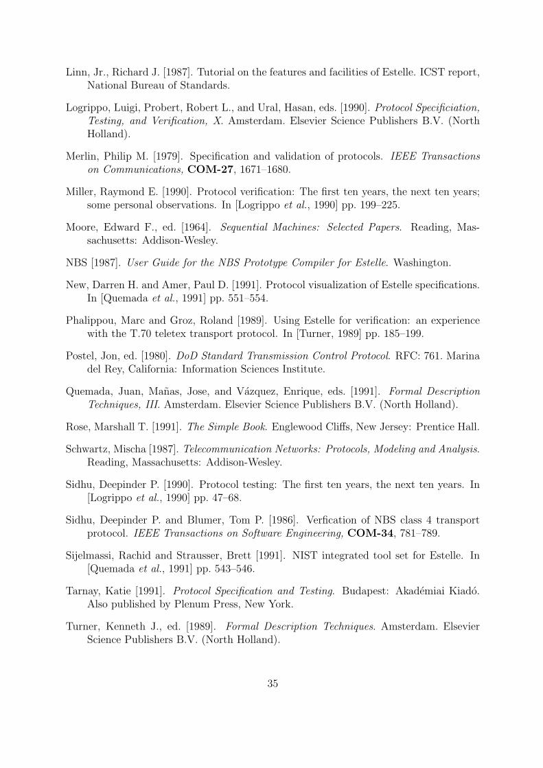
Linn, Jr., Richard J. [1987]. Tutorial on the features and facilities of Estelle. ICST report,National Bureau of Standards.
Logrippo, Luigi, Probert, Robert L., and Ural, Hasan, eds. [1990]. Protocol Specificiation,Testing, and Verification, X. Amsterdam. Elsevier Science Publishers B.V. (NorthHolland).
Merlin, Philip M. [1979]. Specification and validation of protocols. IEEE Transactionson Communications, COM-27, 1671–1680.
Miller, Raymond E. [1990]. Protocol verification: The first ten years, the next ten years;some personal observations. In [Logrippo et al., 1990] pp. 199–225.
Moore, Edward F., ed. [1964]. Sequential Machines: Selected Papers. Reading, Mas-sachusetts: Addison-Wesley.
NBS [1987]. User Guide for the NBS Prototype Compiler for Estelle. Washington.
New, Darren H. and Amer, Paul D. [1991]. Protocol visualization of Estelle specifications.In [Quemada et al., 1991] pp. 551–554.
Phalippou, Marc and Groz, Roland [1989]. Using Estelle for verification: an experiencewith the T.70 teletex transport protocol. In [Turner, 1989] pp. 185–199.
Postel, Jon, ed. [1980]. DoD Standard Transmission Control Protocol. RFC: 761. Marinadel Rey, California: Information Sciences Institute.
Quemada, Juan, Manas, Jose, and Vazquez, Enrique, eds. [1991]. Formal DescriptionTechniques, III. Amsterdam. Elsevier Science Publishers B.V. (North Holland).
Rose, Marshall T. [1991]. The Simple Book. Englewood Cliffs, New Jersey: Prentice Hall.
Schwartz, Mischa [1987]. Telecommunication Networks: Protocols, Modeling and Analysis.Reading, Massachusetts: Addison-Wesley.
Sidhu, Deepinder P. [1990]. Protocol testing: The first ten years, the next ten years. In[Logrippo et al., 1990] pp. 47–68.
Sidhu, Deepinder P. and Blumer, Tom P. [1986]. Verfication of NBS class 4 transportprotocol. IEEE Transactions on Software Engineering, COM-34, 781–789.
Sijelmassi, Rachid and Strausser, Brett [1991]. NIST integrated tool set for Estelle. In[Quemada et al., 1991] pp. 543–546.
Tarnay, Katie [1991]. Protocol Specification and Testing. Budapest: Akademiai Kiado.Also published by Plenum Press, New York.
Turner, Kenneth J., ed. [1989]. Formal Description Techniques. Amsterdam. ElsevierScience Publishers B.V. (North Holland).
35

Turner, Kenneth J. [1993]. Using Formal Description Techniques — An Introduction toEstelle, LOTOS and SDL. Chichester: John Wiley & Sons.
Vuong, Son T., ed. [1990]. Formal Description Techniques, II. Amsterdam. Elsevier Sci-ence Publishers B.V. (North Holland).
Vuong, Son T. and Chan, Wendy Y. L. [1989]. Validation of the Ferry Clip local testingsystem using an Estelle-C compiler. In [Turner, 1989] pp. 337–351.
36