Protecting Environmentally-Sensitive Areas and Promoting ...
Upload
khangminh22Category
view
0download
0
Citation: Larrea, A.; Arruebo, M.;
Serra, C.A.; Sebastián, V. Trojan
pH-Sensitive Polymer Particles
Produced in a Continuous-Flow
Capillary Microfluidic Device Using
Water-in-Oil-in-Water
Double-Emulsion Droplets.
Micromachines 2022, 13, 878.
https://doi.org/10.3390/
mi13060878
Academic Editors: Zebing Mao,
Jin Xie and Hong Ding
Received: 3 May 2022
Accepted: 26 May 2022
Published: 31 May 2022
Publisher’s Note: MDPI stays neutral
with regard to jurisdictional claims in
published maps and institutional affil-
iations.
Copyright: © 2022 by the authors.
Licensee MDPI, Basel, Switzerland.
This article is an open access article
distributed under the terms and
conditions of the Creative Commons
Attribution (CC BY) license (https://
creativecommons.org/licenses/by/
4.0/).
micromachines
Article
Trojan pH-Sensitive Polymer Particles Produced in aContinuous-Flow Capillary Microfluidic Device UsingWater-in-Oil-in-Water Double-Emulsion DropletsAne Larrea 1, Manuel Arruebo 1,2,3 , Christophe A. Serra 4,* and Victor Sebastián 1,2,3,5,*
1 Instituto de Nanociencia y Materiales de Aragón (INMA), CSIC-Universidad de Zaragoza,50009 Zaragoza, Spain; [email protected] (A.L.); [email protected] (M.A.)
2 Department of Chemical Engineering, Campus Río Ebro-Edificio I+D, University of Zaragoza,C/Poeta Mariano Esquillor S/N, 50018 Zaragoza, Spain
3 Networking Research Center on Bioengineering, Biomaterials and Nanomedicine, CIBER-BBN,28029 Madrid, Spain
4 Université de Strasbourg, CNRS, ICS UPR 22, F-67000 Strasbourg, France5 Laboratorio de Microscopías Avanzadas, Universidad de Zaragoza, 50018 Zaragoza, Spain* Correspondence: [email protected] (C.A.S.); [email protected] (V.S.)
Abstract: A facile and robust microfluidic method to produce nanoparticle-in-microparticle systems(Trojan systems) is reported as a delivery vector for the oral administration of active pharmaceuticalingredients. The microfluidic system is based on two coaxial capillaries that produce monodispersewater-in-oil-in-water (W/O/W) double emulsions in a highly controlled fashion with precise controlover the resulting particle structure, including the core and shell dimensions. The influence of thethree phase flow rates, pH and drying process on the formation and overall size is evaluated. Thesedroplets are then used as templates for the production of pH-sensitive Trojan microparticles aftersolvent evaporation. The shell of Trojan microparticles is made of Eudragit®, a methacrylic acid-ethylacrylate copolymer that would enable the Trojan microparticle payload to first pass through thestomach without being degraded and then dissolve in the intestinal fluid, releasing the inner payload.The synthesis of the pH-sensitive Trojan microparticles was also compared with a conventional batchproduction method. The payloads considered in this work were different in nature: (1) fluorescein, tovalidate the feasibility of the polymeric shell to protect the payload under gastric pH; (2) poly(D,L-lactic acid/glycolic acid)-PLGA nanoparticles loaded with the antibiotic rifampicin. These PLGAnanoparticles were produced also using a microfluidic continuous process and (3) PLGA nanoparticlesloaded with Au nanoparticles to trace the PLGA formulation under different environments (gastricand intestinal), and to assess whether active pharmaceutical ingredient (API) encapsulation in PLGAis due efficiently. We further showed that Trojan microparticles released the embedded PLGAnanoparticles in contact with suitable media, as confirmed by electron microscopy. Finally, the resultsshow the possibility of developing Trojan microparticles in a continuous manner with the ability todeliver therapeutic nanoparticles in the gastrointestinal tract.
Keywords: microfluidics; PLGA; oral administration; Trojan particles; emulsion-solvent evaporation;enteric coatings
1. Introduction
Oral administration of active pharmaceutical ingredients (APIs) is the preferable ad-ministration route compared to some other routes, such as using parenteral forms, due todifferent aspects of convenience including: high patient compliance, cost-effectiveness, norequirement of specific sterile conditions and ease of large-scale manufacturing of manyoral dosage forms. It is estimated that 84% of the best-selling pharmaceutical productsare designed for oral administration, being valued at USD 35 billion with a remarkable
Micromachines 2022, 13, 878. https://doi.org/10.3390/mi13060878 https://www.mdpi.com/journal/micromachines
Micromachines 2022, 13, 878 2 of 17
annual growth rate of 10% [1,2]. However, APIs administered orally can suffer from lowbioavailability if the vector is not well suited to the acidic and biological environments(enzymatic digestion) in the gastrointestinal tract and during the presystemic metabolismbefore reaching the targeted sites [3]. The most popular dosage forms for oral administra-tion include tablets, capsules, granulates and syrups. However, some of these formulationsare not able to circumvent the plethora of harsh conditions and barriers required to reachthe target. The development of polymer chemistry has resulted in the design of a widevariety of new polymers with specific functions to address previous shortcomings. Forinstance, many of the APIs sensitive to acidic pH conditions are formulated with an en-tering coating. This coating consists of a gastro-resistant polymeric layer, mostly derivedfrom cationic polymers which are stable at acidic pH values to preserve the APIs fromdegrading in the stomach. The coating is gradually hydrolyzed upon reaching the smallintestine, where the pH level is more alkaline than in the stomach. Other polymers havemucoadhesive and mucus-penetrating properties to achieve site-specific internalization orare just designed to be metabolized selectively by the colonic microbiota, meanwhile beingresistant to enzymatic digestion in the small intestine [4].
Microparticles and nanoparticles are considered the most promising carriers in drugdelivery, being also incorporated downstream into different pharmaceutical dosage formsused in oral administration. Both entities have the potential to improve the stabilityand solubility of encapsulated cargoes. Differently from nanoparticles, microparticles actonly locally since they do not traverse into biological barriers (low intracellular uptake),but enable the loading of large doses of drug cargoes [5] and even nutraceuticals (i.e.,probiotics) [6]. Micro/nanomization of APIs enables one to attain a controlled or sustainedrelease pattern to diminish the dosage frequency while the maximum therapeutic effectis achieved. Regarding therapeutic microparticles, a large number of pharmaceuticalforms composed of microparticles has been successfully commercialized, mainly usingparenteral forms of administration [7] (Trelstar®, Sandostatin LAR®, Risperdal Consta®,Nutropin®, Vivitrol®, Zilretta®, Bydureon®, Zmax®, Arestin®, DepoCyt®, etc.). Some FDA-approved drugs are orally administered as microparticles: Cotempla XR ODT®, AdzenysXR-ODT®, Adzenys ER®, Quillivant XR®, QuilliChew ER®, Aptensio XR®. On the otherhand, therapeutic nanoparticles are considered when the APIs must be delivered throughbiological barriers, improving bioavailability, circulation time, safety and absorption. Lipidand polymer-based nanoparticles are the most relevant FDA-approved nanomedicinesthat are currently used in the clinic for parenteral administration [8]: Doxil®, Onivyde®,Onpattro®, Abraxane®, Adynovate®, etc.
The most relevant methods developed during the last two decades to produce micro-and nanoparticles with controlled characteristics can be summarized as [2,5,9]: spray-drying, extrusion, coacervation, freeze-drying, emulsification and nanoprecipitation, withall of them using both batch and microfluidic reactors. Combining microparticles andnanoparticles in a single carrier to synergically exploit their potential advantages hasresulted in a new concept of delivery systems named nanoparticle-in-microparticle, alsoknown as Trojan systems [10]. Ideally, once orally administered, the microparticle providesprotection to the nanoparticles until they deliver their cargo near the targeted site. Oncethe delivery is activated, the microparticle will dissolve or erode, triggering the releaseof the inner nanoparticles. On the other hand, nanoparticles will be internalized acrossdifferent biological barriers, including the intestinal barrier, to release the APIs, minimizingthe cargo clearance before reaching the target. Trojan particles are usually produced by thecombination of complex multistep procedures [10] including some of the aforementionedfor the production of their single counterparts. Nanoparticles are first produced andthen microencapsulated without affecting previous specifications, which is sometimeschallenging. Generally, spray-drying and gelation techniques are the procedures consideredthe most, but size control and loading selectivity are not well realized. Each manufacturingapproach has pros and cons; the most limiting one is the productivity. In fact, the failure ofthe majority of formulations to meet FDA Current Good Manufacturing Practices (cGMPs)

Micromachines 2022, 13, 878 3 of 17
is related to the complexity of the production process and the lack of reproducibility [11]. Asa result, they are plenty of formulations produced at lab scale, but the number is drasticallydiminished when the production is scaled-up to market. Out of the aforementionedapproaches, microfluidics is one of the most apt approaches for producing a plethora offormulations, including nanoparticles [12], microparticles [7], and Trojan particles [13],with an excellent control concerning formulation specifications (size, chemical compositionand shape), productivity and reproducibility while maintaining a continuous production.
Micron-sized channels enable one to handle a large number of inlet streams with preci-sion, leading to a highly reproducible mixing of reagents. In addition, microfluidics providessome advantages against classical production systems [14]: portability, low energy con-sumption, fast screening of synthesis conditions, highly integrated multifunction and easyscalability. It has been accepted that droplet-based microfluidic devices are unique systemsfor controlling size, shape and loading during the microencapsulation process [15], being alsofeasible in terms of scaling up the production by a parallelization approach [16]. Previousmicrofluidic systems based on drop flow have been successfully applied to produce Trojanmicroparticles. For instance, Liu et al. [17] prepared porous silicon microparticles (c.a. 5 µm)containing two chemotherapeutic drugs. These microparticles were then microencapsulatedusing a single O/W drop microfluidic system and a pH-responsive polymer (derivative ofhypromellose acetate succinate) solubilized in ethyl acetate. The solvent evaporation of ethylacetate after microdrop formations resulted in polymer precipitation and the production of129 ± 2.3 µm Trojan particles. Using a similar microfluidic system, Zhang et al. [18] consid-ered a cargo composed of porous silicon nanoparticles (151.1 ± 4.0 nm) functionalized withpoly(methyl vinyl ether-co-maleic acid) to endow the cargo with mucoadhesive properties.Then, the cargo was microencapsulated in pH-responsive hydroxypropyl-methylcelluloseacetate succinate, yielding homogenous Trojan microparticles with a narrow size distri-bution (ca. 30 µm). Ideally, nanoparticles should also be produced in continuous flowto produce downstream the Trojan particles, but this approach is challenging and it ishighly dependent on nanoparticle purification, concentration, and fluid dynamics. Forinstance, viscosity, flow rates and surfactant concentration are some key variables thatshould be carefully studied to achieve a stable drop flow regime. The values of thesevariables are difficult to match when two different microfluidic processes are coupled, hin-dering the continuous production. Semi-continuous approaches have been considered inorder to overcome previous shortcomings and ease the continuous production of Trojanparticles. Our research teams have much experience in the production of nanoparticles, mi-croparticles and Trojan particles using microfluidics. Trojan particles loaded with ketoprofennanoparticles were successfully produced using UV-induced free radical polymerization [13]in a two-step semi-continuous process. First, a single nanoemulsion composed of keto-profen, monomers (acrylate and acrylamide) and a photoinitiator was produced with anelongational-flow micromixer. Afterwards, the nanoemulsion was injected into a coaxialcapillary-based microfluidic device to generate O/W microdroplets. The microdropletsand their cargo (i.e., nanoemulsion) were exposed to UV irradiation in a continuous flowto activate a dual free radical polymerization to solidify the droplets into Trojan particleswith tuneable sizes (200–388 mm) [13,19]. On the other hand, a two-step semi-continuousprocess was considered to produce thermoresponsive Trojan microparticles composed ofpoly(N-isopropylacrylamide)-based microparticles loaded with plasmonic hollow goldnanoparticles and bupivacaine [7]. Plasmonic Au-hollow nanoparticles (40 ± 3.2 nm) withNIR absorption were successfully produced under continuous flow using a galvanic replace-ment reaction and an oxygen segmented flow [20]. The resulting plasmonic nanoparticleswere then injected into a coaxial capillary microfluidic device, together with the monomer(N-isopropylacrylamide) and the crosslinker (N,N-methylenebisacrylamide), constitutingthe aqueous dispersed phase. The continuous phase was composed of hexane, a surfactant(Span® 80) and the photoinitiator (2-diethoxyacetophenone). The flow focus of both phasesyielded drops with tunable sizes and, downstream, the reactor was linked to a capillary
Micromachines 2022, 13, 878 4 of 17
exposed to UV-LED to activate the radical polymerization and the formation of Trojanmicroparticles with NIR-light response [7].
This work makes the first attempt to produce pH-sensitive Trojan microparticles witha shell made of Eudragit®, a methacrylic acid-ethyl acrylate copolymer that would enablethe Trojan microparticle payload to first pass through the stomach without being dissolvedand then dissolve in the intestinal fluid, releasing the inner payload. A two-step semi-continuous process based on two coaxial capillaries was designed to produce monodispersewater-in-oil-in-water (W/O/W) double emulsions in a highly controlled fashion in drip-ping mode, with a precise control over the structure, such as the core and shell dimensions.In order to study the optimal synthesis conditions and achieve the maximum encapsu-lation efficiency, the influence of the following variables on the generation of the Trojanmicroparticles was studied: (1) continuous phase and surfactant viscosity; (2) capillaries’alignment and their relative position; (3) system pH; (4) washing, drying and storage of themicroparticles; (5) Eudragit® polymer concentration; and (6) continuous and internal phaseflow rates. The synthesis of the pH-sensitive Trojan microparticles was also compared witha conventional batch production method. Finally, the gastro-resistant behaviour of theproduced Trojan MPs was evaluated using a novel procedure based on the use of PLGAnanoparticles loaded with Au nanoparticles which have the role of being tracers and maketheir identification by electron microscopy analysis easier.
2. Experimental Section2.1. Materials
Both polymers—Eudragit® L100-55, an enteric polymer based on an anionic methacrylicacid-ethyl acrylate copolymer (1:1), and Resomer® RG 504, an ester terminated poly(D,L-lactic acid/glycolic acid) 50:50 (PLGA; MW 38–54 KDa)—were supplied by Evonik Indus-tries (Evonik Röhm GmbH, Germany). The surfactants sodium cholate hydrate (<99%),Pluronic F68, Span® 80 and PVA (Mowiol® 18–88, P.M~130,000); the encapsulated drugrifampicin, fluorescein 5-isothiocyanate (FITC); and methylcellulose and solvents includingethyl acetate, ethanol, acetonitrile were purchased from Sigma Aldrich (St. Louis, MO, USA)and used as received.
2.2. Nano- and Microparticle Synthesis2.2.1. PLGA-Based NPs Produced in Continuous Flow
PLGA-based nanoparticles were prepared by two different procedures publishedby our group elsewhere [21–23] and here briefly summarized. Rifampicin-loaded PLGAnanoparticles were prepared in a continuous PEEK-made interdigital micromixer (SIMM-V2, Slit Interdigital Micro Mixer, IMM, Mainz, Germany) using an oil-in-water (O/W)emulsification process followed by a solvent evaporation procedure [21,22]. The organicphase was composed by 1% (w/v) PLGA (50:50) polymer, 0.1% (w/v) rifampicin, 2% (w/v)surfactant (Pluronic F68) and ethyl acetate (used as organic solvent). Aqueous and organicphases were injected by syringe pumps (Harvard Apparatus) at the proper flow rate toachieve a residence time of 10 ms. Ethyl acetate was evaporated after the emulsificationprocess to yield rifampicin-PLGA (PLGA-RIF) nanoparticles. On the other hand, Au-PLGA nanoparticles were produced in two consecutive PEEK-made interdigital micromixers(SIMM-V2, Slit Interdigital Micro Mixer, IMM, Mainz, Germany) using a double emulsionwater-in-oil-in-water (W/O/W) emulsification process followed by a thermal treatment toactivate the Au precursor reduction and the solvent evaporation [13,23]. A primary W/Oemulsion was produced after mixing in continuous flow an aqueous stream consisting ofchloroauric acid and sodium citrate, with an organic stream of ethyl acetate and PLGA.The resulting emulsion was injected under continuous flow in a second micromixer, to-gether with an aqueous stream consisting of sodium cholate to form a double W/O/Wemulsion. Afterwards, the Au precursor loaded in the internal phase was heated at 45 ◦C ina continuous flow with a residence time of 10 min to promote electron supply from sodiumcitrate (redox reaction) forming Au nanoparticles. Finally, the organic solvent (ethyl acetate)
Micromachines 2022, 13, 878 5 of 17
was evaporated under continuous stirring in an open flask to yield Au-PLGA NPs. Thesynthesis of these nanomaterials was carried out with the Synthesis of Nanoparticles Unitof the ICTS “NANBIOSIS” at the Institute of Nanoscience and Materials of Aragon (INMA)Universidad de Zaragoza.
2.2.2. Trojan Eudragit® Microparticles Produced in a Batch Type Reactor
Trojan Eudragit® microparticles were prepared in a batch type reactor using a W/O/Wdouble emulsification process with solvent evaporation. This procedure was publishedelsewhere by our group [3] and is here briefly described. The method used rifampicin-loaded PLGA–NPs in the inner water phase. In a mixture of ethanol:ethyl acetate (1:4;organic phase), 2% (w/v) Eudragit® L100-55 was dissolved and emulsified with a PLGA-RIF suspension by ultrasonication (Digital Sonifier 450) at a 40% amplitude for 30 s. Theformed W/O emulsion was then emulsified with an aqueous solution of sodium cholateat 40% amplitude for 35 s to obtain the W/O/W emulsion. To promote the stability ofthe final emulsion, 0.3% (w/v) sodium cholate solution was also added before the solventevaporation step. The organic solvent was evaporated under continuous stirring to obtainTrojan Eudragit® microparticles loaded with PLGA-RIF nanoparticles.
2.2.3. Trojan Eudragit® Microparticles Produced in Continuous Flow
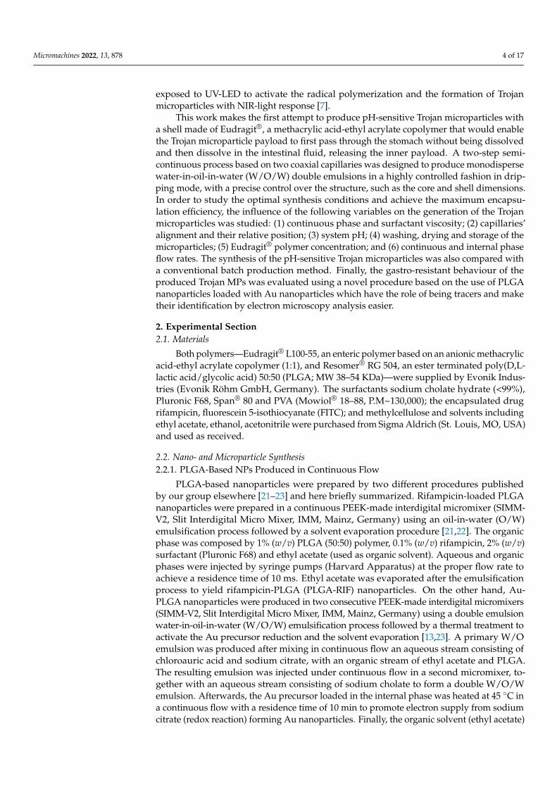
The microfluidic system used for the continuous synthesis of pH-sensitive Trojanmicroparticles (MPs) is based on the microfluidic droplet device developed by Khan et al.for the synthesis of core-shell microparticles sensitive to pH [13], with certain modifications.The microfluidic system consisted of three syringe pumps (Harvard Apparatus), two T-joints (1/16”, Upchurch Scientific), a hydrophilic internal capillary (silica tube with aninternal diameter of 100 µm, Polymicro Technologies) that was used to inject the internalaqueous phase and a hydrophobic middle capillary (PEEK tube with 255 µm internaldiameter, Upchurch Scientific) that allowed one to administer the middle organic phase.Both capillaries were arranged coaxially and placed in the center of a PTFE outlet tubing(1 mm internal diameter). The two dispersed phases (internal and middle phase) wereinjected in the continuous phase, forming a double drop at the tip of the coaxial capillaries,as shown in Figure 1. Finally, the organic solvent (ethanol/ethyl acetate) was evaporatedfrom the double emulsion droplets generated in the coaxial system to favor the precipitationof the polymer and the formation of the Trojan MPs.
Micromachines 2022, 13, x 5 of 18
W/O/W emulsion. Afterwards, the Au precursor loaded in the internal phase was heated at 45 °C in a continuous flow with a residence time of 10 min to promote electron supply from sodium citrate (redox reaction) forming Au nanoparticles. Finally, the organic sol-vent (ethyl acetate) was evaporated under continuous stirring in an open flask to yield Au-PLGA NPs. The synthesis of these nanomaterials was carried out with the Synthesis of Nanoparticles Unit of the ICTS “NANBIOSIS” at the Institute of Nanoscience and Ma-terials of Aragon (INMA) Universidad de Zaragoza.
2.2.2. Trojan Eudragit® Microparticles Produced in a Batch Type Reactor Trojan Eudragit® microparticles were prepared in a batch type reactor using a
W/O/W double emulsification process with solvent evaporation. This procedure was pub-lished elsewhere by our group [3] and is here briefly described. The method used rifam-picin-loaded PLGA–NPs in the inner water phase. In a mixture of ethanol:ethyl acetate (1:4; organic phase), 2% (w/v) Eudragit® L100-55 was dissolved and emulsified with a PLGA-RIF suspension by ultrasonication (Digital Sonifier 450) at a 40% amplitude for 30 s. The formed W/O emulsion was then emulsified with an aqueous solution of sodium cholate at 40% amplitude for 35 s to obtain the W/O/W emulsion. To promote the stability of the final emulsion, 0.3% (w/v) sodium cholate solution was also added before the sol-vent evaporation step. The organic solvent was evaporated under continuous stirring to obtain Trojan Eudragit® microparticles loaded with PLGA-RIF nanoparticles.
2.2.3. Trojan Eudragit® Microparticles Produced in Continuous Flow The microfluidic system used for the continuous synthesis of pH-sensitive Trojan mi-
croparticles (MPs) is based on the microfluidic droplet device developed by Khan et al. for the synthesis of core-shell microparticles sensitive to pH [13], with certain modifica-tions. The microfluidic system consisted of three syringe pumps (Harvard Apparatus), two T-joints (1/16”, Upchurch Scientific), a hydrophilic internal capillary (silica tube with an internal diameter of 100 μm, Polymicro Technologies) that was used to inject the inter-nal aqueous phase and a hydrophobic middle capillary (PEEK tube with 255 μm internal diameter, Upchurch Scientific) that allowed one to administer the middle organic phase. Both capillaries were arranged coaxially and placed in the center of a PTFE outlet tubing (1 mm internal diameter). The two dispersed phases (internal and middle phase) were injected in the continuous phase, forming a double drop at the tip of the coaxial capillaries, as shown in Figure 1. Finally, the organic solvent (ethanol/ethyl acetate) was evaporated from the double emulsion droplets generated in the coaxial system to favor the precipita-tion of the polymer and the formation of the Trojan MPs.
Figure 1. Scheme of the microfluidic system formed by two coaxial capillaries used for the produc-tion of Trojan MPs by double emulsion.
Figure 1. Scheme of the microfluidic system formed by two coaxial capillaries used for the productionof Trojan MPs by double emulsion.
Due to the high sensitivity of the droplet microfluidic system, the composition of eachphase of the emulsion must be carefully selected, as well as the operating conditions usedfor the formation of the pH-sensitive Trojan MPs. The droplet internal aqueous phasewas varied depending on the formulation aim using: fluorescein 5-isothiocyanate as amodel to optically analyze the microparticle formation, Au-PLGA NPs to assemble TrojanMPs with a potential application in theragnosis [24] and PLGA-RIF NPs to produce a
Micromachines 2022, 13, 878 6 of 17
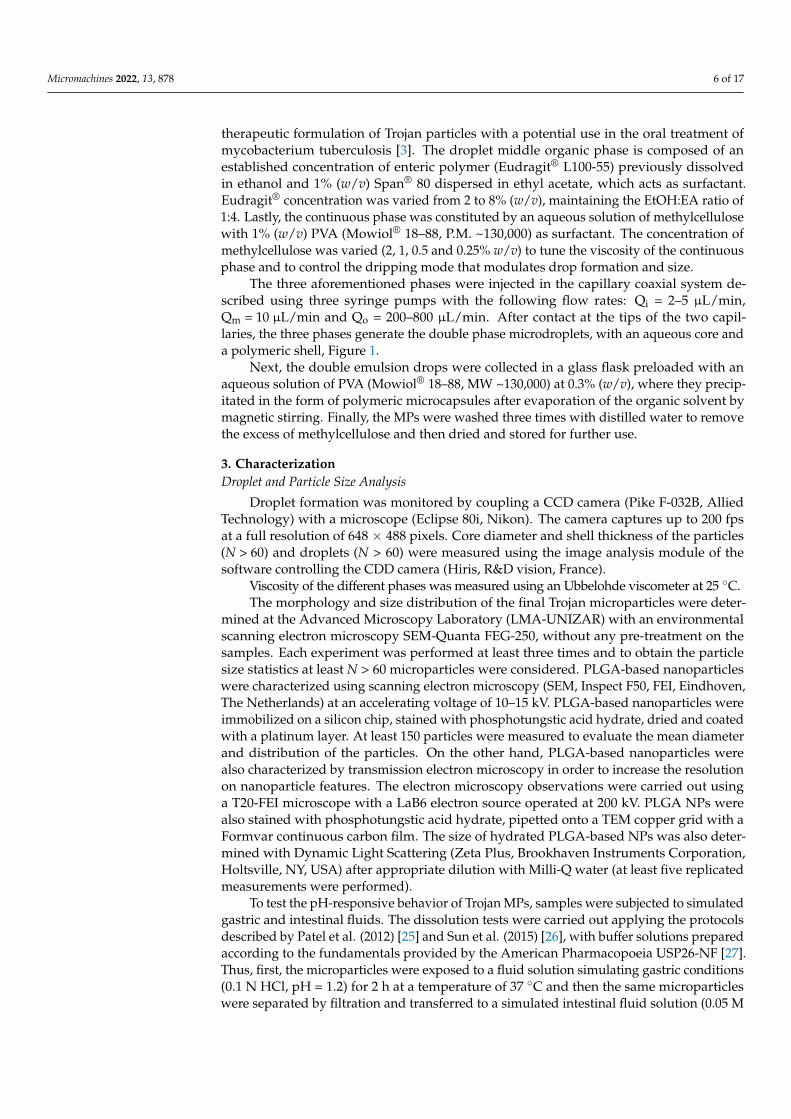
therapeutic formulation of Trojan particles with a potential use in the oral treatment ofmycobacterium tuberculosis [3]. The droplet middle organic phase is composed of anestablished concentration of enteric polymer (Eudragit® L100-55) previously dissolvedin ethanol and 1% (w/v) Span® 80 dispersed in ethyl acetate, which acts as surfactant.Eudragit® concentration was varied from 2 to 8% (w/v), maintaining the EtOH:EA ratio of1:4. Lastly, the continuous phase was constituted by an aqueous solution of methylcellulosewith 1% (w/v) PVA (Mowiol® 18–88, P.M. ~130,000) as surfactant. The concentration ofmethylcellulose was varied (2, 1, 0.5 and 0.25% w/v) to tune the viscosity of the continuousphase and to control the dripping mode that modulates drop formation and size.
The three aforementioned phases were injected in the capillary coaxial system de-scribed using three syringe pumps with the following flow rates: Qi = 2–5 µL/min,Qm = 10 µL/min and Qo = 200–800 µL/min. After contact at the tips of the two capil-laries, the three phases generate the double phase microdroplets, with an aqueous core anda polymeric shell, Figure 1.
Next, the double emulsion drops were collected in a glass flask preloaded with anaqueous solution of PVA (Mowiol® 18–88, MW ~130,000) at 0.3% (w/v), where they precip-itated in the form of polymeric microcapsules after evaporation of the organic solvent bymagnetic stirring. Finally, the MPs were washed three times with distilled water to removethe excess of methylcellulose and then dried and stored for further use.
3. CharacterizationDroplet and Particle Size Analysis
Droplet formation was monitored by coupling a CCD camera (Pike F-032B, AlliedTechnology) with a microscope (Eclipse 80i, Nikon). The camera captures up to 200 fpsat a full resolution of 648 × 488 pixels. Core diameter and shell thickness of the particles(N > 60) and droplets (N > 60) were measured using the image analysis module of thesoftware controlling the CDD camera (Hiris, R&D vision, France).
Viscosity of the different phases was measured using an Ubbelohde viscometer at 25 ◦C.The morphology and size distribution of the final Trojan microparticles were deter-
mined at the Advanced Microscopy Laboratory (LMA-UNIZAR) with an environmentalscanning electron microscopy SEM-Quanta FEG-250, without any pre-treatment on thesamples. Each experiment was performed at least three times and to obtain the particlesize statistics at least N > 60 microparticles were considered. PLGA-based nanoparticleswere characterized using scanning electron microscopy (SEM, Inspect F50, FEI, Eindhoven,The Netherlands) at an accelerating voltage of 10–15 kV. PLGA-based nanoparticles wereimmobilized on a silicon chip, stained with phosphotungstic acid hydrate, dried and coatedwith a platinum layer. At least 150 particles were measured to evaluate the mean diameterand distribution of the particles. On the other hand, PLGA-based nanoparticles werealso characterized by transmission electron microscopy in order to increase the resolutionon nanoparticle features. The electron microscopy observations were carried out usinga T20-FEI microscope with a LaB6 electron source operated at 200 kV. PLGA NPs werealso stained with phosphotungstic acid hydrate, pipetted onto a TEM copper grid with aFormvar continuous carbon film. The size of hydrated PLGA-based NPs was also deter-mined with Dynamic Light Scattering (Zeta Plus, Brookhaven Instruments Corporation,Holtsville, NY, USA) after appropriate dilution with Milli-Q water (at least five replicatedmeasurements were performed).
To test the pH-responsive behavior of Trojan MPs, samples were subjected to simulatedgastric and intestinal fluids. The dissolution tests were carried out applying the protocolsdescribed by Patel et al. (2012) [25] and Sun et al. (2015) [26], with buffer solutions preparedaccording to the fundamentals provided by the American Pharmacopoeia USP26-NF [27].Thus, first, the microparticles were exposed to a fluid solution simulating gastric conditions(0.1 N HCl, pH = 1.2) for 2 h at a temperature of 37 ◦C and then the same microparticleswere separated by filtration and transferred to a simulated intestinal fluid solution (0.05 M
Micromachines 2022, 13, 878 7 of 17
KH2PO4, pH adjusted to 6.8 ± 0.1 with 0.2 N NaOH) for 6 hours, keeping the temperatureconstant at 37 ◦C.
The determination of the encapsulated NPs in the core of the Eudragit® Trojan MPs wasperformed as follows: (1) The MPs were dissolved in PBS at pH = 7.4 (over the degradationpH of Eudragit® L100 = 5.5) to release the PLGA-rifampicin NPs; (2) the NPs released werewashed by centrifugation to eliminate the traces of enteric polymer and the PBS salts thatwere added; (3) The washed NPs were analyzed with UV-Vis (Jasco V-670 spectrophotome-ter). The encapsulation efficiency of PLGA-rifampicin NPs was determined with UV-Visdirectly (NPs liberated from Trojan MPs at pH > 5.5), considering the absorbance of thenanoparticles at 477 nm, corresponding to one of the three absorbance peaks characteristicof rifampicin [28]. Once the absorbance was determined from the spectrum of each sample,its encapsulation efficiency was calculated using the linear adjustment obtained from thecalibration curve of the starting NPs (PLGA-RIF NPs used for the encapsulation in the entericpolymer, Figures S1 and S2). The results are expressed in both encapsulation efficiency(% EE) and drug loading (% DL), using Equations (1) and (2), respectively.
EE (%) =Amount o f PLGA − RIF NPs loaded
Total amount o f NPs used× 100 (1)
DL (%) =Amount o f PLGA − RIF NPs loaded
Total amount o f Microparticles× 100 (2)
4. Results and Discussions
The variables that influence the formation of multiple-core drops (W/O/W, O/W/O)in a coaxial microfluidic system are numerous [19,29], but out of them, it can be highlightedthat the most relevant are: (1) hydrodynamic conditions, (2) the alignment of capillary tipsand their relative position, (3) pH of the external phase, (4) drying process, (5) polymerconcentration in the middle phase stream, and (6) internal and continuous phase flow rates.
4.1. Hydrodynamic Conditions
According to the hydrodynamics for multiple-core drop formation [30], the innerand middle injected solutions must be immiscible fluids as well as the middle and outerphases, or at least the different viscosity between both phases must be high enough toreduce molecular diffusion and apparent miscibility between them. On the other hand,the surface energy of the capillaries should be adapted to the fluid wettability. In this case,the aqueous inert fluid was injected through a capillary with a hydrophilic inner surface,whereas the middle capillary surface was hydrophobic. On the other hand, it is necessaryto add surfactants into the middle and outer phases to control the interfacial tension forcesand to promote a stable and homogenous double drop formation (Figure 2).
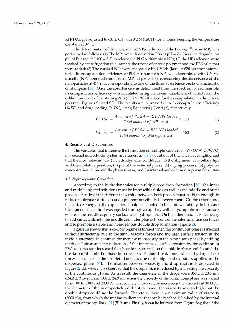
Figure 2a shows that a co-flow regime is formed when the continuous phase is injectedwithout surfactants due to the small viscous forces and the high surface tension in themiddle interface. In contrast, the increase in viscosity of the continuous phase by addingmethylcellulose and the reduction of the interphase surface tension by the addition ofPVA as surfactant increased the shear forces exerted on the middle phase and favored thebreakup of the middle phase into droplets. A short break time induced by large shearforces can decrease the droplet diameters due to the higher shear stress applied to thedispersed phase [31]. The relation between viscosity and drop rupture is depicted inFigure 2c,d,f, where it is observed that the droplet size is reduced by increasing the viscosityof the continuous phase. As a result, the diameters of the drops were 859.2 ± 28.5 µm,624.0 ± 31.6 µm and 506 ± 24.9 µm when the viscosity of the continuous phase was variedfrom 500 to 1000 and 2000 cSt, respectively. However, by increasing the viscosity at 3000 cSt,the diameter of the microparticles did not decrease; the viscosity was so high that thedouble drops could not be formed. Therefore, there is a maximum value of viscosity(2000 cSt), from which the minimum diameter that can be reached is limited by the internaldiameter of the capillary [31] (510 µm). Finally, it can be inferred from Figure 2e,g that if the
Micromachines 2022, 13, 878 8 of 17
viscosity of the middle phase was doubled, by increasing the concentration of the polymer,the viscosity of the continuous phase should be proportionally increased to preserve asteady dripping mode.
Micromachines 2022, 13, x 8 of 18
Figure 2. Optical microscopy images of the double drop of emulsion formed at the end of the coaxial capillaries according to the composition of the phases. Without surfactants in the continuous and dispersed phases, 2% Eudragit®: (a) viscosity of the continuous phase < 500 cSt; (b) viscosity of the continuous phase = 500 cSt. Addition of surfactants in the continuous and dispersed phases: (c) vis-cosity 500 cSt, 2% Eudragit®; (d) viscosity 1000 cSt, 2% Eudragit®; (e) viscosity 1000 cSt, 4% Eu-dragit®; (f) viscosity 2000 cSt, 2% Eudragit®; (g) viscosity 2000 cSt, 4% Eudragit®.
Figure 2a shows that a co-flow regime is formed when the continuous phase is in-jected without surfactants due to the small viscous forces and the high surface tension in the middle interface. In contrast, the increase in viscosity of the continuous phase by add-ing methylcellulose and the reduction of the interphase surface tension by the addition of PVA as surfactant increased the shear forces exerted on the middle phase and favored the breakup of the middle phase into droplets. A short break time induced by large shear forces can decrease the droplet diameters due to the higher shear stress applied to the dispersed phase [31]. The relation between viscosity and drop rupture is depicted in Fig-ure 2c,d,f, where it is observed that the droplet size is reduced by increasing the viscosity of the continuous phase. As a result, the diameters of the drops were 859.2 ± 28.5 μm, 624.0 ± 31.6 μm and 506 ± 24.9 μm when the viscosity of the continuous phase was varied from 500 to 1000 and 2000 cSt, respectively. However, by increasing the viscosity at 3000 cSt, the diameter of the microparticles did not decrease; the viscosity was so high that the double drops could not be formed. Therefore, there is a maximum value of viscosity (2000 cSt), from which the minimum diameter that can be reached is limited by the internal diameter of the capillary [31] (510 μm). Finally, it can be inferred from Figure 2e,g that if the viscosity of the middle phase was doubled, by increasing the concentration of the pol-ymer, the viscosity of the continuous phase should be proportionally increased to pre-serve a steady dripping mode.
4.2. Capillaries’ Alignment and Their Relative Position There are different capillary arrangements [29], where the capillaries’ tips can be as-
sembled with similar, positive and negative relative positions (Δ). Single and multiple cores can be engineered depending on the relative position of the inner and middle capil-laries’ tips. Taking into account previous results [29], the microfluidic device considered in this work was designed with similar relative position (Δ = 0), where droplet formation was achieved in dripping mode to ensure the formation of monodisperse drops. The inner
Figure 2. Optical microscopy images of the double drop of emulsion formed at the end of the coaxialcapillaries according to the composition of the phases. Without surfactants in the continuous anddispersed phases, 2% Eudragit®: (a) viscosity of the continuous phase < 500 cSt; (b) viscosity ofthe continuous phase = 500 cSt. Addition of surfactants in the continuous and dispersed phases:(c) viscosity 500 cSt, 2% Eudragit®; (d) viscosity 1000 cSt, 2% Eudragit®; (e) viscosity 1000 cSt, 4%Eudragit®; (f) viscosity 2000 cSt, 2% Eudragit®; (g) viscosity 2000 cSt, 4% Eudragit®.
4.2. Capillaries’ Alignment and Their Relative Position
There are different capillary arrangements [29], where the capillaries’ tips can be as-sembled with similar, positive and negative relative positions (∆). Single and multiple corescan be engineered depending on the relative position of the inner and middle capillaries’tips. Taking into account previous results [29], the microfluidic device considered in thiswork was designed with similar relative position (∆ = 0), where droplet formation wasachieved in dripping mode to ensure the formation of monodisperse drops. The innercapillary tip, where the core droplet is generated, was assembled at the same position asthe middle capillary tip, where the shell layer is formed, Figure 1.
4.3. pH at the External Phase
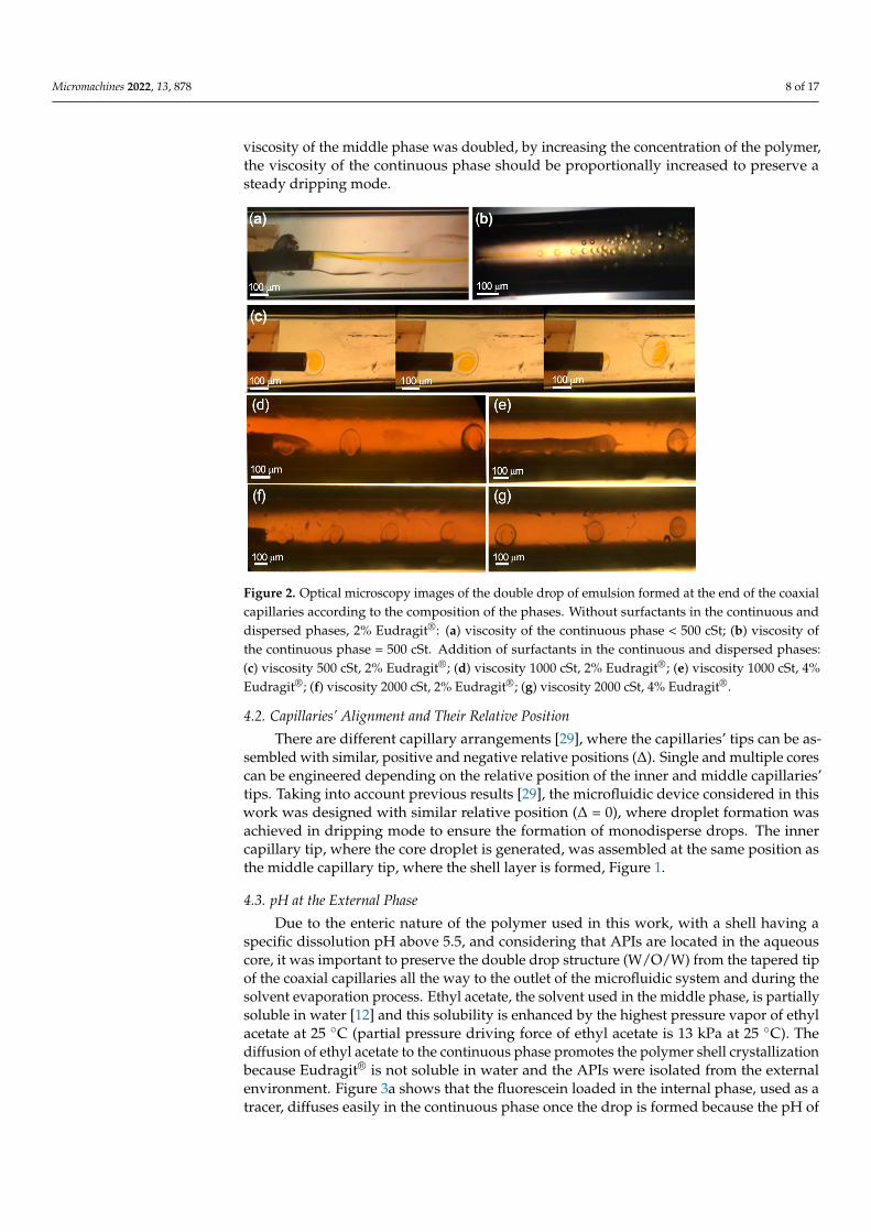
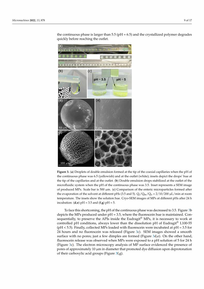
Due to the enteric nature of the polymer used in this work, with a shell having aspecific dissolution pH above 5.5, and considering that APIs are located in the aqueouscore, it was important to preserve the double drop structure (W/O/W) from the tapered tipof the coaxial capillaries all the way to the outlet of the microfluidic system and during thesolvent evaporation process. Ethyl acetate, the solvent used in the middle phase, is partiallysoluble in water [12] and this solubility is enhanced by the highest pressure vapor of ethylacetate at 25 ◦C (partial pressure driving force of ethyl acetate is 13 kPa at 25 ◦C). Thediffusion of ethyl acetate to the continuous phase promotes the polymer shell crystallizationbecause Eudragit® is not soluble in water and the APIs were isolated from the externalenvironment. Figure 3a shows that the fluorescein loaded in the internal phase, used as atracer, diffuses easily in the continuous phase once the drop is formed because the pH of
Micromachines 2022, 13, 878 9 of 17
the continuous phase is larger than 5.5 (pH = 6.5) and the crystallized polymer degradesquickly before reaching the outlet.
Micromachines 2022, 13, x 9 of 18
capillary tip, where the core droplet is generated, was assembled at the same position as the middle capillary tip, where the shell layer is formed, Figure 1.
4.3. pH at the External Phase Due to the enteric nature of the polymer used in this work, with a shell having a
specific dissolution pH above 5.5, and considering that APIs are located in the aqueous core, it was important to preserve the double drop structure (W/O/W) from the tapered tip of the coaxial capillaries all the way to the outlet of the microfluidic system and during the solvent evaporation process. Ethyl acetate, the solvent used in the middle phase, is partially soluble in water [12] and this solubility is enhanced by the highest pressure vapor of ethyl acetate at 25 °C (partial pressure driving force of ethyl acetate is 13 kPa at 25 °C). The diffusion of ethyl acetate to the continuous phase promotes the polymer shell crystal-lization because Eudragit® is not soluble in water and the APIs were isolated from the external environment. Figure 3a shows that the fluorescein loaded in the internal phase, used as a tracer, diffuses easily in the continuous phase once the drop is formed because the pH of the continuous phase is larger than 5.5 (pH = 6.5) and the crystallized polymer degrades quickly before reaching the outlet.
Figure 3. (a) Droplets of double emulsion formed at the tip of the coaxial capillaries when the pH of the continuous phase was 6.5 (yellowish) and at the outlet (white); insets depict the drops’ hue at the tip of the capillaries and at the outlet. (b) Double emulsion drops stabilized at the outlet of the microfluidic system when the pH of the continuous phase was 3.5. Inset represents a SEM image of produced MPs. Scale bar is 500 μm. (c) Comparison of the enteric microparticles formed after the evaporation of the solvent at different pHs (3.5 and 5). Qi/Qm/Qo = 2/10/200 μL/min at room temper-ature. The insets show the solution hue. Cryo-SEM images of MPs at different pHs after 24 h incu-bation: (d,e) pH = 3.5 and (f,g) pH = 5.
Figure 3. (a) Droplets of double emulsion formed at the tip of the coaxial capillaries when the pH ofthe continuous phase was 6.5 (yellowish) and at the outlet (white); insets depict the drops’ hue atthe tip of the capillaries and at the outlet. (b) Double emulsion drops stabilized at the outlet of themicrofluidic system when the pH of the continuous phase was 3.5. Inset represents a SEM imageof produced MPs. Scale bar is 500 µm. (c) Comparison of the enteric microparticles formed afterthe evaporation of the solvent at different pHs (3.5 and 5). Qi/Qm/Qo = 2/10/200 µL/min at roomtemperature. The insets show the solution hue. Cryo-SEM images of MPs at different pHs after 24 hincubation: (d,e) pH = 3.5 and (f,g) pH = 5.
To face this shortcoming, the pH of the continuous phase was decreased to 3.5. Figure 3bdepicts the MPs produced under pH = 3.5, where the fluorescein hue is maintained. Con-sequentially, to preserve the APIs inside the Eudragit® MPs, it is necessary to work atcontrolled pH conditions, always lower than the dissolution pH of Eudragit® L100-55(pH < 5.5). Finally, collected MPs loaded with fluorescein were incubated at pH = 3.5 for24 hours and no fluorescein was released (Figure 3c). SEM images showed a smoothsurface with no pores; just a few dimples are formed (Figure 3d,e). On the other hand,fluorescein release was observed when MPs were exposed to a pH solution of 5 for 24 h(Figure 3c). The electron microscopy analysis of MP surface evidenced the presence ofpores of approximately 10 µm in diameter that promoted dye diffusion upon deprotonationof their carboxylic acid groups (Figure 3f,g).

Micromachines 2022, 13, 878 10 of 17
4.4. Polymer Concentration in the Middle Phase Stream
As mentioned, viscosity, viscoelasticity and interfacial tension are hydrodynamicparameters that govern the uniform formation of droplets by using the dripping mode.Regarding the polymer concentration in the middle phase, despite not preventing thecollapse of the enteric MPs during their drying process at room temperature, it exerts agreat influence on MPs’ size, as well as on their encapsulation efficiency and loading. Theincrease of the polymer concentration in the middle phase (2–8%), while keeping constantthe other operating and material parameters (pH = 3.5, surfactant concentration, flowrates), leads to a progressive increase in the enteric MPs’ size. The size of MPs varied from397.1 µm ± 17.8 µm to 605 µm ± 29.2 µm when the Eudragit® concentration was increasedfrom 2% to 8% w/v, respectively (Figure 4a,b and Figure S2). This tendency is justifiedbecause increasing the concentration of Eudragit® polymer in the middle organic phaseincreases the viscosity of the dispersed phase, decreasing the viscosity difference and theshear stress between the external and middle phases (Figure 4a,b). As a result, there is aretardation of the speed of breakup and drops are larger in size. The coefficient of variation(CV) of polymer MP sizes remains below 5% w/v for the low polymer concentrations, but at8% w/v when the CV is large, this being an indication of polydispersity (Figure 4a,b). Thisis consistent with previously reported observations when using the dripping mode [19].
Micromachines 2022, 13, x 10 of 18
To face this shortcoming, the pH of the continuous phase was decreased to 3.5. Figure 3b depicts the MPs produced under pH = 3.5, where the fluorescein hue is maintained. Consequentially, to preserve the APIs inside the Eudragit® MPs, it is necessary to work at controlled pH conditions, always lower than the dissolution pH of Eudragit® L100-55 (pH < 5.5). Finally, collected MPs loaded with fluorescein were incubated at pH = 3.5 for 24 hours and no fluorescein was released (Figure 3c). SEM images showed a smooth surface with no pores; just a few dimples are formed (Figure 3d,e). On the other hand, fluorescein release was observed when MPs were exposed to a pH solution of 5 for 24 h (Figure 3c). The electron microscopy analysis of MP surface evidenced the presence of pores of ap-proximately 10 μm in diameter that promoted dye diffusion upon deprotonation of their carboxylic acid groups (Figure 3f,g).
4.4. Polymer Concentration in the Middle Phase Stream As mentioned, viscosity, viscoelasticity and interfacial tension are hydrodynamic pa-
rameters that govern the uniform formation of droplets by using the dripping mode. Re-garding the polymer concentration in the middle phase, despite not preventing the col-lapse of the enteric MPs during their drying process at room temperature, it exerts a great influence on MPs’ size, as well as on their encapsulation efficiency and loading. The in-crease of the polymer concentration in the middle phase (2–8%), while keeping constant the other operating and material parameters (pH = 3.5, surfactant concentration, flow rates), leads to a progressive increase in the enteric MPs’ size. The size of MPs varied from 397.1 μm ± 17.8 μm to 605 μm ± 29.2 μm when the Eudragit® concentration was increased from 2% to 8% w/v, respectively (Figures 4a,b and S2). This tendency is justified because increasing the concentration of Eudragit® polymer in the middle organic phase increases the viscosity of the dispersed phase, decreasing the viscosity difference and the shear stress between the external and middle phases (Figure 4a,b). As a result, there is a retar-dation of the speed of breakup and drops are larger in size. The coefficient of variation (CV) of polymer MP sizes remains below 5% w/v for the low polymer concentrations, but at 8% w/v when the CV is large, this being an indication of polydispersity (Figure 4a,b). This is consistent with previously reported observations when using the dripping mode [19].
Figure 4. (a) SEM image of a Trojan microparticle synthesize with 2% (w/v) Eudragit® using the coaxial microfluidic system. Study of the influence of Eudragit® concentration on: (b) the diameter, (c) the encapsulation efficiency (EE) and drug loading (DL) of the enteric microparticles synthesized in the microfluidic system. (d,e) SEM images and (f) size distribution of the Trojan microparticles obtained in batch conditions with 2% (w/v) Eudragit®.
Figure 4. (a) SEM image of a Trojan microparticle synthesize with 2% (w/v) Eudragit® using thecoaxial microfluidic system. Study of the influence of Eudragit® concentration on: (b) the diameter,(c) the encapsulation efficiency (EE) and drug loading (DL) of the enteric microparticles synthesizedin the microfluidic system. (d,e) SEM images and (f) size distribution of the Trojan microparticlesobtained in batch conditions with 2% (w/v) Eudragit®.
Fluorescein was substituted in the internal phase by PLGA NPs loaded with rifampicin(PLGA-RIF NPs). The overall MP diameter was not influenced by the different APIsdispersed in the internal phase. This is probably caused because the shear stress at theouter/middle interface remains almost invariant to the inner phase [29]. MPs loadedwith PLGA-RIF NPs were lyophilized to preserve the APIs during long-term storage.Lyophilized MPs were incubated at pH = 7.4 to dissolve the enteric shell and release thePLGA-RIF NPs. This process eases the determination of encapsulation efficiency andloading by measuring the absorbance of the PLGA-RIF NPs at λ = 477 nm by UV-Visspectrophotometry As depicted in Figure 4c, the coaxial microfluidic system enabled theachievement of 100% EE, maintaining this percentage at all the polymer concentrationstested. This result was granted by the fast precipitation of the polymeric shell, which ispromoted by the acid nature of the external phase (pH = 3.5). Consequently, the internal
Micromachines 2022, 13, 878 11 of 17
phase is totally wrapped by the middle phase and no diffusion occurs between the internaland external phases. On the other hand, despite the high EE reached, the percentage ofdrug loading (DL) decreased gradually while increasing the concentration of Eudragit®
in the formulation of MPs (Figure 4c). Since the concentration of the drug added in theinternal phase remains constant in all the tests carried out, this result is rationalized by thethicker polymeric shell resulting in a small internal core as the polymer concentration isincreased. Therefore, we selected 2% (w/v) Eudragit® as the optimal polymer concentrationin the middle phase to obtain a complete EE (~100%) and the highest DL (62.5%).
When comparing the Trojan MPs obtained using the microfluidic system (Figure 4a)with the ones obtained by the batch type reactor (Figure 4d,e), significant differences couldbe observed: (1) SEM morphological analysis revealed spherical particles with micrometricsizes (397.1 ± 17.8 µm) in the coaxial system, compared to the bipyramidal structure withsmaller sizes (9.3 ± 2.0 µm, CV ~21%) when using batch reactors. (2) The maximum EEobtained by the batch was 48.0 ± 2.7%, corresponding to 9.6 ± 0.5% DL, compared to a100% EE and a DL of 62.5 ± 2.0% obtained in the microfluidic system, both with 2% w/vEudragit® concentration during the production process. These differences are remarkableand highlight that the coaxial microfluidic system considered in this work is more efficientin terms of loading different APIs than the conventional W/O/W emulsification processesproduced in a batch-type reactor. In addition, the microfluidic system can be continuouslyoperated with high reproducibility and saves a costly polymer.
4.5. Internal and Continuous Phase Flow
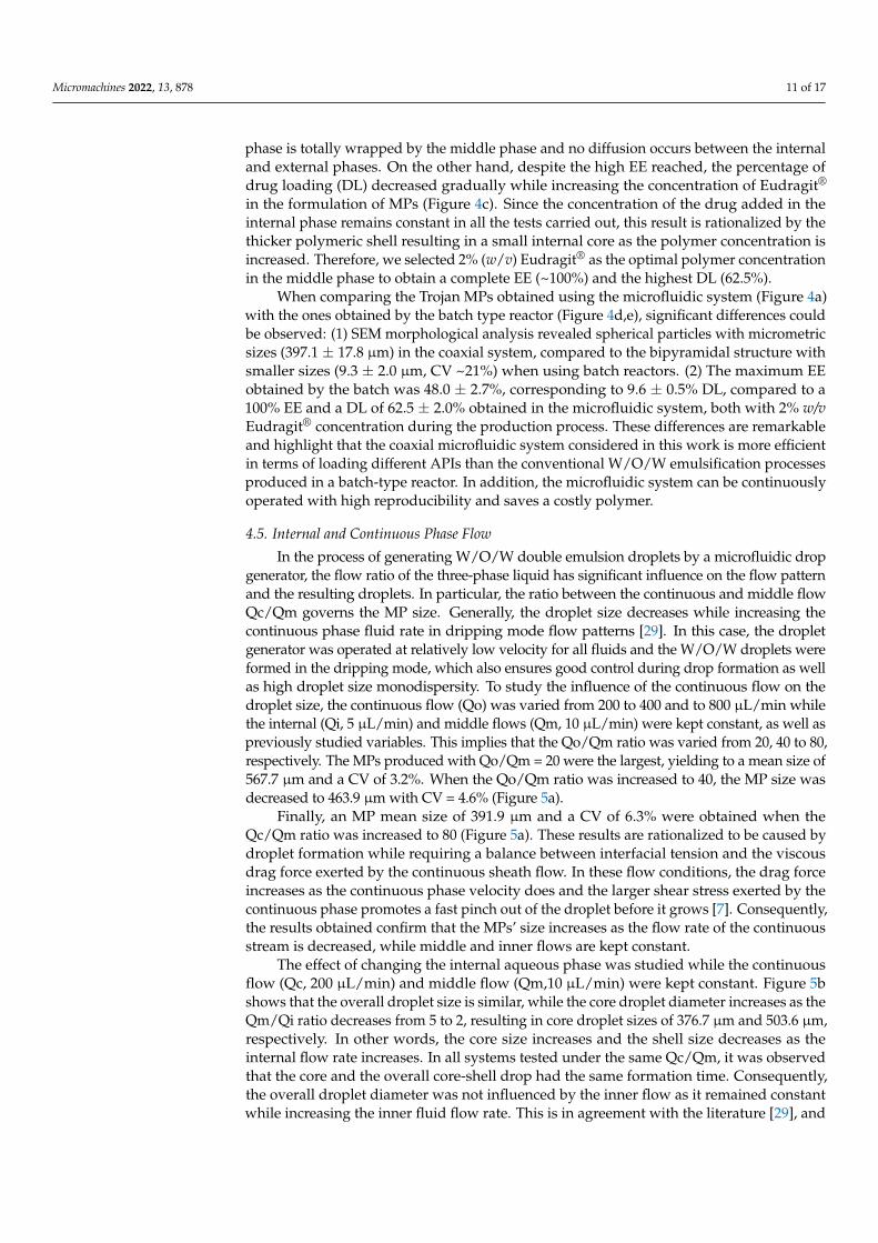
In the process of generating W/O/W double emulsion droplets by a microfluidic dropgenerator, the flow ratio of the three-phase liquid has significant influence on the flow patternand the resulting droplets. In particular, the ratio between the continuous and middle flowQc/Qm governs the MP size. Generally, the droplet size decreases while increasing thecontinuous phase fluid rate in dripping mode flow patterns [29]. In this case, the dropletgenerator was operated at relatively low velocity for all fluids and the W/O/W droplets wereformed in the dripping mode, which also ensures good control during drop formation as wellas high droplet size monodispersity. To study the influence of the continuous flow on thedroplet size, the continuous flow (Qo) was varied from 200 to 400 and to 800 µL/min whilethe internal (Qi, 5 µL/min) and middle flows (Qm, 10 µL/min) were kept constant, as well aspreviously studied variables. This implies that the Qo/Qm ratio was varied from 20, 40 to 80,respectively. The MPs produced with Qo/Qm = 20 were the largest, yielding to a mean size of567.7 µm and a CV of 3.2%. When the Qo/Qm ratio was increased to 40, the MP size wasdecreased to 463.9 µm with CV = 4.6% (Figure 5a).
Finally, an MP mean size of 391.9 µm and a CV of 6.3% were obtained when theQc/Qm ratio was increased to 80 (Figure 5a). These results are rationalized to be caused bydroplet formation while requiring a balance between interfacial tension and the viscousdrag force exerted by the continuous sheath flow. In these flow conditions, the drag forceincreases as the continuous phase velocity does and the larger shear stress exerted by thecontinuous phase promotes a fast pinch out of the droplet before it grows [7]. Consequently,the results obtained confirm that the MPs’ size increases as the flow rate of the continuousstream is decreased, while middle and inner flows are kept constant.
The effect of changing the internal aqueous phase was studied while the continuousflow (Qc, 200 µL/min) and middle flow (Qm,10 µL/min) were kept constant. Figure 5bshows that the overall droplet size is similar, while the core droplet diameter increases as theQm/Qi ratio decreases from 5 to 2, resulting in core droplet sizes of 376.7 µm and 503.6 µm,respectively. In other words, the core size increases and the shell size decreases as theinternal flow rate increases. In all systems tested under the same Qc/Qm, it was observedthat the core and the overall core-shell drop had the same formation time. Consequently,the overall droplet diameter was not influenced by the inner flow as it remained constantwhile increasing the inner fluid flow rate. This is in agreement with the literature [29], and
Micromachines 2022, 13, 878 12 of 17
it is ascribed to the fact that the shear stress at the outer/middle drop interface remainsalmost the same when the inner fluid flow rate is varied.
Micromachines 2022, 13, x 12 of 18
Figure 5. (a) SEM image of Trojan microparticles produced by altering the continuous phase flow rate (Qo) from 200 to −800 μL/min and leaving constant the internal (Qi, 5 μL/min) and middle flow rates (Qm, 10 μL/min). Mean size and coefficient of variation (CV). (b) Effect of Qm/Qi ratio when Qo (200 μL/min) and middle flow Qm (10 μL/min) were kept constant. Shell and core diameters were measured from optical images such as the ones depicted in the insets.
Finally, an MP mean size of 391.9 μm and a CV of 6.3% were obtained when the Qc/Qm ratio was increased to 80 (Figure 5a). These results are rationalized to be caused by droplet formation while requiring a balance between interfacial tension and the viscous drag force exerted by the continuous sheath flow. In these flow conditions, the drag force increases as the continuous phase velocity does and the larger shear stress exerted by thecontinuous phase promotes a fast pinch out of the droplet before it grows [7]. Conse-quently, the results obtained confirm that the MPs’ size increases as the flow rate of the continuous stream is decreased, while middle and inner flows are kept constant.
The effect of changing the internal aqueous phase was studied while the continuous flow (Qc, 200 μL/min) and middle flow (Qm,10 μL/min) were kept constant. Figure 5b shows that the overall droplet size is similar, while the core droplet diameter increases as the Qm/Qi ratio decreases from 5 to 2, resulting in core droplet sizes of 376.7 μm and 503.6 μm, respectively. In other words, the core size increases and the shell size decreases as theinternal flow rate increases. In all systems tested under the same Qc/Qm, it was observed that the core and the overall core-shell drop had the same formation time. Consequently, the overall droplet diameter was not influenced by the inner flow as it remained constant
Figure 5. (a) SEM image of Trojan microparticles produced by altering the continuous phase flowrate (Qo) from 200 to −800 µL/min and leaving constant the internal (Qi, 5 µL/min) and middle flowrates (Qm, 10 µL/min). Mean size and coefficient of variation (CV). (b) Effect of Qm/Qi ratio whenQo (200 µL/min) and middle flow Qm (10 µL/min) were kept constant. Shell and core diameterswere measured from optical images such as the ones depicted in the insets.
4.6. Drying Process
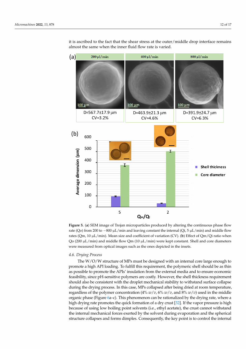
The W/O/W structure of MPs must be designed with an internal core large enough topromote a high API loading. To fulfill this requirement, the polymeric shell should be as thinas possible to promote the APIs’ insulation from the external media and to ensure economicfeasibility, since pH-sensitive polymers are costly. However, the shell thickness requirementshould also be consistent with the droplet mechanical stability to withstand surface collapseduring the drying process. In this case, MPs collapsed after being dried at room temperature,regardless of the polymer concentration (4% w/v, 6% w/v, and 8% w/v) used in the middleorganic phase (Figure 6a–c). This phenomenon can be rationalized by the drying rate, where ahigh drying rate promotes the quick formation of a dry crust [32]. If the vapor pressure is highbecause of using low boiling point solvents (i.e., ethyl acetate), the crust cannot withstandthe internal mechanical forces exerted by the solvent during evaporation and the sphericalstructure collapses and forms dimples. Consequently, the key point is to control the internal
Micromachines 2022, 13, 878 13 of 17
vapor pressure during the drying process. Considering that in this case at room temperaturethe MP collapse was evident, a low temperature dehydration process was proposed. MPswere frozen in liquid nitrogen and lyophilized to slowly remove the solvent by ice sublimation.Proceeding in this way, the structural stability of the dry particles was successfully achieved,retaining their spherical morphology (Figure 6d–f).
Micromachines 2022, 13, x 13 of 18
while increasing the inner fluid flow rate. This is in agreement with the literature [29], and it is ascribed to the fact that the shear stress at the outer/middle drop interface remains almost the same when the inner fluid flow rate is varied.
4.6. Drying Process The W/O/W structure of MPs must be designed with an internal core large enough
to promote a high API loading. To fulfill this requirement, the polymeric shell should be as thin as possible to promote the APIs’ insulation from the external media and to ensure economic feasibility, since pH-sensitive polymers are costly. However, the shell thickness requirement should also be consistent with the droplet mechanical stability to withstand surface collapse during the drying process. In this case, MPs collapsed after being dried at room temperature, regardless of the polymer concentration (4% w/v, 6% w/v, and 8% w/v) used in the middle organic phase (Figure 6a–c). This phenomenon can be rationalized by the drying rate, where a high drying rate promotes the quick formation of a dry crust [32]. If the vapor pressure is high because of using low boiling point solvents (i.e., ethyl acetate), the crust cannot withstand the internal mechanical forces exerted by the solvent during evaporation and the spherical structure collapses and forms dimples. Conse-quently, the key point is to control the internal vapor pressure during the drying process. Considering that in this case at room temperature the MP collapse was evident, a low temperature dehydration process was proposed. MPs were frozen in liquid nitrogen and lyophilized to slowly remove the solvent by ice sublimation. Proceeding in this way, the structural stability of the dry particles was successfully achieved, retaining their spherical morphology (Figure 6d–f).
Figure 6. Drying of the enteric microparticles synthesized in the coaxial microfluidic system, Qi/Qm/Qo = 5/10/200 μL/min. (a) Optical microscopy image of the 2% Eudragit® microparticles after filtering and drying at room temperature. SEM images of the microparticles synthesized with (b) 2% and (c) 4% Eudragit® after filtering and drying at room temperature. (d) Optical microscopy image of the 2% Eudragit® microparticles after the lyophilization process. SEM images of the micro-particles synthesized with (e) 2% and (f) 4% Eudragit® after the lyophilization process.
Considering the results obtained in each of the variables tested, the optimal condi-tions of composition and operation are the following: (1) viscosity of the continuous phase
200 µm
200 µm
a)
d)
200 µm
200 µm
b) c)
f)e)
Filtering and drying at room temperature
Lyophilization
(
(
( (
((
Figure 6. Drying of the enteric microparticles synthesized in the coaxial microfluidic system,Qi/Qm/Qo = 5/10/200 µL/min. (a) Optical microscopy image of the 2% Eudragit® microparti-cles after filtering and drying at room temperature. SEM images of the microparticles synthesizedwith (b) 2% and (c) 4% Eudragit® after filtering and drying at room temperature. (d) Optical mi-croscopy image of the 2% Eudragit® microparticles after the lyophilization process. SEM images ofthe microparticles synthesized with (e) 2% and (f) 4% Eudragit® after the lyophilization process.
Considering the results obtained in each of the variables tested, the optimal conditionsof composition and operation are the following: (1) viscosity of the continuous phase of2000 cSt, corresponding to a concentration of methylcellulose of 1% (w/v); (2) surfactantSpan® 80 in the middle phase and PVA in the continuous phase, both with a 1% (w/v)concentration; (3) system pH, continuous phase and evaporation solution at pH = 3.5 ± 0.5;(4) washing, drying and storage of the microparticles. Wash the microparticles with anaqueous solution at pH = 3.5 ± 0.5 and subsequent lyophilization; (5) polymer concentra-tion, 2% (w/v) since a low polymer concentration carries a higher inner load percentage;(6) Continuous phase flow rate. The best balance between the monodispersity of theparticles (CV < 5%) and their size was obtained when using a flow rate of 400 µL/min;(7) internal phase flow rate, 5 µL/min, assessing the fact that the larger the size of the corein the emulsion drop, the greater the volume of the active load encapsulated.
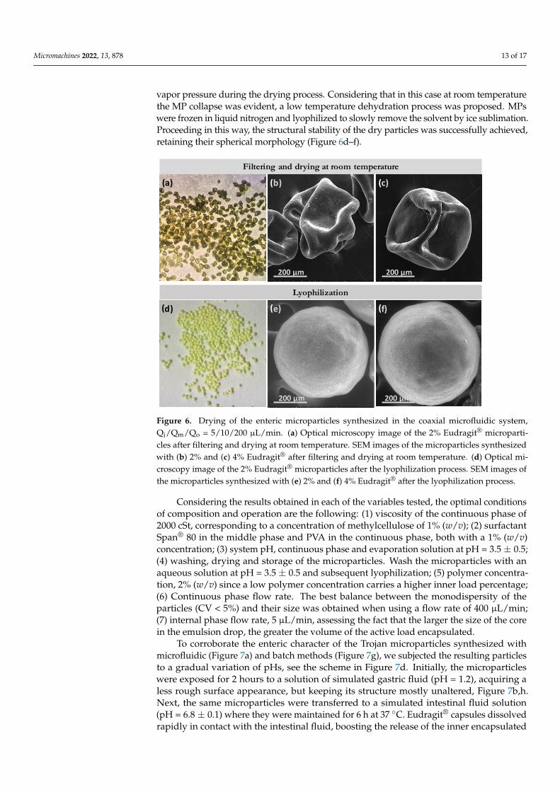
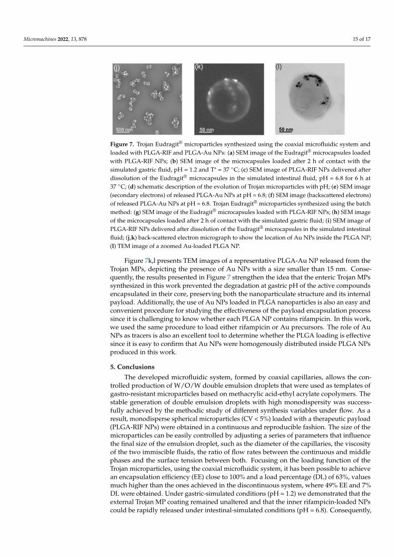
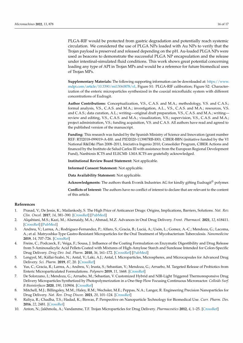
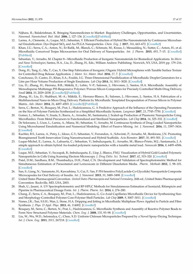
To corroborate the enteric character of the Trojan microparticles synthesized withmicrofluidic (Figure 7a) and batch methods (Figure 7g), we subjected the resulting particlesto a gradual variation of pHs, see the scheme in Figure 7d. Initially, the microparticleswere exposed for 2 hours to a solution of simulated gastric fluid (pH = 1.2), acquiring aless rough surface appearance, but keeping its structure mostly unaltered, Figure 7b,h.Next, the same microparticles were transferred to a simulated intestinal fluid solution(pH = 6.8 ± 0.1) where they were maintained for 6 h at 37 ◦C. Eudragit® capsules dissolvedrapidly in contact with the intestinal fluid, boosting the release of the inner encapsulated
Micromachines 2022, 13, 878 14 of 17
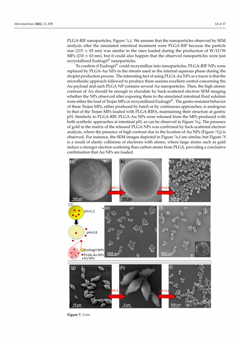
PLGA-RIF nanoparticles, Figure 7c,i. We assume that the nanoparticles observed by SEManalysis after the simulated intestinal treatment were PLGA-RIF because the particlesize (215 ± 65 nm) was similar to the ones loaded during the production of W/O/WMPs (210 ± 63 nm), but it could also happen that the observed nanoparticles were justrecrystallized Eudragit® nanoparticles.
To confirm if Eudragit® could recrystallize into nanoparticles, PLGA-RIF NPs werereplaced by PLGA-Au NPs in the stream used as the internal aqueous phase during thedroplet production process. The interesting fact of using PLGA-Au NPs as a tracer is that themicrofluidic approach followed to produce them assures excellent control concerning theAu payload and each PLGA NP contains several Au nanoparticles. Then, the high atomiccontrast of Au should be enough to elucidate by back-scattered electron SEM imagingwhether the NPs observed after exposing them to the simulated intestinal fluid solutionwere either the load of Trojan MPs or recrystallized Eudragit®. The gastro-resistant behaviorof these Trojan MPs, either produced by batch or by continuous approaches, is analogousto that of the Trojan MPs loaded with PLGA-RIFA, maintaining their structure at gastricpH. Similarly to PLGA-RIF, PLGA-Au NPs were released from the MPs produced withboth synthetic approaches at intestinal pH, as can be observed in Figure 7e,j. The presenceof gold in the matrix of the released PLGA NPs was confirmed by back-scattered electronanalysis, where the presence of high contrast due to the location of Au NPs (Figure 7f,j) isobserved. For instance, the SEM images depicted in Figure 7e,f are similar, but Figure 7fis a result of elastic collisions of electrons with atoms, where large atoms such as goldinduce a stronger electron scattering than carbon atoms from PLGA, providing a conclusiveconfirmation that Au NPs are loaded.
Micromachines 2022, 13, x 15 of 18
Figure 7. Trojan Eudragit® microparticles synthesized using the coaxial microfluidic system and loaded with PLGA-RIF and PLGA-Au NPs: (a) SEM image of the Eudragit® microcapsules loaded with PLGA-RIF NPs; (b) SEM image of the microcapsules loaded after 2 h of contact with the simu-lated gastric fluid, pH = 1.2 and Tª = 37 °C; (c) SEM image of PLGA-RIF NPs delivered after disso-lution of the Eudragit® microcapsules in the simulated intestinal fluid, pH = 6.8 for 6 h at 37 °C; (d) schematic description of the evolution of Trojan microparticles with pH; (e) SEM image (secondary electrons) of released PLGA-Au NPs at pH = 6.8; (f) SEM image (backscattered electrons) of released PLGA-Au NPs at pH = 6.8. Trojan Eudragit® microparticles synthesized using the batch method: (g) SEM image of the Eudragit® microcapsules loaded with PLGA-RIF NPs; (h) SEM image of the mi-crocapsules loaded after 2 h of contact with the simulated gastric fluid; (i) SEM image of PLGA-RIF NPs delivered after dissolution of the Eudragit® microcapsules in the simulated intestinal fluid; (j,k) back-scattered electron micrograph to show the location of Au NPs inside the PLGA NP; (l) TEM image of a zoomed Au-loaded PLGA NP.
Figure 7. Cont.
Micromachines 2022, 13, 878 15 of 17
Micromachines 2022, 13, x 15 of 18
Figure 7. Trojan Eudragit® microparticles synthesized using the coaxial microfluidic system and loaded with PLGA-RIF and PLGA-Au NPs: (a) SEM image of the Eudragit® microcapsules loaded with PLGA-RIF NPs; (b) SEM image of the microcapsules loaded after 2 h of contact with the simu-lated gastric fluid, pH = 1.2 and Tª = 37 °C; (c) SEM image of PLGA-RIF NPs delivered after disso-lution of the Eudragit® microcapsules in the simulated intestinal fluid, pH = 6.8 for 6 h at 37 °C; (d) schematic description of the evolution of Trojan microparticles with pH; (e) SEM image (secondary electrons) of released PLGA-Au NPs at pH = 6.8; (f) SEM image (backscattered electrons) of released PLGA-Au NPs at pH = 6.8. Trojan Eudragit® microparticles synthesized using the batch method: (g) SEM image of the Eudragit® microcapsules loaded with PLGA-RIF NPs; (h) SEM image of the mi-crocapsules loaded after 2 h of contact with the simulated gastric fluid; (i) SEM image of PLGA-RIF NPs delivered after dissolution of the Eudragit® microcapsules in the simulated intestinal fluid; (j,k) back-scattered electron micrograph to show the location of Au NPs inside the PLGA NP; (l) TEM image of a zoomed Au-loaded PLGA NP.
Figure 7. Trojan Eudragit® microparticles synthesized using the coaxial microfluidic system andloaded with PLGA-RIF and PLGA-Au NPs: (a) SEM image of the Eudragit® microcapsules loadedwith PLGA-RIF NPs; (b) SEM image of the microcapsules loaded after 2 h of contact with thesimulated gastric fluid, pH = 1.2 and Tª = 37 ◦C; (c) SEM image of PLGA-RIF NPs delivered afterdissolution of the Eudragit® microcapsules in the simulated intestinal fluid, pH = 6.8 for 6 h at37 ◦C; (d) schematic description of the evolution of Trojan microparticles with pH; (e) SEM image(secondary electrons) of released PLGA-Au NPs at pH = 6.8; (f) SEM image (backscattered electrons)of released PLGA-Au NPs at pH = 6.8. Trojan Eudragit® microparticles synthesized using the batchmethod: (g) SEM image of the Eudragit® microcapsules loaded with PLGA-RIF NPs; (h) SEM imageof the microcapsules loaded after 2 h of contact with the simulated gastric fluid; (i) SEM image ofPLGA-RIF NPs delivered after dissolution of the Eudragit® microcapsules in the simulated intestinalfluid; (j,k) back-scattered electron micrograph to show the location of Au NPs inside the PLGA NP;(l) TEM image of a zoomed Au-loaded PLGA NP.
Figure 7k,l presents TEM images of a representative PLGA-Au NP released from theTrojan MPs, depicting the presence of Au NPs with a size smaller than 15 nm. Conse-quently, the results presented in Figure 7 strengthen the idea that the enteric Trojan MPssynthesized in this work prevented the degradation at gastric pH of the active compoundsencapsulated in their core, preserving both the nanoparticulate structure and its internalpayload. Additionally, the use of Au NPs loaded in PLGA nanoparticles is also an easy andconvenient procedure for studying the effectiveness of the payload encapsulation processsince it is challenging to know whether each PLGA NP contains rifampicin. In this work,we used the same procedure to load either rifampicin or Au precursors. The role of AuNPs as tracers is also an excellent tool to determine whether the PLGA loading is effectivesince it is easy to confirm that Au NPs were homogenously distributed inside PLGA NPsproduced in this work.
5. Conclusions
The developed microfluidic system, formed by coaxial capillaries, allows the con-trolled production of W/O/W double emulsion droplets that were used as templates ofgastro-resistant microparticles based on methacrylic acid-ethyl acrylate copolymers. Thestable generation of double emulsion droplets with high monodispersity was success-fully achieved by the methodic study of different synthesis variables under flow. As aresult, monodisperse spherical microparticles (CV < 5%) loaded with a therapeutic payload(PLGA-RIF NPs) were obtained in a continuous and reproducible fashion. The size of themicroparticles can be easily controlled by adjusting a series of parameters that influencethe final size of the emulsion droplet, such as the diameter of the capillaries, the viscosityof the two immiscible fluids, the ratio of flow rates between the continuous and middlephases and the surface tension between both. Focusing on the loading function of theTrojan microparticles, using the coaxial microfluidic system, it has been possible to achievean encapsulation efficiency (EE) close to 100% and a load percentage (DL) of 63%, valuesmuch higher than the ones achieved in the discontinuous system, where 49% EE and 7%DL were obtained. Under gastric-simulated conditions (pH = 1.2) we demonstrated that theexternal Trojan MP coating remained unaltered and that the inner rifampicin-loaded NPscould be rapidly released under intestinal-simulated conditions (pH = 6.8). Consequently,
Micromachines 2022, 13, 878 16 of 17
PLGA-RIF would be protected from gastric degradation and potentially reach systemiccirculation. We considered the use of PLGA NPs loaded with Au NPs to verify that theTrojan payload is preserved and released depending on the pH. Au-loaded PLGA NPs wereused as beacons to demonstrate the successful PLGA NP encapsulation and the releaseunder intestinal-simulated fluid conditions. This work shows great potential concerningloading any type of API in Trojan MPs and would be a reference for future biomedical usesof Trojan MPs.
Supplementary Materials: The following supporting information can be downloaded at: https://www.mdpi.com/article/10.3390/mi13060878/s1, Figure S1: PLGA-RIF calibration; Figure S2: Character-ization of the enteric microparticles synthesized in the coaxial microfluidic system with differentconcentrations of Eudragit.
Author Contributions: Conceptualization, V.S., C.A.S. and M.A.; methodology, V.S. and C.A.S.;formal analysis, V.S., C.A.S. and M.A.; investigation, A.L., V.S., C.A.S. and M.A.; resources, V.S.and C.A.S.; data curation, A.L.; writing—original draft preparation, V.S., C.A.S. and M.A.; writing—review and editing, V.S., C.A.S. and M.A.; visualization, V.S.; supervision, V.S., C.A.S. and M.A.;project administration, V.S.; funding acquisition, V.S. and C.A.S. All authors have read and agreed tothe published version of the manuscript.
Funding: This research was funded by the Spanish Ministry of Science and Innovation (grant numberREF: RTI2018-099019-A-I00. and PID2020-113987RB-I00). CIBER-BBN (initiative funded by the VINational R&D&i Plan 2008–2011, Iniciativa Ingenio 2010, Consolider Program, CIBER Actions andfinanced by the Instituto de Salud Carlos III with assistance from the European Regional DevelopmentFund), Nanbiosis ICTS and ELECMI- LMA ICTS are gratefully acknowledged.
Institutional Review Board Statement: Not applicable.
Informed Consent Statement: Not applicable.
Data Availability Statement: Not applicable.
Acknowledgments: The authors thank Evonik Industries AG for kindly gifting Eudragit® polymer.
Conflicts of Interest: The authors have no conflict of interest to declare that are relevant to the contentof this article.
References1. Prasad, V.; De Jesús, K.; Mailankody, S. The High Price of Anticancer Drugs: Origins, Implications, Barriers, Solutions. Nat. Rev.
Clin. Oncol. 2017, 14, 381–390. [CrossRef] [PubMed]2. Alqahtani, M.S.; Kazi, M.; Alsenaidy, M.A.; Ahmad, M.Z. Advances in Oral Drug Delivery. Front. Pharmacol. 2021, 12, 618411.
[CrossRef] [PubMed]3. Andreu, V.; Larrea, A.; Rodriguez-Fernandez, P.; Alfaro, S.; Gracia, B.; Luciá, A.; Usón, L.; Gomez, A.-C.; Mendoza, G.; Lacoma,
A.; et al. Matryoshka-Type Gastro-Resistant Microparticles for the Oral Treatment of Mycobacterium Tuberculosis. Nanomedicine2019, 14, 707–726. [CrossRef]
4. Freire, C.; Podczeck, F.; Veiga, F.; Sousa, J. Influence of the Coating Formulation on Enzymatic Digestibility and Drug Releasefrom 5-Aminosalicylic Acid Pellets Coated with Mixtures of High-Amylose Starch and Surelease Intended for Colon-SpecificDrug Delivery. Drug Dev. Ind. Pharm. 2010, 36, 161–172. [CrossRef] [PubMed]
5. Lengyel, M.; Kállai-Szabó, N.; Antal, V.; Laki, A.J.; Antal, I. Microparticles, Microspheres, and Microcapsules for Advanced DrugDelivery. Sci. Pharm. 2019, 87, 20. [CrossRef]
6. Yus, C.; Gracia, R.; Larrea, A.; Andreu, V.; Irusta, S.; Sebastian, V.; Mendoza, G.; Arruebo, M. Targeted Release of Probiotics fromEnteric Microparticulated Formulations. Polymers 2019, 11, 1668. [CrossRef]
7. De Solorzano, I.; Mendoza, G.; Arruebo, M.; Sebastian, V. Customized Hybrid and NIR-Light Triggered Thermoresponsive DrugDelivery Microparticles Synthetized by Photopolymerization in a One-Step Flow Focusing Continuous Microreactor. Colloids Surf.B Biointerfaces 2020, 190, 110904. [CrossRef]
8. Mitchell, M.J.; Billingsley, M.M.; Haley, R.M.; Wechsler, M.E.; Peppas, N.A.; Langer, R. Engineering Precision Nanoparticles forDrug Delivery. Nat. Rev. Drug Discov. 2021, 20, 101–124. [CrossRef]
9. Raliya, R.; Chadha, T.S.; Hadad, K.; Biswas, P. Perspective on Nanoparticle Technology for Biomedical Use. Curr. Pharm. Des.2016, 22, 2481. [CrossRef]
10. Anton, N.; Jakhmola, A.; Vandamme, T.F. Trojan Microparticles for Drug Delivery. Pharmaceutics 2012, 4, 1–25. [CrossRef]
Micromachines 2022, 13, 878 17 of 17
11. Nijhara, R.; Balakrishnan, K. Bringing Nanomedicines to Market: Regulatory Challenges, Opportunities, and Uncertainties.Nanomed. Nanotechnol. Biol. Med. 2006, 2, 127–136. [CrossRef] [PubMed]
12. Larrea, A.; Clemente, A.; Luque, M.E.; Sebastian, V. Efficient Production of Hybrid Bio-Nanomaterials by Continuous Microchan-nel Emulsification: Dye-Doped SiO2 and Au-PLGA Nanoparticles. Chem. Eng. J. 2017, 316, 663–672. [CrossRef]
13. Khan, I.U.; Serra, C.A.; Anton, N.; Er-Rafik, M.; Blanck, C.; Schmutz, M.; Kraus, I.; Messaddeq, N.; Sutter, C.; Anton, H.; et al.Microfluidic Conceived Trojan Microcarriers for Oral Delivery of Nanoparticles. Int. J. Pharm. 2015, 493, 7–15. [CrossRef][PubMed]
14. Sebastian, V.; Arruebo, M. Chapter 8—Microfluidic Production of Inorganic Nanomaterials for Biomedical Applications. In Microand Nano Technologies; Santos, H.A., Liu, D., Zhang, H., Eds.; William Andrew Publishing: Norwich, NY, USA, 2019; pp. 179–216.[CrossRef]
15. Dong, H.; Tang, G.; Ma, T.; Cao, X. One-Step Fabrication of Inorganic/Organic Hybrid Microspheres with Tunable Surface Texturefor Controlled Drug Release Application. J. Mater. Sci. Mater. Med. 2016, 27, 7. [CrossRef]
16. Conchouso, D.; Castro, D.; Khan, S.A.; Foulds, I.G. Three-Dimensional Parallelization of Microfluidic Droplet Generators for aLitre per Hour Volume Production of Single Emulsions. Lab Chip 2014, 14, 3011–3020. [CrossRef]
17. Liu, D.; Zhang, H.; Herranz, B.B.; Mäkilä, E.; Lehto, V.-P.; Salonen, J.; Hirvonen, J.; Santos, H.A. Microfluidic Assembly ofMonodisperse Multistage PH-Responsive Polymer/Porous Silicon Composites for Precisely Controlled Multi-Drug Delivery.Small 2014, 10, 2029–2038. [CrossRef] [PubMed]
18. Zhang, H.; Liu, D.; Shahbazi, M.-A.; Mäkilä, E.; Herranz-Blanco, B.; Salonen, J.; Hirvonen, J.; Santos, H.A. Fabrication of aMultifunctional Nano-in-Micro Drug Delivery Platform by Microfluidic Templated Encapsulation of Porous Silicon in PolymerMatrix. Adv. Mater. 2014, 26, 4497–4503. [CrossRef] [PubMed]
19. Serra, C.; Berton, N.; Bouquey, M.; Prat, L.; Hadziioannou, G. A Predictive Approach of the Influence of the Operating Parameterson the Size of Polymer Particles Synthesized in a Simplified Microfluidic System. Langmuir 2007, 23, 7745–7750. [CrossRef]
20. Gomez, L.; Sebastian, V.; Irusta, S.; Ibarra, A.; Arruebo, M.; Santamaria, J. Scaled-up Production of Plasmonic Nanoparticles UsingMicrofluidics: From Metal Precursors to Functionalized and Sterilized Nanoparticles. Lab Chip 2014, 14, 325–332. [CrossRef]
21. De Solorzano, I.; Uson, L.; Larrea, A.; Miana, M.; Sebastian, V.; Arruebo, M. Continuous Synthesis of Drug-Loaded NanoparticlesUsing Microchannel Emulsification and Numerical Modeling: Effect of Passive Mixing. Int. J. Nanomed. 2016, 11, 3397–3416.[CrossRef]
22. Kuchler, B.S.; Larrea, A.; Petry, L.; Idoux, G.Y.; Sebastian, V.; Ferrandon, A.; Schwinté, P.; Arruebo, M.; Benkirane, J.N. PromotingBioengineered Tooth Innervation Using Nanostructured and Hybrid Scaffolds. Acta Biomater. 2017, 50, 493–501. [CrossRef]
23. Luque-Michel, E.; Larrea, A.; Lahuerta, C.; Sebastian, V.; Imbuluzqueta, E.; Arruebo, M.; Blanco-Prieto, M.J.; Santamaría, J. Asimple approach to obtain hybrid Au-loaded polymeric nanoparticles with a tunable metal load. Nanoscale 2016, 8, 6495–6506.[CrossRef]
24. Luque, M.E.; Sebastian, V.; Szczupak, B.; Imbuluzqueta, E.; Llop, J.; Blanco, P.M.J. Visualization of Hybrid Gold-Loaded PolymericNanoparticles in Cells Using Scanning Electron Microscopy. J. Drug Deliv. Sci. Technol. 2017, 42, 315–320. [CrossRef]
25. Patel, D.M.; Sardhara, B.M.; Thumbadiya, D.H.; Patel, C.N. Development and Validation of Spectrophotometric Method forSimultaneous Estimation of Paracetamol and Lornoxicam in Different Dissolution Media. Pharm. Methods 2012, 3, 98–101.[CrossRef]
26. Sun, S.; Liang, N.; Yamamoto, H.; Kawashima, Y.; Cui, F.; Yan, P. PH-Sensitive Poly(Lactide-Co-Glycolide) Nanoparticle CompositeMicrocapsules for Oral Delivery of Insulin. Int. J. Nanomed. 2015, 10, 3489–3498. [CrossRef]
27. United States Pharmacopeial Convention. United States Pharmacopeia and National Formulary, 26th ed.; United States PharmacopeialConvention: Rockville, MD, USA, 2003.
28. Shah, U.; Jasani, A. UV Spectrophotometric and RP-HPLC Methods for Simulataneous Estimation of Isoniazid, Rifampicin andPiperine in Pharmaceutical Dosage Form. Int. J. Pharm. Pharm. Sci. 2014, 6, 274–280.
29. Chang, Z.; Serra, C.A.; Bouquey, M.; Prat, L.; Hadziioannou, G. Co-Axial Capillaries Microfluidic Device for Synthesizing Size-and Morphology-Controlled Polymer Core-Polymer Shell Particles. Lab Chip 2009, 9, 3007–3011. [CrossRef]
30. Nunes, J.K.; Tsai, S.S.H.; Wan, J.; Stone, H.A. Dripping and Jetting in Microfluidic Multiphase Flows Applied to Particle and FiberSynthesis. J. Phys. D Appl. Phys. 2013, 46, 114002. [CrossRef]
31. Bouquey, M.; Serra, C.; Berton, N.; Prat, L.; Hadziioannou, G. Microfluidic Synthesis and Assembly of Reactive Polymer Beads toForm New Structured Polymer Materials. Chem. Eng. J. 2008, 135, 93–98. [CrossRef]
32. Liu, W.; Wu, W.D.; Selomulya, C.; Chen, X.D. Uniform Chitosan Microparticles Prepared by a Novel Spray-Drying Technique.Int. J. Chem. Eng. 2011, 2011, 267218. [CrossRef]
Copyright © 2022 FDOKUMEN