Trisobuild Brochure 2021 - Tata Steel
25
Trisobuild® Site assembled roofing and cladding systems Uniclass CI/SfB L5221:P4 December 2021 (4-) Nh
-
Upload
khangminh22 -
Category
Documents
-
view
2 -
download
0
Transcript of Trisobuild Brochure 2021 - Tata Steel

Trisobuild®Site assembled roofing and cladding systems
Uniclass
CI/SfBL5221:P4
December 2021(4-) Nh

2 T: +44 (0) 1244 892199 | www.tatasteeleurope.com
Contents4-5 Introduction and benefits6-9 Profile types10 Trisobuild® systems reference guide11 Trisobuild® R /RWL systems12-13 Trisobuild® CR system14-17 Trisobuild® acoustic systems18 Trisobuild® wall systems19 Trisobuild® - Fire performance20-21 Trisobuild® fire wall systems22 Trinsul® system23 Colorcoat® products and services24-25 Quality assurance and site guidance26-34 Roof construction details and
installation guidance35-46 Wall construction details and
installation guidance47 Performance benefits
London Victoria Station
Client: Network Rail
Main contractor: May Gurney
Design engineer: WSP
Tata Steel products: Trisobuild® R46 and PM13 profiles
Colorcoat® product: Colorcoat HPS200 Ultra® 3T: +44 (0) 1244 892199 | www.tatasteeleurope.com
needs and to making them in the most responsible way possible.
This means, practically, that we commit to: n Producing steel products for the future.n Investing in sustainable steel making.n Improving our existing processes.n Facilitating the recycling loop.
Building envelopeTata Steel has extensive panel and profiling manufacturing capabilities. We are the only company able to offer a comprehensive range of insulated panels, built-up systems, special profiles, structural roof and floor decking profiles from one single UK source, with the support and backing of a truly global company and complete supply chain.
With such a diverse product portfolio and 60 years experience, we are uniquely able to offer the specifier an unbiased solution to meet the design criteria for any project.
Tata Steel is one of Europe’s leading steel producers. Our comprehensive range of high quality products and services are supported by steel making sites in the UK and The Netherlands, a European-wide distribution and service centre network and downstream businesses ranging from tubes and building systems to plating.
Our approach to business is unique. We believe our strength is how we build collaborative relationships that create new success for our customers, adding value to their business and helping them to perform in their markets. As a company, we are dedicated to managing our operations responsibly and to continuously improving our performance. We operate in a way that is safe for our people and which respects the environment, with care towards the communities surrounding our operations and beyond.
SustainabilitySteel is an essential material, intrinsic to our way of life and to the products society will demand in a sustainable future. Steel is a material that is used, not consumed. It is recycled and used again, without any loss of quality, time after time. At Tata Steel, we are committed to making the products society
Tata Steel

5T: +44 (0) 1244 892199 | www.tatasteeleurope.com
Platinum® Plus system guaranteeA guarantee of enduring performance
Platinum® Plus is a system guarantee for 25 years, that covers the durability, structural and thermal performance of all system components. It is fully transferable on change of ownership of the building. Our reputable supply chain partners and commitment to responsible sourcing creates an enhanced building envelope system that is robust and proven. Platinum® Plus offers enduring durability and building performance, lowering cost of ownership through the life of the building.
Key features of Platinum® Plus system guarantee:n Support from specification to on-site check.
n One point of contact.
n Broad choice of components available directly from leading suppliers.
n 60 years’ experience and extensive testing.
n Fully traceable and integrated Tata Steel supply chain.
n Underpinned by Confidex®.
n EPD third-party verification.
n Fully transferable guarantee direct to the building owner.
Create online project specific specifications:Generate bespoke building envelope systems that will bring your design to life. Our online specification builder is super easy to use, complete with 3D product previews and access to our full range of colours. Manage all your specifications from ‘My projects’.
For information and help on creating your Platinum® Plus tailored specification please contact: T: +44 (0) 1244 892199 E: technical.envelopeproducts@tatasteeleurope.comwww.tatasteelconstruction.com/speccreator
Instaloc® Plus
The Instaloc® Plus spacer system from Tata Steel provides a stronger design than a conventional spacer.
This design is incorporated into both Trisobuild® roof and vertical wall systems and provides a stable platform with depths available from 140mm up to 400mm in 20mm increments.
This increased strength allows the designer the ability to specify deeper systems to comply with the demands of lower U-value requirements.
Comprehensive testing has shown that the bracket spacing can extend to 1200mm in most load cases, saving time and material cost as well as complementing standard insulation quilt widths
For further information on span load and installation details please contact our Technical Department on +44 (0) 1244 892199.
All U-value calculations shown within this brochure for roof and vertical wall systems incorporate the Instaloc® Plus spacer.
3
1
2
4
Trisobuild®
Technical support freely availableAll our products are fully tested by third parties for criteria such as thermal performance, fire safety, acoustic performance, air-tightness, and resistance to water penetration. This together with our extensive and unbiased technical support sets us apart.
We will recommend the most appropriate system for your project to provide you with a building envelope solution that meets your requirements, performance criteria and is long lasting.
We offer support on:n Specification writing.n Detail design.n Wind and snow load calculations.n U-value calculation.n Load span checks.n Acoustic SRI predictions.n Building Regulations advice.n Assistance with SBEM.n Advice on maximising BREEAM credits.n Condensation risk analysis.n Fire performance.
All our steel profiles are manufactured in factory conditions operating to Quality Management standard BS EN ISO 9001:2015 and Environmental Management standard BS EN ISO 14001:2015 with full traceability, all our steel profile components are certified ‘Very Good’ to BRE’s responsible sourcing standard BES 6001.
Trisobuild® systemsColorcoat® pre-finished steel external weathering profile.
Platinum® Plus approved insulation layer.
Instaloc® Plus spacer system.
Colorcoat® pre-finished steel liner profile.
1
2
3
4
4 T: +44 (0) 1244 892199 | wwww.tatasteeleurope.com
Trisobuild® systems
Made in the UK at our Shotton site in North Wales, Tata Steel offers a comprehensive range of Trisobuild® systems tailored to meet therequirements of your building specification. Our internal and external profilesoffer design flexibility with an offering from 19mm to 46mm deep and achoice of perforated liners for acoustic applications.
Trisobuild® systems can be customised to meet your design requirementsincluding thermal performance, fire resistance and acoustic performance. All our Trisobuild® systems comprise of a Colorcoat® pre-finished steel trapezoidal liner profile, an Instaloc® Plus spacer system, an insulation layer and a Colorcoat® pre-finished steel external weathering profile.

7T: +44 (0) 1244 892199 | www.tatasteeleurope.com
Wall profiles
Tata Steel offer an attractive and economic range ofwall profiles to meet the aesthetic requirements of the designer.
Load/span figuresThe load/span information in the table below is based on a span of 1.5m and a deflection limit of L/150 and should be used as a guide only.For full load span table information please visit our website or contact the Technical Department.
Curving The factory curved data relates to a single convex curve.
For information regarding double or wave curves please contact our Technical Department on:T: +44 (0) 1244 892199E: [email protected]
Wall profile range
Profile Material and available finish
Gauge (mm)
Weight (kg/m2)
Max. load for a 1.5m span Max.sheetlength
Min. factory curve (mm*)
Suitableforhorizontaluse?
Imposed load (kN/m2) Wind suction load (kN/m2)
Single span
Double span
Multispan
Single span
Double span
Multi span
13.5/3 Steel (H, HDS, P & LG)
0.7 6.90 1.01 1.60 1.94 1.01 1.60 1.94 8000 NA Yes
CL19 Steel (H, P & LG)
0.5 4.53 0.53 0.74 0.89 0.79 0.84 1.05 10000 350 No
Steel(H, P & LG)
0.7 6.34 0.91 1.35 1.64 1.22 1.50 1.88 10000 400 Yes***
Steel (H, HDS*, P & LG)
0.7 6.77 2.38 1.74 2.09 2.46 2.38 2.98 16000 400 Yes***(MR only)
Aluminium (MF, SA & CA)
0.9 2.99 1.49 1.58 1.89 1.45 2.31 2.89 16000
Aluminium(MF, SA & CA)
0.9 3.05 0.48 1.15 1.15 0.48 1.15 1.15 8000 NA Yes***
C32 andC32MR
* HDS notavailablefor C32MR
Steel (H, HDS*, P & LG)
0.5 4.83 1.37 0.92 1.09 1.38 1.37 1.71 16000 400 No
1000 Yes***(MR only)
Key:H – Colorcoat HPS200 Ultra®HDS – Colorcoat HPS200 Ultra® double sidedP – Colorcoat Prisma®LG – Colorcoat® LGMF – Mill finish aluminiumSA – Stucco embossed aluminium**CA – Pre painted aluminium**
For an up to date list of our standard colours please contact our sales department.
** Subject to min order quantities.*** For horizontal cladding Tata Steel recommend the allowable variation in the
outer flange level of the cladding rail with respect to a vertical datum line is L/600 (where L is the rail spacing).
* Measured to inside face.
32
200 Pitch
27
27
128
1000 Cover width
603
CL19 profile
C32 profile
C32MR profile
200 Pitch 127
1000 Cover width
1000 Cover width
25
Colourside
Colourside
46
19
67
900 Cover width
225 Pitch
C46 profile
105
166.6 Pitch
Colourside
Colourside
106.6
Steel (H, HDS, P & LG)
0.7 7.36 3.67 2.44 2.86 5.82 5.50 6.88 16000 400 Yes***
Aluminium (MF, SA & CA)
0.9 3.25 2.99 2.10 2.44 2.99 2.06 2.39 16000
C46 Steel (H, HDS, P & LG)
0.5 5.25 1.78 1.26 1.47 3.45 3.08 3.86 16000 400 No
1000 Yes***
Note: all measurements in diagrams are in mm.
6 T: +44 (0) 1244 892199 | wwww.tatasteeleurope.com
Roof profiles
Tata Steel offer an attractive range of roof profiles to meet both the aesthetic and structural requirements of the designer.
Load/span figuresThe load/span information in the table below is based on safe loads over a 1.8m span and a deflection limit of L/200 and should be used as a guide only. For full load span table information please visit our website or contact the Technical Department on +44 (0) 1244 892199.
Curving Although the self curve minimum values shown have been chosen with aesthetics in mind some stress marking may be present in the profile trough. The factory curved data relates to a single convex curve. Information regarding double or wave curves please contact the Technical Department.
Further information about design and detailing of a curved roof can be found under the Trisobuild® CR system section of this brochure.
Roof profile range
Profile Material and available finish
Gauge (mm)
Weight (kg/m2)
Max. load for a 1.8m span Max.sheetlength
Min. factory curve (mm)*
Min. roof pitch***Imposed load (kN/m2) Wind suction load (kN/m2)
Single span
Double span
Multispan
Single span
Double span
Multi span
13.5/3 Steel (H, HDS, P & LG)
0.7 6.90 0.37 1.00 1.00 – 1.21 1.47 8000 NA 10
R32 Steel (H, HDS, P & LG)
0.7 6.76 1.38 1.24 1.50 1.47 1.75 2.18 16000 400 4
Aluminium (MF, SA & CA)
0.9 2.99 0.60 1.18 1.42 0.90 1.59 1.98 16000 1000 4
R46 Steel (H, HDS, P & LG)
0.7 7.36 3.01 1.82 2.15 3.87 4.07 5.10 16000 400 4
Aluminium (MF, SA & CA)
0.9 3.25 1.74 1.63 1.92 2.31 3.61 4.51 16000
Min.convexselfcurve (m)
30
40
R35 Steel (H, P & LG)
0.7 7.08 2.11 1.81 2.18 2.43 2.56 3.19 16000 NA 455
40
55
55 1000 4
Key:H – Colorcoat HPS200 Ultra®HDS – Colorcoat HPS200 Ultra® double sidedP – Colorcoat Prisma®LG – Colorcoat® LGMF – Mill finish aluminiumSA – Stucco embossed aluminium**CA – Pre painted aluminium**
For an up to date list of our standard colours please contact our sales department.
** Subject to min order quantities.*** Min. pitch after design deflections.
* Measured to inside face.
Profile manufacturing tolerance (This applies to all profiles)
Cover width (mm) ± 5
Squareness (mm) < 0.5% of cover width
Length (mm) < 3m + 10, -5
Length (mm) > 3m + 20, -5
Tolerance is in accordance with BS EN 14782
General referenceAll measurements throughout this brochure are referenced in mm unless stated otherwise. Technical illustrations are not to scale.
990.6 Cover width
76.2 Pitch
900 Cover width
225 Pitch
105
67
46
19
Colourside
Colourside
13.5/3 profile
1000 Cover width
200 Pitch
127.5
27
32Colourside
Colourside
R32 profile
R46 profile
Trisobuild® systems
900 Cover width150 Pitch
25
35
75
35
R35 profile
Note: all measurements in diagrams are in mm.

9T: +44 (0) 1244 892199 | www.tatasteeleurope.com
Tailored profile range
You can create expressive designs, putting your own stamp on your building, using our Trisobuild® tailored profile range. Architecturally inspired façades built from an exclusive offering from Tata Steel, available in the Colorcoat Prisma® pre-finished steel range of colours, perfectly complementing one another.
Whatever functionality or aesthetic appeal is sought there is a solution in Tata Steel’s profiles range, which has been expanded with new styles that can be tailored to create a unique aesthetic. The exciting new profile shapes offer unparalleled creative freedom for building modern and contemporary looking structures that will provide truly unique and sensational building façades.
For more details and to view the full range visit our website or contact the Technical Department on:T: +44 (0) 1244 892199E: technical.envelopeproducts@tatasteeleurope.comwww.tatasteelconstruction.com
Liner profilesTata Steel offer a range of liner profiles, which providean attractive clean and highly reflective internalappearance. The RL32 liner can offer a working platform during the construction phase when specified non-perforated. When the RL32 is perforated it can facilitate various acoustic specifications, however should be classed as fragile.
LengthsLong lengths are available, however for practical site handling purposes when using the 0.40mm gauge we would suggest these are kept to a maximum of 5.5m.
SpansIn a roof application, the spanning capabilities of the liner profilesare largely dependent upon their self-weight and the weight of theinsulation they are required to support. If a working platform is requiredwe recommend the RL32 in a 0.7mm steel thickness. If a non-fragilityrating is required a maximum span and fixing arrangement will need tobe specified, for further information on non-fragility specifications, seepage 11.
For structural decks and liner trays please refer to our RoofDek brochure,this can be found at www.tatasteelconstruction.com
Note: all measurements in diagrams are in mm.
1000 Cover width
166.6 Pitch
106.6
RL321000 Cover width
200 Pitch
127.5
LP1000
RL32 liner, trough perforated liner
1000 Cover width
25
27
19
253
127.5
200 Pitch 27
32
32
Colourside
Colourside
Colourside
RL32 liner, fully perforated liner
1000 Cover width
200 Pitch
127.5
27
32Colourside
Oban High School, Argyll (see front cover image)
Client: Oban High School Architect: Ryder Architecture Cladding contractor: Chemplas
Tata Steel products: Trisobuild® C32/1000 and Trisobuild® Pyramid 50/1000
Colorcoat® product: Colorcoat Prisma®
Trisobuild® systems
8 T: +44 (0) 1244 892199 | wwww.tatasteeleurope.com
Special wall profiles
Tata Steel offer an attractive range of special order wall profiles in a range of finishes and colours to meet the aesthetic requirements of the designer.
Sinusoidal profiles
Further informationFor further information on span tables, profile self weight, gauge options, external finish options and colour range please contact us for further information on +44 (0) 1244 892199.
42/960 profile
13.5/3 profile
Pyramid 37/460
990.6 Cover width
76.2 Pitch
19
Colourside
40.5
Pyramid profilesPyramid 37/510
Special profiles
333.3 30
33
Twin 33/10001000 Cover width
183.3
60
960 Cover width
35160
510 Cover width
460 Cover width
440 Cover width
37
170 98 72
Plank profilesPlank 30/250
Plank 23/250
30
250
1000
25A
B
Diamond 40/440
40
117 30
35
37
20 7292
19
250
247 3
23
Plank 40/300 micro
A
B
A
B
Plank 23/250 micro
250
300
247 3
±25
23
40
275
FabricationsTata Steel supply fabrications in a variety of girths to suit individual customers’ requirements.
Alternative lengths are available upon request in girths between 250mm and 600mm. For high quality finishes a strippable film can be applied to the external surface for additional protection from scratches and scuff marks during subsequent handling and fixing.
WP40 profile
275
300 Cover width
40 40
WP40H profile
300 Cover width
272
PR8 profile
PM13 profile
8
1136 Cover width
142 Pitch 25
104 Crowntest cut
1078 Cover width
Note: all measurements in diagrams are in mm.
154 Pitch
132 Crown
13
13
PD 22/500
190
105
20
500 Cover width
Pagode 40/450
450 Cover width
30
80 200
22
40

11
Trisobuild® R and RWL systems
Trisobuild® R - LP1000, 0.4mm liner. Trisobuild® RWL - RL32, 0.7mm liner (RL32 shown)
Tata Steel’s Instaloc® Plus spacer system
U-values are based on secondary steelwork support at 1.8m centres,1.2m bracket spacing and insulation with a 0.040W/mK thermal conductivity.
Tata Steel external roofing profiles,Colorcoat® pre-finished steel.
Liner non fragility fixing arrangement
Trisobuild® R system
Constructions tested and assessed in accordance with ACR[M]001:2011 Test For Non-Fragility of Profiled Sheeted Roofing Assemblies (third edition).
The Trisobuild® R system comprises of a standard LP1000 steel 0.4mm liner. The RWL system uses the 0.7mm steel RL32 as its liner, which is a robust walkable liner.
Both systems can be spaced according to the required U-value requirement using Tata Steel’s Instaloc® Plus spacer system.
LP1000 0.4mm steel liner (R) RL32 0.7mm steel liner (RWL)
Span arrangement: Double span
Maximum span: 1,800mm
Number of fixings: 3 per sheet at all supports
Min. end distance: 30mm
Fastener washer size: 19mm
Result: Class C non-fragile
Span arrangement: Double span
Maximum span: 2,000mm
Number of fixings: 3 per sheet at all supports
Min. end distance: 30mm
Fastener washer size: 19mm
Result: Class B non-fragile
T: +44 (0) 1244 892199 | www.tatasteeleurope.com
30mm (centre ofscrew -> sheet end)
30mm
Bracketheight(mm)
140
160
180
200
220
240
260
280
300
Insulationdepth(mm)
140
160
180
200
220
240
260
280
300
U-value(W/m2K)
0.30
0.26
0.24
0.21
0.19
0.18
0.16
0.15
0.14
Trisobuild® RWL system
Bracketheight(mm)
140
160
180
200
220
240
260
280
300
Insulationdepth(mm)
140
160
180
200
220
240
260
280
300
U-value(W/m2K)
0.32
0.28
0.25
0.22
0.20
0.18
0.17
0.16
0.15
span
span
30mm (centre ofscrew -> sheet end)
30mm
span
span
10
Trisobuild® systems reference guide
The following codes are used as a quick reference within specifications, EPDs, construction drawings etc, to aid communication within dialogue between all parties in the specification process.
Trisobuild® systems reference code example
Help with specification creation:
(System reference) (External reference) – (Insulation/spacer depth) – (Liner profile reference)
Should you require help with creating your Platinum® Plus tailored specification please contact:T: +44 (0) 1244 892199 E: [email protected] www.tatasteelconstruction.com/speccreator
Trisobuild® systems reference codesRoof
Code Description
Trisobuild – R Roof system (always uses LP1000 0.4mm liner)
Trisobuild – RWL Roof system with liner (always uses walkable RL32 0.7mm liner)
Wall
Code Description
Trisobuild – VW Vertical Wall systems
Trisobuild – HW Horizontal Wall systems
Fire wall codes These are to be applied before the initial code eg, FW60-VWC32-180-LP1000
Code Description
FW15V or H Fire Wall system giving 15 mins insulation and 4 hrs integrity
FW30V or H Fire Wall system giving 30 mins insulation and 4 hrs integrity
FW60V or H Fire Wall system giving 60 mins insulation and 4 hrs integrity
Acoustic system codes These are to be applied after initial code (can be used for both roof or wall, eg, SR38-VW-C32-180-R32 or SA1+ (50)-RWL-R32-120-RL32
Code Description
SR (value) Sound Reduction system with predicted Weight SRi value after code
SA1 (slab depth) Sound Absorption system – RL32 0.7mm liner with standard trough perforations without trough fillers
Trinsul®The overall thickness (t) should be quoted after the intial code eg, Trinsul-M-160.
Code Description
Trinsul-M The Trinsul® system with a 85kg/m3 mineral fibre core
Trinsul-D The Trinsul® system with a 140kg/m3 core
SA1+ (slab depth) Sound Absorption system – RL32 0.7mm liner with standard trough perforations with trough fillers
SA2 (slab depth) Sound Absorption system – RL32 0.7mm fully perforated liner without trough fillers
SA2+ (slab depth) Sound Absorption system – RL32 0.7mm fully perforated liner with trough fillers
VW – –R32 120 LP1000
Trisobuild® systems
T: +44 (0) 1244 892199 | wwww.tatasteeleurope.com

13T: +44 (0) 1244 892199 | www.tatasteeleurope.com
System testing The Trisobuild® CR has been system tested independently, as recommended in BS 5427:2017 ‘Code of practice for the use of profiled sheet for roof and wall cladding’.
The testing was conducted at the BRE in accordance with BS EN 12865 ‘Hygrothermal performance of building components and building elements’ which was felt the best method available for testing for driving rain and water penetration.
System constructed to 40m radii Test apparatus built around specimen and pressurised
12
Trisobuild® systems
T: +44 (0) 1244 892199 |
Table above assumes radius of roof is after designed deflection.
The Trisobuild® CR system is a tried and testedassembly with a through fixed trapezoidal outer sheet which can self-curve around a range of radii. The system is specified with an apex sheet long enough to ensure that the end lap of the profile or roof light is below the 4 degree pitch of the curve. Designing the roof and using Trisobuild® CR within this radius range allows the specifier to optimise cost and provide an attractive low profile roof, with the confidence that all detailing has been third-party assessed.
Fixing instructionsFollow the guidance table above to ensure that the position of the first down slope end lap is at a pitch of 4 degrees or higher. The end lap sealant specification follows the same 6x5mm high performance strip sealant as the standard Trisobuild® roof system with two runs 15mm from both ends of the lap.
The apex sheet should be laid centrally to the peak of the curve and fixed systematically either side of the apex point with crown fasteners using saddle washers. This will pull the sheet around the curve, which can then be fixed at the end lap point using two fastener positioned at quarter points within the profile trough.
The side lap should be fixed with fasteners at a maximum of 450mm.
Fasteners downslope of this top end lap position can be more conventionally placed in every trough as shown below.
Radius (m) 40 45 50 55 60 65 70 75 80 85 90 95 100 105 110
Apex sheetlength required 5.59 6.28 6.98 7.68 8.38 9.08 9.77 10.47 11.17 11.87 12.57 13.27 13.96 14.66 15.36for end lap at 40
Trisobuild® CR system
All support positions between first downslope end laps.
All end lap positions.
Standard fix at intermediate positions below first downslope end lap.
wwww.tatasteeleurope.com
Two trough fasteners placed in every trough at each end lap position
Crown fixed at every rib on each support betweenthe first downslope end lap positions
Side stitch atend lap line and
at a maximum of450mm centres
between
Two 6x5mm high performance butyl strip sealants placed 15mm from either end of the 150mm lap
Fix one fastener through alternate troughs of the profile at intermediate
supports positioned below theupslope end lap

15
Trisobuild® systems sound absorption
The procedure for determining the sound absorption coefficient of a construction for airborne sound is described in standard BS EN ISO 354.
The way sound waves are reflected and absorbed will affect the overall noise level and the clarity of sound within the building. Perforations within the systems liner will allow sound absorption into the soft insulation layer and reduce sound reflection.
Sound absorption is used to reduce noise levels and improve the acoustics for different purposes in different kinds of rooms, eg, the promotion of speech intelligibility in rooms such as meeting and conference rooms, auditoriums and classrooms, and the reduction of disturbing noise from machines and equipment in office, healthcare and industrial buildings.
The greater the absorption co-efficient, the more the sound is absorbed in the structure.
n An absorption co-efficient of 0 means total reflection of sound.
n An absorption co-efficient of 1.0 means total absorption of sound. Co-efficients greater than 1.0 can be recorded due to the surface area being greater than plan area. In these cases 1.0 is used.
RL32 liner, fully perforated
1000 Cover width
200 Pitch
127.5
27
32Colourside
RL32 liner, trough perforated
1000 Cover width
127.5
200 Pitch 27
32Colourside
Liner perforation options
SA1 & SA2 systems
Fully perforated metal providing perforations to the full width of the liner profile, providing an open area of 46% and giving enhanced performance.
Circular perforations within the trough of the liner profile only,providing an open area of 22%.
T: +44 (0) 1244 892199 | www.tatasteeleurope.com
ClassA
Trisobuild® SA1 and SA2 systems are tested assemblies that provide excellent sound absorption. Both systems use the RL32 as their liner profile with the SA1 being trough perforated and the SA2 being fully perforated, see below.
The troughs of the liner can either be left unfilled or stone wool trough fillers can be used to enhance the performance
A stone wool slab of density 60Kg/m2 is used above the liner with a vapour control layer laid above this. A steel galvanised top hat stool creates support through this first insulation
layer for the spacer system which in turn supports the external profile and allows standard glass fibre quilt insulation to be added to fulfil the required U-value performance.
The tested systems have all used a minimal 100mm layer of quilt, however increasing this to meet lower insulation values will not reduce the absorption figures quoted.
See opposite a table showing the calculated U-values for various layers of quilt. The soundreduction figures obtained from the systems tests are shown on the next two pages.
U-values are based on secondary steelwork support at 1.8m centres,1.0m bracket spacing and insulation with a 0.040 W/mK thermal conductivity.
U-value table for each both SA1 and SA2 systems based on slab depth of 50mm with varying quilt thickness (W/m2K).
Quilt(mm)
100
120
140
180
Troughs unfilledSA1 and SA2
0.26
0.23
0.20
0.17
Troughs filledSA1+ and SA2+
0.23
0.20
0.19
0.16
14
Trisobuild® acoustic systems
Trisobuild® sound reduction (SRi) systemsThe procedure for determining the insulation of a construction against airborne sound isdescribed in the standard BS EN ISO 10140-2.
Airborne noise may need to be considered for the requirements of the building for either, internal process noise breakout eg, factory in a residential area; or external noise break-in eg, airport terminal buildings.
The sound reduction index (SRi) at different frequencies is plotted against each level of sound frequency and quoted in decibels (dB).
Generally, noise with a lower frequency is more easily transmitted and the sound SRi figure at these levels is lower.
The weighted sound reduction index (Rw) is calculated by comparing the sixteen values of SRi from 100Hz to 3150Hz with a defined reference curve in accordance with BS EN ISO 717-1. This is then quoted as a single figure rating. A construction with a higher SRi has a better acoustic performance.
SRi Weighted Values, Rw (dB)
Trisobuild® built-up systems sound reduction predictions
Insulation and cavity thickness (mm)
Internal LP1000 Liner (0.4mm Steel) Internal RL32 Liner (0.7mm Steel)
GlassfibreInsulation(nom. 12.5kg/m³)
StonefibreInsulation(nom. 23kg/m³)
GlassfibreInsulation(nom. 12.5kg/m³)
StonefibreInsulation(nom. 23kg/m³)
0.5mm ExternalProfile
0.7mm ExternalProfile
0.5mm ExternalProfile
0.7mm ExternalProfile
0.5mm ExternalProfile
0.7mm ExternalProfile
0.5mm ExternalProfile
0.7mm ExternalProfile
120 36.8 38.3 37.8 39.2
140 37.0 38.5 38.2 39.5
160 37.2 38.7 38.5 39.8
180 41.9 43.3 43.3 44.5
200 42.1 43.5 43.6 44.7
220 42.3 43.6 47.7 45.0
240 46.3 47.6 48.0 49.1
280 46.6 47.9 48.5 49.6
300 46.8 48.1 48.8 49.8
320 47.0 48.2 49.0 50.0
39.0 40.2 39.8 40.9
39.1 40.3 40.1 41.1
39.3 40.5 40.3 41.4
43.9 45.1 45.0 46.0
44.1 45.2 45.3 46.3
44.2 45.3 45.5 46.5
48.2 49.3 49.6 50.5
260 46.5 47.8 48.3 49.3 48.4 49.4 49.8 50.7
48.5 49.5 50.0 50.9
48.6 49.7 50.3 51.1
48.8 49.8 50.5 51.3
340 47.2 48.4 49.3 50.2 48.9 49.9 50.7 51.5
360 47.3 48.5 49.5 50.5 49.1 50.0 50.9 51.7
380 47.5 48.7 49.8 50.7 49.2 50.2 51.1 51.9
400 47.7 48.8 50.0 50.9 49.3 50.3 51.3 52.1
Acoustic performance is an increasingly important functional requirement for goodbuilding design. Whether it is reducing noise levels within a factory environment or eliminating nuisance from sound in residential areas, acoustic control is a significant aspect of steel cladding design. In recognition of this, Tata Steel have conducted a number of live acoustic tests. The results have produced a broad range of systems that meet sound reduction and sound absorption standards frequently specified by industry today. This section illustrates some of the tested and modelled Trisobuild® systems available for both sound reduction and sound absorption.
Trisobuild® systems
T: +44 (0) 1244 892199 | wwww.tatasteeleurope.com
53
For information on individual frequency ratings please contact the Technical Department for Tata Steel’s Building Systems UK. T: +44 (0) 1244 892199, E: [email protected]
The acoustic performance of the profiled metal cladding construction detailed above has been predicted using the 2019 version of the computer programme developed by Tata Steel.
CAUTION: The predicted SRI values should be used only to provide guidance for preliminary design and/or appraisal of cladding systems. Laboratory measurements should still be used to provide definitive acoustic data.
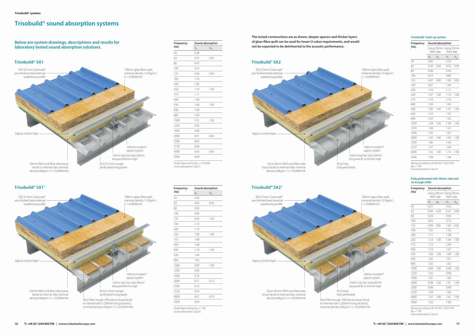
Trisobuild® SA2
Trisobuild® SA2+
R32 0.7mm Colorcoat®pre-finished steel external
weathering profile
50 or 30mm RW3 rock fibre slab tissue faced to internal side, nominal
density 60kg/m3, λ = 0.039W/mk
RL32 liner,fully perforated
100mm Instaloc® spacer system
1.6mm top hat stub, 60mm long and 85 or 65mm high
Vapour control layer
100mm glass fibre quilt, nominal density 12.5kg/m3, λ = 0.040W/mk
R32 0.7mm Colorcoat®
pre-finished steel external weathering profile
50 or 30 mm RW3 rock fibre slab tissue faced to internal side, nominal
density 60kg/m3, λ = 0.039W/mk
RL32 liner,fully perforated
100mm Instaloc® spacer system
1.6mm top hat stub, 60mm long and 85 or 65mm high
Vapour control layer
100mm glass fibre quilt, nominal density 12.5kg/m3, λ = 0.040W/mk
Rock fibre trough infill pieces tissue faced to internal side (1,200mm long sections), nominal density 45kg/m3, λ = 0.035W/mk)
17
Frequency
Fully perforated with 30mm slab andno trough infills
(Hz)Sound absorption
αs
Using 30mmRW3 slab
Using 50mmRW3 slab
αp
50 0.21
63 0.40 0.40
80 0.34
100 0.63
125 0.89 0.95
160 1.05
200 1.11
250 1.10 1.00
315 1.13
400 1.10
500 1.09 1.00
630 1.05
800 1.02
1000 0.99 1.00
1250 1.02
1600 1.01
2000 0.98 1.00
2500 0.98
3150 1.04
4000 1.01 1.00
αp
0.30
0.85
1.00
1.00
1.00
1.00
1.00
5000 1.02
αs
0.33
0.47
0.46
0.73
1.03
1.05
1.09
1.04
1.09
1.07
1.00
1.01
1.02
0.98
0.98
1.04
1.01
0.98
1.00
1.01
1.00
Rating according to BS EN ISO 11654:1997 αw = 1.00Sound absorption Class A.
Frequency
Trisobuild® built-up system
(Hz)Sound absorption
αs
Using 30mmRW3 slab
Using 50mmRW3 slab
αp
50 0.30
63 0.49 0.45
80 0.46
100 0.72
125 0.97 0.95
160 0.97
200 1.16
250 1.07 1.00
315 1.10
400 1.09
500 1.05 1.00
630 1.10
800 1.02
1000 1.04 1.00
1250 1.08
1600 1.05
2000 1.05 1.00
2500 1.06
3150 1.07
4000 1.02 1.00
αp
0.40
0.90
1.00
1.00
1.00
1.00
1.00
5000 1.08
αs
0.37
0.53
0.46
0.84
1.00
1.05
1.11
1.13
1.10
1.09
1.01
1.07
1.02
1.06
1.07
1.07
1.05
1.06
1.09
1.10
1.06
Rating according to BS EN ISO 11654:1997 αw = 1.00Sound absorption Class A.
The tested constructions are as drawn, deeper spacers and thicker layers of glass fibre quilt can be used for lower U-value requirements, and would not be expected to be detrimental to the acoustic performance.
T: +44 (0) 1244 892199 | www.tatasteeleurope.com16
Trisobuild® SA1
Trisobuild® SA1+
Trisobuild® sound absorption systems
Below are system drawings, descriptions and results for laboratory tested sound absorption solutions.
Frequency (Hz)
Sound absorptionαs αp
50 0.28
63 0.57 0.45
80 0.47
100 0.74
125 0.94 0.95
160 1.10
200 1.06
250 1.24 1.00
315 1.11
400 1.06
500 1.09 1.00
630 1.09
800 1.09
1000 1.01 1.00
1250 0.83
1600 0.68
2000 0.61 0.65
2500 0.63
3150 0.66
4000 0.63 0.65
5000 0.69
Single figure rating: αw = 0.75(LM), Sound absorption Class C.
Frequency (Hz)
Sound absorptionαs αp
50 0.26
63 0.65 0.50
80 0.59
100 0.90
125 0.93 1.00
160 1.12
200 1.14
250 1.00 1.00
315 1.08
400 1.08
500 1.10 1.00
630 1.09
800 1.05
1000 0.99 1.00
1250 0.90
1600 0.76
2000 0.71 0.75
2500 0.72
3150 0.74
4000 0.67 0.70
5000 0.69
Single figure rating: αw = 1.00, Sound absorption Class B.
Trisobuild® systems
T: +44 (0) 1244 892199 | wwww.tatasteeleurope.com
R32 0.7mm Colorcoat®pre-finished steel external
weathering profile
50mm RW3 rock fibre slab tissue faced to internal side, nominal
density 60kg/m3, λ = 0.039W/mk
RL32 0.7mm trough, perforated lining panel
100mm Instaloc® spacer system
1.6mm top hat stub, 60mm long and 85mm high
Vapour control layer
100mm glass fibre quilt, nominal density 12.5kg/m3, λ = 0.040W/mk
R32 0.7mm Colorcoat®
pre-finished steel external weathering profile
50mm RW3 rock fibre slab tissue faced to internal side, nominal
density 60kg/m3, λ = 0.039W/mk
RL32 0.7mm trough, perforated lining panel
100mm Instaloc® spacer system
1.6mm top hat stub, 60mm long and 85mm high
Vapour control layer
100mm glass fibre quilt, nominal density 12.5kg/m3, λ = 0.040W/mk
Rock fibre trough infill pieces tissue faced to internal side (1,200mm long sections), nominal density 45kg/m3, λ = 0.035W/mk)
Trisobuild® - Fire performance
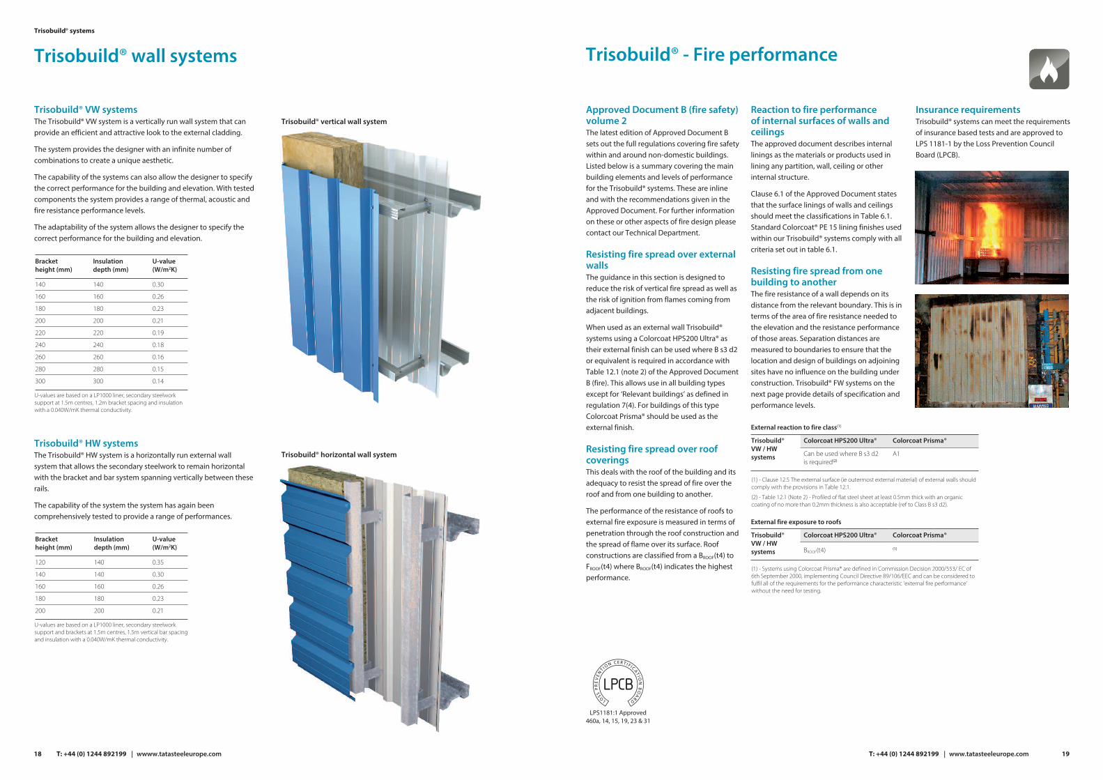
External reaction to fire class(1)
Colorcoat HPS200 Ultra®Trisobuild® VW / HW systems
Colorcoat Prisma®
Can be used where B s3 d2 is required(2)
A1
(1) - Clause 12.5 The external surface (ie outermost external material) of external walls should comply with the provisions in Table 12.1.
(2) - Table 12.1 (Note 2) - Profiled of flat steel sheet at least 0.5mm thick with an organic coating of no more than 0.2mm thickness is also acceptable (ref to Class B s3 d2).
External fire exposure to roofs
Colorcoat HPS200 Ultra®Trisobuild® VW / HW systems
Colorcoat Prisma®
BROOF(t4) (1)
(1) - Systems using Colorcoat Prisma® are defined in Commission Decision 2000/553/ EC of 6th September 2000, implementing Council Directive 89/106/EEC and can be considered to fulfil all of the requirements for the performance characteristic ‘external fire performance’ without the need for testing.
Approved Document B (fire safety) volume 2The latest edition of Approved Document B sets out the full regulations covering fire safety within and around non-domestic buildings. Listed below is a summary covering the main building elements and levels of performance for the Trisobuild® systems. These are inline and with the recommendations given in the Approved Document. For further information on these or other aspects of fire design please contact our Technical Department.
Resisting fire spread over external wallsThe guidance in this section is designed to reduce the risk of vertical fire spread as well as the risk of ignition from flames coming from adjacent buildings.
When used as an external wall Trisobuild® systems using a Colorcoat HPS200 Ultra® as their external finish can be used where B s3 d2 or equivalent is required in accordance with Table 12.1 (note 2) of the Approved Document B (fire). This allows use in all building types except for ‘Relevant buildings’ as defined in regulation 7(4). For buildings of this type Colorcoat Prisma® should be used as the external finish.
Resisting fire spread over roof coveringsThis deals with the roof of the building and its adequacy to resist the spread of fire over theroof and from one building to another.
The performance of the resistance of roofs to external fire exposure is measured in terms of penetration through the roof construction and the spread of flame over its surface. Roof constructions are classified from a BROOF(t4) to FROOF(t4) where BROOF(t4) indicates the highest performance.
Reaction to fire performance of internal surfaces of walls and ceilingsThe approved document describes internal linings as the materials or products used in lining any partition, wall, ceiling or other internal structure.
Clause 6.1 of the Approved Document states that the surface linings of walls and ceilings should meet the classifications in Table 6.1. Standard Colorcoat® PE 15 lining finishes used within our Trisobuild® systems comply with all criteria set out in table 6.1.
Resisting fire spread from one building to anotherThe fire resistance of a wall depends on its distance from the relevant boundary. This is in terms of the area of fire resistance needed to the elevation and the resistance performance of those areas. Separation distances are measured to boundaries to ensure that the location and design of buildings on adjoining sites have no influence on the building under construction. Trisobuild® FW systems on the next page provide details of specification and performance levels.
Insurance requirementsTrisobuild® systems can meet the requirements of insurance based tests and are approved to LPS 1181-1 by the Loss Prevention Council Board (LPCB).
LPS1181:1 Approved460a, 14, 15, 19, 23 & 31
19T: +44 (0) 1244 892199 | www.tatasteeleurope.com
Trisobuild® VW systemsThe Trisobuild® VW system is a vertically run wall system that can provide an efficient and attractive look to the external cladding.
The system provides the designer with an infinite number of combinations to create a unique aesthetic.
The capability of the systems can also allow the designer to specify the correct performance for the building and elevation. With tested components the system provides a range of thermal, acoustic and fire resistance performance levels.
The adaptability of the system allows the designer to specify the correct performance for the building and elevation.
Trisobuild® vertical wall system
18
Trisobuild® wall systemsTrisobuild® systems
T: +44 (0) 1244 892199 | wwww.tatasteeleurope.com
U-values are based on a LP1000 liner, secondary steelwork support at 1.5m centres, 1.2m bracket spacing and insulation with a 0.040W/mK thermal conductivity.
Bracketheight (mm)
Insulationdepth (mm)
U-value(W/m2K)
140
160
180
200
220
240
260
280
300
140
160
180
200
220
240
260
280
300
0.30
0.26
0.23
0.21
0.19
0.18
0.16
0.15
0.14
Trisobuild® HW systemsThe Trisobuild® HW system is a horizontally run external wall system that allows the secondary steelwork to remain horizontal with the bracket and bar system spanning vertically between these rails.
The capability of the system the system has again been comprehensively tested to provide a range of performances.
U-values are based on a LP1000 liner, secondary steelwork support and brackets at 1.5m centres, 1.5m vertical bar spacing and insulation with a 0.040W/mK thermal conductivity.
Bracketheight (mm)
Insulationdepth (mm)
U-value(W/m2K)
120
140
160
180
200
140
140
160
180
200
0.35
0.30
0.26
0.23
0.21
Trisobuild® horizontal wall system

21
Trisobuild® horizontal fire wall systems
Vertical sections
Trisobuild® FW30H
Trisobuild® FW15H
Trisobuild® FW60H
160mm of glass fibre quilt, nominal density 12.5kg/m3 (max. λ = 0.040W/mK)
Tata Steel internal liner profile
The fire performance does not require side stitching to the external lap - See note on aesthetics on page 46
160mm of stone fibre quilt, nominal density 24kg/m3 (max. λ = 0.040W/mK)
Tata Steel internal liner profile
The fire performance does not require side stitching to the external lap - See note on aesthetics on page 46
200mm of stone fibre quilt, nominal density 24kg/m3 (max. λ = 0.040W/mK)
Tata Steel internal liner profile
The fire performance does not require side stitching to the external lap - See note on aesthetics on page 46
Integrity Insulation
240 minutes 15 minutes
Integrity Insulation
240 minutes 30 minutes
Integrity Insulation
240 minutes
All fire wall systems have a maximum span between supports of 2m.
60 minutes
T: +44 (0) 1244 892199 | www.tatasteeleurope.com
15
30
60
Minimum 140mmPlatinum® Plus approvedspacer system
Minimum 180mmPlatinum® Plus approvedspacer system
Minimum 140mmPlatinum® Plus approvedspacer system
20
Trisobuild® vertical fire wall systems
Trisobuild® FW30V
Trisobuild® FW15V SA
Trisobuild® FW60V
150mm stone fibrequilt, nominal density 24kg/m3
Tata Steel external profile, side laps to be stitched at 450mm centres
30mm RW5 Rockwool slab tissuefaced to internal side, nominal density 100kg/m3
RL32 0.7mm steel troughperforated lining panel
Minimum 140mmInstaloc® Plus spacer system
The fire performance does not require side stitching to the external lap - See note on aesthetics on page 46
Tata Steel internal liner profile
160mm of glass fibre quilt, nominal density12.5kg/m3 (max. λ = 0.040W/mK)
Minimum 180mmInstaloc® Plus spacer system
The fire performance does not require side stitching to the external lap - See note on aesthetics on page 46
Tata Steel internal liner profile
200mm of stone fibre quilt, nominal density 24kg/m3 (max. λ = 0.040W/mK)
15
30
60
Integrity Insulation
240 minutes 15 minutes
Integrity Insulation
240 minutes 30 minutes
Integrity Insulation
240 minutes 60 minutes
Trisobuild® systems
Vertical sections
T: +44 (0) 1244 892199 | wwww.tatasteeleurope.com
All fire wall systems have a maximum span between supports of 2m.
Vapour control layer
1.6mm top hat stub, 60mm long and 60mm high
Minimum 150mmInstaloc® Plus spacer system

23T: +44 (0) 1244 892199 | www.tatasteeleurope.com
Trisobuild® systems are supplied with Colorcoat® pre-finished steel for the external and internal skin so that we can provide the very highest quality and service to our customers.
Colorcoat® products and services
Colorcoat® products and services The Colorcoat® brand provides the recognised mark of quality and metal envelope expertise exclusively from Tata Steel. For 50 years Tata Steel has developed a range of technically leading Colorcoat® pre-finished steel products which have been comprehensively tested and manufactured to the highest quality standards. Colorcoat® products manufactured in the UK are certified to BES 6001 Responsible Sourcing standard and fully REACH compliant and free of chromates, including hexavalent chrome.
Colorcoat HPS200 Ultra® Designed to withstand aggressive environments Colorcoat HPS200 Ultra® combines outstanding performance with exceptional durability to provide long-term integrity for the building envelope. Making it the first choice for aggressive internal and external applications. For more information visit www.colorcoat-online.com/ultra
Key benefits include:n 40 standard colours in solid and matt shades.
n Surpasses requirements of RUV4 and RC5 as per EN 10169 proving outstanding colour retention and corrosion resistance.
n Optimised Galvalloy® metallic coating for exceptional corrosion resistance and cut edge protection.
n Scintilla® embossed as a mark of authenticity from Tata Steel.
n Repertoire® colour matching service for solid colours with a minimum order quantity of 5000m2.
n Exceeds requirements of CPI5 as per EN 10169:2010 demonstrating excellent barrier properties when used internally.
Colorcoat Prisma® The latest generation pre-finished steel product, three layer Colorcoat Prisma® utilises cutting-edge clear coat technology to provide an optimised pre-finished steel product that pushes the boundaries of UV and corrosion performance. Enabling a wide range of contemporary aesthetic colours, that are truly built to last. For more information visit www.colorcoat-online.com/prisma
Key benefits include:n Wide range of standard colours including, natural metal colours,
metallics, matts and metallic matts.
n Surpasses requirements of RUV4 and RC5 as per EN 10169 proving outstanding colour retention and corrosion resistance.
n Optimised Galvalloy® metallic coating for ultimate corrosion resistance and cut edge performance.
n Repertoire® colour matching service for solid colours with a minimum order quantity of 5000m2.
Colorcoat® High ReflectIn addition to the standard liner, we also offer the Colorcoat® High Reflect as an option.
Key benefits include:n ≥ 85% reflectance, reducing the amount of energy required to
achieve the same level of lighting.
n Possible energy savings of up to 12% per year.
n Significantly reduces CO2 emissions by 2-3% per year, helping you to achieve compliance with tightening regulations.
Confidex® Guarantee for up to 40 yearsOffers the most comprehensive pre-finished steel guarantee for the weatherside of industrial and commercial buildings in Europe. Confidex® is project specific and upon online registration, is offered directly to the building owner with no inspection or maintenance to maintain its validity.
Can include cover for the pre-finished steel that is under photovoltaic (PV) frame modules, providing the building owner with the confidence that installing a PV array will not have a detrimental effect on the performance of the roof and that the whole roof is guaranteed to perform for the same duration of up to 40 years.
For more information about Colorcoat® products and services call the Colorcoat Connection® helpline on T: +44 (0) 1244 892434.
um
Building owner
Main contractor
Cladding contractor
System manufacturer
Confidex® provides a direct guarantee from Tata steel
Trisobuild® systems
Medium dense core (85kg/m³ rock fibre slab)
Fire insulation(minutes)
Minimum core depth (mm)
Fire integrity(minutes)
60 240 80
Minimum core depth (mm)
120
Dense core (140kg/m³ rock fibre slab)
Fire insulation(minutes)
Fire integrity(minutes)
120 120
Trinsul® system
The Trinsul® system is a site assembled composite cladding system, offering the performance of a composite panel plus the flexibility and ease of handling of standard single skin profiles.
The core of the system uses high-density rock fibre insulation, providing superb fire and acoustic properties, profiled to ensure there are no voids between the outer sheets and lining panel.
This also reduces cold bridging and makes the system highly resistant to condensation.
The Trinsul® system offers a highly consistent insulation performance and flexibility to offer a wide range of U-values.
System options The Trinsul® system is available in the following standard combinations of profile and liner, making use of standard load/span tables.
The profiled insulation core is available in medium dense and dense rock fibre.
Fire resistance Trinsul® systems offer Grade EXT-B and EXT-A60 approval by the LPCB together with approved fire resistance performance of up to 120 minutes insulation and 4 hours integrity.
The fire performance depends on the depth and density of rock fibre core selected, and is valid from either direction for all combinations of core and profile specification.
22 T: +44 (0) 1244 892199 | wwww.tatasteeleurope.com
1000 Cover width
200 Pitch 127.5 27R32 ext. profile0.7mm steel
Profiled rock fibre slab
RL32 liner panel0.7mm steel
32
Core depth
200 Pitch 127.5 27
32
U-values for R32 external profile, medium dense rock fibre slab, RL32 liner
Core thickness (mm)
Coretype
Typical U-value(W/m²K)
Systemweight(kg/m²)
93 Mediumdense
0.30 22.53
118 Mediumdense
0.25 24.90
168 Mediumdense
0.19 29.15
U-values for R32 external profile, dense rock fibre slab, RL32 liner
Core thickness (mm)
Coretype
Typical U-value(W/m²K)
Systemweight(kg/m²)
128 Dense 0.26 33.67
168 Dense 0.20 39.27
Thermal performanceThe tables below indicate the U-values when calculated at 1.8m purlin centres.
These values have been computer modelled in accordance with EN ISO 10211.
The core thickness is the distance between the bottom face of the external steel and the top face of the internal steel, as shown in the diagram opposite.
Alternative slab thicknesses and profile options are available on request.

Site guidance
This guide assumes that all current safety regulations are in place before the installers commence work.
PackagingPackaging for the Trisobuild® systems external and liner profiles use loose timber packers, with the sheets banded together. Edge protectors are used in the location of the banding to prevent edge damage. An additional sheet of the same profile is used as the top sheet of each pack, to help protect the sheets below from scratching during transportation. The sheets are supplied in a maximum pack weight of 1,500kg.
Receipt of materials on-siteAll materials arriving on-site must be checked promptly before offloading. Checks should be made against the relevant delivery notes to ensure that the correct quantities and specifications have been delivered and to determine any possible transportation damage. Any discrepancies or damage observed should be recorded immediately on the proof of delivery paperwork, and a written report should be submitted within 14 days. Please note that offloading is the customer’s responsibility.
OffloadingWherever possible, the profile packs should be offloaded directly from the vehicle to the area where they will be used to reduce the risk of on-site damage. Offloading is to be undertaken as per Tata Steel recommendations. If product is not to be installed shortly after its offload, the profile packs must be stored on level ground (in accordance with storage instructions below). Tata Steel can offer an offloading service, if requested prior to delivery.
There are two recommended methods for offloading:
n Forklift or telehandler (on-site plant): These can be used when offloading profile packs less than 6m long. Care must be taken not to tip or damage the pack when driving on uneven ground. Only one pack at a time should be unloaded. Open forks fully before lifting.
n Crane: Where slings or grabs are used, precautions should be taken to prevent edge damage and to avoid pressure across the profile width, which may cause distortion (chains should not be used). When lifting packs over 8m long, a spreader bar with sufficient hoisting belts to spread the load should be used. If required, temporary edge protection can be installed to prevent local damage. Only one pack at a time should be offloaded.
StorageIn addition to the guidelines below, the bundles should be stored on level ground eg a floor slab. The packs should be stacked no more than three packs high, supports between packs should be kept in line and be at no more than 1.25m centres. There should be adequate separation between stacks to provide access and to avoid end damage.
Storage guidelines
Do not stand uncovered stacks in the open. Store under cover and away from open doorways.
If stacks cannot be stored under cover, erect a simple scaffold around them and cover it with a waterproof sheet, tarpaulin or polythene. Leave space between the cover and stacks to allow air to circulate.
Store stacks off the ground and on a slope, so that if rain penetrates the cover, the water will drain away.
Inspect the storage site regularly to ensure that moisture has not penetrated the stack.
Do not store sheets where people will walk across them.
Pre-erection checksA secondary support structure is necessary to support the cladding system at the required positions and transfer all loads imposed on and by the cladding system back to the primary structure.
Before any work starts, a full survey or inspection should be carried out to ensure that the support steelwork and any other associated materials are in the correct positions and are within tolerance so that the Trisobuild® systems can be fixed correctly. Any obvious problems should be reported immediately to the main contractor to enable remedial work to be undertaken before installation of the cladding.
Tata Steel recommendation for the allowable variation in the top flange level of the purlin with respect to a datum line running parallel to the rafter is L/200 (where L is the purlin spacing). For wall cladding the vertical datum should be within L/400 for vertical cladding and L/600 for horizontal cladding.Further guidance on steelwork tolerance is found in the Steel Construction Institute publication P346: Best Practice for the specification in installation of metal cladding and secondary steelwork.
HandlingWhen lifting individual profiles from the pack they should be lifted vertically without sliding, to avoid the risk of surface scratching to profile face below.
Due to the lightweight nature of the individual components used within the Trisobuild® systems mechanical handling is not normally required, and profiles can be positioned manually. However extra caution should be taken when using a 0.4mm liner and lengths should be limited to 5m.
Cutting For all cuts we recommend using a nibbler. A grinding blade should not be used, as this hot cut will damage the coating. All cutting, wherever possible, should be undertaken atground level. Where it is not possible toprotect the site cut edge from weathering by a cover flashing, they should be treated with a suitable edge protection paint or lacquer.
T: +44 (0) 1244 892199 | www.tatasteeleuropecom 25
Key
Quality Assurance
ManagementTo provide the best quality service, Tata Steel is quality assured to Quality Management standard BS ISO 9001:2015. This management process puts quality at the heart of our business. Tata Steel’s culture and the employment of quality control specialists that operate and police these policies ensure consistently high standards.
EnvironmentTata Steel has a dedicated policy towards our surrounding environment, our energy use and management and control of our waste, shown and managed through our certification to the environmental standard BS EN ISO 14001:2015.
Present and future impactPart of managing risk is thinking about how a building will perform in 30 or 50 years’ time, when the unpredictability in our climate could be more extreme than it is now. Sourcing raw materials and using them responsibly is a part of designing resiliency into our built environment, protecting building users from the effects of changing climate, and reducing our impact on our surroundings.
As such our products and services have achieved certification to BES 6001, the
Responsible Sourcing Standard for construction products. We are also the world’s first steel company to be approved to operate an Environmental Product Declaration programme. This means that we are now able to provide the market with third-party verified, product-specific EPDs for our construction products and the systems they become part of. This along with BES 6001 responsible sourcing certification, assists our construction supply chains to accrue points under building certification schemes, such as LEED and BREEAM, on their projects.
CE MarkingTata Steel’s cladding profiles are fully compliant with the regulations.
The Regulations are legally binding across the European Union (EU). Roof and wall cladding sheets are covered by BS EN 14782. This ensures the performance of cladding sheets are described in accordance with defined standards to allow direct comparison.
Importance of gaugeAll the above mentioned controls over quality and material sourcing guarantee that the strength and gauge of steel supplied by Tata Steel are within the European tolerances.
The gauge of the pre-finished steel coil or sheet plays a vital role in the physical properties of the roof and wall cladding system of which it is a part. The gauge of the product can affect the safe span/load figures, the ability to resist concentrated loads, the systems non-fragility classification, visual appearance, and even the reaction to fire performance.
The actual gauge of a pre-finished steel product is measured using a micrometer and includes the steel substrate and metallic coatings, but excludes the paint and primer layers. The only accurate way to carry this out is to actually remove the paint coatings from the area to be measured, prior to measurement as shown below.
Topcoat Pre-treatment Substrate
Primer Metallic coating Backing coat
London Victoria Station
Client: Network Rail
Main contractor: May Gurney
Design engineer: WSP
Tata Steel products: Trisobuild® R46 and PM13 profiles
Colorcoat® product: Colorcoat HPS200 Ultra®
24
Trisobuild® systems
T: +44 (0) 1244 892199 | wwww.tatasteeleurope.com

27T: +44 (0) 1244 892199 | www.tatasteeleurope.com
EavesThe Cantilever Gutter system is manufactured to suit the pitch of the roof and downpipes can be positioned as required. For further information on the Cantilever Gutter system and assistance with rainflow calculations please contact the Technical Department T: +44 (0) 1244 892199E: [email protected]
Sealed rivets or self drilling fasteners with sealing washers. 3 per gutter support bracket
Gutter support bracket 1 metre spacing and either side of gutter joint
Cantilever gutter (roof pitch and external profile must be specified)
Trisobuild® roofcladding system
175 Nom
Eaves beam (by others) air sealed at joints
Vented profile filler sealed to its base with 9 x 3mm high grade butyl mastic
Self drilling self tapping primary
fastener
Trisobuild® verticalcladding system
Psi value(W/mK)
f factor
0.021 0.95
Stated calculation results are dependent on components being as shown. Computer modelled in accordance with EN ISO 10211.
The details within this section are recommendations and have been designed to give practical solutions to minimise thermal bridging and air loss at junctions. For each junction detail, Ψ values (psi) and f values have been calculated in accordance with BS EN ISO 10211.NB. All support steelwork by others.
Construction details – roof
Ridge
Sealed rivets or self drilling fasteners with sealing washers at max 450mm centres
Trisobuild®roof cladding system
Vented profile filler sealed to its base with 9 x 3mm high grade butyl mastic
Self drilling selftapping primaryfastener
0.7mm steel internal liner flashing lapped 150mm at ends and sealed on top with 50 x 1mm high grade butyl mastic (minimum 25 year guarantee)
Ridge flashing butt or lapjointed and sealed with tworuns of continuous 4mm diahigh grade butyl mastic(minimum 25 year guarantee)
RidgeFillers should be positioned back from the edge of the ridge flashing by approximately 80mm to avoid the risk of bird attack.
Psi value(W/mK)
f factor
0.001 0.98
Stated calculation results are dependent on components being as shown. Computer modelled in accordance with EN ISO 10211.
Eaves
Profile filler sealedtop and bottom
with 9 x 3mm highgrade butyl mastic
26
Trisobuild® systems
T: +44 (0) 1244 892199 | wwww.tatasteeleurope.com
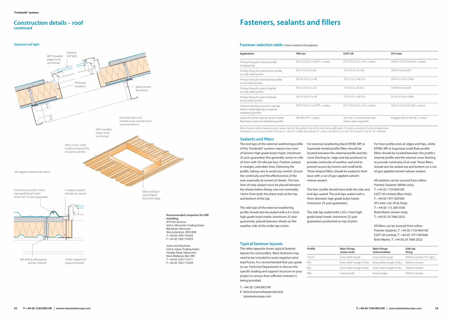
Roof installation
Start installation ofliner from rafter line
1
2
3
4
5
6
Install liner and spacer bar (1m bars) in tiers from staging platform
1
2
3
4
5
6
External sheets shouldbe laid with the exposedjoints of the side laps awayfrom the prevailing wind
Direction of prevailing wind
Working on a roof is high-risk work, which requires the closest attention to detail at all times. There should be a job specific method statement in writing, agreed and understood by all parties before the work starts. Rigorous supervision is needed to ensure that the agreed method is followed in practice. Further guidance can be found in the Advisory Committee for Roofwork ‘Orange Book’ ACR[CP]001:2007 Rev.3 ‘Recommended Practice for Work on Profiled Sheeted Roofs’.
The steps given below are instructions for a typical construction and should be used only as a guide. An extended list of construction details is available from Tata Steel, and advice can be given via our Technical Department on any bespoke details that may be required.
Carry out preparation work on internal ridge, eaves and trim flashing etc, and ensure that these are lined and levelled and sealed as specified, before starting to lay liner sheet. When lifting packs onto the roof ensure that these are placed over a rafter line and secured.
The liner sheet can be used to quickly line out part or all of the roof elevation, this operation should always start at a rafter and move into the span of the purlins, with cladding installers working off ‘Youngmans’ boards or similar staging installing one tier at a time as shown below.
The liners should be fully fixed as per the non-fragility specifications on page 11 and sealed as specified on page 34. The spacer system should also be installed during this sequence, using 1m bars again working off staging and installing a tier at a time.
It is not advised, even when fully fixed, to walk on the LP1000 0.4mm liner, due to the risk of damage. If access is required across the liner (ie, lining the whole roof before returningto install the rest of the system) then the RL32, 0.7mm walkable liner should be used. The other advantage of using this profile is that longer lengths can be used. The insulation and external sheet should be laid in sequence from one edge of the roof using the fully fixed external sheets as a working platform.
When lifting external packs onto the spacer system ensure that these are placed over a rafter line, and consult the spacer manufacturer for any additional instructions to ensure the stability of the system.
When installing the insulation ensure all edges are close butt jointed to achieve continuity between spacers. The insulation can be installed in more than one layer, if so, the joints in each layer should be offset. The quilt must be cut and tucked under the spacer bar so that there is no air gap under the bar. It is important to keep the insulation dry.
Where possible, the external sheets should be laid with the exposed joints of the side laps away from the prevailing wind unless shown otherwise on drawings. The outer sheets should be laid to the sequence shown in the diagram below, and sealed as specified on page 34. Advice should be obtained from our Technical Department on fastener layout, as this will depend on the calculated wind load for the cladding.
The contractor should ensure that all swarf and debris are removed from the surface of the external sheet as work progresses and should be inspected again after installation is completed.
29T: +44 (0) 1244 892199 | www.tatasteeleurope.com
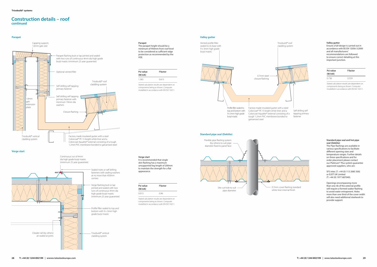
Valley gutter
Valley gutterEnsure a full design is carried out in accordance with BS EN 12056-3:2000 and all manufacturers’ recommendations are followed to ensure correct detailing at this important junction.
Factory made insulated gutter with a steel Colorcoat® PE 15 bright white liner and a Colorcoat Aquatite® external consisting of a tough 1.2mm PVC membrane bonded to galvanised steel
Trisobuild® roof cladding system
Vented profile filler sealed to its base with 9 x 3mm high grade butyl mastic
0.7mm steel closure flashing
Self drilling self tapping primary fastener
Standard pipe seal (Dektite)
Standard pipe seal and hot pipe seal (Dektite)The Pipe flashings are available in various specifications to facilitate different opening sizes and temperature ranges. Further details on these specifications and for order placement please contact our Platinum® Plus system guarantee approved suppliers, who are:
SFS intec (T: +44 (0) 113 2085 500) or EJOT UK Limited (T: +44 (0) 1977 687040).
Openings encompassing more than one rib of the external profile will require a formed soaker flashing to avoid water entrapment. Holes more than one third of the cover width will also need additional steelwork to provide support.
Flexible pipe flashing system (by others) to suit pipe
diameter fixed to panel face
Site cut hole to suit pipe diameter
0.7mm cover flashing standard white liner internal finish
Psi value(W/mK)
f factor
0.736 0.559
Stated calculation results are dependent on components being as shown. Computer modelled in accordance with EN ISO 10211.
Profile filler sealed totop and bottom with 9 x 3mm high grade butyl mastic
28
Trisobuild® systems
T: +44 (0) 1244 892199 | wwww.tatasteeleurope.com
Parapet
ParapetThe parapet height should be a minimum of 950mm from roof level to be considered as sufficient edge protection as recommended by the HSE.
Parapet flashing butt or lap jointed and sealed with two runs of continuous 4mm dia high grade butyl mastic (minimum 25 year guarantee)
Optional vented filler
Capping support, 1.6mm galv zed
Factory made insulated gutter with a steel Colorcoat® PE 15 bright white liner and a Colorcoat Aquatite® external consisting of a tough 1.2mm PVC membrane bonded to galvanised steel
Trisobuild® roofcladding system
Closure flashing
Self drilling self tapping primary fastener
Self drilling self tapping primary fastener with minimum 19mm dia washers
Trisobuild® verticalcladding system
1.6mm galv extension plate
Psi value(W/mK)
f factor
1.365 0.615
Stated calculation results are dependent on components being as shown. Computer modelled in accordance with EN ISO 10211.
Psi value(W/mK)
f factor
0.013 0.96
Stated calculation results are dependent on components being as shown. Computer modelled in accordance with EN ISO 10211.
Verge start
Verge flashing butt or lap jointed and sealed with two runs of continuous 4mm dia high grade butyl mastic (minimum 25 year guarantee)
Sealed rivets or self drilling fasteners with sealing washers at no more than 450mm centres
Profile filler sealed to top and bottom with 9 x 3mm high grade butyl mastic
Trisobuild® verticalcladding system
Cleader rail (by others) air sealed at joints
Continuous run of 4mm dia high grade butyl mastic (minimum 25 year guarantee)
Verge startIt is recommended that single skin flashing has a maximum unsupported leg length of 200mm to maintain the strength for a flat appearance.
Construction details – roofcontinued

51XA
M°
Latchways constant force post 333x400mm
Mansafe componentry
Latchways stitching screw x 16 No.
FORCECONSTANT
R32 external roof sheet shown. Details to suit all other external profiles are available on request
Constant force posts fixed down in accordance with latchways data sheet 65602-current
Latchways sealing tape x 4 per post
FORCECONSTANT
Roof to wall junction
Roof to wall junctionEnsure that the insulation runs continuously between the roof and wall junction to avoid cold bridging so that the low psi and f values shown in the box above are achieved.
Apron flashing butt or lap jointed and sealed with two runs of continuous 4mm dia high grade butyl mastic (minimum 25 year guarantee)
Sealed rivets or self drilling fasteners with sealing washers at max 450mm centres
Trisobuild® roof cladding system
Profile filler sealed top and bottom with 9 x 3mm high grade butyl mastic
0.7mm steel internal liner flashing lapped 150mm at ends and sealed on top with 50 x 1mm high grade butyl mastic (minimum 25 year guarantee)
Optional vented profile filler
Roof safety system
Roof safety systemThe detail shown indicates a MSA Latchways system, with the Sotersystem also available from QBM. These systems will require specialist roof layout design and installation, together with a maintenance and inspection program. Therefore Tata Steel recommend that this specialist advice be obtained from one of two companies below.
MSA LatchwaysT: +44 (0) 1380 732700E: [email protected]
SFS (Soter™ II Horizontal Lifeline system)T: +44 (0) 113 2085 500E: [email protected]
Psi value(W/mK)
f factor
0.019 0.975
Stated calculation results are dependant on components being as shown. Computer modelled in accordance with EN ISO 10211.
31T: +44 (0) 1244 892199 | www.tatasteeleurope.com
Vented profile filler
Vented profile filler
Self drilling selftapping primaryfastener
Gun applied sealant (optional)
Insulating core panel ends should be sealed on top with 50 x 1mm high grade butyl mastic (minimum 25 year guarantee)
1 continuous run of Ø 4mm high grade butyl mastic (minimum 25year guarantee) in a straight unbroken line placed into troughs do not allow to stretch or to sag
Two runs of 6x5mmhigh grade butyl mastic (minimum 25 year guarantee)
Gun gradesealant
10
Roof light side lap
Roof light end lap
Roof light side lapIn order to achieve a 2.2W/m2K,U-value and comply with the current building regulations for heated buildings a minimum of a triple skin roof light construction should be specified. These triple skin constructions from our approved suppliers (see below for details) provide U-values between 1.9 and 0.9W/m2K.
The roof light liner should be side lapped over the adjacent metal liners on both sides and the side lap joints sealed as shown.
The internal core layer can be laid in place after the liner has been fixed and sealed, and positioned so that it is in contact with the overlapping profile crowns and simply secured with the 50mm film backed butyl tape along each side lap.
Roof light end lapLiner end laps should be located directly above a purlin and be a minimum of 100mm. The edges of any sheet in the joint should be minimum of 50mm from the fixing line.
The butyl seals at the end lap position are to be positioned in straight unbroken lines and placed into troughs without allowing the sealant to stretch or sag.
Please refer to manufacturer's information for further details on durability, fragility and fire performance.
Brett Martin Daylight Systems LimitedT: +44 (0) 24 7660 2022E: [email protected]
Filon Products Limited
Hambleside DanelawT: +44 (0) 1327 701 900E: [email protected]
T: +44 (0) 1543 687 300E: [email protected]
Side lap stitching screw at 450mm max centres where rooflight overlaps metal sheet. On exposed sites and roof pitches below 10˚reduce centres to 300mm
0.7mm steel closure flashing
Insulating core panel ends should be sealed on top with 50 x 1mm highgrade butyl mastic (minimum 25 year guarantee)
Self drilling self tappingprimary fasteners
Self drilling self tapping primary fastener with minimum 29mm dia washers (minimum of 5 per sheet per support)
Grommet type stitch bolts at maximum
450mm centres
Maximum 200
Continuous run of 6 x 5mm high grade butyl mastic
(minimum 25 year guarantee)
30
Trisobuild® systems
T: +44 (0) 1244 892199 | wwww.tatasteeleurope.com
Construction details – roofcontinued
Fasteners, sealants and fillers
Fastener selection table (15mm washers throughout)
Application EJOT UK SFS intec
Primary fixing for external profileto spacer bar
CF19-JT3-3-5.5 x 25 + colour SX3/9-L12-S19-6.0x29 + colour
Primary fixing for internal liner profileto cold rolled purlins
JT3-3-5.5 x 25 S16 SX3/9-S16-6.0x29
Primary fixing for internal liner profileto hot rolled purlins
JT3-12-5.5 x 40 S16 SX14/12-S16-5,5X40
Primary fixing for spacer bracketto cold rolled purlins
JT3-3-5.5 x 35 S16 SX3/9-S16-6.0x29
Primary fixing for spacer bracketto hot rolled purlins
JT3-12-5.5 x 40 S16 SX14/12-S16-5.5x40
External stitching screw for side-lap and/or metal flashing to external weathering profile
CF15-JT3-2-5.5 x 25 + colour SL2-S-L12-S16-6.3x28 + colour
External rivet for side-lap and/or metal flashing to external weathering profile
ALV 4.8 x 15 aluminium rivet (state colour required)
PMJ-tec
SH LS S19 5.5 x 28 PP + colour
SH LS S16 5.5 x 25
SH HS S16 5.5 x 40
SH LS S16 5.5 x 28
SH HS S16 5.5 x 40
SH ST S16 5.5 x 22 PP + colour
RIV 0619 PP + colour Polygrip-ASO-D-48100 + colour
When fixing to timber, fastener pullout values may limit the ability of the roof to resist wind uplift loads. If in doubt, consult the Technical Department. All fasteners can be sourced from SFS intec (T: +44 (0) 113 2085 500), PMJ-tec (T: +44 (0) 1451 822777), or EJOT UK Limited (T: +44 (0) 1977 687040).
Sealants and fillersThe end laps of the external weathering profileof the Trisobuild® systems require two rowsof 6x5mm high grade butyl mastic (minimum 25 year guarantee) this generally comes in rolls of 9.6m with 30 rolls per box. Position sealant in straight, unbroken lines, following the profile, taking care to avoid any stretch. Ensure the continuity and the effectiveness of the seal, especially at corners of sheets. The two lines of strip sealant must be placed between the sheets before fixing: one row nominally 10mm from both the sheet ends at the top and bottom of the lap.
The side laps of the external weathering profile should also be sealed with a 6 x 5mm high grade butyl mastic (minimum 25 year guarantee), placed between sheets on the weather side of the under lap crown.
Typical fastener layoutsThe table opposite shows typical fastener layouts for roof profiles. More fasteners may need to be included to resist negative wind load forces. It is recommended that you speak to our Technical Department to discuss the specific loading and support structure on your project to ensure that sufficient restraint is being provided.
T: +44 (0) 1244 892199E: technical.envelopeproducts@
tatasteeleurope.com
For external weathering black EPDM, MP or Superseal vented profile fillers should be located between the external profile and the cover flashing (ie, ridge and hip positions) to provide continuity of weather seal and to prevent access by insects and small birds. These shaped fillers should be sealed to their base with a run of gun-applied solvent-release sealant.
The liner profile should have both the side andend laps sealed. The end laps sealed with a4mm diameter high grade butyl mastic (minimum 25 year guarantee).
The side lap sealed with a 50 x 1mm high grade butyl mastic (minimum 25 year guarantee) positioned on top of joint.
For liner profile ends at ridges and hips, white EPDM, MP or Superseal small-flute-profile fillers should be located between the profile's internal profile and the internal cover flashing to provide continuity of air seal. These fillers should also be sealed top and bottom on a run of gun-applied solvent-release sealant.
All sealants can be sourced from either:Premier Sealants (White strip),T: +44 (0) 1724 864100EJOT UK Limited (Blue Strip).T: +44 (0) 1977 687040SFS intec Ltd, (Pink Strip).T: +44 (0) 113 208 5500Brett Martin (Green strip), T: +44 (0) 24 7660 2022
All fillers can be sourced from either:Premier Sealants, T: +44 (0) 1724 864100EJOT UK Limited, T: +44 (0) 1977 687040 Brett Martin, T: +44 (0) 24 7660 2022
Profile
13½/3
Main fixings(sheet ends)
Every third trough
Main fixings(intermediate)
Side lapfixing
Every third trough 450mm centres (1½ laps)
R32 Every other trough (5 No.) Every other trough (3 No.) 450mm centres
R35 Every other trough (6 No.) Every other trough (4 No.) 450mm centres
R46 Every trough Every trough 450mm centres
33T: +44 (0) 1244 892199 | www.tatasteeleurope.com32
Trisobuild® systems
T: +44 (0) 1244 892199 | wwww.tatasteeleurope.com
Upstand roof light
GRP mouldedsoaker to besite formed
Upstandroof light
Note: Roof light to beinstalled as per manufacturer’srecommendations
PIR boardinsulation
Self drilling self tapping primary fastener
Timber support for support brackets
L shaped support brackets at corners
Continuous run of 6 x 5mmhigh grade butyl mastic(minimum 25 year guarantee)
Steel trimmer(by others)
Note: correct, width,length and upstand lipshould be specified
All support steelwork by others
Sides and back raised higher than front edge
Recommended companies for GRP mouldingM R Site ServicesUnit 6, Worcester Trading EstateBlackpole, WorcesterWorcestershire, WR3 8HRT: +44 (0) 1905 755055F: +44 (0) 1905 755053
Jones and WoolmanUnit 6, Hayes Trading EstateHingley Road, HalesowenWest Midlands, B63 2RRT: +44 (0) 1922 712111F: +44 (0) 1922 712539
GRP mouldedsoaker to besite formed
Construction details – roofcontinued

35T: +44 (0) 1244 892199 | www.tatasteeleurope.com
The steps given below are instructions for a typical construction and should be used only as a guide. Specific technical details, method statements and site-specific risk assessments should be produced and applied for each building. An extended list of construction details is available from Tata Steel, and advice can be given via our Technical Department on any bespoke details that may be required.
Firstly checks should be carried out to make sure that all rails are adequately supported and level along their full length, before commencing installation work. If this is satisfactory, carry out preparation work on cill trims and internal corner flashing etc. and ensure these are lined, levelled and sealed as specified.
Install the liner sheets in tiers over part or all of the elevation, ensuring alignment and cover is maintained. Seal liner laps as shown on page 46.
Lie out the Instaloc® Plus spacer system on the floor using 3m or 3.6m bars and ensure bracketsare positioned at specified centres and adjacentto liner troughs. Install the Instaloc® Plus spacersystem along the rail line ensuring level is maintained.
The insulation and external sheet should be laid in sequence from one corner of the building elevation so that wherever possible the exposed joints of the side laps are away from the prevailing wind. The sheeting should be installed in the sequence shown below.
Before installing the insulation, ‘stick pins’ should be positioned to the liner face at mid span, and then the insulation should be draped from the eaves and tucked behind the horizontal spacer system and over the ‘stick pins’ so that it is held in place. Each tier of insulation should be compressed tightly with the previously one to make certain there are no gaps. If there are two layers of insulation; the joints in each layer should be offset.
The end and side laps of the external sheet should be sealed as specified on page 46. Advice should be obtained from our Technical Department on fastener frequency, as this will depend on the calculated wind load for the cladding.
Direction ofprevailing wind
Exposed joints of theside laps are away fromthe prevailing wind
1 3 5
4 6 2
Vertical wall installation
Trisobuild® VW vertical wall system
Instaloc® Plus spacer system
Tata Steel external wall profiles.
Colorcoat Prisma® or Colorcoat HPS200 Ultra® pre-finished steel
Trisobuild® - LP1000, 0.4mm liner.
Colorcoat® PE 15 or Colorcoat® High Reflect pre-finished steel
Help with specification creation:For information and help on creating your Platinum® Plus tailored specification please contact: T: +44 (0) 1244 892199 E: technical.envelopeproducts@tatasteeleurope.comwww.tatasteelconstruction.com/speccreator
Internal side lap A continuous run of 50 x 1mm high grade butyl mastic (minimum25 year guarantee), positioned on top of the lap as shown
External side lapA continuous run of 6 x 5mm high grade butyl mastic (minimum 25 year guarantee),positioned weather sideof the stitching fastener
Stitching fastener at a maximum of 450mmcentres for roofapplications and600mm centres forwall applications
External end lap150mm min end lap with central fixing
One continuous runof 6 x 5mm high grade butyl mastic (minimum 25 yearguarantee)
1575
75
Internal end lap60mm min end lap with central fixing
One continuous run of 4mm diameter bead of high grade butyl mastic (minimum 25 yearguarantee)
30 30
External End Lap
Internal End Lap
External Side Lap
Internal Side Lap
Fasteners, sealants and fillers
34
Trisobuild® systems
T: +44 (0) 1244 892199 | wwww.tatasteeleurope.com
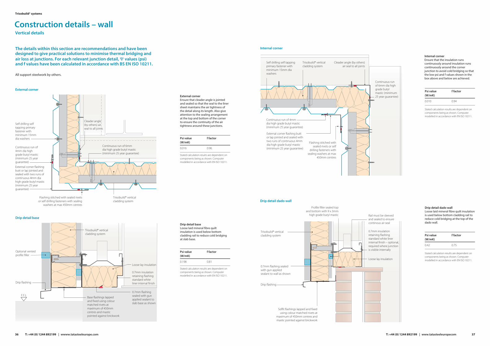
Internal corner
Drip detail dado wall
Drip detail dado wallLoose laid mineral fibre quilt insulation is used below bottom cladding rail to reduce cold bridging at the top of the dado wall.
Cleader angle (by others) air seal to all joints
Self drilling self tapping primary fastener with minimum 15mm dia washers
Continuous run of 6mm dia high grade butyl mastic (minimum 25 year guarantee)
Continuous run of 4mm dia high grade butyl mastic (minimum 25 year guarantee)
Trisobuild® verticalcladding system
External corner flashing buttor lap jointed and sealed withtwo runs of continuous 4mmdia high grade butyl mastic (minimum 25 year guarantee)
Flashing stitched with sealed rivets or self
drilling fasteners with sealing washers at max
450mm centres
0.7mm flashing sealed with gun applied sealant to wall as shown
Drip flashing
Soffit flashings lapped and fixed using colour matched rivets at
maximum of 450mm centres and mastic pointed against brickwork
Trisobuild® vertical cladding system
Profile filler sealed topand bottom with 9 x 3mm
high grade butyl mastic
0.7mm insulation retaining flashing standard white liner internal finish – optional, required where junction is visible internally
Loose lay insulation
Rail must be sleeved and sealed to ensure continous air seal
Psi value(W/mK)
f factor
0.010 0.94
Stated calculation results are dependent on components being as shown. Computer modelled in accordance with EN ISO 10211.
Psi value(W/mK)
f factor
0.42 0.75
Stated calculation results are dependent on components being as shown. Computer modelled in accordance with EN ISO 10211.
37T: +44 (0) 1244 892199 | www.tatasteeleuropecom
Ensure that the insulation runs continuously around insulation runs continuously around the corner junction to avoid cold bridging so that the low psi and f values shown in the box above and below are achieved.
Internal corner
Construction details – wall
External corner Ensure that cleader angle is jointed and sealed so that the seal to the liner sheet maintains the air tightness of the detail along its length. Also give attention to the sealing arrangement at the top and bottom of the corner to ensure the continuity of the air tightness around these junctions.
Drip detail base
Drip detail baseLoose laid mineral fibre quilt insulation is used below bottom cladding rail to reduce cold bridging at slab base.
The details within this section are recommendations and have been designed to give practical solutions to minimise thermal bridging and air loss at junctions. For each relevant junction detail, Ψ values (psi) and f values have been calculated in accordance with BS EN ISO 10211.
Self drilling self tapping primary fastener with minimum 15mm dia washers
Flashing stitched with sealed rivets or self drilling fasteners with sealing
washers at max 450mm centres
Continuous run of 4mm dia high grade butyl mastic (minimum 25 year guarantee)
Continuous run of 6mm dia high grade butyl mastic (minimum 25 year guarantee)
Trisobuild® verticalcladding system
External corner flashing butt or lap jointed and sealed with two runs of continuous 4mm dia high grade butyl mastic (minimum 25 year guarantee)
Cleader angle (by others) air seal to all joints
Drip flashing
0.7mm insulation retaining flashing standard white liner internal finish
Loose lay insulation
F.F.L
Trisobuild® verticalcladding system
Base flashings lappedand fixed using colour matched rivets at maximum of 450mm centres and mastic pointed against brickwork
0.7mm flashing sealed with gun applied sealant to slab base as shown
Optional vented profile filler
Vertical details
Psi value(W/mK)
f factor
0.016 0.96
Stated calculation results are dependent on components being as shown. Computer modelled in accordance with EN ISO 10211.
Psi value(W/mK)
f factor
0.198 0.81
Stated calculation results are dependent on components being as shown. Computer modelled in accordance with EN ISO 10211.
36
Trisobuild® systems
T: +44 (0) 1244 892199 | wwww.tatasteeleurope.com
External corner
All support steelwork by others.

Vertical to horizontal break
Brick wall abutment
Vertical to horizontal breakHorizontal and vertical profiles can be installed adjacent to each other creating interesting architectural features, while the drip flashing detail still maintains thermal performance and an efficient weather seal.
Brick wall abutmentMasonry fasteners to be stainless steel to maintain the durability of the system.
Drip flashing stitched withsealed rivets or self drillingfasteners with sealing washersat max 450mm centres
Connector
Trisobuild® horizontalcladding system
A continuous run of 9 x 3mmdiameter high grade butyl mastic(minimum 25 year guarantee)between panel and support angle
Trisobuild® verticalcladding system
1.6mm galvanisedsupport angle
Optional vented profile filler
Self drilling self tappingprimary fastener
Closure flashing butt or lap jointed and sealedwith two runs of continuous 4mm diameter highgrade butyl mastic (minimum 25 year guarantee)
All support steelworkby others
Continuous run of 4mmdiameter high grade butylmastic (25 year guarantee)
Sealed rivets or self drillingfasteners with sealing washersat no more than 450mm centres
Trisobuild® verticalcladding system
0.7mm steel internal liner flashinglapped 150mm at ends and sealed on
top with 50 x 1mm high grade butylmastic (minimum 25 year guarantee)
Cleader angle (by others)air sealed at joints
Psi value(W/mK)
f factor
0.010 0.94
Stated calculation results are dependent on components being as shown. Computer modelled in accordance with EN ISO 10211.
Internalflashingsealedto wall
39T: +44 (0) 1244 892199 | www.tatasteeleurope.com
Continuous run of 6mm diahigh grade butyl mastic
(minimum 25 year guarantee)
Seal against wall withbacking rod and gunmastic
Window head/sill
Window head/sillThis window flashing detail has been designed so that it can accommodate any proprietary window. The window should be installed as per manufacturer's recommendations.
Window head
Psi value(W/mK)
f factor
0.070 0.96
Stated calculation results are dependent on components being as shown. Computer modelled in accordance with EN ISO 10211.
Window sill
Psi value(W/mK)
f factor
0.030 0.96
Stated calculation results are dependent on components being as shown. Computer modelled in accordance with EN ISO 10211.
Window jamb
Window opening
Internal jamb flashing.No connection to external flashing
Jamb steelworkby others
Loose lay insulationsite applied
25mm thickPIR insulation
Optional site applied cover
flashing
Head flashing stitchedat 450mm centres to external flashing
Continuous run of 4mm dia high grade butyl mastic (minimum 25 year guarantee)
External soffit flashing.No connection tointernal flashing
Polyethylene backing rod and silicone sealant by others
25mm thick PIR insulation
External cill flashing.No connection to internal flashing
Min 3 deg fall for drainage
Window frame and frame fixing arrangement by others
Loose lay insulation
Window support rail
Internal head flashing. No connection to external flashing
Internal cill flashings.No connection toexternal cill flashing
Ope
ning
size
to su
it pa
nel m
odul
e
Window jambTrimming steelwork around the opening is required to support the window independent to the panels.
Psi value(W/mK)
f factor
0.030 0.96
Stated calculation results are dependent on components being as shown. Computer modelled in accordance with EN ISO 10211.
Continuous run of 4mm diameter high grade butyl mastic(minimum 25 year guarantee)
External jambflashing. No
connection toinner flashing
Continuous run of 4mm diameter high grade butyl mastic(minimum 25 year guarantee)
38
Trisobuild® systems
T: +44 (0) 1244 892199 | wwww.tatasteeleurope.com
Optional vented profile filler
Optional vented profile filler
Construction details – wallVertical details continued

41T: +44 (0) 1244 892199 | www.tatasteeleurope.com
Sealed rivets or self drillingfasteners with sealing washersat max 450mm centres
Trisobuild® horizontalcladding system
Cleader angle (by other) air seal to all joints
Inner seal is a continuous run of6mm dia high grade butyl mastic(minimum 25 year guarantee)
Vented profile filler sealed to its base with 9 x 3mm high grade butyl strip sealant
External corner flashingbutt or lap jointed andsealed with two runs ofcontinuous 9 x 3mm diahigh grade butyl mastic(minimum 25 year guarantee)
External corner flashing butt or lapjointed and sealed with two runs ofcontinuous 9 x 3mm dia high grade butylmastic (minimum 25 year guarantee)
Inner seal is a continuous run of6mm dia high grade butyl mastic
(minimum 25 year guarantee)
Cleader angle (by other)air sealed at joints
Trisobuild® horizontalcladding system
Vented profile filler sealed to its base with 9 x 3mm high grade butyl stripsealant
0.7mm steel internal liner flashing lapped150mm at endsand sealed on topwith 50 x 1mm highgrade butyl mastic(minimum 25year guarantee)
Sealed rivets or selfdrilling fasteners with
sealing washers at max450mm centres
Internal corner
External cornerEnsure that cleader angle is jointed and sealed so that the seal to the liner sheet maintains the air tightness of the detail along its length. Also give attention to the sealing arrangement at the top and bottom of the corner to ensure the continuity of the air tightness around these junctions.
Internal cornerIn addition and also related to the above detail, ensure that the insulation runs continuously around the corner junction to avoid cold bridging so that the low psi and f values shown in the box above and below are achieved.
External corner
Psi value(W/mK)
f factor
0.016 0.96
Stated calculation results are dependent on components being as shown. Computer modelled in accordance with EN ISO 10211.
Psi value(W/mK)
f factor
0.002 0.975
Stated calculation results are dependent on components being as shown. Computer modelled in accordance with EN ISO 10211.
Construction details – wallHorizontal details
All support steelworkby others
All support steelworkby others
40 T: +44 (0) 1244 892199 | wwww.tatasteeleurope.com
Horizontal wall installation
The following guidance assumes a regular horizontal cladding rail arrangement with a vertical liner and vertical Platinum® Plusapproved spacer system . The steps given below are instructions for a typical construction and should be used only as a guide. Specific technical details, method statements and site-specific risk assessments should be produced and applied for each building. An extended list of construction details is available from Tata Steel, and advice can be given via our Technical Department on any bespoke details that may be required.
Firstly checks should be carried out to make sure that the base rail is adequately supported and level along its full length and that the flanges of all rails are within the specified vertical datum tolerance. If satisfactory carry out preparation work on cill trims and internal corner flashing etc. and ensure these are lined, levelled and sealed as specified.
Install vertical liner in tiers over part or all of the elevation, ensuring alignment and cover is maintained. Seal liner laps as shown onpage 46.
Install and align the vertical HW Instaloc® system by positioning the spacer brackets at secondary rail positions and running over the brackets and securing using fasteners either side of the rail. Ensure that the spacing and fastener frequency is to the specification and has been checked for design loadings.
The insulation and external sheet should be laid in sequence from the base of the elevation to the eaves in rows the full length
of the elevation. This sequence will ensure the correct lapping arrangement and maintain profile alignment. When 3 metres off floor level it may be more efficient to continue in tiers with a platform lift, if this is preferred, make sure subsequent tiers are aligned and top corner of the sheet is lapped correctly with previous tier (ie as if you were cladding in rows).
Before installing the insulation, ‘stick pins’ should be positioned to the liner face at mid span between vertical rails, and then the insulation should be run horizontally and tucked behind the vertical spacer system and over the ‘stick pins’ so that it is held in place.
Each row of insulation should be compressed tightly with the previously row to make certain there are no gaps. If there are two layers of insulation; the joints in each layer should be offset.
The end and side laps of the external sheet should be sealed as specified on page 46. Advice should be obtained from our Technical Department on fastener frequency, as this will depend on the calculated wind load for the cladding.
The contractor should ensure that any swarf or debris that have fallen onto the ledges of the profile ribs are removed on final inspection.
2
4
6
3
5
1
Direction of prevailing wind
Instaloc® Plus HW Spacer Bar
Instaloc® Plus HW
Trisobuild® systems
Trisobuild® HW horizontal wall system
Tata Steel external horizontal wall profiles.
Colorcoat Prisma® or Colorcoat HPS200 Ultra® pre-finished steel
Trisobuild® - LP1000, 0.4mm liner.
Colorcoat® PE 15 or Colorcoat® High Reflect pre-finished steel
Help with specification creation:For information and help on creating your Platinum® Plus tailored specification please contact: T: +44 (0) 1244 892199 E: technical.envelopeproducts@tatasteeleurope.comwww.tatasteelconstruction.com/speccreator

43T: +44 (0) 1244 892199 | www.tatasteeleurope.com
Window/door head
Window/door jamb
Window/door jambTrimming steelwork around the opening is required to support the window or door independent to the panels.
Loose lay insulation
External soffit flashing.No connection to internal flashing
External sill flashing.No connection to
internal flashing
Optional internal head flashing. No connection to external flashing
Internal cill flashings. No connection to external flashing
25mm thickPIR Insulation
Min 3 degreefall for drainage
25mm thick insulation board
Optional site appliedcover flashing
Loose lay insulationsite applied
External jamb flashing.No connection to
inner flashing
Vented profile filler sealed toits base with 9 x 3mm highgrade butyl strip sealant
Vented profile filler sealed toits base with 9 x 3mm high
grade butyl strip sealant
Window opening
NOTE: Window tobe installed as per
manufacturersrecommendations
25mm thickInsulation board
Internal jamb flashing. Noconnection to external flashing
Window/door headThis window flashing detail has been designed so that it can accommodate any proprietary window. The window should be installed as per manufacturer's recommendations.
Psi value(W/mK)
f factor
0.070 0.580
Stated calculation results are dependent on components being as shown. Computer modelled in accordance with EN ISO 10211.
Window sill
Psi value(W/mK)
f factor
0.580 0.960
Stated calculation results are dependent on components being as shown. Computer modelled in accordance with EN ISO 10211.
Slab base drip
Dado wall drip
Slab base dripLoose laid mineral fibre quilt insulation is used below bottom cladding rail to reduce cold bridging at slab base.
Dado wall dripLoose laid mineral fibre quilt insulation is used below bottom cladding rail to reduce cold bridging at the top of the dado wall.
0.7mm insulation retaining flashing standard white liner internal finish - Optional, required where junction is visible internally
0.7mm flashing sealed with gun applied sealant to slab base as shown
Soffit flashings lapped and fixedusing colour matched rivets at
maximum of 450mm centres
Self drilling self tapping primary fastener with minimum 15mm diawashers Loose lay
insulation
Drip flashing
F.F.L
Profile filler sealed top and bottom with 9 x 3mm high grade butyl stripsealant
0.7mm flashing sealed with gun applied butyl sealant to wall as shown
0.7mm insulation retaining flashing standard white liner internal finish – optional, required where junction is visible internally
Self drilling self tappingprimary fastener with minimum 15mm dia washers
Trisobuild® horizontal cladding system
Trisobuild® horizontal cladding system
Soffit flashings lapped and fixed using colour matched rivets at
maximum of 450mm centres and mastic pointed against brickwork
Drip flashing
Psi value(W/mK)
f factor
0.210 0.95
Stated calculation results are dependent on components being as shown. Computer modelled in accordance with EN ISO 10211.
Psi value(W/mK)
f factor
0.210 0.95
Stated calculation results are dependent on components being as shown. Computer modelled in accordance with EN ISO 10211.
42
Construction details – wallHorizontal details continued
Trisobuild® systems
T: +44 (0) 1244 892199 | wwww.tatasteeleurope.com
Profile filler sealed top and bottom with 9 x 3mm high grade butyl stripsealant

45T: +44 (0) 1244 892199 | www.tatasteeleurope.com
Fasteners, sealants and fillers
Sealants and fillersVertical external profileThe end laps of the external weathering profile of the vertical Trisobuild® systems do not require sealant.
The side laps of the vertical external weathering profile also do not require sealant, but should be stitched at a maximum of 500mm centres.
Horizontal profileThe end laps of the external weathering profile of the horizontal Trisobuild® systems require two runs of gun-applied solvent-release sealant. Ensure the continuity and the effectiveness of the seal. The two lines of sealant must be placed between the sheets before fixing: one row 10mm from both the sheet ends at the top and bottom of the lap (ensure space is left for compression).
The side laps of the horizontal external weathering profile do not require sealant, but should be stitched at a maximum of 600mm centres.
For external weathering black EPDM, MP or Superseal vented profile fillers should be located between the external profile and the cover flashing to provide continuity of weather seal and to prevent access by insects and small birds. These shaped fillers should be sealed at their base with a run of 9 x 3mm high grade butyl strip sealant.
The liner profile should have both the side and end laps sealed. The end laps sealed with a 4mm diameter high grade butyl mastic (minimum 25 year guarantee). The side lapsealed with a 50 x 1mm high grade butyl mastic(minimum 25 year guarantee) positioned ontop of joint.
For liner profile ends at eaves base of wall, white EPDM, MP or Superseal profile fillers should be located between the profile's internal profile and the internal cover flashing to provide continuity of air seal. These fillers should also be sealed top and bottom on a run of 9 x 3mm high grade butyl strip sealant.
All sealants can be sourced from eitherPremier Sealants (White strip),T: +44 (0) 1724 864100EJOT UK Limited (Blue Strip).T: +44 (0) 1977 687040SFS intec Ltd (Pink Strip).T: +44 (0) 113 208 5500.
All fillers can be sourced from either:Premier Sealants, T: +44 (0) 1724 864100EJOT UK Limited, T: +44 (0) 1977 687040Brett Martin, T: +44 (0) 24 7660 2022
Typical fastener layoutsMore fasteners may need to be included to resist negative wind load forces. It is recommended that you speak to our Technical Department to discuss the specific loading and support structure on your project to ensure that sufficient restraint is being provided.
T: +44 (0) 1244 892199E: technical.envelopeproducts@
tatasteeleurope.com
Fastener selection table (15mm washers throughout)
Application EJOT UK SFS intec
Primary fixing for external profileto spacer bar
CF15-JT3-3-5.5 x 25 + colour SX3/9-L12-S16-6.0x29 + colour
Primary fixing for internal liner profileto cold rolled purlins
JT3-3-5.5 x 25 S16 SX3/9-S16-6.0x29
Primary fixing for internal liner profileto hot rolled purlins
JT3-12-5.5 x 40 S16 SX14/12-S16-5,5X40
Primary fixing for spacer bracketto cold rolled purlins
JT3-3-5.5 x 35 S16 SX3/9-S16-6.0x29
Primary fixing for spacer bracketto hot rolled purlins
JT3-12-5.5 x 40 S16 SX14/12-S16-5.5x40
External stitching screw for side-lap and/or metal flashing to external weathering profile
CF15-JT3-2-5.5 x 25 + colour SL2-S-L12-S16-6.3x28 + colour
External rivet for side-lap and/or metal flashing to external weathering profile
ALV 4.8 x 15 aluminium rivet (state colour required)
PMJ-tec
SH LS S16 5.5 x 28 PP + colour
SH LS S16 5.5 x 25
SH HS S16 5.5 x 40
SH LS S16 5.5 x 28
SH HS S16 5.5 x 40
SH ST S16 5.5 x 22 PP+ colour
RIV 0619 PP + colour Polygrip-ASO-D-48100 + colour
When fixing to timber, fastener pullout values may limit the ability of the roof to resist wind uplift loads. If in doubt, consult the Technical Department. All fasteners can be sourced from SFS intec (T: +44 (0) 113 2085 500), PMJ-tec (T: +44 (0) 1451 822777), or EJOT UK Limited (T: +44 (0) 1977 687040).
44 T: +44 (0) 1244 892199 | wwww.tatasteeleurope.com
Horizontal to vertical break
be installed adjacent to each other Horizontal and vertical profiles can
creating interesting architectural
still maintains thermal performance and an efficient weather seal.
features, while the drip flashing detail
Brick wall abutmentMasonry fasteners to be stainless steel to maintain the durability of the system.
Psi value(W/mK)
f factor
1.103 0.579
Stated calculation results are dependent on components being as shown. Computer modelled in accordance with EN ISO 10211.
Psi value(W/mK)
f factor
0.010 0.940
Stated calculation results are dependent on components being as shown. Computer modelled in accordance with EN ISO 10211.
Construction details – wallHorizontal details continued
Optional vented profile filler
A continuous run of 9 x 3mmdiameter high grade butyl mastic(minimum 25 year guarantee)between panel and support angle
Trisobuild® horizontalcladding system
Drip flashing stitched with sealed rivets or self drilling fasteners with sealing washers at max 450mm centres
1.6mm galvanizedsupport angle
Self drilling self tappingprimary fastener
Vented profile filler sealed top and bottom with a 9 x 3mm high grade butyl strip sealant
Sealed rivets or self drilling fasteners with sealing washers at no more than 450mm centres
Closure flashing butt or lapjointed and sealed with tworuns of continuous 9 x 3mm
high grade butyl mastic (minimum 25 year guarantee)
All support steelworkby others
Seal against wall withbacking rod and gunmastic
Trisobuild® horizontalcladding system
Continuous run of 6mmdiameter high grade butylmastic (25 year guarantee)
0.7mm steel internal liner flashinglapped 150mm at ends and sealed
on top with 50 x 1mm high grade butylmastic (minimum 25 year guarantee)
Cleader angle (by others) air sealed at joints
Internalflashingsealedto wall
Horizontal to vertical break
Brick wall abutment
Trisobuild® Systems
Trisobuild® verticalcladding system
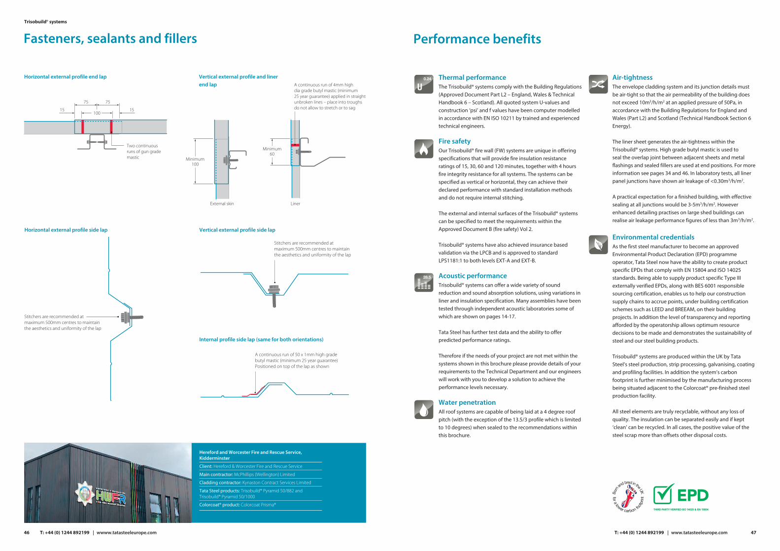
Performance benefits
Thermal performance The Trisobuild® systems comply with the Building Regulations (Approved Document Part L2 – England, Wales & Technical Handbook 6 – Scotland). All quoted system U-values and construction ‘psi’ and f values have been computer modelled in accordance with EN ISO 10211 by trained and experiencedtechnical engineers.
Fire safety Our Trisobuild® fire wall (FW) systems are unique in offering specifications that will provide fire insulation resistance ratings of 15, 30, 60 and 120 minutes, together with 4 hours fire integrity resistance for all systems. The systems can be specified as vertical or horizontal, they can achieve their declared performance with standard installation methods and do not require internal stitching.
The external and internal surfaces of the Trisobuild® systems can be specified to meet the requirements within the Approved Document B (fire safety) Vol 2.
Trisobuild® systems have also achieved insurance based validation via the LPCB and is approved to standard LPS1181:1 to both levels EXT-A and EXT-B.
Acoustic performance Trisobuild® systems can offer a wide variety of sound reduction and sound absorption solutions, using variations in liner and insulation specification. Many assemblies have been tested through independent acoustic laboratories some of which are shown on pages 14-17.
Tata Steel has further test data and the ability to offer predicted performance ratings.
Therefore if the needs of your project are not met within the systems shown in this brochure please provide details of your requirements to the Technical Department and our engineers will work with you to develop a solution to achieve the performance levels necessary.
Water penetrationAll roof systems are capable of being laid at a 4 degree roof pitch (with the exception of the 13.5/3 profile which is limited to 10 degrees) when sealed to the recommendations within this brochure.
Air-tightness The envelope cladding system and its junction details must be air-tight so that the air permeability of the building does not exceed 10m3/h/m2 at an applied pressure of 50Pa, in accordance with the Building Regulations for England and Wales (Part L2) and Scotland (Technical Handbook Section 6 Energy).
The liner sheet generates the air-tightness within the Trisobuild® systems. High grade butyl mastic is used to seal the overlap joint between adjacent sheets and metal flashings and sealed fillers are used at end positions. For more information see pages 34 and 46. In laboratory tests, all liner panel junctions have shown air leakage of <0.30m3/h/m2.
A practical expectation for a finished building, with effective sealing at all junctions would be 3-5m3/h/m2. However enhanced detailing practises on large shed buildings can realise air leakage performance figures of less than 3m3/h/m2.
Environmental credentials As the first steel manufacturer to become an approved Environmental Product Declaration (EPD) programme operator, Tata Steel now have the ability to create product specific EPDs that comply with EN 15804 and ISO 14025 standards. Being able to supply product specific Type III externally verified EPDs, along with BES 6001 responsible sourcing certification, enables us to help our construction supply chains to accrue points, under building certification schemes such as LEED and BREEAM, on their building projects. In addition the level of transparency and reporting afforded by the operatorship allows optimum resource decisions to be made and demonstrates the sustainability of steel and our steel building products.
Trisobuild® systems are produced within the UK by Tata Steel’s steel production, strip processing, galvanising, coating and profiling facilities. In addition the system’s carbon footprint is further minimised by the manufacturing process being situated adjacent to the Colorcoat® pre-finished steel production facility.
All steel elements are truly recyclable, without any loss of quality. The insulation can be separated easily and if kept ‘clean’ can be recycled. In all cases, the positive value of the steel scrap more than offsets other disposal costs.
U0.24
28.5
47T: +44 (0) 1244 892199 | www.tatasteeleurope.com
15 15
Minimum100
75 75
Two continuousruns of gun grademastic
Minimum60
A continuous run of 4mm high dia grade butyl mastic (minimum 25 year guarantee) applied in straight unbroken lines – place into troughs do not allow to stretch or to sag
A continuous run of 50 x 1mm high grade butyl mastic (minimum 25 year guarantee) Positioned on top of the lap as shown
Stitchers are recommended at maximum 500mm centres to maintain the aesthetics and uniformity of the lap
Stitchers are recommended at maximum 500mm centres to maintain the aesthetics and uniformity of the lap
Horizontal external profile end lap
Horizontal external profile side lap
Vertical external profile and liner end lap
Vertical external profile side lap
Internal profile side lap (same for both orientations)
Hereford and Worcester Fire and Rescue Service, Kidderminster
Client: Hereford & Worcester Fire and Rescue Service
Main contractor: McPhillips (Wellington) Limited
Cladding contractor: Kynaston Contract Services Limited
Tata Steel products: Trisobuild® Pyramid 50/882 and Trisobuild® Pyramid 50/1000
Colorcoat® product: Colorcoat Prisma®
46
Fasteners, sealants and fillersTrisobuild® systems
T: +44 (0) 1244 892199 | wwww.tatasteeleurope.com
100
External skin Liner

www.tatasteeleurope.com
Trademarks of Tata Steel UK LimitedAquatite, Colorcoat, Colorcoat Connection, Colorcoat HPS200 Ultra, Colorcoat Prisma, Confidex, Galvalloy, Platinum, Repertoire, Scintilla, Trinsul and Trisobuild are registered trademarks of Tata Steel UK Limited.
While care has been take to ensure that the information contained in this publication is accurate, neither Tata Steel, nor its subsidiaries, accept responsibility or liability for errors or for information which is found to be misleading.
Before using products or services supplied or manufactured by TataSteel and its subsidiaries, customers should satisfy themselves as totheir suitability.
Copyright 2021
Tata Steel UK Limited
Tata SteelShotton WorksDeesideFlintshireCH5 2NHT: +44 (0) 1244 892199E: [email protected] W: www.tatasteeleurope.com
Tata Steel UK Limited is registered in England under number 2280000 with registered office at 18 Grosvenor Place, London, SW1X 7HS.
UK 1221
Scan for the latestversion of this literature