
Are Microcredit Participants in Bangladesh Trapped in Poverty and Debt?
Upload
independentCategory
view
1download
0
Hyperfine Interact (2010) 196:177–189DOI 10.1007/s10751-009-0144-0
Towards sympathetic cooling of trapped ions withlaser-cooled Mg+ ions for mass spectrometryand laser spectroscopy
Radu Cazan · Christopher Geppert ·Wilfried Nörtershäuser · Rodolfo Sánchez
Published online: 21 January 2010© Springer Science+Business Media B.V. 2010
Abstract Sympathetic cooling by laser cooled Mg ions has been proposed as amethod for fast cooling of highly charged ions to a very low temperature. The paperdescribes the construction of the solid state laser system at 279.63 nm requiredfor laser cooling of the Mg ions. The laser system is composed of a fiber laser at1,118.54 nm and two successive second harmonic generation (SHG) ring cavitiesfor frequency quadrupling. In the first SHG cavity, non-critical phase matching ofa lithium triborate (LBO) crystal is used for doubling from 1,118.54 to 559.27 nm.The second SHG cavity uses critical phase matching of a β-barium borate (BBO)crystal for doubling from 559.27 to 279.63 nm. With the aid of Boyd–Kleinmanntheory, optimum experimental parameters are calculated and used for an efficientSHG. Besides this, the paper intends to be a shortcut for practical applications of theBoyd–Kleinmann theory for SHG.
Keywords SHG · LBO · NCPM · BBO · Mg cooling
1 Introduction
In most experiments with trapped ions it is necessary to reduce the temperatureof the ions in order to increase the accuracy of the measurements and to diminishthe magnitude of some undesirable effects such as Doppler shifts or to extendthe storage time of the ions in the trap. Depending on the characteristics of theexperiment and temperature expectations, several methods can be employed, suchas buffer gas cooling, resistive cooling, laser cooling or electron cooling [1, 2]. While
R. Cazan (B) · C. Geppert · W. NörtershäuserInstitut für Kernchemie, Johannes Gutenberg Universität, Mainz, Germanye-mail: [email protected]
R. SánchezGSI Helmholtzzentrum für Schwerionenforschung, Darmstadt, Germany

178 R. Cazan et al.
these universal methods fulfill most experimental requirements, there are someexperiments which require specialized approaches: precision mass spectrometry orlaser spectroscopy with highly charged ions (HCI) [3].
Experiments with HCI, especially with H-like and Li-like ions are an excellenttesting ground for quantum electrodynamics (QED) in strong electric and magneticfields and for precise measurements of fundamental constants [4]. For example,spectroscopy experiments are planned at the GSI Helmholtz Center for Heavy IonResearch to measure the ground state hyperfine splitting in HCI [5]: this splittingincreases roughly proportional to Z 3 and was previously measured to amount to243,87(4) nm in 209Bi82+ [6]. This splitting was measured on a relativistic ion beamat the Experimental Storage Ring (ESR) at GSI and the accuracy was limited bythe residual Doppler broadening of the ion beam after electron cooling. However,the interpretation of the results concerning a test of QED is strongly limited dueto nuclear structure effects [7]. At the ESR, an experiment is being prepared tosearch for the hyperfine transition in lithium-like 209Bi82+ in order to disentanglenuclear structure from QED effects [7]. Subsequent precision laser spectroscopymeasurements of these transitions are prepared by the SPECTRAP collaboration[8, 9] as part of the HITRAP project [10]. The measurements in the ion trap providethe unique possibility to perform spectroscopy on a well localized cloud of highlycharged ions with continuous laser excitation and relative efficient fluorescencedetection. Moreover, if the ions are cooled, the Doppler broadening of the line isreduced according to:
�λ
λ=
√kBTmc2
(1)
where kB is the Boltzmann constant, m is the ion mass, c is the speed of light and Tis the temperature of the ion ensemble. As for mass spectrometry, in a Penning trap,the resolution is given by [3]:
�mm
∝ mtm BN1/2 QHCI
(2)
where tm is the measurement time, N is the number of ions, B is the induction of thetrap magnetic field and QHCI is the charge of the HCI. It can be easily noticed thatthe easiest ways to improve the precision are to increase the ion charge and also tomaintain the HCI in the trap for longer times by cooling it.
Buffer gas cooling, though a very efficient method for cooling of large samplesdown to a very low temperature, is an inappropriate method for cooling HCI dueto the high recombination rate of HCI with free electrons from the buffer gas. Ingeneral, resistive and electron cooling are used for this type of ions, each with its owndisadvantages: long cooling times and high limit temperature for resistive cooling andlong cooling sections plus the necessity of collection of the electrons after one passfor electron cooling [1, 3].
In the SPECTRAP experiment, resistive cooling is foreseen for first experiments.Meanwhile, we are currently setting up a laser system for laser cooling of Mg+ions inside the trap, with which HCI can be quickly and efficiently cooled downsympathetically.

Towards sympathetic cooling of trapped ions with laser-cooled Mg+ ions 179
2 Laser cooling and sympathetic cooling
Over the last decades, laser cooling [11, 12] has proved to be a versatile tool for veryfast cooling of ions or atoms down to mK temperatures. Yet, this method is restrictedto ions with favorable structure of the energy levels. The ion should have a closedtransition between the ground state and the excited state—without dark states. Also,this transition should be achievable with a laser.
The aim of our experiment is to setup a system for cooling ions in a trap to avery low temperature regardless of their charge state, energy level structure or otherparameters. This will be done by sympathetic cooling [13]. Through sympatheticcooling in a trap, we can cool one type of ion by the Coulomb interactions withanother type of ions, which have been previously laser cooled and stored in theexperiment trap. This method is applicable to virtually any ion species in smallamount and can cool to temperatures below 0.25 K in a rather short time [1].
For sympathetic cooling one needs a trap filled with laser cooled ions whichimplies the necessity of an ion species suitable for laser cooling and a laser systemcapable of delivering a tunable, narrow linewidth laser beam at the wavelength ofinterest. For our experiment we have chosen 24Mg+ ions and to build a laser systemat 279.5 nm consisting of a fiber laser emitting at 1,118 nm and two successive secondharmonic generation (SHG) ring cavities for frequency quadrupling.
The choice of using 24Mg+ ions is obvious through the fact that 24Mg is a naturaloccurring, abundant and non-toxic element with a convenient structure of energylevels, without any dark states between the levels implied in the transition used forcooling. The apparently more complicated solution of building two SHG stages andusing a fiber laser instead of using a dye laser and only one SHG stage is motivated byconsidering that, over the last years, the fiber laser proved to be a high power, reliableand stable laser source compared to dye lasers [14]. Alternatively, there is also thepossibility to use two lasers for sum frequency generation and two ring cavities [15]but this would increase the maintenance effort. The simplicity of operation is of keyimportance for online applications like at HITRAP. Moreover, the nonlinear crystalsbecame widely available and building of SHG cavities imposes no great experimentaldifficulties. Furthermore, the laser beam emitted by the fiber laser has a very narrowlinewidth (δλ<200 kHz) and an excellent quality factor (M2<1.05).
3 Design of the first SHG cavity
3.1 Boyd-Kleinmann theory
For designing the SHG stages, the Boyd–Kleinmann theory [16] was used. Choosingthe crystal type and length can be a real challenge nowadays given the multitude ofnonlinear crystal types present on the market. As a general rule, it is preferable touse non-critical (temperature tunning) phase matching (NCPM) over critical phasematching (CPM) for the same or comparable crystals. NCPM has many advantages,which are: non-astigmatic gaussian beam output, higher efficiency, simple optimiza-tion, greater acceptance angle and wavelength bandwidth and no walk-off angle.
For SHG at 1,118 nm, several crystals are capable of NCPM: lithium triborate(LBO) [17, 18], lithium niobate (LNO) and potassium niobate (KNO). Optical

180 R. Cazan et al.
homogeneity, linear absorption and the amount of inclusions in the crystal arevery important for the doubling efficiency once the crystal is placed inside anenhancement cavity. LNO and KNO have a typical optical inhomogeneity of δn ≈5 · 10−5cm−1 compared to only δn ≈ 10−6cm−1 for LBO which also has less inclusionsand lower linear absorption. Moreover, the theoretical temperature for NCPM at1,118 nm is around 90◦C for LBO compared to above 200◦C for the other twocrystals. Thus, we chose to use LBO for the first SHG cavity despite its approximativefour times smaller nonlinear coefficient compared to the other two crystals.
From Boyd–Kleinmann theory, the harmonic power depends on several factors:
P2ω ={
16π2d2eff
λ3εon2c
}· L · e−(α1+0.5α2)L · h(σ, β, κ, ξ, μ) · P2
ω (3)
deff is the effective nonlinear coefficient, εo is the vacuum permittivity, n is therefractive index of the crystal at phase matching, L is the length of the crystal, α1,α2 are the absorption coefficients of the crystal for the fundamental and the secondharmonic, respectively, and Pω is the power of the fundamental beam. The first termis constant under normal circumstances. The function h is the so-called function ofoptimizable parameters and depends on:
– σ - a phase mismatch factor depending on the confocal parameter of the laserbeam b and the fluctuations in the wavenumber of the laser inside the crystal:
σ = 1
2b�k (4)
– ξ - the optimum focusing parameter which gives the optimum confocal parameterof the laser beam as a function of crystal length for a given walk-off angle (ρ) ofthe laser inside the crystal:
ξ = Lb
(5)
– β - a walk-off factor depending on the optimum focusing parameter ξ , the crystallength, the wavenumber k of the fundamental laser beam inside the crystal andthe walk-off angle ρ:
β = 1
2ρ
√Lkξ
(6)
– κ - an absorption factor depending on the confocal parameter and the absorptioncoefficients for the harmonic and fundamental laser beams:
κ = b(α1 − 12α2)
2(7)
– μ - a factor which measures the displacement of the laser focus from the centerof the crystal. It depends on the relative position of the laser focus f from theentrance of the crystal:
μ = L − 2 fL
(8)
Towards sympathetic cooling of trapped ions with laser-cooled Mg+ ions 181
The general form of the function h is:
h(σ, β, κ, ξ, μ) = eμαL
4ξ
∫ ∫ ξ(1+μ)
ξ(1−μ)
exp[−κ(τ + τ ′) + iσ(τ − τ ′) − β2(τ − τ ′)2](1 + iτ)(1 − iτ)
dτdτ ′
(9)
From Boyd–Kleinmann simulations, for our case with zero walk-off angle (due tothe NCPM) the value of the optimum focusing parameter is ξ = 2.84 and, also byassuming the focus of the laser in the center of the crystal, β = μ = 0. By consideringξ fixed, the confocal parameter can be expressed as b = L/ξ and then we can write:
κ = L(α1 − 12α2)
2ξ(10)
σ = Lξ
k�n (11)
where we considered that the fluctuations of the wavenumbers are due to thevariations of the refractive index �n inside the crystal. These variations are causedby the optical inhomogeneity of the crystal and the temperature fluctuations of theoven. Thus, h(σ, β, κ, ξ, μ) depends on the quality of the crystal and the performanceof the temperature stabilization as given parameters and only on the crystal lengthas variable.
The typical fluctuation in the refractive index of LBO is δnL ≈ 10−6cm−1 due toinhomogeneities and δnT ≈ (7.3 · 10−6 − 2.1 · λ)K−1 due to temperature fluctuationwhich is maximum 0.1 K for our case. The typical absorption coefficients areα1 ≈ 0.1% cm−1 and α2 ≈ 0.3% cm−1. Taking these parameters into account andusing Matlab for numerically solving the double integral in Eq. (9), the function ofoptimizable parameters h(L) was plotted in Fig. 1a over a virtual crystal length from0 to 200 mm.
Equation (3) can be written as:
P2ω = ηP2ω (12)
where η for our case is:
η ={
16π2d2ef f
λ3εon2c
}Le−(α1+0.5α2)Lh(L) (13)
The simulated conversion coefficient η is plotted in Fig. 1b for the same virtualcrystal length domain. Compared to h, η depends more on the length of the crystaland it has a maximum at 85 mm. Even with such a hypothetically long crystal whichwould greatly reduce the angle, temperature and spectral acceptance, the harmonicoutput for a single pass would be ≈ 1.3 mW for a fundamental input of 1 W.
3.2 Cavity enhancement
Relations (3) and (12) explicitly show us that the power level of the fundamental laseris very important for an efficient SHG. For a 33 fold increase in fundamental power,the harmonic increases ≈ 1,000 times. A 33 fold increase can be easily achieved after

182 R. Cazan et al.
0 50 100 150 2000
0.2
0.4
0.6
0.8
1
a
0 50 100 150 2000
0.2
0.4
0.6
0.8
1
1.2
x 10–3b
Fig. 1 The function of optimizable parameters (a) and the conversion coefficient (b) for single-passSHG in LBO at 1,118 nm as a function of the crystal length L
placing the crystal inside a ring cavity. The power of the fundamental laser in thecavity is:
Pcavω = A(ceff Pinp
ω ) (14)
ceff is a coupling efficiency coefficient and it represents the ratio between the powerof the fundamental laser in front of the input mirror and the power entering thecavity at resonance. It depends on the laser waist size and position (mode matching)and on the reflectivity of the input mirror. The actual enhancement factor A is [19]:
A = 1 − r
(1 − √rv)2
(15)
where r is the reflectivity of the input mirror and v represents the ratio between thelaser power after one round trip inside the cavity and the initial power. For a given v,the maximum value of A is for r = v which is called impedance matching and actuallymeans that at resonance, the losses inside the cavity have the same value as the lossesat the input mirror. A positive side effect of choosing a mirror with a reflectivity inorder to meet the conditions for impedance matching is that the coupling efficiencyceff has a maximum for a given laser waist size and position.
v contains all the losses inside the cavity:
v = (1 − α1 L)(1 − ηPcavω )(1 − t) (16)
where the first term represents the losses due to linear absorption inside the crystal,the second term represents the losses due to SHG and the last term represents thetotal losses due to transmission or reflections of the laser on the surfaces inside thecavity.
Under normal circumstances, it is quite difficult to meet the condition for im-pedance matching but, as it can be seen in Eq. (15), it is always advisable to haveminimum losses by using high reflectivity mirrors, good anti-reflection (AR) coatingson the crystal, short good quality crystals and by maintaining clean surfaces. In Fig. 2,the enhancement factor is plotted versus the reflectivity of the input mirror for four

Towards sympathetic cooling of trapped ions with laser-cooled Mg+ ions 183
Fig. 2 The enhancementfactor A of a ring cavity asfunction of input mirrorreflectivity and round trip ratiolevel v of the fundamentallaser
0.95 0.96 0.97 0.98 0.99 10
20
40
60
80
100
120
round trip ratio levels between 98 and 99.2%. Even with a small change of only 1.2%in the round trip level, the enhancement factor in the cavity varies by a factor of ≈ 3.Hence, from Eqs. (12) and (14), only 1.2% additional losses inside the cavity wouldlead to an ≈ 9 fold decrease of the harmonic output.
From Eqs. (14), (15) and (16), A depends on Pcavω which in turn depends on A, thus
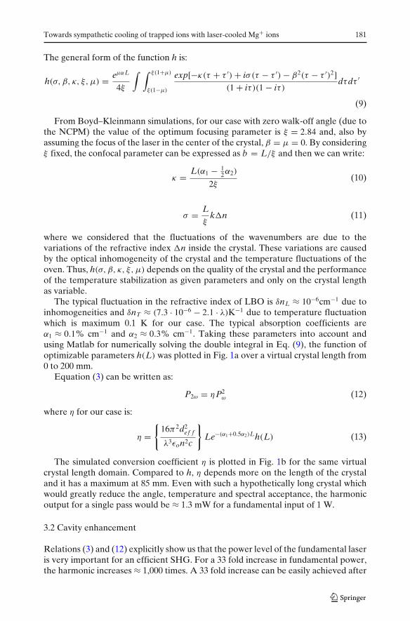
forming a nonlinear equation. This equation was solved numerically using Matlab.In the experiment, we used an input mirror with r = 0.978 and the tangential linearlypolarized laser power in front of the mirror was measured to be 0.95 W. Besidesthis, for the simulations, we assumed t ≈ 1%, ceff ≈ 80% and η to be the one plottedin Fig. 1b. Thus, the fundamental power inside the cavity is plotted in Fig. 3a forthe same crystal length domain and it has a minimum corresponding roughly to themaximum of the conversion coefficient η (see Fig. 1b and Rel. (16)).
Finally, there is a trade-off between the conversion efficiency and the power builtinside the cavity regarding the crystal length. By combining the plot from Fig. 1b withthe one from Fig. 3a according to Eq. (12) we obtain the expected P2ω in Fig. 3b. Thefirst maximum is obtained at 20 mm and the expected power level is around 200 mW.
3.3 Experimental setup
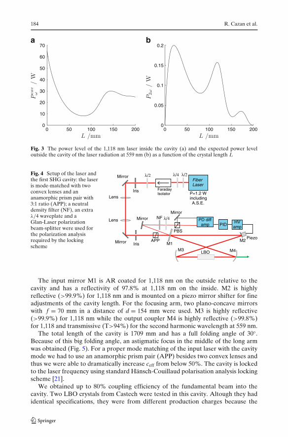
A Koheras Boostik fiber laser was used as the fundamental laser source for thefirst SHG cavity. The laser was specified to deliver 1.66 W maximum output power,but a maximum of 1.2 W including the amplified spontaneous emission (ASE) wasobserved. The useful power, without ASE, was at delivery maximum 1.1 W anddropped below 0.7 W after a few hundred of hours of operation in parallel withan increase in ASE. The output polarization was optimized and controlled with aquarter- and a half-waveplate. An optical isolator was used to avoid back reflectionsinto the laser (Fig. 4).
The 20 mm long LBO nonlinear crystal was cut for non-critical phase matching(NCPM), type I XY/XZ, θ = 90◦, ϕ = 0◦. Relation (5) for the optimum ξ = 2.84 isequivalent with obtaining a beam waist of 28 μm in the middle of the crystal. Usingthe ray transfer matrix analysis [20] we designed a bow tie resonator that allows us tofit the oven with the crystal in the middle of the short arm and to obtain the requiredbeam waist in the middle of the crystal (see Fig. 5).
184 R. Cazan et al.
0 50 100 150 2000
10
20
30
40
50
60
70
L /mm
0 50 100 150 2000
0.05
0.1
0.15
0.2
L /mm
a b
Fig. 3 The power level of the 1,118 nm laser inside the cavity (a) and the expected power leveloutside the cavity of the laser radiation at 559 nm (b) as a function of the crystal length L
Fig. 4 Setup of the laser andthe first SHG cavity: the laseris mode-matched with twoconvex lenses and ananamorphic prism pair with3:1 ratio (APP); a neutraldensity filter (NF), an extraλ/4 waveplate and aGlan-Laser polarizationbeam-splitter were used forthe polarization analysisrequired by the lockingscheme
FiberLaser
FaradayIsolator
λ /2λ /4
PD diffamp PID
HVamp
λ /4Lens MirrorMirror
LBO
Piezo
PBS
NF
M4M3
M2M1
λ /2
Mirror
Mirror
LensIris
IrisAPP
P=1.2 WincludingA.S.E.
The input mirror M1 is AR coated for 1,118 nm on the outside relative to thecavity and has a reflectivity of 97.8% at 1,118 nm on the inside. M2 is highlyreflective (>99.9%) for 1,118 nm and is mounted on a piezo mirror shifter for fineadjustments of the cavity length. For the focusing arm, two plano-concave mirrorswith f = 70 mm in a distance of d = 154 mm were used. M3 is highly reflective(>99.9%) for 1,118 nm while the output coupler M4 is highly reflective (>99.8%)for 1,118 and transmissive (T>94%) for the second harmonic wavelength at 559 nm.
The total length of the cavity is 1709 mm and has a full folding angle of 30◦.Because of this big folding angle, an astigmatic focus in the middle of the long armwas obtained (Fig. 5). For a proper mode matching of the input laser with the cavitymode we had to use an anamorphic prism pair (APP) besides two convex lenses andthus we were able to dramatically increase ceff from below 50%. The cavity is lockedto the laser frequency using standard Hänsch-Couillaud polarisation analysis lockingscheme [21].
We obtained up to 80% coupling efficiency of the fundamental beam into thecavity. Two LBO crystals from Castech were tested in this cavity. Altough they hadidentical specifications, they were from different production charges because the

Towards sympathetic cooling of trapped ions with laser-cooled Mg+ ions 185
Fig. 5 Beam waist size insidethe cavity for the sagittal andtangential plane
0 400 800 1200 16000
100
200
300
400
500
600
700
800
900
1000
wai
st/ μ
mtangential (horizontal)sagittal (vertical)
second crystal was bought one year later. At maximum power, the maximum greenoutput was approximately 175 mW for the first crystal and 240 mW for the secondcrystal, which is in accordance with the simulations. This output difference betweenthe two crystals can be caused by a difference in their quality but it rather seems thatafter a few months the crystal surfaces may have become dirty and thus it affectedthe SHG efficiency. A precise answer is not possible because the optimization for thefirst crystal took a few months while for the second crystal it took only a few days. Apossible way to protect the crystal surfaces is to seal the doubling cavity and to usea continuous flow of dry nitrogen to purge the contaminants. The maximum overallSHG efficiency was >25% relative to the power in front of the cavity and >31%relative to the power coupled in. The cavity was stable for the tested periods (up to1 h) and the output beam was a nice gaussian TEM00 mode which is crucial for thenext frequency doubling step.
4 Design of the second SHG cavity
For doubling at 559 nm, to our knowledge, there is no common nonlinear crystalcapable of NCPM. Therefore, we checked crystals for critical phase matching (CPM)at this wavelength and with a transparency range down to at least 279 nm. Thepotential candidates were LBO, potassium dihydrogen phosphate (KDP) and β-barium borate (BBO). KDP has a very good optical quality and was previously usedfor doubling at 559 nm [22] but an efficient SHG requires very long crystals due to itsrelatively small nonlinear coefficient. While LBO and BBO have comparable opticalquality, BBO has an approximately twice as large nonlinear coefficient compared toLBO and was frequently used for very efficient SHG around 559 nm [17, 18, 23, 24].Moreover, the bigger nonlinear coefficient allows us to use shorter crystals andimprove the enhancement factor of a ring cavity by reducing the linear losses insidethe crystal, thus making BBO the optimum choice.
Compared to NCPM, for CPM the walk-off angle is non-zero. Specifically forour case, ρ ≈ 4.8◦, β �= 0 and the corresponding value of the optimum focusingparameter is ξ = 1.39. As for the refractive index of BBO, the typical fluctuationis δnL ≈ 10−6cm−1 due to inhomogeneities and δnT ≈ 7.3 · 10−6K−1 due to temper-

186 R. Cazan et al.
0 10 20 30 40 500
0.1
0.2
0.3
0.4
0.5a
0 10 20 30 40 500
0.5
1
1.5
x 10–4b
Fig. 6 The function of optimizable parameters (a) the conversion coefficient (b) and for SHG inBBO at 559 nm as a function of the crystal length L
ature fluctuation which is, like in the case of first SHG cavity, maximum 0.1 K forour case. The typical absorption coefficients are α1 ≈ 0.3% cm−1 and α2 ≈ 4% cm−1.Again, using these parameters and Matlab for numerically solving the double integralin Eq. (9), we plotted h(L) in Fig. 6a over a relevant virtual crystal length from 0to 50 mm. The resulting conversion coefficient is plotted in Fig. 6b and it reaches80% of its maximum already for a crystal length of 10 mm. Compared to LBO,the conversion coefficient of BBO doesn’t have a prominent maximum, but rather aplateau which makes useless any intention to use longer crystals in order to increasethe efficiency, even for the single-pass case.
For simulating the behavior of the BBO crystal inside the cavity we considered aninput mirror with r = 0.99 and a power level of 200 mW for the horizontal linearlypolarized green laser in front of the cavity. After the initial simulations, it appearedthat it is more favorable to use a crystal with Brewster-cut surfaces than with ARcoated surfaces because of the much smaller reflectivity of the first type. We assumedt ≈ 0.75% and ceff ≈ 80%. The power level of the fundamental laser inside the cavityis plotted in Fig. 7a. Using Eq. (12) and the simulated data, we obtain the expectedpower level of the laser at 279 nm outside the cavity in Fig. 7b. We estimated thatfrom the UV laser radiation generated inside the crystal, only 75% can be usedoutside the cavity. The losses are mainly at the output surface of the Brewster-cutcrystal for 559 nm but also at the inner surface of the output dichroic mirror. Thefirst maximum is obtained at 7 mm and has an expected power level of about 17 mW.
Correspondingly, a 7 mm long Brewster-cut BBO-crystal was used for type I CPMat 559 nm with θ = 44.45◦, ϕ = 0◦ crystal cut. From relation (5), the correspondingbeam waist in the middle of the crystal for the optimum ξ = 1.39 is approximately16 μm. Due to the astigmatism introduced by the concave spherical mirrors, crystalfaces and crystal axis, it is impossible to design a simple cavity which facilitates thefocusing of the laser to a round waist inside the crystal. Therefore, we designed abow-tie resonator capable of achieving a focus in the middle of the crystal with awaist of 16 μm in the vertical plane and 25 μm in the horizontal plane (see Fig. 8).

Towards sympathetic cooling of trapped ions with laser-cooled Mg+ ions 187
0 10 20 30 40 500
5
10
15
20a
0 10 20 30 40 500
0.005
0.01
0.015
b
Fig. 7 The power level of the 559 nm laser inside the cavity (a) and the expected power level outsidethe cavity of the laser radiation at 279 nm (b) as a function of the crystal length L
Fig. 8 Beam waist size insidethe second cavity
0 100 200 300 400 5000
100
200
300
400
500
600
wai
st/ μ
m
tangential (vertical)sagittal (horizontal)
From Fig. 9, M5 is AR coated for 559 nm on the outside relative to the cavity andit has a reflectivity of 99.3% on the inside, which is slightly higher than the optimumand resulted in locking [21] problems during first tests, as observed in [25]. The mirrorwill be replaced by one with lower reflectivity. The rest of the cavity mirrors have ahigh reflectivity (>99.9%) for 559 nm and high transmissivity (>90%) for 279 nmon the inside. On the outside they are AR coated for 279 nm, even though that isnecessary only for M8. M6 is mounted on a piezo tube which allows us to make fastcorrection to the cavity length. M7 is a plano-concave mirror while M8 is a concave-convex zero-lens shaped mirror, both with a focal length of 50 mm. The distancebetween the focusing mirrors and the nearest crystal face is 48.7 mm, the full foldingangle is 18.8◦ and the total length of the cavity is 504 mm. The crystal is kept at 50◦Cto avoid condensation of water vapor on its faces.
Currently, the second doubler has been setup and we performed some initialtests, at low fiber laser power before the fiber laser became unusable. Even withoutappropriate locking, we measured a coupling efficiency up to 75% at resonance

188 R. Cazan et al.
Fig. 9 Second doubler layoutM8
M7
M6(Piezo mirror)
M5
48,7 mm
136 mm
9,4 Grad
BBO
and we were able to obtain a power level of maximum 0.8 mW for the 279 nmradiation with an input power level of approximately 100 mW at 559 nm. Typically,the maximum period of continuous locking was around 1 min. Further efforts will bemade in order to increase the efficiency of SHG and to optimize the stability of thecavity after refurbishment of the initial fiber laser.
5 Applications
Once the system has been completely installed, we will first test it at an existing Paultrap setup at the University of Mainz. After demonstration of Mg+ laser cooling,it will be transported to GSI and first tests will be performed at the SPECTRAPPenning trap using Mg+ ions produced in an off-line ion source. Injection of otherion species into the cloud of laser cooled Mg+ ions and sympathetic cooling will bedemonstrated first with Ar+ ions from a sputter gun ion source before we switch tomultiply charged ions from a DREEBIT ion source [26] and finally to highly chargedions provided by the HITRAP facility.
6 Conclusions
We described the setup of a laser system which will be used for cooling Mg+ ionsin a trap and, furthermore, for sympathetically cooling of highly charged ions. Thelaser system consists of a fiber laser at 1,118 nm and two SHG cavities for successivefrequency doubling down to 279 nm. The cavities were designed using the Boyd-Kleinmann theory and the matrix ray transfer analysis. We presented numericalsimulations as well as experimental results. The first cavity uses a 20 mm longLBO crystal and non-critical phase matching. We obtained up to 240 mW of greenradiation at 559 nm with 950 mW of 1,118 nm radiation in front of the cavity. Thesecond cavity uses a 7 mm long BBO crystal and critical phase matching. Though thiscavity was locked improperly, after initial tests at low input power levels, we obtainedup to 0.8 mW of UV radiation at 279 nm with 100 mW of 559 nm radiation in frontof the cavity for time periods around 1 min.
Acknowledgements This work was supported by the Helmholtz Association under ContractVH-NG-148, by the State of Rhineland-Palatinate via the Research Center “Elementary Forcesand Mathematical Foundations”, and by the GSI Helmholtzzentrum für SchwerionenforschungDarmstadt.
Towards sympathetic cooling of trapped ions with laser-cooled Mg+ ions 189
References
1. Itano, W.M., Berquist, J.C., Bollinger, J.J., Wineland, D.J.: Phys. Scr. T59, 106–120 (1995)2. Blaum, K.: Phys. Rep. 425, 1–78 (2006)3. Bussmann, M., Schramm, U., Habs, D., Kolhinen, V.S., Szerypo, J.: Int. J. Mass Spectrom. 251,
179–189 (2006)4. Beier, T.: Phys. Rep. 339, 79–213 (2000)5. Winters, D.F.A., Abdulla, A.M., Castrejon Pita, J.R., de Lange, A., Segal, D.M., Thompson,
R.C.: Nucl. Instrum. Methods Phys. Res B 235, 201–205 (2005)6. Klaft, I., Borneis, S., Engel, T., Fricke, B., Grieser, R., Huber, G., Kühl, T., Marx, D., Neumann,
R., Schröder, S., Seelig, P., Völker, L.: Phys. Rev. Lett. 73, 2425–2427 (1994)7. Shabaev, V.M., Artemyev, A.N., Yerokhin, V.A., Zherebtsov, O.M., Soff, G.: Phys. Rev. Lett.
86, 3959–3962 (2001)8. Vogel, M., Winters, D.F.A., Segal, D.M., Thompson, R.C.: Rev. Sci. Instrum. 76, 103102 (2005)9. Andjelkovic, Z., Bharadia, S., Sommer, B., Vogel, M., Nörtershäuser, W.: Towards high
precision in-trap laser spectroscopy of highly charged ions. Hyperfine Interact. doi:10.1007/s10751-009-0155-x (2010)
10. Kluge, H.-J., Beier, T., Nlaum, K., Dahl, L., Eliseev, S., Herfurth, F., Hofmann, B., Kester, O.,Koszudowski, S., Kozhuharov, C., Maero, G., Nörtershäuser, W., Pfister, J., Quint, W., Ratzinger,U., Schempp, A., Schuch, R., Stöhlker, Th., Thompson, R.C., Vogel, M., Vorobjev, G., Winters,D.F.A., Werth, G.: Adv. Quantum Chem. 53, 83–98 (2008)
11. Hänsch, T.W., Schawlowa, A.L.: Opt. Commun. 13, 68–69 (1975)12. Phillips, W.D., Lett, P.D., Rolston, S.L., Tanner, C.E., Watts, R.N., Westbrook, C.I., Salomon,
C., Dalibard, J., Clairon, A., Guellati, S.: Phys. Scr. T34, 20–22 (1991)13. Drullinger, R.E., Wineland, D.J., Bergquist, J.C.: Appl. Phys. 22, 365–368 (1980)14. Canning, J: Opt. Lasers Eng. 44, 647–676 (2006)15. Mimoun, E., de Sarlo, L., Zondy, J.-J., Dalibard, J., Gerbier, F.: Opt. Express 16, 18684–18691
(2008)16. Boyd, G.D., Kleinman, D.A.: J. Appl. Phys. 39, 3597–3639 (1968)17. Friedenauer, A., Markert, F., Schmitz, H.,Petersen, L., Kahra, S., Herrmann, M., Udem, T.,
Hänsch, T.W., Schätz, T.: Appl. Phys., B 84, 371–373 (2006)18. Herskind, P., Lindballe, J., Clausen, C., Srensen, J.L., Drewsen, M.: Opt. Lett. 32, 268–270 (2007)19. Brieger, M., Büsener, H., Hese, A., v.Moers, F., Renn, A.: Opt. Commun. 38, 423–426 (1981)20. Freeregarde, T., Zimmermann, C.: Opt. Commun. 199, 435–446 (2001)21. Hänsch, T.W., Couillaud, B.: Opt. Commun. 35, 441–443 (1980)22. Nielsen, J.S.: Opt. Lett. 20, 840–842 (1995)23. Kondo, K., Oka, M., Wada, H., Fukui, T., Umezu, N., Tatsuki, K., Kubota S.: Opt. Lett. 23,
195–197 (1998)24. Bhawalkar, J.D., Mao, Y., Po, H., Goyal, A.K., Gavrilovic, P., Conturie, Y., Singh, S.: Opt. Lett.
24, 823–825 (1999)25. Madsen, D.N., Yu, P., Balslev S., Thomsen J.W.: Appl. Phys. B 75, 835–839 (2002)26. http://www.dreebit.com/
Copyright © 2022 FDOKUMEN