Granitic quarry sludge waste in mortar: Effect on strength and durability

© 2013 Ed. Univ. „Al. I. Cuza” Iași. All rights reserved Corresponding author’s e-mail: [email protected]
Available online at http://geology.uaic.ro/auig/
Analele Stiintifice ale Universitatii “Al. I. Cuza” din Iasi Seria Geologie 59 (2) (2013) 19–40
AUI GEOLOGIE
Towards digital preservation of Repedea's big quarry outcrop using “Structure-from-Motion” photogrammetry tools Tony – Cristian Dumitriu1 1 “Alexandru Ioan Cuza” University of Iaşi, Faculty of Geography and Geology, Department of Geology, 20A Carol I Blv., 700505 Iaşi, Romania
Abstract In the present paper, four free “structure from motion” photogrammetry tools (Visual SfM with PMVS/CMVS, Photosynth with PhotoSynthToolkit, 123D Catch and Recap Photo) have been compared using photographs taken from four locations in Hășmaș Mountains, in order to determine which tool is better suitable for Repedea Hill’s big quarry outcrop preservation and study. The results have shown that 123D Catch has provided a very good texture and geometry detail of the 3D models that can also be used with ease between many modeling software. Therefore the resulting Repedea 3D outcrop models (nine 3D models) are precise and highly detailed preserving a good geometry of the original outcrop and making possible a preliminary calculation of surfaces and volumes of some parts from the studied area. Thus, digitizing the outcrop partially solves the problem of geological reservation preservation by keeping the studied area in a virtual environment in which further geological investigation is possible. Keywords: Repedea Hill, structure from motion photogrammetry, 3D outcrop, geological reservation, Hășmaș Mountains, Moldavian Platform.
Introduction
Structure-from-Motion” photogrammetry is a set of tehniques one can use to extract the 3D properties of an object using only 2D pictures taken with a digital camera. Along with LiDAR (Light Detecting and Ranging) and TLS (Terrestrial Laser Scanning), photogrammetry is included in the “remote sensing” techniques and it is used in numerous fields of study.
LiDAR and TLS technologies work by sending light to a desired location, in the form of a pulsed laser and measure the time in which the light bounces back from that location and into the sensor. Then this light pulses are analyzed and combined with other data, resulting a precise three-dimensional model of that location. The main difference between LiDAR and TLS is that LiDAR is airborne (Fig. 1).

20 Dumitriu T.-C.
AUI–G, 59, 2, (2013) 19–40
Fig. 1 Airborne LiDAR scanning system.
Although these two technologies are very precise they are usually very expensive, time consuming and require at least one specialist to operate them and to use the software that analyzes and manages the data received from the instruments.
One the other hand photogrammetry makes use of techniques that are more and more easy to learn and do not require the presence of a technician. Furthermore it is very cheap and is of a light weight and can be carried anywhere with ease, even mounted on a UAV (unmanned aerial vehicle) in order to obtain a DTM (digital terrain model).
Lately it was shown that photogrammetry is a very precise technique used in various domains.
Buckley et al. (2006) proposes the study of sedimentary outcrops analogs for hydrocarbon deposits correlation by combining laser scan-ning techniques with photogrammetry tech-niques. They show that measurements done on
the resulting 3D model are more precise and are done in shorter period of time than with classical measurements.
Schober and Exner (2011) studied an outcrop from a quarry situated SW from Vienna, in which they discovered folds with unknown origin. They have used the photo-grammetry technique to identify the source of the folds: tectonic or gravitational. The con-ducted study has shown that the folds were of gravitational origin and that the photogram-metry technique can replace more sophisti-cated high cost technologies like TLS and airborne LiDAR.
A direct approach on automated “struc-ture from motion” photogrammetry has been made by James et al. (2013) who has evalu-ated the degree of erosion on a seashore cliff and the changes on the sand volume of a pocket beach. By making a series of photos on the objectives the authors were able to make 3D models of the studied area. By comparing

„Structure-from-Motion” tool applied to Repedea quarry 21
AUI–G, 59, 2, (2013) 19–40
the models from different periods of a year they were able to determine the degree of erosion on the seashore cliff and to calculate a total of 87 m3 difference in the sand volume between January and May.
As shown above, “structure from motion” photogrammetry is used in various domains with results comparable to laser scanner technologies.
Four different free “structure from motion” photogrammetry tools have been compared in this research. The purpose of this paper is to choose between those four tools and to obtain 3D models for every studied location, to evaluate the benefits of low cost “structure from motions” photogrammetry in outcrop study. Geological setting
1. Repedea Hill Repedea Hill is situated south of Iași city,
it belongs to Moldavian Platform’s central-eastern part and it has been studied since the beginning of the Romanian geology.
The outcrop from Repedea region, pre-sented by Cobălcescu in 1862, represents the Repedea Formation’s holostratotype. According to Ionesi and Ionesi (2002) Repedea Formation is 25 meters thick and in Repedea Hill’s quarry it’s represented by: oolitic yellow or grey col-ored limestone, lumaselic limestone, sandstone and sand (Fig. 2).
Fig. 2 Lithostratigraphic and biostratigraphic col-umn representing the Repedea Formation: a–oosparite, b–biosparite with Mactra (P.) podolica, c–sands and sandstones, d–sand with fossils
2. Hășmaș Mountains This area is situated in the “Eastern
Carpathian Marginal Syncline” (Uhlig, 1903) and it has a crystalline foundation covered with Mesozoic deposits. This syncline shows an axial heightening that divides it in the Rarău syncline in the north and the Hășmaș syncline in the south (Fig. 3).
As far as the Hășmaș syncline and, im-plicitly, the Hășmaș mountains are regarded, Săndulescu (1975) would bring forth a radical change in how the tectonics of the studied area is viewed, by dividing the syncline into three tectonic nappes: the sub-Bukovinian nappe, the Bukovinian nappe and the Hășmaș nappe, each with a different mechanism of formation.
The Bukovinian nappe is a shear nappe and it has the most complex stratigraphic column from all the nappes in the Moldavian Section, with formations from Superior Precambrian to Barremian-Albian.
The Hășmaș nappe is a gravitational slide nappe and encompasses formations with ages between Kimmeridgian and Urgonian. (Grasu et al., 2012) Materials and techniques
As a result of investigations and measure-ments made in the discussed area, there could be seventeen 3D models carried out for five studied locations:
- Location 1 – an outcrop of middle Jurassic limestone formation from Bukovinian nappe, situated near Bălan city (Fig. 3);
- Location 2 – a fragment of crystalline schist known as Tulgheș formation, from lower Cambrian age, situated on the Olt river’s upper basin (Fig. 5);
- Location 3 – a klippe made of Tithonian limestone from Hășmaș nappe, near the geomorphological formation known as Solitary Rock (Fig. 6);
- Location 4 – an outcrop of Tulgheș formation, situated on the Olt river’s right bank (Fig. 7);
- Location 5 – Repedea Hill’s big quarry outcrop (Fig. 8).

22 Dumitriu T.-C.
AUI–G, 59, 2, (2013) 19–40
Fig. 3 Tectonic structure and bordering units of Moldavian Compartment from Crystalline Mesozoic Zone in Eastern Carpathians (drawn after Grasu et al., 1995)

„Structure-from-Motion” tool applied to Repedea quarry 23
AUI–G, 59, 2, (2013) 19–40
Fig. 4 Outcrop of middle Jurassic formation. Fig. 5 Fragment of crystalline schist.
Fig. 6 Klippe made of Tithonian limestone. Fig. 7 Outcrop of Tulgheș formation.
For every chosen location a series of photos have been captured, based on James and Robson (2012) rules: - use an 35 mm lens; - take pictures every 10 to 20 degrees; - try to avoid shadows; - try to avoid glossy surfaces.
For this paper it has been used a FujiFilm FinePix HS25EXR camera, with the lenses fixed to 35 mm. The chosen angles differed from one location to the next, but they were kept between 10 to 30 degrees.
The studied outcrops and klippe from Hășmaș Mounatins were rather small, that is why the photo sets between 4 and 32 were sufficient:
- for the outcrop of Jurassic formation (Location 1) – 4 photos;
- for the fragment of crystalline schist (Location 2) – 22 photos;
- for a klippe of tithonian limestone (Location 3) – 32 photos;
- for an outcrop of crystalline schist (Location 4) – 9 photos. Because digitizing the outcrop from
Location 5, thus prezerving the geological reservation in a virtual environment, was the primary objective of this paper, it was needed a better detail degree so the number of photos used were 410. Moreover the choise of an appropriate tool, for generating a 3D outcrop, was essential.

Fig. 8 A panorama of the Repedea’s big quarry outcrop (Location 5), showing the parts used to make 3D models.
„Structure-from-Motion” tool applied to Repedea quarry 25
AUI–G, 59, 2, (2013) 19–40
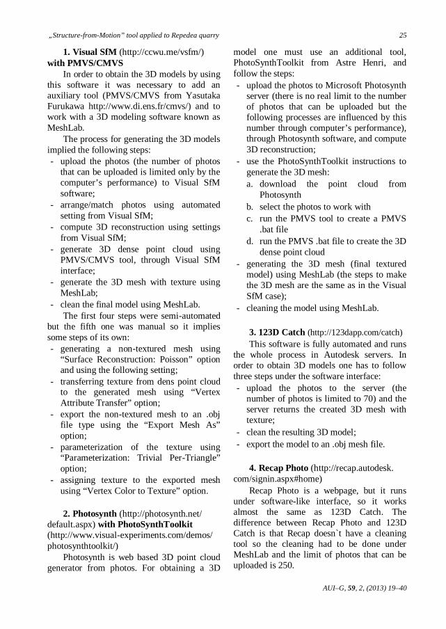
1. Visual SfM (http://ccwu.me/vsfm/) with PMVS/CMVS
In order to obtain the 3D models by using this software it was necessary to add an auxiliary tool (PMVS/CMVS from Yasutaka Furukawa http://www.di.ens.fr/cmvs/) and to work with a 3D modeling software known as MeshLab.
The process for generating the 3D models implied the following steps: - upload the photos (the number of photos
that can be uploaded is limited only by the computer’s performance) to Visual SfM software;
- arrange/match photos using automated setting from Visual SfM;
- compute 3D reconstruction using settings from Visual SfM;
- generate 3D dense point cloud using PMVS/CMVS tool, through Visual SfM interface;
- generate the 3D mesh with texture using MeshLab;
- clean the final model using MeshLab. The first four steps were semi-automated
but the fifth one was manual so it implies some steps of its own: - generating a non-textured mesh using
“Surface Reconstruction: Poisson” option and using the following setting;
- transferring texture from dens point cloud to the generated mesh using “Vertex Attribute Transfer” option;
- export the non-textured mesh to an .obj file type using the “Export Mesh As” option;
- parameterization of the texture using “Parameterization: Trivial Per-Triangle” option;
- assigning texture to the exported mesh using “Vertex Color to Texture” option.
2. Photosynth (http://photosynth.net/
default.aspx) with PhotoSynthToolkit (http://www.visual-experiments.com/demos/ photosynthtoolkit/)
Photosynth is web based 3D point cloud generator from photos. For obtaining a 3D
model one must use an additional tool, PhotoSynthToolkit from Astre Henri, and follow the steps: - upload the photos to Microsoft Photosynth
server (there is no real limit to the number of photos that can be uploaded but the following processes are influenced by this number through computer’s performance), through Photosynth software, and compute 3D reconstruction;
- use the PhotoSynthToolkit instructions to generate the 3D mesh: a. download the point cloud from
Photosynth b. select the photos to work with c. run the PMVS tool to create a PMVS
.bat file d. run the PMVS .bat file to create the 3D
dense point cloud - generating the 3D mesh (final textured
model) using MeshLab (the steps to make the 3D mesh are the same as in the Visual SfM case);
- cleaning the model using MeshLab.
3. 123D Catch (http://123dapp.com/catch) This software is fully automated and runs
the whole process in Autodesk servers. In order to obtain 3D models one has to follow three steps under the software interface: - upload the photos to the server (the
number of photos is limited to 70) and the server returns the created 3D mesh with texture;
- clean the resulting 3D model; - export the model to an .obj mesh file.
4. Recap Photo (http://recap.autodesk.
com/signin.aspx#home) Recap Photo is a webpage, but it runs
under software-like interface, so it works almost the same as 123D Catch. The difference between Recap Photo and 123D Catch is that Recap doesn`t have a cleaning tool so the cleaning had to be done under MeshLab and the limit of photos that can be uploaded is 250.

Tab. 1 Visual SfM
VISUAL SfM Number of the location and (*number of photos used) 1 (*4) 2 (*22) 3 (*32) 4 (*9) Photo upload time (seconds) 3 20 28 9 Photo arranging/matching time (seconds) 6 120 175 21 Compute 3D reconstruction time (seconds) 4 2470.02 2389.02 63 Generating 3D dense point cloud time (seconds) 68 976.02 840 299 Generating Mesh time including mesh cleaning (seconds) 240 420 600 300 Total time (seconds) 321 4006.04 4032.02 629 Generated mesh’s vertices (number) 68,516 289,623 719,623 283,873 Generated mesh’s faces (number) 131,936 578,984 1,438,509 567,184 Degree of texture detail (from 1 to 4) 2 2 2 2 Size of final .obj file mesh (megabytes) 19 89.7 224.421 84.7 Size of texture files (megabytes)/texture file’s resolution (pixels) 1×0.615/2048×2048 1×1.35/2048×2048 1×1.146/2048×2048 1×0.661/2048×2048
Tab. 2 PHOTOSYNTH with PHOTOSYNTHTOOLKIT
PHOTOSYNTH with PHOTOSYNTHTOOLKIT Number of the location and (*number of photos used) 1 (*4) 2 (*22) 3 (*32) 4 (*9) Photo upload time (seconds)
124 260 340 175 Photo arranging/matching time (seconds) Compute 3D reconstruction time (seconds) Generating 3D dense point cloud time (seconds) 140 320 470 200 Generating Mesh time including mesh cleaning (seconds) 195 312 580 293 Total time (seconds) 459 892 1390 668 Generated mesh’s vertices (number) 64,715 275,047 215,342 311,450 Generated mesh’s faces (number) 128,712 549,083 429,651 621,802 Degree of texture detail (from 1 to 4) 2 2 2 2 Size of final .obj file mesh (megabytes) 19.626 87.298 87.653 98.955 Size of texture files (megabytes)/texture file’s resolution (pixels) 1×8.516/4096×4096 1×25.14/4096×4096 1×20.31/4096×4096 1×23.28/4096×4096

Tab. 3 123D CATCH
123D CATCH Number of the location and (*number of photos used) 1 (*4) 2 (*22) 3 (*32) 4 (*9) Photo upload time (seconds)
360 1200 1740 660 Photo arranging/matching time (seconds) Compute 3D reconstruction time (seconds) Generating 3D dense point cloud time (seconds) Generating Mesh time (seconds) Mesh cleaning time (seconds) 32 43 25 36 Total time (seconds) 392 1243 1765 696 Generated mesh’s vertices (number) 56,838 376,913 287,070 113,332 Generated mesh’s faces (number) 112,786 752,839 572,194 225,727 Degree of texture detail (from 1 to 4) 3 3 3 3 Size of final .obj file mesh (megabytes) 7.12 51.5 38.9 14.5
Size of texture files (megabytes)/texture file’s resolution (pixels) 1×1.85/4096×2048 1×10/4096×4096 1×5.98/4096×2096 1×2.90/2048×2048 1×3.91/4096×2048
Tab. 4 RECAP PHOTO
RECAP PHOTO Number of the location and (*number of photos used) 1 (*4) 2 (*22) 3 (*32) 4 (*9) Photo upload time (seconds)
~14,400 ~18,000 ~21,600 ~25,200 Photo arranging/matching time (seconds) Compute 3D reconstruction time (seconds) Generating 3D dense point cloud time (seconds) Generating Mesh time (seconds) Mesh cleaning time (seconds) 112 150 133 142 Total time (seconds) ~14,512 ~18,150 21,733 ~25,342 Generated mesh’s vertices (number) 244,445 1,783,710 786,333 516,590 Generated mesh’s faces (number) 488,207 3,566,493 1,571,253 1,032,496 Degree of texture detail (from 1 to 4) 4 4 4 4 Size of final .obj file mesh (megabytes) 37.3 291 161 80.6
Size of texture files (megabytes)/texture file’s resolution (pixels) 1×11.2/8192×8192 1×24/8192×8192 1×18/8192×8192
1×19.5/8192×8192 1×19.5/8192×8192 1×13.8/8192×8192

28 Dumitriu T.-C.
AUI–G, 59, 2, (2013) 19–40
Results and discussions
After obtaining the 3D models from
Visual SfM, Photosynth, 123D Catch and Recap Photo, Cloud Compare software has been used to count cloud points, mesh faces and to compare the resulting texture of the models. The resulting numbers are shown in the tables 1, 2, 3, and 4.
A sample of the resulting texture and mesh geometry of the Hășmaș Mountains locations are shown in the Plates 1, 2, 3 and 4. After comparing the images for texture and mesh, it has been easy to determine the degree of the detail on a scale from one to four.
The best detailed 3D models were obtained with Recap Photo, followed by 123D Catch. Visual SfM and Photosynth tools generate less detailed meshes and texture (as seen in Plate 1, Visual SfM and Photosynth with PhotoSynthTookit have not been able to generate the whole model), but in some cases (Plate 2 and 4) comparable with 123D Catch.
The time it takes for a model to be gene-rated under these four tools varies much, so the fastest way to obtain a model is by Photosynth, in most cases, followed by 123D Catch and Visual SfM. The slowest process is done by Recap Photo, although the resulting details of the models compensate the lack of speed. Plate 1 is the best example in which Recap Photo’s models has the best texture detail and geometry of the mesh. Furthermore Recap Photo delivers high quality meshes in which the geometry follows the texture trans-forming almost every detail on the texture into measurable topography.
On the other hand, 123D Catch is the best compromise between speed and quality and the resulting 3D models are quite small (from 7.12 Mb to 51.5 Mb), that is why editing these models can be done even on a slow computer.
Even if the custom made working station has had a fairly good configuration (AMD FX 6100 processor, 8 GB of DDR3 RAM and Sapphire AMD Radeon HD 6570 video card), increasing the system’s performance may improve the quality of Visual SfM and PhotoSynthToolkit’s models, since these tools
use only the power from one’s personal computer and not from a server, like 123D Catch and Recap Photo.
After comparing the results, one can conclude that for outcrop study and preservation it should choose two tools: - 123D Catch for easy editing, handling and
transfer between various software, preser-ving however a good detail of the real scene;
- Recap Photo for conserving the best texture detail and geometry of the real scene. Therefore Repedea Hill’s big quarry was
modeled using 123D Catch. Because this software has a limit of
maximum 70 photos that can be uploaded and processed per one project, the 410 photos taken for this location were divided in six separate groups (Fig. 8). Each one of this group had some overlapping photos so the resulting 3D models (Location 5 Part 1 to Part 6) can be later on stitched together, forming thus a more complete model of the studied aria.
In addition it has been chosen three sets of photos: - the first set with 15 photos represents a
larger detail level without any of the surrounding area (Location 5 Details 1);
- the second set with 16 photos represents the same level of details like the first set but capturing the surrounding area (Location 5 Details 2);
- the third set with 61 photos captures the smallest cave in the area (Location 5 Cave 1) (Fig. 8). The resulting texture and meshes of the
Repedea’s 3D models are shown in the Plates 5 to 9; the generated number of vertices and faces in Table 5.
Using Meshlab the models were sized using a 50 centimeters iron level as a refer-ence from the pictures taken in the field. Using the same iron level as a reference for Location 1 and 3, a hammer for Location 2 and a GPS for Location 4, the models obtained from these locations were sized as well. The values in meters for these model’s surfaces and volumes (where it was applicable) were acquired with Meshlab and are shown in Table 6.

„Structure-from-Motion” tool applied to Repedea quarry 29
AUI–G, 59, 2, (2013) 19–40
Tab. 5 The generated number of vertices and faces of the 3D model
Name and Number of the locations Vertices Faces
Location 5 Part 1 306,998 610,544 Location 5 Part 2 93,636 186,466 Location 5 Part 3 453,170 903,244 Location 5 Part 4 406,757 812,007 Location 5 Part 5 575,793 1,148,975 Location 5 Part 6 695,127 1,388,355 Location 5 Details 1 26,069 50,003 Location 5 Details 2 435,451 869,963 Location 5 Cave 1 1,260,832 2,518,134
Tab. 6 The generated number of vertices and faces of the 3D model
Name and Number of the locations Surface (square meters) Volume (cubic meters) Location 1 3.9 Location 2 16.6 Location 3 76.5 54.4 Location 4 56.9 Location 5 Part 1 1147.8 Location 5 Part 2 462.2 Location 5 Part 3 1122.4 Location 5 Part 4 526.1 Location 5 Part 5 620.2 Location 5 Part 6 122.9 Location 5 Details 1 1.05 Location 5 Details 2 18.8 Location 5 Cave 1 34.5 9.5
Although the measurements were very
accurate, is recommended that the resulting calculated values should be used only as guidelines until the precision and the margin of error can be thoroughly examined in future studies.
At the end of this paper (in the digital version of the study) a 3D PDF will be attached which will contain all the 3D models discussed so far, plus a 3D model showing an overview of the entire area. In order to be able to implement the models into the PDF, the models were decimated to 30% of their original mesh quality and size preserving however the texture quality. Moreover measurements of length and angles can be
done on these 3D models through Adobe’s Reader interface. Conclusions
“Structure from Motion” Photogrammetry techniques can be used to obtain high quality geometry and texture for small scenes, big scenes and even for inaccessible heights, through simple operations by only one individual, with low costs, using light and easy to transport equipment.
The Repedea Hill’s big quarry outcrop 3D models have been made using only one digital bridge camera and free software in a relative short time.

30 Dumitriu T.-C.
AUI–G, 59, 2, (2013) 19–40
As any geologist knows, an outcrop can often disappear in time due to a landslide or human interventions. By obtaining these 3D models the Repedea outcrop’s original scene is preserved and can be visualized, studied and measured with high accuracy. For ins-tance measuring the apparent thickness, which in some cases is equal to the true thickness (when the attitude of the unit is horizontal), can be done easier and precise even for unreachable slopes.
Thereby, this study has partially solved the problem of geological reservation preser-vation by modeling a part of the area in a 3D virtual environment which can be improved by future studies. References Buckley, S.J., Howell, J.A., Enge, H.D., Leren, B.L.S.,
Kurz, T.H., 2006. Integration of terrestrial laser scanning, digital photogrammetry and geostatistical methods for high-resolution modelling of geological outcrops. International Archives of the Photogram-metry, Remote Sensing and Spatial Information Science, 36, B5. Proceedings of ISPRS Commission V Symposium, Dresden, 2006.
Grasu, C., Turculeț, I., Catana, C., Niță, M., 1995. The petrography of the mesozoic from “the external marginal syncline”. Edit. Acad. Rom., Bucureşti. (in Romanian)
Grasu, C., Miclăuș, C., Brânzilă, M., Baciu, D.S., 2012. Tulgheș-Hășmaș-Ciuc mesozoic syncline: geological monography. Edit. Univ. „Alexandru Ioan Cuza”, Iași. (In Romanian).
James, M.R., Robson, S., 2012. Straightforward recon-struction of 3D surfaces and topography with a camera: Accuracy and geosciences application. Journal of Geophysical Research, 117: F03017, doi: 10.1029/2011JF002289
James, M.R., Ilic, S., Ruzic, I., 2013. Measuring 3d coastal change with a digital camera. Coastal Dyna-mics, 893–904. http://www.coastaldynamics2013.fr/ pdf_files/081_James_Mike.pdf
Ionesi, L., Ionesi, B., 2002. The Repedea Formation and its lithological variations (Moldavian Platform). Mem. Sec. St., Ser. IV, XXV, 85–116 (In Romanian).
Săndulescu, M., 1975. Geological survey of the central and northern part of the structure of Hăghimaș syncline (the Eastern Carpathians). An. Inst. Geol., XLV, 5–200 (In Romanian).
Schober, A., Exner, U., 2011. 3D Structural Modelling of an Outcrop-scale Fold Train Using Photogrammetry and GPS Mapping. Austrian Journal of Earth Sciences, 104, 2, 73–79.
Uhlig, V., 1903. Construction and image of the Carpa-thians. In: Tempsky, F., Freytag, G. (Eds.) (1903) Bau und Bild Osterreichs, Wien. (In German).
Wu, C., 2013. Towards linear-time incremental structure from motion. International Conference on 3D Vision, University of Washington, Seattle.
Wu, C., Agarwal, S., Curless, B., Seitz, S.M., 2011. Mul-ticore bundle adjustment. Computer vision and pattern recognition conference, Colorado Springs.
123D Catch (http://123dapp.com/catch) Cloud Compare (http://www.danielgm.net/cc/) MeshLab (http://meshlab.sourceforge.net/) Photosynth (http://photosynth.net/default.aspx) PhotoSynthToolkit (http://www.visual-experiments.com/
demos/photosynthtoolkit/) PMVS/CMVS (http://www.di.ens.fr/cmvs/) Recap Photo (http://recap.autodesk.com/signin. aspx#
home) Visual SfM (http://ccwu.me/vsfm/)

„Structure-from-Motion” tool applied to Repedea quarry 31
AUI–G, 59, 2, (2013) 19–40
CAPTION OF PLATES Plate 1 Representation of Location 1 with all four tools: 1-Visual SfM 3-123D Catch
2-Photosynth with PhotoSynthToolkit 4-Recap Photo
a-mesh with texture; b-mesh without texture Plate 2 Representation of Location 2 with all four tools: 1-Visual SfM 3-123D Catch
2-Photosynth with PhotoSynthToolkit 4-Recap Photo
a-mesh with texture; b-mesh without texture Plate 3 Representation of Location 3 with all four tools: 1-Visual SfM 3-123D Catch
2-Photosynth with PhotoSynthToolkit 4-Recap Photo
a-mesh with texture; b-mesh without texture Plate 4 Representation of Location 4 with all four tools: 1-Visual SfM 3-123D Catch
2-Photosynth with PhotoSynthToolkit 4-Recap Photo
a-mesh with texture; b-mesh without texture Plate 5 Sample pictures from the 3D models made with 123D Catch of: 1a-1b Location 5 Part 1 2a-2b Location 5 Part 2
a-mesh with texture; b-mesh without texture Plate 6 Sample pictures from the 3D models made with 123D Catch of: 1a-1b Location 5 Part 3 2a-2b Location 5 Part 4
a-mesh with texture; b-mesh without texture Plate 7 Sample pictures from the 3D models made with 123D Catch of: 1a-1b Location 5 Part 5 2a-2b Location 5 Part 6
a-mesh with texture; b-mesh without texture Plate 8 Sample pictures from the 3D models made with 123D Catch of: 1a-1b Location 5 Details 1 2a-2b Location 5 Details 2
a-mesh with texture; b-mesh without texture Plate 9 Sample pictures from the 3D models made with 123D Catch of: 1a-1b Location 5 Cave 1 a-mesh with texture; b-mesh without texture

32 Dumitriu T.-C.
AUI–G, 59, 2, (2013) 19–40
Plate 1

Dumitriu T.-C. 33
AUI–G, 59, 2, (2013) 19–40
Plate 2

34 Dumitriu T.-C.
AUI–G, 59, 2, (2013) 19–40
Plate 3

Dumitriu T.-C. 35
AUI–G, 59, 2, (2013) 19–40
Plate 4

36 Dumitriu T.-C.
AUI–G, 59, 2, (2013) 19–40
Plate 5

Dumitriu T.-C. 37
AUI–G, 59, 2, (2013) 19–40
Plate 6

38 Dumitriu T.-C.
AUI–G, 59, 2, (2013) 19–40
Plate 7

Dumitriu T.-C. 39
AUI–G, 59, 2, (2013) 19–40
Plate 8

40 Dumitriu T.-C.
AUI–G, 59, 2, (2013) 19–40
Plate 9

Instruction for viewing and using the 3D models
1 – to view and work with a model one must enable it using the left click from the mouse 2 – to disable the content (in order not to fill the computer memory with all the models opened) one must right click on content and select Disable content after using it 3 – when the content is enabled one can interact with it by using the tools that appear on top ( if the tools do not appear unfolded on top one should have only the Rotate and a little arrow on the left from which one can choose the rest of the tools). From these tools some are in this case useful and will be explained in the following: *Rotate, Spin, Pan, Zoom, Fly (the next image) (these five tools are used for moving the model or viewing it from different directions)
*3D Measurement Tool which opens a new menu with tools from which one can choose to measure length or angles (an example is to choose the first snap enable and the first measurement type for length measure ; and the first snap enable and the last measurement type for angle measure like in the next image *) * it is adviced that one should not combine two Snap Enables or two Measuremens Types at the same time when doing measurement on the 3D model
*Enable Extra Lighting and Background Color tools (the next image). The first one can be used to change different lightning types (although the Cube Lights the default chosen lights preserve the texture and color of the original scene) and the second tool can be used to change the background color (the default is black).
4 – when the content is enabled another menu appears left, named Model Tree (image below). This menu allows the user to enable or disable content from the 3D model by checking or unchecking the desired parts.
5 – if one think that the texture and color of the model is washed-out, one can change this by Right click on the content—choose 3D Preference (a menu will appear)—on Preferred Renderer choose Software instead of any DirectX that is there (*). (choosing Software renderer will improve the color but will slow down the visualization of the model) *render option are affecting the color of the models only on computers or laptops with dedicated graphic cards (if one’s computer does not have any dedicated graphic card then the default option should not be changed) 6 – all model have the measurements units set to their real units. 7 – on every model there is a 3D text (Front-Up) which should be used as a reference for how the model should be oriented

LOCATION 1 (FROM HĂȘMAȘ AREA)

LOCATION 2 (FROM HĂȘMAȘ AREA)

LOCATION 3 (FROM HĂȘMAȘ AREA)

LOCATION 4 (FROM HĂȘMAȘ AREA)

LOCATION 5 – PART 1 (FROM REPEDEA AREA)

LOCATION 5 – PART 2 (FROM REPEDEA AREA)

LOCATION 5 – PART 3 (FROM REPEDEA AREA)

LOCATION 5 – PART 4 (FROM REPEDEA AREA)

LOCATION 5 – PART 5 (FROM REPEDEA AREA)

LOCATION 5 – PART 6 (FROM REPEDEA AREA)

LOCATION 5 – DETAILS 2 (FROM REPEDEA AREA)

LOCATION 5 – CAVE 1 (FROM REPEDEA AREA)
Copyright © 2022 FDOKUMEN