Towards a common hardware/software specification and ...
378
HAL Id: tel-00524737 https://tel.archives-ouvertes.fr/tel-00524737 Submitted on 8 Oct 2010 HAL is a multi-disciplinary open access archive for the deposit and dissemination of sci- entific research documents, whether they are pub- lished or not. The documents may come from teaching and research institutions in France or abroad, or from public or private research centers. L’archive ouverte pluridisciplinaire HAL, est destinée au dépôt et à la diffusion de documents scientifiques de niveau recherche, publiés ou non, émanant des établissements d’enseignement et de recherche français ou étrangers, des laboratoires publics ou privés. Towards a common hardware/software specification and implementation approach for distributed, rel time and embedded systems, based on middlewares and object-oriented components Gregory Gailliard To cite this version: Gregory Gailliard. Towards a common hardware/software specification and implementation approach for distributed, rel time and embedded systems, based on middlewares and object-oriented components. Engineering Sciences [physics]. Université de Cergy Pontoise, 2010. English. tel-00524737
-
Upload
khangminh22 -
Category
Documents
-
view
1 -
download
0
Transcript of Towards a common hardware/software specification and ...
HAL Id: tel-00524737https://tel.archives-ouvertes.fr/tel-00524737
Submitted on 8 Oct 2010
HAL is a multi-disciplinary open accessarchive for the deposit and dissemination of sci-entific research documents, whether they are pub-lished or not. The documents may come fromteaching and research institutions in France orabroad, or from public or private research centers.
L’archive ouverte pluridisciplinaire HAL, estdestinée au dépôt et à la diffusion de documentsscientifiques de niveau recherche, publiés ou non,émanant des établissements d’enseignement et derecherche français ou étrangers, des laboratoirespublics ou privés.
Towards a common hardware/software specification andimplementation approach for distributed, rel time and
embedded systems, based on middlewares andobject-oriented components
Gregory Gailliard
To cite this version:Gregory Gailliard. Towards a common hardware/software specification and implementation approachfor distributed, rel time and embedded systems, based on middlewares and object-oriented components.Engineering Sciences [physics]. Université de Cergy Pontoise, 2010. English. �tel-00524737�
ECOLE DOCTORALE SCIENCES ET INGENIERIEde l’université de Cergy-Pontoise
THESE
Présentée pour obtenir le grade de docteur d’universitéDiscipline : Sciences et Technologies de l’Information et de la Communication
Spécialité : Informatique
Vers une approche commune pour le logiciel et le matériel de spécification et d’implémentationdes systèmes embarqués temps-réels distribués, basée sur les intergiciels et les composants
orientés objetApplication aux modèles de composants Software Communications Architecture (SCA) et Lightweight
Corba Component Model (LwCCM) pour les systèmes de radio logicielle
Towards a common hardware/software specification and implementation approach fordistributed, real-time and embedded systems, based on middlewares and object-oriented
componentsApplication to Software Communications Architecture (SCA) and Lightweight Corba Component
Model (LwCCM) component models for Software Defined Radio (SDR) systems
parGrégory Gailliard
Laboratoire Equipes Traitement des Images et du Signal (ETIS) - CNRS UMR 8051Equipe Architecture, Systèmes, Technologies pour les unités Reconfigurables Embarquées (ASTRE)
Thèse soutenue le Vendredi 5 Février 2010
Devant le jury composé de :
M. Jean-Luc Dekeyser PrésidentM. Michel Auguin ExaminateurM. Christophe Dony ExaminateurM. Laurent Pautet RapporteurM. Guy Gogniat RapporteurM. François Verdier Directeur de thèseM. Michel Sarlotte Invité

1
The devil lies in the detailsProverb
Everything should be made as simple as possible, but not simplerAlbert Einstein
Acknowledgments
I would like to thank my thesis director, François Verdier, and my industrial tutor, Michel Sarlotte,for providing me with a very interesting Ph.D. topic. I appreciated the autonomy and trust they havegiven me throughout my thesis. I am grateful to Michel Sarlotte for having allowed me to have a trainee,Benjamin Turmel, who helped me a lot in the implementation ofmy ideas down to hardware. I alsothank the members of the jury for having accepted to be part ofmy Ph.D. examinating board.
I would also like to thank Bruno Counil for discussions aboutthe SCA, Hugues Balp and Vin-cent Seignole for discussions about CCM, the IDL-to-VDHL mapping and participation in the SPICESproject.
I also thank Eric Nicollet for discussions about the MDE approach and the importance of an IDL-to-VHDL mapping.
I am very grateful to Bertrand Caron for its precious advicesabout VHDL and for the discussionsabout the Transceiver and the MHAL.
I also thank Bertrand Mercier for our common work on DiMITRI.My thanks are also due to Bernard Candaele for its suggestions and the trainings.I acknowledge my colleagues during three years for providing me a very nice work environment
at Thales: Helene Came, Frédéric Dotto, Olivier Pierrelee,Eric Combot, Laurent Chaillou, FrançoisKasperski, Jérôme Quevremont, Rémi Chau, Matthieu Paccot,Pauline Roux, Jessica Bouvier, LaurentChmelesvki, Eric Chabod, Vincent Chiron, Eliane Carimantrant and all the others.
My gratitude also goes to Lesly Levy for its native rereadingof some chapters.Finally, I thank my close family members and relatives for their support and encouragements all
through this work.
3

4 Acknowledgments
Contents
Acknowledgments 3
1 Introduction 9
1.1 Context: Real-Time, Heterogeneous and Distributed Hardware/Software Embedded Systems 9
1.2 Thesis Organization . . . . . . . . . . . . . . . . . . . . . . . . . . . . . .. . . . . . . 13
2 Models and Methodologies for Embedded Systems Design 15
2.1 Introduction . . . . . . . . . . . . . . . . . . . . . . . . . . . . . . . . . . . .. . . . . 15
2.2 Languages . . . . . . . . . . . . . . . . . . . . . . . . . . . . . . . . . . . . . . .. . 18
2.3 Models of Computation . . . . . . . . . . . . . . . . . . . . . . . . . . . . .. . . . . 22
2.4 Models of Communication . . . . . . . . . . . . . . . . . . . . . . . . . . .. . . . . . 23
2.5 Parallel Programming Models . . . . . . . . . . . . . . . . . . . . . . .. . . . . . . . 24
2.6 Traditional hardware/software design flow . . . . . . . . . . .. . . . . . . . . . . . . . 25
2.7 System-Level Design (SLD) with Transaction-Level Modeling (TLM) . . . . . . . . . . 27
2.8 Model-Based Design (MBD) and Model-Driven Engineering(MDE) . . . . . . . . . . 29
2.9 Platform-Based Design (PBD) . . . . . . . . . . . . . . . . . . . . . . .. . . . . . . . 33
2.10 Conclusion . . . . . . . . . . . . . . . . . . . . . . . . . . . . . . . . . . . . .. . . . 33
3 Hardware Communication Infrastructure Architecture 35
3.1 On-chip buses . . . . . . . . . . . . . . . . . . . . . . . . . . . . . . . . . . . .. . . 35
3.2 Interconnection Sockets . . . . . . . . . . . . . . . . . . . . . . . . . .. . . . . . . . 38
3.3 Network-On-Chip (NoC) Architecture . . . . . . . . . . . . . . . .. . . . . . . . . . . 44
3.4 Conclusion . . . . . . . . . . . . . . . . . . . . . . . . . . . . . . . . . . . . . .. . . 49
4 Object-Oriented Design (OOD) 51
4.1 Fundamental Concepts . . . . . . . . . . . . . . . . . . . . . . . . . . . . .. . . . . . 52
4.2 Object-Oriented Hardware Design . . . . . . . . . . . . . . . . . . .. . . . . . . . . . 63
4.3 Synthesis . . . . . . . . . . . . . . . . . . . . . . . . . . . . . . . . . . . . . . .. . . 84
4.4 Conclusion . . . . . . . . . . . . . . . . . . . . . . . . . . . . . . . . . . . . . .. . . 84
5
6 Contents
5 Middlewares 89
5.1 Middleware Definition . . . . . . . . . . . . . . . . . . . . . . . . . . . . .. . . . . . 90
5.2 Middleware Requirements . . . . . . . . . . . . . . . . . . . . . . . . . .. . . . . . . 90
5.3 Middleware Classification . . . . . . . . . . . . . . . . . . . . . . . . .. . . . . . . . 92
5.4 OMG Object Management Architecture (OMA) . . . . . . . . . . . .. . . . . . . . . 97
5.5 CORBA Object Model . . . . . . . . . . . . . . . . . . . . . . . . . . . . . . . .. . . 99
5.6 State of the art on hardware implementations of object middlewares . . . . . . . . . . . 119
5.7 Conclusion . . . . . . . . . . . . . . . . . . . . . . . . . . . . . . . . . . . . . .. . . 126
6 Component-Oriented Architecture 127
6.1 Introduction . . . . . . . . . . . . . . . . . . . . . . . . . . . . . . . . . . . .. . . . . 129
6.2 Definitions . . . . . . . . . . . . . . . . . . . . . . . . . . . . . . . . . . . . . .. . . 131
6.3 From Object-Oriented to Component-Oriented approach .. . . . . . . . . . . . . . . . 132
6.4 Principles . . . . . . . . . . . . . . . . . . . . . . . . . . . . . . . . . . . . . .. . . . 135
6.5 Technical Concepts . . . . . . . . . . . . . . . . . . . . . . . . . . . . . . .. . . . . . 137
6.6 Software Component Models . . . . . . . . . . . . . . . . . . . . . . . . .. . . . . . 144
6.7 Hardware Component Models for FPGAs and ASICs . . . . . . . . .. . . . . . . . . . 163
6.8 System Component Models . . . . . . . . . . . . . . . . . . . . . . . . . . .. . . . . 173
6.9 Conclusion . . . . . . . . . . . . . . . . . . . . . . . . . . . . . . . . . . . . . .. . . 175
7 Unified Component and Middleware Approach for Hardware/Software Embedded Systems 179
7.1 Introduction . . . . . . . . . . . . . . . . . . . . . . . . . . . . . . . . . . . .. . . . . 180
7.2 Component-Oriented Design Flow . . . . . . . . . . . . . . . . . . . .. . . . . . . . . 181
7.3 Mapping OO component-based specification to system, SW and HW components . . . . 185
7.4 Hardware Application of the Software Communications Architecture . . . . . . . . . . 235
7.5 Hardware Middleware Architecture Framework . . . . . . . . .. . . . . . . . . . . . . 245
7.6 Limitations . . . . . . . . . . . . . . . . . . . . . . . . . . . . . . . . . . . . .. . . . 249
7.7 Conclusion . . . . . . . . . . . . . . . . . . . . . . . . . . . . . . . . . . . . . .. . . 250
8 Experiments 253
8.1 Introduction . . . . . . . . . . . . . . . . . . . . . . . . . . . . . . . . . . . .. . . . . 253
8.2 DiMITRI MPSoC for Digital Radio Mondiale (DRM) . . . . . . . .. . . . . . . . . . 254
8.3 High-Data Rate OFDM Modem . . . . . . . . . . . . . . . . . . . . . . . . . .. . . . 258
8.4 Conclusion . . . . . . . . . . . . . . . . . . . . . . . . . . . . . . . . . . . . . .. . . 276
9 Conclusions and Perspectives 279
9.1 Problems . . . . . . . . . . . . . . . . . . . . . . . . . . . . . . . . . . . . . . . .. . 279
7
9.2 Synthesis . . . . . . . . . . . . . . . . . . . . . . . . . . . . . . . . . . . . . . .. . . 279
9.3 Contributions . . . . . . . . . . . . . . . . . . . . . . . . . . . . . . . . . . .. . . . . 280
9.4 Limitations . . . . . . . . . . . . . . . . . . . . . . . . . . . . . . . . . . . . .. . . . 282
9.5 Conclusions . . . . . . . . . . . . . . . . . . . . . . . . . . . . . . . . . . . . .. . . . 282
9.6 Perspectives . . . . . . . . . . . . . . . . . . . . . . . . . . . . . . . . . . . .. . . . . 283
A CORBA IDL3 to VHDL and SystemC RTL Language Mappings 285
A.1 Naming Convention . . . . . . . . . . . . . . . . . . . . . . . . . . . . . . . .. . . . . 286
A.2 Common Standard Interfaces and Protocols . . . . . . . . . . . .. . . . . . . . . . . . 287
A.3 Constant . . . . . . . . . . . . . . . . . . . . . . . . . . . . . . . . . . . . . . . .. . . 295
A.4 Basic Data Types . . . . . . . . . . . . . . . . . . . . . . . . . . . . . . . . . .. . . . 295
A.5 Constructed Data Types . . . . . . . . . . . . . . . . . . . . . . . . . . . .. . . . . . . 297
A.6 Attribute . . . . . . . . . . . . . . . . . . . . . . . . . . . . . . . . . . . . . . .. . . . 310
A.7 Scoped Name . . . . . . . . . . . . . . . . . . . . . . . . . . . . . . . . . . . . . .. . 310
A.8 Module . . . . . . . . . . . . . . . . . . . . . . . . . . . . . . . . . . . . . . . . . .. 310
A.9 Interface . . . . . . . . . . . . . . . . . . . . . . . . . . . . . . . . . . . . . . .. . . . 311
A.10 Operation Invocation . . . . . . . . . . . . . . . . . . . . . . . . . . . .. . . . . . . . 318
A.11 Object . . . . . . . . . . . . . . . . . . . . . . . . . . . . . . . . . . . . . . . . .. . . 321
A.12 Inheritance . . . . . . . . . . . . . . . . . . . . . . . . . . . . . . . . . . . .. . . . . 321
A.13 Interface Attribute . . . . . . . . . . . . . . . . . . . . . . . . . . . . .. . . . . . . . . 322
A.14 Component Feature . . . . . . . . . . . . . . . . . . . . . . . . . . . . . . .. . . . . . 324
A.15 Not Supported Features . . . . . . . . . . . . . . . . . . . . . . . . . . .. . . . . . . . 326
A.16 Mapping Summary . . . . . . . . . . . . . . . . . . . . . . . . . . . . . . . . .. . . . 326
B Personal Bibliography 329
C Résumé Etendu 331
List of Figures 335
List of Tables 339
List of Listings 340
Acronyms 343
Glossary 347
Bibliography 351

Chapter 1
Introduction
Contents1.1 Context: Real-Time, Heterogeneous and Distributed Hardware/Software Embedded Systems 9
1.1.1 Modem applications . . . . . . . . . . . . . . . . . . . . . . . . . . . . .. . 9
1.1.2 Embedded Systems . . . . . . . . . . . . . . . . . . . . . . . . . . . . . . .. 10
1.1.3 Middlewares . . . . . . . . . . . . . . . . . . . . . . . . . . . . . . . . . . .10
1.1.4 Real-Time Systems . . . . . . . . . . . . . . . . . . . . . . . . . . . . . .. . 10
1.1.5 Software Defined Radio . . . . . . . . . . . . . . . . . . . . . . . . . . .. . 10
1.1.6 Software Communications Architecture (SCA) Requirements . . . . . . . . . 12
1.1.7 Problems Formulation . . . . . . . . . . . . . . . . . . . . . . . . . . .. . . 13
1.2 Thesis Organization . . . . . . . . . . . . . . . . . . . . . . . . . . . . . .. . . . . 13
1.1 Context: Real-Time, Heterogeneous and Distributed Hardware/Soft-ware Embedded Systems
This PhD thesis took place in collaboration between Thales Communications and the ETIS laboratoryof the University of Cergy-Pontoise in France. This work deals with the design of real-time, heteroge-neous and distributed hardware/software embedded systemsfor Software Defined Radio(SDR). Withinthe digital hardware design service led by Bernard Candaelethen Michel Sarlotte, we focused on thehardware implementation of the physical layer of radio modems (modulator-demodulator).
1.1.1 Modem applications
In telecommunications, amodemis a digital communication system that transmits and receives userapplication data by applying successive signal processingtransformations: source coding/decoding i.e.data compression, channel coding/decoding for detection and correction of transmission errors (a.k.a.Forward Error Correction(FEC)), and modulation/demodulation of an analog carrier wave into a digitalbit stream. This digital bit stream is then converted into electromagnetic signals usingDigital-to-AnalogandAnalog-to-Digital Converters(DAC/ADC) and antenna(s).
9
10 Chapter 1. Introduction
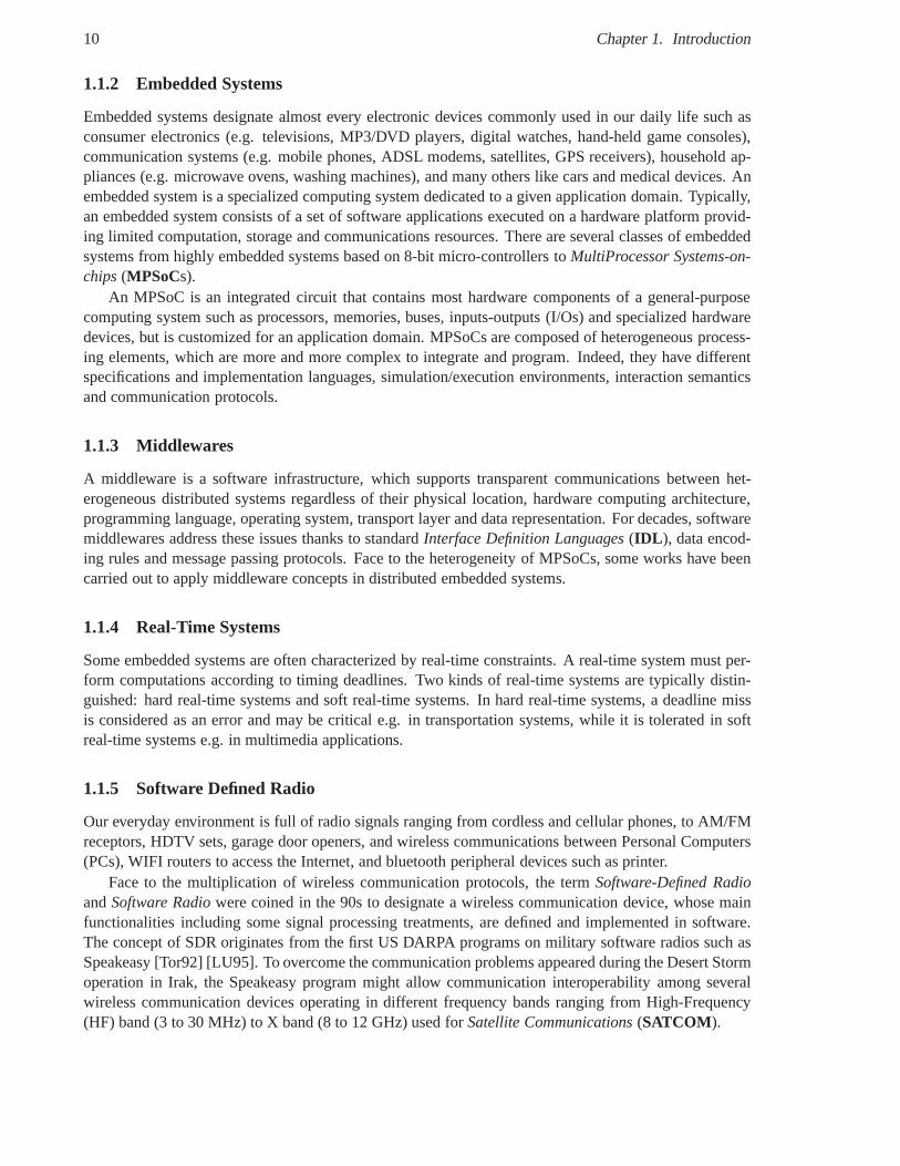
1.1.2 Embedded Systems
Embedded systems designate almost every electronic devices commonly used in our daily life such asconsumer electronics (e.g. televisions, MP3/DVD players,digital watches, hand-held game consoles),communication systems (e.g. mobile phones, ADSL modems, satellites, GPS receivers), household ap-pliances (e.g. microwave ovens, washing machines), and many others like cars and medical devices. Anembedded system is a specialized computing system dedicated to a given application domain. Typically,an embedded system consists of a set of software applications executed on a hardware platform provid-ing limited computation, storage and communications resources. There are several classes of embeddedsystems from highly embedded systems based on 8-bit micro-controllers toMultiProcessor Systems-on-chips(MPSoCs).
An MPSoC is an integrated circuit that contains most hardware components of a general-purposecomputing system such as processors, memories, buses, inputs-outputs (I/Os) and specialized hardwaredevices, but is customized for an application domain. MPSoCs are composed of heterogeneous process-ing elements, which are more and more complex to integrate and program. Indeed, they have differentspecifications and implementation languages, simulation/execution environments, interaction semanticsand communication protocols.
1.1.3 Middlewares
A middleware is a software infrastructure, which supports transparent communications between het-erogeneous distributed systems regardless of their physical location, hardware computing architecture,programming language, operating system, transport layer and data representation. For decades, softwaremiddlewares address these issues thanks to standardInterface Definition Languages(IDL ), data encod-ing rules and message passing protocols. Face to the heterogeneity of MPSoCs, some works have beencarried out to apply middleware concepts in distributed embedded systems.
1.1.4 Real-Time Systems
Some embedded systems are often characterized by real-timeconstraints. A real-time system must per-form computations according to timing deadlines. Two kindsof real-time systems are typically distin-guished: hard real-time systems and soft real-time systems. In hard real-time systems, a deadline missis considered as an error and may be critical e.g. in transportation systems, while it is tolerated in softreal-time systems e.g. in multimedia applications.
1.1.5 Software Defined Radio
Our everyday environment is full of radio signals ranging from cordless and cellular phones, to AM/FMreceptors, HDTV sets, garage door openers, and wireless communications between Personal Computers(PCs), WIFI routers to access the Internet, and bluetooth peripheral devices such as printer.
Face to the multiplication of wireless communication protocols, the termSoftware-Defined RadioandSoftware Radiowere coined in the 90s to designate a wireless communicationdevice, whose mainfunctionalities including some signal processing treatments, are defined and implemented in software.The concept of SDR originates from the first US DARPA programson military software radios such asSpeakeasy [Tor92] [LU95]. To overcome the communication problems appeared during the Desert Stormoperation in Irak, the Speakeasy program might allow communication interoperability among severalwireless communication devices operating in different frequency bands ranging from High-Frequency(HF) band (3 to 30 MHz) to X band (8 to 12 GHz) used forSatellite Communications(SATCOM ).
1.1. Context: Real-Time, Heterogeneous and Distributed Hardware/Software Embedded Systems11
Software-Defined Radios are much more flexible than older "hardware-defined radios" whose func-tionalities were hard-wired. A Software Defined Radio is a reconfigurable radio whose functionalitiesare defined in software and moved closer to the antenna [Tut02] [III00]. It is able to run a set of waveformapplications on the same radio platform
A waveform applicationis a component-based software application. The waveform componentsnotably implement signal processing treatments, which process the received data from the antenna to theend user and vice versa. These treatments are defined in custom or standard waveform specificationssuch as military NATO (North Atlantic Treaty Organization)Standardization Agreements(STANAGs)or civil ITU(International Telecommunication Union) standards such as WIFI/WIMAX. A waveformapplication may be roughly seen as a radio protocol stack organized in a similar way to the OSI (OpenSystems Interconnection) reference model. Aradio platform is a set of software and hardware layers,which provide the services required by the waveform application layer throughApplication ProgrammingInterfaces(APIs). A radio platform includes radio devices (e.g. a GPS receiver) and radio services (e.g.a log service).
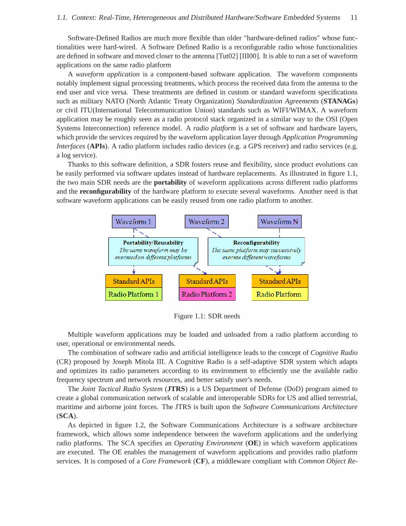
Thanks to this software definition, a SDR fosters reuse and flexibility, since product evolutions canbe easily performed via software updates instead of hardware replacements. As illustrated in figure 1.1,the two main SDR needs are theportability of waveform applications across different radio platformsand thereconfigurability of the hardware platform to execute several waveforms. Another need is thatsoftware waveform applications can be easily reused from one radio platform to another.
Figure 1.1: SDR needs
Multiple waveform applications may be loaded and unloaded from a radio platform according touser, operational or environmental needs.
The combination of software radio and artificial intelligence leads to the concept ofCognitive Radio(CR) proposed by Joseph Mitola III. A Cognitive Radio is a self-adaptive SDR system which adaptsand optimizes its radio parameters according to its environment to efficiently use the available radiofrequency spectrum and network resources, and better satisfy user’s needs.
TheJoint Tactical Radio System(JTRS) is a US Department of Defense (DoD) program aimed tocreate a global communication network of scalable and interoperable SDRs for US and allied terrestrial,maritime and airborne joint forces. The JTRS is built upon the Software Communications Architecture(SCA).
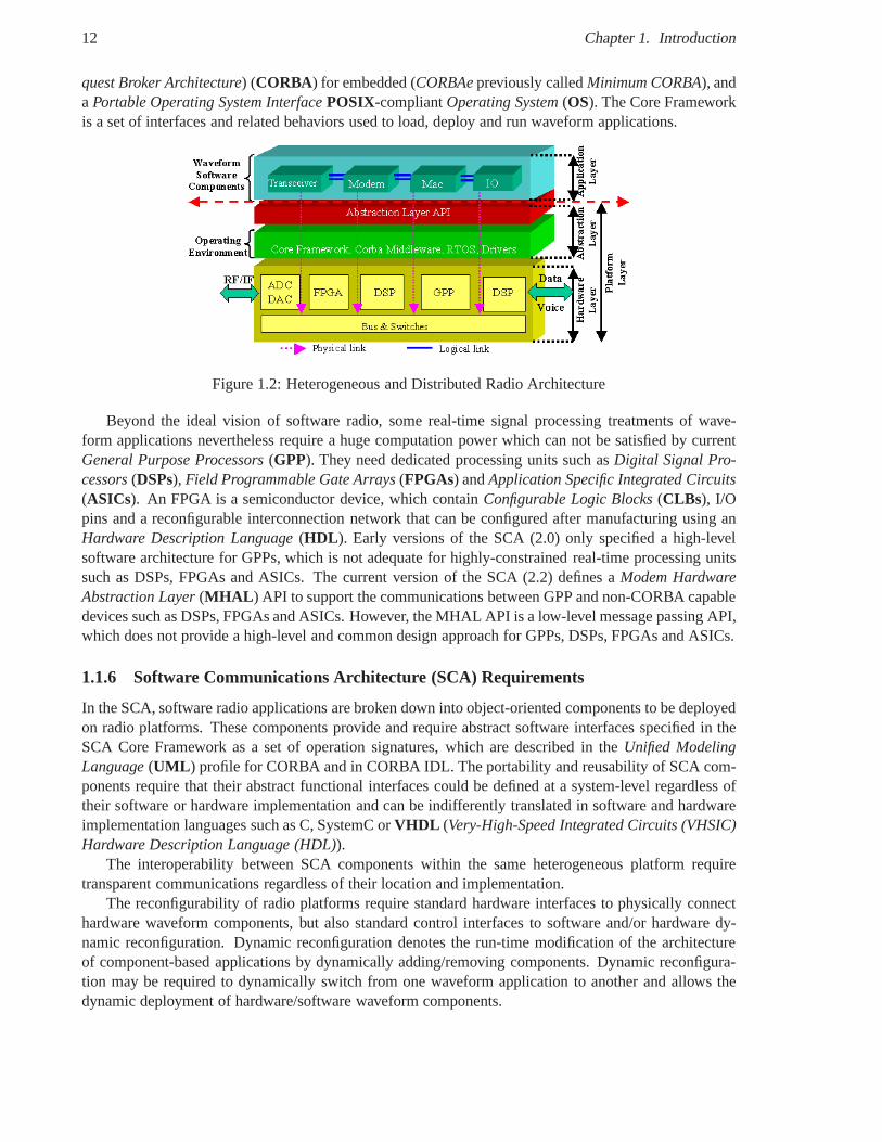
As depicted in figure 1.2, the Software Communications Architecture is a software architectureframework, which allows some independence between the waveform applications and the underlyingradio platforms. The SCA specifies anOperating Environment(OE) in which waveform applicationsare executed. The OE enables the management of waveform applications and provides radio platformservices. It is composed of aCore Framework(CF), a middleware compliant withCommon Object Re-
12 Chapter 1. Introduction
quest Broker Architecture) (CORBA) for embedded (CORBAepreviously calledMinimum CORBA), andaPortable Operating System InterfacePOSIX-compliantOperating System(OS). The Core Frameworkis a set of interfaces and related behaviors used to load, deploy and run waveform applications.
Figure 1.2: Heterogeneous and Distributed Radio Architecture
Beyond the ideal vision of software radio, some real-time signal processing treatments of wave-form applications nevertheless require a huge computationpower which can not be satisfied by currentGeneral Purpose Processors(GPP). They need dedicated processing units such asDigital Signal Pro-cessors(DSPs), Field Programmable Gate Arrays(FPGAs) andApplication Specific Integrated Circuits(ASICs). An FPGA is a semiconductor device, which containConfigurable Logic Blocks(CLBs), I/Opins and a reconfigurable interconnection network that can be configured after manufacturing using anHardware Description Language(HDL ). Early versions of the SCA (2.0) only specified a high-levelsoftware architecture for GPPs, which is not adequate for highly-constrained real-time processing unitssuch as DSPs, FPGAs and ASICs. The current version of the SCA (2.2) defines aModem HardwareAbstraction Layer(MHAL ) API to support the communications between GPP and non-CORBA capabledevices such as DSPs, FPGAs and ASICs. However, the MHAL API is a low-level message passing API,which does not provide a high-level and common design approach for GPPs, DSPs, FPGAs and ASICs.
1.1.6 Software Communications Architecture (SCA) Requirements
In the SCA, software radio applications are broken down intoobject-oriented components to be deployedon radio platforms. These components provide and require abstract software interfaces specified in theSCA Core Framework as a set of operation signatures, which are described in theUnified ModelingLanguage(UML ) profile for CORBA and in CORBA IDL. The portability and reusability of SCA com-ponents require that their abstract functional interfacescould be defined at a system-level regardless oftheir software or hardware implementation and can be indifferently translated in software and hardwareimplementation languages such as C, SystemC orVHDL (Very-High-Speed Integrated Circuits (VHSIC)Hardware Description Language (HDL)).
The interoperability between SCA components within the same heterogeneous platform requiretransparent communications regardless of their location and implementation.
The reconfigurability of radio platforms require standard hardware interfaces to physically connecthardware waveform components, but also standard control interfaces to software and/or hardware dy-namic reconfiguration. Dynamic reconfiguration denotes therun-time modification of the architectureof component-based applications by dynamically adding/removing components. Dynamic reconfigura-tion may be required to dynamically switch from one waveformapplication to another and allows thedynamic deployment of hardware/software waveform components.
1.2. Thesis Organization 13
In addition to the SCA component model, we consider the general-purpose component model of theCORBA middleware calledCORBA Component Model(CCM ). In particular, we focus on a reducedversion of CCM which is dedicated to embedded systems and called Lightweight CORBA ComponentModel(LwCCM ). The main reason of this choice is that LwCCM is a software industry standard main-tained by an open industry consortium calledObject Management Group(OMG ). For instance, UMLand CORBA are OMG standards. Moreover, Thales is an active OMG member.
1.1.7 Problems Formulation
The ambitious goal of this PhD thesis is to apply some successful software engineering concepts usedin the SCA down to FPGAs to propose a common and unified approach of specification and implemen-tation of hardware/software component-based waveform applications. These concepts are distilled fromcomponent-based software architecture and middlewares.
To address the portability requirement for SCA hardware components, we propose some require-ments and mapping rules between an operation-based abstract software interface in CORBA IDL orUML, an operation-based concrete software interface in system languages such as SystemC at trans-actional level, and a signal-based physical interface in HDLs such as VHDL and SystemC at RegisterTransfer Level (RTL).
The interoperability requirement has been addressed by prototyping a middleware core which trans-parently implements memory-mapping and message-passing using two protocols: the General Inter-ORBProtocol (GIOP) used by CORBA middlewares and the SCA MHAL messages. As opposed to hardwareimplementation of commercial CORBA middlewares, we demonstrated the overhead of a request-replyGIOP message decoder compared to a MHAL message decoder, anda classical memory-mapped addressdecoder with the same functionalities on an application example implemented on FPGA.
The second objective of this PhD thesis is to evaluate the useof virtual platforms in SystemC atTransaction Level to improve the design and validation of hardware/software waveform applications onvirtual radio platforms. Indeed, waveforms and platforms design becomes more and more complex (highdata rate antenna processing, programmable RF...) and involves new methodological needs, that we tryto address in this work. Indeed, executable specifications are needed to validate waveform consistencyand compliance against specifications. Hardware/softwarepartitioning and architecture exploration haveto be studied to achieve the required performances, which have to be estimated and compared to Qualityof Service (QoS) and real-time constraints. We modeled partof a MPSoC platform in SystemC usingTransaction Level Modeling(TLM ) and propose a SystemC-based design methodology.
1.2 Thesis Organization
In chapter 2, we provide an overview of the concepts, models and methodologies used to design embed-ded systems. In chapter 3, we present the on-chip communication architecture of buses and network-on-chips. In chapter 4, we present the fundamental concepts of the object-oriented approach used by theSCA and their applications in hardware design. In chapter 5,we provide an overview of middlewaresused by the SCA to abstract the distribution of software entities and their hardware implementations inSoCs. In chapter 6, we present the concepts of the component-oriented approach in software and hard-ware engineering and stress their commonalities. In chapter 7, our unified object-oriented componentand middleware approach is presented for both hardware and software components. In chapter 8, someexperiments are described to validate our proposition. Finally, a conclusion summarizes our contribu-tions.

Chapter 2
Models and Methodologies for EmbeddedSystems Design
Contents2.1 Introduction . . . . . . . . . . . . . . . . . . . . . . . . . . . . . . . . . . . .. . . 15
2.1.1 Models and Methodologies . . . . . . . . . . . . . . . . . . . . . . . .. . . . 16
2.1.2 General Concepts of Design . . . . . . . . . . . . . . . . . . . . . . .. . . . 17
2.2 Languages . . . . . . . . . . . . . . . . . . . . . . . . . . . . . . . . . . . . . . .. 18
2.2.1 Modeling Languages . . . . . . . . . . . . . . . . . . . . . . . . . . . . .. . 19
2.2.2 Software Programming Languages . . . . . . . . . . . . . . . . . .. . . . . . 20
2.2.3 Hardware Description Languages (HDL) . . . . . . . . . . . . .. . . . . . . 21
2.2.4 Structured Data Description Language . . . . . . . . . . . . .. . . . . . . . . 21
2.3 Models of Computation . . . . . . . . . . . . . . . . . . . . . . . . . . . . .. . . . 22
2.4 Models of Communication . . . . . . . . . . . . . . . . . . . . . . . . . . .. . . . 23
2.4.1 ISO OSI Reference Model . . . . . . . . . . . . . . . . . . . . . . . . . .. . 23
2.5 Parallel Programming Models . . . . . . . . . . . . . . . . . . . . . . .. . . . . . 24
2.5.1 Shared Memory Programming, Communication and Architecture Model . . . . 24
2.5.2 Message Passing Programming, Communication and Architecture Model . . . 25
2.5.3 Combination of Shared memory and Message Passing Model . . . . . . . . . 25
2.6 Traditional hardware/software design flow . . . . . . . . . . .. . . . . . . . . . . 25
2.7 System-Level Design (SLD) with Transaction-Level Modeling (TLM) . . . . . . . 27
2.8 Model-Based Design (MBD) and Model-Driven Engineering(MDE) . . . . . . . . 29
2.8.1 OMG Model-Driven Architecture (MDA) . . . . . . . . . . . . . .. . . . . . 30
2.9 Platform-Based Design (PBD) . . . . . . . . . . . . . . . . . . . . . . .. . . . . . 33
2.10 Conclusion . . . . . . . . . . . . . . . . . . . . . . . . . . . . . . . . . . . . .. . . 33
2.1 Introduction
Embedded systems are more and more complex to design notablydue to the increasing number of ap-plication needs in terms of performances to take into account and the heterogeneity of computation,storage and communications resources which are integratedin MPSoCs. This complexity is also due to
15
16 Chapter 2. Models and Methodologies for Embedded Systems Design
the design trade-offs to accomplish between cost, time, performances, the inherent concurrency issuesand the huge exploration space all along the design flow. The design exploration space is a multidi-mensional problem with some orthogonal directions such as hardware/software partitioning, hardware/-software architecture, tools availability and maturity, reusability of previous designs, etc. The design ofembedded systems requires skills in various domains such assoftware engineering and hardware engi-neering, along with expertise in the targeted application domain(s) such as signal processing. In orderto manage such complexity, numerous models, languages, methods and methodologies have been de-veloped to raise the abstraction level of design. Many design methods have been developed in industryand academia to address the specification, modeling, development and validation of embedded systems.Examples include models of computation and communication,Model-Based Design and Model-DrivenEngineering, Platform-Based Design, Hardware/Software Co-design, Transaction-Level modeling andHigh-Level Synthesis. The objective of system, software, hardware engineers consists in choosing thebetter combination of models, languages, methods and methodologies that satisfy the application needsand the allocated cost and time budgets.
A fundamental problem is how to unambigously specify an application with sufficient details toperform a good implementation. Industry companies may either define custom specification languagesand models or use existing standards to guarantee the perenity of application specifications, tools anddesign flows. In the latter case, companies need to identify and select the relevant standards to build acoherent design methodology.
This chapter is organized as follows. Section 2.2 presents modeling languages such as UML andSystemC, software programming languages such as C/C++ and Java, and hardware description languagessuch as VHDL and Verilog. Section 2.3 describes models of computation such as Finite State Machinesand Synchronous Data Flow. Section 2.4 presents models of communication such as the OSI referencenetwork model. Section 2.5 exposes parallel programming models such as shared memory model andthe message passing model. Section 2.8 presents model-based design and model-driven engineering suchas the OMG Model-Driven Architecture. Section 2.9 describes platform-based design for embeddedsystems. Finally, section 2.10 concludes this chapter.
2.1.1 Models and Methodologies
It is commonly accepted that engineering is all about modeling. modeling allows engineers to abstract aproblem regardless of the scientific domain: mathematical model, data model, biological model, socialmodel, mechanical model, electrical/electronic model, object/component model, etc. Generally speak-ing, a model represents the key characteristics of a problemand provides a conceptual framework toreason about it. A model is a specification of the function, structure and/or behavior of an applicationor system. This specification may be formal when it is based ona strong mathematical foundation.Otherwise, the specification is informal and may be subject to interpretations e.g. in case of textualspecifications. In embedded systems design, several modelsmay be required to capture all the functionaland non-functional properties of a system such as behavioral and structural models. A complete designmethodology relies on a collection of models. Each model focuses on different aspects of a system likeits behavior, its architecture or its real-time constraints. A typical methodology consists on a number ofsteps such as specification, design, developing and validating the system.Model Refinementconsists insuccessively enriching a model with additional details. For instance, a high-level behavioral model of asignal-processing treatment must be refined to be implemented as an software or hardware module in anelectronic circuit. Models are formalized by languages. Like any human spoken language, a languagehave aSyntaxand Semantics. The syntax of a language defines its well-formed structure, while seman-tics define its meaning and behavior [RIJ04]. A language may have a textual and/or graphical syntax.Moreover, a language may be based on mathematically-provenformal methods or be informal.
2.1. Introduction 17
2.1.2 General Concepts of Design
The general concepts underlying the design of any system isabstraction, encapsulation, modularityandhierarchy. They provide valuable design practices. These concepts have been presented by Booch[BME+07] in the context of the object-oriented approach, which ispresented in chapter 4, but they arequite general enough to be applicable to any design approachregardless of the engineering domain. Inthe following, we present these concepts as the main characteristics common to the models and method-ologies presented in these chapter.
Abstraction
Generally speaking, anabstractionis a relative distinction made between relevant and less relevant de-tails of a problem domain to enhance understanding and reduce complexity [Arm06, BME+07]. Therelevant details become explicit, whereas the other details are implicit. Abstractions help the separationor orthogonalization of concerns in a system. Raising the abstraction level is the main objective of lan-guages, models and methodologies created for system design. However, higher the level of abstractionis, bigger the conceptual gap between the specification and their implementation is. Several abstractionlevels are thus required to present a manageable view of a system and ease the refinement from onelevel of abstraction to another. The key point is to define theright set of abstractions for a particulardomain. According to Booch [BME+07], the quality of an abstraction may be measured by its coupling,cohesion, sufficiency, completeness and primitiveness. Inthis chapter, we will briefly present the mainabstractions used in the today models and methodologies fordesigning complex embedded systems.
Encapsulation
Encapsulationconsists in hiding the internal view of an abstraction in order to better deal with its com-plexity [BME+07]. The principle of encapsulation supports the well-known separation of concerns be-tween the definition of an interface and its implementation in a software programming language or ahardware description language as proposed in Interface-Based Design [RSV97]. Encapsulation allowsone to modify the implementation of an interface without changing the way users access to it. Encapsu-lation is often used a a synonym for an older concept calledinformation hiding[Arm06] [BME+07].
Modularity
Modularity consists in breaking down a complex system into aset of simple and more manageablemodules [BME+07]. A module represents a unit of design and reuse, which allows developers to work inparallel independently of one another. The objective of a modular approach is to improve cohesion withina module and reduce coupling among modules. A highly cohesive module encapsulates a set of relatedabstractions, while a loosely coupled module has few dependencies on other modules. Designers have tomake a trade-off on the granularity of a module and their number: too many modules result in too manyinterfaces and possible communication overhead, while toofew modules are less manageable. In theobject-oriented approach presented in chapter 4, a module is an object, while in the component-orientedapproach presented in chapter 6, a module corresponds to a component. Many languages support theconcept of modularity as for example through packages in Java, Ada and VHDL, or through namespacesin C++.
18 Chapter 2. Models and Methodologies for Embedded Systems Design
Hierarchy
Hierarchy establishes an ordering among a set of abstractions [BME+07]. The decomposition of asystem into hierarchical layers of abstraction is a key concept to design complex systems. An upperlayer is built upon a lower layer. In particular, the explicit details of the lower layer becomes implicit inthe upper layer. Examples of layered systems include theOpen Systems Interconnection(OSI) model, thesocket-based approach for on-chip communication buses, Network-On-Chips and middlewares presentedin chapter 5.
Like for modularity, designers have to trade off the abstraction level of a layer and their number. Ahigher abstraction level is more independent from low-level details of a platform at the expense of lesscontrol over it. Conversely, too many layers result in important performance overhead e.g. in term ofmemory footprint, latency, bandwidth and silicon area.
2.2 Languages
In order to better manage the ever increasing complexity of embedded systems and to increase produc-tivity, several specification, modeling and implementation languages have been developed since 1950s toraise the abstraction level at which design is performed. These languages allows designers to reduce de-velopment time and cost as less lines of code are needed to implement the same functionality. The briefhistory of languages shows that each new generation of language is build upon the previous one and re-sides at a higher-level of abstraction The trend is applicable to both software programming languages andhardware description languages. The often cited generation of software programming languages include[BME+07] [WQ05] [MSUW04]:
• Gear-Oriented Design with Pascal’s mechanical computer in 1642;
• Switch-Oriented Design with the first electronic computerENIAC1 in 1942;
• Instruction-Oriented Design with assembly languages;
• Procedure-Oriented Design or Structured Design based on sub-programs with Fortran, Pascal, Cand RPC IDL;
• Object-Oriented Design (OOD) with Smalltalk, Java, C++, Python, CORBA IDL 2.x, UML;
• Aspect-Oriented Design (AOD) [KLM+97] with AspectJ and AspectC++;
• Component-Oriented Design (COD) with ArchJava, CORBA IDL3.x, UML 2;
• Model-Based Design (MBD) with ArchJava, CORBA IDL 3.x;
Each term before the wordorienteddesignates the main design abstraction. For instance, the Object-Oriented Design considers anobjectas the main design unit.
In the same manner, hardware design has evolved to reach higher-level of abstraction.
• Transistor-level Design;
• Gate-level Design using AND, OR and NAND gates;
• Register-Transfer Level (RTL) Design with VHDL and Verilog, SystemC RTL;
1Electronic Numerical Integrator And Computer
2.2. Languages 19
• IP-based Design with SystemC;
• Transaction Level Modeling (TLM) with SystemC;
• Object-Oriented Design with object-oriented Hardware Description Language (HDL);
• Component-Based Design with hardware modules called Intellectual Properties (IPs);
• Model-Based Design with Model-Driven Engineering generating RTL code.
• Component-Oriented Design with SCA hardware components [JTR05] andthis thesis;
This work is an attempt to unify component-oriented design for both software and hardware compo-nents.
2.2.1 Modeling Languages
Unified Modeling Language (UML)
UML [OMG07d] is a graphical object-oriented modeling language standardized by the Open Manage-ment Group (OMG). UML allows designers to model a complex system according to multiple viewpointssuch as its structural and behavioral characteristics.
UML specifies thirteen diagrams divided into two main categories: Structural modeling and behav-ioral modeling. The structural diagrams include package diagrams, component diagrams, deploymentdiagrams, class diagrams, object diagrams, composite structure diagrams, interaction overview diagramsand communication diagrams. The behavioral diagrams include use case diagrams, activity diagrams,sequence diagrams, state machine diagrams, timing diagrams. Obviously, we cannot describe all thesekinds of diagrams here, nevertheless some of them are brieflydescribed in the following [BME+07]:
• A package diagram provides the means to organize the artifacts of the development process.
• A component diagram shows the internal structure of components and their dependencies withother components. This diagram provides the representation of components, collaborating throughwell-defined interfaces, to provide system functionality.
• A deployment diagram shows the allocation of artifacts to nodes in the physical design of a system.During development, we use deployment diagrams to indicatethe physical collection of nodes thatserve as the platform for execution of our system.
• A use case diagram depicts the functionality provided by a system. Use case diagrams depictwhich actors interact with the system.
• An activity diagram provides the visual depiction of the flow of activities. These diagrams focus onthe activities performed and who (or what) is responsible for the performance of those activities.
• A class diagram captures the structure of the classes and their relationships in the system.
• A sequence diagram represents a temporal sequence of operation calls
• An interaction overview diagram is a combination of activity diagrams and interaction diagramsto provide an overview of the flow of control between diagram elements.
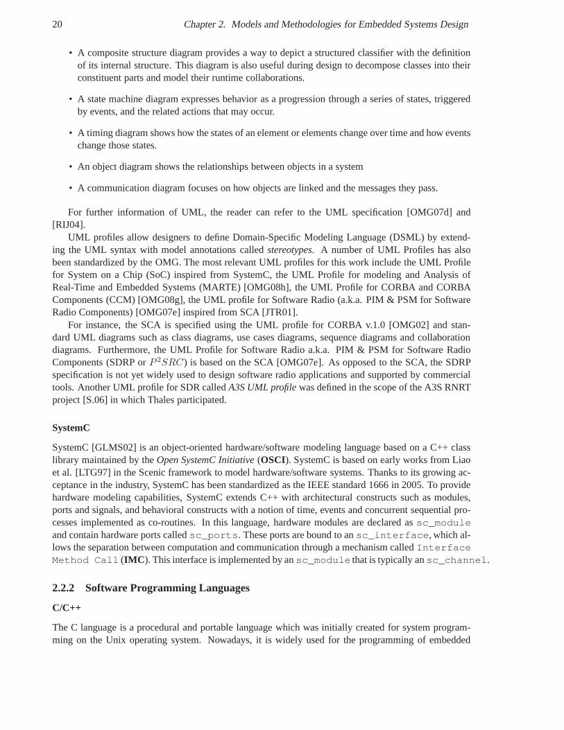
20 Chapter 2. Models and Methodologies for Embedded Systems Design
• A composite structure diagram provides a way to depict a structured classifier with the definitionof its internal structure. This diagram is also useful during design to decompose classes into theirconstituent parts and model their runtime collaborations.
• A state machine diagram expresses behavior as a progression through a series of states, triggeredby events, and the related actions that may occur.
• A timing diagram shows how the states of an element or elements change over time and how eventschange those states.
• An object diagram shows the relationships between objectsin a system
• A communication diagram focuses on how objects are linked and the messages they pass.
For further information of UML, the reader can refer to the UML specification [OMG07d] and[RIJ04].
UML profiles allow designers to define Domain-Specific Modeling Language (DSML) by extend-ing the UML syntax with model annotations calledstereotypes. A number of UML Profiles has alsobeen standardized by the OMG. The most relevant UML profiles for this work include the UML Profilefor System on a Chip (SoC) inspired from SystemC, the UML Profile for modeling and Analysis ofReal-Time and Embedded Systems (MARTE) [OMG08h], the UML Profile for CORBA and CORBAComponents (CCM) [OMG08g], the UML profile for Software Radio (a.k.a. PIM & PSM for SoftwareRadio Components) [OMG07e] inspired from SCA [JTR01].
For instance, the SCA is specified using the UML profile for CORBA v.1.0 [OMG02] and stan-dard UML diagrams such as class diagrams, use cases diagrams, sequence diagrams and collaborationdiagrams. Furthermore, the UML Profile for Software Radio a.k.a. PIM & PSM for Software RadioComponents (SDRP orP 2SRC) is based on the SCA [OMG07e]. As opposed to the SCA, the SDRPspecification is not yet widely used to design software radioapplications and supported by commercialtools. Another UML profile for SDR calledA3S UML profilewas defined in the scope of the A3S RNRTproject [S.06] in which Thales participated.
SystemC
SystemC [GLMS02] is an object-oriented hardware/softwaremodeling language based on a C++ classlibrary maintained by theOpen SystemC Initiative(OSCI). SystemC is based on early works from Liaoet al. [LTG97] in the Scenic framework to model hardware/software systems. Thanks to its growing ac-ceptance in the industry, SystemC has been standardized as the IEEE standard 1666 in 2005. To providehardware modeling capabilities, SystemC extends C++ with architectural constructs such as modules,ports and signals, and behavioral constructs with a notion of time, events and concurrent sequential pro-cesses implemented as co-routines. In this language, hardware modules are declared assc_moduleand contain hardware ports calledsc_ports. These ports are bound to ansc_interface, which al-lows the separation between computation and communicationthrough a mechanism calledInterfaceMethod Call (IMC ). This interface is implemented by ansc_module that is typically ansc_channel.
2.2.2 Software Programming Languages
C/C++
The C language is a procedural and portable language which was initially created for system program-ming on the Unix operating system. Nowadays, it is widely used for the programming of embedded
2.2. Languages 21
systems notably thanks to the error-prone concept ofpointer which allows developers to directly accesssystem memory and memory-mapped hardware registers. C++ isa general-purpose language that ex-tends C with object-oriented capability of C++ and standardhigh-level library such as theStandard Tem-plate Library (STL). For instance, software waveform components are mainly implemented in C/C++on embedded radio platforms. C/C++ may also be used to build functional model of hardware waveformcomponents.
Java
Java is a general purpose, concurrent, object-oriented andplatform independent programming language.Java is compiled into abstract instructions calledbytecodein .classfiles. This bytecode is executed bya run-time environment called the Java Virtual Machine (JVM). Java may also be compiled to a nativeinstruction set using the GNU Compiler Collection (GCC). Due to its interpreted nature, Java is notwidely used for embedded systems and notably for radio applications.
2.2.3 Hardware Description Languages (HDL)
A Hardware Description Language(HDL ) is a language to formally model electronic circuits. Whereassoftware programming languages are compiled into a binary code executed on an instruction-set pro-cessor, HDLs are synthesized into a piece of hardware typically on Field Programmable Gate Array(FPGA) or Application Specific Integrated CircuitASIC. An HDL allows hardware designers to de-scribe at Register Transfer Level (RTL) the architecture ofhardware building blocks, whose temporaland logic behavior is checked thanks to simulation tools i.e. simulators. The two main Hardware De-scription Languages (HDL) are the Very-High-Speed Integrated CircuitsVHSIC Hardware DescriptionLanguage (VHDL ) and Verilog. Interestingly, HDLs were originally developed for the documentationand simulation of gate-based schematics. HDLs may model discrete events for digital hardware and con-tinuous time for analog hardware. As hardware is inherentlyparallel, an HDL allows to explicitly specifyconcurrency through concurrent statements and time with wait statements for simulation purpose. HDLssupport appropriate data types to model hardware modules like bit arrays.
Logic synthesisis a process by which a RTL model specified in an HDL is inferredinto a set ofinterconnected logic gates described by anetlist. The hardware model have to typically respect somecoding guidelines imposed by synthesis tools calledsynthesizerin order to produce the required behavior.These guidelines include the use of a synthesizable subset of HDLs and some code templates to facilitatethe inference of memory units such as registers, RAM/ROM or hardware operators like multipliers.For instance, high-level HDL constructs, which are used forsimulation in testbenches, are typically notsynthesizable. In a similar way than code written in low-level assembly languages is more optimized, butless portable than code written in portable programming languages like C, HDL code based on vendor-specific modules is optimized for a given FPGA platform, but is not portable for another platform, whileHDL code written with generic modules are portable, but not optimized. Hence, it is not always possibleto write portable code for FPGAs.
2.2.4 Structured Data Description Language
Structured data description languages are used to describeuser-defined data and the data used to de-scribed the user-defined data themselves calledmeta-data. The eXtensible Markup Language (XML) isa structured data description language with use markups to describe information as plain text in files withthe.xml extension. The content and structure of XML documents are constrained by rules expressedin a XML Schema Language such asDocument Type Definition(DTD) with .dtd extensions and XML
22 Chapter 2. Models and Methodologies for Embedded Systems Design
Schemewith .xsd extension. DTD files describe a type of XML documents as a structured set of ele-ments that contain data and attributes. For instance, XML isused in software component models such asCCM and SCA, meta-data for hardware components such as SPIRIT, and storage of UML models suchas XMI.
2.3 Models of Computation
A Model of Computation(MoC) is the formal abstraction of the execution in a computer. Itallows one toformally describe and reason about concurrent and distributed systems. A model of computation definesthe behavior and interaction semantics that govern the elements in different parts or at different levels of asystem. As its name does not suggest, a model of computation describes the semantics of communicationbetween components. It contains operational rules which drive the execution of a model in particularwhen components perform computation, update their state and perform communication [LN04]. Modelsof computations are to actor-oriented design what design patterns are to object-oriented design and whatcommunication protocols are to signal-oriented design [LN04]. Many models of computation have beenidentified in the literature:
• Synchronous Data Flow(SDF) is a static data flow in which the number of data token produced orconsumed by each processing node is known at design time [LM87]. Nodes communicate throughqueues and can be statically scheduled at compile time. Signal processing applications can betypically described as a synchronous data flow. They can be specified by aData-Flow Graph(DFG) where each node represents a processing block and each arc adata path. This model hasbeen used to describe both hardware and software systems.
• In theContinuous Time(CT) MoC, processing elements communicate via a continuous time signalat a given time point. Such systems are typically represented by differential equations like physicalsystems.
• Communicating Sequential Processes(CSP) communicate via synchronous message passing orrendezvous.
• Process Networks(PN) like Kahn Process Networks(KPN) communicate via asynchronous mes-sage passing. Sequential processes communicate through unbounded FIFO channels. KPNs arenotably used to model signal processing applications e.g. see our experiments in §8.3.2.
• Finite State Machines(FSM) are represented byControl-Flow Graph(CFG) in which a noderepresent a state and an arc a state transition triggered by some boolean expression called guard.
• Discrete-Events(DE): processing nodes interact via an event queue. This model is used to modeldigital circuits, asynchronous circuits and events in physical systems.
• Petri Nets(PN): processing nodes performs asynchronous computation with explicit synchroniza-tion points. The UML2 activity model is inspired from Petri nets [RIJ04].
• Synchronous Reactive(SR): computation elements update the values of their output until the sys-tem stabilizes. This MoC is used in synchronous languages like Esterel, Lustre and Signal used todescribe both hardware and software systems.
For instance, a domain-specific specification language calledWaveform Description Languages(WDL )has been proposed by E.W. at Thales Reseach Inc. to specify waveform applications. WDL is a
2.4. Models of Communication 23
component-based graphical language where components havedata-flow ports and is based on a Syn-chronous Data Flow model of computation.
Various modeling frameworks such as Ptolemy [HLL+03], Metropolis [BWH+03] and BIP [Sif05]propose to model and simulate embedded systems through the hierarchical composition of computationmodels [GBA+07].
As far as SDR is concerned, waveform applications are roughly based on FSM for the control pathe.g. to manage a mode switch and a synchronous data flow for thedata path.
2.4 Models of Communication
2.4.1 ISO OSI Reference Model
The International Organization for Standardization (ISO)Reference Model (RM) of Open Systems Inter-connection (OSI) is an abstract layered communication architecture organized as a stack of seven layers:Physical, Data Link, Network, Transport, Session, Presentation and Application [Zim80]. The OSI RMprovides a common conceptual framework to describe standard protocols.
Basically, a computer network is a set of computers calledhostwhich communicate to one another.The seven layers are implemented on each host, while only thetree lowest layers are used in the inter-mediate routers.
Such a layered approach allows an independent modification of the implementation of each layer,while their interfaces and behaviors must remain the same. Asystem is logically divided into successivehorizontal layers from the Application layer at the top to the Physical layer at the bottom.
Each layer provides and requires a set of services to the nextupper and lower layer through interfacescalledService Access Point(SAP), which are implemented by groups of functions calledEntities. Withinthe same horizontal layer, two entities on different hosts virtually communicate using a peer-to-peerprotocol based on a standardized message format calledProtocol Data Unit(PDU). In reality, the dataare transferred through the protocol stack of the lower layers. Each successive protocol layer encapsulatesthe data received from the previous layer with a layer-specific control header to build a new message.The layers do not know the meaning of the encapsulated data, the message format or protocol used toprovide a complete decoupling of each layer.
The ISO OSI reference model is structured as a hierarchy of seven layers.
• The Physical Layer (PHY) deals with the transfer of rawbit stream on a medium (cable, air,water, space, etc). This layer defines the electrical and mechanical characteristics for transmis-sion such as wire voltages, timing, frequency, width. Examples include serial (RS232), Ethernet(10/100/1000BASE-T) and WIFI (802.11 PHY).
• TheData Link Layer is in charge of the reliability offramesused by the network layer. This layerperforms physical addressing and error control by introducing additional bits in the raw bit streamto detect and correct transmission errors. It typically contains two sub-layers calledMedium AccessControl (MAC ) andLogical Link Control(LLC ). Examples include Ethernet MAC (802.3), WIFIMAC/LLC (802.11), ATM and HDLC.
• TheNetwork Layer is responsible for the delivery and routing of packets used by the transportlayer. This layer performs logical addressing and flow control to avoid congestion in the routers.Examples include the Internet Protocol (IP) and Internet Control Message Protocol (ICMP) usedby ping and traceroute tools.
24 Chapter 2. Models and Methodologies for Embedded Systems Design
• TheTransport Layer establishes an end-to-end communication between hosts using the networklayer. Examples include TCP (Transmission Control Protocol) and UDP (User Datagram Proto-col).
• The Session Layercopes with setting up, managing and tearing down connectionbetween ap-plication processes based on the transport layer between hosts. Examples includeInter-ProcessCommunication(IPC) such as named pipes and sockets.
• ThePresentation layer is concerned with the transformations of application data prior to trans-mission such as compression, encryption, conversion called marshallingto a common data repre-sentation. Examples include ASCII, MPEG, MIME, XDR, SSL, CORBA CDR.
• TheApplication Layer is used by the user applications for distributed communications. This layerperforms synchronization between application processes.Examples include HTTP, FTP, DNS andCORBA GIOP
For instance, SDR applications are an assembly of waveform components, whose functionalitiesare organized as in the OSI model: digital signal processingfor Modem components in the physicallayer, medium acess control for MAC components, data link for Link components, routing for Networkcomponents and input/output access for I/O components.
2.5 Parallel Programming Models
A parallel computing architecture contains a set of processing elements that communicate and cooperateto execute applications according their performances requirements. Concurrent software applicationsexecuted on parallel computing architectures need to be developed according to one or severalparallelprogramming models. A programming model defines how parts of an application communicate with oneanother and coordinate their activities [CSG98].
The two main programming models which have been traditionally identified for parallel computingarchitectures are shared memory and message passing. Otherprogramming models include data parallelprocessing i.e. Single Program Multiple Data (SPMD), data-flow processing and systolic processing[CSG98].
A parallel programming model allows developers to abstractthe heterogeneity of different hard-ware/software platform architectures and to abstract communication using an Application ProgrammingInterfaces (API). This API specifies communication and synchronization operations which are used bythe applications and implemented by the platform using compilers and libraries from languages, OS andmiddlewares. Parallel programming models must balance twocontradictory objectives: reduce devel-opment time and cost using higher-level programming model,and improve system performances usinglower-level programming model [JBP06]. As opposed to classical APIs for desktop and enterprise com-puters such asPortable Operating System Interface(POSIX) andMessage Passing API(MPI ), APIs forMPSoCs may be not standard and customized for a particular platform and their implementation mustbe optimized to satisfy the performance requirements of a specific application or application domain.
Each programming model provides different trade-offs in terms of performance, time, space andsynchronization coupling [LvdADtH05]. For instance, the MultiFlex platform [PPL+06b] supports botha CORBA-like message passing model and a POSIX-like shared memory model.
2.5.1 Shared Memory Programming, Communication and Architecture Model
In the shared memory model, two or more application entitiescommunicate through shared variablesby writing and reading data at pre-defined addresses in the same shared address space. This memory
2.6. Traditional hardware/software design flow 25
is shared and accessible by all participants in the communication. Application data do not need to becopied because they are directly accessible. The application entities reside in the same address space.The shared memory model implies a tight coupling between communicating entities due to synchroniza-tion. Since the memory locations are shared, only one writerat a time is allowed on a given address toensure memory consistency, while several readers can read this location without harm. The writer mustacquire and release a lock before and after a write. This requires special hardware support for indivisi-ble or atomic operations for synchronization. Successive writes from several writers must be serializedto ensure ordered memory accesses and avoid race conditions. Standard APIs for shared memory in-clude POSIX and synchronization primitives offered by programming languages. From a programmingviewpoint, different processes/threads running on the same or different processors may communicatethrough shared variables. The basic communication primitives arereadandwrite operations, which areimplemented by the load and store instructions of processors. From a hardware architecture viewpoint,a shared memory multiprocessor calledSymmetric Multiprocessor(SMP) may be used with aUniformMemory Architecture(UMA ) where the access time to the shared memory is the same for allprocessors.
2.5.2 Message Passing Programming, Communication and Architecture Model
In the message passing model, two or more application entities communicate with each other by sendingand receiving messages. The application entities reside indifferent address space and have their ownprivate memory. Application data must be copied from the sender memory to the message and from themessage to the receiver memory. The message passing model allows a loose coupling between commu-nicating entities e.g. via buffering. The basic communication primitives are send and receive operations.Standard APIs for message passing include MPI [For08]. Froma programming viewpoint, process-es/threads running on the same or different processors may communicate through message queues, OSor middleware calls. From a hardware architecture viewpoint, each processing unit has its own privatememory and form a dedicated node which communicate with other nodes through the network e.g. abus.
2.5.3 Combination of Shared memory and Message Passing Model
Both models may be used independently and they may be combined. For instance, a memory accessmay be encapsulated in a message to be sent over the network [Bje05]. Each processing unit has itsown memory which has either a private and a shared part or is private the processor can access a globalshared memory. This architecture has a Non-Uniform Memory Architecture (NUMA) where the memoryaccess time depends on the memory location. Indeed, a local memory access takes less time than a remotememory access in the local memory of another processor. The local memory controller determines if amemory access on the local memory or a message passing with the remote memory controller has to beperformed.
Traditionally, the design of modems relies on a shared memory model in which DSPs read/write data,commands, parameters and status to/from FPGAs using register banks. Due to the heterogeneous anddistributed nature of SDR platforms, the SCA introduces theuse of middlewares such as CORBA andthe SCA Modem Hardware Abstraction Layer (MHAL) for modem design. Hence, SDR applicationsand platforms may be developped using a combination of both programming models.
2.6 Traditional hardware/software design flow
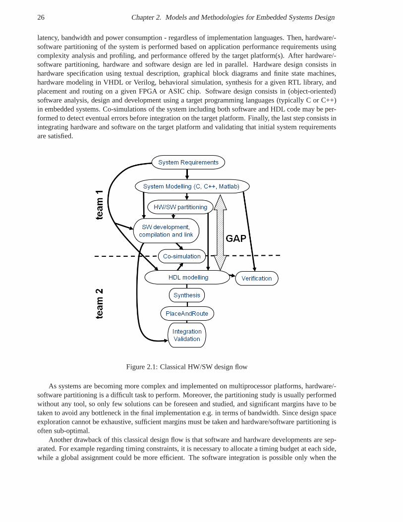
The traditional hardware/software design flow is depicted in figure 2.1. First, an executable model ofthe system is developed according to system requirements such as the number of operations per second,
26 Chapter 2. Models and Methodologies for Embedded Systems Design
latency, bandwidth and power consumption - regardless of implementation languages. Then, hardware/-software partitioning of the system is performed based on application performance requirements usingcomplexity analysis and profiling, and performance offeredby the target platform(s). After hardware/-software partitioning, hardware and software design are led in parallel. Hardware design consists inhardware specification using textual description, graphical block diagrams and finite state machines,hardware modeling in VHDL or Verilog, behavioral simulation, synthesis for a given RTL library, andplacement and routing on a given FPGA or ASIC chip. Software design consists in (object-oriented)software analysis, design and development using a target programming languages (typically C or C++)in embedded systems. Co-simulations of the system including both software and HDL code may be per-formed to detect eventual errors before integration on the target platform. Finally, the last step consists inintegrating hardware and software on the target platform and validating that initial system requirementsare satisfied.
Figure 2.1: Classical HW/SW design flow
As systems are becoming more complex and implemented on multiprocessor platforms, hardware/-software partitioning is a difficult task to perform. Moreover, the partitioning study is usually performedwithout any tool, so only few solutions can be foreseen and studied, and significant margins have to betaken to avoid any bottleneck in the final implementation e.g. in terms of bandwidth. Since design spaceexploration cannot be exhaustive, sufficient margins must be taken and hardware/software partitioning isoften sub-optimal.
Another drawback of this classical design flow is that software and hardware developments are sep-arated. For example regarding timing constraints, it is necessary to allocate a timing budget at each side,while a global assignment could be more efficient. The software integration is possible only when the
2.7. System-Level Design (SLD) with Transaction-Level Modeling (TLM) 27
hardware module are already modeled. Indeed, in the classical flow, no intermediate hardware modelis available for software integration, hence hardware modeling and software integration cannot be per-formed in parallel. Moreover, hardware and software teams can make misleading interpretations resultingin difficult integration, rework and time loss. An importantabstraction gap exists between algorithmscaptured by the C/C++/Matlab reference model, also calledbusiness code, and the final hardware imple-mentation.
Face to the number of applications to be integrated on System-on-Chip platforms, new methodolo-gies and tools are required to address the drawbacks of the classical hardware/software design flow. Inparticular, these methodologies must fill in the gap betweensystem modeling and hardware modeling.In the next sections, we describe methodologies that may address these needs.
2.7 System-Level Design (SLD) with Transaction-Level Modeling (TLM)
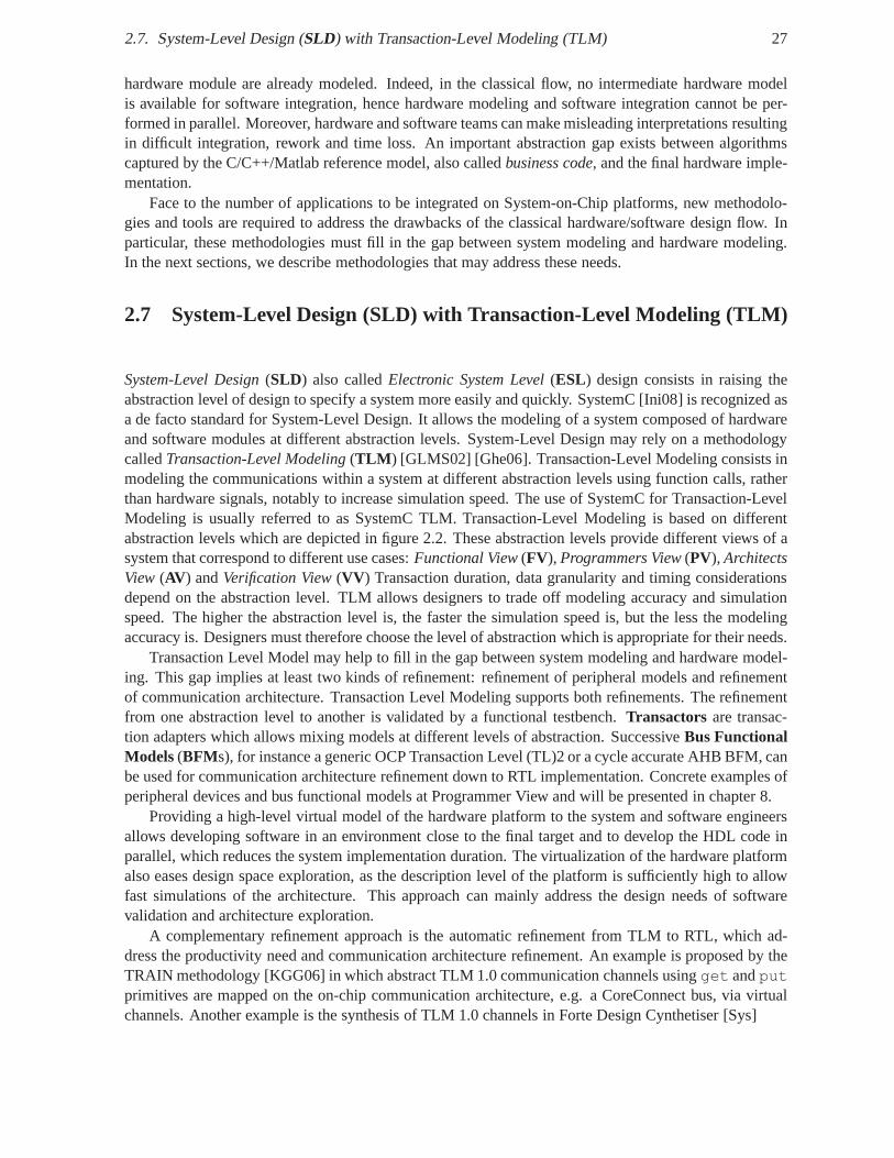
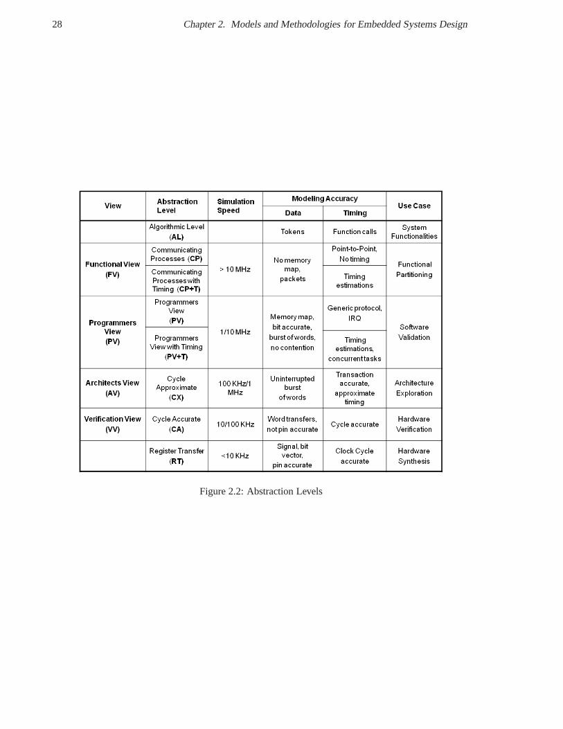
System-Level Design(SLD) also calledElectronic System Level(ESL) design consists in raising theabstraction level of design to specify a system more easily and quickly. SystemC [Ini08] is recognized asa de facto standard for System-Level Design. It allows the modeling of a system composed of hardwareand software modules at different abstraction levels. System-Level Design may rely on a methodologycalledTransaction-Level Modeling(TLM ) [GLMS02] [Ghe06]. Transaction-Level Modeling consists inmodeling the communications within a system at different abstraction levels using function calls, ratherthan hardware signals, notably to increase simulation speed. The use of SystemC for Transaction-LevelModeling is usually referred to as SystemC TLM. Transaction-Level Modeling is based on differentabstraction levels which are depicted in figure 2.2. These abstraction levels provide different views of asystem that correspond to different use cases:Functional View(FV), Programmers View(PV), ArchitectsView (AV ) andVerification View(VV ) Transaction duration, data granularity and timing considerationsdepend on the abstraction level. TLM allows designers to trade off modeling accuracy and simulationspeed. The higher the abstraction level is, the faster the simulation speed is, but the less the modelingaccuracy is. Designers must therefore choose the level of abstraction which is appropriate for their needs.
Transaction Level Model may help to fill in the gap between system modeling and hardware model-ing. This gap implies at least two kinds of refinement: refinement of peripheral models and refinementof communication architecture. Transaction Level Modeling supports both refinements. The refinementfrom one abstraction level to another is validated by a functional testbench.Transactors are transac-tion adapters which allows mixing models at different levels of abstraction. SuccessiveBus FunctionalModels(BFMs), for instance a generic OCP Transaction Level (TL)2 or a cycle accurate AHB BFM, canbe used for communication architecture refinement down to RTL implementation. Concrete examples ofperipheral devices and bus functional models at ProgrammerView and will be presented in chapter 8.
Providing a high-level virtual model of the hardware platform to the system and software engineersallows developing software in an environment close to the final target and to develop the HDL code inparallel, which reduces the system implementation duration. The virtualization of the hardware platformalso eases design space exploration, as the description level of the platform is sufficiently high to allowfast simulations of the architecture. This approach can mainly address the design needs of softwarevalidation and architecture exploration.
A complementary refinement approach is the automatic refinement from TLM to RTL, which ad-dress the productivity need and communication architecture refinement. An example is proposed by theTRAIN methodology [KGG06] in which abstract TLM 1.0 communication channels usingget andputprimitives are mapped on the on-chip communication architecture, e.g. a CoreConnect bus, via virtualchannels. Another example is the synthesis of TLM 1.0 channels in Forte Design Cynthetiser [Sys]
28 Chapter 2. Models and Methodologies for Embedded Systems Design
Figure 2.2: Abstraction Levels
2.8. Model-Based Design (MBD) and Model-Driven Engineering (MDE) 29
The second refinement approach is High-Level Synthesis (HLS) that consists in the automatic gener-ation of HDL code using the system model with tools such as Mentor Catapult [Gra07] and MathworksSimulink [Mat08]. As a single team is involved in the translation of system requirements, some mis-interpretations may be avoided. Moreover, rework is quite simple as automatic re-generation can beperformed quickly. Nevertheless, most of these tools mainly address data flow oriented digital signalprocessing applications, while control and scheduling functionalities are much less supported and mayrequire third-party tools. HLS only satisfies the productivity need of coding and the translation of pe-ripheral models. As there is no intermediate model between the high-level algorithmic model and itsRTL implementation, this approach is similar to the hardware classical flow and its drawbacks: slowsimulation speed and time consuming verification. A trade-off between simulation speed and modelingaccuracy is no more possible and this does not provide the good level of details to address use cases suchas software validation and architecture exploration.
The OSCI published a first version of TLM APIs called TLM 1.0 [RSPF05] to provide commonmodeling interfaces and allow portability of TLM models across academic and industry organizations.However, the format of TLM 1.0 messages was not standardized. As a result, TLM 1.0 models werenot interoperable. So, the OSCI published a second version of TLM APIs called TLM 2.0 [OSC09] tobetter support interoperability between TLM models. TLM 2.0 notably defines a generic payload forTLM messages with ignorable extensions for advanced bus features.
In addition, working group of OCP-IP dedicated to System Level Design proposed a TLM API forOCP [OI07]. This modeling is based on three TLM layers above the RTL layer: a Message Layer (TL3),a Transaction Layer (TL2) and a Transfer Layer (TL1), while the RTL Layer is called TL0. A TLMstandardization agreement was signed between OSCI and OCP-IP [OI04]. Besides, OCP TL2 and TL3can be mapped to the OSCI TLM API [THA05], and both TLM APIs canbe mixed using transactors, aspresented in chapter 8. The PV API from OSCI is a standard interface enabling SystemC IP reuse, whileOCP TLM layers are standard user layers, above OSCI foundation layer [THA05].
A partnership exists between OSCI and OCP-IP to guarantee some coherence between TLM inter-faces.
2.8 Model-Based Design (MBD) and Model-Driven Engineering(MDE)
A model is a formal specification of the function, structure and/or behavior of an application or system.Model Driven Engineering(MDE ) is a promising design methodology in whichmodelsare the corner-stone of system development. The objective is to extensively use models all along the design flow of asystem from specification to design and implementation. A model allows designers to raise the abstrac-tion level by hiding implementation details and to better manage complexity usually via hierarchicalvisual models. Models may be described at different abstraction levels and may focus on specific aspectsor views of a system such as its structure or behavior.
Model-Based Design(MBD ) aims at developing customized design environments which are tailoredto a particular application domain e.g. automotive, avionic or radio domain. With MDE, designer’swork is shifted from code development to system modeling. Designers describe a system using domain-specific concepts and their relationships. The most popularMDE approaches are the OMG initiativescalledModel-Driven Development™(MDD™) andModel Driven Architecture®(MDA ®) [MSUW04].These initiatives are naturally based on the UML modeling language which is standardized by the OMG.Other closely related terminologies for MDE includeModel-Based Design(MBD ) andModel-IntegratedComputing(MIC ) [SK97].
Model-Based Design places an abstract model of an algorithmat the center of the design cycle andprovides a coherent view in all design phases: executable specification, simulation, test and verification,
30 Chapter 2. Models and Methodologies for Embedded Systems Design
and implementation based on automatic code generation.An often-cited example of Model-Based Design tools is MathWorks Simulink [Mat08]. MathWorks
Simulink is a graphical modeling tool for algorithms and systems whose models provide an executablespecification. Designers may interconnect predefined processing blocks and configure them, or they maydescribe an algorithm in the Matlab language calledM language. Code generation allows the synchro-nization between the model and its implementation. Designers can select particular platforms or targetspecific tools such as TI Code Composer, Altera DSPBuilder orXilinx System Generator.
In addition, a design methodology for SoC/SoPC developmentis proposed based on MDD and theMARTE UML profile in the scope of the MOPCOM research project [AKL +09] . The MOPCOM toolsetnotably supports HDL code generation within the Rhapsody UML modeler.
2.8.1 OMG Model-Driven Architecture (MDA)
The Model-Driven Architecture (MDA) [OMG03] [MSUW04] is the Model-Driven Engineering ap-proach standardized by the OMG. The MDA promotes the separation between the specification of systemfunctionalities captured in aPlatform Independent Model(PIM ) from the specification of their imple-mentation on a particular platform defined in thePlatform Specific Model(PSM).
Platform Independent Model (PIM)
One or several PSMs can be associated to the same PIM. PIMs andPSMs may be specified in UML. Forinstance, the PIM may be defined using standard UML or a domain-specific UML profile like the UMLprofile for SDR [OMG07e], while the PSMs may rely on platform-specific UML profiles such as theUML profile for CORBA and CCM. A PSM results from the mapping ofa PIM on the implementationtechnologies available on a particular hardware/softwareplatform such as a programming language likeC, C++, Java, SystemC and VHDL, a meta-data language like XMLor a middleware platform like .NET,EJB and CORBA.
For instance, the UML Profile for Software Radio [OMG07e] leverages the SCA using the MDAapproach in which PIMs of SDR applications are decoupled from their realization in PSMs such asCORBA.
MDA raises the level of abstraction and reusability and introduces the concept ofdesign-time interop-erability [MSUW04]. Indeed, MDA aims developers to build independentand reusable models of a sys-tem and to combine or glue them "only at the last minute" to build and deploy the system. These modelsare typically an application model and a platform model which are mapped together using a deploymentmodel to build a system. Model transformations may also be used to generate adapters [KMD05] or in-teroperability bridges [Bon06]. The MDA is based on three main OMG standards: theUnified modelingLanguage(UML ) [OMG07b] for modeling, theMeta Object Facilities(MOF ) [OMG05a] [OMG06c]for meta-modeling and theXML Metadata Interchange(XMI ) [OMG07c] for storing orserializingmod-els and meta-models as persistent XML files.
MOF is a meta-model and modeling language to describe meta-models. A meta-model is a modelof a modeling language. A meta-model is a model whose instances are the data types of another model.It specifies the concepts of the language used to define a model. A meta-model defines the structure,semantics and constraints for a family of models conformingto this meta-model. Each model is capturedby a particular meta-model.
Meta-models allow the definition of model transformations from a source model conforming to asource meta-model to a target model conforming to a target meta-model. XMI is a mapping from MOFto XML. XMI is a XML schema allowing the exportation and importation of UML models from/to UMLmodeling tools. XMI supports the interoperability and integration of different tools along the design
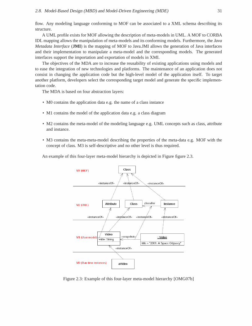
2.8. Model-Based Design (MBD) and Model-Driven Engineering (MDE) 31
flow. Any modeling language conforming to MOF can be associated to a XML schema describing itsstructure.
A UML profile exists for MOF allowing the description of meta-models in UML. A MOF to CORBAIDL mapping allows the manipulation of meta-models and its conforming models. Furthermore, theJavaMetadata Interface(JMI ) is the mapping of MOF to Java.JMI allows the generation of Java interfacesand their implementation to manipulate a meta-model and thecorresponding models. The generatedinterfaces support the importation and exportation of models in XMI.
The objectives of the MDA are to increase the reusability of existing applications using models andto ease the integration of new technologies and platforms. The maintenance of an application does notconsist in changing the application code but the high-levelmodel of the application itself. To targetanother platform, developers select the corresponding target model and generate the specific implemen-tation code.
The MDA is based on four abstraction layers:
• M0 contains the application data e.g. the name of a class instance
• M1 contains the model of the application data e.g. a class diagram
• M2 contains the meta-model of the modeling language e.g. UML concepts such as class, attributeand instance.
• M3 contains the meta-meta-model describing the properties of the meta-data e.g. MOF with theconcept of class. M3 is self-descriptive and no other level is thus required.
An example of this four-layer meta-model hierarchy is depicted in Figure figure 2.3.
Figure 2.3: Example of this four-layer meta-model hierarchy [OMG07b]
32 Chapter 2. Models and Methodologies for Embedded Systems Design
Model Transformation
A fundamental concept of the MDE/MDA approach is the creation of models at different abstractionlevels and the transformation of models to map them togetherand build an implementation. This conceptis for instance applied by compilers and assemblers which automatically map a high abstraction level to alower abstraction level e.g. from a high-level programminglanguage to assembly language and machinecode. A system is modeled in a PIM model using a modeling language such as UML which is describedby a meta-modeling language such as MOF. The meta-model may be tailored to the particular businessconcepts of an application domain like SDR. The definition ofa meta-model for an application domainrequires the experience of a domain expert.
Transformation Rules
Model transformation consists in translating a source model M1 conforming to the meta-model MM1into a model M2 conforming to the meta-model MM2 using mapping rules. A model transformationconverts a model at a given abstraction level to another model at another abstraction level. The mappingrules are reusable and systematic design decisions as opposed to code-driven engineering where themapping rules are implicit. Mapping rules are defined at the meta-model level and are not dedicated toa particular model. They are applicable to the set of source models conforming to the meta-model forwhich the mapping rules have been defined. Automatic model transformations reduce development timeand cost while increasing software quality.
The principles underlying the MDE/MDA approach are not restricted to UML and may be used forDomain-Specific Languages(DSL) andDomain-Specific modeling Languages(DSML ).
Face to the heterogeneity of specification, simulation, execution languages, and abstraction levels, amodel-based approach may provide a separation of concerns between the applications and the hardware/-software platforms, the mapping between them and the interoperability between the different languagesand abstraction levels.
The MDA approach may support the specification of application models and hardware architecturemodels using UML tools, the reuse of functional and physicalIPs, the refinement between abstractionlevels using mapping rules, the interoperability between abstraction levels during co-design and co-simulation, and the interoperability between tools using standards such as XMI [DMM+05].
As model transformation is at the heart of the MDA approach, the OMG has standardized a modeltransformation standard called MOFQuery / Views / Transformations(QVT) [OMG08e]. The QVTspecification is organized into a two-layer declarative part and an imperative part. The two-layer declara-tive part includes two declarative transformation meta-models and languages at two different abstractionlevels calledRelationsandCorewith standard mapping rules from the Relations to the Core language.The Relations language has a textual and a graphical syntax.The imperative part containsBlack Boximplementations and an imperative transformation meta-model and language calledOperational Map-pingswhich extends both Relations and Core languages. QVT/BlackBox allows model transformationswith non-QVT languages, libraries and tools such as any programming language with a MOF bindingusing the MOF-to-CORBA mapping or JMI, domain-specific libraries and tools. Implementations ofQVT are developed in the Model to Model Transformation (M2M)2 subproject of the top-level Eclipsemodeling Project and by France Telecom R&D with SmartQVT3 in the IST Modelware project4. Threetransformation engines are developed in the M2M project: Atlas Transformation Language (ATL)5,
2http://www.eclipse.org/m2m3http://smartqvt.elibel.tm.fr4http://www.modelware-ist.org5http://www.eclipse.org/m2m/atl
2.9. Platform-Based Design (PBD) 33
Operational QVT Language (QVTO) a.k.a Procedural QVT (Operational Mappings), Relational QVTLanguage (QVTR) a.k.a. Declarative QVT (Core and Relations). ATL is a QVT-like transformationlanguage and engine with a large community of users and an open source library of transformations.SmartQVT is an open source model transformation tool implementing the MOF 2.0 QVT-Operationallanguage. Other transformation languages similar in capabilities to QVT include Tefkat, Kermeta, andGREAT.
The MDA approach has been proposed for the co-design of embedded system notably by the LIFL[DBDM03] [DMM +05] and to map waveforms to radio platforms [GTS+05].
In addition, a methodology for SDR based on MDA and a dedicated UML profile were proposed inthe scope of the A3S RNRT project [S.06] in which Thales participated. In the A3S design flow, themodeling and the specification of the application is performed in a PIM. In parallel, the modeling andthe specification of the hardware platform is realized. Then, both models are mapped during hardware/-software partitioning to build the PSM. Non-functional properties may be verified such as schedulingand resource usage. The A3S design flow relies on a library of abstract UML components representing alibrary of concrete hardware and software components.
2.9 Platform-Based Design (PBD)
Platform-Based Design(PBD) [SV07, CSL+03, SV02] consists in mapping an application model and aplatform model successively through various abstraction levels. PBD is neither a top-down or bottom-upapproach, but a middle-out approach, where an application instance from the application design spaceand a platform instance from the platform design space are mapped together to form the desired em-bedded system. The application model is an abstract and formal application specification, typically analgorithm, whereas a platform model corresponds to a specific implementation. An application modeldescribes the functionalities to be implemented and the required services that should be provided bythe platform model characterized by platform constraints.This methodology is similar to the Gajski’sY-diagram, however the result of a mapping of an applicationto a platform model at level N is theapplication model at the level N+1 that will be mapped on the platform model at level N+1. A platform-based taxonomy reviews in [DPSV06] the existing methodology and tools from a platform viewpoint.Moreover, UML has been used to specify application and platform models in PBD [CSL+03].
2.10 Conclusion
In this chapter, we presented the main concepts, models and methodologies used to design hardware/-software embedded systems. These notions will be encountered all along this document.
As far as the SCA is concerned, the UML profile for CORBA v.1.0 is used to specify abstract softwareinterfaces, which are typically implemented in C/C++ by application and platform components. TheUML Profile for Software Radio a.k.a. PIM & PSM for Software Radio Components (SDRP orP 2SRC)is based on the SCA and leverages its architecture with the Model-Driven Architecture (MDA) approach.Waveform applications are roughly based on Finite State Machine for the control path e.g. to managea mode switch and a synchronous data flow for the data path. SDRapplications are an assembly ofwaveform components, whose functionalities are organizedas in the OSI model. In this work, we focuson the functionalities of the physical layer of SDR applications, which are implemented on FPGAs.Traditionally, the design of modems relies on a shared memory model using register banks. Due to theheterogeneous and distributed nature of SDR platforms, theSCA introduces the use of middlewares suchas CORBA and the SCA Modem Hardware Abstraction Layer (MHAL)for modem design. Hence, SDRapplications and platforms may be developped using a combination of both programming models. Due
34 Chapter 2. Models and Methodologies for Embedded Systems Design
to the portability need of the SCA and its use of OMG standardssuch as UML and CORBA IDL, theSCA naturally tends to follow Model-Driven Architecture and Platform-Based Design.
As far as our work is concerned, we propose to combine the presented concepts, models and method-ologies to build a common object-oriented component approach for embedded systems. Our objectivesare to describe applications are a set of components whose interfaces are defined by abstract specificationlanguages at system-level and to map these definitions to hardware, software or system implementationlanguages. We propose language mappings from UML/IDL to VHDL and SystemC RTL/TLM accord-ing to MDA. Application components have ports, which may be gouverned by different computationmodels such as FSM and synchronous data flow. These components are deployed on a component-basedhardware/software platform following a platform-based design. To support transparent communicationsbetween distributed components, we propose a layered middleware architecture framework supportingboth programming models and inspired from the OSI communication model.
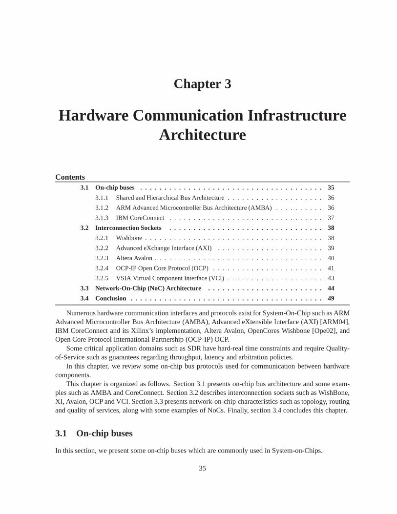
Chapter 3
Hardware Communication InfrastructureArchitecture
Contents3.1 On-chip buses . . . . . . . . . . . . . . . . . . . . . . . . . . . . . . . . . . . .. . 35
3.1.1 Shared and Hierarchical Bus Architecture . . . . . . . . . .. . . . . . . . . . 36
3.1.2 ARM Advanced Microcontroller Bus Architecture (AMBA) . . . . . . . . . . 36
3.1.3 IBM CoreConnect . . . . . . . . . . . . . . . . . . . . . . . . . . . . . . . .37
3.2 Interconnection Sockets . . . . . . . . . . . . . . . . . . . . . . . . . .. . . . . . 38
3.2.1 Wishbone . . . . . . . . . . . . . . . . . . . . . . . . . . . . . . . . . . . . . 38
3.2.2 Advanced eXchange Interface (AXI) . . . . . . . . . . . . . . . .. . . . . . 39
3.2.3 Altera Avalon . . . . . . . . . . . . . . . . . . . . . . . . . . . . . . . . . .. 40
3.2.4 OCP-IP Open Core Protocol (OCP) . . . . . . . . . . . . . . . . . . .. . . . 41
3.2.5 VSIA Virtual Component Interface (VCI) . . . . . . . . . . . .. . . . . . . . 43
3.3 Network-On-Chip (NoC) Architecture . . . . . . . . . . . . . . . .. . . . . . . . 44
3.4 Conclusion . . . . . . . . . . . . . . . . . . . . . . . . . . . . . . . . . . . . . .. . 49
Numerous hardware communication interfaces and protocolsexist for System-On-Chip such as ARMAdvanced Microcontroller Bus Architecture (AMBA), Advanced eXtensible Interface (AXI) [ARM04],IBM CoreConnect and its Xilinx’s implementation, Altera Avalon, OpenCores Wishbone [Ope02], andOpen Core Protocol International Partnership (OCP-IP) OCP.
Some critical application domains such as SDR have hard-real time constraints and require Quality-of-Service such as guarantees regarding throughput, latency and arbitration policies.
In this chapter, we review some on-chip bus protocols used for communication between hardwarecomponents.
This chapter is organized as follows. Section 3.1 presents on-chip bus architecture and some exam-ples such as AMBA and CoreConnect. Section 3.2 describes interconnection sockets such as WishBone,XI, Avalon, OCP and VCI. Section 3.3 presents network-on-chip characteristics such as topology, routingand quality of services, along with some examples of NoCs. Finally, section 3.4 concludes this chapter.
3.1 On-chip buses
In this section, we present some on-chip buses which are commonly used in System-on-Chips.
35
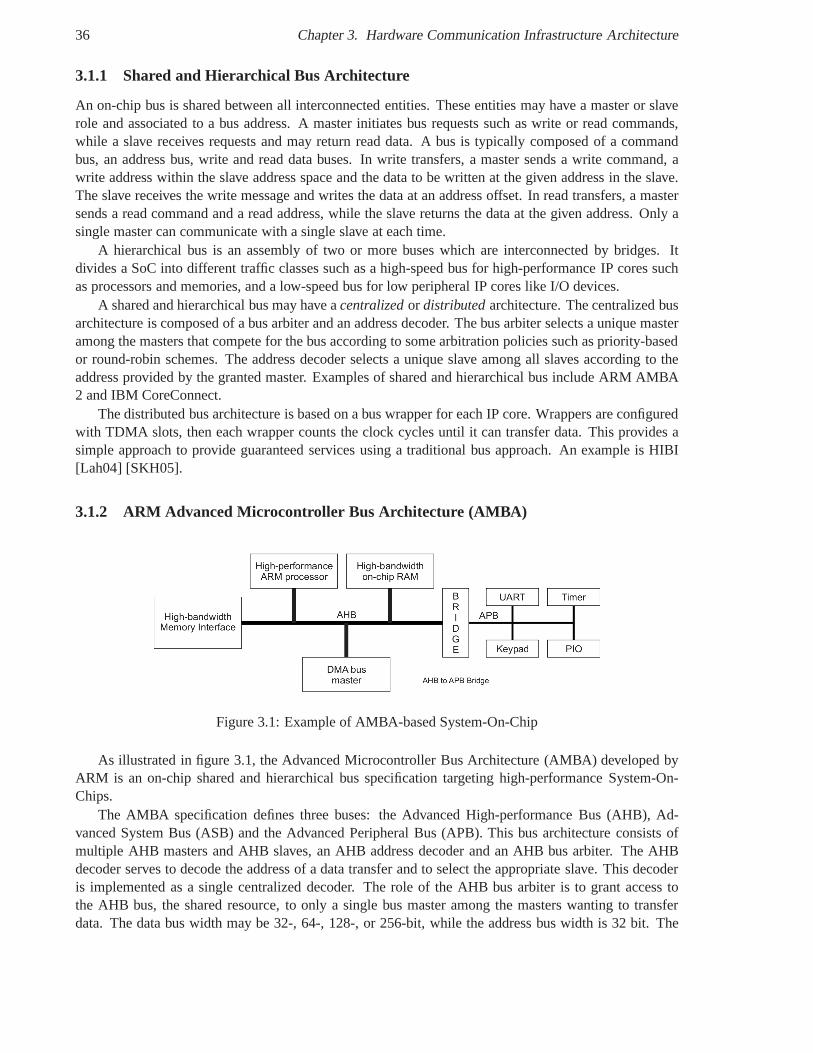
36 Chapter 3. Hardware Communication Infrastructure Architecture
3.1.1 Shared and Hierarchical Bus Architecture
An on-chip bus is shared between all interconnected entities. These entities may have a master or slaverole and associated to a bus address. A master initiates bus requests such as write or read commands,while a slave receives requests and may return read data. A bus is typically composed of a commandbus, an address bus, write and read data buses. In write transfers, a master sends a write command, awrite address within the slave address space and the data to be written at the given address in the slave.The slave receives the write message and writes the data at anaddress offset. In read transfers, a mastersends a read command and a read address, while the slave returns the data at the given address. Only asingle master can communicate with a single slave at each time.
A hierarchical bus is an assembly of two or more buses which are interconnected by bridges. Itdivides a SoC into different traffic classes such as a high-speed bus for high-performance IP cores suchas processors and memories, and a low-speed bus for low peripheral IP cores like I/O devices.
A shared and hierarchical bus may have acentralizedor distributedarchitecture. The centralized busarchitecture is composed of a bus arbiter and an address decoder. The bus arbiter selects a unique masteramong the masters that compete for the bus according to some arbitration policies such as priority-basedor round-robin schemes. The address decoder selects a unique slave among all slaves according to theaddress provided by the granted master. Examples of shared and hierarchical bus include ARM AMBA2 and IBM CoreConnect.
The distributed bus architecture is based on a bus wrapper for each IP core. Wrappers are configuredwith TDMA slots, then each wrapper counts the clock cycles until it can transfer data. This provides asimple approach to provide guaranteed services using a traditional bus approach. An example is HIBI[Lah04] [SKH05].
3.1.2 ARM Advanced Microcontroller Bus Architecture (AMBA )
Figure 3.1: Example of AMBA-based System-On-Chip
As illustrated in figure 3.1, the Advanced Microcontroller Bus Architecture (AMBA) developed byARM is an on-chip shared and hierarchical bus specification targeting high-performance System-On-Chips.
The AMBA specification defines three buses: the Advanced High-performance Bus (AHB), Ad-vanced System Bus (ASB) and the Advanced Peripheral Bus (APB). This bus architecture consists ofmultiple AHB masters and AHB slaves, an AHB address decoder and an AHB bus arbiter. The AHBdecoder serves to decode the address of a data transfer and toselect the appropriate slave. This decoderis implemented as a single centralized decoder. The role of the AHB bus arbiter is to grant access tothe AHB bus, the shared resource, to only a single bus master among the masters wanting to transferdata. The data bus width may be 32-, 64-, 128-, or 256-bit, while the address bus width is 32 bit. The
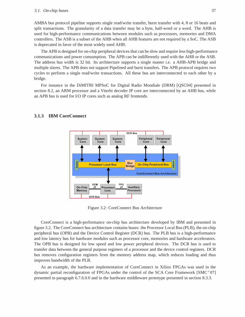
3.1. On-chip buses 37
AMBA bus protocol pipeline supports single read/write transfer, burst transfer with 4, 8 or 16 beats andsplit transactions. The granularity of a data transfer may be a byte, half-word or a word. The AHB isused for high-performance communications between modulessuch as processors, memories and DMAcontrollers. The ASB is a subset of the AHB when all AHB features are not required by a SoC. The ASBis deprecated in favor of the most widely used AHB.
The APB is designed for on-chip peripheral devices that can be slow and require less high-performancecommunications and power consumption. The APB can be indifferently used with the AHB or the ASB.The address bus width is 32 bit. Its architecture supports a single master i.e. a AHB-APB bridge andmultiple slaves. The APB does not support Pipelined and burst transfers. The APB protocol requires twocycles to perform a single read/write transactions. All these bus are interconnected to each other by abridge.
For instance in the DiMITRI MPSoC for Digital Radio Mondiale(DRM) [QSC04] presented insection 8.2, an ARM processor and a Viterbi decoder IP core are interconnected by an AHB bus, whilean APB bus is used for I/O IP cores such as analog RF frontends.
3.1.3 IBM CoreConnect
Figure 3.2: CoreConnect Bus Architecture
CoreConnect is a high-performance on-chip bus architecture developed by IBM and presented infigure 3.2. The CoreConnect bus architecture contains buses: the Processor Local Bus (PLB), the on-chipperipheral bus (OPB) and the Device Control Register (DCR) bus. The PLB bus is a high-performanceand low latency bus for hardware modules such as processor core, memories and hardware accelerators.The OPB bus is designed for low speed and low power peripheraldevices. The DCR bus is used totransfer data between the general purpose registers of a processor and the device control registers. DCRbus removes configuration registers from the memory addressmap, which reduces loading and thusimproves bandwidth of the PLB.
As an example, the hardware implementation of CoreConnect in Xilinx FPGAs was used in thedynamic partial reconfiguration of FPGAs under the control of the SCA Core Framework [SMC+07]presented in paragraph 6.7.6.0.0 and in the hardware middleware prototype presented in section 8.3.3.
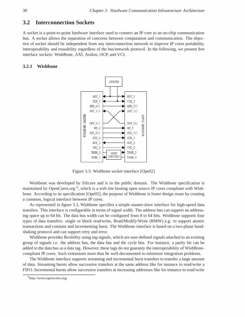
38 Chapter 3. Hardware Communication Infrastructure Architecture
3.2 Interconnection Sockets
A socket is a point-to-point hardware interface used to connect an IP core to an on-chip communicationbus. A socket allows the separation of concerns between computation and communication. The objec-tive of socket should be independent from any interconnection network to improve IP cores portability,interoperability and reusability regardless of the bus/network protocol. In the following, we present fiveinterface sockets: WishBone, AXI, Avalon, OCP, and VCI.
3.2.1 Wishbone
Figure 3.3: Wishbone socket interface [Ope02]
Wishbone was developed by Silicore and is in the public domain. The Wishbone specification ismaintained by OpenCores.org6, which is a web site hosting open source IP cores compliant with Wish-bone. According to its specification [Ope02], the purpose ofWishbone is foster design reuse by creatinga common, logical interface between IP cores.
As represented in figure 3.3, Wishbone specifies a simple master-slave interface for high-speed datatransfers. This interface is configurable in terms of signalwidth. The address bus can support an address-ing space up to 64 bit. The data bus width can be configured from8 to 64 bits. Wishbone supports fourtypes of data transfers: single or block read/write, Read/Modify/Write (RMW) e.g. to support atomictransactions and constant and incrementing burst. The Wishbone interface is based on a two-phase hand-shaking protocol and can support retry and error.
Wishbone provides flexibility usingtagsignals, which are user-defined signals attached to an existinggroup of signals i.e. the address bus, the data bus and the cycle bus. For instance, a parity bit can beadded to the data bus as a data tag. However, these tags do not guaranty the interoperability of WishBone-compliant IP cores. Such extensions must thus be well-documented to minimize integration problems.
The Wishbone interface supports streaming and incrementalburst transfers to transfer a large amountof data. Streaming bursts allow successive transfers at thesame address like for instance to read/write aFIFO. Incremental bursts allow successive transfers at increasing addresses like for instance to read/write
6http://www.opencores.org/
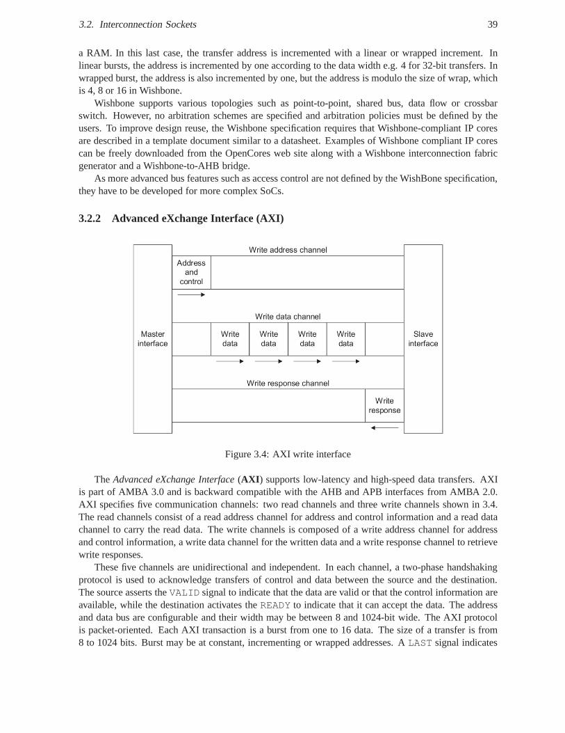
3.2. Interconnection Sockets 39
a RAM. In this last case, the transfer address is incrementedwith a linear or wrapped increment. Inlinear bursts, the address is incremented by one according to the data width e.g. 4 for 32-bit transfers. Inwrapped burst, the address is also incremented by one, but the address is modulo the size of wrap, whichis 4, 8 or 16 in Wishbone.
Wishbone supports various topologies such as point-to-point, shared bus, data flow or crossbarswitch. However, no arbitration schemes are specified and arbitration policies must be defined by theusers. To improve design reuse, the Wishbone specification requires that Wishbone-compliant IP coresare described in a template document similar to a datasheet.Examples of Wishbone compliant IP corescan be freely downloaded from the OpenCores web site along with a Wishbone interconnection fabricgenerator and a Wishbone-to-AHB bridge.
As more advanced bus features such as access control are not defined by the WishBone specification,they have to be developed for more complex SoCs.
3.2.2 Advanced eXchange Interface (AXI)
Figure 3.4: AXI write interface
TheAdvanced eXchange Interface(AXI ) supports low-latency and high-speed data transfers. AXIis part of AMBA 3.0 and is backward compatible with the AHB andAPB interfaces from AMBA 2.0.AXI specifies five communication channels: two read channelsand three write channels shown in 3.4.The read channels consist of a read address channel for address and control information and a read datachannel to carry the read data. The write channels is composed of a write address channel for addressand control information, a write data channel for the written data and a write response channel to retrievewrite responses.
These five channels are unidirectional and independent. In each channel, a two-phase handshakingprotocol is used to acknowledge transfers of control and data between the source and the destination.The source asserts theVALID signal to indicate that the data are valid or that the controlinformation areavailable, while the destination activates theREADY to indicate that it can accept the data. The addressand data bus are configurable and their width may be between 8 and 1024-bit wide. The AXI protocolis packet-oriented. Each AXI transaction is a burst from oneto 16 data. The size of a transfer is from8 to 1024 bits. Burst may be at constant, incrementing or wrapped addresses. ALAST signal indicates
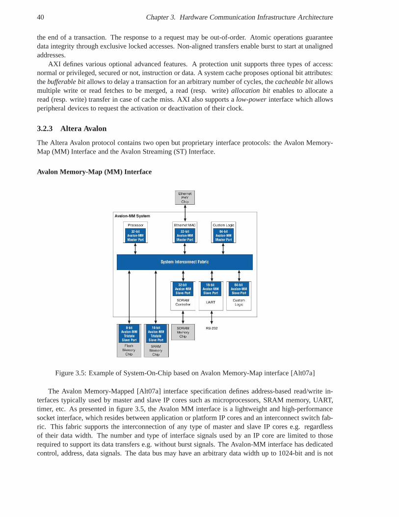
40 Chapter 3. Hardware Communication Infrastructure Architecture
the end of a transaction. The response to a request may be out-of-order. Atomic operations guaranteedata integrity through exclusive locked accesses. Non-aligned transfers enable burst to start at unalignedaddresses.
AXI defines various optional advanced features. A protection unit supports three types of access:normal or privileged, secured or not, instruction or data. Asystem cache proposes optional bit attributes:thebufferable bitallows to delay a transaction for an arbitrary number of cycles, thecacheable bitallowsmultiple write or read fetches to be merged, a read (resp. write) allocation bit enables to allocate aread (resp. write) transfer in case of cache miss. AXI also supports alow-powerinterface which allowsperipheral devices to request the activation or deactivation of their clock.
3.2.3 Altera Avalon
The Altera Avalon protocol contains two open but proprietary interface protocols: the Avalon Memory-Map (MM) Interface and the Avalon Streaming (ST) Interface.
Avalon Memory-Map (MM) Interface
Figure 3.5: Example of System-On-Chip based on Avalon Memory-Map interface [Alt07a]
The Avalon Memory-Mapped [Alt07a] interface specificationdefines address-based read/write in-terfaces typically used by master and slave IP cores such as microprocessors, SRAM memory, UART,timer, etc. As presented in figure 3.5, the Avalon MM interface is a lightweight and high-performancesocket interface, which resides between application or platform IP cores and an interconnect switch fab-ric. This fabric supports the interconnection of any type ofmaster and slave IP cores e.g. regardlessof their data width. The number and type of interface signalsused by an IP core are limited to thoserequired to support its data transfers e.g. without burst signals. The Avalon-MM interface has dedicatedcontrol, address, data signals. The data bus may have an arbitrary data width up to 1024-bit and is not
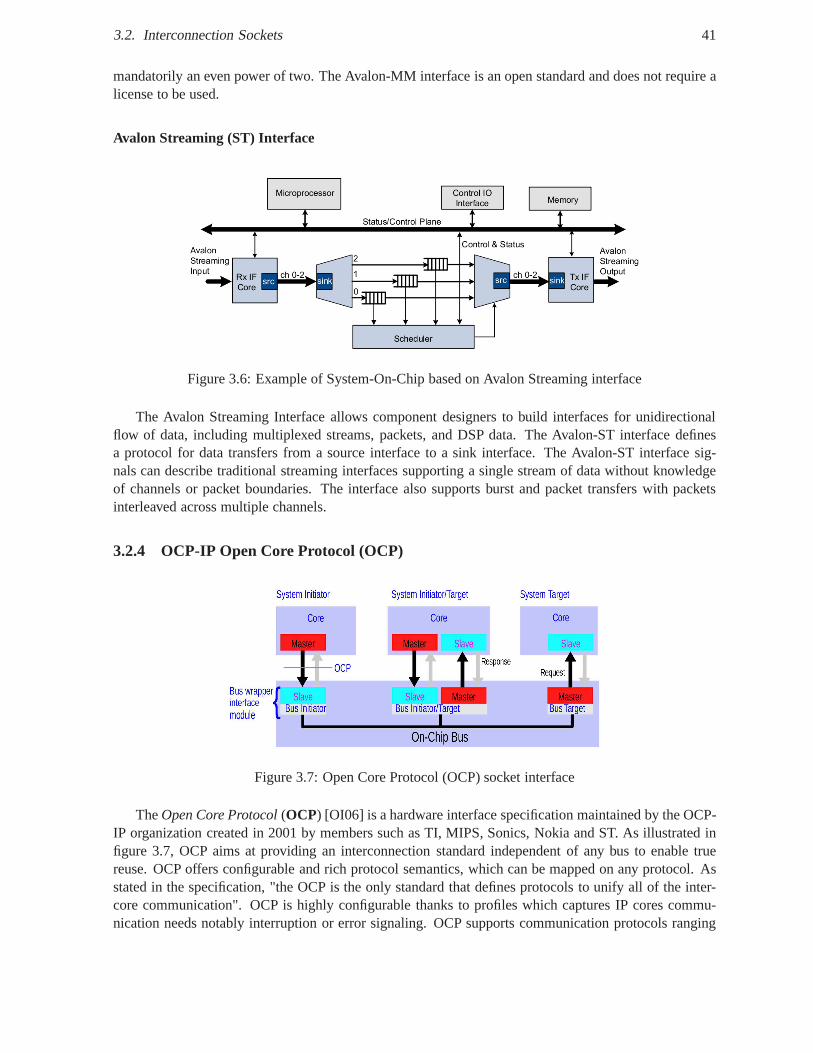
3.2. Interconnection Sockets 41
mandatorily an even power of two. The Avalon-MM interface isan open standard and does not require alicense to be used.
Avalon Streaming (ST) Interface
Figure 3.6: Example of System-On-Chip based on Avalon Streaming interface
The Avalon Streaming Interface allows component designersto build interfaces for unidirectionalflow of data, including multiplexed streams, packets, and DSP data. The Avalon-ST interface definesa protocol for data transfers from a source interface to a sink interface. The Avalon-ST interface sig-nals can describe traditional streaming interfaces supporting a single stream of data without knowledgeof channels or packet boundaries. The interface also supports burst and packet transfers with packetsinterleaved across multiple channels.
3.2.4 OCP-IP Open Core Protocol (OCP)
Figure 3.7: Open Core Protocol (OCP) socket interface
TheOpen Core Protocol(OCP) [OI06] is a hardware interface specification maintained bythe OCP-IP organization created in 2001 by members such as TI, MIPS, Sonics, Nokia and ST. As illustrated infigure 3.7, OCP aims at providing an interconnection standard independent of any bus to enable truereuse. OCP offers configurable and rich protocol semantics,which can be mapped on any protocol. Asstated in the specification, "the OCP is the only standard that defines protocols to unify all of the inter-core communication". OCP is highly configurable thanks to profiles which captures IP cores commu-nication needs notably interruption or error signaling. OCP supports communication protocols ranging
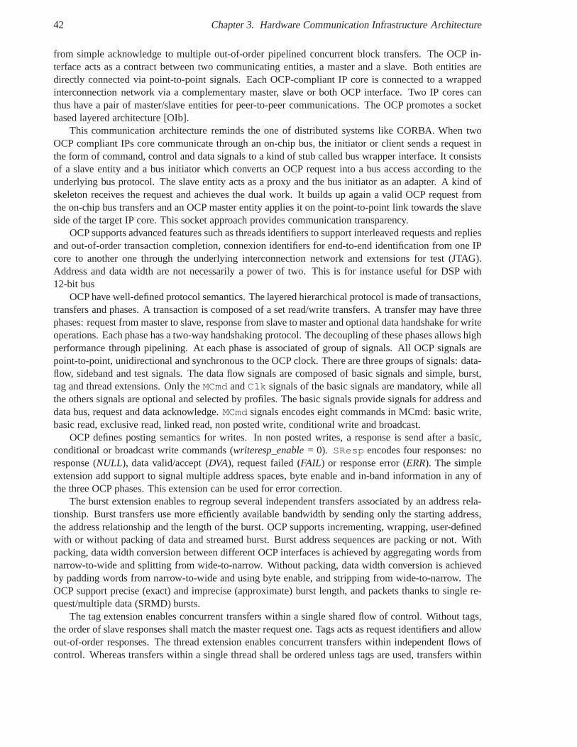
42 Chapter 3. Hardware Communication Infrastructure Architecture
from simple acknowledge to multiple out-of-order pipelined concurrent block transfers. The OCP in-terface acts as a contract between two communicating entities, a master and a slave. Both entities aredirectly connected via point-to-point signals. Each OCP-compliant IP core is connected to a wrappedinterconnection network via a complementary master, slaveor both OCP interface. Two IP cores canthus have a pair of master/slave entities for peer-to-peer communications. The OCP promotes a socketbased layered architecture [OIb].
This communication architecture reminds the one of distributed systems like CORBA. When twoOCP compliant IPs core communicate through an on-chip bus, the initiator or client sends a request inthe form of command, control and data signals to a kind of stubcalled bus wrapper interface. It consistsof a slave entity and a bus initiator which converts an OCP request into a bus access according to theunderlying bus protocol. The slave entity acts as a proxy andthe bus initiator as an adapter. A kind ofskeleton receives the request and achieves the dual work. Itbuilds up again a valid OCP request fromthe on-chip bus transfers and an OCP master entity applies iton the point-to-point link towards the slaveside of the target IP core. This socket approach provides communication transparency.
OCP supports advanced features such as threads identifiers to support interleaved requests and repliesand out-of-order transaction completion, connexion identifiers for end-to-end identification from one IPcore to another one through the underlying interconnectionnetwork and extensions for test (JTAG).Address and data width are not necessarily a power of two. This is for instance useful for DSP with12-bit bus
OCP have well-defined protocol semantics. The layered hierarchical protocol is made of transactions,transfers and phases. A transaction is composed of a set read/write transfers. A transfer may have threephases: request from master to slave, response from slave tomaster and optional data handshake for writeoperations. Each phase has a two-way handshaking protocol.The decoupling of these phases allows highperformance through pipelining. At each phase is associated of group of signals. All OCP signals arepoint-to-point, unidirectional and synchronous to the OCPclock. There are three groups of signals: data-flow, sideband and test signals. The data flow signals are composed of basic signals and simple, burst,tag and thread extensions. Only theMCmd andClk signals of the basic signals are mandatory, while allthe others signals are optional and selected by profiles. Thebasic signals provide signals for address anddata bus, request and data acknowledge.MCmd signals encodes eight commands in MCmd: basic write,basic read, exclusive read, linked read, non posted write, conditional write and broadcast.
OCP defines posting semantics for writes. In non posted writes, a response is send after a basic,conditional or broadcast write commands (writeresp_enable= 0). SResp encodes four responses: noresponse (NULL), data valid/accept (DVA), request failed (FAIL) or response error (ERR). The simpleextension add support to signal multiple address spaces, byte enable and in-band information in any ofthe three OCP phases. This extension can be used for error correction.
The burst extension enables to regroup several independenttransfers associated by an address rela-tionship. Burst transfers use more efficiently available bandwidth by sending only the starting address,the address relationship and the length of the burst. OCP supports incrementing, wrapping, user-definedwith or without packing of data and streamed burst. Burst address sequences are packing or not. Withpacking, data width conversion between different OCP interfaces is achieved by aggregating words fromnarrow-to-wide and splitting from wide-to-narrow. Without packing, data width conversion is achievedby padding words from narrow-to-wide and using byte enable,and stripping from wide-to-narrow. TheOCP support precise (exact) and imprecise (approximate) burst length, and packets thanks to single re-quest/multiple data (SRMD) bursts.
The tag extension enables concurrent transfers within a single shared flow of control. Without tags,the order of slave responses shall match the master request one. Tags acts as request identifiers and allowout-of-order responses. The thread extension enables concurrent transfers within independent flows ofcontrol. Whereas transfers within a single thread shall be ordered unless tags are used, transfers within
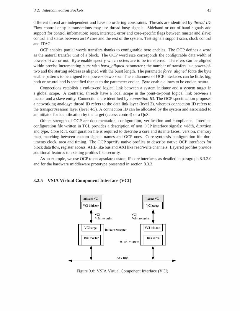
3.2. Interconnection Sockets 43
different thread are independent and have no ordering constraints. Threads are identified bythread ID.Flow control or split transactions may use thread busy signals. Sideband or out-of-band signals addsupport for control information: reset, interrupt, error and core-specific flags between master and slave;control and status between an IP core and the rest of the system. Test signals support scan, clock controland JTAG.
OCP enables partial words transfers thanks to configurable byte enables. The OCP defines a wordas the natural transfer unit of a block. The OCP word size corresponds the configurable data width ofpower-of-two or not. Byte enable specify which octets are tobe transferred. Transfers can be alignedwithin precise incrementing burst withburst_alignedparameter : the number of transfers is a power-of-two and the starting address is aligned with the burst length. The parameterforce_alignedforce the byteenable patterns to be aligned to a power-of-two size. The endianness of OCP interfaces can be little, big,both or neutral and is specified thanks to the parameter endian. Byte enable allows to be endian neutral.
Connections establish a end-to-end logical link between a system initiator and a system target ina global scope. A contrario, threads have a local scope in thepoint-to-point logical link between amaster and a slave entity. Connections are identified byconnection ID. The OCP specification proposesa networking analogy: thread ID refers to the data link layer(level 2), whereas connection ID refers tothe transport/session layer (level 4/5). A connection ID can be allocated by the system and associated toan initiator for identification by the target (access control) or a QoS.
Others strength of OCP are documentation, configuration, verification and compliance. Interfaceconfiguration file written in TCL provides a description of non OCP interface signals: width, directionand type. Core RTL configuration file is required to describe acore and its interfaces: version, memorymap, matching between custom signals names and OCP ones. Core synthesis configuration file doc-uments clock, area and timing. The OCP specify native profiles to describe native OCP interfaces forblock data flow, register access, AHB like bus and AXI like read/write channels. Layered profiles provideadditional features to existing profiles like security.
As an example, we use OCP to encapsulate custom IP core interfaces as detailed in paragraph 8.3.2.0and for the hardware middleware prototype presented in section 8.3.3.
3.2.5 VSIA Virtual Component Interface (VCI)
Figure 3.8: VSIA Virtual Component Interface (VCI)
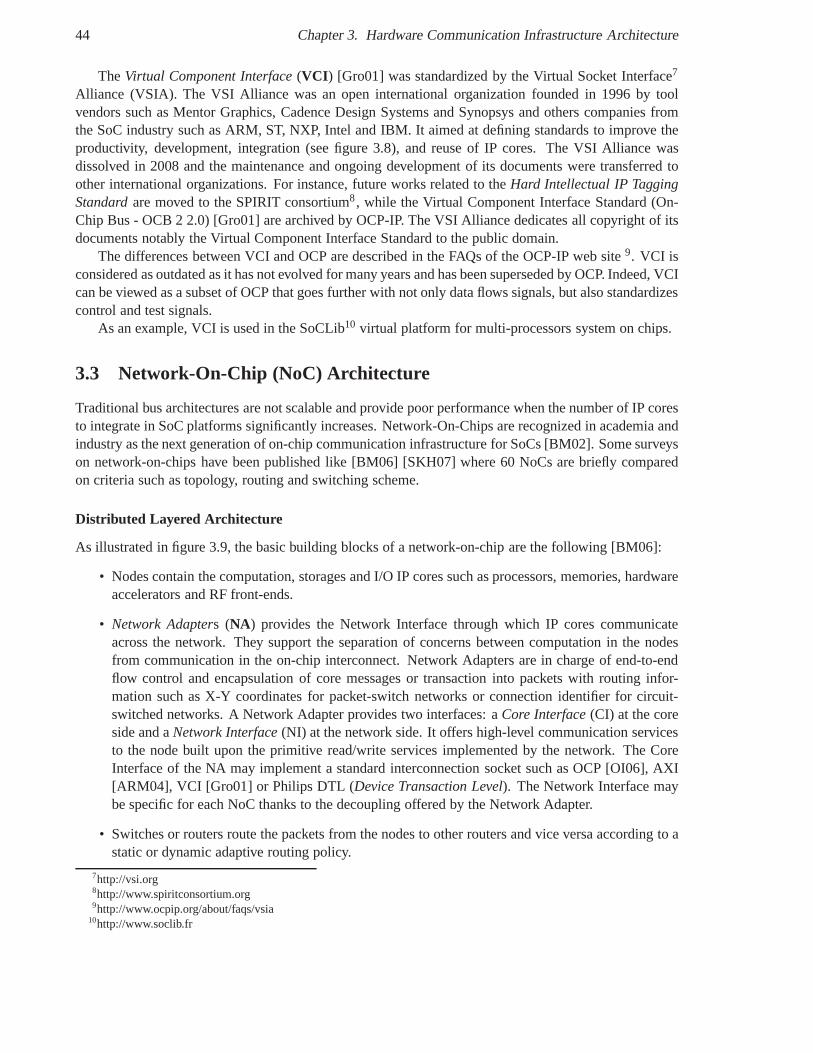
44 Chapter 3. Hardware Communication Infrastructure Architecture
TheVirtual Component Interface(VCI ) [Gro01] was standardized by the Virtual Socket Interface7
Alliance (VSIA). The VSI Alliance was an open internationalorganization founded in 1996 by toolvendors such as Mentor Graphics, Cadence Design Systems andSynopsys and others companies fromthe SoC industry such as ARM, ST, NXP, Intel and IBM. It aimed at defining standards to improve theproductivity, development, integration (see figure 3.8), and reuse of IP cores. The VSI Alliance wasdissolved in 2008 and the maintenance and ongoing development of its documents were transferred toother international organizations. For instance, future works related to theHard Intellectual IP TaggingStandardare moved to the SPIRIT consortium8, while the Virtual Component Interface Standard (On-Chip Bus - OCB 2 2.0) [Gro01] are archived by OCP-IP. The VSI Alliance dedicates all copyright of itsdocuments notably the Virtual Component Interface Standard to the public domain.
The differences between VCI and OCP are described in the FAQsof the OCP-IP web site9. VCI isconsidered as outdated as it has not evolved for many years and has been superseded by OCP. Indeed, VCIcan be viewed as a subset of OCP that goes further with not onlydata flows signals, but also standardizescontrol and test signals.
As an example, VCI is used in the SoCLib10 virtual platform for multi-processors system on chips.
3.3 Network-On-Chip (NoC) Architecture
Traditional bus architectures are not scalable and providepoor performance when the number of IP coresto integrate in SoC platforms significantly increases. Network-On-Chips are recognized in academia andindustry as the next generation of on-chip communication infrastructure for SoCs [BM02]. Some surveyson network-on-chips have been published like [BM06] [SKH07] where 60 NoCs are briefly comparedon criteria such as topology, routing and switching scheme.
Distributed Layered Architecture
As illustrated in figure 3.9, the basic building blocks of a network-on-chip are the following [BM06]:
• Nodes contain the computation, storages and I/O IP cores such as processors, memories, hardwareaccelerators and RF front-ends.
• Network Adapters (NA) provides the Network Interface through which IP cores communicateacross the network. They support the separation of concernsbetween computation in the nodesfrom communication in the on-chip interconnect. Network Adapters are in charge of end-to-endflow control and encapsulation of core messages or transaction into packets with routing infor-mation such as X-Y coordinates for packet-switch networks or connection identifier for circuit-switched networks. A Network Adapter provides two interfaces: aCore Interface(CI) at the coreside and aNetwork Interface(NI) at the network side. It offers high-level communication servicesto the node built upon the primitive read/write services implemented by the network. The CoreInterface of the NA may implement a standard interconnection socket such as OCP [OI06], AXI[ARM04], VCI [Gro01] or Philips DTL (Device Transaction Level). The Network Interface maybe specific for each NoC thanks to the decoupling offered by the Network Adapter.
• Switches or routers route the packets from the nodes to other routers and vice versa according to astatic or dynamic adaptive routing policy.
7http://vsi.org8http://www.spiritconsortium.org9http://www.ocpip.org/about/faqs/vsia
10http://www.soclib.fr
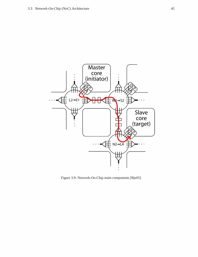
3.3. Network-On-Chip (NoC) Architecture 45
Figure 3.9: Network-On-Chip main components [Bje05]
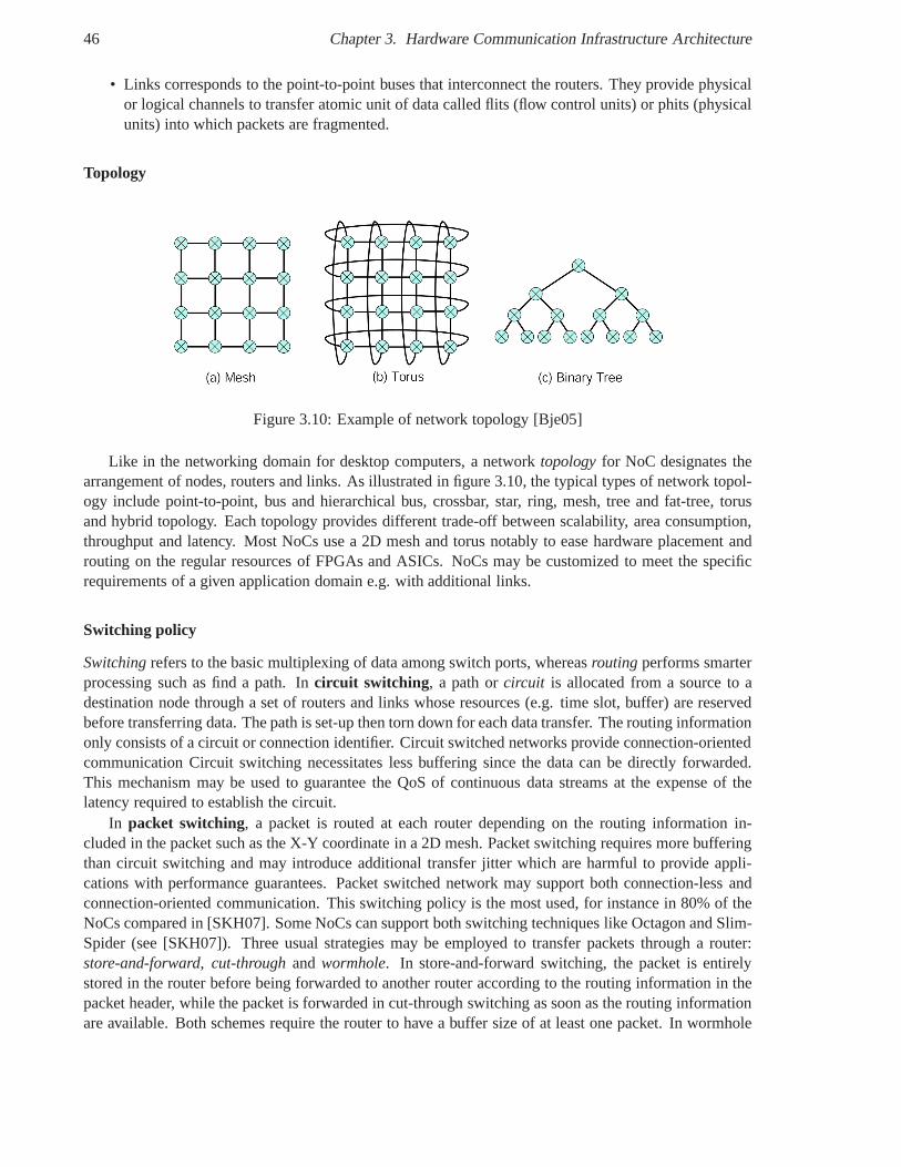
46 Chapter 3. Hardware Communication Infrastructure Architecture
• Links corresponds to the point-to-point buses that interconnect the routers. They provide physicalor logical channels to transfer atomic unit of data called flits (flow control units) or phits (physicalunits) into which packets are fragmented.
Topology
Figure 3.10: Example of network topology [Bje05]
Like in the networking domain for desktop computers, a network topologyfor NoC designates thearrangement of nodes, routers and links. As illustrated in figure 3.10, the typical types of network topol-ogy include point-to-point, bus and hierarchical bus, crossbar, star, ring, mesh, tree and fat-tree, torusand hybrid topology. Each topology provides different trade-off between scalability, area consumption,throughput and latency. Most NoCs use a 2D mesh and torus notably to ease hardware placement androuting on the regular resources of FPGAs and ASICs. NoCs maybe customized to meet the specificrequirements of a given application domain e.g. with additional links.
Switching policy
Switchingrefers to the basic multiplexing of data among switch ports,whereasrouting performs smarterprocessing such as find a path. Incircuit switching , a path orcircuit is allocated from a source to adestination node through a set of routers and links whose resources (e.g. time slot, buffer) are reservedbefore transferring data. The path is set-up then torn down for each data transfer. The routing informationonly consists of a circuit or connection identifier. Circuitswitched networks provide connection-orientedcommunication Circuit switching necessitates less buffering since the data can be directly forwarded.This mechanism may be used to guarantee the QoS of continuousdata streams at the expense of thelatency required to establish the circuit.
In packet switching, a packet is routed at each router depending on the routing information in-cluded in the packet such as the X-Y coordinate in a 2D mesh. Packet switching requires more bufferingthan circuit switching and may introduce additional transfer jitter which are harmful to provide appli-cations with performance guarantees. Packet switched network may support both connection-less andconnection-oriented communication. This switching policy is the most used, for instance in 80% of theNoCs compared in [SKH07]. Some NoCs can support both switching techniques like Octagon and Slim-Spider (see [SKH07]). Three usual strategies may be employed to transfer packets through a router:store-and-forward, cut-throughand wormhole. In store-and-forward switching, the packet is entirelystored in the router before being forwarded to another router according to the routing information in thepacket header, while the packet is forwarded in cut-throughswitching as soon as the routing informationare available. Both schemes require the router to have a buffer size of at least one packet. In wormhole
3.3. Network-On-Chip (NoC) Architecture 47
switching, a packet is fragmented into several flits, which are routed as soon as possible like the cut-through switching. The packet may be spread among several routers along the data path like a worm. Inthis case, the router needs less buffering resources and mayrequire at least one flit. Wormhole switchingis widely used in NoCs to reduce silicon area while providingthe same switching functionality.
Routing
Routing consists in forwarding a packet to the right router or node according to a routing strategy. Rout-ing may bedeterministicor adaptive. In deterministic routing, all packets are routed along thesamepath from a source to a destination node as opposed to adaptive routing. Deterministic routing schemesinclude source routing and X-Y routing. In source routing, the source node provides the route e.g. a listof router included in the packet header up to the destinationnode. Each router may remove itself fromthe list before forwarding the packet to the next router and gradually reduce the size of the packet header.In X-Y routing, packets are forwarded in one direction alongthe columns (X) or the rows (Y) then alongthe other direction up to the destination node. In adaptive routing, the path is re-determined at each hopfrom one router to another according to some criteria such aslink congestion. Adaptive routing may thusbe used to dynamically find a better path to reduce congestion, bypass faulty routers and support loadbalancing [BM06]. However, additional hardware resourcesare required to avoid livelocks/deadlocksand re-order out-of-order packets.
NoCs may also support routing schemes for group communications between one source node andseveral destination nodes such as one-to-all i.e. broadcast communications, one-to-many i.e. multicastcommunications [BM06].
Flow Control
NoCs may control the flow of data usingvirtual channels(VC). A virtual channel is a logical channelwithin a router or network adapter. It has its own buffering resources, but shares a common physicalchannel i.e. a link with other virtual channels. For instance, a router may have between 2 and 16 virtualchannels per physical channel [BM06]. Obviously, virtual channels consume more area and may increasepower consumption and transfer latency. However, they alsoprovide some additional benefits such asdecreasing latency, better wire efficiency, better performance, avoiding deadlock and providing differentlevels of QoS.
Quality of Services
Some high-performance and real-time applications may require stringent guarantees on the Quality ofServices (QoS) provided by NoCs. Each IP core in a SoC may havedifferent communication needsand the level of services proposed by NoCs should be independent of the number and nature of IPsto be interconnected. The QoS guarantees may concern properties such as timing (throughput, latencyand jitter), integrity (error rate, packet loss) and packetdelivery (in-order or out-of-order) [SKH07].Twoclasses of QoS are commonly distinguished:Best-Effort(BE) services andGuaranteed Services(GS).Best Effort services provide no guarantees on packet routing and delivery. Guaranteed Services mostlyprovide predictable throughput, latency and jitter using Time-Multiplexing Division (TDM) like in Nos-trum [MNTJ04], AEthereal [RGR+03] and HIBI [SKH05] or Spatial-Multiplexing Division (SDM) likein [MVS+05]. To provide hard-real time guarantees and avoid congestion, each data stream must beassigned to a dedicated connection. A connection is established by creating a virtual circuit with logi-cally independent resources such as virtual channels, temporal slots (TDM) or individual wires in links(SDM). Each one of these resources may be associated with a priority to allow high-priority packets tobe routed before lower-priority packets.
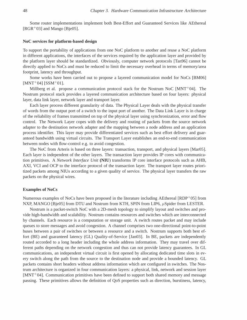
48 Chapter 3. Hardware Communication Infrastructure Architecture
Some router implementations implement both Best-Effort and Guaranteed Services like AEthereal[RGR+03] and Mango [Bje05].
NoC services for platform-based design
To support the portability of applications from one NoC platform to another and reuse a NoC platformin different applications, the interfaces of the services required by the application layer and provided bythe platform layer should be standardized. Obviously, computer network protocols [Tan96] cannot bedirectly applied to NoCs and must be reduced to limit the necessary overhead in terms of memory/areafootprint, latency and throughput.
Some works have been carried out to propose a layered communication model for NoCs [BM06][MNT+04] [SSM+01].
Millberg et al. propose a communication protocol stack for the Nostrum NoC [MNT+04]. TheNostrum protocol stack provides a layered communication architecture based on four layers: physicallayer, data link layer, network layer and transport layer.
Each layer process different granularity of data. The Physical Layer deals with the physical transferof words from the output port of a switch to the input port of another. The Data Link Layer is in chargeof the reliability of frames transmitted on top of the physical layer using synchronization, error and flowcontrol. The Network Layer copes with the delivery and routing of packets from the source networkadapter to the destination network adapter and the mapping between a node address and an applicationprocess identifier. This layer may provide differentiated services such as best effort delivery and guar-anteed bandwidth using virtual circuits. The Transport Layer establishes an end-to-end communicationbetween nodes with flow-control e.g. to avoid congestion.
The NoC from Arteris is based on three layers: transaction, transport, and physical layers [Mar05].Each layer is independent of the other layers. The transaction layer provides IP cores with communica-tion primitives. ANetwork Interface Unit(NIU ) transforms IP core interface protocols such as AHB,AXI, VCI and OCP to the interface protocol of the transactionlayer. The transport layer routes priori-tized packets among NIUs according to a given quality of service. The physical layer transfers the rawpackets on the physical wires.
Examples of NoCs
Numerous examples of NoCs have been proposed in the literature including AEthereal [RDP+05] fromNXP, MANGO [Bje05] from DTU and Nostrum from KTH, SPIN from LIP6,µSpider from LESTER.
Nostrum is a packet-switch NoC with a 2D-mesh topology to simplify layout and switches and pro-vide high-bandwidth and scalability. Nostrum contains resources and switches which are interconnectedby channels. Each resource is a computation or storage unit.A switch routes packet and may includequeues to store messages and avoid congestion. A channel comprises two one-directional point-to-pointbuses between a pair of switches or between a resource and a switch. Nostrum supports both best ef-fort (BE) and guaranteed latency (GL) Quality-of-Service [Jan03]. In BE, packets are independentlyrouted accorded to a long header including the whole addressinformation. They may travel over dif-ferent paths depending on the network congestion and thus can not provide latency guarantees. In GLcommunications, an independent virtual circuit is first opened by allocating dedicated time slots in ev-ery switch along the path from the source to the destination node and provide a bounded latency. GLpackets contains short headers without address information which are configured in switches. The Nos-trum architecture is organized in four communication layers: a physical, link, network and session layer[MNT+04]. Communication primitives have been defined to support both shared memory and messagepassing. These primitives allows the definition of QoS properties such as direction, burstiness, latency,
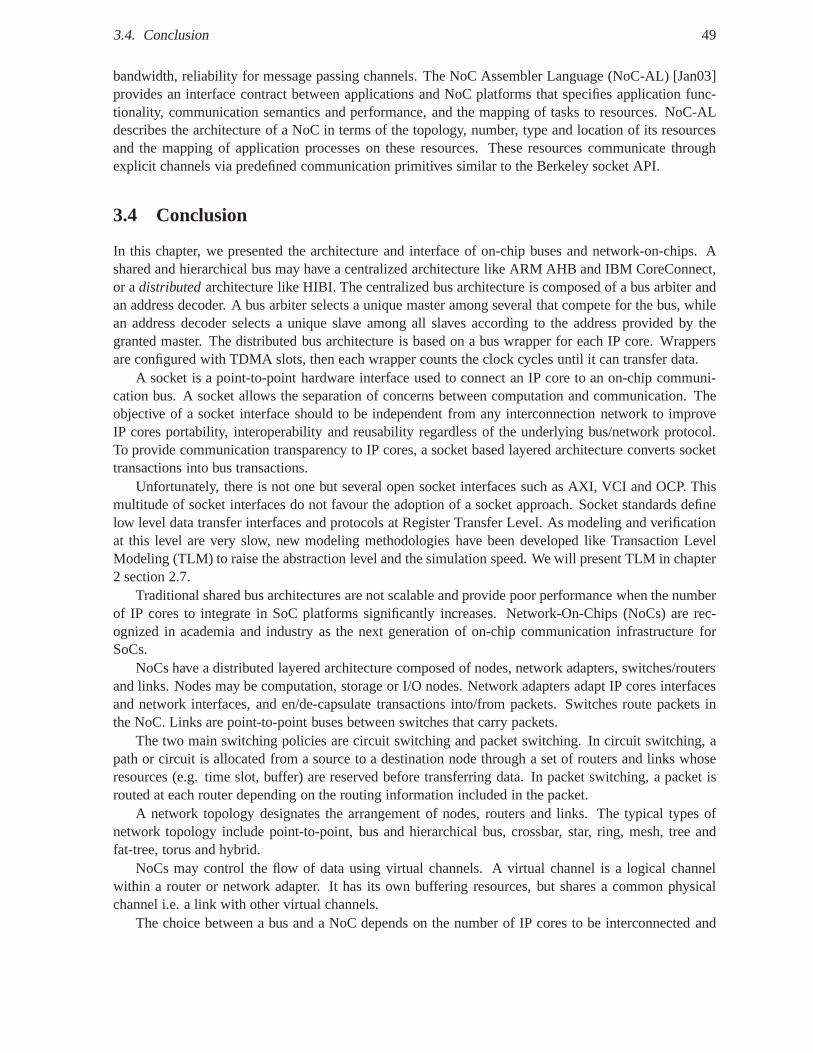
3.4. Conclusion 49
bandwidth, reliability for message passing channels. The NoC Assembler Language (NoC-AL) [Jan03]provides an interface contract between applications and NoC platforms that specifies application func-tionality, communication semantics and performance, and the mapping of tasks to resources. NoC-ALdescribes the architecture of a NoC in terms of the topology,number, type and location of its resourcesand the mapping of application processes on these resources. These resources communicate throughexplicit channels via predefined communication primitivessimilar to the Berkeley socket API.
3.4 Conclusion
In this chapter, we presented the architecture and interface of on-chip buses and network-on-chips. Ashared and hierarchical bus may have a centralized architecture like ARM AHB and IBM CoreConnect,or adistributedarchitecture like HIBI. The centralized bus architecture is composed of a bus arbiter andan address decoder. A bus arbiter selects a unique master among several that compete for the bus, whilean address decoder selects a unique slave among all slaves according to the address provided by thegranted master. The distributed bus architecture is based on a bus wrapper for each IP core. Wrappersare configured with TDMA slots, then each wrapper counts the clock cycles until it can transfer data.
A socket is a point-to-point hardware interface used to connect an IP core to an on-chip communi-cation bus. A socket allows the separation of concerns between computation and communication. Theobjective of a socket interface should to be independent from any interconnection network to improveIP cores portability, interoperability and reusability regardless of the underlying bus/network protocol.To provide communication transparency to IP cores, a socketbased layered architecture converts sockettransactions into bus transactions.
Unfortunately, there is not one but several open socket interfaces such as AXI, VCI and OCP. Thismultitude of socket interfaces do not favour the adoption ofa socket approach. Socket standards definelow level data transfer interfaces and protocols at Register Transfer Level. As modeling and verificationat this level are very slow, new modeling methodologies havebeen developed like Transaction LevelModeling (TLM) to raise the abstraction level and the simulation speed. We will present TLM in chapter2 section 2.7.
Traditional shared bus architectures are not scalable and provide poor performance when the numberof IP cores to integrate in SoC platforms significantly increases. Network-On-Chips (NoCs) are rec-ognized in academia and industry as the next generation of on-chip communication infrastructure forSoCs.
NoCs have a distributed layered architecture composed of nodes, network adapters, switches/routersand links. Nodes may be computation, storage or I/O nodes. Network adapters adapt IP cores interfacesand network interfaces, and en/de-capsulate transactionsinto/from packets. Switches route packets inthe NoC. Links are point-to-point buses between switches that carry packets.
The two main switching policies are circuit switching and packet switching. In circuit switching, apath or circuit is allocated from a source to a destination node through a set of routers and links whoseresources (e.g. time slot, buffer) are reserved before transferring data. In packet switching, a packet isrouted at each router depending on the routing information included in the packet.
A network topology designates the arrangement of nodes, routers and links. The typical types ofnetwork topology include point-to-point, bus and hierarchical bus, crossbar, star, ring, mesh, tree andfat-tree, torus and hybrid.
NoCs may control the flow of data using virtual channels. A virtual channel is a logical channelwithin a router or network adapter. It has its own buffering resources, but shares a common physicalchannel i.e. a link with other virtual channels.
The choice between a bus and a NoC depends on the number of IP cores to be interconnected and
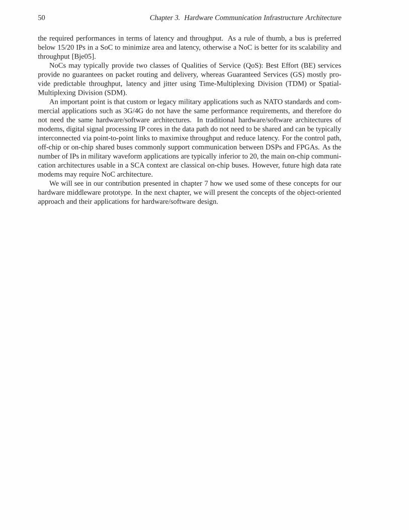
50 Chapter 3. Hardware Communication Infrastructure Architecture
the required performances in terms of latency and throughput. As a rule of thumb, a bus is preferredbelow 15/20 IPs in a SoC to minimize area and latency, otherwise a NoC is better for its scalability andthroughput [Bje05].
NoCs may typically provide two classes of Qualities of Service (QoS): Best Effort (BE) servicesprovide no guarantees on packet routing and delivery, whereas Guaranteed Services (GS) mostly pro-vide predictable throughput, latency and jitter using Time-Multiplexing Division (TDM) or Spatial-Multiplexing Division (SDM).
An important point is that custom or legacy military applications such as NATO standards and com-mercial applications such as 3G/4G do not have the same performance requirements, and therefore donot need the same hardware/software architectures. In traditional hardware/software architectures ofmodems, digital signal processing IP cores in the data path do not need to be shared and can be typicallyinterconnected via point-to-point links to maximixe throughput and reduce latency. For the control path,off-chip or on-chip shared buses commonly support communication between DSPs and FPGAs. As thenumber of IPs in military waveform applications are typically inferior to 20, the main on-chip communi-cation architectures usable in a SCA context are classical on-chip buses. However, future high data ratemodems may require NoC architecture.
We will see in our contribution presented in chapter 7 how we used some of these concepts for ourhardware middleware prototype. In the next chapter, we willpresent the concepts of the object-orientedapproach and their applications for hardware/software design.
Chapter 4
Object-Oriented Design (OOD)
Contents4.1 Fundamental Concepts . . . . . . . . . . . . . . . . . . . . . . . . . . . . .. . . . 52
4.1.1 Origin . . . . . . . . . . . . . . . . . . . . . . . . . . . . . . . . . . . . . . . 52
4.1.2 Identifiable Objects as Instances of Classes . . . . . . . .. . . . . . . . . . . 52
4.1.3 Method Invocation and Message Passing . . . . . . . . . . . . .. . . . . . . 53
4.1.4 Encapsulation: Interface and Implementation(s) . . .. . . . . . . . . . . . . . 54
4.1.5 Inheritance and White-Box Reuse . . . . . . . . . . . . . . . . . .. . . . . . 55
4.1.6 Polymorphism . . . . . . . . . . . . . . . . . . . . . . . . . . . . . . . . . .56
4.1.7 Relationship . . . . . . . . . . . . . . . . . . . . . . . . . . . . . . . . . .. 57
4.1.8 Concurrency, Synchronization and Coordination . . . .. . . . . . . . . . . . 58
4.1.9 Persistence . . . . . . . . . . . . . . . . . . . . . . . . . . . . . . . . . . .. 61
4.1.10 Distribution . . . . . . . . . . . . . . . . . . . . . . . . . . . . . . . . .. . . 61
4.2 Object-Oriented Hardware Design . . . . . . . . . . . . . . . . . . .. . . . . . . 63
4.2.1 Object-Oriented Extensions to Hardware DescriptionLanguages . . . . . . . . 63
4.2.2 Object-Oriented Languages for Hardware Design . . . . .. . . . . . . . . . . 64
4.2.3 Object-Oriented Hardware Architecture . . . . . . . . . . .. . . . . . . . . . 66
4.2.4 Model Driven Engineering (MDE) for Hardware Design . .. . . . . . . . . . 76
4.3 Synthesis . . . . . . . . . . . . . . . . . . . . . . . . . . . . . . . . . . . . . . .. . 84
4.4 Conclusion . . . . . . . . . . . . . . . . . . . . . . . . . . . . . . . . . . . . . .. . 84
In this chapter, the terminology and main concepts of the concurrent and distributed object-orientedmodel are introduced notably the principles of encapsulation, inheritance and polymorphism. The subtledifferences of terminology, semantics and implementationof these concepts are also presented whenrelevant in the UML object-oriented modeling language and in object-oriented programming languagessuch as SmallTalk, C++, Java and Ada.
A state of the art is then presented on the applications of these concepts in hardware/software co-design of embedded systems. Finally, the intrinsic strengths and weaknesses of the object paradigm areidentified to justify the emergence of the more evolvedcomponent-oriented modelpresented in the nextsection.
This chapter is organized as follows. Section 4.1 presents the fundamental concepts underlying theobject model such as the equivalence between method invocation and message passing, encapsulation,
51
52 Chapter 4. Object-Oriented Design (OOD)
inheritance and polymorphism. Section 4.2 describes Object-Oriented Hardware Design such as Object-Oriented Hardware Description Languages (OO-HDL), Object-Oriented Languages for Hardware De-sign like SystemC, Object-Oriented Hardware Architectureand Model Driven Engineering (MDE) forHardware Design. Section 3.3 presents network-on-chip characteristics such as topology, routing andquality of services, along with some examples of NoCs. Section 4.3 proposes a synthesis on the workspresented in this chapter. Finally, section 4.4 concludes this chapter.
4.1 Fundamental Concepts
Surprisingly, no real consensus seems to exist about the concepts characterizing the object model andtheir definition [Arm06]. Armstrong reviewed the OO literature from 1966 to 2005 to identify the fun-damental concepts underlying the object model. She identified 39 concepts and classified them by theirnumber of occurrences in the literature. The eight first retained concepts mentioned by more than 50%of the reviewed papers were inheritance, object, class, encapsulation, method, message passing, poly-morphism and abstraction. Instead of selecting only eight of these concepts, we will attempt to puttogether all these concepts and stress their relationshipsto build the whole concurrent and distributedobject paradigm.
4.1.1 Origin
The object-oriented approach evolved from previous works achieved during the sixties in various re-search domains such as data structure abstraction, system simulation, operation systems, database mod-els, graphical user interface (GUI) and artificial intelligence [Cap03] [Kay93]. The concept of "object"emerged almost independently and simultaneously in these research domains in the early 1970s to des-ignate a set of common concepts [BME+07] [Kay93]. This concept was introduced in the Simula 67programming language by Nygaard and Dahl. Its designers observed that Simula I "processes oftenshared a number of common properties, both in data attributes and actions, when writing simulationprograms" [ND81]. The term "object" was considered more neutral compared to the word "process" ofSimula I. Interestingly, the first application of Simula I was the simulation of logic circuits. The term"object-oriented" was chosen by Alan Kay to refer to this newdesign paradigm during the developmentof the Smalltalk programming language from 1972. "Smalltalk’s design - and existence - is due to theinsight that everything we can describe can be represented by the recursive composition of a single kindof behavioral building block that hides its combination of state and process inside itself and can be dealtwith only through the exchange of messages" [Kay93].
4.1.2 Identifiable Objects as Instances of Classes
The primary abstraction of the object-oriented design isclasses of objectsto represent a system. Anobject is a self-contained and identifiable entity, which encloses its own state and behavior and commu-nicates only through message passing [Arm06] [BME+07]. In the client-server model of interaction, aclient object is any object that requires the services provided by another object called the server object.An object typically represents a category orclassof real or imaginary things. In object terminology, anobject is said to be aninstanceof a class. A class describes the common characteristics shared by a set ofobjects in term of structure and behavior [BME+07]. In programming languages, a class defines thetypeof an object. The state of an object corresponds to the set of values of all static and dynamic propertiesor attributesof an object [BME+07]. An object behavior is provided by the implementation ofclassfunctionalities.
4.1. Fundamental Concepts 53
4.1.3 Method Invocation and Message Passing
The behavior of an object takes the form of a set of methods in the object class. A method describes theactions that an object must perform depending on the type of invocation message received by the object.The process of selecting a method based on a request message is calledmethod dispatching. The termmethodoriginates from Smalltalk, whereas the termsoperationandmember functionare respectivelyemployed in Ada and C++ [BME+07]. In such programming languages, the terms "method" and "op-eration" can be considered as synonyms. However, OMG standards such as UML and CORBA make aclear distinction between method and operation. In UML, a method is an operation implementation thatspecifies the algorithm associated with an operation, whilean operation declares a service that can beprovided by class instances [OMG07d]. An operation is invoked by a call. A method may have addi-tional constraints compared to its operation. For instance, a sequential operation may be implementedas a concurrent method [RIJ04]. Generally speaking, a classprovides services to clients through itsmethods. Methods typically allows one to get and set object attributes and process the data passed asmethod parameters. A method may raise anexceptionto indicate that an user-defined or system errorhas occurred. The concepts of method and message are often used as synonyms in the OO literature[Arm06].
The concept of message undeniably makes sense in distributed systems, where it provides the sameabstraction to unify both local and remote communications between distributed objects. Indeed, thelocal and implicit transfer of control and data of a method invocation can be formally translated into theremote and explicit transfer of a message and vice versa. In distributed systems, the systematic translationbetween method invocation and message passing is the cornerstone ofRemote Method Invocation(RMI )used in object-oriented middlewares such as Sun Java RMI, Microsoft DCOM or OMG CORBA. RMIresults from the straightforward transposition ofRemote Procedure Call(RPC) [BN84] in the object-oriented model. Typically,proxies or surrogates[GHJV95] are automatically generated to make localand remote communications indistinguishable from the viewpoint of client and server objects thanksto request-replymessage protocol. A client-side proxy calledstub encodes the input and input-outputparameters of a remote method invocation into a request message payload and conversely decodes areply message payload into the output and input-output parameters and the return value. A server-sideproxy calledskeletondecodes a request message payload into the input and input-output parameters of alocal method invocation to the object implementation and conversely encodes the output and input-outputparameters and the return value into a reply message payload.
In the UML object model, objects communicate through two types of messages. A message is eitheranoperation callor asignal. A signal may represent, for instance, a hardware interruption e.g. mousebutton click. A message has argument values, which have to becompliant with the direction and typesof the corresponding operation parameters or signal attributes. The parameter direction may bein, inout,out, or return for input, output or return parameters.
An operation call may be asynchronous or synchronous i.e. blocking as the caller waits until itreceives a response with any return values.
A signal is sent from one sender object to one or several receiver object i.e. broadcast. The sending ofa signal is oneway and asynchronous i.e. non-blocking as thesender continues immediately its executionafter signal sending. The receipt of a signal may trigger a state machine transition.
Figure 4.1 represents the graphical notation used for all these types of messages within an UML se-quence diagram. Real-time constraints may be specified bytiming constraintsandduration constraints.
In hardware, these interaction styles will depend on the hardware invocation protocol used by hard-ware objects to communicate. We will analyze how they have been implemented in hardware in section4.2 p. 63.
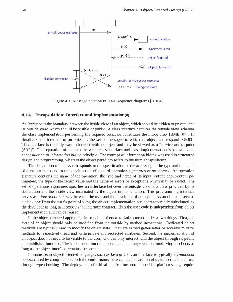
54 Chapter 4. Object-Oriented Design (OOD)
Figure 4.1: Message notation in UML sequence diagrams [RIJ04]
4.1.4 Encapsulation: Interface and Implementation(s)
An interfaceis the boundary between the inside view of an object, which should be hidden or private, andits outside view, which should be visible or public. A class interface captures the outside view, whereasthe class implementation performing the required behaviorconstitutes the inside view [BME+07]. InSmalltalk, the interface of an object is the set of messages to which an object can respond [GR83].This interface is the only way to interact with an object and may be viewed as a "service access point(SAP)". The separation of concerns between class interfaceand class implementation is known as theencapsulationor information hidingprinciple. The concept of information hiding was used in structureddesign and programming, whereas the object paradigm refersto the term encapsulation.
The declaration of a class corresponds to the specification of the access right, the type and the nameof class attributes and to the specification of a set of operation signatures or prototypes. An operationsignature contains the name of the operation, the type and name of its input, output, input-output pa-rameters, the type of the return value and the name of errors or exceptions which may be raised. Theset of operations signatures specifies aninterface between the outside view of a class provided by itsdeclaration and the inside view incarnated by the object implementation. This programming interfaceserves as afunctional contractbetween the user and the developer of an object. As an object is seen asa black box from the user’s point of view, the object implementation can be transparently substituted bythe developer as long as it respects the interface contract.Thus the user code is independent from objectimplementation and can be reused.
In the object-oriented approach, the principle ofencapsulationmeans at least two things. First, thestate of an object should only be modified from the outside by method invocations. Dedicated objectmethods are typically used to modify the object state. They are named getter/setter or accessor/mutatormethods to respectively read and write private and protected attributes. Second, the implementation ofan object does not need to be visible to the user, who can only interact with the object through its publicand published interface. The implementation of an object can be change without modifying its clients aslong as the object interface remains the same.
In mainstream object-oriented languages such as Java or C++, an interface is typically asyntacticalcontractused by compilers to check the conformance between the declaration of operations and their usethrough type checking. The deployment of critical applications onto embedded platforms may require
4.1. Fundamental Concepts 55
more guarantees in terms of behavior, performance or origine.g. trusted computing.Beugnard et al. define four levels of contract [BJPW99] of increasing negotiability: basic or syntac-
tical, behavioral, synchronization and quantitative.Syntactical contractsrefer to static or dynamic type checking in any language. This include model-
ing languages like UML, interface definition languages (IDLs), usual software programming languagese.g. Java, C/C++/C#, SystemC and hardware description languages e.g. VHDL and Verilog.
Behavioral contracts rely on boolean assertions called pre- and post-conditions[Hoa69] to con-straint operation behavior and enforce class invariant properties. An interface may be defined by itsbehavior protocol [PV02] that describes the ordered set of operation invocations that a client is allowedto perform. Such a protocol can be represented by a so-calledprotocol state machine [OMG07d] inUML. The termDesign by Contract™(DbC) [Mey92] was coined by Meyer to refer to this designmethodology also know asProgramming by Contract. This approach has been supported either na-tively or via libraries in various programming languages such as Eiffel designed by Meyer, Java andC/C++ and in UML through behavioral and protocol state machines and the Object Constraint Language(OCL) [OMG06d]. In hardware, Programming by Contract corresponds to Assertion-based Verificationwith Hardware Verification Languages (HVL) such asProperty Specification Language(PSL) [Acc04a],Cadence Specmane, SystemC [Ini08] and SystemVerilog [Acc04b].
Synchronization contracts specify synchronization constraints between concurrent method calls.Such constraints may take the form of synchronization policies such as mutual exclusion or singlewriter/multiple readers as defined by McHale [McH94]. For instance, the mutual execution of methodexecutions is supported in Java with thesynchronizedkeyword. In hardware, synchronization betweenhardware modules relies on explicit arbiters in classical HDLs or rules in BlueSpec that produce implicitarbiters.
Quantitative contracts allow one to define quality of service constraints also knownas non-functionalproperties to ensure execution guarantees such as performance (latency, throughput), security or avail-ability [Kra08]. Examples are the Real-Time (RT) CORBA policies. In hardware, quality of servicestypically refers to latency and throughput of data transfers between hardware master and slave modulesin on-chip buses or NoCs.
This work primary aims at defining an interface mapping from IDL to VHDL therefore at a syntacti-cal level. However, we will attempt in our proposition to include other aspects related to behavioral andconcurrency semantics and quality of services within on-chip interconnection networks.
4.1.5 Inheritance and White-Box Reuse
Inheritance permits to gather common functionalities between classes and to reuse interface definitionsand implementations. This mechanism avoids duplication and redundancy. It also provides an elegantway to extend functionality and to more easily manage complexity by using a hierarchy of classes froma general parent to specialized derived classes. The definition of interfaces is therefore modular andreusable. Theinheritance principle consists in deriving the declaration and possibly implementation ofa derivedor child class from abaseor parent class. The child class includes by default the data andbehavior of the parent class. It may also declare additionalattributes and methods. The behavior of thederived class may be either based on or replace (override) the behavior of its base class. Inheritancesupports the substitution principle of Liskov: if an interface I2 is derived from an interface I1, then I2is a subtype of I1 and a reference to an object of type I1 can be substituted by any object of type I2[OMG08b]. Reuse based on inheritance is called white-box reuse [GHJV95]. Indeed, the subclass mayaccess the private implementation of its parent, actually breaking the encapsulation principle.
Multiple inheritance allows a child class to inherit from more than one parent class. For instance,Java only supports single inheritance, whereas C++ supports multiple inheritance.
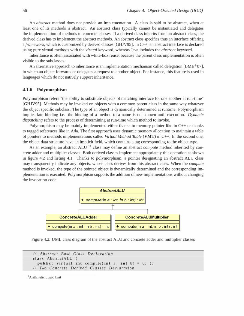
56 Chapter 4. Object-Oriented Design (OOD)
An abstractmethod does not provide an implementation. A class is said tobe abstract, when atleast one of its methods is abstract. An abstract class typically cannot be instantiated and delegatesthe implementation of methods to concrete classes. If a derived class inherits from an abstract class, thederived class has to implement the abstract methods. An abstract class specifies thus an interface offeringa framework, which is customized by derived classes [GHJV95]. In C++, anabstract interface is declaredusing pure virtual methods with thevirtual keyword, whereas Java includes theabstractkeyword.
Inheritance is often associated with white-box reuse, because the parent class implementation is oftenvisible to the subclasses.
An alternative approach to inheritance is an implementation mechanism called delegation [BME+07],in which an object forwards or delegates a request to anotherobject. For instance, this feature is used inlanguages which do not natively support inheritance.
4.1.6 Polymorphism
Polymorphism refers "the ability to substitute objects of matching interface for one another at run-time"[GHJV95]. Methods may be invoked on objects with a common parent class in the same way whateverthe object specific subclass. The type of an object is dynamically determined at runtime. Polymorphismimplies late binding i.e. the binding of a method to a name is not known until execution.Dynamicdispatchingrefers to the process of determining at run-time which method to invoke.
Polymorphism may be mainly implemented either thanks to memory pointer like in C++ or thanksto tagged references like in Ada. The first approach uses dynamic memory allocation to maintain a tableof pointers to methods implementations calledVirtual Method Table(VMT ) in C++. In the second one,the object data structure have an implicit field, which contains a tag corresponding to the object type.
As an example, an abstract ALU11 class may define an abstractcomputemethod inherited by con-crete adder and multiplier classes. Both derived classes implement appropriately this operation as shownin figure 4.2 and listing 4.1. Thanks to polymorphism, a pointer designating an abstract ALU classmay transparently indicate any objects, whose class derives from this abstract class. When thecomputemethod is invoked, the type of the pointed object is dynamically determined and the corresponding im-plementation is executed. Polymorphism supports the addition of new implementations without changingthe invocation code.
Figure 4.2: UML class diagram of the abstract ALU and concrete adder and multiplier classes
/ / A b s t r a c t Base C lass D e c l a r a t i o nc l a s s AbstractALU {
pub l i c : v i r t u a l i n t compute (i n t a , i n t b ) = 0 ; } ;/ / Two Concre te Der ived C l a s s e s D e c l a r a t i o n
11Arithmetic Logic Unit
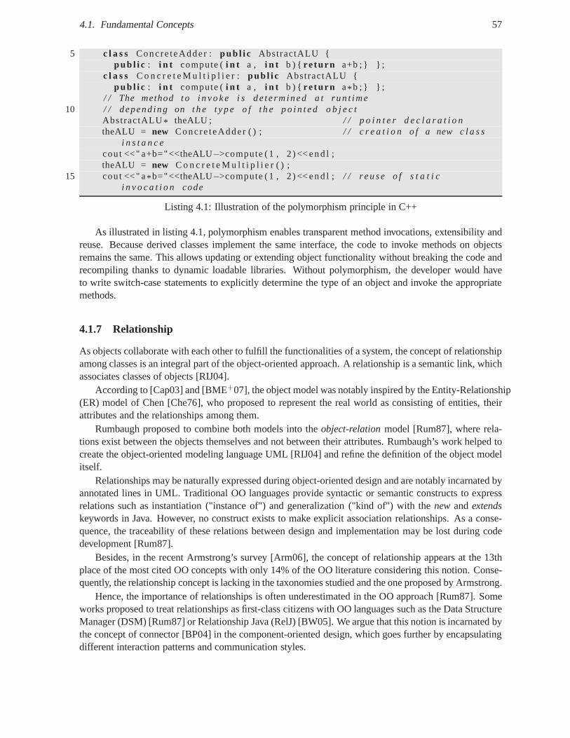
4.1. Fundamental Concepts 57
5 c l a s s Concre teAdder : pub l i c AbstractALU {pub l i c : i n t compute (i n t a , i n t b ) { re turn a+b ; } } ;
c l a s s C o n c r e t e M u l t i p l i e r : pub l i c AbstractALU {pub l i c : i n t compute (i n t a , i n t b ) { re turn a* b ; } } ;
/ / The method t o i n v o k e i s de te rm ined a t run t ime10 / / depend ing on t h e t y p e o f t h e p o i n t e d o b j e c t
AbstractALU* theALU ; / / p o i n t e r d e c l a r a t i o ntheALU = new Concre teAdder ( ) ; / / c r e a t i o n o f a new c l a s s
i n s t a n c ecout <<" a+b="<<theALU−>compute ( 1 , 2 ) << end l ;theALU = new C o n c r e t e M u l t i p l i e r ( ) ;
15 cout <<" a* b="<<theALU−>compute ( 1 , 2 ) << end l ; / / r e u s e o f s t a t i ci n v o c a t i o n code
Listing 4.1: Illustration of the polymorphism principle inC++
As illustrated in listing 4.1, polymorphism enables transparent method invocations, extensibility andreuse. Because derived classes implement the same interface, the code to invoke methods on objectsremains the same. This allows updating or extending object functionality without breaking the code andrecompiling thanks to dynamic loadable libraries. Withoutpolymorphism, the developer would haveto write switch-case statements to explicitly determine the type of an object and invoke the appropriatemethods.
4.1.7 Relationship
As objects collaborate with each other to fulfill the functionalities of a system, the concept of relationshipamong classes is an integral part of the object-oriented approach. A relationship is a semantic link, whichassociates classes of objects [RIJ04].
According to [Cap03] and [BME+07], the object model was notably inspired by the Entity-Relationship(ER) model of Chen [Che76], who proposed to represent the real world as consisting of entities, theirattributes and the relationships among them.
Rumbaugh proposed to combine both models into theobject-relationmodel [Rum87], where rela-tions exist between the objects themselves and not between their attributes. Rumbaugh’s work helped tocreate the object-oriented modeling language UML [RIJ04] and refine the definition of the object modelitself.
Relationships may be naturally expressed during object-oriented design and are notably incarnated byannotated lines in UML. Traditional OO languages provide syntactic or semantic constructs to expressrelations such as instantiation ("instance of") and generalization ("kind of") with thenewandextendskeywords in Java. However, no construct exists to make explicit association relationships. As a conse-quence, the traceability of these relations between designand implementation may be lost during codedevelopment [Rum87].
Besides, in the recent Armstrong’s survey [Arm06], the concept of relationship appears at the 13thplace of the most cited OO concepts with only 14% of the OO literature considering this notion. Conse-quently, the relationship concept is lacking in the taxonomies studied and the one proposed by Armstrong.
Hence, the importance of relationships is often underestimated in the OO approach [Rum87]. Someworks proposed to treat relationships as first-class citizens with OO languages such as the Data StructureManager (DSM) [Rum87] or Relationship Java (RelJ) [BW05]. We argue that this notion is incarnated bythe concept of connector [BP04] in the component-oriented design, which goes further by encapsulatingdifferent interaction patterns and communication styles.
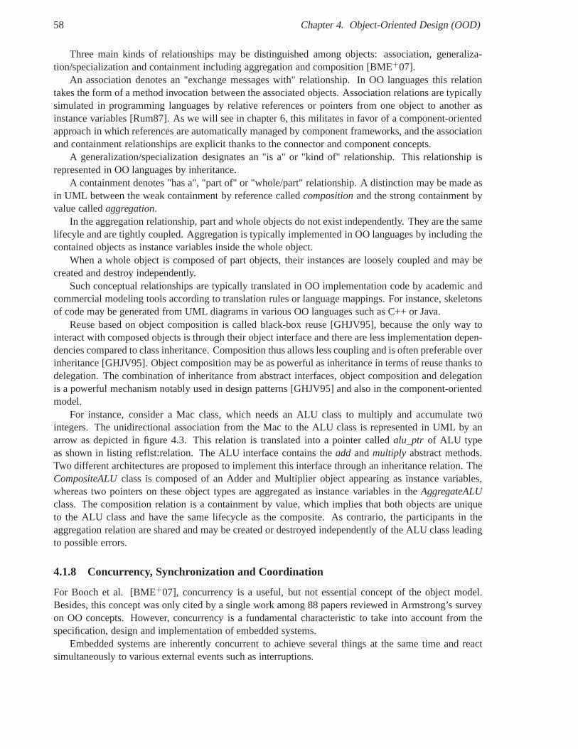
58 Chapter 4. Object-Oriented Design (OOD)
Three main kinds of relationships may be distinguished among objects: association, generaliza-tion/specialization and containment including aggregation and composition [BME+07].
An association denotes an "exchange messages with" relationship. In OO languages this relationtakes the form of a method invocation between the associatedobjects. Association relations are typicallysimulated in programming languages by relative referencesor pointers from one object to another asinstance variables [Rum87]. As we will see in chapter 6, thismilitates in favor of a component-orientedapproach in which references are automatically managed by component frameworks, and the associationand containment relationships are explicit thanks to the connector and component concepts.
A generalization/specialization designates an "is a" or "kind of" relationship. This relationship isrepresented in OO languages by inheritance.
A containment denotes "has a", "part of" or "whole/part" relationship. A distinction may be made asin UML between the weak containment by reference calledcompositionand the strong containment byvalue calledaggregation.
In the aggregation relationship, part and whole objects do not exist independently. They are the samelifecyle and are tightly coupled. Aggregation is typicallyimplemented in OO languages by including thecontained objects as instance variables inside the whole object.
When a whole object is composed of part objects, their instances are loosely coupled and may becreated and destroy independently.
Such conceptual relationships are typically translated inOO implementation code by academic andcommercial modeling tools according to translation rules or language mappings. For instance, skeletonsof code may be generated from UML diagrams in various OO languages such as C++ or Java.
Reuse based on object composition is called black-box reuse[GHJV95], because the only way tointeract with composed objects is through their object interface and there are less implementation depen-dencies compared to class inheritance. Composition thus allows less coupling and is often preferable overinheritance [GHJV95]. Object composition may be as powerful as inheritance in terms of reuse thanks todelegation. The combination of inheritance from abstract interfaces, object composition and delegationis a powerful mechanism notably used in design patterns [GHJV95] and also in the component-orientedmodel.
For instance, consider a Mac class, which needs an ALU class to multiply and accumulate twointegers. The unidirectional association from the Mac to the ALU class is represented in UML by anarrow as depicted in figure 4.3. This relation is translated into a pointer calledalu_ptr of ALU typeas shown in listing reflst:relation. The ALU interface contains theadd andmultiply abstract methods.Two different architectures are proposed to implement thisinterface through an inheritance relation. TheCompositeALUclass is composed of an Adder and Multiplier object appearing as instance variables,whereas two pointers on these object types are aggregated asinstance variables in theAggregateALUclass. The composition relation is a containment by value, which implies that both objects are uniqueto the ALU class and have the same lifecycle as the composite.As contrario, the participants in theaggregation relation are shared and may be created or destroyed independently of the ALU class leadingto possible errors.
4.1.8 Concurrency, Synchronization and Coordination
For Booch et al. [BME+07], concurrency is a useful, but not essential concept of the object model.Besides, this concept was only cited by a single work among 88papers reviewed in Armstrong’s surveyon OO concepts. However, concurrency is a fundamental characteristic to take into account from thespecification, design and implementation of embedded systems.
Embedded systems are inherently concurrent to achieve several things at the same time and reactsimultaneously to various external events such as interruptions.
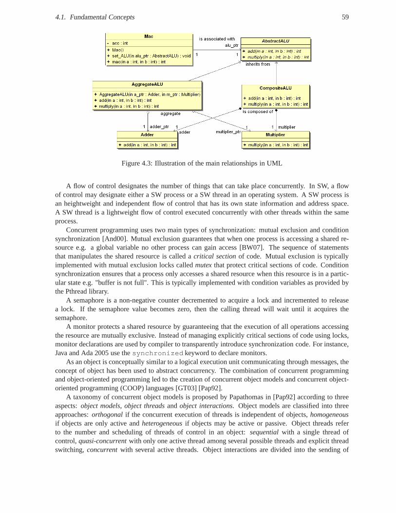
4.1. Fundamental Concepts 59
Figure 4.3: Illustration of the main relationships in UML
A flow of control designates the number of things that can takeplace concurrently. In SW, a flowof control may designate either a SW process or a SW thread in an operating system. A SW process isan heightweight and independent flow of control that has its own state information and address space.A SW thread is a lightweight flow of control executed concurrently with other threads within the sameprocess.
Concurrent programming uses two main types of synchronization: mutual exclusion and conditionsynchronization [And00]. Mutual exclusion guarantees that when one process is accessing a shared re-source e.g. a global variable no other process can gain access [BW07]. The sequence of statementsthat manipulates the shared resource is called acritical sectionof code. Mutual exclusion is typicallyimplemented with mutual exclusion locks calledmutexthat protect critical sections of code. Conditionsynchronization ensures that a process only accesses a shared resource when this resource is in a partic-ular state e.g. "buffer is not full". This is typically implemented with condition variables as provided bythe Pthread library.
A semaphore is a non-negative counter decremented to acquire a lock and incremented to releasea lock. If the semaphore value becomes zero, then the callingthread will wait until it acquires thesemaphore.
A monitor protects a shared resource by guaranteeing that the execution of all operations accessingthe resource are mutually exclusive. Instead of managing explicitly critical sections of code using locks,monitor declarations are used by compiler to transparentlyintroduce synchronization code. For instance,Java and Ada 2005 use thesynchronized keyword to declare monitors.
As an object is conceptually similar to a logical execution unit communicating through messages, theconcept of object has been used to abstract concurrency. Thecombination of concurrent programmingand object-oriented programming led to the creation of concurrent object models and concurrent object-oriented programming (COOP) languages [GT03] [Pap92].
A taxonomy of concurrent object models is proposed by Papathomas in [Pap92] according to threeaspects:object models, object threadsandobject interactions. Object models are classified into threeapproaches:orthogonal if the concurrent execution of threads is independent of objects,homogeneousif objects are only active andheterogeneousif objects may be active or passive. Object threads referto the number and scheduling of threads of control in an object: sequentialwith a single thread ofcontrol,quasi-concurrentwith only one active thread among several possible threads and explicit threadswitching,concurrentwith several active threads. Object interactions are divided into the sending of
60 Chapter 4. Object-Oriented Design (OOD)
requests by clients and the acceptance of requests by servers. The sending of requests can be eitherasynchronousvia one-way messages without reply orsynchronousvia request/reply messages. Theacceptance of requests can beexplicit through a statement,conditional through a guard orreflectivethrough a meta-object. We note that the acceptance of reply messages is not considered in the studiedsoftware concurrent object models and languages.
In many concurrent programming languages, the concept ofactive objecthas been usually usedto introduce concurrency between objects [GT03] [GMTB04].For Booch et al., "Concurrency is theproperty that distinguishes an active object from one that is not active" [BME+07]. The termactor issometimes employed to refer to active objects [Lea99]. The concept of active object relies on the supportof concurrency by OO languages that is either built-in as in Java, Smalltalk and Ada or provided byexternal libraries such as POSIX OS libraries for C++.
In VHDL, parallelism is modeled with hardware semantics according to 1 writer-N readers protocol:only one sequential or concurrent process is allowed to write onto an entity port or an architecture signalto avoid conflicts, whereas any number of processes can read them in the same clock cycle. Otherwise,concurrency between several writers has to be explicitly managed by the hardware designer. An accessarbiter controlling a multiplexer is typically used to implement an via an ad-hoc N writers-N readersprotocol.
As concurrency inherently exists in embedded systems and have to be implemented in HW and SWlanguages by designers, object-oriented system specifications should make explicit concurrency amongobjects and among methods within an object.
In the UML object model, concurrency may be modeled by activity, state, sequence and class dia-grams. Two granularity levels of concurrency may be specified in class diagram: at the class level withtheactive classconcept or at the operation level with a dedicated concurrency attribute [GT03].
At the class level, a class is eitheractiveor passive. An active (resp. passive) object is an instance ofan active (resp. passive) class.
According to [OMG07d] [RIJ04] [BRJ05] [BME+07], an active object has "its own thread of con-trol", whereas a passive object is executed in the context ofanother thread of control. However, anattentive reading of [BRJ05] shows that "an active class is aclass whose objects own one or more pro-cesses or threads". In this work, we consider that active object can own multiple flows of control to allowthe most general object model as supported by object-oriented programming languages.
To model class behavior, two kinds of state machines exist inUML: behavioral state machineandprotocol state machine[OMG07d]. A behavioral state machine specifies an executable behavior of aclass or method through states and transitions, which are triggered by events. A transition is associatedwith a sequence of actions. In contrast, a protocol state machine specifies the legal order of operationinvocations and signals reception that an object expects.
As the independent execution of an operation may access shared resources e.g. attributes in a passiveobject, the concurrent execution of multiple operations may require some execution control to preventdata corruption or inconsistent behavior. At the operationlevel, UML defines three semantics for con-current invocations to the same passive object i.e. with theisActiveattribute set to false. The meta-classOperationowns an inherited attribute calledconcurrency, whose value is defined by the enumerationCallConcurrencyKind[OMG07d] [BRJ05]:
• sequential: the operation assumes sequential invocations. Concurrent invocations have to be ex-plicitly serialized to allow only one invocation at a time. Object semantics and integrity cannotbe guaranteed with multiple flows of control. Hence, some coordination may be required betweencalling objects through synchronization, scheduling or arbitration.
• guarded: the operation supports simultaneous invocations from multiple flows of control, but only
4.1. Fundamental Concepts 61
a single execution. Only one invocation is executed, while the others are blocked until the first onecompletes. Thus, invocations are implicitly serialized.
• concurrent: the object supports simultaneous invocations and executions of any concurrent opera-tion requested from multiple flows of control. For instance,these flows may read data or write toindependent set of data.
Concurrency must be defined separately for each operation and for the entire object [BRJ05]. Operation-level concurrency specifies that multiple invocations of anoperation can execute concurrently, whileobject-level concurrency means that invocations of different operations can execute concurrently.
In OO programming languages, the UMLconcurrencyattribute is supported either natively like inJava with the equivalentsynchronizedkeyword [GJSB05] or by construction using mutex, semaphoresand monitors.
Active objects can control the simultaneous invocations oftheir behavior as they have their ownthread(s) of control. Each instance of an active class controls its own concurrency. Their behavior istypically specified by state machines, whose semantics haveto be clarified to support unambiguouslyconcurrent invocations [GMTB04].
However, even after several decades of concurrent and object-oriented technologies, UML semanticshave still ambiguities and inconsistencies concerning concurrency. Numerous works emphasize theirlimitations and propose to clarify UML semantics about active and passive object model [OS99] [GO01][SS01] [GMTB04] [Sel04] [JS07].
As opposed to software objects, hardware modules have always one or several independent threadsof control, which are modeled in VHDL by sequential processes and concurrent statements. From aconceptual viewpoint, VHDL processes correspond to SW threads and are modeled by SC_THREADin SystemC. These processes are simulated concurrently, but truly run in parallel in hardware and co-ordinate their execution through signals within a VHDL architecture. Hardware entities can be consid-ered asactiveobjects, which are internally parallel and communicate with each other through signals.Synchronous or asynchronous interaction styles depend on the hardware invocation protocol. We willanalyze how concurrency and synchronization have been implemented in hardware objects in section 4.2p. 63.
4.1.9 Persistence
Persistencerefers to the capability for an object to exist, while its creator e.g. process or thread hasceased to exist. In practice, persistence is performed by saving the state of an object from a volatilememory e.g. RAM or registers to a non-volatile or persistentstorage e.g. file, database or flash memory.The persistent object is saved before it is destroyed and restored in another class instance at its nextcreation or "reincarnation". Objects that are not persistent are calledtransientobjects.
4.1.10 Distribution
The metaphor of objects as little computers that interact only through messages [Kay93] provides a suit-able model to abstract distributed systems and let to the emerging of the distributed object model. Objectoriented-middleware platforms such as CORBA have been designed to offer an infrastructure supportingthe development, deployment and execution of distributed object-oriented applications. One of the maingoals of object-oriented middlewares is to make invisible or transparentthe distribution of objects fromthe viewpoint of the objects themselves, and the application designers and users. TheReference Model ofOpen Distributed Processing(RM-ODP) [Org98] standardizes an object modeling approach to system
62 Chapter 4. Object-Oriented Design (OOD)
specification along with numerous transparency criteria. Some of these criteria directly originate from aprevious initiative called the Advanced Networked SystemsArchitecture (ANSA) project [Man89].
RM-ODP defines the following distribution transparencies [Org98]:
• Access transparencymasks differences in data representation and invocation mechanisms to en-able interworking between objects.
• Failure transparency masks from an object the failure and possible recovery of other objects(or itself) to enable fault tolerance. Failure transparency depends on replication and concurrencytransparencies [PPL+06a].
• Location transparency masks the use of information about location in space when identifyingand binding to interfaces. This distribution transparencyprovides a logical view of naming, inde-pendent of actual physical location.
• Migration transparency masks from an object the ability of a system to change the locationof that object. Migration is often used to achieve load balancing and reduce latency. Migrationtransparency depends on access and location transparencies [PPL+06a].
• Relocation transparencymasks relocation of an interface from other interfaces bound to it.
• Replication transparencymasks the use of a group of mutually behaviorally compatibleobjectsto support an interface. Replication is often used to enhance performance and availability. Repli-cation transparency depends on access and location transparencies [PPL+06a].
• Persistence transparencymasks from an object the deactivation and reactivation of other objects(or itself).
• Transaction transparency masks coordination of activities among objects to guarantee consis-tency.
The ANSA project also definestechnology transparencyas the fact that different technologies suchas programming languages or operating systems are hidden from the user [PRP05]. Other forms oftransparency include [PPL+06a]:
• Scalability transparency: the system can continue to operate as more resources and services areadded and more concurrent requests have to be dispatched andprocessed. Scalability transparencydepends on migration and replication transparencies.
• Performance transparencymeans it is transparent to users and programmers how performance isactually achieved. Performance transparency depends on migration and replication transparencies.
• Concurrency transparency allows multiple clients to request transparently the same service si-multaneously. Each client does not need to know the existence of other clients or how concurrencyand consistency are managed by the service.
However, a variable number of these distribution criteria may be not relevant for some class ofembedded systems, which are static by nature. In these cases, objects are statically assigned to executionnodes and do not require location, migration or replicationtransparencies.
In a unified approach, an application of middleware conceptsinto hardware necessitates defining anarchitecture supporting part or all of the distribution transparencies. In the following we will present theworks performed towards this goal.
4.2. Object-Oriented Hardware Design 63
4.2 Object-Oriented Hardware Design
Although it originates from software engineering, the object model appears to be sufficiently general andtechnology independent to be applicable to the hardware domain in an attempt to provide a common andunified high-level approach to embedded systems design.
As studied in a recent survey performed in 2004 [Dv04a], manyresearchers have proposed to applythe object-oriented concepts for hardware design. The mainquestions that cross our mind are how manyobject concepts and how these concepts have been interpreted and implemented in hardware.
In the following, the various forms through which the object-oriented model has been applied downto hardware will be presented. On the one hand, hardware description languages like VHDL and Veriloghave been extended to support object-oriented features like OO-VHDLs and SystemVerilog. On the otherhand, mainstream object-oriented languages such as Java and C++ have been extended with hardware-specific libraries like SystemC. Moreover, hardware objectarchitectures have been proposed using Jav-aBean, Finite-State Machine (FSM) and distributed objects. Other works have presented object-orientedhardware platforms with OO-ASIP and hardware middlewares like StepNP, OOCE (Object-OrientedCommunication Engine) and hardware CORBA, implementations. Finally, model-driven engineeringhas been used to model hardware objects in UML and generate VHDL and Verilog. The presentationof the related work and the associated discussions will be focused on the interpretations of objects inhardware and particularly on the hardware interfaces used for method invocations.
4.2.1 Object-Oriented Extensions to Hardware DescriptionLanguages
In the 1990s, numerous works were devoted to the propositionof object-oriented extensions to HDLs[AWM99]. VHDL was widely selected since it natively separates the declaration of component interfacein entity from their implementation(s) inarchitecture(s). These extensions took the form of new OOlanguage constructs, which were translated by preprocessors into synthesizable VHDL. According to[Rad00], two main approaches have been distinguished to provide object-orientation to VHDL.
In theentity-basedapproach, a VHDL entity is considered as a class declaration, whereas a VHDLarchitecture is viewed as a class implementation. Hence, hardware objects are interpreted as VHDLcomponent instances.
Thetype-basedapproach extends HDLs with a novel class data type, whose instances are equivalentto VHDL variables and signals. If one consider that VHDL was inspired by Ada, this approach is similarto consider the object-oriented data types added to Ada83 tobuild Ada95. Examples of this categoryinclude OO-VHDL [Sch99], SUAVE [AWM98] and Objective VHDL [Rad00]. Interestingly, an IEEEstudy group called OO-VHDL12 was created in late 1993 to establish requirements for an object-orientedVHDL and to propose language extensions. A merger of the SUAVE and Objective VHDL proposalswas investigated [AR98]. However, many advanced concepts of SUAVE were not synthesizable and nosimulator was developed, whereas Objective VHDL was designed to be synthesizable, but the translationtool to VHDL was not mature enough [Opp05]. Both works stopped and these efforts unfortunately failedto be standardized. Afterwards, the community preferred tomodel hardware design using high-levelobject-oriented languages as presented below. Recent revisions of the VHDL standard called VHDL-200x should include object-orientation with inheritance and interface modeling based on Ashenden’sproposal according to [BMB+04] [Lew07].
Furthermore, Verilog has been enhanced with object-oriented extensions to build SystemVerilog 3.x[Acc04b] to facilitate the verification of abstract hardware models. As Verilog syntax is inspired by theC language, SystemVerilog naturally provides OO extensions close to C++. Aclassconstruct was intro-
12http://www.eda.org/oovhdl
64 Chapter 4. Object-Oriented Design (OOD)
duced to declare instance variables calledpropertiesand member functions namedmethods. SystemVer-ilog supports class inheritance, polymorphism and dynamicallocation of classes, but the synthesizablesemantics of these advanced features are not defined.
Although our work could benefit from OO extensions to HDLs, wedo not consider such customextensions and we restrict our proposition to the synthesizable subset of standard HDLs such as VHDLand Verilog.
4.2.2 Object-Oriented Languages for Hardware Design
In order to raise the level of hardware abstraction and increase simulation speed, mainstream OO lan-guages such as Java and C++ have been intensively used to model hardware design. The main objectivewas to replace the use of two languages such as C/C++ and VHDL/Verilog to specify software andhardware with different programming models and semantics by a common language for system specifi-cation [HO97, YMS+98, KSKR00]. Obviously, usual OO languages do not natively provide adequateconstructs to model hardware characteristics like ports, wires, time, event or specific data types such asbitvectors. OO libraries have thus been developed to provide new language syntax and semantics closeto those found in HDLs. The main advantage of this approach isthe possibility to model both hardwareand software thanks to widely available software tools likethe free and open-source GNU tools. Thistrend gained so importance in industry and academia that a defacto C++ library calledSystemCbecamean IEEE standard in 2005.
Java
The Java software programming language has been proposed inthe 2000s to design, specify and simulatehardware/software embedded systems. Java is a high-level and platform independent language with real-time extension. Java provides an object-oriented framework with standard APIs allowing to explicitlyspecify concurrency with threads and monitors, and reactivity with events and timing. However, dy-namic loading and linking of Java objects at run-time complicate the analysis and optimization of systemspecification [HO97] [YMS+98].
In [HO97], Java is used as an executable system specificationlanguage to support functional vali-dation and hardware/software co-design. In [YMS+98], Java serves as a general purpose language tocapture a first system specification, which is successively refined by an user-guided tool into a formalmodel that is deterministic in term of behavior, bounded execution time and memory consumption.
Whereas both previous approaches are only focused on behavioral specifications of hardware/soft-ware systems from an algorithmic viewpoint, Java is considered as a behavioral and structural descriptionat system, algorithmic and register transfer levels in [KR98], [KRK99] and [KSKR00]. These later workswill be described in more details in the next section.
From our viewpoint, Java cannot be considered as a system-level language as Java is basically notused for real-time signal-processing applications on embedded GPPs and DSPs. In contrast, C and C++are quasi-exclusively used in such a context. Hence, system-level languages derived from C/C++ suchas SystemC are more relevant notably to refine a behavioral specification down to implementations onGPPs and DSPs.
SystemC
SystemC [GLMS02] is an OO modeling language based on a C++ class library. It allows the model-ing of hardware/software embedded systems at various levels of abstraction. However, there is still noconsensus on the number and purpose of these abstraction levels. Although the OSCI Transaction Level
4.2. Object-Oriented Hardware Design 65
Modeling (TLM) [Ghe06] standards have defined some APIs (TLM1.0 and TLM 2.0), the main difficultyremains the refinement from one level of abstraction to another. The transformation from a high-levelfunctional specification down to a synthesizable hardware description is still tedious and error-prone.For instance, SystemC FIFOs have to be manually translated into signals. Moreover, the draft of a syn-thesizable subset [oOSI04] started in 2004 is still under public review. As a consequence, commercialand academic tools such as Cynthesizer [Sys, CM08] and FOSSY[GGON07] may propose their ownabstraction levels and refinement methodology. Furthermore, OO concepts like inheritance or polymor-phism are not supported by such synthesis tools. In conclusion, SystemC allows OO HW modeling, butnot OO HW design [SVL01] [SKWS+04].
From SystemC-Plus to OSSS+R at the University of Oldenburg and OFFIS Institute In the scopeof the project ICODES [ICO08], a synthesizable subset of SystemC calledOSSS[GGON07] [BGG+07]for OldenburgSystemSynthesisSubset was developed by the OFFIS research institute and the Univer-sity of Oldenburg to improve the refinement of SystemC modelsdown to HW implementation. OSSS isa C++ class library on top of SystemC with well-defined synthesizable semantics to model HW/SW em-bedded systems based on OO principles. OSSS is based on the SystemC-Plus library [ICE01] [GTF+02][GO03]. A Remote Method Invocation(RMI ) mechanism has been designed to transform method-basedcommunications between HW/SW objects to signal-based communications through buses and point-to-point channels.
The concept ofShared Objectis used to homogeneously model HW/SW as well as HW/HW com-munications through method invocations. Shared objects arbitrate concurrent invocations on shared re-sources like a buffer using provided or user-defined scheduling algorithms.
In the scope of the ANDRES [AND08] project, the OSSS+R13 [SON06] library is developed asan extension of the existing OSSS library to target the modeling and simulation of dynamic and partialreconfiguration in digital hardware systems. OSSS+R aims tooffer new language features to SystemC tomanage the reconfiguration process transparently from the designer’s point of view. OSSS+R approachis based on an analogy between polymorphism and hardware run-time reconfiguration. Polymorphismallows one to dynamically change the behavior of an object, while the code to call it remains static.The same remains valid for reconfigurable hardware where thehardware interface between the staticand dynamic part is fixed, while the implementation of the dynamic part may be changed at run-time byloading partial bitstreams. In OSSS+R, polymorphic objects act as reconfigurable containers to modelreconfigurable areas. A container is responsible for arbitrating the access to the contained objects and torequest a unique reconfiguration controler.
As the analogy between polymorphism and routing in [GZH07],we consider that the analogy be-tween polymorphism and reconfiguration is interesting since the high-level operation-based interfacespecified in a class hierarchy is directly translated into a low-level signal-based hardware interface speci-fied in VHDL. Moreover, polymorphic objects cope with non functional services such as object life cycleand resource sharing in a similar way tocontainersand component factories in the component approachdescribed in the next section.
The OASE project at the University of Tübingen The OASE project [UoT08] at the University ofTübingen was concerned with the object-oriented design of hardware/software systems. This projectstudied the modeling [SKWS+04], specification [KSKR00], co-simulation [KR98, KRK99] partitioning[SKKR01], synthesis and verification [KOSK+01, KOW+01] of embedded systems based on variousobject-oriented languages such as Java [KR98, KRK99, KSKR00], e [KOSK+01, KOW+01], C++ andSystemC [SKWS+04].
13OSSS+Reconfiguration
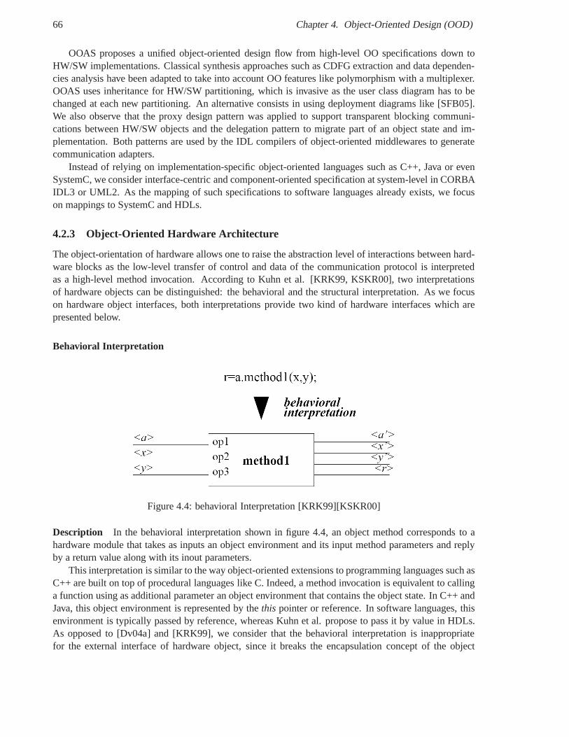
66 Chapter 4. Object-Oriented Design (OOD)
OOAS proposes a unified object-oriented design flow from high-level OO specifications down toHW/SW implementations. Classical synthesis approaches such as CDFG extraction and data dependen-cies analysis have been adapted to take into account OO features like polymorphism with a multiplexer.OOAS uses inheritance for HW/SW partitioning, which is invasive as the user class diagram has to bechanged at each new partitioning. An alternative consists in using deployment diagrams like [SFB05].We also observe that the proxy design pattern was applied to support transparent blocking communi-cations between HW/SW objects and the delegation pattern tomigrate part of an object state and im-plementation. Both patterns are used by the IDL compilers ofobject-oriented middlewares to generatecommunication adapters.
Instead of relying on implementation-specific object-oriented languages such as C++, Java or evenSystemC, we consider interface-centric and component-oriented specification at system-level in CORBAIDL3 or UML2. As the mapping of such specifications to software languages already exists, we focuson mappings to SystemC and HDLs.
4.2.3 Object-Oriented Hardware Architecture
The object-orientation of hardware allows one to raise the abstraction level of interactions between hard-ware blocks as the low-level transfer of control and data of the communication protocol is interpretedas a high-level method invocation. According to Kuhn et al. [KRK99, KSKR00], two interpretationsof hardware objects can be distinguished: the behavioral and the structural interpretation. As we focuson hardware object interfaces, both interpretations provide two kind of hardware interfaces which arepresented below.
Behavioral Interpretation
Figure 4.4: behavioral Interpretation [KRK99][KSKR00]
Description In the behavioral interpretation shown in figure 4.4, an object method corresponds to ahardware module that takes as inputs an object environment and its input method parameters and replyby a return value along with its inout parameters.
This interpretation is similar to the way object-oriented extensions to programming languages such asC++ are built on top of procedural languages like C. Indeed, amethod invocation is equivalent to callinga function using as additional parameter an object environment that contains the object state. In C++ andJava, this object environment is represented by thethis pointer or reference. In software languages, thisenvironment is typically passed by reference, whereas Kuhnet al. propose to pass it by value in HDLs.As opposed to [Dv04a] and [KRK99], we consider that the behavioral interpretation is inappropriatefor the external interface of hardware object, since it breaks the encapsulation concept of the object
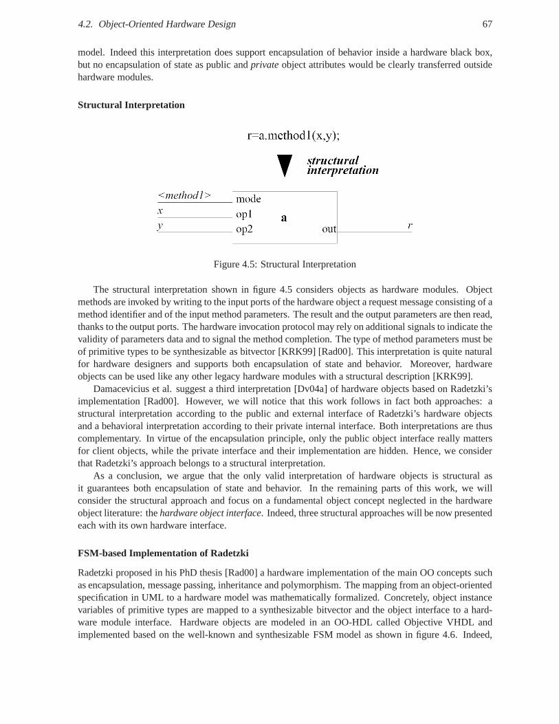
4.2. Object-Oriented Hardware Design 67
model. Indeed this interpretation does support encapsulation of behavior inside a hardware black box,but no encapsulation of state as public andprivateobject attributes would be clearly transferred outsidehardware modules.
Structural Interpretation
Figure 4.5: Structural Interpretation
The structural interpretation shown in figure 4.5 considersobjects as hardware modules. Objectmethods are invoked by writing to the input ports of the hardware object a request message consisting of amethod identifier and of the input method parameters. The result and the output parameters are then read,thanks to the output ports. The hardware invocation protocol may rely on additional signals to indicate thevalidity of parameters data and to signal the method completion. The type of method parameters must beof primitive types to be synthesizable as bitvector [KRK99][Rad00]. This interpretation is quite naturalfor hardware designers and supports both encapsulation of state and behavior. Moreover, hardwareobjects can be used like any other legacy hardware modules with a structural description [KRK99].
Damacevicius et al. suggest a third interpretation [Dv04a]of hardware objects based on Radetzki’simplementation [Rad00]. However, we will notice that this work follows in fact both approaches: astructural interpretation according to the public and external interface of Radetzki’s hardware objectsand a behavioral interpretation according to their privateinternal interface. Both interpretations are thuscomplementary. In virtue of the encapsulation principle, only the public object interface really mattersfor client objects, while the private interface and their implementation are hidden. Hence, we considerthat Radetzki’s approach belongs to a structural interpretation.
As a conclusion, we argue that the only valid interpretationof hardware objects is structural asit guarantees both encapsulation of state and behavior. In the remaining parts of this work, we willconsider the structural approach and focus on a fundamentalobject concept neglected in the hardwareobject literature: thehardware object interface. Indeed, three structural approaches will be now presentedeach with its own hardware interface.
FSM-based Implementation of Radetzki
Radetzki proposed in his PhD thesis [Rad00] a hardware implementation of the main OO concepts suchas encapsulation, message passing, inheritance and polymorphism. The mapping from an object-orientedspecification in UML to a hardware model was mathematically formalized. Concretely, object instancevariables of primitive types are mapped to a synthesizable bitvector and the object interface to a hard-ware module interface. Hardware objects are modeled in an OO-HDL called Objective VHDL andimplemented based on the well-known and synthesizable FSM model as shown in figure 4.6. Indeed,
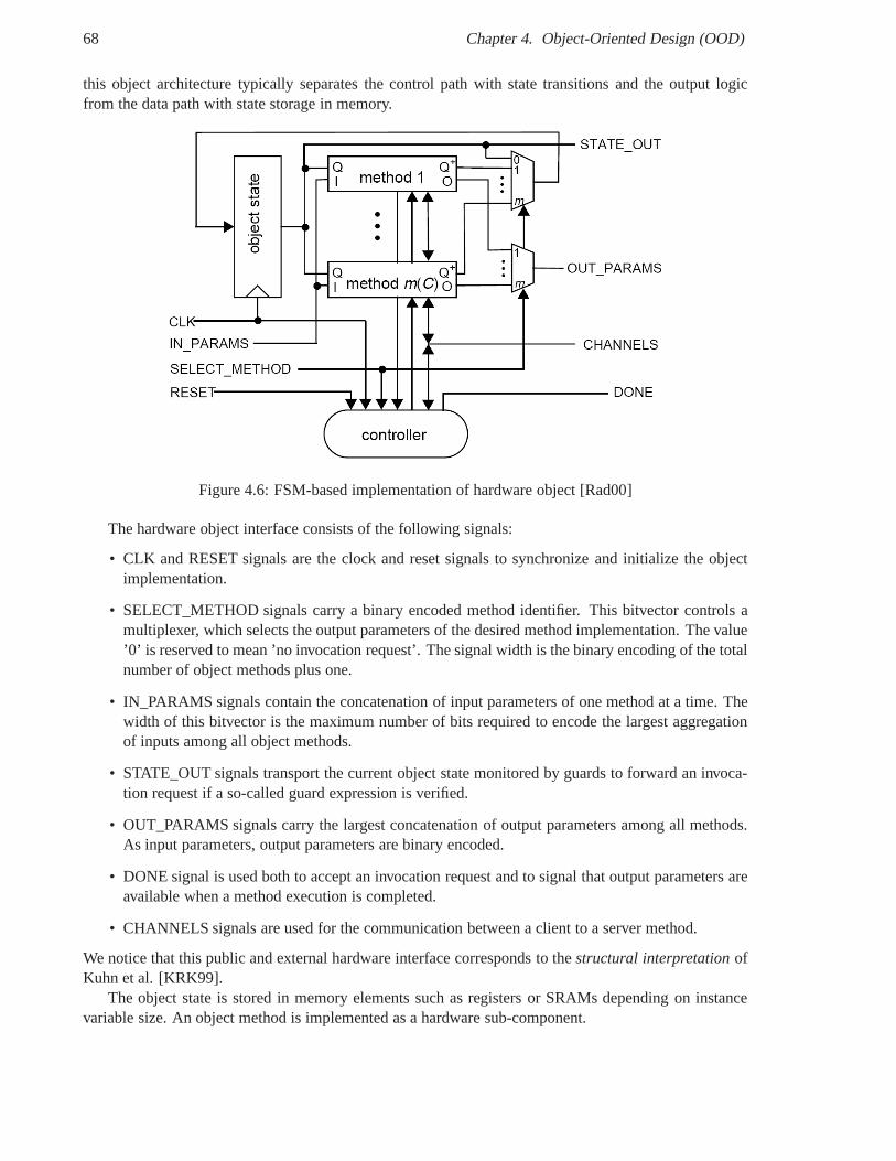
68 Chapter 4. Object-Oriented Design (OOD)
this object architecture typically separates the control path with state transitions and the output logicfrom the data path with state storage in memory.
Figure 4.6: FSM-based implementation of hardware object [Rad00]
The hardware object interface consists of the following signals:
• CLK and RESET signals are the clock and reset signals to synchronize and initialize the objectimplementation.
• SELECT_METHOD signals carry a binary encoded method identifier. This bitvector controls amultiplexer, which selects the output parameters of the desired method implementation. The value’0’ is reserved to mean ’no invocation request’. The signal width is the binary encoding of the totalnumber of object methods plus one.
• IN_PARAMS signals contain the concatenation of input parameters of one method at a time. Thewidth of this bitvector is the maximum number of bits required to encode the largest aggregationof inputs among all object methods.
• STATE_OUT signals transport the current object state monitored by guards to forward an invoca-tion request if a so-called guard expression is verified.
• OUT_PARAMS signals carry the largest concatenation of output parameters among all methods.As input parameters, output parameters are binary encoded.
• DONE signal is used both to accept an invocation request andto signal that output parameters areavailable when a method execution is completed.
• CHANNELS signals are used for the communication between a client to a server method.
We notice that this public and external hardware interface corresponds to thestructural interpretationofKuhn et al. [KRK99].
The object state is stored in memory elements such as registers or SRAMs depending on instancevariable size. An object method is implemented as a hardwaresub-component.
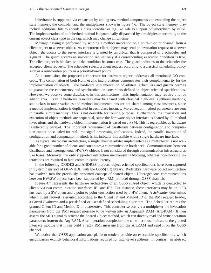
4.2. Object-Oriented Hardware Design 69
Inheritance is supported via expansion by adding new methodcomponents and extending the objectstate memory, the controler and the multiplexers shown in figure 4.6. The object state memory mayinclude additional bits to encode a class identifier or tag like Ada to support polymorphism by value.The implementation of an inherited method is dynamically dispatched by a multiplexer according to thecurrent object class type in the tag, which may change at run-time.
Message passing is performed by sending a method invocationon a point-to-point channel from aclient object to a server object. As concurrent client objects may send an invocation request to a serverobject, the access to the server interface is granted by an arbiter that is composed of a scheduler anda guard. The guard accepts an invocation request only if a corresponding execution condition is true.The client object is blocked until the condition becomes true. The guard indicates to the scheduler theaccepted client requests. The scheduler selects a client request according to a classical scheduling policysuch as a round-robin policy or a priority-based policy.
As a conclusion, the proposed architecture for hardware objects addresses all mentioned OO con-cepts. The combination of both Kuhn et al.’s interpretations demonstrates their complementarity for theimplementation of objects. The hardware implementation ofarbiters, schedulers and guards permitsto guarantee the concurrency and synchronization constraints defined in object-oriented specifications.However, we observe some drawbacks in this architecture. This implementation may require a lot ofsilicon area. Even if hardware resources may be shared with classical high-level synthesis methods,static class instance variables and method implementations are not shared among class instances, sincea method implementation is duplicated in each class instance. Moreover, all method parameters are sentin parallel simultaneously. This is not desirable for routing purpose. Furthermore, the invocation andexecution of object methods are sequential, since the hardware object interface is shared by all methodinvocations and the hardware object implementation is based on a FSM. This is regrettable, as hardwareis inherently parallel. The important requirement of parallelism between configuration and computa-tion cannot be satisfied for real-time signal processing applications. Indeed, the parallel invocation ofconfiguration and computation methods is intrinsically impossible with a single hardware interface.
As typical shared bus architecture, a single channel arbiter implemented as a multiplexer is not scal-able for a great number of clients and constitutes a communication bottleneck. Communications betweendistributed and heterogeneous HW/SW objects is not considered through communication infrastructureslike buses. Moreover, the only supported interaction mechanism is blocking, whereas non-blocking in-teractions are required to hide communication latency.
In the following ICODES and ANDRES projects, object-oriented specifications have been capturedin SystemC instead of OO-VHDL with the OSSS(+R) library. Radetzki’s hardware object architecturehas evolved into the previously presented concept of sharedobject. Heterogeneous communicationsbetween HW/SW objects have been supported by a RMI protocol through OSSS channels.
Figure 4.7 represents the hardware architecture of an OSSS shared object, which is connected toclients via two communication interfaces IF1 and IF2. For instance, these interfaces may be an OPBbus used by a SW client and a point-to-point connection used by a HW client. ASchedulerdetermineswhich client request is granted according to the Client ID and Method ID of the RMI request header,a Guard Evaluatorand a pre-defined or user-defined scheduling algorithm. The Scheduler returns thegranted Client ID and MethodID to acontroler. This controler selects via a multiplexer the invocationparameters from the RMI request message to be written into anArgument RAM (Arg-RAM). It thenasserts the MID signal to activate the Shared Object method,which can directly read and write operationparameters from/to the Arg-RAM. After operation completion, the controler must indicate to the grantedinterface module that it can build a reply RMI message from the ArgRAM and send it on the OSSSchannel.
We notice that OSSS application and platform models providean executable specification, whichencompasses explicit behavioral informations required for high-level synthesis. In contrast, an abstract
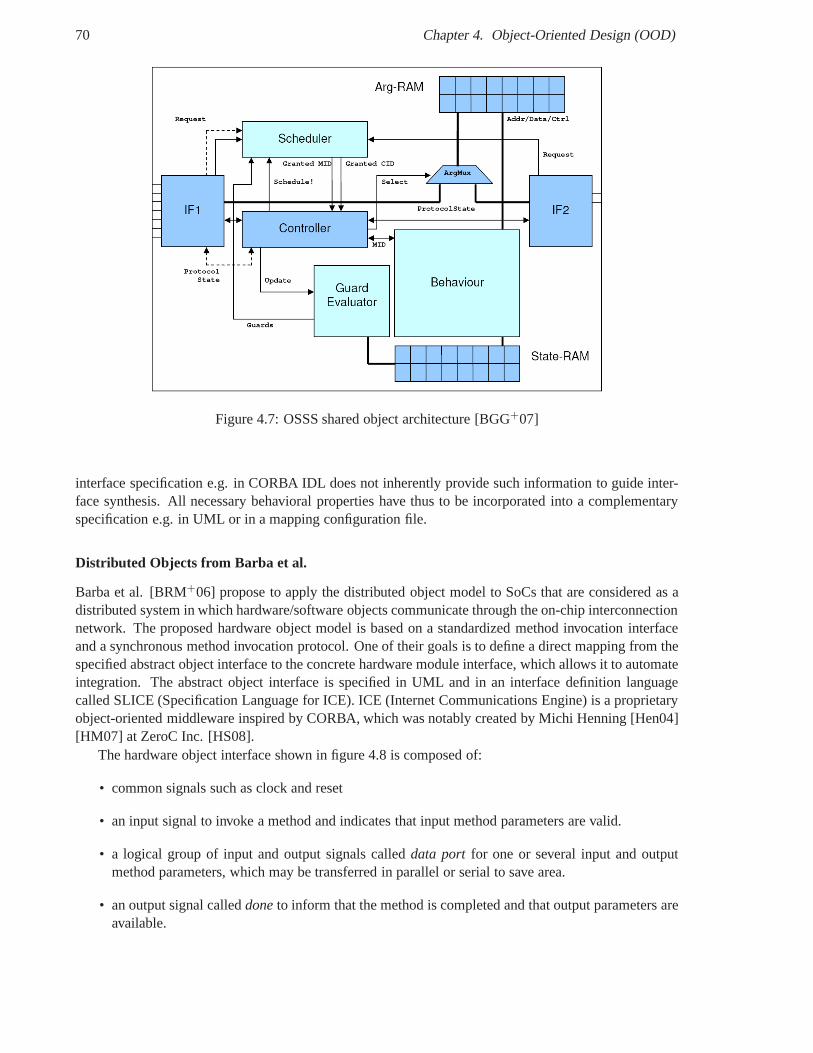
70 Chapter 4. Object-Oriented Design (OOD)
Figure 4.7: OSSS shared object architecture [BGG+07]
interface specification e.g. in CORBA IDL does not inherently provide such information to guide inter-face synthesis. All necessary behavioral properties have thus to be incorporated into a complementaryspecification e.g. in UML or in a mapping configuration file.
Distributed Objects from Barba et al.
Barba et al. [BRM+06] propose to apply the distributed object model to SoCs that are considered as adistributed system in which hardware/software objects communicate through the on-chip interconnectionnetwork. The proposed hardware object model is based on a standardized method invocation interfaceand a synchronous method invocation protocol. One of their goals is to define a direct mapping from thespecified abstract object interface to the concrete hardware module interface, which allows it to automateintegration. The abstract object interface is specified in UML and in an interface definition languagecalled SLICE (Specification Language for ICE). ICE (Internet Communications Engine) is a proprietaryobject-oriented middleware inspired by CORBA, which was notably created by Michi Henning [Hen04][HM07] at ZeroC Inc. [HS08].
The hardware object interface shown in figure 4.8 is composedof:
• common signals such as clock and reset
• an input signal to invoke a method and indicates that input method parameters are valid.
• a logical group of input and output signals calleddata port for one or several input and outputmethod parameters, which may be transferred in parallel or serial to save area.
• an output signal calleddoneto inform that the method is completed and that output parameters areavailable.
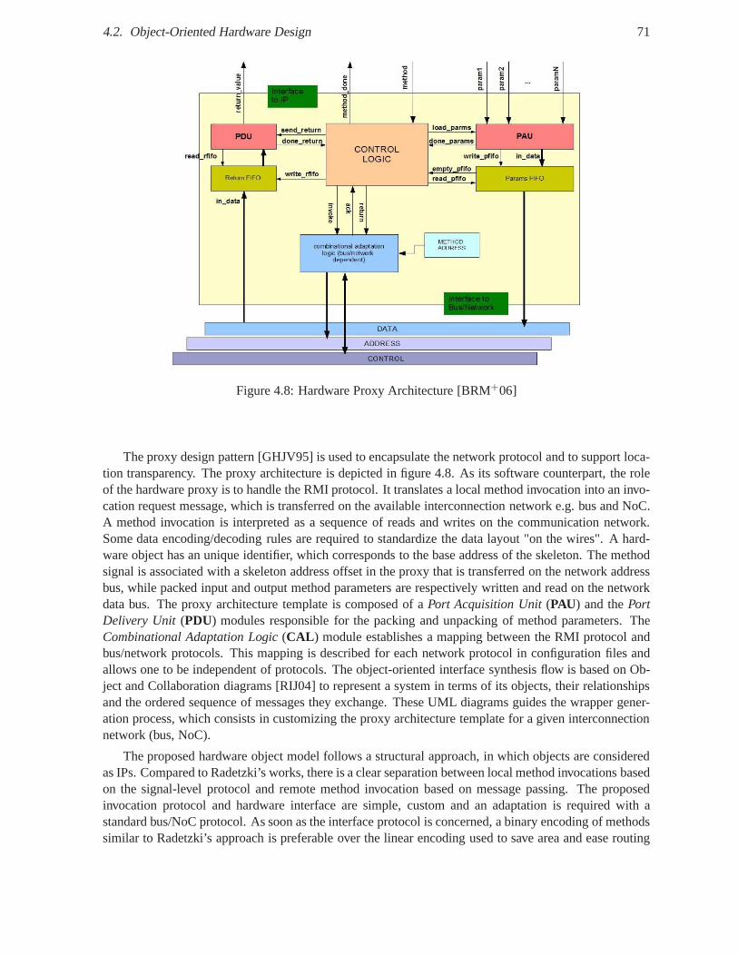
4.2. Object-Oriented Hardware Design 71
Figure 4.8: Hardware Proxy Architecture [BRM+06]
The proxy design pattern [GHJV95] is used to encapsulate thenetwork protocol and to support loca-tion transparency. The proxy architecture is depicted in figure 4.8. As its software counterpart, the roleof the hardware proxy is to handle the RMI protocol. It translates a local method invocation into an invo-cation request message, which is transferred on the available interconnection network e.g. bus and NoC.A method invocation is interpreted as a sequence of reads andwrites on the communication network.Some data encoding/decoding rules are required to standardize the data layout "on the wires". A hard-ware object has an unique identifier, which corresponds to the base address of the skeleton. The methodsignal is associated with a skeleton address offset in the proxy that is transferred on the network addressbus, while packed input and output method parameters are respectively written and read on the networkdata bus. The proxy architecture template is composed of aPort Acquisition Unit(PAU) and thePortDelivery Unit (PDU) modules responsible for the packing and unpacking of method parameters. TheCombinational Adaptation Logic(CAL ) module establishes a mapping between the RMI protocol andbus/network protocols. This mapping is described for each network protocol in configuration files andallows one to be independent of protocols. The object-oriented interface synthesis flow is based on Ob-ject and Collaboration diagrams [RIJ04] to represent a system in terms of its objects, their relationshipsand the ordered sequence of messages they exchange. These UML diagrams guides the wrapper gener-ation process, which consists in customizing the proxy architecture template for a given interconnectionnetwork (bus, NoC).
The proposed hardware object model follows a structural approach, in which objects are consideredas IPs. Compared to Radetzki’s works, there is a clear separation between local method invocations basedon the signal-level protocol and remote method invocation based on message passing. The proposedinvocation protocol and hardware interface are simple, custom and an adaptation is required with astandard bus/NoC protocol. As soon as the interface protocol is concerned, a binary encoding of methodssimilar to Radetzki’s approach is preferable over the linear encoding used to save area and ease routing
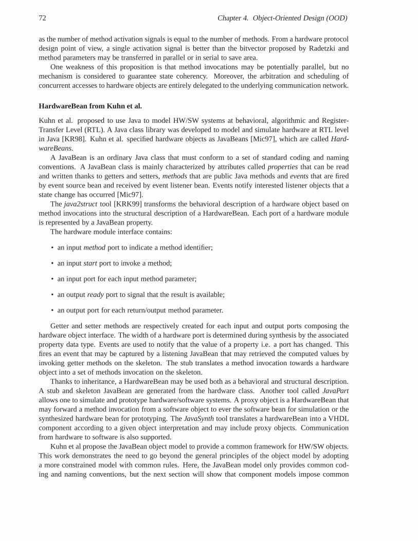
72 Chapter 4. Object-Oriented Design (OOD)
as the number of method activation signals is equal to the number of methods. From a hardware protocoldesign point of view, a single activation signal is better than the bitvector proposed by Radetzki andmethod parameters may be transferred in parallel or in serial to save area.
One weakness of this proposition is that method invocationsmay be potentially parallel, but nomechanism is considered to guarantee state coherency. Moreover, the arbitration and scheduling ofconcurrent accesses to hardware objects are entirely delegated to the underlying communication network.
HardwareBean from Kuhn et al.
Kuhn et al. proposed to use Java to model HW/SW systems at behavioral, algorithmic and Register-Transfer Level (RTL). A Java class library was developed to model and simulate hardware at RTL levelin Java [KR98]. Kuhn et al. specified hardware objects as JavaBeans [Mic97], which are calledHard-wareBeans.
A JavaBean is an ordinary Java class that must conform to a setof standard coding and namingconventions. A JavaBean class is mainly characterized by attributes calledpropertiesthat can be readand written thanks to getters and setters,methodsthat are public Java methods andeventsthat are firedby event source bean and received by event listener bean. Events notify interested listener objects that astate change has occurred [Mic97].
The java2structtool [KRK99] transforms the behavioral description of a hardware object based onmethod invocations into the structural description of a HardwareBean. Each port of a hardware moduleis represented by a JavaBean property.
The hardware module interface contains:
• an inputmethodport to indicate a method identifier;
• an inputstart port to invoke a method;
• an input port for each input method parameter;
• an outputreadyport to signal that the result is available;
• an output port for each return/output method parameter.
Getter and setter methods are respectively created for eachinput and output ports composing thehardware object interface. The width of a hardware port is determined during synthesis by the associatedproperty data type. Events are used to notify that the value of a property i.e. a port has changed. Thisfires an event that may be captured by a listening JavaBean that may retrieved the computed values byinvoking getter methods on the skeleton. The stub translates a method invocation towards a hardwareobject into a set of methods invocation on the skeleton.
Thanks to inheritance, a HardwareBean may be used both as a behavioral and structural description.A stub and skeleton JavaBean are generated from the hardwareclass. Another tool calledJavaPartallows one to simulate and prototype hardware/software systems. A proxy object is a HardwareBean thatmay forward a method invocation from a software object to ever the software bean for simulation or thesynthesized hardware bean for prototyping. TheJavaSynthtool translates a hardwareBean into a VHDLcomponent according to a given object interpretation and may include proxy objects. Communicationfrom hardware to software is also supported.
Kuhn et al propose the JavaBean object model to provide a common framework for HW/SW objects.This work demonstrates the need to go beyond the general principles of the object model by adoptinga more constrained model with common rules. Here, the JavaBean model only provides common cod-ing and naming conventions, but the next section will show that component models impose common
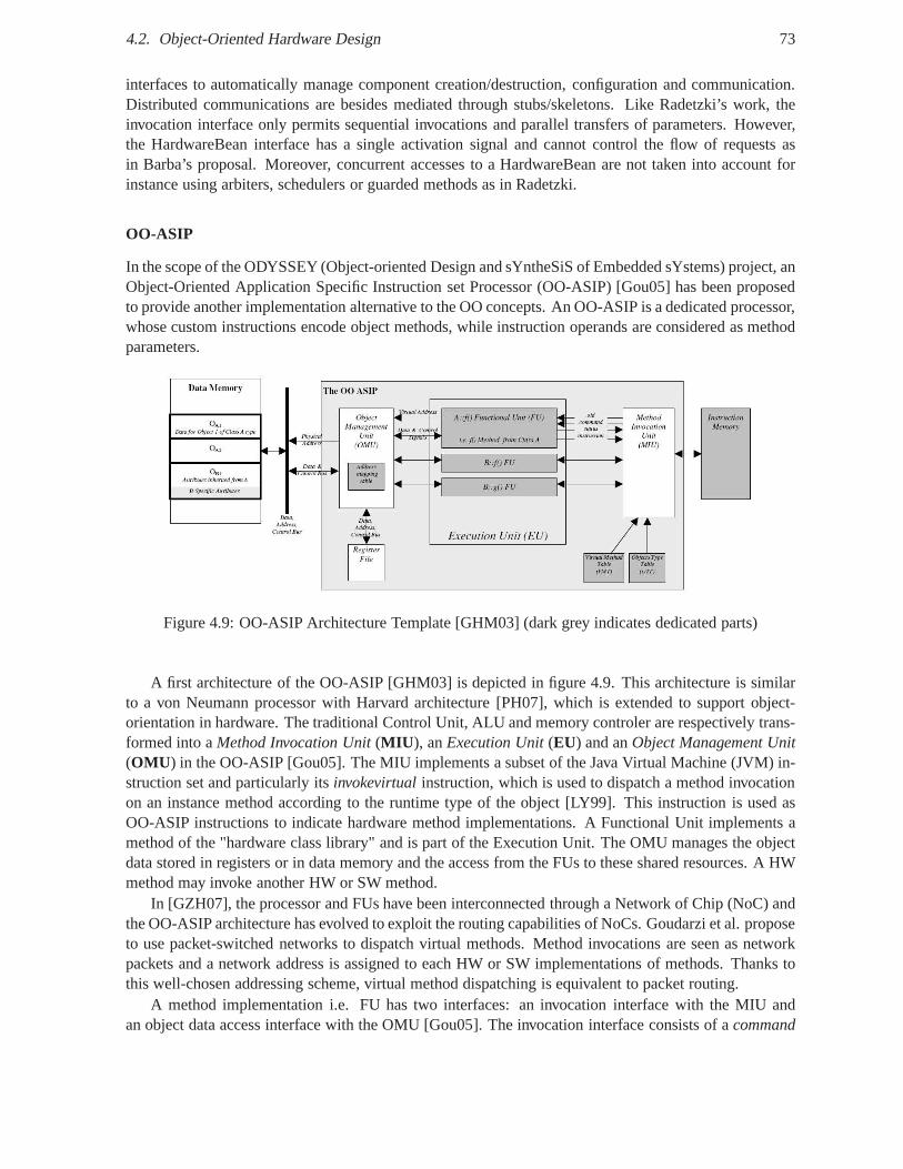
4.2. Object-Oriented Hardware Design 73
interfaces to automatically manage component creation/destruction, configuration and communication.Distributed communications are besides mediated through stubs/skeletons. Like Radetzki’s work, theinvocation interface only permits sequential invocationsand parallel transfers of parameters. However,the HardwareBean interface has a single activation signal and cannot control the flow of requests asin Barba’s proposal. Moreover, concurrent accesses to a HardwareBean are not taken into account forinstance using arbiters, schedulers or guarded methods as in Radetzki.
OO-ASIP
In the scope of the ODYSSEY (Object-oriented Design and sYntheSiS of Embedded sYstems) project, anObject-Oriented Application Specific Instruction set Processor (OO-ASIP) [Gou05] has been proposedto provide another implementation alternative to the OO concepts. An OO-ASIP is a dedicated processor,whose custom instructions encode object methods, while instruction operands are considered as methodparameters.
Figure 4.9: OO-ASIP Architecture Template [GHM03] (dark grey indicates dedicated parts)
A first architecture of the OO-ASIP [GHM03] is depicted in figure 4.9. This architecture is similarto a von Neumann processor with Harvard architecture [PH07], which is extended to support object-orientation in hardware. The traditional Control Unit, ALUand memory controler are respectively trans-formed into aMethod Invocation Unit(MIU ), anExecution Unit(EU) and anObject Management Unit(OMU ) in the OO-ASIP [Gou05]. The MIU implements a subset of the Java Virtual Machine (JVM) in-struction set and particularly itsinvokevirtualinstruction, which is used to dispatch a method invocationon an instance method according to the runtime type of the object [LY99]. This instruction is used asOO-ASIP instructions to indicate hardware method implementations. A Functional Unit implements amethod of the "hardware class library" and is part of the Execution Unit. The OMU manages the objectdata stored in registers or in data memory and the access fromthe FUs to these shared resources. A HWmethod may invoke another HW or SW method.
In [GZH07], the processor and FUs have been interconnected through a Network of Chip (NoC) andthe OO-ASIP architecture has evolved to exploit the routingcapabilities of NoCs. Goudarzi et al. proposeto use packet-switched networks to dispatch virtual methods. Method invocations are seen as networkpackets and a network address is assigned to each HW or SW implementations of methods. Thanks tothis well-chosen addressing scheme, virtual method dispatching is equivalent to packet routing.
A method implementation i.e. FU has two interfaces: an invocation interface with the MIU andan object data access interface with the OMU [Gou05]. The invocation interface consists of acommand
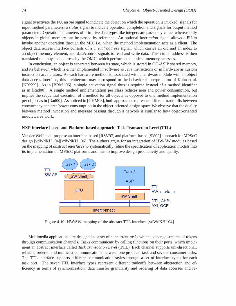
74 Chapter 4. Object-Oriented Design (OOD)
signal to activate the FU, anoid signal to indicate the object on which the operation is invoked, signals forinput method parameters, astatussignal to indicate operation completion and signals for output methodparameters. Operation parameters of primitive data types like integers are passed by value, whereas onlyobjects in global memory can be passed by reference. An optional instruction signal allows a FU toinvoke another operation through the MIU i.e. when the method implementation acts as a client. Theobject data access interface consists of avirtual addresssignal, which carries an oid and an index toan object memory element, and data/control signals to read and write data. This virtual address is thentranslated to a physical address by the OMU, which performs the desired memory accesses.
In conclusion, an object is separated between its state, which is stored in OO-ASIP shared memory,and its behavior, which is either implemented in software asJava instructions or in hardware as custominstruction accelerators. As each hardware method is associated with a hardware module with an objectdata access interface, this architecture may correspond tothe behavioral interpretation of Kuhn et al.[KRK99]. As in [BRM+06], a single activation signal thus is required instead of amethod identifieras in [Rad00]. A single method implementation per class reduces area and power consumption, butimplies the sequential execution of a method for all objectsas opposed to one method implementationper object as in [Rad00]. As noticed in [GHM03], both approaches represent different trade-offs betweenconcurrency and area/power consumption in the object-oriented design space We observe that the dualitybetween method invocation and message passing through a network is similar to how object-orientedmiddlewares work.
NXP Interface-based and Platform-based approach: Task Transaction Level (TTL)
Van der Wolf et al. propose an interface-based [RSV97] and platform-based [SV02] approach for MPSoCdesign [vdWdKH+04][vdWdKH+06]. The authors argue for an integration of HW/SW modules basedon the mapping ofabstract interfacesto systematically refine the specification of application models intoits implementation on MPSoC platforms and thus to improve design productivity and quality.
Figure 4.10: HW/SW mapping of the abstract TTL interface [vdWdKH+04]
Multimedia applications are designed as a set of concurrenttasks which exchange streams of tokensthrough communication channels. Tasks communicate by calling functions on their ports, which imple-ment an abstract interface calledTask Transaction Level(TTL ). Each channel supports uni-directional,reliable, ordered and multicast communications between one producer task and several consumer tasks.The TTL interface supports different communication stylesthrough a set of interface types for eachtask port. The seven TTL interface types represent different tradeoffs between abstraction and ef-ficiency in terms of synchronization, data transfer granularity and ordering of data accesses and re-
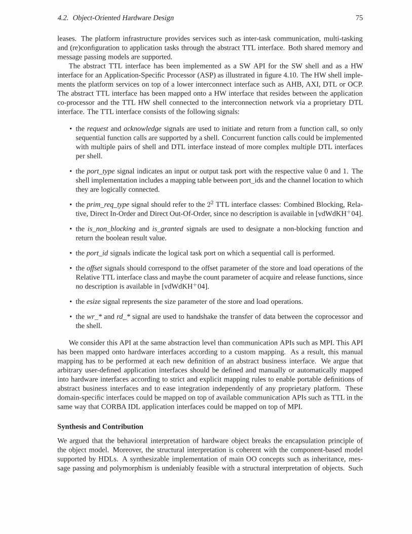
4.2. Object-Oriented Hardware Design 75
leases. The platform infrastructure provides services such as inter-task communication, multi-taskingand (re)configuration to application tasks through the abstract TTL interface. Both shared memory andmessage passing models are supported.
The abstract TTL interface has been implemented as a SW API for the SW shell and as a HWinterface for an Application-Specific Processor (ASP) as illustrated in figure 4.10. The HW shell imple-ments the platform services on top of a lower interconnect interface such as AHB, AXI, DTL or OCP.The abstract TTL interface has been mapped onto a HW interface that resides between the applicationco-processor and the TTL HW shell connected to the interconnection network via a proprietary DTLinterface. The TTL interface consists of the following signals:
• the requestandacknowledgesignals are used to initiate and return from a function call,so onlysequential function calls are supported by a shell. Concurrent function calls could be implementedwith multiple pairs of shell and DTL interface instead of more complex multiple DTL interfacesper shell.
• theport_typesignal indicates an input or output task port with the respective value 0 and 1. Theshell implementation includes a mapping table between port_ids and the channel location to whichthey are logically connected.
• theprim_req_typesignal should refer to the22 TTL interface classes: Combined Blocking, Rela-tive, Direct In-Order and Direct Out-Of-Order, since no description is available in [vdWdKH+04].
• the is_non_blockingand is_grantedsignals are used to designate a non-blocking function andreturn the boolean result value.
• theport_id signals indicate the logical task port on which a sequentialcall is performed.
• theoffsetsignals should correspond to the offset parameter of the store and load operations of theRelative TTL interface class and maybe the count parameter of acquire and release functions, sinceno description is available in [vdWdKH+04].
• theesizesignal represents the size parameter of the store and load operations.
• thewr_* andrd_* signal are used to handshake the transfer of data between thecoprocessor andthe shell.
We consider this API at the same abstraction level than communication APIs such as MPI. This APIhas been mapped onto hardware interfaces according to a custom mapping. As a result, this manualmapping has to be performed at each new definition of an abstract business interface. We argue thatarbitrary user-defined application interfaces should be defined and manually or automatically mappedinto hardware interfaces according to strict and explicit mapping rules to enable portable definitions ofabstract business interfaces and to ease integration independently of any proprietary platform. Thesedomain-specific interfaces could be mapped on top of available communication APIs such as TTL in thesame way that CORBA IDL application interfaces could be mapped on top of MPI.
Synthesis and Contribution
We argued that the behavioral interpretation of hardware object breaks the encapsulation principle ofthe object model. Moreover, the structural interpretationis coherent with the component-based modelsupported by HDLs. A synthesizable implementation of main OO concepts such as inheritance, mes-sage passing and polymorphism is undeniably feasible with astructural interpretation of objects. Such
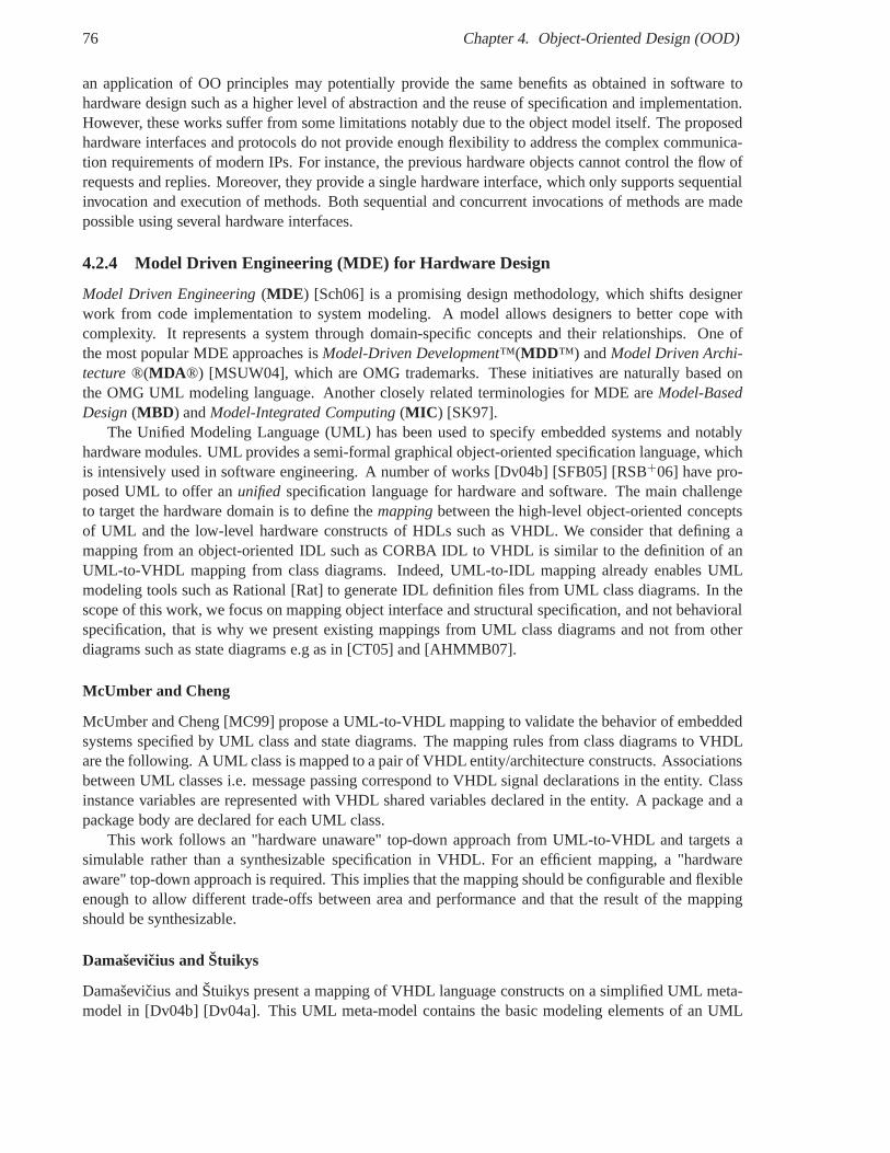
76 Chapter 4. Object-Oriented Design (OOD)
an application of OO principles may potentially provide thesame benefits as obtained in software tohardware design such as a higher level of abstraction and thereuse of specification and implementation.However, these works suffer from some limitations notably due to the object model itself. The proposedhardware interfaces and protocols do not provide enough flexibility to address the complex communica-tion requirements of modern IPs. For instance, the previoushardware objects cannot control the flow ofrequests and replies. Moreover, they provide a single hardware interface, which only supports sequentialinvocation and execution of methods. Both sequential and concurrent invocations of methods are madepossible using several hardware interfaces.
4.2.4 Model Driven Engineering (MDE) for Hardware Design
Model Driven Engineering(MDE ) [Sch06] is a promising design methodology, which shifts designerwork from code implementation to system modeling. A model allows designers to better cope withcomplexity. It represents a system through domain-specificconcepts and their relationships. One ofthe most popular MDE approaches isModel-Driven Development™(MDD™) andModel Driven Archi-tecture®(MDA ®) [MSUW04], which are OMG trademarks. These initiatives are naturally based onthe OMG UML modeling language. Another closely related terminologies for MDE areModel-BasedDesign(MBD ) andModel-Integrated Computing(MIC ) [SK97].
The Unified Modeling Language (UML) has been used to specify embedded systems and notablyhardware modules. UML provides a semi-formal graphical object-oriented specification language, whichis intensively used in software engineering. A number of works [Dv04b] [SFB05] [RSB+06] have pro-posed UML to offer anunifiedspecification language for hardware and software. The main challengeto target the hardware domain is to define themappingbetween the high-level object-oriented conceptsof UML and the low-level hardware constructs of HDLs such as VHDL. We consider that defining amapping from an object-oriented IDL such as CORBA IDL to VHDLis similar to the definition of anUML-to-VHDL mapping from class diagrams. Indeed, UML-to-IDL mapping already enables UMLmodeling tools such as Rational [Rat] to generate IDL definition files from UML class diagrams. In thescope of this work, we focus on mapping object interface and structural specification, and not behavioralspecification, that is why we present existing mappings fromUML class diagrams and not from otherdiagrams such as state diagrams e.g as in [CT05] and [AHMMB07].
McUmber and Cheng
McUmber and Cheng [MC99] propose a UML-to-VHDL mapping to validate the behavior of embeddedsystems specified by UML class and state diagrams. The mapping rules from class diagrams to VHDLare the following. A UML class is mapped to a pair of VHDL entity/architecture constructs. Associationsbetween UML classes i.e. message passing correspond to VHDLsignal declarations in the entity. Classinstance variables are represented with VHDL shared variables declared in the entity. A package and apackage body are declared for each UML class.
This work follows an "hardware unaware" top-down approach from UML-to-VHDL and targets asimulable rather than a synthesizable specification in VHDL. For an efficient mapping, a "hardwareaware" top-down approach is required. This implies that themapping should be configurable and flexibleenough to allow different trade-offs between area and performance and that the result of the mappingshould be synthesizable.
Damaševicius and Štuikys
Damaševicius and Štuikys present a mapping of VHDL language constructs on a simplified UML meta-model in [Dv04b] [Dv04a]. This UML meta-model contains the basic modeling elements of an UML
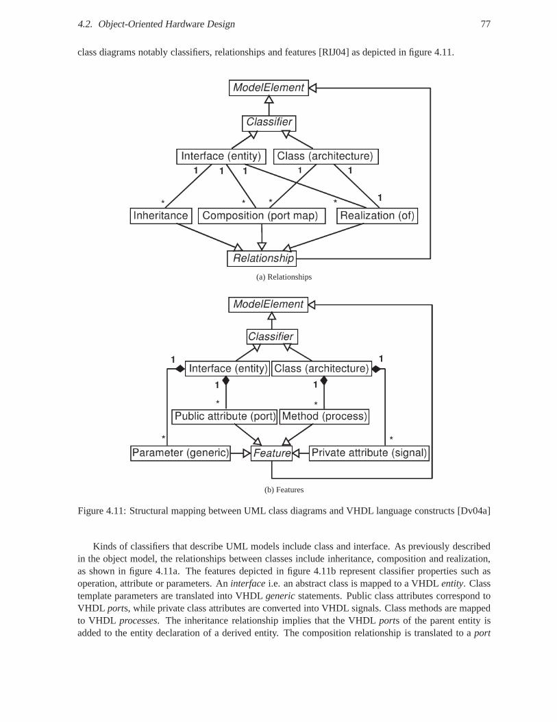
4.2. Object-Oriented Hardware Design 77
class diagrams notably classifiers, relationships and features [RIJ04] as depicted in figure 4.11.
(a) Relationships
(b) Features
Figure 4.11: Structural mapping between UML class diagramsand VHDL language constructs [Dv04a]
Kinds of classifiers that describe UML models include class and interface. As previously describedin the object model, the relationships between classes include inheritance, composition and realization,as shown in figure 4.11a. The features depicted in figure 4.11brepresent classifier properties such asoperation, attribute or parameters. Aninterfacei.e. an abstract class is mapped to a VHDLentity. Classtemplate parameters are translated into VHDLgenericstatements. Public class attributes correspond toVHDL ports, while private class attributes are converted into VHDL signals. Class methods are mappedto VHDL processes. The inheritance relationship implies that the VHDLports of the parent entity isadded to the entity declaration of a derived entity. The composition relationship is translated to aport
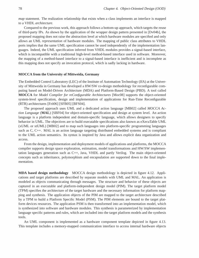
78 Chapter 4. Object-Oriented Design (OOD)
mapstatement. The realization relationship that exists when aclass implements an interface is mappedto a VHDL architecture.
Compared to the previous work, this approach follows a bottom-up approach, which targets the reuseof third-party IPs. As shown by the application of the wrapper design pattern presented in [Dv04b], theproposed mapping does not raise the abstraction level at which hardware modules are specified and onlyallows an UMLrepresentationof hardware modules. The mapping of public class attributesto VHDLports implies that the same UML specification cannot be used independently of the implementation lan-guages. Indeed, the UML specification inferred from VHDL modules provides a signal-based interface,which is incompatible with a traditional high-level method-based interface used in software. Moreover,the mapping of a method-based interface to a signal-based interface is inefficient and is incomplete asthis mapping does not specify an invocation protocol, whichis sadly lacking in hardware.
MOCCA from the University of Mittweida, Germany
The Embedded Control Laboratory (LEC) of the Institute of Automation Technology (IfA) at the Univer-sity of Mittweida in Germany has developed a HW/SW co-designmethodology for reconfigurable com-puting based on Model-Driven Architecture (MDA) and Platform-Based Design (PBD). A tool calledMOCCA for Model Compiler for reConfigurable Architectures[Moc08] supports the object-orientedsystem-level specification, design and implementation of applications for Run-Time Reconfigurable(RTR) architectures [Frö06] [SFB05] [BFS04].
The proposed approach uses UML and a dedicated action language [MB02] calledMOCCA Ac-tion Language(MAL ) [SBF04] for object-oriented specification and design at system level. An actionlanguage is a platform independent and domain-specific language, which allows designers to specifybehavior in UML. The objectives are to build executable specifications also known as eXecuTable UML(xUML or xtUML) [MB02] and to map such languages into platform-specific programming languagessuch as C, C++. MAL is an action language targeting distributed embedded systems and is compliantto the UML action semantics. Its syntax is inspired by Java and allows explicit data organization andaccess.
From the design, implementation and deployment models of applications and platforms, the MOCCAcompiler supports design space exploration, estimation, model transformations and HW/SW implemen-tation languages generation such as C++, Java, VHDL and partly Verilog. The main object-orientedconcepts such as inheritance, polymorphism and encapsulation are supported down to the final imple-mentation.
MDA based design methodology MOCCA design methodology is depicted in figure 4.12. Appli-cations and target platforms are described by separate models with UML and MAL. An application ismodeled as objects communicating through messages. The structure and behavior of these objects arecaptured in an executable and platform-independent designmodel (PIM). The target platform model(TPM) specifies the architecture of the target hardware and the necessary information for platform map-ping and synthesis. The application objects of the PIM are mapped to the target architecture describedby a TPM to build a Platform Specific Model (PSM). The PIM elements are bound to the target plat-form devices resources. The application PSM is then transformed into an implementation model, whichis synthesized into software and hardware modules. This synthesis is parameterized by implementationlanguage specific patterns and rules, which are included into the target platform models and the synthesistools.
An UML component is implemented as a hardware component template depicted in figure 4.13.This template includes a memory-mapped communication interface to access internal hardware objects
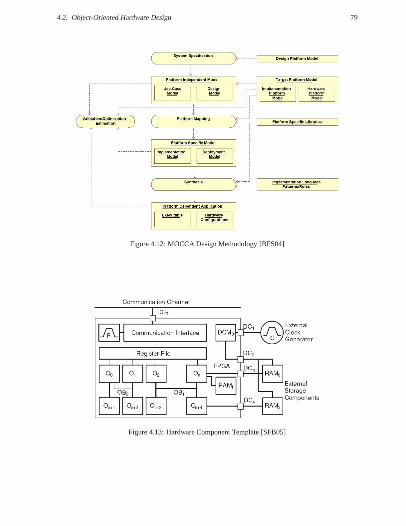
4.2. Object-Oriented Hardware Design 79
Figure 4.12: MOCCA Design Methodology [BFS04]
Figure 4.13: Hardware Component Template [SFB05]
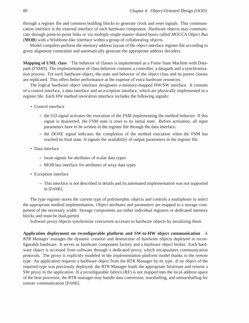
80 Chapter 4. Object-Oriented Design (OOD)
through a register file and common building blocks to generate clock and reset signals. This communi-cation interface is the external interface of each hardwarecomponent. Hardware objects may communi-cate through point-to-point links or via multiple single-master shared buses calledMOCCA Object Bus(MOB ) with a Wishbone-like interface within a group of collaborating objects.
Model compilers perform the memory address layout of the object interface register file according togiven alignment constraints and automatically generate the appropriate address decoders.
Mapping of UML class The behavior of classes is implemented as a Finite State Machine with Data-path (FSMD). The implementation of class behavior containsa controller, a datapath and a synchroniza-tion process. For each hardware object, the state and behavior of the object class and its parent classesare replicated. This offers better performance at the expense of extra hardware resources.
The logical hardware object interface designates a memory-mapped HW/SW interface. It consistsof a control interface, a data interface and an exception interface, which are physically implemented in aregister file. Each HW method invocation interface includesthe following signals:
• Control interface
– theGO signal activates the execution of the FSM implementing the method behavior. If thissignal is deasserted, the FSM state is reset to its initial state. Before activation, all inputparameters have to be written in the register file through thedata interface.
– the DONE signal indicates the completion of the method execution when the FSM hasreached its final state. It signals the availability of output parameters in the register file.
• Data interface
– inout signals for attributes of scalar data types
– MOB bus interface for attributes of array data types
• Exception interface
– This interface is not described in details and its automatedimplementation was not supportedin [Frö06].
The type register stores the current type of polymorphic objects and controls a multiplexer to selectthe appropriate method implementation. Object attributesand parameters are mapped to a storage com-ponent of the necessary width. Storage components are either individual registers or dedicated memoryblocks and must be dual-ported.
Software proxy objects synchronize concurrent accesses tohardware objects by serializing them.
Application deployment on reconfigurable platform and SW-to-HW object communication ARTR Managermanages the dynamic creation and destruction of hardware objects deployed in recon-figurable hardware. It serves as hardware component factoryand a hardware object broker. Each hard-ware object is accessed from software through a dedicated proxy, which encapsulates communicationprotocols. The proxy is explicitly modeled in the implementation platform model thanks to theremotetype. An application requests a hardware object from the RTRManager by its type. If no object of therequired type was previously deployed, the RTR Manager loads the appropriate bitstream and returns aSW proxy to the application. If a reconfigurable fabrics (RF)is not mapped into the local address spaceof the host processor, the RTR-manager may handle data conversion, marshalling, and unmarshalling forremote communication [Frö06].
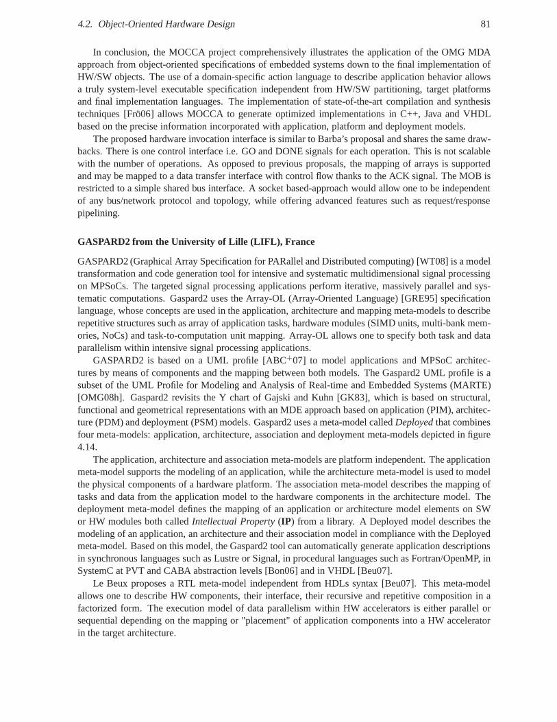
4.2. Object-Oriented Hardware Design 81
In conclusion, the MOCCA project comprehensively illustrates the application of the OMG MDAapproach from object-oriented specifications of embedded systems down to the final implementation ofHW/SW objects. The use of a domain-specific action language to describe application behavior allowsa truly system-level executable specification independentfrom HW/SW partitioning, target platformsand final implementation languages. The implementation of state-of-the-art compilation and synthesistechniques [Frö06] allows MOCCA to generate optimized implementations in C++, Java and VHDLbased on the precise information incorporated with application, platform and deployment models.
The proposed hardware invocation interface is similar to Barba’s proposal and shares the same draw-backs. There is one control interface i.e. GO and DONE signals for each operation. This is not scalablewith the number of operations. As opposed to previous proposals, the mapping of arrays is supportedand may be mapped to a data transfer interface with control flow thanks to the ACK signal. The MOB isrestricted to a simple shared bus interface. A socket based-approach would allow one to be independentof any bus/network protocol and topology, while offering advanced features such as request/responsepipelining.
GASPARD2 from the University of Lille (LIFL), France
GASPARD2 (Graphical Array Specification for PARallel and Distributed computing) [WT08] is a modeltransformation and code generation tool for intensive and systematic multidimensional signal processingon MPSoCs. The targeted signal processing applications perform iterative, massively parallel and sys-tematic computations. Gaspard2 uses the Array-OL (Array-Oriented Language) [GRE95] specificationlanguage, whose concepts are used in the application, architecture and mapping meta-models to describerepetitive structures such as array of application tasks, hardware modules (SIMD units, multi-bank mem-ories, NoCs) and task-to-computation unit mapping. Array-OL allows one to specify both task and dataparallelism within intensive signal processing applications.
GASPARD2 is based on a UML profile [ABC+07] to model applications and MPSoC architec-tures by means of components and the mapping between both models. The Gaspard2 UML profile is asubset of the UML Profile for Modeling and Analysis of Real-time and Embedded Systems (MARTE)[OMG08h]. Gaspard2 revisits the Y chart of Gajski and Kuhn [GK83], which is based on structural,functional and geometrical representations with an MDE approach based on application (PIM), architec-ture (PDM) and deployment (PSM) models. Gaspard2 uses a meta-model calledDeployedthat combinesfour meta-models: application, architecture, association and deployment meta-models depicted in figure4.14.
The application, architecture and association meta-models are platform independent. The applicationmeta-model supports the modeling of an application, while the architecture meta-model is used to modelthe physical components of a hardware platform. The association meta-model describes the mapping oftasks and data from the application model to the hardware components in the architecture model. Thedeployment meta-model defines the mapping of an applicationor architecture model elements on SWor HW modules both calledIntellectual Property(IP) from a library. A Deployed model describes themodeling of an application, an architecture and their association model in compliance with the Deployedmeta-model. Based on this model, the Gaspard2 tool can automatically generate application descriptionsin synchronous languages such as Lustre or Signal, in procedural languages such as Fortran/OpenMP, inSystemC at PVT and CABA abstraction levels [Bon06] and in VHDL [Beu07].
Le Beux proposes a RTL meta-model independent from HDLs syntax [Beu07]. This meta-modelallows one to describe HW components, their interface, their recursive and repetitive composition in afactorized form. The execution model of data parallelism within HW accelerators is either parallel orsequential depending on the mapping or "placement" of application components into a HW acceleratorin the target architecture.
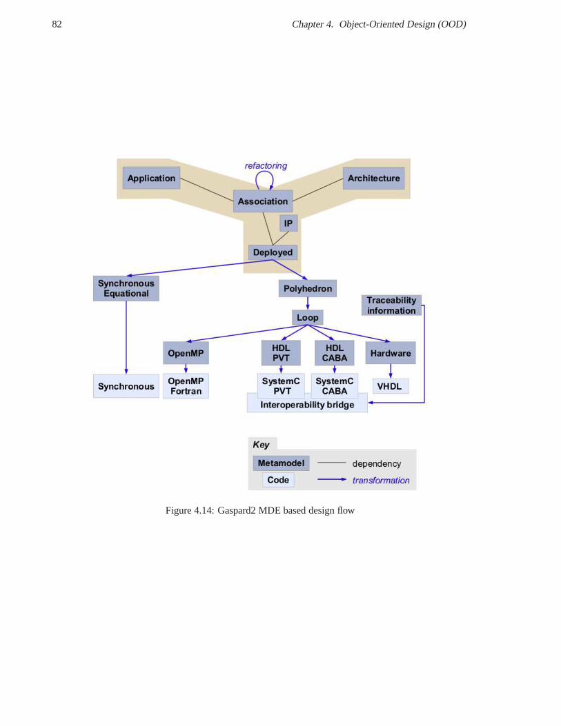
82 Chapter 4. Object-Oriented Design (OOD)
Figure 4.14: Gaspard2 MDE based design flow
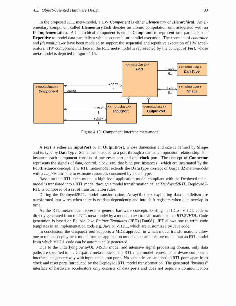
4.2. Object-Oriented Hardware Design 83
In the proposed RTL meta-model, a HWComponent is eitherElementary or Hierarchical. An el-ementary component calledElementaryTask denotes an atomic computation unit associated with anIP Implementation. A hierarchical component is eitherCompound to represent task parallelism orRepetitive to model data parallelism with a sequential or parallel execution. The concepts ofcontrollerand(de)multiplexerhave been modeled to support the sequential and repetitive execution of HW accel-erators. HW component interface in the RTL meta-model is represented by the concept ofPort, whosemeta-model is depicted in figure 4.15.
Figure 4.15: Component interface meta-model
A Port is either anInputPort or anOutputPort , whose dimension and size is defined byShapeand its type byDataType. Semantics is added to a port through a named composition relationship. Forinstance, each component consists of onereset port and oneclock port. The concept ofConnectorrepresents the signals of data, control, clock, etc. that bind port instances , which are incarnated by thePortInstance concept. The RTL meta-model extends theDataType concept of Gaspard2 meta-modelswith anb_bitsattribute to estimate resources consumed by a data type.
Based on this RTL meta-model, a high-level application model compliant with the Deployed meta-model is translated into a RTL model through a model transformation calledDeployed2RTL. Deployed2-RTL is composed of a set of transformation rules.
During the Deployed2RTL model transformation, ArrayOL tilers expliciting data parallelism aretransformed into wires when there is no data dependency and into shift registers when data overlap intime.
As the RTL meta-model represents generic hardware conceptsexisting in HDLs, VHDL code isdirectly generated from the RTL meta-model by a model to texttransformation calledRTL2VHDL. Codegeneration is based on EclipseJava Emitter Templates(JET) [Fou08]. JET allows one to write codetemplates in an implementation code e.g. Java or VHDL, whichare customized by Java code.
In conclusion, the Gaspard2 tool supports a MDE approach in which model transformations allowone to refine a deployment model from an application model on an architecture model into an RTL modelfrom which VHDL code can be automatically generated.
Due to the underlying ArrayOL MSDF model and intensive signal processing domain, only datapaths are specified in the Gaspard2 meta-models. The RTL meta-model represents hardware componentinterface in a generic way with input and output ports. No semantics are attached to RTL ports apart fromclock and reset ports introduced by the Deployed2RTL model transformation. The generated "business"interface of hardware accelerators only consists of data ports and does not require a communication
84 Chapter 4. Object-Oriented Design (OOD)
protocol. This data interface is the simplest member of the family of interfaces, which is required for thecommunication between HW components. Our goal is to be able to specify this interface family and notonly simple data wire interface. Furthermore, HW/SW communication through some buses or NoCs isnot supported in Gaspard2 as the application is entirely deployed either in SW or in HW.
Other approaches
Some approaches define a mapping from UML to C-like hardware description languages such as Handel-C in [SR04] or ImpulseC [PT05] in [WX07]. In our proposition,we do not target such proprietarylanguages and focus on the standard HDLs such as VHDL.
4.3 Synthesis
Tables 4.1 and 4.2 summarizes the state of the art concerningthe application of the object-orientedconcepts down to hardware. This table particularly shows the mapping space from object-oriented speci-fications into the interface and architecture of hardware objects. A flexible UML/IDL-to-VHDL mappingshould be able to address all these mapping solutions with standardized hardware interfaces and archi-tecture templates/patterns while only consuming the required hardware resources.
4.4 Conclusion
The object-oriented design methodology is a widely teachedand used methodology to develop softwareapplications. It is based on high-level concepts such as encapsulation, inheritance and polymorphism,and favors reuse. In the object-oriented approach, an object is a self-contained and identifiable entity,which encloses its own state and behavior in a method-based interface, and communicates only throughmessage passing. A method describes the actions to perform depending on the type of message receivedby the object. A method invocation requests the execution ofa method. Method invocation is equivalentto message passing. The local and implicit transfer of control and data of a method invocation can be for-mally translated into the remote and explicit transfer of a message over a network and vice versa. A clientobject is any object that requires the services provided by another object called the server object. Proxiesor surrogates make local and remote communications indistinguishable from the viewpoint of client andserver objects by translating local method invocations into request-reply messages. A client-side proxycalledstub encodes the input parameters of a remote method invocation into a request message and con-versely decodes a reply message into the output parameters and the return value. A server-side proxycalledskeletondecodes a request message into the input parameters of a local method invocation to theobject implementation and conversely encodes the output parameters and the return value into a replymessage payload.
Usually, the integration of hardware modules relies on low-level hardware/software interfaces, whichconsists of proprietary bus interfaces, memory-mapped registers and interrupts to synchronize hardware/-software modules. As a result, this integration is tedious and error-prone, and the reuse of HW/SWmodules is limited. Co-design methodologies have been developed to bridge the conceptual gap betweenhardware design and software design. To provide a common hardware/software design approach, theconcepts of the object model has been applied to hardware design through four main directions: object-oriented extensions to hardware description languages such as OO-VHDL, object-oriented languages forhardware design such as Java and SystemC, object-oriented hardware architecture with hardware objects,and model-driven engineering for hardware design using UML.
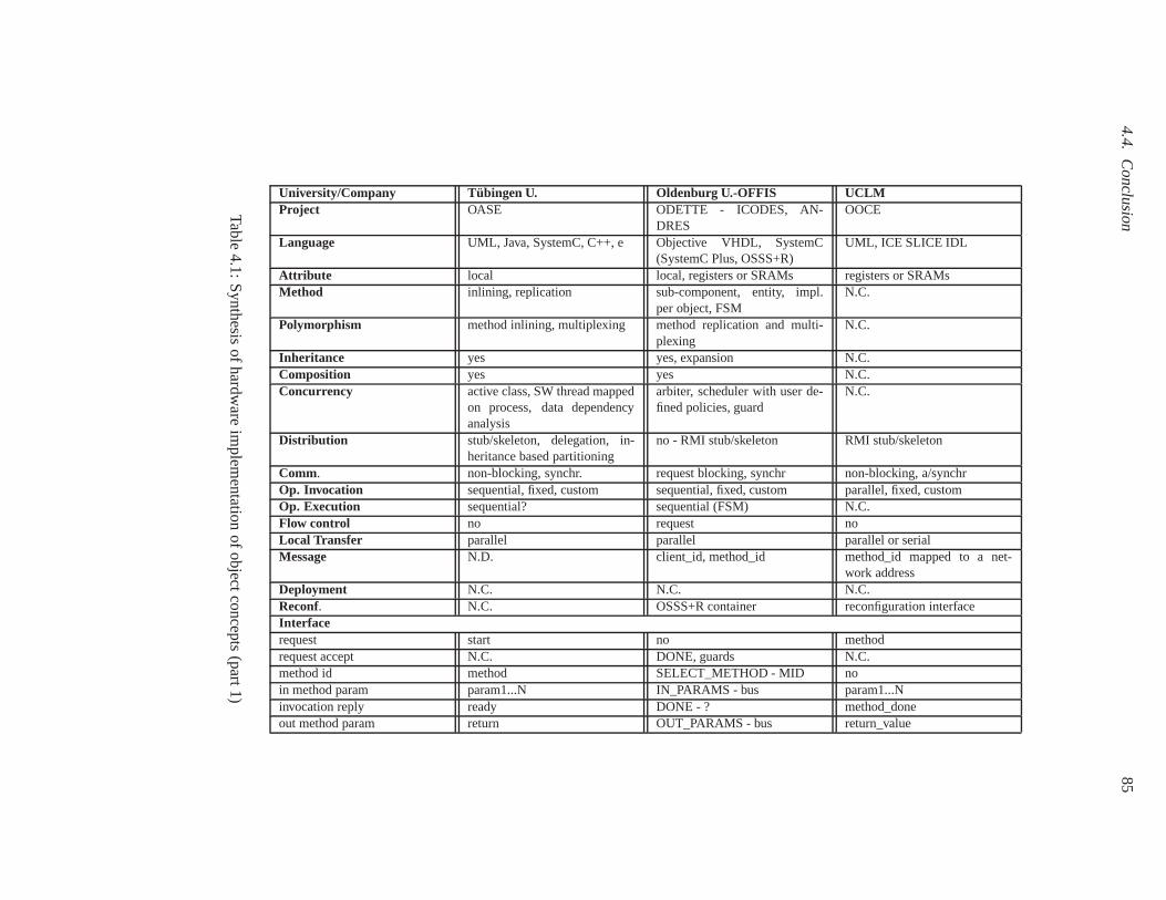
4.4.C
onclusion85
University/Company Tübingen U. Oldenburg U.-OFFIS UCLMProject OASE ODETTE - ICODES, AN-
DRESOOCE
Language UML, Java, SystemC, C++, e Objective VHDL, SystemC(SystemC Plus, OSSS+R)
UML, ICE SLICE IDL
Attribute local local, registers or SRAMs registers or SRAMsMethod inlining, replication sub-component, entity, impl.
per object, FSMN.C.
Polymorphism method inlining, multiplexing method replication and multi-plexing
N.C.
Inheritance yes yes, expansion N.C.Composition yes yes N.C.Concurrency active class, SW thread mapped
on process, data dependencyanalysis
arbiter, scheduler with user de-fined policies, guard
N.C.
Distribution stub/skeleton, delegation, in-heritance based partitioning
no - RMI stub/skeleton RMI stub/skeleton
Comm. non-blocking, synchr. request blocking, synchr non-blocking, a/synchrOp. Invocation sequential, fixed, custom sequential, fixed, custom parallel, fixed, customOp. Execution sequential? sequential (FSM) N.C.Flow control no request noLocal Transfer parallel parallel parallel or serialMessage N.D. client_id, method_id method_id mapped to a net-
work addressDeployment N.C. N.C. N.C.Reconf. N.C. OSSS+R container reconfiguration interfaceInterfacerequest start no methodrequest accept N.C. DONE, guards N.C.method id method SELECT_METHOD - MID noin method param param1...N IN_PARAMS - bus param1...Ninvocation reply ready DONE - ? method_doneout method param return OUT_PARAMS - bus return_value
Table4.1:
Synthesis
ofhardware
implem
entationofobjectc
oncepts(part1)
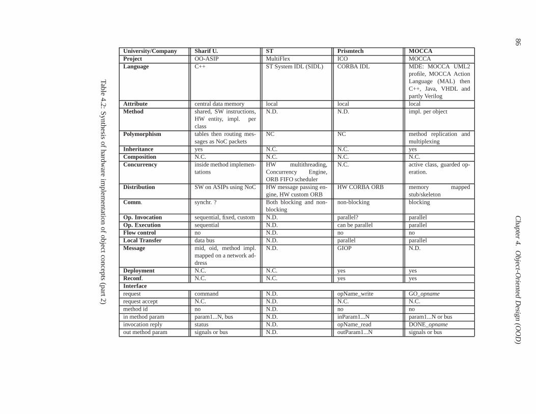
86C
hapter4.
Object-O
rientedD
esign(O
OD
)
University/Company Sharif U. ST Prismtech MOCCAProject OO-ASIP MultiFlex ICO MOCCALanguage C++ ST System IDL (SIDL) CORBA IDL MDE: MOCCA UML2
profile, MOCCA ActionLanguage (MAL) thenC++, Java, VHDL andpartly Verilog
Attribute central data memory local local localMethod shared, SW instructions,
HW entity, impl. perclass
N.D. N.D. impl. per object
Polymorphism tables then routing mes-sages as NoC packets
NC NC method replication andmultiplexing
Inheritance yes N.C. N.C. yesComposition N.C. N.C. N.C. N.C.Concurrency inside method implemen-
tationsHW multithreading,Concurrency Engine,ORB FIFO scheduler
N.C. active class, guarded op-eration.
Distribution SW on ASIPs using NoC HW message passing en-gine, HW custom ORB
HW CORBA ORB memory mappedstub/skeleton
Comm. synchr. ? Both blocking and non-blocking
non-blocking blocking
Op. Invocation sequential, fixed, custom N.D. parallel? parallelOp. Execution sequential N.D. can be parallel parallelFlow control no N.D. no noLocal Transfer data bus N.D. parallel parallelMessage mid, oid, method impl.
mapped on a network ad-dress
N.D. GIOP N.D.
Deployment N.C. N.C. yes yesReconf. N.C. N.C. yes yesInterfacerequest command N.D. opName_write GO_opnamerequest accept N.C. N.D. N.C. N.C.method id no N.D. no noin method param param1...N, bus N.D. inParam1...N param1...N or businvocation reply status N.D. opName_read DONE_opnameout method param signals or bus N.D. outParam1...N signals or bus
Table4.2:
Synthesis
ofhardware
implem
entationofobjectc
oncepts(part2)
4.4. Conclusion 87
To apply the object model down to synthesizable hardware, the previous works propose a mappingbetween a method-based interface to a signal-based interface. Hardware object-oriented design allowsto raise the abstraction level of hardware module interfaces, to reduce the conceptual and abstraction gapbetween interface specification and implementation, and toenforce a clean separation between compu-tation and communication through remote method invocation.
However, these works suffer from some limitations notably due to the object model itself. Theproposed hardware interfaces and protocols do not provide enough flexibility to address the complexcommunication requirements of modern IPs. Indeed, they provide a single hardware interface, whichonly supports sequential invocation and execution of methods. Each presented work proposes a mapping,which represents one solution in the mapping exploration space.
We propose to generalize and leverage the existing mapping propositions with an explicit and finemapping configuration using a named family of hardware interfaces with well-defined semantics. Ourmapping approach gives the user a level of control over the mapped hardware interface never reachedby all other fixed mapping approaches and is similar to what isavailable for hardware designers in high-level synthesis e.g. from C-like languages. To go further tothe object-oriented approach, we proposea component-oriented approach in which component ports maybe independently mapped to hardwareinterfaces and which allows both sequential and concurrentinvocations of methods. In the next chapter,we will present middlewares. In particular, we will focus onthe application of the distributed objectmodel in object-oriented middlewares like CORBA.

Chapter 5
Middlewares
Contents5.1 Middleware Definition . . . . . . . . . . . . . . . . . . . . . . . . . . . . .. . . . 90
5.2 Middleware Requirements . . . . . . . . . . . . . . . . . . . . . . . . . .. . . . . 90
5.2.1 Portability . . . . . . . . . . . . . . . . . . . . . . . . . . . . . . . . . . .. . 91
5.2.2 Interoperability . . . . . . . . . . . . . . . . . . . . . . . . . . . . . .. . . . 92
5.3 Middleware Classification . . . . . . . . . . . . . . . . . . . . . . . . .. . . . . . 92
5.3.1 Message Passing . . . . . . . . . . . . . . . . . . . . . . . . . . . . . . . .. 92
5.3.2 Procedural middlewares . . . . . . . . . . . . . . . . . . . . . . . . .. . . . 93
5.3.3 Distributed Object Middlewares . . . . . . . . . . . . . . . . . .. . . . . . . 93
5.3.4 Component middlewares . . . . . . . . . . . . . . . . . . . . . . . . . .. . . 94
5.3.5 Message-Oriented Middlewares . . . . . . . . . . . . . . . . . . .. . . . . . 94
5.3.6 Publish-Subscribe middlewares . . . . . . . . . . . . . . . . . .. . . . . . . 95
5.3.7 Transaction middleware . . . . . . . . . . . . . . . . . . . . . . . . .. . . . 95
5.3.8 Database Middleware . . . . . . . . . . . . . . . . . . . . . . . . . . . .. . . 96
5.3.9 Distributed Shared Memory . . . . . . . . . . . . . . . . . . . . . . .. . . . 96
5.3.10 Web middlewares . . . . . . . . . . . . . . . . . . . . . . . . . . . . . . .. . 96
5.3.11 Position . . . . . . . . . . . . . . . . . . . . . . . . . . . . . . . . . . . . .. 97
5.4 OMG Object Management Architecture (OMA) . . . . . . . . . . . . . . . . . . . 97
5.5 CORBA Object Model . . . . . . . . . . . . . . . . . . . . . . . . . . . . . . . .. 99
5.5.1 CORBA Overview . . . . . . . . . . . . . . . . . . . . . . . . . . . . . . . . 99
5.5.2 CORBA Implementation . . . . . . . . . . . . . . . . . . . . . . . . . . .. . 102
5.5.3 Illustration of CORBA Middleware Design Flow . . . . . . .. . . . . . . . . 103
5.5.4 Overview of CORBA Interface Definition Language (IDL). . . . . . . . . . . 105
5.5.5 Portability using CORBA IDL mapping to implementation languages . . . . . 108
5.5.6 Interoperability with CORBA Inter-ORB Protocol (IOP) . . . . . . . . . . . . 112
5.5.7 Real-Time CORBA . . . . . . . . . . . . . . . . . . . . . . . . . . . . . . . .112
5.5.8 CORBA for embedded systems . . . . . . . . . . . . . . . . . . . . . . .. . 113
5.5.9 OMG Extensible Transport Framework (ETF) . . . . . . . . . .. . . . . . . . 113
5.5.10 State of the art on real-time and embedded CORBA middlewares . . . . . . . 114
5.6 State of the art on hardware implementations of object middlewares . . . . . . . 119
5.6.1 ST StepNP MPSoC Platform and MultiFlex Programming Models . . . . . . . 119
89
90 Chapter 5. Middlewares
5.6.2 UCLM Object-Oriented Communication Engine (OOCE) . .. . . . . . . . . 120
5.6.3 Commercial Hardware CORBA ORBs . . . . . . . . . . . . . . . . . . .. . . 122
5.6.4 PrismTechnologies, Ltd. Integrated Circuit ORB (ICO) . . . . . . . . . . . . . 123
5.6.5 Objective Interface Systems, Inc. ORBexpressFPGA . . . . . . . . . . . . . . 125
5.6.6 OMG IDL-to-VHDL mapping . . . . . . . . . . . . . . . . . . . . . . . . .. 126
5.7 Conclusion . . . . . . . . . . . . . . . . . . . . . . . . . . . . . . . . . . . . . .. . 126
This chapter is divided into three parts: first we present in ageneral way the definition, the mainrequirements and a classification of middlewares. We then focus on distributed object middlewares andin particular on the OMG CORBA middleware required by the SCA. Finally, we present a state ofthe art on software implementations of real-time and embedded CORBA middlewares and on hardwareimplementations of object middlewares including CORBA.
This chapter is organized as follows. Section 5.1 defines what are middlewares. Section 5.2 describesthe main requirements of middlewares, portability and interoperability. Section 5.3 presents a middle-ware classification. Section 5.4 presents the Object Management Architecture (OMA) from the ObjectManagement Group (OMG). Section 5.5 presents the CORBA Object Model and its software implemen-tations notably for embedded and real-time systems. Section 5.6 describes a state of the art on hardwareimplementations of object-oriented middlewares including CORBA. Finally, section 5.7 concludes thischapter.
5.1 Middleware Definition
A middleware platform is a software communication infrastructure that is used forthe development,deployment and execution of applications that are distributed across different computing environmentsranging from enterprise to embedded computers. From an application designer viewpoint, a middlewareis a software layer between applications, operating systems and network protocol stacks. It is basicallyimplemented as a software library with which applications are linked. From an OSI model viewpoint,a middleware is traditionally a set of layers from the application layer down to the network layer. Amiddleware aims at supporting transparent communicationsbetween heterogeneous systems regardlessof their distribution, hardware computing architecture, programming language, operating system, trans-port layer and data representation. The objective is to provide a uniform view of a distributed system toapplication developers.
A middleware is often referred to as a software or logical busbetween communicating entities, al-though in reality a middleware instance typically resides at each communication node. A middlewareraises the abstraction level at which distributed applications are developed. Developers no longer needto cope with low-level, tedious and error-prone aspects of distribution such as network programminge.g. using Internet sockets to locate objects, marshal application data, demultiplex and dispatch requests[SLM98]. This complexity is shifted from application to middleware designers. Developers can thusfocus on business application logic.
5.2 Middleware Requirements
The two key requirements of middlewares are to provideportability and interoperability to distributedapplications [PRP05].
5.2. Middleware Requirements 91
5.2.1 Portability
Portability denotes the property of an application, which can be migrated or ported from one operatingenvironment to another one with little or no efforts in termsof time and cost. Two kinds of portabilitycan be distinguished: portability atsource codelevel viaApplication Programming Interface(API ) andportability atbinary codelevel viaApplication Binary Interface(ABI ) [PH07]. Concretely, an API is aset of operations which are directly called by developers according to some use rules. Examples of APIsinclude the Portable Operating System Interface (POSIX) for system programming and the BerkeleySocket API for network programming. An API is traditionallyredefined for each specific procedural orobject-oriented implementation language and operating environment. For instance, the Socket API hasbeen redefined in C for Linux and Windows, in Java for Sun Java Virtual Machines (JVMs) and in .NETlanguages (C++.NET, VB.NET, C#) for Microsoft Virtual Machines called Common Language Runtime(CLR). The porting of an application from one tuple (language, operating system, processor) to anotherone may require its source code to be adapted to the target APIinterface and to be recompiled and linkedto its implementation library.
In contrast, an ABI corresponds to the instructions set and calling convention of real and virtualmachines. It is indirectly used by developers via the binarycode executed by real machines from thecompilation of native programming languages such as C/C++ or by virtual machines from the interpre-tation or run-time/design-time compilation of languages such as Java and Microsoft .NET languages.The porting of an application from one tuple (language, operating system, processor) may require noextra work as the binary code of the application compiled forone machine can be directly executed ontoanother machine without recompilation.
Middlewares support the portability of distributed applications through standard middleware APIsand abstraction of underlying language, operating system,processor and network. The middleware APIis used by distributed applications and provided by each middleware platform implementation. It allowsapplications to communicate with each other and use middleware services e.g. to locate applicationentities. Each middleware platform like CORBA, Java RMI or .NET provides its unique, yet closelyrelated, API in terms of functionalities [SSC98] [VKZ04].
A standard middleware API guarantees that the porting of a distributed application from one com-pliant middleware implementation e.g. the TAO CORBA middleware [SLM98] to another one e.g. theomniORB CORBA middleware [GLR06] only requires some minor source code modifications, recom-pilation and linking with the target middleware library.
In addition to using middleware APIs, distributed applications specify user-defined APIs. Theseapplication APIs are provided by distributed object implementations and required by client objects torequest application services through the middleware platform. Whatever the implementation technology,middleware platforms allow client and server objects to be portable so long as the application interfaceon which they depend remains the same. An application API is either specified in a specific program-ming language like Java for Java RMI or .NET languages for .NET Remoting or an implementation-independentInterface Definition Language(IDL ) such as CORBA IDL, Microsoft COM IDL and XML-based WSDL (Web Service Definition Language).
IDLs allow the specification of abstract APIs that are translated into concrete APIs. IDL compilersautomatically perform this translation in target implementation languages according to language map-pings. Developers no longer need to manually redefine APIs ineach implementation language andoperating environment. The automatic mapping of APIs guarantees a systematic consistency across lan-guages and enforces common coding rules. Hence, the combination of IDLs and standard mapping rulesenables the portability of APIs themselves regardless of their implementation and operating environment.
In summary, IDLs allow portability at source code level using API, while programming languagesand virtual machines provide portability at binary code level using ABI. The main differences between
92 Chapter 5. Middlewares
these interface and implementation-centric approaches is1) an interface is less likely to change thanits implementation and 2) the integration of legacy systemsis achieved through interface adaptationrather than source code reimplementation [Vin03]. In this work, we follow an interface-centric approachusing IDLs since this approach is technology independent and more applicable to hardware applicationmodules i.e. IPs.
5.2.2 Interoperability
The second objective of middleware is interoperability. Interoperability is the ability of applications tointeroperate (i.e. understand each other) and perform system functionalities although they are executedusing different operating environments. Middlewares provide interoperability to distributed applicationsthanks to standard message protocols. A message protocol specifies the ordered set of messages, whichare sent and received between middleware implementations through the communication network. Thesemessages are formatted according to message building blocks calledProtocol Data Units(PDUs). Theassociated message format defines a standard data structurewith an ordered set of message fields formessage header and payload along with standard data encoding and alignment rules. These encodingrules indicate how the common IDL data types defined and used by an application are encoded in a neu-tral data representation for network transmission in messages. Examples of message protocols includeCORBA GIOP (General Inter-ORB Protocol), Sun JRMP (Java Remote Method Protocol) and SOAP(Simple Object Access Protocol) used in Web Services.
5.3 Middleware Classification
Middlewares may implement one or several distributed communication models. These communicationmodels belong to different abstraction levels and are not obvious to classify and compare [EFGK03].The main communication models include: Message Passing, Message Queuing, Remote ProcedureCalls (RPC) and Remote Method Invocations (RMI), Publish-Subscribe, Transaction, Distributed SharedMemory (DSM) [Tho97] [EFGK03] [LvdADtH05].
Based on these communication paradigms, middlewares can bedivided into the following mainclasses [Hur98] [Rit98] [Emm00]: Procedural middlewares,Object middlewares, Message Queuing mid-dlewares, Messaging middlewares, Publish-Subscribe middlewares, Transaction middlewares, Databasemiddlewares, Shared Spaces middlewares, and Web middlewares.
The separation between these different kinds of middlewares is rather fuzzy [Hur98]. Indeed, databasemiddlewares may have object-orientation. Object middlewares like CORBA provide services for trans-action, queuing, messaging and publish-subscribe. Finally, message queuing middlewares may also sup-port transaction, DBMS and publish-subscribe. For instance, the Java Message Service (JMS) [Mic02]supports both message queuing and publish-subscribe models.
5.3.1 Message Passing
In Message Passing, a sender directly sends messages to a receiver using low-level send/receive prim-itives. Communications are mainly point-to-point and unidirectional from the sender to the receiver.Senders may send messages asynchronously and continue their processing, while receivers wait for themessages and receive them synchronously. The send/receiveoperations may be blocking, non-blockingor a combination of both. Higher-level interactions can be built on top of these primitives like remoteinvocations. Senders and receivers are time and space coupled as they need to be running at the sametime and the sender needs to know the receiver address. Message passing does not generally provideaccess and location transparency as data marshalling and addressing are explicit at the application level.
5.3. Middleware Classification 93
Examples of message passing API are Internet sockets and Message Passing Interface (MPI) [For08].The socket API explicitly requires the network address endpoint (IP address and port number). Read-/write operations include as parameters a data buffer and its size. Sockets may also be used for groupcommunication. In MPI, instead of using an interface definition language, developers explicitly describethe data types of user-defined data structures programmatically at low-level in order that the MPI runtimelibrary automatically performs data alignment (MPI_GET_ADDRESS) and marshalling.
5.3.2 Procedural middlewares
Procedural middlewares rely on Remote Procedure Calls (RPCs) [BN84]. Examples include DistributedComputing Environment (DCE)14 RPC from the Open Software Foundation (OSF), the Open NetworkComputing (ONC)15 RPC from Sun Microsystems, and Microsoft RPC (MSRPC)16. A distributedentity is viewed as a loosely cohesive set of user-defined procedures typically in C. A caller acting asclient calls an user-defined callee procedure at server side. The signatures of remotely accessible pro-cedures are defined in a language-independent Interface Definition Language (IDL) such as DCE/RPCIDL or Microsoft IDL. The call statement is exactly the same regardless of the local or remote locationof the server. This location transparency is allowed by a proxy representing the server called stub thatperforms data marshalling and unmarshalling to and from a neutral network data representation. Themarshalling and unmarshalling routines are automaticallygenerated by an IDL compiler and providesaccess transparency to client and server entities. The IDL compiler performs the mapping or bindingof language-independent interfaces defined in IDL to language-specific procedures e.g. in C. When theclient performs a remote call, the input procedure parameters are marshalled by a stub into a byte stream,which is sent in a request message to the server using networkprotocols such as TCP or UDP. Thenthe message is received by the server, the parameters are unmarshalled and the procedure is called. Fi-nally the results of the remote procedure are marshalled into a reply message and returned to the stub,which unmarhalls the return value and delivers it to the local procedure. In synchronous RPCs, the callerthread of control is blocked until a reply is returned, whileasynchronous RPCs do not block the caller[ATK92]. RPCs are space and time coupled with partial synchronization decoupling [LvdADtH05]. RPCrequest is a blocking send and non-blocking receive, while RPC reply is a non-blocking send and block-ing receive. Asynchronous RPCs allow a caller to initiate aninvocation that immediately returns andcontinues its processing, whereas the invocation is concurrently performed. Caller execution and calleeinvocation are thus decoupled, while the latency of communication and callee computation are masked.Asynchronous RPCs may be without a reply (unreliable onewaycalled fire-and-forget [VKZ04]) or witha reply (twoway). A twoway synchronous invocation can be transformed into two request-reply asyn-chronous invocations for the request and the reply. Communications between the caller and the callee areprimarily point-to-point, while group communications could be built on top of the basic RPC mechanism.
5.3.3 Distributed Object Middlewares
Distributed Object Middlewares, also known as Object-Oriented Middlewares, are based on RemoteMethod Invocation (RMI). Examples include OMG CORBA [OMG08b], Sun Java RMI [Mic08], ZeroCICE [HM07], Microsoft Distributed Component Object Model(DCOM) 17 and Microsoft .NET Remot-ing 18. RMI is to object-oriented programming languages what RPC is to procedural languages. RPCs
14http://www.opengroup.org/dce15http://www.ietf.org/rfc/rfc1831.txt16http://msdn.microsoft.com/en-us/library/ms691207(VS.85).aspx17http://www.microsoft.com/com/default.mspx18http://msdn.microsoft.com/en-us/library/72x4h507(VS.85).aspx
94 Chapter 5. Middlewares
have been basically applied to object-oriented languages and extended with object-oriented conceptssuch as interface, object references and exceptions to build RMI. Object reference can be passed byvalue and used to call remote operations. The object paradigm is used as the primary abstraction in RMIto encapsulate the state and behavior of a distributed entity. A distributed object represents typically anatomic distribution unit. After obtaining an object reference typically from a naming service, a clientobject invokes user-defined remote methods on a server object as if it were local. As RPC, an IDL suchas CORBA IDL or Java for Java RMI is used to describe the interfaces provided by objects, but are morenaturally mapped to the native concept of interfaces in object-oriented languages. The automatic gener-ation of client and server stubs is also supported by IDL compilers to marshal method parameters intorequests and replies. Object Request Brokers (ORB) convey and dispatch requests from client to serverobjects and return replies in the opposite direction. RMI may be synchronous or asynchronous e.g. usingCORBA reliable oneway operations and Asynchronous Method Invocation (AMI) with explicit pollingor callback model. Both RPC and RMI are based on a request-reply message protocol, which is inher-ently asynchronous and characteristic of client-server interaction. However, request-reply messages aremore implicit than in message passing and message-orientedmiddleware. As opposed to RPCs, JavaRMI is space decoupled, but also time coupled with partial synchronization decoupling [LvdADtH05].Java RMI request is blocking send and non-blocking receive,while Java RMI reply is non-blocking sendand blocking receive. CORBA is time coupled, space coupled or decoupled with blocking send andnon-blocking receive [LvdADtH05]. Based on the basic mechanism of RMI, Distributed Object Mid-dlewares can provide the same functionalities as RPCs, Transaction middlewares and Message-OrientedMiddlewares and replace them [Pin04].
5.3.4 Component middlewares
Component middlewares [SDG+07] are an extension to distributed object middlewares. A distributedentity is no longer a single object, but an aggregation of objects with explicit dependencies called a com-ponent. Examples are as OMGCORBA Component ModelCCM [OMG06a], SunEnterprise JavaBeans(EJB) [Mic06], Microsoft Distributed Component Object ModelDCOM 19. The concept of componentwill be studied deeper in the next section.
5.3.5 Message-Oriented Middlewares
Message-Oriented Middlewares (MOM) include message passing, Message Queuing [Kra08] and Publish-Subscribe middlewares. Many MOM supports both Message Queuing and Publish-Subscribe models likethe Java Message Service (JMS).
Message Queuing (MQ) middlewares provide a fixed set of predefined asynchronous messagingprimitives to send and receive messages anonymously from one sender to one or multiple receiversthrough indirect, explicit and named communication channels calledmessage queues. A message queueis basically a FIFO message buffer and is managed by a queue manager. The sender send a requestmessage to a message queue, then the receiver receives the request message from the queue and mayreturn a reply message via another queue. Typically, a message consists of a header including control androuting information and a payload with application-specific data. Message Queuing may provide Qualityof Services such as reliable and ordered message delivery. Message Queuing systems may store/forwardand route messages. Message queues may be persistent for fault-tolerance or mobile receivers, which aresometimes disconnected from the network. They may be also transactional to guarantee atomic i.e. all ornothing delivery of messages to multiple receivers. Messages can be reordered by priority or deadlinesor converted from one sender native format to another receiver format. Compared to RPCs, messaging
19http://technet.microsoft.com/en-us/library/cc722927.aspx
5.3. Middleware Classification 95
systems support more network protocols [Emm00]. Message Queuing provides location transparency assenders and receivers do not know the physical address of each other. Access transparency is limited sincemessage queues are used for remote (but not for local) communications and marshalling is not automated,but handled by application developers [Emm00]. Messaging products do not guaranty portability andinteroperability of applications due to the lack of platform-independent standards. Indeed, JMS appearsas a de-facto standard API, but only for Java platforms.
Examples of MOM include Java Message Service (JMS) [Mic02],IBM WebSphere MQ20, MicrosoftMessage Queuing (MSMQ)21, and Apache ActiveMQ22
Message-Oriented Middlewares such as JMS, MSMQ, WebSphere-MQ are time and space decoupledwith blocking send and blocking receive (pull) or non-blocking receive (notification) for synchronizationdecoupling [LvdADtH05]. Indeed, senders and receivers do not know each other and can use the messagequeues at different time. Group communication from one sender to several receivers may be supportedusing multicast delivery. Besides, the concept of message queues is also used for inter-process, task andthread communication in RTOS such as VxWorks andµC/OS. The SCA MHAL [JTR07] specificationdefines a standard MOM API and message header for GPP, DSP and FPGAs/ASICs. Hence, the MHALcan be considered as a hardware/software message broker forSDR platforms. The MHAL LogicalDestination (LD) serves as Message Endpoint [BHS07].
5.3.6 Publish-Subscribe middlewares
In Publish-Subscribe middlewares, message receivers called subscribersregister their interest in themiddleware to receive a particular kind of information typically calledevent. When a message producercalledpublishergenerates this information, the middleware notifies i.e. deliver the desired event to allregistered subscribers. Examples of such middlewares include OMG Data-Distribution Service for Real-Time Systems (DDS) [OMG07a], TIBCO Rendezvous, Tuxedo, Apache ActiveMQ , CORBA Event andNotification services and JMS. Publication and subscription may be based on the topic, content or typeof events [EFGK03]. Publish/subscribe messaging allows one-to-many, non-blocking and anonymouscommunications between a publisher and its subscribers [McH07]. Publish-Subscribe provides thusdecoupling in terms of time, space and synchronization [EFGK03]. Publish-Subscribe supports locationtransparency as senders and receivers do not know the physical address of each others. For instance,DDS is a topic and content-based data-centric publish-subscribe middleware.
5.3.7 Transaction middleware
Transaction middleware or Transaction Processing (TP) Monitors are based on the concept of transac-tion. A transaction is a sequence of operations, which is either totally executed or not at all. It representsa single logical operation and unit of distributed processing. If an operation in a transaction fails, allthe previous operations are cancelled orrolled backedusing transaction logs. Otherwise, the transac-tion is totally executed orcommited. A widely cited example of transaction is a money transfer opera-tion, which requires two operations i.e. to withdraw money from one account and deposit it to another[CDK01]. Examples of transaction middlewares include IBM CICS 23 (Customer Information ControlSystem), Oracle Tuxedo24, CORBA Object Transaction Service (OTS), Java TransactionAPI (JTA) andX/Open Transaction Architecture (XA).Transaction provides a powerful abstraction to manage concur-
20www.ibm.com/software/mqseries21http://www.microsoft.com/windowsserver2003/technologies/msmq/default.mspx22http://activemq.apache.org23www.ibm.com/cics24http://www.oracle.com/products/middleware/tuxedo/index.html
96 Chapter 5. Middlewares
rent accesses to shared resources such as data from multipledistributed clients. Transaction middlewaressupport both synchronous and asynchronous interactions, fail over and recovery capabilities that providefault-tolerant and reliability, load balancing and replication. However, they do not automate marshallingand unmarshalling of complex data structures [Emm00].
The fundamental properties of reliable transactions are contained in the "ACID" mnemonic: Atom-icity (transactions are indivisible - all or nothing), Consistency (the state of a system remains consistentbefore and after a transaction), Isolation (transactions are independent from each other) and Durability(the commitment of a transaction is persistent and resistant to failures). The concept of atomic transactionhas been used in database systems, distributed systems, filesystems like Transactional NTFS, SoftwareTransactional Memory (STM) [ST95] and in BlueSpec for High-Level Synthesis (HLS) [CM08]. Notethat the term transaction aforementioned has nothing to do with "Transaction Level Modeling" (TLM)[Ghe06], which will be described later in this work. The linkbetween both terms is studied in [NH07].
5.3.8 Database Middleware
Database Middleware mediate access to Database ManagementSystems (DBMS) like Microsoft Access,Oracle databases or MySQL using standard APIs like the Open Database Connectivity (ODBC), whichis independent of programming languages, operating systems and DBMS. SQL (Structured Query Lan-guage) is a declarative query language with procedural programming extensions that is used to create,insert, update, retrieve and delete data in relational DBMS.
5.3.9 Distributed Shared Memory
Distributed Shared Memory (DSM) provides a global logical address space, which is shared by producersand consumers in distributed address spaces.An example is tuple spaces. Tuple spaces can be viewed assoftware Distributed Shared Memory, Blackboard [BHS07], content-addressable memory or associativememory. In mathematics, a n-tuple is a bounded sequence i.e.ordered list of n elements, which may beof various types and present multiple times. A tuple space isa repository of tuples, which are accessedconcurrently by producers and consumers working in parallel. Producers write data as tuples to the tuplespace, while consumers read or take (i.e. read and remove) data from the tuple space according to somesearch criteria e.g. content or type. Tuple spaces are time and space decoupled with total or partialsynchronization coupling thanks to asynchronous notifications [LvdADtH05]. Indeed, producers andconsumers are anonymous and do not know each other. The tuplespaces paradigm originates from earlyworks on the Linda coordination language [GC92]..
5.3.10 Web middlewares
Web middlewares are based on Internet technologies and protocols such as XML and HTTP to offer anuniform view of Web applications independently of languages, operating systems or databases. Examplesare Web Services, Web portals and application servers. Web Services are based on XML for both servicedefinition using the Web Service Definition Language (WSDL) and message protocol using the SimpleObject Access Protocol (SOAP).
Web Services are application services, which are remotely accessible using Internet technologiesand protocols. Web Services target the integration of distributed enterprise applications that may relyon heterogeneous middleware platforms such as RPC, CORBA, Java RMI, .NET, JMS or MQSeries tobuild an independent Service-Oriented Architecture (SOA).
Web Services use XML for both service interface definition and message protocol using respectivelyWSDL and SOAP. The eXtensible Markup Language (XML) allows storing any data in .xml files under
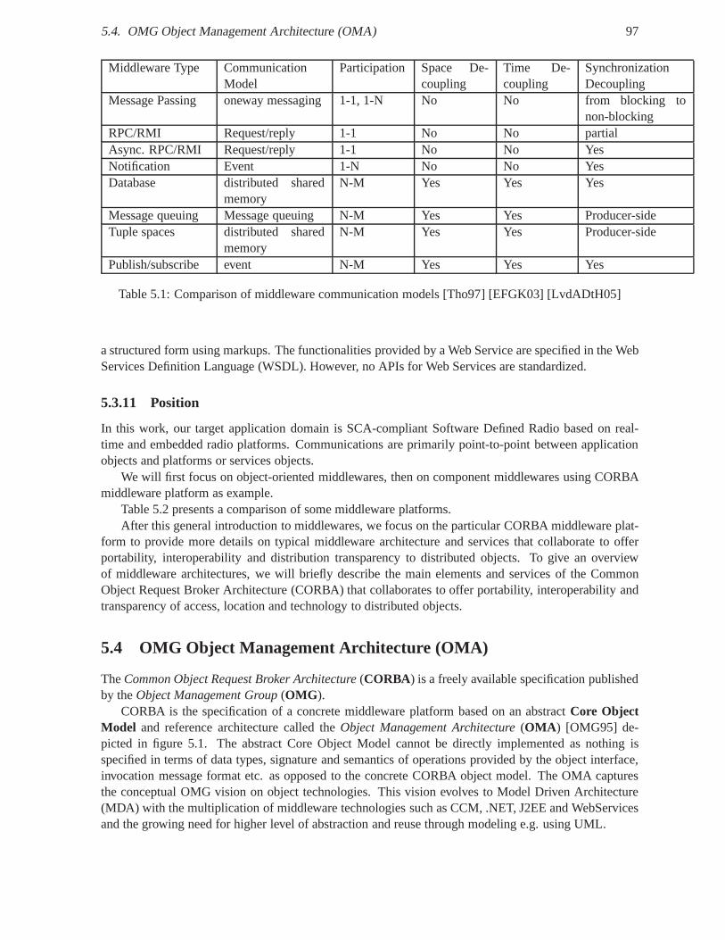
5.4. OMG Object Management Architecture (OMA) 97
Middleware Type CommunicationModel
Participation Space De-coupling
Time De-coupling
SynchronizationDecoupling
Message Passing oneway messaging 1-1, 1-N No No from blocking tonon-blocking
RPC/RMI Request/reply 1-1 No No partialAsync. RPC/RMI Request/reply 1-1 No No YesNotification Event 1-N No No YesDatabase distributed shared
memoryN-M Yes Yes Yes
Message queuing Message queuing N-M Yes Yes Producer-sideTuple spaces distributed shared
memoryN-M Yes Yes Producer-side
Publish/subscribe event N-M Yes Yes Yes
Table 5.1: Comparison of middleware communication models [Tho97] [EFGK03] [LvdADtH05]
a structured form using markups. The functionalities provided by a Web Service are specified in the WebServices Definition Language (WSDL). However, no APIs for Web Services are standardized.
5.3.11 Position
In this work, our target application domain is SCA-compliant Software Defined Radio based on real-time and embedded radio platforms. Communications are primarily point-to-point between applicationobjects and platforms or services objects.
We will first focus on object-oriented middlewares, then on component middlewares using CORBAmiddleware platform as example.
Table 5.2 presents a comparison of some middleware platforms.After this general introduction to middlewares, we focus onthe particular CORBA middleware plat-
form to provide more details on typical middleware architecture and services that collaborate to offerportability, interoperability and distribution transparency to distributed objects. To give an overviewof middleware architectures, we will briefly describe the main elements and services of the CommonObject Request Broker Architecture (CORBA) that collaborates to offer portability, interoperability andtransparency of access, location and technology to distributed objects.
5.4 OMG Object Management Architecture (OMA)
TheCommon Object Request Broker Architecture(CORBA) is a freely available specification publishedby theObject Management Group(OMG ).
CORBA is the specification of a concrete middleware platformbased on an abstractCore ObjectModel and reference architecture called theObject Management Architecture(OMA ) [OMG95] de-picted in figure 5.1. The abstract Core Object Model cannot bedirectly implemented as nothing isspecified in terms of data types, signature and semantics of operations provided by the object interface,invocation message format etc. as opposed to the concrete CORBA object model. The OMA capturesthe conceptual OMG vision on object technologies. This vision evolves to Model Driven Architecture(MDA) with the multiplication of middleware technologies such as CCM, .NET, J2EE and WebServicesand the growing need for higher level of abstraction and reuse through modeling e.g. using UML.
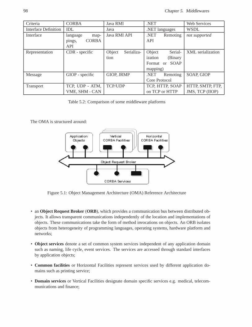
98 Chapter 5. Middlewares
Criteria CORBA Java RMI .NET Web ServicesInterface Definition IDL Java .NET languages WSDLInterface language map-
pings, CORBAAPI
Java RMI API .NET RemotingAPI
not supported
Representation CDR - specific Object Serializa-tion
Object Serial-ization (BinaryFormat or SOAPmapping)
XML serialization
Message GIOP - specific GIOP, JRMP .NET RemotingCore Protocol
SOAP, GIOP
Transport TCP, UDP - ATM,VME, SHM - CAN
TCP/UDP TCP, HTTP, SOAPon TCP or HTTP
HTTP, SMTP, FTP,JMS, TCP (IIOP)
Table 5.2: Comparison of some middleware platforms
The OMA is structured around:
Figure 5.1: Object Management Architecture (OMA) Reference Architecture
• anObject Request Broker(ORB), which provides a communication bus between distributed ob-jects. It allows transparent communications independently of the location and implementations ofobjects. These communications take the form of method invocations on objects. An ORB isolatesobjects from heterogeneity of programming languages, operating systems, hardware platform andnetworks;
• Object servicesdenote a set of common system services independent of any application domainsuch as naming, life cycle, event services. The services areaccessed through standard interfacesby application objects;
• Common facilities or Horizontal Facilities represent services used by different application do-mains such as printing service;
• Domain servicesor Vertical Facilities designate domain specific services e.g. medical, telecom-munications and finance;
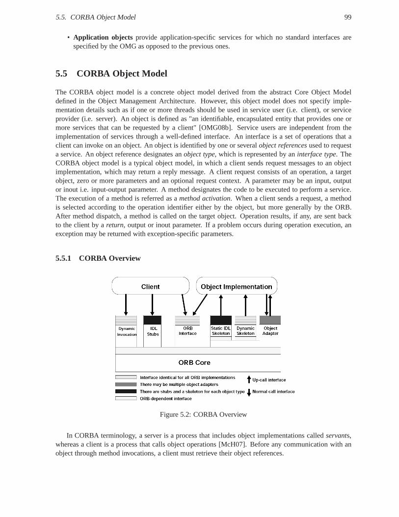
5.5. CORBA Object Model 99
• Application objects provide application-specific services for which no standard interfaces arespecified by the OMG as opposed to the previous ones.
5.5 CORBA Object Model
The CORBA object model is a concrete object model derived from the abstract Core Object Modeldefined in the Object Management Architecture. However, this object model does not specify imple-mentation details such as if one or more threads should be used in service user (i.e. client), or serviceprovider (i.e. server). An object is defined as "an identifiable, encapsulated entity that provides one ormore services that can be requested by a client" [OMG08b]. Service users are independent from theimplementation of services through a well-defined interface. An interface is a set of operations that aclient can invoke on an object. An object is identified by one or severalobject referencesused to requesta service. An object reference designates anobject type, which is represented by aninterface type. TheCORBA object model is a typical object model, in which a client sends request messages to an objectimplementation, which may return a reply message. A client request consists of an operation, a targetobject, zero or more parameters and an optional request context. A parameter may be an input, outputor inout i.e. input-output parameter. A method designates the code to be executed to perform a service.The execution of a method is referred as amethod activation. When a client sends a request, a methodis selected according to the operation identifier either by the object, but more generally by the ORB.After method dispatch, a method is called on the target object. Operation results, if any, are sent backto the client by areturn, output or inout parameter. If a problem occurs during operation execution, anexception may be returned with exception-specific parameters.
5.5.1 CORBA Overview
Figure 5.2: CORBA Overview
In CORBA terminology, a server is a process that includes object implementations calledservants,whereas a client is a process that calls object operations [McH07]. Before any communication with anobject through method invocations, a client must retrieve their object references.
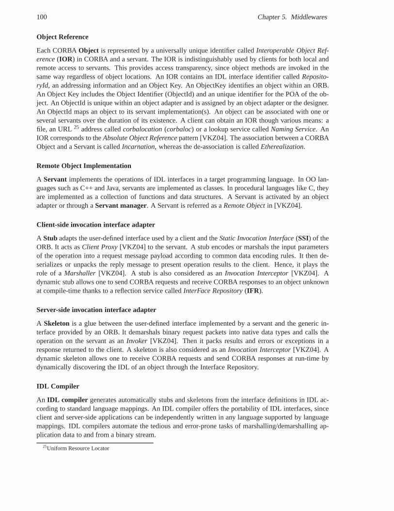
100 Chapter 5. Middlewares
Object Reference
Each CORBAObject is represented by a universally unique identifier calledInteroperable Object Ref-erence(IOR ) in CORBA and a servant. The IOR is indistinguishably used byclients for both local andremote access to servants. This provides access transparency, since object methods are invoked in thesame way regardless of object locations. An IOR contains an IDL interface identifier calledReposito-ryId, an addressing information and an Object Key. An ObjectKey identifies an object within an ORB.An Object Key includes the Object Identifier (ObjectId) and an unique identifier for the POA of the ob-ject. An ObjectId is unique within an object adapter and is assigned by an object adapter or the designer.An ObjectId maps an object to its servant implementation(s). An object can be associated with one orseveral servants over the duration of its existence. A client can obtain an IOR though various means: afile, an URL25 address calledcorbalocation(corbaloc) or a lookup service calledNaming Service. AnIOR corresponds to theAbsolute Object Referencepattern [VKZ04]. The association between a CORBAObject and a Servant is calledIncarnation, whereas the de-association is calledEtherealization.
Remote Object Implementation
A Servant implements the operations of IDL interfaces in a target programming language. In OO lan-guages such as C++ and Java, servants are implemented as classes. In procedural languages like C, theyare implemented as a collection of functions and data structures. A Servant is activated by an objectadapter or through aServant manager. A Servant is referred as aRemote Objectin [VKZ04].
Client-side invocation interface adapter
A Stub adapts the user-defined interface used by a client and theStatic Invocation Interface(SSI) of theORB. It acts asClient Proxy[VKZ04] to the servant. A stub encodes or marshals the input parametersof the operation into a request message payload according tocommon data encoding rules. It then de-serializes or unpacks the reply message to present operation results to the client. Hence, it plays therole of a Marshaller [VKZ04]. A stub is also considered as anInvocation Interceptor[VKZ04]. Adynamic stub allows one to send CORBA requests and receive CORBA responses to an object unknownat compile-time thanks to a reflection service calledInterFace Repository(IFR ).
Server-side invocation interface adapter
A Skeleton is a glue between the user-defined interface implemented by aservant and the generic in-terface provided by an ORB. It demarshals binary request packets into native data types and calls theoperation on the servant as anInvoker [VKZ04]. Then it packs results and errors or exceptions in aresponse returned to the client. A skeleton is also considered as anInvocation Interceptor[VKZ04]. Adynamic skeleton allows one to receive CORBA requests and send CORBA responses at run-time bydynamically discovering the IDL of an object through the Interface Repository.
IDL Compiler
An IDL compiler generates automatically stubs and skeletons from the interface definitions in IDL ac-cording to standard language mappings. An IDL compiler offers the portability of IDL interfaces, sinceclient and server-side applications can be independently written in any language supported by languagemappings. IDL compilers automate the tedious and error-prone tasks of marshalling/demarshalling ap-plication data to and from a binary stream.
25Uniform Resource Locator
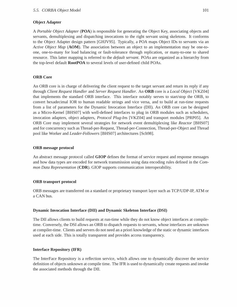
5.5. CORBA Object Model 101
Object Adapter
A Portable Object Adapter(POA) is responsible for generating the Object Key, associatingobjects andservants, demultiplexing and dispatching invocations to the right servant using skeletons. It conformsto the Object Adapter design pattern [GHJV95]. Typically, aPOA maps Object IDs to servants via anActive Object Map(AOM ). The association between an object to an implementation may be one-to-one, one-to-many for load balancing or fault-tolerance through replication, or many-to-one to sharedresource. This latter mapping is referred to thedefault servant. POAs are organized as a hierarchy fromthe top-level defaultRootPOA to several levels of user-defined child POAs.
ORB Core
An ORB core is in charge of delivering the client request to the target servant and return its reply if anythroughClient Request HandlerandServer Request Handler. An ORB core is aLocal Object[VKZ04]that implements the standard ORB interface. This interfacenotably serves to start/stop the ORB, toconvert hexadecimal IOR to human readable strings and vice versa, and to build at run-time requestsfrom a list of parameters for the Dynamic Invocation Interface (DII). An ORB core can be designedas a Micro-Kernel [BHS07] with well-defined interfaces to plug in ORB modules such as schedulers,invocation adapters, object adapters,Protocol Plug-Ins [VKZ04] and transport modules [PRP05]. AnORB Core may implement several strategies for network eventdemultiplexing likeReactor[BHS07]and for concurrency such as Thread-per-Request, Thread-per-Connection, Thread-per-Object and Threadpool like Worker andLeader-Followers[BHS07] architectures [Sch98].
ORB message protocol
An abstract message protocol calledGIOP defines the format of service request and response messagesand how data types are encoded for network transmission using data encoding rules defined in theCom-mon Data Representation(CDR). GIOP supports communication interoperability.
ORB transport protocol
ORB messages are transferred on a standard or proprietary transport layer such as TCP/UDP-IP, ATM ora CAN bus.
Dynamic Invocation Interface (DII) and Dynamic Skeleton Interface (DSI)
The DII allows clients to build requests at run-time while they do not know object interfaces at compile-time. Conversely, the DSI allows an ORB to dispatch requeststo servants, whose interfaces are unknownat compiler-time. Clients and servers do not need an a prioriknowledge of the static or dynamic interfacesused at each side. This is totally transparent and provides access transparency.
Interface Repository (IFR)
The InterFace Repository is a reflection service, which allows one to dynamically discover the servicedefinition of objects unknown at compile time. The IFR is usedto dynamically create requests and invokethe associated methods through the DII.
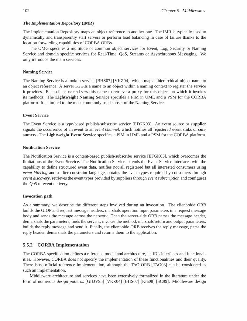
102 Chapter 5. Middlewares
The Implementation Repository (IMR)
The Implementation Repository maps an object reference to another one. The IMR is typically used todynamically and transparently start servers or perform load balancing in case of failure thanks to thelocation forwarding capabilities of CORBA ORBs.
The OMG specifies a multitude of common object services for Event, Log, Security or NamingService and domain specific services for Real-Time, QoS, Streams or Asynchronous Messaging. Weonly introduce the main services:
Naming Service
The Naming Service is a lookup service [BHS07] [VKZ04], which maps a hierarchical object name toan object reference. A serverbinds a name to an object within a naming context to register the serviceit provides. Each clientresolves this name to retrieve a proxy for this object on which it invokesits methods. TheLightweight Naming Service specifies a PIM in UML and a PSM for the CORBAplatform. It is limited to the most commonly used subset of the Naming Service.
Event Service
The Event Service is a type-based publish-subscribe service [EFGK03]. An event source orsuppliersignals the occurrence of an event to anevent channel, which notifies allregisteredevent sinks orcon-sumers. TheLightweight Event Servicespecifies a PIM in UML and a PSM for the CORBA platform.
Notification Service
The Notification Service is a content-based publish-subscribe service [EFGK03], which overcomes thelimitations of the Event Service. The Notification Service extends the Event Service interfaces with thecapability to define structured event data, notifies not all registered but all interested consumers usingevent filteringand a filter constraint language, obtains the event types required by consumers throughevent discovery, retrieves the event types provided by suppliers throughevent subscriptionand configurestheQoSof event delivery.
Invocation path
As a summary, we describe the different steps involved during an invocation. The client-side ORBbuilds the GIOP and request message headers, marshals operation input parameters in a request messagebody and sends the message across the network. Then the server-side ORB parses the message header,demarshals the parameters, finds the servant, invokes the method, marshals return and output parameters,builds the reply message and send it. Finally, the client-side ORB receives the reply message, parse thereply header, demarshals the parameters and returns them tothe application.
5.5.2 CORBA Implementation
The CORBA specification defines a reference model and architecture, its IDL interfaces and functional-ities. However, CORBA does not specify the implementation of these functionalities and their quality.There is no official reference implementation, although theTAO ORB [TAO08] can be considered assuch an implementation.
Middleware architecture and services have been extensively formalized in the literature under theform of numerousdesign patterns[GHJV95] [VKZ04] [BHS07] [Kra08] [SC99]. Middleware design
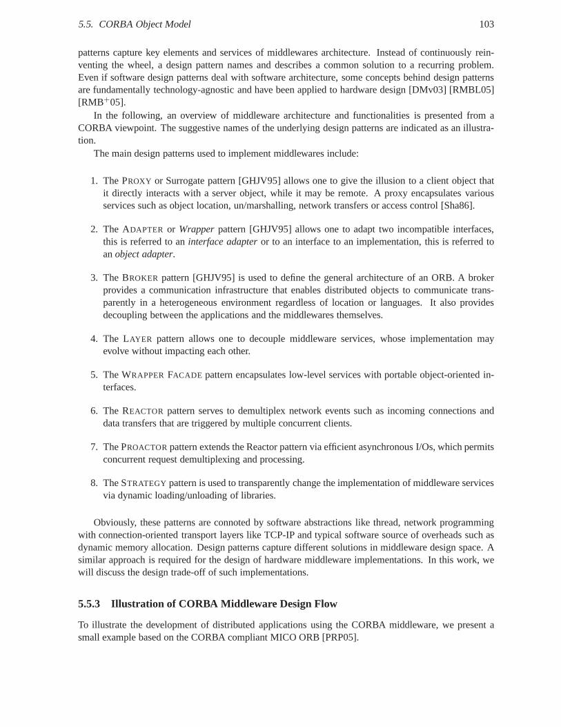
5.5. CORBA Object Model 103
patterns capture key elements and services of middlewares architecture. Instead of continuously rein-venting the wheel, a design pattern names and describes a common solution to a recurring problem.Even if software design patterns deal with software architecture, some concepts behind design patternsare fundamentally technology-agnostic and have been applied to hardware design [DMv03] [RMBL05][RMB+05].
In the following, an overview of middleware architecture and functionalities is presented from aCORBA viewpoint. The suggestive names of the underlying design patterns are indicated as an illustra-tion.
The main design patterns used to implement middlewares include:
1. The PROXY or Surrogate pattern [GHJV95] allows one to give the illusion to a client object thatit directly interacts with a server object, while it may be remote. A proxy encapsulates variousservices such as object location, un/marshalling, networktransfers or access control [Sha86].
2. The ADAPTER or Wrapperpattern [GHJV95] allows one to adapt two incompatible interfaces,this is referred to aninterface adapteror to an interface to an implementation, this is referred toanobject adapter.
3. The BROKER pattern [GHJV95] is used to define the general architecture of an ORB. A brokerprovides a communication infrastructure that enables distributed objects to communicate trans-parently in a heterogeneous environment regardless of location or languages. It also providesdecoupling between the applications and the middlewares themselves.
4. The LAYER pattern allows one to decouple middleware services, whose implementation mayevolve without impacting each other.
5. The WRAPPERFACADE pattern encapsulates low-level services with portable object-oriented in-terfaces.
6. The REACTOR pattern serves to demultiplex network events such as incoming connections anddata transfers that are triggered by multiple concurrent clients.
7. The PROACTORpattern extends the Reactor pattern via efficient asynchronous I/Os, which permitsconcurrent request demultiplexing and processing.
8. The STRATEGY pattern is used to transparently change the implementationof middleware servicesvia dynamic loading/unloading of libraries.
Obviously, these patterns are connoted by software abstractions like thread, network programmingwith connection-oriented transport layers like TCP-IP andtypical software source of overheads such asdynamic memory allocation. Design patterns capture different solutions in middleware design space. Asimilar approach is required for the design of hardware middleware implementations. In this work, wewill discuss the design trade-off of such implementations.
5.5.3 Illustration of CORBA Middleware Design Flow
To illustrate the development of distributed applicationsusing the CORBA middleware, we present asmall example based on the CORBA compliant MICO ORB [PRP05].
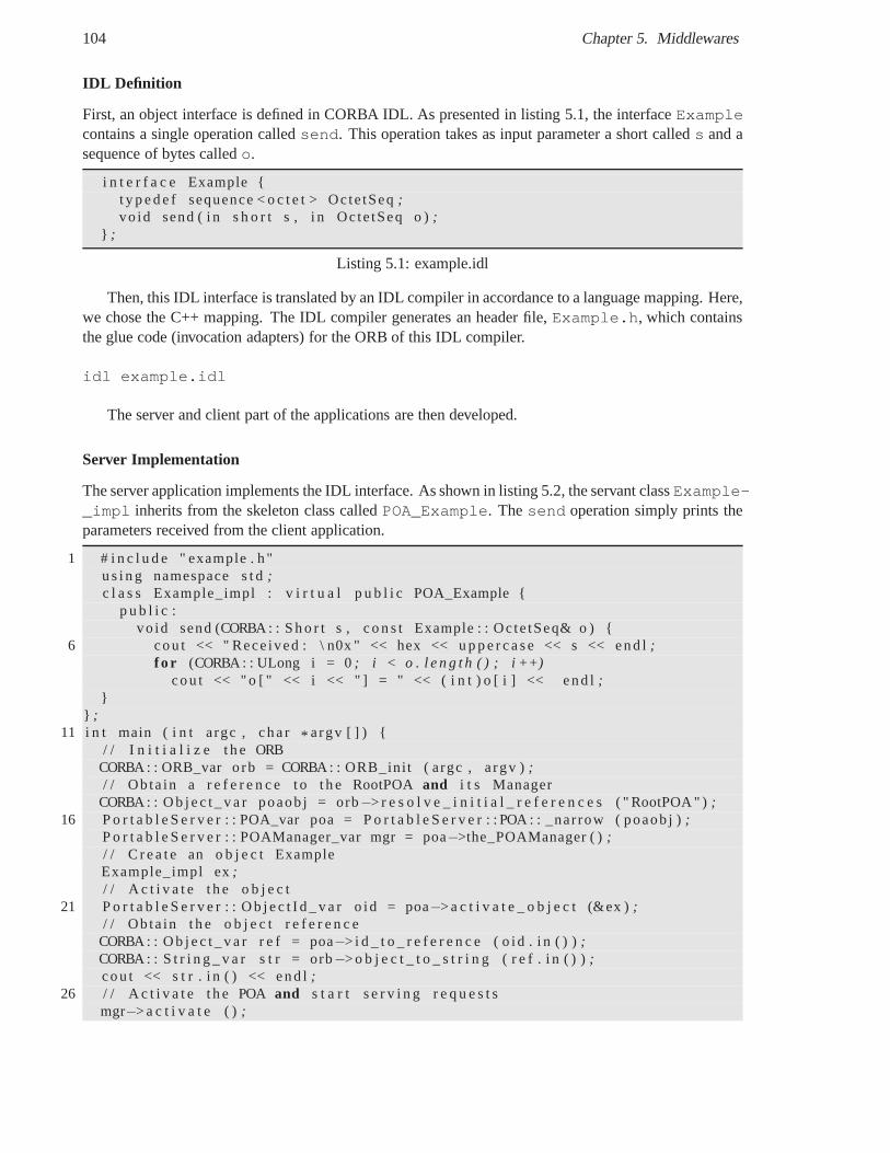
104 Chapter 5. Middlewares
IDL Definition
First, an object interface is defined in CORBA IDL. As presented in listing 5.1, the interfaceExamplecontains a single operation calledsend. This operation takes as input parameter a short calleds and asequence of bytes calledo.
i n t e r f a c e Example {t y p e d e f sequence < o c t e t > Octe tSeq;vo id send ( i n s h o r t s , i n Octe tSeq o );
} ;
Listing 5.1: example.idl
Then, this IDL interface is translated by an IDL compiler in accordance to a language mapping. Here,we chose the C++ mapping. The IDL compiler generates an header file, Example.h, which containsthe glue code (invocation adapters) for the ORB of this IDL compiler.
idl example.idl
The server and client part of the applications are then developed.
Server Implementation
The server application implements the IDL interface. As shown in listing 5.2, the servant classExample-_impl inherits from the skeleton class calledPOA_Example. Thesend operation simply prints theparameters received from the client application.
1 # i n c l u d e " example . h "u s i n g namespace s t d;c l a s s Example_impl : v i r t u a l p u b l i c POA_Example {
p u b l i c :vo id send (CORBA : : S h o r t s , c o n s t Example : : Oc te tSeq& o ) {
6 cou t << " Rece ived : \ n0x " << hex << u p p e r c a s e << s << end l;f o r (CORBA : : ULong i = 0; i < o . l e n g t h ( ) ; i ++)
cou t << " o [ " << i << " ] = " << ( i n t ) o [ i ] << end l ;}
} ;11 i n t main ( i n t argc , cha r* argv [ ] ) {
/ / I n i t i a l i z e t h e ORBCORBA : : ORB_var o rb = CORBA : : ORB_ini t ( argc , a rgv );/ / Ob ta in a r e f e r e n c e t o t h e RootPOAand i t s Manager
CORBA : : O b j e c t _ v a r poaob j = orb−> r e s o l v e _ i n i t i a l _ r e f e r e n c e s ( " RootPOA " );16 P o r t a b l e S e r v e r : : POA_var poa = P o r t a b l e S e r v e r : : POA : : _narrow ( poaob j );
P o r t a b l e S e r v e r : : POAManager_var mgr = poa−>the_POAManager ( );/ / C r e a t e an o b j e c t ExampleExample_impl ex;/ / A c t i v a t e t h e o b j e c t
21 P o r t a b l e S e r v e r : : O b j e c t I d _ v a r o id = poa−> a c t i v a t e _ o b j e c t (&ex );/ / Ob ta in t h e o b j e c t r e f e r e n c e
CORBA : : O b j e c t _ v a r r e f = poa−> i d _ t o _ r e f e r e n c e ( o id . i n ( ) );CORBA : : S t r i n g _ v a r s t r = orb−> o b j e c t _ t o _ s t r i n g ( r e f . i n ( ) );cou t << s t r . i n ( ) << end l;
26 / / A c t i v a t e t h e POAand s t a r t s e r v i n g r e q u e s t smgr−> a c t i v a t e ( );
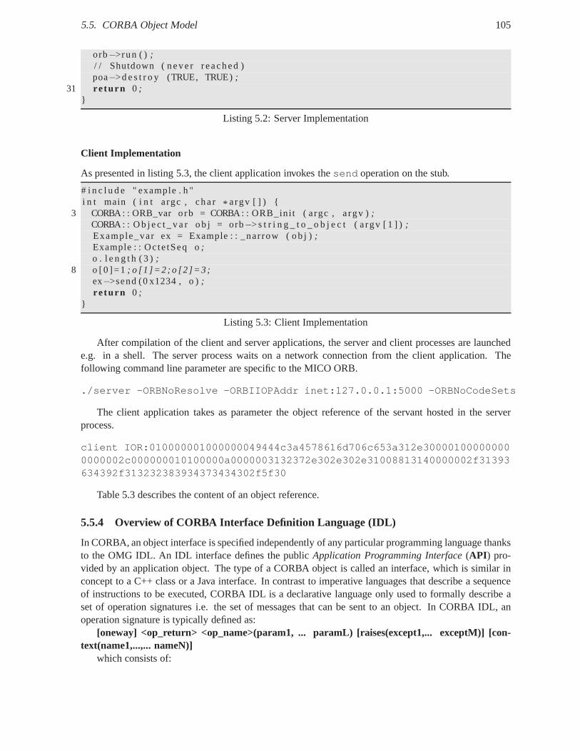
5.5. CORBA Object Model 105
orb−>run ( ) ;/ / Shutdown ( neve r reached )poa−>d e s t r o y (TRUE, TRUE);
31 re turn 0 ;}
Listing 5.2: Server Implementation
Client Implementation
As presented in listing 5.3, the client application invokesthesend operation on the stub.
# i n c l u d e " example . h "i n t main ( i n t argc , cha r * argv [ ] ) {
3 CORBA : : ORB_var o rb = CORBA : : ORB_ini t ( argc , a rgv );CORBA : : O b j e c t _ v a r ob j = orb−> s t r i n g _ t o _ o b j e c t ( a rgv [ 1 ] );Example_var ex = Example : : _narrow ( ob j );Example : : Oc te tSeq o;o . l e n g t h ( 3 );
8 o [0 ]=1 ; o [1 ]=2 ; o [2 ]=3 ;ex−>send (0 x1234 , o );re turn 0 ;
}
Listing 5.3: Client Implementation
After compilation of the client and server applications, the server and client processes are launchede.g. in a shell. The server process waits on a network connection from the client application. Thefollowing command line parameter are specific to the MICO ORB.
./server -ORBNoResolve -ORBIIOPAddr inet:127.0.0.1:5000 -ORBNoCodeSets
The client application takes as parameter the object reference of the servant hosted in the serverprocess.
client IOR:010000001000000049444c3a4578616d706c653a312e300001000000000000002c000000010100000a0000003132372e302e302e31008813140000002f31393634392f313232383934373434302f5f30
Table 5.3 describes the content of an object reference.
5.5.4 Overview of CORBA Interface Definition Language (IDL)
In CORBA, an object interface is specified independently of any particular programming language thanksto the OMG IDL. An IDL interface defines the publicApplication Programming Interface(API ) pro-vided by an application object. The type of a CORBA object is called an interface, which is similar inconcept to a C++ class or a Java interface. In contrast to imperative languages that describe a sequenceof instructions to be executed, CORBA IDL is a declarative language only used to formally describe aset of operation signatures i.e. the set of messages that canbe sent to an object. In CORBA IDL, anoperation signature is typically defined as:
[oneway] <op_return> <op_name>(param1, ... paramL) [raises(except1,... exceptM)] [con-text(name1,...,... nameN)]
which consists of:
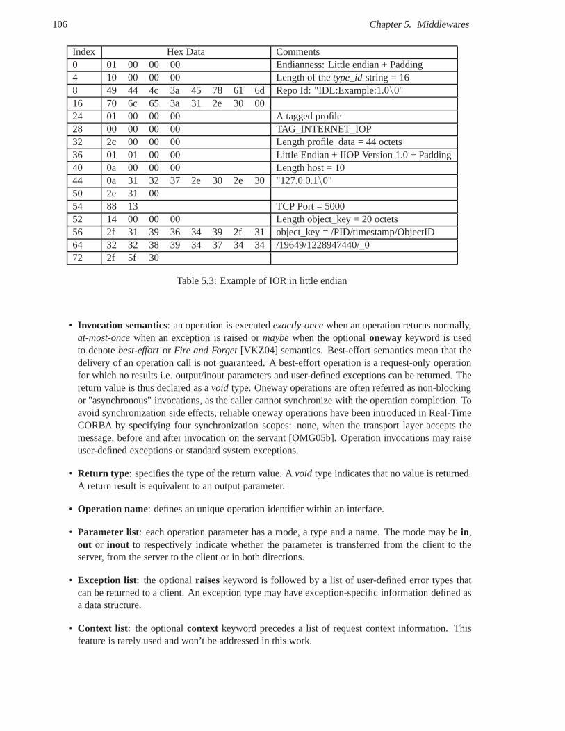
106 Chapter 5. Middlewares
Index Hex Data Comments0 01 00 00 00 Endianness: Little endian + Padding4 10 00 00 00 Length of thetype_idstring = 168 49 44 4c 3a 45 78 61 6d Repo Id: "IDL:Example:1.0\0"16 70 6c 65 3a 31 2e 30 0024 01 00 00 00 A tagged profile28 00 00 00 00 TAG_INTERNET_IOP32 2c 00 00 00 Length profile_data = 44 octets36 01 01 00 00 Little Endian + IIOP Version 1.0 + Padding40 0a 00 00 00 Length host = 1044 0a 31 32 37 2e 30 2e 30"127.0.0.1\0"50 2e 31 0054 88 13 TCP Port = 500052 14 00 00 00 Length object_key = 20 octets56 2f 31 39 36 34 39 2f 31 object_key = /PID/timestamp/ObjectID64 32 32 38 39 34 37 34 34 /19649/1228947440/_072 2f 5f 30
Table 5.3: Example of IOR in little endian
• Invocation semantics: an operation is executedexactly-oncewhen an operation returns normally,at-most-oncewhen an exception is raised ormaybewhen the optionalonewaykeyword is usedto denotebest-effortor Fire and Forget[VKZ04] semantics. Best-effort semantics mean that thedelivery of an operation call is not guaranteed. A best-effort operation is a request-only operationfor which no results i.e. output/inout parameters and user-defined exceptions can be returned. Thereturn value is thus declared as avoid type. Oneway operations are often referred as non-blockingor "asynchronous" invocations, as the caller cannot synchronize with the operation completion. Toavoid synchronization side effects, reliable oneway operations have been introduced in Real-TimeCORBA by specifying four synchronization scopes: none, when the transport layer accepts themessage, before and after invocation on the servant [OMG05b]. Operation invocations may raiseuser-defined exceptions or standard system exceptions.
• Return type: specifies the type of the return value. Avoid type indicates that no value is returned.A return result is equivalent to an output parameter.
• Operation name: defines an unique operation identifier within an interface.
• Parameter list: each operation parameter has a mode, a type and a name. The mode may bein,out or inout to respectively indicate whether the parameter is transferred from the client to theserver, from the server to the client or in both directions.
• Exception list: the optionalraiseskeyword is followed by a list of user-defined error types thatcan be returned to a client. An exception type may have exception-specific information defined asa data structure.
• Context list: the optionalcontext keyword precedes a list of request context information. Thisfeature is rarely used and won’t be addressed in this work.
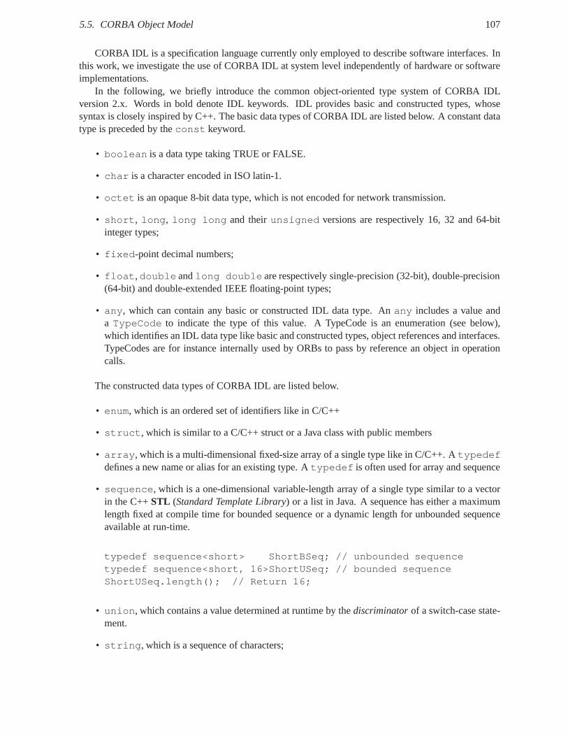
5.5. CORBA Object Model 107
CORBA IDL is a specification language currently only employed to describe software interfaces. Inthis work, we investigate the use of CORBA IDL at system levelindependently of hardware or softwareimplementations.
In the following, we briefly introduce the common object-oriented type system of CORBA IDLversion 2.x. Words in bold denote IDL keywords. IDL providesbasic and constructed types, whosesyntax is closely inspired by C++. The basic data types of CORBA IDL are listed below. A constant datatype is preceded by theconst keyword.
• boolean is a data type taking TRUE or FALSE.
• char is a character encoded in ISO latin-1.
• octet is an opaque 8-bit data type, which is not encoded for networktransmission.
• short, long, long long and theirunsigned versions are respectively 16, 32 and 64-bitinteger types;
• fixed-point decimal numbers;
• float,double andlong double are respectively single-precision (32-bit), double-precision(64-bit) and double-extended IEEE floating-point types;
• any, which can contain any basic or constructed IDL data type. Anany includes a value anda TypeCode to indicate the type of this value. A TypeCode is an enumeration (see below),which identifies an IDL data type like basic and constructed types, object references and interfaces.TypeCodes are for instance internally used by ORBs to pass byreference an object in operationcalls.
The constructed data types of CORBA IDL are listed below.
• enum, which is an ordered set of identifiers like in C/C++
• struct, which is similar to a C/C++ struct or a Java class with publicmembers
• array, which is a multi-dimensional fixed-size array of a single type like in C/C++. Atypedefdefines a new name or alias for an existing type. Atypedef is often used for array and sequence
• sequence, which is a one-dimensional variable-length array of a single type similar to a vectorin the C++STL (Standard Template Library) or a list in Java. A sequence has either a maximumlength fixed at compile time for bounded sequence or a dynamiclength for unbounded sequenceavailable at run-time.
typedef sequence<short> ShortBSeq; // unbounded sequencetypedef sequence<short, 16>ShortUSeq; // bounded sequenceShortUSeq.length(); // Return 16;
• union, which contains a value determined at runtime by thediscriminatorof a switch-case state-ment.
• string, which is a sequence of characters;
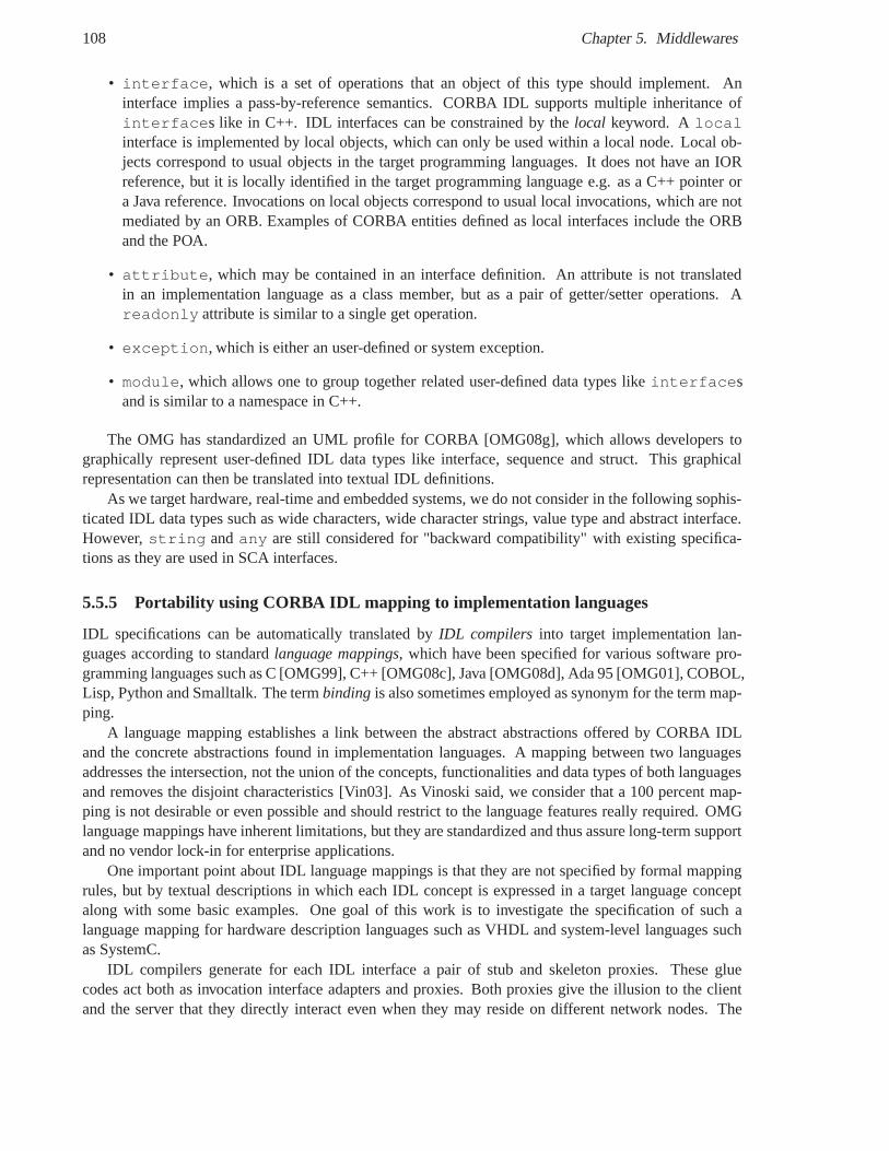
108 Chapter 5. Middlewares
• interface, which is a set of operations that an object of this type should implement. Aninterface implies a pass-by-reference semantics. CORBA IDL supports multiple inheritance ofinterfaces like in C++. IDL interfaces can be constrained by thelocal keyword. Alocalinterface is implemented by local objects, which can only beused within a local node. Local ob-jects correspond to usual objects in the target programminglanguages. It does not have an IORreference, but it is locally identified in the target programming language e.g. as a C++ pointer ora Java reference. Invocations on local objects correspond to usual local invocations, which are notmediated by an ORB. Examples of CORBA entities defined as local interfaces include the ORBand the POA.
• attribute, which may be contained in an interface definition. An attribute is not translatedin an implementation language as a class member, but as a pairof getter/setter operations. Areadonly attribute is similar to a single get operation.
• exception, which is either an user-defined or system exception.
• module, which allows one to group together related user-defined data types likeinterfacesand is similar to a namespace in C++.
The OMG has standardized an UML profile for CORBA [OMG08g], which allows developers tographically represent user-defined IDL data types like interface, sequence and struct. This graphicalrepresentation can then be translated into textual IDL definitions.
As we target hardware, real-time and embedded systems, we donot consider in the following sophis-ticated IDL data types such as wide characters, wide character strings, value type and abstract interface.However,string andany are still considered for "backward compatibility" with existing specifica-tions as they are used in SCA interfaces.
5.5.5 Portability using CORBA IDL mapping to implementation languages
IDL specifications can be automatically translated byIDL compilers into target implementation lan-guages according to standardlanguage mappings, which have been specified for various software pro-gramming languages such as C [OMG99], C++ [OMG08c], Java [OMG08d], Ada 95 [OMG01], COBOL,Lisp, Python and Smalltalk. The termbinding is also sometimes employed as synonym for the term map-ping.
A language mapping establishes a link between the abstract abstractions offered by CORBA IDLand the concrete abstractions found in implementation languages. A mapping between two languagesaddresses the intersection, not the union of the concepts, functionalities and data types of both languagesand removes the disjoint characteristics [Vin03]. As Vinoski said, we consider that a 100 percent map-ping is not desirable or even possible and should restrict tothe language features really required. OMGlanguage mappings have inherent limitations, but they are standardized and thus assure long-term supportand no vendor lock-in for enterprise applications.
One important point about IDL language mappings is that theyare not specified by formal mappingrules, but by textual descriptions in which each IDL conceptis expressed in a target language conceptalong with some basic examples. One goal of this work is to investigate the specification of such alanguage mapping for hardware description languages such as VHDL and system-level languages suchas SystemC.
IDL compilers generate for each IDL interface a pair of stub and skeleton proxies. These gluecodes act both as invocation interface adapters and proxies. Both proxies give the illusion to the clientand the server that they directly interact even when they mayreside on different network nodes. The
5.5. CORBA Object Model 109
stub presents to the client object the same user-defined interface as the server object, while the skeletoninvokes uses by respectively presenting and calling the same user-defined interface. On the one hand,these glue codes adapt user-defined IDL interfaces e.g. witha void add(in long a, inout long b, out longc) operation with the generic and ORB-specific interface with an operation likevoid invoke(in stringoperationName, in any inArgs, inout any inoutArgs, out any outArgs. Another important point is thatIDL language mappings only standardize glue code interfaces, but not their implementation. This allowsORB implementers to provide additional features like smartproxies as in TAO ORB or optimizationse.g. when the client and the server are colocalized in the same address space. Application developershave to implement their business logic within the code generated by the IDL compiler.
User-defined IDL interfaces implicitly inherit from the pseudoObject interface. AnObjectmustprovide a set of predefined operations, which are part of the CORBA Object model. The implementationof these operations is not provided by the application, but by the ORB or by the glue code generatedby the IDL compilers. TheObject interface does not represent an user object implementation, but itsobject reference.
Tables 5.4 and 5.5 summarize language mappings for C, C++, Java and Ada 95. Obviously, we donot aim at describing in detail these mappings, but only the interesting points for this work. We chose topresent the mappings to the C language and its object-oriented extension, C++, since these languages arewidely used in the embedded domain, whereas Java was designed as a portable object-oriented languagefrom the outset. The mapping to Ada 95 is also presented as VHDL syntax was inspired from Adasyntax.
What is interesting to note from the table 5.4 is that each mapping is closely adapted to the syntaxand semantics of the target language.
As the C and Ada languages are not object-oriented programming languages, IDL object-orientedconstructs had to be "emulated" in both IDL language mappings. The lack of code modularization con-structs like C++ namespace and class is overcome by naming conventions, in which IDL data typesand operation names are respectively prefixed withCORBA_and the name of IDL modules and in-terfaces in C. An IDL operation is mapped to a C function usingas arguments: an opaque data typecalled CORBA_Objectsimilar to the self-object referencethis in C++ and Java that includes the ob-ject state and identity, the operation parameters mapped tofunction arguments, an optional opaque datatype called CORBA_Context that provides a request invocation context, and a partially opaque data typeCORBA_Environment that allows developers to set and get an exception identifier when an exception israised.
The C++ mapping is reputed to be complicated and to require animportant learning curve [Hen04][KKSC04] [SV01]. As the size of C++ data types are not standardized and are thus not portable, CORBAdata types were defined in C++. The mapping of multiple inheritance in IDL and C++ is direct. As Javadata types are portable, a direct mapping of type has been proposed between CORBA IDL and Java.
Each CORBA middleware implementation includes its own IDL compiler. As any compiler, the mainobjective of IDL compilers is to generate optimized proxy code in terms of footprint and performance.IDL compilers improve local communications between objects colocalized in the same address spacethanks tocolocalizationproxies [PRP05] [SLM98]. First IDL compilers had an monolithic implemen-tation with inextensible and hardwired IDL language mappings. Some works have been carried out tostudy the design and implementation of flexible IDL compilers such as Flick (Flexible IDL CompilerKit) [ESSL99], IDLFlex [RSH01] and USC (Universal Stub Compiler) [OPM94]. Basically, there aretwo marshalling approaches for stub and skeleton proxies: compiled and interpreted approaches. In thecompiled approach, the marshalling code is hardwired and dedicated to the user-data types. In the inter-preted approach, the marshalling code dynamically encodesand decodes operation parameters based onthe types of user-data that are either transferred with the messages or read from the IDL meta-data storedin the Interface Repository. A natural trade-off exists between the size and speed of marshalling code
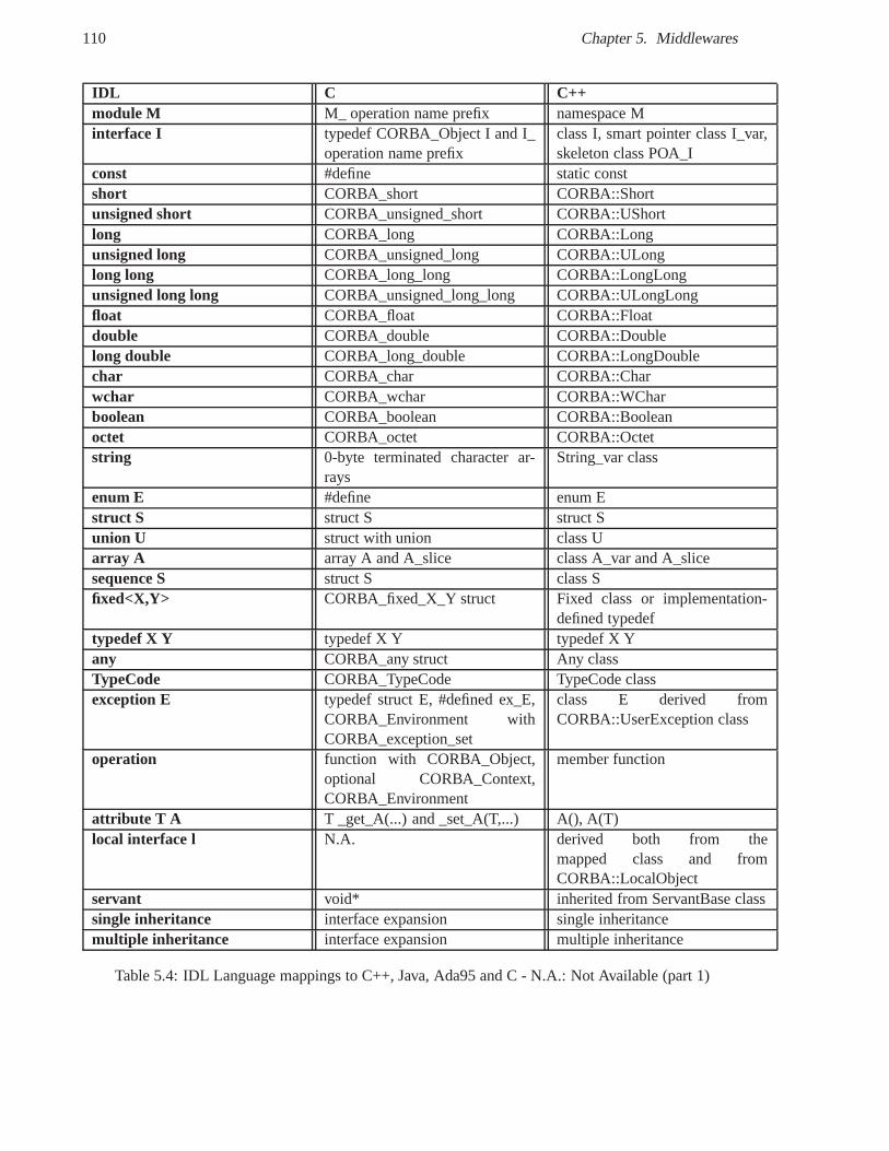
110 Chapter 5. Middlewares
IDL C C++module M M_ operation name prefix namespace Minterface I typedef CORBA_Object I and I_
operation name prefixclass I, smart pointer class I_var,skeleton class POA_I
const #define static constshort CORBA_short CORBA::Shortunsigned short CORBA_unsigned_short CORBA::UShortlong CORBA_long CORBA::Longunsigned long CORBA_unsigned_long CORBA::ULonglong long CORBA_long_long CORBA::LongLongunsigned long long CORBA_unsigned_long_long CORBA::ULongLongfloat CORBA_float CORBA::Floatdouble CORBA_double CORBA::Doublelong double CORBA_long_double CORBA::LongDoublechar CORBA_char CORBA::Charwchar CORBA_wchar CORBA::WCharboolean CORBA_boolean CORBA::Booleanoctet CORBA_octet CORBA::Octetstring 0-byte terminated character ar-
raysString_var class
enum E #define enum Estruct S struct S struct Sunion U struct with union class Uarray A array A and A_slice class A_var and A_slicesequence S struct S class Sfixed<X,Y> CORBA_fixed_X_Y struct Fixed class or implementation-
defined typedeftypedef X Y typedef X Y typedef X Yany CORBA_any struct Any classTypeCode CORBA_TypeCode TypeCode classexception E typedef struct E, #defined ex_E,
CORBA_Environment withCORBA_exception_set
class E derived fromCORBA::UserException class
operation function with CORBA_Object,optional CORBA_Context,CORBA_Environment
member function
attribute T A T _get_A(...) and _set_A(T,...) A(), A(T)local interface l N.A. derived both from the
mapped class and fromCORBA::LocalObject
servant void* inherited from ServantBase classsingle inheritance interface expansion single inheritancemultiple inheritance interface expansion multiple inheritance
Table 5.4: IDL Language mappings to C++, Java, Ada95 and C - N.A.: Not Available (part 1)
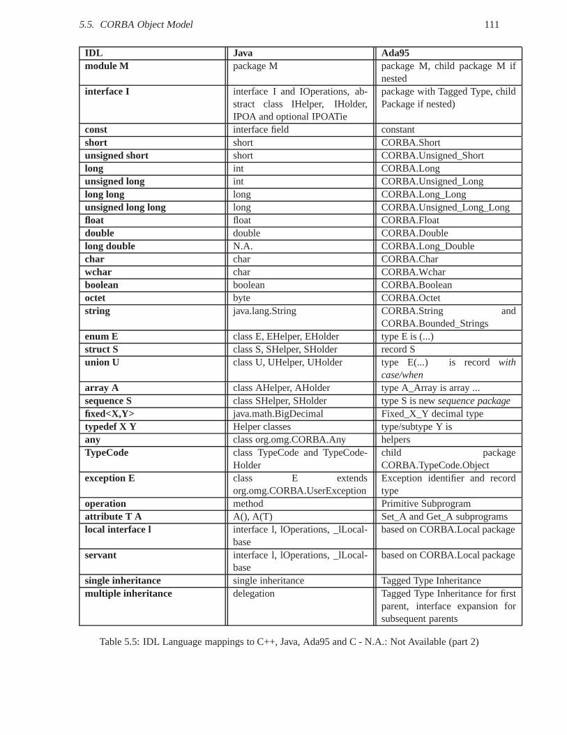
5.5. CORBA Object Model 111
IDL Java Ada95module M package M package M, child package M if
nestedinterface I interface I and IOperations, ab-
stract class IHelper, IHolder,IPOA and optional IPOATie
package with Tagged Type, childPackage if nested)
const interface field constantshort short CORBA.Shortunsigned short short CORBA.Unsigned_Shortlong int CORBA.Longunsigned long int CORBA.Unsigned_Longlong long long CORBA.Long_Longunsigned long long long CORBA.Unsigned_Long_Longfloat float CORBA.Floatdouble double CORBA.Doublelong double N.A. CORBA.Long_Doublechar char CORBA.Charwchar char CORBA.Wcharboolean boolean CORBA.Booleanoctet byte CORBA.Octetstring java.lang.String CORBA.String and
CORBA.Bounded_Stringsenum E class E, EHelper, EHolder type E is (...)struct S class S, SHelper, SHolder record Sunion U class U, UHelper, UHolder type E(...) is record with
case/whenarray A class AHelper, AHolder type A_Array is array ...sequence S class SHelper, SHolder type S is newsequence packagefixed<X,Y> java.math.BigDecimal Fixed_X_Y decimal typetypedef X Y Helper classes type/subtype Y isany class org.omg.CORBA.Any helpersTypeCode class TypeCode and TypeCode-
Holderchild packageCORBA.TypeCode.Object
exception E class E extendsorg.omg.CORBA.UserException
Exception identifier and recordtype
operation method Primitive Subprogramattribute T A A(), A(T) Set_A and Get_A subprogramslocal interface l interface l, lOperations, _lLocal-
basebased on CORBA.Local package
servant interface l, lOperations, _lLocal-base
based on CORBA.Local package
single inheritance single inheritance Tagged Type Inheritancemultiple inheritance delegation Tagged Type Inheritance for first
parent, interface expansion forsubsequent parents
Table 5.5: IDL Language mappings to C++, Java, Ada95 and C - N.A.: Not Available (part 2)
112 Chapter 5. Middlewares
[Hos98]. Compiled marshalling code is faster, but requiresmore memory, while interpreted marshallingcode is slower, but more compact [SLM98]. After presenting how CORBA ORB provide portability tobusiness applications through language mappoibngs, we will now see how they guarantee interoperabilitybetween ORBs.
5.5.6 Interoperability with CORBA Inter-ORB Protocol (IOP )
GIOP is the native protocol of CORBA ORBs. GIOP is an abstractprotocol which has to be mapped ontoconcrete transport protocols. For instance,Internet Inter-ORB Protocol(IIOP ) is a mapping of GIOPon TCP-IP. AnEnvironment-Specific Inter-ORB Protocol(ESIOP) provides interoperability betweenCORBA ORBs and other middleware through legacy or custom protocols. GIOP specification describes aCommon Data Representation(CDR), messages format and transport layer requirements. CDR specifiesthe bijective mapping from IDL data types to a byte or octet stream and vice versa. In CDR, primitive datatypes are aligned on their natural boundaries. Any primitive of sizen octets must start at an octet streamindex that is a multiple ofn. This data alignment implies padding. In constructed data types of fixedlength like struct, union or array, constituents are marshalled by their respective type. The marshalling ofvariable length types like string or sequence consists in encoding their length, then their constituents. Tominimize the overhead of encoding integers as octets,Compact CDR(CCDR) [KJH+00a] was porposedas an optimization of CDR. GIOP defines eight messages to sendrequests, receive replies, locate objectsand manage logical connections. Four versions of GIOP messages exist from 1.0 to 1.3. To be conformedto the 1.n version, the ORB shall implement the 1.m versions with m≤ n.
Like a visiting card, an object reference may list all the ways to contact an object using several trans-port profiles. Each profile contains a profile Id and addressing information to locate a communicationendpoint for a given transport protocol. A profile may include information about QoS, network, transportand message protocols, data encoding rules, addresses or routes. For instance, IIOP profiles compriseIIOP version, host address and port number to locate the server process and an Object Key. This lattercontains typically a POA Id an Object Id to locate a servant.
GIOP requires that the transport layer is connection and byte stream oriented, reliable and notifiesfailures. Multiple independent requests for different objects, or a single object, may share the sameconnection. GIOP requests can be ordered or not thanks to request_id. Clients may have multiplepending requests. A client need not wait for a reply from a previous request before sending anotherrequest.
For instance, the GIOP request message for the invocation ofthesendoperation presented in listing5.3 is depicted in table 5.6.
5.5.7 Real-Time CORBA
Real-Time systems require strict QoS guarantees in terms ofexecution time, bandwidth, latency and jitter.However, CORBA does not offer natively IDL interfaces to configure QoS properties.Real-Time (RT)CORBA [OMG05b] [KKSC04] is an extension to the CORBA and CORBA Messaging specificationsto supportend-to-end predictabilityfrom client to server applications across the network. Middlewareelements have been extended with RT-POA, RT-ORB and RT-policies. To support QoS constraints,ORBs must schedule CPUs, memory and network resources. RT-CORBA allows the explicit control andconfiguration of processor, communication and memory resources [KKSC04]:
• Processor resourceswith priorities, mutexes, threadpools and a static scheduling service.
• Communication resourceswith priority banded connections, private connections andprotocolproperties and asynchronous invocations.
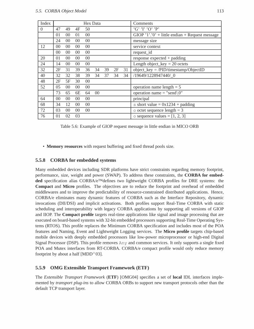
5.5. CORBA Object Model 113
Index Hex Data Comments0 47 49 4F 50 ’G’ ’I’ ’O’ ’P’
01 00 01 00 GIOP ’1’.’0’ + little endian + Request message24 00 00 00 message size
12 00 00 00 00 service context00 00 00 00 request_id
20 01 00 00 00 response expected + padding24 14 00 00 00 Length object_key = 20 octets32 2F 31 39 36 34 39 2F 31 object_key = /PID/timestamp/ObjectID40 32 32 38 39 34 37 34 34 /19649/1228947440/_048 2F 5F 30 0052 05 00 00 00 operation name length = 5
73 65 6E 64 00 operation name = "send\0"64 00 00 00 00 principal68 34 12 00 00 s short value = 0x1234 + padding72 03 00 00 00 o octet sequence length = 376 01 02 03 o sequence values = [1, 2, 3]
Table 5.6: Example of GIOP request message in little endian in MICO ORB
• Memory resourceswith request buffering and fixed thread pools size.
5.5.8 CORBA for embedded systems
Many embedded devices including SDR platforms have strict constraints regarding memory footprint,performance, size, weight and power (SWAP). To address these constraints, theCORBA for embed-ded specification alias CORBA/e™defines two lightweight CORBA profiles for DRE systems: theCompact and Micro profiles. The objectives are to reduce the footprint and overhead of embeddedmiddlewares and to improve the predictability of resource-constrained distributed applications. Hence,CORBA/e eliminates many dynamic features of CORBA such as the Interface Repository, dynamicinvocations (DII/DSI) and implicit activations. Both profiles support Real-Time CORBA with staticscheduling and interoperability with legacy CORBA applications by supporting all versions of GIOPand IIOP. TheCompact profile targets real-time applications like signal and image processing that areexecuted on board-based systems with 32-bit embedded processors supporting Real-Time Operating Sys-tems (RTOS). This profile replaces the Minimum CORBA specification and includes most of the POAfeatures and Naming, Event and Lightweight Logging services. TheMicro profile targets chip-basedmobile devices with deeply embedded processors like low-power microprocessor or high-end DigitalSignal Processor (DSP). This profile removesAny and common services. It only supports a single fixedPOA and Mutex interfaces from RT-CORBA. CORBA/e compact profile would only reduce memoryfootprint by about a half [MDD+03].
5.5.9 OMG Extensible Transport Framework (ETF)
The Extensible Transport Framework(ETF) [OMG04] specifies a set oflocal IDL interfaces imple-mented bytransport plug-insto allow CORBA ORBs to support new transport protocols otherthan thedefault TCP transport layer.
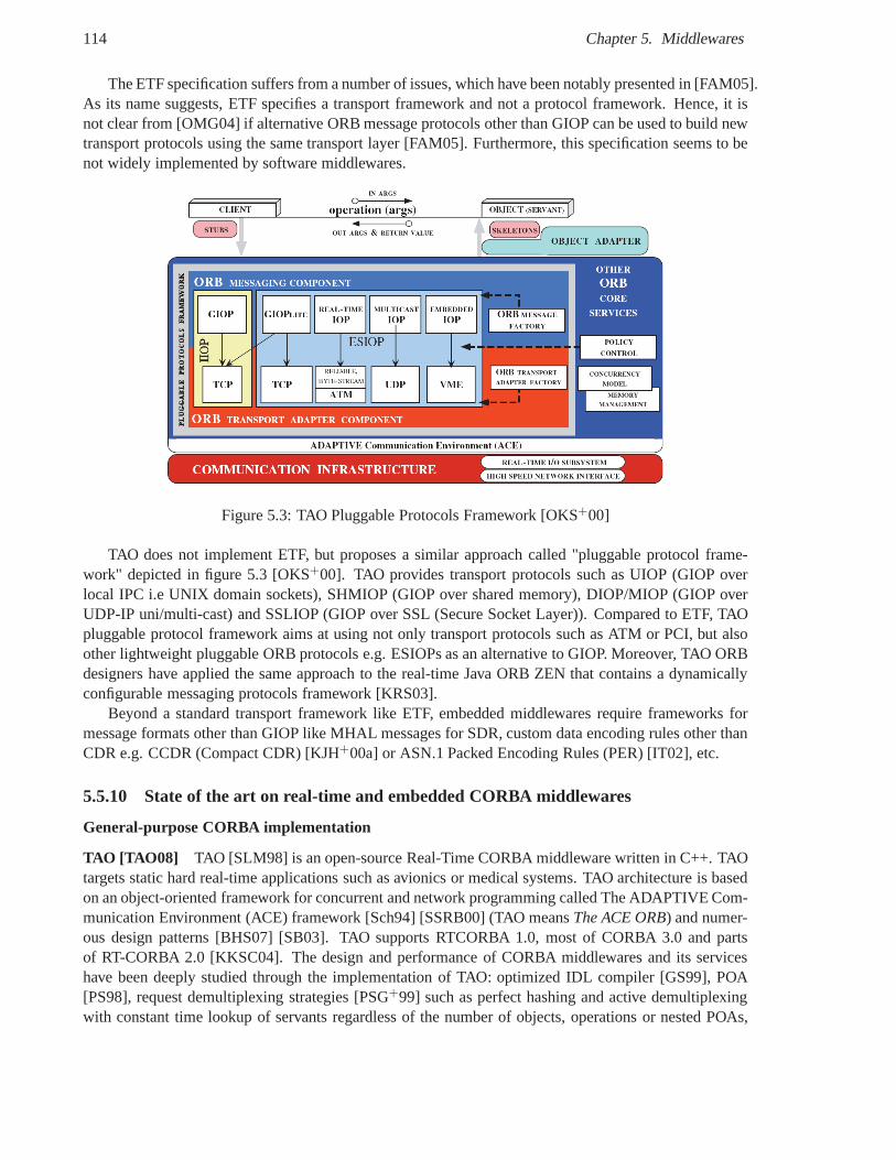
114 Chapter 5. Middlewares
The ETF specification suffers from a number of issues, which have been notably presented in [FAM05].As its name suggests, ETF specifies a transport framework andnot a protocol framework. Hence, it isnot clear from [OMG04] if alternative ORB message protocolsother than GIOP can be used to build newtransport protocols using the same transport layer [FAM05]. Furthermore, this specification seems to benot widely implemented by software middlewares.
Figure 5.3: TAO Pluggable Protocols Framework [OKS+00]
TAO does not implement ETF, but proposes a similar approach called "pluggable protocol frame-work" depicted in figure 5.3 [OKS+00]. TAO provides transport protocols such as UIOP (GIOP overlocal IPC i.e UNIX domain sockets), SHMIOP (GIOP over sharedmemory), DIOP/MIOP (GIOP overUDP-IP uni/multi-cast) and SSLIOP (GIOP over SSL (Secure Socket Layer)). Compared to ETF, TAOpluggable protocol framework aims at using not only transport protocols such as ATM or PCI, but alsoother lightweight pluggable ORB protocols e.g. ESIOPs as analternative to GIOP. Moreover, TAO ORBdesigners have applied the same approach to the real-time Java ORB ZEN that contains a dynamicallyconfigurable messaging protocols framework [KRS03].
Beyond a standard transport framework like ETF, embedded middlewares require frameworks formessage formats other than GIOP like MHAL messages for SDR, custom data encoding rules other thanCDR e.g. CCDR (Compact CDR) [KJH+00a] or ASN.1 Packed Encoding Rules (PER) [IT02], etc.
5.5.10 State of the art on real-time and embedded CORBA middlewares
General-purpose CORBA implementation
TAO [TAO08] TAO [SLM98] is an open-source Real-Time CORBA middleware written in C++. TAOtargets static hard real-time applications such as avionics or medical systems. TAO architecture is basedon an object-oriented framework for concurrent and networkprogramming called The ADAPTIVE Com-munication Environment (ACE) framework [Sch94] [SSRB00] (TAO meansThe ACE ORB) and numer-ous design patterns [BHS07] [SB03]. TAO supports RTCORBA 1.0, most of CORBA 3.0 and partsof RT-CORBA 2.0 [KKSC04]. The design and performance of CORBA middlewares and its serviceshave been deeply studied through the implementation of TAO:optimized IDL compiler [GS99], POA[PS98], request demultiplexing strategies [PSG+99] such as perfect hashing and active demultiplexingwith constant time lookup of servants regardless of the number of objects, operations or nested POAs,
5.5. CORBA Object Model 115
multi-threaded CORBA ORB architecture [Sch98], pluggableprotocols framework [OKS+00], [GS98],A configuration file allows the definition of the strategies tobe loaded in the TAO ORB to cope withaspects like concurrency, request demultiplexing, scheduling and connection management. TAO is ahighly configurable and efficient middleware for real-time systems, however its footprint between 1 and2Mo is a limitation for some memory-constrained embedded systems. An inherent limitation cited in[KKSC04] is the complexity and the associated learning curve of the IDL-to-C++ mapping.
RTZen [RTZ] RTZen is an open-source Real-Time CORBA middleware [RZP+05] developed accord-ing to the Real-Time Specification for Java (RTSJ) to enhancepredictability. Java provides interestingfeatures such as dynamic class loading, introspection, andlanguage-level support for concurrency andsynchronization. RTZen is based on the experience gained inthe TAO design and evaluation. RTZenhas also a pattern-oriented software architecture. The primary design goal are predictability with end-to-end priority preservation, bounded latency and jitter,bandwidth guarantees, and 2) a micro-kernel[BHS07] architecture to dynamically plug in the needed middleware services and to reduce the ORBfootprint. Eight modular ORB services have been identified:object adapters [KKS02], message bufferallocators, GIOP message handling, CDR Stream readers/writers, protocol transports [KRS03], objectresolvers, IOR parsers andAny handlers. Java is both an advantage and a drawback as real-time vir-tual machines are not widely available and employed in radioplatforms with embedded processors andDSPs. For instance, Java is typically used for portable GUI on workstations and not for signal processingapplications.
ZeroC Internet Communication Engine (ICE) According to Henning [Hen04], the CORBA Objectmodel suffers from some limitations such as opaque object reference, complex type system and lackof multiple interfaces. ICE provides interface inheritance and interface aggregation like COM. It has anIDL calledSpecification Language for ICE(SLICE ). SLICE does not include character, unsigned, fixed-point, unicode string, typedef, any and unions, array and bounded sequences, attributes, inout, context.The ICE C++ mapping is thread-safe and uses ISO C++. The only standardized transport layer forCORBA is TCP-IP, while ICE supports TCP-IP, SSL and UDP. Developers can implement new transportplug-ins. In ICE, all data are always in little endian byte order and with byte-alignment (no padding) forsimplicity, compactness and to minimize bandwidth consumption. The protocol state machine consistsof five messages types: Request, BatchRequest, Reply, ValidateConnection and CloseConnection. TheICE protocol supports compression. ICE compresses messages larger than 100 bytes in bzip2 whichis useful for low-bandwidth links. ICE-E is an implementation of ICE for embedded systems, whichremoves the dynamic features of ICE.
Special-purpose CORBA implementation
PicoObjects [MVV +07] PicoCORBA and PicoICE are minimalist implementations of CORBA andZeroC ICE [HM07] middlewares to provide interoperability with embedded objects calledpicoObjectsin Wireless Sensor Networks (WSN). Instead of generating one skeleton per object interface as in con-ventional object-oriented ORBs, the picoObject compiler generates a single skeleton for all the interfacesimplemented on a server node. This skeleton contains an ad-hoc Finite State Machine (FSM) that parsesrequests and builds replies according to CORBA and ICE message protocols. Instead of byte-leveldecoding, the FSM compares the request signature with the set of expected signatures. PicoCORBAobjects implement the bare minimum to ensure CORBA interoperability. They only implement thenon_existent andis_a operations from the CORBA::Object interface and the Request and Re-ply GIOP 1.0 messages. All non-supported messages are simply ignored. The FSM is generated in aimplementation independent description, which is translated in supported target languages such as C,
116 Chapter 5. Middlewares
Microchip PIC assembler, Java and VHDL. The footprint of minimal software servers in PicoCORBAis significantly lower than in various middleware implementations. However, this ad-hoc approach doesnot target portability using standard language mappings.
CAN-CORBA CAN-CORBA [KJH+00b] is a specialized CORBA implementation dedicated to dis-tributed embedded control systems using the CAN26 bus. The CAN bus is a standard embedded busoriginally designed for the automotive domain that supports up to 8 bytes communication at 1Mbps be-tween microcontrollers and devices e.g. within a car. CAN-CORBA supports both connection-orientedpoint-to-point and publish-subscribe communication overCAN. Kim et al. [KJH+00a] [HK05] proposean Environment Specific Inter-ORB Protocol (ESIOP) calledEmbedded Inter-ORB Protocol(EIOP)for the CAN bus. EIOP is based on the optimization of CORBA CDRencoding rules calledCompactCommon Data Representation(CCDR). To remove padding bytes, integers are not aligned on 32-bitboundaries, use variable-length encoding and big-endian ordering. The first two MSBs are used to in-dicate the integer size in bytes. An integer is encoded usingone to five bytes according to its value.Moreover, EIOP supports only theRequest andCancelRequestmessages from the eight messagesof GIOP. The packed encoding rules may require more processing, but use the network bandwidth moreefficiently. EIOP drastically reduces the size of invocation messages by optimizing GIOP and CDR.Even if CORBA interoperability is sacrified, application portability is preserved using the same CORBAIDL and APIs.
ROFES ROFES (Real-Time CORBA For Embedded Systems)27 [LJB05] is a RT-CORBA middle-ware, which extends the Embedded Inter-ORB Protocol (EIOP)from Kim et al. [KJH+00a] to sup-port RT-CORBA on the CAN bus. Lankes et al. propose another ESIOP called the CAN-based Inter-ORB Protocol (CANIOP), which reuse the same CCDR encoding rules [KJH+00a]. CAN priorities aremapped on RT-CORBA priority bands. The CANIOP message header only contains a single octet toindicate the message type and some flags like protocol version and endianness, and two octets for themessage size.
nORB nORB28 [SXG+04] [SCG05] is a customized middleware for distributed real-time and embed-ded systems. It targets the networks of memory-constrainedmicrocontrollers. Instead of using a top-down approach by subsetting an existing middleware, nORB follows a bottom-up approach by reusingonly the needed concepts and features from existing frameworks like ACE portable infrastructure, TAOORB core, Kokyo real-time scheduler and dispatcher, UCI-Core canonical middleware and CORBAobject model. From CORBA IDL, nORB supports only the data types required by the application do-main such as primitive types, structures and sequences. From CORBA GIOP, nORB uses CORBA CDRencoding rules. A subset of GIOP messages has been selected and customized like such as Request,Reply, Locate Request and Locate Reply [SCG05]. Some message fields have been moved like theoperation name in Request andobject_key in object references. Others fields have been removedlike requesting_principal andservice_context in Request. APriority field has beenadded to Request messages and object reference to support similar concepts as RT-CORBA. nORB onlyprovides a single object adapter per ORB. Object registration operations have been moved from theobject adapter interface to the ORB interface. In conclusion, nORB sacrifices both CORBA portabil-ity and interoperability to reduce the middleware footprint and presents the trade-offs needed to adapt
26Controller Area Network27http://www.rofes.de28http://deuce.doc.wustl.edu/nORB
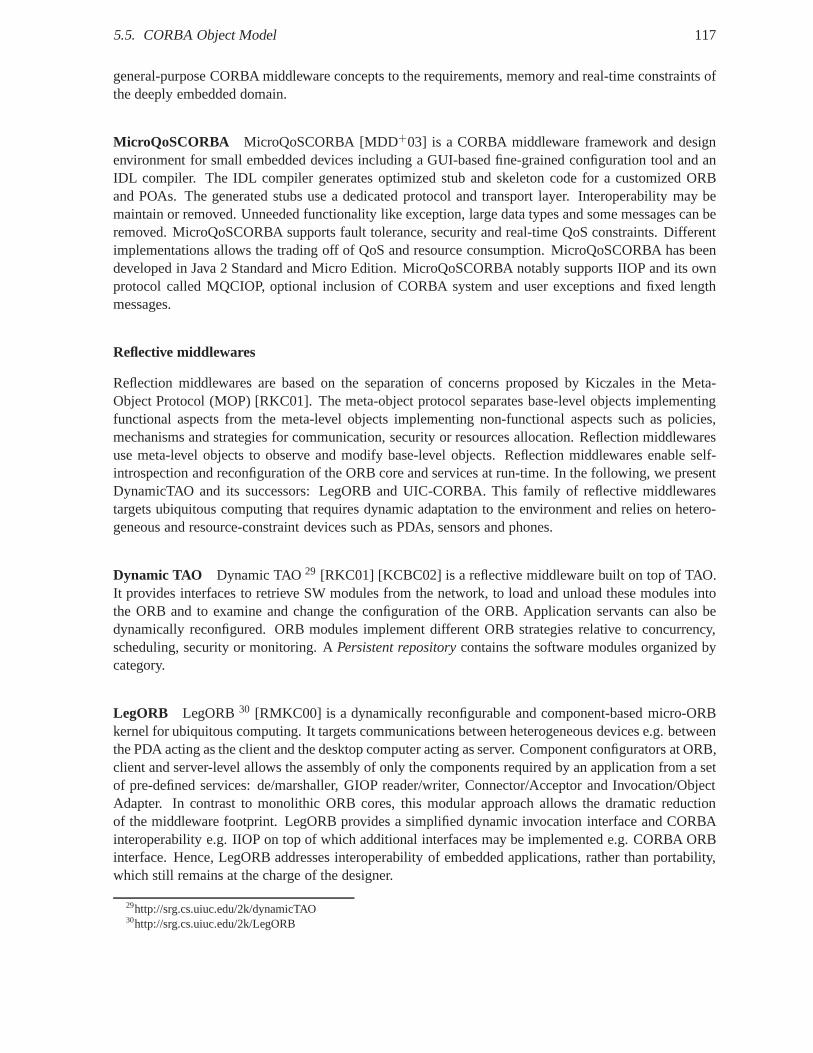
5.5. CORBA Object Model 117
general-purpose CORBA middleware concepts to the requirements, memory and real-time constraints ofthe deeply embedded domain.
MicroQoSCORBA MicroQoSCORBA [MDD+03] is a CORBA middleware framework and designenvironment for small embedded devices including a GUI-based fine-grained configuration tool and anIDL compiler. The IDL compiler generates optimized stub andskeleton code for a customized ORBand POAs. The generated stubs use a dedicated protocol and transport layer. Interoperability may bemaintain or removed. Unneeded functionality like exception, large data types and some messages can beremoved. MicroQoSCORBA supports fault tolerance, security and real-time QoS constraints. Differentimplementations allows the trading off of QoS and resource consumption. MicroQoSCORBA has beendeveloped in Java 2 Standard and Micro Edition. MicroQoSCORBA notably supports IIOP and its ownprotocol called MQCIOP, optional inclusion of CORBA systemand user exceptions and fixed lengthmessages.
Reflective middlewares
Reflection middlewares are based on the separation of concerns proposed by Kiczales in the Meta-Object Protocol (MOP) [RKC01]. The meta-object protocol separates base-level objects implementingfunctional aspects from the meta-level objects implementing non-functional aspects such as policies,mechanisms and strategies for communication, security or resources allocation. Reflection middlewaresuse meta-level objects to observe and modify base-level objects. Reflection middlewares enable self-introspection and reconfiguration of the ORB core and services at run-time. In the following, we presentDynamicTAO and its successors: LegORB and UIC-CORBA. This family of reflective middlewarestargets ubiquitous computing that requires dynamic adaptation to the environment and relies on hetero-geneous and resource-constraint devices such as PDAs, sensors and phones.
Dynamic TAO Dynamic TAO29 [RKC01] [KCBC02] is a reflective middleware built on top of TAO.It provides interfaces to retrieve SW modules from the network, to load and unload these modules intothe ORB and to examine and change the configuration of the ORB.Application servants can also bedynamically reconfigured. ORB modules implement differentORB strategies relative to concurrency,scheduling, security or monitoring. APersistent repositorycontains the software modules organized bycategory.
LegORB LegORB30 [RMKC00] is a dynamically reconfigurable and component-based micro-ORBkernel for ubiquitous computing. It targets communications between heterogeneous devices e.g. betweenthe PDA acting as the client and the desktop computer acting as server. Component configurators at ORB,client and server-level allows the assembly of only the components required by an application from a setof pre-defined services: de/marshaller, GIOP reader/writer, Connector/Acceptor and Invocation/ObjectAdapter. In contrast to monolithic ORB cores, this modular approach allows the dramatic reductionof the middleware footprint. LegORB provides a simplified dynamic invocation interface and CORBAinteroperability e.g. IIOP on top of which additional interfaces may be implemented e.g. CORBA ORBinterface. Hence, LegORB addresses interoperability of embedded applications, rather than portability,which still remains at the charge of the designer.
29http://srg.cs.uiuc.edu/2k/dynamicTAO30http://srg.cs.uiuc.edu/2k/LegORB
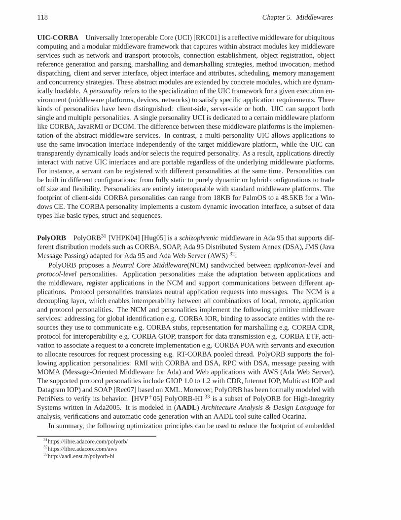
118 Chapter 5. Middlewares
UIC-CORBA Universally Interoperable Core (UCI) [RKC01] is a reflective middleware for ubiquitouscomputing and a modular middleware framework that captureswithin abstract modules key middlewareservices such as network and transport protocols, connection establishment, object registration, objectreference generation and parsing, marshalling and demarshalling strategies, method invocation, methoddispatching, client and server interface, object interface and attributes, scheduling, memory managementand concurrency strategies. These abstract modules are extended by concrete modules, which are dynam-ically loadable. Apersonalityrefers to the specialization of the UIC framework for a givenexecution en-vironment (middleware platforms, devices, networks) to satisfy specific application requirements. Threekinds of personalities have been distinguished: client-side, server-side or both. UIC can support bothsingle and multiple personalities. A single personality UCI is dedicated to a certain middleware platformlike CORBA, JavaRMI or DCOM. The difference between these middleware platforms is the implemen-tation of the abstract middleware services. In contrast, a multi-personality UIC allows applications touse the same invocation interface independently of the target middleware platform, while the UIC cantransparently dynamically loads and/or selects the required personality. As a result, applications directlyinteract with native UIC interfaces and are portable regardless of the underlying middleware platforms.For instance, a servant can be registered with different personalities at the same time. Personalities canbe built in different configurations: from fully static to purely dynamic or hybrid configurations to tradeoff size and flexibility. Personalities are entirely interoperable with standard middleware platforms. Thefootprint of client-side CORBA personalities can range from 18KB for PalmOS to a 48.5KB for a Win-dows CE. The CORBA personality implements a custom dynamic invocation interface, a subset of datatypes like basic types, struct and sequences.
PolyORB PolyORB31 [VHPK04] [Hug05] is aschizophrenicmiddleware in Ada 95 that supports dif-ferent distribution models such as CORBA, SOAP, Ada 95 Distributed System Annex (DSA), JMS (JavaMessage Passing) adapted for Ada 95 and Ada Web Server (AWS)32.
PolyORB proposes aNeutral Core Middleware(NCM) sandwiched betweenapplication-levelandprotocol-levelpersonalities. Application personalities make the adaptation between applications andthe middleware, register applications in the NCM and support communications between different ap-plications. Protocol personalities translates neutral application requests into messages. The NCM is adecoupling layer, which enables interoperability betweenall combinations of local, remote, applicationand protocol personalities. The NCM and personalities implement the following primitive middlewareservices: addressing for global identification e.g. CORBA IOR, binding to associate entities with the re-sources they use to communicate e.g. CORBA stubs, representation for marshalling e.g. CORBA CDR,protocol for interoperability e.g. CORBA GIOP, transport for data transmission e.g. CORBA ETF, acti-vation to associate a request to a concrete implementation e.g. CORBA POA with servants and executionto allocate resources for request processing e.g. RT-CORBApooled thread. PolyORB supports the fol-lowing application personalities: RMI with CORBA and DSA, RPC with DSA, message passing withMOMA (Message-Oriented Middleware for Ada) and Web applications with AWS (Ada Web Server).The supported protocol personalities include GIOP 1.0 to 1.2 with CDR, Internet IOP, Multicast IOP andDatagram IOP) and SOAP [Rec07] based on XML. Moreover, PolyORB has been formally modeled withPetriNets to verify its behavior. [HVP+05] PolyORB-HI33 is a subset of PolyORB for High-IntegritySystems written in Ada2005. It is modeled in (AADL ) Architecture Analysis & Design Languageforanalysis, verifications and automatic code generation withan AADL tool suite called Ocarina.
In summary, the following optimization principles can be used to reduce the footprint of embedded
31https://libre.adacore.com/polyorb/32https://libre.adacore.com/aws33http://aadl.enst.fr/polyorb-hi
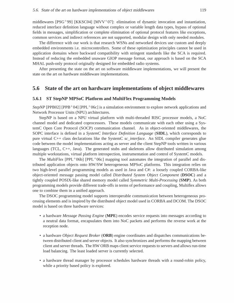
5.6. State of the art on hardware implementations of object middlewares 119
middlewares [PSG+99] [KKSC04] [MVV+07]: elimination of dynamic invocation and instantiation,reduced interface definition language without complex or variable length data types, bypass of optionalfields in messages, simplification or complete elimination of optional protocol features like exceptions,common services and indirect references are not supported,modular design with only needed modules.
The difference with our work is that research WSNs and networked devices use custom and deeplyembedded environments i.e. microcontrollers. Some of these optimization principles cannot be used inapplication domains where backward compatibility with stringent standards like the SCA is required.Instead of reducing the embedded unaware GIOP message format, our approach is based on the SCAMHAL push-only protocol originally designed for embedded radio systems.
After presenting the state on the art on software middlewareimplementations, we will present thestate on the art on hardware middleware implementations.
5.6 State of the art on hardware implementations of object middlewares
5.6.1 ST StepNP MPSoC Platform and MultiFlex Programming Models
StepNP[PPB02] [PPB+04] [PPL+06c] is a simulation environment to explore network applications andNetwork Processor Units (NPU) architectures.
StepNP is based on a NPU virtual platform with multi-threaded RISC processor models, a NoCchannel model and dedicated coprocessors. These models communicate with each other using a Sys-temC Open Core Protocol (SOCP) communication channel. As inobject-oriented middlewares, theSOPC interface is defined in aSystemC Interface Definition Language(SIDL ), which corresponds topure virtual C++ class declarations like the SystemCsc_interface. An SIDL compiler generates gluecode between the model implementations acting as server andthe client StepNP tools written in variouslanguages (TCL, C++, Java). The generated stubs and skeletons allow distributed simulation amongmultiple workstations, virtual platform introspection, instrumentation and control of SystemC models.
The MultiFlex [PPL+06b] [PPL+06c] mapping tool automates the integration of parallel anddis-tributed application objects onto HW/SW heterogeneous MPSoC platforms. This integration relies ontwo high-level parallel programming models as used in Java and C#: a loosely coupled CORBA-likeobject-oriented message passing model calledDistributed System Object Component(DSOC) and atightly coupled POSIX-like shared memory model calledSymmetric Multi-Processing(SMP). As bothprogramming models provide different trade-offs in terms of performance and coupling, Multiflex allowsone to combine them in a unified approach.
The DSOC programming model supports interoperable communication between heterogeneous pro-cessing elements and is inspired by the distributed object model used in CORBA and DCOM. The DSOCmodel is based on three hardware services:
• a hardwareMessage Passing Engine(MPE) encodes service requests into messages according toa neutral data format, encapsulates them into NoC packets and performs the reverse work at thereception node.
• a hardwareObject Request Broker(ORB) engine coordinates and dispatches communications be-tween distributed client and server objects. It also synchronizes and performs the mapping betweenclient and server threads. The HW ORB maps client service requests to servers and allows run-timeload balancing. The least loaded server is currently selected.
• a hardware thread manager by processor schedules hardwarethreads with a round-robin policy,while a priority based policy is explored.
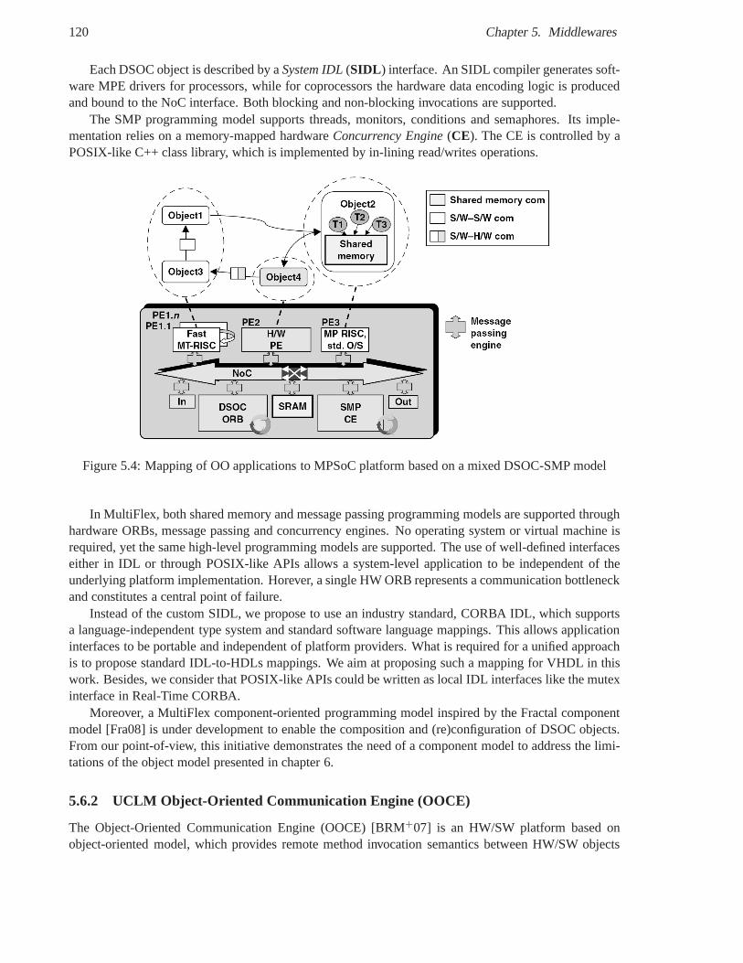
120 Chapter 5. Middlewares
Each DSOC object is described by aSystem IDL(SIDL ) interface. An SIDL compiler generates soft-ware MPE drivers for processors, while for coprocessors thehardware data encoding logic is producedand bound to the NoC interface. Both blocking and non-blocking invocations are supported.
The SMP programming model supports threads, monitors, conditions and semaphores. Its imple-mentation relies on a memory-mapped hardwareConcurrency Engine(CE). The CE is controlled by aPOSIX-like C++ class library, which is implemented by in-lining read/writes operations.
Figure 5.4: Mapping of OO applications to MPSoC platform based on a mixed DSOC-SMP model
In MultiFlex, both shared memory and message passing programming models are supported throughhardware ORBs, message passing and concurrency engines. Nooperating system or virtual machine isrequired, yet the same high-level programming models are supported. The use of well-defined interfaceseither in IDL or through POSIX-like APIs allows a system-level application to be independent of theunderlying platform implementation. Horever, a single HW ORB represents a communication bottleneckand constitutes a central point of failure.
Instead of the custom SIDL, we propose to use an industry standard, CORBA IDL, which supportsa language-independent type system and standard software language mappings. This allows applicationinterfaces to be portable and independent of platform providers. What is required for a unified approachis to propose standard IDL-to-HDLs mappings. We aim at proposing such a mapping for VHDL in thiswork. Besides, we consider that POSIX-like APIs could be written as local IDL interfaces like the mutexinterface in Real-Time CORBA.
Moreover, a MultiFlex component-oriented programming model inspired by the Fractal componentmodel [Fra08] is under development to enable the composition and (re)configuration of DSOC objects.From our point-of-view, this initiative demonstrates the need of a component model to address the limi-tations of the object model presented in chapter 6.
5.6.2 UCLM Object-Oriented Communication Engine (OOCE)
The Object-Oriented Communication Engine (OOCE) [BRM+07] is an HW/SW platform based onobject-oriented model, which provides remote method invocation semantics between HW/SW objects
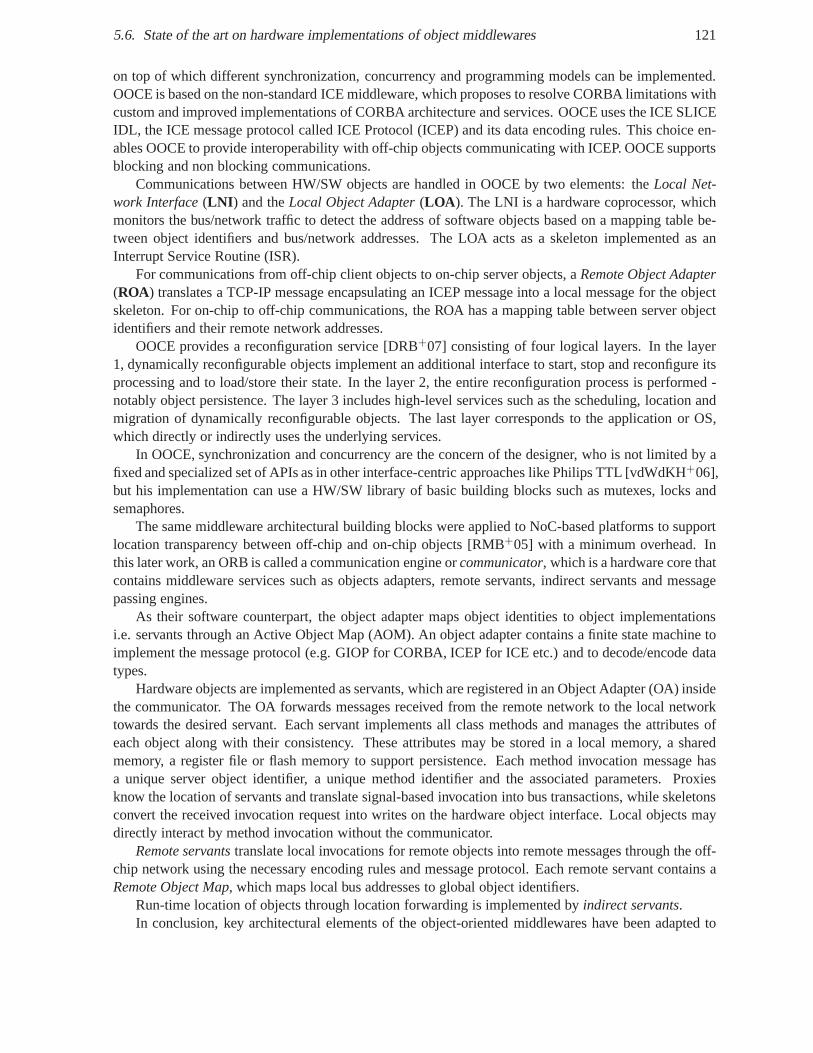
5.6. State of the art on hardware implementations of object middlewares 121
on top of which different synchronization, concurrency andprogramming models can be implemented.OOCE is based on the non-standard ICE middleware, which proposes to resolve CORBA limitations withcustom and improved implementations of CORBA architectureand services. OOCE uses the ICE SLICEIDL, the ICE message protocol called ICE Protocol (ICEP) andits data encoding rules. This choice en-ables OOCE to provide interoperability with off-chip objects communicating with ICEP. OOCE supportsblocking and non blocking communications.
Communications between HW/SW objects are handled in OOCE bytwo elements: theLocal Net-work Interface(LNI ) and theLocal Object Adapter(LOA ). The LNI is a hardware coprocessor, whichmonitors the bus/network traffic to detect the address of software objects based on a mapping table be-tween object identifiers and bus/network addresses. The LOAacts as a skeleton implemented as anInterrupt Service Routine (ISR).
For communications from off-chip client objects to on-chipserver objects, aRemote Object Adapter(ROA) translates a TCP-IP message encapsulating an ICEP messageinto a local message for the objectskeleton. For on-chip to off-chip communications, the ROA has a mapping table between server objectidentifiers and their remote network addresses.
OOCE provides a reconfiguration service [DRB+07] consisting of four logical layers. In the layer1, dynamically reconfigurable objects implement an additional interface to start, stop and reconfigure itsprocessing and to load/store their state. In the layer 2, theentire reconfiguration process is performed -notably object persistence. The layer 3 includes high-level services such as the scheduling, location andmigration of dynamically reconfigurable objects. The last layer corresponds to the application or OS,which directly or indirectly uses the underlying services.
In OOCE, synchronization and concurrency are the concern ofthe designer, who is not limited by afixed and specialized set of APIs as in other interface-centric approaches like Philips TTL [vdWdKH+06],but his implementation can use a HW/SW library of basic building blocks such as mutexes, locks andsemaphores.
The same middleware architectural building blocks were applied to NoC-based platforms to supportlocation transparency between off-chip and on-chip objects [RMB+05] with a minimum overhead. Inthis later work, an ORB is called a communication engine orcommunicator, which is a hardware core thatcontains middleware services such as objects adapters, remote servants, indirect servants and messagepassing engines.
As their software counterpart, the object adapter maps object identities to object implementationsi.e. servants through an Active Object Map (AOM). An object adapter contains a finite state machine toimplement the message protocol (e.g. GIOP for CORBA, ICEP for ICE etc.) and to decode/encode datatypes.
Hardware objects are implemented as servants, which are registered in an Object Adapter (OA) insidethe communicator. The OA forwards messages received from the remote network to the local networktowards the desired servant. Each servant implements all class methods and manages the attributes ofeach object along with their consistency. These attributesmay be stored in a local memory, a sharedmemory, a register file or flash memory to support persistence. Each method invocation message hasa unique server object identifier, a unique method identifierand the associated parameters. Proxiesknow the location of servants and translate signal-based invocation into bus transactions, while skeletonsconvert the received invocation request into writes on the hardware object interface. Local objects maydirectly interact by method invocation without the communicator.
Remote servantstranslate local invocations for remote objects into remotemessages through the off-chip network using the necessary encoding rules and messageprotocol. Each remote servant contains aRemote Object Map, which maps local bus addresses to global object identifiers.
Run-time location of objects through location forwarding is implemented byindirect servants.In conclusion, key architectural elements of the object-oriented middlewares have been adapted to
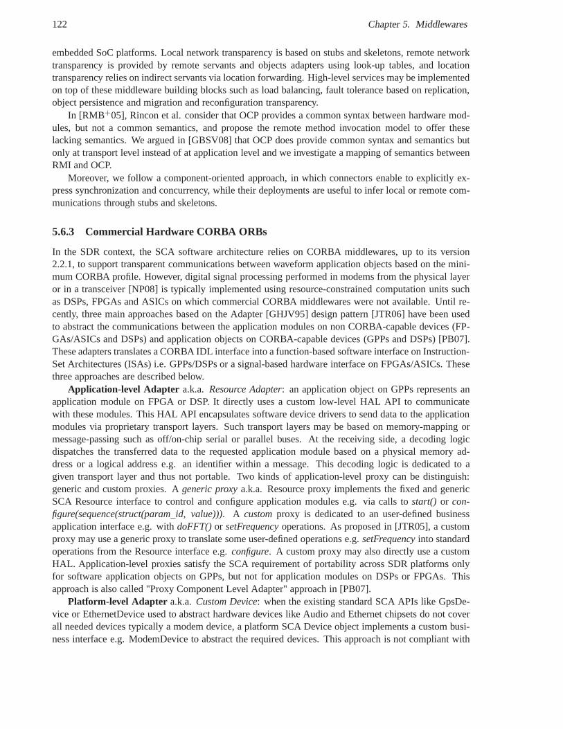
122 Chapter 5. Middlewares
embedded SoC platforms. Local network transparency is based on stubs and skeletons, remote networktransparency is provided by remote servants and objects adapters using look-up tables, and locationtransparency relies on indirect servants via location forwarding. High-level services may be implementedon top of these middleware building blocks such as load balancing, fault tolerance based on replication,object persistence and migration and reconfiguration transparency.
In [RMB+05], Rincon et al. consider that OCP provides a common syntaxbetween hardware mod-ules, but not a common semantics, and propose the remote method invocation model to offer theselacking semantics. We argued in [GBSV08] that OCP does provide common syntax and semantics butonly at transport level instead of at application level and we investigate a mapping of semantics betweenRMI and OCP.
Moreover, we follow a component-oriented approach, in which connectors enable to explicitly ex-press synchronization and concurrency, while their deployments are useful to infer local or remote com-munications through stubs and skeletons.
5.6.3 Commercial Hardware CORBA ORBs
In the SDR context, the SCA software architecture relies on CORBA middlewares, up to its version2.2.1, to support transparent communications between waveform application objects based on the mini-mum CORBA profile. However, digital signal processing performed in modems from the physical layeror in a transceiver [NP08] is typically implemented using resource-constrained computation units suchas DSPs, FPGAs and ASICs on which commercial CORBA middlewares were not available. Until re-cently, three main approaches based on the Adapter [GHJV95]design pattern [JTR06] have been usedto abstract the communications between the application modules on non CORBA-capable devices (FP-GAs/ASICs and DSPs) and application objects on CORBA-capable devices (GPPs and DSPs) [PB07].These adapters translates a CORBA IDL interface into a function-based software interface on Instruction-Set Architectures (ISAs) i.e. GPPs/DSPs or a signal-based hardware interface on FPGAs/ASICs. Thesethree approaches are described below.
Application-level Adapter a.k.a. Resource Adapter: an application object on GPPs represents anapplication module on FPGA or DSP. It directly uses a custom low-level HAL API to communicatewith these modules. This HAL API encapsulates software device drivers to send data to the applicationmodules via proprietary transport layers. Such transport layers may be based on memory-mapping ormessage-passing such as off/on-chip serial or parallel buses. At the receiving side, a decoding logicdispatches the transferred data to the requested application module based on a physical memory ad-dress or a logical address e.g. an identifier within a message. This decoding logic is dedicated to agiven transport layer and thus not portable. Two kinds of application-level proxy can be distinguish:generic and custom proxies. Ageneric proxya.k.a. Resource proxy implements the fixed and genericSCA Resource interface to control and configure applicationmodules e.g. via calls tostart() or con-figure(sequence(struct(param_id, value))). A customproxy is dedicated to an user-defined businessapplication interface e.g. withdoFFT()or setFrequencyoperations. As proposed in [JTR05], a customproxy may use a generic proxy to translate some user-defined operations e.g.setFrequencyinto standardoperations from the Resource interface e.g.configure. A custom proxy may also directly use a customHAL. Application-level proxies satisfy the SCA requirement of portability across SDR platforms onlyfor software application objects on GPPs, but not for application modules on DSPs or FPGAs. Thisapproach is also called "Proxy Component Level Adapter" approach in [PB07].
Platform-level Adapter a.k.a.Custom Device: when the existing standard SCA APIs like GpsDe-vice or EthernetDevice used to abstract hardware devices like Audio and Ethernet chipsets do not coverall needed devices typically a modem device, a platform SCA Device object implements a custom busi-ness interface e.g. ModemDevice to abstract the required devices. This approach is not compliant with
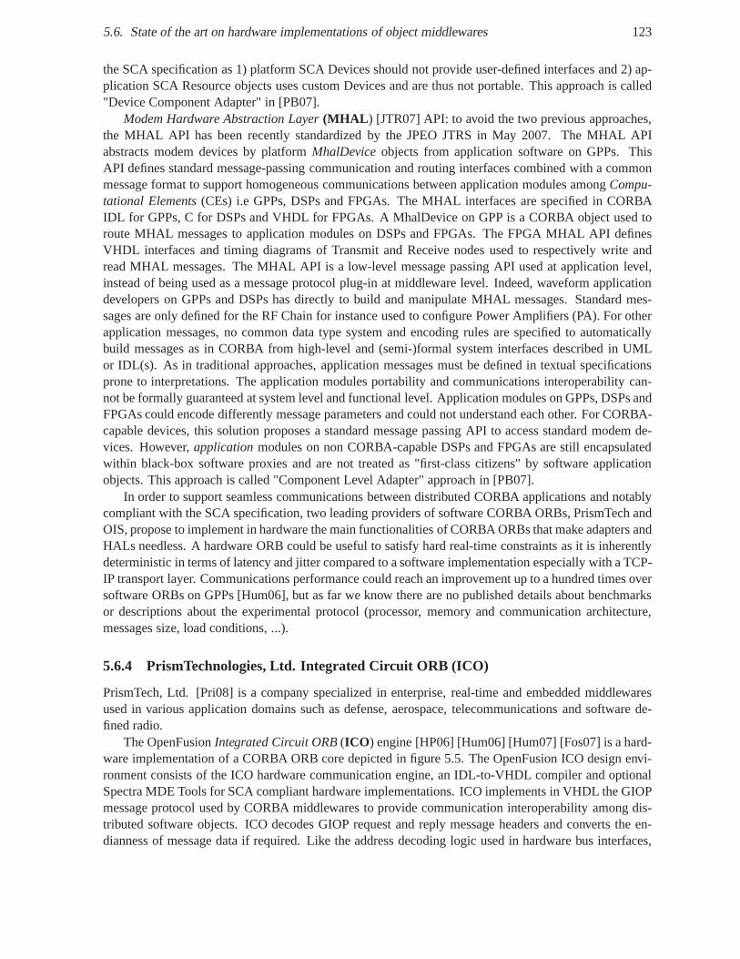
5.6. State of the art on hardware implementations of object middlewares 123
the SCA specification as 1) platform SCA Devices should not provide user-defined interfaces and 2) ap-plication SCA Resource objects uses custom Devices and are thus not portable. This approach is called"Device Component Adapter" in [PB07].
Modem Hardware Abstraction Layer(MHAL ) [JTR07] API: to avoid the two previous approaches,the MHAL API has been recently standardized by the JPEO JTRS in May 2007. The MHAL APIabstracts modem devices by platformMhalDeviceobjects from application software on GPPs. ThisAPI defines standard message-passing communication and routing interfaces combined with a commonmessage format to support homogeneous communications between application modules amongCompu-tational Elements(CEs) i.e GPPs, DSPs and FPGAs. The MHAL interfaces are specified in CORBAIDL for GPPs, C for DSPs and VHDL for FPGAs. A MhalDevice on GPPis a CORBA object used toroute MHAL messages to application modules on DSPs and FPGAs. The FPGA MHAL API definesVHDL interfaces and timing diagrams of Transmit and Receivenodes used to respectively write andread MHAL messages. The MHAL API is a low-level message passing API used at application level,instead of being used as a message protocol plug-in at middleware level. Indeed, waveform applicationdevelopers on GPPs and DSPs has directly to build and manipulate MHAL messages. Standard mes-sages are only defined for the RF Chain for instance used to configure Power Amplifiers (PA). For otherapplication messages, no common data type system and encoding rules are specified to automaticallybuild messages as in CORBA from high-level and (semi-)formal system interfaces described in UMLor IDL(s). As in traditional approaches, application messages must be defined in textual specificationsprone to interpretations. The application modules portability and communications interoperability can-not be formally guaranteed at system level and functional level. Application modules on GPPs, DSPs andFPGAs could encode differently message parameters and could not understand each other. For CORBA-capable devices, this solution proposes a standard messagepassing API to access standard modem de-vices. However,applicationmodules on non CORBA-capable DSPs and FPGAs are still encapsulatedwithin black-box software proxies and are not treated as "first-class citizens" by software applicationobjects. This approach is called "Component Level Adapter"approach in [PB07].
In order to support seamless communications between distributed CORBA applications and notablycompliant with the SCA specification, two leading providersof software CORBA ORBs, PrismTech andOIS, propose to implement in hardware the main functionalities of CORBA ORBs that make adapters andHALs needless. A hardware ORB could be useful to satisfy hardreal-time constraints as it is inherentlydeterministic in terms of latency and jitter compared to a software implementation especially with a TCP-IP transport layer. Communications performance could reach an improvement up to a hundred times oversoftware ORBs on GPPs [Hum06], but as far we know there are no published details about benchmarksor descriptions about the experimental protocol (processor, memory and communication architecture,messages size, load conditions, ...).
5.6.4 PrismTechnologies, Ltd. Integrated Circuit ORB (ICO)
PrismTech, Ltd. [Pri08] is a company specialized in enterprise, real-time and embedded middlewaresused in various application domains such as defense, aerospace, telecommunications and software de-fined radio.
The OpenFusionIntegrated Circuit ORB(ICO ) engine [HP06] [Hum06] [Hum07] [Fos07] is a hard-ware implementation of a CORBA ORB core depicted in figure 5.5. The OpenFusion ICO design envi-ronment consists of the ICO hardware communication engine,an IDL-to-VHDL compiler and optionalSpectra MDE Tools for SCA compliant hardware implementations. ICO implements in VHDL the GIOPmessage protocol used by CORBA middlewares to provide communication interoperability among dis-tributed software objects. ICO decodes GIOP request and reply message headers and converts the en-dianness of message data if required. Like the address decoding logic used in hardware bus interfaces,
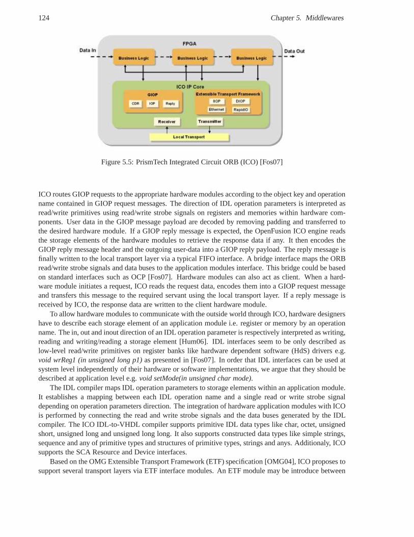
124 Chapter 5. Middlewares
Figure 5.5: PrismTech Integrated Circuit ORB (ICO) [Fos07]
ICO routes GIOP requests to the appropriate hardware modules according to the object key and operationname contained in GIOP request messages. The direction of IDL operation parameters is interpreted asread/write primitives using read/write strobe signals on registers and memories within hardware com-ponents. User data in the GIOP message payload are decoded byremoving padding and transferred tothe desired hardware module. If a GIOP reply message is expected, the OpenFusion ICO engine readsthe storage elements of the hardware modules to retrieve theresponse data if any. It then encodes theGIOP reply message header and the outgoing user-data into a GIOP reply payload. The reply message isfinally written to the local transport layer via a typical FIFO interface. A bridge interface maps the ORBread/write strobe signals and data buses to the applicationmodules interface. This bridge could be basedon standard interfaces such as OCP [Fos07]. Hardware modules can also act as client. When a hard-ware module initiates a request, ICO reads the request data,encodes them into a GIOP request messageand transfers this message to the required servant using thelocal transport layer. If a reply message isreceived by ICO, the response data are written to the client hardware module.
To allow hardware modules to communicate with the outside world through ICO, hardware designershave to describe each storage element of an application module i.e. register or memory by an operationname. The in, out and inout direction of an IDL operation parameter is respectively interpreted as writing,reading and writing/reading a storage element [Hum06]. IDLinterfaces seem to be only described aslow-level read/write primitives on register banks like hardware dependent software (HdS) drivers e.g.void wrReg1 (in unsigned long p1)as presented in [Fos07]. In order that IDL interfaces can be used atsystem level independently of their hardware or software implementations, we argue that they should bedescribed at application level e.g.void setMode(in unsigned char mode).
The IDL compiler maps IDL operation parameters to storage elements within an application module.It establishes a mapping between each IDL operation name anda single read or write strobe signaldepending on operation parameters direction. The integration of hardware application modules with ICOis performed by connecting the read and write strobe signalsand the data buses generated by the IDLcompiler. The ICO IDL-to-VHDL compiler supports primitiveIDL data types like char, octet, unsignedshort, unsigned long and unsigned long long. It also supports constructed data types like simple strings,sequence and any of primitive types and structures of primitive types, strings and anys. Additionaly, ICOsupports the SCA Resource and Device interfaces.
Based on the OMG Extensible Transport Framework (ETF) specification [OMG04], ICO proposes tosupport several transport layers via ETF interface modules. An ETF module may be introduce between
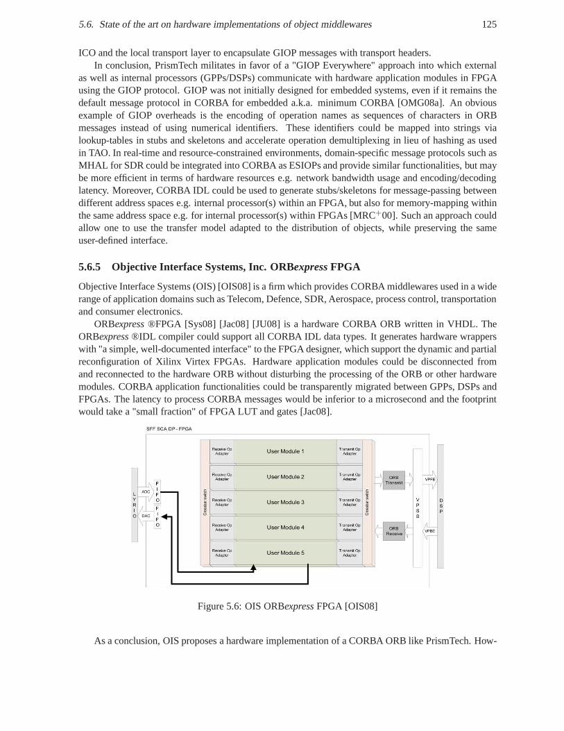
5.6. State of the art on hardware implementations of object middlewares 125
ICO and the local transport layer to encapsulate GIOP messages with transport headers.In conclusion, PrismTech militates in favor of a "GIOP Everywhere" approach into which external
as well as internal processors (GPPs/DSPs) communicate with hardware application modules in FPGAusing the GIOP protocol. GIOP was not initially designed forembedded systems, even if it remains thedefault message protocol in CORBA for embedded a.k.a. minimum CORBA [OMG08a]. An obviousexample of GIOP overheads is the encoding of operation namesas sequences of characters in ORBmessages instead of using numerical identifiers. These identifiers could be mapped into strings vialookup-tables in stubs and skeletons and accelerate operation demultiplexing in lieu of hashing as usedin TAO. In real-time and resource-constrained environments, domain-specific message protocols such asMHAL for SDR could be integrated into CORBA as ESIOPs and provide similar functionalities, but maybe more efficient in terms of hardware resources e.g. networkbandwidth usage and encoding/decodinglatency. Moreover, CORBA IDL could be used to generate stubs/skeletons for message-passing betweendifferent address spaces e.g. internal processor(s) within an FPGA, but also for memory-mapping withinthe same address space e.g. for internal processor(s) within FPGAs [MRC+00]. Such an approach couldallow one to use the transfer model adapted to the distribution of objects, while preserving the sameuser-defined interface.
5.6.5 Objective Interface Systems, Inc. ORBexpress FPGA
Objective Interface Systems (OIS) [OIS08] is a firm which provides CORBA middlewares used in a widerange of application domains such as Telecom, Defence, SDR,Aerospace, process control, transportationand consumer electronics.
ORBexpress®FPGA [Sys08] [Jac08] [JU08] is a hardware CORBA ORB writtenin VHDL. TheORBexpress®IDL compiler could support all CORBA IDL data types. It generates hardware wrapperswith "a simple, well-documented interface" to the FPGA designer, which support the dynamic and partialreconfiguration of Xilinx Virtex FPGAs. Hardware application modules could be disconnected fromand reconnected to the hardware ORB without disturbing the processing of the ORB or other hardwaremodules. CORBA application functionalities could be transparently migrated between GPPs, DSPs andFPGAs. The latency to process CORBA messages would be inferior to a microsecond and the footprintwould take a "small fraction" of FPGA LUT and gates [Jac08].
Figure 5.6: OIS ORBexpressFPGA [OIS08]
As a conclusion, OIS proposes a hardware implementation of aCORBA ORB like PrismTech. How-
126 Chapter 5. Middlewares
ever, as far we know there are not many published details on its implementation and particularly on thehardware object interface, which are generated by their IDL-to-VHDL compiler.
5.6.6 OMG IDL-to-VHDL mapping
The two main providers of commercial real-time and embeddedCORBA middlewares - PrismTech andOIS - have proposed a hardware implementation of a CORBA ORB core. The implementation of acommon message protocol such as GIOP should provide communications interoperability. However,PrismTech and OIS have implemented their own IDL-to-VHDL mapping as no OMG standard exists atthe moment. As a consequence, the portability of hardware application modules cannot be guaranteed forORB users. The migration from one ORB vendor to another will require a manual integration betweenthe application logic and the proprietary and incompatiblestubs and skeletons. Hence, this is againstone of the main motivations underlying object-oriented middlewares i.e. to automate the integration ofapplication objects. To solve these issues, initial discussions about a standard IDL-to-VHDL languagebinding have started since December 2007 between four OMG members: on the one hand, the two ORBvendors that have implemented CORBA in hardware and on the other hand, two ORB users - Mercuryand Thales - whose goal is to present industrial requirements.
In the scope of this work, we propose the mapping requirements for Thales based on the previousanalysis of the state of the art about the application of the object concepts down to hardware [WSBG08].These requirements will be presented later with our contribution.
Initially, PrismTech wanted to propose a Request for Comments (RFC) concerning the IDL-to-VHDLmapping [Bic07], but finally OIS and PrismTech were not focused on the interface mapping at this time,but more on using GIOP for heterogeneous communications with FPGAs [GP08].
5.7 Conclusion
A middleware aims at supporting transparent communications between heterogeneous systems regard-less of their distribution, hardware computing architecture, programming language, operating system,transport layer and data representation. The main objectives of middlewares are to provide portabilityand interoperability to distributed applications. Since the CORBA object-oriented middleware is re-quired by the SCA framework v.2.2.2 for SDR applications, wefocused on the CORBA object modeland presented its design flow, language mappings, message protocol and implementations. CORBA pro-vides portability through the standard CORBA middleware API and middleware services, and standardlanguage mappings from CORBA Interface Definition Language(IDL) to software programming lan-guages. IDL describe user-defined messages as operation signatures. CORBA provides interoperabilitythrough a standard protocol calledGeneral Inter-ORB Protocol(GIOP), which is mapped to transportlayers such as internet protocols or shared memory. CORBA also allowsEnvironment Specific Inter-ORBProtocols(ESIOPs) to support communications in resource-constraint systems. We presented a state ofthe art on software implementations of real-time and embedded CORBA middlewares and on hardwareimplementations of object middlewares including CORBA. Inembedded and real-time hardware/soft-ware platforms, middleware implementations have been lightened and customized to limit middlewarefunctionalities to what is really needed by an application domain and to reduce middleware footprint.In the next chapter, we will present the component-orientedapproach, which leverages the object andmiddleware approach.
Chapter 6
Component-Oriented Architecture
Contents6.1 Introduction . . . . . . . . . . . . . . . . . . . . . . . . . . . . . . . . . . . .. . . 129
6.2 Definitions . . . . . . . . . . . . . . . . . . . . . . . . . . . . . . . . . . . . . .. . 131
6.3 From Object-Oriented to Component-Oriented approach .. . . . . . . . . . . . 132
6.3.1 Object model vs. component model . . . . . . . . . . . . . . . . . .. . . . . 132
6.3.2 Separation of concerns . . . . . . . . . . . . . . . . . . . . . . . . . .. . . . 133
6.3.3 Explicit dependency and multiple interfaces . . . . . . .. . . . . . . . . . . . 134
6.3.4 Interactions . . . . . . . . . . . . . . . . . . . . . . . . . . . . . . . . . .. . 134
6.3.5 Composition rather than implementation inheritance. . . . . . . . . . . . . . 134
6.3.6 Granularity of composition, distribution and reuse .. . . . . . . . . . . . . . 134
6.3.7 Language Independence . . . . . . . . . . . . . . . . . . . . . . . . . .. . . 134
6.3.8 Deployment and administration . . . . . . . . . . . . . . . . . . .. . . . . . 135
6.3.9 Higher-level reuse . . . . . . . . . . . . . . . . . . . . . . . . . . . . .. . . 135
6.4 Principles . . . . . . . . . . . . . . . . . . . . . . . . . . . . . . . . . . . . . .. . 135
6.4.1 From Hardware/Software Design to System Architecture . . . . . . . . . . . . 135
6.4.2 From Development to Integration . . . . . . . . . . . . . . . . . .. . . . . . 136
6.4.3 Separation of Concerns . . . . . . . . . . . . . . . . . . . . . . . . . .. . . . 136
6.4.4 Reusability . . . . . . . . . . . . . . . . . . . . . . . . . . . . . . . . . . .. 137
6.4.5 Assembly and Composition . . . . . . . . . . . . . . . . . . . . . . . .. . . 137
6.4.6 Component infrastructure or framework . . . . . . . . . . . .. . . . . . . . . 137
6.5 Technical Concepts . . . . . . . . . . . . . . . . . . . . . . . . . . . . . . .. . . . 137
6.5.1 Component Infrastructure or Framework . . . . . . . . . . . .. . . . . . . . 137
6.5.2 Component . . . . . . . . . . . . . . . . . . . . . . . . . . . . . . . . . . . . 138
6.5.3 Component Model . . . . . . . . . . . . . . . . . . . . . . . . . . . . . . . .138
6.5.4 Interfaces . . . . . . . . . . . . . . . . . . . . . . . . . . . . . . . . . . . .. 139
6.5.5 Behavior . . . . . . . . . . . . . . . . . . . . . . . . . . . . . . . . . . . . . 141
6.5.6 Port . . . . . . . . . . . . . . . . . . . . . . . . . . . . . . . . . . . . . . . . 141
6.5.7 Connection Model . . . . . . . . . . . . . . . . . . . . . . . . . . . . . . .. 141
6.5.8 Container . . . . . . . . . . . . . . . . . . . . . . . . . . . . . . . . . . . . .143
6.5.9 Deployment model . . . . . . . . . . . . . . . . . . . . . . . . . . . . . . .. 143
6.6 Software Component Models . . . . . . . . . . . . . . . . . . . . . . . . .. . . . . 144
127
128 Chapter 6. Component-Oriented Architecture
6.6.1 Software Component Models for Software Defined Radio .. . . . . . . . . . 144
6.6.2 General Purpose Component Models . . . . . . . . . . . . . . . . .. . . . . 157
6.6.3 Software Component Models for Real-Time and EmbeddedSystems . . . . . . 160
6.6.4 Architecture Description Language (ADL) . . . . . . . . . .. . . . . . . . . 162
6.6.5 Comparison of Software Component Models . . . . . . . . . . .. . . . . . . 162
6.7 Hardware Component Models for FPGAs and ASICs . . . . . . . . .. . . . . . . 163
6.7.1 Component Models supported by Hardware Description Languages . . . . . . 163
6.7.2 Connection Model for hardware . . . . . . . . . . . . . . . . . . . .. . . . . 166
6.7.3 High-Level Synthesis (HLS) . . . . . . . . . . . . . . . . . . . . . .. . . . . 166
6.7.4 Hardware Interface Synthesis . . . . . . . . . . . . . . . . . . . .. . . . . . 168
6.7.5 Packaging Model . . . . . . . . . . . . . . . . . . . . . . . . . . . . . . . .. 169
6.7.6 Deployment Model . . . . . . . . . . . . . . . . . . . . . . . . . . . . . . .. 169
6.8 System Component Models . . . . . . . . . . . . . . . . . . . . . . . . . . .. . . . 173
6.8.1 SystemC components . . . . . . . . . . . . . . . . . . . . . . . . . . . . .. . 173
6.8.2 Actor-Oriented Components . . . . . . . . . . . . . . . . . . . . . .. . . . . 175
6.9 Conclusion . . . . . . . . . . . . . . . . . . . . . . . . . . . . . . . . . . . . . .. . 175
In software architecture, the component-oriented approach is a specialization of the object-orientedapproach in which a component may be roughly viewed as a composition of objects, which are dedicatedto a particular functionality or aspect such as computation, communication, (re-)configuration, life-cycle,etc.
The component-oriented approach has been successfully applied to embedded software. Our objec-tive is to explore and propose a common object-oriented component-based approach for both hardwareand software components, all along the design flow and at different abstraction levels.
The main goal of the component-oriented software architecture is the separation of concerns betweenwhat is the responsibility of the software designer (business code implementation) and all the otherorthogonal preoccupations such as component management (instantiation, configuration, deployment...)and communication protocols.
In this chapter, we will introduce the main component models, which are used in the design ofhardware/software embedded systems.
This chapter is organized as follows. Section 6.1 introduces the notion of component as used inhardware and software engineering. Section 6.2 presents classical definitions of software componentsand discusses their applicability to hardware components.Section 6.3 motivates the transition from anobject-oriented approach to a component-oriented approach for both software and hardware entities.Section 6.4 describes the principles of the component approach such as architecture, integration andcomposition. Section 6.4 explains the technical concepts of the component approach such as componentmodel, connection model and deployment model. Section 6.6 presents software component models forSDR such as SCA, general purpose component model such as CCM and software component modelsfor real-time and embedded systems. Section 6.7 describes the hardware component model supported byhardware description languages and connection models Section 6.8 presents system component modelssuch as the SystemC component model at different abstraction levels and actor-oriented components.Finally, section 6.9 concludes this chapter.
6.1. Introduction 129
6.1 Introduction
Generally speaking, a component is a smaller, self-contained part of a larger entity34. Etymologically,componentis the present participle ofcomposefrom Latin "componere" that means "to put together":com- ("together") and ponere ("to put"). Components are assembled to form larger components thatcompose a system. Hence, the term component is quite generaland usually employed to designate anyphysical or logical piece of hardware and software in electronic devices.
Hardware engineering inherently follows a component-based approach at all design levels. Froma macroscopic viewpoint, the motherboard of Personal Computer (PC) supports the assembly of vari-ous components such as microprocessor chips on CPU sockets,memory modules in memory slots, harddisk, dedicated boards such as graphics card, sound card, network card using internal buses like PCIand peripheral devices like mouse, keyboard on external buses such as USB and Firewire. Each of thesecomponents has well-defined hardware interfaces and implement standard protocols to provide portabil-ity from one motherboard to another and interoperability ofcommunications between these components.Over the past 50 years, the continuous improvement of integrated circuits fabrication allows the miniatur-ization and integration of the main components of usual PCs onto a single chip to build System-on-Chip(SoC) on ASICs and FPGAs. From a microscopic viewpoint, hardware components in System-on-Chip(SoC) are basically calledIntellectual Properties(IP) cores and include soft microprocessor cores (e.g.Xilinx MicroBlaze and Altera Nios II), bus controllers (e.g. UART35, I2C36 and RapidIO) memory con-troller (e.g. DDR2 SDRAM37 and Flash memory), Ethernet MAC cores, Digital Signal Processing IPssuch filters (e.g. FIR38 and CIC39 filters), encoder-decoder (e.g. Viterbi, Reed-Solomon, Turbo Code IPs)and much more. In ASICs, hardware components are custom IPs and standard cells, which implementbasic functionalities such as NAND gates, FIFOs and RAMs.
Software engineering also follows a component-based approach through the use of various softwarelibraries provided by languages e.g. C standard library, device drivers, OS, middlewares, and softwareplatforms such as the Java Class Library (JCL) of the Java platform and the Base Class Library (BCL) ofthe .NET Framework.
Hardware components such as hardware devices and IP cores typically appear as software compo-nents through device drivers. A device driver is a software code that bridges the gap between high-levelprocedural or object-oriented application interfaces andlow-level software interfaces based on read andwrite primitives to configure and control hardware devices.
A software library is merely a reusable set of classes and functions used by developers to obtainsome functionality. In contrast, an object-oriented framework is a set of classes that provide a reusablesoftware architecture dedicated to a given application domain [BHS07] [SB03]. Examples of frame-works include graphical user interface (GUI) frameworks such as Microsoft Foundation Classes (MFC),network frameworks such as ACE, middleware frameworks likeTAO, application frameworks like theSCA [JTR06] for SDR applications.
The application of the concept of hardware component in software led to the emergence of "Component-Based Software Engineering (CBSE)". One of the first appearances of the concept of "software com-ponents" originates from McIlroy [McI68]. Instead of redeveloping from scratch, component-basedhardware and software engineering consists of assembling new systems by reusing in-house businesscomponents or purchasing a license for prebuilt black-box components often calledCommercial Off-
34http://en.wiktionary.org/wiki/component35Universal Asynchronous Receiver Transmitter36Inter Integrated Circuit37Double Data Rate Synchronous Dynamic Random Access Memory38Finite Impulse Response39Cascaded Integrator-Comb
130 Chapter 6. Component-Oriented Architecture
The-Shelf(COTS) components. Components can have a wide spectrum of granularity ranging fromfine-grained components like device drivers and UART cores to large-grained components such as OSand soft CPU cores. Facing ever increasing design size and complexity, the reuse and assembly of previ-ously validated components allows increased productivityand quality, while reducing development timeand costs. Component-Based Design allows one to design or buy oncea component and use itmultipletimes, amortizing its development or purchase costs. In classical software engineering, the traditionaldesign flow consists of object-oriented analysis, design, programming, testing and integration.
In CBSE, designers activity is shifted from component specification, design, development and valida-tion to component selection and integration. The selectionof components is based on technical descrip-tions provided by datasheets. For hardware components, datasheets mainly describe hardware interface,timing behavior and footprint in terms of logical elements and/or gates. For software components, theytypically contain memory footprint and supported instruction set architecture and compilers. The integra-tion work depends on the quality of the chosen component, itsdocumentation and optional testbenchesand drivers. Due to proprietary standards, the use of COTS components results in a dependency on com-ponent suppliers or even vendor lock-in as users do not have any control on future component changes.For instance, the migration of a design from one FPGA vendor to another may require choosing func-tionally equivalent IP cores and lead to supplementary integration problems since each vendor uses itsown bus interface and protocol. This clearly shows the limitations of the classical hardware componentapproach based on IP cores, on which we will focus in the following.
Due to the weak meaning of the termcomponent, a "component-based system" does not have muchmore sense than a "part-based whole" [BBB+00]. Like the distinction made between object-based andobject-oriented languages [Cap03], we make a distinction between component-based and component-oriented approaches. Indeed, Ada83 was defined as an object-based language because it provided theconcept of object, but not the concept of inheritance which is characteristic of object-oriented languages[Cap03]. In the same way, the component-oriented approach goes further than the component-basedapproach as it provides in addition :
• standardcomponent models to define component structure and behavior like the interfaces com-ponent must implement,
• standardconnector models to specify component interactions, assemble components into largercomponents and into applications,
• standardcontainer models to mediate access to middleware services such as event, notification,transaction and persistence services,
• standardpackaging and deployment models to deploy distributed component-oriented applica-tions.
Over the past 40 years, a cross-fertilization, i.e. a mutually productive and beneficial exchange, hasoccurred between component-based software engineering and component-based hardware engineering.Starting from the vision of McIlroy [McI68] in 1968, software components have been inspired by hard-ware components. Then, software components have independently evolved and led to a higher-level ofabstraction and better separation of concerns that could improve hardware components. Our goal is topropose a common and unified component-oriented approach ofdesign at system-level.
An important question is what are the differences between hardware and software components ? ForWang and Qian [WQ05], hardware components and software components are logically equivalent, butthe software component approach needs a formal theory and associated tools to reach the maturity ofhardware engineering. They propose an algebra for components in [WQ05] that is illustrated with EJB,CCM, OSGi and Web Services.
6.2. Definitions 131
From a logical viewpoint, the same algorithm and model of computation can be clearly implementedin a hardware and/or software component. A system-level specification must be defined independentlyof hardware and software implementation languages. Examples of specifications languages are UML,SDL and Esterel. Various modeling frameworks such as Ptolemy [HLL +03], Metropolis [BWH+03] andBIP [Sif05] propose to model and simulate embedded systems through the hierarchical composition ofcomputation models [GBA+07], which are implementation agnostic. However from an implementationviewpoint, hardware and software components have different execution model. Hardware componentscan be defined using logical equations according to the boolean logic and simulated as well-understooddiscrete events. Software components can be notably specified with the Hoare logic [Hoa69] using pre-and post-conditions, that have to be extended from procedural programming to component behavior andinteractions [WQ05].
To support a common component-oriented approach at system-level which can be refined at im-plementation level as hardware/software components, system, hardware and software engineering mustshare the same abstract concepts and how these concepts can be implemented using system, softwareand hardware implementation languages. Such an approach will allow a better communication betweensystem, hardware and software engineers.
6.2 Definitions
As in the case of objects, there is no real consensus on the definition of software components [Kra08].The main reason is that each commercial, industrial and academic component technology applies theconcept of component slightly differently for each execution environment (e.g. enterprise, embeddedand/or real-time system) according to application domain requirements (e.g. financial, consumer elec-tronics, automotive, avionics, software radio domain).
There is a lack of agreement about what software components are and how they are used to designand develop component-based applications [BBB+00]. Nevertheless, one of the most cited definition ofsoftware components is [SP96]:
"A component is a unit of composition with contractually specified interfaces and explicit contextdependencies only. A component can be deployed independently and is subject to composition by thirdparties."
This definition underlines that the raison d’être of components is to be composed i.e. put togetheronly through multiple well-defined interfaces and explicitdependencies forming a contract with theirenvironment in which they are deployed. Note that this definition is sufficiently general to be applicableto both software components and hardware components including chips and IPs. Numerous discussionsexist in the software literature about a definition of software components [WQ05], whereas there are nosuch debates in the hardware literature probably since hardware components are much better understood.Software component interfaces are typically operation-based software interfaces, while the componentcontext in this definition is vague and may designate required interfaces or some software platformservices such as periodic activation and communication services. Similarly, hardware component inter-faces designate "wire"-based hardware interfaces, while the component context may designate requiredinput/output wires or some hardware platform services suchclock frequency, asynchronous reset andcommunication bus. Although this definition could be sufficient for hardware components, it needs to beextended with the closely related definitions of component model and software component architecturedefined by Heineman and Councill in [HC01] and cited in [Kra08]:
"A software componentis a software element that conforms to a component model and can beindependently deployed and composed without modification according to a composition standard."
"A component modeldefines specific interaction and composition standards. A component model
132 Chapter 6. Component-Oriented Architecture
implementation is the dedicated set of executable softwareelements required to support the execution ofcomponents that conform to the model."
Bachmann et al [BBB+00] add that "the component model imposes design constraints on componentdevelopers, and the component framework enforces these constraints in addition to providing usefulservices."
These definitions stress the need for a component model, a composition standard and a supportingcomponent infrastructure. The composition model includesa connector model and a deployment model.These definitions specify that components obey the interaction and composition rules of a componentmodel, whose implementation allows one to enforce them. Forhardware components, the interaction andcomposition standards may respectively designate standard communication protocols such as AMBA andhardware interconnection rules such as matching types and width of input/output ports for IPs or voltagefor chips.
"A software component infrastructure is a set of interacting software components designed to en-sure that a software system or subsystem constructed using those components and interfaces will satisfyclearly defined performance specifications."
A component infrastructure guaranties that a component assembly will respect the performance con-straints specified at a system level.
However, this formulation was more clearly refined by Krakowiak in [Kra08]:"A software component infrastructureor framework, is a software system that provides the services
needed to develop, deploy, manage and execute applicationsbuilt using a specific component modelimplementation. It may itself be organized as a set of interacting software components."
A possible application of this definition to hardware components is the collection of EDA tools usedby hardware designers to respectively write and simulate HDL code, synthesize, place, route and loadbitstream down to FPGAs and/or produce ASICs.
A software component technology consists of a component model and component framework [BBB+00].Each component technology has its own component model, component framework, languages and filesto specify component interfaces, assembly, packaging, configuration and deployment.
This heterogeneity led the OMG to shift from Object Management Architecture [OMG95] centeredaround object request brokers to Model-Driven Architecture [OMG03] focused on models.
The integration of multiple heterogeneous component technologies requires component middlewares.Moreover, the concept of connectors has been proposed to provide interoperability between these tech-nologies.
6.3 From Object-Oriented to Component-Oriented approach
The inherent limitation of the object-oriented approach has motivated the emergence of an evolutionarycomponent-oriented approach. The main differences between the object orientation (OO) and component-orientation (CO) are listed below [WQ05] :
6.3.1 Object model vs. component model
The only constraint that is imposed on objects is to satisfy the principles of the object model such asencapsulation, inheritance, methods that can be invoked onan object interface i.e. messages that canreceive an object. In contrast, a component model imposes much more constraints on components suchas rules of naming, design, composition, configuration, packaging, deployment and interfaces to use andimplement.
In the list below, we briefly review object concepts and contrast them with component concepts.
6.3. From Object-Oriented to Component-Oriented approach 133
• Identifiable Objects as Instances of Classes: Like an object, a component is a self-containedand identifiable entity. While an object is said to be an instance of a class, there is not such aclear distinction between the static type of a component andits run-time existence. We will simplysay that a "component instance" is an instance of a "component type". The term "component"generally refers to a component instance.
• Method Invocation and Message Passing: while an object is conceptually based on a single formof interaction i.e. method invocation, a component do not only communicate through messagepassing, but also via other communication models such as event and data stream.
• Encapsulation: Interface and Implementation(s): Like an object, a component encloses its ownstate and behavior that are only accessible through interface. Hence, a component also respectsthe encapsulation principle.
• White-Box Reuse and Black Box Reuse: Objects and components may support both white-boxreuse through inheritance and black-box reuse through composition.
• Polymorphism: polymorphism can be extended to component interface type and component type.
• Relationship: As opposed to objects, components explicitly specify their dependencies. Compo-nents may support hierarchical containment to build composite components from primitive com-ponents. A component may be part of more than one assembly called configuration and sharedbetween several components.
• Concurrency, Synchronization and Coordination: While interactions between objects are pri-marily based on method invocations, interactions between components may be explicitly mediatedby special components calledconnectors.
• Persistence: As opposed to objects, components are hosted in containersthat provide and mediateaccess to common services like persistence.
• Distribution : While an object is typically a fine-grained unit of distribution, a component may befrom a fine to a large-grained unit of distribution thanks to hierarchical containment. Connectorscan transparently deal with the non-functional aspect of distribution, while avoiding deploymentanomalies [B02].
Component concepts will be describe in more details in the following.
6.3.2 Separation of concerns
Objects directly use various technical services for naming, event, persistence, transaction, concurrencyand security that are dependent on the underlying software platform and are interwoven with businesslogic. However, the same component could be reused in various applications and operating environ-ments. The component-oriented approach introduces the concept of CONTAINER [BHS07] to mediatecomponent access to platform services and automate their use instead of manual user interventions.These common services are provided by component frameworksthat encapsulate middleware and OSservices. Designers can thus focus on component functionallogic rather than on the technical details ofeach platform on which components may be deployed.
134 Chapter 6. Component-Oriented Architecture
6.3.3 Explicit dependency and multiple interfaces
An object only provides one interface that is the most-derived interface in the inheritance tree calledprincipal interface in CORBA [OMG08b]. In contrast, a component provides and requires multipleinterfaces that allow 1) an explicit specification of the external dependency of components, and 2) aseparation of concerns between functional interfaces for business logic and non-functional interfaces fortechnical logic e.g. regarding configuration, deployment and activation. Component interfaces can bemore easily added to extend component functionalities.
6.3.4 Interactions
OO basically supports a single type of interactions under the form of method invocations. CO goes fur-ther by taking into account multiple types of interactions such as invocations, events, and data streams.In CO, these interactions are reified i.e. materialized by the first-class concept of connectors. Connec-tors are used to mediate interactions between components and allow one to clearly separate componentcomputation from component communication.
6.3.5 Composition rather than implementation inheritance
OO extensively relies on inheritance. While specification inheritance is beneficial to constrain implemen-tations through abstract interfaces, implementation inheritance results in loose cohesion, tight coupling,may break the encapsulation principle and lead to inheritance anomaly [MS04]. Objects are looselycohesive because attributes and methods implementation are implicitly scattered all over the inheritancehierarchy. Objects are tightly coupled since classes depend on each other implementation. Derivedclasses depend on the implementation of all classes on top ofthem in the inheritance hierarchy. Baseclasses may depend on the implementation of some functionalities that are left to derived classes or thatderived classes should customize. Modifications in some classes may cause unexpected behavior andside effects in others classes. The encapsulation principle may be broken when derived classes directlyaccess base classes attributes without using accessor methods as permitted by the public and protectedqualifier of some OOLs such as Java and C++. Inheritance anomaly designates the abnormal modifi-cation of base classes that is required to guarantee the synchronization constraints of derived classes.In contrast, CO is based on the composition of components through their interfaces and results in tightcohesion, loose coupling and tight encapsulation.
6.3.6 Granularity of composition, distribution and reuse
In OO, units of composition, distribution and reuse are fine-grained objects, while CO allows a hierar-chical composition of components from fine to large granularity. A component can be basically viewedas a composition of objects.
6.3.7 Language Independence
While OO mainly assumes object-oriented languages to notably provide inheritance, CO could be imple-mented in any language [WQ05]. One possible reason is that composition is basically supported by alllanguages as opposed to inheritance. Examples are softwarecomponents in C such as in the Kaola, Frac-tal and PIN component models, in SmallTalk like in [FDH08], and hardware components in HDLs. BothC and HDLs are clearly not object-oriented languages, but they support component-based approaches.Nevertheless, non-OO languages must also preserve component concepts such as encapsulation.
6.4. Principles 135
6.3.8 Deployment and administration
OO is focused on implementation, while CO is centered on packaging, deployment (i.e. installation,connection), life cycle (i.e. initialization, configuration and activation), administration (e.g. monitoringand reconfiguration) in distributed systems [Kra08]. Indeed, objects and classes are not self-containedand self-deployable [WQ05].
6.3.9 Higher-level reuse
Due to their difference of granularity, OO is primarily based on low-level reuse of attributes, methodsand classes through inheritance or composition, while CO originally supports higher-level reuse of com-ponent assemblies.
In summary, the software component-oriented approach is anevolution from the object-orientedapproach. The object-oriented approach is focused on classes, objects and inheritance, whereas thecomponent-oriented approach is focused on interfaces, interactions, dependencies and compositions.
6.4 Principles
Whatever the disagreements concerning their definitions, the principles underlying software componentsare basically the same in the literature and exposed in [WQ05]. Interestingly, these principles are alsoapplicable to hardware components and are presented in an implementation-agnostic manner.
1. Components are based on decomposition and abstraction. Decomposition breaks a system intomodules called components, which are self-described, self-contained and self-deployable. Ab-straction determines the relevant level of details with which decomposition is performed.
2. During their design flow, components permits reuse at eachlevel of their existence: componentspecification, component interface specification, component implementation in source code, com-ponents binaries registered in a repository and deployed component instances.
3. Component-based engineering increases quality and dependability since each component is sup-posed to have been tested and reused many times.
4. Component-based engineering could increase productivity since components are reused instead ofbeing redeveloped from scratch at each time.
5. Component-based engineering promotes standardizationto enable component "plug-and-play" andthe emergence of component markets [Szy02]. Indeed, the need for portability and interoperabil-ity of hardware and software components has motivated the creation of international standards byvarious consortium such as IP-XACT [SPI08] specification for XML meta-data and tool interfacesfrom the SPIRIT (Structure for Packaging, Integrating and Re-using IP within Tool flows) consor-tium, interface and protocol standard such as AXI, VCI and OCP, the Corba Component Model(CCM) and Deployment and Configuration (D&C) [OMG06b] of Component-based DistributedApplications by the OMG.
6.4.1 From Hardware/Software Design to System Architecture
To tackle the complexity of modern embedded systems, it is increasingly accepted that hardware/softwaredesign needs to evolve towards system-level design [KNRSV00] [Dv04a] [SV07]. This evolution hasmotivated the emergence of system-level standards such as SystemC and SysML. In the same way that
136 Chapter 6. Component-Oriented Architecture
hardware/software design evolves towards hardware/software architecture, system-level design needs toevolve to system-level architecture.
System-level architecture is the art and science of structuring a system, which may consist of het-erogeneous parts such as a combination of hardware and software modules. A software architecturedescribes the subsystems and components of a software system, their relationships and their functionaland non-functional properties [BHS07]. Software architecture separates multiple levels of concerns suchas computation and communication thanks to two structural constructs: components and connectors. Asoftware architecture can be dynamically changed through run-time allocation, instantiation and bindingof components and connectors to provide a software system with adaptability and evolution. Similarly,the increasing industrial maturity of dynamic and partial reconfiguration of FPGAs enables to dynami-cally change a hardware architecture by loading partial bitstreams.
In [Per97], Perry justifies the required separation between(software) architecture and design. Archi-tecture resides at a higher level of abstraction than design. It targets early engineering steps and providesa preliminary structure to a system. While design is focusedon concrete implementation constructs suchas algorithms, procedures, types and their interactions such as procedures calls and data access, archi-tecture reasons about a system in terms of their components and their interactions. The constituents arerepresented by components, while their interactions are embodied by connectors. In our opinion, theseprinciples are common to hardware and software architecture and could be applied at system-level.
An architectural style defines a set of rules that describe orconstrain the structure of architecturesand the way in which their components interact. Common architectural styles include pipes and filters,Abstract Data Type(ADT ) like objects, events, messages and dataflow [GS94] [MMP00], layered style,shared memory with repositories (database and blackboard), distributed processes with client-server or-ganization, FSM state transition systems. These common architectural styles have been formalized inarchitectural patterns such as LAYERS, PIPES AND FILTERS, BROKER, BLACKBOARD to build Pattern-Oriented Software Architecture (POSA) [BMR+96] [BHS07].
We believe that software architecture helps reason about hardware architecture through common,well-defined and well-understood architectural patterns and concepts such as connectors.
6.4.2 From Development to Integration
Component-based engineering accelerates development cycle and reduce costs. The assembly of com-ponents is based on their interfaces and semantics. The creation of a system from sub-system made ofcomponents is a natural work for numerous engineering domains such as aerospatial, avionic, automo-tive, mechanical, electrical and electronics systems.
6.4.3 Separation of Concerns
Separation of concerns allows the reduction of the conceptual size of each individual abstraction andmakes it more cohesive [BME+07]. Components have multiple interfaces. Each component interfacecorresponds to an individual object interface and deals with a single aspect or facet. This decomposi-tion favors separation of concerns and avoids monolithic or"god" objects. The multiple interfaces ofcomponents allow scalability and extensibility since a newinterface can be added to a component tohandle unforeseen aspects.Aspect-Oriented Programming(AOP) [KLM +97] provides another form ofseparation of concerns at source-code level rather than at interface level. In other words, an aspect isencapsulated within an interface in component-oriented programming rather than a piece of code as inaspect-oriented programming.
6.5. Technical Concepts 137
6.4.4 Reusability
Reuse allows one time implementation and multiple use, and increases productivity and quality [WQ05].Reuse can be performed at different levels of granularity from low-level source code copy, inextensiblefunction libraries, extensible class libraries that require a lot of understanding to high-level black-boxreuse of components [WQ05].
6.4.5 Assembly and Composition
The key technical challenges of component-based design areformal approaches forcorrect by construc-tion assembly of components [WQ05] and the prediction of the properties of a component-based systemfrom the properties of the components themselves [BBB+00].
6.4.6 Component infrastructure or framework
A component infrastructure or framework consists of three models: a component model, a connectionmodel, and a deployment model [WQ05]. The component model defines what a component is and how tocreate a new component under the component infrastructure.Component designers build components ac-cording to the component model. The connection model definesa collection of connectors and supportingfacilities for component assembling. The deployment modeldescribes how to install component-basedapplications into the execution environment. A component infrastructure or framework is also sometimescalled "component technology" or "component architecture" in literature [WQ05].
Examples of component technologies include JavaBeans fromSun Microsystems, COM (ComponentObject Model) and DCOM (Distributed COM) from Microsoft andCORBA Component Model (CCM)from the OMG.
6.5 Technical Concepts
6.5.1 Component Infrastructure or Framework
A component infrastructure or framework consists of a component model, a connection model and com-ponent management. Component framework automates tedioustasks such as the configuration and de-ployment of component-based applications. These tasks areno longer required to be performed by thedesigners, who can now focus on business logic aspects. A component framework supports componentswith middleware services such as persistence, transaction, event service, security and quality of servicesuch as availability and real-time performances. In many respects, component frameworks can be viewedas high-level and specialized operating systems [BBB+00].
Requirements
A component framework is required to manage a component-based application, notably its deploymentinto the execution environment. Application deployment consists in retrieving component artifacts (bi-naries, bitstreams) from a component repository, allocating the needed processing, memory and com-munication resources, installing component artifacts on the distributed execution nodes, then creating,initializing, connecting, configuring and activating component instances. The component frameworkmakes component interfaces available to the end-users and monitors application activities to obtain itsstatus, performances, load factors etc [Kra08]. When the end-users cease to use an application, the com-ponent framework can perform the reverse deployment actions: deactivation, disconnection, destructionof component instances, disinstallation and disallocation of component artifacts. Component framework
138 Chapter 6. Component-Oriented Architecture
are required to provide common services to applications andguarantee their quality of services. Devel-opers should have the capabilities to indicate the servicestheir applications require, while componentframeworks automatically inject the needed invocations inthe application code and encapsulate compo-nents into containers to enforce separations of concerns [Kra08].
6.5.2 Component
A component provides its functionalities through requiredand provided interfaces. While most currentcomponent technologies only recognize software application components, we distinguish like the SCAtwo basic kinds of components: application components and platform components. A component can beviewed in multiple layers of a system. For instance, a software application component may be deployedon a software platform component called GPP logical device that represents the soft processor IP core(virtual hardware component) on which it is deployed. This IP core, its software and other hardware ap-plication components may be deployed on an FPGA chip and in anexternal flash memory chip (hardwareplatform components).
Application components implement business logic and require HW/SW platform services, whileplatform components implement technical logic and provides HW/SW platform services.
A component may have a functional or algorithmic implementation e.g. in executable UML, Mat-lab/Simulink, SystemC TLM; a software implementation e.g.in C, C++ or Java; or a hardware imple-mentation e.g. in synthesizable SystemC RTL, VHDL or Verilog.
Logically, a software component has logical ports that provide and require properties, methods andevents. Component properties also called attributes are either functional properties or non-functionalproperties also called extra-functional properties. Non-functional properties may be related to qualityof service such as memory footprint and worst-case execution time (WCET ) or to component meta-data such as required processor, OS and software libraries or component name, version and source files.Events trigger the execution of an associated method calledan event handler or callback. Methods maybe synchronous or asynchronous i.e. blocking or non-blocking using oneway semantics, while events aretypically asynchronous.
A hardware component has input, output, input/output hardware ports that provide and require oneor several signal-based interfaces. Logically, it also provides and requires functional and non-functionalproperties and events. Functional properties or attributes are explicitly read and write through the com-ponent interface according to a custom or standard data transfer protocol and may be stored in registersor RAMs. Non-functional properties include footprint in terms of area, maximum execution frequency,latency, bandwidth regarding QoS or required FPGA, bus and hardware libraries, component name, ver-sion and source files. Writing on component ports triggers the activation of processes that implementcomponent functionalities. Hardware components are typically synchronized by a clock port and initial-ized by an asynchronous reset port.
A component is governed by a component model, which may be based on a composition of modelsof computation, one for each of its different types of interfaces. For instance, control interfaces mayrely on a FSM model of computation, while data stream interfaces may rely on a data flow model ofcomputation.
6.5.3 Component Model
A component model is a set of standards, conventions and rules that components must respect. Theserules assure that component developed by different designers and enterprises can be correctly installed incomponent repositories, deployed in an execution environment and interact at run-time with each other.
6.5. Technical Concepts 139
A component model defines the set of rules that describes the creation, configuration, compositionand interaction of software components. A component model contains the interfaces that must implementa component.
Some works have been carried out to define formal component models using component algebra[WQ05] [BBS06] [dAH01] and models of computation [GBA+07] [RL02].
Requirements for component models
Requirements for a component model depend on the targeted application domains and application needs.General-purpose enterprise component technologies such as CCM and EJB provide full-featured com-ponent frameworks with advanced services such as persistence, transaction and security. In contrast,special-purpose embedded and real-time component technologies such asPErvasive COmponent Sys-tems(PECOS) [GCW+02] require a small number of lightweight services to decrease memory footprintand may have stringent non-functional constraints regarding latency, bandwidth, deadlines, and priority.
We reformulate the requirements for a component model proposed by Bruneton et al. [BCS02] andKrakowiak [Kra08] at the hardware/software system level. In addition to requirements inherited fromthe object approach such as encapsulation and reusability,a component model should support:
• hierarchical containment of primitive components to build composite or compound components,
• component sharingto allow a component to be part of several component assemblies or configu-rations. Shared components may be used to abstract logical and hardware resources that are sharedby multiple components such as processor, memory, communication bus,
• explicit architectural description of a component-based system to specify units of compositionsuch as components and connectors usingArchitecture Description Languages(ADL s),
• off-line or run-time reconfiguration of component assemblies to add, remove, replace, modifycomponent interfaces, components and connectors and allows system adaptation and evolution,
• component control and managementduring its life cycle to deploy components i.e. to instal-l/uninstall, create/destroy, initialize, configure/query, connect/disconnect and start/stop compo-nents and during its execution for interception, monitoring and introspection.
Few component models such as Fractal support shared components. We add that a component modelshould enforce real-time constraints using scheduling anddeal with concurrency within a component,while a connector model should cope with concurrency between components. Moreover, a componentmodel should be able to describe software components as wellas hardware components, but also appli-cation components as well as platform components. For instance, the SCA component model supportsthe description of hardware platform components as software components called logical devices.
6.5.4 Interfaces
Components specify the functionalities they provide and require through one or several interfaces.
Software component interfaces
Software interfaces typically define the set of operations they implement. In OO languages, a softwarecomponent interface is generally a plain old object interface.
140 Chapter 6. Component-Oriented Architecture
Two kinds of software component interfaces can be distinguished: user-defined application interfacesand standard interfaces from the component technology including the component model, the connectionmodel, the deployment model and external middleware/OS services.
Component technologies may be based on implementation-independent interfaces such as CCMwith CORBA IDL or implementation-specific interfaces such as EJB with Java and .NET with C# andVB.NET.
Hardware component interfaces
A hardware interface consists of the set of input, output andinput-output ports offered by a hardwarecomponent. It is specified by an entity in VHDL or a module in SystemC and Verilog for virtual hardwarecomponents i.e. IP cores or a schematic in a datasheet for virtual and physical components.
Four dimensions for hardware interfaces can be distinguished: custom vs. standard, bus vs. core-centric.
Custom hardware interfaces are based on proprietary namingconventions and protocols that areparticular to a designer, a group of designers or an enterprise. Hardware component ports are namedaccording to traditional naming rules for clock (clk), active low asynchronous reset (rst_n), enable(en), strobe, data valid, chip select (cs), address (addr) and data etc. Interface protocols are graphicallyrepresented by timing diagrams in datasheets or in application specifications. Each usual and basichardware components such as shifter, serial-parallel converter, FIFOs and RAMs has its own custominterfaces. As a result, designers need more time to understand, assemble and use hardware components.
In contrast, standard hardware interfaces provide common signal names and protocols among hard-ware designers. They favor component composition and avoidintegration errors. Interface adapters arerequired to adapt custom interfaces to standard interfacesand may add performance overheads.
Contract
A contract determines the rights and duties of participantsin a relationship. Beugnard et al. define fourlevels of contract [BJPW99] of increasing negotiability: basic or syntactical, behavioral, synchronizationand quantitative 4.1.4.
A software component interface is often restricted to a syntactic contract [BJPW99] in standardcomponent technologies, while academic component technologies may include syntactical, behavioral,synchronization and quantitative contracts. The definition of quality of service for components remainsa major concern in component specification.
For Bachmann et al. [BBB+00], two kinds of contracts are required for CBSE: componentcontactsand interaction contracts. However beyond distinctions regarding these contracts, Bachmann et al. donot describe concretely what they should include.
A component contractspecifies patterns of interaction that are specific to a component. Componentcontracts include the functional and non-functional requirements (rights) and provisions (duties) specificto a component as a whole and the interface contract of all component interfaces.
An interaction contract specifies patterns of interaction that are generic and independent from com-ponents. For naming consistency with the term "component contract", we consider that interaction con-tract can be more clearly renamed intoconnector contract. These patterns of interaction are representedby roles provided by connectors and used by components. Examples of interaction patterns includemethod invocation between client and server roles, event delivery between publisher and subscriberroles, data stream between source and sink roles, message passing between sender and receiver roles andshared memory between writer and reader roles.
6.5. Technical Concepts 141
Although the separation of responsibilities and contractsbetween components and connectors is notobvious, we consider that component contracts should include syntactical, behavioral and quantitativecontracts through each of its interface contracts, while connector contracts should consist of synchroniza-tion and quantitative contracts. Indeed, a component provides typed service interfaces with well-definedusage rules and whose services may be required to execute in agiven worst-case execution time. A con-nector may deal with communication, synchronization, arbitrating, scheduling between components witha given quality of service e.g. latency or fairness. It is independent from typed component interfaces.
Component-based system are assembled from the compositionof components and connectors thatrespects each other’s contract.
6.5.5 Behavior
A software component can be viewed as a composition of software objects. The same techniques usedto specify object behavior can be extended to describe component behavior. Like an object, the behaviorof a component can be divided into different views such as specified by UML diagrams. Temporalbehavior can be specified by UML sequence diagrams for software components, and chronograms ortiming diagrams for hardware components. Functional behavior can be specified by:
• state machines for hardware and software components e.g. using UML behavioral and protocolstate machines [OMG07d], statecharts [Har87], interface automata [dAH01] or behavior protocols[PV02]. These state machines specify the order in which the methods provided and required by acomponent interface can be invoked. Based on these different formalisms, the compatibility andcomposition of components can be analyzed like in [dAH01] and [PV02].
• an implementation-dependent language such as C/C++/Java/SystemC for software and hardwarecomponents in case of High-Level Synthesis, and VHDL/Verilog for hardware components
• by an implementation-independent language such as an UML action language, the Matlab M lan-guage or through the assembly of pre-existing components like in Simulink,
• assertion-based constraints to specify pre-/post-conditions and invariants using e.g. OMG ObjectConstraint Language (OCL) [OMG06d] for software components or Hardware Verification Lan-guages (HVL) such asProperty Specification Language(PSL) [Acc04a] and Cadence Specmanefor HW components.
6.5.6 Port
A component has ports that are service access points and the conceptual interface between the inner andouter view of a component. Component ports have a type such asan integer type e.g. for properties, amethod-based interface type or an event type, a direction such as input, output or input-output or inoutfor short and interaction semantics such as synchronous or asynchronous method invocations in point-to-point mode, asynchronous event in publish-subscribe mode, or data stream in point-to-point mode.
6.5.7 Connection Model
In software architecture, a software connector is a component which binds the required and providedports of two or more components. While components have ports, the interface access points of connec-tors are called roles [B02]. In contrast to the object-oriented approach, the notion of connector reifies therelationships and interactions among components. Software connectors have been treated as first-classarchitectural entities in software architectures notablyby Architecture Description Languages (ADLs).
142 Chapter 6. Component-Oriented Architecture
Connectors separate computation from interactions. A connector may implement all functionalities ex-cept application functionalities. They can be used as a means of communication, mediation, coordinationand control, and allows one to decouple and compose all theseaspects [Per97]. While usual componentsimplement application-specific functionalities, connectors implement generic and reusable communica-tion and interaction patterns. Components and connectors can thus be reused independently.
Taxonomy of Software Connectors
In the taxonomy of connectors proposed in [MMP00], the threeidentified building blocks of softwareinteractions are ducts, data transfer, and control transfer. A software connector mediates componentinteractions through one or more basic channels calledducts without associated behavior along whichdata and/or control are transferred among components. For instance, a pipe is a simple connector with oneduct that only supports unidirectional transfer of raw datastreams. Four main categories of connectorsare identified according to the services they provide: communication for transfer of data, coordinationfor transfer of control, conversion regarding the type, number, frequency, or order of interactions, andfacilitation for scheduling, arbitration, synchronization and concurrency control and load balancing. Bothcommunication and coordination services may be provided byconnectors such as function calls andmethod invocations. Like noted in [MMP00], transfer of control does not mandatorily imply loss ofcontrol from the caller to the callee. Moreover, eight typesof connector are distinguished: procedure callfor transfer of control and data; event for transfer of control and data; data access for transfer of data,conversion and persistence; linkage for facilitation; stream for data transfer; arbitrator for facilitation andcoordination; adapter for conversion; and distributor forfacilitation. Each connector type supports oneor more interaction services. Connectors may thus adapt different interaction semantics and protocols.
Connectors as Middlewares
Connectors can provide components with distribution transparency. When components bound by a con-nector are deployed in the same address space on a single node, the connector may be implemented assimple pointers [Kra08]. When the same components are deployed on several nodes in different addressspaces, the connector may use or implement the required middlewares services such as marshalling/un-marshalling, interface adaptation, interception, request dispatching etc. In this case, the connector ispartitioned into two "fragments" that may represent a stub/skeleton pair or two middleware instances.For instance, software connectors have been employed in distributed embedded systems to drive thegeneration of dedicated middlewares thanks to their explicit expression of communication [SG07b].
Middlewares provide generic services to support various interactions among components, but it isoften difficult to tailor a middleware to the specific needs ofan application. Connectors typically pro-vide services which are typically found in middlewares suchas persistence, invocation, messaging andtransactions. In the connector model proposed in [B02], the three generic types of connectors that havebeen selected from [MMP00] are procedure calls, event delivery and data stream. Connector templatearchitecture may include interceptors, stub/skeleton, dispatcher, arbiter and scheduler. Each connectortemplate called frame is generic and parametrized by user-specific interfaces.
Composite connectors
To encapsulate various component interactions, connectors may implement from simple to complex func-tionalities. For instance, a connector may represent a POSIX mutex, a simple FIFO or use burst transfersand DMA. Composite connectors result from the composition of connectors and components [B02].
An assembly of components and connectors is called a configuration. A configuration must com-ply with the composition rules of the connection model that describe how components and connectors
6.5. Technical Concepts 143
can be assembled. If the component model supports hierarchical containment, a configuration may beconsidered itself as a deployable component [Kra08].
Soundness of connectors
Some works such as [Kel07] [FDH08] have recognized that the distinction between components andconnectors is not obvious or even artificial [Szy02]. We argue that the distinction between componentand connector is relative to the considered level of abstraction. For instance, the Linux process schedulercan be viewed as a connector for application developers since it is not part of application functionalities[MMP00], but it can also be seen as a component for OS developers since it is part of OS businesslogic e.g. for innovative scheduling algorithms. In other words, components in the platform layer can beconsidered as connectors in the application layer and vice versa.
Related work on support of connectors in ADLs and component frameworks
The concept of connector has been used in Architecture Description Languages (ADLs) [MT00] andin some component frameworks such as SOFA [B02] [BP04]. The use of explicit connectors has beenproposed for distributed embedded systems in [SG07a] and in[RRS+05] with Lightweight CCM.
Connector model
A connector is governed by a connector model, which may be based on a composition of models ofcommunication, one for each of its different types of roles.For instance, method-based interfaces relyon a message-passing model of communication, while event-based interfaces may rely on a publish-subscribe model of communication.
Although connectors have been studied for over a decade, they are not widely used in standardcomponent technologies and have been proposed only recently by Thales and Mercury at the OMG forCCM and DDS.
6.5.8 Container
The CONTAINER design pattern [BHS07] allows the isolation of a component from the technical de-tails of its possibly numerous operating environments. Components can access platform services fromtheir container either through an explicit interface or viacallbacks. Containers transparently integratecomponents into their execution environment. They use middleware services such as persistence, eventnotification, transactions, load-balancing and security as proxy of components. Containers also managecomponent life cycle such as creation/destruction using component factories, interconnection of com-ponent ports, configuration using configuration files typically in XML and activation e.g. using a timerservice. A component typically provides a DECLARATIVE COMPONENT CONFIGURATION [BHS07] asin CCM, EJB and .NET that describes the platform services andresources it requires and how it wants touse them. The component framework or infrastructure automatically generates part of the container i.e.the glue code that is specific to the component requirements and the underlying platform.
6.5.9 Deployment model
The deployment model of a component infrastructure includes component instantiation, interconnec-tion, configuration and activation. The deployment model isone of the fundamental differences amongdifferent component infrastructures [WQ05].
144 Chapter 6. Component-Oriented Architecture
6.6 Software Component Models
In this section, we provide an overview of some component models.
6.6.1 Software Component Models for Software Defined Radio
JTRS JPEO Software Communications Architecture (SCA)
Introduction, Context and Objectives The Software Communications Architecture (SCA) [JTR01][JTR06] [BJ07] is a software radio architecture published and maintained by the Joint Program ExecutiveOffice (JPEO) of the US Military Joint Tactical Radio System (JTRS) program. The SCA is consideredas the de-facto standard for the SDR industry [OMG07e].
The SCA aims at enabling the portability, interoperabilityand reusability of software waveform ap-plications that are deployed on different SCA-compliant radio platforms and reducing their developmenttime and costs using software industry standards such as IEEE POSIX and its Application EnvironmentProfile (AEP) for Realtime and Embedded Applications, OMG UML v.1.4.2, OMG Minimum CORBAv.1.0, W3C XML v.1.0 and OSF DCE v.1.1 UUID40 .
UML is used to graphically represent SCA interfaces, operational scenarios, use cases, and collabo-ration diagrams using when possible the UML profile for CORBAv.1.0 [OMG02]. CORBA IDL is usedto define the SCA interfaces. XML is used in the SCA Domain Profile, which identifies the capabilities,properties, dependencies, and location of software components and hardware devices of SCA-compliantradio systems.
The SCA has been primarily designed to satisfy the requirements of military radio applications, butit can also be used for commercial radio equipments. The SCA has received wide acceptance from mili-tary radio manufacturers, industry associations such as the SDRForum41 and support from tools such asZeligSoft Component Enabler and PrismTech Spectra tools. The ultimate goal would be that the SCAbecomes a commercial standard maintained by an international organization such as the OMG. A con-crete realization of this objective is the UML Profile for Software Radio a.k.a. PIM & PSM for SoftwareRadio Components (SDRP) based on the SCA [OMG07e]. The SDRP specification leverages the SCAwith the OMG Model-Driven Architecture (MDA) approach in which the Platform-Independent Modelof SDR applications are decoupled from their realization inPlatform-Specific Models for instance usinga CORBA middleware. As opposed to the SCA, the SDRP specification is not yet widely used to designsoftware radio applications and supported by commercial tools. The SCA follows a component-orientedsoftware architecture approach through its own software component model and software architecturalpatterns (e.g. LAYERS and WHOLE-PART [BHS07]) and an object-oriented design and implementationapproach using software design patterns (e.g. FACTORY METHOD, DISPOSAL METHOD, ADAPTER,PROXY, WRAPPERFACADE, OBJECTMANAGER, L IFECYCLE CALLBACK [BHS07]). The SCA masksthe heterogeneity of hardware/software applications and platforms using a common object-oriented com-ponent approach. The SCA allows a functionality to be implemented either in hardware or software.
The SCA standardizes a software architecture for the deployment, management, interconnection, andintercommunication of software SDR application and platform components within radio communicationsystems.
The SCA specifies an implementation-independent set of interfaces, behaviors and rules to constrainthe design and deployment of waveform applications and improve their portability. However, the SCAdoes not specify, like CORBA, how application components must be implemented notably in terms of
40Universally Unique IDentifier41http://www.sdrforum.org
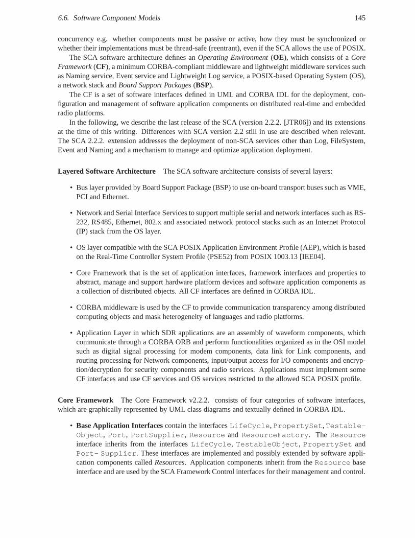
6.6. Software Component Models 145
concurrency e.g. whether components must be passive or active, how they must be synchronized orwhether their implementations must be thread-safe (reentrant), even if the SCA allows the use of POSIX.
The SCA software architecture defines anOperating Environment(OE), which consists of aCoreFramework(CF), a minimum CORBA-compliant middleware and lightweight middleware services suchas Naming service, Event service and Lightweight Log service, a POSIX-based Operating System (OS),a network stack andBoard Support Packages (BSP).
The CF is a set of software interfaces defined in UML and CORBA IDL for the deployment, con-figuration and management of software application components on distributed real-time and embeddedradio platforms.
In the following, we describe the last release of the SCA (version 2.2.2. [JTR06]) and its extensionsat the time of this writing. Differences with SCA version 2.2still in use are described when relevant.The SCA 2.2.2. extension addresses the deployment of non-SCA services other than Log, FileSystem,Event and Naming and a mechanism to manage and optimize application deployment.
Layered Software Architecture The SCA software architecture consists of several layers:
• Bus layer provided by Board Support Package (BSP) to use on-board transport buses such as VME,PCI and Ethernet.
• Network and Serial Interface Services to support multipleserial and network interfaces such as RS-232, RS485, Ethernet, 802.x and associated network protocol stacks such as an Internet Protocol(IP) stack from the OS layer.
• OS layer compatible with the SCA POSIX Application Environment Profile (AEP), which is basedon the Real-Time Controller System Profile (PSE52) from POSIX 1003.13 [IEE04].
• Core Framework that is the set of application interfaces, framework interfaces and properties toabstract, manage and support hardware platform devices andsoftware application components asa collection of distributed objects. All CF interfaces are defined in CORBA IDL.
• CORBA middleware is used by the CF to provide communicationtransparency among distributedcomputing objects and mask heterogeneity of languages and radio platforms.
• Application Layer in which SDR applications are an assembly of waveform components, whichcommunicate through a CORBA ORB and perform functionalities organized as in the OSI modelsuch as digital signal processing for modem components, data link for Link components, androuting processing for Network components, input/output access for I/O components and encryp-tion/decryption for security components and radio services. Applications must implement someCF interfaces and use CF services and OS services restrictedto the allowed SCA POSIX profile.
Core Framework The Core Framework v2.2.2. consists of four categories of software interfaces,which are graphically represented by UML class diagrams andtextually defined in CORBA IDL.
• Base Application Interfacescontain the interfacesLifeCycle,PropertySet,Testable-Object, Port, PortSupplier, Resource and ResourceFactory. The Resourceinterface inherits from the interfacesLifeCycle, TestableObject, PropertySet andPort- Supplier. These interfaces are implemented and possibly extended bysoftware appli-cation components calledResources. Application components inherit from theResource baseinterface and are used by the SCA Framework Control interfaces for their management and control.
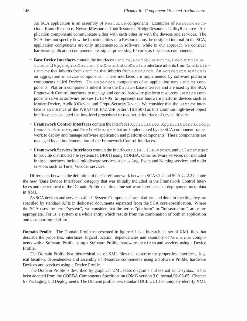
146 Chapter 6. Component-Oriented Architecture
An SCA application is an assembly ofResource components. Examples ofResources in-clude RouterResource, NetworkResource, LinkResource, BridgeResource, UtilityResource. Ap-plication components communicate either with each other orwith the devices and services. TheSCA does not specify how the functionalities of a Resource must be designed internal In the SCA,application components are only implemented in software, while in our approach we considerhardware application components i.e. signal processing IPcores as first-class components.
• Base Device Interfacescontain the interfacesDevice,LoadableDevice,ExecutableDe-vice, andAggregateDevice. TheExecutableDevice interface inherits fromLoadable-Device that inherits fromDevice that inherits fromResource. An AggregateDevice isan aggregation of device components. These interfaces are implemented by software platformcomponents calledDevices. TheResource components of an application usesDevice com-ponents. Platform components inherit from theDevice base interface and are used by the SCAFramework Control interfaces to manage and control hardware platform resources.Device com-ponents serve as software proxies [GHJV95] to represent real hardware platform devices such asModemDevice, AudioIODevice and CryptoSecurityDevice. Weconsider that theDevice inter-face is an instance of the WRAPPERFACADE pattern [BHS07] as this common high-level objectinterface encapsulated the low-level procedural or read/write interface of device drivers.
• Framework Control Interfaces contain the interfacesApplication,ApplicationFactory,Domain Manager, andDeviceManager that are implemented by the SCA component frame-work to deploy and manage software application and platformcomponents. These components aremanaged by an implementation of the Framework Control Interfaces.
• Framework Services Interfacescontain the interfacesFile,FileSystem, andFileManagerto provide distributed file systems [CDK01] using CORBA. Other software services not includedin these interfaces include middleware services such as Log, Event and Naming services and radioservices such as Time, Vocoder services.
Differences between the definition of the CoreFramework between SCA v2.2 and SCA v2.2.2 includethe new "Base Device Interfaces" category that was initially included in the Framework Control Inter-faces and the removal of the Domain Profile that do define software interfaces but deployment meta-datain XML.
As SCA devices and services called "System Components" are platform and domain specific, they arespecified by standard APIs in dedicated documents separatedfrom the SCA core specification. Wherethe SCA uses the term "system", we consider that the terms "platform" or "infrastructure" are moreappropriate. For us, a system is a whole entity which resultsfrom the combination of both an applicationand a supporting platform.
Domain Profile The Domain Profile represented in figure 6.1 is a hierarchicalset of XML files thatdescribe the properties, interfaces, logical location, dependencies and assembly ofResource compo-nents with a Software Profile using a Software Profile, hardware Devices and services using a DeviceProfile.
The Domain Profile is a hierarchical set of XML files that describe the properties, interfaces, log-ical location, dependencies and assembly of Resource components using a Software Profile, hardwareDevices and services using a Device Profile.
The Domain Profile is described by graphical UML class diagrams and textual DTD syntax. It hasbeen adapted from the CORBA Components Specification (OMG version 3.0, formal/02-06-65: Chapter6 - Packaging and Deployment). The Domain profile uses standard DCE UUID to uniquely identify XML
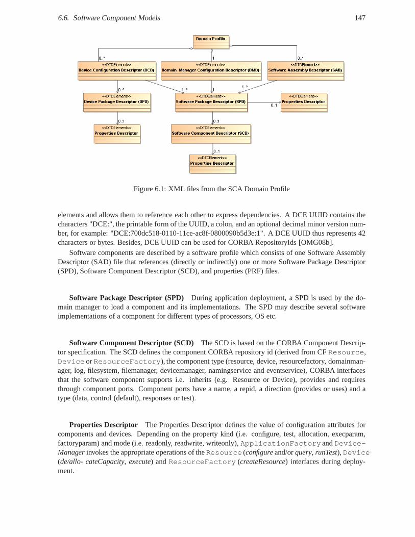
6.6. Software Component Models 147
Figure 6.1: XML files from the SCA Domain Profile
elements and allows them to reference each other to express dependencies. A DCE UUID contains thecharacters "DCE:", the printable form of the UUID, a colon, and an optional decimal minor version num-ber, for example: "DCE:700dc518-0110-11ce-ac8f-0800090b5d3e:1". A DCE UUID thus represents 42characters or bytes. Besides, DCE UUID can be used for CORBA RepositoryIds [OMG08b].
Software components are described by a software profile which consists of one Software AssemblyDescriptor (SAD) file that references (directly or indirectly) one or more Software Package Descriptor(SPD), Software Component Descriptor (SCD), and properties (PRF) files.
Software Package Descriptor (SPD) During application deployment, a SPD is used by the do-main manager to load a component and its implementations. The SPD may describe several softwareimplementations of a component for different types of processors, OS etc.
Software Component Descriptor (SCD) The SCD is based on the CORBA Component Descrip-tor specification. The SCD defines the component CORBA repository id (derived from CFResource,Device orResourceFactory), the component type (resource, device, resourcefactory,domainman-ager, log, filesystem, filemanager, devicemanager, namingservice and eventservice), CORBA interfacesthat the software component supports i.e. inherits (e.g. Resource or Device), provides and requiresthrough component ports. Component ports have a name, a repid, a direction (provides or uses) and atype (data, control (default), responses or test).
Properties Descriptor The Properties Descriptor defines the value of configurationattributes forcomponents and devices. Depending on the property kind (i.e. configure, test, allocation, execparam,factoryparam) and mode (i.e. readonly, readwrite, writeonly), ApplicationFactoryandDevice-Managerinvokes the appropriate operations of theResource (configureand/orquery, runTest), Device(de/allo- cateCapacity, execute) andResourceFactory (createResource) interfaces during deploy-ment.
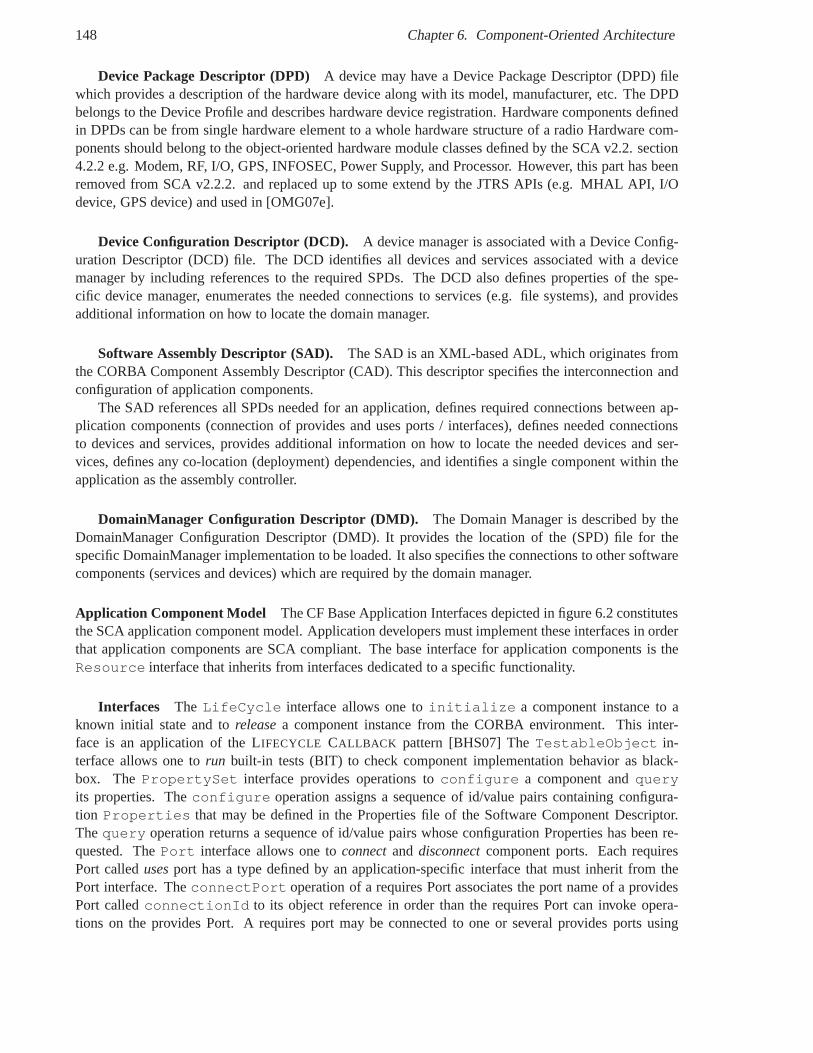
148 Chapter 6. Component-Oriented Architecture
Device Package Descriptor (DPD) A device may have a Device Package Descriptor (DPD) filewhich provides a description of the hardware device along with its model, manufacturer, etc. The DPDbelongs to the Device Profile and describes hardware device registration. Hardware components definedin DPDs can be from single hardware element to a whole hardware structure of a radio Hardware com-ponents should belong to the object-oriented hardware module classes defined by the SCA v2.2. section4.2.2 e.g. Modem, RF, I/O, GPS, INFOSEC, Power Supply, and Processor. However, this part has beenremoved from SCA v2.2.2. and replaced up to some extend by theJTRS APIs (e.g. MHAL API, I/Odevice, GPS device) and used in [OMG07e].
Device Configuration Descriptor (DCD). A device manager is associated with a Device Config-uration Descriptor (DCD) file. The DCD identifies all devicesand services associated with a devicemanager by including references to the required SPDs. The DCD also defines properties of the spe-cific device manager, enumerates the needed connections to services (e.g. file systems), and providesadditional information on how to locate the domain manager.
Software Assembly Descriptor (SAD). The SAD is an XML-based ADL, which originates fromthe CORBA Component Assembly Descriptor (CAD). This descriptor specifies the interconnection andconfiguration of application components.
The SAD references all SPDs needed for an application, defines required connections between ap-plication components (connection of provides and uses ports / interfaces), defines needed connectionsto devices and services, provides additional information on how to locate the needed devices and ser-vices, defines any co-location (deployment) dependencies,and identifies a single component within theapplication as the assembly controller.
DomainManager Configuration Descriptor (DMD). The Domain Manager is described by theDomainManager Configuration Descriptor (DMD). It providesthe location of the (SPD) file for thespecific DomainManager implementation to be loaded. It alsospecifies the connections to other softwarecomponents (services and devices) which are required by thedomain manager.
Application Component Model The CF Base Application Interfaces depicted in figure 6.2 constitutesthe SCA application component model. Application developers must implement these interfaces in orderthat application components are SCA compliant. The base interface for application components is theResource interface that inherits from interfaces dedicated to a specific functionality.
Interfaces The LifeCycle interface allows one toinitialize a component instance to aknown initial state and toreleasea component instance from the CORBA environment. This inter-face is an application of the LIFECYCLE CALLBACK pattern [BHS07] TheTestableObject in-terface allows one torun built-in tests (BIT) to check component implementation behavior as black-box. ThePropertySet interface provides operations toconfigure a component andqueryits properties. Theconfigure operation assigns a sequence of id/value pairs containing configura-tion Properties that may be defined in the Properties file of the Software Component Descriptor.Thequery operation returns a sequence of id/value pairs whose configuration Properties has been re-quested. ThePort interface allows one toconnectand disconnectcomponent ports. Each requiresPort calledusesport has a type defined by an application-specific interface that must inherit from thePort interface. TheconnectPort operation of a requires Port associates the port name of a providesPort calledconnectionId to its object reference in order than the requires Port can invoke opera-tions on the provides Port. A requires port may be connected to one or several provides ports using
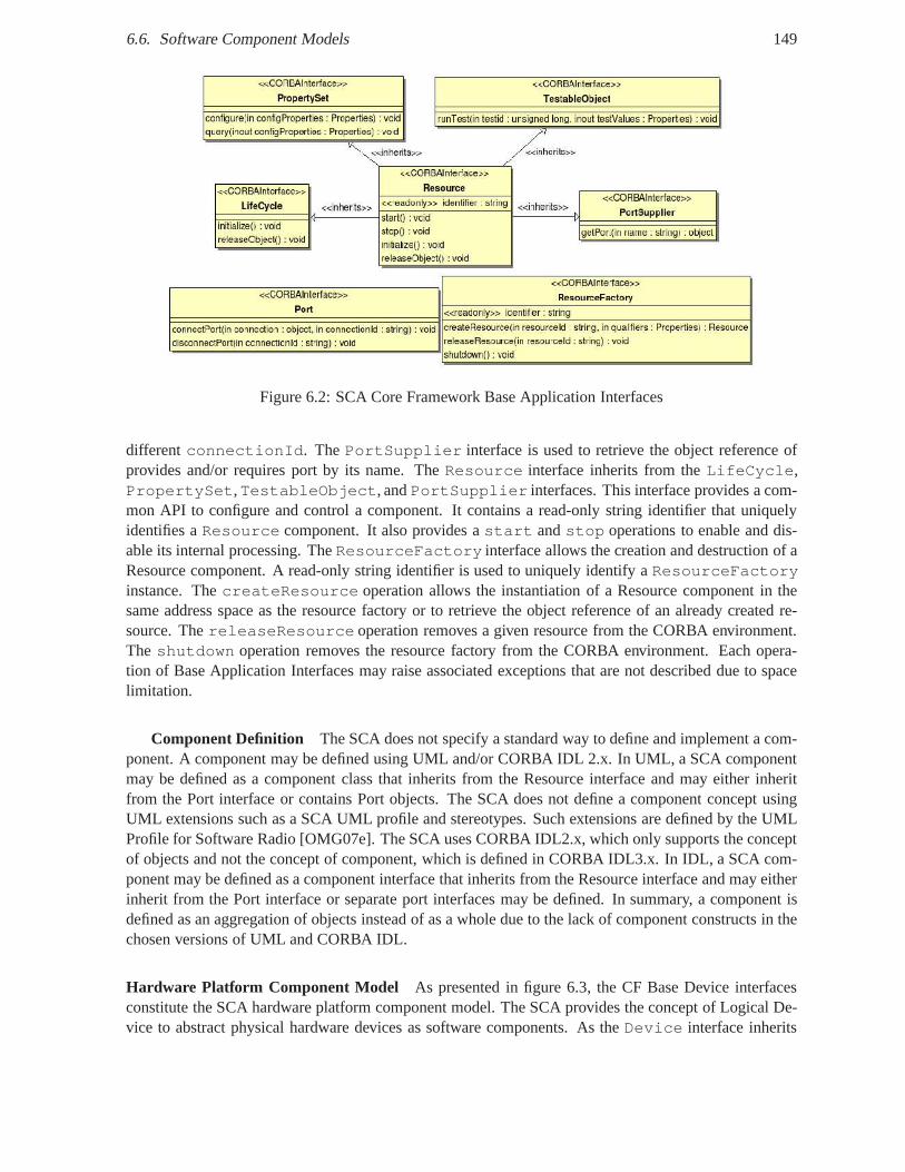
6.6. Software Component Models 149
Figure 6.2: SCA Core Framework Base Application Interfaces
differentconnectionId. ThePortSupplier interface is used to retrieve the object reference ofprovides and/or requires port by its name. TheResource interface inherits from theLifeCycle,PropertySet,TestableObject, andPortSupplier interfaces. This interface provides a com-mon API to configure and control a component. It contains a read-only string identifier that uniquelyidentifies aResource component. It also provides astart andstop operations to enable and dis-able its internal processing. TheResourceFactory interface allows the creation and destruction of aResource component. A read-only string identifier is used touniquely identify aResourceFactoryinstance. ThecreateResource operation allows the instantiation of a Resource componentin thesame address space as the resource factory or to retrieve theobject reference of an already created re-source. ThereleaseResource operation removes a given resource from the CORBA environment.Theshutdown operation removes the resource factory from the CORBA environment. Each opera-tion of Base Application Interfaces may raise associated exceptions that are not described due to spacelimitation.
Component Definition The SCA does not specify a standard way to define and implementa com-ponent. A component may be defined using UML and/or CORBA IDL 2.x. In UML, a SCA componentmay be defined as a component class that inherits from the Resource interface and may either inheritfrom the Port interface or contains Port objects. The SCA does not define a component concept usingUML extensions such as a SCA UML profile and stereotypes. Suchextensions are defined by the UMLProfile for Software Radio [OMG07e]. The SCA uses CORBA IDL2.x, which only supports the conceptof objects and not the concept of component, which is defined in CORBA IDL3.x. In IDL, a SCA com-ponent may be defined as a component interface that inherits from the Resource interface and may eitherinherit from the Port interface or separate port interfacesmay be defined. In summary, a component isdefined as an aggregation of objects instead of as a whole due to the lack of component constructs in thechosen versions of UML and CORBA IDL.
Hardware Platform Component Model As presented in figure 6.3, the CF Base Device interfacesconstitute the SCA hardware platform component model. The SCA provides the concept of Logical De-vice to abstract physical hardware devices as software components. As theDevice interface inherits
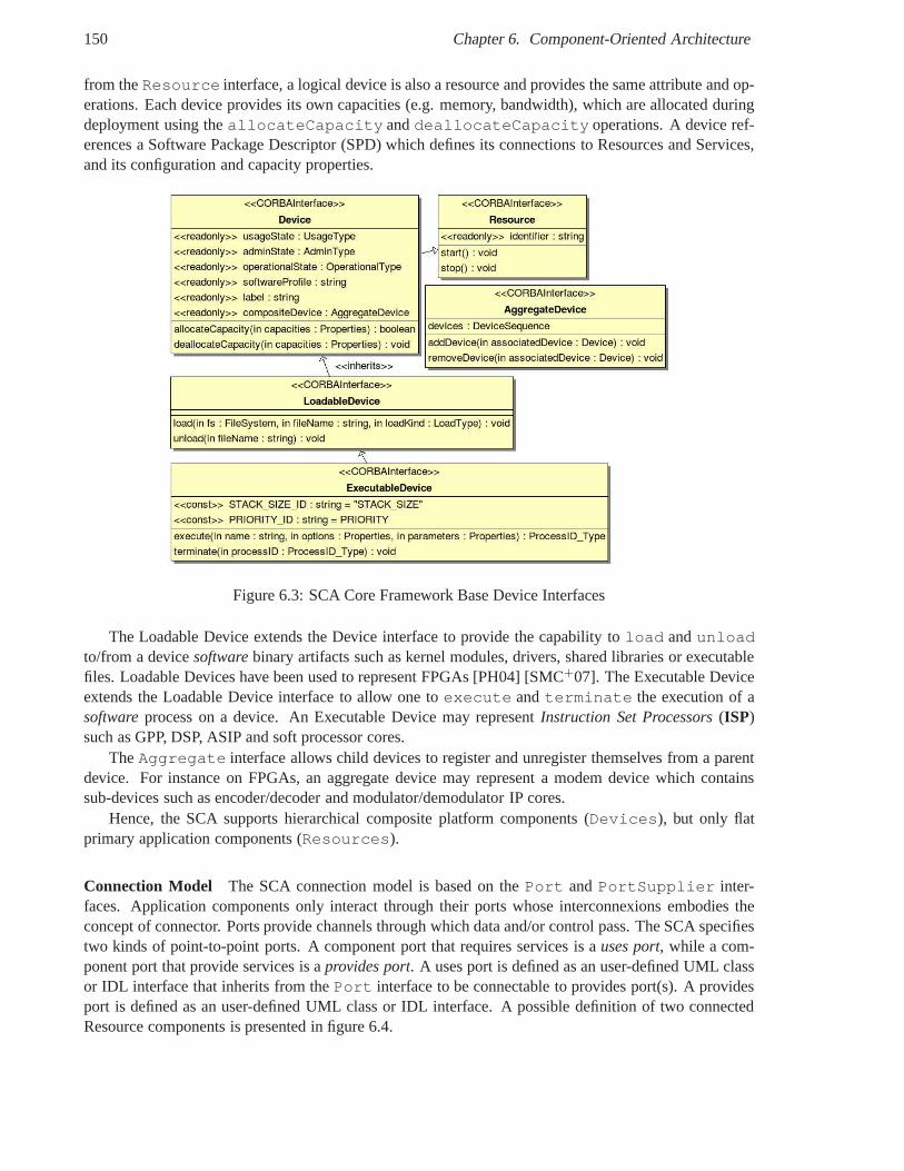
150 Chapter 6. Component-Oriented Architecture
from theResource interface, a logical device is also a resource and provides the same attribute and op-erations. Each device provides its own capacities (e.g. memory, bandwidth), which are allocated duringdeployment using theallocateCapacity anddeallocateCapacity operations. A device ref-erences a Software Package Descriptor (SPD) which defines its connections to Resources and Services,and its configuration and capacity properties.
Figure 6.3: SCA Core Framework Base Device Interfaces
The Loadable Device extends the Device interface to providethe capability toload andunloadto/from a devicesoftwarebinary artifacts such as kernel modules, drivers, shared libraries or executablefiles. Loadable Devices have been used to represent FPGAs [PH04] [SMC+07]. The Executable Deviceextends the Loadable Device interface to allow one toexecute andterminate the execution of asoftwareprocess on a device. An Executable Device may representInstruction Set Processors(ISP)such as GPP, DSP, ASIP and soft processor cores.
TheAggregate interface allows child devices to register and unregister themselves from a parentdevice. For instance on FPGAs, an aggregate device may represent a modem device which containssub-devices such as encoder/decoder and modulator/demodulator IP cores.
Hence, the SCA supports hierarchical composite platform components (Devices), but only flatprimary application components (Resources).
Connection Model The SCA connection model is based on thePort andPortSupplier inter-faces. Application components only interact through theirports whose interconnexions embodies theconcept of connector. Ports provide channels through whichdata and/or control pass. The SCA specifiestwo kinds of point-to-point ports. A component port that requires services is auses port, while a com-ponent port that provide services is aprovides port. A uses port is defined as an user-defined UML classor IDL interface that inherits from thePort interface to be connectable to provides port(s). A providesport is defined as an user-defined UML class or IDL interface. Apossible definition of two connectedResource components is presented in figure 6.4.
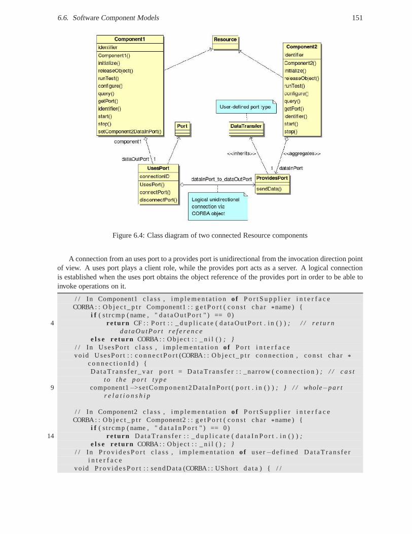
6.6. Software Component Models 151
Figure 6.4: Class diagram of two connected Resource components
A connection from an uses port to a provides port is unidirectional from the invocation direction pointof view. A uses port plays a client role, while the provides port acts as a server. A logical connectionis established when the uses port obtains the object reference of the provides port in order to be able toinvoke operations on it.
/ / In Component1 c l a s s , i m p l e m e n t a t i o no f P o r t S u p p l i e r i n t e r f a c eCORBA : : O b j e c t _ p t r Component1 : : g e t P o r t ( c o n s t cha r* name ) {
i f ( s t rcmp ( name , " d a t a O u t P o r t " ) == 0)4 re turn CF : : P o r t : : _ d u p l i c a t e ( d a t a O u t P o r t . i n ( ) ); / / r e t u r n
da taOu tPo r t r e f e r e n c ee l s e re turn CORBA : : Ob jec t : : _ n i l ( ); }
/ / In UsesPo r t c l a s s , i m p l e m e n t a t i o no f P o r t i n t e r f a c evo id UsesPo r t : : c o n n e c t P o r t (CORBA : : O b j e c t _ p t r connec t ion , c o n s t cha r *
c o n n e c t i o n I d ) {D a t a T r a n s f e r _ v a r p o r t = D a t a T r a n s f e r : : _narrow ( c o n n e c t io n ) ; / / c a s t
t o t h e p o r t t y p e9 component1−>se tComponen t2Da ta InPor t ( p o r t . i n ( ) ); } / / whole−p a r t
r e l a t i o n s h i p
/ / In Component2 c l a s s , i m p l e m e n t a t i o no f P o r t S u p p l i e r i n t e r f a c eCORBA : : O b j e c t _ p t r Component2 : : g e t P o r t ( c o n s t cha r* name ) {
i f ( s t rcmp ( name , " d a t a I n P o r t " ) == 0)14 re turn D a t a T r a n s f e r : : _ d u p l i c a t e ( d a t a I n P o r t . i n ( ) );
e l s e re turn CORBA : : Ob jec t : : _ n i l ( ); }/ / In P r o v i d e s P o r t c l a s s , i m p l e m e n t a t i o no f user−d e f i n e d D a t a T r a n s f e r
i n t e r f a c evo id P r o v i d e s P o r t : : sendData (CORBA : : UShort d a t a ) { / /
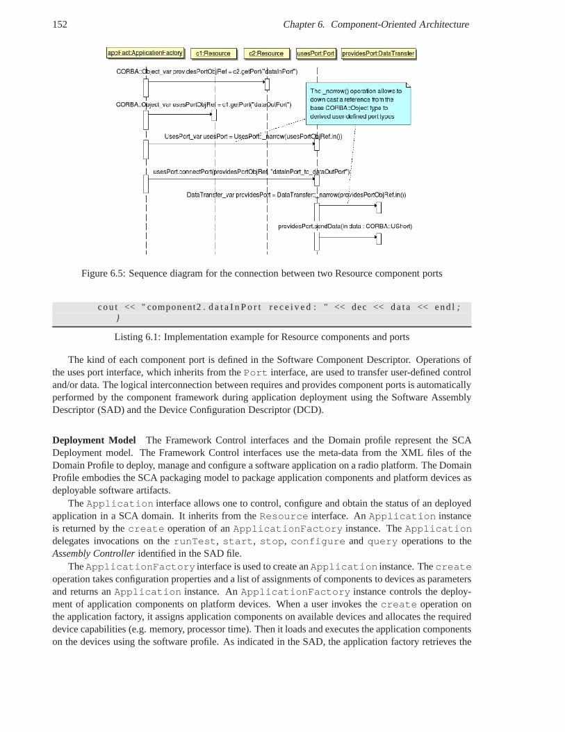
152 Chapter 6. Component-Oriented Architecture
Figure 6.5: Sequence diagram for the connection between twoResource component ports
cou t << " component2 . d a t a I n P o r t r e c e i v e d : " << dec << d a t a <<end l ;}
Listing 6.1: Implementation example for Resource components and ports
The kind of each component port is defined in the Software Component Descriptor. Operations ofthe uses port interface, which inherits from thePort interface, are used to transfer user-defined controland/or data. The logical interconnection between requiresand provides component ports is automaticallyperformed by the component framework during application deployment using the Software AssemblyDescriptor (SAD) and the Device Configuration Descriptor (DCD).
Deployment Model The Framework Control interfaces and the Domain profile represent the SCADeployment model. The Framework Control interfaces use themeta-data from the XML files of theDomain Profile to deploy, manage and configure a software application on a radio platform. The DomainProfile embodies the SCA packaging model to package application components and platform devices asdeployable software artifacts.
TheApplication interface allows one to control, configure and obtain the status of an deployedapplication in a SCA domain. It inherits from theResource interface. AnApplication instanceis returned by thecreate operation of anApplicationFactory instance. TheApplicationdelegates invocations on therunTest, start, stop, configure andquery operations to theAssembly Controlleridentified in the SAD file.
TheApplicationFactory interface is used to create anApplication instance. Thecreateoperation takes configuration properties and a list of assignments of components to devices as parametersand returns anApplication instance. AnApplicationFactory instance controls the deploy-ment of application components on platform devices. When a user invokes thecreate operation onthe application factory, it assigns application components on available devices and allocates the requireddevice capabilities (e.g. memory, processor time). Then itloads and executes the application componentson the devices using the software profile. As indicated in theSAD, the application factory retrieves the
6.6. Software Component Models 153
object reference of a Resource either directly using the Naming Service or indirectly using a registeredResource Factory that willcreates it. The application factoryinitializes the obtained Resource,gets its Ports andconnects them. Itconfigures the assembly controller that can dispatch con-figuration commands to the assembled components. Finally, theApplication instance is returned, amessage may be writen to the Log service and a event may be pushed to the domain event service.
TheDevice Manager interface allows the management of a set of logical devices and services. ADomain Manager instance allows one toregister andunregister devices and services with adevice manager,shutdown a device manager andget the SPD implementation ID used by the DeviceManager to create a component.
The Domain Manager interface serves for the control and configuration of a SCA domain. ADomain Manager instance allows one toregister andunregister device managers with adomain manager, devices and services with a device manager,objects in an given event channel andinstall anduninstall an application.
Evolution of the integration of application components on non-CORBA capable processors
Adapters in SCA v2.2 in 2001 Adapters [GHJV95] areResources or Devices that transpar-ently convert CORBA invocations toResource or Device operations into appropriate actions forapplication or platform components e.g. Modem and Securitycomponents that reside on non-CORBAcapable processing units such as DSPs, FPGAs and ASICs. Thisadaptation allows the integration ofbusiness, legacy or COTS components which are implemented in hardware or software with CORBA-capable Resources in an uniform object-oriented approach.However, this integration is manually per-formed by application developers for each specific component. Resource adapters include dedicated codeto control and communicate with non-CORBA capable application components and thus do not meet theportability and interoperability requirements of the SCA.Device adapters do not belong to predefinedDevice types such as AudioDevice and cannot implement theirassociated standard APIs. Moreover,these adapters only address the portability and interoperability of software application components, butnot of non-CORBA capable application components on DSP, FPGA and ASIC.
Software integration approaches for software components on DSPs and hardware components onFPGAs has been successively proposed in [JTR04], [JTR05] [KB05].
Specialized Hardware Supplement (SHS) to the SCA specification v3.0 in 2004 The SCA spec-ification version 3.0 was proposed to extend the version 2.2 and address the limitations of the SCA re-garding the portability of application components on specialized processing units such as DSPs, FPGAsand ASICs. These dedicated processors suffer from a lack of standard operating environments to supportportability such as standard OS on DSP and execution models on DSPs, FPGAs and ASICs. The SCAv.3.0 never became a standard release of the SCA and is not anymore available on the SCA JTRS website 42. The Specialized Hardware Supplement (SHS) [JTR04] to the SCA v3.0 specified four ingredi-ents to improve the portability of components on non-CORBA capable processing units: a HardwareAbstraction Layer Connectivity (HAL-C), a reduced POSIX Application Environment Profile for DSPs,waveform functional blocks and an API for antenna subsystem.
The Hardware Abstraction Layer Connectivity (HAL-C) defines standard hardware and softwarecommunication interfaces between application componentsdeployed on specialized hardware devicesi.e. DSP and FPGA.
42http://sca.jpeojtrs.mil
154 Chapter 6. Component-Oriented Architecture
TheHAL-C Infrastructurerefers to the software or hardware implementations of HAL-Cinterfacesthat provides the operating environment for HCs and supports location transparent communication be-tween HCs residing on the same and/or different PEs.
The HAL-C infrastructure may be considered as a message-passing middleware that supports porta-bility through the HAL-C API like the socket API, but no built-in support for inter-HC communicationinteroperability using a standard message protocol like CORBA GIOP.
Extension for component portability for Specialized Hardware Processors (SHP) to the SCAv3.1x a.k.a. SCA Change Proposal (CP) 289 in 2005A container-component approach is proposedin [KB05] for non-CORBA capable SCA components calledworkeron FPGAs and DSPs. We focus onthe proposition for hardware components.
Workers have three kinds of ports: a control port, "business" ports associated to a subset of IDLand ports for local services provided by containers. An OCP profile is provided for each port category.Workers produce and consume messages through their ports. Mapping from IDL to OCP in this ap-proach is not systematic since it depends on the meaning of the operations within an IDL interface. SCAcontrol operations (i.e start/stop) are encoded on OCP address signals on thread 0, while invocationswithout parameter are interpreted as read. Configuration operations (i.e. configure/query) are not seenas invocations, but as regular read/write on the OCP MThreadID 1. Business operations are mapped onOCP Control or Status signals. For business interfaces, there is one port for requests and one port for re-sponses. The logical container invokes and controls one or several components. It provides local servicessuch as Reset, Clock and local memory services. This container only addresses waveform componentportability. Interoperability is considered the integrator or platform provider responsibility. Willingly,no standard message format is proposed. A generic software proxy is proposed to adapt SCA Resourceinterface to a simplified control interface to manage hardware components.
We assume that the message header can be encoded by the container, while message body is encodedwith CDR and has to be decoded a priori within the worker instead of within the container. Input andoutput ports only support read and write operations respectively. Provides component ports receiverequest messages on input ports and send response messages on output ports. Uses component portssend request messages on output ports and receive response messages on input ports. Port readinesscan be indicated using theSThreadBusysignal on thread 0. On output ports, operation or exceptionare encoded on OCP Control signals, on input ports, operation or exception are encoded on OCP Statussignals. Signals can be removed for one way operation (response port), single operation (Control/Status)or FIFO access (MAddr). Moreover, the granularity of the data unit transferred through component portsis a request or response message body rather than individualoperation parameters.
Modem Hardware Abstraction Layer (MHAL) API in 2007 The SCA MHAL [JTR07] spec-ification defines a standard MOM API and message header for GPP, DSP and FPGAs/ASICs. Hence,the MHAL can be considered as a hardware/software message broker for SDR platforms. The MHALLogical Destination (LD) correspond to Message Endpoint [BHS07] and notably to HAL-C endpoints.
Development of a new SCA release in 2009The JPEO JTRS annonced in August 2009 the de-velopment of a new SCA release [JTR09] in which the SCA specification will become technology in-dependent and make CORBA optional. The change proposals forthis new release notably concern thedefinition of SCA PIM and PSMs, SCA profiles with lightweight SCA components, operating environ-ments other than for GPPs, real-time implementations.
Implementations
6.6. Software Component Models 155
Software Implementations Open source implementations of the SCA Core Framework includeSCARI43 (Software Communications Architecture - Reference Implementation) from the Canadian CRC(Communications Research Centre) which is written in Java and was demanded by the SDRForum andOSSIE44 (Open Source SCA Implementation::Embedded) from VirginiaTech which is written in C++.The OSSIE Core Framework has been ported on the TI OMAP SoC [Bal07]. Moreover, the SCA CF hasbeen been used in mobile robots [HLEJ06].
Commercial implementations of the SCA Core Framework include Componennt Enabler from Zelig-Soft and Spectra SDR tools from PrismTech.
SCA Overhead Evaluation The overhead of implementing waveform with the SCA has beenevaluated in [OS07] compared to a custom waveform implementation, in terms of latency [TBR07] andmemory [BDR07].
Hardware Implementations Dynamic and partial hardware reconfiguration of FPGAs has beenimplemented under the control of the SCA CF [SMC+07]. Hardware implementations of SCA com-ponent have been proposed in [Hum06]. Standard interfaces for FPGA components using OCP aremotivated in [NK07].
Extension for Quality of Services Some works such as [LPHH05] [LKPH06] have been carriedout to extend the SCA CF to support the specification of Quality of Services.
OMG UML Profile for Software Radio
The adoption of the SCA by the SDRForum has contributed to theevolution of the SCA as a commer-cial standard within the OMG. Following the OMG Model-Driven Architecture (MDA) initiative, theUML Profile for Software-Defined Radio specifies a Platform-Independent Model (PIM) and a Platform-Specific Model (PSM) for CORBA of software radio infrastructures on top of which waveform appli-cations may be developed. This profile is also known as PIM & PSM for Software Radio Components.The separation between the PIM and its implementation in PSM(s) facilitates the portability of waveformapplications which may be deployed on various heterogeneous SDR platforms.
The UML Profile for Software Radio (SDRP) extends the UML modeling language with SDR domainspecific concepts using stereotypes to model software radiocomponents.
This specification defines a set offacilities to model the behavior of SDR systems and specify stan-dardized APIs. A facility is defined as the realization of certain functionality through a set of well-definedinterfaces. Facilities are independent from a particular middleware technology such as CORBA.
The SDRP specification is divided into 5 volumes: Communication Channel and Equipment, Com-ponent Document Type Definitions, Component Framework, Common and Data Link Layer Facilities,and POSIX Profiles.
The set of stereotypes of the UML profile defined in the Component Framework volume is organizein two main packages: the Applications and Devices package and the Infrastructure package.
The Applications and Devices package defines the concepts for the development of waveform appli-cations and devicesResourceandDevicecomponents. The Infrastructure package defines the conceptsto deploy services and applications on a SDR platform.
The Application and Device Components package contains 5 packages:
• Base Typespackage defines types for applications, logical devices, and component definitions.
43http://www.crc.ca/scari44http://ossie.wireless.vt.edu
156 Chapter 6. Component-Oriented Architecture
• Propertiespackage defines properties for configure, query, testable, service artifact and executableproperties for components and executable code artifacts.
• Interface & Port Stereotypespackage defines stereotypes for interfaces and components.
• Resource Componentspackage defines stereotypes for the interfaces and components for theResourceComponent, which is the basic component type for application and device components.
• Device Componentspackage defines stereotypes for the logical device components on whichcomponents are deployed or which are provided by the radio platform.
• Application Componentspackage defines stereotypes for the ResourceComponents within appli-cations.
Within the UML profile for Software Radio, the UML Profile for Component Framework specifi-cation defines UML stereotypes for component property, interface and port.Interface stereotypesrepresent the type of interface provided or used by components through their ports.Port stereotypesrepresent the kind of ports a component may have.Property stereotypes represent the type of proper-ties for interface and component attributes.
TheInterface stereotype defines the following types of interfaces: IControl, IDataControl, IData,IStream and StreamControl. TheIControl interface allows sending or receiving control. TheIDatainterface allows sending data. TheIDataControl interface allows sending data with control. TheIStream interface allows managing streams. TheIStreamControl interface allows controllingstreams including user data and control information.
Based on these interfaces, thePort stereotype defines the following types of component ports:ControlPort,DataControlPort,DataPort,ProvidesPort,RequiresPort,Service-Port, StreamControlPort andStreamPort.
The Property stereotypes defines the following types of component properties: Constant,ReadOnly andReadWrite.
The Communication Channel Facilities PIM is a non-normative specification of the physical layerand radio control facilities. It defines Physical Layer Facilities and Radio Control Facilities.
The Physical Layer Facilities specify a set of interfaces toconvert the digitized signal into a propa-gating RF wave and vice versa, and to control and configure HW/SW physical layer components. ThePhysical Layer Facilities are divided into data transfer facilities, control facilities and I/O facilities. Thedata transfer facilities are defined in the Common and Data Link Layer Facilities::Common Layer Facil-ities. A physical layer component must realize i.e. implement data transfer interfaces to communicatewith the upper OSI layers. The control facilities contain modem facilities and RF/IF facilities. Themodem facilities include all digital signal processing elements required to convert bits into symbolsand vice versa. They include baseband and passband digital modulation schemes such as QAM, PSK,Direct Sequence Spread Spectrum (DSSS), Orthogonal Frequency Division Multiplex (OFDM), and ana-log modulation schemes such as Amplitude Modulation (AM), Frequency Modulation (FM), and PhaseModulation (PM).
The modem facilities defines modem interfaces and components realizing these interfaces such asPNSequenceGeneratorComponent,ChannelCoder,BlockInterleaver,Mapper,Source-CoderComponent andChannelCoderComponent.
The RF/IF facilities defines interfaces and components realizing these interfaces such as:Amplifier-Device,SwitchDevice,HoppingFrequencyConverterDevice,FrequencyConverter-Device, AntennaDevice,DigitalConverterDevice andFilterDevice.
The I/O facilities defines two types of I/O mechanisms: Serial IO and Audio IO. The Serial I/O pack-age defines theSerialIODeviceComponent which provides and uses theSerialIOSignals,
6.6. Software Component Models 157
SerialIODevice,SerialIOControl interfaces. The Audio I/O package defines an AudioIODe-viceComponent that provides and uses the AudioIOControl and AudioIODevice interfaces.
The ModemComponentcomponent is an abstract component from which all components in themodem facilities inherit. Modem components are stereotyped as«resourcecomponent» to indi-cate that they could either be implemented in software or in hardware via a«devicecomponent»component. ModemComponent provides oneControlPort and at least oneDataControlPortorDataPort.
The Radio Control Facilities defines a set of interfaces to manage the radio domain and channelswithin the radio.
Finally, the Common and Data Link Layer Facilities defines the Quality of Service Facilities, FlowControl Facilities, Measurement Facilities, Error Control Facilities, Protocol Data Unit (PDU) Facilitiesand Stream Facilities.
GNU Radio
The GNU Radio45 project, founded by Eric Blossom, provides an open-source software signal process-ing library to build software-defined radios primarily on desktop computers. A software radio applicationresults from the interconnection of signal processing components. GNU Radio components are imple-mented in C++ and optimized using SIMD instructions, then they are wrapped in the Python object-oriented scripting language using SWIG46(Simplified Wrapper and Interface Generator). GNU Radiotargets the Universal Software Radio Peripheral (USRP) board which can be connected to a desktopcomputer via an USB cable (USRP1) or an Ethernet cable (USRP2).
6.6.2 General Purpose Component Models
Sun Enterprise Java Bean (EJB)
The Enterprise JavaBeans (EJB) is a commercial and general-purpose component model for desktopand server-side applications developed by Sun MicroSystems. EJB components are developped in Java.They extend theEJBObject base interface to add user-defined interfaces. Required interfaces arenot explicitly specified. EJB does not provide the concept ofport. EJB components are deployed andexecuted within EJB containers, which manage component life-cycle (creation/destruction, start/stop,activation/passivation) and mediate access to non-functional platform services such as the Java namingand directory service (JNDI), Java RMI, Java Message Service (JMS), transactions, persistence. Compo-nents are created using theEJBHomeinterface implemented by containers . The EJB component modeldoes not support hierarchical composition or dynamic reconfiguration. The EJB deployment model isbased on component packages in .jar files calledbeansand a deployment descriptor in XML. EJB doesnot exist in a lightweight version for embedded systems Moreover, EJB are based on the standard Javaplatform, which is not appropriate for resource-constrained embedded platforms.
OMG CORBA Component Model (CCM) and its Lightweight version (LwCCM)
The distributed object-oriented model of CORBA evolved to the distributed component-oriented modelof the CORBA Component Model (CCM) [OMG06a]. New CORBA IDL keywords have been addedto the object-oriented IDL 2.x to form the component-oriented IDL 3.x, which supports CCM. IDL 3.xkeywords are intuitive and written in bold in the following.
45http://gnuradio.org46http://www.swig.org
158 Chapter 6. Component-Oriented Architecture
Component Model For synchronous or blocking interactions, a CCM componentprovides an inter-face through afacet port andusesan interface through areceptacleport. A receptacle can be eithersimplexor multiplex, if it is connected to a single facet or multiple facet(s). For asynchronous or non-blocking interactions, a CCM componentpublishesevents (broadcast) oremitsevents (unicast) throughan event source port andconsumesevents via an event sink port. Other OMG specifications proposeadditional functionalities such as the support for streamsand quality-of-service.
The base interface implicitly inherited by all CCM components is theCCMObject interface. TheCCMObject interface inherits from three others interfaces, which provides information on the compo-nent. TheNavigation interface allows a client to retrieve references to the facet ports of a component.TheReceptaclesinterface allows one to connect a receptacle to a facet, to retrieve receptacles of a com-ponent and existing connections. TheEvents interface allows a component to be connected to send andreceive events, and to retrieve consumers, emitters and publishers. CCM components are created throughdedicated interfaces calledCCMHome andKeylessCCMHome.
Lightweight CORBA Component Model (LwCCM) The Lightweight CORBA Component Model(LwCCM) is a lightweight profile of CCM which targets distributed embedded systems. In particular,the following features are removed from the general purposeCCM model: Persistence, Introspection,Navigation, Transactions and Security.
Connection Model The CCM offers two kinds of messages: Synchronous messages provided bythe communication between facet and receptacles, Asynchronous messages provided by event-basedcommunication.
CCM D&C XML descriptors serve as an ADL and notably specify the configuration, assembly andallocation of CCM components onto execution nodes. CCM is based on a container, which is stronglyinspired from the EJB. The CCM container is the execution environment, which transparently managefor component developers the life cycle of the hosted components, the management of events, the useof CORBA middlewares As the full CCM container is more dedicated to large distributed informationsystems, it may also manage advanced features such as persistence, security and transactions.
Deployment and Configuration Model A mapping from the abstractDeployment and Configura-tion (D&C) specification has been standardized to address the deployment of CCM based applications.The deployment process consist in:
• Installation : software packages are installed into the software repository.
• Configuration: this step consists in creating multiple assembly of the component-based applica-tion.
• Planning: according to application requirements, a component implementation is selected andassociated to an execution node. The result of the planning is a "deployment plan".
• Preparation: this step consists in the installation of the binary files onthe execution nodes.
• Launch: this step consists in instantiating components, interconnecting and configuring them, andstarting application execution.
CCM is based on several XML descriptors:
• the Component Interface Descriptor (.ccd) contains data from the Component Interface De-scription. It is created by thearchitectand can be generated from the component IDL.
6.6. Software Component Models 159
• The Component Implementation Descriptor (.cid) describes a single implementation and iscreated by thedeveloperwhich creates a monolithic implementation, or by anassemblerthat cre-ates a component assembly. It contains information about Component Implementation Descrip-tion, Component Assembly Description, Monolithic Implementation Description.
• TheImplementation Artifact Descriptor (.iad) contains information from Implementation Ar-tifact Description and is created by the developer of the artifact.
• TheComponent Package Descriptor(.cpd) contains data from the Component PackageDescrip-tion. It is created by thepackagerthat put together one or several implementations.
Implementations Open-source implementations of the CORBA component model includeOpen-CCM47 written in Java and developed by LIFL, INRIA and Thales in various european research projects,andMICO-CCM 48 written in C++ and implemented by Frank Pilhofer. An open-source implementationof the Lightweight CORBA component model ismicroCCM developed by Thales and CEA in theCOMPARE project. Commercial implementations of CCM have also been developed such asMyCCMfrom Thales and OpenFusion CCM from PrismTech.
In [JNH06], HW/SW components are described as CCM components to target a custom middle-ware for robotic. Indeed, the separation of concerns of the component-approach allows one to decouplecomponents from their execution and communication environment e.g. CORBA itself.
Software CCM components have also been simulated in SystemC[KBG+08] [KBY+06]. Some toolshave been created for the development, deployment and configuration of CCM components like Cadena49
from the Kansas State University based on Eclipse and COSMIC50 from the Vanderbilt University basedon Model-Driven Engineering.
Microsoft Component Object Model (COM)
The Component Object Model (COM) is a commercial and general-purpose component model for desk-top and server-side applications developed by Microsoft. The COM component model considers com-ponents as a set of binary object interface to support interoperability between components written indifferent language. The object interfaces of COM components are defined in a proprietary Interface Def-inition Language (IDL) derived from DCE IDL. The COM component model supports a limited form ofintrospection through interface navigation which allows one to retrieve a pointer to every interface sup-ported by the object. COM technologies include COM, DCOM (Distributed Component Object Model)and COM+. DCOM (Distributed Component Object Model) extends COM to support distributed compo-nents. COM+ is an execution environment for COM/DCOM components provided with Windows. COMtechnologies are being replaced by the .NET framework. OpenCOM51 is an open source implementationof COM developed by the University of Lancaster.
Fractal
Fractal [Fra08] [BCL+06] is a generic component model developed by France TelecomR&D and thefrench national institute for research in computer scienceand control called INRIA52 . The Fractal com-ponent model provides advanced features such as hierarchical composition, introspection and sharing of
47http://openccm.objectweb.org48http://www.fpx.de/MicoCCM49cadena.projects.cis.ksu.edu50http://www.dre.vanderbilt.edu/cosmic51http://sourceforge.net/projects/opencom52Institut National de Recherche en Informatique et Automatique
160 Chapter 6. Component-Oriented Architecture
components to represent shared resources such as device drivers. A Fractal component has a contentpart containing the implementation of primitive components or sub-components for composite com-ponents and a control part implementing multiple control interfaces and other non-functional aspects.Fractal defines a component model template which may be customized to meet application needs. Forinstance, Fractal has been used to build a component-based operating system called Think [FSLM02] anda message-oriented middleware called DREAM53. The Fractal component model has been implementedin various programming languages such as Julia in Java, Cecilia and THINK in C, while implementationsin .NET and SmallTalk are being developed.
Software Appliances (SOFA)
SOFA and its extension SOFA 2.0 [BHP06] is a component model developed at Charles University inPrague. SOFA supports the hierarchical composition of primitive components to build composite com-ponents. Primitive components are directly implemented ina programming language e.g. Java, whilecomposite components are implemented by its sub-components. The SOFA component model defines acomponent by aframeand anarchitecture. The frame represents the black-box view of a component inwhich its provided and required interfaces are specified. The implementation of a SOFA component con-sists of a functional part implementing thebusinessinterfaces and a control part implementing the controlinterfaces required by the component model. These control interfaces provide non-functional servicessuch as life-cycle, connection, reconfiguration and introspection which are implemented by controllerse.g. a lifecycle controller and binding controller. Controllers are used by the component framework (run-time environment, administration and deployment tools) and by the application business logic for someservices e.g. to retrieve component properties. The control part is composed ofmicro-componentswhichare objects implementing a control interface. The SOFA connection model reifies component bindingby first-classconnectorsthat support four communication styles: method invocation, message passing,streaming and distributed shared memory [BP04]. These communication styles are supported at bothdesign and execution time. In SOFA 2, connectors allow provided-to-provided and required-to-requiredconnections to integrate multiple communication styles. The assembly of components and connectors isdescribed by an Architecture Description Language calledComponent Description Language(CDL ) inSOFA and by a meta-model in SOFA 2. This meta-model allows theautomatic generation of a repos-itory, model editor, code skeletons for primitive components, XML descriptors (e.g. deployment plan)and automatic application deployment. The behavior of SOFAcomponents can be formally specified bybehavior protocols based on regular expressions [PV02]. Based on CDL description, the SOFA CDLcompiler generates component templates to be filled by the programmer in a target programming lan-guage such as C++ or Java. The SOFA deployment model is based on a repository to store componentdescription and implementation, a deployment plan to associate components to execution nodes and toallocate the required resources, and a distributed runtimeenvironment calledSOFA nodecomposed ofcomponent containers called deployment docks. SOFA 2 supports dynamic reconfiguration of softwarecomponents according to predefined reconfiguration patterns.
6.6.3 Software Component Models for Real-Time and EmbeddedSystems
Koala
The Koala [vOvdLKM00] component model is used at Philips forembedded software design in resource-constrained systems such as TV sets. Software component interfaces are described by a textualInter-face Definition Language(IDL). Component configurations are specified by anArchitecture Description
53http://dream.ow2.org
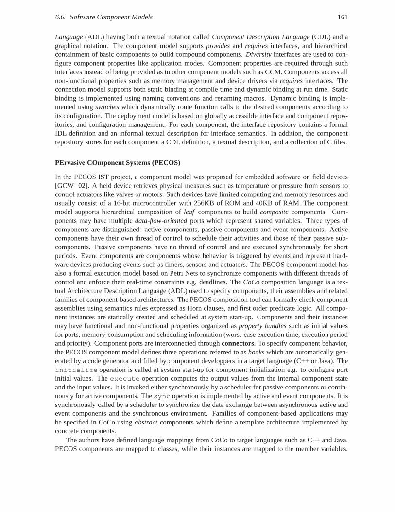
6.6. Software Component Models 161
Language(ADL) having both a textual notation calledComponent Description Language(CDL) and agraphical notation. The component model supportsprovidesand requires interfaces, and hierarchicalcontainment of basic components to build compound components. Diversity interfaces are used to con-figure component properties like application modes. Component properties are required through suchinterfaces instead of being provided as in other component models such as CCM. Components access allnon-functional properties such as memory management and device drivers viarequiresinterfaces. Theconnection model supports both static binding at compile time and dynamic binding at run time. Staticbinding is implemented using naming conventions and renaming macros. Dynamic binding is imple-mented usingswitcheswhich dynamically route function calls to the desired components according toits configuration. The deployment model is based on globallyaccessible interface and component repos-itories, and configuration management. For each component,the interface repository contains a formalIDL definition and an informal textual description for interface semantics. In addition, the componentrepository stores for each component a CDL definition, a textual description, and a collection of C files.
PErvasive COmponent Systems (PECOS)
In the PECOS IST project, a component model was proposed for embedded software on field devices[GCW+02]. A field device retrieves physical measures such as temperature or pressure from sensors tocontrol actuators like valves or motors. Such devices have limited computing and memory resources andusually consist of a 16-bit microcontroller with 256KB of ROM and 40KB of RAM. The componentmodel supports hierarchical composition ofleaf components to buildcompositecomponents. Com-ponents may have multipledata-flow-orientedports which represent shared variables. Three types ofcomponents are distinguished: active components, passivecomponents and event components. Activecomponents have their own thread of control to schedule their activities and those of their passive sub-components. Passive components have no thread of control and are executed synchronously for shortperiods. Event components are components whose behavior istriggered by events and represent hard-ware devices producing events such as timers, sensors and actuators. The PECOS component model hasalso a formal execution model based on Petri Nets to synchronize components with different threads ofcontrol and enforce their real-time constraints e.g. deadlines. TheCoCocomposition language is a tex-tual Architecture Description Language (ADL) used to specify components, their assemblies and relatedfamilies of component-based architectures. The PECOS composition tool can formally check componentassemblies using semantics rules expressed as Horn clauses, and first order predicate logic. All compo-nent instances are statically created and scheduled at system start-up. Components and their instancesmay have functional and non-functional properties organized asproperty bundlessuch as initial valuesfor ports, memory-consumption and scheduling information(worst-case execution time, execution periodand priority). Component ports are interconnected throughconnectors. To specify component behavior,the PECOS component model defines three operations referredto ashookswhich are automatically gen-erated by a code generator and filled by component developpers in a target language (C++ or Java). Theinitialize operation is called at system start-up for component initialization e.g. to configure portinitial values. Theexecute operation computes the output values from the internal component stateand the input values. It is invoked either synchronously by ascheduler for passive components or contin-uously for active components. Thesync operation is implemented by active and event components. Itissynchronously called by a scheduler to synchronize the dataexchange between asynchronous active andevent components and the synchronous environment. Families of component-based applications maybe specified in CoCo usingabstractcomponents which define a template architecture implemented byconcrete components.
The authors have defined language mappings from CoCo to target languages such as C++ and Java.PECOS components are mapped to classes, while their instances are mapped to the member variables.
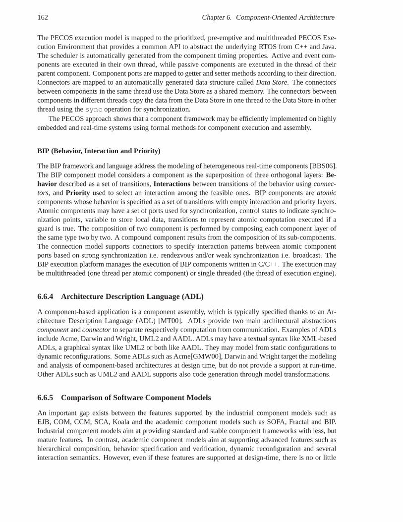
162 Chapter 6. Component-Oriented Architecture
The PECOS execution model is mapped to the prioritized, pre-emptive and multithreaded PECOS Exe-cution Environment that provides a common API to abstract the underlying RTOS from C++ and Java.The scheduler is automatically generated from the component timing properties. Active and event com-ponents are executed in their own thread, while passive components are executed in the thread of theirparent component. Component ports are mapped to getter and setter methods according to their direction.Connectors are mapped to an automatically generated data structure calledData Store. The connectorsbetween components in the same thread use the Data Store as a shared memory. The connectors betweencomponents in different threads copy the data from the Data Store in one thread to the Data Store in otherthread using thesync operation for synchronization.
The PECOS approach shows that a component framework may be efficiently implemented on highlyembedded and real-time systems using formal methods for component execution and assembly.
BIP (Behavior, Interaction and Priority)
The BIP framework and language address the modeling of heterogeneous real-time components [BBS06].The BIP component model considers a component as the superposition of three orthogonal layers:Be-havior described as a set of transitions,Interactions between transitions of the behavior usingconnec-tors, andPriority used to select an interaction among the feasible ones. BIP components areatomiccomponents whose behavior is specified as a set of transitions with empty interaction and priority layers.Atomic components may have a set of ports used for synchronization, control states to indicate synchro-nization points, variable to store local data, transitionsto represent atomic computation executed if aguard is true. The composition of two component is performedby composing each component layer ofthe same type two by two. A compound component results from the composition of its sub-components.The connection model supports connectors to specify interaction patterns between atomic componentports based on strong synchronization i.e. rendezvous and/or weak synchronization i.e. broadcast. TheBIP execution platform manages the execution of BIP components written in C/C++. The execution maybe multithreaded (one thread per atomic component) or single threaded (the thread of execution engine).
6.6.4 Architecture Description Language (ADL)
A component-based application is a component assembly, which is typically specified thanks to an Ar-chitecture Description Language (ADL) [MT00]. ADLs provide two main architectural abstractionscomponentandconnectorto separate respectively computation from communication.Examples of ADLsinclude Acme, Darwin and Wright, UML2 and AADL. ADLs may havea textual syntax like XML-basedADLs, a graphical syntax like UML2 or both like AADL. They maymodel from static configurations todynamic reconfigurations. Some ADLs such as Acme[GMW00], Darwin and Wright target the modelingand analysis of component-based architectures at design time, but do not provide a support at run-time.Other ADLs such as UML2 and AADL supports also code generation through model transformations.
6.6.5 Comparison of Software Component Models
An important gap exists between the features supported by the industrial component models such asEJB, COM, CCM, SCA, Koala and the academic component models such as SOFA, Fractal and BIP.Industrial component models aim at providing standard and stable component frameworks with less, butmature features. In contrast, academic component models aim at supporting advanced features such ashierarchical composition, behavior specification and verification, dynamic reconfiguration and severalinteraction semantics. However, even if these features aresupported at design-time, there is no or little
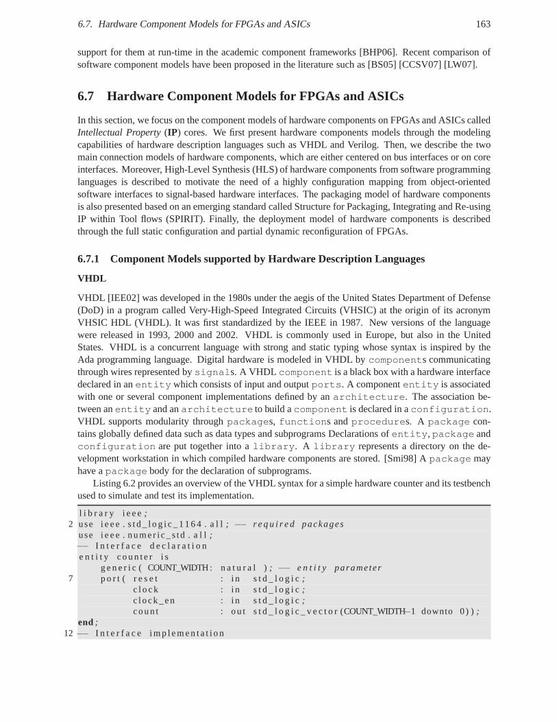
6.7. Hardware Component Models for FPGAs and ASICs 163
support for them at run-time in the academic component frameworks [BHP06]. Recent comparison ofsoftware component models have been proposed in the literature such as [BS05] [CCSV07] [LW07].
6.7 Hardware Component Models for FPGAs and ASICs
In this section, we focus on the component models of hardwarecomponents on FPGAs and ASICs calledIntellectual Property(IP) cores. We first present hardware components models throughthe modelingcapabilities of hardware description languages such as VHDL and Verilog. Then, we describe the twomain connection models of hardware components, which are either centered on bus interfaces or on coreinterfaces. Moreover, High-Level Synthesis (HLS) of hardware components from software programminglanguages is described to motivate the need of a highly configuration mapping from object-orientedsoftware interfaces to signal-based hardware interfaces.The packaging model of hardware componentsis also presented based on an emerging standard called Structure for Packaging, Integrating and Re-usingIP within Tool flows (SPIRIT). Finally, the deployment modelof hardware components is describedthrough the full static configuration and partial dynamic reconfiguration of FPGAs.
6.7.1 Component Models supported by Hardware Description Languages
VHDL
VHDL [IEE02] was developed in the 1980s under the aegis of theUnited States Department of Defense(DoD) in a program called Very-High-Speed Integrated Circuits (VHSIC) at the origin of its acronymVHSIC HDL (VHDL). It was first standardized by the IEEE in 1987. New versions of the languagewere released in 1993, 2000 and 2002. VHDL is commonly used inEurope, but also in the UnitedStates. VHDL is a concurrent language with strong and statictyping whose syntax is inspired by theAda programming language. Digital hardware is modeled in VHDL by components communicatingthrough wires represented bysignals. A VHDL component is a black box with a hardware interfacedeclared in anentitywhich consists of input and outputports. A componententity is associatedwith one or several component implementations defined by anarchitecture. The association be-tween anentity and anarchitecture to build acomponent is declared in aconfiguration.VHDL supports modularity throughpackages, functions andprocedures. A package con-tains globally defined data such as data types and subprograms Declarations ofentity, package andconfiguration are put together into alibrary. A library represents a directory on the de-velopment workstation in which compiled hardware components are stored. [Smi98] Apackage mayhave apackage body for the declaration of subprograms.
Listing 6.2 provides an overview of the VHDL syntax for a simple hardware counter and its testbenchused to simulate and test its implementation.
l i b r a r y i e e e;2 use i e e e . s t d _ l o g i c _ 1 1 6 4 . a l l; −− r e q u i r e d packages
use i e e e . numer i c_s td . a l l;−− I n t e r f a c e d e c l a r a t i o ne n t i t y c o u n t e r i s
g e n e r i c ( COUNT_WIDTH: n a t u r a l ); −− e n t i t y parameter7 p o r t ( r e s e t : i n s t d _ l o g i c;
c l o c k : i n s t d _ l o g i c;c lock_en : i n s t d _ l o g i c;coun t : ou t s t d _ l o g i c _ v e c t o r (COUNT_WIDTH−1 downto 0) );
end;12 −− I n t e r f a c e i m p l e m e n t a t i o n
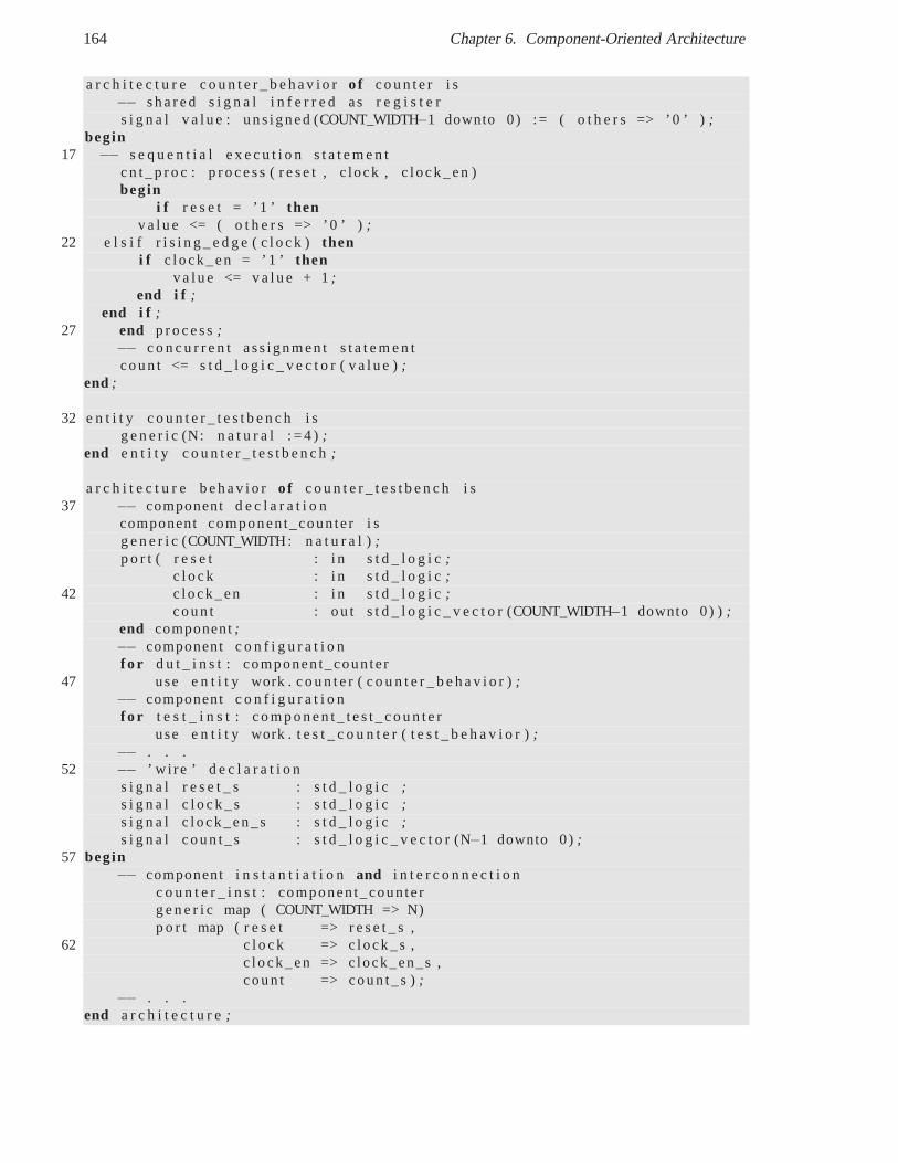
164 Chapter 6. Component-Oriented Architecture
a r c h i t e c t u r e c o u n t e r _ b e h a v i o ro f c o u n t e r i s−− s h a r e d s i g n a l i n f e r r e d as r e g i s t e rs i g n a l v a l u e : uns igned (COUNT_WIDTH−1 downto 0) := ( o t h e r s => ’0 ’ );
begin17 −− s e q u e n t i a l e x e c u t i o n s t a t e m e n t
c n t _ p r o c : p r o c e s s ( r e s e t , c lock , c lock_en )begin
i f r e s e t = ’1 ’ thenv a l u e <= ( o t h e r s => ’0 ’ );
22 e l s i f r i s i n g _ e d g e ( c l o c k )theni f c lock_en = ’ 1 ’ then
v a l u e <= v a l u e + 1;end i f ;
end i f ;27 end p r o c e s s;
−− c o n c u r r e n t ass ignmen t s t a t e m e n tcoun t <= s t d _ l o g i c _ v e c t o r ( v a l u e );
end ;
32 e n t i t y c o u n t e r _ t e s t b e n c h i sg e n e r i c (N: n a t u r a l : = 4 );
end e n t i t y c o u n t e r _ t e s t b e n c h;
a r c h i t e c t u r e b e h a v i o ro f c o u n t e r _ t e s t b e n c h i s37 −− component d e c l a r a t i o n
component componen t_coun ter i sg e n e r i c (COUNT_WIDTH: n a t u r a l );p o r t ( r e s e t : i n s t d _ l o g i c;
c l o c k : i n s t d _ l o g i c;42 c lock_en : i n s t d _ l o g i c;
coun t : ou t s t d _ l o g i c _ v e c t o r (COUNT_WIDTH−1 downto 0) );end component;−− component c o n f i g u r a t i o nf o r d u t _ i n s t : componen t_coun ter
47 use e n t i t y work . c o u n t e r ( c o u n t e r _ b e h a v i o r );−− component c o n f i g u r a t i o nf o r t e s t _ i n s t : c o m p o n e n t _ t e s t _ c o u n t e r
use e n t i t y work . t e s t _ c o u n t e r ( t e s t _ b e h a v i o r );−− . . .
52 −− ’ w i re ’ d e c l a r a t i o ns i g n a l r e s e t _ s : s t d _ l o g i c;s i g n a l c l o c k _ s : s t d _ l o g i c ;s i g n a l c lock_en_s : s t d _ l o g i c;s i g n a l coun t_s : s t d _ l o g i c _ v e c t o r (N−1 downto 0);
57 begin−− component i n s t a n t i a t i o nand i n t e r c o n n e c t i o n
c o u n t e r _ i n s t : componen t_coun terg e n e r i c map ( COUNT_WIDTH => N)p o r t map ( r e s e t => r e s e t _ s ,
62 c l o c k => c lock_s ,c lock_en => c lock_en_s ,coun t => coun t_s );
−− . . .end a r c h i t e c t u r e;
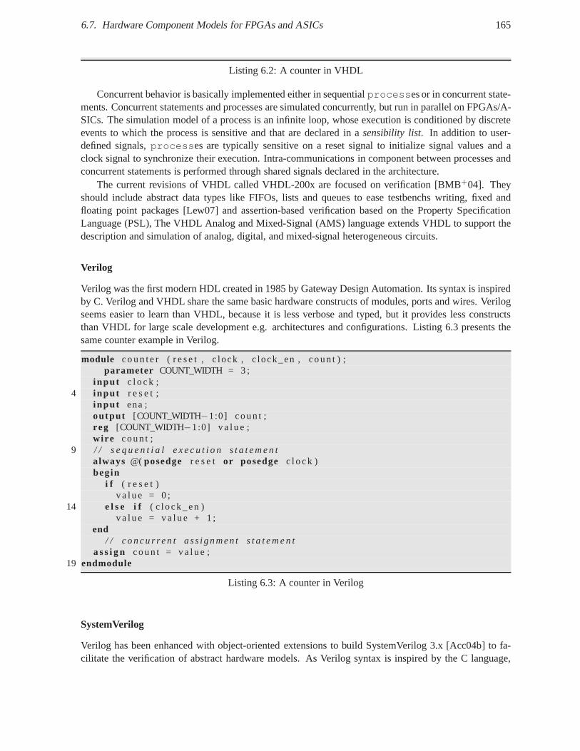
6.7. Hardware Component Models for FPGAs and ASICs 165
Listing 6.2: A counter in VHDL
Concurrent behavior is basically implemented either in sequentialprocesses or in concurrent state-ments. Concurrent statements and processes are simulated concurrently, but run in parallel on FPGAs/A-SICs. The simulation model of a process is an infinite loop, whose execution is conditioned by discreteevents to which the process is sensitive and that are declared in a sensibility list. In addition to user-defined signals,processes are typically sensitive on a reset signal to initialize signal values and aclock signal to synchronize their execution. Intra-communications in component between processes andconcurrent statements is performed through shared signalsdeclared in the architecture.
The current revisions of VHDL called VHDL-200x are focused on verification [BMB+04]. Theyshould include abstract data types like FIFOs, lists and queues to ease testbenchs writing, fixed andfloating point packages [Lew07] and assertion-based verification based on the Property SpecificationLanguage (PSL), The VHDL Analog and Mixed-Signal (AMS) language extends VHDL to support thedescription and simulation of analog, digital, and mixed-signal heterogeneous circuits.
Verilog
Verilog was the first modern HDL created in 1985 by Gateway Design Automation. Its syntax is inspiredby C. Verilog and VHDL share the same basic hardware constructs of modules, ports and wires. Verilogseems easier to learn than VHDL, because it is less verbose and typed, but it provides less constructsthan VHDL for large scale development e.g. architectures and configurations. Listing 6.3 presents thesame counter example in Verilog.
module c o u n t e r ( r e s e t , c lock , c lock_en , coun t ) ;parameter COUNT_WIDTH = 3 ;
i nput c l o c k ;4 i nput r e s e t ;
i nput ena ;output [COUNT_WIDTH−1:0] coun t ;reg [COUNT_WIDTH−1:0] v a l u e ;wire coun t ;
9 / / s e q u e n t i a l e x e c u t i o n s t a t e m e n talways @( posedge r e s e t or posedge c l o c k )begin
i f ( r e s e t )v a l u e = 0 ;
14 e l s e i f ( c l ock_en )v a l u e = v a l u e + 1 ;
end/ / c o n c u r r e n t ass ignmen t s t a t e m e n t
a s s i g n coun t = v a l u e ;19 endmodule
Listing 6.3: A counter in Verilog
SystemVerilog
Verilog has been enhanced with object-oriented extensionsto build SystemVerilog 3.x [Acc04b] to fa-cilitate the verification of abstract hardware models. As Verilog syntax is inspired by the C language,
166 Chapter 6. Component-Oriented Architecture
SystemVerilog naturally provides OO extensions close to C++. A classconstruct was introduced to de-clare instance variables calledpropertiesand member functions namedmethods. SystemVerilog supportsclass inheritance, polymorphism and dynamic allocation ofclasses, but the synthetizable semantics ofthese advanced features are not defined.
6.7.2 Connection Model for hardware
Two main integration approaches are usually distinguishedconcerning the interfaces of IP cores: bus-centric and core-centric approaches [CLN+02].
Bus-Centric Interfaces
In the bus-centric approach, hardware component interfaces conform to a computer or SoC bus speci-fication such as ARM AMBA, IBM CoreConnect or Altera Avalon for virtual IP core components, orPCI Express or USB for physical components. Dedicated wrappers must be developed or bought to reuseexisting IPs on another bus. Such an approach is not satisfactory for a standard mapping for IDL to HDL.
Core-Centric or Socket-based Interfaces
In the core-centric or socket-based approach, hardware component interfaces conform to a hardwareinterface specification such as VCI [Gro01] or OCP [OI06]. Socket-based design allow designers todecouple IPs cores from each other and from the on-chip interconnect. Sockets favor reuse and portabilityof IP cores. Interface adapters are required to convert the common interface and protocol to proprietaryinterfaces and protocols. However, this adaptation is inferior or equal to the efforts required by the bus-centric approach, as the socket interface is designed to only capture the communication needs of each IPcore [OIa] [OIb]. The core-centric approach is compatible with the portability requirement of hardwarebusiness components, that is why we propose in chapter 7 an IDL-to-HDL mapping inspired by thesocket-based approach.
6.7.3 High-Level Synthesis (HLS)
With equivalent functionalities, writing HDL code is oftenmuch more verbose, error-prone and timeconsuming than coding in a high-level software programminglanguages. This productivity gap is similarto the use of assembly languages instead of high level languages like C. The main reason is the low levelof abstraction offered by HDLs. Since the 2000s, numerous works have thus proposed to translate high-level languages into HDLs throughHigh-Level Synthesis(HLS). Thanks to the maturity of HLS tools,HLS recently seems to have gained more acceptance in the electronics industry. Advances in HLS allowto obtain comparable or even better results in terms of speedand area than handwritten HDL code, sincedesigners may focus on design space exploration instead of HDL coding.
Numerous commercial tools perform high-level synthesis mostly from C-like languages such as Cyn-thesizer [Sys] from Forte Design Systems, PICO [Syn] from Synfora Inc., CoDeveloper [Tec] from Im-pulse Accelerated Technologies Inc., DK Design Suite [Sol]from Agility Design Solutions Inc., C-To-Hardware [Alt] from Altera and Catapult C [Gra] from Mentor Graphics Corp, CyberWorkBench [NST]from NEC System Technologies Ltd., XtremDSP from Xilinx andBluespec SystemVerilog (BSV) [Blu]from Bluespec Inc.
There are also various academic tools such as Stream-C [FGL01] from Los Alamos National Lab-oratories, ROCCC [GMN06] from the university of Riverside,SA-C [RCP+01] from the university ofColorado, SPARK [GDGN03] from the university of San Diego and GAUT [CCB+06] from Lester inFrance. Some of these commercial and academic tools are presented in [CM08].
6.7. Hardware Component Models for FPGAs and ASICs 167
HLS from sequential languages
G.A.U.T. GAUT54 [CCB+06] is an academic HLS tool targeting digital signal processing applica-tions. GAUT generates RTL VHDL and cycle-accurate SystemC for the SoCLib55 virtual platform froma bit-accurate algorithmic specification in C/C++. After choosing a library of hardware operators char-acterized for specific FPGA/ASIC technology targets and compiling the C/C++ code, GAUT generates acontrol-data flow graph describing the dependencies between input/output data and hardware operatorslike multipliers and adders. Designers may specify hardware synthesis constraints such as clock period,cadence i.e. throughput, target technology, allocation strategy (e.g. distributed or global) and schedulingstrategy. (e.g. As Soon As Possible (ASAP) or no pipeline). Designers may also specify I/O timing andmemory mapping constraints. Memory constraints allow assigning variables and constants in registersor in memory banks at user-defined addresses and with initialvalues. After synthesis, a GANTT dia-gram presents the scheduling of accesses to operators, variables and registers. The architecture may beautomatically pipelined. The generated accelerator may besimulated with ModelSim. The architectureof the produced accelerators contains of a functionalProcessing Unit(PU), a Memory Unit (MU ), aCommunication and Multiplexing Unit(COMU ) and a GALS/LIS56 interface. The interface of a PUhas clock, reset, enable and internal input/output data signals. The PU consists of operators, registersand FSM with Datapath (FSMD). The MU has the same type of interface and contains RAM(s), addressgenerators, mux, read and write registers and tri-states connected to the internal input/output data buses.The COMU has also the same type of interface and provides external signals (clock, reset and I/O ports).The generation of the memory unit is configured with the assignment of variables to memory banks,their address and initial values of constants. The generation of the configuration unit is configured bychoosing the number of dedicated I/O ports, their latency and by selecting between different kinds androle of hardware interfaces (LIS master, LIS slave, FIFO andSundance57-specific interfaces).
HLS from concurrent languages
Instead of using sequential C code, some HLS tools such as Cynthesizer and BlueSpec use nativelyconcurrent languages resp SystemC and BlueSpec SystemVerilog (BSV).
Forte Cynthesizer Cynthesizer [Sys] [CM08] from Forte Design Systems is a HLS tool which takesas input SystemC code and generates SystemC RTL and Verilog RTL code. As opposed to ANSI C,SystemC allows designers to explicitly describe concurrency. Supported SystemC constructs includeSC_CTHREAD, SC_METHOD, MODULE and sc_in/sc_out ports. Designers must implement thecommunication protocol in SystemC RTL using sc_in/sc_out ports. The member variables in MODULEsare inferred as storage elements. The supported data types includesc_int/sc_bigint, fixed-pointand floating-point types. Examples of generated designs go from control-oriented applications such asUSB/SATA controllers to signal-processing IPs. Cynthesizer also supports architecture exploration. Tooptimize the synthesis, each operator such as multipliers has been characterized in terms of timing inparticular latency, area and power consumption.
BlueSpec BlueSpec HLS tool relies on a formal and parallel language called BlueSpec SystemVerilog(BSV). This language is inspired from works achieved in concurrent programming, notably the Haskellfunctional language, and Hoe and Arvind’s works [HA04] at MIT on Term Rewriting Systems (TRS) for
54http://www-labsticc.univ-ubs.fr/www-gaut55https://www.soclib.fr56Latency-insensitive system57http://www.sundancedsp.com
168 Chapter 6. Component-Oriented Architecture
hardware design. BSV is based on the concept of parallel transactions. As in transaction middlewares,an atomic transaction is a collection of sequential actionswhich are either all executed (commit) ornot at all (cancelled or rollback). As opposed to blocking synchronization based on locks using mutexand semaphores, transactions support non-blocking synchronization avoiding deadlocks. Atomicity oftransactions allows safer composition and better scalability than the lock-based approach. The BSVlanguage allows the definition of guarded atomic methods whose execution is conditioned by executionrules such as empty/full FIFO. BlueSpec automatically generates the control logic to shared resources.The hardware interface of method invocations contains an inputenable signal, an outputready signal,input signals for method parameters and output signals for results. Implementations in BSV can beparametrized by generic data types similar to templates andmodule composition. Methods may beregrouped into interfaces provided and required by modules. IP cores in Verilog can be imported in thetool and converted to BSV description to ease IP reuse. The tool has been used to design control-orientedapplications such as processor, DMA, peripheral devices and data-oriented applications such as H264,OFDM 802.11a (WiFi) and 802.16 (WiMax)58.
6.7.4 Hardware Interface Synthesis
The application of the object model downto hardware presented in chapter 4.2.3 shows that a single kindof hardware interfaces, i.e. write-only interfaces, is proposed for hardware objects and such an interfacerepresents one point in the mapping space. Works achieved inhardware interface synthesis [RBK00] mo-tivate the need for more flexibility when mapping object interfaces to hardware interfaces. In [SKH98],the following classification of hardware interfaces is proposedsend and forgetinterfaces for data buses,strobe interfaces to indicate when data are valid on a data bus,handshakeinterfaces andFIFO inter-faces. In Mentor Catapult®tool [Gra07], designers explicitty associate to one or several parameters of aC function hardware interfaces similar to the ones proposedin [SKH98]. Input function parameters areread, while output parameters are written. In Altera C2H ®compiler [Alt07b], the generated hardwareaccelerators have read-only Avalon Memory-Mapped ports for input parameters and write-only ports foroutput parameters.
Position of this work
Classical works have been carried out in hardware interfacesynthesis [RBK00] to generate the hardwarecomponent interfaces such as network interfaces in MPSoCs [GRJ04] or the wrappers to adapt the in-terfaces of hardware components [PRSV98] [DRS04]. However, all these works are based on low-levelinterface specification typically at RTL level, while we target high-level interface synthesis and interfacerefinement.
An IDL-to-VHDL mapping should generate standard core interfaces to support reuse. In addition tothe low-level contract of interconnection protocols, a higher level approach requires a functional contract,which may be specified in IDL and formally mapped onto a message whatever the abstraction levels. Ourproposition consists in mixing the higher semantics level of hardware components and the flexibility ofHLS.
There are still open questions regarding HLS tools such as the portability of C-like source codesfrom one tool to another due to the use of proprietary libraries, the lack of a standard mapping fromC-like languages to HDLs, and the integration of the generated hardware modules within existing SoCson FPGAs.
58http://csg.csail.mit.edu/oshd/index.html
6.7. Hardware Component Models for FPGAs and ASICs 169
6.7.5 Packaging Model
An emerging standard packaging model for hardware components at different abstraction level is theIP-XACT specification. IP-XACT is a set of specifications proposed by the SPIRIT (Structure for Pack-aging, Integrating and Re-using IP within Tool flows) [SPI08] consortium, which is composed of EDAvendors such as Cadence, Mentor Graphics and Synopsis, and end-users such as ARM, ST, NXP andTI. The objective of this consortium are to improve IP reuse and enables design automation. Anotherobjective is that the same hardware component could be described at several abstraction levels, notablyTLM and RTL, that offer different views according to the level of details required by the design phase(design, validation, integration) [Ghe06]. The IP-XACT specification defines XML files formats (XMLSchema) to describe the characteristics of Intellectual Properties such as hardware component interfaces(signal direction and width, bus interfaces), registers (address, width and bitfields) and the interconnec-tion between hardware components (business components andbus components).
An API calledTight Generator Interface(TGI ) is also specified to make this information (meta-data)accessible to generation tools. Based on this API, a chain ofgenerators can be developed to automate andcustomize each phase of enterprise design flow notably the documentation, configuration and integrationof IP blocks. These generators may be scripts or software programs that instantiate hardware componentsin a top-level component and generate the required interface and protocol adapters and drivers. Thesespecifications are freely available and are studied by the IEEE Working Group P1685 for standardization.We consider that the IP-XACT specification could correspondto a Platform Specific Model (PSM) forthe Deployment and Configuration (OMG D&C) of hardware components. The IP-XACT API allowsaccess to repositories of hardware components. Compared tosoftware packaging models, SPIRIT doesnot define the location of hardware artifacts such as bitstream.
6.7.6 Deployment Model
Hardware IP core components can be either statically deployed on an FPGA at reset-time or dynamicallydeployed at run-time. Static FPGA reconfiguration means thecomplete configuration of the FPGA chipusing a total bitstream. In dynamic partial reconfiguration, IP cores belonging to the so-called static partwithin the FPGA may be still running, while other IP cores arebeing physically configured by a partialbitstream.
FPGA devices are configured by loading a set of configuration bits referred to as abitstreamfile intothe SRAM-based configuration memory of the FPGA. As the SRAM59 memory is volatile i.e. its contentmay be lost when the memory is not powered, FPGA devices need to be configured at each power-up.
Static Total Reconfiguration of FPGAs
Static total reconfiguration of FPGAs is typically triggered outside the FPGA by a third party e.g. theend users when the chip is reset either when powered-up (a.k.a. power-on reset) or while running.Another classical way to totally reconfigure an FPGA is via a JTAG 60 port but this is only used bythe designers for debug purpose and not by the end users during system operation. Usually, the totalbitstream is persistently stored in an on-board EEPROM (Electrically-Erasable Programmable Read-Only Memory) which may be programmed by FPGA vendor programmer tools such as Xilinx iMPACTor Altera Quartus Programmer.
As the reconfiguration time is proportional to the bitstreamsize, the width of the physical configura-tion bus and the bitstream transfer rate, a total reconfiguration of an FPGA is time consuming. Moreover,
59Static Random Access Memory60Joint Test Action Group
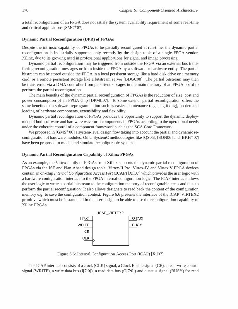
170 Chapter 6. Component-Oriented Architecture
a total reconfiguration of an FPGA does not satisfy the systemavailability requirement of some real-timeand critical applications [SMC+07].
Dynamic Partial Reconfiguration (DPR) of FPGAs
Despite the intrinsic capability of FPGAs to be partially reconfigured at run-time, the dynamic partialreconfiguration is industrially supported only recently bythe design tools of a single FPGA vendor,Xilinx, due to its growing need in professional applications for signal and image processing.
Dynamic partial reconfiguration may be triggered from outside the FPGA via an external bus trans-ferring reconfiguration messages or from inside the FPGA by asoftware or hardware entity. The partialbitstream can be stored outside the FPGA in a local persistent storage like a hard disk drive or a memorycard, or a remote persistent storage like a bitstream server[BDGC08]. The partial bitstream may thenbe transferred via a DMA controller from persistent storages in the main memory of an FPGA board toperform the partial reconfiguration.
The main benefits of the dynamic partial reconfiguration of FPGAs is the reduction of size, cost andpower consumption of an FPGA chip [DPML07]. To some extend, partial reconfiguration offers thesame benefits than software reprogrammation such as easier maintenance (e.g. bug fixing), on-demandloading of hardware components, extensibility and flexibility.
Dynamic partial reconfiguration of FPGAs provides the opportunity to support the dynamic deploy-ment of both software and hardware waveform components in FPGAs according to the operational needsunder the coherent control of a component framework such as the SCA Core Framework.
We proposed in [GMS+06] a system-level design flow taking into account the partial and dynamic re-configuration of hardware modules. Other SystemC methodologies like [QS05], [SON06] and [BKH+07]have been proposed to model and simulate reconfigurable systems.
Dynamic Partial Reconfiguration Capability of Xilinx FPGAs
As an example, the Virtex family of FPGAs from Xilinx supports the dynamic partial reconfiguration ofFPGAs via the ISE and Plan Ahead design tools. Virtex-II Pro,Virtex-IV and Virtex V FPGA devicescontain an on-chipInternal Configuration Access Port(ICAP ) [Xil07] which provides the user logic witha hardware configuration interface to the FPGA internal configuration logic. The ICAP interface allowsthe user logic to write a partial bitstream to the configuration memory of reconfigurable areas and thus toperform the partial reconfiguration. It also allows designers to read back the content of the configurationmemory e.g. to save the configuration context. Figure 6.6 presents the interface of the ICAP_VIRTEX2primitive which must be instantiated in the user design to beable to use the reconfiguration capability ofXilinx FPGAs.
Figure 6.6: Internal Configuration Access Port (ICAP) [Xil07]
The ICAP interface consists of a clock (CLK) signal, a Clock Enable signal (CE), a read-write controlsignal (WRITE), a write data bus (I[7:0]), a read data bus (O[7:0]) and a status signal (BUSY) for read
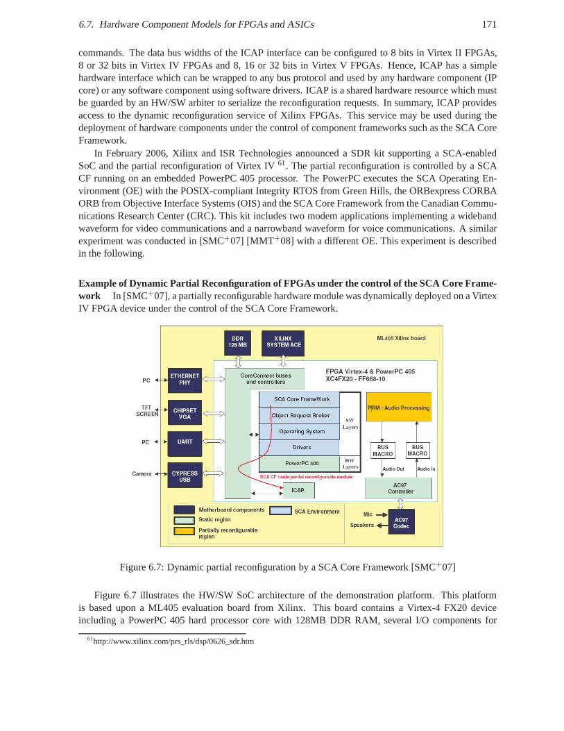
6.7. Hardware Component Models for FPGAs and ASICs 171
commands. The data bus widths of the ICAP interface can be configured to 8 bits in Virtex II FPGAs,8 or 32 bits in Virtex IV FPGAs and 8, 16 or 32 bits in Virtex V FPGAs. Hence, ICAP has a simplehardware interface which can be wrapped to any bus protocol and used by any hardware component (IPcore) or any software component using software drivers. ICAP is a shared hardware resource which mustbe guarded by an HW/SW arbiter to serialize the reconfiguration requests. In summary, ICAP providesaccess to the dynamic reconfiguration service of Xilinx FPGAs. This service may be used during thedeployment of hardware components under the control of component frameworks such as the SCA CoreFramework.
In February 2006, Xilinx and ISR Technologies announced a SDR kit supporting a SCA-enabledSoC and the partial reconfiguration of Virtex IV61. The partial reconfiguration is controlled by a SCACF running on an embedded PowerPC 405 processor. The PowerPCexecutes the SCA Operating En-vironment (OE) with the POSIX-compliant Integrity RTOS from Green Hills, the ORBexpress CORBAORB from Objective Interface Systems (OIS) and the SCA Core Framework from the Canadian Commu-nications Research Center (CRC). This kit includes two modem applications implementing a widebandwaveform for video communications and a narrowband waveform for voice communications. A similarexperiment was conducted in [SMC+07] [MMT+08] with a different OE. This experiment is describedin the following.
Example of Dynamic Partial Reconfiguration of FPGAs under the control of the SCA Core Frame-work In [SMC+07], a partially reconfigurable hardware module was dynamically deployed on a VirtexIV FPGA device under the control of the SCA Core Framework.
Figure 6.7: Dynamic partial reconfiguration by a SCA Core Framework [SMC+07]
Figure 6.7 illustrates the HW/SW SoC architecture of the demonstration platform. This platformis based upon a ML405 evaluation board from Xilinx. This board contains a Virtex-4 FX20 deviceincluding a PowerPC 405 hard processor core with 128MB DDR RAM, several I/O components for
61http://www.xilinx.com/prs_rls/dsp/0626_sdr.htm
172 Chapter 6. Component-Oriented Architecture
communications such as USB chip and Ethernet PHY transceiver, and audio and video facilities viaVGA62 and AC6397 chips.
Hardware architecture The hardware architecture consists of a CoreConnect On-Chip Periph-eral Bus (OPB) bus on which are connected an ICAP controller and various IP cores such as an AC97controller to control external I/O chips.
The embedded PowerPC manages the dynamic partial reconfiguration through the ICAP controllerdriver, the continuous display of a video on a TFT screen connected to the VGA chip and the communi-cation with a GUI residing on a laptop via an Ethernet cable. Amicrophone and a speaker are connectedto the board.
An audio processing module is implemented as a dynamically and partially reconfigurable module.The user may choose via the GUI the audio effects to be appliedon the voice which is captured by themicrophone. This choice triggers the partial reconfiguration of a dynamic reconfigurable area with thepartial bitstream of the audio processing module.
Software architecture The software architecture of the demonstrator is compliantwith the SCAspecification [JTR01] The SCA OE is based on the MontaVista64 Linux Real-Time Operating System,the open-source MICO65 CORBA ORB and Thales SCA-compliant Core Framework.
The static bitstream of the hardware platform components (i.e. the OPB bus and the I/O IP cores),the dynamic bitstreams of the hardware application components (i.e. the audio processing module), thesofware image of the OE and the software application components are stored on a Compact Flash cardusing System ACE66. The static bitstream and the sofware image of the OE are loaded on the FPGAwhen the board is powered up. During application deployment, the Core Framework dynamically loadsthe partial bitstream stored in the Compact Flash and writesits content to the ICAP controller using theICAP driver appearing as a Linux kernel module.
The SCA Core Framework manages both the deployment of software application components on thePowerPC processor and the deployment of the hardware audio component in the reconfigurable area.The PowerPC processor is abstracted by a GPP Executable Device which provides an OS-independentAPI to load and execute the software application on the processor. The reconfigurable area is abstractedby an FPGA Loadable Device which provides an FPGA-independent API to load a partial bitstream in areconfigurable region.
An open design decision about the software architecture concerns the granularity of an FPGA logicaldevice i.e. the number of reconfigurable areas which must be assigned to an FPGA logical device.Indeed, a SCA logical device may be assigned to all reconfigurable areas or to each area. In this case,the number of logical device instances depends on the numberof reconfigurable areas. In the nextchapter, we will consider that an FPGA logical device for allreconfigurable areas is a better solutionas 1) a single logical device coherently represents the configuration logic (e.g. the ICAP controller)as a shared resource which can only be used by a single software driver and can only satisfy a singlereconfiguration request at a time, and 2) the bitstream is self-contained andself-deployableas it containsa header with addressing information indicating the area tobe reconfigured. The main avantage is thatthere is always a single FPGA logical device instance regardless of the number of reconfigurable areas.Hence, the software architecture is independent from the hardware reconfiguration architecture and both
62Video Graphics Array63Audio Codec64http://www.mvista.com65http://www.mico.org66Advanced Configuration Environment
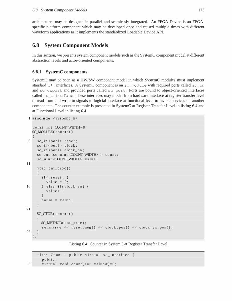
6.8. System Component Models 173
architectures may be designed in parallel and seamlessly integrated. An FPGA Device is an FPGA-specific platform component which may be developed once and reused multiple times with differentwaveform applications as it implements the standardized Loadable Device API.
6.8 System Component Models
In this section, we presents system component models such asthe SystemC component model at differentabstraction levels and actor-oriented components.
6.8.1 SystemC components
SystemC may be seen as a HW/SW component model in which SystemC modules must implementstandard C++ interfaces. A SystemC component is ansc_module with required ports calledsc_inandsc_export and provided ports calledsc_port. Ports are bound to object-oriented interfacescalledsc_interface. These interfaces may model from hardware interface at register transfer levelto read from and write to signals to logicial interface at functional level to invoke services on anothercomponents. The counter example is presented in SystemC at Register Transfer Level in listing 6.4 andat Functional Level in listing 6.4.
1 # i nc lude <systemc . h>
c o n s t i n t COUNT_WIDTH=8;SC_MODULE( c o u n t e r ){
6 sc_ in <bool > r e s e t ;sc_ in <bool > c l o c k ;sc_ in <bool > c lock_en ;sc_ou t < s c _ u i n t <COUNT_WIDTH> > coun t ;s c _ u i n t <COUNT_WIDTH> v a l u e ;
11vo id c n t _ p r o c ( ){
i f ( ! r e s e t ) {v a l u e = 0 ;
16 } e l s e i f ( c l ock_en ) {v a l u e ++;
}coun t = v a l u e ;
}21
SC_CTOR( c o u n t e r ){
SC_METHOD( c n t _ p r o c ) ;s e n s i t i v e << r e s e t . neg ( ) << c l o c k . pos ( ) << c lock_en . pos ( );
26 }} ;
Listing 6.4: Counter in SystemC at Register Transfer Level
c l a s s Count : p u b l i c v i r t u a l s c _ i n t e r f a c e {p u b l i c :
3 v i r t u a l vo id coun t ( i n t v a l u e&) =0 ;
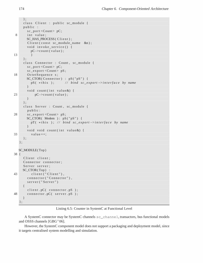
174 Chapter 6. Component-Oriented Architecture
} ;c l a s s C l i e n t : p u b l i c sc_module {p u b l i c :
s c _ p o r t <Count > pC ;8 i n t v a l u e ;
SC_HAS_PROCESS ( C l i e n t ) ;C l i e n t ( c o n s t sc_module_name &n ) ;vo id i n v o k e _ s e r v i c e ( ) {
pC−>coun t ( v a l u e ) ;13 }
} ;c l a s s Connec to r : Count , sc_module {
s c _ p o r t <Count > pC ;sc_expo r t <Count > pS ;
18 Oc te tSequence s ;SC_CTOR( Connec to r ) : pS ( " pS " ) {
pS ( * t h i s ) ; / / b ind sc_expo r t−>i n t e r f a c e by name}vo id coun t ( i n t v a l u e&) {
23 pC−>coun t ( v a l u e ) ;}
} ;c l a s s S e r v e r : Count , sc_module {
p u b l i c :28 sc_expo r t <Count > pS ;
SC_CTOR( Modem ) : pS ( " pS" ) {pT ( * t h i s ) ; / / b ind sc_expo r t−>i n t e r f a c e by name
}vo id vo id coun t ( i n t v a l u e&) {
33 v a l u e ++;} ;
} ;
SC_MODULE( Top )38 {
C l i e n t c l i e n t ;Connec to r c o n n e c t o r ;S e r v e r s e r v e r ;SC_CTOR( Top ) :
43 c l i e n t ( " C l i e n t " ) ,c o n n e c t o r ( " Connec to r " ) ,s e r v e r ( " S e r v e r " )
{c l i e n t . pC ( c o n n e c t o r . pS ) ;
48 c o n n e c t o r . pC ( s e r v e r . pS ) ;}
} ;
Listing 6.5: Counter in SystemC at Functional Level
A SystemC connector may be SystemC channelssc_channel, transactors, bus functional modelsand OSSS channels [GBG+06].
However, the SystemC component model does not support a packaging and deployment model, sinceit targets centralised system modelling and simulation.
6.9. Conclusion 175
6.8.2 Actor-Oriented Components
To bridge the conceptual gap between signal-based hardwaredesign and method-based software design,Lee et al. propose the concept ofactors. Actors are abstract system components which are concurrent andreconfigurable. They provide a data-flow oriented interfacecomposed of ports and configurable param-eters. A hierarchical composition of actors is called amodel. An actor provide an executable behavioralspecification based on operational semantics. The component model of actor-oriented components aremodel of computations. Each model of computations containsoperational rules which govern the exe-cution of a model in particular when components perform computation, update their state and performcommunication. The Ptolemy II tool supports the hierarchical composition of heterogeneous models ofcomputation.
The concept of Lee’s actor is related to the actor concurrency model introduced by Hewittt anddeveloped by Agha. The differences between Lee’s and Agha’sactors are that Agha’s actors are activecomponents with their own thread of control and communicatethrough asynchronous message passing,while Lee’s actors are passive components without their ownthread of control and communicate throughasynchronous or synchronous message passing.
The differences between object-oriented components and actor-oriented components are that objectinterfaces do not describe explicitly time, concurrency, communication and usage patterns as opposedto actors. The differences between signal-based hardware components and actor-oriented componentsare that patterns of communication and interaction are difficult to specify in HDLs. The set of signalsprovided and required by hardware component interfaces describe a low-level transfer syntax but not thehigh-level semantics needed for component composition.
For Lee et al., software methods represent atransfer of controland sequential execution, whilehardware signals represent atransfer of dataand parallel execution. We consider this separation as toosimplistic. Any application has both control-oriented anddata-oriented processing at various degrees. Weconsider that software methods and hardware signals may represent a transfer of control, a transfer ofdata or a transfer of control and data. Transfer of control does not mandatorily imply loss of control fromthe caller/master to the callee/slave [MMP00]. Software methods may be blocking or non-blocking usingfuture variables to perform computation and communication in parallel. Hardware interfaces typicallycontain control and/or data signals to implement synchronization and communication protocols.
However, the refinement and generation of hardware and software components from actor-orientedmodels are not described in details as far as we know. While actor-oriented components have data ports,object-oriented components have higher-level object-oriented interfaces that provide functional services.In contrast to the execution model of actor-oriented components based on formal models of computation,the object-oriented component approach relies on more models for component, connector, configuration,packaging and deployment. In this work, we focus on the interface refinement of abstract object-orientedcomponents to synthetizable hardware object-oriented components.
6.9 Conclusion
In this chapter, we presented the main concepts underlying the component oriented approach for softwareand hardware engineering.
Hardware components provide and require low-level signal-based interfaces, which consist of input,output and input/output RTL ports. Software components provide and require high-level method-basedinterfaces, which consist of operations with input, outputand input/output parameters.
The software component-oriented approach is an evolution from the object-oriented approach. Whereasthe object-oriented approach is focused on classes, objects and inheritance, the component-oriented ap-proach is focused on interactions, dependencies and composition.
176 Chapter 6. Component-Oriented Architecture
In software architecture, the component-oriented approach relies on four main standard models:component models defining component structure and behavior,connector models to specify com-ponent interactions,container model to mediate access to middleware services, andpackaging anddeployment models to deploy distributed component-based applications. Thecomposition model in-cludes the connector model and the deployment model. The component model is a set of standards,conventions and rules that components must respect. The connection model defines a collection of con-nectors and supporting facilities for component assembling. The deployment model describes how toinstall component-based applications into the execution environment.
A software component provides and requires services through multiple interfaces that allow an ex-plicit specification of external dependencies and a separation of concerns between functional interfacesfor business logic and non-functional interfaces for technical logic e.g. regarding configuration, deploy-ment and activation, packaging, deployment (i.e. installation, connection), life cycle (i.e. initialization,configuration and activation), administration (e.g. monitoring and reconfiguration). A software compo-nent has logical ports that provide and require properties,methods and events.
A software connector is a component which binds the requiredand provided ports of two or morecomponents. It mediates component interactions. Examplesof interaction patterns include method in-vocation between client and server roles, event delivery between publisher and subscriber roles, datastream between source and sink roles, message passing between sender and receiver roles and sharedmemory between writer and reader roles. It may deal with non-functional services such as commu-nication, coordination, conversion, synchronization, arbitrating, routing, and scheduling. Connectorsseparate computation from interactions. The notion of connector reifies the notions of relationships andinteractions in the object model. When the same components are deployed on nodes in different addressspaces, the connector may use or implement the required middlewares services such as marshalling/un-marshalling and interface adaptation. In this case, the connector is partitioned into two "fragments" thatmay represent a stub/skeleton pair or two middleware instances.
Connector template architecture may include interceptors, stub/skeleton, dispatcher, arbiter and sched-uler.
A software container transparently integrates componentsinto their operating environment, mediateaccess to middleware services and manage component life cycle.
Like the SCA, we distinguish two basic kinds of components: application components and platformcomponents. Application components implement business logic and require HW/SW platform services,while platform components implement technical logic and provides HW/SW platform services.
A component may have a functional or algorithmic implementation e.g. in executable UML, Mat-lab/Simulink, SystemC TLM; a software implementation e.g.in C, C++ or Java; or a hardware imple-mentation e.g. in synthesizable SystemC RTL, VHDL or Verilog.
For instance, the SCA component model defines an ApplicationComponent Model with theLifeCycleandPropertySet interface withih theResource interface and a Hardware Platform ComponentModel with theDevice interface. The SCA connection model is based on thePort andPortSupplierinterfaces. The SCA deployment model is based on the Framework Control interfaces and the Domainprofile defining XML descriptors.
In the hardware component models, a hardware component has input, output, input/output RTL portsthat provide and require one or several signal-based interfaces. The connection model of hardware com-ponents is based on standard bus interfaces and communication protocols. An emerging packaging modelfor hardware components is the IP-XACT specification, whichdefines XML schema files to describe thecharacteristics of IP core components such as hardware interfaces, registers and interconnection. Thedeployment model of hardware IP core components can be either statically deployed on an FPGA atreset-time or dynamically deployed at run-time.
In the next chapter, we will expose how we propose to unify hardware, software and system compo-

6.9. Conclusion 177
nents by mapping high-level method-based software interfaces onto the signal-based hardware interfacesto reduce the abstraction and implementation gap.

Chapter 7
Unified Component and MiddlewareApproach for Hardware/Software
Embedded Systems
Contents7.1 Introduction . . . . . . . . . . . . . . . . . . . . . . . . . . . . . . . . . . . .. . . 180
7.2 Component-Oriented Design Flow . . . . . . . . . . . . . . . . . . . .. . . . . . . 181
7.2.1 Existing design flow and methodology for SDR . . . . . . . . .. . . . . . . . 181
7.2.2 Proposed simulation methodology . . . . . . . . . . . . . . . . .. . . . . . . 182
7.2.3 Proposed Design Flow . . . . . . . . . . . . . . . . . . . . . . . . . . . .. . 183
7.3 Mapping OO component-based specification to system, SW and HW components 185
7.3.1 IDL3 to SystemC Language Mapping . . . . . . . . . . . . . . . . . .. . . . 185
7.3.2 IDL3 to HDL Mapping . . . . . . . . . . . . . . . . . . . . . . . . . . . . . .191
7.3.3 Hardware Mapping Applications . . . . . . . . . . . . . . . . . . .. . . . . . 211
7.3.4 Mapping Implementation and Code Generation . . . . . . . .. . . . . . . . . 219
7.4 Hardware Application of the Software Communications Architecture . . . . . . . 235
7.4.1 Hardware SCA Resources, Device and Services . . . . . . . .. . . . . . . . . 235
7.4.2 SCA Operating Environment for FPGA . . . . . . . . . . . . . . . .. . . . . 236
7.4.3 Hardware SCA Resource Interface . . . . . . . . . . . . . . . . . .. . . . . . 239
7.4.4 Memory-Mapped Hardware/Software Resource Interface . . . . . . . . . . . . 240
7.4.5 Extension of the SCA Domain Profile for hardware components . . . . . . . . 241
7.4.6 Deployment of Hardware SCA Resource Components . . . . .. . . . . . . . 244
7.5 Hardware Middleware Architecture Framework . . . . . . . . . . . . . . . . . . 245
7.5.1 Application and Protocol personalities . . . . . . . . . . .. . . . . . . . . . . 246
7.5.2 Application layer . . . . . . . . . . . . . . . . . . . . . . . . . . . . . .. . . 246
7.5.3 Presentation layer . . . . . . . . . . . . . . . . . . . . . . . . . . . . .. . . . 246
7.5.4 Dispatching layer . . . . . . . . . . . . . . . . . . . . . . . . . . . . . .. . . 248
7.5.5 Messaging layer . . . . . . . . . . . . . . . . . . . . . . . . . . . . . . . .. 248
7.5.6 Transport layer . . . . . . . . . . . . . . . . . . . . . . . . . . . . . . . .. . 249
7.5.7 Performance Overhead . . . . . . . . . . . . . . . . . . . . . . . . . . .. . . 249
7.6 Limitations . . . . . . . . . . . . . . . . . . . . . . . . . . . . . . . . . . . . .. . . 249
179
180Chapter 7. Unified Component and Middleware Approach for Hardware/Software Embedded Systems
7.7 Conclusion . . . . . . . . . . . . . . . . . . . . . . . . . . . . . . . . . . . . . .. . 250
In the previous chapters, we saw that different concepts, models and methodologies were proposedto unify the design of hardware/software embedded systems.The distributed object model was notablyapplied to hardware/software modules to provide common concepts between hardware and software de-signers. Language mappings were proposed to map method-based software interfaces to signal-basedhardware interfaces, but each mapping proposition only represents one solution in the mapping explo-ration space. The component-oriented model was proposed toaddress the limitations of the object modelnotably to impose strict design constraints to designers inorder to ease component reuse and integration.We showed that the component-based design is natural for both hardware and software engineers, butfew language mappings were proposed to support the mapping of abstract component-oriented modelsto hardware, software and system component models. The purpose of this chapter is to define suchlanguage mappings, while exploring the mapping exploration space and providing transparent commu-nications between the mapped components.
7.1 Introduction
The CORBA Interface Definition Language (IDL) 3.x allows designers to specify the software interfacesthat a software component provides and requires through ports. Language mappings or bindings specifymapping rules to translate IDL3 interfaces into software interfaces in a target implementation language.
Our objective is to propose an IDL3-to-VHDL mapping and IDL3-to-SystemC mapping at differentabstraction levels to apply the same middleware and component concepts down to hardware and providea common design flow for hardware, software and system components. The goal is also to propose a sys-tematic refinement of interfaces. Hence, IDL3 interfaces would be used to specify business componentinterfaces at system-level independently of their hardware or software implementation.
The specification from an operation-based abstract software interface to a signal-based hardwareinterface is not an easy task due to the important abstraction and conceptual gap.
One goal of the following chapter is to define the necessary requirements to enable the generationof hardware component interfaces from a HW/SW neutral IDL specification. These requirements arebased on the analysis of the state of the art presented in the previous chapters. The key questions raisedby such a high-level mapping are: What is a hardware component from a software component-orientedpoint of view ? How a software operation invocation is translated into VHDL code ? What is the VHDLentity interface of a hardware component, which should be generated from the IDL specification ofthis component ? How component attributes and operation parameters appear to hardware designers inhis/her business code ? Our mapping proposition tries to answer these mapping requirements.
The second objective is to propose a middleware architecture framework to host the mapped hardwarecomponents and provide interoperability between hardware/software components.
This chapter is organized as follows. Section 7.2 presents the Component-Oriented Design Flowwe propose. Section 7.3 describes the proposed mapping fromobject-oriented component-based spec-ification to system components at transactional level and hardware components at Register TransferLevel. Section 7.4 proposes to extend the Software Communications Architecture for hardware IP corecomponents in FPGAs. Section 7.5 presents a hardware middleware architecture framework to supporttransparent communication between hardware/software components Finally, section 7.7 concludes thischapter.
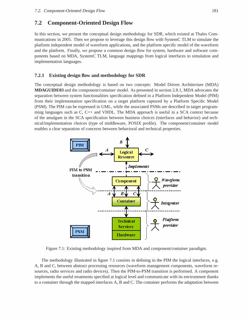
7.2. Component-Oriented Design Flow 181
7.2 Component-Oriented Design Flow
In this section, we present the conceptual design methodology for SDR, which existed at Thales Com-munications in 2005. Then we propose to leverage this designflow with SystemC TLM to simulate theplatform independent model of waveform applications, and the platform specific model of the waveformand the platform. Finally, we propose a common design flow forsystem, hardware and software com-ponents based on MDA, SystemC TLM, language mappings from logical interfaces to simulation andimplementation languages.
7.2.1 Existing design flow and methodology for SDR
The conceptual design methodology is based on two concepts:Model Driven Architecture (MDA)MDAGUIDE03 and the component/container model. As presented in section2.8.1, MDA advocates theseparation between system functionalities specification defined in a Platform Independent Model (PIM)from their implementation specification on a target platform captured by a Platform Specific Model(PSM). The PIM can be expressed in UML, while the associated PSMs are described in target program-ming languages such as C, C++ and VHDL. The MDA approach is useful in a SCA context becauseof the amalgam in the SCA specification between business choices (interfaces and behavior) and tech-nical/implementation choices (type of middleware, POSIX profile). The component/container modelenables a clear separation of concerns between behavioral and technical properties.
Figure 7.1: Existing methodology inspired from MDA and component/container paradigm.
The methodology illustrated in figure 7.1 consists in defining in the PIM the logical interfaces, e.g.A, B and C, between abstract processing resources (waveformmanagement components, waveform re-sources, radio services and radio devices). Then the PIM-to-PSM transition is performed. A componentimplements the useful treatments specified at logical leveland communicate with its environment thanksto a container through the mapped interfaces A, B and C. The container performs the adaptation between
182Chapter 7. Unified Component and Middleware Approach for Hardware/Software Embedded Systems
logical interfaces and available technical services. These latter provide the software and hardware ser-vices used by the implementation of the logical semantics. This approach is compliant with SCA forGPPs and has been successfully applied on DSPs. It seems to bepromising for FPGAs.
The design flow based on this methodology starts at PIM level with waveform specifications. Thelogical interfaces and real-time constraints between the logical waveform components themselves andwith the radio sub-system are modeled in UML thanks to use case, class, statechart and scenario graph-ical diagrams. The breakdown into waveform logical components are performed according to systemrequirements (characteristics of usable GPPs, DSPs, FPGAs) and business experience. Then subsequenthardware and software design flow can begin. The waveform application can be lately validated on anSCA compliant workstation. However, the final validation can only be done once the hardware platformis available. Thanks to SystemC TLM, we propose a PIM/PSM design flow to design and validate earlierwaveform applications on virtual SDR platforms.
7.2.2 Proposed simulation methodology
MDA and component/container paradigm approach can be simulated thanks to SystemC TLM as illus-trated in figure 7.2. The business services of logical components are implemented in a C/C++ model.This independent and reusable model is encapsulated in a SystemC TLM container, which abstracts itfrom its virtual execution environment. For a software component, the container could use an API, whilefor a hardware component, it could contain a register bank (see our experiments in chapter 8). Devel-opers can validate that the SystemC TLM virtual module provides the required behavior and perform apartitioning based on performances estimation. The model can be either refined until RTL for a hardwarecomponent or extracted to be optimized and cross-compiled for a software component. If the partitioningwas already performed, the C/C++ model can be used without a SystemC TLM encapsulation directlyon an Instruction Set Simulator (ISS) if available, otherwise the SystemC kernel could be used. ThisSystemC TLM based methodology allows to simulate the heterogeneous architecture of SDR platforms.
Thus, we propose SystemC TLM for the simulation and validation of PIM and PSM. In the SDRcontext, an important need is to be able to simulate the real-time constraints of a radio system, from itsspecifications to its final validation. SystemC appears, as far as we know, as the only language addressingthis kind of needs.
At PIM side, SystemC at functional level can be used to model the logical interfaces and simulatethe real-time constraints between the waveform logical components themselves and with the radio sub-system. The resulting SystemC TLM modules could include a behavioral model or acts as dummy blackbox. This model can be used as a useful and undeniable executable specification between hardware andsoftware teams that anticipates the PSM and accelerates thedevelopment cycle. The concepts of requiredand provided interfaces specified in the PIM can be natively found in SystemC 2.1 and used to simulatea PIM.
Event and time driven systems can be modeled withsc_event andwait statements, while UMLsynchronous and asynchronous calls can be respectively modeled with SystemC TLM blocking and non-blocking calls.
At PSM side, SystemC at cycle level enables performance estimation (profiling) of waveform soft-ware components executed on a virtual radio platform composed of ISS for GPP and DSP andBusFunctional Models(BFM ) if available. Thus, real-time constraints simulated in the PIM model can bereused to validate the PSM model. SystemC TLM allows one to simulate and to validate only criticalparts instead of the entire radio system model. A concrete example will be seen in our experiments toillustrate the modeling of PIM and PSM in SystemC TLM (see chapter 8).
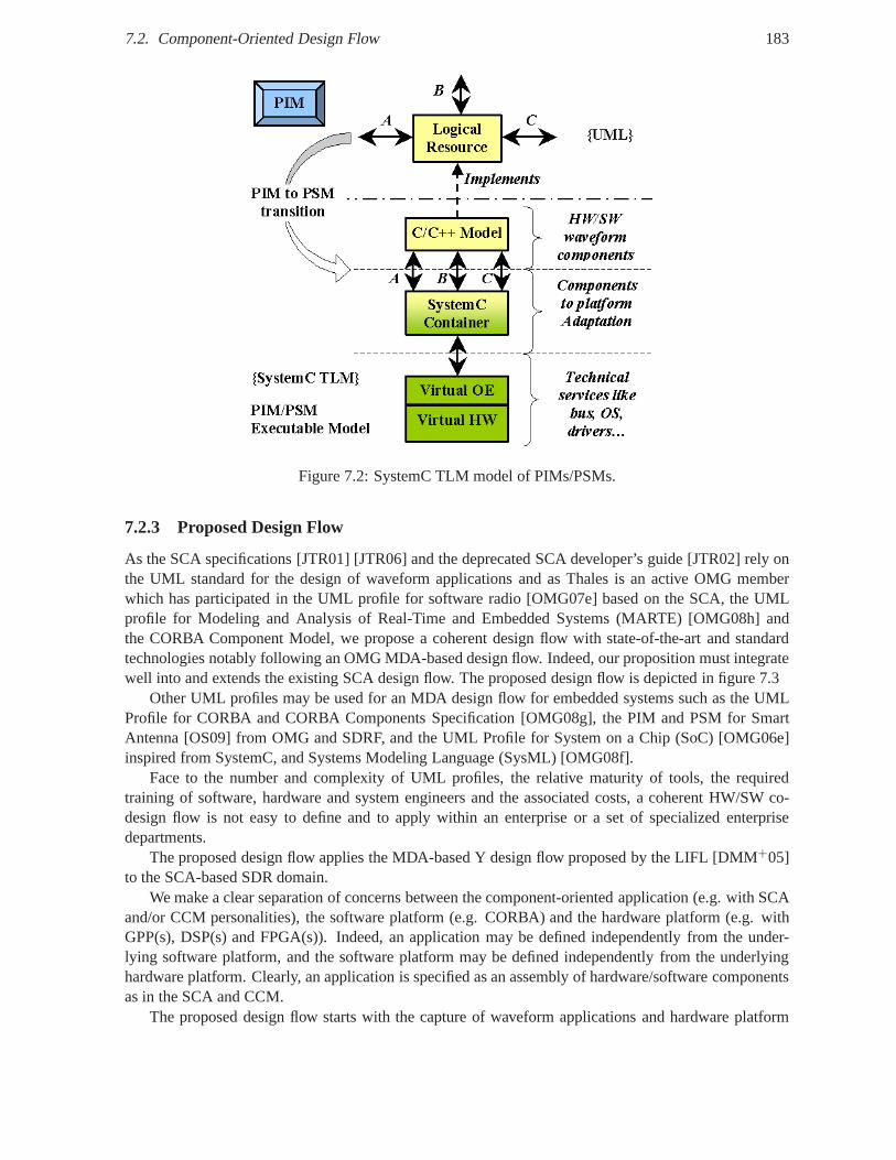
7.2. Component-Oriented Design Flow 183
Figure 7.2: SystemC TLM model of PIMs/PSMs.
7.2.3 Proposed Design Flow
As the SCA specifications [JTR01] [JTR06] and the deprecatedSCA developer’s guide [JTR02] rely onthe UML standard for the design of waveform applications andas Thales is an active OMG memberwhich has participated in the UML profile for software radio [OMG07e] based on the SCA, the UMLprofile for Modeling and Analysis of Real-Time and Embedded Systems (MARTE) [OMG08h] andthe CORBA Component Model, we propose a coherent design flow with state-of-the-art and standardtechnologies notably following an OMG MDA-based design flow. Indeed, our proposition must integratewell into and extends the existing SCA design flow. The proposed design flow is depicted in figure 7.3
Other UML profiles may be used for an MDA design flow for embedded systems such as the UMLProfile for CORBA and CORBA Components Specification [OMG08g], the PIM and PSM for SmartAntenna [OS09] from OMG and SDRF, and the UML Profile for System on a Chip (SoC) [OMG06e]inspired from SystemC, and Systems Modeling Language (SysML) [OMG08f].
Face to the number and complexity of UML profiles, the relative maturity of tools, the requiredtraining of software, hardware and system engineers and theassociated costs, a coherent HW/SW co-design flow is not easy to define and to apply within an enterprise or a set of specialized enterprisedepartments.
The proposed design flow applies the MDA-based Y design flow proposed by the LIFL [DMM+05]to the SCA-based SDR domain.
We make a clear separation of concerns between the component-oriented application (e.g. with SCAand/or CCM personalities), the software platform (e.g. CORBA) and the hardware platform (e.g. withGPP(s), DSP(s) and FPGA(s)). Indeed, an application may be defined independently from the under-lying software platform, and the software platform may be defined independently from the underlyinghardware platform. Clearly, an application is specified as an assembly of hardware/software componentsas in the SCA and CCM.
The proposed design flow starts with the capture of waveform applications and hardware platform
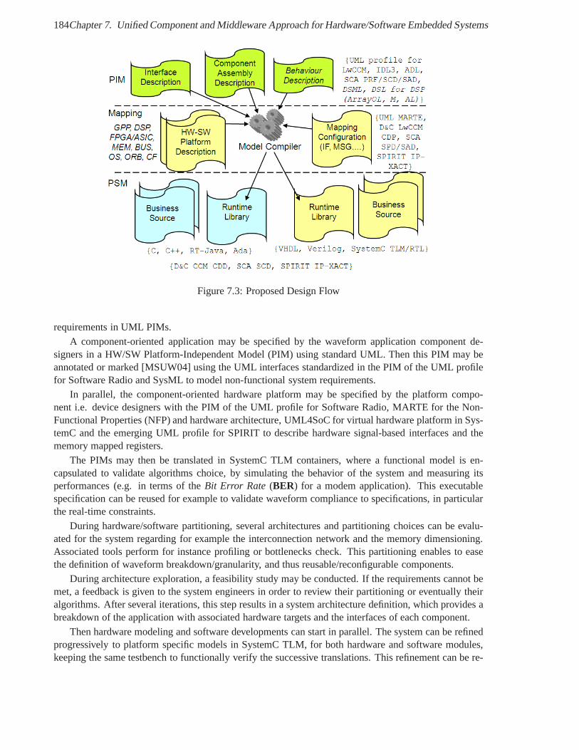
184Chapter 7. Unified Component and Middleware Approach for Hardware/Software Embedded Systems
Figure 7.3: Proposed Design Flow
requirements in UML PIMs.
A component-oriented application may be specified by the waveform application component de-signers in a HW/SW Platform-Independent Model (PIM) using standard UML. Then this PIM may beannotated or marked [MSUW04] using the UML interfaces standardized in the PIM of the UML profilefor Software Radio and SysML to model non-functional systemrequirements.
In parallel, the component-oriented hardware platform maybe specified by the platform compo-nent i.e. device designers with the PIM of the UML profile for Software Radio, MARTE for the Non-Functional Properties (NFP) and hardware architecture, UML4SoC for virtual hardware platform in Sys-temC and the emerging UML profile for SPIRIT to describe hardware signal-based interfaces and thememory mapped registers.
The PIMs may then be translated in SystemC TLM containers, where a functional model is en-capsulated to validate algorithms choice, by simulating the behavior of the system and measuring itsperformances (e.g. in terms of theBit Error Rate (BER) for a modem application). This executablespecification can be reused for example to validate waveformcompliance to specifications, in particularthe real-time constraints.
During hardware/software partitioning, several architectures and partitioning choices can be evalu-ated for the system regarding for example the interconnection network and the memory dimensioning.Associated tools perform for instance profiling or bottlenecks check. This partitioning enables to easethe definition of waveform breakdown/granularity, and thusreusable/reconfigurable components.
During architecture exploration, a feasibility study may be conducted. If the requirements cannot bemet, a feedback is given to the system engineers in order to review their partitioning or eventually theiralgorithms. After several iterations, this step results ina system architecture definition, which provides abreakdown of the application with associated hardware targets and the interfaces of each component.
Then hardware modeling and software developments can startin parallel. The system can be refinedprogressively to platform specific models in SystemC TLM, for both hardware and software modules,keeping the same testbench to functionally verify the successive translations. This refinement can be re-
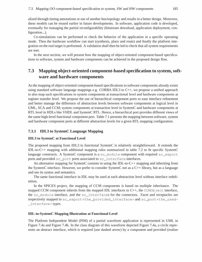
7.3. Mapping OO component-based specification to system, SWand HW components 185
alized through timing annotations or use of another bus/topology and results in a better design. Moreover,these models can be reused earlier in future developments. In software, application code is developed,eventually for managing the partial reconfigurability (bitstream download, application deployment, con-figuration...).
Co-simulations can be performed to check the behavior of theapplication in a specific operatingmode. Then the hardware workflow can start (synthesis, placeand route) and finally the platform inte-gration on the real target is performed. A validation shall then be led to check that all system requirementsare met.
In the next section, we will present how the mapping of object-oriented component-based specifica-tions to software, system and hardware components can be achieved in the proposed design flow.
7.3 Mapping object-oriented component-based specification to system, soft-ware and hardware components
As the mapping of object-oriented component-based specifications to software components already existsusing standard software language mappings e.g. CORBA IDL3 to C++, we propose a unified approachto also map such specifications to system components at transactional level and hardware components atregister transfer level. We propose the use of hierarchicalcomponent ports to ease interface refinementand better manage the difference of abstraction levels between software components at logical level inUML, SCA and CCM; system components at transaction level in SystemC and hardware components atRTL level in HDLs like VHDL and SystemC RTL. Hence, a hierarchical port provides different views ofthe same high-level functional component port. Table 7.1 presents the mapping between software, systemand hardware component ports at different abstraction levels for a given RTL mapping configuration.
7.3.1 IDL3 to SystemC Language Mapping
IDL3 to SystemC at Functional Level
The proposed mapping from IDL3 to functional SystemC is relatively straightforward. It extends theIDL-to-C++ mapping with additional mapping rules summarized in table 7.2 to fit specific SystemClanguage constructs. A SystemC component is asc_module component with requiredsc_exportports and providedsc_port ports associated tosc_interface interfaces.
An alternative mapping for SystemC consists in using the IDL-to-C++ mapping and inheriting fromthe SystemC interface. However, we prefer to consider SystemC not as a C++ library, but as a languageand use its syntax and semantics.
The same functional interface in IDL may be used at each abstraction level without interface redefi-nition.
In the SPICES project, the mapping of CCM components is basedon multiple inheritance. Themapped CCM component inherits from the mapped IDL interfaces to C++, theCCMObject interface,the sc_module interface, and thesc_interfaces for the connectors. Facet and receptacles arerespectively mapped tosc_export<the_provided_interface> andsc_port<the_used-_interface> types.
IDL-to-SystemC Mapping Illustration at Functional Level
The Platform Independent Model (PIM) of a partial waveform application is represented in UML inFigure 7.4a and Figure 7.4b. In the class diagram of this waveform depicted Figure 7.4a, a circle repre-sents an abstract interface, which is required (use dashed arrow) by a component and provided (realize
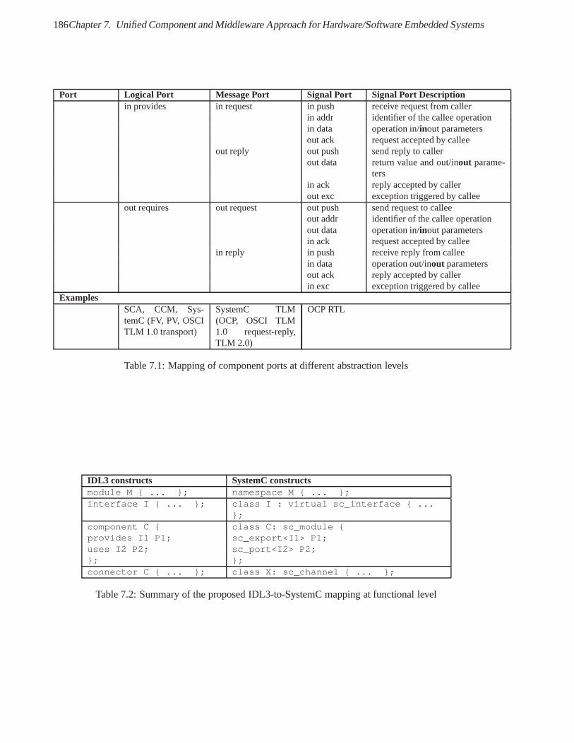
186Chapter 7. Unified Component and Middleware Approach for Hardware/Software Embedded Systems
Port Logical Port Message Port Signal Port Signal Port Descriptionin provides in request in push receive request from caller
in addr identifier of the callee operationin data operation in/inout parametersout ack request accepted by callee
out reply out push send reply to callerout data return value and out/inout parame-
tersin ack reply accepted by callerout exc exception triggered by callee
out requires out request out push send request to calleeout addr identifier of the callee operationout data operation in/inout parametersin ack request accepted by callee
in reply in push receive reply from calleein data operation out/inout parametersout ack reply accepted by callerin exc exception triggered by callee
ExamplesSCA, CCM, Sys-temC (FV, PV, OSCITLM 1.0 transport)
SystemC TLM(OCP, OSCI TLM1.0 request-reply,TLM 2.0)
OCP RTL
Table 7.1: Mapping of component ports at different abstraction levels
IDL3 constructs SystemC constructsmodule M { ... }; namespace M { ... };interface I { ... }; class I : virtual sc_interface { ...
};component C { class C: sc_module {provides I1 P1; sc_export<I1> P1;uses I2 P2; sc_port<I2> P2;}; };connector C { ... }; class X: sc_channel { ... };
Table 7.2: Summary of the proposed IDL3-to-SystemC mappingat functional level
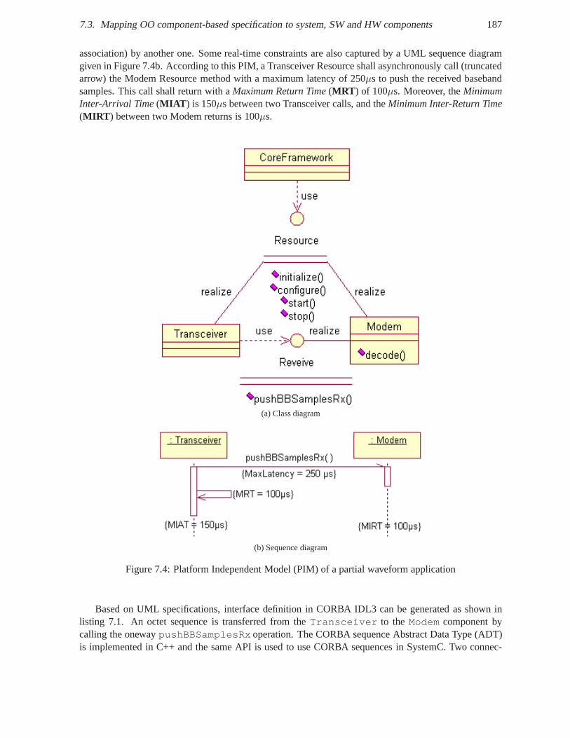
7.3. Mapping OO component-based specification to system, SWand HW components 187
association) by another one. Some real-time constraints are also captured by a UML sequence diagramgiven in Figure 7.4b. According to this PIM, a Transceiver Resource shall asynchronously call (truncatedarrow) the Modem Resource method with a maximum latency of 250µs to push the received basebandsamples. This call shall return with aMaximum Return Time(MRT ) of 100µs. Moreover, theMinimumInter-Arrival Time(MIAT ) is 150µs between two Transceiver calls, and theMinimum Inter-Return Time(MIRT ) between two Modem returns is 100µs.
(a) Class diagram
(b) Sequence diagram
Figure 7.4: Platform Independent Model (PIM) of a partial waveform application
Based on UML specifications, interface definition in CORBA IDL3 can be generated as shown inlisting 7.1. An octet sequence is transferred from theTransceiver to theModem component bycalling the onewaypushBBSamplesRx operation. The CORBA sequence Abstract Data Type (ADT)is implemented in C++ and the same API is used to use CORBA sequences in SystemC. Two connec-
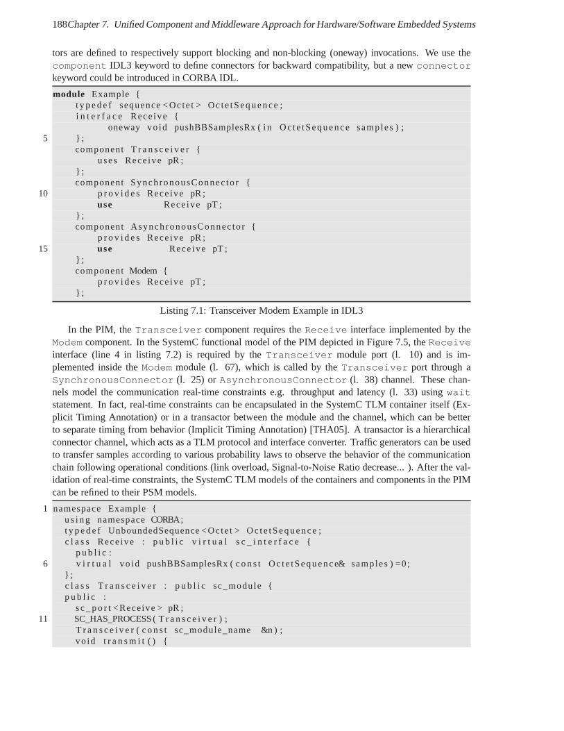
188Chapter 7. Unified Component and Middleware Approach for Hardware/Software Embedded Systems
tors are defined to respectively support blocking and non-blocking (oneway) invocations. We use thecomponent IDL3 keyword to define connectors for backward compatibility, but a newconnectorkeyword could be introduced in CORBA IDL.
module Example {t y p e d e f sequence <Octe t > Oc te tSequence ;i n t e r f a c e Rece ive {
oneway vo id pushBBSamplesRx ( i n Oc te tSequence samples ) ;5 } ;
component T r a n s c e i v e r {uses Rece ive pR ;
} ;component SynchronousConnec to r {
10 p r o v i d e s Rece ive pR ;use Rece ive pT ;
} ;component AsynchronousConnec to r {
p r o v i d e s Rece ive pR ;15 use Rece ive pT ;
} ;component Modem {
p r o v i d e s Rece ive pT ;} ;
Listing 7.1: Transceiver Modem Example in IDL3
In the PIM, theTransceiver component requires theReceive interface implemented by theModem component. In the SystemC functional model of the PIM depicted in Figure 7.5, theReceiveinterface (line 4 in listing 7.2) is required by theTransceiver module port (l. 10) and is im-plemented inside theModem module (l. 67), which is called by theTransceiver port through aSynchronousConnector (l. 25) or AsynchronousConnector (l. 38) channel. These chan-nels model the communication real-time constraints e.g. throughput and latency (l. 33) usingwaitstatement. In fact, real-time constraints can be encapsulated in the SystemC TLM container itself (Ex-plicit Timing Annotation) or in a transactor between the module and the channel, which can be betterto separate timing from behavior (Implicit Timing Annotation) [THA05]. A transactor is a hierarchicalconnector channel, which acts as a TLM protocol and interface converter. Traffic generators can be usedto transfer samples according to various probability laws to observe the behavior of the communicationchain following operational conditions (link overload, Signal-to-Noise Ratio decrease... ). After the val-idation of real-time constraints, the SystemC TLM models ofthe containers and components in the PIMcan be refined to their PSM models.
1 namespace Example {u s i n g namespace CORBA;t y p e d e f UnboundedSequence <Octe t > Oc te tSequence ;c l a s s Rece ive : p u b l i c v i r t u a l s c _ i n t e r f a c e {
p u b l i c :6 v i r t u a l vo id pushBBSamplesRx ( c o n s t Oc te tSequence& samples ) =0 ;
} ;c l a s s T r a n s c e i v e r : p u b l i c sc_module {p u b l i c :
s c _ p o r t <Receive > pR ;11 SC_HAS_PROCESS ( T r a n s c e i v e r ) ;
T r a n s c e i v e r ( c o n s t sc_module_name &n ) ;vo id t r a n s m i t ( ) {
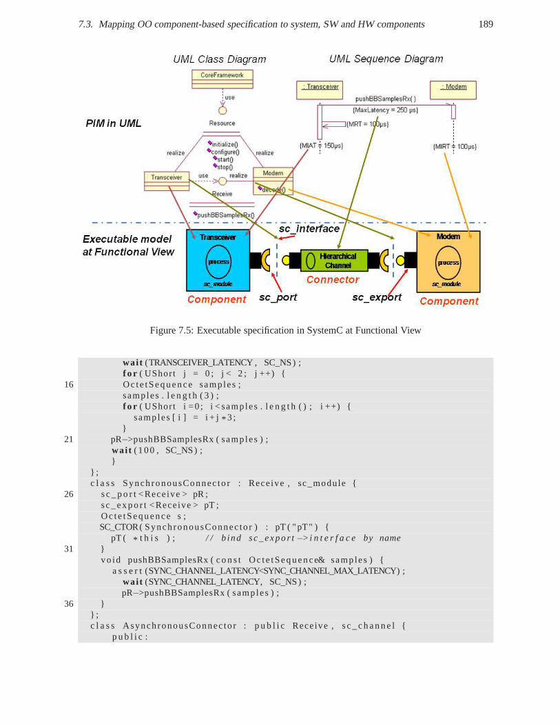
7.3. Mapping OO component-based specification to system, SWand HW components 189
Figure 7.5: Executable specification in SystemC at Functional View
wai t (TRANSCEIVER_LATENCY , SC_NS) ;f o r ( UShort j = 0 ; j < 2 ; j ++) {
16 Oc te tSequence samples ;samp les . l e n g t h ( 3 ) ;f o r ( UShort i =0 ; i < samp les . l e n g t h ( ) ; i ++) {
samp les [ i ] = i + j* 3 ;}
21 pR−>pushBBSamplesRx ( samp les ) ;wai t ( 100 , SC_NS) ;}
} ;c l a s s SynchronousConnec to r : Receive , sc_module {
26 s c _ p o r t <Receive > pR ;sc_expo r t <Receive > pT ;Oc te tSequence s ;SC_CTOR( SynchronousConnec to r ) : pT ( "pT" ) {
pT ( * t h i s ) ; / / b ind sc_expo r t−>i n t e r f a c e by name31 }
vo id pushBBSamplesRx ( c o n s t Oc te tSequence& samples ) {a s s e r t (SYNC_CHANNEL_LATENCY<SYNC_CHANNEL_MAX_LATENCY) ;
wai t (SYNC_CHANNEL_LATENCY, SC_NS) ;pR−>pushBBSamplesRx ( samp les ) ;
36 }} ;c l a s s AsynchronousConnec to r : p u b l i c Receive , s c _ c h a n n e l{
p u b l i c :
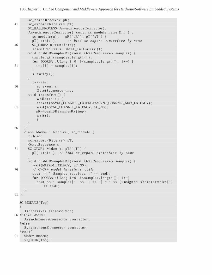
190Chapter 7. Unified Component and Middleware Approach for Hardware/Software Embedded Systems
s c _ p o r t <Receive > pR ;41 sc_expo r t <Receive > pT ;
SC_HAS_PROCESS ( AsynchronousConnec to r ) ;AsynchronousConnec to r ( c o n s t sc_module_name & n ) :
sc_module ( n ) , pR ( "pR" ) , pT ( "pT" ) {pT ( * t h i s ) ; / / b ind sc_expo r t−>i n t e r f a c e by name
46 SC_THREAD( t r a n s f e r t ) ;s e n s i t i v e << s ; d o n t _ i n i t i a l i z e ( ) ;
vo id pushBBSamplesRx ( c o n s t Oc te tSequence& samples ) {tmp . l e n g t h ( samp les . l e n g t h ( ) ) ;f o r (CORBA : : ULong i =0 ; i < samp les . l e n g t h ( ) ; i ++) {
51 tmp [ i ] = samp les [ i ] ;}s . n o t i f y ( ) ;
}p r i v a t e :
56 s c _ e v e n t s ;Oc te tSequence tmp ;
vo id t r a n s f e r t ( ) {whi le ( t r u e ) {a s s e r t (ASYNC_CHANNEL_LATENCY<ASYNC_CHANNEL_MAX_LATENCY) ;
61 wai t (ASYNC_CHANNEL_LATENCY, SC_NS) ;pR−>pushBBSamplesRx ( tmp ) ;wai t ( ) ;}
}66 } ;
c l a s s Modem : Receive , sc_module {p u b l i c :sc_expo r t <Receive > pT ;Oc te tSequence s ;
71 SC_CTOR( Modem ) : pT ( "pT" ) {pT ( * t h i s ) ; / / b ind sc_expo r t−>i n t e r f a c e by name
}vo id pushBBSamplesRx ( c o n s t Oc te tSequence& samples ) {
wai t (MODEM_LATENCY, SC_NS) ;76 / / C /C++ model f u n c t i o n s c a l l s
cou t << " Samples r e c e i v e d : " << end l ;f o r (CORBA : : ULong i =0 ; i < samp les . l e n g t h ( ) ; i ++)
cou t << " samp les [ " << i << " ] = " << (unsigned s h o r t ) samp les [ i ]<< end l ;
} ;81 } ;
SC_MODULE( Top ){
T r a n s c e i v e r t r a n s c e i v e r ;86 # i f d e f ASYNC
AsynchronousConnec to r c o n n e c t o r ;# e l s e
SynchronousConnec to r c o n n e c t o r ;# e n d i f
91 Modem modem;SC_CTOR( Top ) :
7.3. Mapping OO component-based specification to system, SWand HW components 191
t r a n s c e i v e r ( " T r a n s c e i v e r " ) ,c o n n e c t o r ( " Connec to r " ) ,modem( "Modem" )
96 {t r a n s c e i v e r . pR( c o n n e c t o r . pT ) ;c o n n e c t o r . pR ( modem . pT ) ;
}} ;
Listing 7.2: Transceiver Modem Example in SystemC at Functional View
IDL3 to SystemC at Transactional Level
The IDL-to-HDL mapping can be seen as a refinement problem in SystemC. User-defined interfacesin IDL may be mapped to SystemC at Functional Level. Transactional connectors called transactorsmay adapt these interfaces to standard TLM interfaces. The key point is that the invocation messagesderived from IDL interfaces are identical and carry the samesemantics at all abstraction levels. Forinstance in TLM 2.0, invocation messages may be sent in the generic payload of TLM transactions.At all abstraction levels, the syntax and semantics of the business interfaces in UML or IDL and theassociated messages will the same, only the manner to transfer the messages will change according tothe abstraction level. The equivalence between operation invocation and message transmission providesa systematic approach for the refinement from one abstraction level to another. This object-orientedapproach to refinement contrast with the classical ad-hoc refinement in SystemC where the syntax andsemantics of business interfaces are lost during refinement.
This mapping proposition will be illustrated in chapter 8 with the refinement of a business componentfrom a functional model in C to a SystemC component at Programmer View (PV) level (see §8.2.2), therefinement of a transactional connector from an OCP TL2 to an AHB bus functional model (see §8.2.2),and the refinement at different abstraction levels from SystemC FIFO to OCP TLM and OCP RTL (see§8.3.2).
The mapping from IDL3 to SystemC RTL is presented in the following subsection with the IDL3 toHDL Mapping and detailed in chapter
7.3.2 IDL3 to HDL Mapping
In this section, we present a language mapping from component specification in CORBA IDLs to com-ponent specification in HDLs in particular VHDL.
Differences between a SW-to-SW interfaces mapping and a SW-to-HW interfaces mapping
Basically, software IDLs like CORBA IDL have been designed for software programming languages.There is only a systematic and one-to-one mapping between anIDL interface and a software interfacein the target implementation language, which reside at close abstraction levels. Defining a standardmapping for HDLs such as VHDL is much more difficult.
In software programming languages, a procedure call convention [PH07] specifies the executionmodel of an operation call for compilers and transparently hides this model from the application devel-oper’s point of view. For instance in MIPS processors [PH07], the first four procedure arguments arepassed in registers, while the remaining arguments are pushed on the stack. The return address of thecaller is saved in a register and the program counter jumps tothe callee procedure. The callee performsthe computations and place the results in dedicated registers. The program counter finally jumps to the
192Chapter 7. Unified Component and Middleware Approach for Hardware/Software Embedded Systems
saved return address to return the control to the caller. Compared to a hardware designer, a software de-signer has little room in its design to optimize the execution time or memory consumption of an operationcall. Indeed, this optimization is performed by the compiler according to the procedure call conventionand directives given by the user. In hardware description languages, an inherent design trade-off ex-ists between area, performance (e.g. bandwidth, latency) and power consumption for hardware modules.Hardware designers require a complete control over this trade-off. An example is the numerous knobs of-fered by usual synthesis tools and/or high-level synthesistools to explore and optimize the design space.Note that we focus on the mapping space for hardware component interfaces and not on the design spacerelated to the implementation of component business functionalities. An IDL-to-HDL mapping requiresto select and configure non-functional properties such as hardware interfaces, timing and protocols. Asopposed to software mapping, the final hardware interface may depend on the set of methods declaredin the IDL interface for instance to configure a address bus used for method invocations. Because theCORBA IDL3 only specifies functional properties i.e. behavior, a standardized mapping configurationfile should explicitly define these non-functional properties. This file could be generated manually, via agraphical tool or inferred by an IDL compiler front-end.
Mapping Requirements
In the following, we present some mapping requirements based on the compilation of the state of the arton hardware and software implementations of objects, middlewares and components. They are notablyfocused on concurrency, message and transport.
Component-oriented hardware architecture A component interface is represented by a VHDLentity.A component implementation is represented by a VHDLarchitecture. A component implementa-tion is selected by a VHDLconfiguration.
Encapsulation The value of component attributes shall be retrieved and modified only through dedi-cated accessor and mutator operations called "getter" and "setter". No direct access to internal componentattributes should be allowed from component outside. Awriteonly keyword is required for IDL3 at-tributes and would implicitly infer a setter method. For instance, a hardware register may be write-onlyfor software and read-only for hardware. In this case, the external bus interface may be a write-onlyhardware port, while the internal component interface may be a read-only hardware port.
Concurrent implementation of a method There should be no assumption on component hardwareimplementation, sequential processes and concurrent statements may be used. Sequential implementa-tions only based on FSMs such as in [Rad00] are not required. Implementation may be hand-coded orgenerated by some HLS tools. The only constraint is to respect the interface contract both at system-levelin IDL and at RTL-level with the mapped hardware interface.
Concurrent method invocations and executions within a component Multiple clients may invokesimultaneously the same method or distinct methods that maybe executed in both cases sequentiallyor in parallel. Multiple methods may be invoked and executedindependently to enable pipelining ofconfiguration and computation and exploit hardware parallelism.
Figure 7.6 illustrates that parallel method invocations may increase performance by pipeling opera-tion executions. In case A), sequential method invocationswith no pipeline require 2 cycles per iteration.In case B), parallel method invocations allows one to achieve 1 cycle per iteration using a simple pipelinewith 2 stages that is a gain of 1 cycle compared to case A). Sucha requirement militates in favor of a
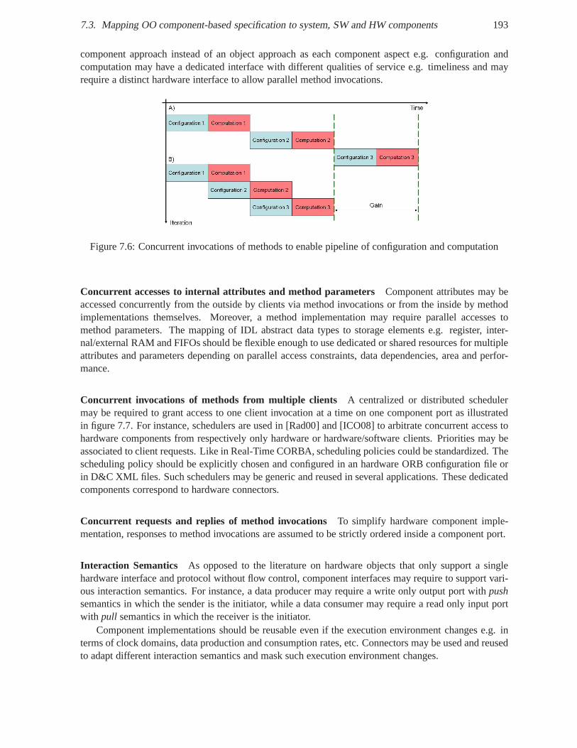
7.3. Mapping OO component-based specification to system, SWand HW components 193
component approach instead of an object approach as each component aspect e.g. configuration andcomputation may have a dedicated interface with different qualities of service e.g. timeliness and mayrequire a distinct hardware interface to allow parallel method invocations.
Figure 7.6: Concurrent invocations of methods to enable pipeline of configuration and computation
Concurrent accesses to internal attributes and method parameters Component attributes may beaccessed concurrently from the outside by clients via method invocations or from the inside by methodimplementations themselves. Moreover, a method implementation may require parallel accesses tomethod parameters. The mapping of IDL abstract data types tostorage elements e.g. register, inter-nal/external RAM and FIFOs should be flexible enough to use dedicated or shared resources for multipleattributes and parameters depending on parallel access constraints, data dependencies, area and perfor-mance.
Concurrent invocations of methods from multiple clients A centralized or distributed schedulermay be required to grant access to one client invocation at a time on one component port as illustratedin figure 7.7. For instance, schedulers are used in [Rad00] and [ICO08] to arbitrate concurrent access tohardware components from respectively only hardware or hardware/software clients. Priorities may beassociated to client requests. Like in Real-Time CORBA, scheduling policies could be standardized. Thescheduling policy should be explicitly chosen and configured in an hardware ORB configuration file orin D&C XML files. Such schedulers may be generic and reused in several applications. These dedicatedcomponents correspond to hardware connectors.
Concurrent requests and replies of method invocations To simplify hardware component imple-mentation, responses to method invocations are assumed to be strictly ordered inside a component port.
Interaction Semantics As opposed to the literature on hardware objects that only support a singlehardware interface and protocol without flow control, component interfaces may require to support vari-ous interaction semantics. For instance, a data producer may require a write only output port withpushsemantics in which the sender is the initiator, while a data consumer may require a read only input portwith pull semantics in which the receiver is the initiator.
Component implementations should be reusable even if the execution environment changes e.g. interms of clock domains, data production and consumption rates, etc. Connectors may be used and reusedto adapt different interaction semantics and mask such execution environment changes.
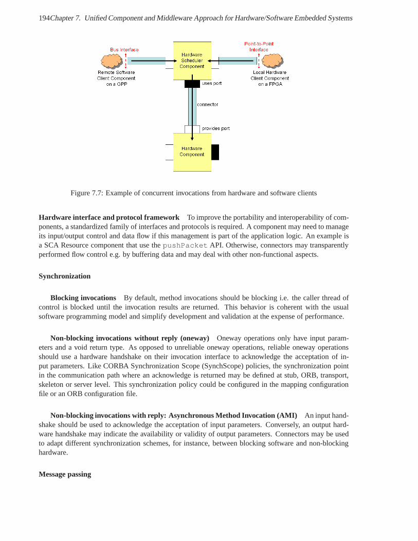
194Chapter 7. Unified Component and Middleware Approach for Hardware/Software Embedded Systems
Figure 7.7: Example of concurrent invocations from hardware and software clients
Hardware interface and protocol framework To improve the portability and interoperability of com-ponents, a standardized family of interfaces and protocolsis required. A component may need to manageits input/output control and data flow if this management is part of the application logic. An example isa SCA Resource component that use thepushPacket API. Otherwise, connectors may transparentlyperformed flow control e.g. by buffering data and may deal with other non-functional aspects.
Synchronization
Blocking invocations By default, method invocations should be blocking i.e. the caller thread ofcontrol is blocked until the invocation results are returned. This behavior is coherent with the usualsoftware programming model and simplify development and validation at the expense of performance.
Non-blocking invocations without reply (oneway) Oneway operations only have input param-eters and a void return type. As opposed to unreliable onewayoperations, reliable oneway operationsshould use a hardware handshake on their invocation interface to acknowledge the acceptation of in-put parameters. Like CORBA Synchronization Scope (SynchScope) policies, the synchronization pointin the communication path where an acknowledge is returned may be defined at stub, ORB, transport,skeleton or server level. This synchronization policy could be configured in the mapping configurationfile or an ORB configuration file.
Non-blocking invocations with reply: Asynchronous MethodInvocation (AMI) An input hand-shake should be used to acknowledge the acceptation of inputparameters. Conversely, an output hard-ware handshake may indicate the availability or validity ofoutput parameters. Connectors may be usedto adapt different synchronization schemes, for instance,between blocking software and non-blockinghardware.
Message passing
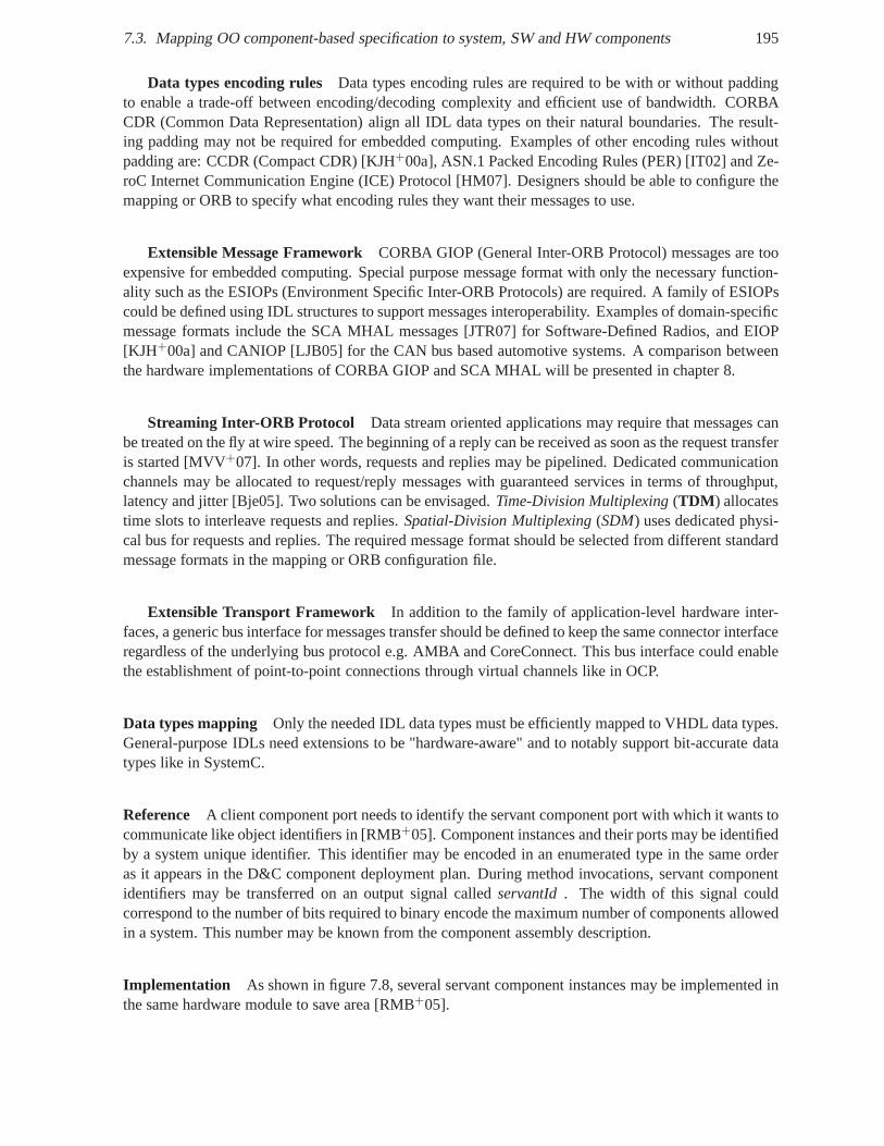
7.3. Mapping OO component-based specification to system, SWand HW components 195
Data types encoding rules Data types encoding rules are required to be with or without paddingto enable a trade-off between encoding/decoding complexity and efficient use of bandwidth. CORBACDR (Common Data Representation) align all IDL data types ontheir natural boundaries. The result-ing padding may not be required for embedded computing. Examples of other encoding rules withoutpadding are: CCDR (Compact CDR) [KJH+00a], ASN.1 Packed Encoding Rules (PER) [IT02] and Ze-roC Internet Communication Engine (ICE) Protocol [HM07]. Designers should be able to configure themapping or ORB to specify what encoding rules they want theirmessages to use.
Extensible Message Framework CORBA GIOP (General Inter-ORB Protocol) messages are tooexpensive for embedded computing. Special purpose messageformat with only the necessary function-ality such as the ESIOPs (Environment Specific Inter-ORB Protocols) are required. A family of ESIOPscould be defined using IDL structures to support messages interoperability. Examples of domain-specificmessage formats include the SCA MHAL messages [JTR07] for Software-Defined Radios, and EIOP[KJH+00a] and CANIOP [LJB05] for the CAN bus based automotive systems. A comparison betweenthe hardware implementations of CORBA GIOP and SCA MHAL willbe presented in chapter 8.
Streaming Inter-ORB Protocol Data stream oriented applications may require that messages canbe treated on the fly at wire speed. The beginning of a reply canbe received as soon as the request transferis started [MVV+07]. In other words, requests and replies may be pipelined. Dedicated communicationchannels may be allocated to request/reply messages with guaranteed services in terms of throughput,latency and jitter [Bje05]. Two solutions can be envisaged.Time-Division Multiplexing(TDM ) allocatestime slots to interleave requests and replies.Spatial-Division Multiplexing(SDM) uses dedicated physi-cal bus for requests and replies. The required message format should be selected from different standardmessage formats in the mapping or ORB configuration file.
Extensible Transport Framework In addition to the family of application-level hardware inter-faces, a generic bus interface for messages transfer shouldbe defined to keep the same connector interfaceregardless of the underlying bus protocol e.g. AMBA and CoreConnect. This bus interface could enablethe establishment of point-to-point connections through virtual channels like in OCP.
Data types mapping Only the needed IDL data types must be efficiently mapped to VHDL data types.General-purpose IDLs need extensions to be "hardware-aware" and to notably support bit-accurate datatypes like in SystemC.
Reference A client component port needs to identify the servant component port with which it wants tocommunicate like object identifiers in [RMB+05]. Component instances and their ports may be identifiedby a system unique identifier. This identifier may be encoded in an enumerated type in the same orderas it appears in the D&C component deployment plan. During method invocations, servant componentidentifiers may be transferred on an output signal calledservantId . The width of this signal couldcorrespond to the number of bits required to binary encode the maximum number of components allowedin a system. This number may be known from the component assembly description.
Implementation As shown in figure 7.8, several servant component instances may be implemented inthe same hardware module to save area [RMB+05].
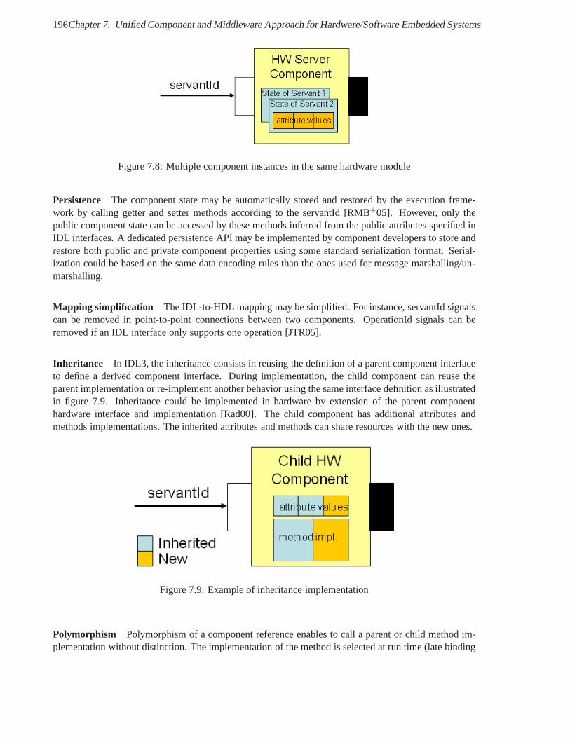
196Chapter 7. Unified Component and Middleware Approach for Hardware/Software Embedded Systems
Figure 7.8: Multiple component instances in the same hardware module
Persistence The component state may be automatically stored and restored by the execution frame-work by calling getter and setter methods according to the servantId [RMB+05]. However, only thepublic component state can be accessed by these methods inferred from the public attributes specified inIDL interfaces. A dedicated persistence API may be implemented by component developers to store andrestore both public and private component properties usingsome standard serialization format. Serial-ization could be based on the same data encoding rules than the ones used for message marshalling/un-marshalling.
Mapping simplification The IDL-to-HDL mapping may be simplified. For instance, servantId signalscan be removed in point-to-point connections between two components. OperationId signals can beremoved if an IDL interface only supports one operation [JTR05].
Inheritance In IDL3, the inheritance consists in reusing the definition of a parent component interfaceto define a derived component interface. During implementation, the child component can reuse theparent implementation or re-implement another behavior using the same interface definition as illustratedin figure 7.9. Inheritance could be implemented in hardware by extension of the parent componenthardware interface and implementation [Rad00]. The child component has additional attributes andmethods implementations. The inherited attributes and methods can share resources with the new ones.
Figure 7.9: Example of inheritance implementation
Polymorphism Polymorphism of a component reference enables to call a parent or child method im-plementation without distinction. The implementation of the method is selected at run time (late binding
7.3. Mapping OO component-based specification to system, SWand HW components 197
or dynamic binding) depending on the type of the referenced component. Hardware implementations ofpolymorphism have been presented in [Rad00], [GHM03] and [Frö06].
Systematic mapping The transformation rules to map software interfaces to hardware interface shouldbe (semi-)formal to be automated and not on a case by case basis as in [JTR05]. A systematic mappingallows one to map every IDL interfaces from application objects and components to lightweight ORBservices such as Name service, Event service and ExtensibleTransport Framework (ETF).
Mapping Proposition
We propose to map abstract object-oriented components in a PIM to object-oriented hardware compo-nents in PSMs. The mapping of concepts from software to hardware components is general enough toaddress software components such as SCA, CCM and UML components and hardware description lan-guages such as VHDL, Verilog and SystemC RTL. In this chapter, we focus on language mappings fromCORBA IDL3 [OMG08b] to VHDL and SystemC RTL. CORBA IDL3 notably includes the componentconcepts of the CORBA Component Model. We give an overview ofthe mapping proposition in the fol-lowing. The language mappings are described in details in chapter A. The IDL-to-HDL mapping focuseson the interface between business components and the connector fragments a.k.a. stubs/skeletons with-out making any assumption on the middleware implementation. The underlying hardware middlewarearchitecture framework will be presented in section 7.5.
Our mapping proposition is based on a structural interpretation of abstract object-oriented compo-nents. A hardware CCM component is represented by a VHDLentity and its implementation corre-sponds to a VHDLarchitecture, which is selected by a VHDLconfiguration. An abstractCCM component port is mapped to a logical hardware componentport, which is a set of VHDL inputand output ports. Each hardware CCM component port is based on one or more named hardware inter-faces for the invocation request (incl. operation identifier and input parameters) and reply (incl. outputparameters, return value and optional exceptions).
Hardware CCM component port allows the separation of concerns between computation in the com-ponent and non-functional properties like synchronization and storage. To separate concerns and improveits reuse, a hardware component port may correspond to a VHDLentity with its architecture.The component coreentity and its logical portentitiesmay be put together in a global componententity. In this case, a logical component port is a subset of the global entity ports.
A hardware connector may represent non-functional properties such as synchronization and commu-nication: flow control, clock domain crossing, interactionsemantics, protocols of point-to-point buses,shared buses or NoCs. A connector may also handle interruption and DMA services to transfer messagesbetween two connector fragments. The implementation of theconnector fragments may be software-to-hardware or hardware-to-hardware.
A hardware container provide all remaining non-functionalservices such as persistence and lifecycle.The lifecycle service may manage component creation/destruction e.g. with dynamic partial reconfigu-ration, component initialization e.g. with a asynchronousor synchronous reset, parameters configurationwith register banks, and activation/deactivation e.g. with a clock or enable signal.
Besides, we consider that IP-XACT is to hardware componentswhat D&C is to software compo-nents. OMG D&C and SPIRIT IP-XACT XML files describe the implementation, configuration andinterconnection of respectively hardware and software components. The IP-XACT specification couldcorrespond to a D&C PSM for the deployment and configuration of hardware components. D&C mainlyspecifies application software components, while IP-XACT describes application and platform IP corecomponents. We argue that D&C concepts should be extended with SCA and IP-XACT concepts to
198Chapter 7. Unified Component and Middleware Approach for Hardware/Software Embedded Systems
address the description, configuration and deployment of hardware/software application components ondistributed hardware/software platforms.
In the following, we present the mapping from abstract component concepts such ascomponent, port,interface, attributes, operation parameters, andconnectors to concrete component concepts inHDLs.
Component Implementation An abstract object-oriented component at system-level mayhave a func-tional implementation e.g. in executable UML, Matlab/Simulink, SystemC TLM; a software implemen-tation e.g. in C, C++ or Java; or a hardware implementation e.g. in synthesizable SystemC RTL, VHDLor Verilog.
Component Port Owing to the abstraction gap between hardware and software constructs, an ab-stract component port corresponds to several HDL I/O ports.The HDL block construct such as VHDLentity or Verilogmodule permits a logical grouping of related signals to form a hardware interface.A HW component port may be either a logical set of I/O ports in ahardware module e.g. VHDL in/outports in anentity, or a hardware module e.g. a VHDLentity. In the first approach, all softwareinterfaces of an abstract component are mapped to a single hardware interface. Due to the lake of namescoping in HDLs, signal names must be artificially prefixed bythe port name of the abstract componentto ensure their uniqueness. The second approach allows the reuse of component ports as hardware mod-ules which implement reusable hardware interfaces and protocols. This is coherent with object-orientedsoftware components, in which each port is represented by a class in software and therefore a module inhardware. This ensures the separation of concerns between different component ports. From a synthesisviewpoint, the hierarchy of blocks in the second approach isbroken by the synthesis tool and becomesthus similar to the first mapping approach. A hardware mapping should be configurable to permit bothalternatives depending on the user preferences. Regardless of the mapping choices, both approachesallow a transparent interconnection of hardware modules asthey finally provide and require the samesignals.
Moreover, input and output hardware ports may be passive or active. An input component port maybe active by pulling/reading data like the consumer in the producer/consumer model e.g. SystemC inputport. An input port may also be passive, when the outside pushes/writes data on it. Conversely, anoutput port may be active by pushing/writing data like the producer in the producer/consumer modele.g. SystemC output port. An output port may also be passive,when the outside pulls/reads data on it.Connectors may adapt and decouple data production and consumption rates.
Component Interfaces A component interface is represented by a VHDLentity, a Verilog or Sys-temCmodule. We distinguish three kinds of hardware interfaces: the business component core inter-face, the invocation interface of component ports and the connector interface. These interfaces may beconfigured by VHDL generics, Verilog parameter and SystemC static class variables or#define.
Internal component interface to access operation parameters The component interface is theinternal interface directly visible by the hardware designer. This interface is explicitly chosen and con-figured from a family of standardized hardware interfaces. These choices are described in a standardizedmapping configuration file used by IDL3-to-VHDL compilers togenerate hardware component. Such astandard configuration file can be inspired by High-Level Synthesis tools and could also be used in thesetools instead of custom configuration file, scripts or GUI. For instance, a read-write component attributeor property may be associated to a register, RAM or FIFO interface.
7.3. Mapping OO component-based specification to system, SWand HW components 199
External component interface to send/receive invocations The invocation interface is the exter-nal interface of component ports that is visible from the outside world i.e. the operating environment,component users, bus etc. An operation call is invoked on this interface by a client through a connector.The Operation Identifier (OpID) enables to select the methodto execute as in numerous works such as[KR98], [Rad00] and [BGG+07].
The distinction between internal component object interfaces and external component port objectinvocation interfaces can be useful for RAMs to explicitly express an external dependency thanks to ageneric RAM interface and to enforce reusable components independent of proprietary RAMs inside acomponent.
Concurrent method invocations By default, operations defined in the same object interface aremapped to the same hardware logical port. To simplify the mapping, method invocations on the samehardware logical port are sequential, while method invocations on different hardware logical ports areparallel. To enforce these mapping constraints, operationidentifiers are assigned on a single sharedaddress bus e.g. "operationID" like in [Rad00]. Protocol state machines may specify the order in whichmethods are allowed to be called. We also consider to extend OMG IDL or UML to explicitly specifythe concurrency constraints among operations like in [GMTB04] and [JS07] and to map accordinglysequential invocation to the same hardware logical port. The objective is to allow parallel execution ofnon-concurrent methods and sequential execution of concurrent methods.
Interface Family We propose a family of named hardware interfaces with well-defined semanticsto enable a flexible, extensible and efficient IDL3-to-VHDL mapping. Indeed, such a mapping must behighly flexible to satisfy the various performance-cost trade-offs inherent to the hardware domain. Inour proposition, the same IDL interface could be mapped to several hardware interfaces, because thesame functionality may require different hardware invocation protocols depending on the performancetrade-off.
Selection of the abstract interfaces or operations to be mapped A hardware mapping shouldallow the selection of the abstract interfaces or operations, which are meaningful in hardware. Evenif theoretically any abstract interface could be mapped in hardware, the hardware cost would be tooimportant in practice.
Attributes and operation parameters In the same way that CORBA provides transparent access toattributes and operation parameters, a hardware mapping should mask the access to and storage of com-ponent properties and method parameters. To allow concurrent access to operation parameters frommethod implementation, each parameter must have unshared data signals.
The width of the data bus used to transfer parameters may be explicitly chosen during IDL compila-tion to save area. Operation parameters, whose size are larger that the data bus width, must be serialized.Component interfaces should have unshared data buses.
Attributes and method parameters stored within hardware component ports The location ofthe memory to store attributes and method parameters may be within the component, in the componentport or in an external on-chip or off-chip memory.
Attributes and methods parameters may be stored in registers or RAM/ROM inside a component portto separate functional aspects such as computation from non-functional aspects such as memory storageand concurrent access control.
200Chapter 7. Unified Component and Middleware Approach for Hardware/Software Embedded Systems
The nature of the memory (register, internal or external RAM/ROM) used to store attributes andparameters value may be inferred by an IDL compiler from their types (scalar like integer or constructedlike array and struct). However, the resulting hardware component interface shall be explicitly chosen ina mapping configuration file used by IDL3 compilers. A family of named hardware interfaces shall bestandardized and parameterized e.g. by VHDL generics. The internal component interface for attributesstored in registers may be composed of only a data bus since nocontrol signals may be required. Thecomponent interface for attributes stored in RAM require a generic RAM interface to be independentfrom proprietary memory interfaces on FPGA/ASIC platforms.
The memory address mapping and data layout of parameters should be explicitly defined in themapping configuration file. The method invocation interfacerequires control and data buses to invokethe hardware method implementation. The control bus contains an virtual address bus to select themethod to execute as in [Rad00].
Implementation A component implementation is represented by a VHDLarchitecture.
Configuration A component implementation is selected by a VHDLconfiguration.
Connectors Software connectors are typically represented in programming languages with procedurecalls and shared data, and usually take the form of librariesand frameworks. In hardware descriptionlanguages, we can notice that interactions among hardware modules are specified using VHDL signals,Verilog wires and SystemC channels, memory modules (registers, FIFO, RAM) and more rarely proce-dure calls.
Taxonomy of hardware connectors We consider all these hardware languages constructs as hard-ware connectors that are used to bind hardware components. Like abstract components, an abstract con-nector at system-level may have a functional implementation e.g. in executable UML, Matlab/Simulink,SystemC TLM; a software implementation e.g. in C, C++ or Java; or a hardware implementation e.g. insynthesizable SystemC RTL, VHDL or Verilog.
Moreover, we argue that the taxonomy of software connectorsproposed in [MMP00] can be eas-ily applied to hardware to provide a unified concept of connector at system-level. Indeed, a hardwareconnector consists of one or more ducts i.e. wires or signalsused for control transfer e.g. forclock,reset, data_valid,enable, control bus signals, and data transfer e.g. data bus signals for packetsserialized on a parametrized data width. The separation between control and data in software connec-tors is a common practice in hardware design with the controlpath e.g. implemented using conditionalstatements and FSM, etc., and the data path e.g. implementedusing data flow operators such as adders,shifter, etc.
We propose some examples of hardware connectors for each connector type identified in [MMP00].Procedure call connectorshave been proposed in the application of object concepts down to hard-
ware [Dv04a]. They were studied in the section 4.2. Examplesof such connectors include [KRK99],[Rad00] and [BRM+06].
Event connectorsinclude the heterogeneous composite connector for interruptions, which consistsof Interrupt Service Routines (ISRs), Programmable Interrupt Controllers (PICs) and interruption lines.Transfer of control is supported by IRQ signals that make theprocessor Program Counter (PC) jump tothe ISR, while transfer of data are supported by usual bus transfers and DMA controllers.
Data access connectorsare used to read/write data from transient memories such as registers, FIFO,internal and external RAM or persistent memories like flash memories, Direct Memory Access (DMA)controllers, parallel-to-serial data converters using shift registers, rate converter using FIFOs, protocol
7.3. Mapping OO component-based specification to system, SWand HW components 201
converters such as bus bridges. Adata access connectormay be bound to a standard bus interface toconfigure hardware components.
Linkage connectorsinclude wires connecting IP cores to on-chip/off-chip buses and NoC links.Stream connectorsinclude hardware pipes i.e. the point-to-point wires used in custom data bus to
bind data flow-oriented IP cores within the same FPGA chip that act as hardware filters in the PIPES
AND FILTERS architectural pattern [BMR+96], serial bus controllers such as RapidIO and Ethernet con-trollers, and burst based buses. A stream connector that communicates behind the FPGA chip boundariesmay be directly bound to the physical interface i.e. pins. ofFPGA chips.
Arbitrator connectors include hardware multiplexers (mux), arbiters, schedulers and address de-coders that are typically found in on-chip, off-chip bused such as AHB and NoC routers, or in OSSSguards [BGG+07] and channels [GBG+06].
Adaptor connectors include hardware interface and protocol adapters in bridges and NoC NetworkAdaptor. Many works in the literature deal with the synthesis of hardware adapters such as [MS98].
Distributor connectors are represented by the broadcast functionality of NoCs and off-chip bus likethe CAN bus and socket interface like OCP.
Connector Duct Family We keep the same connector model than [MMP00]. A hardware connec-tor has one or more ducts used to transfer control and data. However, the taxonomy in [MMP00] doesdescribe ducts and the direction of data and control flow. Based on our previous family of interfaces, werefine our taxonomy of hardware connectors by identifying atomic ducts whose roles may have differentinteraction semantics as shown in figure 7.10. A connector results from the composition of hardwareinterfaces to represent different interaction semantics.Connector ports or roles implement the chosenhardware interfaces.
In this section, we explore the mapping space for procedure call connectors, which are required bythe client-server object model of CORBA. As a consequence, interactions are mainly based on point-to-point and one-to-one communications.
The transfer of control is either blocking for synchronous invocations or not blocking for asyn-chronous invocations. A procedure call connector is composed of two ducts: one duct for invocationrequests and one duct for invocation replies. These ducts may support buffering (e.g. register, FIFO,LIFO or local/system RAM), flow control, reliability, and ordering of transfers. A duct may be a simpleset of point-to-point wires, an on-chip bus such as AHB or on-board bus like TI DSP EMIF (ExternalMemory Interface), HPI (Host Port Interface) and Expansion(XBUS) buses. The roles of duct are acomposition of two atomic push or pull interactions. The direction of the transfer of control goes fromthe client to the server and is indicated by the direction of the push and pull arrows in figure 7.10. Thedirection of the transfer of data goes from a component output port to a component input port. In pushinteractions, the direction of the transfers of control anddata is the same from the client to the server. Inpull interactions, transfer of control goes from the clientto the server, while transfer of data goes fromthe server to the client.
Thepush connector ductis only based on push interfaces. Two push connector ducts are used totransfer requests and replies in hardware objects [Frö06] [Rad00] [KRK99] [BRM+06]. The "wire" pushconnector contains a duct without memory, while the "delay"push connector has a duct with register(s)to delay the arrival of data. This type of connector is also used in software to send messages in themessage passing model.
Thepull connector duct is only based on pull interfaces. We distinguish theproactivepull connectorin which the master input port initiates the pull interaction on its own and thereactivepull connector inwhich an event triggers the pull interaction. For instance,theproactivepull connector is used for pollingthe value of a register i.e. to perform blocking read. Thereactivepull connector is used to trigger a read
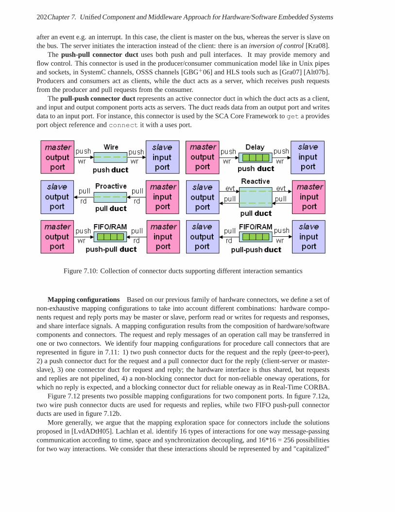
202Chapter 7. Unified Component and Middleware Approach for Hardware/Software Embedded Systems
after an event e.g. an interrupt. In this case, the client is master on the bus, whereas the server is slave onthe bus. The server initiates the interaction instead of theclient: there is aninversion of control[Kra08].
The push-pull connector duct uses both push and pull interfaces. It may provide memory andflow control. This connector is used in the producer/consumer communication model like in Unix pipesand sockets, in SystemC channels, OSSS channels [GBG+06] and HLS tools such as [Gra07] [Alt07b].Producers and consumers act as clients, while the duct acts as a server, which receives push requestsfrom the producer and pull requests from the consumer.
Thepull-push connector ductrepresents an active connector duct in which the duct acts asa client,and input and output component ports acts as servers. The duct reads data from an output port and writesdata to an input port. For instance, this connector is used bythe SCA Core Framework toget a providesport object reference andconnect it with a uses port.
Figure 7.10: Collection of connector ducts supporting different interaction semantics
Mapping configurations Based on our previous family of hardware connectors, we define a set ofnon-exhaustive mapping configurations to take into accountdifferent combinations: hardware compo-nents request and reply ports may be master or slave, performread or writes for requests and responses,and share interface signals. A mapping configuration results from the composition of hardware/softwarecomponents and connectors. The request and reply messages of an operation call may be transferred inone or two connectors. We identify four mapping configurations for procedure call connectors that arerepresented in figure in 7.11: 1) two push connector ducts forthe request and the reply (peer-to-peer),2) a push connector duct for the request and a pull connector duct for the reply (client-server or master-slave), 3) one connector duct for request and reply; the hardware interface is thus shared, but requestsand replies are not pipelined, 4) a non-blocking connector duct for non-reliable oneway operations, forwhich no reply is expected, and a blocking connector duct forreliable oneway as in Real-Time CORBA.
Figure 7.12 presents two possible mapping configurations for two component ports. In figure 7.12a,two wire push connector ducts are used for requests and replies, while two FIFO push-pull connectorducts are used in figure 7.12b.
More generally, we argue that the mapping exploration spacefor connectors include the solutionsproposed in [LvdADtH05]. Lachlan et al. identify 16 types ofinteractions for one way message-passingcommunication according to time, space and synchronization decoupling, and 16*16 = 256 possibilitiesfor two way interactions. We consider that these interactions should be represented by and "capitalized"
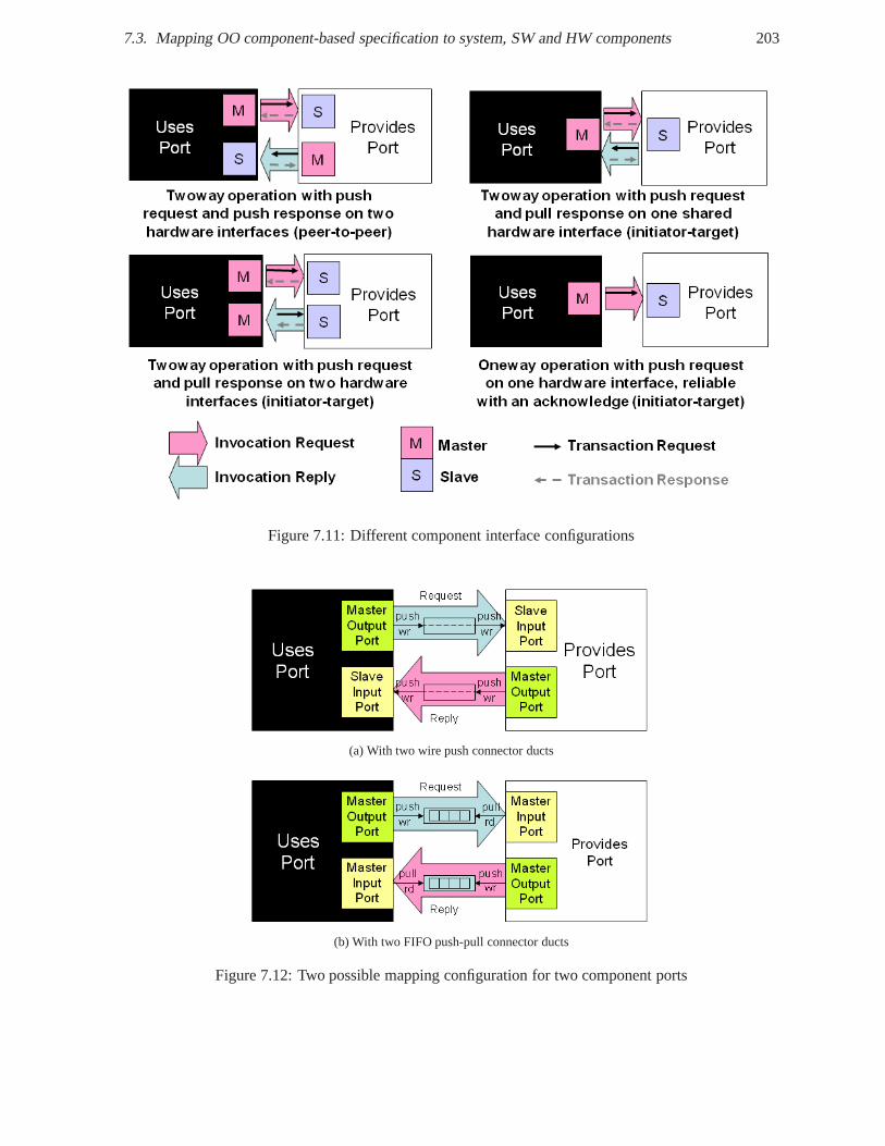
7.3. Mapping OO component-based specification to system, SWand HW components 203
Figure 7.11: Different component interface configurations
(a) With two wire push connector ducts
(b) With two FIFO push-pull connector ducts
Figure 7.12: Two possible mapping configuration for two component ports
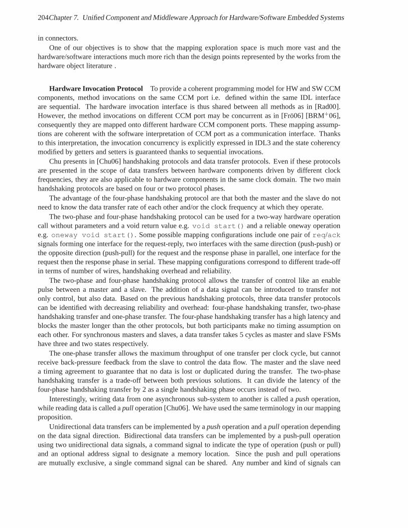
204Chapter 7. Unified Component and Middleware Approach for Hardware/Software Embedded Systems
in connectors.One of our objectives is to show that the mapping explorationspace is much more vast and the
hardware/software interactions much more rich than the design points represented by the works from thehardware object literature .
Hardware Invocation Protocol To provide a coherent programming model for HW and SW CCMcomponents, method invocations on the same CCM port i.e. defined within the same IDL interfaceare sequential. The hardware invocation interface is thus shared between all methods as in [Rad00].However, the method invocations on different CCM port may beconcurrent as in [Frö06] [BRM+06],consequently they are mapped onto different hardware CCM component ports. These mapping assump-tions are coherent with the software interpretation of CCM port as a communication interface. Thanksto this interpretation, the invocation concurrency is explicitly expressed in IDL3 and the state coherencymodified by getters and setters is guaranteed thanks to sequential invocations.
Chu presents in [Chu06] handshaking protocols and data transfer protocols. Even if these protocolsare presented in the scope of data transfers between hardware components driven by different clockfrequencies, they are also applicable to hardware components in the same clock domain. The two mainhandshaking protocols are based on four or two protocol phases.
The advantage of the four-phase handshaking protocol are that both the master and the slave do notneed to know the data transfer rate of each other and/or the clock frequency at which they operate.
The two-phase and four-phase handshaking protocol can be used for a two-way hardware operationcall without parameters and a void return value e.g.void start() and a reliable oneway operatione.g. oneway void start(). Some possible mapping configurations include one pair ofreq/acksignals forming one interface for the request-reply, two interfaces with the same direction (push-push) orthe opposite direction (push-pull) for the request and the response phase in parallel, one interface for therequest then the response phase in serial. These mapping configurations correspond to different trade-offin terms of number of wires, handshaking overhead and reliability.
The two-phase and four-phase handshaking protocol allows the transfer of control like an enablepulse between a master and a slave. The addition of a data signal can be introduced to transfer notonly control, but also data. Based on the previous handshaking protocols, three data transfer protocolscan be identified with decreasing reliability and overhead:four-phase handshaking transfer, two-phasehandshaking transfer and one-phase transfer. The four-phase handshaking transfer has a high latency andblocks the master longer than the other protocols, but both participants make no timing assumption oneach other. For synchronous masters and slaves, a data transfer takes 5 cycles as master and slave FSMshave three and two states respectively.
The one-phase transfer allows the maximum throughput of onetransfer per clock cycle, but cannotreceive back-pressure feedback from the slave to control the data flow. The master and the slave needa timing agreement to guarantee that no data is lost or duplicated during the transfer. The two-phasehandshaking transfer is a trade-off between both previous solutions. It can divide the latency of thefour-phase handshaking transfer by 2 as a single handshaking phase occurs instead of two.
Interestingly, writing data from one asynchronous sub-system to another is called apushoperation,while reading data is called apull operation [Chu06]. We have used the same terminology in our mappingproposition.
Unidirectional data transfers can be implemented by apushoperation and apull operation dependingon the data signal direction. Bidirectional data transferscan be implemented by a push-pull operationusing two unidirectional data signals, a command signal to indicate the type of operation (push or pull)and an optional address signal to designate a memory location. Since the push and pull operationsare mutually exclusive, a single command signal can be shared. Any number and kind of signals can
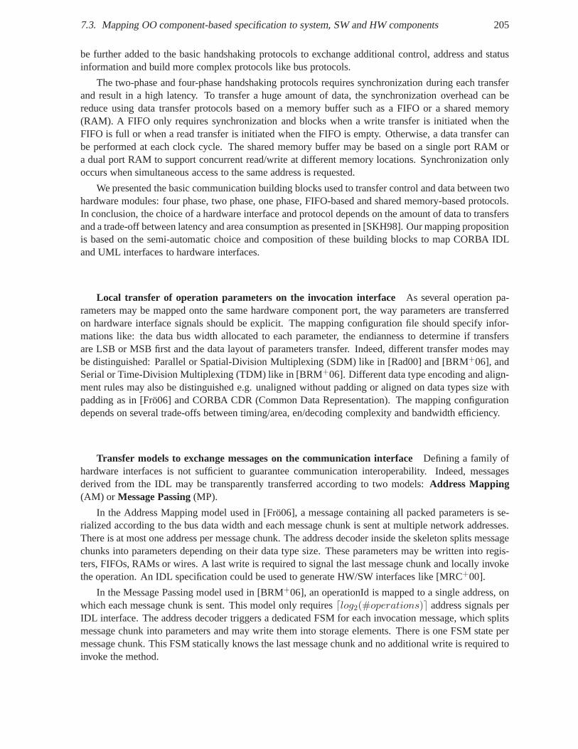
7.3. Mapping OO component-based specification to system, SWand HW components 205
be further added to the basic handshaking protocols to exchange additional control, address and statusinformation and build more complex protocols like bus protocols.
The two-phase and four-phase handshaking protocols requires synchronization during each transferand result in a high latency. To transfer a huge amount of data, the synchronization overhead can bereduce using data transfer protocols based on a memory buffer such as a FIFO or a shared memory(RAM). A FIFO only requires synchronization and blocks whena write transfer is initiated when theFIFO is full or when a read transfer is initiated when the FIFOis empty. Otherwise, a data transfer canbe performed at each clock cycle. The shared memory buffer may be based on a single port RAM ora dual port RAM to support concurrent read/write at different memory locations. Synchronization onlyoccurs when simultaneous access to the same address is requested.
We presented the basic communication building blocks used to transfer control and data between twohardware modules: four phase, two phase, one phase, FIFO-based and shared memory-based protocols.In conclusion, the choice of a hardware interface and protocol depends on the amount of data to transfersand a trade-off between latency and area consumption as presented in [SKH98]. Our mapping propositionis based on the semi-automatic choice and composition of these building blocks to map CORBA IDLand UML interfaces to hardware interfaces.
Local transfer of operation parameters on the invocation interface As several operation pa-rameters may be mapped onto the same hardware component port, the way parameters are transferredon hardware interface signals should be explicit. The mapping configuration file should specify infor-mations like: the data bus width allocated to each parameter, the endianness to determine if transfersare LSB or MSB first and the data layout of parameters transfer. Indeed, different transfer modes maybe distinguished: Parallel or Spatial-Division Multiplexing (SDM) like in [Rad00] and [BRM+06], andSerial or Time-Division Multiplexing (TDM) like in [BRM+06]. Different data type encoding and align-ment rules may also be distinguished e.g. unaligned withoutpadding or aligned on data types size withpadding as in [Frö06] and CORBA CDR (Common Data Representation). The mapping configurationdepends on several trade-offs between timing/area, en/decoding complexity and bandwidth efficiency.
Transfer models to exchange messages on the communication interface Defining a family ofhardware interfaces is not sufficient to guarantee communication interoperability. Indeed, messagesderived from the IDL may be transparently transferred according to two models:Address Mapping(AM) or Message Passing(MP).
In the Address Mapping model used in [Frö06], a message containing all packed parameters is se-rialized according to the bus data width and each message chunk is sent at multiple network addresses.There is at most one address per message chunk. The address decoder inside the skeleton splits messagechunks into parameters depending on their data type size. These parameters may be written into regis-ters, FIFOs, RAMs or wires. A last write is required to signalthe last message chunk and locally invokethe operation. An IDL specification could be used to generateHW/SW interfaces like [MRC+00].
In the Message Passing model used in [BRM+06], an operationId is mapped to a single address, onwhich each message chunk is sent. This model only requires⌈log2(#operations)⌉ address signals perIDL interface. The address decoder triggers a dedicated FSMfor each invocation message, which splitsmessage chunk into parameters and may write them into storage elements. There is one FSM state permessage chunk. This FSM statically knows the last message chunk and no additional write is required toinvoke the method.
206Chapter 7. Unified Component and Middleware Approach for Hardware/Software Embedded Systems
Common Interfaces and Protocols
Defining a mapping from IDLs to HDLs is a high-level interfacesynthesis problem. This mappingrequires to be flexible enough in reason of the inherent hardware trade-off between timing, area andpower consumption.
To support portability and interoperability of hardware components and propose a flexible and exten-sible mapping, we propose common hardware interfaces and protocols to provide the building blocks ofa mapping framework. Such a framework will allow to customize a mapping to fit application require-ments.
The purpose of this mapping framework is to explicitly associate with one or more operation param-eters the required hardware interface and protocol that best correspond to the implicit communicationmodel of the parameter (control or data, continuous or buffered stream, with or without control flow,memory-mapped access and so on). These interfaces present the mapping framework approach, but cannot be considered as exhaustive. New interfaces could be added to address unforeseen needs. The namesof the presented signals may be changed by the user to correspond to specific coding rules. User-definednames are alias for the real name of the standard interfaces signal. The only important point is to respectthe standard interface protocol.
Figure 7.13 depicts this non-exhaustive and generic set of interfaces: from simple data interfacefor registered attributes to addressable blocking interface for sequential synchronous invocations. Eachsuccessive interface adds semantics: blocking or non-blocking, push semantics for write or pull forread, with or without flow control, addressable or not. Theseinterfaces can be easily mapped ontosocket protocols like OCP. Instead of the raw OCP interface,its 100 parameters, its bridging profiles andsome OCP subsets, these named interfaces explicitly specify the invocation semantics and ease mappingconfigurability.
These interfaces are presented in more details in annexe A which describes the CORBA IDL3 toVHDL and SystemC Language Mappings.
Mapping of Data Structure
As depicted in figure 7.14, the data address offset, data layout and endianness must be explicitly definedin the mapping configuration file.
Transfer of operation parameters
A logical hardware input port is a a set of VHDL entity I/O ports that is associated with one or severalinput parameters It implements a standard hardware interface (syntax) and protocol (semantics) e.g.push or pull, blocking or non-blocking, with/without data or flow control and addressable interface. Thismapping should be flexible and extensible, because the nature of operation parameters is totally implicitin IDL: control flow, data flow or a mix, continuous or discontinuous, with or without flow control etc.The association between parameters and input ports is explicitly specified in a mapping configurationfile. The component-oriented nature of CORBA can be used to define dedicated IDL interfaces forcontrol, configuration or data-oriented aspects. The nature of communication could be expressed by newIDL keywords to better characterize CORBA component ports such asbuffered, addressable,stream and infer hardware interfaces based on register, fifo, and RAM. When several input parametersare associated to an input port, the way input parameters aretransferred on hardware interface signalsshould be explicit. The data bus width is specified in the mapping configuration file. It is not requiredto be a power of two. The endianness is configured to determineif transfers are LSB or MSB first. Thedata layout of parameters transfer shall also be configured.
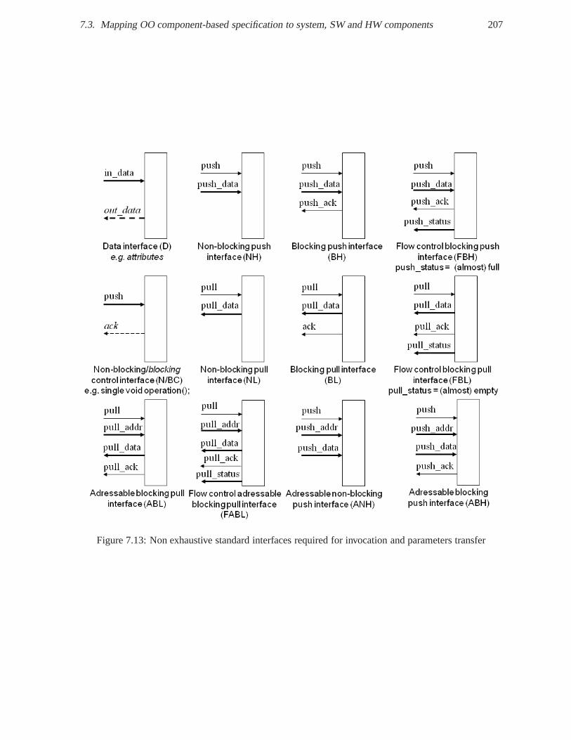
7.3. Mapping OO component-based specification to system, SWand HW components 207
Figure 7.13: Non exhaustive standard interfaces required for invocation and parameters transfer
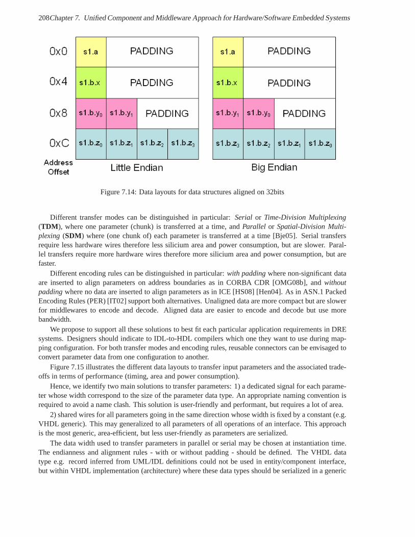
208Chapter 7. Unified Component and Middleware Approach for Hardware/Software Embedded Systems
Figure 7.14: Data layouts for data structures aligned on 32bits
Different transfer modes can be distinguished in particular: Serial or Time-Division Multiplexing(TDM ), where one parameter (chunk) is transferred at a time, andParallel or Spatial-Division Multi-plexing (SDM) where (one chunk of) each parameter is transferred at a time[Bje05]. Serial transfersrequire less hardware wires therefore less silicium area and power consumption, but are slower. Paral-lel transfers require more hardware wires therefore more silicium area and power consumption, but arefaster.
Different encoding rules can be distinguished in particular: with paddingwhere non-significant dataare inserted to align parameters on address boundaries as inCORBA CDR [OMG08b], andwithoutpaddingwhere no data are inserted to align parameters as in ICE [HS08] [Hen04]. As in ASN.1 PackedEncoding Rules (PER) [IT02] support both alternatives. Unaligned data are more compact but are slowerfor middlewares to encode and decode. Aligned data are easier to encode and decode but use morebandwidth.
We propose to support all these solutions to best fit each particular application requirements in DREsystems. Designers should indicate to IDL-to-HDL compilers which one they want to use during map-ping configuration. For both transfer modes and encoding rules, reusable connectors can be envisaged toconvert parameter data from one configuration to another.
Figure 7.15 illustrates the different data layouts to transfer input parameters and the associated trade-offs in terms of performance (timing, area and power consumption).
Hence, we identify two main solutions to transfer parameters: 1) a dedicated signal for each parame-ter whose width correspond to the size of the parameter data type. An appropriate naming convention isrequired to avoid a name clash. This solution is user-friendly and performant, but requires a lot of area.
2) shared wires for all parameters going in the same direction whose width is fixed by a constant (e.g.VHDL generic). This may generalized to all parameters of alloperations of an interface. This approachis the most generic, area-efficient, but less user-friendlyas parameters are serialized.
The data width used to transfer parameters in parallel or serial may be chosen at instantiation time.The endianness and alignment rules - with or without padding- should be defined. The VHDL datatype e.g. record inferred from UML/IDL definitions could notbe used in entity/component interface,but within VHDL implementation (architecture) where thesedata types should be serialized in a generic
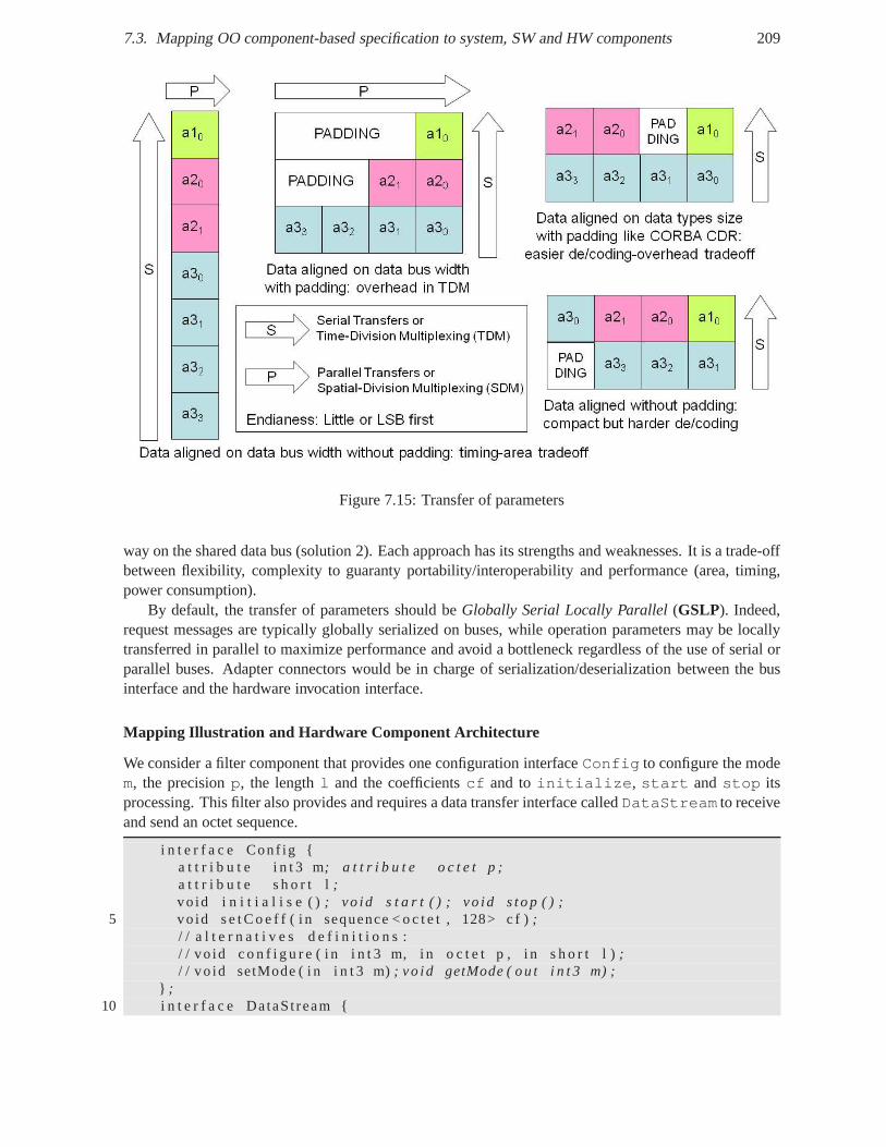
7.3. Mapping OO component-based specification to system, SWand HW components 209
Figure 7.15: Transfer of parameters
way on the shared data bus (solution 2). Each approach has itsstrengths and weaknesses. It is a trade-offbetween flexibility, complexity to guaranty portability/interoperability and performance (area, timing,power consumption).
By default, the transfer of parameters should beGlobally Serial Locally Parallel(GSLP). Indeed,request messages are typically globally serialized on buses, while operation parameters may be locallytransferred in parallel to maximize performance and avoid abottleneck regardless of the use of serial orparallel buses. Adapter connectors would be in charge of serialization/deserialization between the businterface and the hardware invocation interface.
Mapping Illustration and Hardware Component Architecture
We consider a filter component that provides one configuration interfaceConfig to configure the modem, the precisionp, the lengthl and the coefficientscf and toinitialize, start andstop itsprocessing. This filter also provides and requires a data transfer interface calledDataStream to receiveand send an octet sequence.
i n t e r f a c e Conf ig {a t t r i b u t e i n t 3 m; a t t r i b u t e o c t e t p ;a t t r i b u t e s h o r t l;vo id i n i t i a l i s e ( ) ; vo id s t a r t ( ) ; vo id s t o p ( ) ;
5 vo id s e t C o e f f ( i n sequence < o c t e t , 128> c f );/ / a l t e r n a t i v e s d e f i n i t i o n s :/ / vo id c o n f i g u r e ( i n i n t 3 m, i n o c t e t p , i n s h o r t l );/ / vo id setMode ( i n i n t 3 m); vo id getMode ( ou t i n t 3 m) ;
} ;10 i n t e r f a c e DataSt ream {
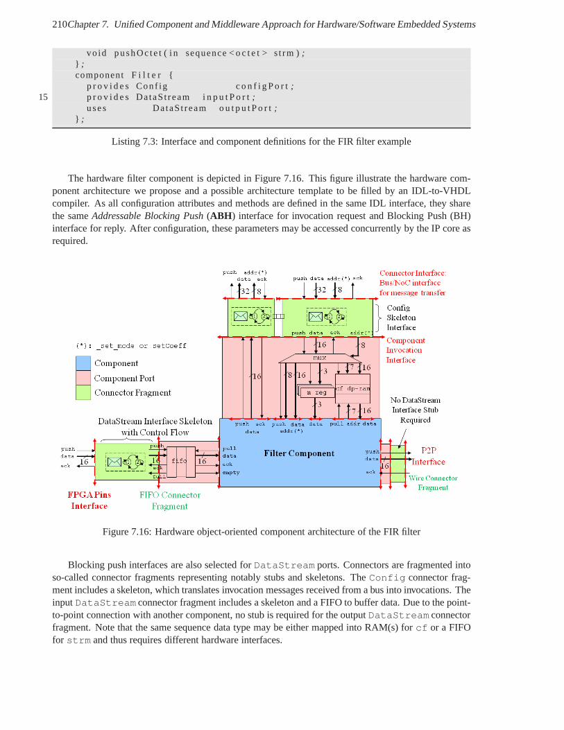
210Chapter 7. Unified Component and Middleware Approach for Hardware/Software Embedded Systems
vo id pushOc te t ( i n sequence < o c t e t > s t rm );} ;component F i l t e r {
p r o v i d e s Conf ig c o n f i g P o r t;15 p r o v i d e s DataSt ream i n p u t P o r t;
uses DataSt ream o u t p u t P o r t;} ;
Listing 7.3: Interface and component definitions for the FIRfilter example
The hardware filter component is depicted in Figure 7.16. This figure illustrate the hardware com-ponent architecture we propose and a possible architecturetemplate to be filled by an IDL-to-VHDLcompiler. As all configuration attributes and methods are defined in the same IDL interface, they sharethe sameAddressable Blocking Push(ABH ) interface for invocation request and Blocking Push (BH)interface for reply. After configuration, these parametersmay be accessed concurrently by the IP core asrequired.
Figure 7.16: Hardware object-oriented component architecture of the FIR filter
Blocking push interfaces are also selected forDataStream ports. Connectors are fragmented intoso-called connector fragments representing notably stubsand skeletons. TheConfig connector frag-ment includes a skeleton, which translates invocation messages received from a bus into invocations. TheinputDataStream connector fragment includes a skeleton and a FIFO to buffer data. Due to the point-to-point connection with another component, no stub is required for the outputDataStream connectorfragment. Note that the same sequence data type may be eithermapped into RAM(s) forcf or a FIFOfor strm and thus requires different hardware interfaces.
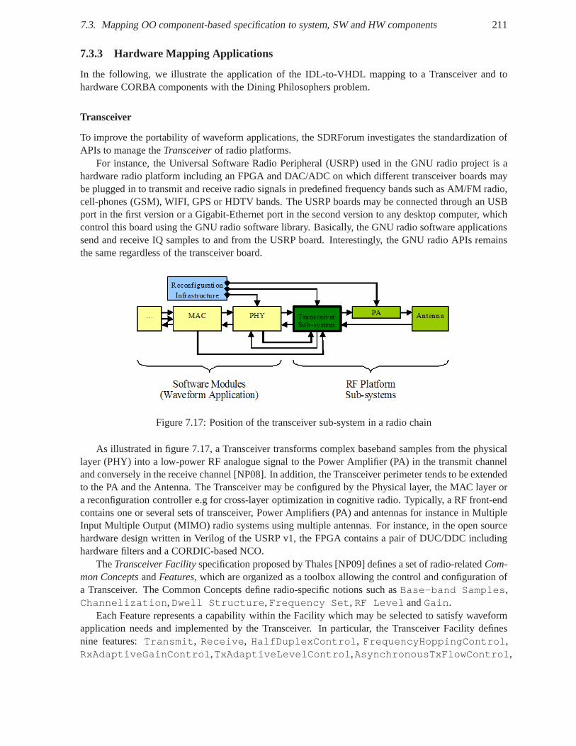
7.3. Mapping OO component-based specification to system, SWand HW components 211
7.3.3 Hardware Mapping Applications
In the following, we illustrate the application of the IDL-to-VHDL mapping to a Transceiver and tohardware CORBA components with the Dining Philosophers problem.
Transceiver
To improve the portability of waveform applications, the SDRForum investigates the standardization ofAPIs to manage theTransceiverof radio platforms.
For instance, the Universal Software Radio Peripheral (USRP) used in the GNU radio project is ahardware radio platform including an FPGA and DAC/ADC on which different transceiver boards maybe plugged in to transmit and receive radio signals in predefined frequency bands such as AM/FM radio,cell-phones (GSM), WIFI, GPS or HDTV bands. The USRP boards may be connected through an USBport in the first version or a Gigabit-Ethernet port in the second version to any desktop computer, whichcontrol this board using the GNU radio software library. Basically, the GNU radio software applicationssend and receive IQ samples to and from the USRP board. Interestingly, the GNU radio APIs remainsthe same regardless of the transceiver board.
Figure 7.17: Position of the transceiver sub-system in a radio chain
As illustrated in figure 7.17, a Transceiver transforms complex baseband samples from the physicallayer (PHY) into a low-power RF analogue signal to the Power Amplifier (PA) in the transmit channeland conversely in the receive channel [NP08]. In addition, the Transceiver perimeter tends to be extendedto the PA and the Antenna. The Transceiver may be configured bythe Physical layer, the MAC layer ora reconfiguration controller e.g for cross-layer optimization in cognitive radio. Typically, a RF front-endcontains one or several sets of transceiver, Power Amplifiers (PA) and antennas for instance in MultipleInput Multiple Output (MIMO) radio systems using multiple antennas. For instance, in the open sourcehardware design written in Verilog of the USRP v1, the FPGA contains a pair of DUC/DDC includinghardware filters and a CORDIC-based NCO.
TheTransceiver Facilityspecification proposed by Thales [NP09] defines a set of radio-relatedCom-mon ConceptsandFeatures, which are organized as a toolbox allowing the control and configuration ofa Transceiver. The Common Concepts define radio-specific notions such asBase-band Samples,Channelization,Dwell Structure,Frequency Set, RF Level andGain.
Each Feature represents a capability within the Facility which may be selected to satisfy waveformapplication needs and implemented by the Transceiver. In particular, the Transceiver Facility definesnine features:Transmit, Receive, HalfDuplexControl, FrequencyHoppingControl,RxAdaptiveGainControl,TxAdaptiveLevelControl,AsynchronousTxFlowControl,
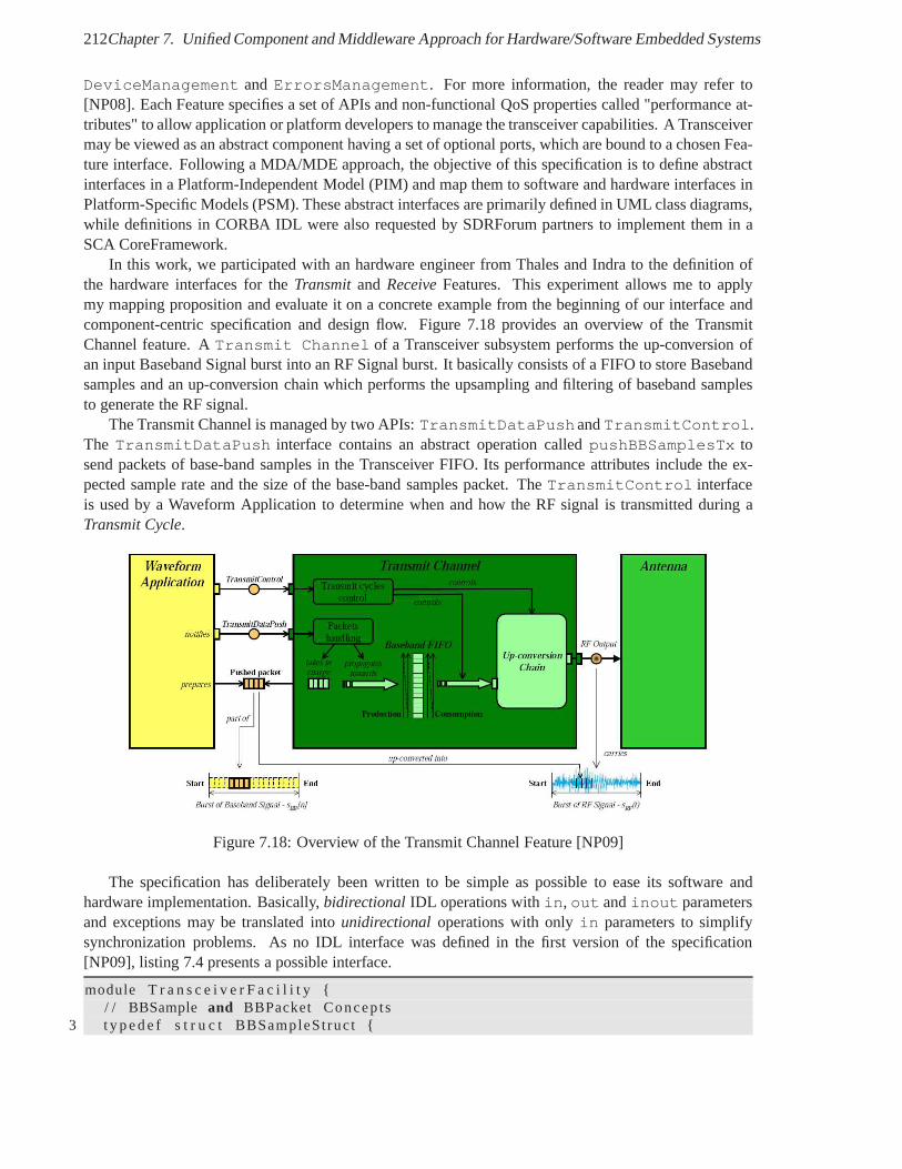
212Chapter 7. Unified Component and Middleware Approach for Hardware/Software Embedded Systems
DeviceManagement andErrorsManagement. For more information, the reader may refer to[NP08]. Each Feature specifies a set of APIs and non-functional QoS properties called "performance at-tributes" to allow application or platform developers to manage the transceiver capabilities. A Transceivermay be viewed as an abstract component having a set of optional ports, which are bound to a chosen Fea-ture interface. Following a MDA/MDE approach, the objective of this specification is to define abstractinterfaces in a Platform-Independent Model (PIM) and map them to software and hardware interfaces inPlatform-Specific Models (PSM). These abstract interfacesare primarily defined in UML class diagrams,while definitions in CORBA IDL were also requested by SDRForum partners to implement them in aSCA CoreFramework.
In this work, we participated with an hardware engineer fromThales and Indra to the definition ofthe hardware interfaces for theTransmitand ReceiveFeatures. This experiment allows me to applymy mapping proposition and evaluate it on a concrete examplefrom the beginning of our interface andcomponent-centric specification and design flow. Figure 7.18 provides an overview of the TransmitChannel feature. ATransmit Channel of a Transceiver subsystem performs the up-conversion ofan input Baseband Signal burst into an RF Signal burst. It basically consists of a FIFO to store Basebandsamples and an up-conversion chain which performs the upsampling and filtering of baseband samplesto generate the RF signal.
The Transmit Channel is managed by two APIs:TransmitDataPushandTransmitControl.The TransmitDataPush interface contains an abstract operation calledpushBBSamplesTx tosend packets of base-band samples in the Transceiver FIFO. Its performance attributes include the ex-pected sample rate and the size of the base-band samples packet. TheTransmitControl interfaceis used by a Waveform Application to determine when and how the RF signal is transmitted during aTransmit Cycle.
Figure 7.18: Overview of the Transmit Channel Feature [NP09]
The specification has deliberately been written to be simpleas possible to ease its software andhardware implementation. Basically,bidirectional IDL operations within, out andinout parametersand exceptions may be translated intounidirectional operations with onlyin parameters to simplifysynchronization problems. As no IDL interface was defined inthe first version of the specification[NP09], listing 7.4 presents a possible interface.
module T r a n s c e i v e r F a c i l i t y {/ / BBSample and BBPacket Concep ts
3 t y p e d e f s t r u c t BBSampleStruct {
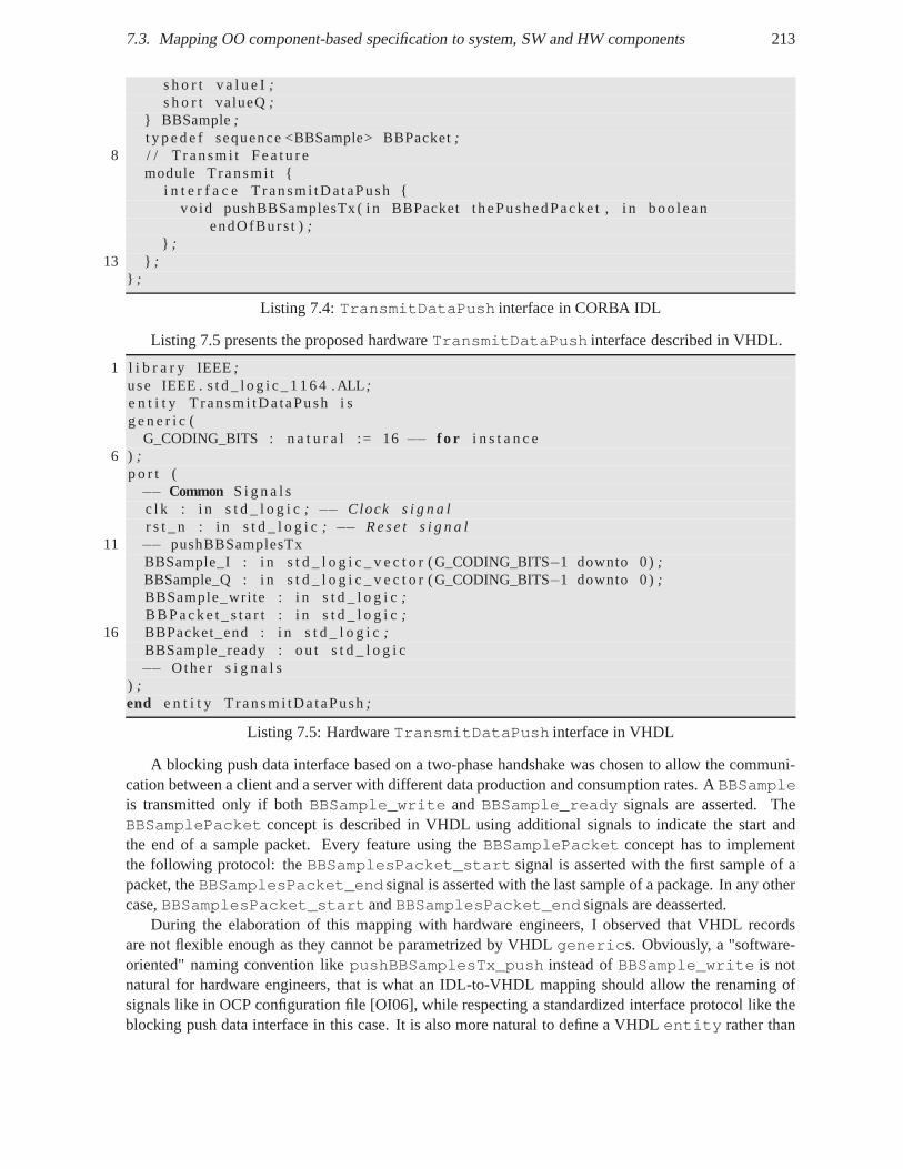
7.3. Mapping OO component-based specification to system, SWand HW components 213
s h o r t v a l u e I;s h o r t valueQ;
} BBSample;t y p e d e f sequence <BBSample> BBPacket;
8 / / T ransm i t F e a t u r emodule T ransm i t {
i n t e r f a c e T ransm i tDataPush {vo id pushBBSamplesTx ( i n BBPacket thePushedPacke t , i n boolean
endOfBurs t );} ;
13 } ;} ;
Listing 7.4:TransmitDataPush interface in CORBA IDL
Listing 7.5 presents the proposed hardwareTransmitDataPush interface described in VHDL.
1 l i b r a r y IEEE;use IEEE . s t d _ l o g i c _ 1 1 6 4 .ALL;e n t i t y T ransm i tDa taPush i sg e n e r i c (
G_CODING_BITS : n a t u r a l := 16−− f o r i n s t a n c e6 ) ;
p o r t (−− Common S i g n a l sc l k : i n s t d _ l o g i c; −− Clock s i g n a lr s t _ n : i n s t d _ l o g i c; −− R e s e t s i g n a l
11 −− pushBBSamplesTxBBSample_I : i n s t d _ l o g i c _ v e c t o r (G_CODING_BITS−1 downto 0);BBSample_Q : i n s t d _ l o g i c _ v e c t o r (G_CODING_BITS−1 downto 0);BBSample_wri te : i n s t d _ l o g i c;B B P a c k e t _ s t a r t : i n s t d _ l o g i c;
16 BBPacket_end : i n s t d _ l o g i c;BBSample_ready : ou t s t d _ l o g i c−− Other s i g n a l s
) ;end e n t i t y T ransm i tDa taPush;
Listing 7.5: HardwareTransmitDataPush interface in VHDL
A blocking push data interface based on a two-phase handshake was chosen to allow the communi-cation between a client and a server with different data production and consumption rates. ABBSampleis transmitted only if bothBBSample_write and BBSample_ready signals are asserted. TheBBSamplePacket concept is described in VHDL using additional signals to indicate the start andthe end of a sample packet. Every feature using theBBSamplePacket concept has to implementthe following protocol: theBBSamplesPacket_start signal is asserted with the first sample of apacket, theBBSamplesPacket_end signal is asserted with the last sample of a package. In any othercase,BBSamplesPacket_start andBBSamplesPacket_end signals are deasserted.
During the elaboration of this mapping with hardware engineers, I observed that VHDL recordsare not flexible enough as they cannot be parametrized by VHDLgenerics. Obviously, a "software-oriented" naming convention likepushBBSamplesTx_push instead ofBBSample_write is notnatural for hardware engineers, that is what an IDL-to-VHDLmapping should allow the renaming ofsignals like in OCP configuration file [OI06], while respecting a standardized interface protocol like theblocking push data interface in this case. It is also more natural to define a VHDLentity rather than
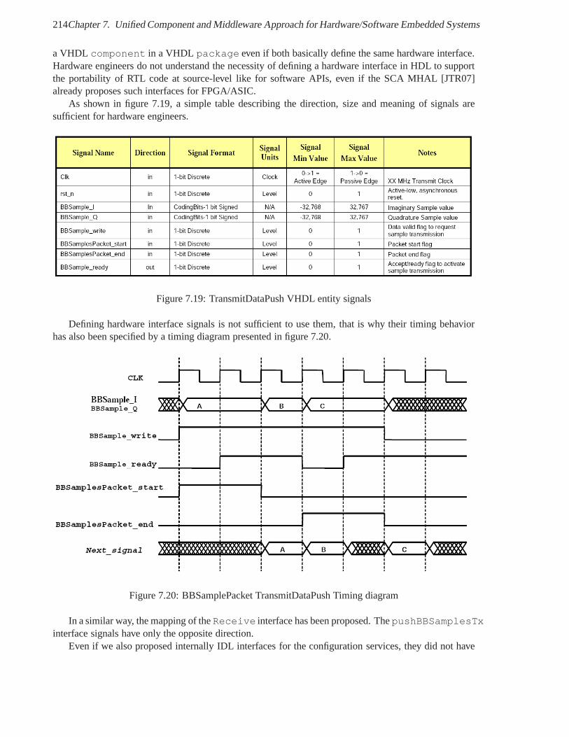
214Chapter 7. Unified Component and Middleware Approach for Hardware/Software Embedded Systems
a VHDL component in a VHDL package even if both basically define the same hardware interface.Hardware engineers do not understand the necessity of defining a hardware interface in HDL to supportthe portability of RTL code at source-level like for software APIs, even if the SCA MHAL [JTR07]already proposes such interfaces for FPGA/ASIC.
As shown in figure 7.19, a simple table describing the direction, size and meaning of signals aresufficient for hardware engineers.
Figure 7.19: TransmitDataPush VHDL entity signals
Defining hardware interface signals is not sufficient to use them, that is why their timing behaviorhas also been specified by a timing diagram presented in figure7.20.
Figure 7.20: BBSamplePacket TransmitDataPush Timing diagram
In a similar way, the mapping of theReceive interface has been proposed. ThepushBBSamplesTxinterface signals have only the opposite direction.
Even if we also proposed internally IDL interfaces for the configuration services, they did not have
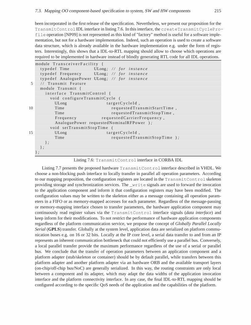
7.3. Mapping OO component-based specification to system, SWand HW components 215
been incorporated in the first release of the specification. Nevertheless, we present our proposition for theTransmitControl IDL interface in listing 7.6. In this interface, thecreateTransmitCyclePro-file operation [NP09] is not represented as this kind of "factory" method is useful for a software imple-mentation, but not for a hardware implementation. Indeed, such an operation is used to create a softwaredata structure, which is already available in the hardware implementation e.g. under the form of regis-ters. Interestingly, this shows that a IDL-to-RTL mapping should allow to choose which operations arerequired to be implemented in hardware instead of blindly generating RTL code for all IDL operations.
module T r a n s c e i v e r F a c i l i t y {t y p e d e f Time ULong; / / f o r i n s t a n c et y p e d e f Frequency ULong; / / f o r i n s t a n c et y p e d e f AnaloguePower ULong; / / f o r i n s t a n c e
5 / / T ransm i t F e a t u r emodule T ransm i t {
i n t e r f a c e T r a n s m i t C o n t r o l {vo id c o n f i g u r e T r a n s m i t C y c l e (
ULong t a r g e t C y c l e I d ,10 Time r e q u e s t e d T r a n s m i t S t a r t T i m e ,
Time reques tedT ransm i tS topT ime ,Frequency r e q u e s t e d C a r r i e r F r e q u e n c y ,AnaloguePower requestedNominalRFPower );
vo id se tT ransm i tS topT ime (15 ULong t a r g e t C y c l e I d ,
Time r e q u e s t e d T rans m i tS t opT i me );} ;
} ;} ;
Listing 7.6:TransmitControl interface in CORBA IDL
Listing 7.7 presents the proposed hardwareTransmitControl interface described in VHDL. Wechoose a non-blocking push interface to locally transfer inparallel all operation parameters. Accordingto our mapping proposition, the configuration registers arelocated in theTransmitControl skeletonproviding storage and synchronization services. The_write signals are used to forward the invocationto the application component and inform it that configuration registers may have been modified. Theconfiguration values may be written to the skeleton either asa message containing all operation param-eters in a FIFO or as memory-mapped accesses for each parameter. Regardless of the message-passingor memory-mapping interface chosen to transfer parameters, the hardware application component maycontinuously read register values via theTransmitControl interface signals (data interface) andkeep inform for their modifications. To not restrict the performance of hardware application componentsregardless of the platform communication service, we propose the concept ofGlobally Parallel LocallySerial(GPLS) transfer. Globally at the system level, application data are serialized on platform commu-nication buses e.g. on 16 or 32 bits. Locally at the IP core level, a serial data transfer to and from an IPrepresents an inherent communication bottleneck that could not efficiently use a parallel bus. Conversely,a local parallel transfer provide the maximum performance regardless of the use of a serial or parallelbus. We conclude that the transfer of operation parameters between an application component and aplatform adapter (stub/skeleton or container) should be bydefault parallel, while transfers between thisplatform adapter and another platform adapter via an hardware ORB and the available transport layers(on-chip/off-chip bus/NoC) are generally serialized. In this way, the routing constraints are only localbetween a component and its adapter, which may adapt the datawidths of the application invocationinterface and the platform connectivity interface. In any case, the final IDL-to-RTL mapping should beconfigured according to the specific QoS needs of the application and the capabilities of the platform.
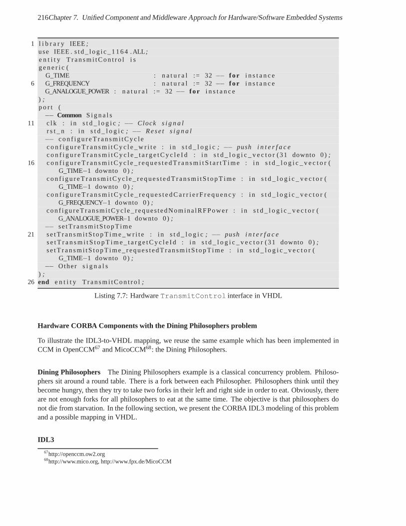
216Chapter 7. Unified Component and Middleware Approach for Hardware/Software Embedded Systems
1 l i b r a r y IEEE;use IEEE . s t d _ l o g i c _ 1 1 6 4 .ALL;e n t i t y T r a n s m i t C o n t r o l i sg e n e r i c (
G_TIME : n a t u r a l := 32−− f o r i n s t a n c e6 G_FREQUENCY : n a t u r a l := 32−− f o r i n s t a n c e
G_ANALOGUE_POWER : n a t u r a l := 32−− f o r i n s t a n c e) ;p o r t (−− Common S i g n a l s
11 c l k : i n s t d _ l o g i c; −− Clock s i g n a lr s t _ n : i n s t d _ l o g i c; −− R e s e t s i g n a l−− c o n f i g u r e T r a n s m i t C y c l ec o n f i g u r e T r a n s m i t C y c l e _ w r i t e : i n s t d _ l o g i c; −− push i n t e r f a c ec o n f i g u r e T r a n s m i t C y c l e _ t a r g e t C y c l e I d : i n s t d _ l o g i c _ v ec t o r (31 downto 0);
16 c o n f i g u r e T r a n s m i t C y c l e _ r e q u e s t e d T r a n s m i t S t a r t T i m e: i n s t d _ l o g i c _ v e c t o r (G_TIME−1 downto 0);
c o n f i g u r e T r a n s m i t C y c l e _ r e q u e s t e d T r a n s m i t S t o p T i m e : i ns t d _ l o g i c _ v e c t o r (G_TIME−1 downto 0);
c o n f i g u r e T r a n s m i t C y c l e _ r e q u e s t e d C a r r i e r F r e q u e n c y : i ns t d _ l o g i c _ v e c t o r (G_FREQUENCY−1 downto 0);
con f i gu reT ransm i tCyc le_ reques tedNomina lRFPower : i n s td _ l o g i c _ v e c t o r (G_ANALOGUE_POWER−1 downto 0);
−− se tT ransm i tS topT ime21 s e t T r a n s m i t S t o p T i m e _ w r i t e : i n s t d _ l o g i c; −− push i n t e r f a c e
s e t T r a n s m i t S t o p T i m e _ t a r g e t C y c l e I d : i n s t d _ l o g i c _ v e c t or (31 downto 0);s e t T r a n s m i t S t opT i me_ r eque s t edT ran sm i t S t opT i me : i n s t d_ l o g i c _ v e c t o r (
G_TIME−1 downto 0);−− Other s i g n a l s
) ;26 end e n t i t y T r a n s m i t C o n t r o l;
Listing 7.7: HardwareTransmitControl interface in VHDL
Hardware CORBA Components with the Dining Philosophers problem
To illustrate the IDL3-to-VHDL mapping, we reuse the same example which has been implemented inCCM in OpenCCM67 and MicoCCM68: the Dining Philosophers.
Dining Philosophers The Dining Philosophers example is a classical concurrencyproblem. Philoso-phers sit around a round table. There is a fork between each Philosopher. Philosophers think until theybecome hungry, then they try to take two forks in their left and right side in order to eat. Obviously, thereare not enough forks for all philosophers to eat at the same time. The objective is that philosophers donot die from starvation. In the following section, we present the CORBA IDL3 modeling of this problemand a possible mapping in VHDL.
IDL3
67http://openccm.ow2.org68http://www.mico.org, http://www.fpx.de/MicoCCM
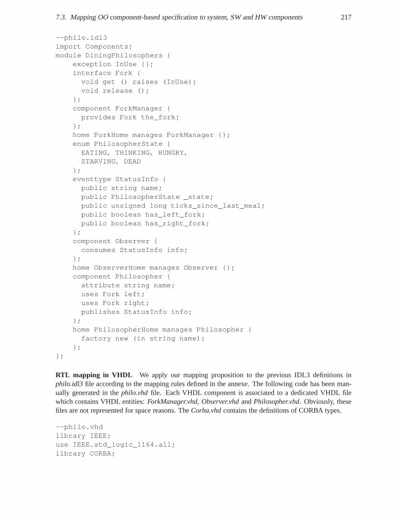
7.3. Mapping OO component-based specification to system, SWand HW components 217
--philo.idl3import Components;module DiningPhilosophers {
exception InUse {};interface Fork {void get () raises (InUse);void release ();
};component ForkManager {provides Fork the_fork;
};home ForkHome manages ForkManager {};enum PhilosopherState {EATING, THINKING, HUNGRY,STARVING, DEAD
};eventtype StatusInfo {public string name;public PhilosopherState _state;public unsigned long ticks_since_last_meal;public boolean has_left_fork;public boolean has_right_fork;
};component Observer {consumes StatusInfo info;
};home ObserverHome manages Observer {};component Philosopher {attribute string name;uses Fork left;uses Fork right;publishes StatusInfo info;
};home PhilosopherHome manages Philosopher {factory new (in string name);
};};
RTL mapping in VHDL We apply our mapping proposition to the previous IDL3 definitions inphilo.idl3 file according to the mapping rules defined in the annexe. The following code has been man-ually generated in thephilo.vhdfile. Each VHDL component is associated to a dedicated VHDL filewhich contains VHDL entities:ForkManager.vhd, Observer.vhdandPhilosopher.vhd. Obviously, thesefiles are not represented for space reasons. TheCorba.vhdcontains the definitions of CORBA types.
--philo.vhdlibrary IEEE;use IEEE.std_logic_1164.all;library CORBA;
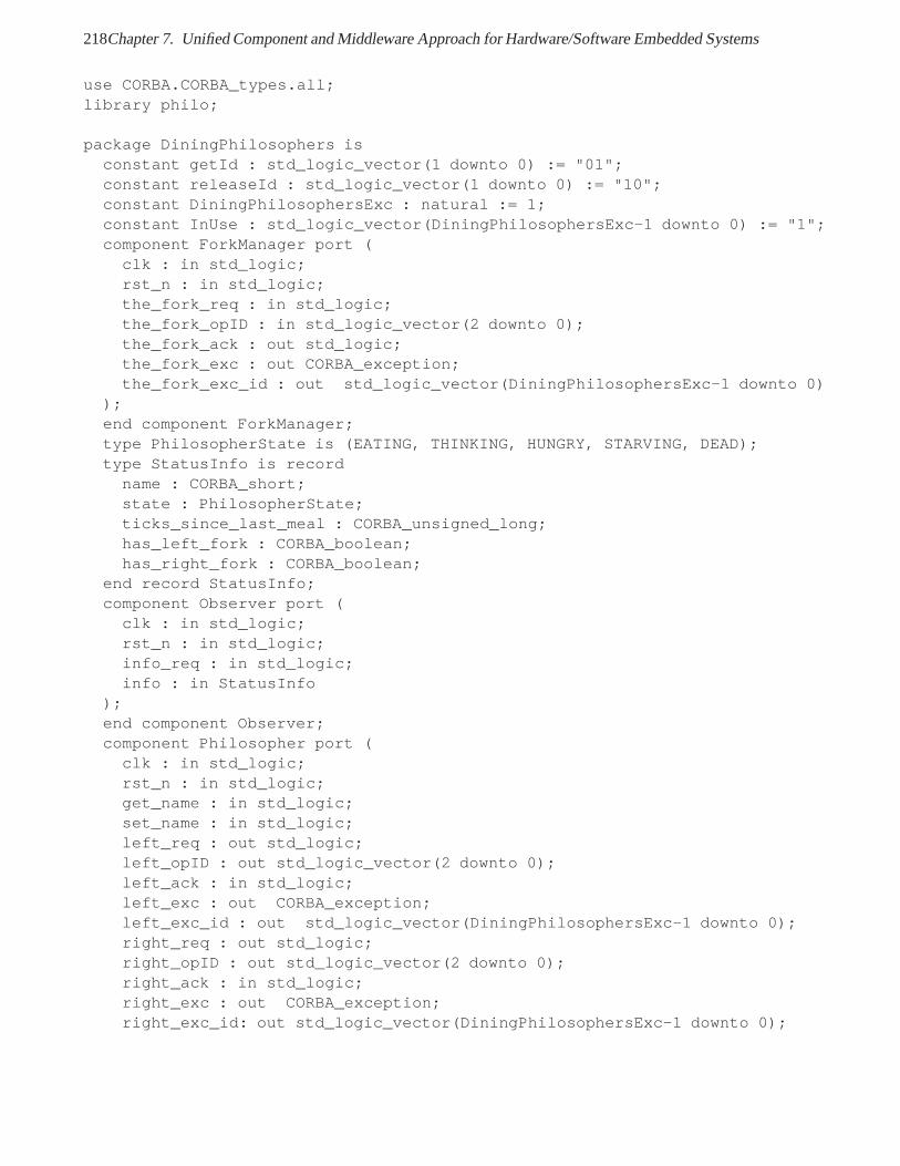
218Chapter 7. Unified Component and Middleware Approach for Hardware/Software Embedded Systems
use CORBA.CORBA_types.all;library philo;
package DiningPhilosophers isconstant getId : std_logic_vector(1 downto 0) := "01";constant releaseId : std_logic_vector(1 downto 0) := "10";constant DiningPhilosophersExc : natural := 1;constant InUse : std_logic_vector(DiningPhilosophersExc-1 downto 0) := "1";component ForkManager port (clk : in std_logic;rst_n : in std_logic;the_fork_req : in std_logic;the_fork_opID : in std_logic_vector(2 downto 0);the_fork_ack : out std_logic;the_fork_exc : out CORBA_exception;the_fork_exc_id : out std_logic_vector(DiningPhilosophersExc-1 downto 0)
);end component ForkManager;type PhilosopherState is (EATING, THINKING, HUNGRY, STARVING, DEAD);type StatusInfo is recordname : CORBA_short;state : PhilosopherState;ticks_since_last_meal : CORBA_unsigned_long;has_left_fork : CORBA_boolean;has_right_fork : CORBA_boolean;
end record StatusInfo;component Observer port (clk : in std_logic;rst_n : in std_logic;info_req : in std_logic;info : in StatusInfo
);end component Observer;component Philosopher port (clk : in std_logic;rst_n : in std_logic;get_name : in std_logic;set_name : in std_logic;left_req : out std_logic;left_opID : out std_logic_vector(2 downto 0);left_ack : in std_logic;left_exc : out CORBA_exception;left_exc_id : out std_logic_vector(DiningPhilosophersExc-1 downto 0);right_req : out std_logic;right_opID : out std_logic_vector(2 downto 0);right_ack : in std_logic;right_exc : out CORBA_exception;right_exc_id: out std_logic_vector(DiningPhilosophersExc-1 downto 0);
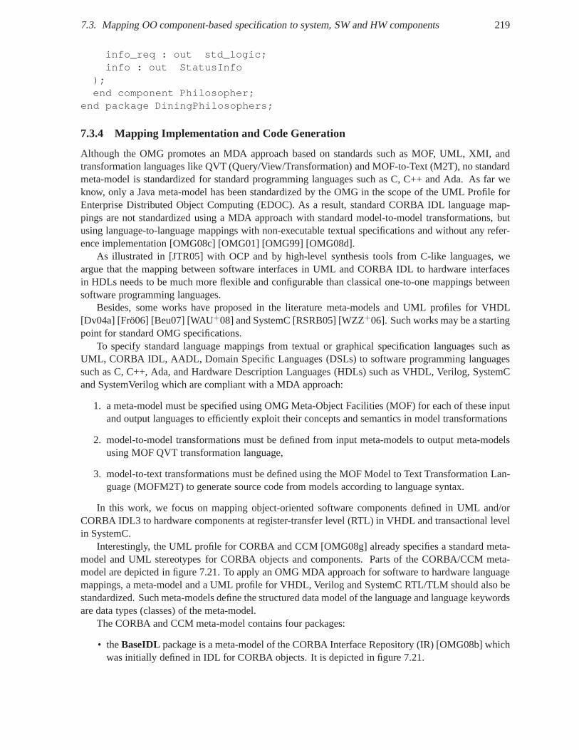
7.3. Mapping OO component-based specification to system, SWand HW components 219
info_req : out std_logic;info : out StatusInfo
);end component Philosopher;
end package DiningPhilosophers;
7.3.4 Mapping Implementation and Code Generation
Although the OMG promotes an MDA approach based on standardssuch as MOF, UML, XMI, andtransformation languages like QVT (Query/View/Transformation) and MOF-to-Text (M2T), no standardmeta-model is standardized for standard programming languages such as C, C++ and Ada. As far weknow, only a Java meta-model has been standardized by the OMGin the scope of the UML Profile forEnterprise Distributed Object Computing (EDOC). As a result, standard CORBA IDL language map-pings are not standardized using a MDA approach with standard model-to-model transformations, butusing language-to-language mappings with non-executabletextual specifications and without any refer-ence implementation [OMG08c] [OMG01] [OMG99] [OMG08d].
As illustrated in [JTR05] with OCP and by high-level synthesis tools from C-like languages, weargue that the mapping between software interfaces in UML and CORBA IDL to hardware interfacesin HDLs needs to be much more flexible and configurable than classical one-to-one mappings betweensoftware programming languages.
Besides, some works have proposed in the literature meta-models and UML profiles for VHDL[Dv04a] [Frö06] [Beu07] [WAU+08] and SystemC [RSRB05] [WZZ+06]. Such works may be a startingpoint for standard OMG specifications.
To specify standard language mappings from textual or graphical specification languages such asUML, CORBA IDL, AADL, Domain Specific Languages (DSLs) to software programming languagessuch as C, C++, Ada, and Hardware Description Languages (HDLs) such as VHDL, Verilog, SystemCand SystemVerilog which are compliant with a MDA approach:
1. a meta-model must be specified using OMG Meta-Object Facilities (MOF) for each of these inputand output languages to efficiently exploit their concepts and semantics in model transformations
2. model-to-model transformations must be defined from input meta-models to output meta-modelsusing MOF QVT transformation language,
3. model-to-text transformations must be defined using the MOF Model to Text Transformation Lan-guage (MOFM2T) to generate source code from models according to language syntax.
In this work, we focus on mapping object-oriented software components defined in UML and/orCORBA IDL3 to hardware components at register-transfer level (RTL) in VHDL and transactional levelin SystemC.
Interestingly, the UML profile for CORBA and CCM [OMG08g] already specifies a standard meta-model and UML stereotypes for CORBA objects and components.Parts of the CORBA/CCM meta-model are depicted in figure 7.21. To apply an OMG MDA approachfor software to hardware languagemappings, a meta-model and a UML profile for VHDL, Verilog andSystemC RTL/TLM should also bestandardized. Such meta-models define the structured data model of the language and language keywordsare data types (classes) of the meta-model.
The CORBA and CCM meta-model contains four packages:
• theBaseIDL package is a meta-model of the CORBA Interface Repository (IR) [OMG08b] whichwas initially defined in IDL for CORBA objects. It is depictedin figure 7.21.
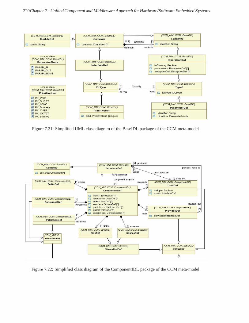
220Chapter 7. Unified Component and Middleware Approach for Hardware/Software Embedded Systems
Figure 7.21: Simplified UML class diagram of the BaseIDL package of the CCM meta-model
Figure 7.22: Simplified class diagram of the ComponentIDL package of the CCM meta-model
7.3. Mapping OO component-based specification to system, SWand HW components 221
• theComponentIDL package extends the BaseIDL package with the CORBA Component Model(CCM) concepts.
• theCIF package is a meta-model of the language used to describe component implementations.
• theDeploymentpackage is a meta-model of the Deployment and Configuration (D&C) conceptsfor CCM such as the assembly of CCM components. It can be used to generate CCM XMLdescriptors.
• theStreamspackage extends the CCM meta-model to describe the exchangeof continuous datastreams between CORBA components. These streams seem to initially target multimedia streamsfor music and video contents over computer networks, but could be relevant for data streaming inSoftware Defined Radio applications.
• the CCMQoS package extends the CCM meta-model with the definition of QoSproperties forCORBA components.
Note that in the Lightweight CORBA Component Model (LwCCM) meta-model defined in [OMG08g],the event ports and provides/uses ports are included, but not the stream ports.
In a similar way, to apply an MDA approach to the SCA, a UML profile for SCA concepts and ameta-model for the SCA component model need to be defined. TheUML profile for SCA is already stan-dardized within the UML profile for Software Radio [OMG07e].Moreover, since SCA uses the object-oriented CORBA IDL 2.x to define SCA component interfaces, the meta-model for these interfaces isalready standardized in the BaseIDL package of the UML profile for CORBA and CCM. Finally, sincethe SCA component model evolved from an early version of the CORBA Component Model (CCM),the meta-model for the SCA component model can be consideredas a subset of the CORBA Compo-nent Model which is standardized in the ComponentIDL package of the UML profile for CORBA andCCM. For instance, the uses and provides ports of SCA components that are described in SCA SoftwareComponent Descriptors (SCD) can be considered as the facetsand receptacles of CCM components.Furthermore the SCDs specify some types of uses and providescomponents ports such as control, data,responses, and test ports. These types of ports have been refined and included in the UML profile forSoftware Radio as stereotypes for component ports such asControlPort, DataControlPort,DataPort, StreamControlPort and StreamPort. Besides, the SCA and CCM componentmodels rely on different base interfaces, respectivelyResource andCCMObject, but these interfacesare internal to the component model and are not for instance part of the CCM meta-model. Hence, themeta-model for SCA and Software Radio components may be defined as the CCM meta-model extendedto Control ports,DataControl ports,Data ports andStreamControl ports.
The necessity for interoperability between multiple inputand output standards requires a flexibleIDL compiler architecture, which can certainly benefit froman MDA approach. Each input and out-put formalism needs respectively a dedicated front-end andbackend centered around central models.Input and output formalism are described by a meta-model andIDL compilation can be revisited as atransformation of models between between input models to output models.
Architecture of the IDL3-to-VHDL compiler prototype
From a general point of view, we propose the following architecture for an IDL3-to-HDL compiler:
• multiple input standards such as domain-specific UML profiles like UML for SDR and MARTE,CORBA IDL, Domain-Specific Languages (DSLs) and Domain-Specific Modeling Languages(DSMLs).
222Chapter 7. Unified Component and Middleware Approach for Hardware/Software Embedded Systems
• object-oriented component meta-models e.g. for SCA, CCM,but also VHDL, Verilog and Sys-temC.
• multiple output standards for VHDL, Verilog, SystemC, IPXACT SPIRIT.
Obviously, already standardized language mappings to software languages can be included notablyto target SDR embedded platforms using C, C++ and Ada.
Model transformations can be used from input formalisms to software component models such asSCA and CCM and from software component models to hardware component models for VHDL, Verilogand SystemC.
We have built a prototype for an IDL3-to-VHDL compiler usingthe MDA principles. The implemen-tation of our prototype uses the front-end of an open-sourceproject developed at Thales called MyCCMHigh Integrity (HI) 69 available on source forge web site. MyCCM-HI is a C componentframework forcritical distributed real time embedded software. MyCCM-HI contains a meta-model of the LightweightCORBA Component Model described using the meta-language ofthe Eclipse project called Ecore.
Eclipse is an open-source community which develops a Java-based software development platform.The Eclipse Project was originally initiated by IBM in 2001.Eclipse provides an Integrated Devel-opment Environment (IDE) which can be extended by means of user-developed or free/commercialthird-party components called plug-ins or bundles. These components are besides developed againsta service-oriented component framework called OSGi whose implementation is called Equinox. TheEclipse Foundation hosts a number of Eclipse projects notably the Eclipse Modeling Project. The EclipseModeling Project contains subprojects such as the Graphical Editing Framework (GEF) to build domain-specific editors, Graphical Modeling Framework (GMF) project to build Domain-Specific Modeling Lan-guages (DSML), the Eclipse Modeling Framework (EMF) project to build Domain-Specific Meta-Model,the Model-to-Model Transformation (M2M) and the Model To Text (M2T) projects, Textual ModelingFramework (XText) project to build Domain-Specific Languages (DSLs). The EMF project allows de-velopers to describe a structured data meta-model in UML, inXML as XML Schema Definition (XSD)or Java and to generate the associate Ecore meta-model. Based on this meta-model, Eclipse can generateJava code to manipulate and serialize a compliant model in XML and to create and edit models with anautomatically generated simple editor.
Extension of the CCM meta-model for RTL mapping configuration
We have extended the Ecore meta-model of LwCCM from MyCCM-HIto allow the flexible config-uration of the IDL3-to-HDL mapping. In addition to the existing baseidl, cif and componentidlpackages in the rootccm package, we introduce aRtlMappingConfiguration package which isdepicted in figure 7.23.
This package contains a data model with the following mapping information:
• the FlowControlKind enumeration indicates how a hardware component interface handlesflow control. For instance, flow control may beProactivee.g. using a accept signal orReactivee.g. using a busy signal.
• theProtocolKind enumeration indicates a signal-based interface protocol such asTwoPhase-Handshakeor FourPhaseHandshake.
• theAlignmentKind enumeration indicates how the alignment of data in a messageand on thewire. The alignment may beOnZeroBytes, OnTwoBytes, OnFourBytesor OnDataTypeSizelike inCORBA GIOP.
69http://myccm-hi.sf.net
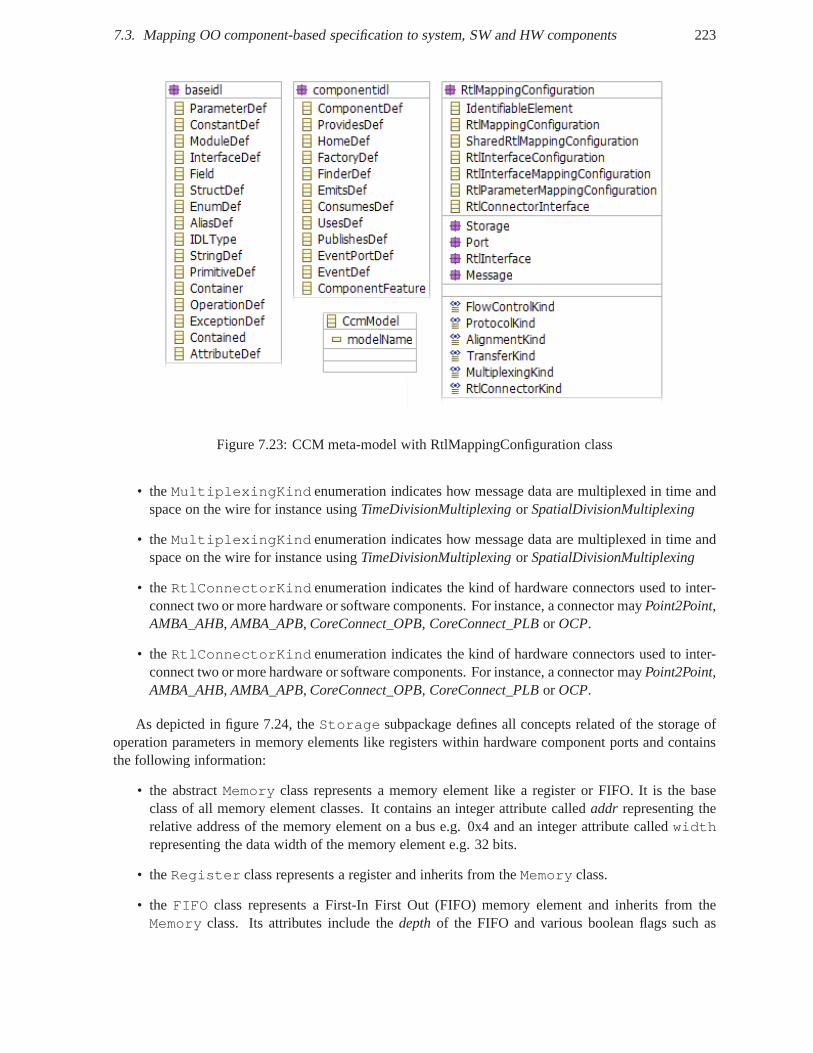
7.3. Mapping OO component-based specification to system, SWand HW components 223
Figure 7.23: CCM meta-model with RtlMappingConfiguration class
• theMultiplexingKind enumeration indicates how message data are multiplexed in time andspace on the wire for instance usingTimeDivisionMultiplexingor SpatialDivisionMultiplexing
• theMultiplexingKind enumeration indicates how message data are multiplexed in time andspace on the wire for instance usingTimeDivisionMultiplexingor SpatialDivisionMultiplexing
• theRtlConnectorKind enumeration indicates the kind of hardware connectors usedto inter-connect two or more hardware or software components. For instance, a connector mayPoint2Point,AMBA_AHB, AMBA_APB, CoreConnect_OPB, CoreConnect_PLBor OCP.
• theRtlConnectorKind enumeration indicates the kind of hardware connectors usedto inter-connect two or more hardware or software components. For instance, a connector mayPoint2Point,AMBA_AHB, AMBA_APB, CoreConnect_OPB, CoreConnect_PLBor OCP.
As depicted in figure 7.24, theStorage subpackage defines all concepts related of the storage ofoperation parameters in memory elements like registers within hardware component ports and containsthe following information:
• the abstractMemory class represents a memory element like a register or FIFO. Itis the baseclass of all memory element classes. It contains an integer attribute calledaddr representing therelative address of the memory element on a bus e.g. 0x4 and aninteger attribute calledwidthrepresenting the data width of the memory element e.g. 32 bits.
• theRegister class represents a register and inherits from theMemory class.
• the FIFO class represents a First-In First Out (FIFO) memory elementand inherits from theMemory class. Its attributes include thedepthof the FIFO and various boolean flags such as
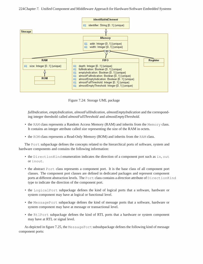
224Chapter 7. Unified Component and Middleware Approach for Hardware/Software Embedded Systems
Figure 7.24: Storage UML package
fullIndication, emptyIndication, almostFullIndication, almostEmptyIndicationand the correspond-ing integer threshold calledalmostFullThresholdandalmostEmptyThreshold.
• theRAM class represents a Random Access Memory (RAM) and inherits from theMemory class.It contains an integer attribute calledsizerepresenting the size of the RAM in octets.
• theROM class represents a Read-Only Memory (ROM) and inherits fromtheRAM class.
ThePort subpackage defines the concepts related to the hierarchicalports of software, system andhardware components and contains the following information:
• theDirectionKind enumeration indicates the direction of a component port such asin, outor inout.
• the abstractPort class represents a component port. It is the base class of allcomponent portclasses. The component port classes are defined in dedicatedpackages and represent componentports at different abstraction levels. ThePort class contains adirectionattribute ofDirectionKindtype to indicate the direction of the component port.
• the LogicalPort subpackage defines the kind of logical ports that a software,hardware orsystem component may have at logical or functional level.
• theMessagePort subpackage defines the kind of message ports that a software,hardware orsystem component may have at message or transactional level.
• theRtlPort subpackage defines the kind of RTL ports that a hardware or system componentmay have at RTL or signal level.
As depicted in figure 7.25, theMessagePortsubsubpackage defines the following kind of messagecomponent ports:
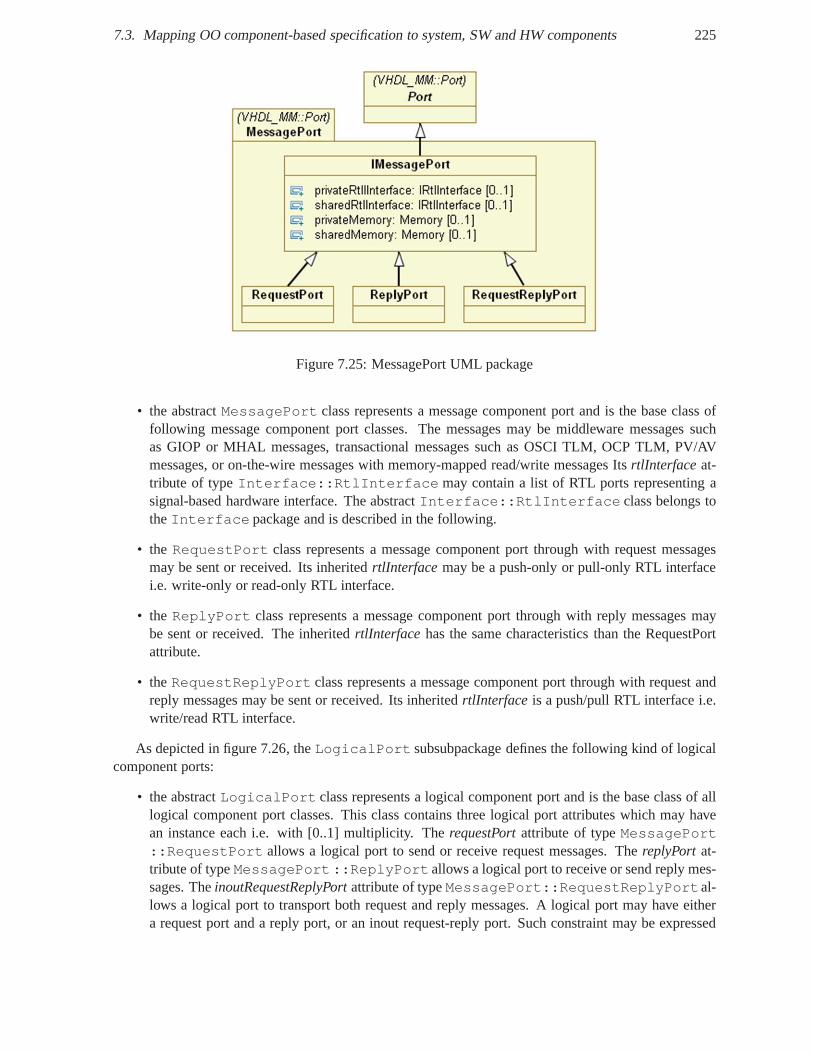
7.3. Mapping OO component-based specification to system, SWand HW components 225
Figure 7.25: MessagePort UML package
• the abstractMessagePort class represents a message component port and is the base class offollowing message component port classes. The messages maybe middleware messages suchas GIOP or MHAL messages, transactional messages such as OSCI TLM, OCP TLM, PV/AVmessages, or on-the-wire messages with memory-mapped read/write messages ItsrtlInterface at-tribute of typeInterface::RtlInterface may contain a list of RTL ports representing asignal-based hardware interface. The abstractInterface::RtlInterface class belongs totheInterface package and is described in the following.
• the RequestPort class represents a message component port through with request messagesmay be sent or received. Its inheritedrtlInterface may be a push-only or pull-only RTL interfacei.e. write-only or read-only RTL interface.
• theReplyPort class represents a message component port through with reply messages maybe sent or received. The inheritedrtlInterface has the same characteristics than the RequestPortattribute.
• theRequestReplyPort class represents a message component port through with request andreply messages may be sent or received. Its inheritedrtlInterface is a push/pull RTL interface i.e.write/read RTL interface.
As depicted in figure 7.26, theLogicalPort subsubpackage defines the following kind of logicalcomponent ports:
• the abstractLogicalPort class represents a logical component port and is the base class of alllogical component port classes. This class contains three logical port attributes which may havean instance each i.e. with [0..1] multiplicity. TherequestPortattribute of typeMessagePort::RequestPort allows a logical port to send or receive request messages. The replyPort at-tribute of typeMessagePort::ReplyPort allows a logical port to receive or send reply mes-sages. TheinoutRequestReplyPortattribute of typeMessagePort::RequestReplyPortal-lows a logical port to transport both request and reply messages. A logical port may have eithera request port and a reply port, or an inout request-reply port. Such constraint may be expressed
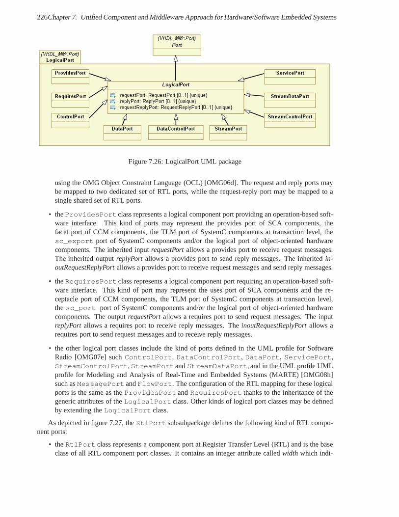
226Chapter 7. Unified Component and Middleware Approach for Hardware/Software Embedded Systems
Figure 7.26: LogicalPort UML package
using the OMG Object Constraint Language (OCL) [OMG06d]. The request and reply ports maybe mapped to two dedicated set of RTL ports, while the request-reply port may be mapped to asingle shared set of RTL ports.
• theProvidesPort class represents a logical component port providing an operation-based soft-ware interface. This kind of ports may represent the provides port of SCA components, thefacet port of CCM components, the TLM port of SystemC components at transaction level, thesc_export port of SystemC components and/or the logical port of object-oriented hardwarecomponents. The inherited inputrequestPortallows a provides port to receive request messages.The inherited outputreplyPort allows a provides port to send reply messages. The inheritedin-outRequestReplyPortallows a provides port to receive request messages and send reply messages.
• theRequiresPort class represents a logical component port requiring an operation-based soft-ware interface. This kind of port may represent the uses portof SCA components and the re-ceptacle port of CCM components, the TLM port of SystemC components at transaction level,thesc_port port of SystemC components and/or the logical port of object-oriented hardwarecomponents. The outputrequestPortallows a requires port to send request messages. The inputreplyPort allows a requires port to receive reply messages. TheinoutRequestReplyPortallows arequires port to send request messages and to receive reply messages.
• the other logical port classes include the kind of ports defined in the UML profile for SoftwareRadio [OMG07e] suchControlPort, DataControlPort, DataPort, ServicePort,StreamControlPort,StreamPort andStreamDataPort, and in the UML profile UMLprofile for Modeling and Analysis of Real-Time and Embedded Systems (MARTE) [OMG08h]such asMessagePort andFlowPort. The configuration of the RTL mapping for these logicalports is the same as theProvidesPort andRequiresPort thanks to the inheritance of thegeneric attributes of theLogicalPort class. Other kinds of logical port classes may be definedby extending theLogicalPort class.
As depicted in figure 7.27, theRtlPort subsubpackage defines the following kind of RTL compo-nent ports:
• theRtlPort class represents a component port at Register Transfer Level (RTL) and is the baseclass of all RTL component port classes. It contains an integer attribute calledwidth which indi-
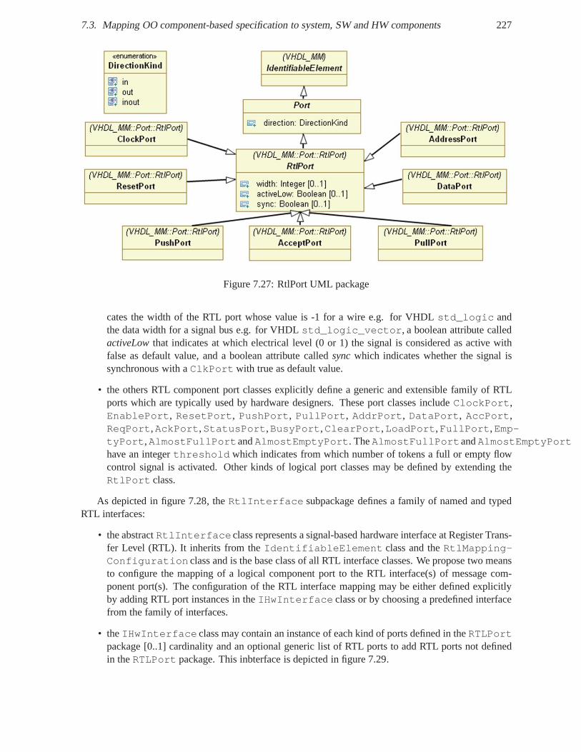
7.3. Mapping OO component-based specification to system, SWand HW components 227
Figure 7.27: RtlPort UML package
cates the width of the RTL port whose value is -1 for a wire e.g.for VHDL std_logic andthe data width for a signal bus e.g. for VHDLstd_logic_vector, a boolean attribute calledactiveLowthat indicates at which electrical level (0 or 1) the signal is considered as active withfalse as default value, and a boolean attribute calledsyncwhich indicates whether the signal issynchronous with aClkPortwith true as default value.
• the others RTL component port classes explicitly define a generic and extensible family of RTLports which are typically used by hardware designers. Theseport classes includeClockPort,EnablePort, ResetPort, PushPort, PullPort, AddrPort, DataPort, AccPort,ReqPort,AckPort,StatusPort,BusyPort,ClearPort,LoadPort,FullPort,Emp-tyPort,AlmostFullPortandAlmostEmptyPort. TheAlmostFullPortandAlmostEmptyPorthave an integerthreshold which indicates from which number of tokens a full or empty flowcontrol signal is activated. Other kinds of logical port classes may be defined by extending theRtlPort class.
As depicted in figure 7.28, theRtlInterface subpackage defines a family of named and typedRTL interfaces:
• the abstractRtlInterfaceclass represents a signal-based hardware interface at Register Trans-fer Level (RTL). It inherits from theIdentifiableElement class and theRtlMapping-Configuration class and is the base class of all RTL interface classes. We propose two meansto configure the mapping of a logical component port to the RTLinterface(s) of message com-ponent port(s). The configuration of the RTL interface mapping may be either defined explicitlyby adding RTL port instances in theIHwInterface class or by choosing a predefined interfacefrom the family of interfaces.
• theIHwInterface class may contain an instance of each kind of ports defined in theRTLPortpackage [0..1] cardinality and an optional generic list of RTL ports to add RTL ports not definedin theRTLPort package. This inbterface is depicted in figure 7.29.
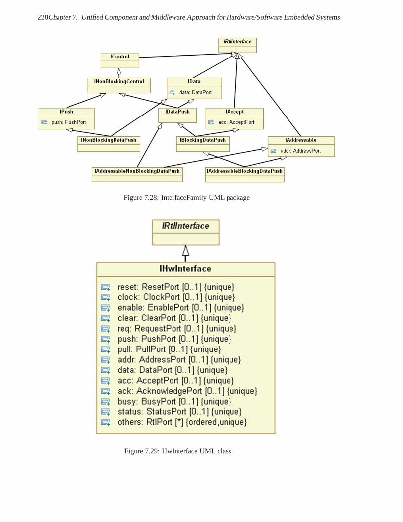
228Chapter 7. Unified Component and Middleware Approach for Hardware/Software Embedded Systems
Figure 7.28: InterfaceFamily UML package
Figure 7.29: HwInterface UML class
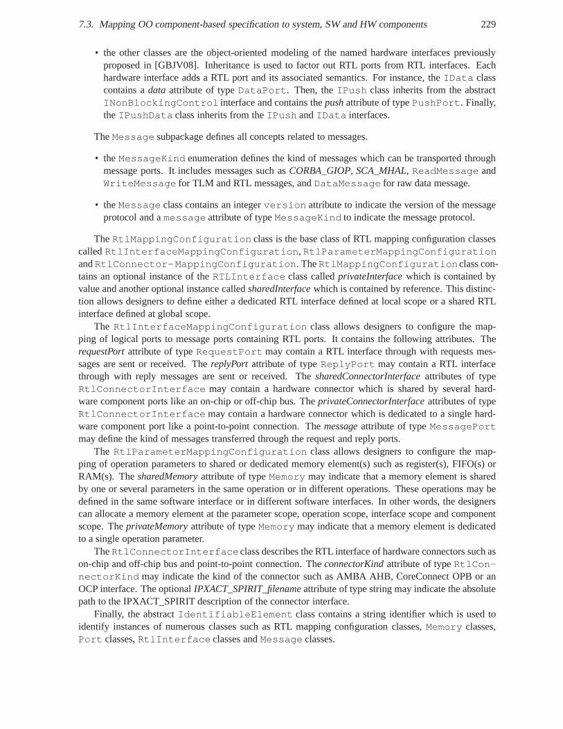
7.3. Mapping OO component-based specification to system, SWand HW components 229
• the other classes are the object-oriented modeling of the named hardware interfaces previouslyproposed in [GBJV08]. Inheritance is used to factor out RTL ports from RTL interfaces. Eachhardware interface adds a RTL port and its associated semantics. For instance, theIData classcontains adata attribute of typeDataPort. Then, theIPush class inherits from the abstractINonBlockingControl interface and contains thepushattribute of typePushPort. Finally,theIPushData class inherits from theIPush andIData interfaces.
TheMessage subpackage defines all concepts related to messages.
• theMessageKind enumeration defines the kind of messages which can be transported throughmessage ports. It includes messages such asCORBA_GIOP, SCA_MHAL, ReadMessage andWriteMessage for TLM and RTL messages, andDataMessage for raw data message.
• theMessage class contains an integerversion attribute to indicate the version of the messageprotocol and amessage attribute of typeMessageKind to indicate the message protocol.
TheRtlMappingConfiguration class is the base class of RTL mapping configuration classescalledRtlInterfaceMappingConfiguration, RtlParameterMappingConfigurationandRtlConnector-MappingConfiguration. TheRtlMappingConfigurationclass con-tains an optional instance of theRTLInterface class calledprivateInterfacewhich is contained byvalue and another optional instance calledsharedInterfacewhich is contained by reference. This distinc-tion allows designers to define either a dedicated RTL interface defined at local scope or a shared RTLinterface defined at global scope.
The RtlInterfaceMappingConfiguration class allows designers to configure the map-ping of logical ports to message ports containing RTL ports.It contains the following attributes. TherequestPortattribute of typeRequestPort may contain a RTL interface through with requests mes-sages are sent or received. ThereplyPort attribute of typeReplyPort may contain a RTL interfacethrough with reply messages are sent or received. ThesharedConnectorInterfaceattributes of typeRtlConnectorInterface may contain a hardware connector which is shared by several hard-ware component ports like an on-chip or off-chip bus. TheprivateConnectorInterfaceattributes of typeRtlConnectorInterface may contain a hardware connector which is dedicated to a single hard-ware component port like a point-to-point connection. Themessageattribute of typeMessagePortmay define the kind of messages transferred through the request and reply ports.
The RtlParameterMappingConfiguration class allows designers to configure the map-ping of operation parameters to shared or dedicated memory element(s) such as register(s), FIFO(s) orRAM(s). ThesharedMemoryattribute of typeMemory may indicate that a memory element is sharedby one or several parameters in the same operation or in different operations. These operations may bedefined in the same software interface or in different software interfaces. In other words, the designerscan allocate a memory element at the parameter scope, operation scope, interface scope and componentscope. TheprivateMemoryattribute of typeMemory may indicate that a memory element is dedicatedto a single operation parameter.
TheRtlConnectorInterfaceclass describes the RTL interface of hardware connectors such ason-chip and off-chip bus and point-to-point connection. The connectorKindattribute of typeRtlCon-nectorKind may indicate the kind of the connector such as AMBA AHB, CoreConnect OPB or anOCP interface. The optionalIPXACT_SPIRIT_filenameattribute of type string may indicate the absolutepath to the IPXACT_SPIRIT description of the connector interface.
Finally, the abstractIdentifiableElement class contains a string identifier which is used toidentify instances of numerous classes such as RTL mapping configuration classes,Memory classes,Port classes,RtlInterface classes andMessage classes.
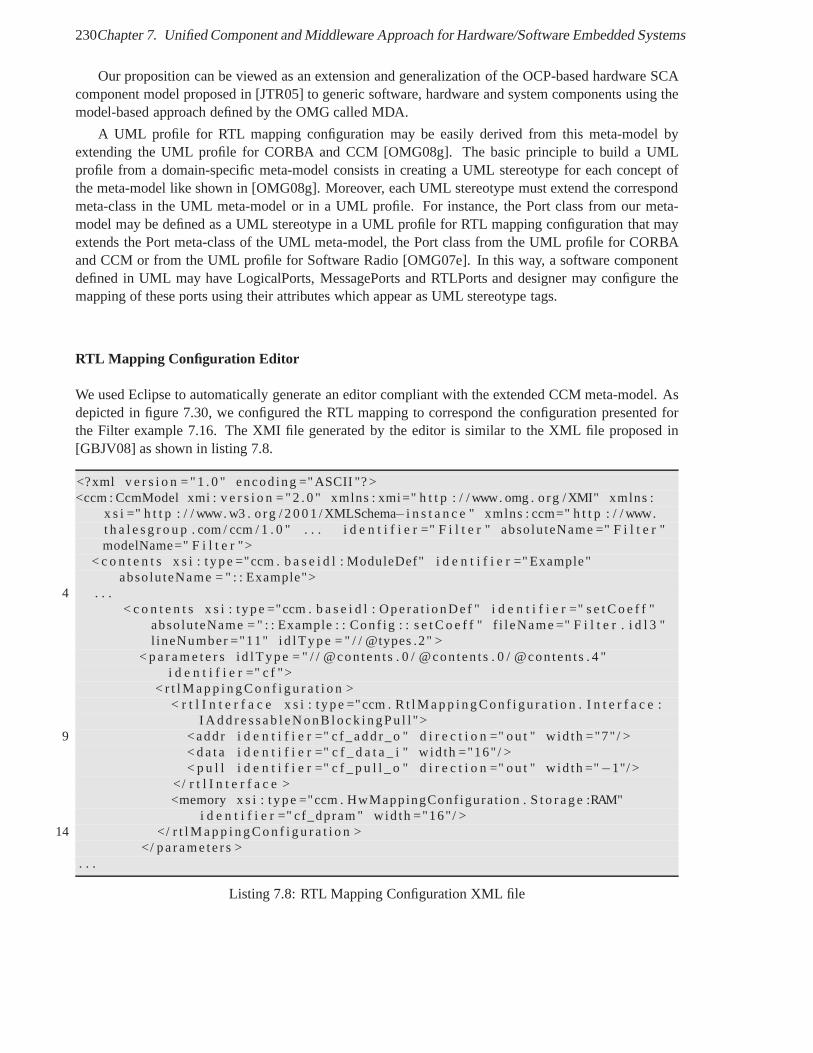
230Chapter 7. Unified Component and Middleware Approach for Hardware/Software Embedded Systems
Our proposition can be viewed as an extension and generalization of the OCP-based hardware SCAcomponent model proposed in [JTR05] to generic software, hardware and system components using themodel-based approach defined by the OMG called MDA.
A UML profile for RTL mapping configuration may be easily derived from this meta-model byextending the UML profile for CORBA and CCM [OMG08g]. The basic principle to build a UMLprofile from a domain-specific meta-model consists in creating a UML stereotype for each concept ofthe meta-model like shown in [OMG08g]. Moreover, each UML stereotype must extend the correspondmeta-class in the UML meta-model or in a UML profile. For instance, the Port class from our meta-model may be defined as a UML stereotype in a UML profile for RTL mapping configuration that mayextends the Port meta-class of the UML meta-model, the Port class from the UML profile for CORBAand CCM or from the UML profile for Software Radio [OMG07e]. Inthis way, a software componentdefined in UML may have LogicalPorts, MessagePorts and RTLPorts and designer may configure themapping of these ports using their attributes which appear as UML stereotype tags.
RTL Mapping Configuration Editor
We used Eclipse to automatically generate an editor compliant with the extended CCM meta-model. Asdepicted in figure 7.30, we configured the RTL mapping to correspond the configuration presented forthe Filter example 7.16. The XMI file generated by the editor is similar to the XML file proposed in[GBJV08] as shown in listing 7.8.
<?xml v e r s i o n = " 1 . 0 " encod ing ="ASCII "? ><ccm : CcmModel xmi : v e r s i o n = " 2 . 0 " xmlns : xmi=" h t t p : / / www. omg . o rg /XMI" xmlns :
x s i =" h t t p : / / www. w3 . o rg / 2 0 0 1 / XMLSchema− i n s t a n c e " xmlns : ccm=" h t t p : / / www.t h a l e s g r o u p . com / ccm / 1 . 0 " . . . i d e n t i f i e r =" F i l t e r " abso lu teName =" F i l t e r "modelName=" F i l t e r ">
< c o n t e n t s x s i : t ype ="ccm . b a s e i d l : ModuleDef" i d e n t i f i e r=" Example"abso lu teName = " : : Example">
4 . . .< c o n t e n t s x s i : t ype ="ccm . b a s e i d l : Ope ra t i onDe f " i d e n t i fi e r =" s e t C o e f f "
abso lu teName = " : : Example : : Con f ig : : s e t C o e f f " f i leName =" F i l t e r . i d l 3 "l ineNumber ="11" id lType = " / / @types .2" >
< p a r a m e t e r s id lType = " / / @con ten ts . 0 / @conten ts . 0 / @conten ts . 4 "i d e n t i f i e r =" c f ">
< r t l M a p p i n g C o n f i g u r a t i o n >< r t l I n t e r f a c e x s i : t ype ="ccm . R t l M a p p i n g C on f i gu r a t i o n .I n t e r f a c e :
I A d d r e s s a b l eN onB l oc k i ngP u l l ">9 <addr i d e n t i f i e r =" c f_add r_o " d i r e c t i o n =" ou t " w id th ="7" / >
< d a t a i d e n t i f i e r =" c f _ d a t a _ i " w id th ="16" / >< p u l l i d e n t i f i e r =" c f _ p u l l _ o " d i r e c t i o n =" ou t " w id th ="−1"/ >
</ r t l I n t e r f a c e ><memory x s i : t ype ="ccm . HwMappingConf igurat ion . S t o r a g e:RAM"
i d e n t i f i e r =" cf_dpram " wid th ="16" / >14 </ r t l M a p p i n g C o n f i g u r a t i o n >
</ pa rame te rs >. . .
Listing 7.8: RTL Mapping Configuration XML file
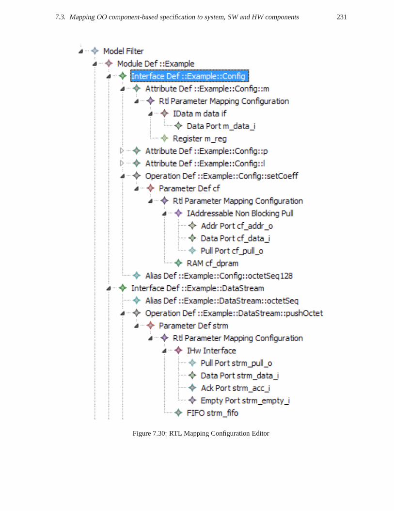
7.3. Mapping OO component-based specification to system, SWand HW components 231
Figure 7.30: RTL Mapping Configuration Editor
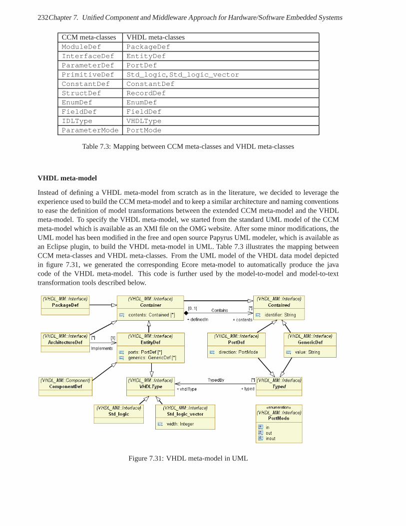
232Chapter 7. Unified Component and Middleware Approach for Hardware/Software Embedded Systems
CCM meta-classes VHDL meta-classesModuleDef PackageDefInterfaceDef EntityDefParameterDef PortDefPrimitiveDef Std_logic,Std_logic_vectorConstantDef ConstantDefStructDef RecordDefEnumDef EnumDefFieldDef FieldDefIDLType VHDLTypeParameterMode PortMode
Table 7.3: Mapping between CCM meta-classes and VHDL meta-classes
VHDL meta-model
Instead of defining a VHDL meta-model from scratch as in the literature, we decided to leverage theexperience used to build the CCM meta-model and to keep a similar architecture and naming conventionsto ease the definition of model transformations between the extended CCM meta-model and the VHDLmeta-model. To specify the VHDL meta-model, we started fromthe standard UML model of the CCMmeta-model which is available as an XMI file on the OMG website. After some minor modifications, theUML model has been modified in the free and open source PapyrusUML modeler, which is available asan Eclipse plugin, to build the VHDL meta-model in UML. Table7.3 illustrates the mapping betweenCCM meta-classes and VHDL meta-classes. From the UML model of the VHDL data model depictedin figure 7.31, we generated the corresponding Ecore meta-model to automatically produce the javacode of the VHDL meta-model. This code is further used by the model-to-model and model-to-texttransformation tools described below.
Figure 7.31: VHDL meta-model in UML
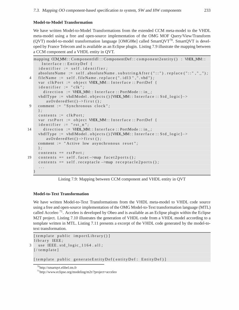
7.3. Mapping OO component-based specification to system, SWand HW components 233
Model-to-Model Transformation
We have written Model-to-Model Transformations from the extended CCM meta-model to the VHDLmeta-model using a free and open-source implementation of the OMG MOF Query/View/Transform(QVT) model-to-model transformation language [OMG08e] called SmartQVT70. SmartQVT is devel-oped by France Telecom and is available as an Eclipse plugin.Listing 7.9 illustrate the mapping betweena CCM component and a VHDL entity in QVT.
mapping CCM_MM: : Component Id l : : ComponentDef : : c o m p o n e nt 2en t i t y ( ) : VHDL_MM: :I n t e r f a c e : : E n t i t y D e f {
i d e n t i f i e r := s e l f . i d e n t i f i e r;absolu teName := s e l f . abso lu teName . s u b s t r i n g A f t e r ( " : : ") . r e p l a c e ( " : : " , " _ " );
4 f i leName := s e l f . f i l eName . r e p l a c e ( " . i d l 3 " , " . vhd " );va r c l k P o r t := o b j e c t VHDL_MM: : I n t e r f a c e : : Po r tDe f {i d e n t i f i e r := " c l k " ;
d i r e c t i o n := VHDL_MM: : I n t e r f a c e : : PortMode : : i n_;vhdlType := vhdlModel . o b j e c t s ( ) [VHDL_MM: : I n t e r f a c e : : St d _ l o g i c ]−>
a s O r d e r e d S e t ( )−> f i r s t ( ) ;9 comment := " Synchronous c l o c k ";
} ;c o n t e n t s := c l k P o r t;va r r s t P o r t := o b j e c t VHDL_MM: : I n t e r f a c e : : Po r tDe f {i d e n t i f i e r := " r s t _ n ";
14 d i r e c t i o n := VHDL_MM: : I n t e r f a c e : : PortMode : : i n_;vhdlType := vhdlModel . o b j e c t s ( ) [VHDL_MM: : I n t e r f a c e : : St d _ l o g i c ]−>
a s O r d e r e d S e t ( )−> f i r s t ( ) ;comment := " Ac t i ve low asynch ronous r e s e t ";} ;c o n t e n t s += r s t P o r t;
19 c o n t e n t s += s e l f . f a c e t−>map f a c e t 2 p o r t s ( );c o n t e n t s += s e l f . r e c e p t a c l e−>map r e c e p t a c l e 2 p o r t s ( );. . .
}
Listing 7.9: Mapping between CCM component and VHDL entity in QVT
Model-to-Text Transformation
We have written Model-to-Text Transformations from the VHDL meta-model to VHDL code sourceusing a free and open-source implementation of the OMG Model-to-Text transformation language (MTL)called Acceleo71. Acceleo is developed by Obeo and is available as an Eclipse plugin within the EclipseM2T project. Listing 7.10 illustrates the generation of VHDL code from a VHDL model according to atemplate written in MTL. Listing 7.11 presents a excerpt of the VHDL code generated by the model-to-text transformation.
[ t e m p l a t e p u b l i c i m p o r t L i b r a r y ( ) ]l i b r a r y IEEE;
3 use IEEE . s t d _ l o g i c _ 1 1 6 4 . a l l;[ / t e m p l a t e ]
[ t e m p l a t e p u b l i c g e n e r a t e E n t i t y D e f ( e n t i t y D e f : E n t i t y D ef ) ]
70http://smartqvt.elibel.tm.fr71http://www.eclipse.org/modeling/m2t/?project=acceleo
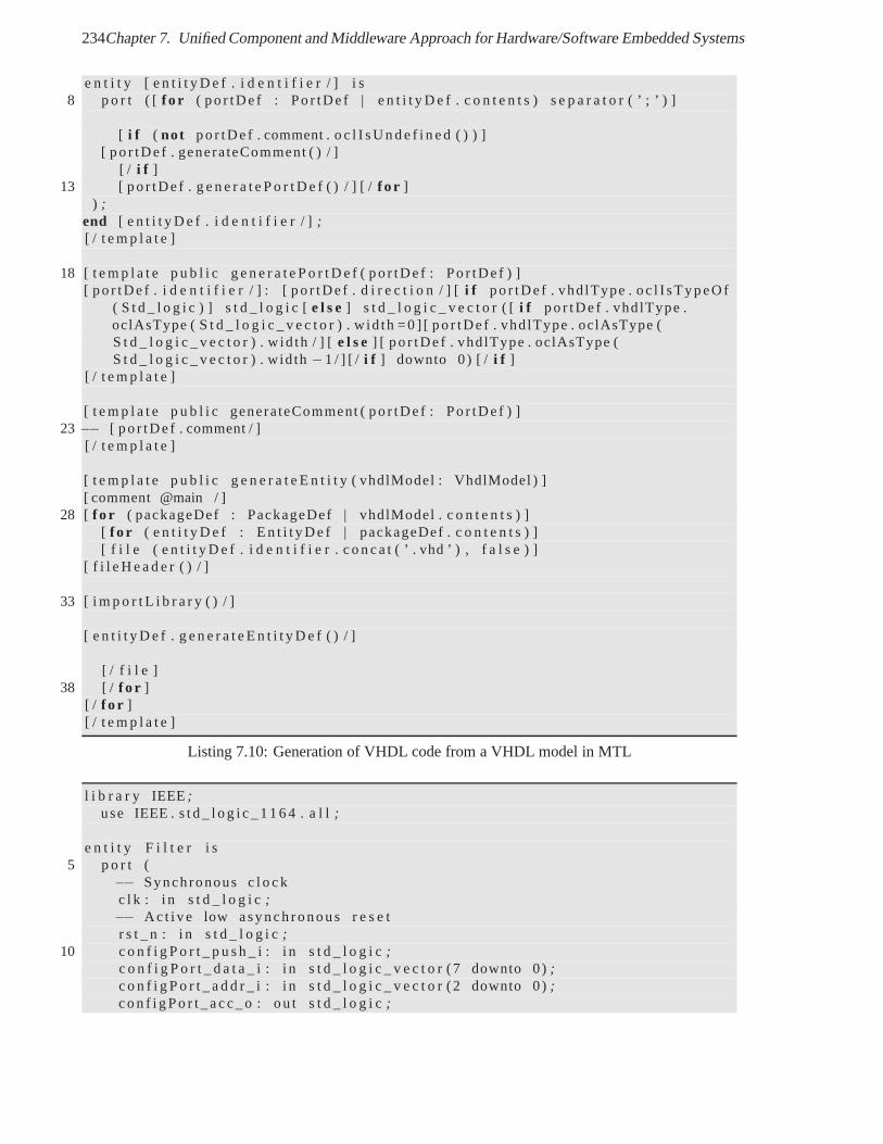
234Chapter 7. Unified Component and Middleware Approach for Hardware/Software Embedded Systems
e n t i t y [ e n t i t y D e f . i d e n t i f i e r / ] i s8 p o r t ( [ f o r ( po r tDe f : Po r tDe f | e n t i t y D e f . c o n t e n t s ) s e p a r a t o r ( ’ ; ’ ) ]
[ i f ( not po r tDe f . comment . o c l I s U n d e f i n e d ( ) ) ][ po r tDe f . generateComment ( ) / ]
[ / i f ]13 [ po r tDe f . g e n e r a t e P o r t D e f ( ) / ] [ /f o r ]
) ;end [ e n t i t y D e f . i d e n t i f i e r / ] ;[ / t e m p l a t e ]
18 [ t e m p l a t e p u b l i c g e n e r a t e P o r t D e f ( po r tDe f : Po r tDe f ) ][ po r tDe f . i d e n t i f i e r / ] : [ po r tDe f . d i r e c t i o n / ] [i f po r tDe f . vhd lType . oc l I sTypeOf
( S t d _ l o g i c ) ] s t d _ l o g i c [e l s e] s t d _ l o g i c _ v e c t o r ( [i f po r tDe f . vhd lType .oclAsType ( S t d _ l o g i c _ v e c t o r ) . w id th =0 ] [ po r tDe f . vhd lType . oclAsType (S t d _ l o g i c _ v e c t o r ) . w id th / ] [e l s e] [ po r tDe f . vhd lType . oclAsType (S t d _ l o g i c _ v e c t o r ) . wid th−1 / ] [ / i f ] downto 0) [ / i f ]
[ / t e m p l a t e ]
[ t e m p l a t e p u b l i c generateComment ( po r tDe f : Po r tDe f ) ]23 −− [ po r tDe f . comment / ]
[ / t e m p l a t e ]
[ t e m p l a t e p u b l i c g e n e r a t e E n t i t y ( vhdlModel : VhdlModel ) ][ comment @main / ]
28 [ f o r ( packageDef : PackageDef | vhdlModel . c o n t e n t s ) ][ f o r ( e n t i t y D e f : E n t i t y D e f | packageDef . c o n t e n t s ) ][ f i l e ( e n t i t y D e f . i d e n t i f i e r . c o n c a t ( ’ . vhd ’ ) , f a l s e ) ]
[ f i l e H e a d e r ( ) / ]
33 [ i m p o r t L i b r a r y ( ) / ]
[ e n t i t y D e f . g e n e r a t e E n t i t y D e f ( ) / ]
[ / f i l e ]38 [ / f o r ]
[ / f o r ][ / t e m p l a t e ]
Listing 7.10: Generation of VHDL code from a VHDL model in MTL
l i b r a r y IEEE;use IEEE . s t d _ l o g i c _ 1 1 6 4 . a l l;
e n t i t y F i l t e r i s5 p o r t (
−− Synchronous c l o c kc l k : i n s t d _ l o g i c;−− Ac t i ve low asynch ronous r e s e tr s t _ n : i n s t d _ l o g i c;
10 c o n f i g P o r t _ p u s h _ i : i n s t d _ l o g i c;c o n f i g P o r t _ d a t a _ i : i n s t d _ l o g i c _ v e c t o r (7 downto 0);c o n f i g P o r t _ a d d r _ i : i n s t d _ l o g i c _ v e c t o r (2 downto 0);c o n f i g P o r t _ a c c _ o : ou t s t d _ l o g i c;
7.4. Hardware Application of the Software Communications Architecture 235
c o n f i g P o r t _ p u s h _ o : ou t s t d _ l o g i c;15 c o n f i g P o r t _ d a t a _ o : ou t s t d _ l o g i c _ v e c t o r (7 downto 0);
c o n f i g P o r t _ a c c _ i : i n s t d _ l o g i c;i n p u t P o r t _ p u s h _ i : i n s t d _ l o g i c;i n p u t P o r t _ d a t a _ i : i n s t d _ l o g i c _ v e c t o r (7 downto 0);i n p u t P o r t _ a d d r _ i : i n s t d _ l o g i c _ v e c t o r (0 downto 0);
20 i n p u t P o r t _ a c c _ o : ou t s t d _ l o g i c;i n p u t P o r t _ p u s h _ o : ou t s t d _ l o g i c;i n p u t P o r t _ d a t a _ o : ou t s t d _ l o g i c _ v e c t o r (7 downto 0);i n p u t P o r t _ a c c _ i : i n s t d _ l o g i c;o u t p u t P o r t _ p u s h _ o : ou t s t d _ l o g i c;
25 o u t p u t P o r t _ d a t a _ o : ou t s t d _ l o g i c _ v e c t o r (7 downto 0);o u t p u t P o r t _ a d d r _ o : ou t s t d _ l o g i c _ v e c t o r (0 downto 0);o u t p u t P o r t _ a c c _ i : i n s t d _ l o g i c;o u t p u t P o r t _ p u s h _ i : i n s t d _ l o g i c;o u t p u t P o r t _ d a t a _ i : i n s t d _ l o g i c _ v e c t o r (7 downto 0);
30 o u t p u t P o r t _ a c c _ o : ou t s t d _ l o g i c );end F i l t e r ;
Listing 7.11: Example of generated code for the Filter
7.4 Hardware Application of the Software Communications Architecture
As far we know, the only hardware interface that has been proposed for the JTRS SCAResourceinterface has been presented in [JTR05] based on OCP. This mapping proposition uses the specific ca-pabilities of the OCP model such as Threads. It assumes that control and configuration operations canbe invokes concurrently. Moreover, the resulting mapping is totally customized to the semantics of eachResource component. To guarantee a consistent behavior and simplifythe hardware mapping, we con-sider that the invocations on theResource interface are serialized. Indeed, the Core Framework shouldsequentiallyinitialize, configure, start, stop, configure... components. The behaviorof this interface protocol could be described as an UML protocol state machine, which only permits apredefined sequence of invocations to proceed.
7.4.1 Hardware SCA Resources, Device and Services
The main abstractions of the SCA can be divided into application abstraction with the Resources andplatform abstractions with the Devices and Services including the radio devices and radio services.
The hardware implementation of a SCAResource component represents a hardware applicationcomponent. Examples of hardware application components include DSP IP cores such as convolutionalen/decoders and Viterbi en/decoders. A hardwareResource component may either contain a newuser-defined IP core developed from scratch, a reused user-defined IP core or a third-party COTS IPcore. The hardware interfaces of the new IP cores directly result from the mapping of software UMLor IDL interfaces (e.g. the SCA Resource interface and the user-defined interfaces) to HDLs, while thereused and COTS IP cores are encapsulated within a wrapper providing the resulting hardware interfaces.This top-down design flow is similar to the design of softwareobjects and component with CORBA inwhich the software developers performs its implementationagainst the mapped software interfaces.
The hardware implementation of a SCA Device component represents a hardware device component.Examples of hardware device components include I/O IP coressuch as Ethernet MAC, AC97 chipset,
236Chapter 7. Unified Component and Middleware Approach for Hardware/Software Embedded Systems
RapidIO, I2C. In the same way as software application components access hardware platform compo-nents via logical devices with standard interfaces to increase application portability, hardware applicationcomponents should access these hardware platform components via standard hardware interfaces. Forinstance, in the same way as logical Ethernet Devices have a standard software interfaces, all EthernetMAC IP core should have the same hardware interfaces. However, these hardware interfaces must havestronger semantics than the existing hardware interfaces which are proprietary bus protocols such asCoreConnect for Xilinx IP cores and Avalon for Altera IP cores.
The interfaces of a SCAResource component may be implemented in software, in hardware or inboth. Beyond the custom proxies described in [JTR05], the standardization of a configurable mappingbetween software and hardware interfaces for component portability and of lightweight ESIOP(s) forcomponent interoperability should shift the generation ofproxies from end-users to middlewares.
7.4.2 SCA Operating Environment for FPGA
The Software Communications Architecture defines an Operating Environment (OE) which consists ofa Core Framework (CF), a CORBA middleware, Name and Event middlewares services, a POSIX-basedOperating System (OS), its network stack and Board Support Packages (BSP).
An OE needs to be standardized for non-CORBA capable processing elements such as DSP, FP-GAs and ASICs. Extensions of the SCA have successively proposed with the Specialized HardwareSupplement (SHS) [JTR04] in 2004, the extension for component portability for Specialized HardwareProcessors (SHP) [JTR05] in 2005 and the Modem Hardware Abstraction Layer (MHAL) [JTR07] APIin 2007. Furthermore, an OE has been proposed for DSP in the scope of the IST End-to-End Reconfig-urability (E2R)72 european project for the OMG SWRadio specification which is inspired from the SCA[LN07]. OEs for GPP, DSP and FPGAs are also investigated in the European Defense Agency (EDA)European Secure Software Radio (ESSOR) project73.
In this section, we propose an Operating Environment for theSCA in FPGA.The functionalities required for an OE on FPGA are the following:
1. To guaranty the portability of hardware SCA components from one FPGA platform to anotherprovided by different providers. This portability requires standard hardware interfaces on whichhardware components may depend without any other dependencies to the FPGA platform. Thisfunctionality is provided by the Application Programming Interfaces of POSIX, CORBA and theCF.
2. To guaranty the interoperability of hardware SCA components with software SCA componentsdistributed across the SDR platform. This functionality isprovided by CORBA with messageprotocols.
3. To support the deployment of hardware SCA components in FPGA. This deployment correspondto the loading and unloading of total or partial bitstream inthe FPGA. The partial and dynamicreconfiguration of FPGAs enables the application of the dynamic deployment approach of the SCAdownto FPGA. This functionality is provided by the interfaces CF
A naive application of the SCA OE in hardware would to proposean substitute for POSIX, CORBAand CF. An Operating Environment for FPGA must only implement a subset of the required function-alities of the SCA OE which is specified for General Purpose Processor. Proposing an OE for FPGA
72http://www.ist-world.org73http://www.eda.europa.eu
7.4. Hardware Application of the Software Communications Architecture 237
basically means proposing a hardware signal-based interface and implementation for the services pro-vided by POSIX, CORBA and CF. However, hardware resources inFPGA are too expensive and scarceto allow and want the implementation of all these services inhardware. Only a hardware interface andimplementation for the required services is needed and mustbe proposed. We assume that if a mappingbetween a software operation-based interface and a hardware signal-based interface is possible, then themapping of POSIX, CORBA and CF interfaces is a particular case. We focus on the selection of theservices which are meaningful and useful in hardware.
POSIX-like Services
In the following, we present the main services standardizedby the POSIX specification and discuss theirutility for hardware components.
1. Process and Thread management for the creation, control,termination, scheduling of processesand threads. Dynamic and partial reconfiguration of FPGA allows the dynamic configuration ofFPGA logic blocks and routing resources with a partial bitstream. This configuration simulatesthe creation and termination of hardware process with a hardware module (VHDL entity). Theseprocesses communicate through signals acting as shared variables. For Xilinx FPGAs, the hard-ware interface for the creation and termination of hardwarethreads corresponds to the interfaceof the Internal Configuration Access Port (ICAP). A vendor-independent standard bitstream inter-face must be proposed and the proprietary interface like ICAP would be wrapped by this standardinterface.
2. Inter-Process Communication (IPC): signal, pipes, message passing, shared memory. VHDL pro-cesses and modules primarily communicate via signals representing shared variables. Based onthis signal-based interactions, message passing communications may rely on FIFOs and sharedmemory communications may rely on local or system RAM.
3. Time services: clocks and timers. In synchronous digitaldesign, hardware modules are synchro-nized by a common clock signal within a synchronous domain. Using the clock signal, time delaysmay be obtained with counters or timers.
4. File management. Due to scarce hardware resources, a file management service is typically notimplemented in hardware, but in software on a GPP dedicated to control, management and deploy-ment tasks. File management is required to deploy an application using its deployment plan andassociated (XML) descriptors. In hardware, it is needed to load a total or partial bitstream downto an FPGA.
5. C library services. The C library provides services such as timers, I/O, memory allocation. TheVHDL library provides basic services such as data types and their conversion. The VHDL librarydo not offer services such as storage services with standardFIFOs, RAM and registers. Users mustdefine their own storage elements based on the available hardware resources.
6. Synchronous and asynchronous I/O management. Hardware modules have typically synchronousI/O signals. In Globally Asynchronous Locally Synchronous(GALS) system, asynchronous com-munications take place between synchronous domain. From a hardware interface protocol view-point, the synchronous i.e. blocking communications are obtained with two-phase and four-phasehandshaking protocol, while asynchronous communicationsare obtained with enable-based pro-tocol.
238Chapter 7. Unified Component and Middleware Approach for Hardware/Software Embedded Systems
7. Coordination/synchronization services: semaphores, condition variables, barriers. Intra-moduleand inter-module coordination is performed using explicitmultiplexer according to the one-writer/ multiple reader protocol.
Obviously due to the different nature of the hardware and software execution, all these services are notrequired in FPGA. No such standardized services exist for hardware implementations. However, hard-ware implementation of POSIX-like OS services have been proposed in the literature with include Hy-brid Thread (HThread) [APS+07] for reconfigurable computing from Kansas University andMultiFlex[PPL+06b] for networking and multimedia from ST.
CORBA-like services
Basically, the SCA relies on the CORBA middleware to providelocation transparency via opaque refer-ence, a standard middleware API, a remote method invocation(RMI) service, and lightweight Naming,Event and Log Services. Location transparency may be provided to hardware components by applyingthe Proxy design pattern [GHJV95] in hardware. The hardwareproxies provide the same signal-basedinterface as the business component for which they act as proxies. The client proxy stores the physicaladdress of the server component port e.g. in a register whichmay be modified if the server compo-nent is migrated to another location. These proxies are responsible for the packing and unpacking ofdata transferred on the signal based interface to and from request and reply messages to implement aRMI protocol. If a systematic UML/IDL-to-HDL/SystemC mapping is defined, any software interfacefrom CORBA services may be refined downto hardware if meaningful. In particular, this is true for thelightweight Naming, Event and Log Services. The application of CORBA middleware services downtohardware will be described in the next section.
Application of the Domain Profile
Due to the overhead of XML parsing, this functionality of theSCA CF deployment service will certainlyremain in software on a control general-purpose processor.Nevertheless, the XML descriptors of thedomain profile needs to be adapted to the description of hardware SCA components.
Services provided by the OE for FPGA
The services of an OE for FPGA are listed in the following. These services are conceptually providedby a hardware container to the hardware business componentsi.e. IP-cores. The portability of hardwaremodules relies on the standardized hardware interfaces of these services. An abstract interface in CORBAIDL may be mapped to each of these services.
• thefunctional configuration interface allows the deployment framework to configure the param-eters of business components. The abstract interface in UML/CORBA IDL may contain a read-only, write-only or read/write attributes, explicit getter/setter methods such assetParam(), ora genericconfiguremethod like in the SCA . The hardware interface for a write-only attributeor setter method typically consists of an input control signal like enable, write or push, anoptional address signal when the number and size of parameters is relatively big, and an input datasignal per parameter or for all parameters respectively fora small or big number of parameters. Anacknowledge signal is generally not required. Conversely,the hardware interface for a read-onlyattribute or getter method typically consists of an input control signal likeread or pull, an op-tional address signal when the number and size of parametersis relatively big, and a output datasignal per parameter or for all parameters respectively fora small or big number of parameters.
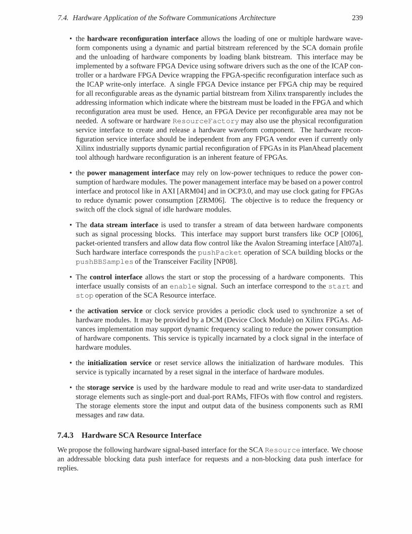
7.4. Hardware Application of the Software Communications Architecture 239
• the hardware reconfiguration interface allows the loading of one or multiple hardware wave-form components using a dynamic and partial bitstream referenced by the SCA domain profileand the unloading of hardware components by loading blank bitstream. This interface may beimplemented by a software FPGA Device using software drivers such as the one of the ICAP con-troller or a hardware FPGA Device wrapping the FPGA-specificreconfiguration interface such asthe ICAP write-only interface. A single FPGA Device instance per FPGA chip may be requiredfor all reconfigurable areas as the dynamic partial bitstream from Xilinx transparently includes theaddressing information which indicate where the bitstreammust be loaded in the FPGA and whichreconfiguration area must be used. Hence, an FPGA Device per reconfigurable area may not beneeded. A software or hardwareResourceFactorymay also use the physical reconfigurationservice interface to create and release a hardware waveformcomponent. The hardware recon-figuration service interface should be independent from anyFPGA vendor even if currently onlyXilinx industrially supports dynamic partial reconfiguration of FPGAs in its PlanAhead placementtool although hardware reconfiguration is an inherent feature of FPGAs.
• the power management interfacemay rely on low-power techniques to reduce the power con-sumption of hardware modules. The power management interface may be based on a power controlinterface and protocol like in AXI [ARM04] and in OCP3.0, andmay use clock gating for FPGAsto reduce dynamic power consumption [ZRM06]. The objectiveis to reduce the frequency orswitch off the clock signal of idle hardware modules.
• The data stream interface is used to transfer a stream of data between hardware componentssuch as signal processing blocks. This interface may support burst transfers like OCP [OI06],packet-oriented transfers and allow data flow control like the Avalon Streaming interface [Alt07a].Such hardware interface corresponds thepushPacket operation of SCA building blocks or thepushBBSamples of the Transceiver Facility [NP08].
• The control interface allows the start or stop the processing of a hardware components. Thisinterface usually consists of anenable signal. Such an interface correspond to thestart andstop operation of the SCA Resource interface.
• the activation service or clock service provides a periodic clock used to synchronize a set ofhardware modules. It may be provided by a DCM (Device Clock Module) on Xilinx FPGAs. Ad-vances implementation may support dynamic frequency scaling to reduce the power consumptionof hardware components. This service is typically incarnated by a clock signal in the interface ofhardware modules.
• the initialization service or reset service allows the initialization of hardware modules. Thisservice is typically incarnated by a reset signal in the interface of hardware modules.
• the storage serviceis used by the hardware module to read and write user-data to standardizedstorage elements such as single-port and dual-port RAMs, FIFOs with flow control and registers.The storage elements store the input and output data of the business components such as RMImessages and raw data.
7.4.3 Hardware SCA Resource Interface
We propose the following hardware signal-based interface for the SCAResource interface. We choosean addressable blocking data push interface for requests and a non-blocking data push interface forreplies.
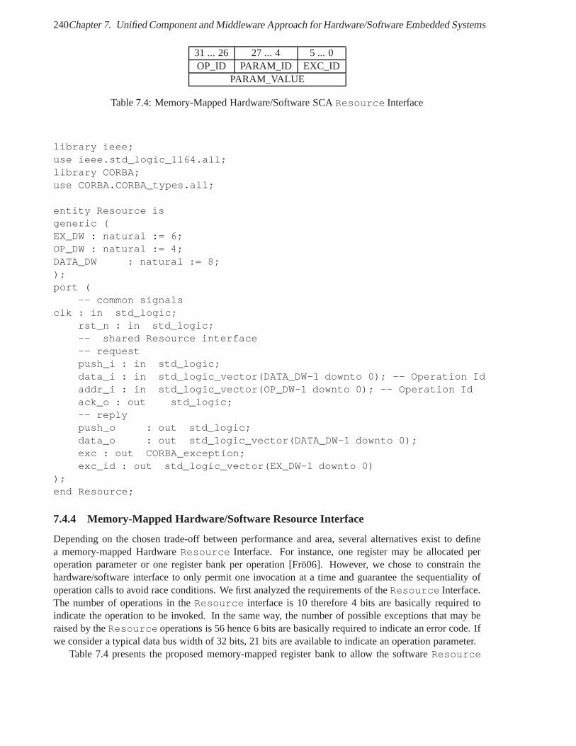
240Chapter 7. Unified Component and Middleware Approach for Hardware/Software Embedded Systems
31 ... 26 27 ... 4 5 ... 0OP_ID PARAM_ID EXC_ID
PARAM_VALUE
Table 7.4: Memory-Mapped Hardware/Software SCAResource Interface
library ieee;use ieee.std_logic_1164.all;library CORBA;use CORBA.CORBA_types.all;
entity Resource isgeneric (EX_DW : natural := 6;OP_DW : natural := 4;DATA_DW : natural := 8;);port (
-- common signalsclk : in std_logic;
rst_n : in std_logic;-- shared Resource interface-- requestpush_i : in std_logic;data_i : in std_logic_vector(DATA_DW-1 downto 0); -- Operation Idaddr_i : in std_logic_vector(OP_DW-1 downto 0); -- Operation Idack_o : out std_logic;-- replypush_o : out std_logic;data_o : out std_logic_vector(DATA_DW-1 downto 0);exc : out CORBA_exception;exc_id : out std_logic_vector(EX_DW-1 downto 0)
);end Resource;
7.4.4 Memory-Mapped Hardware/Software Resource Interface
Depending on the chosen trade-off between performance and area, several alternatives exist to definea memory-mapped HardwareResource Interface. For instance, one register may be allocated peroperation parameter or one register bank per operation [Frö06]. However, we chose to constrain thehardware/software interface to only permit one invocationat a time and guarantee the sequentiality ofoperation calls to avoid race conditions. We first analyzed the requirements of theResource Interface.The number of operations in theResource interface is 10 therefore 4 bits are basically required toindicate the operation to be invoked. In the same way, the number of possible exceptions that may beraised by theResource operations is 56 hence 6 bits are basically required to indicate an error code. Ifwe consider a typical data bus width of 32 bits, 21 bits are available to indicate an operation parameter.
Table 7.4 presents the proposed memory-mapped register bank to allow the softwareResource
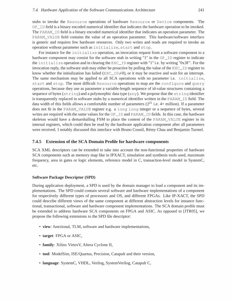
7.4. Hardware Application of the Software Communications Architecture 241
stubs to invoke theResource operations of hardwareResource or Device components. TheOP_ID field is a binary encoded numerical identifier that indicatesthe hardware operation to be invoked.ThePARAM_ID field is a binary encoded numerical identifier that indicatesan operation parameter. ThePARAM_VALUE field contains the value of an operation parameter. This hardware/software interfaceis generic and requires few hardware resources. Only two writes and reads are required to invoke anoperation without parameter such asinitialize,start andstop.
For instance for theinitialize operation, an invocation request from a software componentto ahardware component may consist for the software stub in writing "1" in theOP_ID register to indicatetheinitializeoperation and in clearing theEXC_ID register with "1" i.e. by writing "0x3F". For theinvocation reply, the software stub may either be proactiveby polling the value of theEXC_ID register toknow whether the initialization has failed (EXC_ID 6=0), or it may be reactive and wait for an interrupt.The same mechanism may be applied to all SCA operations with no parameter i.e.initialize,start andstop. The most difficultResource operations to map are theconfigure andqueryoperations, because they use as parameter a variable-length sequence of id-value structures containing asequence of bytes (string) and a polymorphic data type (any). We propose that thestring identifieris transparently replaced in software stubs by a numerical identifier written in thePARAM_ID field. Thedata width of this fields allows a comfortable number of parameters (221 i.e. 4+ million). If a parameterdoes not fit in thePARAM_VALUE register e.g. along long integer or a sequence of bytes, severalwrites are required with the same values for theOP_ID andPARAM_ID fields. In this case, the hardwareskeleton would have a demarshalling FSM to place the contentof the PARAM_VALUE register in itsinternal registers, which could then be read by the hardwareapplication component after all parameterswere received. I notably discussed this interface with Bruno Counil, Rémy Chau and Benjamin Turmel.
7.4.5 Extension of the SCA Domain Profile for hardware components
SCA XML descriptors can be extended to take into account the non-functional properties of hardwareSCA components such as memory map like in IPXACT, simulationand synthesis tools used, maximumfrequency, area in gates or logic elements, reference modelin C, transaction-level model in SystemC,etc.
Software Package Descriptor (SPD)
During application deployment, a SPD is used by the domain manager to load a component and its im-plementations. The SPD could contain several software and hardware implementations of a componentfor respectively different types of processors and OS, and different FPGAs. Like IP-XACT, the SPDcould describe different views of the same component at different abstraction levels for instance func-tional, transactional, software and hardware component implementations. The SCA domain profile mustbe extended to address hardware SCA components on FPGA and ASIC. As opposed to [JTR05], wepropose the following extensions to the SPD file descriptor:
• view: functional, TLM, software and hardware implementations,
• target: FPGA or ASIC,
• family : Xilinx VirtexV, Altera Cyclone II,
• tool: ModelSim, ISE/Quartus, Precision, Catapult and their version,
• language: SystemC, VHDL, Verilog, SystemVerilog, Catapult C,
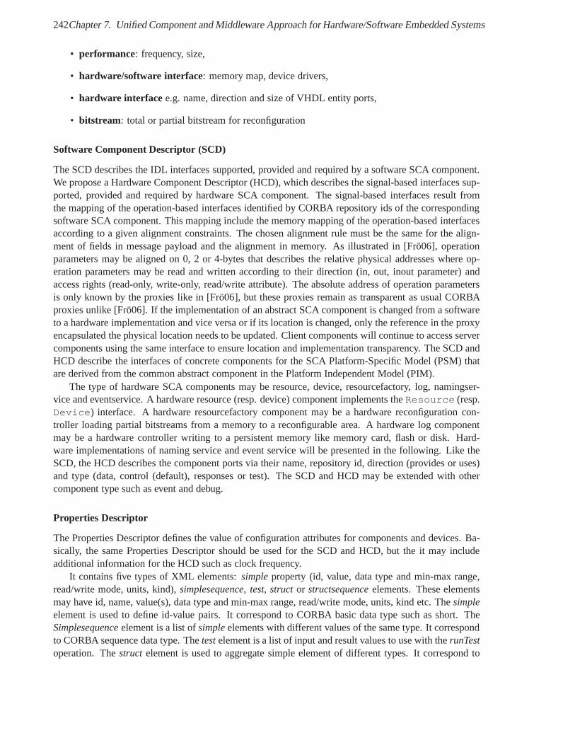
242Chapter 7. Unified Component and Middleware Approach for Hardware/Software Embedded Systems
• performance: frequency, size,
• hardware/software interface: memory map, device drivers,
• hardware interface e.g. name, direction and size of VHDL entity ports,
• bitstream: total or partial bitstream for reconfiguration
Software Component Descriptor (SCD)
The SCD describes the IDL interfaces supported, provided and required by a software SCA component.We propose a Hardware Component Descriptor (HCD), which describes the signal-based interfaces sup-ported, provided and required by hardware SCA component. The signal-based interfaces result fromthe mapping of the operation-based interfaces identified byCORBA repository ids of the correspondingsoftware SCA component. This mapping include the memory mapping of the operation-based interfacesaccording to a given alignment constraints. The chosen alignment rule must be the same for the align-ment of fields in message payload and the alignment in memory.As illustrated in [Frö06], operationparameters may be aligned on 0, 2 or 4-bytes that describes the relative physical addresses where op-eration parameters may be read and written according to their direction (in, out, inout parameter) andaccess rights (read-only, write-only, read/write attribute). The absolute address of operation parametersis only known by the proxies like in [Frö06], but these proxies remain as transparent as usual CORBAproxies unlike [Frö06]. If the implementation of an abstract SCA component is changed from a softwareto a hardware implementation and vice versa or if its location is changed, only the reference in the proxyencapsulated the physical location needs to be updated. Client components will continue to access servercomponents using the same interface to ensure location and implementation transparency. The SCD andHCD describe the interfaces of concrete components for the SCA Platform-Specific Model (PSM) thatare derived from the common abstract component in the Platform Independent Model (PIM).
The type of hardware SCA components may be resource, device,resourcefactory, log, namingser-vice and eventservice. A hardware resource (resp. device) component implements theResource (resp.Device) interface. A hardware resourcefactory component may be a hardware reconfiguration con-troller loading partial bitstreams from a memory to a reconfigurable area. A hardware log componentmay be a hardware controller writing to a persistent memory like memory card, flash or disk. Hard-ware implementations of naming service and event service will be presented in the following. Like theSCD, the HCD describes the component ports via their name, repository id, direction (provides or uses)and type (data, control (default), responses or test). The SCD and HCD may be extended with othercomponent type such as event and debug.
Properties Descriptor
The Properties Descriptor defines the value of configurationattributes for components and devices. Ba-sically, the same Properties Descriptor should be used for the SCD and HCD, but the it may includeadditional information for the HCD such as clock frequency.
It contains five types of XML elements:simpleproperty (id, value, data type and min-max range,read/write mode, units, kind),simplesequence, test, struct or structsequenceelements. These elementsmay have id, name, value(s), data type and min-max range, read/write mode, units, kind etc. Thesimpleelement is used to define id-value pairs. It correspond to CORBA basic data type such as short. TheSimplesequenceelement is a list ofsimpleelements with different values of the same type. It correspondto CORBA sequence data type. Thetestelement is a list of input and result values to use with therunTestoperation. Thestruct element is used to aggregate simple element of different types. It correspond to
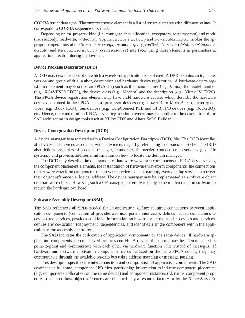
7.4. Hardware Application of the Software Communications Architecture 243
CORBA struct data type. Thestructsequenceelement is a list ofstructelements with different values. Itcorrespond to CORBA sequence of structs.
Depending on the property kind (i.e. configure, test, allocation, execparam, factoryparam) and mode(i.e. readonly, readwrite, writeonly),ApplicationFactory andDeviceManager invokes the ap-propriate operations of theResource (configureand/orquery, runTest), Device (de/allocateCapacity,execute) andResourceFactory (createResource) interfaces using these elements as parameters atapplication creation during deployment.
Device Package Descriptor (DPD)
A DPD may describe a board on which a waveform application is deployed. A DPD contains an id, name,version and group of title, author, description and hardware device registration. A hardware device reg-istration element may describe an FPGA chip such as the manufacturer (e.g. Xilinx), the model number(e.g. XC4VFX20-FF672), the device class (e.g. Modem) and the description (e.g. Virtex IV FX20).The FPGA device registration element may have child hardware devices which describe the hardwaredevices contained in the FPGA such as processor devices (e.g. PowerPC or MicroBlaze), memory de-vices (e.g. Block RAM), bus devices (e.g. CoreConnect PLB and OPB), I/O devices (e.g. RocketIO),etc. Hence, the content of an FPGA device registration element may be similar to the description of theSoC architecture in design tools such as Xilinx EDK and Altera SoPC Builder.
Device Configuration Descriptor (DCD)
A device manager is associated with a Device Configuration Descriptor (DCD) file. The DCD identifiesall devices and services associated with a device manager byreferencing the associated SPDs. The DCDalso defines properties of a device manager, enumerates the needed connections to services (e.g. filesystems), and provides additional information on how to locate the domain manager.
The DCD may describe the deployment of hardware waveform components to FPGA devices usingthe component placement elements, the instantiation of hardware waveform components, the connectionsof hardware waveform components to hardware services such as naming, event and log service to retrievetheir object reference i.e. logical address. The device manager may be implemented as a software objector a hardware object. However, such a CF management entity islikely to be implemented in software toreduce the hardware overhead.
Software Assembly Descriptor (SAD)
The SAD references all SPDs needed for an application, defines required connections between appli-cation components (connection of provides and uses ports / interfaces), defines needed connections todevices and services, provides additional information on how to locate the needed devices and services,defines any co-location (deployment) dependencies, and identifies a single component within the appli-cation as the assembly controller.
The SAD indicates the collocation of application components on the same device. If hardware ap-plication components are colocalized on the same FPGA device, their ports may be interconnected inpoint-to-point and communicate with each other via hardware function calls instead of messages. Ifhardware and software application components are colocalized on the same FPGA device, they maycommunicate through the available on-chip bus using address mapping or message passing.
This descriptor specifies the interconnection and configuration of application components. The SADdescribes an id, name, component SPD files, partitioning information to indicate component placement(e.g. components collocation on the same device) and component instances (id, name, component prop-erties, details on how object references are obtained - by a resource factory or by the Name Service),
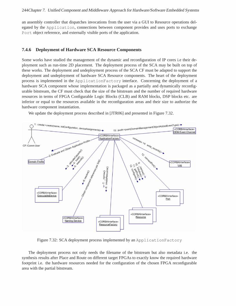
244Chapter 7. Unified Component and Middleware Approach for Hardware/Software Embedded Systems
an assembly controller that dispatches invocations from the user via a GUI to Resource operations del-egated by theApplication, connections between component provides and uses ports to exchangePort object reference, and externally visible ports of the application.
7.4.6 Deployment of Hardware SCA Resource Components
Some works have studied the management of the dynamic and reconfiguration of IP cores i.e their de-ployment such as run-time 2D placement. The deployment process of the SCA may be built on top ofthese works. The deployment and undeployment process of theSCA CF must be adapted to support thedeployment and undeployment of hardware SCA Resource components. The heart of the deploymentprocess is implemented in theApplicationFactory interface. Concerning the deployment of ahardware SCA component whose implementation is packaged asa partially and dynamically reconfig-urable bitstream, the CF must check that the size of the bitstream and the number of required hardwareresources in terms of FPGA Configurable Logic Blocks (CLB) and RAM blocks, DSP blocks etc. areinferior or equal to the resources available in the reconfiguration areas and their size to authorize thehardware component instantiation.
We update the deployment process described in [JTR06] and presented in Figure 7.32.
Figure 7.32: SCA deployment process implemented by anApplicationFactory
The deployment process not only needs the filename of the bitstream but also metadata i.e. thesynthesis results after Place and Route on different targetFPGAs to exactly know the required hardwarefootprint i.e. the hardware resources needed for the configuration of the chosen FPGA reconfigurablearea with the partial bitstream.
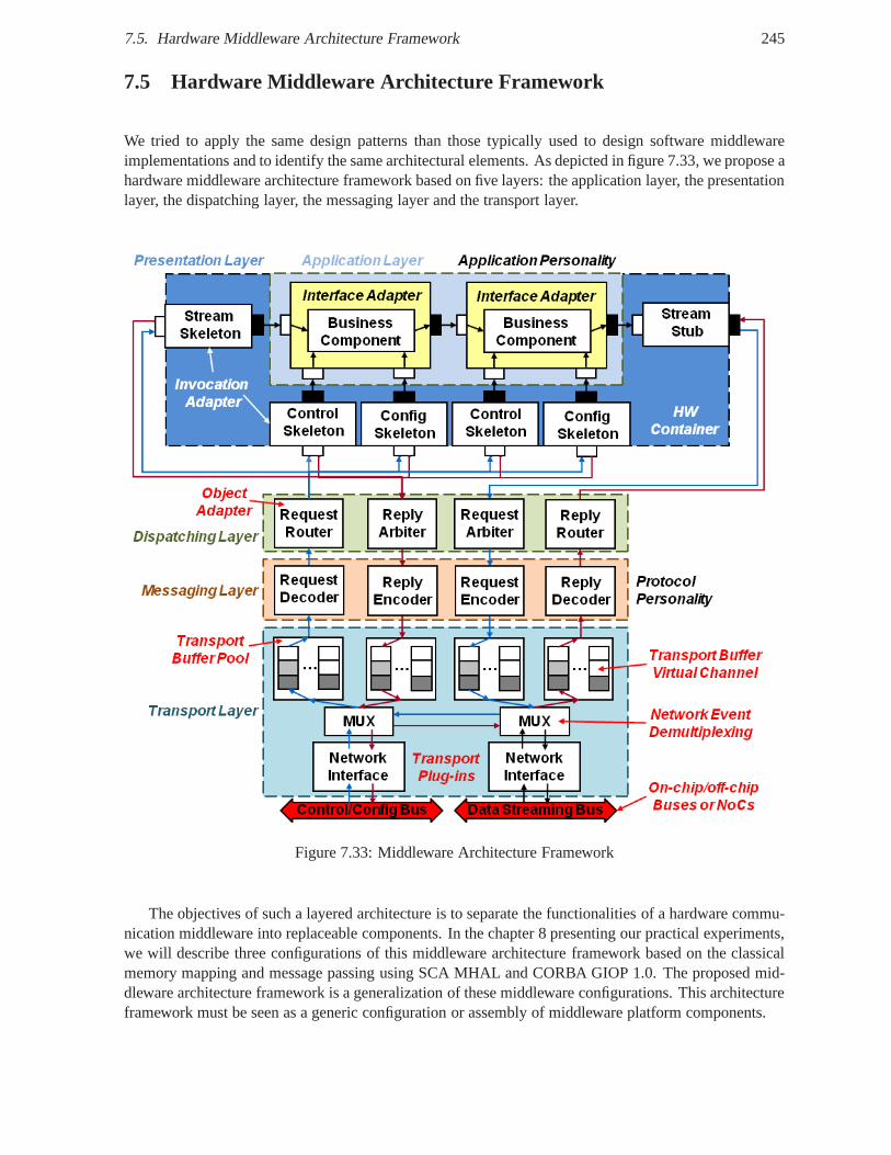
7.5. Hardware Middleware Architecture Framework 245
7.5 Hardware Middleware Architecture Framework
We tried to apply the same design patterns than those typically used to design software middlewareimplementations and to identify the same architectural elements. As depicted in figure 7.33, we propose ahardware middleware architecture framework based on five layers: the application layer, the presentationlayer, the dispatching layer, the messaging layer and the transport layer.
Figure 7.33: Middleware Architecture Framework
The objectives of such a layered architecture is to separatethe functionalities of a hardware commu-nication middleware into replaceable components. In the chapter 8 presenting our practical experiments,we will describe three configurations of this middleware architecture framework based on the classicalmemory mapping and message passing using SCA MHAL and CORBA GIOP 1.0. The proposed mid-dleware architecture framework is a generalization of these middleware configurations. This architectureframework must be seen as a generic configuration or assemblyof middleware platform components.
246Chapter 7. Unified Component and Middleware Approach for Hardware/Software Embedded Systems
7.5.1 Application and Protocol personalities
We reuse the notion of application and protocol personalities proposed for PolyORB [VHPK04]. Weconsider the hardware SCA components as part of a SCA application personality. Another applicationpersonality could be based on hardware CCM components or other component models. Two protocolpersonalities have been implemented using SCA MHAL and CORBA GIOP 1.0. The request and re-ply paths may be merged if the message protocol does not perform no distinction between requests andreplies like MHAL. The hardware middleware architecture presented in figure 7.33 is generic enoughto include the studied middleware configurations. However,application and protocol requirements mayrequire exploration of the middleware architecture to satisfy given QoS constraints. For instance, thenumber of buffers and network interfaces and the allocationof physical addresses i.e.network endpointsto component ports may change from one pair of application and platform to another one. Indeed, the fi-nal middleware configuration depends on the mapping of connectors, which bind application componentports, to the platform communication buses. Various application to platform mapping may be possibleaccording to the communication constraints. For instance,the application information flows like con-trol, configuration and data stream may be mapped onto sharedor dedicated buses for each or all flows.Moreover, the platform typically provide proprietary buses for DSP-FPGA, FPGA or GPP-FPGA com-munications No encapsulation into messages of data streamsmay be required if the real-time constraintsare too stringent to accept the overhead in latency needed for message decoding and encoding. The over-head of message encapsulations depends on the ratio betweenthe message format and raw user-data.
7.5.2 Application layer
Theapplication layercontains the hardware application components. These components may be for in-stance hardware SCAResources or CCM components. They implement in hardware the most relevantoperations required by the software component model interfaces. The other operations can be transpar-ently implemented in software stubs to save hardware resources. The components in the application layercan be reused independently of the other middleware layers.
7.5.3 Presentation layer
The presentation layerperforms the encoding/decoding of message payloads. It consists of hardwarestubs and skeletons which accomplish the hardware marshalling/demarshalling of message byte streams.They act as invocation adapters [PRP05] which adapt the generic interface of the middleware and thespecific application components. IDL compilers may automatically produce these stubs/skeletons bygenerating dedicated FSMs. Based on the operation signatures defined in CORBA IDL, encoding/de-coding FSMs may extract a known set of bits from the message byte stream in one or several clockcycles depending on the mapping configuration (e.g. the databus width). Like proposed by the PackedEncoding Rules (PER), message payloads may be encoded usingdata alignment like GIOP CDR or notlike SCA MHAL and ZeroC ICE. Stubs decode message payloads into operation parameters which arestored in memories (registers, FIFOs or RAMs). Stubs may forward the invocation to the applicationcomponents via apush interface, or the components can read the parameters valuesvia adata inter-face or apull interface. The collection of stubs/skeletons that isolatethe application components fromtheir operating environment can be viewed as a hardwarecontainerwhich provides activation (via writesfor hardware invocations), synchronization (e.g. clock),storage (e.g. registers) services.
We investigate the implementation of theConfig port in VHDL based on both MM and MP transfermodes. We present some code excerpt in listing 7.12.
−− Package r e s u l t i n g from t h e mapping c o n f i g u r a t i o n
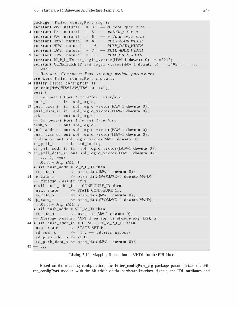
7.5. Hardware Middleware Architecture Framework 247
package F i l t e r _ c o n f i g P o r t _ c f g i scons tan t MW: n a t u r a l := 3 ; −− m data t y p e s i z e
4 cons tan t D: n a t u r a l := 5 ; −− paDding f o r pcons tan t PW: n a t u r a l := 8 ; −− p da ta t y p e s i z econs tan t HAW: n a t u r a l := 8 ; −− PUSH_ADDR_WIDTHcons tan t HDW: n a t u r a l := 16 ;−− PUSH_DATA_WIDTHcons tan t LAW: n a t u r a l := 7 ; −− PULL_ADDR_WIDTH
9 cons tan t LDW: n a t u r a l := 16 ; −− PULL_DATA_WIDTHcons tan t M_P_L_ID : s t d _ l o g i c _ v e c t o r (HAW−1 downto 0) := x " 04 " ;cons tan t CONFIGURE_ID: s t d _ l o g i c _ v e c t o r (HAW−1 downto 0) := x " 05 " ; −− . . .
end ;−− Hardware Component Por t s t o r i n g method pa rame te rsuse work . F i l t e r _ c o n f i g P o r t _ c f g .a l l ;
14 e n t i t y F i l t e r _ c o n f i g P o r t i sgene r i c (HAW,HDW,LAW,LDW: n a t u r a l ) ;por t (−− Component Por t I n v o c a t i o n I n t e r f a c epush_ i : i n s t d _ l o g i c ;
19 push_add r_ i : i n s t d _ l o g i c _ v e c t o r (HAW−1 downto 0) ;p u s h _ d a t a _ i : i n s t d _ l o g i c _ v e c t o r (HDW−1 downto 0) ;ack : out s t d _ l o g i c ;−− Component Por t I n t e r n a l I n t e r f a c epush_o : out s t d _ l o g i c ;
24 push_addr_o :out s t d _ l o g i c _ v e c t o r (HAW−1 downto 0) ;push_da ta_o :out s t d _ l o g i c _ v e c t o r (HDW−1 downto 0) ;m_data_o : out s t d _ l o g i c _ v e c t o r (MW−1 downto 0) ;c f _ p u l l _ i : i n s t d _ l o g i c ;c f _ p u l l _ a d d r _ i : i n s t d _ l o g i c _ v e c t o r (LAW−1 downto 0) ;
29 c f _ p u l l _ d a t a _ i : out s t d _ l o g i c _ v e c t o r (LDW−1 downto 0) ;−− . . . ) ; end ;−− Memory Map (MM) 1e l s i f push_addr = M_P_L_IDthenm_data_o <= push_da ta (MW−1 downto 0) ;
34 p_data_o <= push_da ta (PW+MW+D−1 downto MW+D) ;−− Message Pass ing (MP) 1e l s i f push_add r_ in = CONFIGURE_IDthen
n e x t _ s t a t e <= STATE_CONFIGURE_CF;m_data_o <= push_da ta (MW−1 downto 0) ;
39 p_data_o <= push_da ta (PW+MW+D−1 downto MW+D) ;−− Memory Map (MM) 2e l s i f push_addr = SET_M_IDthenm_data_o <= push_da ta (MW−1 downto 0) ;
−− Message Pass ing (MP) 2 on top o f Memory Map (MM) 244 e l s i f push_add r_ in = CONFIGURE_M_P_L_IDthen
n e x t _ s t a t e <= STATE_SET_P ;ad_push_o <= ’1 ’ ;−− add ress decoderad_push_addr_o <= M_ID ;ad_push_da ta_o <= push_da ta (MW−1 downto 0) ;
49 −− . . .
Listing 7.12: Mapping Illustration in VHDL for the FIR filter
Based on the mapping configuration, theFilter_configPort_cfg package parameterizes theFil-ter_configPort module with the bit width of the hardware interface signals,the IDL attributes and
248Chapter 7. Unified Component and Middleware Approach for Hardware/Software Embedded Systems
parameters and operation identifiers. In the MM1 and MP1 mode, the skeleton decodes the same mes-sage containing m,p,l and ten coefficients. MP1 requires more hardware resources notably a DSP48 toincrement the address of coefficients in RAM.
Thanks to logic optimization, the support of both schemes requires fewer resources than the sum ofboth. In the second experiment, we develop a generic addressdecoder to allow the separate configurationof each attribute and parameter on top of which a MP to MM adapter may be implemented. No RAM isthus required in this adapter. This approach provides more flexibility at the expense of more consumedresources. Based on these prototypes, more exhaustive investigations are necessary to observe how theseschemes behave in time and space when scaling up. MM or MP or a combination of both could be chosentransparently and explicitly.
7.5.4 Dispatching layer
Thedispatching layerperforms the routing of incoming messages and the arbitration of outcoming mes-sages. When the component port provides services and acts asa server port, the incoming messages arerequest messages, while the outgoing messages are reply messages. Conversely, when the componentport uses services and acts as a client port, the incoming messages are reply messages, while the outgoingmessages are request messages.
When ingoing messages are received, the input router dispatches incoming invocations to the appro-priate skeleton according to the logical address in the request or reply message header e.g. an operationname or request identifier for GIOP or a Command Symbol for MHAL. For hardware object-orientedmiddlewares, the router acts as anobject adapter. In memory mapping, the router is implemented as aclassical address decoder that selects a skeleton based on the input physical address. This router sharesthe same design trade-offs as its counterpart in buses and NoCs. It may be implemented as a simple1-to-N multiplexer where N is the number of skeletons, but this is not scalable when the number of com-ponent ports increases. To increase its scalability, the router can have a distributed implementation forinstance as a tree of 1-to-2 multiplexer that makes a better use of FPGA routing resources. The routerimplementation may generic and configured at compile time depending on the number of componentports.
When outgoing messages are ready to be sent, the output arbiter selects a skeleton for replies orstub for requests according to some classical arbitration policies e.g. round-robin, priority-based or acombination of both.
7.5.5 Messaging layer
The messaging layerperforms the encoding and decoding of message headers, encapsulates messagepayloads with message headers, and implements the protocolstate machine with FSMs. The more themessage format contains information and the messaging protocol is complex, the more there are statesand the more hardware resources are consumed to implement it. For instance, the implementation ofGIOP 1.0 request-reply messages and MHAL messages showed that GIOP requires 52% of total LUTs inaddition. In memory mapping, this layer is empty since no message processing is necessary. The messagepayloads are directly transferred from the transport layerto the dispatching layer. The messaging layerprovides anExtensible Messaging Framework(EMF ) in which message plug-ins may be introduced tosupport various message protocols. Dynamic and partial hardware reconfiguration of FPGAs [SMC+07]may be used to dynamically loadable hardware messaging modules as they were dynamically linkablesoftware libraries.
7.6. Limitations 249
7.5.6 Transport layer
The transport layerprovides a generic hardware interface to the underlying transport mechanisms e.g.on-chip or off-chip buses, Network Interfaces in NoCs, high-speed serial links, etc. It includestransportbuffers to store the incoming and outcoming messages to be sent and received from the network. In ourexperiments, the transport buffers have been implemented as generic hardware FIFOs which have beenmapped to the FIFOs available from the target FPGA library. Transport buffers may be organized as abounded pool of buffers with a configurable depth and width defined at compile time. Each transportbuffer represents avirtual channeland may be associated with a predefined priority to avoidpriorityinversionlike in Real-Time CORBA ORBs and NoCs. For instance, a low-priority control/configurationmessage should not be blocked by the processing of a high priority data stream message. These virtualchannels allow to provide differentiated services with best-effort or guaranteed quality of services (QoS)regarding throughput, latency and jitter like in NoCs [RDP+05] [Bje05]. Typically, the transfer of video,voice and data has different qualities of services. This layer containstransport plug-ins like bus bridgesto adapt the generic interface of the transport buffers and the specific interface of the standard bus. Eachtransport plug-in constitutes anetwork interface. Such transport plug-ins require stable hardware in-terfaces which can be derived from CORBA IDL interfaces according to our mapping proposition. Inour experiments, we evaluate OCP to provide a standard interconnection socket. For instance, an Xil-inx OPB-to-OCP bridge have been implemented and used in our middleware prototypes. The transportlayer provides anExtensible Transport Framework(ETF) like in Real-Time CORBA in which transportplug-ins may be introduced to support various transport protocols. Dynamic and partial hardware recon-figuration of FPGAs [SMC+07] may be used to dynamically loadable hardware transport modules asthey were dynamically linkable software libraries.
7.5.7 Performance Overhead
We consider that the services provided by each of these layers are more or less already implemented byclassical communication buses. Indeed, communication buses need to transfer messages from a commu-nicating entity to another, route messages to the appropriate entity, which must marshal and unmarshalcommands and parameters to and from messages. These services are simply organized as a set of well-defined layers. This organization does not necessarily imply an important performance overhead in itself.The potential performance overhead will primarily depend on the implementation of each layer. The pro-posed middleware framework is generic and must be tailored to the specific communication requirementsof an application. For instance, a designer may choose memory mapping instead of message passing orprefer a lightweight message format to reduce communication latency. The increasing overhead of threeconfigurations of this middleware architecture framework will be illustrated in chapter 8.
7.6 Limitations
As already said previously, the CORBA Interface Definition Language suffers from inherent limitationsto address hardware design. The standard CORBA IDL is a declarative language, which does not ad-dress behavioral specification. As a number of language mappings to software implementation languagesare already specified, a natural approach was the specification of a IDL-to-HDL and IDL-SystemC TLMmappings. The other standard use by the SCA which could be used is UML, but no standard mapping ex-ist between UML and software programming languages. Since astandard mapping exists between UMLand CORBA IDL using the UML for profile CORBA and CCM, definition a mapping from IDL-to-HDLis similar to defining a mapping from UML-to-HDL. CORBA IDL can be considered as a concrete tex-tual syntax to the UML graphical language. Nevertheless, UML provides a standard mean to specify
250Chapter 7. Unified Component and Middleware Approach for Hardware/Software Embedded Systems
behavior of abstract components independently of their implementations. It notably provides ActionLanguage, Sequence Diagram and State Diagram. Another approach would be to include language con-struct proposed in the academic literature, but these extensions would be not standard. These extensionsinclude for instance behavioral protocol [PV02]. Moreover, the use of the MDA approach is conceptualrather than a strict implementation of the OMG approach e.g.using UML.
7.7 Conclusion
In this chapter, we presented a common component approach for system, hardware and software com-ponents based on the language mappings of a high-level interface specification in CORBA IDL or UMLand a common middleware approach through a hardware middleware architecture framework.
We propose to leverage the conceptual SDR design methodology based on MDA and the compo-nent/container approach, which existed at Thales Communications in 2005 [GNSV07] , with SystemCTransaction Level Modeling (TLM) to simulate the platform independent model of waveform applica-tions (see §7.3.1.0), and the platform specific models of waveform applications and SDR platforms (see§8.2.2). The component/container approach allows one to transparently integrate functional models inC as SystemC components in virtual platforms. SystemC TLM allows the simulation and validation ofPIMs and PSMs at different abstraction levels. We propose a common design flow for system, hardwareand software components based on MDA, SystemC TLM, and language mappings from business inter-faces to simulation and implementation languages at different abstraction levels. The MDA approach iscoherent with the development of the new technology-independent SCA release
To support the systematic refinement of object-oriented component interfaces in CORBA IDL orUML to system, software, and hardware component interfacesin C/C++, SystemC and VHDL, we pro-pose to define new language mappings from CORBA IDL to SystemCTLM/RTL and VHDL.
The mapping from IDL3 to functional SystemC extends the IDL-to-C++ mapping with additionalmapping rules to fit specific SystemC language constructs. A SystemC component is asc_modulecomponent with requiredsc_export ports and providedsc_port ports which are associated tosc_interface interfaces. We illustrate the UML/IDL-to-SystemC mappingat functional level throughthe transition from a Platform Independent Model (PIM) in UML of two waveform components to a Plat-form Specific Model (PSM) in SystemC (see §7.3.1.0).
The mapping from IDL3 to SystemC at Transactional Level is based on transactional connectorscalled transactors, which adapt the mapping of user-definedobject-oriented interfaces to standard TLMinterfaces. The cornerstone of this mapping relies on the equivalence between operation signatures andmessage definition in the object-oriented approach. Regardless of the abstraction level, the syntax andsemantics of the business interfaces in UML or IDL and the associated transactions are the same, onlythe manner of transferring messages changes with the abstraction level. This object-oriented approach torefinement contrast with the classical ad-hoc refinement in SystemC, where the syntax and semantics ofbusiness interfaces are lost during refinement.
For the mapping from CORBA IDL to Hardware Description Languages (HDLs), we emphasizethe differences between interface mapping between software languages, and interface mapping betweenhardware and software languages. Existing CORBA IDL language mappings are generally systematicand one-to-one mapping, which share a common procedure callabstraction. Software-to-hardware map-ping require more flexibility due to the inherent hardware trade-off between area, performance and powerconsumption. An IDL-to-HDL mapping requires to select and configure non-functional properties suchas hardware interfaces, timing and protocols, and explore the mapping space. We propose the use of astandardized mapping configuration file to explicitly and finely configure the mapping.
We formulate user and implementation requirements for a standard IDL3-to-HDL mapping. The
7.7. Conclusion 251
most important requirements concern concurrency (e.g. concurrent method invocations and executionswithin a component, concurrent accesses to internal attributes and method parameters, concurrent invo-cations of methods from multiple clients); connectors to adapt different interaction semantics or syn-chronization schemes; hardware interface and protocol framework to improve the portability and in-teroperability of HW components; blocking and non-blocking synchronization; message passing withaligned/unaligned data types encoding rules; stream-oriented Inter-ORB Protocol to pipeline requestsand replies with Time or Space Division Multiplexing (TDM/SDM); Extensible Transport Framework(ETF) with a generic bus interface like OCP; Extensible Message Framework (EMF) to support domain-specific message protocols like SCA MHAL, and a subset of IDL data types with bit-accurate types.
In our mapping proposition, a hardware object-oriented component (e.g. SCA, UML, CCM) is rep-resented by a hardware module, whose implementation (e.g. VHDL architecture may be selectedby a hardware configuration e.g. VHDLconfiguration. An abstract component port is mapped toa logical hardware component port, which is a set of RTL inputand output ports.
We distinguish three kinds of hardware component interfaces: the business component core interfaceor internal component interface to access operation parameters, the invocation interface of componentports or external component interface to send/receive invocations, and the connector interface to send/re-ceive messages. By default, methods in the same object interface share the same hardware port and thusmethod invocations of the same interface are sequential.
A hardware connector may represent non-functional properties such as synchronization and commu-nication such as flow control, clock domain crossing, interaction semantics, and protocols of point-to-point buses, shared buses or NoCs.
A hardware container provide all remaining non-functionalservices such as lifecycle and persistenceto store component state. For instance, the lifecycle service may manage component creation/destruc-tion e.g. with dynamic partial reconfiguration, component initialization e.g. with a asynchronous orsynchronous reset, parameters configuration with registerbanks, and activation/deactivation e.g. with aclock or enable signal.
The mapping is based on a common and independent family of hardware interfaces and connectors.We apply our mapping proposition to the interfaces of a FIR filter, a Transceiver standardized at theSDRForum, a convcoder and bitinterleaver SCA components and the dining philosopher problem inCCM and a modulator in [GBSV08].
An IDL3-to-VHDL compiler prototype has been implemented according to a MDA approach. Basedon the LwCCM meta-model, we define a VHDL meta-model. We extended the standard CCM meta-model and proposed a VHDL meta-model based on the architecture of the first one. The RTL mappingis finely configured by an editor generated from the CCM meta-model. Model-to-model transforma-tions rules were defined in the OMG QVT language. Model-to-text transformations were defined bycode templates using OMG MOF2Text language. Our hardware middleware architecture framework al-lows hardware components to transparently communicate with software and/or hardware componentsusing either classical memory mapping or message passing with CORBA GIOP or SCA MHAL. Theproposed middleware architecture applies the software middleware design patterns down to hardware.The hardware middleware architecture framework contains five layers: the application layer consists ofthe hardware application components, the presentation layer performs the encoding/decoding of mes-sage payloads, the dispatching layer deals with the routingof incoming messages and the arbitration ofoutcoming messages, the messaging layer takes care of the encoding and decoding of message headers,encapsulation of message payloads and the protocol state machine, and the transport layer provides ageneric hardware communication interface and transport buffers. The hardware middleware architectureframework is based on the concepts of application and protocol personalities. An application personalitycorresponds to a component model personality e.g. SCA or CCM. A protocol personality correspondsto a message protocol such as SCA MHAL and CORBA GIOP.

252Chapter 7. Unified Component and Middleware Approach for Hardware/Software Embedded Systems
Our mapping proposition was first dedicated to CORBA IDL, butcan be easily extended to anyobject-oriented interface description notably in UML.
Chapter 8
Experiments
Contents8.1 Introduction . . . . . . . . . . . . . . . . . . . . . . . . . . . . . . . . . . . .. . . 253
8.2 DiMITRI MPSoC for Digital Radio Mondiale (DRM) . . . . . . . . . . . . . . . . 254
8.2.1 Application and Platform presentation . . . . . . . . . . . .. . . . . . . . . . 254
8.2.2 Executable PSM in SystemC TLM . . . . . . . . . . . . . . . . . . . . .. . 254
8.2.3 Results Analysis . . . . . . . . . . . . . . . . . . . . . . . . . . . . . . .. . 257
8.3 High-Data Rate OFDM Modem . . . . . . . . . . . . . . . . . . . . . . . . . .. . 258
8.3.1 Application and Platform presentation . . . . . . . . . . . .. . . . . . . . . . 258
8.3.2 Modeling at Different Abstraction Levels . . . . . . . . . .. . . . . . . . . . 259
8.3.3 Hardware Middleware Implementations . . . . . . . . . . . . .. . . . . . . . 266
8.3.4 Results on Virtex IV after Place&Route . . . . . . . . . . . . .. . . . . . . . 273
8.3.5 Results Analysis . . . . . . . . . . . . . . . . . . . . . . . . . . . . . . .. . 275
8.4 Conclusion . . . . . . . . . . . . . . . . . . . . . . . . . . . . . . . . . . . . . .. . 276
8.1 Introduction
This chapter presents the experiments on which the propositions of the previous chapter are based. Theseexperiments are part of our contributions. The two studied applications are signal-processing applicationsin wireless digital communication systems. These systems are typical products developed by ThalesCommunications, where most of our thesis took place. In particular, these experiments focus on thephysical layer of radio modems, which are implemented on FPGA.
This chapter is organized as follows. First, section 8.2 presents the modeling of an existing RTLIP core component as a reusable SystemC component at Programmer View (PV) level, its integrationand software validation in a virtual platform of a subset of an MPSoC and the refinement of this virtualplatform to be closer to the real platform. Then, section 8.3describes the modeling at different abstractionlevels of a subset of a high-data rate OFDM modem using SystemC FIFO channels, OCP TLM and OCPRTL, and the implementation of the proposed hardware middleware framework using memory-mappingand message-passing with CORBA GIOP and SCA MHAL. Finally, section 8.4 concludes this chapter.
253
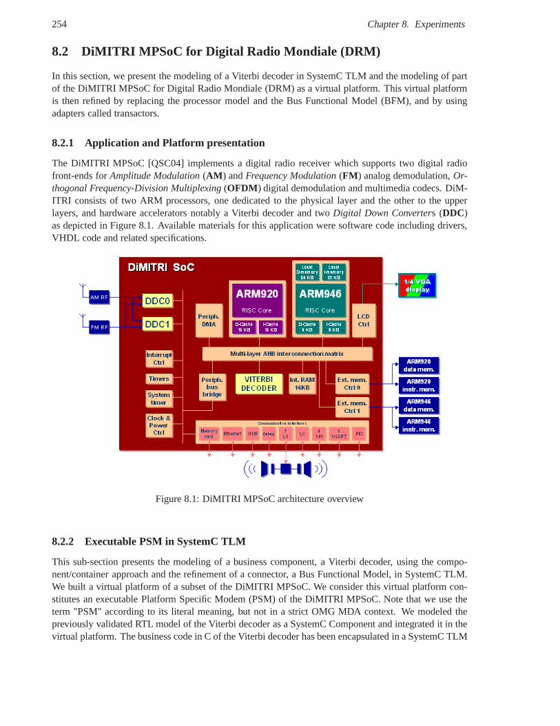
254 Chapter 8. Experiments
8.2 DiMITRI MPSoC for Digital Radio Mondiale (DRM)
In this section, we present the modeling of a Viterbi decoderin SystemC TLM and the modeling of partof the DiMITRI MPSoC for Digital Radio Mondiale (DRM) as a virtual platform. This virtual platformis then refined by replacing the processor model and the Bus Functional Model (BFM), and by usingadapters called transactors.
8.2.1 Application and Platform presentation
The DiMITRI MPSoC [QSC04] implements a digital radio receiver which supports two digital radiofront-ends forAmplitude Modulation(AM ) andFrequency Modulation(FM ) analog demodulation,Or-thogonal Frequency-Division Multiplexing(OFDM ) digital demodulation and multimedia codecs. DiM-ITRI consists of two ARM processors, one dedicated to the physical layer and the other to the upperlayers, and hardware accelerators notably a Viterbi decoder and twoDigital Down Converters (DDC)as depicted in Figure 8.1. Available materials for this application were software code including drivers,VHDL code and related specifications.
Figure 8.1: DiMITRI MPSoC architecture overview
8.2.2 Executable PSM in SystemC TLM
This sub-section presents the modeling of a business component, a Viterbi decoder, using the compo-nent/container approach and the refinement of a connector, aBus Functional Model, in SystemC TLM.We built a virtual platform of a subset of the DiMITRI MPSoC. We consider this virtual platform con-stitutes an executable Platform Specific Modem (PSM) of the DiMITRI MPSoC. Note that we use theterm "PSM" according to its literal meaning, but not in a strict OMG MDA context. We modeled thepreviously validated RTL model of the Viterbi decoder as a SystemC Component and integrated it in thevirtual platform. The business code in C of the Viterbi decoder has been encapsulated in a SystemC TLM
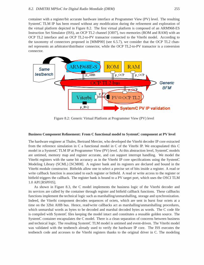
8.2. DiMITRI MPSoC for Digital Radio Mondiale (DRM) 255
container with a register/bit accurate hardware interfaceat Programmer View (PV) level. The resultingSystemC TLM IP has been reused without any modification during the refinement and exploration ofthe virtual platform depicted in Figure 8.2. The first virtual platform is composed of an ARM968-ESInstruction Set Simulator (ISS), an OCP TL2 channel [OI07],two memories (ROM and RAM) with anOCP TL2 interface and an OCP TL2-to-PV transactor connectedto the Viterbi model. According tothe taxonomy of connectors proposed in [MMP00] (see 6.5.7),we consider that the OCP TL2 chan-nel represents an arbitrator/distributor connector, while the OCP TL2-to-PV transactor is a conversionconnector.
Figure 8.2: Generic Virtual Platform at Programmer View (PV) level
Business Component Refinement: From C functional model to SystemC component at PV level
The hardware engineer at Thales, Bertrand Mercier, who developed the Viterbi decoder IP core extractedfrom the reference simulation in C a functional model in C of the Viterbi IP. We encapsulated this Cmodel in a SystemC TLM IP at Programmer View (PV) level. At this abstraction level, SystemC modelsare untimed, memory map and register accurate, and can support interrupt handling. We model theViterbi registers with the same bit accuracy as in the Viterbi IP core specifications using the SystemCModeling Library (SCML) [SCM08]. A register bank and its registers are declared and bound in theViterbi module constructor. Bitfields allow one to select a precise set of bits inside a register. A read orwrite callback function is associated to each register or bitfield. A read or write access to the register orbitfield triggers the callback. The register bank is bound toa PV target port, which uses the OSCI TLM1.0 API [RSPF05].
As shown in Figure 8.3, the C model implements the business logic of the Viterbi decoder andits services are called by the container through register and bitfield callback functions. These callbacksfunctions implement the technical logic such as marshalling/unmarshalling, storage and synchronization.Indeed, the Viterbi component decodes sequences of octets,which are sent in burst four octets at atime on the 32bit AHB bus. Hence, read/write callbacks act asmarshalling/unmarshalling procedures,which unmarshal words as bytes to be decoded and marshal decoded bytes as words. The C code fileis compiled with SystemC files keeping the model intact and constitutes a reusable golden source. TheSystemC container encapsulates the C model. There is a cleanseparation of concerns between businessand technical logic. The resulting SystemC TLM model is untimed and event-driven. The Viterbi modelwas validated with the testbench already used to verify the hardware IP core. The ISS executes thetestbench code and accesses to the Viterbi registers thanksto the original driver in C. The modeling
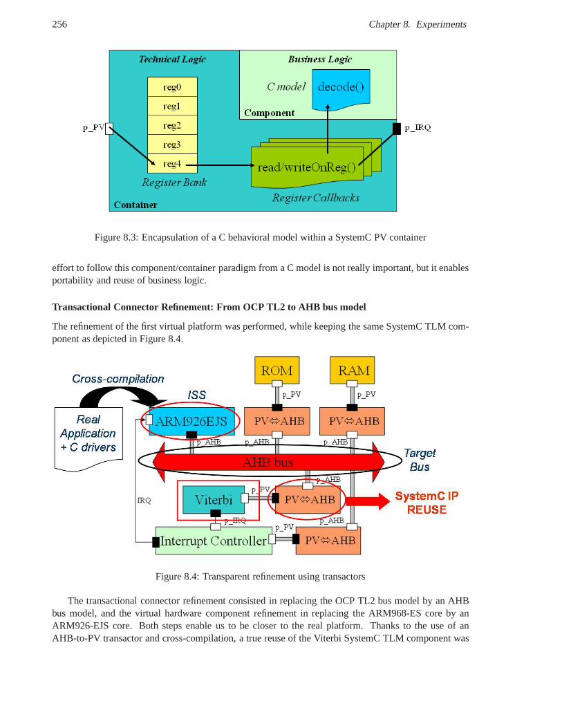
256 Chapter 8. Experiments
Figure 8.3: Encapsulation of a C behavioral model within a SystemC PV container
effort to follow this component/container paradigm from a Cmodel is not really important, but it enablesportability and reuse of business logic.
Transactional Connector Refinement: From OCP TL2 to AHB bus model
The refinement of the first virtual platform was performed, while keeping the same SystemC TLM com-ponent as depicted in Figure 8.4.
Figure 8.4: Transparent refinement using transactors
The transactional connector refinement consisted in replacing the OCP TL2 bus model by an AHBbus model, and the virtual hardware component refinement in replacing the ARM968-ES core by anARM926-EJS core. Both steps enable us to be closer to the realplatform. Thanks to the use of anAHB-to-PV transactor and cross-compilation, a true reuse of the Viterbi SystemC TLM component was
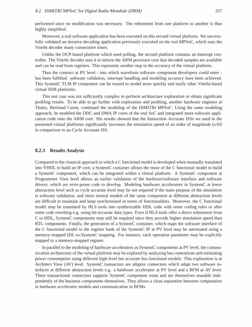
8.2. DiMITRI MPSoC for Digital Radio Mondiale (DRM) 257
performed since no modification was necessary. The refinement from one platform to another is thushighly simplified.
Moreover, a real software application has been executed on this second virtual platform. We success-fully validated an iterative decoding application previously executed on the real MPSoC, which uses theViterbi decoder many consecutive times.
Unlike the OCP-based platform which used polling, the second platform contains an interrupt con-troller. The Viterbi decoder uses it to inform the ARM processor core that decoded samples are availableand can be read from registers. This represents another stepin the accuracy of the virtual platform.
Thus the contract at PV level - into which waveform software component developers could enter -has been fulfilled: software validation, interrupt handling and modeling accuracy have been achieved.This SystemC TLM IP component can be reused to model more quickly and easily other Viterbi-basedvirtual SDR platforms.
This test case was not sufficiently complex to perform architecture exploration or obtain significantprofiling results. To be able to go further with exploration and profiling, another hardware engineer atThales, Bertrand Caron, continued the modeling of the DiMITRI MPSoC. Using the same modelingapproach, he modeled the DDC and DMA IP cores of the real SoC and integrated more software appli-cation code onto the ARM core. His results showed that the Instruction Accurate ISSs we used in thepresented virtual platforms significantly increases the simulation speed of an order of magnitude (x10)in comparison to an Cycle Accurate ISS.
8.2.3 Results Analysis
Compared to the classical approach in which a C functional model is developed when manually translatedinto VHDL to build an IP core, a SystemC container allows the reuse of the C functional model to builda SystemC component, which can be integrated within a virtual platform. A SystemC component atProgrammer View level allows an earlier validation of the hardware/software interface and softwaredrivers, which are error-prone code to develop. Modeling hardware accelerators in SystemC at lowerabstraction level such as cycle accurate level may be not required if the main purpose of the simulationis software validation, and since several models of the samecomponent at different abstraction levelsare difficult to maintain and keep synchronized in terms of functionalities. Moreover, the C functionalmodel may be translated by HLS tools into synthesizable HDL code with some coding rules or aftersome code rewriting e.g. using bit-accurate data types. Even if HLS tools offer a direct refinement fromC to HDL, SystemC components may still be required since theyprovide higher simulation speed thanRTL components. Finally, the generation of a SystemC container, which maps the software interface ofthe C functional model to the register bank of the SystemC IP at PV level may be automated using amemory-mapped IDL-to-SystemC mapping. For instance, eachoperation parameter may be explicitlymapped to a memory-mapped register.
In parallel to the modeling of hardware accelerators as SystemC components at PV level, the commu-nication architecture of the virtual platform may be explored by analyzing bus contentions and estimatingpower consumption using different high-level but accuratebus functional models. This exploration is atArchitect View (AV) level. SystemC transactors are adaptorconnectors which adapt two software in-terfaces at different abstraction levels e.g. a hardware accelerator at PV level and a BFM at AV level.These transactional connectors supports SystemC component reuse and are themselves reusable inde-pendently of the business components themselves. They allows a clean separation between computationin hardware accelerator models and communication in BFMs.
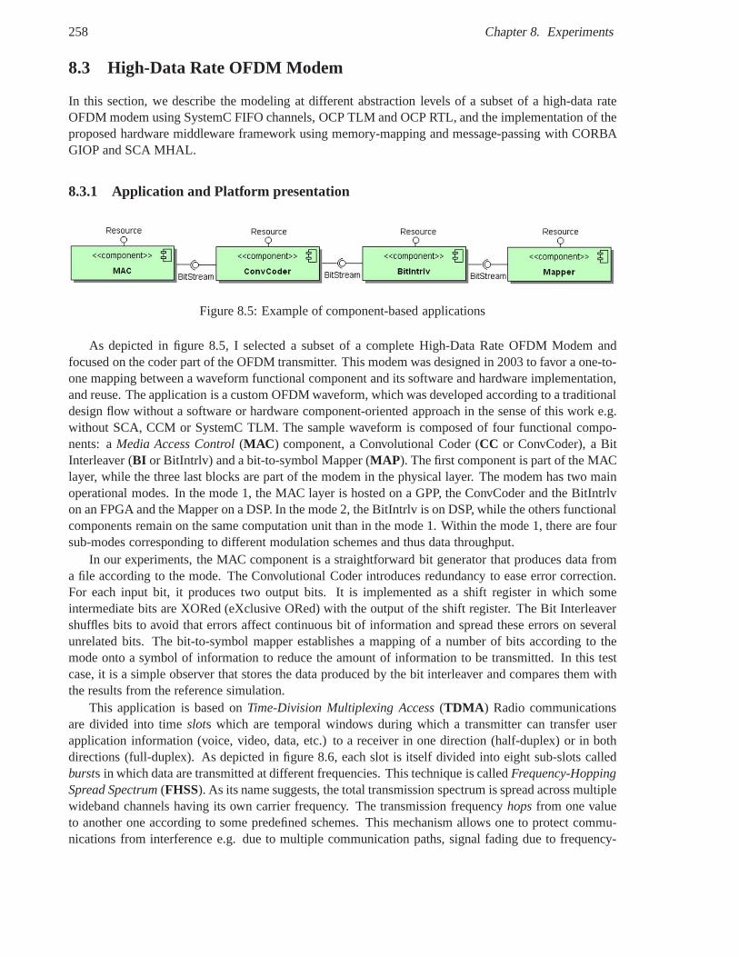
258 Chapter 8. Experiments
8.3 High-Data Rate OFDM Modem
In this section, we describe the modeling at different abstraction levels of a subset of a high-data rateOFDM modem using SystemC FIFO channels, OCP TLM and OCP RTL, and the implementation of theproposed hardware middleware framework using memory-mapping and message-passing with CORBAGIOP and SCA MHAL.
8.3.1 Application and Platform presentation
Figure 8.5: Example of component-based applications
As depicted in figure 8.5, I selected a subset of a complete High-Data Rate OFDM Modem andfocused on the coder part of the OFDM transmitter. This modemwas designed in 2003 to favor a one-to-one mapping between a waveform functional component and itssoftware and hardware implementation,and reuse. The application is a custom OFDM waveform, which was developed according to a traditionaldesign flow without a software or hardware component-oriented approach in the sense of this work e.g.without SCA, CCM or SystemC TLM. The sample waveform is composed of four functional compo-nents: aMedia Access Control(MAC ) component, a Convolutional Coder (CC or ConvCoder), a BitInterleaver (BI or BitIntrlv) and a bit-to-symbol Mapper (MAP ). The first component is part of the MAClayer, while the three last blocks are part of the modem in thephysical layer. The modem has two mainoperational modes. In the mode 1, the MAC layer is hosted on a GPP, the ConvCoder and the BitIntrlvon an FPGA and the Mapper on a DSP. In the mode 2, the BitIntrlv is on DSP, while the others functionalcomponents remain on the same computation unit than in the mode 1. Within the mode 1, there are foursub-modes corresponding to different modulation schemes and thus data throughput.
In our experiments, the MAC component is a straightforward bit generator that produces data froma file according to the mode. The Convolutional Coder introduces redundancy to ease error correction.For each input bit, it produces two output bits. It is implemented as a shift register in which someintermediate bits are XORed (eXclusive ORed) with the output of the shift register. The Bit Interleavershuffles bits to avoid that errors affect continuous bit of information and spread these errors on severalunrelated bits. The bit-to-symbol mapper establishes a mapping of a number of bits according to themode onto a symbol of information to reduce the amount of information to be transmitted. In this testcase, it is a simple observer that stores the data produced bythe bit interleaver and compares them withthe results from the reference simulation.
This application is based onTime-Division Multiplexing Access(TDMA ) Radio communicationsare divided into timeslots which are temporal windows during which a transmitter can transfer userapplication information (voice, video, data, etc.) to a receiver in one direction (half-duplex) or in bothdirections (full-duplex). As depicted in figure 8.6, each slot is itself divided into eight sub-slots calledbursts in which data are transmitted at different frequencies. This technique is calledFrequency-HoppingSpread Spectrum(FHSS). As its name suggests, the total transmission spectrum is spread across multiplewideband channels having its own carrier frequency. The transmission frequencyhopsfrom one valueto another one according to some predefined schemes. This mechanism allows one to protect commu-nications from interference e.g. due to multiple communication paths, signal fading due to frequency-
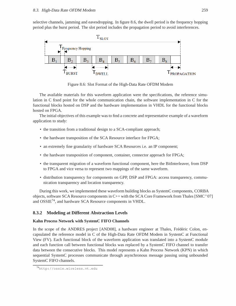
8.3. High-Data Rate OFDM Modem 259
selective channels, jamming and eavesdropping. In figure 8.6, the dwell period is the frequency hoppingperiod plus the burst period. The slot period includes the propagation period to avoid interferences.
Figure 8.6: Slot Format of the High-Data Rate OFDM Modem
The available materials for this waveform application werethe specifications, the reference simu-lation in C fixed point for the whole communication chain, thesoftware implementation in C for thefunctional blocks hosted on DSP and the hardware implementation in VHDL for the functional blockshosted on FPGA.
The initial objectives of this example was to find a concrete and representative example of a waveformapplication to study:
• the transition from a traditional design to a SCA-compliant approach;
• the hardware transposition of the SCA Resource interface for FPGA;
• an extremely fine granularity of hardware SCA Resources i.e. an IP component;
• the hardware transposition of component, container, connector approach for FPGA;
• the transparent migration of a waveform functional component, here the BitInterleaver, from DSPto FPGA and vice versa to represent two mappings of the same waveform.
• distribution transparency for components on GPP, DSP and FPGA: access transparency, commu-nication transparency and location transparency.
During this work, we implemented these waveform building blocks as SystemC components, CORBAobjects, software SCA Resource components in C++ with the SCA Core Framework from Thales [SMC+07]and OSSIE74, and hardware SCA Resource components in VHDL.
8.3.2 Modeling at Different Abstraction Levels
Kahn Process Network with SystemC FIFO Channels
In the scope of the ANDRES project [AND08], a hardware engineer at Thales, Frédéric Colon, en-capsulated the reference model in C of the High-Data Rate OFDM Modem in SystemC at FunctionalView (FV). Each functional block of the waveform application was translated into a SystemC moduleand each function call between functional blocks was replaced by a SystemC FIFO channel to transferdata between the consecutive blocks. This model representsa Kahn Process Network (KPN) in whichsequential SystemC processes communicate through asynchronous message passing using unboundedSystemC FIFO channels.
74http://ossie.wireless.vt.edu
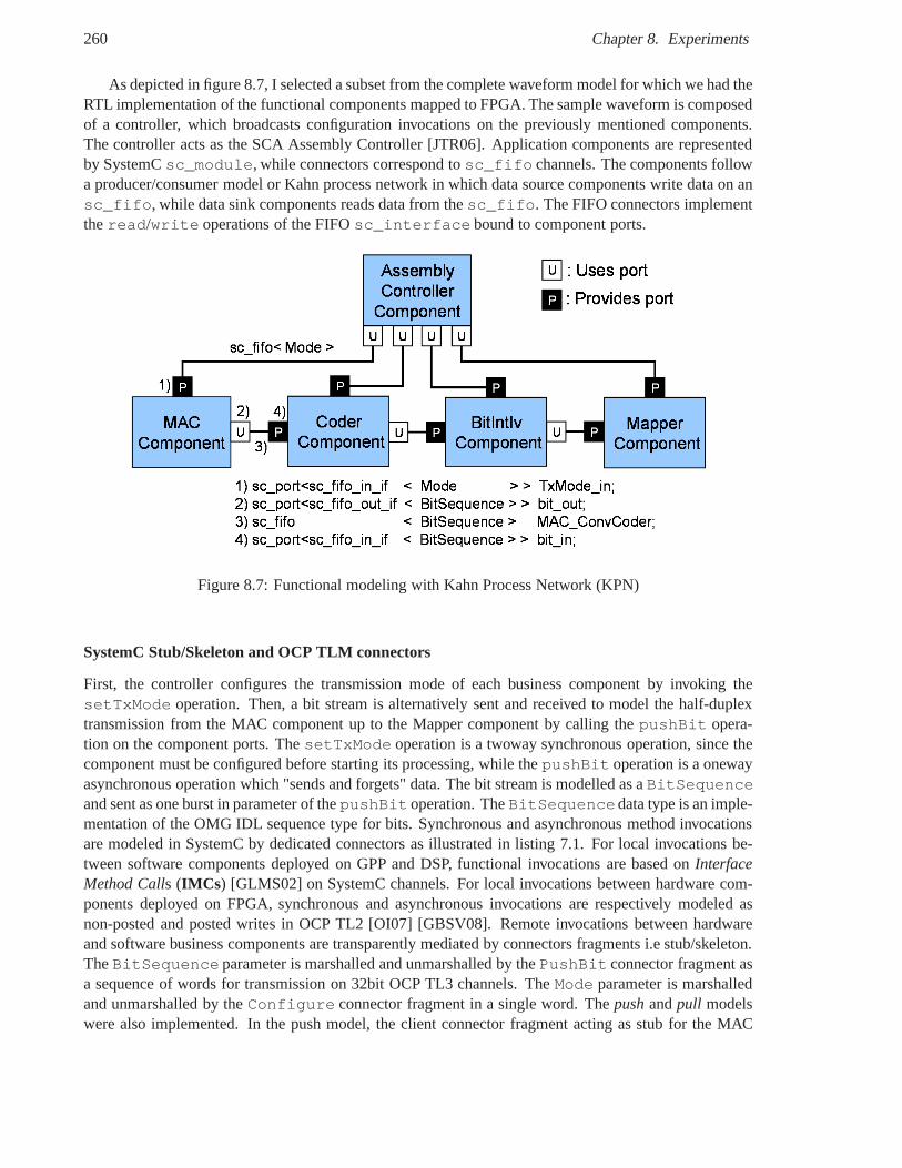
260 Chapter 8. Experiments
As depicted in figure 8.7, I selected a subset from the complete waveform model for which we had theRTL implementation of the functional components mapped to FPGA. The sample waveform is composedof a controller, which broadcasts configuration invocations on the previously mentioned components.The controller acts as the SCA Assembly Controller [JTR06].Application components are representedby SystemCsc_module, while connectors correspond tosc_fifo channels. The components followa producer/consumer model or Kahn process network in which data source components write data on ansc_fifo, while data sink components reads data from thesc_fifo. The FIFO connectors implementtheread/write operations of the FIFOsc_interface bound to component ports.
Figure 8.7: Functional modeling with Kahn Process Network (KPN)
SystemC Stub/Skeleton and OCP TLM connectors
First, the controller configures the transmission mode of each business component by invoking thesetTxMode operation. Then, a bit stream is alternatively sent and received to model the half-duplextransmission from the MAC component up to the Mapper component by calling thepushBit opera-tion on the component ports. ThesetTxMode operation is a twoway synchronous operation, since thecomponent must be configured before starting its processing, while thepushBit operation is a onewayasynchronous operation which "sends and forgets" data. Thebit stream is modelled as aBitSequenceand sent as one burst in parameter of thepushBit operation. TheBitSequencedata type is an imple-mentation of the OMG IDL sequence type for bits. Synchronousand asynchronous method invocationsare modeled in SystemC by dedicated connectors as illustrated in listing 7.1. For local invocations be-tween software components deployed on GPP and DSP, functional invocations are based onInterfaceMethod Calls (IMCs ) [GLMS02] on SystemC channels. For local invocations between hardware com-ponents deployed on FPGA, synchronous and asynchronous invocations are respectively modeled asnon-posted and posted writes in OCP TL2 [OI07] [GBSV08]. Remote invocations between hardwareand software business components are transparently mediated by connectors fragments i.e stub/skeleton.TheBitSequence parameter is marshalled and unmarshalled by thePushBit connector fragment asa sequence of words for transmission on 32bit OCP TL3 channels. TheMode parameter is marshalledand unmarshalled by theConfigure connector fragment in a single word. Thepushandpull modelswere also implemented. In the push model, the client connector fragment acting as stub for the MAC
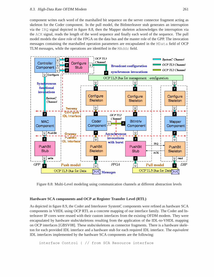
8.3. High-Data Rate OFDM Modem 261
component writes each word of the marshalled bit sequence onthe server connector fragment acting asskeleton for the Coder component. In the pull model, the BitInterleaver stub generates an interruptionvia theIRQ signal depicted in figure 8.8, then the Mapper skeleton acknowledges the interruption viatheACK signal, reads the length of the word sequence and finally eachword of the sequence. The pullmodel models the slave role of the FPGA on the data bus and the master role of the GPP. The invocationmessages containing the marshalled operation parameters are encapsulated in theMData field of OCPTLM messages, while the operations are identified in theMAddr field.
Figure 8.8: Multi-Level modeling using communication channels at different abstraction levels
Hardware SCA components and OCP at Register Transfer Level (RTL)
As depicted in figure 8.9, the Coder and Interleaver SystemC components were refined as hardware SCAcomponents in VHDL using OCP RTL as a concrete mapping of our interface family. The Coder and In-terleaver IP cores were reused with their custom interfacesfrom the existing OFDM modem. They wereencapsulated by hardware stubs/skeletons resulting from the application of the IDL-to-VHDL mappingon OCP interfaces [GBSV08]. These stubs/skeletons as connector fragments. There is a hardware skele-ton for each provided IDL interface and a hardware stub for each required IDL interface. TheequivalentIDL interfaces implemented by the hardware SCA components are the following:
interface Control { // from SCA Resource interface
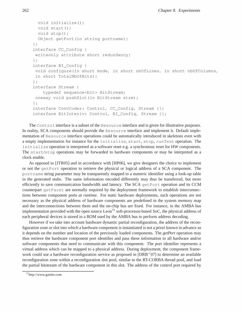
262 Chapter 8. Experiments
void initialize();void start();void stop();Object getPort(in string portname);
};interface CC_Config {writeonly attribute short redundancy;};interface BI_Config {void configure(in short mode, in short nbOfLines, in short nbOfColumns,in short TotalNbOfBits);};interface Stream {
typedef sequence<bit> BitStream;oneway void pushSlot(in BitStream strm);};interface ConvCoder: Control, CC_Config, Stream {};interface BitInterlv: Control, BI_Config, Stream {};
TheControl interface is a subset of theResource interface and is given for illustrative purposes.In reality, SCA components should provide theResource interface and implement it. Default imple-mentation ofResource interface operations could be automatically introduced inskeletons even witha empty implementation for instance for theinitialize, start, stop, runTest operation. Theinitialize operation is interpreted as a software reset e.g. a synchronous reset for HW components.The start/stop operations may be forwarded to hardware components or may beinterpreted as aclock enable.
As opposed to [JTR05] and in accordance with [HP06], we give designers the choice to implementor not thegetPort operation to retrieve the physical or logical address of a SCA component. Theportname string parameter may be transparently mapped to a numeric identifier using a look-up tablein the generated stubs. The same information encoded differently may thus be transferred, but moreefficiently to save communication bandwidth and latency. The SCAgetPort operation and its CCMcounterpartgetFacet are normally required by the deployment framework to establish interconnec-tions between component portsat runtime. For static hardware deployments, such operations are notnecessary as the physical address of hardware components are predefined in the system memory mapand the interconnections between them and the on-chip bus are fixed. For instance, in the AMBA busimplementation provided with the open source Leon75 soft-processor-based SoC, the physical address ofeach peripheral devices is stored in a ROM used by the AMBA busto perform address decoding.
However if we take into account hardware dynamic partial reconfiguration, the address of the recon-figuration zone or slot into which a hardware component is instantiated is not a priori known in advance asit depends on the number and location of the previously loaded components. ThegetPortoperation maythus retrieve the hardware component port identifier and pass these information to all hardware and/orsoftware components that need to communicate with this component. The port identifier represents avirtual address which can be mapped to a physical address. During deployment, the component frame-work could use a hardware reconfiguration service as proposed in [DRB+07] to determine an availablereconfiguration zone within a reconfiguration slot pool, similar to the RT-CORBA thread pool, and loadthe partial bitstream of the hardware component in this slot. The address of the control port required by
75http://www.gaisler.com
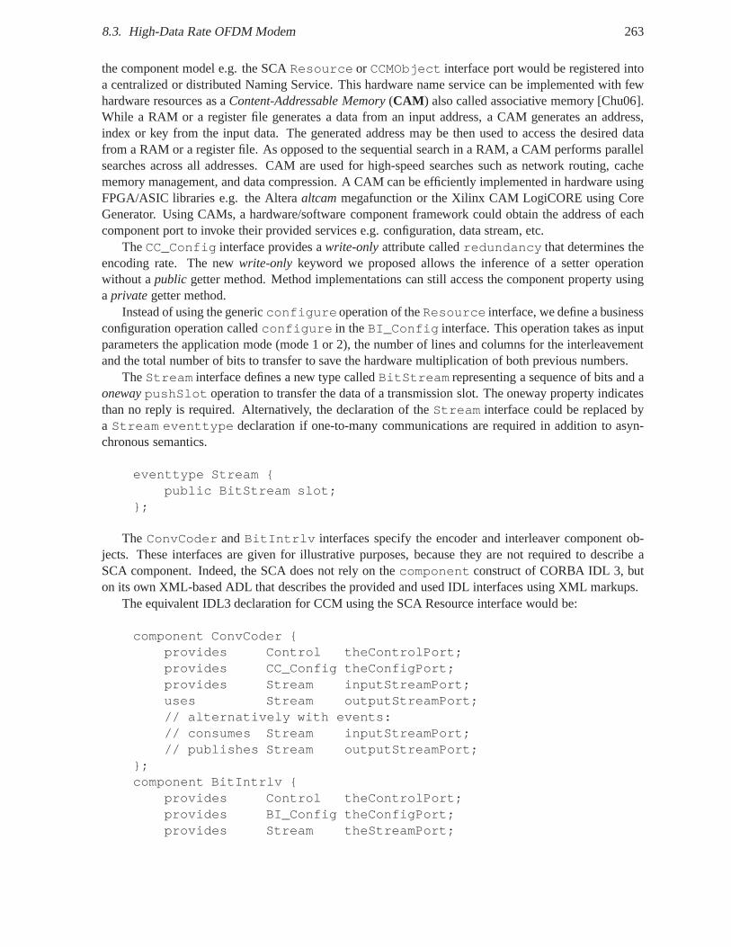
8.3. High-Data Rate OFDM Modem 263
the component model e.g. the SCAResource or CCMObject interface port would be registered intoa centralized or distributed Naming Service. This hardwarename service can be implemented with fewhardware resources as aContent-Addressable Memory(CAM ) also called associative memory [Chu06].While a RAM or a register file generates a data from an input address, a CAM generates an address,index or key from the input data. The generated address may bethen used to access the desired datafrom a RAM or a register file. As opposed to the sequential search in a RAM, a CAM performs parallelsearches across all addresses. CAM are used for high-speed searches such as network routing, cachememory management, and data compression. A CAM can be efficiently implemented in hardware usingFPGA/ASIC libraries e.g. the Alteraaltcammegafunction or the Xilinx CAM LogiCORE using CoreGenerator. Using CAMs, a hardware/software component framework could obtain the address of eachcomponent port to invoke their provided services e.g. configuration, data stream, etc.
TheCC_Config interface provides awrite-onlyattribute calledredundancy that determines theencoding rate. The newwrite-only keyword we proposed allows the inference of a setter operationwithout apublic getter method. Method implementations can still access thecomponent property usingaprivategetter method.
Instead of using the genericconfigureoperation of theResource interface, we define a businessconfiguration operation calledconfigure in theBI_Config interface. This operation takes as inputparameters the application mode (mode 1 or 2), the number of lines and columns for the interleavementand the total number of bits to transfer to save the hardware multiplication of both previous numbers.
TheStream interface defines a new type calledBitStream representing a sequence of bits and aonewaypushSlot operation to transfer the data of a transmission slot. The oneway property indicatesthan no reply is required. Alternatively, the declaration of the Stream interface could be replaced bya Stream eventtype declaration if one-to-many communications are required inaddition to asyn-chronous semantics.
eventtype Stream {public BitStream slot;
};
TheConvCoder andBitIntrlv interfaces specify the encoder and interleaver component ob-jects. These interfaces are given for illustrative purposes, because they are not required to describe aSCA component. Indeed, the SCA does not rely on thecomponent construct of CORBA IDL 3, buton its own XML-based ADL that describes the provided and usedIDL interfaces using XML markups.
The equivalent IDL3 declaration for CCM using the SCA Resource interface would be:
component ConvCoder {provides Control theControlPort;provides CC_Config theConfigPort;provides Stream inputStreamPort;uses Stream outputStreamPort;// alternatively with events:// consumes Stream inputStreamPort;// publishes Stream outputStreamPort;
};component BitIntrlv {
provides Control theControlPort;provides BI_Config theConfigPort;provides Stream theStreamPort;
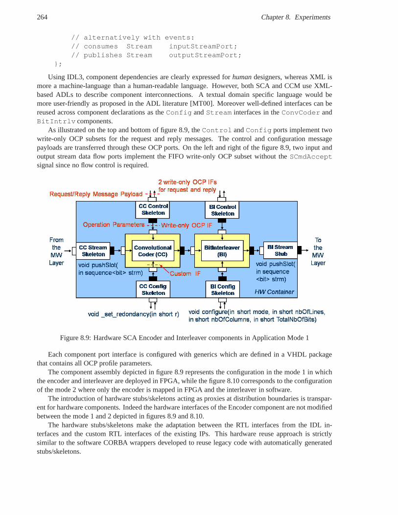
264 Chapter 8. Experiments
// alternatively with events:// consumes Stream inputStreamPort;// publishes Stream outputStreamPort;
};
Using IDL3, component dependencies are clearly expressed for humandesigners, whereas XML ismore a machine-language than a human-readable language. However, both SCA and CCM use XML-based ADLs to describe component interconnections. A textual domain specific language would bemore user-friendly as proposed in the ADL literature [MT00]. Moreover well-defined interfaces can bereused across component declarations as theConfig andStream interfaces in theConvCoder andBitIntrlv components.
As illustrated on the top and bottom of figure 8.9, theControl andConfig ports implement twowrite-only OCP subsets for the request and reply messages. The control and configuration messagepayloads are transferred through these OCP ports. On the left and right of the figure 8.9, two input andoutput stream data flow ports implement the FIFO write-only OCP subset without theSCmdAcceptsignal since no flow control is required.
Figure 8.9: Hardware SCA Encoder and Interleaver components in Application Mode 1
Each component port interface is configured with generics which are defined in a VHDL packagethat contains all OCP profile parameters.
The component assembly depicted in figure 8.9 represents theconfiguration in the mode 1 in whichthe encoder and interleaver are deployed in FPGA, while the figure 8.10 corresponds to the configurationof the mode 2 where only the encoder is mapped in FPGA and the interleaver in software.
The introduction of hardware stubs/skeletons acting as proxies at distribution boundaries is transpar-ent for hardware components. Indeed the hardware interfaces of the Encoder component are not modifiedbetween the mode 1 and 2 depicted in figures 8.9 and 8.10.
The hardware stubs/skeletons make the adaptation between the RTL interfaces from the IDL in-terfaces and the custom RTL interfaces of the existing IPs. This hardware reuse approach is strictlysimilar to the software CORBA wrappers developed to reuse legacy code with automatically generatedstubs/skeletons.
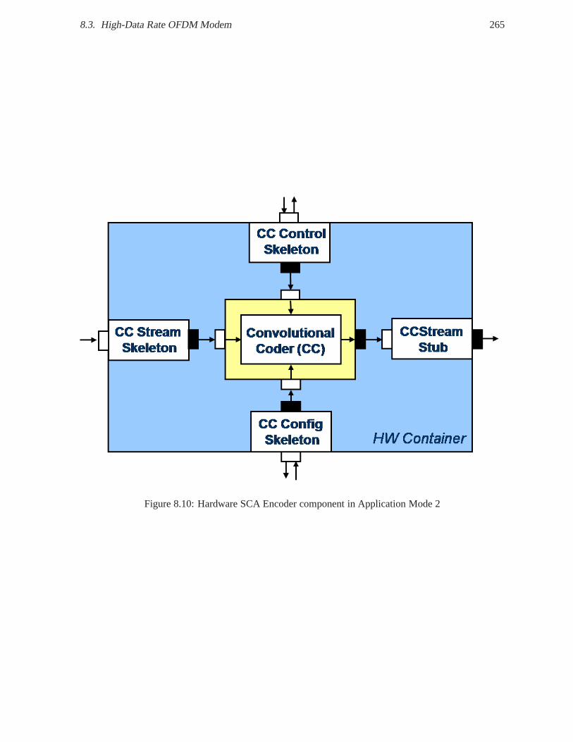
8.3. High-Data Rate OFDM Modem 265
Figure 8.10: Hardware SCA Encoder component in ApplicationMode 2
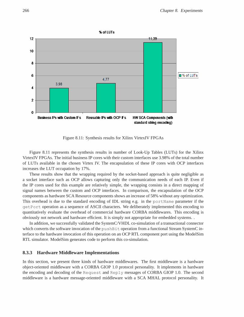
266 Chapter 8. Experiments
Figure 8.11: Synthesis results for Xilinx VirtexIV FPGAs
Figure 8.11 represents the synthesis results in number of Look-Up Tables (LUTs) for the XilinxVirtexIV FPGAs. The initial business IP cores with their custom interfaces use 3.98% of the total numberof LUTs available in the chosen Virtex IV. The encapsulationof these IP cores with OCP interfacesincreases the LUT occupation by 17%.
These results show that the wrapping required by the socket-based approach is quite negligible asa socket interface such as OCP allows capturing only the communication needs of each IP. Even ifthe IP cores used for this example are relatively simple, thewrapping consists in a direct mapping ofsignal names between the custom and OCP interfaces. In comparison, the encapsulation of the OCPcomponents as hardware SCA Resource components shows an increase of 58% without any optimization.This overhead is due to the standard encoding of IDL string e.g. in theportName parameter if thegetPort operation as a sequence of ASCII characters. We deliberately implemented this encoding toquantitatively evaluate the overhead of commercial hardware CORBA middlewares. This encoding isobviously not network and hardware efficient. It is simply not appropriate for embedded systems. .
In addition, we successfully validated the SystemC/VHDL co-simulation of a transactional connectorwhich converts the software invocation of thepushBit operation from a functional Stream SystemC in-terface to the hardware invocation of this operation on an OCP RTL component port using the ModelSimRTL simulator. ModelSim generates code to perform this co-simulation.
8.3.3 Hardware Middleware Implementations
In this section, we present three kinds of hardware middlewares. The first middleware is a hardwareobject-oriented middleware with a CORBA GIOP 1.0 protocol personality. It implements in hardwarethe encoding and decoding of theRequest andReply messages of CORBA GIOP 1.0. The secondmiddleware is a hardware message-oriented middleware witha SCA MHAL protocol personality. It
8.3. High-Data Rate OFDM Modem 267
supports the hardware encoding and decoding of SCA MHAL header messages and dispatches the samemessage payloads than the GIOP messages to provide transparent communications to application com-ponents. While the two first middlewares are based on messagepassing, the last hardware middlewareimplementation is based on memory-mapping and allows one toevaluate the overhead of the two pre-vious approaches. We consider these middleware implementations as three configurations of the samemiddleware architecture framework which revisits bus and NoC concepts for hardware middlewares.
All hardware middleware implementations have been deployed on the Xilinx ML405 board. Thehardcore PowerPC embedded processor within the VirtexIV FPGA executes a software testbench, whichwrites request messages in the middleware FIFOs across the Xilinx OPB bus and read reply messagesto compare them with reference results. Note that the on-chip processor is only used to debug andvalidate the middleware prototypes. In a real implementation, instead of sending both message headersand payloads through the on-chip bus, only message payloadswould be sent to hardware IP componentsto reduce bandwidth usage. In this case, addressing information in message headers would be mappedto bus addresses. In fact, this experiment simulates the reception of GIOP messages from outside theFPGA. The final combination of the hardware/software application and platform components is definedby the system engineers according to performance requirements and design trade-offs. For instance,memory mapping could be chosen for local communications within an FPGA, while message passingusing GIOP or MHAL could be chosen for external communications outside the FPGA. GIOP or MHALmessages could be received from external high-speed communication links e.g. from the buffers of anEthernet MAC IP core or a RapidIO serial link without the needof a embedded processor.
In all these implementations, OCP interfaces have been usedin each middleware layer to evaluatethe hardware socket-based approach which is close to the interface-centric and component-oriented mid-dleware approach. We think that OCP provides a generic communication model and a common interfacelanguage for hardware designers, who only need to know one interface protocol. However, we alsoremark in our experiments that OCP and even its profiles are too large in scope and that our middle-ware implementation only requires OCP subsets such as write-only FIFO interfaces. We consider thatstandardized OCP profiles may address middleware interfaces at transport level for on-chip and off-chipbuses, while the OCP subsets cited as examples in the OCP specification [OI06] may address applicationinterfaces for business IP core components.
Moreover, OCP has some technical limitations for a standardmapping since it remains a bus-orientedinterface protocol. Indeed, an OCP address is a byte addressaligned on an OCP word whose size refersto the width of the OCP data bus [OI06]. For instance, if the data bus width is 32 bits, the address must beincremented by 4 since there are 4 byte addresses for each byte of a 32 bit word. Even if this correlationbetween the address and data buses is justified for physical addresses for bus transfers, this is a drawbackwhen the address bus is used to carry a logical address representing an operation identifier. This logicaladdress should be incremented by one to save area and remove useless address signals. Of course, otherOCP signals could be used likeMReqInfo, but this is counterintuitive for hardware designers, whereasthe address signal provides a better mapping of semantics between RMI and OCP.
Like the address signal, the burst length signal designatesa number of words. For instance, if wewould like to transfer an IDL array of 16octets as a burst on a 32bit data bus, the burst length wouldbe 4 words. If we would like to transfer an IDL array of 16octets as a burst on a 8bit data bus, theburst length would be 16 words. For instance, if we would liketo transfer an IDL sequence of 4longsas a burst, the burst length would be 4 words on a 32bit data busand 8 words on a 16bit data bus. Hence,the address and burst length are not related to the payload but to the data bus width. This is required forbus transfers at the transport level, but useless for methodinvocations at application level.
The OCP interfaces we use help us to define our family of interfaces, which must be independentfrom any existingproprietary interface protocol to be used in a standard IDL-to-RTL mapping for theOMG.
268 Chapter 8. Experiments
Moreover, defining a standard OMG mapping based on OCP requires that commercial and open-source ORB implementers buy membership to OCP-IP to validate their implementation of the OCPprotocol. In any case, these considerations are out-of-thescope of this thesis. In fine, these OCP inter-faces can be considered as the mapping of our independent interfaces on the particular OCP protocol.Other hardware interface mappings could be defined for the deprecated VCI protocol or other interfaceprotocols in the future.
GIOP RMI-oriented protocol personality
With the help of a trainee I supervised, we prototyped a GIOP message decoder/encoder to evaluate theoverhead of an hardware implementation of the GIOP protocolas proposed by the two leading embeddedORB vendors PrismTech [HP06] and OIS [OIS08].
Thanks to the open-source network analyzer Wireshark76 (formerly named Ethereal), I recorded theGIOP messages exchanged between the software SCA components. Then these messages have been sentto the hardware SCA components by a software testbench executed on the PowerPC embedded processor.
Figure 8.12 depicts the hardware implementation of an Object Request Broker (ORB) with a CORBAGIOP personality. We tried to apply the same design patternsand to identify the same architectural el-ements than those typically found in software middleware implementations. The architecture of thishardware ORB can be divided into five layers: the applicationlayer, the presentation layer, the dispatch-ing layer, the messaging layer and the transport layer.
Theapplication layer contains the hardware application components i.e. the Convolutional Encoderand the BitInterleaver in our experiments. These components are SCA Resources. They implementthe most relevant operations required by theResource interface in hardware. The otherResourceoperations can be transparently implemented in software stubs.
Thepresentation layerconsists of the manually generated hardware stubs and skeletons. They actas invocation adapters [PRP05] which perform the decoding and encoding of GIOP message payload.Stubs decode message payloads encoded with the Common Data Representation (CDR) encoding rulesinto operation parameters which are stored in registers. They can either forward the invocation to theapplication components via a write-only interface (push interface) to inform them that they can readparameter values, or the components can continuously read their values via a signal (data interface).The collection of stubs/skeletons that isolate the application components from their operating environ-ment can be viewed as a hardwarecontainerwhich provides activation (e.g writes), synchronization (e.g.clock) and storage (e.g. memories) services.
Thedispatching layer contains a generic request router and a reply arbiter. Therequest routeractsas an object adapter, which dispatches incoming invocations to the appropriate skeleton according tothe operation identifier transferred in the GIOP request message header. This router is similar to a busaddress decoder or a NoC router. It decodes the internal logical address of the request and routes itto the appropriate skeleton. The router shares the same design trade-offs as in buses and NoCs. Thisoperation name is a string of ASCII characters decoded by an FSM which compares it with the manuallygenerated arrays declared in a VHDL package. Due to the smallnumber of component ports or skeletons,this router is implemented as a 1-to-N multiplexer which is not scalable. To increase its scalability, therequest router can have a distributed implementation e.g. as a tree of 1-to-2 multiplexer. Thereply arbiterselects a skeleton according to their priority among those which want to send a reply message. In this testcase, only theControl interface skeletons of the Encoder and Interleaver components return a reply tothegetPort operation.
Themessaging layerimplements the GIOP protocol state machine. It contains a request decoder,
76http://www.wireshark.org
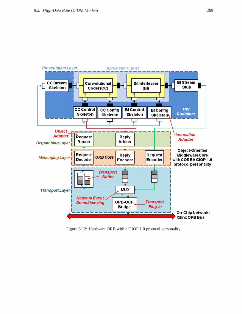
8.3. High-Data Rate OFDM Modem 269
Figure 8.12: Hardware ORB with a GIOP 1.0 protocol personality
270 Chapter 8. Experiments
a reply encoder and a request encoder. The request decoder decodes GIOP request message of theinitialize,start,stop, andset_redundancyandconfigure operations using a hierarchi-cal FSM. A first FSM decodes the GIOP message header, then a second FSM continues the decoding de-pending on the message type (Request or Reply). This modular FSM reduces the required hardwareresources by only implementing the needed types of messagesand can be used for an optimized code gen-eration. For instance, the following types of GIOP messageswere not implemented:LocateRequest,LocateReply, CancelRequest, MessageError andCloseConnection. The request de-coder writes on its output port the fields extracted from the message header. These fields are then usedby the following ORB modules, the request router and the skeletons, to perform their processing basedon the message body. To reduce the footprint of IDLstrings while decoding standard GIOP messages,this module maps sequences of ASCII characters in the headerinto numerical identifiers. Such a mappingmay be performed by IDL compilers inside the generated stubsat the expense of GIOP interoperability.The request encoder integrates a generic scheduler like in software middlewares to choose between thetwo available reception buffers. There are two reception buffers acting as two virtual input channels.The scheduling policy is the following: when a request is available, the request decoder selects a bufferaccording to its priority and reads a predefined number of message words per buffer to be decoded aslong as there are enough data available otherwise it choosesanother channel buffer. These virtual chan-nels allow the efficient sharing of the available bandwidth between the virtual channels. A priority isassigned to each FIFO to avoidpriority inversion. The decoding is performed separately for each vir-tual channel. The FSM decoding state is saved and restored during virtual channel switch to allow thedecoder to alternatively decode one message from each FIFO buffer. The GIOP request decoder is thusgeneric and independent from the number of transport buffers. The request and reply encoders performthe reverse steps of the request decoder. They produce the message header based on the fields it receivesfrom the stubs/skeletons. Thereply encoderprepends a GIOP message header and a reply header to thepushPacket message payload provided by theControl skeletons and writes the resulting messageto a transport buffer. Therequest encoderprepends a GIOP message header and a request header tothegetPort message payload provided by theStream stubs and writes the resulting message to atransport buffer. The request encoder uses the numerical identifier generated by the request decoder andreceived from the stubs to produce the IDL strings containedin the outcoming request message.
The transport layer includes transport buffers used to send and receive GIOP messages across thenetwork, here the Xilinx OPB bus for validation purpose. It contains a transport plug-in, which is a anOPB-to-OCP bridge. The transport buffers areactiveFIFOs. The receiving buffers send write requeststo the request decoder when data from a message are received.The request decoder may immediatelyaccept the write request or delay its response to process a message from another buffer. In the sameway, the sending buffers send read requests to the reply and request encoders which are free to accept ornot. The active FIFOs reduce the latency required between a read or write request from the messaginglayer and the response from passive FIFOs. In the current implementation, there are two input buffersfor incoming request messages, an output buffer for reply messages and an output buffer for outcomingrequest messages. The number and depth of each buffer is chosen according to our particular scenarioand may be adapted for other use cases. A multiplexer is used to demultiplex incoming messages to theinput buffers and outcoming messages from the output buffers.
The transport buffers were implemented as FIFO memories, but they also may be implemented asaddressable memories using RAMs to bypass useless data fromGIOP messages such as padding, re-questing principal and service context list during their decoding instead of reading these data from theFIFO buffer.
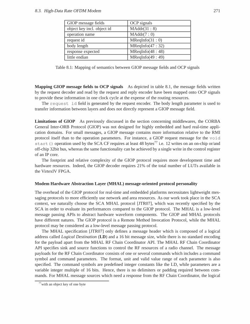
8.3. High-Data Rate OFDM Modem 271
GIOP message fields OCP signalsobject key incl. object id MAddr(31 : 8)operation name MAddr(7 : 0)request id MReqInfo(31 : 0)body length MReqInfo(47 : 32)response expected MReqInfo(48 : 48)little endian MReqInfo(49 : 49)
Table 8.1: Mapping of semantics between GIOP message fields and OCP signals
Mapping GIOP message fields to OCP signals As depicted in table 8.1, the message fields writtenby the request decoder and read by the request and reply encoder have been mapped onto OCP signalsto provide these information in one clock cycle at the expense of the routing resources.
Therequest id field is generated by the request encoder. The body length parameter is used totransfer information between layers and does not directly represent a GIOP message field.
Limitations of GIOP As previously discussed in the section concerning middlewares, the CORBAGeneral Inter-ORB Protocol (GIOP) was not designed for highly embedded and hard real-time appli-cation domains. For small messages, a GIOP message containsmore information relative to the RMIprotocol itself than to the operation parameters. For instance, a GIOP request message for thevoidstart() operation used by the SCA CF requires at least 48 bytes77 i.e. 12 writes on an on-chip or/andoff-chip 32bit bus, whereas the same functionality can be achieved by a single write in the control registerof an IP core.
The footprint and relative complexity of the GIOP protocol requires more development time andhardware resources. Indeed, the GIOP decoder requires 21% of the total number of LUTs available inthe VirtexIV FPGA.
Modem Hardware Abstraction Layer (MHAL) message-orientedprotocol personality
The overhead of the GIOP protocol for real-time and embeddedplatforms necessitates lightweight mes-saging protocols to more efficiently use network and area resources. As our work took place in the SCAcontext, we naturally choose the SCA MHAL protocol [JTR07],which was recently specified by theSCA in order to evaluate its performances compared to the GIOP protocol. The MHAL is a low-levelmessage passing APIs to abstract hardware waveform components. The GIOP and MHAL protocolshave different natures. The GIOP protocol is a Remote MethodInvocation Protocol, while the MHALprotocol may be considered as a low-level message passing protocol.
The MHAL specification [JTR07] only defines a message header which is composed of a logicaladdress calledLogical Destination(LD ) and a 16 bit message size, while there is no standard encodingfor the payload apart from the MHAL RF Chain Coordinator API.The MHAL RF Chain CoordinatorAPI specifies sink and source functions to control the RF resources of a radio channel. The messagepayloads for the RF Chain Coordinator consists of one or several commands which includes a commandsymbol and command parameters. The format, unit and valid value range of each parameter is alsospecified. The command symbols are predefined integer constants like the LD, while parameters are avariable integer multiple of 16 bits. Hence, there is no delimiters or padding required between com-mands. For MHAL message sources which need a response from the RF Chain Coordinator, the logical
77with an object key of one byte
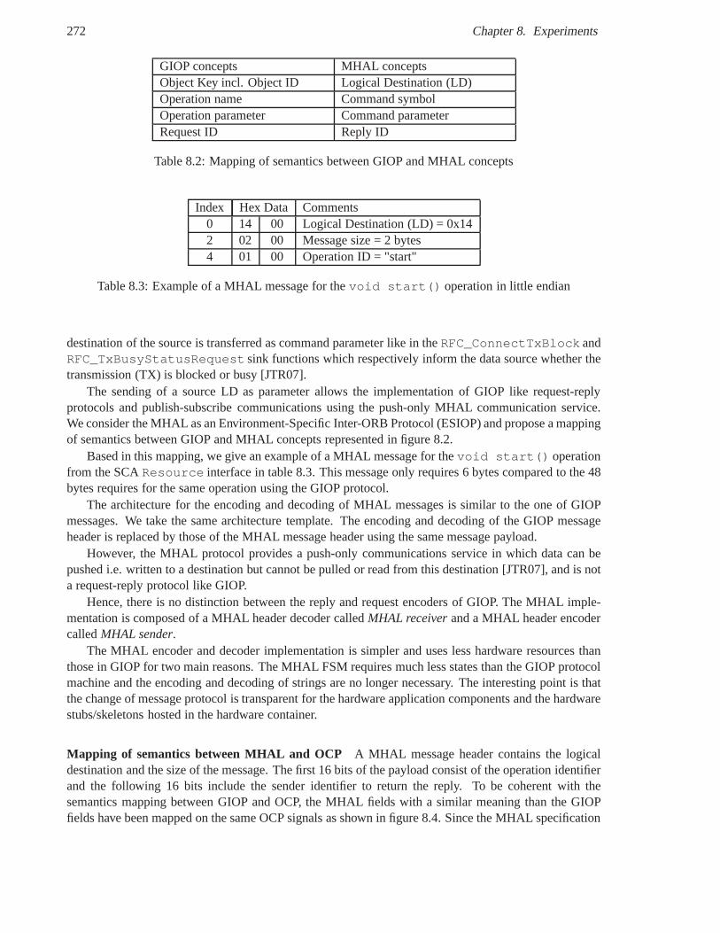
272 Chapter 8. Experiments
GIOP concepts MHAL conceptsObject Key incl. Object ID Logical Destination (LD)Operation name Command symbolOperation parameter Command parameterRequest ID Reply ID
Table 8.2: Mapping of semantics between GIOP and MHAL concepts
Index Hex Data Comments0 14 00 Logical Destination (LD) = 0x142 02 00 Message size = 2 bytes4 01 00 Operation ID = "start"
Table 8.3: Example of a MHAL message for thevoid start() operation in little endian
destination of the source is transferred as command parameter like in theRFC_ConnectTxBlock andRFC_TxBusyStatusRequest sink functions which respectively inform the data source whether thetransmission (TX) is blocked or busy [JTR07].
The sending of a source LD as parameter allows the implementation of GIOP like request-replyprotocols and publish-subscribe communications using thepush-only MHAL communication service.We consider the MHAL as an Environment-Specific Inter-ORB Protocol (ESIOP) and propose a mappingof semantics between GIOP and MHAL concepts represented in figure 8.2.
Based in this mapping, we give an example of a MHAL message forthevoid start() operationfrom the SCAResource interface in table 8.3. This message only requires 6 bytes compared to the 48bytes requires for the same operation using the GIOP protocol.
The architecture for the encoding and decoding of MHAL messages is similar to the one of GIOPmessages. We take the same architecture template. The encoding and decoding of the GIOP messageheader is replaced by those of the MHAL message header using the same message payload.
However, the MHAL protocol provides a push-only communications service in which data can bepushed i.e. written to a destination but cannot be pulled or read from this destination [JTR07], and is nota request-reply protocol like GIOP.
Hence, there is no distinction between the reply and requestencoders of GIOP. The MHAL imple-mentation is composed of a MHAL header decoder calledMHAL receiverand a MHAL header encodercalledMHAL sender.
The MHAL encoder and decoder implementation is simpler and uses less hardware resources thanthose in GIOP for two main reasons. The MHAL FSM requires muchless states than the GIOP protocolmachine and the encoding and decoding of strings are no longer necessary. The interesting point is thatthe change of message protocol is transparent for the hardware application components and the hardwarestubs/skeletons hosted in the hardware container.
Mapping of semantics between MHAL and OCP A MHAL message header contains the logicaldestination and the size of the message. The first 16 bits of the payload consist of the operation identifierand the following 16 bits include the sender identifier to return the reply. To be coherent with thesemantics mapping between GIOP and OCP, the MHAL fields with asimilar meaning than the GIOPfields have been mapped on the same OCP signals as shown in figure 8.4. Since the MHAL specification
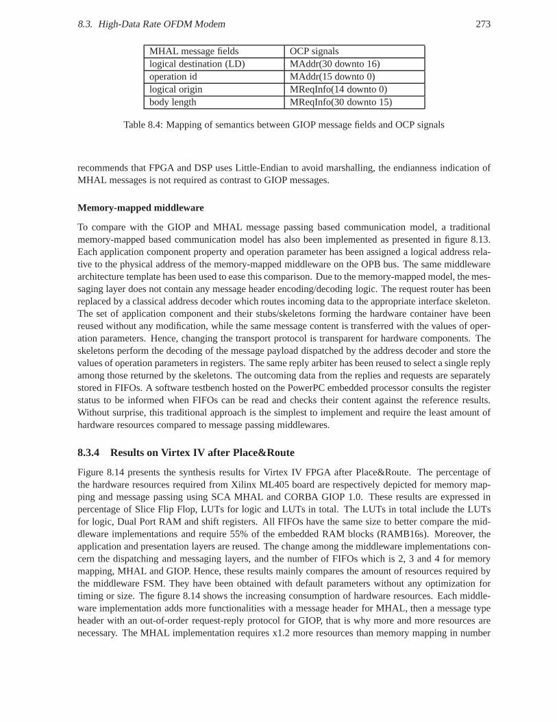
8.3. High-Data Rate OFDM Modem 273
MHAL message fields OCP signalslogical destination (LD) MAddr(30 downto 16)operation id MAddr(15 downto 0)logical origin MReqInfo(14 downto 0)body length MReqInfo(30 downto 15)
Table 8.4: Mapping of semantics between GIOP message fields and OCP signals
recommends that FPGA and DSP uses Little-Endian to avoid marshalling, the endianness indication ofMHAL messages is not required as contrast to GIOP messages.
Memory-mapped middleware
To compare with the GIOP and MHAL message passing based communication model, a traditionalmemory-mapped based communication model has also been implemented as presented in figure 8.13.Each application component property and operation parameter has been assigned a logical address rela-tive to the physical address of the memory-mapped middleware on the OPB bus. The same middlewarearchitecture template has been used to ease this comparison. Due to the memory-mapped model, the mes-saging layer does not contain any message header encoding/decoding logic. The request router has beenreplaced by a classical address decoder which routes incoming data to the appropriate interface skeleton.The set of application component and their stubs/skeletonsforming the hardware container have beenreused without any modification, while the same message content is transferred with the values of oper-ation parameters. Hence, changing the transport protocol is transparent for hardware components. Theskeletons perform the decoding of the message payload dispatched by the address decoder and store thevalues of operation parameters in registers. The same replyarbiter has been reused to select a single replyamong those returned by the skeletons. The outcoming data from the replies and requests are separatelystored in FIFOs. A software testbench hosted on the PowerPC embedded processor consults the registerstatus to be informed when FIFOs can be read and checks their content against the reference results.Without surprise, this traditional approach is the simplest to implement and require the least amount ofhardware resources compared to message passing middlewares.
8.3.4 Results on Virtex IV after Place&Route
Figure 8.14 presents the synthesis results for Virtex IV FPGA after Place&Route. The percentage ofthe hardware resources required from Xilinx ML405 board arerespectively depicted for memory map-ping and message passing using SCA MHAL and CORBA GIOP 1.0. These results are expressed inpercentage of Slice Flip Flop, LUTs for logic and LUTs in total. The LUTs in total include the LUTsfor logic, Dual Port RAM and shift registers. All FIFOs have the same size to better compare the mid-dleware implementations and require 55% of the embedded RAMblocks (RAMB16s). Moreover, theapplication and presentation layers are reused. The changeamong the middleware implementations con-cern the dispatching and messaging layers, and the number ofFIFOs which is 2, 3 and 4 for memorymapping, MHAL and GIOP. Hence, these results mainly compares the amount of resources required bythe middleware FSM. They have been obtained with default parameters without any optimization fortiming or size. The figure 8.14 shows the increasing consumption of hardware resources. Each middle-ware implementation adds more functionalities with a message header for MHAL, then a message typeheader with an out-of-order request-reply protocol for GIOP, that is why more and more resources arenecessary. The MHAL implementation requires x1.2 more resources than memory mapping in number
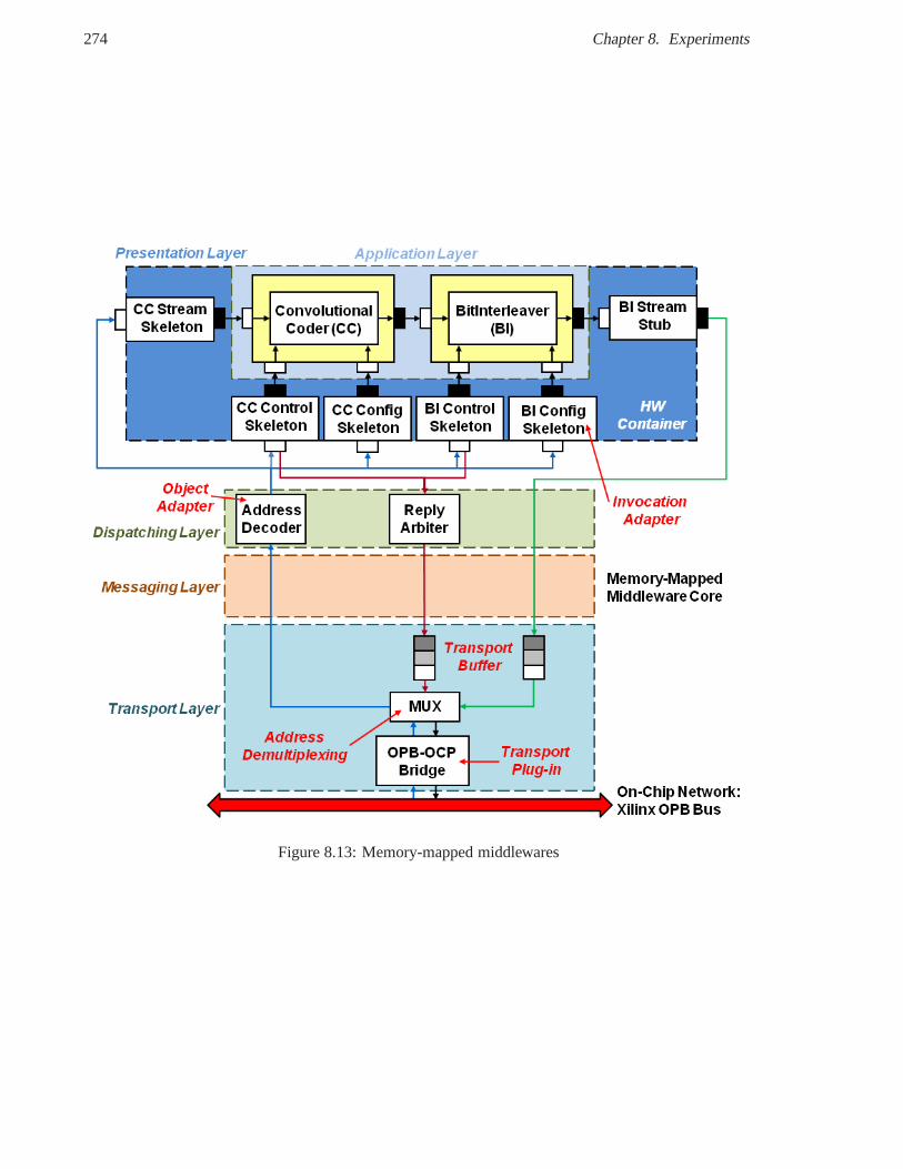
274 Chapter 8. Experiments
Figure 8.13: Memory-mapped middlewares
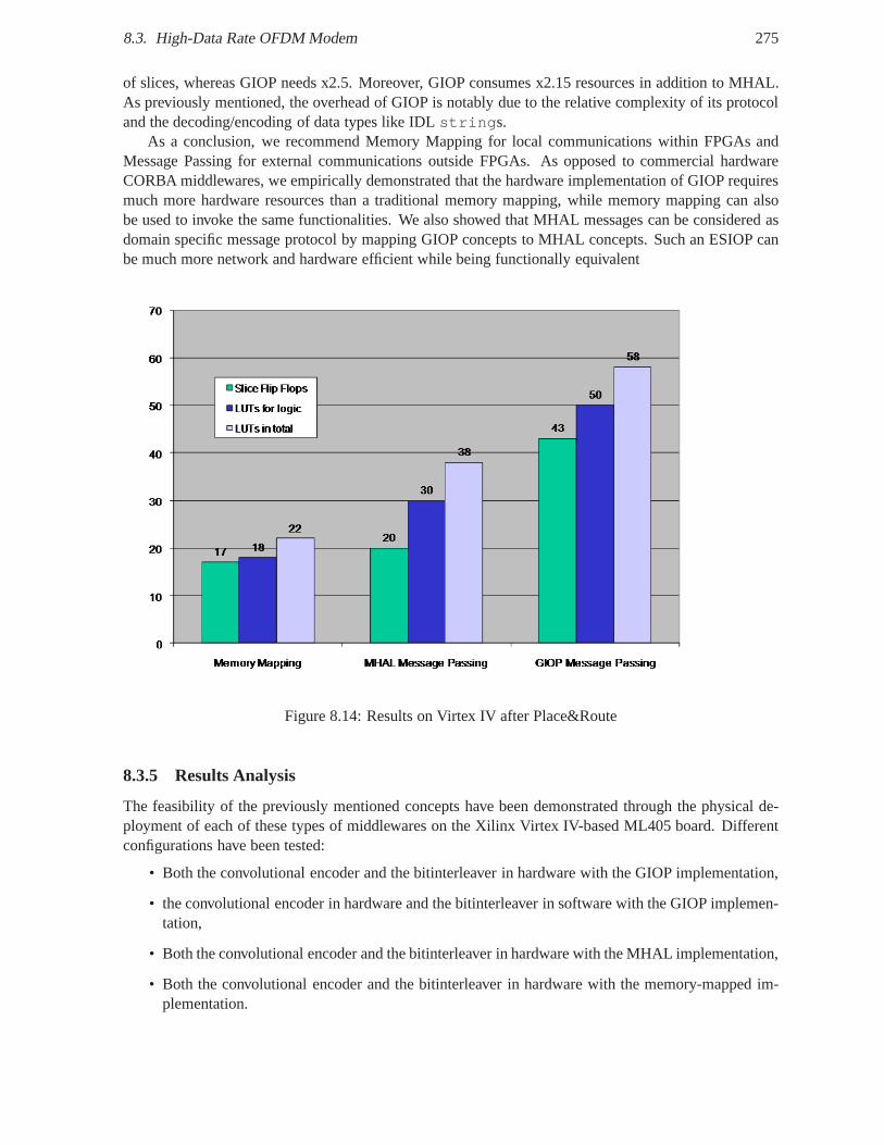
8.3. High-Data Rate OFDM Modem 275
of slices, whereas GIOP needs x2.5. Moreover, GIOP consumesx2.15 resources in addition to MHAL.As previously mentioned, the overhead of GIOP is notably dueto the relative complexity of its protocoland the decoding/encoding of data types like IDLstrings.
As a conclusion, we recommend Memory Mapping for local communications within FPGAs andMessage Passing for external communications outside FPGAs. As opposed to commercial hardwareCORBA middlewares, we empirically demonstrated that the hardware implementation of GIOP requiresmuch more hardware resources than a traditional memory mapping, while memory mapping can alsobe used to invoke the same functionalities. We also showed that MHAL messages can be considered asdomain specific message protocol by mapping GIOP concepts toMHAL concepts. Such an ESIOP canbe much more network and hardware efficient while being functionally equivalent
Figure 8.14: Results on Virtex IV after Place&Route
8.3.5 Results Analysis
The feasibility of the previously mentioned concepts have been demonstrated through the physical de-ployment of each of these types of middlewares on the Xilinx Virtex IV-based ML405 board. Differentconfigurations have been tested:
• Both the convolutional encoder and the bitinterleaver in hardware with the GIOP implementation,
• the convolutional encoder in hardware and the bitinterleaver in software with the GIOP implemen-tation,
• Both the convolutional encoder and the bitinterleaver in hardware with the MHAL implementation,
• Both the convolutional encoder and the bitinterleaver in hardware with the memory-mapped im-plementation.
276 Chapter 8. Experiments
All these different deployments have been transparent for the hardware SCA components thanks tothe hardware stubs/skeletons acting as hardware proxies. The two first configurations demonstrate thetransparent deployment of components in hardware and software. Moreover, the control of the dynamicand partial reconfiguration of a hardware module has been showed in [SMC+07] using the same board.Unfortunately, the integration of both approaches has not been performed for space limitations on theboard and for time reasons. Nevertheless, we can envisage the dynamic partial reconfiguration of hard-ware SCA components under the control of a software SCA CoreFramework and their hardware/softwaremigration according to some load conditions or waveform application modes.
8.4 Conclusion
In this chapter, we presented two modem applications on which we built our propositions and the experi-ments on which we validated part of our contributions. We built an executable Platform Specific Model inSystemC TLM of part of the DiMITRI MPSoC. We recognize the unifying concepts of component, con-tainer and connector at transactional and register transfer levels. The C reference model of the classicaldesign flow 2.6 implements the business logic of a RTL IP core componentw, while its services are calledby the enclosing container through register and bitfield callback functions using the SystemC ModelingLibrary (SCML) [SCM08]. These callbacks functions implement the technical logic like storage andsynchronization). According to the taxonomy of connectorsin 6.5.7, an OCP TL2 channel representsan arbitrator/distributor connector, while the OCP TL2-to-PV transactor is a conversion connector. ASystemC component at Programmer View level allows an earlier validation of the hardware/softwareinterface and software drivers, which are error-prone codeto develop.
We illustrated our IDL-to-SystemC TLM mapping propositionthrough the encapsulation of invo-cation messages in OCP TLM connectors. We present the refinement of a business component from afunctional model in C to a SystemC component at Programmer View (PV) level, the refinement of atransactional connector from an OCP TL2 to an AHB bus functional model, and the refinement at dif-ferent abstraction levels from SystemC FIFO channels to OCPTLM and OCP RTL. The introduction ofSystemC TLM stubs/skeletons acting as connector fragmentsat distribution boundaries was transparentfor hardware/software SystemC components.
We illustrate our IDL-to-VHDL mapping proposition with twohardware SCA components, a con-volutional encoder and a bit interleaver. The RTL stubs/skeletons make the adaptation between the RTLinterfaces derived from IDL interfaces and the custom RTL interfaces of the existing IPs, in a similarway to the software CORBA wrappers developed to reuse legacycode with automatically generatedstubs/skeletons. The collection of stubs/skeletons that isolate the application components from theiroperating environment can be viewed as a hardwarecontainer, which provides activation (e.g writes),synchronization (e.g. clock) and storage (e.g. memories) services. The interesting point is that thechange of message protocol is transparent for the hardware application components and the hardwarestubs/skeletons hosted in the hardware container.
We refined a Coder and Interleaver SystemC components to hardware SCA components in VHDLusing OCP RTL as a concrete mapping of our interface family. Our results showed that the overhead ofthe socket-based approach is quite negligible (17%) compared to a socket interface such as OCP, whichonly captures the communication needs of each IP core of overhead. Hence in our case, the wrappingconsists in a direct mapping of signal names between the custom and OCP interfaces. We evaluatedthe important overhead (58%) of the encapsulation of the OCPcomponents as hardware SCA Resourcecomponents with the standard encoding of IDL string proposed by commercial hardware ORB vendors.Hence, portability and interoperability of waveform components have a cost without any optimization.
From an industrial viewpoint, the maintenance of multiple models at different abstraction levels is
8.4. Conclusion 277
difficult to manage without dedicated standards like SPIRITIP-XACT. Standard language mappingsfrom OMG IDL/UML to the standard TLM interfaces may help to generate transactional connectorsfrom one abstraction level to another, if not already in a library. Moreover, SystemC-based design flowsrequire to train (dedicated) HW/SW engineers, to buy commercial tools like CoWare Platform Architector to develop custom tools for entreprises, which reach a critical mass of complex projects like STMi-croelectronics. For instance, hardware/software engineers at Thales Communications generally prefer Crather than SystemC : 1) to increase simulation speed via native execution (w/o ISSs) and direct plaformintegrations, 2) to avoid learning another language, and 3)in reasons of the conceptual gap introduced bySystemC and its maturity. Since Thales products have long life cycles, SystemC waveform componentsand SDR platform models could be a good investment. Moreover, an MDE/MDA approach may allowone to define future mappings to new Platform Specific Models as the technology rapidly evolves. Evenif HLS tools offer a direct refinement from C to HDL sometimes at the expense of some code rewriting,we argue that SystemC components may still be required sincethey provide higher simulation speed thanRTL components.
Finally, three different configurations of the proposed hardware middleware architecture frameworkwere implemented using memory mapping and message passing.We showed how a dedicated messagepassing protocol such as MHAL is more hardware efficient thana general purpose message protocollike CORBA GIOP. We recommend memory mapping for local communications within an FPGA, andmessage passing using GIOP or MHAL for external communications outside the FPGA.

Chapter 9
Conclusions and Perspectives
Contents9.1 Problems . . . . . . . . . . . . . . . . . . . . . . . . . . . . . . . . . . . . . . . .. 279
9.2 Synthesis . . . . . . . . . . . . . . . . . . . . . . . . . . . . . . . . . . . . . . .. . 279
9.3 Contributions . . . . . . . . . . . . . . . . . . . . . . . . . . . . . . . . . . .. . . 280
9.4 Limitations . . . . . . . . . . . . . . . . . . . . . . . . . . . . . . . . . . . . .. . . 2829.5 Conclusions . . . . . . . . . . . . . . . . . . . . . . . . . . . . . . . . . . . . .. . . 282
9.6 Perspectives . . . . . . . . . . . . . . . . . . . . . . . . . . . . . . . . . . . .. . . 283
In this section, we recap the problems addressed in this workand summarize our contributions. Wealso present some limitations of this PhD thesis and draw some perspectives.
9.1 Problems
The SCA specifies an Operating Environment composed of a CoreFramework, a CORBA-compliantmiddleware and a POSIX-compliant OS. The Core Framework is aset of UML and CORBA interfacesto load, deploy and run waveform applications. This OE targets GPPs, but not highly-constrained pro-cessing units such as DSPs, FPGAs and ASICs. The goal of this thesis was to apply some successfulsoftware engineering concepts used in the SCA down to hardware in FPGA to provide a common and uni-fied approach of specification, design and implementation ofhardware/software component-based SDRapplications. Moreover, the main requirements of the SCA are portability, interoperability, reuse andreconfigurability of SCA components. Hence, we had also to address these requirements for hardwarecomponents in HDLs such as VHDL and SystemC RTL, and transactional components in SystemC TLMto raise the simulation speed. In addition, our second objective was to apply the Lightweight CORBAComponent Model to VHDL/SystemC component to support another common hardware/software com-ponent model. The ultimate objective of this work is to sharethe same concepts between hardwareand software engineering to define a common component-oriented system architecture and to raise theabstraction level of hardware components.
9.2 Synthesis
Usually, the integration of hardware modules relies on low-level hardware/software interfaces, whichconsists of proprietary bus interfaces, memory-mapped registers and interrupts to synchronize hard-ware/software modules. As a result, this integration is tedious and error-prone, and the reuse of HW/SW
279
280 Chapter 9. Conclusions and Perspectives
modules is limited. Co-design methodologies have been developed to bridge the conceptual gap betweenhardware design and software design. To provide a common hardware/software design approach, theconcepts of the object model has been applied to hardware design. In the object-oriented approach, anobject is a self-contained and identifiable entity, which encloses its own state and behavior in a method-based interface, and communicates only through message passing. To apply the object model down tosynthesizable hardware, the previous works propose a mapping between a method-based interface to asignal-based interface. Hardware object-oriented designallows to raise the abstraction level of hardwaremodule interfaces, to reduce the conceptual and abstraction gap between interface specification and im-plementation, and to enforce a clean separation between computation and communication through remotemethod invocation. Existing works propose a mapping, whichrepresents one solution in the mappingexploration space. Moreover, the object-oriented approach has some limitations: only one providedinterface (the most derived), implicit dependencies, and no clear separation of concerns between func-tional and non functional logic like communication and deployment. The software component-orientedapproach is an evolution from the object-oriented approach.
In software architecture, the component-oriented approach relies on four main standard models:component models defining component structure and behavior,connector models to specify com-ponent interactions,container model to mediate access to middleware services, andpackaging anddeployment models to deploy distributed component-based applications.
A software component provides and requires services through multiple interfaces that allow an ex-plicit specification of external dependencies and a separation of concerns between functional interfacesfor business logic and non-functional interfaces for technical logic e.g. regarding configuration, deploy-ment and activation, packaging, deployment (i.e. installation, connection), life cycle (i.e. initialization,configuration and activation), administration (e.g. monitoring and reconfiguration). A software compo-nent has logical ports that provide and require properties,methods and events. A software connector is acomponent which binds the required and provided ports of twoor more components.
In the hardware component models, a hardware component has input, output, input/output RTL portsthat provide and require one or several signal-based interfaces. The connection model of hardware com-ponents is based on standard bus interfaces and communication protocols. An emerging packaging modelfor hardware components is the IP-XACT specification, whichdefines XML schema files to describe thecharacteristics of IP core components such as hardware interfaces, registers and interconnection. Thedeployment model of hardware IP core components can be either statically deployed on an FPGA atreset-time or dynamically deployed at run-time.
To support the systematic refinement of object-oriented component interfaces in CORBA IDL orUML to system, software, and hardware component interfacesin C/C++, SystemC and VHDL, we pro-pose to define new language mappings from CORBA IDL to SystemCTLM/RTL and VHDL.
9.3 Contributions
We investigate the hardware implementation of abstract object-oriented components. While most of theworks on the application of the software concepts to hardware design are based on an object-orientedapproach, we consider in contrast the application of the component-oriented software architecture. Weargue that the component-oriented approach provides better unifying concepts for hardware/softwareembedded systems, than the object-oriented approach. We provide a state of the art on the application ofthe object, component and middleware concepts to hardware engineering.
Concerning SDR design methodology, we proposed to leveragethe conceptual SDR design method-ology based on MDA and the component/container approach, which existed at Thales Communicationsin 2005, with SystemC Transaction Level Modeling (TLM) to simulate the platform independent model
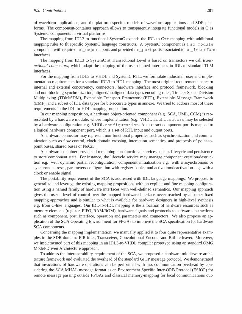
9.3. Contributions 281
of waveform applications, and the platform specific models of waveform applications and SDR plat-forms. The component/container approach allows to transparently integrate functional models in C asSystemC components in virtual platforms.
The mapping from IDL3 to functional SystemC extends the IDL-to-C++ mapping with additionalmapping rules to fit specific SystemC language constructs. A SystemC component is asc_modulecomponent with requiredsc_exportports and providedsc_portports associated tosc_interfaceinterfaces.
The mapping from IDL3 to SystemC at Transactional Level is based on transactors we calltrans-actional connectors, which adapt the mapping of the user-defined interfaces in IDL to standard TLMinterfaces.
For the mapping from IDL3 to VHDL and SystemC RTL, we formulate industrial, user and imple-mentation requirements for a standard IDL3-to-HDL mapping. The most original requirements concerninternal and external concurrency, connectors, hardware interface and protocol framework, blockingand non-blocking synchronization, aligned/unaligned data types encoding rules, Time or Space DivisionMultiplexing (TDM/SDM), Extensible Transport Framework (ETF), Extensible Message Framework(EMF), and a subset of IDL data types for bit-accurate types in annexe. We tried to address most of theserequirements in the IDL-to-HDL mapping proposition.
In our mapping proposition, a hardware object-oriented component (e.g. SCA, UML, CCM) is rep-resented by a hardware module, whose implementation (e.g. VHDL architecture may be selectedby a hardware configuration e.g. VHDLconfiguration. An abstract component port is mapped toa logical hardware component port, which is a set of RTL inputand output ports.
A hardware connector may represent non-functional properties such as synchronization and commu-nication such as flow control, clock domain crossing, interaction semantics, and protocols of point-to-point buses, shared buses or NoCs.
A hardware container provide all remaining non-functionalservices such as lifecycle and persistenceto store component state. For instance, the lifecycle service may manage component creation/destruc-tion e.g. with dynamic partial reconfiguration, component initialization e.g. with a asynchronous orsynchronous reset, parameters configuration with registerbanks, and activation/deactivation e.g. with aclock or enable signal.
The portability requirement of the SCA is addressed with IDLlanguage mappings. We propose togeneralize and leverage the existing mapping propositionswith an explicit and fine mapping configura-tion using a named family of hardware interfaces with well-defined semantics. Our mapping approachgives the user a level of control over the mapped hardware interface never reached by all other fixedmapping approaches and is similar to what is available for hardware designers in high-level synthesise.g. from C-like languages. Our IDL-to-HDL mapping is the allocation of hardware resources such asmemory elements (register, FIFO, RAM/ROM), hardware signals and protocols to software abstractionssuch as component, port, interface, operation and parameters and connectors. We also propose an ap-plication of the SCA Operating Environment for FPGAs to improve the SCA specification for hardwareSCA components.
Concerning the mapping implementation, we manually applied it to four quite representative exam-ples in the SDR domain: FIR filter, Transceiver, Convolutional Encoder and BitInterleaver. Moreover,we implemented part of this mapping in an IDL3-to-VHDL compiler prototype using an standard OMGModel-Driven Architecture approach.
To address the interoperability requirement of the SCA, we proposed a hardware middleware archi-tecture framework and evaluated the overhead of the standard GIOP message protocol. We demonstratedthat invocations of hardware operations can be performed with less communication overhead by con-sidering the SCA MHAL message format as an Environment Specific Inter-ORB Protocol (ESIOP) forremote message passing outside FPGAs and classical memory-mapping for local communications out-
282 Chapter 9. Conclusions and Perspectives
side FPGAs.Results of these works have served as inputs to european projects, mainly from the European Defence
Agency (EDA) such as RECOPS, WINTSEC, SPICES and ESSOR, which conversely contributed toimprove our proposition.
The concepts of component-oriented hardware/software architecture are general enough to be notrestricted to an application domain such as SDR and component models such as SCA and LwCCM. Allalong this thesis, we tried to fill the gap between industrialconstraints and requirements such as industrystandards from the OMG (UML, CORBA, MDA), OCP-IP, and standardization (OMG, ESSOR), and thestate-of-art of the research in the domains such as computerscience and electrical engineering.
9.4 Limitations
The validation of such complex language mappings requires the application of these mappings to variousapplications to refine the mapping requirements and improveits implementation. We notably chose afine component granularity e.g. by considering a filter as oneCCM or SCA component, which may beunrealistic. We applied the mapping on part of available application examples.
We focused on the specification of the IDL3-to-VHDL mapping.The implementation of our IDL3-to-VHDL compiler is still experimental, but remains innovative through the application of OMG MDAstandards. In addition to OMG IDL3, this compiler may also support UML component diagrams asinput. Such a compiler may increase designer productivity by reducing the gap between specification andimplementation through code generation. Unfortunately, this productivity gain could not be measured inour examples.
Face to the number and complexity of standards, the relativematurity of tools, the required trainingof software, hardware and system engineers and the associated costs, a coherent HW/SW co-design flowis not easy to define and to apply within an enterprise or a set of specialized enterprise departments. Theconceptual design flow we proposed was not applied to real designs, but it is based on current statesof the art and trends. Moreover, the use of the MDA approach from a methodology point-of-view isconceptual, rather than a strict implementation of the OMG approach e.g. using UML and its variousUML profiles such as MARTE, SysML, IP-XACT and PIM/PSMs for SDR.
Finally, we measured the increasing overhead in terms of area of three configurations of our mid-dleware architecture framework, but we did not find the time to measure the corresponding overhead interms of latency. The latency overhead would certainly alsoincrease like the size overhead, since it alsodepends on message size and the complexity of their encodingand decoding.
9.5 Conclusions
After several decades of cross-fertilization between software and hardware engineering, one can ob-serve a progressive convergence towards common component approach at system level. In this work,we attended to provide a unified object-oriented component-based approach for software components affunctional level, hardware components at registertranferlevel and system components at transactionallevel and register transfer level. Such a common approach may help software, hardware and systemengineers to share a common and unified approach of specification, design and implementation of hard-ware/software component- embedded systems. We apply the portability and interoperability of softwaremiddlewares to provide a hardware/software middleware approach to mask the heterogeneity of lan-guages, implementation, environment and abstraction level between hardware and software components.
Due to the complexity of the mapping space and our maturity, it may be better to define hard-ware application programming interfaces under the form of standardized hardware interfaces like the
9.6. Perspectives 283
Transceiver, to increase portability and reusability rather than defining mappings for business interfaces.This requires to find a boundary between business interfacesand standard platform services, and thatSDR enterprises find a consensus on these standard interfaces.
In particular, the interfaces of radio services and radio devices may be standardized. An exampleis CORBA with business applications and standard CORBA services. However, interfaces of waveformcomponents may be standardized like in the UML profile for SDR, but they are also part of businessinterfaces, know-how and innovation. As the SCA defines standard software interfaces, it may alsodefine standard hardware interfaces other than low-level MHAL nodes.
It’s only recently, in August 2009, that the JPEO JTRS annonced the development of a technologyindependent SCA specification in which CORBA will become optional [JTR09] ! This recent change isthe result of a long maturation process. Even if CORBA becomes optional in the SCA, the needs to mapabstract object-oriented components in technology/platform independent models to concrete componentsin technology/platform specific models will subsist.
9.6 Perspectives
Cooperations between our approach and third-party HLS tools may be envisaged to leverage the maturityof these tools, which are more and more recognized and used inthe industry, to efficiently generatesynthetizable HDL code from a high-level object-oriented component specification in UML or CORBAIDL. In particular, HLS tools may address the limitation of declarative interface definition languages likeOMG IDL through the synthesis from behavioral/algorithmicspecification in C/C++, domain-specificlanguages or UML action languages.
Existing component-oriented languages such as UML2, CORBAIDL3 and D&C XML descriptorscould be extended with SCA and IP-XACT concepts to address the description, configuration and de-ployment of hardware/software application components onto hardware/software distributed embeddedplatforms. These languages could be improved by taking intoaccount description of execution platformssuch as available hardware resources and communication buses to generate optimized integration code.We defined different hardware interfaces and connector types to finely map the semantics of communi-cations between components, but interaction semantics could be more formally specified using formalmodels of computation and communication, and executable meta-models of components and connectors.Transformation rules might guarantee the traceability of semantics between system specification and theresulting hardware, software and system components.
Despite numerous achievements in Model-Driven Engineering (MDE), Transaction-Level Modelingand High-Level Synthesis (HLS), the design and implementation of heterogeneous real-time distributedembedded systems remain complex and hard. A lot of work remains to do to seamlessly integrate theseheterogeneous technologies and provide a unified approach to end-users. Numerous standards exist in theworld that provide part of solutions to recurring problems to embedded system design such as mappingapplications to execution platforms. Some languages such as AADL and domain-specific ADLs mightbe better than the languages we used in this work for mapping specification and code generation.
We believe that Model-Driven Engineering (MDE), model transformations, interface mapping andrefinement at different abstraction levels and integrationof such heterogeneous technologies are goodcandidates to reach such ambitious objectives. Finally, webelieve that the common component-orientedand middleware approach we proposed for hardware/softwareembedded and real-time systems is promis-ing and only at its beginning. Further investigations are still required, but such an approach could bestandardized in the future at the OMG.

284 Chapter 9. Conclusions and Perspectives
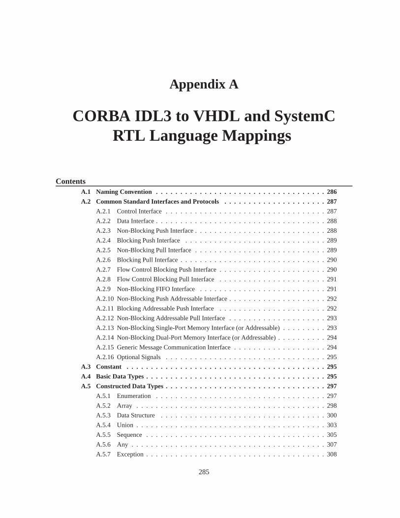
Appendix A
CORBA IDL3 to VHDL and SystemCRTL Language Mappings
ContentsA.1 Naming Convention . . . . . . . . . . . . . . . . . . . . . . . . . . . . . . . .. . . 286
A.2 Common Standard Interfaces and Protocols . . . . . . . . . . . .. . . . . . . . . 287
A.2.1 Control Interface . . . . . . . . . . . . . . . . . . . . . . . . . . . . . .. . . 287
A.2.2 Data Interface . . . . . . . . . . . . . . . . . . . . . . . . . . . . . . . . .. . 288
A.2.3 Non-Blocking Push Interface . . . . . . . . . . . . . . . . . . . . .. . . . . . 288
A.2.4 Blocking Push Interface . . . . . . . . . . . . . . . . . . . . . . . . .. . . . 289
A.2.5 Non-Blocking Pull Interface . . . . . . . . . . . . . . . . . . . . .. . . . . . 289
A.2.6 Blocking Pull Interface . . . . . . . . . . . . . . . . . . . . . . . . .. . . . . 290
A.2.7 Flow Control Blocking Push Interface . . . . . . . . . . . . . .. . . . . . . . 290
A.2.8 Flow Control Blocking Pull Interface . . . . . . . . . . . . . .. . . . . . . . 291
A.2.9 Non-Blocking FIFO Interface . . . . . . . . . . . . . . . . . . . . .. . . . . 291
A.2.10 Non-Blocking Push Addressable Interface . . . . . . . . .. . . . . . . . . . . 292
A.2.11 Blocking Addressable Push Interface . . . . . . . . . . . . .. . . . . . . . . 292
A.2.12 Non-Blocking Addressable Pull Interface . . . . . . . . .. . . . . . . . . . . 293
A.2.13 Non-Blocking Single-Port Memory Interface (or Addressable) . . . . . . . . . 293
A.2.14 Non-Blocking Dual-Port Memory Interface (or Addressable) . . . . . . . . . . 294
A.2.15 Generic Message Communication Interface . . . . . . . . .. . . . . . . . . . 294
A.2.16 Optional Signals . . . . . . . . . . . . . . . . . . . . . . . . . . . . . .. . . 295
A.3 Constant . . . . . . . . . . . . . . . . . . . . . . . . . . . . . . . . . . . . . . . .. 295
A.4 Basic Data Types . . . . . . . . . . . . . . . . . . . . . . . . . . . . . . . . . .. . . 295
A.5 Constructed Data Types . . . . . . . . . . . . . . . . . . . . . . . . . . . .. . . . . 297
A.5.1 Enumeration . . . . . . . . . . . . . . . . . . . . . . . . . . . . . . . . . . .297
A.5.2 Array . . . . . . . . . . . . . . . . . . . . . . . . . . . . . . . . . . . . . . . 298
A.5.3 Data Structure . . . . . . . . . . . . . . . . . . . . . . . . . . . . . . . . .. 300
A.5.4 Union . . . . . . . . . . . . . . . . . . . . . . . . . . . . . . . . . . . . . . . 303
A.5.5 Sequence . . . . . . . . . . . . . . . . . . . . . . . . . . . . . . . . . . . . . 305
A.5.6 Any . . . . . . . . . . . . . . . . . . . . . . . . . . . . . . . . . . . . . . . . 307
A.5.7 Exception . . . . . . . . . . . . . . . . . . . . . . . . . . . . . . . . . . . . .308
285
286 Appendix A. CORBA IDL3 to VHDL and SystemC RTL Language Mappings
A.5.8 Strings . . . . . . . . . . . . . . . . . . . . . . . . . . . . . . . . . . . . . . 309
A.5.9 Float . . . . . . . . . . . . . . . . . . . . . . . . . . . . . . . . . . . . . . . 310
A.5.10 Fixed . . . . . . . . . . . . . . . . . . . . . . . . . . . . . . . . . . . . . . . 310
A.6 Attribute . . . . . . . . . . . . . . . . . . . . . . . . . . . . . . . . . . . . . . .. . 310
A.7 Scoped Name . . . . . . . . . . . . . . . . . . . . . . . . . . . . . . . . . . . . . .. 310
A.8 Module . . . . . . . . . . . . . . . . . . . . . . . . . . . . . . . . . . . . . . . . . .310
A.9 Interface . . . . . . . . . . . . . . . . . . . . . . . . . . . . . . . . . . . . . . .. . 311
A.9.1 Non-reliable oneway operation . . . . . . . . . . . . . . . . . . .. . . . . . . 311
A.9.2 One twoway operation . . . . . . . . . . . . . . . . . . . . . . . . . . . .. . 311
A.9.3 Two twoway operation . . . . . . . . . . . . . . . . . . . . . . . . . . . .. . 312
A.9.4 Operation with one input parameter . . . . . . . . . . . . . . . .. . . . . . . 313
A.9.5 Operation with input/output parameters . . . . . . . . . . .. . . . . . . . . . 313
A.9.6 Asynchronous Method Invocation . . . . . . . . . . . . . . . . . .. . . . . . 314
A.9.7 Pull for output parameter . . . . . . . . . . . . . . . . . . . . . . . .. . . . . 315
A.9.8 Blocking Pull for output parameter . . . . . . . . . . . . . . . .. . . . . . . . 316
A.9.9 Pull/Push for input/output parameters . . . . . . . . . . . .. . . . . . . . . . 317
A.10 Operation Invocation . . . . . . . . . . . . . . . . . . . . . . . . . . . .. . . . . . 318
A.10.1 Phases . . . . . . . . . . . . . . . . . . . . . . . . . . . . . . . . . . . . . . .318
A.10.2 Mapping solutions . . . . . . . . . . . . . . . . . . . . . . . . . . . . .. . . 318
A.10.3 Operation parameter transfer . . . . . . . . . . . . . . . . . . .. . . . . . . . 319
A.10.4 Operation-level concurrency . . . . . . . . . . . . . . . . . . .. . . . . . . . 321
A.11 Object . . . . . . . . . . . . . . . . . . . . . . . . . . . . . . . . . . . . . . . . .. . 321
A.12 Inheritance . . . . . . . . . . . . . . . . . . . . . . . . . . . . . . . . . . . .. . . . 321
A.13 Interface Attribute . . . . . . . . . . . . . . . . . . . . . . . . . . . . .. . . . . . . 322
A.14 Component Feature . . . . . . . . . . . . . . . . . . . . . . . . . . . . . . .. . . . 324
A.14.1 Component . . . . . . . . . . . . . . . . . . . . . . . . . . . . . . . . . . . .324
A.14.2 Facet . . . . . . . . . . . . . . . . . . . . . . . . . . . . . . . . . . . . . . . 325
A.14.3 Receptacle . . . . . . . . . . . . . . . . . . . . . . . . . . . . . . . . . . .. 325
A.15 Not Supported Features . . . . . . . . . . . . . . . . . . . . . . . . . . .. . . . . . 326
A.16 Mapping Summary . . . . . . . . . . . . . . . . . . . . . . . . . . . . . . . . .. . 326
In this annexe chapter, we propose the specification of language mappings from OMG IDL3 toVHDL and SystemC RTL. We improved a first proposition made by Hugues Balp and Christophe Jouvrayin the scope of the ITEA SPICES project. Our improvements notably include the definition of commonstandard interfaces and protocols, the illustration of themapping space exploration with these interfaces,
A.1 Naming Convention
To enhance readability, a clock signal is namedclk and a reset signalrst. Moreover, the name of asignal active on low level ends with the suffix_n. Note that VHDL is a case-insensitive language.
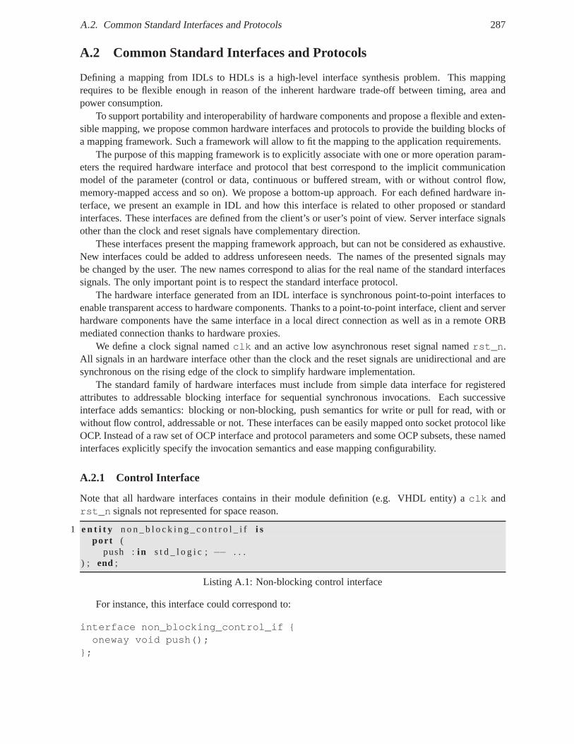
A.2. Common Standard Interfaces and Protocols 287
A.2 Common Standard Interfaces and Protocols
Defining a mapping from IDLs to HDLs is a high-level interfacesynthesis problem. This mappingrequires to be flexible enough in reason of the inherent hardware trade-off between timing, area andpower consumption.
To support portability and interoperability of hardware components and propose a flexible and exten-sible mapping, we propose common hardware interfaces and protocols to provide the building blocks ofa mapping framework. Such a framework will allow to fit the mapping to the application requirements.
The purpose of this mapping framework is to explicitly associate with one or more operation param-eters the required hardware interface and protocol that best correspond to the implicit communicationmodel of the parameter (control or data, continuous or buffered stream, with or without control flow,memory-mapped access and so on). We propose a bottom-up approach. For each defined hardware in-terface, we present an example in IDL and how this interface is related to other proposed or standardinterfaces. These interfaces are defined from the client’s or user’s point of view. Server interface signalsother than the clock and reset signals have complementary direction.
These interfaces present the mapping framework approach, but can not be considered as exhaustive.New interfaces could be added to address unforeseen needs. The names of the presented signals maybe changed by the user. The new names correspond to alias for the real name of the standard interfacessignals. The only important point is to respect the standardinterface protocol.
The hardware interface generated from an IDL interface is synchronous point-to-point interfaces toenable transparent access to hardware components. Thanks to a point-to-point interface, client and serverhardware components have the same interface in a local direct connection as well as in a remote ORBmediated connection thanks to hardware proxies.
We define a clock signal namedclk and an active low asynchronous reset signal namedrst_n.All signals in an hardware interface other than the clock andthe reset signals are unidirectional and aresynchronous on the rising edge of the clock to simplify hardware implementation.
The standard family of hardware interfaces must include from simple data interface for registeredattributes to addressable blocking interface for sequential synchronous invocations. Each successiveinterface adds semantics: blocking or non-blocking, push semantics for write or pull for read, with orwithout flow control, addressable or not. These interfaces can be easily mapped onto socket protocol likeOCP. Instead of a raw set of OCP interface and protocol parameters and some OCP subsets, these namedinterfaces explicitly specify the invocation semantics and ease mapping configurability.
A.2.1 Control Interface
Note that all hardware interfaces contains in their module definition (e.g. VHDL entity) aclk andrst_n signals not represented for space reason.
1 e n t i t y n o n _ b l o c k i n g _ c o n t r o l _ i f i spor t (
push :i n s t d _ l o g i c ; −− . . .) ; end ;
Listing A.1: Non-blocking control interface
For instance, this interface could correspond to:
interface non_blocking_control_if {oneway void push();
};
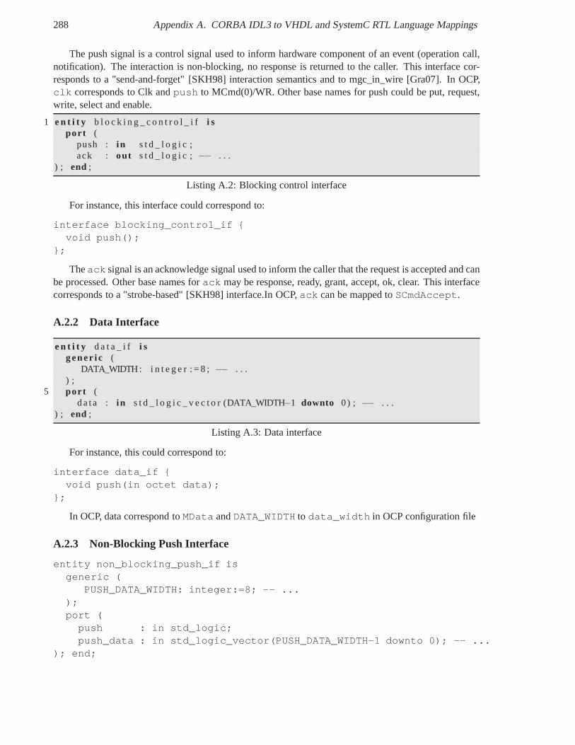
288 Appendix A. CORBA IDL3 to VHDL and SystemC RTL Language Mappings
The push signal is a control signal used to inform hardware component of an event (operation call,notification). The interaction is non-blocking, no response is returned to the caller. This interface cor-responds to a "send-and-forget" [SKH98] interaction semantics and to mgc_in_wire [Gra07]. In OCP,clk corresponds to Clk andpush to MCmd(0)/WR. Other base names for push could be put, request,write, select and enable.
1 e n t i t y b l o c k i n g _ c o n t r o l _ i f i spor t (
push : i n s t d _ l o g i c ;ack : out s t d _ l o g i c ; −− . . .
) ; end ;
Listing A.2: Blocking control interface
For instance, this interface could correspond to:
interface blocking_control_if {void push();
};
Theack signal is an acknowledge signal used to inform the caller that the request is accepted and canbe processed. Other base names forack may be response, ready, grant, accept, ok, clear. This interfacecorresponds to a "strobe-based" [SKH98] interface.In OCP,ack can be mapped toSCmdAccept.
A.2.2 Data Interface
e n t i t y d a t a _ i f i sgene r i c (
DATA_WIDTH: i n t e g e r : = 8 ; −− . . .) ;
5 por t (d a t a : i n s t d _ l o g i c _ v e c t o r (DATA_WIDTH−1 downto 0) ; −− . . .
) ; end ;
Listing A.3: Data interface
For instance, this could correspond to:
interface data_if {void push(in octet data);
};
In OCP, data correspond toMData andDATA_WIDTH to data_width in OCP configuration file
A.2.3 Non-Blocking Push Interface
entity non_blocking_push_if isgeneric (
PUSH_DATA_WIDTH: integer:=8; -- ...);port (push : in std_logic;push_data : in std_logic_vector(PUSH_DATA_WIDTH-1 downto 0); -- ...
); end;
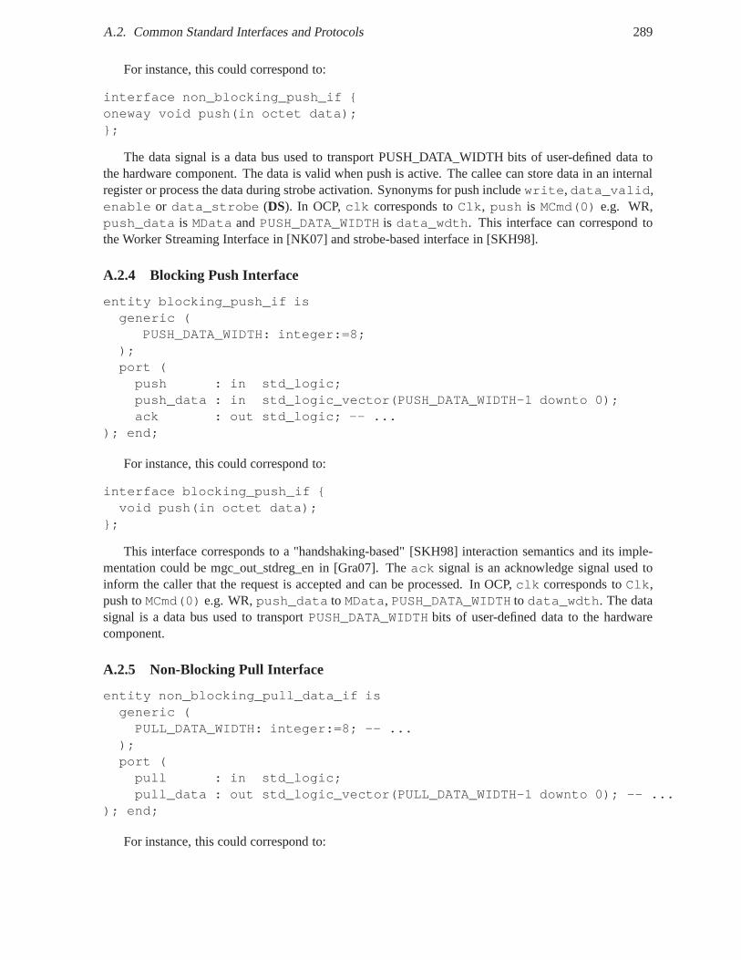
A.2. Common Standard Interfaces and Protocols 289
For instance, this could correspond to:
interface non_blocking_push_if {oneway void push(in octet data);};
The data signal is a data bus used to transport PUSH_DATA_WIDTH bits of user-defined data tothe hardware component. The data is valid when push is active. The callee can store data in an internalregister or process the data during strobe activation. Synonyms for push includewrite,data_valid,enable or data_strobe (DS). In OCP,clk corresponds toClk, push is MCmd(0) e.g. WR,push_data is MData andPUSH_DATA_WIDTH is data_wdth. This interface can correspond tothe Worker Streaming Interface in [NK07] and strobe-based interface in [SKH98].
A.2.4 Blocking Push Interface
entity blocking_push_if isgeneric (
PUSH_DATA_WIDTH: integer:=8;);port (push : in std_logic;push_data : in std_logic_vector(PUSH_DATA_WIDTH-1 downto 0);ack : out std_logic; -- ...
); end;
For instance, this could correspond to:
interface blocking_push_if {void push(in octet data);
};
This interface corresponds to a "handshaking-based" [SKH98] interaction semantics and its imple-mentation could be mgc_out_stdreg_en in [Gra07]. Theack signal is an acknowledge signal used toinform the caller that the request is accepted and can be processed. In OCP,clk corresponds toClk,push toMCmd(0) e.g. WR,push_data to MData, PUSH_DATA_WIDTH to data_wdth. The datasignal is a data bus used to transportPUSH_DATA_WIDTH bits of user-defined data to the hardwarecomponent.
A.2.5 Non-Blocking Pull Interface
entity non_blocking_pull_data_if isgeneric (PULL_DATA_WIDTH: integer:=8; -- ...
);port (pull : in std_logic;pull_data : out std_logic_vector(PULL_DATA_WIDTH-1 downto 0); -- ...
); end;
For instance, this could correspond to:
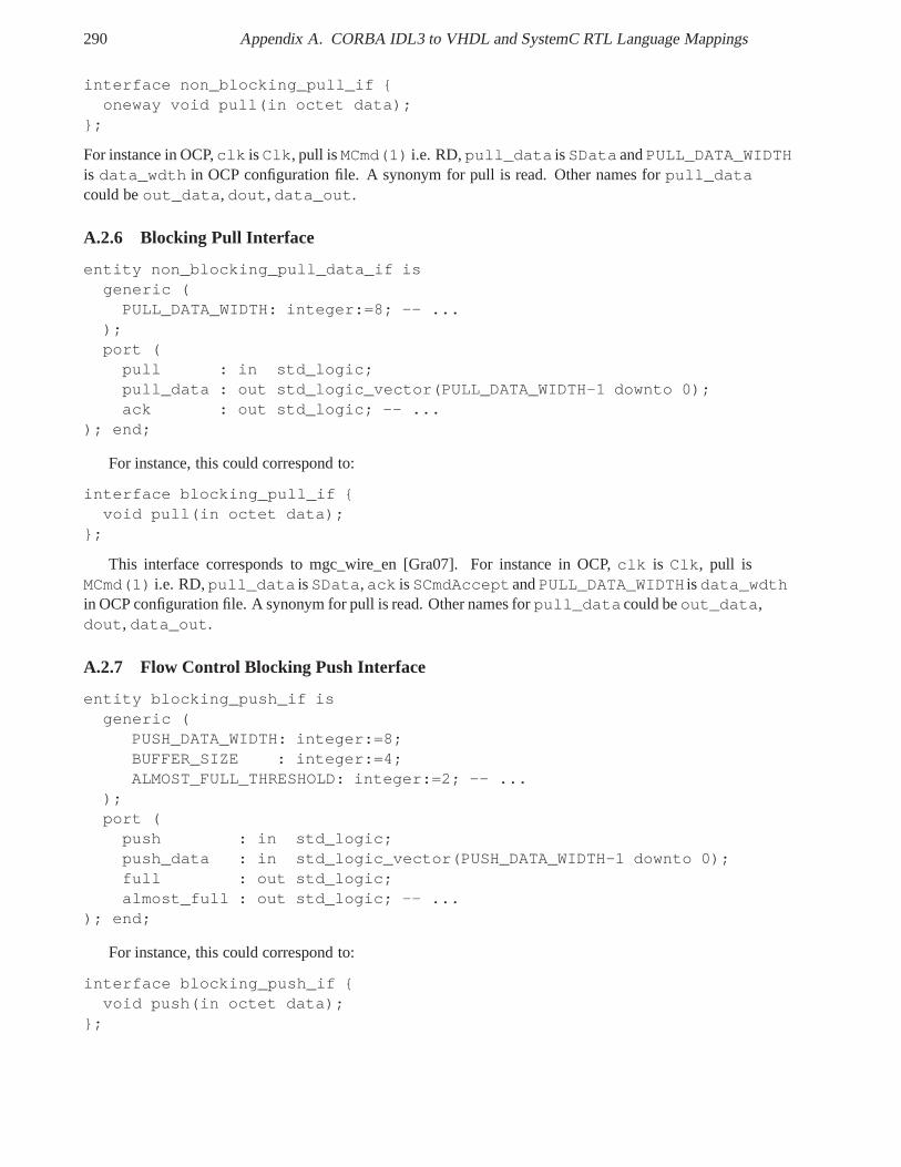
290 Appendix A. CORBA IDL3 to VHDL and SystemC RTL Language Mappings
interface non_blocking_pull_if {oneway void pull(in octet data);
};
For instance in OCP,clk isClk, pull isMCmd(1) i.e. RD,pull_data isSData andPULL_DATA_WIDTHis data_wdth in OCP configuration file. A synonym for pull is read. Other names forpull_datacould beout_data, dout, data_out.
A.2.6 Blocking Pull Interface
entity non_blocking_pull_data_if isgeneric (PULL_DATA_WIDTH: integer:=8; -- ...
);port (pull : in std_logic;pull_data : out std_logic_vector(PULL_DATA_WIDTH-1 downto 0);ack : out std_logic; -- ...
); end;
For instance, this could correspond to:
interface blocking_pull_if {void pull(in octet data);
};
This interface corresponds to mgc_wire_en [Gra07]. For instance in OCP,clk is Clk, pull isMCmd(1) i.e. RD,pull_data isSData,ack isSCmdAcceptandPULL_DATA_WIDTH isdata_wdthin OCP configuration file. A synonym for pull is read. Other names forpull_datacould beout_data,dout, data_out.
A.2.7 Flow Control Blocking Push Interface
entity blocking_push_if isgeneric (
PUSH_DATA_WIDTH: integer:=8;BUFFER_SIZE : integer:=4;ALMOST_FULL_THRESHOLD: integer:=2; -- ...
);port (push : in std_logic;push_data : in std_logic_vector(PUSH_DATA_WIDTH-1 downto 0);full : out std_logic;almost_full : out std_logic; -- ...
); end;
For instance, this could correspond to:
interface blocking_push_if {void push(in octet data);
};
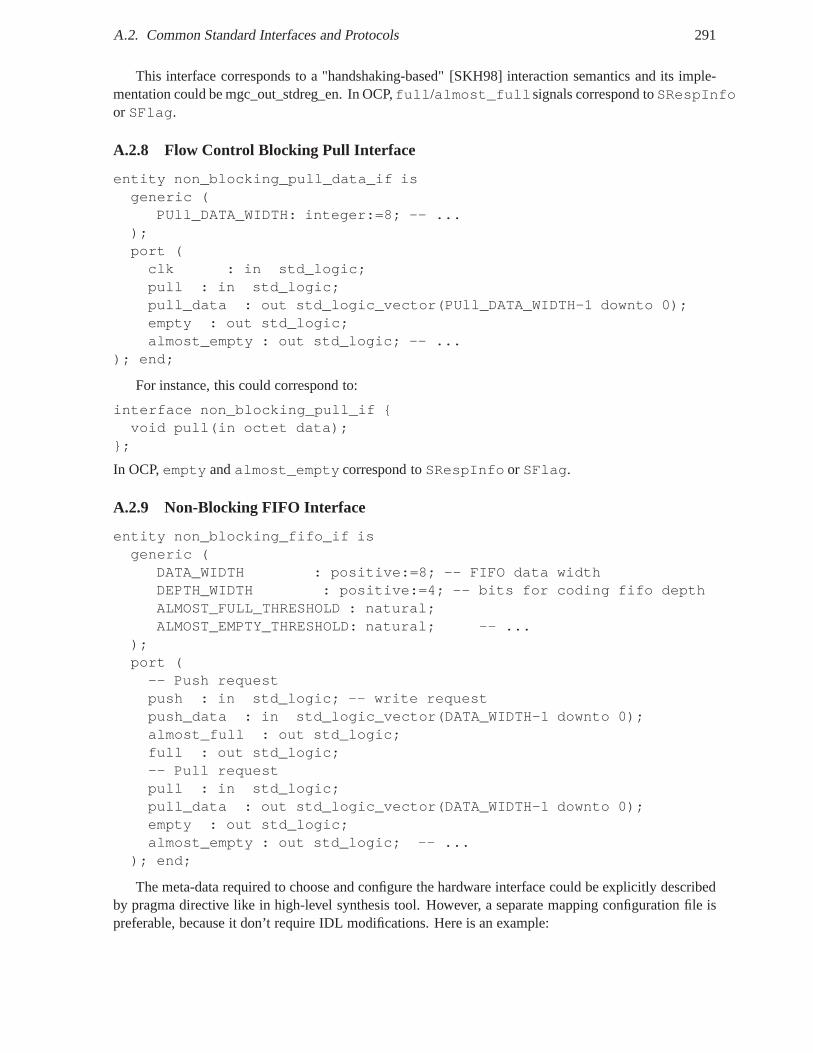
A.2. Common Standard Interfaces and Protocols 291
This interface corresponds to a "handshaking-based" [SKH98] interaction semantics and its imple-mentation could be mgc_out_stdreg_en. In OCP,full/almost_fullsignals correspond toSRespInfoor SFlag.
A.2.8 Flow Control Blocking Pull Interface
entity non_blocking_pull_data_if isgeneric (
PUll_DATA_WIDTH: integer:=8; -- ...);port (clk : in std_logic;pull : in std_logic;pull_data : out std_logic_vector(PUll_DATA_WIDTH-1 downto 0);empty : out std_logic;almost_empty : out std_logic; -- ...
); end;
For instance, this could correspond to:
interface non_blocking_pull_if {void pull(in octet data);
};
In OCP,empty andalmost_empty correspond toSRespInfo or SFlag.
A.2.9 Non-Blocking FIFO Interface
entity non_blocking_fifo_if isgeneric (
DATA_WIDTH : positive:=8; -- FIFO data widthDEPTH_WIDTH : positive:=4; -- bits for coding fifo depthALMOST_FULL_THRESHOLD : natural;ALMOST_EMPTY_THRESHOLD: natural; -- ...
);port (-- Push requestpush : in std_logic; -- write requestpush_data : in std_logic_vector(DATA_WIDTH-1 downto 0);almost_full : out std_logic;full : out std_logic;-- Pull requestpull : in std_logic;pull_data : out std_logic_vector(DATA_WIDTH-1 downto 0);empty : out std_logic;almost_empty : out std_logic; -- ...
); end;
The meta-data required to choose and configure the hardware interface could be explicitly describedby pragma directive like in high-level synthesis tool. However, a separate mapping configuration file ispreferable, because it don’t require IDL modifications. Here is an example:
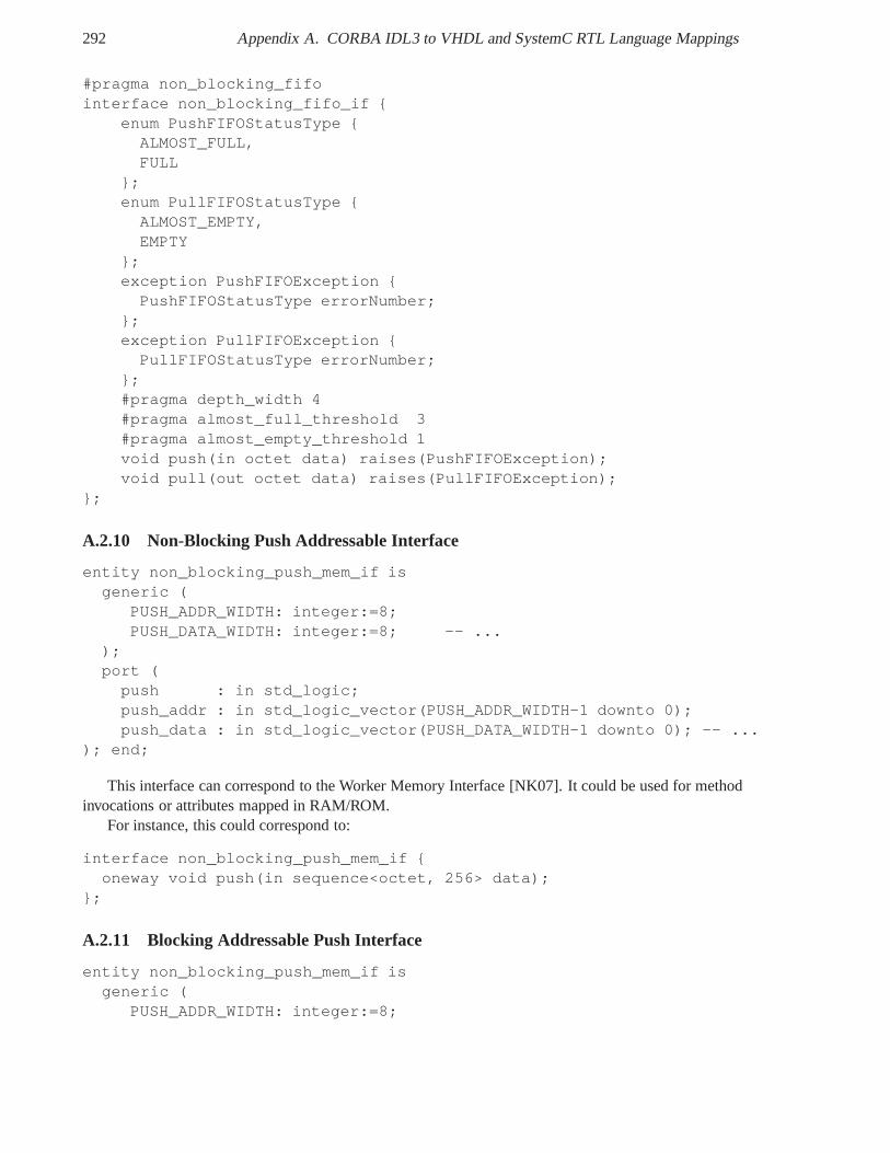
292 Appendix A. CORBA IDL3 to VHDL and SystemC RTL Language Mappings
#pragma non_blocking_fifointerface non_blocking_fifo_if {
enum PushFIFOStatusType {ALMOST_FULL,FULL
};enum PullFIFOStatusType {ALMOST_EMPTY,EMPTY
};exception PushFIFOException {PushFIFOStatusType errorNumber;
};exception PullFIFOException {PullFIFOStatusType errorNumber;
};#pragma depth_width 4#pragma almost_full_threshold 3#pragma almost_empty_threshold 1void push(in octet data) raises(PushFIFOException);void pull(out octet data) raises(PullFIFOException);
};
A.2.10 Non-Blocking Push Addressable Interface
entity non_blocking_push_mem_if isgeneric (
PUSH_ADDR_WIDTH: integer:=8;PUSH_DATA_WIDTH: integer:=8; -- ...
);port (push : in std_logic;push_addr : in std_logic_vector(PUSH_ADDR_WIDTH-1 downto 0);push_data : in std_logic_vector(PUSH_DATA_WIDTH-1 downto 0); -- ...
); end;
This interface can correspond to the Worker Memory Interface [NK07]. It could be used for methodinvocations or attributes mapped in RAM/ROM.
For instance, this could correspond to:
interface non_blocking_push_mem_if {oneway void push(in sequence<octet, 256> data);
};
A.2.11 Blocking Addressable Push Interface
entity non_blocking_push_mem_if isgeneric (
PUSH_ADDR_WIDTH: integer:=8;
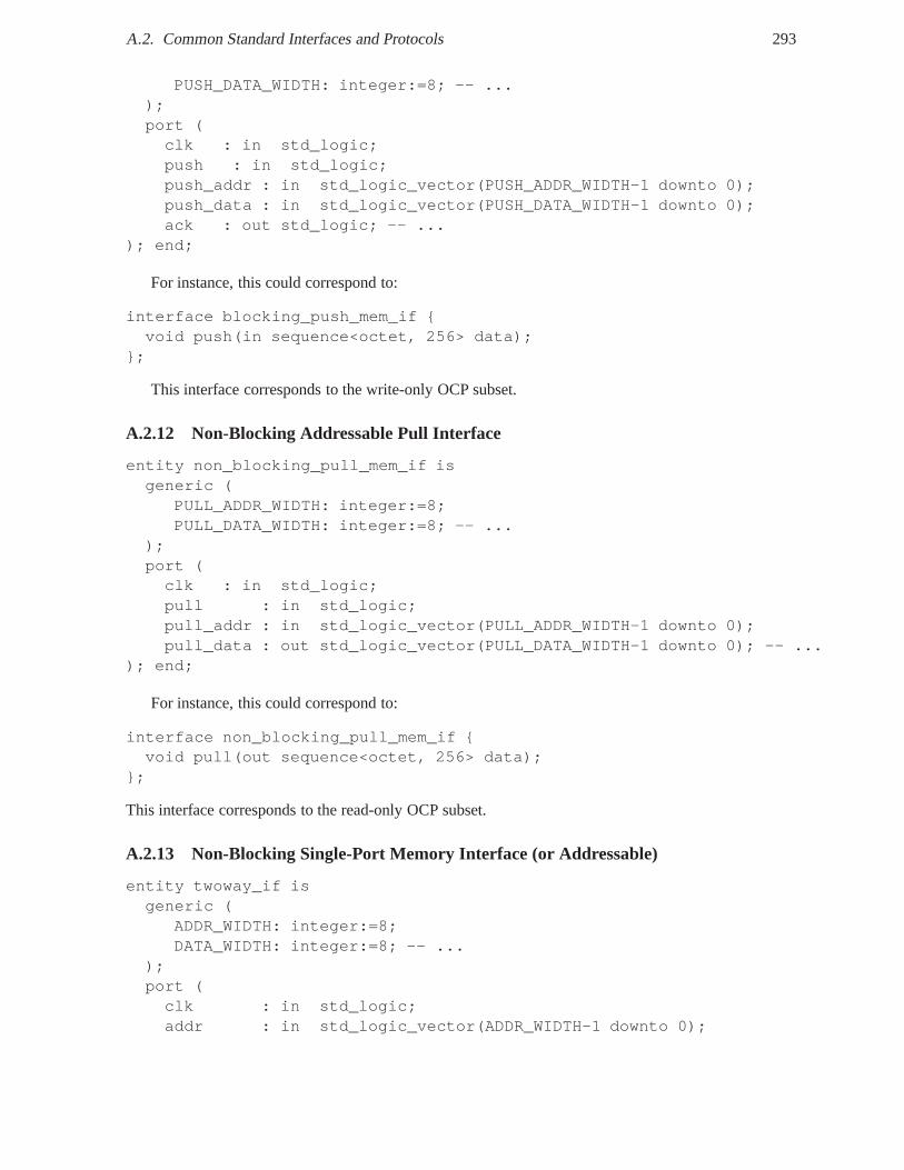
A.2. Common Standard Interfaces and Protocols 293
PUSH_DATA_WIDTH: integer:=8; -- ...);port (clk : in std_logic;push : in std_logic;push_addr : in std_logic_vector(PUSH_ADDR_WIDTH-1 downto 0);push_data : in std_logic_vector(PUSH_DATA_WIDTH-1 downto 0);ack : out std_logic; -- ...
); end;
For instance, this could correspond to:
interface blocking_push_mem_if {void push(in sequence<octet, 256> data);
};
This interface corresponds to the write-only OCP subset.
A.2.12 Non-Blocking Addressable Pull Interface
entity non_blocking_pull_mem_if isgeneric (
PULL_ADDR_WIDTH: integer:=8;PULL_DATA_WIDTH: integer:=8; -- ...
);port (clk : in std_logic;pull : in std_logic;pull_addr : in std_logic_vector(PULL_ADDR_WIDTH-1 downto 0);pull_data : out std_logic_vector(PULL_DATA_WIDTH-1 downto 0); -- ...
); end;
For instance, this could correspond to:
interface non_blocking_pull_mem_if {void pull(out sequence<octet, 256> data);
};
This interface corresponds to the read-only OCP subset.
A.2.13 Non-Blocking Single-Port Memory Interface (or Addressable)
entity twoway_if isgeneric (
ADDR_WIDTH: integer:=8;DATA_WIDTH: integer:=8; -- ...
);port (clk : in std_logic;addr : in std_logic_vector(ADDR_WIDTH-1 downto 0);
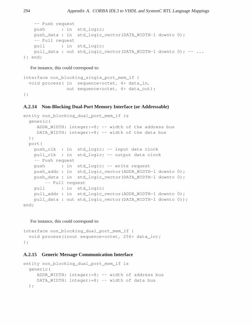
294 Appendix A. CORBA IDL3 to VHDL and SystemC RTL Language Mappings
-- Push requestpush : in std_logic;push_data : in std_logic_vector(DATA_WIDTH-1 downto 0);-- Pull requestpull : in std_logic;pull_data : out std_logic_vector(DATA_WIDTH-1 downto 0); -- ...
); end;
For instance, this could correspond to:
interface non_blocking_single_port_mem_if {void process( in sequence<octet, 4> data_in,
out sequence<octet, 4> data_out);};
A.2.14 Non-Blocking Dual-Port Memory Interface (or Addressable)
entity non_blocking_dual_port_mem_if isgeneric(
ADDR_WIDTH: integer:=8; -- width of the address busDATA_WIDTH: integer:=8; -- width of the data bus
);port(push_clk : in std_logic; -- input data clockpull_clk : in std_logic; -- output data clock-- Push requestpush : in std_logic; -- write requestpush_addr : in std_logic_vector(ADDR_WIDTH-1 downto 0);push_data : in std_logic_vector(DATA_WIDTH-1 downto 0);
-- Pull requestpull : in std_logic;pull_addr : in std_logic_vector(ADDR_WIDTH-1 downto 0);pull_data : out std_logic_vector(DATA_WIDTH-1 downto 0));
end;
For instance, this could correspond to:
interface non_blocking_dual_port_mem_if {void process(inout sequence<octet, 256> data_in);
};
A.2.15 Generic Message Communication Interface
entity non_blocking_dual_port_mem_if isgeneric(
ADDR_WIDTH: integer:=8; -- width of address busDATA_WIDTH: integer:=8; -- width of data bus
);
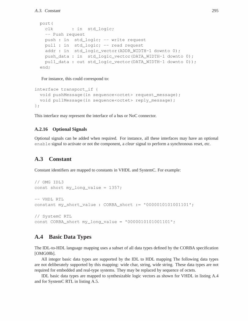
A.3. Constant 295
port(clk : in std_logic;-- Push requestpush : in std_logic; -- write requestpull : in std_logic; -- read requestaddr : in std_logic_vector(ADDR_WIDTH-1 downto 0);push_data : in std_logic_vector(DATA_WIDTH-1 downto 0);pull_data : out std_logic_vector(DATA_WIDTH-1 downto 0));
end;
For instance, this could correspond to:
interface transport_if {void pushMessage(in sequence<octet> request_message);void pullMessage(in sequence<octet> reply_message);
};
This interface may represent the interface of a bus or NoC connector.
A.2.16 Optional Signals
Optional signals can be added when required. For instance, all these interfaces may have an optionalenable signal to activate or not the component, aclear signal to perform a synchronous reset, etc.
A.3 Constant
Constant identifiers are mapped to constants in VHDL and SystemC. For example:
// OMG IDL3const short my_long_value = 1357;
-- VHDL RTLconstant my_short_value : CORBA_short := "0000010101001101";
// SystemC RTLconst CORBA_short my_long_value = "0000010101001101";
A.4 Basic Data Types
The IDL-to-HDL language mapping uses a subset of all data types defined by the CORBA specification[OMG08b].
All integer basic data types are supported by the IDL to HDL mapping The following data typesare not deliberately supported by this mapping: wide char, string, wide string. These data types are notrequired for embedded and real-type systems. They may be replaced by sequence of octets.
IDL basic data types are mapped to synthesizable logic vectors as shown for VHDL in listing A.4and for SystemC RTL in listing A.5.
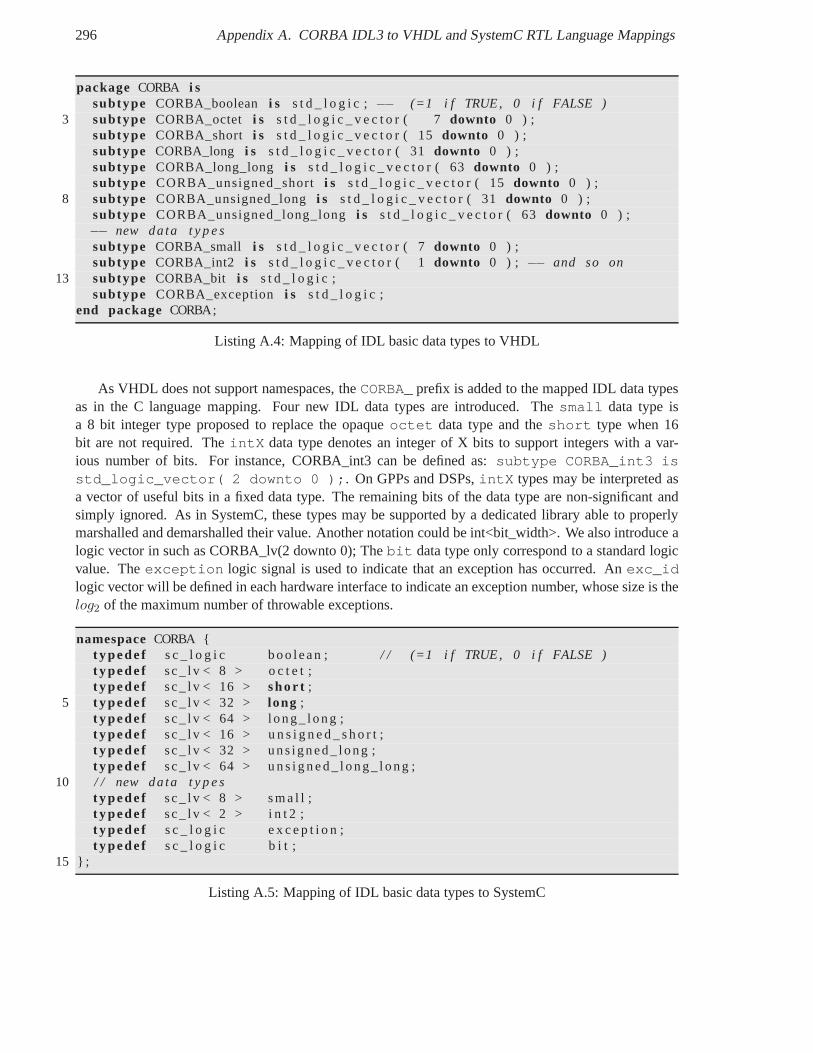
296 Appendix A. CORBA IDL3 to VHDL and SystemC RTL Language Mappings
package CORBA i ssubtype CORBA_boolean i s s t d _ l o g i c ; −− (=1 i f TRUE, 0 i f FALSE )
3 subtype CORBA_octet i s s t d _ l o g i c _ v e c t o r ( 7downto 0 ) ;subtype CORBA_short i s s t d _ l o g i c _ v e c t o r ( 15downto 0 ) ;subtype CORBA_long i s s t d _ l o g i c _ v e c t o r ( 31downto 0 ) ;subtype CORBA_long_long i s s t d _ l o g i c _ v e c t o r ( 63downto 0 ) ;subtype CORBA_unsigned_shorti s s t d _ l o g i c _ v e c t o r ( 15downto 0 ) ;
8 subtype CORBA_unsigned_longi s s t d _ l o g i c _ v e c t o r ( 31downto 0 ) ;subtype CORBA_unsigned_long_longi s s t d _ l o g i c _ v e c t o r ( 63downto 0 ) ;−− new data t y p e ssubtype CORBA_small i s s t d _ l o g i c _ v e c t o r ( 7downto 0 ) ;subtype CORBA_int2 i s s t d _ l o g i c _ v e c t o r ( 1downto 0 ) ; −− and so on
13 subtype CORBA_bit i s s t d _ l o g i c ;subtype CORBA_exception i s s t d _ l o g i c ;
end package CORBA;
Listing A.4: Mapping of IDL basic data types to VHDL
As VHDL does not support namespaces, theCORBA_ prefix is added to the mapped IDL data typesas in the C language mapping. Four new IDL data types are introduced. Thesmall data type isa 8 bit integer type proposed to replace the opaqueoctet data type and theshort type when 16bit are not required. TheintX data type denotes an integer of X bits to support integers with a var-ious number of bits. For instance, CORBA_int3 can be defined as: subtype CORBA_int3 isstd_logic_vector( 2 downto 0 );. On GPPs and DSPs,intX types may be interpreted asa vector of useful bits in a fixed data type. The remaining bitsof the data type are non-significant andsimply ignored. As in SystemC, these types may be supported by a dedicated library able to properlymarshalled and demarshalled their value. Another notationcould be int<bit_width>. We also introduce alogic vector in such as CORBA_lv(2 downto 0); Thebit data type only correspond to a standard logicvalue. Theexception logic signal is used to indicate that an exception has occurred. Anexc_idlogic vector will be defined in each hardware interface to indicate an exception number, whose size is thelog2 of the maximum number of throwable exceptions.
namespaceCORBA {t ypede f s c _ l o g i c boo lean ; / / (=1 i f TRUE, 0 i f FALSE )t ypede f sc_ l v < 8 > o c t e t ;t ypede f sc_ l v < 16 > sho r t ;
5 t ypede f sc_ l v < 32 > long ;t ypede f sc_ l v < 64 > long_ long ;t ypede f sc_ l v < 16 > u n s i g n e d _ s h o r t ;t ypede f sc_ l v < 32 > uns igned_ long ;t ypede f sc_ l v < 64 > u n s i g n e d _ l ong_ l ong ;
10 / / new data t y p e st ypede f sc_ l v < 8 > s m a l l ;t ypede f sc_ l v < 2 > i n t 2 ;t ypede f s c _ l o g i c e x c e p t i o n ;t ypede f s c _ l o g i c b i t ;
15 } ;
Listing A.5: Mapping of IDL basic data types to SystemC
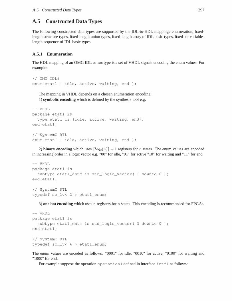
A.5. Constructed Data Types 297
A.5 Constructed Data Types
The following constructed data types are supported by the IDL-to-HDL mapping: enumeration, fixed-length structure types, fixed-length union types, fixed-length array of IDL basic types, fixed- or variable-length sequence of IDL basic types.
A.5.1 Enumeration
The HDL mapping of an OMG IDLenum type is a set of VHDL signals encoding the enum values. Forexample:
// OMG IDL3enum etat1 { idle, active, waiting, end };
The mapping in VHDL depends on a chosen enumeration encoding:1) symbolic encodingwhich is defined by the synthesis tool e.g.
-- VHDLpackage etat1 istype etat1 is (idle, active, waiting, end);
end etat1;
// SystemC RTLenum etat1 { idle, active, waiting, end };
2) binary encoding which uses⌈log2(n)⌉ + 1 registers forn states. The enum values are encodedin increasing order in a logic vector e.g. "00" for idle, "01"for active "10" for waiting and "11" for end.
-- VHDLpackage etat1 issubtype etat1_enum is std_logic_vector( 1 downto 0 );
end etat1;
// SystemC RTLtypedef sc_lv< 2 > etat1_enum;
3) one hot encodingwhich usesn registers forn states. This encoding is recommended for FPGAs.
-- VHDLpackage etat1 issubtype etat1_enum is std_logic_vector( 3 downto 0 );
end etat1;
// SystemC RTLtypedef sc_lv< 4 > etat1_enum;
The enum values are encoded as follows: "0001" for idle, "0010" for active, "0100" for waiting and"1000" for end.
For example suppose the operationoperation1 defined in interfaceintf1 as follows:
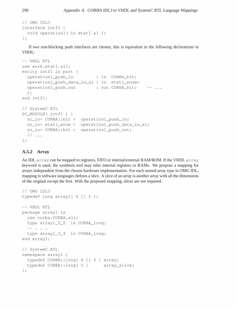
298 Appendix A. CORBA IDL3 to VHDL and SystemC RTL Language Mappings
// OMG IDL3interface intf1 {
void operation1( in etat1 a1 );};
If two non-blocking push interfaces are chosen, this is equivalent to the following declarations inVHDL:
-- VHDL RTLuse work.etat1.all;entity intf1 is port (
operation1_push_in : in CORBA_bit;operation1_push_data_in_a1 : in etat1_enum;operation1_push_out : out CORBA_bit; -- ...);
end intf1;
// SystemC RTLSC_MODULE( intf1 ) {
sc_in< CORBA::bit > operation1_push_in;sc_in< etat1_enum > operation1_push_data_in_a1;sc_in< CORBA::bit > operation1_push_out;// ...
};
A.5.2 Array
An IDL array can be mapped to registers, FIFO or internal/external RAM/ROM. If the VHDL arraykeyword is used, the synthesis tool may infer internal registers or RAMs. We propose a mapping forarrays independent from the chosen hardware implementation. For each named array type in OMG IDL,mapping to software languages defines a slice. A slice of an array is another array with all the dimensionsof the original except the first. With the proposed mapping, slices are not required.
// OMG IDL3typedef long array1[ 4 ][ 5 ];
-- VHDL RTLpackage array1 is
use corba.CORBA.all;type array1_0_0 is CORBA_long;-- . . .type array1_3_4 is CORBA_long;
end array1;
// SystemC RTLnamespace array1 {
typedef CORBA::long[ 4 ][ 5 ] array;typedef CORBA::long[ 5 ] array_slice;
};
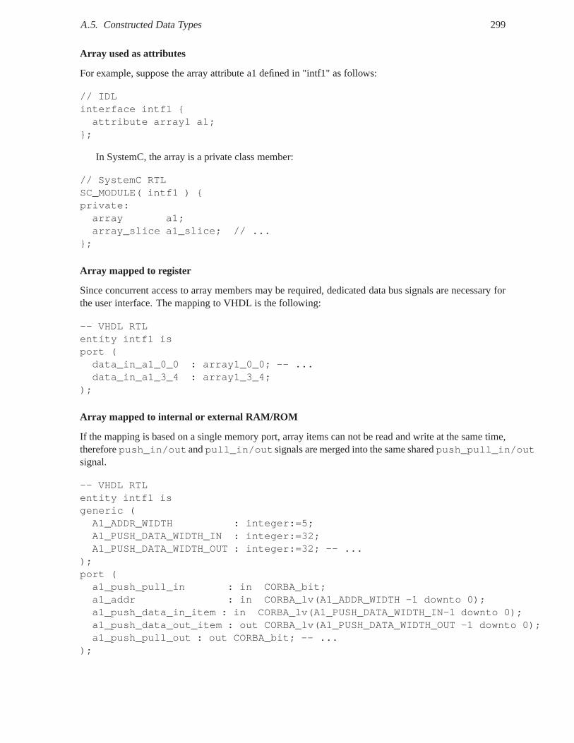
A.5. Constructed Data Types 299
Array used as attributes
For example, suppose the array attribute a1 defined in "intf1" as follows:
// IDLinterface intf1 {attribute array1 a1;
};
In SystemC, the array is a private class member:
// SystemC RTLSC_MODULE( intf1 ) {private:array a1;array_slice a1_slice; // ...
};
Array mapped to register
Since concurrent access to array members may be required, dedicated data bus signals are necessary forthe user interface. The mapping to VHDL is the following:
-- VHDL RTLentity intf1 isport (data_in_a1_0_0 : array1_0_0; -- ...data_in_a1_3_4 : array1_3_4;
);
Array mapped to internal or external RAM/ROM
If the mapping is based on a single memory port, array items can not be read and write at the same time,thereforepush_in/outandpull_in/outsignals are merged into the same sharedpush_pull_in/outsignal.
-- VHDL RTLentity intf1 isgeneric (A1_ADDR_WIDTH : integer:=5;A1_PUSH_DATA_WIDTH_IN : integer:=32;A1_PUSH_DATA_WIDTH_OUT : integer:=32; -- ...
);port (a1_push_pull_in : in CORBA_bit;a1_addr : in CORBA_lv(A1_ADDR_WIDTH -1 downto 0);a1_push_data_in_item : in CORBA_lv(A1_PUSH_DATA_WIDTH_IN-1 downto 0);a1_push_data_out_item : out CORBA_lv(A1_PUSH_DATA_WIDTH_OUT -1 downto 0);a1_push_pull_out : out CORBA_bit; -- ...
);
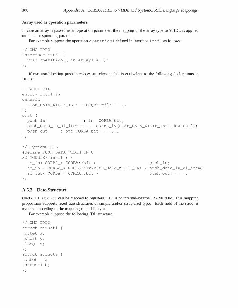
300 Appendix A. CORBA IDL3 to VHDL and SystemC RTL Language Mappings
Array used as operation parameters
In case an array is passed as an operation parameter, the mapping of the array type to VHDL is appliedon the corresponding parameter.
For example suppose the operationoperation1 defined in interfaceintf1 as follows:
// OMG IDL3interface intf1 {
void operation1( in array1 a1 );};
If two non-blocking push interfaces are chosen, this is equivalent to the following declarations inHDLs:
-- VHDL RTLentity intf1 isgeneric (
PUSH_DATA_WIDTH_IN : integer:=32; -- ...);port (
push_in : in CORBA_bit;push_data_in_a1_item : in CORBA_lv(PUSH_DATA_WIDTH_IN-1 downto 0);push_out : out CORBA_bit; -- ...
);
// SystemC RTL#define PUSH_DATA_WIDTH_IN 8SC_MODULE( intf1 ) {
sc_in< CORBA_< CORBA::bit > push_in;sc_in < CORBA_< CORBA::lv<PUSH_DATA_WIDTH_IN> > push_data_in_a1_item;sc_out< CORBA_< CORBA::bit > push_out; -- ...
};
A.5.3 Data Structure
OMG IDL struct can be mapped to registers, FIFOs or internal/external RAM/ROM. This mappingproposition supports fixed-size structures of simple and/or structured types. Each field of the struct ismapped according to the mapping rule of its type.
For example suppose the following IDL structure:
// OMG IDL3struct struct1 {octet x;short y;long z;
};struct struct2 {octet a;struct1 b;
};
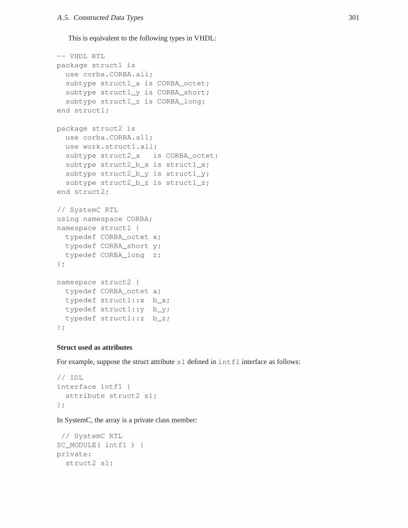
A.5. Constructed Data Types 301
This is equivalent to the following types in VHDL:
-- VHDL RTLpackage struct1 isuse corba.CORBA.all;subtype struct1_x is CORBA_octet;subtype struct1_y is CORBA_short;subtype struct1_z is CORBA_long;
end struct1;
package struct2 isuse corba.CORBA.all;use work.struct1.all;subtype struct2_a is CORBA_octet;subtype struct2_b_x is struct1_x;subtype struct2_b_y is struct1_y;subtype struct2_b_z is struct1_z;
end struct2;
// SystemC RTLusing namespace CORBA;namespace struct1 {typedef CORBA_octet x;typedef CORBA_short y;typedef CORBA_long z;
};
namespace struct2 {typedef CORBA_octet a;typedef struct1::x b_x;typedef struct1::y b_y;typedef struct1::z b_z;
};
Struct used as attributes
For example, suppose the struct attributes1 defined inintf1 interface as follows:
// IDLinterface intf1 {attribute struct2 s1;
};
In SystemC, the array is a private class member:
// SystemC RTLSC_MODULE( intf1 ) {private:struct2 s1;
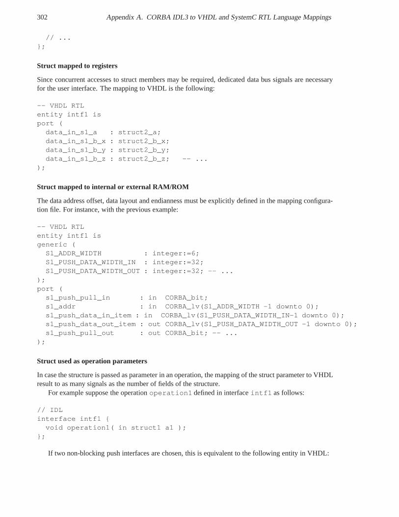
302 Appendix A. CORBA IDL3 to VHDL and SystemC RTL Language Mappings
// ...};
Struct mapped to registers
Since concurrent accesses to struct members may be required, dedicated data bus signals are necessaryfor the user interface. The mapping to VHDL is the following:
-- VHDL RTLentity intf1 isport (
data_in_s1_a : struct2_a;data_in_s1_b_x : struct2_b_x;data_in_s1_b_y : struct2_b_y;data_in_s1_b_z : struct2_b_z; -- ...
);
Struct mapped to internal or external RAM/ROM
The data address offset, data layout and endianness must be explicitly defined in the mapping configura-tion file. For instance, with the previous example:
-- VHDL RTLentity intf1 isgeneric (
S1_ADDR_WIDTH : integer:=6;S1_PUSH_DATA_WIDTH_IN : integer:=32;S1_PUSH_DATA_WIDTH_OUT : integer:=32; -- ...
);port (
s1_push_pull_in : in CORBA_bit;s1_addr : in CORBA_lv(S1_ADDR_WIDTH -1 downto 0);s1_push_data_in_item : in CORBA_lv(S1_PUSH_DATA_WIDTH_IN-1 downto 0);s1_push_data_out_item : out CORBA_lv(S1_PUSH_DATA_WIDTH_OUT -1 downto 0);s1_push_pull_out : out CORBA_bit; -- ...
);
Struct used as operation parameters
In case the structure is passed as parameter in an operation,the mapping of the struct parameter to VHDLresult to as many signals as the number of fields of the structure.
For example suppose the operationoperation1 defined in interfaceintf1 as follows:
// IDLinterface intf1 {
void operation1( in struct1 a1 );};
If two non-blocking push interfaces are chosen, this is equivalent to the following entity in VHDL:
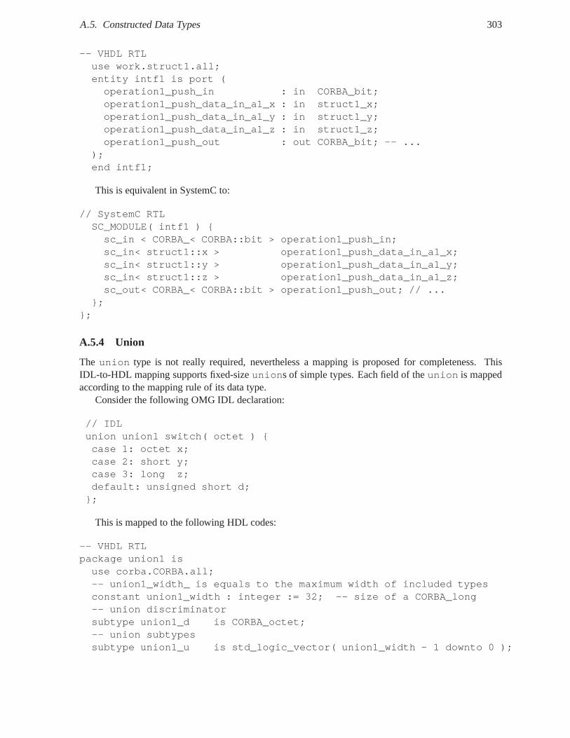
A.5. Constructed Data Types 303
-- VHDL RTLuse work.struct1.all;entity intf1 is port (operation1_push_in : in CORBA_bit;operation1_push_data_in_a1_x : in struct1_x;operation1_push_data_in_a1_y : in struct1_y;operation1_push_data_in_a1_z : in struct1_z;operation1_push_out : out CORBA_bit; -- ...
);end intf1;
This is equivalent in SystemC to:
// SystemC RTLSC_MODULE( intf1 ) {sc_in < CORBA_< CORBA::bit > operation1_push_in;sc_in< struct1::x > operation1_push_data_in_a1_x;sc_in< struct1::y > operation1_push_data_in_a1_y;sc_in< struct1::z > operation1_push_data_in_a1_z;sc_out< CORBA_< CORBA::bit > operation1_push_out; // ...
};};
A.5.4 Union
The union type is not really required, nevertheless a mapping is proposed for completeness. ThisIDL-to-HDL mapping supports fixed-sizeunions of simple types. Each field of theunion is mappedaccording to the mapping rule of its data type.
Consider the following OMG IDL declaration:
// IDLunion union1 switch( octet ) {case 1: octet x;case 2: short y;case 3: long z;default: unsigned short d;
};
This is mapped to the following HDL codes:
-- VHDL RTLpackage union1 isuse corba.CORBA.all;-- union1_width_ is equals to the maximum width of included typesconstant union1_width : integer := 32; -- size of a CORBA_long-- union discriminatorsubtype union1_d is CORBA_octet;-- union subtypessubtype union1_u is std_logic_vector( union1_width - 1 downto 0 );
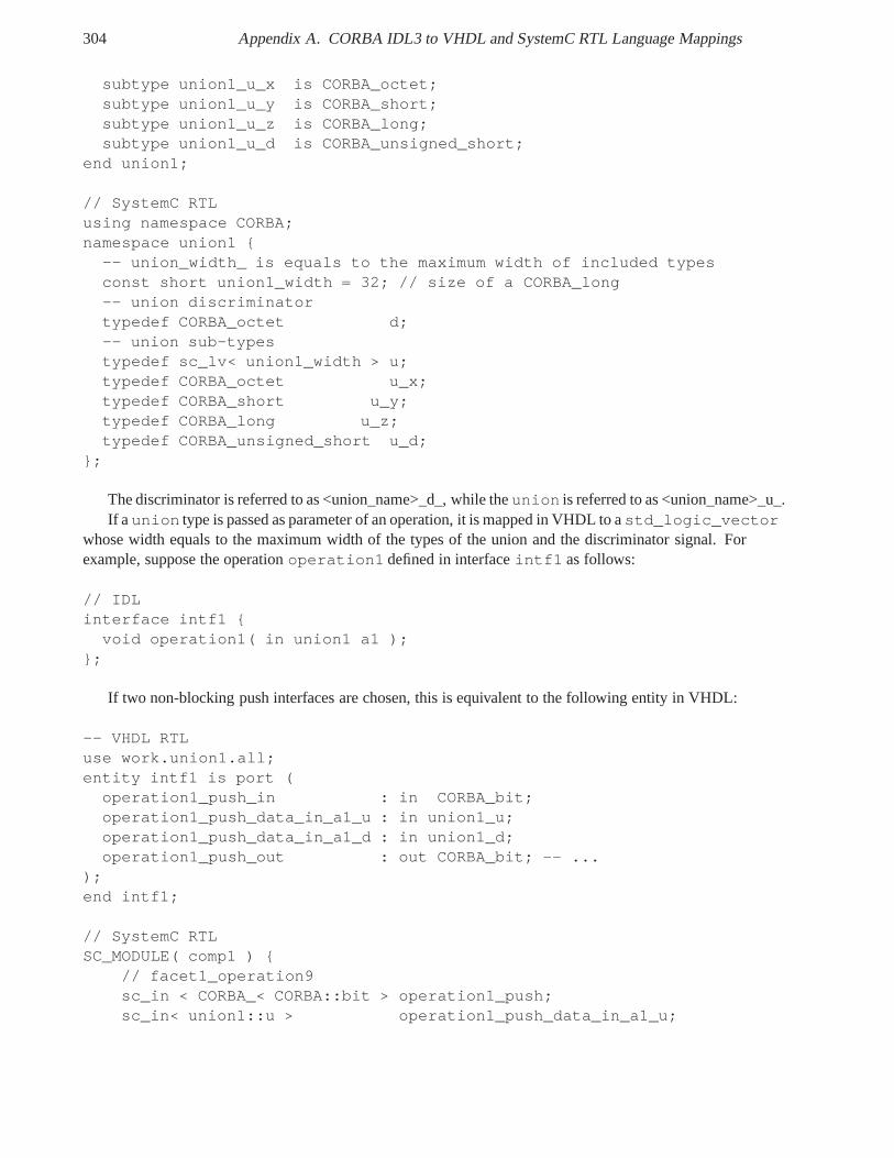
304 Appendix A. CORBA IDL3 to VHDL and SystemC RTL Language Mappings
subtype union1_u_x is CORBA_octet;subtype union1_u_y is CORBA_short;subtype union1_u_z is CORBA_long;subtype union1_u_d is CORBA_unsigned_short;
end union1;
// SystemC RTLusing namespace CORBA;namespace union1 {
-- union_width_ is equals to the maximum width of included typesconst short union1_width = 32; // size of a CORBA_long-- union discriminatortypedef CORBA_octet d;-- union sub-typestypedef sc_lv< union1_width > u;typedef CORBA_octet u_x;typedef CORBA_short u_y;typedef CORBA_long u_z;typedef CORBA_unsigned_short u_d;
};
The discriminator is referred to as <union_name>_d_, whiletheunion is referred to as <union_name>_u_.If a union type is passed as parameter of an operation, it is mapped in VHDL to astd_logic_vector
whose width equals to the maximum width of the types of the union and the discriminator signal. Forexample, suppose the operationoperation1 defined in interfaceintf1 as follows:
// IDLinterface intf1 {
void operation1( in union1 a1 );};
If two non-blocking push interfaces are chosen, this is equivalent to the following entity in VHDL:
-- VHDL RTLuse work.union1.all;entity intf1 is port (
operation1_push_in : in CORBA_bit;operation1_push_data_in_a1_u : in union1_u;operation1_push_data_in_a1_d : in union1_d;operation1_push_out : out CORBA_bit; -- ...
);end intf1;
// SystemC RTLSC_MODULE( comp1 ) {
// facet1_operation9sc_in < CORBA_< CORBA::bit > operation1_push;sc_in< union1::u > operation1_push_data_in_a1_u;
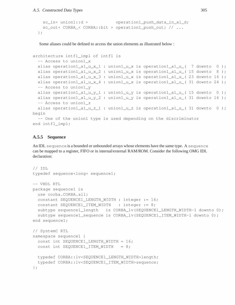
A.5. Constructed Data Types 305
sc_in< union1::d > operation1_push_data_in_a1_d;sc_out< CORBA_< CORBA::bit > operation1_push_out; // ...
};
Some aliases could be defined to access the union elements as illustrated below :
architecture intf1_impl of intf1 is-- Access to union1_xalias operation1_a1_u_x_1 : union1_u_x is operation1_a1_u_( 7 downto 0 );alias operation1_a1_u_x_2 : union1_u_x is operation1_a1_u_( 15 downto 8 );alias operation1_a1_u_x_3 : union1_u_x is operation1_a1_u_( 23 downto 16 );alias operation1_a1_u_x_4 : union1_u_x is operation1_a1_u_( 31 downto 24 );-- Access to union1_yalias operation1_a1_u_y_1 : union1_u_y is operation1_a1_u_( 15 downto 0 );alias operation1_a1_u_y_2 : union1_u_y is operation1_a1_u_( 31 downto 16 );-- Access to union1_zalias operation1_a1_u_z_1 : union1_u_z is operation1_a1_u_( 31 downto 0 );
begin-- One of the union1 type is used depending on the discriminator
end intf1_impl;
A.5.5 Sequence
An IDL sequence is a bounded or unbounded arrays whose elements have the sametype. Asequencecan be mapped to a register, FIFO or in internal/external RAM/ROM. Consider the following OMG IDLdeclaration:
// IDLtypedef sequence<long> sequence1;
-- VHDL RTLpackage sequence1 isuse corba.CORBA.all;constant SEQUENCE1_LENGTH_WIDTH : integer := 16;constant SEQUENCE1_ITEM_WIDTH : integer := 8;subtype sequence1_length is CORBA_lv(SEQUENCE1_LENGTH_WIDTH-1 downto 0);subtype sequence1_sequence is CORBA_lv(SEQUENCE1_ITEM_WIDTH-1 downto 0);
end sequence1;
// SystemC RTLnamespace sequence1 {const int SEQUENCE1_LENGTH_WIDTH = 16;const int SEQUENCE1_ITEM_WIDTH = 8;
typedef CORBA::lv<SEQUENCE1_LENGTH_WIDTH>length;typedef CORBA::lv<SEQUENCE1_ITEM_WIDTH>sequence;
};
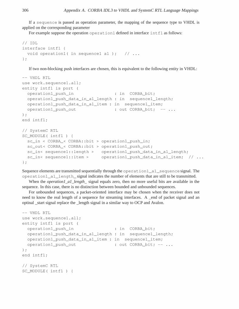
306 Appendix A. CORBA IDL3 to VHDL and SystemC RTL Language Mappings
If a sequence is passed as operation parameter, the mapping of the sequence type to VHDL isapplied on the corresponding parameter
For example suppose the operationoperation1 defined in interfaceintf1 as follows:
// IDLinterface intf1 {
void operation1( in sequence1 a1 ); // ...};
If two non-blocking push interfaces are chosen, this is equivalent to the following entity in VHDL:
-- VHDL RTLuse work.sequence1.all;entity intf1 is port (
operation1_push_in : in CORBA_bit;operation1_push_data_in_a1_length : in sequence1_length;operation1_push_data_in_a1_item : in sequence1_item;operation1_push_out : out CORBA_bit; -- ...
);end intf1;
// SystemC RTLSC_MODULE( intf1 ) {
sc_in < CORBA_< CORBA::bit > operation1_push_in;sc_out< CORBA_< CORBA::bit > operation1_push_out;sc_in< sequence1::length > operation1_push_data_in_a1_length;sc_in< sequence1::item > operation1_push_data_in_a1_item; // ...
};
Sequence elements are transmitted sequentially through theoperation1_a1_sequencesignal. Theoperation1_a1_length_ signal indicates the number of elements that are still to be transmitted.
When theoperation1_a1_length_signal equals zero, then no more useful bits are available inthesequence. In this case, there is no distinction between bounded and unbounded sequences.
For unbounded sequences, a packet-oriented interface may be chosen when the receiver does notneed to know the real length of a sequence for streaming interfaces. A _end of packet signal and anoptinal _start signal replace the _length signal in a similar way to OCP and Avalon.
-- VHDL RTLuse work.sequence1.all;entity intf1 is port (
operation1_push_in : in CORBA_bit;operation1_push_data_in_a1_length : in sequence1_length;operation1_push_data_in_a1_item : in sequence1_item;operation1_push_out : out CORBA_bit; -- ...
);end intf1;
// SystemC RTLSC_MODULE( intf1 ) {
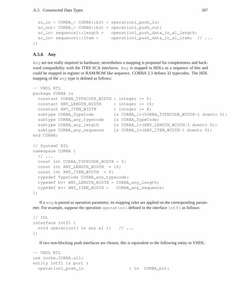
A.5. Constructed Data Types 307
sc_in < CORBA_< CORBA::bit > operation1_push_in;sc_out< CORBA_< CORBA::bit > operation1_push_out;sc_in< sequence1::length > operation1_push_data_in_a1_length;sc_in< sequence1::item > operation1_push_data_in_a1_item; // ...
};
A.5.6 Any
Any are not really required in hardware, nevertheless a mappingis proposed for completeness and back-ward compatibility with the JTRS SCA interfaces.Any is mapped in HDLs as a sequence of bits andcould be mapped in register or RAM/ROM like sequence. CORBA 2.3 defines 32 typecodes. The HDLmapping of theany type is defined as follows:
-- VHDL RTLpackage CORBA isconstant CORBA_TYPECODE_WIDTH : integer := 5;constant ANY_LENGTH_WIDTH : integer := 16;constant ANY_ITEM_WIDTH : integer := 8;subtype CORBA_TypeCode is CORBA_lv(CORBA_TYPECODE_WIDTH-1 downto 0);subtype CORBA_any_typecode is CORBA_TypeCode;subtype CORBA_any_length is CORBA_lv(ANY_LENGTH_WIDTH-1 downto 0);subtype CORBA_any_sequence is CORBA_lv(ANY_ITEM_WIDTH-1 downto 0);
end CORBA;
// SystemC RTLnamespace CORBA {// ...const int CORBA_TYPECODE_WIDTH = 5;const int ANY_LENGTH_WIDTH = 16;const int ANY_ITEM_WIDTH = 8;typedef TypeCode CORBA_any_typecode;typedef bv< ANY_LENGTH_WIDTH > CORBA_any_length;typedef bv< ANY_ITEM_WIDTH > CORBA_any_sequence;
};
If a any is passed as operation parameter, its mapping rules are applied on the corresponding param-eter. For example, suppose the operationoperation1 defined in the interfaceintf1 as follows:
// IDLinterface intf1 {void operation1( in any a1 ); // ...
};
If two non-blocking push interfaces are chosen, this is equivalent to the following entity in VHDL:
-- VHDL RTLuse corba.CORBA.all;entity intf1 is port (operation1_push_in : in CORBA_bit;
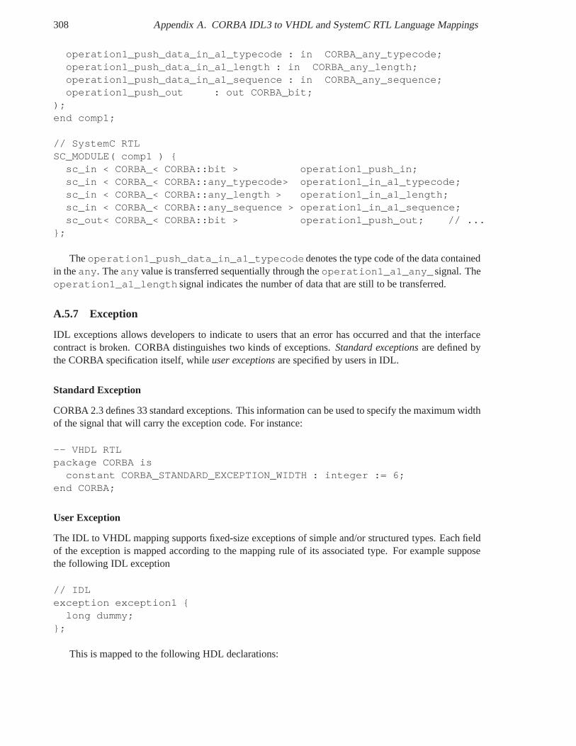
308 Appendix A. CORBA IDL3 to VHDL and SystemC RTL Language Mappings
operation1_push_data_in_a1_typecode : in CORBA_any_typecode;operation1_push_data_in_a1_length : in CORBA_any_length;operation1_push_data_in_a1_sequence : in CORBA_any_sequence;operation1_push_out : out CORBA_bit;
);end comp1;
// SystemC RTLSC_MODULE( comp1 ) {
sc_in < CORBA_< CORBA::bit > operation1_push_in;sc_in < CORBA_< CORBA::any_typecode> operation1_in_a1_typecode;sc_in < CORBA_< CORBA::any_length > operation1_in_a1_length;sc_in < CORBA_< CORBA::any_sequence > operation1_in_a1_sequence;sc_out< CORBA_< CORBA::bit > operation1_push_out; // ...
};
Theoperation1_push_data_in_a1_typecodedenotes the type code of the data containedin theany. Theany value is transferred sequentially through theoperation1_a1_any_signal. Theoperation1_a1_length signal indicates the number of data that are still to be transferred.
A.5.7 Exception
IDL exceptions allows developers to indicate to users that an error has occurred and that the interfacecontract is broken. CORBA distinguishes two kinds of exceptions. Standard exceptionsare defined bythe CORBA specification itself, whileuser exceptionsare specified by users in IDL.
Standard Exception
CORBA 2.3 defines 33 standard exceptions. This information can be used to specify the maximum widthof the signal that will carry the exception code. For instance:
-- VHDL RTLpackage CORBA is
constant CORBA_STANDARD_EXCEPTION_WIDTH : integer := 6;end CORBA;
User Exception
The IDL to VHDL mapping supports fixed-size exceptions of simple and/or structured types. Each fieldof the exception is mapped according to the mapping rule of its associated type. For example supposethe following IDL exception
// IDLexception exception1 {
long dummy;};
This is mapped to the following HDL declarations:
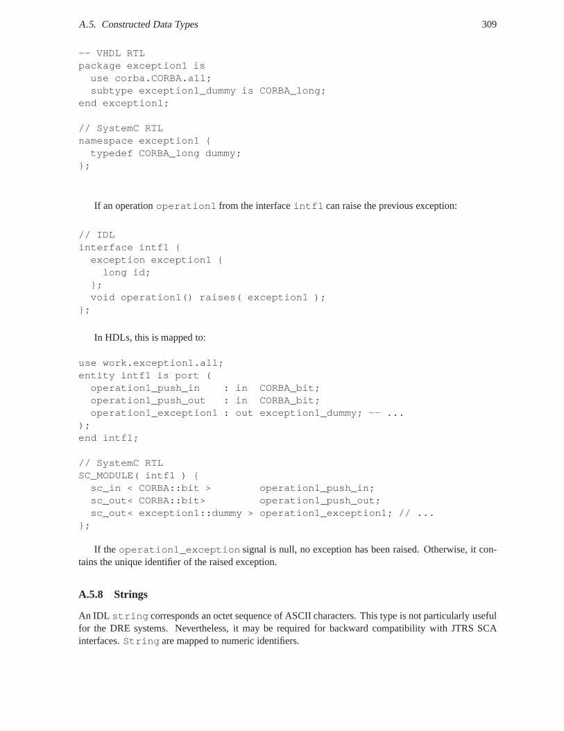
A.5. Constructed Data Types 309
-- VHDL RTLpackage exception1 isuse corba.CORBA.all;subtype exception1_dummy is CORBA_long;
end exception1;
// SystemC RTLnamespace exception1 {typedef CORBA_long dummy;
};
If an operationoperation1 from the interfaceintf1 can raise the previous exception:
// IDLinterface intf1 {exception exception1 {long id;
};void operation1() raises( exception1 );
};
In HDLs, this is mapped to:
use work.exception1.all;entity intf1 is port (operation1_push_in : in CORBA_bit;operation1_push_out : in CORBA_bit;operation1_exception1 : out exception1_dummy; -- ...
);end intf1;
// SystemC RTLSC_MODULE( intf1 ) {sc_in < CORBA::bit > operation1_push_in;sc_out< CORBA::bit> operation1_push_out;sc_out< exception1::dummy > operation1_exception1; // ...
};
If the operation1_exception signal is null, no exception has been raised. Otherwise, it con-tains the unique identifier of the raised exception.
A.5.8 Strings
An IDL string corresponds an octet sequence of ASCII characters. This type is not particularly usefulfor the DRE systems. Nevertheless, it may be required for backward compatibility with JTRS SCAinterfaces.String are mapped to numeric identifiers.
310 Appendix A. CORBA IDL3 to VHDL and SystemC RTL Language Mappings
A.5.9 Float
Float integers could be temporarily mapped into logic vectors, however a recent Accellera standard calledVHDL-2006-D3.0 already provides VHDL packages for synthesizable floats. Hence, we recommend adirect mapping from IDL floats to VHDL floats. This standard isready for industry adoption. Synthesistools will certainly support it when hardware middlewares will be available and used.
A.5.10 Fixed
Fixed point integers could be temporarily mapped into bitvectors, however a recent Accellera standardcalled VHDL-2006-D3.0 already provides a VHDL package calledieee.fixed_pkg.allwith thesynthesizableufixed andsfixed fixed point types. Hence, we recommend a direct mapping fromIDL floats to VHDL floats. This standard is ready for industry adoption. Synthesis tools will certainlysupport it when hardware middlewares will be available and used.
A.6 Attribute
In software language mappings, IDLattributes are inferred as a pair of setter and getter operationsto assign and retrieve the value of anattribute. Some possible mapping choices include defining twooperations for each attribute, defining two operations to set or get any attribute, and defining operationsto set or get groups of attributes, and so forth.
A.7 Scoped Name
As HDLs such as VHDL and Verilog do not support scoped names, hardware designers must use theglobal name for a type, constant, exception, or operation. The scope symbol:: in OMG IDL is mappedto an underscore_ in VHDL.
A.8 Module
The module IDL keyword is mapped to package in VHDL and namespace in SystemC as follows:
// OMG IDL3module module1 {
// ...};
-- VHDL RTLpackage module1 is
-- ...end module1;
// SystemC RTLnamespace module1 {
// ...};
A.9. Interface 311
A.9 Interface
In the following, we present mapping configurations for someIDL interfaces based on the previousfamily of hardware interfaces. In other words, we try to explore the mapping exploration space andillustrate its inherent complexity.
A.9.1 Non-blocking control interface for non-reliable oneway operation
If the interfaceintf1 is defined as:
// OMG IDL3interface intf1 {// unreliable onewayoneway void operation1( );
};
The mapped hardware interfaces are defined as:
-- VHDL RTLentity intf1 is port (operation1_push_in : in CORBA_bit; -- ...
);end intf1;
// SystemC RTLSC_MODULE( intf1 ) {sc_in < CORBA::bit > operation1_push_in; // ...
};
A.9.2 Non-blocking control interfaces for operations without parameters or reliable onewayoperation
If the interfaceintf1 is defined as:
// OMG IDL3interface intf1 {void operation1( );
};orinterface intf1 {// reliable onewayoneway void operation1( );
};
The mapped hardware interfaces are defined as:
-- VHDL RTLentity intf1 is port (operation1_push_in : in CORBA_bit;operation1_push_out : out CORBA_bit; -- ...
312 Appendix A. CORBA IDL3 to VHDL and SystemC RTL Language Mappings
);end intf1;
// SystemC RTLSC_MODULE( intf1 ) {
sc_in < CORBA::bit > operation1_push_in;sc_out< CORBA::bit > operation1_push_out; // ...
};
Theoperation1_push_out indicates the completion of the operation. This interface correspondsto the mapping proposed in [BRM+06] and the process-level handshake in [Gra].
A.9.3 Addressable non-blocking push interface without data in input and non-blockingcontrol interface in output for several operations without parameters or reliableoneway operation
If the interfaceintf1 is defined as:
// OMG IDL3interface intf1 {
void operation1( );void operation2( );
};
The mapped hardware interfaces are defined as:
-- VHDL RTLentity intf1 isgeneric (
OPERATION_WIDTH: integer:=1; -- ...);port (
push_in : in CORBA_bit;addr : in CORBA_lv(OPERATION_WIDTH-1 downto 0);push_out : out CORBA_bit; -- ...
);// SystemC RTL#define OPERATION_WIDTH 1SC_MODULE( intf1 ) {
// operation1sc_in < CORBA::bit > push_in;sc_in< CORBA::bv< OPERATION_WIDTH > >addr;sc_out < CORBA::bit > push_out;// ...
};
The parameterOPERATION_WIDTH is the numbers of bits required to binary encode the operationsi.e. OPERATION_WIDTH = ⌈log2(#operations)⌉.
A.9. Interface 313
A.9.4 Addressable non-blocking push interface for input and non-blocking control in-terface for output for several operations with input parameters
For an important number of operations and parameters, hardware I/O ports can be shared to save area.The width of the data bus for operation parameters have to be specified in a mapping configuration file.The parameters are serialized on the data bus according to some standard encoding rules.
If the interfaceintf1 is defined as:
// OMG IDL3interface intf1 {void operation1( );void operation2( in long a1 );
};
The mapped hardware interfaces are defined as:
-- VHDL RTLentity intf1 isgeneric (OPERATION_WIDTH : integer:=1;PUSH_DATA_WIDTH_IN : integer:=32; -- ...
);port (push_in : in CORBA_bit;addr : in CORBA_lv(OPERATION_WIDTH-1 downto 0);push_data_in : in CORBA_lv(PUSH_DATA_WIDTH_IN-1 downto 0);push_out : out CORBA_bit; -- ...
);
// SystemC RTL#define OPERATION_WIDTH 4#define PUSH_DATA_WIDTH_IN 32SC_MODULE( intf1 ) {sc_in < CORBA::bit > push_in;sc_in< CORBA::bv< PUSH_ADDR_WIDTH > > addr;sc_in< CORBA::bv< PUSH_DATA_ WIDTH_IN> > push_data_in;sc_out < CORBA::bit > push_out; // ...
};
Thepush_out indicated the end of the operation and does not acknowledge input parameters re-ception.
A.9.5 Addressable non-blocking push interface in inputs and Non-blocking push inter-face in outputs for several operations with parameters
If the interfaceintf1 is defined as:
// OMG IDL3interface intf1 {void operation1( );
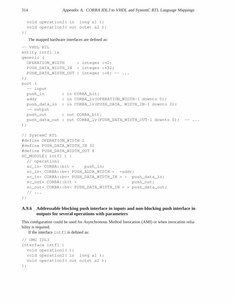
314 Appendix A. CORBA IDL3 to VHDL and SystemC RTL Language Mappings
void operation2( in long a1 );void operation3( out octet a2 );
};
The mapped hardware interfaces are defined as:
-- VHDL RTLentity intf1 isgeneric (
OPERATION_WIDTH : integer :=2;PUSH_DATA_WIDTH_IN : integer :=32;PUSH_DATA_WIDTH_OUT : integer :=8; -- ...
);port (
-- inputpush_in : in CORBA_bit;addr : in CORBA_lv(OPERATION_WIDTH-1 downto 0);push_data_in : in CORBA_lv(PUSH_DATA_ WIDTH_IN-1 downto 0);-- outputpush_out : out CORBA_bit;push_data_out : out CORBA_lv(PUSH_DATA_WIDTH_OUT-1 downto 0); -- ...
);
// SystemC RTL#define OPERATION_WIDTH 2#define PUSH_DATA_WIDTH_IN 32#define PUSH_DATA_WIDTH_OUT 8SC_MODULE( intf1 ) {
// operation1sc_in< CORBA::bit > push_in;sc_in< CORBA::bv< PUSH_ADDR_WIDTH > >addr;sc_in< CORBA::bv< PUSH_DATA_WIDTH_IN > > push_data_in;sc_out< CORBA::bit > push_out;sc_out< CORBA::bv< PUSH_DATA_WIDTH_IN > > push_data_out;// ...
};
A.9.6 Addressable blocking push interface in inputs and non-blocking push interface inoutputs for several operations with parameters
This configuration could be used for Asynchronous Method Invocation (AMI) or when invocation relia-bility is required.
If the interfaceintf1 is defined as:
// OMG IDL3interface intf1 {
void operation1( );void operation2( in long a1 );void operation3( out octet a2 );
};
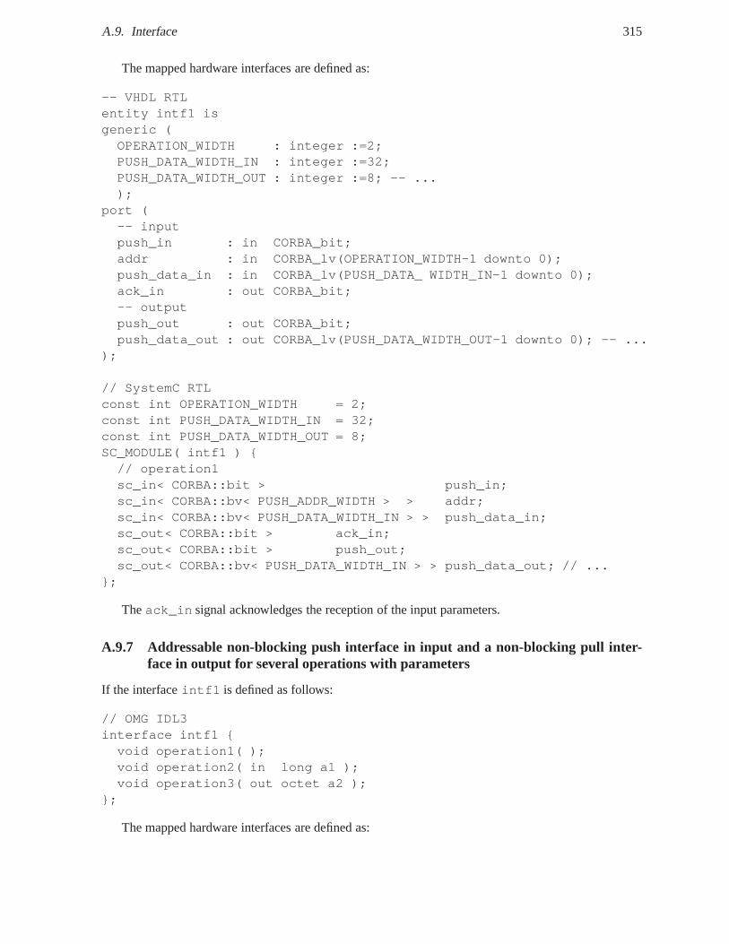
A.9. Interface 315
The mapped hardware interfaces are defined as:
-- VHDL RTLentity intf1 isgeneric (OPERATION_WIDTH : integer :=2;PUSH_DATA_WIDTH_IN : integer :=32;PUSH_DATA_WIDTH_OUT : integer :=8; -- ...);
port (-- inputpush_in : in CORBA_bit;addr : in CORBA_lv(OPERATION_WIDTH-1 downto 0);push_data_in : in CORBA_lv(PUSH_DATA_ WIDTH_IN-1 downto 0);ack_in : out CORBA_bit;-- outputpush_out : out CORBA_bit;push_data_out : out CORBA_lv(PUSH_DATA_WIDTH_OUT-1 downto 0); -- ...
);
// SystemC RTLconst int OPERATION_WIDTH = 2;const int PUSH_DATA_WIDTH_IN = 32;const int PUSH_DATA_WIDTH_OUT = 8;SC_MODULE( intf1 ) {// operation1sc_in< CORBA::bit > push_in;sc_in< CORBA::bv< PUSH_ADDR_WIDTH > > addr;sc_in< CORBA::bv< PUSH_DATA_WIDTH_IN > > push_data_in;sc_out< CORBA::bit > ack_in;sc_out< CORBA::bit > push_out;sc_out< CORBA::bv< PUSH_DATA_WIDTH_IN > > push_data_out; // ...
};
Theack_in signal acknowledges the reception of the input parameters.
A.9.7 Addressable non-blocking push interface in input anda non-blocking pull inter-face in output for several operations with parameters
If the interfaceintf1 is defined as follows:
// OMG IDL3interface intf1 {void operation1( );void operation2( in long a1 );void operation3( out octet a2 );
};
The mapped hardware interfaces are defined as:
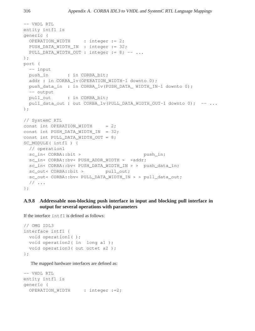
316 Appendix A. CORBA IDL3 to VHDL and SystemC RTL Language Mappings
-- VHDL RTLentity intf1 isgeneric (
OPERATION_WIDTH : integer := 2;PUSH_DATA_WIDTH_IN : integer := 32;PULL_DATA_WIDTH_OUT : integer := 8; -- ...
);port (
-- inputpush_in : in CORBA_bit;addr : in CORBA_lv(OPERATION_WIDTH-1 downto 0);push_data_in : in CORBA_lv(PUSH_DATA_ WIDTH_IN-1 downto 0);-- outputpull_out : in CORBA_bit;pull_data_out : out CORBA_lv(PULL_DATA_WIDTH_OUT-1 downto 0); -- ...
);
// SystemC RTLconst int OPERATION_WIDTH = 2;const int PUSH_DATA_WIDTH_IN = 32;const int PULL_DATA_WIDTH_OUT = 8;SC_MODULE( intf1 ) {
// operation1sc_in< CORBA::bit > push_in;sc_in< CORBA::bv< PUSH_ADDR_WIDTH > >addr;sc_in< CORBA::bv< PUSH_DATA_WIDTH_IN > > push_data_in;sc_out< CORBA::bit > pull_out;sc_out< CORBA::bv< PULL_DATA_WIDTH_IN > > pull_data_out;// ...
};
A.9.8 Addressable non-blocking push interface in input andblocking pull interface inoutput for several operations with parameters
If the interfaceintf1 is defined as follows:
// OMG IDL3interface intf1 {
void operation1( );void operation2( in long a1 );void operation3( out octet a2 );
};
The mapped hardware interfaces are defined as:
-- VHDL RTLentity intf1 isgeneric (
OPERATION_WIDTH : integer :=2;
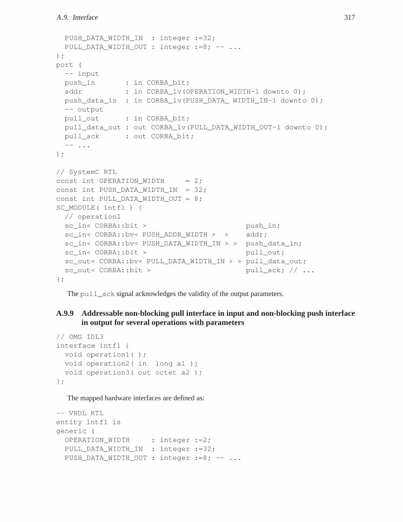
A.9. Interface 317
PUSH_DATA_WIDTH_IN : integer :=32;PULL_DATA_WIDTH_OUT : integer :=8; -- ...
);port (-- inputpush_in : in CORBA_bit;addr : in CORBA_lv(OPERATION_WIDTH-1 downto 0);push_data_in : in CORBA_lv(PUSH_DATA_ WIDTH_IN-1 downto 0);-- outputpull_out : in CORBA_bit;pull_data_out : out CORBA_lv(PULL_DATA_WIDTH_OUT-1 downto 0);pull_ack : out CORBA_bit;-- ...
);
// SystemC RTLconst int OPERATION_WIDTH = 2;const int PUSH_DATA_WIDTH_IN = 32;const int PULL_DATA_WIDTH_OUT = 8;SC_MODULE( intf1 ) {// operation1sc_in< CORBA::bit > push_in;sc_in< CORBA::bv< PUSH_ADDR_WIDTH > > addr;sc_in< CORBA::bv< PUSH_DATA_WIDTH_IN > > push_data_in;sc_in< CORBA::bit > pull_out;sc_out< CORBA::bv< PULL_DATA_WIDTH_IN > > pull_data_out;sc_out< CORBA::bit > pull_ack; // ...
};
Thepull_ack signal acknowledges the validity of the output parameters.
A.9.9 Addressable non-blocking pull interface in input andnon-blocking push interfacein output for several operations with parameters
// OMG IDL3interface intf1 {void operation1( );void operation2( in long a1 );void operation3( out octet a2 );
};
The mapped hardware interfaces are defined as:
-- VHDL RTLentity intf1 isgeneric (OPERATION_WIDTH : integer :=2;PULL_DATA_WIDTH_IN : integer :=32;PUSH_DATA_WIDTH_OUT : integer :=8; -- ...
318 Appendix A. CORBA IDL3 to VHDL and SystemC RTL Language Mappings
);port (
-- inputpull_out : out CORBA_bit;addr : in CORBA_lv(OPERATION_WIDTH-1 downto 0);pull_data_in : in CORBA_lv(PULL_DATA_WIDTH_IN-1 downto 0);-- outputpush_out : out CORBA_bit;push_data_out : out CORBA_lv(PUSH_DATA_WIDTH_OUT-1 downto 0); -- ...
);
// SystemC RTLconst int OPERATION_WIDTH = 2;const int PUSH_DATA_WIDTH_IN = 32;const int PULL_DATA_WIDTH_OUT = 8;SC_MODULE( intf1 ) {
// operation1sc_out< CORBA::bit > pull_out;sc_in< CORBA::bv< PUSH_ADDR_WIDTH > > addr;sc_in< CORBA::bv< PUSH_DATA_WIDTH_IN > > push_data_in;sc_out< CORBA::bit > push_out;sc_out< CORBA::bv< PULL_DATA_WIDTH_OUT > > push_data_out;// ...
};
Thepull_out serves to read input parameters, for instance in the consumer model of communica-tion.
A.10 Operation Invocation
A.10.1 Phases
We distinguish two phases: request for operation call and input parameters transfer, and response foroperation return, error/exception and output parameters transfer. Each phase should have a two-phasehandshake. An acknowledge is useful in SW for synchronization, but needless most of the time in HW(e.g. no acknowledge for write to a configuration register).This acknowledge should be configure foreach operation.
A.10.2 Mapping solutions
We identify two main mapping solutions: 1) explicit IDL-to-VHDL mapping configuration file such asOCP interface configuration files with which hardware interfaces exactly satisfy communication needs,but more tedious and possible incompatibilities to be handled by adapter connectors, 2) fixed hardwareinterface and protocol adapted to specific constraints. This second solution is suitable for the definitionof a fixed API as we will see for the Transceiver component.
A.10. Operation Invocation 319
A.10.3 Operation parameter transfer
A virtual hardware input port is a a set of VHDL entity I/O ports that is associated with one or severalinput parameters It implements a standard hardware interface (syntax) and protocol (semantics) e.g.push or pull, blocking or non-blocking, with/without data or flow control and addressable interface. Thismapping should be flexible and extensible, because the nature of operation parameters is totally implicitin IDL: control flow, data flow or a mix, continuous or discontinuous, with or without flow control etc.The association between parameters and input ports is explicitly specified in a mapping configurationfile. The component-oriented nature of CORBA can be used to define dedicated IDL interfaces forcontrol, configuration or data-oriented aspects. The nature of communication could be expressed by newIDL keywords to better characterize CORBA component ports such asbuffered, addressable,stream and infer hardware interfaces based on register, fifo, and RAM. When several input parametersare associated to an input port, the way input parameters aretransferred on hardware interface signalsshould be explicit. The data bus width is specified in the mapping configuration file. It is not requiredto be a power of two. The endianness is configured to determineif transfers are LSB or MSB first. Thedata layout of parameters transfer shall also be configured.
Different transfer modes can be distinguished in particular: Serial or Time-Division Multiplexing(TDM ), where one parameter (chunk) is transferred at a time, andParallel or Spatial-Division Multi-plexing (SDM) where (one chunk of) each parameter is transferred at a time[Bje05]. Serial transfersrequire less hardware wires therefore less silicium area and power consumption, but are slower. Paral-lel transfers require more hardware wires therefore more silicium area and power consumption, but arefaster.
Different encoding rules can be distinguished in particular: with paddingwhere non-significant dataare inserted to align parameters on address boundaries as inCORBA CDR [OMG08b], andwithoutpaddingwhere no data are inserted to align parameters as in ICE [HS08] [Hen04]. As in ASN.1 PackedEncoding Rules (PER) [IT02] support both alternatives. Unaligned data are more compact but are slowerfor middlewares to encode and decode. Aligned data are easier to encode and decode but use morebandwidth.
We propose to support all these solutions to best fit each particular application requirements in DREsystems. Designers should indicate to IDL-to-HDL compilers which one they want to use during map-ping configuration. For both transfer modes and encoding rules, reusable connectors can be envisaged toconvert parameter data from one configuration to another.
For instance, consider the following interfaceintf1:
// OMG IDL3interface intf1 {void operation1( in octet a1, in short a2, in long a3 );
};or similarly:typedef struct s { octet a1; short a2; long a3; } myStruct;void operation1( in myStruct s1);
};
Hence, we identify two main solutions to transfer parameters: 1) a dedicated signal for each parame-ter whose width correspond to the size of the parameter data type. An appropriate naming convention isrequired to avoid a name clash. This solution is user-friendly and performant, but requires a lot of area.
interface Example {exception Err1{};
320 Appendix A. CORBA IDL3 to VHDL and SystemC RTL Language Mappings
exception Err2{};boolean op1( in boolean p1, out short p2, inout long p3) raises(Err1, Err2);
};
If blocking push interfaces are used, the mapped hardware interface may be:
entity Example isport (
op1_push_in : in CORBA_bit; -- requestop1_ack_in : out CORBA_bit;op1_p1 : in CORBA_boolean;op1_p3_in : in CORBA_long;op1_push_out : out CORBA_bit; -- responseop1_ack_out : in CORBA_bit; -- optionalop1_p2 : out CORBA_short;op1_p3_out : out CORBA_long;op1_return : out CORBA_boolean;op1_exc : out exception;op1_exc_id : out CORBA_lv(op1ExcDW-1 downto 0);
);end entity Example;
2) shared wires for all parameters going in the same direction whose width is fixed by a constant (e.g.VHDL generic). This may generalized to all parameters of alloperations of an interface. This approachis the most generic, area-efficient, but less user-friendlyas parameters are serialized.
entity Example isgeneric (natural op1InPrmDW := 1);port (
op1_push_in : in std_logic; -- request \\op1_acc_in : out std_logic; -- optional}op1_in : in std_logic_vector(op1InPrmDW-1 downto 0);op1_push_out : out std_logic; -- responseop1_ack_out : in std_logic; -- optionalop1_out : out std_logic_vector(op1OutPrmDW-1 downto 0);op1_return : out CORBA_boolean;op1_exc : out exception;op1_exc_id : out std_logic_vector(op1ExcDW-1 downto 0);
);end entity Example;
The data width used to transfer parameters in parallel or serial may be chosen at instantiation time.The endianness and alignment rules - with or without padding- should be defined. The VHDL datatype e.g. record inferred from UML/IDL definitions could notbe used in entity/component interface,but within VHDL implementation (architecture) where thesedata types should be serialized in a genericway on the shared data bus (solution 2). Each approach has itsstrengths and weaknesses. It is a trade-offbetween flexibility, complexity to guaranty portability/interoperability and performance (area, timing,power consumption).
A.11. Object 321
The transfer of parameters should beGlobally Serial Locally Parallel(GSLP). Indeed, request mes-sages are typically globally serialized on buses, while operation parameters may be locally transferredin parallel to maximize performance and avoid a bottleneck regardless of the used serial or parallel bus.Adapter connectors would be in charge of serialization/deserialization between the bus interface and thehardware invocation interface.
A.10.4 Operation-level concurrency
Operation-level concurrency should be defined in a similar way to UML concurrency constraint, [GMTB04]and [JS07] for more efficiency. Groups of sequential operations are inferred as shared invocation sig-nals acting as a virtual address, while parallel operationsare inferred as dedicated invocation signalsto enable independent invocations. For instance, we consider that all operations of the SCA Resourceinterface are sequentially invocable to allows consistency between mono-threaded and multi-thread SCACoreFramework implementations.
A.11 Object
We assume that the interconnection between client and server objects is entirely handled by the underly-ing middleware in a transparent manner from the user’s pointof view.
The configuration of the middleware for a given application is made from an OMG D&C componentdeployment plan. This deployment plan specifies all object instances, their locations and connections.
To identify object instances, a CORBA::Object is defined by asystem unique identifier encoded inan enumerated type. The enumerate is fixed thanks to the D&C component deployment plan and takesinto account all component instances.
A.12 Inheritance
OMG IDL supports inheritance of IDL interfaces. An child interface can inherit operations from otherinterfaces. For instance:
// OMG IDL3interface intf1 {void operation1( );
};interface intf2 : intf1 {void operation2( in long a2, out octet a3 );
};
If four non-blocking push interfaces are chosen with the data bus width corresponding to parameterssize, this is equivalent to the following VHDL declarations:
-- VHDL RTLentity intf2 is port (operation1_push_in : in CORBA_bit;operation1_push_out : out CORBA_bit;operation2_push_in : in CORBA_bit;operation2_push_data_in_a2 : in CORBA_long;operation2_push_data_out_a3 : out CORBA_octet;
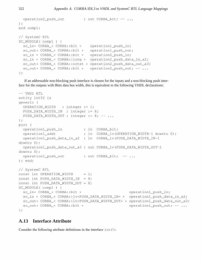
322 Appendix A. CORBA IDL3 to VHDL and SystemC RTL Language Mappings
operation2_push_out : out CORBA_bit; -- ...);end comp1;
// SystemC RTLSC_MODULE( comp1 ) {
sc_in< CORBA_< CORBA::bit > operation1_push_in;sc_out< CORBA_< CORBA::bit > operation1_push_out;sc_in < CORBA_< CORBA::bit > operation2_push_in;sc_in < CORBA_< CORBA::long > operation2_push_data_in_a2;sc_out< CORBA_< CORBA::octet > operation2_push_data_out_a3;sc_out< CORBA_< CORBA::bit > operation2_push_out; -- ...
};
If an addressable non-blocking push interface is chosen forthe inputs and a non-blocking push inter-face for the outputs with 8bits data bus width, this is equivalent to the following VHDL declarations:
-- VHDL RTLentity intf2 isgeneric (
OPERATION_WIDTH : integer := 1;PUSH_DATA_WIDTH_IN : integer := 8;PUSH_DATA_WIDTH_OUT : integer := 8; -- ...
);port (
operation1_push_in : in CORBA_bit;operation1_addr : in CORBA_lv(OPERATION_WIDTH-1 downto 0);operation1_push_data_in_a2 : in CORBA_lv(PUSH_DATA_WIDTH_IN-1
downto 0);operation1_push_data_out_a3 : out CORBA_lv(PUSH_DATA_WIDTH_OUT-1
downto 0);operation1_push_out : out CORBA_bit; -- ...
); end;
// SystemC RTLconst int OPERATION_WIDTH = 1;const int PUSH_DATA_WIDTH_IN = 8;const int PUSH_DATA_WIDTH_OUT = 8;SC_MODULE( comp1 ) {
sc_in< CORBA_< CORBA::bit > operation1_push_in;sc_in < CORBA_< CORBA::lv<PUSH_DATA_WIDTH_IN> > operation1_push_data_in_a2;sc_out< CORBA_< CORBA::lv<PUSH_DATA_WIDTH_OUT> > operation1_push_data_out_a3;sc_out< CORBA_< CORBA::bit > operation1_push_out; -- ...
};
A.13 Interface Attribute
Consider the following attribute definitions in the interfaceintf1:
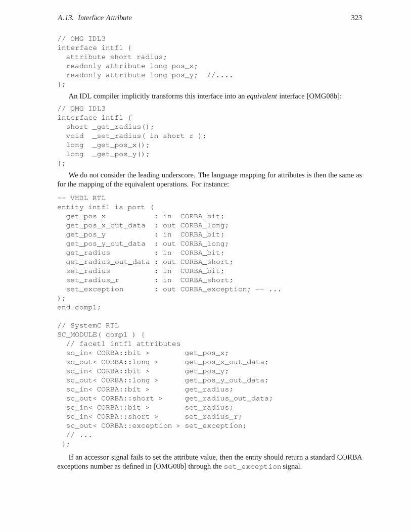
A.13. Interface Attribute 323
// OMG IDL3interface intf1 {attribute short radius;readonly attribute long pos_x;readonly attribute long pos_y; //....
};
An IDL compiler implicitly transforms this interface into an equivalentinterface [OMG08b]:
// OMG IDL3interface intf1 {short _get_radius();void _set_radius( in short r );long _get_pos_x();long _get_pos_y();
};
We do not consider the leading underscore. The language mapping for attributes is then the same asfor the mapping of the equivalent operations. For instance:
-- VHDL RTLentity intf1 is port (get_pos_x : in CORBA_bit;get_pos_x_out_data : out CORBA_long;get_pos_y : in CORBA_bit;get_pos_y_out_data : out CORBA_long;get_radius : in CORBA_bit;get_radius_out_data : out CORBA_short;set_radius : in CORBA_bit;set_radius_r : in CORBA_short;set_exception : out CORBA_exception; -- ...
);end comp1;
// SystemC RTLSC_MODULE( comp1 ) {// facet1 intf1 attributessc_in< CORBA::bit > get_pos_x;sc_out< CORBA::long > get_pos_x_out_data;sc_in< CORBA::bit > get_pos_y;sc_out< CORBA::long > get_pos_y_out_data;sc_in< CORBA::bit > get_radius;sc_out< CORBA::short > get_radius_out_data;sc_in< CORBA::bit > set_radius;sc_in< CORBA::short > set_radius_r;sc_out< CORBA::exception > set_exception;// ...
};
If an accessor signal fails to set the attribute value, then the entity should return a standard CORBAexceptions number as defined in [OMG08b] through theset_exception signal.
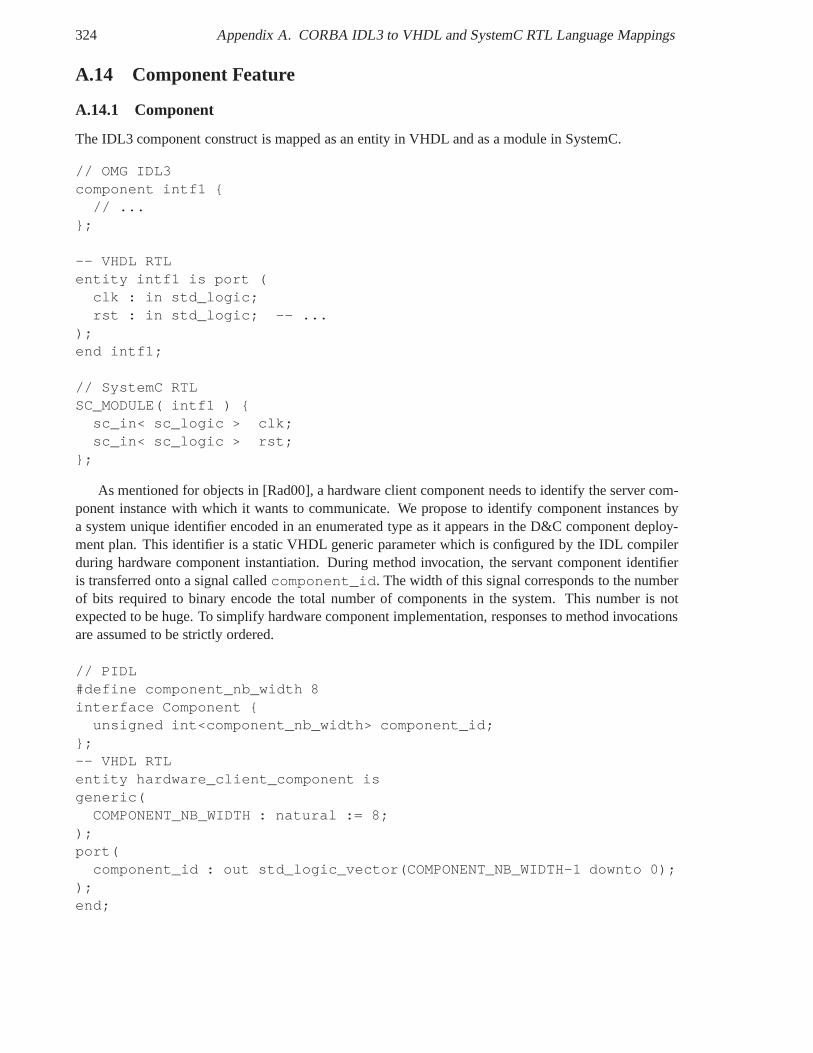
324 Appendix A. CORBA IDL3 to VHDL and SystemC RTL Language Mappings
A.14 Component Feature
A.14.1 Component
The IDL3 component construct is mapped as an entity in VHDL and as a module in SystemC.
// OMG IDL3component intf1 {
// ...};
-- VHDL RTLentity intf1 is port (
clk : in std_logic;rst : in std_logic; -- ...
);end intf1;
// SystemC RTLSC_MODULE( intf1 ) {
sc_in< sc_logic > clk;sc_in< sc_logic > rst;
};
As mentioned for objects in [Rad00], a hardware client component needs to identify the server com-ponent instance with which it wants to communicate. We propose to identify component instances bya system unique identifier encoded in an enumerated type as itappears in the D&C component deploy-ment plan. This identifier is a static VHDL generic parameterwhich is configured by the IDL compilerduring hardware component instantiation. During method invocation, the servant component identifieris transferred onto a signal calledcomponent_id. The width of this signal corresponds to the numberof bits required to binary encode the total number of components in the system. This number is notexpected to be huge. To simplify hardware component implementation, responses to method invocationsare assumed to be strictly ordered.
// PIDL#define component_nb_width 8interface Component {
unsigned int<component_nb_width> component_id;};-- VHDL RTLentity hardware_client_component isgeneric(
COMPONENT_NB_WIDTH : natural := 8;);port(
component_id : out std_logic_vector(COMPONENT_NB_WIDTH-1 downto 0););end;
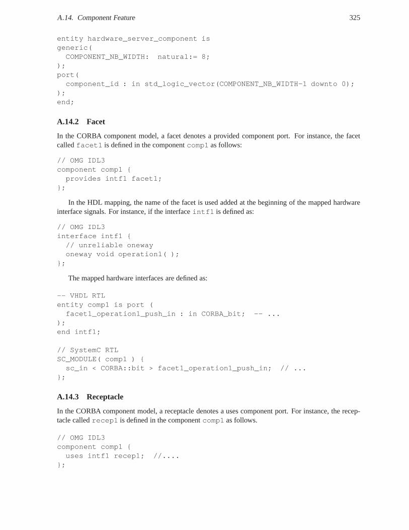
A.14. Component Feature 325
entity hardware_server_component isgeneric(COMPONENT_NB_WIDTH: natural:= 8;
);port(component_id : in std_logic_vector(COMPONENT_NB_WIDTH-1 downto 0);
);end;
A.14.2 Facet
In the CORBA component model, a facet denotes a provided component port. For instance, the facetcalledfacet1 is defined in the componentcomp1 as follows:
// OMG IDL3component comp1 {provides intf1 facet1;
};
In the HDL mapping, the name of the facet is used added at the beginning of the mapped hardwareinterface signals. For instance, if the interfaceintf1 is defined as:
// OMG IDL3interface intf1 {// unreliable onewayoneway void operation1( );
};
The mapped hardware interfaces are defined as:
-- VHDL RTLentity comp1 is port (facet1_operation1_push_in : in CORBA_bit; -- ...
);end intf1;
// SystemC RTLSC_MODULE( comp1 ) {sc_in < CORBA::bit > facet1_operation1_push_in; // ...
};
A.14.3 Receptacle
In the CORBA component model, a receptacle denotes a uses component port. For instance, the recep-tacle calledrecep1 is defined in the componentcomp1 as follows.
// OMG IDL3component comp1 {uses intf1 recep1; //....
};
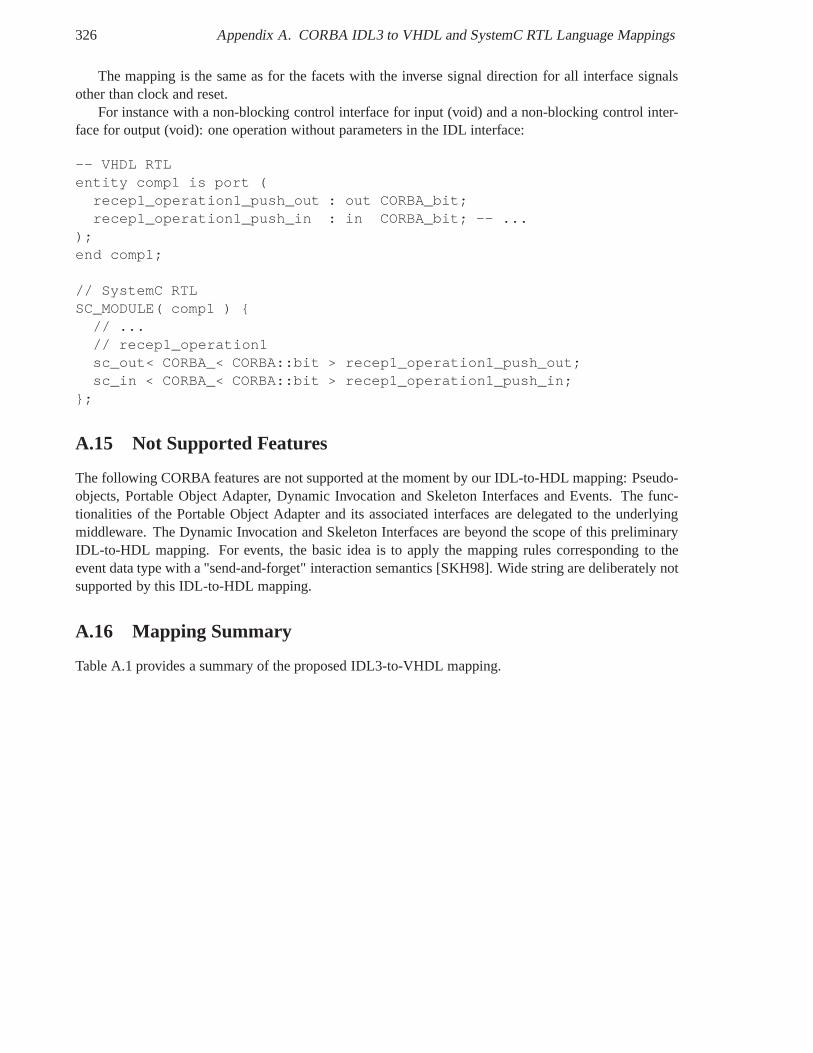
326 Appendix A. CORBA IDL3 to VHDL and SystemC RTL Language Mappings
The mapping is the same as for the facets with the inverse signal direction for all interface signalsother than clock and reset.
For instance with a non-blocking control interface for input (void) and a non-blocking control inter-face for output (void): one operation without parameters inthe IDL interface:
-- VHDL RTLentity comp1 is port (
recep1_operation1_push_out : out CORBA_bit;recep1_operation1_push_in : in CORBA_bit; -- ...
);end comp1;
// SystemC RTLSC_MODULE( comp1 ) {
// ...// recep1_operation1sc_out< CORBA_< CORBA::bit > recep1_operation1_push_out;sc_in < CORBA_< CORBA::bit > recep1_operation1_push_in;
};
A.15 Not Supported Features
The following CORBA features are not supported at the momentby our IDL-to-HDL mapping: Pseudo-objects, Portable Object Adapter, Dynamic Invocation and Skeleton Interfaces and Events. The func-tionalities of the Portable Object Adapter and its associated interfaces are delegated to the underlyingmiddleware. The Dynamic Invocation and Skeleton Interfaces are beyond the scope of this preliminaryIDL-to-HDL mapping. For events, the basic idea is to apply the mapping rules corresponding to theevent data type with a "send-and-forget" interaction semantics [SKH98]. Wide string are deliberately notsupported by this IDL-to-HDL mapping.
A.16 Mapping Summary
Table A.1 provides a summary of the proposed IDL3-to-VHDL mapping.
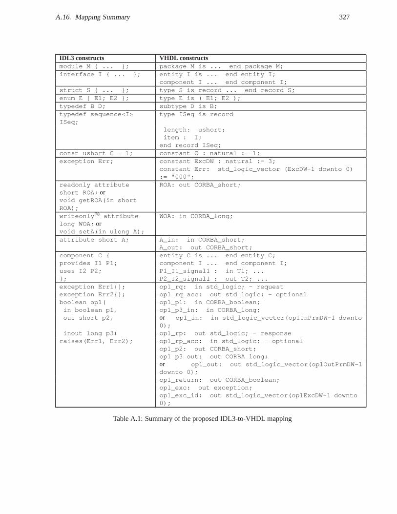
A.16. Mapping Summary 327
IDL3 constructs VHDL constructsmodule M { ... }; package M is ... end package M;interface I { ... }; entity I is ... end entity I;
component I ... end component I;struct S { ... }; type S is record ... end record S;enum E { E1; E2 }; type E is ( E1; E2 );typedef B D; subtype D is B;typedef sequence<I>ISeq;
type ISeq is record
length: ushort;item : I;
end record ISeq;const ushort C = 1; constant C : natural := 1;exception Err; constant ExcDW : natural := 3;
constant Err: std_logic_vector (ExcDW-1 downto 0):= "000";
readonly attributeshort ROA; or
ROA: out CORBA_short;
void getROA(in shortROA);writeonly78 attributelong WOA; or
WOA: in CORBA_long;
void setA(in ulong A);attribute short A; A_in: in CORBA_short;
A_out: out CORBA_short;component C { entity C is ... end entity C;provides I1 P1; component I ... end component I;uses I2 P2; P1_I1_signal1 : in T1; ...}; P2_I2_signal1 : out T2; ...exception Err1{}; op1_rq: in std_logic; - requestexception Err2{}; op1_rq_acc: out std_logic; - optionalboolean op1( op1_p1: in CORBA_boolean;in boolean p1, op1_p3_in: in CORBA_long;out short p2, or op1_in: in std_logic_vector(op1InPrmDW-1 downto
0);inout long p3) op1_rp: out std_logic; - response
raises(Err1, Err2); op1_rp_acc: in std_logic; - optionalop1_p2: out CORBA_short;op1_p3_out: out CORBA_long;or op1_out: out std_logic_vector(op1OutPrmDW-1downto 0);op1_return: out CORBA_boolean;op1_exc: out exception;op1_exc_id: out std_logic_vector(op1ExcDW-1 downto0);
Table A.1: Summary of the proposed IDL3-to-VHDL mapping

Appendix B
Personal Bibliography
This section contains the list of the publications written during this PhD work.
1. Gailliard, G.; Balp, H.; Jouvray, C.; Verdier, F., "Towards a Common HW/SW Interface-Centricand Component-Oriented Specification and Design Methodology", in Proceedings of the Forumon Specification and Design Languages (FDL), pp. 31-36, 23-25 September 2008, Stuttgart, Ger-many.
2. Gailliard, G.; Balp, H.; Sarlotte, M.; Verdier, F., "Mapping Semantics of CORBA IDL and GIOPto Open Core Protocol for Portability and Interoperabilityof SDR Waveform Components", In-ternational Conference on Design and Test in Europe (DATE),pp. 330-335, 10-14 March 2008,Munich, Germany.
3. Manet, P.; Maufroid, D.; Tosi, L.; Gailliard, G.; Mulertt, O.; Di Ciano, M.; Legat, J.; Aulagnier,D.; Gamrat, C.; Liberati, R.; La Barba, V.; Cuvelier, P.; Rousseau, B.; and Gelineau, P. An evalua-tion of dynamic partial reconfiguration for signal and imageprocessing in professional electronicsapplications. EURASIP Journal on Embedded Systems. 2008 , pp. 1-11., 3 November 2008.
4. Gailliard, G.; Nicollet, E.; Sarlotte, M.; Verdier, F., "Transaction Level modeling of SCA Com-pliant Software Defined Radio Waveforms and Platforms PIM/PSM", International Conference onDesign and Test in Europe (DATE), pp. 1-6, 16-20 April 2007, Nice, France.
5. Gailliard, G.; Mercier, B.; Sarlotte, M.; Candaele, B.; Verdier, F., "Towards a SystemC TLMbased Methodology for Platform Design and IP reuse: Application to Software Defined Radio",Second European Workshop on Reconfigurable Communication-Centric SoCs (RECOSOC), 3-5July 2006, Montpellier, France.
This section contains the list of the project deliverables in which I participated presented during thisPhD work.
1. WINTSEC (Wireless INTeroperability for SECurity), State on the art on hardware componentmodels, October 2007.
2. Watine, V.; Seignole, V.; Balp, H. and G. Gailliard, "IDL-to-VHDL Mapping Initial Require-ments", OMG Washington Technical Meeting, March 2008.
3. RECOPS (Reconfiguring Programmable Devices for MilitaryHardware Electronics) The RE-COPS project is an EDA project no 05/102.016/010
329
330 Appendix B. Personal Bibliography
4. SPICES (Support for Predictable Integration of mission Critical Embedded Systems) . SPICES isan EUREKA-ITEA project and runs from 01/09/2006 until 31/08/2009.
5. MOSART (Mapping Optimization for Scalable multi-core ARchiTecture) Project (IST-215244)Website (ITEA)
6. Nicollet, E.; Pothin, S.; Gailliard G.; Caron B.; Ruben, Transceiver Facility Specification, SDRF-08-S-0008-V1.0.0, January, 2009, SDR Forum.
This section contains the list of the presentations presented during this PhD work.
1. Gailliard, G., "Déclinaison matérielle du canevas logiciel SCA", Poster presented at Ecole d’hiverFrancophone sur les Technologies de Conception des systèmes embarqués Hétérogènes (FETCH’07),10-12 January 2007, Villard-de-Lans, France.
2. CNRS Groupement de Recherche (GDR) Information, Signal,Images, viSion (ISIS), C theme,"Outils, méthodes pour les Traitements Du Signal et de l’Image (TDSI)", September 2006
Appendix C
Résumé Etendu
Cette thèse s’intéresse à la déclinaison matérielle des concepts logiciels d’intergiciel et d’architecturelogicielle à base de composants, conteneurs et connecteursdans les réseaux de portes programmablesin situ (Field-Programmable Gate Array- FPGA). Le domaine d’applications ciblé est la radio définielogiciellement ou plus généralement radio logicielle (Software Defined Radio(SDR)).
Une radio logicielle est une radio reconfigurable dont les fonctionnalités sont définies logiciellementau plus proche de l’antenne. Elle est capable d’exécuter un ensemble d’applications de forme d’ondesur la même plateforme radio. Une seule application est exécutée à la fois. Une application de formed’onde est une application logicielle à base de composants.Ces composants implémentent notammentdes algorithmes de traitement du signal, qui traitent les données reçues de l’antenne vers l’utilisateurfinal et vice versa.
Une plateforme radio est un ensemble de couches logicielleset matérielles fournissant les servicesrequis par la couche applicative de forme d’onde.
Au delà de la vision idéale d’une radio entièrement logicielle, les traitements numériques du signal decertaines applications de formes d’onde requièrent néanmoins une forte puissance de calcul, que ne sontpas capables de fournir les processeurs classiques (ARM, PowerPC, etc). Ils ont donc besoin d’unitésde traitements dédiées telles que les processeurs de traitements du signal (Digital Signal Processors-DSPs), les FPGAs et les circuits intégrés spécifiques à une application (Application Specific IntegratedCircuits - ASICs).
Nous nous intéressons plus particulièrement aux radios logicielles conformes au canevas d’architecturelogicielle appeléSoftware Communications Architecture(SCA). Le SCA est un standard de-facto de laradio logicielle militaire, mais il peut tout à fait être utilisé pour des équipements civils. De plus, lesprincipaux besoins du SCA sontportabilité , interoperabilite , reutilisation et reconfiguration des com-posants SCA.
Les principaux besoins de la SDR et du SCA sont: laportabilité des applications de forme d’ondeparmi différentes plateformes radios, l’interopérabilité des communications hétérogènes entre ses com-posants logiciels et matériels, leurréutilisabilité et la reconfigurabilité de la plateforme radio pourexécuter un ensemble de formes d’ondes, qui peuvent avoir des contraintes, notamment temps-réels,différentes.
Le SCA spécifie un environnement d’exploitation (ouOperating Environment(OE)) pour gérer lesapplications radios et offrir les services extra-fonctionnels de la plateforme radio. Cet OE contientun ensemble d’interfaces logicielles appeléCore Framework, un intergiciel conforme àCommon Ob-jet Request Broker Architecture) (CORBA) pour l’embarqué (CORBAeanciennement appeléMinimumCORBA) et un système d’exploitation (Operating System- OS) conforme avec les interfacesPOSIX(Portable Operating System Interface). L’OE SCA cible les processeurs généraux, mais n’est pas adapté
331
332 Appendix C. Résumé Etendu
pour les unités de traitement dédiées comme les DSPs, FPGAs et ASICs.Les besoins de portabilité et de réutilisation des composants SCA requièrent que leurs interfaces ab-
straites définies à un niveau système soient indépendantes d’une implémentation logicielle ou matérielleet puissent être indifféremment traduites dans un langage de programmation logiciel tel que C/C++, unlangage système tel que SystemC au niveau transaction , ou unlangage de description matériel tel queVHDL ou SystemC au niveau registre (Register Transfer Level- RTL ).
La modélisation au niveau transactionnel (Transaction Level Modeling- TLM ) consiste à modéliserles communications d’un système à différents niveaux d’abstraction en utilisant des appels de fonctions,plutôt que des signaux matériels comme dans les simulateursau niveau RTL, afin d’augmenter la vitessede simulation de systèmes embarqués mêlant logiciel et matériel,
Le but ambitieux poursuivi par cette thèse est de décliner les concepts du génie logiciel, notam-ment utilisés par le SCA, aux FPGAs afin de proposer une approche commune de spécification etd’implémentation des applications de radio logicielle à base de composants logiciels/matériels. Cesconcepts sont issus principalement de l’architecture logicielle à base de composants et des intergiciels.
Habituellement, l’intégration de modules matériels dans les FPGAs s’appuie sur des interfaces logi-cielles et matérielles bas niveau, composées d’interfacesde bus propriétaires, de registres mappés enmémoire et d’interruption pour la synchronisation entre les modules logiciels et matériels. Cette inté-gration est fastidieuse et source d’erreurs. De plus, la réutilisabilité de ces modules est limitée. Desméthodologies de conception conjointe pour le logiciel et le matériel ont donc été proposées pour réduirele fossé conceptuel entre conception logicielle et conception matérielle, et ainsi faciliter cette intégration.
Etant donné que le SCA est fondamentalement basé sur le modèle objet, nous nous sommes partic-ulièrement intéressés par l’application des concepts du modèle objet à la conception matérielle.
Dans l’approche orientée objet, un objet est une entité identifiable, qui a un état et un comportement,qui lui sont propres. Ce comportement n’est accessible qu’au travers d’une interface à base de signaturesd’opérations. L’appel d’une opération déclenche le comportement associé et est équivalent à l’envoi d’unmessage contenant l’identifiant et les paramètres de l’opération.
Pour appliquer le modèle objet à du matériel synthétisable dans les FPGAs, les travaux précédentsproposent un mapping d’une interface logicielle à base d’opérations à une interface matérielle à base designaux ou "fils". Cependant, ces travaux ne représentent qu’une solution dans l’espace d’exploration dumapping. De plus, l’approche objet a quelques limitations.Un objet ne présente pas plusieurs, mais uneseule interface fournie, la plus dérivée, même s’il hérite de multiple interfaces. Les dépendances d’unobjet sont implicites car aucune interface n’est requise, et il n’y a pas de séparation claire entre logiquefonctionnelle et non-fonctionnelle telle que la communication entre objets et le déploiement d’objets.
Alors que la plupart des travaux sur l’application des concepts logiciels à la conception matériellesont basés sur une approche orientée objet, nous allons plusloin en considérant l’application de l’architecturelogicielle orientée composant, qui est un autre aspect du SCA.
L’approche orientée composant s’appuie sur quatre principaux modèles: les modèles de composantsdéfinissant la structure et le comportement des composants,les modèles de connecteurs pour spécifierles interactions entre les composants, les modèles de conteneurs pour accéder notamment aux servicesd’intergiciels, et les modèles de déploiement et d’archivage pour déployer les applications à base decomposants distribués. Nous avons naturellement décliné ces concepts pour les composants matériels.
Nous avons investigué l’implémentation matérielle de composants abstraits orienté objet. Nousdéfendons l’idée que l’approche composant fournit de meilleurs concepts unifiant pour les systèmesembarqués mêlant logiciel et matériel, que l’approche objet seule. Nous proposons un état de l’art surl’application des concepts d’objet, de composant et d’intergiciel à la conception matérielle.
Pour permettre le raffinement systématique d’interfaces decomposants orientés objet définis dans lelangage de définition d’interface (IDL) de l’intergiciel CORBA ou le langage de modélisation unifiéeUML, en interfaces de composants systèmes, logiciels et matériels, nous proposons de définir de nou-
333
veaux mappings de langages de CORBA IDL vers SystemC au niveau transactionnel ou au niveau reg-istre, et VHDL, lui aussi au niveau registre. L’exigence de portabilité du SCA est adressée par ces map-pings de langages. Notre mapping d’IDL à SystemC au niveau fonctionnel considère surtout SystemCcomme un langage et non comme une extension du C++ pour le mapping des concepts de composant etde connecteur. Pour le reste, il s’appuie sur la mapping au niveau RTL (e.g. types de données) et à défautsur le mapping existant entre IDL et C++ par héritage des interfaces de la librairie SystemC.
Le mapping d’IDL à SystemC au niveau transactionnel s’appuie sur des adapteurs d’interfacesappelés transacteurs. Nous considérons ces transacteurs comme des connecteurs transactionnels, quiadaptent le mapping des interfaces utilisateurs en IDL/UMLaux interfaces standards TLM 1.0/2.0.
Pour le mapping d’IDL à VHDL et SystemC RTL, nous avons formulé des exigences pour un map-ping standard IDL et les langages de description matériel. Notre mapping IDL/HDL consiste en une al-location manuelle ou semi-automatique d’éléments mémoire(registre, FIFO, RAM/ROM), d’interfacesmatérielles et de protocoles, à des abstractions logicielles telles que composant, port, interface, opérra-tion, paramètre et connecteur. Cette approche permet un mapping générique, flexible, configurable, maisplus complexe à mettre en oeuvre. L’implémentation de composants SCA matériels montre la nécessitéd’une implémentation optimisée d’un modèle de composant logiciel.
De plus, nous avons prototypé un compilateur IDL3-VHDL en utilisant les technologies d’ingénieriedirigée par les modèles en utilisant des transformationsQuery View Transform(QVT ) du meta-modèleLightweight CORBA Component Model(LwCCM) étendu pour la mapping RTL, vers un meta-modèleVHDL, et des transformations modèle à texte pour la génération de code VHDL avecMOF2Text.
Le besoin d’interopérabilité du SCA a été adressé en prototypant un intergiciel matériel utilisantde façon transparente le mapping mémoire et deux protocolesde messages: CORBAGeneral Inter-Object Request Broker Protocol(GIOP) et le protocoleModem Hardware Abstraction Layer(MHAL )du SCA. Nous avons proposé un canevas d’architecture pour les intergiciels matériels en appliquantles patrons de conception de la littérature sur les intergiciels logicielles. Ce canevas est basé sur cinqcouches. La couche applicative contient les composants applicatifs matériels. La couche présentation dedonnées réalise l’encodage/décodage des corps de message.La couche de routage route les messagesentrants et arbitre les messages sortants. La couche de messagerie traite de l’encodage/décodage desentêtes de message, de l’encapsulation des corps de messages, et de la machine d’état du protocole. Lacouche transport offre une interface matérielle de communication générique et des tampons mémoirespour les messages. Ce canevas d’architecture intègre aussiles concepts de personnalités applicatives etprotocolaires. Une personnalité applicative correspond àun modèle de composants e.g. SCA ou CCM,tandis qu’une personnalité protocolaire correspond à un protocole e.g. SCA MHAL et CORBA GIOP.Les résultats expérimentaux montrent qu’un adressage mémoire classique et qu’un format de messagespécifique à l’embarqué sont moins coûteux que GIOP, qui n’a pas été conçu pour l’embarqué temps-réel.

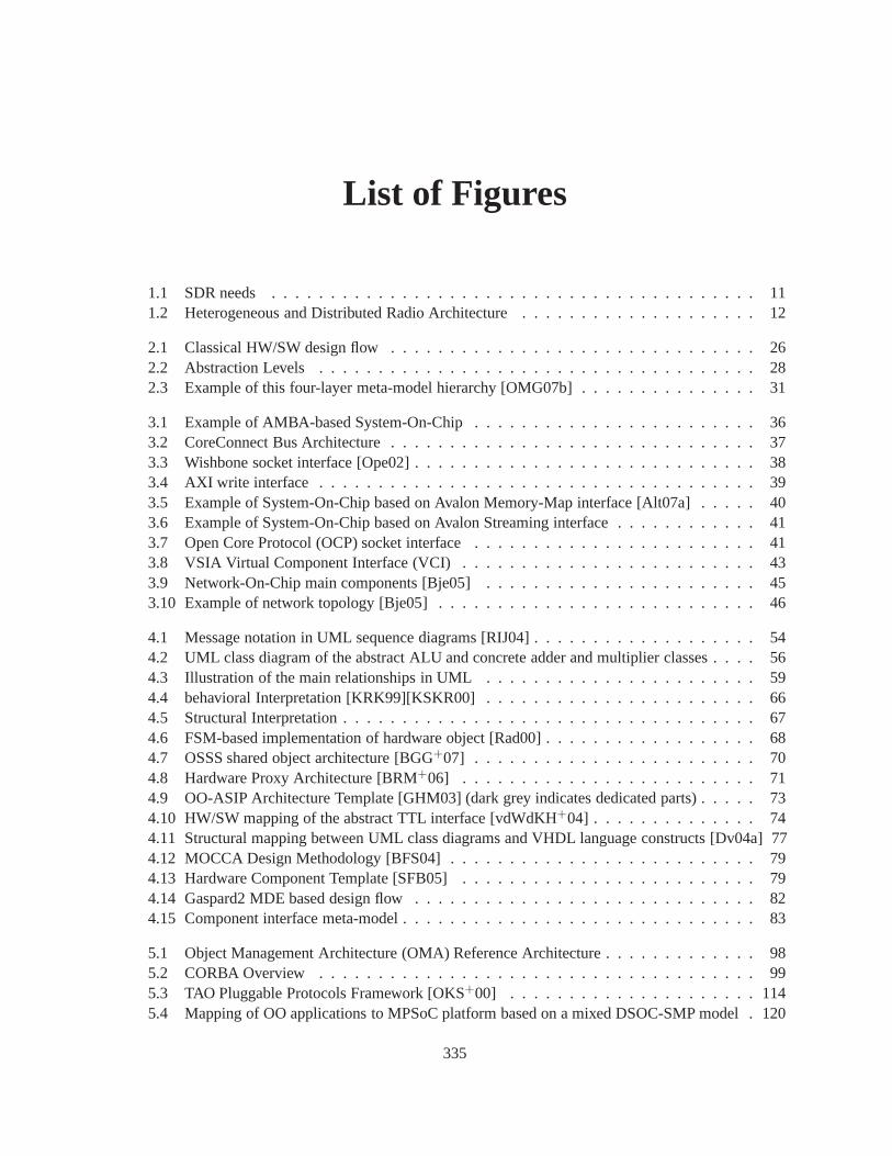
List of Figures
1.1 SDR needs . . . . . . . . . . . . . . . . . . . . . . . . . . . . . . . . . . . . . . . .. 111.2 Heterogeneous and Distributed Radio Architecture . . . .. . . . . . . . . . . . . . . . 12
2.1 Classical HW/SW design flow . . . . . . . . . . . . . . . . . . . . . . . . .. . . . . . 262.2 Abstraction Levels . . . . . . . . . . . . . . . . . . . . . . . . . . . . . . .. . . . . . 282.3 Example of this four-layer meta-model hierarchy [OMG07b] . . . . . . . . . . . . . . . 31
3.1 Example of AMBA-based System-On-Chip . . . . . . . . . . . . . . .. . . . . . . . . 363.2 CoreConnect Bus Architecture . . . . . . . . . . . . . . . . . . . . . .. . . . . . . . . 373.3 Wishbone socket interface [Ope02] . . . . . . . . . . . . . . . . . .. . . . . . . . . . . 383.4 AXI write interface . . . . . . . . . . . . . . . . . . . . . . . . . . . . . . .. . . . . . 393.5 Example of System-On-Chip based on Avalon Memory-Map interface [Alt07a] . . . . . 403.6 Example of System-On-Chip based on Avalon Streaming interface . . . . . . . . . . . . 413.7 Open Core Protocol (OCP) socket interface . . . . . . . . . . . .. . . . . . . . . . . . 413.8 VSIA Virtual Component Interface (VCI) . . . . . . . . . . . . . .. . . . . . . . . . . 433.9 Network-On-Chip main components [Bje05] . . . . . . . . . . . .. . . . . . . . . . . 453.10 Example of network topology [Bje05] . . . . . . . . . . . . . . . .. . . . . . . . . . . 46
4.1 Message notation in UML sequence diagrams [RIJ04] . . . . .. . . . . . . . . . . . . . 544.2 UML class diagram of the abstract ALU and concrete adder and multiplier classes . . . . 564.3 Illustration of the main relationships in UML . . . . . . . . .. . . . . . . . . . . . . . 594.4 behavioral Interpretation [KRK99][KSKR00] . . . . . . . . .. . . . . . . . . . . . . . 664.5 Structural Interpretation . . . . . . . . . . . . . . . . . . . . . . . .. . . . . . . . . . . 674.6 FSM-based implementation of hardware object [Rad00] . .. . . . . . . . . . . . . . . . 684.7 OSSS shared object architecture [BGG+07] . . . . . . . . . . . . . . . . . . . . . . . . 704.8 Hardware Proxy Architecture [BRM+06] . . . . . . . . . . . . . . . . . . . . . . . . . 714.9 OO-ASIP Architecture Template [GHM03] (dark grey indicates dedicated parts) . . . . . 734.10 HW/SW mapping of the abstract TTL interface [vdWdKH+04] . . . . . . . . . . . . . . 744.11 Structural mapping between UML class diagrams and VHDLlanguage constructs [Dv04a] 774.12 MOCCA Design Methodology [BFS04] . . . . . . . . . . . . . . . . . .. . . . . . . . 794.13 Hardware Component Template [SFB05] . . . . . . . . . . . . . . .. . . . . . . . . . 794.14 Gaspard2 MDE based design flow . . . . . . . . . . . . . . . . . . . . . .. . . . . . . 824.15 Component interface meta-model . . . . . . . . . . . . . . . . . . .. . . . . . . . . . . 83
5.1 Object Management Architecture (OMA) Reference Architecture . . . . . . . . . . . . . 985.2 CORBA Overview . . . . . . . . . . . . . . . . . . . . . . . . . . . . . . . . . . .. . 995.3 TAO Pluggable Protocols Framework [OKS+00] . . . . . . . . . . . . . . . . . . . . . 1145.4 Mapping of OO applications to MPSoC platform based on a mixed DSOC-SMP model . 120
335
336 List of Figures
5.5 PrismTech Integrated Circuit ORB (ICO) [Fos07] . . . . . . .. . . . . . . . . . . . . . 1245.6 OIS ORBexpressFPGA [OIS08] . . . . . . . . . . . . . . . . . . . . . . . . . . . . . . 125
6.1 XML files from the SCA Domain Profile . . . . . . . . . . . . . . . . . . .. . . . . . . 1476.2 SCA Core Framework Base Application Interfaces . . . . . . .. . . . . . . . . . . . . 1496.3 SCA Core Framework Base Device Interfaces . . . . . . . . . . . .. . . . . . . . . . . 1506.4 Class diagram of two connected Resource components . . . .. . . . . . . . . . . . . . 1516.5 Sequence diagram for the connection between two Resource component ports . . . . . . 1526.6 Internal Configuration Access Port (ICAP) [Xil07] . . . . .. . . . . . . . . . . . . . . 1706.7 Dynamic partial reconfiguration by a SCA Core Framework [SMC+07] . . . . . . . . . 171
7.1 Existing methodology inspired from MDA and component/container paradigm. . . . . . 1817.2 SystemC TLM model of PIMs/PSMs. . . . . . . . . . . . . . . . . . . . . .. . . . . . 1837.3 Proposed Design Flow . . . . . . . . . . . . . . . . . . . . . . . . . . . . . .. . . . . 1847.4 Platform Independent Model (PIM) of a partial waveform application . . . . . . . . . . 1877.5 Executable specification in SystemC at Functional View .. . . . . . . . . . . . . . . . 1897.6 Concurrent invocations of methods to enable pipeline ofconfiguration and computation . 1937.7 Example of concurrent invocations from hardware and software clients . . . . . . . . . . 1947.8 Multiple component instances in the same hardware module . . . . . . . . . . . . . . . 1967.9 Example of inheritance implementation . . . . . . . . . . . . . .. . . . . . . . . . . . 1967.10 Collection of connector ducts supporting different interaction semantics . . . . . . . . . 2027.11 Different component interface configurations . . . . . . .. . . . . . . . . . . . . . . . 2037.12 Two possible mapping configuration for two component ports . . . . . . . . . . . . . . 2037.13 Non exhaustive standard interfaces required for invocation and parameters transfer . . . 2077.14 Data layouts for data structures aligned on 32bits . . . .. . . . . . . . . . . . . . . . . 2087.15 Transfer of parameters . . . . . . . . . . . . . . . . . . . . . . . . . . .. . . . . . . . 2097.16 Hardware object-oriented component architecture of the FIR filter . . . . . . . . . . . . 2107.17 Position of the transceiver sub-system in a radio chain. . . . . . . . . . . . . . . . . . . 2117.18 Overview of the Transmit Channel Feature [NP09] . . . . . .. . . . . . . . . . . . . . 2127.19 TransmitDataPush VHDL entity signals . . . . . . . . . . . . . .. . . . . . . . . . . . 2147.20 BBSamplePacket TransmitDataPush Timing diagram . . . .. . . . . . . . . . . . . . . 2147.21 Simplified UML class diagram of the BaseIDL package of the CCM meta-model . . . . 2207.22 Simplified class diagram of the ComponentIDL package ofthe CCM meta-model . . . . 2207.23 CCM meta-model with RtlMappingConfiguration class . . .. . . . . . . . . . . . . . . 2237.24 Storage UML package . . . . . . . . . . . . . . . . . . . . . . . . . . . . . .. . . . . 2247.25 MessagePort UML package . . . . . . . . . . . . . . . . . . . . . . . . . .. . . . . . . 2257.26 LogicalPort UML package . . . . . . . . . . . . . . . . . . . . . . . . . .. . . . . . . 2267.27 RtlPort UML package . . . . . . . . . . . . . . . . . . . . . . . . . . . . . .. . . . . . 2277.28 InterfaceFamily UML package . . . . . . . . . . . . . . . . . . . . . .. . . . . . . . . 2287.29 HwInterface UML class . . . . . . . . . . . . . . . . . . . . . . . . . . . .. . . . . . . 2287.30 RTL Mapping Configuration Editor . . . . . . . . . . . . . . . . . . .. . . . . . . . . 2317.31 VHDL meta-model in UML . . . . . . . . . . . . . . . . . . . . . . . . . . . .. . . . 2327.32 SCA deployment process implemented by anApplicationFactory . . . . . . . . . 2447.33 Middleware Architecture Framework . . . . . . . . . . . . . . . .. . . . . . . . . . . . 245
8.1 DiMITRI MPSoC architecture overview . . . . . . . . . . . . . . . .. . . . . . . . . . 2548.2 Generic Virtual Platform at Programmer View (PV) level .. . . . . . . . . . . . . . . . 2558.3 Encapsulation of a C behavioral model within a SystemC PVcontainer . . . . . . . . . . 256
337
8.4 Transparent refinement using transactors . . . . . . . . . . . .. . . . . . . . . . . . . . 2568.5 Example of component-based applications . . . . . . . . . . . .. . . . . . . . . . . . . 2588.6 Slot Format of the High-Data Rate OFDM Modem . . . . . . . . . . .. . . . . . . . . 2598.7 Functional modeling with Kahn Process Network (KPN) . . .. . . . . . . . . . . . . . 2608.8 Multi-Level modeling using communication channels at different abstraction levels . . . 2618.9 Hardware SCA Encoder and Interleaver components in Application Mode 1 . . . . . . . 2648.10 Hardware SCA Encoder component in Application Mode 2 . .. . . . . . . . . . . . . . 2658.11 Synthesis results for Xilinx VirtexIV FPGAs . . . . . . . . .. . . . . . . . . . . . . . . 2668.12 Hardware ORB with a GIOP 1.0 protocol personality . . . . .. . . . . . . . . . . . . . 2698.13 Memory-mapped middlewares . . . . . . . . . . . . . . . . . . . . . . .. . . . . . . . 2748.14 Results on Virtex IV after Place&Route . . . . . . . . . . . . . .. . . . . . . . . . . . 275

List of Tables
4.1 Synthesis of hardware implementation of object concepts (part 1) . . . . . . . . . . . . . 854.2 Synthesis of hardware implementation of object concepts (part 2) . . . . . . . . . . . . . 86
5.1 Comparison of middleware communication models [Tho97][EFGK03] [LvdADtH05] . 975.2 Comparison of some middleware platforms . . . . . . . . . . . . .. . . . . . . . . . . 985.3 Example of IOR in little endian . . . . . . . . . . . . . . . . . . . . . .. . . . . . . . . 1065.4 IDL Language mappings to C++, Java, Ada95 and C - N.A.: NotAvailable (part 1) . . . 1105.5 IDL Language mappings to C++, Java, Ada95 and C - N.A.: NotAvailable (part 2) . . . 1115.6 Example of GIOP request message in little endian in MICO ORB . . . . . . . . . . . . 113
7.1 Mapping of component ports at different abstraction levels . . . . . . . . . . . . . . . . 1867.2 Summary of the proposed IDL3-to-SystemC mapping at functional level . . . . . . . . . 1867.3 Mapping between CCM meta-classes and VHDL meta-classes. . . . . . . . . . . . . . 2327.4 Memory-Mapped Hardware/Software SCAResource Interface . . . . . . . . . . . . . 240
8.1 Mapping of semantics between GIOP message fields and OCP signals . . . . . . . . . . 2718.2 Mapping of semantics between GIOP and MHAL concepts . . . .. . . . . . . . . . . . 2728.3 Example of a MHAL message for thevoid start() operation in little endian . . . . 2728.4 Mapping of semantics between GIOP message fields and OCP signals . . . . . . . . . . 273
A.1 Summary of the proposed IDL3-to-VHDL mapping . . . . . . . . .. . . . . . . . . . . 327
339

Listings
4.1 Illustration of the polymorphism principle in C++ . . . . .. . . . . . . . . . . . . . . . 56
5.1 example.idl . . . . . . . . . . . . . . . . . . . . . . . . . . . . . . . . . . . . .. . . . 104
5.2 Server Implementation . . . . . . . . . . . . . . . . . . . . . . . . . . . .. . . . . . . 104
5.3 Client Implementation . . . . . . . . . . . . . . . . . . . . . . . . . . . .. . . . . . . 105
6.1 Implementation example for Resource components and ports . . . . . . . . . . . . . . . 151
6.2 A counter in VHDL . . . . . . . . . . . . . . . . . . . . . . . . . . . . . . . . . .. . . 163
6.3 A counter in Verilog . . . . . . . . . . . . . . . . . . . . . . . . . . . . . . .. . . . . . 165
6.4 Counter in SystemC at Register Transfer Level . . . . . . . . .. . . . . . . . . . . . . 173
6.5 Counter in SystemC at Functional Level . . . . . . . . . . . . . . .. . . . . . . . . . . 173
7.1 Transceiver Modem Example in IDL3 . . . . . . . . . . . . . . . . . . .. . . . . . . . 188
7.2 Transceiver Modem Example in SystemC at Functional View. . . . . . . . . . . . . . . 188
7.3 Interface and component definitions for the FIR filter example . . . . . . . . . . . . . . 209
7.4 TransmitDataPush interface in CORBA IDL . . . . . . . . . . . . . . . . . . . . . 212
7.5 HardwareTransmitDataPush interface in VHDL . . . . . . . . . . . . . . . . . . . 213
7.6 TransmitControl interface in CORBA IDL . . . . . . . . . . . . . . . . . . . . . . 215
7.7 HardwareTransmitControl interface in VHDL . . . . . . . . . . . . . . . . . . . 216
7.8 RTL Mapping Configuration XML file . . . . . . . . . . . . . . . . . . . .. . . . . . . 230
7.9 Mapping between CCM component and VHDL entity in QVT . . . .. . . . . . . . . . 233
7.10 Generation of VHDL code from a VHDL model in MTL . . . . . . . .. . . . . . . . . 233
7.11 Example of generated code for the Filter . . . . . . . . . . . . .. . . . . . . . . . . . . 234
7.12 Mapping Illustration in VHDL for the FIR filter . . . . . . . .. . . . . . . . . . . . . . 246
A.1 Non-blocking control interface . . . . . . . . . . . . . . . . . . . .. . . . . . . . . . . 287
A.2 Blocking control interface . . . . . . . . . . . . . . . . . . . . . . . .. . . . . . . . . 288
A.3 Data interface . . . . . . . . . . . . . . . . . . . . . . . . . . . . . . . . . . .. . . . . 288
A.4 Mapping of IDL basic data types to VHDL . . . . . . . . . . . . . . . .. . . . . . . . 296
A.5 Mapping of IDL basic data types to SystemC . . . . . . . . . . . . .. . . . . . . . . . 296
341

344 Acronyms
Acronyms
3G Third generation of mobile telecommunications standards4G Fourth generation of mobile telecommunications standardsADC Analog-to-Digital ConverterAHB AMBA High-performance BusAMBA Advanced Microcontroller Bus ArchitectureANSA Advanced Network Systems ArchitectureANSI American National Standards InstituteAMI Asynchronous Method InvocationAPI Application Programming InterfaceASIC Application Specific Integrated CircuitASIP Application-Specific Instruction-set ProcessorASN.1 Abstract Syntax Notation OneBFM Bus Functional ModelBSP Board Support PackageCBSE Component-Based Software EngineeringCCDR Compact Common Data RepresentationCCM CORBA Component ModelCDR Common Data RepresentationCF Core FrameworkCLB Configurable Logic BlockCORBA Common ORB ArchitectureCOTS Commercial Off-The-ShelfDAC Digital-to-Analog ConverterDDC Digital Down ConverterDPR Dynamic Partial ReconfigurationDRE Distributed Real-time EmbeddedDSL Domain-Specific LanguageDSML Domain-Specific Modeling LanguageDSP Digital Signal Processor or Digital Signal ProcessingDTD Document Type DefinitionEDA Electronic Design AutomationEJB Enterprise JavaBeanEMF Eclipse Modeling FrameworkESIOP Environment Specific Inter-ORB ProtocolESL Electronic System LevelFE Front-EndFEC Forward Error CorrectionFIFO First In First OutFIR Finite Impulse ResponseFPGA Field-Programmable Gate ArrayFSM Finite State MachineFSMD Finite State Machine with Datapath
345
GIOP General Inter-ORB ProtocolHDL Hardware Description LanguageICAP Internal Configuration Access PortIDL Interface Definition LanguageIOP Inter-ORB ProtocolIOR Interoperable Object ReferenceIP Intellectual Property or Internet ProtocolIPC Inter-Process CommunicationIRQ Interrupt RequestISS Instruction Set SimulatorJET Java Emitter TemplatesJPEO Joint Program Executive OfficeJTRS Joint Tactical Radio SystemLD Logical DestinationLSB Least Significant BitLUT Look-Up TableMAC Medium Access ControlMDA Model-Driven Architecture ®MDE Model-Driven EngineeringMHAL Modem Hardware Abstraction LayerMOF Meta-Object FacilityMOM Message-Oriented MiddlewareMPI Message Passing InterfaceMPSoC Multi-Processor System-on-ChipMSB Most Significant BitMUX MultiplexersNoC Network-on-ChipOCP Open Core ProtocolOCP-IP OCP International PartnershipOE Operating EnvironmentOFDM Orthogonal Frequency-Division MultiplexingOMA Object Management ArchitectureOMG Object Management GroupOPB On-Chip Peripheral BusORB Object Request BrokerOSCI Open SystemC InitiativeOSI Open Systems InterconnectionP 2SRC PIM & PSM for Software Radio ComponentsPA Power AmplifierPDU Protocol Data UnitPER Packed Encoding RulesPIM Platform-Independent ModelPLB Processor Local BusPSM Platform-Specific ModelPOSIX Portable Operating System Interface (for Unix)QoS Quality of ServiceQVT Query / Views / TransformationsRAM Random Access MemoryRMI Remote Method InvocationRPC Remote Procedure CallRTOS Real-Time Operating SystemSCA Software Communications Architecture
346 Acronyms
SDM Space Division MultiplexingSDR Software-Defined RadioSDRP Software-Defined Radio ProfileSLD System-Level DesignSoC System On ChipSoPC System On Programmable ChipSPIRIT Structure for Packaging, Integrating and Re-using IP within Tool flowsSysML Systems Modeling LanguageTDM Time-Division MultiplexingTLM Transaction Level ModelingUML Unified Modeling LanguageVC Virtual ChannelVCI Virtual Component InterfaceVHDL VHSIC Hardware Description LanguageXMI XML Metadata InterchangeXML eXtensible Markup Language

342 Listings
Glossary
Abstract: an abstract class typically cannot be instantiated and delegates the implementation ofmethods to concrete classes.
Abstraction: an abstraction is a relative distinction made between relevant and less relevant detailsof a problem domain to enhance understanding and reduce complexity.
Access transparency: access transparency masks differences in data representation and invocationmechanisms to enable interworking between objects.
Aggregation: the aggregation relationship refers to a strong containment by value in UML.Application Binary Interface (ABI) : an ABI corresponds to the instructions set and calling conven-
tion of real and virtual machines.Application Programming Interface (API) : an API is a set of operations which are directly called
by developers according to some use rules.Asynchronous Call: asynchronous calls allow a caller to initiate an invocation that immediately
returns and continues its processing, whereas the invocation is concurrently performed. Caller executionand callee invocation are thus decoupled, while the latencyof communication and callee computationare masked.
Class: A class describes the common characteristics shared by a set of objects in term of structureand behavior [BME+07]. In programming languages, a class defines thetypeof an object.
Client: any entity that requires the services provided by another entity called the server.Component: "A component is a unit of composition with contractually specified interfaces and
explicit context dependencies only. A component can be deployed independently and is subject to com-position by third parties." [SP96]
Component Model: "A component modeldefines specific interaction and composition standards.A component model implementation is the dedicated set of executable software elements required tosupport the execution of components that conform to the model." [Kra08] The component model imposesdesign constraints on component developers, and the component framework enforces these constraintsin addition to providing useful services." [BBB+00]
Composition: the composition relationship refers to weak containment by reference in UML.Connector: In software architecture, a software connector is a component which binds the required
and provided ports of two or more components. It mediates component interactions and may deal withnon-functional services such as communication, coordination, conversion, synchronization, arbitrating,routing, and scheduling. While components have ports, the interface access points of connectors arecalled roles.
Container: A container allows the isolation of a component from the technical details of its possiblynumerous operating environments. Containers transparently integrate components into their executionenvironment. They use middleware services such as persistence, event notification, transactions, load-balancing and security as proxy of components. Containers also manage component life cycle such ascreation/destruction using component factories, interconnection of component ports, configuration usingconfiguration files typically in XML and activation e.g. using a timer service.
347
Encapsulation: encapsulation consists in hiding the internal view of an abstraction in order to betterdeal with its complexity [BME+07]. It denotes the separation of concerns between an interface and itsimplementation.
Exception: An exceptionis an user-defined or system error raised by a method in object-orientedlanguages.
Globally Asynchronous Locally Synchronous: systems on chip in which IP cores do not shared aglobal clock, but may share a local clock forming "synchronous islands".
Hierarchy establishes an ordering among a set of abstractions [BME+07]. The decomposition of asystem into hierarchical layers of abstraction is a key concept to design complex systems.
Inheritance: the inheritance principle consists in deriving the declaration and possibly implemen-tation of aderivedor child class from abaseor parentclass. The child class includes by default the dataand behavior of the parent class. The child class can be either based or replace (override) the behaviorof the inherited behavior. The derived class may also declare additional attributes and methods.
Interoperability : Interoperability is the ability of applications to interoperate (i.e. understand eachother) and perform system functionalities although they are executed using different operating environ-ments.
IP core: an Intellectual Property (IP) core is a reusable hardware module in an ASIC or FPGA.Location transparency provides a logical view of naming, independent of actual physical location.Message: A message is equivalent to a method invocation. The transfer of control and data of a
method invocation, which is implicit and local to a computer, can be formally translated into a remoteand explicit transfer of a message between distributed computers and vice versa.
Meta-Model: A meta-model is a model of a modeling language. It specifies the concepts of thelanguage used to define a model. A meta-model defines the structure, relationships, semantics and con-straints of these concepts for a family of models conformingto this meta-model. Each model can becaptured by a particular meta-model.
Meta Object Facilities (MOF): MOF is a meta-model and modeling language standardised by theOMG to describe OMG meta-models such as UML and CCM meta-models.
Method: A method describes the actions to perform depending on the type of invocation messagereceived by the object. The termmethodoriginates from Smalltalk, whereas the termsoperationandmember functionare respectively employed in Ada and C++ [BME+07]. In UML, a method is anoperation implementation that specifies the algorithm associated with an operation.
Method Dispatching: Method dispatchingis the process of selecting a method based on a requestmessage.Dynamic dispatchingrefers to the process of determining at run-time which method to invoke.
Method Invocation: A method invocationrequests the execution of a method.Middleware: A middleware is communication infrastructure which aims at supporting transparent
communications between heterogeneous systems regardlessof their distribution, hardware computingarchitecture, programming language, operating system, transport layer and data representation.
Model of Computation (MoC): a model of computation is the formal abstraction of the executionin a computer. A model of computation defines the behavior andinteraction semantics that govern theelements in different parts or at different levels of a system.
Modularity : modularity consists in breaking down a complex system intoa set of simple and moremanageable modules [BME+07].
Model: a model represents the key characteristics of a problem andprovides a conceptual frameworkto reason about it. A model is a formal specification of the function, structure and/or behavior of anapplication or system.
Model-Driven Architecture (MDA) : the Model-Driven Architecture (MDA) [OMG03] [MSUW04]is the Model-Driven Engineering approach standardized by the OMG. The MDA promotes the separationbetween the specification of system functionalities captured in aPlatform Independent Model(PIM )
from the specification of their implementation on a particular platform defined in thePlatform SpecificModel(PSM).
Model transformation : model transformation consists in translating a source model M1 conformingto the meta-model MM1 into a model M2 conforming to the meta-model MM2 using mapping rules.Mapping rules are defined at the meta-model level and are not dedicated to a particular model.
Monitor : A monitor protects a shared resource by guarantying that the execution of all operationsaccessing the resource are mutually exclusive. Instead of managing explicitly critical sections of codeusing locks, monitor declarations are used by compiler to transparently introduce synchronization code.
Object: An object is a self-contained and identifiable entity, which encloses its own state and be-havior and communicates only through message passing [Arm06] [BME+07]. The state of an objectcorresponds to the set of values of all static and dynamic properties orattributesof an object [BME+07].The behavior of an object takes the form of a set of methods in the object class.
Open Core Protocol(OCP): OCP is a hardware interface specification maintained by the OCP-IPorganization created in 2001 by members such as TI, MIPS, Sonics, Nokia and ST. OCP supports com-munication protocols ranging from simple acknowledge to multiple out-of-order pipelined concurrentblock transfers. The OCP promotes a socket based layered architecture [OIb].
Operation: In UML and CORBA, an operation declares a service that can beprovided by classinstances.
Operation Call: An operation call is the invocation of a service.Operation Signature: an operation signature contains the name of the operation,the type and name
of its input, output, input-output parameters, the type of the return value and the name of errors orexceptions which may be raised.
Persistent object: a persistent object is saved before it is destroyed and restored in another classinstance at its next creation or "reincarnation". Objects that are not persistent are calledtransientobjects.
Platform-Based Design (PBD): Platform-Based Design consists in mapping an applicationmodeland a platform model successively through various abstraction levels. The result of a mapping of anapplication to a platform model at level N is the applicationmodel at the level N+1 that will be mappedon the platform model at level N+1.
Polymorphism: polymorphism is refers to "the ability to substitute objects of matching interface forone another at run-time" [GHJV95].
Portability : portability denotes the property of an application, whichcan be migrated or ported fromone operating environment to another one with little efforts in terms of time and cost. There are usuallytwo kinds of portability: portability atsource codelevel viaApplication Programming Interface(API )and portability atbinary codelevel viaApplication Binary Interface(ABI ).
Programming Model: a programming model defines how parts of an application communicatewith one another and coordinate their activities [CSG98]. The two main programming models whichhave been traditionally identified for parallel computing architectures are shared memory and messagepassing. Other programming models include data parallel processing i.e. Single Program Multiple Data(SPMD), dataflow processing and systolic processing [CSG98].
Proxy: middleware interface compilers automatically generateproxies a.k.a. surrogatesto makelocal and remote communications indistinguishable from the viewpoint of client and server objects.
Push model: model of interaction in which the transfer of control and/or data is initiated by thesender e.g. writes from a master to a slave in on-chip bus.
Pull model: model of interaction in which the transfer of control and/or data is initiated by thereceiver e.g. reads from a master to a slave after an interruption in on-chip bus.
Query / Views / Transformations (QVT): MOF QVT is a model transformation language standard-ized by the OMG [OMG08e].
Remote Method Invocation (RMI): A Remote Method Invocation is a method invocation whichtakes place between distributed objects. In distributed systems, the systematic translation betweenmethod invocation and message passing is the cornerstone ofRemote Method Invocation(RMI ) usedin object-oriented middlewares such as Sun Java RMI, Microsoft DCOM or OMG CORBA.
Semaphore: A semaphore is a non-negative integer shared variable thatcan be initialized to a valueand then can only be modified by two operations calledwait andsendor P andV by its inventor Di-jkstra. These operations respectively acquire and releasea lock and decremente and incremente thesemaphore value. If the semaphore value becomes zero, then the calling thread will wait until it acquiresthe semaphore. The initialization value is 0 or 1 for binary semaphores to protect a single shared resourceor N for counting semaphores to protect a pool of N resources.
Server: any entity that provides the services required by another entities called the clients.Skeleton: A server-side proxy calledskeletondecodes a request message payload into the input and
input-output parameters of a local method invocation called on the object implementation and converselyencodes the output and input-output parameters and the return value into a reply message payload.
Software Component: "A software componentis a software element that conforms to a componentmodel and can be independently deployed and composed without modification according to a composi-tion standard." [Kra08]
Software Component Infrastructure: "A software component infrastructureor framework, is asoftware system that provides the services needed to develop, deploy, manage and execute applicationsbuilt using a specific component model implementation. It may itself be organized as a set of interactingsoftware components." [Kra08]
Software Interface: The set of operations signatures specifies aninterface between the outside viewof a class provided by its declaration and the inside view incarnated by the object implementation.
Stub: A client-side proxy calledstub encodes the input and input-output parameters of a remotemethod invocation into a request message payload and conversely decodes a reply message payload intothe output and input-output parameters and the return value. The request message payload is encapsu-lated by the request message header of the RMI protocol and the lower protocol layer
Synchronous Call: In synchronous calls, the caller thread of control is blocked until a reply isreturned, while asynchronous RPCs do not block the caller [ATK92]. Synchronous calls are space andtime coupled with partial synchronization decoupling.
Transaction: A transaction is a sequence of operations, which is either totally executed or not at all.XML Metadata Interchange (XMI) : XMI is an OMG standard for storing orserializingmodels
and meta-models as persistent XML files. XMI is a mapping fromMOF to XML. For instance, it allowsthe exportation and importation of UML models from/to UML modeling tools.
Bibliography
[ABC+07] R. Ben Atitallah, P. Boulet, A. Cuccuru, J.-L. Dekeyser,A. Honoré, O. Labbani, S. LeBeux, P. Marquet, E. Piel, J. Taillard, and H. Yu. Gaspard2 UML profile documentation.Technical Report 0342, INRIA Futurs, Lille, France, September 2007.
[Acc04a] Accellera. Property Specification Language Reference Manual, v.1.1.www.eda.org/sv, June 2004.
[Acc04b] Accellera. SystemVerilog 3.1a Language Reference Manual (LRM).www.eda.org/sv, May 2004.
[AHMMB07] D. Akehurst, G. Howells, K. McDonald-Maier, and B. Bordbar. An Experiment inUsing Model Driven Development : Compiling UML State Diagrams into VHDL. InForum on specification and design languages (FDL’07), pages 88–93, Septembre 2007.
[AKL +09] Denis Aulagnier, Ali Koudri, Stéphane Lecomte, Philippe Soulard, Joël Champeau, Jor-giano Vidal, Gilles Perrouin, and Pierre Leray. SoC/SoPC development using MDD andMARTE profile. In Model Driven Engineering for Distributed Real-Time EmbeddedSystems. Hermes, 2009.
[Alt] Altera. C-to-Hardware.www.altera.com.
[Alt07a] Altera. Avalon Memory-Mapped Interface Specification v3.3. www.altera.org,May 2007.
[Alt07b] Altera. Nios II C2H Compiler User Guide, v7.2, 2007.
[And00] G. R. Andrews.Foundations of Multithreaded, Parallel, and Distributed Programming.Addison-Wesley, 2000.
[AND08] ANDRES (Analysis and Design of run-time Reconfigurable, heterogeneous Systems)IST-FP6 Project, June 2006 - May 2009.andres.offis.de, June 2008.
[APS+07] E. Anderson, W. Peck, J. Stevens, J. Agron, F. Baijot, S. Warn, and D. Andrews. Sup-porting High Level Language Semantics within Hardware Resident Threads.17th Inter-national Conference on Field Programmable Logic and Applications (FPL’07), pages98–103, August 2007.
[AR98] P. J. Ashenden and M. Radetzki. A Comparison of SUAVE and Objective VHDL,Report for the IEEE DASC Object-Oriented VHDL Study Group, December 1998.
[ARM04] ARM. AMBA AXI Protocol Specification v1.0, March 2004.
351
[Arm06] D. J. Armstrong. The quarks of object-oriented development. Communications of theACM, 49(2):123–128, February 2006.
[ATK92] A. L. Ananda, B. H. Tay, and E. K. Koh. A survey of asynchronous remote procedurecalls. SIGOPS Oper. Syst. Rev., 26(2):92–109, 1992.
[AWM98] P. J. Ashenden, P. Wilsey, and D. Martin. SUAVE: Object-Oriented and GenericityExtensions to VHDL for High-Level Modeling. InIn Proceedings of Forum on Specifi-cation and Design Languages (FDL’98), pages 109–118, September 1998.
[AWM99] P. J. Ashenden, P. Wilsey, and D. Martin. Principlesfor Language Extensions to VHDLto Support High-Level Modeling.VLSI Design, 1999.
[B02] Dušan Bálek.Connectors in Software Architectures. PhD thesis, Charles University,Czech Republic, 2002.
[Bal07] P. J. Balister. A Software Defined Radio Implementedusing the OSSIE Core FrameworkDeployed on a TI OMAP Processor. Master’s thesis, Virginia Polytechnic Institute andState University, Dec. 2007.
[BBB+00] F. Bachmann, L. Bass, C. Buhman, S. Comella-Dorda, F. Long, J. Robert, R. Seacord,and K. C. Wallnau. Volume II: Technical Concepts of Component-Based Software Engi-neering, 2nd Edition. Technical Report CMU/SEI-2000-TR-008, Software EngineeringInstitute (SEI) Carnegie Mellon University (CMU), May 2000.
[BBS06] Ananda Basu, Marius Bozga, and Joseph Sifakis. Modeling Heterogeneous Real-timeComponents in BIP. InProc. of the Fourth IEEE International Conference on SoftwareEngineering and Formal Methods (SEFM ’06), pages 3–12, Washington, DC, USA,2006. IEEE Computer Society.
[BCL+06] E. Bruneton, T. Coupaye, M. Leclercq, V. Quéma, and J.-B.Stefani. The FRACTALcomponent model and its support in Java: Experiences with Auto-adaptive and Recon-figurable Systems.Softw. Pract. Exper., 36(11-12):1257–1284, 2006.
[BCS02] E. Bruneton, T. Coupaye, and J.-B. Stefani. Recursive and dynamic software composi-tion with sharing. InProc. of the 7th ECOOP International Workshop on Component-Oriented Programming (WCOP’02), Malaga, Spain, 2002.
[BDGC08] P. Bomel, J.-P. Diguet, G. Gogniat, and J. Crenne. Bitstreams Repository Hierarchy forFPGA Partially Reconfigurable Systems. InParallel and Distributed Computing, 2008.ISPDC ’08. International Symposium on, pages 228–234, July 2008.
[BDR07] P.J. Balister, C. Dietrich, and J.H. Reed. Memory Usage of a Software CommunicationsArchitecture Waveform. InSDR Forum Technical Conference, Denver, CO, November2007.
[Beu07] S. Le Beux.Un flot de conception pour applications de traitement du signal systéma-tique implémentées sur FPGA à base d’Ingénierie Dirigée parles Modèles. PhD thesis,University of Lille, Laboratoire d’Informatique Fondamentale de Lille (LIFL), France,December 2007.
[BFS04] T. Beierlein, D. Fröhlich, and B. Steinbach. Model-driven compilation of UML-modelsfor reconfigurable architectures. InIn Proc. of the Second RTAS Workshop on Model-Driven Embedded Systems (MoDES’04), 2004.
[BGG+07] C. Brunzema, C. Grabbe, K. Grüttner, P. A. Hartmann, A. Herrholz, H. Kleen, F. Oppen-heimer, A. Schallenberg, C. Stehno, and T. Schubert.OSSS - A Library for SynthesisableSystem Level Models in SystemC(TM) - A tutorial for OSSS 2.0, November 2007.
[BHP06] T. Bures, P. Hnetynka, and F. Plasil. SOFA 2.0: Balancing Advanced Features in aHierarchical Component Model. InSoftware Engineering Research, Management andApplications, 2006. Fourth International Conference on, pages 40–48, Aug. 2006.
[BHS07] F. Buschmann, K. Henney, and D.C. Schmidt.Pattern-Oriented Software Architecture(POSA) Vol. 4: A Pattern Language for Distributed Computing. Wiley, May 2007.
[Bic07] J. Bickle. IDL to HDL Mapping Proposal, OMG Burlingame Technical Meeting.www.omg.org/docs/mars/07-12-20.pdf, December 2007.
[BJ07] John Bard and Vincent J. Kovarik Jr., editors.Software Defined Radio: The SoftwareCommunications Architecture. Wiley, May 2007.
[Bje05] T. Bjerregaard.The MANGO clockless network-on-chip: Concepts and implementation.PhD thesis, Informatics and Mathematical Modelling, Technical University of Denmark,DTU, 2005.
[BJPW99] A. Beugnard, J.-M. Jézéquel, N. Plouzeau, and D. Watkins. Making components con-tract aware.Computer, 32(7):38–45, 1999.
[BKH+07] A.V. Brito, M. Kuhnle, M. Hubner, J. Becker, and E.U.K. Melcher. Modelling andSimulation of Dynamic and Partially Reconfigurable Systemsusing SystemC. InVLSI,2007. ISVLSI ’07. IEEE Computer Society Annual Symposium on, pages 35–40, March2007.
[Blu] Bluespec. Bluespec SystemVerilog (BSV).www.bluespec.com/products/bsv.htm.
[BM02] L. Benini and G. De Micheli. Networks on Chips: A New SoC Paradigm.Computer,35(1):70–78, January 2002.
[BM06] T. Bjerregaard and S. Mahadevan. A survey of researchand practices of Network-on-Chip. ACM Comput. Surv., 38(1):1, 2006.
[BMB+04] S. Bailey, E. Marschner, J. Bhasker, J. Lewis, and P. Ashenden. Improving Design andVerification Productivity with VHDL-200x. InDATE ’04: Proceedings of the confer-ence on Design, Automation and Test in Europe, Washington, DC, USA, 2004. IEEEComputer Society.
[BME+07] G. Booch, R. A. Maksimchuk, M. W. Engle, B. J. Young, J. Conallen, and K. A. Hous-ton. Object-Oriented Analysis and Design with Applications, 3rd Edition. AddisonWesley, Redwood City, CA, USA, April 2007.
[BMR+96] F. Buschmann, R. Meunier, H. Rohnert, P. Sommerlad, and M. Stal. Pattern-OrientedSoftware Architecture (POSA) Vol. 1: A System of Patterns. Wiley, July 1996.
[BN84] Andrew D. Birrell and Bruce Jay Nelson. Implementingremote procedure calls.ACMTrans. Comput. Syst., 2(1):39–59, 1984.
[Bon06] L. Bondé.Transformations de Modèles et Interopérabilité dans la Conception de Sys-tèmes Hétérogènes sur Puce à Base d’IP. PhD thesis, University of Lille, Laboratoired’Informatique Fondamentale de Lille (LIFL), France, December 2006.
[BP04] T. Bures and F. Plasil.Software Engineering Research and Applications, chapter Com-munication Style Driven Connector Configurations, pages 102–116. Lecture Notes inComputer Science (LNCS). Springer-Verlag, 2004.
[BRJ05] G. Booch, J. Rumbaugh, and I. Jacobson.The Unified Modeling Language User GuideSecond Edition. Addison Wesley, May 2005.
[BRM+06] J. Barba, F. Rincón, F. Moya, F. J. Villanueva, D. Villa, and J. C. López. LightweightCommunication Infrastructure for IP Integration. InIP-Based SoC Design Conference(IP-SoC), December 2006.
[BRM+07] J. Barba, F. Rincon, F. Moya, F. J. Villanueva, D. Villa, J. Dondo, and J. C. Lopez.OOCE: Object-Oriented Communication Engine for SoC Design. In Proc. of the 10thEuromicro Conference on Digital System Design Architectures, Methods and Tools(DSD’07), pages 296–302, Washington, DC, USA, Aug. 2007. IEEE Computer Society.
[BS05] Bruno Bouyssounouse and Joseph Sifakis.Embedded Systems Design, volume 3436 ofLecture Notes in Computer Science, chapter Component Models and Integration Plat-forms: Landscape, pages 160–193. Springer-Verlag New York, LLC, March 2005.
[BW05] G. M. Bierman and A. Wren. First-class relationshipsin an object-oriented language.In ECOOP 2005 - Object-Oriented Programming, 19th European Conference, Glasgow,UK, July 25-29, 2005, Proceedings, pages 262–286, 2005.
[BW07] A. Burns and A. Wellings.Concurrent and Real-time Programming in Ada 2005. Cam-bridge University Press, 2007.
[BWH+03] F. Balarin, Y. Watanabe, H. Hsieh, L. Lavagno, C. Passerone, and A. Sangiovanni-Vincentelli. Metropolis: an integrated electronic systemdesign environment.Computer,36(4):45–52, April 2003.
[Cap03] L. F. Capretz. A brief history of the object-oriented approach.SIGSOFT Softw. Eng.Notes, 28(2):6, March 2003.
[CCB+06] P. Coussy, E. Casseau, P. Bomel, A. Baganne, and E. Martin. A formal method for hard-ware IP design and integration under I/O and timing constraints. ACM Trans. Embed.Comput. Syst., 5(1):29–53, 2006.
[CCSV07] Ivica Crnkovic, Michel Chaudron, Séverine Sentilles, and Aneta Vulgarakis. A clas-sification framework for component models. InProceedings of the 7th Conference onSoftware Engineering and Practice in Sweden, October 2007.
[CDK01] G. F. Coulouris, J. Dollimore, and T. Kindberg.Distributed systems: concepts anddesign, 3rd ed.Addison-Wesley, Boston, MA, USA, 2001.
[Che76] P.P.-S. Chen. The entity-relationship model—toward a unified view of data.ACM Trans.Database Syst., 1(1):9–36, 1976.
[Chu06] Pong P. Chu.RTL Hardware Design Using VHDL: Coding for Efficiency, Portability,and Scalability. Wiley-IEEE Press, April 2006.
[CLN+02] W. O. Cesario, D. Lyonnard, G. Nicolescu, Y. Paviot, S. Yoo, A. A.Jerraya, L. Gau-thier, and M. Diaz-Nava. Multiprocessor SoC Platforms: A Component-Based DesignApproach.IEEE Design and Test of Computers, 19(6):52–63, 2002.
[CM08] P. Coussy and A. Morawiec, editors.High-Level Synthesis: From Algorithm to DigitalCircuit. Springer, 2008.
[CSG98] David Culler, J. P. Singh, and Anoop Gupta.Parallel Computer Architecture: A Hard-ware/Software Approach. Morgan Kaufmann, August 1998.
[CSL+03] R. Chen, M. Sgroi, L. Lavagno, G. Martin, A. Sangiovanni-Vincentelli, and J. Rabaey.UML for Real: Design of Embedded Real-Time Systems, chapter UML and platform-based design, pages 107–126. Kluwer Academic Publishers, 2003.
[CT05] F. P. Coyle and M. A. Thornton. From UML to HDL: a Model Driven ArchitecturalApproach to Hardware-Software Co-Design. InInformation Systems: New GenerationsConference (ISNG), pages 88–93, April 2005.
[dAH01] Luca de Alfaro and Thomas A. Henzinger. Interface automata. In Proc. Of the 9thSymposium on Foundations of Software Engineering (FSE), 26(5):109–120, 2001.
[DBDM03] C. Dumoulin, P. Boulet, J.-L. Dekeyser, and P. Marquet. MDA for SoC design, inten-sive signal processing experiment. InIn Proc. of Forum on Specification and DesignLanguages (FDL’03), September 2003.
[DMM +05] J.-L. Dekeyser, P. Marquet, S. Meftali, C. Dumoulin, P. Boulet, and S. Niar. Why todo without Model Driven Architecture in embedded system codesign? InFirst IEEEBENELUX/DSP Valley Signal Processing Symposium, 2005.
[DMv03] R. Damaševicius, G. Majauskas, and V. Štuikys. Application of design patterns for hard-ware design. InDAC ’03: Proceedings of the 40th conference on Design automation,pages 48–53, New York, NY, USA, 2003. ACM.
[DPML07] J.-P. Delahaye, J. Palicot, C. Moy, and P. Leray. Partial Reconfiguration of FPGAsfor Dynamical Reconfiguration of a Software Radio Platform.Mobile and WirelessCommunications Summit, 2007. 16th IST, pages 1–5, July 2007.
[DPSV06] D. Densmore, R. Passerone, and A. Sangiovanni-Vincentelli. A Platform-Based Taxon-omy for ESL Design.IEEE Des. Test, 23(5):359–374, 2006.
[DRB+07] J. Dondo, F. Rincon, J. Barba, F. Moya, F.J. Villanueva, D. Villa, and J.C. Lopez.Dynamic Reconfiguration Management Based on a Distributed Object Model. inProc. of 17th International Conference on Field Programmable Logic and Applications(FPL’07), pages 684–687, August 2007.
[DRS04] V. D’silva, S. Ramesh, and A. Sowmya. Bridge over troubled wrappers: automatedinterface synthesis.In Proc. of the 17th International Conference on VLSI Design,(VLSI Design’04), pages 189–194, 2004.
[Dv04a] R. Damaševicius and V. Štuikys. Application of the object-oriented principles for hard-ware and embedded system design.Integr. VLSI J., 38(2):309–339, 2004.
[Dv04b] R. Damaševicius and V. Štuikys. Application of UML for hardware design based ondesign process model. InASP-DAC ’04: Proceedings of the 2004 conference on AsiaSouth Pacific design automation, pages 244–249, Piscataway, NJ, USA, 2004. IEEEPress.
[EFGK03] Patrick Th. Eugster, Pascal A. Felber, Rachid Guerraoui, and Anne-Marie Kermarrec.The many faces of publish/subscribe.ACM Comput. Surv., 35(2):114–131, 2003.
[Emm00] Wolfgang Emmerich. Software engineering and middleware: a roadmap. InICSE ’00:Proceedings of the Conference on The Future of Software Engineering, pages 117–129,New York, NY, USA, 2000. ACM.
[ESSL99] Eric Eide, James L. Simister, Tim Stack, and Jay Lepreau. Flexible IDL compilation forcomplex communication patterns.Sci. Program., 7(3-4):275–287, 1999.
[FAM05] A. Foster and S. Aslam-Mir. Practical Experiences using the OMG’s Extensible Trans-port Framework (ETF) under a Real-Time CORBA ORB to Implement QoS SensitiveCustom Transports for SDR. InProc. of the 2005 Software Defined Radio TechnicalConference (SDR’05), Hyatt Regency - Orange County, California, November 2005.
[FDH08] Luc Fabresse, Christophe Dony, and Marianne Huchard. Foundations of a Simple andUnified Component-Oriented Language.Journal of Computer Languages, Systems &Structures, 34/2-3(2-3):130–149, 2008.
[FGL01] Jan Frigo, Maya Gokhale, and Dominique Lavenier. Evaluation of the streams-C C-to-FPGA compiler: an applications perspective. InFPGA ’01: Proceedings of the 2001ACM/SIGDA ninth international symposium on Field programmable gate arrays, pages134–140, New York, NY, USA, 2001. ACM.
[For08] Message Passing Interface Forum. MPI: A Message-Passing Interface Standard, Version2.1. www.mpi-forum.org, Sept. 2008.
[Fos07] A. Foster. Using a Hardware ORB to Facilitate Seamless Communication with FP-GAs in DRE Systems, OMG Real-time & Embedded Systems Workshop (RTESW).www.omg.org/news/meetings/workshops/rt_2007.htm, July 2007.
[Fou08] Eclipse Foundation. Java Emitter Templates (JET).www.eclipse.org/modeling/m2t/?project=jet, 2008.
[Fra08] The Fractal component model.fractal.ow2.org, 2008.
[Frö06] D. Fröhlich.Object-Oriented Development for Reconfigurable Architectures. PhD the-sis, Hochschule Mittweida, TU Bergakademie Freiberg, Germany, August 2006.
[FSLM02] J.-P. Fassino, J.-B. Stefani, J. L. Lawall, and G. Muller. Think: A Software Frame-work for Component-based Operating System Kernels. InATEC ’02: Proceedings ofthe General Track of the annual conference on USENIX Annual Technical Conference,pages 73–86, Berkeley, CA, USA, 2002. USENIX Association.
[GBA+07] A. Goderis, C. Brooks, I. Altintas, E.A. Lee, and C. Goble. Heterogeneous Compo-sition of Models of Computation. Technical Report UCB/EECS-2007-139, EECS De-partment, University of California, Berkeley, November 2007.
[GBG+06] K. Grüttner, C. Brunzema, C. Grabbe, T. Schubert, and F. Oppenheimer. OSSS-Channels: Modelling and Synthesis of Communication With SystemC. InForum onSpecification & Design Languages, September 2006.
[GBJV08] G. Gailliard, H. Balp, C. Jouvray, and F. Verdier. Towards a Common HW/SWInterface-Centric and Component-Oriented Specification and Design Methodology. InIn Proc. of Forum on Specification and Design Languages 2008 (FDL’08), Sept. 2008.
[GBSV08] G. Gailliard, H. Balp, M. Sarlotte, and F. Verdier.Mapping Semantics of CORBA IDLand GIOP to Open Core Protocol for Portability and Interoperability of SDR WaveformComponents. Design, Automation and Test in Europe (DATE ’08), pages 330–335,March 2008.
[GC92] David Gelernter and Nicholas Carriero. Coordination languages and their significance.Commun. ACM, 35(2):97–107, 1992.
[GCW+02] Thomas Genssler, Alexander Christoph, Michael Winter,Oscar Nierstrasz, StéphaneDucasse, Roel Wuyts, Gabriela Arévalo, Bastiaan Schönhage, Peter Müller, and ChrisStich. Components for embedded software: the PECOS approach. In CASES ’02: Pro-ceedings of the 2002 international conference on Compilers, architecture, and synthesisfor embedded systems, pages 19–26, New York, NY, USA, 2002. ACM.
[GDGN03] S. Gupta, N. Dutt, R. Gupta, and A. Nicolau. SPARK: ahigh-level synthesis frameworkfor applying parallelizing compiler transformations.In Proc. of 16th International Con-ference on VLSI Design, pages 461–466, Jan. 2003.
[GGON07] K. Grüttner, C. Grabbe, F. Oppenheimer, and W. Nebel. Object Oriented Design andSynthesis of Communication in Hardware-Software Systems with OSSS. InIn Pro-ceedings of SASIMI 2007, Hokkaido, Japan, October 2007.
[Ghe06] Frank Ghenassia, editor.Transaction-Level Modeling with Systemc: TLM Concepts andApplications for Embedded Systems. Springer-Verlag, 2006.
[GHJV95] E. Gamma, R. Helm, R. Johnson, and J. Vlissides.Design patterns: elements ofreusable object-oriented software. Addison-Wesley Professional, 1995.
[GHM03] M. Goudarzi, S. Hessabi, and A. Mycroft. Object-oriented ASIP Design and Synthesis.In Proc. of Forum on Specification and Design Languages (FDL’03), September 2003.
[GJSB05] J. Gosling, B. Joy, G. Steele, and G. Bracha.The Java™Language Specification ThirdEdition. Addison-Wesley Professional, 2005.
[GK83] D.D. Gajski and R.H. Kuhn. New VLSI Tools.Computer, 16(12):11–14, Dec. 1983.
[GLMS02] T. Grötker, S. Liao, G. Martin, and S. Swan.System Design with SystemC. KluwerAcademic Publishers, May 2002.
[GLR06] D. Grisby, S.-L. Lo, and D. Riddoch. The omniORB version 4.1 User’s Guide.omniorb.sourceforge.net, April 2006.
[GMN06] Z. Guo, A. Mitra, and W. Najjar. Automation of IP CoreInterface Generation for Re-configurable Computing. InField Programmable Logic and Applications, 2006. FPL’06. International Conference on, pages 1–6, Aug. 2006.
[GMS+06] G. Gailliard, B. Mercier, M. Sarlotte, B. Candaele, and F. Verdier. Towards a SystemCTLM based Methodology for Platform Design and IP reuse: Application to SoftwareDefined Radio. InSecond European Workshop on Reconfigurable Communication-Centric SoCs (RECOSOC 2006), Montpellier, France, July 2006.
[GMTB04] S. Gerard, C. Mraidha, F. Terrier, and B. Baudry. A UML-based concept for high con-currency: the real-time object.In Proc. of the Seventh IEEE International Symposiumon Object-Oriented Real-Time Distributed Computing (ISORC’04), pages 64–67, May2004.
[GMW00] David Garlan, Robert T. Monroe, and David Wile. Acme: Architectural description ofcomponent-based systems. In Gary T. Leavens and Murali Sitaraman, editors,Founda-tions of Component-Based Systems, pages 47–68. Cambridge University Press, 2000.
[GNSV07] G. Gailliard, E. Nicollet, M. Sarlotte, and F. Verdier. Transaction Level Modelling ofSCA Compliant Software Defined Radio Waveforms and Platforms PIM/PSM.Design,Automation & Test in Europe Conference (DATE ’07), pages 1–6, April 2007.
[GO01] S. Gérard and I. Ober. Parallelism/Concurrency specification within UML, white paper,Workshop on Concurrency Issues in UML, The Unified Modeling Language. ModelingLanguages, Concepts, and Tools UML 2001.wooddes.intranet.gr/uml2001,October 2001.
[GO03] E. Grimpe and F. Oppenheimer. Extending the SystemC Synthesis Subset by ObjectOriented Features. InCODES + ISSS 2003. CODES + ISSS 2003, October 2003.
[Gou05] M. Goudarzi.The ODYSSEY Methodology: ASIP-Based Design of Embedded Systemsfrom Object-Oriented System-Level Models. PhD thesis, Sharif University of Technol-ogy, Iran, June 2005.
[GP08] V. Giddings and D. Paniscotti. IDL to Hardware Response toThales/Mercury Presentations, OMG Washington Technical Meeting.www.omg.org/docs/mars/08-03-18.pdf, March 2008.
[GR83] A. Goldberg and D. Robson.Smalltalk-80: The Language and its Implementation.Addison-Wesley, May 1983.
[Gra] Mentor Graphics. Catapult.www.mentor.com.
[Gra07] Mentor Graphics. Catapult®synthesis user’s and reference manual, system-level andblock-level products, release 2007a, May 2007.
[GRE95] GRETSI, Groupe d’Etudes du Traitement du Signal et des Images.Array-OL : proposi-tion d’un formalisme tableau pour le traitement de signal multi-dimensionnel, Septem-ber 1995.
[GRJ04] A. Grasset, F. Rousseau, and A. A. Jerraya. Network Interface Generation for MPSOC:From Communication Service Requirements to RTL Implementation. In RSP ’04: Pro-ceedings of the 15th IEEE International Workshop on Rapid System Prototyping, pages66–69, Washington, DC, USA, 2004. IEEE Computer Society.
[Gro01] On-Chip Bus Development Working Group. Virtual Component Interface Standard Ver-sion 2 (OCB 2 2.0). Technical report, VSI Alliance™, April 2001.
[GS94] David Garlan and Mary Shaw. An introduction to software architecture. TechnicalReport CMU-CS-94-166, Carnegie Mellon University, January 1994.
[GS98] Aniruddha S. Gokhale and Douglas C. Schmidt. Principles for Optimizing CORBAInternet Inter-ORB Protocol Performance. InHICSS ’98: Proceedings of the Thirty-First Annual Hawaii International Conference on System Sciences-Volume 7, page 376,Washington, DC, USA, 1998. IEEE Computer Society.
[GS99] A.S. Gokhale and D.C. Schmidt. Optimizing a CORBA Internet Inter-ORB protocol(IIOP) engine for minimal footprint embedded multimedia systems.Selected Areas inCommunications, IEEE Journal on, 17(9):1673–1706, Sep 1999.
[GT03] S. Gérard and F. Terrier.UML for real: design of embedded real-time systems, chapterUML for Real-Time: Which native concepts to use ?, pages 107–126. Kluwer AcademicPublishers, 2003.
[GTF+02] E. Grimpe, B. Timmermann, T. Fandrey, R. Biniasch, and F.Oppenheimer. SystemCObject-Oriented Extensions and Synthesis Features. InTagungsband. In Proc. of Forumon Specification and Design Languages (FDL’02), September 2002.
[GTS+05] C. Grassman, A. Troya, M. Sauermann, U. Ramacher, and M. Richter. Mapping wave-forms to mobile parallel processor architectures. InProc. of the SDR Forum TechnicalConference (SDR’05), November 2005.
[GZH07] M. Goudarzi, N. Mohammad Zadeh, and S. Hessabi. Using on-chip networks to imple-ment polymorphism in the co-design of object-oriented embedded systems.J. Comput.Syst. Sci., 73(8):1221–1231, 2007.
[HA04] J.C. Hoe and Arvind. Operation-centric hardware description and synthesis.Computer-Aided Design of Integrated Circuits and Systems, IEEE Transactions on, 23(9):1277–1288, Sept. 2004.
[Har87] D. Harel. Statecharts: A visual formalism for complex systems.Sci. Comput. Program.,8(3):231–274, 1987.
[HC01] G. T. Heineman and W. T. Councill.Component-Based Software Engineering: Puttingthe Pieces Together. Addison-Wesley, 2001.
[Hen04] M. Henning. A New Approach to Object-Oriented Middleware. IEEE Internet Com-puting, 8(1):66–75, 2004.
[HK05] S. Hong and T. H. Kim. Resource conscious developmentof middleware for control en-vironments: a case of CORBA-based middleware for the CAN bussystems.Informationand Software Technology, 47(6):411 – 425, 2005.
[HLEJ06] Seongsoo Hong, Jaesoo Lee, Hyeonsang Eom, and Gwangil Jeon. The robot soft-ware communications architecture (RSCA): embedded middleware for networked ser-vice robots.Parallel and Distributed Processing Symposium, 2006. IPDPS 2006. 20thInternational, pages 8 pp.–, April 2006.
[HLL +03] C. Hylands, E. A. Lee, J. Liu, X. Liu, S. Neuendorffer, Y. Xiong, Y. Zhao, and H. Zheng.Overview of the Ptolemy project. Technical Report UCB/ERL M03/25, University ofCalifornia at Berkeley, July 2003.
[HM07] M. Henning and M.Spruiell. Distributed Programmingwith ICE, revision 3.2.www.zeroc.com, March 2007.
[HO97] R. Helaihel and K. Olukotun. Java as a specification language for hardware-softwaresystems. InICCAD ’97: Proceedings of the 1997 IEEE/ACM international conferenceon Computer-aided design, pages 690–697, Washington, DC, USA, 1997. IEEE Com-puter Society.
[Hoa69] C. A. R. Hoare. An axiomatic basis for computer programming. Commun. ACM,12(10):576–580, 1969.
[Hos98] Philipp Hoschka. Compact and efficient presentation conversion code.IEEE/ACMTrans. Netw., 6(4):389–396, 1998.
[HP06] F. Humcke and D. Paniscotti. Integrated Circuit ORB (ICO) White Paper, v1.1.www.prismtech.com, 2006.
[HS08] M. Henning and M. Spruiell. Distributed Programmingwith Ice, Revision 3.3.0. ze-roc.com, May 2008.
[Hug05] J. Hugues.Architecture et Services des Intergiciels Temps Réel. PhD thesis, Universityof Paris VI, Pierre et Marie-Curie, France, September 2005.
[Hum06] F. Humcke. Making FPGAs "First Class" SCA Citizens.In Proc. of the SDR ForumTechnical Conference (SDR’06), November 2006.
[Hum07] F. Humcke. Making FPGAs "First Class" SCA Citi-zens, OMG Software-Based Communications (SBC) Workshop.www.omg.org/news/meetings/workshops/sbc_2007.htm, March2007.
[Hur98] Judith Hurwitz. Sorting out middleware.DBMS, 11(1):10–12, 1998.
[HVP+05] J. Hugues, T. Vergnaud, L. Pautet, Y. Thierry-Mieg, S. Baarir, and F. Kordon. On theFormal Verification of Middleware Behavioral Properties.Electr. Notes Theor. Comput.Sci., 133:139–157, 2005.
[ICE01] ICECS 2001: the 8th IEEE International Conference on Electronics, Circuits and Sys-tems.Object-oriented high level synthesis based on SystemC, September 2001.
[ICO08] ICODES (Interface and Communication based Design ofEmbedded Systems) IST-FP6Project, August 2004-2007.icodes.offis.de, June 2008.
[IEE02] IEEE. IEEE Standard VHDL Language Reference Manual, IEEE Std 1076(TM)-2002,May 2002.
[IEE04] IEEE. IEEE Standard for Information Technology- Standardized Application Environ-ment Profile (AEP)-POSIX Realtime and Embedded ApplicationSupport, 2004.
[III00] J. Mitola III, editor. Software Radio Architecture: Object-Oriented Approachesto Wire-less Systems Engineering. Wiley, November 2000.
[Ini08] Open SystemC Initiative. Systemc.www.systemc.org, June 2008.
[IT02] International Telecommunication Union (ITU)-T. Specification of Packed EncodingRules (PER), ITU-T Recommendation X.691.www.itu.int, July 2002.
[Jac08] J. M. Jacob. No Processor Is an Island: Developing Multiple Processor Systems withthe "New" CORBA.www.dsp-fpga.com, Feb. 2008.
[Jan03] A. Jantsch. NoCs: a new contract between hardware and software. InDigital SystemDesign, 2003. Proceedings. Euromicro Symposium on, pages 10–16, Sept. 2003.
[JBP06] A. A. Jerraya, A. Bouchhima, and F. Pétrot. Programming models and HW-SW inter-faces abstraction for multi-processor SoC. InDAC ’06: Proceedings of the 43rd annualconference on Design automation, pages 280–285, New York, NY, USA, 2006. ACM.
[JNH06] S. Jorg, M. Nickl, and G. Hirzinger. Flexible signal-oriented hardware abstraction forrapid prototyping of robotic systems.IEEE/RSJ International Conference on IntelligentRobots and Systems, pages 3755–3760, Oct. 2006.
[JS07] S. Jagadish and R. K. Shyamasundar. UML-based Approach to Specify Secured,Fine-grained Concurrent Access to Shared Resources.Journal of Object Technology,6(1):107–119, Jan.-Fev. 2007.
[JTR01] JPEO JTRS. Software Communications Architecture (SCA) Specification v2.2.sca.jpeojtrs.mil, November 2001.
[JTR02] JPEO JTRS. SCA Developer’s Guide, Rev 1.1, June 2002.
[JTR04] JPEO JTRS. Specialized Hardware Supplement (SHS) to the Software CommunicationArchitecture (SCA) Specification v3.0, August 2004.
[JTR05] JPEO JTRS. Extension for component portability forSpecialized Hard-ware Processors (SHP) to the JTRS Software Communication Architec-ture (SCA) Specification, v3.1x, a.k.a. SCA Change Proposal(CP) 289.www.mc.com/uploadedFiles/CP289_v1_0_TAG.pdf, March 2005.
[JTR06] JPEO JTRS. Software Communications Architecture (SCA) Specification v2.2.2.sca.jpeojtrs.mil, May 2006.
[JTR07] JPEO JTRS. Modem Hardware Abstraction Layer (MHAL)API, Version 2.11.1.sca.jpeojtrs.mil, May 2007.
[JTR09] JPEO JTRS. News Release: JPEO JTRS initiates the develop-ment of a new Software Communications Architecture (SCA) Release.sca.jpeojtrs.mil/_downloads/JPEO-NR-2009-005.pdf, August2009.
[JU08] J. M. Jacob and M. Uhm. CORBA for FPGAs: Tying togetherGPPs, DSPs, and FPGAs.www.rtcmagazine.com, February 2008.
[Kay93] A. C. Kay. The early history of smalltalk. InHOPL-II: The second ACM SIGPLANconference on History of programming languages, pages 69–95, New York, NY, USA,1993. ACM.
[KB05] J. Kulp and M. Bicer. Integrating Specialized Hardware to JTRS/SCA Software DefinedRadios. InMilcom’05, October 2005.
[KBG+08] L. Kriaa, A. Bouchhima, M. Gligor, A.-M. Fouillart, F. Pétrot, and A. A. Jerraya. Par-allel Programming of Multi-processor SoC: A HW-SW Interface Perspective.Interna-tional Journal of Parallel Programming, 36(1):68–92, 2008.
[KBY +06] Lobna Kriaa, Aimen Bouchhima, Wassim Youssef, FredericPetrot, Anne-Marie Fouil-lart, and Ahmed Jerraya. Service Based Component Design Approach for FlexibleHardware/Software Interface Modeling. InRSP ’06: Proceedings of the SeventeenthIEEE International Workshop on Rapid System Prototyping, pages 156–162, Washing-ton, DC, USA, 2006. IEEE Computer Society.
[KCBC02] Fabio Kon, Fabio Costa, Gordon Blair, and Roy H. Campbell. The case for reflectivemiddleware.Commun. ACM, 45(6):33–38, 2002.
[Kel07] Stephen Kell. Rethinking software connectors. InFirst International Workshop onSynthesis and Analysis of Component Connectors, pages 7–19, September 2007.
[KGG06] Wolfgang Klingauf, Hagen Gädke, and Robert Günzel.TRAIN: a virtual transactionlayer architecture for TLM-based HW/SW codesign of synthesizable MPSoC. IninProc. of the conference on Design, Automation and Test in Europe (DATE’06), pages1318–1323, 3001 Leuven, Belgium, Belgium, 2006. European Design and AutomationAssociation.
[KJH+00a] K. Kim, G. Jeon, S. Hong, S. Kim, and T. Kim. Resource-Conscious Customizationof CORBA for CAN-Based Distributed Embedded Systems. InIn Proc. of the ThirdIEEE International Symposium on Object-Oriented Real-Time Distributed Computing(ISORC’00), page 34, Washington, DC, USA, 2000. IEEE Computer Society.
[KJH+00b] K. Kim, G. Jeon, S. Hong, T.-H. Kim, and S. Kim. Integrating Subscription-Basedand Connection-Oriented Communications into the EmbeddedCORBA for the CANBus. InIn Proc. of the Sixth IEEE Real Time Technology and Applications Symposium(RTAS’00), page 178, Washington, DC, USA, 2000. IEEE Computer Society.
[KKS02] R. Klefstad, A. S. Krishna, and D. C. Schmidt. Designand Performance of a ModularPortable Object Adapter for Distributed, Real-Time, and Embedded CORBA Applica-tions. InOn the Move to Meaningful Internet Systems, 2002 - DOA/CoopIS/ODBASE2002 Confederated International Conferences DOA, CoopIS and ODBASE 2002, pages549–567, London, UK, 2002. Springer-Verlag.
[KKSC04] A. S. Krishna, R. Klefstad, D. C. Schmidt, and A. Corsaro.Middleware for Communi-cations, chapter Real-time CORBA Middleware. Wiley, 2004.
[KLM +97] G. Kiczales, J. Lamping, A. Menhdhekar, C. Maeda, C. Lopes, J.-M. Loingtier, and J. Ir-win. Aspect-oriented programming. In Mehmet Aksit and Satoshi Matsuoka, editors,Proceedings European Conference on Object-Oriented Programming, volume 1241,pages 220–242. Springer-Verlag, Berlin, Heidelberg, and New York, 1997.
[KMD05] A. Koudri, S. Meftali, and J.-L. Dekeyser. IP integration in embedded systems model-ing. In In 14th IP Based SoC Design Conference (IP-SoC’05), December 2005.
[KNRSV00] K. Keutzer, A.R. Newton, J.M. Rabaey, and A. Sangiovanni-Vincentelli. System-leveldesign: orthogonalization of concerns and platform-baseddesign. IEEE Transactionson Computer-Aided Design of Integrated Circuits and Systems, 19(12):1523–1543, De-cember 2000.
[KOSK+01] T. Kuhn, T. Oppold, C. Schulz-Key, M. Winterholer, W. Rosenstiel, M. Edwards, andY. Kashai. Object oriented hardware synthesis and verification. In ISSS ’01: Proceed-ings of the 14th international symposium on Systems synthesis, pages 189–194, NewYork, NY, USA, 2001. ACM.
[KOW+01] T. Kuhn, T. Oppold, M. Winterholer, W. Rosenstiel, M. Edwards, and Y. Kashai. Aframework for object oriented hardware specification, verification, and synthesis. InInProc. of the 38th conference on Design automation (DAC ’01), pages 413–418, NewYork, NY, USA, 2001. ACM.
[KR98] T. Kuhn and W. Rosenstiel. Java Based Modeling And Simulation Of Digital SystemsOn Register Transfer Level. InIn Proc. of Workshop on System Design Automation(SDA), March 1998.
[Kra08] S. Krakowiak. Middleware Architecture with Patterns and Frameworks.sardes.inrialpes.fr/~krakowia/MW-Book, April 2008.
[KRK99] T. Kuhn, W. Rosenstiel, and U. Kebschull. Description and simulation of hardware/soft-ware systems with Java. InDAC ’99: Proceedings of the 36th ACM/IEEE conferenceon Design automation, pages 790–793, New York, NY, USA, 1999. ACM.
[KRS03] R. Klefstad, S. Rao, and D. C. Schmidt. Design and Performance of a DynamicallyConfigurable, Messaging Protocols Framework for Real-TimeCORBA. In In Proc.of the 36th Annual Hawaii International Conference on System Sciences (HICSS’03),Washington, DC, USA, 2003. IEEE Computer Society.
[KSKR00] T. Kuhn, C. Schulz-Key, and W. Rosenstiel. Object oriented hardware specificationwith java. InProceedings of the ninth workshop on Synthesis and System Integration ofMixed Technologies (SASIMI’2000), 2000.
[Lah04] Vesa Lahtinen.Design and Analysis of Interconnection Architecture in On-Chip DigitalSystems. PhD thesis, Tampere University, 2004.
[Lea99] D. Lea. Concurrent Programming in Java. Second Edition: Design Principles andPatterns. Addison-Wesley, Boston, MA, USA, 1999.
[Lew07] J. Lewis. What’s Next in VHDL.www.accellera.org, April 2007.
[LJB05] S. Lankes, A. Jabs, and T. Bemmerl. Design and performance of a CAN-basedconnection-oriented protocol for real-time CORBA.J. Syst. Softw., 77(1):37–45, 2005.
[LKPH06] Jaesoo Lee, Saehwa Kim, Jiyong Park, and Seongsoo Hong. Q-SCA: IncorporatingQoS support into Software Communications Architecture forSDR waveform process-ing. Real-Time Syst., 34(1):19–35, 2006.
[LM87] E.A. Lee and D.G. Messerschmitt. Synchronous data flow. Proceedings of the IEEE,75(9):1235–1245, Sept. 1987.
[LN04] Edward A. Lee and Stephen Neuendorffer.Actor-oriented models for codesign: bal-ancing re-use and performance, pages 33–56. Kluwer Academic Publishers, Norwell,MA, USA, 2004.
[LN07] F. Lafaye and E. Nicollet. A DSP Micro-Framework (DSPµF) for OMG SWRadiospecification extension.In Proc. of the SDR 07 Technical Conference, pages 1–6, Nov.2007.
[LPHH05] Jaesoo Lee, Jiyong Park, Seunghyun Han, and Seongsoo Hong. Extending SoftwareCommunications Architecture for QoS support in SDR signal processing. InRTCSA’05: Proceedings of the 11th IEEE International Conferenceon Embedded and Real-Time Computing Systems and Applications, pages 117–122, Washington, DC, USA,2005. IEEE Computer Society.
[LTG97] S. Liao, S. Tjiang, and R. Gupta. An efficient implementation of reactivity for modelinghardware in the scenic design environment. InDAC ’97: Proceedings of the 34th annualconference on Design automation, pages 70–75, New York, NY, USA, 1997. ACM.
[LU95] R.I. Lackey and D.W. Upmal. Speakeasy: the military software radio.CommunicationsMagazine, IEEE, 33(5):56–61, May 1995.
[LvdADtH05] A. Lachlan, W.M.P. van der Aalst, M. Dumas, and A.H.M. ter Hofstede. In Proc. ofthe 7th International Symposium on Distributed Objects andApplications (DOA), Onthe Move to Meaningful Internet Systems, volume 3761 ofLecture Notes in ComputerScience (LNCS), chapter On the Notion of Coupling in Communication Middleware,pages 1015–1033. Springer Berlin / Heidelberg, Agia Napa, Cyprus., Oct. 2005.
[LW07] Kung-Kiu Lau and Zheng Wang. Software component models. Software Engineering,IEEE Transactions on, 33(10):709–724, Oct. 2007.
[LY99] T. Lindholm and F. Yellin.The Java™Language Specification Second Edition. Addison-Wesley, 1999.
[Man89] Architecture Projects Management. The Advanced Network Systems Architecture(ANSA) Reference Manual, release 1.1, Castle Hill, Cambridge, UK, July 1989.
[Mar05] Philippe Martin. Design of a virtual component neutral network-on-chip transactionlayer. InDATE ’05: Proceedings of the conference on Design, Automation and Test inEurope, pages 336–337, 2005.
[Mat08] Mathworks.www.mathworks.com, 2008.
[MB02] S. J. Mellor and M. J. Balcer.Executable UML: A Foundation for Model-Driven Archi-tecture. Addison Wesley, May 2002.
[MC99] W. E. McUmber and B. H. C. Cheng. UML-Based Analysis ofEmbedded SystemsUsing a Mapping to VHDL. Inin the 4th IEEE International Symposium on High-Assurance Systems Engineering (HASE ’99), pages 56–63, Washington, DC, USA,1999. IEEE Computer Society.
[McH94] C. McHale. Synchronisation in Concurrent, Object-oriented Languages: ExpressivePower, Genericity and Inheritance. PhD thesis, University of Dublin, Trinity College,October 1994.
[McH07] C. McHale. CORBA Explained Simply. www.CiaranMcHale.com, February 2007.
[McI68] M. D. McIlroy. Software Engineering: Report on a conference by the NATO ScienceCommittee, chapter Mass produced software components, pages 138–150. ScientificAffairs Division, NATO, 1968.
[MDD+03] A. D. McKinnon, K. E. Dorow, T. R. Damania, O. Haugan, W. E.Lawrence, D. E.Bakken, and J. C. Shovic. A Configurable Middleware Framework with Multiple Qual-ity of Service Properties for Small Embedded Systems. InIn Proc. of the Second IEEEInternational Symposium on Network Computing and Applications (NCA’03), page 197,Washington, DC, USA, 2003. IEEE Computer Society.
[Mey92] B. Meyer. Applying "Design by Contract".Computer, 25(10):40–51, 1992.
[Mic97] Sun Microsystems. Javabeans specification v1.0.1-a. java.sun.com/javase, Au-gust 1997.
[Mic02] Sun Microsystems. Java Message Service (JMS), Version 1.1, JSR 914.java.sun.com/products/ejb/docs.html, April 2002.
[Mic06] Sun Microsystems. EnterprisejavabeansTM 3.0, java specification request (jsr) 220.java.sun.com/products/ejb/docs.html, May 2006.
[Mic08] Sun Microsystems. Java remote method invocation.java.sun.com/javase/6/docs/platform/rmi, November 2008.
[MMP00] Nikunj R. Mehta, Nenad Medvidovic, and Sandeep Phadke. Towards a taxonomy ofsoftware connectors. InICSE ’00: Proceedings of the 22nd international conferenceonSoftware engineering, pages 178–187, New York, NY, USA, 2000. ACM.
[MMT +08] Philippe Manet, Daniel Maufroid, Leonardo Tosi, Gregory Gailliard, Olivier Mulertt,Marco Di Ciano, Jean-Didier Legat, Denis Aulagnier, Christian Gamrat, RaffaeleLiberati, Vincenzo La Barba, Pol Cuvelier, Bertrand Rousseau, and Paul Gelineau. Anevaluation of dynamic partial reconfiguration for signal and image processing in profes-sional electronics applications.EURASIP J. Embedded Syst., 2008:1–11, 2008.
[MNT+04] M. Millberg, E. Nilsson, R. Thid, S. Kumar, and A. Jantsch. The nostrum backbone-acommunication protocol stack for networks on chip. InVLSI Design, 2004. Proceed-ings. 17th International Conference on, pages 693–696, 2004.
[MNTJ04] M. Millberg, E. Nilsson, R. Thid, and A. Jantsch. Guaranteed bandwidth using loopedcontainers in temporally disjoint networks within the nostrum network on chip. InDe-sign, Automation and Test in Europe Conference and Exhibition, 2004. Proceedings,volume 2, pages 890–895, Feb. 2004.
[Moc08] Mocca Project, the Mocca-compiler for run-time reconfigurable architectures.www.htwm.de/~lec, 2008.
[MRC+00] F. Mérillon, L. Réveillère, C. Consel, R. Marlet, and G. Muller. Devil: an IDL forhardware programming. InIn Proc. of the 4th conference on Symposium on OperatingSystem Design & Implementation (OSDI’00), pages 2–2, Berkeley, CA, USA, 2000.USENIX Association.
[MS98] G. De Micheli and J. Smith. Automated composition of hardware components.DAC,00:14–19, 1998.
[MS04] G. Milicia and V. Sassone. The inheritance anomaly: ten years after. InSAC ’04:Proceedings of the 2004 ACM symposium on Applied computing, pages 1267–1274,New York, NY, USA, 2004. ACM.
[MSUW04] S. J. Mellor, K. Scott, A. Uhl, and D. Weise.MDA Distilled: Principles of Model-DrivenArchitecture. Addison-Wesley, Boston, March 2004.
[MT00] N. Medvidovic and R.N. Taylor. A classification and comparison framework for soft-ware architecture description languages.Software Engineering, 26(1):70–93, 2000.
[MVS+05] P. Marchal, D. Verkest, A. Shickova, F. Catthoor, F. Robert, and A. Leroy. Spatial di-vision multiplexing: a novel approach for guaranteed throughput on NoCs.Hardware/-Software Codesign and System Synthesis, 2005. CODES+ISSS ’05. Third IEEE/ACM/I-FIP International Conference on, pages 81–86, Sept. 2005.
[MVV +07] F. Moya, D. Villa, F. J. Villanueva, J. Barba, F. Rincón, and J. C. López. Embeddingstandard distributed object-oriented middlewares in wireless sensor networks.WirelessCommunications and Mobile Computing, pages 1–10, 2007.
[ND81] K. Nygaard and O.-J. Dahl. The development of the simula languages. InHistory ofprogramming languages I, pages 439–480, New York, NY, USA, 1981. ACM.
[NH07] Bernhard Niemann and Christian Haubelt. Towards a Unified Execution Model forTransactions in TLM.In Proc. of the 5th IEEE/ACM International Conference on For-mal Methods and Models for Codesign (MEMOCODE’07), pages 103–112, June 2007.
[NK07] J. Noseworthy and J. Kulp. Standard Interfaces for FPGA Components. InMilcom’07,pages 1–5, October 2007.
[NP08] E. Nicollet and L. Pucker. Standardizing Transceiver APIs for Software Defined andCognitive Radio, RF Design magazine.www.rfdesign.com, February 2008.
[NP09] E. Nicollet and S. Pothin. Transceiver Facility Specification, SDRF-08-S-0008-V1.0.0,January 2009.
[NST] Ltd. NEC System Technologies. Cyberworkbench.www.necst.co.jp/product/cwb/english.
[OIa] OCP-IP. Socket-centric ip core interface maximizes ip applications.www.ocpip.org/socket/whitepapers.
[OIb] OCP-IP. The Importance of Sockets in SOC Design.www.ocpip.org/socket/whitepapers.
[OI04] OCP-IP. The Open SystemC Initiative And The Open CoreProtocol International Part-nership Join Forces to Target TLM Layer Standardization.www.ocpip.org, May2004.
[OI06] OCP-IP. Open core protocol specification, v2.2.1.www.ocpip.org, January 2006.
[OI07] OCP-IP. A systemc™ocp transaction level communication channel, v2.2.www.ocpip.org, February 2007.
[OIS08] Objective interface systems website.www.ois.com, June 2008.
[OKS+00] C. O’Ryan, F. Kuhns, D. C. Schmidt, O. Othman, and J. Parsons. The design and perfor-mance of a pluggable protocols framework for real-time distributed object computingmiddleware. InIFIP/ACM International Conference on Distributed systemsplatforms,Middleware’00, pages 372–395, Secaucus, NJ, USA, 2000. Springer-Verlag New York,.
[OMG95] OMG. Object Management Architecture (OMA) Guide, Third Edition, Juin 1995.
[OMG99] OMG. IDL to C Language Mapping, v.1.2, July 1999.
[OMG01] OMG. IDL to Ada Language Mapping, v.1.2, October 2001.
[OMG02] OMG. UML Profile for CORBA Specification, Version 1.0, April 2002.
[OMG03] OMG. MDA Guide V1.0.1, June 2003.
[OMG04] OMG. Extensible Transport Framework (ETF), OMG Final Adopted Specification,March 2004.
[OMG05a] OMG. Meta Object Facility (MOF) Specification, v 1.4.1, May 2005.
[OMG05b] OMG. Real-time CORBA Specification v.1.2, January2005.
[OMG06a] OMG. CORBA Component Model (CCM) Specification, Version 4.0, April 2006.
[OMG06b] OMG. Deployment and Configuration of Component-based Distributed ApplicationsSpecification, Version 4.0, April 2006.
[OMG06c] OMG. Meta Object Facility (MOF) Core Specification, v2.0, January 2006.
[OMG06d] OMG. Object Constraint Language, v.2.0, May 2006.
[OMG06e] OMG. UML Profile for SoC Specification, v1.0.1, August 2006.
[OMG07a] OMG. Data Distribution Service for Real-time Systems, v1.2, Jan. 2007.
[OMG07b] OMG. Infrastructure UML modeling, v.2.1.1, February 2007.
[OMG07c] OMG. MOF 2.0/XMI Mapping, Version 2.1.1, Dec. 2007.
[OMG07d] OMG. Superstructure UML modeling, v.2.1.1, February 2007.
[OMG07e] OMG. UML Profile for Software Radio (a.k.a. PIM & PSMfor Software Radio Com-ponents), March 2007.
[OMG08a] OMG. Common Object Request Broker Architecture (CORBA) for embedded (COR-BAe), Version 1.0 - Beta 2, Janvier 2008.
[OMG08b] OMG. Common Object Request Broker Architecture (CORBA) Specification, Version3.1, Janvier 2008.
[OMG08c] OMG. IDL to C++ Language Mapping, v.1.2, January 2008.
[OMG08d] OMG. IDL to Java Language Mapping, v.1.3, January 2008.
[OMG08e] OMG. MOF 2.0 Query/View/Transformation (QVT), v1.0, Apr. 2008.
[OMG08f] OMG. OMG Systems Modeling Language (SysML), v1.1,Nov. 2008.
[OMG08g] OMG. UML profile for CORBA and CORBA Components Specification, Version 1.0,April 2008.
[OMG08h] OMG. UML profile for Modeling and Analyzis of Real-Time and Embedded Systems(MARTE), Beta 1, August 2008.
[oOSI04] Synthesis Working Group of Open SystemC Initiative. SystemC Synthesizable Subset,Draft.1.1.18.www.systemc.org, December 2004.
[Ope02] OpenCores.org. WISHBONE System-on-Chip (SoC) Interconnection Architecture forPortable IP Cores specification, revision B.3.www.opencores.org, September2002.
[OPM94] Sean O’Malley, Todd Proebsting, and Allen Brady Montz. USC: a universal stub com-piler. SIGCOMM Comput. Commun. Rev., 24(4):295–306, 1994.
[Opp05] F. Oppenheimer.OOCOSIM - An Object-Oriented Co-design Method for EmbeddedHW/SW Systems. PhD thesis, University of Oldenburg, Germany, February 2005.
[Org98] International Standards Organization. Information Technology - Open Distributed Pro-cessing - Reference Model: Overview, ISO/IEC 10746-1:1998(E), December 1998.
[OS99] I. Ober and I. Stan. On the Concurrent Object Model of UML. In Proc. of the 5thInternational Euro-Par Conference on Parallel Processing(Euro-Par ’99), pages 1377–1384, London, UK, 1999. Springer-Verlag.
[OS07] D. R. Oldham and M. C. Scardelletti. JTRS/SCA and Custom/SDR Waveform Com-parison. IEEE Military Communications Conference (MILCOM’07), pages 1–5, Oct.2007.
[OS09] OMG and SDRForum. PIM and PSM for Smart Antenna, Version 1.0, Jan. 2009.
[OSC09] OSCI. TLM-2.0 Language Reference Manual.www.systemc.org, Jul. 2009.
[Pap92] M. Papathomas.Language Design Rationale and Semantic Framework for ConcurrentObject-Oriented Programming. PhD thesis, University of Geneva, January 1992.
[PB07] D. Paniscotti and J. Bickle. SDR Signal Processing Distributive-Development Ap-proaches. InIn Proc. of the SDR Forum Technical Conference (SDR’07), November2007.
[Per97] D. E. Perry. Software architecture and its relevance to software engineering, invitedtalk. In Second International Conference on Coordination Models and Languages (Co-ord’97), Berlin, Germany, September 1997.
[PH04] L. Pucker and J. Holt. Extending the SCA core framework inside the modem archi-tecture of a software defined radio.IEEE Radio Communications, 42:21–25, March2004.
[PH07] D. A. Patterson and J. L. Hennessy.Computer Organization and Design: the Hard-ware/Software Interface, 3th edition. Morgan Kaufmann, San Francisco, CA, USA,2007.
[Pin04] Hennadiy Pinus. Middleware: Past and present a comparison.www.st.informatik.tu-darmstadt.de, June 2004.
[PPB02] P. Paulin, C. Pilkington, and E. Bensoudane. StepNP: A System-Level ExplorationPlatform for Network Processors.IEEE Des. Test, 19(6):17–26, 2002.
[PPB+04] P. G. Paulin, C. Pilkington, E. Bensoudane, M. Langevin,and D. Lyonnard. Applicationof a Multi-Processor SoC Platform to High-Speed Packet Forwarding. InIn Proc. ofthe conference on Design, Automation and Test in Europe (DATE ’04), page 30058,Washington, DC, USA, 2004. IEEE Computer Society.
[PPL+06a] P. G. Paulin, C. Pilkington, M. Langevin, E. Bensoudane, O. Benny, D. Lyonnard,B. Lavigueur, and D. Lo. Distributed object models for multi-processor SoC’s, withapplication to low-power multimedia wireless systems. InDATE, pages 482–487, 2006.
[PPL+06b] P. G. Paulin, C. Pilkington, M. Langevin, E. Bensoudane, D. Lyonnard, O. Benny,B. Lavigueur, D. Lo, G. Beltrame, V. Gagne, and G. Nicolescu.Parallel program-ming models for a multiprocessor SoC platform applied to networking and multimedia.IEEE Transactions on Very Large Scale Integration (VLSI) Systems, 14(7):667–680,July 2006.
[PPL+06c] P. G. Paulin, C. Pilkington, M. Langevin, E. Bensoudane, D. Lyonnard, and G. Nico-lescu.Embedded Systems Handbook, chapter A Multiprocessor SoC Platform and Toolsfor Communications Applications. CRC Press, 2006.
[Pri08] Prismtech website.www.prismtech.com, June 2008.
[PRP05] A. Puder, K. Römer, and F. Pilhofer.Distributed Systems Architecture: A MiddlewareApproach. Morgan Kaufmann, San Francisco, CA, USA, November 2005.
[PRSV98] R. Passerone, J.A. Rowson, and A. Sangiovanni-Vincentelli. Automatic synthesis ofinterfaces between incompatible protocols.In Proc. of the 36th Design AutomationConference (DAC’98), pages 8–13, Jun 1998.
[PS98] Irfan Pyarali and Douglas C. Schmidt. An overview of the CORBA portable objectadapter.StandardView, 6(1):30–43, 1998.
[PSG+99] Irfan Pyarali, Douglas Schmidt, Aniruddha Gokhale, Nanbor Wang, and VishalKachroo. Applying Optimization Principle Patterns to Real-time ORBs. InProc. 5th USENIX Conference on O-O Technologies and Systems (COOTS’99, 1999.
[PT05] D. Pellerin and S. Thibault.Practical FPGA Programming in C. Prentice Hall PTR,April 2005.
[PV02] F. Plasil and S. Visnovsky. Behavior protocols for software components.SoftwareEngineering, IEEE Transactions on, 28(11):1056–1076, Nov 2002.
[QS05] Yang Qu and Juha-Pekka Soininen. SystemC-based Design Methodology for Reconfig-urable System-on-Chip. InDSD ’05: Proceedings of the 8th Euromicro Conference onDigital System Design, pages 364–371, Washington, DC, USA, 2005. IEEE ComputerSociety.
[QSC04] J. Quévremont, M. Sarlotte, and B. Candaele. Development process of a DRM digitalbroadcast SoC receiver platform.Annales des Télécommunications, Sept-Oct 2004.
[Rad00] M. Radetzki.Synthesis of Digital Circuits from Object-Oriented Specifications. PhDthesis, University of Oldenburg, Germany, April 2000.
[Rat] Rational.www.ibm.com/software/rational.
[RBK00] A. Rajawat, M. Balakrishnan, and A. Kumar. Interface synthesis: issues and approaches.In Proc. of the 13th International Conference on VLSI Design(VLSI Design’00), pages92–97, 2000.
[RCP+01] R. Rinker, M. Carter, A. Patel, M. Chawathe, C. Ross, J. Hammes, W. A. Najjar, andW. Böhm. An automated process for compiling dataflow graphs into reconfigurablehardware.IEEE Trans. Very Large Scale Integr. Syst., 9(1):130–139, 2001.
[RDP+05] A. Radulescu, J. Dielissen, S.G. Pestana, O.P. Gangwal,E. Rijpkema, P. Wielage, andK. Goossens. An efficient on-chip NI offering guaranteed services, shared-memoryabstraction, and flexible network configuration.Computer-Aided Design of IntegratedCircuits and Systems, IEEE Transactions on, 24(1):4–17, Jan. 2005.
[Rec07] W3C Recommendation. SOAP Version 1.2 specification.www.w3.org/TR/soap12, April 2007.
[RGR+03] E. Rijpkema, K. Goossens, A. Radulescu, J. Dielissen, J.van Meerbergen, P. Wielage,and E. Waterlander. Trade-offs in the design of a router withboth guaranteed and best-effort services for networks on chip.IEEE Proceedings Computers and Digital Tech-niques, 150(5):294–302, Sept. 2003.
[RIJ04] J. Rumbaugh and G. Booch I. Jacobson.The Unified Modeling Language ReferenceManual Second Edition. Addison Wesley, July 2004.
[Rit98] David Ritter. The middleware muddle.SIGMOD Rec., 27(4):86–93, 1998.
[RKC01] Manuel Roman, Fabio Kon, and Roy H. Campbell. Reflective middleware: From yourdesk to your hand.IEEE Distributed Systems Online, 2(5), 2001.
[RL02] John Reekie and Edward A. Lee. Lightweight ComponentModels for Embedded Sys-tems. Technical Report UCB ERL M02/30, Electronics Research Laboratory, Universityof California at Berkeley, October 2002.
[RMB+05] F. Rincón, F. Moya, J. Barba, D. Villa, F. J. Villanueva, and J. C. López. A NewModel for NoC-based Distributed Heterogeneous System Design. In Parallel Com-puting, ParCo’05, pages 777–784, September 2005.
[RMBL05] F. Rincón, Francisco Moya, Jesús Barba, and Juan Carlos López. Model Reuse throughHardware Design Patterns. InDATE ’05: Proceedings of the conference on Design,Automation and Test in Europe, pages 324–329, Washington, DC, USA, 2005. IEEEComputer Society.
[RMKC00] Manuel Roman, M. Dennis Mickunas, Fabio Kon, and Roy Campbell. LegORB andubiquitous CORBA. Inin Proc. IFIP/ACM Middleware’2000 Workshop on ReflectiveMiddleware (RM2000, pages 1–2, 2000.
[RRS+05] Sylvain Robert, Ansgar Radermacher, Vincent Seignole,Sébastien Gérard, Virginie Wa-tine, and François Terrier. The CORBA connector model. InSEM ’05: Proceedings ofthe 5th international workshop on Software engineering andmiddleware, pages 76–82,New York, NY, USA, 2005. ACM.
[RSB+06] M. Rieder, R. Steiner, C. Berthouzoz, F. Corthay, and T. Sterren. Rapid Integration ofSoftware Engineering Techniques, volume 3943 ofLecture Notes in Computer Science,chapter Synthesized UML, a Practical Approach to Map UML to VHDL„ pages 203–217. Springer Berlin / Heidelberg, May 2006.
[RSH01] Hans Reiser, Martin Steckermeier, and Franz J. Hauck. IDLflex: a flexible and genericcompiler for CORBA IDL. InIn Proc. of the Net.ObjectDays, pages 151–160, Erfurt,Germany, Sep. 2001.
[RSPF05] A. Rose, S. Swan, J. Pierce, and J.-M. Fernandez. Transaction Level Modelling inSystemC, OSCI whitepaper.www.systemc.org, April 2005.
[RSRB05] E. Riccobene, P. Scandurra, A. Rosti, and S. Bocchio. A SoC Design MethodologyInvolving a UML 2.0 Profile for SystemC. InDATE ’05: Proceedings of the conferenceon Design, Automation and Test in Europe, pages 704–709, Washington, DC, USA,2005. IEEE Computer Society.
[RSV97] J. A. Rowson and A. Sangiovanni-Vincentelli. Interface-based design. InDAC ’97:Proceedings of the 34th annual conference on Design automation, pages 178–183, NewYork, NY, USA, 1997. ACM.
[RTZ] RT Zen.doc.ece.uci.edu/rtzen.
[Rum87] J. Rumbaugh. Relations as semantic constructs in anobject-oriented language. InOOP-SLA ’87: Conference proceedings on Object-oriented programming systems, languagesand applications, pages 466–481, New York, NY, USA, October 1987. ACM.
[RZP+05] Krishna Raman, Yue Zhang, Mark Panahi, Juan A. Colmenares, Raymond Klefstad,and Trevor Harmon. RTZen: Highly Predictable, Real-Time Java Middleware for Dis-tributed and Embedded Systems. InMiddleware, pages 225–248, 2005.
[S.06] Rouxel S.Modélisation et Caractérisation d’une Plate-Forme SOC Hétérogène : Ap-plication à la Radio Logicielle. PhD thesis, University of South Brittany, France, De-cember 2006.
[SB03] D. C. Schmidt and F. Buschmann. Patterns, frameworks, and middleware: their syn-ergistic relationships. InIn Proc. of the 25th International Conference on SoftwareEngineering (ICSE ’03), pages 694–704, Washington, DC, USA, 2003. IEEE ComputerSociety.
[SBF04] B. Steinbach, T. Beierlein, and D. Fröhlich.Languages for system specification: se-lected contributions from FDL’03, chapter UML-based co-design for run-time recon-figurable architectures, pages 5–19. Kluwer Academic Publishers, Norwell, MA, USA,2004.
[SC99] D.C. Schmidt and C. Cleeland. Applying patterns to develop extensible ORB middle-ware. IEEE Communications Magazine, 37(4):54–63, Apr 1999.
[SCG05] V. Subramonian and C. Christopher Gill.Embedded Systems Handbook, chapter Mid-dleware Design and Implementation for Networked Embedded Systems, pages pp. 1–17. CRC Press, Florida, richard zurawski edition, 2005.
[Sch94] D. C. Schmidt. The adaptive communication environment: Object-oriented networkprogramming components for developing client/server applications. In12th Sun UsersGroup Conference, June 1994.
[Sch98] D. C. Schmidt. Evaluating architectures for multithreaded object request brokers.Com-mun. ACM Special Issue on CORBA, 41(10):54–60, 1998.
[Sch99] G. Schumacher.Object-oriented hardware specification and design with a languageextension to VHDL. PhD thesis, University of Oldenburg, Germany, April 1999.
[Sch06] D.C. Schmidt. Model-driven engineering.Computer, 39(2):25–31, February 2006.
[SCM08] CoWare SCML (SystemC Modeling Library) source codekit.www.coware.com/solutions/scml_kit.php, 2008.
[SDG+07] Venkita Subramonian, Gan Deng, Christopher Gill, Jaiganesh Balasubramanian, Liang-Jui Shen, William Otte, Douglas C. Schmidt, Aniruddha Gokhale, and Nanbor Wang.The design and performance of component middleware for QoS-enabled deploymentand configuration of DRE systems.J. Syst. Softw., 80(5):668–677, 2007.
[Sel04] B. Selic.Formal Methods for the Design of Real-Time Systems, volume 3185 ofLectureNotes in Computer Science, chapter On the Semantic Foundations of Standard UML2.0, pages 181–199. Springer, December 2004.
[SFB05] B. Steinbach, D. Fröhlich, and T. Beierlein.UML for SOC Design, chapter Hard-ware/Software Codesign of Reconfigurable Architectures Using UML, pages 89–117.Springer, 2005.
[SG07a] D. Schreiner and K. M. Göschka. Explicit connectorsin component based softwareengineering for distributed embedded systems. InSOFSEM, pages 923–934, 2007.
[SG07b] D. Schreiner and K. M. Göschka. Synthesizing communication middleware from ex-plicit connectors in component based distributed architectures. InSoftware Composi-tion, pages 160–167, March 2007.
[Sha86] M. Shapiro. Structure and encapsulation in distributed systems: the proxy principle.In Proceedings of the 6th Int. Conf. on Distributed Systems (ICDCS), pages 198–204,Cambridge MA (USA), May 1986.
[Sif05] Joseph Sifakis. A framework for component-based construction extended abstract. InSEFM ’05: Proceedings of the Third IEEE International Conference on Software En-gineering and Formal Methods, pages 293–300, Washington, DC, USA, 2005. IEEEComputer Society.
[SK97] J. Sztipanovits and G. Karsai. Model-integrated computing. Computer, 30(4):110–111,April 1997.
[SKH98] B. Svantesson, S. Kumar, and A. Hemani. A methodology and algorithms for efficientinterprocess communication synthesis from system description in SDL. In In Proc. ofthe Eleventh International Conference on VLSI Design, pages 78–84, Erfurt, Germany,Jan. 1998.
[SKH05] E. Salminen, A. Kulmala, and T.D. Hamalainen. HIBI-based multiprocessor SoC onFPGA. Circuits and Systems, 2005. ISCAS 2005. IEEE InternationalSymposium on,4:3351–3354, May 2005.
[SKH07] E. Salminen, A. Kulmala, and T.D. Hamalainen. On network-on-chip comparison. InDigital System Design Architectures, Methods and Tools, 2007. DSD 2007. 10th Eu-romicro Conference on, pages 503–510, Aug. 2007.
[SKKR01] C. Schulz-Key, T. Kuhn, and W. Rosenstiel. A Framework for System-Level Partitioningof Object-Oriented Specifications. InWorkshop on Synthesis and System Integration ofMixed Technologies (SASIMI), 2001.
[SKWS+04] C. Schulz-Key, M. Winterholer, T. Schweizer, T. Kuhn, and W. Rosenstiel. Object-oriented modeling and synthesis of SystemC specifications.In In Proc. of the 2004conference on Asia South Pacific design automation (ASP-DAC’04), pages 238–243,Piscataway, NJ, USA, 2004. IEEE Press.
[SLM98] D. C. Schmidt, D. L. Levine, and S. Mungee. The Designof the TAO Real-Time ObjectRequest Broker.Computer Communications, 21(4):294–324, April 1998.
[SMC+07] M. Sarlotte, D. Maufroid, R. Chau, B. Counil, and P. Gelineau. Partial reconfigura-tion concept in a SCA approach. InIn Proc. of the SDR Forum Technical Conference(SDR’07), November 2007.
[Smi98] Douglas J. Smith.HDL Chip Design: A Practical Guide for Designing, Synthesizingand Simulating ASICs and FPGAs Using VHDL or Verilog. Doone Publications, 1998.Foreword By-Zamfirescu, Alex.
[Sol] Agility Design Solutions. DK Design Suite.www.agilityds.com.
[SON06] A. Schallenberg, F. Oppenheimer, and W. Nebel. OSSS+R: Modelling and SimulatingSelf-Reconfigurable Systems. In IEEE, editor,In Proc. of International Conference onField Programmable Logic and Applications (FPL’06), pages 177–182, August 2006.
[SP96] C. Szyperski and C. Pfister. First International Workshop on Component-Oriented Pro-gramming WCOP’96, Workshop Report, July 1996.
[SPI08] SPIRIT. IP-XACT v1.4: a specification for XML meta-data and tool interfaces.www.spiritconsortium.org, March 2008.
[SR04] T. Schattkowsky and A. Rettberg. UML for FPGA Synthesis. In Proc. of the UML forSoC Design Workshop, June 2004.
[SS01] S. Sendall and A. Strohmeier.UML 2001 - The Unified Modeling Language. ModelingLanguages, Concepts, and Tools, volume 2185 ofLecture Notes in Computer Science,chapter Specifying Concurrent System Behavior and Timing Constraints Using OCLand UML, pages 391–405. Springer, January 2001.
[SSC98] A. Singhai, A. Sane, and R.H. Campbell. Quarterwarefor middleware. DistributedComputing Systems, 1998. Proceedings. 18th InternationalConference on, pages 192–201, May 1998.
[SSM+01] M. Sgroi, M. Sheets, A. Mihal, K. Keutzer, S. Malik, J. Rabaey, andA. Sangiovanni-Vincentelli. Addressing the System-on-a-Chip Interconnect WoesThrough Communication-Based Design. InIn Proceedings of the 38th Design Automa-tion Conference, DAC ’01, June 2001.
[SSRB00] D. Schmidt, M. Stal, H. Rohnert, and F. Buschmann.Pattern-Oriented Software Ar-chitecture (POSA) Vol. 2: Patterns for Concurrent and Networked Objects. Wiley, July2000.
[ST95] Nir Shavit and Dan Touitou. Software transactional memory. InPODC ’95: Proceed-ings of the fourteenth annual ACM symposium on Principles ofdistributed computing,pages 204–213, New York, NY, USA, 1995. ACM.
[SV01] Douglas C. Schmidt and Steve Vinoski. Using StandardC++ in the OMG C++ Mapping.Dr. Dobb’s Journal, avril 2001.
[SV02] A. Sangiovanni-Vincentelli. Defining Platform-based Design.EEDesign of EETimes,February 2002.
[SV07] A. L. Sangiovanni-Vincentelli. Quo Vadis SLD: Reasoning about Trends and Chal-lenges of System-Level Design.Proceedings of the IEEE, 95(3):467–506, March 2007.
[SVL01] D. Truscan S. Virtanen and J. Lilius. SystemC Based Object Oriented System Design. InIn Proc. of Forum on Specification and Design Languages 2002 (FDL’01), September2001.
[SXG+04] V. Subramonian, Guoliang Xing, C. Gill, Chenyang Lu, andR. Cytron. Middlewarespecialization for memory-constrained networked embedded systems.Real-Time andEmbedded Technology and Applications Symposium, 2004. Proceedings. RTAS 2004.10th IEEE, pages 306–313, May 2004.
[Syn] Synfora. Pico express.www.synfora.com.
[Sys] Forte Design Systems. Cynthesizer.www.forteds.com.
[Sys08] Objective Interface Systems. ORBexpress®FPGA Datasheet.www.ois.com, June2008.
[Szy02] C. Szyperski.Component Software - Beyond Object-Oriented Programming,2nd ed.Addison-Wesley, 2002.
[Tan96] A. S. Tanenbaum.Computer Networks, 3rd ed.Prentice Hall, 1996.
[TAO08] The ACE ORB (TAO).www.cs.wustl.edu/~schmidt/TAO.html, 2008.
[TBR07] T. Tsou, P.J. Balister, and J.H. Reed. Latency Profiling for SCA Software Radio. InSDR Forum Technical Conference, Denver, CO, November 2007.
[Tec] Impulse Accelerated Technologies. ImpulseC.www.impulsec.com/C_to_fpga.htm.
[THA05] T.Kogel, A. Haverinen, and J. Altis. OCP TLM for Architectural Modelling, OCP-IPwhite-paper.www.ocpip.org, 2005.
[Tho97] J. Thompson. Avoiding a middleware muddle.Software, IEEE, 14(6):92–95, Nov/Dec1997.
[Tor92] F.M. Torre. Speakeasy - a new direction in tactical communications for the 21st century.In Proc. of the Tactical Communications Conference, volume 1, pages 139–142 vol.1,Apr 1992.
[Tut02] W. H.W. Tuttlebee, editor.Software Defined Radio: Origins, Drivers and InternationalPerspectives. Wiley, January 2002.
[UoT08] Germany University of Tuebingen. OASE (Objektorientierter hArdware/Soft-ware Entwurf, Object oriented design of hardware/softwaresystems) Project.www-ti.informatik.uni-tuebingen.de/~oase, June 2008.
[vdWdKH+04] P. van der Wolf, E. de Kock, T. Henriksson, W. Kruijtzer, and G. Essink. Designand programming of embedded multiprocessors: an interface-centric approach. InCODES+ISSS ’04: Proceedings of the 2nd IEEE/ACM/IFIP international conferenceon Hardware/software codesign and system synthesis, pages 206–217, New York, NY,USA, 2004. ACM.
[vdWdKH+06] P. van der Wolf, E. de Kock, T. Henriksson, W. Kruijtzer, and G. Essink.EmbeddedSystems Handbook, chapter Design and Programming of Embedded Multiprocessors:An Interface-Centric Approach. CRC Press, 2006.
[VHPK04] T. Vergnaud, J. Hugues, L. Pautet, and F. Kordon. PolyORB: A Schizophrenic Mid-dleware to Build Versatile Reliable Distributed Applications. In Reliable SoftwareTechnologies - Ada-Europe 2004, volume 3063 ofLecture Notes in Computer Science(LNCS), pages 106 — 119, June 2004.
[Vin03] S. Vinoski. It’s just a mapping problem.Internet Computing, IEEE, 7(3):88–90, May-June 2003.
[VKZ04] M. Voelter, M. Kircher, , and U. Zdun.Remoting Patterns - Foundations of Enterprise,Internet, and Realtime Distributed Object Middleware. Wiley, October 2004.
[vOvdLKM00] R. van Ommering, F. van der Linden, J. Kramer, and J. Magee. The Koala componentmodel for consumer electronics software.Computer, 33(3):78–85, Mar 2000.
[WAU+08] S.K. Wood, D.H. Akehurst, O. Uzenkov, W.G.J. Howells, and K.D. McDonald-Maier.A Model-Driven Development Approach to Mapping UML State Diagrams to Synthe-sizable VHDL.Computers, IEEE Transactions on, 57(10):1357–1371, Oct. 2008.
[WQ05] A. J. A. Wang and K. Qian.Component-Oriented Programming. John Wiley & Sons,May 2005.
[WSBG08] V. Watine, V. Seignole, H. Balp, and G. Gailliard. IDL-to-VHDLMapping Initial Requirements, OMG Washington Technical Meeting.www.omg.org/docs/mars/08-03-17.pdf, March 2008.
[WT08] LIFL Laboratory West Team, DaRT Project. GASPARD2 (Graphical ArraySpecification for Parallel and Distributed Computing) MPSoC co-modeling tool.www2.lifl.fr/west/gaspard/, 2008.
[WX07] Y. F. Wu and Y. Xu. Model-Driven SoC/SoPC Design via UML to Impulse C. InProceedings of the UML for SoC Design Workshop, June 2007.
[WZZ+06] Ying Wang, Xue-Gong Zhou, Bo Zhou, Liang Liang, and Cheng-Lian Peng. A MDAbased SoC Modeling Approach using UML and SystemC. InComputer and InformationTechnology, 2006. CIT ’06. The Sixth IEEE International Conference on, pages 245–245, Sept. 2006.
[Xil07] Xilinx. Virtex-II Pro and Virtex-II Pro X FPGA User Guide v.4.2.www.xilinx.com,Nov. 2007.
[YMS+98] J. S. Young, J. MacDonald, M. Shilman, A. Tabbara, P. Hilfinger, and A. R. Newton.Design and specification of embedded systems in Java using successive, formal refine-ment. InDAC ’98: Proceedings of the 35th annual conference on Designautomation,pages 70–75, New York, NY, USA, 1998. ACM.
[Zim80] H. Zimmermann. OSI Reference Model–The ISO Model ofArchitecture for Open Sys-tems Interconnection.Communications, IEEE Transactions on, 28(4):425–432, Apr1980.
[ZRM06] Y. Zhang, J. Roivainen, and A. Mammela. Clock-Gating in FPGAs: A Novel andComparative Evaluation. InDigital System Design: Architectures, Methods and Tools,2006. DSD 2006. 9th EUROMICRO Conference on, pages 584–590, 2006.
Abstract
This thesis deals with the hardware application of the software concepts of middleware and softwarearchitecture based on components, containers and connectors within Field-Programmable Gate Arrays(FPGAs). The target application domain isSoftware Defined Radio(SDR) compliant with theSoftwareCommunications Architecture(SCA). With the SCA, software radio applications are broken intofunc-tional waveform components to be deployed on heterogeneousand distributed hardware/software radioplatforms. These components provide and require abstract software interfaces described using operationsignatures in theUnified Modeling Language(UML ) and/or theInterface Definition Language(IDL )of theCommon Object Request Broker Architecture(CORBA) middleware, both standardized by an in-ternational software industry consortium calledObject Management Group(OMG ). The portability andreusability needs of these business components require that their abstract interfaces defined at a systemlevel are independent of a software or hardware implementation and can be indifferently translated into asoftware programming language like C/C++, a system language like SystemC at transaction level (Trans-action Level Modeling- TLM ), or a hardware description language like VHDL or SystemC atRegisterTransfer Level(RTL ). The interoperability need of SDR components requires transparent communica-tions regardless of their hardware/software implementation and their distribution. These first needs wereaddressed by formalizing mapping rules between abstract components in OMG IDL3 or UML2, signal-based hardware components described in VHDL or SystemC RTL,and system components in SystemCTLM. The second requirement was addressed by prototyping a hardware middleware using transparentlymemory mapping and two message protocols: CORBAGeneral Inter-Object Request Broker Protocol(GIOP) and SCAModem Hardware Abstraction Layer(MHAL ).
Résumé
Cette thèse s’intéresse à la déclinaison matérielle des concepts logiciels d’intergiciel et d’architecturelogicielle à base de composants, conteneurs et connecteursdans les réseaux de portes programmables insitu (Field-Programmable Gate Array- FPGA). Le domaine d’applications ciblé est la radio définie logi-ciellement (Software Defined Radio(SDR)) conforme au standardSoftware Communications Architec-ture) (SCA). Avec le SCA, les applications radio sont décomposées en composants fonctionnels, qui sontdéployés sur des plateformes radios hétérogènes et distribuées. Ces composants fournissent et requièrentdes interfaces logicielles abstraites décrites sous formede signatures d’opérations dans le langage demodélisation unifié appeléUnified Modeling Language(UML ) et/ou le langage de définition d’interface(Interface Definition Language- IDL ) de l’intergicielCORBA (Common Object Request Broker Archi-tecture) standardisé par un consortium industriel appeléObject Management Group(OMG ). Les besoinsde portabilité et de réutilisation de ces composants requièrent que leurs interfaces abstraites définies auniveau système soient indépendantes d’une implémentationlogicielle ou matérielle et puissent être in-différemment traduites dans un langage de programmation logiciel tel que C/C++, un langage systèmetel que SystemC au niveau transaction (Transaction Level Modeling- TLM ), ou un langage de descrip-tion matériel tel que VHDL ou SystemC au niveau registre (Register Transfer Level- (RTL )). Le besoind’interopérabilité de ces composants requière des communications transparentes quelques soient leurimplémentation logicielle ou matérielle et leur distribution. Ces premiers besoins ont été adressés en for-malisant des règles de mise en correspondance entre des composants abstraits en OMG IDL3 ou UML2,des composants matériels à base de signaux en VHDL ou SystemCRTL, et des composants systèmes enSystemC TLM. Le deuxième besoin a été adressé en prototypantun intergiciel matériel utilisant de façontransparente le mapping mémoire et deux protocoles messages: CORBAGeneral Inter-Object RequestBroker Protocol(GIOP) et SCAModem Hardware Abstraction Layer(MHAL ).