PowerChart Patient Education: Selecting, Printing and Signing ...
Upload
khangminh22Category
view
0download
0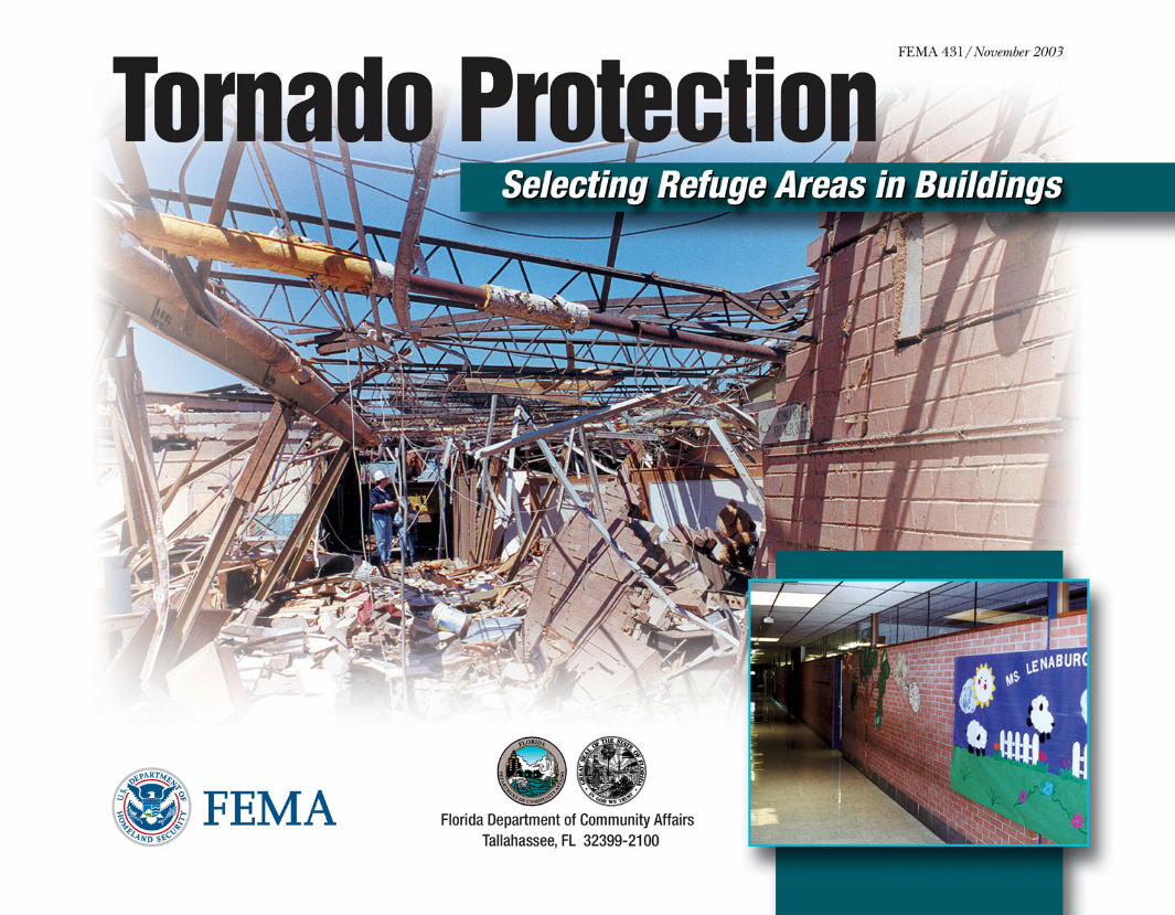
Foreword
About the Cover
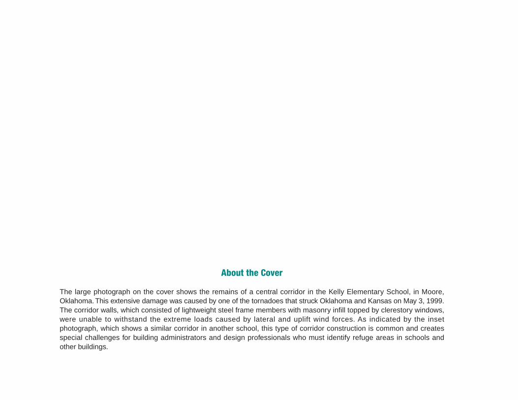
The large photograph on the cover shows the remains of a central corridor in the Kelly Elementary School, in Moore,Oklahoma. This extensive damage was caused by one of the tornadoes that struck Oklahoma and Kansas on May 3, 1999.The corridor walls, which consisted of lightweight steel frame members with masonry infill topped by clerestory windows,were unable to withstand the extreme loads caused by lateral and uplift wind forces. As indicated by the insetphotograph, which shows a similar corridor in another school, this type of corridor construction is common and createsspecial challenges for building administrators and design professionals who must identify refuge areas in schools andother buildings.
Contents
i
ContentsForeword ............................................................................... iii
Introduction ............................................................................ v
Chapter 1: Tornado Profile .....................................................1
Chapter 2: Effects of High Winds ...........................................7Wind Effects on Buildings ........................................................................ 7
Atmospheric Pressure Changes .............................................................. 8
Debris Impact ........................................................................................... 9
Selecting Refuge Areas ......................................................................... 10
Chapter 3: Case Studies ......................................................11Xenia Senior High School ...................................................................... 13
St. Augustine Elementary School and Gymnasium ............................... 21
St. Augustine Elementary School Building ................................. 22
St. Augustine Elementary School Gymnasium .......................... 25
Kelly Elementary School ........................................................................ 27
Tornado Protection: Selecting Refuge Areas in Buildings
Contents
ii
Chapter 4: Selection Procedure ........................................... 37Determine the Required Amount of Refuge Area Space ....................... 38
Review Construction Drawings and Inspect the Building ....................... 39
Assess the Site ....................................................................................... 42
Example of Refuge Area Selection Process........................................... 44
General ........................................................................................ 44
Required Refuge Area Space ..................................................... 46
Architectural and Structural Characteristics ................................ 46
Identifying the Best Available Refuge Areas ............................... 51
Verifying the Best Available Refuge Areas.................................. 54
Selecting the Best Available Refuge Areas inOther Types of Buildings ......................................................................... 55
Mid-Rise and High-Rise Buildings .............................................. 55
Large Stores and Movie Theaters ............................................... 55
Chapter 5: Conclusions......................................................... 57
Information Sources .............................................................. 61
Foreword
iii
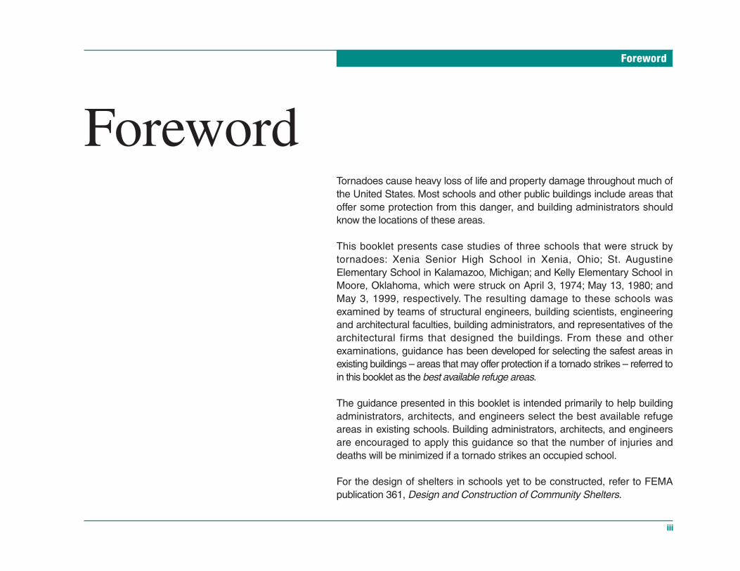
ForewordTornadoes cause heavy loss of life and property damage throughout much ofthe United States. Most schools and other public buildings include areas thatoffer some protection from this danger, and building administrators shouldknow the locations of these areas.
This booklet presents case studies of three schools that were struck bytornadoes: Xenia Senior High School in Xenia, Ohio; St. AugustineElementary School in Kalamazoo, Michigan; and Kelly Elementary School inMoore, Oklahoma, which were struck on April 3, 1974; May 13, 1980; andMay 3, 1999, respectively. The resulting damage to these schools wasexamined by teams of structural engineers, building scientists, engineeringand architectural faculties, building administrators, and representatives of thearchitectural firms that designed the buildings. From these and otherexaminations, guidance has been developed for selecting the safest areas inexisting buildings – areas that may offer protection if a tornado strikes – referred toin this booklet as the best available refuge areas.
The guidance presented in this booklet is intended primarily to help buildingadministrators, architects, and engineers select the best available refugeareas in existing schools. Building administrators, architects, and engineersare encouraged to apply this guidance so that the number of injuries anddeaths will be minimized if a tornado strikes an occupied school.
For the design of shelters in schools yet to be constructed, refer to FEMApublication 361, Design and Construction of Community Shelters.

Introduction
v
IntroductionThe likelihood that a tornado will strike a building is a matter of probability.Tornado damage to buildings is predictable. Administrators of schools andother public buildings should have a risk analysis performed to determine thelikelihood that a tornado will occur and the potential severity of the event. If abuilding is determined to be at sufficient risk, the safest areas of the building –areas that may offer protection if a tornado strikes – should be identified. Thisbooklet refers to such areas as the best available refuge areas. In manybuildings, the best available refuge areas are large enough to accommodatethe number of people who normally occupy the building. A qualified architector structural engineer should assess an existing building and identify the bestavailable refuge areas.
This booklet presents information that will aid qualified architects and engi-neers in the identification of the best available refuge areas in existing build-ings. Architects and engineers who are designing tornado shelters within newbuildings may also find this booklet useful, but should refer to Design andConstruction Guidance for Community Shelters (FEMA 361) for more detailedinformation. FEMA 361 includes design criteria, information about the perfor-mance of specific construction materials under wind and debris impact loads,and examples of construction plans and costs.
The Wind Engineering Research Center at Texas Tech University providedmuch of the substance of this booklet. Dr. Kishor Mehta of the Center as-sisted in the preparation and review of the material. Invaluable assistancewas provided by the architects and engineers of the buildings presented ascase studies and by the school administrators.
What Are “Best Available Refuge Areas”?The term best available refuge areas refers to ar-eas in an existing building that have been deemedby a qualified architect or engineer to likely offer thegreatest safety for building occupants during a tor-nado. It is important to note that, because these ar-eas were not specifically designed as tornadoshelters, their occupants may be injured or killedduring a tornado. However, people in the best avail-able refuge areas are less likely to be injured orkilled than people in other areas of a building.

Chapter 1: Tornado Profile
1
Tornado ProfileThe National Weather Service defines a tornado as a violently rotating col-umn of air pendant from a thunderstorm cloud that touches the ground.
From a local perspective, a tornado is the most destructive of all atmospheric-generated phenomena. In an average year, a little more than 800 tornadoeshit various parts of the United States, though the number has varied from 500to 1,400 in a given year. More tornadoes are recorded in the months of Mayand June than in any other month (Figure 1-1). Figure 1-2 shows the geo-graphic distribution of tornadoes in the United States.
Figure 1-1 Tornado occurrence by month in the United States.
Determining Tornado RiskDetailed guidance for determining the magnitudeof the tornado risk in a specific area of the UnitedStates is presented in FEMA publication 361, Designand Construction Guidance for Community Shelters(for more information, see the section of this book-let titled Information Sources).
FE
MA

Chapter 1: Tornado Profile
2 Tornado Protection: Selecting Refuge Areas in Buildings
Figure 1-2 Tornado occurrence in the United States based on historical data.
Chapter 1: Tornado Profile
3
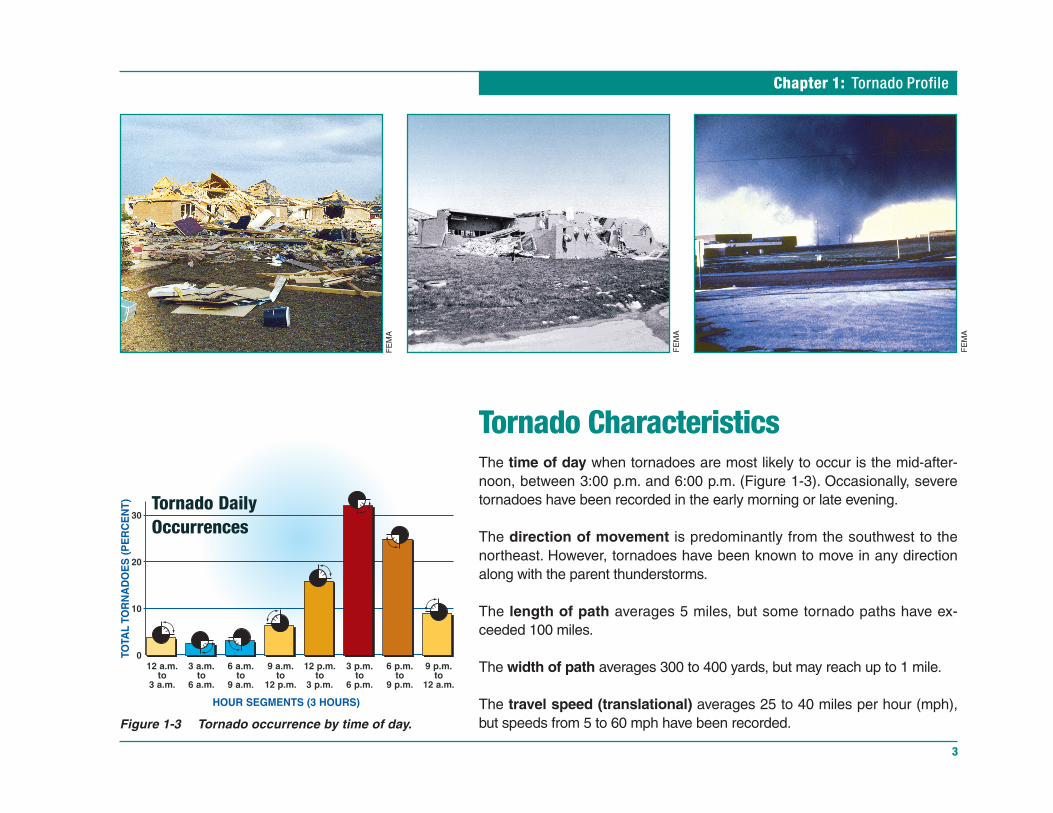
Tornado CharacteristicsThe time of day when tornadoes are most likely to occur is the mid-after-noon, between 3:00 p.m. and 6:00 p.m. (Figure 1-3). Occasionally, severetornadoes have been recorded in the early morning or late evening.
The direction of movement is predominantly from the southwest to thenortheast. However, tornadoes have been known to move in any directionalong with the parent thunderstorms.
The length of path averages 5 miles, but some tornado paths have ex-ceeded 100 miles.
The width of path averages 300 to 400 yards, but may reach up to 1 mile.
The travel speed (translational) averages 25 to 40 miles per hour (mph),but speeds from 5 to 60 mph have been recorded.Figure 1-3 Tornado occurrence by time of day.
FE
MA
FE
MA
FE
MA

Chapter 1: Tornado Profile
4 Tornado Protection: Selecting Refuge Areas in Buildings
The rotational speed is assumed to be symmetrical. The maximum rota-tional velocity occurs at the edge of the tornado core. The speed reducesrapidly as the distance from the edge increases.
The intensity of damage from a tornado is related to wind speed, windbornedebris, and type of construction. The atmospheric pressure drop in the centerof a tornado does not destroy buildings, because pressures inside and out-side of buildings equalize through broken windows and doors or throughopenings that result when sections of the roof are removed.
Tornadoes are rated by the National Weather Service according to thetornado damage scale developed by Dr. Theodore Fujita, a professor of me-teorology. Ratings vary from F0, for light damage, to F5, for total destructionof a building (Figure 1-4). Ninety percent of the tornadoes recorded over thepast 45 years have been categorized as F0, F1, or F2 (Figure 1-5).
Figure 1-4 The Fujita Tornado Damage Scale.
Figure 1-5Percentage of recorded tornadoes by Fujita TornadoDamage Scale ranking.

Chapter 1: Tornado Profile
5
Rotation is generally counterclockwise in the northern hemisphere (Figure1-6). About 10 percent of tornadoes have been known to rotate clockwise.
Wind speed is the sum of rotational speed and translational speed. The ro-tational speed decreases as the distance from the center of a tornadoincreases. With a counterclockwise rotation, the wind speed on the rightside of the tornado is higher because the translational speed adds to therotational speed.
Because of the unpredictability of tornado paths and the destruction of com-monly used instruments, direct measurements of wind speeds have not beenmade in tornadoes. Rather, wind speeds are judged from the intensity ofdamage to buildings. Engineering assessment of damage puts the maximumwind speed at 200 mph in most destructive tornadoes, and the speed is notlikely to exceed 250 mph near ground level.
Figure 1-6Typical tornado rotation.
FE
MA
FE
MA
Chapter 2: Effects of High Winds
7
Effects of High WindsIn buildings hit by tornadoes, the threat to life is due to a combination of effectsthat occur at almost the same time. To understand the tornado damage thatcan occur in a building, the following must be considered:
• wind-induced forces
• changes in atmospheric pressure
• debris impact
Wind Effects on BuildingsThe wind speeds generated by some tornadoes are so great that designingfor these extreme winds is beyond the scope of building codes and engineer-ing standards. Most buildings that have received some engineering attention,such as schools, and that are built in accordance with sound constructionpractices can usually withstand wind speeds specified by building codes.Meeting these code-specified wind speeds can provide sufficient resistanceto tornadic winds if the building is located on the outer edge of the tornadovortex. In addition, if a portion of the building is built to a higher tornado de-sign standard, then both building and occupant survival are improved.
Wind creates inward- and outward-acting pressures on building surfaces, de-pending on the orientation of the surface (e.g., flat, vertical, low-slope). As thewind moves over and around the building, the outward-acting pressure in-creases as the building geometry forces the wind to change direction. Thesepressure increases create uplift on parts of the building, forcing the building

Tornado Protection: Selecting Refuge Areas in Buildings
Chapter 2: Effects of High Winds
8
apart if it is too weak to resist the wind loads. When wind forces its way insideor creates an opening by breaking a window or penetrating the roof or walls,the pressures on the building increase even more. Figure 2-1 shows howwind affects both an enclosed building and a building with openings.
Heavy building materials (e.g., reinforced masonry or concrete) that are welltied to all other building components often survive extreme winds. The weightof these materials helps resist uplift and lateral loads, and heavy materials of-ten stop windborne debris that can increase damage to the building. However,heavy concrete roof panels and heavy masonry walls that are not adequatelyconnected or reinforced have failed during severe winds. Lightweight roofingand siding materials such as gravel, insulation, shingles, roofing membranes,and brick veneer can also be a problem.
Building shapes that “catch” the wind, such as overhangs, canopies, andeaves, tend to fail and become “sails” in extreme winds. Flat roofs can be liftedoff when the wind flows over them and increases the uplift pressure at thecorners and edges of the roofs.
Atmospheric Pressure ChangesInitially, the pressure outside a building during a tornado is very low com-pared to the pressure inside. In most buildings, however, there is enoughair leakage through building component connections to equalize thesepressures. Also, windborne debris is likely to break windows and allow windto enter.
The explosion of buildings during a tornado due to atmospheric pressure dif-ferences is a myth. In reality, the combination of internal pressure and out-ward pull on the building from suction pressure has caused building failuresthat have forced the walls outward and given the building the appearance ofhaving exploded. During an event, doors and windows should remain closed onall sides of the building in order to minimize the entry of wind into the building.
FE
MA
Figure 2-1Effects of wind on a fully enclosed building and on abuilding with openings.
Chapter 2: Effects of High Winds
9
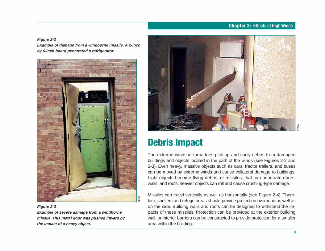
Debris ImpactThe extreme winds in tornadoes pick up and carry debris from damagedbuildings and objects located in the path of the winds (see Figures 2-2 and2-3). Even heavy, massive objects such as cars, tractor trailers, and busescan be moved by extreme winds and cause collateral damage to buildings.Light objects become flying debris, or missiles, that can penetrate doors,walls, and roofs; heavier objects can roll and cause crushing-type damage.
Missiles can travel vertically as well as horizontally (see Figure 2-4). There-fore, shelters and refuge areas should provide protection overhead as well ason the side. Building walls and roofs can be designed to withstand the im-pacts of these missiles. Protection can be provided at the exterior buildingwall, or interior barriers can be constructed to provide protection for a smallerarea within the building.
Figure 2-2Example of damage from a windborne missile. A 2-inchby 6-inch board penetrated a refrigerator.
Figure 2-3Example of severe damage from a windbornemissile. This metal door was pushed inward bythe impact of a heavy object.
FE
MA
FE
MA
Tornado Protection: Selecting Refuge Areas in Buildings
Chapter 2: Effects of High Winds
10
Selecting Refuge AreasWind effects on buildings have been studied sufficiently to predict whichbuilding elements are most likely to successfully resist the extreme wind pres-sures caused by tornadoes and which are most likely to fail. Sufficient mate-rial testing and design work has been performed for large shelters to developa refuge area selection guide for any building in which such areas areneeded. Many buildings contain a small interior area or areas that couldserve as the best available refuge area or possibly be converted or reinforcedfor refuge area use.
The selection of refuge areas in existing buildings is discussed in Chapter 4.For more information about refuge areas and shelter design, refer to FEMApublication 361, Design and Construction Guidance for Community Shelters(see sidebar on page 11).
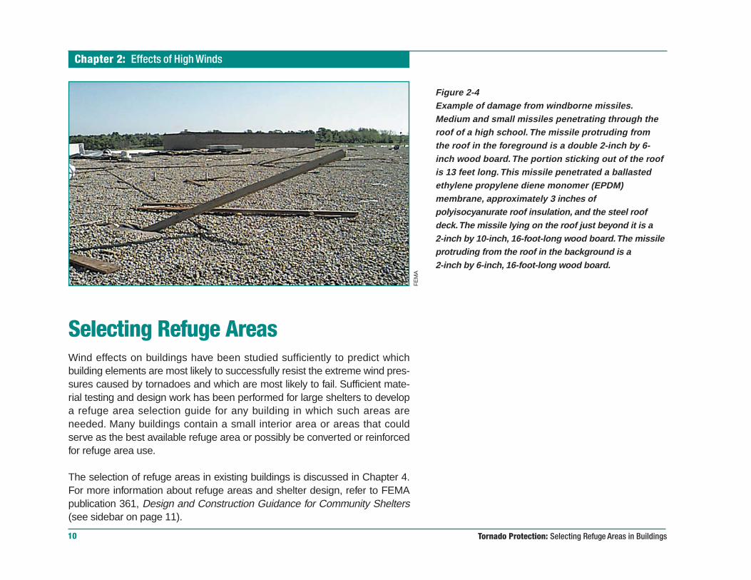
Figure 2-4Example of damage from windborne missiles.Medium and small missiles penetrating through theroof of a high school. The missile protruding fromthe roof in the foreground is a double 2-inch by 6-inch wood board. The portion sticking out of the roofis 13 feet long. This missile penetrated a ballastedethylene propylene diene monomer (EPDM)membrane, approximately 3 inches ofpolyisocyanurate roof insulation, and the steel roofdeck. The missile lying on the roof just beyond it is a2-inch by 10-inch, 16-foot-long wood board. The missileprotruding from the roof in the background is a2-inch by 6-inch, 16-foot-long wood board.
FE
MA
Chapter 3: Case Studies
11
Case StudiesA large number of schools have been destroyed or heavily damaged by tor-nadoes, and there have been many injuries and deaths. The three schoolbuildings presented as case studies in this booklet were selected for the fol-lowing reasons:
• All were hit by different, but intense storms.
• The three structures varied in size, age, and type of construction.
• All were designed by different architects and engineers to national build-ing codes.
• All had to be partially or totally destroyed later because of the extent ofthe tornado damage.
The building damage was examined by teams of structural engineers, build-ing scientists, specially trained members of engineering and architecturalfaculties and firms, building administrators, and representatives of the archi-tectural firms that designed the buildings.
The determination of the best available refuge areas in the three buildings(shown on floor plans presented later in this chapter) was based on threesources of information, in the following order of importance:
• persons who were in each building during the tornado
• building examinations by engineers and architects
• aerial photographs taken shortly after the storms
Guidance for Refuge Area SelectionDetailed evaluation checklists for selecting the bestavailable refuge areas in existing buildings and guid-ance for designing and constructing shelters arepresented in FEMA publication 361, Design andConstruction Guidance for Community Shelters (formore information, see the section of this booklettitled Information Sources).
FE
MA

Tornado Protection: Selecting Refuge Areas in Buildings
Chapter 3: Case Studies
12
The identified refuge areas in these buildings are the best that were availablein each of the three buildings when the storms occurred.
These case studies are presented here with two goals:
• to help building designers and administrators locate accurately the partsof a building that would likely be left standing after a tornado—before thetornado strikes
• to help architects and engineers design buildings that offer occupants ex-cellent tornado protection

Chapter 3: Case Studies
13
Figure 3-1 Xenia Senior High School, Xenia, Ohio.
Xenia Senior High SchoolXenia, Ohio
Building population: 1,450, including staff12 students, 3 staff in building during tornado
Tornado direction: From southwestDamage intensity: F5Time: 4:45 p.m.Date: April 3, 1974
WE
RC
, TE
XA
S T
EC
H U
NIV
ER
SIT
Y

Tornado Protection: Selecting Refuge Areas in Buildings
Chapter 3: Case Studies
14
Xenia Senior High School (Figure 3-1) was a two-story, slab-on-grade build-ing without a basement located on the north side of Xenia, Ohio. It facedShawnee Park to the west.
The massive tornado hit 1 hour and 45 minutes after school dismissal. It wasspotted by a student who was leaving the school. She alerted drama studentswho were rehearsing in the auditorium. The students ran and dove for shelterin a nearby corridor.
The tornado passed directly over the school. Two school buses came to reston the stage where the students had been rehearsing. Some of the studentswere treated for injuries at a nearby hospital.
The building was found to be unsafe to enter and was demolished.
ConstructionThe construction types varied among the main parts of the school—originalbuilding, three additions (A, B, and C):
Original building and addition B: Lightweight steel frame, open-web steeljoists, 2-inch gypsum roof deck.
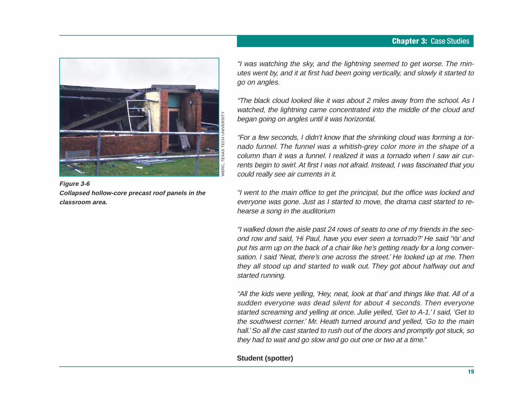
Addition A: Loadbearing masonry walls, hollow-core precast concrete roofplanks.
Addition C: Precast concrete frame, concrete double-tee floor/roof beams.
Girls’ gym: Loadbearing masonry wall, precast concrete tee beams.
Auditorium and boys’ gym: Loadbearing masonry walls, steel trusses.

Chapter 3: Case Studies
15
Tornado DamageThe tornado passed directly over the school, engulfing the entire building andthe adjacent fieldhouse to the south (Figure 3-2).
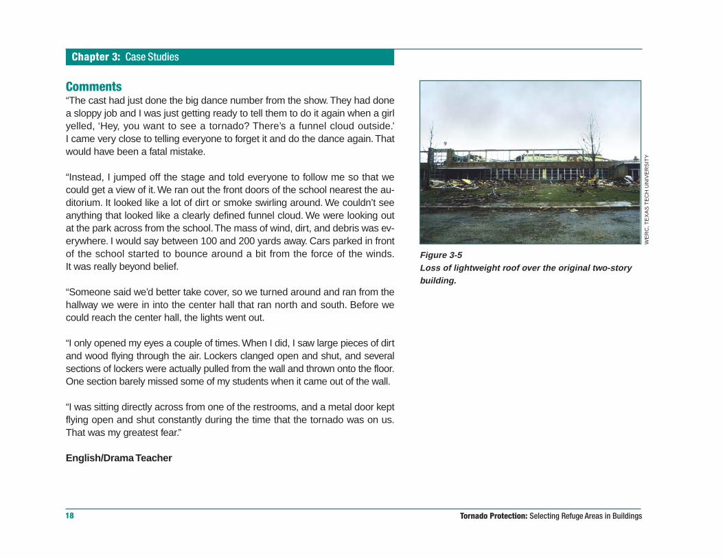
The enclosure walls failed on the west and south sides, allowing the winds toenter the building. The roofs collapsed over the three large spans—the audi-torium, the boys’ gym, and the girls’ gym. The lightweight roof over the originaltwo-story building was torn off by the extreme winds.
Figure 3-2 Xenia Senior High School, Xenia, Ohio.
WE
RC
, TE
XA
S T
EC
H U
NIV
ER
SIT
Y
Tornado Protection: Selecting Refuge Areas in Buildings
Chapter 3: Case Studies
16
Hazardous ElementsAll windows on the west and south sides were blown into the interior. Thehigh single-story, loadbearing masonry walls of the long-span roomsfailed, allowing the roofs to fall in. The unbaffled west entrances allowed theeast-west corridors to become wind tunnels.
Debris from nearby houses, vehicles, and Shawnee Park became missiles,many of which hit and entered the school. The 46-foot-high masonry chimneycollapsed. A non-loadbearing second-floor wall on the north side collapsedonto a lower roof.
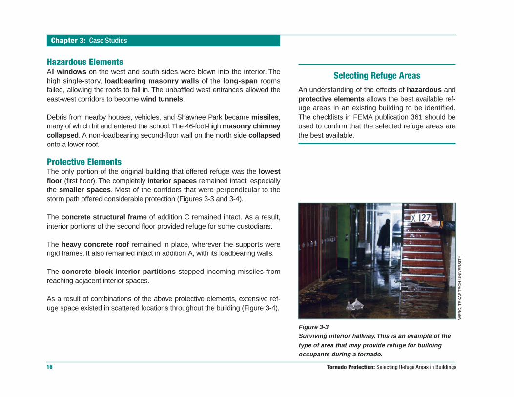
Protective ElementsThe only portion of the original building that offered refuge was the lowestfloor (first floor). The completely interior spaces remained intact, especiallythe smaller spaces. Most of the corridors that were perpendicular to thestorm path offered considerable protection (Figures 3-3 and 3-4).
The concrete structural frame of addition C remained intact. As a result,interior portions of the second floor provided refuge for some custodians.
The heavy concrete roof remained in place, wherever the supports wererigid frames. It also remained intact in addition A, with its loadbearing walls.
The concrete block interior partitions stopped incoming missiles fromreaching adjacent interior spaces.
As a result of combinations of the above protective elements, extensive ref-uge space existed in scattered locations throughout the building (Figure 3-4).
Figure 3-3Surviving interior hallway. This is an example of thetype of area that may provide refuge for buildingoccupants during a tornado.
WE
RC
, TE
XA
S T
EC
H U
NIV
ER
SIT
Y
Selecting Refuge AreasAn understanding of the effects of hazardous andprotective elements allows the best available ref-uge areas in an existing building to be identified.The checklists in FEMA publication 361 should beused to confirm that the selected refuge areas arethe best available.

Chapter 3: Case Studies
17
Figure 3-4 Best available refuge areas in Xenia Senior High School.
DRAFTINGROOM
OFFICES
Tornado Protection: Selecting Refuge Areas in Buildings
Chapter 3: Case Studies
18
Comments“The cast had just done the big dance number from the show. They had donea sloppy job and I was just getting ready to tell them to do it again when a girlyelled, ‘Hey, you want to see a tornado? There’s a funnel cloud outside.’I came very close to telling everyone to forget it and do the dance again. Thatwould have been a fatal mistake.
“Instead, I jumped off the stage and told everyone to follow me so that wecould get a view of it. We ran out the front doors of the school nearest the au-ditorium. It looked like a lot of dirt or smoke swirling around. We couldn’t seeanything that looked like a clearly defined funnel cloud. We were looking outat the park across from the school. The mass of wind, dirt, and debris was ev-erywhere. I would say between 100 and 200 yards away. Cars parked in frontof the school started to bounce around a bit from the force of the winds.It was really beyond belief.
“Someone said we’d better take cover, so we turned around and ran from thehallway we were in into the center hall that ran north and south. Before wecould reach the center hall, the lights went out.
“I only opened my eyes a couple of times. When I did, I saw large pieces of dirtand wood flying through the air. Lockers clanged open and shut, and severalsections of lockers were actually pulled from the wall and thrown onto the floor.One section barely missed some of my students when it came out of the wall.
“I was sitting directly across from one of the restrooms, and a metal door keptflying open and shut constantly during the time that the tornado was on us.That was my greatest fear.”
English/Drama Teacher
Figure 3-5Loss of lightweight roof over the original two-storybuilding.
WE
RC
, TE
XA
S T
EC
H U
NIV
ER
SIT
Y
Chapter 3: Case Studies
19
“I was watching the sky, and the lightning seemed to get worse. The min-utes went by, and it at first had been going vertically, and slowly it started togo on angles.
“The black cloud looked like it was about 2 miles away from the school. As Iwatched, the lightning came concentrated into the middle of the cloud andbegan going on angles until it was horizontal.
“For a few seconds, I didn’t know that the shrinking cloud was forming a tor-nado funnel. The funnel was a whitish-grey color more in the shape of acolumn than it was a funnel. I realized it was a tornado when I saw air cur-rents begin to swirl. At first I was not afraid. Instead, I was fascinated that youcould really see air currents in it.
“I went to the main office to get the principal, but the office was locked andeveryone was gone. Just as I started to move, the drama cast started to re-hearse a song in the auditorium
“I walked down the aisle past 24 rows of seats to one of my friends in the sec-ond row and said, ‘Hi Paul, have you ever seen a tornado?’ He said ‘Ya’ andput his arm up on the back of a chair like he’s getting ready for a long conver-sation. I said ‘Neat, there’s one across the street.’ He looked up at me. Thenthey all stood up and started to walk out. They got about halfway out andstarted running.
“All the kids were yelling, ‘Hey, neat, look at that’ and things like that. All of asudden everyone was dead silent for about 4 seconds. Then everyonestarted screaming and yelling at once. Julie yelled, ‘Get to A-1.’ I said, ‘Get tothe southwest corner.’ Mr. Heath turned around and yelled, ‘Go to the mainhall.’ So all the cast started to rush out of the doors and promptly got stuck, sothey had to wait and go slow and go out one or two at a time.”
Student (spotter)
Figure 3-6Collapsed hollow-core precast roof panels in theclassroom area.
WE
RC
, TE
XA
S T
EC
H U
NIV
ER
SIT
Y

Tornado Protection: Selecting Refuge Areas in Buildings
Chapter 3: Case Studies
20
“When we were warned about the tornado, we all ran to the door to look at it. Iwas about the last one to arrive there, and I stood there very long until some-one yelled from around the corner to get over there. The last thing I saw thetornado doing was picking up my car which was parked out on the street.
“I then ran around the corner and found everyone already lying along eachside of the wall and some around the corner. I then ran to the intersection ofthe two halls and laid alongside the wall.
“When it was all over, I was buried from the waist down in little pieces ofgravel, boards, and a lot of water from the lake across the street in the park.”
Student
“The first place I ran to was this little cubbyhole right in front of the girls’restroom door. If I had stayed there, I would have been splattered across thehall, because it blew so hard it almost came off its hinges. For some reason,which I cannot account for, I dived across the hall right after the lights wentout and got to the other side of the hall just as the front doors were breaking.
“I kept my eyes open, which was stupid on my part. I was looking down at thefloor rather than out and I could see big chunks of wood and debris flyingdown the hall by my feet. It was incredible.”
Student
Figure 3-7Collapsed gymnasium walls and roof, where open-web roof joists were supported on unreinforcedmasonry walls.
WE
RC
, TE
XA
S T
EC
H U
NIV
ER
SIT
Y
Chapter 3: Case Studies
21
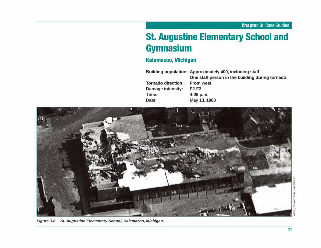
Figure 3-8 St. Augustine Elementary School, Kalamazoo, Michigan.
St. Augustine Elementary School andGymnasiumKalamazoo, Michigan
Building population: Approximately 400, including staffOne staff person in the building during tornado
Tornado direction: From westDamage intensity: F2-F3Time: 4:09 p.m.Date: May 13, 1980
WE
RC
, TE
XA
S T
EC
H U
NIV
ER
SIT
Y
Tornado Protection: Selecting Refuge Areas in Buildings
Chapter 3: Case Studies
22
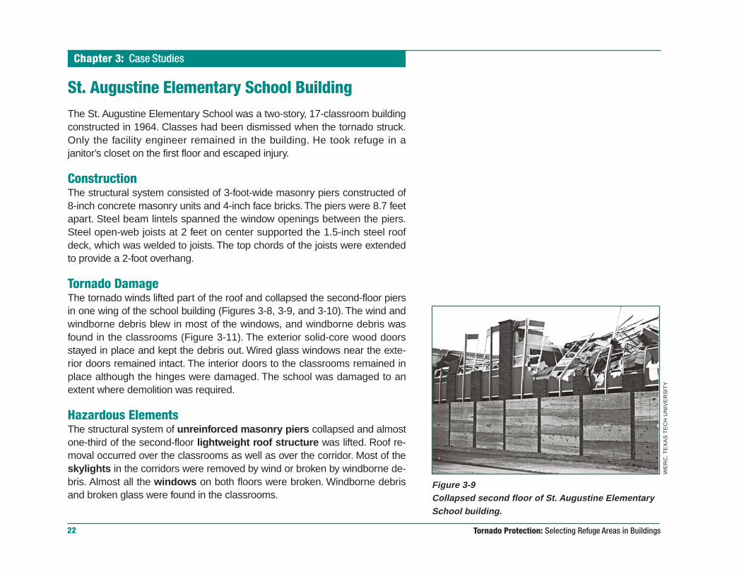
Figure 3-9Collapsed second floor of St. Augustine ElementarySchool building.
St. Augustine Elementary School BuildingThe St. Augustine Elementary School was a two-story, 17-classroom buildingconstructed in 1964. Classes had been dismissed when the tornado struck.Only the facility engineer remained in the building. He took refuge in ajanitor’s closet on the first floor and escaped injury.
ConstructionThe structural system consisted of 3-foot-wide masonry piers constructed of8-inch concrete masonry units and 4-inch face bricks. The piers were 8.7 feetapart. Steel beam lintels spanned the window openings between the piers.Steel open-web joists at 2 feet on center supported the 1.5-inch steel roofdeck, which was welded to joists. The top chords of the joists were extendedto provide a 2-foot overhang.
Tornado DamageThe tornado winds lifted part of the roof and collapsed the second-floor piersin one wing of the school building (Figures 3-8, 3-9, and 3-10). The wind andwindborne debris blew in most of the windows, and windborne debris wasfound in the classrooms (Figure 3-11). The exterior solid-core wood doorsstayed in place and kept the debris out. Wired glass windows near the exte-rior doors remained intact. The interior doors to the classrooms remained inplace although the hinges were damaged. The school was damaged to anextent where demolition was required.
Hazardous ElementsThe structural system of unreinforced masonry piers collapsed and almostone-third of the second-floor lightweight roof structure was lifted. Roof re-moval occurred over the classrooms as well as over the corridor. Most of theskylights in the corridors were removed by wind or broken by windborne de-bris. Almost all the windows on both floors were broken. Windborne debrisand broken glass were found in the classrooms.
WE
RC
, TE
XA
S T
EC
H U
NIV
ER
SIT
Y

Chapter 3: Case Studies
23
Figure 3-10Floor plan of second floor of St. Augustine Elementary School showinglocations of roof removal.
Figure 3-11Broken windows and debris in classroom of St.Augustine Elementary School building.
WE
RC
, TE
XA
S T
EC
H U
NIV
ER
SIT
Y
Tornado Protection: Selecting Refuge Areas in Buildings
Chapter 3: Case Studies
24
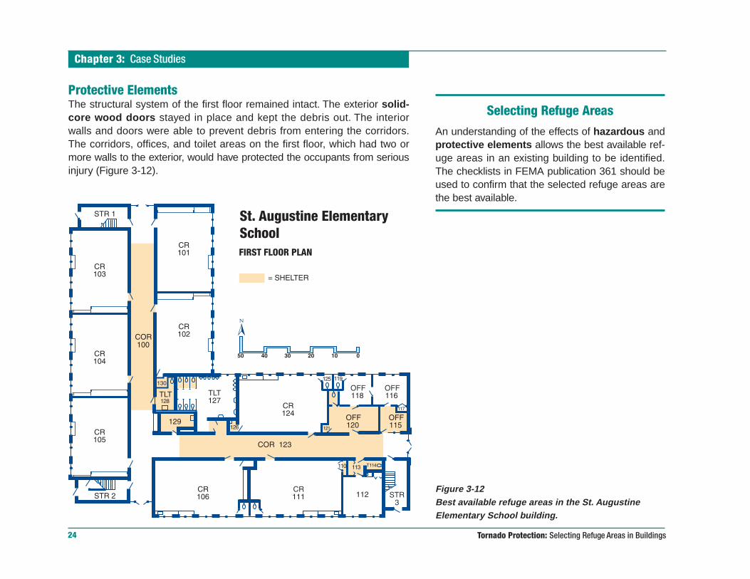
Protective ElementsThe structural system of the first floor remained intact. The exterior solid-core wood doors stayed in place and kept the debris out. The interiorwalls and doors were able to prevent debris from entering the corridors.The corridors, offices, and toilet areas on the first floor, which had two ormore walls to the exterior, would have protected the occupants from seriousinjury (Figure 3-12).
Figure 3-12Best available refuge areas in the St. AugustineElementary School building.
Selecting Refuge AreasAn understanding of the effects of hazardous andprotective elements allows the best available ref-uge areas in an existing building to be identified.The checklists in FEMA publication 361 should beused to confirm that the selected refuge areas arethe best available.
Chapter 3: Case Studies
25
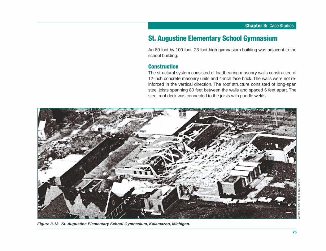
Figure 3-13 St. Augustine Elementary School Gymnasium, Kalamazoo, Michigan.
St. Augustine Elementary School GymnasiumAn 80-foot by 100-foot, 23-foot-high gymnasium building was adjacent to theschool building.
ConstructionThe structural system consisted of loadbearing masonry walls constructed of12-inch concrete masonry units and 4-inch face brick. The walls were not re-inforced in the vertical direction. The roof structure consisted of long-spansteel joists spanning 80 feet between the walls and spaced 6 feet apart. Thesteel roof deck was connected to the joists with puddle welds.
WE
RC
, TE
XA
S T
EC
H U
NIV
ER
SIT
Y

Tornado Protection: Selecting Refuge Areas in Buildings
Chapter 3: Case Studies
26
Tornado DamageThe building was destroyed (Figures 3-13 and 3-14). The loadbearing west wallcollapsed inward, and the east wall fell outward. The roof fell in the building whenthe walls collapsed.
Hazardous ElementsSlender unreinforced masonry walls and long-span roof structure.
Protective ElementsNone
Observations: School Building and GymnasiumThe unreinforced masonry walls combined with the lightweight roof structurein the building as well as the gymnasium building were vulnerable to collapsein windstorms. Gymnasium buildings are not considered suitable for occupantprotection because they usually include tall walls and long-span roofs. Light-weight roof structures that are not adequately anchored can be lifted inwindstorms. Except in violent (F4 and F5) tornadoes, the lower floor (in two-story or higher buildings) generally provides good protection for occupantswhen there are two or more walls between the refuge area and the outside.
Figure 3-14Collapsed St. Augustine Elementary SchoolGymnasium building.
WE
RC
, TE
XA
S T
EC
H U
NIV
ER
SIT
Y
Chapter 3: Case Studies
27
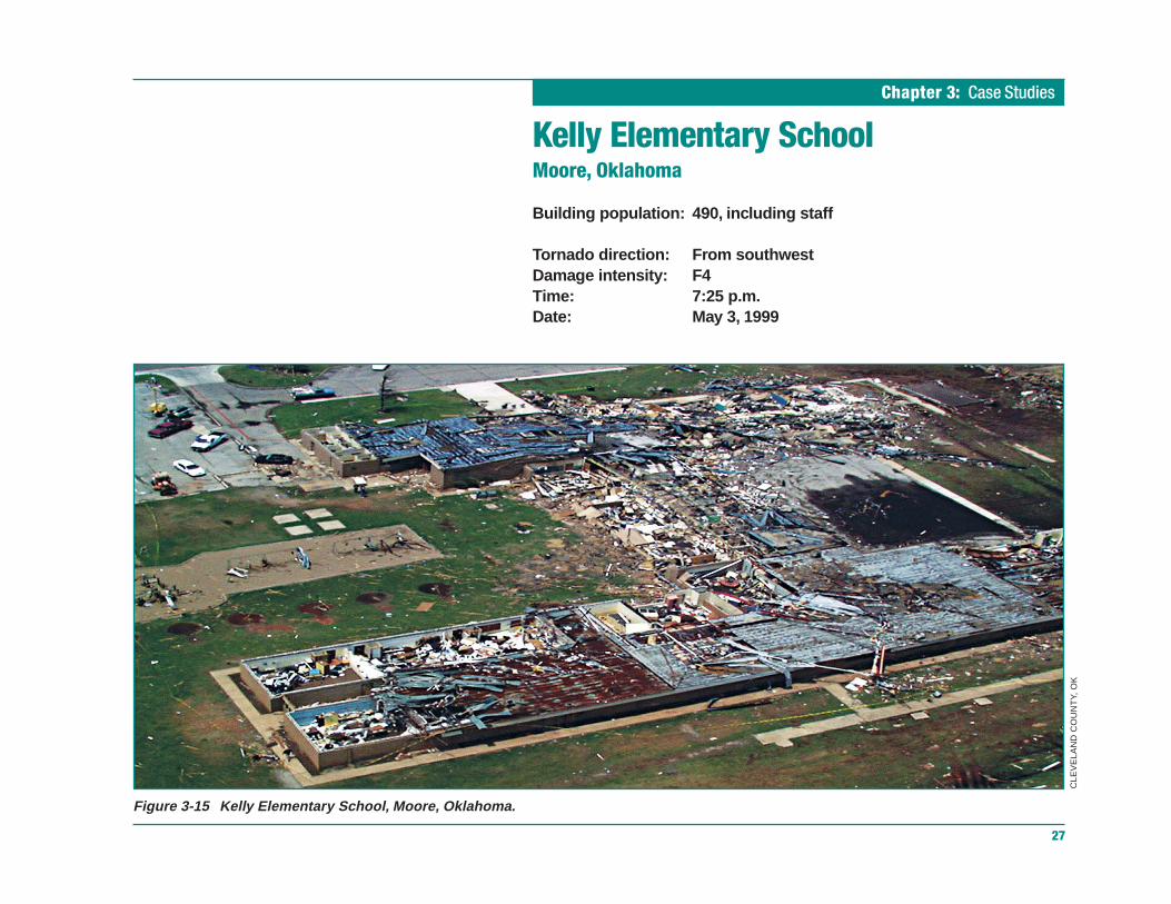
Kelly Elementary SchoolMoore, Oklahoma
Building population: 490, including staff
Tornado direction: From southwestDamage intensity: F4Time: 7:25 p.m.Date: May 3, 1999
Figure 3-15 Kelly Elementary School, Moore, Oklahoma.
CLE
VE
LAN
D C
OU
NT
Y, O
K

Tornado Protection: Selecting Refuge Areas in Buildings
Chapter 3: Case Studies
28
The Kelly Elementary School was a one-story slab-on-grade building, withouta basement, located in Moore, Oklahoma.
The tornado hit after school hours and passed just to the north of the site.Damage to the school building was both severe and extensive (Figure 3-15).As discussed in the Lessons Learned section in this case study, the remain-ing structure was demolished and the school was rebuilt. The new schoolincludes structural elements designed to provide increased wind resistance.
ConstructionThree basic wall types were used in the construction of the school:
• reinforced masonry
• unreinforced masonry topped by reinforced bond beams
• lightweight steel frame with masonry infill
The roof system consisted of open-web steel roof joists, metal decking, and abuilt-up roof. Wall and roof construction of this type is common to manyschools in the United States.
Hall corridors were the designated areas of refuge (see Figure 3-16). The cor-ridor walls were of lightweight steel frame with masonry infill. The infillextended to a height of approximately 7 feet. Above this height were clerestorywindows that extended to the tops of the walls. Had the halls been occupiedduring the tornado, many injuries and deaths would have occurred (see Figure3-20, later in this chapter).

Chapter 3: Case Studies
29
Figure 3-16 Designated refuge areas in the original Kelly Elementary School.
Tornado Protection: Selecting Refuge Areas in Buildings
Chapter 3: Case Studies
30
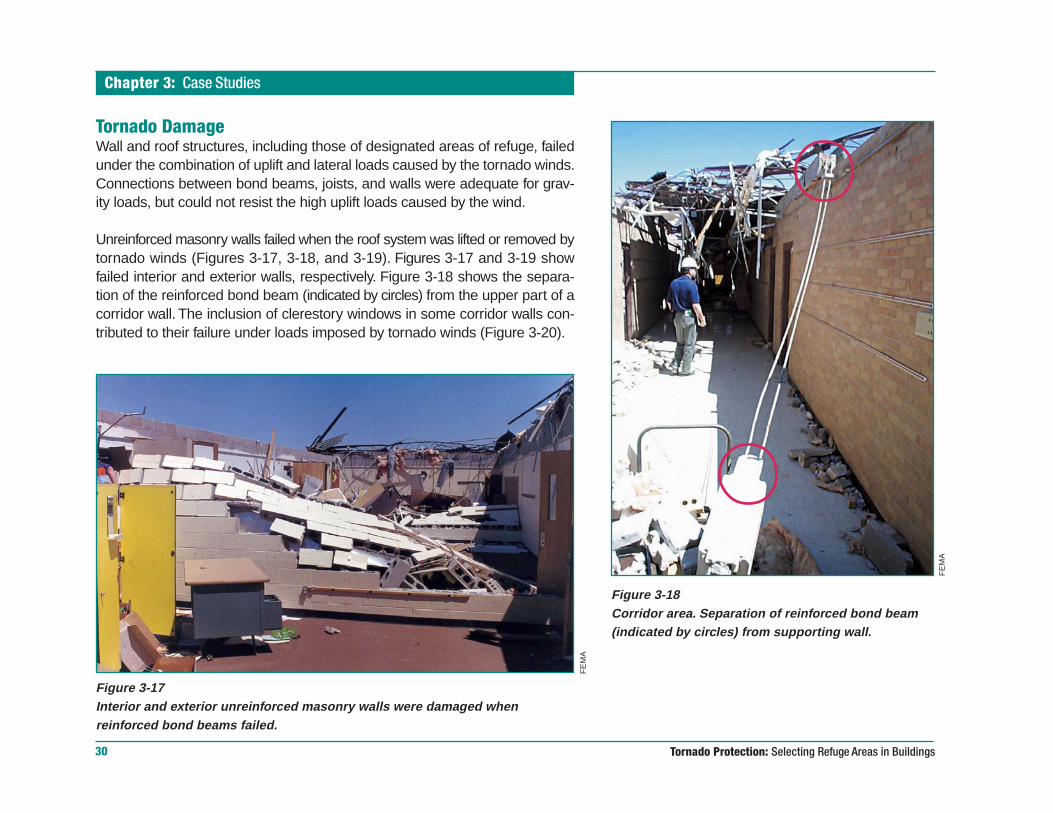
Figure 3-18Corridor area. Separation of reinforced bond beam(indicated by circles) from supporting wall.
Figure 3-17Interior and exterior unreinforced masonry walls were damaged whenreinforced bond beams failed.
Tornado DamageWall and roof structures, including those of designated areas of refuge, failedunder the combination of uplift and lateral loads caused by the tornado winds.Connections between bond beams, joists, and walls were adequate for grav-ity loads, but could not resist the high uplift loads caused by the wind.
Unreinforced masonry walls failed when the roof system was lifted or removed bytornado winds (Figures 3-17, 3-18, and 3-19). Figures 3-17 and 3-19 showfailed interior and exterior walls, respectively. Figure 3-18 shows the separa-tion of the reinforced bond beam (indicated by circles) from the upper part of acorridor wall. The inclusion of clerestory windows in some corridor walls con-tributed to their failure under loads imposed by tornado winds (Figure 3-20).
FE
MA
FE
MA
Chapter 3: Case Studies
31
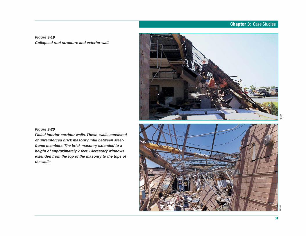
Figure 3-19Collapsed roof structure and exterior wall.
Figure 3-20Failed interior corridor walls. These walls consistedof unreinforced brick masonry infill between steel-frame members. The brick masonry extended to aheight of approximately 7 feet. Clerestory windowsextended from the top of the masonry to the tops ofthe walls.
FE
MA
FE
MA

Tornado Protection: Selecting Refuge Areas in Buildings
Chapter 3: Case Studies
32
Inspection of the roof damage revealed that the roof decking failed at thepoints where it was welded to the tops of the steel trusses. Although thespacing of the welds appeared to be consistent with standard practice, thewelds were not strong enough to resist the wind uplift forces (Figure 3-21).
Damage was also caused by the impact of windborne missiles. Figure 2-3,in Chapter 2, shows a steel door that appeared to have been opened by theimpact of a heavy object. This door led into an area where the roof wasmissing. The opening created by this breached door may have allowed windto enter the building and create internal pressure that increased the load onthe building envelope. Figure 3-22 shows damage to a laminated glass win-dow hit by a table.
Figure 3-21Failed roof structure showing broken welds between metal roof deckand tops of joists (upper circle) and lack of vertical reinforcement(bottom circle).
FE
MA
FE
MA Figure 3-22
Impact performance of laminated glass. The cornerof a table penetrated this laminated glass window,but the glass remained in its frame.

Chapter 3: Case Studies
33
Hazardous ElementsWalls with clerestory windows, such as the corridor walls of the designatedareas of refuge, have limited capacity to resist lateral forces.
Unreinforced masonry walls failed when the reinforced bond beams at thetops of the walls failed.
Welds between the roof decking at the tops of the metal joists failed becausethey were not strong enough to resist the uplift.
Unprotected doors and windows can be breached by windborne missiles.The resulting openings allow wind to enter the building, where it causes in-creased pressures on the building envelope.
Protective ElementsNone
Lessons LearnedBecause the damage to Kelly Elementary School was so great, the schoolwas demolished and completely rebuilt. The new building, although con-structed on the same footprint, incorporated several structural improvementsspecifically designed to provide improved resistance to extreme winds andcreate refuge areas for the school’s occupants. As in the original building, thecentral corridors of the three wings are the designated refuge areas (Figures3-23 and 3-24).
The creation of refuge areas in the new school involved, among other im-provements, the design and construction of stronger loadbearing walls, roofs,roof-to-wall connections, and wall-to-foundation connections. Figure 3-25 is atypical cross-section of the top of a safe area (corridor) wall in the new school.As shown in this figure, the wall is constructed of reinforced concrete ma-sonry. Note the continuous, closely spaced (8 inches on center) verticalreinforcement bars, fully grouted block cells, 6-inch-thick reinforced concrete

Tornado Protection: Selecting Refuge Areas in Buildings
Chapter 3: Case Studies
34
Figure 3-24Corridor (designated safe area) in reconstructedKelly Elementary School.
Figure 3-23Designated refuge areas in the reconstructed Kelly Elementary School.
CIT
Y O
F M
OO
RE
, O
K
Chapter 3: Case Studies
35
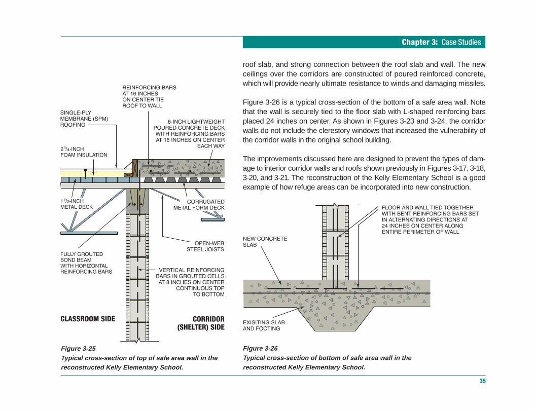
roof slab, and strong connection between the roof slab and wall. The newceilings over the corridors are constructed of poured reinforced concrete,which will provide nearly ultimate resistance to winds and damaging missiles.
Figure 3-26 is a typical cross-section of the bottom of a safe area wall. Notethat the wall is securely tied to the floor slab with L-shaped reinforcing barsplaced 24 inches on center. As shown in Figures 3-23 and 3-24, the corridorwalls do not include the clerestory windows that increased the vulnerability ofthe corridor walls in the original school building.
The improvements discussed here are designed to prevent the types of dam-age to interior corridor walls and roofs shown previously in Figures 3-17, 3-18,3-20, and 3-21. The reconstruction of the Kelly Elementary School is a goodexample of how refuge areas can be incorporated into new construction.
Figure 3-25Typical cross-section of top of safe area wall in thereconstructed Kelly Elementary School.
Figure 3-26Typical cross-section of bottom of safe area wall in thereconstructed Kelly Elementary School.

Chapter 4: Selection Procedure
37
Selection ProcedureThe procedure presented in this chapter is designed to assist in a systematicreview of a building for the purpose of selecting the areas within the buildingthat are likely to be the most resistant to tornadoes, referred to in this bookletas the best available refuge areas. When used for refuge during tornadoes,these areas do not guarantee safety; they are, however, the safest areasavailable for building occupants. This selection procedure does not apply tostructures such as lightweight modular houses and offices and relocatableclassrooms. Such structures are presumed to fail, and they must be evacuated.
Most buildings, unless specifically designed as shelters, will sustain cata-strophic damage if they take a direct hit from a Violent Tornado (i.e., a tornadoranked F4 or F5 on the Fujita Tornado Damage Scale—see Chapter 1). Be-cause the maximum wind speeds associated with a Violent Tornado greatlyexceed the wind speeds that the buildings were designed to withstand, com-plete destruction will usually occur during these extremely rare events.
In reality, most tornadoes do not produce the winds of a Violent Tornado, andsome areas of many buildings can survive these lesser events without cata-strophic damage or collapse. Placing building occupants in the bestavailable refuge areas within a building greatly reduces the risk of injury ordeath. However, unless the refuge area was designed as a shelter, its occu-pants are vulnerable to injury or death.
Selecting the best available refuge areas involves three main steps:
• determining how much refuge area space is required to housebuilding occupants
Guidance for Refuge Area SelectionDetailed evaluation checklists for selecting the bestavailable refuge areas in existing buildings and guid-ance for designing and constructing shelters arepresented in FEMA 361, Design and ConstructionGuidance for Community Shelters (for more infor-mation, see the section of this booklet titledInformation Sources.)
FE
MA

Tornado Protection: Selecting Refuge Areas in Buildings
Chapter 4: Selection Procedure
38
• reviewing construction drawings and inspecting the building toidentify the strongest portion(s) of the building
• assessing the site to identify potential tree, pole, and tower fall-downand windborne missiles
Determining the required refuge area space and assessing the site arerelatively straightforward tasks that can be completed by many people. Thedrawing review and building inspections are more technical in nature. Quali-fied structural engineers or architects should be consulted for those tasks.
Determine the Required Amountof Refuge Area SpaceRefuge areas must be large enough to provide space for all occupants whomay be in the building when a tornado strikes. In schools, space must be pro-vided for all students and faculty, maintenance and custodial workers, andany parents or other visitors who may be present.
Refuge area space requirements vary according to the age of the occupantsand any special needs they may have. FEMA publication 361, Design andConstruction Guidance for Community Shelters, recommends that shelterspace determinations be based on the following guidelines:
Children Under 10 5 square feet per person1
Adults, Standing 5 square feet per person
Adults, Seated 6 square feet per person
Wheelchair Users 10 square feet per person
Bedridden Children or Adults 30 square feet per person1 Previous editions of this booklet recommended 3 square feet per person for small children.
Example Calculation of RequiredRefuge Area Space
Consider an elementary school that has 560 stu-dents, 2 of whom use wheelchairs; 28 facultymembers; and 3 custodial and maintenance work-ers. Calculating the required refuge area spaceinvolves identifying all groups of occupants and theirrefuge space needs:
558 Children @ 5 sq ft each = 2,790 sq ft
31 Adults @ 6 sq ft each = 186 sq ft
2 Wheelchair users @ 10 sq ft each = 20 sq ft
Total = 2,996 sq ft
In this instance, the required refuge area spacecould be provided by a total of 375 feet of 8-foot-wide corridor or by a combination of smaller areas.

Chapter 4: Selection Procedure
39
In larger buildings, several dispersed refuge areas should be selected whenpossible so that travel times for building occupants are minimized. Keep inmind that building occupants with special needs, such as wheelchair users,may require additional time to reach the refuge area.
Review Construction Drawings andInspect the BuildingAs there are stronger and weaker tornadoes, there are stronger and weakerportions of any building. The construction drawing review and building inspec-tion help identify the stronger areas that are most resistant to damage fromhigh winds and windborne missiles.
Selecting the best available refuge areas involves predicting how a buildingmay fail during an event that produces complex winds and unpredictable mis-siles. The failure modes in a building are numerous, complex, andprogressive. The complex nature of tornadoes and the variations in as-builtconstruction limit the effectiveness of even detailed engineering models in ac-curately predicting failure of an existing building. However, experience andsubjective judgment can help identify areas that are less prone to failure duringa tornado.
Protective ElementsThe lowest floor of a building is usually the safest. Upper floors receive the fullstrength of the winds. Occasionally, tornado funnels hover near the ground buthit only upper floors. Belowground space is almost always the safest locationfor a refuge area. If a building has only one floor and no basement, look forbuilding elements that can improve the chances for occupant survival:
1. Interior partitions that provide the greatest protection are somewhatmassive, fit tightly to the roof or floor structure above, and are securelyconnected to the floor or roof. Avoid interior partitions that contain windows.
Why Are Individual BuildingInspections Needed?
This section describes the role of different building el-ements in providing safety from extreme winds.However, individual buildings can vary considerably;therefore, individual building assessments based onthe guidelines of FEMA publication 361 are alwaysrecommended. For example, although the lowestfloors in a building are usually the safest, an indi-vidual evaluation of a school building may find thatsecond-story areas are safest in a particular instance.Another example, shown previously, is the perfor-mance of Kelly Elementary School. Although interiorcorridors are often one of the safer areas, the corri-dors in Kelly Elementary School, as originallyconstructed, were unsafe during the F4 tornado thatstruck Moore, Oklahoma. An individual evaluation ofKelly Elementary School using the checklists inFEMA 361 would reveal these weaknesses.
Tornado Protection: Selecting Refuge Areas in Buildings
Chapter 4: Selection Procedure
40
2. Short spans on the roof (see sidebar) or floor structure are more likely toremain intact. This is because short spans limit the amount of uplift onconnections caused by winds. Although short spans are best, smallrooms, even those with walls that do not support the roof, may be thebest available refuge areas. If the roof rises and then collapses, the inte-rior walls may become supporting walls and thereby protect theoccupants, although there is the risk that the walls will also collapse or beblown away.
3. Buildings with rigid frames usually remain intact. Buildings with heavysteel or reinforced concrete frames rigidly connected for lateral and verti-cal strength are superior to buildings that contain loadbearing walls. Onthe other hand, wood-framed construction used in residences and in lightcommercial buildings can be extremely vulnerable to damage from highwinds. Wood-framed and pre-engineered metal buildings should not beused as tornado shelters.
4. Poured-in-place reinforced concrete, fully grouted and reinforcedmasonry, and rigidly connected steel frames are usually still in placeafter a tornado passes. However, in either type of construction, the flooror roof system must be securely connected to the supports. Gravity con-nection of the roof deck to the frame is inadequate. Generally, the heavierthe floor or roof system, the more resistant it is to lifting and removal byextreme winds. Figure 4-1 shows typical fully grouted, reinforced masonrywall construction.
Hazardous ElementsThe following building elements seriously diminish occupant safety. Areasthat contain these elements should not be used as refuge areas.
1. Long-span roofs are almost always found on rooms with high ceilings(e.g., gyms, auditoriums, music and multipurpose rooms). The exteriorwalls of such rooms are higher than typical one-story walls and often col-lapse under the forces imposed by tornado winds. Occasionally, high
What is a Short-Span Roof?No single number defines a “short span.” The abilityof any roof to resist wind uplift depends on severalfactors. The type of structural members used in theroof (e.g., steel joists vs. reinforced concreteframes), the weight of the roof (heavy for concretedecks vs. light for most metal decks), and thestrength of the connections between the roof andthe supporting structure all dictate how well a roofwill resist high winds.
In FEMA publication 342, Midwest Tornadoes of May3, 1999, FEMA’s Building Performance AssessmentTeam recommended that rooms with roof spanslonger than 40 feet not be used as refuge areas.Similarly, the Red Cross limits roof spans to 40 feetfor hurricane shelters. The 40-foot criterion should beconsidered an absolute maximum unless an engi-neering analysis determines that the roof system isadequate. Preferably, best available refuge areasshould have roof spans that are 25 feet or less.

Chapter 4: Selection Procedure
41
walls collapse into a long-span room, and roofs that depend on the wallsfor support collapse. Building administrators must resist the temptation togather many building occupants into a large space so that control will beeasier. Often these spaces incur maximum damage; if a large group ofpeople is present, many deaths and injuries are likely to result.
2. Lightweight roofs (e.g., steel deck, gypsum, lightweight insulating con-crete, cement woodfiber, wood plank, and plywood) usually will be liftedand partially carried away while roof debris falls into the room below. Theresulting opening then allows other flying debris to be thrown into the inte-rior space. In addition, walls often collapse after loss of the roof deck.
3. Heavier roofs (e.g., precast concrete planks, channels, and tees) may belifted, move slightly, and then fall. If supporting walls or other membershave collapsed, the roof may fall onto the floor below, killing or seriouslyinjuring anyone there. Cast-in-place concrete decks typically remain inplace.
4. Windows are no match for the extreme winds or missiles of a tornado.Windows usually break into many jagged pieces and are blown into inte-rior spaces. Even tempered glass will break, but usually into thousands ofsmall, cube-like pieces. Windows in interior spaces also break, usuallyfrom missile impact. Acrylic or polycarbonate plastics are more resistantto impact than glass, but large panes may pop out, and the fumes givenoff when these materials burn can be toxic. Laminated glass can be quiteeffective, except when hit by very powerful missiles (see Figure 3-22, inChapter 3). Windows at the ends of corridors are particularly dangerousbecause high winds can blow them down the corridor. (See window pro-tection sidebar on page 42.)
5. Wind tunnels occur in unprotected corridors facing oncoming winds. Inpost-event damage inspections, debris marks have been found coveringthe full height of corridor walls, indicating that the winds occupied almostthe entire volume of the corridor. If entrances are baffled with a solid,massive wall, this effect is much less serious.
Figure 4-1Typical fully grouted, reinforced masonry construction.

Tornado Protection: Selecting Refuge Areas in Buildings
Chapter 4: Selection Procedure
42
6. Loadbearing walls are the sole support for floors or roofs above. If windscause the supporting walls to fail, part or all of the roof or floors will col-lapse. In addition, walls often collapse after loss of the roof deck.
7. Masonry construction is not immune to wall collapse. Most masonrywalls are not vertically reinforced and can fail when high horizontalforces such as those caused by winds or earthquakes occur. Masonrywalls without vertical reinforcement are potentially hazardous. Such wallscan also fail and create an additional hazard if the roof deck is lost.
Assess the SiteInspect the site and identify trees in excess of 6 inches in diameter, poles(e.g., light fixture poles, flag poles, power poles), masonry chimneys, andtowers (e.g., electrical transmission and communication towers). Those trees,poles, chimneys, and towers that are close enough to fall on the buildingshould be marked on a site plan. Accurately locate those trees, poles, chim-neys, and towers and note the approximate height of each on the plan. (Anexample of a site plan is shown in the refuge area selection example pre-sented later in this chapter.)
In selecting the best available refuge areas, plot the tree, pole, chimney, andtower fall-down areas on the building plan. The best available refuge areashould not be located within or adjacent to the fall-down areas, because fall-down of trees, poles, chimneys, and towers can cause localized buildingcollapse (see Figures 4-2 and 4-3). In addition to falling, these elements canalso be blown a considerable distance (see Figure 4-4).
For most building locations, there will be many nearby sources of small andlarge windborne missiles. Missile examples include aggregate roof surfacing,rooftop HVAC equipment, components from nearby damaged buildings (e.g.,roof decking, studs, joists, trusses, hot water heaters, kitchen appliances,building furnishings), tree limbs, trees, trash containers, propane tanks, poles,
A Note About Window ProtectionMany facilities in hurricane-prone areas have provi-sions to protect vulnerable windows from high windsand windborne debris. Most window protectionmethods are designed for wind speeds much lowerthan those associated with tornadoes. Also, somewindow protection devices, such as shutters andstorm panels, need to be installed or closed to offerany benefit. With tornadoes, there will generally notbe sufficient warning time for this to be accom-plished. Consequently, any refuge area with largewindows should be avoided.
An evaluation of potential refuge areas may includeareas with doors that contain small windows. Afteran evaluation has been completed, areas that in-clude such doors could still be considered the bestavailable refuge areas despite the vulnerability ofthe glass. However, known problems should be ad-dressed to the extent possible. Examples ofcorrective actions that could be taken include re-placing any doors that contain windows, replacingthe existing glazing with more impact-resistant glaz-ing, and ensuring that the occupants of the refugearea are not in the path of any debris that could begenerated by the failure of these small windows.

Chapter 4: Selection Procedure
43
Figure 4-2Two trees toppled by tornado winds damaged thishouse in Haysville, Kansas.
Figure 4-3Failure of brick chimney under tornado windsdamaged the room of this house in Moore, Oklahoma.
FE
MA
FE
MA

Tornado Protection: Selecting Refuge Areas in Buildings
Chapter 4: Selection Procedure
44
Figure 4-5This photograph illustrates the importance ofoverhead protection in refuge areas. The missileshown here fell nearly straight down.
automobiles, buses, and trucks. Missiles can be propelled horizontally andvertically (see Figures 2-2, 2-3, 2-4, and 4-5). Therefore, in selecting the bestavailable refuge areas, it is typically prudent to assume that the building beingevaluated will be bombarded with both small and large missiles, travelinghorizontally and vertically.
Example of Refuge Area SelectionProcessThe following example illustrates the methodology for assessing refuge areaneeds and identifying the best available refuge areas.
GeneralThe example facility is a single-story elementary school built in the early1990s. In layout, design, and construction, it is typical of many schools in
Figure 4-4This power pole penetrated a window and extendedseveral feet into the house after being blown 40 feetfrom its original location.
FE
MA
FE
MA

Chapter 4: Selection Procedure
45
Figure 4-6 Site plan for example facility.
Tornado Protection: Selecting Refuge Areas in Buildings
Chapter 4: Selection Procedure
46
Florida. As shown by the site plan in Figure 4-6, the school consists of eightseparate wings (Buildings 100–800) situated around a central courtyard. Theschool site includes parking areas to the west and south, several wood-framed portable classrooms near the library, a tall flagpole in the courtyard,and a trash container and aboveground propane tank near the kitchen.
The school population comprises 1,146 students, 49 faculty and administra-tive staff, and 3 maintenance workers and custodians. One of the studentsuses a wheelchair.
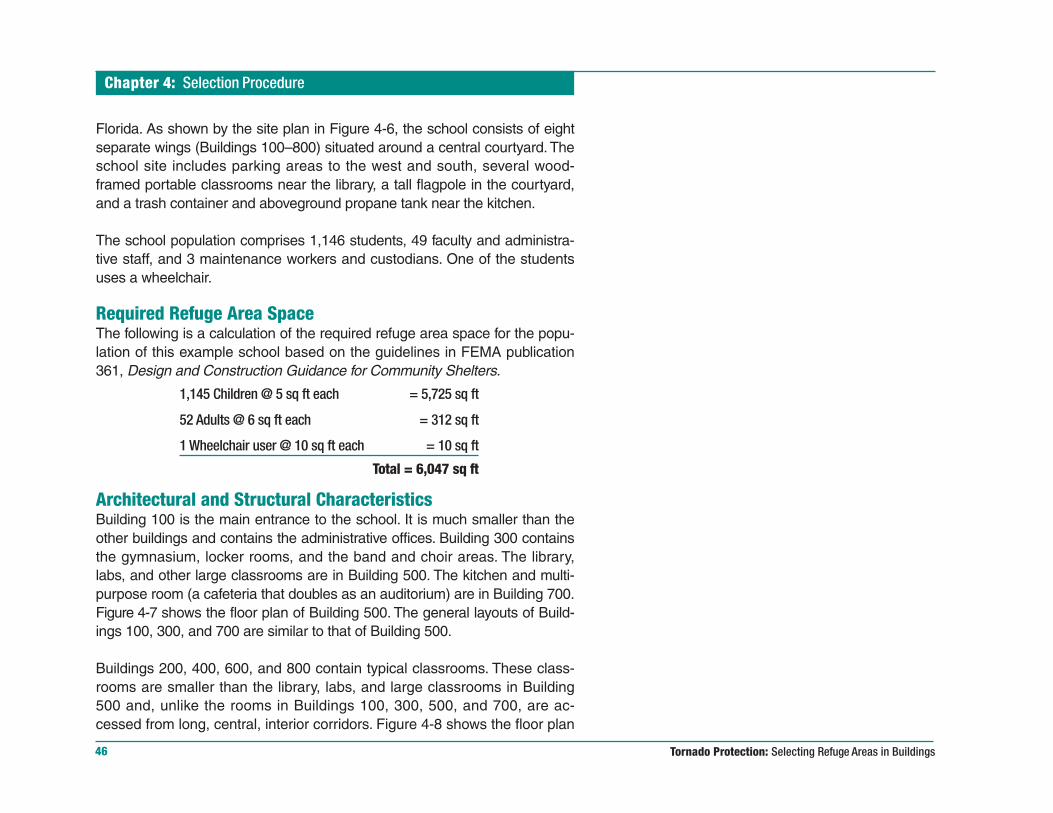
Required Refuge Area SpaceThe following is a calculation of the required refuge area space for the popu-lation of this example school based on the guidelines in FEMA publication361, Design and Construction Guidance for Community Shelters.
1,145 Children @ 5 sq ft each = 5,725 sq ft
52 Adults @ 6 sq ft each = 312 sq ft
1 Wheelchair user @ 10 sq ft each = 10 sq ft
Total = 6,047 sq ft
Architectural and Structural CharacteristicsBuilding 100 is the main entrance to the school. It is much smaller than theother buildings and contains the administrative offices. Building 300 containsthe gymnasium, locker rooms, and the band and choir areas. The library,labs, and other large classrooms are in Building 500. The kitchen and multi-purpose room (a cafeteria that doubles as an auditorium) are in Building 700.Figure 4-7 shows the floor plan of Building 500. The general layouts of Build-ings 100, 300, and 700 are similar to that of Building 500.
Buildings 200, 400, 600, and 800 contain typical classrooms. These class-rooms are smaller than the library, labs, and large classrooms in Building500 and, unlike the rooms in Buildings 100, 300, 500, and 700, are ac-cessed from long, central, interior corridors. Figure 4-8 shows the floor plan

Chapter 4: Selection Procedure
47
Figure 4-7Floor plan of Building 500.
Figure 4-8Floor plan of Buildings 200, 400,600, and 800 (see Figure 4-10 forthe wall cross-section at A-A).

Tornado Protection: Selecting Refuge Areas in Buildings
Chapter 4: Selection Procedure
48
of Buildings 200, 400, 600, and 800. One of the central corridors in thesebuildings is shown in Figure 4-9.
In each of the eight buildings, exterior and interior loadbearing concrete blockmasonry walls support the roof above. These walls are reinforced with verticalsteel spaced at 2 feet 8 inches on center. Figure 4-10 shows a cross-sectionof one of the loadbearing corridor walls in Buildings 200, 400, 600, and 800(the location of this cross-section is shown in Figure 4-8). The exterior wallsinclude a brick veneer that is relatively resistant to the impact of small wind-borne debris. The interior partition (non-loadbearing) walls are unreinforcedmasonry, extend only 6 inches above the suspended ceilings, and are not lat-erally secured to the roof.
Figure 4-9Interior central corridor – typical of the corridors in Buildings 200, 400, 600,and 800.
Figure 4-10Cross-section A-A through corridor/classroom wall –Buildings 200, 400, 600, and 800 (see Figure 4-8 forlocation of A-A).
FLO
RID
A D
CA
Chapter 4: Selection Procedure
49
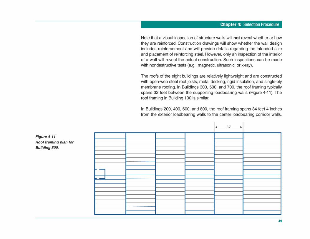
Figure 4-11Roof framing plan forBuilding 500.
Note that a visual inspection of structure walls will not reveal whether or howthey are reinforced. Construction drawings will show whether the wall designincludes reinforcement and will provide details regarding the intended sizeand placement of reinforcing steel. However, only an inspection of the interiorof a wall will reveal the actual construction. Such inspections can be madewith nondestructive tests (e.g., magnetic, ultrasonic, or x-ray).
The roofs of the eight buildings are relatively lightweight and are constructedwith open-web steel roof joists, metal decking, rigid insulation, and single-plymembrane roofing. In Buildings 300, 500, and 700, the roof framing typicallyspans 32 feet between the supporting loadbearing walls (Figure 4-11). Theroof framing in Building 100 is similar.
In Buildings 200, 400, 600, and 800, the roof framing spans 34 feet 4 inchesfrom the exterior loadbearing walls to the center loadbearing corridor walls.
Tornado Protection: Selecting Refuge Areas in Buildings
Chapter 4: Selection Procedure
50
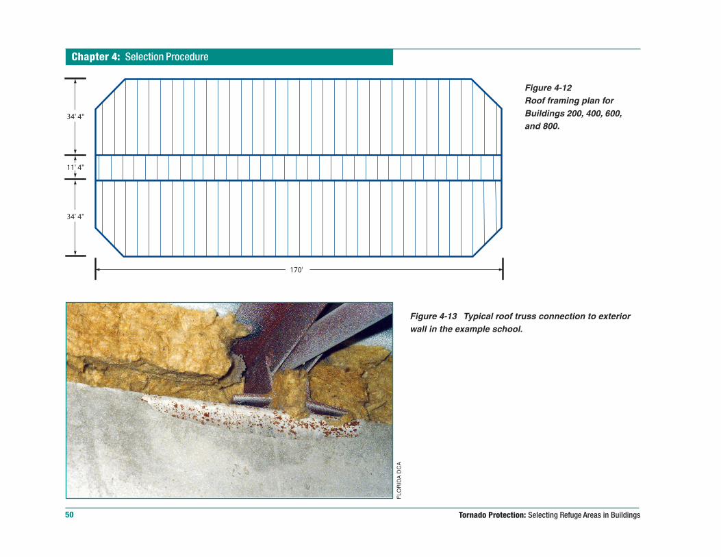
Figure 4-12Roof framing plan forBuildings 200, 400, 600,and 800.
Figure 4-13 Typical roof truss connection to exteriorwall in the example school.
FLO
RID
A D
CA
Chapter 4: Selection Procedure
51
Separate roof joists span the 11-foot 4-inch-wide corridors (Figure 4-12). In alleight buildings, the roof joists are fastened to the tops of the masonry load-bearing walls with welded base plates and anchor bolts (Figure 4-13).
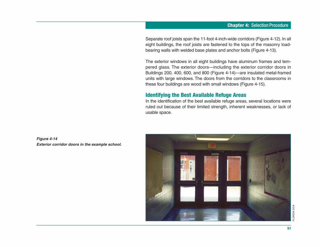
The exterior windows in all eight buildings have aluminum frames and tem-pered glass. The exterior doors—including the exterior corridor doors inBuildings 200, 400, 600, and 800 (Figure 4-14)—are insulated metal-framedunits with large windows. The doors from the corridors to the classrooms inthese four buildings are wood with small windows (Figure 4-15).
Identifying the Best Available Refuge AreasIn the identification of the best available refuge areas, several locations wereruled out because of their limited strength, inherent weaknesses, or lack ofusable space.
FLO
RID
A D
CA
Figure 4-14Exterior corridor doors in the example school.

Tornado Protection: Selecting Refuge Areas in Buildings
Chapter 4: Selection Procedure
52
Buildings 300, 500, and 700 were ruled out for two reasons:
1. Vulnerability to debris impact and wind penetration. These buildingscontain many large exterior windows that are extremely vulnerable topenetration by windborne debris. As noted in Chapter 2, once the buildingenvelope is breached, wind enters the building and the pressures on thebuilding increase. In addition, debris can enter the building through thewindow openings and may injure or kill building occupants.
2. Long roof spans. As noted earlier, the roof spans in these buildings are32 feet long. Long-span roofs are more susceptible to uplift, which canlead to the collapse of the supporting walls.
Building 100 was also ruled out. In addition to sharing the vulnerabilities ofBuildings 300, 500, and 700, Building 100 is relatively small, as are therooms it contains. The available space in this building is further restricted bythe large amount of furniture and office equipment normally found in an ad-ministrative building.
Figure 4-15Door connecting classroom to corridor – Buildings200, 400, 600, and 800.
FLO
RID
A D
CA

Chapter 4: Selection Procedure
53
The interior corridors in Buildings 200, 400, 600, and 800 (Figure 4-16) offerthe best available refuge areas in this example. The corridors have relativelyshort roof spans and relatively small percentages of exterior window glass. Inaddition, because the classroom doors open onto the corridors, the occu-pants of these buildings would have ready access to these refuge areas.
Each corridor is 10 feet 8 inches wide (11 feet 4 inches minus the 8-inch wallthickness) and 170 feet long, and provides approximately 1,800 square feetof gross refuge area space. Assuming that a 2-foot-wide clear area must be
Figure 4-16 Best available refuge areas in the example school – corridors in Buildings 200, 400, 600, and 800.

Tornado Protection: Selecting Refuge Areas in Buildings
Chapter 4: Selection Procedure
54
maintained to allow students and staff to access the refuge area, each corridorcan provide approximately 1,500 square feet of usable refuge area space.The four corridors provide 6,000 square feet of usable refuge area. Whileslightly less than the recommended total of 6,047 square feet, the availableusable refuge area space satisfies the intent of FEMA publication 361.
Although these corridors are the best available refuge areas in this example,they could be made more resistant by the construction of a wind-resistant al-cove that would protect the exterior glass doors and help prevent the entry ofwind and debris into the refuge area (Figure 4-17). An alternative would be toinstall solid, wind-resistant exterior doors that, although normally left open,could be closed when a tornado warning is issued. A less desirable optionwould be to add a double set of laminated glass exterior doors.
Building administrators and school officials must weigh the protective benefitsof such modifications against potential security problems, in the case of solid-wall alcoves, and the need for adequate warning time, for the operation ofprotective doors. An upgrade alternative for the interior corridor doors wouldbe to replace them with stronger doors equipped with stronger hardware andsmall laminated glass windows.
In many buildings, the size of the best available refuge area will be less thanthe required size determined according to the guidelines in FEMA publication361. In such buildings, the occupants will need to be housed in either smallerareas or more vulnerable areas. Although there are physical limits to thenumber of people a space can accommodate, housing more people in lessspace is preferable to locating them in more vulnerable areas.
Verifying the Best Available Refuge AreasAfter refuge areas have been selected according to the methodology de-scribed in this chapter, the evaluation checklists in FEMA publication 361should be used to verify that the selected areas are the best available in thebuilding. FEMA 361 also includes information that can help building adminis-
Figure 4-17Glass exterior doors can be protected from windand debris with a wind-resistant alcove.
402ENGLISH
403SOCIAL STUDIES
CORRIDORSHELTER AREA
PROTECTIVE ALCOVECONSTRUCTED WITH
MISSILE-RESISTANTWALLS AND ROOF
Chapter 4: Selection Procedure
55
trators improve the effectiveness of the selected refuge areas (e.g., guide-lines concerning signage and operations plans).
Selecting the Best Available RefugeAreas in Other Types of BuildingsMid-Rise and High-Rise BuildingsIn buildings with more than five stories, the building frames receive customstructural engineering analysis and design attention. Experiences of the past50 years indicate that these buildings do not collapse under wind loads, butthe outside walls and roof structure can receive major damage. The bestavailable refuge areas in these buildings are in the lower floors (basement ifavailable) and in the central part of the building. Stairwells (particularly thosewith reinforced concrete walls) typically provide the best available refuge. Ifthe stairwells have inadequate capacity for the occupant load, restrooms typi-cally provide the next best available refuge areas.
Large Stores and Movie TheatersIn large stores and movie theaters, the best available refuge areas will typi-cally be restrooms, closets, or narrow storage areas. For example, in 2002, inVan Wert, Ohio, 50 people in a movie theater took refuge in restrooms whenwarned about an approaching tornado. The building collapsed, but no onesuffered significant injury. In grocery stores, if restrooms, closets, or narrowstorage areas are not accessible, building occupants should crouch in narrowfrozen food aisles between freezer cases and cover their heads. This tacticwill reduce the likelihood of injuries from a falling roof. The aisles used shouldbe as far as possible from exterior glass and masonry walls. Also, aisles withvery tall storage racks should be avoided.
Again, the selection of refuge areas should always be verified with the check-lists provided in FEMA publication 361.

Chapter 5: Conclusions
57
ConclusionsIn regions of the United States subject to tornadoes, the identification of bestavailable refuge areas within schools and other public buildings is essentialfor the safety of building occupants. Shelters specifically designed and con-structed to resist wind-induced forces and the impact of windborne debrisprovide the best protection. However, findings from investigations of past tor-nadoes show that many buildings contain rooms or areas that may affordsome degree of protection from all but the most extreme tornadoes (i.e., tor-nadoes ranked F4 or F5 on the Fujita Tornado Damage Scale—see Chapter 1).In buildings not designed and constructed to serve as shelters, the goalshould be to select the best available refuge areas—the areas that will pro-vide the greatest degree of protection.
A building administrator, working with a qualified architect or structural engi-neer, can select the best available refuge areas within a building. Asdiscussed in Chapter 4, the selection must account for the required amountof shelter space, the layout and structure of the building, and potential mis-siles at and near the building site. In general, the best available refugeareas will meet the following criteria:
Interior rooms. Rooms that do not depend on the exterior walls of the build-ing are less likely to be penetrated by windborne debris.
Location below ground or at ground level. Upper floors are more vulner-able to wind damage.

Tornado Protection: Selecting Refuge Areas in Buildings
Chapter 5: Conclusions
58
A minimal amount of glass area. Typical windows and glass doors are ex-tremely vulnerable to high wind pressures and the impact of windbornedebris.
Reinforced concrete or reinforced masonry walls. Reinforced walls aremuch more resistant to wind pressures and debris impact, but can fail if theroof deck is blown away.
Strong connections between walls and roof and walls and foundation.Walls and roofs will be better able to resist wind forces when they are securelytied together and anchored to the building foundation.
Short roof spans. Roofs with spans of less than 25 feet are less likely to belifted up and torn off by high winds.
As illustrated in the case studies and selection procedure presented in thisbooklet, long central corridors often qualify as the best available refuge areasin a school building. In addition to having desirable structural characteristics(e.g., short roof spans, minimal glass area, and interior locations), corridorsusually are long enough to provide the required amount of refuge area spaceand can be quickly reached by building occupants. Other potential refuge areasinclude small interior storage rooms, restrooms, and offices.
Building administrators should also consider increasing the resistance of ex-isting rooms or areas within a building whenever repairs or reconstruction arenecessary. In high-risk areas, it may be prudent to perform remedial work(such as that noted on page 54) without waiting for other repairs or recon-struction to become necessary. As discussed in Chapter 3, the modificationsmade to the Kelly Elementary School during reconstruction after tornadodamage are an excellent example of what can be done to improve the windresistance of a school and provide shelter areas.

Chapter 5: Conclusions
59
In conclusion, it is particularly important for building administrators andbuilding occupants to be aware that the best available refuge areas do notensure the safety or survival of their occupants. They are simply the areasof a building in which survival is most likely. To provide a high reliability ofsafety, a shelter area must be intentionally designed and constructed as ashelter. Refer to FEMA publication 361, Design and Construction Guidancefor Community Shelters, for shelter performance criteria, sample construc-tion plans, and other detailed information.

Information Sources
61
Information SourcesFEMA Publications
Taking Shelter From the Storm – Building a Safe Room in Your HouseFEMA Publication 320, August 1999
This illustrated, full-color booklet is intended for homeowners and contractors.It explains the hazards posed by severe winds associated with tornadoesand hurricanes, includes maps and charts for assessing tornado risk, pre-sents shelter design criteria, and includes estimated costs and detailedconstruction drawings for several types of in-residence shelters.
National Performance Criteria for Tornado SheltersAugust 1999
The performance criteria presented in this booklet are intended for designprofessionals, shelter manufacturers, building officials, and emergency man-agement officials. The issues addressed include resistance of shelter walls,ceilings, and doors to wind loads and missile impacts; shelter size, ventilation,lighting, and accessibility; and multihazard (e.g., flooding and earthquake)effects. The criteria form the basis for the construction of tornado shelters thatwill provide a consistently high level of protection.
FEMA 320
FEMA NPC
FE
MA
FE
MA
Additional information about tornado shelters is available from theFederal Emergency Management Agency (FEMA).
Tornado Protection: Selecting Refuge Areas in Buildings
Information Sources
62
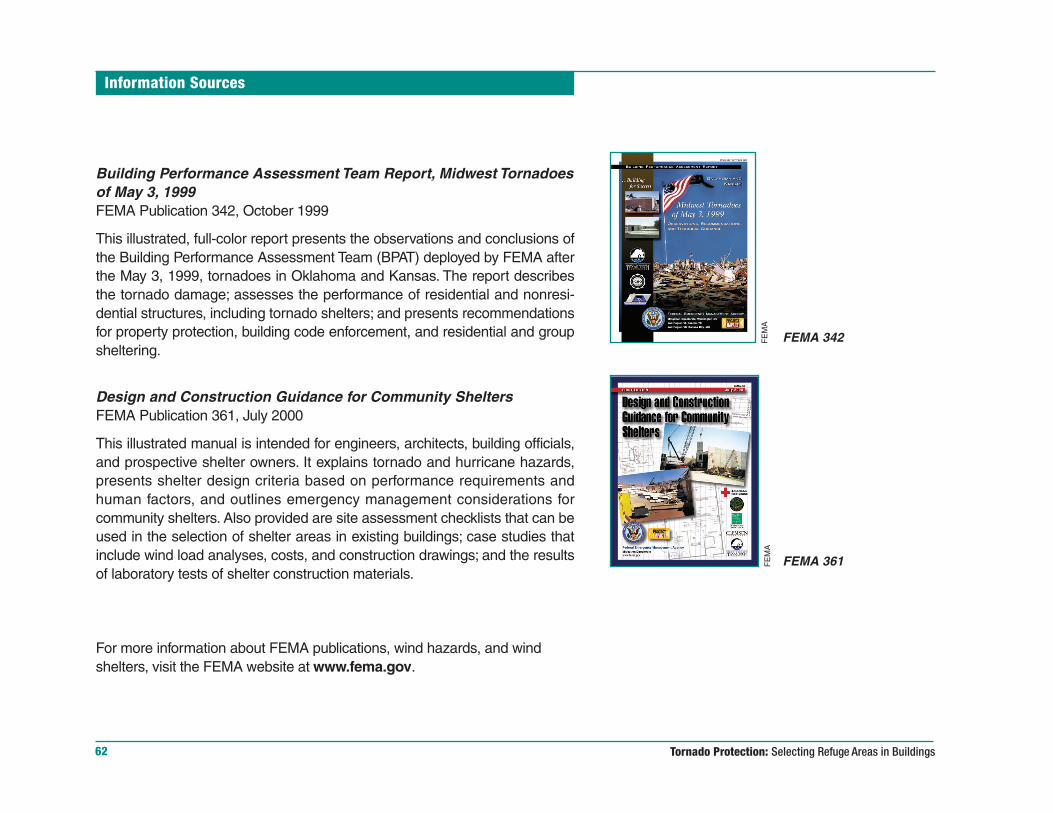
Building Performance Assessment Team Report, Midwest Tornadoesof May 3, 1999FEMA Publication 342, October 1999
This illustrated, full-color report presents the observations and conclusions ofthe Building Performance Assessment Team (BPAT) deployed by FEMA afterthe May 3, 1999, tornadoes in Oklahoma and Kansas. The report describesthe tornado damage; assesses the performance of residential and nonresi-dential structures, including tornado shelters; and presents recommendationsfor property protection, building code enforcement, and residential and groupsheltering.
Design and Construction Guidance for Community SheltersFEMA Publication 361, July 2000
This illustrated manual is intended for engineers, architects, building officials,and prospective shelter owners. It explains tornado and hurricane hazards,presents shelter design criteria based on performance requirements andhuman factors, and outlines emergency management considerations forcommunity shelters. Also provided are site assessment checklists that can beused in the selection of shelter areas in existing buildings; case studies thatinclude wind load analyses, costs, and construction drawings; and the resultsof laboratory tests of shelter construction materials.
For more information about FEMA publications, wind hazards, and windshelters, visit the FEMA website at www.fema.gov.
FEMA 342
FEMA 361
FE
MA
FE
MA

Copyright © 2022 FDOKUMEN