School's out for summer, school's out forever: the long-term health ...
Upload
khangminh22Category
view
1download
0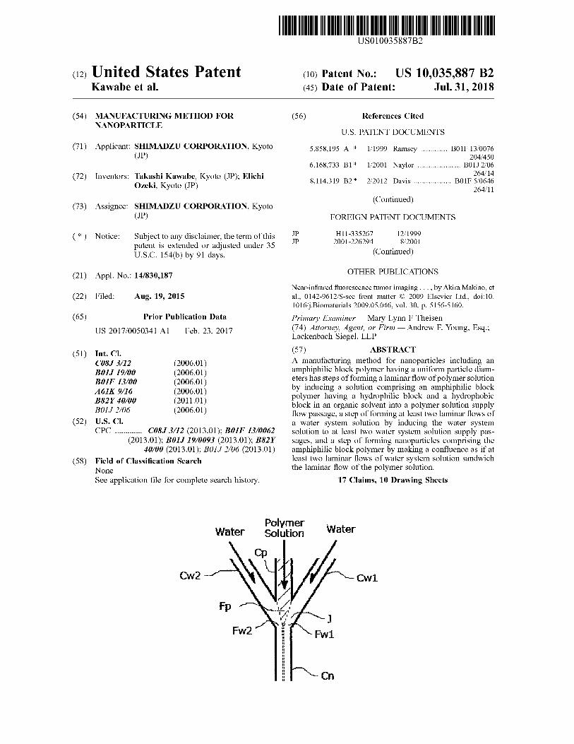
TOMMAND DUE TO ALL OUT ON TOTTI US010035887B2
( 12 ) United States Patent Kawabe et al .
( 10 ) Patent No . : US 10 , 035 , 887 B2 ( 45 ) Date of Patent : Jul . 31 , 2018
( 54 ) MANUFACTURING METHOD FOR NANOPARTICLE
( 56 ) References Cited U . S . PATENT DOCUMENTS
@ ( 71 ) Applicant : SHIMADZU CORPORATION , Kyoto ( JP ) 5 , 858 , 195 A *
6 , 168 , 733 B1 * @ ( 72 ) Inventors : Takashi Kawabe , Kyoto ( JP ) ; Elichi
Ozeki , Kyoto ( JP )
1 / 1999 Ramsey . . . . . . . . . . . . . B01F 13 / 0076 204 / 450
1 / 2001 Naylor . . . . . . . . . . . . . . . . . . . . . . B01J 2 / 06 264 / 14
2 / 2012 Davis . . . . . . . . . . . . . . . . . . . . B01F 5 / 0646 264 / 11
( Continued )
8 , 114 , 319 B2 *
( 73 ) Assignee : SHIMADZU CORPORATION , Kyoto ( JP ) FOREIGN PATENT DOCUMENTS
( * ) Notice : Subject to any disclaimer , the term of this patent is extended or adjusted under 35 U . S . C . 154 ( b ) by 91 days .
H11 - 335267 12 / 1999 2001 - 226294 8 / 2001
( Continued )
OTHER PUBLICATIONS ( 21 ) Appl . No . : 14 / 830 , 187 ( 22 ) Filed : Aug . 19 , 2015
( 65 ) Prior Publication Data US 2017 / 0050341 A1 Feb . 23 , 2017
( 51 ) Int . CI . C08 ) 3 / 12 ( 2006 . 01 ) BOIJ 19 / 00 ( 2006 . 01 ) B01F 13 / 00 ( 2006 . 01 ) A61K 9 / 16 ( 2006 . 01 ) B82Y 40 / 00 ( 2011 . 01 ) B01J 2 / 06 ( 2006 . 01 )
( 52 ) U . S . CI . CPC . . . . . . . . . . . . . C08J 3 / 12 ( 2013 . 01 ) ; BOIF 13 / 0062
( 2013 . 01 ) ; B01J 19 / 0093 ( 2013 . 01 ) ; B82Y 40 / 00 ( 2013 . 01 ) ; BOIJ 2 / 06 ( 2013 . 01 )
( 58 ) Field of Classification Search None See application file for complete search history .
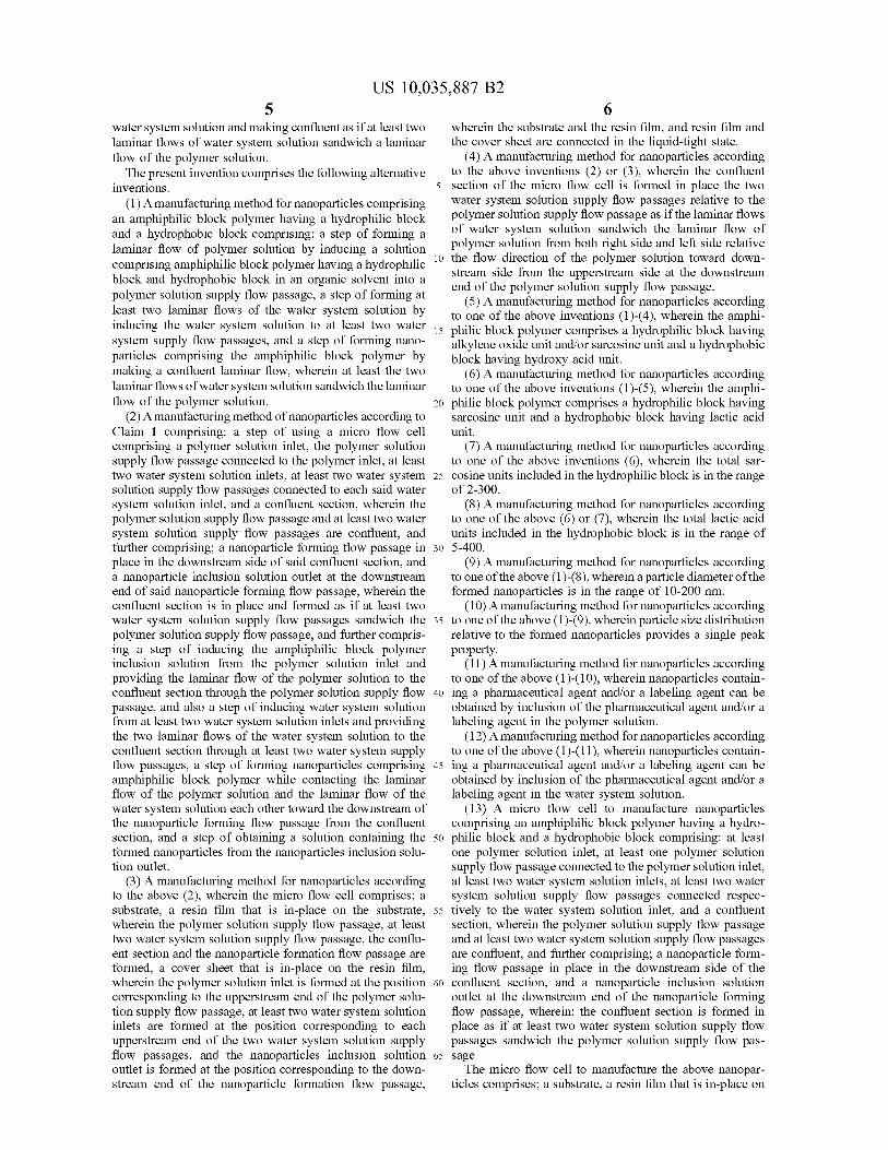
Near - infrared fluorescence tumor imaging . . . , by Akira Makino , et al . , 0142 - 9612 / $ - see front matter © 2009 Elsevier Ltd . , doi : 10 . 1016 / j . Biomaterials 2009 . 05 . 046 , vol . 30 , p . 5156 - 5160 . Primary Examiner — Mary Lynn F Theisen ( 74 ) Attorney , Agent , or Firm — Andrew F . Young , Esq . ; Lackenbach Siegel , LLP ( 57 ) ABSTRACT A manufacturing method for nanoparticles including an amphiphilic block polymer having a uniform particle diam eters has steps of forming a laminar flow of polymer solution by inducing a solution comprising an amphiphilic block polymer having a hydrophilic block and a hydrophobic block in an organic solvent into a polymer solution supply flow passage , a step of forming at least two laminar flows of a water system solution by inducing the water system solution to at least two water system solution supply pas sages , and a step of forming nanoparticles comprising the amphiphilic block polymer by making a confluence as if at least two laminar flows of water system solution sandwich the laminar flow of the polymer solution .
17 Claims , 10 Drawing Sheets
Water Polymer Solution Water
Cw2 Cw1
Y
Fw2 " Fw1 Fw1
tan

US 10 , 035 , 887 B2 Page 2
( 56 ) References Cited 2013 / 0046030 A1 *
U . S . PATENT DOCUMENTS 2013 / 0119570 A1 *
2014 / 0127132 A1 *
2 / 2013 Rotem . . . . . . . . . . . . . . . . . . B01F 3 / 0807 516 / 21
5 / 2013 Sugiura . . . . . . . . . . . . . . . . B01F 3 / 0807 264 / 5
5 / 2014 Ozeki . . . . . . . . . . . . . . . . . . A61K 9 / 1075 424 / 9 . 1
5 / 2014 Hiddessen . . . . . . . . . . . . . GOIN 1 / 38 435 / 6 . 12
5 / 2015 van Hoeve . . . . . . . . . . B01J 19 / 0093 424 / 9 . 52
6 / 2017 Weitz . . . BOIF 13 / 0062
2014 / 0134623 A1 *
2015 / 0125400 A1 * 2017 / 0151536 A1 *
FOREIGN PATENT DOCUMENTS . . . . . . . . . . . . .
8 , 911 , 864 B1 * 12 / 2014 Petsev . . . . . . . . . . . . . . . . . . . . C01B 33 / 18 427 / 212
9 , 259 , 701 B2 * 2 / 2016 Palmer . . . . . BO1J 2 / 08 2003 / 0201022 A1 * 10 / 2003 Kawai . . . . . . . . . . . . . . . . B01D 11 / 04
137 / 828 2007 / 0028969 A1 * 2 / 2007 Bovd . . . . . . . . . . . . . . . . . B01F 13 / 0059
137 / 606 2007 / 0054119 A1 * 3 / 2007 Garstecki . . . . . . . . . . . . . B01J 19 / 0093
428 / 402 2008 / 0019908 AL 1 / 2008 Akitsu et al . 2008 / 0067128 A1 * 3 / 2008 Hoyos . . . . . . . BOIL 3 / 502761
210 / 658 2009 / 0114285 Al * 5 / 2009 Hashimoto . . . . . . . . . . . . . B01F 5 / 064
137 / 13 2009 / 0197977 A1 * 8 / 2009 Haeberle . . . . . . . . . . . . . B01F 3 / 04446
516 / 10 2010 / 0184928 A1 * 7 / 2010 Kumacheva . . . . . . . . . B01F 3 / 0807
526 / 65 2010 / 0188466 A1 * 7 / 2010 Clarke . . . . . . . . . . . . . . . . B05B 7 / 0408
347 / 75 2011 / 0256529 A1 * 10 / 2011 Daniels B01J 2 / 06
435 / 6 . 1
2003 - 26812 2008 - 24816
2009 - 256324 2012 - 170861 2012 - 213747 2014 - 15655
WO 2009 / 148121 WO 2012 / 176885
1 / 2003 2 / 2008
11 / 2009 9 / 2012 11 / 2012 8 / 2014
12 / 2009 2 / 2015
JP * JP
WO WO
. . . . . . . . . . * cited by examiner
atent Jul . 31 , 2018 Sheet 1 of 10 US 10 , 035 , 887 B2
FIG . 1 Water
Polymer Solution Water
Fp
Fw2 Fw1
US 10 , 035 , 887 B2
FIG . 2
Solution
wala walking
si concomitantimamente innan Mati AMARRAKOMAAN
inaltimewwwwwwwww
wwwwwwwwwwwwwwwwwwwwwww
wwwwwwwwwwwwwwwwwwwwwCMAMAAKwanie * *
Vanterian erra
+ H . Yhtu
C
tut
fining
cognos 30 31 32
n
a
heiminn Wat
Sheet 2 of 10
mainwind
Swimwi
manter
antrinis
VAN primera
W
ynan Ruminuminiowwwwatu apligtende ting , som
UD
ZMIST 14
NORDI
www
poistamine toimuni na mtoto huyo santys ratione turismo solarity in this
Water
* * * *
*
OUR
WOM ENTARIOS
WYKONAWE * A
KM
* * * *
. www my
www . m
23
????????????????
21 . white
I
nicos ' s
Jul . 31 , 2018
tim mirom . www
*
eu
* * * . * * .
*
* * *
*
* *
* * *
7
dund dund
sinemas
u ndinami pang
misionin
Mua &
k
And when to wwwwww
.
MO
92 SZ
Jojobuoo
med
VZ
www .
d
a
ndi
* * * * *
* * * * *
* * *
W
i ll
IMI
U . S . Patent
U . S . Patent Jul . 31 , 2018 Sheet 3 of 10 US 10 , 035 , 887 B2
FIG . 3
momento c
IW2 Ip Iwi om
One CW2
propr io MG www my 102 102 X Binding for
Facp Binding contents of * * * Bismiss
R primav
e vere one
aksha Sam Cw1 de
WWW . Awtubi . . .
the 101 _ - 101 1
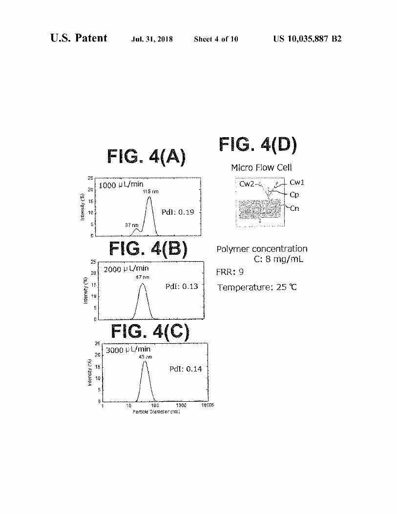
U . S . Patent Jul . 31 , 2018 Sheet 4 of 10 US 10 , 035 , 887 B2
S : FIG . 4 ( D ) FIG . 4 ( A ) Micro Flow Cell CW2 27 cw1 L .
. . .
mana u 1000 WL / min 115 mm
. . . .
* "
. . . . . . . . . . . . . ve Intensity ( % ) . ' " met een
PdI ; 0 . 19 : " " " "
en betonwerken Meth wi 37 THTI . . . . . . . . . . . . . - -
U w wwwwwwwwwwwwwwwwww whermometerhuntematon som ha d demthelle Ann
FIG . 4 ( B ) Ma www
Polymer concentration Polymer concentration C : 8 mg / mL
FRR : 9 Temperature : 25C
2000 WL / min 47 m
.
) p
Pdi : 0 . 13 wish yatowe ath t interty he store
wio w w w . by . Antheilenden toteuttamattom u udesta tuloy the tot
FIG . 4 ( C ) www wwwwwwww . prprphy
3000 L / min 43 nm ethnal entretien
Intensity ( ' % ) Pdi : 0 . 14 an
th
i
ww w . hehehe . . . . . til - - L ule
10000 w 10 11 ? Particle Diameter ( nm )
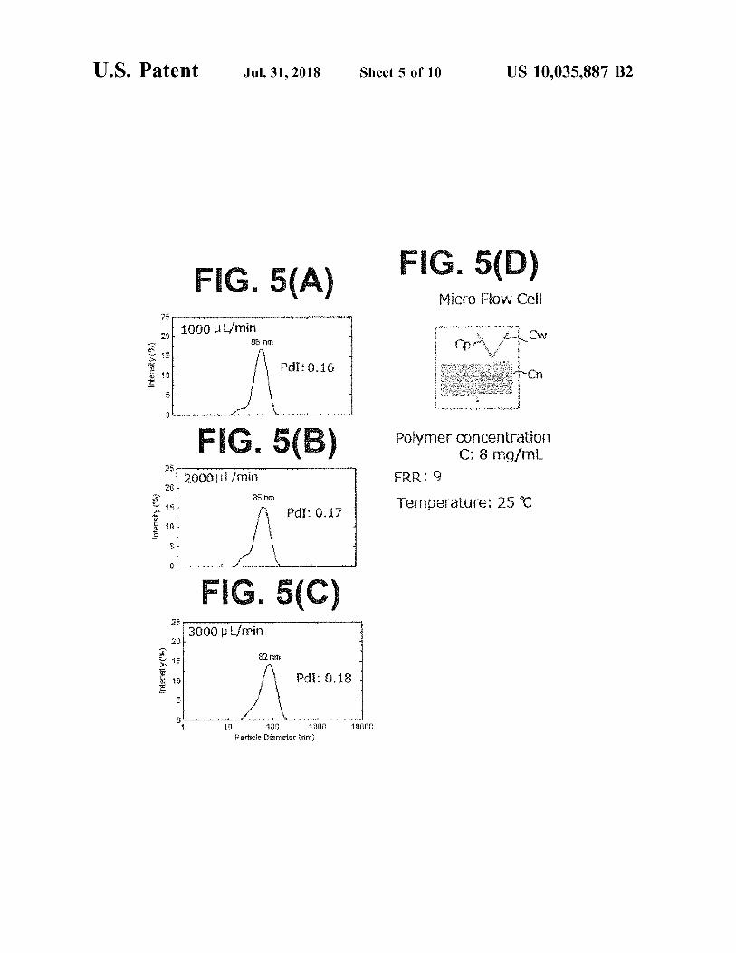
U . S . Patent Jul . 31 , 2018 Sheet 5 of 10 US 10 , 035 , 887 B2
VK
WA FIG . 5 ( A ) FIG . 5 ( D ) Micro Flow Cell
* * * *
1000 UL / min 90 om Opment Cw
Intensity ( 2 ) wwwwwwwwwwwwwwwwwwwwwwwwwwwwwwwwwwwwwwwwwwwwwwwwww PdI : 0 . 16 wwwww wwww Y - . . i . . . . . . .
www . interpersonal tra i ler lewww . . www . twitter to bet ter than meline
FIG . 5 ( B ) Polymer concentration C : 8 mg / mL
FRR : 9 pupil . . . . . . . 2000 L / min Y
85 mm . . . .
se non Temperature : 25 C Intensity ( * * ) Pdi : 0 . 17
. . .
se . . .
W .
. . .
Artikelnummer w w w . kantor pertama berte m . nhundertonesia dari bentuk
FIG . 5 ( C ) 3000 L / min
. com
w 82 mm . Imensly ( * * )
Pdi : 0 . 18 1 . . . . . . . . wwwwwwwwwwwwwwwwwwww .
www westest the commawomitmesuguli mehshorthanthintentio n em 10000 10 100 1000
Particle Diameter ( rim )
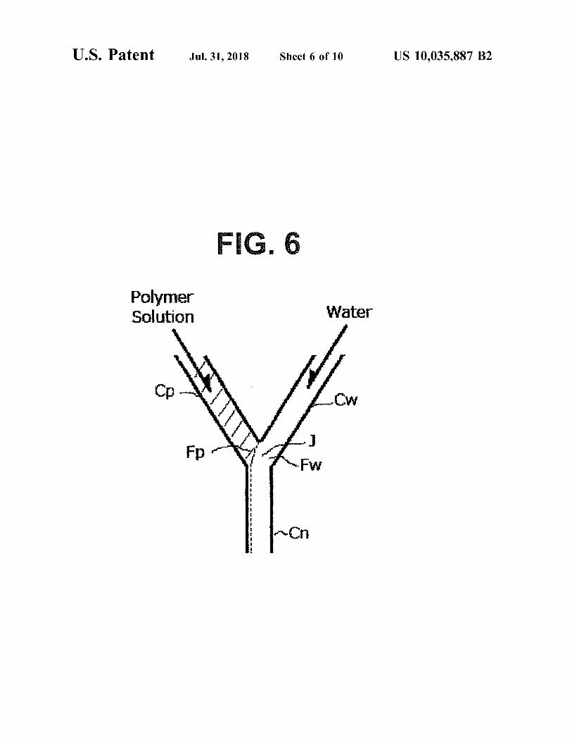
U . S . Patent Jul . 31 , 2018 Sheet 6 of 10 US 10 , 035 , 887 B2
FIG , 6 Polymer Solution Water
??
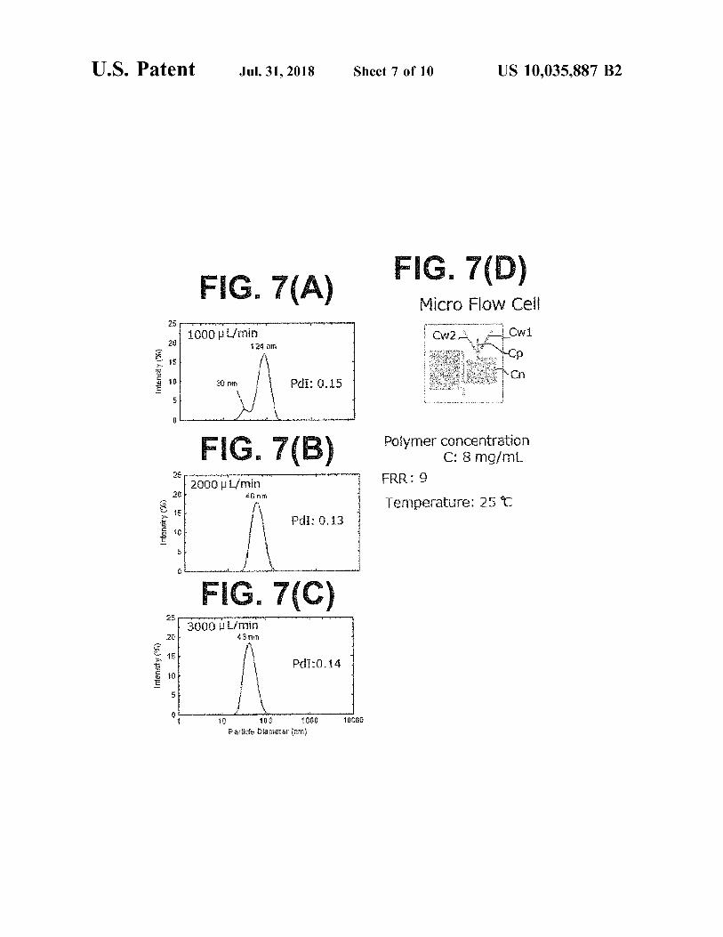
U . S . Patent Jul . 31 , 2018 Sheet 7 of 10 US 10 , 035 , 887 B2
FIG . 7 ( A ) FIG . 7 ( D ) Micro Flow Cell CW2Cw1 1000 L / min
124 min cp . Intensity ( 49 ) CI .
30 mm Pdi : 0 . 15
Wwwerotikus formaimeshuntirish firewwwwwww per b eda
Polymer concentration C : 8 mg / m .
FRR : 9 2000 L / min 46 am Temperature : 250
Intensty ( % ) Pdi : 0 . 13 * *
* *
www themet wwwdenthetett
FIG . 7 ( C ) poveren
3000 L / min 43 nm grandatele !
Intensity ( 43 ) Pd? : 0 . 14
www 10 1000 1000G 100
Particle D is meie
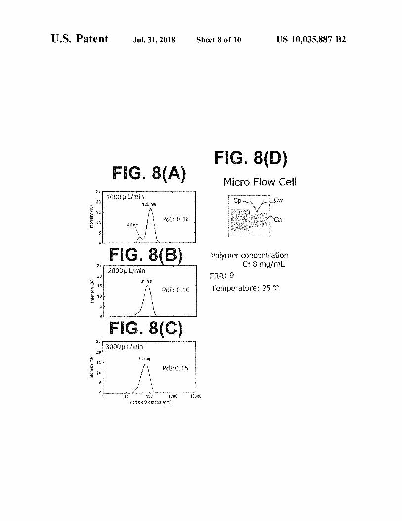
U . S . Patent Jul . 31 , 2018 Sheet 8 of 10 US 10 , 035 , 887 B2
FIG . 8 ( D ) : : : : : - : : - : : FIG . 8 ( A ) w pewnym uyqanetyper
Micro Flow Cell CD me . CW
M
I
y 1000 L / min 120 nm . 4 + 1 , 75
k say thank 4 * - * * * * *
W Intensity ( * * ) houseshoe khách s?n
Khu loubout Pdi : 0 . 18 - Y - r - an
???? ? - + +
us
Warenhemintellettunt that w o
FIG . 8 ( B ) The
www
2000 L / min
Polymer concentration C : 8 mg / mL .
FRR : 9 Temperature : 250
ight 81 min Intensity ( K )
PdI : 0 . 16
? how they startowe montowanowhite Awwwwwwwww w
FIG . 8 ( C N 2
3000L / min 71 mm
N est het Intensity ( % ) T
wordt -
( # *
PdI : 0 . 15 w wwwwwwwwwwwwwwwwww Antowwwwww ww
wwwwww w wwwwwwwwwww . . . 10000 10 100 1000
Particle Dia meter ( nm )
U . S . Patent Jul . 31 , 2018 Sheet 9 of 10 US 10 , 035 , 887 B2
FIG . 9 ( A ) Water
Polymer Solution Water
ow2 W CW2 min ith Cw1
Fpts Fw2Fw1
Aaliha ??????????? # # ???
FIG . 9 ( B ) Polymer Solution Water Water
Interface
ü ón Flow Rate , , ( m / s ) 3000 l / min
2000 ulimin
- 0 100
1000 ml min 200 300 400 500 600 Channel Width , W . ( um )
700
U . S . Patent Jul . 31 , 2018 Sheet 10 of 10 US 10 , 035 , 887 B2
. FIG . 10 ( A ) Polymer Solution Water
FW
FIG . 10 ( B ) = 10 Polymer Solution Water
Interface
3000 mL / min Flow Rate , v4 ( m / s )
- -
2000 ulimin
- 1000 ml / min -
wwww wwwwwwwwwwww
0 100 700 200 300 400 500 600 Channel Width , Wc ( um )
US 10 , 035 , 887 B2
MANUFACTURING METHOD FOR JPH11 - 335267A , JP2003 - 26812A , and JP2001 - 226294 NANOPARTICLE disclose the manufacturing method for polymer micelles
containing poorly - water soluble pharmaceutical substance , CROSS REFERENCE TO RELATED and the entire contents of each of which are incorporated
APPLICATION 5 herein by reference . According to JP2001 - 226294 , the manufacturing method for polymer micelles enclosing a
This application relates to , but does not claim priority This application relates to but does not claim priority poorly - water soluble pharmaceutical substance is disclosed , from . JP App , Ser . No . 2013 - 28491 filed Feb . 17 . 2013 . the wherein an organic solution is prepared by dissolving a
poorly - water soluble pharmaceutical substance and a block entire contents of which are incorporated herein by refer 10 co - polymer including hydrophilic segment and hydrophobic ence . segment in water immiscible organic solvent ; the obtained FIGURE SELECTED FOR PUBLICATION organic solution is mixed with aqueous vehicle to provide an
oil - in - water emulsion ; the polymer micelles enclosing the pharmaceutical substance is formed by evaporating the FIG . 1 15 organic solvent from the obtained emulsion ; and if neces sary , the obtained polymer micelle solution is subjected to BACKGROUND OF THE INVENTION sonication and ultrafiltration . However , according to the same Patent Document , the organic solvent is removed by a Field of the Invention dialysis process and then the particles are pulverized by a The present invention relates to supermolecular chemis 20 sonication process ( i . e . , top - down process ) so that the pro try , medicine , technology and pharmacology alliance area cess can be complicated . Further , pulverization of particles
and nano - medicine . The present invention further relates to by the sonication process is difficult to provide precious a manufacturing method for a nanoparticle comprising an control of the particle size . In addition , once prepared amphiphilic block polymer , and further specifically relates particles are broken down by the sonication process so that to the nanopolymer comprising the amphiphilic block poly - 25 the content inside the particle might leak and the inclusion mer using a novel combinatorial structure made from poly - quantity of the pharmaceutical substance might be out of mer solution and an aqueous solution . Even more particu - control . larly , the present invention provides for a continuous JP2012 - 213747A , the contents of which are fully incor manufacture method and system of nanoparticles having a porated by reference , discloses a fine particle manufacturing homogeneous particle diameter comprising a block polymer 30 apparatus comprising ; a pressurizing module that presses a having a superior biocompatibility . In addition , the present flow passage member having fine flow passage of 50 - 30 um invention also relates to a micro flow cell and system that in diameter and starting material solution in which particles can be used for the continuous manufacture of the nanopar are dispersed or dissolved and transports to the flow passage ticles . member under pressure , and a vacuum drying chamber to
Description of the Related Art 35 receive and dry the staring material solution passed through the flow passage member . The fine particle manufacturing
Technical Background apparatus disclosed in the same Patent Document transports under pressure and pulverizes the already formed particles
A molecular imaging technology is being developed to ( i . e . , top - down system ) . diagnose a tumor and other diseases . The molecular imaging 40 JP2005 - 246227A , the contents of which are fully incor technology may include Positron Emission Tomography porated by reference , discloses the manufacturing method ( PET ) , Single Photon Emission Computed Tomography for a leuco dye inclusion microcapsule that contains air ( SPECT ) , Magnetic Resonance Imaging ( MRI ) and Fluoro - bubbles and can be broken down by sonication or pressure . metric Imaging and so forth . An adequate probe for each The particle diameter that is manufactured is micrometer in diagnosis , having high sensitivity , i . e . , high integration 45 size and large ( e . g . , 4 um [ 0021 ] in Example 1 and 6 um selectivity for a lesion , and low invasiveness , is being [ 0033 ] in Example 3 ) . The large particles are pulverized into sought . micrometer size particles by using a homogenizer , i . e . , On the other hand , relative to a medical treatment , a top - down system , so that the inclusion quantity control of
cancer chemotherapy using an anti - tumor agent during a leuco dye in the microcapsule might be difficult . prognosis of an early stage treatment , a surgical treatment 50 JP2009 - 256324A , the contents of which are fully incor and radiotherapy , is conducted to prevent a cancer metasta - porated by reference , discloses the manufacturing method sis . An anticancer agent may also seriously damage a normal for fine particles containing a biologically active substance , tissue and accordingly , an adverse reaction is concern . A wherein the step that prepares an emulsion by mixing the variety of drug delivery systems ( DDS ) have been devel volatile organic acid aqueous solution containing the bio oped to reduce the severity of adverse reaction . As one of 55 logically active substance or volatile organic acid solution them , DDS utilizing nanoparticles as a carrier utilizing containing the biologically active substance and volatile Enhanced Permeability and Retention Effect ( EPR Effect ) , a organic acid solvent containing biodegradable polymers and characteristics of angiogenesis , observed remarkably at the the step that the obtained emulsion is mixed with aqueous initial proliferation stage of tumor is noticed and a variety of polymer solution having negative charge are included . The nanoparticles have been studied . ERP effect is set forth as a 60 particle diameter of fine particles has not been disclosed . phenomenon in which several tens of nm to several hun - JP2012 - 170861A , the contents of which are fully incor dreds of nm ( e . g . , around 20 - 200 nm ) nanoparticles admin - porated by reference , discloses the synthesis method for istered into blood vessels drain from the blood capillary non - sphere hydrogel particles , wherein ; relative to an flow system in which permeability is abnormally enhanced , and passage structure X comprising at least two inlets 11 - In accumulate in the interstitial space of rapidly proliferating 65 ( n22 ) , at least one outlet O , inlet flow passages C1 - Cn tumor tissues because of partial contribution of immature respectively connected to the 11 - In , a flow passage J that is lymph channel . formed by that the inlet flow passage C1 - Cn is flowing into

US 10 , 035 , 887 B2
each other at the same time or step - by - step and connected to Patent Document 9 : US2008 / 0019908 outlet ; a gel solution Z that is a starting material for the Patent Document 10 : WO2009 / 148121 hydrogel is induced from the inlet I1 and the gelling agent Patent Document 11 : WO2012 / 176885 solution G from the inlet 12 are induced respectively and continuously , a fiber in which gel solution Z is at least even 5 Non - Patent Document part turned into gel in the flow passage J is formed , and further the fiber is cut by enclosing the fiber , for which the Non - Patent Document : Biomaterials , 2009 , Vol . 30 , Page gel solution Z is at least partially turned into gel in the inside 5156 - 51600 or outside of the flow passage X , into the droplet , by which non - sphere hydro gel is prepared . The same Patent Docu - 10 ASPECTS AND SUMMARY OF THE ment disclose that gel solution Z and gelling agent solution INVENTION are continuously induced together and the fiber that the gel solution is turned into a gel is formed at the flow passage J Problems to be Solved by the Invention after flowing into each other . The fiber is cut by enclosing the fiber formed by gelation to produce non - sphere hydro - 15 According to WO2009 / 148121 and WO2012 / 176885 , gel . The same Patent Document disclose no amphiphilic nanoparticles are produced from amphiphilic block poly block polymers and further the produced hydrogel particle is mers by a film method . The film method comprises the very large , wherein the size thereof is from several um to following steps . Specifically , the steps comprises the step of several cm in diameter . Nanoparticles applied to DDS is disclosed in , e . g . , 20 preparing a solution comprising amphiphilic block polymers
JP2008 - 24816A ( US2008 / 0019908 ) , the contents of which in an organic solvent in the vessel ( e . g . , glass container ) , the are fully incorporated by reference , that an amphiphilic step of obtaining a film having amphiphilic block polymer
on the inside wall of the vessel by removing the organic block polymer comprises a hydrophilic block and a hydro phobic block , wherein the hydrophilic block is a hydrophilic phobic black wherein the hydrophilic block is a hydrophilic solvent from the solution , and the step of obtaining a polypeptide chain having 10 or more sarcosine units and the 25 molecular dispersion solution of the molecular assembly by hydrophobic block is a hydrophobic molecular chain com - converting the film - like material to particles of molecular prising units selected from the group consisting of amino assembly by means of a sonication process , and sonication acid units and hydroxyl acid units as essential structural devices are recognized by those of skill in the art . Further , units , and the amphiphilic block polymer is an hydrophobic the film method may further include the step of freeze molecular chain having 5 or more the essential structure 30 drying the dispersion solution of the molecular assembly . units , and the molecular assembly having 10 - 500 nm in The film method is a batch - wise system so that the method diameter comprises the amphiphilic block polymer . cannot be preferred from productivity standpoints and may PCT / WO2009 / 148121 and Biomaterials , 2009 , Vol . 30 , p . be inadequate to control the particle diameter thereof
5156 - 5160 , the contents of each of which are fully incor porated by reference , disclose that linear amphiphilic block 35 Further . WO2009 / 148121 and WO2012 / 176885 does not polymers having a polylactic acid chain as the hydrophobic disclose , whether actually conducted or not , but an injection block and the polysarcosine chain as the hydrophilic block method to produce nanoparticles is disclosed ( 10145 ] in are self - assembled in the aqueous solution to form high WO2009 / 148121 and [ 0088 ] in WO2012 / 176885 ) . The molecular micelles ( lactosome ) that are larger than 30 nm in injection method comprises the following steps . Specifi particle diameter lactosome is highly long - lasing in blood 40 cally , the steps comprises the step of preparing a solution and it is reported that the integrated amount in liver is extremely low compared to the already developed high comprising amphiphilic block polymers in an organic sol molecular micelles . lactosome can be applied as a nano vent in the vessel ( e . g . , test tube ) , the step of dispersing the carrier for molecular imaging targeting tumor tissues or for solution into water or an aqueous solution , and step of drug delivery by utilizing the EPR effect ( property of 45 removing the organic solvent . Further , the injection method nanoparticles in blood having tens to hundreds nm particle may include the step of purifying process arbitrarily prior to diameter tend to accumulate in tumor tissue ) . the step of removing the organic solvent . The injection PCT / WO2012 / 176885 , the contents of which are fully method is a batch - wise system so that the method cannot be
incorporated by reference , discloses that branched amphi - preferred from productivity standpoints and may be inad philic block polymers having the branched hydrophilic 50 equate to control the particle diameter thereof between block having sarcosine and the hydrophobic block having a batches . polylactic acid are self - assembled in the aqueous solution to Further , on the other hand , it is expected to prepare form high molecular micelles ( lactosome ) having 10 - 50 nm nanoparticles having a uniform particle diameter in the particle diameter . range of 20 - 200 nm to provide the desired EPR Effect .
55 The purpose of the present invention is to provide a PRIOR ART DOCUMENTS manufacturing method for nanoparticles comprising amphi
philic block polymer having a uniform particle diameter . Patent Document
Means for Solving the Problem Patent Document 1 : JP Patent Published H11 - 335267 Patent Document 2 : JP Patent Published 2003 - 26812 The inventors of the present invention extensively studied Patent Document 3 : JP Patent Published 2001 - 226294 to complete the present invention to provide a continuous Patent Document 4 : JP Patent Published 2012 - 213747 production of nanoparticles comprising an amphiphilic Patent Document 5 : JP Patent Published 2005 - 246227 block polymer having a uniform particle diameter approxi Patent Document 6 : JP Patent Published 2009 - 256324 65 mately in the range of 20 - 200 nm by forming a laminar flow Patent Document 7 : JP Patent Published 2012 - 170861 of amphiphilic block polymer having a hydrophilic block Patent Document 8 : JP Patent Published 2008 - 24816 and a hydrophobic block and at least two laminar flows of
60
US 10 , 035 , 887 B2
water system solution and making confluent as if at least two wherein the substrate and the resin film , and resin film and laminar flows of water system solution sandwich a laminar the cover sheet are connected in the liquid - tight state . flow of the polymer solution . ( 4 ) A manufacturing method for nanoparticles according
The present invention comprises the following alternative to the above inventions ( 2 ) or ( 3 ) , wherein the confluent inventions . 5 section of the micro flow cell is formed in place the two
( 1 ) A manufacturing method for nanoparticles comprising water system solution supply flow passages relative to the an amphiphilic block polymer having a hydrophilic block pols polymer solution supply flow passage as if the laminar flows and a hydrophobic block comprising : a step of forming a of water system solution sandwich the laminar flow of laminar flow of polymer solution by inducing a solution polymer solution from both right side and left side relative
10 the flow direction of the polymer solution toward down comprising amphiphilic block polymer having a hydrophilic stream side from the upperstream side at the downstream block and hydrophobic block in an organic solvent into a end of the polymer solution supply flow passage . polymer solution supply flow passage , a step of forming at ( 5 ) A manufacturing method for nanoparticles according least two laminar flows of the water system solution by to one of the above inventions ( 1 ) - ( 4 ) , wherein the amphi inducing the water system solution to at least two water 15 philic block polymer comprises à hydrophilic block having system supply flow passages , and a step of forming nano alkylene oxide unit and / or sarcosine unit and a hydrophobic particles comprising the amphiphilic block polymer by block having hydroxy acid unit . block having hydroxy a making a confluent laminar flow , wherein at least the two ( 6 ) A manufacturing method for nanoparticles according laminar flows of water system solution sandwich the laminar to one of the above inventions ( 1 ) - ( 5 ) , wherein the amphi flow of the polymer solution . 20 philic block polymer comprises a hydrophilic block having
( 2 ) A manufacturing method of nanoparticles according to sarcosine unit and a hydrophobic block having lactic acid Claim 1 comprising : a step of using a micro flow cell unit . comprising a polymer solution inlet , the polymer solution ( 7 ) A manufacturing method for nanoparticles according supply flow passage connected to the polymer inlet , at least to one of the above inventions ( 6 ) , wherein the total sar two water system solution inlets , at least two water system 25 cosine units included in the hydrophilic block is in the range solution supply flow passages connected to each said water of 2 - 300 . system solution inlet , and a confluent section , wherein the ( 8 ) A manufacturing method for nanoparticles according polymer solution supply flow passage and at least two water to one of the above ( 6 ) or ( 7 ) , wherein the total lactic acid system solution supply flow passages are confluent , and units included in the hydrophobic block is in the range of further comprising ; a nanoparticle forming flow passage in 30 5 - 400 . place in the downstream side of said confluent section , and ( 9 ) A manufacturing method for nanoparticles according a nanoparticle inclusion solution outlet at the downstream to one of the above ( 1 ) - ( 8 ) , wherein a particle diameter of the end of said nanoparticle forming flow passage , wherein the formed nanoparticles is in the range of 10 - 200 nm . confluent section is in place and formed as if at least two ( 10 ) A manufacturing method for nanoparticles according water system solution supply flow passages sandwich the 35 to one of the above ( 1 ) - ( 9 ) , wherein particle size distribution polymer solution supply flow passage , and further compris - relative to the formed nanoparticles provides a single peak ing a step of inducing the amphiphilic block polymer property . inclusion solution from the polymer solution inlet and ( 11 ) A manufacturing method for nanoparticles according providing the laminar flow of the polymer solution to the to one of the above ( 1 ) - ( 10 ) , wherein nanoparticles contain confluent section through the polymer solution supply flow 40 ing a pharmaceutical agent and / or a labeling agent can be passage , and also a step of inducing water system solution obtained by inclusion of the pharmaceutical agent and / or a from at least two water system solution inlets and providing labeling agent in the polymer solution . the two laminar flows of the water system solution to the ( 12 ) A manufacturing method for nanoparticles according confluent section through at least two water system supply to one of the above ( 1 ) - ( 11 ) , wherein nanoparticles contain flow passages , a step of forming nanoparticles comprising 45 ing a pharmaceutical agent and / or a labeling agent can be amphiphilic block polymer while contacting the laminar obtained by inclusion of the pharmaceutical agent and / or a flow of the polymer solution and the laminar flow of the labeling agent in the water system solution . water system solution each other toward the downstream of ( 13 ) A micro flow cell to manufacture nanoparticles the nanoparticle forming flow passage from the confluent comprising an amphiphilic block polymer having a hydro section , and a step of obtaining a solution containing the 50 philic block and a hydrophobic block comprising : at least formed nanoparticles from the nanoparticles inclusion solu - one polymer solution inlet , at least one polymer solution tion outlet . supply flow passage connected to the polymer solution inlet ,
( 3 ) A manufacturing method for nanoparticles according at least two water system solution inlets , at least two water to the above ( 2 ) , wherein the micro flow cell comprises ; a system solution supply flow passages connected respec substrate , a resin film that is in - place on the substrate , 55 tively to the water system solution inlet , and a confluent wherein the polymer solution supply flow passage , at least section , wherein the polymer solution supply flow passage two water system solution supply flow passage , the conflu - and at least two water system solution supply flow passages ent section and the nanoparticle formation flow passage are are confluent , and further comprising ; a nanoparticle form formed , a cover sheet that is in - place on the resin film , ing flow passage in place in the downstream side of the wherein the polymer solution inlet is formed at the position 60 confluent section , and a nanoparticle inclusion solution corresponding to the upperstream end of the polymer solu - outlet at the downstream end of the nanoparticle forming tion supply flow passage , at least two water system solution flow passage , wherein : the confluent section is formed in inlets are formed at the position corresponding to each place as if at least two water system solution supply flow upperstream end of the two water system solution supply passages sandwich the polymer solution supply flow pas flow passages , and the nanoparticles inclusion solution 65 sage . outlet is formed at the position corresponding to the down - The micro flow cell to manufacture the above nanopar stream end of the nanoparticle formation flow passage , ticles comprises ; a substrate , a resin film that is in - place on
US 10 , 035 , 887 B2
the substrate , wherein the polymer solution supply flow system solution surrounding the laminar flow of the polymer passage , at least two water system solution supply flow solution may increase . It is considered that the self - assembly passage , the confluent section and the nanoparticle forma of the amphiphilic block polymer may take place mainly in tion flow passage are formed , a cover sheet that is in - place the liquid - liquid boundary face . The self - assembly of the on the resin film , wherein the polymer solution inlet is 5 amphiphilic block polymer is enhanced by an increase of the formed at the position corresponding to the upperstream end area of the liquid - liquid boundary face at the confluent of the polymer solution supply flow passage , at least two section and an increase of the flow rate of the laminar flow water system solution inlets are formed at the position of the polymer solution and nanoparticles having a uniform corresponding to each upperstream end of the two water particle diameter approximately in the range of 20 - 200 nm system solution supply flow passages , and the nanoparticles 10 are formed i . e . , the particle distribution provides a single inclusion solution outlet is formed at the position corre - peak property ) . sponding to the downstream end of the nanoparticle forma According to the manufacturing method of the present tion flow passage , wherein the substrate and the resin film , invention , nanoparticles comprising the amphiphilic block and resin film and the cover sheet are connected in the polymer have a uniform particle diameter approximately in liquid - tight state . 15 the range of 20 - 200 nm so that an expected EPR Effect can
According to another alternative aspect of the present be obtained . Accordingly , if the nanoparticles are formulated invention , a micro flow cell system that is for manufacturing in a labeling agent , a useful molecular probe for a molecular the above nanoparticles is provided wherein the micro flow imaging system can be provided . Further , if the nanopar cell confluent section is formed by positioning the two water ticles are formulated in a pharmaceutical substance , a useful system solution supply flow passage relative to the polymer 20 carrier for DDS can be provided . solution supply flow passage as if the laminar flows of water Further , according to the present invention , nanoparticles system solution sandwich the laminar flow of polymer comprising an amphiphilic block polymer can be continu solution from both right side and left side relative the flow ously produced . A continuous production may provide a direction of the polymer solution toward downstream side superior production efficiency and no irregularity between from upperstream side at the downstream end of the polymer 25 batches so that nanoparticles having uniform particle diam solution supply flow passage . eter can be stably provided .
A particle diameter control method for nanoparticles Further , according to the present invention , a particle comprising an amphiphilic block polymer having an hydro diameter of a nanoparticle can be controlled by changing the philic block and a hydrophobic block comprising : a step of flow rates of the laminar flow of the amphiphilic block forming a laminar flow of polymer solution by inducing a 30 polymer and the laminar flow of the water system solution . solution comprising amphiphilic block polymer having a The above and other aspects , features and advantages of hydrophilic block and a hydrophobic block in an organic the present invention will become apparent from the fol solvent into a polymer solution supply flow passage , a step lowing description read in conjunction with the accompa of forming at least two laminar flows of water system nying drawings , in which like reference numerals designate solution by inducing water system solution to at least two 35 the same elements . water system supply flow passages , and a step of forming nanoparticles comprising amphiphilic block polymer by BRIEF DESCRIPTION OF THE DRAWINGS making confluent section as if at least two laminar flows of water system solution sandwich the laminar flow of polymer FIG . 1 is a schematic plan view illustrating a confluent solution . 40 mode of a laminar flow of an amphiphilic block polymer and
a laminar flow of a water system solution according to one Effects of the Invention aspect of the present invention .
FIG . 2 is a schematic diagram illustrating an example of According to the present invention , a laminar flow of an manufacturing apparatuses for a nanoparticle .
amphiphilic block polymer having a hydrophilic block and 45 FIG . 3 is a detail view illustrating a micro flow cell . a hydrophobic block and at least two laminar flows of water FIGS . 4 ( A ) , 4 ( B ) , 4 ( C ) are graphs illustrating the DLS system solution are formed and nanoparticles comprising the measurement result of Example 1 , and FIG . 4 ( D ) is a amphiphilic block polymer is formed by making confluence diagram illustrating a flow passage of the micro flow cell of as if at least two laminar flow of water system solution Example 1 . sandwich and enrobe and surround and bound the laminar 50 FIGS . 5 ( A ) , 5 ( B ) , 5 ( C ) are graphs illustrating the DLS flow of the polymer solution . measurement result of Comparison Example 1 , and FIG .
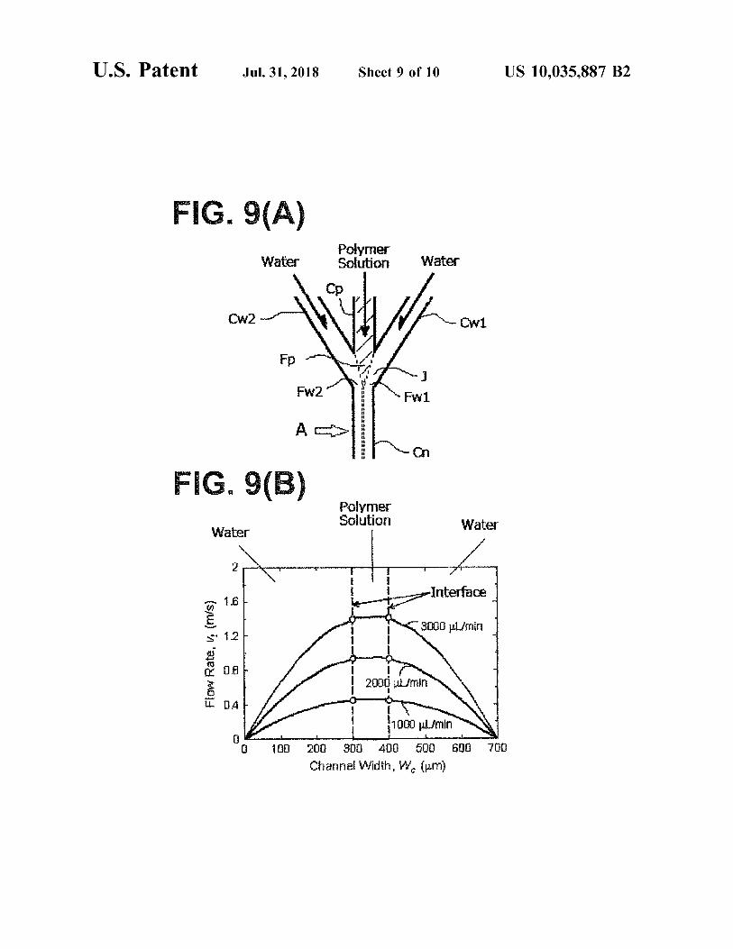
The laminar flows of water system solution sandwich the 5 ( D ) is a diagram illustrating a flow passage of the micro laminar flow of polymer solution from both right side and flow cell of Comparison Example 1 . left side relative to the flow direction of the polymer solution FIG . 6 is a schematic plan view illustrating a confluent toward downstream side from the upperstream side at the 55 mode of a laminar flow of an amphiphilic block polymer and confluent section ( i . e . , the downstream end of the polymer a laminar flow of a water system solution of a Comparison solution supply flow passage ) . Accordingly , the laminar flow Example . of the polymer solution flows at the center of the flow FIGS . 7 ( A ) , 7 ( B ) , 7 ( C ) are graphs illustrating the DLS passage and the laminar flow of the water system solution measurement result of Example 2 , and FIG . 7 ( D ) is a flows proximate the inner periphery of the flow passage 60 diagram illustrating a flow passage of the micro flow cell of ( contact area to the inside wall of the flow passage ) toward Example 2 . the nanoparticle forming flow passage from the confluent FIGS . 8 ( A ) , 8 ( B ) , 8 ( C ) are graphs illustrating the DLS section ( the upperstream area of the nanoparticle forming measurement result of Comparison Example 2 , and FIG . flow passage ) . The flow rate of the laminar flow of the 8 ( D ) is a diagram illustrating a flow passage of the micro polymer solution increases because of running in the center 65 flow cell of Comparison Example 2 . of the flow passage so that the area of the liquid - liquid FIG . 9 ( a ) is a view illustrating a simulation relative to the boundary face in between the laminar flow of the water confluent structure of flow passages in FIG . 1 according to
US 10 , 035 , 887 B2
1
the present invention , and FIG . 9 ( A ) is basically the same as hydrophilic block provides relatively stronger hydrophilicity illustrated in FIG . 1 and FIG . 9 ( B ) is a graph illustrating the compared to the lactic acid chain of the hydrophobic block simulation result . later set forth . Or it means that the hydrophilicity is in the
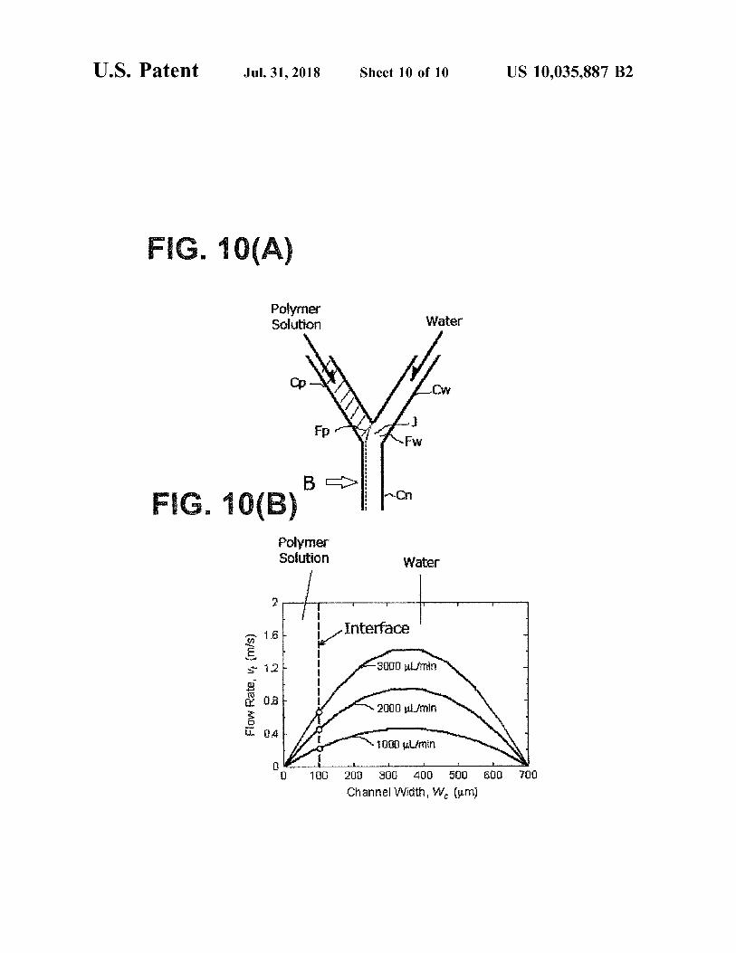
FIG . 10 ( A ) is a view illustrating a simulation relative to certain level at which the entirety of polymer molecule the confluent structure of Y - shape flow passages in FIG . 6 5 formed by co - polymerization of the hydrophilic block and disaccord with the present invention , and FIG . 10 ( A ) is the hydrophobic block allows providing an amphiphilicity in basically the same as illustrated in FIG . 6 and FIG . 10 ( B ) is reality . Further , or , it means that the hydrophilicity is in the a graph illustrating the simulation result . certain level at which the amphiphilic block polymer can
self - assemble and allows forming the self - assembly , particu DETAILED DESCRIPTION OF THE larly the particle - like self - assembly . PREFERRED EMBODIMENTS According to the present invention , the hydrophilic block Reference will now be made in detail to embodiments of of the amphiphilic block polymer may have either a linear
the invention . Wherever possible , same or similar reference chain structure or a branched chain structure . In the case of numerals are used in the drawings and the description to 15 the the branched structure , each branch of the hydrophilic block refer to the same or like parts or steps . The drawings are in should include sarcosine . simplified form and are not to precise scale . The word A person skilled in the art can decide arbitrarily the kind ' couple ' and similar terms do not necessarily denote direct and ratio of the structure unit relative to the hydrophilic and immediate connections , but also include connections block as if the entirety of the block is hydrophilic as set forth through intermediate elements or devices . For purposes of 20 above . For example , the total sarcosine units included in the convenience and clarity only , directional ( up / down , etc . ) or hydrophilic block is in the range of 2 - 300 . Specifically , in motional ( forward / back , etc . ) terms may be used with the case of a linear chain type , the total sarcosine unit can be , respect to the drawings . These and similar directional terms for example , approximately in the range of 10 - 300 , 20 - 200 , should not be construed to limit the scope in any manner . It or 20 - 100 . If the structure unit number is over the above will also be understood that other embodiments may be 25 range and then molecular assembly is formed , the formed utilized without departing from the scope of the present molecular assembly tends to be less stable . If the structure invention , and that the detailed description is not to be taken unit number is less than the above range , the amphiphilic in a limiting sense , and that elements may be differently block polymer does not work or it tends that the formation positioned , or otherwise noted as in the appended claims of the molecular assembly per se might be difficult . without requirements of the written description being 30 In the case of a branched chain type , the total sarcosine required thereto . unit in all branches can be , for example , in the range of
Various operations may be described as multiple discrete 2 - 200 , 2 - 100 or 2 - 10 . Or , in the case of a branched chain operations or steps or constructions in turn , in a manner that type , the total sarcosine unit included in a plurality of may be helpful in understanding embodiments of the present hydrophilic block can be , for example , in the range of invention ; however , the order of description should not be 35 30 - 200 or 50 - 100 . Average sarcosine unit number per branch construed to imply that these operations are order depen - can be , for example , 1 - 60 , 1 - 30 , 1 - 10 , or 1 - 6 . Specifically , dent . each amphiphilic block polymer can comprise sarcosine or The Best Mode of Embodiment of the Present Invention polysarcosine chain . If the structure unit number is over the
1 . Amphiphilic Block Polymer above range and then molecular assembly is formed , the According to the present invention , if an amphiphilic 40 formed molecular assembly tends to be less stable . If the
block polymer comprising a hydrophilic block and a hydro - structure unit number is less than the above range , the phobic block self - assembles by contacting a water system amphiphilic block polymer does not work or it tends that the solution ( water or an aqueous solution ) and then forms a formation of the molecular assembly per se might be diffi nanoparticle , the use thereof is not particularly limited . A cult . nanoparticle is a nanometer size particle and may include a 45 In the case of a branched type , two and more branches molecular assembly such as a micelle and a vesicle and so relative to the hydrophilic block are preferable , but three and forth . more is further preferable in the light of obtaining efficiently
The amphiphilic block polymer that comprises a hydro - particle like micelles upon forming the molecular assembly . philic block having an alkylene oxide unit and / or sarcosine A maximum number of branches relative to the amphiphilic unit and a hydrophobic block having hydroxy acid unit can 50 block polymer is not particularly limited but it may be 27 , be used . An alkylene oxide unit may include ethylene oxide for example . Particularly , in the present invention , the num unit and propylene oxide unit and so forth . In the case of ber of branches of the amphiphilic block polymer is pref ethylene oxide unit , the hydrophilic block includes PEG erably 3 . A person killed in the art can arbitrarily design the chain . A hydroxy acid unit may include glycolic acid , lactic branched structure . acid . hydroxybutyric acid and so forth . 55 Sarcosine ( i . e . , N - methylglycine ) is highly water soluble
Next , as an example of an amphiphilic block polymer , the and N - substituted amide of a polymer of sarcosine can be amphiphilic block polymer comprising a hydrophilic block subjected to cis - trans isomerization compared to the normal having sarcosine unit and a hydrophobic block having lactic amide group and the steric hindrance around Ca - carbon is acid unit is set forth . The amphiphilic block polymer may be less so that the polymer may have high flexibility . In the case either linear type or branch type . The hydrophilic block and 60 of using such structure as a constitution block , a basic the hydrophobic block are connected through a linker ele - property having high hydrophilicity or a basic property ment . having high hydrophilicity and high flexibility together is
1 - 1 . Hydrophilic Block provided to the block so that it can be very useful . According to the present invention , a physical property of Further , it is preferable that the hydrophilic block com
“ hydrophilicity ” that belongs to the hydrophilic block of the 65 prises a hydrophilic group ( e . g . , represented by hydroxy amphiphilic block polymer is not particularly limited to a group ) at the end ( i . e . , the opposite end of the linker specific level , but it means that at least the entirety of the element ) .

11
5
US 10 , 035 , 887 B2 12
Further , relative to polysarcosine chain , all sarcosine units lactic acid as a constitution block . Accordingly , such can be either sequential or non - sequential , but the molecular molecular assembly is very useful in the light of safety design as the entirety of the peptide chains might not damage relative to in vivo . the above basic properties is preferable . Further , relative to poly lactic acid chain ( PLA ) consti 1 - 2 . Hydrophobic Block tuting hydrophobic block , all lactic acid units can be either According to the present invention , a physical property of sequential or non - sequential , but the molecular design is “ hydrophobicity ” that belongs to the hydrophobic block is preferable as the entirety of the hydrophobic block might not not particularly limited to a specific level , but the level damage the above basic properties . should provide hydrophobicity as at least the hydrophobic block provides relatively stronger hydrophobicity compared 10 Poly lactic acid chain ( PLA ) constituting hydrophobic to the entirety of the hydrophilic block and forms a copo block can be either poly - L - lactic acid chain ( PLLA ) com lymer with the hydrophilic block so that the entirety of the prising L - lactic acid unit or poly - D - lactic acid chain ( PDLA )
comprising D - lactic acid unit . Further , it may comprise both copolymer may bring the amphiphilicity in reality . Or , the L - lactic acid unit and D - lactic acid unit . In this case , L - lactic hydrophobicity may be in the certain level at which the 15 acid unit and D - lactic acid unit may be in any arrangement amphiphilic block polymer can self - assemble and allows including alternative arrangement , block arrangement or forming the self - assembly , preferably the particle - like self random arrangement . assembly .
The hydrophobic block of one amphiphilic block polymer 1 - 3 . Ratio of Sarcosine Unit Number to Lactic Acid Unit may be either not - branched or branched . However , it is 20 Number considered that if the hydrophobic block is not branched , the Relative to an amphiphilic block polymer , if sarcosine density of the hydrophilicity branch type shell element unit number ( i . e . , a number of sarcosine units included in a increases relative to the hydrophobicity core element so that hydrophilic block or a number of sarcosine units included in stable core / shell type molecular assembly having small the entirety of branches in the case of the branched hydro particle diameter may be easily formed . 25 philic block ) is NS and a number of poly lactic acid units
According to the present invention , the hydrophobic ( i . e . , a number of lactic acid units included in a hydrophobic block includes polylactic acid chain ( PLA ) . A person skilled block or a number of lactic acid units included in the entirety in the art can decide arbitrarily the kind and ratio of the of branches in the case of the branched hydrophobic block )
is NL , the ratio NS / NL can be , for example , in the range of structure unit relative to the hydrophobic block as the 30 0 . 05 - 5 or 0 . 05 - 4 . Further preferably , NS / NL can be more entirety of the block is hydrophobic as set forth above . For than 0 . 05 and less than 1 . 8 , for example , more than 0 . 05 and example , the total lactic acid units included in the hydro less than 1 . 7 , more than 0 . 05 and less than 1 . 67 . more than phobic block is in the range of 5 - 400 . Specifically , for 0 . 1 and less than 1 . 7 , or more than 0 . 1 and less than 1 . 67 . example , the hydrophobic block is not branched , the number of lactic acid units can be e . g . , in the range of 5 - 100 , 15 - 60 26 1 - 4 . Structure of Polymer or 25 - 45 . The hydrophobic block is branched , the number of If a structure of a linker element connecting a hydrophilic lactic acid units included in the entirety of the branch can be block and a hydrophobic block is chemically - acceptable e . g . , in the range of 10 - 400 and preferably 20 - 200 . In this structure , it is not particularly limited . A person killed in the case , an average lactic acid unit number per branch can be , art can arbitrarily design the molecule . e . g . , in the range of 5 - 100 and preferably 10 - 100 . 40 In the case of a branched structure , for example , if the
If the structure unit number is over the above range and number of branches of the hydrophilic block is two , two then molecular assembly is formed , the formed molecular molecular chains including polysarcosine chain can branch assembly tends to be less stable . If the structure unit number from one N - atom of the linker element of the molecular is less than the above range , it tends that the formation of the chain including poly lactic acid chain . In other words , molecular assembly per se might be difficult . 45 N - atom connecting directly or indirectly to poly lactic acid
In the case of branched hydrophobic block , the number of chain can connect directly or indirectly to 2 polysarcosine branches is not particularly limited , but in the light of chains . obtaining efficiently particle like micelles upon forming the Further , for example , if the number of branches of the molecular assembly , for example , it can be less than the hydrophilic block is three , three molecular chains including branch number of the hydrophilic block . 50 polysarcosine chain can branch from one C - atom of the
Polylactic acid has the following basic properties . linker element of the molecular chain including poly lactic Polylactic acid has a superior biocompatibility and sta - acid chain . In other words , C - atom connecting directly or
bility . Accordingly , the molecular assembly obtained from indirectly to poly lactic acid chain can connect directly or an amphiphilic substance having polylactic acid as an con - indirectly to three polysarcosine chains . If one P - atom or stitution block is very useful in the light of application in 55 Si - atom of the linker element branches or if the entirety of vivo , particularly human . an amphiphilic block polymer molecule forms quaternary
Further , as polylactic acid has a superior biodegradability , ammonium molecule , it can be the same . it can be quickly metabolized so that the integration in the the If the number of branches of the hydrophilic block is more normal human tissue other than the cancer tissue is less . than three , it can be designed as the branch has an additional Accordingly , the molecular assembly obtained from an 60 bra branch structure . amphiphilic substance having polylactic acid as an consti tution block is very useful in the light of specific integration If the hydrophobic block branches , a molecule can be in the cancer tissue . designed as well as from the above standpoint .
In addition , poly lactic acid is highly soluble in a low The following Formula 1 illustrates the preferred structure boiling point solvent so that the use of harmful high boiling 65 of the branched amphiphilic block polymer when the num point solvent can be avoided when the molecular assembly ber of branches in the hydrophilic block side is three and is obtained from the amphiphilic substance having poly there is no branch in the hydrophobic block side .
13
viestit HO .
non ti HO
Chemical Formula 2
US 10 , 035 , 887 B2 13 14
addition of sarcosine moiety or polymerization of polysar Chemical Formula 1 cosine moiety and by polymerization of poly lactic acid
moiety . Further , for example , after addition of sarcosine to the
5 linker agent , or after addition of polysarcosine chain as the hydrophilic block prepared by polymerization in advance , the poly lactic acid chain is extended to synthesize the branched amphiphilic block polymer .
Further , for example , both polysarcosine or polysarcosine chain and poly lactic acid chain are prepared in advance respectively as a hydrophilic block and a hydrophobic block , and each block can be connected by a linker agent , sepa rately synthesized , to synthesize a branched amphiphilic block polymer .
A structure of a linker agent may include one or a number of functional groups ( e . g . , hydroxy group , amino group ) connectible to lactic acid monomers ( lactic acid or lactide )
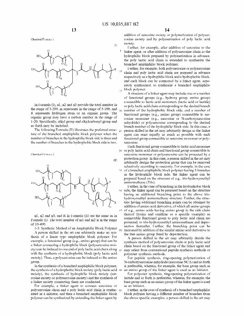
In Formula ( I ) , n1 , n2 and n3 provide the total number in or poly lactic acid chain corresponding to the desired branch the range of 3 - 200 , m represents in the range of 5 - 100 , and , 1 20 number of the hydrophobic block side , and a number of R represents hydrogen atom or an organic group . The functional groups ( e . g . , amino group ) connectible to sar organic group may have a carbon number in the range of cosine monomer ( e . g . , sarcosine or N - carboxysarcosine 1 - 20 . Specifically , alkyl group and alkylcarbonyl group and anhydride ) or polysarcosine corresponding to the desired so forth may be included . branch number of the hydrophilic block side . In this case , a
The following Formula ( II ) illustrates the preferred struc - 25 person skilled in the art may arbitrarily design as the linker ture of the branched amphiphilic block polymer when the agent can react equally as much as possible with each number of branches in the hydrophilic block side is three and functional group connectible to sarcosine monomer or poly the number of branches in the hydrophobic block side is two . sarcosine .
Each functional group connectible to lactic acid monomer 30 or poly lactic acid chain and functional group connectible to
sarcosine monomer or polysarcosine can be protected by a protection group . In this case , a person skilled in the art may arbitrarily design the protection group that can be removed selectively according to necessity . For example , in the case
35 of a branched amphiphilic block polymer having 3 branches in the hydrophilic block side , the linker agent can be prepared based on the structure of e . g . , tris - hydroxymethyl aminomethane ( Tris ) .
Further , in the case of branching in the hydrophobic block 40 side , the linker agent can be prepared based on the structure
having an additional branching point to the above tris hydroxymethyl aminomethane structure . Further , the struc
R ture having additional branching points can be obtained by addition of amino acid derivative , of which all amino groups
45 of e . g . , amino acids having amino group in the side chain
n1 , n2 and n3 , and R in Formula ( II ) are the same as in thereof ( lysine and omithine as a specific example ) as Formula ( I ) . The total number of m1 and m2 is in the range connectible functional group to poly lactic acid chain are
protected , to tris - hydroxymethyl aminomethane and depro of 10 - 400 . tection thereafter . Further , the branching point can be 1 - 5 . Synthetic Method of an Amphiphilic Block Polymer 50 increased by addition of the similar amino acid derivative to A person skilled in the art can arbitrarily make an syn the free amino group freed by deprotection . thesis of a linear type amphiphilic block polymer . For A person skilled in the art may arbitrarily decide the example , a functional group ( e . g . , amino group ) that can be synthesis method of polysarcosine chain or poly lactic acid a linker connecting a hydrophilic block ( polysarcosine moi - chain based on the functional group of the linker agent and ety ) can be induced to one end of poly lactic acid chain along 55 may select from conventional peptide synthesis methods or with the synthesis of a hydrophobic block ( poly lactic acid polyester synthesis methods . moiety ) . Then , a polysarcosine can be induced to the amino For peptide synthesis , ring - opening polymerization of group . N - carboxysarcosine anhydride ( sarcosine NCA ) and so forth
In the synthesis of a branched amphiphilic block polymer , is preferable , wherein , for example , the base group such as the synthesis of a hydrophobic block moiety ( poly lactic acid 60 an amino group of the linker agent is used as an initiator . moiety ) , the synthesis of hydrophilic block moiety ( sar - For polyester synthesis , ring - opening polymerization of cosine moiety or polysarcosine moiety ) and the synthesis of lactide and so forth is preferable , wherein , for example , the a linker moiety connecting them are conducted . base group such as an amino group of the linker agent is used
For example , a linker agent to connect sarcosine or as an initiator . polysarcosine chain and a poly lactic acid chain is synthe - 65 Further , in the case of synthesis of a branched amphiphilic sized as a initiator , and then a branched amphiphilic block block polymer having a different number of branches from polymer can be synthesized by extending the linker agent by the above specific examples , a person skilled in the art may
HO . i HO
H
HO .
m2
US 10 , 035 , 887 B2 15 16
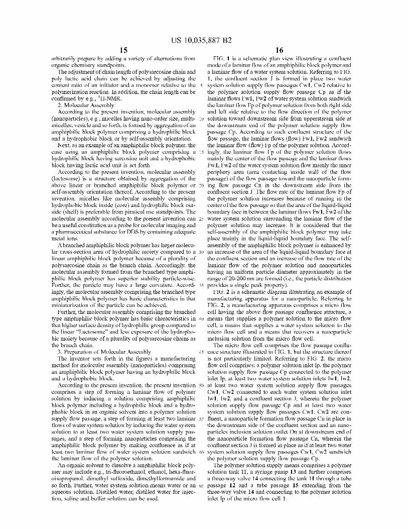
arbitrarily prepare by adding a variety of alternations from FIG . 1 is a schematic plan view illustrating a confluent organic chemistry standpoints . mode of a laminar flow of an amphiphilic block polymer and
The adjustment of chain length of polysarcosine chain and a laminar flow of a water system solution . Referring to FIG . poly lactic acid chain can be achieved by adjusting the 1 , the confluent section J is formed in place two water content ratio of an initiator and a monomer relative to the 5 system solution supply flow passages Cwl , Cw2 relative to polymerization reaction . In addition , the chain length can be the polymer solution supply flow passage Cp as if the confirmed by e . g . , ' H - NMR . laminar flows Fw1 , Fw2 of water system solution sandwich
2 . Molecular Assembly the laminar flow Fp of polymer solution from both right side According to the present invention , molecular assembly and left side relative to the flow direction of the polymer
( nanoparticles ) , e . g . , micelles having nano - order size , multi - 10 solution toward downstream side from upperstream side at micelles , vesicle and so forth , is formed by aggregation of an the downstream end of the polymer solution supply flow amphiphilic block polymer comprising a hydrophilic block passage Cp . According to such confluent structure of the and a hydrophobic block or by self - assembly orientation . flow passage , the laminar flows ( flow ) Fwl , Fw2 sandwich Next , as an example of an amphiphilic block polymer , the the laminar flow ( flow ) Fp of the polymer solution . Accord
case using an amphiphilic block polymer comprising a 15 ingly , the laminar flow Fp of the polymer solution flows hydrophilic block having sarcosine unit and a hydrophobic mainly the center of the flow passage and the laminar flows block having lactic acid unit is set forth . Fwl , Fw2 of the water system solution flow mainly the inner
According to the present invention , molecular assembly periphery area ( area contacting inside wall of the flow ( lactosome ) is a structure obtained by aggregation of the passage ) of the flow passage toward the nanoparticle form above linear or branched amphiphilic block polymer or 20 ing flow passage Cn in the downstream side from the self - assembly orientation thereof . According to the present confluent section J . The flow rate of the laminar flow Fp of invention , micelles like molecular assembly comprising the polymer solution increases because of running in the hydrophobic block inside ( core ) and hydrophilic block out - center of the flow passage so that the area of the liquid - liquid side ( shell ) is preferable from piratical use standpoints . The boundary face in between the laminar flows Fw1 , Fw2 of the molecular assembly according to the present invention can 25 water system solution surrounding the laminar flow of the be a useful constitution as a probe for molecular imaging and polymer solution may increase . It is considered that the a pharmaceutical substance for DDS by containing adequate self - assembly of the amphiphilic block polymer may take metal ions . place mainly in the liquid - liquid boundary face . The self
A branched amphiphilic block polymer has larger molecu - assembly of the amphiphilic block polymer is enhanced by lar cross - section area of hydrophilic moiety compared to a 30 an increase of the area of the liquid - liquid boundary face at linear amphiphilic block polymer because of a plurality of the confluent section and an increase of the flow rate of the polysarcosine chain as the branch chain . Accordingly , the laminar flow of the polymer solution and nanoparticles molecular assembly formed from the branched type amphi - having an uniform particle diameter approximately in the philic block polymer has superior stability particle - wise . range of 20 - 200 nm are formed ( i . e . , the particle distribution Further , the particle may have a large curvature . Accord - 35 provides a single peak property ) . ingly , the molecular assembly comprising the branched type FIG . 2 is a schematic diagram illustrating an example of amphiphilic block polymer has basic characteristics in that manufacturing apparatus for a nanoparticle . Referring to miniaturization of the particle can be achieved . FIG . 2 , a manufacturing apparatus comprises a micro flow
Further , the molecular assembly comprising the branched cell having the above flow passage confluence structure , a type amphiphilic block polymer has basic characteristics in 40 means that supplies a polymer solution to the micro flow that higher surface density of hydrophilic group compared to cell , a means that supplies a water system solution to the the linear “ Lactosome ” and less exposure of the hydropho - micro flow cell and a means that recovers a nanoparticle bic moiety because of a plurality of polysarcosine chains as inclusion solution from the micro flow cell . the branch chain . The micro flow cell comprises the flow passage conflu
3 . Preparation of Molecular Assembly 45 ence structure illustrated in FIG . 1 , but the structure thereof The inventor sets forth in the figures a manufacturing is not particularly limited . Referring to FIG . 2 . the micro
method for molecular assembly ( nanoparticles ) comprising flow cell comprises ; a polymer solution inlet Ip , the polymer an amphiphilic block polymer having an hydrophilic block solution supply flow passage Cp connected to the polymer and a hydrophobic block . inlet Ip , at least two water system solution inlets Iwl , Iw2 ,
According to the present invention , the present invention 50 at least two water system solution supply flow passages comprises a step of forming a laminar flow of polymer Cw1 , Cw2 connected to each water system solution inlet solution by inducing a solution comprising amphiphilic Iwi , Iw2 , and a confluent section J , wherein the polymer block polymer including a hydrophilic block and a hydro - solution supply flow passage Cp and at least two water phobic block in an organic solvent into a polymer solution system solution supply flow passages Cw1 , Cw2 are con supply flow passage , a step of forming at least two laminar 55 fluent , a nanoparticle formation flow passage Cn in place in flows of water system solution by inducing the water system the downstream side of the confluent section and an nano solution to at least two water system solution supply pas - particles inclusion solution outlet On at downstream end of sages , and a step of forming nanoparticles comprising the the nanoparticle formation flow passage Cn , wherein the amphiphilic block polymer by making confluence as if at confluent section J is formed in place as if at least two water least two laminar flow of water system solution sandwich 60 system solution supply flow passages Cwl , Cw2 sandwich the laminar flow of the polymer solution . the polymer solution supply flow passage Cp .
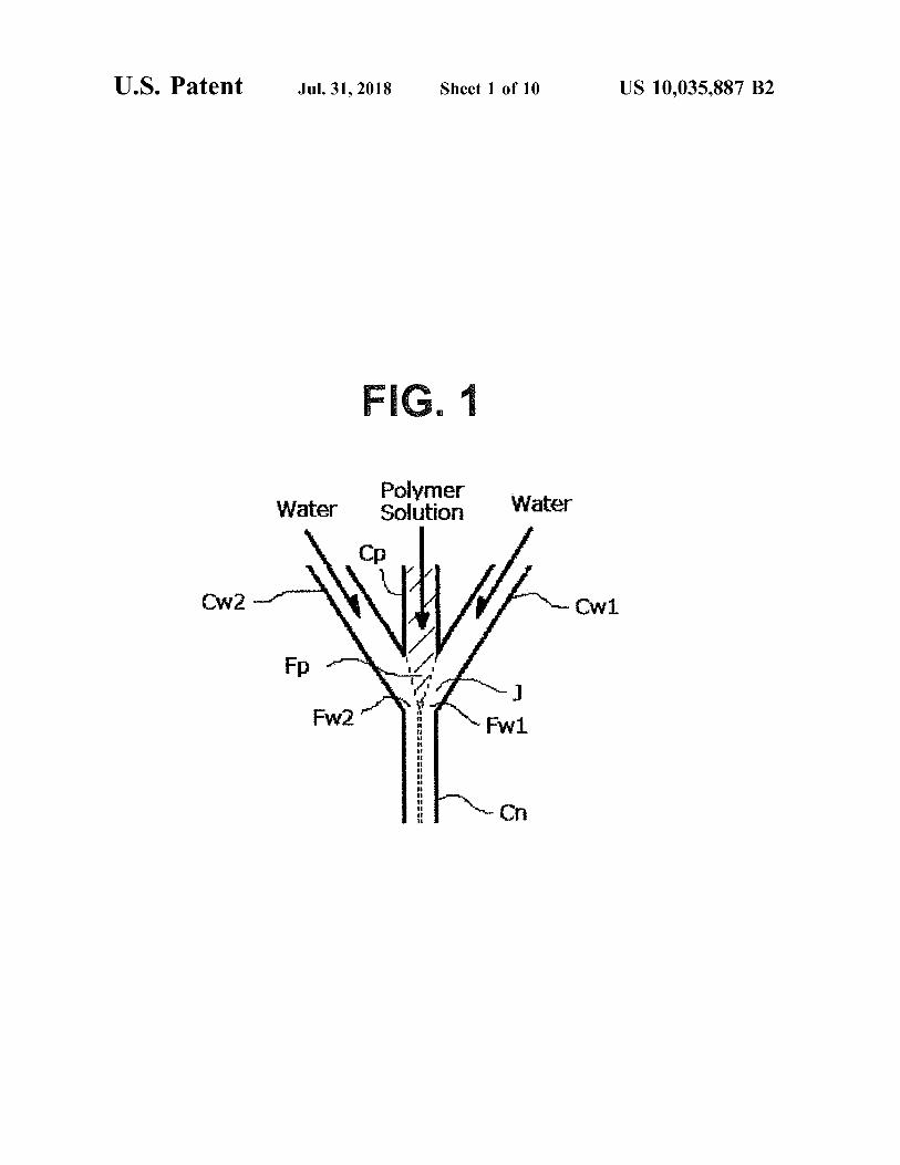
An organic solvent to dissolve a amphiphilic block poly - The polymer solution supply means comprises a polymer mer may include e . g . , tri - fluoroethanol , ethanol , hexa - fluor - solution tank 11 , a syringe pump 13 and further comprises oisopropanol , dimethyl sulfoxide , dimethylformamide and a three - way valve 14 connecting the tank 11 through a tube so forth . Further , water system solution means water or an 65 passage 12 and a tube passage 15 extending from the aqueous solution . Distilled water , distilled water for injec - three - way valve 14 and connecting to the polymer solution tion , saline and buffer solution can be used . inlet Ip of the micro flow cell 1 .
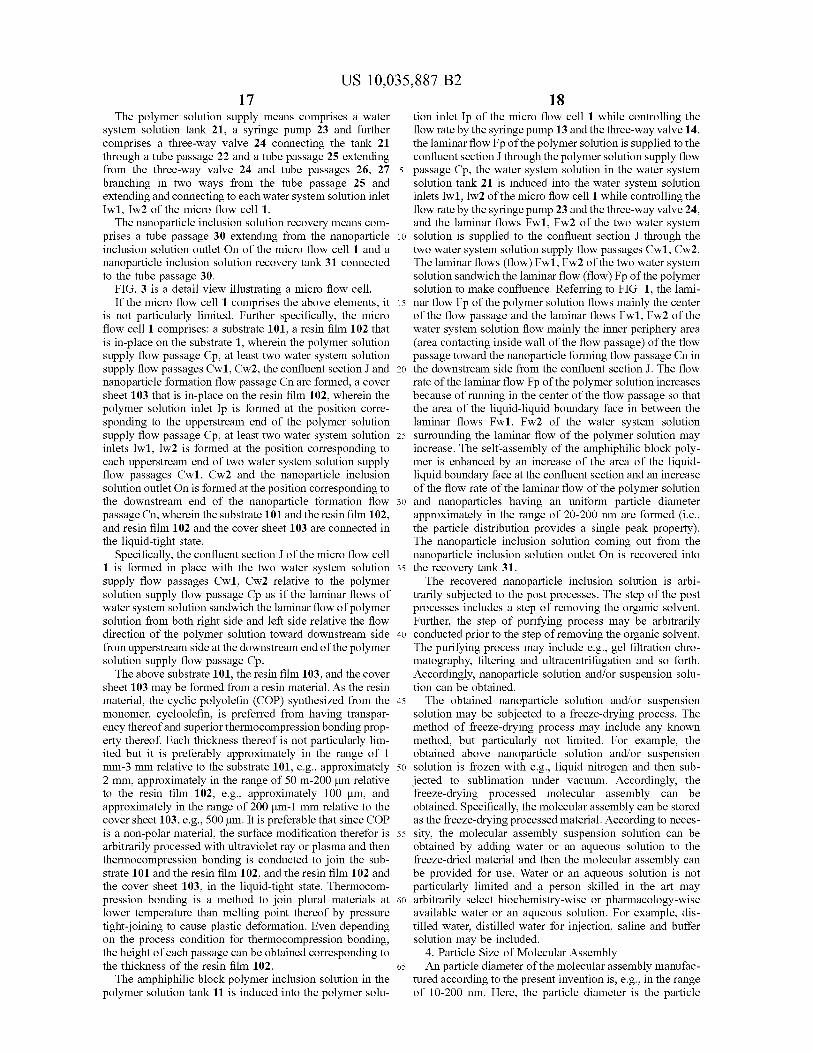
17 US 10 , 035 , 887 B2
18 The polymer solution supply means comprises a water tion inlet Ip of the micro flow cell 1 while controlling the
system solution tank 21 , a syringe pump 23 and further flow rate by the syringe pump 13 and the three - way valve 14 , comprises a three - way valve 24 connecting the tank 21 the laminar flow Fp of the polymer solution is supplied to the through a tube passage 22 and a tube passage 25 extending confluent section J through the polymer solution supply flow from the three - way valve 24 and tube passages 26 , 27 5 passage Cp , the water system solution in the water system branching in two ways from the tube passage 25 and solution tank 21 is induced into the water system solution extending and connecting to each water system solution inlet inlets Iw1 , Iw2 of the micro flow cell 1 while controlling the Iwl , Iw2 of the micro flow cell 1 . flow rate by the syringe pump 23 and the three - way valve 24 ,
The nanoparticle inclusion solution recovery means com and the laminar flows Fw1 , Fw2 of the two water system prises a tube passage 30 extending from the nanoparticle 10 solution is supplied to the confluent section J through the inclusion solution outlet On of the micro flow cell 1 and a two water system solution supply flow passages Cw1 , Cw2 . nanoparticle inclusion solution recovery tank 31 connected The laminar flows ( flow ) Fwl , Fw2 of the two water system to the tube passage 30 . solution sandwich the laminar flow ( flow ) Fp of the polymer
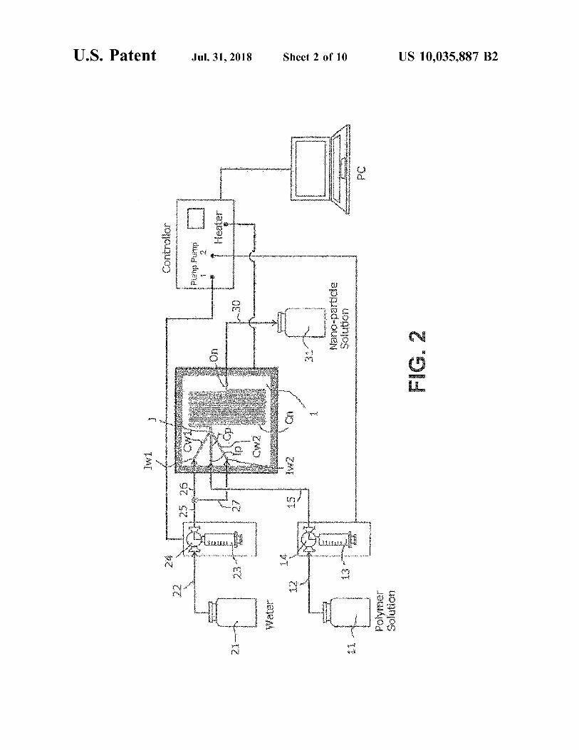
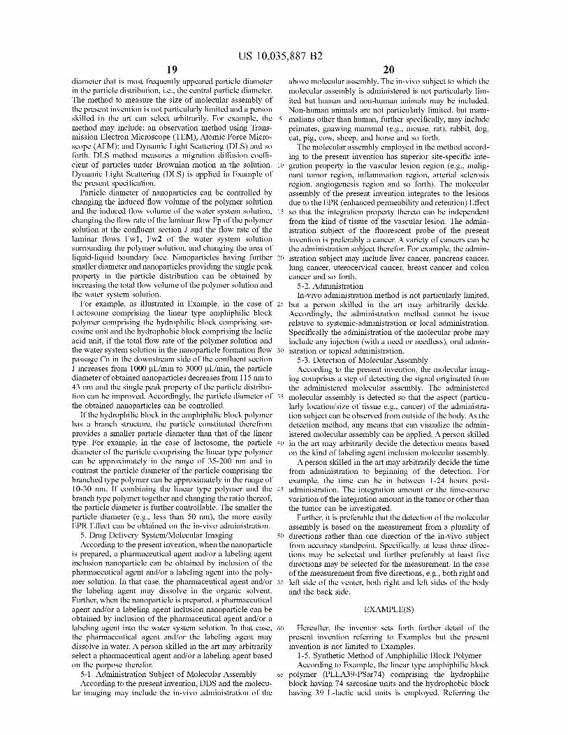
FIG . 3 is a detail view illustrating a micro flow cell . solution to make confluence . Referring to FIG . 1 , the lami If the micro flow cell 1 comprises the above elements , it 15 nar flow Fp of the polymer solution flows mainly the center
is not particularly limited . Further specifically , the micro of the flow passage and the laminar flows Fwl , Fw2 of the flow cell 1 comprises : a substrate 101 , a resin film 102 that water system solution flow mainly the inner periphery area is in - place on the substrate 1 , wherein the polymer solution ( area contacting inside wall of the flow passage ) of the flow supply flow passage Cp , at least two water system solution passage toward the nanoparticle forming flow passage Cn in supply flow passages Cwl , Cw2 , the confluent section J and 20 the downstream side from the confluent section J . The flow nanoparticle formation flow passage Cn are formed , a cover rate of the laminar flow Fp of the polymer solution increases sheet 103 that is in - place on the resin film 102 , wherein the because of running in the center of the flow passage so that polymer solution inlet Ip is formed at the position corre - the area of the liquid - liquid boundary face in between the sponding to the upperstream end of the polymer solution laminar flows Fw1 , Fw2 of the water system solution supply flow passage Cp , at least two water system solution 25 surrounding the laminar flow of the polymer solution may inlets Iwl , Iw2 is formed at the position corresponding to increase . The self - assembly of the amphiphilic block poly each upperstream end of two water system solution supply mer is enhanced by an increase of the area of the liquid flow passages Cwl , Cw2 and the nanoparticle inclusion liquid boundary face at the confluent section and an increase solution outlet On is formed at the position corresponding to of the flow rate of the laminar flow of the polymer solution the downstream end of the nanoparticle formation flow 30 and nanoparticles having an uniform particle diameter passage Cn , wherein the substrate 101 and the resin film 102 , approximately in the range of 20 - 200 nm are formed ( i . e . , and resin film 102 and the cover sheet 103 are connected in the particle distribution provides a single peak property ) . the liquid - tight state . The nanoparticle inclusion solution coming out from the
Specifically , the confluent section J of the micro flow cell nanoparticle inclusion solution outlet On is recovered into 1 is formed in place with the two water system solution 35 the recovery tank 31 . supply flow passages Cwl , Cw2 relative to the polymer The recovered nanoparticle inclusion solution is arbi solution supply flow passage Cp as if the laminar flows of trarily subjected to the post processes . The step of the post water system solution sandwich the laminar flow of polymer processes includes a step of removing the organic solvent . solution from both right side and left side relative the flow Further , the step of purifying process may be arbitrarily direction of the polymer solution toward downstream side 40 conducted prior to the step of removing the organic solvent . from upperstream side at the downstream end of the polymer The purifying process may include e . g . , gel filtration chro solution supply flow passage Cp . matography , filtering and ultracentrifugation and so forth .
The above substrate 101 , the resin film 103 , and the cover Accordingly , nanoparticle solution and / or suspension solu sheet 103 may be formed from a resin material . As the resin tion can be obtained . material , the cyclic polyolefin ( COP ) synthesized from the 45 The obtained nanoparticle solution and / or suspension monomer , cycloolefin , is preferred from having transpar - solution may be subjected to a freeze - drying process . The ency thereof and superior thermocompression bonding prop - method of freeze - drying process may include any known erty thereof . Each thickness thereof is not particularly lim - method , but particularly not limited . For example , the ited but it is preferably approximately in the range of 1 obtained above nanoparticle solution and / or suspension mm - 3 mm relative to the substrate 101 , e . g . , approximately 50 solution is frozen with e . g . , liquid nitrogen and then sub 2 mm , approximately in the range of 50 m - 200 um relative jected to sublimation under vacuum . Accordingly , the to the resin film 102 , e . g . , approximately 100 um , and freeze - drying processed molecular assembly can be approximately in the range of 200 um - 1 mm relative to the obtained . Specifically , the molecular assembly can be stored cover sheet 103 , e . g . , 500 um . It is preferable that since COP as the freeze - drying processed material . According to neces is a non - polar material , the surface modification therefor is 55 sity , the molecular assembly suspension solution can be arbitrarily processed with ultraviolet ray or plasma and then obtained by adding water or an aqueous solution to the thermocompression bonding is conducted to join the sub - freeze - dried material and then the molecular assembly can strate 101 and the resin film 102 , and the resin film 102 and be provided for use . Water or an aqueous solution is not the cover sheet 103 , in the liquid - tight state . Thermocom - particularly limited and a person skilled in the art may pression bonding is a method to join plural materials at 60 arbitrarily select biochemistry - wise or pharmacology - wise lower temperature than melting point thereof by pressure available water or an aqueous solution . For example , dis tight - joining to cause plastic deformation . Even depending tilled water , distilled water for injection , saline and buffer on the process condition for thermocompression bonding solution may be included . the height of each passage can be obtained corresponding to 4 . Particle Size of Molecular Assembly the thickness of the resin film 102 . 65 An particle diameter of the molecular assembly manufac
The amphiphilic block polymer inclusion solution in the tured according to the present invention is , e . g . , in the range polymer solution tank 11 is induced into the polymer solu - of 10 - 200 nm . Here , the particle diameter is the particle
20 US 10 , 035 , 887 B2
19 diameter that is most frequently appeared particle diameter above molecular assembly . The in - vivo subject to which the in the particle distribution , i . e . , the central particle diameter . molecular assembly is administered is not particularly lim The method to measure the size of molecular assembly of ited but human and non - human animals may be included . the present invention is not particularly limited and a person Non - human animals are not particularly limited , but mam skilled in the art can select arbitrarily . For example , the 5 malians other than human , further specifically , may include method may include ; an observation method using Trans - primates , gnawing mammal ( e . g . , mouse , rat ) , rabbit , dog , mission Electron Microscope ( TEM ) , Atomic Force Micro cat , pig , cow , sheep , and horse and so forth . scope ( AFM ) ; and Dynamic Light Scattering ( DLS ) and so The molecular assembly employed in the method accord forth . DLS method measures a migration diffusion coeffi - ing to the present invention has superior site - specific inte cient of particles under Brownian motion in the solution . 10 gration property in the vascular lesion region ( e . g . , malig Dynamic Light Scattering ( DLS ) is applied in Example of nant tumor region , inflammation region , arterial sclerosis the present specification . region , angiogenesis region and so forth ) . The molecular
Particle diameter of nanoparticles can be controlled by assembly of the present invention integrates to the lesions changing the induced flow volume of the polymer solution due to the EPR ( enhanced permeability and retention ) Effect and the induced flow volume of the water system solution , 15 so that the integration property thereto can be independent changing the flow rate of the laminar flow Fp of the polymer from the kind of tissue of the vascular lesion . The admin solution at the confluent section J and the flow rate of the istration subject of the fluorescent probe of the present laminar flows Fwl , Fw2 of the water system solution invention is preferably a cancer . A variety of cancers can be surrounding the polymer solution , and changing the area of the administration subject therefor . For example , the admin liquid - liquid boundary face . Nanoparticles having further 20 istration subject may include liver cancer , pancreas cancer , smaller diameter and nanoparticles providing the single peak lung cancer , uterocervical cancer , breast cancer and colon property in the particle distribution can be obtained by cancer and so forth . increasing the total flow volume of the polymer solution and 5 - 2 . Administration the water system solution . In - vivo administration method is not particularly limited ,
For example , as illustrated in Example , in the case of 25 but a person skilled in the art may arbitrarily decide . Lactosome comprising the linear type amphiphilic block Accordingly , the administration method cannot be issue polymer comprising the hydrophilic block comprising sar - relative to systemic - administration or local administration . cosine unit and the hydrophobic block comprising the lactic Specifically the administration of the molecular probe may acid unit , if the total flow rate of the polymer solution and include any injection ( with a need or needless ) , oral admin the water system solution in the nanoparticle formation flow 30 istration or topical administration . passage Cn in the downstream side of the confluent section 5 - 3 . Detection of Molecular Assembly J increases from 1000 uL / min to 3000 uL / min , the particle According to the present invention , the molecular imag diameter of obtained nanoparticles decreases from 115 nm to ing comprises a step of detecting the signal originated from 43 nm and the single peak property of the particle distribu - the administered molecular assembly . The administered tion can be improved . Accordingly , the particle diameter of 35 molecular assembly is detected so that the aspect ( particu the obtained nanoparticles can be controlled . larly location / size of tissue e . g . , cancer ) of the administra
If the hydrophilic block in the amphiphilic block polymer tion subject can be observed from outside of the body . As the has a branch structure , the particle constituted therefrom detection method , any means that can visualize the admin provides a smaller particle diameter than that of the linear istered molecular assembly can be applied . A person skilled type . For example , in the case of lactosome , the particle 40 in the art may arbitrarily decide the detection means based diameter of the particle comprising the linear type polymer on the kind of labeling agent inclusion molecular assembly . can be approximately in the range of 35 - 200 nm and in A person skilled in the art may arbitrarily decide the time contrast the particle diameter of the particle comprising the from administration to beginning of the detection . For branched type polymer can be approximately in the range of example , the time can be in between 1 - 24 hours post 10 - 30 nm . If combining the linear type polymer and the 45 administration . The integration amount or the time - course branch type polymer together and changing the ratio thereof , variation of the integration amount in the tumor or other than the particle diameter is further controllable . The smaller the the tumor can be investigated . particle diameter ( e . g . , less than 50 nm ) , the more easily Further , it is preferable that the detection of the molecular EPR Effect can be obtained on the in - vivo administration . assembly is based on the measurement from a plurality of
5 . Drug Delivery System / Molecular Imaging 50 directions rather than one direction of the in - vivo subject According to the present invention , when the nanoparticle from accuracy standpoint . Specifically , at least three direc
is prepared , a pharmaceutical agent and / or a labeling agent tions may be selected and further preferably at least five inclusion nanoparticle can be obtained by inclusion of the directions may be selected for the measurement . In the case pharmaceutical agent and / or a labeling agent into the poly - of the measurement from five directions , e . g . , both right and mer solution . In that case , the pharmaceutical agent and / or 55 left side of the venter , both right and left sides of the body the labeling agent may dissolve in the organic solvent . and the back side . Further , when the nanoparticle is prepared , a pharmaceutical agent and / or a labeling agent inclusion nanoparticle can be EXAMPLE ( S ) obtained by inclusion of the pharmaceutical agent and / or a labeling agent into the water system solution . In that case , 60 Hereafter , the inventor sets forth further detail of the the pharmaceutical agent and / or the labeling agent may present invention referring to Examples but the present dissolve in water . A person skilled in the art may arbitrarily invention is not limited to Examples . select a pharmaceutical agent and / or a labeling agent based 1 - 5 . Synthetic Method of Amphiphilic Block Polymer on the purpose therefor . According to Example , the linear type amphiphilic block
5 - 1 . Administration Subject of Molecular Assembly 65 polymer ( PLLA39 - PSar74 ) comprising the hydrophilic According to the present invention , DDS and the molecu - block having 74 sarcosine units and the hydrophobic block
lar imaging may include the in - vivo administration of the having 39 L - lactic acid units is employed . Referring the

US 10 , 035 , 887 B2 21
74
HN _ CH ;
??3
von 4 HO
CH30 174 . ! CHz /
method disclosed in WO2009 / 148121 and WO2012 / 17688 , water was partitioned to each tube passage 26 , 27 through the synthesis of polymer is conducted by using glycolic acid , two way connector from the tube passage 25 to make water O - ( benzotriazol - 1 - yl ) - N , N , N ' , N ' - tetramethyluronium flow rate to each water system solution supply flow passages hexafluorophosphate ( HATU ) and N , N - Diisopropylethyl - Cwl , Cw2 equal . amine ( DIEA ) from sarcosine - NCA ( Sar - NCA ) and amino - 5 Referring to Example 1 , the width of flow passage of the poly - L - lactic acid ( ( a - PLLA ) . micro flow cell shown in FIG . 4 ( D ) is 700 um ; the flow
passage length thereof is 611 mm ; the flow capacity is 29 uL ; and the turn number relative to the nanoparticle formation
Chemical Formula 3 flow passage Cn in the downstream from the confluent 10 section J is 14 . Temperature of the flow passage of the micro
flow cell was 25° C . In addition , referring to FIG . 3 , all substrate 101 , resin film 102 , and cover sheet 103 are made of cycloolefin resin ( Zeonor ( TM ) 1600R , glass transition temperature 161° C . , Nippon Zeon ) , the thickness of the
15 substrate 101 is 2 mm , the thickness of the resin film 102 is Sar - NCA 100 um and the thickness of the resin film 103 is 500 um .
( a ) Firstly , under FRR = 9 condition , the polymer solution and water were induced to the polymer solution supply flow 1 . rt / DMF passage Cp and two water system solution supply flow 2 . Glycolic acid / 20 passages Cwl , Cw2 to make 1000 ?L / min of the total flow HATU , DIEA rate of the polymer solution and water , Qt = Qw + Qp . Nano particles inclusion solution is recovered 31 from the down stream end of the nanoparticle formation flow passage Cn . a - PLLA The recovered nanoparticles inclusion solution is diluted
25 with Milli - Q to make double . The diluted solution was CH ; filtrated through 200 nm filter ( PALL Acrodisc? 25 mm
Syringe Filter w / 0 . 2 um Supor® Membrane ) and the pro cessed solution with the filter was subjected to DLC mea surement .
PLLA39 - PSar74 . 30 The result of DLS measurement is illustrated in FIG . 4 ( A ) . The horizontal axis is Particle Diameter in nm and the perpendicular axis is Intensity in % . The main peak appears at 115 nm and the side peak appears at 37 nm . PdI value
Example 1 representing the level of polydispersity of particle distribu 35 tional is 0 . 19 .
Nanoparticles were prepared from the linear type amphi ( b ) Next , under FRR = 9 condition , the polymer solution philic block polymer ( PLLA39 - PSar74 ) using apparatuses and water were induced to the polymer solution supply flow illustrated in FIG . 1 - 3 as follows . passage Cp and two water system solution supply flow
Milli - Q was used for water 21 . The amphiphilic block passages Cwl , Cw2 to make 2000 uL / min of the total flow polymer ( PLLA39 - PSar74 ) was dissolved in DMF to pro - 40 rate of the polymer solution and water , Qt = Qw + Qp and vide the 8 mg / mL solution , and stirred at 603 for 30 min in other than that , the same operations as the above ( a ) have the oil bath and then cooled down to room temperature to been conducted and DLS ( using Malvern Instruments Ltd , provide the polymer solution 11 to be used . Zetasizer Nano S ) thereof was measured .
Referring to the apparatus in FIGs . , the syringe pump 14 , The result of DLS measurement is illustrated in FIG . 24 ( Hamilton PSD / 3 ) was used to send the solution , and two 45 4 ( B ) . The main peak appears at 47 nm and obviously the solutions of the polymer solution 11 and the water system single peak property was provided . PdI value is 0 . 13 . solution 21 were induced to the micro flow cell 1 fixed to the ( c ) Next , under FRR = 9 condition , the polymer solution jig through Teflon® tube 12 , 15 , 22 , 25 , 26 , 27 . A heater and and water were induced to the polymer solution supply flow a thermocouple are installed to the jig so that the micro flow passage Cp and two water system solution supply flow cell can be heated . The syringe pumps 14 , 24 are connected 50 passages Cw1 , Cw2 to make 3000 uL / min of the total flow to a personal computer through a controller so that the flow rate of the polymer solution and water , Qt - Qw + Qp and rate control could be conducted by the personal computer . Other than that , the same operations as the above ( a ) have First , the flow passage Cn in the downstream from the been conducted and DLS thereof was measured . confluent section J was filled up with water and then the The result of DLS measurement is illustrated in FIG . polymer solution was sent , the first flow 500 uL was 55 4 ( C ) . The main peak appears at 43 nm and obviously the discarded and the sampling was initiated . Further , the capac - single peak property was provided . PdI value is 0 . 14 . ity of the syringe is 2 . 5 mL so that the solution sending has Accordingly , miniaturization of nanoparticles and provid been suspended at the time when all water were flowed out . ing the single peak property are achieved by increasing the The particle diameter and the particle distribution of the total flow quantity Qt of the solution . obtained sample were measured by using DLS ( Malvern 60 Zetasizer Nano S ) . Comparison Example 1
The water flow rate FRR to the polymer solution ( Flow Rate Ratio ) is represented by FRR = Qw / Qp ; wherein a Instead of the micro flow cell 1 referring to FIG . 1 - 3 , the polymer solution flow rate Qp , and Qw is a flow rate of micro flow cell having Y structure relative to the confluent water . 65 structure of flow passages is employed and other than that ,
In Example , FRR is set as FRR = 9 . The total flow rate of the same operations as Example 1 have been conducted . the polymer solution and water is Qt = Qw + Qp . Further , FIG . 5 ( D ) is a schematic view illustrating the flow passages
ra

23
15
US 10 , 035 , 887 B2 24
of the micro flow cell . Further , FIG . 6 is a schematic plan Further , when the total flow quantity Qt of the solution view illustrating a confluent mode of a laminar flow of a increases , PdI value slightly increased and polydispersity polymer solution and a laminar flow of a water system level increased . solution .
Referring to FIG . 5 and FIG . 6 , the polymer solution 5 Example 2 supply flow passage Cp and one water system solution supply flow passage Cw join at the confluent section J and Instead of the micro flow cell 1 referring to FIG . 1 - 3 , the make Y shape with the nanoparticle formation flow passage micro flow cell having the same confluent structure of flow Cn in the downstream side from the confluent section J . passages but double turn number of the nanoparticle forma Specifically , the confluent section J is formed in place with 10 tion flow passage Cn structure is employed and other than one water system solution supply flow passage Cw relative that , the same operations as Example 1 have been con to the polymer solution supply flow passage Cp as if the ducted . FIG . 7 ( D ) is a schematic view illustrating the flow laminar flow Fw of water system solution from only left side passages of the micro flow cell . relative the flow direction of the polymer solution toward 15 Referring to Example 2 , the width of flow passage of the downstream side from upperstream side pushes the laminar micro flow cell is 700 um ; the flow passage length thereof flow Fp of the polymer solution to the inside wall surface of is 612 mm ; the flow capacity is 29 uL ; and the turn number the nanoparticle formation flow passage Cn . According to relative to the nanoparticle formation flow passage Cn in the such flow passage structure , the laminar flow ( flow ) Fp of downstream from the confluent section J is 28 . Temperature the polymer solution cannot run in the center of flow passage 20 of the flow passage of the micro flow cell was 252 . and flows mainly in the contact area of the inside wall of the ( a ) Firstly , under FRR = 9 condition , the polymer solution flow passage . Therefore , the flow rate of the laminar flow Fp and water were induced to the polymer solution supply flow of the polymer solution will not increase and the area of the passage Cp and two water system solution supply flow liquid - liquid boundary surface in between the laminar flow passage Cw1 , Cw2 to make 1000 uL / min of the total flow of the water system solution might not increase . Accord - 25 rate of the polymer solution and water , Qt = Qw + Qp . The ingly , such confluent structure does not accelerate the self - same operations as Example 1 ( a ) were conducted and DLS assembly of the amphiphilic block polymer and the single measurement was conducted . peak property of the particles is inferior . The result of DLS measurement is illustrated in FIG .
Referring to Comparison Example 1 , the width of flow 7 ( A ) . The main peak appears at 124 mn and the smaller peak passage of the micro flow cell is 700 um ; the flow passage 30 appears at 30 nm . PdI value is 0 . 15 . length thereof is 611 mm ; the flow capacity is 28 uL ; and the ( b ) Next , under FRR = 9 condition , the polymer solution turn number relative to the nanoparticle formation flow and water were induced to the polymer solution supply flow passage Cn in the downstream from the confluent section J passage Cp and two water system solution supply flow is 14 . Temperature of the flow passage of the micro flow cell passages Cw1 , Cw2 to make 2000 uL / min of the total flow was 253 . 35 rate of the polymer solution and water , Qt = Qw + Qp and
( a ) First , under FRR = 9 condition , the polymer solution other than that , the same operations as the above ( a ) have and water were induced to the polymer solution supply flow been conducted and DLS thereof was measured . passage Cp and the water system solution supply flow The result of DLS measurement is illustrated in FIG . passage Cw to make 1000 uL / min of the total flow rate of the 7 ( B ) . The main peak appears at 46 nm and obviously the polymer solution and water , Qt = Qw + Qp , and other than 40 single peak property was provided . PdI value is 0 . 13 . that , the same operations as the above Example 1 ( a ) have ( c ) Next , under FRR = 9 condition , the polymer solution been conducted and DLS thereof was measured . and water were induced to the polymer solution supply flow
The result of DLS measurement is illustrated in FIG . passage Cp and two water system solution supply flow 5 ( A ) . The main peak appears at 98 nm and the smaller peak passages Cw1 , Cw2 to make 3000 uL / min of the total flow appears . Pdl value is 0 . 16 . 45 rate of the polymer solution and water , Qt = Qw + Qp and
( b ) First , under FRR = 9 condition , the polymer solution other than that , the same operations as the above ( a ) have and water were induced to the polymer solution supply flow been conducted and DLS thereof was measured . passage Cp and the water system solution supply flow The result of DLS measurement is illustrated in FIG . passage Cw to make 2000 uL / min of the total flow rate of the 7 ( C ) . The main peak appears at 43 nm and obviously the polymer solution and water , Qt = Qw + Qp , and other than 50 single peak property was provided . PdI value is 0 . 14 . that , the same operations as the above ( a ) have been con Accordingly , miniaturization of nanoparticles and provid ducted and DLS thereof was measured . ing the single peak property are achieved by increasing the
The result of DLS measurement is illustrated in FIG . total flow quantity Qt of the solution . Further , compared to 5 ( B ) . The main peak appears at 85 nm and the smaller peak Example 1 , the confluence structure of the flow passages is appears . PdI value is 0 . 17 . 55 confirmed as an important factor miniaturization of nano
( c ) First , under FRR = 9 condition , the polymer solution particle and single peak property therefor . The turn number and water were induced to the polymer solution supply flow of the nanoparticle formation flow passage Cn after conflu passage Cp and the water system solution supply flow ence is not very important factor . passage Cw to make 3000 UL / min of the total flow rate of the polymer solution and water , Qt = Qw + Qp , and other than 60 Comparison Example 2 that , the same operations as the above ( a ) have been con ducted and DLS thereof was measured . Instead of the micro flow cell 1 referring to FIG . 1 - 3 , the
The result of DLS measurement is illustrated in FIG . micro flow cell having Y structure relative to the confluent 5 ( C ) . The main peak appears at 82 nm and the smaller peak structure of flow passages as the same as Comparison appears . PdI value is 0 . 18 . 65 Example 1 but double turn number of the nanoparticle
Accordingly , miniaturization of nanoparticles barely took formation flow passage Cn structure is employed and other place by increasing the total flow quantity Qt of the solution . than that , the same operations as Example 1 have been

25 US 10 , 035 , 887 B2
26 conducted . FIG . 8 ( D ) is a schematic view illustrating the from the arrow A side of the inner diameter width direction flow passages of the micro flow cell . of the tube passage Cn , and the perpendicular axis represents
Referring to Comparison Example 2 , the width of flow the laminar flow ( flow ) rate [ Flow Rate , Vt ( m / sec ) ] in the passage of the micro flow cell is 700 um ; the flow passage position of the width direction . length thereof is 612 mm ; the flow capacity is 28 uL ; and the 5 Referring further to FIG . 9 ( B ) , the flow rate of the laminar turn number relative to the nanoparticle formation flow flow of the polymer solution at the interface between the passage Cn in the downstream from the confluent section J laminar flow Fp of the polymer solution running in the is 28 . Temperature of the flow passage of the micro flow cell center of the flow passage and the laminar flow Fw1 , Fw2 was 252 . of the water system solution increased from approximately
( a ) First , under FRR = 9 condition , the polymer solution 10 0 . 4 to approximately 0 . 8 , approximately 1 . 4 times , follow and water were induced to the polymer solution supply flow ing the increase of the total flow quantity Qt of the polymer passage Cp and the water system solution supply flow solution and water from 1000 uL / min to 2000 uL / min and passage Cw to make 1000 uL / min of the total flow rate of the 3000 uL / min . Specifically , the simulation results indicate polymer solution and water , Qt = Qw + Qp , and other than that the flow rate of the laminar flow Fp of the polymer that , the same operations as the above Example 1 ( a ) have 15 solution increases because of running in the center of the been conducted and DLS thereof was measured . flow passage Cn so that the area of the liquid - liquid bound
The result of DLS measurement is illustrated in FIG . ary face in between the laminar flows Fw1 , Fw2 of the water 8 ( A ) . The main peak appears at 120 nm and the smaller peak system solution surrounding the laminar flow Fp of the appears at 40 nm . PdI value is 0 . 18 . polymer solution may increase . The simulation results back
( b ) First , under FRR = 9 condition , the polymer solution 20 up that the self - assembly of the amphiphilic block polymer and water were induced to the polymer solution supply flow is enhanced by an increase of the area of the liquid - liquid passage Cp and the water system solution supply flow boundary face at the confluent section and an increase of the passage Cw to make 2000 uL / min of the total flow rate of the flow rate of the laminar flow of the polymer solution and polymer solution and water , Qt = Qw + Qp , and other than nanoparticles having an uniform particle diameter are that , the same operations as the above ( a ) have been con - 25 formed i . e . , the particle distribution provides single peak ) . ducted and DLS thereof was measured . The simulation results coincide with the results of Example
The result of DLS measurement is illustrated in FIG . 1 , 2 . 8 ( B ) . The main peak appears at 81 nm and the shoulder peak Confluent structure of Y - shape flow passages that does not appears in the smaller peak area . PdI value is 0 . 16 . meet the present invention is discussed herein .
( c ) First , under FRR = 9 condition , the polymer solution 30 Here , FIG . 10 ( A ) is a view illustrating a simulation and water were induced to the polymer solution supply flow relative to the confluent structure of Y - shape flow passages , passage Cp and the water system solution supply flow which does not meet the present invention and is generally passage Cw to make 3000 uL / min of the total flow rate of the shown in FIG . 6 to further illustrate an option for the present polymer solution and water , Qt = Qw + Qp , and other than invention . FIG . 10 ( A ) is basically the same as illustrated in that , the same operations as the above ( a ) have been con - 35 FIG . 6 but for the details noted therein . The simulation was ducted and DLS thereof was measured . conducted as to the laminar flow Fp of the polymer solution
The result of DLS measurement is illustrated in FIG . and the flow rate of the laminar flow of the water system 8 ( C ) . The main peak appears at 71 nm . PdI value is 0 . 15 . solution relative to the position of inner diameter width
Accordingly , less miniaturization of nanoparticles took direction of the tube passage Cn near the location indicated place compared to Example 2 by increasing the total flow 40 by arrow B of the nanoparticle formation flow passage Cn in quantity Qt of the solution . the downstream right from the confluent section J . FIG .
Study of Fluidity in the Flow Passage Using Simulation 10 ( B ) a graph illustrating the simulation result , the horizon Confluent Structure Coinciding with Flow Passage of the tal axis represents the position of inner diameter width
Present Invention direction Channel Width , Wc ( um ) ] from the arrow B side As set forth above , in the case of the coincident confluent 45 of the inner diameter width direction of the tube passage Cn ,
structure of the flow passages , it is confirmed by Examples and the perpendicular axis represents the laminar flow ( flow ) that miniaturization of nanoparticles and providing the rate [ Flow Rate , Vt ( m / sec ) ] in the position of the width single peak property are achieved by increasing the total direction . flow quantity Qt of the solution . The inventor studied the Referring to FIG . 10 ( B ) , the flow rate of the laminar flow results by simulation methodology . COMSOL Multiphysics 50 of the polymer solution at the interface between the laminar 4 . 2a was employed for simulation and 2D simulation was flow Fp of the polymer solution running in the inner wall conducted . A variety of parameters were input according to side of the nanoparticle formation flow passage Cn and the COMSOL Multiphysics 4 . 2a . The concentration of the poly - laminar flow Fw of the water system solution increased only mer solution is 8 mg / mL and FRR = Qw / Qp = 9 is set . from approximately 0 . 2 , approximately 0 . 4 to approximately
FIG . 9 ( A ) is a view illustrating a simulation of the 55 0 . 6 , following even the increase of the total flow quantity Qt confluent structure of flow passages similar to FIG . 1 and so of the polymer solution and water from 1000 uL / min to 2000 coincides with the present invention . FIG . 9 ( A ) is basically uL / min and 3000 uL / min . Specifically , the simulation results the same as illustrated in FIG . 1 but for the details noted . The indicate that the flow rate of the laminar flow Fp of the simulation was conducted as to the laminar flow Fp of the polymer solution increases because of running in the inner polymer solution and the flow rate of the laminar flows Fwl , 60 wall side of the flow passage Cn so that the flow rate slightly Fw2 of the water system solution relative to the position of increases compared to running in the center of the flow inner diameter width direction of the tube passage Cn near passage Cn and the area of the liquid - liquid boundary face the location indicated by arrow A of the nanoparticle for - in between the laminar flow Fw of the water system solution mation flow passage Cn in the downstream right from the surrounding the laminar flow Fp of the polymer solution confluent section J . FIG . 9 ( B ) a graph illustrating the simu - 65 might not increase . Accordingly , the simulation results back lation result , the horizontal axis represents the position of up that such confluent structure does not accelerate the inner diameter width direction [ Channel Width , Wc ( um ) ] self - assembly of the amphiphilic block polymer and the
27 US 10 , 035 , 887 B2
28 single peak property of the particle is inferior . The simula at least two water system solution inlets ; tion results coincide with the results of Example 1 , 2 . at least two water system solution supply flow passages
It will be understood that wherein the description herein operatively connecting to each said water system discusses apparatus , features , or elements that are not dis solution inlet ; cussed in explicit detail ( e . g . , " controller ' or ' heater ' or ' PC ' 5 a confluent section , wherein said polymer solution ( see FIG . 2 for example ) , it will be understood by those of supply flow passage is sandwiched by and is con skill in this particular art that operative structures are nec fluent with said at least two water system solution essarily understood to be operatively included therein by supply flow passages ; those of such skill . For example , the personal computer ( PC ) a nanoparticle forming flow passage in place in a will be understood as containing all necessary components 10 downstream side of said confluent section ; and and features to operate as required as a computer , including a nanoparticle inclusion solution outlet in a down process controllers , display screens , programming and com stream end of said nanoparticle forming flow pas puting systems including software code , memory devices , sage ; resistors , transistors , display screens , input and export appa ( b ) introducing an amphiphilic block polymer inclusion ratus , etc . all common in a computer without departing from 15 solution into said polymer solution inlet and providing the scope and spirit of the present invention . Similarly the a laminar flow of said polymer solution to said conflu controller or heater will be understood to contain features for ent section through said polymer solution supply flow controlling the flows , switches , and operational steps of the passage during a use ; present devices and the heater is effective to control a ( c ) introducing a water system solution into said at least temperature in the proposed system , the flow passages are 20 two water system solution inlets and providing at least bounded passages , and the valves and controllers are suffi two laminar flows of said water system solution to said cient to operate as necessitated herein all without departing confluent section through said at least two water system from the scope and spirit of the present invention as would supply flow passages during said use ; be recognized by those of skill in the art . In a similar manner , ( d ) contacting said laminar flow of said polymer solution it will be understood that the descriptive phrase ' nanopar - 25 and said laminar flow of said water system solution ticle ' will be understood to be a small - sized particle typically with each other within said confluent section , forming and most usefully discussed in the nanometer ( nm ) scale . a continuous confluent laminar flow wherein at least However , since depending upon the descriptive nomencla said two laminar flows of water system solution bound ture and conversion factors used ( millimeters ( mm ) , microns and sandwich the laminar flow of said polymer solu ( u ) , or nanometers ( nm ) maybe used interchangeably ) an 30 tion ; will be understood ( with suitable conversions ) by those of ( e ) thereby forming within said nanoparticle forming flow skill in the art within the scope and spirit of the present passage , nanoparticles comprising said amphiphilic invention ; similarly for units of volume ( e . g . , micro liters block polymer ; and ( UL ) ) . Similarly such phrases may be used descriptively , ( f ) obtaining a solution containing said formed nanopar e . g . , “ nanoparticle flow passage ' refers to the passage for the 35 ticles from said nanoparticles inclusion solution outlet ; flow of the particles — not the dimension of the particular wherein the diameter of said laminar flow of said polymer passage — although the particular passage may be very very solution in said confluent zone is about 100 um , the small and also describable on a “ nanoparticle ’ type scale flow rate of said laminar flow of said polymer solution such that no confusion would exist for one of skill in the art is at least 2000 uL / min , and the nanoparticles are having studied the present disclosure . monodisperse with a polydispersity index of 0 . 14 or
Having described at least one of the preferred embodi less . ments of the present invention with reference to the accom - 2 . The method for manufacturing , according to claim 1 , panying drawings , it will be apparent to those skills that the wherein : invention is not limited to those precise embodiments , and said micro flow cell further comprises ; that various modifications and variations can be made in the 45 a substrate ; presently disclosed system without departing from the scope a resin film that is in - place on said substrate , wherein said or spirit of the invention . Thus , it is intended that the present polymer solution supply flow passage , said at least two disclosure cover modifications and variations of this disclo water system solution supply flow passage , said con sure provided they come within the scope of the appended fluent section , and said nanoparticle formation flow claims and their equivalents . passage are formed ;
a cover sheet that is in - place on said resin film , wherein EXPLANATION OF REFERENCES said polymer solution inlet is formed at the position
corresponding to the upperstream end of said polymer J Confluent section solution supply flow passage , said at least two water Cp Polymer solution supply flow passage system solution inlets are formed at positions corre Cw1 , Cw2 Water system solution supply flow passage sponding to respective upperstream ends of said two Cn Nanoparticle formation flow passage water system solution supply flow passages , and form Fw1 , Fw2 Laminar flow of water system solution ing said nanoparticles inclusion solution outlet at a Fp Laminar flow of polymer solution position corresponding to the downstream end of said What is claimed is : nanoparticle formation flow passage ; and 1 . A method for manufacturing nanoparticles comprising said substrate and said resin film , and said resin film and
an amphiphilic block polymer having a hydrophilic block said cover sheet are respectively operatively connected and a hydrophobic block , comprising the steps of : in a liquid - tight state during said use .
( a ) providing a micro flow cell comprising 3 . The method for manufacturing , according to claim 2 , a polymer solution inlet ; 65 wherein : a polymer solution supply flow passage operatively said confluent section of said micro flow cell is formed at
connecting to said polymer solution inlet ; a location proximate a convergence of said two water
50
55
60
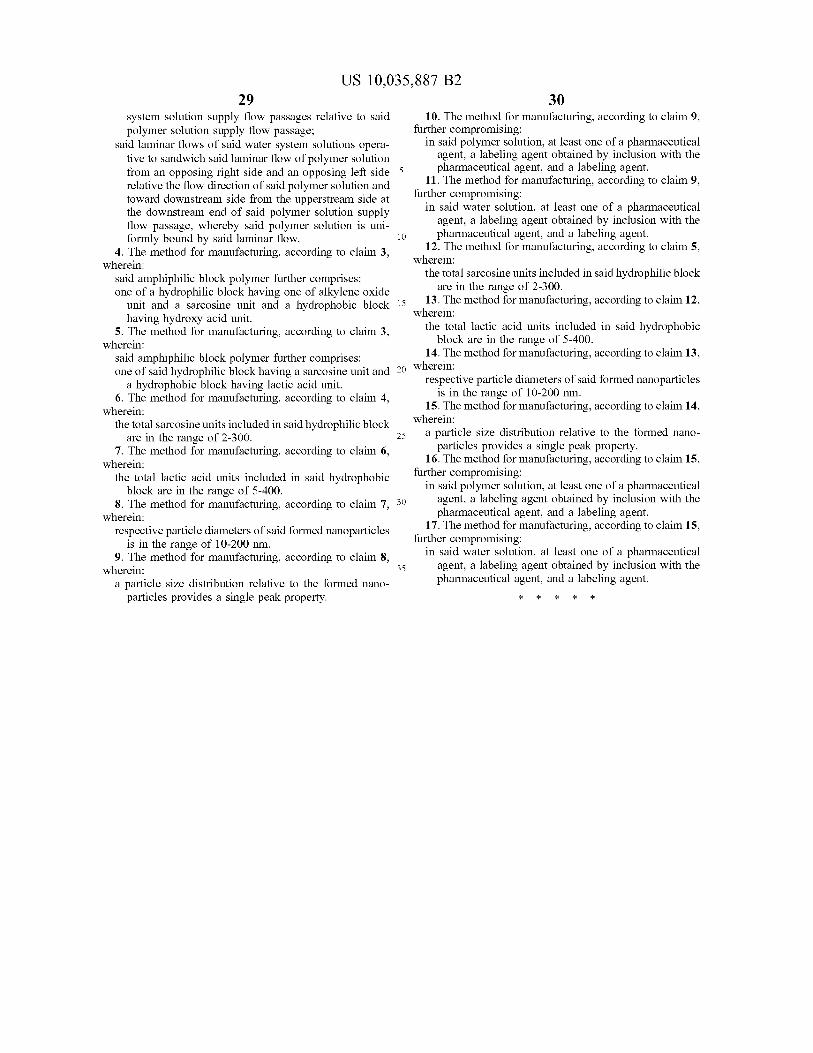
US 10 , 035 , 887 B2 30
system solution supply flow passages relative to said 10 . The method for manufacturing , according to claim 9 , polymer solution supply flow passage ; further compromising :
said laminar flows of said water system solutions opera in said polymer solution , at least one of a pharmaceutical tive to sandwich said laminar flow of polymer solution agent , a labeling agent obtained by inclusion with the from an opposing right side and an opposing left side 5 pharmaceutical agent , and a labeling agent . relative the flow direction of said polymer solution and 11 . The method for manufacturing , according to claim 9 , toward downstream side from the upperstream side at further compromising : the downstream end of said polymer solution supply in said water solution , at least one of a pharmaceutical flow passage , whereby said polymer solution is uni agent , a labeling agent obtained by inclusion with the
formly bound by said laminar flow . pharmaceutical agent , and a labeling agent . 4 . The method for manufacturing , according to claim 3 , 12 . The method for manufacturing , according to claim 5 ,
wherein : wherein : said amphiphilic block polymer further comprises : the total sarcosine units included in said hydrophilic block one of a hydrophilic block having one of alkylene oxide are in the range of 2 - 300 .
unit and a sarcosine unit and a hydrophobic block 15 15 13 . The method for manufacturing , according to claim 12 , having hydroxy acid unit . wherein :
5 . The method for manufacturing , according to claim 3 , the total lactic acid units included in said hydrophobic wherein : block are in the range of 5 - 400 .
said amphiphilic block polymer further comprises : 14 . The method for manufacturing , according to claim 13 , one of said hydrophilic block having a sarcosine unit and 20 Wh
a hydrophobic block having lactic acid unit . respective particle diameters of said formed nanoparticles 6 . The method for manufacturing , according to claim 4 , is in the range of 10 - 200 nm .
wherein : 15 . The method for manufacturing , according to claim 14 , the total sarcosine units included in said hydrophilic block wherein : W
are in the range of 2 - 300 . * 25 a particle size distribution relative to the formed nano 7 . The method for manufacturing , according to claim 6 , particles provides a single peak property .
wherein : 16 . The method for manufacturing , according to claim 15 , the total lactic acid units included in said hydrophobic further compromising :
block are in the range of 5 - 400 . in said polymer solution , at least one of a pharmaceutical 8 . The method for manufacturing according to claim 7 . 30 agent , a labeling agent obtained by inclusion with the
wherein : pharmaceutical agent , and a labeling agent . respective particle diameters of said formed nanoparticles 17 . The method for manufacturing , according to claim 15 ,
is in the range of 10 - 200 nm . further compromising : 9 . The method for manufacturing , according to claim 8 , in said water solution , at least one of a pharmaceutical
wherein : agent , a labeling agent obtained by inclusion with the a particle size distribution relative to the formed nano pharmaceutical agent , and a labeling agent .
particles provides a single peak property . * * * * *
35
Copyright © 2022 FDOKUMEN