TMI-2 PDMS SAR Update 14 & QA Plan (Rev 18 & 19) Biennial ...
567
10 CFR 50.71(e) 10 CFR 50.54(a)(c)(3) August 10, 2021 TMl2-RA-COR-2021-0012 U.S. Nuclear Regulatory Commission Attn: Document Control Desk Washington, DC 20555 Three Mile Island Nuclear Station, Unit 2 (TMI-2) Possession Only License No. DPR-73 Docket No. 50-320 Subject: Three Mile Island Nuclear Station, Unit 2 Update 14 of Post-Defueling Monitored Storage Safety Analysis Report Enclosed is Update 14 of the Post-Defueling Monitored Storage Safety Analysis Report (PDMS SAR) for TMl-2. As required by TMl-2 Technical Specification 6.8.1.4.a, Update 14 must reflect changes made to TMl-2 up to a minimum of 6 months prior to the date of the filing. The last revision of the PDMS SAR was issued as Update 13 on August 23, 2019. Update 14 revises the PDMS SAR to reflect the current plant configuration, administrative processes, and editorial changes. The revised pages are indicated on the list of effective pages, which immediately follow the Table of Contents of the PDMS SAR. The changes made in Update 14 are identified by "UPDATE 14 - AUGUST 2021" in the lower right portion of the section pages, and a vertical bar is located in the right margin of the page, which identifies the specific changes. TMI-2 Solutions, LLC, will issue the next revision of the PDMS SAR no later than 24 months from the date of this submittal. Enclosed are also the Revisions 18 and 19 of the TMI-2 PDMS QA Plan. Both were implemented without prior NRC approval as allowed by 10 CFR 50.54(a). However, the biennial updates were not previously provided to the NRC. This brings TMI-2 back into compliance with 10 CFR 50.54(a)(c)(3). TMI-2 Solutions will provide Revision 20 to support validation of the relocations committed to in the PDMS-DECON License Amendment Request currently under NRC review. The timing will be coordinated with the final review of the LAR. As required by 10 CFR 50.71(e)(2)(i), I certify that to the best of my knowledge, the information contained in the Enclosures and Attachments to this letter accurately reflect information and analyses submitted to the NRC, or prepared pursuant to NRC requirements as described above.
-
Upload
khangminh22 -
Category
Documents
-
view
0 -
download
0
Transcript of TMI-2 PDMS SAR Update 14 & QA Plan (Rev 18 & 19) Biennial ...

10 CFR 50.71(e) 10 CFR 50.54(a)(c)(3)
August 10, 2021 TMl2-RA-COR-2021-0012 U.S. Nuclear Regulatory Commission Attn: Document Control Desk Washington, DC 20555
Three Mile Island Nuclear Station, Unit 2 (TMI-2) Possession Only License No. DPR-73 Docket No. 50-320
Subject: Three Mile Island Nuclear Station, Unit 2 Update 14 of Post-Defueling Monitored Storage Safety Analysis Report
Enclosed is Update 14 of the Post-Defueling Monitored Storage Safety Analysis Report (PDMS SAR) for TMl-2. As required by TMl-2 Technical Specification 6.8.1.4.a, Update 14 must reflect changes made to TMl-2 up to a minimum of 6 months prior to the date of the filing. The last revision of the PDMS SAR was issued as Update 13 on August 23, 2019. Update 14 revises the PDMS SAR to reflect the current plant configuration, administrative processes, and editorial changes. The revised pages are indicated on the list of effective pages, which immediately follow the Table of Contents of the PDMS SAR. The changes made in Update 14 are identified by "UPDATE 14 - AUGUST 2021" in the lower right portion of the section pages, and a vertical bar is located in the right margin of the page, which identifies the specific changes. TMI-2 Solutions, LLC, will issue the next revision of the PDMS SAR no later than 24 months from the date of this submittal. Enclosed are also the Revisions 18 and 19 of the TMI-2 PDMS QA Plan. Both were implemented without prior NRC approval as allowed by 10 CFR 50.54(a). However, the biennial updates were not previously provided to the NRC. This brings TMI-2 back into compliance with 10 CFR 50.54(a)(c)(3). TMI-2 Solutions will provide Revision 20 to support validation of the relocations committed to in the PDMS-DECON License Amendment Request currently under NRC review. The timing will be coordinated with the final review of the LAR. As required by 10 CFR 50.71(e)(2)(i), I certify that to the best of my knowledge, the information contained in the Enclosures and Attachments to this letter accurately reflect information and analyses submitted to the NRC, or prepared pursuant to NRC requirements as described above.

TMI2-RA-COR-2021-0012 Page 2 of 3 Please contact Craig W. Smith of TMl-1 Regulatory Assurance at (717) 948-8776 if you have any questions regarding Update 14 to the TMl-2 PDMS SAR. Sincerely, Gerard van Noordennen Senior Vice President Regulatory Affairs Enclosures: TMI-2 Post-Defueling Monitored Storage Safety Analysis Report, Update 14 TMI-2 Post-Defueling Monitored Storage QA Plan, Revisions 18 and 19 Attachments: Description of Changes to TMI-2 Post-Defueling Monitored Storage Safety
Analysis Report as well as the Post-Defueling Monitored Storage QA Plan cc: w/Enclosures & Attachments: USNRC Regional Administrator, Region I USNRC TMI-2 Project Manager
Director, Bureau of Radiation Protection – PA Department of Environmental Protection

TMI2-RA-COR-2021-0012 Page 3 of 3 TMI-2 Service List cc w/Enclosures & Attachments: Ken Robuck President and CEO EnergySolutions 299 South Main Street, Suite 1700 Salt Lake City, UT 84111 John Sauger President and Chief Nuclear Officer Reactor D&D EnergySolutions 121 W. Trade Street, Suite 2700 Charlotte, NC 28202 Mike Lackey Senior Vice President D&D Operations EnergySolutions 121 W. Trade Street, Suite 2700 Charlotte, NC 28202 Gerard van Noordennen Senior Vice President Regulatory Affairs EnergySolutions 121 W. Trade Street, Suite 2700 Charlotte, NC 28202 Frank Helin Project Director TMI-2 Solutions 121 W. Trade Street, Suite 2700 Charlotte, NC 28202 Russ Workman General Counsel EnergySolutions 299 South Main Street, Suite 1700 Salt Lake City, UT 84111 Daniel F. Stenger Hogan Lovells US LLP 555 13th St NW Washington, D.C. 20004
Director, Bureau of Radiation Protection, Department of Environmental Protection, Commonwealth of Pennsylvania
Rachael Carson State Office BLDG. 13TH Floor P.O. Box 8469 Harrisburg, PA 17105-8469 Chief, Division of Nuclear Safety, Bureau of Radiation Protection, Department of Environmental Protection, Commonwealth of Pennsylvania
Rachael Carson State Office BLDG. 13TH Floor P.O. BOX 8469 Harrisburg, PA 17105-8469 Chairman, Board of County Commissioners, Dauphin County 112 Market Street 7th Floor Harrisburg, PA 17101 Chairman, Board of Supervisors of Londonderry Township 783 S. Geyers Church Rd. Middletown PA 17057 Ken Wilson Manager, Nuclear Licensing TMI-2 Solutions 121 W. Trade Street, Suite 2700 Charlotte, NC 28202

ENCLOSURES
TMI-2 Post-Defueling Monitored Storage Safety Analysis Report, Update 14 TMI-2 Post-Defueling Monitored Storage QA Plan, Revisions 18 and 19

TMI-2 Post-Defueling Monitored Storage Safety Analysis Report, Update 14

UPDATE 14 AUGUST 2021
TMI-2
POST-DEFUELING
MONITORED STORAGE
SAFETY ANALYSIS
REPORT

UPDATE 14 AUGUST 2021
TABLE OF CONTENTS
CHAPTER TITLE
1 INTRODUCTION AND GENERAL DESCRIPTION OF PLANT
2 SITE CHARACTERISTICS 3 DESIGN CRITERIA - STRUCTURES,
SYSTEMS, AND COMPONENTS
6 DEACTIVATED SYSTEMS AND FACILITIES
7 OPERATIONAL SYSTEMS AND FACILITIES
10 ADMINISTRATIVE FUNCTIONS
APPENDIX H
H 1 INTRODUCTION AND GENERAL DESCRIPTION OF PLANT
H 3 DESIGN CRITERIA - STRUCTURES, SYSTEMS, AND COMPONENTS
H 4 FUEL
H 5 PDMS RADIOLOGICAL CONDITIONS
H 6 DEACTIVATED SYSTEMS AND FACILITIES
H 7 OPERATIONAL SYSTEMS AND FACILITIES
H 8 ROUTINE AND UNANTICIPATED RELEASES
H 9 TECHNICAL SPECIFICATIONS

TMI-2 POST-DEFUELING MONITORED STORAGE SAFETY ANALYSIS REPORT
List of Effective Pages
Page # Update # Date
UPDATE 14 AUGUST 2021
TC-1 10 8/13 1-i 10 8/13 1-1 14 8/21 1-2 13 8/19 1-3 10 8/13 2-i 10 8/13 2-1 14 8/21 2-2 14 8/21 2-3 14 8/21 2-4 14 8/21 2-5 14 8/21 2-6 10 8/13 2-7 10 8/13 2-8 10 8/13 2-9 10 8/13 2-10 10 8/13 3-i 10 8/13 3-1 10 8/13 6-i 10 8/13 6-ii 10 8/13 6-iii 10 8/13 6-iv 10 8/13 6-v 10 8/13 6-vi 10 8/13 6-1 10 8/13 6-2 10 8/13 6-3 10 8/13

TMI-2 POST-DEFUELING MONITORED STORAGE SAFETY ANALYSIS REPORT
List of Effective Pages
Page # Update # Date
UPDATE 14 AUGUST 2021
6-4 10 8/13 6-5 10 8/13 6-6 10 8/13 6-7 10 8/13 6-8 10 8/13 6-9 10 8/13 6-10 10 8/13 6-11 13 8/19 6-12 10 8/13 6-13 10 8/13 6-14 10 8/13 6-15 10 8/13 6-16 10 8/13 6-17 10 8/13 6-18 10 8/13 6-19 10 8/13 6-20 10 8/13 7-i 10 8/13 7-ii 10 8/13 7-iii 10 8/13 7-iv 10 8/13 7-v 10 8/13 7-vi 10 8/13 7-vii 10 8/13 7-1 10 8/13 7-2 13 8/19 7-3 13 8/19

TMI-2 POST-DEFUELING MONITORED STORAGE SAFETY ANALYSIS REPORT
List of Effective Pages
Page # Update # Date
UPDATE 14 AUGUST 2021
7-4 13 8/19 7-5 14 8/21 7-6 13 8/19 7-7 13 8/19 7-8 13 8/19 7-9 10 8/13 7-10 10 8/13 7-11 10 8/13 7-12 10 8/13 7-13 10 8/13 7-14 14 8/21 7-15 14 8/21 7-16 14 8/21 7-17 14 8/21 7-18 14 8/21 7-19 14 8/21 7-20 14 8/21 7-21 14 8/21 7-22 10 8/13 7-23 13 8/19 7-24 10 8/13 7-25 10 8/13 7-26 13 8/19 7-27 13 8/19 7-28 10 8/13 7-29 13 8/19 7-30 10 8/13

TMI-2 POST-DEFUELING MONITORED STORAGE SAFETY ANALYSIS REPORT
List of Effective Pages
Page # Update # Date
UPDATE 14 AUGUST 2021
7-31 10 8/13 7-32 13 8/19 7-33 10 8/13 7-34 10 8/13 7-35 10 8/13 7-36 10 8/13 7-37 10 8/13 7-38 10 8/13 7-39 10 8/13 7-40 10 8/13 7-41 10 8/13 7-42 10 8/13 7-43 10 8/13 7-44 10 8/13 7-45 10 8/13 7-46 10 8/13 7-47 10 8/13 7-48 10 8/13 7-49 10 8/13 7-50 10 8/13 7-51 10 8/13 7-52 10 8/13 7-53 10 8/13 10-i 14 8/21 10-1 14 8/21 10-2 10 8/13 10-3 14 8/21

TMI-2 POST-DEFUELING MONITORED STORAGE SAFETY ANALYSIS REPORT
List of Effective Pages
Page # Update # Date
UPDATE 14 AUGUST 2021
10-4 14 8/21 10-5 14 8/21 H 1-i 14 8/21 H 1-1 14 8/21 H 1-2 10 8/13 H 1-3 10 8/13 H 1-4 10 8/13 H 1-5 10 8/13 H 1-6 14 8/21 H 1-7 10 8/13 H 1-8 10 8/13 H 1-9 14 8/21 H 1-10 10 8/13 H 1-11 10 8/13 H 1-12 10 8/13 H 1-13 10 8/13 H 1-14 10 8/13 H 1-15 10 8/13 H 1-16 10 8/13 H 1-17 10 8/13 H 1-18 14 8/21 H 1-19 14 8/21 H 1-20 14 8/21 H 1-21 14 8/21 H 3-i 10 8/13 H 3-ii 10 8/13 H 3-iii 10 8/13

TMI-2 POST-DEFUELING MONITORED STORAGE SAFETY ANALYSIS REPORT
List of Effective Pages
Page # Update # Date
UPDATE 14 AUGUST 2021
H 3-iv 10 8/13 H 3-v 10 8/13 H 3-vi 10 8/13 H 3-vii 10 8/13 H 3-viii 10 8/13 H 3-1 10 8/13 H 3-2 10 8/13 H 3-3 10 8/13 H 3-4 10 8/13 H 3-5 10 8/13 H 3-6 10 8/13 H 3-7 10 8/13 H 3-8 10 8/13 H 3-9 10 8/13 H 3-10 10 8/13 H 3-11 10 8/13 H 3-12 10 8/13 H 3-13 10 8/13 H 3-14 10 8/13 H 3-15 10 8/13 H 3-16 10 8/13 H 3-17 10 8/13 H 3-18 10 8/13 H 3-19 10 8/13 H 3-20 10 8/13 H 3-21 10 8/13 H 3-22 10 8/13

TMI-2 POST-DEFUELING MONITORED STORAGE SAFETY ANALYSIS REPORT
List of Effective Pages
Page # Update # Date
UPDATE 14 AUGUST 2021
H 3-23 10 8/13 H 3-24 10 8/13 H 3-25 14 8/21 H 3-26 10 8/13 H 3-27 10 8/13 H 3-28 10 8/13 H 3-29 10 8/13 H 3-30 10 8/13 H 3-31 10 8/13 H 3-32 10 8/13 H 3-33 10 8/13 H 3-34 10 8/13 H 3-35 10 8/13 H 3-36 10 8/13 H 3-37 10 8/13 H 3-38 10 8/13 H 3-39 10 8/13 H 3-40 10 8/13 H 3-41 10 8/13 H 3-42 10 8/13 H 3-43 10 8/13 H 3-44 10 8/13 H 3-45 10 8/13 H 3-46 10 8/13 H 3-47 10 8/13 H 3-48 13 8/19 H 3-49 10 8/13

TMI-2 POST-DEFUELING MONITORED STORAGE SAFETY ANALYSIS REPORT
List of Effective Pages
Page # Update # Date
UPDATE 14 AUGUST 2021
H 3-50 10 8/13 H 3-51 10 8/13 H 3-52 10 8/13 H 3-53 10 8/13 H 3-54 10 8/13 H 3-55 10 8/13 H 3-56 10 8/13 H 3-57 10 8/13 H 3-58 10 8/13 H 3-59 10 8/13 H 3-60 10 8/13 H 3-61 10 8/13 H 3-62 10 8/13 H 3-63 10 8/13 H 3-64 10 8/13 H 4-i 10 8/13 H 4-ii 10 8/13 H 4-iii 10 8/13 H 4-1 10 8/13 H 4-2 10 8/13 H 4-3 10 8/13 H 4-4 10 8/13 H 4-5 10 8/13 H 4-6 10 8/13 H 4-7 10 8/13 H 4-8 10 8/13 H 4-9 10 8/13

TMI-2 POST-DEFUELING MONITORED STORAGE SAFETY ANALYSIS REPORT
List of Effective Pages
Page # Update # Date
UPDATE 14 AUGUST 2021
H 4-10 10 8/13 H 4-11 10 8/13 H 4-12 10 8/13 H 4-13 10 8/13 H 4-14 10 8/13 H 4-15 10 8/13 H 4-16 10 8/13 H 4-17 10 8/13 H 4-18 10 8/13 H 4-19 10 8/13 H 4-20 10 8/13 H 4-21 10 8/13 H 4-22 10 8/13 H 4-23 10 8/13 H 4-24 10 8/13 H 4-25 10 8/13 H 4-26 10 8/13 H 4-27 10 8/13 H 4-28 10 8/13 H 4-29 10 8/13 H 4-30 10 8/13 H 4-31 10 8/13 H 4-32 10 8/13 H 5-i 10 8/13 H 5-ii 10 8/13 H 5-iii 10 8/13 H 5-iv 10 8/13

TMI-2 POST-DEFUELING MONITORED STORAGE SAFETY ANALYSIS REPORT
List of Effective Pages
Page # Update # Date
UPDATE 14 AUGUST 2021
H 5-v 10 8/13 H 5-1 10 8/13 H 5-2 10 8/13 H 5-3 10 8/13 H 5-4 10 8/13 H 5-5 10 8/13 H 5-6 10 8/13 H 5-7 10 8/13 H 5-8 10 8/13 H 5-9 10 8/13 H 5-10 10 8/13 H 5-11 10 8/13 H 5-12 10 8/13 H 5-13 10 8/13 H 5-14 10 8/13 H 5-15 10 8/13 H 5-16 10 8/13 H 5-17 10 8/13 H 5-18 10 8/13 H 5-19 10 8/13 H 5-20 10 8/13 H 5-21 10 8/13 H 5-22 10 8/13 H 5-23 10 8/13 H 5-24 10 8/13 H 5-25 10 8/13 H 5-26 10 8/13

TMI-2 POST-DEFUELING MONITORED STORAGE SAFETY ANALYSIS REPORT
List of Effective Pages
Page # Update # Date
UPDATE 14 AUGUST 2021
H 5-27 10 8/13 H 5-28 10 8/13 H 5-29 10 8/13 H 5-30 10 8/13 H 5-31 10 8/13 H 5-32 10 8/13 H 5-33 10 8/13 H 5-34 10 8/13 H 5-35 10 8/13 H 5-36 10 8/13 H 5-37 10 8/13 H 5-38 10 8/13 H 5-39 10 8/13 H 5-40 10 8/13 H 5-41 10 8/13 H 5-42 10 8/13 H 5-43 10 8/13 H 5-44 10 8/13 H 5-45 10 8/13 H 5-46 10 8/13 H 5-47 10 8/13 H 5-48 10 8/13 H 5-49 10 8/13 H 5-50 10 8/13 H 5-51 10 8/13 H 5-52 10 8/13 H 5-53 10 8/13

TMI-2 POST-DEFUELING MONITORED STORAGE SAFETY ANALYSIS REPORT
List of Effective Pages
Page # Update # Date
UPDATE 14 AUGUST 2021
H 5-54 10 8/13 H 5-55 10 8/13 H 5-56 10 8/13 H 5-57 10 8/13 H 5-58 10 8/13 H 5-59 10 8/13 H 5-60 10 8/13 H 5-61 10 8/13 H 5-62 10 8/13 H 5-63 10 8/13 H 5-64 10 8/13 H 5-65 10 8/13 H 6-i 10 8/13 H 6-ii 10 8/13 H 6-iii 10 8/13 H 6-iv 10 8/13 H 6-1 10 8/13 H 6-2 10 8/13 H 6-3 11 8/15 H 6-4 10 8/13 H 6-5 10 8/13 H 6-6 10 8/13 H 6-7 10 8/13 H 6-8 10 8/13 H 6-9 10 8/13 H 6-10 10 8/13 H 6-11 10 8/13

TMI-2 POST-DEFUELING MONITORED STORAGE SAFETY ANALYSIS REPORT
List of Effective Pages
Page # Update # Date
UPDATE 14 AUGUST 2021
H 6-12 10 8/13 H 6-13 10 8/13 H 6-14 10 8/13 H 6-15 10 8/13 H 6-16 10 8/13 H 6-17 10 8/13 H 6-18 10 8/13 H 6-19 10 8/13 H 6-20 10 8/13 H 6-21 10 8/13 H 7-i 10 8/13 H 7-1 10 8/13 H 7-2 10 8/13 H 7-3 10 8/13 H 7-4 10 8/13 H 7-5 10 8/13 H 8-i 10 8/13 H 8-ii 10 8/13 H 8-1 10 8/13 H 8-2 10 8/13 H 8-3 10 8/13 H 8-4 10 8/13 H 8-5 13 8/19 H 8-6 13 8/19 H 8-7 10 8/13 H 8-8 10 8/13 H 8-9 10 8/13

TMI-2 POST-DEFUELING MONITORED STORAGE SAFETY ANALYSIS REPORT
List of Effective Pages
Page # Update # Date
UPDATE 14 AUGUST 2021
H 8-10 14 8/21 H 8-11 10 8/13 H 8-12 10 8/13 H 8-13 10 8/13 H 8-14 10 8/13 H 8-15 10 8/13 H 8-16 10 8/13 H 8-17 10 8/13 H 8-18 10 8/13 H 8-19 14 8/21 H 8-20 10 8/13 H 8-21 10 8/13 H 8-22 14 8/21 H 9 10 8/13

UPDATE 10 - AUGUST 2013
CHAPTER 1
INTRODUCTION AND
GENERAL DESCRIPTION OF PLANT

1-i UPDATE 10 AUGUST 2013
CHAPTER 1 INTRODUCTION AND GENERAL DESCRIPTION OF PLANT
TABLE OF CONTENTS
SECTION TITLE PAGE
1.2.2.3 CONTAINMENT ATMOSPHERIC BREATHER 1-1
1.2.3 FIRE PROTECTION, SERVICE, AND SUPPRESSION 1-1
1.2.4 RADIOACTIVE WASTE MANAGEMENT 1-1
1.2.5 RADIATION MONITORING 1-1
1.2.6 ELECTRICAL SYSTEMS 1-1
1.2.7 PDMS SUPPORT SYSTEMS 1-2
LIST OF FIGURES
FIGURE TITLE PAGE
1.4-1 Cork Seam Modifications 1-3

CHAPTER 1 INTRODUCTION AND GENERAL DESCRIPTION OF PLANT
1-1 UPDATE 14 - AUGUST 2021
1.2.2.3 Containment Atmospheric Breather
The Containment Atmospheric Breather has been added to the Containment to provide passive pressure control of the Containment relative to ambient atmospheric pressure (via the AFHB) and to establish a "most probable pathway" through which the Containment will "breathe". The breather is a passive system consisting of a 6 in. diameter duct with a HEPA filter. Providing this filtered pathway will ensure insignificant leakage through any uncontrolled pathway. The Containment Atmospheric Breather is described in more detail in Section 7.2.1.2.
1.2.3 FIRE PROTECTION, SERVICE, AND SUPPRESSION
Fire Protection is provided during PDMS to reasonably prevent fires from occurring, to rapidly detect, control and suppress fires which could result in a radiological hazard, and ensure the risk of fire induced radiological hazards to the public, environment and plant personnel is minimized.
These objectives have been achieved through a combination of (1) minimizing the potential for a fire by minimizing combustible materials and ignition sources and, (2) by providing suitable fire protection to deal with any fire which could present a radiological hazard.
1.2.4 RADIOACTIVE WASTE MANAGEMENT
The generation of radioactive waste during PDMS will be minimal. A small amount of radioactive waste will be generated from the processing of water inleakage to contaminated areas, small decontamination tasks, and surveillance and maintenance activities. Liquid radwaste will be collected in the various sumps and handled through the liquid radwaste disposal system. Other radwastes will be collected and disposed of as appropriate.
1.2.5 RADIATION MONITORING
During PDMS, radiation monitors will be maintained operational to provide for evaluation of airborne radiological conditions. This requires monitoring the Reactor Building exhaust ventilation and the station vent during periods when a ventilation system is operating. The monitors will provide the necessary information to evaluate environmental releases and air quality conditions in the plant. This monitoring will provide a basis for determining the total integrated dose to the public.
Monitoring and survey data will provide a basis for a trend analysis to ensure that the plant is maintained in a stable condition and enables timely corrective actions, if necessary.
1.2.6 ELECTRICAL SYSTEMS
During PDMS, portions of the TMI-2 AC and DC electrical systems will be maintained operational to provide reliable power to PDMS support systems, controls, and instrumentation. Electrical equipment not required for PDMS support is minimized to enhance overall plant safety; nearly all such items have been deactivated.

CHAPTER 1 INTRODUCTION AND GENERAL DESCRIPTION OF PLANT
1-2 UPDATE 13 - AUGUST 2019
1.2.7 PDMS SUPPORT SYSTEMS
Other systems necessary to support PDMS activities also have been provided. The ventilation systems for the Auxiliary, Fuel Handling, Control and Service Buildings will be maintained operational to the extent needed to maintain an acceptable level of habitability in the areas and to mitigate the effects of temperature and humidity extremes. The systems may be replaced with suitable temporary local ventilation equipment if age and deterioration leads to failure of the original installed plant equipment.

CHAPTER 1 INTRODUCTION AND GENERAL DESCRIPTION OF PLANT
FIGURE 1.4-1 GENERAL ARRANGEMENT TMI-2 CORK SEAM AREA
1-3 UPDATE 10 - AUGUST 2013

UPDATE 10 - AUGUST 2013
CHAPTER 2
SITE CHARACTERISTICS

2-i UPDATE 10 - AUGUST 2013
CHAPTER 2 SITE CHARACTERISTICS
TABLE OF CONTENTS
SECTION TITLE PAGE
2.1 GEOGRAPHY AND DEMOGRAPHY 2-1
2.1.1 SITE LOCATION 2-1
2.1.2 SITE DESCRIPTION 2-1
2.1.3 POPULATION AND POPULATION DISTRIBUTION
2-1
2.2 NEARBY INDUSTRIAL, TRANSPORTATION, AND MILITARY FACILITIES
2-1
2.3 METEOROLOGY 2-1
2.4 HYDROLOGIC ENGINEERING 2-2
2.4.1 HYDROLOGIC DESCRIPTION 2-2
2.4.1.1 SITE AND FACILITIES 2-2
2.4.2 FLOODS 2-2
2.4.3 FLOODING PROTECTION REQUIREMENTS 2-2
2.4.4 ENVIRONMENTAL ACCEPTANCE OF EFFLUENTS
2-3
2.4.5 GROUNDWATER 2-4
2.4.6 EMERGENCY OPERATIONS REQUIREMENTS 2-5
2.4.6.1 FLOOD PROTECTION 2-5
2.5 GEOLOGY AND SEISMOLOGY 2-5
LIST OF FIGURES
FIGURE NO. TITLE PAGE
2.1-1 GENERAL AREA MAP 2-6
2.1-2 SITE TOPOGRAPHY 5 MILE RADIUS 2-7
2.1-3 EXTENDED PLOT PLAN 2-8
2.4-1 FLOOD WATER SURFACE PROFILES 2-9
2.4-2 DETAILS OF EFFLUENT DISCHARGE SYSTEM 2-10

CHAPTER 2 SITE CHARACTERISTICS
2-1 UPDATE 14 - AUGUST 2021
2.1 GEOGRAPHY AND DEMOGRAPHY
2.1.1 SITE LOCATION
Three Mile Island is located approximately 2-1/2 miles south of Middletown, Pennsylvania at longitude 76" 43' 30" west and at latitude 40" 9' 15" north. The Unit 2 reactor vessel coordinates are N300, 324.40, E2, 286, 366.04, based on the Pennsylvania State coordinate system (UTM coordinates, Zone 18, 4, 446, 020 meters north, 353, 070 meters east). It is one of the largest of a group of several islands in the Susquehanna River and is situated about 900 ft. from the east bank. It is elongated parallel to the flow of the river, with its 11,000 ft. in length and 1700 ft. in width. TMI-2 is located in the northern one third of the island.
The southeasterly-flowing Susquehanna River makes a sharp change in direction, to nearly due south, in the vicinity of Middletown. After this directional change just north of Three Mile Island, the channel widens to approximately 1.5 miles.
The Three Mile Island Nuclear Station, Unit 2 is located adjacent to Unit 1 in Londonderry Township of Dauphin County, Pennsylvania, about 2-1/2 miles north of the southern tip of Dauphin County, where Dauphin is conterminal with York and Lancaster counties. Its location with respect to regional topographic and cultural features is shown on Figure 2.1-1 and with respect to local features on Figure 2.1-2. The station is located on Three Mile Island situated in the Susquehanna River upstream from York Haven Dam.
2.1.2 SITE DESCRIPTION
Figure 2.1-3 shows the site marked to indicate the Site and the minimum exclusion distance. For accident evaluations, the distance to the site boundary in each direction is used. Those distances may be derived from Figure 2.1-3.
2.1.3 POPULATION AND POPULATION DISTRIBUTION
The population and population demographics are given in Section 2.2 of the TMI Unit 1 DSAR. This information is updated as appropriate with the Unit 1 DSAR updates.
2.2 NEARBY INDUSTRIAL, TRANSPORTATION, AND MILITARY FACILITIES
The nearby industrial, transportation, and military facilities are described in Chapter 2 of the TMI Unit 1 DSAR.
2.3 METEOROLOGY
The meteorology for the Three Mile Island site is given in Section 2.5 of the TMI Unit 1 DSAR. Since TMI-1 and TMI-2 are on the same site, the meteorological information for the two units is the same. The TMI-1 DSAR is updated periodically in accordance with NRC regulations and contains the currently applicable meteorological information for the TMI site.

CHAPTER 2 SITE CHARACTERISTICS
2-2 UPDATE 14 - AUGUST 2021
2.4 HYDROLOGIC ENGINEERING
2.4.1 HYDROLOGIC DESCRIPTION
2.4.1.1 Site and Facilities
TMI Unit 2 is located on Three Mile Island in the Susquehanna River about ten miles southeast of Harrisburg. Existing grade elevation at the site is approximately 304.0 ft. based upon U.S.G.S. datum,
All of the necessary features of Unit 2 are protected from flood and wave action associated with these floods up to and including the Probable Maximum Flood (1,625,000 CFS) by the installation of barriers as described in Section 2.4.3 .
2.4.2 FLOODS
The description of flooding conditions which were considered in the design of the site and facilities on the site is given in Section 2.4 of the TMI-2 FSAR. These flooding conditions include the Probable Maximum Flood with coincident wind wave activity, the Probable Maximum Precipitation, potential dam failures, ice flooding, and channel diversions.
2.4.3 FLOODING PROTECTION REQUIREMENTS
Three Mile Island Nuclear Station is situated on a portion of the island that is, under natural conditions, above the level of an "Agnes" magnitude flood. Natural topography in the main station area is above elevation 300.5 ft., the crest of the Agnes flood at approximately one million cubic feet per second.
The original design flood for the site was established at 1,100,000 cfs, based upon the provisional Probable Maximum Flood established by the Army Corps of Engineers prior to 1969.
In June of 1969 the Corps of Engineers issued a revised and provisional value of the Probable Maximum Flood for the Susquehanna River at Harrisburg, which was established as 1,600,000 cfs, as the result of upstream reservoir regulation. This flood at Three Mile Island was established at 1,625,000 cfs and the water surface profiles on Figure 2.4-1 were extended by computation to cover this flood magnitude. Unit backwater computations established a PMF elevation of 308.5 ft on the west side and 308 ft on the east side of the site. Due to wave action, flood protection is designed to protect against a water level of at least four feet above the PMF water level or 312.5 ft on the west side and 312 ft on the east side as described in Section 3.4.4.

CHAPTER 2 SITE CHARACTERISTICS
2-3 UPDATE 14 - AUGUST 2021
Various components which have been protected include, but are not limited to the following locations and type of flood protection:
a. Fuel Handling Building - The only opening in this building which requires flood protection is the ground level entrance from the Fuel Handling Building Truck Bay into the TMI-2 Model room. A flood panel is provided for this entrance.
b. Control Building – Flood panels are provided for all ground level entrances.
c. Auxiliary Building – A flood panel is provided for the ground level entrance.
d. Control Building Area – Access to the tendon gallery is protected by watertight enclosures and flood panels at ground level.
e. Air Intake – Located at an elevation above PMF level and a watertight hatch.
f. General – Structures are provided with complete protection at the entrance faces rather than attempting to protect individual equipment or systems. Ground level doors and entrances to the Concrete Power Block Buildings are either water tight or are provided with flood panels. All openings that are potential leaks (e.g., ducts, pipes, conduits, cable trays) are configured to minimize water intrusion. The water stops between adjacent building walls and mats were designed to be capable of withstanding a maximum water head of 45 ft, which is in excess of the maximum head associated with the flood level.
Unit flood protection will be achieved by instituting operational procedures and actions predicated upon monitoring of upstream river stages and precipitation reports through the National Weather Service Advance Hydrologic Prediction service. Operational procedures to establish flood protection for TMI-2 are outlined in Section 2.4.6. Reference Section 7.1.4, Flood Protection.
2.4.4 ENVIRONMENTAL ACCEPTANCE OF EFFLUENTS
Liquid effluents from TMI- I and TMI-2 enter the middle channel of the Susquehanna River through the station discharge pipe located approximately 640 ft. downstream from the intake structures, as shown in Figure 2.4-2. Processed liquid waste will be discharged on a batch basis. Prior to release, each batch will be sampled and analyzed to determine its radioactivity content. Based upon the activity analysis, the wastes will either be released under controlled conditions or recycled for further processing. The flowrate of waste discharge will be a function of the activity analysis and the flowrate of the discharge from the Unit 1 mechanical draft cooling owners. The ability of the Susquehanna River to disperse and dilute the station discharge stream is dependent upon the magnitude of river water flow.

CHAPTER 2 SITE CHARACTERISTICS
2-4 UPDATE 14 - AUGUST 2021
A section of the York Haven Dam blocks the east channel of the Susquehanna River at Three Mile Island approximately one mile downstream from TMI-2. The York Haven Dam forms a pool extending approximately 3-1/2 miles up- stream containing a volume of about 10.000 acre-feet. As long as the river flow is 20,000 cfs or less, all flow discharges through the York Haven Hydro Plant tailrace into the lower section of Conewago Falls. When the river flow is above 20,000 cfs, the excess flow spills over the portion of the main dam upstream of the headrace wall and flows down through the Conewago Falls joining the flow from the tailrace at the foot of the dam; the full river flow then continues through the lower section of the falls. The exact extent of the mixing of TMINS effluents with the river depends on such factors as station discharge flowrate and the river flowrate. In 1980, an experiment was conducted which tracked the dispersion and dilution of a dye from the TMINS discharge. This study showed that the plant discharge water and Susquehanna River water are typically 99% or greater mixed before intake by downstream users.
TMINS effluent releases are diluted by the effluent of the mechanical draft cooling towers by factors typically ranging from 167 times to 7600 times, depending upon the water intake from the river. The diluted radiological waste is further diluted by the flow of the Susquehanna River. At low flow (1700 cfs), the river would dilute the effluent by a factor of 20. However, at normal river flow (34,000 cfs) the dilution from the river would be 403 times. For effluent releases a minimum flow rate of 5000 gpm is maintained from the Mechanical Draft cooling Towers, however, 8,000 gpm MDCT flow is always maintained during IWTS and/or IWFS releases (continuous releases). Dilution credit up to 38,000 gpm is taken for Mechanical Draft Cooling Tower effluent rates in FSAR calculations.
All users of water downstream of Three Mile Island are also downstream of York Haven Dam. Therefore, it is assured that mixing of station effluent and river water flow will occur prior to use.
2.4.5 GROUNDWATER
Three Mile Island Nuclear Station is located in the Triassic lowland of Pennsylvania, a region often referred to as the Gettysburg Basin. The island was formed as a result of fluvial deposition by the Susquehanna River. It is composed of sub-rounded to rounded sand and gravel, containing varying amounts of silt and clay. Soil depths vary from approximately 6 feet at the south of the island to about 30 feet at the center of the island. The site is underlain by Gettysburg shale which is at approximately 277 feet elevation.
There are two different water-bearing zones at TMINS. One is comprised of the unconsolidated materials overlying the Gettysburg shale (bedrock), and the other is comprised of the bedrock. Permeabilities in the geologic materials on TMINS vary; however, groundwater discharges into the Susquehanna River and does not communicate with off-site groundwater supplies.
Hydrostatic pressure of the water table on the east and west shores of the river should prevent the island groundwater and the station discharge from communications with onshore groundwater. Therefore groundwater effluents from TMINS cannot impact the quality of groundwater off-site. Additionally, the tritium concentrations in the TMINS groundwater are well below the 10 CFR 20 regulatory limits and will not adversely affect the Susquehanna River.
A more thorough description of the groundwater characteristics and related features are given in Section 2.4.13 of the Unit 2 FSAR.

CHAPTER 2 SITE CHARACTERISTICS
2-5 UPDATE 14 - AUGUST 2021
2.4.6 Flood Protection
The emergency flood protection procedures are entered when Susquehanna River water level exceeds 284.2 feet at the Unit 1 Intake Screen Pump House, Susquehanna River flow at Harrisburg exceeds 200,000 CFS, or the National Weather Service (NWS) Forecast Center forecasts a Susquehanna River flow greater than 350,000 CFS within the next 36 hours.
The Susquehanna River forecast for flow and river level at Harrisburg are obtained from the National Weather Service Advance Hydrologic Prediction Service. The forecast should always provide a minimum of a 48 hour forecast and is updated as required every six hours during a potential flood condition. For this purpose, the flow at TMI is assumed to be equal to the flow at Harrisburg. The river flow and level forecast is based upon both measured rainfall and rainfall forecasts across the Susquehanna watershed.
When a 36 hour forecast of 900,000 cfs or greater is received flood panels will be moved into place.
2.5 GEOLOGY AND SEISMOLOGY
The geology and seismology for the Three Mile Island site has been reviewed and accepted by the NRC based on the information presented in Section 2.5 of the Unit 2 FSAR.

FIGURE 2.1-1 GENERAL AREA MAP
2-6 UPDATE 10 - AUGUST 2013

FIGURE 2.1-2 SITE TOPOGRAPHICAL MAP
5 MILE RADIUS
2-7 UPDATE 10 - AUGUST 2013

2-8 UPDATE 10 - AUGUST 2013
FIGURE 2.1-3 EXTENDED PLOT PLAN

2-9 UPDATE 10 - AUGUST 2013
FIGURE 2.4-1 FLOOD WATER SURFACE PROFILES

FIGURE 2.4-2 DETAILS OF EFFLUENT DISCHARGE SYSTEM
2-10 UPDATE 10 AUGUST 2013

UPDATE 10 - AUGUST 2013
CHAPTER 3
DESIGN CRITERIA - STRUCTURES, SYSTEMS, AND
COMPONENTS

CHAPTER 3
DESIGN CRITERIA - STRUCTURES, SYSTEMS, AND COMPONENTS
TABLE OF CONTENTS
3-i UPDATE 10 AUGUST 2013
SECTION TITLE PAGE
3.4 WATER LEVEL (FLOOD) DESIGN 3-1
3.4.1 FLOOD ELEVATION 3-1
3.4.2 PHENOMENA CONSIDERED IN DESIGN LOAD CALCULATIONS
3-1
3.4.3 FLOOD FORCE APPLICATION 3-1
3.4.4 FLOOD PROTECTION 3-1

CHAPTER 3
DESIGN CRITERIA - STRUCTURES, SYSTEMS, AND COMPONENTS
3-1 UPDATE 10 AUGUST 2013
3.4 WATER LEVEL (FLOOD) DESIGN
Flood history, flood design consideration, design of hydraulic facilities and emergency operation requirements for the unit facilities are discussed in Section 2.4.
3.4.1 FLOOD ELEVATION
The foundation mats, exposed walls and flood panels of those structures designed to withstand floods are designed to withstand the hydrostatic pressures associated with a water level of 312 ft. on the east side and 312.5 ft. on the west side.
3.4.2 PHENOMENA CONSIDERED IN DESIGN LOAD CALCULATIONS
Due to wave action, the maximum water level considered is 4'-0" higher than the PMF elevation expected around the station facilities. See Section 2.4.3 of the TMI-2 FSAR. No other phenomena have been considered in the design load calculations.
3.4.3 FLOOD FORCE APPLICATION
Static forces on the flood panels and vertical walls are calculated considering hydrostatic pressures. Dynamic forces on the flood panels and vertical walls are calculated considering wave action. The buoyancy forces on the mats are calculated considering the uplift due to the height of water above the bottom of the mats.
3.4.4 FLOOD PROTECTION
Unit design is based on a water elevation of 308.5 ft. on the west side and 308 ft. on the east side under flood conditions. Structures which originally contained Engineered Safety Feature equipment are sealed against entry of flood water to an elevation of 312.5 ft. on the west side and 312 ft. on the east side. Complete protection has been provided at the exterior faces of these structures. The waterstops between adjacent building walls and mats are capable of withstanding a maximum water head of 45 feet which is in excess of maximum associated head for the flood level. The exterior sliding doors and flood panels are provided with watertight seals.

UPDATE 10- AUGUST 2013
CHAPTER 6
DEACTIVATED SYSTEMS AND FACILITIES

CHAPTER 6 DEACTIVATED SYSTEMS AND FACILITIES
TABLE OF CONTENTS
6-i UPDATE 10- AUGUST 2013
SECTION TITLE PAGE
6.0 INTRODUCTION 6-1
6.2 DEACTIVATED PASSIVE SYSTEMS 6-1
6.2.1 MAIN AND REHEAT STEAM SYSTEM 6-2
6.2.1.1 SYSTEM DESIGN 6-2
6.2.1.2 PDMS FUNCTION 6-2
6.2.2 PRIMARY NUCLEAR PLANT HYDROGEN SUPPLY SYSTEM 6-2
6.2.2.1 SYSTEM DESIGN 6-2
6.2.2.2 PDMS FUNCTION 6-2
6.2.3 FUEL HANDLING AND STORAGE SYSTEM 6-2
6.2.3.1 SYSTEM DESIGN 6-2
6.2.3.2 PDMS FUNCTION 6-2
6.2.4 STANDBY REACTOR COOLANT PRESSURE CONTROL SYSTEM
6-3
6.2.4.1 SYSTEM DESIGN 6-3
6.2.4.2 PDMS FUNCTION 6-3
6.2.5 MINI-DECAY HEAT REMOVAL SYSTEM 6-3
6.2.5.1 SYSTEM DESIGN 6-3
6.2.5.2 PDMS FUNCTION 6-3
6.2.6 SPENT FUEL COOLING SYSTEM 6-3
6.2.6.1 SYSTEM DESIGN 6-3
6.2.6.2 PDMS FUNCTION 6-3
6.2.7 REACTOR COOLANT MAKEUP AND PURIFICATION SYSTEM
6-4
6.2.7.1 SYSTEM DESIGN 6-4
6.2.7.2 PDMS FUNCTION 6-4
6.2.8 DECAY HEAT REMOVAL SYSTEM 6-4
6.2.8.1 SYSTEM DESIGN 6-4

CHAPTER 6 DEACTIVATED SYSTEMS AND FACILITIES
TABLE OF CONTENTS
6-ii UPDATE 10- AUGUST 2013
SECTION TITLE PAGE
6.2.8.2 PDMS FUNCTION 6-5
6.2.9 REACTOR BUILDING LEAK RATE TEST SYSTEM 6-5
6.2.9.1 SYSTEM DESIGN 6-5
6.2.9.2 PDMS FUNCTION 6-5
6.2.10 SERVICE AIR SYSTEM 6-5
6.2.10.1 SYSTEM DESIGN 6-5
6.2.10.2 PDMS FUNCTION 6-5
6.2.11 CHEMICAL ADDITION SYSTEM 6-5
6.2.11.1 SYSTEM DESIGN 6-5
6.2.11.2 PDMS FUNCTION 6-6
6.2.12 REACTOR BUILDING EMERGENCY SPRAY SYSTEM 6-6
6.2.12.1 SYSTEM DESIGN 6-6
6.2.12.2 PDMS FUNCTION 6-6
6.2.13 NUCLEAR SAMPLING SYSTEM 6-6
6.2.13.1 SYSTEM DESIGN 6-6
6.2.13.2 PDMS FUNCTION 6-6
6.2.14 NUC. PLANT AND RADWASTE NITROGEN SYSTEMS 6-6
6.2.14.1 SYSTEM DESIGN 6-6
6.2.14.2 PDMS FUNCTION 6-6
6.2.15 DECAY HEAT CLOSED COOLING WATER SYSTEM 6-7
6.2.15.1 SYSTEM DESIGN 6-7
6.2.15.2 PDMS FUNCTION 6-7
6.2.16 RADWASTE DISPOSAL, WASTE DISPOSAL GAS SYSTEM 6-7
6.2.16.1 SYSTEM DESIGN 6-7
6.2.16.2 PDMS FUNCTION 6-7
6.2.17 REACTOR BUILDING EMERGENCY COOLING WATER SYSTEM
6-7

CHAPTER 6 DEACTIVATED SYSTEMS AND FACILITIES
TABLE OF CONTENTS
6-iii UPDATE 10- AUGUST 2013
SECTION TITLE PAGE
6.2.17.1 SYSTEM DESIGN 6-7
6.2.17.2 PDMS FUNCTION 6-7
6.2.18 INTERMEDIATE CLOSED COOLING WATER SYSTEM 6-8
6.2.18.1 SYSTEM DESIGN 6-8
6.2.18.2 PDMS FUNCTION 6-8
6.2.19 FUEL POOL WASTE STORAGE SYSTEM 6-8
6.2.19.1 SYSTEM DESIGN 6-8
6.2.19.2 PDMS FUNCTION 6-8
6.2.20 TEMPORARY NUCLEAR SAMPLING SYSTEM 6-8
6.2.20.1 SYSTEM DESIGN 6-8
6.2.20.2 PDMS FUNCTION 6-8
6.2.21 OTSG CHEMICAL CLEANING SYSTEM 6-9
6.2.21.1 SYSTEM DESIGN 6-9
6.2.21.2 PDMS FUNCTION 6-9
6.2.22 CORE FLOODING SYSTEM 6-9
6.2.22.1 SYSTEM DESIGN 6-9
6.2.22.2 PDMS FUNCTION 6-9
6.2.23 FEEDWATER SYSTEM 6-9
6.2.23.1 SYSTEM DESIGN 6-9
6.2.23.2 PDMS FUNCTION 6-9
6.2.24 NUC. SERVICES CLOSED COOLING WATER SYSTEM 6-10
6.2.24.1 SYSTEM DESIGN 6-10
6.2.24.2 PDMS FUNCTION 6-10
6.2.25 HYDROGEN RECOMBINER 6-10
6.2.25.1 SYSTEM DESIGN 6-10
6.2.25.2 PDMS FUNCTION 6-10

CHAPTER 6 DEACTIVATED SYSTEMS AND FACILITIES
TABLE OF CONTENTS
6-iv UPDATE 10- AUGUST 2013
SECTION TITLE PAGE
6.2.26 EMERGENCY FEEDWATER SYSTEM 6-10
6.2.26.1 SYSTEM DESIGN 6-10
6.2.26.2 PDMS FUNCTION 6.10
6.2.27 REACTOR COOLANT SYSTEM 6.10
6.2.27.1 SYSTEM DESIGN 6.10
6.2.27.2 PDMS FUNCTION 6.11
6.2.28 SOLID RADWASTE DISPOSAL SYSTEM 6.11
6.2.28.1 SYSTEM DESIGN 6.11
6.2.28.2 PDMS FUNCTION 6.11
6.2.29 REACTOR FEEDWATER HEAT SYSTEM 6.11
6.2.29.1 SYSTERNDESIGN 6.11
6.2.29.2 PDMS FUNCTION 6-11
6.2.30 STEAM GENERATOR SECONDARY VENTS & DRAINS SYSTEM 6-11
6.2.30.1 SYSTEM DESIGN 6-11
6.2.30.2 PDMS FUNCTION 6-11
6.2.31 DEWATERING SYSTEM 6-12
6.2.31.1 SYSTEM DESIGN 6-12
6.2.31.2 PDMS FUNCTION 6-12
6.2.32 FUEL TRANSFER CANAL FILL AND DRAIN SYSTEM 6-12
6.2.32.1 SYSTEM DESIGN 6-12
6.2.32.2 PDMS FUNCTION 6-12
6.2.33 DELETED 6-12
6.2.34 DELETED 6-12
6.2.35 DELETED 6-12
6.2.36 SUBMERGED DEMINERALLZER SYSTEM 6-13

CHAPTER 6 DEACTIVATED SYSTEMS AND FACILITIES
TABLE OF CONTENTS
6-v UPDATE 10- AUGUST 2013
SECTION TITLE PAGE
6.2.36.1 SYSTEM DESIGN 6-13
6.2.36.2 PDMS FUNCTION 6-13
6.2.37 DELETED 6-13
6.2.38 OTSG RECIRCULATING SYSTEM 6-13
6.2.38.1 SYSTEM DESIGN 6-13
6.2.38.2 PDMS FUNCTION 6-13
6.2.39 DECONTAMINATION SERVICE AIR SYSTEM 6-13
6.2.39.1 SYSTEM DESIGN 6-13
6.2.39.2 PDMS FUNCTION 6-13
6.2.40 DECON PROCESSED WATER SYSTEM 6-14
6.2.40.1 SYSTEM DESIGN 6-14
6.2.40.2 PDMS FUNCTION 6-14
6.2.41 SLUDGE TRANSFER AND PROCESSING SYSTEM 6-14
6.2.41.1 SYSTEM DESIGN 6-14
6.2.41.2 PDMS FUNCTION 6-14
6.2.42 DEFUELING WATER CLEANUP SYSTEM 6-14
6.2.42.1 SYSTEM DESIGN 6-14
6.2.42.2 PDMS FUNCTION 6-14
6.2.43 PLASMA ARC NITROGEN SYSTEM 6-15
6.2.43.1 SYSTEM DESIGN 6-15
6.2.43.2 PDMS FUNCTION 6-15
6.2.44 REACTOR BUILDING SUMP LEVEL SYSTEM 6-15
6.2.44.1 SYSTEM DESIGN 6-15
6.2.44.2 PDMS FUNCTION 6-15
6.2.45 REACTOR BUILDING AIR SAMPLING SYSTEM 6-15
6.2.45.1 SYSTEM DESIGN 6-15

CHAPTER 6 DEACTIVATED SYSTEMS AND FACILITIES
TABLE OF CONTENTS
6-vi UPDATE 10- AUGUST 2013
SECTION TITLE PAGE
6.2.45.2 PDMS FUNCTION 6-15
6.2.46 WASTE DISPOSAL LIQUID, REACTOR COOLANT SYSTEM 6-16
6.2.46.1 SYSTEM DESIGN 6-16
6.2.46.2 PDMS FUNCTION 6-16
6.2.47 SECONDARY PLANT SAMPLING SYSTEM 6-16
6.2.47.1 SYSTEM DESIGN 6-16
6.2.47.2 PDMS FUNCTION 6-16
6.2.48 MAKEUP WATER TREATMENT AND CONDENSATE POLISHING SYSTEM
6-16
6.2.48.1 SYSTEM DESIGN 6-16
6.2.48.2 PDMS FUNCTION 6-16
CHAPTER 6 DEACTIVATED SYSTEMS AND FACILITIES
LIST OF TABLES
TABLE NO. TITLE PAGE
Table 6.2-1 DEACTIVATED PASSIVE SYSTEMS 6-17

CHAPTER 6 DEACTIVATED SYSTEMS AND FACILITIES
6-1 UPDATE 10- AUGUST 2013
6.0 INTRODUCTION
This chapter describes those systems and facilities which have been deactivated for PDMS. There are two categories of deactivated systems and facilities: 1) deactivated systems and facilities with passive PDMS functions and 2) deactivated systems and facilities.
The first category consists of those systems or facilities which have been deactivated but provide the passive function(s) during PDMS of contamination control and/or containment isolation. No effort will be expended to maintain the design functional capability of these systems and facilities. However, the passive function(s) of the affected systems or facilities will be maintained throughout PDMS to provide reasonable assurance that TMI-2 can be maintained in the PDMS condition with no risk to the health and safety of the public. The passive function of containment isolation will be maintained as required in the PDMS technical specifications section 3.1.1.1, primary containment isolation. The passive function of contamination control will be maintained by adherence to the requirements of the TMI Radiation Protection Program and 1000-PLN-7200.04 (PDMS Quality Assurance Plan).
The second category consists of those systems and facilities which are deactivated because they serve no active or passive function during PDMS. No maintenance is required and no attempts will be made to preserve or maintain these systems and facilities.
Tables 6.1- 1, 6.2- 1, and 6.3- 1 provide a listing of those facilities and systems which will be deactivated during PDMS. These tables also provide other relevant status information for the listed facilities and systems.
Equipment, components, and parts may be removed from systems and facilities designated as deactivated, and used for other purposes, provided their removal does not adversely affect the PDMS function of the system(s) or facilities involved. This may include complete system dismantlement, component removal for use elsewhere, and possible conversion of portions of systems for other uses.
Similarly, equipment, components, and parts may be removed from systems and facilities designated as deactivated with PDMS passive functions provided, the passive function is not compromised or provided, decontamination activities have negated the need for the passive function of contamination control.
A detailed original design description of deactivated facilities and systems may be found in the TMI-2 FSAR and/or system operating description books.
6.1 DEACTIVATED FACILITIES - Transferred to Appendix H Chapter 6.
6.2 DEACTIVATED PASSIVE SYSTEMS
This section describes those systems which have been deactivated but provide some passive function during PDMS. No effort will be expended to maintain the design function of these systems. The identified passive function or functions of the affected systems will be maintained through the PDMS configuration of the TMI-2 facility. Equipment, components, and parts may be removed from these systems provided the passive function is not compromised or provided decontamination and dismantlement activities have negated the need for the passive function. Removal may involve dismantlement, scrap recovery or conversion of components or systems to other uses in support of dismantlement or in support of Unit 1 activities.
Table 6.2-1 provides a listing of deactivated passive systems for the TMI-2 facility. Also listed is the system code, status of containment isolation, whether the system has internal contamination, and relevant remarks regarding the final layup of the system. Each of the following sections addresses the original design function of the system and its PDMS passive function or functions. Additional reference information is listed in Section 6.5.

CHAPTER 6 DEACTIVATED SYSTEMS AND FACILITIES
6-2 UPDATE 10- AUGUST 2013
6.2.1 MAIN AND REHEAT STEAM SYSTEM
6.2.1.1 System Design
The main steam piping was originally designed to deliver main steam from the steam generators to the high pressure turbine. It was also designed to provide main steam to the steam generator feed pump turbines; emergency steam generator feed pump turbine, second stage reheaters of the moisture separator-reheaters, turbine bypass valves, and the turbine gland seal system.
The primary function of the Reheat Steam Piping System was to deliver reheat steam from upstream of the high pressure turbine to the moisture separator-reheaters to reheat the high pressure turbine exhaust steam. It also provided reheat steam to the steam generator feed pump turbines.
6.2.1.2 PDMS Function
This Main and Reheat Steam System provides no active function during PDMS. The passive functions provided by this system during PDMS are Containment isolation and contamination control. The Containment isolation function is provided by maintaining valves MS-V1A/B, MS-V2A/B, MS-V4A/B, MS-V11A/B, MS-V7A/B, MS-V15A/B, MS-V50A/B, MS-V51A/B, MS-V224, MS-V225, MS-V226, and MS-V227 in the closed position. Also MS-R-21A/B, MS-R-22A/B, MS-R-23A/B, MS-R-24A/B, MS-R-25A/B, MS-R-26A/B, MS-R-27A/B, MS-R-28A/B, MS-R-29A/B AND MS-R-30A/B are in the closed position.
6.2.2 PRIMARY NUCLEAR PLANT HYDROGEN SUPPLY SYSTEM
6.2.2.1 System Design
The Nuclear Plant Hydrogen Supply System was designed to store nuclear grade hydrogen and supply it at a reduced pressure to the make-up tank in the Auxiliary Building. Hydrogen was used in the primary coolant to reduce the concentration of free oxygen.
6.2.2.2 PDMS Function
This system provides no active function during PDMS. The passive function provided by this system during PDMS is contamination control. All hydrogen bottles have been removed.
6.2.3 FUEL HANDLING AND STORAGE SYSTEM
6.2.3.1 System Design
The Fuel Handling and Storage System, was designed to provide the capability of receiving new fuel assemblies, storing new and spent fuel assemblies, delivering new fuel to the reactor core, removing spent fuel from the reactor core, rearranging fuel within the core and transferring spent fuel from the site. This system was modified and utilized during the cleanup period to receive fuel canisters and transfer them from the Reactor Vessel to the Spent Fuel Pool for eventual transfer off-site.
6.2.3.2 PDMS Function
This system provides no active function during PDMS. The passive functions provided by this system during PDMS are Containment isolation and contamination control. The Containment isolation function is provided by blind flanges installed downstream of valves FH-V1A/B with test valves FH- V1C/D on the flanges in the closed position. Contamination within Spent Fuel Pools (SFP) "A" and "B" is controlled by a sheet metal cover installed above each SFP. The covers consist of steel roof decking supported by structural

CHAPTER 6 DEACTIVATED SYSTEMS AND FACILITIES
6-3 UPDATE 10- AUGUST 2013
steel beams strung across each SFP. Included in each cover is a filter to contain the spread of contamination from the SFP and an access port to allow personnel access to the inside of the SFP.
6.2.4 STANDBY REACTOR COOLANT PRESSURE CONTROL SYSTEM
6.2.4.1 System Design
The Standby Reactor Coolant Pressure Control System was designed and installed during the TMI-2 cleanup period for maintaining RCS volume and pressure control.
6.2.4.2 PDMS Function
This system provides no active function during PDMS. The passive function provided by this system during PDMS is contamination control.
6.2.5 MINI-DECAY HEAT REMOVAL SYSTEM
6.2.5.1 System Design
The Mini-Decay Heat Removal (MDHR) System was designed and installed during the TMI-2 cleanup period. The MDHR system was designed to remove heat from the Reactor Coolant System by forced circulation through the core, provide a means for sampling the Reactor Coolant System and control ambient temperature and airborne contamination levels in the pump and heat exchanger vault.
6.2.5.2 PDMS Function
This system provides no active function during PDMS. The passive function provided by this system during PDMS is contamination control. This system was never actually used during the cleanup period.
6.2.6 SPENT FUEL COOLING SYSTEM
6.2.6.1 System Design
The Spent Fuel Cooling System was designed to remove the decay heat generated by the spent fuel stored within the fuel pools and purify the water in the Fuel Transfer Canal and the fuel storage pools. Other functions of the system were as follows:
a. Filled and drained the Fuel Transfer Canal.
b. Purified the water in the Fuel Transfer Canal during refueling operations.
c. Purified the water in the Borated Water Storage Tank after a refueling.
d. Drained and filled the storage pools when required.
e. Purified the water in the RCS while in the decay heat removal mode of operation.
f. Recovery flow path for DWCS-FTC "A" SFP Clean-Up System.
6.2.6.2 PDMS Function
This system provides no active function during PDMS. The passive functions provided by this system during PDMS are Containment isolation and contamination control. The Containment isolation function is provided by maintaining valve SF-V105 in the closed position.

CHAPTER 6 DEACTIVATED SYSTEMS AND FACILITIES
6-4 UPDATE 10- AUGUST 2013
6.2.7 REACTOR COOLANT MAKEUP AND PURIFICATION SYSTEM
6.2.7.1 System Design
The Makeup and Purification System was designed to provide a means for controlling the reactor coolant inventory during reactor power operations as well as maintaining the water quality and chemistry of the coolant within prescribed specifications. The system also served to accomplish the following:
a. Provided seal injection water to the Reactor Coolant Pumps to establish a primary coolant pressure boundary and to supply pump cooling water.
b. Provided a means of venting radioactive and flammable gases from the RCS.
c. Added makeup water to the core flooding tanks
d. Served a safety features function by injecting high pressure water into the RCS in the event of a LOCA.
e. Provided an indication of failed fuel.
6.2.7.2 PDMS Function
This system provides no active function during PDMS. The passive functions provided by this system during PDMS are Containment isolation and contamination control. The Containment isolation function is provided by maintaining valves MU-V16A/B/C/D, MU-V366, MU-V368, MU-V376, MU-V377, MU-V18, MU-V379, MU-V315, MU-V316, MU-V380, MU-V381, MU-V382; MU-V383A/B/C/D, and MU-V384A/B/C/D in the closed position.
6.2.8 DECAY HEAT REMOVAL SYSTEM
6.2.8.1 System Design
The Decay Heat Removal system was designed to provide the following functions:
a. Remove core decay heat after the reactor coolant had reached the minimum temperature possible with condensate and feedwater cooling (250°F). Heat was removed from both the core and pressurizer.
b. Fill, recirculate, purify (via the spent fuel system), and drain the Fuel Transfer Canal for refueling.
c. Minimize the consequences of a loss of coolant accident in the following manner:
1. By injecting borated water and sodium hydroxide solutions into the core at a low reactor pressure.
2. By providing long term cooling after a LOCA by recirculating water from the Reactor Building sump to the core.
3. By supplying the suction of the high pressure injection makeup pumps for long-term cooling after a LOCA.
4. By supplying the building spray pumps with water from the BWST, the sodium hydroxide tanks, or from the Reactor Building sump.

CHAPTER 6 DEACTIVATED SYSTEMS AND FACILITIES
6-5 UPDATE 10- AUGUST 2013
5. Circulating the content. of the BWST tank for mixing and sampling.
6. Serve as a Recovery flow path for borated water to the defueling water clean-up system.
6.2.8.2 PDMS Function
This system provides no active function during PDMS. The passive functions provided by this system during PDMS are Containment isolation, contamination control, and RB sump level and pumpdown flow path. The Containment isolation function is provided by maintaining valves DH-V3, DH-V4A/B, DH-V6A/B, DH-V187, DH-V205, and DH-V225 in the closed position.
6.2.9 REACTOR BUILDING LEAK RATE TEST SYSTEM
6.2.9.1 System Design
The Reactor Building leak rate test system was designed to verify the leak tightness of the Containment.
6.2.9.2 PDMS Function
This system serves no active function during PDMS. The passive function provided by this system during PDMS is Containment isolation which is ensured by installed blind flanges on penetrations R-571A and R-571D and a welded cap on R-571B.
6.2.10 SERVICE AIR SYSTEM
6.2.10.1 System Design
The Service Air was piped to quick-disconnect hose connections throughout the plant and was used by the dernineralizer systems for resin mixing and transport and other pneumatic equipment. Air for these purposes was oil-free, but not specially dried. Breathing air could be taken from the Service Air System at any of the outlets if the proper adapters were used.
6.2.10.2 PDMS Function
This system provides no active function during PDMS. However, portions of the Service Air System are utilized by the Compressed Air System (see section 7.2.6.4). The passive function provided by this system during PDMS is Containment isolation. The Containment isolation function is provided by maintaining valve SA-V20 in the closed position.
6.2.11 CHEMICAL ADDITION SYSTEM
6.2.11.1 System design
The Chemical Addition System was designed to perform the following functions:
a. Dissolve chemicals in demineralized water.
b. Store dissolved chemicals.
c. Provide positive manual control of the transfer of chemicals to the appropriate system in the required quantity and concentration.
d. Provide a means of sampling all chemical concentrations.

CHAPTER 6 DEACTIVATED SYSTEMS AND FACILITIES
6-6 UPDATE 10- AUGUST 2013
6.2.11.2 PDMS Function
This system provides no active function during PDMS. The passive function provided by this system during PDMS is contamination control.
6.2.12 REACTOR BUILDING EMERGENCY SPRAY SYSTEM
6.2.12.1 System Design
The Reactor Building Emergency Spray was designed to cool the Reactor Building atmosphere following a RCS piping rupture, thereby effecting a pressure reduction within the building, and consequently, minimizing the potential leakage of radioactivity from the building to the site and surrounding areas.
The spray system also functioned to remove radioiodine from the Reactor Building atmosphere by chemical reaction and to wash suspended particulate radioactivity out of the Reactor Building atmosphere.
6.2.12.2 PDMS Function
This system provides no active function during PDMS. However, RB pressure monitoring is provided via BS-V146 and 149 for RB pressure indication and a 0.5 psig Hi RB pressure alarm. A portion of the R.B. spray system piping will be utilized as a flow path for R.B. sump draining if required. The passive functions provided by this system during PDMS are Containment isolation and contamination control. The Containment isolation function is provided by maintaining valves BS-V148, BS-V147, BS-V1A/B, and BS-V130A/B in the closed position.
6.2.13 NUCLEAR SAMPLING SYSTEM
6.2.13.1 System Design
The Nuclear Sampling System was designed to provide the capability to obtain representative liquid and gas samples from nuclear systems.
6.2.13.2 PDMS Function
This system provides no active function during PDMS. The passive functions provided by this system during PDMS are Containment isolation and contamination control. The Containment isolation function is provided by maintaining valves CA-V8, CA-V9, and CA-Vl0 in the closed position.
6.2.14 NUCLEAR PLANT AND RADWASTE NITROGEN SYSTEMS
6.2.14.1 System Design
The Nuclear Plant and Radwaste Nitrogen System was designed to store and supply nuclear grade nitrogen at various pressures to several systems in the Reactor and Auxiliary Buildings and storage tanks in the yard.
6.2.14.2 PDMS Function
This system provides no active function during PDMS. The passive functions provided by this system during PDMS are Containment isolation and contamination control. The Containment isolation function is provided by maintaining valve NM-V52 in the closed position. All nitrogen bottles have been removed.

CHAPTER 6 DEACTIVATED SYSTEMS AND FACILITIES
6-7 UPDATE 10- AUGUST 2013
6.2.15 DECAY HEAT CLOSED COOLING WATER SYSTEM
6.2.15.1 System Design
The Decay Heat Closed Cooling Water System (DHCCW) was designed to cool the Decay Heat Removal Coolers, the Reactor Coolant Drain Tank Leakage Coolers, Decay Heat Removal Pump and Motors, and the Decay Heat Closed Cooling Water Pump Motor. The DHCCW system provided a barrier between the reactor coolant and the Nuclear Services River Water System to prevent the release of radioactivity to the environment. During the recovery period a portion was used as a return flow path for the DWCS FTC/"A" S..F. Pool Clean-Up System.
6.2.15.2 PDMS Function
This system provides no active function during PDMS. The passive functions provided by this system during PDMS are Containment isolation and contamination control. The Containment isolation function is provided by maintaining valves DC-V103, DC-V115, and DC-V137 in the closed position.
6.2.16 RADWASTE DISPOSAL, WASTE DISPOSAL GAS SYSTEM
6.2.16.1 System Design
The Radwaste Disposal, Waste Disposal Gas System was designed to provide a means to collect potentially radioactive gas from components and tanks in the plant, compress and deliver this gas to the waste gas decay tanks, store the gas for decay, and recycle or release the gas through the unit vent at a controlled rate within the limits of 10 CFR 20.
During the recovery period a portion of the system was utilized as a flow path for the DWCS Reactor Vessel Clean-Up System.
6.2.16.2 PDMS Function
This system provides no active function during PDMS. The passive functions provided by this system during PDMS are containment isolation and contamination control. The containment isolation function is provided by maintaining WDG-V-199 in the closed position. Contamination within the system is controlled by the installed air filters for the contaminated portions of the system.
6.2.17 REACTOR BUILDING EMERGENCY COOLING WATER SYSTEM
6.2.17.1 System Design
The Reactor Building Emergency Cooling Water System was designed to provide cooling water to the Reactor Building cooling units in the event of a LOCA.
6.2.17.2 PDMS Function
This system provides no active function during PDMS. The passive function provided by this system during PDMS is Containment isolation. The Containment isolation function is provided by maintaining valves RR-V5A/B/C, RR-V6C/D/E, RR-V11A/B/C/D/E, RR-V25 A/B/C/D/E, RR-V28 A/B/C/D/E, RR-V75 A/B/C/D/E, RR-V86, RR-V88, RR-V90, RR-V92, RR-V94, RR-V96, and RR-V98 in the closed position.

CHAPTER 6 DEACTIVATED SYSTEMS AND FACILITIES
6-8 UPDATE 10- AUGUST 2013
6.2.18 INTERMEDIATE CLOSED COOLING WATER SYSTEM
6.2.18.1 System Design
The Intermediate Closed Cooling Water System was designed to provide cooling water to the following equipment located inside the Reactor Building.
a. The Makeup and Purification System Letdown Coolers, MU-C-1A and 1B.
b. The mechanical seal area and cooling jacket for each of the four Reactor Coolant Pumps.
c. The stator coil cooler for each of the 69 control rod drive mechanisms.
d. The Steam Generators Hot Drain Cooler.
6.2.18.2 PDMS Function
This system provides no active function during PDMS. The passive functions provided by this system during PDMS are Containment isolation and contamination control. The Containment isolation function is provided by maintaining valves IC-V3, IC-V4, IC-V5, and IC-V207 in the closed position.
6.2.19 FUEL POOL WASTE STORAGE SYSTEM
6.2.19.1 System Design
This system was designed and installed during the TMI-2 cleanup period. It provided a temporary storage facility for radioactive liquid wastes from the Reactor Building Sump and the Miscellaneous Waste Holdup Tank without contaminating the Fuel Storage Pool. It also provided the capability to transfer liquid wastes from one set of storage tanks to another or to the Auxiliary Building Emergency Cleanup System. Most of this system has been removed. The only remaining portion is WG-P-1 (flow path from RB sump) and its associated piping. This portion was never used during the cleanup period.
6.2.19.2 PDMS Function
This system provides no active function during PDMS. The passive function provided by this system during PDMS are containment isolation and contamination control. The containment isolation function is provided by maintaining SWS-FV-1 in the closed position with the penetration blind flange installed.
6.2.20 TEMPORARY NUCLEAR SAMPLING SYSTEM
6.2.20.1 System Design
This system was designed and installed during the TMI-2 cleanup period. The temporary nuclear sampling system provided representative liquid and gas samples from selected points containing post-accident waste.
6.2.20.2 PDMS Function
This system provides no active function during PDMS. The passive function provided by this system during PDMS is contamination control.

CHAPTER 6 DEACTIVATED SYSTEMS AND FACILITIES
6-9 UPDATE 10- AUGUST 2013
6.2.21. OTSG CHEMICAL CLEANING SYSTEM
6.2.21.1 System Design
The OTSG Chemical Cleaning System was designed to chemically remove corrosion products and contaminants from selected portions of the Condensate, Feedwater, Emergency Feedwater and Main Steam Systems prior to operation and from the Steam Generators as needed during the life of the plant. The Feedwater, Condensate, and Main Steam Chemical Cleaning System used temporary piping and equipment connected to the existing system piping.
During the recovery period a portion of the chemical cleaning piping was utilized for support systems; Decon Service Air, Temporary Decon Water and the Fuel Transfer Canal Fill and Drains System.
6.2.21.2 PDMS Function
This system provides no active function during PDMS. The passive functions provided by this system during PDMS are Containment isolation and contamination control. The Containment isolation function is provided by maintaining valves in the Decon Service Air System, the fuel transfer canal fill and drains system and the Temporary Decon Water System DSA-V-004, DSA-V-006, PW-V-069, PW-V-099, TDW-V-001 and TDW-V-003 in the closed position.
16.2.22 CORE FLOODING SYSTEM
6.2.22.1 System Design
The Core Flooding System was designed to flood the Reactor Vessel core with borated water in the event of a major loss of coolant accident.
During the recovery period a portion of the Core Flooding System was utilized as a sampling flow path for the DWCS-Reactor Vessel Clean-up System.
6.2.22.2 PDMS Function
This system provides no active function during PDMS. The passive functions provided by this system during PDMS are Containment isolation and contamination control. The Containment isolation function is provided by maintaining valves CF-V114A/B, CF-V144, CF-V145, CF-V146, and CF-V129A/B in the closed position.
CFT-1A is being used for storage of LCSA pieces that were cut up and removed from the Reactor Vessel; this tank is vented to the atmosphere via an installed filter.
6.2.23 FEEDWATER SYSTEM
6.2.23.1 System Design
The Feedwater System was designed to supply feedwater to the steam generators. In addition. the system raised the temperature of the feedwater before entry into the steam generators.
6.2.23.2 PDMS Function
This system provides no active function during PDMS. The passive functions provided by this system during PDMS are Containment isolation and contamination control. The Containment isolation function is provided by maintaining valves FW-V17A/B, FW-V19A/B FW-V35A/B, and FW-V68A/B, in the closed position.

CHAPTER 6 DEACTIVATED SYSTEMS AND FACILITIES
6-10 UPDATE 10- AUGUST 2013
6.2.24 NUCLEAR SERVICES CLOSED COOLING WATER SYSTEM
6.2.24.1 System Design
This system was designed to supply normal and emergency cooling water through various plant equipment and system heat exchangers to remove heat generated by operation. The heat was subsequently transferred to the Nuclear Services River Water System.
6.2.24.2 PDMS Function
'Ibis system provides no active function during PDMS. The passive function provided by this system during PDMS is Containment isolation. The Containment isolation function is provided by maintaining valves NS-V72, NS-V81, and NS-V210 in the closed position.
6.2.25 HYDROGEN RECOMBINER
6.2.25.1 System Design
Hydrogen accumulation in the Containment following a LOCA was controlled by the post-LOCA hydrogen recombiner with a purge to atmosphere through an appropriate filter train provided as a backup.
After the accident, the two post-LOCA hydrogen recombiners were transferred to TMI Unit 1. Only portions of the piping system presently remain.
6.2.25.2 PDMS Function
This system provides no active function during PDMS. The passive function provided by this system during PDMS is Containment isolation. The Containment isolation function is provided by maintaining valves AH-V90A/B, AH-V120A/B, AH-V149, and AH-V151 in the closed position.
6.2.26 EMERGENCY FEEDWATER SYSTEM
6.2.26.1 System Design
The Emergency Feedwater System was designed to provide a limited amount of feedwater to the steam generators on loss of all reactor coolant pumps or feedwater pumps.
6.2.26.2 PDMS Function
This system provides no active function during PDMS. The passive functions provided by this system during PDMS are Containment isolation and contamination control. The Containment isolation function is provided by maintaining valves EF-V12A/B, EF-V33A/B, and EF-V36 in the closed position.
6.2.27 REACTOR COOLANT SYSTEM
6.2.27.1 System Design
The RCS consists of the Reactor Vessel, two vertical Once-Through Steam Generators, four shaft-sealed reactor coolant pumps, an electrically heated pressurizer and interconnecting piping. The system, located entirely within the Containment, is arranged in two heat transport loops, each with two reactor coolant pumps and one steam generator. The reactor coolant was transported through piping connecting the Reactor Vessel to the steam generators and flowed downward through the steam generator tubes, transferring heat to the steam and water on the shell side of the steam generator. The reactor coolant was returned to the reactor through two lines, each containing a reactor coolant pump.

CHAPTER 6 DEACTIVATED SYSTEMS AND FACILITIES
6-11 UPDATE 13- AUGUST 2019
6.2.27.2 PDMS Function
This system provides no active function during PDMS. The passive function provided by this system during PDMS is contamination control. Contamination within the system is controlled by the installation of a contamination barrier over the open Reactor Vessel. This barrier consists of lead shielding installed above the shielded work platform to reduce radiation levels emanating from the Reactor Vessel and a moisture/contamination barrier. In addition, the RCS has been drained to the extent practical; less than 10 gallons of water remain in the Reactor Vessel and less than 100 gallons remain in each OTSG (including J-legs). Boron impregnated glass shards were also added to the Reactor Vessel (Ref. Section 4.3 5).
6.2.28 SOLID RADWASTE DISPOSAL SYSTEM
6.2.28.1 System Design
The Solid Radwaste Disposal System was designed to store and transfer resin, radioactive liquid wastes, and concentrated boric acid for processing, packaging, and subsequent transportation to a disposal site. During the recovery period portions of the Solid Radwaste Disposal System were used in the sludge transfer and processing system. Refer to Section 6.2.41.
6.2.28.2 PDMS Function
This system provides no active function during PDMS. The passive function provided by this system during PDMS is contamination control.
6.2.29 REACTOR FEEDWATER HEAT SYSTEM
6.2.29.1 System Design
The Reactor Feedwater Heat System was designed and installed to provide a method to heat and add chemicals to the RCS water. The system was rendered obsolete before its construction was completed. The pump, heaters, and chemical addition equipment for the system have been removed. Only miscellaneous piping and valves remain.
6.2.29.2 PDMS Function
This system provides no active function during PDMS. The passive function provided by this system during PDMS is contamination control.
6.2.30 STEAM GENERATOR SECONDARY VENTS & DRAINS SYSTEM
6.2.30.1 System Design
The Steam Generator Secondary Side Vents and Drains System were designed to drain the water from the secondary side of the steam generators. In addition, it provided a flow path for nitrogen to purge all noncondensable gases from the OTSGs. It also provided the flow paths for sampling and chemical cleaning of the OTSGs.
6.2.30.2 PDMS Function
This system provides no active function during PDMS. The passive function provided by this system during PDMS is Containment isolation. The Containment isolation function is provided by maintaining valves SV-V18 and SV-V55 in the closed position.

CHAPTER 6 DEACTIVATED SYSTEMS AND FACILITIES
6-12 UPDATE 10- AUGUST 2013
6.2.31 DEWATERING SYSTEM
6.2.31.1 System Design
The Dewatering System was designed and installed during the TMI-2 cleanup period. This system removed and filtered the water from submerged defueling canisters and provided a transfer path to the Defueling Water Cleanup System for processing. The Dewatering System also provided the cover gas for canister shipping.
The water was removed from the defueling canisters to reduce the weight of the canisters for shipping and prevent the precious metal catalysts from being submerged. A cover of argon was provided to reduce water intrusion when the canister was in the water, reduce air intrusion when the canister was out of the water, and reduce the pyrophoricity potential of the debris within the canister.
6.2.31.2 PDMS Function
This system provides no active function during PDMS. The passive function provided by this system during PDMS is contamination control. Contamination within the system is controlled by a cover over the “A” spent fuel pool.
6.2.32 FUEL TRANSFER CANAL FILL AND DRAIN SYSTEM
6.2.32.1 System Design
This system was designed and installed during the TMI-2 cleanup period. It provided a means of supplying borated water to the Reactor Building from the borated water storage tank through a spent fuel cooling pump (for high flow) or a sandpiper pump (for low flow) for filling the Fuel Transfer Canal and the Internals Indexing Fixture. In addition, this system was used to distribute processed water in the Reactor Building. This system was installed, in part, because the normal Fuel Transfer Canal fill capability had been lost due to an inaccessible closed valve in the Reactor Building.
6.2.32.2 PDMS Function
This system provides no active function during PDMS. The passive functions provided by this system during PDMS are Containment isolation and contamination control. The Containment isolation function is provided by maintaining valves PW-V069 and PW-V099 in the closed position. These same valves provide the isolation function for the processed water storage and distribution system.
6.2.33 DELETED
6.2.34 DELETED
6.2.35 DELETED

CHAPTER 6 DEACTIVATED SYSTEMS AND FACILITIES
6-13 UPDATE 10- AUGUST 2013
6.2.36 SUBMERGED DEMINERALIZER SYSTEM
6.2.36.1 System Design
The SDS was a temporary liquid radwaste processing system designed to reconcentrate the fission products contained in the waters in the Reactor Building sump, the RCS and liquid waste systems and reduce the fission products to levels acceptable for final treatment through the EPICOR II system. The SDS was installed during the TMI-2 cleanup period.
6.2.36.2 PDMS Function
This system provides no active function during PDMS. The passive function provided by this system during PDMS is contamination control. The SDS system and "B" spent fuel pool were drained of water and the "B" spent fuel pool was covered.
6.2.37 DELETED
6.2.38 OTSG RECIRCULATING SYSTEM
6.2.38.1 System Design
The OTSG Recirculating System was designed and installed during the TMI-2 cleanup period. The primary function was to:
1. Remove radioactivity from steam generator RC-H-1B (OTSG "B", due to a tube leak), and
2. Chemically treat water in both steam generators (RC-H-1A, 1B) for wet-layup condition.
6.2.38.2 PDMS Function
This system provides no active function during PDMS. The passive functions provided by this system are Containment isolation and contamination control. The Containment isolation function is provided by maintaining valves GR-V1A, 1B, GR-V7A and 7B in the closed position.
6.2.39 DECONTAMINATION SERVICE AIR SYSTEM
6.2.39.1 System Design
The function of the Decontamination Service air System was to supply a source of air during the cleanup period (in addition to the existing service air system) to:
a. The Unit 2 Reactor Building for support of work activities.
b. The Unit 2 AFHB for operation of decontamination equipment.
6.2.39.2 PDMS Function
This system provides no active function during PDMS. The passive function provided by this system is Containment isolation which is provided by maintaining valves DSA-V004 and DSA-V006 in the closed position.

CHAPTER 6 DEACTIVATED SYSTEMS AND FACILITIES
6-14 UPDATE 10- AUGUST 2013
6.2.40 DECON PROCESSED WATER SYSTEM
6.2.40.1 System Design
The Decon Processed Water System was designed during the cleanup period to provide a sufficient source of flush water for the sludge transfer and processing systems and for decontamination in the AFHB and RB. The NLB pump, piping, and valves and the Elliott pump were included in this system. Two centrifugal pumps, DPW-P-12A and 12B, a distribution header, and a valve manifold supplied the previously installed hose network.
6.2.40.2 PDMS Function
This system provides no active function during PDMS. The passive functions provided by this system are Containment isolation and contamination control. Containment isolation is provided by maintaining valves DW-V28, TDW-V001, and TDW-V003 in the closed position. The NLB pump, the Elliott pump and hose distribution system have been removed.
6.2.41 SLUDGE TRANSFER AND PROCESSING SYSTEM
6.2.41.1 System Design
The Sludge Transfer and Processing System were designed during the cleanup period to provide for removal, processing, and solidification of sediment in the Reactor Building basement, Auxiliary Building Sump, and selected AFHB tanks. The system modified the Spent Resin Storage Tanks and portions of the Waste Disposal Solid system piping.
6.2.41.2 PDMS Function
This system provides no active function during PDMS. The passive functions provided by this system are Containment isolation and contamination control. Containment isolation is provided by maintaining valves WDS-FV612 and WDS-FW614 in the closed position.
6.2.42 DEFUELING WATER CLEANUP SYSTEM
6.2.42.1 System Design
The DWCS is a system which was designed during the cleanup period and installed to clean two bodes of water.
1) The Fuel Transfer Canal Spent Fuel Pool Cleanup System was a temporary liquid processing system which was designed to process water contained in the SFP and/or the FTC.
2) The Reactor Vessel Cleanup System was a temporary liquid processing system which was designed to process water contained in the Reactor Vessel.
6.2.42.2 PDMS Function
This system provides no active function during PDMS. The passive functions provided by this system are Containment isolation and contamination control. The Containment isolation function is provided by maintaining valves SF-V105, CF-V145, CF-V114B, CF-V129B, DC-V137, DC-V103, DH-V205, DH-V187, DWC-V038, DWC-V040B, DWC-V037, DWC-V040A, WDG-V199, WDL-V1092, DWC-V316, and DWC-V318 in the closed position. The above valves include other system designators considered as part of the DWCS.

CHAPTER 6 DEACTIVATED SYSTEMS AND FACILITIES
6-15 UPDATE 10- AUGUST 2013
6.2.43 PLASMA ARC NTI'ROGEN SYSTEM
6.2.43.1 System Design
The Plasma Arc Nitrogen System was designed during the defueling period to provide a source of quenching gas during plasma arc cutting operations of the Reactor Vessel internals.
6.2.43.2 PDMS Function
This system provides no active function during PDMS. The passive function provided by this system is Containment Isolation which is provided by maintaining valves PAN-V-005, 017 and 019 in the closed position.
6.2.44 REACTOR BULLDING SUMP (LEVEL MEASUREMENT)
6.2.44.1 System Design
The Reactor Building Sump Level System was designed and installed during the clean-up period to measure the 8' of water which accumulated in the Reactor Building Basement. It utilized an instrument air purge (bubbler) and measured the back pressure of the air which corresponded to a height of water in the R.B. Basement.
6.2.44.2 PDMS Function
This system provides no active function during PDMS. The passive functions provided by this system are contamination control and Containment Isolation which is provided by maintaining valves RBS-IV-1009, 1011, 1013 and 1014 in the closed position.
6.2.45 REACTOR BUILDING AIR SAMPLING SYSTEM
6.2.45.1 System Design
The Reactor Building Air Sampling System was designed to provide the capability of obtaining representative R.B. air samples during normal and emergency conditions and Radiation monitoring of the ventilation exhaust air during purge operations.
6.2.45.2 PDMS Function
This system provides no active function during PDMS. The passive function provided by this system are contamination control and Containment Isolation which is provided by maintaining valves AH-V-143, 145, 168, 169, 170, 171, 227 and 230 in the closed position.
For PDMS a new R.B. air sampling system was designed and installed through R.B. personnel airlock #2.

CHAPTER 6 DEACTIVATED SYSTEMS AND FACILITIES
6-16 UPDATE 10- AUGUST 2013
6.2.46 WASTE DISPOSAL LIQUID, REACTOR COOLANT
6.2.46.1 System Design
The Waste Disposal Liquid, Reactor Coolant System was designed to receive and transfer reactor coolant from inside the Reactor Building to locations outside the R.B. for storage and/or processing for reuse or disposal.
6.2.46.2 PDMS Function
The system provides no active function during PDMS. The passive functions provided by this system are Containment Isolation and Contamination Control. The Containment Isolation function is provided by maintaining valves WDL-V-1092 and WDL-V-1125 in the closed position.
6.2.47 SECONDARY PLANT SAMPLING SYSTEM
6.2.47.1 System Design
The Secondary Plant Sampling System monitored the concentration of impurities and chemical additives in the water and steam which recirculated in systems in the secondary plant. During the clean-up period the sampling system was used to monitor OTSG levels and provide a flow path for draining the OTSG's.
6.2.47.2 PDMS Function
This system provided no active function for PDMS. The passive function provided by this system is contamination control
6.2.48 MAKEUP WA'IER TREATMENT AND CONDENSATE POLISHING SYSTEM
6.2.48.1 System Design
The makeup water treatment system processed Susquehanna River water and provided high purity demineralized water to the Demineralized Service Water System. It also supplied the condensate polishing system which reduced the level of suspended and dissolved impurities in the condensate and feedwater systems to acceptable levels. This system is dismantled.
6.2.48.2 PDMS Function
This system provides no active function for PDMS. The passive function provided by this system is contamination control.

ACTIVE CHAPTER 6 TABLE 6.2-1
DEACTIVATED PASSIVE SYSTEMS
6-17 UPDATE 10- AUGUST 2013
SYSTEM DESCRIPTION SYSTEM CODE
CONTAINMENT ISOLATION
INTERNAL CONTAMINATION REMARKS
Main and Reheat Steam MS YES YES
Primary Nuclear Plant Hydrogen Supply HY NO YES All bottles of gas removed from plant.
Fuel Handling and Storage FH YES YES
Standby Pressure Control System SPC NO YES
Mini Decay Heat MDH NO YES
Spent Fuel Cooling SF YES YES
RC Makeup & Purification MU YES YES
Decay Heat Removal DH YES YES See Defueling Water Clean-up System
RB Leak Rate Test LR YES NO
Service Air SA YES NO Portions utilized by compressed air system.
Chemical Addition CA NO YES See nuclear sampling system.

ACTIVE CHAPTER 6 TABLE 6.2-1 (Continued)
DEACTIVATED PASSIVE SYSTEMS
6-18 UPDATE 10- AUGUST 2013
SYSTEM DESCRIPTION SYSTEM CODE
CONTAINMENT ISOLATION
INTERNAL CONTAMINATION REMARKS
Reactor Building Emergency Spray BS YES YES RB pressure signals are provided for RB pressure indication and Alarm.
Nuclear Sampling System SN YES YES CA-V8, CA-V9, CA-V 10 are considered part of nuclear samplings system.
Nuclear Plant and Radwaste Nitrogen NM YES YES
Decay Heat Closed Cooling DC YES YES See Defueling Water Clean-up System
Waste Disposal Gas WDG NO YES See Defueling Water Clean-up System
Reactor Bldg. Emergency Cooling Wtr RR YES NO
Intermediate Closed Cooling IC YES YES
Fuel Pool Waste Storage WG YES YES SWS-FV-I Containment Isolation
Temporary Nuclear Sampling System SNS NO YES
OTSG Chemical Cleaning SGC YES YES
Core Flooding CF YES YES See Defueling Water Clean-up System
Feedwater FW YES YES
Nuclear Services Closed Cooling Water NS YES NO

ACTIVE CHAPTER 6 TABLE 6.2-1 (Continued)
DEACTIVATED PASSIVE SYSTEMS
6-19 UPDATE 10- AUGUST 2013
SYSTEM DESCRIPTION SYSTEM CODE
CONTAINMENT ISOLATION
INTERNAL CONTAMINATION REMARKS
Hydrogen Recombiner HR YES YES
Emergency Feedwater EF YES YES
Reactor Coolant System RG NO YES
Waste Disposal – Solid WDS NO YES WDS-FV-612 and 614 are considered part of Sludge Transfer System.
RC Feedwater Heat RCF NO YES
SG Secondary Vent & Drain. SV YES YES
Dewatering System DS NO YES
Fuel Transfer Canal Fill & Drain FCC YES YES
DELETED
Submerged Demineralizer System SDS NO YES

ACTIVE CHAPTER 6 TABLE 6.2-1 (Continued)
DEACTIVATED PASSIVE SYSTEMS
6-20 UPDATE 10- AUGUST 2013
SYSTEM DESCRIPTION SYSTEM CODE
CONTAINMENT ISOLATION
INTERNAL CONTAMINATION REMARKS
DELETED
OTSG Recirculation GR YES YES
Decon Service Air DSA YES NO
Decon Process Water DPW YES YES DW-V28 is considered part of decon processed water system.
Sludge Transfer and Processing System STS YES YES Modified SRST and WDS piping.
Defueling Water Cleanup System DWC YES YES
Plasma Arc Nitrogen PAN YES NO
Reactor Building Sump (Level) RBS YES YES
Reactor Building Air Sampling System AH YES YES
Waste Disposal Liquid, Reactor Coolant WDL YES YES See Defueling Water Clean-up System
Secondary Plant Sampling SS NO YES
Water Treatment and Condensate Polishing
WT NO YES

UPDATE 10 - AUGUST 2013
CHAPTER 7
OPERATIONAL SYSTEMS
AND FACILITIES

CHAPTER 7 OPERATIONAL SYSTEMS AND FACILITIES
TABLE OF CONTENTS
7-i UPDATE 10 - AUGUST 2013
SECTION TITLE PAGE NO.
7.0 INTRODUCTION 7-1
7.1 OPERATIONAL FACILITIES 7-1
7.1.1 CONTAINMENT (REACTOR BUILDING) 7-1
7.1.1.1 PDMS FUNCTION 7-1
7.1.1.2 CONTAINMENT STRUCTURE 7-2
7.1.1.3 CONTAINMENT FUNCTIONAL DESIGN 7-2
7.1.1.4 FACILITY DESCRIPTION 7-2
7.1.1.5 EVALUATION 7-3
7.1.2 AUXILIARY BUILDING 7-3
7.1.2.1 PDMS FUNCTION 7-3
7.1.2.2 FACILITY DESCRIPTION 7-3
7.1.2.3 EVALUATION 7-4
7.1.3 FUEL HANDLING BUILDING 7-4
7.1.3.1 PDMS FUNCTION 7-4
7.1.3.2 FACILITY DESCRIPTION 7-4
7.1.3.3 EVALUATION 7-4
7.1.4 FLOOD PROTECTION 7-4
7.1.4.1 PDMS FUNCTION 7-5
7.1.4.2 FACILITY DESCRIPTION 7-5
7.1.4.3 EVALUATION 7-6
7.1.5 AIR INTAKE TUNNEL 7-6
7.1.5.1 PDMS FUNCTION 7-6
7.1.5.2 FACILITY DESCRIPTION 7-6
7.1.5.3 EVALUATION 7-6

CHAPTER 7 OPERATIONAL SYSTEMS AND FACILITIES
TABLE OF CONTENTS (Continued)
7-ii UPDATE 10 - AUGUST 2013
SECTION TITLE PAGE NO.
7.1.6 UNIT 1/UNIT 2 CORRIDOR 7-7
7.1.6.1 PDMS FUNCTION 7-7
7.1.6.2 FACILITY DESCRIPTION 7-7
7.1.6.3 EVALUATION 7-7
7.1.7 CONTROL AND SERVICE BUILDINGS 7-7
7.1.7.1 PDMS FUNCTION 7-7
7.1.7.2 FACILITY DESCRIPTION 7-7
7.1.7.3 EVALUATION 7-8
7.1.8 TURBINE BUILDING 7-8
7.1.8.1 PDMS FUNCTION 7-8
7.1.8.2 FACILITY DESCRIPTION 7-8
7.1.8.3 EVALUATION 7-8
7.2 OPERATIONAL SYSTEMS 7-10
7.2.1. CONTAINMENT SYSTEMS 7-10
7.2.1.1 CONTAINMENT ISOLATION 7-10
7.2.1.2 CONTAINMENT ATMOSPHERIC BREATHER 7-11
7.2.1.2.1 PDMS FUNCTION 7-11
7.2.1.2.2 SYSTEM DESCRIPTION 7-11
7.2.1.3 CONTAINMENT VENTILATION AND PURGE 7-12
7.2.1.3.1 PDMS FUNCTION 7-12
7.2.1.3.2 SYSTEM DESCRIPTION 7-12
7.2.1.3.3 EVALUATION 7-12
7.2.1.4 CONTAINMENT AIRLOCKS AND EQUIPMENT HATCH 7-13
7.2.1.4.1 PDMS FUNCTION 7-13
7.2.1.4.2 SYSTEM DESCRIPTION 7-13
7.2.1.4.3 EVALUATION 7-13

CHAPTER 7 OPERATIONAL SYSTEMS AND FACILITIES
TABLE OF CONTENTS (Continued)
7-iii UPDATE 10 - AUGUST 2013
SECTION TITLE PAGE NO.
7.2.2 FIRE PROTECTION, SERVICE, AND SUPPRESSION 7-14
7.2.2.1 PDMS FUNCTION 7-14
7.2.2.2 SYSTEM DESCRIPTION 7-14
7.2.2.3 EVALUATION 7-15
7.2.3 RADLOACTIVE WASTE MANAGEMENT 7-16
7.2.3.1 RADIOACTIVE WASTE - MISCELLANEOUS LIQUIDS 7-16
7.2.3.1.1 PDMS FUNCTION 7-16
7.2.3.1.2 SYSTEM DESCRIPTION 7-16
7.2.3.1.3 EVALUATION 7-17
7.2.3.2 SUMP PUMP DISCHARGE AND MISCELLANEOUS SUMPS SYSTEM
7-17
7.2.3.2.1 PDMS FUNCTION 7-17
7.2.3.2.2 SYSTEM DESCRIPTION 7-18
7.2.3.2.3 EVALUATION 7-18
7.2.4 RADIATION MONITORING 7-18
7.2.4.1 PDMS FUNCTION 7-18
7.2.4.2 RADIOLOGICAL SURVEYS 7-19
7.2.4.2.1 AFHB RADIOLOGICAL SURVEYS 7-19
7.2.4.2.2 CONTAINMENT RADIOLOGICAL SURVEYS 7-19
7.2.4.3 EFFLUENT MONITORING 7-19
7.2.4.3.1 AFHE3 AIRBORNE EVALUATION 7-20
7.2.4.4 GENERAL RADIOLOGICAL MONITORING 7-21
7.2.4.5 EVALUATION 7-21
7.2.5 ELECTRICAL SYSTEMS 7-21
7.2.5.1 PDMS ELECTRICAL DISTRIBUTION SYSTEM 7-21
7.2.5.1.1 PDMS FUNCTION 7-21
7.2.5.1.2 SYSTEM DESCRIPTION 7-22
7.2.5.1.3 EVALUATION 7-22

CHAPTER 7 OPERATIONAL SYSTEMS AND FACILITIES
TABLE OF CONTENTS (Continued)
7-iv UPDATE 10 - AUGUST 2013
SECTION TITLE PAGE NO.
7.2.5.2 NORMAL AND EMERGENCY LIGHTING 7-23
7.2.5.2.1 PDMS FUNCTION 7-23
7.2.5.2.2 SYSTEM DESCRIPTION 7-23
7.2.5.2.3 EVALUATION 7-23
7.2.5.3 COMMUNICATIONS SYSTEM 7-24
7.2.5.3.1 PDMS FUNCTION 7-24
7.2.5.3.2 SYSTEM DESCRIPTION 7-24
7.2.5.3.3 EVALUATION 7-24
7.2.6 PDMS SUPPORT SYSTEMS 7-25
7.2.6.1 AUXILIARY BUILDING VENTILATION SYSTEM 7-25
7.2.6.1.1 PDMS FUNCTION 7-25
7.2.6.1.2 SYSTEM DESCRIPTION 7-25
7.2.6.1.3 EVALUATION 7-25
7.2.6.2 FUEL HANDLING BUILDING VENTILATION SYSTEM 7-25
7.2.6.2.1 PDMS FUNCTION 7-26
7.2.6.2.2 SYSTEM DESCRIPTION 7-26
7.2.6.2.3 EVALUATION 7-26
7.2.6.3 AIR INTAKE TUNNEL VENTILATION SYSTEM 7-26
7.2.6.4 COMPRESSED AIR SUPPLY SYSTEM 7-27
7.2.6.4.1 PDMS FUNCTION 7-27
7.2.6.4.2 SYSTEM DESCRIPTION 7-27
7.2.6.4.3 EVALUATION 7-27
7.2.6.5 BUILDING INLEAKAGE WATERPROOFING SYSTEM 7-27
7.2.6.5.1 PDMS FUNCTION 7-27
7.2.6.5.2 SYSTEM DESCRIPTION 7-28
7.2.6.5.3 EVALUATION 7-28

CHAPTER 7 OPERATIONAL SYSTEMS AND FACILITIES
TABLE OF CONTENTS (Continued)
7-v UPDATE 10 - AUGUST 2013
SECTION TITLE PAGE NO.
7.2.6.6 SEWERS 7-28
7.2.6.6.1 PDMS FUNCTION 7-28
7.2.6.6.2 SYSTEM DESCRIPTION 7-28
7.2.6.6.3 EVALUATION 7-28
7.2.6.7 DOMESTIC WATER SYSTEM 7-29
7.2.6.7.1 PDMS FUNCTION 7-29
7.2.6.7.2 SYSTEM DESCRIPTION 7-29
7.2.6.7.3 EVALUATION 7-29
7.2.6.8 CONTROL ROOM VENTILATION SYSTEM 7-29
7.2.6.8.1 PDMS FUNCTION 7-29
7.2.6.8.2 SYSTEM DESCRIPTION 7-29
7.2.6.8.3 EVALUATION 7-30
7.2.6.9 CABLE ROOM VENTILATION SYSTEM 7-30
7.2.6.9.1 PDMS FUNCTION 7-30
7.2.6.9.2 SYSTEM DESCRIPTION 7-30
7.2.6.9.3 EVALUATION 7-30
7.2.6.10 SERVICE BUILDING VENTILATION SYSTEM 7-30
7.2.6.10.1 PDMS FUNCTION 7-30
7.2.6.10.2 SYSTEM DESCRIPTION 7-30
7.2.6.10.3 EVALUATION 7-31
7.2.6.11 PDMS ALAM MONITORING SYSTEM 7-31
7.2.6.11.1 PDMS FUNCTION 7-31
7.2.6.11.2 SYSTEM DESCRIPTION 7-31
7.2.6.11.3 EVALUATION 7-32

CHAPTER 7 OPERATIONAL SYSTEMS AND FACILITIES
TABLE OF CONTENTS (Continued)
7-vi UPDATE 10 - AUGUST 2013
SECTION TITLE PAGE NO.
7.2.6.12 CONTROL BUILDING - MECHANICAL EQUIPMENT ROOM VENTILATION SYSTEM
7-32
7.2.6.12.1 PDMS FUNCTION 7-32
7.2.6.12.2 SYSTEM DESCRIPTION 7-32
7.2.6.12.3 EVALUATION 7-32
7.2.6.13 CONTROL BUILDING AREA VENTILATION SYSTEM 7-32
7.2.6.13.1 PDMS FUNCTION 7-32
7.2.6.13.2 SYSTEM DESCRIPTION 7-32
7.2.6.13.3 EVALUATION 7-32

CHAPTER 7 OPERATIONAL SYSTEMS AND FACILITIES
TABLE OF CONTENTS (Continued)
7-vii UPDATE 10 - AUGUST 2013
LIST OF TABLES
TABLE TITLE PAGE.
7.1-1 OPERATIONAL FACILITIES 7-9
7.2-1 OPERATIONAL SYSTEMS 7-33
7.2-2 CONTAINMENT ISOLATION TABLE 7-36
7.2-3 OPERATIONAL SUMP SYSTEMS FOR PDMS 7-49
7.2-4 DELETED 7-49
LIST OF FIGURES
FIGURE TITLE PAGE. NO.
7.2-1 CONTAINMENT ATMOSPHERIC BREATHER "MOST PORTABLE" PATHWAY MODEL
7-50
7.2-11 RADIATION SURVEY LOCATIONS; R.B. ELEVATION 347' 7-51
7.2-12 RADIATION SURVEY LOCATIONS; R.B. ELEVATION 305' 7-52
REFERENCES
References were moved to historical section of Chapter 7.

CHAPTER 7 OPERATIONAL SYSTEMS AND FACILITIES
7-1 UPDATE 10 - AUGUST 2013
7.0 INTRODUCTION
This chapter describes those systems and facilities which will be maintained in an operational condition during PDMS. Generally, those facilities which are maintained operational are those buildings or areas that contain operational systems or partially operational systems. An operational facility may include both operational systems (see Section 7.2) and deactivated systems (see Chapter 6).
Operational facilities and systems serve several functions within the scope of PDMS activities, including support of site operations, maintenance activities, and surveillance activities. Tables 7.1-1 and 7.2-1 provide a listing of those facilities and systems which will be maintained in an operational condition during the PDMS period. These tables also provide other relevant information concerning the status of the listed facilities and systems.
The following systems and facilities discussed in Chapter 7 provide reasonable assurance that TMI-2 can be maintained in the PDMS condition with no risk to the health and safety of the public: 1) the Containment structure; 2) the Containment Ventilation and Purge System; 3) the Containment Atmospheric Breather; 4) the Fire Detection, Service, and Suppression System; 5) the Auxiliary Building Ventilation System; 6) the Fuel Handling Building Ventilation System; 7) the associated support and monitoring systems; and 8) the unit's flood protection capabilities.
7.1 OPERATIONAL FACILITIES
TMI-2 facilities required to be operational during PDMS are described in this section. Facilities are required to be operational to support operational systems within those facilities and/or to isolate internal contamination from the environment. Table 7.1-1 provides a listing of operational facilities for TMI-2 during PDMS. Each internally contaminated facility is identified along with any relevant remarks regarding the final layup of the facility.
Each of the following sections addresses the PDMS function of the facility, the facility description, and applicable evaluations. Additional reference information is listed in Section 7.3.
7.1.1 CONTAINMENT (REACTOR BUILDING)
7.1.1.1 PDMS Function
The primary function of the Containment during PDMS is a contamination barrier. The Containment provides shielding of the environment from the contained radiation. It also provides the means to assure that any effluents from the Containment will be controlled, filtered, and monitored. The containment was designed to withstand approximately 60 psi of internal pressure, airplane crashes, a safe-shutdown-earthquake, tornado’s, floods and other natural phenomena. The containment was also designed with the capability to isolate any radioactive materials produced as a result of accidents or other unplanned events.
Although modifications were made to several of the Containment penetrations, (See Table 3.7-1) the structural capabilities of the containment were not significantly diminished by the accident or any of the cleanup activities and are expected to be retained through the PDMS period. The Containment design and isolation capabilities relied upon during PDMS are detailed in the following sections.

CHAPTER 7 OPERATIONAL SYSTEMS AND FACILITIES
7-2 UPDATE 13 - AUGUST 2019
7.1.1.2 Containment Structure
The Containment is a reinforced concrete structure composed of cylindrical walls with a flat foundation mat and a dome roof and lined with a carbon steel liner. The structure provides biological shielding for normal and unanticipated conditions. The steel liner encloses the equipment and systems which remain inside the Containment and ensures that an acceptable upper limit of leakage of radioactive material will not be exceeded under the worst unanticipated event.
The foundation slab is reinforced with conventional carbon steel reinforcing. The cylindrical walls are prestressed with a grout tendon post-tensioning system in the vertical and horizontal directions. The dome roof is prestressed utilizing a three-way grouted tendon post-tensioning system. The inside surface of the Reactor Building is lined with carbon steel to ensure a high degree of leak tightness. The thickness of the liner plate is 3/8 in. for the cylinder 1/2 in. for the dome and 1/4 in for the base.
The foundation mat bears on the bedrock and is 11 feet 6 inches thick with an additional 2 foot thick concrete slab above the liner plate. The cylindrical portion has an inside diameter of 130 feet, wall thickness of 4 feet, and a height of 157 feet from the top of the foundation slab to the spring line. The roof is a shallow dome which has a large radius of 110 feet and a transition radius of 20 feet 6 inches.
7.1.1.3 Containment Functional Design
During PDMS, the Containment serves primarily as a contamination barrier and provides shielding from the radiation due to contained contamination. All effluents will be controlled, filtered, and monitored. The functional requirements for the Reactor Building during PDMS are listed below:
a. The containment pressure will be maintained at equilibrium with atmospheric pressure by utilizing a passive ventilation system (see Containment Atmospheric Breather, Section 7.2.1.2) via the auxiliary Building.
b. Containment isolation will be maintained by a single passive barrier either inside or outside of Containment on each Containment penetration. Various passive means, or their equivalent, are acceptable for piping systems and include locked closed valves, closed and deactivated remote manual valves, closed and deactivated automatic valves, and blind flanges.
c. Monitoring of effluent releases will be provided by existing and/or additional monitoring equipment as designated in Section 7.2.4.
7.1.1.4 Facility Description
Systems within the Containment not required to be maintained in an operational condition during PDMS have been deactivated. The electric power circuits in the containment have been deenergized except for those necessary for PDMS monitoring, inspection, and surveillance equipment, and other PDMS support requirements. Prior to each inspection inside the Containment, circuits will be energized to provide lighting and power for required equipment.

CHAPTER 7 OPERATIONAL SYSTEMS AND FACILITIES
7-3 UPDATE 13 - AUGUST 2019
7.1.1.5 Evaluation
The containment was originally designed to withstand airplane crashes, seismic events, tornados, floods, and other natural phenomena. Although there were modifications made during the cleanup period to several of the piping penetrations, these modifications were performed so that the structural integrity of the Containment has been maintained. Neither the accident nor any activity during the cleanup period has significantly degraded any of the structural capabilities of the Containment. Therefore, the containment is structurally capable of withstanding the original design basis events (except internal pressurization) during the PDMS period without further analysis.
The internal pressure of the containment during PDMS is controlled by a passive breather system (see Section 7.2.1.2). This system will maintain the Reactor Building in equilibrium with atmospheric pressure (via the Auxiliary building) at all times during its use. In addition, a range of postulated events has been investigated (see Chapter 8) and none of these events could result in any significant pressurization of the Containment. Therefore, even with the reduced pressure capabilities due to the existence of modified penetrations, the Containment is capable of performing its intended function of contamination isolation throughout the range of normal and postulated unanticipated events.
The Containment will remain isolated during PDMS. The Containment Atmospheric Breather will close on a High RB pressure, if in operation.
7.1.2 AUXILIARY BUILDING
7.1.2.1 PDMS Function
The Auxiliary Building will serve primarily to support operation of the liquid radwaste, Auxiliary Building sump, ventilation, and effluent monitoring systems required for PDMS activities.
7.1.2.2 Facility Description
The Auxiliary Building shares a common wall with the Fuel Handling Building on the west side and has a vertical air intake shaft attached to the east wall. The Auxiliary Building is rectangular in plan with three main floors of slab-beam and flat slab construction. At the east exterior wall, a large door opening is located at grade level. This door opening is not protected from an aircraft impact loading or external missiles (see Section 3.5). The Auxiliary Building is accessible from the Service Building, the Fuel Handling Building, and the Unit 1 - Unit 2 corridor.
During PDMS, the capability to provide ventilation with a HEPA filtered pathway to the environment from the Auxiliary Building will be maintained. The Auxiliary Building Sump and the Auxiliary Building Sump Tank will remain available to collect water with appropriate means to measure the water level and to pump out the contents with either installed plant equipment or portable pumping systems. Most loads of 480 VAC and above have been deenergized at the switchgear and/or motor control centers. However, selected loads (e.g., welding receptacles, heaters, pump motors, and fan motors) will remain energized and available for use, as needed. The Auxiliary Building will be accessible for periodic surveillance entries and other limited activities.

CHAPTER 7 OPERATIONAL SYSTEMS AND FACILITIES
7-4 UPDATE 13 - AUGUST 2019
7.1.2.3 Evaluation
System operations and activities in the Auxiliary Building during PDMS are at a reduced level, thereby substantially reducing the potential for spread of contamination. The Auxiliary Building Sump will remain capable of collecting liquids and either the rad-waste system or other temporary collection and processing systems will be provided to collect, store, and process liquids to minimize the uncontrolled accumulation of liquid waste during PDMS.
7.1.3 FUEL HANDLING BUILDING
7.1.3.1 PDMS Function
During PDMS, the Fuel Handling Building is not required for storage of new or spent fuel. However, it may be utilized for the temporary staging of site-generated radwaste or other appropriate uses. The Model Room in the fuel handling building is used for TMI-1 storage and for time critical activities (i.e., access to the SBO diesel, security events, and fire related incidents).
7.1.3.2 Facility Description
The Fuel Handling Building shares a common wall on the east side with the Auxiliary Building and a common truck bay with the Unit 1 Fuel Handling Building on the north end. One bridge crane, common to both buildings, was provided for fuel handling; no separating wall exists above the operating floor, i.e., elevation 347'-6". The Containment is located on the south side of this building. Two stainless steel lined; reinforced concrete fuel storage pools are located in the building.
During PDMS, the capability to ventilate the Fuel Handling Building with a HEPA filtered pathway to the environment will be maintained for the elevations below the 347’-6” elevation. The operating floor (el. 347’-6”) area will be ventilated by the TMI-1 ventilation system until such time as TMI-1 terminates operation of their ventilation system. If that occurs, alternative means for HEPA filtered ventilation will be provided.
Electric distribution will remain configured to power low voltage (120/208 VAC) lighting loads and fire detectors.
All fuel canisters have been removed from the spent fuel pools and shipped off-site. Both fue1 pool structures will remain intact. The SDS has been deactivated. The Fuel Transfer Tubes have been isolated. Access to the fuel pool area from TMI-2 will be appropriately controlled to prevent unauthorized access to the TMI-1 fuel pool area which is classified as a vital area of TMI-1. The FHB truck bay will be accessible from and under operational control of TMI-1.
7.1.3.3 Evaluation
The Fuel Handling Building configuration for PDMS minimizes sources of contamination; therefore, the potential for spread of contamination is very low.
Current use of the Model Room for time critical activities does not increase the potential for the spread of contamination.

CHAPTER 7 OPERATIONAL SYSTEMS AND FACILITIES
7-5 UPDATE 14 - AUGUST 2021
7.1.4 FLOOD PROTECTION
Flood Protection for TMI-2 is described in Section 2.4.
7.1.5 AIR INTAKE TUNNEL
7.1.5.1 PDMS Function
During PDMS, the Air Intake Tunnel provides a pathway for screened air to the following operational plant ventilating systems:
a. Reactor Building Ventilation
b. Auxiliary Building Ventilation
c. Fuel Handling Building Ventilation
d. Control Building Ventilation
e. Service Building Ventilation
f. Control Building Area Ventilation
The Air Intake Tunnel protects these plant ventilating systems from air borne debris, flood water, and fire.
7.1.5.2 Facility Description
The Air Intake Tunnel consists of a cylindrical intake tower with screens aid baffles, a 100,000 gallon sump, and an underground tunnel leading to the plant ventilating systems. The tunnel floor drains to the sump. The tunnel leads to a vertical air intake shaft which branches out into the individual supply' ducts for the plant ventilating systems. The sump will be pumped out via a temporary pump, when required.
7.1 5.3 Evaluation
The Air Intake Tunnel is maintained during PDMS to provide an air supply pathway for operational plant ventilating systems. The structure is designed to protect the Air Intake System against projectiles and flooding. The openings in the tower are above the probable maximum flood level; and the baffled intake and screen prevent projectiles from entering the intake.
The Air Intake Tunnel, by design, also helps prevent the spread of fire into plant ventilating systems.
7.1.6 UNIT 1/UNIT 2 CORRIDOR
7.1.6.1 PDMS Function
During PDMS, the Unit 1/Unit 2 corridor serves as an operational facility to provide:
a. Heated weather enclosure for various operational system piping such as domestic water, Unit 1 discharge to IWTS and the Unit 1 Processed Water Storage Transfer System.

CHAPTER 7 OPERATIONAL SYSTEMS AND FACILITIES
7-6 UPDATE 13 - AUGUST 2019
b. Access to the Auxiliary Building from the east outside yard through rollup security door 10.
c. Interconnecting corridor between Unit 1 and Unit 2.
7.1.6.2 Facility Description
The Unit 1/Unit 2 corridor is a heated passageway running north to south adjacent to the east side of the Turbine, Service and Control, and Auxiliary Buildings. It is a steel frame structure with metal siding over a concrete base floor, with a partial block wall up to the windows to the outside east yard. The roof has a rubber coating.
7.1.6.3 Evaluation
The Unit l/Unit 2 corridor provides sufficient heating during PDMS to prevent freezing of the enclosed operational system piping. All contaminated equipment has been removed or adequately isolated to minimize the spread of contamination.
7.1.7 CONTROL AND SERVICE BUILDINGS
7.1.7.1 PDMS Function
The Control Building houses the Unit 2 Control Room, a relay room, two deactivated inverter battery rooms, a cable spreading room, and a mechanical equipment room. Although the PDMS Alarm Monitoring System directs instrument alarm outputs to the Unit 1 Control Room, the Unit 2 Control Room annunciators/panel indications will be relied upon to provide specific information should the need arise.
The Service Building houses the operational Compressed Air System compressors, receiver tanks, and associated piping. In addition, the Service Building provides access to the Reactor Building, the Auxiliary Building, the Control Building and the air intake tunnel. The Control/Service Building sumps will remain available for collection of water intrusion and means will be provided to pump accumulated water out to a storage or processing facility.
7.1.7.2 Facility Description
The Control and Service Buildings are separated by a common wall. The Control and Service Buildings are rectangular buildings with a common foundation mat. The floors of the Control Building are supported by interior walls. A peripheral gap of 4 in. between edges of the floors and the inside face of the exterior walls has been provided to create a structural separation between the exterior structure and the interior structure. The purpose of this separation was to protect vital and sensitive Control Room equipment from dynamic aircraft impact loading to which the exterior walls and the roof could be subjected. Door openings and other penetrations in exterior walls of the Control Building that are susceptible to aircraft loading have been shielded by reinforced concrete shield walls.
During PDMS, provisions will be made to ventilate the various areas of the Control Building, including the Control Room, as needed to assure habitability of these areas for performance of PDMS tasks.

CHAPTER 7 OPERATIONAL SYSTEMS AND FACILITIES
7-7 UPDATE 13 - AUGUST 2019
Additionally, electrical distribution will remain configured to power low voltage (120/208 VAC) lighting loads, fire detectors, communications and panel annunciators.
7.1.7.3 Evaluation
The Control and Service Buildings configuration for PDMS minimizes sources of contamination; therefore, the potential for spread of contamination is very low.
7.1.8 TURBINE BUILDING
7.1.8.1 PDMS Function
The Turbine Building will be utilized to house operational support systems and deactivated passive systems during PDMS. Operational systems located in the Turbine Building include:
a. The main 13.2KV power feed disconnects 480/120VAC distribution systems and a 125VDC distribution system.
b. Sump pump and sump discharge lines from TMI Unit 2.
c. DELETED
d. DELETED
e. Sewage system for the temporary personnel access facility.
f. Domestic water and heat trace.
g. Turbine Building crane and elevator
Deactivated passive functions in the Turbine Building are Reactor Building containment isolations and contamination isolations.
7.1.8.2 Facility Description
The Turbine Building is rectangular in plan with three main floors of slab-beam construction. It houses the main turbine and condenser, a portion of the steam supply system and the condensate and feedwater systems.
During PDMS, the Turbine auxiliary and support systems will remain deactivated. The Turbine Building does not have flood protection.
Equipment, components and parts may be removed from deactivated systems provided their removal does not adversely affect the PDMS function of the system(s) involved in the Turbine Building.

CHAPTER 7 OPERATIONAL SYSTEMS AND FACILITIES
7-8 UPDATE 10 - AUGUST 2013
7.1.8.3 Evaluation
The Turbine Building Configuration for PDMS minimizes sources of contamination; therefore the potential of spread of contamination is very low.

CHAPTER 7 OPERATIONAL SYSTEMS AND FACILITIES
TABLE 7.1-1 OPERATIONAL FACILITIES
FACILITY DESCRIPTION
CONTAINMENT ISOLATION
INTERNAL CONTAMINATION
REMARKS
7-9 UPDATE 10 - AUGUST 2013
CONTAINMENT (REACTOR BUILDING)
YES YES OPERATIONAL ONLY TO THE EXTENT NECESSARY TO SUPPORT OPERATING SYSTEMS.
AUXILIARY BUILDING
YES YES OPERATIONAL ONLY TO THE EXTENT NECESSARY TO SUPPORT OPERATING SYSTEMS.
FUEL HANDLING BUILDING
YES YES OPERATIONAL ONLY TO THE EXTENT NECESSARY TO SUPPORT OPERATING SYSTEMS.
FLOOD PROTECTION
NO NO MANUALLY INSTALLED FLOOD PROTECTION DOORS WILL BE AVAILABLE FOR WATER INGRESS PROTECTION.
AIR INTAKE TUNNEL
NO NO OPERATIONAL ONLY TO THE EXTENT NECESSARY TO SUPPORT OPERATING SYSTEMS.
UNIT l/UNIT 2 CORRIDOR
NO YES OPERATIONAL ONLY TO THE EXTENT NECESSARY TO SUPPORT OPERATING SYSTEMS.
CONTROL AND SERVICE BUILDINGS
NO YES OPERATIONAL ONLY TO THE EXTENT NECESSARY TO SUPPORT OPERATING SYSTEMS.
TURBINE BUILDING
YES YES OPERATIONAL ONLY TO THE EXTENT NECESSARY TO SUPPORT OPERATING SYSTEMS.

CHAPTER 7 OPERATIONAL SYSTEMS AND FACILITIES
7-10 UPDATE 10 - AUGUST 2013
7.2 OPERATIONAL SYSTEMS
The following sections describe the systems that will be maintained in an operational condition during PDMS. Table 7.2-1 provides a listing of those systems. Also listed are the system code, status of containment isolation function, internal contamination, and any relevant remarks regarding operation in the PDMS configuration.
Each of the following sections addresses the PDMS function of the specific system, system description, and an evaluation. A list of references providing more detailed information is included in Section 7.3.
As required by the PDMS Quality Assurance Plan, procedures are in-place to control the operations, surveillance, testing, modifications, and maintenance of the operational systems.
7.2.1 CONTAINMENT SYSTEMS
The following systems or portions of systems provide the necessary measures to ensure that the Containment maintains its primary function as a contamination barrier throughout PDMS:
a. Portions of systems consisting of Containment penetration isolations
b. Containment Ventilation and Purge System
c. Containment Atmospheric Breather
d. Containment Airlocks and Equipment Hatch.
7.2.1.1 Containment Isolation
An operating nuclear power plant requires double barrier isolation capabilities so that no single, credible failure or malfunction of an active component can result in leakage due to loss of Containment isolation. The installed double barriers in piping systems usually include various types of valves located inside and outside of the Reactor Building penetration. Due to the non-operating and defueled condition of TMI-2 during PDMS, there are no piping systems which penetrate the Containment that require double barrier active isolation capability. Therefore, except for the Containment Atmospheric Breather and RB pressure indicating piping, all piping penetrations will be isolated by a single, passive barrier either inside or outside of Containment. Locked closed valves, closed and deactivated remote manual valves, closed and deactivated automatic valves, and blind flanges are examples of acceptable means of Containment isolation during PDMS.
Table 7.2-2 describes the means of isolation for each Containment penetration. Any system required to be operated during PDMS which necessitates the opening of a Containment isolation feature shall be controlled by procedures which delineate the requirements for opening and reestablishing isolation of the penetration.
Several Containment penetrations were modified during the cleanup period to provide capabilities necessary for cleanup operations. The piping penetration modifications installed during the cleanup period were designed to withstand a rnaximum of 5 psig of pressure, (Reference 7.3-12). All other piping penetrations that have not been modified are presumed to have a retained capability at or near their original design pressure.

CHAPTER 7 OPERATIONAL SYSTEMS AND FACILITIES
7-11 UPDATE 10 - AUGUST 2013
Although Table 7.2-2 provides a listing of specific means of Containment isolation, any equivalent means of isolation is acceptable and will not constitute a change to the Containment isolation capability. For example, a valve may be removed and replaced by a blind flange and result in no change in the Containment isolation capability.
7.2.1.2 Containment Atmospheric Breather
7.2.1.2.1 PDMS Function
The Containment Atmospheric Breather has been added to the Containment to provide passive pressure control of the Containment relative to ambient atmospheric pressure via the Auxiliary Building and to establish a "most probable pathway" through which the Containment will "breathe." The Containment Atmospheric Breather is designed to provide a specific pathway through which the Containment atmosphere can aspirate to maintain pressure equilibrium with the environment external to the Containment. The Breather is designed so that the Containment atmosphere will preferentially aspirate through it to the Auxiliary Building rather than through other potential Containment leak paths. In addition to assuring that the Containment structure will not experience significant pressure differential, positive or negative, which could threaten the structural capability of the contamination boundaries provided by the Containment, the pathway assures that effluents from the Containment to the environment will pass through the filtered Breather pathway.
The Breather is a passive system which requires only periodic inspection of the HEPA filter and maintenance of the system isolation valve. Besides the isolation valve, there are no active parts which can fail and cause the Breather to become inoperative. The Containment Atmospheric Breather model is shown on Figure 7.2-1.
The Breather is assured to be the "most probable" pathway because the size of the Breather is very large compared to other potential leak paths. The analysis which demonstrates that the Containment Atmospheric Breather is the most probable pathway is given in Section 7.2.1.2.3. Finally, the unfiltered leak rate test required by PDMS Technical Specifications 3/4.1.1.2 ensures that the flow through the breather remains greater than 100 times the flow through the other unfiltered leak paths.
7.2.1.2.2 System Description
The Breather is a passive system consisting of a 6 in. diameter duct with A HEPA filter and a welded plate installed downstream of the HEPA that holds four sample filter paper frames. Each frame holds a set of two sample filter papers that can be removed for radionuclide analysis. The PDMS configuration is shown on GPUN Drawing 302-2041 The Hydrogen Control System line is used as the Containment Atmospheric Breather. Filter position AH-F-33 contains a 24" x 24" x 11 1/2" HEPA. There is an isolation valve between Containment and the Breather HEPA filter that will automatically close upon receipt of a Containment pressure increase of ¼ psi. The purpose of this isolation is to protect the Breather HEPA filter in the event of a significant fire in the Reactor Building.1

CHAPTER 7 OPERATIONAL SYSTEMS AND FACILITIES
7-12 UPDATE 10 - AUGUST 2013
The Breather is operated in the following Modes:
• Passive Breathing – AH-V-3A, AH-V-52, AH-V-153, AH-V-154 and AH-V-25 are open and AH-V-4A and AH-V-120A are closed. A filter housing door downstream of AH-F-33 is opened. In this configuration, the Reactor Building is allowed to naturally aspirate via a HEPA-filtered pathway to the Auxiliary Building which, in turn, either naturally aspirates or is ventilated to the environment through yet another set of HEPA filters. In the event of a loss of air or power, AH-V-52 will fail closed.
• DOP Testing – DOP testing of the HEPA filter is performed without the sample filter paper frames in place. ANSI N510-1980, Testing of Nuclear Air-Cleaning system will provide guidance in the performance of DOP testing of the HEPA filter.
Prior to operation of the RB Purge System, the RB Breather will be isolated. In this configuration, valve AH-V-120A, AH-V-153, AH-V-154, AH-V-25, and AH-V-52 will be closed and valve AH-V-3A and AH-V-4A will be open
Provisions have been made to allow annual sample filter paper removal and assay and reinstallation or replacement of the HEPA filter.
7.2.1.2.3: Evaluation
The Containment Atmospheric Breather Evaluation was moved to historical section of Chapter 7.
7.2.1.3 Containment Ventilation and Purge
7.2.1.3.1 PDMS Function
During PDMS, the Containment Ventilation and Purge System ensures that uncontrolled atmospheric migration of radioactive contamination will not create a hazard to either the public or site personnel.
7.2.1.3.2 System Description
The Containment Ventilation and Purge System will be maintained in an operational condition to support activities in the Containment (eg. surveillance entries, maintenance) during PDMS. Testing to ensure operability of the Containment Ventilation and Purge including the HEPA filter pressure drop, exhaust flow rate, DOP testing (guidance provided be ANSI N510-1980), and visual inspection of filter train. The Containment Ventilation and Purge consists of a single operational Containment purge exhaust unit, make-up air supply associated ductwork, dampers, and filters. The purge exhaust unit (Maximum flow 25,000 cfm) draws air from the D-rings through HEPA filters, and discharges to station vent. The PDMS configuration is shown on GPUN Drawing 302-2041.
7.2.1.3.3 Evaluation
Operation of the Containment Vent and Purge System provides fresh air to containment while providing a filtered, monitored exhaust path. Atmospheric radiation monitoring, as described in section 7.2.4, provides for monitoring of airborne releases from the system by using monitors located in the exhaust duct and in the station vent. This ensures that releases from Containment to the environment are minimal.

CHAPTER 7 OPERATIONAL SYSTEMS AND FACILITIES
7-13 UPDATE 10 - AUGUST 2013
7.2.1.4 Containment Airlocks and Equipment Hatch
7.2.1.4.1 PDMS Function
The airlock doors will be used during PDMS for Containment ingress and egress. The airlocks are designed as a double-door system with one of the doors always closed during routine entry into the Containment. Under these conditions, the Containment remains isolated (an enclosed volume) at all times and the amount of Containment air which could be released to or from the Containment is limited to the volume inside of an airlock assembly.
7.2.1.4.2 System Description
The Equipment Hatch is located in the southwest quadrant of the Containment. It is a 24 ft. 8 inch diameter, 20.5 ton cover for a 23 ft. diameter penetration in the Containment wall. Its design purpose is to accommodate the movement of large objects into and out of the Containment.
A removable personnel airlock assembly (airlock 1) is incorporated into the Equipment Hatch. The airlock has a 9 ft. outside diameter, a 12 ft. 6 in. length, and weighs approximately 15 tons. Both the Equipment Hatch and the airlock are double gasketed with the Equipment Hatch bolted to a steel flange on the Containment wall.
A separate personnel airlock assembly (airlock 2) is located in the southeast quadrant of the Containment. Its use is intended primarily for personnel access and is permanently mounted in the Containment wall. Both personnel airlock assemblies are manually operated and require no electric power to open or close.
7.2.1.4.3 Evaluation
There are situations when it is necessary to open both doors of an airlock assembly simultaneously, as is the case of movement of a long piece of equipment into or out of the Containment. The relevant issues associated with opening both airlock doors simultaneously during PDMS include:
a. Release of radioactivity during maintenance or surveillance activities, transient conditions, or other natural or man-made events.
b. Assurance that the airlock doors can be closed.
Typically, both airlock doors would be open only for the period of time necessary to complete the relevant activity and the Reactor Building Purge System would be operating, thereby minimizing any effluent.
Natural phenomena, such as floods and high winds, are not considered to pose a safety concern because there is adequate warning to ensure that the airlock doors could be closed prior to a significant release. From a seismic standpoint, the airlocks serve no structural function, and therefore, will not affect the seismic integrity of the Containment.

CHAPTER 7 OPERATIONAL SYSTEMS AND FACILITIES
7-14 UPDATE 14 - AUGUST 2021
7.2.2 FIRE PROTECTION, SERVICE, AND SUPPRESSION
The Fire Protection Program is in accordance with 10 CFR 50.48(f).Fire Protection is provided during PDMS to reasonably prevent fires from occurring, to rapidly detect, control, and suppress fires which could result in a radiological hazard, and ensure the risk of fire induced radiological hazards to the public, environment and plant personnel is minimized. .
These objectives are achieved by minimizing the potential for fire by strict control of combustible materials and ignition sources and by providing fire protection suitable to deal with any fire which could present a radiological hazard.
7.2.2.1 PDMS Function
The overall fire protection objectives are achieved by providing a system of fire protection features designed to ensure the following primary functional requirements:
1) Minimize the potential for a fire by minimizing combustible materials and ignition sources and,
2) By providing fire protection suitable to deal with any fire which could present a radiological hazard.
7.2.2.2 System Description
The original TMI-2 system of fire protection has been modified to address the functional requirements for fire protection for PDMS. The Fire Service, and Suppression System as configured for PDMS are shown on Drawings 302-231, Sht. 1 and 302-234. The measures required to provide the necessary degree of fire protection are described below.
a. The yard fire main will be maintained pressurized using the station fire pumps in Unit 1 with the altitude tank as a backup water source.
b. A heat sensitive wire fire detection system has been installed which provides detection capability in the Reactor, Auxiliary, Fuel Handling, Control, Service and Turbine Buildings. The detectors are divided into six (6) zones with the fire and trouble alarms transmitted to the control panel on the TMI Unit 1 Turbine Deck that alarms in the TMI-1 Processing Center. The detector will actuate when its temperature reaches 150 to 165 degrees Fahrenheit. The installation of this system supports the plan to remove the original plant high voltage detection system.
c. Equipment-related fire detectors, installed on various components within the plant to monitor a specific hazard and automatically trip the associated fire suppression system, have been deactivated along with the related fire suppression system.

CHAPTER 7 OPERATIONAL SYSTEMS AND FACILITIES
7-15 UPDATE 14 - AUGUST 2021
d. The Halon system2 protecting the Air Intake Tunnel has been deactivated by removing the Halon cylinders and deenergizing the ultraviolet and Pressure detectors. The Halon system protecting the relay room has been deactivated by removing the cylinders. The heat sensitive wire fire detection system will remain operational to monitor these areas.
e. Portable fire extinguishers and self-contained breathing apparatus are staged with emergency response crew equipment. Additional portable fire extinguishers are located throughout the plants as needed to support work activities.
f. Transient combustibles inside the Containment and the AFHB have been removed to the maximum extent practical.
g. DELETED
h. The charcoal filters have been removed from all HVAC systems in Unit 2.
i. The 12 in fire service loop, which runs through the Diesel Generator Building, AFHB. Control Building area and Turbine Building (east and west), has been cut and capped off. The Diesel Generator Building has been turnover to TMI-1. Fire Service Water System standpipes have been configured to the East and West side of the Turbine Building which permits connection of the local fire hydrants to the 331’ elevation of the Turbine Deck by the way of staged fire hoses. This will allow responsive action by the responding offsite Fire Department(s).
j. DELETED
k. The incipient fire brigade is fully trained to assure that the personnel are familiar with system configuration, plant layout, and the procedures in Unit 2.
l. The Fire Protection Programs and Housekeeping inspections and their frequency are addressed in plant procedures.
7.2.2.3 Evaluation The scope of the fire protection has been reduced for areas in which systems have been deactivated and combustibles have been significantly reduced, so that the corresponding fire hazards have been minimized. Deluge systems in that Air Intake tunnel, the Auxiliary, the Turbine, and Control buildings have been deactivated for PDMS. There are no deluge systems in the containment Detection devices provide contacts for supervisory indication that each device is operational and in the event of a detector actuation, indicates the location where the wire detector actuated the alarm. The incipient fire brigade is under the supervisory control of Unit 1. Upon detection of a fire in Unit 2, the incipient fire brigade will respond to the specific location in Unit 2. This response in accordance with ongoing incipient fire brigade training and procedures will ensure mitigation of a fire in Unit 2 during PDMS. The fire protection and suppression systems are configured to provide adequate capability to extinguish and potential fire during PDMS. __________________________________________________________________________ 2The air intake tunnel Halon system was removed because the probability of an air plane crash in the vicinity of the air intake tunnel was estimated to be less than 2E-7/ year and because of the presence of heat activated detectors

CHAPTER 7 OPERATIONAL SYSTEMS AND FACILITIES
7-16 UPDATE 14 - AUGUST 2021
7.2.3 RADIOACTIVE WASTE MANAGEMENT
Liquid radwaste management systems that are operational during PDMS are the Radioactive Waste - Miscellaneous Liquids System and the Sump Pump Discharge and Miscellaneous Sumps System. Major portions of these two systems are operational during PDMS to prevent localized flooding and to provide proper disposal of effluents.
7.2.3.1 Radioactive Waste - Miscellaneous Liquids
7.2.3.1.1 PDMS Function
During the PDMS period, portions of the WDL system remain operational. This status provides assurance that significant quantities of liquid wastes will not accumulate in an uncontrolled manner in the Auxiliary and Containment Buildings. Liquid radwaste in these buildings may result from either rainwater inleakage or PDMS activities. The WDL system achieves its objective by meeting the following criteria.
a. Existing sumps in the Auxiliary and Containment Buildings will be monitored and pumped, as required.
b. Liquid storage capabilities have been provided for accumulation until sufficient quantities are available for batch processing, as necessary.
c. A Receiving Tank (T-3) is in place in the Kelly Enclosure (281’ AB) to accept water from the MWHT to recirc, sample, and transfer liquid radioactive waste to a vendor truck for offsite processing / disposal.
7.2.3.1.2 System Description
The WDL system is designed to receive liquids from the Auxiliary and Fuel Handling Buildings, assorted equipment in these buildings, and from the Containment sump. This system has the capability to retain waste liquids for radioactive decay, sampling, filtering, or transferring liquids for transportation, processing and/or disposal offsite in accordance with NRC and Department of Transportation regulations contained in 10 CFR Parts 20, 61, and 71, and 49 CFR Part 173. The PDMS configuration is shown on GPUN Drawing 302-2045 as modified by OP-2TM-2232-401/TE 14-00365..
Liquid waste sources from the AFHB and Containment include tank drains, vents, filter drains, flush line drains, and floor drains. Rain water inleakage into the AFHB also accumulates in the Auxiliary Building sump.
Some floor drains have the potential of spreading contamination from their drain lines back into the room. Selected drains may have a ball float valve device or plug installed to preclude the spread of contamination.
The WDL components that will be utilized during PDMS include:
a. MWHT (WDL-T-2) - A 19,518 gallon capacity, stainless steel, horizontal tank provides the waste water feed for transfer/processing. It collects water from the operable sumps, which are preferentially lined up to it. The tank has redundant inlet filters (WDL-F-8A & B) to partially clean up the influent.

CHAPTER 7 OPERATIONAL SYSTEMS AND FACILITIES
7-17 UPDATE 14 - AUGUST 2021
b. Sumps - The Containment Basement and Auxiliary Building sumps are lined with stainless steel. A means of level measurement will be maintained for the Auxiliary Building sump and Containment Basement sumps.
c. The Auxiliary Building Sump, the two Decay Heat Vault sumps, and the two Building Spray Vault Sumps remain in use for the collection of water. Pumping of these sumps is done using the installed sump pumps or by use of portable sump pumps that can be lowered into the sumps for transferring of accumulated water to the Miscellaneous Waste Holdup Tank or the Auxiliary Building Sump Tank as needed.
d. ABST (WDL-T-5) - A 3,085 gallon capacity, stainless steel, horizontal tank and its associated equipment will be maintained operational as a backup in case the MWHT is not available for extended periods.
e. A 4000 gallon Poly Receiving Tank (T-3) is in place in the Kelly Enclosure (281’ AB) to accept water from the MWHT to recirc, sample and transfer liquid radioactive wastes to a vendor truck for offsite processing/disposal.
Selected WDL tanks (e.g., the MWHT, ABST, and Poly Receiving Tank) have cartridge type HEPA filters installed on selected opening(s) to protect against airborne releases from these tanks. Deactivated WDL tanks are vented to the waste gas disposal header which has a cartridge type HEPA filter installed to protect against airborne releases.
During PDMS, the Auxiliary Building Ventilation System is not required for waste water transfer operations in the Auxiliary Building. These transfer operations do not pose an airborne problem since any airborne contaminants would be released from the water prior to entering the MWHT or the ABST. Contaminants stirred up in the MWHT or ABST will be contained by the HEPA filters installed on these WDL tanks.
The Containment Sump and Sump Pumps are in an undetermined condition. Because the existing plant sump pumps WDL-P-2A and 2B have not been refurbished, an alternate flow path will be utilized to drain down the RB basement sump. A tie-in to the WDL system has been provided outside of penetration R-593. This tie-in runs from the decay heat removal and building spray pump suction header isolation valves to the "A" RB spray pump room sump via BS-P-1A drain valves.
7.2.3.1.3 Evaluation
Because a majority of plant systems are deactivated, have been drained, and placed in a layup condition, there are a limited number of activities that can generate liquid waste during PDMS. Liquid waste in the remaining systems and accumulated water in-leakage will be handled by periodic shipment offsite for processing and/or disposal in accordance with NRC and Department of Transportation regulations contained in 10 CFR Parts 20, 61, and 71, and 49 CFR Part 173. This ensures minimum exposure to plant personnel and minimizes releases to the environment in accordance with l0 CFR Parts 20 and 50.
7.2.3.2 Sump Pump Discharge and Miscellaneous Sumps System
7.2.3.2.1 PDMS Function

CHAPTER 7 OPERATIONAL SYSTEMS AND FACILITIES
7-18 UPDATE 14 - AUGUST 2021
There are a number of sumps in TMI-2 that will be maintained in an operational condition during PDMS. The various sumps and their locations are listed in Table 7.2-3.
Maintaining the various building sumps operational assures that water buildup does not cause adverse localized flooding. These sumps will contain water that is either clean or slightly radioactive. Clean water is presently routed to the Industrial Waste Treatment System (IWTS). Radioactive water will be processed and discharged via approved pathways; slightly radioactive water will be pumped to the IWTS and released in accordance with 10 CFR 20, 10 CFR 50 and NPDES regulations. The discharge from the IWTS is monitored for radiation in accordance with the ODCM.
7.2.3.2.2 System Description
The designs of the various sumps are delineated in the applicable documents referenced in Section 7.3. The PDMS configuration is shown on GPUN drawing 302-2496. The sump pumping will normally be performed by operating the remaining installed pumps in manual mode. When needed, pumping will be performed using portable pumps and hoses connected to installed plant piping and operated in accordance with approved procedures.
Where still functional, high level alarms that annunciate in the Control Room and the PDMS Alarm Monitoring System will alert to high sump levels. Sumps will be periodically checked manually for level measurement and tracking of rates of water accumulation.
Water from the floor drains that enters these sumps is generally not contaminated, although sumps within the Turbine Building, Control Building Area, Control and Service Building, and Tendon Access Gallery have recirculation and grab sample lines to permit sampling for radioactivity
7.2.3.2.3 Evaluation
In general, the functional requirements of each sump and sump pump have been determined on an individual basis.
Monitoring of level in the various sumps by remote means and/or visual inspections ensures that accumulated leakage is transferred for processing in a timely manner. Sampling will be used to quantify radioactive content and ensure proper waste stream processing.
Therefore, operation of the sump pump discharge system ensures liquid waste streams generated during PDMS are adequately transferred for ultimate processing and do not adversely affect the PDMS plant conditions.
7.2.4 RADIATION MONITORING
7.2.4.1 PDMS Function
During PDMS, the radiation monitoring requirements for the facility are primarily those associated with assuring the stability of the radiological conditions in the facility and effluent monitoring. The off-site dose calculations for normal time periods and unanticipated events (see Chapter 8) are based on assumed and measured radiological conditions associated with the various areas of the facility. In order to assure that the off-site dose calculations for the various events remain bounding, the radiological conditions must be periodically monitored to assure they remain within acceptable bounds. In addition, all effluents must be monitored to assure all

CHAPTER 7 OPERATIONAL SYSTEMS AND FACILITIES
7-19 UPDATE 14 - AUGUST 2021
off-site releases are within acceptable bounds, as well as to meet regulatory requirements for effluent reporting.
Broader radiological conditions monitoring will be conducted throughout the facility- to assure compliance with good radiological conditions practices and 10 CFR 20. These radiological monitoring activities are required to support other PDMS activities such as visual inspections, preventive maintenance or other routine tasks.
7.2.4.2 Radiological Surveys
7.2.4.2.1 AFHB Radiological Surveys
Radiological surveys will be conducted on a periodic basis to monitor radiological conditions in the Auxiliary and Fuel Handling Buildings. These radiological surveys will be conducted annually and will consist of air sampling, loose surface contamination and radiation dose rate surveys. In addition, DLR’s may be placed in fixed locations and changed out periodically to monitor dose rates over a long-term period. Radiological survey results will be reviewed and evaluate for trends to provide early detection of deteriorating radiological conditions.
7.2.4.2.2 Containment Radiological Surveys
Periodic Containment radiological surveys are required to provide information regarding the stability of the radiological conditions inside the Containment. As stated in Section 7.2.4.1, this information is necessary to periodically validate the off-site releases as calculated in Chapter 8. Radiological surveys just outside the containment airlock doors will be conducted quarterly, as expressed in Regulatory Guide 1.86 Position 3.C. Radiological surveys inside containment will be conducted every 5 years, as a minimum, at the approximate locations shown on Figures 7.2-11 and 7.2-12. Radiological surveys in the Containment were performed after the RB was placed in its PDMS condition in order to develop an adequate data base. These surveys consisted of loose surface contamination and radiation dose rates at all survey locations and at least one air sample inside the containment.
The 5 year surveys will collect data from the same locations. In addition, DLR’s may be placed in fixed locations and changed out periodically to monitor dose rates over a long-term period. These surveys will be reviewed and evaluated for any indicated trends. This will either provide assurance that contamination conditions inside the Containment are stable or will provide early indication of any changing conditions which may require corrective action.
7.2.4.3 Effluent Monitoring
Airborne effluents will be monitored during active and passive ventilation of the Containment. Periodic operation of the Reactor Building Purge may be necessary during personnel entries. During Reactor Building Ventilation System operation, the station ventilation stack monitor, HP-R-219 or HP-R-219A, will provide real time monitoring of releases. The Reactor Building effluent monitoring system is shown on GPUN Drawing 302-2219. During periods when the Containment ventilation systems are not operating, airborne effluents from the Containment will continue to be monitored as discussed in Section 7.2.1.2.3.
The Containment is passively vented to the Auxiliary Building through a breather pathway which will be filtered using a HEPA filtration system. During periods of Reactor Building Purge operation the breather pathway will be isolated. During passive ventilation the purge exhaust will be isolated and the Containment will be vented though the breather HEPA filter. On an annual

CHAPTER 7 OPERATIONAL SYSTEMS AND FACILITIES
7-20 UPDATE 14 - AUGUST 2021
basis, a sample filter paper installed downstream of the HEPA filter will be assayed for its radioactivity content to evaluate any release to the environment during periods of inactivity.
The Containment Atmospheric Breather System allows pressure equalization between the Containment and the environment via the Auxiliary Building. For this reason there is no motive force to cause contamination to leak out other than through the Containment Atmospheric Breather. Therefore, it is not anticipated that releases to the environment will occur through pathways other than the breather. Operating procedures for Containment isolation and operation of airlock doors will be used during PDMS to ensure isolation is maintained.
In the AFHB, negligible airborne effluent discharges are anticipated during normal events. This conclusion is based on three factors: 1) de facto isolation of the AFHB. 2) prevention of airborne events within the AFHB, and 3) the periodic monitoring of radiological conditions. Access to the AFHB is limited and controlled by site procedures. The ventilation system exhaust, as shown in GPUN Drawing 302-2042 houses a prefilter for large particulates, and two banks of DOP-tested HEPA filters in series. With the AFHB essentially isolated, there is no motive force to generate significant airborne contamination levels, and air airborne contamination that might develop is filtered by the ventilation system exhaust pathway prior to release to the Station Vent
Prevention of airborne contamination with the AFHB results, in part, from the lessened level and frequency of plant system operations and reduced access and activities of plant personnel. In addition, internally contaminated systems inside the AFHB are drained of liquids, and isolated by closing the respective boundary valves. Spent fuel pool “A/B” were sealed since they contained loose contamination sufficient to pose a contamination spreading concern.
Throughout PDMS, an ongoing radiological surveillance program will monitor radiological conditions within the AFHB. By means of various surveys, as described in Section 7.2.4.2, potential degradation of radiological conditions will be identified in order for appropriate remedial actions to be taken. A special monitoring program of AFHB airborne levels, see Section 7.2.4.3.1, was conducted for a one year period prior to PDMS, and was continued for a minimum of one year after implementation of PDMS. The information gathered during these evaluations constitutes an extensive data base that provides additional assurance that AFHB airborne effluent releases will be insignificant in nature. In addition to the special monitoring program, whenever the AFHB ventilation systems are operated during PDMS, the HEPA filtered exhaust is also monitored by the real time sampling of the Station Vent Monitor, thus assuring a controlled, monitored effluent release.
Considering that the AFHB has orders of magnitude less contamination than the Containment, the airborne effluent controls described above are sufficient for assuring airborne effluent releases from the AFHB during normal events will be insignificant.
A certain amount of inleakage into sumps is anticipated during PDMS and periodic discharges will be necessary. Initial samples will be taken and analyzed to quantify radioactive effluents. All radioactive liquid discharges will be via an approved pathway which will provide dilution and monitoring capabilities.
7.2.4.3.1 AFHB Airborne Evaluation
A special monitoring program was designed to evaluate particulate airborne concentrations in the AFHB prior to, and after, entry into PDMS. The purpose of the evaluation was to determine the airborne levels in the AFHB during steady state conditions.

CHAPTER 7 OPERATIONAL SYSTEMS AND FACILITIES
7-21 UPDATE 14 - AUGUST 2021
The most representative sample point of AFHB airborne particulates was directly upstream of the plant ventilation system HEPA filter banks. Installed plant monitoring capabilities existed at both of these locations, i.e., HP-R-221A for the Fuel Handling Building and HP-R-222 for the Auxiliary Building. The moving filter paper mechanisms of these plant monitors were disabled, creating fixed filter sample points. The filter papers at these plant monitors were periodically changed out, and air sample results were reported quarterly.
The special monitoring program was temporarily suspended whenever plant activities in the AFHB were expected to generate significant airborne levels.
The special AFHB airborne evaluation concluded that the average particulate airborne generation rates of the Auxiliary and Fuel Handling Buildings were significantly below the 2.4 E-4 uci/sec acceptance criterion. The acceptance criterion was less than 1% of the TMI-2 Recovery Technical Specification for release of rate particulates with half lives greater than eight days. This corresponds to less than 1% of 0.024 uci/sec when averaged over any calendar quarter.
7.2.4.4 General Radiological Monitoring
It is anticipated that the routine radiological surveys will only be performed in areas requiring access for visual inspection, preventive maintenance, or other routine tasks. "High radiation," "high contamination," and sealed areas will not normally be accessed for routine surveys unless access is required for some other purpose. Radiological support of work during PDMS will be conducted in accordance with Radiological Controls procedures and good radiological work practices.
7.2.4.5 Evaluation
The radiological effluent and monitoring programs described above address the principal radiological concerns for PDMS. These programs assure the radiological conditions in the facility are monitored and any significant deteriorating conditions will be identified in a timely period and appropriate correction action taken. Also, both liquid and gaseous effluents are monitored to assure all radioactive releases are within acceptable bounds. These monitoring programs, in conjunction with general radiological controls activities, assure that the radiological aspects of PDMS are appropriately addressed.
7.2.5 ELECTRICAL SYSTEMS
During PDMS, various plant systems will be required to remain operational to support the monitoring, protection, and surveillance activities associated with PDMS. Some systems require continuous operation while others require only intermittent operation. Due to the need for electrical power support for these activities the PDMS Electrical Distribution System will be maintained operational and remain energized during PDMS.
7.2.5.1 PDMS Electrical Distribution System
7.2.5.1.1 PDMS Function
During PDMS, the TMI-2 Electrical Distribution System will be maintained operational and energized to provide reliable power sources for the PDMS support systems and their associated controls and instrumentation. Power will also be available for area lighting, receptacles, heating and ventilation to support PDMS surveillance activities. In some instances, systems utilized for PDMS surveillance activities may require energization from local control stations prior to commencing the surveillance activity.

CHAPTER 7 OPERATIONAL SYSTEMS AND FACILITIES
7-22 UPDATE 13 - AUGUST 2019
7.2.5.1.2 System Description
The TMI-2 Electrical Distribution System is powered from a 13.2 KV offsite power source. The 13.2 KV/480 VAC transformers, in Unit Substations 2-31, 2-32, 2-35, 2-45 and 2-37, provide 480 VAC power to locations in the Turbine, Service and Auxiliary Buildings. Unit Substation 2-31 provides 480 VAC to bus Unit Substation 2-22E in the Control Building. All of the PDMS electrical loads are consolidated on these six buses.
Unit Substations 2-31 and 2-32 provide 480 VAC to five (5) Motor Control Centers (MCCs), MCC 2-31H, MCC-2-33A, MCC 2-31A, MCC 2-32A and MCC 2-42C. These contain combination motor starters using molded case circuit breakers and magnetic contactors.
The low voltage 120/208-volt AC distribution system supplies control, instrumentation, and power loads requiring unregulated 120/208-volt AC power. It consists of distribution panelboards, branch breakers, and transformers located in and powered from 480-volt MCCs through 480/120-volt dry-type transformers.
A 125-volt rectifier provides DC power to a single distribution panel. The rectifier is normally fed from Unit Substation 2-22E. All PDMS DC control have been consolidated on this panel.
The vital 120-volt AC system consists of distribution panels, 2-12R and 2-22R, fed from regulated transformers. They receive power from Unit Substation 2-22E through 480/120-volt step-down-transformers. The regulated 120-volt AC power system supplies control and instrumentation loads as well as power for communication and annunciators. Single line diagrams of the Unit 2 AC distribution system are shown on GPUN Drawings 206-201, 206-202, 206-203, 206-204, 3009, 3010, 3010, 3016, 3017 Sheets 1, 2 and 3, E021, E025, E116, 2E21-011 and 2E21-012.
7.2.5.1.3 Evaluation
The Electrical Distribution System has been modified to meet the requirements of PDMS. Due to the deactivation of the reactor and its associated support systems, Class 1E emergency diesel backed power systems are no longer required. In support of this, the emergency diesel generators have been turned over to TMI-1 and the Engineered Safety Feature buses no longer have connection capability to the emergency diesel generator buses 2DG-1 and 2DG-2. The Engineered Safety Feature buses will no longer be considered Class 1E. As a result of an effort to isolate non-PDMS support systems and components from the TMI-2 electrical distribution system, nearly all such loads have been de-activated. Administrative controls have been developed and are in place to govern the use of PDMS support systems and prevent unauthorized use of deactivated systems. Load consolidation has been performed in order to reduce the number of energized circuits, which reduces plant maintenance and surveillance activities, thereby enhancing overall plant safety. DC power required during PDMS is supplied through a rectifier.
The Electrical Distribution System, as modified for PDMS, will provide sufficient reliable electrical power to support all PDMS activities with enhanced overall plant and personnel safety. In the event that all electrical power is lost, actions will be taken expeditiously to restore power. In the unlikely event that power cannot be restored within 14 days, a report will be submitted to the NRC within 30 days detailing the plans and schedule to restore power.

CHAPTER 7 OPERATIONAL SYSTEMS AND FACILITIES
7-23 UPDATE 10 - AUGUST 2013
7.2.5.2 Normal and Emergency Lighting
7.2.5.2.1 PDMS Function
TMI Unit 2 is provided with normal lighting systems using mercury-vapor, metal halide, fluorescent and incandescent luminaries. These systems provide illumination for PDMS support activities and for personnel safety. All lighting not required for security and monitoring activities will be turned off. Lighting will be energized as needed for maintenance activities.
Installed emergency lighting will be maintained during PDMS. One-half of the normal lighting originally designed and installed is available throughout TMI-2 except in the RB. Normal lighting within the RB is provided by strings of lights installed on the 305' and 347' elevations. The lighting is adequate to support PDMS inspection and test activities without additional illumination from permanently installed building lighting. Eight-hour portable emergency lighting will be carried by emergency personnel crews entering the buildings. This lighting will be staged with emergency response crew equipment. Routine entry crews will carry flashlights.
7.2.5.2.2 System Description
The PDMS lighting system is powered from normal AC power sources: an exception to this is the RB lighting system discussed below. This system utilizes three types of luminaries: mercury-vapor, fluorescent and incandescent. The mercury-vapor and metal halide luminaries are powered from 480/277-volt systems directly from the 480-volt unit substations or from 480-volt motor control centers. The fluorescent and incandescent luminaries are powered from 208/120-volt systems utilizing 30 KVA step-down transformers which are supplied from the 480-volt sources. In general, the mercury-vapor luminaries are used in high ceiling areas, the fluorescent luminaries in almost all other areas, and the incandescent luminaries where environmental conditions require their use. Exit signs are powered from receptacle power with rechargeable internal batteries for backup.
Emergency lighting consists of lamps powered by batteries which initiate operation upon loss of the normal lighting system. This lighting is provided to ensure safe egress for personnel. Additional exit information will be provided by postings.
The RB normal lighting system consists of lights on the 305' and 347' elevations fed from Portable Power Distribution Centers (PPDC) or "power buggies”. These power supplies were originally installed in the RB to support defueling activities. Two power buggies are located on the 305' elevation and two are located on the 347' elevation. The power feed is from either USS 2-35 or USS 2-45 and is configured such that the two power buggies on each elevation are energized from different sources, i.e., on each elevation, one-half of the lighting is fed from one source and the other half is fed from the other source. In the event one source of power is lost during an entry, adequate lighting would remain to assist in the safe evacuation of personnel.
7.2.5.2.3 Evaluation
The majority of the existing lighting systems remain operational during PDMS. Sufficient lighting capability is provided for anticipated support activities. If further needs arise, temporary lighting will be added for specific PDMS activities.

CHAPTER 7 OPERATIONAL SYSTEMS AND FACILITIES
7-24 UPDATE 10 - AUGUST 2013
7.2.5.3 Communications System
7.2.5.3.1 PDMS Function
The TMI-2 Communications System during PDMS will provide normal communication channels throughout Unit 1 and Unit 2.
In addition, the Communications System will provide the capability to announce alarms and alert personnel to radiation and fire hazards.
7.2.5.3.2 System Description
Portions of the original system have been retained for PDMS as follows:
a. Normal Page - Party System
This system is powered from a separate 120-volt, single-phase AC power bus. The system is compatible with TMI Unit 1 and was merged with the TMI Unit 1 system through a merge-isolate switching arrangement in the control room to provide normal communication channels throughout TMI Units 1 and 2 (excluding Unit 2 RB) during PDMS.
The reactor building paging system is currently disabled. This was accomplished by disconnecting five cables and removing the handsets inside both air locks. The cables can be re-landed and the handsets reinstalled to allow the reactor building paging system to be returned to service.
The system consists of handsets, amplifiers loudspeakers, evacuation tone generator, isolating transformer, and the necessary special equipment to provide a paging channel and three party line channels.
b. Radio-Antenna System
This system consists of antennas located at strategic points within the TMI-2 PDMS Buildings to ensure full coverage for radio communications. This system is the backup system for a loss of the normal page-party system.
c. Commercial Telephone system
This system’s trunk lines are leased from the Telephone Company. The handsets and switching equipment are maintained by TMI-1 personnel. This system provides links with all on site as well as off-site locations.
7.2.5.3.3 Evaluation
The communication system will remain in an operational condition during PDMS to provide the following capabilities:
a. Communications throughout Unit 1 and Unit 2.
b. Communication for identification of fire, injury, and flood. Alarms are generated from the TMI-1 Control Room.
c. Communication for evacuation of normally unoccupied areas. Some of the areas identified may be used for storage of equipment and thus require occasional ingress and egress

CHAPTER 7 OPERATIONAL SYSTEMS AND FACILITIES
7-25 UPDATE 13 - AUGUST 2019
7.2.6 PDMS SUPPORT SYSTEMS
The operational systems discussed in this section provide the necessary measures to support PDMS activities. Although they do not directly ensure protective functions, their operation is necessary to carry out anticipated operation, inspection, surveillance, and maintenance activities through-PDMS.
7.2.6.1 Auxiliary Building Ventilation System
7.2.6.1.1 PDMS Function
The ability to ventilate the Auxiliary Building will be maintained to support PDMS activities. When in operation, this system performs the following functions:
a. Provides fresh, filtered, heated air in sufficient quantity to maintain room temperatures compatible for personnel and equipment.
b. Minimizes the spread of contamination by providing air flow from clean areas to potentially contaminated areas and to the exhaust.
c. Filters exhaust air.
The system will also operate to provide freeze protection, as necessary, for liquid systems inside the Auxiliary Building.
7.2.6.1.2 System Description
Auxiliary Building Ventilation will be maintained by operating, as needed, a forced flow once through system that provides heating, appropriate air flow for habitability, and monitored exhaust to the atmosphere via a HEPA filter train.
7.2.6.1.3 Evaluation
During PDMS, Auxiliary Building ventilation and air handling equipment provide a filtered pathway during system operation to meet industrial and radiological requirements. Sources of contamination have been minimized (e-g., fuel removed, fuel pool drained, layup of deactivated systems); therefore, spread of potential contamination during PDMS has been greatly reduced.

CHAPTER 7 OPERATIONAL SYSTEMS AND FACILITIES
7-26 UPDATE 13 - AUGUST 2019
7.2.6.2 Fuel Handling Building Ventilation System
7.2.6.2.1 PDMS Function
The ability to ventilate the Fuel Handling Building will be maintained to support PDMS activities.
a. Provides fresh, filtered, heated air in sufficient quantity to maintain room temperatures suitable for personnel and equipment.
b. Minimizes the spread of contamination by providing air flow from clean areas to potentially contaminated areas, and then to the exhaust.
c. Filters exhaust air.
d. During operation of TMI-1, the system maintains the lower elevations of the Fuel Handling Building separate from the operating deck on elevation 347’-6”. The operating deck is maintained at a slightly negative pressure by the TMI-1 ventilation system. If TMI-1 ceases operation and no longer needs to operate their ventilation system, alternative means will be installed to prevent uncontrolled airborne releases to the environment from the TMI-2 operating deck, if needed.
The system will also operate to provide freeze protection, as necessary, for liquid systems inside the Fuel Handling Building.
7.2.6.2.2 System Description
Fuel Handling Building Ventilation will be maintained by operating, as needed, a forced flow once through system that provides heating, appropriate air flow for habitability, and monitored exhaust to the atmosphere via a HEPA filter train. If needed to support future activities, ventilation will be provided for the operating deck and truck bay such that any potential releases of airborne activity to the environment will be monitored and filtered.
7.2.6.2.3 Evaluation
During PDMS, FHB ventilation and air handling equipment provide a filtered pathway during system operation to meet industrial and radiological requirements. Sources of contamination have been minimized (e.g., fuel removed, fuel pool drained, layup of deactivated systems, covers installed on spent fuel pools); therefore, spread of potential contamination during PDMS has been greatly reduced.
7.2.6.3 Air Intake Tunnel Ventilation System
The Air Intake Tunnel will be maintained only as a supply pathway for screened air to plant ventilating systems during operation. It consists of a cylindrical intake tower with screens and baffles, a 100,000 gallon sump, and an underground tunnel leading to the plant ventilation systems. The PDMS configuration is shown on GPUN Drawing 302-2219.
During PDMS, the Air Intake Tunnel provides a supply pathway for ventilation systems operation to meet industrial and radiological requirements.

CHAPTER 7 OPERATIONAL SYSTEMS AND FACILITIES
7-27 UPDATE 10 - AUGUST 2013
7.2.6.4 Compressed Air Supply System
7.2.6.4.1 PDMS Function
Portions of the original plant Instrument and Service Air Systems will be utilized during PDMS to provide compressed air to operational pneumatic devices in the following systems:
a. Waste Disposal - Liquid
b. Auxiliary Building Ventilation System
c. Fuel Handling Building Ventilation System
d. Control Building Ventilation System
e. Service Building Ventilation System
f. RB Purge System
g. RB Breather System
7.2.6.4.2 System Description
The Compressed Air Supply System consists of two air-cooled air compressors, air dryer, receivers, and the piping and valves required to distribute compressed air to operational pneumatic devices. The major components, piping, and valves of the original plant Instrument/Service Air Systems have been incorporated as part of the Compressed Air Supply System. Two air-cooled air compressors and associated air dryer are used to supply air to the modified systems in place of the original water-cooled compressors. The Compressed Air System will be operated continuously to support operations.
7.2.6.4.3 Evaluation
The Compressed Air Supply System primarily utilizes the portions of the original plant Instrument/Service Air System, which are required to store and distribute air to pneumatic devices supporting PDMS. Since cooling water will not be available during PDMS to cool air compressors, aircooled air compressors have been used.
7.2.6.5 Building Inleakage Waterproofing System
7.2.6.5.1 PDMS Function
During PDMS, the TMI-2 building waterproofing systems serve to direct roof rainwater into the site storm water drainage system and prevent groundwater from entering buildings through joints, penetrations, and cracks.

CHAPTER 7 OPERATIONAL SYSTEMS AND FACILITIES
7-28 UPDATE 13 - AUGUST 2019
7.2.6.5.2 System Description
The plant waterproofing systems consist of:
a. Building roofing systems
b. Basement waterproofing from groundwater
c. A cork seam monitoring system (see Section 1.1.2.2.4)
Rainwater is directed via roof slope to roof drains which carry the rainwater to the site stormwater drainage piping. All runoff is collected in a retention basin which can be monitored prior to discharge into the Susquehanna River.
All basement walls are poured concrete. To prevent groundwater in leakage, the following were performed:
a. All penetrations through basement walls were sealed.
b. Expansion joints between building foundations were sealed with waterstops, cork filler, and epoxy sealant.
c. Construction joints were keyed to deter water seepage through them
7.2.6.5.3 Evaluation
In preparation for PDMS, various building seams, link seals, and major cracks have been repaired to the extent practical to minimize expected inleakage from storms and high groundwater levels. The inleakage rates and flowpaths experienced to date do not affect plant equipment required for PDMS. Additionally, the Sump Pump Discharge and WDL system are operational to transfer accumulated water to minimize potential spread of contamination due to localized flooding.
7.2.6.6 Sewers
7.2.6.6.1 PDMS Function
The basic function of sewage collection system is to transport sewage from TMI-2 structures to the Sewage Treatment Plant. The PDMS configuration is shown on GPUN Drawing 302-151.
7.2.6.6.2 System Description
Sewage from the personal access facility (PAF) in the Turbine Building is routed to the Sewage Treatment Plant (STP) which serve both TMI-1 and TMI-2. The major operational portion of the Sewer System is underground gravity flow piping that provides for the transport of sewage from the Unit 2 support facilities to the STP.
7.2.6.6.3 Evaluation
The Sewage Treatment Plant will process sewage from PAF. The majority of TMI-2 sewage piping is underground below frost line. The original plant sanitary waste/sewage system is deactivated.

CHAPTER 7 OPERATIONAL SYSTEMS AND FACILITIES
7-29 UPDATE 10 - AUGUST 2013
7.2.6.7 Domestic Water System
7.2.6.7.1 PDMS Function
During PDMS, portions of the existing domestic water system will remain operational to provide domestic water service required during PDMS.
7.2.6.7.2 System Description
The domestic water system is maintained as a modified operational system. Unit 2 is supplied with domestic water from Unit 1 which is then distributed to Unit 2 support facilities. Domestic water is provided to the radwaste seal water unit in the Auxiliary Building, to the PAF in the Turbine Building, and to several outbuildings. The PDMS configuration is shown on GPUN Drawing 302-158 Sht 4.
7.2.6.7.3 Evaluation
Since personnel access into the plant will be infrequent, only one source of domestic water is required in the Turbine Building. The Auxiliary Building header supplies domestic water to the seal water unit. Unit 1 and Unit 2 support facilities will remain operational; therefore, domestic water will continue to be supplied.
7.2.6.8 Control Room Ventilation System
7.2.6.8.1 PDMS Function
The Control Room Ventilation System will be maintained in an operational condition to support PDMS activities. This system provides fresh, filtered, heated or cooled air in sufficient quantity to support personnel occupancy and equipment protection.
7.2.6.8.2 System Description
The Control Room Ventilation System consists of one supply fan (AH-C-16B) running in a forced ventilation mode during normal year round conditions. The supply fan will primarily recirculate the control room air as it is heated/cooled. A small amount of fresh air (outside air) will be forced supplied by bypass booster fan (AH-C-16X). Exhaust fan (AH-E-35) will return control room air to the suction of supply fan (AH-C-16B). A small amount of the control room air will be “exhausted” out of this recirc mode, primarily by exfiltration dampers in the control room and via kitchen and toilet fans. This provides for a small amount of air exchanged per day.
Control Room air temperature is monitored by a temperature element located in the Control Room return air duct. The temperature element provides signals to a programmable thermostat, which controls heating or cooling as conditions dictate. Two steps of heating are available for freeze protection and cooling is available from the 10 ton air conditioner which also reduces Control Room humidity.
Neither cooling nor heating functions will operate unless Supply fan (AH-C-16B) is running and satisfying a flow switch in the supply air duct.
Additional outside air can be provided by performing special operations if the chiller malfunctions and/or additional cool outside air is desired.

CHAPTER 7 OPERATIONAL SYSTEMS AND FACILITIES
7-30 UPDATE 10 - AUGUST 2013
7.2.6.8.3 Evaluation
During PDMS, Control Room ventilation and air handling equipment provides a filtered pathway for active operation to meet industrial and radiological requirements. The Control Room Ventilation System is maintained operational for the maintenance and surveillance entries into the TMI-2 Control Room and in response to off-normal conditions.
7.2.6.9 Cable Room Ventilation System
7.2.6.9.1 PDMS Function
The Cable Room Ventilation System will be maintained in an operational condition to support PDMS activities. When in operation, this system provides fresh, filtered, heated air in sufficient quantity to maintain room temperatures suitable for personnel and equipment.
7.2.6.9.2 System Description
The Cable Room Ventilation System is a forced flow heating and ventilation system consisting of a supply and exhaust-return subsystem which provides ventilation with partial recirculation.
When the ventilation system is not operating, a damper in the bypass duct will open, allowing free passage of air in the exhaust-retun1 duct system.
7.2.6.9.3 Evaluation
During PDMS, Cable Room ventilation and air handling equipment provide a filtered pathway during system operation to meet industrial requirements and provide the appropriate environment for instrumentation and annunciator equipment.
7.2.6.10 Service Building Ventilation System
7.2.6.10.1 PDMS Function
The Service Building Ventilation System will be maintained in an operational condition to support PDMS activities. When in operation, this system performs the following functions:
a. Provides fresh, filtered, heated air in sufficient quantity to maintain room temperatures suitable for personnel and equipment.
b. Minimizes the spread of contamination by providing air flow from clean areas to potentially contaminated areas, and then to the exhaust.
c. Filters exhaust air
7.2.6.10.2 System Description
The Service Building Ventilation System is a forced flow heating and ventilation system consisting of supply and exhaust subsystems. Exhaust HEPA filter trains, which provide once-through ventilation with partial recirculation of clean areas.

CHAPTER 7 OPERATIONAL SYSTEMS AND FACILITIES
7-31 UPDATE 13 - AUGUST 2019
7.2.6.10.3 Evaluation
During PDMS, Service Building ventilation and air handling equipment provide a filtered pathway during system operation to meet industrial and radiological requirements. This system is maintained operational for personnel ingress and egress to the Reactor Building, Auxiliary Building, and Unit 2 Control Room, for maintenance and surveillance entries into the Service Building, and provides ventilation for the Compressed Air System compressors.
7.2.6.11 PDMS Alarm Monitoring System
7.2.6.11.1 PDMS Function
The function of the plant computer alarm system is to notify plant operations personnel of an abnormal plant condition which requires operator action to correct or which represents a threat to plant, personnel or equipment safety. The PDMS Alarm Monitoring System provides the means to remotely monitor select TMI-2 alarms and TMI-2 station vent monitor signals in the TMI-1 Control Room via the TMI-1 plant computer. As required by the TMI Emergency Plan, the PDMS Alarm Monitoring System is designed such that if the remote monitoring of the alarms in Unit 1 becomes inoperable, the TMI-2 Control Room alarms and station vent monitor signals can be monitored from the annunciators and other recorders/equipment in the TMI-2 Control Room. The alarms and functions to be monitored are listed in Operating Procedure OP-2TM-2602-401, Response to PDMS PPC Alarms. (Ref. 7.3-13).
7.2.6.11.2 System Description
The plant computer uses four types of alarm information display systems - alarm CRTs, alarm displays on a Utility CRT, alarm summaries on a Utility CRT and an alarm printer. The modifications that were necessary to facilitate installation/operation of the PDMS Alarm Monitoring System were as follows:
1 A fiber optics cable link was installed between the TMI-1 computer system in the OSF Building and the TMI-2 multiplexer unit located in the TMI-2 Control Room.
2. A multiplexer unit was installed in the Unit 2 Control Room to interface with all required signals from the field (i.e., sensors or annunciators) or the Unit 2 Control Room annunciators. The multiplexer performs the necessary signal processing to convert the digital and analog signals to a light signal which is transmitted back to the TMI-1 computer via the fiber optics cable link.
3. The required digital alarm inputs and analog signals were interconnected to the multiplexer unit.
4. The multiplexer receives 120VAC power from a 480/120VAC regulated transformer. This transformer receives 480VAC power from the TMI-2 480VAC system.
5. A Mini-Uninterruptible Power Supply (UPS) provides backup power to the multiplexer in case of failure of the normal 120 VAC power source. The UPS will provide this backup power for a minimum of one hour.
6 Computer software was developed and tested to generate the required audible annunciator signals and the displays on the existing CRTs in the TMI-1 Control Room.

CHAPTER 7 OPERATIONAL SYSTEMS AND FACILITIES
7-32 UPDATE 10 - AUGUST 2013
7.2.6.11.3 Evaluation
The PDMS Alarm Monitoring System does not meet NFPA requirements with respect to supervised circuits. However, the intent of the NFPA standards is met by the use of a multiplexer/communication link trouble alarm, which notifies the Unit 1 computer and operators of a failure in the multiplexer or fiber optics cable. In addition, in the event of a communications problem, the system software will suppress all other TMI-2 alarm conditions to avoid overloading the Unit 1 operators with spurious alarms that normally would result from such a failure.
7.2.6.12 Control Building-Mechanical Equipment Room Ventilation System
7.2.6.12.1 PDMS Function
Part of the Control Building-Mechanical Equipment Room Ventilation System will be maintained in an operational condition to support PDMS. The modified system provides fresh, filtered, heated air in sufficient quantity to maintain room temperatures suitable for personnel and equipment.
7.2.6.12.2 System Description
The Control Building-Mechanical Equipment Room Ventilation System is a forced flow heating ventilation system consisting of a supply and exhaust subsystem which provides once-through ventilation with no recirculation.
7.2.6.12.3 Evaluation
During PDMS, the Control Building-Mechanical Equipment Room Ventilation and air handling equipment provides a filtered pathway during system operation to meet industrial and radiological requirements. The Control Building-Mechanical Equipment Room Ventilation System is maintained operational for maintenance and surveillance entries into the mechanical equipment room and in response to off-normal conditions. During the winter it provides pipe freeze protection.
7.2.6.13 Control Building Area Ventilation System
7.2.6.13.1 PDMS Function
The Control Building Area Ventilation System will be maintained in an operational condition to support PDMS. When in operation, the system provides fresh, filtered, heated air in sufficient quantity to maintain room temperatures suitable for personnel and equipment.
7.2.6.13.2 System Description
The Control Building Area Ventilation System is a forced flow heating and ventilation system consisting of a supply fan, air filter, and duct heater unit, which provides heated (when required) fresh air into the Control Building Area and Tendon Access Gallery.
7.2.6.13.3 Evaluation
During PDMS, the Control Building Area Ventilation and air handling equipment provides an active filtered pathway that meets industrial requirements. The Control Building Area Ventilation System is maintained operational for maintenance and surveillance entries into the Control Building Area/Tendon Access Gallery and to provide pipe freeze protection.

CHAPTER 7
TABLE 7.2-1 OPERATIONAL SYSTEMS
SYSTEM DESCRIPTION SYS CODE CONTAINMENT
ISOLATION INTERNAL
CONTAMINATION REMARKS
7-33 UPDATE 10 - AUGUST 2013
CONTAINMENT ATMOSPHERIC BREATHER
AH YES YES PASSIVE SYSTEM: PERIODIC INSPECTION OF HEPA FILTERS & ASSAY OF SAMPLE FILTER PAPERS
CONTAINMENT VENTILATION & PURGE
AH YES YES OPERATED IN PURGE MODE TO SUPPORT CONTAINMEN'T ENTRIES
CONTAINMENT AIRLOCKS & EQUIPMENT HATCH
RBA YES N/A AIRLOCKS FOR PERSONNEL/EQUIPMENT ACCESS. EQUIPIVLENT HATCH WILL REMAIN IN PLACE
FIRE PROTECTION FP N/A N/A ZONE FIRE DETECTION SHALL BE OPERATIONAL THROUGHOUT OPERATIONAL PLANT AREAS
FIRE SERVICE FS YES N/A PROVISIONS HAVE BEEN MADE AND EQUIPMENT HAS BEEN STAGED TO UTILIZE LOOP HYDRANTS
FIRE SUPPRESSION EQUIPMENT
FS N/A N/A PORTABLE FIRE SUPPRESSION EQUIPMENT ARE STAGED WITH EMERGENCY RESPONSE CREW EQUIPMENT
WASTE DISPOSAL - LIQUID (MISC)
WDL YES YES NECESSARY EQUIPMENT/TANKS TO PROCESS WATER WILL BE MAINTAINED OPERATIONAL. ONLY THE BUILDING SUMP PUMPS, THE MISC. WASTE HOLDUP TANK (WDL-T-2), THE ABST (WDL-T-5) AND INTERCONNEC'TING PIPE SHALL REMAIN OPERATIONAL FOR WATER REMOVAL FUNCTIONS
SUMP PUMP DISCHARGE & MISCELLANEOUS
SD N/A YES FACILITIES ARE SEALED TO LIMIT EXTENOR WATER INGRESS. PERIODIC SUMP PUMP OPERATIONS WILL PREVENT SUMP ACCUMULATION OF DRAINAGE AND INADVERTENT INLEAKAGE

CHAPTER 7
TABLE 7.2-1 (Continued) OPERATIONAL SYSTEMS
SYSTEM DESCRIPTION SYS CODE CONTAINMENT
ISOLATION INTERNAL
CONTAMINATION REMARKS
7-34 UPDATE 10 - AUGUST 2013
RADIATION MONITORING
HP N/A YES RADIATION MONITORS AND ALARMS REMAIN IN OPERATION AS DEEMED NECESSARY BY RADCON SELECTED HP MONITORING AND SURVEY PROGRAMS ARE ALSO CON'TINUED
ELECTRIC DISTRIBUTION
EE N/A N/A ELECTRICAL EQUIPMENT WHICH SUPPORTS OPERABLE SYSTEMS AND FACILITIES SHALL REMAIN OPERATIONAL
LIGHTING & EMERGENCY LIGHTING
EL N/A N/A AREA LIGHTING WILL BE AVAILABLE TIIROUGIIOUT THE PLANT. EMERGENCY LIGHTING EXISTS TO PERMIT PERSONNEL EGRESS.
COMMUNICATIONS COM N/A N/A COMMUNICATIONS WILL BE OPERATIONAL TO THE EXTENT NECESSARY FOR PDMS ACTIVITIES
AUXILIARY BUILDING VENTILATION
AH N/A YES VENTILATION WILL BE OPERATIONAL TO THE EXTENT NECESSARY FOR PDMS ACTIVITIES
FUEL HANDLING BUILDING VENTILATION
AH N/A YES VENTILATION WILL BE OPERATIONAL TO THE EXTENT NECESSARY FOR PDMS ACTIVITIES
AIR INTAKE TUNNEL VENTILATION
AH NO NO MAINTAINED ONLY AS A SUPPLY PATHWAY
COMPRESSED AIR SUPPLY
IA/SA NO NO NO AIR-COOLED AIR COMPRESSORS USE PORTIONS OF INSTRUMENT AND SERVICE AIR SYSTEMS.
BUILDING INLEAKAGE CS NO YES WATERPROOFING WILL MINIMIZE IN-LEAKAGE TO THE EXTENT THAT ANY 1NLEAKAGE CAN BE ADEQUATELY IIANDLED BY PERIODIC TRANSFER TO BUILDING SUMPS

CHAPTER 7
TABLE 7.2-1 (Continued) OPERATIONAL SYSTEMS
SYSTEM DESCRIPTION SYS CODE CONTAINMENT
ISOLATION INTERNAL
CONTAMINATION REMARKS
7-35 UPDATE 10 - AUGUST 2013
SEWERS SE N/A NO OPERATIONAL FOR OUTBUILDINGS AND TEMPORARY PERSONNEL ACCESS FACILITY ONLY. DEACTIVATED FOR IN-PLANT PORTIONS
DOMESTIC WATER DO N/A NO OPERATIONAL ONLY TO THE EXTENT REQUIRED TO SUPPORT PDMS ACTIVITIES
CONTROL BUILDING VENTILATION
AH N/A NO VENTILATION WILL BE OPERATIONAL TO THE EXTENT NECESSARY FOR PDMS ACTIVITIES. CONSISTS OF THREE OPERATIONAL SUBSYSTEMS; CONTROL ROOM, CABLE ROOM AND MECHANICAL EQUIPMENT ROOM VENTILATION SYSTEMS
SERVICE BUILDING VENTILATION
AH N/A YES VENTILATION WILL BE OPERATIONAL TO THE EXTENT NECESSARY FOR PDMS ACTIVITIES; INCLUDES, CONTROL BUILDING AREA VENT
PDMS ALARM MONITORING SYSTEM
N/A N/A

CHAPTER 7
TABLE 7.2-2 CONTAINMENT ISOLATION TABLE
Penetration Service System Operational
System
Line Size
(inches) Isolation Valves Status
7-36 UPDATE 10 - AUGUST 2013
R-524 Fuel Transfer Canal Fill Line
SF NO 10 SF-V105 Manual-Locked Closed (L.C.)
R-525 Decay Heat Coolant
Letdown
DH NO 12 1/2
DH-V3 DH-V225
De-energized Manual-L.C
R-526 Steam Generator "A"
Sample Line
CA NO 1/2 CA-V8 De-energized-L.C.
R-527 Core Flood Tank Bleed & Sample
CF NO 1 CF-V144 De-energized-L.C.
R-528 Steam Generator "B" Sample Line
CA NO 1/2 CA-V9 De-energized-L.C.
R-529 Reactor Coolant Drain Pump Discharge
WDL NO 4 WDL-V1125 De-energized-L.C.
R-530 Steam Generator Side Vent & Drain
SV NO 2 SV-V55 De-energized-L.C.
R-531 Decay Heat CCW for RC Leak Recovery
DC NO 8 DC-V115 De-energized-L.C.
R-532 Fuel Transfer Tube
FH NO 1 39
FH-V1D Blind Flange
Manual-L.C Installed

CHAPTER 7
TABLE 7.2-2 (Continued) CONTAINMENT ISOLATION TABLE
Penetration Service System Operational
System
Line Size
(inches) Isolation Valves Status
7-37 UPDATE 10 - AUGUST 2013
R-533 Fuel Transfer Tube FH NO 1 39
FH-V1C Blind Flange
Manual-L.C. Installed
R-535 Demineralized Water DW NO 3 DW-V28 Manual-L.C.
R-536 Plasma Arc Nitrogen PAN NO 2 3/4 1
PAN-V5 PAN-V17 PAN-V19
Manual-L.C. Manual-L.C. Manual-L.C.
R-537 Nitrogen & Fill to Core Flood Tank
CF NO 1 1
1/2
CF-V145 CF-V114B CF-V129B
Manual-L.C. Manual-L.C. Manual-L.C.
R-538 Pressurizer Steam & Water Space
Sample Line
SN NO 1/2 CA-V10 De-energized-L.C.
R-539 DWCS Isolation
DC NO 8 1/2
DC-V103 DC-V137
De-energized-L.C. Manual-L.C.
R-541 Letdown Line to Purification Demin.
MU NO 2 1/2 MU-V376 De-energized-L.C.
R-542 DWCS Borated Water Flush
DH NO 3 1
DH-V187 DH-V205
Manual-L.C. Manual-L.C.
R-543 Reactor Building Nitrogen Header
NM NO 1 NM-V-52 Air Disabled-L.C.
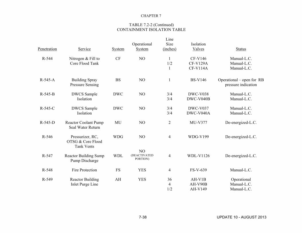
CHAPTER 7
TABLE 7.2-2 (Continued) CONTAINMENT ISOLATION TABLE
Penetration Service System Operational
System
Line Size
(inches) Isolation Valves Status
7-38 UPDATE 10 - AUGUST 2013
R-544 Nitrogen & Fill to
Core Flood Tank CF NO 1
1/2 1
CF-V146 CF-V129A CF-V114A
Manual-L.C. Manual-L.C. Manual-L.C.
R-545-A Building Spray Pressure Sensing
BS NO 1 BS-V146 Operational – open for RB pressure indication
R-545-B DWCS Sample Isolation
DWC NO 3/4 3/4
DWC-V038 DWC-V040B
Manual-L.C. Manual-L.C.
R-545-C DWCS Sample Isolation
DWC NO 3/4 3/4
DWC-V037 DWC-V040A
Manual-L.C. Manual-L.C.
R-545-D Reactor Coolant Pump Seal Water Return
MU NO 2 MU-V377 De-energized-L.C.
R-546 Pressurizer, RC, OTSG & Core Flood
Tank Vents
WDG NO 4 WDG-V199 De-energized-L.C.
R-547 Reactor Building Sump Pump Discharge
WDL NO
(DEACTIVATED PORTION)
4 WDL-V1126 De-energized-L.C.
R-548 Fire Protection FS YES 4 FS-V-639 Manual-L.C.
R-549 Reactor Building Inlet Purge Line
AH YES 36 4
1/2
AH-V1B AH-V90B AH-V149
Operational Manual-L.C. Manual-L.C.

CHAPTER 7
TABLE 7.2-2 (Continued) CONTAINMENT ISOLATION TABLE
Penetration Service System Operational
System
Line Size
(inches) Isolation Valves Status
7-39 UPDATE 10 - AUGUST 2013
R-550 Reactor Building
Inlet Purge Line
AH YES 36 4
1/2
AH-V1A AH-V90A AH-V151
Operational Manual-L.C. Manual-L.C.
R-551 Reactor Building Outlet Purge Line
AH YES 36 10 4
1/2
AH-V4A AH-V52
AH-V120A AH-V153
Operational Operational Manual-L.C. Operational
R-552 Reactor Building Outlet Purge Line
AH YES 36 10 10 4
AH-V4B AH-V7
AH-V81 AH-V120B
Operational Air Disabled-L.C. Air Disabled-L.C.
Manual-L.C.
R-553 DWCS to RB Isolation DWCS NO 2 WDL-V1092 De-energized-L.C.
R-554-A Instrument Air, Purge IA NO 1/2 1/2 1/2
AH-V213 AH-V214 AH-V221
Manual-L.C. Manual-L.C. Manual-L.C.
R-554-B Air Sample Supply (Radiation Detection)
AH NO 1/2 1/2
AH-V169 AH-V230
Manual-L.C. Manual-L.C.
R-554-C Building Spray Pressure Sensing
BS NO 1 BS-V147 Manual-L.C.
R-554-D Instrument Air to DWCS
DWC NO 3/4 3/4 1/2
DWC-V316 DWC-V318
Pipe Cap
Manual-L.C. Manual-L.C.
Installed

CHAPTER 7
TABLE 7.2-2 (Continued) CONTAINMENT ISOLATION TABLE
Penetration Service System Operational
System
Line Size
(inches) Isolation Valves Status
7-40 UPDATE 10 - AUGUST 2013
R-555-A Air Sample Supply
(Radiation Detection) AH NO 1
1/2 AH-V143 AH-V168
Manual-L.C. Manual-L.C.
R-555-B Air Sample Return (Radiation Detection)
AH NO 1 1/2
AH-V145 AH-V171
Manual-L.C. Manual-L.C.
R-555-C PCI Isolated Ground Cable
PCI NO 1 Blind Flange Installed
R-555-D Air Sample Return (Radiation Detection)
AH NO 1/2 1/2
AH-V170 AH-V227
Manual-L.C. Manual-L.C.
R-557 To RC Pump Oil & Motor Coolers
NS NO 8 1/2
NS-V72 NS-V210
Air Disabled-L.C. Manual-L.C.
R-558 From RC Pump Oil & Motor Coolers
NS NO 8 NS-V81 Air Disabled-L.C.
R-559 Intermediate Cooling to Control
Rod Drive Mechanisms
IC NO 3 IC-V5 Air Disabled-L.C.
R-560 High Pressure Water TDW NO 1 1
10
TDW-V001 TDW-V003 Blind flange
Manual-L.C. Manual-L.C.
Installed
R-561 Decon Service Air DSA NO 1 3/4
DSA-V004 DSA-V006
Manual-L.C. Manual-L.C.

CHAPTER 7
TABLE 7.2-2 (Continued) CONTAINMENT ISOLATION TABLE
Penetration Service System Operational
System
Line Size
(inches) Isolation Valves Status
7-41 UPDATE 10 - AUGUST 2013
R-562-A Instrument Air
Supply IA NO 1/2
1/2 1/2
AH-V215 AH-V216 AH-V223
Manual-L.C. Manual-L.C. Manual-L.C.
R-562-B Pressure Transfer Fans
AH NO 1/2 1
AH-V147 Pipe Cap
Manual-L.C. Installed
R-562-C Building Spray Pressure Sensing
BS NO 1 BS-V148 Manual-L.C.
R-562-D RB Sludge Transfer
WDS NO NO
1 1
WDS-FV612 WDS-FV614
Manual-L.C. Manual-L.C.
R-563 Intermediate Cooling System
IC NO 6 1/2
IC-V4 IC-V207
Air Disabled-L.C. Manual-L.C.
R-565 Processed Water Supply PW to Reactor
Building
PW NO 3 1 4
PW-V69 PW-V99 Flange
Manual-L.C. Manual-L.C.
Installed
R-566 Service Air SA NO 2 1/2 SA-V20 Air Disabled-L.C.
R-567 Intermediate Cooling System
IC NO 6 IC-V3 Air Disabled-L.C.
R-569 Sec. System Flush & Drain
SV NO 3 SV-V18 L.C.
R-570 High Pressure Injection Line
MU NO 2 1/2 1/2
MU-V16A MU-V315
De-energized-L.C. Manual-L.C.

CHAPTER 7
TABLE 7.2-2 (Continued) CONTAINMENT ISOLATION TABLE
Penetration Service System Operational
System
Line Size
(inches) Isolation Valves Status
7-42 UPDATE 10 - AUGUST 2013
R-571-A Integrated Leak
Rate Test LR NO 1 Blind Flange Installed
R-571-B Integrated Leak Rate Test
LR NO 1 Welded Cap Installed
R-571-C Building Spray BS NO 1 BS-V149 Operational – open for RB high pressure alarm signal
R-571-D Integrated Leak Rate Test
LR NO 1 Blind Flange Installed
R-572 High Pressure Injection Line & Makeup
MU NO 1/2 2 1/2 2 1/2
MU-V316 MU-V16B MU-V18
Manual-L.C. De-energized-L.C. Air Disabled-L.C.
R-573 Reactor Coolant Pump Seal Water Supply
MU NO 3/4 3/4 3/4
MU-V379 MU-V383A MU-V384A
Manual-L.C. Manual-L.C. Manual-L.C.
R-574 Reactor Coolant Pump Seal Water Supply
MU NO 3/4 3/4 3/4
MU-V380 MU-V383B MU-V384B
Manual-L.C. Manual-L.C. Manual-L.C.
R-575 Reactor Coolant Pump Seal Water Supply
MU NO 3/4 3/4 3/4
MU-V381 MU-V383C MU-V384C
Manual-L.C. Manual-L.C. Manual-L.C.
R-576 Reactor Coolant Pump Seal Water Supply
MU NO 3/4 3/4 3/4
MU-V382 MU-V383D MU-V384D
Manual-L.C. Manual-L.C. Manual-L.C.

CHAPTER 7
TABLE 7.2-2 (Continued) CONTAINMENT ISOLATION TABLE
Penetration Service System Operational
System
Line Size
(inches) Isolation Valves Status
7-43 UPDATE 10 - AUGUST 2013
R-577 Reactor Building
Air Coolers RR NO 8
1 1/2
RR-V5A RR-V28A RR-V86A
De-energized-L.C. Manual-L.C. Manual-L.C.
R-578 Reactor Building Air Coolers
RR NO 6 1/2 6
RR-V11A RR-V75A RR-V25A
Air Disabled-L.C. Manual-L.C. Air Disabled-L.C.
R-579 Reactor Building Air Coolers
RR NO 8 1
1/2
RR-V5B RR-V28B RR-V88
De-energized-L.C. Manual-L.C. Manual-L.C.
R-580 Reactor Building Air Coolers
RR NO 8 8 1
1/2 1/2
RR-V5C RR-V6C RR-V28C RR-V90 RR-V92
De-energized-L.C. De-energized-L.C. Manual-L.C. Manual-L.C. Manual-L.C.
R-581 Reactor Building Air Coolers
RR NO 6 1/2 6
RR-V11C RR-V75C RR-V25C
Air Disabled-L.C. Manual-L.C. Air Disabled-L.C.
R-582 Reactor Building Air Coolers
RR NO 6 1/2 6
RR-V11B RR-V75B RR-V25B
Air Disabled-L.C. Manual-L.C. Air Disabled-L.C.
R-583 Reactor Building Spray Inlet Line
BS NO 8 3
BS-V1B BS-V130B
De-energized-L.C. Manual-L.C.

CHAPTER 7
TABLE 7.2-2 (Continued) CONTAINMENT ISOLATION TABLE
Penetration Service System Operational
System
Line Size
(inches) Isolation Valves Status
7-44 UPDATE 10 - AUGUST 2013
R-584 Reactor Building Air Coolers
RR NO 8 1
1/2 1
RR-V6D RR-V28D RR-V94 RR-V98
De-energized-L.C. Manual-L.C. Manual-L.C. Manual-L.C.
R-585 Reactor Building Air Coolers
RR NO 6 1/2 6
RR-V11D RR-V75D RR-V25D
Air Disabled-L.C. Manual-L.C. Air Disabled-L.C.
R-586 Reactor Building Spray Inlet Line
BS No 8 3
BS-V1A BS-V130A
De-energized-L.C. Manual-L.C.
R-587 Reactor Building Air Coolers
RR NO 8 1
1/2
RR-V6E RR-V28E RR-V96
De-energized-L.C. Manual-L.C. Manual-L.C.
R-588 Reactor Building Air Coolers
RR NO 6 1/2 6
RR-V11E RR-V75E RR-V25E
Air Disabled-L.C. Manual-L.C. Air Disabled-L.C..
R-589 Decay Heat Coolant Supply
DH NO 10 DH-V4A De-energized-L.C.
R-590 Decay Heat Coolant Supply
DH NO 10 DH-V4B De-energized-L.C.
R-591 High Pressure Injection Line
MU NO 2 1/2 1/2
MU-V16C MU-V-366
De-energized-L.C. Manual-L.C.
R-592 High Pressure Injection Line
MU NO 2 1/2 1/2
MU-V16D MU-V-368
De-energized-L.C. Manual-L.C.

CHAPTER 7
TABLE 7.2-2 (Continued) CONTAINMENT ISOLATION TABLE
Penetration Service System Operational
System
Line Size
(inches) Isolation Valves Status
7-45 UPDATE 10 - AUGUST 2013
R-593 Sump Penetration Sleeve & Drain Line
DH YES 18 DH-V6A Operational
R-594 Sump Penetration Sleeve & Drain Line
DH YES 18 DH-V6B Operational
R-616 Emergency Feedwater to OTSG "B"
EF NO 6 4
3/4 6 6
EF-V12B EF-V33B EF-V36 Blind Flange Blind Flange
De-energized-L.C. De-energized-L.C. Manual-L.C. Installed Installed
R-617 Feedwater to OTSG "B"
FW NO 20 6
3/4 3/4 2
10
FW-V17B FW-V19B FW-V68B FW-V35B GR-V7B Blind Flange
De-energized-L.C. De-energized-L.C. Manual-L.C. Manual-L.C. Manual-L.C. Installed

CHAPTER 7
TABLE 7.2-2 (Continued) CONTAINMENT ISOLATION TABLE
Penetration Service System Operational
System
Line Size
(inches) Isolation Valves Status
7-46 UPDATE 10 - AUGUST 2013
R-618 Feedwater to OTSG "A"
FW NO 20 6
3/4 3/4 2
10
FW-V17A FW-V19A FW-V68A FW-V35A GR-V7A Blind Flange
De-energized-L.C. De-energized-L.C. Manual-L.C. Manual-L.C. Manual-L.C. Installed
R-619 Main Steam to Turbine
MS NO 24 10 3/4 1
MS-V7B MS-V15B MS-V224 MS-V51B
De-energized-L.C. De-energized-L.C. Manual-L.C. Manual-L.C.
R-620 Main Steam to Turbine
MS NO 24 6
3/4 4 1
3/4 2
MS-V4B MS-V1B MS-V2B MS-V11B MS-V50B MS-V225 GR-V1B
De-energized-L.C. Manual-L.C. Manual-L.C. De-energized-L.C. Manual-L.C. Manual-L.C. Manual-L.C.
R-621 Main Steam to Turbine
MS NO 24 10 1 4
3/4
MS-V7A MS-V15A MS-V51A MS-V11A MS-V227
De-energized-L.C. De-energized-L.C. Manual-L.C. De-energized-L.C. Manual-L.C.

CHAPTER 7
TABLE 7.2-2 (Continued) CONTAINMENT ISOLATION TABLE
Penetration Service System Operational
System
Line Size
(inches) Isolation Valves Status
7-47 UPDATE 10 - AUGUST 2013
R-622 Main Steam to Turbine
MS NO 24 6
3/4 1
3/4 2
MS-V4A MS-V1A MS-V2A MS-V50A MS-V226 GR-V1A
De-energized-L.C. Manual-L.C. Manual-L.C. Manual-L.C. Manual-L.C. Manual-L.C.
R-623 Emergency Feedwater to OTSG "A"
EF NO 6 4 6 6
EF-V12A EF-V33A Blind Flange Blind Flange
De-energized-L.C. De-energized-L.C. Installed Installed
R-626 Spare N/A NO 2 12
SWS-FV-1 Flange
Manual-L.C. Installed
R-401 RB Basement Level Indication
RBS NO 1/2 1/2 1/2 1/2 12
RBS-IV-1009 RBS-IV-1011 RBS-IV-1013 RBS-IV-1014 Flange
Manual-L.C. Manual-L.C. Manual-L.C. Manual-L.C. Installed
R-508 Electrical Penetration ROSA/CCTV Coax Cables
N/A NO 11 Flange Installed

CHAPTER 7
TABLE 7.2-2 (Continued) CONTAINMENT ISOLATION TABLE
Penetration Service System Operational
System
Line Size
(inches) Isolation Valves Status
7-48 UPDATE 10 - AUGUST 2013
N/A RB Personnel (Air Sampling)
RBA YES 1/2 1/2
RBA-V-2 RBA-V-3
Operational Operational
N/A RB Personnel Hatch (Airlock #2)
N/A YES N/A Personnel Door
Operational
N/A RB Equipment Hatch N/A NO 31’6” N/A Bolted Flange
N/A RB Equipment Hatch (Airlock #1)
N/A YES N/A Personnel Door
Operational

CHAPTER 7
7-49 UPDATE 10 - AUGUST 2013
TABLE 7.2-3
OPERATIONAL SUMP SYSTEMS FOR PDMS
Sumps Associated With SD System
Sump Location
Turbine Building Sump Turbine Building
Control Building Area Sump M-20 Area West
Control & Service Building Sump Service Building
Tendon Access Gallery Sump Tendon Access Gallery
Air Intake Tunnel Normal Sump Air Intake Tunnel
Sumps Associated With WDL System
Sump Location
Containment Basement Sump Containment Building
Auxiliary Building Sump Auxiliary Building
Decay Heat Removal Pump Room Sumps (2)
Auxiliary Building
Reactor Building Spray Pump Room Sumps (2)
Auxiliary Building
Contaminated Drain Tank Room Sump
Service Building
TABLE 7.2-4 DELETED

CHAPTER 7 OPERATIONAL SYSTEMS AND FACILITIES
7-50 UPDATE 10 - AUGUST 2013
HEPA FILTER
EQUIVALENT LEAK
ASSUMPTIONS 1. LAMINAR FLOW IN VENT AND LEAK 2. NEGLIGIBLE TURNING, ENTRANCE LOSSES 3. NO LOSSES IN VALVES
FIGURE 7.2-1 CONTAINMENT ATMOSPHERIC BREATHER “MOST PROBABLE"
PATHWAY MODEL
30 ft

CHAPTER 7 OPERATIONAL SYSTEMS AND FACILITIES
7-51 UPDATE 10 - AUGUST 2013
FIGURE 7.2-11 RADIATION SURVEY
LOCATION – 347’ ELEV.

CHAPTER 7 OPERATIONAL SYSTEMS AND FACILITIES
7-52 UPDATE 10 - AUGUST 2013
FIGURE 7.2-12 RADIATION SURVEY
LOCATION – 305’ ELEV.

UPDATE 10 AUGUST 2013
CHAPTER 10
ADMINISTRATIVE FUNCTIONS

UPDATE 10 AUGUST 2013
APPENDIX H
CHAPTER 1
INTRODUCTION AND
GENERAL DESCRIPTION OF PLANT

UPDATE 10 AUGUST 2013
APPENDIX H CHAPTER 3
DESIGN CRITERIA - STRUCTURES, SYSTEMS, AND
COMPONENTS

APPENDIX H CHAPTER 3
DESIGN CRITERIA - STRUCTURES, SYSTEMS, AND COMPONENTS
TABLE OF CONTENTS
Appendix H 3-i UPDATE 10 AUGUST 2013
SECTION TITLE PAGE
3.1 REGULATORY CONFORMANCE 3-1
3.1.1 CONFORMANCE WITH 10 CFR PART 50 GENERAL PROVISIONS 3-1
3.1.1.1 10 CFR 50.1 - Basis, Purpose, & Procedures Applicable 3-1
3.1.1.2 10 CFR 50.2 - Definitions 3-1
3.1.1.3 10 CFR 50.3 - Interpretations 3-1
3.1.1.4 10 CFR 50.4 - Communications 3-1
3.1.1.4a 10 CFR 50.5 - Deliberate Misconduct 3-1
3.1.1.5 10 CFR 50.7 - Employee Protection 3-2
3.1.1.6 10 CFR 50.8 - Information Collection Requirements: OMB Approval
3-2
3.1.1.6a 10 CFR 50.9 - Completeness & Accuracy of Information 3-2
REQUIREMENT OF LICENSE, EXCEPTIONS
3.1.1.7 10 CFR 50.10 - License Required 3-2
3.1.1.8 10 CFR 50.11 - Exceptions & Exemptions from Licensing Requirements
3-2
3.1.1.9 10 CFR 50.12 - Specific Exemptions 3-2
3.1.1.10 10 CFR 50.13 - Attacks & Destructive Acts by Enemies of the United States; and Defense Activities
3-2
CLASSIFICATION AND DESCRIPTION OF LICENSES
3.1.1.11 10 CFR 50.20 - Two Classes of Licenses 3-2
3.1.1.12 10 CFR 50.21 - Class 104 Licenses; for Medical Therapy and Research and Development Facilities
3-2
3.1.1.13 10 CFR 50.22 - Class 103 Licenses; for Commercial 62 Industrial Facilities
3-3
3.1.1.14 10 CFR 50.23 - Construction Permits 3-3
APPLICATIONS FOR LICENSES, FORM, CONTENTS, INELIGIBILITY OF CERTAIN APPLICANTS
3.1.1.15 10 CFR 30 Filing of Applications for Licenses; Oath or Affirmation
3-3
3.1.1.16 10 CFR 50.31 - Combining Applications 3.1-3 3-3
3.1.1.17 10 CFR 50.32 - Elimination of Repetition 3.1-3 3-3

APPENDIX H CHAPTER 3
DESIGN CRITERIA - STRUCTURES, SYSTEMS, AND COMPONENTS
TABLE OF CONTENTS
Appendix H 3-ii UPDATE 10 AUGUST 2013
SECTION TITLE PAGE
3.1.1.18 10 CFR 50.33 - Contents of Applications; General Information
3-3
3.1.1.19 10 CFR 50.33a - Information Requested by the Attorney General for Antitrust Review
3-3
3.1.1.20 10 CFR 50.34 - Contents of Applications; Technical Information 3-3
3.1.1.21 10 CFR 50.34a - Design Objectives for Equipment to Control 3.1-9 Releases of Radioactive Material in Effluents- Nuclear Power Reactors
3-9
3.1.1.22 10 CFR 50.35 - Issuance of Construction Permits 3.1-9 3-9
3.1.1.23 10 CFR 50.36 - Technical Specifications 3.1-9 3-9
3.1.1.24 10 CFR 50.36a - Technical Specifications on Effluents from Nuclear Power Reactors
3-9
3.1.1.25 10 CFR 50.36b - Environmental Conditions 3.1-10 3-10
3.1.1.26 10 CFR 50.37 - Agreement Limiting Access to Restricted Data
3-10
3.1.1.27 10 CFR 50.38 - Ineligibility of Certain Applications 3-10
3.1.1.27 10 CFR 50.38 - Ineligibility of Certain Applications 3-10
3.1.1.28 10 CFR 50.39 - Public Inspection of Applications 3-10
STANDARDS FOR LICENSES AND CONSTRUCTION PERMITS
3.1.1.29 10 CFR 50.40 - Common Standards 3-10
3.1.1.30 10 CFR 50.41 - Additional Standards for Class 104 License 3-10
3.1.1.31 10 CFR 50.42 - Additional Standards for Class 103 Licenses 3-11
3.1.1.32 10 CFR 50.43 - Additional Standards and Provisions Affecting Class 103 Licenses for Commercial Power
3-11
3.1.1.33 10 CFR 50.44 - Standards for Combustible Gas Control System in Light-Water-cooled Power Reactors 3-11
3.1.1.34 10 CFR 50.45 - Standards for Construction Permits 3-11
3.1.1.35 10 CFR 50.46 - Acceptance Criteria for Emergency 3.1-12 Core Cooling Systems for Light Water Nuclear Power Reactors
3-11
3.1.1.35a 10 CPR 50.46a - Acceptance Criteria for Reactor Coolant Venting Systems 3-11 3.1.1.36 10 CFR 50.47 - Emergency Plans 3-11 3.1.1.37 10 CFR 50.48 - Fire Protection 3-12 3.1.1.38 10 CFR 50.49 - Environmental Qualification of Electric Equipment Important
to Safety for Nuclear Power Plants. 3-12
3.1.1.39 10 CFR 50.50 - Issuance of Licenses and Construction Permits 3-12 3.1.1.40 10 CFR 50.5 1 - Duration of License, Renewal 3-12 3.1.1.41 10 CFR 50.52 - Combining Licenses 3-12

APPENDIX H CHAPTER 3
DESIGN CRITERIA - STRUCTURES, SYSTEMS, AND COMPONENTS
TABLE OF CONTENTS
Appendix H 3-iii UPDATE 10 AUGUST 2013
SECTION TITLE PAGE
3.1.1.42 10 CFR 50.53 – Jurisdictional Limitations 3-12
3.1.1.43 10 CFR 50.54 - Conditions of Licenses 3-12
ISSUANCE, LIMITATIONS; & CONDITIONS OF LICENSES & CONSTRUCTION PERMITS
3.1.1.44 10 CFR 50.55 - Conditions of Construction Permits 3-16
3.1.1.45 10 CFR 50.55a - Codes and Standards 3-17
3.1.1.46 I0 CFR 50.56 - Conversion of Construction Permit to License; or Amendment of License
3-18
3.1.1.47 10 CFR 50.57 - Issuance of Operating License 3-18
3.1.1.48 10 CFR 50.58 - Hearings and Report of the Advisory Committee on Reactor Safeguards
3-18
3.1.1.49 10 CFR 50.59 - Changes, Tests and Experiments 3-18
3.1.1.50 10 CFR 50.60 - Acceptance Criteria for Fracture Prevention Measures for Light-Water Nuclear Power Reactors for Normal Operation
3-19
3.1.1.51 10 CFR 50.61 - Fracture Toughness Requirements for Protection Against Pressurized Thermal Shock Events
3-19
3.1.1.52 10 CFR 50.62 - Requirements for Reduction of Risk horn Anticipated Transients without Scram (ATWS) Events for Light-Water Cooled Nuclear Power Plants
3-19
3.1.1.53 10 CFR 50.63 - Loss of Alternating Current Power 3-19
3.1.1.54 10 CFR 50.64 - Limitations on the Use of Highly Enriched Uranium (HEW in Domestic Non- Power Reactors
3-19
3.1.1.54a 10 CFR 50.65 - Requirements for Monitoring the Effectiveness of Maintenance at Nuclear Power Plants"
3-19
3.1.1.54b 10 CER 50.66 - Requirements for Thermal Annealing of the Reactor Vessel 3-20
3.1.1.54c 10 CFR 50.67 - Accident Source Term 3-20
3.1.1.54d 10 CFR 50.68 - Criticality accident requirements 3-20
3.1.1.54e 10 CFR 50.69 - Issuance, Limitations and Conditions of Licenses and Construction Permits
3-20
INSPECTION; RECORDS, REPORTS, NOTIFICATIONS
3.1.1.55 10 CFR 50.70 – Inspections 3-20
3 1.1.56 10 CFR 50.7 1 - Maintenance of Records, Making of Reports 3-20
3.1.1.57 10 CFR 50.72 - Immediate Notification Requirements for Operating Nuclear Power Reactors
3-20
3.1.1.58 10 CFR 50.73 - Licensee Event Report System 3-21

APPENDIX H CHAPTER 3
DESIGN CRITERIA - STRUCTURES, SYSTEMS, AND COMPONENTS
TABLE OF CONTENTS
Appendix H 3-iv UPDATE 10 AUGUST 2013
SECTION TITLE PAGE
3.1.1.58a 10 CFR 50.73 – Notifications o f Change in Operator or Senior Operator Status"
3-21
3.1.1.59 10 CFR 50.75 - Reporting and Recordkeeping for Decommissioning Planning 3-21
3.1.1.59a 10 CFR 50.76 - Licensee's Change of Status, Financial Qualifications 3-21
US/1AEA SAFEGUARDS AGREEMENT
3.1.1.60 10 CFR 50 78 - installation Information and Verification 3-21
TRANSFERS OF LICENSES-CREDITORS RIGHTS-SURRENDER OF LICENSES
3.1.1.61 10 CFR 50.80 - Transfer of Licenses 3-21
3.1.1.62 10 CFR 50.8 1 - Creditor Regulations 3-22
3.1.1.63 10 CFR 50.82 - Applications for Termination of Licenses3.1-22 3-22
3.1.1.63a 10 CFR 50.83 -Release of Part of a Power Reactor Facility or
Site for Unrestricted Use I
3-22
3.1.1.64 10 CFR 50.90 - Application for Amendment of License or Construction Pernit 3-22
3.1.1.65 10 CFR 50.91 - Notice for Public Comment; State Consultation 3-22 3.1.1.66 10 CFR 50.92 - Issuance of Amendment 3-22
REVOCATION, SUSPENSION, MODIFICATION, AMENDMENT OF LICENSES AND
CONSTRUCTION PERMITS, EMERGENCY OPERATIONS BY THE COMMISSION
3.1.1.67 10 CFR 50.100 - Revocation, Suspension, Modification of Licenses and Construction Permits for Cause
3-22
3.1.1.68 10 CFR 50.101 -Retaking Possession of Special Nuclear Material 3-22
3.1.1.69 10 CFR 50.102 - Commission Order for Operation After Revocation
3-23
3.1.1.70 10 CFR 50.103 - Suspension and Operation in War or National Emergency
3-23
3.1.1.71 10 CFR 50.109 – Backfitting 3-23
ENFORCEMENT ZXC
3.1.1.72 10 CFR 50.110 - Violations 3-23
3.1.1.73 10 CFR 50.111 - Criminal Penalties" 3-23
3.1.1.74 10 CFR 50.120 - Training and Qualifications of Nuclear Power Plant Personnel
3-23
3.1.2 GENERAL DESIGN CRITERIA 3-23
3.1.2.1 Criterion 1 - Quality Standards and Records 3-24
3.1.2.2 Criterion 2 - Design Bases for Protection Against Natural Phenomena 3-24

APPENDIX H CHAPTER 3
DESIGN CRITERIA - STRUCTURES, SYSTEMS, AND COMPONENTS
TABLE OF CONTENTS
Appendix H 3-v UPDATE 10 AUGUST 2013
SECTION TITLE PAGE
3.1.2.3 Criterion 3 - Fire Protection 3-25
3.1.2.4 Criterion 4 - Environmental and Missile Design Bases 3-25
3.1.2.5 Criterion 5 - Sharing of Structures, Systems, and Components 3-26
3.1.2.6 Criterion 10 - Reactor Design 3-26
3.1.2.7 Criterion 11 - Reactor Inherent Protection 3-26
3.1.2.8 Criterion 12 - Suppression of Reactor Power Oscillations 3-27
3.1.2.9 Criterion 13 - Instrumentation and Control 3-27
3.1.2.10 Criterion 14 - Reactor Coolant Pressure Boundary 3-27
3.1.2.11 Criterion 15 - Reactor Coolant System Design 3-27
3.1.2.12 Criterion 16 - Containment Design 3-28
3.1.2.13 Criterion 17 - Electric Power Systems 3-28
3.1.2.14 Criterion 18 - Inspection and Testing of Electric Power Systems 3-29
3.1.2.15 Criterion 19 - Control Room 3-29
3.1.2.16 Criterion 20 - Protection System Functions 3-29
3.1.2.17 Criterion 2 1 - Protection System Reliability and Testability 3-30
3.1.2.18 Criterion 22 - Protection System Independence 3-30
3.1.2.19 Criterion 23 - Protection System Failure Modes 3-30
3.1.2.20 Criterion 24 - Separation of Protection and Control Systems 3-31
3.1.2.21 Criterion 25 - Protection System Requirements for Reactivity Control Malfunctions
3-31
3.1.2.22 Criterion 26 - Reactivity Control System Redundancy and Capability 3-31
3.1.2.23 Criterion 27 - Combined Reactivity Control Systems Capability 3-31
3.1.2.24 Criterion 28 - Reactivity Limits 3-32
3.1.2.25 Criterion 29 - Protection Against Anticipated Operational Occurrences
3-32
3.1.2.26 Criterion 30 - Quality of Reactor Coolant Pressure Boundary
3-32
3.1.2.27 Criterion 3 1 - Fracture Prevention of Reactor Coolant Pressure Boundary
3-33
3.1.2.28 Criterion 32 - Inspection of Reactor Coolant Pressure Boundary
3-33
3.1.2.29 Criterion 33 - Reactor Coolant Makeup 3-33
3.1.2.30 Criterion 34 - Residual Heat Removal 3-34

APPENDIX H CHAPTER 3
DESIGN CRITERIA - STRUCTURES, SYSTEMS, AND COMPONENTS
TABLE OF CONTENTS
Appendix H 3-vi UPDATE 10 AUGUST 2013
SECTION TITLE PAGE
3.1.2.31 Criterion 35 - Emergency Core Cooling 3-34
3.1.2.32 Criterion 36 - Inspection of Emergency Core Cooling System 3-34
3.1.2.33 Criterion 37 - Testing of Emergency Core Cooling System 3-35
3.1.2.34 Criterion 38 - Containment Heat Removal 3-35
3.1.2.35 Criterion 39 - Inspection of Containment Heat Removal System 3-35
3.1.2.36 Criterion 40 - Testing of Containment Heat Removal System 3-36
3.1.2.37 Criterion 41 - Containment Atmosphere Cleanup 3-36
3.1.2.38 Criterion 42 - Inspection of Containment Atmosphere Cleanup Systems
3-36
3.1.2.39 Criterion 43 - Testing of Containment Atmosphere Cleanup Systems 3-37
3.1.2.40 Criterion 44 - Cooling Water 3-37
3.1.2.41 Criterion 45 - Inspection of Cooling Water System 3-37
3.1.2.42 Criterion 46 - Testing of Cooling Water System 3-38
3.1.2.43 Criterion 50 - Containment Design Basis 3-38
3.1.2.44 Criterion 51 - Fracture Prevention of Containment Pressure Boundary
3-39
3.1.2.45 Criterion 52 - Capability for Containment Leakage Rate Testing
3-39
3.1.2.46 Criterion 53 - Provisions for Containment Testing and Inspection 3-39
3.1.2.47 Criterion 54 - Piping Systems Penetrating Containment 3-40
3.1.2.48 Criterion 55 - Reactor Coolant Pressure Boundary Penetrating Containment
3-40
3.1.2.49 Criterion 56 - Primary Containment Isolation 3-41
3.1.2.50 Criterion 57 - Closed System Isolation Valves 3-41
3.1.2.51 Criterion 60 - Control of Releases of Radioactive Materials to the Environment
3-42
3.1.2.52 Criterion 61 - Fuel Storage and Handling and Radioactivity Control 3-42
3.1.2.53 Criterion 62 - Prevention of Criticality in Fuel Storage and Handling 3-43
3.1.2.54 Criterion 63 - Monitoring Fuel and Waste Storage 3-43
3.1.2.55 Criterion 64 - Monitoring Radioactivity Releases 3-43
3.2 CLASSIFICATION OF STRUCTURES, SYSTEMS, AND COMPONENTS
3-45
3.2.1 SESMIC CLASSIFICATION 3-45

APPENDIX H CHAPTER 3
DESIGN CRITERIA - STRUCTURES, SYSTEMS, AND COMPONENTS
TABLE OF CONTENTS
Appendix H 3-vii UPDATE 10 AUGUST 2013
SECTION TITLE PAGE
3.2.1.1 Seismic Category I 3-45
3.2.1.2 PDMS Category II 3-45
3.2.1.2.1 Design Basis 3-46
3.2.1.2.2 PDMS Category II Structures 3-46
3.2.1.2.3 PDMS Category II Systems 3-46
3.2.2 SYSTEM QUALITY GROUP CLASSIFICATION 3-46
3.2.2.1 Identification of Safety Related Systems and Components 3-46
3.3 WIND AND TORNADO LOADINGS 3-49
3.3.1 WIND LOADINGS 3-49
3.3.1.1 Design Wind Velocity 3-49
3.3.2 TORNADO LOADINGS 3-49
3.3.2.1 Applicable Design Parameters 3-49
3.3.2.2 Tornado Missiles 3-49
3.5 MISSILE PROTECTION CRITERIA 3-51
3.5.1 MISSILE LOADINGS AND BARRIERS 3-51
3.5.2 MISSILE SELECTION 3-51
3.5.3 SELECTED MISSILES 3-51
3.5.3.1 Tornado Generated Missiles 3-51
3.5.3.2 Aircraft Impact 3-51
3.5.4 BARRIER DESIGN PROCEDURES 3-52
3.5.4.1 Overall Structural Effect 3-52
3.5.4.2 Missile Penetration (Localized Effect) 3-52
3.5.5 MISSILE BARRIER FEATURES 3-52
3.6 SEISMIC DESIGN 3-53
3.7 DESIGN OF PRINCIPAL BUILDING STRUCTURES 3-53
3.7.1 CONTAINMENT BUILDING 3-53
3.7.1.1 Structure Description 3-53
3.7.1.2 Liner Plate and Penetrations 3-53
3.7.2 OTHER PRINCIPAL STRUCTURES 3-55
3.7.2.1 Description of Structures 3-55
3.7.2.1.1 Auxiliary Building 3-55

APPENDIX H CHAPTER 3
DESIGN CRITERIA - STRUCTURES, SYSTEMS, AND COMPONENTS
TABLE OF CONTENTS
Appendix H 3-viii UPDATE 10 AUGUST 2013
SECTION TITLE PAGE
3.7.2.1.2 Fuel Handling Building 3-55
3.7.2.1.3 Control and Services Buildings 3-56
3.7.2.1.4 Control Building Area 3-56
3.7.2.1.5 Air Intake Tunnel 3-56
List of Tables
TABLE # TITLE PAGE
3.2-1 PDMS CATEGORY I1 SYSEMS 3-47
3.3-1 TORNADO GENERATED MISSLLES 3-50
3.7-1 MODIFIED CONTAINVENT PENETRATIONS 3-57
LIST OF FIGURES
FIGURE # TITLE PAGE
3.7-1 REACTOR BUILDING GENERAL LAYOUT 3-59
3.7-2 REACTOR BUILDING PERSONNEL AND EQUIPMENT ACCESS OPENINGS DETAIL
3-60
3.7-3 CONTAINMENT WALL PENETRATION DETAILS 3-61
3.7-4 SECTION THROUGH THE PLANT STRUCTURES - "A-A" 3-62 3.7.5 SECTION THROUGH THE PLANTSTRUCTURES - "B-B" 3-63
3.7-6 SECTION THROUGH THE PLANT STRUCTURES "C-C" & "D-D" 3-64

APPENDIX H CHAPTER 3
DESIGN CRITERIA - STRUCTURES, SYSTEMS, AND COMPONENTS
Appendix H 3-1 UPDATE 10 AUGUST 2013
3.1 REGULATORY CONFORMANCE
3.1.1 CONFORMANCE WITH 10 CFR Part 50
Three Mile Island Nuclear Station Unit 2 was originally designed to conform to the Regulations of 10 CFR Part 50, including the General Design Criteria of Appendix A. On March 28, 1979, the unit experienced an accident which severely damaged the reactor core. Subsequently, the core was removed and shipped off-site. The removal of the reactor core and the revision of the license to a non-operating license have changed the function of the facility from an operating nuclear power plant to one of management and maintenance. These characteristics substantially alter the applicability and the requirement for Three Mile Island Unit 2 conformance with the regulations of 10 CFR Part 50. The degree and manner of addressing those regulations which are applicable to Three Mile Island Unit 2 during Post Defueling Monitored Storage are described in the following sections. In addition, based on this evaluation, a request for relief from the insevice inspection requirements of 10 CFR 50.55a and an exemption from the requirements of 10 CFR 50.60 are also provided. The regulations which have been reviewed are those which were revised as of January 1, 1995.
3.1.1.1 10 CFR 50.1 - Basis, purpose, and procedures applicable.
Article 50.1 describes the basis, purpose, and procedures of 10 CFR Part 50 and gives notice that persons may be individually subject to NRC Enforcement Actions for violations of Article 10 CFR 50.5 "Deliberate Misconduct." No exceptions are taken to the provisions of this article.
3.1.1.2 10 CFR 50.2 - Definitions
Article 50.2 provides definitions of terms used throughout 10 CFR 50. No exceptions are taken to the provisions of this article.
3.1.1.3 10 CFR 50.3 - Interpretations.
Article 50.3 delegates the responsibility for interpretations of 10 CFR 50 to the General Counsel. No exceptions are taken to the provisions of this article.
3.1.1.4 10 CFR 50.4 - Communications.
Article 50.4 describes communications requirements for nuclear power plants. No exceptions are taken to the provisions of this article.
3.1.1.4a 10 CFR 50.5 - Deliberate Misconduct
Article 50.5 prohibits deliberate misconduct as defined in this article by Licensees, applicants for a license, contractors, sub-contractors, and their respective employees and provides for appropriate enforcement anion. No exceptions are taken to the provisions of this article.

APPENDIX H CHAPTER 3
DESIGN CRITERIA - STRUCTURES, SYSTEMS, AND COMPONENTS
Appendix H 3-2 UPDATE 10 AUGUST 2013
3.1.1.5 10 CFR 50.7 - Employee Protection
Article 50.7 describes provisions relating to the protection of employees at nuclear facilities. No exceptions are taken to the provisions of this article.
3.1.1.6 10 CFR 50.8 - Information Collection Requirements: OMB Approval
Article 50.8 states that the OMB has approved NRC information requirements. No exceptions are taken to the provisions of this article.
3.1.1.6a "10CFR50.9 - Completeness and Accuracy of Information"
Article 50.9 provides requirements for licensees to maintain and to provide the NRC complete and accurate information. No exceptions are taken to the provisions of this article.
3.1.1.7 10 CFR 50.10 - License Required
Article 50.10 describes the requirements and restrictions of a license obtained pursuant to 10 CFR Part 50. No exceptions are taken to the provisions of this article.
3.1.1.8 10 CFR 50.11 - Exceptions and Exemptions from Licensing Requirements
Article 50.1 1 describes certain agencies of the Federal Government not required to obtain a license pursuant to 10 CFR 50. No exceptions are taken to the provisions of this article.
3.1.1.9 10 CFR 50.12 - Specific Exemptions
Paragraph 50.12 allows the Commission to grant exemptions from the requirements of regulations. No exceptions are taken to the provisions of this article.
3.1.1.10 10 CFR 50.13 - Attacks and Destructive Acts by Enemies of the United States; and Defense Activities
Article 50.13 exempts Licensees from having to provide design features to protect a facility from sabotage and other destructive acts. No exceptions are taken to the provisions of this article.
3.1.1.11 10 CFR 50.20 - Two Classes of Licenses
Article 50.20 provides for two classes of licenses; class 103 and 104. TMI-2 currently possesses a class 103 license.
3.1.1.12 10 CFR 50.21 - Class 104 Licenses; for Medical Therapy and Research and Development Facilities
The class of license described in Article 50.21 does not apply to TMI-2.

APPENDIX H CHAPTER 3
DESIGN CRITERIA - STRUCTURES, SYSTEMS, AND COMPONENTS
Appendix H 3-3 UPDATE 10 AUGUST 2013
3.1.l.13 10 CFR 50.22 - Class 103 Licenses; for Commercial and Industrial Facilities
The class of license described in Article 50.22 is applicable to TMI-2 and is the class of license under which the facility is currently licensed. TMI-2 will continue to be licensed as a Class 103 facility but the license has been modified to recognize the unique PDMS condition of the plant.
3.1.1.14 10 CFR 50.23 – Construction Permits
Article 50.23 describes to whom and when a construction permit will be issued. No exceptions are taken to the provisions of this article.
3.1.1.15 10 CFR 50.30 - Filing of Applications for Licenses; Oath or Affirmation
Article 50.30 describes requirements for filing for amendments to a facility license. No exceptions are taken to the provisions of this article.
3.1.1.16 10 CFR 50.31 – Combining Applications
Article 50.31 states that applications for licenses may be combined. No exceptions are taken to the provisions of this article.
3.1.1.17 10 CFR 50.32 - Elimination of Repetition
Article 50.32 states that applications may reference information in other applications. No exceptions are taken to the provisions of this article. In fact, the TMI-2 FSAR and the TMI-1 USAR are referenced in the application.
3.1.1.18 10 CFR 5 0.33 - Contents of Applications; General Information
Article 50.33 specifies general requirements for applications. No exceptions are taken to the provisions of this article.
3.1.1.19 10 CFR 50.33a - Information Requested by the Attorney General for Antitrust Review
Article 50.33a specifies information required to be filed by applicants who are filing construction permit applications for nuclear power reactors, uranium enrichment or fuel reprocessing plants. No exceptions are taken to the provisions of this article.
3.1.1.20 10 CFR 50.34 - Contents of Applications; Technical Information
Paragraph 50.34(a) describes requirements for a Preliminary Safety Analysis Report (PSAR) to be filed with an application for a construction permit. Since TMI-2 has completed the construction permit process and received a license, the requirements of this paragraph are no longer applicable to TMI-2.

APPENDIX H CHAPTER 3
DESIGN CRITERIA - STRUCTURES, SYSTEMS, AND COMPONENTS
Appendix H 3-4 UPDATE 10 AUGUST 2013
Paragraph 50.34(b) requires that each application for a license to operate a facility shall include a Final Safety Analysis Report (FSAR) and describes the required contents of that FSAR. This paragraph requires the FSAR to include information that describes the facility, presents the design basis and presents a safety analysis of the structures, systems and components of the facility as a whole. The original TMI-2 license application included the required FSAR which addressed the requirements of paragraph 50.34(b). Although TMI-2 has addressed the requirements of paragraph 50.34(b) in the FSAR, it is useful to review each of the FSAR requirements in the context of Post-Defueling Monitored Storage. A paragraph by paragraph review of the content requirements of the FSAR, considering the circumstances which exist during Post-Defueling Monitored Storage, follows:
50.34(b) (1)
Paragraph 50.34(b)(l) requires the FSAR to include all current information, such as the results of environmental and meteorological monitoring programs, which has been developed since issuance of the construction permit, relating to site evaluation factors identified in Part 100 of this chapter. This information was included in the FSAR and is bounding for Post-Defueling Monitored Storage. 10 CFR Part 100 evaluation factors generally include such assumptions as a substantial meltdown of the reactor core with subsequent release of appreciable quantities of fission products for site evaluation. While these kinds of assumptions were used in the initial siting evaluation of TMI-2, they do not apply during Post-Defueling Monitored Storage. Due to the non-operating and defueled status of TMI-2, a major nuclear event can no longer occur at TMI-2. In order to assure that TMI-2 does not present any significant risk to the public during PDMS, 10 CFR 50 Appendix I release guidelines (see SAR Table 8.1-4) have been selected as the limiting criteria for the evaluation of routine and unanticipated releases. Therefore, although the evaluation criteria of paragraph 50.34(b) (l) are no longer directly applicable during PDMS, comparable evaluations have been reviewed using the limiting criteria specified above. In addition, TM-1 has in place an extensive Radiological and Environmental Monitoring Program for the TMI site. Since TMI-2 is on the same site and will utilize relevant site information (i.e., the ODCM), TMI-2 will utilize the latest applicable site-related environmental and meteorological information.
50.34(b) (2)
Paragraph 50.34(b) (2) requires descriptions and analysis of structures, systems and components. Although the specific requirements of this paragraph cannot be complied with as written due to the unique condition of TMI-2 during PDMS, the intent of this paragraph has been addressed by providing descriptions of the structures, systems and components that provide necessary protective functions during PDMS. The primary protective function of structures, systems, and components during PDMS is the isolation from the environment of the contamination which remains at TMI-2.
50.34(b) (2) (i)
Paragraph 50.34(b) (2) (i) requires the discussion of several items (e.g., reactor core, reactor coolant system, emergency systems) for nuclear reactors. Due to the non-operating and defueled status of TMI-2 during PDMS, the facility is no longer a "nuclear reactor." Although many of the items referenced in this paragraph will not exist or have no function during PDMS, the intent of this paragraph has been addressed by providing descriptions of those items which are required during PDMS. See the discussion of paragraph
50.34(b) (2) (ii).

APPENDIX H CHAPTER 3
DESIGN CRITERIA - STRUCTURES, SYSTEMS, AND COMPONENTS
Appendix H 3-5 UPDATE 10 AUGUST 2013
Paragraph 50.34(b) (2) (ii) requires the discussion of a number of items (e.g., ventilation systems, control systems, waste handling) for facilities other than nuclear reactors. Although TMI-2 was originally licensed as a nuclear reactor, during PDMS the facility will not function as a nuclear reactor. Due to the unique condition of TMI-2 during PDMS, the provisions described in this paragraph more accurately portray requirements for TMI-2 than does paragraph 50.34(b) (2) (i). The intent of the provisions of this paragraph, as they relate to TMI-2 has been addressed in this document with the additional consideration that TMI-2 was originally licensed as a nuclear power reactor.
50.34(b) (3)
Paragraph 50.34(b) (3) requires that the kinds of radioactive materials produced and the means for controlling and limiting effluents and exposures be described. Although there will be no radioactive materials produced during PDMS as would normally occur at an operating power reactor, there will be some radioactive waste generated as well as the residual contamination that remains within the facility. Although the specific requirements of this paragraph cannot be complied with as written due to the unique condition of TMI-2 during PDMS, the intent of the provisions of this paragraph has been addressed by providing descriptions of the kinds of radioactive materials which remain at the facility and the means for controlling and limiting effluents and exposures to these materials to within the limits of 10 CFR 20.
50.34(b) (4)
Paragraph 50.34(b) (4) requires a final analysis and evaluation of the structures, systems and components which relate to the protection of the public from the consequences of normal operation, transients, and accidents. Although the specifics of these requirements as given in paragraph 50.34{b)(4) do not apply for PDMS, the intent of these requirements has been addressed for the limited number of postulated events and the insignificant risk to public health and safety has been demonstrated.
Paragraph 50.34(b) (4) also requires an analysis and evaluation of ECCS cooling performance following postulated loss-of-coolant accidents in accordance with the requirements of 10 CFR 50.46. As 10 CFR 50.46 does not apply to TMI-2 in its current defueled condition, an analysis of ECCS cooling performance is not provided.
50.34(b) (5)
Paragraph 50.34(b) (5) requires the description and evaluation of programs to resolve safety questions identified at the construction permit stage. These requirements were addressed in the FSAR and do not apply to TMI-2 during PDMS.

APPENDIX H CHAPTER 3
DESIGN CRITERIA - STRUCTURES, SYSTEMS, AND COMPONENTS
Appendix H 3-6 UPDATE 10 AUGUST 2013
50.34(b) (6) (i)
Paragraph 50.34(b) (6) (i) requires information concerning the applicant's organizational structure, allocations of responsibilities and authorities, and personnel qualifications requirements. Although the actual organization and responsibilities will be substantially different than that of a normally operating power plant, the requirements of this paragraph as they apply to TMI-2 during PDMS have been addressed in Section 10.5.
50.34(b) (6) (ii)
Paragraph 50.34(b) (6) (ii) requires a description of the managerial and administrative controls used to satisfy applicable requirements of 10 CFR Part 50 Appendix B. Appendix B establishes quality assurance requirements for activities affecting the safety-related functions of those structures, systems and components that prevent or mitigate the consequences of postulated accidents that could cause undue risk to the health and safety of the public. During PDMS, TMI-2 has no structures, systems or components classified as safety-related and, therefore, the requirements of paragraph 50.34(b) (6) (ii) and Appendix B do not apply to TMI-2 during PDMS. Due to the unique condition of TMI-2 during PDMS, the specific requirements of this paragraph are not directly applicable; however, TMI-2 has addressed the intent of this paragraph by establishing a quality assurance program similar to that described in Appendix B for activities such as radioactive waste shipping and conformance with 10 CFR 20 requirements as well as for all activities which are judged to be within the intent of this paragraph.
50.34(b) (6) (iii)
Paragraph 50.34(b) (6) (iii) requires information concerning plans for preoperational testing and initial operations. These requirements do not apply to TMI-2 during PDMS.
50.34(b) (7)
Paragraph 50.34(b) (7) requires information concerning plans for conduct of normal operations, including maintenance, surveillance and periodic testing of structures, systems and components. During PDMS, operations are limited to those activities related to monitoring and maintaining the facility- in a stable condition. Although the specific requirements of this paragraph do not apply due to the unique condition of TMI-2 during PDMS, the intent of these provisions has been addressed by providing information concerning activities appropriate during PDMS.

APPENDIX H CHAPTER 3
DESIGN CRITERIA - STRUCTURES, SYSTEMS, AND COMPONENTS
Appendix H 3-7 UPDATE 10 AUGUST 2013
50.34(b) (6) (v)
Paragraph 50.34(b)(6)(v) requires information concerning plans for coping with emergencies, which shall include the items specified in Appendix E. Emergency planning requirements are based on the assumption of the potential necessity to notify the public of the existence of, or potential for significant off-site releases. Appendix E recognizes that emergency planning needs are different for facilities that present less risk to the public. Due to the non-operating and defueled status of TMI-2 during PDMS, there is no potential for any significant off-site radioactive release. Further, due to the existence of TMI-I on the same site, emergency planning requirements for the site are dominated by TMI-1. Therefore, the limited emergency planning necessary to accommodate the existence of TMI-2 on the same site as TIMH-1 has been incorporated in one integrated emergency plan. There exists only one Emergency Preparedness Plan for the TMI station. The Plan encompasses both TMI-1 and TMI-2 and is under the authority of Exelon Generation Company, the TMI-1 License holder.
50.34(b) (6) (vi)
Paragraph 50.34(b) (6) (vi) requires information concerning proposed technical specifications prepared in accordance with the requirements of Article 50.36. Due to the unique condition of TMI-2 during PDMS, the specific requirements of Article 50.36 are not applicable; however, the intent of this article has been addressed. Rev. 0 of the PDMS SAR provided draft Technical Specifications (Tech. Specs.). The NRC subsequently, issued TMI-2 Technical Specifications as Appendix A to the Possession-Only License for PDMS. The draft Tech. Specs, in Chapter 9 have been deleted from the PDMS SAR to prevent confusion between the draft and the actual Tech. Specs.
50.34(b) (6) (vii)
Paragraph 50.34(b) (6) (vii) requires information concerning the construction of multiunit power plant sites. These requirements are not applicable to TMI-2 during PDMS.
50.34(b) (7)
Paragraph 50.34(b) (7) requires the SAR to include the technical qualifications of the applicant to engage in the proposed activities in accordance with the regulations in this chapter. The technical qualifications of GPU Nuclear, which are applicable to activities related to the unique PDMS conditions, are provided in Section 10.5.
50.34(b) (8)
Paragraph 50.34(b) (8) requires the SAR to include a description and plans for implementation of an operator requalification program. The operator requalification program shall, as a minimum, meet the requirements for those programs contained in Appendix A of Part 55 of this chapter. Due to the nonoperating and defueled status of TMI-2 during PDMS, the requirements for licensed reactor operators do not apply and consequently the requirements for operator requalification also do not apply.

APPENDIX H CHAPTER 3
DESIGN CRITERIA - STRUCTURES, SYSTEMS, AND COMPONENTS
Appendix H 3-8 UPDATE 10 AUGUST 2013
50.34(b) (9)
Paragraph 50.34(b) (9) requires a description of protection provided against pressurized thermal shock events. Due to the non-operating and defueled status of TMI-2 during PDMS, the requirements of paragraph 50.34(b) (9) do not apply. In addition, TMI-2 was granted an exemption to 10 CFR 50.6 1 (Reference 3.1-1) which acknowledged that TMI-2 need take no measures to protect against pressurized thermal shock.
50.34(c)
Paragraph 50.34(c) requires each application for a license to operate a production or utilization facility to include a physical security plan. Due to the unique condition of TMI-2 during PDMS, the specific requirements of this paragraph are not applicable; however, the intent of the requirements has been addressed in this SAR. The security provisions necessary for TMI-2 have been provided by locating the unit inside the same protected area as TMI Unit 1 and the provisions incorporated in the TMI site security plan referenced in Section 10.2.
50.34(d)
Paragraph 50.34(d) requires that each application for a license to operate a production or utilization facility that is subject to Article 73.50, Article 73.55, or Article 73.60 shall include a licensee safeguards contingency plan in accordance with the criteria set forth in Appendix C to 10 CFR Part 73. The safeguards contingency provisions necessary for TMI-2 are provided by being located inside the same protected area as TMI-1 and are incorporated in the safeguards contingency plan for the TMI site. See Section 10.2.
50.34(e)
Paragraph 50.34(e) requires that each applicant for a license to operate a production or SC. utilization facility who prepared a physical security plan, a safeguards contingency plan, or a guard qualification and training plan shall protect the plans and other related Safeguards Information against unauthorized disclosure in accordance with the requirements of 10 CFR 73.21 as appropriate. Due to the non-operating and defueled status of TMI-2 during PDMS and the location of TMI-I on the same site, overall security will be controlled by the site security plan. All security activities established in accordance with the regulations in 10 GFR Part 50 will be protected against unauthorized disclosure in accordance with 10 CFR 73.21.
50.34(f)
Paragraph 50.34(f) establishes TMI-related requirements for a specific group of plants. TMI-2 is not included in this group of plants; therefore, this paragraph does not apply to TMI-2.

APPENDIX H CHAPTER 3
DESIGN CRITERIA - STRUCTURES, SYSTEMS, AND COMPONENTS
Appendix H 3-9 UPDATE 10 AUGUST 2013
50.34(g)
Paragraph 50.34(g) requires all applicants for a reactor construction permit or operating license docketed after October 16, 2003 to include analyses and descriptions of the equipment and systems required by Article 50.44 Combustible Gas Control for Nuclear Power Reactors. As this application is not requesting a construction permit or an operating license for TMI-2, this paragraph does not apply to TMI-2.
50.34(h)
Paragraph 50.34(h) requires applicants for operating licenses docketed after May 17, 1982, to include SRP evaluations with their license applications. As h s application is not requesting an operating license for TMI-2, this paragraph does not apply to TMI-2.
3.1.1.21 10 CFR 50.34a - Design objectives for equipment to control releases of radioactive material in effluents-nuclear power reactors.
Article 50.34a establishes requirements for radioactive effluent control descriptions in construction permit and operating license applications. Due to tile unique condition of TMI-2 during PDMS, the specific requirements of this article are not applicable; however, there will be limited radioactive effluents to the environment during PDMS. Descriptions of the equipment to monitor and control those releases are provided consistent with the intent of this article.
3.1.1.22 10 CFR 50.35 - Issuance of construction permits
Article 50.35 establishes requirements for the Commission with respect to the issuance of construction permits and defines the limitations of the construction permit. No exceptions are taken to the provisions of this article.
3.1.1.23 10 CFR 50.36 - Technical specifications
Article 50.36 establishes requirements for Technical Specifications. No exceptions are taken to the provisions of this article.
3 .1.1.24 10 CFR 50.3 6a - Technical specifications on effluents from nuclear power reactors
50.36a (a)
Paragraph 50.36a (a) establishes requirements for effluents for operating reactors. Although TMI-2 is not an operating reactor and the requirements of this paragraph cannot be complied with as mitten, the effluents during PDMS will be controlled and limited to very low values. The intent of the provisions of this paragraph is addressed by providing effluent limits and the description of how these limits will be met in Chapters 7 and 8.
50.36a (a) (l)
Paragraph 50.36a(a)(l) requires that procedures be developed for the control of effluents and that equipment installed in radioactive waste systems pursuant to 50.34(a) be maintained and used. Procedures in use will be in place for the control of effluents during PDMS. The TMI-2 equipment

APPENDIX H CHAPTER 3
DESIGN CRITERIA - STRUCTURES, SYSTEMS, AND COMPONENTS
Appendix H 3-10 UPDATE 10 AUGUST 2013
that will be used to process radioactive wastes during PDMS will be maintained and is described in Section 7.2.3.
50.36a (a) (2)
Paragraph 50.36a (a) (2) requires that each licensee submit annual reports on effluents and prepare estimated public dose from those effluents. These requirements are applicable to TMI-2 during PDMS.
50.36a (b)
Paragraph 50.36a (b) establishes guidelines for limiting radioactive effluents and references 10 CFR 20.106 and 10 CFR 50 Appendix I as applicable in limiting effluents. These requirements are applicable to TMI-2 during PDMS.
3.1.1.25 10 CFR 50.36b - Environmental Conditions
Article 50.36b establishes that the NRC may specify conditions as part of the license to protect the environment. No exceptions are taken to the provisions of this article.
3.1.1.26 10 CFR 50.37 - Agreement Limiting Access to Restricted Data
Article 50.37 establishes requirements for access to Restricted Data and classified National Security Information. No exceptions are taken to the provisions of this article.
3.1.1.27 10 CFR 50.38 - Ineligibility of Certain Applicants
Article 50.38 establishes that certain persons are not eligible to apply for or obtain a license. No exceptions are taken to the provisions of this article.
3.1.1.28 10 CFR 50.39 - Public Inspection of Applications
Article 50.35 states that applications and documents submitted to the Commission may be made available for public inspection. No exceptions are taken to the provisions of this article.
3.1.1.29 10 CFR 50.40 - Common Standards
Article 50.40 establishes guidelines for the Commission in determining if a License will be issued to an applicant. No exceptions are taken to the provisions of this article.
3.1.1.30 10 CFR 50.41 - Additional Standards for Class 104 Licenses
Article 50.41 establishes additional standards for class 104 licenses for the Commission to use in determining if a license will be issued to an applicant. The class of license described in this article does not apply to TMI-2.

APPENDIX H CHAPTER 3
DESIGN CRITERIA - STRUCTURES, SYSTEMS, AND COMPONENTS
Appendix H 3-11 UPDATE 10 AUGUST 2013
3.1.1.31 10 CFR 50.42 - Additional Standards for Class 103 Licenses
Article 50.42 establishes additional standards for class 103 licenses for the Commission to use in determining if a license will be issued to an applicant. No exceptions are taken to the provisions of this article.
3.1.1.32 10 CFR 50.43 - Additional Standards and Provision Affecting Class 103 Licenses for Commercial Power
Article 5 0.43 establishes additional standards and provisions for class 103 licenses. No exceptions are taken to the provisions of this article.
3.1.1.33 10 CFR 50.44 - Standards for Combustible Gas Control System in Light-Water-Cooled Power Reactors
Article 50.44 specifically exempts plants that have permanently ceased operations from the requirement to establish a combustible gas control system to be used in the event of a LOCA. This exemption reapplies to TMI-2 during PDMS. Thus, no exceptions to the provisions of this article are necessary.
3.1.1.34 10 CFR 50.45 – Standards for Construction Permits
Article 50.45 establishes standards for the issuance of a construction permit. No exceptions are taken to the provisions of this article.
3.1.1.35 10 CFR 50.46 - Acceptance Criteria for Emergency Core Cooling Systems for Light Water Nuclear Power Reactors
Article 50.46 specifically exempts plants that have permanently ceased operations from the requirement for emergency core cooling systems for light water nuclear power reactors. 'This exemption applies to TMI-2 during PDMS. Thus, no exceptions to the provisions of this article are necessary.
3.1.1.35a 10 CFR 50.46a - Acceptance Criteria for Reactor Coolant Venting Systems
Article 50.46a establishes requirements for high point vents for the reactor coolant system. As TMI-2 is permanently shutdown and defueled with the reactor vessel head removed the requirements of this rule do not apply.
3.1.1.36 10 CFR 50.47 – Emergency Plans
Article 50.47 establishes requirements for the content and criteria for acceptance of emergency plans. Emergency planning requirements are based on the assumption of the potential necessity to notify the public of the existence of, or potential for significant off-site releases, Appendix E recognizes that emergency planning needs are different for facilities that present less risk to the public. Due to the non-operating and defueled status of TMI-2 during PDMS, there is no potential for any significant off-site radioactive release. Due to the existence of TMI-1 on the same site, emergency planning requirements for the site are dominated by TMI-1. Therefore, the limited emergency planning necessary to accommodate the existence of TMI-2 on the same site as TMI-1 has been incorporated into one integrated emergency plan. The Plan encompasses both TMI-1 and TMI-2 and is under the authority of Exelon Generation Company, the TMI-1 License holder. See the discussion of paragraph 50.34(b) (6) (v).
3.1.1.37 10 CFR 50.48 - Fire Protection

APPENDIX H CHAPTER 3
DESIGN CRITERIA - STRUCTURES, SYSTEMS, AND COMPONENTS
Appendix H 3-12 UPDATE 10 AUGUST 2013
Article 50.48 establishes fire protection requirements for plants that have permanently ceased operation. These requirements are applicable to TMI-2 during PDMS.
3.1.1.38 10 CFR 50.49 - Environmental Qualification of Electric Equipment Important to Safety for Nuclear Power Plants
Article 50.49 specifically exempts plants that have permanently ceased operations from the requirements to establish a program for the qualification of electrical equipment important to safety. This exemption applies to TMI-2 during PDMS. Thus, no exceptions are taken to the provisions of this article.
3.1.1.39 10 CFR 50.50 - Issuance of Licenses and Construction Permits
Article 50.50 states that the Commission will issue a license or construction permit with such conditions and limitations as it deems appropriate. No exceptions are taken to the provisions of this article.
3.1.1.40 10 CFR 50.51 - Continuation of License.
Article 50.5 1 establishes the duration of Licenses issued by the Commission. No exceptions are taken to the provisions of this article.
3.1.1.41 10 CFR 50.52 – Combining Licenses
Article 50.52 establishes that the Commission may combine licensed activities in a single license. No exceptions are taken to the provisions of this article.
3.1.1.42 10 CFR 50.53 - Jurisdictional Licenses
Article 50.53 establishes jurisdictional limitations on licenses. No exceptions are taken to the provisions of this article.
3.1.1.43 10 CFR 50.54 - Conditions of Licenses
Article 50.54 establishes a series of conditions applicable to holders of a license. Due to the non-operating and defueled status of TMI-2 dining PDMS, many of these requirements do not apply. The applicability of each paragraph of Article 50.54 has been addressed in the following review.

APPENDIX H CHAPTER 3
DESIGN CRITERIA - STRUCTURES, SYSTEMS, AND COMPONENTS
Appendix H 3-13 UPDATE 10 AUGUST 2013
50.54(a) Paragraph 50.54(a) requires that each nuclear power plant or fuel reprocessing plant licensee subject to the criteria of 10 CFR Part 50 Appendix B implement a quality assurance program pursuant to paragraph 50.34(b)(6)(ii). Appendix B establishes quality assurance requirements for the safety-related functions of those structures, systems and components that prevent or mitigate the consequences of postulated accidents that could cause undue risk to the health and safety of the public. During PDMS, TMI-2 will not have any structures, systems or components classified as safety-related and, therefore, the requirements of 50.54 (a) paragraphs (1), (2), (3), (4), 50.34 (b)(6)(ii), and Appendix B do not apply to TMI-2. However, the intent of these articles has been addressed by establishing a mainframe quality assurance program similar to that described in Appendix B for TMI-2 activities.
50.54(b) through 50.54(h)
Paragraphs 50.54(b) through 50.54(h) establish general limitations on licenses. No exceptions are taken to the provisions of these paragraphs.
50.54(i) through 50.54(m)
Paragraphs 50.54(i) through 50.54(m) establish requirements related to reactor operators and senior reactor operators. As discussed in License Amendment No. 30 (Reference 3.1 -3), these requirements are specified for fueled reactors. As the TMI-2 reactor has been defueled, the requirements of these paragraphs do not apply to TMI-2 during PDMS. Also see Section 3.1.1.20 regarding paragraph 50.34(b) (8).
50.54(n)
Paragraph 50.54(n) states that "The licensee shall not, except as authorized pursuant to a construction permit, make any alteration in the facility constituting a change from the technical specifications previously incorporated in a license or construction permit pursuant to Article 50.36 of this part." No exceptions are taken to the provisions of the article.
50.54(o)
Paragraph 50.54(0) specifically exempts the primary reactor containment of plants that have permanently ceased operation from the requirements of 10 CFR 50 Appendix J. This exemption applies to TMI-2 during PDMS. Thus, no exceptions to the provisions of this article are necessary.
50.54(p)
Paragraph 50.54(p) requires that a licensee prepare and maintain safeguard contingency plan procedures and provides for revisions to those procedures. The safeguards contingency provisions necessary for TMI-2 are provided by being located inside the same protected area as TMI-1 and are incorporated in the safeguards contingency plan for the TMI site. See Section 10.2.
50.54(q)

APPENDIX H CHAPTER 3
DESIGN CRITERIA - STRUCTURES, SYSTEMS, AND COMPONENTS
Appendix H 3-14 UPDATE 10 AUGUST 2013
Paragraph 50.54(q) requires that a licensee shall follow and maintain emergency plans which meet the requirements of paragraph 50.47(b). This paragraph also defines requirements for revising those emergency plans. Due to the existence of TMI-l on the same site as TMI-2, emergency planning requirements for the site are dominated by TMI-1. Therefore, the limited emergency planning necessary to accommodate the existence of TMI-2 on the same site as TMI-1 has been incorporated into one integrated emergency plan. The Plan encompasses both TMI-1 and TMI-2 and is under the authority of Exelon Generation Company, the TMI-1 License holder.
50.54(r)
Paragraph 50.54(r) establishes requirements for test reactors. These requirements do not apply to TMI-2.
50.54(s)
Paragraph 50.54(s) requires each licensee who is authorized to possess and/or operate a nuclear power reactor to submit radiological emergency plans of state and local governmental entities to the NRC. All radiological emergency planning provisions necessary for TMI-2 have been incorporated in the TMI site emergency planning process, including the provisions of paragraph 50.54(s).
50.54(t)
Paragraph 50.54(t) establishes requirements for the development, revision, implementation and maintenance of the emergency preparedness program for nuclear power reactors. Emergency preparedness requirements applicable to TMI-2 are incorporated in the emergency preparedness program established for the TMI site. See Section 10.3.
50.54(u)
Paragraph 50.54(u) requires each licensee to submit emergency plans in accordance with 10 CFR 50.47(b) and Appendix E. Article 50.47 establishes requirements for the content and criteria for acceptance of emergency plans. Emergency planning requirements are based on the assumption of the potential necessity to notify the public of the existence of, or potential for significant off-site releases. Appendix E recognizes that emergency planning needs are different for facilities that present less risk to the public. Due to the non-operating and defueled status of TMI-2 during PDMS there is no potential for any significant off-site radioactive release and due to the existence of TM-I on the same site, emergency planning requirements for the site will be dominated by TMI-I. Therefore, the limited emergency planning necessary to accommodate the existence of TMI-2 on the same site as TMI-I has been incorporated into one integrated emergency plan. The Plan encompasses both TMI-1 and TMI-2 and is under the authority of Exelon Generation Company, the TMI-1 License holder. See Section 3.1.1.20 regarding paragraph 50.34(b) (6) (v).

APPENDIX H CHAPTER 3
DESIGN CRITERIA - STRUCTURES, SYSTEMS, AND COMPONENTS
Appendix H 3-15 UPDATE 10 AUGUST 2013
50.54(v)
Paragraph 50.54(v) requires that each licensee shall ensure that physical security, safeguards contingency and guard qualification and training plans and other related safeguards information are protected against unauthorized disclosure in accordance with the requirements of 10 CFR 73.21 as appropriate. To the extent that TMI-2 possesses the above information during PDMS, it will be protected from unauthorized disclosure in accordance with 10 CFR 73.2 1. See paragraphs 50.34(c), 50.34(d) and 50.34(e).
50.54(w)
Paragraph 50.54(w) requires that each electric utility licensed under this part for a production or utilization facility of the type described in paragraph 50.21(b) or paragraph 50.22 shall by June 29, 1982 take reasonable steps to obtain on-site property damage insurance available at reasonable costs and at reasonable terms from private sources. Reference 3.1-16 exempted TMI-2 from certain requirements of this paragraph. Based on this exemption the appropriate insurance has been acquired and will be maintained for TMI-2.
50.54(x) and 50.54(y)
Paragraph 50.54(x) allows a licensee to take action which departs from a license condition or technical specification in an emergency when this action is immediately needed to protect the health and safety of the public. Paragraph 50.54(y) requires that for plants that have permanently ceased operation, any action taken pursuant to paragraph 50.54(x) be approved, as a minimum, by a licensed senior operator or a certified fuel handler prior to taking the action. The provisions of this article have limited applicability to TMI-2 during PDMS. Due to the non-operating and defueled status of TMI-2 during PDMS, there are no postulated events which could affect public health and safety in such a manner. In addition, the technical specifications will be of limited scope and it is not anticipated that a condition will exist such that it could become necessary to take action that departs from either a license condition or a technical specification to protect public health and safety. Since TMI-2 will not have licensed senior reactor operators or certified fuel handlers during PDMS, if an extremely unlikely event were to occur necessitating deviation from the technical specifications the action would have to be approved by senior management.
50.54(z)
Paragraph 50.54(z) requires each licensee to notify the NRC Operations Center of the occurrence of any event specified in 10 CFR 50.72. Due to the non-operating and defueled status of TMI-2 during PDMS, there are very few potential events which would require reporting under 10 CFR 50.72. However, to the extent that reporting is required under 10 CFR 50.72, the requirements of this paragraph are applicable. See Section 3.1.1.57 regarding paragraph 10 CFR 50.72.
50.54(aa)
Paragraph 50.54(aa) establishes that the licensee must meet Sections 401(a)(2) and 401(d) of the Federal Water Pollution Control Act. No exceptions are taken to the provisions of this article.

APPENDIX H CHAPTER 3
DESIGN CRITERIA - STRUCTURES, SYSTEMS, AND COMPONENTS
Appendix H 3-16 UPDATE 10 AUGUST 2013
50.54(bb)
Paragraph 50.54(bb) requires licensees of operating nuclear power reactors to acquire NRC approval of the program to fund, manage, and transfer irradiated fuel upon expiration of the reactor operating license. It further requires that Licensees that ceased operation prior to April 4, 1994 to submit their spent fuel management funding plan by April 4, 1996. As the irradiated fuel which comprised the IMI-2 reactor core has been transferred to the possession of the Department of Energy no funding plan is required for TMI-2. A letter documenting this position was submitted to the NRC on May 31, 1994 (C311-94-2077).
50.54(cc)
Paragraph 50.54(cc) requires licensee written notifications of the appropriate NRC Regional Administrator of certain bankruptcy filings. No exceptions are taken to the provisions of this article.
50.54(dd)
Paragraph 50.54(dd) allows licensees to take reasonable actions that depart from a license condition or a Technical Specification under certain conditions during a National Security Emergency. No exceptions are taken to the provisions of this article.
50.54(ee)
Paragraph 50.54(ee) allows licensees, authorized to possess by product and special nuclear material to receive back low level waste (LLW) separated at the plant and shipped off-site for processing. No exceptions are taken to the provisions of this article.
50.54(ff)
Paragraph 50.54(ff) establishes requirements for plant shutdown and subsequent restart if vibratory ground motion exceeds that for an operating basis earthquake for future nuclear power stations. As TMI-2 is currently licensed (i.e. permanently shutdown) the requirements of this paragraph do not apply to TMI-2.
3.1.1.44 10 CFR 50.55 - Conditions of Construction Permits
Article 50.55 establishes terms and conditions of construction permits. No exceptions are taken to the provisions of this article.

APPENDIX H CHAPTER 3
DESIGN CRITERIA - STRUCTURES, SYSTEMS, AND COMPONENTS
Appendix H 3-17 UPDATE 10 AUGUST 2013
3.1.1.45 10 CFR 50.55a – Codes and Standards
Article 50.55a requires each operating license for a nuclear power facility be subject to the inservice testing and inspection requirements of paragraphs (Q and (g) to Article 50.55a and that each construction permit be subject to the remaining paragraphs of the article. As this application is not for a construction permit, paragraphs (f) and (g) of Article 50.55a are the only portions of the article potentially applicable to TMI-2 in PDMS. Paragraphs (f) (1) and (g) (1) are the paragraphs which apply to TMI-2. These paragraphs require that safety related pumps, valves and components (including supports) meet the requirements of paragraphs (f) (4) and (5) or (g) (4) and (5). These paragraphs define the inservice testing and inspection requirements and provide a mechanism for relief from impractical requirements based on a satisfactory demonstration of this action to the Nuclear Regulatory Commission. Relief from these requirements was sought and for the most part granted early in the M - 2 Cleanup Program. The NRC granted the following relief for TMI-2 (Reference 3.1-5):
1. The provisions of IWA-2400 of Section XI of the ASME Boiler and Pressure Vessel Code (code) 1974 edition, Summer 1975 Addenda for extending the inspection interval for a period of time equivalent to the shutdown period of TMI-2 was applicable.
2. Testing of pumps in accordance with Section IWP-3400 of the code was only required for those pumps specified in the Recovery Technical Specifications.
3. Category A valves were defined to be containment isolation valves. The NRC agreed that these valves should not be exercised. However, 10 CFR Part 50 Appendix J Type "C" testing was required for any containment isolation valve that was opened and subsequently closed in order to verify its containment isolation function.
4. Category B and C valves in systems out-of-service need not be tested; however, Category B and C valves in safety related systems in service should be exercised at least once per 92 days.
5. The Mini Decay Heat Removal System was to be handled as a separate action.
During PDMS, the relief granted by the NRC still applies. In addition, based on the following justification, no further inservice inspection is required.
1. The PDMS Technical Specifications require no pumps to be operable. Therefore, based on the existing relief, testing of pumps in accordance with W-3400 would not be required during PDMS.
2. Performance of Type "C" testing of containment isolation valves (Category A valves) in accordance with 10 CFR Part 50 Appendix J is not required at TMI-2. The NRC granted TMI-2 an exemption from Type "C" testing (Reference 3.1-4).
3. During PDMS, there will be no safety related systems at TMI-2. Therefore, performance of testing of Category B and C valves is not required based on the relief granted by the NRC .

APPENDIX H CHAPTER 3
DESIGN CRITERIA - STRUCTURES, SYSTEMS, AND COMPONENTS
Appendix H 3-18 UPDATE 10 AUGUST 2013
4. No testing is required for the MDHR System as it will be deactivated for PDMS (see Section 6.25). Article 50.55a further requires in paragraph 50.55a (g) (6) (EE) (A) an augmented examination of the reactor vessel to look for degradation of reactor vessel materials in accordance with Section XI Division 1 of the ASME Code. As the TMI-2 Reactor Vessel is no longer a pressure retaining component this examination is not applicable to the TMI-2 as described in paragraph 1WB-1200 "Components Subject to Examinations" of Section XI Division 1 of the ASME Code.
Therefore, as discussed above, complete relief from the inservice testing and inspection requirements of 10 CFR 50.55a during PDMS is appropriate.
3.1.1.46 10 CFR 50.56 - Conversion of Construction Permit to License; or Amendment of License
Article 50.56 establishes that the Commission will, in the absence of good cause shown to the contrary, issue a license or amendment of a license as the case may be. No exceptions are taken to the provisions of this article.
3.1.1.47 10 CFR 50.57 - Issuance of Operating License
Article 50.57 establishes the standards the Commission shall use in determining the issuance of an operating license. No exceptions are taken to the provisions of this article.
3.1.1.48 10 CFR 50.58 - Hearings and Report of the Advisory Committee on Reactor Safeguards
50.58(a)
Paragraph 50.58(a) establishes that each application for a construction permit, an operating license, or an amendment to the construction permit or operating license may be referred to the Advisory Committee on Reactor Safeguards. The report from the Advisory Committee on Reactor Safeguards will be made part of the public record. No exceptions are taken to the provisions of this article.
50.58(b)
Paragraph 50.58(b) establishes that the Commission may hold hearings on each application for a construction permit or an operating license for a production or utilization facility of the type described in 10 CFR 50.21(b) or 10 CFR 50.22. No exceptions are taken to the provisions of this paragraph.
3.1.1.49 10 CFR 50.59 – Changes, Tests and Experiments
Article 50.59 establishes the requirements for changes, tests or experiments that affect the facility. No exceptions are taken to the provisions of this article.

APPENDIX H CHAPTER 3
DESIGN CRITERIA - STRUCTURES, SYSTEMS, AND COMPONENTS
Appendix H 3-19 UPDATE 10 AUGUST 2013
3.1.1.50 10 CFR 50.60 - Acceptance Criteria for Fracture Prevention Measures for Lightwater Nuclear Power Reactors for Normal Operation
10 CFR 50.60 specifically exempts plants that have permanently ceased operation from the requirement that all light water nuclear power reactors meet the fracture toughness and material surveillance program requirements for the reactor coolant pressure boundary as set forth in Appendices G and H to 10 CFR 50. This exemption applies to TMI-2 during PDMS. Thus, no exceptions are taken to the provisions of this article.
3.1.1.51 10 CFR 50.61 - Fracture toughness requirements for protection against pressurized thermal shock events.
Article 50.61 specifically exempts plants that have permanently ceased operations from the requirements for protection against pressurized thermal shock in pressurized water nuclear power reactors. This exemption applies to TMI-2 during PDMS. Thus, no exceptions to the provisions of this article are necessary.
3.1.1.52 10 CFR 50.62 - Requirements for reduction of risk from anticipated transients without scram (ATWS) events for light-water-cooled nuclear power reactors.
Article 50.62 specifically exempts plants that have permanently ceased operations from the requirements to have equipment to address ATWS events. This exemption applies to TMI-2 during PDMS. Thus, no exceptions to the provisions of this article are necessary.
3.1.1.53 10 CFR 50.63 - Loss of alternating current power.
Article 50.63 requires that each light-water-cooled nuclear power plant licensed to operate be able to withstand and recover from a station blackout event. Since this application eliminates the legal authority to operate the TMI-2 facility from the license, a subsequent license application would be necessary to resume operation. Therefore, during PDMS the requirements of this article are not applicable to TMI-2.
3.1.1.54 10 CFR 50.64 - Limitations on the use of highly enriched uranium (HEU) in domestic non-power reactors.
Article 50.64 establishes requirements for the issuance of licenses to use highly enriched uranium fuel in non-power reactors. No exceptions are taken to the provisions of this article.
3.1.1.54a 10 CFR 50.65 - Requirements for Monitoring the Effectiveness of Maintenance at Nuclear Power Plants"
Article 50.65 specifically exempts plants that have permanently ceased operations from the requirement that each holder of a license to operate and monitor the performance or conditions of structures, systems and components against licensed established goals with the exception of structures, systems and components associated with storage, control, and maintenance of spent fuel in a safe condition. TMI-2's fuel has been shipped off site; thus the requirements of this article do not apply to TMI-2.

APPENDIX H CHAPTER 3
DESIGN CRITERIA - STRUCTURES, SYSTEMS, AND COMPONENTS
Appendix H 3-20 UPDATE 10 AUGUST 2013
3.1.1.54b 10 CFR 50.66 - Requirements for Thermal Annealing of the Reactor Pressure Vessel
Article 50.66 provides a consistent set of requirements for the use of thermal annealing to mitigate the effects of neutron irradiation. Due to the defueled non-operating status of TMI-2 in PDMS, the TMI-2 Reactor Vessel will not be thermally annealed. Thus the requirements of this article do not apply.
3.1.1.54c 10CFR50.67 - Accident Source Term
This article allows holders of operating licenses to replace the traditional source terms used in design basis accident analysis with alternative source terms. As TMI-2 has permanently ceased operation, this rule is not applicable to TMI-2 in PDMS.
3.1.1.54d l0 CFR 50.68 - Criticality accident requirements
Article 50.68 provides an alternative method that licensees can use to meet the requirements of 10 CFR 70.24. The NRC granted TMI-2 an exemption to 10 CFR 70.24 (Reference 3.1-14). This exemption applies to TMI-2 during PDMS, thus, no exceptions to the provision of this article are necessary.
3.1.1.54e 10 CFR 50.69 - Issuance, Limitations and Conditions of Licenses and Construction Permits
Article 50.69 provides an alternative approach for establishing the requirements for treatment of structures, systems and components (SSC's) using a risk-informed method of categorizing SSC's according to their safety significance. As TMI-2 is permanently shutdown and defueled it does not fail within the scope of this rule as defined by Article 50.69(b).
3.1.1.55 10 CFR 50.70 - Inspections
Article 50 70 establishes requirements to permit NRC inspectors to maintain activities at each nuclear power plant site. During PDMS, TMI-2 will be required to support NRC Inspection activities to the extent determined necessary by the NRC. No exceptions are taken to the provisions of this article
3.1.1.56 10 CFR 50.71 - Maintenance of records, making of reports
Article 50.71 establishes requirements for facility records and updating the Safety Analysis Reports. The requirements of these paragraphs apply to TMI-2 during PDMS.
3.1.1.57 10 CFR 50.72 - Immediate notification requirements for operating nuclear power reactors.
With the exception of paragraphs 50.72(b)(2)(xi) and 50.72(b)(3)(xii), the requirements for notification address events or situations which are related to the operation of the power plant and conditions which do, or may compromise the safe operation of the plant or cask storage of spent fuel on-site. Since TMI-2 will be specifically precluded from the operation of the plant during PDMS, the requirements of those paragraphs which relate to power plant operation will not apply. Similarly, since TMI-2's fuel has been shipped off-site; and there is no cask storage on-site, the requirements of the paragraph related to cask storage does not apply.

APPENDIX H CHAPTER 3
DESIGN CRITERIA - STRUCTURES, SYSTEMS, AND COMPONENTS
Appendix H 3-21 UPDATE 10 AUGUST 2013
Paragraphs 50.72(b) (2) (xi) and 50.72(b) (3) (xii) require the reporting of any event or situation related to the health and safety of the public or onsite personnel, or protection of the environment, for which a news release is planned or notification to other government agencies has been or will be made, and any event requiring the transport of a radioactively contaminated person to an off-site medical facility for treatment. These requirements are also applicable to TMI-2 during PDMS. With the exception of subparagraph 50.72(a) (4) which is not applicable to TMI-2, required notifications will be made in accordance with paragraph 5 0.72(a).
3.1.1.58 10 CFR 50.73 - Licensee Event Report System
Article 50.73 requires that the holder of an operating license for nuclear power plant (licensee) shall submit a Licensee Event Report (LER) for any event of the type described in the paragraph within 60 days after the discovery of the event. The requirements of this article are applicable to TMI-2 during PDMS.
3.1.1.58a "Article 5 0.74 - Notification of Change in Operator or Senior Operator Status"
Article 50.74 requires each Licensee to notify the commission of a change in status of any licensed operator or senior operator. As the TMI-2 reactor has been defueled and the requirement to maintain licensed operators and senior operators at TMI-2 has been eliminated (Reference 3.1-3) these requirement is not applicable to TMI-2 in PDMS.
3.1.1.59 10 CFR 50.75 - Reporting and recordkeeping for decommissioning planning
Article 50.75 establishes requirements for providing reasonable assurance to the NRC that funds will be available for decommissioning and periodically reporting the status of these funds to the NRC.. No exceptions are taken to the provisions of this article. Additionally, Reference 3.1-6 provided the decommissioning funding plan for TMI-2 required by 50.75 (b) and Reference 3.1-1 5 provided the initial decommissioning fund status required by 50.75 (I) (1).
3.1.1.59a 10 CFR 50.76 - Licensee's Change of Status, Financial Qualifications
Article 50.76 requires that a licensee changing from a electric utility to a non-electric utility entity (i.e., a company that does not obtain revenue from the cost-of-service ratemaking process), in a manner other than a license transfer under 10 CFR 50.80, must submit the financial information required by Article 50.33(f)(2) for obtaining an operating license. As TMI-2 is permanently shutdown and defueled the requirements of Article do not apply.
3.1.1.60 10 CFR 50.78 -Installation Information and Verification
Article 50.78 requires that, "Each holder of a construction permit shall, if requested by the Commission, submit installation information on Form N-7 1, permit verification thereof by the International Atomic Energy Agency, and take such other action as may be necessary to implement the USIIAEA Safeguards Agreement, in the manner set forth in Articles 75.6 and 75.1 1 through 75.14 of this chapter. " No exceptions are taken to the provisions of this article.
3.1.1.61 10 CFR 50.80 – Transfer of Licenses
Article 50.80 specifies requirements for transferring a license from one entity to another. No exceptions are taken to the provisions of this article.
3.1.1.62 10 CFR 50.81 - Creditor Regulations

APPENDIX H CHAPTER 3
DESIGN CRITERIA - STRUCTURES, SYSTEMS, AND COMPONENTS
Appendix H 3-22 UPDATE 10 AUGUST 2013
Article 50.81 defines the rights and restrictions applying to any creditor relative to any license issued by the Commission. No exceptions are taken to the provisions of this article.
3.1.1.63 10 CFR 50.82 - Termination of Licenses
Article 50.82 defines the requirements for terminating a license. No exceptions are taken to the provisions of this article.
3.1.1.63a - 10 CFR 50.83 - Release of Part of a Power Reactor Facility or Site for Unrestricted Use
Article 50.83 defines the requirements for releasing any part of a power reactor facility or site for unrestricted use prior to receiving approval of the License Termination Plan. No exceptions are taken to the provisions of this article.
3.1.1.64 10 CFR 50.90 - Application for Amendment of License or Construction Permit
Article 50.90 establishes that a holder of a license must file an application for an amendment, describing the changes desired, if the license holder ~wishes to amend the license. No exceptions are taken to the provisions of this article.
3.1.1.65 10 CFR 50.91 - Notice for Public Comment; State Consultation
Article 50.91 establishes requirements applying to the Commission and TMI-2 regarding the application for an amendment to a 10 CFR Part 50 license following permanent removal of the fuel. The requirements of this article apply to TMI-2.
3.1.1.66 10 CFR 50.92 - Issuance of Amendment
Article 50.92 establishes the standards by which the Commission determines if no significant hazards exist for a license amendment. The licensee must file a no significant hazards analysis with each amendment application using the standards set forth in Article 50.92 as required by Article 50.9 1. The requirements of this article apply to TMI-2.
3.1.1.67 10 CFR 50.100 - Revocation, Suspension, Modification, of Licenses and Construction Permits for Cause
Article 50.100 provides that the Commission may revoke, suspend, or modify a license or construction permit for any material false statement or for other reasons specified in Article 50.100. No exceptions are taken to the provisions of this article.
3.1.1.68 10 CFR 50.10 1 - Retaking Possession of Special Nuclear Material
Article 50.101 establishes that the Commission may cause the retaking or possession of special nuclear material upon revocation of a license. No exceptions are taken to the provisions of this article.

APPENDIX H CHAPTER 3
DESIGN CRITERIA - STRUCTURES, SYSTEMS, AND COMPONENTS
Appendix H 3-23 UPDATE 10 AUGUST 2013
3.1.1.69 10 CFR 50.102 - Commission Order for Operation after Revocation
Article 50.102 establishes that the Commission may, by following the requirements of Article 50.102, order operation of a facility whose license has been revoked. No exceptions are taken to the provisions of this article.
3.1.1.70 10 CFR 50.103 - Suspension and Operation in War or National Emergency
Article 50.103 establishes that the Commission has, upon declaration of war by the Congress, certain rights regarding the suspension and/or operation of nuclear power plants licensed by the Commission. No exceptions are taken to the provisions of this article.
3.1.1.71 10 CFR 50.109 - Backfitting
Article 50.109 defines backfitting and defines requirements the Commission must meet regarding backfitting. No exceptions are taken to the provisions of this article.
3.1.1.72 10 CFR 50.110 - Violations
Article 50.110 establishes actions the NRC may take regarding violations of any provision of the Atomic Energy Act of 1954, as amended, or Title I1 of the Energy Reorganization Act of 1974, or any regulation or order issued thereunder. No exceptions are taken to the provisions of this article.
3.1.1.73 "Article 50.111 - Criminal Penalties"
Article 50.1 1 defines which articles of 10CFR Part 50 are subject to criminal sanction as defined in the Atomic Energy Act of 1954. No exceptions are taken to the provisions of this article.
3.1.1.74 "Article 50.120 - Training and Qualifications of Nuclear Power Plant Personnel"
As described in TSCR No. 79 Revision 2, TMI-2 complies with the systems approach to training as defined by 10 CFR 50.120 for non-licensed personnel.
3.1.2 GENERAL DESIGN CRITERIA
The Three Mile Island Nuclear Station Unit 2 was designed and constructed in accordance with the 70 general design criteria as listed in Appendix A of 10 CFR 50 dated July 11, 1967. A discussion of each criterion, demonstrating how the principal design features or design bases meet these criteria, is presented in Section 3.1.1 of the TMI-2 FSAR.
The general design criteria in Appendix A were revised by the AEC on July 15, 1971. The design and purchase of many Three Mile Island Unit 2 components were completed prior to the issuance of these revised general design criteria. These revised criteria, as they applied to the original design of the plant, are addressed in Section 3.1.2 of the TMI-2 FSAR.

APPENDIX H CHAPTER 3
DESIGN CRITERIA - STRUCTURES, SYSTEMS, AND COMPONENTS
Appendix H 3-24 UPDATE 10 AUGUST 2013
During the PDMS period, fulfillment of many of the general design criteria in Appendix A of 10 CFR 50 are not necessary or appropriate; departure from the criteria are identified and justified herein. Other of the criteria are applicable only to a very limited degree. Criteria which address such requirements as containment, quality standards, and natural phenomena are examples of those criteria which apply only to a limited degree during PDMS. Since the plant was originally designed and constructed in accordance with these criteria and since neither the accident nor activities during the recovery period significantly degraded the plant with respect to the capabilities required during PDMS, the facility, as it exists, is designed and constructed to standards which far exceed the requirements for PDMS. Each of the general design criteria in Appendix A of 10 CFR 50, as revised on January 1, 1987, and the necessary and appropriate degree of applicability during PDMS is discussed in the following sections.
3.1.2.1 Criterion 1 - Quality Standards and Records
Structures, systems, and components important to safety shall be designed, fabricated, erected, and tested to quality standards commensurate with the importance of the safety function to be performed. Where generally recognized codes and standards are used, they shall be identified and evaluated to determine their applicability, adequacy, and sufficiency and shall be supplemented or modified as necessary to assure a quality product in keeping with the required safety function. A quality assurance program shall be established and implemented in order to provide adequate assurance that these structures, systems, and components will satisfactorily perform their safety functions. Appropriate records of the design, fabrication, erection, and testing of structures, systems, and components important to safety shall be maintained by or under the control of the nuclear power unit licensee throughout the life of the unit.
Discussion
Due to the unique condition of TMI-2 during PDMS, the specific requirements of Criterion 1 are not applicable; however, the intent of Criterion 1 has been addressed recognizing that the degree of quality assurance necessary to assure that the required capabilities are maintained during PDMS is far less extensive than that which was originally required for TMI-2. A quality assurance program has been established and will be maintained commensurate with the functional requirements of PDMS. The Quality Assurance Plan for PDMS is referenced in Section 10.1.
3.1.2.2 Criterion 2 - Design Bases for Protection against Natural Phenomena
Structures, systems, and components important to safety shall be designed to withstand the effect of natural phenomena, such as earthquakes, tornadoes, hurricanes, floods, tsunami, and seiches without loss of capability to perform their safety functions. The design bases for these structures, systems, and components shall reflect: (1) Appropriate consideration of the most severe of the natural phenomena that have been historically reported for the site and surrounding area, with sufficient margin for the limited accuracy, quantity, and period of time in which the historical data have been accumulated, (2) appropriate combinations of the effects of normal and accident conditions with the effects of the natural phenomena and (3) the importance of the safety functions to be performed.

APPENDIX H CHAPTER 3
DESIGN CRITERIA - STRUCTURES, SYSTEMS, AND COMPONENTS
Appendix H 3-25 UPDATE 14 AUGUST 2021
Discussion
Due to the unique condition of TMI-2 during PDMS, the specific requirements of Criterion 2 are not applicable; however, the intent of Criterion 2 has been addressed by recognizing that the level of protection from natural phenomena required during PDMS is that which is required to maintain the isolation of the contamination which remains at the facility. There are no active functions required to be performed by any system to provide the protection from natural phenomena during PDMS. For example, all that is required during a seismic event is that the structure or system remain intact. Those structures, systems, and components necessary for the level of protection required for PDMS were originally designed and constructed to criteria which exceed the requirements for PDMS. This level of protection is more than adequate to meet the functional requirements for protection from natural phenomena during PDMS.
3.1.2.3 Criterion 3 - Fire Protection
Structures, systems, and components important to safety shall be designed and located to minimize, consistent with other safety requirements, the probability and effect of fires and explosions. Noncombustible and heat resistant materials shall be used whenever practical throughout the unit, particularly in locations such as the containment and control room. Fire detection and fighting systems of appropriate capacity and capability shall be provided and designed to minimize the adverse effects of fires on structures, systems, and components important to safety. Fire fighting systems shall be designed to assure that their rupture or inadvertent operation does not significantly impair the safety capability of these structures, systems, and components.
Discussion
In the permanently defueled condition of TMI-2 during PDMS, the specific requirements of Criterion 3 are not applicable. 10 CFR 50.48(f) is applicable. A fire protection program has been established and will be maintained which complies with 10 CFR 50.48(f) and Regulatory Guide 1.191. The Fire Protection System is described in Section 7.2.2.
3.1.2.4 Criterion 4 - Environmental and Missile Design Bases
Structures, systems, and components important to safety shall be designed to accommodate the effects of and be compatible with the environmental conditions associated with normal operation, maintenance, testing, and postulated accidents, including loss-of-coolant accidents. These structures, systems, and components shall be appropriately protected against dynamic effect, including the effects of missiles, pipe whipping, and discharging fluids, that may result from equipment failures and from events and conditions outside the nuclear power unit. However, the dynamic effects associated with postulated pipe ruptures of primary coolant loop piping in pressurized water reactors may be excluded from the design basis when analyses demonstrate the probability of rupturing such piping is extremely low under design basis conditions.

APPENDIX H CHAPTER 3
DESIGN CRITERIA - STRUCTURES, SYSTEMS, AND COMPONENTS
Appendix H 3-26 UPDATE 10 AUGUST 2013
Discussion
Due to the non-operating and defueled condition of TMI-2, the requirements of Criterion 4 associated with the dynamic effect, including the effects of missiles, pipe whipping, and discharging fluids, that may result from equipment failures and from events and conditions outside the nuclear power unit do not apply. Structures, systems and components relied upon to provide protection from the effects of and required to be compatible with environmental conditions associated with PDMS operations, maintenance, testing, and postulated unanticipated events are appropriately designed to accommodate effects associated with these activities.
3.1.2.5 Criterion 5 - Sharing of Structures, Systems, and Components
Structures, systems, and components important to safety shall not be shared among nuclear power units unless it can be shown that such sharing will not significantly impair their ability to perform their safety function, including, in the event of an accident in one unit, an orderly shutdown and cool down of the remaining units.
Discussion
Due to the non-operating and defueled condition of TMI-2, there are no important to safety functions associated with any TMI-2 structure, system, or component. The required TMI-1 safety functions associated with the few structures and systems shared by TMI-1 and TMI-2 are independent of any TMI-2 function for the respective structure or system.
3.1.2.6 Criterion 10 - Reactor Design
The reactor core and associated coolant, control, and protection systems shall be designed with appropriate margin to assure that specified acceptable fuel design limits are not exceeded during any condition of normal operation, including the effects of anticipated operational occurrences.
Discussion
Due to the non-operating and defueled condition of TMI-2, the requirements of Criterion 10 are not applicable.
3.1.2.7 Criterion 11 - Reactor Inherent Protection
The reactor core and associated coolant systems shall be designed so that in the power operating range the net effect to the prompt inherent nuclear feedback characteristics tends to compensate for a rapid increase in reactivity.
Discussion
Due to the non-operating and defueled condition of TMI-2, the requirements of Criterion 11 are not applicable.

APPENDIX H CHAPTER 3
DESIGN CRITERIA - STRUCTURES, SYSTEMS, AND COMPONENTS
Appendix H 3-27 UPDATE 10 AUGUST 2013
3.1.2.8 Criterion 12 - Suppression of Reactor Power Oscillations
The reactor core and associated coolant, control, and protection systems shall be designed to assure that power oscillations which can result in conditions exceeding specified acceptable fuel design limits are not possible or can be reliably and readily detected and suppressed.
Discussion
Due to the non-operating and defueled condition of TMI-2, the requirements of Criterion 12 are not applicable.
3.1.2.9 Criterion 13 - Instrumentation and Control
Instrumentation shall be provided to monitor variables and systems over their anticipated ranges for normal operation, for anticipated operational occurrences, and for accident conditions as appropriate to assure adequate safety, including those variables and systems that can affect the fission process, the integrity of the reactor core, the reactor coolant pressure boundary, and the containment and its associated systems. Appropriate controls shall be provided to maintain these variables and systems within prescribed operation ranges.
Discussion
Due to the non-operating and defueled condition of TMI-2, the requirements of Criterion 13 are not applicable.
3.1.2.10 Criterion 14 - Reactor Coolant Pressure Boundary
The reactor coolant pressure boundary shall be designed, fabricated, erected, and tested so as to have an extremely low probability of abnormal leakage, of rapidly propagating failure, and of gross rupture.
Discussion
Due to the non-operating and defueled condition of TMI-2, the requirements of Criterion 14 are not applicable.
3.1.2.11 Criterion 15 - Reactor Coolant System Design
The reactor coolant system and associated auxiliary, control, and protection systems shall be designed with sufficient margin to assure that the design conditions of the reactor coolant pressure boundary are not exceeded during any condition of normal operation, including anticipated operational occurrences.
Discussion
Due to the non-operating and defueled condition of TMI-2, the requirements of Criterion 15 are not applicable.

APPENDIX H CHAPTER 3
DESIGN CRITERIA - STRUCTURES, SYSTEMS, AND COMPONENTS
Appendix H 3-28 UPDATE 10 AUGUST 2013
3.1.2.12 Criterion 16 - Containment Design
Reactor containment and associated systems shall be provided to establish an essentially leak-tight barrier against the uncontrolled release of radioactivity to the environment and to assure that the containment design conditions important to safety are not exceeded for as long as postulated accident conditions require.
Discussion
The Containment and associated systems are maintained during PDMS to prevent the uncontrolled release of the contamination which remains inside the Containment. In addition, the Containment serves as the primary environmental barrier for the radioactive materials inside the Containment. Although the Containment will not be maintained during PDMS to the same degree of leaktightness as during power operation, there will be essentially no uncontrolled or monitored leakage. Normally, all effluents to the environment will be through the Containment Atmospheric Breather System via the Auxiliary Building or the Containment Purge System, both of which have HEPA-filtered systems. Leakage to the environment from other pathways has been demonstrated, by analysis (see Section 7.2.1.2) and by periodic testing, to be a very small portion of the overall leakage from the Containment. The Containment Atmospheric Breather System controls the Containment effluents during passive storage periods consistent with the "most probable pathway" concept referred to in Regulatory Guide 1.86 "Termination of Operating License for Nuclear Reactors."
3.1.2.13 Criterion 17 - Electric Power Systems
An onsite electric power system and an off-site electric power system shall be provided to permit functioning of structures, systems, and components important to safety. The safety function for each system (assuming the other system is not functioning) shall be to provide sufficient capacity and capability to assure that (1) specified acceptable fuel design limits and design conditions of the reactor coolant pressure boundary are not exceeded as a result of anticipated operational occurrences and (2) the core is cooled and containment integrity and other vital functions are maintained in the event of postulated accidents.
The onsite electric power supplies, including the batteries, and the onsite electric distribution system, shall have sufficient independence, redundancy, and testability to perform their safety functions assuming a single failure.
Electric power from the transmission network to the onsite electric distribution system shall be supplied by two physically independent circuits (not necessarily on separate rights of way) designed and located so as to minimize to the extent practical the likelihood of their simultaneous failure under operating and postulated accident and environmental conditions. A switchyard common to both circuits is acceptable. Each of these circuits shall be designed to be available in sufficient time following a loss of all onsite alternating current power supplies and the other off-site electric power circuit, to assure that specified acceptable fuel design limits and design conditions of the reactor coolant pressure boundary are not exceeded. One of these circuits shall be designed to be available within a few seconds following a loss-of-coolant accident to assure that core cooling, containment integrity, and other vital safety functions are maintained.
Provisions shall be included to minimize the probability of losing electric power from any of the remaining supplies as a result of, or coincident with, the loss of power generated by the nuclear power unit, the loss of power from the transmission network, or the loss of power from the onsite electric power supplies.

APPENDIX H CHAPTER 3
DESIGN CRITERIA - STRUCTURES, SYSTEMS, AND COMPONENTS
Appendix H 3-29 UPDATE 10 AUGUST 2013
Discussion
Due to the non-operating and defueled condition of TMI-2, the requirements of Criterion 17 are not applicable. However, capabilities for electric power are maintained during PDMS commensurate with the electric power requirements necessary for PDMS activities.
3.1.2.14 Criterion 18 - Inspection and Testing of Electric Power Systems
Electric power systems important to safety shall be designed to permit appropriate periodic inspection and testing of important areas and features, such as wiring, insulation, connections, and switchboards, to assess the continuity of the systems and the condition of their components. The systems shall be designed with a capability to test periodically (1) the operability and functional performance of the components of the systems, such as onsite power sources, relays, switches, and buses, and (2) the operability of the systems as a whole and, under conditions as close to design as practical, the full operation sequence that brings the systems into operation, including operation of applicable portions of the protection system, and the transfer of power among the nuclear power unit, the off-site power system, and the onsite power system.
Discussion
Due to the non-operating and defueled condition of TMI-2, the requirements of Criterion 18 are not applicable.
3.1.2.15 Criterion 19 – Control Room
A control room shall be provided from which actions can be taken to operate the nuclear power unit safely under normal conditions and to maintain it in a safe condition under accident conditions, including loss-of-coolant accidents. Adequate radiation protection shall be provided to permit access and occupancy of the control room under accident conditions without personnel receiving radiation exposures in excess of 5 rem whole body, or its equivalent to any part of the body, for the duration of the accident.
Equipment at appropriate locations outside the control room shall be provided (1) with a design capability for prompt hot shutdown of the reactor, including necessary instrumentation and controls to maintain the unit in a safe condition during hot shutdown, and (2) with a potential capability for subsequent cold shutdown of the reactor through the use of suitable procedures.
Discussion
Due to the non-operating and defueled condition of TMI-2, the requirements of Criterion 19 are not applicable.
3.1.2.16 Criterion 20 - Protection System Functions
The protection system shall be designed (1) to initiate automatically the operation of appropriate systems including the reactivity control systems, to assure that specified acceptable fuel design limits are not exceeded as a result of anticipated operation occurrences and (2) to sense accident conditions and to initiate the operation of systems and components important to safety.

APPENDIX H CHAPTER 3
DESIGN CRITERIA - STRUCTURES, SYSTEMS, AND COMPONENTS
Appendix H 3-30 UPDATE 10 AUGUST 2013
Discussion
Due to the non-operating and defueled condition of TMI-2, the requirements of Criterion 20 are not applicable.
3.1.2.17 Criterion 2 1 - Protection System Reliability and Testability
The protection system shall be designed for high functional reliability and inservice testability commensurate with the safety functions to be performed. Redundancy and independence designed into the protection system shall be sufficient to assure that (1) no single failure results in loss of the protection function and (2) removal from service of any component or channel does not result in loss of the required minimum redundancy unless the acceptable reliability of operation of the protection system can be otherwise demonstrated. The protection system shall be designed to permit periodic testing of its functioning when the reactor is in operation, including a capability to test channels independently to determine failures and losses of redundancy that may have occurred.
Discussion
Due to the non-operating and defueled condition of TMI-2, the requirements of Criterion 21 are not applicable.
3.1.2.18 Criterion 22 - Protection System Independence
The protection system shall be designed to assure that the effects of natural phenomena, and of normal operating, maintenance, testing, and postulated accident conditions on redundant channels do not result in loss of the protection function, or shall be demonstrated to be acceptable on some other defined basis. Design techniques, such as functional diversity or diversity in component design and principles of operation, shall be used to the extent practical to prevent loss of the protection function.
Discussion
Due to the non-operating and defueled condition of TMI-2, the requirements of Criterion 22 are not applicable.
3.1.2.19 Criterion 23 - Protection System Failure Modes
The protection system shall be designed to fail into a safe state or into a state demonstrated to be acceptable on some other defined basis if conditions such as disconnection of the system, loss of energy (e.g., electric power, instrument air), or postulated adverse environments (e.g., extreme heat or cold, fire, pressure, steam, water, and radiation) are experienced.
Discussion
Due to the non-operating and defueled condition of TMI-2, the requirements of Criterion 23 are not applicable.

APPENDIX H CHAPTER 3
DESIGN CRITERIA - STRUCTURES, SYSTEMS, AND COMPONENTS
Appendix H 3-31 UPDATE 10 AUGUST 2013
3.1.2.20 Criterion 24 - Separation of Protection and Control Systems
The protection system shall be separated from control systems to the extent that failure of any single control system component or channel, or failure or removal from service of any single protection system component or channel which is common to the control and protection systems leaves intact a system satisfying all reliability, redundancy, and independence requirements of the protection system. Interconnection of the protection and control systems shall be limited so as to assure that safety is not significantly impaired.
Discussion
Due to the non-operating and defueled condition of TMI-2, the requirements of Criterion 24 are not applicable.
3.1.2.21 Criterion 25 - Protection System Requirements for Reactivity Control Malfunctions
The protection system shall be designed to assure that specified acceptable fuel design limits are not exceeded for any single malfunction of the reactivity control systems, such as accidental withdrawal (not ejection or dropout) of control rods.
Discussion
Due to the non-operating and defueled condition of TMI-2, the requirements of Criterion 25 are not applicable.
3.1.2.22 Criterion 26 - Reactivity Control System Redundancy and Capability
Two independent reactivity control systems of different design principles shall be provided. One of the systems shall use control rods, preferably including a positive means for inserting the rods, and shall be capable of reliably controlling reactivity changes to assure that under conditions of normal operation, including anticipated operational occurrences, and with appropriate margin for malfunctions such as stuck rods, specified acceptable fuel design limits are not exceeded. The second reactivity control system shall be capable of reliably controlling the rate of reactivity changes resulting from planned, normal power changes (including xenon burnout) to assure acceptable fuel design limits are not exceeded. One of the systems shall be capable of holding the reactor core subcritical under cold conditions.
Discussion
Due to the non-operating and defueled condition of TMI-2, the requirements of Criterion 26 are not applicable.
3.1.2.23 Criterion 27 - Combined Reactivity Control Systems Capability
The reactivity control systems shall be designed to have a combined capability, in conjunction with poison addition by the emergency core cooling system, of reliably controlling reactivity changes to assure that under postulated accident conditions and with appropriate margin for stuck rods the capability to cool the core is maintained.

APPENDIX H CHAPTER 3
DESIGN CRITERIA - STRUCTURES, SYSTEMS, AND COMPONENTS
Appendix H 3-32 UPDATE 10 AUGUST 2013
Discussion
Due to the non-operating and defueled condition of TMI-2, the requirements of Criterion 27 are not applicable.
3.1.2.24 Criterion 28 - Reactivity Limits
The reactivity control systems shall be designed with appropriate limits on the potential amount and rate of reactivity increase to assure that the effects of postulated reactivity accidents can neither (l).result in damage to the reactor coolant pressure boundary greater than limited local yielding nor (2) sufficiently disturb the core, its support structures of other reactor pressure vessel internals to impair significantly the capability to cool the core. These postulated reactivity accidents shall include consideration of rod ejection (unless prevented by positive means), rod dropout, steam line rupture, changes in reactor coolant temperature and pressure, and cold water addition.
Discussion
Due to the non-operating and defueled condition of TMI-2, the requirements of Criterion 28 are not applicable.
3.1.2.25 Criterion 29 - Protection Against Anticipated Operational Occurrences
The protection and reactivity control systems shall be designed to assure an extremely high probability of accomplishing their safety functions in the event of anticipated operational occurrences.
Discussion
Due to the non-operating and defueled condition of TMI-2, the requirements of Criterion 29 are not applicable.
3.1.2.26 Criterion 30 - Quality of Reactor Coolant Pressure Boundary
Components which are part of the reactor coolant pressure boundary shall be designed, fabricated, erected, and tested to the highest quality standards practical. Means shall be provided for detecting and, to the extent practical, identifying the location of the source of reactor coolant leakage.
Discussion
Due to the non-operating and defueled condition of TMI-2, the requirements of Criterion 30 are not applicable.
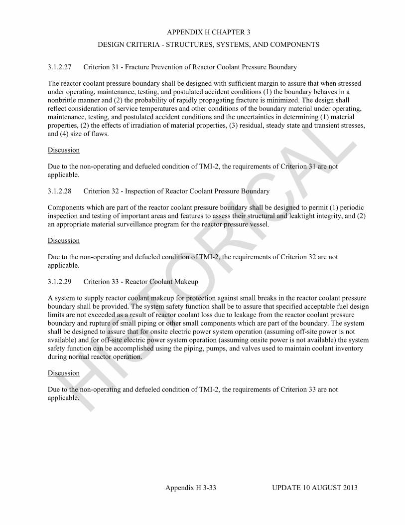
APPENDIX H CHAPTER 3
DESIGN CRITERIA - STRUCTURES, SYSTEMS, AND COMPONENTS
Appendix H 3-33 UPDATE 10 AUGUST 2013
3.1.2.27 Criterion 31 - Fracture Prevention of Reactor Coolant Pressure Boundary
The reactor coolant pressure boundary shall be designed with sufficient margin to assure that when stressed under operating, maintenance, testing, and postulated accident conditions (1) the boundary behaves in a nonbrittle manner and (2) the probability of rapidly propagating fracture is minimized. The design shall reflect consideration of service temperatures and other conditions of the boundary material under operating, maintenance, testing, and postulated accident conditions and the uncertainties in determining (1) material properties, (2) the effects of irradiation of material properties, (3) residual, steady state and transient stresses, and (4) size of flaws.
Discussion
Due to the non-operating and defueled condition of TMI-2, the requirements of Criterion 31 are not applicable.
3.1.2.28 Criterion 32 - Inspection of Reactor Coolant Pressure Boundary
Components which are part of the reactor coolant pressure boundary shall be designed to permit (1) periodic inspection and testing of important areas and features to assess their structural and leaktight integrity, and (2) an appropriate material surveillance program for the reactor pressure vessel.
Discussion
Due to the non-operating and defueled condition of TMI-2, the requirements of Criterion 32 are not applicable.
3.1.2.29 Criterion 33 - Reactor Coolant Makeup
A system to supply reactor coolant makeup for protection against small breaks in the reactor coolant pressure boundary shall be provided. The system safety function shall be to assure that specified acceptable fuel design limits are not exceeded as a result of reactor coolant loss due to leakage from the reactor coolant pressure boundary and rupture of small piping or other small components which are part of the boundary. The system shall be designed to assure that for onsite electric power system operation (assuming off-site power is not available) and for off-site electric power system operation (assuming onsite power is not available) the system safety function can be accomplished using the piping, pumps, and valves used to maintain coolant inventory during normal reactor operation.
Discussion
Due to the non-operating and defueled condition of TMI-2, the requirements of Criterion 33 are not applicable.

APPENDIX H CHAPTER 3
DESIGN CRITERIA - STRUCTURES, SYSTEMS, AND COMPONENTS
Appendix H 3-34 UPDATE 10 AUGUST 2013
3.1.2.30 Criterion 34 - Residual Heat Removal
A system to remove residual heat shall be provided. The system safety function shall be to transfer fission product decay heat and other residual heat from the reactor core at a rate such that specified acceptable fuel design limits and the design conditions of the reactor coolant pressure boundary are not exceeded.
Suitable redundancy in components and features, and suitable interconnections, leak detection, and isolation capabilities shall be provided to assure that for onsite electric power system operation (assuming off-site power is not available) and for off-site electric power system operation (assuming onsite power is not available) the system safety function can be accomplished, assuming a single failure.
Discussion
Due to the non-operating and defueled condition of TMI-2, the requirements of Criterion 34 are not applicable.
3.1.2.31 Criterion 3 5 - Emergency Core Cooling
A system to provide abundant emergency core cooling shall be provided. The system safety function shall be to transfer heat from the reactor core following any loss of reactor coolant at a rate such that (1) fuel and clad damage that could interfere with continued effective core cooling is prevented and (2) clad metal-water reaction is limited to negligible amounts.
Suitable redundancy in components and features, and suitable interconnections, leak detection, isolation, and containment capabilities shall be provided to assure that for onsite electric power system operation (assuming off-site power is not available) and for off-site electric power system operation (assuming onsite power is not available) the system safety function can be accomplished, assuming a single failure.
Discussion
Due to the non-operating and defueled condition of TMI-2, the requirements of Criterion 35 are not applicable.
3.1.2.32 Criterion 36 - Inspection of Emergency Core Cooling System
The emergency core cooling system shall be designed to permit appropriate periodic inspection of important components, such as spray rings in the reactor pressure vessel, water injection nozzles, and piping, to assure the integrity and capability of the system.
Discussion
Due to the non-operating and defueled condition of TMI-2, the requirements of Criterion 36 are not applicable.

APPENDIX H CHAPTER 3
DESIGN CRITERIA - STRUCTURES, SYSTEMS, AND COMPONENTS
Appendix H 3-35 UPDATE 10 AUGUST 2013
3.1.2.33 Criterion 37 - Testing of Emergency Core Cooling System
The emergency core cooling system shall be designed to permit appropriate periodic pressure and functional testing to assure (1) the structural and leaktight integrity of its components, (2) the operability and performance of the active components of the system, and (3) the operability of the system as a whole and, under conditions as close to design as practical, the performance of the full operational sequence that brings the system into operation, including operation of applicable portions of the protection system, the transfer between normal and emergency power sources, and the operation of the associated cooling water system.
Discussion
Due to the non-operating and defueled condition of TMI-2, the requirements of Criterion 37 are not applicable.
3.1.2.34 Criterion 38 - Containment Heat Removal
A system to remove heat from the reactor containment shall be provided. The system safety function shall be to reduce rapidly, consistent with the functioning of other associated systems, the containment pressure and temperature following any loss-of-coolant accident and maintain them at acceptably low levels. Suitable redundancy in components and features, and suitable interconnections, leak detection, isolation, and containment capabilities shall be provided to assure that for onsite electric power system operation (assuming off-site power is not available) and for off-site electric power system operation (assuming onsite power is not available) the system safety function can be accomplished assuming a single failure.
Discussion
Due to the non-operating and defueled condition of TMI-2, the requirements of Criterion 38 are not applicable.
3.1.2.35 Criterion 39 - Inspection of Containment Heat Removal System
The containment heat removal system shall be designed to appropriate periodic inspection of important components, such as the torus, sumps, spray nozzles, and piping to assure the integrity and capability of the system.
Discussion
Due to the non-operating and defueled condition of TMI-2, the requirements of Criterion 39 are not applicable.

APPENDIX H CHAPTER 3
DESIGN CRITERIA - STRUCTURES, SYSTEMS, AND COMPONENTS
Appendix H 3-36 UPDATE 10 AUGUST 2013
3.1.2.36 Criterion 40 - Testing of Containment Heat Removal System
The containment heat removal system shall be designed to permit appropriate periodic pressure and functional testing to assure (1) the structural and leaktight integrity of its components, (2) the operability and performance of the active components of the system, and (3) the operability of the system as a whole, and under conditions as close to the design as practical the performance of the full operational sequence that brings the system into operation, including operation of applicable portions of the protection system, the transfer between n o d and emergency power sources and the operation of the associated cooling water system.
Discussion
Due to the non-operating and defueled condition of TMI-2, the requirements of Criterion 40 are not applicable.
3.1.2.37 Criterion 41 - Containment Atmosphere Cleanup
Systems to control fission product, hydrogen, oxygen, and other substances which may be released in the reactor containment shall be provided as necessary to reduce, consistent with the functioning of other associated systems, the concentration and quality of fission products released to the environment following postulated accidents, and to control the concentration of hydrogen or oxygen and other substances in the containment atmosphere following postulated accidents to assure that containment integrity is maintained.
Each system shall have suitable redundancy in components and features, and suitable interconnections, leak detection, isolation, and containment capabilities to assure that for onsite electric power system operation (assuming off-site power is not available) and for off-site electric power system operation (assuming onsite power is not available) its safety function can be accomplished, assuming a single failure.
Discussion
Due to the non-operating and defueled condition of TMI-2, there are no postulated accidents during PDMS which could result in the generation of fission products, hydrogen, oxygen or other substances which would require Containment atmosphere cleanup systems as described in Criterion 4 1. Therefore, design of the Containment atmosphere cleanup system for TMI-2 during PDMS in accordance with Criterion 41 is not applicable. See the analysis in Section 8.2.
3.1.2.38 .Criterion 42 - Inspection of Containment Atmosphere Cleanup Systems
The containment atmosphere cleanup systems shall be designed to permit appropriate periodic inspection of important components, such as filter frames, ducts, and piping to assure the integrity and capability of the systems.
Discussion
Due to the non-operating and defueled condition of TMI-2, there are no postulated accidents during PDMS which could result in the generation of fission products, hydrogen, oxygen or other substances which would require containment atmosphere cleanup systems as described in Criterion 41. Therefore, design of the Containment atmosphere cleanup system in accordance with Criterion 42 is not applicable to TMI-2 during PDMS.

APPENDIX H CHAPTER 3
DESIGN CRITERIA - STRUCTURES, SYSTEMS, AND COMPONENTS
Appendix H 3-37 UPDATE 10 AUGUST 2013
3.1.2.39 Criterion 43 - Testing of Containment Atmosphere Cleanup Systems
The containment atmosphere cleanup systems shall be designed to permit appropriate periodic pressure and functional testing to assure (1) the structural and leaktight integrity of its components, (2) the operability and performance of the active components of the systems such as fans , filters, dampers, pumps, and valves and (3) the operability of the systems as a whole and, under conditions as close to design as practical, the performance of the full operational sequence that brings the systems into operation, including operation of applicable portions of the protection system, the transfer between normal and emergency power sources, and the operation of associated systems.
Discussion
Due to the non-operating and defueled condition of TMI-2, there are no postulated accidents during PDMS which could result in the generation of fission products, hydrogen, oxygen or other substances which would require containment atmosphere cleanup systems as described in Criterion 41. Therefore, design of the Containment atmosphere cleanup system in accordance with Criterion 43 is not applicable to TMI-2 during PDMS.
3.1.2.40 Criterion 44 - Cooling Water
A system to transfer heat from structures, systems, and components important to safety, to an ultimate heat sink shall be provided. The system safety function shall be to transfer the combined heat load of these structures, systems, and components under normal operation and accident conditions.
Suitable redundancy in components and features, and suitable interconnections, leak detection, and isolation capabilities shall be provided to assure that for onsite electric power system operation (assuming off-site power is not available) and for off-site electric power system operation (assuming onsite power is not available) the system safety function can be accomplished, assuming a single failure.
Discussion
Due to the non-operating and defueled condition of TMI-2, the requirements of Criterion 44 are not applicable.
3.1.2.41 Criterion 45 - Inspection of Cooling Water System
The cooling water system shall be designed to permit appropriate periodic inspection of important components, such as heat exchangers and piping, to assure the integrity and capability of the system.
Discussion
Due to the non-operating and defueled condition of TMI-2, the requirements of Criterion 45 are not applicable.

APPENDIX H CHAPTER 3
DESIGN CRITERIA - STRUCTURES, SYSTEMS, AND COMPONENTS
Appendix H 3-38 UPDATE 10 AUGUST 2013
3.1.2.42 Criterion 46 - Testing of Cooling Water System
The cooling water system shall be designed to permit appropriate periodic pressure and functional testing to assure (1) the structural and leaktight integrity of its components, (2) the operability and the performance of the active components of the system, and (3) the operability of the system as a whole and, under conditions as close to design as practical, the performance of the fuI1 operational sequence that brings the system into operation for reactor shutdown and for loss-of-coolant accidents, including operation of applicable portions of the protection system and the transfer between normal and emergency power sources.
Discussion
Due to the non-operating and defueled condition of TMI-2, the requirements of Criterion 46 are not applicable.
3.1.2.43 Criterion 50 - Containment Design Basis
The reactor containment structure, including access openings, penetrations, and the containment heat removal system shall be designed so that the containment structure and its internal compartments can accommodate, without exceeding the design leakage rate and with sufficient margin, the calculated pressure and temperature conditions resulting from any loss-of-coolant accident. The margin shall reflect consideration of (1) the effects of potential energy sources which have not been included in the determination of the peak conditions, such as energy in steam generators and as required by article 50.44 energy from metal-water and other chemical reactions that may result from degradation but not total failure of emergency core coding functioning, (2) the limited experience and experimental data available for defining accident phenomena and containment responses, and (3) the conservatism of the calculational model and input parameters.
Discussion
Due to the non-operating and defueled condition of TMI-2, the requirements of Criterion 50 are not applicable. However, the intent of Criterion 50 has been addressed by considering that there are functional requirements required to be provided by the Containment during the PDMS period which are different, and substantially less than those described in Criterion 50. The Containment, during PDMS, is required to function as the primary barrier between the radioactive contamination inside the Containment and the environment. It provides the function in three ways: I) it minimizes the uncontrolled migration of contamination from inside the Containment to the environment, 2) it functions as an envelope to control the release of Containment atmosphere effluents to the environment, and 3) it functions as primary shielding for the radioactive materials inside the Containment.
The Containment was originally designed and constructed to the criteria described in Criterion 50. Since the design basis requirements for the Containment during PDMS are substantially less than that required by Criterion 50, the Containment isolation capabilities were not degraded by either the accident or the recovery activities, the Containment is capable of meeting the requirements of PDMS. (See Section 7.1.2)

APPENDIX H CHAPTER 3
DESIGN CRITERIA - STRUCTURES, SYSTEMS, AND COMPONENTS
Appendix H 3-39 UPDATE 10 AUGUST 2013
3.1.2.44 Criterion 51 - Fracture Prevention of Containment Pressure Boundary
The reactor containment boundary shall be designed with sufficient margin to assure that under operation, maintenance, testing, and postulated accident conditions (1) its ferritic materials behave in a nonbrittle manner and (2) the probability of rapidly propagating fracture is minimized. The design shall reflect consideration of service temperatures and other conditions of the containment boundary material during operation, maintenance, testing, and postulated accident conditions, and the uncertainties in determining (1) material properties, (2) residual, steady state, and transient stresses, and (3) size of flaws.
Discussion
Due to the non-operating and defueled condition of TMI-2, the requirements of Criterion 5 1 are not applicable.
3.1.2.45 Criterion 52 - Capability for Containment Leakage Rate Testing
The reactor containment and other equipment which may be subjected to containment test conditions shall be designed so that periodic integrated leakage rate testing can be conducted at containment design pressure.
Discussion
The requirements for leakage rate testing capability as established in Criterion 52 assume the possibility of pressurization events and the consequent potential for leakage of fission products. Due to the non-operating and defueled condition of TMI-2, there are no events which can result in significant pressurization of the Containment and threaten its isolation capabilities (See Criterion 50). During passive pressure control, the Containment will be continually vented to the AFHB through a passive breather system. During operation of the Containment Purge System, a filtered, monitored exhaust path is provided via the station vent to the atmosphere. Therefore, no significant pressurization of the Containment could occur during this mode of operation. Based on the above conditions, no leak rate testing at containment design pressure is required during PDMS.
3.1.2.46 Criterion 53 - Provisions for Containment Testing and Inspection
The reactor containment shall be designed to permit (1) appropriate periodic inspection of all important areas, such as penetrations, (2) an appropriate surveillance program, and (3) periodic testing at containment design pressure of the leaktightness of penetrations which have resilient seals and expansion bellows.
Discussion
The Containment has been designed and constructed in accordance with Criterion 53. Due to the unique condition of TMI-2 during PDMS, the specific requirements of Criterion 53 are not applicable; however, the intent of Criterion 53 has been addressed by providing the appropriate surveillance activities based on the Containment isolation requirements for PDMS as described in Section 7.2.1.

APPENDIX H CHAPTER 3
DESIGN CRITERIA - STRUCTURES, SYSTEMS, AND COMPONENTS
Appendix H 3-40 UPDATE 10 AUGUST 2013
3.1.2.47 Criterion 54 - Piping Systems Penetrating Containment
Piping systems penetrating primary reactor containment shall be provided with leak detection, isolation, and containment capabilities having redundancy, reliability, and performance capabilities which reflect the importance to safety of isolating these piping systems. Such piping systems shall be designed with a capability to test periodically the operability of the isolation valves and associated apparatus and to determine if valve leakage is within acceptable limits.
Discussion
Due to the non-operating and defueled condition of TMI-2 during PDMS, the specific requirements of Criterion 54 regarding leak detection, isolation, and containment capabilities are not applicable. However, piping systems penetrating Containment have been isolated and will be maintained isolated during PDMS as described in Section 7.2.1.
3.1.2.48 Criterion 55 - Reactor Coolant Pressure Boundary Penetrating Containment
Each line that is part of the reactor coolant pressure boundary and that penetrates primary reactor containment shall be provided with containment isolation valves as follows, unless it can be demonstrated that the containment isolation provisions for a specific class of lines, such as instrument lines, are acceptable on some other defined basis:
1. One locked closed isolation valve inside and one locked closed isolation valve outside containment; or
2. One automatic isolation valve inside and one locked closed isolation valve outside containment; or
3. One locked closed isolation valve inside and one automatic isolation valve outside containment. A simple check valve may not be used as the automatic isolation valve outside containment; or
4. One automatic isolation valve inside and one automatic isolation valve outside containment. A simple check valve may not be used as the automatic isolation valve outside containment.
Isolation valves outside containment shall be located as close to containment as practical and upon loss of actuating power, automatic isolation valves shall be designed to take the position that provides greater safety.
Other appropriate requirements to minimize the probability of consequences of an accidental rupture of these lines or of lines connected to them shall be provided as necessary to assure adequate safety. Determination of the appropriateness of these requirements, such as higher quality in design, fabrication, and testing, additional provisions for inservice inspection, protection against more severe natural phenomena, and additional isolation valves and containment, shall include consideration of the population density, use characteristics, and physical characteristics of the site environs.

APPENDIX H CHAPTER 3
DESIGN CRITERIA - STRUCTURES, SYSTEMS, AND COMPONENTS
Appendix H 3-41 UPDATE 10 AUGUST 2013
Discussion
Due to the non-operating and defueled condition of TMI-2 there is no reactor coolant pressure boundary, therefore, the specific requirements of Criterion 55 are not applicable. However, the intent of Criterion 55 has been addressed for PDMS. All piping which penetrates the Containment has been isolated as described in Section 7.2.1.
3.1.2.49 Criterion 56 - Primary Containment Isolation
Each line that connects directly the containment atmosphere and penetrates primary reactor containment shall be provided with containment isolation valves as follows, unless it can be demonstrated that the containment isolation provisions for a specific class of lines, such as instrument lines, are acceptable on some other defined basis:
1. One locked closed isolation valve inside and one locked closed isolation valve outside containment; or
2. One automatic isolation valve inside and one locked closed isolation valve outside containment; or
3. One locked closed isolation valve inside and one automatic isolation valve outside containment. A simple check valve may not be used as the automatic isolation valve outside containment; or
4. One automatic isolation valve inside and one automatic isolation valve outside containment. A simple check valve may not be used as the automatic isolation valve outside containment.
Isolation valves outside containment shall be located as close to containment as practical and upon loss of actuating power, automatic isolation valves shall be designed to take the position that provides greater safety.
Discussion
Due to the unique condition of TMI-2 during PDMS, the specific requirements of Criterion 56 are not applicable; however, the intent of Criterion 56 has been addressed for PDMS. Piping systems penetrating Containment have been isolated outside Containment and will be maintained isolated. Due to the non-operating and defueled condition of TMI-2, one closed isolation valve outside Containment on each piping penetration provides suitable Containment isolation during PDMS. See Section 7.2.1.
3.1.2.50 Criterion 57 - Closed System Isolation Valves
Each line that penetrates primary reactor containment and is either part of the reactor coolant pressure boundary or connected directly to the containment atmosphere shall have at least one containment isolation valve which shall be either automatic, or locked closed, or capable of remote manual operation. This valve shall be outside containment and located as close to the containment as practical. A simple check valve may not be used as the automatic isolation valve.

APPENDIX H CHAPTER 3
DESIGN CRITERIA - STRUCTURES, SYSTEMS, AND COMPONENTS
Appendix H 3-42 UPDATE 10 AUGUST 2013
Discussion
Due to the unique condition of TMI-2 during PDMS, the specific requirements of Criterion 57 are not applicable; however, the intent of Criterion 57 has been addressed for PDMS. All piping systems penetrating Containment have been isolated as described in Section 7.2.1.
3.1.2.51 Criterion 60 - Control of Releases of Radioactive Materials to the Environment
The nuclear power unit design shall include means to control suitably the release of radioactive materials in gaseous and liquid effluents and to handle radioactive solid wastes produced during normal reactor operation, including anticipated operational occurrences. Sufficient holdup capacity shall be provided for retention of gaseous and liquid effluents containing radioactive materials, particularly where unfavorable site environmental conditions can be expected to impose unusual operational limitations upon the release of such effluents to the environment.
Discussion
Due to the unique condition of TMI-2 during PDMS, the specific requirements for Criterion 60 are not applicable; however, the intent of Criterion 60 has been addressed by providing means to suitably control releases of radioactive materials to the environment during PDMS.
3.1.2.52 Criterion 61 - Fuel Storage and Handling and Radioactivity Control
The fuel storage and handling, radioactive waste, and other systems which may contain radioactivity shall be designed to assure adequate safety under normal and postulated accident conditions. These systems shall be designed (1) with a capability to permit appropriate periodic inspection and testing of components important to safety, (2) with suitable shielding for radiation protection, (3) with appropriate containment, confinement, and filtering systems, (4) with a residual heat removal capability having reliability and testability that reflects the importance to safety of decay heat and other residual heat removal, and (5) to prevent significant reduction in fuel storage coolant inventory under accident conditions.
Discussion
Due to the non-operating and defueled condition of TMI-2, the requirements of Criterion 6 1 with regards to fuel handling and storage are not applicable. However, small quantities of residual fuel remain in various locations within the Reactor Coolant System and in other areas of the Reactor Building; the Post-Defueling Survey Reports (References 3.1-8 through 12) identified the quantity of residual fuel in each defined location and addressed the potential for &el relocation. As discussed in Section 4.3.4, the criticality analyses provided in the Defueling Completion Report (DCR) (Reference 3.1-7) and in GPU Nuclear letter, C312-92-2080, dated December 18, 1992 (Reference 3.1-1 3) demonstrated that criticality has been precluded at TMI-2. Finally, personnel accessibility, potential exposure, and other protective features for the residual fuel and other radioactive material are provided consistent with the requirements of Criterion 61.

APPENDIX H CHAPTER 3
DESIGN CRITERIA - STRUCTURES, SYSTEMS, AND COMPONENTS
Appendix H 3-43 UPDATE 10 AUGUST 2013
3.1.2.53 Criterion 62 - Prevention of Criticality in Fuel Storage and Handling
Criticality in the fuel storage and handling system shall be prevented by physical systems or processes, preferably by use of geometrically safe configurations.
Discussion
Due to the non-operating and defueled condition of TMI-2, the requirements of Criterion 62 are not applicable. See Section 4.3.
3.1.2.54 Criterion 63 - Monitoring Fuel and Waste Storage
Appropriate systems shall be provided in fuel storage and radioactive waste systems and associated handling areas (1) to detect conditions that may result in loss of residual heat removal capability and excessive radiation levels and (2) to initiate appropriate safety actions.
Discussion
Due to the non-operating and defueled condition of TMI-2 there will not be any materials which can generate sufficient decay heat to require residual heat removal capabilities. Therefore, the requirements of Criterion 63 are not applicable.
3.1.2.55 Criterion 64 - Monitoring Radioactivity Releases
Means shall be provided for monitoring the reactor containment atmosphere, spaces containing components for recirculation of loss-of-coolant accident fluids, effluent discharge paths, and the plant environs for radioactivity that may be released from normal operation, including anticipated operational occurrences, and from postulated accidents.
Discussion
Due to the unique condition of TMI-2 during PDMS, the specific requirements of Criterion 64 are not applicable; however, the intent of Criterion 64 has been addressed by providing means to monitor radioactivity releases, as described in Sections 7.2.1.2 and 7.2.4, commensurate with the plant condition during PDMS.
REFERENCES
3.1-1 Letter, Travers, W. D. (NRC) to Standerfer, F. R. (GPUNC), "Approval of Exemption from 10 CFR 50.61," dated December 30, 11985.
3.1-2 Letter, Snyder, B. J. (NRC) to Kanga, B. K. (GPUNC), " 10 CFR 50.49, 'Environmental Qualification of Electrical Equipment Important to Safety for Nuclear Power Plants'," dated July 22, 1983.
3.1-3 Letter, Stolz, J. F. (NRC) to Standerfer, F. R. (GPUNC), "Issuance of Amendment (TAC No. 65337)," dated May 27, 1988.
3.1-4 Letter, Snyder, B. J. (NRC) to Hovey, G. K. (Met-Ed), Re: Exemption from 10 CFR 50 Appendix J, dated September 2, 198 1.

APPENDIX H CHAPTER 3
DESIGN CRITERIA - STRUCTURES, SYSTEMS, AND COMPONENTS
Appendix H 3-44 UPDATE 10 AUGUST 2013
3.1-5 Letter, Snyder, B. J. (NRC) to Hovey, G. K. (Met-Ed), Re: Relief from the Inservice Inspection Program Requirements of 10 CFR 50.55a, dated April 27, 1981.
3.1-6 GPU Nuclear letter, 4410-90-L-0044, "Decommissioning Financial Assurance Certification Report for ... TMI-2," dated July 26, 1990.
3.1-7 GPU Nuclear letter, 4410-90-L-0012, "Defueling Completion Report, Final Submittal," dated February 22, 1990.
3.1-8 GPU Nuclear letter, C312-91-2045, "SNM Accountability," transmitting the Auxiliary and Fuel Handling Buildings PDSR, dated June 7, 199 1.
3.1-9 GPU Nuclear letter, C312-91-2052, "SNM Accountability," transmitting the Reactor Building Miscellaneous Components PDSR, dated June 18, 1991.
3.1-10 GPU Nuclear letter, C312-91-2055, "SNM Accountability," transmitting the Reactor Coolant System PDSR, dated July 3, 1991.
3.1-11 GPU Nuclear letter, C312-91-2064, "SNM Accountability," transmitting the 'A' and 'B' Once- Through Steam Generators PDSR, Revision 1, dated July 3, 1991.
3.1-12 GPU Nuclear letter, C312-93-2004, "SNM Accountability, transmitting the Reactor Vessel PDSR, dated February 1, 1993.
3.1-13 GPU Nuclear letter, C312-92-2080;"TMI-2 Reactor Vessel Criticality Safety Analysis,” dated December 18, 1992.
3.1-14 Letter, Masnik, M. T. (NRC) to Standerfer, F. R. (GPUNC) "Three Mile Island Nuclear Station Unit 2 Approval of Exemptions from 10 CFR 70.24 'Criticality Accident Requirements'," dated May 27, 1988.
3.1-15 GPU Nuclear, letter, 1920-99-20112, "Decommissioning Funding Status," dated March 3 1, 1999.
3.1-16 Letter, Thonus, L. H. (NRC) to Langenbach, J. W. (GPUNC) "Exemption from Insurance Coverage Limit of 10 CFR 50.54(w), " dated July 21,1999.

APPENDIX H CHAPTER 3
DESIGN CRITERIA - STRUCTURES, SYSTEMS, AND COMPONENTS
Appendix H 3-45 UPDATE 10 AUGUST 2013
3.2 CLASSIFICATION OF STRUCTURES, SYSTEMS, AND COMPONENTS
3.2.1 SEISMIC CLASSIFICATION
The unit structures, systems, and components have been classified according to their function and the degree of integrity required to protect the public. Structures, components, and systems are classified for seismic design purposes as either Category I or Category II. The original seismic design criteria for structures, components, and systems utilized during PDMS is given in Section 3.2 of the TMI-2 FSAR.
3.2.1.1 Seismic Category I
Seismic Category I structures, systems, and components, including instruments and controls, are those which are necessary to ensure:
a. The integrity of the reactor coolant pressure boundary,
b. The capability to shutdown the reactor and to maintain it in a safe shutdown condition, or
c. The capability to prevent or mitigate the consequences of accidents which could result in potential off-site exposures comparable to the guideline exposures of 10 CFR Part 100.
The first criterion requires the reactor coolant pressure boundary to be ensured. Due to the non- operating and defueled condition of TMI-2, there is no reactor coolant pressure boundary.
The second criterion requires the capability to shutdown the reactor and maintain it in a safe shutdown condition. Due to the non-operating and defueled condition of TMI-2, there is no reactor to shutdown and maintain in a safe shutdown condition. In addition, the criticality analysis discussed in Section 4.3.4 demonstrates that criticality has been precluded at TMI-2.
The third criterion requires the capability to prevent or mitigate the consequences of accidents that could result in potential off-site exposures comparable to the 10 CFR Part 100 guidelines. Analysis demonstrates (see Chapters 7 and 8) that there are no postulated events that could result in releases greater than 10 CFR 50 Appendix I limits, therefore there are no postulated events which could result in exposures comparable to 10 CFR Part 100 guidelines.
Due to the non-operating and defueled status of TMI-2 during PDMS, there are no structures, systems, or components which are required to meet the criteria of seismic Category I. Therefore, there are no structures, systems, or components classified as seismic Category I at TMI-2 during PDMS.
Those structures, systems, and components which were originally designed as seismic Category I and the applicable design criteria are described in Section 3.2.1 of the TMI-2 FSAR.
3.2.1.2 PDMS Category II
Those structures, components and systems which are relied upon for the isolation of residual contamination from the environment and for the prevention of an uncontrolled release of radioactivity during a seismic event have been designated as PDMS Category II.

APPENDIX H CHAPTER 3
DESIGN CRITERIA - STRUCTURES, SYSTEMS, AND COMPONENTS
Appendix H 3-46 UPDATE 10 AUGUST 2013
3.2.1.2.1 Design Basis
All structures, components, and systems which were designed to seismic Category I or seismic Category II are in conformance with the seismic loading requirements of the Uniform Building Code for Zone 1.Those structures, systems, and components that were originally designed and fabricated to seismic Category I or seismic Category I1 requirements have not had their original structural design capability significantly degraded and will meet the seismic loading requirements of the Uniform Building Code for Zone 1.
3.2.1.2.2 PDMS Category II Structures
Structures designated as PDMS Category II are the Reactor Building, the Control and Service Buildings, the Auxiliary Building, and the Fuel Handling Building. These five structures were originally designed to seismic Category I requirements.
3.2.1.2.3 PDMS Category II Systems
As a result of the accident on March 28, 1979, various original plant systems were contaminated with radioactive materials from the reactor core. These systems have been decontaminated to the extent practical. However, a number of these systems still contain some degree of residual contamination and provide an initial barrier for control of the contamination which remains within the respective system. The Containment provides a second barrier for those systems or partial systems located within that structure. The structural capabilities of the systems as originally designed to seismic Category I and seismic Category II criteria have not been degraded significantly and these capabilities provide the necessary degree of contamination control. These PDMS Category II systems and their original seismic design criteria are listed in Table 3.2- 1.
Other piping systems designated as PDMS Category II which were not designed to seismic Category I or seismic Category II criteria also provide an initial barrier for control of internal contamination during the PDMS period. Since these systems were designed to function under equal or higher pressure and temperature conditions, they will maintain structural integrity under the conditions which exist during PDMS. In addition, deactivated systems have been drained to the extent practical, thus, minimizing contaminated leakage from these systems. A breach in system piping which has been deactivated would expose only a very small portion of the piping systems internal surface contamination and as deactivated systems are not pressurized, there is no motive force to expel contamination. Therefore, no further design, analysis, testing, or surveillance is required to assure the structural integrity of those systems relied upon during PDMS. These PDMS Category II systems are listed on Table 3.2-1 and are identified as not being designed to seismic criteria (N/S).
3.2.2 SYSTEM QUALITY GROUP CLASSIFICATION
3.2.2.1 Identification of Safety Related Systems and Components
Due to the non-operating and defueled status of TMI-2 during PDMS there are no safety related systems or components. The original quality group classifications and other design criteria for the original plant systems listed in Table 3.2-11 are given in Section 3.2 of the TMI-2 FSAR.

APPENDIX H CHAPTER 3
DESIGN CRITERIA - STRUCTURES, SYSTEMS, AND COMPONENTS
Appendix H 3-47 UPDATE 10 AUGUST 2013
TABLE 3.2-1
PDMS CATEGORY I1 SYSTEMS
SYSTEM FSAR
SEISMIC CLASS
IN CONTAINMENT
OPERATIONAL/ DEACTIVATED
Core Flood I(1) PART.(2) DEACT.
RB Spray I PART. DEACT.
Decay Heat Removal I PART. DEACT.
Steam Generator Recirculation N/S NO DEACT.
Spent Fuel I PART. DEACT.
Main Steam I(3) PART. DEACT.
Decon Process Water N/S PART. DEACT.
Dewatering Station N/S NO DEACT.
Fuel Transfer Canal Fill and Drain N/S PART. DEACT.
Makeup & Purification I PART. DEACT.
Nuclear Plant Nitrogen II PART. DEACT.
Nuclear Sampling I(4) PART. DEACT.
Temporary Nuclear Sampling N/S(5) No DEACT.
Steam Generator Secondary Vent and Drain Inside Containment
I & II YES DEACT.
Waste Disposal Gas I(6) PART. DEACT.
Defueling Water Cleanup N/S PART. DEACT.
Reactor Coolant I YES DEACT.
Waste Disposal Solid I PART. DEACT.
Fuel Handling I PART. DEACT.
Submerged Demineralizer N/S NO DEACT.
Reactor Building Sump (Level Measurement)
N/S PART. OPER.
Sump Water Sucker N/S PART. DEACT.
Processed Water Storage and Distribution
N/S NO DEACT.
Canister Loading Decon N/S NO DEACT.
Defueling(7) N/S YES DEACT.
Decant Filter Skid N/S NO DEACT.
Sludge Transfer N/S PART. DEACT.

APPENDIX H CHAPTER 3
DESIGN CRITERIA - STRUCTURES, SYSTEMS, AND COMPONENTS
Appendix H 3-48 UPDATE 13 AUGUST 2019
TABLE 3.2-1 (continued)
PDMS CATEGORY I1 SYSTEMS
SYSTEM FSAR
SEISMIC CLASS
IN CONTAINMENT
OPERATIONAL/ DEACTIVATED
Reactor Building Purge Exhaust Upstream of HEPA Filter
II NO OPER.
Upstream of HEPA Filter Waste Disposal - Liquid
I & II PART. OPER.
Key: N/S - Non-seismic
PART. - Partially
DEACT. - Deactivated
OPER. - Operational
NOTES:
(1) Except for N2 supply lines from NM-U-26 and 27 to CF-V-114 and 115.
(2) All of system is in containment except for 1 inch fill and drain lines.
(3) Seismic I up to MSWs and EF-P-2. All else is Seismic II. Portions of Seismic II piping are contaminated.
(4) Majority of system is Seismic 1. Seismic II portion is very small and contains a small pump and associated 1 1/2 inch tubing.
(5) System consists of mainly 1/2 inch and 3/8 inch diameters.
(6) System was designed and constructed Seismic I except for 2 flexible connections to the secondary vent and drain system. A few non-seismic modifications were made during the course of the cleanup effort; however, the majority of the system remains seismically qualified.
(7) System consists of the defueling equipment that remains in the RV.

APPENDIX H CHAPTER 3
DESIGN CRITERIA - STRUCTURES, SYSTEMS, AND COMPONENTS
Appendix H 3-49 UPDATE 10 AUGUST 2013
3.3 WIND AND TORNADO LOADINGS
3.3.1 WIND LOADINGS
3.3.1.1 Design Wind Velocity
Recurrence intervals, data sources and the history of occurrence of high winds, hurricanes and tornadoes in the vicinity of the site are discussed in Sections 2.3.1 and 2.3.2 of the TMI-2 FSAR. Based on studies by the Weather Bureau, wind speeds 30 feet above the site grade are expected to exceed 78 mph once in 100 years. Hence, all structures were designed for forces associated with a wind of 80 mph and, with limited exceptions as described in SAR Section 3.7.2.1.1, exist as originally designed. Additional design information is given in Section 3.3 of the TMI-2 FSAR.
3.3.2 TORNADO LOADINGS
3.3.2.1 Applicable Design Parameters
The forces due to tornado loading have been assumed as the forces associated with a wind having a velocity of 360 mph. The 360 mph velocity is considered as the resultant of a 300 mph tangential and 60 mph translational velocity of the storm. A differential pressure of 3 psi between inside and outside has been considered in the design of the Reactor Building. All other structures designed for tornado loadings are provided either with adequate areas of openings to relieve the differential pressure of 3 psi in 3 seconds or are designed to withstand an external pressure of 3 psi.
3.3.2.2 Tornado Missiles
The missiles assumed to have been generated by the tornado event are listed in Table 3.3-1. They include items such as siding panel, pipe, and steel plate which could be detached from structures under tornado-associated loadings. All these missiles have been investigated for their ability to penetrate exterior concrete walls and slabs. The maximum penetration of a concrete barrier was found to be 30 in. The minimum thickness of structures designed to withstand tornado generated missiles is 36 in. Their effects on the buildings designed for tornado loadings were considered together with the effects of loadings described in Section 3.3.2.1. Thus, with limited exceptions as described in SAR Section 3.7.2.1.1, the capability of buildings designed for tornado loadings will not be jeopardized as a result of flying objects from other structures under a tornado event.

APPENDIX H CHAPTER 3
DESIGN CRITERIA - STRUCTURES, SYSTEMS, AND COMPONENTS
Appendix H 3-50 UPDATE 10 AUGUST 2013
TABLE 3.3-1 TORNADO GENERATED MISSILES
Weight
(lb)
Impact Area
(sq-ft)
Impact Elevation
Above Grade
(ft)
Impact Velocity (mph)
1. Utility pole 1200 1.0 25 200
2. Passenger Auto 2000 25 25 100
3. Passenger Auto 4000 30 3 100
4. Concrete Fragment 10' dia. x 3' x 4"
4500 30 5 60
5. Steel plate 1000 1.0 10 200
6. Crated motor 1000 15 10 200
7. Pipe, 4" 12-0"
250 0.15 25 200
8. Wood plank 4" x 12" x 12’-0"
110 0.33 any height
360
9. Street light fixture 25 0.5 any height
360
10. Crushed rock, 1-1/2"
.25 0.01 any height
360
11. Siding Panels 1.5' x 50'
400 0.04 any height
360
12. Tools 125 0.1 any height
360
13. Ductwork 150 0.3 any height
360
14. 8' Handrail Section
50 0.05 any height
360

Appendix H 3-51 UPDATE 10 AUGUST 2013
3.5 MISSILE PROTECTION CRITERIA
The missile protection criterion (i.e., GDC 4; see Section 3.1.2.4) is based on precluding damage to structures, systems, and components important to safety. During PDMS, there is no equipment that is important to safety; therefore, the consequences of a missile impact are limited to physical damage. With limited exceptions as described in Section 3.7.2.1.1, all contamination isolation structures are protected from a loss of function due to damage from potential external missiles as described below. Due to the non-operating and defueled status of TMI-2 during PDMS, there are no postulated internally generated missiles which would have any effect on the capability of structures to provide their required contamination isolation function.
3.5.1 MISSILE LOADINGS AND BARRJERS
The exterior walls of the Reactor Building, Auxiliary and Fuel Handling Buildings and the Control & Service Buildings were designed to withstand the effects of external missiles.
3.5.2 MISSILE SELECTION
The potential sources of external missiles have been investigated for those buildings designed for missile protection. Missiles generated by environmental conditions and a postulated aircraft impact have been considered. The critical possible missiles have been selected and analyzed. They are described in the following paragraphs.
3.5.3 SELECTED MISSILES
3.5.3.1 Tornado Generated Missiles
The residual contamination which remains at TMI-2 is contained within buildings that have been designed to withstand tornado generated missiles as discussed in Section 3.3.2.2.'
3.5.3.2 Aircraft Impact
The probability of aircraft impact on the station has been studied. The results of evaluations show that the probability of an aircraft impact on the unit is very low (see Section 2.2.3.1.2 of the TMI-2 FSAR and Reference 3.5-1). In addition, all contamination isolation structures1 were designed to withstand a hypothetical aircraft incident. The impact loadings on these structures are assumed to come from:
1. An aircraft of 200,000 lbs. traveling at 200 knots impacting on an effective area of 19 ft. diameter
2. An aircraft of 300,000 lbs. traveling at 200 knots impacting on an area of 16 ft. diameter
3. An object of 6000 lbs. traveling at 200 knots impacting on an effective area of 5 ft. diameter
4. An object of 4000 lbs. traveling at 200 knots impacting on an effective area of 3 ft. diameter.
The results of these analyses provide assurance that with limited exceptions as described in SAR Section 3.7.2.1.1 the hypothetical objects would not perforate or cause collapse of any of these structures.
1 The "Other Buildings" from Table 5.36 that contain less than 1 μCi residual contamination are excluded from this discussion.

Appendix H 3-52 UPDATE 10 AUGUST 2013
3.5.4 BARRIER DESIGN PROCEDURES
With limited exceptions as described in SAR Section 3.7.2.1.1, structures are protected against the effects of all possible missiles, described above, by concrete barriers. The effects depend on the missile features such as weight, shape and velocity, as well as on the barrier features such as material properties and geometry of the barrier. These effects can be classified as follows:
3.5.4.1 Overall Structural Effect
The overall structural effect of a missile impacting on a structure is evaluated by the equivalent static load produced by the missiles. This is done by determining the deflection resulting from dissipation of the kinetic energy and finding the equivalent static load or directly from the kinetic energy of the missile and the magnitude of the missile penetration.
3.5.4.2 Missile Penetration (Localized Effect)
The following empirical formulas have been used to determine the missile penetration into the concrete barrier.
a. Modified Petry Formula
b. Army Corps of Engineers
c. Ballistic Research Laboratory
Computations have been made for all missiles described previously using these formulas. The results show the Petry formula as least conservative, and the Ballistic Research Laboratories formulas as most conservative.
Based on these considerations, it has been ascertained that with limited exceptions as described in SAR Section 3.7.2.1.1, a potential missile would not jeopardize the function of the structures analyzed.
3.5.5 MISSILE BARRIER FEATURES
As shown in Figures 3.7- 1, 3.7 -2 and 3.7-3, the exterior concrete walls and slabs of structures were designed to act as barriers against external missiles.
REFERENCES
3.5-1 ALAB-692 dated September 14, 1982

Appendix H 3-53 UPDATE 10 AUGUST 2013
3.6 SEISMIC DESIGN
The Reactor Building, the Auxiliary and Fuel Handling Buildings, Control and Service Buildings, and other buildings were originally designed to Category I criteria for seismic design. These criteria may be found in Section 3.7 of the TMI-2 FSAR. Due to the non-operating and defueled status of TMI-2 during PDMS, it is not required that these buildings meet the seismic Category I criteria. The seismic criteria in the Uniform Building Code for Zone 1 is suitable for the PDMS period. It is assumed that the structural capability of the buildings as originally designed has not been significantly degraded and would fully comply with the criteria in the Uniform Building Code.
There are no systems which are required to meet the seismic Category I criteria. It is assumed that the systems which were designed to the seismic Category I criteria and contain residual contamination will retain their structural capability through the PDMS period and continue to isolate internal contamination from the external environment.
3.7 DESIGN OF PRINCIPAL BUILDING STRUCTURES
This section addresses the design of the principal buildings which serve protective functions during PDMS. These structures were originally designated as Category I structures and were designed to provide the protective functions associated with an operating nuclear power plant. During PDMS, the protective functions provided by these structures are very limited compared to those for which the building was originally designed. This section presents a summary of the criteria necessary to provide the protective functions required during PDMS. The detailed design criteria for the Category I structures is given in Section 3.8 of the TMI-2 FSAR.
3.7.1 CONTAINMENT BUILDING
3.7.1.1 Structure Description
The Containment Building is a reinforced concrete structure composed of a cylindrical wall with a flat foundation mat and a dome roof. The foundation slab is reinforced with conventional mild steel reinforcing. The cylindrical wall is prestressed with a post tensioning system in the vertical and hoop directions. The dome roof is prestressed utilizing a three-way post tensioning system. The inside surface of the Containment Building is lined with a carbon steel liner to ensure a high degree of leak tightness. The nominal liner plate thickness is 318 in. for the cylinder, 112 in. for the dome and 114 in. for the base.
The foundation mat is bearing on rock and is 11 ft. 6 in. thick with a 2 ft. thick concrete slab above the base liner plate. The cylinder has an inside diameter of 130 ft., a wall thickness of 4 ft. and a height of 157 ft. from the top of the foundation slab to the spring line. The roof is a shallow dome having a large radius of 110 ft., a transition radius of 20 ft. 6 in., and a thickness of 3 ft. 6 in. Typical Containment Building details are shown in Figure 3.7-1.

Appendix H 3-54 UPDATE 10 AUGUST 2013
3.7.1.2 Liner Plate and Penetrations
The liner plate has been designed to function as a leak-tight membrane. Nominal steel plate thicknesses for the plate are 1/2 in. for the dome and the ring girder, 3/8 in. for the cylindrical wall and 1/4 in. for the base. The thicknesses are locally increased at penetrations, polar crane supporting brackets and at equipment support locations.
The liner is anchored to the concrete shell by means of structural tees (ST 31) running vertically and meridionally along the cylinder and dome, respectively. The anchorage system is designed to prevent elastic instability of the liner. A continuous system of steel channel is welded over all liner weld seams on the face of the base line, and over all inaccessible liner weld seams (on the exposed face of the liner) of the wall.
The liner plate and the concrete shell are penetrated by the openings as described below:
a. Equipment Access Hatch and Personnel Air Locks
An equipment hatch with an inside diameter of 23 ft. has been provided to allow passage of large equipment and components into the Containment Building. The equipment hatch is an integral part of the Containment and is bolted to a flanged steel sleeve anchored in the concrete Containment wall and welded to the Containment liner so that the equipment hatch can be removed and reinstalled from the outside of the Containment Building. One personnel air lock is a removable unit penetrating through the equipment hatch. The equipment hatch, consisting of the hatch cover, the attached air lock, and the flanged sleeve, is a complete gas-tight unit when field assembled. A second personnel air lock is welded to the Containment liner, detailed layouts of these openings are shown in Figure 3.7-2.
b. Piping and Electrical Penetrations
The piping penetrations are normally anchored at the Containment Building shell. Typical piping ducts and penetrations are shown in Figure 3.7-3. All penetrations are of the double barrier type. Where temperature considerations require, the second barrier of the piping penetration includes expansion bellows. The electrical penetrations are welded closures.
c. Modified Penetrations
Several penetrations were modified during the cleanup period. These penetrations were modified in accordance with criteria submitted to the NRC (Reference 3.7-1).
Piping and electrical penetrations were designed and modified to withstand at least 5 psig and tested to hold 1.2 to 1.5 times this pressure for not less than 10 minutes in accordance with ANSI B3 1.1. Fluid hard piped piping was designed, modified, and tested in accordance with ANSI B3 1.1.
The leakrate from modified penetrations, including flange and isolation valve leakage, was limited to 100 sccm per 1 inch of pipe diameter.

Appendix H 3-55 UPDATE 10 AUGUST 2013
c. Modified Penetrations (continued)
A complete listing of all containment penetrations is provided in PDMS SAR Table 7.2- 2 which includes the status of each for PDMS. The containment penetrations that are in a modified configuration for PDMS are listed in Table 3.7-1 which also provides details of the modifications. For this review, a modification to a containment penetration was included if the modification was made to the area from the inboard isolation valve through the penetration to and including the outboard isolation valve. Modifications to containment penetrations during the recovery period have been accomplished such that the combined modified cross sectional area does not exceed the NRC safety evaluation requirement of 40 square feet (Reference 3.7-2).
The Containment Atmospheric Breather has been added to the Containment to provide passive pressure control of the Containment relative to ambient atmospheric pressure and to establish a "most probable pathway" through which the Containment will "breathe." This addition ensures that the Containment structure will not experience significant pressure differential to threaten the structural capability of the contamination boundaries provided by the Containment. Further discussion of the Breather is provided in PDMS SAR Section 7.2.1.2.
3.7.2 OTHER PRINCIPAL STRUCTURES
3.7.2.1 Description of Structures
The physical layout of other principal structures for the unit is shown in Figures 3.7-4 and 3.7-5.Following is the physical description of these structures. All these structures are constructed of reinforced concrete.
3.7.2.1.1 Auxiliary Building
The Auxiliary Building was designed to house the components of auxiliary systems required for reactor coolant purification, conditioning, reprocessing and cooling, radwaste processing, and engineered safety features. The Fuel Handling Building and this building are physically attached by means of a common structural wall. A vertical air intake shaft is also attached to the east wall of this building. The Auxiliary Building is rectangular in plan and has three main floors. At the east exterior wall, a large door opening is located at the grade level. This door opening is not protected from an aircraft impact loading or external missiles. In addition, concrete drilling operations in a small exterior wall section of the Auxiliary Building damaged six (6) reinforcing steel bars, two (2) of which impact the ability of the Auxiliary Building to meet TMI-2 FSAR design criteria for aircraft impact. Nonetheless, the wall presently meets normal non-operating load requirements. These two (2) areas comprise the limited exceptions to wind and tornado loadings and missile protection alluded to in SAR Sections 3.3 and 3.5. To the south of this building is the Service Building and a portion of the Control Building Area. There is one foot separation between these structures. All floors of this building are slab-beam and flat slab construction. '
3.7.2.1.2 Fuel Handling Building
The Fuel Handling Building was designed to accommodate the storage of new and spent fuel. In addition, it provides an area to accommodate the storage of packaged waste prior to off-site disposal. This building is physically connected to the Auxiliary Building on the east side by means of a common wall. The Fuel Handling Building of Unit 1 is located on the north side. The clear distance between these two buildings is 3 in. One bridge crane, common to both buildings, is used for fuel handling. There is no wall separating these structures at the top floor (above elevation 347'-6"). The Containment structure is located on the south side of this building and is separated by a clear gap of 2 in. Two stainless steel lined, reinforced concrete fuel storage pools are located in the Fuel Handling Building.

Appendix H 3-56 UPDATE 10 AUGUST 2013
3.7.2.1.3 Control and Service Buildings
The Control Building and the Service Building are separated by a common wall. The Control Building houses a control room, a battery room, a cable room and a mechanical equipment room. The Service Building provides access to the Reactor Building, the Auxiliary Building and the control room. The Service Building serves as the Rad. Con. Control Point for Unit Two. The Control and Service Buildings are rectangular buildings with a common foundation mat. Floors of the control building are supported by interior walls only and a peripheral gap of 4" between edges of the floors and the inside face of the exterior walls has been provided to create a structural separation between the exterior structure and the interior structure. The purpose of this separation is to protect vital and sensitive control room equipment from dynamic aircraft impact loading to which the exterior walls and the roof could be subjected. Door openings and other penetrations in exterior walls of the control building that are susceptible to aircraft loading have been shielded by reinforced concrete shield walls. The Control and Service Buildings are surrounded but physically separated from the Auxiliary Building, the Control Building Area and the Turbine Building.
3.7.2.1.4 Control Building; Area
The Control Building Area is located between the Reactor Building and the Turbine Building and accommodates the main steam relief and isolation valves and emergency steam generator feedwater pumps. This is a one story underground structure from the Turbine Building on the south end. At the north end, this structure follows the curvature of the outside face of the Containment Structure. On the west side, a metal frame structure called the CACE is situated at ground level. Protecting the RB equipment hatch.
3.7.2.1.5 Air Intake Tunnel
The air intake tunnel provides a passage for air to be distributed into the following structures: Reactor Building, Auxiliary Building, Fuel Handling Building, Control Building, Service Building and Control Building Area. The air intake tower at an end of the tunnel extends above the grade level. The bottom of the air intake extends 12' -0" below the bottom of the tunnel providing a large well for the accumulation of rain water inleakage. Access to the tunnel is provided from the Service Building and from the air intake tower. One manhole from the grade level to the tunnel floor has been provided for emergency egress. Near the Auxiliary Building, the tunnel bends 90 degrees upward and changes into a rectangular concrete plenum. The plenum extends above the grade level and is closed off at the Auxiliary Building roof level. The supply air enters the Service Building and the Auxiliary Building through the openings in walls of the plenum.
REFERENCES
3.7- 1 GPU Nuclear letter LL2-81-0191, "Design Pressure for Containment and Future Mechanical and Electrical Penetration Modifications," dated December 4, 1981.
3.7-2 Letter, W. D. Travers (NRC) to F. R. Standerfer (GPUNC), "Seismic Design Criteria for Modified Containment Penetrations" dated April 3, 1987.

Appendix H 3-57 UPDATE 10 AUGUST 2013
TABLE 3.7-1
MODIFIED CONTAINMENT PENETRATIONS
PENETRATION NUMBER MODIFICATION
R-401 This penetration was modified in late summer 1979 to allow access to obtain samples of the Reactor Building (RB) sump water. Following successful completion of the sampling program, further changes were made to use the penetration for RB water level measurement by addition of a manometer system to the sampling tube. A further modification was made to provide a more permanent closure in consideration of future potential increase of RB water level to the extent of flooding the penetration. This final modification removed the 12 inch gate valve and special cover assembly outboard of the valve and welded a closure assembly to the penetration.
R-561 The penetration was modified to provide a flow path into the RB for a high pressure decontamination water supply and additional service air. This penetration modification consisted of replacing an existing 10 inch penetration with a 10 inch flange with three piping connections on the outboard side containing isolation valves and hose connections on the inboard side.
R-545 The spare penetration was modified to provide a flow path into and out of the RB for the DWCS. This penetration modification consisted of adding a double valve pressure boundary on the outboard side and providing piping for a hose connection on the inboard side.
R-536 This spare penetration was modified to provide a flow path into the RB for Plasma Arc Nitrogen as a quenching gas for PC1 cutting operations. This penetration modification consisted of adding a two inch pipe through the penetration with isolation valves on the outboard side, including penetration test connections and hose adapter on the inboard side.
R-508 This electrical penetration was modified to provide an access for ROSA cables and CCTV coaxial cables. This penetration modification consisted of boring and tapping holes in the existing flange for cable routing, resealing and testing for leaks.
R-554 The penetration was modified to provide a source of clean compressed air for use with pneumatic controls and operators. This penetration modification consisted of replacing two (2) outboard containment isolation valves with three (3) valves and adding a flow limiter and quick disconnect on the inboard side.
R-555(c) The penetration was modified to provide access for a Plasma Arc Cutting machine ground cable. This penetration has had a blind flange installed.

Appendix H 3-58 UPDATE 10 AUGUST 2013
TABLE 3.7-1 continued
MODIFIED CONTAINMENT PENETRATIONS
PENETRATION NUMBER MODIFICATION
R-562 The penetration was modified to provide a flow path for sludge transfer from the RB to the spent resin storage tank in the Auxiliary Building. This penetration modification consisted of adding a double valve pressure boundary on the outboard side and piping for a hose connection on the inboard side.
R-565 The penetration was modified to provide a means of transferring shield water to the containment sump. This penetration modification consisted of adding a piping spool assembly to the outboard side of the penetration.
R-626 The penetration was initially modified to insert an antenna and camera arrangement into Containment. These were subsequently removed and the penetration was modified to allow pumping out of the RB basement. This penetration modification consisted of installing a new spool piece and piping. For PDMS, a flange was bolted over the penetration with a single pipe centered in the flange. The pipe has an isolation valve with a cap installed on the end of the pipe.
*"Tying-in with the pipe" can be effected in one of two ways:
1. Cutting the existing pipe completely and adding a "T" fitting; or
2. Cutting a circular hole in the existing pipe and welding a new pipe to it.
In either case, the end result of two parallel flow paths where one previously existed.

Appendix H 3-59 UPDATE 10 AUGUST 2013
FIGURE 3.7-1 REACTOR BUILDING GENERAL LAYOUT
*** Best Available Copy

Appendix H 3-60 UPDATE 10 AUGUST 2013
FIGURE 3.7-2 REACTOR BUILDING
PERSONNEL & EQUIPMENT ACCESS OPENINGS DETAIL

Appendix H 3-61 UPDATE 10 AUGUST 2013
FIGURE 3.7-3 CONTAINMENT WALL
PENETRATIONS DETAILS

Appendix H 3-62 UPDATE 10 AUGUST 2013
FIGURE 3.7-4 SECTION THROUGH THE
PLANT STRUCTURES – “A-A”

Appendix H 3-63 UPDATE 10 AUGUST 2013
FIGURE 3.7-5 SECTION THROUGH THE
PLANT STRUCTURES – “B-B”

Appendix H 3-64 UPDATE 10 AUGUST 2013
FIGURE 3.7-6 SECTION THROUGH THE
PLANT STRUCTURES “C-C” & “D-D”

Appendix H 1-i UPDATE 14 AUGUST 2021
APPENDIX H CHAPTER 1 INTRODUCTION AND GENERAL DESCRIPTION OF PLANT
TABLE OF CONTENTS
SECTION TITLE PAGE
1.1 INTRODUCTION 1-1
1.1.1 POST-DEFUELING MONITORED STORAGE 1-1
1.1.2 TRANSITION TO POST-DEFUELING MONITORED STORAGE
1-2
1.1.2.1. PREREQUISITES FOR PDMS 1-2
1.1.2.2 TRANSITION ACTIVITIES 1-3
1.1.3 APPLICABLE REGULATIONS 1-5
1.1.4 SAFETY-RELATED STRUCTURES, SYSTEMS, AND COMPONENTS
1-5
1.1.5 DEVELOPMENT OF ACCEPTABLE OFF-SITE DOSE 1-6
1.1.6 RELATIONS OF THIS PDMS SAR TO EXISTING UNIT DSAR AND UNIT 2 FSAR
1-6
1.2 GENERAL PLANT DESCRIPTION 1-6
1.2.1 SITE CHARACTERISTICS 1-7
1.2.2 CONTAINMENT SYSTEMS 1-7
1.2.2.1 CONTAINMENT 1-7
1.2.2.2 CONTAINMENT ISOLATION VALVES 1-7
1.2.8 FACILITIES AND SYSTEMS RELEASED FOR SITE USE 1-7
1.3 MATERIAL REFERENCED 1-9
1.4 PRESENTATION 1-13
1.4-1 DRAWINGS 1-13
1.4-2 ABBREVIATIONS AND ACRONYMS 1-13
LIST OF TABLES
Table 1.4-1 DRAWINGS 1-14
Tables 1.4-2 ABBREVIATIONS AND ACRONYMS 1-17

APPENDIX H CHAPTER 1 INTRODUCTION AND GENERAL DESCRIPTION OF PLANT
Appendix H 1-1 UPDATE 14 AUGUST 2021
1.1 INTRODUCTION
This Post-Defueling Monitored Storage (PDMS) Safety Analysis Report (SAR) was submitted in support of the application of GPU Nuclear Corporation (GPU Nuclear) as agent for Metropolitan Edison Company (Met-Ed), Jersey Central Power & Light Company (JCP&L), and Pennsylvania Electric Company (Penelec) for revision of the existing Class 103 license to delineate the non-operating status of the nuclear electric generating station designated as Three Mile Island Nuclear Station Unit 2 (TMI-2). There are various sections of this SAR which reference either the Unit 1 DSAR or Unit 2 FSAR for relevant information. These refer to information which has been previously reviewed and approved by the NRC, remains valid, and does not require further review. The TMI-1 DSAR will continue to be updated in accordance with 10 CFR 50.71(e) whereas the TMI-2 FSAR update is no longer required.
The Three Mile Island Unit 2 operating license was issued on February 8, 1978, and commercial operation was declared on December 30, 1978. On March 28, 1979, the unit experienced an accident which resulted in severe damage to the reactor core. TMI-2 has been in a non-operating status since that time. GPU Nuclear conducted a substantial program to defuel the Reactor Vessel and decontaminate the facility. As a result, TMI-2 has been defueled and decontaminated to the extent that the plant is in a safe, inherently stable condition suitable for long-term management and any threat to the public health and safety has been eliminated. This long-term management condition is termed Post-Defueling Monitored Storage.
1.1.1 POST-DEFUELING MONITORED STORAGE
Post-Defueling Monitored Storage has been established at this time based on three principal considerations:
1. The Reactor Vessel and the Reactor Coolant System have been defueled and the core material has been shipped off-site.
2. Decontamination has been completed to the extent that further major decontamination programs are not justified on the basis of worker dose.
3. A condition of stability and safety has been established such that there is no risk to public health and safety.
These three criteria are interrelated in that each has some degree of dependence on the other. A significant amount of decontamination had to be completed prior to the beginning of defueling. As defueling progressed and was completed, further decontamination tasks were undertaken which allowed for the completion of other cleanup activities. Extensive decontamination and the completion of defueling were required to establish the inherently stable and safe condition of the facility such that there was no risk to public health and safety.

APPENDIX H CHAPTER 1 INTRODUCTION AND GENERAL DESCRIPTION OF PLANT
Appendix H 1-2 UPDATE 10 AUGUST 2013
Although it would be possible to continue decontamination of the facility, this effort would not appreciably enhance the overall stability and maintainability of the facility nor would it add to the overall margin of safety for the public. However, additional decontamination at this time would result in unnecessary additional occupational exposure to personnel who would be conducting the decontamination tasks. In addition, further decontamination might require some destructive decontamination techniques which would be best conducted when the plant is decommissioned. By placing TMI-2 in a long-term monitored storage condition at this time (i.e., until the time of decommissioning of TMI-I), it is possible to realize a significant savings in occupational exposure by deferring remaining decontamination activities for a number of years. For example, assuming all other factors to be equal, natural decay of the dominant radioactive isotopes (Sr-90, Cs-137) over a 30-year period would result in the occupational exposure being reduced by a factor of approximately two for any given task. It is possible that additional reductions in occupational exposure also could result from advances in decontamination technology and robotics. Although the exact reductions in occupational exposure are extremely difficult to quantify, it is clear that postponement of the remaining pre-decommissioning decontamination activities will result in a significant savings in occupational exposure (Reference Table 5A-10, Chapter 5). This estimate was based on information published by the NRC in Supplement 1 to the Programmatic Environmental Impact Statement (PEIS) and adjusted to account for variations in the scope of the work and actual exposure experience during the cleanup.
Based on this preliminary analysis and using revised data, GPU Nuclear, in 1985, more accurately quantified the potential savings in occupational exposure due to the deferral of the remaining decontamination tasks. The results of this extensive effort are presented in Chapter 5, Appendix 5A. Given that occupational exposure remains the singular contributor to environmental impact, avoidance of unnecessary exposure where the public health and safety are not at risk is appropriate.
1.1.2 TRANSITION TO POST-DEFUELING MONITORED STORAGE
The formal transition from the post-accident condition to PDMS required NRC approval. The establishment of PDMS occurred over a period of time preceding the formal implementation of PDMS and extending into PDMS. Not all activities leading to the final PDMS configuration were completed prior to the implementation of PDMS. However, during the transition period, all of the prerequisites to PDMS were satisfied. The following sections outline those conditions which were established prior to the implementation of PDMS and those activities which extended for some period of time subsequent to PDMS implementation.
1.1.2.1 Prerequisites for PDMS
The following prerequisites were satisfied prior to the implementation of PDMS.
1. It has been demonstrated that there is no credible possibility of nuclear criticality. This condition has been assured by the removal of substantially all of the fuel from the Reactor Vessel and elimination of all potentially critical configurations. The elimination of any credible possibility of nuclear criticality was demonstrated as a requirement for transition to Mode 2 in accordance with the TMI-2 Recovery Technical Specifications. GPU Nuclear Letters 4410-90-L-0012 (Defueling Completion Report), C312-92-2080 (Reactor Vessel Criticality Safety Analyses) and C312-93-2004 (Reactor Vessel Post Defueling Survey Reports) have been submitted to support this conclusion.

APPENDIX H CHAPTER 1 INTRODUCTION AND GENERAL DESCRIPTION OF PLANT
Appendix H 1-3 UPDATE 10 AUGUST 2013
2. All fuel and core debris which have been removed from the Reactor Vessel and associated systems have been shipped off-site.
3. Any potential for a significant release of radioactive material has been eliminated. Radioactive material has been removed and other sources of radioactivity have been isolated so that any potential radioactive release will be within 10 CFR 50 Appendix I guidelines for off site dose consequences.
4. As precondition to implementing PDMS, water has been removed to the extent practical from the Reactor Coolant System and the Fuel Transfer Canal, and the fuel transfer tubes have been isolated. To the extent that the Spent fuel Pools are needed to support Accident Generated Water disposal activities, water may remain in these pools subsequent to the implementation of PDMS. The treatment and processing of the Accident Generated Water has been completed.
5. All radioactive waste from the major cleanup activities has been shipped off-site or has been packaged and staged for shipment off-site.
6. Radiation within the facility has been reduced, as necessary, consistent with As-low-as reasonably-achievable (ALARA) principles to levels which will allow necessary plant monitoring activities, the performance of required maintenance, and any necessary inspections.
1.1.2.2 Transition Activities
Although the conditions described in Section 1.1.2.1 were established prior to the implementation of PDMS, there were some conditions described in this SAR which were not essential to the implementation of PDMS and the related activities were conducted subsequent to the implementation of PDMS. A general description of some of those activities and conditions follows.
1. Decontamination – During the initial stages of PDMS, removal or isolation of small sources of radioactivity or radioactive material will be ongoing.
2. Radioactive Waste – Small quantities of radioactive waste will continue to be generated, accumulated, and packaged during PDMS. Thus, radioactive waste shipments will continue during PDMS.
3. PDMS Electrical Modification – The TMI-2 PDMS Electrical Modification results in a safer, more reliable power system than the system existing during Facility Mode 3. Although many electrical loads were eliminated during PDMS preparation, this modification further consolidates loads to produce a simpler, easier to maintain electrical power system. The PDMS Electrical Modification was completed in July of 1994.
4. Cork Seam – The TMI-2 Cork Seam is a cork-filled construction joint located between the various major structures at TMI-2 (See Figure 1.4-1). During the TMI-2 accident, the cork seam located in the Auxiliary Building Seal Injection Valve Room (SIVR) was contaminated with radioactive water. Since the accident, radioactive material has spread along the joint in one direction into the Annulus, and in the other direction into the Auxiliary Building, Service Building, and control building Area. The radioactive contamination is prevented from entering the ground water table by a PVC waterstop and thus represents no threat to the health and safety of the public.

APPENDIX H CHAPTER 1 INTRODUCTION AND GENERAL DESCRIPTION OF PLANT
Appendix H 1-4 UPDATE 10 AUGUST 2013
Modifications have been made to the cork seam to allow periodic monitoring of the water levels in the joint, to permit periodic removal, and to prevent water and contamination migration within the cork filled joint. Figure 1.4-1 shows the locations where the cork seam was penetrated and modifications performed. At locations S-2, S-6, S-7, S-8, and S-9, one inch diameter holes were drilled into the cork seam to a depth of about one inch above the PVC waterstop. A perforated tube was inserted into these monitoring holes and acts much like a conventional well point providing a means of pumping accumulated water out of the seam in the vicinity. Also, the monitor pipes have been fitted with bubbler devices that allow measuring of the water level in the hole.
During the drilling for hole S-6, samples of water and cork were removed for analysis. From the data obtained, it was determined that the 40-year Total Integrated Dose to the PVC waterstop in this area would be 6.3E5 rads. This is less than 5% of the dose that would cause degradation of the material.
At locations S-1, S-3, S-4, S-5, and S-10, four inch diameter holes were core bored to penetrate the cork and the adjacent concrete slab on both sides of the seam. These holes extend down to the surface of the PVC waterstop. When these holes were drilled, the bottom was carefully probed with a blunt instrument to verify that the hole had actually reached the waterstop and to verify that the water stop had not been breached and the material was still pliable. Where possible the waterstop was visually inspected. The hole was then filled with a moisture activated expandable polyurethane foam material that will bond well with both the concrete and waterstop material. These locations serve as dams that will block water migration within the cork seam.
To prevent any additional spread of contamination from the cork seam in the future, work was completed to install a seal over the top of the cork filled joint. The work involved excavating about 3 inches of cork from the top of the joint along all accessible areas of the full length of the seam. The concrete edges were surface prepped and primed where required; an open cell polyurethane foam backer bar was packed into the joint. The materials chosen for this modification are expected to provide a very tight bond with the concrete and provide a good pliable contamination barrier over the surface of the cork seam.
The monitoring holes remained intact after installation of the top seal as described above. This will permit continued monitoring and sampling of the water that may enter the seam, and removal for processing as required. A program is in place for continued monitoring of the water level in the cork seam by the PDMS staff. If the water levels begin to increase, the water will be pumped out for processing as needed.
TMI-2 has been maintained in a safe, monitored condition throughout the transition period prior to PDMS, and will be maintained accordingly following implementation of PDMS even though some transition activities are ongoing. A commitment tracking process was established to verify the status and completion of all activities performed in preparation for PDMS and during the PDMS transition period to ensure all required activities described in this SAR are completed.

APPENDIX H CHAPTER 1 INTRODUCTION AND GENERAL DESCRIPTION OF PLANT
Appendix H 1-5 UPDATE 10 AUGUST 2013
1.1.3 APPLICABLE REGULATIONS
GPU Nuclear received an amended facility license for TMI-2 in accordance with the provisions of Title 10 to the Code of Federal Regulations, Part 50 (10 CFR 50). The provisions of 10 CFR 50, as established, were intended to be applicable to an operable nuclear power plant. For this reason, many of the requirements originally imposed on TMI-2 no longer apply or can be substantially reduced in scope because of the status of TMI-2 during PDMS.'
Because nuclear criticality has been precluded with removal of substantially all of the fuel from TMI-2, and because radiation hazards have been substantially reduced due to the immobilization of essentially all of the radioactivity remaining in the plant, many systems, structures, and components are no longer required and the regulations governing these systems, structures, and components have a significantly reduced scope of applicability at TMI-2.
In order to assure compliance with the appropriate requirements of the regulations in 10 CFR 50, a thorough review of these regulations was undertaken. Chapter 3 of this SAR presents the results of that review and serves as the basis for determining which regulations have a controlling impact on TMI-2.
The determination of applicability does not suggest that some regulations can be ignored. Rather, the intent of some regulations can be met with no impact or additional requirements imposed due to the PDMS status of TMI-2.
1.1.4 SAFETY-RELATED STRUCTURES, SYSTEMS, AND COMPONENTS
There are no structures, systems, or components classified as safety-related at TMI-2 during PDMS. GPU Nuclear procedures define safety-related structures, systems, and components as those which are necessary to ensure:
a. The integrity of the reactor coolant 'pressure boundary,
b. The capability to shutdown the reactor and to maintain it in a safe shutdown condition, or
c. The capability to prevent or mitigate the consequences of accidents which could result in potential off-site exposures comparable to the guidelines exposures of 10 CFR Part 100.
Criterion a requires maintenance of the reactor coolant pressure boundary. Due to the defueled condition of TMI-2, there is no reactor coolant or reactor coolant pressure boundary required.
Criterion b requires a capability to shutdown the reactor and maintains it in a safe shutdown condition. In ' its current defueled state, there are no structures, systems, or components required to maintain a safe shutdown condition.
Criterion c requires a capability to prevent or mitigate the consequences of accidents that could result in potential off-site exposures comparable to the 10 CFR Part 100 guidelines. Analysis demonstrates (see Chapters 4 and 8) that there are no postulated events that result in releases greater than 10 CFR 50 Appendix 1 guidelines. Since 10 CFR 50 Appendix I is more restrictive, there are no postulated events which could result in exposures comparable to 10 CFR Part 100 guidelines. Due to the non-operating and defueled status of TM-2 during PDMS, there are no structures, systems, or components which are required to meet the safety-related criteria. Therefore, there are no structures, systems, or components classified as safety-related at TMI-2 during PDMS.

APPENDIX H CHAPTER 1 INTRODUCTION AND GENERAL DESCRIPTION OF PLANT
Appendix H 1-6 UPDATE 14 AUGUST 2021
1.1.5 DEVELOPMENT OF ACCEPTABLE OFF-SITE DOSE CRITERIA
Various regulations establish permissible limits for off-site radiation exposures resulting from the operation of licensed nuclear reactors and other nuclear fuel cycle activities. These regulations include 10 CFR 20, 10 CFR 50 Appendix I, 10 CFR 100, 40 CFR 190, and the EPA Protective Action Guidelines. The licensing basis for off-site dose criteria for PDMS has been derived from these existing regulations and applicable precedents. Specifically, 10 CFR 50 Appendix I, which is recognized as demonstrably safe with respect to radiological implications, has been established as the PDMS standard. A small fraction (i.e., less than 10%) of the Appendix I off-site dose guidelines is expected to be maintained for normal conditions prevailing during PDMS. The potential off-site radiological doses resulting from postulated off-normal conditions will be within the 10 CFR 50 Appendix I guidelines.
Due to the non-operating and defueled status of TMI-2, a major radiological release approaching the guidelines of 10 CFR 100 is no longer credible. As noted above, Appendix I guidelines have been selected as the limiting criteria for the evaluation of unanticipated events as an unarguable, demonstrably, conservative basis. This ultra-conservative approach far exceeds the regulatory limits for unanticipated events in operating nuclear power plants.
1.1.6 RELATIONS OF THIS PDMS SAR TO THE EXISTING UNIT 1 DSAR AND UNIT 2 FSAR
This PDMS SAR makes reference to relevant portions of the Unit 1 DSAR or the Unit 2 FSAR. The TMI-1 DSAR will continue to be updated as required, and the updated document will be applicable for those changing site-related conditions that have a bearing on TMI-2. The TMI-2 FSAR will not be updated but will continue to be applied as appropriate to TMI - 2 in the PDMS condition. In particular, the bounding conditions in the TM-2 FSAR as augmented by the PDMS SAR will be used to judge the acceptability of changes, tests, and experiments with regard to 10CFR50.59. The TMI-2 FSAR also applies for those areas not addressed by this PDMS SAR.
1.2 GENERAL PLANT DESCRIPTION
On March 28, 1979, Three Mile Island Unit 2 experienced an accident which severely damaged the reactor core. In the ensuing years, the reactor core has been removed and shipped to the Idaho National Engineering Laboratory for analysis and long-term storage. In addition, the facility has been substantially decontaminated and is in a stable and benign condition suitable for long-term management.
Three Mile Island Unit 2 was originally designed to comply with the seventy General Design Criteria of 10-CFR 50, Appendix A, dated July 11, 1967 and addressed plant design with respect to the Revised General Design Criteria dated July 15, 1971. Due to the defueled and non-operating status of TMI-2 during PDMS, many of these criteria no longer apply to the facility. A review of the General Design Criteria, revised as of January 1, 1987, is included k Section 3.1 of this SLY.
The general arrangement of major equipment and structures, including the Reactor, Auxiliary, and Turbine Buildings is shown on Drawings listed in Table 1.4-1.

APPENDIX H CHAPTER 1 INTRODUCTION AND GENERAL DESCRIPTION OF PLANT
Appendix H 1-7 UPDATE 10 AUGUST 2013
1.2.1 SITE CHARACTERISTICS
The site is located on the Susquehanna River about ten miles southeast of Harrisburg, Pennsylvania. It is characterized by a 2,000 foot minimum exclusion distance; a two mile radius low population zone; sound bedrock as a structural foundation; an ample supply of emergency off-site power and favorable conditions of hydrology, geology, seismology and meteorology. The land within a ten mile radius of the site is used primarily for farming.
There are two airports within ten miles of the site.' Harrisburg International Airport (formerly Olmsted State Airport) is located approximately two and one-half miles northwest of the site, and the Capitol City Airport is located approximately eight miles west-northwest of the site.
1.2.2 CONTAINMENT SYSTEMS
The Containment and associated systems are used during PDMS as the environmental barrier for the residual contamination which remains inside the Containment structure. The Containment encloses the areas and systems which contain essentially all of the contamination which could potentially result in off-site exposures.
1.2.2.1 Containment
The primary function of the Containment during PDMS is as a contamination barrier. The Containment will provide shielding of the environment from the radiation inside the Containment, and will also provide the means to assure that any effluents from the Containment will be controlled, filtered, and monitored.
The Containment is a reinforced concrete structure composed of cylindrical walls with a flat foundation mat and a dome roof lined with carbon steel. The structure provides biological shielding for normal and unanticipated conditions. The steel liner encloses the equipment and systems which remain inside the Containment and ensures that the upper limit of potential leakage of radioactive material will not be exceeded under the worst unanticipated event.
1.2.2.2 Containment Isolation Valves
The Containment isolation valves were designed to provide a barrier on the system lines which penetrate the Containment so that no event can result in loss of isolation or intolerable leakage. In most cases, the valves are installed both inside and outside the Reactor Building on each system line. Only one valve is required for isolation during PDMS. All valves used for containment isolation during PDMS are normally closed and locked, closed and deactivated or closed and administratively maintained closed except for the breather isolation valve and RB pressure indication piping which are normally open.
1.2.8 FACILITIES AND SYSTEMS RELEASED FOR SITE USE
As a result of the accident, unique situations developed which could not be properly managed with the existing facilities or systems which were designed for normal operating power plant use. Several systems were designed and fabricated to process the radioactive wastes resulting from cleanup activities.
Upon completion of cleanup activities, several of these facilities were released to general site use (and included under the TMI- 1 license). These systems and facilities include:

APPENDIX H CHAPTER 1 INTRODUCTION AND GENERAL DESCRIPTION OF PLANT
Appendix H 1-8 UPDATE 10 AUGUST 2013
1. Auxiliary Building Emergency Liquid Cleanup (EPICOR II) 2. Waste Handling and Packaging Facility 3. Interim Solid Waste Storage Facility 4. Solid Waste Staging Facility 5. Respirator Cleaning and Laundry Maintenance Facility 6. Solid Waste Storage Building 7. Processed Water Storage Facility

APPENDIX H CHAPTER 1 INTRODUCTION AND GENERAL DESCRIPTION OF PLANT
Appendix H 1-9 UPDATE 14 AUGUST 2021
1.3 MATERIAL REFERENCED
The following documents are referenced as part of this application.
Document Referenced in SAR Section
TMI-2 Final Safety Analysis Report 1.1, 1.1.6, 2.4.2, 2.4.5, 2.5 3.1.1.17, 3.1.2, 3.2.1 3.2.1.1, 3.2.2.1 3.3.1.1 3.4.2, 3.5.3.2, 3.6, 3.7 3.7.2.1.1, 6.0
TMI- 1 Defueled Safety Analysis Report 1.1, 1.1.6, 2.1.3, 2.2, 2.3 2.4.3, 3.1.1.17
NUREG-0683, Supplement No. 1, "Programmatic Environmental Impact Statement . ..," October 1984
1.1.1
NUREG-0683, Supplement No. 3, "Programmatic Environmental Impact Statement.. .," August 1989
5A.1.2, 5A.8, 5A.10
"Decontamination Task Force Report," by P. R. Bengel, et al, December 18, 1985
5A.2.1 5A.8
Technical Bulletin 85-1, "Reactor Building General Area Radiation Survey Maps," Rev. 3, February 3, 1988
5A.4.1
Technical Bulletin 86- 10, ""B" Steam Generator TLD Characterization," Rev. 0, February 18, 1986
5A-4.1
GPU Nuclear memorandum 9240-88-4372 from J. E. Tarpinian to D. W. Turner, "Comparison of TMI-2 with other B&W Plants," dated February 2, 1988
5A.4.4
BBR GMBH Report Number 595-C0 1A (82), "Evaluation of the Dose Rate Data of Various Nuclear Power Plants with B&W Nuclear Steam Supply Systems"
5A.4.4
GPU Nuclear memorandum 66 15-90-0 188 from S. E. Acker to E. D. Schrull, "PDMS SAR Ch 8 Dose Calculations;" dated November 5, 1990
5A.4, 5A.11
Technical Plan TPO/TMI-188, "TMI-2 Cleanup Program Post-Defkeling Monitored Storage," Revision 0, January 1987
5A.6.1.2
"Disposition of the Reactor Building Blockwall," by P. R. Bengel, et al, June 19, 1987 (Attachment to GPU Nuclear Memorandum 4440-87-048)
5A.7.1, Table 5A-5, Table 5A-9

APPENDIX H CHAPTER 1 INTRODUCTION AND GENERAL DESCRIPTION OF PLANT
Appendix H 1-10 UPDATE 10 AUGUST 2013
Document Referenced in SAR Section
"Task Force Report - Reactor Building Basement Decontamination," November 1987
5A.7.1
GPU Nuclear memorandum 9240-88-4521, from D. J. Merchant to J. E. Tarpinian, "Review of 1986 Collective Dose Goal," dated May 9, 1988
5A.9.1
TPO/TMI-009, "Gross Decontamination Experiment Report," Bechtel National, Inc., September 1982
5A.2.1
Letter, Travers, W. D. (NRC) to Standerfer, F. R. (GPUNC), "Approval of Exemption from 10 CFR 50.61," dated December 30, 1985
3.1.1.20, 3.1.1.51
Letter, Snyder, B. J. (NRC) to Kanga, B. K. (GPUNC) "10 CFR 50.49, 'Environmental Qualification of Electrical Equipment Important to Safety for Nuclear Power Plants'," dated July 22, 1983
3.1.1.38
Letter, Stolz, J. F. (NRC) to Standerfer, F. R. (GPUNC), "Issuance of Amendment (TAC No. 65337)," dated May 27,1988
3.1.1.43
Letter, Snyder, B. J. (NRC) to Hovey, G. K. (Met-Ed), Re: Exemption from 10 CFR 50 Appendix J, dated September 2, 1981
3.1.1.43, 3.1.1.45
Letter, Snyder, B. J. (NRC) to Hovey, G. K. (Met-Ed), Re: Relief from the Inservice Inspection Program Requirements of 10 CFR 50.55a, dated April 27, 1981
3.1.1.45
GPU Nuclear letter, 44 10-90-L-0044, "Decommissioning Financial Assurance Certification Report for . . . TMI-2," dated July 26, 1990
3.1.1.59
GPU Nuclear letter, 44 10-90-L-00 12, "Defueling Completion Report, Final Submittal," dated February 22,1990
1.1.2.1, 3.1.2.52, 4.0, 4.3.1
ALAB-692 dated September 14, 1982 3.5.3.2
GPU Nuclear letter, LL2-8 1-0 19 1, "Design Pressure for Containment and Future Mechanical and Electrical Penetration Modifications," dated December 4, 1981
3.7.1.2, 7.2.1.1

APPENDIX H CHAPTER 1 INTRODUCTION AND GENERAL DESCRIPTION OF PLANT
Appendix H 1-11 UPDATE 10 AUGUST 2013
Document Referenced in SAR Section
Letter, W. D. Travers (NRC) to F. R. Standerfer (GPUNC), "Seismic Design Criteria or Modified Containment Penetrations," dated April 3, 1987
3.7.1.2
Technical Bulletin 89-08, Revision 0, "Final Core Material Estimates," October 19, 1989
4.1.2
DOE letter WWB-100-85, W. W. Bixby (DOE) to H. M. Burton (EG&G), "Accountability for the TMI-2 Core," dated October 8, 1985
4.3.2
Letter, B. J. Snyder (NRC) to F. R. Standerfer (GPUNC), "Approval of Exemption fiom 10 CFR 3 0.5 1, 40.61, 70.51(d), and 70.53," dated October 17, 1985
4.3.2, 4.3.6
NSAC 80-1, "Analysis of Three Mile Island - Unit 2 Accident.," Electrical Power Research Institute, March 1980
4.3.3.1
Rogovin M., et.al., "Three Mile Island, A Report to the Commissioners and the Public," US Nuclear Regulatory Commission, January 1980
4.3.3.1
GPU Nuclear Procedure 4000-PLN-4420.02, "SNM Accountability Plan"
4.3.3.2
TPOITMI-05 1, "Location and Characterization of Fuel Debris in TMI-2," Revision 0, April 1984
4.3.3.2
TPO/TMI-124, "Ex-Vessel Fuel Characterization, " Revision 0, July 1984
4.3.3.2
TPO/TMI-187, "Instrument Selection for Residual Fuel Measurements," Revision 0, January 1987
4.3.3.2
GPU Nuclear Procedure 4000-ADM-4420.03, "Review and Qualification of Selected Preliminary Calculations and Characterization Measurements for SNM Documentation"
4.3.3.2
Letter, Stolz, J. F. (NRC) to Roche, M. B. (GPUNC), "Three Mile Island Unit No. 2 Mode Changes," dated April 26, 1990
4.3.5
GPU Nuclear memorandum, from D. W. Ballengee to T. D. Murphy," Safety/Environmental Determination and Review of SEEDS," dated August 10,1990
8.1.3

APPENDIX H CHAPTER 1 INTRODUCTION AND GENERAL DESCRIPTION OF PLANT
Appendix H 1-12 UPDATE 10 AUGUST 2013
Document Referenced in SAR Section
Letter, W. D. Travers (NRC) to F. R. Standerfer (GPUNC), "Seismic Design Criteria for Modified Containment Penetrations," dated April 3, 1987
GPU Nuclear letter, C3 12-9 1-2045, "SNM Accountability," transmitting the Auxiliary and Fuel Handling Buildings PDSR, dated June 7, 1991
3.1.2.52, 4.0, 4.3.3.3
GPU Nuclear letter, C3 12-9 1-2052, "SNM Accountability," transmitting the Reactor Building Miscellaneous Components PDSR, dated June 18, 1991
3.1.2.52, 4.0, 4.3.3.3
GPU Nuclear letter, C312-91-2055, " SNM Accountability," transmitting the Reactor Coolant System PDSR, dated July 3, 1991
3.1.2.52, 4.0, 4.3.3.3
GPU Nuclear letter, C312-91-2064, "SNM Accountability," transmitting the 'A' and 'B' Once-Through Steam Generators PDSR, Revision 1, dated July 3, 1991
3.1.2.52, 4.0, 4.3.3.3
GPU Nuclear letter, C3 12-93-2004, “SNM Accountability” transmitting the Reactor Vessel PDSR, Dated February 1, 1993
1.2.2.1,3.1.2.52,4.0,4.3.3.3
GPU Nuclear letter, C312-92-2080, "TMI-2 Reactor Vessel Criticality Safety Analysis," dated December 18, 1992
1.1.2.1, 3.1.2.52, 4.0, 4.3.1, 4.3.5
zTMI Radiological Controls Department Procedure, CY-TM-170-300, "Offsite Dose Calculation Manual (ODCM)''
3.1.1.20
TMI-2 Recovery Technical Specifications 1.1.2.1
GPU Nuclear memorandum 6615-92-0160, from S . Acker to E. Schrull, "Dose Calculation Results per memo C312-92-1045, PDMS SAR Rev. 16," dated October 27, 1992
5A.11, 8.2.5
GPU Nuclear memorandum 6615 -92-0162, from S. Acker to E. Schrull, "Additional Dose Calculations per memo C312-92-1045, PDMS SAR Rev. 16," dated October 30, 1992
8.2.6
GPU Nuclear memorandum 6510-93-0077, from S. Acker to E. Schrull, "Dose Calculation Results per memo C312-93-1019, PDMS SAR Rev. 17," dated May 21, 1993
8.2.6

APPENDIX H CHAPTER 1 INTRODUCTION AND GENERAL DESCRIPTION OF PLANT
Appendix H 1-13 UPDATE 10 AUGUST 2013
1.4 PRESENTATION
1.4.1 DRAWINGS
Drawings listed in Table 1.4- 1 are referenced throughout the text of the PDMS SAR. Copies of the current revision of each drawing are readily available at the Three Mile Island Nuclear Station. Drawing 2001, P & ID Symbol Identification, provides explanation for symbols used in non-electrical drawings. Drawing 3001, Electrical Symbol List, provides explanation for symbols used in electrical drawings.
1.4.2 ABBREVIATIONS AND ACRONYMS
Abbreviations and acronyms which are used in this document are listed in Table 1.4-2.

APPENDIX H CHAPTER 1 TABLE 1.4-1 DRAWINGS
Appendix H 1-14 UPDATE 10 AUGUST 2013
TITLE DWG. NO.
Site Plan 1E-120-01-001
Reactor Building Basement Floor 2060
Reactor Building Ground Floor 2061
Reactor Building Operating Floor 2062
Reactor Building Section A-A 2063
Reactor Building Sections B-B, C-C, D-D
2064
Auxiliary and Fuel Handling Building, Basement and Sub-Basement Floor
2065
Auxiliary and Fuel Handling Building, Ground Floor
2066
Auxiliary and Fuel Handling Building, First Floor
2067
Auxiliary and Fuel Handling Floor Building, Operating
2068
Auxiliary and Fuel Handling Building, Sections A-A and B-B
2069
Auxiliary and Fuel Handling Building, Section C-C
2070
Auxiliary and Fuel Handling Building, Section D-D
2071
Auxiliary and Fuel Handling Building, Section E-E
2072
Control and Service Building, Lower Floor Plans
2380
Control and Service Building, Upper Floor Plans
2381
Control and Service Building, Sections
2382
River Water Pump House 2338

APPENDIX H CHAPTER 1 TABLE 1.4-1 DRAWINGS
Appendix H 1-15 UPDATE 10 AUGUST 2013
Turbine Building Basement Plan - East Side 2051
TITLE DWG. NO.
Turbine Building Basement Plan - West Side 2052
Turbine Building Ground Floor Plan - East Side 2053
Turbine Building Ground Floor Plan - West Side 2054
Turbine Building Operating Floor - East Side 2055
Turbine Building Operating Floor - West Side 2056
Turbine Building Section B-B 2057
Turbine Building Sections A-A and C-C 2058
Turbine Building Sections D-D and E-E 2059
P&ID Symbol Identification 2001
Electrical Symbol List 3001
Reactor Building Ventilation and Purge 302-2041
Fire Protection 302-231
Radwaste Disposal Miscellaneous Liquids 302-2045
Radwaste Pumps Seal Water 302-2492
Sump Pump Discharge and Miscellaneous Sumps 302-2496
Building Air Intake, Exhaust, and Radiation Monitoring
302-2219
13.2 KV One Line Diagram 206201
480 Volt Unit Substation 206202
480 Volt Unit Substation 206203
480 Volt Unit Substation 206204
120V Regulated Voltage System 3009
DC One Line Diagram 3010
480V USS 2-3 8,2-48 One Line Diagram E013
Reactor Building Portable Power Distr. Center 2-E21-011

APPENDIX H CHAPTER 1 TABLE 1.4-1 DRAWINGS
Appendix H 1-16 UPDATE 10 AUGUST 2013
Reactor Building Portable Power Distr. Center 2-E21-012
TITLE DWG. NO.
Power Distribution Key Diagram 3015
Power Distribution Panel Schedules 3016
Miscellaneous Power Panel Schedules 3017 Sh. 1
Miscellaneous Power Panel Schedules 3017 Sh. 2
Miscellaneous Power Panel Schedules 3017 Sh. 3
Auxiliary Building Heating and Ventilation 302-2042
Fuel Handling Building Heating and Ventilation 302-2343
Instrument Air Supply 302-2012 Sht. 1
Compressed Air Supply 302-2012 Sht. 2
Service Air 302-2014 Sht. 3
PDMS SAR FIGURES
TITLE PDMS SAR FIG. NO.
General Area Map 2.1-1
Site Topography 5 Mile Radius 2.1-2
Extended Plot Plan 2.1-3
Flood Water Surface Profiles 2.4- 1
Details of Effluent Discharge System 2.4-2
Reactor Building - General Layout 3.7-1
Reactor Building Personnel and Equipment Access Openings Detail
3.7-2

APPENDIX H CHAPTER 1 TABLE 1.4-2
ABBREVIATIONS AND ACRONYMS
Appendix H 1-17 UPDATE 10 AUGUST 2013
ABST Auxiliary Building Sump Tank
ACES Automated Cutting Equipment System
AEC Atomic Energy Commission
AFHB Auxiliary and Fuel Handling Buildings
AGW Accident Generated Water
AISC American Institute of Steel Construction
AIT Air Intake Tunnel
ALARA As Low As Is Reasonably Achievable
ANS American Nuclear Society
ANSI American National Standards Institute
ASME American Society of Mechanical Engineers
ASTM American Society of Testing Materials
ATWS Anticipated Transients Without Scram
AWS American Welding Society
BBR Brown Boveri Reactor
BWST Borated Water Storage Tank
B&R Bums and Roe
B&W Babcock and Wilcox
CACE Containment Air Control Envelope
CAS Compressed Air System
ccw Closed Cooling Water
CCTV Closed Circuit Television
CFR Code of Federal Regulations
cfs/cfm Cubic Feet Per Second/Cubic Feet Per Minute
Ci Curie
CRD Control Rod Drive
CRDCS Control Rod Drive Control System
CRDM Control Rod Drive Motor
CRDS Control Rod Drive System
CS Cork Seam System
CSA Core Support Assembly
DCR Defueling Completion Report
DHCCW Decay Heat Closed Cooling Water

APPENDIX H CHAPTER 1 TABLE 1.4-2
ABBREVIATIONS AND ACRONYMS
Appendix H 1-18 UPDATE 14 AUGUST 2021
DH Decay Heat Removal
DOE Department of Energy
DOP
DSAR
Dioctyl Phthalate
Defueled Safety Analysis Report
DTA Defueling Test Assembly
DTFR Decontamination Task Force Report
DWC Defueling Water Cleanup System
EPA Environmental Protection Agency
ESF Engineered Safety Features
ETN Exposure Tracking Number
FCN Field Change Notice
FHB FuelHandling Building
FPPE Fire Protection Program Evaluation
FSAR Final Safety Analysis Report
FTC Fuel Transfer Canal
GDC General Design Criteria
GI Gastrointestinal
gpm Gallons Per Minute
GPU General Public Utilities
GPUN GPU Nuclear
GPUNC GPU Nuclear Corporation
GRC General Review Committee
H&V Heating and Ventilation
HEPA High Efficiency Particulate Air
HEU Highly Enriched Uranium
HIC High Integrity Container
HVAC Heating, Ventilating, and Air Conditioning
IAEA International Atomic Energy Agency
INEL Idaho National Engineering Laboratory
IOSRG Independent Onsite Safety Review Group
IWTS Industrial Waste Treatment System
JCP&L Jersey Central Power and Light
LCSA Lower Core Support Assembly
LER Licensee Event Report

APPENDIX H CHAPTER 1 TABLE 1.4-2
ABBREVIATIONS AND ACRONYMS
Appendix H 1-19 UPDATE 14 AUGUST 2021
LLD Lowest Level of Detection
LOCA Loss of Coolant Accident
MDH Mini-Decay Heat Removal
MET-ED Metropolitan Edison Company
MIDAS Meteorological Information and Dose Assessment System
MPC Maximum Permissible Concentration
mph Miles Per Hour
MSIV Main Steam Isolation Valve
MSR Moisture Separator Reheater
MU Makeup and Purification System
MWHT Miscellaneous Waste Holdup Tank
NFPA National Fire Protection Agency
NLB National Liquid Blasting
NPDES National Pollutant Discharge Elimination System
NRC Nuclear Regulatory Commission
NSAC Nuclear Safety Analysis Center
NTU Nephelometric Turbidity Index
ODCM Off-site Dose Calculation Manual
OMB Office of Management and Budget
ORNL Oak Ridge National Laboratory
OTSG Once Through Steam Generator
PAF Personnel Access Facility
PDMS Post-Defueling Monitored Storage
PDSR Post-Defueling Survey Report
PEIS Programmatic Environmental Impact Statement
PENELEC Pennsylvania Electric Company
PMF Probable Maximum Flood
PORC Plant Operations Review Committee
PORV Pilot Operated Relief Valve
PSAR Preliminary Safety Analysis Report
psi Pounds Per Square Inch
P&ID Piping and Instrument Diagram

APPENDIX H CHAPTER 1 TABLE 1.4-2
ABBREVIATIONS AND ACRONYMS
Appendix H 1-20 UPDATE 14 AUGUST 2021
QA Quality Assurance
RAF Radiation Area Factor
RB Reactor Building
RC Reactor Coolant System
RCBT Reactor Coolant Bleed Tank
RCMM Remote Controlled Mobile Manipulator
RCP Reactor Coolant Pump
RCS Reactor Coolant System
RCTV Remote Controlled Transport Vehicle
RPS Reactor Protection System
RRV Remote Reconnaissance Vehicle
RV Reactor Vessel
RWP Radiation Work Permit
SAR Safety Analysis Report
SCBA Self-Contained Breathing Apparatus
sccm Standard Cubic Centimeters per Minute
scfm Standard Cubic Feet Per Minute
SD System Description
SDS Submerged Demineralizer System
SEEDS Simplified Environmental Effluent Dosimetry System
SER Safety Evaluation Report
SFAS Safety Features Actuation System
SFML Safe Fuel Mass Limit
SFP Spent Fuel Pool
SG Steam Generator
SISI System In-Service Inspection
SNM Special Nuclear Material
SPC Standby Pressure Control
SRP Standard Review Plan
SSCCW Secondary Side Closed Cooling Water
STP Sewage Treatment Plant
TER Technical Evaluation Report
TLD Thermoluminescent Dosimeter

APPENDIX H CHAPTER 1 TABLE 1.4-2
ABBREVIATIONS AND ACRONYMS
Appendix H 1-21 UPDATE 14 AUGUST 2021
TMI Three Mile Island
TMINS Three Mile Island Nuclear Station
TPAF Temporary Personnel Access Facility
USGS U. S. Geological Survey
UTM Universal Transmeridian
WDG Waste Disposal Gas
WDL Waste Disposal Liquid
WDS Waste Disposal Solid
WHPF Waste Handling and Packaging Facility

10-i UPDATE 14 AUGUST 2021
CHAPTER 10 ADMINISTRATIVE FUNCTIONS
TABLE OF CONTENTS
SECTION TITLE PAGE NO.
10.0 INTRODUCTION 10.-1
10.1 QUALITY ASSURANCE PLAN 10-1
10.2 SECURITY PLAN 10-1
10.3 EMERGENCY PLAN 10-2
10.4 RADIATION PROTECTION PROGRAM 10-2
10.5 ORGANIZATION 10-3
10.5.1 DELETED
10.5.1.1 DELETED
10.5.2 DELETED
10.5.3 DELETED
10.5.4 DELETED
10.5.5 DELETED
10.5.6 DELETED
10.5.7 ORGANIZATIONAL COMMITMENTS 10-4
FIGURE NO. TITLE PAGE NO.
10.5-1 DELETED

10-1 UPDATE 14 AUGUST 2021
CHAPTER 10
ADMINISTRATIVE FUNCTIONS
10.0 INTRODUCTION
The primary administrative functions for the management of TMI-2 during PDMS are referenced in this chapter.
On December 23, 2008, the NRC issued an Order approving the transfer of the operating license for Three Mile Nuclear Station, Unit 1, held by AmerGen Energy Company, LLC, to Exelon Generation Company, LLC (Exelon Generation Company). Thus any reference in this Section to Exelon Generation Company is made based on this Order.
10.1 QUALITY ASSURANCE PLAN
TMI-2 Solutions will initially maintain the TMI-2 site under the PDMS condition as it prepares for decommissioning. The PDMS condition was established following the accident at TMI-2 to establish an inherently stable and safe condition of the facility such that there is no risk to public health and safety. The PDMS condition has been approved by the NRC and is governed by the PDMS Safety Analysis Report, PDMS Technical Specifications, and PDMS Quality Assurance Program.
During the PDMS condition, TMI-2 Solutions is licensed under 10 CFR 50 to "possess but not to operate" the TMI-2 facility. Since the plant is in a non-operating and defueled status, there are no structures, systems, or components that perform a safety function. Therefore, the quality assurance requirements of 10 CFR 50 Appendix B does not specifically apply. However, this Plan has been developed to provide TMI-2 with a limited scope PDMS QA Program based upon the guidance of Appendix B requirements. The specific requirements for QA during PDMS are documented in the “PDMS QA Plan for TMI Unit 2.”
10.2 SECURITY PLAN
The code of Federal Regulations 10 CFR 50 and 10 CFR 73 defines the security requirements for nuclear power plants. Due to the defueled and non-operating condition of TMI-2 during PDMS, the security requirements applicable to the facility are less than those applicable to an operating nuclear power plant. TMI-2 complies with all applicable security requirements. TMI-2 utilizes site physical security, guard training and qualification, and safeguards contingency plans maintained by TMI-1. These plans are administered and are under the authority of Exelon Generation Company, the TMI-1 License holder. The specific security provisions for TMI-2 are in the Three Mile Island Nuclear Station Security Plan, Training and Qualification Plan, Safeguards Contingency Plan.

10-2 UPDATE 10 AUGUST 2013
10.3 EMERGENCY PLAN
10 CFR 50.47 establishes requirements for the content and criteria for acceptance of emergency plans. Emergency planning requirements are based on the assumption of the potential necessity to notify the public of the existence of, or potential for significant off-site releases. 10 CFR 50 Appendix E recognizes that emergency planning needs are different for facilities that present less risk to the public. Due to the non-operating and defueled status of TMI-2 during PDMS, there is no potential for any significant off-site radioactive releases and, due to the existence of TMI-1 on the same site; emergency planning requirements for the site are dominated by TMI-1. Therefore, the limited emergency planning necessary to accommodate the existence of TMI-2 on the same site as TMI-I has been incorporated into one integrated emergency plan. There exists only one Emergency Preparedness Plan for the TMI station. The Plan encompasses both TMI-1 and TMI-2 and is under the authority of Exelon Generation Company, the TMI-1 License holder.
The emergency plan for the TMI site incorporates all of the essential emergency planning requirements established by 10 CFR 50 Appendix E and other regulatory guidance. Since there are no events associated with TMI-2 which could result in a release approaching the levels established in the Protection Action Guide, the site emergency action levels are based on potential events which could occur at TMI-1. The site emergency facilities, such as the Unit 1 Main Control Room, the Technical Support Center, and the Operations Support center are located in or in convenient proximity to TMI-1. All site personnel are trained and drilled to respond to site events in accordance with the TMI Emergency Plan.
10.4 RADIATION PROTECTION PROGRAM
TMI- 1 maintains a Radiation Protection Program which meets or exceeds standards for protection against exposures to radiation and radioactivity at the TMI site. There exists only one Radiation Protection Program for the TMI station. The Program encompasses both TMI-1 and TM-2 and is under the authority of Exelon Generation Company, the TMI- 1 License holder. The implementation of the Radiation Protection Program ensures that the facility will be managed and maintained during PDMS in a manner which minimizes risks to employees, contractors, visitors, and the public from exposure to radiation and radioactivity at the facility. The implementation of the program also ensures a radiologically safe working environment for employees and visitors at TMI-2.

10-3 UPDATE 14 AUGUST 2021
10.5 ORGANIZATION
The organizational elements and specific responsibilities for the PDMS condition are discussed below. Additionally, the PDMS Technical Specifications prescribe specific requirements for staff qualifications, and training. Review and audit of TMI-2 activities are described in the PDMS QA Plan for TMI Unit 2.
As part of the sale of TMI-2, TMI-2 Solutions, has entered into a service agreement, Exelon provides the services necessary to maintain TMI-2 in a PDMS condition on behalf of TMI-2 Solutions. Services provided by Exelon will meet all the requirements of the PDMS Safety Analysis Report, Technical Specifications and PDMS QA Plan for TMI Unit 2.Quality Assurance Program. Services include:
● Management services;
● Operations, maintenance and training;
● Radwaste operations;
● Quality Assurance;
● Radiation controls and health physics;
● Environmental controls;
Security;
Safety;
● Administrative services, including logistical support, information technology support and procurement services;
● Engineering and Licensing;
● Warehousing and housekeeping;
● Support services required in connection with the performance of routine corrective and preventive maintenance;
● Interface with the NRC as necessary in connection with inspections, audits, site visits or meetings;
● Maintain required NRC licensing documents for TMI-2; and
● Prepare regulatory correspondence for TMI-2 Solutions signature or file on behalf of TMI-2 Solutions, to the extent permitted under applicable NRC regulations, all documents required in connection with PDMS of TMI-2.
Refer to Section 5.1 “Criterion 1, Organization” of the PDMS QA Plan for TMI Unit 2; for a description of the TMI-2 Solutions organization for the management, conduct, and oversight of PDMS activities within the scope of the QA Plan.

10-4 UPDATE 14 AUGUST 2021
10.5.7 Organizational Commitments
TMI-2 License Amendment and Technical Specification Change Request No.78 submitted to the NRC on April 6, 2000, requested organizational and administrative changes that will exist following the sale of the Oyster Creek Nuclear Generating Station to AmerGen. Attachment 3 to that submittal listed a number of commitments for TMI-2 and a general commitment to list the commitments in the PDMS SAR. The listing, issued in TMI-2 technical Specification amendment No. 54 as modified to reflect current conditions, is as follows:
1. The TMI-2 Solutions Cognizant Officer will have overall responsibility for TMI-2. A description of responsibilities and qualifications for this position is addressed in the PDMS Quality Assurance (QA) Plan.
2. The TMI-2 Solutions Project Director has the overall responsibility for the management of TMI-2 during PDMS/SAFSTOR, and direct responsibility for, and line of communication with, the Manager, PDMS.
3. The individual responsible for the Employee Concerns Program will have access, if necessary, to the highest level of corporate management. This function is described in the PDMS Quality Assurance Plan.
4. TMI-2 Solutions will periodically assess Exelon Generation Company performance with support from other TMI-2 Solutions or Energy Solutions organizations as needed (e.g., GPU Internal Audits, Contracts, Legal, etc.).
5. TMI-2 Solutions will establish a Decommissioning Nuclear Safety Review Board (DNSRB) that will advise the TMI-2 Solutions Cognizant Officer. A description of responsibilities and qualifications is addressed in the PDMS Quality Assurance Plan.
6. All Quality Assurance audit reports prepared by Exelon Generation Company for TMI-2 will be provided to the TMI-2 Solutions Cognizant Officer.
7. TMI-2 Solutions will conduct a periodic QA Plan audit of Exelon Generation Company. The audit and frequency is specified in the TMI-2 Solutions PDMS Quality Assurance Plan.
8. A TMI-2 Solutions employee or third party contractor (ultimately responsible to TMI-2 Solutions) will review and approve all 10 CFR 50.59 evaluations unique to TMI-2 and all evaluations involving a TMI-2 facility change. This is incorporated in the TMI Review and Approval Matrix.
9. A TMI-2 Solutions employee or third party contractor (ultimately responsible to TMI-2 Solutions) will review and approve proposed changes to the emergency preparedness program that are unique to TMI-2.

10-5 UPDATE 14 AUGUST 2021
DELETED
Figure 10.5-1

UPDATE 10 AUGUST 2013
APPENDIX H CHAPTER 3
DESIGN CRITERIA - STRUCTURES, SYSTEMS, AND
COMPONENTS

APPENDIX H CHAPTER 3
DESIGN CRITERIA - STRUCTURES, SYSTEMS, AND COMPONENTS
TABLE OF CONTENTS
Appendix H 3-i UPDATE 10 AUGUST 2013
SECTION TITLE PAGE
3.1 REGULATORY CONFORMANCE 3-1
3.1.1 CONFORMANCE WITH 10 CFR PART 50 GENERAL PROVISIONS 3-1
3.1.1.1 10 CFR 50.1 - Basis, Purpose, & Procedures Applicable 3-1
3.1.1.2 10 CFR 50.2 - Definitions 3-1
3.1.1.3 10 CFR 50.3 - Interpretations 3-1
3.1.1.4 10 CFR 50.4 - Communications 3-1
3.1.1.4a 10 CFR 50.5 - Deliberate Misconduct 3-1
3.1.1.5 10 CFR 50.7 - Employee Protection 3-2
3.1.1.6 10 CFR 50.8 - Information Collection Requirements: OMB Approval
3-2
3.1.1.6a 10 CFR 50.9 - Completeness & Accuracy of Information 3-2
REQUIREMENT OF LICENSE, EXCEPTIONS
3.1.1.7 10 CFR 50.10 - License Required 3-2
3.1.1.8 10 CFR 50.11 - Exceptions & Exemptions from Licensing Requirements
3-2
3.1.1.9 10 CFR 50.12 - Specific Exemptions 3-2
3.1.1.10 10 CFR 50.13 - Attacks & Destructive Acts by Enemies of the United States; and Defense Activities
3-2
CLASSIFICATION AND DESCRIPTION OF LICENSES
3.1.1.11 10 CFR 50.20 - Two Classes of Licenses 3-2
3.1.1.12 10 CFR 50.21 - Class 104 Licenses; for Medical Therapy and Research and Development Facilities
3-2
3.1.1.13 10 CFR 50.22 - Class 103 Licenses; for Commercial 62 Industrial Facilities
3-3
3.1.1.14 10 CFR 50.23 - Construction Permits 3-3
APPLICATIONS FOR LICENSES, FORM, CONTENTS, INELIGIBILITY OF CERTAIN APPLICANTS
3.1.1.15 10 CFR 30 Filing of Applications for Licenses; Oath or Affirmation
3-3
3.1.1.16 10 CFR 50.31 - Combining Applications 3.1-3 3-3
3.1.1.17 10 CFR 50.32 - Elimination of Repetition 3.1-3 3-3

APPENDIX H CHAPTER 3
DESIGN CRITERIA - STRUCTURES, SYSTEMS, AND COMPONENTS
TABLE OF CONTENTS
Appendix H 3-ii UPDATE 10 AUGUST 2013
SECTION TITLE PAGE
3.1.1.18 10 CFR 50.33 - Contents of Applications; General Information
3-3
3.1.1.19 10 CFR 50.33a - Information Requested by the Attorney General for Antitrust Review
3-3
3.1.1.20 10 CFR 50.34 - Contents of Applications; Technical Information 3-3
3.1.1.21 10 CFR 50.34a - Design Objectives for Equipment to Control 3.1-9 Releases of Radioactive Material in Effluents- Nuclear Power Reactors
3-9
3.1.1.22 10 CFR 50.35 - Issuance of Construction Permits 3.1-9 3-9
3.1.1.23 10 CFR 50.36 - Technical Specifications 3.1-9 3-9
3.1.1.24 10 CFR 50.36a - Technical Specifications on Effluents from Nuclear Power Reactors
3-9
3.1.1.25 10 CFR 50.36b - Environmental Conditions 3.1-10 3-10
3.1.1.26 10 CFR 50.37 - Agreement Limiting Access to Restricted Data
3-10
3.1.1.27 10 CFR 50.38 - Ineligibility of Certain Applications 3-10
3.1.1.27 10 CFR 50.38 - Ineligibility of Certain Applications 3-10
3.1.1.28 10 CFR 50.39 - Public Inspection of Applications 3-10
STANDARDS FOR LICENSES AND CONSTRUCTION PERMITS
3.1.1.29 10 CFR 50.40 - Common Standards 3-10
3.1.1.30 10 CFR 50.41 - Additional Standards for Class 104 License 3-10
3.1.1.31 10 CFR 50.42 - Additional Standards for Class 103 Licenses 3-11
3.1.1.32 10 CFR 50.43 - Additional Standards and Provisions Affecting Class 103 Licenses for Commercial Power
3-11
3.1.1.33 10 CFR 50.44 - Standards for Combustible Gas Control System in Light-Water-cooled Power Reactors 3-11
3.1.1.34 10 CFR 50.45 - Standards for Construction Permits 3-11
3.1.1.35 10 CFR 50.46 - Acceptance Criteria for Emergency 3.1-12 Core Cooling Systems for Light Water Nuclear Power Reactors
3-11
3.1.1.35a 10 CPR 50.46a - Acceptance Criteria for Reactor Coolant Venting Systems 3-11 3.1.1.36 10 CFR 50.47 - Emergency Plans 3-11 3.1.1.37 10 CFR 50.48 - Fire Protection 3-12 3.1.1.38 10 CFR 50.49 - Environmental Qualification of Electric Equipment Important
to Safety for Nuclear Power Plants. 3-12
3.1.1.39 10 CFR 50.50 - Issuance of Licenses and Construction Permits 3-12 3.1.1.40 10 CFR 50.5 1 - Duration of License, Renewal 3-12 3.1.1.41 10 CFR 50.52 - Combining Licenses 3-12

APPENDIX H CHAPTER 3
DESIGN CRITERIA - STRUCTURES, SYSTEMS, AND COMPONENTS
TABLE OF CONTENTS
Appendix H 3-iii UPDATE 10 AUGUST 2013
SECTION TITLE PAGE
3.1.1.42 10 CFR 50.53 – Jurisdictional Limitations 3-12
3.1.1.43 10 CFR 50.54 - Conditions of Licenses 3-12
ISSUANCE, LIMITATIONS; & CONDITIONS OF LICENSES & CONSTRUCTION PERMITS
3.1.1.44 10 CFR 50.55 - Conditions of Construction Permits 3-16
3.1.1.45 10 CFR 50.55a - Codes and Standards 3-17
3.1.1.46 I0 CFR 50.56 - Conversion of Construction Permit to License; or Amendment of License
3-18
3.1.1.47 10 CFR 50.57 - Issuance of Operating License 3-18
3.1.1.48 10 CFR 50.58 - Hearings and Report of the Advisory Committee on Reactor Safeguards
3-18
3.1.1.49 10 CFR 50.59 - Changes, Tests and Experiments 3-18
3.1.1.50 10 CFR 50.60 - Acceptance Criteria for Fracture Prevention Measures for Light-Water Nuclear Power Reactors for Normal Operation
3-19
3.1.1.51 10 CFR 50.61 - Fracture Toughness Requirements for Protection Against Pressurized Thermal Shock Events
3-19
3.1.1.52 10 CFR 50.62 - Requirements for Reduction of Risk horn Anticipated Transients without Scram (ATWS) Events for Light-Water Cooled Nuclear Power Plants
3-19
3.1.1.53 10 CFR 50.63 - Loss of Alternating Current Power 3-19
3.1.1.54 10 CFR 50.64 - Limitations on the Use of Highly Enriched Uranium (HEW in Domestic Non- Power Reactors
3-19
3.1.1.54a 10 CFR 50.65 - Requirements for Monitoring the Effectiveness of Maintenance at Nuclear Power Plants"
3-19
3.1.1.54b 10 CER 50.66 - Requirements for Thermal Annealing of the Reactor Vessel 3-20
3.1.1.54c 10 CFR 50.67 - Accident Source Term 3-20
3.1.1.54d 10 CFR 50.68 - Criticality accident requirements 3-20
3.1.1.54e 10 CFR 50.69 - Issuance, Limitations and Conditions of Licenses and Construction Permits
3-20
INSPECTION; RECORDS, REPORTS, NOTIFICATIONS
3.1.1.55 10 CFR 50.70 – Inspections 3-20
3 1.1.56 10 CFR 50.7 1 - Maintenance of Records, Making of Reports 3-20
3.1.1.57 10 CFR 50.72 - Immediate Notification Requirements for Operating Nuclear Power Reactors
3-20
3.1.1.58 10 CFR 50.73 - Licensee Event Report System 3-21

APPENDIX H CHAPTER 3
DESIGN CRITERIA - STRUCTURES, SYSTEMS, AND COMPONENTS
TABLE OF CONTENTS
Appendix H 3-iv UPDATE 10 AUGUST 2013
SECTION TITLE PAGE
3.1.1.58a 10 CFR 50.73 – Notifications o f Change in Operator or Senior Operator Status"
3-21
3.1.1.59 10 CFR 50.75 - Reporting and Recordkeeping for Decommissioning Planning 3-21
3.1.1.59a 10 CFR 50.76 - Licensee's Change of Status, Financial Qualifications 3-21
US/1AEA SAFEGUARDS AGREEMENT
3.1.1.60 10 CFR 50 78 - installation Information and Verification 3-21
TRANSFERS OF LICENSES-CREDITORS RIGHTS-SURRENDER OF LICENSES
3.1.1.61 10 CFR 50.80 - Transfer of Licenses 3-21
3.1.1.62 10 CFR 50.8 1 - Creditor Regulations 3-22
3.1.1.63 10 CFR 50.82 - Applications for Termination of Licenses3.1-22 3-22
3.1.1.63a 10 CFR 50.83 -Release of Part of a Power Reactor Facility or
Site for Unrestricted Use I
3-22
3.1.1.64 10 CFR 50.90 - Application for Amendment of License or Construction Pernit 3-22
3.1.1.65 10 CFR 50.91 - Notice for Public Comment; State Consultation 3-22 3.1.1.66 10 CFR 50.92 - Issuance of Amendment 3-22
REVOCATION, SUSPENSION, MODIFICATION, AMENDMENT OF LICENSES AND
CONSTRUCTION PERMITS, EMERGENCY OPERATIONS BY THE COMMISSION
3.1.1.67 10 CFR 50.100 - Revocation, Suspension, Modification of Licenses and Construction Permits for Cause
3-22
3.1.1.68 10 CFR 50.101 -Retaking Possession of Special Nuclear Material 3-22
3.1.1.69 10 CFR 50.102 - Commission Order for Operation After Revocation
3-23
3.1.1.70 10 CFR 50.103 - Suspension and Operation in War or National Emergency
3-23
3.1.1.71 10 CFR 50.109 – Backfitting 3-23
ENFORCEMENT ZXC
3.1.1.72 10 CFR 50.110 - Violations 3-23
3.1.1.73 10 CFR 50.111 - Criminal Penalties" 3-23
3.1.1.74 10 CFR 50.120 - Training and Qualifications of Nuclear Power Plant Personnel
3-23
3.1.2 GENERAL DESIGN CRITERIA 3-23
3.1.2.1 Criterion 1 - Quality Standards and Records 3-24
3.1.2.2 Criterion 2 - Design Bases for Protection Against Natural Phenomena 3-24

APPENDIX H CHAPTER 3
DESIGN CRITERIA - STRUCTURES, SYSTEMS, AND COMPONENTS
TABLE OF CONTENTS
Appendix H 3-v UPDATE 10 AUGUST 2013
SECTION TITLE PAGE
3.1.2.3 Criterion 3 - Fire Protection 3-25
3.1.2.4 Criterion 4 - Environmental and Missile Design Bases 3-25
3.1.2.5 Criterion 5 - Sharing of Structures, Systems, and Components 3-26
3.1.2.6 Criterion 10 - Reactor Design 3-26
3.1.2.7 Criterion 11 - Reactor Inherent Protection 3-26
3.1.2.8 Criterion 12 - Suppression of Reactor Power Oscillations 3-27
3.1.2.9 Criterion 13 - Instrumentation and Control 3-27
3.1.2.10 Criterion 14 - Reactor Coolant Pressure Boundary 3-27
3.1.2.11 Criterion 15 - Reactor Coolant System Design 3-27
3.1.2.12 Criterion 16 - Containment Design 3-28
3.1.2.13 Criterion 17 - Electric Power Systems 3-28
3.1.2.14 Criterion 18 - Inspection and Testing of Electric Power Systems 3-29
3.1.2.15 Criterion 19 - Control Room 3-29
3.1.2.16 Criterion 20 - Protection System Functions 3-29
3.1.2.17 Criterion 2 1 - Protection System Reliability and Testability 3-30
3.1.2.18 Criterion 22 - Protection System Independence 3-30
3.1.2.19 Criterion 23 - Protection System Failure Modes 3-30
3.1.2.20 Criterion 24 - Separation of Protection and Control Systems 3-31
3.1.2.21 Criterion 25 - Protection System Requirements for Reactivity Control Malfunctions
3-31
3.1.2.22 Criterion 26 - Reactivity Control System Redundancy and Capability 3-31
3.1.2.23 Criterion 27 - Combined Reactivity Control Systems Capability 3-31
3.1.2.24 Criterion 28 - Reactivity Limits 3-32
3.1.2.25 Criterion 29 - Protection Against Anticipated Operational Occurrences
3-32
3.1.2.26 Criterion 30 - Quality of Reactor Coolant Pressure Boundary
3-32
3.1.2.27 Criterion 3 1 - Fracture Prevention of Reactor Coolant Pressure Boundary
3-33
3.1.2.28 Criterion 32 - Inspection of Reactor Coolant Pressure Boundary
3-33
3.1.2.29 Criterion 33 - Reactor Coolant Makeup 3-33
3.1.2.30 Criterion 34 - Residual Heat Removal 3-34

APPENDIX H CHAPTER 3
DESIGN CRITERIA - STRUCTURES, SYSTEMS, AND COMPONENTS
TABLE OF CONTENTS
Appendix H 3-vi UPDATE 10 AUGUST 2013
SECTION TITLE PAGE
3.1.2.31 Criterion 35 - Emergency Core Cooling 3-34
3.1.2.32 Criterion 36 - Inspection of Emergency Core Cooling System 3-34
3.1.2.33 Criterion 37 - Testing of Emergency Core Cooling System 3-35
3.1.2.34 Criterion 38 - Containment Heat Removal 3-35
3.1.2.35 Criterion 39 - Inspection of Containment Heat Removal System 3-35
3.1.2.36 Criterion 40 - Testing of Containment Heat Removal System 3-36
3.1.2.37 Criterion 41 - Containment Atmosphere Cleanup 3-36
3.1.2.38 Criterion 42 - Inspection of Containment Atmosphere Cleanup Systems
3-36
3.1.2.39 Criterion 43 - Testing of Containment Atmosphere Cleanup Systems 3-37
3.1.2.40 Criterion 44 - Cooling Water 3-37
3.1.2.41 Criterion 45 - Inspection of Cooling Water System 3-37
3.1.2.42 Criterion 46 - Testing of Cooling Water System 3-38
3.1.2.43 Criterion 50 - Containment Design Basis 3-38
3.1.2.44 Criterion 51 - Fracture Prevention of Containment Pressure Boundary
3-39
3.1.2.45 Criterion 52 - Capability for Containment Leakage Rate Testing
3-39
3.1.2.46 Criterion 53 - Provisions for Containment Testing and Inspection 3-39
3.1.2.47 Criterion 54 - Piping Systems Penetrating Containment 3-40
3.1.2.48 Criterion 55 - Reactor Coolant Pressure Boundary Penetrating Containment
3-40
3.1.2.49 Criterion 56 - Primary Containment Isolation 3-41
3.1.2.50 Criterion 57 - Closed System Isolation Valves 3-41
3.1.2.51 Criterion 60 - Control of Releases of Radioactive Materials to the Environment
3-42
3.1.2.52 Criterion 61 - Fuel Storage and Handling and Radioactivity Control 3-42
3.1.2.53 Criterion 62 - Prevention of Criticality in Fuel Storage and Handling 3-43
3.1.2.54 Criterion 63 - Monitoring Fuel and Waste Storage 3-43
3.1.2.55 Criterion 64 - Monitoring Radioactivity Releases 3-43
3.2 CLASSIFICATION OF STRUCTURES, SYSTEMS, AND COMPONENTS
3-45
3.2.1 SESMIC CLASSIFICATION 3-45

APPENDIX H CHAPTER 3
DESIGN CRITERIA - STRUCTURES, SYSTEMS, AND COMPONENTS
TABLE OF CONTENTS
Appendix H 3-vii UPDATE 10 AUGUST 2013
SECTION TITLE PAGE
3.2.1.1 Seismic Category I 3-45
3.2.1.2 PDMS Category II 3-45
3.2.1.2.1 Design Basis 3-46
3.2.1.2.2 PDMS Category II Structures 3-46
3.2.1.2.3 PDMS Category II Systems 3-46
3.2.2 SYSTEM QUALITY GROUP CLASSIFICATION 3-46
3.2.2.1 Identification of Safety Related Systems and Components 3-46
3.3 WIND AND TORNADO LOADINGS 3-49
3.3.1 WIND LOADINGS 3-49
3.3.1.1 Design Wind Velocity 3-49
3.3.2 TORNADO LOADINGS 3-49
3.3.2.1 Applicable Design Parameters 3-49
3.3.2.2 Tornado Missiles 3-49
3.5 MISSILE PROTECTION CRITERIA 3-51
3.5.1 MISSILE LOADINGS AND BARRIERS 3-51
3.5.2 MISSILE SELECTION 3-51
3.5.3 SELECTED MISSILES 3-51
3.5.3.1 Tornado Generated Missiles 3-51
3.5.3.2 Aircraft Impact 3-51
3.5.4 BARRIER DESIGN PROCEDURES 3-52
3.5.4.1 Overall Structural Effect 3-52
3.5.4.2 Missile Penetration (Localized Effect) 3-52
3.5.5 MISSILE BARRIER FEATURES 3-52
3.6 SEISMIC DESIGN 3-53
3.7 DESIGN OF PRINCIPAL BUILDING STRUCTURES 3-53
3.7.1 CONTAINMENT BUILDING 3-53
3.7.1.1 Structure Description 3-53
3.7.1.2 Liner Plate and Penetrations 3-53
3.7.2 OTHER PRINCIPAL STRUCTURES 3-55
3.7.2.1 Description of Structures 3-55
3.7.2.1.1 Auxiliary Building 3-55

APPENDIX H CHAPTER 3
DESIGN CRITERIA - STRUCTURES, SYSTEMS, AND COMPONENTS
TABLE OF CONTENTS
Appendix H 3-viii UPDATE 10 AUGUST 2013
SECTION TITLE PAGE
3.7.2.1.2 Fuel Handling Building 3-55
3.7.2.1.3 Control and Services Buildings 3-56
3.7.2.1.4 Control Building Area 3-56
3.7.2.1.5 Air Intake Tunnel 3-56
List of Tables
TABLE # TITLE PAGE
3.2-1 PDMS CATEGORY I1 SYSEMS 3-47
3.3-1 TORNADO GENERATED MISSLLES 3-50
3.7-1 MODIFIED CONTAINVENT PENETRATIONS 3-57
LIST OF FIGURES
FIGURE # TITLE PAGE
3.7-1 REACTOR BUILDING GENERAL LAYOUT 3-59
3.7-2 REACTOR BUILDING PERSONNEL AND EQUIPMENT ACCESS OPENINGS DETAIL
3-60
3.7-3 CONTAINMENT WALL PENETRATION DETAILS 3-61
3.7-4 SECTION THROUGH THE PLANT STRUCTURES - "A-A" 3-62 3.7.5 SECTION THROUGH THE PLANTSTRUCTURES - "B-B" 3-63
3.7-6 SECTION THROUGH THE PLANT STRUCTURES "C-C" & "D-D" 3-64

APPENDIX H CHAPTER 3
DESIGN CRITERIA - STRUCTURES, SYSTEMS, AND COMPONENTS
Appendix H 3-1 UPDATE 10 AUGUST 2013
3.1 REGULATORY CONFORMANCE
3.1.1 CONFORMANCE WITH 10 CFR Part 50
Three Mile Island Nuclear Station Unit 2 was originally designed to conform to the Regulations of 10 CFR Part 50, including the General Design Criteria of Appendix A. On March 28, 1979, the unit experienced an accident which severely damaged the reactor core. Subsequently, the core was removed and shipped off-site. The removal of the reactor core and the revision of the license to a non-operating license have changed the function of the facility from an operating nuclear power plant to one of management and maintenance. These characteristics substantially alter the applicability and the requirement for Three Mile Island Unit 2 conformance with the regulations of 10 CFR Part 50. The degree and manner of addressing those regulations which are applicable to Three Mile Island Unit 2 during Post Defueling Monitored Storage are described in the following sections. In addition, based on this evaluation, a request for relief from the insevice inspection requirements of 10 CFR 50.55a and an exemption from the requirements of 10 CFR 50.60 are also provided. The regulations which have been reviewed are those which were revised as of January 1, 1995.
3.1.1.1 10 CFR 50.1 - Basis, purpose, and procedures applicable.
Article 50.1 describes the basis, purpose, and procedures of 10 CFR Part 50 and gives notice that persons may be individually subject to NRC Enforcement Actions for violations of Article 10 CFR 50.5 "Deliberate Misconduct." No exceptions are taken to the provisions of this article.
3.1.1.2 10 CFR 50.2 - Definitions
Article 50.2 provides definitions of terms used throughout 10 CFR 50. No exceptions are taken to the provisions of this article.
3.1.1.3 10 CFR 50.3 - Interpretations.
Article 50.3 delegates the responsibility for interpretations of 10 CFR 50 to the General Counsel. No exceptions are taken to the provisions of this article.
3.1.1.4 10 CFR 50.4 - Communications.
Article 50.4 describes communications requirements for nuclear power plants. No exceptions are taken to the provisions of this article.
3.1.1.4a 10 CFR 50.5 - Deliberate Misconduct
Article 50.5 prohibits deliberate misconduct as defined in this article by Licensees, applicants for a license, contractors, sub-contractors, and their respective employees and provides for appropriate enforcement anion. No exceptions are taken to the provisions of this article.

APPENDIX H CHAPTER 3
DESIGN CRITERIA - STRUCTURES, SYSTEMS, AND COMPONENTS
Appendix H 3-2 UPDATE 10 AUGUST 2013
3.1.1.5 10 CFR 50.7 - Employee Protection
Article 50.7 describes provisions relating to the protection of employees at nuclear facilities. No exceptions are taken to the provisions of this article.
3.1.1.6 10 CFR 50.8 - Information Collection Requirements: OMB Approval
Article 50.8 states that the OMB has approved NRC information requirements. No exceptions are taken to the provisions of this article.
3.1.1.6a "10CFR50.9 - Completeness and Accuracy of Information"
Article 50.9 provides requirements for licensees to maintain and to provide the NRC complete and accurate information. No exceptions are taken to the provisions of this article.
3.1.1.7 10 CFR 50.10 - License Required
Article 50.10 describes the requirements and restrictions of a license obtained pursuant to 10 CFR Part 50. No exceptions are taken to the provisions of this article.
3.1.1.8 10 CFR 50.11 - Exceptions and Exemptions from Licensing Requirements
Article 50.1 1 describes certain agencies of the Federal Government not required to obtain a license pursuant to 10 CFR 50. No exceptions are taken to the provisions of this article.
3.1.1.9 10 CFR 50.12 - Specific Exemptions
Paragraph 50.12 allows the Commission to grant exemptions from the requirements of regulations. No exceptions are taken to the provisions of this article.
3.1.1.10 10 CFR 50.13 - Attacks and Destructive Acts by Enemies of the United States; and Defense Activities
Article 50.13 exempts Licensees from having to provide design features to protect a facility from sabotage and other destructive acts. No exceptions are taken to the provisions of this article.
3.1.1.11 10 CFR 50.20 - Two Classes of Licenses
Article 50.20 provides for two classes of licenses; class 103 and 104. TMI-2 currently possesses a class 103 license.
3.1.1.12 10 CFR 50.21 - Class 104 Licenses; for Medical Therapy and Research and Development Facilities
The class of license described in Article 50.21 does not apply to TMI-2.

APPENDIX H CHAPTER 3
DESIGN CRITERIA - STRUCTURES, SYSTEMS, AND COMPONENTS
Appendix H 3-3 UPDATE 10 AUGUST 2013
3.1.l.13 10 CFR 50.22 - Class 103 Licenses; for Commercial and Industrial Facilities
The class of license described in Article 50.22 is applicable to TMI-2 and is the class of license under which the facility is currently licensed. TMI-2 will continue to be licensed as a Class 103 facility but the license has been modified to recognize the unique PDMS condition of the plant.
3.1.1.14 10 CFR 50.23 – Construction Permits
Article 50.23 describes to whom and when a construction permit will be issued. No exceptions are taken to the provisions of this article.
3.1.1.15 10 CFR 50.30 - Filing of Applications for Licenses; Oath or Affirmation
Article 50.30 describes requirements for filing for amendments to a facility license. No exceptions are taken to the provisions of this article.
3.1.1.16 10 CFR 50.31 – Combining Applications
Article 50.31 states that applications for licenses may be combined. No exceptions are taken to the provisions of this article.
3.1.1.17 10 CFR 50.32 - Elimination of Repetition
Article 50.32 states that applications may reference information in other applications. No exceptions are taken to the provisions of this article. In fact, the TMI-2 FSAR and the TMI-1 USAR are referenced in the application.
3.1.1.18 10 CFR 5 0.33 - Contents of Applications; General Information
Article 50.33 specifies general requirements for applications. No exceptions are taken to the provisions of this article.
3.1.1.19 10 CFR 50.33a - Information Requested by the Attorney General for Antitrust Review
Article 50.33a specifies information required to be filed by applicants who are filing construction permit applications for nuclear power reactors, uranium enrichment or fuel reprocessing plants. No exceptions are taken to the provisions of this article.
3.1.1.20 10 CFR 50.34 - Contents of Applications; Technical Information
Paragraph 50.34(a) describes requirements for a Preliminary Safety Analysis Report (PSAR) to be filed with an application for a construction permit. Since TMI-2 has completed the construction permit process and received a license, the requirements of this paragraph are no longer applicable to TMI-2.

APPENDIX H CHAPTER 3
DESIGN CRITERIA - STRUCTURES, SYSTEMS, AND COMPONENTS
Appendix H 3-4 UPDATE 10 AUGUST 2013
Paragraph 50.34(b) requires that each application for a license to operate a facility shall include a Final Safety Analysis Report (FSAR) and describes the required contents of that FSAR. This paragraph requires the FSAR to include information that describes the facility, presents the design basis and presents a safety analysis of the structures, systems and components of the facility as a whole. The original TMI-2 license application included the required FSAR which addressed the requirements of paragraph 50.34(b). Although TMI-2 has addressed the requirements of paragraph 50.34(b) in the FSAR, it is useful to review each of the FSAR requirements in the context of Post-Defueling Monitored Storage. A paragraph by paragraph review of the content requirements of the FSAR, considering the circumstances which exist during Post-Defueling Monitored Storage, follows:
50.34(b) (1)
Paragraph 50.34(b)(l) requires the FSAR to include all current information, such as the results of environmental and meteorological monitoring programs, which has been developed since issuance of the construction permit, relating to site evaluation factors identified in Part 100 of this chapter. This information was included in the FSAR and is bounding for Post-Defueling Monitored Storage. 10 CFR Part 100 evaluation factors generally include such assumptions as a substantial meltdown of the reactor core with subsequent release of appreciable quantities of fission products for site evaluation. While these kinds of assumptions were used in the initial siting evaluation of TMI-2, they do not apply during Post-Defueling Monitored Storage. Due to the non-operating and defueled status of TMI-2, a major nuclear event can no longer occur at TMI-2. In order to assure that TMI-2 does not present any significant risk to the public during PDMS, 10 CFR 50 Appendix I release guidelines (see SAR Table 8.1-4) have been selected as the limiting criteria for the evaluation of routine and unanticipated releases. Therefore, although the evaluation criteria of paragraph 50.34(b) (l) are no longer directly applicable during PDMS, comparable evaluations have been reviewed using the limiting criteria specified above. In addition, TM-1 has in place an extensive Radiological and Environmental Monitoring Program for the TMI site. Since TMI-2 is on the same site and will utilize relevant site information (i.e., the ODCM), TMI-2 will utilize the latest applicable site-related environmental and meteorological information.
50.34(b) (2)
Paragraph 50.34(b) (2) requires descriptions and analysis of structures, systems and components. Although the specific requirements of this paragraph cannot be complied with as written due to the unique condition of TMI-2 during PDMS, the intent of this paragraph has been addressed by providing descriptions of the structures, systems and components that provide necessary protective functions during PDMS. The primary protective function of structures, systems, and components during PDMS is the isolation from the environment of the contamination which remains at TMI-2.
50.34(b) (2) (i)
Paragraph 50.34(b) (2) (i) requires the discussion of several items (e.g., reactor core, reactor coolant system, emergency systems) for nuclear reactors. Due to the non-operating and defueled status of TMI-2 during PDMS, the facility is no longer a "nuclear reactor." Although many of the items referenced in this paragraph will not exist or have no function during PDMS, the intent of this paragraph has been addressed by providing descriptions of those items which are required during PDMS. See the discussion of paragraph
50.34(b) (2) (ii).

APPENDIX H CHAPTER 3
DESIGN CRITERIA - STRUCTURES, SYSTEMS, AND COMPONENTS
Appendix H 3-5 UPDATE 10 AUGUST 2013
Paragraph 50.34(b) (2) (ii) requires the discussion of a number of items (e.g., ventilation systems, control systems, waste handling) for facilities other than nuclear reactors. Although TMI-2 was originally licensed as a nuclear reactor, during PDMS the facility will not function as a nuclear reactor. Due to the unique condition of TMI-2 during PDMS, the provisions described in this paragraph more accurately portray requirements for TMI-2 than does paragraph 50.34(b) (2) (i). The intent of the provisions of this paragraph, as they relate to TMI-2 has been addressed in this document with the additional consideration that TMI-2 was originally licensed as a nuclear power reactor.
50.34(b) (3)
Paragraph 50.34(b) (3) requires that the kinds of radioactive materials produced and the means for controlling and limiting effluents and exposures be described. Although there will be no radioactive materials produced during PDMS as would normally occur at an operating power reactor, there will be some radioactive waste generated as well as the residual contamination that remains within the facility. Although the specific requirements of this paragraph cannot be complied with as written due to the unique condition of TMI-2 during PDMS, the intent of the provisions of this paragraph has been addressed by providing descriptions of the kinds of radioactive materials which remain at the facility and the means for controlling and limiting effluents and exposures to these materials to within the limits of 10 CFR 20.
50.34(b) (4)
Paragraph 50.34(b) (4) requires a final analysis and evaluation of the structures, systems and components which relate to the protection of the public from the consequences of normal operation, transients, and accidents. Although the specifics of these requirements as given in paragraph 50.34{b)(4) do not apply for PDMS, the intent of these requirements has been addressed for the limited number of postulated events and the insignificant risk to public health and safety has been demonstrated.
Paragraph 50.34(b) (4) also requires an analysis and evaluation of ECCS cooling performance following postulated loss-of-coolant accidents in accordance with the requirements of 10 CFR 50.46. As 10 CFR 50.46 does not apply to TMI-2 in its current defueled condition, an analysis of ECCS cooling performance is not provided.
50.34(b) (5)
Paragraph 50.34(b) (5) requires the description and evaluation of programs to resolve safety questions identified at the construction permit stage. These requirements were addressed in the FSAR and do not apply to TMI-2 during PDMS.

APPENDIX H CHAPTER 3
DESIGN CRITERIA - STRUCTURES, SYSTEMS, AND COMPONENTS
Appendix H 3-6 UPDATE 10 AUGUST 2013
50.34(b) (6) (i)
Paragraph 50.34(b) (6) (i) requires information concerning the applicant's organizational structure, allocations of responsibilities and authorities, and personnel qualifications requirements. Although the actual organization and responsibilities will be substantially different than that of a normally operating power plant, the requirements of this paragraph as they apply to TMI-2 during PDMS have been addressed in Section 10.5.
50.34(b) (6) (ii)
Paragraph 50.34(b) (6) (ii) requires a description of the managerial and administrative controls used to satisfy applicable requirements of 10 CFR Part 50 Appendix B. Appendix B establishes quality assurance requirements for activities affecting the safety-related functions of those structures, systems and components that prevent or mitigate the consequences of postulated accidents that could cause undue risk to the health and safety of the public. During PDMS, TMI-2 has no structures, systems or components classified as safety-related and, therefore, the requirements of paragraph 50.34(b) (6) (ii) and Appendix B do not apply to TMI-2 during PDMS. Due to the unique condition of TMI-2 during PDMS, the specific requirements of this paragraph are not directly applicable; however, TMI-2 has addressed the intent of this paragraph by establishing a quality assurance program similar to that described in Appendix B for activities such as radioactive waste shipping and conformance with 10 CFR 20 requirements as well as for all activities which are judged to be within the intent of this paragraph.
50.34(b) (6) (iii)
Paragraph 50.34(b) (6) (iii) requires information concerning plans for preoperational testing and initial operations. These requirements do not apply to TMI-2 during PDMS.
50.34(b) (7)
Paragraph 50.34(b) (7) requires information concerning plans for conduct of normal operations, including maintenance, surveillance and periodic testing of structures, systems and components. During PDMS, operations are limited to those activities related to monitoring and maintaining the facility- in a stable condition. Although the specific requirements of this paragraph do not apply due to the unique condition of TMI-2 during PDMS, the intent of these provisions has been addressed by providing information concerning activities appropriate during PDMS.

APPENDIX H CHAPTER 3
DESIGN CRITERIA - STRUCTURES, SYSTEMS, AND COMPONENTS
Appendix H 3-7 UPDATE 10 AUGUST 2013
50.34(b) (6) (v)
Paragraph 50.34(b)(6)(v) requires information concerning plans for coping with emergencies, which shall include the items specified in Appendix E. Emergency planning requirements are based on the assumption of the potential necessity to notify the public of the existence of, or potential for significant off-site releases. Appendix E recognizes that emergency planning needs are different for facilities that present less risk to the public. Due to the non-operating and defueled status of TMI-2 during PDMS, there is no potential for any significant off-site radioactive release. Further, due to the existence of TMI-I on the same site, emergency planning requirements for the site are dominated by TMI-1. Therefore, the limited emergency planning necessary to accommodate the existence of TMI-2 on the same site as TIMH-1 has been incorporated in one integrated emergency plan. There exists only one Emergency Preparedness Plan for the TMI station. The Plan encompasses both TMI-1 and TMI-2 and is under the authority of Exelon Generation Company, the TMI-1 License holder.
50.34(b) (6) (vi)
Paragraph 50.34(b) (6) (vi) requires information concerning proposed technical specifications prepared in accordance with the requirements of Article 50.36. Due to the unique condition of TMI-2 during PDMS, the specific requirements of Article 50.36 are not applicable; however, the intent of this article has been addressed. Rev. 0 of the PDMS SAR provided draft Technical Specifications (Tech. Specs.). The NRC subsequently, issued TMI-2 Technical Specifications as Appendix A to the Possession-Only License for PDMS. The draft Tech. Specs, in Chapter 9 have been deleted from the PDMS SAR to prevent confusion between the draft and the actual Tech. Specs.
50.34(b) (6) (vii)
Paragraph 50.34(b) (6) (vii) requires information concerning the construction of multiunit power plant sites. These requirements are not applicable to TMI-2 during PDMS.
50.34(b) (7)
Paragraph 50.34(b) (7) requires the SAR to include the technical qualifications of the applicant to engage in the proposed activities in accordance with the regulations in this chapter. The technical qualifications of GPU Nuclear, which are applicable to activities related to the unique PDMS conditions, are provided in Section 10.5.
50.34(b) (8)
Paragraph 50.34(b) (8) requires the SAR to include a description and plans for implementation of an operator requalification program. The operator requalification program shall, as a minimum, meet the requirements for those programs contained in Appendix A of Part 55 of this chapter. Due to the nonoperating and defueled status of TMI-2 during PDMS, the requirements for licensed reactor operators do not apply and consequently the requirements for operator requalification also do not apply.

APPENDIX H CHAPTER 3
DESIGN CRITERIA - STRUCTURES, SYSTEMS, AND COMPONENTS
Appendix H 3-8 UPDATE 10 AUGUST 2013
50.34(b) (9)
Paragraph 50.34(b) (9) requires a description of protection provided against pressurized thermal shock events. Due to the non-operating and defueled status of TMI-2 during PDMS, the requirements of paragraph 50.34(b) (9) do not apply. In addition, TMI-2 was granted an exemption to 10 CFR 50.6 1 (Reference 3.1-1) which acknowledged that TMI-2 need take no measures to protect against pressurized thermal shock.
50.34(c)
Paragraph 50.34(c) requires each application for a license to operate a production or utilization facility to include a physical security plan. Due to the unique condition of TMI-2 during PDMS, the specific requirements of this paragraph are not applicable; however, the intent of the requirements has been addressed in this SAR. The security provisions necessary for TMI-2 have been provided by locating the unit inside the same protected area as TMI Unit 1 and the provisions incorporated in the TMI site security plan referenced in Section 10.2.
50.34(d)
Paragraph 50.34(d) requires that each application for a license to operate a production or utilization facility that is subject to Article 73.50, Article 73.55, or Article 73.60 shall include a licensee safeguards contingency plan in accordance with the criteria set forth in Appendix C to 10 CFR Part 73. The safeguards contingency provisions necessary for TMI-2 are provided by being located inside the same protected area as TMI-1 and are incorporated in the safeguards contingency plan for the TMI site. See Section 10.2.
50.34(e)
Paragraph 50.34(e) requires that each applicant for a license to operate a production or SC. utilization facility who prepared a physical security plan, a safeguards contingency plan, or a guard qualification and training plan shall protect the plans and other related Safeguards Information against unauthorized disclosure in accordance with the requirements of 10 CFR 73.21 as appropriate. Due to the non-operating and defueled status of TMI-2 during PDMS and the location of TMI-I on the same site, overall security will be controlled by the site security plan. All security activities established in accordance with the regulations in 10 GFR Part 50 will be protected against unauthorized disclosure in accordance with 10 CFR 73.21.
50.34(f)
Paragraph 50.34(f) establishes TMI-related requirements for a specific group of plants. TMI-2 is not included in this group of plants; therefore, this paragraph does not apply to TMI-2.

APPENDIX H CHAPTER 3
DESIGN CRITERIA - STRUCTURES, SYSTEMS, AND COMPONENTS
Appendix H 3-9 UPDATE 10 AUGUST 2013
50.34(g)
Paragraph 50.34(g) requires all applicants for a reactor construction permit or operating license docketed after October 16, 2003 to include analyses and descriptions of the equipment and systems required by Article 50.44 Combustible Gas Control for Nuclear Power Reactors. As this application is not requesting a construction permit or an operating license for TMI-2, this paragraph does not apply to TMI-2.
50.34(h)
Paragraph 50.34(h) requires applicants for operating licenses docketed after May 17, 1982, to include SRP evaluations with their license applications. As h s application is not requesting an operating license for TMI-2, this paragraph does not apply to TMI-2.
3.1.1.21 10 CFR 50.34a - Design objectives for equipment to control releases of radioactive material in effluents-nuclear power reactors.
Article 50.34a establishes requirements for radioactive effluent control descriptions in construction permit and operating license applications. Due to tile unique condition of TMI-2 during PDMS, the specific requirements of this article are not applicable; however, there will be limited radioactive effluents to the environment during PDMS. Descriptions of the equipment to monitor and control those releases are provided consistent with the intent of this article.
3.1.1.22 10 CFR 50.35 - Issuance of construction permits
Article 50.35 establishes requirements for the Commission with respect to the issuance of construction permits and defines the limitations of the construction permit. No exceptions are taken to the provisions of this article.
3.1.1.23 10 CFR 50.36 - Technical specifications
Article 50.36 establishes requirements for Technical Specifications. No exceptions are taken to the provisions of this article.
3 .1.1.24 10 CFR 50.3 6a - Technical specifications on effluents from nuclear power reactors
50.36a (a)
Paragraph 50.36a (a) establishes requirements for effluents for operating reactors. Although TMI-2 is not an operating reactor and the requirements of this paragraph cannot be complied with as mitten, the effluents during PDMS will be controlled and limited to very low values. The intent of the provisions of this paragraph is addressed by providing effluent limits and the description of how these limits will be met in Chapters 7 and 8.
50.36a (a) (l)
Paragraph 50.36a(a)(l) requires that procedures be developed for the control of effluents and that equipment installed in radioactive waste systems pursuant to 50.34(a) be maintained and used. Procedures in use will be in place for the control of effluents during PDMS. The TMI-2 equipment

APPENDIX H CHAPTER 3
DESIGN CRITERIA - STRUCTURES, SYSTEMS, AND COMPONENTS
Appendix H 3-10 UPDATE 10 AUGUST 2013
that will be used to process radioactive wastes during PDMS will be maintained and is described in Section 7.2.3.
50.36a (a) (2)
Paragraph 50.36a (a) (2) requires that each licensee submit annual reports on effluents and prepare estimated public dose from those effluents. These requirements are applicable to TMI-2 during PDMS.
50.36a (b)
Paragraph 50.36a (b) establishes guidelines for limiting radioactive effluents and references 10 CFR 20.106 and 10 CFR 50 Appendix I as applicable in limiting effluents. These requirements are applicable to TMI-2 during PDMS.
3.1.1.25 10 CFR 50.36b - Environmental Conditions
Article 50.36b establishes that the NRC may specify conditions as part of the license to protect the environment. No exceptions are taken to the provisions of this article.
3.1.1.26 10 CFR 50.37 - Agreement Limiting Access to Restricted Data
Article 50.37 establishes requirements for access to Restricted Data and classified National Security Information. No exceptions are taken to the provisions of this article.
3.1.1.27 10 CFR 50.38 - Ineligibility of Certain Applicants
Article 50.38 establishes that certain persons are not eligible to apply for or obtain a license. No exceptions are taken to the provisions of this article.
3.1.1.28 10 CFR 50.39 - Public Inspection of Applications
Article 50.35 states that applications and documents submitted to the Commission may be made available for public inspection. No exceptions are taken to the provisions of this article.
3.1.1.29 10 CFR 50.40 - Common Standards
Article 50.40 establishes guidelines for the Commission in determining if a License will be issued to an applicant. No exceptions are taken to the provisions of this article.
3.1.1.30 10 CFR 50.41 - Additional Standards for Class 104 Licenses
Article 50.41 establishes additional standards for class 104 licenses for the Commission to use in determining if a license will be issued to an applicant. The class of license described in this article does not apply to TMI-2.

APPENDIX H CHAPTER 3
DESIGN CRITERIA - STRUCTURES, SYSTEMS, AND COMPONENTS
Appendix H 3-11 UPDATE 10 AUGUST 2013
3.1.1.31 10 CFR 50.42 - Additional Standards for Class 103 Licenses
Article 50.42 establishes additional standards for class 103 licenses for the Commission to use in determining if a license will be issued to an applicant. No exceptions are taken to the provisions of this article.
3.1.1.32 10 CFR 50.43 - Additional Standards and Provision Affecting Class 103 Licenses for Commercial Power
Article 5 0.43 establishes additional standards and provisions for class 103 licenses. No exceptions are taken to the provisions of this article.
3.1.1.33 10 CFR 50.44 - Standards for Combustible Gas Control System in Light-Water-Cooled Power Reactors
Article 50.44 specifically exempts plants that have permanently ceased operations from the requirement to establish a combustible gas control system to be used in the event of a LOCA. This exemption reapplies to TMI-2 during PDMS. Thus, no exceptions to the provisions of this article are necessary.
3.1.1.34 10 CFR 50.45 – Standards for Construction Permits
Article 50.45 establishes standards for the issuance of a construction permit. No exceptions are taken to the provisions of this article.
3.1.1.35 10 CFR 50.46 - Acceptance Criteria for Emergency Core Cooling Systems for Light Water Nuclear Power Reactors
Article 50.46 specifically exempts plants that have permanently ceased operations from the requirement for emergency core cooling systems for light water nuclear power reactors. 'This exemption applies to TMI-2 during PDMS. Thus, no exceptions to the provisions of this article are necessary.
3.1.1.35a 10 CFR 50.46a - Acceptance Criteria for Reactor Coolant Venting Systems
Article 50.46a establishes requirements for high point vents for the reactor coolant system. As TMI-2 is permanently shutdown and defueled with the reactor vessel head removed the requirements of this rule do not apply.
3.1.1.36 10 CFR 50.47 – Emergency Plans
Article 50.47 establishes requirements for the content and criteria for acceptance of emergency plans. Emergency planning requirements are based on the assumption of the potential necessity to notify the public of the existence of, or potential for significant off-site releases, Appendix E recognizes that emergency planning needs are different for facilities that present less risk to the public. Due to the non-operating and defueled status of TMI-2 during PDMS, there is no potential for any significant off-site radioactive release. Due to the existence of TMI-1 on the same site, emergency planning requirements for the site are dominated by TMI-1. Therefore, the limited emergency planning necessary to accommodate the existence of TMI-2 on the same site as TMI-1 has been incorporated into one integrated emergency plan. The Plan encompasses both TMI-1 and TMI-2 and is under the authority of Exelon Generation Company, the TMI-1 License holder. See the discussion of paragraph 50.34(b) (6) (v).
3.1.1.37 10 CFR 50.48 - Fire Protection

APPENDIX H CHAPTER 3
DESIGN CRITERIA - STRUCTURES, SYSTEMS, AND COMPONENTS
Appendix H 3-12 UPDATE 10 AUGUST 2013
Article 50.48 establishes fire protection requirements for plants that have permanently ceased operation. These requirements are applicable to TMI-2 during PDMS.
3.1.1.38 10 CFR 50.49 - Environmental Qualification of Electric Equipment Important to Safety for Nuclear Power Plants
Article 50.49 specifically exempts plants that have permanently ceased operations from the requirements to establish a program for the qualification of electrical equipment important to safety. This exemption applies to TMI-2 during PDMS. Thus, no exceptions are taken to the provisions of this article.
3.1.1.39 10 CFR 50.50 - Issuance of Licenses and Construction Permits
Article 50.50 states that the Commission will issue a license or construction permit with such conditions and limitations as it deems appropriate. No exceptions are taken to the provisions of this article.
3.1.1.40 10 CFR 50.51 - Continuation of License.
Article 50.5 1 establishes the duration of Licenses issued by the Commission. No exceptions are taken to the provisions of this article.
3.1.1.41 10 CFR 50.52 – Combining Licenses
Article 50.52 establishes that the Commission may combine licensed activities in a single license. No exceptions are taken to the provisions of this article.
3.1.1.42 10 CFR 50.53 - Jurisdictional Licenses
Article 50.53 establishes jurisdictional limitations on licenses. No exceptions are taken to the provisions of this article.
3.1.1.43 10 CFR 50.54 - Conditions of Licenses
Article 50.54 establishes a series of conditions applicable to holders of a license. Due to the non-operating and defueled status of TMI-2 dining PDMS, many of these requirements do not apply. The applicability of each paragraph of Article 50.54 has been addressed in the following review.

APPENDIX H CHAPTER 3
DESIGN CRITERIA - STRUCTURES, SYSTEMS, AND COMPONENTS
Appendix H 3-13 UPDATE 10 AUGUST 2013
50.54(a) Paragraph 50.54(a) requires that each nuclear power plant or fuel reprocessing plant licensee subject to the criteria of 10 CFR Part 50 Appendix B implement a quality assurance program pursuant to paragraph 50.34(b)(6)(ii). Appendix B establishes quality assurance requirements for the safety-related functions of those structures, systems and components that prevent or mitigate the consequences of postulated accidents that could cause undue risk to the health and safety of the public. During PDMS, TMI-2 will not have any structures, systems or components classified as safety-related and, therefore, the requirements of 50.54 (a) paragraphs (1), (2), (3), (4), 50.34 (b)(6)(ii), and Appendix B do not apply to TMI-2. However, the intent of these articles has been addressed by establishing a mainframe quality assurance program similar to that described in Appendix B for TMI-2 activities.
50.54(b) through 50.54(h)
Paragraphs 50.54(b) through 50.54(h) establish general limitations on licenses. No exceptions are taken to the provisions of these paragraphs.
50.54(i) through 50.54(m)
Paragraphs 50.54(i) through 50.54(m) establish requirements related to reactor operators and senior reactor operators. As discussed in License Amendment No. 30 (Reference 3.1 -3), these requirements are specified for fueled reactors. As the TMI-2 reactor has been defueled, the requirements of these paragraphs do not apply to TMI-2 during PDMS. Also see Section 3.1.1.20 regarding paragraph 50.34(b) (8).
50.54(n)
Paragraph 50.54(n) states that "The licensee shall not, except as authorized pursuant to a construction permit, make any alteration in the facility constituting a change from the technical specifications previously incorporated in a license or construction permit pursuant to Article 50.36 of this part." No exceptions are taken to the provisions of the article.
50.54(o)
Paragraph 50.54(0) specifically exempts the primary reactor containment of plants that have permanently ceased operation from the requirements of 10 CFR 50 Appendix J. This exemption applies to TMI-2 during PDMS. Thus, no exceptions to the provisions of this article are necessary.
50.54(p)
Paragraph 50.54(p) requires that a licensee prepare and maintain safeguard contingency plan procedures and provides for revisions to those procedures. The safeguards contingency provisions necessary for TMI-2 are provided by being located inside the same protected area as TMI-1 and are incorporated in the safeguards contingency plan for the TMI site. See Section 10.2.
50.54(q)

APPENDIX H CHAPTER 3
DESIGN CRITERIA - STRUCTURES, SYSTEMS, AND COMPONENTS
Appendix H 3-14 UPDATE 10 AUGUST 2013
Paragraph 50.54(q) requires that a licensee shall follow and maintain emergency plans which meet the requirements of paragraph 50.47(b). This paragraph also defines requirements for revising those emergency plans. Due to the existence of TMI-l on the same site as TMI-2, emergency planning requirements for the site are dominated by TMI-1. Therefore, the limited emergency planning necessary to accommodate the existence of TMI-2 on the same site as TMI-1 has been incorporated into one integrated emergency plan. The Plan encompasses both TMI-1 and TMI-2 and is under the authority of Exelon Generation Company, the TMI-1 License holder.
50.54(r)
Paragraph 50.54(r) establishes requirements for test reactors. These requirements do not apply to TMI-2.
50.54(s)
Paragraph 50.54(s) requires each licensee who is authorized to possess and/or operate a nuclear power reactor to submit radiological emergency plans of state and local governmental entities to the NRC. All radiological emergency planning provisions necessary for TMI-2 have been incorporated in the TMI site emergency planning process, including the provisions of paragraph 50.54(s).
50.54(t)
Paragraph 50.54(t) establishes requirements for the development, revision, implementation and maintenance of the emergency preparedness program for nuclear power reactors. Emergency preparedness requirements applicable to TMI-2 are incorporated in the emergency preparedness program established for the TMI site. See Section 10.3.
50.54(u)
Paragraph 50.54(u) requires each licensee to submit emergency plans in accordance with 10 CFR 50.47(b) and Appendix E. Article 50.47 establishes requirements for the content and criteria for acceptance of emergency plans. Emergency planning requirements are based on the assumption of the potential necessity to notify the public of the existence of, or potential for significant off-site releases. Appendix E recognizes that emergency planning needs are different for facilities that present less risk to the public. Due to the non-operating and defueled status of TMI-2 during PDMS there is no potential for any significant off-site radioactive release and due to the existence of TM-I on the same site, emergency planning requirements for the site will be dominated by TMI-I. Therefore, the limited emergency planning necessary to accommodate the existence of TMI-2 on the same site as TMI-I has been incorporated into one integrated emergency plan. The Plan encompasses both TMI-1 and TMI-2 and is under the authority of Exelon Generation Company, the TMI-1 License holder. See Section 3.1.1.20 regarding paragraph 50.34(b) (6) (v).

APPENDIX H CHAPTER 3
DESIGN CRITERIA - STRUCTURES, SYSTEMS, AND COMPONENTS
Appendix H 3-15 UPDATE 10 AUGUST 2013
50.54(v)
Paragraph 50.54(v) requires that each licensee shall ensure that physical security, safeguards contingency and guard qualification and training plans and other related safeguards information are protected against unauthorized disclosure in accordance with the requirements of 10 CFR 73.21 as appropriate. To the extent that TMI-2 possesses the above information during PDMS, it will be protected from unauthorized disclosure in accordance with 10 CFR 73.2 1. See paragraphs 50.34(c), 50.34(d) and 50.34(e).
50.54(w)
Paragraph 50.54(w) requires that each electric utility licensed under this part for a production or utilization facility of the type described in paragraph 50.21(b) or paragraph 50.22 shall by June 29, 1982 take reasonable steps to obtain on-site property damage insurance available at reasonable costs and at reasonable terms from private sources. Reference 3.1-16 exempted TMI-2 from certain requirements of this paragraph. Based on this exemption the appropriate insurance has been acquired and will be maintained for TMI-2.
50.54(x) and 50.54(y)
Paragraph 50.54(x) allows a licensee to take action which departs from a license condition or technical specification in an emergency when this action is immediately needed to protect the health and safety of the public. Paragraph 50.54(y) requires that for plants that have permanently ceased operation, any action taken pursuant to paragraph 50.54(x) be approved, as a minimum, by a licensed senior operator or a certified fuel handler prior to taking the action. The provisions of this article have limited applicability to TMI-2 during PDMS. Due to the non-operating and defueled status of TMI-2 during PDMS, there are no postulated events which could affect public health and safety in such a manner. In addition, the technical specifications will be of limited scope and it is not anticipated that a condition will exist such that it could become necessary to take action that departs from either a license condition or a technical specification to protect public health and safety. Since TMI-2 will not have licensed senior reactor operators or certified fuel handlers during PDMS, if an extremely unlikely event were to occur necessitating deviation from the technical specifications the action would have to be approved by senior management.
50.54(z)
Paragraph 50.54(z) requires each licensee to notify the NRC Operations Center of the occurrence of any event specified in 10 CFR 50.72. Due to the non-operating and defueled status of TMI-2 during PDMS, there are very few potential events which would require reporting under 10 CFR 50.72. However, to the extent that reporting is required under 10 CFR 50.72, the requirements of this paragraph are applicable. See Section 3.1.1.57 regarding paragraph 10 CFR 50.72.
50.54(aa)
Paragraph 50.54(aa) establishes that the licensee must meet Sections 401(a)(2) and 401(d) of the Federal Water Pollution Control Act. No exceptions are taken to the provisions of this article.

APPENDIX H CHAPTER 3
DESIGN CRITERIA - STRUCTURES, SYSTEMS, AND COMPONENTS
Appendix H 3-16 UPDATE 10 AUGUST 2013
50.54(bb)
Paragraph 50.54(bb) requires licensees of operating nuclear power reactors to acquire NRC approval of the program to fund, manage, and transfer irradiated fuel upon expiration of the reactor operating license. It further requires that Licensees that ceased operation prior to April 4, 1994 to submit their spent fuel management funding plan by April 4, 1996. As the irradiated fuel which comprised the IMI-2 reactor core has been transferred to the possession of the Department of Energy no funding plan is required for TMI-2. A letter documenting this position was submitted to the NRC on May 31, 1994 (C311-94-2077).
50.54(cc)
Paragraph 50.54(cc) requires licensee written notifications of the appropriate NRC Regional Administrator of certain bankruptcy filings. No exceptions are taken to the provisions of this article.
50.54(dd)
Paragraph 50.54(dd) allows licensees to take reasonable actions that depart from a license condition or a Technical Specification under certain conditions during a National Security Emergency. No exceptions are taken to the provisions of this article.
50.54(ee)
Paragraph 50.54(ee) allows licensees, authorized to possess by product and special nuclear material to receive back low level waste (LLW) separated at the plant and shipped off-site for processing. No exceptions are taken to the provisions of this article.
50.54(ff)
Paragraph 50.54(ff) establishes requirements for plant shutdown and subsequent restart if vibratory ground motion exceeds that for an operating basis earthquake for future nuclear power stations. As TMI-2 is currently licensed (i.e. permanently shutdown) the requirements of this paragraph do not apply to TMI-2.
3.1.1.44 10 CFR 50.55 - Conditions of Construction Permits
Article 50.55 establishes terms and conditions of construction permits. No exceptions are taken to the provisions of this article.

APPENDIX H CHAPTER 3
DESIGN CRITERIA - STRUCTURES, SYSTEMS, AND COMPONENTS
Appendix H 3-17 UPDATE 10 AUGUST 2013
3.1.1.45 10 CFR 50.55a – Codes and Standards
Article 50.55a requires each operating license for a nuclear power facility be subject to the inservice testing and inspection requirements of paragraphs (Q and (g) to Article 50.55a and that each construction permit be subject to the remaining paragraphs of the article. As this application is not for a construction permit, paragraphs (f) and (g) of Article 50.55a are the only portions of the article potentially applicable to TMI-2 in PDMS. Paragraphs (f) (1) and (g) (1) are the paragraphs which apply to TMI-2. These paragraphs require that safety related pumps, valves and components (including supports) meet the requirements of paragraphs (f) (4) and (5) or (g) (4) and (5). These paragraphs define the inservice testing and inspection requirements and provide a mechanism for relief from impractical requirements based on a satisfactory demonstration of this action to the Nuclear Regulatory Commission. Relief from these requirements was sought and for the most part granted early in the M - 2 Cleanup Program. The NRC granted the following relief for TMI-2 (Reference 3.1-5):
1. The provisions of IWA-2400 of Section XI of the ASME Boiler and Pressure Vessel Code (code) 1974 edition, Summer 1975 Addenda for extending the inspection interval for a period of time equivalent to the shutdown period of TMI-2 was applicable.
2. Testing of pumps in accordance with Section IWP-3400 of the code was only required for those pumps specified in the Recovery Technical Specifications.
3. Category A valves were defined to be containment isolation valves. The NRC agreed that these valves should not be exercised. However, 10 CFR Part 50 Appendix J Type "C" testing was required for any containment isolation valve that was opened and subsequently closed in order to verify its containment isolation function.
4. Category B and C valves in systems out-of-service need not be tested; however, Category B and C valves in safety related systems in service should be exercised at least once per 92 days.
5. The Mini Decay Heat Removal System was to be handled as a separate action.
During PDMS, the relief granted by the NRC still applies. In addition, based on the following justification, no further inservice inspection is required.
1. The PDMS Technical Specifications require no pumps to be operable. Therefore, based on the existing relief, testing of pumps in accordance with W-3400 would not be required during PDMS.
2. Performance of Type "C" testing of containment isolation valves (Category A valves) in accordance with 10 CFR Part 50 Appendix J is not required at TMI-2. The NRC granted TMI-2 an exemption from Type "C" testing (Reference 3.1-4).
3. During PDMS, there will be no safety related systems at TMI-2. Therefore, performance of testing of Category B and C valves is not required based on the relief granted by the NRC .

APPENDIX H CHAPTER 3
DESIGN CRITERIA - STRUCTURES, SYSTEMS, AND COMPONENTS
Appendix H 3-18 UPDATE 10 AUGUST 2013
4. No testing is required for the MDHR System as it will be deactivated for PDMS (see Section 6.25). Article 50.55a further requires in paragraph 50.55a (g) (6) (EE) (A) an augmented examination of the reactor vessel to look for degradation of reactor vessel materials in accordance with Section XI Division 1 of the ASME Code. As the TMI-2 Reactor Vessel is no longer a pressure retaining component this examination is not applicable to the TMI-2 as described in paragraph 1WB-1200 "Components Subject to Examinations" of Section XI Division 1 of the ASME Code.
Therefore, as discussed above, complete relief from the inservice testing and inspection requirements of 10 CFR 50.55a during PDMS is appropriate.
3.1.1.46 10 CFR 50.56 - Conversion of Construction Permit to License; or Amendment of License
Article 50.56 establishes that the Commission will, in the absence of good cause shown to the contrary, issue a license or amendment of a license as the case may be. No exceptions are taken to the provisions of this article.
3.1.1.47 10 CFR 50.57 - Issuance of Operating License
Article 50.57 establishes the standards the Commission shall use in determining the issuance of an operating license. No exceptions are taken to the provisions of this article.
3.1.1.48 10 CFR 50.58 - Hearings and Report of the Advisory Committee on Reactor Safeguards
50.58(a)
Paragraph 50.58(a) establishes that each application for a construction permit, an operating license, or an amendment to the construction permit or operating license may be referred to the Advisory Committee on Reactor Safeguards. The report from the Advisory Committee on Reactor Safeguards will be made part of the public record. No exceptions are taken to the provisions of this article.
50.58(b)
Paragraph 50.58(b) establishes that the Commission may hold hearings on each application for a construction permit or an operating license for a production or utilization facility of the type described in 10 CFR 50.21(b) or 10 CFR 50.22. No exceptions are taken to the provisions of this paragraph.
3.1.1.49 10 CFR 50.59 – Changes, Tests and Experiments
Article 50.59 establishes the requirements for changes, tests or experiments that affect the facility. No exceptions are taken to the provisions of this article.

APPENDIX H CHAPTER 3
DESIGN CRITERIA - STRUCTURES, SYSTEMS, AND COMPONENTS
Appendix H 3-19 UPDATE 10 AUGUST 2013
3.1.1.50 10 CFR 50.60 - Acceptance Criteria for Fracture Prevention Measures for Lightwater Nuclear Power Reactors for Normal Operation
10 CFR 50.60 specifically exempts plants that have permanently ceased operation from the requirement that all light water nuclear power reactors meet the fracture toughness and material surveillance program requirements for the reactor coolant pressure boundary as set forth in Appendices G and H to 10 CFR 50. This exemption applies to TMI-2 during PDMS. Thus, no exceptions are taken to the provisions of this article.
3.1.1.51 10 CFR 50.61 - Fracture toughness requirements for protection against pressurized thermal shock events.
Article 50.61 specifically exempts plants that have permanently ceased operations from the requirements for protection against pressurized thermal shock in pressurized water nuclear power reactors. This exemption applies to TMI-2 during PDMS. Thus, no exceptions to the provisions of this article are necessary.
3.1.1.52 10 CFR 50.62 - Requirements for reduction of risk from anticipated transients without scram (ATWS) events for light-water-cooled nuclear power reactors.
Article 50.62 specifically exempts plants that have permanently ceased operations from the requirements to have equipment to address ATWS events. This exemption applies to TMI-2 during PDMS. Thus, no exceptions to the provisions of this article are necessary.
3.1.1.53 10 CFR 50.63 - Loss of alternating current power.
Article 50.63 requires that each light-water-cooled nuclear power plant licensed to operate be able to withstand and recover from a station blackout event. Since this application eliminates the legal authority to operate the TMI-2 facility from the license, a subsequent license application would be necessary to resume operation. Therefore, during PDMS the requirements of this article are not applicable to TMI-2.
3.1.1.54 10 CFR 50.64 - Limitations on the use of highly enriched uranium (HEU) in domestic non-power reactors.
Article 50.64 establishes requirements for the issuance of licenses to use highly enriched uranium fuel in non-power reactors. No exceptions are taken to the provisions of this article.
3.1.1.54a 10 CFR 50.65 - Requirements for Monitoring the Effectiveness of Maintenance at Nuclear Power Plants"
Article 50.65 specifically exempts plants that have permanently ceased operations from the requirement that each holder of a license to operate and monitor the performance or conditions of structures, systems and components against licensed established goals with the exception of structures, systems and components associated with storage, control, and maintenance of spent fuel in a safe condition. TMI-2's fuel has been shipped off site; thus the requirements of this article do not apply to TMI-2.

APPENDIX H CHAPTER 3
DESIGN CRITERIA - STRUCTURES, SYSTEMS, AND COMPONENTS
Appendix H 3-20 UPDATE 10 AUGUST 2013
3.1.1.54b 10 CFR 50.66 - Requirements for Thermal Annealing of the Reactor Pressure Vessel
Article 50.66 provides a consistent set of requirements for the use of thermal annealing to mitigate the effects of neutron irradiation. Due to the defueled non-operating status of TMI-2 in PDMS, the TMI-2 Reactor Vessel will not be thermally annealed. Thus the requirements of this article do not apply.
3.1.1.54c 10CFR50.67 - Accident Source Term
This article allows holders of operating licenses to replace the traditional source terms used in design basis accident analysis with alternative source terms. As TMI-2 has permanently ceased operation, this rule is not applicable to TMI-2 in PDMS.
3.1.1.54d l0 CFR 50.68 - Criticality accident requirements
Article 50.68 provides an alternative method that licensees can use to meet the requirements of 10 CFR 70.24. The NRC granted TMI-2 an exemption to 10 CFR 70.24 (Reference 3.1-14). This exemption applies to TMI-2 during PDMS, thus, no exceptions to the provision of this article are necessary.
3.1.1.54e 10 CFR 50.69 - Issuance, Limitations and Conditions of Licenses and Construction Permits
Article 50.69 provides an alternative approach for establishing the requirements for treatment of structures, systems and components (SSC's) using a risk-informed method of categorizing SSC's according to their safety significance. As TMI-2 is permanently shutdown and defueled it does not fail within the scope of this rule as defined by Article 50.69(b).
3.1.1.55 10 CFR 50.70 - Inspections
Article 50 70 establishes requirements to permit NRC inspectors to maintain activities at each nuclear power plant site. During PDMS, TMI-2 will be required to support NRC Inspection activities to the extent determined necessary by the NRC. No exceptions are taken to the provisions of this article
3.1.1.56 10 CFR 50.71 - Maintenance of records, making of reports
Article 50.71 establishes requirements for facility records and updating the Safety Analysis Reports. The requirements of these paragraphs apply to TMI-2 during PDMS.
3.1.1.57 10 CFR 50.72 - Immediate notification requirements for operating nuclear power reactors.
With the exception of paragraphs 50.72(b)(2)(xi) and 50.72(b)(3)(xii), the requirements for notification address events or situations which are related to the operation of the power plant and conditions which do, or may compromise the safe operation of the plant or cask storage of spent fuel on-site. Since TMI-2 will be specifically precluded from the operation of the plant during PDMS, the requirements of those paragraphs which relate to power plant operation will not apply. Similarly, since TMI-2's fuel has been shipped off-site; and there is no cask storage on-site, the requirements of the paragraph related to cask storage does not apply.

APPENDIX H CHAPTER 3
DESIGN CRITERIA - STRUCTURES, SYSTEMS, AND COMPONENTS
Appendix H 3-21 UPDATE 10 AUGUST 2013
Paragraphs 50.72(b) (2) (xi) and 50.72(b) (3) (xii) require the reporting of any event or situation related to the health and safety of the public or onsite personnel, or protection of the environment, for which a news release is planned or notification to other government agencies has been or will be made, and any event requiring the transport of a radioactively contaminated person to an off-site medical facility for treatment. These requirements are also applicable to TMI-2 during PDMS. With the exception of subparagraph 50.72(a) (4) which is not applicable to TMI-2, required notifications will be made in accordance with paragraph 5 0.72(a).
3.1.1.58 10 CFR 50.73 - Licensee Event Report System
Article 50.73 requires that the holder of an operating license for nuclear power plant (licensee) shall submit a Licensee Event Report (LER) for any event of the type described in the paragraph within 60 days after the discovery of the event. The requirements of this article are applicable to TMI-2 during PDMS.
3.1.1.58a "Article 5 0.74 - Notification of Change in Operator or Senior Operator Status"
Article 50.74 requires each Licensee to notify the commission of a change in status of any licensed operator or senior operator. As the TMI-2 reactor has been defueled and the requirement to maintain licensed operators and senior operators at TMI-2 has been eliminated (Reference 3.1-3) these requirement is not applicable to TMI-2 in PDMS.
3.1.1.59 10 CFR 50.75 - Reporting and recordkeeping for decommissioning planning
Article 50.75 establishes requirements for providing reasonable assurance to the NRC that funds will be available for decommissioning and periodically reporting the status of these funds to the NRC.. No exceptions are taken to the provisions of this article. Additionally, Reference 3.1-6 provided the decommissioning funding plan for TMI-2 required by 50.75 (b) and Reference 3.1-1 5 provided the initial decommissioning fund status required by 50.75 (I) (1).
3.1.1.59a 10 CFR 50.76 - Licensee's Change of Status, Financial Qualifications
Article 50.76 requires that a licensee changing from a electric utility to a non-electric utility entity (i.e., a company that does not obtain revenue from the cost-of-service ratemaking process), in a manner other than a license transfer under 10 CFR 50.80, must submit the financial information required by Article 50.33(f)(2) for obtaining an operating license. As TMI-2 is permanently shutdown and defueled the requirements of Article do not apply.
3.1.1.60 10 CFR 50.78 -Installation Information and Verification
Article 50.78 requires that, "Each holder of a construction permit shall, if requested by the Commission, submit installation information on Form N-7 1, permit verification thereof by the International Atomic Energy Agency, and take such other action as may be necessary to implement the USIIAEA Safeguards Agreement, in the manner set forth in Articles 75.6 and 75.1 1 through 75.14 of this chapter. " No exceptions are taken to the provisions of this article.
3.1.1.61 10 CFR 50.80 – Transfer of Licenses
Article 50.80 specifies requirements for transferring a license from one entity to another. No exceptions are taken to the provisions of this article.
3.1.1.62 10 CFR 50.81 - Creditor Regulations

APPENDIX H CHAPTER 3
DESIGN CRITERIA - STRUCTURES, SYSTEMS, AND COMPONENTS
Appendix H 3-22 UPDATE 10 AUGUST 2013
Article 50.81 defines the rights and restrictions applying to any creditor relative to any license issued by the Commission. No exceptions are taken to the provisions of this article.
3.1.1.63 10 CFR 50.82 - Termination of Licenses
Article 50.82 defines the requirements for terminating a license. No exceptions are taken to the provisions of this article.
3.1.1.63a - 10 CFR 50.83 - Release of Part of a Power Reactor Facility or Site for Unrestricted Use
Article 50.83 defines the requirements for releasing any part of a power reactor facility or site for unrestricted use prior to receiving approval of the License Termination Plan. No exceptions are taken to the provisions of this article.
3.1.1.64 10 CFR 50.90 - Application for Amendment of License or Construction Permit
Article 50.90 establishes that a holder of a license must file an application for an amendment, describing the changes desired, if the license holder ~wishes to amend the license. No exceptions are taken to the provisions of this article.
3.1.1.65 10 CFR 50.91 - Notice for Public Comment; State Consultation
Article 50.91 establishes requirements applying to the Commission and TMI-2 regarding the application for an amendment to a 10 CFR Part 50 license following permanent removal of the fuel. The requirements of this article apply to TMI-2.
3.1.1.66 10 CFR 50.92 - Issuance of Amendment
Article 50.92 establishes the standards by which the Commission determines if no significant hazards exist for a license amendment. The licensee must file a no significant hazards analysis with each amendment application using the standards set forth in Article 50.92 as required by Article 50.9 1. The requirements of this article apply to TMI-2.
3.1.1.67 10 CFR 50.100 - Revocation, Suspension, Modification, of Licenses and Construction Permits for Cause
Article 50.100 provides that the Commission may revoke, suspend, or modify a license or construction permit for any material false statement or for other reasons specified in Article 50.100. No exceptions are taken to the provisions of this article.
3.1.1.68 10 CFR 50.10 1 - Retaking Possession of Special Nuclear Material
Article 50.101 establishes that the Commission may cause the retaking or possession of special nuclear material upon revocation of a license. No exceptions are taken to the provisions of this article.

APPENDIX H CHAPTER 3
DESIGN CRITERIA - STRUCTURES, SYSTEMS, AND COMPONENTS
Appendix H 3-23 UPDATE 10 AUGUST 2013
3.1.1.69 10 CFR 50.102 - Commission Order for Operation after Revocation
Article 50.102 establishes that the Commission may, by following the requirements of Article 50.102, order operation of a facility whose license has been revoked. No exceptions are taken to the provisions of this article.
3.1.1.70 10 CFR 50.103 - Suspension and Operation in War or National Emergency
Article 50.103 establishes that the Commission has, upon declaration of war by the Congress, certain rights regarding the suspension and/or operation of nuclear power plants licensed by the Commission. No exceptions are taken to the provisions of this article.
3.1.1.71 10 CFR 50.109 - Backfitting
Article 50.109 defines backfitting and defines requirements the Commission must meet regarding backfitting. No exceptions are taken to the provisions of this article.
3.1.1.72 10 CFR 50.110 - Violations
Article 50.110 establishes actions the NRC may take regarding violations of any provision of the Atomic Energy Act of 1954, as amended, or Title I1 of the Energy Reorganization Act of 1974, or any regulation or order issued thereunder. No exceptions are taken to the provisions of this article.
3.1.1.73 "Article 50.111 - Criminal Penalties"
Article 50.1 1 defines which articles of 10CFR Part 50 are subject to criminal sanction as defined in the Atomic Energy Act of 1954. No exceptions are taken to the provisions of this article.
3.1.1.74 "Article 50.120 - Training and Qualifications of Nuclear Power Plant Personnel"
As described in TSCR No. 79 Revision 2, TMI-2 complies with the systems approach to training as defined by 10 CFR 50.120 for non-licensed personnel.
3.1.2 GENERAL DESIGN CRITERIA
The Three Mile Island Nuclear Station Unit 2 was designed and constructed in accordance with the 70 general design criteria as listed in Appendix A of 10 CFR 50 dated July 11, 1967. A discussion of each criterion, demonstrating how the principal design features or design bases meet these criteria, is presented in Section 3.1.1 of the TMI-2 FSAR.
The general design criteria in Appendix A were revised by the AEC on July 15, 1971. The design and purchase of many Three Mile Island Unit 2 components were completed prior to the issuance of these revised general design criteria. These revised criteria, as they applied to the original design of the plant, are addressed in Section 3.1.2 of the TMI-2 FSAR.

APPENDIX H CHAPTER 3
DESIGN CRITERIA - STRUCTURES, SYSTEMS, AND COMPONENTS
Appendix H 3-24 UPDATE 10 AUGUST 2013
During the PDMS period, fulfillment of many of the general design criteria in Appendix A of 10 CFR 50 are not necessary or appropriate; departure from the criteria are identified and justified herein. Other of the criteria are applicable only to a very limited degree. Criteria which address such requirements as containment, quality standards, and natural phenomena are examples of those criteria which apply only to a limited degree during PDMS. Since the plant was originally designed and constructed in accordance with these criteria and since neither the accident nor activities during the recovery period significantly degraded the plant with respect to the capabilities required during PDMS, the facility, as it exists, is designed and constructed to standards which far exceed the requirements for PDMS. Each of the general design criteria in Appendix A of 10 CFR 50, as revised on January 1, 1987, and the necessary and appropriate degree of applicability during PDMS is discussed in the following sections.
3.1.2.1 Criterion 1 - Quality Standards and Records
Structures, systems, and components important to safety shall be designed, fabricated, erected, and tested to quality standards commensurate with the importance of the safety function to be performed. Where generally recognized codes and standards are used, they shall be identified and evaluated to determine their applicability, adequacy, and sufficiency and shall be supplemented or modified as necessary to assure a quality product in keeping with the required safety function. A quality assurance program shall be established and implemented in order to provide adequate assurance that these structures, systems, and components will satisfactorily perform their safety functions. Appropriate records of the design, fabrication, erection, and testing of structures, systems, and components important to safety shall be maintained by or under the control of the nuclear power unit licensee throughout the life of the unit.
Discussion
Due to the unique condition of TMI-2 during PDMS, the specific requirements of Criterion 1 are not applicable; however, the intent of Criterion 1 has been addressed recognizing that the degree of quality assurance necessary to assure that the required capabilities are maintained during PDMS is far less extensive than that which was originally required for TMI-2. A quality assurance program has been established and will be maintained commensurate with the functional requirements of PDMS. The Quality Assurance Plan for PDMS is referenced in Section 10.1.
3.1.2.2 Criterion 2 - Design Bases for Protection against Natural Phenomena
Structures, systems, and components important to safety shall be designed to withstand the effect of natural phenomena, such as earthquakes, tornadoes, hurricanes, floods, tsunami, and seiches without loss of capability to perform their safety functions. The design bases for these structures, systems, and components shall reflect: (1) Appropriate consideration of the most severe of the natural phenomena that have been historically reported for the site and surrounding area, with sufficient margin for the limited accuracy, quantity, and period of time in which the historical data have been accumulated, (2) appropriate combinations of the effects of normal and accident conditions with the effects of the natural phenomena and (3) the importance of the safety functions to be performed.

APPENDIX H CHAPTER 3
DESIGN CRITERIA - STRUCTURES, SYSTEMS, AND COMPONENTS
Appendix H 3-25 UPDATE 14 AUGUST 2021
Discussion
Due to the unique condition of TMI-2 during PDMS, the specific requirements of Criterion 2 are not applicable; however, the intent of Criterion 2 has been addressed by recognizing that the level of protection from natural phenomena required during PDMS is that which is required to maintain the isolation of the contamination which remains at the facility. There are no active functions required to be performed by any system to provide the protection from natural phenomena during PDMS. For example, all that is required during a seismic event is that the structure or system remain intact. Those structures, systems, and components necessary for the level of protection required for PDMS were originally designed and constructed to criteria which exceed the requirements for PDMS. This level of protection is more than adequate to meet the functional requirements for protection from natural phenomena during PDMS.
3.1.2.3 Criterion 3 - Fire Protection
Structures, systems, and components important to safety shall be designed and located to minimize, consistent with other safety requirements, the probability and effect of fires and explosions. Noncombustible and heat resistant materials shall be used whenever practical throughout the unit, particularly in locations such as the containment and control room. Fire detection and fighting systems of appropriate capacity and capability shall be provided and designed to minimize the adverse effects of fires on structures, systems, and components important to safety. Fire fighting systems shall be designed to assure that their rupture or inadvertent operation does not significantly impair the safety capability of these structures, systems, and components.
Discussion
In the permanently defueled condition of TMI-2 during PDMS, the specific requirements of Criterion 3 are not applicable. 10 CFR 50.48(f) is applicable. A fire protection program has been established and will be maintained which complies with 10 CFR 50.48(f) and Regulatory Guide 1.191. The Fire Protection System is described in Section 7.2.2.
3.1.2.4 Criterion 4 - Environmental and Missile Design Bases
Structures, systems, and components important to safety shall be designed to accommodate the effects of and be compatible with the environmental conditions associated with normal operation, maintenance, testing, and postulated accidents, including loss-of-coolant accidents. These structures, systems, and components shall be appropriately protected against dynamic effect, including the effects of missiles, pipe whipping, and discharging fluids, that may result from equipment failures and from events and conditions outside the nuclear power unit. However, the dynamic effects associated with postulated pipe ruptures of primary coolant loop piping in pressurized water reactors may be excluded from the design basis when analyses demonstrate the probability of rupturing such piping is extremely low under design basis conditions.

APPENDIX H CHAPTER 3
DESIGN CRITERIA - STRUCTURES, SYSTEMS, AND COMPONENTS
Appendix H 3-26 UPDATE 10 AUGUST 2013
Discussion
Due to the non-operating and defueled condition of TMI-2, the requirements of Criterion 4 associated with the dynamic effect, including the effects of missiles, pipe whipping, and discharging fluids, that may result from equipment failures and from events and conditions outside the nuclear power unit do not apply. Structures, systems and components relied upon to provide protection from the effects of and required to be compatible with environmental conditions associated with PDMS operations, maintenance, testing, and postulated unanticipated events are appropriately designed to accommodate effects associated with these activities.
3.1.2.5 Criterion 5 - Sharing of Structures, Systems, and Components
Structures, systems, and components important to safety shall not be shared among nuclear power units unless it can be shown that such sharing will not significantly impair their ability to perform their safety function, including, in the event of an accident in one unit, an orderly shutdown and cool down of the remaining units.
Discussion
Due to the non-operating and defueled condition of TMI-2, there are no important to safety functions associated with any TMI-2 structure, system, or component. The required TMI-1 safety functions associated with the few structures and systems shared by TMI-1 and TMI-2 are independent of any TMI-2 function for the respective structure or system.
3.1.2.6 Criterion 10 - Reactor Design
The reactor core and associated coolant, control, and protection systems shall be designed with appropriate margin to assure that specified acceptable fuel design limits are not exceeded during any condition of normal operation, including the effects of anticipated operational occurrences.
Discussion
Due to the non-operating and defueled condition of TMI-2, the requirements of Criterion 10 are not applicable.
3.1.2.7 Criterion 11 - Reactor Inherent Protection
The reactor core and associated coolant systems shall be designed so that in the power operating range the net effect to the prompt inherent nuclear feedback characteristics tends to compensate for a rapid increase in reactivity.
Discussion
Due to the non-operating and defueled condition of TMI-2, the requirements of Criterion 11 are not applicable.

APPENDIX H CHAPTER 3
DESIGN CRITERIA - STRUCTURES, SYSTEMS, AND COMPONENTS
Appendix H 3-27 UPDATE 10 AUGUST 2013
3.1.2.8 Criterion 12 - Suppression of Reactor Power Oscillations
The reactor core and associated coolant, control, and protection systems shall be designed to assure that power oscillations which can result in conditions exceeding specified acceptable fuel design limits are not possible or can be reliably and readily detected and suppressed.
Discussion
Due to the non-operating and defueled condition of TMI-2, the requirements of Criterion 12 are not applicable.
3.1.2.9 Criterion 13 - Instrumentation and Control
Instrumentation shall be provided to monitor variables and systems over their anticipated ranges for normal operation, for anticipated operational occurrences, and for accident conditions as appropriate to assure adequate safety, including those variables and systems that can affect the fission process, the integrity of the reactor core, the reactor coolant pressure boundary, and the containment and its associated systems. Appropriate controls shall be provided to maintain these variables and systems within prescribed operation ranges.
Discussion
Due to the non-operating and defueled condition of TMI-2, the requirements of Criterion 13 are not applicable.
3.1.2.10 Criterion 14 - Reactor Coolant Pressure Boundary
The reactor coolant pressure boundary shall be designed, fabricated, erected, and tested so as to have an extremely low probability of abnormal leakage, of rapidly propagating failure, and of gross rupture.
Discussion
Due to the non-operating and defueled condition of TMI-2, the requirements of Criterion 14 are not applicable.
3.1.2.11 Criterion 15 - Reactor Coolant System Design
The reactor coolant system and associated auxiliary, control, and protection systems shall be designed with sufficient margin to assure that the design conditions of the reactor coolant pressure boundary are not exceeded during any condition of normal operation, including anticipated operational occurrences.
Discussion
Due to the non-operating and defueled condition of TMI-2, the requirements of Criterion 15 are not applicable.

APPENDIX H CHAPTER 3
DESIGN CRITERIA - STRUCTURES, SYSTEMS, AND COMPONENTS
Appendix H 3-28 UPDATE 10 AUGUST 2013
3.1.2.12 Criterion 16 - Containment Design
Reactor containment and associated systems shall be provided to establish an essentially leak-tight barrier against the uncontrolled release of radioactivity to the environment and to assure that the containment design conditions important to safety are not exceeded for as long as postulated accident conditions require.
Discussion
The Containment and associated systems are maintained during PDMS to prevent the uncontrolled release of the contamination which remains inside the Containment. In addition, the Containment serves as the primary environmental barrier for the radioactive materials inside the Containment. Although the Containment will not be maintained during PDMS to the same degree of leaktightness as during power operation, there will be essentially no uncontrolled or monitored leakage. Normally, all effluents to the environment will be through the Containment Atmospheric Breather System via the Auxiliary Building or the Containment Purge System, both of which have HEPA-filtered systems. Leakage to the environment from other pathways has been demonstrated, by analysis (see Section 7.2.1.2) and by periodic testing, to be a very small portion of the overall leakage from the Containment. The Containment Atmospheric Breather System controls the Containment effluents during passive storage periods consistent with the "most probable pathway" concept referred to in Regulatory Guide 1.86 "Termination of Operating License for Nuclear Reactors."
3.1.2.13 Criterion 17 - Electric Power Systems
An onsite electric power system and an off-site electric power system shall be provided to permit functioning of structures, systems, and components important to safety. The safety function for each system (assuming the other system is not functioning) shall be to provide sufficient capacity and capability to assure that (1) specified acceptable fuel design limits and design conditions of the reactor coolant pressure boundary are not exceeded as a result of anticipated operational occurrences and (2) the core is cooled and containment integrity and other vital functions are maintained in the event of postulated accidents.
The onsite electric power supplies, including the batteries, and the onsite electric distribution system, shall have sufficient independence, redundancy, and testability to perform their safety functions assuming a single failure.
Electric power from the transmission network to the onsite electric distribution system shall be supplied by two physically independent circuits (not necessarily on separate rights of way) designed and located so as to minimize to the extent practical the likelihood of their simultaneous failure under operating and postulated accident and environmental conditions. A switchyard common to both circuits is acceptable. Each of these circuits shall be designed to be available in sufficient time following a loss of all onsite alternating current power supplies and the other off-site electric power circuit, to assure that specified acceptable fuel design limits and design conditions of the reactor coolant pressure boundary are not exceeded. One of these circuits shall be designed to be available within a few seconds following a loss-of-coolant accident to assure that core cooling, containment integrity, and other vital safety functions are maintained.
Provisions shall be included to minimize the probability of losing electric power from any of the remaining supplies as a result of, or coincident with, the loss of power generated by the nuclear power unit, the loss of power from the transmission network, or the loss of power from the onsite electric power supplies.

APPENDIX H CHAPTER 3
DESIGN CRITERIA - STRUCTURES, SYSTEMS, AND COMPONENTS
Appendix H 3-29 UPDATE 10 AUGUST 2013
Discussion
Due to the non-operating and defueled condition of TMI-2, the requirements of Criterion 17 are not applicable. However, capabilities for electric power are maintained during PDMS commensurate with the electric power requirements necessary for PDMS activities.
3.1.2.14 Criterion 18 - Inspection and Testing of Electric Power Systems
Electric power systems important to safety shall be designed to permit appropriate periodic inspection and testing of important areas and features, such as wiring, insulation, connections, and switchboards, to assess the continuity of the systems and the condition of their components. The systems shall be designed with a capability to test periodically (1) the operability and functional performance of the components of the systems, such as onsite power sources, relays, switches, and buses, and (2) the operability of the systems as a whole and, under conditions as close to design as practical, the full operation sequence that brings the systems into operation, including operation of applicable portions of the protection system, and the transfer of power among the nuclear power unit, the off-site power system, and the onsite power system.
Discussion
Due to the non-operating and defueled condition of TMI-2, the requirements of Criterion 18 are not applicable.
3.1.2.15 Criterion 19 – Control Room
A control room shall be provided from which actions can be taken to operate the nuclear power unit safely under normal conditions and to maintain it in a safe condition under accident conditions, including loss-of-coolant accidents. Adequate radiation protection shall be provided to permit access and occupancy of the control room under accident conditions without personnel receiving radiation exposures in excess of 5 rem whole body, or its equivalent to any part of the body, for the duration of the accident.
Equipment at appropriate locations outside the control room shall be provided (1) with a design capability for prompt hot shutdown of the reactor, including necessary instrumentation and controls to maintain the unit in a safe condition during hot shutdown, and (2) with a potential capability for subsequent cold shutdown of the reactor through the use of suitable procedures.
Discussion
Due to the non-operating and defueled condition of TMI-2, the requirements of Criterion 19 are not applicable.
3.1.2.16 Criterion 20 - Protection System Functions
The protection system shall be designed (1) to initiate automatically the operation of appropriate systems including the reactivity control systems, to assure that specified acceptable fuel design limits are not exceeded as a result of anticipated operation occurrences and (2) to sense accident conditions and to initiate the operation of systems and components important to safety.

APPENDIX H CHAPTER 3
DESIGN CRITERIA - STRUCTURES, SYSTEMS, AND COMPONENTS
Appendix H 3-30 UPDATE 10 AUGUST 2013
Discussion
Due to the non-operating and defueled condition of TMI-2, the requirements of Criterion 20 are not applicable.
3.1.2.17 Criterion 2 1 - Protection System Reliability and Testability
The protection system shall be designed for high functional reliability and inservice testability commensurate with the safety functions to be performed. Redundancy and independence designed into the protection system shall be sufficient to assure that (1) no single failure results in loss of the protection function and (2) removal from service of any component or channel does not result in loss of the required minimum redundancy unless the acceptable reliability of operation of the protection system can be otherwise demonstrated. The protection system shall be designed to permit periodic testing of its functioning when the reactor is in operation, including a capability to test channels independently to determine failures and losses of redundancy that may have occurred.
Discussion
Due to the non-operating and defueled condition of TMI-2, the requirements of Criterion 21 are not applicable.
3.1.2.18 Criterion 22 - Protection System Independence
The protection system shall be designed to assure that the effects of natural phenomena, and of normal operating, maintenance, testing, and postulated accident conditions on redundant channels do not result in loss of the protection function, or shall be demonstrated to be acceptable on some other defined basis. Design techniques, such as functional diversity or diversity in component design and principles of operation, shall be used to the extent practical to prevent loss of the protection function.
Discussion
Due to the non-operating and defueled condition of TMI-2, the requirements of Criterion 22 are not applicable.
3.1.2.19 Criterion 23 - Protection System Failure Modes
The protection system shall be designed to fail into a safe state or into a state demonstrated to be acceptable on some other defined basis if conditions such as disconnection of the system, loss of energy (e.g., electric power, instrument air), or postulated adverse environments (e.g., extreme heat or cold, fire, pressure, steam, water, and radiation) are experienced.
Discussion
Due to the non-operating and defueled condition of TMI-2, the requirements of Criterion 23 are not applicable.

APPENDIX H CHAPTER 3
DESIGN CRITERIA - STRUCTURES, SYSTEMS, AND COMPONENTS
Appendix H 3-31 UPDATE 10 AUGUST 2013
3.1.2.20 Criterion 24 - Separation of Protection and Control Systems
The protection system shall be separated from control systems to the extent that failure of any single control system component or channel, or failure or removal from service of any single protection system component or channel which is common to the control and protection systems leaves intact a system satisfying all reliability, redundancy, and independence requirements of the protection system. Interconnection of the protection and control systems shall be limited so as to assure that safety is not significantly impaired.
Discussion
Due to the non-operating and defueled condition of TMI-2, the requirements of Criterion 24 are not applicable.
3.1.2.21 Criterion 25 - Protection System Requirements for Reactivity Control Malfunctions
The protection system shall be designed to assure that specified acceptable fuel design limits are not exceeded for any single malfunction of the reactivity control systems, such as accidental withdrawal (not ejection or dropout) of control rods.
Discussion
Due to the non-operating and defueled condition of TMI-2, the requirements of Criterion 25 are not applicable.
3.1.2.22 Criterion 26 - Reactivity Control System Redundancy and Capability
Two independent reactivity control systems of different design principles shall be provided. One of the systems shall use control rods, preferably including a positive means for inserting the rods, and shall be capable of reliably controlling reactivity changes to assure that under conditions of normal operation, including anticipated operational occurrences, and with appropriate margin for malfunctions such as stuck rods, specified acceptable fuel design limits are not exceeded. The second reactivity control system shall be capable of reliably controlling the rate of reactivity changes resulting from planned, normal power changes (including xenon burnout) to assure acceptable fuel design limits are not exceeded. One of the systems shall be capable of holding the reactor core subcritical under cold conditions.
Discussion
Due to the non-operating and defueled condition of TMI-2, the requirements of Criterion 26 are not applicable.
3.1.2.23 Criterion 27 - Combined Reactivity Control Systems Capability
The reactivity control systems shall be designed to have a combined capability, in conjunction with poison addition by the emergency core cooling system, of reliably controlling reactivity changes to assure that under postulated accident conditions and with appropriate margin for stuck rods the capability to cool the core is maintained.

APPENDIX H CHAPTER 3
DESIGN CRITERIA - STRUCTURES, SYSTEMS, AND COMPONENTS
Appendix H 3-32 UPDATE 10 AUGUST 2013
Discussion
Due to the non-operating and defueled condition of TMI-2, the requirements of Criterion 27 are not applicable.
3.1.2.24 Criterion 28 - Reactivity Limits
The reactivity control systems shall be designed with appropriate limits on the potential amount and rate of reactivity increase to assure that the effects of postulated reactivity accidents can neither (l).result in damage to the reactor coolant pressure boundary greater than limited local yielding nor (2) sufficiently disturb the core, its support structures of other reactor pressure vessel internals to impair significantly the capability to cool the core. These postulated reactivity accidents shall include consideration of rod ejection (unless prevented by positive means), rod dropout, steam line rupture, changes in reactor coolant temperature and pressure, and cold water addition.
Discussion
Due to the non-operating and defueled condition of TMI-2, the requirements of Criterion 28 are not applicable.
3.1.2.25 Criterion 29 - Protection Against Anticipated Operational Occurrences
The protection and reactivity control systems shall be designed to assure an extremely high probability of accomplishing their safety functions in the event of anticipated operational occurrences.
Discussion
Due to the non-operating and defueled condition of TMI-2, the requirements of Criterion 29 are not applicable.
3.1.2.26 Criterion 30 - Quality of Reactor Coolant Pressure Boundary
Components which are part of the reactor coolant pressure boundary shall be designed, fabricated, erected, and tested to the highest quality standards practical. Means shall be provided for detecting and, to the extent practical, identifying the location of the source of reactor coolant leakage.
Discussion
Due to the non-operating and defueled condition of TMI-2, the requirements of Criterion 30 are not applicable.

APPENDIX H CHAPTER 3
DESIGN CRITERIA - STRUCTURES, SYSTEMS, AND COMPONENTS
Appendix H 3-33 UPDATE 10 AUGUST 2013
3.1.2.27 Criterion 31 - Fracture Prevention of Reactor Coolant Pressure Boundary
The reactor coolant pressure boundary shall be designed with sufficient margin to assure that when stressed under operating, maintenance, testing, and postulated accident conditions (1) the boundary behaves in a nonbrittle manner and (2) the probability of rapidly propagating fracture is minimized. The design shall reflect consideration of service temperatures and other conditions of the boundary material under operating, maintenance, testing, and postulated accident conditions and the uncertainties in determining (1) material properties, (2) the effects of irradiation of material properties, (3) residual, steady state and transient stresses, and (4) size of flaws.
Discussion
Due to the non-operating and defueled condition of TMI-2, the requirements of Criterion 31 are not applicable.
3.1.2.28 Criterion 32 - Inspection of Reactor Coolant Pressure Boundary
Components which are part of the reactor coolant pressure boundary shall be designed to permit (1) periodic inspection and testing of important areas and features to assess their structural and leaktight integrity, and (2) an appropriate material surveillance program for the reactor pressure vessel.
Discussion
Due to the non-operating and defueled condition of TMI-2, the requirements of Criterion 32 are not applicable.
3.1.2.29 Criterion 33 - Reactor Coolant Makeup
A system to supply reactor coolant makeup for protection against small breaks in the reactor coolant pressure boundary shall be provided. The system safety function shall be to assure that specified acceptable fuel design limits are not exceeded as a result of reactor coolant loss due to leakage from the reactor coolant pressure boundary and rupture of small piping or other small components which are part of the boundary. The system shall be designed to assure that for onsite electric power system operation (assuming off-site power is not available) and for off-site electric power system operation (assuming onsite power is not available) the system safety function can be accomplished using the piping, pumps, and valves used to maintain coolant inventory during normal reactor operation.
Discussion
Due to the non-operating and defueled condition of TMI-2, the requirements of Criterion 33 are not applicable.

APPENDIX H CHAPTER 3
DESIGN CRITERIA - STRUCTURES, SYSTEMS, AND COMPONENTS
Appendix H 3-34 UPDATE 10 AUGUST 2013
3.1.2.30 Criterion 34 - Residual Heat Removal
A system to remove residual heat shall be provided. The system safety function shall be to transfer fission product decay heat and other residual heat from the reactor core at a rate such that specified acceptable fuel design limits and the design conditions of the reactor coolant pressure boundary are not exceeded.
Suitable redundancy in components and features, and suitable interconnections, leak detection, and isolation capabilities shall be provided to assure that for onsite electric power system operation (assuming off-site power is not available) and for off-site electric power system operation (assuming onsite power is not available) the system safety function can be accomplished, assuming a single failure.
Discussion
Due to the non-operating and defueled condition of TMI-2, the requirements of Criterion 34 are not applicable.
3.1.2.31 Criterion 3 5 - Emergency Core Cooling
A system to provide abundant emergency core cooling shall be provided. The system safety function shall be to transfer heat from the reactor core following any loss of reactor coolant at a rate such that (1) fuel and clad damage that could interfere with continued effective core cooling is prevented and (2) clad metal-water reaction is limited to negligible amounts.
Suitable redundancy in components and features, and suitable interconnections, leak detection, isolation, and containment capabilities shall be provided to assure that for onsite electric power system operation (assuming off-site power is not available) and for off-site electric power system operation (assuming onsite power is not available) the system safety function can be accomplished, assuming a single failure.
Discussion
Due to the non-operating and defueled condition of TMI-2, the requirements of Criterion 35 are not applicable.
3.1.2.32 Criterion 36 - Inspection of Emergency Core Cooling System
The emergency core cooling system shall be designed to permit appropriate periodic inspection of important components, such as spray rings in the reactor pressure vessel, water injection nozzles, and piping, to assure the integrity and capability of the system.
Discussion
Due to the non-operating and defueled condition of TMI-2, the requirements of Criterion 36 are not applicable.

APPENDIX H CHAPTER 3
DESIGN CRITERIA - STRUCTURES, SYSTEMS, AND COMPONENTS
Appendix H 3-35 UPDATE 10 AUGUST 2013
3.1.2.33 Criterion 37 - Testing of Emergency Core Cooling System
The emergency core cooling system shall be designed to permit appropriate periodic pressure and functional testing to assure (1) the structural and leaktight integrity of its components, (2) the operability and performance of the active components of the system, and (3) the operability of the system as a whole and, under conditions as close to design as practical, the performance of the full operational sequence that brings the system into operation, including operation of applicable portions of the protection system, the transfer between normal and emergency power sources, and the operation of the associated cooling water system.
Discussion
Due to the non-operating and defueled condition of TMI-2, the requirements of Criterion 37 are not applicable.
3.1.2.34 Criterion 38 - Containment Heat Removal
A system to remove heat from the reactor containment shall be provided. The system safety function shall be to reduce rapidly, consistent with the functioning of other associated systems, the containment pressure and temperature following any loss-of-coolant accident and maintain them at acceptably low levels. Suitable redundancy in components and features, and suitable interconnections, leak detection, isolation, and containment capabilities shall be provided to assure that for onsite electric power system operation (assuming off-site power is not available) and for off-site electric power system operation (assuming onsite power is not available) the system safety function can be accomplished assuming a single failure.
Discussion
Due to the non-operating and defueled condition of TMI-2, the requirements of Criterion 38 are not applicable.
3.1.2.35 Criterion 39 - Inspection of Containment Heat Removal System
The containment heat removal system shall be designed to appropriate periodic inspection of important components, such as the torus, sumps, spray nozzles, and piping to assure the integrity and capability of the system.
Discussion
Due to the non-operating and defueled condition of TMI-2, the requirements of Criterion 39 are not applicable.

APPENDIX H CHAPTER 3
DESIGN CRITERIA - STRUCTURES, SYSTEMS, AND COMPONENTS
Appendix H 3-36 UPDATE 10 AUGUST 2013
3.1.2.36 Criterion 40 - Testing of Containment Heat Removal System
The containment heat removal system shall be designed to permit appropriate periodic pressure and functional testing to assure (1) the structural and leaktight integrity of its components, (2) the operability and performance of the active components of the system, and (3) the operability of the system as a whole, and under conditions as close to the design as practical the performance of the full operational sequence that brings the system into operation, including operation of applicable portions of the protection system, the transfer between n o d and emergency power sources and the operation of the associated cooling water system.
Discussion
Due to the non-operating and defueled condition of TMI-2, the requirements of Criterion 40 are not applicable.
3.1.2.37 Criterion 41 - Containment Atmosphere Cleanup
Systems to control fission product, hydrogen, oxygen, and other substances which may be released in the reactor containment shall be provided as necessary to reduce, consistent with the functioning of other associated systems, the concentration and quality of fission products released to the environment following postulated accidents, and to control the concentration of hydrogen or oxygen and other substances in the containment atmosphere following postulated accidents to assure that containment integrity is maintained.
Each system shall have suitable redundancy in components and features, and suitable interconnections, leak detection, isolation, and containment capabilities to assure that for onsite electric power system operation (assuming off-site power is not available) and for off-site electric power system operation (assuming onsite power is not available) its safety function can be accomplished, assuming a single failure.
Discussion
Due to the non-operating and defueled condition of TMI-2, there are no postulated accidents during PDMS which could result in the generation of fission products, hydrogen, oxygen or other substances which would require Containment atmosphere cleanup systems as described in Criterion 4 1. Therefore, design of the Containment atmosphere cleanup system for TMI-2 during PDMS in accordance with Criterion 41 is not applicable. See the analysis in Section 8.2.
3.1.2.38 .Criterion 42 - Inspection of Containment Atmosphere Cleanup Systems
The containment atmosphere cleanup systems shall be designed to permit appropriate periodic inspection of important components, such as filter frames, ducts, and piping to assure the integrity and capability of the systems.
Discussion
Due to the non-operating and defueled condition of TMI-2, there are no postulated accidents during PDMS which could result in the generation of fission products, hydrogen, oxygen or other substances which would require containment atmosphere cleanup systems as described in Criterion 41. Therefore, design of the Containment atmosphere cleanup system in accordance with Criterion 42 is not applicable to TMI-2 during PDMS.

APPENDIX H CHAPTER 3
DESIGN CRITERIA - STRUCTURES, SYSTEMS, AND COMPONENTS
Appendix H 3-37 UPDATE 10 AUGUST 2013
3.1.2.39 Criterion 43 - Testing of Containment Atmosphere Cleanup Systems
The containment atmosphere cleanup systems shall be designed to permit appropriate periodic pressure and functional testing to assure (1) the structural and leaktight integrity of its components, (2) the operability and performance of the active components of the systems such as fans , filters, dampers, pumps, and valves and (3) the operability of the systems as a whole and, under conditions as close to design as practical, the performance of the full operational sequence that brings the systems into operation, including operation of applicable portions of the protection system, the transfer between normal and emergency power sources, and the operation of associated systems.
Discussion
Due to the non-operating and defueled condition of TMI-2, there are no postulated accidents during PDMS which could result in the generation of fission products, hydrogen, oxygen or other substances which would require containment atmosphere cleanup systems as described in Criterion 41. Therefore, design of the Containment atmosphere cleanup system in accordance with Criterion 43 is not applicable to TMI-2 during PDMS.
3.1.2.40 Criterion 44 - Cooling Water
A system to transfer heat from structures, systems, and components important to safety, to an ultimate heat sink shall be provided. The system safety function shall be to transfer the combined heat load of these structures, systems, and components under normal operation and accident conditions.
Suitable redundancy in components and features, and suitable interconnections, leak detection, and isolation capabilities shall be provided to assure that for onsite electric power system operation (assuming off-site power is not available) and for off-site electric power system operation (assuming onsite power is not available) the system safety function can be accomplished, assuming a single failure.
Discussion
Due to the non-operating and defueled condition of TMI-2, the requirements of Criterion 44 are not applicable.
3.1.2.41 Criterion 45 - Inspection of Cooling Water System
The cooling water system shall be designed to permit appropriate periodic inspection of important components, such as heat exchangers and piping, to assure the integrity and capability of the system.
Discussion
Due to the non-operating and defueled condition of TMI-2, the requirements of Criterion 45 are not applicable.

APPENDIX H CHAPTER 3
DESIGN CRITERIA - STRUCTURES, SYSTEMS, AND COMPONENTS
Appendix H 3-38 UPDATE 10 AUGUST 2013
3.1.2.42 Criterion 46 - Testing of Cooling Water System
The cooling water system shall be designed to permit appropriate periodic pressure and functional testing to assure (1) the structural and leaktight integrity of its components, (2) the operability and the performance of the active components of the system, and (3) the operability of the system as a whole and, under conditions as close to design as practical, the performance of the fuI1 operational sequence that brings the system into operation for reactor shutdown and for loss-of-coolant accidents, including operation of applicable portions of the protection system and the transfer between normal and emergency power sources.
Discussion
Due to the non-operating and defueled condition of TMI-2, the requirements of Criterion 46 are not applicable.
3.1.2.43 Criterion 50 - Containment Design Basis
The reactor containment structure, including access openings, penetrations, and the containment heat removal system shall be designed so that the containment structure and its internal compartments can accommodate, without exceeding the design leakage rate and with sufficient margin, the calculated pressure and temperature conditions resulting from any loss-of-coolant accident. The margin shall reflect consideration of (1) the effects of potential energy sources which have not been included in the determination of the peak conditions, such as energy in steam generators and as required by article 50.44 energy from metal-water and other chemical reactions that may result from degradation but not total failure of emergency core coding functioning, (2) the limited experience and experimental data available for defining accident phenomena and containment responses, and (3) the conservatism of the calculational model and input parameters.
Discussion
Due to the non-operating and defueled condition of TMI-2, the requirements of Criterion 50 are not applicable. However, the intent of Criterion 50 has been addressed by considering that there are functional requirements required to be provided by the Containment during the PDMS period which are different, and substantially less than those described in Criterion 50. The Containment, during PDMS, is required to function as the primary barrier between the radioactive contamination inside the Containment and the environment. It provides the function in three ways: I) it minimizes the uncontrolled migration of contamination from inside the Containment to the environment, 2) it functions as an envelope to control the release of Containment atmosphere effluents to the environment, and 3) it functions as primary shielding for the radioactive materials inside the Containment.
The Containment was originally designed and constructed to the criteria described in Criterion 50. Since the design basis requirements for the Containment during PDMS are substantially less than that required by Criterion 50, the Containment isolation capabilities were not degraded by either the accident or the recovery activities, the Containment is capable of meeting the requirements of PDMS. (See Section 7.1.2)

APPENDIX H CHAPTER 3
DESIGN CRITERIA - STRUCTURES, SYSTEMS, AND COMPONENTS
Appendix H 3-39 UPDATE 10 AUGUST 2013
3.1.2.44 Criterion 51 - Fracture Prevention of Containment Pressure Boundary
The reactor containment boundary shall be designed with sufficient margin to assure that under operation, maintenance, testing, and postulated accident conditions (1) its ferritic materials behave in a nonbrittle manner and (2) the probability of rapidly propagating fracture is minimized. The design shall reflect consideration of service temperatures and other conditions of the containment boundary material during operation, maintenance, testing, and postulated accident conditions, and the uncertainties in determining (1) material properties, (2) residual, steady state, and transient stresses, and (3) size of flaws.
Discussion
Due to the non-operating and defueled condition of TMI-2, the requirements of Criterion 5 1 are not applicable.
3.1.2.45 Criterion 52 - Capability for Containment Leakage Rate Testing
The reactor containment and other equipment which may be subjected to containment test conditions shall be designed so that periodic integrated leakage rate testing can be conducted at containment design pressure.
Discussion
The requirements for leakage rate testing capability as established in Criterion 52 assume the possibility of pressurization events and the consequent potential for leakage of fission products. Due to the non-operating and defueled condition of TMI-2, there are no events which can result in significant pressurization of the Containment and threaten its isolation capabilities (See Criterion 50). During passive pressure control, the Containment will be continually vented to the AFHB through a passive breather system. During operation of the Containment Purge System, a filtered, monitored exhaust path is provided via the station vent to the atmosphere. Therefore, no significant pressurization of the Containment could occur during this mode of operation. Based on the above conditions, no leak rate testing at containment design pressure is required during PDMS.
3.1.2.46 Criterion 53 - Provisions for Containment Testing and Inspection
The reactor containment shall be designed to permit (1) appropriate periodic inspection of all important areas, such as penetrations, (2) an appropriate surveillance program, and (3) periodic testing at containment design pressure of the leaktightness of penetrations which have resilient seals and expansion bellows.
Discussion
The Containment has been designed and constructed in accordance with Criterion 53. Due to the unique condition of TMI-2 during PDMS, the specific requirements of Criterion 53 are not applicable; however, the intent of Criterion 53 has been addressed by providing the appropriate surveillance activities based on the Containment isolation requirements for PDMS as described in Section 7.2.1.

APPENDIX H CHAPTER 3
DESIGN CRITERIA - STRUCTURES, SYSTEMS, AND COMPONENTS
Appendix H 3-40 UPDATE 10 AUGUST 2013
3.1.2.47 Criterion 54 - Piping Systems Penetrating Containment
Piping systems penetrating primary reactor containment shall be provided with leak detection, isolation, and containment capabilities having redundancy, reliability, and performance capabilities which reflect the importance to safety of isolating these piping systems. Such piping systems shall be designed with a capability to test periodically the operability of the isolation valves and associated apparatus and to determine if valve leakage is within acceptable limits.
Discussion
Due to the non-operating and defueled condition of TMI-2 during PDMS, the specific requirements of Criterion 54 regarding leak detection, isolation, and containment capabilities are not applicable. However, piping systems penetrating Containment have been isolated and will be maintained isolated during PDMS as described in Section 7.2.1.
3.1.2.48 Criterion 55 - Reactor Coolant Pressure Boundary Penetrating Containment
Each line that is part of the reactor coolant pressure boundary and that penetrates primary reactor containment shall be provided with containment isolation valves as follows, unless it can be demonstrated that the containment isolation provisions for a specific class of lines, such as instrument lines, are acceptable on some other defined basis:
1. One locked closed isolation valve inside and one locked closed isolation valve outside containment; or
2. One automatic isolation valve inside and one locked closed isolation valve outside containment; or
3. One locked closed isolation valve inside and one automatic isolation valve outside containment. A simple check valve may not be used as the automatic isolation valve outside containment; or
4. One automatic isolation valve inside and one automatic isolation valve outside containment. A simple check valve may not be used as the automatic isolation valve outside containment.
Isolation valves outside containment shall be located as close to containment as practical and upon loss of actuating power, automatic isolation valves shall be designed to take the position that provides greater safety.
Other appropriate requirements to minimize the probability of consequences of an accidental rupture of these lines or of lines connected to them shall be provided as necessary to assure adequate safety. Determination of the appropriateness of these requirements, such as higher quality in design, fabrication, and testing, additional provisions for inservice inspection, protection against more severe natural phenomena, and additional isolation valves and containment, shall include consideration of the population density, use characteristics, and physical characteristics of the site environs.

APPENDIX H CHAPTER 3
DESIGN CRITERIA - STRUCTURES, SYSTEMS, AND COMPONENTS
Appendix H 3-41 UPDATE 10 AUGUST 2013
Discussion
Due to the non-operating and defueled condition of TMI-2 there is no reactor coolant pressure boundary, therefore, the specific requirements of Criterion 55 are not applicable. However, the intent of Criterion 55 has been addressed for PDMS. All piping which penetrates the Containment has been isolated as described in Section 7.2.1.
3.1.2.49 Criterion 56 - Primary Containment Isolation
Each line that connects directly the containment atmosphere and penetrates primary reactor containment shall be provided with containment isolation valves as follows, unless it can be demonstrated that the containment isolation provisions for a specific class of lines, such as instrument lines, are acceptable on some other defined basis:
1. One locked closed isolation valve inside and one locked closed isolation valve outside containment; or
2. One automatic isolation valve inside and one locked closed isolation valve outside containment; or
3. One locked closed isolation valve inside and one automatic isolation valve outside containment. A simple check valve may not be used as the automatic isolation valve outside containment; or
4. One automatic isolation valve inside and one automatic isolation valve outside containment. A simple check valve may not be used as the automatic isolation valve outside containment.
Isolation valves outside containment shall be located as close to containment as practical and upon loss of actuating power, automatic isolation valves shall be designed to take the position that provides greater safety.
Discussion
Due to the unique condition of TMI-2 during PDMS, the specific requirements of Criterion 56 are not applicable; however, the intent of Criterion 56 has been addressed for PDMS. Piping systems penetrating Containment have been isolated outside Containment and will be maintained isolated. Due to the non-operating and defueled condition of TMI-2, one closed isolation valve outside Containment on each piping penetration provides suitable Containment isolation during PDMS. See Section 7.2.1.
3.1.2.50 Criterion 57 - Closed System Isolation Valves
Each line that penetrates primary reactor containment and is either part of the reactor coolant pressure boundary or connected directly to the containment atmosphere shall have at least one containment isolation valve which shall be either automatic, or locked closed, or capable of remote manual operation. This valve shall be outside containment and located as close to the containment as practical. A simple check valve may not be used as the automatic isolation valve.

APPENDIX H CHAPTER 3
DESIGN CRITERIA - STRUCTURES, SYSTEMS, AND COMPONENTS
Appendix H 3-42 UPDATE 10 AUGUST 2013
Discussion
Due to the unique condition of TMI-2 during PDMS, the specific requirements of Criterion 57 are not applicable; however, the intent of Criterion 57 has been addressed for PDMS. All piping systems penetrating Containment have been isolated as described in Section 7.2.1.
3.1.2.51 Criterion 60 - Control of Releases of Radioactive Materials to the Environment
The nuclear power unit design shall include means to control suitably the release of radioactive materials in gaseous and liquid effluents and to handle radioactive solid wastes produced during normal reactor operation, including anticipated operational occurrences. Sufficient holdup capacity shall be provided for retention of gaseous and liquid effluents containing radioactive materials, particularly where unfavorable site environmental conditions can be expected to impose unusual operational limitations upon the release of such effluents to the environment.
Discussion
Due to the unique condition of TMI-2 during PDMS, the specific requirements for Criterion 60 are not applicable; however, the intent of Criterion 60 has been addressed by providing means to suitably control releases of radioactive materials to the environment during PDMS.
3.1.2.52 Criterion 61 - Fuel Storage and Handling and Radioactivity Control
The fuel storage and handling, radioactive waste, and other systems which may contain radioactivity shall be designed to assure adequate safety under normal and postulated accident conditions. These systems shall be designed (1) with a capability to permit appropriate periodic inspection and testing of components important to safety, (2) with suitable shielding for radiation protection, (3) with appropriate containment, confinement, and filtering systems, (4) with a residual heat removal capability having reliability and testability that reflects the importance to safety of decay heat and other residual heat removal, and (5) to prevent significant reduction in fuel storage coolant inventory under accident conditions.
Discussion
Due to the non-operating and defueled condition of TMI-2, the requirements of Criterion 6 1 with regards to fuel handling and storage are not applicable. However, small quantities of residual fuel remain in various locations within the Reactor Coolant System and in other areas of the Reactor Building; the Post-Defueling Survey Reports (References 3.1-8 through 12) identified the quantity of residual fuel in each defined location and addressed the potential for &el relocation. As discussed in Section 4.3.4, the criticality analyses provided in the Defueling Completion Report (DCR) (Reference 3.1-7) and in GPU Nuclear letter, C312-92-2080, dated December 18, 1992 (Reference 3.1-1 3) demonstrated that criticality has been precluded at TMI-2. Finally, personnel accessibility, potential exposure, and other protective features for the residual fuel and other radioactive material are provided consistent with the requirements of Criterion 61.

APPENDIX H CHAPTER 3
DESIGN CRITERIA - STRUCTURES, SYSTEMS, AND COMPONENTS
Appendix H 3-43 UPDATE 10 AUGUST 2013
3.1.2.53 Criterion 62 - Prevention of Criticality in Fuel Storage and Handling
Criticality in the fuel storage and handling system shall be prevented by physical systems or processes, preferably by use of geometrically safe configurations.
Discussion
Due to the non-operating and defueled condition of TMI-2, the requirements of Criterion 62 are not applicable. See Section 4.3.
3.1.2.54 Criterion 63 - Monitoring Fuel and Waste Storage
Appropriate systems shall be provided in fuel storage and radioactive waste systems and associated handling areas (1) to detect conditions that may result in loss of residual heat removal capability and excessive radiation levels and (2) to initiate appropriate safety actions.
Discussion
Due to the non-operating and defueled condition of TMI-2 there will not be any materials which can generate sufficient decay heat to require residual heat removal capabilities. Therefore, the requirements of Criterion 63 are not applicable.
3.1.2.55 Criterion 64 - Monitoring Radioactivity Releases
Means shall be provided for monitoring the reactor containment atmosphere, spaces containing components for recirculation of loss-of-coolant accident fluids, effluent discharge paths, and the plant environs for radioactivity that may be released from normal operation, including anticipated operational occurrences, and from postulated accidents.
Discussion
Due to the unique condition of TMI-2 during PDMS, the specific requirements of Criterion 64 are not applicable; however, the intent of Criterion 64 has been addressed by providing means to monitor radioactivity releases, as described in Sections 7.2.1.2 and 7.2.4, commensurate with the plant condition during PDMS.
REFERENCES
3.1-1 Letter, Travers, W. D. (NRC) to Standerfer, F. R. (GPUNC), "Approval of Exemption from 10 CFR 50.61," dated December 30, 11985.
3.1-2 Letter, Snyder, B. J. (NRC) to Kanga, B. K. (GPUNC), " 10 CFR 50.49, 'Environmental Qualification of Electrical Equipment Important to Safety for Nuclear Power Plants'," dated July 22, 1983.
3.1-3 Letter, Stolz, J. F. (NRC) to Standerfer, F. R. (GPUNC), "Issuance of Amendment (TAC No. 65337)," dated May 27, 1988.
3.1-4 Letter, Snyder, B. J. (NRC) to Hovey, G. K. (Met-Ed), Re: Exemption from 10 CFR 50 Appendix J, dated September 2, 198 1.

APPENDIX H CHAPTER 3
DESIGN CRITERIA - STRUCTURES, SYSTEMS, AND COMPONENTS
Appendix H 3-44 UPDATE 10 AUGUST 2013
3.1-5 Letter, Snyder, B. J. (NRC) to Hovey, G. K. (Met-Ed), Re: Relief from the Inservice Inspection Program Requirements of 10 CFR 50.55a, dated April 27, 1981.
3.1-6 GPU Nuclear letter, 4410-90-L-0044, "Decommissioning Financial Assurance Certification Report for ... TMI-2," dated July 26, 1990.
3.1-7 GPU Nuclear letter, 4410-90-L-0012, "Defueling Completion Report, Final Submittal," dated February 22, 1990.
3.1-8 GPU Nuclear letter, C312-91-2045, "SNM Accountability," transmitting the Auxiliary and Fuel Handling Buildings PDSR, dated June 7, 199 1.
3.1-9 GPU Nuclear letter, C312-91-2052, "SNM Accountability," transmitting the Reactor Building Miscellaneous Components PDSR, dated June 18, 1991.
3.1-10 GPU Nuclear letter, C312-91-2055, "SNM Accountability," transmitting the Reactor Coolant System PDSR, dated July 3, 1991.
3.1-11 GPU Nuclear letter, C312-91-2064, "SNM Accountability," transmitting the 'A' and 'B' Once- Through Steam Generators PDSR, Revision 1, dated July 3, 1991.
3.1-12 GPU Nuclear letter, C312-93-2004, "SNM Accountability, transmitting the Reactor Vessel PDSR, dated February 1, 1993.
3.1-13 GPU Nuclear letter, C312-92-2080;"TMI-2 Reactor Vessel Criticality Safety Analysis,” dated December 18, 1992.
3.1-14 Letter, Masnik, M. T. (NRC) to Standerfer, F. R. (GPUNC) "Three Mile Island Nuclear Station Unit 2 Approval of Exemptions from 10 CFR 70.24 'Criticality Accident Requirements'," dated May 27, 1988.
3.1-15 GPU Nuclear, letter, 1920-99-20112, "Decommissioning Funding Status," dated March 3 1, 1999.
3.1-16 Letter, Thonus, L. H. (NRC) to Langenbach, J. W. (GPUNC) "Exemption from Insurance Coverage Limit of 10 CFR 50.54(w), " dated July 21,1999.

APPENDIX H CHAPTER 3
DESIGN CRITERIA - STRUCTURES, SYSTEMS, AND COMPONENTS
Appendix H 3-45 UPDATE 10 AUGUST 2013
3.2 CLASSIFICATION OF STRUCTURES, SYSTEMS, AND COMPONENTS
3.2.1 SEISMIC CLASSIFICATION
The unit structures, systems, and components have been classified according to their function and the degree of integrity required to protect the public. Structures, components, and systems are classified for seismic design purposes as either Category I or Category II. The original seismic design criteria for structures, components, and systems utilized during PDMS is given in Section 3.2 of the TMI-2 FSAR.
3.2.1.1 Seismic Category I
Seismic Category I structures, systems, and components, including instruments and controls, are those which are necessary to ensure:
a. The integrity of the reactor coolant pressure boundary,
b. The capability to shutdown the reactor and to maintain it in a safe shutdown condition, or
c. The capability to prevent or mitigate the consequences of accidents which could result in potential off-site exposures comparable to the guideline exposures of 10 CFR Part 100.
The first criterion requires the reactor coolant pressure boundary to be ensured. Due to the non- operating and defueled condition of TMI-2, there is no reactor coolant pressure boundary.
The second criterion requires the capability to shutdown the reactor and maintain it in a safe shutdown condition. Due to the non-operating and defueled condition of TMI-2, there is no reactor to shutdown and maintain in a safe shutdown condition. In addition, the criticality analysis discussed in Section 4.3.4 demonstrates that criticality has been precluded at TMI-2.
The third criterion requires the capability to prevent or mitigate the consequences of accidents that could result in potential off-site exposures comparable to the 10 CFR Part 100 guidelines. Analysis demonstrates (see Chapters 7 and 8) that there are no postulated events that could result in releases greater than 10 CFR 50 Appendix I limits, therefore there are no postulated events which could result in exposures comparable to 10 CFR Part 100 guidelines.
Due to the non-operating and defueled status of TMI-2 during PDMS, there are no structures, systems, or components which are required to meet the criteria of seismic Category I. Therefore, there are no structures, systems, or components classified as seismic Category I at TMI-2 during PDMS.
Those structures, systems, and components which were originally designed as seismic Category I and the applicable design criteria are described in Section 3.2.1 of the TMI-2 FSAR.
3.2.1.2 PDMS Category II
Those structures, components and systems which are relied upon for the isolation of residual contamination from the environment and for the prevention of an uncontrolled release of radioactivity during a seismic event have been designated as PDMS Category II.

APPENDIX H CHAPTER 3
DESIGN CRITERIA - STRUCTURES, SYSTEMS, AND COMPONENTS
Appendix H 3-46 UPDATE 10 AUGUST 2013
3.2.1.2.1 Design Basis
All structures, components, and systems which were designed to seismic Category I or seismic Category II are in conformance with the seismic loading requirements of the Uniform Building Code for Zone 1.Those structures, systems, and components that were originally designed and fabricated to seismic Category I or seismic Category I1 requirements have not had their original structural design capability significantly degraded and will meet the seismic loading requirements of the Uniform Building Code for Zone 1.
3.2.1.2.2 PDMS Category II Structures
Structures designated as PDMS Category II are the Reactor Building, the Control and Service Buildings, the Auxiliary Building, and the Fuel Handling Building. These five structures were originally designed to seismic Category I requirements.
3.2.1.2.3 PDMS Category II Systems
As a result of the accident on March 28, 1979, various original plant systems were contaminated with radioactive materials from the reactor core. These systems have been decontaminated to the extent practical. However, a number of these systems still contain some degree of residual contamination and provide an initial barrier for control of the contamination which remains within the respective system. The Containment provides a second barrier for those systems or partial systems located within that structure. The structural capabilities of the systems as originally designed to seismic Category I and seismic Category II criteria have not been degraded significantly and these capabilities provide the necessary degree of contamination control. These PDMS Category II systems and their original seismic design criteria are listed in Table 3.2- 1.
Other piping systems designated as PDMS Category II which were not designed to seismic Category I or seismic Category II criteria also provide an initial barrier for control of internal contamination during the PDMS period. Since these systems were designed to function under equal or higher pressure and temperature conditions, they will maintain structural integrity under the conditions which exist during PDMS. In addition, deactivated systems have been drained to the extent practical, thus, minimizing contaminated leakage from these systems. A breach in system piping which has been deactivated would expose only a very small portion of the piping systems internal surface contamination and as deactivated systems are not pressurized, there is no motive force to expel contamination. Therefore, no further design, analysis, testing, or surveillance is required to assure the structural integrity of those systems relied upon during PDMS. These PDMS Category II systems are listed on Table 3.2-1 and are identified as not being designed to seismic criteria (N/S).
3.2.2 SYSTEM QUALITY GROUP CLASSIFICATION
3.2.2.1 Identification of Safety Related Systems and Components
Due to the non-operating and defueled status of TMI-2 during PDMS there are no safety related systems or components. The original quality group classifications and other design criteria for the original plant systems listed in Table 3.2-11 are given in Section 3.2 of the TMI-2 FSAR.

APPENDIX H CHAPTER 3
DESIGN CRITERIA - STRUCTURES, SYSTEMS, AND COMPONENTS
Appendix H 3-47 UPDATE 10 AUGUST 2013
TABLE 3.2-1
PDMS CATEGORY I1 SYSTEMS
SYSTEM FSAR
SEISMIC CLASS
IN CONTAINMENT
OPERATIONAL/ DEACTIVATED
Core Flood I(1) PART.(2) DEACT.
RB Spray I PART. DEACT.
Decay Heat Removal I PART. DEACT.
Steam Generator Recirculation N/S NO DEACT.
Spent Fuel I PART. DEACT.
Main Steam I(3) PART. DEACT.
Decon Process Water N/S PART. DEACT.
Dewatering Station N/S NO DEACT.
Fuel Transfer Canal Fill and Drain N/S PART. DEACT.
Makeup & Purification I PART. DEACT.
Nuclear Plant Nitrogen II PART. DEACT.
Nuclear Sampling I(4) PART. DEACT.
Temporary Nuclear Sampling N/S(5) No DEACT.
Steam Generator Secondary Vent and Drain Inside Containment
I & II YES DEACT.
Waste Disposal Gas I(6) PART. DEACT.
Defueling Water Cleanup N/S PART. DEACT.
Reactor Coolant I YES DEACT.
Waste Disposal Solid I PART. DEACT.
Fuel Handling I PART. DEACT.
Submerged Demineralizer N/S NO DEACT.
Reactor Building Sump (Level Measurement)
N/S PART. OPER.
Sump Water Sucker N/S PART. DEACT.
Processed Water Storage and Distribution
N/S NO DEACT.
Canister Loading Decon N/S NO DEACT.
Defueling(7) N/S YES DEACT.
Decant Filter Skid N/S NO DEACT.
Sludge Transfer N/S PART. DEACT.

APPENDIX H CHAPTER 3
DESIGN CRITERIA - STRUCTURES, SYSTEMS, AND COMPONENTS
Appendix H 3-48 UPDATE 13 AUGUST 2019
TABLE 3.2-1 (continued)
PDMS CATEGORY I1 SYSTEMS
SYSTEM FSAR
SEISMIC CLASS
IN CONTAINMENT
OPERATIONAL/ DEACTIVATED
Reactor Building Purge Exhaust Upstream of HEPA Filter
II NO OPER.
Upstream of HEPA Filter Waste Disposal - Liquid
I & II PART. OPER.
Key: N/S - Non-seismic
PART. - Partially
DEACT. - Deactivated
OPER. - Operational
NOTES:
(1) Except for N2 supply lines from NM-U-26 and 27 to CF-V-114 and 115.
(2) All of system is in containment except for 1 inch fill and drain lines.
(3) Seismic I up to MSWs and EF-P-2. All else is Seismic II. Portions of Seismic II piping are contaminated.
(4) Majority of system is Seismic 1. Seismic II portion is very small and contains a small pump and associated 1 1/2 inch tubing.
(5) System consists of mainly 1/2 inch and 3/8 inch diameters.
(6) System was designed and constructed Seismic I except for 2 flexible connections to the secondary vent and drain system. A few non-seismic modifications were made during the course of the cleanup effort; however, the majority of the system remains seismically qualified.
(7) System consists of the defueling equipment that remains in the RV.

APPENDIX H CHAPTER 3
DESIGN CRITERIA - STRUCTURES, SYSTEMS, AND COMPONENTS
Appendix H 3-49 UPDATE 10 AUGUST 2013
3.3 WIND AND TORNADO LOADINGS
3.3.1 WIND LOADINGS
3.3.1.1 Design Wind Velocity
Recurrence intervals, data sources and the history of occurrence of high winds, hurricanes and tornadoes in the vicinity of the site are discussed in Sections 2.3.1 and 2.3.2 of the TMI-2 FSAR. Based on studies by the Weather Bureau, wind speeds 30 feet above the site grade are expected to exceed 78 mph once in 100 years. Hence, all structures were designed for forces associated with a wind of 80 mph and, with limited exceptions as described in SAR Section 3.7.2.1.1, exist as originally designed. Additional design information is given in Section 3.3 of the TMI-2 FSAR.
3.3.2 TORNADO LOADINGS
3.3.2.1 Applicable Design Parameters
The forces due to tornado loading have been assumed as the forces associated with a wind having a velocity of 360 mph. The 360 mph velocity is considered as the resultant of a 300 mph tangential and 60 mph translational velocity of the storm. A differential pressure of 3 psi between inside and outside has been considered in the design of the Reactor Building. All other structures designed for tornado loadings are provided either with adequate areas of openings to relieve the differential pressure of 3 psi in 3 seconds or are designed to withstand an external pressure of 3 psi.
3.3.2.2 Tornado Missiles
The missiles assumed to have been generated by the tornado event are listed in Table 3.3-1. They include items such as siding panel, pipe, and steel plate which could be detached from structures under tornado-associated loadings. All these missiles have been investigated for their ability to penetrate exterior concrete walls and slabs. The maximum penetration of a concrete barrier was found to be 30 in. The minimum thickness of structures designed to withstand tornado generated missiles is 36 in. Their effects on the buildings designed for tornado loadings were considered together with the effects of loadings described in Section 3.3.2.1. Thus, with limited exceptions as described in SAR Section 3.7.2.1.1, the capability of buildings designed for tornado loadings will not be jeopardized as a result of flying objects from other structures under a tornado event.

APPENDIX H CHAPTER 3
DESIGN CRITERIA - STRUCTURES, SYSTEMS, AND COMPONENTS
Appendix H 3-50 UPDATE 10 AUGUST 2013
TABLE 3.3-1 TORNADO GENERATED MISSILES
Weight
(lb)
Impact Area
(sq-ft)
Impact Elevation
Above Grade
(ft)
Impact Velocity (mph)
1. Utility pole 1200 1.0 25 200
2. Passenger Auto 2000 25 25 100
3. Passenger Auto 4000 30 3 100
4. Concrete Fragment 10' dia. x 3' x 4"
4500 30 5 60
5. Steel plate 1000 1.0 10 200
6. Crated motor 1000 15 10 200
7. Pipe, 4" 12-0"
250 0.15 25 200
8. Wood plank 4" x 12" x 12’-0"
110 0.33 any height
360
9. Street light fixture 25 0.5 any height
360
10. Crushed rock, 1-1/2"
.25 0.01 any height
360
11. Siding Panels 1.5' x 50'
400 0.04 any height
360
12. Tools 125 0.1 any height
360
13. Ductwork 150 0.3 any height
360
14. 8' Handrail Section
50 0.05 any height
360

Appendix H 3-51 UPDATE 10 AUGUST 2013
3.5 MISSILE PROTECTION CRITERIA
The missile protection criterion (i.e., GDC 4; see Section 3.1.2.4) is based on precluding damage to structures, systems, and components important to safety. During PDMS, there is no equipment that is important to safety; therefore, the consequences of a missile impact are limited to physical damage. With limited exceptions as described in Section 3.7.2.1.1, all contamination isolation structures are protected from a loss of function due to damage from potential external missiles as described below. Due to the non-operating and defueled status of TMI-2 during PDMS, there are no postulated internally generated missiles which would have any effect on the capability of structures to provide their required contamination isolation function.
3.5.1 MISSILE LOADINGS AND BARRJERS
The exterior walls of the Reactor Building, Auxiliary and Fuel Handling Buildings and the Control & Service Buildings were designed to withstand the effects of external missiles.
3.5.2 MISSILE SELECTION
The potential sources of external missiles have been investigated for those buildings designed for missile protection. Missiles generated by environmental conditions and a postulated aircraft impact have been considered. The critical possible missiles have been selected and analyzed. They are described in the following paragraphs.
3.5.3 SELECTED MISSILES
3.5.3.1 Tornado Generated Missiles
The residual contamination which remains at TMI-2 is contained within buildings that have been designed to withstand tornado generated missiles as discussed in Section 3.3.2.2.'
3.5.3.2 Aircraft Impact
The probability of aircraft impact on the station has been studied. The results of evaluations show that the probability of an aircraft impact on the unit is very low (see Section 2.2.3.1.2 of the TMI-2 FSAR and Reference 3.5-1). In addition, all contamination isolation structures1 were designed to withstand a hypothetical aircraft incident. The impact loadings on these structures are assumed to come from:
1. An aircraft of 200,000 lbs. traveling at 200 knots impacting on an effective area of 19 ft. diameter
2. An aircraft of 300,000 lbs. traveling at 200 knots impacting on an area of 16 ft. diameter
3. An object of 6000 lbs. traveling at 200 knots impacting on an effective area of 5 ft. diameter
4. An object of 4000 lbs. traveling at 200 knots impacting on an effective area of 3 ft. diameter.
The results of these analyses provide assurance that with limited exceptions as described in SAR Section 3.7.2.1.1 the hypothetical objects would not perforate or cause collapse of any of these structures.
1 The "Other Buildings" from Table 5.36 that contain less than 1 μCi residual contamination are excluded from this discussion.

Appendix H 3-52 UPDATE 10 AUGUST 2013
3.5.4 BARRIER DESIGN PROCEDURES
With limited exceptions as described in SAR Section 3.7.2.1.1, structures are protected against the effects of all possible missiles, described above, by concrete barriers. The effects depend on the missile features such as weight, shape and velocity, as well as on the barrier features such as material properties and geometry of the barrier. These effects can be classified as follows:
3.5.4.1 Overall Structural Effect
The overall structural effect of a missile impacting on a structure is evaluated by the equivalent static load produced by the missiles. This is done by determining the deflection resulting from dissipation of the kinetic energy and finding the equivalent static load or directly from the kinetic energy of the missile and the magnitude of the missile penetration.
3.5.4.2 Missile Penetration (Localized Effect)
The following empirical formulas have been used to determine the missile penetration into the concrete barrier.
a. Modified Petry Formula
b. Army Corps of Engineers
c. Ballistic Research Laboratory
Computations have been made for all missiles described previously using these formulas. The results show the Petry formula as least conservative, and the Ballistic Research Laboratories formulas as most conservative.
Based on these considerations, it has been ascertained that with limited exceptions as described in SAR Section 3.7.2.1.1, a potential missile would not jeopardize the function of the structures analyzed.
3.5.5 MISSILE BARRIER FEATURES
As shown in Figures 3.7- 1, 3.7 -2 and 3.7-3, the exterior concrete walls and slabs of structures were designed to act as barriers against external missiles.
REFERENCES
3.5-1 ALAB-692 dated September 14, 1982

Appendix H 3-53 UPDATE 10 AUGUST 2013
3.6 SEISMIC DESIGN
The Reactor Building, the Auxiliary and Fuel Handling Buildings, Control and Service Buildings, and other buildings were originally designed to Category I criteria for seismic design. These criteria may be found in Section 3.7 of the TMI-2 FSAR. Due to the non-operating and defueled status of TMI-2 during PDMS, it is not required that these buildings meet the seismic Category I criteria. The seismic criteria in the Uniform Building Code for Zone 1 is suitable for the PDMS period. It is assumed that the structural capability of the buildings as originally designed has not been significantly degraded and would fully comply with the criteria in the Uniform Building Code.
There are no systems which are required to meet the seismic Category I criteria. It is assumed that the systems which were designed to the seismic Category I criteria and contain residual contamination will retain their structural capability through the PDMS period and continue to isolate internal contamination from the external environment.
3.7 DESIGN OF PRINCIPAL BUILDING STRUCTURES
This section addresses the design of the principal buildings which serve protective functions during PDMS. These structures were originally designated as Category I structures and were designed to provide the protective functions associated with an operating nuclear power plant. During PDMS, the protective functions provided by these structures are very limited compared to those for which the building was originally designed. This section presents a summary of the criteria necessary to provide the protective functions required during PDMS. The detailed design criteria for the Category I structures is given in Section 3.8 of the TMI-2 FSAR.
3.7.1 CONTAINMENT BUILDING
3.7.1.1 Structure Description
The Containment Building is a reinforced concrete structure composed of a cylindrical wall with a flat foundation mat and a dome roof. The foundation slab is reinforced with conventional mild steel reinforcing. The cylindrical wall is prestressed with a post tensioning system in the vertical and hoop directions. The dome roof is prestressed utilizing a three-way post tensioning system. The inside surface of the Containment Building is lined with a carbon steel liner to ensure a high degree of leak tightness. The nominal liner plate thickness is 318 in. for the cylinder, 112 in. for the dome and 114 in. for the base.
The foundation mat is bearing on rock and is 11 ft. 6 in. thick with a 2 ft. thick concrete slab above the base liner plate. The cylinder has an inside diameter of 130 ft., a wall thickness of 4 ft. and a height of 157 ft. from the top of the foundation slab to the spring line. The roof is a shallow dome having a large radius of 110 ft., a transition radius of 20 ft. 6 in., and a thickness of 3 ft. 6 in. Typical Containment Building details are shown in Figure 3.7-1.

Appendix H 3-54 UPDATE 10 AUGUST 2013
3.7.1.2 Liner Plate and Penetrations
The liner plate has been designed to function as a leak-tight membrane. Nominal steel plate thicknesses for the plate are 1/2 in. for the dome and the ring girder, 3/8 in. for the cylindrical wall and 1/4 in. for the base. The thicknesses are locally increased at penetrations, polar crane supporting brackets and at equipment support locations.
The liner is anchored to the concrete shell by means of structural tees (ST 31) running vertically and meridionally along the cylinder and dome, respectively. The anchorage system is designed to prevent elastic instability of the liner. A continuous system of steel channel is welded over all liner weld seams on the face of the base line, and over all inaccessible liner weld seams (on the exposed face of the liner) of the wall.
The liner plate and the concrete shell are penetrated by the openings as described below:
a. Equipment Access Hatch and Personnel Air Locks
An equipment hatch with an inside diameter of 23 ft. has been provided to allow passage of large equipment and components into the Containment Building. The equipment hatch is an integral part of the Containment and is bolted to a flanged steel sleeve anchored in the concrete Containment wall and welded to the Containment liner so that the equipment hatch can be removed and reinstalled from the outside of the Containment Building. One personnel air lock is a removable unit penetrating through the equipment hatch. The equipment hatch, consisting of the hatch cover, the attached air lock, and the flanged sleeve, is a complete gas-tight unit when field assembled. A second personnel air lock is welded to the Containment liner, detailed layouts of these openings are shown in Figure 3.7-2.
b. Piping and Electrical Penetrations
The piping penetrations are normally anchored at the Containment Building shell. Typical piping ducts and penetrations are shown in Figure 3.7-3. All penetrations are of the double barrier type. Where temperature considerations require, the second barrier of the piping penetration includes expansion bellows. The electrical penetrations are welded closures.
c. Modified Penetrations
Several penetrations were modified during the cleanup period. These penetrations were modified in accordance with criteria submitted to the NRC (Reference 3.7-1).
Piping and electrical penetrations were designed and modified to withstand at least 5 psig and tested to hold 1.2 to 1.5 times this pressure for not less than 10 minutes in accordance with ANSI B3 1.1. Fluid hard piped piping was designed, modified, and tested in accordance with ANSI B3 1.1.
The leakrate from modified penetrations, including flange and isolation valve leakage, was limited to 100 sccm per 1 inch of pipe diameter.

Appendix H 3-55 UPDATE 10 AUGUST 2013
c. Modified Penetrations (continued)
A complete listing of all containment penetrations is provided in PDMS SAR Table 7.2- 2 which includes the status of each for PDMS. The containment penetrations that are in a modified configuration for PDMS are listed in Table 3.7-1 which also provides details of the modifications. For this review, a modification to a containment penetration was included if the modification was made to the area from the inboard isolation valve through the penetration to and including the outboard isolation valve. Modifications to containment penetrations during the recovery period have been accomplished such that the combined modified cross sectional area does not exceed the NRC safety evaluation requirement of 40 square feet (Reference 3.7-2).
The Containment Atmospheric Breather has been added to the Containment to provide passive pressure control of the Containment relative to ambient atmospheric pressure and to establish a "most probable pathway" through which the Containment will "breathe." This addition ensures that the Containment structure will not experience significant pressure differential to threaten the structural capability of the contamination boundaries provided by the Containment. Further discussion of the Breather is provided in PDMS SAR Section 7.2.1.2.
3.7.2 OTHER PRINCIPAL STRUCTURES
3.7.2.1 Description of Structures
The physical layout of other principal structures for the unit is shown in Figures 3.7-4 and 3.7-5.Following is the physical description of these structures. All these structures are constructed of reinforced concrete.
3.7.2.1.1 Auxiliary Building
The Auxiliary Building was designed to house the components of auxiliary systems required for reactor coolant purification, conditioning, reprocessing and cooling, radwaste processing, and engineered safety features. The Fuel Handling Building and this building are physically attached by means of a common structural wall. A vertical air intake shaft is also attached to the east wall of this building. The Auxiliary Building is rectangular in plan and has three main floors. At the east exterior wall, a large door opening is located at the grade level. This door opening is not protected from an aircraft impact loading or external missiles. In addition, concrete drilling operations in a small exterior wall section of the Auxiliary Building damaged six (6) reinforcing steel bars, two (2) of which impact the ability of the Auxiliary Building to meet TMI-2 FSAR design criteria for aircraft impact. Nonetheless, the wall presently meets normal non-operating load requirements. These two (2) areas comprise the limited exceptions to wind and tornado loadings and missile protection alluded to in SAR Sections 3.3 and 3.5. To the south of this building is the Service Building and a portion of the Control Building Area. There is one foot separation between these structures. All floors of this building are slab-beam and flat slab construction. '
3.7.2.1.2 Fuel Handling Building
The Fuel Handling Building was designed to accommodate the storage of new and spent fuel. In addition, it provides an area to accommodate the storage of packaged waste prior to off-site disposal. This building is physically connected to the Auxiliary Building on the east side by means of a common wall. The Fuel Handling Building of Unit 1 is located on the north side. The clear distance between these two buildings is 3 in. One bridge crane, common to both buildings, is used for fuel handling. There is no wall separating these structures at the top floor (above elevation 347'-6"). The Containment structure is located on the south side of this building and is separated by a clear gap of 2 in. Two stainless steel lined, reinforced concrete fuel storage pools are located in the Fuel Handling Building.

Appendix H 3-56 UPDATE 10 AUGUST 2013
3.7.2.1.3 Control and Service Buildings
The Control Building and the Service Building are separated by a common wall. The Control Building houses a control room, a battery room, a cable room and a mechanical equipment room. The Service Building provides access to the Reactor Building, the Auxiliary Building and the control room. The Service Building serves as the Rad. Con. Control Point for Unit Two. The Control and Service Buildings are rectangular buildings with a common foundation mat. Floors of the control building are supported by interior walls only and a peripheral gap of 4" between edges of the floors and the inside face of the exterior walls has been provided to create a structural separation between the exterior structure and the interior structure. The purpose of this separation is to protect vital and sensitive control room equipment from dynamic aircraft impact loading to which the exterior walls and the roof could be subjected. Door openings and other penetrations in exterior walls of the control building that are susceptible to aircraft loading have been shielded by reinforced concrete shield walls. The Control and Service Buildings are surrounded but physically separated from the Auxiliary Building, the Control Building Area and the Turbine Building.
3.7.2.1.4 Control Building; Area
The Control Building Area is located between the Reactor Building and the Turbine Building and accommodates the main steam relief and isolation valves and emergency steam generator feedwater pumps. This is a one story underground structure from the Turbine Building on the south end. At the north end, this structure follows the curvature of the outside face of the Containment Structure. On the west side, a metal frame structure called the CACE is situated at ground level. Protecting the RB equipment hatch.
3.7.2.1.5 Air Intake Tunnel
The air intake tunnel provides a passage for air to be distributed into the following structures: Reactor Building, Auxiliary Building, Fuel Handling Building, Control Building, Service Building and Control Building Area. The air intake tower at an end of the tunnel extends above the grade level. The bottom of the air intake extends 12' -0" below the bottom of the tunnel providing a large well for the accumulation of rain water inleakage. Access to the tunnel is provided from the Service Building and from the air intake tower. One manhole from the grade level to the tunnel floor has been provided for emergency egress. Near the Auxiliary Building, the tunnel bends 90 degrees upward and changes into a rectangular concrete plenum. The plenum extends above the grade level and is closed off at the Auxiliary Building roof level. The supply air enters the Service Building and the Auxiliary Building through the openings in walls of the plenum.
REFERENCES
3.7- 1 GPU Nuclear letter LL2-81-0191, "Design Pressure for Containment and Future Mechanical and Electrical Penetration Modifications," dated December 4, 1981.
3.7-2 Letter, W. D. Travers (NRC) to F. R. Standerfer (GPUNC), "Seismic Design Criteria for Modified Containment Penetrations" dated April 3, 1987.

Appendix H 3-57 UPDATE 10 AUGUST 2013
TABLE 3.7-1
MODIFIED CONTAINMENT PENETRATIONS
PENETRATION NUMBER MODIFICATION
R-401 This penetration was modified in late summer 1979 to allow access to obtain samples of the Reactor Building (RB) sump water. Following successful completion of the sampling program, further changes were made to use the penetration for RB water level measurement by addition of a manometer system to the sampling tube. A further modification was made to provide a more permanent closure in consideration of future potential increase of RB water level to the extent of flooding the penetration. This final modification removed the 12 inch gate valve and special cover assembly outboard of the valve and welded a closure assembly to the penetration.
R-561 The penetration was modified to provide a flow path into the RB for a high pressure decontamination water supply and additional service air. This penetration modification consisted of replacing an existing 10 inch penetration with a 10 inch flange with three piping connections on the outboard side containing isolation valves and hose connections on the inboard side.
R-545 The spare penetration was modified to provide a flow path into and out of the RB for the DWCS. This penetration modification consisted of adding a double valve pressure boundary on the outboard side and providing piping for a hose connection on the inboard side.
R-536 This spare penetration was modified to provide a flow path into the RB for Plasma Arc Nitrogen as a quenching gas for PC1 cutting operations. This penetration modification consisted of adding a two inch pipe through the penetration with isolation valves on the outboard side, including penetration test connections and hose adapter on the inboard side.
R-508 This electrical penetration was modified to provide an access for ROSA cables and CCTV coaxial cables. This penetration modification consisted of boring and tapping holes in the existing flange for cable routing, resealing and testing for leaks.
R-554 The penetration was modified to provide a source of clean compressed air for use with pneumatic controls and operators. This penetration modification consisted of replacing two (2) outboard containment isolation valves with three (3) valves and adding a flow limiter and quick disconnect on the inboard side.
R-555(c) The penetration was modified to provide access for a Plasma Arc Cutting machine ground cable. This penetration has had a blind flange installed.

Appendix H 3-58 UPDATE 10 AUGUST 2013
TABLE 3.7-1 continued
MODIFIED CONTAINMENT PENETRATIONS
PENETRATION NUMBER MODIFICATION
R-562 The penetration was modified to provide a flow path for sludge transfer from the RB to the spent resin storage tank in the Auxiliary Building. This penetration modification consisted of adding a double valve pressure boundary on the outboard side and piping for a hose connection on the inboard side.
R-565 The penetration was modified to provide a means of transferring shield water to the containment sump. This penetration modification consisted of adding a piping spool assembly to the outboard side of the penetration.
R-626 The penetration was initially modified to insert an antenna and camera arrangement into Containment. These were subsequently removed and the penetration was modified to allow pumping out of the RB basement. This penetration modification consisted of installing a new spool piece and piping. For PDMS, a flange was bolted over the penetration with a single pipe centered in the flange. The pipe has an isolation valve with a cap installed on the end of the pipe.
*"Tying-in with the pipe" can be effected in one of two ways:
1. Cutting the existing pipe completely and adding a "T" fitting; or
2. Cutting a circular hole in the existing pipe and welding a new pipe to it.
In either case, the end result of two parallel flow paths where one previously existed.

Appendix H 3-59 UPDATE 10 AUGUST 2013
FIGURE 3.7-1 REACTOR BUILDING GENERAL LAYOUT
*** Best Available Copy

Appendix H 3-60 UPDATE 10 AUGUST 2013
FIGURE 3.7-2 REACTOR BUILDING
PERSONNEL & EQUIPMENT ACCESS OPENINGS DETAIL

Appendix H 3-61 UPDATE 10 AUGUST 2013
FIGURE 3.7-3 CONTAINMENT WALL
PENETRATIONS DETAILS

Appendix H 3-62 UPDATE 10 AUGUST 2013
FIGURE 3.7-4 SECTION THROUGH THE
PLANT STRUCTURES – “A-A”

Appendix H 3-63 UPDATE 10 AUGUST 2013
FIGURE 3.7-5 SECTION THROUGH THE
PLANT STRUCTURES – “B-B”

Appendix H 3-64 UPDATE 10 AUGUST 2013
FIGURE 3.7-6 SECTION THROUGH THE
PLANT STRUCTURES “C-C” & “D-D”

UPDATE 10 AUGUST 2013
APPENDIX H
CHAPTER 4
FUEL

APPENDIX H CHAPTER 4
FUEL
Appendix H 4-i UPDATE 10 AUGUST 2013
SECTION TITLE PAGE
4.0 INTRODUCTION 4-1
4.1 BACKGROUND INFORMATION 4-1
4.1.1 DESCRIPTION OF THE MARCH 1979 ACCIDENT 4-1
4.1.2 POST-ACCIDENT CHARACTERIZATION 4-2
4.1.2.1 Core Inventory 4-2
4.1.2.2 Upper Core Region 4-2
4.1.2.3 Mid-Core Region 4-3
4.1.2.4 Lower Core Region 4-3
4.1.2.5 Lower CSA Region 4-3
4.1.2.6 Lower Head Region 4-3
4.1.2.7 Core Former Region 4-4
4.1.2.8 Ex-Vessel 4-4
4.2 FUEL RELATED ACTIVITIES 4-6
4.2.1 DESCRIPTION OF FUEL REMOVAL ACTIVITIES 4-6
4.2.1.1 Scope of Defueling 4-6
4.2.1.2 Defueling Equipment 4-7
4.3 SNM ACCOUNTABILITY AND CRITICALITY SAFETY ANALYSIS
4-7
4.3.1 INTRODUCTION 4-7
4.3.2 BACKGROUND 4-7
4.3.3 SNM ACCOUNTABILITY PROCESS 4-8
4.3.3.1 Classification of Plant Areas 4-8
4.3.3.2 SNM Accountability Methods 4-8
4.3.3.3 Documentation 4-10
4.3.4 FINAL SNM ACCOUNTABILITY 4-10
4.3.5 CRITICALITY ANALYSIS 4-11

APPENDIX H CHAPTER 4
FUEL
Appendix H 4-ii UPDATE 10 AUGUST 2013
SECTION TITLE PAGE
4.3.6 CONTROL OF SNM DURING PDMS 4-11
APPENDIX 4A PAGE
DEFUELING EQUIPMENT 4-25
Shielded Rotatable Work Platform 4-25
Defueling Canisters 4-26
Defueling Vacuum System - Airlift Systems 4-27
Core Bore Equipment 4-28
The Automated Cutting Equipment System (ACES) 4-28
Long-Handled Tools 4-28
APPENDIX H CHAPTER 4
TABLE OF CONTENTS
LIST OF TABLES
TABLE NO.
TITLE PAGE
4.1-1 4.1-1 CORE MATERIAL INVENTORY 4-5
4.3-1 FINAL SNM INVENTORY BY LOCATION - Reactor Building
4-13
4.3-2 FINAL SNM INVENTORY BY LOCATION - Auxiliary and Fuel Handling Buildings
4-14

APPENDIX H CHAPTER 4
FUEL
Appendix H 4-iii UPDATE 10 AUGUST 2013
LIST OF FIGURES
FIGURE NO.
TITLE PAGE
4.3-1 SNM ACCOUNTABILITY LOCATIONS REACTOR BUILDING 282'6" EL.
4-15
4.3-2 SNM ACCOUNTABILITY LOCATIONS REACTOR BUILDING 305'-0" EL.
4-16
4.3-3 SNM ACCOUNTABILITY LOCATIONS REACTOR BUILDING 347'6" EL
4-17
4.3-4 SNM ACCOUNTABILITY LOCATIONS AUXILIARY/FUEL HANDLING BLDG.
4-18
4.3-5 SNM ACCOUNTABILITY LOCATIONS AUXILIARY/FUEL HANDLING BLDG.
4-19
4.3-6 SNM ACCOUNTABILITY LOCATIONS AUXILIARY/FUEL HANDLING BLDG.
4-20
4.3-7 SNM ACCOUNTABILITY LOCATIONS AUXILIARY/FUEL 280’-6”
4-21
4.3-8 SNM ACCOUNTABILITY LOCATIONS AUXILIARY/FUEL HANDLING BLDG. 305'-0" EL.
4-22
4.3-9 SNM ACCOUNTABILITY LOCATIONS AUXILIARY/FUELHANDLING BLDG. 328'-0" EL.
4-23
4.3-10 SNM ACCOUNTABILITY LOCATIONS AUXILIARY/FUEL HANDLING BLDG. 347'-6" EL.
4-24
APPENDIX 4A FIGURES
4A- 1 SHIELDED WORK PLATFORM ASSEMBLY 4.29
4A-2 FUEL CANISTER 4-30
4A-3 KNOCKOUT CANISTER 4-31
4A-4 FILTER CANISTER 4-32

APPENDIX H CHAPTER 4
FUEL
Appendix H 4-1 UPDATE 10 AUGUST 2013
4.0 INTRODUCTION
This chapter summarizes the conditions and activities associated with the TMI-2 core subsequent to the accident on March 28, 1979.
Section 4.1 provides a brief description of the accident and the post-accident core conditions as they became known through the defueling process. Section 4.2 provides summary descriptions of the major defueling activities, the background and understanding of the core conditions which prevailed after the accident, and the basis for the review and approval of the fuel-related conditions of TMI-2 during PDMS. This discussion is relevant because the core debris which remains during PDMS is directly dependent on the core conditions subsequent to the accident and the level of success achieved by the activities undertaken to remove the core debris. The residual fuel conditions are provided in the Post- Defueling Survey Reports (PDSRs); this information is summarized on Tables 4.3-1 and 4.3-2. The analysis demonstrating assured subcriticality during PDMS is provided in the Defueling Completion Report (DCR) and the criticality safety analyses presented in GPU Nuclear letter (C312-92-2080), dated December 18, 1992 and summarized in Section 4.3.
4.1 BACKGROUND INFORMATION
4.1.1 DESCRIPTION OF THE MARCH 1979 ACCIDENT
The March 1979 accident was initiated by cessation of secondary feedwater flow. The steam generator boiled dry, and the resultant reduction of primary-to-secondary heat transfer caused the primary coolant to heat up and increase the primary system pressure. The Pilot Operated Relief Valve (PORV) opened to relieve pressure. Primary system pressure continued to rise, causing a reactor trip, but the PORV failed to close when the pressure decreased. The first 100 minutes of the accident can be characterized as a small break loss-of-coolant accident with resultant loss of primary coolant and decreasing pressure. It differed from the scenario expected during a LOCA in that the pressurizer liquid level indication remained high. This was interpreted by the reactor operator as indicating that the Reactor Coolant System (RCS) was full of water when, in fact, the RCS was continually voiding. Up to about 100 minutes into the accident, the core was still covered with sufficient water to be cooled.
The Reactor Coolant Pumps were turned off at 100 minutes and core heat-up began as the water level decreased to elevations below the top of the core. By 150 minutes, a Zircaloy-steam exothermic reaction was occurring, which increased the core heat-up rate. Consequently, Zircaloy melting temperatures were exceeded, resulting in relocation of the molten Zircaloy and some liquefied fuel to the lower core regions, solidifying near the coolant interface. This condition prevailed until 174 minutes, at which time a large region of consolidated, degraded core material existed in the lower, central regions of the core. Coolant flow through this consolidated material was probably negligible. The intact fuel rod stubs in the lower core region indicate that only the lower portion of the core remained cool.

APPENDIX H CHAPTER 4
FUEL
Appendix H 4-2 UPDATE 10 AUGUST 2013
A Reactor Coolant Pump was turned on briefly at 174 minutes and coolant was pumped into the Reactor Vessel. The resultant thermal-mechanical forces generated from the rapid steam formation are believed to have shattered the oxidized fuel rod remnants in the upper regions of the core, forming a rubble bed on top of the consolidated core materials. The consolidated core materials continued to heat up during the next 50 minutes (174 to 224 min.), even though coolant delivery to the Reactor Vessel from the pump transient and emergency core cooling injection is estimated to have covered the core by approximately 210 minutes. By 224 minutes, much of the non-cooled consolidated region had reached temperatures sufficient to melt the U-Zr-O ternary mixture.
On-line TMI-2 data recorded during the accident suggests that the crust surrounding the consolidated core failed between 224 and 226 minutes into the accident. Based on the end-state core and core support assembly configuration and supporting analysis of the degraded core heat-up, it is believed that as the crust failed, molten core material migrated to the lower internals. The majority of the molten material flowed down through the region of the southeastern assemblies and into the core bypass region. A portion of the molten core material flowed around the bypass region and migrated down into the lower internals and lower head region. Limited damage to the CSA occurred as the core material flowed to the lower plenum. It is estimated that about 17-20 tons of material relocated to the lower internals and lower head region. Several incore instrument guide tubes were melted but overall vessel integrity was maintained throughout the accident.
4.1.2 POST-ACCIDENT CHARACTERIZATION
The post-accident conditions inside the TMI-2 Reactor Vessel, as currently understood, are summarized in the following sections. A detailed description of the conditions in the Reactor Vessel is given in Reference 4.1-1.
4.1.2.1 Core Inventory
The original core inventory included approximately 207,300 lb of fuel (i.e., UO2) and 75,400 lb of structural and absorber material for a total of 282,700 lb. Including the material added as a result of damage to the Reactor Vessel internal components due to the dynamics of the accident and the material generated by defueling activities, the total post-accident core debris material was estimated to be 296,100 lb. This estimate does not include any portions of the CSA and grid structures beneath the core that may have partially melted and mixed with the core material. See Table 4.1-1. Due to the accident progression, some of this core material was relocated within and outside of the Reactor Vessel. Each of the relevant areas is discussed separately.
4.1.2.2 Upper Core Region
This region covers approximately the top 8 ft. of the original core height (13.8 ft.). The bottom boundary of this region is the layer of resolidified material identified during debris bed probing and observed during the core bore activities.
The material in this region consisted of partial, standing peripheral assemblies, partial assemblies hanging from the underside of the plenum, loose debris, fuel assembly and control element structural components such as end fittings and spiders, fuel rods of various sizes, and loose debris consisting of resolidified material and fractured fuel rods and pellets.

APPENDIX H CHAPTER 4
FUEL
Appendix H 4-3 UPDATE 10 AUGUST 2013
4.1.2.3 Mid-Core Region
This region includes the layer of resolidified material referenced above (Section 4.1.2.2). This region was surrounded by standing peripheral assemblies and supported by partial fuel assemblies.
This region consisted of a large resolidified mass that was relatively thin at the periphery and very thick near the center. The thickness varied from about 13 in. at the periphery to about 60 in. at the center. Composition of this damaged material included a monolithic porous resolidified mass rubble that was fused together by once-molten material, buried end fittings, and other structural material.
4.1.2.4 Lower Core Region
The geometrically intact partial assemblies at the bottom of the core varied in length from 9 in. near the center to full length at the periphery outboard of the resolidified material. Only two assemblies were full length and with better than 90% of the fuel rod cross-section. Most of the lower portions of these fuel assemblies were ductile while upper portions were brittle, indicating a higher degree of oxidation. On the eastern side of the core near the major relocation path, a number of the partial assemblies were brittle near the bottom with ductile fuel rods on the upper portions of the stub assemblies. Several assemblies on the east side were resolidified masses with no identifiable fuel rods.
4.1.2.5 Lower CSA Region
This region consists of the area between the bottom of the lower end fittings and the 2 inch-thick flow distributor. The majority of the region just beneath the core region contained only fine loose debris with no structural damage. The region outboard of the fue1 region under the flow bypass region contained a large number of resolidified columns which were created by the downward flow of melted core material from the bypass region. The eastern part of the lower internals contained a large amount of resolidified material under several fuel assemblies and under the bypass region. This area was the major relocation path for the melted core material which flowed to the lower head region. There was some structural damage in this area with some melting of incore guide tubes and support posts.
4.1.2.6 Lower Head Region
The lower head region encompassed the space between the flow distributor and the spherical lower head. A large quantity of material was relocated to this region during the accident. The material appeared to be distributed non-uniformly. Particle sizes in the loose portion ranged from fine dust to approximately 8 in. diameter nodules. There was much less loose material in the north quadrant of this region than in the other areas.

APPENDIX H CHAPTER 4
FUEL
Appendix H 4-4 UPDATE 10 AUGUST 2013
4.1.2.7 Core Former Region
This region includes the area between the baffle plates and the thermal shield in the upper CSA. Some damage (melting) to the baffle plates occurred on the eastern side. Inspections of this region revealed a large mass of material between the baffle plates and the core barrel. Material was observed on the various core former plates around the core circumference with most of the material accumulated in the east and the north. No physical damage of the thermal shield and core barrel was observed. Resolidified material was seen at a number of locations just below and penetrating through flow holes below the core former plates.
4.1.2.8 Ex-Vessel
This region consisted of any area outside the boundaries of the Reactor Vessel where core material had been transported. This included the Reactor Coolant System and associated components, and the Reactor Building and Auxiliary and Fuel Handling Building sumps. During the accident, small quantities of core debris were relocated throughout the RCS and support systems.
REFERENCES
4.1-1 Technical Bulletin 89-08, Revision 0, "Final Core Material Estimates," October 19, 1989

APPENDIX H CHAPTER 4
FUEL
Appendix H 4-5 UPDATE 10 AUGUST 2013
TABLE 4.1-1
CORE MATERIAL INVENTORY
Original Loading Weight (lb)
Total UO2 (177 assemblies) 207,300
Total Zircaloy - 4 51,100
Absorber and Other Structural Material
24,300
Total Original Core Material 282,700
Post-Accident Weight (lb)
Original Mass 282,700
Material Melted from Plenum Upper Core Tie Plate and Grid Pads
500
Material Melted from Baffle Plates, Core Former, and Incore Assemblies
600
02 Due to Zr Oxidation 7,700
Defueling-generated Material 4,600
Total Estimated Post-accident Core Debris Material Inventory
296,100

APPENDIX H CHAPTER 4
FUEL
Appendix H 4-6 UPDATE 10 AUGUST 2013
4.2 FUEL RELATED ACTIVITIES
4.2.1 DESCRIPTION OF FUEL REMOVAL ACTIVITIES
This section provides a summary description of the activities associated with the removal of the damaged reactor core from the Reactor Vessel and the shipping of the core debris to the storage site in Idaho.
4.2.1.1 Scope of Defueling
The activities associated with the defueling of the TMI-2 Reactor Vessel were primarily the removal of core material from the Reactor Vessel, encapsulation of these materials within specially designed canisters, and placement of the canisters into the storage racks located in Spent Fuel Pool "A". The canisters were subsequently shipped to Idaho National Engineering Laboratory for analysis and storage. The defueling process was divided into four major activities. These four activities are described below.
1. Initial defueling - This task involved the removal of loose debris which was readily accessible and small enough for easy handling and placement in canisters without sizing. This debris was located on the top of the core region and readily accessible once the Reactor Vessel head and plenum assembly were removed from the Reactor Vessel. The loose debris was composed primarily of fuel element end fittings, small pieces of fuel rods, intact and broken fuel pellets, fuel fines, and other miscellaneous debris.
2. Core region defueling - This task involved the removal of the debris remaining in the core region after completion of the initial defueling. This phase differed from the initial defueling in that significant sizing operations had to be performed on much of the remaining debris prior to placing the pieces in the canisters. This involved the boring and breaking up of the solid fused portion of the core and sizing any pieces too large to be placed in canisters. Once the large or fused portions of the core were sized and placed in canisters, the stubs of damaged fuel assemblies were also removed and placed in canisters. Finally, general cleaning of debris from the lower grid assembly completed the core region defueling.
3. Other vessel regions defueling - This task involved the removal of core debris from the upper and lower core support assembly, the core formers, and the lower Reactor Vessel head. The core debris in these locations consisted of debris which relocated from the original core boundaries during defueling operations or flowed, as molten material, out of the core region during the accident. The defueling of these locations involved the disassembly and removal of reactor internals to provide access to the fuel. The core debris was sized, as required, for placement in canisters.
4. Ex-vessel defueling - This task involved the removal of core debris from some locations within the Reactor Coolant System, outside the Reactor Vessel. Small quantities of fuel were located in the steam generators, pressurizer, other Reactor Coolant System components, and Reactor Coolant System piping.

APPENDIX H CHAPTER 4
FUEL
Appendix H 4-7 UPDATE 10 AUGUST 2013
4.2.1.2 Defueling Equipment
The unique defueling operations required the design and fabrication of special equipment and tools. Although not directly applicable to this SAR, the major equipment and tools are described in Appendix 4A for historical reference.
4.3 SNM ACCOUNTABILITY AND CRITICALITY SAFETY ANALYSIS
4.3.1 INTRODUCTION
The purpose of this section is to describe the TMI-2 SNM Accountability Program and summarize the criticality safety analyses presented in the Defueling Completion Report (DCR) (Reference 4.3-10) and in GPU Nuclear letter, C312-92-2080, dated December 18, 1992 (Reference 4.3-11). This section identifies the methods and sequence of events for residual SNM accountability; the Quality Assurance program applied to the SNM measurements; the areas, systems and components that were assessed for residual quantities of SNM; and the areas, systems and components that did not require SNM assessment.
The quantity of fuel (i.e., UO2) remaining at TMI-2 is a small fraction of the initial fuel load. As a result of TMI-2 defueling and decontamination activities, approximately 99% of the fuel was removed and transferred to DOE and/or licensed burial facilities.
The final results of the SNM Accountability Program are based on a comprehensive post-defueling survey of the TMI-2 facility. The post-defueling survey consisted of a review of the TMI-2 plant to identify areas that could contain SNM and areas unlikely to contain SNM. The quantity of SNM was determined in each area that was identified to have SNM present. This section describes the process by which the post-defueling survey was conducted and summarizes the results of the survey.
Finally, this section presents a summary of the criticality safety analyses presented in References 4.3-10 and 4.3-11 which demonstrated that a criticality event could not occur in TMI-2.
4.3.2 BACKGROUND
The March 1979 accident resulted in significant damage to the reactor core with a subsequent release of fuel and fission products into the Reactor Coolant System and other connected systems. The core was reduced to fractured fuel pellets, resolidified fuel masses, structural metal components, loose rubble and partial fuel assemblies. The generic term used to refer to the post-accident core material is core debris. The core debris removed from the TMI-2 facility was loaded into special canisters for shipment to the DOE INEL facility in Idaho. Each shipment was accompanied by a Nuclear Material Transaction Report (DOE/NRC Form 741) which recorded the net weight of the contents of each canister. Fuel accountability by the normal method, i.e., accounting for individual fuel assemblies, was not possible. Since the canisters were filled with a mixture of SNM, other materials, and water, there was no practical or feasible method to determine the exact SNM content in each canister. A statement to that effect was included on each DOE/NRC Form 741.

APPENDIX H CHAPTER 4
FUEL
Appendix H 4-8 UPDATE 10 AUGUST 2013
In October 1985, GPU Nuclear, the U.S. Department of Energy and the U.S. Nuclear Regulatory Commission entered into an agreement (References 4.3-1 and 4.3-2) that final SNM accountability for TMI-2 would be performed after defueling was completed. The accountability would be based upon a thorough post-defueling survey of TMI-2 which would quantify the amount of residual SNM in plant systems and components. Implied in this agreement was an understanding that the post-defueling survey would involve all areas, structures, systems and components where SNM could reasonably be suspected to have been deposited as a result of the 1979 accident and subsequent cleanup activities.
4.3.3 SNM ACCOUNTABILI'IY PROCESS
4.3.3.1 Classification of Plant Areas
The entire TMI-2 plant was reviewed to determine where SNM could have been deposited as a result of the 1979 accident and subsequent cleanup activities. Each area was classified into one of three categories:
CATEGORY 1 - Locations where SNM was highly probable
CATEGORY 2 - Locations where it was possible that SNM could be deposited
CATEGORY 3 - Locations where it was unlikely that SNM was deposited
Category 1 locations required that measurements or, in selected cases, analysis, be performed for SNM. Category 2 areas were considered to have a lower probability for fuel deposits, but were assessed in the same manner as the Category 1 areas. Category 3 areas were determined not to require SNM assessment based on analyses of the TMI-2 accident (References 4.3-3 and 4.3-4) and review of cleanup activities.
4.3.3.2 SNM Accountability Methods
SNM accountability for TMI-2 was completed in accordance with the SNM Accountability Plan (Reference 4.3-5). Several plant areas and components were characterized for SNM deposits prior to initiation of the formal SNM Accountability Program. In some cases, ALARA considerations, the quality of the previous measurements, and lack of actions potentially affecting SNM deposits warranted their use. These measurements were independently reviewed in accordance with Reference 4.3-9 to ensure sufficient data existed to meet SNM accountability QA standards. In all cases, the quantity of residual SNM was determined through measurements, sampling, inspection, or engineering analysis.

APPENDIX H CHAPTER 4
FUEL
Appendix H 4-9 UPDATE 10 AUGUST 2013
MEASUREMENTS
In most cases, measurements were performed in individual locations after planned cleanup activities were completed within the area. In some areas, as stated above, it was determined that the cleanup activities did not materially affect the original SNM measurements which were then used for SNM accountability. The post-defueling survey required the application of several measurement techniques. Technique selection for an individual measurement depended upon the geometry of the component/system or area to be assayed, physical access limitations, radiological conditions, personnel exposure considerations and the probable quantity of SNM in the area. Where required or desirable, the measurements also involved use of more than one measurement technique. Since the final SNM accountability activities were classified as "Important to Safety," measurements conducted for SNM accountability were performed using QA approved procedures.
Gamma scintillation spectrometry using sodium iodide detectors accounted for the majority of the early work. Later measurements involved the use of high purity germanium detectors, which allowed greater resolution for the tracer isotopes of interest. Other measurement techniques included alpha scans using proportional detectors and gross gamma measurement techniques using collimated Geiger-Mueller detectors. The end fitting and dry-vessel measurements were completed using neutron interrogation techniques. Detailed descriptions of the measurement techniques and selection criteria can be found in References 4.3-6 through 4.3-8.
SAMPLING
To obtain additional isotopic and volumetric information for use with the other analysis techniques, sampling of suspected fuel locations was performed. Solid and liquid samples were obtained from various areas and components to obtain isotopic, composition, and density data for use with measurements and visual inspections. Scrape samples were taken of metal surfaces (i.e., manways, piping, filter housings) to determine film depositions. These samples were analyzed using either on-site or off-site facilities, applying QA-approved procedures.
VISUAL INSPECTION
In areas where measurement was not practical, video camera probes were used to estimate the volume of material remaining in the subject area. Using the volumetric data generated through sampling, a fuel quantity was assigned.
ENGINEERING ANALYSIS
In the latter part of the project, several areas that had not been measured were estimated using a flowpath analysis. The flow-path analysis was performed by examination of possible SNM introduction pathways into an area through plant systems during the accident or subsequent cleanup activities.

APPENDIX H CHAPTER 4
FUEL
Appendix H 4-10 UPDATE 10 AUGUST 2013
4.3.3.3 Documentation
The quantity of residual SNM in each location was documented in a GPU Nuclear engineering calculation. The overall results are provided in References 4.3-13 through 4.3-17 and summarized in Tables 4.3-1 and 4.3-2. Figures 4.3-1 through 4.3-8 provide the locations of residual SNM in the Reactor, Auxiliary, and Fuel Handling Buildings. The engineering calculations were based on geometric configuration, analysis of the measurement data, instrument calibrations, capabilities and performance. Also included in the calculations were any specific assumptions made based on review of earlier measurements and the relevant history of that location during the accident and cleanup. All SNM engineering calculations were produced and approved in accordance with approved procedures.
The engineering calculations, in turn, provide the quantity of SNM for a specific area, system or component that is outlined in the PDSR. Each PDSR contains:
- a detailed description of the area, system or component
- its role in the accident and/or cleanup activities
- the rationale supporting a conclusion as to whether contained residual SNM exists and, if so, a summary of the appropriate SNM engineering calculations
- applicable photographs and/or drawings of the area
- an assessment of residual fuel
The PDSRs were forwarded to the NRC (e.g., References 4.3-13 through 4.3-17). The completed PDSRs formed the basis for the final TMI-2 SNM inventory detailed on Tables 4.3-1 and 4.3-2.
4.3.4 FINAL SNM ACCOUNTABILITY
Final accountability was performed by summing the residual fie1 quantities identified in the PDSRs and reporting the results as the remaining plant inventory of Special Nuclear Material. The amount of fuel shipped to the DOE INEL was determined by subtracting the sum of the final plant inventory and the amount of SNM shipped as radioactive waste from the pre-accident plant inventory of SNM, as corrected for decay in the most recent SNM Material Balance Report.
PRE-ACCIDENT REPORTED INVENTORY (corrected for decay) - Final In-Plant Inventory - SNM shipped as Samples/Radwaste = SNM SHIPPED TO INEL (in canisters)
The resulting SNM inventory was reported on the PDMS SNM Material Balance Report (DOE/NRC Form 742).

APPENDIX H CHAPTER 4
FUEL
Appendix H 4-11 UPDATE 10 AUGUST 2013
4.3.5 CRITICALITY ANALYSIS
The inherent criticality safety of the residual fuel during the PDMS period has been demonstrated by Reference 4.3-10 which was submitted to support the transition from Mode 1 to Mode 2 in accordance with the TMI-2 Recovery Technical Specifications and by Reference 4.3-11 which evaluated RV subcriticality based on an increased RV fuel estimate. The criticality analyses presented in References 4.3-10 and 4.3-11 addressed the quantity of residual fuel in each defined location and the potential for fuel relocation. The analyses estimated the quantity of fuel remaining, its location, its dispersion within the location, its physical form (i.e., film, finely fragmented, intact fuel pellets, resolidified), its mobility, the presence of any mechanism that would contribute to the mobility of the material, the presence of any moderating or reflecting material, and its potential for a critical event. Each issue was addressed to the extent appropriate for a given quantity of fuel. The NRC staff concurred with the criticality analyses presented in the DCR via their April 26, 1990 letter (Reference 4.3-12) stating "no objections" to the TMI-2 transition from Facility Mode 1 to Facility Mode 2.
A reanalysis of the RV steady state and accident criticality safety evaluations was necessitated by an increase in the estimated quantity of fuel remaining in the RV above that assumed for the DCR. A conservative criticality model was used to bound the most credible fuel configuration.
These analyses have demonstrated that criticality has been precluded as a result of the extensive TMI-2 defueling effort. This conclusion was based on three evaluations: the Safe Fuel Mass Limit determination, the bounding Reactor Vessel steady state criticality calculations, and the potential for criticality under accident conditions. In fact, it was demonstrated that no physically achievable quantity of residual core debris could result in a critical fuel configuration. Therefore, criticality is precluded for all credible conditions. Although not needed to assure reactivity control over the long-term, as an additional conservative measure, a stable and insoluble neutron poison, consisting of 1400 lbs of Boron Silicate glass shards, was added to the bottom head of the RV.
4.3.6 CONTROL OF SNM DURING PDMS
Control of SNM at TMI-2 during PDMS relies upon isolation boundaries and control of access to components which contain SNM. Isolation boundaries will be maintained, as necessary, to prevent relocation of significant SNM quantities. The Reactor Coolant System, which contains the largest quantity of SNM, will be drained to the extent practical and isolated within the Containment Building. There will be no physical inventory of SNM quantities at TMI-2 during PDMS because the remaining materials are of low enrichment, highly radioactive and relatively inaccessible. The NRC has granted TMI-2 an exemption from the 10 CFR 70.51(d) physical inventory requirements (Reference 4.3-2). However, all shipments of accountable quantities of SNM from TMI-2 during PDMS will be reported as required on DOE/NRC 741 Nuclear Material Transaction Reports.
10 CFR numbering was revised. The exemption applies to current regulation 10 CFR 74.19(c).

APPENDIX H CHAPTER 4
FUEL
Appendix H 4-12 UPDATE 10 AUGUST 2013
REFERENCES
4.3-1 DOE letter WWB-100-85, Bixby, W. W. (DOE) to Burton, H. M. (EG&G), "Accountability for the TMI-2 Core," dated October 8, 1985
4.3-2 Letter, Snyder, B. J. (NRC) to Standerfer, F. R. (GPUNC), "Approval of Exemption from 10 CFR 30.51,40.61,70.51(d) and 70.53," dated October 17, 1985
4.3-3 NSAC 80-1, "Analysis of Three Mile Island - Unit 2 Accident," Electrical Power Research Institute, March 1980
4.3-4 Rogovin M., et.al., "Three Mile Island, A Report to the Commissioners and the Public," US Nuclear Regulatory Commission, January 1980
4.3-5 GPU Nuclear Procedure 4000-PLN-4420.02, "SNM Accountability Plan"
4.3-6 TPO/TMI-051, "Location and Characterization of Fuel Debris in TMI-2," Revision 0, April 1984
4.3-7 TPO/'TMI-124, "Ex-Vessel Fuel Characterization," Revision 0, July 1984
4.3-8 TPO/TMI-187, "Instrument Selection for Residual Fuel Measurements,” Revision 0, January 1987
4.3-9 GPU Nuclear Procedure 4000-ADM-4420.03, "Review and Qualification of Selected Preliminary Calculations and Characterization Measurements for SNM Documentation"
4.3-10 GPU Nuclear letter, 4410-90-L-0012, "Defueling Completion Report, Final Submittal," dated February 22, 1990
4.3-11 GPU Nuclear letter, C312-92-2080, "TMI-2 Reactor Vessel Criticality Safety Analyses," dated December 18, 1992
4.3-12 Letter, Stolz, J. F. (NRC) to Roche, M. B. (GPUNC), "Three Mile Island Unit No. 2 Mode Changes," dated April 26, 1990
4.3-13 GPU Nuclear letter, C312-91-2045, "SNM Accountability," transmitting the Auxiliary and Fuel Handling Buildings PDSR, dated June 7, 199 1
4.3-14 GPU Nuclear letter, C312-91-2052, "SNM Accountability," transmitting the Reactor Building Miscellaneous Components PDSR, dated June 18, 1991
4.3-15 GPU Nuclear letter, C312-91-2055, "SNM Accountability," transmitting the Reactor Coolant System PDSR, dated July 3, 1991
4.3-16 GPU Nuclear letter, C3 12-91-2064, "SNM Accountability," transmitting the 'A' and 'B' Once-Through Steam Generators PDSR, Revision 1, dated July 3, 1991
4.3-17 GPU Nuclear letter, C3 12-93-2004, "SNM Accountability," transmitting the Reactor Vessel PDSR, dated February 1, 1993

APPENDIX H CHAPTER 4
FUEL
Appendix H 4-13 UPDATE 10 AUGUST 2013
TABLE 4.3-1
FINAL SNM INVENTORY BY LOCATION
Reactor Building
LOCATION DESCRIPTION FUEL (kg)
RB Reactor Vessel 925RB Reactor Head 1.3RB Plenum 2.1RB Pressurizer (including surge line) 0.5RB OTSG "A" Tube Sheet 1.4RB OTSG "A" Tube Bundle 1.7RB OTSG "A" Lower Head and J-Legs 4.0RB "A" Hot Leg 0.9RB "A" Cold Legs 7.2RB "A" Core Flood Line 0.6RB OTSG "B" Tube Sheet 36.0RB OTSG "B" Tube Bundle 9.1RB OTSG "B" Lower Head and J-Legs 10.1RB "B" Hot Leg 1.8RB "B" Cold Legs 2.4RB "B" Core Flood Line 0.4RB Reactor Coolant Pumps 6.2RB Decay Heat Drop Line 1.5
RB Basement Letdown Coolers 3.7*RB Basement Reactor Coolant Drain Tank 0.1RB Basement RB Basement and Sump 1.3
RB Fuel Transfer Canal 18.9RB Core Flood System 4.9RB Incore Instrument Guide Tubes in the "A" D-ring 21.0RB Upper Endfitting Storage Area 5.9RB Tool Decontamination Facility 0.1RB DWCS 3.7RB Defueling Tools 0.6RB TRVFS 4.4RB RB Drains 4.4RB RCS Surface Films 4.6
TOTAL SNM INVENTORY < 1086
* Minimum Detectable Limit (MDL)

APPENDIX H CHAPTER 4
FUEL
Appendix H 4-14 UPDATE 10 AUGUST 2013
TABLE 4.3-2 FINAL SNM INVENTORY BY LOCATION
Auxiliary and Fuel Handling Buildings LOCATION DESCRIPTION FUEL
(kg) AX004 Seal Injection Valve Room 0.03 AX006 Make Up Pump Room - 1B 0.07* AX007 Make Up Pump Room - 1A 0.23* AX012 Auxiliary Building Sump Tank Room 0.10 AX015a/b Cleanup Filters 0.10* AX019 Waste Disposal Liquid Valve Room 0.01* AX020 Reactor Coolant Bleed Tank Room - 1B & 1C 3.50 AX021 Reactor Coolant Bleed Tank Room - 1A 0.31 AX024 Auxiliary Building Sump Filters 0.02 AX102 RB Sump Pump Filter Room AX131 Miscellaneous Waste Tank Room 0.10 AX134 Miscellaneous Waste Tank Pump Room AX112 Seal Return Coolers and Filter Room 0.30* AX114 MU & P Demineralizer Room - 1A 1.06 AX115 MU & P Demineralizer Room - 1B 0.13 AX116 Make Up Tank Room 0.31 AX117 MU & P Filter Room 0.06 AX128 Instrument and Valve Room 0.01 AX218 Concentrated Waste Storage Tank Room 0.01 AX501 RB Spray Pump - 1A 0.01 AX502 RB Spray Pump - 1B 0.01 AX503 DHR Cooler & Pump - 1A 0.01 AX504 DHR Cooler & Pump - 1B 0.01 FH001 MU Suction Valve Room 0.46 FH002 Access Corridor FH004 Westinghouse Valve Room 0.16 FH014 Annulus FH003a Make Up Discharge Valve Room 0.01 FH003b Make Up Discharge Valve Room 0.10 FHl01 MU & P Valve Room 0.32 FH109 Spent Fuel Pool "A" 3.80 FH112 Annulus 0.01
Embedded Valves and Piping (MU System) 0.17 Embedded Valves and Piping (WDL System) 0.04
TOTAL SNM INTENTORY 11.46 *Minimum Detectable Limit (MDL) NOTE: All other locations contain less than 0.005 kg UO2 per area.

APPENDIX H CHAPTER 4
FUEL
Appendix H 4-15 UPDATE 10 AUGUST 2013
FIG
UR
E 4.
3-1

APPENDIX H CHAPTER 4
FUEL
Appendix H 4-16 UPDATE 10 AUGUST 2013
FIG
UR
E 4.
3-2

APPENDIX H CHAPTER 4
FUEL
Appendix H 4-17 UPDATE 10 AUGUST 2013
FIG
UR
E 4.
3-3

APPENDIX H CHAPTER 4
FUEL
Appendix H 4-18 UPDATE 10 AUGUST 2013
FIGURE 4.3-4 AUXILIARY & FUEL HANDLING BUILDING CUBICLE DESIGNATION TABLE
CUBICLE # LEVEL AREA DESIGNATION FH001 280’-6” MAKE-UP SUCTION VALVE ROOMFH002 280’-6” ACCESS CORRIDOR
FH003a,b 280’-6” MAKE-UP DISCHARGE VALVE ROOMSFN004 280’-6” WESTINGHOUSE VALVE ROOMFH005 280’-6” MINI DECAY HEAT VAULTFH006 280’-6” DECAY HEAT SERVICE COOLERSFH007 280’-6” NEUTRALIZER & RECLAIMED BORIC ACID ACCESS AREAFH008 280’-6” NEUTRALIZER TANK PUMPS ROOMFH009 280’-6” NEUTRALIZER TANK ROOMFH010 280’-6” RECLAIMED BORIC ACID TANK ROOMFH011 280’-6” RECLAIMED BORIC ACID PUMP ROOMFH012 280’-6” NEUTRALIZER TANK FILTER ROOMFH013 280’-6” OIL DRUM STORAGE ROOMFH014 280’-6” ANNULUS FROM 280’6” TO 305’FH101 305’ MAKE-UP & PURIFICATION VALVE ROOM FH102 305’ EAST CORRIDORFH103 305’ SAMPLE ROOMFH104 305’ WEST CORRIDORFH105 305’ MODEL ROOMFH106 305’ MONITOR TANKS & SAMPLE SINK AREA FH107 305’ TRASH COMPACTOR AREAFH108 305’ TRUCK BAYFH109 305’ A SPENT FUEL POOL (UNDER COVER)FH110 305’ SDS SPENT FUEL POOL. “B” (UNDER COVER) FH111 305’ FUEL CASK STORAGE (UNDER COVER)FH112 305’ ANNULUS FROM 305’ TO 328’FH201 328’ EAST CORRIDORFH202 328’ WEST CORRIDORFH203 328’ SURGE TANKFH204 328’ NEW FUEl. STORAGE - SPC PITFH205 328’ ANNULUS FROM 328’ T0 347’6”FH301 347’-6” “A” SPENT FUEL POOL (ABOVE COVER)FH302 347’-6” “B” SPENT FUEL POOL (ABOVE COVER)FH303 347’-6” UPPER NEW FUEL STORAGE AREAFH304 347’-6” ANNULUS ABOVE 347’-6”FH305 347’-6” SPENT FUEL POOL ACCESS AREAAX501 258-6” REACTOR BUILDING SPRAY PUMP 1A ROOM AX502 258-6” REACTOR BUILDING SPRAY PUMP 1B ROOM AX503 258-6” DECAY HEAT REMOVAL COOLER & PUMP 1A ROOM AX504 258’6” DECAY HEAT REMOVAL COOLER & PUMP 1B ROOM AX001 280’-6” REACT. BLDG. EMER COOLING BSTR PUMPS AREA AX002 250-6 ACCESS CORRIDORAX002a 280’-6” NITROGEN PIPINGAX003 280’-6” ACCESS AREAAX004 280’-6” SEAL INJECTION VALVE ROOMAX005 280’-6” MAKE-UP & PURIFICATlON PUMP 1C ROOM AX006 280’-6” MAKE-UP & PURIFICATlON PUMP 1B ROOM .AX007 280’-6” MAKE-UP & PURIFICATlON PUMP 1A ROOM AX008 280’-6” SPENT RESIN STG TANK 1B ROOM & ACCESS AREA

APPENDIX H CHAPTER 4
FUEL
Appendix H 4-19 UPDATE 10 AUGUST 2013
FIGURE 4.3-5 AUXILIARY & FUEL HANDLING BUILDING CUBICLE DESIGNATION TABLE
CUBICLE # LEVEL AREA DESIGNATION AX009 280’-6” SPENT RESIN STORAGE TANK IA ROOMAX010 280’-6” SPENT RESIN TRANSFER PUMP ROOMAX011 280’-6” AUX BLDG. SUMP TANK PUMP & VALVE ROOM AX012 280’-6” AUX BLDG SUMP, PUMP, & TANK ROOM AX013 280’-6” EVAP TANKS, PUMPS, AND DEMIN. AREA AX014 280’-6” REACTOR COOLANT EVAPORATOR ROOM
AX015a,b 280’-6” CLEAN UP FILTERS AREAAX016 280’-6” CLEAN UP DEMINERALIZER 2A ROOMAX017 280’-6” CLEAN UP DEMINERALIZER 2B ROOMAX018 280’-6” WASTE TRANSFER PUMPS ROOMAX019 280’-6” WASTE DISPOSAL LIQUID VALVE ROOM AX020 280’-6” REAC COOLANT BLD HOLD UP TNK 1B &1C ROOM AX021 280’-6” REAC COOLANT BLD HOLD UP TNK 1A ROOM AX022 280’-6” NORTH STAIRWEEL BETWEEN 280’-6” & 309’ AX023 280’-6” ELEVATOR SHAFT FROM SUMP TO 305’AX024 280’-6” AUX BLDG SUMP FILTERS ROOMAX025 280’-6” AREA BETWEEN SERV & CTRL & REAC.BLDG AX026 280’-6” SEAL INJECTION FILTERS AREAAX027 280’-6” SOUTH STAIRWELLAX101 305’ RADWASTE DISPOSAL CNTL PNL ACCESS AREA AX102 305’ REACTOR BLDG SLUMP PUMP’ FILTERS AREA AX103 305’ MOTOR CONTROL CENTER 2-11EB ROOM AX104 305’ MOTOR CONTROL CENTER 2-21EB ROOM AX105 305’ SUBSTATION 2-11E ROOMAX106 305’ SUBSTATION 2-21E ROOMAX107 305’ MOTOR CONTROL CENTER 2-11EA ROOM AX108 305’ MOTOR CONTROL CENTER 2-21EA ROOM AX109 305’ NUCLEAR SERVICE COOLERS & PUMPS AREA AX110 305’ INTERMEDIATE COOLERS AREAAX111 305’ INTERMEDIATE COOLING PUMPS & FILTERS AX112 305’ SEAL RETURN COOLERS AND FILTER AREA AX113 305’ WASTE GAS ANALYZER ROOMAX114 305’ MAKE UP & PUPIFICATION DEMIN 1A ROOM AX115 305’ MAKE UP & RPIFICATION DEMIN 1B ROOM AX116 305’ MAKE UP TANK ROOMAX117 305’ MAKE UP & PURIFICATION FILTER ROOM AX118 305’ SPENT FUEL COOLERS AREAAX119 305’ SPENT FUEL DEMINRALIZER ROOMAX120 305’ SPENT FUEL FILTERS AREAAX121 305’ ELEVATOR SHAFT FROM 305’ TO 328’AX122 305’ NORTH STAIRWELL FROM 305’ TO 328’AX123 305’ ACCESS AREAAX124 305’ CONCENTRATED LIQUID WASTE PUMP ROOM AX125 305’ WASTE GAS DECAY TANK 1B ROOMAX126 305’ WASTE GAS FLITER. ROOMAX127 305’ WASTE GAS DECAY TK 1A RM & ACCESS CORRIDOR AX128 305’ VENT HEADER,VALVE AND INSTRUMENT ROOM AX129 305’ DEBORATING DEMINERALIZER 1B ROOM AX130 305’ DEBORATING DEMINERALIZER 1A ROOM

APPENDIX H CHAPTER 4
FUEL
Appendix H 4-20 UPDATE 10 AUGUST 2013
FIGURE 4.3-6 AUXILIARY & FUEL HANDLING BUILDING CUBICLE DESIGNATION TABLE
CUBICLE # LEVEL AREA DESIGNATION AX131 305’ MISC WASTE HOLD UP TANK ROOMAX132 305’ CORRIDOR BETWEEN UNIT 1 AND UNIT 2 AX133 305’ SOUTH STAIRWELL BETWEEN 305’ AND 328’ AX134 305’ MWHT PUMP ROOMAX 135 305’ RADWASTE DISPOSAL CONTROL PANELS AX136 305’ HOT TOOL ROOM (PART AX-123)AX201 328’ NORTH STAIRWELL FROM 328’ TO 347’AX202 328’ ELEVATOR SHAFT FROM 328’ TO 347’AX203 328’ 4160V SWITCHGEAR 2-1E ROOMAX204 328’ 4160V SWITCHGEAR 2-2E ROOMAX205 328’ REACTOR BUILDING PURGE AND BREATHER AREA AX206 328’ REACTOR BUILDING PURGE AIR EXHAUST UNIT 1B AX207 328’ REACTOR BUILDING PURGE AIR EXHAUST UNIT 1A AX208 328’ AUX BUILDING EXHAUST UNIT BAX209 328’ AUX BUILDING EXHAUST UNIT AAX210 328’ FUEL HANDLING BUILDING EXHAUST UNIT B AX211 328’ FUEL HANDLING BUILDING EXHAUST UNIT B AX212 328’ DECAY HEAT SURGE TANK& UNIT SUBSTATION AREAAX213 328’ UNIT SUBSTATIONS AND ACCESS AREA AX214 328’ ELECTRO-CON FACILITYAX215 328’ FUEL HANDLING BUILDING SUPPLY UNIT AX216 328’ AUX BUILDING SUPPLY UNITAX217 328’ ACCESS AREAAX218 328’ CONCENTRATED WASTE TANK ROOMAX219 328’ INST. RACKS & ATMOS. MONITOR CABINET AREA AX220 328’ CHEMICAL ADDITION AREAAX221 328’ CHEMICAL ADDITION AREA CORRIDORAX222 328’ SOUTH STAIRWELL ABOVE 379’AX223 328’ AIR HANDLING UNITS GENERAL AREAAX301 363’-9” ELEV. SHAFT ABOVE 347’-6” & MACH ROOM 363’-9” AX302 328 NORTH STAIRWELL ABOVE 347’-6”AX303 347’-6” ELEVATOR AND STAIRWELL ACCESSAX401 353’-6” ROOFAX402 356’-6” COOLING WATER SURGE TANK ROOMAX403 353’-6” DAMPER ROOM (PENT HOUSE)

APPENDIX H CHAPTER 4
Appendix H 4-21 UPDATE 10 AUGUST 2013
FIG
UR
E 4.
3-7

APPENDIX H CHAPTER 4
Appendix H 4-22 UPDATE 10 AUGUST 2013
FIG
UR
E 4.
3-8

APPENDIX H CHAPTER 4
Appendix H 4-23 UPDATE 10 AUGUST 2013
FIG
UR
E 4.
3-9

APPENDIX H CHAPTER 4
Appendix H 4-24 UPDATE 10 AUGUST 2013
FIG
UR
E 4.
3-10

APPENDIX H CHAPTER 4
Appendix H 4-25 UPDATE 10 AUGUST 2013
APPENDIX 4A
DEFUELING EOUIPMENT
The major equipment and tools utilized during defueling are described below.
1. Shielded rotatable work platform/canister positioning system (cps)
2. Defueling canisters
3. Defueling vacuum system - airlift systems
4. Core bore equipment
5. The automated cutting equipment system (ACES)
6. Long-handled tools
(1) - Shielded Rotatable Work Platform
Once the Reactor Head and Plenum Assembly had been removed from the Reactor Vessel, the core was visible. In order to provide a working platform with the appropriate accommodations for the specialized defueling equipment and shielding for personnel performing the defueling operations, a rotatable and shielded work platform was designed, fabricated and installed on the top surface of the Reactor Vessel.
The Shielded Rotatable Work Platform is approximately 17 feet in diameter. The perimeter of the platform is a fabricated wide flange beam with roller assemblies mounted on the lower flange. The roller assemblies mate with the support rail mounted on the support structure. A cable drive system provides the rotational drive for the platform. This platform supports six inches of stainless steel shielding as well as some of the defueling tools and their reaction loads and the operators. Three transfer ports are provided to allow canisters to be installed and removed through the Shielded Work Platform. Two removable jib cranes are mounted on the Shielded Work Platform to aid the operators in the manipulation of the long-handled tools in the tool working slots. To avoid inadvertent movement of the Shielded Work Platform a manual disc-type brake is attached to the service platform of the shielded support structure. The skirt on the Shielded Work Platform serves as the disc. A cutaway view of the Shielded Work Platform is shown in Figure 4A-1. The shielded work platform and canister positioning system were left "as-is" for PDMS.
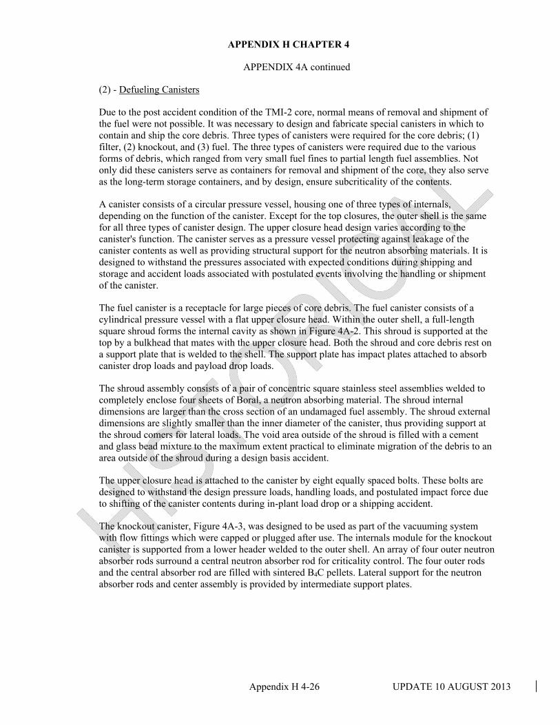
APPENDIX H CHAPTER 4
Appendix H 4-26 UPDATE 10 AUGUST 2013
APPENDIX 4A continued
(2) - Defueling Canisters
Due to the post accident condition of the TMI-2 core, normal means of removal and shipment of the fuel were not possible. It was necessary to design and fabricate special canisters in which to contain and ship the core debris. Three types of canisters were required for the core debris; (1) filter, (2) knockout, and (3) fuel. The three types of canisters were required due to the various forms of debris, which ranged from very small fuel fines to partial length fuel assemblies. Not only did these canisters serve as containers for removal and shipment of the core, they also serve as the long-term storage containers, and by design, ensure subcriticality of the contents.
A canister consists of a circular pressure vessel, housing one of three types of internals, depending on the function of the canister. Except for the top closures, the outer shell is the same for all three types of canister design. The upper closure head design varies according to the canister's function. The canister serves as a pressure vessel protecting against leakage of the canister contents as well as providing structural support for the neutron absorbing materials. It is designed to withstand the pressures associated with expected conditions during shipping and storage and accident loads associated with postulated events involving the handling or shipment of the canister.
The fuel canister is a receptacle for large pieces of core debris. The fuel canister consists of a cylindrical pressure vessel with a flat upper closure head. Within the outer shell, a full-length square shroud forms the internal cavity as shown in Figure 4A-2. This shroud is supported at the top by a bulkhead that mates with the upper closure head. Both the shroud and core debris rest on a support plate that is welded to the shell. The support plate has impact plates attached to absorb canister drop loads and payload drop loads.
The shroud assembly consists of a pair of concentric square stainless steel assemblies welded to completely enclose four sheets of Boral, a neutron absorbing material. The shroud internal dimensions are larger than the cross section of an undamaged fuel assembly. The shroud external dimensions are slightly smaller than the inner diameter of the canister, thus providing support at the shroud comers for lateral loads. The void area outside of the shroud is filled with a cement and glass bead mixture to the maximum extent practical to eliminate migration of the debris to an area outside of the shroud during a design basis accident.
The upper closure head is attached to the canister by eight equally spaced bolts. These bolts are designed to withstand the design pressure loads, handling loads, and postulated impact force due to shifting of the canister contents during in-plant load drop or a shipping accident.
The knockout canister, Figure 4A-3, was designed to be used as part of the vacuuming system with flow fittings which were capped or plugged after use. The internals module for the knockout canister is supported from a lower header welded to the outer shell. An array of four outer neutron absorber rods surround a central neutron absorber rod for criticality control. The four outer rods and the central absorber rod are filled with sintered B4C pellets. Lateral support for the neutron absorber rods and center assembly is provided by intermediate support plates.

APPENDIX H CHAPTER 4
Appendix H 4-27 UPDATE 10 AUGUST 2013
APPENDIX 4A continued
The filter canisters were designed to function in conjunction with either the Defueling Water Cleanup System or the Westinghouse Vacuum System to remove small debris particles from the water. The filter assembly bundle that fits inside the canister shell was designed to remove particulates down to 0.5 microns. Flow into and out of the filter canister is through two quick disconnect fitting. See Figure 4A-4.
The internal filter assembly bundle consists of a circular cluster of 17 filter elements, a drain line and a neutron absorber assembly. The influent enters the upper plenum region, flows down past the support plate, through the filter media and down the filter element drain tube to the lower sump. The flow is from outside to inside with the particulate remaining around the outer perimeter of the filter element. The filtered water exits the canister through the drain line. All fuel, filter and knockout canisters that were utilized during the recovery/defueling period were shipped offsite for storage. However, one canister vessel (outer shell), without any internals, was used to store three fuel assembly end fittings. This canister was placed into the canister storage rack located on the south end of the fuel transfer canal, which is covered for PDMS. Three dummy canister test weight vessels are stored in the "A" spent fuel pool during PDMS.
(3) - Defueling Vacuum System - Airlift Systems
The vacuum system was designed to remove small size fuel debris and fuel fines from the debris bed and discharge them into an appropriate canister. It also was designed to be adapted to permit vacuuming of debris in the lower vessel head region. The system was composed of a pump, piping, valving, and other miscellaneous components. It was located under, and supported from the Shielded Work Platform. It had a control console mounted on the auxiliary platform.
The vacuum pickup nozzle was connected to a defueling canister by a flexible hose and was manually manipulated by a long-handled tool supported from the Shielded Work Platform. The system was modular to permit remote installation and removal of the pump, load cell, valving and piping sections.
The airlift systems were devices designated to transfer small fuel debris from the debris bed to a fuel canister. These devices either discharged the debris directly to the canister or dumped the debris into a container which was then used to dump the debris into the canister. The airlift consists of a suction nozzle with air inlet, a separation chamber, and in some cases, a debris bucket. Depending on the unit, the debris bucket was removed from the airlift for dumping the debris into a fuel canister or the debris bucket was integral with the separation chamber. The integral bucket was equipped with a discharge chute having a sliding door for dumping the debris into a fuel canister. Hoses have been removed and the remaining hardware will remain "as-is" during PDMS.

APPENDIX H CHAPTER 4
Appendix H 4-28 UPDATE 10 AUGUST 2013
APPENDIX 4A continued
(4) - Core Bore Equipment
It was known that a large solidified mass existed below the loose core debris. Equipment was designed and fabricated which could drill into this mass and extract core stratification samples. The core bore equipment was subsequently modified to be fitted with a solid face bit to break up the solid material into smaller pieces. The core bore equipment also was used to cut some of the lower core support assembly structural elements. This equipment was mounted and supported from the rotatable platform. This equipment has been disassembled and is stored inside the R.B., on top of the "A&B" D-ring missile shields (367').
(5) - The Automated Cutting Equipment System (ACES)
The ACES was installed and operated to cut the lower core support assembly structural elements to provide access to remove fuel from the core support assembly and the Reactor Vessel lower head. The system consisted of the required frarne work and mechanical elements to position and control a plasma torch underwater during structure cutting. These parts were located in the Reactor Vessel and were serviced with electrical power and other services delivered through umbilical cords from outside the vessel. The plasma torch was controlled and operated by a modified commercial power supply. The movement of the torch was powered and controlled by a special five-axis control system. This equipment was disassembled and is stored on the 347' elevation of the R.B., east of the "B" D-ring.
(6) - Long-Handled Tools
The Rotatable Shielded Work Platform is located approximately 40 feet above the working area in the core region. This necessitates the use of long handled tools which can be operated from the Shielded Rotatable Platform. The tools are operated through slots in the rotatable platform. Most tools are supported by an overhead crane that provides vertical and lateral motion. Several cranes are available for use, including the two jib cranes on the platform, the Reactor Building service crane and the polar crane. Most of the long-handled tools are stored in various tool storage racks inside the R.B. during PDMS.

APPENDIX H CHAPTER 4
Appendix H 4-29 UPDATE 10 AUGUST 2013
NO
TE:
For P
DM
S th
e ha
ndra
ils h
ave
been
rem
oved
and
a m
oist
ure/
cont
amin
atio
n ba
rrier
con
sist
ing
of
a le
ad b
rick
chim
ney
was
inst
alle
d on
top
of th
e pl
atfo
rm.
This
chi
mne
y al
so p
rovi
des
acce
ss
for a
0 to
200
F R
TD s
uspe
nded
in th
e R
eact
or V
esse
l. T
he R
TD h
as a
rem
ote
digi
tal r
eado
ut
in th
e U
nit 2
con
trol R
oom
FIG
UR
E 4A
-1

APPE
ND
IX H
CH
APT
ER
4
Appendix H
4-30 UPD
ATE 10 A
UG
UST 2013
FIGURE 4A-2
Upper Cloture Head w/Bolt1
Fuel Canister
Drain Tube Recombtner Catalyst
. .. . .. . .. .. . . . . . . . : .
Inner Shroud A11embly w/llor•I Pl•t• ln1ert
,·; ... -. ..... ..... . ' :::. ::. ' .. · .: . . '• . • !~ ....... t IL t t •
icm Dn1ity . Concrete Mixture
Support i'i1to1 -' j lower Heed .

APPENDIX H CHAPTER 4
Appendix H 4-31 UPDATE 10 AUGUST 2013
FIGURE 4A-3

APPENDIX H CHAPTER 4
Appendix H 4-32 UPDATE 10 AUGUST 2013
FIG
UR
E 4A
-4

UPDATE 10 AUGUST 2013
APPENDIX H
CHAPTER 5
PDMS
RADIOLOGICAL CONDITIONS

APPENDIX H CHAPTER 5 PDMS RADIOLOGICAL CONTROLS
Appendix H 5-i UPDATE 10 AUGUST 2013
TABLE OF CONTENTS
SECTION TITLE PAGE
5.0 INTRODUCTION 5-1
5.1 GENERAL DECONTAMINATION ACTIVITIES 5-1
5.1.1 GENERAL DECONTAMINATION OBJECTIVES 5-1
5.1.2 REACTOR BUILDING 5-2
5.1.2.1 REACTOR BUILDING ELEVATION 282'(BASEMENT AND SUMP)
5-2
5.1.2.2 REACTOR BUILDING ELEVATIONS 305' AND 347' 5-2
5.1.2.3 REACTOR BUILDING D-RINGS 5-2
5.1.2.4 REFUELING CANAL 5-2
5.1.3 AUXILIARY AND FUEL HANDLING BUILDINGS 5-3
5.1.3.1 AUXILIARY BUILDING 5-3
5.1.3.2 FUEL HANDLING BUILDING 5-3
5.1.4 OTHER BUILDINGS 5-3
5.1.4.1 SERVICE BUILDING (ELEVATION 281', TENDON ACCESS GALLERY)
5-3
5.1.4.2 SERVICE BUILDING (ELEVATION 305') 5-3
5.1.4.3 CONTROL BUILDING AREAS (EAST & WEST) 5-3
5.1.4.4 TURBINE BUILDING (ELEVATION 281') 5-3
5.1.4.5 CACE BUILDING 5-3
5.1.5 SYSTEMS 5-4
5.1.5.1 REACTOR COOLANT SYSTEM 5-4
5.1.5.2 NON-REACTOR COOLANT SYSTEMS 5-4
5.2 SPECIFIC DECONTAMINATION ACTIVITIES 5-6
5.2.1 SPECIFIC DECONTAMINATION GOALS 5-6
5.2.2 GENERAL CHARACTERIZATION OF CONTAMINATIONS
5-6
5.2.3 DECONTAMINATION TECHNIQUES 5-7
5.3 PDMS RADIOLOGICAL SURVEY 5-7
5.3.1 RADIOLOGICAL ASSESSMENT 5-7
5.3.1.1 PRE-PDMS RADIOLOGICAL SURVEY METHODOLOGY 5-7
5.3.1.2 POST-PDMS RADIOLOGICAL SURVEY METHODOLOGY
5-8

APPENDIX H CHAPTER 5 PDMS RADIOLOGICAL CONTROLS
Appendix H 5-ii UPDATE 10 AUGUST 2013
SECTION TITLE PAGE
5.3.1.3 REMEDIAL DECONTAMINATION ACTIVITIES 5-8
5.3.2 RADIOLOGICAL CONDITIONS AT BEGINNING OF PDMS
5-8
5.3.2.1 SURFACE CONTAMINATION AT BEGINNING OF PDMS 5-8
APPENDIX 5A - POTENTIAL REDUCTIONS IN OCCUPATIONAL EXPOSURE
SECTION TITLE PAGE
5A.1 SUMMARY AND INTRODUCTION 5-34
5A.1.1 SUMMARY 5-34
5A.1.2 INTRODUCTION 5-34
5A.2 BACKGROUND INFORMATION 5-35
5A.2.1 RECOVERY TASKS 5-35
5A.2.1.1 DECONTAMINATION TASK FORCE REPORT 5-36
5A.2.2 FUTURE DECONTAMINATION TASKS 5-36
5A.3 CRITERIA FOR PERFORMING THE EVALUATION 5-37
5A.4 RADIOLOGICAL CONDITIONS 5-37
5A.4.1 CONDITIONS AT THE END OF PHASE I11 5-37
5A.4.2 CONDITIONS DURING PDMS 5-38
5A.4.3 CONDITIONS AT THE END OF PDMS 5-38
5A.4.4 BASE CASE PLANT CONDITIONS 5-38
5A.4.5 ISOTOPIC CHARACTERIZATION 5-39
5A.5 OFF-SITE DOSES DURING PDMS 5-39
5A.6 DOSE RATE ESTIMATION 5-39
5A.6.1 DECONTAMINATION TASKS 5-40
5A.6.1.1 TASKS PERFORMED ROBOTICALLY 5-40
5A.6.1.2 EXAMPLE OF ESTIMATING DOSE RATES 5-40
5A.6.2 RADIOACTIVE WASTE PROCESSING 5-41
5A.7 ACTIVITIES EVALUATED 5-41
5A.7.1 FUTURE DECONTAMINATION TASKS 5-41
5A.7.2 RADIOACTIVE WASTE MANAGEMENT TASKS 5-42
5A.7.3 ACTIVITIES DURING PDMS 5-42
5A.8 JOB-HOUR ESTIMATES 5-42
5A.8.1 SCOPE MODIFICATIONS 5-43

APPENDIX H CHAPTER 5 PDMS RADIOLOGICAL CONTROLS
Appendix H 5-iii UPDATE 10 AUGUST 2013
SECTION TITLE PAGE
5A.8.1.1 IMMEDIATE ADDITIONAL DECONTAMINATION 5-43
5A.8.1.2 FINAL DECONTAMINATION AS A PART OF DECOMMISSIONING
5-44
5A.8.1.3 EXAMPLE OF ESTIMATING SCOPE MODIFICATION 5A-10
5-44
5A.8.2 RADIATION AREA JOB-HOURS 5A-10 5-44
5A.8.2.1 EXAMPLE OF DETERMINING RADIATION AREA JOB-HOURS
5-45
5A.8.3 JOB-HOURS DURING PDMS 5-45
5A.8.4 RADIOACTIVE WASTE MANAGEMENT 5-46
5A.8.5 EXAMPLE OF JOB-HOUR ESTIMATION 5-46
5A.9 PERSONNEL EXPOSURE 5-46
5A.9.1 DECONTAMINATION TASKS 5-46
5A.9.2 RADIOACTIVE WASTE MANAGEMENT 5-46
5A.9.3 PDMS TASKS 5-47
5A.9.4 TOTAL PERSON-REM 5-47
5A.10 COMPARISON CASE - 20-YEAR PDMS 5-48
5A.11 CONCLUSION 5-48
5A.12 REFERENCES 5-49
APPENDIX B -DECONTAMINATION ACTIVITIES 5B-1
KELLY VACUUMAC 5-63
CONCRETE SCABBLING 5-63
STRIPPABLE COATINGS 5-63
HIGH PRESSURE SPRAY AND FLUSHING 5-63
SYSTEM FLUSHING 5-63
HANDS-ON DECONTAMINATION 5-64
ROBOTIC DEVICES 5-64
SYSTEM IN-SERVICE INSPECTION (SISI) 5-64
REMOTE CONTROLLED MOBILE MANIPULATOR (RCMM)
5-64
REMOTE RECONNAISSANCE VEHICLE (RRV) 5-64
REMOTE CONTROLLED TRANSPORT VEHICLE (RCTV)
5-64

APPENDIX H CHAPTER 5 PDMS RADIOLOGICAL CONTROLS
Appendix H 5-iv UPDATE 10 AUGUST 2013
LOUIE-2 5-65
WATER PROCESSING 5-65
SUBMERGED DEMINERALIZER SYSTEM 5-65
EPICOR I1 5-65
DEFUELING WATER CLEANUP SYSTEM (ION EXCHANGER-PORTION)
5-65

APPENDIX H CHAPTER 5 PDMS RADIOLOGICAL CONTROLS
Appendix H 5-v UPDATE 10 AUGUST 2013
TABLE OF CONTENTS (Cont'd)
LIST OF TABLES
TABLE NO. TITLE PAGE
5.1-1 BASELINE RADIOLOGICAL CRITERIA - REACTOR BUILDING
5-4
5.1-2 BASELINE RADIOLOGICAL CRITERIA - AFHB 5-5
5.3-1 PDMS RADIOLOGICAL CONDITIONS – REACTOR BUILDING
5-9
5.3-2 PDMS RADIOLOGICAL CONDITIONS - AFHB 5-10
5.3-3 PDMS RADIOLOGICAL CONDITIONS – OTHER BUILDING
5-21
5.3-4 SURFACE CONTAMINATION - REACTOR BUILDING 5-22
5.3-5 SURFACE CONTAMINATION - AFHB 5-23
5.3-6 SURFACE CONTAMINATION - OTHER BUILDINGS 5-32
5.A.1 PHASE I11 ENDPOINT CRITERIA 5-50
5.A.2 END OF PHASE III AND BASE CASE DOSE RATES - REACTOR BUILDING
5-51
5.A.3 END OF PHASE I11 AND BASE CASE DOSE RATES - AUXILIARY AND FUEL HANDLING BUILDINGS
5-52
5.A.4 ESTIMATED CS AND SR ACTIVITIES IN THE REACTOR BUILDING
5-53
5.A.5 DOSE RATES AND ADJUSTED JOB-HOURS 5-54
5.A.6 FINAL CLEANUP ACTIVITIES (TYPICAL) 5-56
5.A.7 RADIATION AREA JOB-HOW 5-58
5.A.8 ETN AND RWP HOURS 5-59
5A.9 SUMMARY TABLE FOR PERSON-REM EVALUATION ANALYSIS
5-60
5A.10 ESTIMATED TOTAL PERSON-REM FOR FINAL DECONTAMINATION OPTIONS
5-62

APPENDIX H CHAPTER 5 PDMS - RADIOLOGICAL CONDITIONS
Appendix H 5-1 UPDATE 10 AUGUST 2013
5.0 INTRODUCTION
One consequence of the March 1979 accident was wide spread radioactive contamination of the Reactor, Fuel Handling, and Auxiliary Buildings. Reactor Coolant System water was released to the Reactor Building and overflowed to the Auxiliary and Fuel Handling Buildings. These areas required extraordinary decontamination efforts to achieve the cleanup program objectives. Contamination of areas outside the RB and AFHB were minor and limited. These areas outside the RB and AFHB were decontaminated and either released for unrestricted use or configured such that the contamination is suitably contained. The objectives of the decontamination program were to remove and/or stabilize the contamination to reduce occupational exposure to workers and to prevent release of contamination to the environment during recovery and cleanup activities. In addition, a final decontamination objective was to ensure that any remaining contamination was stable and suitably isolated for the PDMS period. The following discussion provides the major decontamination objectives and techniques utilized at TMI-2, as well as the contamination levels remaining in the various areas of the plant. Also included (Appendix 5A) are potential reductions in occupational exposure due to PDMS.
5.1 GENERAL DECONTAMINATION ACTIVITIES
The decontamination of TMI-2 was accomplished in two phases. The initial phase improved the radiological conditions in the facility such that the dose rates were acceptably low to permit the necessary accident cleanup activities. The second phase was a decontamination program initiated for the purpose of systematically improving radiological conditions in the plant regardless of whether access was required for cleanup activities.
In order to establish goals for the TMI-2 decontamination program, decontamination criteria were established for the RB, AFHB, and specific portions of other buildings, where relevant. The primary consideration in establishing the criteria for the initial phase was the anticipated need for personnel access during the cleanup and post-cleanup timeframe. Table 5.1- 1 presents the Baseline Radiological Criteria for the RB and Table 5.1-2 provides the Baseline Radiological Criteria for the AFHB.
The general decontamination criteria for piping system, equipment, and components were based solely on their contribution to area dose rates. It should be emphasized that these criteria were intended as guidelines rather than absolute criteria. The guidelines were used in conjunction with common sense and good radiological practices.
5.1.1 GENERAL DECONTAMINATION OBJECTIVES
The general decontamination program objectives were assigned primarily by area. The general objectives established for each area were based on initial contamination levels, the need for personnel access, and the possibility of release of radioactivity to the environment.
The facility was categorized into the following areas:
a. Reactor Building 1. Reactor Building elevation 282' 2. Reactor Building elevations 305' and 347' 3. Reactor Building D-Rings

APPENDIX H CHAPTER 5 PDMS - RADIOLOGICAL CONDITIONS
Appendix H 5-2 UPDATE 10 AUGUST 2013
4. Refueling Canal
b. Auxiliary and Fuel Handling Buildings 1. Auxiliary Building Cubicles (total of 99) 2. Fuel Handling Building Cubicles (total of 37)
c. Other Buildings 1. Service Building (elevation 28 l', Tendon Access Gallery) 2. Service Building (elevation 305') 3. Control Building Areas (East & West) 4. Turbine Building (elevation 28 1') 5. CACE Building
d. Systems 1. Reactor Coolant System 2. Non-Reactor Coolant Systems
The general decontamination objective for each area is outlined below.
5.1.2 REACTOR BUILDING
5.1.2.1 Reactor Building Elevation 282' (Basement and Sump)
The general decontamination objectives in the Reactor Building basement were to enhance the ability to characterize the basement with respect to residual fuel and to promote the long-term stability of contamination during the PDMS period. The specific program objectives included removing the sludge from all accessible areas in the Reactor Building basement and conduct a high pressure flush of walls, floors, and overheads.
5.1.2.2 Reactor Building Elevations 305' and 347'
The original general decontamination objective on elevations 305' and 347' of the Reactor Building was to reduce dose rate levels low enough to support continued personnel occupation during defueling operations and other associated activities. These dose rate goals were achieved to allow for defueling operations. However, post-defueling draindown of CFT-1A has increased the dose rates for elevations 305' and 347' such that the PDMS general area dose rate goal had to be increased to 100 mR/hr.
5.1.2.3 Reactor Building D-Rings
The general decontamination objectives within the upper portion of the D-rings were to support efforts to locate, characterize, and remove fuel from the pressurizer, steam generator, and reactor coolant piping and to evaluate the feasibility of RC pump removal.
5.1.2.4 Refueling Canal
The original general decontamination objective in the refueling canal was to reduce dose rates sufficiently to support construction activities for defueling equipment installation. These dose rate goals were achieved for installation of defueling equipment and actual RV defueling. However, post-defueling pumpdown of the RV and the refueling canal has increased the dose rates in the refueling canal such that the PDMS general area dose rate goal had to be increased to 100 rnR/hr.

APPENDIX H CHAPTER 5 PDMS - RADIOLOGICAL CONDITIONS
Appendix H 5-3 UPDATE 10 AUGUST 2013
5.1.3 AUXILLARY AND FUEL HANDLING BUILDINGS
5.1.3.1 Auxiliary Building
The Auxiliary Building was categorized into 99 separate areas or cubicles, which accounted for essentially all of the walls, floors, and overhead areas in the building. The general decontamination objective for the contaminated cubicles was to support ongoing cleanup activities. The Baseline Radiological Criteria referenced in Table 5.1-2 were applied to each Auxiliary Building cubicle as a guideline for the decontamination efforts.
5.1.3.2 Fuel Handling Building
The Fuel Handling Building was categorized into 37 separate areas or cubicles which accounted for essentially all of the walls, floors, and overhead areas in the building. The general decontamination objectives for the contaminated areas within the Fuel Handling Building were established to support ongoing cleanup activities and to stabilize localized contamination. As in the Auxiliary Building, the Baseline Radiological Criteria referenced in Table 5.1-2 were applied to each Fuel Handling Building cubicle for use as guideline for the programmatic decontamination effort.
5.1.4 OTHER BUILDINGS
5.1.4.1 Service Building (Elevation 28l', Tendon Access Gallery)
The general decontamination objective in the Service Building was to identify hot spots and remove or shield contamination. One objective was the partial removal and stabilization of the contaminated cork seal material from a building construction joint.
5.1.4.2 Service Building (Elevation 305')
The general decontamination objective in the Service Building (elevation 305') was to identify hot spots and remove or shield contamination.
5.1.4.3 Control Building Areas (East & West)
The general decontamination objective in this portion of the Control Building Areas was to identify hot spots and remove or shield contamination.
5.1.4.4 Turbine Building (Elevation 281')
The general decontamination objective in this portion of the Turbine Building (elevation 28 1') was to identify hot spots and remove or shield contamination.
5.1.4.5 CACE Building
The general decontamination objective in the CACE Building was to identify hot spots and remove or shield contamination.

APPENDIX H CHAPTER 5 PDMS - RADIOLOGICAL CONDITIONS
Appendix H 5-4 UPDATE 10 AUGUST 2013
5.1.5 SYSTEMS
5.1.5.1 Reactor Coolant System
The general decontamination objective for the Reactor Coolant System was to remove residual fuel and other contamination to the maximum extent practical.
5.1.5.2 Non-Reactor Coolant Systems
The general decontamination objective for the non-reactor coolant systems was to reduce radiation dose rates low enough to support general area dose rate goals. The systems decontamination program was integrated with the systematic cubicle and area decontamination programs.
TABLE 5.1-1
BASELINE RADIOLOGICAL CRITERIA - REACTOR BUILDING
GENERAL AREADOSE RATE
SURFACE CONTAMINATION
(dpm1100cm2) (mR/hr) BELOW 7' ABOVE 7'
Infrequent (Quarterly)
Elevation 305' to 347' <100 <50,000 NOTE 3
Elevation 347' and Above <30 <50,000 NOTE 3
Refueling Canal <600 <50,000 NOTE 3
Top of D-Rings <100 <50,000 NOTE 3
Access Not Required
D-Ring Interior, El. 349' and Above
"AS IS"
"AS IS"
NOTE 3
Basement (El. 282') "AS IS" "AS IS" NOTE 3
NOTES:
1. These criteria refer to general access areas and should not be used as maximum levels allowed (i.e., hot spots could have higher dose rates).
2. Areas of the Reactor Building not listed in this table are left "as is" for PDMS.
3. Since access is not required above 7', and the overheads are generally not the major contributors to the general area dose rate, these areas may be left without decontamination.

APPENDIX H CHAPTER 5 PDMS - RADIOLOGICAL CONDITIONS
Appendix H 5-5 UPDATE 10 AUGUST 2013
TABLE 5.1-2
BASELINE RADIOLOGICAL CRITERIA - AFHB
GENERAL AREADOSE RATE
MAXIMUMHOT SPOT
SURFACE CONTAMINATION
ACCESS FREOUENCY (mR/hr) (mR/hr) (dprn/100 cm2)
Routine - (40 hr/wk access) < 2.5 10 NOTE 1
Frequent - (daily access) < 50 100 NOTE 1
Occasional - (weekly access) < 500 1000 NOTE 1
Infrequent - (monthly access or less) < 1000 2000 NOTE 1
NOTES:
1. Smearable contamination (dpm/100 cm2) will be either:
a. 4000 below 7'/<10,000 in overheads (generally applied to corridors and access ways)
or
b. <50,000 below 7'/<50,000 in overheads (generally applied to cubicles)

APPENDIX H CHAPTER 5 PDMS - RADIOLOGICAL CONDITIONS
Appendix H 5-6 UPDATE 10 AUGUST 2013
5.2 SPECIFIC DECONTAMINATION ACTIVITIES
The primary decontamination activities at TMI-2 were in the AFHB and the Reactor Building. Some decontamination tasks were also required in other areas such as the Turbine and Service Buildings. However, the extent of work required in these areas was relatively minor compared to the AFHB and Reactor Building work scope.
5.2.1 SPECIFIC DECONTAMINATION GOALS
Specific decontamination goals were developed by applying the baseline decontamination criteria introduced in Section 5.1 to specific areas within the facility. Note that these specific decontamination goals apply to general area access and do not represent the maximum levels allowed (i.e., hot spots could have higher dose rates and contamination levels). Categorization of the facility into specific areas was done within the context of the general decontamination program objectives as discussed in Section 5.1.1. In the case of the Reactor Building, the physical layout of the building and the anticipated personnel access requirements favored the use of the general criteria as specific goals. The Auxiliary and Fuel Handling Buildings and the specific portions of other buildings are configured in such a way as to favor applying the general criteria to much smaller areas, designated as cubicles, to derive the specific decontamination goals. The specific decontamination goals for the Reactor Building are presented in Table 5.3-1. Table 5.3-2 presents specific decontamination goals for the Auxiliary and Fuel Handling Buildings and Table 5.3-3 encompasses other buildings.
5.2.2 GENERAL CHARACTERIZATION OF CONTAMINATION
There were various conditions of radiological contamination at TMI-2 after the accident. The majority of contamination can be characterized as a layer of loose particulate covering soluble contaminants that had been absorbed into the coatings and the surface layers of concrete and dried. Several areas, such as the Reactor Building basement, presented particularly difficult decontamination challenges.
Originally, it was anticipated that water flushing would remove the majority of surface contamination. However, subsequent to the early decontamination efforts, decontaminated surfaces often became recontaminated to the earlier contamination levels.
In order to identify the sources of recontamination, survey techniques were developed to determine if the recontamination was from outside sources or from other mechanisms. It was determined that much of the recontamination resulted from soluble contaminants leaching from the surface materials into which they had been absorbed during and following the accident. Techniques were developed to physically remove coatings from floors or to remove a layer of concrete from both coated and non-coated surfaces.
After water flushing removed the loose surface contamination on areas where large open surfaces were contaminated, scabblers were used to reduce contamination levels to permit cleanup activities with as little personnel exposure as possible. The floor contamination levels in most areas of the AFHB were reduced to those typical of pre-accident conditions by this technique. In the Reactor Building, radiation levels in frequently accessed areas were reduced by 85% by scabbling accessible areas and shielding finite sources.

APPENDIX H CHAPTER 5 PDMS - RADIOLOGICAL CONDITIONS
Appendix H 5-7 UPDATE 10 AUGUST 2013
In the AFHB cubicles, it was necessary to flush piping in some areas to remove contained contaminants before scabbling was performed. The logic was to conduct a gross flush of an area using remote nozzles. A survey was then performed. If less exposure was required to perform a system flush of piping followed by scabbling, the piping flush was initially performed. Some exceptions to this logic were encountered because flow points through piping were totally blocked or a very localized area contained a large source of radioactive material. In these cases, the source of contamination was physically removed.
Approximately 17 Ci of contamination remains in the AFHB floor drains and approximately 600 Ci remains contained in the Auxiliary Building sump. The AFHB sumps are in service. Most floor drains in the A.FHl3 remain open and unaltered. Some drains were altered to have either a ball float valve installed or to be plugged. This was done for those drains that had become a source of contamination in their cubicle.
5.2.3 DECONTAMINATION TECHNIQUES
The major decontamination techniques utilized during the cleanup period are described in Appendix 5B.
5.3 PDMS RADIOLOGICAL SURVEY
This section describes the radiological conditions at the TMI-2 facility upon entering PDMS. These conditions are expressed in terms of general area dose rate, loose surface contamination, and general isotopic distribution.
5.3.1 RADIOLOGICAL ASSESSMENT
Upon completion of cleanup activities (including decontamination) in a given area or cubicle, the area was isolated to prohibit uncontrolled access. Deactivated systems traversing the area or cubicle were drained, vented, and isolated. The subject area was, at that point, configured for long-term monitored storage and available for a final PDMS radiological assessment. This assessment was performed utilizing radiological surveys (in this case, radiation, contamination and air activity surveys performed by radiological controls technicians) as a basis for determining whether the established decontamination program endpoints were achieved as well as to document the radiological conditions which existed upon entering PDMS. If at the conclusion of the radiological assessment it was determined that satisfactory radiological conditions were not achieved, additional decontamination efforts were undertaken or exceptions to the goals were taken.
5.3.1.1 Pre-PDMS Radiological Survey Methodology
Radiation contamination and air activity surveys were routinely performed during the course of the cleanup program in support of work activities. These surveys were performed in accordance with regulatory and industry standards and practices to verify and document radiation and contamination levels for use in controlling personnel exposure. These surveys were then evaluated as to whether or not they supported the conclusion that decontamination endpoints had been achieved. In those instances where existing surveys were judged unsuitable for substantiating decontamination endpoints, additional surveys were conducted.

APPENDIX H CHAPTER 5 PDMS - RADIOLOGICAL CONDITIONS
Appendix H 5-8 UPDATE 10 AUGUST 2013
5.3.1.2 Post-PDMS Radiological Survey Methodology
During the PDMS period, radiological conditions within the facility will be monitored through sampling and periodic surveillance. Surveillance activities for the Reactor Building consist of radiation surveys in conjunction with planned Reactor Building inspections. The purpose for conducting these surveys is to provide assurance that conditions are stable or to provide early indication of any changing conditions which may require corrective action. The Radiological Survey Plan for PDMS is described in Section 7.2.4.2.
5.3.1.3 Remedial Decontamination Activities
In the event that changing conditions are indicated, an evaluation will be performed as to the need for, and form of, corrective action to be taken. In general, areas will be assessed on a case-by-case basis with the deciding factors being the area's impact on personnel exposure and the possibility of a release to the environment. The Unit 2 PDMS organization will be staffed to provide the capability to take corrective action or call upon additional resources necessary to take corrective action.
5.3.2 RADIOLOGICAL CONDITIONS AT BEGINNING OF PDMS
Table 5.3-1 lists the specific radiological goals for the TMI-2 Reactor Building and the corresponding radiological conditions as of the most current radiological surveys existing in September 1992. The RB radiological conditions listed in Table 5.3-1 reflect rounded-off, average PDMS survey data for the entire cubicle/area in question. These data were compiled in the manner described in Section 5.3.1.1.
Table 5.3-2 lists the equivalent information for the AFHB as of November 1993.
Table 5.3-3 provides a summary of the radiological conditions for the balance-of-plant areas not covered by Tables 5.3-1 and 5.3-2.
5.3.2.1 Surface Contamination at Beginning of PDMS
To establish a baseline at the beginning of PDMS, the radioactivity present as surface contamination in various areas of the facility has been evaluated. This information serves as an initial reference for the evaluation of any future activities in the respective areas.
In order to appraise the radioactivity present as loose surface contamination upon entry into PDMS, an analytical model was constructed utilizing available loose surface contamination data, generalized waste stream isotopic distributions and estimates of surface area. This information is formatted in a manner similar to the general area dose rate and loose surface contamination data presented in Tables 5.3-1, 5.3-2, and 5.3-3. Only surface contamination was considered; fixed contamination or contamination internal to piping systems or equipment was omitted. The generalized waste streams or distribution of principal isotopes are referenced on each of the tables.
Table 5.3-4 lists the data obtained from the analytical model described above for the TMI-2 Reactor Building. Table 5.3-5 lists the equivalent data for the AFHE3 and Table 5.3-6 provides a similar summary for the balance-of-plant areas. All of the calculations of the quantities of curies listed are based on the specific decontamination goals given on Tables 5 -3-2 and 5.3-3.

APPENDIX H CHAPTER 5 PDMS - RADIOLOGICAL CONDITIONS
Appendix H 5-9 UPDATE 10 AUGUST 2013
TABLE 5.3-1
PDMS RADIOLOGICAL CONDITIONS - REACTOR BUILDING
SPECIFIC DECONTAMINATION GOALS GENERAL AREA SURFACE
PDMS RADIOLOGICAL CONDITIONS* GENERAL AREA SURFACE
AREA DESCRIPTION DOSE RATE (mR/hr)
CONTAMINATION (dpm/100 cm2)
DOSE RATE (mR/hr)
CONTAMINATION (dpm/100 cm2)
Elevation 305' to 347'
<100 <50,000 150 2,000,000
Elevation 347' and Above
<30 <50,000 50 710,000
Refueling Canal <100 <50,000 120 670,000
D-Ring Interior, EL 349' and Above "A" D-Ring "B" D-Ring
"AS IS" "AS IS"
"AS IS" "AS IS"
300 200
280,000 220,000
Top of D-Rings <100 <50,000 40 ("A" D-Ring) 50 ("B" D-Ring)
270.000 190,000
Basement, El. 282' "AS IS" "AS IS" 56,000** NOTE 1
* The radiological conditions in this table reflect rounded-off, average PDMS survey data.
** This is the decay-corrected dose rate taken by ROVER (TPB 85-3 Rev. 0, February 1985.)
NOTES:
1. This area is inaccessible; no meaningful data exists.

APPENDIX H CHAPTER 5 PDMS - RADIOLOGICAL CONDITIONS
TABLE 5.3-2 PDMS RADIOLOGICAL CONDITIONS – AFHB
SPECIFIC DECONTAMINATION GOALS PDMS RADIOLOGICAL CONDITIONS*CUBICLE NUMBER
AREA DESCRIPTION
GENERAL AREA DOSE RATE
(mR/hr)
SURFACE CONTAMINATION
<7'/Overheads (dpm/100 cm2)
GENERAL AREA
DOSE RATE (mR/hr)
SURFACE CONTAMINATION
<7'/Overheads (dpm/100 cm2)
Appendix H 5-10 UPDATE 10 AUGUST 2013
AX001 RB Emerg. Cooling Booster Pumps Area [WGP- 1 Shielded Enclosure]
<2.5 <2.5
<1,000/<10,000 <1,000/<10,000
1.5 2.4
590/2,500 81,000/6,500
AX002 Access Corridor <2.5 <1,000/<10,000 1.5 110/1,300
AX002a N2 Piping System <2.5 <1,000/N/A 1.8 110/N/A
AX003 Access Area <2.5 <1,000/<10,000 0.8 2,900/2,300
AX004 Seal Injection Valve Rm <1000 <50,000/<50,000 120 68,000/750,000
AX005 MUP Pump 1C Rm <500 <50,000/<50,000 8 40,000/30,000
AX006 MUP Pump 1B Rm <500 <50,000/<50,000 60 88,000/29,000
AX007 MUP Pump 1A Rm <500 <50,000/<50,000 40 9,200/21,000
AX008 Spent Resin Stor Tank 1B Rm
"AS IS" "AS IS" 170 960,000/3,400,000
AX009 Spent Resin Stor Tank 1A Rm
"AS IS" "AS IS" 1,700 3,000,000/6,000,000
AX010 Spent Resin Transfer Pump Rm
"AS IS" "AS IS" 180 1,400,000/5,100,000
AX011 AB Sump Tank Pump/Valve Rm
<50 <5,000/<50,000 8 3,200/4,900
AX012 Aux Bldg Sump & Tank Rm <50 <5,000/<50,000 560 390,000/68,000
AX013 Evap Cond Tanks, Pumps Demins Rm
<500 <1,000/<10,000 5 130/140

APPENDIX H CHAPTER 5 PDMS - RADIOLOGICAL CONDITIONS
TABLE 5.3-2 PDMS RADIOLOGICAL CONDITIONS – AFHB
SPECIFIC DECONTAMINATION GOALS PDMS RADIOLOGICAL CONDITIONS*CUBICLE NUMBER
AREA DESCRIPTION
GENERAL AREA DOSE RATE
(mR/hr)
SURFACE CONTAMINATION
<7'/Overheads (dpm/100 cm2)
GENERAL AREA
DOSE RATE (mR/hr)
SURFACE CONTAMINATION
<7'/Overheads (dpm/100 cm2)
Appendix H 5-11 UPDATE 10 AUGUST 2013
AX014 RC Evaporator Rm <500 <50,000/<50,000 18 20,000/8,100
AX015a Cleanup Filters Rm <500 <50,000/<50,000 110 10,000/8,700
AX015b Cleanup After Filters Rm <500 <50,000/<50,000 38 21,000/13,000
AX016 Cleanup Demineralizer 2A Rm
<500 <50,000/<50,000 38 21,000/13,000
AX017 Cleanup Demineralizer 2B Rm
<500 <50,000/<50,000 110 10,000/8,700
AX018 Waste Transfer Pumps Rm <500 <50,000/<50,000 10 17,000/14,000
AX019 Waste Disposal Liquid Valve Rm
<500 <50,000/<50,000 19 7,800/5,700
AX020 RC Bleed Holdup Tanks 1B & 1C Rm
<500 <50,000/<50,000 160 520,000/200,000
AX021 RC Bleed Holdup Tank 1A Rm
<500 <50,000/<50,000 18 1,800/12,000
AX022 North Stairwell <2.5 <1,000/N/A 0.3 440/N/A
AX023 Elevator Pit and <10 <50,000/N/A 14 25,000/N/A
AX024 Aux Bldg Sump Filters Rm <500 <50,000/<50,000 15 156,400/11,000
AX025 Area Between Service, Control, & RB
<500 <1,000/10,000 3.5 1,000/310
AX026 Seal Injection Filters Rm <500 <50,000/<50,000 12 9,000/1,100
AX027 South Stairwell <2.5 <1,000/N/A 0.2 480/N/A

APPENDIX H CHAPTER 5 PDMS - RADIOLOGICAL CONDITIONS
TABLE 5.3-2 PDMS RADIOLOGICAL CONDITIONS – AFHB
SPECIFIC DECONTAMINATION GOALS PDMS RADIOLOGICAL CONDITIONS*CUBICLE NUMBER
AREA DESCRIPTION
GENERAL AREA DOSE RATE
(mR/hr)
SURFACE CONTAMINATION
<7'/Overheads (dpm/100 cm2)
GENERAL AREA
DOSE RATE (mR/hr)
SURFACE CONTAMINATION
<7'/Overheads (dpm/100 cm2)
Appendix H 5-12 UPDATE 10 AUGUST 2013
AX101 Radwaste Disp. Cntrl Panel Area
<2.5 <1,000/10,000 0.2 90/110
AX102 RB Sump Pumps Filters Rm <1000 <50,000/<50,000 47 9,300/4,200
AX103 Motor Control Center 2-11EB Rm
<2.5 <1,000/10,000 0.2 470/480
AX104 Motor Control Center 2-21EB Rm
<2.5 <1,000/<10,000 0.2 470/470
AX105 Substation 2-11E Rm <2.5 <1,000/<10,000 0.2 480/530
AX106 Substation 2-21E Rm <2.5 <1,000/<10,000 0.2 480/530
AX107 Motor Control Center 2-11EA Rm
<2.5 <1,000/<10,000 0.2 460/530
AX108 Motor Control Center 2-21EA Rm
<2.5 <1,000/<10,000 0.2 480/500
AX109 Nuclear Services Coolers & Pumps Area
<2.5 <1,000/<10,000 0.2 100/130
AX110 Intermediate Coolers Area <2.5 <1,000/<10,000 0.2 100/130
AX111 Intermed. Cooling Pumps & Filters Room
<50 <1,000/<10,000 0.7 440/410
AX112 Seal Return Coolers & Filter Room
<1000 <50,000/<50,000 99 350,000/38,000
AX113 Waste Gas Analyzer Rm <50 <50,000/<50,000 19 22,000/6,400
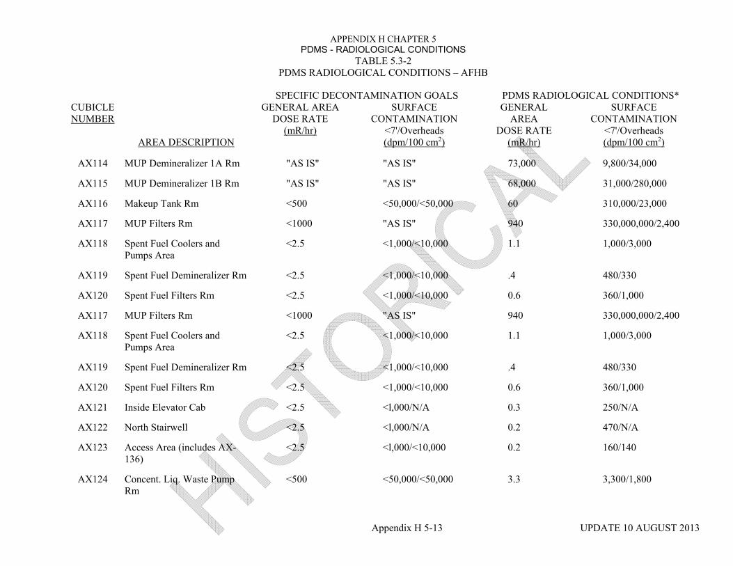
APPENDIX H CHAPTER 5 PDMS - RADIOLOGICAL CONDITIONS
TABLE 5.3-2 PDMS RADIOLOGICAL CONDITIONS – AFHB
SPECIFIC DECONTAMINATION GOALS PDMS RADIOLOGICAL CONDITIONS*CUBICLE NUMBER
AREA DESCRIPTION
GENERAL AREA DOSE RATE
(mR/hr)
SURFACE CONTAMINATION
<7'/Overheads (dpm/100 cm2)
GENERAL AREA
DOSE RATE (mR/hr)
SURFACE CONTAMINATION
<7'/Overheads (dpm/100 cm2)
Appendix H 5-13 UPDATE 10 AUGUST 2013
AX114 MUP Demineralizer 1A Rm "AS IS" "AS IS" 73,000 9,800/34,000
AX115 MUP Demineralizer 1B Rm "AS IS" "AS IS" 68,000 31,000/280,000
AX116 Makeup Tank Rm <500 <50,000/<50,000 60 310,000/23,000
AX117 MUP Filters Rm <1000 "AS IS" 940 330,000,000/2,400
AX118 Spent Fuel Coolers and Pumps Area
<2.5 <1,000/<10,000 1.1 1,000/3,000
AX119 Spent Fuel Demineralizer Rm <2.5 <1,000/<10,000 .4 480/330
AX120 Spent Fuel Filters Rm <2.5 <1,000/<10,000 0.6 360/1,000
AX117 MUP Filters Rm <1000 "AS IS" 940 330,000,000/2,400
AX118 Spent Fuel Coolers and Pumps Area
<2.5 <1,000/<10,000 1.1 1,000/3,000
AX119 Spent Fuel Demineralizer Rm <2.5 <1,000/<10,000 .4 480/330
AX120 Spent Fuel Filters Rm <2.5 <1,000/<10,000 0.6 360/1,000
AX121 Inside Elevator Cab <2.5 <l,000/N/A 0.3 250/N/A
AX122 North Stairwell <2.5 <l,000/N/A 0.2 470/N/A
AX123 Access Area (includes AX-136)
<2.5 <l,000/<10,000 0.2 160/140
AX124 Concent. Liq. Waste Pump Rm
<500 <50,000/<50,000 3.3 3,300/1,800

APPENDIX H CHAPTER 5 PDMS - RADIOLOGICAL CONDITIONS
TABLE 5.3-2 PDMS RADIOLOGICAL CONDITIONS – AFHB
SPECIFIC DECONTAMINATION GOALS PDMS RADIOLOGICAL CONDITIONS*CUBICLE NUMBER
AREA DESCRIPTION
GENERAL AREA DOSE RATE
(mR/hr)
SURFACE CONTAMINATION
<7'/Overheads (dpm/100 cm2)
GENERAL AREA
DOSE RATE (mR/hr)
SURFACE CONTAMINATION
<7'/Overheads (dpm/100 cm2)
Appendix H 5-14 UPDATE 10 AUGUST 2013
AX125 Waste Gas Decay Tank 1B Rm
<500 <50,000/<50,000 0.2 1,000/1,000
AX126 Waste Gas Filter Rm <500 <50,000/<50,000 0.2 100/160
AX127 Waste Gas Decay Tank lA Rm
<500 <50,000/<50,000 0.6 6,400/690
AX128 Valve & Instrument Rm <500 <50,000/<50,000 2.7 1,000/1,300
AX129 Deborating Demin, 1B Rm <500 <50,000/<50,000 0.3 1,000/600
AX130 Deborating Detnin. 1A Rm <500 <50,000/<50,000 0.5 540/520
AX131 Misc. Waste Holdup Talk Rm <50 <5,000/<50,000 120 1,900/6,500
AX132 Unit 1 and Unit 2 Corridor <2.5 <l,000/<10,000 0.2 100/100
AX133 South Stairwell <2.5 <l,000/N/A 0.2 500/N/A
AX134 Misc. Waste Tank Pumps Rm <50 <50,000/<50,000 13 13,000/45,000
AX135 Radwaste Disposal Control Pnls
<2.5 <l,000/<10,000 0.2 130/120
AX201 North Stairwell <2.5 <l,000/N/A 0.2 450/N/A
AX202 Elevator Shaft <2.5 <l,000/<10,000 0.2 480/480
AX203 4160V Switchgear 2-1E Rm <2.5 <l,000/<10,000 0.2 480/460
AX134 Misc. Waste Tank Pumps Rm <50 <50,000/<50,000 13 13,000/45,000
AX135 Radwaste Disposal Control Pnls
<2.5 <l,000/<10,000 0.2 130/120

APPENDIX H CHAPTER 5 PDMS - RADIOLOGICAL CONDITIONS
TABLE 5.3-2 PDMS RADIOLOGICAL CONDITIONS – AFHB
SPECIFIC DECONTAMINATION GOALS PDMS RADIOLOGICAL CONDITIONS*CUBICLE NUMBER
AREA DESCRIPTION
GENERAL AREA DOSE RATE
(mR/hr)
SURFACE CONTAMINATION
<7'/Overheads (dpm/100 cm2)
GENERAL AREA
DOSE RATE (mR/hr)
SURFACE CONTAMINATION
<7'/Overheads (dpm/100 cm2)
Appendix H 5-15 UPDATE 10 AUGUST 2013
AX201 North Stairwell <2.5 <l,000/N/A 0.2 450/N/A
AX202 Elevator Shaft <2.5 <l,000/<10,000 0.2 480/480
AX203 4160V Switchgear 2-1E Rm <2.5 <l,000/<10,000 0.2 480/460
AX204 4160V Switchgear 2-2E Rm <2.5 <I ,000/< 10,000 0.2 480/480
AX205 RB Purge Air Sup. and Hy Cntrl Exh Area
<2.5 <I ,000/< 10,000 0.7 100/130
AX206 RB Purge Air Exhaust Unit B <50 N/A 10 200.000/N/A
AX207 RB Purge Air Exhaust Unit A <50 N/A 13 200.000/N/A
AX208 Aux Bldg Exhaust Unit B <50 N/A 0.4 3,900/N/A
AX209 Aux Bldg Exhaust Unit A <50 N/A 0.7 10,000/N/A
AX210 Fuel Handling Bldg Exhaust Unit B
<50 N/A 0.9 12,000/N/A
AX211 Fuel Handling Bldg Exhaust Unit A
<50 N/A 0.3 7,200/N/A
AX212 Decay Ht Surge Tk & Substatiori
<2.5 <1,000/< 10,000 0.2 Area
100/90
AX213 Unit Substations & Access Area
<2.5 <1,000/< 10,000 0.2 130/120
AX214 Decon Facility [Internal Area of Decon Facility Tanks]
<2.5 <2.5
<1,000/< 10,000 <1,000/N/A
0.3 0.4
150/100 4,400/N/A

APPENDIX H CHAPTER 5 PDMS - RADIOLOGICAL CONDITIONS
TABLE 5.3-2 PDMS RADIOLOGICAL CONDITIONS – AFHB
SPECIFIC DECONTAMINATION GOALS PDMS RADIOLOGICAL CONDITIONS*CUBICLE NUMBER
AREA DESCRIPTION
GENERAL AREA DOSE RATE
(mR/hr)
SURFACE CONTAMINATION
<7'/Overheads (dpm/100 cm2)
GENERAL AREA
DOSE RATE (mR/hr)
SURFACE CONTAMINATION
<7'/Overheads (dpm/100 cm2)
Appendix H 5-16 UPDATE 10 AUGUST 2013
AX215 Fuel Handling Bldg Supply <2.5 N/A 0.2 450/N/A
AX216 Aux Bldg Supply Unit <2.5 N/A 0.2 450/N/A
AX217 Access Area <2.5 <1,000/< 10,000 0.2 120/370
AX218 Concentrated Waste Stor. Tank Rm
<500 <50,000/<50,000 15 1,900/1,000
AX219 Inst. Racks & Atmospheric Monitor Area
<2.5 <1,000/<10,000 0.3 390/5,900
AX220 Caustic Liquids Mixing Area <500 <1,000/<10,000 1.4 440/360
AX221 Caustic Liquids Mixing Area Corridor
<500 <1,000/<10,000 0.8 450/880
AX222 South Stairwell <2.5 <1,000/N/A 0.2 100/N/A
AX223 Air Handling Units General Area
<2.5 <5,000/<10,000 0.8 490/450
AX301 Elevator Machine Rm <2.5 <1,000/<10,000 0.2 100/170
AX302 North Stairwell <2.5 <1,000/<10,000 0.2 480/480
AX303 Elevator and Stairwell Access <2.5 <1,000/<10,000 0.2 510/510
AX304 Aux. Bldg. Exhaust Fan #8 <2.5 <1,000/<10,000 0.6 750/510
AX305 Fuel Handling Bldg. Exh. Fan #10
<2.5 <1,000/<10,000 0.2 650/390
AX401 Roof <2.5 <1,000/N/A 0.2 90/N/A

APPENDIX H CHAPTER 5 PDMS - RADIOLOGICAL CONDITIONS
TABLE 5.3-2 PDMS RADIOLOGICAL CONDITIONS – AFHB
SPECIFIC DECONTAMINATION GOALS PDMS RADIOLOGICAL CONDITIONS*CUBICLE NUMBER
AREA DESCRIPTION
GENERAL AREA DOSE RATE
(mR/hr)
SURFACE CONTAMINATION
<7'/Overheads (dpm/100 cm2)
GENERAL AREA
DOSE RATE (mR/hr)
SURFACE CONTAMINATION
<7'/Overheads (dpm/100 cm2)
Appendix H 5-17 UPDATE 10 AUGUST 2013
AX402 Cooling Water Surge Tanks Rm
<500 <50,000/<50,000 0.2 110/230
AX403 Damper Rm <500 <50,000/<50,000 0.2 120/130
AX501 RB Spray Pump 1A Rm <25 <5,000/<50,000 17 370,000/2,100,00
AX502 RB Spray Pump 1B Rm <25 "AS IS" 31 110,000/540,000
AX402 Cooling Water Surge Tanks Rm
<500 <50,000/<50,000 0.2 110/230
AX403 Damper Rm <500 <50,000/<50,000 0.2 120/130
AX501 RB Spray Pump 1A Rm <25 <5,000/<50,000 17 370,000/2,100,00
AX502 RB Spray Pump 1B Rm <25 "AS IS" 31 110,000/540,000
AX503 Decay Heat Removal Cooler & Pump 1A Rm
<25 <50,000/<50,00 11 43,000/280,000
AX504 Decay Heat Removal Cooler & Pump 1B Rm
<25 <50,000/<50,00 6.1 15,000/89,000
FH001 Makeup Suction Valve Rm 500 "AS IS” 19 70,000/89,000
FH002 Access Corridor <25 <1,000/<10,000 1.5 1,000/1,500
FH003a Makeup Discharge Valve Rm <1000 <50,000/<100,000 69 140,000/77,000
FH003b Makeup Discharge Valve Rm <1000 <50,000/<100,000 220 510,000/180,000
FH004 Westinghouse Valve Rm <500 <50,000/<50,000 59 38,000/1,100,000
FH005 Mini Decay Heat Vault <500 <50,000/<50,000 2.4 2,700/1,500

APPENDIX H CHAPTER 5 PDMS - RADIOLOGICAL CONDITIONS
TABLE 5.3-2 PDMS RADIOLOGICAL CONDITIONS – AFHB
SPECIFIC DECONTAMINATION GOALS PDMS RADIOLOGICAL CONDITIONS*CUBICLE NUMBER
AREA DESCRIPTION
GENERAL AREA DOSE RATE
(mR/hr)
SURFACE CONTAMINATION
<7'/Overheads (dpm/100 cm2)
GENERAL AREA
DOSE RATE (mR/hr)
SURFACE CONTAMINATION
<7'/Overheads (dpm/100 cm2)
Appendix H 5-18 UPDATE 10 AUGUST 2013
FH006 Decay Heat Service Coolers Area
<500 <1,000/<10,000 6.4 1,100/1,400
FH007 Neutrl and Recl Boric Acid Access Area
<500 <1,000/<10,000 0.8 100/460
FH008 Neutralizer Tanks Pumps Rm <500 <50,000/<50,000 180 22,000/4,700
FH009 Neutralizer Tanks Rm <500 <50,000/<50,000 150 21,000/8,300
FH010 Reclaimed Boric Acid Tank Rm
<500 <50,000/<50,000 4.3 2,400/6,300
FH011 Reclaimed Boric Acid Pump Rm
<500 <50,000/<50,000 9.1 14,000/20,000
FH012 Neutralizer Tanks Filters Rm <500 <50,000/<50,000 31 2,800/1,200
FH013 Oil Drum Storage Area <500 <1,000/<10,000 0.2 100/100
FH014 Annulus <500 <50,000/<50,000 110 37,000/7,500
FH101 MUP Valve Rm <500 <50,000/<50,000 200 85,000/14,000,000
FH102 East Corridor [Chemistry Sample Shielded Storage Cage]
<2.5 <2.5
<1,000/<10,000 <1,000/N/A
1.1 4
200/31,000 380,000/N/A
FH103 Sample Rm <50 <50,000/<50,000 1.2 4,000/1,600
FH104 West Corridor <2.5 <1,000/<10,000 0.2 120/100

APPENDIX H CHAPTER 5 PDMS - RADIOLOGICAL CONDITIONS
TABLE 5.3-2 PDMS RADIOLOGICAL CONDITIONS – AFHB
SPECIFIC DECONTAMINATION GOALS PDMS RADIOLOGICAL CONDITIONS*CUBICLE NUMBER
AREA DESCRIPTION
GENERAL AREA DOSE RATE
(mR/hr)
SURFACE CONTAMINATION
<7'/Overheads (dpm/100 cm2)
GENERAL AREA
DOSE RATE (mR/hr)
SURFACE CONTAMINATION
<7'/Overheads (dpm/100 cm2)
Appendix H 5-19 UPDATE 10 AUGUST 2013
FH105 Model Room [Boronorneter Shielded Enclosure]
<2.5 <2.5
<1,000/<10,000 <1,000/N/A
0.2 21
100/100 22,000/N/A
FH106 Monitor Tanks & Sample Sink Area
<2.5 <1,000/<10,000 0.7 330/110
FH107 Trash Compactor Area <2.5 <1,000/<10,000 0.2 100/130
FH108 Truck Bay <2.5 <1,000/<10,000 0.2 70/70
FH109 Spent Fuel Pool A (Under fuel pool cover)
"AS IS" "AS IS"/N/A 230 55,000,000/N/A
FH110 SDS Spent Fuel Pool B <2.5 <1,000/N/A 6.9 180,000/N/A
FH111 Fuel Cask Storage (Under Fuel Pool Cover)
<1000 <1,000/N/A 0.3 150,000/N/A
FH112 Annulus <100 <50,000/<50,000 19 3,500/840
FH201 East Corridor <2.5 <1,000/<10,000 1.0 420/9,400
FH202 West Corridor <2.5 <1,0001<10,000 0.2 480/490
FH203 Surge Tank Area <500 <50,000/<50,000 28 1,000/Inaccessible
FH204 Standby Pressure Control Area
<500 <1,0001<10,000 0.2 1,000/1,000
FH205 Annulus <100 <50,000/<50,000 8.7 700/8,500

APPENDIX H CHAPTER 5 PDMS - RADIOLOGICAL CONDITIONS
TABLE 5.3-2 PDMS RADIOLOGICAL CONDITIONS – AFHB
SPECIFIC DECONTAMINATION GOALS PDMS RADIOLOGICAL CONDITIONS*CUBICLE NUMBER
AREA DESCRIPTION
GENERAL AREA DOSE RATE
(mR/hr)
SURFACE CONTAMINATION
<7'/Overheads (dpm/100 cm2)
GENERAL AREA
DOSE RATE (mR/hr)
SURFACE CONTAMINATION
<7'/Overheads (dpm/100 cm2)
Appendix H 5-20 UPDATE 10 AUGUST 2013
FH301 Upper Spent Fuel Pool A Area (Above Fuel Pool Cover)
<2.5 <1,000/<10,000 3.9 240/300
FH302 SDS Operating Area <2.5 <1,000/<10,000 1.2 480/400
FH303 Upper Standby Pressure Control Area
<2.5 <1,000/<10,000 0.2 300/160
FH304 Annulus <500 <50,000/<50,000 0.6 2,200/2,200
FH305 Spent Fuel Pool Access Area
<2.5 <1,000/<10,000 1.3 390/900

APPENDIX H CHAPTER 5 PDMS - RADIOLOGICAL CONDITIONS
TABLE 5.3-3 PDMS RADIOLOGICAL CONDITIONS – OTHER BUILDING
SPECIFIC DECONTAMINATION GOALS PDMS RADIOLOGICAL CONDITIONS*CUBICLE NUMBER
AREA DESCRIPTION
GENERAL AREA DOSE RATE
(mR/hr)
SURFACE CONTAMINATION
<7'/Overheads (dpm/100 cm2)
GENERAL AREA
DOSE RATE (mR/hr)
SURFACE CONTAMINATION
<7'/Overheads (dpm/100 cm2)
Appendix H 5-21 UPDATE 10 AUGUST 2013
SB000 Service Building El. 281' <2.5 <1,000/< 10,000 0.4 100(2)/330
SB00 M-20 Area <2.5 <1,000/< 10,000 0.3 110/110
SB00 M-20 Area Sump <2.5 <1,000/N/A 0.4 100/N/A
SB100 Service Building El. 305' [RB Containment Control Cubicle Secondary Chem Lab]
<2.5 <2.5 <2.5
<1,000/< 10,000 <1,000/< 10,000 <1,000/< 10,000
0.2 0.2 0.2
100/380 1,300/4,000 1,700/400
SB500 Tendon Access Gallery <2.5 <1,000/< 10,000 0.4 110/110
TB000 Turbine Building El. 281' <2.5 <1,000/< 10,000 0.2 100/100
PA108 CACE Building <2.5 <1,000/< 10,000 0.4 100/100
RA101 PWST House [PWST Sump]
<2.5 <2.5
<1,000/< 10,000 <1,000/N/A
0.2 0.2
120/110 120/N/A
RA104 BWST Area <2.5 <1,000/N/A 0.3 90/N/A
(1) The radiological conditions in this table reflect rounded-off, average PDMS survey data.
(2) Does not include surface contamination on the cork seam.

APPENDIX H CHAPTER 5 PDMS - RADIOLOGICAL CONDITIONS
Appendix H 5-22 UPDATE 10 AUGUST 2013
TABLE 5.3-4
SURFACE CONTAMINATION - REACTOR BUILDING
AREA DESCRIPTION PRINCIPLE ISOTOPES CURIES
Elevations 305' to 347 Cs-137 Sr-90
9.7E-1 1.9E-1
Elevation 347' and Above Cs-137 Sr-90
6.7E-1 3.3E-1
Refueling Canal Cs-137 Sr-90
2.8E-2 2.2E-2
D-Ring InteriorElevation 349' and Above
Cs-137 Sr-90
3.8E-2 2.0E-3
Basement, Elevation 282' Cs-137 Sr-90
6.5E+2 5.9E+2

APPENDIX H CHAPTER 5 PDMS - RADIOLOGICAL CONDITIONS
Appendix H 5-23 UPDATE 10 AUGUST 2013
TABLE 5.3-5
SURFACE CONTAMINATION - AFHB
CUBICLE NUMBER AREA DESCRIPTION
PRINCIPAL ISOTOPES (*) CURIES (**)
AX001 RB Emerg. Cooling Booster Pumps Area C 1.82E-3
AX002 Access Corridor B 5.45E-5
AX002a N2 Piping System C 6.67E-6
AX003 Access Area C 9.35E-4
AX004 Seal Injection Valve Rm B 9.33E-3
AX005 MUP Pump 1C Rm B 4.36E-3
AX006 MUP Pump 1B Rm A 9.45E-3
AX007 MUP Pump 1A Rm B 1.00E-3
AX008 Spent Resin Storage Tank 1 B Rm B 1.30E-1
AX009 Spent Resin Storage Tank 1A Rm B 2.54E-1
AX010 Spent Resin Transfer Pump Rm B 6.74E-2
AX011 Aux Bldg Sump Tank Pumps and Valve Rm B 1.18E-4
AX012 Aux Bldg Sump and Tank Rm B 3.97E-2
AX013 Evap Cond Tanks, Pumps and Demins Rm B 2.32E-5
AX014 RC Evaporator Rm A 2.27E-3
AX015a Cleanup Filters Rm A 3.78E-4

APPENDIX H CHAPTER 5 PDMS - RADIOLOGICAL CONDITIONS
Appendix H 5-24 UPDATE 10 AUGUST 2013
TABLE 5.3-5 (Cont'd)
SURFACE CONTAMINATION - AFHB
CUBICLE NUMBER AREA DESCRIPTION
PRINCIPAL ISOTOPES (*) CURIES (**)
AX015b Cleanup After Filters Rm A 7.71E-4
AX016 Cleanup Demineralizer 2A Rm A 1.23E-3
AX017 Cleanup Demineralizer 2B Rm A 6.03E-4
AX018 Waste Transfer Pumps Rm B 1.06E-3
AX019 Waste Disposal Liquid Valve Rm A 7.94E-4
AX020 RC Bleed Holdup Tanks 1B and 1C Rm A 3.05E-1
AX021 RC Bleed Holdup Tank 1A Rm B 7.97E-4
AX022 North Stairwell B 2.80E-5
AX023 Elevator Pit and Associated Equipment B 1.01E-3
AX024 Aux Bldg Sump Filters Rm B 1.78E-4
AX025 Area Between Service, Control, and RB B 1.73E-4
AX026 Seal Injection Filters Rm C 1.90E-4
AX027 South Stairwell B 1.71E-5
AX101 Radwaste Disposal Control Panel Area B 1.96E-5
AX102 RB Sump Pumps Filters Rm B 2.61E-4
AX103 Motor Control Center 2-11EB Rm C 2.88E-5

APPENDIX H CHAPTER 5 PDMS - RADIOLOGICAL CONDITIONS
Appendix H 5-25 UPDATE 10 AUGUST 2013
TABLE 5.3-5 (Cont'd)
SURFACE CONTAMINATION - AFHB
CUBICLE NUMBER AREA DESCRIPTION
PRINCIPAL ISOTOPES (*) CURIES (**)
AX104 Motor Control Center 2-21EB Rm B 3.03E-5
AX105 Substation 2-11E Rm B 7.10E-5
AX106 Substation 2-21E Rm B 8.04E-5
AX107 Motor Control Center 2-11EA Rm B 8.94E-5
AX108 Motor Control Center 2-21A Rm A 6.46E-5
AX109 Nuclear Services Coolers and Pumps Area B 3.42E-5
AX110 Intermediate Coolers Area C 3.54E-5
AX111 Interrned Cooling Pumps and Filters Rm B 7.16E-5
AX112 Seal Return Coolers and Filter Rm B 2.43E-2
AX113 Waste Gas Analyzer Rm B 2.97E-3
AX114 MUP Demineralizer 1A Rm B 5.99E-4
AX115 MUP Demineralizer 1B Rm B 2.78E-3
AX116 Makeup Tank Rm A 2.15E-2
AX117 MUP Filters Rm C 2.58E+1
AX118 Spent Fuel Coolers and Pumps Area C 2.89E-4

APPENDIX H CHAPTER 5 PDMS - RADIOLOGICAL CONDITIONS
Appendix H 5-26 UPDATE 10 AUGUST 2013
TABLE 5.3-5 (Cont'd)
SURFACE CONTAMINATION - AFHB
CUBICLE NUMBER AREA DESCRIPTION
PRINCIPAL ISOTOPES (*) CURIES (**)
AX119 Spent Fuel Demineralizer Rm B 2.81E-5
AX120 Spent Fuel Filters Rm A 9.33E-6
AX121 Inside Elevator Cab B 1.14E-5
AX122 North Stairwell B 2.95E-5
AX123 Access Area (includes AX-136 Hot Tool Room) B 9.45E-5
AX124 Concentrated Liquid Waste Pump Rm B 1.09E-4
AX125 Waste Gas Decay Tank 1B Rm B 1.92E-4
AX126 Waste Gas Filter Rm B 4.75E-6
AX127 Waste Gas Decay Tank 1A Rm B 1.17E-3
AX128 Valve and Instrument Rm B 8.02E-5
AX129 Deborating Demineralizer 1 B Rm B 5.80E-5
AX130 Deborating Demineralizer 1A Rm B 3.21E-5
AX131 Miscellaneous Waste Holdup Tank Rm B 2.69E-4
AX132 Corridor Between Unit 1 and Unit 2 B 1.47E-4
AX133 South Stairwell B 2.41E-5
AX134 Miscellaneous Waste Tank Pumps RM A 1.38E-3

APPENDIX H CHAPTER 5 PDMS - RADIOLOGICAL CONDITIONS
Appendix H 5-27 UPDATE 10 AUGUST 2013
TABLE 5.3-5 (Cont'd)
SURFACE CONTAMINATION - AFHB
CUBICLE NUMBER AREA DESCRIPTION
PRINCIPAL ISOTOPES (*) CURIES (**)
AX135 Radwaste Disposal Control Panels B 4.61E-6
AX201 North Stairwell B 2.54E-5
AX202 Elevator Shaft B 2.16E-5
AX203 4160V Switchgear 2-1E Rm B 1.05E-4
AX204 4160V Switchgear 2-2E Rm B 1.09E-4
AX205 RB Purge Air Sup. and Hy Ctrl Exh Area A 3.95E-5
AX206 RB Purge Air Exhaust Unit B B 1.41E-2
AX207 RB Purge Air Exhaust Unit A B 1.56E-2
AX208 Aux Bldg Exhaust Unit B B 2.42E-4
AX209 Aux Bldg Exhaust Unit A B 6.24E-4
AX210 Fuel Handling Bldg Exhaust Unit B B 6.06E-4
AX211 Fuel Handling Bldg Exhaust Unit A B 3.56E-4
AX212 Decay Heat Surge Tk and Substation Area B 6.33E-5
AX213 Unit Substations and Access Area C 8.11E-5
AX214 Decon Facility C 1.68E-4
AX215 Fuel Handling Bldg Supply Unit C 2.80E-5

APPENDIX H CHAPTER 5 PDMS - RADIOLOGICAL CONDITIONS
Appendix H 5-28 UPDATE 10 AUGUST 2013
TABLE 5.3-5 (Cont'd)
SURFACE CONTAMINATION - AFHB
CUBICLE NUMBER AREA DESCRIPTION
PRINCIPAL ISOTOPES (*) CURIES (**)
AX216 Aux Bldg Supply Unit B 3.36E-5
AX217 Access Area B 6.94E-5
AX218 Concentrated Waste Storage Tank Rm B 1.44E-4
AX219 Inst Racks and Atmospheric Monitor Area B 6.39E-5
AX220 Caustic Liquids Mixing Area B 4.28E-5
AX221 Caustic Liquids Mixing Area Corridor B 1.12E-4
AX222 South Stairwell B 4.89E-6
AX223 Air Handling Units General Area C 3.79E-4
AX301 Elevator Machine Rm C 5.67E-6
AX302 North Stairwell B 2.40E-5
AX303 Elevator and Stairwell Access C 4.83E-5
AX304 Auxiliary Building Exhaust Fan #8 C 2.22E-5
AX305 Fuel Handling Building Exhaust Fan # 10 A 1.94E-5
AX401 Roof A 1.54E-4
AX402 Cooling Water Surge Tanks Rm C 1.55E-5
AX403 Damper Rm B 1.26E-5

APPENDIX H CHAPTER 5 PDMS - RADIOLOGICAL CONDITIONS
Appendix H 5-29 UPDATE 10 AUGUST 2013
TABLE 5.3-5 (Cont'd)
SURFACE CONTAMINATION - AFHB
CUBICLE NUMBER AREA DESCRIPTION
PRINCIPAL ISOTOPES (*) CURIES (**)
AX501 RB Spray Pump 1A Rm A 2.98E-2
AX502 RB Spray Pump 1B Rm B 8.56E-3
AX503 Decay Heat Remov Cooler and Pump 1A Rm A 8.08E-3
AX504 Decay Heat Remov Cooler and Pump 1 B Rm A 2.67E-3
FH001 Makeup Suction Valve Rm C 1.57E-2
FH002 Access Corridor C 2.17E-4
FH003a Makeup Discharge Valve Rm B 3.45E-3
FH003b Makeup Discharge Valve Rm B 1.75E-2
FH004 Westinghouse Valve Rm C 6.66E-3
FH005 Mini Decay Heat Vault B 8.61E-5
FH006 Decay Heat Service Coolers Area B 4.48E-4
FH007 Neutral and Reclaimed Boric Acid Access Area B 4.50E-5
FH008 Neutralizer Tanks Pumps Rm B 2.17E-3
FH009 Neutralizer Tanks Rm B 2.94E-3
FH010 Reclaimed Boric Acid Tank Rm A 1.97E-4

APPENDIX H CHAPTER 5 PDMS - RADIOLOGICAL CONDITIONS
Appendix H 5-30 UPDATE 10 AUGUST 2013
TABLE 5.3-5 (Cont'd)
SURFACE CONTAMINATION - AFHB
CUBICLE NUMBER AREA DESCRIPTION
PRINCIPAL ISOTOPES (*) CURIES (**)
FH011 Reclaimed Boric Acid Pump Rm A A 9.16E-4
FH012 Neutralizer Tanks Filters Rm B 4.29E-5
FH013 Oil Drum Storage Area B 4.49E-6
FH014 Annulus A 5.22E-3
FH101 MUP Valve Rm B 1.14E-1
FH102 East Corridor B 5.67E-4
FH103 Sample Rm B 2.40E-4
FH104 West Corridor C 3.20E-5
FH105 Model Rm B 4.38E-4
FH106 Monitor Tanks and Sample Sink Area C 7.08E-5
FH107 Trash Compactor Area B 5.62E-6
FH108 Truck Bay A 5.46E-5
FH109 Spent Fuel Pool A* C 1.35E+2
FH110 SDS Spent Fuel Pool* C 4.62E-2
FH111 Fuel Cask Storage* C 1.14E-2
FH112 Annulus B 4.39E-4
FH201 East Corridor B 1.5 1E-4
FH202 West Corridor B 1.07E-4
(*) A metal cover with an access door was placed over these areas to prevent spread of contamination.

APPENDIX H CHAPTER 5 PDMS - RADIOLOGICAL CONDITIONS
Appendix H 5-31 UPDATE 10 AUGUST 2013
TABLE 5.3-5 (Cont'd)
SURFACE CONTAMINATION - AFHB
CUBICLE NUMBER AREA DESCRIPTION
PRINCIPAL ISOTOPES (*) CURIES (**)
FH203 Surge Tank Area B 4.35E-5
FH204 Standby Pressure Control Area C 2.36E-4
FH205 Annulus B 7.24E-5
FH301 Upper Spent Fuel Pool A Area C 5.30E-5
FH302 SDS Operating Area B 1.53E-4
FH303 Upper Standby Pressure Control Area C 1.92E-4
FH304 Annulus B 6.05E-4
FH305 Spent Fuel Pool Access Area C 2.65E-4
NOTES:
(*) The principal isotopes and their relative distribution are defined below. The Sr-90 value represents the sum of the Sr-90 and Y-90 isotopes which are in equilibrium; the Cs-137 value represents the sum of the Cs-137 and Ba-137m isotopes which are in equilibrium. The "A, "B", and "C" categories relate to normal, makeup, and defueling waste streams, respectively. Only those isotopes important from an offsite dose perspective are included.
(**) These are calculated values based on the specific decontamination values given on Table 5.3-2.
A B C Sr-90 0.08 Sr-90 0.29 Sr-90 0.63 CS-137 0.92 Cs-137 0.71 Cs-137 0.28 Pu-238 4.43E-6 Pu-238 1.67E-5 Pu-238 4.25E-4 Pu-239 5.39E-5 Pu-239 2.04E-4 Pu-239 5.18E-3 Pu-240 1.43E-5 Pu-240 5.418-5 Pu-240 1.37E-3 Pu-241 4.86E-4 Pu-241 1.84E-3 Pu-241 0.04 Am-241 1.56E-5 Am-241 5.92E-5 Am-241 1.50E-3 . Pm-147 0.04

APPENDIX H CHAPTER 5 PDMS - RADIOLOGICAL CONDITIONS
Appendix H 5-32 UPDATE 10 AUGUST 2013
TABLE 5.3-6
CUBICLE SURFACE CONTAMINATION - OTHER BUILDINGS
CUBICLE NUMBER AREA DESCRIPTION
PRINCIPAL ISOTOPES (*) CURIES (**)
SB000 Service Building El. 281' A 1.31E-4
SB002 M-20 Area A 1.16E-4
SB002 M-20 Area Sump A 1.04E-5
SB100 Service Building El. 305' A 7.23E-5
[RB Containment Control Cubicle] [Secondary Chem Lab]
B B
5.72E-5 3.81E-4
SB500 Tendon Access Gallery A 1.22E-4
TB000 Turbine Building El. 281' A 5.90E-4
PA108 CACE Building B 2.69E-5
RA101 PWST Pump House A 2.72E-5
[PWST Sump] A 2.53E-6
RA104 BWST Area A 2.92E-5
NOTES:
(*) The principal isotopes and their relative distribution are defined below. The Sr-90 value represents the sum of tile Sr-90 and Y-90 isotopes which are in equilibrium; tile Cs-137 value represents tile sum of the Cs-137 and Ba-137m isotopes which are in equilibrium. Tile "A" and "B" categories relate to normal and make up waste streams, respectively. Only those isotopes important from an offsite dose perspective are included.

APPENDIX H CHAPTER 5 PDMS - RADIOLOGICAL CONDITIONS
Appendix H 5-33 UPDATE 10 AUGUST 2013
A B Sr-90 0.08 Sr-90 0.29 CS-137 0.92 Cs-137 0.71 Pu-238 4.43E-6 Pu-238 1.67E-5 Pu-239 5.39E-5 Pu-239 2.04E-4 Pu-240 1.43E-5 Pu-240 5.418-5 Pu-241 4.86E-4 Pu-241 1.84E-3 Am-241 1.56E-5 Am-241 5.92E-5
(* *) These are calculated values based on the specific decontamination values given on Table 5.3-3.

APPENDIX H CHAPTER 5 PDMS - RADIOLOGICAL CONDITIONS
Appendix H 5-34 UPDATE 10 AUGUST 2013
APPENDIX 5A
POTENTIAL REDUCTIONS IN OCCUPATIONAL EXPOSURE
DUE TO POST-DEFUELING MONITORED STORAGE
[NOTE: The following is a historical treatise that discusses the results of the Decontamination Task Force Report (DTFR) (Reference 2) conducted in 1985. The DTFR provides an evaluation of the reduction in occupational exposure attributed to PDMS. The actual radiological conditions existing in December 1993, i.e., at the time of entry into PDMS, as given in Section 5, have a negligible impact on the conclusions reached by this study. This Appendix will remain in its current condition to maintain that historical perspective. No further attempt will be made to be consistent with the rest of the SAR as it is revised.]
5A. 1 SUMMARY AND INTRODUCTION
5A. 1.1 SUMMARY
A comprehensive evaluation of the person-rem associated with additional required decontamination of the TMI-2 plant after completion of the "Cleanup Program" (i.e., Phase 111 Endpoint) has determined that deferring this decontamination for a period of 30 years will result in a potential occupational exposure savings in the range of 4,500 to 9,800 person-rem. In calculating this savings, person-rem resulting from decontamination tasks, radioactive waste processing tasks, and exposures due to tasks performed during PDMS were estimated. Table 5A-10 contains a summary of the estimated range of person-rem for both immediate additional decontamination and final decontamination as a part of decommissioning, assuming a 30-year period of PDMS.
5A.1.2 INTRODUCTION
Following the completion of the prerequisites identified in Section 1.1.2.1 of the PDMS SAR, the TMI-2 plant will enter PDMS. To enter this mode, the TMI-2 plant must be in a safe, stable condition so that it does not pose a risk to the health or safety of the public. GPU Nuclear has determined that by deferring any remaining decontamination until after PDMS, a significant savings in the occupational radiation exposures will be realized. The difference in occupational exposure as a result of performing these tasks after a period of PDMS (final decontamination as a part of decommissioning) instead of at the end of Phase I11 (immediate additional decontamination) is based on:
● Reduction in radiation dose rates due to the natural decay of radioactive materials remaining in the plant;
● Advances in remote technology directly applicable to final cleanup activities;
● Advances in chemical decontamination methods; and
● A longer development period to plan, engineer and, in some cases, perform further decontamination activities.

APPENDIX H CHAPTER 5 PDMS - RADIOLOGICAL CONDITIONS
Appendix H 5-35 UPDATE 10 AUGUST 2013
This report quantifies the potential savings in occupational exposure which might be realized due to delaying the final decontamination until after the PDMS period. The evaluation performed considers two cases: "immediate additional decontamination" (i.e., immediately after Phase 111) and "final decontamination as a part of decommissioning" after PDMS; the delay is assumed to be approximately 30 years. Neither case calculates person-rem exposures for normal decommissioning activities. This report describes the plant conditions assumed to exist both before and after decontamination activities. These conditions form the basis for the dose rates used in the person-rem evaluation. The basis for the job-hour estimates used in the analysis are also provided in this report. This study is considered a reasonable estimate of the potential person-rem savings associated with PDMS based on available information.
In addition to the two cases listed above, person-rem are also evaluated assuming final decontamination as a part of decommissioning after a PDMS period of 20 years. This case is included to facilitate comparison with the person-rem stated in Supplement 3 of the Programmatic Environmental Impact Statement (Reference l), which assumes a PDMS duration of 20 years followed by 4 years of final decontamination. It is not the plan of GPU Nuclear to have a PDMS period of 20 years nor has GPU Nuclear specified a duration for completing the decontamination activities, except that PDMS shall not continue beyond the time of decommissioning TMI- 1.
This study should not be interpreted to imply a commitment by GPU Nuclear to employ specific decontamination techniques, nor to achieve specific endpoint radiological conditions during final decontamination.
5A.2 BACKGROUND INFORMATION
5A.2.1 RECOVERY TASKS
Decontamination and dose reduction activities have been conducted continuously during the TMI-2 cleanup period. Major tasks that have been performed are:
● Decontamination Task Force Report (Reference 2)
● Gross Decontamination Experiment (Reference 12)
● Dose Reduction Working Group Tasks
● Auxiliary and Fuel Handling Buildings (AFHB) decontamination
● Reactor Building (RB) decontamination
In general, these tasks have been geared to ensuring that the recovery tasks, including stabilizing the plant and defueling, were performed in a radiological environment that ensured occupational exposures were ALARA. During the cleanup period, the priority tasks were those associated with removing the nuclear fuel from the plant. These tasks were important as they reduced the risk to public health and safety.

APPENDIX H CHAPTER 5 PDMS - RADIOLOGICAL CONDITIONS
Appendix H 5-36 UPDATE 10 AUGUST 2013
5A.2.1.1 Decontamination Task Force Report
The Decontamination Task Force Report (DTFR) was prepared by a joint group of TMI-2 organization representatives. It is the most comprehensive, as well as the most current, review of the effort required to decontaminate TMI-2. The report was prepared by a task force formed in 1985 to evaluate the problems and activities associated with achieving Phase III radiological completion criteria by mid-1988. The objective of the Decontamination Task Force was to arrive at a consensus technical approach to each of the major areas of decontamination work identified by the Task Force. The ten major areas evaluated by the Task Force were:
● Remote equipment development
● Sludge transfer and disposal
● D-ring dose reduction and decontamination
● Reactor Building basement recovery
● FHB surface decontamination
● Non-RCS systems decontamination
● Reactor Building HVAC modifications
● Reactor Building Phase III surface decontamination
● Reactor Coolant System decontamination
● Reactor Building Phase III decontamination waste management
The Task Force based its evaluations, technical approaches and schedules on available technical plans.
During the evaluation, several critical areas were identified including remote technology development and Reactor Building basement cleanup. These remain critical areas as the end of Phase III approaches.
5A.2.2 FUTURE DECONTAMINATION TASKS
Tasks performed for immediate decontamination (Post-Phase III decontamination) or for final decontamination as a part of decommissioning (Post-PDMS decontamination) differ from cleanup tasks in that the' priority will have changed from removing &el in order to reduce the risk to the health and safety of the public, to removing radioactivity from the plant in order to provide a radiologically improved environment for future plant work. As the maximum annual off-site dose from routine releases during PDMS is projected to be 0.02 mrem/yr (PDMS SAR Table 8.1-5), the PDMS configuration presents negligible risk to the health and safety of the public (see Section 5A.5). Future work, therefore, will be planned to maintain worker radiation exposures ALARA.

APPENDIX H CHAPTER 5 PDMS - RADIOLOGICAL CONDITIONS
Appendix H 5-37 UPDATE 10 AUGUST 2013
5A.3 CRITERIA FOR PERFORMING TEE EVALUATION
To perform the person-rem study in a thorough and efficient manner, the following criteria were established for the evaluation:
● Task evaluations should reflect GPU Nuclear's current plans.
● Person-rem estimates should be developed for the two cases such that the calculated difference (i.e., the savings) is representative.
● The expected plant conditions at the end of Phase III should be projected, based on current progress and on-going cleanup activities.
● No time dependence is assumed to account for the actual schedule for performing the work.
● The decontamination techniques to be employed are assumed to be those envisioned by the DTFR.
● The job-hours spent in radiation areas should be estimated from historical data for total job-hours and time spent in radiation areas.
5A.4 RADIOLOGICAL CONDITIONS
5A.4.1 CONDITIONS AT THE END OF PHASE III
Table 5A-1 summarizes the Phase III endpoint dose rate criteria. Some of these criteria have already been met or exceeded. Chapter 5 of the PDMS SAR describes the radiological conditions at the end of Phase III, which are the conditions that will be in effect at the beginning of PDMS. In general, the plant can be categorized into three areas:
● Auxiliary and Fuel Handling Buildings. Some cubicles are locked because of high radiation levels; however, general area dose rates throughout the buildings are relatively low and permit personnel access. Many areas, including hallways and access corridors, allow essentially unlimited access. Surface contamination, particularly in the overhead areas, is relatively high in TMI-2. However, the surface contamination present does not normally impact the general area dose rate (see Table 5A-3 and Table 5.3-2 of the PDMS SAR);
● Reactor Building Entry and Operating Levels. General area dose rates allow access to most areas, and permit reasonably long stay times (see Table 5A-2 and Table 5.3-1 of the PDMS SAR). Based on available data, dose rates on the 305' elevation are generally less than 150 mrem/hr. On the 347' elevation dose rates are generally less than 50 me&, and
● Reactor Building Basement and D-Rings. Radiological conditions in these areas severely limit accessibility and stay times. The average dose rates in the basement are in excess of 10 R/hr. The "B" D-ring dose rates average approximately 1 R/hr and those in the "A" D-ring approximately 500 mrem/hr.
These dose rates are based on surveys and other available documentation (e.g., References 3 & 4).

APPENDIX H CHAPTER 5 PDMS - RADIOLOGICAL CONDITIONS
Appendix H 5-38 UPDATE 10 AUGUST 2013
5A.4.2 CONDITIONS DURING PDMS
It is planned that PDMS will go into effect at the completion of Phase III; therefore the radiological conditions in the plant at the beginning of PDMS will be the same as those at the end of Phase III. During PDMS the dose rates in the plant will decrease due to natural decay of the radionuclides.
5A.4.3 CONDITIONS AT THE END OF PDMS
The dose rates for final decontamination as part of decommissioning will be lower than those for immediate additional decontamination due to the decay of the radionuclides. After a 30-year period of PDMS, dose rates were assumed to be half of those existing at the end of Phase III. This accounts for the decay of dominant dose rate contributor (i.e., cesium-137), which has a half-life of 30 years.
5A.4.4 BASE CASE PLANT CONDITIONS
The dose rate criteria assumed as endpoint goals for the final decontamination activities are the dose rates postulated for a typical pressurized water reactor during shutdown. This condition is referred to as the "base case" plant condition. Radiological data from six Babcock & Wilcox plants: Oconee Units 1, 2 and 3, Arkansas Nuclear One Unit-1, Rancho Seco and Th41-Unit 1, were used to establish the base case plant condition (Reference 5). TMI-1 dose rates were obtained from TML-1 surveys, and data for the other plants were obtained from the Brown Boveri Reactor (BBR) GMBH Report titled "Evaluation of the Dose Rate Data of Various Nuclear Power Plants with B&W Nuclear Steam Supply Systems" (Reference 6). This report lists both the TMI-1 survey data and the common mean of the radiation levels at the six plants. The common mean from all six Babcock & Wilcox plants is used when it is available. However, for most areas in the AFHB the data in the BBR Report lacked sufficient detail, therefore, the TMI-1 survey data forms the base case criteria for these areas. Tables 5A-2 and 5A-3 list the base case dose rates for the Reactor Building and AFHB respectively, with the Phase III endpoint dose rates listed for comparison. It can be noted, from these tables, that:
● Dose rates in the AFHB, including corridors and cubicles, are, in general, comparable in both cases.
● Conditions in the TMI-2 Reactor Building are not comparable to the base case plant. Dose rates throughout the Reactor Building, especially in the D-rings and basement, are much higher at TMI-2.
Thus, it can be concluded that future decontamination tasks will be concentrated in the Reactor Building, with a smaller effort required in the AFHB.

APPENDIX H CHAPTER 5 PDMS - RADIOLOGICAL CONDITIONS
Appendix H 5-39 UPDATE 10 AUGUST 2013
5A.4.5 ISOTOPIC CHARACTERIZATION
Radioactive source terms expected to remain at the TMI-2 plant are discussed in Chapter 8 of the PDMS SAR. The predominant dose contributors are the gamma emitters. This is due to the penetrating nature of gamma radiation, as compared to beta radiation which is non-penetrating and easily shielded. Beta dose rates are normally not the controlling radiological concern for plant personnel. Radionuclides which decay by way of beta or alpha particle emissions are primarily a concern for internal uptake from inhalation of airborne radioactivity. Experience during the recovery period has shown that occupational internal exposures are small compared to the external gamma exposures. Therefore the analysis to assess person -rem savings associated with PDMS has focused on direct gamma occupational exposures. The gamma emitter that will be the predominant dose contributor is Cs-137, which has a 30-year half-life. Thus, dose rates are expected to decrease to 50 percent of their original values during the 30-year period of PDMS assumed in this evaluation.
The areas of highest radioactivity are the basement and the D-rings. Tasks required to decontaminate these areas are expected to consume a significant number of person-rem. The major contributor in the basement is the block wall which has a current Cs-137 activity of approximately 19,000 curies. The total radioactivity in the D-rings is estimated to include approximately 17,000 curies of Cs-137. Table 5A-4 lists the cesium and strontium activities estimated for these areas.
5A.5 OFF-SITE DOSES DURING PDMS
Table 8.1-5 of the PDMS SAR lists the estimated maximum off-site doses from both routine and accidental releases during PDMS. The annual doses from routine releases are based on airborne and liquid releases from the Reactor Building. The maximum doses, which are from the airborne source, are 2 x 10 -2 mrem/yr to the bone and 1 x 10 -2 mrem/yr total body. Annual doses from contamination in the AFHB are expected to be negligible, when compared to those from the Reactor Building, due to the lower radioactivity levels in the AFHB for both the liquid and airborne pathways. The estimated annual off-site doses from airborne radioactivity from the AFHB are 1 x 10 -4 mrem/yr to the bone and 3 x 10 -5 mrem/yr total body (Reference 7).
The routine release annual off-site doses are within the PDMS administrative limits listed in Table 8.1-4 of the PDMS SAR and, therefore, their reduction will not be the focus of fixture work.
5A.6 DOSE RATE ESTIMATION
Dose rates estimated for immediate additional decontamination are based on current data and the dose rate criteria for the end of Phase III. The dose rates for performing the final decontamination as a part of decommissioning are assumed to be 50 percent of those for immediate additional decontamination. This results from the decay of Cs- 137, the predominant dose contributor, over the assumed PDMS period of 3 0 years.

APPENDIX H CHAPTER 5 PDMS - RADIOLOGICAL CONDITIONS
Appendix H 5-40 UPDATE 10 AUGUST 2013
5A.6.1 DECONTAMINATION TASKS
The dose rates used in the person-rem analysis, which are listed in Table 5A-5, are estimated considering the following:
● Phase III endpoints (see Table 5A-1);
● Average dose rates for 1987, from Exposure Tracking Numbers (Table 5A-8 lists the applicable ETNs);
● Planned Robotic use;
● Decrease in dose rates as decontamination work proceeds; and
● Time spent in radiation areas with lower dose rates than the area being decontaminated.
No dose rates are listed for health physics support as previous experience shows that 20 percent of the total person-rem expended is attributable to health physics. The person-rem for health physics support in this evaluation will, therefore, be based on this criterion.
5A.6.1.1 Tasks Performed Robotically
Due to the high general area radiation dose rates present in all areas of the Reactor Building basement and in some areas of the D-rings, it is assumed that many of the tasks in these areas will require remote or semi-remote operations. Remote tasks to be performed in the basement include removal of the block wall, general cleanup activities and cubicle cleanup. The use of robotics for cleanup of the D-rings will be limited by physical accessibility. It is assumed that all robotic operations will be remotely controlled from an operations center outside the Reactor Building. Although robotic operations will be performed remotely, personnel exposures will be incurred for robotic support tasks, including robot deployment and retrieval, robotic maintenance, repair and decontamination.
To estimate the personnel exposure associated with robotic tasks, radiation work permit (RWP) hours and person-rem data for previous robotic activities, which are tracked on an exposure tracking number (ETN) data base, were used. As a significant amount of work utilizing robotics was completed in 1987, data for this year were used to develop an average exposure estimate. Based on data obtained from the ETN data base, the average exposure rate associated with robotic activities was 64 mrem/hr.
Tasks that have been accomplished using robots include basement characterization, including video and radiological examinations; basement floor and wall concrete bore samples; basement wall and overhead gross flushing; and basement floor desludging.
5A.6.1.2 Example of Estimating Dose Rates
As an example of how the dose rates used in this evaluation are estimated, the approach used for estimating the basement dose rates is considered representative. The estimated average dose rate for immediate additional decontamination of the basement, excluding the block wall, is 100 mrem/hr. This is based on:

APPENDIX H CHAPTER 5 PDMS - RADIOLOGICAL CONDITIONS
Appendix H 5-41 UPDATE 10 AUGUST 2013
● Current dose rates for placement and maintenance tasks associated with the use of robots - 64 me& (from ETN C91K001);
● Limited personnel access into the basement after dose rates decrease to approximately 10 R/hr (Reference 8);
● Increased time spent in the basement as the dose rates approach the base case criteria of approximately 20 mrem/hr; and
● Time spent in areas of lower dose rates.
It is assumed that most of the decontamination will be performed robotically until the dose rates have decreased sufficiently to allow fairly long personnel entries into the basement.
5A.6.2 RADIOACTIVE WASTE PROCESSING
The dose rate for radioactive waste processing is based on the dose per cubic foot of waste processed during 1987, adjusted to account for the fact that waste from highly radioactive areas, such as the Reactor Building basement, will be processed. This waste has higher activities than those in areas of the Reactor Building or AFHB from which waste is presently processed. The dose rate for final decontamination as a part of decommissioning is assumed to be half the dose rate for immediate additional decontamination because of the 30-year half-life of Cs-137.
It is assumed that the volume of radioactive waste that will be processed is in the range of 120,000 - 183,000 cubic feet. This volume is within 20 percent of the total volume shipped through 1987.
5A.7 ACTIVITIES EVALUATED
The activities that are considered in this person-rem analysis include final decontamination tasks, radioactive waste management tasks associated with the decontamination, and activities during PDMS.
5A.7.1 FUTURE DECONTAMINATION TASKS
The "future decontamination tasks" are defined as those tasks which are required to improve radiological conditions from the Phase III endpoint criteria to the base case level. The actual work required to accomplish the final cleanup, listed in Table 5A-6, was estimated based on the following sources:
● Decontamination Task Force Report
● Decontamination Approaches
● Decontamination Technical specifications'
● TMI-2 Reactor Building Blockwall Report and Task Force Report (References 9 and 10)
These future tasks will also include processing the radwaste produced by the decontamination.

APPENDIX H CHAPTER 5 PDMS - RADIOLOGICAL CONDITIONS
Appendix H 5-42 UPDATE 10 AUGUST 2013
5A.7.2 RADIOACTIVE WASTE MANAGEMENT TASKS
Radioactive waste will be generated during the decontamination of TMI-2. Radwaste tasks will include removing this waste from the Reactor Building or AFHB; processing the waste (e.g., compacting); and shipping it to the appropriate disposal facility.
5A.7.3 ACTIVTTIES DURING PDMS
Work performed in radiation areas during PDMS includes maintenance in the Reactor Building and in the AFHB, surveys and inspections in these facilities and radioactive waste processing.
5A.8 JOB-HOUR ESTIMATES
The most comprehensive study pertaining to the work scope and approach for decontamination activities is the DTFR which defines decontamination tasks necessary to achieve the Phase III endpoint criteria, along with the associated job-hours required to complete these tasks. The information presented in Reference 2, categorized by Reactor Building and AFHB activities, assumes 3 years to complete the decontamination tasks.
The Decontamination Technical Specifications are not associated with the operating license. They are reports discussing decontamination techniques.
The DTFR is used as the basis for the job-hour estimates for this present evaluation as many of the tasks specified in the report will also be required for future decontamination. However, the total number of hours required to reach the base case criteria from current or Phase III endpoint conditions will differ from those listed in the DTFR, and no time dependence is assumed for reducing the dose rates to the base case criteria. In addition, the hours developed in the report were initially used for budget purposes and hence were billable hours (i.e., total hours committed) rather than an estimate of the actual hours spent in a radiation field. Therefore, the job-hour estimates in the DTFR were modified for this evaluation. This modification considers:
● The difference in scope between the DTFR estimates and the Post-Phase I11 required additional decontamination; and
● The fraction of the total job-hours that will be spent in radiation areas.
Table 5A-7 lists the estimated job-hours that will be spent in radiation fields, using the categories in the DTFR, with the DTFR total job-hours included for comparison. The radiation area job-hours are given for three cases: 1) immediate additional decontamination following Phase III; 2) final decontamination as a part of decommissioning following 20 years of PDMS (the Reference 1 base case); and 3) final decontamination as a part of decommissioning following 30 years of PDMS (the base case assumed in this SAR). These categories were expanded for this evaluation, as shown in Table 5A-5. The job-hours assumed for each of these categories are also listed. Previous history has shown that person-rem attributable to health physics support is a percentage of total person-rem, therefore no job-hours are listed for this task.

APPENDIX H CHAPTER 5 PDMS - RADIOLOGICAL CONDITIONS
Appendix H 5-43 UPDATE 10 AUGUST 2013
5A.8.1 SCOPE MODIFICATIONS
Identified modifications to the work scope are used to estimate the change in total job-hours based on a change in the desired endpoint of the tasks or a change in the decontamination program starting point.
5A. 8.1.1 Immediate Additional Decontamination
In all areas of the Reactor Building the Phase III endpoint dose rates are higher than the base case plant dose rates; therefore the scope is increased to account for the lower dose rate goals of the final decontamination activities. Modification is also made to tasks that require fewer job-hours because the task is partially completed or a reassessment of the job-hours required has been made.
In general, most areas of the AFHB are close to the base case criteria. Therefore, the original job-hour estimate is reduced to show that only action of the work outlined by the Task Force will remain at the end of Phase III.
Generally, the modifications to job-hours are determined as follows:
● The job-hours increase if the base case is lower than the Phase III endpoints assumed in the DTFR and decontamination has not reduced dose rates significantly. It also increases if the current Phase III endpoint is higher than the endpoint assumed in the DTFR and decontamination has not reduced it to below the endpoint. An example of an increase in scope is the D-rings where the general area dose rate criteria has been decreased, but, because access is difficult, little decontamination has been done in the lower sections of the "B" D-ring. In addition, the average dose rates in the “A” D-ring are also considerably above the dose rate criteria.
● The job-hours are unchanged if the work already done has reduced the present dose rate to a level where an equivalent amount of work is required to attain the base case criteria as that originally assumed to reach the Phase III endpoints. For example, it is assumed that the scope for desludging previously unaccessed areas of the Reactor Building basement is the same as for the Phase III desludging tasks.
● The job-hours are decreased if decontamination has reduced the dose rates to close to the base case criteria, or to a point where less work is expected to obtain these criteria. A decrease in scope is seen primarily in the AFHB where most areas, except for some cubicles, are at or close to the base case dose rates. Every task in the AFHB is assumed to require fewer job-hours than listed in the DTFR.
In addition to these general assumptions for job-hour modifications the following should be noted:
● The DTFR included job-hours for possible modification to the RB HVAC systems to establish isolation zones to prevent re-contamination. It has been determined, based on work experience, that modification to the HVAC system will not be required.

APPENDIX H CHAPTER 5 PDMS - RADIOLOGICAL CONDITIONS
Appendix H 5-44 UPDATE 10 AUGUST 2013
● Robotics. The job-hours in the DTFR included robotic development. This task will not involve time in a radiation area; therefore the hours are not included in this evaluation
5A.8.1.2 Final Decontamination As A Part of Decommissioning
The required job-hours for each task are generally assumed to be lower for decontamination deferred until after PDMS. This accounts for the decay that will occur during PDMS, thus reducing the job-hours required to meet the base case dose rates.
5A. 8.1.3 Example of Estimating Scope Modification
As for the previous dose rate example (Section 5A.6.1.2), Reactor Building basement recovery job-hours will be used to demonstrate the job-hour modifications, both in scope and time spent in radiation areas. For immediate additional decontamination the job-hours required to complete this work are increased by a factor of three (3) as compared to the DTFR. This increase is based on:
● A decrease in the endpoint criteria. The interim radiological endpoint criteria for the DTFR were 1 R/hr general area in the basement, and 5 R/hr general area in the cubicles. These dose rate criteria have been reduced to 20 mr/hr general area and 1 R/hr general area in the cubicles, respectively, for the base case plant;
● The assumption that no appreciable dose rate reduction has occurred in the basement since the DTFR was written.
For final decontamination as a part of decommissioning the job-hour requirement is also assumed to increase, based on these factors. This increase takes into account the decrease in dose rates in the basement during the 30 years assumed for PDMS, but also recognizes the fact that the dose rates will still be very high at the start of decontamination.
5A. 8.2 RADIATION AREA JOB-HOURS
The job-hours developed in the DTFR are total, billable hours (i.e., they include time spent on engineering tasks such as design; administrative tasks, such as record keeping; and planning and preparation that are spent away from radiation areas). The time spent by radiation workers for dressing out and other worker activities is also compensated for in the estimate of the time spent in radiation areas. Therefore, a factor needs to be applied to the total hours developed in the DTFR to account for these tasks which are not performed in radiation areas. To determine the job-hours spent in radiation areas, the total job-hours listed in the DTFR were modified by factors based on actual billed hours and RWP hours (i.e., job-hours in radiation areas) for the decontamination group workers in 1987. These RWP hours include the hours spent on health physics support. Based on previous experience, it is assumed that the job-hours that apply to health physics support equal 20 percent of those expended on decontamination tasks. Table 5A-8 lists the ETNs, used for tracking RWPs, and the total RWP hours that were used in determining these modification factors. These factors were not developed for individual tasks but by type of task, as listed below:

APPENDIX H CHAPTER 5 PDMS - RADIOLOGICAL CONDITIONS
Appendix H 5-45 UPDATE 10 AUGUST 2013
RB AFHB
R obotics 0.15 N/A
Decon 0.20 0.50
Characterization 0.20 0.30
System 0.10 0.10
The Robotics radiation area factor (RAF) was used for tasks that are expected to require extensive use of robots. For tasks where limited robot use is expected, the RAF for decontamination is assumed. The RAF for systems work is assumed to be the same for both buildings. These assumed radiation area factors also assume that as dose rates decrease, allowing longer periods to be spent in radiation area, the percentage of total job-hours spent in radiation areas will increase.
5A. 8.2.1 Example of Determining Radiation Area Job-hours
Although both robotics and personnel access will be used in decontaminating the basement, the radiation area factor for robotic work is assumed for this task. The radiation area factor for robotic work is based on the following:
● Total job-hours for robotics tasks, in 1987, was 4990;
● Total hours spent in radiation areas for robotic work in 1987 was 820 hours (ETN C91K001);
● Radiation area hours that apply to Health Physics Support are 20% of the hours for decontamination tasks.
Based on the above data a radiation area factor of 0.15 was derived for robotic tasks:
(820/1.2 rad areas hrs)/4990 total hours = 0.15)
5A.8.3 JOB-HOURS DURING PDMS
It will be necessary for personnel to spend some time in the Reactor Building and AFHB for maintenance tasks and surveys. The job-hours for the period of PDMS are not estimated by task but, rather, are based on estimated annual job-hour requirements.

APPENDIX H CHAPTER 5 PDMS - RADIOLOGICAL CONDITIONS
Appendix H 5-46 UPDATE 10 AUGUST 2013
5A.8.4 RADIOACTIVE WASTE MANAGEMENT
Job-hour estimates have not been made for radioactive waste management tasks. The person-rem for these tasks are based on the total volume of waste that it is estimated will be processed.
5A. 8.5 EXAMPLE OF JOB-HOUR ESTIMATION
The decontamination activities for which person-rem are estimated differ from task descriptions in the DTFR. For instance, the total job-hours for Reactor Building Recovery are assumed to include the hours spent on general decontamination in the basement, decontamination of the basement cubicles, and removal of the block wall. This example focuses on the hours spent in radiation areas during decontamination of the basement cubicles.
The total number of job-hours that are estimated for the basement recovery tasks is:
Radiation Areas Job-hours = DTFR job-hours * scope modification
* radiation area factor
= 114610 * 3.00 * 0.15
= 5 1575 hours
It is estimated that half of these hours will be spent on basement cubicle decontamination, therefore, this activity is estimated to require 25,788 job-hours in radiation areas.
5A.9 PERSONNEL EXPOSURE
Personnel exposures were determined for two cases:
1. Immediate additional decontaminations (i.e., at the end of Phase III) and
2. Final decontamination as part of decommissioning (ie after PDMS)
The parameters described in the earlier sections were used in computing a range of estimated person-rem for final decontamination of the TMI-2 plant, radwaste management and tasks that will be performed during PDMS.
5A.9.1 DECONTAMTNATION TASKS
The person-rem estimated for the decontamination tasks listed in Table 5A-5 are the products of the dose rates and radiation area job-hours also listed in that table. As described in Section 5A.6.1, the dose rates for each task, for immediate additional decontamination, are based on the dose rate criteria for the start and finish of each task. The dose rates for final decontamination as a part of decommissioning are assumed to be half of the dose rates for immediate additional decontamination, to account for radionuclide decay.

APPENDIX H CHAPTER 5 PDMS - RADIOLOGICAL CONDITIONS
Appendix H 5-47 UPDATE 10 AUGUST 2013
In determining person-rem, the job-hours spent in radiation areas are required. In this evaluation these hours are developed from the total, billable job-hours developed in the DTFR for decontamination tasks required to meet Phase III criteria, as described in Section 5A.8. The d a t a o n area job-hours are applied to several categories of tasks, such as Reactor Building cubicle cleanup, which are listed in Table 5A-5. The person-rem are estimated for each of these categories, as listed in Table 5A-9. However, there are many activities associated with each of these task categories. The array of activities considered in developing the total person-rem estimate for decontamination of TMI-2 are listed in Table 5A-6. Table 5A-6 gives a general idea of the extensive amount of work required to complete future decontamination activities. Historical data from similar studies show that person-rem estimates for forecasted tasks tend to be a factor of 2 high when compared to the actual person-rem received in performing the tasks (Reference 1.1). To account for these uncertainties the person-rem for each task can be expressed as a range. The lower bound of the range is, therefore, assumed to be half of the calculated person-rem dose. In addition, to allow for uncertainty, the upper bound is assumed to be 10 percent higher than the calculated number. The person-rem for health physics support is 20% of the total person-rem for the other decontamination tasks.
5A.9.2 RADIOACTIVE WASTE MANAGEMENT
The total person-rem estimated for radioactive waste management associated with the decontamination tasks is 360 - 550 person-rem if the decontamination is performed at the end of Phase III and 180 – 280 person-rem if additional required decontamination is deferred for a 30-year period of PDMS. This is based on the assumption that the volume of waste processed will be in the assumed range of 120,000 to 183,000 cubic feet, which is within 20% of the total radioactive waste processed to date. The estimated person-rem savings from radwaste processing is 180 - 280 person-rem, which accounts for less than 5 percent of the total savings.
5A.9.3 PDMS TASKS
It is estimated that the occupational exposure during PDMS will be in the range of 230 - 490 person-rem. This dose is less than 10% of the total estimated person-rem from final decontamination as a part of decommissioning. Tasks to be performed during PDMS, along with the estimated person-rem are:
Maintenance & Radwaste Processing 190-4 10
Surveys and Inspections 40 – 80
Total 230 – 490
5A.9.4 TOTAL PERSON-REM
The estimated person-rem for the two cases considered in this evaluation are listed by category in Table 5A-10. The total person-rem are:
Immediate Additional Decontamination 7,160 – 15,350 person-rem
Final Decontamination as a part of Decommissioning 2,710 - 5,770 person-rem
The difference between these ranges (i.e., approximately 4,500 - 9,800 person-rem) is the estimated savings when further decontamination is deferred until after a 30-year period of PDMS.

APPENDIX H CHAPTER 5 PDMS - RADIOLOGICAL CONDITIONS
Appendix H 5-48 UPDATE 10 AUGUST 2013
5A. 10 COMPARISON CASE - 20-YEAR PDMS
The person-rem savings listed in the PEIS (Reference 1) is based on a PDMS duration of 20 years. The estimated person-rem savings, assuming 20 years of PDMS, has been determined for comparison with the PEIS numbers. The estimated total person-rem for this case are 4,100 - 8,800 person-rem, with a resultant savings in the range of 3,100 - 6,800 person-rem. This person-rem estimate for final decontamination following PDMS was determined using the methods described in this Appendix with a 20-year decay factor applied to the dose rates.
5A. 11 CONCLUSION
Table 5A-10 lists the estimated person-rem for immediate additional decontamination and for final decontamination as a part of decommissioning assuming a 30-year period for PDMS. The estimated occupational person-rem savings from deferring further decontamination of the TMI-2 plant until after a PDMS period of 30 years is in the range of 4500 - 9800 person-rem. Person-rem estimated for activities during PDMS are small in comparison to the total savings. The range of estimated savings has been determined based on present knowledge of tasks that will be performed during the decontamination, and assuming that the decay of radionuclides during PDMS will be at least that of Cs-137, the predominant dose contributor. It should be noted that Cs-137, with a half-life of 30 years, is one of the longer-lived isotopes. It is, therefore, conceivable that the dose rates at the end of PDMS will have decreased by more than 50%. Robotic development during the period of PDMS could also decrease the person-rem from deferred decontamination due to increased efficiency and reliability of the robots, i.e., less job-hours required in radiation areas.
The person-rem evaluation demonstrates that deferring decontamination of TMI-2 beyond that required to achieve the postulated PDMS conditions for a period of 30 years will result in an occupational person-rem savings in the range of 4,500 - 9,800 person-rem; the shorter period of 20 years postulated in Reference 1 will provide estimated savings in the range of 3,100 - 6,800 person-rem. As has been shown, the risk to the general public is negligible during PDMS (References 7 and 13). Therefore, this large estimated person-rem savings clearly warrants deferral of further decontamination beyond that currently included in the TMI-2 Cleanup Program for the period of PDMS.

APPENDIX H CHAPTER 5 PDMS - RADIOLOGICAL CONDITIONS
Appendix H 5-49 UPDATE 10 AUGUST 2013
5A. 12 REFERENCES
1. NUREG-0683, Supplement No. 3, "Programmatic Environmental Impact Statement.. .," August 1989
2. "Decontamination Task Force Report," by P. R. Bengel, et al, December 18, 1985
3. Technical Bulletin 85-1, "Reactor Building General Area Radiation Survey Maps," Rev. 3, February 3, 1988
4. Technical Bulletin 86-10, ""B" Steam Generator TLD Characterization," Rev. 0, February 18, 1986
5. GPU Nuclear memorandum 9240-88-4372 from J. E. Tarpinian to D. W. Turner, "Comparison ofTMI-2 with other B&W Plants," dated February 2, 1988
6. BBR GMBH Report Number 595-C01A (82), "Evaluation of the Dose Rate Data of Various Nuclear Power Plants with B&W Nuclear Steam Supply Systems"
7. GPU Nuclear memorandum 6615-90-0188, from S. E. Acker to E. D. Schrull, "PDMS SAR Ch 8 Dose Calculations," dated November 5, 1990
8. Technical Plan TPO/TMI-188, "TMI-2 Cleanup Program Post-Defueling Monitored Storage," Revision 0, January 1987
9. "Disposition of the Reactor Building Blockwall," by P. R. Bengel, et al, June 19, 1987 (Attachment to GPU Nuclear Memorandum 4440-87-048)
10. "Task Force Report - Reactor Building Basement Decontamination," November 1987
11. GPU Nuclear memorandum 9240-88-4521, from D. J. Merchant to J. E. Tarpinian, "Review of 1986 Collective Dose Goal," dated May 9, 1988
12. TPOlTMI-009, "Gross Decontamination Experiment Report," Bechtel National, Inc., September 1982
13. GPU Nuclear memorandum 6615-92-160, from S. Acker to E. Schrull, "Dose Calculation Results per memo C3 12-92-1045, PDMS SAR Rev. 16," dated October 27, 1992.

APPENDIX H CHAPTER 5 PDMS - RADIOLOGICAL CONDITIONS
Appendix H 5-50 UPDATE 10 AUGUST 2013
TABLE 5A-1
PHASE III END POINT CRITERIA
AREA DESCRIPTION
GENERAL AREA DOSE RATE
R/hr
REACTOR BUILDING
Refueling Canal <0.10
Elevation 347' and above (except D-Ring)
<0.03
Elevation 305' to 347' <0.10
Basement (El. 282) "AS IS"
AUXILIARY BUILDING
Corridors <0.0025
Other Areas <0.05
FUEL HANDLING BUILDING
Corridors <0.0025
Other Areas <0.05
OTHER BUILDINGS
Turbine Building <0.0025
Chemical Cleanup Building (except EPICOR I1 pump area to be left operable)
<0.0025
Service Building Containment Tank Area
<0.0025
NOTES:
1. Conditions pertain to general area; excludes "hot spots" (e.g., basement block wall) and those that are locked high radiation areas (e.g., seal injection valve room).

APPENDIX H CHAPTER 5 PDMS - RADIOLOGICAL CONDITIONS
Appendix H 5-51 UPDATE 10 AUGUST 2013
TABLE 5A-2
END OF PHASE III AND BASE CASE DOSE RATES REACTOR BUILDING
DOSE RATES (mrem/hr) LOCATION TMI-2 Base Case
Top of Reactor Vessel Support structure
5-60 55
Reactor Vessel Head Stand Area
24-30 155
Pressurizer Top 400-600 25-65
OTSG Sides 600-3,000 10-35
OTSG Top 80-20000->2,000 10-35
281' Reactor Building 10,000-50,000 <.2-18
D-Ring Walkways 25-80 8
Incore Table 120-150 4
Equipment Hatch Area 80-200 4

APPENDIX H CHAPTER 5 PDMS - RADIOLOGICAL CONDITIONS
Appendix H 5-52 UPDATE 10 AUGUST 2013
TABLE 5A-3
END OF PHASE III AND BASE CASE DOSE RATES AUXILIARY AND FUEL HANDLING BUILDINGS
DOSE RATES (mrem/hr) LOCATION TMI-2 Base Case
General Areas Walkways (non-cubicle areas)
281’ <0.2-20 0.2-18
305’ <0.2 <0.2
328’ <0.2 <0.2
347’ 0.5-30 0.2 Other Areas
Make-up Pump Areas (high pressure injection)ND (C)
20-80 (A) <500 (B) 26
Concentrated Waste Storage Tank Area
10-22 90
Spent Resin Tank Area ND (B) 0.2-1 (A) 3800
Miscellaneous Waste Tank <50 65
Reactor Coolant Evaporator Room <50 2.2-6.0
Spent Fuel Pool Cooler 0.2-1.0 0.2-.5
Waste Transfer Pump Room <60 0.6-1.0
Reclaim Boric Acid Tank <0.6 15-26
Reclaim Boric Acid Pump <100 8-12
Neutralizer Pump Room 5-36 18-40
Decay Heat Vaults 5-50 3-18 (both)
Reactor Building Spray Pumps 50-150 (B)
4-15 (A) 0.2-2.5 (both)
Auxiliary Sump ND 10-25
Seal Injection Valve Room ND 5-20
Makeup Valve Areas 2-500 12-100
ND - no data

APPENDIX H CHAPTER 5 PDMS - RADIOLOGICAL CONDITIONS
Appendix H 5-53 UPDATE 10 AUGUST 2013
TABLE 5A-4
ESTIMATED Cs AND Sr ACTIVITIES IN THE REACTOR BUILDING
SOURCE Cs-137
(Curies)Sr-90
Curies)
D-Ring 'A' 1,666 80
D-Ring 'B' 15,000 750
Block wall 19,000 750
Previously Submerged Floors and Walls
7,000 300
Sediment 460 450
*NOTE: These activities are from Chapter 8 of the PDMS SAR

APPENDIX H CHAPTER 5 PDMS - RADIOLOGICAL CONDITIONS
Appendix H 5-54 UPDATE 10 AUGUST 2013
TABLE 5A-5
DOSE RATES AND ADJUSTED JOB-HOURS
INDEX DECONTAMINATIONPOST-PHASE III
DOSE RATESPOST-PDMS
DOSE RATESNUMBER TASKS (mrem/hr) JOB-HOURS (mrem/hr) JOB-HOURS
1.0 Reactor Building
1.1 Preparations/support Activities
1.1.1 Characterization 30 1.901 15 1,721
1.1.2 Ventilation control and Area Isolation - 0 - 0
1.1.3 Health Physics support1 - 0 - 0
1.1.4 Engineering Support 30 3,810 15 3,810
1.2 Basement General Cleanup 100 26.740 50 21,009
1.3 Basement Cubicle Cleanup 100 25,788 50 17,192
1.4 Basement Block Wall Removal2 - 8,596 5,731
1.5 D-Ring Dose Reduction 150 9,400 75 4,700
1.6 D-Ring Final Decontamination 100 14,848 50 11,136
1.7 Dome and Polar Crane Decon 50 762 25 381
1.8 El. 347'-0" Decon Dose Reduction 30 4,700 15 2,350
1.9 El. 347'-0" Final Cleanup 20 37,303 10 18,651
1.10 El. 305'-0" Decon Dose Reduction 50 4,700 25 2,350
1.11 El. 305'-0" Final Cleanup 30 38,064 15 19,032
1.12 Systems Decontamination
1.12.1 Reactor Coolant Sys. 50 267 25 267
1.12.2 Non-RCS Systems 50 2,392 25 2,392
Subtotal 179,268 110,720

APPENDIX H CHAPTER 5 PDMS - RADIOLOGICAL CONDITIONS
Appendix H 5-55 UPDATE 10 AUGUST 2013
TABLE 5A-5 (Cont'd)
DOSE RATES AND ADJUSTED JOB-HOURS
INDEX DECONTAMINATIONPOST-PHASE III
DOSE RATESPOST-PDMS
DOSE RATESNUMBER TASKS (mrem/hr) JOB-HOURS (mrem/hr) JOB-HOURS
2.0 Auxiliary and Fuel Handling Buildings
2.1 Preparation and support Activities
2.1.1 Characterization 10 1.092 5 767
2.1.2 Health Physics Support1 - - - -
2.1.3 Engineering support 10 139 5 28
2.2 AFHB Decon/Dose Reduction 10 19682 5 8,065
Subtotal 20,913 8,861
Total 200,181 119,581
NOTES:
1. No job-hours or dose rates are listed for health physics. Person-rem for health physics support is assumed to be 20% of total person-rem for other tasks.
2. Person-rem for removal of the blockwall were developed in Reference 9, therefore, no dose rates were assumed in this evaluation.

APPENDIX H CHAPTER 5 PDMS - RADIOLOGICAL CONDITIONS
Appendix H 5-56 UPDATE 10 AUGUST 2013
TABLE 5A-6
FINAL CLEANUP ACTIVITIES (TYPICAL)
REACTOR BUILDING
1.1 Preparations/Support Activities
Characterization Ventilation Control and Area Isol. Health Physics Support Engineering Support Remove Structural Steel
1.2 Basement General Cleanup
Desludge Floors Gross Water Flush High Pressure Water Flush Remove Instrument Racks Remove Pumps, Heat Exchangers Concrete pad removal Piping, Cable, Conduit Removal Scarify Concrete Wall Scarify Floors Coating Removal From Steel Surfaces Coating Removal From Contmnt. Liner Remove Hoses, General Trash Remove Ventilation Ducts Clean Floor Drains Install Waste Handling System
1.3 Basement Cubicle Cleanup
Remove Door, Cages to Cubicles Concrete Removal for Robot Access Desludge Sump Flush, Scarify Sump Chemical Clean Letdown Coolers Remove Letdown Coolers Gross Water Flush All Cubicles High Pressure Flush All Cubicles Remove Piping, Cables, Conduit Scarify Floors of All Cubicles Scarify Walls in All Cubicles Miscellaneous Coatings Removal
1.4 Basement Block Wall Removal
Remove Hand Rail Remove Elevator Access Platform Demolish Elevator Work Platform Core Bore Concrete Beneath Access Remove Seismic Screen Core Drill Concrete Block Walls Cut/Remove Steel Beams Remove Access Ladder Decontaminate Elevator Pit Fill Pit With Concrete Dismantle Stairs
1.5 D-Ring Dose Reduction
Low Pressure Flush All Surfaces Limited Removal of Mirror Insul. Lower Pressure Flush Exposure Surf. High and Ultrahigh Pressure Flush Limited Coatings Removal Placement of Temporary Shielding Flush/Move Basement Sludge
1.6 D-Ring Final Decon
Complete Insulation Removal Low Pressure Flush All Surfaces High and Ultrahigh Pressure Flush Removal of Contaminated Coatings Clean Platforms, Structural Steel Decontaminate RC Pumps Scarify Inside D-Ring Walls Scarify All Bathtub Ring Areas Paint Removal From Steel Surfaces Sandblast RCS Component Surfaces Decontaminate/Remove HVAC Ducts

APPENDIX H CHAPTER 5 PDMS - RADIOLOGICAL CONDITIONS
Appendix H 5-57 UPDATE 10 AUGUST 2013
TABLE 5A-6 (Cont'd)
FINAL CLEANUP ACTIVITIES (TYPICAL)
REACTOR BUILDING
1.7 Dome and Polar Crane Decon
Scarify Crane Rail Support Remove Crane Motors/Equipment Remove Dome Coating Above LOCA Ducts Remove Dome Coating Other Areas
1.8 El. 347'-0" Decon/Dose Reduction
Low Pressure Water Flush Limited Equipment Removal Placement of Temporary Shielding
1.9 El. 347'-0" Final Cleanup
Aggressive Decon Overheads, Walls Remove Concrete Pads Decontamination/Remove Equipment Clean Drains Decontaminate/Scarify Floors Remove Steel Coatings Decon/Remove Defueling Equipment Remove LOCA Ducts Scabble Missile Shields Decontaminate Head Cut Up and Remove Plenum
1.10 El. 305'-0" Decon/Dose Reduction
Gross Flush of Overheads and Walls Limited Equipment Removal Placement of Temporary Shielding
1.11 El. 305'-0" Final Cleanup
Aggressive Decon Overheads, Walls Remove Concrete Pads Decontaminate/Remove Equipment Clean Drains Decontaminate/Scarify Floors Remove Steel Coatings Decon/Remove Defueling Equipment Remove Air Cooler Motors and Fans Scarify Walls Around Open Stairwell Remove LCSA Pieces From CFT Decon/Remove Core Flood Lines Remove Overheads Around Open Stair
1.12 Systems Decontamination
Reactor Coolant System Non-RCS Systems
AUXILIARY AND FUEL HANDLING BUILDINGS
2.1 Preparations/Support Activities
Characterization Health Physics Support Engineering Support
2.2 AFHB Decon/Dose Reduction
Decon Spent Resin Storage Tanks Decon Makeup Demin Cubicle Decon Cleanup Demin Cubicle Decon Misc. Waste Holdup Tank RoomDecon Seal Injection Valve Room Decon Other AFHB Areas Systems Decon
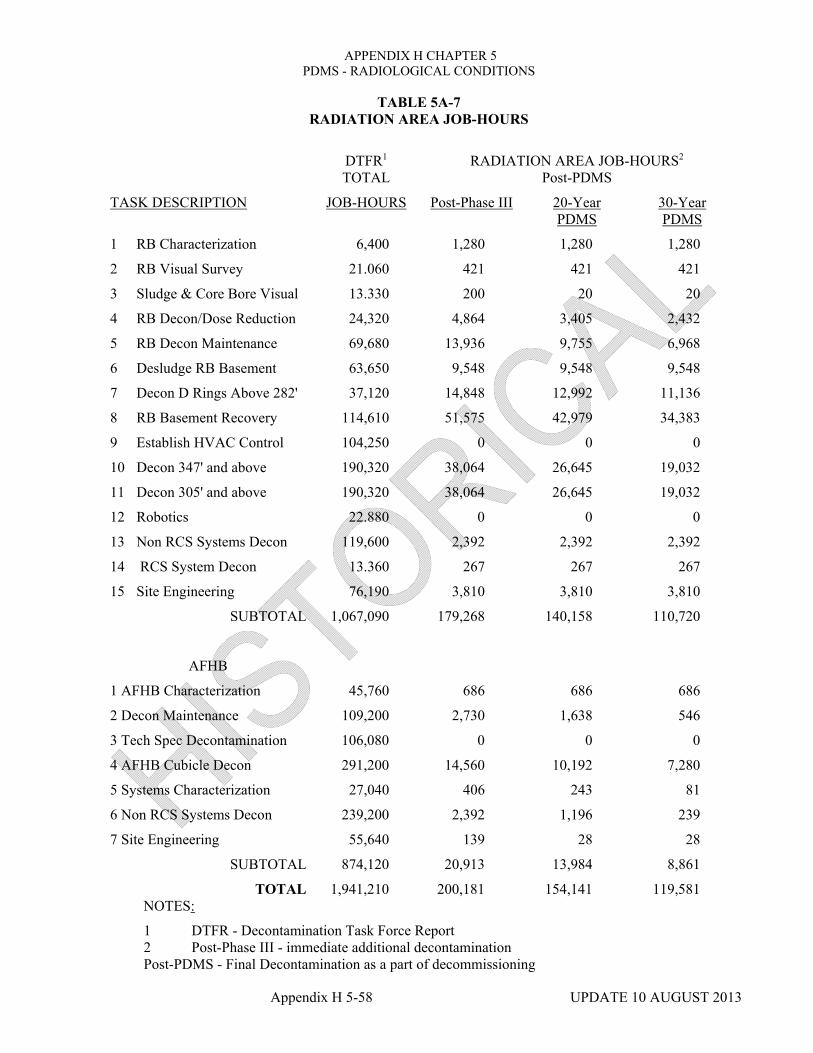
APPENDIX H CHAPTER 5 PDMS - RADIOLOGICAL CONDITIONS
Appendix H 5-58 UPDATE 10 AUGUST 2013
TABLE 5A-7 RADIATION AREA JOB-HOURS
DTFR1 TOTAL
RADIATION AREA JOB-HOURS2
Post-PDMS
TASK DESCRIPTION JOB-HOURS Post-Phase III 20-Year PDMS
30-Year PDMS
1 RB Characterization 6,400 1,280 1,280 1,280
2 RB Visual Survey 21.060 421 421 421
3 Sludge & Core Bore Visual 13.330 200 20 20
4 RB Decon/Dose Reduction 24,320 4,864 3,405 2,432
5 RB Decon Maintenance 69,680 13,936 9,755 6,968
6 Desludge RB Basement 63,650 9,548 9,548 9,548
7 Decon D Rings Above 282' 37,120 14,848 12,992 11,136
8 RB Basement Recovery 114,610 51,575 42,979 34,383
9 Establish HVAC Control 104,250 0 0 0
10 Decon 347' and above 190,320 38,064 26,645 19,032
11 Decon 305' and above 190,320 38,064 26,645 19,032
12 Robotics 22.880 0 0 0
13 Non RCS Systems Decon 119,600 2,392 2,392 2,392
14 RCS System Decon 13.360 267 267 267
15 Site Engineering 76,190 3,810 3,810 3,810
SUBTOTAL 1,067,090 179,268 140,158 110,720
AFHB
1 AFHB Characterization 45,760 686 686 686
2 Decon Maintenance 109,200 2,730 1,638 546
3 Tech Spec Decontamination 106,080 0 0 0
4 AFHB Cubicle Decon 291,200 14,560 10,192 7,280
5 Systems Characterization 27,040 406 243 81
6 Non RCS Systems Decon 239,200 2,392 1,196 239
7 Site Engineering 55,640 139 28 28
SUBTOTAL 874,120 20,913 13,984 8,861
TOTAL 1,941,210 200,181 154,141 119,581NOTES:
1 DTFR - Decontamination Task Force Report 2 Post-Phase III - immediate additional decontamination Post-PDMS - Final Decontamination as a part of decommissioning

APPENDIX H CHAPTER 5 PDMS - RADIOLOGICAL CONDITIONS
Appendix H 5-59 UPDATE 10 AUGUST 2013
TABLE 5A-8
ETN AND RWP HOURS
ETN RWP HOURS
Reactor Building
Robotics C91K001 819.25
Characterization C90K001 1,213.63
Decontamination C30C001 0.0
C30D001 10.80
C30E001 0.0
C30D002 498.02
K20H015 170.07
D47H004* 1,322.93
Auxiliary & Fuel Handling Building
Decontamination J30CO11 397.12
J30C012 2,218.47
J30C013 1,491.62
J30C070 148.18
J30J103 3,353.57
J30C082 307.93
J30C083 18.78
J25H001 57,482.77
J30J040 538.65
Characterization Systems J90H001 664.32
E30C001 1,664.37
* Not all the RWPs included in this ETN were for decontamination work. The hours listed are only for decontamination tasks.

APPENDIX H CHAPTER 5 PDMS - RADIOLOGICAL CONDITIONS
Appendix H 5-60 UPDATE 10 AUGUST 2013
TABLE 5A-9
SUMMARY TABLE FOR PERSON-REM EVALUATION ANALYSIS
POST-PHASE III POST-PDMS
INDEX NUMBER
DECONTAMINATION TASKS
DOSE RATES
(mrem/hr) (JOB-
HOURS) PERSON-
REM5 JOB-
HOURS PERSON-
REM
1.0 Reactor Building
1.1 Preparations/support Activities
1.1.1 Characterization 30 1.901 30-60 1,721 10-30
1.1.2 Ventilation control and Area Isolation - 0
0-0 0 0-0
1.1.3 Health Physics support2 - 0 - 2,450 370-820
1.1.4 Engineering Support 30 3,810 60-130 3,810 30-60
1.2 Basement General Cleanup 100 26.740 1,340-2,940 21,009 530-1,160
1.3 Basement Cubicle Cleanup 100 25,788 1,290-2,840 17,192 430-950
1.4 Basement Block Wall Removal - 8,596 180-400 5,731 100-210
1.5 D-Ring Dose Reduction 150 9,400 710-1,550 4,700 180-390
1.6 D-Ring Final Decontamination 100 14,848 740-1,630 11,136 280-610
1.7 Dome and Polar Crane Decon 50 762 20-40 381 0-10
1.8 El. 347'-0" Decon Dose Reduction 30 4,700 70-160 2,350 20-40
1.9 El. 347'-0" Final Cleanup 20 37,303 370-820 18,651 90-120
1.10 El. 305'-0" Decon Dose Reduction 50 4,700 120-260 2,350 30-60

APPENDIX H CHAPTER 5 PDMS - RADIOLOGICAL CONDITIONS
Appendix H 5-61 UPDATE 10 AUGUST 2013
TABLE 5A-9 (Cont'd)
SUMMARY TABLE FOR PERSON-REM EVALUATION ANALYSIS
POST-PHASE III POST-PDMS
INDEX NUMBER
DECONTAMINATION TASKS
DOSE RATES
(mrem/hr) (JOB-
HOURS) PERSON-
REM5 JOB-
HOURS PERSON-
REM
1.11 El. 305'-0" Final Cleanup 30 38,064 570-1,260 19,032 140-310
1.12 Systems Decontamination
1.12.1 Reactor Coolant Sys. 50 267 10-20 267 0-10
1.12.2 Non-RCS Systems 50 2,392 60-130 2,392 30-70
Subtotal 179,268 6,680-14,690 110,720 2,240-4,940
2.0 Auxiliary and Fuel Handling Buildings
2.1 Preparation and support Activities
2.1.1 Characterization 10 1.092 10-10 767 Neg.
2.1.2 Health Physics Support1 - - 20-50 0-10
2.1.3 Engineering support 10 139 Neg. 28 Neg.
2.2 AFHB Decon/Dose Reduction 10 19682 100-220 8,065 20-40
Subtotal 20,913 130-280 8,861 20-50
Total 200,181 6,810-14,970 119,581 2,260-4,990

APPENDIX H CHAPTER 5 PDMS - RADIOLOGICAL CONDITIONS
Appendix H 5-62 UPDATE 10 AUGUST 2013
TABLE 5A-9 (Cont'd)
SUMMARY TABLE FOR PERSON-REM EVALUATION ANALYSIS
NOTES:
1. Dose rates for Post-PDMS are 50% of those listed for Post-Phase III.
2. Person-rem for health physics support are assumed to be 20% of total person-rem.
3. Person-rem for block wall removal are from Reference 9.
4. The range of person-rem is assumed to be from 50% below to 10% above the product of dose rate and job-hours columns from Table 5A-9.
5. Neg. = Less than 5 person-rem.
TABLE 5A-10
ESTIMATED TOTAL PERSON-REM FOR FINAL DECONTAMINATION OPTIONS
TASK
POST-PHASE III1
(Person-rem)
POST-PDMS2 (Person-rem)
During PDMS N/A 230 - 490
Cleanup 6,800 - 15,000 2,300 - 5,000
Radwaste Handling 360 - 550 180 - 280
Total 7,160 - 15,550 2,710 - 5,770
PDMS Person rem Savings*
4,500 - 9,800
*The savings is defined to be the difference in total person rem required for deferred and immediate decontamination.
NOTES:
1. Immediate additional decontamination.
2. Final decontamination as a part of decommissioning (30-year PDMS)

APPENDIX H CHAPTER 5 PDMS - RADIOLOGICAL CONDITIONS
Appendix H 5-63 UPDATE 10 AUGUST 2013
APPENDIX 5B
DECONTAMINATION ACTIVITIES
The primary techniques used to decontaminate the TMI-2 facility are listed below and discussed as appropriate.
a. Kelly Vaccumac
b. Scabbling
c. Strippable Coatings
d. High Pressure Spray
e. System Flushing
f. Hands-on Decontamination
Kellv Vaccumac
During the decontamination program, steam cleaning machines, called Kelly Vaccumac, were procured. Contamination was removed from surfaces by a steam cleaning wand, then vacuumed much like conventional steam cleaning unit used on carpeting.
Concrete Scabbling
A concrete scabbler was developed at TMI-2. This machine removed a layer of concrete surface from the floors of many contaminated areas of the plant and vacuumed the residue. Scabbled surfaces were then coated or painted to prevent recontamination.
Strippable Coating
Strippable coatings made of various polymer substances were applied to surfaces. When subsequently removed, gross particulate contamination adhered and also was removed.
High Pressure Spray and Flushing
Several different types of high pressure spray and flush operations were used to decontaminate the plant areas. These techniques varied water temperature and pressure; however, in each case, water was the only medium used to remove loose contamination from walls and surfaces in the various areas of the plant.
System Flushing;
Processed borated water was circulated through most contaminated systems to remove contaminants. All of the systems were then drained to the extent practical and isolated unless required for PDMS activities.

APPENDIX H CHAPTER 5 PDMS - RADIOLOGICAL CONDITIONS
Appendix H 5-64 UPDATE 10 AUGUST 2013
Hands-On Decontamination
Hands-on decontamination is a mechanical technique that was generally used on floors and walls to remove loosely held contamination. Typically, rags, absorbent cloths, brushes, and abrasive pads were utilized for this decontamination technique. In addition, mechanically driven hand brushes and floor brushes were utilized where required. Grit or abrasives were added, as necessary, to aid in surface cutting or removal of a portion of the surface if the contamination was more tightly fixed. Occasionally, approved chemical decontamination agents were used to enhance the effectiveness of hands-on techniques. However, no major chemical decontamination activities were conducted.
ROBOTIC DEVICES
In several cases, the decontamination equipment was mounted on remotely controlled robots and used to treat surfaces that were inaccessible to personnel. These robots were used in the Reactor Building basement and AFHB cubicles. Each robot is described below.
System In-Service Inspection (SISI)
In 1982 a device was developed to perform remote sampling and radiation surveys in the makeup purification dernineralizer cubicles. This device was a small track, tethered vehicle that contained several CCTV cameras, a radiation detector, and a small manipulator arm for sample collection. Determination of the levels of smearable contamination of the floor surface was the extent of the sample collection intended.
Remote Controlled Mobile Manipulator (RCMM)
In December 1982 a RCMM device, designated "Fred" was purchased. This device was tethered, six-wheeled vehicle with a simple manipulator. The RCMM was used to remotely flush areas in the plant to minimize the requirement for personnel exposure in high radiation areas for extended periods of time. The acquisition of this device essentially was the first use of remote equipment to perform clean up tasks as a means of reducing occupational radiation exposure.
The first use of the RCMM was in the Auxiliary Building for flushing the "B" and "C" reactor coolant bleed tank cubicles and makeup pump 1B room. A high pressure water nozzle mounted on the end of the manipulator arm was used to flush the rooms. A support camera with pan and tilt capabilities was used to provide additional viewing capability.
Remote Reconnaissance Vehicle RRV)
During the first part of 1984 a Remote Reconnaissance Vehicle, designated "ROVER," was delivered to TMI. The RRV was a six-wheeled, tethered mobile vehicle. It contained CCTV cameras for viewing in the forward and rear directions. The tethered playout and takeup was controlled by the RRV operator. A space on the front of the RRV allowed attachment of devices to perform remote activities. During initial use of the RRV, a radiation detector on an x-y positioner allowed surveys and vertical radiation profiles to be performed. Later the RRV was equipped with flushing, core boring, concrete removal and sludge removal tools.
Remote Controlled Transport Vehicle (RCTV)
In 1984 a RCTV was loaned to GPU Nuclear Corporation by the Department of Energy. It contained a manipulator arm mounted to a telescoping column. Power and controls to the RCTV are transmitted through a tether that follows the movement of the transporter. Lessons learned

APPENDIX H CHAPTER 5 PDMS - RADIOLOGICAL CONDITIONS
Appendix H 5-65 UPDATE 10 AUGUST 2013
during the implementation of the previously used remote vehicles helped make the first use of the RCTV a success.
The first effort with the RCTV was to perform a radiation survey and measure the radiation profile of the “A and “B” makeup demineralizer tanks.
Louie-2
GPU Nuclear designed and fabricated a six-wheeled, skid-steered remote vehicle named Louie-2, primarily to remove the highly contaminated grout pad from the floor of the seal injection valve room. The device was configured with a three-piston scabbler and a vacuum shroud to remove the scabbled debris.
The robots developed and used at TMI-2 performed a variety of recovery tasks including data acquisition, dose reduction, and waste management. Throughout the entire cleanup period, new equipment and techniques were developed as necessary to meet the challenges presented by the cleanup task.
In some cases, the most efficient and cost effective means of mitigating the contamination and minimizing exposure was to remove the contaminated equipment involved. It was then packaged and shipped to the appropriate commercial radioactive waste disposal facility.
WASTE PROCESSING
Several processing systems were developed for use in dispositioning both the accident water and the water necessary to accomplish the TMI-2 cleanup operations. Primarily, water use was restricted to the original accident generated water, which was cleaned and reused throughout the cleanup program. The primary water processing systems developed were the Submerged Demineralizer System, EPICOR 11, and the Defueling Water Cleanup System.
Submerged Demineralizer System
The Submerged Demineralizer System (SDS) was a primary water processing system utilizing shielded, expendable vessels. The system was located in the Unit 2 Spent Fuel Pool ‘B’ and shielded by the pool water. The processing media were zeolites and it was most effective in removing soluble cesium and strontium. At the completion of Th4I-2 waste management activities, the system was deactivated, the expendable vessels were disposed of at a commercial radioactive waste burial site or shipped to a DOE research facility, and the shielding water was disposed of as part of the accident generated water disposal program.
EPICOR II
EPICOR II was configured as a primary processing system utilizing three disposable dernineralizer vessels (liners). The first position liner utilized zeolites as a processing media and served to remove soluble cesium and strontium. The second and third liners utilized organic resins as the process media and served primarily as polishers.
Defueling Water Cleanup System (Ion-Exchanger Portion)
The Defueling Water Cleanup System (DWCS) was a primary processing system. It utilized a disposable High Integrity Container (HIC) with zeolites as a processing media. It was effective in removing soluble cesium and strontium. Like the SDS, it was deactivated at the conclusion of the TMI-2 waste management activities.

UPDATE 10 - AUGUST 2013
APPENDIX H
CHAPTER 6
DEACTIVATED SYSTEMS AND FACILITIES

APPENDIX H CHAPTER 6 DEACTIVATED SYSTEMS AND FACILITIES
TABLE OF CONTENTS
Appendix H 6-i UPDATE 10 - AUGUST 2013
SECTION TITLE PAGE
6.0 INTRODUCTION 6-1
6.1 DEACTIVATED FACILITIES 6-1
6.1.1 DELETED 6-1
6.1.2 DELETED 6-1
6.1.3 CONTAINMENT AIR CONTROL ENVELOPE 6-2
6.1.4 CIRCULATING WATER PUMP HOUSE 6-2
6.1.5 CIRCULATING WATER CHLORINATOR HOUSE
6-2
6.1.6 NATURAL DRAFT COOLING TOWERS 6-2
6.1.7 MECHANICAL DRAFT COOLING TOWER 6-2
6.1.8 DELETED 6-2
6.1.9 TENDON ACCESS GALLERY 6-3
6.1.10 RIVER WATER AND FIRE PUMP HOUSE 6-3
6.1.11 BWST PIPE CHASE 6-3
6.1.12 CONTROL BUILDING (M-20) AREA EAST 6-3
6.1.13 CONTROL BUILDING (M-20) AREA WEST 6-3
6.1.14 DELETED 6-3
6.3 DEACTIVATED SYSTEMS 6-6
6.3.1 AUXILIARY STEAM SYSTEM 6-6
6.3.2 DELETED 6-6
6.3.3 DELETED 6-6
6.3.4 DELETED 6-6
6.3.5 DELETED 6-6
6.3.6 DELETED 6-6
6.3.7 DELETED 6-6

APPENDIX H CHAPTER 6 DEACTIVATED SYSTEMS AND FACILITIES
TABLE OF CONTENTS
Appendix H 6-ii UPDATE 10 - AUGUST 2013
SECTION TITLE PAGE
6.3.8 INSTRUMENT AIR SYSTEM 6-6
6.3.9 DELETED 6-6
6.3.10 DELETED 6-6
6.3.11 DELETED 6-6
6.3.12 DELETED 6-6
6.3.13 DEMINERALIZED SERVICE WATER SYSTEM 6-7
6.3.14 DELETED 6-7
6.3.15 NUCLEAR SERVICES RIVER WATER SYSTEM 6-7
6.3.16 REACTOR BUILDING NORMAL COOLING WATER SYSTEM
6-7
6.3.17 REACTOR BUILDING PENETRATIONS FORCED AIR COOLING SYSTEM
6-7
6.3.18 DELETED 6-7
6.3.19 CIRCULATING WATER SYSTEM 6-7
6.3.20 DELETED 6-7
6.3.21 ENVIRONMENTAL BARRIER SYSTEM 6-8
6.3.22 PENETRATION PRESSURIZATION SYSTEM 6-8
6.3.23 GLAND STEAM SYSTEM 6-8
6.3.24 DELETED 6-8
6.3.25 DELETED 6-8
6.3.26 DELETED 6-8
6.3.27 DELETED 6-8
6.3.28 DELETED 6-8
6.3.29 DELETED 6-8
6.3.30 DELETED 6-8
6.3.31 DELETED 6-8

APPENDIX H CHAPTER 6 DEACTIVATED SYSTEMS AND FACILITIES
TABLE OF CONTENTS
Appendix H 6-iii UPDATE 10 - AUGUST 2013
SECTION TITLE PAGE
6.3.32 DELETED 6-8
6.3.33 DELETED 6-8
6.3.34 DELETED 6-8
6.3.35 DELETED 6-8
6.3.36 DELETED 6-8
6.3.37 DELETED 6-8
6.3.38 DELETED 6-8
6.3.39 DELETED 6-8
6.3.40 TEMPORARY NUCLEAR SERVICES CLOSED 6-9
6.3.41 DELETED 6-9
6.3.42 DELETED 6-9
6.3.43 DELETED 6-9
6.3.44 DELETED 6-9
6.3.45 DELETED 6-9
6.3.46 DELETED 6-9
6.3.47 DELETED 6-9
6.3.48 DELETED 6-9
6.3.49 DELETED 6-9
6.3.50 EARTHQUAKE DETECTION SYSTEM 6-9
6.3.51 REACTOR COOLANT PUMPS MOTOR OIL DRAIN SYSTEM
6-9
6.3.52 DELETED 6-9
6.3.53 DELETED 6-9
6.3.54 DELETED 6-9
6.3.55 DELETED 6-9

APPENDIX H CHAPTER 6 DEACTIVATED SYSTEMS AND FACILITIES
TABLE OF CONTENTS
Appendix H 6-iv UPDATE 10 - AUGUST 2013
SECTION TITLE PAGE
6.3.56 POLAR CRANE 6-10
6.4 DELETED 6-10
6.5 SYSTEM REFERENCES 6-13
HISTORY CHAPTER 6 DEACTIVATED SYSTEMS AND FACILITIES
TABLES
TABLE TITLE PAGE
6.1-1 DEACTIVATED FACILITIES 6-4
6.3-1 DEACTIVATED SYSTEMS 6-11

APPENDIX H CHAPTER 6 DEACTIVATED SYSTEMS AND FACILITIES
Appendix H 6-1 UPDATE 10 - AUGUST 2013
6.0 INTRODUCTION
This chapter describes those systems and facilities which have been deactivated for PDMS. There are two categories of deactivated systems and facilities: 1) deactivated systems and facilities with passive PDMS functions and 2) deactivated systems and facilities.
The first category consists of those systems or facilities which have been deactivated but provide the passive function(s) during PDMS of contamination control and/or containment isolation. No effort will be expended to maintain the design functional capability of these systems and facilities. However, the passive function(s) of the affected systems or facilities will be maintained throughout PDMS to provide reasonable assurance that TMI-2 can be maintained in the PDMS condition with no risk to the health and safety of the public. The passive function of containment isolation will be maintained as required in the PDMS technical specifications section 3.1.1.1, primary containment isolation. The passive function of contamination control will be maintained by adherence to the requirements of the TMI Radiation Protection Program and 1000-PLN-7200.04 (PDMS Quality Assurance Plan).
The second category consists of those systems and facilities which are deactivated because they serve no active or passive function during PDMS. No maintenance is required and no attempts will be made to preserve or maintain these systems and facilities.
Tables 6.1- 1, 6.2- 1, and 6.3- 1 provide a listing of those facilities and systems which will be deactivated during PDMS. These tables also provide other relevant status information for the listed facilities and systems.
Equipment, components, and parts may be removed from systems and facilities designated as deactivated, and used for other purposes, provided their removal does not adversely affect the PDMS function of the system(s) or facilities involved. This may include complete system dismantlement, component removal for use elsewhere, and possible conversion of portions of systems for other uses.
Similarly, equipment, components, and parts may be removed from systems and facilities designated as deactivated with PDMS passive functions provided, the passive function is not compromised or provided, decontamination activities have negated the need for the passive function of contamination control.
A detailed original design description of deactivated facilities and systems may be found in the TMI-2 FSAR and/or system operating description books.
6.1 DEACTIVATED FACILITIES
Table 6.1-1 provides a listing of deactivated facilities for TMI-2. Also listed are the status of internal contamination and relevant remarks regarding the final layup of the facility. The following sections address the facility description and the PDMS function of the facility.
6.1.1 DELETED
6.1.2 DELETED

APPENDIX H CHAPTER 6 DEACTIVATED SYSTEMS AND FACILITIES
Appendix H 6-2 UPDATE 10 - AUGUST 2013
6.1.3 CONTAINMENT AIR CONTROL ENVELOPE
The CACE was installed during the cleanup period and provided space to mobilize equipment and materials needed to support the in-containment activities through defueling. Location of the CACE at the equipment hatch allows equipment and materials to be moved into and out of the Containment Building with a minimum of difficulty through the equipment hatch airlock doors. The CACE served as an aid in the control of the spread of contamination and airborne radioactivity during those times when the airlock doors were opened.
During PDMS, this facility serves no active function and as such is designated deactivated. Certain types of RB entries require the CACE to be in a closed condition; thus, the CACE serves a passive function.
6.1.4 CIRCULATING WATER PUMP HOUSE
The Circulating Water Pump House contained the six circulating water pumps and their controls which provide a flowpath from the circulating water flume to the main condenser.
This facility has had its contents dismantled, the pump bay filled in and is being utilized by the site transportation department. Final Decommissioning release surveys were completed on the pump basin prior to filling it with crushed stone. Since this constituted final release surveys, the area is posted with warning signs against the admittance of radioactive material into the building. Reference 6.5-129.
6.1.5 CIRCULATING WATER CHLORINATOR HOUSE
The Circulating Water Chlorinator House contained the chlorine evaporator, chlorinator and ejector and storage tanks in addition to the sulfuric acid storage tank. This facility supported the chemical treatment of the Circulating Water System. All equipment and hazardous materials (chlorine. Sulfuric acid) have been removed.
During PDMS, this facility serves no active or passive function and as such is designated deactivated.
6.1.6 NATURAL DRAFT COOLING TOWERS
Two cooling towers were provided as a heat sink for the plant circulating water system. During PDMS, these towers serve no active or passive function and as such are designated deactivated. Therefore, the combustible material from this facility has been removed. The aircraft warning lights will remain operational.
6.1.7 MECHANICAL DRAFT COOLING TOWER
The original design of the Mechanical Draft Cooling Tower was to remove the heat added by the Service Cooling Water Systems before it was returned to the river.
This facility has been dismantled and the combustible material has been removed; only the concrete basin and pump house remain.
6.1.8 DELETED

APPENDIX H CHAPTER 6 DEACTIVATED SYSTEMS AND FACILITIES
Appendix H 6-3 UPDATE 11 - AUGUST 2015
6.1.9 TENDON ACCESS GALLERY The Tendon Access Gallery provided access for initial positioning and tightening of the Tendon Post-Tensioning System during construction. The Tendon Post-Tensioning System is grouted and as such does not require periodic torquing During PDMS, this facility serves the passive function of contamination control and housing an operational sump pump
6.1.10 DELETED
6.1.11 BWST PIPE CHASE
The Borated Water Storage Tank (BWST) Pipe Chase is an underground tunnel extending from the BWST into the Auxiliary Building on the east side. It enclosed piping for the Decay Heat Removal and Building Spray Systems. During PDMS, this area serves the passive function of contamination control.
6.1.12 CONTROL BUILDING (M-20) AREA EAST
The Control Building Area is the plant area below elevation 305' between the Turbine, Reactor, and Service Buildings. The east portion is separated from the west by a barrier wall. This area provides access to the Tendon Access Gallery on the east side and the Control and Service Buildings from theTurbine Building. During PDMS, this area serves the passive functions of housing containment isolations and contamination control. It also contains a portion of the cork seam monitoring system.
6.1.13 CONTROL BUILDING (M-20) AREA WEST
The Control Building Area west portion houses the turbine-driven Emergency Steam Generator Feed Pump, Main Steam Isolations, Relief and Atmospheric Vent Valves, the Control Building Area Sump, and Unit Substations 2-34 and 2-44. 'This area also provides access to the Tendon Access Gallery on the west side.
During PDMS, this area serves the passive functions of housing containment isolations and contamination control. However, one sump pump and a portion of the cork seam monitoring system will remain operational.
6.1.14 DELETED

Appendix H 6-4 UPDATE 10 - AUGUST 2013
TABLE 6.1-1
DEACTIVATED FACILITIES
FACILITY DESCRIPTION
PDMS FUNCTION
INTERNAL CONTAMINATION ISOLATION REMARKS
DELETED
CACE PASSIVE YES YES Residual fixed contamination in some floor areas
Circulating Water Pump House
NONE NO NO In use by Transportation Dept. Reference 6.5-129
Circulating Water Chlorinator House
NONE NO NO
Natural Draft Cooling Towers
NONE NO NO Aircraft warning lights are operational.
Mechanical Draft Cooling Tower
NONE N/A N/A Dismantled.
DELETED
Tendon Access Gallery Sump
PASSIVE YES YES Residual contamination in sump; one pump operational.
DELETED

Appendix H 6-5 UPDATE 10 - AUGUST 2013
TABLE 6.1-1 (Continued)
DEACTIVATED FACILITIES
FACILITY DESCRIPTION
PDMS FUNCTION
INTERNAL CONTAMINATION ISOLATION REMARKS
BWST Pipe Chase and Decay Heat Removal
PASSIVE YES NO NO Residual contamination in pipe chase piping.
Control Building (M-20) Area East
PASSIVE YES YES YES Residual contamination in access trunk to tendon access gallery. Cork Seam Monitoring System
Control Building (M-20) Area West
PASSIVE YES YES YES Residual contamination in main steam lines and control building area sump; one sump pump operational. Cork Seam Monitoring System
DELETED

APPENDIX H CHAPTER 6 DEACTIVATED SYSTEMS AND FACILITIES
Appendix H 6-6 UPDATE 10 - AUGUST 2013
6.3 DEACTIVATED SYSTEMS
The section provides a description of those systems which are deactivated because they serve no active or passive function during PDMS. Table 6.3-1 lists the deactivated systems for the TMI-2 facility and their PDMS status. All deactivated systems require no maintenance and no attempts will be made to preserve nor maintain these systems. Equipment, components, and parts may be removed from these systems and facilities, and used for other purposes provided their removal does not adversely affect any PDMS function. Each of these systems is described in the following sections.
6.3.1 AUXILIARY STEAM SYSTEM
The Auxiliary Steam System was designed to supply process steam to the following equipment:
a. Reactor Coolant Evaporator
b. DELETED
c. Turbine Gland Seal Steam System
d. Turbine Driven Emergency Steam Generator Feed Pump
e. DELETED
f. Unit l/Unit 2 Aux Steam Cross-Connect Piping.
6.3.2 DELETED
6.3.3 DELETED
6.3.4 DELETED
6.3.5 DELETED
6.3.6 DELETED
6.3.7 DELETED
6.3.8 INSTRUMENT AIR SYSTEM
The Instrument Air System was used throughout the plant for nuclear and non-nuclear instrumentation and controls, and for pneumatic devices where oil and moisture-free air was required. Portions of the instrument air system are incorporated within the compressed air supply system. For additional information see Section 7.2.6.4.
6.3.9 DELETED
6.3.10 DELETED
6.3.11 DELETED
6.3.12 DELETED

APPENDIX H CHAPTER 6 DEACTIVATED SYSTEMS AND FACILITIES
Appendix H 6-7 UPDATE 10 - AUGUST 2013
6.3.13 DEMINERALIZED SERVICE WATER SYSTEM
The Demineralized Service Water System was designed to receive demineralized water from the Demineralizing System. The water was processed for oxygen removal, stored under a nitrogen blanket, and distributed to service as needed. The distribution headers supplied the Reactor Building, Turbine Building,
Control and Service Building, the Auxiliary and Fuel Handling Building, and the Diesel Generator Building. During the clean-up period, a portion of the D.W. System was utilized in the Decon Processed Water System (See Section 6.2.40).
The Radwaste Pumps Seal Water System, a subsystem of the Demineralized Service Water System, provided seal water to pumps that handled contaminated fluid in either normal or abnormal operations. During PDMS, this water is supplied by the Domestic Water System.
6.3.14 DELETED
6.3.15 NUCLEAR SERVICES RIVER WATER SYSTEM
The Nuclear Services River Water System (NSRW) supplied cooling water for all nuclear related and fuel handling requirements and various HVAC services. The system took suction from river water and returned the water to the river via the Mechanical Draft Cooling Tower. The NSRW equipment in the Screenhouse has been removed.
6.3.16 REACTOR BUILDING NORMAL COOLING WATER SYSTEM
The Reactor Building Normal Cooling Water System was designed to circulate treated water through the Reactor Building air cooling units and to remove the heat thus transferred to the water by passing it through an evaporative cooler.
6.3.17 REACTOR BUILDING PENETRATIONS FORCED AIR COOLING SYSTEM
The Reactor Building Penetrations Forced Air Cooling System provided cool air to the feedwater and main steam penetrations in the Reactor Building to maintain the temperature of the concrete surrounding the penetrations within allowable limits.
6.3.18 DELETED
6.3.19 CIRCULATING WATER SYSEM
The Circulating Water System was designed to provide the cooling water requirement for the main condenser.
In addition, the system provided cooling water to the condenser vacuum pump coolers, deicing water supply to the River Water Pump House, and water to the chlorine ejector.
6.3.20 DELETED

APPENDIX H CHAPTER 6 DEACTIVATED SYSTEMS AND FACILITIES
Appendix H 6-8 UPDATE 10 - AUGUST 2013
6.3.21 ENVIRONMENTAL BARRIER SYSTEM
The Environmental Barrier System was designed to provide added assurance that containment atmosphere leakage to the environment, through the isolation valves of selected process lines, would be as low as practical. This system provided a barrier to environmental leakage in addition to the two barriers which were normally supplied by means of the inside and outside Containment isolation valves.
6.3.22 PENETRATION PRESSURIZATION SYSTEM
The Penetration Pressurization System was designed to reduce any leakage of containment atmosphere through penetration sleeve cavities by means of a positive nitrogen gas pressure in the enclosed air spaces incorporated in the penetration design.
6.3.23 GLAND STEAM SYSTEM
The Turbine Gland Sealing System sealed the turbine shaft and rotor to ensure that steam was contained within the turbine casings and to prevent air inleakage. The system provided these functions automatically by controlling the gland steam pressure to an adequate sealing pressure under all conditions of turbine operation.
6.3.24 DELETED
6.3.25 DELETED
6.3.26 DELETED
6.3.27 DELETED
6.3.28 DELETED
6.3.29 DELETED
6.3.30 DELETED
6.3.31 DELETED
6.3.32 DELETED
6.3.33 DELETED
6.3.34 DELETED
6.3.35 DELETED
6.3.36 DELETED
6.3.37 DELTEED
6.3.38 DELETED
6.3.39 DELETED

APPENDIX H CHAPTER 6 DEACTIVATED SYSTEMS AND FACILITIES
Appendix H 6-9 UPDATE 10 - AUGUST 2013
6.3.40 TEMPORARY NUCLEAR SERVICES CLOSED COOLING SYSTEM
This system was designed and installed during the TMI-2 cleanup period. It provided cooling for the mini-decay heat removal heat exchangers. A blank plate was installed in the inlet to spent fuel pool heat exchanger 1A to divert sufficient flow through the Temporary Nuclear Services Closed Cooling System.
6.3.41 DELETED
6.3.42 DELETED
6.3.43 DELETED
6.3.44 DELETED
6.3.45 DELETED
6.3.46 DELETED
6.3.47 DELETED
6.3.48 DELETED
6.3.49 DELETED
6.3.50 EARTHQUAKE DETECTION SYSTEM
The SMA-3 Strong Motion Accelerograph System manufactured by Kinemetrics, Inc. was installed in the basement of the Reactor Building annulus to measure the strength of seismic events. The SMA-3 was a multi-channel strong motion accelerograph. It featured central recording on magnetic tape cassettes with remote accelerometer and starter packages. The system remained in standby condition and would only activate if an earthquake caused the starter to actuate the recording circuits and tape transports.
6.3.51 REACTOR COOLANT PUMPS MOTOR OIL DRAIN SYSTEM
This system was used to drain oil leakage from the RCP motors. Oil was diverted from the upper bearing, oil splash shielding and lower bearing oil splash shielding to oil shield drain tanks located in the Reactor Building basement. Each of the four (4) reactor coolant pumps has the capacity to contain as much as 138 gallons of oil. More than 40% of that oil was removed prior to PDMS. Not all of the oil was removed because the dose rates severely limit access to the area of the pumps and oil collection/drain systems. However, the oil collection tanks meet NFPA-30 requirements and are equipped with flame arrestors. Therefore, the residual oil in the tanks does not present a fire hazard.
6.3.52 DELETED
6.3.53 DELETED
6.3.54 DELETED
6.3.55 DELETED

APPENDIX H CHAPTER 6 DEACTIVATED SYSTEMS AND FACILITIES
Appendix H 6-10 UPDATE 10 - AUGUST 2013
6.3.56 POLARCRANE
The Reactor Building Polar Crane is an electrically powered, pendant operated rotary bridge crane with a single trolley. The crane was originally designed and constructed with a capacity of 500 tons and an auxiliary hoist capacity of 25 tons. During the post accident clean-up period, the crane was extensively refurbished with the refurbishment including deactivation of the cab controls and installation of pendant operating controls and a new festoon cable. It was subjected to a load test to recertify it to a main hoist capacity of 170 tons and an auxiliary hoist capacity of 25 tons in support of reactor vessel head service platform removal.
In October of 1990, the crane manufacturer notified owners that structural defects had been found in a similar crane and recommended certain modifications to preclude failures in all cranes of this type. In lieu of performing the modifications, GPUN elected, with the manufacturer’s approval, to downgrade the crane to a main hoist capacity of 88 tons and an auxiliary hoist capacity of 9 tons. This was sufficient capacity to satisfy the lifting and handling needs for the remainder of the defueling program.
In March of 1994, the crane manufacturer again notified owners of additional defects identified in a similar crane and recommended further remedial modifications. GPUN deactivated the polar crane. During the PDMS period repairs and modifications will be evaluated and the crane may be refurbished to restore it to a lifting capability sufficient to support PDMS related work and future dismantlement and decommissioning needs.
6.4 DELETED

APPENDIX H CHAPTER 6 DEACTIVATED SYSTEMS AND FACILITIES
TABLE 6.3-1
DEACTIVATED SYSTEMS
Appendix H 6-11 UPDATE 10 - AUGUST 2013
SYSTEM DESCRIPTION
SYSTEM CODE
PDMS FUNCTION
CONTAINMENT ISOLATION
INTERNAL CONTAMINATION REMARKS
Auxiliary Steam AS NONE NO NO
Instrument Air IA NONE NO NO Portions of the Inst. Air System will be used in the Compressed Air System
Demin Water DW NONE NO NO DW-V28 transferred to deconprocessed water (DPW) system
Nuclear Services River Water
NR NONE NO NO
Reactor Building Normal Cooling
RB NONE NO NO
Penetration Cooling
PC NONE NO NO
Circ. Water CW NONE NO NO
Environmental Barrier
EB NONE NO NO
Penetration Pressurization
PP NONE NO NO
Gland Steam GS NONE NO NO

APPENDIX H CHAPTER 6 DEACTIVATED SYSTEMS AND FACILITIES
TABLE 6.3-1
DEACTIVATED SYSTEMS
Appendix H 6-12 UPDATE 10 - AUGUST 2013
SYSTEM DESCRIPTION
SYSTEM CODE
PDMS FUNCTION
CONTAINMENT ISOLATION
INTERNAL CONTAMINATION REMARKS
Temp. Nuc. Svc. Closed Cooling
TNS NONE NO NO
Earthquake Detection
ED NONE NO N/A
RC Pump Motor Oil Drains
RO NONE NO NO
Polar Crane N/A NONE NO YES

APPENDIX H CHAPTER 6 DEACTIVATED SYSTEMS AND FACILITIES
Appendix H 6-13 UPDATE 10 - AUGUST 2013
6.5 SYSTEM REFERENCES Provided below is a list of reference documents that provide additional information. Unless otherwise specified, drawing numbers refer to Burns and Roe Flow Diagrams.
REFERENCE DOCUMENT NO. DOCUMENT DESCRIPTION
6.5-1 GPU Dwg. 302-2700, Sheets 1,2 & 3
Reactor Building Isolation Flow Diagram, Unit 2
6.5-2 DELETED
6.5-3 Doc. No. 15737-2-516-001
Bechtel Instr. Index
6.5-4 Work Orders 2555 and 3475
Bums & Roe Instr. List
6.5-5 Dwg No 302-22 19 Radiation Monitoring, Station Vent
6.5-6 DELETED
6.5-7 DELETED
6.5-8 Bechtel Dwg. NO. 15737-2-M74-DW01
Demineralized Service Water P&ID
6.5-9 DELETED
6.5-10 DELETED
6.5-11 Bechtel Dwg. NO. 2-M74-CDWO 1
P&ID Containment Air Control Envelope HVAC System
6.5-12 Bechtel Dwg. NO. 2-M74-DW01
Piping and Instrument Diagram (P&ID). Demineralized Service Water System
6.5-13 Bechtel Dwg. No. 2-M74-DWC01
Defueling Water Clean-Up Reactor Vessel Clean-Up System
6.5-14 Bechtel Dwg. No. 2-M74-DWC02
Defueling Water Clean-Up Fuel Transfer Canal/Spent Fuel Pool Clean-Up System

APPENDIX H CHAPTER 6 DEACTIVATED SYSTEMS AND FACILITIES
Appendix H 6-14 UPDATE 10 - AUGUST 2013
REFERENCE DOCUMENT NO. DOCUMENT DESCRIPTION
6.5-15 Bechtel Dwg. No. 2-M74-DWC03
Defueling Water Clean-Up Auxiliary Systems
6.5-16 Bechtel Dwg. No. 2-M74-PW01
Processed Water Storage and Recycle System
6.5-17 Bechtel Dwg. No. 2-M74-RBC01
Reactor Building Chilled Water System
6.5-18 Bechtel Dwg. No. 2-M74-SDS01
Piping and Instrument Diagram (P&ID)- SDS Feed and Monitor Tank System-
6.5-19 Bechtel Dwg. No. 2-M75-FCC01
Schematic Flow Diagram - Fuel Transfer Canal Fill System
6.5-20 Bechtel Dwg. No. 2-POA-1303
General Arrangement Plenum Removal Reactor Building
6.5-21 Bechtel Dwg. No. 2-POA-6401
General Arrangement Fuel Handling Building Plan El. 347'-6"
6.5-22 Dwg. No. 2002 Main & Reheat Steam and Gland Seal Steam Systems
6.5-23 Dwg. No. 200 Bleed Steam System
6.5-24 Dwg. No. 2004 Auxiliary Steam System
6.5-25 Dwg. No. 2005 Feedwater and Condensate System
6.5-26 Dwg. No. 2006 Make-Up Water Treatment and Condensate Polishing
6.5-27 Dwg. No. 2007 Demineralized Service Water System
6.5-28 Dwg. No. 2008 Feedwater Heater Vents, Reliefs and Misc. Drains System
6.5-29 Dwg. No. 2009 Feedwater Heater Drains System
6.5-30 Dwg. No. 2010 Condenser Air Extraction System

APPENDIX H CHAPTER 6 DEACTIVATED SYSTEMS AND FACILITIES
Appendix H 6-15 UPDATE 10 - AUGUST 2013
REFERENCE DOCUMENT NO. DOCUMENT DESCRIPTION
6.5-31 Dwg. No. 2011 Turbine Lube Oil Purification and Transfer System
6.5-32 Dwg. No. 2012 Instrument and Service Air System
6.5-33 Dwg. No. 2013 Domestic Water
6.5-34 Dwg. No. 2014 Service Air System
6.5-35 Dwg. No. 2015 Turbine Plant sampling System -Secondary Plant
6.5-36 Dwg. No. 2018 Secondary Services Closed Cooling Water
6.5-37 Dwg. No. 2021 Circ. Water & River Water Chemical Treatment
6.5-38 Dwg. No. 2023 Circulating and Secondary Services River Water System
6.5-39 Dwg. No. 2024 Reactor Coolant, Make-Up and Purification System
6.5-40 Dwg. No. 2025 Chemical Addition
6.5-41 Dwg. No. 2026 Spent Fuel Cooling and Decay Heat System
6.5-42 Dwg. No. 2027 Radwaste Disposal Reactor Coolant Liquid
6.5-43 Dwg. No. 2028 Radwaste Disposal Gas
6.5-44 Dwg. No. 2029 Intermediate Closed Cooling Water System
6.5-45 Dwg. No. 2030 Nuclear Services Closed Cooling Water System
6.5-46 Dwg. No. 2031 Nuclear Sampling System
6.5-47 Dwg. No. 2033 Nuclear Services River Water System
6.5-48 Dwg. No. 2034 Reactor Building Emergency Spray and Core Flooding

APPENDIX H CHAPTER 6 DEACTIVATED SYSTEMS AND FACILITIES
Appendix H 6-16 UPDATE 10 - AUGUST 2013
REFERENCE DOCUMENT NO. DOCUMENT DESCRIPTION
6.5-49 Dwg. No. 2035 Decay Heat Closed Cooling Water System
6.5-50 Dwg. No. 2036 Nitrogen for Nuclear and Radwaste Systems
6.5-51 Dwg. No. 2037 Fire Protection System
6.5-52 Dwg. No. 2038 Diesel Fuel Emergency Diesel Generator
6.5-53 Dwg. No. 2039 Radwaste Disposal - Solid
6.5-54 Dwg. No. 2040 Heat and Ventilation, Turbine and Control Building Areas
6.5-55 Dwg. NO. 2041 Reactor Building Ventilation, and Purge System
6.5-56 Dwg. No. 2042 Auxiliary Building Heating & Ventilation System
6.5-57 Dwg. NO. 2044 Heating Ventilation and Air Condition (Control Building, Cable, Battery and Switchgear Rooms
6.5-58 Dwg. No. 2045 Radwaste Disposal Miscellaneous Liquid
6.5-59 Dwg. NO. 2046 Reactor Building Normal Cooling Water
6.5-60 Dwg. No. 2047 Heating and Ventilation, Circulating and River Water Pump House and Fire Pump House
6.5-61 Dwg. No. 2049 Heating and Ventilation, Emergency Diesel Generator Building
6.5-62 Dwg. NO. 2076 Piping Specialty List
6.5-63 Dwg. No. 2219 Heating and Ventilation, Building Air Intake and Exhaust
6.5-64 Dwg. No. 2343 Fuel Handling Building Heating & Ventilation System

APPENDIX H CHAPTER 6 DEACTIVATED SYSTEMS AND FACILITIES
Appendix H 6-17 UPDATE 10 - AUGUST 2013
REFERENCE DOCUMENT NO. DOCUMENT DESCRIPTION
6.5-65 Dwg. NO. 2385 Service Building Heating & Ventilation System
6.5-66 Dwg. NO. 2391 Service & Control Building – Domestic Water. Sanitary Waste & Contamination Drains
6.5.67 Dwg. No. 2397 Reactor Building Penetrations Isolation Valve Seal Water System
6.5-68 Dwg. No. 2414 Steam Generator Secondary Side Vent and Drains
6.5-69 Dwg. NO. 2440 Main, Bleed & Auxiliary Steam System & Traps
6.5-70 Dwg. No. 2475 Heating and Ventilation, Coagulator Building, Circulating Water Chlorinator house, and Mechanical Draft Cooling Tower Pump House
6.5-71 Dwg. No. 2492 Radwaste Pumps Seal Water
6.5-72 Dwg. No. 2496 Sump Pump Discharge
6.5-73 Dwg. No. 2497 Reactor Building Penetration Forced Air Cooling System
6.5-74 Dwg. No. 2517 Reactor Building Leak Rate Test
6.5-75 Dwg. No. 2524 Feedwater Heater Nitrogen Blanketing
6.5-76 Dwg. No. 2532 H2 and CO2 Supply Systems (Secondary Plant)
6.5-77 Dwg. No. 2551 Lube Oil System - Emergency Diesel Generator
6.5-78 Dwg. No. 2552 Starting Air System, Emergency Diesel Generator
6.5-79 Dwg. No. 2596 Flow Diagram, Hydraulic and Pneumatic Fuel Transfer System

APPENDIX H CHAPTER 6 DEACTIVATED SYSTEMS AND FACILITIES
Appendix H 6-18 UPDATE 10 - AUGUST 2013
REFERENCE DOCUMENT NO. DOCUMENT DESCRIPTION
6.5-80 Dwg. No. 2601 Reactor Coolant Pumps Seals
6.5-81 Dwg. No. 2606 OTSG Chemical Cleaning System
6.5-82 Dwg. No. 2626 Lab & Penetration Pressurization Gas Systems and Hydrogen for Make-Up Tank
6.5-83 Dwg. No. 2632 Radwaste Disposal Reactor Coolant Leakage Recovery
6.5-84 Dwg. No. 2633 Flow Diagram Oil Splash Shield Drain Piping for R. C. Pump Motors
6.5-85 Dwg. No. 2634 Gland Steam Seal System Turbine Building
6.5-86 Dwg. No. 2636 Environmental Barrier System
6.5-87 Dwg. No. 2668 SSCCW and Secondary Plant Sampling System, TB & CBA
6.5-88 GPUN Dwg. NO. 2E-35 10-1024
P&ID, Reactor Building Sump Recirculation System
6.5-89 GPUN Dwg. NO. 2E-950-02-00 1
SDS Plan View
6.5-90 GPUN Dwg. NO. 2R-950-21-00 1
P&ID Composite Submerged Demineralizer System
6.5-91 Dwg. No. 3004, Sheet 1 4160V Switchgear One Line Diagram
6.5-92 Dwg. No. 3005, Sheet 3 480V Unit Substations One Line Diagram
6.5-93 Dwg. No. 3011 Safety Features Actuation System Block Diagram
6.5-94 Dwg. NO. 3024-106 Block Diagram Misc. Seismic Monitoring system
6.5-95 Dwg. No. 3073 Diesel Generators Sheets 57, 59, and 60

APPENDIX H CHAPTER 6 DEACTIVATED SYSTEMS AND FACILITIES
Appendix H 6-19 UPDATE 10 - AUGUST 2013
REFERENCE DOCUMENT NO. DOCUMENT DESCRIPTION
6.5-96 Dwg. No. 3091 Safety Features Actuation System Index
6.5-97 Dwg. No. 4148 Reactor Building Containment Wall Penetrations Schedule
6.5-98 Dwg. No. 4479037 Steam Turbine Piping-Steam Drain & Gland Diagram
6.5-99 Dwg. No. 614F177-5 (B&R File No. 0 1-00-0504) Seal Oil Diagram - Turbine Generator
6.5-100 Dwg. No. 614F177-6 Seal Oil System (B&R File No. 1-00-0504)
6.5-101 Dwg. No. 721J843 (B&R File No. 0 1-00-02 10) E. H. Fluid STS & Lube Diagram
6.5-102 Bechtel Dwg. No. 15737-2-M74-DSO1
Piping and Instrument Diagram - Dewatering System
6.5-103 TMI-1 Dwg. NO. C-302-052 Unit 1 Auxiliary Steam System
6.5-104 TMI- 1 Dwg. NO. C-302-051 Auxiliary Steam System of TMI Unit No. 1 Auxiliary Boilers
6.5-105 TMI-1 Dwg. NO. C-302-162 TMI- 1 Plant Filtered Hz0 to and from TMI #2 Plant
6.5-106 TMI- 1 Dwg. NO. C-302-163 The 1,000,000 Gallon Demineralized Water Storage Tank
6.5-107 TMI-1 Dwg. No. C-302-301 The Unit 1 Plant Generator Gas & Vents
6.5-108 TMI- 1 D\vg. No. C-302-671 Unit 1 - Sampling; Liquid and Gas
6.5-109 TMI- 1 D\vg. No. C-302-692 Liquid Waste Disposal System for Unit 2
6.5-110 TMI- 1 D\vg. No. C-302-840 Unit 1 - Auxiliary Building Heating & Ventilation

APPENDIX H CHAPTER 6 DEACTIVATED SYSTEMS AND FACILITIES
Appendix H 6-20 UPDATE 10 - AUGUST 2013
REFERENCE DOCUMENT NO. DOCUMENT DESCRIPTION
6.5-111 TMI- 1 Dwg. No. D-60372 Gland Seal & Ejector System
6.5-112 Dwg. NO. E-032 Misc. Power Panel Schedules, SDS
6.5-113 Dwg. NO. E-302-191 Unit No. 1 OTSG Chemical Cleaning System
6.5-114 TMI-1 Dwg. No. E-302-196 Unit No. 1 OTSG Chemical Cleaning System
6.5-115 TMI-1 Dwg. No. E-302-231 Fire Service Water
6.5-116 Dwg. No. M006 Auxiliary Building Emergency Liquid Clean-Up
6.5-117 Dwg. No. M011 Flow Diagram Condenser Air Extraction Filtration System
6.5-118 Dwg. No. M012 Alternate Condensate System
6.5-119 Dwg. No. M013 HVAC Chemical Cleaning and Health Physics Building
6.5-120 Dwg. No. M014 Fuel Pool Waste Storage System
6.5-121 Dwg. No. M0l5 Auxiliary Building Emergency Liquid Clean-Up System Sampling
6.5-122 Dwg. No. M016 Flow Diagram, Temporary Auxiliary & Fuel Handling Building HVAC
6.5-123 Dwg. No. M021 Long Term OTSG "B" Cooling
6.5- 124 Dwg. No. M022 Standby Reactor Coolant System Pressure Control System
6.5-125 Dwg. No. M041 "Temporary" Nuclear Services Closed Cooling Water System
6.5-126 Dwg. No. M043 Mini Decay Heat Removal System
6.5-127 Dwg. No. M044 & M045 Temporary Nuclear Sampling System, SNS

APPENDIX H CHAPTER 6 DEACTIVATED SYSTEMS AND FACILITIES
Appendix H 6-21 UPDATE 10 - AUGUST 2013
REFERENCE DOCUMENT NO. DOCUMENT DESCRIPTION
6.5-128 Dwg. No. M208 Chemical Cleaning & Health Physics Building Fire Protection
6.5-129 GPUN REPORT NO. 990-2548
Post Dismantlement Radiological and Environmental Survey of the Three Mile Island Unit 2 Circulating Water Pump House Pump Bay

UPDATE 10 AUGUST 2013
APPENDIX H
CHAPTER 7
OPERATIONAL SYSTEMS
AND FACILITIES

APPENDIX H CHAPTER 7 OPERATIONAL SYSTEMS AND FACILITIES
Appendix H 7-i UPDATE 10 AUGUST 2013
TABLE OF CONTENTS
SECTION TITLE PAGE NO.
7.2.1.2.3 CONTAINMENT ATMOSPHERIC BREATHER EVALUATION
7-1
7.3 SYSTEM REFERENCES 7.4
LIST OF FIGURES
FIGURE TITLE PAGE NO.
7.2-1 CONTAINMENT ATMOSPHERIC BREATHER "MOST PROBABLE" PATHWAY MODEL
7-5

APPENDIX H CHAPTER 7 OPERATIONAL SYSTEMS AND FACILITIES
Appendix H 7-1 UPDATE 10 AUGUST 2013
7.2.1.2.3 Containment Atmospheric Breather Evaluation
This section demonstrates that the Containment Atmospheric Breather is the “most probable pathway” by which the containment can discharge air into (or take air from) the environment. It is presumed that the Containment Atmospheric Breather can be deemed the “most probable pathway” if the mass flowrate though the breather system in response to an atmospheric pressure change is orders of magnitude larger then the mass flowrates through all other pathways in response to the same pressure changes.
The mass flowrate through the Breather in response to a pressure differential can be calculated from its flow resistance. Similarly, the mass flowrate through “all other paths” can be calculated from the flow resistance for “all other paths.” The flow resistance for “all other paths” can be calculated from the rate at which the pressure in containment attempts to achieve atmospheric equilibrium when the Containment was sealed and pressurized.
For the purpose of calculating the flowrates, the containment is visualized as shown in Figure 7.2-1. The various known or potential leaks have been lumped together as an “equivalent” leak; The Containment Atmospheric Breather has been modeled as a 30 ft. straight length of 6-inch diameter pipe with one HEPA filter.
The flow through the Breather vent and the "equivalent" leak will be calculated using the extended Bernoulli equation. For the Breather:
fc2
vac2
cc DPg2VdlfPg2VP (1)
where:
Pc = the pressure in the Containment
= density of Containment air
Vc = the (negligible) velocity in the Containment
gc = gravitational constant = 32.17 Lbm-ft/Lbf-sec2
Pa = the ambient pressure
l = pipe length
d = pipe diameter
f = friction factor for flow through the 30 ft. pipe
Vv = velocity in the Breather vent pipe
DPf = pressure drop across the HEPA filter
Since the breather system is designed to allow the Containment to respond to small changes in atmospheric pressure, the pressure differences will be small and the flow in the 6 inch diameter pipe will be assumed to be laminar. In that case, ve dVRf 6464 , where is the absolute viscosity of air.

APPENDIX H CHAPTER 7 OPERATIONAL SYSTEMS AND FACILITIES
Appendix H 7-2 UPDATE 10 AUGUST 2013
The velocity in the pipe can be written in terms of the mass flowrate in the pipe:
2vv dm4V (2)
where: vm = the mass flow rate in the Breather vent pipe d = the diameter of the Breather vent pipe
The pressure drop across the HEPA filter can also be written in terms of the mass flowrate in the pipe:
2vf mKDP (3)
where: K is the rated pressure drop across the filter of 1-inch of water at 1000 CFM which equals
0.312 Lbf-sec/ft5. (Note that this assumes the HEPA filter pressure drop is linear with flow. This is conservative since the actual pressure drop will be less at the expected lower than 1000 CFM flow rate which in turn would allow more flow through the Breather.)
Substituting into equation (1):
Kdlg128PPm 4cacv (4)
For the "equivalent" leak, the result is the same except that the term for the HEPA filter is absent.
4cacl dlg128PPm (5)
In this case, the quantity (l/d4) must be determined. To find an equivalent value of (l/d4) for the leaks, data from the leak test of the Containment were used. In the test, the proportional leak rate was calculated as 0.0852% per day when the Containment was held at 70.6 psia. Since the pressure in the Containment is proportional to the air mass in the Containment, the proportional leak rate is the leak path mass flowrate, m1, divided by the air mass in the Containment at the time of the measurement.
VmMmday08520 ll %.
where: M = the Containment air mass V = the Containment free volume = 2.1E6 ft3 Converting the leak rate from % per day to inverse seconds, and combining with equation (5):
4cac dlg128VPP3600240008520 . (6)
As a result:
3600240008520gV128PPdl cacleak4 .
Which, in turn, leads to the determination that the equivalent value of (l/d4) for the leak paths is:
3leak
4 ft10E612dl .
[If the length of the leak path is on the order of the Containment wall thickness (i.e., 4 ft), the total leak diameter would be 0.042 inches.]

APPENDIX H CHAPTER 7 OPERATIONAL SYSTEMS AND FACILITIES
Appendix H 7-3 UPDATE 10 AUGUST 2013
The ratio of leak flow to Breather vent flow can then be written as:
leak4
cvent4
cvl dlg128Kdlg128mm (7)
with: 3
vent4 ft480dl
5ftlb3120K sec/. This gives the ratio of mass flow rates as:
00000105E8933120007170mm vl ....
Therefore, the Containment Atmospheric Breather clearly is "the most probable pathway".
As stated in section 7.2.1.2.2, there is a welded plate installed downstream of the HEPA filter that holds four sample filter papers frames; each frame holds a set of 2 two filter papers. The air flow into and out of the containment via the Breather also passes through each set of two sample filters. (For the purpose of this discussion, the sample filter paper closest to the Breather HEPA will be refereed to as the No1 filter and the sample filter farthest from the Breather HEPA and closest to Auxiliary Building atmosphere as the No 2 filter.) The Breather HEPA filters the air leaving containment into the Auxiliary Building. Filter No 1 collects the material that may pass through HEPA filter. Filter No 2 filters and samples the air coming back into containment from the Auxiliary Building.
All four of the No 1 filters are removed annually and one is assayed for radioactivity. If any activity is found on the filter, it will be assumed that, for the sample time period, a like amount of activity was released from the containment into the Auxiliary Building (ie, an assumed efficiency of 50%). This is a very conservative approach since the sample filter papers used have a collection efficiency of greater than 90%. Using this methodology, any activity assumed to be released is captured on the filter and will be assumed to have been released over the time period. Since the filter deposition is cumulative, this method provides determinative (but not real time) monitoring to verify that effluents through the Breather are within calculated values in Chapter 8. Due to the extremely low release calculated for PDMS, the sample filter paper is deemed adequate for determining the release anticipated during PDMS.

APPENDIX H CHAPTER 7 OPERATIONAL SYSTEMS AND FACILITIES
Appendix H 7-4 UPDATE 10 AUGUST 2013
7.3 REFERENCES Provided below is a list of reference documents that provide further information. Relevant additional information can be found in these documents (e.g.; drawings, numbers, procedure numbers, etc).
NOTE: Documents designated as “Historical” are for information only and will no longer be updated.
REF DOCUMENT # TITLE
7.3-1 OPM Section R-4 (Historical)
Unit-2 PDMS Ventilation System
7.3-2 OPM Section R-3 (Historical)
Unit-2 Sump Pump and Discharge System
7.3-3 OPM Section R-9 (Historical)
PDMS Compressed Air Supply System
7.3-4 OPM Section R-6 (Historical)
PDMS Electrical
7.3-5 OPM Section M-6 (Historical)
Flood Protection
7.3-6 OPM Section M-8 (Historical)
Plant Communications System Systems
7.3-7 OPM Section R-1 (Historical)
PDMS Alarm Monitoring
7.3-8 OPM Section R-8 (Historical)
Radiation Monitoring in PDMS
7.3-9 OPM Section R-5 (Historical)
Reactor Building Ventilation/Breather
7.3-10 OPM Section R-2 (Historical)
Unit-2 Liquid Radwaste Disposal in PDMS
7.3-11 OPM Section R-10 (Historical)
PDMS Miscellaneous
7.3-12 GPU Nuclear Letter, LL2-8 1-019 1 "Design Pressure for Containment and Future Mechanical And Electrical Penetration Modifications," dated December 04, 1981
7.3-13 TMI Procedure OP-2TM-2602-401 " Response to PDMS PPC Alarms (SAR 7.2.6.11)"
7.3-14 GPU Nuclear SDD T2-680A “TMI-2 Heat Sensitive Wire Fire Detection System”

APPENDIX H CHAPTER 7 OPERATIONAL SYSTEMS AND FACILITIES
Appendix H 7-5 UPDATE 10 AUGUST 2013
HEPA FILTER
EQUIVALENT LEAK
ASSUMPTIONS 1. LAMINAR FLOW IN VENT AND LEAK 2. NEGLIGIBLE TURNING, ENTRANCE LOSSES 3. NO LOSSES IN VALVES
FIGURE 7.2-1 CONTAINMENT ATMOSPHERIC BREATHER “MOST PROBABLE"
PATHWAY MODEL
30 ft

UPDATE 10 - AUGUST 2013
APPENDIX H
CHAPTER 8
ROUTINE AND UNANTICIPATED RELEASES

Appendix H 8-i UPDATE 10 AUGUST 2013
APPENDIX H CHAPTER 8
ROUTINE AND UNANTICIPATED RELEASES
TABLE OF CONTENTS
SECTION TITLE PAGE.
8.1 GENERAL 8-1
8.1.1 ROUTINE RELEASES 8-1
8.1.2 SOURCE TERMS 8-1
8.1.2.1 AIRBORNE RELEASES 8-3
8.1.2.2 LIQUID RELEASES 8-3
8.1.2.3 AIRBORNE SOURCE TERMS DURING PDMS FOR ROUTINE RELEASES
8-3
8.1.3 OFF-SITE DOSE ESTIMATES 8-5
8.1.3.1 ROUTINE RELEASES 8-6
8.1.3.2 UNANTICIPATED RELEASES 8-6
REFERENCES 8-6
8.2 UNANTICIPATED EVENTS ANALYSIS 8-11
8.2.1 VACUUM CANISTER FAILURE 8.11
8.2.2 ACCIDENTAL SPRAYING OF CONCENTRAED CONTAMINATION WITH HIGH PRESSURE SPRAY
8-13
8.2.3 ACCIDENTAL CUTTING OF CONTAMINATED PIPE 8-16
8.2.4 ACCIDENTAL BREAK OF CONTAMINATED PIPING 8-18
8.2.5 FIRE INSIDE CONTAINMENT 8-18
8.2.6 OPEN PENETRATION 8-20
REFERENCES 8-22

Appendix H 8-ii UPDATE 10 AUGUST 2013
APPENDIX H CHAPTER 8
TABLEOFCONTENTS (Cont'd)
LIST OF TABLES
TABLE TITLE PAGE.
8.1-1 SUMMARY OF SOURCE TERMS 8-7
8.1-2 ESTIMATES OF Cs AND Sr INVENTORY OF SELECTED REACTOR BUILDING LOCATIONS
8-8
8.1-3 Ci FRACTION IN RESIDUAL FUEL 8-9
8.1-4 MAXIMUM POTENTIAL DOSES ESTIMATED FROM ROUTINE EFFLUENT RELEASES
8-10
8.1-5 ESTIMATED DOSE COMMITMENTS RESULTING FROM ROUTINE AND UNANTICIPATED EVENTS DURING PDMS
8-11

APPENDIX H CHAPTER 8 ROUTINE AND UNANTICIPATED RELEASES
Appendix H 8-1 UPDATE 10 AUGUST 2013
8.1 GENERAL
The primary objective of the TMI-2 Cleanup Program was the elimination of the radiological hazards to the public resulting from the March 28, 1979 accident and minimization of on-site worker exposure. The program progressed from the initial efforts to stabilize the plant conditions through the final major cleanup efforts, including the removal and shipment of fuel and decontamination of major portions of the AFHB and the Reactor Building. The cleanup efforts have progressed to the point where the plant is in a stable and benign condition suitable for passive storage with minimum active maintenance.
The potential for release of significant quantities of radionuclides during PDMS is substantially reduced from that during normal power plant operation, or any of the post-accident cleanup phases. This results from the reduced radionuclide inventory (see Tables 5.3-4 and 5.3-5) and the absence of inherent driving forces for transport processes. The assessment of any radionuclide release during PDMS, therefore, hinges on the identification of processes or events that could either alter the potential for transport of the remaining radionuclide inventory or provide unanticipated transport mechanisms to the environment. A range of potential unanticipated events has been postulated to establish the bounding conditions of potential off-site releases. The radiological consequences associated with routine releases as well as the bounding conditions are then estimated in subsequent sections.
In addition to the evaluation of routine releases, evaluations of the environmental effects are presented for each unanticipated event which results in off-site radiation exposures in excess of those which result from routine releases.
8.1.1 ROUTINE RELEASES
Atmospheric releases to the environment during routine PDMS operations will be limited to airborne contamination released as a result of operating the Reactor Building ventilation systems or through the Passive Breather System via the Auxiliary Building. Ventilation discharges will be through controlled, HEPA-filtered, and monitored paths. The source terms for these routine releases are tabulated on Table 8.1-1.
Liquid systems, except for systems needed to occasionally process batches of contaminated liquids, were drained to the extent practical and deactivated for PDMS. The major sources of contaminated liquids requiring processing during PDMS are expected to be groundwater inleakage, collected precipitation, and occasional small quantities of fluids used for local decontamination. Rainwater and groundwater inleakage are anticipated. Such inleakage will be collected and analyzed for any contamination. The capability of processing this liquid will be available to ensure that discharges are well within regulatory requirements. The source terms for routine liquid releases are tabulated on Table 8.1-1.
8.1.2 SOURCE TERMS
The inventory of radionuclides remaining on-site during PDMS is greatly reduced from that existing prior to the accident or during any of the phases of the recovery operations. This results primarily from (1) removal of the fuel, which represents the largest concentration of radionuclides, (2) processing and shipping radioactive waste, and (3) natural decay. The remaining radioactivity can be characterized as residual contamination located primarily in either closed piping systems that were drained, but not aggressively decontaminated, or surface films tightly adherent to equipment or structural surfaces. An exception is the Reactor Building basement (elevation 282').

APPENDIX H CHAPTER 8 ROUTINE AND UNANTICIPATED RELEASES
Appendix H 8-2 UPDATE 10 AUGUST 2013
The largest source of radioactivity in the Reactor Building basement is the block wall enclosing the stairwell and elevator. Radionuclides (primarily cesium and strontium) have been absorbed into the concrete structure of the blocks during the period when the wall was partially submerged in the highly-contaminated water which collected in the Reactor Building basement during and following the accident. Since the radioactive material is embedded in the concrete, it is not readily available as a source for airborne release in the near term. However, over longer periods of time, mechanisms related to diffusion and leaching by cyclic changes in moisture content may transport a fraction of the radionuclides in the block wall to the surface where it can become available for suspension. Even though this fraction is expected to be small, the large inventory of the block wall (i.e., an estimated 19,000 Ci of Cs and 750 Ci of Sr) could make any suspension of radionuclides reaching the surface a significant airborne source term.
Other major sources of radioactivity in the Reactor Building, which could make a significant contribution to the airborne source term, include the remaining wall and floor areas that were submerged in the highly-contaminated water located in the Reactor Building basement following the accident, the interior of the D-rings, and the sediment remaining in the Reactor Building basement subsequent to the completion of the sediment removal activities. The current estimates of the inventory of Cs and Sr activity in these areas are listed on Table 8.1-2.
Since these potential sources, as well as other less-significant potential sources of airborne radioactivity, have existed for a number of years, their effect on Reactor Building atmospheric particulate concentrations can be deduced from existing measurements. The derivation of a maximum airborne particulate level for use as a source term for routine releases during PDMS is given in Section 8.1.2.3.
Another important factor in the consideration of residual contamination is the transuranic content. Although the quantity of fuel remaining after completion of defueling is insufficient to be of concern with respect to criticality, it is necessary to examine the potential contribution it could make to radiological source terms.
The relative fractions of the significant transuranic elements remaining in the residual fuel are given in Table 8.1-3. The Ci fractions for the residual fuel were calculated based on the original core inventory corrected for 8 years decay. On the basis of the samples analyzed to date, as well as the analyses of the course of the accident, the transuranic elements can be assumed to be associated with residual fuel. Most of the residual fuel remaining during PDMS will be fixed in the form of fine and granular debris that is inaccessible to defueling, tightly adherent surface deposits not readily removable by available dynamic defueling techniques, and resolidified material that is either tightly adherent to the RV components or inaccessible to defueling. Approximately 1.3 kg of residual fuel fines remain in the Reactor Building basement sediment that could conceivably become airborne. In addition, there is residual fuel in other areas open to the RB atmosphere that could also become airborne and residual fuel in areas that is essentially contained (e.g., the RCS), covered (e.g., the RV), or bagged (i.e., the defueling tools) that was also considered to some degree. As a reference point for the calculations of potential off-site dose consequences, it is conservatively assumed that 2.8 kg of fuel remains as a suspendable airborne source during PDMS.

APPENDIX H CHAPTER 8 ROUTINE AND UNANTICIPATED RELEASES
Appendix H 8-3 UPDATE 10 AUGUST 2013
8.1.2.1 Airborne Releases
The method of suspension and hence the fraction of the inventory contributing to the source term is a function of the scenario postulated. For routine releases, the airborne concentration was estimated from the most applicable observations of Reactor Building airborne concentrations to date (see Section 8.1.2.3). It was assumed that the Reactor Building airborne concentrations will reach equilibrium between intermittent operations of the Reactor Building purge system. Each purge operation is assumed to result in the discharge of the entire contents of the Reactor Building atmosphere. A total of fifty discharges of Reactor Building atmosphere particulate content per year was conservatively assumed for the routine release calculations. For the postulated unanticipated events inventory, experimentally determined suspension fractions were used as described in Section 8.2.
8.1.2.2 Liquid Releases
Inleakage of groundwater and precipitation is anticipated to be the major source of liquids during PDMS. Such inleakage, which has occurred in the past, is kept under control by periodic maintenance. Based on the experience to date, an annual inleakage of 5000 gallons is conservatively estimated. To the extent that such inleakage becomes contaminated by any residual contamination on floors and sumps, it will be processed before discharge. Experience to date has shown that typical release concentrations of Cs-137 and Sr-90 are 4E-6 μCi/ml and 1E-5 μCi/ml, respectively. The liquid effluent source term, therefore, is based on the assumption of a discharge of 5000 gallons annually at the above mentioned radionuclide concentrations. The source terms resulting from these considerations, as well as several of the controlling parameters, are summarized in Table 8.1-1.
8.1.2.3 Airborne Source Terms During PDMS for Routine Releases
The largest sources of radioactive material which could cause significant off-site releases were removed prior to entering PDMS. The remaining radioactivity can be characterized as residual contamination which is either deeply embedded in solid materials (e.g., activation products in the reactor vessel and structural materials), or distributed in thin films adherent to surfaces which have been flushed, but not aggressively decontaminated (e.g., by chemical solutions or mechanical surface removal). This remaining inventory of radionuclides, therefore, is mostly fixed and does not represent a potential airborne source term in the near future.
Over the longer term, however, a small fraction of this inventory may become available for suspension as a result of the aging of surface conditions (e.g., rusting of steel surfaces, chalking of paints, or flaking of concrete surfaces). The mechanisms of suspension of surface contamination resulting from these aging processes are diffusion, air motion and evaporation. In addition to these sources of radioactive material, the sediment remaining in the Reactor Building basement following cleanup activities and the residual fuel in other areas open to the RB atmosphere provide a source of loose activity available for suspension. While it is not practical to attempt quantification of each of the processes described above, the upper bound of their combined effect can be determined empirically from the observation of airborne contamination levels in the Reactor Building.

APPENDIX H CHAPTER 8 ROUTINE AND UNANTICIPATED RELEASES
Appendix H 8-4 UPDATE 10 AUGUST 2013
The Reactor Building atmosphere has experienced conditions spanning a broad range of the variables affecting the formation of airborne contamination (e.g., temperature, humidity and concentration gradients and changes in air flow) which readily encompasses the conditions envisioned for PDMS. The most important factors affecting airborne contamination levels today are human activities associated with decontamination, plant modification, and defueling activities (e.g., foot traffic, vibrations from machinery, cutting, grinding and welding). Since such activities will not routinely occur during PDMS, the Reactor Building air samples from the period prior to routine Reactor Building entries are likely to be more representative of PDMS conditions than the current Reactor Building atmospheric concentrations. Since Reactor Building entries commenced in late July of 1980, a review of Reactor Building air sample results from June and early July, 1980 was performed. The maximum airborne concentrations of Cs- 137 and Sr-90 were 3.8E-10 and 1.3E-10 uCi/cc, respectively.
The rate of build-up of activity following purging can be estimated by the first-order rate equation:
dCi/dt = (ΣSi/V) – (ΣyiCi - [(Q/V)Ci]
Where ΣSi is the net sum of all sources (μCi/day) of radionuclide i, Σyi is the sum of all concentration-dependent removal rate constants and Q is the net exhaust flow of the ventilation (purge) system from the Reactor Building free volume (V).
For the initial conditions of interest (i.e., negligibly small concentrations at the beginning and no purge flow during this period), this equation has the simple solution:
Ci(t) = (Σsi/Σyt)(1-e-Σy-t)
Where si = Si/v
The source and depletion parameters in this equation which approximate the observed behavior following the krypton purge are:
Σs = 5.0 E-11 (μCi/cc/day) for Cs- 137
Σs = 1.5 E-11 (μCi/cc/day) for Sr-90, and
Σy = .005 (day-1) for both isotopes
If the Reactor Building atmosphere was allowed to reach equilibrium (i.e., previously prevented by personnel entries, associated "mini-purges," and other activities) the equilibrium concentration would be:
Ci = (Σsi/Σyi)
The above source and sink estimates would predict equilibria at 1.0E-8 and 3.0E-9 μCi/cc, respectively, for Cs-137 and Sr-90.
These values are considered conservative as they exceed the actually observed levels at any time after initial accident conditions. The removal of many of the potential sources of Cs-137 and Sr-90 in the Reactor Building resulting from the decontamination of large surfaces areas, removal of the basement water and sediment, and flushing and sealing of contaminated systems prior to PDMS, has resulted in further reductions in airborne concentrations during PDMS.

APPENDIX H CHAPTER 8 ROUTINE AND UNANTICIPATED RELEASES
Appendix H 8-5 UPDATE 13 - AUGUST 2019
8.1.3 OFF-SITE DOSE ESTIMATES
Environmental doses from postulated releases were quantified with the SEEDS code. This s is the model used to estimate routine doses for annual reports to the NRC at the time of issuance of the PDMS SAR. The accuracy of the SEEDS code was documented in Reference 8.1-1.
Currently Environmental Doses due to release from TMI-2 are calculated as described in the Offsite Dose Calculation Manual (Reference 8.1-2).

APPENDIX H CHAPTER 8 ROUTINE AND UNANTICIPATED RELEASES
Appendix H 8-6 UPDATE 13 - AUGUST 2019
8.1.3.1 Routine Releases
The off-site doses resulting from routine releases of gaseous fission products and transuranics were estimated by combining the annual release source term discussed h Section 8.1.2.3 and summarized in Table 8.1-1, averaged over the year, with the hourly 1985 meteorological data from the TMI tower. The calculation, therefore, is based on about 8600 different sets of meteorological conditions.
Liquid pathway doses were evaluated using MIDAS (a precursor to SEEDS), based on the 94 year average Susquehanna River flow. MIDAS liquid dose calculations consider three pathways: fish ingestion, water ingestion, and shoreline exposure. The eight organs and four age groups of Regulatory Guide 1.109 also were used.
For comparison, the largest potential doses which could be postulated on the basis of the actual effluent measurements for TMI Units 1 and 2 are shown in Table 8.1-4 for several recent years. It should be noted that the calculated values on this table are hypothetical doses which could be accrued to a maximally-exposed individual on the basis of the measured effluents from TMI-2. The comparison of these calculated doses with the estimated PDMS doses on Table 8.1-4 shows that actual airborne releases from TMI-2 during recent cleanup activities were generally smaller than the projections made for PDMS. It is concluded, therefore, that the estimated values of Table 8.1-5 are conservative estimates of the likely impact of PDMS on the environment. Nevertheless, the estimated doses for PDMS are such small fractions of the normal background doses that they can be considered insignificant.
8.1.3.2 Unanticipated Releases
The off-site doses from unanticipated events have been calculated using SEEDS and other Regulatory Guide 1.109 based calculation methods (e.g., MIDAS). Off-site doses from releases which are described as instantaneous puffs in Section 8.2 were calculated for acute inhalation exposure only. The calculation is based on the actual expected station ventilation flowrate and assumes a very stable G class stability to maximize the off-site concentration estimates. The actual calculated X/Q for these conditions of 7.67E-4 sec/cubic meter was used. Due to the short duration, the other pathways included in the Regulatory Guide 1.109 Appendix I calculation are not considered for instantaneous releases.
The off-site doses from other than puff releases (i.e., 80 minute or longer unanticipated airborne releases) have been evaluated using SEEDS. A 14-hour period of very stable conditions was selected at random from the 1985 TMINS meteorological data. The selection of this data maximized off-site concentration estimates and allows the inclusion of the ingestion pathways into the total dose estimate. The release source terms given in Section 8.2 were averaged over the 14-hour period.
Finally, the long-term (i.e., 3 month) release for the open penetration event was also evaluated using SEEDS. In this case, 1986 meteorological data from the TMI tower (July 1 to September 30) was used. The selection of this data provides a best estimate of the expected dose from a calendar quarter while maximizing some effects such as animal grazing periods. The release source terms given in Section 8.2 were averaged over the 3 month period.
REFERENCES
8.1-1 GPU Nuclear memorandum 6650-90-143, from D. W. Ballengee to T. D. Murphy, "Safety/EnvironmentaI Determination and Review of SEEDS," dated August 10, 1990.
8.1-2 TMI Procedure CY-TM-170-300 Offsite Dose Calculation Manual (ODCM)

APPENDIX H CHAPTER 8 ROUTINE AND UNANTICIPATED RELEASES
Appendix H 8-7 UPDATE 10 AUGUST 2013
TABLE 8.1-1
SUMMARY OF SOURCE TERMS
ROUTINE RELEASES:
Airborne Concentration Cs-137 = 1 x 10⁻⁸ μCi/ml Sr-90 = 3 x 10⁻⁹ μCi/ml
Reactor Building Atmosphere Particulate Content per year
50 Containment volumes
Filter efficiency 99%
Particulate source term Cs-137 = 2.8 x 10⁻⁴ Ci/year Sr-90 = 8.5 x 10⁻⁵ Ci/year
Transuranic source term (See Table 8.1-3 for isotopic composition)
3.2 x 10⁻⁸ Ci/year
LIQUID RELEASES:
Quantity 5000 gal/year
Cs source term 7.6 x 10⁻⁵ Ci/year
Sr source term 1.9 x 10⁻⁴ Ci/year

APPENDIX H CHAPTER 8 ROUTINE AND UNANTICIPATED RELEASES
Appendix H 8-8 UPDATE 10 AUGUST 2013
TABLE 8.1-2
ESTIMATES OF Cs AND Sr INVENTORY OF SELECTED REACTOR BUILDING LOCATIONS
LOCATION Cs-137 ACTIVITY
(CURIES) Sr-90 ACTIVITY
(CURIES)
“B” D-ring 15,000 750
“A” D-ring 1,660 80
Previously Submerged Floors and Walls
7,000 300
Sediment 460 450
Operations Deck (305' and 347')
29,000 8,200
NOTE: These numbers are pre-decontamination, are considered conservative, and have error bands of up to 50%.
TABLE 8.1-3
Ci FRACTIONS IN RESIDUAL FUEL
ISOTOPE Ci FRACTION
Pu-238 1.12 E-2
Pu-239 6.81 E-2
Pu-240 3.32 E-2
Pu-241 7.73 E-1
Am-241 1.15 E-1
TOTAL 1.00

APPENDIX H CHAPTER 8 ROUTINE AND UNANTICIPATED RELEASES
Appendix H 8-9 UPDATE 10 AUGUST 2013
TABLE 8.1-4
MAXIMUM POTENTIAL DOSES ESTIMATED FROM ROUTINE EFFLUENT RELEASES
(mrem/year)
1983 1984 1985 1986 PDMS
(ESTIMATED)
PDMS Administrative
Limit*
Liquid Releases
Critical Organ Dose 2E-3 1.4E-2 4.1E-3 3.2E-3 5.0E-3 10
Critical Organ Liver Liver Bone Bone Bone
Total Body Dose 1E-3 6.8E-3 1.4E-3 1.3E-3 2.0E-3 3
Gaseous Releases
Skin Dose 9E-3 1.lE-2 1.3E-5 5.0E-5 ----- 15
Total Body Dose 8.5E-2 9.3E-5 4.5E-6 4.2E-7 ----- 5
Airborne Particulate Iodine
Critical Organ Dose l.lE-2 1.8E-3 2.2E-3 1.7E-2 2.2E-2 15
Critical Organ Liver Total Body Total Body Bone Bone
* NOTE: The PDMS dose limits were derived from applicable dose limits established in 10 CFR 50 Appendix I.

APPENDIX H CHAPTER 8 ROUTINE AND UNANTICIPATED RELEASES
Appendix H 8-10 UPDATE 10 AUGUST 2013
TABLE 8.1-5
ESTIMATED DOSE COMMITMENTS RESULTING FROM ROUTINE AND UNANTICIPATED EVENTS DURING PDMS
I. POPULATION DOSES Person-rem/year
Population doses from routine releases via airborne pathway:
Bone Dose Total Body Dose
0.12 0.03
Population doses from routine releases via liquid pathway:
Bone Dose Total Body Dose
0.67 0.24
Total population dose:
Bone Dose Total Body Dose
0.21 0.05
II. DOSES TO MAXIMALLY-EXPOSED INDIVIDUAL
mrem/year
Dose from routine releases via airborne pathway:
Bone Dose Total Body Dose
0.02 0.01
Dose from routine releases via liquid pathway.
Bone Dose Total Body Dose
1.18 0.78
III. MAXIMUM UNANTICIPATED RELEASE
Dose to maximally-exposed individual from unanticipated event release (bone dose limiting - inhalation only)
12.4 mrem bone dose
0.97 mrem TEDE

APPENDIX H CHAPTER 8 ROUTINE AND UNANTICIPATED RELEASES
Appendix H 8-11 UPDATE 10 AUGUST 2013
8.2 UNANTICIPATED EVENTS ANALYSIS
Unanticipated radiological releases could occur from unanticipated occurrences arising from the condition or activities postulated during PDMS. Since there are no major activities planned for PDMS, an accidental event involving a major fraction of the remaining inventory of radionuclides is not likely. However, a number of unanticipated events have been postulated, based on the types of activities considered within the scope of PDMS. These events were reviewed to identify the bounding event.
Minor radiological events were postulated, including leaks during vacuum operations, mishaps during local decontamination operations, accidental cutting of contaminated piping and a fire in a contaminated area. Events of these types were postulated and analyzed in a generic study of a PWR decommissioning following an accident (NUREG/CR-2601). This generic study was used as a basis for the initial selection of events to be postulated during PDMS. These events were reviewed and events were added, modified, or deleted as appropriate based on applicability to TMI-2 during PDMS1.
8.2.1 VACUUM CANISTER FAILURE
It is anticipated that floor areas may be contaminated during PDMS by personnel tracking contamination from one area to another or through the settling of airborne contamination on the horizontal floor surfaces. It may be necessary during PDMS to control the spread of contamination in the various plant areas. One method of controlling this contamination is by the use of a HEPA vacuum to remove and trap the contamination in a vacuum bag.
It can be postulated that the vacuum canister could fail due to a defect in the hardware or an operator error. In either case, an event could occur involving a canister loaded with a substantial amount of contamination which could be expelled into the local area. The event could occur with the purge system operating, the building at negative pressure and isolated, or with the building under passive ventilation.
The vacuum canister has a volume of about 2.1E+5 cm3 of contamination with the following isotopic distribution.
ISOTOPE CURIES
Pu-238 l.lE-3 Pu-239 1.3E-2 Pu-240 3.4E-3 Pu-241 l.4E-1 Am-241 2.1E-2 Sr-90 3.8E+0 Cs-137 6.0E-1
_____________________________________________
1In response to an NRC question generated during the review of the PDMS SAR an evaluation of the potential impact of radiolytic generation of nitric acid and hydrogen in the Reactor Vessel was performed. The evaluation concluded the impact was negligible.

APPENDIX H CHAPTER 8 ROUTINE AND UNANTICIPATED RELEASES
Appendix H 8-12 UPDATE 10 AUGUST 2013
Upon failure of the vacuum canister, a portion of the contamination becomes airborne. The airborne release fraction is assumed to be 1E-2. This is a higher release fraction than normally postulated due to the potentially high elevation release and the slightly pressurized expulsion of the contamination. Using the above source term, the following three cases have been analyzed.
Case 1 - Reactor Building Purge system operating
For this case, it is assumed that the Reactor Building Purge is operating at the nominal flow rate and all effluents will be filtered through the Reactor Building Purge HEPA filters with a 99% filter efficiency. It is postulated that the vacuum canister fails and the total source term release fraction is exhausted into the Reactor Building Purge, filtered through the HEPA filters, and exhausted to the environment. That portion of the source term which is exhausted to the environment is treated as a puff release. This results in a release to the environment of:
ISOTOPE CURIES Pu-238 1. lE-7 Pu-239 1.3E-6 Pu-240 3.4E-7 Pu-241 1.4E-5 Am-241 2.1E-6 Sr-90 3.8E-4 Cs-137 6.6E-5
This postulated release results in a calculated bone dose to the maximally exposed individual of 6.9 mrem. This dose includes the inhalation pathway only.
Case 2 - Reactor Building at negative pressure
For this case, it is assumed that the Reactor Building is isolated and is being held at a slightly negative pressure. As in Case 1, it is assumed that the vacuum bag ruptures and the contamination contained in the vacuum canister is then expelled to the Reactor Building atmosphere. A portion of the contamination is suspended and diffused in the Reactor Building atmosphere. It is then assumed that the Reactor Building Purge is actuated and the source term release fraction is exhausted over a period of time through the Reactor Building Purge HEPA filters assuming a 99% filter efficiency. It is assumed that no settling of the suspended contamination occurs and the total release fraction of the vacuum canister source term is exhausted through the Reactor Building Purge during the first Reactor Building air change subsequent to the actuation of the purge system. In addition to the contamination released from the vacuum canister, the source term attributable to one normal Reactor Building volume must be included in the effluent release calculations. This results in a release slightly higher than Case 1 over an 80 minute time period. This results in a release to the environment of:

APPENDIX H CHAPTER 8 ROUTINE AND UNANTICIPATED RELEASES
Appendix H 8-13 UPDATE 10 AUGUST 2013
ISOTOPE CURIES Pu-238 1.1E-7 Pu-239 1.3E-6 Pu-240 3.4E-7 Pu-241 1.4E-5 Am-241 2.1E-6 Sr-90 3.8E-4 Cs-137 6.6E-5
This postulated release results in a calculated dose to the maximally-exposed individual of 1.1 mrem. This dose includes all applicable Appendix I pathways.
Case 3 - Reactor Building under passive ventilation
Although it is not anticipated that personnel will be performing vacuuming operations in the Reactor Building with the building under passive ventilation, this case is considered in the event the situation should occur.
For this case, the assumptions for the source term from the failure of the vacuum canister are the same as for Cases 1 and 2. This case is very similar to Case 2, in that there will be no specific transport mechanism to exhaust the source term from the containment. However, it can be assumed that subsequent to the failure of the vacuum canister, the containment is isolated and the Reactor building Purge is activated. This then would be the same as Case 2, assuming the purge is actuated within a reasonable time after the failure of the vacuum canister. However, the longer the delay after vacuum canister failure before actuation of the Reactor Building Purge, the less the quantity of contamination available for off-site release. The elapsed time would allow a portion of the source term to settle and redeposit on the horizontal surfaces. Thus, the longer the time the greater the amount of source term redeposited and the less the amount of source term available for transport to the environment.
Therefore, Case 3 results in a maximum release no greater than that calculated for Case 2. Since the maximum release for Case 3 can be no greater than that calculated for Case 2, no further analysis of Case 3 is required.
8.2.2 ACCIDENTAL SPRAYING OF CONCENTRATED CONTAMINATION WITH HIGH PRESSURE SPRAY
It is not anticipated that there will be major decontamination efforts during PDMS; however, it may be necessary to undertake some decontamination activities. This could arise from the necessity to undertake activities in areas that are contaminated to levels greater than desired for the planned activities. High pressure spray and low pressure flush are two primary methods of surface decontamination. With either high pressure spray or low pressure flush it is possible to direct the spray fluid to an area with a level of contamination much higher than anticipated. In either case, some contamination may become airborne and be released to the environment. However, due to the higher pressures and velocities associated with the highpressure spray, the amount of contaminated material which may become airborne is greater with the high pressure spray than with the lowpressure flush. Therefore, the high pressure spray case is analyzed.

APPENDIX H CHAPTER 8 ROUTINE AND UNANTICIPATED RELEASES
Appendix H 8-14 UPDATE 10 AUGUST 2013
It is assumed that a 25 gpm spray at 10,000 psi is directed at a representative area of basement contamination for a period of 10 minutes. This results in the following initial airborne source term.
ISOTOPE CURIES Pu-238 1.0E-5 Pu-239 2.6E-4 Pu-240 6.9E-5 Pu-241 9.2E-3 Am-241 1.1E-4 Sr-90 1.5E+O Cs-137 9.6E-1
The amount of contamination that remains airborne for this event is a function of the initial airborne fraction and plate out. It is assumed that a 90% plateout will occur from an initial airborne fraction.
Using the above source term, it is possible to examine three different cases. These are that the postulated event occurs: (1) with the Reactor Building Purge operating; (2) with the Reactor Building isolated and at negative pressure with the Reactor Building Purge secured; and (3) with the Reactor Building under passive ventilation.
Case 1 - Reactor Building Purge system operating
For this case, it is assumed that the Reactor Building Purge is operating at the nominal flow rate and all effluents will be filtered through the Reactor Building Purge HEPA filters with a 99% filter efficiency. It is postulated that the high pressure spray redistributes the contamination and a portion is released to the Reactor Building atmosphere. It is assumed that this source term release fraction is then exhausted into the Reactor Building Purge, filtered through the HEPA filters, and exhausted to the environment. That portion of the source term which is exhausted to the environment is treated as puff release. This results in a release to the environment of:
ISOTOPE CURIES Pu-238 1.0E-8 Pu-239 2.6E-7 Pu-240 6.9E-8 Pu-241 9.2E-6 Am-241 1.1E-7 Sr-90 1.5E-3 Cs-137 9.6E-4
This postulated release results in a calculated bone dose to the maximally-exposed individual of 3.5 mrem. This dose includes the inhalation pathway only.

APPENDIX H CHAPTER 8 ROUTINE AND UNANTICIPATED RELEASES
Appendix H 8-15 UPDATE 10 AUGUST 2013
Case 2 - Reactor Building at negative pressure
For this case, it is assumed that the Reactor Building is isolated at a slightly negative pressure. As in Case 1, it is assumed that the high pressure spray redistributes a portion of the contamination to the Reactor Building atmosphere. However, in this case, the Reactor Building is isolated and the source term release fraction is contained within the Reactor Building and diffused within the Reactor Building atmosphere. It is then assumed that the Reactor Building Purge is actuated and the source term release fraction is exhausted over a period of time through the Reactor Building Purge HEPA filters assuming a 99% filter efficiency. It is also assumed that no settling of the redistributed contamination occurs and the total source term release fraction is exhausted to the environment in the first Reactor Building air change subsequent to the actuation of the Reactor Building Purge. In addition to the source term from the high pressure spray event, the source term attributable to one normal Reactor Building volume must also be included in the total release. This results in a release of the environment of:
ISOTOPE CURIES Pu-238 1.0E-8 Pu-239 2.6E-7 Pu-240 6.9E-8 Pu-241 9.2E-6 Am-241 1.1E-7 Sr-90 1.5E-3 Cs-137 9.6E-4
This postulated release results in a calculated dose to the maximally exposed individual of 4.0 mrem. This dose includes all applicable Appendix I pathways.
Case 3 - Reactor Building under passive ventilation
Although it is not anticipated that personnel will be performing high pressure spray decontamination operations in the Reactor Building with the building under passive ventilation, this case is considered in the event the situation should occur.
For this case, the assumptions for the source term resulting from the high pressure spray event are the same as for Cases 1 and 2. Case 3 is very similar to Case 2. The Reactor Building is under passive ventilation and there will be no specific transport mechanism to exhaust the source tern from the Containment. However, it can be assumed that subsequent to the distribution of contamination by the high pressure spray, the Containment is isolated and the Reactor Building Purge is actuated. This would be the same as Case 2 assuming the purge is actuated within a reasonable time after the high pressure spray event. However, the longer the delay until actuation of the Reactor Building Purge, the less the severity of the event. The elapsed time would allow a portion of the contamination to settle and redeposit on the horizontal surfaces. Thus, the longer the time, the greater the amount of contamination redeposited and the less the amount of source term available for transport to the environment.
Therefore, Case 3 results in a maximum release no greater than that calculated for Case 2. Since the maximum release for Case 3 is no greater than that calculated for Case 2, no further analysis of Case 3 is required.

APPENDIX H CHAPTER 8 ROUTINE AND UNANTICIPATED RELEASES
Appendix H 8-16 UPDATE 10 AUGUST 2013
8.2.3 ACCIDENTAL CU'ITING OF CONTAMINATED PIPE
Although there are no such specific activities planned during PDMS, it may be necessary to cut into system piping. The piping systems are contaminated to various degrees, with many systems containing no contamination at all. Although each activity which involves the cutting of piping will be planned and controlled by procedures, it is possible that the degree of contamination in the planned cutting area may be underestimated or the individual performing the operation simply cut the wrong pipe. In either case, it is possible to release an unplanned source term to the Containment.
It can be postulated that an activity is being conducted which involves the cutting of a contaminated pipe. This cutting may be done by mechanical means, such as metal sawing, or by nonrnechanical means, such as a gas cutting torch. Regardless of the means, it can be postulated that the cutting is done in an area of higher than anticipated contamination or in an area with significant contamination where none was expected. In either scenario, it is assumed that a source term will be released to the containment. The quantities and distribution of the principal isotopes are given below.
ISOTOPE CURIES
Sr-90 1.3E-3 CS-137 4.2E-4 Pu-238 1.5E-8 Pu-239 ' 1.6E-7 Pu-240 4.4E-8 PU-241 2.0E-6 Am-241 3.2E-8
For this case, the source term is not pressurized and is not a loose particulate medium. Rather, it is a film associated with the surface of the pipe. Therefore, the release fraction for this event is assumed to be 1.0E-4.
Using the above source term release fraction, it is possible to examine three different cases. The postulated event occurs: (1) with the Reactor Building Purge operating; (2) with the Reactor Building isolated at a negative pressure and the Reactor Building Purge secured; and (3) with the Reactor Building under passive ventilation.
Case 1 - Reactor Building Purge system operating
For this case, it is assumed that the Reactor Building Purge is operating at the nominal flow rate and all effluents will be filtered through the Reactor Building Purge HEPA filters with a 99% filter efficiency. It is postulated that the process of cutting the pipe releases the contamination and it is assumed that the source term release fraction is distributed into the Reactor Building atmosphere and exhausted into the Reactor Building Purge, filtered through the HEPA filters, and released to the environment. That portion of the source term which is exhausted to the environment is treated as puff release. This results in a release to the environment of:

APPENDIX H CHAPTER 8 ROUTINE AND UNANTICIPATED RELEASES
Appendix H 8-17 UPDATE 10 AUGUST 2013
ISOTOPE CURIES Sr-90 1.3E-9 CS-137 4.2E-10 Pu-238 1.5E-14 Pu-239 ' 1.6E-13 Pu-240 4.4E-14 PU-241 2.0E-12 Am-241 3.2E-14
This postulated release results in a calculated bone dose to the maximally exposed individual of 2.6E-6 mrem. This dose includes the inhalation pathway only.
Case 2 - Reactor Building at negative pressure
For this case, it is assumed that the Reactor Building is isolated at a slightly negative pressure. As in Case 1, it is assumed that the process of cutting the pipe releases the contamination and a portion of the contamination is then released to the Reactor Building atmosphere. However, in this case, the Reactor Building is isolated and the source term release fraction is contained with the Reactor Building and diffused within the Reactor Building atmosphere. It is then assumed that the Reactor Building Purge is actuated and the source term release fraction is exhausted over a period of time through the Reactor Building Purge HEPA filters, assuming a 99% filter efficiency. It is assumed that no settling of the redistributed contamination occurs and the source term release fraction is exhausted through the purge system to the environment in the first Reactor Building air change subsequent to the actuation of the Reactor Building Purge. In addition to the source term resulting from the high pressure spray event, the source term attributable to one normal Reactor Building volume must also be included in the total release. This results in a release to the environment of:
ISOTOPE CURIES CS-137 5.7E-6 Sr-90 1.7E-6 Pu-238 3.2E-12 Pu-239 ' 3.6E-11 Pu-240 9.6E-12 PU-241 4.4E-10 Am-241 7.0E-12
This postulated release results in a calculated dose to the maximally exposed individual of 4.8E-3 mrem. This dose includes all applicable Appendix I pathways.

APPENDIX H CHAPTER 8 ROUTINE AND UNANTICIPATED RELEASES
Appendix H 8-18 UPDATE 10 AUGUST 2013
Case 3 - Reactor Building; under passive ventilation
Although it is not anticipated that personnel will be performing pipe cutting operations with the Reactor Building under passive ventilation, this case is considered in the event the situation should occur.
For this case, the assumptions for the source term resulting from the process of cutting the pipe are the same as for Cases 1 and 2. Case 3 is very similar to Case 2. Since the Reactor Building is under passive ventilation, there will be no specific transport mechanism to exhaust the source term from the containment. However, it can be assumed that subsequent to the redistribution of contamination by the cutting operation, the containment is isolated and the Reactor building Purge is activated. This would be the same as Case 2assuming the purge is actuated within a reasonable time after the pipe cutting event. However, the longer the delay until actuation of the Reactor Building Purge, the less the severity of the event. The elapsed time allows a portion of the source term to settle and deposit on horizontal surfaces. The longer the time, the greater the amount of source term deposited and the less the amount of source term available for transport to the environment.
Therefore, Case 3 results in a maximum release no greater than that calculated for Case 2. Since the maximum release for Case 3 is no greater than that calculated for Case 2, no further analysis of Case 3 is required.
8.2.4 ACCIDENTAL BREAK OF CONTAMINATED PIPING
It may be necessary during PDMS to separate a piping system to remove or install a component, inspect a component, or to decontaminate internal portions of a piping system or component. It can be postulated that the piping system may be broken at a point that contains a higher level of contamination than expected or is contaminated in an area expected to be not contaminated. In either case, an unanticipated source term may be released to the containment.
This sequence of events is very similar to those postulated by the accidental cutting of a contaminated pipe and it can be assumed that the source term will be the same. The consequence of a break in a contaminated pipe will be less than that for the accidental cutting of a contaminated pipe because the driving mechanism for the source term (i.e., the velocity of the gas from a gas cutting torch) will not be present. Therefore, it can be assumed that the off-site consequences of accidental breaking of a contaminated pipe will be no greater than that for the accidental cutting of a contaminated pipe and no further analysis is required.
8.2.5 FIRE INSIDE THE CONTAINMENT
The risk of a fire in the Containment will be greatly reduced during PDMS. Prior to entering PDMS, all unnecessary and removable combustibles will be removed from the Containment and ignition sources will be reduced. For example, all unnecessary electric power sources will be deactivated at locations outside Containment. In addition, personnel population of the Containment will be at a minimum during PDMS. Although the risk of a fire in the Containment during PDMS is very small, there is the possibility that some personnel error or electrical short could lead to a limited fire.

APPENDIX H CHAPTER 8 ROUTINE AND UNANTICIPATED RELEASES
Appendix H 8-19 UPDATE 14 AUGUST 2021
Case 1 - Reactor Building Purge Operating
For Case 1, it is assumed that the fire occurs while the Reactor Building Purge is operating. Therefore, the Reactor Building Purge is assumed to continue to operate at the nominal flowrate through the entire duration of the fire. All fire zones in the Containment were analyzed with respect to resultant off-site dose. The analysis of a fire on the operations deck (El. 305' and 347') produced the highest critical organ dose to the maximally exposed individual, i.e., a 13.5 mrem bone dose. It was assumed that the operations deck contained 29,000 Ci of Cs-137 and 8200 Ci of Sr-90 primarily on the stored RV head assembly. One hundred percent (100%) of the contamination was assumed to be loose, surface activity available t o become airborne in a fire. An airborne suspension factor of 1E-3 was used for both the contamination and fuel. Any plateout of the airborne source term was conservatively ignored. A 99% efficiency is assumed for the HEPA filters in the Reactor Building Purge. This results in a release to the environment of:
ISOTOPE Sr-90 Y-90 Cs-137 Ba-137m Th-230 Th-231 Pa-233
CURIES 1.49E-04 1.46E-04 1.56E-03 1.47E-03 5.77E-15 5.89E-14 3.13E-11
ISOTOPE U-233 U-234 U-235 U-236 U-237 Np-237 Pu-238
CURIES 1.46E-17 2.47E-11 5.89E-14 8.45E-13 1.82E-10 3.13E-11 3.01E-07
ISOTOPE Pu-239 Pu-240 Pu-241 Am-241
CURIES 2.30E-06 1.10E-06 7.44E-06 4.25E-06
This postulated release results in a calculated bone dose to the maximally-exposed individual of 12.4 mrem bone dose and 0.97 mrem Total Effective Dose Equivalent (TEDE) (Reference 8.2-1). This dose includes the inhalation pathway only.
Case 2 - Reactor Building at negative pressure
For this case, it is assumed that the Reactor Building is isolated and is being held at a slightly negative pressure. It is assumed that the postulated fire distributes a portion of the contamination to the Reactor Building atmosphere. However, in this case, the Reactor Building is isolated and the source term release fraction is contained within the Reactor Building and diffused within the Reactor Building atmosphere. It is then assumed that the Reactor Building Purge is actuated and the source term release fraction is exhausted over a period of time through the Reactor Building Purge HEPA filters assuming a 99% filter efficiency. It is also assumed that no settling of the distributed contamination occurs and the total source term release fraction is exhausted to the environment in the first Reactor Building air change subsequent to the actuation of the Reactor Building Purge. In addition to the source term from the postulated fire, the source term attributable to one normal Reactor Building volume must also be included in the total release. All fire zones in the Containment were analyzed with respect to resultant off-site dose. For this case, the analysis of a postulated fire on the operations deck produced the highest dose to the maximally exposed individual. The postulated release to the environment is as follows:

APPENDIX H CHAPTER 8 ROUTINE AND UNANTICIPATED RELEASES
Appendix H 8-20 UPDATE 10 AUGUST 2013
ISOTOPE CURIES Sr-90 9.1E-4 CS-137 3.0E-3 Pu-238 3.5E-7 Pu-239 ' 2.2E-6 Pu-240 1.1E-6 PU-241 2.5E-5 Am-241 3.6E-6
This postulated release results in a calculated bone dose to the maximally-exposed individual of 3.0 mrem (Reference 8.2-2). This dose includes all applicable Appendix I pathways.
Case 3 - Reactor Building under passive ventilation
For this case, it is assumed that the postulated fire occurs during a time when the Reactor Building is under passive ventilation. The postulated fire could either be small or large. In the event of a small fire, it is assumed that there is a slight Reactor Building pressurization (i.e., less than that necessary to initiate automatic closure of the Breather isolation valve) and some airborne contamination is expelled through the filtered breather. With the RB under passive ventilation, the most significant motive force available to expel the airborne contamination would be the pressure differential created by the fire itself. However, the quantity of expelled contamination would be less than that expelled in Case 1 through the RB Purge HEPA filters because of the size and number of the ventilation pathways. In addition, the Breather HEPA filter is assumed to be the same efficiency as the RB Purge HEPA filters, i.e., 99%. Therefore, the off-site dose consequences for the Case 3 small fire are bounded by the off-site dose consequences of Case 1.
In the event of a significant fire, the Breather isolation valve would close and effectively seal off the Reactor Building. Although the RB is not airtight, the amount of unfiltered leakage, as shown in Section 7.2.1.2.3, would be much less than 1/100 of the amount released through the 99% efficient HEPA filter in the above small fire analysis. Therefore, less contamination would be expelled during the time when the isolation valve is shut than when it is open. The Breather isolation valve could subsequently be reopened when RB pressure reached 1/4 psi. The remainder of the event scenario for this large fire case would then follow the above small fire analysis. Therefore, the off-site dose consequences for the Case 3 large fire are also bounded by the offsite dose consequences of Case 1.
8.2.6 OPEN PENETRATION
It can be postulated that during PDMS surveillance or maintenance activities, a penetration isolation mechanism is inadvertently removed or left open. This would result in a potential unfiltered pathway to the environment for the Containment atmosphere. It also can be postulated that the mechanical failure of a piping penetration or failure of the HEPA filter in the passive breather system could result in an unfiltered pathway. The result of any one of the above postulated events can be characterized as an unfiltered path to the environment. Therefore, instead of analyzing each of the events separately, a representative event is analyzed.

APPENDIX H CHAPTER 8 ROUTINE AND UNANTICIPATED RELEASES
Appendix H 8-21 UPDATE 10 AUGUST 2013
For the purposes of this analysis, the following conditions are assumed: 1. The containment is under passive ventilation 2. There is a 6-inch diameter unfiltered pathway to the environment 3. The unfiltered pathway is open for one quarter of a year (i.e., one surveillance interval) 4. 2.5 Reactor Building air changes with the environment 5. 100% of the total release is through the unfiltered pathway 6. "Normal" Reactor Building source term
This results in a release to the environment of:
ISOTOPE CURIES Sr-90 4.2E-4 CS-137 1.4E-3 Pu-238 1.8E-9 Pu-239 ' 1.1E-8 Pu-240 5.3E-9 PU-241 1.2E-7 Am-241 1.8E-8
This postulated release results in a calculated bone dose to the maximally-exposed individual of 4.6E-1 mrem (Reference 8.2-3). This dose includes all applicable Appendix I pathways.

APPENDIX H CHAPTER 8 ROUTINE AND UNANTICIPATED RELEASES
Appendix H 8-22 UPDATE 14 AUGUST 2021
REFERENCES
8.2-1 GPU Nuclear memorandum 6615-92-0 160 from S. Acker to E. Schrull, "Dose Calculation Results per memo C312-92: 1045, PDMS SAR Rev. 16," dated October 27, 1992
8.2-2 GPU Nuclear memorandum 6615-92-0162, from S. Acker to E. Schrull, "Additional Dose Calculations per memo C312-92-1045, PDMS SAR Rev. 16," dated October 30, 1992
8.2-3 GPU Nuclear memorandum 6510-93-0077, from S. Acker to E. Schrull, "Dose Calculation Results per memo C3 12-93-10 19, PDMS SAR Rev. 17," dated May 2 1, 1993.
8.2-4 GPUN memorandum 4240-92-093 from R. Freeman to E. Schrull, "Radiolytic Hydrogen & Nitric Acid Generation in RV," dated June 29, 1992.
8.2-5 GPU Nuclear calculation 4240-3220-9 1-029, "Volume of Water Remaining in RV After Final Pumpdown," dated December, 1991.
8.2-6
8.2-7
GPU Nuclear calculation, 4440-9390-90002, "Condensation in RV during PDMS," dated February, 1990.
GPU Nuclear calculation, 4440-7380-90-017, Revision 3, “PDMS SAR Section 8.2.5 Fire Analysis Source Terms,” dated April, 2019.

UPDATE 10 - AUGUST 2013
APPENDIX H
CHAPTER 9
TECHNICAL SPECIFICATIONS
DELETED

TMI-2 Post-Defueling Monitored Storage QA Plan, Revision 18

Document Site Approval Form Page 1 of 2
AD-AA-101-F-01 Revision 7
See AD-AA· 101 for the procedural requiremen/s associated with this Form I Facility: TMl·2 DesktotJ Instruction available on Intranet or throuqh AD funcfonal area
Document Number: 1000·PLN·7200.04 Revision: 18
Title: GPU Nuclear Post Defueling Monitored Storage Quality Assurance Plan (PDMS QA Plan) for Three Mile Island Unit 2
Superseded Documents: N/A 18] or List:
If superseding document(s) containing commitments, then PROCESS commitment change per LS·AA-110.
Environmental Review Applicability- ls an Environmental Review applicable per EN-AA-103? No~ or Yes 0 If Yes, then attach Environmental Review documentation required per EN-AA-103.
Is this a Fleet Standard Document being processed with form AD-AA-101-F-09? No 18] or Yes U If yes, then
Batch - Are multiple document creations/revisions/cancelations being issued to add/revise/cancel them for similar re uirements? No or Yes If Yes, then idenlif the hi hest level Document and Issue T e below.
Check only one Document Type: Check only one Issue Type: Incorporated Site Items (EC, AR. Level 1 - Continuous Use Procedure O New 0 PCR. etc): Level 2 - Reference Use Procedure O Revision 181
Level 3 . Information Use Procedure 18] Cancel/Supersede Document D T&RM O Cancel Revision 0
Non-Permanent 0 Form 0 CancelNon-PermanentO Other 0 Editorial Revision 0
Revision Summary: See Attached Pa es Attach additional descri tion ii r-e"'"u.;:;.ir=-e..;,,d=:.::.;..;.=..;...;;;;;.oi..;:.-=------- ---------------------11
CONFIRM that no commitments (i.e., those steps annotated with CM-X) have been changed or deist d evaluated via com letion of LS-AA-110 commitment ch an e/deletion form and INITIAL Pre arer :
Preparer John A. Thomas Print
Validation - Is validation required per AD- - 01? No 181 or Yes 0 ff Yes, then attach com feted AD-AA·101·F-03.
Consequence Risk Factors - Is a Risk Assessment required per HU-AA-1212 applicability (e.g. design changes, equipment operating procedures)? No l8I or Yes 0 If Hi h or Medium Risk Factors exist, lhs rocedure velidation is re uired er AD·AA· 101-F-03
NOS Review - Excluding NOE, ISi, Peer Inspection or Independent Verification, is this document used to perform independent inspection for acceptance (including field installation inspections, fabrication inspections, receipt inspections, new fuel inspection, etc.), or for certification of Inspection personnel? No r.81 or Yes 0 II Yes, then NOS Reviewer to print name & sign for acceptance: N/A
Continuation A - Is this a T&RM, Form, or Editorial Revision? No section and o Continuation B.
If yes, then skip the following
Impact on Operating and Design Margins - NIA 18] or explain: __ Attach additional descri lion if re ulred
181 No 0 Yes 10CFR50.59 Appllcable? Tracking Number: NIA
C8l No 0 Yes 10CFR72.48 Applicable?
0 No [81 Yes Other Regulatory Process Applicable? Other Regulatory Process Number: _ 1o_C_F_R_so_.S_4 _ _ ____ -11
If Yes, then Security Reviewer acceptance documented by ~No D Vea Potential security impact per SV-AA·500·127?
[8l No 0 Yes Surveillance Coordinator Review Required?
cross discipline review below II Yes, then Surveillance Coordinator/Predefine Reviewer acceptance documented by cross discipline review below
Cross Discipline Reviews: (list bel:b) _ _
- . fll;\ ~ b"',_,J, ~ -'-'\)..~\-)_,_G......_al --->-re--- -
I rt
SOR Approval 1nd1cates that all required Cross·Dlsclptinary revlev procedure Is !echrncally and functionally accurate for all un
SOR Approval: 6/wd~cJ_ f JI~ /
ot•

--- -----
Document Site Approval Form Page 2 of 2
AD-AA-101-F-01 Revision 7
Continuation B · Is this a T&RM, or Form? No r2S] or Yes D If yes, then skip the following section and go Continuation C.
PORC Required:
181No0 Yes
Plant Manaoe ~nd Sion !when required by orocedurel Date
II yes, then enter PORC Number (alter POAC Approved):
NIA ~ NIA
Continuation C - Is this an Editorial Revision? No l'8l or Yes 0 If yes, then skip the following section and go to Continuation 0.
Applicable Site ContacVSite Change Agents (SME): Cr If - Responsible for Change Management information in ~ this form or 0 HU-AA-1101 Checklist (attached)
• Responsible to shepherd the document throuqh site review, aooroval/authorization, and implementation.
Affected Functional Area(s) or Individuals:
P11m S!gnalurs 0•1• Allottad FA
P1 lr l S1gnaruro Oillil AHetted FA.
Pf int Signature Dale .>.Hoelad FA
At1;1d'I addi11Ql\4l if rao'd
Resources needed to Implement Change: N/A (Only list, if other than Level of Effort.) For ongoing impacts, estimate number of Full Time Equivalents (FTE). If additional resources are needed go to HU-AA-1101 .
Communication Plan: email (e.g., e-mail, Site Paper, Supervisor Briefing, Voice Mail, etc.)
Training Required I Qualifications affected: [8J No 0 Yes If yes, list: __
(e.g., Supervisory Briefing, Tailgate Briefing, Required Reading, Formal Training, recertification etc.)
Update to information infrastructure (e.g. PassPort, PIMS, EDMS workflows, etc.) required to support implementation (including updated forms loaded into PassPort) : N/A
Controlled Document distribution {ref. RM·AA· 102) or Records Retention Schedule (ref. AM·AA-101·1004) impacted: [8J No 0 Yes If yes, describe change and list Records Management Person contacted: __
Continuation D - If all procedurally required activities associated with this document revision have been completed and the document is ready for implementation, then SFAM to print name, sign & date for authorization to implement. Provide implementation date or, if the Implementation Date is blank or NIA then implementation will be upon the issuance by Records Management per RM requirements. Authorization below indicates the SFAM or a des ignee of the SFAM has verified the document does not alter or negatively impact compliance with regulatory requirements or station commitments.
Is this a non-permanent site specific revision to a fleet standard procedure or T&RM or Form? No 181 or Yes 0 If yes, then CFAM approval must been obtained.
Is this a site specific revision thst deviates from fleet standard procedure or T&RM or Form requirements? No [81 or Yes 0 If yes, then CFAM approval must been obtained.
CFAM Authorization when required:
Site Authorization:
l>M \?.i .. ..,...JI ~
SAAS Number 1B.100
Interim Chg #
Dale
1:2.J 18/ t 9 i /;?ho Dale Im I. Date Ex . Dato

Document Site Approval Form, AD-AA-101-F-Ol, Continuation Sheet:
JOOO-PLN-7200.04, GPU Nuclear Post Defueling Monitored Storage Quality Assurance Plan (PDMS QA Plan) for Three Mile Island Unit 2, Revision 18.
This 10 CFR 50.54 "Reduction in Commitment" evaluation was performed using the guidance provided in Exelon Procedure NO-TM-400-001 -1001, revision I, "Performance and Documentation ofTMI-2 PDMS QA Plan Reduction in Commitment Evaluations".
Title: TMI-2 PDMS QA Plan Change Reduction in Commitment Evaluation for revision 18 which is an administrative reorganization and reformatting of the Plan in preparation for an eventual merging of this Plan with an EnergySolutions Quality assurance Plan following License Transfer.
Summary of Changes: Revision 18 is a complete rewrite of the PDMS Quality Assurance Plan intended to reduce unnecessary detail and enhance the readability and usability of the Plan in the unique PDMS/SafStor condition. The changes include the following:
-This revision includes a complete reformatting and reorganization of the Plan.
-The former Appendix A is eliminated by incorporation of the requirements into the main body of the document with references back to the original Technical Specification paragraph numbers.
-The revision more clearly defines "Activities Affecting Quality" and "Conditions Adverse to Quality" and provides guidance on what is Within Plan Scope.
- Clarifies that there are no Safety Related SSC's remaining and explains why, thus reducing the scope of the Plan. This revision clarifies that since there is no fuel remaining, safety as used in the plan applies to radiation dose and radioactive material uptake or release.
- Organizational titles are revised to reflect current GPU Nuclear and FirstEnergy position titles and deletes qualification requirements for the Cognizant Officer.
-This revision removes excessive details so that overall programmatic issues are addressed while detail is in implementing procedures.
-This revision uses the term SafeStor as a condition comparable to PDMS and clarifies that decommissioning activities as described in section III of the PSDAR may be performed under the purview of this Plan.
-Reference to a Component Record List is removed and replaced with a more comprehensive description of In-Scope items in section 3.0.
-A new Appendix is added as a IOCFR7 l Subpart H Plan with clear statements of which criteria apply to the transportation aspects expected in the future. This was done to separate the aspects of the Plan that apply to 10CFR50 related criteria from those that are related to 10CFR7 l. When addressing PDMS activities under 10CFR50, the Graded Approach is applied based on potential impact on safety where Impact on Safety is based on a consideration of the potential for radiation exposure to or uptake of radioactive material by a member of the off-site public or on-site worker, or a release of radioactive material to the environment in an unplanned or unmonitored manner. When addressing transportation of

radioactive material over public road ways in quantities and forms requiring use of an NRC Licensed Shipping Container, the degree to which the Graded Approach is applied is based on considerations of a transportation accident in the public domain. With this in mind, the concept of what is "Important to Safety" in 10CFR7 l uses the guidance of NRC Regulatory Guide 7.10, which states, "For the purposes of this regulatory guide, structures, systems, and components important to safety mean the features of a Type B or fissile material package that are intended to ( l) maintain the conditions required to safely transport the package contents; (2) prevent damage to the package during transport; or (3) provide reasonable assurance that the radioactive contents can be received, handled, transported, and retrieved without undue risk to the health and safety of the public or the environment."
Reason for Changes: GPU Nuclear is in the process of transferring the License for TMI-2 to Energy Solutions who will eventually proceed with decommissioning of the facility . It is desirable to revise the Quality Assurance Plan to bring it line with an eventual Decommissioning Quality Assurance Plan. The current Post Defueling Monitored Storage Quality Assurance Plan was written in such a manner that it contains many aspects that are applicable to an operating nuclear power plant. These aspects are not ever actually invoked since they do not apply to the defueled and non-operating status of TMI-2. This revision removes material that is extraneous to a non-operating facility with no fuel that is incapable of pressurization or heat generation. It simplifies the document and makes it more readable, thus enhancing the ability of users to easily understand and implement the aspects of Quality Assurance that are needed to safeguard the worker and public radiological safety. With the planned transfer of the NRC License and ownership of Three Mile Island Unit 2 from GPU Nuclear to EnergySolutions, this revision is intended to help facilitate the transition process by providing a Plan that will meet the needs of GPU Nuclear in maintaining the PDMS condition until the transfer is complete while also giving Energy Solutions the ability to apply the plan during and after the transition until such time as they prepare a formal Decommissioning Quality Assurance Plan.
Evaluation of Changes: The changes to the PDMS Quality Assurance Plan are designed to produce a Plan that has full applicability to the PDMS/SAFSTOR condition and applicability to early decommissioning activities that would be permissible under the License and in conformance with activities described in section III of the Post Shutdown Decommissioning Activities Report.
The revisions simplify the Plan be eliminating a great amount of detail that would be applicable to an operating nuclear facility but have no applicability or relevance to a facility that has no fuel on site, cannot operate, has no sources of heat or pressure, and has no Structures, Systems, or Components that are required to perform a function needed to mitigate the consequences of an accident. There are no Safety Related systems, structures, or components remaining at the facility.
Removing the aspects of the Plan that no longer have applicability reduces the excessive and unnecessary detail, enhances the readability of the Plan, and allows for easier effective implementation of the Plan.
These simplifications to the Plan do not constitute a reduction in any commitments in the previous revision to the Plan. They merely remove information that is no longer applicable.

hree Mile s and Unit 2
Post Defueling Monitored Storage (PDMS) Quality Assurance Plan
Role
Initiator
Responsible Technical Reviewer
Reviewer
Reviewer
Approver
For Three Mile Island Unit 2
1000-PLN-7200.04, Revision 18
AUTHORIZATIONS
Organizational Element
Senior Technical Consultant, Empyrean Services
PDMS Supervisor
GPUN Project Manager
TMI Nuclear Oversight Manager
Vice President, GPU Nuclear I Oversight
Signature Date
1i/11/
f s/w iz!m/ £~

Record of Changes Page 1 of 4 Rev 18
Record of Changes (R of C) DOCUMENT TITLE: PDMS Quality Assurance Plan for Three Mile Island Unit 2
DOCUMENT NO: 1000-PLN-7200.04
REVISION NO: 18
Revision 5: A revision to reflect the reduced scope and size of the GPU Nuclear organization and the GPU Nuclear/AmerGen Services agreement: Director, Nuclear Safety Assessment changed to GPU Nuclear Cognizant Officer throughout the entire document. Office of the President changed to GPU Nuclear Cognizant Officer throughout the entire document. Section 1.3.2 revised to reference the TMI-2 PDMS SAR rather than the GPU Nuclear Organization Plan. Section 1.3.3 added to reflect the responsibilities and qualifications of the GPU Nuclear Cognizant Officer. New section 2.2 added to reflect the GPU Nuclear agreement with AmerGen regarding TMI-2 activities. Generic names inserted for Quality Verification and Licensing departments throughout document. New section 2.18 added to provide the responsibilities and qualifications of the TMI-2/SNEC Oversight Committee. New section 2.19 added to provide the responsibilities of Ombudsman. Section 5.2 revised to reflect the TMI-2 TSCR 78 change from "GPU Nuclear Review and Approval Matrix" to "TMI Review and Approval Matrix."
Revision 6: A revision to provide for clarity to the original intent of what activities of the PDMS contractor will be audited by GPU Nuclear or a third part contractor other than AmerGen. In Appendix A "Audit Frequencies", second paragraph, first sentence, the words "QA assessment" are added after the words "The performance of".
Revision 7: A revision align TMI 2 requirements with the newly adopted requirements of the Exelon Quality Assurance Topical Report (QATR) adopted for TMI 1. Also, this revision reflects organizational changes resulting from a merger of GPU Incorporated and FirstEnergy Nuclear Operating Company (FENOC). Organizational changes were noted throughout the plan to indicate that the Vice President of GPU Nuclear Oversight is the officer responsible for the Quality Assurance Plan rather than the Cognizant Officer. The cover page was changed to reflect the Vice President of GPU Nuclear Oversight as the approver. A typo, changed reference to 2.2.1 to 2.3.1, was corrected in paragraph 2.3.2 and changed page 11 paragraph number 2.65.3 to 2.6.3. The identification of procedures as within QA plan scope requirement was deleted and the term Quality Classification List (QCL) was changed to Component Record List (CRL) in paragraph 2.4. Deleted paragraph 2.7 in its entirety. This contained the requirement for a statement of policy providing authorization and evidence of management commitment to the QA program. In addition it addressed the requirement for plan approval by the GPU Nuclear Cognizant Officer. Deleted the requirement to incorporate plan changes into implementing procedures within 60 days of issuance unless... from paragraph 2.10, (currently paragraph number 2.9). Changed the term QCL to CRL in paragraph 3.1. Replaced the stamping of documents and use of master list requirements in paragraph 6.2.5 the requirement to establish document control procedures to assure that proper documents are accessible and are being used. Changed paragraph 16.5 requirement for reporting the results of trend reviews to management to reporting the results of significant adverse trends to the appropriate levels of management. Changed the appendix "A" audit frequency for the independent fire protection and loss prevention

Record of Changes Page 2 of 4 Rev 18
Record of Changes (R of C) DOCUMENT TITLE: PDMS Quality Assurance Plan for Three Mile Island Unit 2
DOCUMENT NO: 1000-PLN-7200.04
REVISION NO: 18
program inspection and technical audit from annual to every 24 months. Deleted the "Exhibit 1" Quality Classification List (QCL) definition and added its replacement term, Component Record List (CRL) definition. Deleted the "Exhibit 1" Supplier Quality Classification List definition and added its replacement term, Evaluated Vendors List (EVL) definition.
Revision 8: A revision allow cancellation of the GPU Nuclear Organization Plan by transferring organization descriptions to other licensing basis documents, added the position and responsibilities of the Vice President GPU Nuclear Oversight to the plan, to clarify responsibilities of GPU Nuclear and AmerGen Energy in maintaining TMI 2, to ensure all PDMS Audits required by the Technical Specifications are also contained in the PDMS QA Plan, and to add a reference to the Ombudsman's implementation of the Employee Concerns Program. Description of Changes: Section 1.2.1 was changed to replace the reference to the GPU Nuclear Organization Plan with the PDMS Safety Analysis Report (SAR). Section 1.4 was added to define and document the responsibilities of the Vice President GPU Nuclear Oversight. Section 2.2 was modified to clarify AmerGen Energy's responsibilities with respect to the contract with GPU Nuclear in regards to the oversight and maintenance of TMI 2. Section 2.18 was modified to document the GPU Ombudsman implements the Employee Concerns Program instead of the generic employee concerns program. Appendix A was changed to add the audit of the performance of activities required by the PDMS QA Plan at least once every 24 months as required by Technical Specifications. Revision 9: A revision to delete references to SNEC since the SNEC License has been terminated, to recognize that the owners of TMI-2 are subsidiaries of FirstEnergy Corp, and replace the specific position title of Ombudsman with a generic individual appointed by the Vice President of Nuclear Oversight. Section 1.4.1 was modified, as a result of the completion of the Saxton Nuclear Experimental Corporation (SNEC) Facility decommissioning and license termination, to change the name of the TMI-2/SNEC Oversight Committee to the TMI-2 Company Nuclear Review Board (CNRB). Section 2.18 is changed by deleting the reference to a GPU Nuclear Ombudsman. Section 2.17, 2.17.1, and 2.17.2 are modified as a result of the completion of the Saxton Nuclear Experimental Corporation (SNEC) Facility decommissioning and license termination, to change the name of the TMI-2/SNEC Oversight Committee to the TMI-2 Company Nuclear Review Board (CNRB). Section 2.17.8 is modified, to refer to the FirstEnergy Nuclear Committee of the Board rather than the GPU Nuclear Board of Directors. Section 2.18 is modified to replace the term Ombudsman with a generic individual appointed by the Vice President Nuclear Oversight. An additional modification was made to refer to the FirstEnergy Nuclear Committee of the Board rather than the GPU Nuclear Board of Directors. Revision 10: Section 2.8 is revised to add guidance regarding the requirements for processing and implementing revisions to the PDMS QA Plan. Section 2.8 is revised to document the documentation required to revise the PDMS QA Plan.

Record of Changes Page 3 of 4 Rev 18
Record of Changes (R of C) DOCUMENT TITLE: PDMS Quality Assurance Plan for Three Mile Island Unit 2
DOCUMENT NO: 1000-PLN-7200.04
REVISION NO: 18
Revision 11: The requirement to send PDMS QA Plan changes that are not reductions in commitment to the NRC at least annually was inadvertently deleted in Revision 10. Section 2.8 was revised in Revision 10 and the requirement for the NRC submittals was omitted. The change in Revision 11 includes adding this requirement back into Section 2.8.
Revision 12: A revision to reflect the NRC approved deletion of Technical Specification Section 6.5. The amendment requires a verbatim transfer of the deleted Technical Specification Section 6.5 to the PDMS QA Plan. A new Appendix B is added to this plan that includes the deleted section 6.5 of the Technical Specifications. This Revision includes changing "AmerGen" to "Exelon Generation Company" throughout and format change. Revision 13: Section 1.3.2.7 is revised by deleting outdated reference to Nuclear Safety Assessment and replacing it with Quality Assurance. Section 2.8 is revised to add Responsible Technical Review requirement for all PDMS QA Plan changes and Independent Safety Review to changes that are reductions in commitment. Change reference to NDE/ISI engineering to new NDE/ISI organization. Clarified Appendix A discussions on Radiation Protection Program. Revision 14: Section 2.8 is revised editorially. Section 2.17.1.3 is revised by deleting reference to Technical Specifications that have been transferred to Appendix B of the Plan Section 17.4 is revised description of records retention time frames.
Revision 15: Section 2.8 is revised to require that for revisions that do not involve a reduction in commitment the TMI Resident Inspector and the TMI-2 Project Manager at NRC Headquarters receive a controlled copy distribution of all QA Plan Revisions. Section 5 is revised by replacing reference to the TMI Review and Approval Matrix with reference to 1000-ADM-1291.0, Responsible Technical and Independent Review, and Appendix B of the PDMS QA Plan. Revision 16: Changes include: Summary of Changes is removed because it is redundant to the change documentation in Quality Assurance records. Section 2.8 is revised by correcting the wording to describe the current practice of submitting QA Plan revisions to the TMI Resident Inspector and the TMI1-2 Project Manager at NRC Headquarters. Appendix 'A' is revised to correct a typographical error in the first paragraph, "The audit frequency shall be at lease once per 24 months" to "The audit frequency shall be at least once per 24 months."

Record of Changes Page 4 of 4 Rev 18
Record of Changes (R of C) DOCUMENT TITLE: PDMS Quality Assurance Plan for Three Mile Island Unit 2
DOCUMENT NO: 1000-PLN-7200.04
REVISION NO: 18
Revision 17: Changes include: Summary of Change(s): Section 2.6.2is revised by changing "organization responsible for quality oversight" to "organizations responsible for oversight" Section 2.8 is revised by replacing "TMI Nuclear Oversight Manager" with "NOS Audit Manager" throughout the section. Revision 18: Changes Include a complete reformatting and reorganization of the Plan. -The former Appendix A is eliminated by incorporation of the requirements into the main body of the document with references back to the original Technical Specification paragraph numbers. A new Appendix is added as a 10 CFR 71 Subpart H Plan with clear statements of which criteria apply to the transportation aspects expected in the future. -The revision more clearly defines "Activities Affecting Quality" and Conditions Adverse to Quality" and provides guidance on what is Within Plan Scope. - Clarifies that there are no Safety Related SSC's remaining and explains why, thus reducing the scope of the Plan. This revision clarifies that since there is no fuel remaining, safety as used in the plan applies to radiation dose and radioactive material uptake or release. - Organizational titles are revised to reflect current GPU Nuclear and FirstEnergy position titles. -This revision removes excessive details so that overall programmatic issues are addressed while detail is in implementing procedures. -This revision uses the term SAFSTOR as a condition comparable to PDMS and clarifies that decommissioning activities as described in section III of the PSDAR may be performed under the purview of this Plan. -Reference to a Component Record List is removed and replaced with a more comprehensive description of In-Scope items in section 3.0. - The Exhibit 1 with definition of terms was removed since the terms used are well understood and readily defined elsewhere

Page i Rev 18
LIST OF EFFECTIVE PAGES DOCUMENT NO: PDMS Quality Assurance Plan REVISION NO: 18
Page No. Rev. Level Page No. Rev. Level Page No. Rev. Level Page No. Rev. Level Page No. Rev. Level
Cover 18 A3 18
R of C Page 1 18
A4 18
A5 18
R of C Page 2 18 A6 18
A7 18
R of C Page 3 18 A8 18
A9 18
R of C Page 4 18
i 18
ii 18
iii 18
1 18
2 18
3 18
4 18
5 18
6 18
7 18
8 18
9 18
10 18
11 18
12 18
13 18
14 18
15 18
16 18
17 18
18 18
19 18
20 18
21 18
22 18
23 18
A1 18
A2 18

Page ii Rev 18
TABLE OF CONTENTS
Section Title Page 1.0 Introduction and Background 1
2.0 Quality Policy 2
3.0 Scope 3
4.0 Training 7
5.0 Quality Assurance Criteria 7
5.1 Criterion I, Organization 7
5.2 Criterion II, Quality Assurance Program Description 9
5.3 Criterion III, Design Control 10
5.4 Criterion IV, Procurement Document Control 12
5.5 Criterion V, Instructions, Procedures, Drawings 12
5.6 Criterion VI, Document Control 14
5.7 Criterion VII, Control of Purchased Material, Equipment, and Services 14
5.8 Criterion VIII, Identification and Control of Materials, Parts, and Components
15
5.9 Criterion IX, Control of Special Processes 15
5.10 Criterion X, Inspection 15
5.11 Criterion XI, Test Control 16
5.12 Criterion XII, Control of Measuring and Test Equipment 16
5.13 Criterion XIII, Handling, Storage, and Shipping 17
5.14 Criterion XIV, Inspection Test, and Operating Status 17
5.15 Criterion XV, Non-conforming Materials, Parts, or Components 17
5.16 Criterion XVI, Corrective Action 18
5.17 Criterion XVII, Quality Assurance Records 18
5.18 Criterion XVIII, Audits 19
6.0 Independent Technical Review 20
7.0 Independent Safety Review 21
Appendix A 10 CFR 71 Subpart H Quality Assurance Plan A-1
A1.0 Quality Assurance Program A-1
A2.0 Responsibilities A-1
A3.0 Organization (10 CFR 71.103) A-1
A4.0 Quality Assurance Program (10 CFR 71.105) A-2

Page iii Rev 18
TABLE OF CONTENTS A5.0 Changes To Quality Assurance Program (10 CFR 71.106) A-2
A6.0 Design Control (10 CFR 71.107) A-2
A7.0 Procurement Document Control (10 CFR 71.109) A-3
A8.0 Instructions, Procedures, And Drawings (10 CFR 71.111) A-3
A9.0 Document Control (10 CFR 71.113) A-4
A10.0 Control Of Purchased Material, Equipment, And Services (10 CFR 71.115) A-4
A11.0 Identification And Control Of Materials, Parts, And Components (10 CFR 71.117)
A-4
A12.0 Control Of Special Processes (10 CFR 71.119) A-5
A13.0 Inspection Control (10 CFR 71.121) A-5
A14.0 Test Control (10 CFR 71.123) A-6
A15.0 Control Of Measuring And Test Equipment (10 CFR 71.125) A-6
A16.0 Handling, Storage, And Shipping (10 CFR 71.127) A-7
B17.0 Inspection, Test And Operating Status (10 CFR 71.129) A-8
A18.0 Control Of Nonconforming Materials, Parts Or Components (10 CFR 71.131)
A-8
A19.0 Corrective Action (10 CFR 71.133) A-8
A20.0 Quality Assurance Records (10 CFR 71.135) A-9
A21.0 Audits (10 CFR 71.137) A-9

Document Type: Quality Assurance Plan
Number: 1000-PLN-7200.04
Title: GPU Nuclear Post Defueling Monitored Storage Quality Assurance Plan (PDMS QA Plan) for Three Mile Island Unit 2
Revision: 18
Page: 1 of 23
1.0 INTRODUCTION AND BACKGROUND Upon completion of the TMI-2 Cleanup Program, the facility was placed in a safe stable condition posing no significant risk to the health and safety of the public. This condition is called Post Defueling Monitored Storage or PDMS. It is comparable to the condition described by the Nuclear Regulatory Commission as "SAFSTOR". All reactor and power generating systems are deactivated; the reactor vessel has been defueled to the extent practicable and is in a condition where there is no credible critical geometry for the residual Special Nuclear Material remaining in the vessel and dispersed in various locations in the depressurized and vented Reactor Coolant System; there is no source of heat or pressure remaining; and, there are no systems that require active cooling. The damaged fuel removed from the reactor systems was packaged and transported off site and remains in the custody of the U. S. Department of Energy in an NRC licensed dry storage facility at the Idaho National Laboratory (License Number SNM-2508, Docket Number 72-20). There is no fuel in the spent fuel pools, the pools are drained, there is no fuel stored on site in dry storage, and, there is no need or requirement for NRC Licensed Operators or NRC Licensed Fuel Handlers at TMI-2. Safety Related structures, systems, and components (SSCs), as defined in 10 CFR 50.2, are those that are relied upon to remain functional during and following design basis events to assure the integrity of the reactor coolant boundary, to assure the capability to shut down the reactor and maintain it in a safe shutdown condition, or to assure the capability to prevent or mitigate the consequences of accidents which could result in potential offsite exposures comparable to the applicable guideline exposures set forth in 10 CFR 50.34(a)(1) or 10 CFR 100.11, as applicable. The absence of any significant quantity or configuration of Special Nuclear Material precludes the potential for a nuclear criticality and precludes the need for Structures, Systems, or Components needed to assure the ability to safely shut down the reactor or maintain the integrity of the Reactor Coolant Pressure Boundary. In addition, the analyses presented in Chapter 8 of the PDMS Safety Analysis Report show that the unanticipated event with the largest offsite dose consequences is a fire in the Reactor Building. The off-site radiation exposures from this postulated accident are within the exposure limits of 10 CFR 100. The PDMS SAR analysis of this event was based on residual contamination in the Reactor Building prior to entry into PDMS/SAFSTOR and assumed a HEPA filtered discharge pathway to the environment. A reevaluation of this event using current projected radiological conditions and evaluating both the HEPA Filtered and the Unfiltered discharge pathways, the maximum total doses would be less than the applicable guideline exposures set forth in 10 CFR 50.34(a)(1) and 10 CFR 100.11. Therefore, there are no structures, systems, or components (SSC's) that perform a safety related function where the SSC must perform an active function to prevent or mitigate the consequences of postulated accidents that could cause undue risk to the health and safety of the public.

Document Type: Quality Assurance Plan
Number: 1000-PLN-7200.04
Title: GPU Nuclear Post Defueling Monitored Storage Quality Assurance Plan (PDMS QA Plan) for Three Mile Island Unit 2
Revision: 18
Page: 2 of 23
The facility remains licensed under 10 CFR 50, however, the license is "to possesses but not to operate" the facility. Therefore, the regulations and quality criteria that are designed to protect the public against reactor operation related design basis events are no longer applicable at this permanently shut down and defueled facility. The licensing and regulatory basis of the TMI-2 facility at this time is more representative of a materials licensee storing and processing radioactive waste than a commercial nuclear power reactor authorized to operate. This Plan has been developed to provide TMI-2 with a limited scope Quality Assurance (QA) Program using the criteria of 10 CFR 50 Appendix B as guidelines and is structured to correspond to the 18 criteria format of 10 CFR 50, Appendix B. It is applied as necessary to assure the continued safe and stable PDMS/SAFSTOR conditions, assure compliance with applicable regulatory requirements, assure compliance with the conditions of the NRC License, and assure conformance to the descriptions in the PDMS Safety Analysis Report. The regulations in 10 CFR 50.82a(5) prohibit any "major decommissioning activities" until 90 days after the NRC has received the Post Shut Down Decommissioning Activities Report (PSDAR) and the required certifications of permanent cessation of operations and permanent removal of fuel from the reactor vessel. These reports and notifications have been submitted to and accepted by the NRC. Any decommissioning activities as described in section III of the PSDAR will be under the purview of this Plan until such time as a formal Decommissioning Quality Assurance Plan is prepared. Those activities can be performed under this plan subject to other restrictions imposed in the current License and Technical Specifications regarding Containment Integrity, Fuel Movements, and Load Handling over the Reactor Vessel, or any other restrictions imposed by the License, Technical Specifications, and NRC Regulations. 2.0 QUALITY POLICY GPU Nuclear policy is to conduct PDMS/SAFSTOR activities in a manner that ensures protection of the health and safety of the public and the personnel on site. GPU Nuclear will adhere to the applicable Quality Assurance requirements of 10 CFR 50 Appendix B, to appropriate Regulatory Guides, and to appropriate industrial codes and standards, that are applicable to the shutdown, defueled, and depressurized status of the plant systems and components. This Plan has been developed to provide direction on those aspects of 10 CFR 50 Appendix B that will be applied to PDMS/SAFSTOR activities and is issued under the authority of the Vice President, GPU Nuclear Oversight. Revisions to this Plan will be implemented in accordance with 10 CFR 50.54(a). Revisions will be written as needed, subjected to Independent Technical Review, and shall be approved by the Vice President, GPU Nuclear Oversight. If a change involves a "reduction in Commitment, it shall receive an Independent Safety Review prior to approval. Revisions to this plan will be submitted to the NRC for approval in accordance with 10 CFR 50.54 a (4) prior to the implementation of the changes if they involve a reduction in commitments previously accepted by the NRC. Changes will be submitted to the NRC in

Document Type: Quality Assurance Plan
Number: 1000-PLN-7200.04
Title: GPU Nuclear Post Defueling Monitored Storage Quality Assurance Plan (PDMS QA Plan) for Three Mile Island Unit 2
Revision: 18
Page: 3 of 23
accordance with 10 CFR 50.54 a (3) after implementation if the changes do not involve a reduction in commitment. Copies will be sent to the NRC Region 1 TMI-2 Inspector and the TMI-2 Project Manager at NRC Headquarters. Revisions requiring approval shall be regarded as approved by the NRC upon receipt of an NRC correspondence to this effect from the appropriate reviewing office, or 60 days after submittal to the NRC, whichever comes first. Implementation of this Plan involves the participation of all personnel performing PDMS/SAFSTOR activities and is implemented primarily through a policy of adherence to written instructions, procedures, and drawings. Involvement by all personnel in a program of reporting quality issues and safety concerns to the supervisory and management staff assures continuous review and assessment of activities, the encouragement of a questioning attitude, and the fostering of a Safety Conscience Work Environment. These aspects will provide assurance that quality deficiencies are identified and corrected. This Quality Assurance Plan is implemented in a graded and customized approach which is based on the importance to safety and safety significance of structures, systems, components, and activities, and on an evaluation of regulations, risks, complexity, and history of previous implementation. The application of a graded approach only allows grading of rigor in implementing these requirements and does not relieve GPU Nuclear of its responsibility to maintain compliance with associated regulatory codes and standards. 3.0 SCOPE GPU Nuclear sold its ownership of TMI-1 and no longer holds the operating license for that unit. The current License holder for TMI-1 is Exelon. In addition, an NRC order dated March 7, 2001 approved the merger of GPU, Inc. and FirstEnergy Corp and recognized the holders of the TMI-2 license (GPU Nuclear, Metropolitan Edison Company, Jersey Central Power & Light Company and Pennsylvania Electric Company) as subsidiaries of FirstEnergy Corp. As part of the sale of TMI-1, GPU Nuclear entered into an agreement with Exelon Generation Company (Exelon) where Exelon will provide those services, materials, and equipment that are not specifically identified as the responsibility of GPU Nuclear, required to monitor and maintain TMI-2 in PDMS/SAFSTOR. Under this agreement, Exelon serves as a contractor subject to the ultimate direction and control of GPU Nuclear. Services provided by Exelon include the performance of activities required by the PDMS QA Plan, activities necessary to assure conformance to the PDMS Safety Analysis Report, and activities required to assure compliance with the License and Technical Specifications. Under the contractual arrangement, PDMS/ SAFSTOR activities at TMI-2 performed by Exelon must meet the requirements of this Quality Assurance Plan. Application of this Plan by either GPU Nuclear personnel or Exelon personnel in the performance of PDMS/SAFSTOR activities will satisfy the requirements of this plan. Also, application of current Exelon QA Plans and Procedures by Exelon staff, GPU Nuclear staff, or other contracted
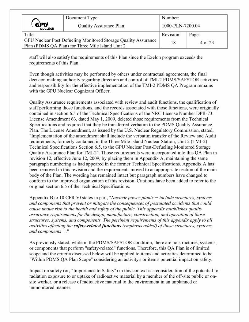
Document Type: Quality Assurance Plan
Number: 1000-PLN-7200.04
Title: GPU Nuclear Post Defueling Monitored Storage Quality Assurance Plan (PDMS QA Plan) for Three Mile Island Unit 2
Revision: 18
Page: 4 of 23
staff will also satisfy the requirements of this Plan since the Exelon program exceeds the requirements of this Plan. Even though activities may be performed by others under contractual agreements, the final decision making authority regarding direction and control of TMI-2 PDMS/SAFSTOR activities and responsibility for the effective implementation of the TMI-2 PDMS QA Program remains with the GPU Nuclear Cognizant Officer. Quality Assurance requirements associated with review and audit functions, the qualification of staff performing those functions, and the records associated with those functions, were originally contained in section 6.5 of the Technical Specifications of the NRC License Number DPR-73. License Amendment 63, dated May 1, 2009, deleted those requirements from the Technical Specifications and required that they be transferred verbatim to the PDMS Quality Assurance Plan. The License Amendment, as issued by the U.S. Nuclear Regulatory Commission, stated, "Implementation of the amendment shall include the verbatim transfer of the Review and Audit requirements, formerly contained in the Three Mile Island Nuclear Station, Unit 2 (TMI-2) Technical Specifications Section 6.5, to the GPU Nuclear Post-Defueling Monitored Storage Quality Assurance Plan for TMI-2". Those requirements were incorporated into this QA Plan in revision 12, effective June 12, 2009, by placing them in Appendix A, maintaining the same paragraph numbering as had appeared in the former Technical Specifications. Appendix A has been removed in this revision and the requirements moved to an appropriate section of the main body of the Plan. The wording has remained intact but paragraph numbers have changed to conform to the improved organization of this revision. Citations have been added to refer to the original section 6.5 of the Technical Specifications. Appendix B to 10 CFR 50 states in part, "Nuclear power plants … include structures, systems, and components that prevent or mitigate the consequences of postulated accidents that could cause undue risk to the health and safety of the public. This appendix establishes quality assurance requirements for the design, manufacture, construction, and operation of those structures, systems, and components. The pertinent requirements of this appendix apply to all activities affecting the safety-related functions (emphasis added) of those structures, systems, and components …." As previously stated, while in the PDMS/SAFSTOR condition, there are no structures, systems, or components that perform "safety-related" functions. Therefore, this QA Plan is of limited scope and the criteria discussed below will be applied to items and activities determined to be "Within PDMS QA Plan Scope" considering an activity's or item's potential impact on safety. Impact on safety (or, "Importance to Safety") in this context is a consideration of the potential for radiation exposure to or uptake of radioactive material by a member of the off-site public or on-site worker, or a release of radioactive material to the environment in an unplanned or unmonitored manner.

Document Type: Quality Assurance Plan
Number: 1000-PLN-7200.04
Title: GPU Nuclear Post Defueling Monitored Storage Quality Assurance Plan (PDMS QA Plan) for Three Mile Island Unit 2
Revision: 18
Page: 5 of 23
Activities and items that are designated "Within PDMS QA Plan Scope", or "in-scope", include the following: • Structures, systems, and components required to be operable by the TMI-2 Technical
Specifications or required for the control or monitoring of radioactive releases to the environment, and activities and equipment that involve their operation, testing, maintenance, surveillance, modification, and analysis are within QA Plan Scope. The degree to which the Quality criteria are applied is based on the potential for failures or deficiencies involving such activities, systems or components to contribute to a loss of containment integrity, violation of Technical Specifications, or unplanned or unmonitored release of radioactive material to the environment and unplanned radiation exposure to a worker or a member of the public.
• Radiological protection and radiological monitoring activities including activities related to
occupational dose control; offsite exposure control, analysis, and evaluation; environmental radiological measurement and analysis; control of instrumentation used in these activities; and, documentation and reporting of required radiological and environmental data are within QA Plan Scope. The degree to which the criteria are applied to equipment used in these activities is based on a graded approach considering the uniqueness and complexity of the equipment, the impact on safety of failures, and the importance of the end use of the data collected.
• Chemistry and radiochemistry analyses needed for control of radioactive effluents to the
environment, evaluation of waste forms, and control of personnel exposure to potential radiological hazards is within QA Plan Scope. Equipment used in these analyses that could affect the outcome of analyses are within QA Plan Scope where testing or calibration of the equipment is required or where the equipment needs certification of accuracy beyond that specified in the manufacturers catalogues or standard literature.
• Management of radioactive waste is within QA Plan Scope where such management
activities involve determination of characteristics and classification of waste for transport or disposal, controls to prevent unplanned or unauthorized dispersal, or controls intended to assure proper packaging for transport or disposal.
• Lifting and Handling activities, including testing and surveillance of cranes and rigging
components where the equipment and activities involve the handling or movement of radioactive material where a load drop or load impingement could contribute to unplanned release or dispersal of radioactive material or where such activity involves the movement of loads over the Reactor Vessel, or the handling of material that could contain Special Nuclear Material.
• Assurance activities including audit, inspection, non-destructive examination, monitoring,
and surveillance of the areas listed above, are within the QA Plan Scope.

Document Type: Quality Assurance Plan
Number: 1000-PLN-7200.04
Title: GPU Nuclear Post Defueling Monitored Storage Quality Assurance Plan (PDMS QA Plan) for Three Mile Island Unit 2
Revision: 18
Page: 6 of 23
• Preparation, independent review, approval, and distribution of instructions, procedures, and
drawings related to "in-scope" activities are activities that are within QA Plan Scope. • Training, Emergency Planning, Security, and Fire Protection activities as they relate to
preventing or minimizing uncontrolled release of radioactive material to the environment or unplanned radiation exposure to workers or members of the public are activities within QA Plan Scope.
• Use of an NRC Licensed shipping container for transport of radioactive material is an activity
within QA Plan Scope. However, the specific quality assurance criteria of 10 CFR 71, subpart H that are applied to this activity are specified in Appendix A of this Plan. The specific packaging, preparation for shipment, and transportation criteria were relocated to the Appendix in this QA Plan revision for two purposes. First, the degree to which the Graded Approach is applied is based on considerations of a transportation accident while moving material over public roadways, by rail, by water, or by any aircraft. Second, the concept of what is "Important to Safety" in 10 CFR 71 differs slightly from the concept in 10 CFR 50 Appendix B. When applying the criteria of 10 CFR 50 Appendix B at TMI-2, the unique shutdown and defueled status of the facility is considered. These considerations have little applicability to the packaging, preparation for shipment, or transportation of radioactive material. Therefore the scope is not as limited as it is with routine PDMS/ SAFSTOR activities. The criteria applied in Appendix A of this Plan consider the guidance in NRC Regulatory Guide 7.10, "Establishing Quality Assurance Programs for Packaging used in Transport of Radioactive Material", Revision 2, dated March 2005. That Guide states, "For the purposes of this regulatory guide, structures, systems, and components important to safety mean the features of a Type B or fissile material package that are intended to (1) maintain the conditions required to safely transport the package contents; (2) prevent damage to the package during transport; or (3) provide reasonable assurance that the radioactive contents can be received, handled, transported, and retrieved without undue risk to the health and safety of the public or the environment."
The items discussed above are considered "Activities Affecting Quality" in the context of this plan. Errors, omissions, deviations, and non-conformances of materials and documents associated with these activities that could have an impact on radiological exposures or releases are considered "Conditions Adverse to Quality" in the context of this plan. Achievement of quality is the responsibility of everyone involved in the performance of, direction of, supervision of, and assessment and oversight of PDMS/SAFSTOR activities. This involves a multi-level approach that includes independent review at the document preparation stage, self-checking and independent verification at the performance stage, and review and audit of in-scope activities.

Document Type: Quality Assurance Plan
Number: 1000-PLN-7200.04
Title: GPU Nuclear Post Defueling Monitored Storage Quality Assurance Plan (PDMS QA Plan) for Three Mile Island Unit 2
Revision: 18
Page: 7 of 23
4.0 TRAINING Personnel performing or verifying activities affecting quality shall receive indoctrination and training as necessary to assure suitable proficiency. Training programs shall be established for those personnel such that they are knowledgeable in the quality assurance program and proficient in implementing these requirements. Training may be conducted by on-site staff or third party organizations as appropriate. These training programs shall assure the following:
• Personnel responsible for performing activities affecting quality understand the purpose, scope, and implementation of applicable procedures,
• Personnel performing activities affecting quality are trained and qualified, as appropriate,
in the principles and techniques of the activity being conducted, and,
• The training is documented and the documentation describes the content and method of the training, attendance, date of attendance, and results of the training session.
The program takes into account the need for special controls, processes, test equipment, tools, and skills to attain the required quality, and the need for verification of satisfactory implementation. 5.0 QUALITY ASSURANCE CRITERIA 5.1 Criterion I, Organization GPU Nuclear shall establish an organization for the management, conduct, and oversight of PDMS/SAFSTOR activities within the scope of this plan. The organization shall conform to the descriptions provided in the PDMS Safety Analysis Report and with the requirements specified in the administrative section of the License Technical Specifications. GPU Nuclear shall exercise overall responsibility for activities affecting quality but may delegate to others, such as third party contractors, agents, or consultants, the work of establishing and executing the quality assurance program, or any part of it, provided GPU Nuclear retains responsibility for all such activities. The persons and organizations performing QA functions shall report to a management level that assures that the required authority and organizational freedom are provided and shall including sufficient independence from cost and schedule. The individuals assigned the responsibility for assuring effective execution of any portion of the QA Plan shall have direct access to the levels of management necessary to perform QA functions. The principle organizational positions are as follows: 5.1.1 Chief Nuclear Officer: The Chief Nuclear Officer is responsible to the FirstEnergy
Operations, Safety, and Nuclear Oversight Committee (formerly titled Nuclear

Document Type: Quality Assurance Plan
Number: 1000-PLN-7200.04
Title: GPU Nuclear Post Defueling Monitored Storage Quality Assurance Plan (PDMS QA Plan) for Three Mile Island Unit 2
Revision: 18
Page: 8 of 23
Committee of the Board) to provide corporate direction on activities associated with the safe and efficient management and oversight of Three Mile Island Unit 2.
5.1.2 President GPU Nuclear/ GPU Nuclear Cognizant Officer: GPU Nuclear Cognizant
Officer is responsible for the overall implementation, and effectiveness of the TMI-2 PDMS QA Program. The individual performing this function may fulfill the combined roles of Chief Nuclear Officer and President, GPU Nuclear, and is responsible to the FirstEnergy Operations, Safety, and Nuclear Oversight Committee. This individual is responsible for the overall direction of PDMS/SAFSTOR activities including Operations and Maintenance, Engineering and Engineering Support, Radiological and Environmental Controls, and regulatory compliance functions including implementation of the Quality Assurance Plan. The Cognizant Officer shall have a minimum of a baccalaureate degree in a technical discipline and five years of experience in a managerial position. Services, materials and equipment, required to maintain TMI-2 in Post-Defueling Monitored Storage (PDMS) are provided by Exelon Generation Company under a services agreement. Those services are required to meet the requirements of the Safety Analysis Report, Technical Specifications, and this Quality Assurance Program. Even though the services are provided by Exelon, the final decision making authority regarding direction and control of TMI-2 PDMS/SAFSTOR activities remains with the GPU Nuclear Cognizant Officer. Also, responsibility for the implementation, and effectiveness of the TMI-2 PDMS QA Program remains with the GPU Nuclear Cognizant Officer.
5.1.3 Vice President, GPU Nuclear Oversight: The Vice President, GPU Nuclear Oversight shall assure independent oversight of the implementation of the TMI-2 PDMS Quality Assurance Program. This position shall assure the performance of reviews to verify that PDMS Quality Assurance Plan, applicable policies and procedures, applicable laws and regulations, and applicable codes and standards are implemented for activities within the scope of this Plan.
This position shall be the ultimate authority for resolution of questions regarding the
applicability and scope of this Plan. This position shall assure the implementation of an Employee Concerns Program with a
designated individual accessible on a confidential basis and with access to the highest level of corporate management as needed, who may be contacted by any company or contracted employee who has a safety concern that he/she considers to be not adequately addressed. The designated individual shall be empowered to investigate such matters and identify needed corrective actions.
5.1.4 Decommissioning Nuclear Safety Review Board (DNSRB): This committee, formerly
titled the Company Nuclear Review Board, or, CNRB, is an independent panel that serves to assure that the TMI-2 structures, systems and components are maintained so as to protect the health and safety of the workers, the public and the environment, and to

Document Type: Quality Assurance Plan
Number: 1000-PLN-7200.04
Title: GPU Nuclear Post Defueling Monitored Storage Quality Assurance Plan (PDMS QA Plan) for Three Mile Island Unit 2
Revision: 18
Page: 9 of 23
enable effective and efficient dismantlement and decommissioning in the future. This board assists and reports to the Vice President GPU Nuclear Oversight in carrying out the oversight functions of that office and serves an advisory role to the GPU Nuclear Cognizant Officer. The Committee reviews overall operating trends at TMI-2, monitors general plant conditions, and performs periodic tours of the facility and meets with site staff to assess the overall safety condition and performance of the facility.
The Decommissioning Nuclear Safety Review Board shall collectively have experience
in the areas of Quality Assurance, Radiological Safety, Environmental Controls, Decommissioning, Civil and Structural Engineering, Industrial Safety, and Facility Management.
5.2 Criterion II, Quality Assurance Program This Quality Assurance Plan provides the base document for the implementation of a quality program that complies with the applicable criteria of 10 CFR 50 Appendix B. This Plan shall be implemented through written policies and procedures. Appendix A of this Plan provides specific Quality Assurance Criteria to be applied to the use of an NRC Licensed Shipping container under the auspices of 10 CFR 71 and specifies how the criteria of 10 CFR 71 subpart H will be applied at TMI-2 during PDMS/SAFSTOR. Quality Assurance is the process of performing planned and systematic actions that will provide a high level of confidence that a structure, system, component, or program will perform its intended actions or achieve its stated goals in a manner consistent with the intended or design safety function. Quality Assurance involves individual efforts, teamwork, interfaces, processes, and programs that are carried out in accordance with the 10 CFR 50, Appendix B principles. Staff and contractors performing Activities Affecting Quality are required to adhere to this program and are required to report any deficiencies or concerns regarding potential safety issues through their supervisory and management chains. Quality Assurance includes Quality Control, which encompasses the measurable processes by which programs, materials, structures, systems, and components are verified to be in conformance to the predetermined requirements and specifications. In addition, management review and oversight of activities is a major aspect of implementing this Quality Assurance Plan. Assuring quality begins with clearly describing the activity affecting quality in appropriate work control documents containing understandable and concise implementing directions, clearly defined performance criteria and acceptance criteria where applicable, and performing the described activity in accordance with the work control documents. Where appropriate, completion of the work is documented through such means as recorded data and documentary evidence, check off lists, and signed off procedural steps, followed by review and verification as

Document Type: Quality Assurance Plan
Number: 1000-PLN-7200.04
Title: GPU Nuclear Post Defueling Monitored Storage Quality Assurance Plan (PDMS QA Plan) for Three Mile Island Unit 2
Revision: 18
Page: 10 of 23
needed. Records of performance of completion are reviewed by appropriate levels of management and maintained in a retrievable and auditable manner. Personnel at all levels of the organization perform quality functions through adherence to instructions, procedures, and drawings, performance of self-checking, looking for deficiencies and errors, and identification and reporting of errors, omissions, and deficiencies. The management and supervisory staff encourage and support workers below them to foster a questioning attitude. Quality verification includes self-checking while preparing written documents and during performance of prescribed activities, peer review, and independent verification of performance of critical activities such as containment isolation valve alignments. Another level of quality verification includes observation of the performance of activities by independent monitors who may periodically assess performance and independently verify data collected, calibration of instruments, and performance of prescribed actions when deemed necessary to assure safety. The highest tier of verification is the formal audit of programmatic areas. Audits are formal reviews performed in accordance with written plans and checklists, are documented, and are reported to senior management. Audits are generally performed by staff not directly responsible for the area being audited and are therefore independent reviews of the implementation of programs. Written reports of Audits, and reviews by independent monitors are prepared and submitted to appropriate levels of management for review. This approach to quality verification assures that deficiencies are identified and reported as soon as possible by the staff performing the activities so that a sense of personal responsibility and ownership of the tasks being performed and the errors that will occur is established. This contributes to the effective implementation of the defense in depth concept where multiple barriers exist to a single error or deficiency resulting in a significant quality defect. 5.3 Criterion III, Design Control When PDMS/SAFSTOR activities require design or modification of structures systems or components within the scope of this Plan, controls shall be applied commensurate with the potential impact on safety of project personnel and the general public. A design control process shall be implemented to assure that new installations and modifications to existing installations within the scope of this plan conform to applicable regulatory requirements, appropriate building codes, and the design bases described in the PDMS Safety Analysis Report. Design activities may be performed by the PDMS Services Contractor (currently Exelon Generation Company) using their processes that meet the requirements of this Plan, by GPU Nuclear using a prescribed process that complies with this QA Plan, or by an outside contractor using a GPU Nuclear reviewed Vendor QA Plan. Regardless of the program

Document Type: Quality Assurance Plan
Number: 1000-PLN-7200.04
Title: GPU Nuclear Post Defueling Monitored Storage Quality Assurance Plan (PDMS QA Plan) for Three Mile Island Unit 2
Revision: 18
Page: 11 of 23
used, GPU Nuclear retains final approval authority for design activities and maintains responsibility for the adequacy of those design activities. Design control measures shall be implemented for structures, systems, and components within the scope of this Plan by controlled written procedures commensurate with the potential impact on safety addressing the following considerations:
• Describes how design inputs are specified and translated into design documents, the verification of design by persons other than the originator, and the assurance that changes to the design are properly reviewed and controlled,
• Prescribes provisions for independent design verification using methods such as design
review or alternate calculations. Verification and independent reviews, including records of these activities and qualifications of reviewer, shall be performed in a manner that meets the requirements of section 6.4 of this Quality Assurance Plan.
• Prescribes an approval process for designs and design changes and requires approval of
field changes by the same level of staff approving the original design,
• Prescribe provisions for design and specification changes, including field changes, and assurance that independent design verification methodology is applied to changes, and that changes to designs or specifications receive at a minimum the same level of review as the original design,
• Provide a mechanism for maintaining records of design activities with sufficient detail to
permit assessment and auditing as required by this Plan,
• Provide methods to ensure that adequate precautions or evaluations are in place to preclude PDMS/SAFSTOR activities, including installation, modification, or removal of SSC's, from damaging or adversely impacting the ability of items required by the Technical Specifications to maintain the plant in a safe and stable PDMS/SAFSTOR condition, or from creating conditions that could preclude future unconditional release of the facility from license control.
In addition, any design control process implemented during PDMS/SAFSTOR shall contain provisions to assure that the reviews and evaluations required by the regulations in 10 CFR 50.59 are performed by qualified individuals and documented in an auditable and retrievable manner. There shall be provisions to assure that responsible plant personnel are made aware of any design changes or modifications that may affect the performance of their duties.

Document Type: Quality Assurance Plan
Number: 1000-PLN-7200.04
Title: GPU Nuclear Post Defueling Monitored Storage Quality Assurance Plan (PDMS QA Plan) for Three Mile Island Unit 2
Revision: 18
Page: 12 of 23
5.4 Criterion IV, Procurement Document Control Procurement documents for materials and services that are within the scope of this plan shall contain sufficient information to assure that quality requirements are clearly communicated to vendors and that sufficient verification of quality requirements is provided by the vendors. This requirement is applicable to procurement activities performed either by GPU Nuclear, the current PDMS Services Contractor, or any other contractor or sub-contractor performing PDMS/SAFSTOR activities. Procurement documents for materials and services that have a potential impact on safety shall contain specific technical and quality requirements. Reference to manufacturer's catalogue specifications is adequate where such specifications adequately address the critical attributes necessary to satisfy the intended safety function of the procured item or service. Critical attributes are those important design, material, and performance characteristics of an item that provide reasonable assurance that it will perform its intended function. Procurement documents for materials and services that have a potential impact on safety shall identify those records which suppliers shall retain, maintain, and control and those which shall be delivered prior to use or delivery of an item or service. If considered necessary by GPU Nuclear Management due to the unique characteristics or safety significance of an SSC or service, procurement documents shall specify that GPU Nuclear or a designee has the right to access the supplier and lower-tier supplier facilities for inspection, audit, or review of records. Procurement processes shall be specified by written procedures which provide for review by appropriate management personnel and require that procurement documents for materials and services within the scope of this plan be subject to a quality review to ensure applicable regulatory requirements, design bases, quality assurance, and other requirements are adequately satisfied prior to release. 5.5 Criterion V, Instructions, Procedures, and Drawings Activities within the scope of this plan shall be conducted in accordance with approved written instruction, procedures, and/or drawings appropriate to the potential impact on safety of the activity. Administrative procedures and instructions shall be implemented that describe the minimum requirements for the preparation, review, approval, and control of instructions, procedures and drawings. Where applicable, instructions, procedures and drawings shall contain appropriate qualitative and quantitative acceptance criteria to ensure activities affecting quality are satisfactorily completed,

Document Type: Quality Assurance Plan
Number: 1000-PLN-7200.04
Title: GPU Nuclear Post Defueling Monitored Storage Quality Assurance Plan (PDMS QA Plan) for Three Mile Island Unit 2
Revision: 18
Page: 13 of 23
and shall assure that appropriate records are maintained to document that important activities are satisfactorily completed. Instructions, procedures, and drawings shall be sufficiently detailed for a qualified individual to perform the required function without direct supervision. The level of detail in the instructions, procedures, and drawings should be commensurate with the complexity of the task and the level of qualifications and training of the individuals normally expected to perform the function. The following are examples of the types of procedures that will be established:
• Administrative Procedures prescribing organizational responsibilities and prescribing the processes and responsibilities for preparation, review, and approval of instructions, procedures, and drawings within the scope of this plan,
• Operating Procedures for SSC's within the scope of this Plan that provide sufficient detail
to assure safe operation in compliance with License Conditions,
• Surveillance, Test, and Preventive Maintenance Procedures that provide sufficient detail for a qualified technician to perform those surveillances, inspections, tests, and calibrations to assure implementation of the requirements of the PDMS License,
• Procedures for implementation of the Technical Specifications (Technical Specification
6.7.1.a),
• Radiation Protection and Chemistry Procedures that assure compliance with applicable radiological safety, sampling, and analysis requirements of the License and of the environmental monitoring programs and the Off-Site Dose Calculation Manual,
• Procedures for implementation of the Radiation Protection Plan (Technical Specification
6.7.1.c),
• Procedures for Radioactive Waste management and shipment (Technical Specification 6.7.1.b),
• Procedures for engineering designs and calculations, procurement of materials and
services, and independent technical and safety reviews of activities within the scope of this Plan,
• Procedures for the implementation of the Flood Protection Program and the Fire
Protection Program (Technical Specification 6.7.1.d and 6.7.1.e),
• Procedures for the implementation of Quality Assurance monitoring, audit, receipt inspection and, and corrective action processes.

Document Type: Quality Assurance Plan
Number: 1000-PLN-7200.04
Title: GPU Nuclear Post Defueling Monitored Storage Quality Assurance Plan (PDMS QA Plan) for Three Mile Island Unit 2
Revision: 18
Page: 14 of 23
5.6 Criterion VI, Document Control Measures shall be established to control the issuance of documents, such as instructions, procedures, drawings and other documents, including changes thereto, which prescribe activities within the scope of this Plan. These measures shall assure that applicable documents are available for use by the individuals performing the activities and at the locations where the activities are being performed. Documents and substantive changes thereto controlling activities within the scope of this Plan shall be prepared by a staff or contractors knowledgeable in the area affected by the procedure and shall be reviewed for technical adequacy by an independent individual(s) or group other than the preparer, but who may be from the same organization as the individual who prepared the procedure or change. (Refer to sections 6.0 and 7.0 of this Plan for requirements related to Technical Review and Control and Independent Safety Review). The process for controlling documents shall specify the organizational elements responsible for approval and issuance of documents. Documents and changes to documents within the scope of this Plan shall be controlled in a manner that precludes the use of inappropriate or outdated documents and there shall be provisions to assure that documents in use are the currently approved revisions. Changes to documents shall be reviewed and approved by the same organizations that performed the original review unless another responsible organization is designated by management. 5.7 Criterion VII, Control of Purchased Material, Equipment, & Services A documented process will be implemented to verify that purchased material within the scope of this plan conforms to the requirements specified in the procurement documents. The process will include measures such as physical inspection of materials upon receipt, review of documentary evidence provided by the vendor, or testing and analysis upon receipt, as appropriate, to determine that the material meets the specifications in the procurement documents. The processes shall use a graded approach applying considerations of a material's or component's importance to safety, complexity, history of previous use, and the ability to be readily assessed by review of vendor published commercial documents such as catalogues and published specification sheets. Applying the graded approach, the procurement documents may also require GPU Nuclear review and approval of the vendor's drawings, procedures, manufacturing plans, and Quality Assurance Plans as needed. When procurement documents require implementation of a Quality Assurance Plan by the vendor, the adequacy of vendor's quality assurance program shall be verified and, if appropriate,

Document Type: Quality Assurance Plan
Number: 1000-PLN-7200.04
Title: GPU Nuclear Post Defueling Monitored Storage Quality Assurance Plan (PDMS QA Plan) for Three Mile Island Unit 2
Revision: 18
Page: 15 of 23
the vendors' adherence to their quality assurance program shall be verified. This may be accomplished by direct audit of the vendor, review of the vendor's documented program, or by review of audit history performed by other clients. Measures shall be established to identify nonconforming items to assure that such items do not get placed in service until the non-conforming issues are corrected. 5.8 Criterion VIII, Identification and Control of Materials, Parts, and Components For materials within the scope of this plan, measures shall be established to assure that only correct and accepted items are used or installed. Identification of items shall be maintained on the items or in documents traceable to the items, or in a manner that assures that identification is established and maintained. 5.9 Criterion IX, Control of Special Processes Measures shall be established to assure that special processes, including welding, heat treating, chemical cleaning, and nondestructive examination are controlled and accomplished by qualified personnel using qualified procedures in accordance with applicable codes, standards, specifications, criteria, and other special requirements. Procedures for the performance of special processes shall have provisions for the recording of the identity and qualification of personnel performing special processes. 5.10 Criterion X, Inspection Appropriate inspections shall be performed to verify that activities within the scope of this plan have been conducted in conformance with the applicable instructions, procedures, and drawings for accomplishing the activity. The frequency and degree of inspection shall be determined through application of the graded approach considering the safety significance and complexity of the structure, system, component, or activity. Such inspections shall be performed by individuals other than those who performed the activity being inspected and shall be performed in accordance with appropriate procedures containing a description of objectives, acceptance criteria and prerequisites for performing the inspections. These procedures shall also specify any special equipment or calibrations required to conduct the inspection. Personnel performing required inspections shall be qualified based upon experience and training in inspection methods.

Document Type: Quality Assurance Plan
Number: 1000-PLN-7200.04
Title: GPU Nuclear Post Defueling Monitored Storage Quality Assurance Plan (PDMS QA Plan) for Three Mile Island Unit 2
Revision: 18
Page: 16 of 23
If mandatory inspection hold points, which require witnessing or inspection and beyond which work shall not proceed without prior consent are required, the specific hold points shall be indicated in the work control documents and the work control documents shall be reviewed prior to implementation by the organization required to perform the inspection. 5.11 Criterion XI, Test Control Appropriate testing shall be performed to demonstrate that the structures, systems or components within the scope of this Plan will perform satisfactorily in service, and that performance criteria specified in Technical Specifications and other License Basis Documents are met. Tests within the scope of this plan shall be prescribed by written procedures that contain detailed performance steps and checklists for conducting the test. Procedures shall include appropriate inspection hold points and provide documentation of performance, results, and satisfactory completion of the prescribed tests. Such documentation shall include an evaluation to verify that test requirements have been met. Where necessary, procedures shall specify test prerequisites such as calibrated instrumentation, required test equipment, controlled and suitable environmental conditions, and provisions for data collection and storage, and shall contain appropriate quantitative and qualitative acceptance criteria that provide evidence that applicable design specifications and procurement specifications have been met. 5.12 Criterion XII, Control of Measuring and Test Equipment Procedures shall be implemented that establish measures to assure that tools, gages, instruments, and other measuring and testing devices used in activities within the scope of this Plan are properly controlled, calibrated, and adjusted at specified periods to maintain accuracy within necessary limits. The procedures shall assure that appropriate records are maintained to provide objective evidence that the control program is implemented. When Measuring and Test Equipment is found to be out of calibration, the validity of previous tests and calibrations where the item had been used since its last calibration shall be evaluated. Such evaluations shall be documented and corrective actions shall be taken as necessary. Rulers, tape measures, levels, and other such devices need not be included in the Measuring and Test Equipment control program if normal commercial practices provide for adequate accuracy.

Document Type: Quality Assurance Plan
Number: 1000-PLN-7200.04
Title: GPU Nuclear Post Defueling Monitored Storage Quality Assurance Plan (PDMS QA Plan) for Three Mile Island Unit 2
Revision: 18
Page: 17 of 23
5.13 Criterion XIII, Handling, Storage and Shipping Procedures will be developed to properly control the handling, storage, and shipping of items within the scope of this plan considering the safety significance, complexity, and physical characteristics of the items and material. The procedures will include requirements as needed to specify cleanliness, packaging and preservation methods to prevent damage, deterioration, or loss. Cleaning and preservation requirements shall be included in design and procurement documents, specifications, and procedures, if appropriate. Controls shall be established to ensure that items whose shelf life has expired will not be used. 5.14 Criterion XIV, Inspection, Test, and Operating Status Measures shall be established to indicate the status of inspections and tests performed on individual items within the scope of this Plan by markings such as stamps, tags, labels, routing cards, inspection records, or other suitable means. The status of inspection and test activities shall be identified either on the items or in documents traceable to the items. These measures will provide for the identification and status of items where it is necessary to ensure that required inspections and tests are performed and to ensure that items that have not passed the required inspections and tests are not inadvertently installed, used, or operated. Measures will also be established for indicating the operating status of structures, systems, and components and to prevent inadvertent operation by such methods as tagging or locking valves and switches. Such measures will include provisions for permission to release equipment or systems for maintenance or modification, documentation of the mechanisms employed to isolate such systems and components for protection of equipment and personnel, and release of the controls for return to service when necessary. Control measures shall include such items as switching and tagging, control of lifted leads and jumpers, and temporary bypasses. 5.15 Criterion XV, Nonconforming Materials, Parts, or Components For items within the scope of this Plan, measures shall be established to control materials, parts, or components which do not conform to requirements in order to prevent their inadvertent use. These measures shall include, as appropriate, procedures for identification, documentation, segregation, disposition and notification to affected organizations. Measures shall be established to control further processing, delivery or installation of a nonconforming item or continuation of a nonconforming service or activity, pending a decision on its disposition.

Document Type: Quality Assurance Plan
Number: 1000-PLN-7200.04
Title: GPU Nuclear Post Defueling Monitored Storage Quality Assurance Plan (PDMS QA Plan) for Three Mile Island Unit 2
Revision: 18
Page: 18 of 23
Nonconforming items shall be reviewed and accepted, rejected, repaired, or reworked in accordance with documented procedures. Procedures will provide for documentation of the review and disposition and will require documented technical justification for the action taken. 5.16 Criterion XVI, Corrective Action A process shall be implemented to assure that conditions adverse to quality, such as failures, malfunctions, discrepancies, deviations from specifications, defective material and equipment, and non-conformances are promptly identified and corrected. For significant conditions adverse to quality, such as Technical Specification or License Condition violations or events reportable to the Nuclear Regulatory Commission, the process will include provisions to assure that the cause of the condition is determined and that corrective actions are implemented to correct the condition and to prevent recurrence of the condition. The identification of the condition adverse to quality, the causes of the condition, and the corrective actions shall be documented and reported to the appropriate management personnel for review. 5.17 Criterion XVII, Quality Assurance Records Sufficient records shall be maintained to provide documentary evidence that activities affecting quality have been adequately performed in compliance with this Plan. These records shall include all those required by Technical Specifications and any Environmental Permits and programs, records of required Independent Technical and Independent Safety Reviews, records of procedure and plan revisions that are within the scope of this Plan, and records of reviews performed pursuant to 10 CFR 50.59. These records shall be identifiable and retrievable and shall document, when applicable, the identification of the individual generating the document or the data recorder, the type of observation, the results, the acceptability, and the action taken in connection with any deficiencies noted. Records stored for retention shall be protected from damage or deterioration from environmental and catastrophic events through either protected storage areas or devices or separate duplicate file storage methods. Records of calibration of measuring and test equipment and instrumentation within the scope of this plan shall contain, or be traceable to, documentary evidence of traceability to national standards. Procedures will be implemented to specify responsibility, duration, and location of records retention.

Document Type: Quality Assurance Plan
Number: 1000-PLN-7200.04
Title: GPU Nuclear Post Defueling Monitored Storage Quality Assurance Plan (PDMS QA Plan) for Three Mile Island Unit 2
Revision: 18
Page: 19 of 23
Written records (Formerly Technical Specification 6.5.1.8) of activities performed in accordance with Sections 6.1 through 6.7 of this Plan (Formerly Technical Specification 6.5.1.1 through 6.5.1.7) shall be maintained in accordance with Section 6.9 of the Technical Specifications. Written records of reports of reviews encompassed in Section 7.4 of this Plan (Formerly Technical Specification 6.5.2.5) shall be maintained in accordance with Section 6.9 of the Technical Specifications. 5.18 Criterion XVIII, Audits Planned audits shall be conducted to verify compliance with appropriate requirements of this Plan and to determine its effectiveness. The audits shall be performed in accordance with written procedures or checklists by appropriately qualified personnel not having direct responsibility in the areas being audited. Audit results shall be documented and reviewed by management having responsibility in the area audited. Follow-up action, including re-audit of discrepant areas, shall be taken where indicated. Audits of unit activities (Formerly Technical Specification 6.5.3.1) shall be performed in accordance with this Plan and shall encompass the following at the specified interval:
a. The conformance of unit operations to provisions contained within the Technical Specifications and applicable license conditions. (Biennial)
b. The performance of activities required by the PDMS QA Plan. (Biennial) c. The Radiation Protection Plan and applicable implementing procedures. (Biennial) d. The Fire Protection Program and implementing procedures. (Biennial) e. An independent fire protection and loss prevention program inspection and technical
audit shall be performed utilizing either qualified licensee personnel or an outside fire protection firm. (Biennial)
f. An inspection and audit of the fire protection and loss prevention program by an outside
qualified fire consultant. (Triennial) g. The Off-site Dose Calculation Manual and implementing procedures. (Biennial) h. The performance of QA Assessment activities provided by the PDMS contractor.
(Biennial) i. Any other area of unit operation considered appropriate by the PDMS Manager or the
GPU Nuclear Cognizant Officer.

Document Type: Quality Assurance Plan
Number: 1000-PLN-7200.04
Title: GPU Nuclear Post Defueling Monitored Storage Quality Assurance Plan (PDMS QA Plan) for Three Mile Island Unit 2
Revision: 18
Page: 20 of 23
Audit reports (Formerly Technical Specification 6.5.3.2) encompassed by this section shall be forwarded for action to the management positions responsible for the areas audited and the GPU Nuclear Cognizant Officer within 60 days after completion of the audit. Upper management shall be informed in accordance with the TMI-2 PDMS QA Plan. Deficiencies in program implementation shall be regarded as Conditions Adverse to Quality and shall be subject to the appropriate Corrective Actions in conformance with section 5.16 of this Plan. Single audits may encompass multiple specified audit areas. Audit interval schedules are based on the month in which the audit begins and the frequency of the audits as specified may be increased by no more than twenty five percent. If intervals are extended, the succeeding audit is scheduled based on the original anniversary month rather than the extended start date, and combined interval for any three consecutive audits shall not exceed 3.25 times the specified audit interval.
6.0 TECHNICAL REVIEW AND CONTROL The GPU Nuclear Cognizant Officer shall be responsible, through its contracted agent, the TMI-1 License holder for ensuring the preparation, review, and approval of documents required by the activities described in the following sections 6.1 through 6.7 (Formerly Technical Specifications Sections 6.5.1.1 through 6.5.1.7) as assigned in the TMI Review and Approval Matrix. Implementing approvals shall be performed at the cognizant manager level or above. 6.1 (Formerly Technical Specification 6.5.1.1) Each procedure required by Section 6.7 of the
Technical Specifications and other procedures including those for tests and experiments and SUBSTANTIVE CHANGES thereto shall be prepared by a designated individual(s) or group knowledgeable in the area affected by the procedure. Each such procedure, and SUBSTANTIVE CHANGES thereto, shall be given a technical review by an individual(s) or group other than the preparer, but who may be from the same organization as the individual who prepared the procedure or change.
6.2 (Formerly Technical Specification 6.5.1.2) Proposed changes to the Technical
Specifications shall be reviewed by a knowledgeable individual(s) or group other than the individual(s) or group who prepared the change.
6.3 (Formerly Technical Specification 6.5.1.3) Proposed tests and experiments shall be
reviewed by a knowledgeable individual(s) or group other than the preparer but who may be from the same division as the individual who prepared the tests and experiments.
6.4 (Formerly Technical Specification 6.5.1.4) Proposed modifications to unit structures,
systems, and components necessary to maintain the PDMS condition as described in the

Document Type: Quality Assurance Plan
Number: 1000-PLN-7200.04
Title: GPU Nuclear Post Defueling Monitored Storage Quality Assurance Plan (PDMS QA Plan) for Three Mile Island Unit 2
Revision: 18
Page: 21 of 23
PDMS SAR shall be designed by an individual/organization knowledgeable in the areas affected by the proposed modification. Each such modification shall be technically reviewed by an individual(s)/group other than the individual/group which designed the modification but may be from the same group as the individual who designed the modification.
6.5 (Formerly Technical Specification 6.5.1.5) Investigation of all violations of the Technical
Specifications including the preparation and forwarding of reports covering evaluation and recommendations to prevent recurrence, shall be reviewed by a knowledgeable individual(s)/group other than the individual(s)/group which performed the investigation.
6.6 (Formerly Technical Specification 6.5.1.6) All REPORTABLE EVENTS shall be
reviewed by an individual/group other than the individual/group which prepared the report.
6.7 (Formerly Technical Specification 6.5.1.7) Individuals responsible for reviews performed
in accordance with Section 6.1 through 6.6 (Formerly Technical Specification 6.5.1.1 through 6.5.1.6) shall include a determination of whether or not additional cross disciplinary review is necessary. If deemed necessary, such review shall be performed by the appropriate personnel. Individuals responsible for reviews considered under Sections 6.1, 6.3, and 6.4 (Formerly Technical Specifications 6.5.1.1, 6.5.1.3, and 6.5.1.4) shall render determinations in writing with regard to whether or not NRC approval is required pursuant to 10 CFR 50.59.
6.8 Responsible Technical Reviewers (Formerly Technical Specification 6.5.1.9) shall meet
or exceed the qualifications of ANSI/ANS 3.1 of 1978 Section 4.6 or 4.4 for applicable disciplines or have 7 years of appropriate experience in the field of his or her specialty. Credit toward experience will be given for advanced degrees on a one to one basis up to a maximum of two years. Responsible Technical Reviewers shall be designated in writing.
7.0 INDEPENDENT SAFETY REVIEW The GPU Nuclear Cognizant Officer (Formerly Technical Specification 6.5.2.1) shall be responsible, through its contracted agent, the TMI-1 License holder, for ensuring the Independent Safety Review of the subjects described in section 7.4 of this Plan (Formerly Technical Specification Section 6.5.2.5), as assigned in the TMI Review and Approval Matrix. 7.1 (Formerly Technical Specification 6.5.2.2) Independent safety review shall be completed
by an individual or group not having direct responsibility for the performance of the activities under review, but who may be from the same functionally cognizant organization as the individual or group performing the original work.

Document Type: Quality Assurance Plan
Number: 1000-PLN-7200.04
Title: GPU Nuclear Post Defueling Monitored Storage Quality Assurance Plan (PDMS QA Plan) for Three Mile Island Unit 2
Revision: 18
Page: 22 of 23
7.2 (Formerly Technical Specification 6.5.2.3) GPU Nuclear, Inc. shall collectively have access to the experience and competence required to independently review subjects in the following areas: a. Nuclear Unit operations b. Nuclear engineering c. Chemistry and radiochemistry d. Metallurgy e. Instrumentation and control f. Radiological safety g. Mechanical engineering h. Electrical engineering i. Administrative controls and quality assurance practices j. Other appropriate fields such as radioactive waste management operations
associated with the unique characteristics of TMI-2. 7.3 (Formerly Technical Specification 6.5.2.4) Consultants may be utilized as determined by
the GPU Nuclear Cognizant Officer to provide expert advice. 7.4 (Formerly Technical Specification 6.5.2.5) The following subjects shall be independently
reviewed by Independent Safety Reviewers (ISRs): a. Written evaluations of changes in the facility as described in the Safety Analysis
Report, of changes in procedures as described in the Safety Analysis Report, and of tests or experiments not described in the Safety Analysis Report, which are completed without prior NRC approval under the provisions of 10 CFR 50.59(c) (1). This review is to verify that such changes, tests or experiments did not involve a change in the Technical Specifications or require NRC approval pursuant to 10 CFR 50.59. Such reviews need not be performed prior to implementation.
b. Proposed changes in procedures, proposed changes in the facility, or proposed
tests or experiments, any of which involves a change in the Technical Specifications or requires NRC approval pursuant to 10 CFR 50.59. Matters of this kind shall be reviewed prior to submittal to the NRC.
c. Proposed changes to Technical Specifications or license amendments shall be
reviewed prior to submittal to the NRC for approval. d. Violations, deviations, and reportable events which require reporting to the NRC
in writing. Such reviews are performed after the fact. Review of events covered under this subsection shall include results of any investigations made and the recommendations resulting from such investigations to prevent or reduce the probability of recurrence of the event.

Document Type: Quality Assurance Plan
Number: 1000-PLN-7200.04
Title: GPU Nuclear Post Defueling Monitored Storage Quality Assurance Plan (PDMS QA Plan) for Three Mile Island Unit 2
Revision: 18
Page: 23 of 23
e. Written summaries of audit reports in the areas specified in Section 5.18 of this
Plan (Formerly Technical Specification 6.5.3). f. Any other matters involving the plant which a reviewer deems appropriate for
consideration or which is referred to the independent reviewers. 7.5 Independent Safety Reviewers or ISR's (Formerly Technical Specification 6.5.2.6) shall
either have a Bachelor’s Degree in Engineering or the Physical Sciences and five years of professional level experience in the area being reviewed or have nine years of appropriate experience in the field of his or her specialty. An individual performing reviews may possess competence in more than one specialty area. Credit toward experience will be given for advanced degrees on a one for one basis up to a maximum of two years.
7.6 Independent reviews performed for Exelon generated documents may be performed in
accordance with the Exelon Station Qualified Review (SQR) program as delineated in Exelon procedure AD-AA-102. This program has been reviewed and is an acceptable equivalent to the RTR/ISR program.

Document Type: Quality Assurance Plan
Number: 1000-PLN-7200.04
Title: GPU Nuclear Post Defueling Monitored Storage Quality Assurance Plan (PDMS QA Plan) for Three Mile Island Unit 2
Revision: 18
Page: A-1 of 9
APPENDIX A
A1.0 QUALITY ASSURANCE PROGRAM
This Appendix to the Quality Assurance Plan addresses the Quality Assurance (QA) requirements applicable when using an NRC Licensed package for transport of radioactive material over public roadways, by rail, by water, or by any aircraft. This Appendix applies if GPU Nuclear contracts for the transport of such materials. If such transport is performed by Exelon under the Services Agreement, the activities will be performed under the cognizance of applicable Exelon procedures and programs. The requirements are contained in 10 CFR 71, Subpart H. There is no reactor fuel remaining on site, therefore, there will be no transportation of reactor fuel. No shipments will be performed under the auspices of this Plan that require the use of inerted casks, use of neutron moderation or other criticality control processes, or with thermal loads that require the use of cask cooling systems.
This Appendix is applicable to procurement, use, and maintenance of packaging and services used to transport greater than Type A quantities of radioactive material in NRC licensed shipping containers. It is designed to assure compliance with 10 CFR 71 and the applicable transportation regulations contained in 49 CFR. This Appendix discusses the application of the eighteen Quality Assurance Criteria of 10 CFR, Part 71, Subpart H, to the packaging, preparation for shipment, and transport of material in an NRC Licensed shipping container by GPU Nuclear or its contractors from Three Mile Island Unit-2. GPU Nuclear, as the Licensee for Three Mile Island Unit-2 and as the registered user of record for NRC Licensed shipping containers retains the responsibility for the overall effectiveness of this Plan. This Plan will be implemented through the use of controlled and approved procedures.
A2.0 RESPONSIBILITIES The President GPU Nuclear/GPU Nuclear Cognizant Officer is responsible for establishing the facility's quality assurance policies, goals, and objectives, retains overall responsibility and the authority for implementing those policies. A3.0 ORGANIZATION (10 CFR 71.103) The GPU Nuclear organization responsible for Three Mile Island Unit-2 is described in section 5.1 of the base PDMS Quality Assurance Plan. Any member of the staff performing activities that are under the purview of this Quality Assurance Plan has the responsibility and authority to stop work and the delivery or installation of nonconforming materials related to this Appendix when quality or safety concerns are identified. These individuals will have direct access to a level of GPU Nuclear Management that can ensure proper evaluation and correction of conditions adverse to quality. Personnel performing activities related to use of an NRC Licensed

Document Type: Quality Assurance Plan
Number: 1000-PLN-7200.04
Title: GPU Nuclear Post Defueling Monitored Storage Quality Assurance Plan (PDMS QA Plan) for Three Mile Island Unit 2
Revision: 18
Page: A-2 of 9
APPENDIX A
Shipping Container will receive training and indoctrination on this Plan and associated procedures. A4.0 QUALITY ASSURANCE PROGRAM (10 CFR 71.105) This Appendix constitutes a program to supplement the base PDMS Quality Assurance Plan for performance of activities associated with the use of NRC Licensed shipping containers under the provisions of 10 CFR 71. As stated in section 1.0 of the base plan, "there are no structures, systems, or components (SSC's) that perform a safety related function where the SSC must perform an active function to prevent or mitigate the consequences of postulated accidents that could cause undue risk to the health and safety of the public" as the base plan is applied to PDMS/SAFSTOR activities and early decommissioning activities. This Appendix recognizes the description of "important to safety" as used in NRC Regulatory Guide 7.10, "Establishing Quality Assurance Programs for Packaging used in Transport of Radioactive Material", Revision 2, dated March 2005. The Regulatory Guide states, "For the purposes of this Regulatory Guide, structures, systems, and components important to safety means the features of a Type B or fissile material package that are intended to (1) maintain the conditions required to safely transport the package contents; (2) prevent damage to the package during transport; or (3) provide reasonable assurance that the radioactive contents can be received, handled, transported, and retrieved without undue risk to the health and safety of the public or the environment". This Appendix will be applied to activities related to the criteria of 10 CFR 71 involving components meeting this definition of Important to Safety. A5.0 CHANGES TO QUALITY ASSURANCE PROGRAM (10 CFR 71.106) Any changes to this Appendix will be considered a change to the PDMS Quality Assurance Plan and will be reviewed and approved in the same manner as the base plan and will be submitted to the Nuclear Regulatory Commission in compliance with the requirements of 10 CFR 71.106. A6.0 DESIGN CONTROL (10 CFR 71.107) As a user of licensed packages, design activities will not be performed by GPU Nuclear at this facility. Consequently, this criterion of 10 CFR Part 71.107 is not applicable. Assurance that the design of packaging used was accomplished under control of an NRC approved QA Program is required and will be accomplished by requiring the supplier of packaging to submit documented proof of package design under an NRC approved QA Program. Documented proof will include

Document Type: Quality Assurance Plan
Number: 1000-PLN-7200.04
Title: GPU Nuclear Post Defueling Monitored Storage Quality Assurance Plan (PDMS QA Plan) for Three Mile Island Unit 2
Revision: 18
Page: A-3 of 9
APPENDIX A
NRC Certificates of Compliance and controlled distribution copies of the vendor's cask manuals. Documents will be kept on file at the TMI site. A7.0 PROCUREMENT DOCUMENT CONTROL (10 CFR 71.109) If a Licensed Transport Container is required, GPU Nuclear will procure the services of vendors of licensed packages. Manufacturers or vendors of packages will be required to supply appropriate certifications verifying that the designated (model and serial number) packaging was manufactured under an approved NRC QA Program. Other available and pertinent documentation (as-built drawings, photographs, sketches, use and maintenance manuals, etc.) are to be furnished by the manufacturer or vendor with the packaging. All pertinent documentation requirements shall be determined, including the identification of the type of verification activities required during use and maintenance of packaging will also be supplied with the procurement of the package. Procurement of licensed package services will also entail procurement of any required Important to Safety replacement parts directly from the package vendor. The vendor will be contractually required to provide any necessary certification documents for purchased material and to provide the services of qualified staff to either perform or oversee the installation of any replacement parts. The vendor will perform such activities under the control of vendor certified procedures and in accordance with the vendor’s NRC approved QA Program. Documentation of the performance of these activities will be provided to GPU Nuclear for retention in project files. A8.0 INSTRUCTIONS, PROCEDURES, AND DRAWINGS (10 CFR 71.111) Activities that are Important to Safety will be prescribed by documented instructions, procedure, or drawings of a type appropriate to the circumstances. These instructions, procedures, or drawings shall be followed and complied with verbatim for all activities performed at Three Mile Island Unit-2. Procedures prepared by GPU Nuclear shall be written, reviewed, and approved in accordance with administrative procedures in effect for TMI-2. Administrative program procedures shall identify the approving organization for instructions and procedures and shall require that changes to approved procedures be reviewed and approved by the same organizations that approved the original document. When appropriate, GPU Nuclear will invoke the use of vendor procedures that have been prepared, reviewed, and approved in accordance with the vendor’s NRC approved QA Program. Instructions, procedures, and drawings shall contain sufficient quantitative and qualitative acceptance criteria to allow determination that activities prescribed have been satisfactorily accomplished. The requirements for preparation, review, independent review, and approval of instructions, procedures, and drawings specified in the base PDMS QA Plan shall also apply to 10 CFR 71 related activities.

Document Type: Quality Assurance Plan
Number: 1000-PLN-7200.04
Title: GPU Nuclear Post Defueling Monitored Storage Quality Assurance Plan (PDMS QA Plan) for Three Mile Island Unit 2
Revision: 18
Page: A-4 of 9
APPENDIX A
If repair, rework, or maintenance is required to be performed on an NRC Licensed package at the Three Mile Island site, the work will be performed either by or under the direct supervision of qualified vendor staff. Such work will be performed in accordance with written procedures that have been prepared, reviewed, and approved in accordance with the requirements of the vendor’s NRC approved QA Program. The work will be coordinated with vendor's quality assurance personnel to ensure that appropriate inspection and test points are incorporated in the procedure and that effective repairs or rework have been satisfactorily performed. A9.0 DOCUMENT CONTROL (10 CFR 71.113) Procedures shall be in effect to control the issuance of documents such as instructions, procedures, and drawings, and changes thereto. Documents prepared by GPU Nuclear shall be performed under the programs described in the main body of this Quality Assurance Plan. Documents prepared by the Vendor shall be prepared and issued in accordance with the Vendor's NRC approved Quality Assurance Program. Vendor documents used at the Three Mile Island site shall be processed in such a manner that GPU Nuclear staff and their contractor staff are on controlled distribution for such documents, and there is an established method for site staff to verify that the documents in use are current and properly approved. A10.0 CONTROL OF PURCHASED MATERIAL, EQUIPMENT, AND SERVICES (10
CFR 71.115) Designated Project personnel will take the necessary measures to assure that purchased material, equipment, and services, whether purchased directly or through contractors and subcontractors, conform to the procurement requirements. Documentary evidence that the package conforms to the procurement specifications shall be supplied with the package. Such documentation should be referenced in the certificate of compliance, relate to the use and maintenance of the package, and identify the necessary actions to be taken prior to delivery of the package to a carrier for transportation. A11.0 IDENTIFICATION AND CONTROL OF MATERIALS, PARTS, AND
COMPONENTS (10 CFR 71.117) To prevent the use of incorrect or defective materials, parts, and components, identification and control measures shall be established. Non-conforming material, parts, and components will be identified and segregated. The identification of the components and parts shall be maintained by appropriate means, either on the item or on records directly traceable to the item. When replacement of limited life items is necessary, measures will be taken to preclude use of items whose shelf life or operation times have expired. Replacement or repair of parts or components

Document Type: Quality Assurance Plan
Number: 1000-PLN-7200.04
Title: GPU Nuclear Post Defueling Monitored Storage Quality Assurance Plan (PDMS QA Plan) for Three Mile Island Unit 2
Revision: 18
Page: A-5 of 9
APPENDIX A
will be performed only at the direction of the Licensed Container Vendor using labeled materials supplied by the Vendor. A12.0 CONTROL OF SPECIAL PROCESSES (10 CFR 71.119) Special processes will not be performed by the GPU Nuclear personnel. Any processes required to effect repairs or modifications to an NRC Licensed container are outside the scope of this Plan. Those processes will be controlled and performed only by the vendor and will be done in accordance with the requirements of the vendor’s NRC approved QA Program. A13.0 INSPECTION CONTROL (10 CFR 71.121) Visual inspections by designated personnel will be performed upon receipt of packaging to ensure compliance with procurement documentation. The criteria for acceptance of each of these inspections and action to be taken if non-compliance is encountered will be specified in written documents conforming to the Vendor's Cask Manual. These visual inspections should include an inspection of the following:
• Surface conditions • Weld and structural integrity • Condition of flange or sealing faces • Gaskets and seals • Gauges, rupture disks, valves, pressure relief devices • Condition of tie-down members • Labeling and marking • Leak-tightness of the packaging
Final inspections will be performed with a checklist to verify as a minimum that the following items are complied with:
• Packages are properly assembled • All shipping papers are properly completed • Packages are conspicuously and durably marked as required by DOT regulations. • Individuals designated by the GPU Nuclear Management have given authorization for
shipment of the package.

Document Type: Quality Assurance Plan
Number: 1000-PLN-7200.04
Title: GPU Nuclear Post Defueling Monitored Storage Quality Assurance Plan (PDMS QA Plan) for Three Mile Island Unit 2
Revision: 18
Page: A-6 of 9
APPENDIX A
The inspection program shall ensure adequate maintenance of packages. The vendor of the package shall identify all items to be maintained, criteria for acceptability or replacement, and the frequencies of inspection assigned to each item during use of the package. Measures will be established to ensure that inspectors are qualified in accordance with applicable codes, standards, and company training programs, such qualifications and certifications are kept current, and inspection personnel are independent from all individuals performing the activity being inspected. A14.0 TEST CONTROL (10 CFR 71.123) The package vendor shall provide for a test program to demonstrate that packaging components will perform satisfactorily in service. The program will be identified and performed in accordance with written test procedures that are prepared, reviewed, and approved in accordance with the vendor’s NRC approved QA Program. These written procedures will incorporate the acceptance limits contained in the package approval, provisions for assuring that all prerequisites for a given test have been met, that adequate test instrumentation is available and used and that the test is performed under suitable environmental conditions. Test results shall be documented and evaluated to assure that test requirements have been satisfied prior to delivering packages for transport to a carrier. The following items shall be included in typical tests:
• Structural integrity • Leak tightness of the package, gaskets, and seals • Shielding integrity
Records of tests shall be retained in the Project files. A15.0 CONTROL OF MEASURING AND TEST EQUIPMENT (10 CFR 71.125) All instruments, gauges, and other measuring and testing devices used in Important to Safety activities shall be properly controlled, calibrated (if necessary), and adjusted at specific times to maintain accuracy within necessary limits. This includes measuring and test equipment used for maintenance of Important to Safety items. Inspection and test equipment will be tagged or labeled to indicate the last calibration date and the calibration due date. All calibration test data shall be maintained with Project records or will be readily traceable to vendor’s records. When Measuring and Test Equipment is found to be out of calibration, the validity of previous tests and calibrations where the item had been used since its last calibration shall be evaluated. Such evaluations shall be documented and corrective actions shall be taken as necessary.

Document Type: Quality Assurance Plan
Number: 1000-PLN-7200.04
Title: GPU Nuclear Post Defueling Monitored Storage Quality Assurance Plan (PDMS QA Plan) for Three Mile Island Unit 2
Revision: 18
Page: A-7 of 9
APPENDIX A
A16.0 HANDLING, STORAGE, AND SHIPPING (10 CFR 71.127) Measures will be taken to control the handling, storage, shipping, cleaning, and preservation of materials and equipment to be used in packaging to prevent damage or deterioration. The following actions will be taken when handling or storing packages:
• If a package requires special handling and lifting equipment such equipment will be provided by or specified by the cask Vendor and will be documented in the vendor supplied package handling procedures. Site personnel will review and verify that appropriate certification documents are provided prior to the use of such special lifting equipment.
• Special handling or storage provisions for packages (e.g., shock absorbers, tags or
markings to adequately protect and identify critical components) will be identified in the vendor’s NRC approved QA Program and the Vendor's controlled cask manuals. Controlled distribution copies of these documents will be provided to the site, will be verified current, and will be used by site personnel.
• Special protective environments (e.g., specific moisture content levels, and temperature
levels) shall be specified and will be verified and monitored at the site where required.
• All conditions identified in a certificate of compliance when unloading packaging will be adhered to. This will be controlled by written instructions and procedures that will implement these requirements as specified in the controlled distribution copies of the Certificates of Compliance and Cask Manuals provided by the vendor.
When preparing a package for shipment the following applicable measures will be taken:
• Specified operations, inspections, and tests will be completed on site in accordance with Vendor documents and documentary evidence of their completion retained in project files.
• NRC and DOT requirements will be verified to have been satisfied prior to delivery to a
carrier.
• Necessary shipping papers will be prepared and approved prior to delivery of package to a carrier.

Document Type: Quality Assurance Plan
Number: 1000-PLN-7200.04
Title: GPU Nuclear Post Defueling Monitored Storage Quality Assurance Plan (PDMS QA Plan) for Three Mile Island Unit 2
Revision: 18
Page: A-8 of 9
APPENDIX A
A17.0 INSPECTION, TEST AND OPERATING STATUS (10 CFR 71.129) The status of inspections and tests performed on individual items of packaging will be indicated by the use of markings such as stamps, tags, labels, checklists, written traveler documents, or other suitable means that provide for the identification of items that have satisfactorily passed required inspections and tests. Application and removal of such status indicators shall be specified and controlled by written procedures where necessary to preclude inadvertent by-passing of such inspections and tests. Measures will also be established to identify the operating status of components of the packaging to prevent inadvertent operation. A18.0 CONTROL OF NONCONFORMING MATERIALS, PARTS OR COMPONENTS
(10 CFR 71.131) Measures shall be established to control materials, parts, or components which do not conform to specified requirements in order to prevent their inadvertent use or installation. Materials, parts, or components that are Important to Safety will be inspected upon receipt by designated personnel. This inspection will include as a minimum:
• Proper identification, • Identification of any nonconforming materials, components, or parts, • Segregation of nonconforming items, • Evaluation and disposition of non-conforming materials, components, or parts, and • Notification of affected organizations of inspection results.
Nonconforming items will be segregated and labeled in such a manner to prevent inadvertent use until proper disposition is completed. Nonconforming items shall be reviewed and accepted, rejected, repaired or reworked in accordance with documented procedures. The acceptability of nonconforming items after designated repair or rework will be verified by designated personnel by re-inspecting or retesting the item against the original requirements. Records of such inspections, evaluations, and re-inspections and disposition will be retained in Project files.
A19.0 CORRECTIVE ACTION (10 CFR 71.133) A process shall be implemented to assure that conditions adverse to quality, such as deficiencies, deviations, defects in material and equipment, and non-conformances are promptly identified and corrected. In the case of a significant condition adverse to quality, the process shall assure that the cause of the condition is determined and corrective action taken to preclude repetition. The

Document Type: Quality Assurance Plan
Number: 1000-PLN-7200.04
Title: GPU Nuclear Post Defueling Monitored Storage Quality Assurance Plan (PDMS QA Plan) for Three Mile Island Unit 2
Revision: 18
Page: A-9 of 9
APPENDIX A
identification of the significant condition adverse to quality, the cause of the condition, and the corrective action taken shall be documented and reported to management personnel for review. A20.0 QUALITY ASSURANCE RECORDS (10 CFR 71.135) Sufficient written records shall be maintained to furnish evidence that Important to Safety activities have been performed in accordance with the written instructions, procedures, and drawings. The records shall include the following:
• Records of use and results of reviews • Tests and Inspections • Audits • Maintenance • Delivery of package to a carrier (including proof that applicable NRC and DOT
requirements have been satisfied). Shipping records required by 10 CFR and 49 CFR shall be maintained by the shipper/licensee for radioactive material and copies will be maintained by the Project in an auditable and retrievable manner in the files. No repairs or modifications to licensed packages will be performed by the Project. These activities will be performed only under the direct control of the vendor and any required records of these activities will be maintained by the vendor in accordance with the vendor’s NRC approved QA Program. A21.0 AUDITS (10 CFR 71.137) Audits of the activities performed under this Plan shall be performed at least biennially to verify compliance with all aspects of the Plan and to verify the effectiveness of the Plan. Audits shall be performed by designated qualified personnel not having direct responsibility in the areas being audited and shall be performed in accordance with appropriate written audit plans or checklists. Audit results shall be documented and reviewed by management having responsibility in the area audited. Follow-up action, including re-audit of deficient areas, shall be taken where indicated.

TMI-2 Post-Defueling Monitored Storage QA Plan, Revision 19

~
TMl-2 SOWTIONS
Three Mile Island Unit 2 Post Defueling Monitored Storage (PDMS)
Quality Assurance Plan
TMI2-QA-PG-001, Revision 19
Title Signature and Date TMl-'2 Solutions Quality Assurance
..................... Authored By: Robert G Oti~".:ai~-·°"' Manager ............. ww-:u.o
TMI-2 Solutions Licensing Manager Irv Mcnnclstein-ext
Reviewed By: fnr Mu-~ Dec 14 2020 11 :58 AM "'*a'
EnergySolutions Group Director, c:~ .......... Reviewed By: rnm Dukes=-~~-=-Oualitv Assurance, D&D -~~..,..,
Approved By: TMI-2 Solutions Project Director ,Jli/_ !J/J'lhut.f> Scott I B
EnergySolutions VP, Nuclear - -Approved By:
Clerud P. Vm Noordemten
OversiJ!ht ~r . ~ 1f.....r- Dec IS 2020 10:32 AM corig>
Approved By: TMI-2 Solutions President and Chief
"" John Sauger
Nuclear Officer 2020.12.15 14:24:17 -05'00'
Approved By: Technical Reviewer/ PORC \. J ,.)_ '5JcL- Frank H. Eppler m Dec 17 2020 2:49 PM
cooi~n
Effective Date: At start of Phase la 11 ? / 1R/?O? I
askett


ATTACHMENTS
Description of Changes to TMI-2 Post-Defueling Monitored Storage Safety Analysis Report as well as the Post-Defueling Monitored Storage QA Plan

Description of Changes to TMI-2 POST-DEFUELING MONITORED STORAGE SAFETY ANALYSIS REPORT
Page 1 of 3
The “TMI-2 POST-DEFUELING MONITORED STORAGE SAFETY ANALYSIS REPORT” was revised in Update 14 with the following changes.
Changes to Original Chapter 1
Chapter 1, Section 1.2.3, Fire Protection, Service, and Suppression, was revised to document compliance with 10 CFR 50.48(f) and Regulatory Guide 1.191. [PSU-2019-T2-006]
Changes to Original Chapter 2
Chapter 2, Site Characteristics, was revised to replace reference to TMI-1 Updated Final Safety Analysis Report (UFSAR) with TMI-1 Defueled Safety Analysis Report (DSAR). [PSU-2020-T2-001]
Chapter 2, Section 2.4, Hydrologic Engineering, was revised to remove reference to protective flood dikes. [PSU 2019-T2-002]
Changes to Original Chapter 3
None
Changes to Original Chapter 4
None
Changes to Original Chapter 5
None
Changes to Original Chapter 6
None
Changes to Original Chapter 7
Chapter 7, Section 7.1.4, Flood Protection, was deleted in its entirety and replaced with reference to Chapter 2, Section 2.4, Hydrologic Engineering. [PSU 2019-T2-002]
Chapter 7, Section 7.2.2, Fire Protection, Service, and Suppression, was revised to document compliance with 10 CFR 50.48(f) and Regulatory Guide 1.191. [PSU-2019-T2-006]
Chapter7, Section 7.2.2, Fire Protection, Service, and Suppression, was revised to replace the station fire brigade with an incipient fire brigade. [PSU 2019-T2-007]

Description of Changes to TMI-2 POST-DEFUELING MONITORED STORAGE SAFETY ANALYSIS REPORT
Page 2 of 3
Chapter 7, Section 7.2.3, Radioactive Waste Management, was revised to describe separation of TMI-1 and TMI-2 radioactive liquid waste disposal (WDL) systems and installation of a poly receiving tank for processing water from the miscellaneous waste holdup tank (MWHT) to a vendor truck for offsite disposal. [PSU-2019-T2-005]
Changes to Original Chapter 8
None
Changes to original Chapter 9
None
Changes to original Chapter 10
Chapter 10, Administrative Functions, was revised to reflect license transfer from First Energy to TMI-2 Solutions. [PSU-2020-T2-002]
Chapter 10, Section 10.5, Organization, was revised to reflect changes in First Energy organizational structure. [ PSU 2019-T2-004] Note - These changes were subsequently revised by PSU-2020-T2-002 following license transfer from First Energy to TMI-2 Solutions.
Changes to Appendix H Chapter 1
Historical Chapter 1, Introduction and General Description of Plant, was revised to replace reference to TMI-1 Updated Final Safety Analysis Report (UFSAR) with TMI-1 Defueled Safety Analysis Report (DSAR). [PSU-2020-T2-001]
Changes to Appendix H Chapter 2
None
Changes to Appendix H Chapter 3
Historical Chapter 3, Section 3.1.2.3, Criterion 3 – Fire Protection, was revised to document compliance with 10 CFR 50.48(f) and Regulatory Guide 1.191. [PSU-2019-T2-006]
Changes to Appendix H Chapter 4
None
Changes to Appendix H Chapter 5
None

Description of Changes to TMI-2 POST-DEFUELING MONITORED STORAGE SAFETY ANALYSIS REPORT
Page 3 of 3
Changes to Appendix H Chapter 6
None
Changes to Appendix H Chapter 7
None
Changes to Appendix H Chapter 8
Historical Chapter 8, Section 8.2.5, Fire Inside Containment, fire analysis source term calculation was updated with revised source term. [PSU-2019-T2-008]
Changes to Appendix H Chapter 9
None

Description of Changes to TMI-2 POST-DEFUELING MONITORED STORAGE QA PLAN
Page 1 of 2
TMI-2 Post-Defueling Monitored Storage QA Plan, Revision 18
Revision 18 is a complete rewrite of the PDMS Quality Assurance (QA) Plan intended to reduce unnecessary detail and enhance the readability and usability of the Plan in the unique PDMS/SafeStor condition. The changes include the following:
• This revision includes a complete reformatting and reorganization of the Plan.
• The former Appendix A is eliminated by incorporation of the requirements into the main body ofthe document with references back to the original Technical Specification paragraph numbers.
• The revision more clearly defines "Activities Affecting Quality" and "Conditions Adverse to Quality"and provides guidance on what is Within Plan Scope.
• Clarifies that there are no Safety Related SSC's remaining and explains why, thus reducing thescope of the Plan. This revision clarifies that since there is no fuel remaining, safety as used in theplan applies to radiation dose and radioactive material uptake or release.
• Organizational titles are revised to reflect current GPU Nuclear and FirstEnergy position titles anddeletes qualification requirements for the Cognizant Officer.
• This revision removes excessive details so that overall programmatic issues are addressed whiledetail is in implementing procedures.
• This revision uses the term SafeStor as a condition comparable to PDMS and clarifies thatdecommissioning activities as described in section III of the PSDAR may be performed under thepurview of this Plan.
• Reference to a Component Record List is removed and replaced with a more comprehensivedescription of In-Scope items in section 3.0.
• A new Appendix is added as a 10 CFR 71 Subpart H Plan with clear statements of which criteriaapply to the transportation aspects expected in the future. This was done to separate the aspectsof the Plan that apply to 10 CFR 50 related criteria from those that are related to 10 CFR 71. Whenaddressing PDMS activities under 10 CFR 50, the Graded Approach is applied based on potentialimpact on safety where Impact on Safety is based on a consideration of the potential for radiationexposure to or uptake of radioactive material by a member of the off-site public or on-site worker,or a release of radioactive material to the environment in an unplanned or unmonitored manner.When addressing transportation of radioactive material over public roadways in quantities andforms requiring use of an NRC Licensed Shipping Container, the degree to which the GradedApproach is applied is based on considerations of a transportation accident in the public domain.With this in mind, the concept of what is "Important to Safety" in 10 CFR 71 uses the guidance ofNRC Regulatory Guide 7.10, which states, "For the purposes of this regulatory guide, structures,

Description of Changes to TMI-2 POST-DEFUELING MONITORED STORAGE QA PLAN
Page 2 of 2
systems, and components important to safety mean the features of a Type B or fissile material package that are intended to (1) maintain the conditions required to safely transport the package contents; (2) prevent damage to the package during transport; or (3) provide reasonable assurance that the radioactive contents can be received, handled, transported, and retrieved without undue risk to the health and safety of the public or the environment."
TMI-2 Post-Defueling Monitored Storage QA Plan, Revision 19
Revision 19 is an initial revision of PDMS QAP for TMI-2 Solutions following License Transfer from the FirstEnergy Companies (GPU Nuclear, Inc., Metropolitan Edison Company, Jersey Central Power & Light Company, and Pennsylvania Electric Company). Changes were generally limited to those necessary to depict TMI-2 Solutions as the licensee and the associated organizational titles. Section 2.0, Quality Policy, was revised to include the approach to revising this plan as stated in the License Transfer Application. Section 3.0, Scope, was revised to recognize the continuity with Exelon by assuming the previous services agreement. Section 5.1 was revised to delete reference to the PDMS SAR for a description of the organization to align with a parallel change to the PDMS SAR. Section 5.7, Control of Purchased Material, Equipment, and Services, was revised to add EnergySolutions as an addition to “other clients”. Sections 6.0 and 7.0 were revised to recognize that TMI-2 Solutions may prepare, review, and approve documents required by the activities described in Section 6.0 and perform Independent Safety Reviews required in Section 7.0 in addition to the TMI-1 License holder. All other changes were administrative in nature and had no impact on technical content (e.g., deletion of historical Record of Changes and List of Effective Pages, spelling, punctuation, format, and consistency in how this plan is referenced).


![jkekf'ki] >qa>quw 2017-18 Community Fund](https://static.fdokumen.com/doc/165x107/632271b628c445989105c764/jkekfki-qaquw-2017-18-community-fund.jpg)