TM 15 - Materials Manual M 46-01
26
WSDOT Materials Manual M 46-01.40 Page 1 of 26 January 2022 WSDOT Errata to WAQTC TM 15 Laboratory Theoretical Maximum Dry Density of Granular Soil and Soil/Aggregate WAQTC TM 15 has been adopted by WSDOT with the following changes: Sample Preparation Replace step one with below: 1. Obtain a representative sample according to Table 3 below. Table 3 TM15 Sample Size Minimum Mass lb (kg) If no more than 15 percent by weight of aggregate exceeds 19 mm (¾ in.) 210 95 If 15 percent or more by weight of aggregate exceeds 19 mm (¾ in.) 330 150 Theoretical Maximum Density Curve Development Replace with below: WSDOT Employees – Enter laboratory data into MATS to develop the maximum density chart and maximum density curve. Non-WSDOT Employees – Enter laboratory data into WAQTC spreadsheet to develop the maximum density chart and maximum density curve. Spreadsheet available at http://waqtc.org/library/library.cfm
-
Upload
khangminh22 -
Category
Documents
-
view
2 -
download
0
Transcript of TM 15 - Materials Manual M 46-01

WSDOT Materials Manual M 46-01.40 Page 1 of 26 January 2022
WSDOT Errata to WAQTC TM 15Laboratory Theoretical Maximum Dry Density of Granular Soil and Soil/Aggregate
WAQTC TM 15 has been adopted by WSDOT with the following changes:
Sample Preparation
Replace step one with below:
1. Obtain a representative sample according to Table 3 below.
Table 3TM15 Sample Size
Minimum Mass lb (kg)If no more than 15 percent by weight of aggregate exceeds 19 mm (¾ in.)
210 95
If 15 percent or more by weight of aggregate exceeds 19 mm (¾ in.)
330 150
Theoretical Maximum Density Curve Development
Replace with below:
WSDOT Employees – Enter laboratory data into MATS to develop the maximum density chart and maximum density curve.
Non-WSDOT Employees – Enter laboratory data into WAQTC spreadsheet to develop the maximum density chart and maximum density curve. Spreadsheet available at http://waqtc.org/library/library.cfm

TM 15
Page 2 of 26 WSDOT Materials Manual M 46-01.40 January 2022
FOP LIBRARY WAQTC WAQTC TM 15
TM15_short_20 FOP Library -1 Pub. October 2021
LABORATORY THEORETICAL MAXIMUM DRY DENSITY OF GRANULAR SOIL AND SOIL/ AGGREGATE WAQTC TM 15 Scope This method is used to establish the theoretical maximum dry density of granular and non-granular soil-aggregate. Use Procedure 1 for material with more than 30 percent retained on the 4.75 mm (No. 4) sieve or Procedure 2 for material with more than 30 percent retained on the 19.0 mm (¾ in.) sieve. Terminology
• Fine aggregate portion – material passing the 4.75 mm (No. 4) Sieve.
• Coarse aggregate portion – material retained on the 4.75 mm (No. 4) sieve.
Significance A theoretical maximum dry density chart and curve are developed by determining a laboratory maximum dry density of a representative sample of material passing the 4.75 mm (No. 4) and the material retained on the 4.75 mm (No. 4), and their respective apparent specific gravities (Gab). The theoretical maximum dry density chart and curve address the range of theoretical maximum dry densities due to fluctuations in coarse and fine aggregate of a given material. To determine the laboratory maximum dry density of the fine aggregate portion, this method allows for use of the FOP for AASHTO T 99/T 180 or by vibratory compactor covered in the method. This method is for use on granular materials having 30 to 70 percent passing the 4.75 mm (No. 4) or 19.0 mm (3/4 in.) sieve. Apparatus • A vibratory spring-loaded compactor – D G Parrott & Son Humphres Maximum Density
machine, or equivalent.
• Molds: solid wall rigid inflexible metal cylinders.
Small mold: volume approximately 0.003 m3 (0.1 ft.3) with an inside diameter of 150 mm ± 5 mm (6 ± 0.15 in.) and a height of 200 ± 5 mm (8 ± 0.1 in.) with base.
Large mold: volume approximately 0.014 m3 (0.5 ft.3) with a height 85 to 150 percent of the inside diameter.
• Cap: rigid, inflexible metal cap fitting inside the mold with 1.5 mm (1/16 in.) max. space between piston and mold wall.
• Spacer blocks: of varying heights compatible with the compactor and pistons.

TM 15
WSDOT Materials Manual M 46-01.40 Page 3 of 26 January 2022
FOP LIBRARY WAQTC WAQTC TM 15
TM15_short_20 FOP Library -2 Pub. October 2021
• Measuring device: minimum length 150 mm (6 in.), accurate and readable to 2.5 mm (0.01 in.)
• Sieves: 75 mm (3 in.), 19 mm (¾ in.), and a 4.75 mm (No. 4) conforming to the FOP for AASHTO T 27/T 11
• Balance or Scale: Capacity sufficient for the principle sample mass, readable to 0.1 percent or 0.1 g, and meeting the requirements of AASHTO M 231
• Tamping rod: straight steel, 16 mm (5/8 in.) in diameter and approximately 400 mm (24 in.) long having at least one end rounded to a hemispherical tip
• Straight edge: at least 25 mm (1 in.) longer than the diameter of the mold
• A stopwatch or timer readable to 1 second
Determining Laboratory Maximum Dry Density Select the proper method for determining the laboratory maximum dry density of the fine aggregate portion of the sample, refer to Table 1, or as directed by the agency. Select the proper method for determining the laboratory maximum dry density of the coarse aggregate portion of the sample, refer to Table 2.
Table 1 Fine Aggregate Portion Laboratory Maximum Dry Density Method
Estimated Soil Type Recommended Test Method
Sandy, non-plastic, permeable soil or non-cohesive soil.
WAQTC TM 15 Vibratory Compactor
Silt, some plasticity, low permeability. FOP for AASTHO T 99/T 180, T 99 Method A
Sandy/silt, some plasticity, permeable. WAQTC TM 15 and FOP for AASHTO T 99/T 180, T 99 Method A (use highest results)

TM 15
Page 4 of 26 WSDOT Materials Manual M 46-01.40 January 2022
FOP LIBRARY WAQTC WAQTC TM 15
TM15_short_20 FOP Library -3 Pub. October 2021
Table 2 Coarse Aggregate Portion Laboratory Maximum Dry Density Method
Coarse Aggregate Amount Test Method
No more than 15 percent by weight of the original aggregate specimen exceeds 19 mm (¾ in.)
WAQTC TM 15 Vibratory Compactor Procedure 1
15 percent or more by weight of the original aggregate specimen is greater than 19 mm (¾ in) but does not exceed 75 mm (3 in.)
WAQTC TM 15 Vibratory Compactor Procedure 2
Sample Preparation 1. Obtain a representative sample according to the FOP for AASHTO R 90, minimum
180 kg. (400 lbs.).
2. Reduce according to the FOP for AASHTO R 76 to a sufficient size to yield amounts required in steps 7 and 8.
3. If the sample is damp, dry until it becomes friable under a trowel. Drying may be in air or by use of a drying apparatus maintained at a temperature not exceeding 60°C (140°F).
4. Thoroughly break up aggregations in a manner that avoids reducing the natural size of individual particles.
5. Remove the material retained on the 75 mm (3 in.) sieve.
6. Separate into coarse and fine aggregate portions by passing the remainder of the sample through the 4.75 mm (No. 4) sieve.
7. Fine aggregate –
a. Obtain a representative sample as described in the FOP for AASHTO T 99/T 180, T 99 Method A, or
b. Obtain at least three representative test samples of approximately 6 kg (13 lb.) each for the fine aggregate vibratory compactor method.
8. Coarse aggregate – obtain a representative sample for one of the following:
a. 19 mm (¾ in) to 4.75 mm (No. 4) – approximately 5 kg (11 lb.) for coarse aggregate vibratory compactor Procedure 1; or
b. 75 mm (3 in) to 4.75 mm (No. 4) – approximately 20 kg (45 lb.) for coarse aggregate vibratory compactor Procedure 2.

TM 15
WSDOT Materials Manual M 46-01.40 Page 5 of 26 January 2022
FOP LIBRARY WAQTC WAQTC TM 15
TM15_short_20 FOP Library -4 Pub. October 2021
Laboratory Maximum Dry Density of Fine Aggregate Portion Determine laboratory maximum dry density of the fine aggregate portion according to the FOP for AASHTO T 180/T 99, T 99 Method A, or the following vibratory compactor method. Refer to Table 1. Vibratory Compactor Method
1. Determine and record the mass of the clean dry small mold to the nearest 5 g (0.01 lb.). Designate this mass as the Mm.
2. Add enough water to one of the fine aggregate portions to saturate the sample, approximately optimum moisture. Do not over saturate (Note 1).
Note 1: The sample is considered saturated when one to two drops of free water are visible at the base of the mold at the end of the first 2-minute load cycle, Table 3. Refer to Step 11.
3. Mix until homogenous.
4. Place approximately one third of the sample in the mold.
5. Consolidate with 25 strokes of the tamping rod, distribute evenly over the surface, and 25 blows of the manually operated rammer.
6. Repeat Steps 4 and 5 for two subsequent lifts. The surface of the top lift should be finished as level as possible.
7. Place the cap on top of the molded specimen and mount the mold on the jack platform in the compactor. Use spacers between the load spring assembly and cap to adjust the elevation of the mold so the hammers strike near the center of the mass of material in the mold.
8. Elevate the mold with the jack until the load spring assembly seats on top of the cap and apply an initial seating load of approximately 100 lbf. on the sample.
9. Start the compactor hammers. Continue to elevate the mold, applying the load gradually over the time stated in the Table 3.
Table 3 Load Application Rate
Load lbf Time
0 to 500 1 min.
500 to 1,000 30 sec.
1,000 to 2,000 30 sec. 10. Upon reaching 2,000 lbf at the end of the 2-minute cycle, stop the hammer, release the
load on the jack, and return to zero pressure.

TM 15
Page 6 of 26 WSDOT Materials Manual M 46-01.40 January 2022
FOP LIBRARY WAQTC WAQTC TM 15
TM15_short_20 FOP Library -5 Pub. October 2021
11. Determine apparent moisture.
a. If the material is pumping around the mold cap or excessive amounts of water are seeping from the mold, prepare a new sample and begin the test again at Step 1.
b. If the base of the mold is dry or there is a small amount of water, repeat Steps 7 through 10, four additional times.
12. Remove the mold assembly from the compactor.
13. Measure the height of the compacted specimen.
a. Lay the straight edge across the mold.
b. Using the measuring device, measure from the bottom of the straight edge to the top of the cap and spacers to the nearest 0.1 mm (0.01 in.). Designate as D.
c. Calculate and record the height, hs, of the compacted specimen, subtract D and the T, from Annex A, from the height of the mold.
14. Determine and record the mass of the mold and specimen, Mms, to the nearest 5 g (0.01 lb.).
15. Determine and record the mass of the specimen, Ms, by subtracting Mm from Mms.
16. Remove the specimen from the mold.
17. Use the entire specimen for a moisture content sample or obtain a representative sample by slicing vertically through the center of the specimen. Obtain at least 500 g. (1.1 lb.) from one of the cut faces, ensuring that all the layers are represented. If a vertical face does not exist, take a representative sample.
18. Determine and record the moisture content, w, according to the FOP for AASHTO T 255/T 265.
19. Calculate and record the wet density, ρw, of the fine aggregate portion.
Slice through the center Representative moisture content sample

TM 15
WSDOT Materials Manual M 46-01.40 Page 7 of 26 January 2022
FOP LIBRARY WAQTC WAQTC TM 15
TM15_short_20 FOP Library -6 Pub. October 2021
20. Calculate and record the laboratory dry density, ρd, of the fine aggregate portion.
Laboratory Maximum Dry Density of the Coarse Portion Vibratory Compactor Method Note 2: Procedure 1 uses the small mold, this procedure is not recommended for material with aggregate larger
than 9.3 mm (3/4 in.).
Procedure 1
1. Determine and record the mass of the small mold to the nearest 5 g (0.01 lb.). Designate this mass as the Mm.
2. Determine and record the mass of the coarse aggregate portion to the nearest 5 g (0.01 lb.). Designate this mass as the Ms. See Note 3.
Note 3: If all the coarse aggregate portion does not fit in the mold or there is some indication that material may have been lost, perform alternate Step 15 to determine Ms.
3. Determine amount of water to add to the coarse aggregate portion by multiplying the mass determined in Step 2 by 0.025 (2.5 percent).
4. Add water to coarse aggregate portion, mix thoroughly.
5. Place approximately one third of the sample in the mold.
6. Tamp the surface lightly with the manually operated rammer to consolidate material and achieve a level surface.
7. Repeat Steps 5 and 6 for two subsequent lifts. Ensure all of the coarse aggregate portion is placed in the mold.
8. Place the cap on top of the molded specimen and mount the mold on the jack platform in the compactor. Use spacers between the load spring assembly and cap to adjust the elevation of the mold so the hammers strike near the center of the mass of material in the mold.
9. Elevate the mold with the jack until the loading spring assembly seats on top of the cap and spacers.
10. Apply an initial seating load of approximately 100 lbf on the sample.
11. Start the compactor hammers. Continue to elevate the mold, applying the load gradually over the time stated in the Table 3.
12. Upon reaching the 2,000 lbf load at the end of the 2-minute cycle, stop the hammer, release the load on the jack, and return to zero pressure.
13. Repeat Steps 10 through 12 four additional times.

TM 15
Page 8 of 26 WSDOT Materials Manual M 46-01.40 January 2022
FOP LIBRARY WAQTC WAQTC TM 15
TM15_short_20 FOP Library -7 Pub. October 2021
14. Remove the mold assembly from the compactor.
15. Measure the height of the compacted specimen.
a. Lay the straight edge across the mold.
b. Using the measuring device, measure from the bottom of the straight edge to the top of the cap and spacers to the nearest 0.1 mm (0.01 in.). Designate as D.
c. Calculate and record the height of the compacted specimen, hs, by subtracting D and T (thickness of the cap) from the height of the mold hm. See Annex A.
16. Alternate method of determining Ms
a. Remove the specimen from the mold.
b. Determine the dry mass according to the FOP for AASHTO T 255. Designate as Ms.
17. Calculate and record the laboratory dry density, ρd, of the coarse aggregate portion.
Procedure 2
1. Determine and record the mass of the large mold and cap to the nearest 5 g (0.01 lb.). Designate this mass as the Mm.
2. Determine and record the mass of the coarse aggregate portion to the nearest 5 g (0.01 lb.). Designate this mass as the Ms.
Note 4: If all the coarse aggregate portion does not fit in the mold or there is some indication that material may have been lost, perform alternate Step 13 to determine Ms.
3. Place approximately one fifth of the sample in the mold.
4. Tamp the surface lightly with the manually operated rammer to consolidate material and achieve a level surface.
5. Place the cap on top of the molded specimen and mount the mold on the jack platform in the compactor. Use spacers between the load spring assembly and cap to adjust the elevation of the mold so the hammers strike near the center of the mass of material in the mold.
6. Elevate the mold with the jack until the loading spring assembly seats on top of the cap.
7. Apply an initial seating load of approximately 100 lbf on the sample.
8. Start the compactor hammers. Continue to elevate the mold, applying the load gradually over the time stated in the Table 3.
9. Upon reaching the 2,000 lbf load at the end of the 2-minute cycle, stop the hammer, release the load on the jack, and return to zero pressure.

TM 15
WSDOT Materials Manual M 46-01.40 Page 9 of 26 January 2022
FOP LIBRARY WAQTC WAQTC TM 15
TM15_short_20 FOP Library -8 Pub. October 2021
10. Repeat Steps 3 through 9 four additional times. Ensure all of the coarse aggregate portion is placed in the mold on the final lift.
11. Remove the mold assembly from the compactor.
12. Measure the height of the compacted specimen.
a. Lay the straight edge across the mold.
b. Using the measuring device, measure from the bottom of the straight edge to the top of the cap and spacers to the nearest 0.1 mm (0.01 in.). Designate as D.
c. Calculate and record the height of the compacted specimen, hs, by subtracting D and T (thickness of cap) from the height of the mold, hs. See Annex A.
13. Alternate method of determining Ms
a. Remove the specimen from the mold.
b. Determine the dry mass of the specimen according to the FOP for AASHTO T 255. Designate as Ms.
14. Calculate and record the laboratory dry density, ρd, of the coarse aggregate portion.
Apparent Specific Gravity of the Fine and Coarse Portions
1. Determine the apparent specific gravity, Gab, of the minus 4.75mm (No. 4) sieve according to AASHTO T 84 or Annex B.
2. Determine the apparent specific gravity, Gab, of the plus 4.75 mm (No. 4) sieve according to the FOP for AASHTO T 85 or Annex B.
TM 15
Page 10 of 26 WSDOT Materials Manual M 46-01.40 January 2022
FOP LIBRARY WAQTC WAQTC TM 15
TM15_short_20 FOP Library -9 Pub. October 2021
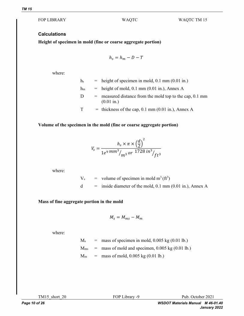
Calculations Height of specimen in mold (fine or coarse aggregate portion)
ℎ𝑠𝑠𝑠𝑠 = ℎ𝑚𝑚𝑚𝑚 − 𝐷𝐷𝐷𝐷 − 𝑇𝑇𝑇𝑇
where: hs = height of specimen in mold, 0.1 mm (0.01 in.) hm = height of mold, 0.1 mm (0.01 in.), Annex A D = measured distance from the mold top to the cap, 0.1 mm
(0.01 in.) T = thickness of the cap, 0.1 mm (0.01 in.), Annex A
Volume of the specimen in the mold (fine or coarse aggregate portion)
𝑉𝑉𝑉𝑉𝑠𝑠𝑠𝑠 =ℎ𝑠𝑠𝑠𝑠 × 𝜋𝜋𝜋𝜋 × �𝑑𝑑𝑑𝑑2�
2
1𝑒𝑒𝑒𝑒9 𝑚𝑚𝑚𝑚𝑚𝑚𝑚𝑚3𝑚𝑚𝑚𝑚3� 𝑜𝑜𝑜𝑜𝑜𝑜𝑜𝑜 1728 𝑖𝑖𝑖𝑖𝑖𝑖𝑖𝑖3
𝑓𝑓𝑓𝑓𝑓𝑓𝑓𝑓3�
where:
Vs = volume of specimen in mold m3 (ft3) d = inside diameter of the mold, 0.1 mm (0.01 in.), Annex A
Mass of fine aggregate portion in the mold
𝑀𝑀𝑀𝑀𝑠𝑠𝑠𝑠 = 𝑀𝑀𝑀𝑀𝑚𝑚𝑚𝑚𝑠𝑠𝑠𝑠 −𝑀𝑀𝑀𝑀𝑚𝑚𝑚𝑚
where: Ms = mass of specimen in mold, 0.005 kg (0.01 lb.) Mms = mass of mold and specimen, 0.005 kg (0.01 lb.) Mm = mass of mold, 0.005 kg (0.01 lb.)

TM 15
WSDOT Materials Manual M 46-01.40 Page 11 of 26 January 2022
FOP LIBRARY WAQTC WAQTC TM 15
TM15_short_20 FOP Library -10 Pub. October 2021
Wet Density of fine aggregate portion
𝜌𝜌𝜌𝜌𝑤𝑤𝑤𝑤 = 𝑀𝑀𝑀𝑀𝑠𝑠𝑠𝑠
𝑉𝑉𝑉𝑉𝑠𝑠𝑠𝑠
Where:
ρw = wet density, kg/m3 (lb/ft3) Ms = mass of specimen in the mold, 0.005 kg (0.01 lb.)
Laboratory maximum dry density fine aggregate portion
𝜌𝜌𝜌𝜌𝑑𝑑𝑑𝑑 = �𝜌𝜌𝜌𝜌𝑤𝑤𝑤𝑤
𝑤𝑤𝑤𝑤 + 100� × 100 𝑜𝑜𝑜𝑜𝑜𝑜𝑜𝑜 𝜌𝜌𝜌𝜌𝑑𝑑𝑑𝑑 =
𝜌𝜌𝜌𝜌𝑤𝑤𝑤𝑤� 𝑤𝑤𝑤𝑤
100� + 1
Where:
ρd = dry density, kg/m3 (lb/ft3) w = moisture content, as a percentage (FOP for AASHTO
T 255)
Laboratory maximum dry density of coarse aggregate portion
𝜌𝜌𝜌𝜌𝑑𝑑𝑑𝑑 = �𝑀𝑀𝑀𝑀𝑠𝑠𝑠𝑠
𝑉𝑉𝑉𝑉𝑠𝑠𝑠𝑠� × 100
Where:
ρd = dry density, kg/m3 (lb/ft3) Ms = mass of specimen in the mold, 0.005 kg (0.01 lb.) Vs = volume of specimen in mold m3 (ft3)

TM 15
Page 12 of 26 WSDOT Materials Manual M 46-01.40 January 2022
FOP LIBRARY WAQTC WAQTC TM 15
TM15_short_20 FOP Library -11 Pub. October 2021
Example Example for small mold fine aggregate portion
Wet mass, Mw = 6.470 kg (14.26 lb) Moisture content, w = 11.3% Height of mold, hm = 203.7 mm (8.02 in.) Inside diameter of mold, d = 153.4 mm (6.04 in.) Measurement from top of mold to cap, D = 44.5 mm (1.75 in.) Thickness of the cap, T = 3.6 mm (0.14 in.) Mass of specimen and mold, Mms = 6.400 kg (14.11 lb) Mass of mold, Mm = 0.280 kg (0.62 lb)
Height of fine aggregate portion in mold
ℎ𝑠𝑠𝑠𝑠 = ℎ𝑚𝑚𝑚𝑚 − 𝐷𝐷𝐷𝐷 − 𝑇𝑇𝑇𝑇
ℎ𝑠𝑠𝑠𝑠 = 203.7 𝑚𝑚𝑚𝑚𝑚𝑚𝑚𝑚− 44.5 𝑚𝑚𝑚𝑚𝑚𝑚𝑚𝑚− 3.6 𝑚𝑚𝑚𝑚𝑚𝑚𝑚𝑚 = 155.6 𝑚𝑚𝑚𝑚𝑚𝑚𝑚𝑚
ℎ𝑠𝑠𝑠𝑠 = 8.02 𝑖𝑖𝑖𝑖𝑖𝑖𝑖𝑖.− 1.75 𝑚𝑚𝑚𝑚𝑚𝑚𝑚𝑚− 0.14 𝑖𝑖𝑖𝑖𝑖𝑖𝑖𝑖. = 6.13 𝑖𝑖𝑖𝑖𝑖𝑖𝑖𝑖. Volume of the fine aggregate in the mold
𝑉𝑉𝑉𝑉𝑠𝑠𝑠𝑠 =ℎ𝑠𝑠𝑠𝑠 × 𝜋𝜋𝜋𝜋 × �𝑑𝑑𝑑𝑑2�
2
1𝑒𝑒𝑒𝑒9 𝑚𝑚𝑚𝑚𝑚𝑚𝑚𝑚3𝑚𝑚𝑚𝑚3� 𝑜𝑜𝑜𝑜𝑜𝑜𝑜𝑜 1728 𝑖𝑖𝑖𝑖𝑖𝑖𝑖𝑖3
𝑓𝑓𝑓𝑓𝑓𝑓𝑓𝑓3�
𝑉𝑉𝑉𝑉𝑠𝑠𝑠𝑠 =155.6 𝑚𝑚𝑚𝑚𝑚𝑚𝑚𝑚 × 𝜋𝜋𝜋𝜋 × �153.4 𝑚𝑚𝑚𝑚𝑚𝑚𝑚𝑚
2 �2
1,000,000,000 𝑚𝑚𝑚𝑚𝑚𝑚𝑚𝑚3
𝑚𝑚𝑚𝑚3�= 0.002876 𝑚𝑚𝑚𝑚3
Or
𝑉𝑉𝑉𝑉𝑠𝑠𝑠𝑠 =6.13 𝑖𝑖𝑖𝑖𝑖𝑖𝑖𝑖. × 𝜋𝜋𝜋𝜋 × �6.04 𝑖𝑖𝑖𝑖𝑖𝑖𝑖𝑖.
2 �2
1728 𝑖𝑖𝑖𝑖𝑖𝑖𝑖𝑖3𝑓𝑓𝑓𝑓𝑓𝑓𝑓𝑓3�
= 0.1016 𝑓𝑓𝑓𝑓𝑓𝑓𝑓𝑓3

TM 15
WSDOT Materials Manual M 46-01.40 Page 13 of 26 January 2022
FOP LIBRARY WAQTC WAQTC TM 15
TM15_short_20 FOP Library -12 Pub. October 2021
Mass of fine aggregate portion in the mold
𝑀𝑀𝑀𝑀𝑠𝑠𝑠𝑠 = 𝑀𝑀𝑀𝑀𝑚𝑚𝑚𝑚𝑠𝑠𝑠𝑠 −𝑀𝑀𝑀𝑀𝑚𝑚𝑚𝑚
𝑀𝑀𝑀𝑀𝑠𝑠𝑠𝑠 = 6.400 𝑘𝑘𝑘𝑘𝑘𝑘𝑘𝑘 − 0.280 𝑘𝑘𝑘𝑘𝑘𝑘𝑘𝑘 = 6.119 𝑘𝑘𝑘𝑘𝑘𝑘𝑘𝑘
𝑀𝑀𝑀𝑀𝑠𝑠𝑠𝑠 = 14.11 𝑙𝑙𝑙𝑙𝑙𝑙𝑙𝑙 − 0.62 𝑙𝑙𝑙𝑙𝑙𝑙𝑙𝑙 = 13.49 𝑙𝑙𝑙𝑙𝑙𝑙𝑙𝑙
Wet density of fine aggregate portion
𝜌𝜌𝜌𝜌𝑤𝑤𝑤𝑤 = 𝑀𝑀𝑀𝑀𝑠𝑠𝑠𝑠
𝑉𝑉𝑉𝑉𝑠𝑠𝑠𝑠
𝜌𝜌𝜌𝜌𝑤𝑤𝑤𝑤 = 6.119 𝑘𝑘𝑘𝑘𝑘𝑘𝑘𝑘
0.002876 𝑚𝑚𝑚𝑚3 = 2128𝑘𝑘𝑘𝑘𝑘𝑘𝑘𝑘 𝑚𝑚𝑚𝑚3�
𝜌𝜌𝜌𝜌𝑤𝑤𝑤𝑤 = 13.49 𝑙𝑙𝑙𝑙𝑙𝑙𝑙𝑙
0.1016 𝑓𝑓𝑓𝑓𝑓𝑓𝑓𝑓3= 132.8 𝑙𝑙𝑙𝑙𝑙𝑙𝑙𝑙 𝑓𝑓𝑓𝑓𝑓𝑓𝑓𝑓3�
Where:
ρw = wet density, kg/m3 (lb/ft3) Ms = mass of specimen in the mold

TM 15
Page 14 of 26 WSDOT Materials Manual M 46-01.40 January 2022
FOP LIBRARY WAQTC WAQTC TM 15
TM15_short_20 FOP Library -13 Pub. October 2021
Laboratory maximum dry density of the fine aggregate portion
𝜌𝜌𝜌𝜌𝑑𝑑𝑑𝑑 = �𝜌𝜌𝜌𝜌𝑤𝑤𝑤𝑤
𝑤𝑤𝑤𝑤 + 100� × 100 𝑜𝑜𝑜𝑜𝑜𝑜𝑜𝑜 𝜌𝜌𝜌𝜌𝑑𝑑𝑑𝑑 =
𝜌𝜌𝜌𝜌𝑤𝑤𝑤𝑤� 𝑤𝑤𝑤𝑤
100� + 1
𝜌𝜌𝜌𝜌𝑑𝑑𝑑𝑑 = �2128 𝑘𝑘𝑘𝑘𝑘𝑘𝑘𝑘 𝑚𝑚𝑚𝑚3⁄11.3% + 100
� × 100 = 1912 𝑘𝑘𝑘𝑘𝑘𝑘𝑘𝑘 𝑚𝑚𝑚𝑚3⁄ 𝜌𝜌𝜌𝜌𝑑𝑑𝑑𝑑 = �132.8 𝑙𝑙𝑙𝑙𝑙𝑙𝑙𝑙 𝑓𝑓𝑓𝑓𝑓𝑓𝑓𝑓3⁄11.3% + 100
� × 100 = 119.3 𝑙𝑙𝑙𝑙𝑙𝑙𝑙𝑙 𝑓𝑓𝑓𝑓𝑓𝑓𝑓𝑓3⁄
Or
𝜌𝜌𝜌𝜌𝑑𝑑𝑑𝑑 = �2128𝑘𝑘𝑘𝑘𝑘𝑘𝑘𝑘 𝑚𝑚𝑚𝑚3⁄
11.3%100 + 1
� = 1912𝑘𝑘𝑘𝑘𝑘𝑘𝑘𝑘 𝑚𝑚𝑚𝑚3⁄ 𝜌𝜌𝜌𝜌𝑑𝑑𝑑𝑑 = �132.8 𝑙𝑙𝑙𝑙𝑙𝑙𝑙𝑙 𝑓𝑓𝑓𝑓𝑓𝑓𝑓𝑓3⁄
11.3%100 + 1
� = 119.3 𝑙𝑙𝑙𝑙𝑙𝑙𝑙𝑙 𝑓𝑓𝑓𝑓𝑓𝑓𝑓𝑓3⁄
Example for small mold coarse aggregate portion (Procedure 1) Calculations will be the same for Procedure 2
Height of mold, hm = 203.7 mm (8.02 in.) Inside diameter of mold, d = 153.4 mm (6.04 in.) Measurement from top of mold to cap, D = 42.4 mm (1.67 in.) Thickness of the cap, T = 3.6 mm (0.14 in.) Mass of coarse aggregate in the mold, Ms = 4.985 kg (10.99 lb)
Height of coarse aggregate portion in mold
ℎ𝑠𝑠𝑠𝑠 = ℎ𝑚𝑚𝑚𝑚 − 𝐷𝐷𝐷𝐷 − 𝑇𝑇𝑇𝑇
ℎ𝑠𝑠𝑠𝑠 = 203.7 𝑚𝑚𝑚𝑚𝑚𝑚𝑚𝑚− 42.4 𝑚𝑚𝑚𝑚𝑚𝑚𝑚𝑚− 3.6 𝑚𝑚𝑚𝑚𝑚𝑚𝑚𝑚 = 157.7 𝑚𝑚𝑚𝑚𝑚𝑚𝑚𝑚
ℎ𝑠𝑠𝑠𝑠 = 8.02 𝑖𝑖𝑖𝑖𝑖𝑖𝑖𝑖.−1.67 𝑖𝑖𝑖𝑖𝑖𝑖𝑖𝑖.− 0.14 𝑖𝑖𝑖𝑖𝑖𝑖𝑖𝑖. = 6.21 𝑖𝑖𝑖𝑖𝑖𝑖𝑖𝑖.

TM 15
WSDOT Materials Manual M 46-01.40 Page 15 of 26 January 2022
FOP LIBRARY WAQTC WAQTC TM 15
TM15_short_20 FOP Library -14 Pub. October 2021
Volume of the coarse aggregate portion in the mold
𝑉𝑉𝑉𝑉𝑠𝑠𝑠𝑠 =ℎ𝑠𝑠𝑠𝑠 × 𝜋𝜋𝜋𝜋 × �𝑑𝑑𝑑𝑑2�
2
1𝑒𝑒𝑒𝑒9 𝑚𝑚𝑚𝑚𝑚𝑚𝑚𝑚3𝑚𝑚𝑚𝑚3� 𝑜𝑜𝑜𝑜𝑜𝑜𝑜𝑜 1728 𝑖𝑖𝑖𝑖𝑖𝑖𝑖𝑖3
𝑓𝑓𝑓𝑓𝑓𝑓𝑓𝑓3�
𝑉𝑉𝑉𝑉𝑠𝑠𝑠𝑠 =157.7 𝑚𝑚𝑚𝑚𝑚𝑚𝑚𝑚 × 𝜋𝜋𝜋𝜋 × �153.4 𝑚𝑚𝑚𝑚𝑚𝑚𝑚𝑚
2 �2
1,000,000,000 𝑚𝑚𝑚𝑚𝑚𝑚𝑚𝑚3
𝑚𝑚𝑚𝑚3�= 0.002915 𝑚𝑚𝑚𝑚3
𝑉𝑉𝑉𝑉𝑠𝑠𝑠𝑠 =6.21 𝑖𝑖𝑖𝑖𝑖𝑖𝑖𝑖. × 𝜋𝜋𝜋𝜋 × �6.04 𝑖𝑖𝑖𝑖𝑖𝑖𝑖𝑖.
2 �2
1728 𝑖𝑖𝑖𝑖𝑖𝑖𝑖𝑖3𝑓𝑓𝑓𝑓𝑓𝑓𝑓𝑓3�
= 0.1030 𝑓𝑓𝑓𝑓𝑓𝑓𝑓𝑓3
Laboratory maximum dry density of coarse aggregate portion
𝜌𝜌𝜌𝜌𝑑𝑑𝑑𝑑 = �𝑀𝑀𝑀𝑀𝑠𝑠𝑠𝑠
𝑉𝑉𝑉𝑉𝑠𝑠𝑠𝑠� × 100
𝜌𝜌𝜌𝜌𝑑𝑑𝑑𝑑 = �4.985 𝑘𝑘𝑘𝑘𝑘𝑘𝑘𝑘
0.002915 𝑚𝑚𝑚𝑚3� × 100 = 1710 𝑘𝑘𝑘𝑘𝑘𝑘𝑘𝑘 𝑚𝑚𝑚𝑚3�
𝜌𝜌𝜌𝜌𝑑𝑑𝑑𝑑 = �10.99 𝑙𝑙𝑙𝑙𝑙𝑙𝑙𝑙
0.1030 𝑓𝑓𝑓𝑓𝑓𝑓𝑓𝑓3�× 100 = 106.7 𝑙𝑙𝑙𝑙𝑙𝑙𝑙𝑙 𝑓𝑓𝑓𝑓𝑓𝑓𝑓𝑓3�
Where:
ρd = dry density, kg/m3 (lb/ft3) Ms = mass of specimen in the mold, 0.005 kg (0.01 lb.) Vs = volume of specimen in mold m3 (ft3)

TM 15
Page 16 of 26 WSDOT Materials Manual M 46-01.40 January 2022
FOP LIBRARY WAQTC WAQTC TM 15
TM15_short_20 FOP Library -15 Pub. October 2021
Theoretical Maximum Density Curve Development Enter the following data into an approved spreadsheet to develop the maximum density chart and maximum density curve.
• Laboratory maximum dry density, ρd, of the coarse aggregate portion to the nearest 1 kg/m3 (0.1 lb/ft3)
• Laboratory maximum dry density, ρd, of the fine aggregate portion to the nearest 1 kg/m3 (0.1 lb/ft3)
• Optimum moisture content to the nearest 0.1 percent if the FOP for AASTHO T 99/T 180, T 99 Method A was used for the fine portion.
• Coarse aggregate apparent specific gravity, Gab, to the nearest 0.001
• Fine aggregate portion apparent specific gravity, Gab, to the nearest 0.001

TM 15
WSDOT Materials Manual M 46-01.40 Page 17 of 26 January 2022
FOP LIBRARY WAQTC WAQTC TM 15
TM15_short_20 FOP Library -16 Pub. October 2021
Example Theoretical Maximum Dry Density Chart
Pass #4 Maximum Pass #4 Maximum Pass #4 Maximum Pass #4 Maximum0.0 104.8 31.0 133.7 62.0 134.6 82.0 129.61.0 105.6 32.0 134.5 63.0 134.3 83.0 129.42.0 106.4 33.0 135.2 64.0 134.0 84.0 129.33.0 107.1 34.0 135.8 65.0 133.6 85.0 129.14.0 107.9 35.0 136.4 66.0 133.3 86.0 128.95.0 108.7 36.0 137.0 67.0 133.1 87.0 128.86.0 109.5 37.0 137.5 68.0 132.8 88.0 128.67.0 110.3 38.0 137.9 69.0 132.5 89.0 128.48.0 111.1 39.0 138.3 70.0 132.2 90.0 128.39.0 112.0 40.0 138.6 71.0 132.0 91.0 128.110.0 112.8 41.0 138.9 72.0 131.7 92.0 128.011.0 113.7 42.0 139.0 73.0 131.5 93.0 127.912.0 114.5 43.0 139.2 74.0 131.2 94.0 127.713.0 115.4 44.0 139.2 75.0 131.0 95.0 127.614.0 116.4 45.0 139.2 76.0 130.8 96.0 127.415.0 117.3 46.0 139.2 77.0 130.6 97.0 127.316.0 118.2 47.0 139.1 78.0 130.4 98.0 127.217.0 119.2 48.0 139.0 79.0 130.2 99.0 127.018.0 120.2 49.0 138.8 80.0 130.0 100.0 126.919.0 121.3 50.0 138.6 81.0 129.820.0 122.3 51.0 138.321.0 123.4 52.0 138.122.0 124.5 53.0 137.8 Pass #4 Maximum Loose23.0 125.6 54.0 137.5 0.0 104.8 87.624.0 126.8 55.0 137.1 20.5 122.8 99.625.0 127.9 56.0 136.8 27.4 130.4 103.826.0 129.0 57.0 136.4 42.5 139.1 105.427.0 130.0 58.0 136.0 61.1 134.9 96.728.0 131.0 59.0 135.7 100.0 126.9 81.929.0 132.0 60.0 135.330.0 132.8 61.0 135.0
Density Curves
Control Points for Density Curves
Density Curves

TM 15
Page 18 of 26 WSDOT Materials Manual M 46-01.40 January 2022
FOP LIBRARY WAQTC WAQTC TM 15
TM15_short_20 FOP Library -17 Pub. October 2021
Theoretical Maximum Dry Density Curve
Report
• Results on standard agency forms
• Sample ID
• Laboratory maximum dry density of the coarse aggregate portion to the nearest 1 kg/m3 (0.1 lb/ft3)
• Laboratory maximum dry density of the fine aggregate portion to the nearest 1 kg/m3 (0.1 lb/ft3)
• Optimum moisture content to the nearest 0.1 percent (when using the FOP for AASTHO T 99/T 180, T 99 Method A for the fine aggregate portion)
• Coarse aggregate apparent specific gravity (Gab) to the nearest 0.001
• Fine aggregate apparent specific gravity (Gab) to the nearest 0.001
• Theoretical maximum dry density chart
• Theoretical maximum dry density curve
70
80
90
100
110
120
130
140
150
160
0 10 20 30 40 50 60 70 80 90 100
Den
sity
(lbs
/ft^3
)
% Passing No. 4 U.S. Standard Sieve
TM 15
WSDOT Materials Manual M 46-01.40 Page 19 of 26 January 2022
FOP LIBRARY WAQTC WAQTC TM 15
TM15_short_20 FOP Library -18 Pub. October 2021
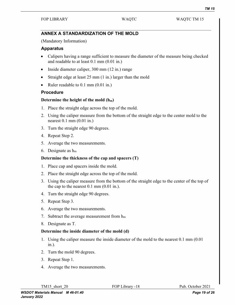
ANNEX A STANDARDIZATION OF THE MOLD (Mandatory Information) Apparatus • Calipers having a range sufficient to measure the diameter of the measure being checked
and readable to at least 0.1 mm (0.01 in.)
• Inside diameter caliper, 300 mm (12 in.) range
• Straight edge at least 25 mm (1 in.) larger than the mold
• Ruler readable to 0.1 mm (0.01 in.) Procedure Determine the height of the mold (hm)
1. Place the straight edge across the top of the mold. 2. Using the caliper measure from the bottom of the straight edge to the center mold to the
nearest 0.1 mm (0.01 in.) 3. Turn the straight edge 90 degrees. 4. Repeat Step 2. 5. Average the two measurements. 6. Designate as hm Determine the thickness of the cap and spacers (T)
1. Place cap and spacers inside the mold. 2. Place the straight edge across the top of the mold. 3. Using the caliper measure from the bottom of the straight edge to the center of the top of
the cap to the nearest 0.1 mm (0.01 in.). 4. Turn the straight edge 90 degrees. 5. Repeat Step 3. 6. Average the two measurements. 7. Subtract the average measurement from hm 8. Designate as T. Determine the inside diameter of the mold (d)
1. Using the caliper measure the inside diameter of the mold to the nearest 0.1 mm (0.01 in.).
2. Turn the mold 90 degrees. 3. Repeat Step 1. 4. Average the two measurements.
TM 15
Page 20 of 26 WSDOT Materials Manual M 46-01.40 January 2022
FOP LIBRARY WAQTC WAQTC TM 15
TM15_short_20 FOP Library -19 Pub. October 2021
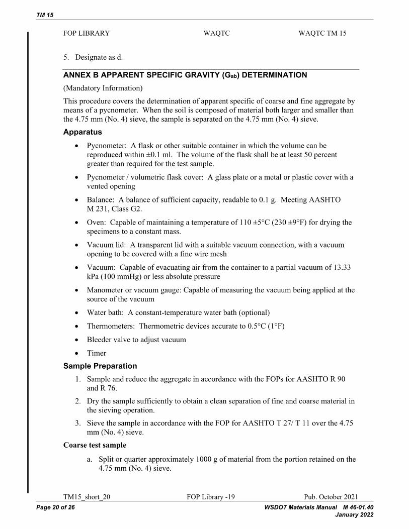
5. Designate as d.
ANNEX B APPARENT SPECIFIC GRAVITY (Gab) DETERMINATION (Mandatory Information) This procedure covers the determination of apparent specific of coarse and fine aggregate by means of a pycnometer. When the soil is composed of material both larger and smaller than the 4.75 mm (No. 4) sieve, the sample is separated on the 4.75 mm (No. 4) sieve. Apparatus
• Pycnometer: A flask or other suitable container in which the volume can be reproduced within ±0.1 ml. The volume of the flask shall be at least 50 percent greater than required for the test sample.
• Pycnometer / volumetric flask cover: A glass plate or a metal or plastic cover with a vented opening
• Balance: A balance of sufficient capacity, readable to 0.1 g. Meeting AASHTO M 231, Class G2.
• Oven: Capable of maintaining a temperature of 110 ±5°C (230 ±9°F) for drying the specimens to a constant mass.
• Vacuum lid: A transparent lid with a suitable vacuum connection, with a vacuum opening to be covered with a fine wire mesh
• Vacuum: Capable of evacuating air from the container to a partial vacuum of 13.33 kPa (100 mmHg) or less absolute pressure
• Manometer or vacuum gauge: Capable of measuring the vacuum being applied at the source of the vacuum
• Water bath: A constant-temperature water bath (optional)
• Thermometers: Thermometric devices accurate to 0.5°C (1°F)
• Bleeder valve to adjust vacuum
• Timer Sample Preparation
1. Sample and reduce the aggregate in accordance with the FOPs for AASHTO R 90 and R 76.
2. Dry the sample sufficiently to obtain a clean separation of fine and coarse material in the sieving operation.
3. Sieve the sample in accordance with the FOP for AASHTO T 27/ T 11 over the 4.75 mm (No. 4) sieve.
Coarse test sample
a. Split or quarter approximately 1000 g of material from the portion retained on the 4.75 mm (No. 4) sieve.

TM 15
WSDOT Materials Manual M 46-01.40 Page 21 of 26 January 2022
FOP LIBRARY WAQTC WAQTC TM 15
TM15_short_20 FOP Library -20 Pub. October 2021
b. Dry to constant mass according to the FOP for AASHTO T 255 at 110 ±5°C (230 ±9°F).
c. Cool to room temperature. Fine test sample
a. Split or quarter approximately 500 g of material from the portion passing the 4.75 mm (No. 4) sieve.
b. Dry to constant mass according to the FOP for AASHTO T 255/T 265 at 110 ±5°C (230 ±9°F).
c. Cool to room temperature. Procedure The procedure is performed on fine and coarse aggregate separately.
1. Determine and record the mass of the dry test sample. Designate as A. 2. Place the test sample in the pycnometer. 3. Add water at approximately 20°C (68°F) until the pycnometer is about ¾ full. 4. Connect the pycnometer to the vacuum system. 5. Apply partial vacuum, 30 mmHg or less absolute pressure, for 20 ± 1 min. 6. Agitate the pycnometer and contents, either continuously by mechanical device or
manually by vigorous shaking, at 2-minute intervals. This agitation facilitates the removal of entrapped air.
7. Release vacuum and disconnect the hoses. 8. Fill the pycnometer with water without reintroducing air. Water temperature should
be maintained as close to 20 ±0.5°C (68 ±1°F) as possible throughout the procedure. Note 1: It may be necessary to place the pycnometer in a water bath for 10 minutes after the release of vacuum to stabilize at 20 ±0.5°C (68 ±1°F).
a. Metal pycnometer (coarse test sample only) – Fill the pycnometer with to 20 ±0.5°C (68 ±1°F) water according to manufacturer’s instructions and dry the outside.
b. Glass pycnometer (fine or coarse test samples) – Completely fill the pycnometer with to 20 ±0.5°C (68 ±1°F) water, slide the calibrated glass plate over the mouth of the pycnometer making sure there are no air bubbles trapped under the plate. Dry the outside.
9. Determine and record the mass of the pycnometer, sample, and water. Designate as C.

TM 15
Page 22 of 26 WSDOT Materials Manual M 46-01.40 January 2022
FOP LIBRARY WAQTC WAQTC TM 15
TM15_short_20 FOP Library -21 Pub. October 2021
Calculation Calculate the Gab to three decimal places as follows:
𝐺𝐺𝐺𝐺𝑎𝑎𝑎𝑎𝑎𝑎𝑎𝑎 = 𝐴𝐴𝐴𝐴
𝐴𝐴𝐴𝐴 + 𝐵𝐵𝐵𝐵 − 𝐶𝐶𝐶𝐶
Where:
A = Mass of dry sample in air, g B = Mass of pycnometer filled with water at 20°C (68°F), g, determined during
the Standardization of Pycnometer procedure C = Mass of pycnometer, water, and the test sample at to 20 ±0.5°C (68 ±1°F), g
Coarse example:
𝐺𝐺𝐺𝐺𝑎𝑎𝑎𝑎𝑎𝑎𝑎𝑎 = 2200.3 𝑘𝑘𝑘𝑘
2200.3 𝑘𝑘𝑘𝑘 + 7502.5 𝑘𝑘𝑘𝑘 − 8812.0 𝑘𝑘𝑘𝑘= 2.470
Given:
A = 2200.3 g B = 7502.5 g C = 8812.0 g
Report
• Report on standard agency forms.
• Report apparent specific gravities, Gab, to the nearest 0.001

TM 15
WSDOT Materials Manual M 46-01.40 Page 23 of 26 January 2022
FOP LIBRARY WAQTC WAQTC TM 15
TM15_short_20 FOP Library -22 Pub. October 2021
Standardization of Pycnometer The pycnometer shall be standardized periodically in conformance with procedures established by the agency.
1. Fill the pycnometer with water at approximately 20°C (68°F). 2. Place the metal or plastic cover, or a glass plate on the pycnometer and eliminate all
air. Note B1: When using a metal pycnometer and cover, place the cover on the pycnometer and push down
slowly, forcing excess water out of the hole in the center of the cover. Use care when filling the pycnometer to avoid reintroducing air into the water.
3. Stabilize the pycnometer at 20 ± 0.5ºC (68 ± 1ºF) for 10 ± 1 min. 4. Towel dry the outside of the pycnometer and cover. 5. Determine and record the mass of the pycnometer, water, and lid. 6. Repeat Steps 2 through 5 two more times for a total of three determinations. 7. If the variation of the three masses is within 0.3 g, average the three masses.
Designate as “B.” 8. If the variation of the masses is greater than 0.3 g, take corrective action and perform
the “Standardization of Pycnometer” again.
TM 15
Page 24 of 26 WSDOT Materials Manual M 46-01.40 January 2022
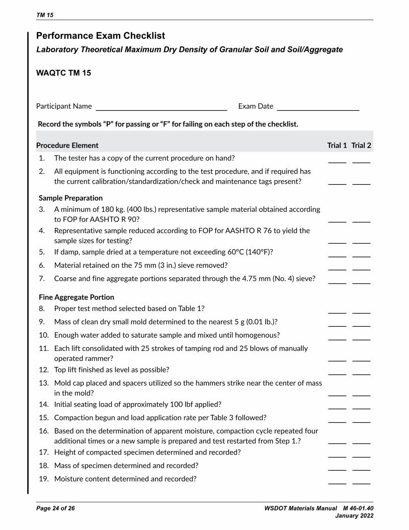
Performance Exam ChecklistLaboratory Theoretical Maximum Dry Density of Granular Soil and Soil/Aggregate
WAQTC TM 15
Participant Name Exam Date
Record the symbols “P” for passing or “F” for failing on each step of the checklist.
Procedure Element Trial 1 Trial 21. The tester has a copy of the current procedure on hand?
2. All equipment is functioning according to the test procedure, and if required has the current calibration/standardization/check and maintenance tags present?
Sample Preparation3. A minimum of 180 kg. (400 lbs.) representative sample material obtained according
to FOP for AASHTO R 90?4. Representative sample reduced according to FOP for AASHTO R 76 to yield the
sample sizes for testing?5. If damp, sample dried at a temperature not exceeding 60°C (140°F)?
6. Material retained on the 75 mm (3 in.) sieve removed?
7. Coarse and fine aggregate portions separated through the 4.75 mm (No. 4) sieve?
Fine Aggregate Portion8. Proper test method selected based on Table 1?
9. Mass of clean dry small mold determined to the nearest 5 g (0.01 lb.)?
10. Enough water added to saturate sample and mixed until homogenous?
11. Each lift consolidated with 25 strokes of tamping rod and 25 blows of manually operated rammer?
12. Top lift finished as level as possible?
13. Mold cap placed and spacers utilized so the hammers strike near the center of mass in the mold?
14. Initial seating load of approximately 100 lbf applied?
15. Compaction begun and load application rate per Table 3 followed?
16. Based on the determination of apparent moisture, compaction cycle repeated four additional times or a new sample is prepared and test restarted from Step 1.?
17. Height of compacted specimen determined and recorded?
18. Mass of specimen determined and recorded?
19. Moisture content determined and recorded?

TM 15
WSDOT Materials Manual M 46-01.40 Page 25 of 26 January 2022
Procedure Element Trial 1 Trial 220. Dry density determined?
21. Coarse Aggregate Portion
22. Proper test method selected based on Table 2?
Procedure 123. Mass of clean dry small mold determined to the nearest 5 g (0.01 lb.)?
24. Mass of coarse aggregate portion determined to the nearest 5 g (0.01 lb.)?
25. Coarse aggregate mass multiplied by 0.025 to determine mass of water to be added?
26. Water and coarse aggregate mixed thoroughly?
27. Each lift tamped lightly with manually operated rammer?
28. Mold cap placed and spacers utilized so the hammers strike near the center of mass in the mold?
29. Initial seating load of approximately 100 lbf applied?
30. Compaction begun and load application rate per Table 3 followed?
31. Compaction cycle repeated four additional times?
32. Height of compacted specimen determined and recorded?
33. Dry density determined?
Procedure 234. Mass of clean dry small mold determined to the nearest 5 g (0.01 lb.)?
35. Mass of coarse aggregate portion determined to the nearest 5 g (0.01 lb.)?
36. Approximately one fifth of the sample place in mold?
37. Lift tamped lightly with manually operated rammer to consolidate and level?
38. Mold cap placed and spacers utilized so the hammers strike near the center of mass in the mold?
39. Initial seating load of approximately 100 lbf applied?
40. Compaction begun and load application rate per Table 3 followed?
41. Aggregate placement and compaction cycle repeated four additional times?
42. Height of compacted specimen determined and recorded?
43. Dry density determined?
TM 15
Page 26 of 26 WSDOT Materials Manual M 46-01.40 January 2022
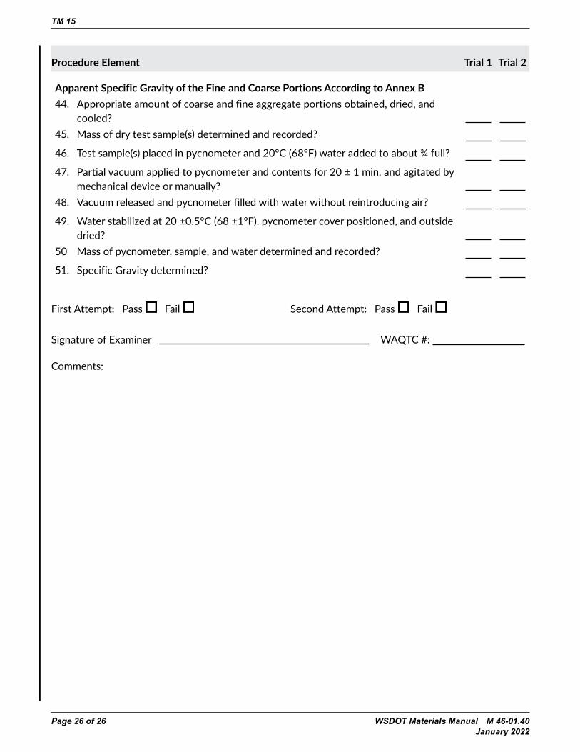
Procedure Element Trial 1 Trial 2
Apparent Specific Gravity of the Fine and Coarse Portions According to Annex B44. Appropriate amount of coarse and fine aggregate portions obtained, dried, and
cooled?45. Mass of dry test sample(s) determined and recorded?
46. Test sample(s) placed in pycnometer and 20°C (68°F) water added to about ¾ full?
47. Partial vacuum applied to pycnometer and contents for 20 ± 1 min. and agitated by mechanical device or manually?
48. Vacuum released and pycnometer filled with water without reintroducing air?
49. Water stabilized at 20 ±0.5°C (68 ±1°F), pycnometer cover positioned, and outside dried?
50 Mass of pycnometer, sample, and water determined and recorded?
51. Specific Gravity determined?
First Attempt: Pass Fail Second Attempt: Pass Fail
Signature of Examiner WAQTC #:
Comments: