TIME-DOMAIN INTEGRAL-EQUATION-BASED SOLVER FOR TRANSIENT AND BROADBAND PROBLEMS IN ELECTROMAGNETICS
11
TIME-DOMAIN INTEGRAL-EQUATION-BASED SOLVER FOR TRANSIENT AND BROADBAND PROBLEMS IN ELECTROMAGNETICS Anatoliy O. Boryssenko ∗ , Daniel H. Schaubert * 1. ABSTRACT A time-domain (TD) numerical method has been developed based on the method-of moments (MoM) and marching-on-time (MoT) solution of the electrical-type integral equation with mixed potential formulation and free-space Green’s functions. This time- domain integral-equation (TDIE) code is applicable for arbitrary 3-D antennas and arrays composed conductors. It was developed particularly to simulate ultra-wideband (UWB), finite phased arrays of tapered slot antennas and some results from this study are included in the paper. The TDIE, which calculates wideband data in a single solution and utilizes basis functions defined only on the surfaces of conductors but not throughout the entire volume of the array, requires much less RAM and CPU time than frequency-domain and FDTD methods. 2. INTRODUCTION Much recent research in computational electromagnetics has been devoted to solutions of integral equations through a MoM-MoT technique 1, 2, 3 called hereafter the TDIE. The main advantage of the TD MoM technique compared to FD is time savings for ultra-broadband simulations because the time-independent impedance matrix for the TDIE must be filled one time only. Also, the diagonal (explicit TDIE algorithm) or sparse diagonal-banded (implicit TDIE algorithm) portion of the impedance matrix must be inverted one time only. On the other hand, filling and inverting the dense frequency- dependent matrix must be repeated many times for the FD MoM solution. The electric- field integral equation (EFIE) is suitable for most geometries of conducting bodies while magnetic-field integral equation is applicable for conducting bodies with closed surfaces. * Antenna Laboratory, University of Massachusetts, Amherst, MA, 01003, USA
-
Upload
independent -
Category
Documents
-
view
4 -
download
0
Transcript of TIME-DOMAIN INTEGRAL-EQUATION-BASED SOLVER FOR TRANSIENT AND BROADBAND PROBLEMS IN ELECTROMAGNETICS

TIME-DOMAIN INTEGRAL-EQUATION-BASED SOLVER FOR TRANSIENT AND BROADBAND
PROBLEMS IN ELECTROMAGNETICS
Anatoliy O. Boryssenko∗, Daniel H. Schaubert*
1. ABSTRACT
A time-domain (TD) numerical method has been developed based on the method-of moments (MoM) and marching-on-time (MoT) solution of the electrical-type integral equation with mixed potential formulation and free-space Green’s functions. This time-domain integral-equation (TDIE) code is applicable for arbitrary 3-D antennas and arrays composed conductors. It was developed particularly to simulate ultra-wideband (UWB), finite phased arrays of tapered slot antennas and some results from this study are included in the paper. The TDIE, which calculates wideband data in a single solution and utilizes basis functions defined only on the surfaces of conductors but not throughout the entire volume of the array, requires much less RAM and CPU time than frequency-domain and FDTD methods. 2. INTRODUCTION
Much recent research in computational electromagnetics has been devoted to solutions of integral equations through a MoM-MoT technique1, 2, 3 called hereafter the TDIE. The main advantage of the TD MoM technique compared to FD is time savings for ultra-broadband simulations because the time-independent impedance matrix for the TDIE must be filled one time only. Also, the diagonal (explicit TDIE algorithm) or sparse diagonal-banded (implicit TDIE algorithm) portion of the impedance matrix must be inverted one time only. On the other hand, filling and inverting the dense frequency-dependent matrix must be repeated many times for the FD MoM solution. The electric-field integral equation (EFIE) is suitable for most geometries of conducting bodies while magnetic-field integral equation is applicable for conducting bodies with closed surfaces.
* Antenna Laboratory, University of Massachusetts, Amherst, MA, 01003, USA

2 A.O. BORYSSENKO, D. H. SCHAUBERT Among EFIE formulations, we prefer a mixed-potential formalism through the
equivalence principal with the free-space Green’s functions4. In this way, the EFIE kernel is less singular, leading to easier evaluation of the required numerical integrals. The MoM-MoT formulation starts from the boundary condition on the PEC antenna surface, Eq. (1), that requires zero magnitude of the total tangential electrical field composed of incident (i) and scattered (s) fields, Eq. (2), and, in turn, the scattered field is expressed via the magnetic vector potential, Eq. (3), and electric scalar potential, Eq. (4),
0=+→→
si EE (1) t),( ),(t),(→→→→→
Φ∇−∂∂
−= rtrAt
rE s (2)
∫ ′⋅′⋅=→→→→
S
sdRrItrA )4(),(),( 0 πτµ (3) ∫ ′⋅′⋅=→→
S
sdRrqtr )4(),(/1),( 0 πτεΦ (4)
The current, I, and the charge, q, densities are connected through the continuity equation:
0),(),( =⋅∇+
∂∂ →→→
trItrqt
(5)
In Eqs. (2)-(5), τ = t – R/c is retarded time, is the distance from the source to the observer; c is the free-space light velocity; ε
||→→′−= rrR
0, µ0 are the fundamental electric and magnetic constants, respectively.
Eqs. (2)-(5) result in the EFIE, which is solved through the standard steps of MoM technique. First, the original problem is converted to a discrete one by employing a system of appropriate space-time basis functions1, 4. At this stage, potential integrals must be evaluated that can be done analytically5 for the case of the free-space Green’s function and subdomain basis functions in time and space1. Second, a testing procedure is applied to convert the discrete vector functional equation into a linear scalar system of equations to compute recursively the current through time stepping1, 3, 6 )()()1( nnn EIZI +⋅=+ (6)
The above operator equation can be solved explicitly/implicitly in the given form, Eq. (6), where Z is a suitable matrix operator and E is a source vector3. Alternatively, a set of equations involving the potentials, the charge and the current can be treated2, 7. This method is utilized in the present study for reasons that are elucidated below. Specifically, the MoM testing must be done through a second integration over surface patches. The integration is applied to a dot product of a testing function and vector functions of the potentials. Usually, the same functions are used for weighting and testing to implement the Galerkin scheme. However, in practice, the integration is replaced usually by less accurate point matching1, 3. This simplification seems a main source of errors resulting in divergence of the computation and some noticeable anomalies6, 8. In this paper, we omit the well-known features of the TDIE formulation1-3, 6, 7 and focus mainly on our specific contributions to support accurate and stable simulation of UWB phased array antennas of complex geometry with the TDIE code.

TIME-DOMAIN INTEGRAL-EQUATION-BASED SOLVER 3 3. CHARGE IN THE TDIE INTERLEAVED COMPUTATIONAL SCHEME
Usually, the charge distribution is included implicitly into a discrete form of the EFIE through the continuity equation, Eq. (5). For the case of rooftop RWG basis functions, Figure 1a, the charge distribution is constant over triangular facets. However, the charge can be kept explicitly in the computational scheme to obtain some attractive benefits in computations2, 7. The TDIE algorithm, where the current is involved only, looks preferable due to lower computer storage/resources to simulate, for example, phased array antennas. Nevertheless, we used the algorithm similar2, 7, which can be more stable than the single operator equation, Eq. (6), which is often used. From another perspective, if the charge is included directly into the TDIE computations, the updating recursive computational scheme can be treated like a digital filter where origins and intensity of digital noise can be traced, analyzed, and sometimes effectively suppressed.
For modeling the electric currents, we use the RWG spatial basis functions over triangular patches4, Figure 1a. The same current mode models the delta-gap source, Figure 1b, necessary to feed antennas in transmit mode. We employ subdomain linear pyramid basis functions9, Figure 1c, to express the charge surface distribution. The number of pyramid basis functions equals to the number of nodes in the grid partitioning the surface into a set of triangular patches. Each pyramid charge mode is maximum at the node and its total support is created by all triangles sharing the node. The pyramid basis functions do not adversely affect on computation time when carefully programmed because all manipulations with them are done at the pre-computing (“matrix-filling”) stage to express the continuity equation (5) in accordance with topological relations, Figure 2b.
As seen in Figure 2b, the connection between the charge and the current, when the former is explicitly approximated by the pyramid functions, is more spatially spread, comparing to the case with triangle-wise constant charge, Figure 2a, over the same mesh. Thus, in fact, some spatial averaging is introduced automatically, which has been found to have a positive effect on stability7. Results2, 7 and our observation reveal improving in accuracy/stability of the TDIE when spatial interleaving for the charge and the current is introduced, Figure 2b. The same fruitful idea works in TD where sampling points in time for the charge and the current must be interleaved by a half of time step2, 7, 10. The both interleaving schemes in space and time are utilized in the TIDE cascaded code to maintain simplicity and accuracy and convergence in computations.
δ
(a) (b) (c)
Figure 1. Basis functions: rooftop RWG mode for the current (a) including delta-gap source mode (b) and pyramid basis function (c) for the charge.

4 A.O. BORYSSENKO, D. H. SCHAUBERT
(a) (b)
Figure 2. Connection between current and charge for triangular-wise constant charge (a) and pyramid function (b). Shaded regions reflect support for the charge modes; bold broken lines specify the interaction regions between the current and the charge; arrows show RWG current modes involved in the continuity equation with specified charge modes. 4. SOME ISSUES ON CODE COMPUTATIONAL STABILITY IN LATE TIME
An important consideration for the TDIE solver, as any TD MoM-MoT scheme, is late-time instability caused by accumulated round-off errors 6, 7, 11-13. To minimize this impact, besides more accurate modeling with explicit surface charge distribution discussed above, incorporating a stabilization procedure for the MoM-MoT solution is necessary. Known stabilizing procedures operate through averaging in time6, 11, 14 and rarely in space 17. For averaging in space or time, the underlying idea is “de-correlation” of accumulated computational noise and, of course, supplementary computer resources are required. In addition, irregularity of the mesh has an effect on accuracy/stability. Many real antennas, like the broadband tapered slot element15 (TSA) shown in Figure 6, have complex shapes. The resulting mesh can be quite irregular in contrast to simple scattering scenarios with flat plates, etc1-4. Known approaches for stabilization do not work properly under such complexity/irregularity. A successful stabilization technique is essential to simulate TSA phased arrays where strong resonances lead to divergence and late-time instability.
In terms of signal processing, the instability means that spurious numerical poles appear in the right half of the complex frequency plane3, 11, 16. These poles are very close to the imaginary axis, but their small positive real part leads unavoidably to divergence and catastrophic instability in late time11, 14. Finite-impulse response (FIR) filtration14 does not guarantee stability. The success of FIR filtration depends strongly on the geometry and mesh for specific problems6, 14. On the other hand, resistive loading introduced in the partial equivalent electrical circuit (PEEC) concept13 seems helpful to suppress late-time instabilities in numerical EFIE solvers. We explored a similar idea but in a different mode. Our approach is relevant to the above formulation, where EM field quantities are utilized rather than circuit ones13. Doing so, we incorporate multiplication of the current computed at each time instant by an exponential coefficient with small damping factor multiplied by the current time.

TIME-DOMAIN INTEGRAL-EQUATION-BASED SOLVER 5 In other words, we force all poles to leave the right half of the complex frequency
plane. At the same time, the poles in the left half-plane will be shifted a little bit from their initial position to the left, Figure 3a. Finally, this heuristic stabilizing technique accomplished with low-order FIR filtration in the time-domain, spatial averaging through the charge mode with extended support, Figure 2b, and interleaving of charge/current in time/space is found to be very effective for all simulated cases for antennas and arrays of composite geometry where late-time instability is still a concern when existing stabilization techniques are used only.
The imposed numerical damping can be removed easy from a final transient solution by using the Prony extrapolation technique17. To this end, a correction needs to be done for all poles and zeros to compensate for the rotation in the complex frequency plane, Figure 3. However, this is not necessary in practice because the small damping that is needed to suppress amplifying growth of digital noise does not significantly influence the input impedance and pattern in the frequency domain. The damping acts like a windowing filtration, which precedes the Fourier processing. The effect of the damping on the magnitude of transient waveforms is nearly the same as the implicit MoM-MoT solvers cause compared with explicit solutions3. Furthermore, FIR filtration that is commonly used6, 11, 14 has the nearly the same amplitude damping effect on transients waveforms as we estimated.
For practical computation with the TDIE, the magnitude of the damping factor σ in the term exp(-σt) can be estimated through some numerical experiments on the trial-and-error basis or, for example, by exploring an “impulse response” of the TDIE scheme14 interpreting as a digital filter. Also, the pole-zero analysis may be utilized in the complex frequency plane11, 16 for the same purpose. These approaches are based on an analysis over the whole mesh16. However, some our findings and results13 corroborate that an analysis of local features in the mesh involving closely spaced, overlapping and non-planar modes only is sufficient.
σ
ω
Damped
Undamped j
0 2 4 6 8 10 12 14 16 18 20-0.6
-0.4
-0.2
0
0.2
0.4
0.6
0.8
1
Time, nc
Am
plitu
de, V Damped
Undamped
(a) (b)
Figure 3. Damping effect on transient exp(-σt)⋅sin(ωt) in the complex frequency plane (a) and in time domain (b) by increasing the attenuation factor σ.
6 A.O. BORYSSENKO, D. H. SCHAUBERT
Indeed, these modes in the mesh are very sensitive to retardation with subsequent degradation in stability13. So, an analysis of such local parts of the mesh can be done to predict the quality of a simulation with the given mesh before running the complete TDIE simulation. The effect of the time domain basis function on stability and accuracy is a closely related to stability considerations. The simplest scheme, which is implemented in most references, is based on separation of temporal and spatial dependencies to avoid cumbersome integration1, 2, 8, 14. This is actually a point at issue because of the strong effect of the time-domain basis functions on late-time numerical stability18. 5. RESULTS OF SIMULATIONS ON UWB ANTENNAS AND PHASED ARRAYS
Here we present results on transient behavior and equivalent FD properties for input impedance and VSWR of some UWB antennas and phased arrays. Radiation patterns and scattering properties, can be studied by the technique19, but are not discussed here. All of the cases shown here and many others have been verified against published data and results of simulations with FD MoM and FDTD codes. Initially, the TDIE code was developed through combined Matlab-Fortran programming with a possibility to have a stand-alone version after compilation. After initial validation, key portions of the Matlab code have been converted to Fortran-90, resulting in an efficient code that was easy to develop. To reduce the computer RAM and CPU time, we have located an efficient representation of the sparse connection matrices.
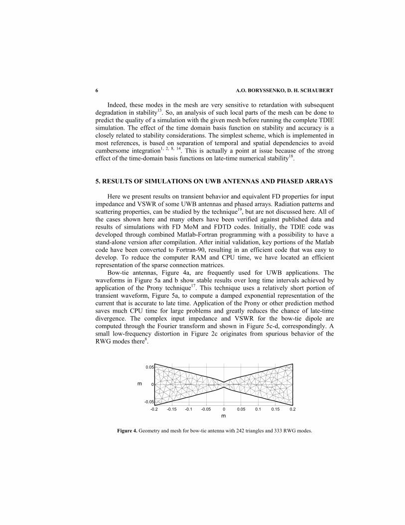
Bow-tie antennas, Figure 4a, are frequently used for UWB applications. The waveforms in Figure 5a and b show stable results over long time intervals achieved by application of the Prony technique17. This technique uses a relatively short portion of transient waveform, Figure 5a, to compute a damped exponential representation of the current that is accurate to late time. Application of the Prony or other prediction method saves much CPU time for large problems and greatly reduces the chance of late-time divergence. The complex input impedance and VSWR for the bow-tie dipole are computed through the Fourier transform and shown in Figure 5c-d, correspondingly. A small low-frequency distortion in Figure 2c originates from spurious behavior of the RWG modes there8.
-0.2 -0.15 -0.1 -0.05 0 0.05 0.1 0.15 0.2 -0.05
0
0.05
m
m
Figure 4. Geometry and mesh for bow-tie antenna with 242 triangles and 333 RWG modes.

TIME-DOMAIN INTEGRAL-EQUATION-BASED SOLVER 7
0 1 2 3 4 5 6 7-8
-6
-4
-2
0
2
4
6x 10
-3C
urre
nt, A
Time, ns0 5 10 15 20 25
-8
-6
-4
-2
0
2
4
6x 10⁻³
Cur
rent
, A
Time, ns (a) (b)
0.2 0.4 0.6 0.8 1 1.2 1.4 1.6 1.8 2 2.20
100
200
300
400
Frequency, GHz
Res
ista
nce,
Ohm
0.2 0.4 0.6 0.8 1 1.2 1.4 1.6 1.8 2 2.2-200
-100
0
100
200
Frequency, GHz
Rea
ctan
ce, O
hm
0.2 0.4 0.6 0.8 1 1.2 1.4 1.6 1.8 2 2.21
1.5
2
2.5
3
3.5
4
4.5
5
Frequency, GHz
VS
WR
(c) (d)
Figure 5. Transient simulated (a) and extrapolated (b) waveforms for antenna feed-point current. Antenna’s FD features versus operating frequency: (c) input impedance and (d) VSWR for 50-Ohm reference.
Next simulated case is the TSA element15 in Figure 6. The mesh has approximately 8
segments per wavelength at the highest frequency of interest. This coarse mesh was chosen to minimize the number of unknowns when a large array of such elements is simulated. The loss in accuracy is not great and the mesh is sufficient for most of the band of interest19. The broadband TSA element, as followed from Figure 7c-d, is the best-known candidate for UWB operation comparing to the matching data in Figure 5c-d for the bow-tie dipole of the almost same overall size. Only the first resonance is strong for the TSA while a couple of impressive resonances occurs for the bow-tie antenna within the same band.
An interesting effect in Figure 7a-b is associated with the Gaussian pulse that is commonly used as a source waveform. This pulse has a DC offset effect on the feed-point current in antenna, Figure 7b. The effect is observed for structures with a closed path for current in close proximity to the source region, like around the square resonator cavity of the TSA element, Figure 6. Although this effect due to low-frequency RWG anomalies8 is annoying in the transient plot of the current, it does not alter antenna parameters such as input impedance except very near DC. To avoid this confusing time-domain behavior, we exploit the Rayleigh pulse, Figure 7a, which does not have DC spectral component.

8 A.O. BORYSSENKO, D. H. SCHAUBERT
0 0.05 0.1 0.15 0.2 0.25 0.30
0.02 0.04 0.06 0.08
m
m
Figure 6. Geometry and triangular mesh for tapered slot antenna.
0 500 1000 1500-8
-6
-4
-2
0
2
4
6x 10⁻³
Cur
rent
, A
Time sample0 500 1000 1500
-6
-4
-2
0
2
4
6
8
10x 10-3
Cur
rent
, A
Time sample (a) (b)
0.2 0.4 0.6 0.8 1 1.2 1.4 1.6 1.8 2 2.20
200
400
600
Frequency, GHz
Res
ista
nce,
Ohm
0.2 0.4 0.6 0.8 1 1.2 1.4 1.6 1.8 2 2.2-300
-200
-100
0
100
200
300
Frequency, GHz
Rea
ctan
ce, O
hm
0.2 0.4 0.6 0.8 1 1.2 1.4 1.6 1.8 2 2.2
1
1.5
2
2.5
3
3.5
4
4.5
5
Frequency, GHz
VS
WR
(c) (d)
Figure 7. Transient current at the TSA feed-point for Rayleigh (a) and Gauss (b) pulses applied. TSA input impedance (c) and VSWR for 100-Ohm reference (d).
Next we show some results for an 8x8 phased array of TSA elements like that in Figure 6. The array is shown in Figure 8; the total number of unknowns is about 7,000. For maximum efficiency of this simulation with the TDIE, all existing symmetries and periodicity in the phased array were exploited. The impedance matrix resulting from Eq. (6), or its equivalent representation utilizing charge, has Toeplitz symmetries that are exploited to reduce storage and CPU time.

TIME-DOMAIN INTEGRAL-EQUATION-BASED SOLVER 9
0 0.1 0.2 0.3 0
0.1
0.2
0.3
0.4
0.5
0.6
m
m
1 2
3 4
5 6
7 8
8
16
64
48
56
40
32
24
(a) (b)
Figure 8. Single sheet of array (a) comprised of eight tapered slot elements and meshed to 704 triangles and 916 RWG modes and geometry (b) of 8x8 phased array.
The sample of TDIE analysis results in Figure 9 reveal that UWB finite arrays are more susceptible to truncation effects than narrow band arrays19. There are usually a few frequency bands where some elements of the array are impacted strongly by a resonance, whereas others are well behaved. Narrow band arrays often do not encounter this problem because the resonance does not occur within their operating band. The exact physical origin and quantification of those resonances are still under investigation. It seems those resonances are associated with edge reflected waves. The resonances affect the central elements of the 3rd and 6th rows for broadside scanning direction and are slightly modified when the array scans to the 45-degree in the diagonal plane. Another interesting observation relates to the low-frequency limit of operation. The VSWR of the single element is very large below 0.7 GHz, Figure 7d. However, most elements of the array are well matched for frequencies as low as 0.4-0.5 GHz, a 30 per cent reduction in the minimum operating frequency or, equivalently, a 30 per cent increase in the ratio of maximum-to-minimum frequencies. 6. DISCUSSIONS AND DIRECTIONS OF FUTURE WORK
The TDIE code can analyze electrically large UWB problems like finite phased array antennas. For example, wideband impedance data for all elements of a 16x16 TSA phased array with about 25,000 unknowns is obtained in a few hours on a 1-GHz CPU computer platform taking 300-MB RAM. Currently we are working on a version of the code to handle phased arrays of size up to 100x100 TSA elements. For this purpose, different acceleration techniques are under testing. For instance, matrix multiplications that resemble convolutions are performed in the Fourier transform domain with considerable savings in computation time.

10 A.O. BORYSSENKO, D. H. SCHAUBERT
(a)
(b)
Figure 9. VSWR versus frequency in 10:1 band for broadside (a) and 45-degree diagonal plane scanning (b) for 1st and 3rd horizontal rows in 8x8 array.
Furthermore, we have found that some of our formulations for array analysis are amenable to either infinite array or finite array analysis through a combined TD-FD technique. As well, we are studying some asymptotic cases to simulate infinite and semi-infinite array configurations. Dielectric materials can be incorporated into the computational domain through the surface/volume equivalence principle, but at the price of additional computer resources. Also antennas built with real (lossy) conductors can be simulated through the TDIE but once more at the price of additional time because of the convolution nature of frequency dependent losses in TD representations.
In fact, the TSA phased arrays are extremely challenging for time marching computations because they are comprised of several parallel sheets of conductors, Figure 8, which support many high-Q resonances. These have a strong effect on late-time stability. We explored many stabilization approaches in the TDIE based on heuristic ideas to de-correlate computational noise and avoid its coherent accumulation to large amplitude in late time. These topics are still under study, but good results have been obtained as shown in this paper.

TIME-DOMAIN INTEGRAL-EQUATION-BASED SOLVER 11
As a general rule, it seems that the best way to avoid late-time instability is accurate filling of the impedance matrix. For this we are exploiting an adaptive procedure whereby the filling for closely spaced elements is accomplished carefully with accurate MoM testing utilizing numerical integration and the filling for widely spaced elements is achieved with efficient point matching techniques. 7. ACKNOWLEDGEMENTS
This research was supported by ASTRON, Dwingeloo, the Netherlands, by DSO National Laboratories, Singapore, and by MURI grant DAAD19-01-1-0477. 8. REFERENCES 1. S. M. Rao, D. R. Witon, Transient Scattering Surfaces of Arbitrary Shape, IEEE Trans. Ant. Propagat. 39(5), pp. 56-61 (1994). 2. B. P. Rynne, Time Domain Scattering from Arbitrary Surfaces Using the Electric Field Integral Equation, J. Electromag. Waves Applicat. 5(1), pp. 93-112 (1991). 3. S. M. Rao, Ed., Time Domain Electromagnetics (Academic Press, London, 1999). 4. S. M. Rao, D. R. Wilton, A. W. Glisson, Electromagnetic Scattering by Surfaces of Arbitrary Shape, IEEE Trans. Ant. Propagat. 30(5), pp. 409-418 (1982). 5. D. R. Wilton, S. M. Rao, et al, Potential Integrals for Uniform and Linear Source Distributions on Polygonal
and Polyhedral Domains, IEEE Trans. Ant. Propagat. 32(3), pp. 276-281 (1984). 6. S. Kashyap, M. Burton, A. Louie, A Stabilizing Scheme for the Explicit Time-Domain Integral-Equation
Algorithm, ACES J. 13(3), pp. 226-233 (1998). 7. P. J. Davies, On the Stability of Time-Marching Schemes for the General Surface Electric-Field Integral
Equation, IEEE Trans. Ant. Propagat. 44(11), pp. 1467-1473 (1996). 8. S. Kashyap, M. Burton, A Study of a New Moment-Method Algorithm that is Accurate to Very Low Frequencies, ACES J. 10(3), pp. 58-68 (1995). 9. N. Ida, J. P. A. Bastos, Electromagnetics and Calculation of Fields (Springer, New York, 1997). 10. B. H. Jung, T. K. Sarkar, Time-Domain Electric-Field Integral Equation with Central Finite Difference, Microwave Opt. Technol. Let. 31(6), pp. 429-435 (2001). 11. B. P. Rynne, P. D. Smith, Stability of Time Marching Algorithms of the Electric Field Integral Equation, J.
Electromag. Waves Applicat. 4(12), pp. 1181-205 (1990). 12. A. G. Tijhuis, Toward a Stable Marching-on-in-Time Method for Two-Dimensional Transient
Electromagnetic Scattering Problems, Radio Sciense 19(5), pp. 1311-1317 (1984). 13. J. E. Garrett, A. E. Ruehli, C. R. Paul, Accuracy and Stability Improvement of Integral Equation Model
Using the Partial Element Equivalent Circuit (PEEC) Approach, IEEE Trans. Ant. Propagat. 46(12), pp. 1824-1832 (1998).
14. A. Sadigh, E. Arvas, Treating the Instabilities in Marching-on-in-Time Method from a Different Perspective, IEEE Trans. Ant. Propagat. 41(12), pp. 1695-1702 (1993).
15. J. Shin, D.H. Schaubert, A Parameter Study of Stripline-Fed Vivaldi Notch-Antenna Arrays, IEEE Trans. Ant. Propagat. 47(5), pp. 879-886 (1999).
16. G. Manara, A. Monorchio, R. Reggiannini, A Space-Time Discretization Criterion for a Stable Time- Marching Solution of the EFIE, IEEE Trans. Ant. Propagat. 45(3), pp. 527-532 (1997).
17. J. F. Callejon, A. R. Bretones, R. G. Martin, On Application of Parametric Models to the Transient Analysis of Resonant and Multiband Antennas, IEEE Trans. Ant. Propagat. 46(3), pp. 312-317 (1998).
18. J.-L. Hu, C. H. Chan, Improved Temporal Basis Function for Time-Domain Electric Field Integral Equation method, Electron. Let. 35(11), pp. 883-885 (1999).
19. A. O. Boryssenko, D. H. Schaubert, Predicted Performance of Small Arrays of Dielectric-Free Tapered Slot Antennas, in: Antenna Application Symposium Digest (Monticello, IL, 2001), pp. 250-279.
20. A. O. Boryssenko, D. H. Schaubert, Optimized Ultra-Wideband Radiation of Dipole Antennas with Triangle Driving Pulses, in: This publication.