Three-dimensional key in a modified joint transform correlator encryption scheme
6
Three-dimensional key in a modified joint transform correlator encryption scheme E. Rueda a , M. Tebaldi b, ⁎, R. Torroba b , N. Bolognini b, c a Grupo de Óptica y Fotónica, Instituto de Física, Universidad de Antioquia, Medellín, Colombia b Centro de Investigaciones Ópticas (CONICET La Plata-CIC) and UID OPTIMO, Facultad de Ingeniería, Universidad Nacional de La Plata, La Plata, Argentina. P.O. Box 3, La Plata (1897), Argentina c Facultad de Ciencias Exactas Universidad Nacional de La Plata, La Plata, Argentina abstract article info Article history: Received 26 November 2010 Received in revised form 25 February 2011 Accepted 2 May 2011 Available online 18 May 2011 Keywords: Encryption JTC architecture Multiplexing We propose a modified encryption joint transform correlator scheme that introduces an additional random phase mask. The positions of both the conventional and the new mask are crucial for successful recovery of the original data. Although the two random phase masks are 2D, variation of their relative distance constitutes an additional dimension. Consequently by including this notion, both random phase masks act as a 3- dimensional (3D) key code increasing thereby the security with respect to the conventional JTC encryption scheme. We employ this scheme to multiplex encrypted data, displacing the encoding masks. During decryption of the multiplexed information, we only reconstruct the object that matches the correct predetermined 3D key code, i.e. that matches the random masks positions in the encryption step. We present actual experimental results, by using BSO crystal as recording medium, as well as their respective analysis. © 2011 Elsevier B.V. All rights reserved. 1. Introduction Encryption techniques imply that we cannot recover the original input image without employing the respective encoding mask, which cannot be inferred by unauthorized users. Conventional optical image-encryption methods are based on the 4-f correlator architec- ture that uses two random phase masks [1–3]. In the mentioned scheme, the optical and geometrical parameters must be precisely known in order to successfully recover the input data [4,5]. Consequently, the key code mask without those parameters cannot be used to access the encrypted data. Unsuccessful recovering shows nothing but noise. Experimental version of this setup was imple- mented with photorefractive crystals as storing medium [6–8]. Optical encoding techniques are not restricted to a 4f scheme. It is well known that the joint transform correlator (JTC) produces a similar but not identical output function to the 4f correlator. In a JTC configuration, 2-dimensional (2D) input data and key code can be placed side by side at the input plane. Many contributions on the random phase encoding technique for security verification show that the JTC can be successfully applied [9–14]. Moreover, the joint power spectrum (JPS) can be eventually recorded in a volume photorefrac- tive intensity sensitive crystal. In the decryption step, after an inverse Fourier transform (FT) of the JPS, which is illuminated by the FT of the key code mask, the input image is correctly recovered. This architecture does not need to generate a conjugate beam, but it is affected from autocorrelation terms that appear in the output plane causing extra noise. Multiplexing techniques are based on encoding two or more input images and adding them into a single recording medium. Different methods have been proposed to multiplex in a 4f architecture, based on shifting the random phase mask (RPM) [15], the use of a sandwich diffuser in the Fourier plane [16], the use of multiple apertures [17], and the change in the polarization state [7] or the wavelength [18].A conventional way to reduce cross-talk between multiplexed images in a 4f scheme is to introduce an appropriate shifting in the encoding mask [19]. In the conventional JTC architecture when a plane- recording medium is considered, the JPS is insensitive to in-plane displacements of the RPM. In fact, it means that a constant phase factor is introduced by the displacement and therefore the JPS does not change. In order to introduce in the JTC scheme an approach similar to the in-plane shifting of the 4f Fourier-plane phase mask, the in-plane invariance needs to be broken. To overcome this problem, a modified setup that allows its use under a multiplexing approach was presented [13]. Instead of placing the encrypting mask in contact with the input JTC plane, the actual optical FT of a diffuser is projected over the input plane of the JTC. Once the invariance is resolved, an in-plane shifting of the encrypting mask achieves multiplexing. The idea behind the last proposal consists in replacing the beam illuminating the conventional JTC double aperture by a structured illumination. In the present contribution, this structured wave front is obtained by introducing an additional RPM in the beam path, instead of a projected image onto the JTC input plane. As the two RPM are 2D, the variation of their relative distance can be considered as an additional dimension, thereby raising the total scheme to a 3D encoding method. This alternative scheme also breaks the mentioned Optics Communications 284 (2011) 4321–4326 ⁎ Corresponding author. Tel.: + 54 221 4840280; fax: + 54 221 4712771. E-mail address: [email protected] (M. Tebaldi). 0030-4018/$ – see front matter © 2011 Elsevier B.V. All rights reserved. doi:10.1016/j.optcom.2011.05.014 Contents lists available at ScienceDirect Optics Communications journal homepage: www.elsevier.com/locate/optcom
Transcript of Three-dimensional key in a modified joint transform correlator encryption scheme

Optics Communications 284 (2011) 4321–4326
Contents lists available at ScienceDirect
Optics Communications
j ourna l homepage: www.e lsev ie r.com/ locate /optcom
Three-dimensional key in a modified joint transform correlator encryption scheme
E. Rueda a, M. Tebaldi b,⁎, R. Torroba b, N. Bolognini b,c
a Grupo de Óptica y Fotónica, Instituto de Física, Universidad de Antioquia, Medellín, Colombiab Centro de Investigaciones Ópticas (CONICET La Plata-CIC) and UID OPTIMO, Facultad de Ingeniería, Universidad Nacional de La Plata, La Plata, Argentina. P.O. Box 3, La Plata (1897), Argentinac Facultad de Ciencias Exactas Universidad Nacional de La Plata, La Plata, Argentina
⁎ Corresponding author. Tel.: +54 221 4840280; fax:E-mail address: [email protected] (M. Tebal
0030-4018/$ – see front matter © 2011 Elsevier B.V. Aldoi:10.1016/j.optcom.2011.05.014
a b s t r a c t
a r t i c l e i n f oArticle history:Received 26 November 2010Received in revised form 25 February 2011Accepted 2 May 2011Available online 18 May 2011
Keywords:EncryptionJTC architectureMultiplexing
We propose a modified encryption joint transform correlator scheme that introduces an additional randomphase mask. The positions of both the conventional and the new mask are crucial for successful recovery ofthe original data. Although the two random phasemasks are 2D, variation of their relative distance constitutesan additional dimension. Consequently by including this notion, both random phase masks act as a 3-dimensional (3D) key code increasing thereby the security with respect to the conventional JTC encryptionscheme. We employ this scheme to multiplex encrypted data, displacing the encoding masks. Duringdecryption of the multiplexed information, we only reconstruct the object that matches the correctpredetermined 3D key code, i.e. that matches the randommasks positions in the encryption step. We presentactual experimental results, by using BSO crystal as recording medium, as well as their respective analysis.
+54 221 4712771.di).
l rights reserved.
© 2011 Elsevier B.V. All rights reserved.
1. Introduction
Encryption techniques imply that we cannot recover the originalinput image without employing the respective encoding mask, whichcannot be inferred by unauthorized users. Conventional opticalimage-encryption methods are based on the 4-f correlator architec-ture that uses two random phase masks [1–3]. In the mentionedscheme, the optical and geometrical parameters must be preciselyknown in order to successfully recover the input data [4,5].Consequently, the key code mask without those parameters cannotbe used to access the encrypted data. Unsuccessful recovering showsnothing but noise. Experimental version of this setup was imple-mented with photorefractive crystals as storing medium [6–8].
Optical encoding techniques are not restricted to a 4f scheme. It iswell known that the joint transform correlator (JTC) produces asimilar but not identical output function to the 4f correlator. In a JTCconfiguration, 2-dimensional (2D) input data and key code can beplaced side by side at the input plane. Many contributions on therandom phase encoding technique for security verification show thatthe JTC can be successfully applied [9–14]. Moreover, the joint powerspectrum (JPS) can be eventually recorded in a volume photorefrac-tive intensity sensitive crystal. In the decryption step, after an inverseFourier transform (FT) of the JPS, which is illuminated by the FTof the key code mask, the input image is correctly recovered. Thisarchitecture does not need to generate a conjugate beam, but it is
affected from autocorrelation terms that appear in the output planecausing extra noise.
Multiplexing techniques are based on encoding two or more inputimages and adding them into a single recording medium. Differentmethods have been proposed to multiplex in a 4f architecture, basedon shifting the random phase mask (RPM) [15], the use of a sandwichdiffuser in the Fourier plane [16], the use of multiple apertures [17],and the change in the polarization state [7] or the wavelength [18]. Aconventional way to reduce cross-talk betweenmultiplexed images ina 4f scheme is to introduce an appropriate shifting in the encodingmask [19]. In the conventional JTC architecture when a plane-recording medium is considered, the JPS is insensitive to in-planedisplacements of the RPM. In fact, it means that a constant phasefactor is introduced by the displacement and therefore the JPS doesnot change. In order to introduce in the JTC scheme an approachsimilar to the in-plane shifting of the 4f Fourier-plane phase mask, thein-plane invariance needs to be broken. To overcome this problem, amodified setup that allows its use under a multiplexing approach waspresented [13]. Instead of placing the encrypting mask in contact withthe input JTC plane, the actual optical FT of a diffuser is projected overthe input plane of the JTC. Once the invariance is resolved, an in-planeshifting of the encrypting mask achieves multiplexing.
The idea behind the last proposal consists in replacing the beamilluminating the conventional JTC double aperture by a structuredillumination. In the present contribution, this structured wave front isobtained by introducing an additional RPM in the beam path, insteadof a projected image onto the JTC input plane. As the two RPM are2D, the variation of their relative distance can be considered as anadditional dimension, thereby raising the total scheme to a 3Dencoding method. This alternative scheme also breaks the mentioned
BSOcrystal
L1
MA
(a)
ME O-MO
D
Z
f
f
L
Nd Yag Laser
yxz
BSOcrystal
L1
L2
Output plane
Nd Yag Laser
(b)
MA
D
Z
f
f
f
f
ME
L
P
yxz
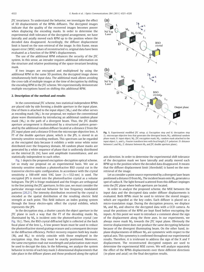
Fig. 1. Experimental modified JTC setup. a) Encryption step and b) decryption step(L: microscope objective lens that generates the divergent beam, MA: additional randomphase mask, O: input object, ME: JTC encryption mask, MO: randommask attached to theinput object; L1 and L2: Fourier transform lens with focal length f; P: polarizer; D: distancebetween L and MA; Z: distance between MA and JTC double aperture plane).
4322 E. Rueda et al. / Optics Communications 284 (2011) 4321–4326
JTC invariance. To understand the behavior, we investigate the effectof 3D displacements of the RPMs diffusers. The decrypted imagesindicate that the quality of the recovered images becomes poorerwhen displacing the encoding masks. In order to determine theexperimental shift tolerance of the decrypted arrangement, we havelaterally and axially moved each RPM up to the position where thedecoded data disappeared. Accordingly, the diffuser displacementlimit is based on the non-retrieval of the image. In this frame, meansquare error (MSE) values of reconstructed vs. original data have beenevaluated as a function of the RPM´s displacements.
The use of the additional RPM enhances the security of the JTCsystem. In this sense, an intruder requires additional information onthe structure and relative positioning of the space-invariant breakingmask.
If two images are encrypted and multiplexed by using theadditional RPM in the same 3D position, the decrypted image showssimultaneously both input data. The additional mask allows avoidingthe cross-talk of multiple images at the time of decryption by shiftingthe encoding RPM in the JTC scheme.We experimentally demonstratemultiple encryptions based on shifting this additional RPM.
2. Description of the method and results
In the conventional JTC scheme, two statistical independent RPMsare placed side by side forming a double aperture in the input plane.One of them is attached to the input object (MO) and the other servesas encoding mask (ME). In our proposal, we replace the conventionalplane wave illumination by introducing an additional random phasemask (MA) in the path of a divergent beam. Thus, the JTC doubleaperture arrangement is illuminated by a structured pattern gener-ated by the additional random diffuser located at a distance Z from theJTC input plane and a distance D from themicroscope objective lens. AFT of the double aperture plane, which is the JPS, is stored in anintensity sensitive recording medium. This spectrum can be regardedas the encrypted data because it exhibits a wide sense white noisedistributed over the frequency domain. All random phase masks aregenerated by a white sequence of phase that is uniformly distributedon the interval [0, 2π], have unit amplitude transmittance, and arestatistically independent to each other.
Fig. 1 depicts the proposed encryption–decryption optical scheme.Let us study our proposal on an experimental basis. We use asintensity sensitive medium a photorefractive BSO crystal cut in thetransverse electro-optic configuration. In accordance with the crystalsensitivity a 100 mW mini YAG laser (λ=532 nm) is used. Theencrypted JPS is stored into the photorefractive crystal as a volumehologram. The JPS is fringe modulated and the fringes are orthogonalto the line joining the JTC apertures. In this case, wemust consider theparticular storage-read-out behavior for low frequency modulatedpatterns [20,21]. The intensity distribution received by the crystal isencoded as the spatial distribution of the resulting electric fieldstrength at each point. This field induces an index grating systemthrough the linear electro-optic effect the crystal exhibits, whichrepresents the JPS.
In the decryption step, a shutter cancels the object aperture in theJTC plane in such a way that the FT of the decoding masks ME
illuminated by MA is incident onto the photorefractive crystal (seeFig. 1b)). Then, the BSO crystal diffracted light is collected at the backfocal plane of the lens L2. A low power beam must be used to reducethe photorefractive stored gratings erasure and a consequent decreasein the diffraction efficiency. Perfect recovery requires both key masks(ME and MA) to strictly coincide with those employed in theencryption step, thus they must be exactly positioned. Moreover,the same encryption read-out wavelength and polarization state mustbe used to decrypt the data. In the following, we analyze the systembehavior in terms of each keymask 2-dimensional displacements thattake place in the diffuser planes and those produced along the optical
axis direction. In order to determine the experimental shift toleranceof the decryption mask we have laterally and axially moved eachRPM up to the position where the decoded data disappeared. It meansthat the diffuser displacement limit (threshold) is based on the non-retrieval of the image.
Let us consider a point source represented by a divergent laser beampositioned adistanceD fromMA. The incident beamontoMAgenerates aspot of radius R. The light forward scattered from this diffuser impingesonto the JTC plane where both apertures are located.
In order to analyze the proposed scheme, the MSE between theinput data and the decrypted data under diffuser displacements isevaluated. Both RPMs must be used to retrieve the stored images;which are regarded as the key codes. Each diffuser is placed on amicro-translation stage. During the decryption process, we displaceME and MA and observe the decrypted data with a CCD camera. Asusual the positions of the RPM are kept fixed before encrypting theinputs. At this point we want to introduce a comment about the signof the displacement along the three axes. In our experiments, wealways move mask MA towards the JTC input plane. Obviously theinverse displacement does not produce the same decrypting behaviorbecause of the divergent illuminating beam. On the other hand, in-plane displacements of diffuser MA are symmetric with respect to theoptical axis. This symmetry is confirmed throughout our experimentalresults. Therefore, it is irrelevant to address the sign of the X and Ydisplacement. The reconstructed decrypted outputs are used todetermine the experimental MSE curves. We will analyze separatelythe effect of the RPMs displacements over three different directions(in-plane and axial) on the final decryption results.

4323E. Rueda et al. / Optics Communications 284 (2011) 4321–4326
The MSE curves of Fig. 2a) and b) correspond to an X-directiondisplacement of MA and ME, respectively. In this case, a divergentbeam generated by a 16 mm focal length objective microscope isemployed. The decrypted image behavior under RPM shifting isevaluated for different distances between ME and MA (Z=28.5 cm,Z=21 cm and Z=16 cm where Z is the distance between MA and theJTC double aperture plane) while the laser source is kept fixed. Theexperimental results of Fig. 2 indicate that when the diffuser ME isdisplaced in X-direction by an amount of±15 μm corresponding toMSE=0.8, the reconstructed beam is unable to decode the encrypteddata stored in the crystal as can be confirmed by observing Fig. 3(b).This figure shows the decrypted image obtained with a 15 μm X-direction displacement of the diffuser MA while the ME matches theencrypted key position. This result corresponds to Z=16 cm and thesame write-in parameters as Fig. 2. The same system sensitivity is alsoobserved by in-plane displacing the diffuser MA in X-direction.Therefore, for 16 mm focal length objective microscope, the resultsof Fig. 2a) and b) show that no matter which mask is laterallydisplaced the system is unable to decrypt the image.
Remembering that the transversal speckle average dimensionsonto the JTC plane are [22]:
Sxh i = SyD E
≈ λZR
ð1Þ
0 5 10 15 20 25 300,0
0,2
0,4
0,6
0,8
1,0 Z=28,5 cm Z=21 cm Z=16 cm
MS
E
MA x-displacement (µm)
(a)
0 5 10 15 20 25 300,0
0,2
0,4
0,6
0,8
1,0 Z=28,5 cm Z=21 cm Z=16 cm
MS
E
ME x-displacement (µm)
(b)
Fig. 2. MSE in terms of the x-direction displacement of: (a) the diffuser MA and (b) thediffuser ME, respectively. The write-in wavelength is 532 nm, the diffuser roughness is30 μm and the microscope objective focal length is 16 mm.
Fig. 3. Decrypted images obtained with: (a) both diffusers matching the correspondingencrypted keys positions (b) results from a 15 μm X-direction displacement of thediffuser MA and the ME matching the encrypted key position. The write-in wavelengthis 532 nm, the diffuser roughness is 30 μm and the microscope objective focal length is16 mm and Z=16 mm.
and the longitudinal speckle average dimension is [22]:
Szh i ≈ λZR
� �2ð2Þ
Note that the average transversal speckle size (Eq. (1)) in the JTCplane can be rewrite as:
Sxh i ≈ λtg αð Þ
ZD
� �=
λtg αð Þ
Zcte−Z
� �ð3Þ
where α indicates the beam divergence, and in our experimentalcondition is imposed by Z+D=constant. It is evident that as Zdecreases and R increases the average values diminish.
Note that when Z decreases, Z/D decreases aswell, and therefore thesituationwhereZ=16 cmismore sensitive todecryption failures underdiffusers shifting in comparison with Z=28.5 cm and Z=21 cm,respectively. This behavior agrees with the results displayed in Fig. 2.
In the case of Fig. 2, due to the large focal length of the microscopeobjective, the divergence angle α is very small (approximately 1degree). The transversal X-direction displacement of MA produces anequivalent transversal displacement of the speckle distributionformed at the JTC input plane. Therefore, when ME is transversallydisplaced andMA is kept fixed, the situation is similar to that obtainedwhenMA is displaced andME is fixed. Note that this result would havebeen obtained in the case where a plane wave would have beenemployed to illuminate MA.
The MSE curves of Fig. 4a) and b) correspond to the case when a4 mm focal length objective microscope generates the incident

0 1 2 3 4 5 6 7
0,0
0,2
0,4
0,6
0,8
1,0
Zi=25 cm
Zi=20 cm
Zi=10 cm
MS
E
MA x-displacement (µm)
(a)
0 5 10 15
0,0
0,2
0,4
0,6
0,8
1,0
Z=25 cm Z=20 cm Z=10 cm
MS
E
ME x-displacement (µm)
(b)
Fig. 4. MSE in terms of the X-direction displacement of: (a) the diffuser MA and (b) thediffuser ME, respectively. The write-in wavelength is 532 nm, the diffuser roughness is30 μm, and the microscope objective focal length is 4 mm.
0 2 4 6 8 10
0,0
0,2
0,4
0,6
0,8
1,0
Z=15 cm Z=30 cm
MS
E
MA y-displacement (µm)
(a)
0 5 10 15 20
0,0
0,2
0,4
0,6
0,8
1,0
Z=30 cm Z=15 cm
MS
E
ME y-displacement (µm)
(b)
Fig. 5. MSE in terms of the Y-direction displacement of: (a) the diffuser MA and (b) thediffuser ME, respectively. The write-in wavelength is 532 nm, the diffuser roughness is30 μm and the microscope objective focal length is 4 mm.
0 20 40 60 80
0,0
0,2
0,4
0,6
0,8
1,0
Z=15 cm Z=10 cm
MS
E
MA z-displacement (mm)
Fig. 6. MSE in terms of the Z-direction displacement of the diffuser MA. The write-inwavelength is 532 nm, the diffuser roughness is 30 μm and the microscope objectivefocal length is 4 mm.
4324 E. Rueda et al. / Optics Communications 284 (2011) 4321–4326
divergent beam. The decrypted image behavior when the randommask moves, in X-direction, is evaluated for different distancesbetween ME and MA (Z=25 cm, Z=20 cm and Z=10 cm) while thelaser source is fixed. The angleα (~7°) is higher in this case than in thecase of Fig. 2. Therefore, a transversal displacement of MA changes thespeckle distribution that impinges on the JTC plane faster than withα=1°, and the decorrelation increases as well. In this situation,moving ME while MA remains fixed is not equivalent to msove MA
while ME is fixed. In Fig. 4b) the speckle distribution incident on theME diffuser does not change significantly and the correlation is keptalong a larger distance.
As it is expected, the transversal displacement along the Y-axisshows an equivalent behavior to that obtained by the X-directiondisplacement, and this result is experimentally confirmed. Fig. 5a) andb) corresponds to the MSE curves when we introduce a transversalY-direction displacement of MA and ME, respectively. In this case, adivergent beam generated by a 4 mm focal length objectivemicroscope is employed. The decrypted output behavior when themask moves is evaluated for different distances between MA and ME
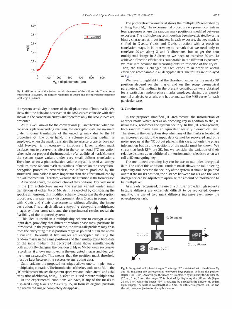
(Z=30 cm and Z=15 cm), while the laser source is fixed.Finally, as it is shown in Figs. 6 and 7 the system is tested when
displacing along Z-axis. Practical limitations of the involved mechan-ical parts in the optical setup did not allow implementing the sameZ-displacements for the MA and ME. This situation is observed inFigs. 6 and 7. Note that the longitudinal speckle average dimensionsare longer than the speckle average transversal dimensions (see Eqs.(1) and (2)). As it is expected, a greater mask displacement along
Z-axis is tolerated in comparison with X-axis and Y-axis displace-ments, in order to decrypt the information. This behavior is revealedwhen comparing the curves for Z=15 cm of Fig. 5a) and Fig. 6.
A correct input recovering depends on the sharpness correlationdegree between both speckle distributions. Therefore, it seemsappropriate to use a speckle correlation-length analysis to determine
0 100 200 300 400 500 600
0,0
0,2
0,4
0,6
0,8
1,0M
SE
ME z-displacement (µm)
Z=30cm
Fig. 7. MSE in terms of the Z-direction displacement of the diffuser ME. The write-inwavelength is 532 nm, the diffuser roughness is 30 μm and the microscope objectivefocal length is 4 mm.
(0, 20 µm, 0)
(0 , 0 , 0)
(20 µm , 0 , 0)(0 , 0 , 80 µm)
X
Y
Z
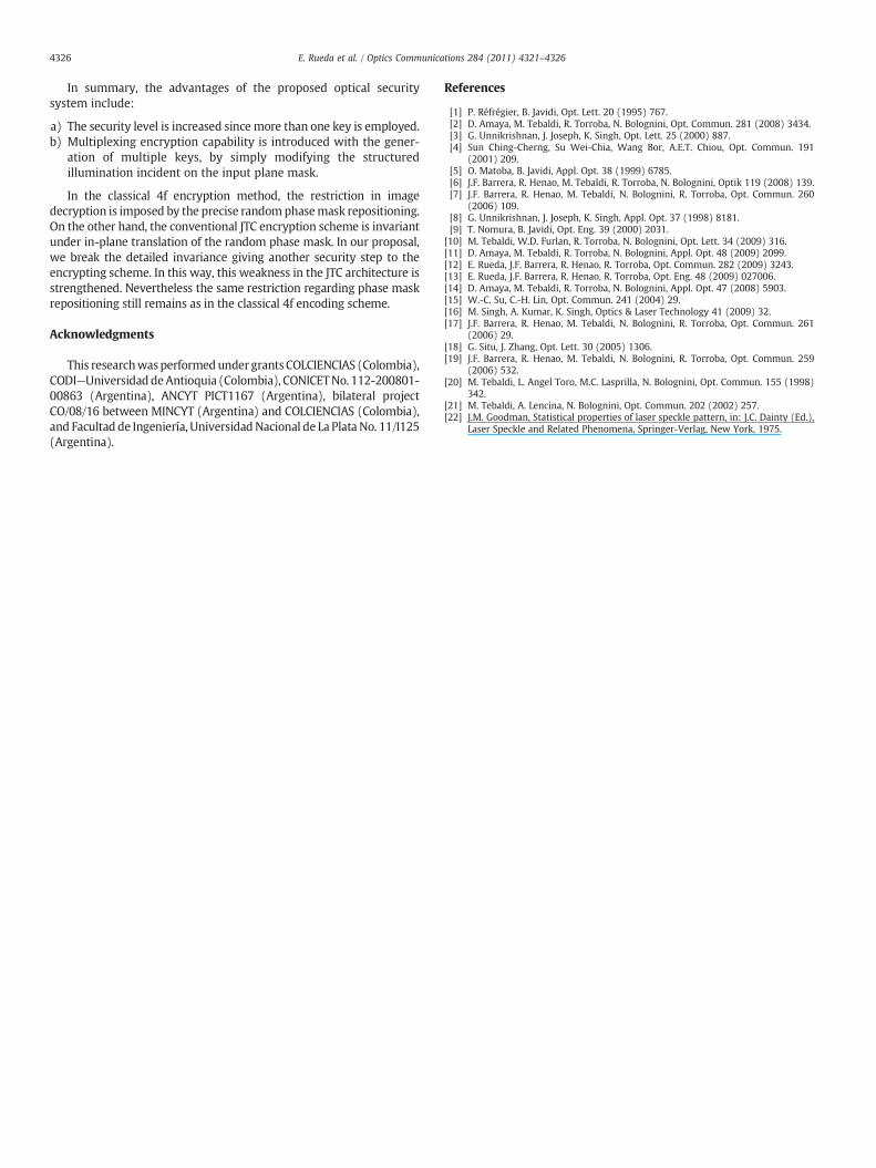
Fig. 8. Decrypted multiplexed images. The image “X” is obtained with the diffuser ME
and MA matching the corresponding encrypted keys position defining the position(0 μm, 0 μm, 0 μm). Accordingly, the image “S” is obtained by displacing the diffuser MA
(20 μm, 0 μm, 0 μm), the image “E” is obtained by displacing the diffuser MA (0 μm,20 μm, 0 μm) while the image “PPF” is obtained by displacing the diffuser MA (0 μm,0 μm, 80 μm). The write-in wavelength is 532 nm, the diffuser roughness is 30 μm andthe microscope objective focal length is 4 mm.
4325E. Rueda et al. / Optics Communications 284 (2011) 4321–4326
the system sensitivity in terms of the displacement of both masks. Weshow that the behavior observed in the MSE curves coincide with thatshown in the correlation curves and therefore only the MSE curves arepresented.
As it is well known for the conventional JTC architecture, when weconsider a plane-recording medium, the encrypted data are invariantunder in-plane translations of the encoding mask due to the FTproperties. On the other hand, if a volume-recording medium isemployed, when the mask translates the invariance property does nothold. However, it is necessary to introduce a larger random maskdisplacement to observe this effect in the conventional JTC encryptionscheme. In our proposal, the introduction of an additionalmaskMA turnsthe system space variant under very small diffuser translations.Therefore, when a photorefractive volume crystal is used as storagemedium, these random mask translations influence on the encryption–decryption procedure. Nevertheless, the influence produced by thestructured illumination is more important than the effect introduced bythevolumemedium. Therefore,we focus the attention in the former case.
As verified above, the introduction of the additional key codemaskin the JTC architecture makes the system variant under smalltranslations of either ME or MA. As it is expected by considering thespeckle dimensions, this modified scheme tolerates, in the decryptionprocedure, a greater mask displacement along Z-axis in comparisonwith X-axis and Y-axis displacements without affecting the imagedecryption. This analysis allows encrypting–decrypting multiplexedimages without cross-talk, and the experimental results reveal thefeasibility of the proposed system.
This idea is useful in a multiplexing scheme to encrypt severalinput data, providing that different random phase mask positions beintroduced. In the proposed scheme, the cross-talk problemmay arisefrom the encrypting masks position range as pointed out in the abovediscussion. Obviously, if two images are encrypted by using therandommasks in the same positions and then multiplexing both dataon the same medium, the decrypted image shows simultaneouslyboth inputs. By changing the position of ME or MA between successiverecordings, it allows multiplexing the encrypted images and decrypt-ing them separately. This means that the position mask thresholdmust be kept between the successive encrypting data.
Summarizing, the proposed technique allows one to implement amultiplexingoperation. The introduction of the key codemaskMA in theJTC architecture makes the system space variant under lateral and axialtranslation of eitherME orMA. This feature is used to storemultiple data.
In the experimental conditions we have, if any of the masks isdisplaced along X-axis or Y-axis by 15 μm from its original position,the recovered image completely disappears.
The photorefractive-material stores the multiple JPS generated byshifting ME or MA. The experimental procedure we present consists infour exposures where the randommask position is modified betweenexposures. Themultiplexing technique has been investigated by usingbinary characters as input images. In each exposure, the key mask isshifted in X-axis, Y-axis and Z-axis direction with a precisiontranslation stage. It is interesting to remark that we need only totranslate 20 μm along X and Y directions, but to get the nextmultiplexed image in Z-direction we need to translate 80 μm. Toachieve diffraction efficiencies comparable in the different exposures,we take into account the recording-erasure response of the crystal.Then, the time is changed in each exposure in order to obtainefficiencies comparable in all decrypted data. The results are displayedin Fig. 8.
We have to highlight that the threshold values for the masks 3Dposition depend on the masks and on the setup geometricalparameters. The findings in the present contribution were obtainedfor a particular random phase masks employed during our experi-mental analysis. As a rule, one has to analyze the MSE curve for eachparticular case.
3. Conclusions
In the proposed modified JTC architecture, the introduction ofanother mask, which acts as an encoding key in addition to the JTCusual mask, reinforces the system security. In this JTC arrangement,both random masks have an equivalent security hierarchical level.Therefore, in the decryption step when any of the masks is located atan incorrect position, the input data cannot be recovered and onlynoise appears at the JTC output plane. In this case, not only the phaseinformation but also the positions of the masks must be known. Westress that both RPM are 2D, but we consider the variation of theirrelative distance as an additional dimension and this leads to what wecall a 3D encrypting key.
The mentioned encoding key can be use to multiplex encrypteddata. The use of this additional random mask allows the multiplexingcapability and increase the security of the system. It should be pointedout that themasks position, the distance betweenmasks, and the laserdivergence can be adjusted to optimize the amount of information tobe multiplexed.
As already recognized, the use of a diffuser provides high securitybecause diffusers are extremely difficult to be replicated. Conse-quently, the use of two mask diffusers increases even more theeavesdropper task.
4326 E. Rueda et al. / Optics Communications 284 (2011) 4321–4326
In summary, the advantages of the proposed optical securitysystem include:
a) The security level is increased since more than one key is employed.b) Multiplexing encryption capability is introduced with the gener-
ation of multiple keys, by simply modifying the structuredillumination incident on the input plane mask.
In the classical 4f encryption method, the restriction in imagedecryption is imposed by the precise randomphasemask repositioning.On the other hand, the conventional JTC encryption scheme is invariantunder in-plane translation of the random phase mask. In our proposal,we break the detailed invariance giving another security step to theencrypting scheme. In this way, this weakness in the JTC architecture isstrengthened. Nevertheless the same restriction regarding phase maskrepositioning still remains as in the classical 4f encoding scheme.
Acknowledgments
This researchwasperformedunder grantsCOLCIENCIAS (Colombia),CODI—UniversidaddeAntioquia (Colombia), CONICETNo. 112-200801-00863 (Argentina), ANCYT PICT1167 (Argentina), bilateral projectCO/08/16 between MINCYT (Argentina) and COLCIENCIAS (Colombia),and Facultad de Ingeniería, UniversidadNacional de La Plata No. 11/I125(Argentina).
References
[1] P. Réfrégier, B. Javidi, Opt. Lett. 20 (1995) 767.[2] D. Amaya, M. Tebaldi, R. Torroba, N. Bolognini, Opt. Commun. 281 (2008) 3434.[3] G. Unnikrishnan, J. Joseph, K. Singh, Opt. Lett. 25 (2000) 887.[4] Sun Ching-Cherng, Su Wei-Chia, Wang Bor, A.E.T. Chiou, Opt. Commun. 191
(2001) 209.[5] O. Matoba, B. Javidi, Appl. Opt. 38 (1999) 6785.[6] J.F. Barrera, R. Henao, M. Tebaldi, R. Torroba, N. Bolognini, Optik 119 (2008) 139.[7] J.F. Barrera, R. Henao, M. Tebaldi, N. Bolognini, R. Torroba, Opt. Commun. 260
(2006) 109.[8] G. Unnikrishnan, J. Joseph, K. Singh, Appl. Opt. 37 (1998) 8181.[9] T. Nomura, B. Javidi, Opt. Eng. 39 (2000) 2031.
[10] M. Tebaldi, W.D. Furlan, R. Torroba, N. Bolognini, Opt. Lett. 34 (2009) 316.[11] D. Amaya, M. Tebaldi, R. Torroba, N. Bolognini, Appl. Opt. 48 (2009) 2099.[12] E. Rueda, J.F. Barrera, R. Henao, R. Torroba, Opt. Commun. 282 (2009) 3243.[13] E. Rueda, J.F. Barrera, R. Henao, R. Torroba, Opt. Eng. 48 (2009) 027006.[14] D. Amaya, M. Tebaldi, R. Torroba, N. Bolognini, Appl. Opt. 47 (2008) 5903.[15] W.-C. Su, C.-H. Lin, Opt. Commun. 241 (2004) 29.[16] M. Singh, A. Kumar, K. Singh, Optics & Laser Technology 41 (2009) 32.[17] J.F. Barrera, R. Henao, M. Tebaldi, N. Bolognini, R. Torroba, Opt. Commun. 261
(2006) 29.[18] G. Situ, J. Zhang, Opt. Lett. 30 (2005) 1306.[19] J.F. Barrera, R. Henao, M. Tebaldi, N. Bolognini, R. Torroba, Opt. Commun. 259
(2006) 532.[20] M. Tebaldi, L. Angel Toro, M.C. Lasprilla, N. Bolognini, Opt. Commun. 155 (1998)
342.[21] M. Tebaldi, A. Lencina, N. Bolognini, Opt. Commun. 202 (2002) 257.[22] J.M. Goodman, Statistical properties of laser speckle pattern, in: J.C. Dainty (Ed.),
Laser Speckle and Related Phenomena, Springer-Verlag, New York, 1975.