Supplier – Forms Completion Request - Global Procurement ...
Upload
khangminh22Category
view
6download
0
HAR 101998 ENGINEERING DATA TRANSMITTAL
2. To: (Receiving Organization)DISTROBUTION
3. From: (Originating Organization)
DC LARSEN/SST TWRS LMH4. Related EDT No.:
6067625. Proj./Prog./Dept./Div.:
241-SY-101/ MITIGATION
6. Design Authority/ Design Agent/Cog.Engr.:
DC LARSEN
7. Purchase Order No.:
N/A8. Originator Remarks:
This ATR documents completion of ATP HNF-1516, "ThermocoupleModule Halt Failure Acceptance Test Procedure for Tank• 241-SY-101".
9. Equip./Component Ho.:
N/A10. System/Bldg./Facility:
241-SY-101/DACS-111. Receiver Remarks:
N/A11A. Design Baseline Document? [] Yes [X] No 12. Major Assm. Dwg. No.:
N/A13. Permit/Permit Application No.:
N/A14. Required Response Date:
N/A
DATA TRANSMITTED(A)
ItemNo.
(B) Document/Drawing No. SheetNo.
(E) Title or Description of DataTransmitted
ApprovalDesig-nator
Reasonfor
Trans-mittal
natorDispo-sition
Dispo-sition
HNF-2351 Thermocouple ModuleHalt FailureAcceptance TestReport for Tank 241-SY-101
Approval Designator (F) Reason for Transmittal (G) Disposition (H) & (I)
E, S, Q, D or N/A(see WHC-CM-3-5,Sec.12.7)
1. Approval 4. Review2. Release 5. Post-Review3. Information 6. Dist. (Receipt Acknow. Required)
1. Approved2. Approved w/coi3. Disapproved w/
4. Reviewed no/comment5. Reviewed w/comment6. Receipt acknowledged
17. SIGNATURE/DISTRIBUTION(See Approval Designator for required signatures)
(G)Rea-
(H)Disp. (K) Signature (L) Date (M) MSIN Rea-
son
(H)Disp. <K> Signature (L) Dote (M) MSIN
esign Au tho r i t y WG Brown
Design A<3'_ . . . . t™?t<- fr/f+m,: ~r* // JO
Cog. Hg r . RE LARSON
Safety
Env.
Authorized Representative Datefor Receiving Organization
Design Authority/Cognizant Manager
21. DOE APPROVAL (if required)
Ctrl. No.
(] Approved[] Approved w/comments[] Disapproved w/coRments
BD-7400-172-1

HNF-2351. Rev. 0
THERMOCOUPLE MODULE HALT ACCEPTANCETEST REPORT FOR TANK 241-SY-101 DACS-1
DOUGLAS C. LARSENLMH, Richland, WA 99352U.S. Department of Energy Contract DE-AC06-96RL13200
EDT/ECN: 621176Org Code: 79460B&R Code:
UC:Charge Code: N16B1Total Pages: 3fir34
Key Words: 241-SY-101, DACS, SOFTWARE, MIXER PUMP, THERMOCOUPLE, MIT
Abstract: The following documents the acceptance test report for the241-SY-101 modicon module software testing performed as a correctiveaction to communications problem.
TRADEMARK DISCLAIMER. Reference herein to any specific commercial product, process, or service bytrade name, trademark, manufacturer, or otherwise, does not necessarily constitute or imply itsendorsement, recommendation, or favoring by the United States Government or any agency thereof orits contractors or subcontractors.
Printed in the United States of America. To obtain copies of this document, contact: DocumentControl Services, P.O. Box 950, Mailstop H6-08, Richland WA 99352, Phone (509) 372-2420;Fax (509) 376-4989.
^ Approval'
DATE: s
S U : ^
MAR 101
Approved for Public Release
A-6400-073 (01/97) GEF321

THERMOCOUPLE MODULE HALT FAILUREACCEPTANCE TEST REPORT FOR TANK 241-SY-101
DACS-1
HNF-2351REVISION 0
MARCH 5, 1998

THERMOCOUPLE MODULE HALT FAILURE ACCEPTANCE TEST REPORT FORTANK 241-SY-101 DACS-1
TABLE OF CONTENTS
Summary of HNF-2351, Rev. 0, "THERMOCOUPLE MODULE HALT FAILURE ACCEPTANCE TEST REPORT FORTANK 241-SY-101 DACS-1". . 3
Completed acceptance test procedure . . . . . . . . 4
DOCUMENT NO.
HNF-2351REVISION
0PAG6 NO,
2 OF 35

THERMOCOUPLE MODULE HALT FAILURE ACCEPTANCE TEST REPORT FORTANK 241-SY-101 DACS-1
SUMMARY OF HNF-2351. Rev. 0. "THERMOCOUPLE MODULE HALT FAILURE ACCEPTANCE TEST REPORT FORTANK 241-SY-101 DACS-1".
Testing was started on February 24, 1998 and completed on February 25, 1998.
The completed procedure consists of 4 acceptance test sections, 6.1 through 6.4.
Three test exceptions were identified during the procedure. The first test exception wasdetermined to be unrelated to the ATP and unfortunate that the instrument failed during theATP. The next two test exceptions were disposition as acceptable because the alarmingfunctions worked correctly in identifying a problem when software communications wereinterrupted. The test was completed satisfactorily over 2 days.
The remainder of the acceptance test report is the completed test procedure
DOCUMENT NO.
HNF-2351REVISION
0
PAGE NO,
3 OF 35

DISTRIBUTION SHEETToDistribution
Project Title/Work Order
FromSESC / Laboratory Services
Thermocouple Module Halt Failure Acceptance Test Procedure for Tank241-SY-101 DACS-1 / NF22Y
Name MSINText
With AllAttach.
Page 1 of 1
Date October 29, 1997
EDT No. 606762
ECN No.
Text Only Attach./Appendix
Only
EDT/ECNOnly
W. G. BrownD. W. CrassJ. A. EllingsworthA. M. ErmiG. J. GauckL. S. KrogsrudD. C. LarsenD. D. TateR.W. TruittR. R. TrueR. P. TuckerS. 0 . Smith / A. C. Zuehlke
DACS Project File
Central Files
T4-07H6-11R2-87L6-37T4-07T4-07T4-08L6-37L6-37T4-07T4-08L6-37
L6-37
Bl-07
X
XXXXX
XX
X
X
X
X
A-6000-135 (01/93) WEF067
HNF-2351, Rev. 0 Page 4 of 35

~.C 0 J l i & f t j " ENGINEERING DATA TRANSMITTALP«ge 1 of 1
1-EDT 6067622, To: (Receiving Organization)
Distribution3- From: (Originating Organization)
AM Ermi / SESC Laboratory Services4- Related EDT No.:
N/A5. Proj /Prog./Dcpt./Div.:
241SY101 Mitigation Project6- Design Authority / Cog. Engr.:GJ Gaud:
7- Purchase Order No.:
N/A8. Originator Remarks:
This ATP, tests the 241SY101 DACS software following changes designed tomonitor and prevent thermocouple module halt failures.(Reference: DACS change control board System Change Request #427)
9. Equip./Component No,:
Software: TEST305, PLC30610. System/Bldg./Facility:
241SY101 DACS Trailer
11. Receiver Remarks: UA. Design Baseline Document? [ ] Yes ^<] No 12. Major Assm. Dwg. No.:
N/A13. Permit/Permit Application No.:
N/A14. Required Response Date:
11/7/97
DATA TRANSMITTED (F) (G) (H)
<B) Docuraenl'Drjwuig No SheetID)
No.{El Title or Description of D»t» Ti
Approvi]Desig-aitor
Trou-miml
Dispo-sition
Receiv-er
Dupe-
HNF-1516 Thermocouple Module HaltFailure Acceptance TestProcedure for Tank241-SY-101 DACS-1
SQ
Approval Denpiaior (F) n fur Tranimitnl fG? Dupoiiuon (HI & (I)
E.S ,Q.DorN/Adee WHC-CM-3-5.Sec. 12 71
I,, ApprovjJ 4.. Review
2 Peleise 5,, Post-Review3 Information 6 Din,, (Receipt Acknow, Required)
] „ Approved2.. Approved w/comnieni3.. Dnippfpved ^/commen
4.. Reviewed no/comment5,, Reviewed w/conunent6 Receipt icknowledged
17,, SIGNATURE/DISTRIBUTION(Set ApproviJ Dwipuior for required ligrmiirc
(H)Diip..
(K) Sifnaurc (I) Dite (M) MSIN Rea-(H)
Dup(J) Name (K) Signature (L) Dale (M) MSIN
Cog Mgr.
19.
Authonicd Rcpmesuuvef
21. DOE APPROVAL (if required)Ctrl. No.
[ ] Approved[ ] Approved w/commentst 1 Disapproved w/comments
BD-7400-172-2 (05/96) GEF097
HNF-2351,Rev. 0 Page 5 of 35
BD-74OO-172-1 107/911

HNF-1516, Rev. 0
THERMOCOUPLE MODULE HALT FAILUREACCEPTANCE TEST PROCEDURE FOR TANK241-SY-101 DACS-1
A. M. ErmiSGN Eurisys Services Corporation, P.O. Box 840, Richland, WA 99352U.S. Department of Energy Contract DE-AC06-96RL13200
EDT: 606762Org Code: S4000B&R Code: EW3120072
UC: 2030Charge Code: NF22YTotal Pages: 30
Key Words: DACS, DATA ACQUISITION AND CONTROL SYSTEM, 241SY101,ACCEPTANCE TEST PLAN, THERMOCOUPLE
Abstract: The readiness of the Tank 241-SY-101 Data Acquisition and Control System(DACS-1) to provide monitoring and alarms for a halt failure of any thermocouple modulewill be tested during the performance of this procedure. Updated DACS-1 "I/O MODULEHEALTH STATUS", "MININ1", and "MININ2" screens, which now provide indication ofthermocouple module failure, will also be tested as part of this procedure.
TRADEMARK DISCLAIMER Reference herein to any specific commercial product, process, or service by trade name,trademark, manufacturer, or otherwise, does not necessarily constitute or imply its endorsement, recommendation, orfavoring by the United States Government or any agency thereof or its contractors or subcontractors.
Printed in the United States of Amenca To obtain copies of this document, contact: Document Control Services, P O Box950, Mailstop H6-08, Richland WA 99352, Phone (509) 372-2420; Fax (509) 376-4989
, /Release Approval ' Release Stamp
Approved for Public ReleaseA-6400-073 (01/97) GEF321
HNF-2351, Rev. 0 Page 6 of 35

HNF-1516Revision 0
Thermocouple Module Halt FailureAcceptance Test Procedure
For Tank 241-SY-lOl DACS-1
October 1997
Prepared by:
A. C. Zuehlke,PLCs Plus
Prepared for:
G. J. Gauck,Lockheed Martin Hanford Corporation
HNF-2351, Rev. 0 Page 7 of 3 5

t THERMOCOUPLE MODULE HALT FAILURE ACCEPTANCE TEST PJROCEDURE |
TARTE O F C O N T E N T S
•1.0 PURPOSE/SCOPE '........' :". 3
2.0 REFERENCES , 3
3.0 RESPONSIBILITIES '....:....'.'.....'...: 4
4.0 DESCRIPTION OF THE SYSTEM , 5
5.0 TEST CONDITIONS AND EQUIPMENT REQUIRED 5
6.0 ACCEPTANCE TEST 76.1 Thermocouple Module "Halt" Failure Initiation Test 76.2 DACS Display Screen Checks 86.3 Instrumentation End-To-End Checks (17B MIT) 136.4 Selected MIT17C and TBST Thermocouple End-To-End Checks 18
7.0 TEST DATA SHEETS 21
8.0 ATTACHMENTS 26Attachment 1: Exception List 27Attachment 2: Measurement and Test Equipment Record Sheet 28Attachment 3: Final Procedure Acceptance Sheet 29
HNF-1516 0 2 OF 29
HNF-2351,Rev. 0 Page 8 of 35

[THERMOCOUPLE MODULE HALT FAILURE ACCEPTANCE TEST PROCEDURE I
1.0 PURPOSE/SCOPE
The readiness of the Data Acquisition and Control System (DACS) to provide monitoring and alarms lor ahalt failure of any thermocouple module will be tested during the performance of this procedure.
Updated DACS "VO MODULE HEALTH STATUS", "MTNTNl",and "MININ2" screens, which nowprovide indicalion of thermocouple module failure, will also be tested as a part of this procedure.
2.0 REFERENCES
2.1 HSR-CM, Rev. 2, Hanford Site Radiological Control Mnnmi
• 2.2 LAUR-92-3196, "Safety Assessment for Proposed Pump Operation to Mitigate Episodic GasReleases in Tank 241-SY-101"
2.3 Hanford Site Policies and Procedures, Occupational Safety and Health
2.4 HNF-PRO-423, Radiological WorV Permit
2.5 HNF-PROV440, F.npinefiring Document Change Control Requirements
2.0 HNF-PRO-446. Testing Practices Requirements
2.7 WHC-IP-0263-TF, Westinghou.se Hanfrirrl Company Rni'Ming Emergency Plan Appendix 0, "S-Kann Complex"
2.8 HNF-IP-0842, Waste Tank Project Administrating, Volume 2, Section 4.9.1, "Lockout•Tagout"
2.9 WHC-SD-WM-HSP-002, Tank Farm Health anrl Safrly Plan
HNF-1516 0 3OF2y
DOT. A D n -ri."

{THERMOCOUPLE MODULE HALT FAILURE ACCEPTANCE TEST PROCEDURE I
3.0 RESPONSIBILITIES
The following personnel wil! be Tequired for the performance of ihis procedure:
• Cognizant Engineer The individual assigned direct responsibility for the preparation,-performance, and adequacy of the test. Also responsible for final approval of resolutions forail exceptions on Attachment 1, "Exception List".
• Test nirertnr- The engineer assigned shift responsibility for performance of the test.
• Test Engineer: The engineer assigned to assist and relieve the Test Director during theperformance of the test.
• Field-Engineer.: A Test Director, Test Engineer, or Technician assigned to direct/verify testingactivities outside of the DACS trailer.
Only personnel designated by the Shift Operations Manager are allowed to direct testing per this procedure,and perform operating and control functions using the DACS computer systems.
One engineer acting as either a Test Director or as a Test Engineer is required to be present in the DACStrailer. One engineer or technician acting as a Field Engineer and one or more Instrument Techniciansand/or Electricians are required to inject test signals from outside of the DACS trailer.
If, during testing, any indicated parameter, control function, or screen display is not correct or appears to bemalfunctioning, then the engineer conducting this test shall make a determination as to the feasibility ofcontinuing testing. In most cases, since actual mixer pump motor operation will not occur during this test,there will be no safely impact to continuing the test and completing corrective actions later. A recorti of allnoted deficiencies will be kept on Attachment 1, "Exception List".
At the completion of all testing, approval of all data collected and DACS system performance shall bedocumented on Attachment 3, "Final Procedure Acceptance Sheet".
All changes to this procedure shall be implemented by ECN, and shall receive the approval signaturesappropriate to the approval designation of the change.
HNF-1516 0 4 OF 29
HNF-2351. Rev 0

{THERMOCOUPLE MODULE HALT FAILURE ACCEPTANCE TEST PROCEDURE I
4.0 DESCRIPTION OF THE SYSTEM
The DACS, which is housed in a trailer located jusl outside of the north fence al the SY tank farm, receivesinput signals from a variety ofsensors located in and around the SY-101 tank. These sensors provideinformation such as:
Tank vapor space and ventilation system H2 concentrationTank waste temperatureTank pressureWaste densityOperating pump parameters such as speed, flow,,rotational position, discharge pressure, and internaltemperature
• Waste level
The output of these sensors is conditioned and transmitted to the DACS computers where these signals arcdisplayed, recorded, and monitored for out-of-specification conditions.
This procedure will test signals transmitted to the DACS from various MIT and Tank Bottom and SideThermocouples (TBST), and verify proper indication and alarms should the I/O modules associated withthese thermocouples experience a "half'failure.
5.0 TEST CONDITIONS AND EQUIPMENT REQUIRED
5 1 The provisions of the following manuals apply to all work performed under this procedure:
• HSR-CM, Rev. 2, Hanford Site Rariinlnpical Control Manual• Hanford Site Policies and Procedures, Occupational Safety and Health• HNF-PRO-423. Radiological WnrW Permit• WHC-SD-WM-HSP-002, Tanl< Farm Hralth and Safety Plan
5.2 Lock and Tag Control
Locks and Tags shall be posted as required by HNF-TP-0842, Waste Tank Project Administration.Volume 2, Section 4.9.1, "Lockout/Tagout"
vtxn.*t»tr"r>
HNF-1516VI-torn
0 5 OF 29
HNF-2351, Rev. 0 Page 11 of 35
THERMOCOUPLE MODULE HALT FAILURE ACCEPTANCE TEST PROCEDURE
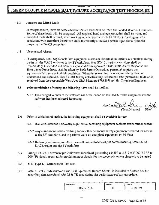
5.3 Jumpers and Lifted Leads
In this procedure, there are some occasions when leads will be lifted and landed at various terminals.Some of these leads will be energized. All required hand and eye protection shall be worn, andinsulated tools shall be used, when working on energized circuits (< 50 Vac). Testing must beconducted with energized instrument leads to correctly simulate a sensor input signal from thesensor to the DACS computers.
5.4 Unexpected Alarms
If unexpected, non-DACS, tank farm equipment alarms or abnormal indications are received duringtesting at the DACS trailer or in the SY tank farm, then SY-101 testing evolutions shall beimmediately suspended and actions, as prescribed in approved Tank Farms Alarm Response andEmergency Procedures, shall be taken by Tank Farms Operations personnel to place theequipment/farm in a safe, stable condition. When the reason for the unexpected condition isunderstood and resolved, then SY-101 testing activities may be resumed after permission to do so isreceived from the responsible West Area Shift Manager (WASM) and the Cognizant Engineer.
5.5 Prior to initiation of testing, the following items shall be veri fied:
5.5.1 The changed version of the software has been loaded on the DACS trailer computers and thesoftware has been released for testing.
Verified bj^(Test Director) Date
5.6 Prior to initiation of testing, the following equipment shall be available foT use:
5.6.1 Insulated hand tools normally required for accessing equipment cabinets and terminal boards
5.6.2 Any anti-contamination clothing and/or other personnel safety equipment required for accessto the SY tank farm, and to perform work on energized equipment (< 50 Vac)
5.6.3 Radios (2 minimum) or other means of communications, for communicating between theDACS trailer and the SY tank farm
5.7 Omega CL-24, Thermocouple Calibrator, capable of generating a 0.397 to 3.819 mV DC (50 °F to200 °F) signal, required for providing input signals for thermocouple sensor channels to be tested
5.8 MIT Type K Thermocouple Test Box
5.9 Attachment 2, "Measurement and Test Equipment Record Sheet", is included in Section 8.0 forrecording data associated with M & TE used during the performance of this procedure.
HNF-1516 0rt.otso
6 OF 29
HNF-2351,Rev. 0 Page 12 of 35

[ THERMOCOUPLE MODULE HALT FAILURE ACCEPTANCE TEST PROCEDURE |
6.0 ACCEPTANCE TEST
6.1 Thermocouple Module "Half" Failure Initiation Test
6.1.1 If any discrepancy is noted during testing, then record a description of the conditionin Attachment 1.
6.1.1.1 For each discrepancy recorded, enter an identifying number in the"EXCEPTION NUMBER" Column of Attachment 1.
6.1.1.2 Reproduce Attachment 1 as needed, and attach the additional pages to thisprocedure, to record all discrepancies noted during testing.
NOTE: The thermocouple module "halt" failure condition was caused by two successive, complete loss-of-power evolutions to both the Primary and Standby PLCs in the DACS trailer. The softwarechanges being tested by this ATP prevent the condition from happening again, regardless of thenumber of loss-of-power evolutions which could occur in the future. Testing per this procedurewill cause two successive loss-of-power evolutions and verify that the thermocouple module"halt" failure does not occur.
6.1.2 At Station #5, display the "ALARM/EVENT SUMMARY" screen.
6.1.3 At Station #6, display the "I/O HEALTH STATUS" screen.
6.1.4 At Station #7, display the "MININ1" screen.
6.1.5 At Station #1, access the Modsoft program and verify that the displayed status forthe following tags is "0":
. TC1CFGERR: Address: 438 • TC2CFGERR: Address: 447TC3CFGERR: Address: 456 • TC4CFGERR: Address: 467TC5CFGERR: Address: 476 • TC6CFGERR: Address: 485TC7CFGERR: Address: 236 • TC8CFGERR: Address: 565TC9CFGERR: Address: 574
6.1.6 Verify that no I/O module health status alarms are displayed on the"ALARM/EVENT SUMMARY" screen.
6.1.7 At the instrumentation rack in the back of the DACS trailer, turn-off the power to thePrimary PLC and, within one second, turn-off power to the Standby PLC.
HNF-1516 I 0 I 7 OF 29
HNF-2351,Rev. 0 Page 13 of 35

THERMOCOUPLE MODULE HALT FAILURE ACCEPTANCE TEST PROCEDURE |
6.1.8 After 30 seconds, turn-on power to the Primary PLC and, within one second, turn-onpower to the Standby PLC.
6.1.9 After 30 seconds, turn-off the power to the Primary PLC and, within one second,tum-off power to the Standby PLC.
6.1.10 After 30 seconds, turn-on power to the Primary PLC and, within one second, tum-onpower to the Standby PLC.
6.1.11 Observe the DACS screens at Stations 5,6, and 7 for a minimum of 1 minute andverify that no I/O module health status alarms are received.
6.1.12 At Station #1, verify that the displayed status for the following tags is "0":
TC1CFGEKR: Address: 438 • TC2CFGERR: Address: 447TC3CFGERR: Address: 456 • TC4CFGERR: Address: 467TC5CFGERR: Address: 476 • TC6CFGERR: Address: 485TC7CFGERR: Address: 236 • TC8CFGERR: Address: 565TC9CFGERR: Address: 574
Testing as directed by this procedure section has been completed, and discrepancies, if any, havebeen listed on Attachment 1, Exception List.
Test ?nSmtx^T£>-Q.-'tij>A4a\a\r-:. 2 J ZH
6.2 DACS Display Screen Checks
6.2.1 If any discrepancy is noted during testing, then record a description of the conditionin Attachment 1.
6.2.1.1 For each discrepancy recorded, enter an identifying number in the"EXCEPTION NUMBER" Column of Attachment 1.
6.2.1.2 Reproduce Attachment 1 as needed, and attach the additional pages to thisprocedure, to record all discrepancies noted during testing.
6.2.2 At Station #7, verify on the "MININ1" and "MINTN2" screens that all 22 of the j"TIR17BXX" tags (associated with the 17B MIT) are displayed in WHITE letters.
6.2.3 At Station #1, disable tag'TClCFGERR" and change the tag status to " 1 " . J
6.2.4 At Station #5, verify that the "DIG 17CTCERR MIT17C I/O MODULE HALT J
ERROR" alarm is displayed.
HNF-1516 8 OF 29
HNF-2351, Rev. 0 Page 14 of 35
I THERMOCOUPLE MODULE HALT FAILURE ACCEPTANCE TEST PROCEDURE 1
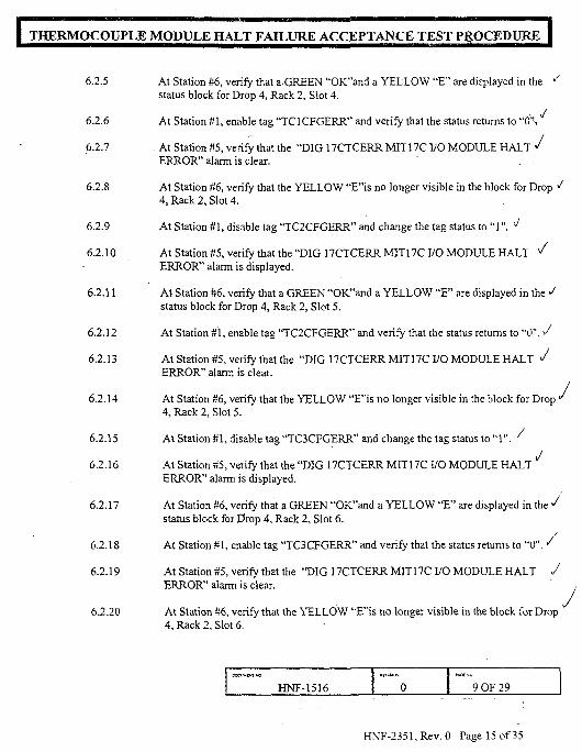
6.2.5 At Station #6, verify that a GREEN "OK"and a YELLOW "E" are displayed in the •'status block for Drop 4, Rack 2, Slot 4.
6.2.6 At Station #1, enable tag "TC1CFGERR" and verify that the status returns to " 6 \ '
6.2.7 At Station #5, verify that the "DIG 17CTCERR MIT17C I/O MODULE HALT </ERROR" alarm is clear.
6.2.8 At Station #6, verify that the YELLOW "E"is no longer visible in the block for Drop J4, Rack 2, Slot 4.
6.2.9 At Station #1, disable tag "TC2CFGERR" and change the tag status to "1" . ^
6.2.10 At Station #5, verify that the "DIG 17CTCERR MIT17C I/O MODULE HALT ^ERROR" alarm is displayed.
6.2.11 At Station #6, verify that a GREEN "OK"and a YELLOW "E" are displayed in the Jstatus block for Drop 4, Rack 2, Slot 5.
6.2.12 At Station #1, enable tag "TC2CFGERR" and verify that the status returns to "0". ^
6.2.13 At Station #5, verify that the "DIG 17CTCERR MIT17C I/O MODULE HALT JERROR" alarm is clear.
6.2.14 At Station #6, verify that the YELLOW "F'is no longer visible in the block for Drop "4, Rack 2, Slot 5.
6.2.15 At Station #1, disable tag "TC3CFGERR" and change the tag status to " 1 " . ^
J6.2.16 At Station #5, verify that the "DIG 17CTCERR MIT17C I/O MODULE HALT
ERROR" alarm is displayed.
6.2.17 At Station #6, verify that a GREEN "OK"and a YELLOW "E" are displayed in the Jstatus block for Drop 4, Rack 2, Slot 6.
6.2.18 At Station #1, enable tag "TC3CFGERR" and verify that the status returns to "0". ^
6.2.19 At Station #5, verify that the "DIG 17CTCERR MIT17C I/O MODULE HALT JERROR" alarm is clear.
6.2.20 At Station #6, verify that the YELLOW "E"is no longer visible in the block for Drop4, Rack 2, Slot 6.
HNF-1516 0 I 9 OF 29
HNF-2351,Rev.O Page 15 of 35

THERMOCOUPLE MODULE HALT FAILURE ACCEPTANCE TEST PJROCEDURE
6.2.21
6.2.22
6.2.23
6.2.24
6.2.25
6.2.26
6.2.27
6.2.28
6.2.29
6.2.30
6.2.31
6.2.32
6.2.33
6.2.34
6.2.35
6.2.36
At Station #1, disable tag "TC4CFGERR" and change the tag status to "1" . :
At Station MS, verify that the "DIG TBSTCERR TBS I/O MODULE HALT 'ERROR" alarm is displayed.
At Station #6, verify that a GREEN "OK"and a YELLOW "E" are displayed in the </status block for Drop 13, Rack 1, Slot 4.
At Station #1, enable tag "TC4CFGERR" and verify that the status returns to "0" . l /
At Station #5, verify that the "DIG TBSTCERR TBS I/O MODULE HALT "ERROR" alarm is clear.
At Station #6, verify that the YELLOW "E"is no longer visible in the block for Drop „•"13, Rack 1, Slot 4.
At Station #1, disable tag "TC5CFGERR" and change the tag status to " 1 " . /
At Station #5, verify that the "DIG TBSTCERR TBS I/O MODULE HALT /ERROR" alarm is displayed.
At Station #6, verify that a GREEN "OK"and a YELLOW "E" are displayed in the /status block for Drop 13, Rack 1, Slot 5.
At Station #1, enable tag "TC5CFGERR" and verify that the status returns to "0">
At Station #5, verify that the "DIG TBSTCERR TBS I/O MODULE HALT SERROR" alarm is clear.
At Station #6, verify that the YELLOW "E"is no longer visible in the block for Drop^13, Rack 1, Slot 5.
At Station #1, disable tag "TC6CFGERR" and change the tag status to " 1". «
At Station #5, verify that the "DIG TBSTCERR TBS I/O MODULE HALTERROR" alarm is displayed.
JAt Station #6, verify that a GREEN "OK"and a YELLOW "E" are displayed in thestatus block for Drop 13, Rack 1, Slot 6.
At Station #1, enable tag "TC6CFGERR" and verify that the status returns to "0". "
D0CW4EWTK)
HNF-1516 0 10 OF 29
HNF-2351, Rev. 0 Page 16 of 35

j THERMOCOUPLE MODULE HALT FAILURE ACCEPTANCE TEST PROCEDURE |
6.2.37
6.2.3S
6.2.39
6.2.40
6.2.41
At Station #5, verify that the "DIG TBSTCERR TBS I/O MODULE HALT' /ERROR" alarm is clear.
At Station #6, verify that the YELLOW "E"is no longer visible in the block for Drop13, Rack 1, Slot 6.
At Station #1, disable tag "TC7CFGERR" and change the tag status to "1" . ^
At Station #5, verify that the "DIG 17BTCERR MIT17B I/O MODULE HALT ^ERROR" alarm is displayed.
At Station #6, verify that a GREEN "OK"and a YELLOW "E" are displayed in the "status block for Drop 4, Rack 1, Slot 7.
NOTK: In order to check the display screens for all of the MIT17B thermocouple tags, the "MrNIN2"screen must be accessed at Station #7 also.
6.2.42 At Station #7, verify that the information for the following MITI 7B tags is displayedin RED letters:
6.2.43
6.2.44
6-2.45
6.2.46
6.2.47
6.2.48
6.2.49
TIR17B01T[R17B10TIR17B19
TIR17B04TIR17B13TIR17B22
TIR17B07TIR17B16
Verify that the information for the other MITI 7B tags is displayed in WHITE lettersY
At Station #1, enable tag "TC7CFGERR" and verify that the status returns to "0". ^
At Station #5, verify that the "DIG 17BTCERR MITI 7B I/O MODULE HALT i /ERROR." alarm is clear.
At Station #6, verify that the YELLOW "E"is no longer visible in the block for Drop4, Rack 1, Slot 7.
At Station #1, disable tag "TC8CFGERR" and change the tag status to " 1 " .
At Station #5, verify that the "DIG 17BTCERR MIT17B I/O MODULE HALTERROR" alarm is displayed.
J
At Station S6, verify that a GREEN "OK"and a YELLOW "E" are displayed in the'status block for Drop 4, Rack 2, Slot 3.
J
HNF-1516ttVUK*
0 11 OF 29
HNF-2351, Rev. 0 Page 17 of 35

THERMOCOUPLE MODULE HALT FAILURE ACCEPTANCE TEST PROCEDURE
6.2.50
6.2.51
6.2.52
6.2.53
6.2.54
6.2.55
6.2.56
6.2.57
6.2.58
6.2.59
6.2.60
6.2.61
6.2.62
At Station HI, verify that the information for the following MITl 7B tags is displayed Jin RED letters:
TIR17B02TIR17B11TIR17B20
TIR17B05TIR17B14
TIR17B08TIR17B17
Verify that the information for the other MIT17B tags is displayed in WHITE letters.
At Station #1, enable tag "TC8CFGERR" and verify that the status returns to "0"y
At Station #5, verify that the "DIG 17BTCERR MIT17B I/O MODULE HALT \iERROR" alarm is clear.
At Station #6, verify that the YELLOW "E"is no longer visible in the block for Dropv
4, Rack 2, Slot 3.
At Station #1, disable tag "TC9CFGERR" and change the tag status to " 1 " . '-'
At Station #5, verify that the "DIG 17BTCERR MIT17B I/O MODULE HALTERROR" alarm is displayed.
At Station #6, verify that a GREEN "OK"and a YELLOW "E" are displayed in the 'status block for Drop 4, Rack 2, Slot 7.
At Station #7, verify that the information for the following MITl 7B tags is displayed 'in RED letters:
TIR17B03TIR17B12TIR17B21
TIR17B06TIR17B15
TIRI7B09TIR17B18
Verify that the information for the other MIT17B tags is displayed in WHITE letters.
At Station #1, enable tag "TC9CFGERR" and verify that the status returns to "0V
j
At Station #5, verify that the "DIG 17BTCERR MITl 7B I/O MODULE HALTERROR" alarm is clear.
J
At Station #6, verify that the YELLOW "E"is no longer visible in the block for Drop4, Rack 2, Slot 7.
HNF-1516 12 OF 29

8 THERMOCOUPLE MODULE HALT FAILURE ACCEPTANCE TEST PROCEDURE |
• 6.2.63 At Station 87, verify on the "MININ1" and "MININ2" screens that all 22 /of the "TIR17BXX" tags (associated with the 17B MIT) are displayed inWHITE letters.
Testing as directed by this procedure section has been completed, and discrepancies, if any, havebeen listed on Attachment 1, Exception List.
Test EngifigeriT^j
6.3 Instrumentation F,nri-To-Fnd Checks (17B MIT)
NOTE: Performance of the steps in this procedure section requires that no other conflicting activities aretaking place in the Control Area of the DACS trailer in conjunction with the testing to beperformed, and that the computers and monitors at Stations #5, #6, and #7 are available tosupport this test section.
6.3.1 If any discrepancy is noted during testing, then record a description of the conditionin Attachment 1.
6.3.1.1 For each discrepancy recorded, enter an identifying number in the"EXCEPTION NUMBER" Column of Attachment 1.
6.3.1.2 Reproduce Attachment 1 as needed, and attach the additional pages to thisprocedure, to record all discrepancies noted during testing.
6.3.2 At Station #5, display the "MIT17B" screen.
6.3.3 At Station #6,"display the "TEMPALM" screen.
6.3.4 At Station #7, display the "SUMMARY" screen.
NOTE: Steps for testing sensors in this section are written generically. Steps shall be repeated asnecessary until required testing is complete.
Sensors shall be tested one at a time, until all have been tested.
Test signals shall be applied to the cable connector going to the I/O Module or DACS trailer,NOT back to the sensor.
6.3.5 Establish communications between field personnel in the SY tank farm and the TestEngineer in the DACS trailer.
tJcnrui*>T HO
HNF-1516 0 13 OF 29
HNF-23S1, Rev. 0 Paac 19 of

I THERMOCOUPLE MODULE HALT FAILURE ACCEPTANCE TEST PROCEDURE |
J 6.3.6 If testing in this section requires more than one shift to complete, then perform Steps6.3.45 through 6.3.49 at the end of each shift.
NOTE: The Test Engineer in the DACS trailer shall direct the performance of the activities in thissection.
6.3.7 If necessary to complete testing, disable the ABORT coils associated with any 101-SY instruments that are sending erratic signals, are out-of-service, or are inoperable,at Station #1.
NOTE: Sensors may be tested in any order, at the discretion of the Test Director.
/ 6.3.8 Record the current value displayed for all 17B MIT sensors on Station #7, in thev "B:" block in the "DACS READING" Column, on the appropriate data sheet.
\ / -6.3.9 Direct field personnel to disconnect the 17B MIT 55-pin connector at the MIT,ensure that the MIT Type K Thermocouple Test Box (test box) selector switch is inthe OFF position, and connect the test box to the cable going to the GMS shack.
6.3.10 Direct field personnel to connect the thermocouple calibrator to the test box inputjack.
6.3.11 Refer to the "DACS Tag" Column of the data sheets to locate the tag # of the sensorsto be tested.
6.3.12 Locate the DACS tag # of the sensor to be tested at Stations #5, #6, and #7.
6.3.13 Refer to the "SELECTOR SWITCH POSITION #" Column of the data sheets, todirect field personnel in determining the correct switch position for the sensor to betested.
6.3.14 Direct field personnel to position the selector switch fov the sensor to be tested.
6.3.15 Direct field personnel to set the output of the thermocouple calibrator to the valuelisted in the "F:" block in the "LOW END READING" Column, on the respectivedata sheet.
6.3.16 Observe the current value displayed at Station #7 ibr the sensor bei ng tested, andrecord the reading in the "D:" block of the "LOW END READING" Column.
HNF-1516 0 14 OF 29
HNF-2351, Rev. 0 Page 20 of 35

THERMOCOUPLE MODULE HALT FAILURE ACCEPTANCE TEST PROCEDURE I
6.3.17 Direct field personnel to slowly increase the output of the thermocouple calibrator tothe value listed in the "F:" block in the "MID RANGE READING" Column of therespective data sheet.
6.3.18 Observe the current value displayed at Station #7 for the sensor being tested, andrecord the reading in the "D:" block in the "MID RANGE READING" Column ofthe respective data sheet.
6.3.19 Direct field personnel to slowly increase the output of the thermocouple calibrator tothe value listed in the "F:" block in the "HIGH END READING" Column of therespective data sheet.
6.3.20 Observe the current value displayed at Station #7 for the sensor being tested, andrecord the reading in the "D:" block in the "HIGH END READING" Column of therespective data sheet.
NOTE: Expected alarm and abort setpoints are listed in parenthesis in the " AL:" and "AB:" blocksrespectively, in the ALARM/ABORT VALUES (DACS) column of the respective data sheet.
6.3.21 Direct field personnel to slowly reduce the output of the thermocouple calibrator to avalue below the alarm setpoint (AL:), listed in the ALARM/ABORT VALUES(DACS) column of the respective data sheet for the sensor being tested.
6.3.22 At Station #5, ensure that any alarms associated with the sensor being tested areclear ("ALARM/EVENT SUMMARY" screen).
6.3.23 Direct field personnel to slowly increase the output of the thermocouple calibratoruntil the associated alarm is actuated.
6.3.24 If the setpoint at which the alarm actuated is uncertain, then repeat Steps 6.3.21through 6.3.23 until the alarm setpoint has been satisfactorily determined, then gotoStep 6.3.25.
6.3.25 At Station #5 verify.
• The displayed value for the sensor being tested is approximately equal tothe value listed for the sensor in parenthesis in the "AL:" block on the datasheet.
• The displayed value is enclosed by a flashing YELLOW box.
• A visual and audible alarm have been received for the sensor being tested.
HNF-1516 0 15 OF 29
HNF-2351, Rev. 0 Page 21 of 35

THERMOCOUPLE MODULE HALT FAILURE ACCEPTANCE TEST PROCEDURE I
6.3.26 Acknowledge the alarm to silence the audible hom.
6.3.27 At Station #6 verify:
• The displayed value for the sensor being tested is approximately equal tothe value listed for the sensor in parenthesis in the "AL:" block on the datasheet.
• The DACS tag # for the sensor being tested is displayed in RED letters.
6.3.28 At Station #7 verify that the displayed value for the sensor being tested isapproximately equal to the value listed for the sensor in parenthesis in the "AL:"block on the data sheet.
6.3.29 Record the value at which the alarm actuated in the "AL:" block on the respectivedata sheet.
6.3.30 At Station.#l, ensure that the abort coil associated with the sensor being tested isenabled.
6.3.31 Ensure that the E Stop circuitry is reset.
6.3.32 Direct field personnel to slowly increase the output of the thermocouple calibratoruntil the associated abort is actuated.
6.3.33 If the setpoint at which the abort actuated is uncertain, then reduce the output of thethermocouple calibrator to a value below the abort setpoint.
6-3.34 Repeat Steps 6.3.31 through 6.3.33 until the abort setpoint has been satisfactorilydetermined, then goto Step 6.3.35.
6.3.35 At Station #5 verify:
• The displayed value for the sensor being tested is approximately equal tothe value listed for the sensor in parenthesis in the "AB:" block on the datasheet.
• The displayed value is enclosed by a flashing YELLOW box.
• . A visual and audible alarm have been received for the sensor being tested.
6.3.36 Acknowledge the alarm to silence the audible hom.
I wvmQfc I F*GE
o LHNF-1516 0 16 OF 29
HNF-2351. Rev. 0 Pase 27 of 35

THERMOCOUPLE MODULE HALT FAILURE ACCEPTANCE TEST PROCEDURE
6.3.37
6.3.38
6.3.39
6.3.40
6.3.41
6.3.42
6 3.43
6.3.44
' 6.3.45
'"6.3.46
6.3.47
/ex6.3.4S
At Station #6 verify:
• The displayed value for the sensor being tested is approximately equal tothe value listed for the sensor in parenthesis in the "AB:" block on the datasheet.
• . The DACS tag # for the sensor being tested is displayed in RED letters.
• A RED box is displayed to the left of the DACS tag # for the sensor beingtested.
At Station #7 verify that the displayed value for the sensor being tested isapproximately equal to the value listed for the sensor in parenthesis in the "AB:"block on the data sheet.
Verify that an E Stop trip has been actuated.
Record the value, at which the abort actuated in the" AB:" block on the respectivedata sheet.
Direct field personnel to decrease the output of the thermocouple calibrator to avalue below the sensor alarm setpoint.
At Station #5, verify that all alarms associated with the sensor that was tested areclear.
Initial the "INITIALS" column for the sensor that was tested, if the test wascompleted satisfactorily.
Repeat Steps 6.3.11 through 6.3.43, as necessary, until all 17B MIT sensors listed onthe aafasHeetstiave been tested, then go'to Step 6.3.45.
Direct field personnel to ensure that the test box selector switch is in OFF and thatthe thermocouple calibrator has been disconnected from the test box.
Direct field personnel to disconnect the test box from the MIT 55-pin connector andto reinstall the 55-pin connector onto the 17B MIT.
Record the current value displayed on Station #7, for each sensor that was tested, inthe "A:" block in the "DACS READING" Column on the appropriate data sheet.
Compare the pre-test (B:) and post-test (A:) readings taken in Step 6.3 8 and 6.3.47.
DOCUWP'INO
HNF-1516 0 17 OF 29
HNF-2351, Rev. 0 Page 23 of 35

I THERMOCOUPLE MODULE HALT FAILURE ACCEPTANCE TEST PROCEDURE I
6.3.48.1 If the pre-test and post-test readings are NOT consistent, then record a description ofthe inconsistency in Attachment 1.
6.3.49 Ensure that the data sheets have been initialed for all sensors that have been tested.
Testing as directed by this procedure section has been completed, and discrepancies, if any, havebeen listed on Attachment 1, Exception List.
Test Engineer:
6.4 Sclcffpd MTT17C and TBST Thermocouple F.nd-To-F.nd Checks
6.4.1 If any discrepancy is noted during testing, then record a description of the conditionin Attachment 1.
6.4.1.1 For each discrepancy recorded, enter an identifying number in the"EXCEPTION NUMBER" Column of Attachment 1.
6.4.1.2 Reproduce Attachment 1 as needed, and attach the additional pages to thisprocedure, to record all discrepancies noted during testing.
6.4.2 Enter Level 3 passwords at Stations #5, #6, and #7.
NOTE: Station #8 will NOT be used during testing per this section. Mixer pump motor and directionaldrive system motor power supply circuit breakers may remain danger tagged OFF for performanceof this test section.
6.4.3 At Station #5, disply the "MIT17C" screen.
6.4.4 At Station #6, display the "SUMMARY" screen.
6.4.5 At Station #7, display the "TBSTC" screen.
NOTES: Steps for testing instruments in this section are written generically. Steps shall be repeated asnecessary until required testing is complete.
Instruments shall be tested one at a time, until all have been tested.
In general, test signals should be applied to a lifted lead, and should be verified to be applied tothe cable going to the I/O Module or DACS trailer, NOT back to the sensor.
Docvusr*t*o
HNF-1516KEVOKVi
0 18 OF 29
HNF-2351,Rev. 0 Pase24of35

I THERMOCOUPLE MODULE HALT FAILURE ACCEPTANCE TEST PROCEDURE |
6.4.6 Establish communications between field personnel in the SY tank farm and the TestEngineer in the DACS trailer.
NOTES: The Test Engineer at the DACS console shall direct the performance of the activities in thissection.
, Checks in this section may be performed in any order, by selecting the sensor to be tested andfollowing the appropriate steps to establish the necessary prerequisite conditions.
6.4.7 Refer to the "DACS Tag" Column of the Test Data Sheets and locate the tag numberof the sensor to be tested.
6.4.8 Refer to the "Input Signal Connectn Points" Column of the Data Sheets, to directfield personnel in locating the correct terminal(s) for the sensor to be tested.
WARNING
All required hand and eye protection shall be worn, and insulated tools shall be used, when working onor near energized electrical circuits (<50 Vdc).
6.4.9 Direct field personnel to access the proper terminal board and locate the associatedsignal lead(s) for the sensor to be tested.
6.4.10 At Station #5 or #7, press the F2 key to display a "TAG" block in the lower portionof the screen.
6.4.11 Type in the DACS tag number for the sensor being tested.
6.4.12 Record the readout value displayed in the "AIN" block, in the "B:" block in the"DACS READING" Column, on the appropriate Data Sheet.
6.4.13 Direct field personnel to lift the lead(s) from the terminal board if necessary andconnect the thermocouple calibrator.
6.4.14 Direct field personnel to set the output of the thermocouple calibrator to the valuelisted in the "F:" block in the "LOW END READING" Column, on the respectiveData Sheet.
6.4.15 Observe the "AIN" value displayed at Station #5 or #7 for the sensor being tested,and record the reading in the "D:" block of the "LOW END READING" Column,,
HNF-1516 0 19 OF 29
HNF-2351,Rev. 0 Page 25 of 35

THERMOCOUPLE MODULE HALT FAILURE ACCEPTANCE TEST PROCEDURE
6.4.16 Direct field personnel to slowly increase the output of the thermocouple calibrator tothe value listed in the "F:" block in the "MID RANGE READING" Column of therespective Data Sheet.
6.4.17 Observe the "AIN" value displayed at Station #5 or #7 for the sensor being tested,and record the reading in the "D:" block in the "MID RANGE READING" Columnof the respective Data Sheet.
6.4.18. . Direct field personnel to slowly increase the output of the thermocouple calibrator tothe value listed in the "F:" block in the "HIGH END READING" Column of therespective Data Sheet.
6.4.19 Observe the "ATN" value displayed at Station #5 or #7 for the sensor being tested,and record the reading in the "D:" block in the "HIGH END READING" Column ofthe respective Data Sheet.
6.4.20 Direct field personnel to reconnect the sensor lead(s) to the proper terminal(s), ifnecessary.
6.4.21 Record the post-test sensor readout from the "Current Value" displayed on Station#5 or #7, for the instrument that was tested, in the "A:" block in the "DACSREADING" Column on the appropriate Data Sheet.
6.4.22 Compare the pre-test (B:) and post-test (A:) readings taken in Steps 6.4.12 and6.4.21.
6.4.22.1 If the pre-test and post-test readings are not consistent, then record adescription of the inconsistency in Attachment 1.
6.4.23 Repeat Steps 6.4.7 through 6.4.22.1 to complete testing for sensors listed in the TestData Sheets, then goto Step 6.4.24.
6.4.24 Direct field personnel to ensure that all leads are properly restored, and that allpanels and covers have been restored to normal.
6.4.25 Initial all Data Sheets for sensors that have been successfully tested.
Testing as directed by this procedure section has been completed, and discrepancies, if any, havebeen listed on Attachment 1, Exception List.
Test Engineer: Date- Z~
HNF-1516 20 OF 29
HNF-2351, Rev. 0 Page 26 of 35

THERMOCOUPLE MODULE HALT FAILURE ACCEPTANCE TEST PROCEDURE
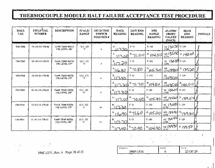
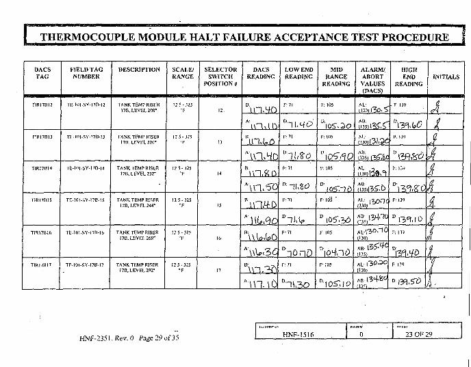
7.0 TEST DATA SHEETS
DACSTAG
TIRI7B0I
T1R17B02
T1RI7B0J
TIR17B04
1IRI7B05
FIELD TAGNUMBER
TL-IO1-SY-17B-OI
T0-I0l-SY-I7n-02
TC-1OI-SY-I7B-O3
1F-1OI.SY-I7B-O4
ni-HH-SY-I7B-O5
DESCRIPTION
TANK TEMP RISER17B.LF.VEL4"
TANK TEMP RISERI7B, LEVEL 16"
TANK TEMP RISER17B, LEVEL 28"
TANK TEMP RISER17B, LEVEL 52"
TANK TEMP RISER17B, I.IIVtL 70"
SCALE/RANGE
12 5-325"F
12 5-325"F
12 5-325T
125-325"F
12 5-325"F
SELECTORSWITCH
POSITION #
1
2
3
4
5
DACSREADING
A!i\u<-fo
A ^ _ „
AUUflou\n,so
LOW ENDREADING
F: 71
F:7I
F: 71
F:71
F:71
MIDRANGE
READING
F; 10S
Fi 105
F; 105
F; 105
D' 105.10F 105
ALARM/ABORTVALUES(DACS)
(130)
» ^
ALi 13,0.40(130)
( 1 3 5 ) ' ^ ' '
mo, 1 3 0 ' 5 2
(135)l3^06
M. 131.10(130)
AB \"i(f^(135)
HIGHEND
READING
F: 139 "
F. 139
D 1^0,00F;I39
PU39
F 139
INITIALS
kkij
I4i4A
HNF-2351, Rev. 0 Page 27 of 35HNF-1516 o 2! OF 29
I THERMOCOUPLE MODULE HALT FAILURE ACCEPTANCE TEST PROCEDURE |
DACS
TAG
TIR17H06
TIRI7IS07
T1R17H08
T1R17B09
TIRI7RI0
TIR17BII
FIELD'TAG
NUMBER
Th-101-SY-17B-06
TR-I0I-SY-I7B-07
TE-1OI-SY-17U-O8
ri;-10I-SY-l7B-OT
TU-I0I-SY-I7B-I0
ri:-im-SY-i7B-n
DESCRIPTION
TANK TEMP RISl'.RI7B, LEVEL 100"
TANK TEMP RISER17B, LEVEL 112"
TANK TEMP RISER17B.LLVEL124"
TANK TEMP RISERI7B, LEVEL 148"
TANK TEMP RISERI7B. LEVEL 172"
TANK TEMP RISER178, LEVEL 196"
SCALE/
RANGE
12.5-325"F
12.5-325T
12.5-325•F
12.5-325•F
12 5-325T
12 5-325•F
SELECTOR
SWITCH
POSITION tt
7
ft
9
10
II
DACS
READING
R:
\V~\\OC
Bi 1-I.3O
AULSOB.
Bin^oA \n,oc
A:\\UfloB;\nnoA:\nM0
LOW END
READING
1- 71
^ ~~1 [ \ 0 &
F: 71
F: 71
°i\noF. 71
D lossr.7i
F; 71
MID
RANGE
READING
F. 105
D {O^SO
F:IO5
F 105
F; 105
r, 105
D |05",00
F; 105
ALARM/
ABORT
VALUES
(DACS)
AL-130.3(130)
(135)
(130)
AL- i3&,o£(130)
(130)
(135)
AL: ftO-57"(130)
1135)
HIGH
END
READING
1 Pi I3">
D J LfQt d0
V: 139
F 139
F- 139
r . 131
F. 139
D {2&,'%l>
INITIALS
i
iA\is
I
HNF-2351, Rev. 0 Page 28 of 35 HNF-1516 0 22 OF 29
THERMOCOUPLE MODULE HALT FAILURE ACCEPTANCE TEST PROCEDURE
DACSTAG
T1RI7BI2
TIK17BI3
TIR17B14
TIR17D15
TIR17DU)
TIRI7UI7
FIELD TAGNUMBER
TE-I0I-SY-17B-I2
T1-I0I-SY-17H-13
TE-101-SY-I7B-14
TDtOl-SY-170-15
TE-101-SY-I7D-16
TF-I0I-SY-17B-I7
DESCRIPTION
TANK TEMP R1SF.R17B. LEVEL 208"
TANK TFMP RISER1711. LEVEL 220"
TANK TEMP RISERI7B, LEVEL 232"
TANK TEMP RISER17B. LEVEL 244"
TANK TEMP RISERI7B, LEVF.L268"
TANK TEMP RISERI7B, LEVEL 292"
SCALE/RANGE
12 5-325
12 5-.125"F
12 5-325•F
12 5-325"F
12 5-325"F
12 5-325*F
SELECTORSWITCH
POSITION <f
12
13
14
15
16
17
DACSREADING
A:u-Mr>
"in.uaA\n»HD*n.«oA\n.5O
AHUAD
"Wlo.loO
\\—i "^TN
LOW ENDREADING
F: 71
nHMOr- 7i
F-71
nnu%oF: 71
F-71
ai0nD
D~U3O
MIDRANGE
READING
F: 105
F: 105
F: 105
F: 105 "
F 105
nio4nc>F 105
D i o£~> l o
ALARMSABORTVALUES(DACS)
AL: ,
(I30)I30'S
030,131,36
035) |T,5i&£
AL: 2
(135)135".&
AB. \y^no
(135)
AL |3O«3C(130)
AB 1 3 4 . ^
HIGHEND
READING
F, 139
F. I39
F: 139
F:I39
P: 139
F- 139
INITIALS
Ai
4
JiiiIII
HNF-2351,Rev. 0 Page 29 of 35 HNF-1516 0 23 OF 29
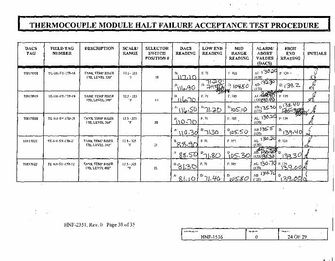
I THERMOCOUPLE MODULE HALT FAILURE ACCEPTANCE TEST PROCEDURE |
DACSTAG
TIR171H8
T1RI7BI9
TIR17B20
TIRI7H2I
T1R17B22
FIELD TAGNUMBER
TU-IOI-SY-I7B-I8
IIMOI-SY-I7R-19
TO-1O1-SY-I7B-20
TF-1O1-SY-17B-21
TE IOI-SY-17B-22
DESCRIPTION
TANK TEMr RISERI7B, LEVEL 326"
TANK TEMP RISER171J. LEVEL 340"
TANK TEMP RISERI7B, LEVEL 364"
TANK TEMP RISERI7B, LLVEL392"
TANK TEMP RISER17B. LEVEL 402"
SCALE/RANGE
123-325= F
12.5-325"I-
12.5-325"F
12 5-325"I-
12 5-325•F
SELECTORSWITCH
POSITION n
is
V)
20
21
22
DACSREADING
XV
B\\ontDA \ \ 0 3 o
O li ^ — ^
LOW ENDREADING
F. 71
F. 71
°1U2DF. 71
F; 71
1 (\ Q\-S
F: 71
MIDRANGE
READING
F:105
r. 105
D/oS"iJO
r? 105 p
F. 105
Dt05-.3OF; 105
ALARM/ABORTVALUES(DACS)
(130) .
(13S)
(135)
AL: 130 » £(130)
(135)
(130)
(135)^.39
(130)
(135)
HIGHEND
READING
F- 139 •
F: 139
F: 139
F: 131
F. 139
INITIALS
,1
Ajl
ii
i4i
HNF-235l,Rev. 0 Page 30 of 35
HNF-1516 0 24 OF 29

| THERMOCOUPLE MODULE HALT FAILURE ACCEPTANCE TEST PROCEDURE |
DACSTAG
T1R17C07
TIR17CIS
TIR17C20
TBSTC10
TU5TCI7
T8STC24
FIELD TAGNUMBER
T1-.-101-SY-I7C-07
TK-10I-SY-17C-I8
TIMOI-SY-17C-20
TE-101Pr 10
TE-101Pr 17
Tf-IOIPr24
DESCRIPTION
TANK TEMP RISHR17C. LEVEL M2"
TANK TCMr RISV.RI7C, LEVEL 340"
TANK TEMP RISER17C. LEVEL 392"
TANK BOTTOMTHERMOCOUPLE
TANK BOTTOMTHERMOCOUPLE
TANK BOTTOMTHERMOCOUPLE
SCALE/RANGE
70-140 "F
70-140 T
7 0 - 1 4 0 - F
50-200 "F
50-200 "F
50-200 *!••
SIGNALINPUT '
CONNECTNTOINTS
CMSITB4
TERMS 7, 8
OMS1TRo
TliRMS l<>, 17
OMSITl!5
TERMS 19, 20
TBX-101+ I0&-10
TBX-101+ I7&-I7
1BX-I01*24 & -24
DACSREADING
*. i n . o oB:l\U3O
B 9n.ut>
B: &O, O
A Sto. o
A : % , 3
B ma oA WO,O,
LOW ENDREADING
F;7I
r. 71
F. 71
F-55 "*
D. 55, ? ,F:55
1): I T W ^
MIDRANGE
READING
F 105
D IOhO.1?
T: 105
F 105
o. 105", 3 0F 125
F-. 125
F. 125
ALARM/ABORTVALUES(DACS)
Al.1 N/A !
ABN/A
AL: N'A
AB; N/A
AL. N/A
AM. N/A
AL. N/A
!>ABN/A
AL H/A
AB H/A
AL. N/A
AB. N/A
HIGHEND
READING
F- 139
r 139
F: 139
r. 195
D. / i3 . 6F. 195
F. 195
n./f5,5
INITIALS
i
i.i
HNF-2351, Rev. 0 Page 31 of 35 HNF-1516 0 25 OF 29

THERMOCOUPLE MODULE HALT FAILURE ACCEPTANCE TEST PROCEDURE
8.0 ATTACHMENTS
Attachment 1, Exception List
Attachment 2, Measurement and Test Equipment Record Sheet
Attachment 3, Final Procedure Acceptance Sheet
HNF-15I6 0 26 OF 29
HNF-2351, Rev. 0 Page 32 of 35

I THERMOCOUPLE MODULE HALT FAILUREACCEPTANCE TEST PROCEDURE |
EXCEPTIONNUMBER
(D
STEPNUMBER
L\. if
LI. IZ-
C&S7/2O& Ti
EXCEPTION DESCRIPTION
ZifUpEI^Z, ;'n Mt£l
A^^t - (Looto/ £e't(<.£
f)
E:y
/««• V
T?) if
EXCEPTION RESOLUTION
AT f ^ t e
tf A-< v . . a . ,
Lit. ^ w dc'&et
• ^ ^ <,
TLns? do •
^ • / / ^ , . ; . ,
(^•/pre^
)
U
-e
*/[
RESOLUTIONAPPROVED
BV:
/ / /
DATE RESOLVED
i ^^ ^
Attnchmciil I: F.xcpptinn l,ist
HNF-2351,Rev.O Page 33 of 35
HNF-1516 0 27 OF 29
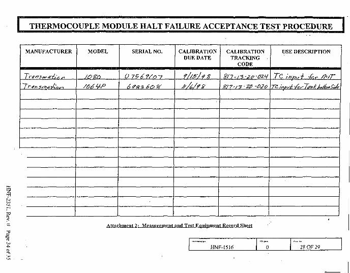
I THERMOCOUPLE MODULE HALT FAILURE ACCEPTANCE TEST PROCEDURE
<o
MANUFACTURER MODEL SERIAL NO.
0 756?/o~7
CALIBRATIONDUE DATE
f//S?Jf %
//A/rz
CALIBRATIONTRACKING
CODE
K/7'i?-&> -Mo
USE DESCRIPTION
7~C input -fnv /h/T~
Attncliment 7.: Mensnrement nntl Test Equipment Record Sheet
HNF-1516 0 28 OF 29

THERMOCOUPLE MODULE HALT FAILURE ACCEPTANCE TEST PROCEDURE
Completion of this procedure has demonstrated that:
• The Data Acquisition and Control System (DACS) provides satisfactory monitoring and alarming ofthe thermocouple module halt failure.
- • The modified DACS screens provide a satisfactory operator interface.
• A record of all noted deficiencies was kept on Attachment 1, Exception List, and all recordedexceptions have been resolved and the resolutions approved.
Approved by:
ivG.J. GauoJ^ Cognizant Engineer Date
L.S: Krogsrud, Nuclear Safety Date
R.R/rrue, Quality Assurance Date
Attachment 3: Final Procedure Acceptance Sheet
HNF-1S16 0 29 OF 29
Paop'lSnf
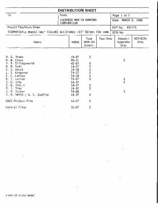
DISTRIBUTION SHEETTo
Project Title/Work Order
THERMOCOUPLE MODULE HALT FAILURE
Name
W. G. BrownD. W. Crass0. A. E i l ingswor thA. M. ErmiG. J . GauckL. S. KrogsrudD. C. LarsenR. E. LarsenD. D. TateR. W. T r u i t tR. R. TrueR. P. TuckerS. 0. Smith / A. C. Zuehike
DACS Project F i l e
Central F i les
From
LOCKHEED MARTIN HANFORDCORPORATION
ACCEPTANCE TEST REPORT FOR TANK
MSINText
With AllAttach.
Page 1 of 1
Date MARCH 5, 1998
EDT No. 621176
ECN No.
Text Only Attach./Appendix
Only
EDT/ECNOnly
T4-07 XH6-11 XR2-87 XL6-37 XT4-08 XT4-07 XT4-08 XT4-07 X XL6-37 XL6-37 XT4-07 XT4-08 XL6-37 X
L6-37 X
Bl-07 X
A-6000-135 (01/93) WEF067
Copyright © 2022 FDOKUMEN