Thesis : Nut Cracking Efficiency in Palm Oil Mill
55
NUT CRACKING EFFICIENCY IN RIPPLE MILL By: ABDUL RAZAK BIN AB HALIM (Matrix no. : 111509) Supervisor: Associate Professor Dr. Roslan b. Ahmad Industrial Supervisor: Mr Shahrizan bin Sulaiman (Mill Manager) June 2015 (Academic Year 2014/2015) This dissertation is submitted to Universiti Sains Malaysia As partial fulfillment of the requirement to graduate with honors degrees in BARCHELOR OF ENGINEERING (MECHANICAL ENGINEERING) School of Mechanical Engineering Engineering Campus Universiti Sains Malaysia
-
Upload
independent -
Category
Documents
-
view
1 -
download
0
Transcript of Thesis : Nut Cracking Efficiency in Palm Oil Mill

NUT CRACKING EFFICIENCY IN RIPPLE MILL
By:
ABDUL RAZAK BIN AB HALIM
(Matrix no. : 111509)
Supervisor:
Associate Professor Dr. Roslan b. Ahmad
Industrial Supervisor:
Mr Shahrizan bin Sulaiman (Mill Manager)
June 2015
(Academic Year 2014/2015)
This dissertation is submitted to
Universiti Sains Malaysia
As partial fulfillment of the requirement to graduate with honors degrees in
BARCHELOR OF ENGINEERING (MECHANICAL ENGINEERING)
School of Mechanical Engineering
Engineering Campus
Universiti Sains Malaysia

2
DECLARATION
This works have not previously been accepted in substance for any degree and is not
being concurrently submitted in candidature for any degree .
Signed ………………………….. (Abdul Razak bin Ab.Halim)
Date …………………………..
STATEMENT 1
This thesis is the result of my own investigations, except where otherwise stated. Other
sources are acknowledged by giving explicit references. Bibliography/ references are
appended.
Signed ………………………….. (Abdul Razak bin Ab.Halim)
Date …………………………...
STATEMENT 2
I hereby give consent for my thesis, if accepted, to be available for photocopying and for
interlibrary loan, and for the title and summary to be made available to outside
organizations.
Signed ………………………….. (Abdul Razak bin Ab.Halim)
Date …………………………..

3
ACKOWLEDGEMENTS
In the name of Allah, the Most Gracious, the Most Merciful. Praise to Him the
Almighty that in His Will and given strength, I had managed to complete the Final Year
Project (FYP). First and foremost, I would like to express my sincere gratitude to my
project supervisors, Prof. Madya Dr. Roslan Ahmad and Mr. Shahrizan Sulaiman for their
valuable guidance and supervision and countless hours spent in sharing their insightful
understanding, profound knowledge and valuable experiences throughout the project.
This research could not have been completed without them who not only served as my
supervisor, but also encouraged and challenged me through the research process.
I am grateful to the Final Year Project (FYP) coordinator, Dr. Yusof bin Idroas
who had dedicatedly provided me with additional support and encouragement throughout
the project. Besides, I would also like to thank the authority of Universiti Sains Malaysia
(USM) and Kilang Miyak Sawit Kamunting Sdn.Bhd for providing me with all the
necessary facilities for the completion of this project. Last but not least, I would like to
pay high regards to all personel who have directly or indirectly support and contribute for
the success of this project. Thank you.

4
Contents
LIST OF TABLES ........................................................................................................................... 6
ABSTRACT ................................................................................................................................. 10
CHAPTER 1................................................................................................................................ 11
INTRODUCTION ................................................................................................................... 11
1.1 Research Background ................................................................................................ 11
1.2 Problem statement ................................................................................................... 15
1.3 Objectives .................................................................................................................. 16
1.4 Scope of Work ........................................................................................................... 16
1.5 Thesis Outline ............................................................................................................ 17
CHAPTER 2 ............................................................................................................................ 19
LITERATURE REVIEW ........................................................................................................ 19
2.1 Introduction .............................................................................................................. 19
2.2 Type of Nut Kernel and effect of Free Fatty Acid (FFA) ............................................ 21
2.3 Process of Kernel Palm Oil ........................................................................................ 23
2.4 Types and performance of cracker ........................................................................... 24
CHAPTER 3................................................................................................................................ 26
Materials and Methodology .................................................................................................... 26
3.1 Mechanical Testing ................................................................................................... 26
3.2 Microstructural Observation ..................................................................................... 28
3.3 Simulation (Solid work) ............................................................................................. 29
3.4 Data measurement on Ripple Mill ............................................................................ 33

5
CHAPTER 4................................................................................................................................ 35
Result and Discussion ............................................................................................................... 35
4.1Percantage of carbon in the rod ...................................................................................... 35
4.2 Maximum Load of Palm Oil Nut ...................................................................................... 36
4.3 Deformation of the Rod in Rotor .................................................................................... 39
4.3.1 Stress (Von Misses Stress) ....................................................................................... 39
4.3.2 Displacement of Deflection ..................................................................................... 41
Figure 4.10 New Distance of Baffle plate ............................................................................. 42
4.4 Nut Cracking Efficiency in Ripple Mill: ............................................................................ 43
4.4.1Cracking efficiency based on variable frequncy(Hz) speed of rotor ........................ 43
4.4.2 Cracking Efficiency based on variable of Spacing between rotor and ripple plate:
.......................................................................................................................................... 45
CHAPTER 5................................................................................................................................ 47
CONCLUSION ......................................................................................................................... 47
Appendices ............................................................................................................................... 49
Appendix 1: ........................................................................................................................... 49
Appendix 2: ........................................................................................................................... 51
Appendix 3: ........................................................................................................................... 54

6
LIST OF TABLES
Tables Pages
Table 4.1 Result Compressive horizontal testing for nut palm oil 40
Table 4.2 Result Compressive vertical testing for nut palm oil 42
Table 4.3 : Average Percentage Cracking Efficiency of Nut 51
Table 4.4 : Average Percentage Cracking Efficiency of Nut 53

7
LIST OF FIGURES
Figures Pages
Figure 1.1 Schematic Diagram of Ripple Mill 11
Figure 1.2 Rotor of Ripple Mill 13
Figure 1.3 Ripple Plate of Ripple Mill 13
Figure 2.1 Cross Section of Oil Palm Fruit 19
Figure 3.1 (a) Horizontal (b) Vertical 25
Figure 3.2 UTM Machine(Compress) 25
Figure 3.3 Nut Fruit Palm cracked 26
Figure 3.4 Desplay result 26
Figure 3.5 Rod Carbon Steel 27
Figure 3.6 Rod Fractured 27
Figure 3.7 Fractured of Rod 28
Figure 3.8 Measure the gage length 28
Figure 3.9 Scanning Electron Machine 29
Figure 3.10 Cross Section Of Carbon Steel 30
Figure 3.11 Ripple Mil 37
Figure 3.12 Inverter 37
Figure 3.13 Uncracked Nut 38
Figure 3.14 Weighter 38

8
NOMECLATURE
LIST OF SYMBOLS
English Symbols
E Young Modulus Pa
A Area
L Length m
D Diameter m
Greek Symbols
Ϭ Stress Pa
ɛ Strain -

9
ABSTRAK
Kajian kes yang dilakukan di Kilang Minyak Sawit Kamunting Sdn.Bhd,
Taiping bertujuan untuk meningkatkan penghasilan minyak sawit dengan melakukan
penambahbaikan pada mesin ‘ripple mill’. Mesin ‘ripple mill’ merupakan sebahagian
dari alatan dalam kilang sawit bertujuan untuk memisahkan tempurung dan isirong
biji sawit. Skop kajian adalah untuk mengkaji peratus kecekapan tempurong dan
isirong yang hancur. Peratus kecekapan ini dapat ditingkatkan dengan melakukan
penambahbaikan pada mesin sedia ada. Mengikut rekabentuk mesin ‘ripple mill’ sedia
ada, jangka hayat ‘ripple rod’ didapati pendek disebabkan perledingan. Antara
parameter yang dijangka memberi kesan pada peratus kecekapan tempurung dan
isirong sawit yang hancur dan peledingan ialah kelajuan optimum pemutar, jarak
sesuai antara pemutar dan plat ‘ripple’, kekuatan bahan rod dan jarak antara plat
‘baffle’. Kajian parametrik berdasarkan eksperimen dan simulasi dilakukan bagi
menentukan kecekapan peratusan tempurung dan isirong yang pecah dalam mesin
‘ripple’. Pemerhatian mikrostuktur menggunakan SEM dan ujian tegangan
menggunakan mesin UTM dilakukan ke atas bahan untuk masing-masing menentukan
kandungan dan kekuatan rod. Ujian mampatan ke atas buah sawit dilakukan untuk
anggaran beban yang ditindaki pada rod. Data dari esperimen dimasukkan dalam
kajian simulasi menggunakan SOLIDWORKS. Kajian kes yang dilakukan mendapati
faktor kelajuan optimum pemutar, jarak sesuai antara pemutar dan plat ‘ripple’,
kekuatan bahan rod dan jarak antara plat ‘baffle’ memberi kesan pada peratus
kecekapan tempurong dan isirong yang hancur.

10
ABSTRACT
The case study was carried out at Kilang Minyak Sawit Kamunting Sdn.Bhd,
Taiping aiming towards increasing the production of palm oil. This could be achieved
by improving the ripple mill machine. The ripple mill machine is part of the palm oil
factory and is used to separate the palm kernel and its shell. The scope of the study is
to investigate the efficiency of palm kernels and shell breakage. The efficiency could
be increased by improving the existing machine. Based on the design of the existing
ripple mill machine, the ripple rod has shorter shelf life due to bending of the rod.
Among the parameters that is expected to affect the efficiency of the palm kernels and
shell breakage and bending of the rods are the optimum speed of the rotor, the
distance between the rotor and the ripple plate, the strength of the rod material and the
spacing between the baffle plates. Parametric study based on the experimental and
simulation was done to determine the efficiency of the palm kernels and shell
breakage in the ripple mill machine. Microstural observation using SEM and tensile
test by using UTM were performed to determine the constituent of the material and
the strength of the rod respectively. Compression test on palm fruits is carried out to
obtain the estimated load being subjected to the rod. Data from the experimental work
is inputed in the simulation study using SOLIDWORKS software. The case study that
was carried out indicate that the optimum speed of the rotor, the distance between the
rotor and the ripple plate, the strength of the rod material and the spacing between the
baffle plates have some effect on the efficiency of the palm kernels and shell
breakage.

11
CHAPTER 1
INTRODUCTION
1.1 Research Background
In general, a palm oil mill produces crude palm oil and kernels as primary
products and biomass as secondary product1. Processes in palm oil mill includes six
parts which is palm bunches receiving, sterilizer, threshing, mashing and pressing,
crude oil clarifying and palm oil kernel recovery 2.The overview of the process is
shown in Figure 1.1.
Figure 1.1 : Palm oil mill process flow diagram
1 http://lipidlibrary.aocs.org/processing/palmoil/index.htm
2 http://www.palmoilextractionmachine.com/product/palm_oil_refinery_process/palm-oil- mill-
85.html
Ripple
Mill

12
The process is started with fruits receiving which is collecting the ripe fresh
cluster from the orchard. Then, the palm fresh fruit bunch (FFB) are airtight sterilized
in sterilizer, injecting direct steam. Sterlization or fruit cooking weakens the pulp
structure, softening it and making it easier to detach the fibrous material and its
contents during the digestion process. The high heat is enough to partially disrupt the
oil-containing cells in the mesocarp and permits oil to be released more readily. After
that the fruits are sent to the thresher. The purpose of threshing is to separate the palm
fruit from the FFB. Palm oil mill process of mashing and pressing will separate the
pulp and nut and crush the palm pulp2. The steam heater is also installed in the
masher. Palm oil mill process of oil clarifying machine-pressed crude oil first diluted
with water washing, through settlement and filtration. At this stage, the fiber material
will be removed from the oil, and then carry out continuous settlement. The whole
outcome is divided into two parts which is oil and sediment to process more. Last but
not least, palm kernel recovery press cake broken by breaking screw conveyor and
transported into the fiber separation air net and fiber polishing roller for fiber
separating2.

13
In addition, nut kernels are produced in this station where the press cake
from the digester is fed to a vertical column (depericarper) where air is channeled to
lift the fibre, thus separating the fibre from the nuts. The nuts are passed to a polishing
drum at the bottom of the depericarper, where pieces of stalks are removed. A
nutcracker cracks the nuts after the conditioning and drying process. A ripple mill is
also used instead of nut cracker. The mixture of cracked nuts and shells are separated
via a winnowing system, followed by a hydrocyclone or a clay bath.2
Palm kernel is a very important part of oil palm produce which is obtained
by cracking of palm nuts and separation of the kernels from the shell (Ajewole, 2014).
In order to produce nut cracking eficiency, a machine has to be used by cracking of
palm nut named as ripple mill (Figure 1.2). In general, the component of ripple mill
consist of the outher disc, ripple mill plate, rod bar and rotor disc3.
Figure 1.2 : Schematic Diagram of Ripple Mill
3 Refer ; http://agrindo.co.id/sparepart-ripple-mill.html

14
The ripple mill machine is placed in kernel plant station. This machine is
used to break the palm nut that regardless of the shell. The process starting with the
nuts enter the top of the mill and are impact several times between stationary plates
and the turning rotor as in Figure 1.1. The rotor imparts the velocity and the impact
forces crack the nut of palm. Besides, other functions of the ripple mill are used for
the pre-grinding of coal, plastics and chemicals prior to micro-fine grinding, coarse
animal feed grinding and other shelling or hulling applications.
To enhance the percentage palm nut cracking effficincy, the impinging
velocity that gives maximum cracking efficiency of a vertical shaft centrifugal palm
nut cracking machine are used. A nut cracking energy instrument which consists of a
hammering mass falling vertically on palm nuts placed on a base was used to
determine potential energy required to crack the nuts (Ajewole, 2014). Besides, static
impact method is another method in order to investigate into the energy demand for
cracking of palm nuts (Esua et.al, 2015) .
In this project, the focus is to determine the suitable rod material and the
spacing of the baffle plate used in the rotor of ripple mill in order to increase the shelf
life of the rod from bending and damages. In addition, parametric studies on the
optimum centrifugal speed of ripple mill and spacing or distance between the rotor
and the ripple plate will be investigated. These parameters are suspected to affect the
percentage cracking efficiency of the ripple mill machine.

15
1.2 Problem statement
The case study was carried out at Kilang Minyak Sawit Kamunting Sdn.Bhd,
Taiping. One of the main problem that affect the productivity of the palm oil is the
quality of palm kernels and shell breakage or the nut cracking efficiency. This
problem is associated with the ripple mill machine. In relation to that, the field work
found that shorter shelf life of rotor rods due to bending and damages (Figure 1.3).
Probably the bending of rotor rods might be due to the materials itself or the spacing
between the baffle plates. Other factors that might affect the quality of the palm
kernels and shell breakage are the speed of the ripple rotor and the spacing of the rotor
and the ripple plate (Figure 1.2). This assumption needs to be investigated and
verified. Hence, observation on the existing operation of the machine at the field and
getting some data for the basis of the study is necessary.
Figure 1.3 :Rotor of Ripple Mill
rod bar
Distance/ spacing
of baffle

16
1.3 Objectives
The main objective of the research is to increase the quality of palm kernels
and shell breakage or the efficiency of the nut cracking in ripple mill. This can be
accomplish through the following objectives.
1. To determine the suitable rod material and baffle spacing for use in
the rotor of ripple mill in order to increase the shelf life of the rod.
2. To assess the operation of ripple mill through parametric study which
is the speed of the rotor and the distance of the rotor and the ripple
plate.
1.4 Scope of Work
The field work is carried out at Kilang Minyak Sawit Kamunting Sdn.Bhd,
Taiping. The area of focus is on ripple mill under the Kernel Plant Station in Palm Oil
Mill. The scope of the case study is on the nut cracking efficiency to obtain data of
parametric study in ripple mill and material of rotor used in ripple mill. The
observation and data collection is done in the field whereas material testing is
performed at USM. Experimental and simulation works are carried out for validation
and comparison.

17
1.5 Thesis Outline
Basically there are five chapters in this thesis which consisted of
introduction, literature review, methodology, results and discussion, and conclusion.
Each chapter plays an important role in assisting the readers to have better
understanding about research which is carried out.
The general outline of the palm oil mill processes, the problem statement
and the objectives of the work is covered in the introduction. The percentage nut
cracking efficiency of kernel palm oil is futher elaborated in the literature review. In
addition, it will further clarify about the type of palm oil nuts and types of other
cracker used.
For methodology section it will discuss about the data collection and testing
done which include the compression load of palm oil nuts, tensile test on the rotor rod
by Universal Testing Machine(UTM). Besides that, it will also discuss about the
procedure to run simulation on the bending of rotor rod by SOLIDWORKS sofware.
Lastly, the procedure to run experiment in palm oil mill on ripple mill in Kilang Sawit
Kamunting Sdn.Bhd.

18
In the section of results and discussion, it shows all the results obtained from
the experimental works and data collection in the field. Results from silmulation
works will be validated and compared. The graph percentage of nut cracking-speed of
rotor ripple mill will be analysed and discussed. The experimental investigation and
anlysis will be concluded and evaluated in the last chapter by mapping it to the
objectives of the thesis.

19
CHAPTER 2
LITERATURE REVIEW
2.1 Introduction
Today, 4.49 million hectares of land in Malaysia is under oil palm
cultivation; producing 17.73 million tonnes of palm oil and 2.13 tonnes of palm
kernel oil. Malaysia is one the largest producers and exporters of palm oil in the
world, accounting for 11% of the world's oils & fats production and 27% of export
trade of oils & fats. The industry provides employment to more than half a million
people and livelihood to an estimated one million people.
Oil palm is the most efficient oilseed crop in the world. One hectare of oil
palm plantation is able to produce up to ten times more oil than other leading oilseed
crops. (Figure 2.1). Indonesia and Malaysia produce about 85% of the world’s palm
oil. Other producer countries include Thailand, Columbia, Nigeria, Papua New
Guinea and Ecuador.

20
Figure 2.1 : Oil Palm Efficiency vs Other Major Oil Crops
(Source: Oil World 2013) (http://www.simedarby.com/upload/Palm_Oil_Facts_and_Figures.pdf)
Nowdays, oil palm is a great economic asset (Elaeis guineensis Jacq.). It is
acclaimed to be the richest vegetable oil plant because many products can be derived
from the oil palm; this includes palm oil, palm kernel oil, palm kernel cake, fibre,
palm wine, fatty alcohol, broom,and wood plank.(Ndukwu & Asoegwu, 2010).
In additiom, palm kernel oil widely use which is the kernels are usually
processed in to obtain oil and cake. The oil is used for making soap, cosmetics,
glycerol, margarine, explosives, refined edible vegetable oil, etc (Esua et al., 2015).
21
In general, a reliable energy-related data and a new approach for the
effective design of palm kernel nut cracking machine is therefore not only necessary
but also important to revitalize the production of palm kernel in other to meet up with
ever increasing industrial demand of its oil.(Esua et al., 2015). So that, the optimal
performance of the cracker is based on cracker efficiency and kernel breakage factor.
It is a compromise between high cracking efficiency and low kernel breakage factor
or ratio.(Ndukwu & Asoegwu, 2010).
2.2 Type of Nut Kernel and effect of Free Fatty Acid (FFA)
The oil palm has many species, as stated in journal and in literature,
classified into two major species widely being cultivated; dura and pisifera. Dura is
thick shelled with thin mesocarp whereas the pisifera species is thin shelled with
thicker mesocarp (Esua et al., 2015). Eventually, in other journal stated three varieties
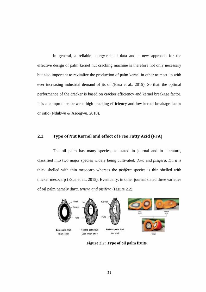
of oil palm namely dura, tenera and pisifera (Figure 2.2).
Figure 2.2: Type of oil palm fruits.

22
Dura is characterized by thin mesocarp, thick endocarp (shell) with generally
large kernel. The duratype is genetically homozygous and dominant for shell. It is
denoted by DD. Tenerapossesses thin mesocarp, thin endocarp with large kernel. This
is a dual-purpose palm for the production of mesocarp oil and kernel.
In addition, palm kernel contains 46% – 54% oil with a Free Fatty Acid
(FFA) of about 4% and this oil is more stable than palm oil. Cracking palm nuts to
release the kernels is a critical step that affects the quality of palm kernel oil. The
level of free fatty acids (FFA) is higher in broken kernels than in whole kernels,
therefore breakage of kernels should be kept as low as possible according to Poku,
2002.
Due to the global demand of palm kernel and its by-products, efforts have
been geared towards an improved method of palm kernel extraction. Locally made
palm kernel nut crackers are characterized by high incidence of kernel splitting. Split
kernels readily grow mould and develop high free fatty acid content which
compromises the oil quality (Esua et al., 2015).

23
2.3 Process of Kernel Palm Oil
The palm fruit is drupe oval in shape and contains kernel which is the seed
(nut). The kernel is surrounded by the fruit wall made up of hard shell (endocarp),
fibrous fruit pulp or oil bearing tissue (mesocarp) and the skin as shown in Figure 2.3
(Hamdan et al, 2000). The nuts of oil palm is dried and cracked into palm kernel and
shell, and the kernel is separated into palm kernel oil (PKO), palm kernel meal
(PKM), and water (Esua et al., 2015).
Figure 2.3 : Cross Section of Oil Palm Fruit
In addition, harvested palm bunches undergo processing stages of
sterilization, stripping, digestion, and palm oil extraction. Palm nuts and fibres are left
as residues. The nuts are dried and cracked into palm kernel and shell. It is separated
into palm kernel oil (PKO), palm kernel meal (PKM), and water (Ndukwu &
Asoegwu, 2010).

24
Last but not least, the nuts were subjected to cracking using the equipment
developed and visual observation was used to assess the level of cracking as follows;
completely cracked (CC), completely cracked with slight damage (CCD), cracked
without nut separation (CWS), unable to crack (UC) and smashed (SM) (Esua et al.,
2015).
2.4 Types and performance of cracker
Actually there many types of cracker and the oldest method of cracking is
done by placing the nut on top of the stone and striking it with another stone with an
impact force, causing the shell to split along the line of impact and the nut is
handpicked. This method of cracking is labour-intensive and less productive though
the hand-cracked kernels attract high costs due to the high grade quality oil recovered
since the level of kernel breakage is low. It also exposes the operator to the danger of
flying shells which can injured the eye or any part of the body (Ndukwu & Asoegwu,
2010).
However, the modern crackers are of two types, the hammer-impact and the
centrifugal-impact types. The hammer-impact type breaks or cracks the nut by impact
when the hammer fail on the nut, while the centrifugal-impact nut cracker uses
centrifugal action to crack the nut (Ndukwu & Asoegwu, 2010).

25
In addition, the impinging velocity that gives that maximum cracking
efficiency of a vertical shaft centrifugal palm nut cracking machine was determined in
this study. A nut cracking energy instrument which consists of a hammering mass
falling vertically on palm nuts placed on a base was used to determine potential
energy required to crack the nuts (Ajewole, 2014).
Eventually, a mathematical model for predicting the cracking efficiency of
vertical-shaft palm nut cracker was presented using dimensional analysis based on the
Buckingham’s π theorem (Ndukwu & Asoegwu, 2011). Some researchers
(Degrimencioglu, Srivastava 1996; Shefii et al. 1996; Mohammed 2002; Ndirika
2006) used the dimensional analysis based on the Buckingham’s π theorem as
veritable instrument in establishing a prediction equation of various systems.
Therefore the present study is under-taken to establish a mathematical model for
predicting the cracking efficiency of vertical-shaft centrifugal palm nut cracker using
the dimensional analysis (Ndukwu & Asoegwu, 2011).
In conclusion, the optimal performance of the cracker is based on cracker
efficiency and kernel breakage factor. It is a compromise between high cracking
efficiency and low kernel breakage factor or ratio (Ndukwu & Asoegwu, 2010).
Cracking efficiency this is the ratio of completely cracked nuts to the total nuts fed
into the hopper (Ndukwu & Asoegwu 2010). Palm kernel is an important part of oil
palm produce, which is obtained by cracking of palm nuts and separation of the
kernels from the shell.(Ajewole, 2014)

26
CHAPTER 3
Materials and Methodology
3.1 Mechanical Testing
Mechanical testing was carried by using a Universal Testing Machine
(UTM) to determine the force needed to break the nut kernel and also to determine the
properties of a rotor rod.
3.1.1 Compression test on kernel nuts
The kernal nuts were tested with horizontal and vertical position as in Figure
3.1 to obtain the maximum breakage force. Each position were tested five times to
obtain repeatability and maximum force.
Figure 3.1: Horizontal and vertical position of kernal nuts

27
Figure 3.2: Compression of kernal nut using UTM
The cracking of the kernel nut was quasi-statically compressed until the nut
breaks and cracks as shown in figure 3.3. A load displacement curves is automatically
displayed as in Figure 3.4.
Figure 3.3: Nut kernel cracked Figure 3.4: Results display from UTM

28
3.2 Microstructural Observation
Microstructural observation is carried out using SEM (Figure 3.9) to
determine the percentage of carbon in carbon steel. The specimen needs to ungergone
material preparation such as cleaning and polishing and also handling procedure.
Cross-section and the prepared sample is shown in Figure 3.10.
Figure 3.9: Scanning Electron Microscope
Figure 3.10 Cross Section Of Carbon Steel

29
3.3 Simulation (Solid work)
A linear simulation is performed using SOLIDWORKS software. The
purpose of the simulation is to understand the behavior of the rotor rod when
subjected to loading due to crushing of the kernels nut. The procedure of the
preprocessing is discussed as follows:
(i) Draw the rotor rod with diameter 250mm
D = diameter
D = 250mm

30
(ii) Select the Solidworks SimulationXpress. Then, set the system unit as
SI unit.
(iii) Apply the fixtures at the both end of the rod ie. the boundary condition
and then apply the loading or force which is the maximum force resisted by
the kernel nut ie. 1391.1 N
Select SI
unit
1391.1

31
(iv) Apply the material properties
(v) After that the simulation is run as instructed in the software.

32
(vi) After pre-processing, the simulation will undergone post-processing
where the rod is subjected to static bending.
(vii) The meshing of the rotor rod is ortogonal.

33
3.4 Data measurement on Ripple Mill
The kernel nut will passed through a ripple mill machine (Figure 3.11) with
a capacity of 9 ton/hour. The purpose is to split the kernel and shell. The speed of the
rotor is controlled by the inverter (in Hz) as shown in Figure 3.12.
Figure 3.11 Ripple Mil
Figure 3.11: The ripple mill machine. Figure 3.12: Speed inverter.
I. Firstly measure the uncracked nut kenel figure 12 below.
Figure 3.13 Uncracked Nut

34
II. Then get the percentage of cracking efficiency as below:
When runned 60Hz of ripple mill:
The mass of uncracked was measured 4.159g by using measurement (figure 13)
below:
Figure 3.14 Weighter
The percentage of uncracked nut kernel
So that the percentage of nut Cracking efficiency = 100% - 0.832%
= 99.17

35
CHAPTER 4
Result and Discussion
4.1Percantage of carbon in the rod
Figure 4.1 Shows the image of micro structure of carbon steel obtained from
scanning electron microscope. Details the material constituent is given in
appendix 3. The content of carbon in the rod is measured to be between 3.82% to
8.02%. Since the content of carbon is higher than 1.5% , the result indicate that
materials is consudered to be harden carbon steel.
Figure 4.1 micro structure of the rod carbon steel

36
4.2 Maximum Load of Palm Oil Nut
The palm oil nut is placed in horizontal and vertical position and subjected to
compression load by using UTM. The results of horizontal position the palm oil nut is
give in table 4.1.
Table 4.1 Result Compressive horizontal testing for nut palm oil
The load displacement curve for all the nut in horizontal position
superimposed together is shown in figure 4.2. About minimize load measured is about
308N and maximum load is 478N. The varietion migth be due to age of that nuts.
Figure 4.2 Result Compressive horizontal testing for nut palm oil

37
The results of compression test on palm oil nut placed in vertical
position is give in table 4.2. The displacement response is shown in figure
4.3 below.
Table 4.2 Result Compressive vertical testing for nut palm oil
Data in table 4.2 above shown that the vertical testing for nut palm oil which
is the minimum compressive load is 598.26721N. But, the vertical testing for nut
palm oil which was the maximum compressive load is 1391.10242N (appendix 2).

38
Figure 4.3 Result Compressive Vertical Testing For Nut Palm Oil
From the both test, the results indicate that the vertical position gave highest
compressive load compared to horizontal position. Hence, the maximum load of
1391N is taken to be input in SOLIDWORKS for simulation proposes.

39
4.3 Deformation of the Rod in Rotor
4.3.1 Stress (Von Misses Stress)
Figure 4.4 shows the stress contour(figure 4.4) of the rod subjected to
distributed load. Initially, the simulationis carried out for the rotor and position
147mm , between the baffle plate(figure 4.5).
Figure 4.4 Stress Contour
The result of the simulation is shows that the maximum stress is 22.585MPa affected
at both end of the rod (figure 4.4). Meanwhile the minimum stress is 0.13Mpa
observed at the middle of the rod.
Figure 4.5 Distance between baffle plate
Distance of
baffle plate
441mm

40
When the baffle distance is adjusted to 110.25mm between them the maximum
stress force to be 18.33MPa occurs at both end of the rod and for minimum stress is
0.171MPa at the middle of the rod (figure 4.7). Effect of changed the distance of the
baffle plate is the reduction in the stresses at the both end of the rod. The percentage
reduction in stress is 18.83%.
Figure 4.7 Stress Contour

41
4.3.2 Displacement of Deflection
Figure 4.8 shows the displacement contour of the rotor rod when the baffle plate is
147mm between them. The results shows that the maximum displacement or bending
of the rod 0.008598mm occurs at the middle of the rod..
Figure 4.8 Displacement Contour
However, when it was compared with distance of baffle plate 110.25mm
(figure 4.9) and with same force 1391.1N was applied on the rod. So that, the
maximum displacement is 0.003968mm occurs at the middle of the rod. As a result, it
shown that new design was decreased of the maximum of the displacement changed
from 0.008598mm decreased to 0.003968mm. The percentage is decreased 53.8% the
displacement of the new rod.

42
Figure 4.9 Displacement Contour
Figure 4.10 New Distance of Baffle plate
In conclusion, the distance between baffle plate has an effect on the stress and
displacement of the rotor rod. When the distance of the plate is reduce from the actual
distance of 147mm to 110.25mm the results were indicated reduction in stress and
displacement. It can be suggested that improvement on the ripple mill can be done by
adjusting the baffle plate.
441mm
110.25mm 110.25mm 110.25mm 110.25mm
Distance of
baffle plate

43
4.4 Nut Cracking Efficiency in Ripple Mill:
4.4.1Cracking efficiency based on variable frequncy(Hz) speed of rotor
Figure 4.11 shows the percentage cracking efficiency versus
frequency(speed) of the rotor. The experiments were carried out at different speed
between 40hz to 60hz. The present frequency used is 50Hz for mill(table 4.3)
throughput 9 Ton/Hour. Five data were measured at each frequency and an average
data of cracking efficiency is taken (Appendix 3).The characteristic in figure 4.11
shows that the presentspeed resulted percentage efficiency of the nut about 98.59%.
Swhen the rotor run at lower speed of 45Hz percentage of cracking efficiency is
97.48%. In addition, when the speed is furthered reduced to 40hz the percentage
cracking efficiency dropped to 94.75% .
Figure 4.11 Cracking Efficiency Versus Frequency
92
93
94
95
96
97
98
99
100
40 45 50 55 60
Percentage Cracking Efficiency(%) Versus Frequency of rotor(Hz)
current value
50hz
Frequency (Hz)
Cra
ckin
g Ef
fici
ency
(%
)

44
The results also indicate that when the speed increased to( Table 4.3) 55hz the
percentage cracking efficiency increased to 98.88% . The maximum speed 60hz of
rotor got highest percentage of nut cracking efficiency is 99.3%. From the figure 4.11
we can be conclude that the relationship between effect of the percentage cracking
efficiency with speed where was increase the value of frequency.
Table 4.3 : Average Percentage Cracking Efficiency of Nut
Frequency(Hz) Percentage Cracking Efficiency (%) Note
60 99.30 Testing 2
55 98.88 Testing 1
50 98.59 Current
45 97.48 Testing 3
40 94.75 Testing 4
The percentage cracking efficiency increased with increasing the speed of rotor.
The limitation of the inverter speed only 60Hz. Hence, the ripple mill can be allowed
to run at 60Hz to produce higher percentage of cracking efficiency.

45
4.4.2 Cracking Efficiency based on variable of Spacing between rotor and ripple plate:
The figure 4.12 shown the percentage cracking efficiency versus gap
between rotor and the ripple plate. The result in figure 4.12 is for average feed
rate of 9tan/hr and the rotor speed of 60hz. Five data were taken for each set
up experiment was run started from 0 inch as at present gap which resulted
the average cracking efficiency of 99.3% (Appendix 3). The average cracking
efficiency was 93.29% when the gap between ripple plate increased to 0.5inch.
The result shown a decreased in average cracking efficiency to 89.13% the gap
between rotor and ripple plate was adjusted to 1 inch (table 4.4).
Figure 4.12 : Percentage Cracking Efficiency(%) Versus The Gap of Ripple
plate
84
86
88
90
92
94
96
98
100
102
0 0.5 1
Percentage Cracking Efficiency(%) Versus Gap (Inch)
Gap (Inch)
Cra
ckin
g Ef
fici
ency
(%
)

46
Table 4.4 : Average Percentage Cracking Efficiency of Nut
Gap(Inch) Percentage Cracking Efficiency (%) Note
0.0 99.30 Testing 2
0.5 93.29 Testing 1
1.0 89.13 Current
It can be concluded that the gap of the rotor and the ripple plate has an effect on
the cracking efficiency. Its the gap increased, the percentage cracking efficiency
decreased. Hence, the present set up of the gap between rotor and ripple plate
resulted the appropriate percentage cracking efficiency.

47
CHAPTER 5
CONCLUSION
In conclusion, the objectives of this project are achieved:
1. The material of the rotor rod was identified as harden carbon steel of
between 3% to 8% carbon. Threatment could be done to increase the
strength of the rotor rod.
2. The suitable distance baffle plate was determined for use at the rotor of
ripple mill in order to increase the shelf life of the rod. To reduce the
bending of the rotor rod, the baffle plate can be increased from two to
three.
3. The speed of ripple mill and spacing between rotor and ripple plate after
the percentage cracking efficiency. By increasing the speed of the rotor
from 40Hz to 60Hz, the percentage cracking efficiency increased. When
the gap of the rotor and the ripple plate increased, the percentage cracking
efficiency decreased.
4. It suggested that, the optimum speed of the rotor is 60Hz and the number
of baffle plate is three.

48
References:
[1] http://lipidlibrary.aocs.org/processing/palmoil/index.htm
[2] http://www.palmoilextractionmachine.com/product/palm_oil_refinery_process/
palm-oil- mill-85.html
[3]
http://www.palmoilextractionmachine.com/product/palm_oil_refinery_process
/palm-oil- mill-85.html
[4] Ajewole, P. O. (2014). Experimental Determination of the Rotor Speed of a
Vertical Shaft Centrifugal Nut Cracking Machine, 2(5), 506–510.0
[5] Esua, O. J., Onwe, D. N., Etuk, V. E., & Okoko, J. U. (2015). Investigation
into the Energy Demand for Palm Nut Cracking Using the Static Impact
Method, 3(1), 7–14.
[6] Ndukwu, M. C., & Asoegwu, S. N. (2010). Functional performance of a
vertical-shaft centrifugal palm nut cracker, 56(2), 77–83.
[7] Ndukwu, M. C., & Asoegwu, S. N. (2011). A mathematical model for predicting
the cracking efficiency of vertical-shaft centrifugal palm nut cracker, 57(3), 110–
115.

49
Appendices
Appendix 1: 1. The horizontal strength of the nut kernel by Universal Testing
Machine(UTM):

50
2. The vertical strength of the nut kernel by using Universal Testing
Machine(UTM):

51
Appendix 2: Percentage of carbon in rod carbon steel:
Result 1:
EDAX TEAM EDS Page
s-3400 Author:
Creation: 2/27/2015
Sample Name: New Sample
Area 1
EDS1 kV: 15 Mag: 2005 Takeoff: 35.5 Live Time: 30 Amp Time: 6.4 Resolution: 125.5
Element Weight % Atomic
%
Net Int. Net Int. Error
C K 3.82 15.16 8.64 0.09
F K 1.63 4.09 24.93 0.1
MnK 0.89 0.77 5.8 0.46
FeK 92.33 78.9 448.55 0.01
CoK 1.34 1.08 5 0.63

52
Result 2:
EDAX TEAM EDS Page 1
s-3400 Author:
Creation: 2/27/2015
Sample Name: New Sample
Area 2
EDS1 kV: 15 Mag: 2001 Takeoff: 35.5 Live Time: 30 Amp Time: 6.4 Resolution: 125.5
Element Weight % Atomic
%
Net Int. Net Int. Error
C K 4.75 17.68 11.84 0.08
F K 3.9 9.18 66.77 0.05
FeK 89.83 71.98 474.82 0.01
CoK 1.53 1.16 6.23 0.45

53
Result 3:
EDAX TEAM EDS
s-3400 Author:
Creation: 2/27/2015
Sample Name: New Sample
Area 3
EDS1 kV: 15 Mag: 2000 Takeoff: 35.7 Live Time: 30 Amp Time: 6.4 Resolution: 125.5
Element Weight % Atomic
%
Net Int. Net Int. Error
C K 8.02 27.17 22.12 0.05
F K 4.12 8.82 73.18 0.04
FeK 86.66 63.17 491.19 0.01
CoK 1.21 0.83 5.28 0.64

54
Appendix 3: 1. Cracking Efficiency based on variable of frequncy(Hz):
(Fixed Variable : gap = 0 inch , throughput = 9ton/hr)
Frequency(Hz) Sample Cracking efficiency(%)
60 1 99.17
2 99.17
3 99.4
4 99.4
5 99.37
average 99.30%
55 1 98.47
2 98.81
3 99.64
4 98.86
5 98.6
average 98.88
50 1 97.87
2 97.66
3 99.38
4 98.73
5 99.33
average 98.59
45 1 97.47
2 96.96
3 97.22
4 97.84
5 97.89
average 97.48
40 1 94.75
2 94.5
3 95.75
4 93.44
5 95.3
average 94.75

55
2. Cracking Efficiency based on variable of Spacing between rotor and ripple
plate: (Fixed Variable : Speed = 60 hz , throughput = 9ton/hr)
Gap (Inch)
Sample Cracking efficiency(%)
0
1 99.17
2 99.17
3 99.4
4 99.4
5 99.37
average 99.30%
Gap(inch)
Sample Cracking efficiency(%)
0.5
1 93.3
2 94.25
3 93.56
4 92.84
5 92.49
average 93.29%
Gap(inch)
Sample Cracking efficiency(%)
1
1 85.34
2 89.84
3 90.76
4 88.94
5 90.76
average 89.13%