Thermodynamics of Oxidation of Iron and Carbon Steels in ...
79
Appendix A Thermodynamics of Oxidation of Iron and Carbon Steels in Water The Belgian scientist Marcel Pourbaix (1904–1998) was the first who showed the power of thermodynamics in the definition of the tendency corrosion of metals in pure water at 25 ◦ C [1]. Townsend [2] expanded the thermodynamics diagram of Marcel Pourbaix for the system Fe–H 2 O up to 200 ◦ C and showed, by means of com- plicated calculations, that corrosion regions are increased at low and high pH. Let us show how simple thermodynamic calculations predict the influence of temperature and pressure on the corrosion reactions of iron with water and some components dissolved in aqueous solutions. A.1 Reactions of Iron and Steels with Water When there is no dissolved oxygen in water, iron reacts with water according to the following reactions: Fe (s) + H 2 O (l) → FeO (s) + H 2(g) , (A.1) G ◦ 298 =−14.26 kJ/mol, S ◦ 298 =+94.16 J/(mol · K), Fe (s) + 2H 2 O (l) → Fe(OH) 2(s) + H 2(g) , (A.2) G ◦ 298 =−15.72 kJ/mol, S ◦ 298 =+51.36 J/(mol · K). G ◦ 298 and S ◦ 298 are changes of Gibbs energy and entropy for the reactions (A.1) and (A.2). The data for the calculations of G ◦ 298 and S ◦ 298 were taken from [3]. G ◦ 298 < 0 for the reactions (A.1) and (A.2). This means that they occur spon- taneously at standard conditions (T = 298 K, P = 1 atm). “Spontaneous” does not mean “fast”. The rate of these reactions may be very low. S ◦ 298 > 0 for the reac- tions (A.1) and (A.2). This means that a rise in temperature results in an increase of the thermodynamic tendency of the reaction between Fe and H 2 O. This derives from the thermodynamic equation (see [4]): 287
-
Upload
khangminh22 -
Category
Documents
-
view
2 -
download
0
Transcript of Thermodynamics of Oxidation of Iron and Carbon Steels in ...

Appendix AThermodynamics of Oxidation of Iron andCarbon Steels in Water
The Belgian scientist Marcel Pourbaix (1904–1998) was the first who showed thepower of thermodynamics in the definition of the tendency corrosion of metals inpure water at 25◦C [1]. Townsend [2] expanded the thermodynamics diagram ofMarcel Pourbaix for the system Fe–H2O up to 200◦C and showed, by means of com-plicated calculations, that corrosion regions are increased at low and high pH. Let usshow how simple thermodynamic calculations predict the influence of temperatureand pressure on the corrosion reactions of iron with water and some componentsdissolved in aqueous solutions.
A.1 Reactions of Iron and Steels with Water
When there is no dissolved oxygen in water, iron reacts with water according to thefollowing reactions:
Fe(s) + H2O(l) → FeO(s) + H2(g), (A.1)
�G◦298 = −14.26 kJ/mol, �S◦
298 = +94.16 J/(mol · K),
Fe(s) + 2H2O(l) → Fe(OH)2(s) + H2(g), (A.2)
�G◦298 = −15.72 kJ/mol, �S◦
298 = +51.36 J/(mol · K).
�G◦298 and �S◦
298 are changes of Gibbs energy and entropy for the reactions (A.1)and (A.2).
The data for the calculations of �G◦298 and �S◦
298 were taken from [3].�G◦
298 < 0 for the reactions (A.1) and (A.2). This means that they occur spon-taneously at standard conditions (T = 298 K, P = 1 atm). “Spontaneous” does notmean “fast”. The rate of these reactions may be very low. �S◦
298 > 0 for the reac-tions (A.1) and (A.2). This means that a rise in temperature results in an increaseof the thermodynamic tendency of the reaction between Fe and H2O. This derivesfrom the thermodynamic equation (see [4]):
287
288 A Thermodynamics of Oxidation of Iron and Carbon Steels in Water
�S◦298 = −
(∂�G◦
298
∂T
)
P
.
When �S◦298 > 0, (∂�G◦
298/∂T )P < 0, and an increase of temperature will resultin a decrease of �G◦
298.In addition to the reactions (A.1) and (A.2), the following reactions may occur:
Fe(s) + 3H2O(l) → Fe(OH)3(s) + 3/2H2(g), (A.3)
�G◦298 = +6.42 kJ/mol, �S◦
298 = +63.45 J/(mol · K),
2Fe(s) + 3H2O(l) → Fe2O3(s) + 3H2(g), (A.4)
�G◦298 = −30.78 kJ/mol, �S◦
298 = +214.95 J/(mol · K).
For reaction (A.3), �G◦298 > 0; this means that this reaction is not spontaneous at
25◦C. For reaction (A.4), �G◦298 < 0; and this reaction can spontaneously occur
at 25◦C. For reaction (A.4), �S◦298 > 0; this means that an increase of temperature
results in an increase in the tendency of a reaction between Fe and H2O with theformation of the haematite Fe2O3. Ferrous hydroxide (II) Fe(OH)2 may convert tomagnetite Fe3O4 according to the reaction
3Fe(OH)2(s) → Fe3O4(s) + 2H2O(l) + H2(g), (A.5)
�G◦298 = −19.68 kJ/mol, �S◦
298 = +152.15 J/(mol · K).
As �S◦298 > 0, the increase of temperature results in increasing the decomposition
tendency of Fe(OH)2. The most stable form for iron oxide is Fe2O3.
2Fe(OH)3(s) → Fe2O3(s) + 3H2O(l), (A.6)
�G◦298 = −43.62 kJ/mol, �S◦
298 = +88.05 J/(mol · K).
Ferric hydroxide (III) Fe(OH)3 is not thermodynamically stable and, on transform-ing to Fe2O3, gives intermediate products characterized by partial dehydration andthe polymeric structure of ferric hydroxides.
An increase of hydrogen gas pressure in reactions (A.1), (A.2), and (A.4) shoulddecrease and even stop the corrosion of iron. For the determination of the minimumpressure of hydrogen gas in these reactions, in order to prevent corrosion of iron inwater, we can use the equation [4]:
�G(P2) = �G(P1) + �nRT · ln
(P2
P1
), (A.7)
�G(P2) – change of Gibbs energy for chemical reaction at pressure P2; �G(P1) –change of Gibbs energy for the same chemical reaction at pressure P1 (usually P1 isthe standard pressure, 1 atm); �n – change in moles of gaseous substances: �n =�n (gaseous products) – �n (gaseous reactants); R – universal gaseous constant;T – temperature in Kelvin. If we know �G(P1) = �G (1 atm) = −14.26 kJ/mol

Corrosion for Everybody 289
for reaction (A.1), it is simple to calculate the minimum hydrogen pressure P2 forreaction (A.1) in order to stop it. For this we have to equal �G(P2) = 0 (at theequilibrium), that is,
0 = −14.26 kJ/mol + 1 mol · 8.314 J/(mol · K) · 10−3 (kJ/J) · 298 K · ln
(P2
1
).
(A.8)Calculation according to (A.8) gives P2 = 316 atm, that is, corrosion of iron ac-cording to reaction (A.1) will stop at a hydrogen pressure above 316 atm. Similarcalculations for reactions (A.2) and (A.4) will give P2 = 570 atm and P2 = 63 atm,respectively. Such simple and enjoyable thermodynamic calculations result in veryimportant conclusions:
1. Pure iron and iron in alloys can be oxidized with water (liquid or steam) tohaematite Fe2O3 or magnetite Fe3O4 at ambient temperatures. The increase oftemperature results in the growth of the tendency of reactions (A.1), (A.2) and(A.4) between iron (including steels) and water.
2. The increase of hydrogen pressure results in diminishing of the tendency of ironto react with water. Iron will be resistant to water at high hydrogen pressures.For reaction (A.1), iron will be resistant at PH2 > 316 atm, for reaction (A.2) atPH2 > 570 atm, and for reaction (A.4) at PH2 > 63 atm, respectively.
A.2 Thermodynamics of Oxidation of Ferrous Ions with Oxygenin Aqueous Solutions
Ferrous cations Fe2+ can be oxidized with dissolved oxygen in water according tothe following reactions:
Fe2+(aq) + O2(aq) + H+
(aq) → Fe3+(aq) + HO2(aq), �G◦
298 = +86.95kJ/mol, (A.9)
2Fe2+(aq) + O2(aq) + 2H+
(aq) → 2Fe3+(aq) + H2O2(aq), �G◦
298 = +12.8kJ/mol,(A.10)
4Fe2+(aq) + O2(aq) + 4H+
(aq) → 4Fe3+(aq) + 2H2O(l), �G◦
298 = −177.40 kJ/mol.(A.11)
Only the last reaction (A.11) may occur spontaneously.
A.3 Reaction of Pure Iron Fe with Ferric Cations Fe3+ inAqueous Solutions
In order to understand the processes occurring in the system iron–water–oxygen, wehave to know the thermodynamic character of the following reaction:
290 A Thermodynamics of Oxidation of Iron and Carbon Steels in Water
Fe(s) + 2Fe3+(aq) → 3Fe2+
(aq), �G◦298 = −233.5 kJ/mol,
�S◦298 = +273 J/(mol · K). (A.12)
Equilibrium constant K for this reaction:
log K = −�G◦298
2.3RT= −233.5 · 103
2.3 · 8.314 · 298= 41,
K = a3Fe2+
a2Fe3+
= 1041.
aFe2+ and aFe3+ are the activities of ferrous and ferric cations, respectively, in asolution; T = 298 K; R = 8.314 J/(mol·K).
These data show that iron is not resistant in water in the presence of dissolvedFe3+ cations from the thermodynamic point of view, and if the concentration ofFe3+ cations in a solution is high, metallic iron will dissolve to full dissolution. Anincrease of temperature will decrease the iron resistance to ferric cations Fe3+, as�S◦
298 > 0 for reaction (A.12).
References
1. Pourbaix, M., Atlas of Electrochemical Equilibria in Aqueous Solutions, Pergamon Press, Ox-ford, 1966, 644 pp.
2. Townsend, H.E., Potential–pH diagrams at Elevated Temperature for the System Fe–H2O, Cor-rosion Science 10, 1970, pp. 343–358.
3. Bard, A.J., Parsons, R. and Jordan, J. (Eds.), Standard Potentials in Aqueous Solutions, Interna-tional Union of Pure and Applied Chemistry (IUPAC), Marcel Dekker, Inc., New York/Basel,1985, 834 pp.
4. Castellan, G.W., Physical Chemistry, Third Edition, Benjamin/Cummings Publishing Com-pany, USA, 1983, 943 pp.
Appendix BReversible and Irreversible Electrode Potential
We have read about different terms of electrode potentials on a metal surface: revers-ible, equilibrium, irreversible, standard, stationary, corrosion, electrode, “mixed”,and “rest” potential. What is the difference between them? We shall begin with thereversible potential.
B.1 Reversible Potential
If pure iron is immersed in 1 M FeCl2 solution, the following redox reversible reac-tion takes place on the iron surface:
Fe2+(aq) + 2e− ↔ Fe(s). (B.1)
The reversible electrode potential corresponding to the redox reaction (B.1) is set onan iron surface immersed in 1 M FeCl2 solution. An aqueous solution of FeCl2 mustnot contain dissolved oxygen and other oxidizers. Otherwise, a complicated systemcontaining two cations, Fe2+ and Fe3+, will be formed. In other words, reversiblepotential represents the equilibrium of redox reaction (B.1) of only one material,iron in this case, and is also called equilibrium potential. Reversible electrode po-tential is defined only by activity (concentration) of species of electrochemical re-action (B.1) occurring on the metal surface. Such an electrode is called reversible.If we do not bring an electric current to a metal, there are no changes on the metalsurface. In the equilibrium state on the reversible electrode, the rates of anodic ia(iron dissolution) and cathodic ic (reduction of Fe2+) reactions equal each other:
i◦ = |ia| = |ic|. (B.2)
The value i◦ is called an exchange current density and is defined as a velocity ofexchange of electrons among two species of electrochemical individual reaction inthe equilibrium state.
291

292 B Reversible and Irreversible Electrode Potential
An exchange current density exists only at a reversible potential. The state of theequilibrium at a constant temperature is defined only by the nature of a metal andcations’ activity of the same metal in a solution. A reversible potential E is definedby the Nernst equation:
E = E◦ +(
RT
nF
)ln az+
M . (B.3)
E◦ is a standard reversible potential at az+M = 1; az+
M is the activity of cations Mz+in solution; in this particular case, Mz+ = Fe2+. Therefore, reversible (equilibrium)potential of a metal does not depend on the dimensions of an electrode, volume ofsolution, and remains constant with time. If a reversible potential on a metal surfaceis measured in relation to the standard hydrogen electrode, the reversible potentialis called the standard electrode potential.
Reversible potentials exist for Fe in 1 M FeCl2 (or FeSO4), Cu in 1 M CuSO4,Zn in 1 M ZnSO4, Ag in 1 M AgNO3, Sn in 1 M SnCl2, Cd in 1 M CdSO4, Hgin 1 M Hg2Cl2. Although it is not possible for all metals to measure the reversiblepotential, their standard potentials are given in Table 1.3. It is very difficult to carryout the equilibrium in a general form
Mz+(aq) + ze− ↔ M(s), (B.4)
because of some disturbances:
(a) Alkali (Li, Na, K, Rb, Cs) and alkaline earth (Be, Mg, Ca, Sr, Ba) metals are notresistant to aqueous solutions because they decompose in water.
(b) Some metals (Pt, Pd, Ir, Os) are inert (noble) from the electrochemical point ofview. Electric potentials on their surface are defined by redox processes whichare not related to the existence of cations of noble metals in solutions.
(c) Many metals (Cr, Ni, Co, Ti, Al, Mg) may be in a passive state, as they con-tain oxide films on their surfaces which do not allow measuring the reversiblepotentials. For such metals, reversible potentials were calculated on the thermo-dynamic basis. Usually, electric potentials on surfaces of such metals are notinfluenced by changes of concentrations of their cations according to the Nernstequation (B.3). Electrode potentials of these metals depend on concentrations ofanions and molecules containing in solution.
B.2 Corrosion Potential
If we put the same piece of pure iron in aerated potable water, two different reactionsdefining the corrosion process take place on the iron’s surface (see Section 1.6):
anodic: Fe(s) → Fe2+(aq) + 2e−, (B.5)
cathodic: O2(aq) + 2H2O(l) + 4e− → 4OH−(aq). (B.6)

Corrosion for Everybody 293
Fig. B.1 Scheme of measuring corrosion potential of metal in an aqueous solution of electrolyte.1 – a metal; 2 – salt bridges; 3 – potentiometer; 4 – reference electrode; 5 – intermediate vesselwith electrolyte; 6 – vessel with electrolyte. Anodic and cathodic reactions occur simultaneouslyon a metal surface.
An electric potential value is formed on an iron surface, when these two reactionstake place simultaneously. This potential is called irreversible, corrosion potential,electrode potential, or stationary potential. The rate of anodic reaction (B.5) (anodiccurrent ia) equals the rate of cathodic reaction (B.6) (cathodic current ic) at a corro-sion potential. A similar situation occurs if we put Zn in H2SO4 aqueous solution.Two different reactions occur on the Zn surface:
Zn(s) → Zn2+(aq) + 2e−, (B.7)
2H3O+(aq) + 2e− → H2(g) + 2H2O(l). (B.8)
Polarization curves (Figure C.4, Appendix C) help us to understand the appearanceof corrosion potential, and the German scientists C. Wagner and W. Traud were thefirst who explained this in 1938, and named it the “mixed” potential. Some scientistscalled it the “rest” potential. Corrosion potential can be measured by two ways. Thefirst one is based on measuring the corrosion potential in relation to some referenceelectrode when there is no net electrical current flowing through the metal surface(see Figure B.1). This is corrosion potential at an open electrical circuit, or OCP(open circuit potential), or zero-current potential.
The second way of measuring corrosion potential is based on polarization curves(see Figure C.4, Appendix C).

294 B Reversible and Irreversible Electrode Potential
If a metal is immersed in sulphuric acid (H2SO4) solution, two cathodic reactionscan occur on the surface of a metal (B.8) and in the presence of dissolved oxygen inthe solution:
O2(aq) + 4H3O+(aq)
+ 4e− → 6H2O(l). (B.9)
Thus, several cathodic reactions, for example, (B.8) and (B.9), and several anodicreactions (if alloy consists of two or more metals, for example, Fe–Cr) may takeplace simultaneously on a surface of alloy:
Fe(s) → Fe2+(aq) + 2e−, (B.10)
Cr(s) → Cr2+(aq) + 2e−. (B.11)
In this case, the sum of anodic currents must be equal to the sum of cathodic cur-rents at the corrosion potential: �|ia| = �|ic|. Now we can sum up the distinctionbetween reversible and corrosion electrode potential.
B.3 Distinction between Reversible and Corrosion ElectrodePotential
1. Reversible (equilibrium) electrode potential represents the equilibrium redox re-action of one material, for example, reversible reaction (B.1) for the iron elec-trode. It is simply to verify if the potential is reversible. Its value must suit theNernst equation (B.3), namely, linear graph E − ln az+
M must exist.The irreversible potential is not suitable for the thermodynamic Nernst equa-tion, that is, it is impossible to calculate irreversible potential. The latter maybe defined only experimentally. Corrosion (irreversible, stationary, electrode,mixed, or rest) potential represents the equilibrium of the sum of chemical ratesof oxidation and reduction for different systems, for example, (B.5) and (B.6) foriron immersed in water, and aqueous solutions of electrolytes, or (B.7) and (B.8)for zinc immersed in acidic solutions. Corrosion potential is defined by factorsattributing to a metal (its type, physico-chemical conditions and structure, sur-face conditions, presence of oxides, adsorbed gases, mechanical stresses, anddefects), and to a solution (its type, concentration of ions in solution, presenceof gases and other non-electrolytes, temperature, pressure, and flow velocity).
2. The chemical composition of phases is constant when reversible potential existsand changes when corrosion potential exists. For example, if iron corrodes inwater, the concentration of iron and hydroxide ions increases in water, and theconcentration of dissolved oxygen decreases. The rates of chemical reactionsdepend on concentration of species in the solution, therefore corrosion potentialmust change in time, but this change is usually slow.
3. Reversible potential does not depend on the conditions of the metal surface, typeof surface preparation, type of crystallographic border, even on the adsorptionand presence of organic substances on the metal surface. All these factors influ-
Corrosion for Everybody 295
ence, by a similar value, the rate of anodic and cathodic reaction (B.1) definingthe reversible potential. Reversible potentials are highly reproducible. Corrosionpotentials depend on all factors influencing the rates of electrochemical reac-tions. Therefore, corrosion potentials are not reproducible. Do not be surprisedif you cannot obtain similar values of corrosion potentials of some metal in asolution. For this, you have to prepare metallic surface identically, but this isnearly impossible. Also, uncontrollable changes of concentrations of reactantsoccur at all times.
4. There are no changes of weight of metal electrode at a reversible potential. Ifan irreversible potential is formed on a metal electrode, corrosion occurs, that ismetal losses its weight.
B.4 Influence of Temperature on Reversible Electrode Potentialof Iron in Aqueous Solutions
For the reaction of iron oxidation by water
Fe(s) + 6H2O(l) → [Fe(H2O)6]2+(aq)
+ 2e−, (B.12)
the conjugated cathodic reaction will be the reduction of water
2H2O(l) + 2e− → H2(g) + 2OH−(aq). (B.13)
We shall analyze the influence of temperature on the occurrence of two reac-tions (B.12) and (B.13). For reaction (B.12), the standard electric potential E◦ =−0.440 V, and the standard temperature coefficient dE◦/dT = +0.052 mV/K [1].
The Nernst equation for reaction (B.12) can be written as
E = E◦ + RT
nF· ln aFe2+, (B.14)
aFe2+ is the activity of cations Fe2+ in solution.The temperature coefficient dE/dT of the electric potential of iron electrode is
defined by the equation:
dE
dT= dE◦
dT+
(R
nF
)· ln aFe2+ = dE◦
dT+ 4.35 · 10−5 ln aFe2+ . (B.15)
In the first approach we took that the activity of Fe2+ cations was not influenced bythe temperature aFe2+ = const., R = 8.314 J/(mol·K), n = 2, F = 96,500 C/g-eqv.The results of calculations of temperature coefficients dE/dT of iron electrodes atdifferent ferrous cation activities aFe2+ in a solution according to (B.15) are shownin Table B.1.

296 B Reversible and Irreversible Electrode Potential
Table B.1 Influence of activity of ferrous cations (Fe2+) on temperature coefficient dE/dT ofelectric potential of an iron electrode.
aFe2+ 10−10 10−7 10−4 10−3 10−2 10−1 1
dEdT
, mV/K –0.940 –0.642 –0.345 –0.246 –0.146 –0.047 +0.052
When the activity of cations Fe2+ in a solution decreases from 1 to 10−10, thetemperature coefficient diminishes, and changes its sign from plus to minus. We canobserve a significant influence of temperature on the reversible electrode potentialof iron in diluted aqueous solutions containing Fe2+ cations. For reaction (B.13) oc-curring in neutral water (pH = 7) at 25◦C, the electric potential is equal to −0.477 V;�S◦
298 = +0.17 J/(mol·K). This value of �S◦298 is correlated with the temperature
potential coefficient dE/dT = +0.26 mV/K. Therefore, an increase of temperat-ure results in an increase of the reduction potential of water: electric potential ischanged to positive values.
The conclusion from Table B.1 is that iron can be resistant from the thermody-namic point of view to deaerated water only at low temperatures when concentrationof Fe2+ is high. In equation (B.15) we did not use the fact that the activity of Fe2+cations depended on the temperature. We can take into account such dependence:
dE
dT= dE◦
dT+
(R
nF
)· ln aFe2+ +
(RT
nF
)·(
∂ ln aFe2+∂T
). (B.16)
Activity aFe2+ is defined by molality m+ and the coefficient of acitivity γ+:
aFe2+ = m+ · γ+, (B.17)
m+ – molality (value of moles of cations in 1000 gram of solvent), which does notdepend on temperature; γ+ – activity coefficient of Fe2+ cations, which depends onthe temperature. Substituting (B.17) into (B.16), we obtain
dE
dT= dE◦
dT+
(R
nF
)· ln aFe2+ +
(RT
nF
)·(
∂lnγ+∂T
). (B.18)
We can use the equation of the Debye–Hückel theory for the rational coefficient ofactivity f+ of cations Fe2+ in the interpretation of Güntelberg for aqueous solutions[2, 3]:
log f+ = −A(Z+)2√
I
1 + √I
, (B.19)
where
I = 1
2·∑
mi(Zi)2
is the ionic strength of the solution; mi is the molality of all ions in solution and Zi
presents the charges of these ions.
Corrosion for Everybody 297
Parameter A is expressed by
A = e3 · (NA)1/2
2.3 · 4π · √2(εkT )3/2,
e – electron charge; NA – Avogadro number; ε – dielectric constant of solution; k –Boltzmann constant; T – temperature in Kelvins.
The rational coefficient of activity f+ and molal activity coefficient γ+ are relatedby the following equation [3]:
f+ = γ+(1 + 0.001ν+m+M◦), (B.20)
where ν+ is the number of cations and M◦ the molar weight of the solvent.Using (B.20) in (B.19) we receive:
log γ+ = −[A(Z+)2√
I ](1 + √
I )− log(1 + 0.001ν+m+M◦). (B.21)
Only parameter A depends on the temperature in equation (B.21), therefore
d log γ+dT
= − (Z+)2√
I
1 + √I
· dA
dT. (B.22)
Using (B.17) in (B.18), we obtain
dE
dT= dE◦
dT+
(2.3R
nF
)· log m+
+(
2.3R
nF
)·[
log γ+ + T
(∂ log γ+
∂T
)]. (B.23)
Using (B.21) and (B.22) in (B.23), we obtain
dE
dT= dE◦
dT+
(2.3R
nF
)(B.24)
×{
log
[m+
(1 + 0.001ν+m+M◦)
]−
[(z+)2
√I
1 + √I
]·(
A + T · ∂A
∂T
)}.
In order to calculate dE/dT for different m+ and T , we have to know the influ-ence of temperature on parameter A. The values of A for different T are taken in[2]. We can change dA/dT for �A/�T . The calculated values of dE/dT for theiron electrode in the solutions of FeCl2 and FeSO4 at their different concentrationsand temperatures, are shown in Table B.2. We may conclude from this table, thattemperature does not influence the temperature coefficient dE/dT , at low concen-trations of FeCl2 and FeSO4 (m < 10−2). At higher concentrations of these salts

298 B Reversible and Irreversible Electrode Potential
Table B.2 The influence of the ionic strength I of FeCl2 and FeSO4 aqueous solutions and tem-perature T on the coefficient dE/dT of iron electrode.
(m > 10−2), increase of temperature causes growth of the temperature coefficientdE/dT , and this influence is stronger in solutions with a higher ionic strength I .
Comparison of the data in Tables B.1 and B.2 shows that when the concentrationsof FeCl2 and FeSO4 are low, taking into consideration the influence of temperatureon Fe2+ activity does not influence the dE/dT coefficient of iron electrodes. Thisinfluence is significant at concentrations m > 10−3. The type of electrolytes (FeCl2or FeSO4) also influences the temperature coefficient at concentrations m > 10−3.
References
1. Bard, A.J., Parsons, R. and Jordan, J. (Eds.), Standard Potentials in Aqueous Solutions, Interna-tional Union of Pure and Applied Chemistry (IUPAC), Marcel Dekker, Inc., New York/Basel,1985, 834 pp.
2. Dean, J.A., Lange’s Handbook of Chemistry, 15th Edition, 1999, McGraw-Hill, Inc., New York,USA, pp. 8.2–8.5.
3. Damaskin, B.B. and Petri, O.A., The Principles of Theoretical Electrochemistry, The HigherSchool, Moscow, 1978, 239 pp.

Appendix CElectrochemical Kinetics and PolarizationCurves
Thermodynamics can define the fundamental possibility of corrosion reactions butcannot forecast their rate and mechanism, because it deals with processes in equi-librium. Time does not exist in thermodynamics. Only kinetic experiments can helpto define the corrosion rate (see Section 1.4) and mechanism. An electrode poten-tial formed on a metal surface in a solution of electrolytes after a long immersiontime (∼20 to 30 min) is related to the “thermodynamic” parameter, but an electriccurrent relates to the kinetic one. How to connect them? Electrochemical kinetics,which relates to corrosion reactions in the solutions of electrolytes, can answer thisquestion. Corrosion processes occurring according to the chemical mechanism (ingases and other non-electrolytes) are not covered in this appendix.
Electrochemical kinetics is the science that deals with rates of electrochemicalreactions occurring at the border between metal and liquid electrolytes. From theengineering point of view, kinetics is a very important subject as it answers thequestions, what is the corrosion rate and corrosion mechanism. As a result the “life-time” of metallic constructions may be defined. Corrosion electrochemical processas any heterogeneous process consists of following continuous stages:
(a) Reactants (H2O, H3O+, O2, Fe3+) must reach metal surface. This is a diffusion(mass transport) stage.
(b) Electrochemical stages are related to electrons or ions passing through the border(double electric layer) between phases of metal and liquid. This is a redox stage:
O2(aq) + 2H2O(l) + 4e− → 4OH−(aq), (C.1)
2H3O+(aq) + 2e− → H2(g) + 2H2O(l), (C.2)
M(s) → Mz+(aq) + ze−, (C.3)
where M is metal.(c) Products of cathodic and anodic electrochemical reactions must leave a metal
surface. This is a diffusion stage, in the opposite direction from the metal surfaceto the solution.
299

300 C Electrochemical Kinetics and Polarization Curves
In addition to these stages, different chemical reactions in the volume of the liquidsolution or on the metal surface may occur:
2Fe2+(aq) + 2OH−
(aq) + O2(aq) + 2H2O(l) → 2Fe(OH)3(s), (C.4)
as well as diffusion of atoms and molecules on the metal surface and its combining:
H(ads) + H(ads) → H2(g). (C.5)
H(ads) presents the adsorbed hydrogen atom on the metal surface.Any of these stages may limit the general corrosion process and define the cor-
rosion rate. The main task of electrochemical kinetics is defining the corrosion rateand limiting stages, as well as the corrosion mechanism, in order to influence thecorrosion process: to predict, to control, and even to prevent it. The bases of elec-trochemical kinetics are the polarization curves, which describe the dependencebetween electric current and electrode potential on the metal surface. However, wewill first discuss polarization.
C.1 Polarization
Let us put a zinc electrode in 1 M ZnSO4 and an iron electrode in 1 M FeSO4aqueous solutions free of dissolved oxygen in an inert non-oxidized atmosphere inone vessel differentiating two solutions with a porous membrane (Figure C.1).
Two electrodes, made of zinc and iron, are connected through reostat R, volt-meter V, and ammeter A. If there is no electric current through these electrodes(electrical resistance R > 106 Ohm), standard electrode potentials are realized onthe metal surfaces (see Table 1.3): E◦
Zn2+/Zn= −0.763 V; E◦
Fe2+/Fe= −0.44 V,
and the voltage (potential difference between zinc and iron electrodes) equalsE◦ = E◦
Fe2+/Fe− E◦
Zn2+/Zn= 0.323 V. Zinc is the anode and iron is the cathode in
this galvanic pair. The reversible potentials of zinc and iron electrodes E◦Zn2+/Zn
and
E◦Fe2+/Fe
(E◦Zn and E◦
Fe for the simplest description) are realized when the electricalouter circuit is open (R is very high), and are called open circuit potentials (OCP).Any reversible potential is OCP, but not any OCP is a reversible potential. UsuallyOCP is an electric potential of the electrode immersed in any electrolyte solutionwhere the net electric current is zero (see Appendix B). Electrochemical corrosionoccurs in this galvanic cell (zinc is the anode and iron is the cathode) according tothe reaction
Zn(s) + Fe2+(aq) → Zn2+
(aq) + Fe(s). (C.6)
If we decrease the electrical resistance R, a small electric current I1 will flowthrough two electrodes, iron and zinc, and the voltage between them will be lessthan 0.323 V, that is, the Ohm equation will be invalid:

Corrosion for Everybody 301
Fig. C.1 Galvanic (corrosion) cell for polarization measurements. R – Reostat; V – voltmeter; A– ammeter; P – porous membrane.
I1 �= E◦c − E◦
a
Re + Rm
. (C.7)
In this case, E◦c = E◦
Fe and E◦a = E◦
Zn; Re and RM represent the electrical resistanceof the liquid electrolyte solution and the metal, respectively. The difference betweenelectrode potentials will be other than E◦
c −E◦a , when electric current flows through
two electrodes. If we measure the potentials of zinc and iron electrodes during theelectric current flow, the potential of zinc (anode) will be more positive:
Ea = E◦a + �Ea (C.8)
and the potential of iron (cathode) will be more negative:
Ec = E◦c − �Ec. (C.9)
We can draw the dependence of change of the potential of zinc and iron electrodesas a function of electric current (Figure C.2).
The higher the electric current I , the more are the deviations of the electrodepotentials from the open circuit potentials E◦
Zn and E◦Fe. In other words, electrode
potentials of anode and cathode draw together. If we short circuit two electrodes,zinc and iron, the difference �E = EFe − EZn will be nearly zero, and we obtainthe maximum electric current Imax. Such a galvanic (corrosion) cell, including zincand iron electrodes, is the analog of microgalvanic, or corrosion, cells which are

302 C Electrochemical Kinetics and Polarization Curves
Fig. C.2 Changes of electrode potentials (E) of iron and zinc electrodes in a galvanic cell as afunction of electric current (I ) flow (polarization diagram). Ea and Ec are electrode potentials ofanode and cathode when electric current I1 flows. Pa and Pc are the slopes of anodic CD andcathodic AB polarization curves respectively. Imax = Icorr is the maximum (corrosion) current inthe polarization diagram.
formed on the surface of corroding metal because of the heterogeneity of the metalsurface and/or the environment.
The phenomenon of the influence of general electric current I on voltage betweentwo electrodes (EFe − EZn) is called polarization. The values �Ea and �Ec arecalled the polarizations of anode and cathode, respectively. In other words, polar-ization is the deviation of electrode potential from the reversible potential (equilib-rium, or open circuit potential in the general case) as a result of electric current flowbetween electrodes. The term polarization was suggested by E.Ch. Lentz in 1839for electrolysis. We can calculate the values of anodic and cathodic polarization, Pa
and Pc, as slopes for the two lines CD (anodic) and AB (cathodic) in Figure C.2:
Pa = �Ea
I, (C.10)
Pc = �Ec
I. (C.11)
We wrote I instead of I1 for the general case. Using (C.8) and (C.9), we can writethe values of electrode potentials at anode (Ea) and cathode (Ec) electrodes duringthe flow of electric current I :
Ea = E◦a + �Ea = E◦
a + I · Pa, (C.12)
Ec = E◦c − �Ec = E◦
c − I · Pc. (C.13)
Corrosion for Everybody 303
The electric current I may be calculated according to Ohm’s law:
I = Ec − Ea
Re
= E◦c − I · Pc − E◦
a − I · Pa
Re
, (C.14)
I = E◦c − E◦
a
Re + Pc + Pa
. (C.15)
Formula (C.15) shows that polarization of anode and cathode is equivalent to theaddition of electrical resistance which is called resistance to polarization, or polar-ization resistance. The latter term was first used in 1951 by K.F. Bonhoeffer andW. Jena, following a suggestion by N.A. Lange to replace the previously used termpolarizability. Existence of polarization resistance results in such a situation thateven when Ohmic resistance of solution is very low (Re → 0), corrosion electriccurrent cannot reach the infinite value. In this case, the maximum electric currentImax is called the corrosion current Icorr (see Figure C.2):
Imax = Icorr = E◦c − E◦
a
Pc + Pa
. (C.16)
The difference of potentials of cathode and anode decreases to a minimum valueImax · Re, named “IR-drop”. The less Re, the lower is the “IR-drop”. At corrosioncurrent Icorr, electrode potentials of cathode and anode are equal and some “mixed”potential are present between E◦
c and E◦a . Polarization occurs both in galvanic (cor-
rosion) cells and in electrolytic baths (during electrolysis), namely, during a flow ofconstant electric current through electrodes. In the next section, we shall explain thecauses of polarization.
C.2 The Causes of Polarization
Let us use the model of the electric double layer formed on a metal surface in aliquid electrolyte (see Section 1.5). This layer plays an important role in corrosionkinetics, as the corrosion process occurs at the border of metal–liquid electrolyte.The electric double layer is the obstacle for flow of electrons, ions, and molecules.This is the energetic barrier which must be overcome for the electrochemical processto occur. In order to understand how the electric double layer forming on cathodeand anode influences the electric current flow in the outer electric circle and thedifference between the electric potentials formed on these electrodes, let us differ-entiate all processes in several stages:
1. Transition of electrons in the outer electric circle. Before the connection of zincand iron electrodes, there was a difference between electric charges on all ofthem. Zinc was more negatively charged than iron, because it had a greater tend-ency to be oxidized. Connection between zinc and iron causes a transition ofelectrons from Zn to Fe. As a result, Zn will be less negative and Fe will be more

304 C Electrochemical Kinetics and Polarization Curves
Fig. C.3 Scheme of anodic and cathodic polarization in “macro” galvanic cell: corrosion cell of Zn(anode) and Fe (cathode) in neutral aqueous solution of electrolytes. 1 – metallic conductor (outerelectric circle); 2 – porous membrane. “Micro” galvanic cells are formed on one whole electrode.
negative (see Figure C.2). Transition of electrons in the metallic conductor (outerelectric circle) is a very fast process.
2. Transition of ions and molecules at the border between the electrodes and a li-quid solution. When zinc is less negative, more quantity of positive zinc cationsmust leave its surface. An electric double layer, which consists of zinc cationsand polar water molecules, resists the new zinc cations leaving the surface of azinc electrode (Figure C.3). This means that the anodic process of zinc dissolu-tion drops behind the transition of electrons from zinc (anode) to iron (cathode),which in its turn causes the lessening of negative charge at the surface of theanode and results in more positive potential of the anode (see Figure C.2). Whathappens on the iron (cathode) surface? Ferrous cations (Fe2+) or other species(dissolved O2 and H2O molecules if iron is immersed in neutral aqueous solu-tions) taking part in cathodic reactions, must pass through the electric doublelayer at the iron electrode (Figure C.3).This layer is the obstacle for species taking part in the cathodic process to pass.Thus, similar to the anodic process, the cathodic process also drops behind thetransition of electrons from zinc (anode) to iron (cathode), which in its turncauses an increase of negative charge at a surface of the cathode and results in amore negative potential of the cathode (see Figure C.2). When electrochemical(corrosion) reactions are slow and define the velocity of all (general) corrosionprocess, this is called activation polarization, because slow kinetics in chem-istry is associated with activation energy. In other words, the influence of surfaceprocesses is related to activation polarization, or activation control. This can beovercome by applying extra voltage, which is known as activation overvoltage.
Corrosion for Everybody 305
3. Diffusion (mass transport) of species to cathode and taking part in cathodic pro-cesses, and products of anodic reaction from anode into a solution, may be slowcompared with the electrochemical stages. The influence of concentrations ofvarious species in a solution is related to concentration polarization, or masstransport control.
Polarization is the result of a lag in electrochemical anodic and cathodic processesor diffusion of species from the surface of an anode or to the surface of a cathodefrom the transition of electrons from anode to cathode in a galvanic (corrosion) cell.Such delay causes a decrease in difference between the electric potentials of twoelectrodes during the transition of electric current in the outer circle. To sum up, thecauses of anodic polarization are:
1. Deceleration of anodic reaction on metal surface – activation polarization.2. Slowing down the diffusion of metallic cations from the surface into the volume
of solution causes concentration polarization of an anode.
The causes of cathodic polarization are:
1. Deceleration of cathodic reaction on metal surface – activation polarization.2. Slowing down the diffusion of species (dissolved O2, H3O+, Fe3+, and others)
taking part in cathodic process, causes concentration polarization of a cathode.
C.3 Polarization Curves
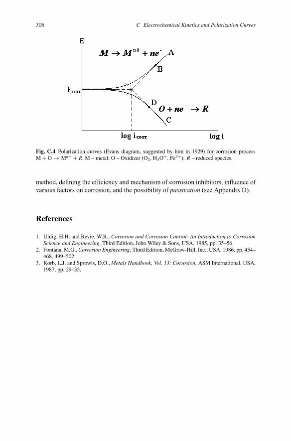
Kinetics of electrochemical corrosion process is adopted to show the polarizationcurves. The latter is a graphic representation of the dependence of electric potential(E) of an electrode on current density (i) (Figure C.4).
Polarization curves describe the behavior of a metal as an anode or cathode ofa corrosion cell. When iron is immersed in a neutral or alkali aqueous solution ofelectrolyte, polarization curves reflect anodic dissolution of iron and cathodic reduc-tion of dissolved oxygen. When iron is immersed in an acidic solution, polarizationcurves reflect the anodic dissolution of iron and cathodic reduction of H3O+ (aloneor together with O2). Two main parameters are defined from polarization curves:corrosion potential Ecorr and corrosion current icorr (corrosion rate). The latter is ob-tained from extrapolating the currents in the two Tafel regions (AB and CD) to thecorrosion potential Ecorr. This method is called Tafel extrapolation and is used in thelaboratory and sometimes under industrial conditions. The slopes (called Tafel con-stants) of polarization curves define the large or small difficulty of anodic and cath-odic processes. A degree of polarization is a measure of how the rates of anodic andcathodic reactions are influenced by various environmental (concentrations of dis-solved oxygen, cations, anions, pH, temperature, agitation in solution) and surfaceprocesses (electrochemical reactions, adsorption, film formation) factors. The firstdefines concentration polarization. The latter defines activation polarization. Polar-ization curves are the basis for determining corrosion rates by the electrochemical
306 C Electrochemical Kinetics and Polarization Curves
Fig. C.4 Polarization curves (Evans diagram, suggested by him in 1929) for corrosion processM + O → Mn+ + R. M – metal; O – Oxidizer (O2, H3O+, Fe3+); R – reduced species.
method, defining the efficiency and mechanism of corrosion inhibitors, influence ofvarious factors on corrosion, and the possibility of passivation (see Appendix D).
References
1. Uhlig, H.H. and Revie, W.R., Corrosion and Corrosion Control: An Introduction to CorrosionScience and Engineering, Third Edition, John Wiley & Sons, USA, 1985, pp. 35–56.
2. Fontana, M.G., Corrosion Engineering, Third Edition, McGraw-Hill, Inc., USA, 1986, pp. 454–468, 499–502.
3. Korb, L.J. and Sprowls, D.O., Metals Handbook, Vol. 13: Corrosion, ASM International, USA,1987, pp. 29–35.

Appendix DPassivity
If we studied chemistry at school, we would probably remember the dependence ofiron dissolution from concentration of sulphuric and nitric acids (Figure D.1).
How did the teacher explain these curves? An increase in the concentration ofsulphuric and nitric acids causes an increased corrosion rate in iron. Then after theconcentration of 60% (for H2SO4) and 40% (for HNO3), the corrosion rate drastic-ally decreases. The greater the concentration of acid, the less concentration of water,namely, less acid molecules capable of dissociating for H3O+, and as a result, thecorrosion rate diminishes. The phenomenon of high resistance of iron in concen-trated sulphuric and nitric acids is explained by passivity. Concentrated sulphuricand nitric acids are stored and transported in tanks made of carbon steel. You mustnot coat them inside and use stainless steel, but be careful. Iron dissolves in di-luted H2SO4 and HNO3 acids. Therefore, any dilution of these acids will cause acatastrophic acceleration of the corrosion rate of carbon steel. For example, vesselsand tanks with concentrated nitric and sulphuric acids must be hermetically closedwith valves to protect them from water penetration. Another point is very import-ant: if iron is immersed in concentrated (∼70%) HNO3 and then is put into diluted(∼30%) HNO3, the passive state of iron may be maintained. Any change in the sur-face condition of iron (for example, scratch) or agitation may cause a disturbance ofpassivity.
Although passivity has been known for about 250 years, there has been no lu-cid explanation until now. Passivity is the phenomenon of relatively high corrosionresistance as a result of diminution of the anodic process. Passivity is the specificphenomenon occurring only with some metals and alloys in particular media.
The Russian scientist Michail Lomonosov (1711–1765), the English scientistsJames Keir (1735–1820), Michael Faraday (1791–1867) and the Swiss chemistChristian Friedrich Schönbein (1799–1868) studied this phenomenon. The lattercoined passive iron and passivity in 1836 in a letter to Michael Faraday. The wordpassive came from the Latin word passivus which means “indifferent, dispassion-ate, inactive”, and is the opposite of active. The difference in corrosion rate betweenpassive and active states of metals may be one million and more. Iron, chromium,nickel, cobalt, molybdenum, titanium, aluminum, magnesium, and their alloys can
307

308 D Passivity
Fig. D.1 Corrosion rate of iron vs concentration of sulphuric and nitric acids.
possess passivity under particular conditions (in specific media). The followingcauses can result in corrosion resistance of metals and alloys: thermodynamic sta-bility, difficulties in transportation of oxidizers to the surface of metals, retardationof the cathodic process, and inhibition of anodic process. The latter is called pas-sivation, passive state, or passivity. There are several ways to transfer metals andalloys into a passive state.
(a) Anodic polarization from the outer source of direct electric current, or by meansof connection to another metal which is a cathode, towards the metal to be po-larized.
(b) Immersion of metals in specific media: iron in aqueous solutions of HNO3(>70%), H2SO4 (>96%), Na2SO4 (1 M), and others.
(c) The presence of oxidizers in solutions, for example, dissolved oxygen (O2), per-oxides (H2O2, KBO3, K4P2O8), and other substances (HNO3, NaNO2, NaNO3,Na2WO4, K2CrO4, K2Cr2O7).
(d) Addition of “noble” elements (Pt, Pd, Rh and Ir) to chromium, titanium, andtheir alloys (noble-metal alloying).
Figure D.2a shows the relationship between electric potential (E) and current dens-ity (i) for metals/alloys possessing a passive state. The polarization curve in Russianliterature is usually depicted in mirror reflection (Figure D.2b). The correct present-ation of the relationship between E and i is shown in Figure D.2c, because we meas-ure electric current density (i) as a function of electric potential (E). In any case, thisanodic polarization curve can be divided into several regions. AB – active, or Tafelregion; a realm when an increase of potentials E causes a raise in corrosion rate(i). When electric potential E reaches the point B, metallic oxides are formed on ametal’s surface, and electric current i (corrosion rate!) diminishes drastically.

Corrosion for Everybody 309
Fig. D.2 Anodic polarization curves of metals/alloys possessing passive state: (a) accepted in cor-rosion literature in Europe and America; (b) in Russia; (c) correct presentation (usually in theelectrochemical literature). E, Volt; i, A·cm−2.
Usually metal (M) is oxidized to MxOy at point B. The area BC is an active–passive transition, when a protective film is formed on the metal surface and themetal “moves” in the passive region. When electric current drops to point C, metalreaches the passive state. This potential (Epass or Epp) is named passivation poten-tial, or Flade potential, in honor of the scientist F. Flade who was the first to observepassivity of iron in sulphuric acid in 1911. Other names for the potential Epp are theprimary passive potential or the potential of full passivity. The electric current inpoint B is named critical passivating current density.
CD is a passive region. The electric current (corrosion rate) does not dependon the electric potential in this region. The corrosion rate of metal is not zero in apassive field, but is a very small and constant value (ipass).
We can detect different oxides (Fe3O4, γ-Fe2O3) or hydroxides (FeOOH) on aniron surface in passive state. These oxides and hydroxides grow directly into themetal and outside it, forming a film which effectively isolates the iron surface fromthe corrosive environment. Such films are so thin that it is impossible to see themwith the naked eye. Contrary to rust, thin oxides are very dense, but are fragile. Wecan point out the characteristic features of passivity:
(a) The electric potential of metals changes in the positive direction, for example,from −0.5 V to +0.5–1.0 V for iron; from −0.6 V to +0.9 V for chromium.
(b) The corrosion rates of metals in the passive state are very low and are stable intime. Usually the transition from active to passive state results in the diminutionof the corrosion rate ∼1 million times.
(c) Passivity is a metastable state, from the Greek “meta” (“after”), movement orchange to unstable condition, and is very simple to disturb by means of scratch,grinding, or changes to the outer conditions: temperature, concentration of ag-gressive variables, and agitation.
Passivity exists because of a thin delicate film of several nanometers thickness (3to 5 nm) on the metal or alloy surface. Passivity is not an inert or static state, but a

310 D Passivity
dynamic condition and belongs to a kinetic phenomenon in which there is continu-ous dissolution and repair of passive layers at discrete points on the surface. Whenmetal reaches point D, the electric current increases to further enhance the electricpotential. Region DF is called transpassivity. “Trans” shows the change, crossing,or passing the boundary of passivity. Several reasons exist for transpassivity:
(a) Molecular oxygen (O2) can be formed on the outer metal surface, that is onoxides, according to the anodic reaction
4OH−(aq) → O2(aq) + 2H2O(l) + 4e−. (D.1)
Certainly, passive film on a metal surface must be electrically conductive. Evenif the film is a semi-conductor, it is very thin, and reaction (D.1) can occur onthe film’s surface.
(b) Electric potential in point D is so large that metal oxide can be oxidized, forexample:
Fe2O3(s) + 5H2O(l) → 2FeO2−4(aq) + 5H2(g), (D.2)
Fe2O3(s) + 5OH−(aq) → 2FeO2−
4(aq) + 5/2H2(g). (D.3)
Passive film is destroyed on the metal surface at electric potentials above ED . Thus,stability of the passive state is restricted by the concentration of oxidizers, or bythe electric potential value during anodic polarization. Any damage of the passivefilm, such as fracture, crumbling, and disintegration, causes initiation of localizedcorrosion: pitting, cracking or crevice corrosion.
We can compare passivity with travelling by car from home to a place of work.If we go out before (earlier than 6 a.m.), or after heavy traffic (later than 9 a.m.), wequickly reach the working place. If we go out exactly during heavy traffic between 6a.m. and 9 a.m. (when all people leave their home), we travel very slowly – “passivemovement”.
We see in passivity the dialectic principle of the struggle of opposites in philo-sophy. When electric potential increases, two processes are in competition on themetal surface: accelerated corrosion and passivation. The equilibrium betweenthese two opposite processes is very delicate. Therefore, it is easy to disturb passiv-ity. Activation is a transfer process of metal from passive into an active state as aresult of outer conditions. Here are the ways to move metal from passivity to activ-ity:
(a) Use of reducers: H2, Na2SO3, Na2S2O3.(b) Use of sea water; aqueous solutions of NaCl (concentrations above 0.01 M); and
ions (Cl−, Br−, I−, SO2−4 , and H3O+).
(c) Cathodic polarization: reduction of oxides on the metal surface by means of dir-ect electric current from a power supply or, alternatively, by connecting passivemetal to more cathodic metal.
Passivity is used in anodic protection.

Corrosion for Everybody 311
References
1. Fontana, M.G., Corrosion Engineering, Third Edition, McGraw-Hill, Inc., USA, 1986, pp. 469–473.
2. Uhlig, H.H. and Revie, W.R., Corrosion and Corrosion Control: An Introduction to CorrosionScience and Engineering, Third Edition, John Wiley & Sons, USA, 1985, pp. 60–89.
3. Korb, L.J. and Sprowls, D.O., Metals Handbook, Vol. 13: Corrosion, ASM International, USA,1987, pp. 35–36.
4. Shreir, L.L., Jarman, R.A. and Burstein, G.T. (Eds.), Corrosion, Vols. 1 and 2, Third Edition,Butterworth Heinemann, UK, 1994, pp. 1:118–1:150.
5. Macdonald, D.D., Passivity – The Key to Our Metals-Based Civilization, Pure Appl. Chem.71(6), 1999, pp. 951–978.
6. Revie, R.W. (Ed.), Uhlig’s Corrosion Handbook, Second Edition, Wiley-Interscience, USA,2006, pp. 165–171, 602.
Appendix ESolubility of Oxygen in Water and AqueousSolutions of Electrolytes
Dissolved oxygen takes part in the cathodic processes on a metal surface (see Sec-tion 1.5). Electrode potential and corrosion kinetics depend on the oxygen concen-tration in solutions.
In spite of polarity of water molecules, non-polar oxygen molecules dissolve inthe voids between water molecules in the tetrahedral arrangement, reaching about8 ppm (2.5 × 10⁻⁴ mol O2 in 1 liter H2O) at 25◦C. Such a small oxygen con-centration is enough for corrosion and, by the way, for many biological processesoccurring in water. Solubility of non-polar oxygen molecules in water and other po-lar solvents is less than that in non-polar solvents (such hydrocarbons as pentane,hexane, toluene, fuels, etc.). Solubility of oxygen in water depends on temperature,pressure, and presence of electrolytes.
E.1 Influence of Temperature on Solubility of Oxygen in Water
Increase of temperature from 0 to 100◦C results in a decrease of oxygen solubilityto nearly zero and a subsequent increase of temperature above 100◦C results inincrease of oxygen solubility (Table E.1). The following increase above 100◦C is soconsiderable that the solubility at 200◦C (473 K) is equal to the oxygen solubility at25◦C. This fact is very important for corrosion at power stations as processes occurat high temperatures and pressures.
E.2 Influence of Pressure on Solubility of Oxygen in Water
The dependence of oxygen solubility in water on pressure is described with Henry’sLaw:
XO2 = KH · PO2 , (E.1)
313

314 E Solubility of Oxygen in Water and Aqueous Solutions of Electrolytes
Table E.1 Solubility (XO2 × 105) of oxygen in water at 273 to 573 K (PO2 = 101,325 Pa) [1].
T K XO2 × 105 T K XO2 × 105 T K XO2 × 105 T K XO2 × 105
273 3.953 313 1.870 353 1.478 453 2.038278 3.462 318 1.775 358 1.462 473 2.388283 3.072 323 1.697 363 1.450 493 2.852288 2.758 328 1.633 368 1.445 513 3.460293 2.504 333 1.580 373 1.444 533 4.250298 2.297 338 1.539 393 1.487 553 5.276303 2.126 343 1.507 413 1.599 573 6.603308 1.986 348 1.483 433 1.780
Note: XO2 = n(O2)/(n(O2)+n(H2O)) is the mole fraction solubility of oxygen in water;n(O2) and n(H2O) represent the number of moles of oxygen and water, respectively.
or, more precisely,aO2 = KH · fO2, (E.2)
where KH is Henry’s Law constant; PO2 is the partial pressure of oxygen; aO2 is theactivity of oxygen in water; fO2 is the fugacity of oxygen in water.
There is a straight line between oxygen solubility and its pressure at low pres-sures (below 3 MPa), but deviation from Henry’s Law occurs at high pressures(>3 MPa) of oxygen gas.
E.3 Influence of Type and Concentration of Electrolyte onOxygen Solubility in Water
Addition of salt or any other electrolyte to water usually decreases oxygen solubil-ity. This phenomenon is called salting out. We can observe the salting out if we addsome table salt to beer. Many bubbles of CO2 and air escape from the beer. Thepolar salt molecules ionize and capture the “voids” in the beer instead of CO2 andair molecules, and the latter escape. The greater the salt or other electrolyte concen-tration in water, the lesser oxygen concentration is in it. The quantitative value forthe salting out phenomenon is the Setschenov coefficient:
Kcα =(
1
C
)log
(αo
α
)[L/mol], (E.3)
where C is the the concentration of electrolyte, mol/L; αo, α is the solubility ofoxygen (Bunsen coefficient) in pure water (αo) and in a solution of electrolyte (α),L = liter.
The Russian physiologist Iliya Setschenov (1889) was the first to study the in-fluence of salts on the solubility of gases in liquids and found the empirical law(E.3).
Corrosion for Everybody 315
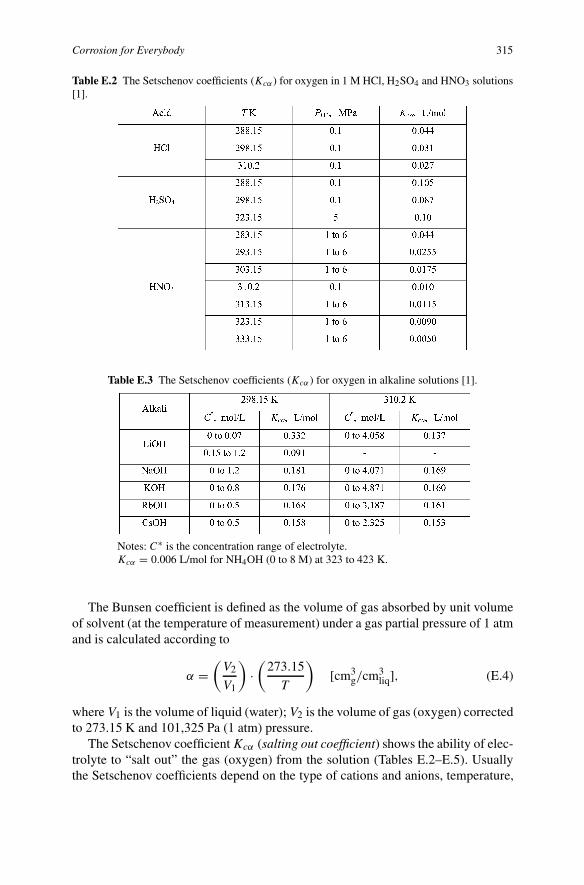
Table E.2 The Setschenov coefficients (Kcα) for oxygen in 1 M HCl, H2SO4 and HNO3 solutions[1].
Table E.3 The Setschenov coefficients (Kcα ) for oxygen in alkaline solutions [1].
Notes: C∗ is the concentration range of electrolyte.Kcα = 0.006 L/mol for NH4OH (0 to 8 M) at 323 to 423 K.
The Bunsen coefficient is defined as the volume of gas absorbed by unit volumeof solvent (at the temperature of measurement) under a gas partial pressure of 1 atmand is calculated according to
α =(
V2
V1
)·(
273.15
T
)[cm3
g/cm3liq], (E.4)
where V1 is the volume of liquid (water); V2 is the volume of gas (oxygen) correctedto 273.15 K and 101,325 Pa (1 atm) pressure.
The Setschenov coefficient Kcα (salting out coefficient) shows the ability of elec-trolyte to “salt out” the gas (oxygen) from the solution (Tables E.2–E.5). Usuallythe Setschenov coefficients depend on the type of cations and anions, temperature,

316 E Solubility of Oxygen in Water and Aqueous Solutions of Electrolytes
Table E.4 The Setschenov coefficients (Kcα ) for oxygen in solutions of halogenide of alkali metals[1] (T = 298 K, PO2 = 0.1 MPa).
Note: The concentration range for salts of Na, K and Li are 0 to 1.2 M; salts of Rb and Cs are 0to 0.5 M. For LiF, the first value Kcα was measured in the range 0 to 0.01 M, the second value isin the range 0.04 to 0.1 M. For LiCl and LiBr, the first value Kcα was measured in the range 0 to0.07 M, for the second value it was in the range 0.15 to 1.2 M.
Table E.5 The Setschenov coefficients (Kcα ) for oxygen in salt solutions [1] (T = 298 K, PO2 =0.1 MPa).
Note: In the parenthesis concentrations were given for which Kcα were calculated; in other casesconcentrations were 0 to 1.2 M.
pressure, and sometimes on the electrolyte concentration. The higher the charge anddimensions of ions, the higher the Setschenov coefficient.
References
1. Groysman, A. and Khomutov, N., Solubility of Oxygen in Aqueous Solutions of Electrolytes,Uspekhi Chimii 59(8), 1990, pp. 1217–1250 [in Russian].
2. Battino, R. (Ed.), Solubility Data Series. Oxygen and Ozone, Vol. 7, Pergamon Press, Oxford,1981, 519 pp.

Appendix FChemical Compositions of Alloys
317
318 F Chemical Compositions of Alloys
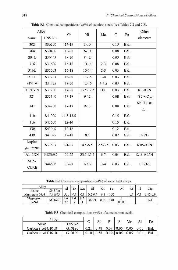
Table F.1 Chemical compositions (wt%) of stainless steels (see Tables 2.2 and 2.3).
Table F.2 Chemical compositions (wt%) of some light alloys.
Table F.3 Chemical compositions (wt%) of some carbon steels.

Corrosion for Everybody 319
Table F.4 Chemical compositions (wt%) of alloys (see Table 2.3).
Appendix GBiocides Used in Industry
References
1. Korb, L.J. and Sprowls, D.O., Metals Handbook, Vol. 13: Corrosion, ASM International, USA,1987, p. 493.
2. Flemming, H.C., Biofouling in Water Treatment. In: Biofouling and Biocorrosion in IndustrialWater Systems, H.C. Flemming and G.G. Geesey (Eds.), Springer-Verlag, Berlin, 1991, p. 47.
321
322 G Biocides Used in Industry
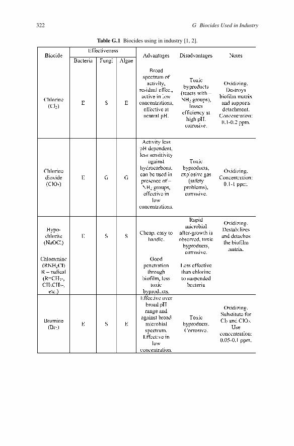
Table G.1 Biocides using in industry [1, 2].
Corrosion for Everybody 323
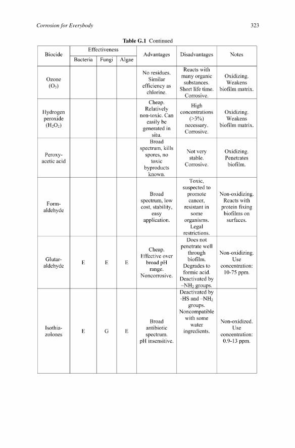
Table G.1 Continued
324 G Biocides Used in Industry
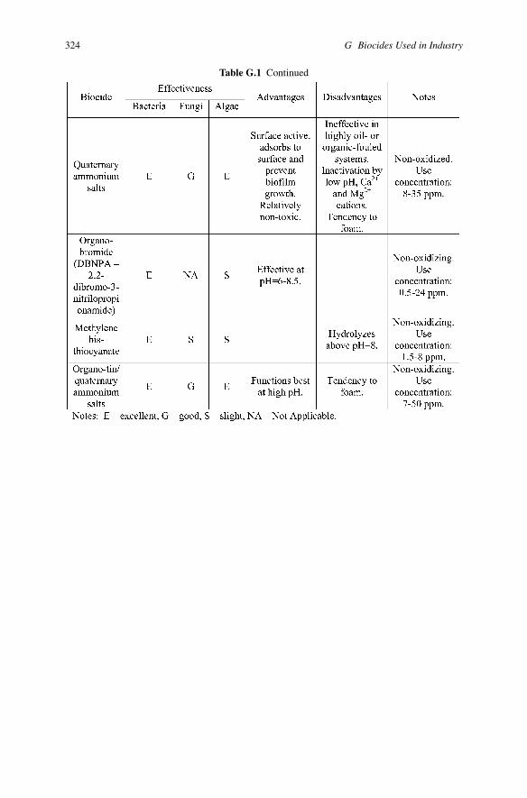
Table G.1 Continued

Appendix HPhysico-Chemical Properties of Crude Oil,Petroleum Distillates/Fuels, Naphthenic, andSome Aliphatic Acids
325
326 H Physico-Chemical Properties
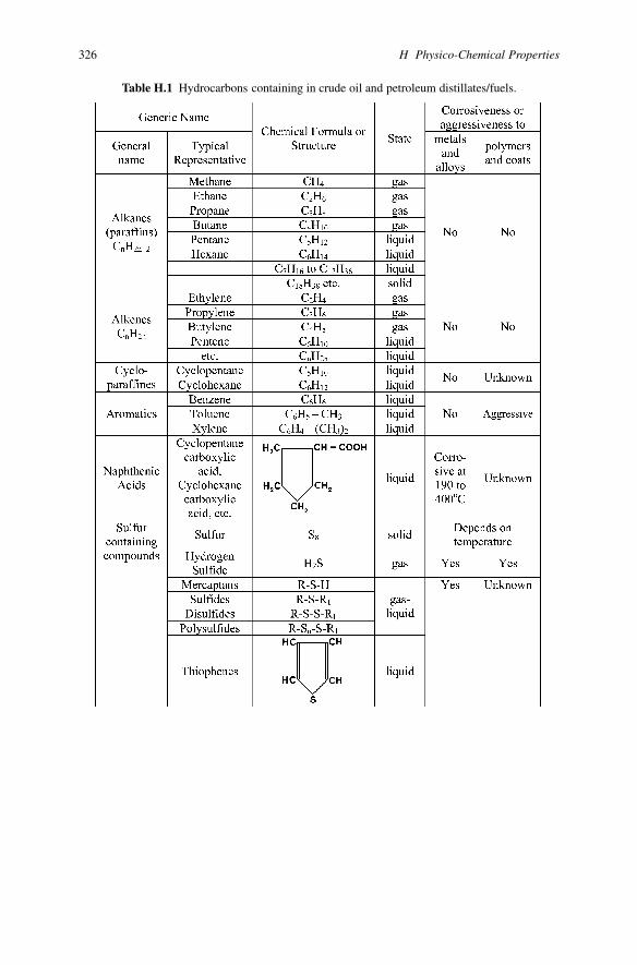
Table H.1 Hydrocarbons containing in crude oil and petroleum distillates/fuels.
Corrosion for Everybody 327
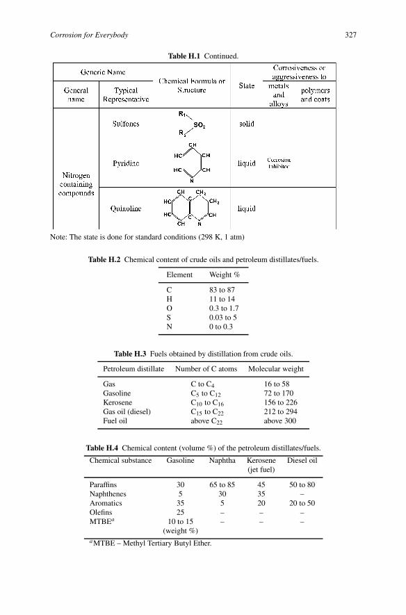
Table H.1 Continued.
Note: The state is done for standard conditions (298 K, 1 atm)
Table H.2 Chemical content of crude oils and petroleum distillates/fuels.
Element Weight %
C 83 to 87H 11 to 14O 0.3 to 1.7S 0.03 to 5N 0 to 0.3
Table H.3 Fuels obtained by distillation from crude oils.
Petroleum distillate Number of C atoms Molecular weight
Gas C to C4 16 to 58Gasoline C5 to C12 72 to 170Kerosene C10 to C16 156 to 226Gas oil (diesel) C15 to C22 212 to 294Fuel oil above C22 above 300
Table H.4 Chemical content (volume %) of the petroleum distillates/fuels.
Chemical substance Gasoline Naphtha Kerosene Diesel oil(jet fuel)
Paraffins 30 65 to 85 45 50 to 80Naphthenes 5 30 35 –Aromatics 35 5 20 20 to 50Olefins 25 – – –MTBEa 10 to 15 – – –
(weight %)aMTBE – Methyl Tertiary Butyl Ether.
328 H Physico-Chemical Properties
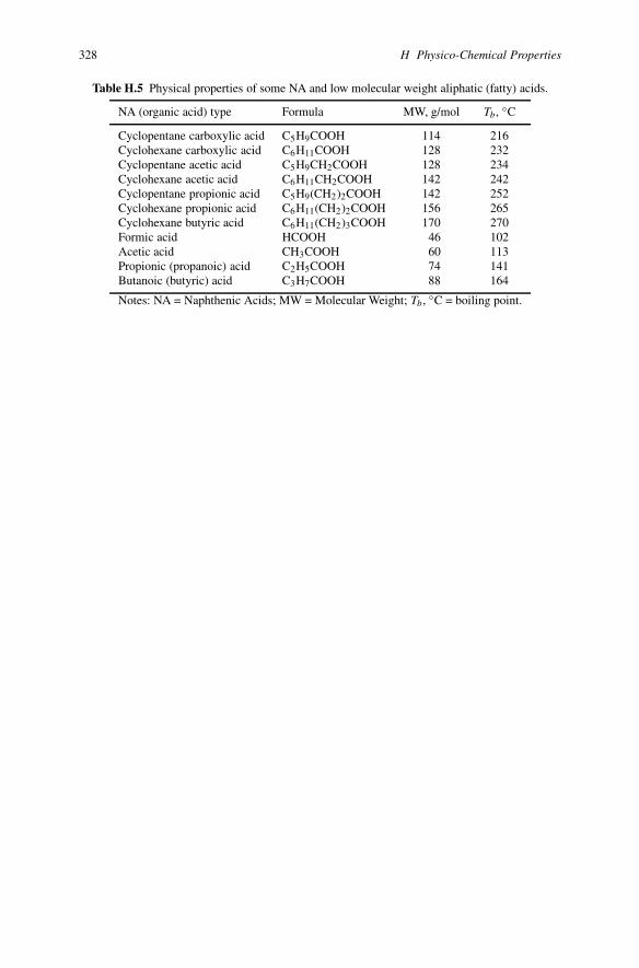
Table H.5 Physical properties of some NA and low molecular weight aliphatic (fatty) acids.
NA (organic acid) type Formula MW, g/mol Tb, ◦C
Cyclopentane carboxylic acid C5H9COOH 114 216Cyclohexane carboxylic acid C6H11COOH 128 232Cyclopentane acetic acid C5H9CH2COOH 128 234Cyclohexane acetic acid C6H11CH2COOH 142 242Cyclopentane propionic acid C5H9(CH2)2COOH 142 252Cyclohexane propionic acid C6H11(CH2)2COOH 156 265Cyclohexane butyric acid C6H11(CH2)3COOH 170 270Formic acid HCOOH 46 102Acetic acid CH3COOH 60 113Propionic (propanoic) acid C2H5COOH 74 141Butanoic (butyric) acid C3H7COOH 88 164
Notes: NA = Naphthenic Acids; MW = Molecular Weight; Tb, ◦C = boiling point.

Appendix IIdentification of Corrosion Products Accordingto Their Colors
329
330 I Identification of Corrosion Products According to Their Colors
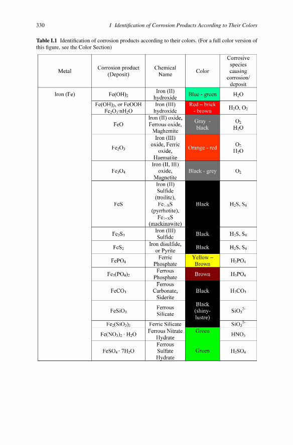
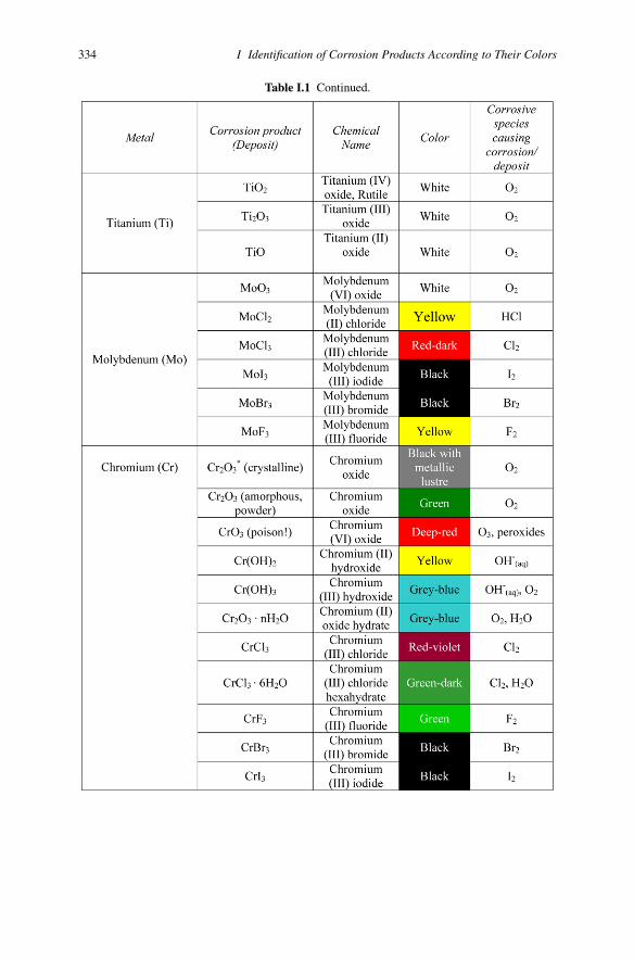
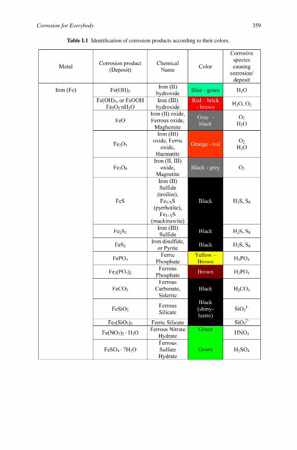
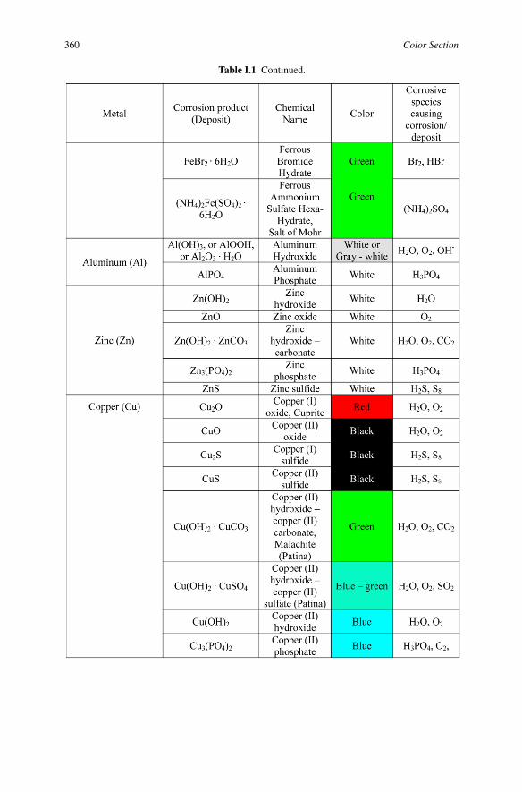
Table I.1 Identification of corrosion products according to their colors. (For a full color version ofthis figure, see the Color Section)

Corrosion for Everybody 331
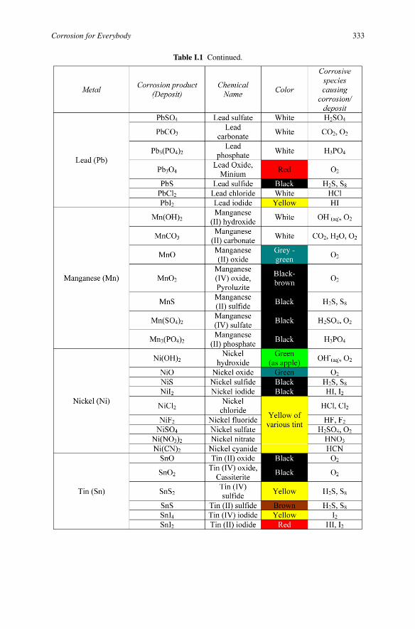
Table I.1 Continued.

332 I Identification of Corrosion Products According to Their Colors
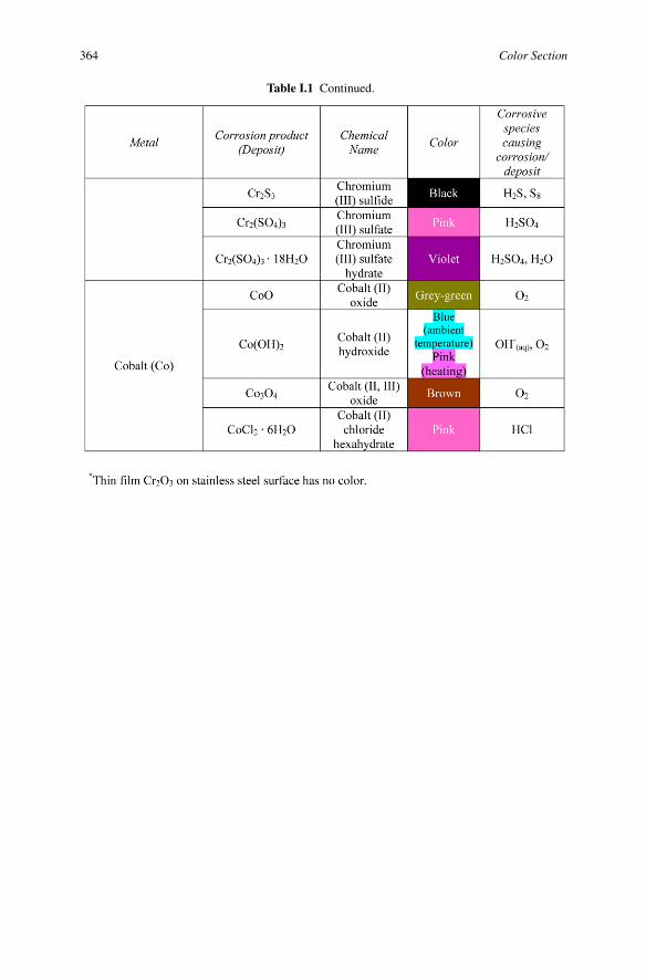
Table I.1 Continued.
Corrosion for Everybody 333
Table I.1 Continued.
334 I Identification of Corrosion Products According to Their Colors
Table I.1 Continued.

Corrosion for Everybody 335
Table I.1 Continued.
Postscript
Is there an end for science, technology, and art? They are integral parts of people’sexistence. People cannot survive without usage of their achievements even if theydo not belong to scientific, technological, and artistic fields of society. Life is basedon paradoxes and contradictions. A tourist is happy twice: when he leaves and re-turns home. I came to the saddest point: we have to separate. We went together thisinteresting way. I began this way many years ago, and I cannot stop it, because I findover again new and original fascinating faces of corrosion, especially in connectionwith humanitarian aspects of life. Discussion between lyrics and physics (Plato andAristotle) failed. This is supported by the work of famous metallurgist Cyril Stan-ley Smith (1904–1992) who said that “the objects here displayed under the twinbanners of Art and Science are to be viewed as reflections of the inner nature ofman”. Both sides of life, our existence, have mutual influence, and they enrich eachother. I hope you found some useful, interesting, and fascinating aspects in the be-havior of metals and alloys, in their corrosion products, in corrosion phenomena, inthe methods of corrosion control and corrosion monitoring. Corrosion of metals isan eternal process, as thermodynamics points out. Our efforts to overcome thermo-dynamic tendency and struggle to continue the healthy life of metals are based onthe importance of corrosion study from the following points of view: economical,safety, quality of the environment, reliability of substances (chemicals, medicines,food, etc.), and preservation (restrictions) of sources of metals in the crust of theEarth.
Kozma Prutkov (the fictional author invented by Aleksey KonstantinovichTolstoy and three Zhemchuzhnikov brothers who lived during Russia’s authorit-arian reign of Nicholas I) said: “One cannot embrace the unembraceable”. I didnot write an encyclopedia. I wanted to show the corrosion world from unusual,philosophical, enjoyable, and beautiful points. In other words, I wanted to show thateven complicated or simple at first glance corrosion phenomena can be explained inan enjoyable way. This is a new approach to understanding and teaching such an oldand nasty phenomenon as corrosion. Our planet, the Earth, is a ball. All phenomenaare interrelated. Maybe our universe is also a ball, or some other geometricalform without beginning and end. There is no end to corrosion, as well as to art,
337

338 Postscript
to universe, to time . . . But I finish this book with the certainty that somebodywill continue this interesting and enjoyable work of connecting corrosion with allaspects of life for everybody.
Alec Groysman

Color Section
339
Fig. 1.12 Corroded anchor made of carbon steel.
Fig. 1.17 Carbon steel after 7 days immersion in cooling water (a) and in water with the additionof sodium peroxoborate (NaBO3) (b). The “beautiful” rust is formed on the steel’s surface in aNaBO3 solution.
340 Color Section
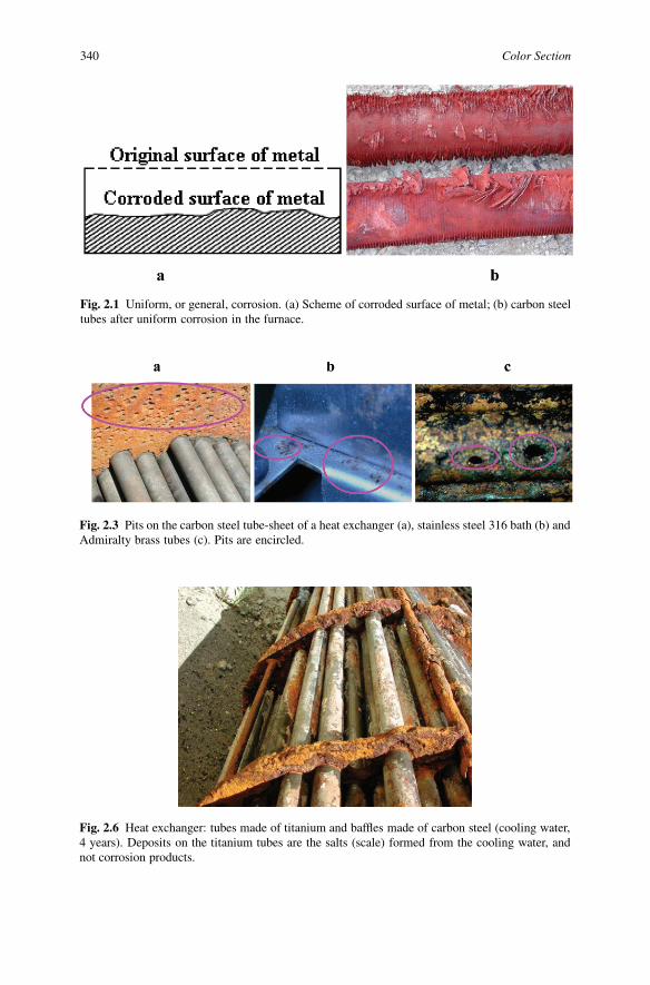
Fig. 2.1 Uniform, or general, corrosion. (a) Scheme of corroded surface of metal; (b) carbon steeltubes after uniform corrosion in the furnace.
Fig. 2.3 Pits on the carbon steel tube-sheet of a heat exchanger (a), stainless steel 316 bath (b) andAdmiralty brass tubes (c). Pits are encircled.
Fig. 2.6 Heat exchanger: tubes made of titanium and baffles made of carbon steel (cooling water,4 years). Deposits on the titanium tubes are the salts (scale) formed from the cooling water, andnot corrosion products.
Corrosion for Everybody 341
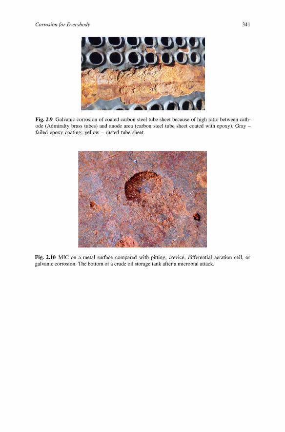
Fig. 2.9 Galvanic corrosion of coated carbon steel tube sheet because of high ratio between cath-ode (Admiralty brass tubes) and anode area (carbon steel tube sheet coated with epoxy). Gray –failed epoxy coating; yellow – rusted tube sheet.
Fig. 2.10 MIC on a metal surface compared with pitting, crevice, differential aeration cell, orgalvanic corrosion. The bottom of a crude oil storage tank after a microbial attack.

342 Color Section
Fig. 2.14 (a) SRB inside cooling water carbon steel pipes (after four years); the thickness ofbiofilm with SRB was about 6 to 10 cm. (b) Corroded carbon steel bottom of the crude oil above-ground storage tank after 18 years of service as a result of SRB activity.
Fig. 2.16 Erosion-corrosion inside a liquefied petroleum gas (LPG) carbon steel tube. “Grooves”are formed as a result of erosion.
Corrosion for Everybody 343
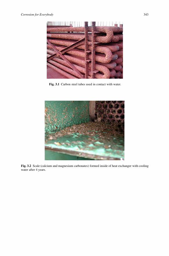
Fig. 3.1 Carbon steel tubes used in contact with water.
Fig. 3.2 Scale (calcium and magnesium carbonates) formed inside of heat exchanger with coolingwater after 4 years.
344 Color Section
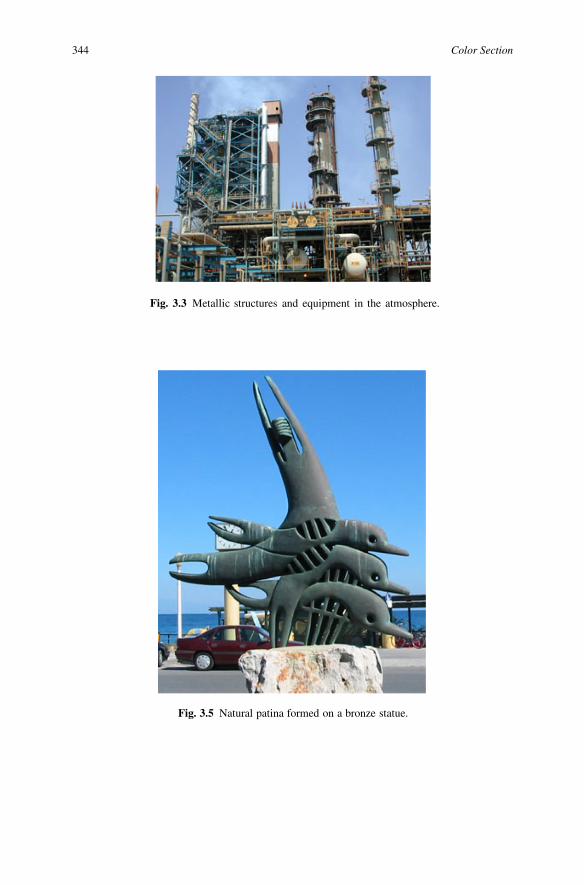
Fig. 3.3 Metallic structures and equipment in the atmosphere.
Fig. 3.5 Natural patina formed on a bronze statue.
Corrosion for Everybody 345
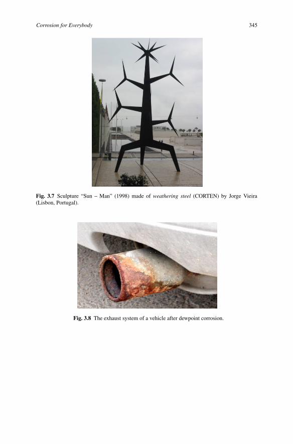
Fig. 3.7 Sculpture “Sun – Man” (1998) made of weathering steel (CORTEN) by Jorge Vieira(Lisbon, Portugal).
Fig. 3.8 The exhaust system of a vehicle after dewpoint corrosion.

346 Color Section
Fig. 3.9 Corrosion of a heat exchanger under thermal insulation.
Fig. 3.11 Corrosion “balls” formed on a carbon steel surface (strip coupons) after 3 days’ immer-sion in kerosene with water (1 wt %) added.

Corrosion for Everybody 347
Fig. 3.15 Corroded roof of the gas oil AST after 5 years of service.
Fig. 3.16 Corroded bottoms of the fuel oil AST after 10 years of service.
348 Color Section
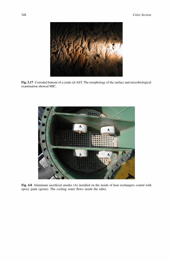
Fig. 3.17 Corroded bottom of a crude oil AST. The morphology of the surface and microbiologicalexamination showed MIC.
Fig. 4.8 Aluminum sacrificial anodes (A) installed on the inside of heat exchangers coated withepoxy paint (green). The cooling water flows inside the tubes.
Corrosion for Everybody 349
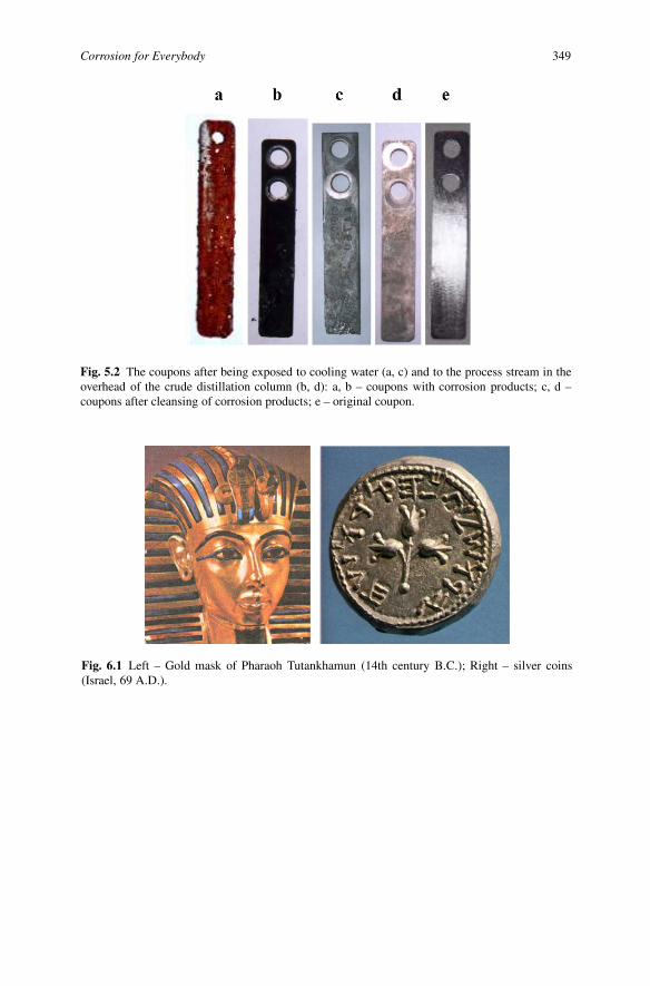
Fig. 5.2 The coupons after being exposed to cooling water (a, c) and to the process stream in theoverhead of the crude distillation column (b, d): a, b – coupons with corrosion products; c, d –coupons after cleansing of corrosion products; e – original coupon.
Fig. 6.1 Left – Gold mask of Pharaoh Tutankhamun (14th century B.C.); Right – silver coins(Israel, 69 A.D.).

350 Color Section
Fig. 6.3 Miniature from the alchemy book. Seven metals are depicted as gods – planets’ symbolssheltered in the cave.
Fig. 6.4 Sasha Okun “Woman”. (Reprinted with permission)

Corrosion for Everybody 351
Fig. 6.5 Noam Ben-Jacov “Motion”. (Reprinted with permission)
Fig. 6.6 Beauty of corroded Raschig rings in an oil refinery.
Fig. 6.8 Cathedral of Christ the Savior (Moscow), stainless steel with decorative and protectivetitanium nitride (TiN) coating.

352 Color Section
Fig. 6.9 “Bone structure V”, carbon steel, treated with vinegar and natural pigments, NatashaCarsberg, England. (Reprinted with permission)
Fig. 6.10 “Come on! Let us fight against corrosion!” Bronze, Israel.

Corrosion for Everybody 353
Fig. 6.11 Alberto Giacometti (1901–1966) “Tall Figure” (1949, painted bronze), resembles uni-form corrosion. © Photo Scala, Florence, The Museum of Modern Art, New York/Scala Florence,2009.
Fig. 6.12 Philip Guston “Pit” (1976) National Gallery of Australia, Canberra. © The Estate ofPhilip Guston. Pitting corrosion – severe local corrosion. Reprinted with permission.

354 Color Section
Fig. 6.13 Umberto Boccioni (1882–1916) “Unique Forms of Continuity in Space” (1913) or“Erosion”. (a, c) Erosion inside brass tube; (b) the sculpture of Umberto Boccioni. © Photo Scala,Florence, The Museum of Modern Art, New York/Scala, Florence, 2009.
Fig. 6.14 Hieronymus Bosch “The Garden of Earthly Delights” (1510–1515) and three periods ofcar’s life: new car, beginning of corrosion, and destruction. (Reprinted with permission, © MuseoNacional del Prado, Madrid, Spain.)

Corrosion for Everybody 355
Fig. 6.16 Russian version of the “The Wizard of Oz” (1939): “Iron Woodman”. Dorothy brings anoil-can against atmospheric corrosion.
Fig. 6.15 Anti-corrosion protection as well as decoration of a storage tank (Israel).
Fig. 6.18 (a) SEM photo of rust (×3,500 and ×1,500; (b) coral reefs.
356 Color Section
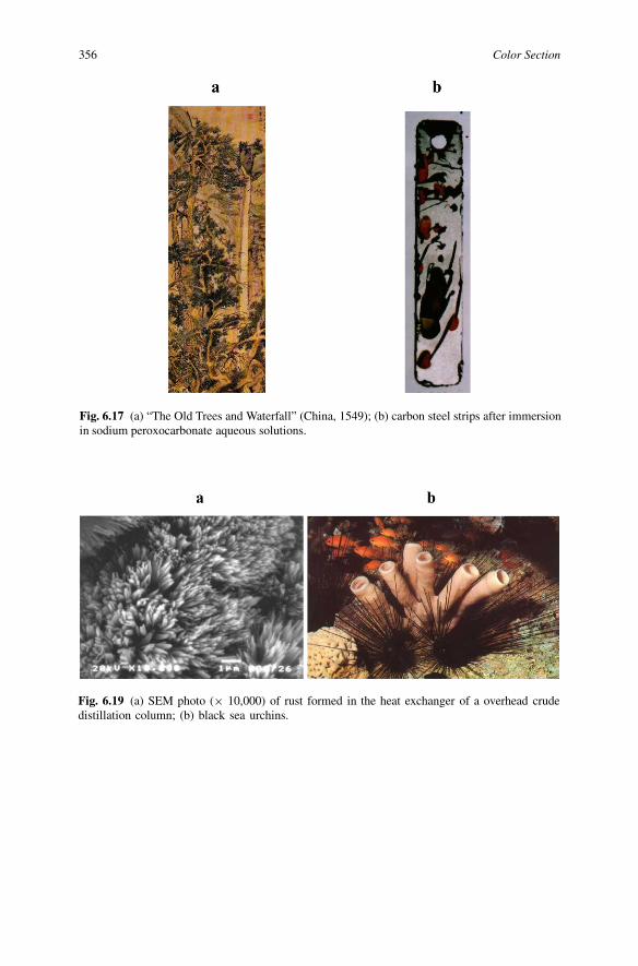
Fig. 6.17 (a) “The Old Trees and Waterfall” (China, 1549); (b) carbon steel strips after immersionin sodium peroxocarbonate aqueous solutions.
Fig. 6.19 (a) SEM photo (× 10,000) of rust formed in the heat exchanger of a overhead crudedistillation column; (b) black sea urchins.

Corrosion for Everybody 357
Fig. 6.22 “Fretting corrosion” – attack due to rubbing contact.
Fig. 6.23 “Impingement attack” – localized attack related to high velocity. (Right – impingementby escaping steam from cracked tube).
358 Color Section
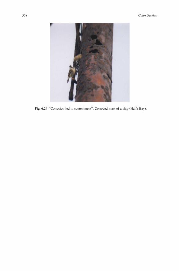
Fig. 6.24 “Corrosion led to contentment”. Corroded mast of a ship (Haifa Bay).
Corrosion for Everybody 359
Table I.1 Identification of corrosion products according to their colors.
360 Color Section
Table I.1 Continued.

Corrosion for Everybody 361
Table I.1 Continued.

362 Color Section
Table I.1 Continued.
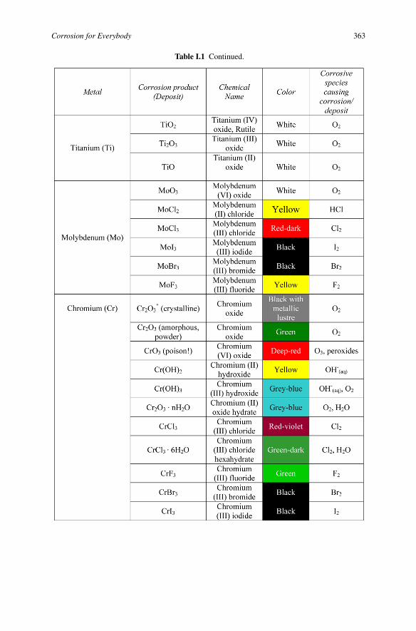
Corrosion for Everybody 363
Table I.1 Continued.
364 Color Section
Table I.1 Continued.
Index
Activation polarization (see polarization), 304,305
Admiralty brass, 2, 57, 66, 67, 69, 71, 99Aerobic microorganisms (see Microbiologic-
ally induced corrosion), 77, 78Alkalies (see Caustic solutions, Hydroxides),
38, 54, 315Aluminum, 39, 40, 54, 64, 68, 71
corrosion inhibitors for, 183corrosion resistance of, 37, 54, 71oxide, 37, 58
Anaerobic microorganisms (see Microbiologic-ally induced corrosion), 77, 78
Anode (see Cathodic protection; Polarization),22, 25, 45, 50, 69, 70, 78, 254
Anodic protection, 168, 261, 310Anodic reaction, 22, 23, 27Atmospheric corrosion (see Corrosion in atmo-
sphere), 115–126Battery, 23, 28, 162, 270
voltaic (see Galvanic, Electrolytic, Electro-chemical), 23, 162
Biocides, (see Microbiologically influencedcorrosion), 88–90, 321–324
Biofouling (see Microbiologically influencedcorrosion), 76, 82, 89, 90
Carbon steel, 30, 32–36, 40, 42, 43, 46, 49, 57,59, 67, 69, 239, 244
Cathode (see Cathodic protection, Polariza-tion), 22, 26, 69, 70, 78, 254
Cathodic protection (see Electrochemical pro-tection), 46, 87, 168–176, 270
Cathodic reaction (process), 22, 26, 27, 30, 31,35, 36, 44, 47, 48
Caustic embrittlement, 37, 100Caustic solution (see Alkalies, Hydroxides), 38,
54, 315
Cavitation, (see also Erosion – corrosion), 87,91–95, 265, 272
Cellcorrosion, 22, 301Daniel, 28differential aeration (see Differential aera-
tion cell), 49–51, 78, 82, 83electrochemical, 22, 23, 27galvanic (see Voltaic, Electrolytic, Electro-
chemical), 23, 301Cementite (see Iron carbide), 24, 33Chemical conversion coatings (see Metallic
coatings), 165–167Chloride, 41, 42, 56–60
critical concentration, 59Coatings
metallic, 143, 144, 161–168chemical plating (see Chemical conver-
sion coatings), 165–167cladding, 167diffusion treatment, 165, 166electrolytic, 162, 163hot dipping, 163metal spraying, 163–165vapor-deposited coatings (see Chemical
conversion coatings), 166, 167organic, 143, 153–160, 175
Concentration polarization (see Polarization),305
Copper and copper alloyscorrosion in acids, 37corrosion in ammonium hydroxide, 43corrosion inhibitors for, 183
Corrosionbasic principles of, 13–36beneficial, 270–272by non-electrolytes, 14
365

366 Index
cell (see electrochemical), 22, 301current, 28, 29, 46, 69, 153, 170, 302, 303,
305definition of, 1–3dissolved oxygen influence, 47electrochemical (see Galvanic, Electro-
lytic), 21–36corrosion cell, 22, 301mechanism, 21–36
factors, 37–49cations participating in cathodic reaction,
44dissolved oxygen, 47dissolved salts in water, 41–43electrical conductance of media, 44-47influence, 37–49pH, 38–41temperature, 47–49, 295–298
form, 53galvanic (see Electrochemical, electro-
lytic), 23, 229general (see Uniform), 53–55, 229in atmosphere, 115–126in water, 109–115localized (see Non-uniform), 53, 55, 56loss (see Weight loss), 10–13, 195–199non-uniform (see Localized), 53, 55, 56penetration, 12, 54phenomena, 53pitting, 56–61, 131, 229potential, 216, 217, 292–295prediction, 6–9products, 3, 32–34, 70, 271
colors of, 329–335temperature influence, 47–49under deposit, 60, 82, 83uniform (see General), 53–55, 229, 275
Corrosion allowance, 192, 193Corrosion fatigue, 107Corrosion in fuels, 133–145Corrosion kinetics, 9, 10Corrosion monitoring, 189–229
at the oil refinery, 203–207chemical analytical methods, 194, 208, 209,
229deposit accumulation test (see Heat transfer
resistance method), 211, 212electrochemical methods, 213–225
corrosion potential, 216, 217, 292–295electrochemical impedance spectroscopy
(EIS), 223–225, 262electrochemical noise measurements
(ENM), 220–223, 229, 271, 272
harmonic distortion analysis (HDA), 225,229
linear polarization resistance (LPR)method, 217–220, 229, 262, 271
open circuit potential, 216, 300–302oxidation/reduction (redox) potential,
215, 216zero resistant ammetry (ZRA), 222, 223
heat transfer resistance method (see Depositaccumulation test), 211, 212
hydrogen monitoring, 212, 213microbiological activity, 209–212physical methods, 193, 195–207
electrical resistance (see ER-probe), 200–207, 229, 271
ER-probe (see Electrical resistance), 200–207, 229, 271
weight loss, 195–199, 203, 204, 207, 229of the atmosphere, 225, 226on-line, real-time, 226, 227physico-chemical methods, 194, 195
Corrosion of storage tanks, 138–145anticorrosion techniques, 142–145cathodic protection, 145corrosion inhibitors, 144, 145metallic coatings, 143, 144organic coatings, 143
Corrosion rate, 10, 11, 46, 190–192formula for expressing, 11, 12linear polarization method for measuring
(LPR), 217–220, 229measuring, 10, 11
Corrosion resistance, 39, 43Corrosion test
duration of, 11–13linear polarization method (see Linear po-
larization resistance method), 217–220Corrosion under thermal insulation, 129–132Current density, 69, 291, 309Dead Sea, 18, 42, 43Deaeration, 48Dealloying, 98–100, 229, 271Dewpoint corrosion, 126–129Dezincification (see Dealloying), 98–100, 255Differential aeration cell, 49–51, 78, 82, 83,
134, 265Dissimilar metal corrosion (see Galvanic corro-
sion), 62–71, 229Ductile, 4Electric double layer (see Helmholtz layer), 16,
303Electric (electrode) potential, 19, 23, 37, 44
absolute, 16corrosion, 292–295

Corrosion for Everybody 367
irreversible, 19, 292–295open circuit potential, 216, 300–302reversible, 19, 291, 292, 294, 295, 302
influence of temperature, 295–298Electric current, 28, 29, 44, 300–303Electrical conductance, 44–46Electrical resistance, 28, 43–46Electrochemical cell, 23Electrochemical kinetics, 299–306Electrochemical protection (see Cathodic pro-
tection), 46, 168–176, 259Electrodes
calomel, 18, 19copper-copper sulphate, 18, 19reference, 17–19silver-silver chloride, 18, 19standard hydrogen, 17, 18
Electrodeposition (see Electrolytic metalliccoatings), 162, 163, 253
Electrolytes, 13, 254Electrolytic cell (see Electrochemical cell), 23Electroplating (see Electrolytic metallic coat-
ings), 162, 163, 253Electromotive force series, 19–21, 64–66Erosion-corrosion, 2, 91–95, 229Faraday’s law, 29, 219Ferric hydroxide, 10, 31–34, 82, 83Ferrous hydroxide, 31–34Fretting corrosion, 96, 97Galvanic cell (see Electrochemical cell), 23Galvanic corrosion, 62–72, 229, 265, 270
factors, 63, 67–70in atmosphere, 71interchange electrode potentials, 67, 68prediction, 66, 67preventive methods, 72
Galvanic electromotive force series, 64–66Galvanized steel (see Zinc coating), 68, 161,
162Gibbs energy, 6–9, 37, 287–290Goethite, 32, 34Graphitic corrosion (see Dealloying), 98–100Haematite, 34Helmholtz layer (see Electric double layer), 16Hot dip coatings (see Metallic coatings), 163Humanitarian aspects of corrosion, 231–285
art and corrosion, 273–285history about corrosion, 231–264
alchemy, 240–244, 264anodic protection, 168, 261, 310brass, 237bronze age, 235–237cathodic protection, 251, 259copper, 234, 235, 237
corrosion definition, 245, 246electrical potential–pH diagram, 260electroplating, 253iron age, 238–240lead, 237, 238linear polarization resistance, 261, 262passivity, 254potentiostat, 261stainless steel, 259, 260tin, 236, 237, 280volatile phase inhibitors, 261voltaic cell, 250zinc, 237, 245
philosophy and corrosion, 264–272, 285beneficial application of corrosion, 270–
272dialectics of corrosion, 266–268duality and uncertainty in corrosion, 265,
266entropy and corrosion, 269, 270time in corrosion, 268, 269
Hydrochloric acid, 37, 38, 41, 44, 54, 60, 79,197
Hydrogen blistering (see Hydrogen damages),104–106
Hydrogen damages, 104–106Hydrogen embrittlement (see Hydrogen dam-
ages), 104–106Hydrogen-induced cracking (see Hydrogen
damages), 104–106, 229Hydrolysis, 57Hydroxides (see Alkalies, Caustic solutions),
38, 54, 315Impingement attack (see Erosion-corrosion),
92, 95Impressed current (see Cathodic protection),
173Inhibitors, 149, 177–188Intergranular corrosion, 97, 98, 229IR drop (see Ohmic potential drop, potential
drop), 46, 47Iron
carbide (see Cementite), 24, 30, 33, 35, 36corrosion in acids, 35, 36, 41corrosion in aqueous salt solutions, 30–35corrosion in caustic solution, 37, 38corrosion in sodium chloride solution, 42,
43corrosion in water, 30–35, 47–49corrosion inhibitors for, 178–184galvanic corrosion, 70history, 238–240oxides, 24, 33, 34, 58
368 Index
potential-pH diagram (see Pourbaix dia-gram), 169, 170
sulphide, 42, 79thermodynamics of oxidation, 287–290
Kinetic curve, 12Kinetics (see Corrosion kinetics), 9, 10Kerosene, 46, 81, 82Lepidokrokite, 32, 34Maghemite, 34Magnetite, 10, 34Malleable, 4Metal, 3–6
amorphous (see Glassy), 29amphoteric, 40glassy (see Amorphous), 29
Metallic bond, 5Metallic coatings (see Coatings), 161–168Metalloids (see Semimetals), 4Microbiologically influenced (induced) corro-
sion (MIC), 72–91, 138, 144, 229bacteria (see Microorganisms), 72–91biocides, 88–90, 321–324biofilm (see Biofouling), 76, 77, 90biofouling (see Biofilm), 76, 82, 139control of microbilogical activity (see Cor-
rosion monitoring), 84, 85, 209–212extracellular polymeric substances, 76microorganisms (see Bacteria), 72–91
aerobic, 77, 78anaerobic, 77, 78, 85facultative (see Heterotrophic), 77, 81, 83fungi, 75, 81, 83heterotrophic (see Facultative), 77, 81, 83hydrogen producing bacteria, 83, 84iron bacteria, 82, 83methane (methanogens) producing bac-
teria, 83, 84oxidizing ammonia, 82prevention, 86–90slime-forming bacteria, 79, 83, 85sulphate reducing bacteria (SRB), 79, 80,
85sulphur oxidizing bacteria, 80, 81, 85
Mils penetration per year (mpy) (corrosion rate,see Corrosion penetration), 54, 55
Naphthenic acid corrosion, 60, 146–149Naval brass, 99Nernst equation, 31, 256, 292Nitric acid, 38, 40, 44, 82, 308, 315Noble metals, 3, 20, 43Non-electrolytes, 14Non-metals, 3–6Non-noble metals, 3Ohmic potential drop (see Potential drop, IR
drop), 46, 47
Ohm’s law, 28, 42, 175Organic coatings (see Coatings), 143, 153–160,
175Oxygen
dissolved, 25, 30, 42, 43, 47–49, 313salting out, 42, 43, 314, 315solubility in aqueous solution of electro-
lytes, 313–316solubility in water, 26, 48, 49, 313–316
Paints (see Organic coatings), 152–160, 187,261
Passive film (see Passivity), 40, 47, 57, 58, 307Passivity, 307–310Periodic Table of the Chemical Elements, 3, 4pH, 37–42, 57, 58Pit, 1, 56–58, 71, 83, 265, 276Polarization, 299–306
activation, 304, 305causes, 303–305concentration (see Diffusion), 305curves, 66, 67, 169–171, 300, 302, 305, 306diagram, 302, 306diffusion (see Concentration), 305resistance, 218, 303
Potential drop (see Ohmic potential drop, IRdrop), 46
Pourbaix diagram, 169, 170, 282, 283Rust, 1, 32, 33, 82, 83Rust converters (see Surface tolerant coatings),
158, 159Sacrificial anodes (see Cathodic protection),
171–173, 175Salting out, 42, 43, 314, 315Selective leaching (see Dealloying), 98–100, 271Semimetals (see Metalloids), 4Stainless steels, 36, 57–59, 61, 196, 253, 259,
260Stress corrosion cracking, 100–103, 258Surface tolerant coatings (see Rust converters),
158, 159Tarnishing, 54Thickness loss (see Weight loss), 12Under deposit corrosion, 60, 82, 83Vapor phase inhibitors (VPI), 123, 124, 145,
261Voltage drop, 46Voltaic battery (see Electrochemical cell), 23Voltaic cell (see Electrochemical cell), 23, 250Weathering steels, 124, 125, 260Weight loss (see Corrosion monitoring), 11–13,
195Wüstit, 34Zinc coating (see Galvanized steel), 68, 122