
THEORY AND PRACTICE OF WATER AND WASTEWATER ...
26
THEORY AND PRACTICE OF WATER AND WASTEWATER TREATMENT RONALD L. DROSTE John Wiley & Sons, Inc. Page 1 of 26 FWS1015
-
Upload
khangminh22 -
Category
Documents
-
view
0 -
download
0
Transcript of THEORY AND PRACTICE OF WATER AND WASTEWATER ...

THEORY AND PRACTICE OF WATER AND
WASTEWATER TREATMENT
RONALD L. DROSTE
John Wiley & Sons, Inc. Page 1 of 26 FWS1015
Acquisitions Editor Production Editor Designer Manufacturing Manager Illustration
Cliff Robichaud Ken Santor Laura Nicholls Mark Cirillo Jaime Perea
Recognizing the importance of preserving what has been written, it is a policy of John Wiley & Sons, Inc. to have books of enduring value published in the United States printed on acid-free paper, and we exert our best efforts to that end.
The paper in this book was manufactured by a mill whose forest management programs include sustained yield harvesting of its timberlands. Sustained yield harvesting principles ensure that the number of trees cut each year does not exceed the amount of new growth.
Copyright© 1997, by John Wiley & Sons, Inc.
All rights reserved. Published simultaneously in Canada.
No part of this publication may be reproduced, stored in a retrieval system or transmitted in any form or by any means, electronic, mechanical, photocopying, recording, scanning or otherwise, except as permitted under Sections 107 or 108 of the 1976 United States Copyright Act, without either the prior written permission of the Publisher, or authorization through payment of the appropriate per-copy fee to the Copyright Clearance Center, 222 Rosewood Drive, Danvers, MA 01923, (978) 750-8400, fax (978) 646-8600. Requests to the Publisher for permission should be addressed to the Permissions Department, John Wiley & Sons, Inc., 111 River Street, Hoboken, NJ 07030, (201) 748-6011, fax (201) 748-6008.
To order books or for customer service please, ca111(800)-CALL-WILEY (225-5945).
Reproduction or translation of any part of this work beyond that permitted by Sections 107 and 108 of the 1976 United States Copyright Act without the permission of the copyright owner is unlawful. Requests for permission or further information should be addressed to the Permissions Department, John Wiley & Sons, Inc.
Library of Congress Cataloging-in-Publication Data
Droste, Ronald L. Theory and practice of water and wastewater treatment/by Ronald
L. Droste. p. em.
Includes index. ISBN 0-471-12444-3 (cloth : alk. paper) 1. Water-Purification. 2. Sewage-Purification.
TD430.D76 1997 628.1'62-dc20
109
I. Title. 96-15477
CIP
Page 2 of 26 FWS1015

CONTENTS
SECTION I CHEMISTRY I
Chapter 1 Basic Chemistry 3
1.1 Definitions 3
1.2 The Expression of Concentration 3
1.3 Ions, Molecules, and Bonding 5
1.4 Balancing Reactions 9 1.5 Oxidation-Reduction
Reactions 10
1.6 Equilibrium 13
1.7 Conductivity and Ionic Strength 14
1.8 Chemical Kinetics 16
1.9 Gas Laws 20
1.10 Gas Solubility: Henry's Law 21
1.11 Solubility Product 23
1.12 Complexes 25
1.13 Nuclear Chemistry 27
Chapter 2 The Thermodynamic Basis for Equilibrium 34
2.1 Thermodynamic Relations 34
2.2 Redox Potentials 42 2.3 Corrosion 48
Chapter 3 Acid-Base Chemistry 57
3.1 pH 57 3.2 Acids and Bases 58
3.3 Equivalents and Normality
3.4 Solution of Multiequilibria Systems 62
3.5 Buffers 63
3.6 Acid-Base Titrations 66
61
3.7 Natural Buffering of Waters from Carbon Dioxide and Related Compounds 71
Chapter 4 Organic and Biochemistry
4.1 Carbon 77
4.2 Properties of Organic Compounds 77
4.3 Functional Groups 78
4.4 Aliphatic Compounds 79 4.5 Nitrogen-Containing
Compounds 81
4.6 Aromatic Compounds 82
4.7 Compounds of Sulfur 83
4.8 Naturally Occurring Organic Compounds 83
4.9 Biochemistry 87
4.10 Glycolysis 87
4.11 The Tricarboxylic Acid Cycle 87
4.12 Enzyme Kinetics 88
Chapter 5 Analysis and Constituents in Water
5.1 Titration 94 5.2 Primary Standards 95
5.3 Acid-Base Titrations 95
5.4 Complex and Precipitate Formation Titrations 97
5.5 Redox Titrations and Potentiometric Analyses 98
5.6 Colorimetric Analyses 103
5.7 Physical Analyses 106
77
94
5.8 Chromatographic Analyses 109
5.9 Determination of Organic Matter 110
xi
Page 3 of 26 FWS1015
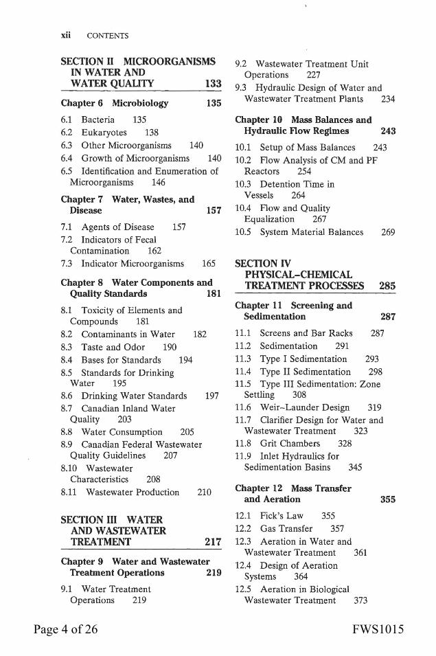
xii CONTENTS
SECTION II MICROORGANISMS IN WATER AND WATER QUAUlY 133
Chapter 6 Microbiology 135
6.1 Bacteria 135 6.2 Eukaryotes 138 6.3 Other Microorganisms 140 6.4 Growth of Microorganisms 140 6.5 Identification and Enumeration of
Microorganisms 146
Chapter 7 Water, Wastes, and Disease 157
7.1 Agents of Disease 157 7.2 Indicators of Fecal
Contamination 162 7.3 Indicator Microorganisms 165
Chapter 8 Water Components and Quality Standards 181
8.1 Toxicity of Elements and Compounds 181
8.2 Contaminants in Water 182 8.3 Taste and Odor 190 8.4 Bases for Standards 194 8.5 Standards for Drinking
Water 195 8.6 Drinking Water Standards 197 8.7 Canadian Inland Water
Quality 203 8.8 Water Consumption 205 8.9 Canadian Federal Wastewater
Quality Guidelines 207 8.10 Wastewater
Characteristics 208 8.11 Wastewater Production
SECTION III WATER AND WASTEWATER
210
TREATMENT 217
Chapter 9 Water and Wastewater Treatment Operations 219
9.1 Water Treatment Operations 219
9.2 Wastewater Treatment Unit Operations 227
9.3 Hydraulic Design of Water and Wastewater Treatment Plants 234
Chapter 10 Mass Balances and Hydraulic Flow Regimes 243
10.1 Setup of Mass Balances 243 10.2 Flow Analysis of CM and PF
Reactors 254 10.3 Detention Time in
Vessels 264 10.4 Flow and Quality
Equalization 267 10.5 System Material Balances 269
SECTION IV PHYSICAL-CHEMICAL TREATMENT PROCESSES 285
Chapter 11 Screening and Sedimentation 287
11.1 Screens and Bar Racks 287 11.2 Sedimentation 291 11.3 Type I Sedimentation 293 11.4 Type II Sedimentation 298 11.5 Type III Sedimentation: Zone
Settling 308 11.6 Weir- Launder Design 319 11.7 Clarifier Design for Water and
Wastewater Treatment 323 11.8 Grit Chambers 328 11.9 Inlet Hydraulics for
Sedimentation Basins 345
Chapter 12 Mass Transfer and Aeration
12.1 Pick's Law 355 12.2 Gas Transfer 357 12.3 Aeration in Water and
Wastewater Treatment 361 12.4 Design of Aeration
Systems 364 12.5 Aeration in Biological
Wastewater Treatment 373
355
Page 4 of 26 FWS1015
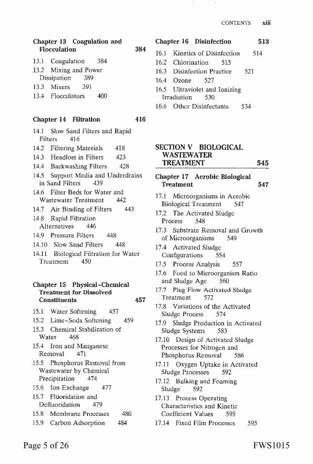
Chapter 13 Coagulation and Rocculation
13.1 Coagulation 384 13.2 Mixing and Power
Dissipation 389 13.3 Mixers 391 13.4 Flocculators 400
Chapter 14 Filtration
14.1 Slow Sand Filters and Rapid Filters 416
14.2 Filtering Materials 418 14.3 Headloss in Filters 423 14.4 Backwashing Filters 428
384
416
14.5 Support Media and Underdrains in Sand Filters 439
14.6 Filter Beds for Water and Wastewater Treatment 442
14.7 Air Binding of Filters 443 14.8 Rapid Filtration
Alternatives 446 14.9 Pressure Filters 448 14.10 Slow Sand Filters 448 14.11 Biological Filtration for Water
Treatment 450
Chapter 15 Physical-Chemical Treatment for Dissolved Constituents 457
15.1 Water Softening 457 15.2 Lime-Soda Softening 459 15.3 Chemical Stabilization of
Water 468 15.4 Iron and Manganese
Removal 471 15.5 Phosphorus Removal from
Wastewater by Chemical Precipitation 474
15.6 Ion Exchange 477 15.7 Fluoridation and
Deftuoridation 479 15.8 Membrane Processes 480 15.9 Carbon Adsorption 484
CONTENTS xiii
Chapter 16 Disinfection 513
16.1 Kinetics of Disinfection 514 16.2 Chlorination 515 16.3 Disinfection Practice 521 16.4 Ozone 527 16.5 Ultraviolet and Ionizing
Irradiation 530 16.6 Other Disinfectants 534
SECTION V BIOLOGICAL WASTEWATER TREATMENT 545
Chapter 17 Aerobic Biological Treabnent 547
17.1 Microorganisms in Aerobic Biological Treatment 547
17.2 The Activated Sludge Process 548
17.3 Substrate Removal and Growth of Microorganisms 549
17.4 Activated Sludge Configurations 554
17.5 Process Analysis 557 17.6 Food to Microorganism Ratio
and Sludge Age 560 17.7 Plug Flow Activated Sludge
Treatment 572 17.8 Variations of the Activated
Sludge Process 574 17.9 Sludge Production in Activated
Sludge Systems 583 17.10 Design of Activated Sludge
Processes for Nitrogen and Phosphorus Removal 586
17.11 Oxygen Uptake in Activated Sludge Processes 592
17.12 Bulking and Foaming Sludge 592
17.13 Process Operating Characteristics and Kinetic Coefficient Values 595
17.14 Fixed Film Processes 595
Page 5 of 26 FWS1015
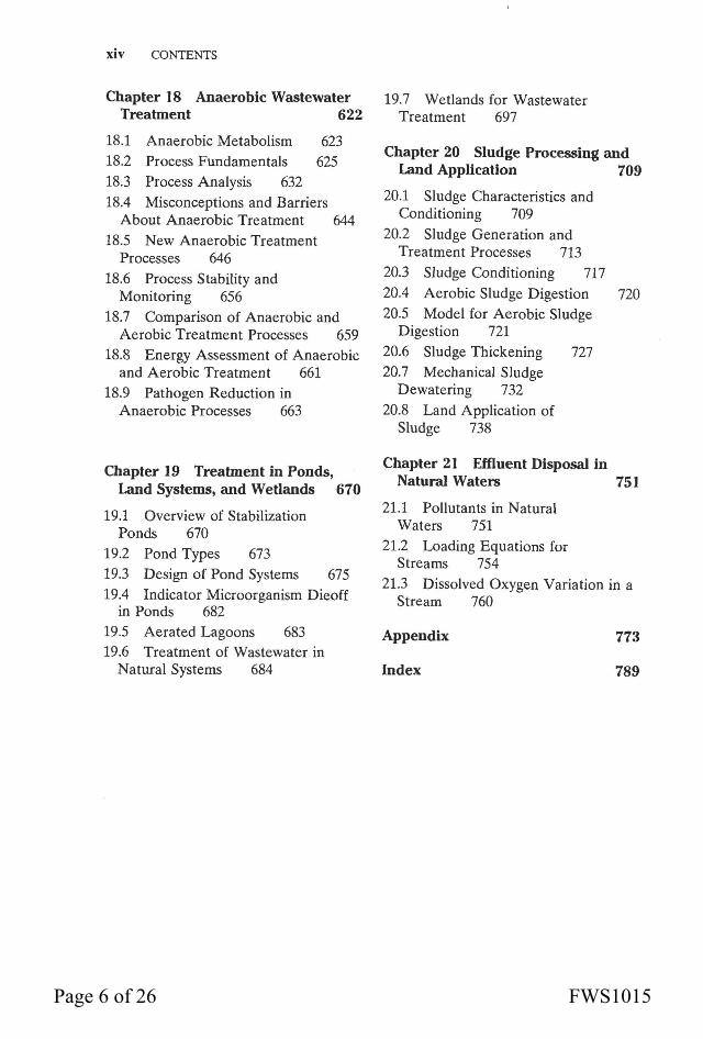
xiv CONTENTS
Chapter 18 Anaerobic Wastewater Treahnent 622
18.1 Anaerobic Metabolism 623 18.2 Process Fundamentals 625 18.3 Process Analysis 632 18.4 Misconceptions and Barriers
About Anaerobic Treatment 644 18.5 New Anaerobic Treatment
Processes 646 18.6 Process Stability and
Monitoring 656 18.7 Comparison of Anaerobic and
Aerobic Treatment Processes 659 18.8 Energy Assessment of Anaerobic
and Aerobic Treatment 661 18.9 Pathogen Reduction in
Anaerobic Processes 663
Chapter 19 Treatment in Ponds ' Land Systems, and Wetlands 670
19.1 Overview of Stabilization Ponds 670
19.2 Pond Types 673 19.3 Design of Pond Systems 675 19.4 Indicator Microorganism Dieoff
in Ponds 682 19.5 Aerated Lagoons 683 19.6 Treatment of Wastewater in
Natural Systems 684
19.7 Wetlands for Wastewater Treatment 697
Chapter 20 Sludge Processing and Land Application 709
20.1 Sludge Characteristics and Conditioning 709
20.2 Sludge Generation and Treatment Processes 713
20.3 Sludge Conditioning 717 20.4 Aerobic Sludge Digestion 720 20.5 Model for Aerobic Sludge
Digestion 721 20.6 Sludge Thickening 727 20.7 Mechanical Sludge
Dewatering 732 20.8 Land Application of
Sludge 738
Chapter 21 Effluent Disposal in Natural Waters 751
21.1 Pollutants in Natural Waters 751
21.2 Loading Equations for Streams 754
21.3 Dissolved Oxygen Variation in a Stream 760
Appendix 773
Index 789
Page 6 of 26 FWS1015

ming EA > Eco),
b.at make up Ec
:r potential than n to proceed as
(2.18)
ential difference eral as different ; are set up and ference between cells or not. An accurately. This l solution when •roceed.
tll possible half(Esys)·
0) (2.19)
be written as a
ll defined but it >t in the system. of a solution. It
:ode is usually a ectrode because it is sensitive to
to the voltmeter .nt potential and :ion. Their only nd makeup of a . be used. Effecm electrochemi-
CHAPTER 2/The Thermodynamic Basis for Equilibrium 47
cal cell. The other half-cell of the electrochemical cell is the solution with the other electrode immersed in it. The half-cells are separated and make electrical contact by a membrane or other equivalent means in the reference electrode.
For a solution at equilibrium with its potential measured by an ideal electrode, Eq. (2.19) will apply. The electrode will transmit Esys· Defining the reference electrode potential as E,.r and considering it to be the anode, the potential reading on the voltmeter will be
Emeter = Ec = Esys - Eref (2.20)
The ORP is usually reported with respect to the hydrogen scale, i.e., the result is normalized with respect to using the SHE as the reference electrode.
Because natural waters are unlikely to be in a state of complete equilibrium, the ORP is a gross indicator of the state of oxidation-reduction in the system. Besides this, the potential reading is influenced by how well the electrode "sees" species in solution among other factors. But this measurement is still a useful tool in many circumstances.
The general form of the Nernst equation for a half-reaction is
ORP = E = E" _ 0.059 1 [reduced species] sys n og [oxidized species] (2.21)
The charge balance always sums to neutrality, but it is seen from Eq. (2.21) that as the concentrations of species able to donate electrons (reduced species) increase, the ORP decreases and vice versa. Thus as oxygen or other oxidants are added to a solution, the 0 RP rises. Water with a pH of 7.00 and temperature of 25°C in equilibrium with oxygen at a partial pressure of 0.21 atm has an ORP of 800 m V on the hydrogen scale. At high ORP there will be a predominance of ions such as so~-, N03, and Fe3+ as opposed to their reduced forms of S2-, NHt, and Fe2+. As free oxygen is removed from a water by chemical or biological reactions, the state of the water changes from an aerobic to an anoxic state, wherein the concentration of oxidized species is predominant compared to their reduced counterparts but there is no significant oxygen concentration. Many microorganisms are able to use so~-, N03, or other oxidized species as electron acceptors. As reaction progresses and oxidized species are consumed and the reduced species predominate, the water reaches an anaerobic state. In anaerobic reactors, ORPs in the range of -300 to -400 mV exist.
• Example 2.6 Use of the Nernst Equation
A platinum electrode and reference electrode were used to measure the ORP of a water. The meter reading was 0.01 V. The reference electrode was known to have a potential of 0.25 V and it can be considered to be the anode. The pH of the water was 8.21. If the water was in equilibrium, what is the ratio of [NHt] to [N03]? Was there any free dissolved oxygen in the water?
The platinum electrode senses the potential of the solution. The potential reading on the meter is Ec. From Eq. (2.20),
Esys = Emeter + Eref = 0.01 V + 0.25 V = 0.26 V
From Table 1.3, the half-reaction for NHt -N03 is
E 0 = 0.880
Page 7 of 26 FWS1015

CHAPTER 9
WATER AND WASTEWATER TREATMENT OPERATIONS
Water and wastewater treatment plants are designed on a unit operations concept in which one operation is optimized to accomplish one task, although more than one problem substance may be remedied in the task. Each operation generally has ramifications on other downstream treatment processes, and tradeoffs between increasing the efficiency of one process or another depend on water characteristics and costs of each operation. A brief description of the processes used for water and wastewater treatment is given here with an explanation of where the process may occur in the treatment stream.
There are a number of manufacturers that supply units designed for one process to prefabricated package plants that incorporate a number of individual unit operations. Package plants may be suitable for smaller installations; larger installations are usually custom designed.
Basins in a treatment operation may be built in parallel or in series. Either option may be dictated by the efficiency of the process and other considerations. Multiple units also provide the capability to treat water or wastewater while one unit is out of service because of breakdown or routine maintenance. In smaller plants, where the design of multiple units is not economical or feasible, bypasses are designed to accommodate shutdown of a unit.
9.1 WATER TREATMENT OPERATIONS
The choice of treatment operations depends on the quality and variability of the raw water source and the treatment objectives, which may vary for industrial as opposed to municipal needs. A thorough survey of the quality and quantity of all possible sources is the first and most important step for designing a water supply process. Compromising the water survey can prove to be very costly in the long run through payment for more complex and expensive treatment operations. Water treatment operations must be designed to handle the extremes in raw water quality variation to provide an acceptable product water at all times.
The unit operations that may be incorporated into a water treatment plant are listed alphabetically below with some comments on their location in the treatment train.
Activated Carbon. Activated carbon is a broad-scale adsorbent of dissolved substances. Dissolved, colloidal, and particulate substances are attracted and attached to the surface of the carbon particles. It is used to remove taste and odor causing compounds as well as toxic organic chemicals. Precipitation and other chemical reac-
219 Page 8 of 26 FWS1015
220 SECfiON III/Water and Wastewater Treatment
tions also occur on the carbon surface. Activated carbon may be used for dechlorination.
A variety of carbon adsorbers can be designed, including batch and continuous flow units. The adsorption capacity of the carbon is eventually exhausted. The carbon is regenerated by heating the carbon, which burns and volatilizes the substances accumulated on it. Instead of heat, strong acids or bases, or other solvent solutions can be used to regenerate the carbon. Smaller operations normally do not regenerate the carbon on site.
Activated carbon can also be used as one of the media in a filtration unit.
Aeration. Aerators expose water to air to remove volatile dissolved components that are in excess of their saturation concentration. Some toxic organics are volatile. Taste- and odor-causing compounds may be removed to satisfactory levels. Groundwaters may have a high C02 content that will be stripped to tolerable levels in aeration.
The transfer of gases from the atmosphere to the water will also be effected. The addition of dissolved oxygen will enhance the oxidation of iron, manganese, and other metals to higher and more insoluble oxidation states. These precipitates will be removed in sedimentation basins and filtration units.
Aeration is one of the first treatment operations applied to a water. It can be designed as an aesthetically pleasing spray aerator open to public view.
Air Flotation. Air flotation is used to separate suspended matter from a water and sometimes used as an alternative to sedimentation. It is primarily used to thicken chemical sludge suspensions. Under pressurized conditions air is injected into the water. The water is released to a vessel at atmospheric pressure that causes the release of the dissolved air as tiny bubbles, which form nuclei to buoy up suspended particulates that are skimmed from the surface.
Biological Treatment. Biological treatment is used for ammonia nitrogen conversion to nitrate, nitrogen removal, and removal of organics in water. It can be accomplished in filters, fluidized beds, or packed beds containing granular activated carbon. Biological treatment of water is an emerging treatment.
Ammonia nitrogen makes a water biologically unstable and high concentrations may be converted to nitrate. Biological removal of nitrogen is accomplished by converting nitrates to nitrogen gas (denitrification). The nitrogen gas is stripped from the water. It is an alternative to ion exchange.
Biological removal of organic matter lessens the amount of disinfection byproducts formed when disinfection agents are added at the end of the treatment plant and renders a water that is less hospitable for growth or regrowth of microorganisms. The water is more biologically stable.
Chemical Feed Mixers. Many processes rely on the addition of chemical agents. 1
Mixers are designed to disperse the chemicals rapidly and thoroughly throughout the water.
Coagulant Recovery. The sludge generated with alum and iron coagulant salts may be regenerated by addition of acid. Recalcination is used to recover calcium oxide (CaO) from calcium carbonate sludge by heating the sludge to drive off carbon dioxide. Calcium oxide is then slaked by adding water to convert it to lime [Ca(OH)2].
Coagulation. Coagulation is the process of adding chemical reagents in a mixing device to destabilize colloidal particles and allow them to agglomerate or flocculate with
'Some chemical agents used in water and wastewater treatment are given in the Appendix along with their bulk densities.
Page 9 of 26 FWS1015

CHAPTER 9/Water and Wastewater Treatment Operations 221
other suspended particles to form larger more readily settled particles. Coagulation reactions are fast and occur in the rapid mixing device. It is essential that the coagulant be dispersed throughout the water to contact and react with the target substances before the coagulant is consumed in side reactions with water itself.
Disinfection. Disinfection is the removal or inactivation of pathogenic microorganisms (not necessarily sterilization). Chemical agents , commonly chlorine or its derivatives, may be used or the water may be exposed to ultraviolet (UV) light or radiation. Ozone is becoming more widely used as a disinfectant. The disinfection tank or device (such as a UV chamber) maintains the water in contact with the dose of disinfectant for a time long enough to assure the required log reductions in indicator bacteria. It is exceedingly rare to find a raw water that would not require disinfection.
North American practice advocates the addition of a small amount of chlorine (and possibly ammonia) to form chloramines, which maintain a small disinfectant residual in the distribution system when other disinfectants are used as the primary disinfectant.
Disinfection is the last treatment applied to a water.
Filtration. Filtration accomplishes polishing of a water and is required for almost every water. Filtration follows sedimentation if it is provided. Water moves through tanks that contain sand and other types of media. Fine solids that did not settle out
· in a sedimentation basin will be entrapped in the filter. There also will be significant removal of bacteria in a filter but not enough (log reduction of bacteria is usually required) to provide a safe water. Larger microorganisms such as protozoans are completely removed in a properly operated filter.
There are two filtration alternatives in common use. Slow sand filters have only sand media. They are cleaned by scraping off the top layer of media on a periodic basis as the filter clogs. Rapid filters are sand filters or multimedia filters that have anthracite, sand, and possibly other media in them. Loading rates of rapid filters are much higher than slow sand filters. Rapid filters are cleaned by backwashing-reversing the flow of water through the media and pumping at a rate sufficient to expand the media. Backwashing is necessary every 1-4 d depending on influent water quality.
The influent to rapid filters generally must have a coagulating agent added to it at some upstream location.
Flow through rapid and slow sand filters is due to gravity. Pressure filters, where water is forced through the filter by applied pressure in a completely enclosed unit, are used in some smaller installations.
Roughing filters that contain coarse media may be used to prefilter water with a very high suspended solids content.
Raw water that is of high quality may require filtration only to remove the small quantities of suspended solids that are present. Otherwise rapid filters are preceded by coagulation, flocculation, and sedimentation.
Flocculation. Flocculators provide gentle agitation of a water that has been coagulated to promote particle contact and formation of larger particles. Hydraulic or mechanically driven flocculators may be designed. Flocculators follow the rapid mixing coagulation tank and precede sedimentation and filtration units.
Fluoridation. Fluoride is added to waters to reduce the incidence of dental caries in the population. The fluoride is added by a chemical feeder. Pumping and flow through the distribution pipes will ensure that the fluoride ion is thoroughly dispersed in the water. Fluoride is added at the end of the treatment train, where its concentration
Page 10 of 26 FWS1015

222 SECTION III /Water and Wastewater Treatment
will not be affected by coagulation, precipitation, sedimentation, and adsorption processes.
When fluoride concentrations in the raw water exceed recommended limits, ion exchange with activated alumina is generally used to remove the excess fluoride.
Ion Exchange. Ion exchange can be used to remove hardness ions, nitrates, or other inorganic constituents. Ion exchangers contain large molecular weight organic substances (resins) that have the ability to exchange one ion for another. For instance there are resins that will exchange hydrogen ions for calcium ions or other positively charged ions. Naturally occurring ion exchangers (crystalline aluminosilicates) are known as zeolites. Eventually the ion exchanger's capacity is exhausted and concentrated solutions of acid, base, or salt are used to regenerate the ion exchanger.
Pipes, Channels, and Other Conduits. Flow in pipes and channels should have a minimum velocity of 0.3 m/s (1 ft/s) to avoid deposition of solids. Recommended velocities at various locations in the plant depend on the state of the water.
Prechlorination or Pre-oxidation. Instead of using aeration, high concentrations of nuisance metals such as Fe and Mn and other metals that may be toxic can be oxidized to more insoluble states by chlorine or other oxidants. The precipitates will be removed by following processes of coagulation, flocculation, sedimentation, and filtration. Sulfides are also oxidized to sulfates. This treatment is also used to retard microbial growth throughout the plant.
This operation is, as the name implies, at the front end of the treatment plant. Elemental chlorine should not be used at this point because it will have a greater tendency to form chloro-organics, some of which are carcinogenic. Other chlorine derivatives such as chloramines or other oxidation agents such as permanganate can be used.
Recarbonation. In water softening plants, it is often necessary to add an excess of lime to facilitate removal of hardness ions. After sedimentation of the CaC03 and Mg(OH)2 precipitates, the pH of the water is high because of the excess lime. Carbon dioxide is added to neutralize the excess OH-.
Reverse Osmosis and Electrodialysis. These technologies are used for the removal of high concentrations of dissolved solids. Reverse osmosis essentially "filters" dissolved solids from the water by forcing the water through a membrane by applying pressure in excess of the osmotic pressure of the dissolved components in the solution. Electrodialysis uses electric current that induces ions to migrate through a membrane. These technologies are primarily used to desalinate brackish waters. They can also be used for softening.
Suspended solids must be removed to a low level before water is subjected to reverse osmosis to prevent fouling of the membrane.
Screens and Bar Racks. Screens and bar racks are used to remove coarse debris from a raw water source. This debris may damage pumps or deposit in channels, causing clogging. They are located at the intake for the water source and at the beginning of the treatment plant. Screenings are collected and disposed at a landfill site.
Sedimentation. Exposing the water to relatively quiescent conditions will allow settleable solids to be removed by the action of the force of gravity. The sludge accumulated in these tanks may be disposed in landfills or the water source downstream of the withdrawal point for the water supply. Sedimentation that has not been preceded by coagulation and flocculation is known as plain sedimentation. Raw waters that contain a high sediment load may be settled in a plain sedimentation basin to remove
Page 11 of 26 FWS1015
CHAPTER 9/Water and Wastewater Treatment Operations 223
the readily settled particulates. Then a chemical assist may be provided through addition of coagulant followed by flocculation and another sedimentation basin to remove slower settling particulates.
Waters, particularly groundwaters that have a low concentration of suspended solids, may not require sedimentation. They can be directly filtered.
Softening. Softening is the removal of multivalent cations (hardness) in the water. As noted above, ion exchange can be used to accomplish this task. Lime-soda (Ca(OH)2-Na2COJ)softening involves the addition of these agents in a mixer, followed by flocculation, sedimentation, and filtration. The alkalinity added by lime and soda ash causes CaC03 and Mg(OH)z to precipitate and be removed in the sedimentation and filtration units. Softening will be practiced in conjunction with coagulation. It is possible to recover the lime.
Super-chlorination. Chlorine is a strong oxidizing agent that can destroy some taste and odor compounds. Also, in plants where filtration is not present and there is a significant risk of protozoan pathogens, elevated levels of chlorination beyond those normally required to disinfect a water will be required. After the chlorine is added, the water is held in a contact basin for the required contact time. Super-chlorination will have to be followed by dechlorination to reduce residual chlorine and the tastes and odors arising from chlorine itself. The dechlorinating agent is usually sulfite, although activated carbon can also be used for dechlorination.
Ultrafiltration. In ultrafiltration or nanofiltration, pressure is used to drive a liquid through a membrane that is permeable to some components. It is similar to reverse osmosis. The process is used to separate higher molecular weight compounds from a water. It is not commonly used for water treatment. Microfiltration uses membranes with larger sized openings to filter small particulates, bacteria, and protozoans from a water.
Water Stabilization. Water stabilization refers to the adjustment of the pH, alkalinity, and calcium content of a water such that there is a slight tendency for the finished water to precipitate CaC03 • A thin deposit of CaC03 in the distribution system pipes will form a protective barrier to retard corrosion of the pipes by agents in the finished water. If softening is practiced, the process must be adjusted to produce the desired concentrations. It may be necessary to add acid or alkaline agents to achieve the desired balance among the three components.
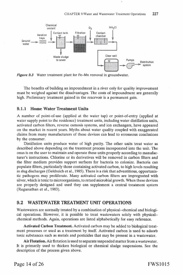
Not all of the above treatment processes will be required for a raw water. There is usually more than one process or a combination of processes that can be used for the same purpose. Also the efficiency of a single unit operation may be significantly influenced by upstream operations. It is even possible for treatment to produce negative results. For example, Himberg et al. (1989) found in a few instances that a conventional treatment process as depicted in Fig. 9.1 produced negative removals of bluegreen algae toxins presumably because of cell lysis and release of toxins to solution in an otherwise proper functioning treatment train. Typical flow charts for water treatment operations are shown in Figs. 9.1, 9.2, and 9.3. There are many possible substitutions . and configuration changes possible. Water treatment processes are classified according to their degree of contaminant removal in Table 9.1.
Reservoirs
Reservoirs are often required to provide a steady supply of water over periods of drought. Some improvement in the quality of a river water can also be obtained by
Page 12 of 26 FWS1015

Pes
tici
des
J:'-
J:'
r-u
r-r
TH
Ms
G-E
p
p p
p F
-G
F-G
F
-G
P-G
F
-E
P-F
p
TH
M p
recu
rsor
s p
F-G
P
-F
F-G
-
G-E
F
-E
G-E
F
-G
F-E
P
-F
P-F
Hep
atot
oxin
s an
d p
p p
--
--
-pd
E
p
neur
otox
ins
from
bl
uegr
een
alga
e'
B.
Seco
ndar
y C
onta
min
ants
C
arbo
n di
oxid
e G
-E
P-I
" E
p
p p
p p
p p
p p
Chl
orid
e p
p p
F-G
p
G-E
p
G-E
p
p p
Col
or
p F
-G
F-G
P
-G
--
--
F-E
E
G
-E
(l
Cop
per
p G
G
-E
p F
-G
E
E
P-F
F
-G
p
Har
dnes
s p
p E
p
E
E
G-E
E
p
p p
p
Hyd
roge
n su
lfid
e F
-E
p F
-G
p p
p p
p F
-E
F-G
p
p
Iron
F
-G
F-E
E
p
G-E
G
-E
G
G-E
G
-E
p p
p
Man
gane
se
P-F
F
-E
E
p G
-E
G-E
G
G
-E
F-E
p
p p
Met
hane
G
-E
P-E
p
p p
p p
p p
F-E
P
-G
p
Sul
fate
p
p p
G-E
p
E
p E
p
p p
G-E
T
aste
and
odo
r F
-E
P-F
P
-F
P-G
-
--
-F
-E
G-E
G
-E
P-F
T
OC
F
P-F
G
-
G-E
E
-
E
p
Tot
al d
isso
lved
sol
ids
p p
P-F
p
p G
-E
P-F
G
-E
p p
p p
Zin
c p
F-G
G
-E
p G
-E
E
-E
p
c. P
ropo
sed
Con
tam
inan
ts
Alu
min
um
p F
F-G
p
G-E
E
-
E
p D
isin
fect
ion
bypr
oduc
ts
-P
-E
P-F
P
-F
-p
F-G
F
-G
F-G
F
-E
P-G
R
adon
G
-E
p p
p p
p p
p p
E
P-F
p
Silv
er
F-G
G
-E
p G
-
--
p F
-G
P-F
U
rani
um
p G
-E
G-E
E
G
-E
E
-E
p
F P
-F
G-E
'Fro
m C
. L
. H
aman
n, J
. B
. M
cEw
en,
and
A.
G.
Mye
rs (
1990
), "G
uide
to
Sele
ctio
n o
f W
ater
Tre
atm
ent
Pro
cess
es,"
in
Wat
er Q
uali
ty a
nd
Tre
atm
ent,
4th
ed.,
F. W
. Po
ntiu
s, e
d.,
Am
eric
an W
ater
W
orks
Ass
ocia
tion
, M
cGra
w-H
ill,
pp.
157-
187.
Rep
rodu
ced
with
per
mis
sion
of
McG
raw
-Hil
l, In
c.
•p,
poor
(0-
20%
rem
oval
); F
, fa
ir (
20-6
0% r
emov
al);
G,
good
(60
-90%
rem
oval
); E
, ex
cell
ent
(90-
100%
rem
ov
al);
"-",
not
app
lica
ble/
insu
ffic
ient
dat
a.
'Aft
er H
imbe
rg e
t al
. (1
989)
. •w
ith
ozo
ne a
s th
e ox
idan
t.
~
Page 13 of 26 FWS1015
CHAPTER 9/Water and Wastewater Treatment Operations 227
Chemical oxidant
Aeration t Contact tank
trays · Ground~ ~ -?--water --
Waste sludge to sewer
03
Filtration ! --?--
Contact chamber
Pumps Distribution
---;.. • ___,.. system
Figure 9.3 Water treatment plant for Fe-Mn removal in groundwater.
The benefits of building an impoundment in a river only for quality improvement must be weighed against the disadvantages. The costs of impoundment are generally high. Preliminary treatment gained in the reservoir is a. permanent gain.
9.1.1 Home Water Treatment Units
A number of point-of-use (applied at the water tap) or point-of-entry (applied at water supply point to the residence) treatment units, including water distillation units, activated carbon filters , reverse osmosis systems, and ion exchangers, have appeared on the market in recent years. Myths about water quality coupled with exaggerated claims from many manufacturers of these devices can lead to erroneous conclusions by the consumer.
Distillation units produce water of high purity. The other units treat water as described above depending on the treatment process incorporated into the unit. The onus is on the user to maintain and operate these units properly according to manufacturer's instructions. Chlorine or its derivatives will be removed in carbon filters and the filter medium provides support surfaces for bacteria to colonize. Bacteria can populate filters, particularly those containing activated carbon, to high levels resulting in slug discharges (Geldreich et at., 1985). There is a risk that adventitious, opportunistic pathogens may proliferate. Many activated carbon filters are impregnated with silver, which is toxic to microorganisms, to retard microbial growth. When these devices are properly designed and used they can supplement a central treatment system (Regunathan et a!., 1983).
9.2 WASTEWATER TREATMENT UNIT OPERATIONS Wastewaters are normally treated by a combination of physical-chemical and biological operations. However, it is possible to treat wastewaters solely with physicalchemical methods. Again, operations are listed alphabetically for easy reference.
Activated Carbon Treatment. Activated carbon may be added to biological treatment processes or used as a treatment by itself. Activated carbon is used to adsorb toxic substances such as metals and pesticides that may be present in a wastewater.
Air Flotation. Air flotation is used to separate suspended matter from a wastewater. It is primarily used to thicken biological or chemical sludge suspensions. See the description of the process given above.
Page 14 of 26 FWS1015
228 SECTION III/Water and Wastewater Treatment
Aerobic Biological Treatment. Many types of processes are possible for the aerobic biological removal of dissolved and suspended organics. In the process, air (oxygen) is supplied to microorganisms that are in contact with the wastewater. The microorganisms metabolize the organic material into carbon dioxide and other end products and new biomass. The putrescibility and soluble oxygen demand is reduced to a small amount.
Some processes such as trickling filters or biodisks (rotating biological contactors) use a solid support media to provide surfaces on which bacteria grow and accumulate. In a trickling filter wastewater is sprayed over a rock or synthetic media bed. Wastewater is applied on a continuous or an intermittent basis. Bacteria attach and grow on the media. Natural air currents supply oxygen. Biodisks work on a similar principle. A series of disks are partially submerged in a tank of wastewater. The disks are rotated to expose the biomass-covered disks to the atmosphere, where oxygen transfer to the biomass occurs. Providing immobilized media for microorganism attachment and growth is known as a fixed film process.
The common activated sludge process is a suspended growth process where the microorganisms are mixed with the wastewater. Air is pumped into the basin to supply oxygen and mixing. Pure oxygen may be supplied as an alternative to air but supplemental mixing is required. There are many variations of the activated sludge process.
Processes may also be designed to oxidize nitrogen or remove nitrogen from the wastewater. It is also possible to design a process for increased removal of phosphorus.
All aerobic biological treatment processes convert some of the dissolved organics into biological solids that must normally be removed in a sedimentation basin following the biological treatment unit. Aerobic biological treatment is often preceded by sedimentation to physically remove suspended organics that would be degraded in the biological treatment process at more expense.
Air Strippers. Volatile compounds or gases present at supersaturated concentrations are amenable to air stripping. Air stripping units are devices that enhance the mass transfer between liquid and the atmosphere. This is accomplished by increasing the surface area of the liquid to maximize its exposure to the atmosphere. There are many types of stripping devices, ranging from highly efficient countercurrent flow to diffused aeration systems. In countercurrent flow devices, the wastewater is injected at the top of a column that contains media such as ceramic berl saddles and air is injected at the bottom of the column.
Diffused aerators inject air into the liquid through porous plates located near the bottom of a tank.
Ammonia Stripping. Ammonia is a volatile component that may be removed by exposing the wastewater to the atmosphere. A high pH favors the formation of ammonia as opposed to ammonium ion. Air strippers are used to remove the unionized ammonia.
Anaerobic Biological Treatment. High-strength wastewaters are amenable to treatment by an anaerobic process. Industrial and agricultural wastewaters are often highly concentrated. Anaerobic treatment occurs in enclosed reactors to prevent access of oxygen. The anaerobic microorganisms that are in contact with the wastewater convert the dissolved and suspended organics into biomass and methane. Significant quantities of methane are produced and it may be used as fuel. As in aerobic biological treatment operations, some processes incorporate solid support media for the microorganisms (fixed film processes), whereas others keep the microorganisms in suspension.
Page 15 of 26 FWS1015

CHAPTER 9/Water and Wastewater Treatment Operations 229
The biological solids produced in an anaerobic process must be settled in a clarifier that may follow the process or be incorporated into the anaerobic reactor. Fixed film and suspended growth processes among other options are used in anaerobic treatment.
Anaerobic digesters are often used to treat solids produced in an aerobic treatment process and in the primary clarifier, considerably reducing the volume of solids finally to be removed from the plant.
Fixed film processes include anaerobic filters and fluidized beds. The suspended growth process is also known as an anaerobic contact process. A unique process in anaerobic treatment is the upflow anaerobic sludge blanket reactor, wherein dense granules of microorganisms are retained in the reactor by inertia.
It is not necessary to presettle the influent to an anaerobic reactor.
Chemical Feed Mixers. Physical-chemical plants rely heavily on the addition of chemical agents.2 Chemical agents are also used in biological treatment plants. Mixers are designed to disperse the chemicals rapidly and thoroughly throughout the water.
Coagulant Recovery. Physical-chemical plants use methods for coagulant recovery described under water treatment.
Coagulation. This process has the same objectives as noted for water treatment and it is used in physical-chemical wastewater treatment processes. Also, chemicals may be added to precipitate a particular constituent such as phosphorus. Alum is commonly applied to effluent from an aeration basin for biological treatment to ensure that phosphorus is precipitated in the final clarifier.
Comminutors. Comminutors are devices that macerate rags, sticks, paper, and other gross solid debris in the wastewater that can clog channels or otherwise obstruct flow through the plant. These devices are placed downstream of the grit chamber. The cuttings from the comminutor are returned directly to the wastewater.
Disinfection. Clarified effluent from the plant may be disinfected to reduce pathogen concentrations prior to discharge to the receiving body of water. Chlorine is usually the disinfectant applied, although UV units are being used at greater frequency. A plug flow contact chamber is used to maintain the wastewater in contact with the disinfectant for the specified time.
Equalization. When flow quantity and quality variations are significant, holding basins are incorporated near the front of the treatment train to allow wastewater to be input to the plant at a more uniform rate and quality. More uniform flows and concentrations reduce the variability of treatment and allow a more compact wastewater treatment plant to be designed with higher utilization of all units. The equalization basin is mixed and aeration may be applied to avoid septic conditions. The amount of biological treatment provided by aerating the wastewater will not be significant. Some stripping of volatile compounds will occur.
Filtration. Filtration is often used in physical-chemical wastewater treatment processes to remove fine colloidal or solid particles that cannot be settled in a sedimentation basin. Filtration is also used finally to polish effluent from clarifiers that have settled effluent from a biological treatment process. It is also used to remove algae in effluent from a stabilization pond process.
Flocculation. This process has the same objectives as noted for water treatment. It is not commonly used in treatment plants that use biological processes but it is an important operation in physical-chemical treatment plants.
2Some chemical agents used in water and wastewater treatment are given in the Appendix along with their bulk densities.
Page 16 of 26 FWS1015

230 SECTION III/Water and Wastewater Treatment
Grit Chambers. After the wastewater is screened, grit is removed. Grit chambers are sedimentation basins designed to remove nonputrescible matter such as silt and sand that cause abrasive wear on channels and pumps and can accumulate and clog channels. Because the materials removed in a grit chamber are essentially nonbiodegradable, they are collected and disposed in a landfill site.
Modern grit chambers are usually aerated chambers with an offset aerator that induces a small degree of water circulation to keep lighter organic particulates in suspension while the heavier grit materials settle.
Incineration. Incineration is used for final stabilization of sludge. An incinerator is a furnace for high-temperature combustion of the sludge. Without emission control, incinerators produce a significant amount of atmospheric contamination.
Lagoons. Lagoons are mechanically aerated ponds that provide aerobic biological treatment.
Membrane Technologies. The membrane technologies of reverse osmosis and electrodialysis described under water treatment can be applied to wastewaters for selective removal and recovery of species.
Neutralization. Industrial wastes with extremely high or low pH are neutralized by acid or base addition. If biological treatment is to be used, a pH near neutrality is required.
Oxidation Ditches. An oxidation ditch is an oval channel with a mechanical aeration device installed to provide aerobic biological treatment.
Pipes, Channels, and Other Conduits. Flow in pipes and channels should have a minimum velocity of 0.6-0.9 m/s (2-3 ft/s) to avoid deposition of solids (WEF and ASCE, 1992). Some facilities use minimum velocities as low as 0.3 m/s (1 ft/s) but the higher minimum is preferred by more operators.
Recarbonation. Carbon dioxide is added to neutralize excess OH- ion that was added earlier in the process for coagulation-flocculation reactions.
Screens and Bar Racks. Screens and bar racks are used to remove coarse debris from wastewater for the same reasons as in a water treatment plant. This debris may damage pumps or deposit in channels, causing clogging. Bar racks are located at the intakes to wet wells in pumping stations in the sewer system as well as at the intake to the wastewater treatment plant. At the wastewater treatment plant screens will also be used after the bar racks. Materials removed on the screens and racks are relatively nonbiodegradable. They are collected and disposed in a landfill site.
Sedimentation. Primary clarifiers are designed to remove settleable solids from a wastewater before biologically treating it for dissolved organics. Removal of biodegradable solids by sedimentation is much less expensive than treating them aerobically in an aeration basin.
Secondary clarifiers follow biological treatment units and are designed to remove biomass formed during biological treatment and other solids present in the influent to the biological treatment unit. In addition to clarification of the wastewater, a secondary clarifier for a biological treatment process is designed to perform some thickening of the biological sludge that accumulates in it.
Sedimentation basins in physical-chemical treatment systems will follow coagulation and flocculation units.
Sludge Concentration and Dewatering. The purpose of sludge concentration units is to reduce the volume of sludge for ultimate disposal in a landfill, incinerator, or on
Page 17 of 26 FWS1015
474 SECfiON IV/Physical-Chemical Treatment Processes
Sequestering Iron and Manganese
Instead of removing iron and manganese, sequestering agents may be added to a water that bind theiron and manganese in polymeric colloidal complexes which prevent them from forming color or turbidity within detention times in the distribution system. Sodium silicates, phosphates, or polyphosphates are the common sequestering agents used. Chlorine must be added simultaneously with sodium silicate to oxidize iron and manganese (Robinson et al., 1992). Iron is most effectively sequestered with silicate; manganese is less susceptible. Silicate doses in the range of 5-25 mg/L as Si02 are normal.
Biological Removal of Iron and Manganese
All of the processes previously discussed for iron and manganese removal are physicalchemical processes. A recent innovation has been the development of biological iron and manganese removal (Mouchet, 1992). The processes are complex and only a brief description is given here (see Mouchet, 1992, for more detail). The processes use filters that support autotrophic iron- and manganese-oxidizing bacteria. Although some bacteria can oxidize both species, others can oxidize only one of them and the optimal conditions for iron removal are different from those for manganese removal. Two separate filters are usually required if both iron and manganese must be removed.
The influent must be adjusted to ORP and pH conditions that promote the activity of the respective groups of bacteria. Dissolved oxygen content of the influent is critical. Conditions that cause physical-chemical removal of iron or manganese will decrease activity of iron and manganese bacteria and ultimately impair process performance. A water must be fully nitrified before biological manganese removal can take place. Higher filtration rates in the range of 25-40 m/h (80-130 ft/h) are used in iron removal filters; typical filtration rates in manganese filters are 10-40 m/h (33-130 ft/h). The higher filtration rates in iron or manganese filters are achieved with coarse sand media with an effective size (d10) of 0.95-1.35 mm or higher. Backwashing frequency depends on the raw water quality but the quantity of backwash water should be well below 1% of the product water.
There are more than 100 bio-Fe or -Mn operations in France alone and other installations throughout Europe. The process greatly reduces the use of chemical agents and is claimed to reduce capital and operating costs (Mouchet, 1992). Sludge produced from the process does not pose treatability problems.
15.5 PHOSPHORUS REMOVAL FROM WASTEWATER BY CHEMICAL PRECIPITATION
Phosphorus is usually the limiting nutrient for eutrophication in inland receiving waters for wastewater treatment plant effluent; therefore, phosphorus concentrations in effluents are controlled. Biological wastewater treatment processes remove some phosphorus in the biological sludge that is formed in these processes but the amount of P removal is normally inadequate for typical wastewaters.
Agents used to precipitate dissolved phosphorus are salts of the metals calcium (Ca2+), iron (either Fe2+ or Fe3+), or aluminum [either alum, Al2(S04) 3 • 18H20 or sodium .aluminate, Na2Al20 4]. The chloride and sulfate salts of Fe2+ and Fe3+ can be used. Pickle liquor, which is a waste product of the steel industry that contains ferrous iron in either a sulfuric or hydrochloric acid solution, may also be used. All of these
Page 18 of 26 FWS1015
626 SECTION V/Biological Wastewater Treatment
18.1. The most important considerations for operation of anaerobic processes are discussed next.
18.2.1 Environmental Variables
Both physical and chemical variables influence the habitat of the microorganisms in the reactor. Oxidation-reduction potentials in anaerobic reactors are usually below -350 mV.
Temperature
As temperature increases the rate of reaction generally increases. For biological systems the rate increases are usually not as great as for chemical reactions.
There are two optimal ranges for process operation to produce methane: 30-40°C (the mesophilic range is from 15 to 40°C) and 50-60°C (the thermophilic range is for temperatures above 40°C). The psychrophilic range is temperatures below 15-20°C. Methane has been produced at temperatures down to 10°C or lower, but for reasonable rates of methane production, temperatures should be maintained above 20°C. Rates of methane production approximately double for each 10°C temperature change in the mesophilic range. Loading rates must decrease as temperature decreases to maintain the same extent of treatment. Operation in the thermophilic range is not generally practical because of the high heating energy requirement. A stable temperature is more conducive to stable operation than any specific temperature.
pH
The most important process control parameter is pH. The optimum pH range for all methanogenic bacteria studied by Zehnder et al. (1982) was between 6 and 8 but the optimum pH for the group as a whole is near 7.0. The lower growth rates of the methanogens require that the process be run at conditions most favorable to them. Numerous references report that the pH required in anaerobic systems for good performance and stability is in the range of 6.5-7.5, although stable operation has been observed outside this range. The system must contain adequate buffering capacity to accommodate the production of volatile acids and carbon dioxide that will dissolve at the operating pressure. Excess alkalinity or ability to control pH must be present to guard against the accumulation of excess volatile acids.
Anaerobic processes can operate over a wide range of volatile acids concentrations (from less than 100 mg/L to over 5 000 mg/L) if proper pH control is practiced. A constant pH lends stability to the process. Automatic pH control is often the most economical means of pH control because less chemicals are consumed. The alkalinity requirement varies with the waste, system operation, and type of process.
The three major chemical sources of alkalinity are lime, sodium bicarbonate, and sodium carbonate. Sodium hydroxide, which is often used in vegetable and fruit peeling operations, is also an important source of alkalinity. Other substances that produce alkalinity are soaps or other salts of organic acids.
Mixing
Septic tanks, Imhoff tanks, and sludge digesters were the first anaerobic treatment operations. All of these processes employed single-tank anaerobic reactors. In septic tanks incoming solids are settled and digested in the same compartment. An additional compartment may be included for polishing of the effluent but the first compartment
Figure
is the treatm digesti mixing plishec
E~ or wit] perf on of dige advanc
Mi mental develo local b inhibit'
Freear accliml the pre more f failure
Wl which receiviJ ofmos1 ever, w pH be)
Sul in sulfi themse tate sul are inh
NutriE
The lm result i1
Page 19 of 26 FWS1015
650 SECTION V/ Biological Wastewater Treatment
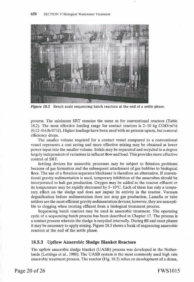
Figure 18.5 Bench scale sequencing batch reactors at the end of a settle phase.
process. The minimum SRT remains the same as for conventional reactors (Table 18.2). The most effective loading range for contact reactors is 2-10 kg COD/m3/d (0.12-0.6lb/ft3/d). Higher loadings have been used with no process upsets, but removal efficiency drops.
The smaller volume required for a contact vessel compared to a conventional vessel represents a cost saving and more effective mixing may be obtained at lower power input into the smaller volume. Solids may be separated and recycled to a degree largely independent of variations in influent flow and load. This provides more effective control of SRT.
Settling devices for anaerobic processes may be subject to flotation problems because of gas formation and the subsequent attachment of gas bubbles to biological floes. The use of a flotation separator/thickener is therefore an alternative. If conventional gravity sedimentation is used, temporary inhibition of the anaerobes should be incorporated to halt gas production. Oxygen may be added to the reactor effluent or its temperature may be rapidly decreased by 5-10°C. Each of these has only a temporary effect on the sludge and does not impair its activity in the reactor. Vacuum degasification before sedimentation does not stop gas production. Lamella or tube settlers are the most efficient gravity sedimentation devices; however, they are susceptible to clogging when treating effluent from a biological treatment process.
Sequencing batch reactors may be used in anaerobic treatment. The operating cycle of a sequencing batch process has been described in Chapter 17. The process is a contact process wherein the sludge is recycled internally. During fill and react phases it may be necessary to apply mixing. Figure 18.5 shows a bank of sequencing anaerobic reactors at the end of the settle phase.
18.5.3 Upflow Anaerobic Sludge Blanket Reactors
The upflow anaerobic sludge blanket (UASB) process was developed in the Netherlands (Lettinga et al., 1980). The UASB system is the most commonly used high rate anaerobic treatment process. The reactor (Fig. 18.3) relies on development of a dense,
Page 20 of 26 FWS1015
CHAPTER IR / Anaerobic Wastewater Treatment 651
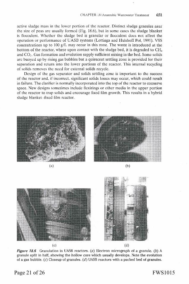
active sludge mass in the lower portion of the reactor. Distinct sludge granules near the size of peas are usually formed (Fig. 18.6). but in some cases the sludge blanket is flocculent. Whether the sludge bed is granular or flocculent does not affect the operation or performance of UASB systems (Lettinga and Hulshoff Pol, 1991). VSS concentrations up to 100 g/L may occur in this zone. The waste is introduced at the bottom of the reactor. where upon contact with the sludge bed, it is degraded to CH4
and CO,. Gas formation and evolution supply sufficient mixing in the bed. Some solids are buoyed up by rising gas bubbles but a quiescent settling zone is provided for their separation and return into the lower portions of the reactor. This internal recycling of solids removes the need for external solids recycle.
Design of the gas separator and solids settling zone is important to the success of the reactor and. if incorrect. significant solids losses may occur, which could result in failure. The clarifier is normally incorporated into the top of the reactor to conserve space. New designs sometimes include flexirings or other media in the upper portion of the reactor to trap solids and encourage fixed film growth. This results in a hybrid sludge blanket-fixed film reactor.
(a) (b)
(c) (d)
Figure 18.6 Granulation in UASB reactors. (a) Electron micrograph of a granule. (b) A granule split in half, showing the hollow core which usually develops. Note the evolution of a gas bubble. (c) Closeup of granules. (d) UASB reactors with a packed bed of granules.
Page 21 of 26 FWS1015

652 SECTION V /Biological Wastewater Treatment
Mechanisms leading to formation of the granular sludge, which is the most significant aspect of these reactors, are not currently well understood but dilute soluble wastes with TSS concentrations less than 1 000-2 000 mg/L give rise to better sludge blankets. The UASB is reported to be more sensitive than other processes to waste composition. Startup is more difficult and requires special considerations to develop the sludge blanket. It has also been reported that wastes high in NHt content or low in divalent cation content are not suited for treatment in a UASB.
Upflow velocities in typical UASB reactors range up to 1-2 m/h (3.3-6.6 ft/h) although Lettinga ·and Hulshoff Pol (1991) and van Haandel and Lettinga (1994) recommend that the average daily upflow velocity should not exceed 1 m/h (3.3 ft/h) . Expanded bed UASB reactors have also been studied (van Haandel and Lettinga (1994). Upflow velocities are in the range of 6-12 m/h (20-40 ft/h) to expand the granules to gain some of the advantages of fluidized bed reactors (discussed in the next section). The potential application of expanded bed UASB reactors is treatment of low-strength wastewaters even at low temperatures. More surface area of the granules is available for microorganism-wastewater contact and the additional mixing intensity from fluid flow compensates for the lower mixing intensity resulting from reduced biogas production of the low strength waste. Influent suspended solids will largely be carried through and out of the expanded bed reactor; therefore, the waste should be pre-settled.
The U ASB process can be used for strong wastewaters provided that the VSS:COD ratio is less than 1.0 or that the VSS are highly biodegradable if the ratio is higher. The reactors have been found capable of treating dilute wastes from 500-600 mg COD/L up to 20 000 mg/L. There are relatively few studies on anaerobic reactors of any type utilizing low-strength wastes (less than 1 000 mg COD/L) and, as noted above, under practical operating conditions, 1 000 mg COD/Lis a realistic minimum cutoff point, although unsettled domestic sewage (BOD5 , 357 mg/L; COD, 627 mg/L) has been successfully treated in UASB reactors operated with a 4-h HRT at temperatures ranging from 18 to 28°C (Barbosa and Sant'Anna, 1989).
Loading rates for UASB reactors range on a COD basis from 0.5 to 40 kg/m3/d (0.03-2.5lb/ft3/d). The HRT can be 1 d or less. The high density of solids in the sludge zone is responsible for retaining the biomass well in excess of minimum SRT for methanogens.
A UASB reactor was found to outperform an anaerobic fixed film reactor and a continuous flow aerobic system (Latkar and Chakrabarti, 1994). Maximum loading rates for 100% conversion of urea were 7.09, 2.73, and 1.3 kg urea/m3/d (0.44, 0.17, and 0.081 lb/ft3/d), respectively. A UASB system can operate safely with an NHt -N loading in the range of 2.4-3.4 kg NHt -N/m3/d (0.15-0.21 lb/ft3/d).
18.5.4 Fixed Film Reactors
Fixed film reactors employ a fixed medium that provides a surface on which bacteria attach and grow. The medium immobilizes the bacteria; consequently, these-reactors can achieve SRT in excess of 100 d. As a result, these processes adjust well to changes in both flow rate and quality of influent and are the most stable of the high-rate reactors. Nonattached biomass also plays a significant role in substrate conversion in fixed film reactors.
As temperature drops, biomass concentrations must rise to maintain the same rate of treatment. These reactors have been demonstrated to perform well at low temperatures with dilute wastes. Fixed film reactors have been shown capable of
Page 22 of 26 FWS1015

CHAPTER 18/ Anaerobic Wastewater Treatment 653
treating domestic wastewater at ambient temperature (25°C) on a lab scale and, along with the UASB, hold the most promise for full-scale domestic sewage treatment.
Startup of a fixed film process is, in general, a more lengthy process than startup for a conventional suspended growth process. On the other hand, the UASB, which is an unconventional suspended growth process, is even slower than the fixed film process in startup. Size of inoculum has less effect for fixed film processes because it does not directly attach to the medium. It may take 6 mo. or more for a biofilm to develop for a low-strength waste treated at a low temperature.
This disadvantage is compensated by the reactor's lowered sensitivity to hydraulic and load variations and its ability to withstand discontinuous operation. A 5-d feeding schedule is adequate and the reactor can recover in 1 or 2 weeks from a period of dormancy of 6 mo. or more. The reactor will retain active biomass when shut down with liquid remaining in it. This feature makes it particularly attractive for seasonal industries.
There are three variations of fixed film reactors: the upflow, downflow, and fluidized bed reactors. Each has particular strengths.
Upflow Fixed Film Reactors
Upflow fixed film reactors are often called "biofilters." This is a misnomer, because filtration does not play a significant role in their performance. They are actually "packed biological reactors," filled with rocks or plastic modules that provide a multitude of random channels and a large surface area. Wastewater is introduced at the bottom and allowed to overflow at the top. Bacteria are present in clumps in channels near the filter bottom as well as being attached to media surfaces throughout the reactor. Flow rates are low and very little shear is exerted on the bacterial slime growth.
Upftow reactors keep some solids in suspension in the pores and treatment derives from both suspended and fixed film growth. Because of the presence of active suspended solids, the specific surface area of medium in upflow fixed film reactors is less important than it is for downftow reactors. Suitable media that have been used are raschig rings, ftexirings, pall rings, rock or plastic balls, and crossflow and tubular media (Fig. 18.7). Using rock or plastic balls of 20 mm (0.8 in.) diameter will result in a void or pore volume of about 40%. Flexirings provide a void volume of about 95% and are therefore more desirable, but they are also more costly. Media used in upftow reactors generally have diameters ranging from 20 to 170 mm (0.8-6.7 in.) .
Crossflow Tubular Pall rings
Figure 18.7 Commercial media used in upflow fixed film reactors.
Page 23 of 26 FWS1015

654 SECTION V /Biological Wastewater Treatment
TABLE 18.3 Performance and Features of Full-Scale Upflow Anaerobic Reactors in North America•·b
Characteristic
Height, m (ft) Temperature, oc Influent COD, mg/L Loading, kg COD/m3/d (lb/ft3/d) Recycled flow: influent flow HRT,h COD removal efficiency, % 'Adapted from Young and Yang (1989). bData on two atypical reactors were not included.
Range
3-12.2 (10-40) 32-37 2 500-24 000 1.5-15 (0.09-0.9) 0-10:1 20-96 61-90+
Media characteristics affect the operation and performance of the reactors. Ideal media have more surface area and high porosity. Higher porosity medium allows the accumulation of more biomass. Sintered glass, raschig rings, or granular activated carbon in addition to ftexirings are examples of more desirable media. Organic loading rates can be increased, which decreases required reactor volume and HRT and also increases the upftow velocity through the reactor. Higher upftow velocities retard clogging but the structure of highly porous media prevents significant biomass loss at higher velocities. A reactor with sintered glass media was able to withstand upftow velocities of 20 m/d (66ft/d) without biomass washout at organic loading rates up to 13 kg COD/m3/d (0.8 lb/ft3/d) (Anderson et al., 1994); a reactor with PVC rings could only deliver equivalent removals at loading rates less than 6 kg COD/m3/d (0.4 lb/ ft3/d) and upftow velocities of 10 m/d (33 ft/d) or lower.
The specific surface of commercial media used in full-scale reactors averages about 100 m2/m3 regardless of the type of medium (Young and Yang, 1989). No instances of plugging or reactors using crossflow or tubular media were found by Young and Yang (1989) in their survey.
COD loadings that can be accommodated by upflow fixed film reactors range from 5 to 30 kg/m3/d. The minimum influent COD concentration is 1 000 and 30 000 mg/L is the upper limit. The reactors function best when influent suspended solids amount to less than 500 mg/L and the ratio of soluble to insoluble COD is greater than 1. Higher suspended solids input may lead to clogging. An HRT of 1 d is usually sufficient.
Information on full-scale upftow anaerobic reactors is contained in Table 18.3. As noted below the table, data from two reactors were not included. One of these was treating domestic sewage with an influent BODs between 100 and 150 mg/L and operating at a loading rate of 0.1-1.2 kg COD/m3/d (0.006-0.075 lb/ft3/d). Removals were 60-70% on a BODs basis. The other was treating landfill leachate and operating at HRTs between 30-40 d. Over 90% of the BODs was being removed.
More recent designs of upflow reactors incorporate a zone that does not have medium at the bottom of the reactor. Suspended growth can accumulate in this zone, resulting in a hybrid reactor.
Downflow Fixed Film Reactors
The downftow stationary fixed film (DSFF) reactor was developed at Canada's National Research Council laboratories. In this reactor bacteria are grown on vertically
Page 24 of 26 FWS1015

CHAPTER 18/ Anaerobic Wastewater Treatment 655
oriented surfaces. Influent is introduced at the top of the reactor and effluent is withdrawn from the bottom of the reactor.
The DSFF reactor is similar in loadings and HRT to the upflow reactor but is less subject to plugging because larger channels are provided in the medium. In a fully developed reactor, gas production from the film provides a considerable degree of mixing. This mixing helps keep the solids in suspension for some time rather than settling directly to the bottom. Suspended solids concentrations up to 3% can be accommodated by downflow fixed film reactors. At higher influent suspended solids concentrations it may be necessary to incorporate recycle to prevent them from settling and plugging the bottom of the reactor.
Various types of vertically oriented supports may be used in DSFF reactors but porous, rough media such as clay or fibrous polyester materials have been found to give the best results. Most reactors have been designed with channels with sides on the order of 1-2.5 em (0.4-1 in.) and specific surfaces in the range of 100-150 m2/m3
(30-46 ft'/ft 3). The void volume is 60-90% of the total reactor volume (Kennedy and Droste, 1991).
Fluidized Bed Reactors
The fluidized or expanded bed reactor is the most recent innovation in anaerobic treatment technology. In these reactors, bacteria are grown on particles of a medium such as sand, and the liquid is pumped through the reactor at a high rate, thereby suspending the medium particles and obtaining high rates of mass transfer. Fluid shear developed by high liquid velocities limits the growth of bacterial films to small thicknesses. Smaller film thickness provides less diffusional resistance to mass transfer of substrate and nutrients than thicker films. Bacterial end products are also removed more quickly from thinner films.
As liquid velocity in the bed is increased, media particles are forced apart and supported by the fluid as opposed to resting on each other. Also there is more movement of the particles as higher velocities are used. Authors distinguish between expanded and fluidized beds: expanded beds are expanded to a lesser degree than fluidized beds and there is little particle movement in an expanded bed. In this text, both expanded and fluidized beds are referred to as fluidized beds.
Approaches described in Chapter 14 for backwashing filters can be used to calculate fluid velocities and bed expansion. Most of the media materials used in fluidized reactors have been natural materials such as crushed rock and sand (Iza, 1991). Recommended media sizes range between 0.1 and 0.7 mm (0.004..:..0.028 in.) nominal diameter. Granular activated carbon medium promotes more rapid accumulation of biomass during startup than anthracite or sand media (Fox et a!., 1990).
In any case, fluidized bed reactors are all high-shear reactors. Flow rates that achieve fluidization require more pumping energy than that needed for other anaerobic processes but the requirement can be lessened by using media with specific gravities near that of water. A media trap, particularly in the case of low-density media, may be needed to prevent media from being carried out with the effluent.
Bed expansion achieves many desirable features. Plugging potential is reduced because growth of thick films is limited. Mass transfer improvements have been mentioned above. However, in a fluidized bed reactor, sufficiently large masses of dense solids still form to provide SRTs in excess of the minimum desirable range. Expansion of the medium provides more surface area upon which bacteria can grow, resulting
Page 25 of 26 FWS1015
656 SECflON V /Biological Wastewater Treatment
in more treatment capability per unit volume of reactor. In addition, flows through the reactor are more uniform.
Fluidized beds have been demonstrated on a laboratory scale to treat domestic sewage at ambient temperatures. The range of acceptable influent COD concentrations is from 1 000 to 30 000 mg/L. The loading rate range is from 1 to 30 kg COD/m3/d (0.06-1.9 lb/ft3/d). HRTs of 9 h to 1 d are normal. Wastes should have soluble to insoluble COD ratios greater than 1 and should not contain solids in excess of 1 000 mg/L.
18.5.5 Two-Phase Anaerobic Digestion
Two-phase anaerobic digestion is adapted to the two-stage nature of anaerobic metabolism. Separate reactors are designed for acidogenesis and methanogenesis. The advantage of this configuration is that conditions in each reactor can be optimized for each group of microorganisms. Low pH and low SRT will limit the growth of methanogens in the acid forming reactor. As noted before the optimal pH for the acid formers is around 5.6, whereas the methane formers have an optimum pH around 7.0. If a low pH in the range of 5.0-6.0 is maintained in the acid forming reactor, then any of the process modifications can be used and acid forming bacteria will be dominant with negligible methanogenic activity. For instance, Fongastitkul et al. (1994) used UASB reactors for each phase; Sutton and Li (1983) used fluidized bed reactors for each phase.
Hydrolysis and formation of volatile fatty acids occurs in the first reactor (phase) and their conversion to methane occurs in the second reactor (phase). Any type of reactor may be designed for the second reactor. Although studies have found that the overall treatment efficiency may be improved in two-phase systems (Ghosh, 1990; Sutton and Li, 1983) there are not a large number of installations. One disadvantage of the process is the additional reactor.
18.6 PROCESS STABILITY AND MONITORING
Anaerobic metabolism is inherently more unstable than aerobic metabolism and, in general, anaerobic treatment is more unstable than aerobic treatment. However, aerobic treatment is not without problems and some of the new anaerobic processes, particularly the fixed film options, are virtually as stable as conventional aerobic treatment. The UASB and conventional processes appear to be the least stable anaerobic processes. This does not mean any of these processes are not viable alternatives.
Anaerobic processes will generally require more time to recover from poisoning by toxic wastes than aerobic processes because of the lower synthesis rate of the anaerobes. Recovery time also depends on the inventory of biomass in the system. Fixed film processes are better able to handle toxicants because of their relatively larger SRT and larger biomass inventory. Wastes from the food and beverage industries, which are often amenable to anaerobic treatment because of their high strength, will not normally have toxicity problems.
More parameters must be monitored in anaerobic processes but the workload increase is not substantial. Besides the routine parameters of pH, COD, VSS, TSS, and alkalinity, an anaerobic process usually requires measurement of volatile acids concentrations and gas composition. A gas chromatograph is needed for each of the latter parameters. These are availa~le for less than $5 000. Methane and carbon dioxide are the two components monitored in the gas. Hydrogen content of the gas requires a specialized instrument but it is another control parameter.
Page 26 of 26 FWS1015