The Whitaker Museum and Art Gallery - Rossendale Borough ...
398
Birmingham | Nottingham | Huntingdon | Leeds | Bristol | Leicester | London| Manchester cpwp.com © Couch Perry Wilkes Whitaker Museum The Whitaker Museum and Art Gallery 180343 Combined M&E Specification DOCUMENT REVISION HISTORY Ref: 180343 Whitaker Museum Rev Author Verification By Date Comments / Status - TS JH Nov 2019 For Tender
-
Upload
khangminh22 -
Category
Documents
-
view
0 -
download
0
Transcript of The Whitaker Museum and Art Gallery - Rossendale Borough ...

Birmingham | Nottingham | Huntingdon | Leeds | Bristol | Leicester | London| Manchester
cpwp.com © Couch Perry Wilkes
Whitaker Museum
The Whitaker Museum and Art Gallery
180343
Combined M&E Specification
DOCUMENT REVISION HISTORY Ref: 180343 Whitaker Museum
Rev Author Verification By Date Comments / Status
- TS JH Nov 2019 For Tender

©2018 Couch Perry Wilkes LLP
Couch Perry Wilkes shall not be liable in whole or part for any use of this document beyond such purpose(s) as the same was originally prepared or provided nor shall Couch Perry Wilkes be liable for any misinterpretation as to such intended purpose(s).
Whitaker Museum Job No. 180343
cpwp.com
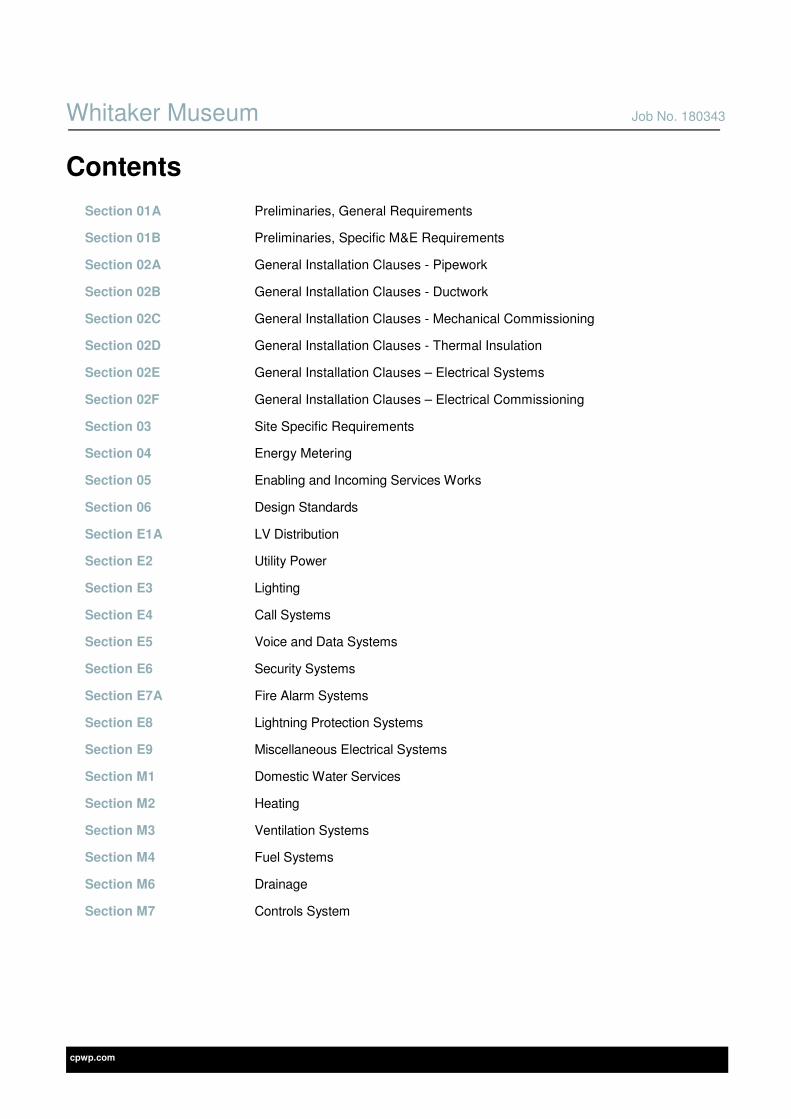
Contents
Section 01A Preliminaries, General Requirements
Section 01B Preliminaries, Specific M&E Requirements
Section 02A General Installation Clauses - Pipework
Section 02B General Installation Clauses - Ductwork
Section 02C General Installation Clauses - Mechanical Commissioning
Section 02D General Installation Clauses - Thermal Insulation
Section 02E General Installation Clauses – Electrical Systems
Section 02F General Installation Clauses – Electrical Commissioning
Section 03 Site Specific Requirements
Section 04 Energy Metering
Section 05 Enabling and Incoming Services Works
Section 06 Design Standards
Section E1A LV Distribution
Section E2 Utility Power
Section E3 Lighting
Section E4 Call Systems
Section E5 Voice and Data Systems
Section E6 Security Systems
Section E7A Fire Alarm Systems
Section E8 Lightning Protection Systems
Section E9 Miscellaneous Electrical Systems
Section M1 Domestic Water Services
Section M2 Heating
Section M3 Ventilation Systems
Section M4 Fuel Systems
Section M6 Drainage
Section M7 Controls System

cpwp.com V2.1
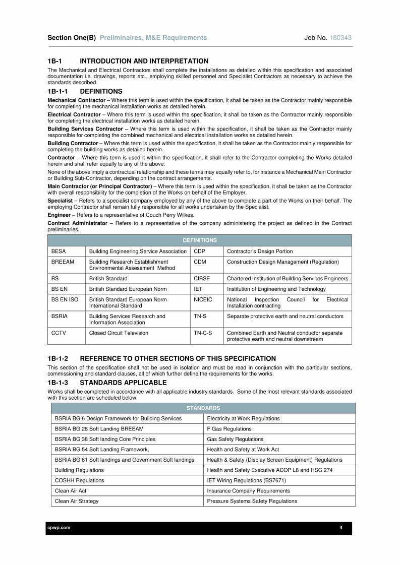
Section One (B) Preliminaries, M&E Requirements

Section One(B) Preliminaires, M&E Requirements Job No. 180343
cpwp.com 2
Contents Page
1B-1 INTRODUCTION AND INTERPRETATION 4
1B-1-1 DEFINITIONS 4
1B-1-2 REFERENCE TO OTHER SECTIONS OF THIS SPECIFICATION 4
1B-1-3 STANDARDS APPLICABLE 4
1B-1-4 CURRENCY OF INDUSTRY STANDARDS 5
1B-2 GENERAL REQUIREMENTS 5
1B-2-1 CONTRACT CONDITIONS 5
1B-2-2 PROJECT DESCRIPTION 5
1B-2-3 PHASING OF THE PROJECT 5
1B-3 SITE VISIT 6
1B-4 CONTRACT INCLUSION 6
1B-5 SPECIFIED EQUIPMENT 6
1B-6 PRE-TENDER ENQUIRIES 6
1B-7 SUPERVISION 7
1B-8 ELECTRICAL SUPPLY 7
1B-9 WATER AND ELECTRICITY 7
1B-10 DESIGN RESPONSIBILITIES 7
1B-10-1 CONTRACTOR DESIGN PORTION 7
1B-10-2 TECHNICAL SUBMISSION 7
1B 10-2-1 GENERAL REQUIREMENTS 7
1B 10-2-2 ALTERNATIVE MANUFACTURERS , MATERIALS, RANGES, ETC (AS ITEM 3 ABOVE) 7
1B 10-2-3 CONTRACTOR DESIGN PORTION (CDP) 8
1B 10-2-4 FULL CONTRACTOR DESIGN 8
1B-10-3 DESIGN REVIEW PROCEDURE 8
1B-11 CO-ORDINATION 8
1B-12 BUILDER'S WORK 9
1B-13 SITE CLEANLINESS 9
1B-14 DAMAGE DUE TO FROST OR RAIN BEFORE PRACTICAL COMPLETION OF THE WORKS 9
1B-15 ARTIFICIAL LIGHTING AND POWER 9
1B-16 WINTER WORKING - ARTIFICIAL LIGHTING 10
1B-17 TEMPORARY WORKS 10
1B-17-1 PLANT, TOOLS AND SCAFFOLDING 10
1B-17-2 DELIVERY AND OFF-LOADING 10
1B-17-3 WORK BY STATUTORY AUTHORITIES 10
1B-18 OVERTIME OR NIGHT WORK 10
1B-19 FIRE PRECAUTIONS 10

Section One(B) Preliminaires, M&E Requirements Job No. 180343
cpwp.com 3
1B-20 TESTING AND COMMISSIONING OF ENGINEERING SERVICES 10
1B-21 SOAK TEST PERIOD 10
1B-22 USE OF BUILDING SERVICES 11
1B-23 DOCUMENTATION TO BE PROVIDED BY CONTRACTOR 11
1B-23-1 FORMATS REQUIRED FOR ANY INFORMATION ISSUED 11
1B-23-2 SCHEDULE OF RATES 12
1B-23-3 CDM REGULATIONS 12
1B-23-4 INSTALLATION (OR WORKING) DRAWINGS 12
1B-23-5 BUILDER'S WORK DRAWINGS 13
1B-23-6 SPECIALIST SUPPLIERS DRAWINGS 13
1B-23-7 PROGRESS DRAWINGS 13
1B-23-8 RECORD DRAWINGS 13
1B-24 PROCEDURES FOR INSPECTION, CHECKING AND ISSUING OF DOCUMENTS 13
1B-25 TIMING OF PREPARATION AND ISSUE OF CONTRACTOR'S DOCUMENTS 14
1B-26 MANUALS 14
1B-26-1 OPERATING AND MAINTENANCE MANUALS 14
1B-26-2 BUILDING LOG BOOK 15
1B-27 LABELLING OF EQUIPMENT 15
1B-28 EXISTING ASBESTOS INSTALLATION 16
1B-29 PRESSURE REGULATION DOCUMENTATION AND COMPLIANCE 16
1B-30 GAS SAFETY REGULATIONS (INSTALLATION AND USE) 16
1B-31 CONSTRUCTION (DESIGN AND MANAGEMENT) REGULATIONS 16
1B-31-1 HEALTH AND SAFETY PLAN 16
1B-31-2 PERSONNEL 16
1B-31-3 HAZARDS OF HEALTH AND SAFETY GENERALLY 16
1B-31-4 CONTRACTORS 16
1B-31-5 INSTRUCTION OF EMPLOYER’S STAFF 16
Section One(B) Preliminaires, M&E Requirements Job No. 180343
cpwp.com 4
1B-1 INTRODUCTION AND INTERPRETATION
The Mechanical and Electrical Contractors shall complete the installations as detailed within this specification and associated documentation i.e. drawings, reports etc., employing skilled personnel and Specialist Contractors as necessary to achieve the standards described.
1B-1-1 DEFINITIONS
Mechanical Contractor – Where this term is used within the specification, it shall be taken as the Contractor mainly responsible for completing the mechanical installation works as detailed herein.
Electrical Contractor – Where this term is used within the specification, it shall be taken as the Contractor mainly responsible for completing the electrical installation works as detailed herein.
Building Services Contractor – Where this term is used within the specification, it shall be taken as the Contractor mainly responsible for completing the combined mechanical and electrical installation works as detailed herein.
Building Contractor – Where this term is used within the specification, it shall be taken as the Contractor mainly responsible for completing the building works as detailed herein.
Contractor – Where this term is used it within the specification, it shall refer to the Contractor completing the Works detailed herein and shall refer equally to any of the above.
None of the above imply a contractual relationship and these terms may equally refer to, for instance a Mechanical Main Contractor or Building Sub-Contractor, depending on the contract arrangements.
Main Contractor (or Principal Contractor) – Where this term is used within the specification, it shall be taken as the Contractor with overall responsibility for the completion of the Works on behalf of the Employer.
Specialist – Refers to a specialist company employed by any of the above to complete a part of the Works on their behalf. The employing Contractor shall remain fully responsible for all works undertaken by the Specialist.
Engineer – Refers to a representative of Couch Perry Wilkes.
Contract Administrator – Refers to a representative of the company administering the project as defined in the Contract preliminaries.
DEFINITIONS
BESA Building Engineering Service Association CDP Contractor’s Design Portion
BREEAM Building Research Establishment Environmental Assessment Method
CDM Construction Design Management (Regulation)
BS British Standard CIBSE Chartered Institution of Building Services Engineers
BS EN British Standard European Norm IET Institution of Engineering and Technology
BS EN ISO British Standard European Norm International Standard
NICEIC National Inspection Council for Electrical Installation contracting
BSRIA Building Services Research and Information Association
TN-S Separate protective earth and neutral conductors
CCTV Closed Circuit Television TN-C-S Combined Earth and Neutral conductor separate protective earth and neutral downstream
1B-1-2 REFERENCE TO OTHER SECTIONS OF THIS SPECIFICATION
This section of the specification shall not be used in isolation and must be read in conjunction with the particular sections, commissioning and standard clauses, all of which further define the requirements for the works.
1B-1-3 STANDARDS APPLICABLE
Works shall be completed in accordance with all applicable industry standards. Some of the most relevant standards associated with this section are scheduled below:
STANDARDS
BSRIA BG 6 Design Framework for Building Services Electricity at Work Regulations
BSRIA BG 28 Soft Landing BREEAM F Gas Regulations
BSRIA BG 38 Soft landing Core Principles Gas Safety Regulations
BSRIA BG 54 Soft Landing Framework, Health and Safety at Work Act
BSRIA BG 61 Soft landings and Government Soft landings Health & Safety (Display Screen Equipment) Regulations
Building Regulations Health and Safety Executive ACOP L8 and HSG 274
COSHH Regulations IET Wiring Regulations (BS7671)
Clean Air Act Insurance Company Requirements
Clean Air Strategy Pressure Systems Safety Regulations

Section One(B) Preliminaires, M&E Requirements Job No. 180343
cpwp.com 5
STANDARDS
Construction (Design and Management) Regulations Liquid Petroleum Regulations
Control of Asbestos Regulation Local Authority Building Control (LABC)
Control of Pollution Act London Building Act and / or Building (Inner London) Regulations where applicable.
Dangerous Substances and Explosive Atmosphere Regulations
National Joint Utilities Group Publications
Electricity Safety, Quality and Continuity Regulation Water Supply Regulations
Requirements of the Environmental Health Officer (EHO), Fire Officer and Building Control Officer
Where the above standards refer to supporting documentation and standards these shall be fully complied with in all respects.
Where discrepancy is found between this specification and the relevant standards, the Contractor shall obtain written clarification from the Engineer prior to submission of the tender. Where a discrepancy has not been clarified prior to tender submission, the Contractor shall include the most onerous requirements.
1B-1-4 CURRENCY OF INDUSTRY STANDARDS
In general, all works shall be completed in accordance with the latest versions of the relevant standards that are applicable at the time of contract commencement.
These standards may be updated, or new standards issued, during the execution of the works and if so the Contractor shall:
1) Comply with all new or updated statutory requirements that come into force during the contract period. Where notice of a change to these is in place during the tender period then compliance is deemed to be included in the tender price.
2) Advise the Engineer of all other relevant new or updated standards when these become known.
3) Obtain confirmation, from the Engineer, as to whether the works shall comply with these new or updated standards with respect to:
• Subsequent phases.
• Variations.
1B-2 GENERAL REQUIREMENTS
This Section of the Specification identifies general requirements which are applicable to all services and all sections of this specification.
1B-2-1 CONTRACT CONDITIONS
The contract conditions shall be as detailed
• In the main contract preliminaries set out for the Contract conditions.
1B-2-2 PROJECT DESCRIPTION
The project involves the design, supply, (modification of existing installation) installation, testing and commissioning of the Mechanical / and / Electrical Services. Scheduled below is a brief list of the services - this list is not exhaustive and is provided to give a general understanding of the works only:
• Isolation and draining down ready for demolition of all services
• Provision of incoming Statutory services i.e. Natural Gas, Water and Electricity
• LTHW heating system
• Mains cold water and Domestic water systems
• General Ventilation systems
• Natural gas supply and distribution system
• Above ground drainage system
• Automatic control/building management system
• LV electrical distribution system
• General and Emergency Lighting systems
• Telecommunication systems
• Security detection and alarms
• Fire detection and alarms
• Earthing and bonding systems
• Lift systems
• Data Systems
Please refer to Main Contractor’s specification for a full description of the overall works.
1B-2-3 PHASING OF THE PROJECT
The project shall be phased to ensure minimum disruption is caused on site.
Section One(B) Preliminaires, M&E Requirements Job No. 180343
cpwp.com 6
Refer to Contract preliminaries for further details.
1B-3 SITE VISIT
A site visit shall be undertaken during the tender period to obtain satisfactory knowledge of the following:
1) Local conditions
2) Nature and accessibility of the site
3) The nature and extent of the operations
4) The supply of and conditions affecting labour
5) Storage space for materials
6) Position of underground services and drains
7) Space available for the execution of the works generally
8) Site Permit schemes and any restrictive site practises
9) Access and site restrictions
The tenderer shall include for all costs necessary to take account of the above. Arrangements for the delivery of materials to site shall be such that no congestion occurs and shall include for all additional handling and transporting due to site conditions.
No additional cost/claim shall be considered due to the failure to undertake a visit site and obtain the necessary knowledge.
1B-4 CONTRACT INCLUSION
The specific contract details are laid out in the Contract preliminaries. The Mechanical and Electrical Contractors shall include for all items necessary for the due and proper completion of the works according to the true intent and meaning of the Tender documentation and this shall include, but not be limited to, all:
1) Materials
2) Labour
3) Carriage
4) Offloading and positioning
5) Tools
6) Minor items such as screws, fixings etc.
7) Items shown on Tender drawings but not detailed in specification
8) Items detailed in specification but not shown on Tender drawings
All materials shall be new unless otherwise specified and of a type and rating matched to the duty for which they are intended. Samples of proposed fittings, materials and workmanship, where required by the Engineer, shall be submitted without delay and in good time to suit the project programme. All systems shall be complete and operational unless otherwise specified.
All test requirements at manufacturer’s works, as listed in relevant British Standards or elsewhere in this specification, shall be met prior to dispatch of equipment.
All items of plant and equipment shall arrive on Site in good condition and be suitably protected from all hazards once there and all prime movers etc. shall be in working order. If items of plant are found not to function correctly after installation and this causes a delay to the Contract, the Mechanical and/or Electrical Contractor shall be charged for any costs incurred.
Care shall be taken to maintain services to areas that need to remain operational during the works. The Mechanical and/or Electrical Contractors shall not disconnect any services until they have established, in writing and through survey, the extent of these areas, and agreed an exact timing and methodology for the necessary isolation and diversion of services.
Where a client/site permit to work scheme (or similar) exists this shall be complied with in full together with necessary notice periods etc.
1B-5 SPECIFIED EQUIPMENT
Where materials are specified in this document they shall be included in the tender without adjustment or alteration. The Engineer may consider alternatives (as a below line tender sum option), at their discretion. Any alternatives must be provided with all supporting information to prove that it is at least equivalent to the specified product particularly regarding the following:
1) Performance
2) Appearance
3) Longevity (robustness)
4) Energy efficiency
5) Certification
6) Product support and Warranty.
Where the specified product satisfies the criteria for enhanced capital allowances and hence is published within the energy technology product list, the alternative product must do likewise.
1B-6 PRE-TENDER ENQUIRIES
Prior to issue of this tender package, enquiries to the marketplace may have been undertaken by Couch Perry Wilkes to obtain quotations from suppliers, manufacturers and specialist installers etc. These may have been requested at varying times through the design development and therefore may not reflect the final design requirements of the project as tendered and may be out of date.
The Contractor shall not rely on the accuracy of pre-tender quotations and shall be responsible for obtaining new quotations based on the final design information contained within the tender specification, drawings, schedules and accompanying tender
Section One(B) Preliminaires, M&E Requirements Job No. 180343
cpwp.com 7
documentation. Where the specification package is issued as Performance information only, the Contractor shall obtain new quotations based on their final design requirements.
No additional cost/claims shall be considered due to the failure to obtain quotations against the final design information.
1B-7 SUPERVISION
Site supervision for the services work is required and shall be by a dedicated Services Site Manager or equivalent permanently based on site throughout the project.
It may be acceptable for a working Charge hand or Foreman to provide this service, but only with prior permission/acceptance by the client.
The supervisor shall be:
1) Present on site whenever work is in progress by or on behalf of the Mechanical or Electrical Contractor.
2) Appropriately qualified and have previous experience for the class of work specified.
3) Approved by the Engineer
4) A responsible representative to whom site working instructions shall be transmitted.
The site supervisor may be changed only after permission to do so has been granted by the Engineer and in exceptional circumstances only.
1B-8 ELECTRICAL SUPPLY
The characteristics of the available electric supply have been determined as follows:
1) Voltage – 400/230 volts
2) Frequency – 50Hz
3) Fault level – TBC by supply authority or measured by Contractor.
4) Earthing arrangements – TN-S or TN-C-S (PME)
The above shall be assumed for Tender purposes only - actual supply details shall be verified on site prior to commencing working drawings / placing orders.
All equipment, including motors and starters shall be provided to suit the voltages and phases as detailed in the particular clauses and shall be verified before final orders for materials are placed.
As part of their co-ordination duties, the Electrical and Mechanical Contractors shall exchange relevant information from their specifications that relate to equipment being procured prior to placing any orders. Thus, for instance, the plant control panels procured by the Mechanical Contractor shall accommodate the incoming cables being procured by the Electrical Contractor.
1B-9 WATER AND ELECTRICITY
Water and electricity consumed during the construction of the works shall be chargeable. For details of any variance refer to Main Contract.
1B-10 DESIGN RESPONSIBILITIES
1B-10-1 CONTRACTOR DESIGN PORTION
The Contractor shall assume full design responsibility for all of the works detailed within this performance specification, drawings and documents.
1B-10-2 TECHNICAL SUBMISSION
The Contractor shall provide technical submissions for all items as listed below:
1) The chosen equipment from the list of manufacturers identified within the specification
2) Where manufacturers provide working drawings (equipment or system)
3) Any alternative item offered that differs from that specified (manufacturer, material, range etc.)
4) Each CDP element ( refer to end of this section)
5) For any design undertaken by the Contractor
6) Any bespoke manufactured equipment.
1B 10-2-1 GENERAL REQUIREMENTS
Each technical submission shall be complete with the following information:
• A completed schedule for each item to show capacity/ duty, efficiencies, redundancy and design parameters used for the selection. (Use schedules within the specific sections of this specification where given.
• Clear identification of the component/equipment/system being submitted with catalogue information, e.g. number or reference or title.
• Specific data sheets for equipment which shall include maintenance and any commissioning requirements.
• Working drawings as appropriate.
• All relevant information required to evaluate the proposal.
1B 10-2-2 ALTERNATIVE MANUFACTURERS , MATERIALS, RANGES, ETC (AS ITEM 3 ABOVE)
In addition to the requirements stated in general requirements above, each alternative proposal shall also include a tabulated comparison with that of the compliant manufacturer’s equipment specified in respect of:
• Clearly stating any deviation from the original specification
• Quantity

Section One(B) Preliminaires, M&E Requirements Job No. 180343
cpwp.com 8
• Duty
• Material
• Physical size
• Efficiency
• Life cycle
• Identical (or better) Warranty
• Same aesthetic appearance (for design team comment)
• Any other relevant information required for an assessment of the alternative submission
1B 10-2-3 CONTRACTOR DESIGN PORTION (CDP)
As a minimum each CDP Submission shall be complete with the following information:
• Detailed design philosophy statement along with any assumptions made.
• Detailed calculations to determine size of plant/equipment/distribution, etc.
• Detailed and complete schematic drawings.
• Clear identification of the component/equipment/system being submitted by catalogue e.g. number or reference or title
• Identification of any available “extras” to enhance proposal
• Specific data sheets for equipment which shall include maintenance and any commissioning requirements
• A completed schedule for each item to show capacity/ duty, efficiencies, redundancy and design parameters used for the selection. Sample schedules are given within the specific sections of this specification.
• Where the subject is ‘technical’ in nature, a simple ‘layman’s’ description to allow consideration and comment by all interested parties, some of whom may not be fully conversant with the proposals but obviously have valid and valuable input.
1B 10-2-4 FULL CONTRACTOR DESIGN
For information on submissions required where the contractor is to assume full design responsibility for all of the works detailed within this performance specification, drawings and documents, refer to the Design Standards section of the specification.
1B-10-3 DESIGN REVIEW PROCEDURE
For each of the Contractor design elements, the Contractor shall provide full detailed technical design submissions to demonstrate that they have understood the requirements of the criteria outlined in the tender documents for that system and have provided a fully compliant solution.
Following the review of the submission the design documents shall be graded as follows:
“A” – Proceed with the works in accordance with the design documents.
“B” – Proceed with the works in accordance with the comments, the design must also be amended to take on board such comments.
“C” – Re-submit design documents incorporating comments made. NO works to be carried out.
Payment will only be forthcoming where the work has been executed in accordance with designs marked A or B.
1B-11 CO-ORDINATION
The tender drawings show design intent. They are not construction or working drawings and therefore do not show all bends, tees, sets etc. that are necessary to locate services correctly to avoid clashes and ensure good maintenance access. The Contractor shall:
1) Include for all materials etc. as required to provide a complete, fully co-ordinated installation for their services.
2) Complete co-ordination in conjunction with the Main Contractor, the Electrical/Mechanical Contractor and the Contract Administrator, both individually and jointly.
3) Be responsible for co-ordination of their Sub-Contractors and/or Specialists’ installation
4) Ensure that all services are co-ordinated with the building itself and any other services present and agree the sequence and timing of each element of the installation in a manner that maintains the agreed co-ordinated arrangements and programme.
5) Where services are exposed to view or of architectural merit, mark out on site the positions of all equipment and services routes, including trunking, conduit and pipework etc. prior to their fixing and agree the same with the Architect/Engineer/ Contract Administrator.
6) Review architect’s room layouts and elevations where available to determine exact locations.
7) Pay particular attention to ensure that accessories are positioned to suit door openings, fitted furniture, etc.
8) At all “pinch points”, heavily serviced areas, congested service routes or corridors and as otherwise specified elsewhere in this specification, produce drawings/sketches/details/REVIT models allocating space for all mechanical and electrical services and demonstrate that crossover points etc. have been agreed in a manner that allows sufficient access to all maintainable items. These drawings/sketches/details shall be produced by the Mechanical Contractor who shall also lead the associated co-ordination process.
9) Produce co-ordinated Mechanical and Electrical ceiling drawings at 1:50 scale, based on Architect’s ceiling layouts, showing all ceiling mounted mechanical and electrical equipment. All necessary mechanical information shall be provided by the Mechanical Contractor. The Electrical Contractor shall take the lead to produce these drawings.
10) Submit all drawings etc. following the requirements for working drawings detailed in this specification.
Section One(B) Preliminaires, M&E Requirements Job No. 180343
cpwp.com 9
11) Liaise with the Contract Administrator and CDM Principal Designer with regard to the assessment and reduction of hazard and risk in accordance with the current CDM regulations.
12) Include for all necessary aspect ratio changes of ductwork where needed to achieve a fully co-ordinated layout or to allow the systems to fit within available voids / under structural steels. These shall be deemed to have been included within the Tender Sum.
13) Take particular care to obtain uniform and tidy arrangements of pumps, valves, switchgear, outlets and ceiling mounted equipment. The precise position of a piece of equipment shall normally be determined as follows: -
a) Single items of equipment which are visually remote from other electrical or mechanical equipment shall be erected at the mounting heights stated in the Specification or shown on the drawings.
b) Two or more items of equipment, whether electrical or mechanical or both, which are to be erected on the same wall or ceiling, or which will otherwise be visually close to each other, shall be arranged in a neat and symmetrical group. Symmetry of arrangement shall be obtained by horizontal and vertical alignment through the centre lines and not the edges of equipment; for this purpose the stated mounting heights may, with the Contract Administrator's approval, be varied slightly.
14) Not install any services in an uncoordinated manner. Any services installed that have not been co-ordinated or as shown on the co-ordinated drawings shall be re-positioned at the Contractor’s own expense as necessary.
Any disputes shall be referred to the Main Contractor, who has overall responsibility for co-ordinating the construction activities.
1B-12 BUILDER'S WORK
Allowances are included in the tender for the provision of builder's work for the works such as:
1) Formation of brick or concrete bases for engineering plant.
2) Formation/excavation of trenches.
3) Provision of anchor thrust blocks.
4) Formation of horizontal and vertical service ducts, covers and access panels as appropriate.
5) Cutting/forming of holes and chases, etc., and making good.
6) Cable tiles, marker tapes and cable markers, which shall be provided by the Contractor, shall be installed by the Building Contractor.
The Contractor shall provide
1) Detailed information to the Building Contractor for all builders work required for the Contract works based on working drawings produced by the Contractor and manufacturers' drawings, etc.
2) Dimensioned drawings showing the sizes and positions of all builders work requirements.
Where it is not practical to indicate on the drawing the positions of small (<100mm dia) holes and chases, they shall be marked out on site by the Contractor; this does not apply to holes through structural concrete or beams, which shall be shown on the drawings.
The Contractor shall be responsible for the preparation of builder's work details of all his Sub Contractors / specialists.
The above shall be provided in good time to enable provision to be made for the same during the construction process.
1B-13 SITE CLEANLINESS
The Contractor shall allow for cleaning up and removal from site of any rubbish as it accumulates during the progress of the works, including that of his Sub-Contractors/specialists. On completion of work the Contractor shall clear up and remove from site all superfluous materials, clean down external faces of buildings affected by the works, scrub paving and floors, clean out gullies and gutters etc., clean glass inside and out, remove all spots, splashes and stains and leave the works and all parts of the premises affected by them clean and in good order to the entire satisfaction of the Contract Administrator.
The Contractor shall ensure that all rubbish, waste and offcuts etc. are cleared away in accordance with the Main Contractor’s waste management plan.
1B-14 DAMAGE DUE TO FROST OR RAIN BEFORE PRACTICAL COMPLETION OF THE WORKS
The Contractor shall make good at his own expense damage caused by frost or rain ingress due to building fabric leaking or equipment being inadequately protected. It is the contractual responsibility of the construction team not to store or install services and equipment in a building that is not sufficiently weather proof or water tight to avoid this damage. Any damaged services and equipment shall be either replaced or repaired to the satisfaction of the contract administrator and all costs for the remedial works shall be borne by the contractor.
1B-15 ARTIFICIAL LIGHTING AND POWER
All artificial lighting and power required for the whole of the works including Mechanical or Electrical Contractor’s works shall be the responsibility of the Main Contractor who shall arrange for temporary supplies as necessary, temporary metering and for payment of cost involved.
Temporary metered electrical supplies to Mechanical and Electrical Contractor’s site accommodation for heating and lighting purposes shall be provided by the Main Contractor. Special electrical supplies for use by the Mechanical and/or Electrical Contractors, e.g. workshop facilities, shall be provided by the Mechanical or Electrical Contractors.
Mechanical and Electrical Contractors shall allow for picking up from the temporary services provided by the Main Contractor with temporary leads to service his own requirements and he is to allow for reimbursing the Main Contractor the cost of electricity used in the Mechanical and/or Electrical Contractor’s site huts.
All temporary electric wiring is to be to the satisfaction of the Contract Administrator.
Section One(B) Preliminaires, M&E Requirements Job No. 180343
cpwp.com 10
1B-16 WINTER WORKING - ARTIFICIAL LIGHTING
The Mechanical and/or Electrical Contractors shall at his own expense provide adequate artificial lighting to ensure that normal weekly working hours may be worked on site despite the loss of natural light.
1B-17 TEMPORARY WORKS
1B-17-1 PLANT, TOOLS AND SCAFFOLDING
Allow for providing everything necessary for the proper execution of the work, including all requisite vehicles, plant, scaffolding, gantries, chutes, stages, fans, ladders, trestles, tarpaulins, tools, rods, moulds, templates, levels, tackle and other implements required for expeditious carrying out of the work in proper sequence, together with the carriage and cartage thereof, maintenance, adapting, shifting and removal of same when no longer required.
The Contractor shall provide and remove on completion, temporary screen and tarpaulins required to give adequate protection against wind, weather and prevent the spreading of dirt, dust and rubbish.
1B-17-2 DELIVERY AND OFF-LOADING
The Contractor shall carry out and shall provide all the necessary equipment for the off-loading, site transport and hoisting to the required level of all materials and equipment supplied under this Contract.
1B-17-3 WORK BY STATUTORY AUTHORITIES
New Electrical connection to be provided
1B-18 OVERTIME OR NIGHT WORK
Overtime and Night work shall only take place as detailed within the Contract Preliminaries.
Where applicable the Contractor shall provide and allow for any overtime as stated within the Specification. The Contract Administrator shall receive not less than 24 hours’ notice specifying times and locations of the work to be done. Any concealed work executed during overtime for which notice has not been given may be required to be opened up for inspection and reinstated at the Contractor's expense.
Should the Contract Administrator issue specific instructions, in writing, for overtime working other than that specified within the Tender Documentation, then the net difference between normal time and overtime rates shall be added in the final account; provided that accurate and detailed returns are submitted each week to the Contract Administrator.
1B-19 FIRE PRECAUTIONS
The Contractor shall take all reasonable precautions to avoid the outbreak of fire, particularly in work involving the use of naked flames. The Contractor shall set in place and rigorously enforce procedures to minimise the risk of an outbreak of fire, which shall address the following general issues as well as any site-specific issue:
1) Disposal of flammable materials
2) Accumulation of rubbish on site
3) Hot works procedures including:
a) Use of fire resisting mats, to prevent scorching or fire.
b) Provision of firefighting equipment during the work.
c) Fire watch during and after hot works.
d) Hot works to stop at least two hours before leaving site.
4) Obtaining and clearing any required work permit from the client and following any additional requirements in their safety procedures.
5) Fire escapes being maintained clear and usable at all times.
6) Safe storage of highly flammable materials and gas cylinders.
The above procedure shall be detailed in a method statement issued to all parties for comment, and any comments incorporated, prior to commencing works.
1B-20 TESTING AND COMMISSIONING OF ENGINEERING SERVICES
Detailed Requirements for testing and commissioned are laid out later in this specification. In general:
1) All testing shall be carried out as recommended by the current edition of the IET wiring regulations (BS7671), relevant British and European Standards and Codes of Practice and current legislation.
2) The Contractor shall draw up a detailed testing and commissioning programme indicating critical dates of external influences.
3) The Contractor shall allow for their Commissioning Engineers being in attendance whilst the Engineer verifies the results and ascertains that the various elements of each system are in full working order. A minimum period of 1 week per month of the contract period (Minimum 2 weeks) shall be allowed for this procedure.
4) The Contractor shall allow for his Commissioning Specialist to demonstrate to the Employer that the design intent of the systems has been achieved.
1B-21 SOAK TEST PERIOD
Upon completion of the setting to work and commissioning of the services the Contractor shall perform a soak test of the systems installed. The soak test shall:
1) Be included in the programme for the works.

Section One(B) Preliminaires, M&E Requirements Job No. 180343
cpwp.com 11
2) Continue until seven continuous days of plant operation have occurred without fault or failure of any component / function.
During the soak test period the Contractor shall:
a) Monitor all functions (pressures/temperatures/starts per hour etc.) which shall be trend logged using the microprocessor controls equipment where installed.
b) Monitor each type of space served by the plant and equipment using digital data recorders (supplied by the Mechanical or Electrical Contractor) to verify the performance.
c) Carry out any specified heat load and noise performance surveys
d) Download/convert all data to Excel spreadsheet format (disc and hard copy).
e) Send all data and monitoring results to the Engineer for acceptance by both the Employer and the professional parties
Should the soak test fail for any reason, then the results shall be null and void and the test period shall re-commence upon rectification of the problem/failure.
All costs associated with the soak test such as test equipment, attendance and supervision shall be included by the Contractor.
Any costs incurred as a result of or a consequence of having to restart the soak test shall be at the Contractor’s expense.
A successful soak test as described shall be carried out prior to practical completion being granted by the Contract Administrator.
1B-22 USE OF BUILDING SERVICES
The Contractor is reminded that they are responsible for the permanent engineering installation provided as part of this Contract until such time as the Certificate of Practical Completion is issued.
These installations shall not be used either directly for, or in connection with carrying out Contract works without the written consent of the Contract Administrator and appropriate Contractors and Manufacturers.
Should any systems be used in this way, the following applies:
1) The Employer does not undertake that it will be available.
2) It shall not be used until the plant has been tested to the satisfaction of the Contract Administrator and Engineer.
3) The Contractor shall take responsibility for operation, maintenance (and remedial work) and arrange supervision by and the indemnification of the appropriate Sub-Contractor and pay all costs arising including extending all associated warranties accordingly.
4) The Contractor shall effect any additional insurances required and pay all additional costs associated.
5) The Contractor shall pay costs of fuel or water used.
6) The Defects Liability Period shall commence from the date of Practical Completion of the works, and not from the date when parts of the installation(s) are brought into use for the above reasons.
7) The Contractor shall indemnify the Employer against the reduction in manufacturer's guarantee resulting from use before practical completion.
8) If it has been agreed that the Contractor may use the permanent lighting then the following shall apply:
a) Diffusers shall be replaced with new just before Practical Completion.
b) Exposed parts of the luminaire shall be protected against paint splashes and other marks.
c) Any separate (e.g. fluorescent) lamps that are used during this period shall be removed and replaced by new, permanent lamps immediately prior to Practical Completion.
d) Where LED fittings with integral lamps are used, the Contractor shall provide financial compensation for the proportion of the fitting life that has been lost due to this usage. This shall be based on the total cost of the fitting and an expected lifespan of 60,000 hours. The running hours shall be logged by the Contractor and certified by the Contract Administrator.
e) Use of the permanent lighting installation and temporary / replacement lamps shall not incur any additional cost to the contract.
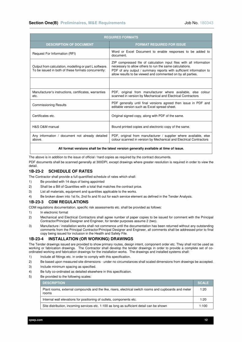
1B-23 DOCUMENTATION TO BE PROVIDED BY CONTRACTOR
The Contractor shall provide all required documentation detailed within this specification, which shall include all technical submissions and design calculations, these documents shall be issued in the formats as detailed below:
1B-23-1 FORMATS REQUIRED FOR ANY INFORMATION ISSUED
The Contractor shall include for all information issued to the client and design team to be provided in the following electronic formats:
REQUIRED FORMATS
DESCRIPTION OF DOCUMENT FORMAT REQUIRED FOR ISSUE
Drawings, to be issued in both of these formats concurrently:
AutoCAD, Issued in .dwg format with any xrefs bound to the drawing.
PDF, without any restrictions on printing, copying, searching etc. (applies to all PDF’s described below.)
Document issue sheets, Technical submittals etc. PDF
Section One(B) Preliminaires, M&E Requirements Job No. 180343
cpwp.com 12
REQUIRED FORMATS
DESCRIPTION OF DOCUMENT FORMAT REQUIRED FOR ISSUE
Request For Information (RFI) Word or Excel Document to enable responses to be added to document.
Output from calculation, modelling or part L software. To be issued in both of these formats concurrently:
ZIP compressed file of calculation input files with all information necessary to allow others to run the same calculations.
PDF of any output / summary reports with sufficient information to allow results to be viewed and commented on by all parties.
Manufacturer’s instructions, certificates, warranties etc.
PDF, original from manufacturer where available, else colour scanned in version by Mechanical and Electrical Contractors
Commissioning Results PDF generally until final versions agreed then issue in PDF and editable version such as Excel spread sheet.
Certificates etc. Original signed copy, along with PDF of the same.
H&S O&M manual Bound printed copies and electronic copy of the same.
Any information / document not already detailed above.
PDF, original from manufacturer / supplier where available, else colour scanned in version by Mechanical and Electrical Contractors
All format versions shall be the latest version generally available at time of issue.
The above is in addition to the issue of official / hard copies as required by the contract documents.
PDF documents shall be scanned generally at 300DPI, except drawings where greater resolution is required in order to view the detail.
1B-23-2 SCHEDULE OF RATES
The Contractor shall provide a full quantified schedule of rates which shall:
1) Be provided with 14 days of being appointed
2) Shall be a Bill of Quantities with a total that matches the contract price.
3) List all materials, equipment and quantities applicable to the works.
4) Be broken down into 1st fix, 2nd fix and fit out for each service element as defined in the Tender Analysis.
1B-23-3 CDM REGULATIONS
CDM regulations documentation, specific risk assessments etc. shall be provided as follows:
1) In electronic format
2) Mechanical and Electrical Contractors shall agree number of paper copies to be issued for comment with the Principal Contractor/Principal Designer and Engineer, for tender purposes assume 2 (two).
3) Manufacture / installation works shall not commence until the documentation has been returned without any outstanding comments from the Principal Contractor/Principal Designer and Engineer, all comments shall be addressed prior to final copy being issued for inclusion in the Health and Safety File.
1B-23-4 INSTALLATION (OR WORKING) DRAWINGS
The Tender drawings issued are provided to show primary routes, design intent, component order etc. They shall not be used as working or fabrication drawings. The Contractor shall develop the tender drawings in order to provide a complete set of co-ordinated working and fabrication drawings for the installation works. The drawings and installed systems shall:
1) Include all fittings etc. in order to comply with this specification.
2) Be based upon measured site dimensions - under no circumstances shall scaled dimensions from drawings be accepted.
3) Include minimum spacing as specified.
4) Be fully co-ordinated as detailed elsewhere in this specification.
5) Be provided to the following scales:
DESCRIPTION SCALE
Plant rooms, external compounds and the like, risers, electrical switch rooms and cupboards and meter rooms
1:20
Internal wall elevations for positioning of outlets, components etc. 1:20
Site distribution, incoming services etc. 1:100 as long as sufficient detail can be shown 1:100

Section One(B) Preliminaires, M&E Requirements Job No. 180343
cpwp.com 13
DESCRIPTION SCALE
Site distribution where insufficient detail can be shown 1:50
Details of brackets, supports and any special fixings 1:10
Manufacturers detail drawings of items of equipment 1:20
Any drawing not listed above 1:50
1) Be provided in electronic format and:
a) The Contractor shall agree the number of paper copies to be issued for comment with the Engineer - for tender purposes assume 3 (three).
b) The Contractor shall agree the number of paper copies to be issued for construction with the Engineer - for tender purposes assume 6 (six).
c) Manufacture / installation works shall not commence until the drawing has been returned without any outstanding comments from the engineer, all comments shall be addressed prior to final copy being issued for manufacture / installation.
1B-23-5 BUILDER'S WORK DRAWINGS
The Contractor shall provide builder’s work drawings that are:
1) Based upon the installation drawings.
2) Fully co-ordinated as detailed elsewhere in this specification.
3) Provided in electronic format and:
a) The Contractor shall agree the number of paper copies to be issued for comment with engineer, for tender purposes assume 6 (six).
b) The Contractor shall agree the number of paper copies to be issued for construction with engineer, for tender purposes assume 10 (ten).
1B-23-6 SPECIALIST SUPPLIERS DRAWINGS
The Contractor shall provide installation/fabrication drawings from all specialist suppliers or manufacturers in accordance with the following:
1) Provide in electronic format for comment prior to construction issue.
2) Provide in electronic format final drawings for construction.
3) Provide electronic format of record drawings and the required number of prints for inclusion within the O & M manuals.
1B-23-7 PROGRESS DRAWINGS
The Contractor shall keep on site, available for reference by the Contract Administrator or other authorised persons, a full set of installation drawings on which the contractor shall record the work as installed.
1B-23-8 RECORD DRAWINGS
The Contractor shall provide record drawings that are:
1) Based upon the installation drawings.
2) An accurate record of the actual installation including any deviations from the working drawings that have occurred on site.
3) Fully co-ordinated as detailed elsewhere in this specification
4) Indicative of the layout identity, size and position of all services installed.
5) Provided in electronic format.
The Contractor shall agree the number of paper copies to be issued for comment with the engineer - for tender purposes assume 2 (two).
The Contractor shall provide one full set of record drawings for each maintenance manual to include:
1) Reduced A3 colour copy inserted unfolded in A3 clear plastic wallets, all drawings to be visible without removing from wallets.
2) Full size copy folded and inserted into clear plastic wallets.
3) USB drive containing electronic copy in formats described elsewhere in this specification.
1B-24 PROCEDURES FOR INSPECTION, CHECKING AND ISSUING OF DOCUMENTS
The above documents shall be issued for inspection by the Engineer and Contract Administrator for comment. The following procedure shall be adopted:
1) Issue electronic and paper copies as detailed above for comment.
2) One marked copy of the document or schedule of comments will be returned.
3) The Contractor shall incorporate comments or provide further information as necessary and re-submit the document for comment.
4) Once the document, in the opinion of the Engineer / Contract Administrator, are free of any comments the Contractor shall:
a) Provide the final document in the required format and quantity, as detailed previously, to form the formal issue.
Section One(B) Preliminaires, M&E Requirements Job No. 180343
cpwp.com 14
b) The formal issue shall be by the Main Contractor.
Any subsequent amendments shall follow the procedure detailed above.
The acceptance in principle shall not relieve the Contractor of their overall responsibility for ensuring fully coordinated and complete documents both from the Contractor and any specialist(s) that are employed.
1B-25 TIMING OF PREPARATION AND ISSUE OF CONTRACTOR'S DOCUMENTS
Any drawings or documents prepared by the Contractor shall be prepared in good time to allow for the inspection procedure outlined above and having due regard to site progress and deliveries of materials.
The time allowed for comment by the Contract Administrator / Engineer shall be at least 10 days, this period shall be allowed for within the program for preparing the above documents.
1B-26 MANUALS
1B-26-1 OPERATING AND MAINTENANCE MANUALS
The Contractor shall produce all information necessary for inclusion in the building Health and Safety file, referred to as Operating and Maintenance (O&M) manuals below.
Program for production of O&M manual.
1) 2 (two) hard copies of the manuals are required, to include record drawings as outlined elsewhere
2) Manuals and record drawings shall be compiled during the contract and an initial draft copy shall be available for the first commissioning of the engineering services. (Minimum 21 days before contract completion.)
3) Practical completion shall not be given until final copies (without unresolved comments from the Engineer) are provided.
4) Allow a minimum of seven days for the Engineer to comment.
5) Incorporate all comments, re-issue for comment if substantial change required.
6) Prior to Practical Completion supply final copies.
The O&M manuals shall be presented as a complete and coordinated package and shall include:
1) Bound in covers capable of withstanding continual heavy use.
2) An Index.
3) Helpful telephone numbers.
4) Instructions for dealing with emergency conditions for each plant.
5) All information to enable operational staff to comprehend fully the extent, purpose and method of operation of the plant(s) including a full description of operation.
6) Detailed schedules of all plant and equipment installed, including model numbers, serial numbers and capacities and with reference numbers which agree with the detailed labelling strategy agreed with the engineer.
7) Schedule of manufacturers' names, addresses and telephone numbers.
8) Detailed instructions on the starting up, running and shut-down of all systems
9) Description of operational routines, together with diagrams showing the functions of all controls.
10) Clearly set out schedules showing the extent and frequency for which maintenance is required, in detail, and how it should be carried out
11) Maintenance and lubrication schedules listed in order of frequency.
12) Information to facilitate the ordering of spares and replacements
13) Common fault finding measures and remedial actions.
14) Any precautionary measures necessary to prevent corrosion or freezing etc.
15) Care required of plant which is or may be subject to seasonal or occasional use
16) A final copy of the report(s) prepared during testing and commissioning, including all test certificates.
17) Maintenance instructions provided by the suppliers of equipment and/or plant to support (not replace) the maintenance information
18) A full set of Record or ‘As Fixed’ Drawings.
19) Circuit and Test charts for each distribution board.
20) NICIEC/IET Test and Completion Certificates
21) Emergency lighting test certificates and record sheets.
22) Fire alarm test certificates.
23) Valve charts referenced to coincide with the marking of valve labels etc. called for in this Specification.
24) The size, type and length of each LV cable (to the nearest metre) together with the measured earth fault loop impedance
25) Interconnections between items of equipment, including those provided by others and terminal numbering and cables core identification for all alarm and control circuits
26) Drawings that include the work of Sub-Contractors, e.g. laboratory / medical gases and ventilation ductwork etc.
27) Schematic diagrams of the application of automatic controls and instruments etc. including a “Description of Operation”.
28) The location and depth of buried services including those installed by Gas, Water and Electricity Authorities etc.
29) Schedules and/or diagrammatic presentations to amplify the drawings where necessary for clarification.
30) Building Regulations Part L Log Book.
31) Pressure Regulations documentation.
Section One(B) Preliminaires, M&E Requirements Job No. 180343
cpwp.com 15
32) Building users guide.
Each manual to contain a DVD or USB memory device to contain the following:
1) CAD drawings (Latest AutoCAD version) and PDF copies of all Record and ‘As Fitted’ drawings.
2) Microsoft Word (Latest version) and PDF of all of Mechanical and Electrical Contractors’ written instructions.
3) PDF copies of all manufacturers O&M manuals (in separate directory, named and cross referenced to match O&M manual descriptions).
4) PDF Copies of all certificates, commissioning results, test certificates etc.
5) Electronic copy of control strategies as final commissioned state.
6) Electronic copies of models, Building Regulation Part L assessments and log book etc. where prepared by the Mechanical and Electrical Contractors.
7) Pressure Regulations documentation.
1B-26-2 BUILDING LOG BOOK
The Building Logbook shall be completed in accordance with Part L of the Building Regulations.
1) In contracts where the Electrical contractor is employed as the Main contractor the log book shall be complied and issued by the Electrical contractor.
2) In contracts where both Electrical and Mechanical contractors are employed, or where Mechanical contractor is employed as Main contractor, the log book shall be compiled and issued by the Mechanical Contractor
The relevant electrical or mechanical information shall be provided to the contractor compiling the Log book as follows:
1) Information to be provided by the Contractor compiling Logbook (Mechanical and/or Electrical Contractor)
a) The location of relevant plant and equipment, including simplified schematic diagrams.
b) The installed capacities (input power and output rating) of the services plant.
c) A report confirming that the building services equipment has been satisfactorily commissioned.
d) Simplified Operating and Maintenance instructions that include provisions enabling the specified performance of equipment to be sustained during operation (this may be cross-referenced to O&M manual documentation).
e) The locations, identifications and descriptions, including instructions of use of all building energy supply meters and sub-meters.
f) A statement regarding air tests and air permeability carried out on the building. (Information may be required from other parties, such as the Main Contractor or Architect).
g) A simple description of the operation and control strategies of the energy consuming services in the building. (Control Specialist to develop from Engineers statements included in Specification).
h) A statement regarding how energy performance of the building (or each separate tenancy in the building) can be calculated from the individual metered energy readings. (Control Specialist to develop from Engineers statements included in Specification).
i) A schedule of floor areas of each of the building zones categorised by environmental servicing type (e.g. air conditioned, naturally ventilated, etc.).
j) Microsoft Excel spreadsheets set up for this particular project to allow recording all meter readings and energy consumption.
2) Information provided by the Engineer or Mechanical Contractor where they are the designer:
a) A description of the whole building, its intended use and design philosophy and the intended purpose of the individual building services systems.
b) Final Part L model output report and energy certificate / display energy certificate as appropriate to the building.
The contractor compiling the information shall be responsible for providing the Building Logbook as part of the O&M documentation. The format of any necessary input to the above items shall be agreed with the contractor compiling the Building Logbook. It shall be the responsibility of either the Electrical or Mechanical Contractor to provide the information in the agreed format.
The contractor compiling the Building Logbook shall be responsible for obtaining the relevant information from the Engineer and other parties in a timely manner to allow the Building Logbook to be provided with the other O&M documentation for comment and final handover.
In the event of this clause not being complied with to the Engineer's satisfaction, the Engineer reserves the right to recommend to the Contract Administrator that the Certificate of Practical Completion to the contractor compiling the documentation be delayed until such time that these items are approved and/or commission independently a Specialist in this field to provide the information, and to deduct the Specialist's cost from the contractor’s final account.
The contractor compiling the Building Logbook shall be responsible to ensure the sign off of this takes place prior to Practical Completion.
1B-27 LABELLING OF EQUIPMENT
Each item of plant and equipment shall bear a metal nameplate giving the maker's name, serial number and relevant performance data. In addition all items of plant and equipment shall be provided with site specific reference labelling, for details refer to Section 3 of this specification.

Section One(B) Preliminaires, M&E Requirements Job No. 180343
cpwp.com 16
1B-28 EXISTING ASBESTOS INSTALLATION
Reference to the Contract preliminaries shall be undertaken to ascertain any work associated with removal of existing asbestos. The Contractor shall also review the Client’s Asbestos Register to become cognisant with all known locations of asbestos and any risks associated with the presence of asbestos
1B-29 PRESSURE REGULATION DOCUMENTATION AND COMPLIANCE
All certification/documentation in compliance with the Pressure Equipment Directive (97/23/EC) and all latest amendments shall be provided.
All equipment installed under this contract and subject to this regulation must be certified and all documentation included within the O & M Manuals.
Failure to provide necessary certification shall render the equipment/system non-functional.
The Mechanical Contractor and Main Contractor shall be liable for any subsequent costs associated with the non-compliance.
The entire installation shall comply in full with the pressure regulations and shall include:
1) Provision of all safety pressure, combined temperature & pressure relief valves and the like.
2) Provision of individual pressure test certificate for all components covered by the regulations. Type testing is not acceptable.
3) Provide, or update an existing when modifying a system, a written scheme of examination in accordance with the regulations, employ a competent person to complete this on the Mechanical Contractor’s behalf if this cannot be completed in house.
All necessary attendances shall be included by the Mechanical Contractor and for compiling all necessary paperwork required to enable the written scheme of examination to be compiled.
1B-30 GAS SAFETY REGULATIONS (INSTALLATION AND USE)
All natural gas pipework shall be undertaken by a company registered by an approved body. The statutory registration body is Gas Safe. If the Mechanical Contractor is not registered this portion of the work shall be sublet to a suitably approved Sub-Contractor.
The Mechanical Contractor shall provide sufficient documentation to prove that the persons undertaking the works are suitably qualified.
All gas installations shall be certified as safe and correct for use on completion by the Gas Safe engineer and this documentation shall be included in the O&M manuals.
1B-31 CONSTRUCTION (DESIGN AND MANAGEMENT) REGULATIONS
For the purposes of the Construction (Design and Management) Regulations, the Main Contractor shall be nominated as and assume the duties of Principal Contractor as defined and set out in those Regulations.
Notwithstanding the requirements of the above clause, the Contractor shall be bound to abide by and implement all regulations, byelaws or other legislation relevant to the health, safety and welfare of all persons on or about the works or likely to be affected by the execution of the works.
1B-31-1 HEALTH AND SAFETY PLAN
The Contractor shall, in conjunction with the CDM Principal Designer, where necessary, amend, adapt, and expand the Health and Safety information provided contained within the tender documents to produce a coherent Construction Phase plan for the project. The plan shall be implemented and monitored and where necessary, adapted, amended or expanded to reflect changes in circumstances which may arise during the construction phase of the project.
1B-31-2 PERSONNEL
The Contractor shall:
1) Ensure suitably qualified personnel are responsible for preparing, implementing and monitoring the Health and Safety Plan for the duration of the construction phase of the project.
2) Obtain the prior written approval of the CDM Principal Designer before changing any of the personnel referred to above.
1B-31-3 HAZARDS OF HEALTH AND SAFETY GENERALLY
The Contractor shall advise the CDM Coordinator immediately of any deficiencies in the Pre-tender Health and Safety information provided or of unforeseen hazards to health and safety which may become apparent as the project proceeds.
1B-31-4 CONTRACTORS
The Contractor shall take all necessary measures to satisfy himself that all Contractors, whether appointed by him directly or not, are competent and have allocated sufficient resources to comply with the requirements on Contractors imposed by the latest Construction (Design and Management) Regulations.
1B-31-5 INSTRUCTION OF EMPLOYER’S STAFF
The Contractor shall, in conjunction with their Specialists and Commissioning engineer, instruct the employer’s staff.
Instruction shall not commence until the following has been achieved:
1) Full commissioning of all services.
2) Checking Verification of Systems.
3) Random Checks of system(s) by Engineer.
4) Note: client instruction shall not take place on same day as commissioning activities for any system.
A programme for all instruction / demonstrations shall be developed in advance and issued to the following parties:

Section One(B) Preliminaires, M&E Requirements Job No. 180343
cpwp.com 17
1) Main Contractor
2) The Contractor and his Specialists / Sub-Contractors.
3) Commissioning specialist
4) Electrical/Mechanical Contractor
5) Client’s facilities management representatives.
6) Client user group(s) representative.
7) Contract Administrator
8) Engineer
For each system the following procedure shall be used:
1) Prepare documentation for instruction including:
a) Relevant as fitted drawings / technical drawings.
b) Relevant section of the O&M manual, including Job specific information, operating instructions, maintenance instructions etc.
c) Final commissioning results.
2) An invitation to attend the client instruction shall be issued to the parties detailed above at least seven days before the date of the instruction. Invitation shall include:
a) Electronic (PDF) copies of all of the documentation for commissioning described above.
b) Agenda for the day’s activities developed from the minimum requirements detailed below.
c) Pro-forma sign off sheet for all attendees.
3) The following parties are required to attend from the contracting team.
a) The Contractor and their Specialists / Sub-Contractors.
b) Commissioning specialist
c) Main Contractor
4) Agenda for system instruction, the following sets out the minimum requirements:
a) Tour of installed system including identifying all key parts of the system and demonstrating these are correctly indicated on the as fitted drawings.
b) Presentation of commissioning results and demonstrate system operating correctly.
c) Presentation of operating and maintenance manuals.
d) Demonstrate day to day and emergency operating procedures.
e) Any discrepancies identified during the demonstration shall be scheduled by the Contractor along with actions / programme for rectification.
Formal acceptance of the system shall occur when all parties are satisfied with the system and understand correct operation, all parties shall then sign the pro-forma described above.
The Contractor shall include in their tender and programme sufficient time to incorporate the client instruction methodology described above.
cpwp.com V3.0
Section Two (A) General Installation Clauses - Pipework
Section TWO(A) General Installation Clauses - Pipework Job No. 180343
cpwp.com 2
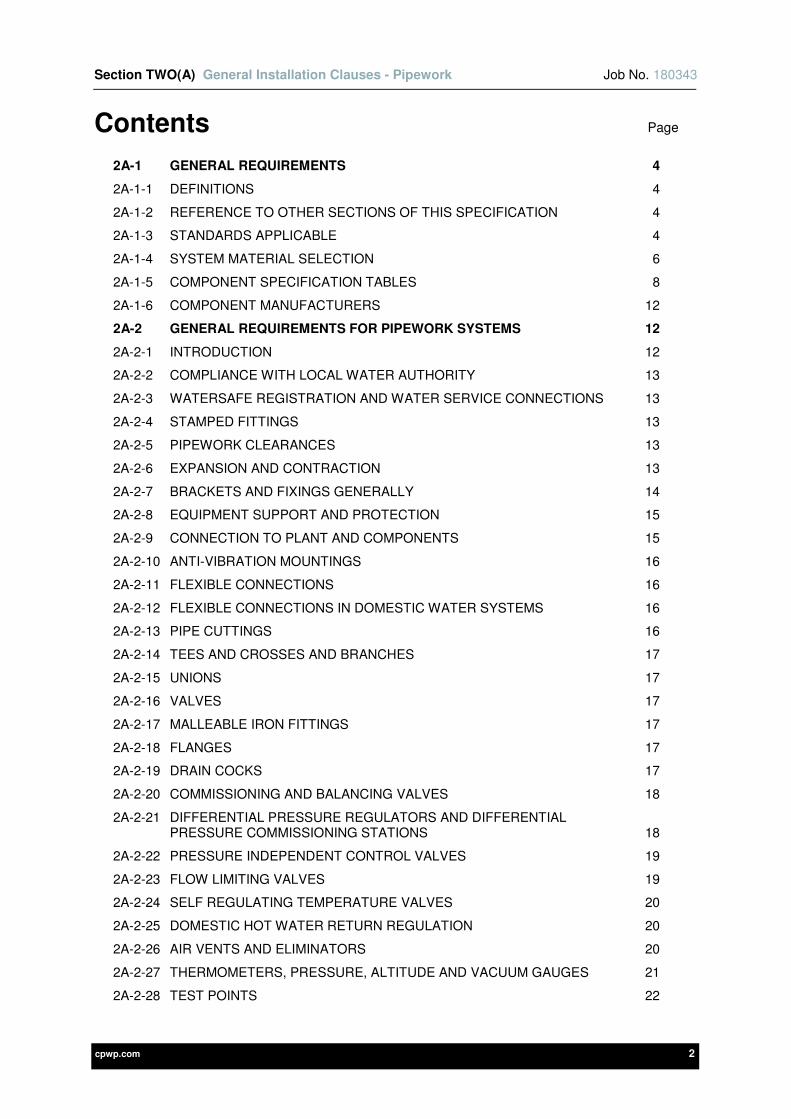
Contents Page
2A-1 GENERAL REQUIREMENTS 4
2A-1-1 DEFINITIONS 4
2A-1-2 REFERENCE TO OTHER SECTIONS OF THIS SPECIFICATION 4
2A-1-3 STANDARDS APPLICABLE 4
2A-1-4 SYSTEM MATERIAL SELECTION 6
2A-1-5 COMPONENT SPECIFICATION TABLES 8
2A-1-6 COMPONENT MANUFACTURERS 12
2A-2 GENERAL REQUIREMENTS FOR PIPEWORK SYSTEMS 12
2A-2-1 INTRODUCTION 12
2A-2-2 COMPLIANCE WITH LOCAL WATER AUTHORITY 13
2A-2-3 WATERSAFE REGISTRATION AND WATER SERVICE CONNECTIONS 13
2A-2-4 STAMPED FITTINGS 13
2A-2-5 PIPEWORK CLEARANCES 13
2A-2-6 EXPANSION AND CONTRACTION 13
2A-2-7 BRACKETS AND FIXINGS GENERALLY 14
2A-2-8 EQUIPMENT SUPPORT AND PROTECTION 15
2A-2-9 CONNECTION TO PLANT AND COMPONENTS 15
2A-2-10 ANTI-VIBRATION MOUNTINGS 16
2A-2-11 FLEXIBLE CONNECTIONS 16
2A-2-12 FLEXIBLE CONNECTIONS IN DOMESTIC WATER SYSTEMS 16
2A-2-13 PIPE CUTTINGS 16
2A-2-14 TEES AND CROSSES AND BRANCHES 17
2A-2-15 UNIONS 17
2A-2-16 VALVES 17
2A-2-17 MALLEABLE IRON FITTINGS 17
2A-2-18 FLANGES 17
2A-2-19 DRAIN COCKS 17
2A-2-20 COMMISSIONING AND BALANCING VALVES 18
2A-2-21 DIFFERENTIAL PRESSURE REGULATORS AND DIFFERENTIAL PRESSURE COMMISSIONING STATIONS 18
2A-2-22 PRESSURE INDEPENDENT CONTROL VALVES 19
2A-2-23 FLOW LIMITING VALVES 19
2A-2-24 SELF REGULATING TEMPERATURE VALVES 20
2A-2-25 DOMESTIC HOT WATER RETURN REGULATION 20
2A-2-26 AIR VENTS AND ELIMINATORS 20
2A-2-27 THERMOMETERS, PRESSURE, ALTITUDE AND VACUUM GAUGES 21
2A-2-28 TEST POINTS 22
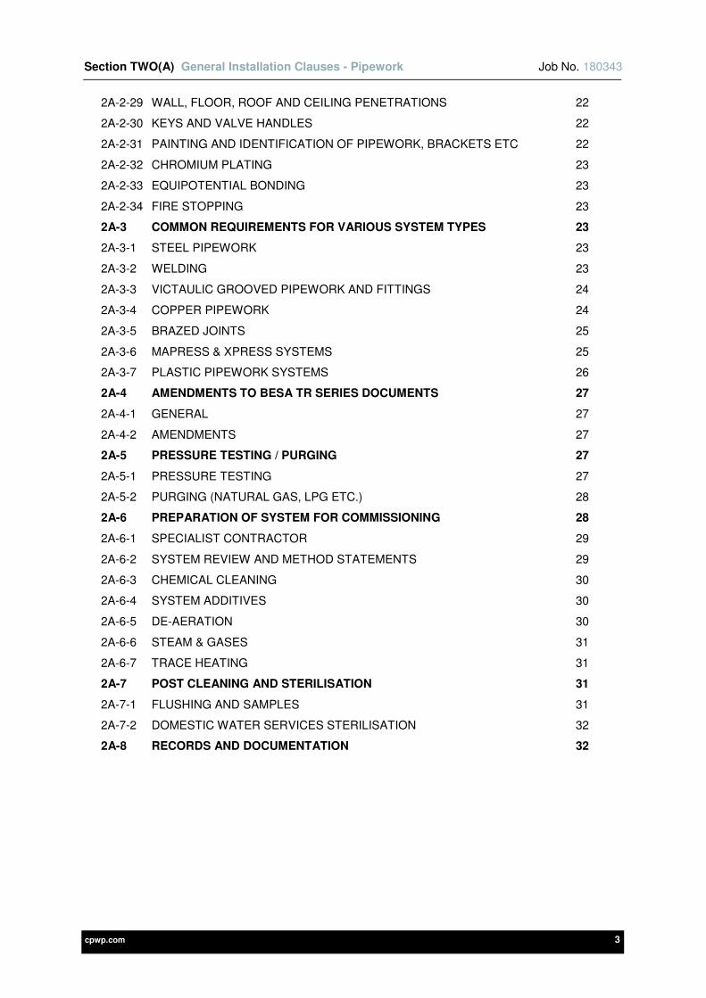
Section TWO(A) General Installation Clauses - Pipework Job No. 180343
cpwp.com 3
2A-2-29 WALL, FLOOR, ROOF AND CEILING PENETRATIONS 22
2A-2-30 KEYS AND VALVE HANDLES 22
2A-2-31 PAINTING AND IDENTIFICATION OF PIPEWORK, BRACKETS ETC 22
2A-2-32 CHROMIUM PLATING 23
2A-2-33 EQUIPOTENTIAL BONDING 23
2A-2-34 FIRE STOPPING 23
2A-3 COMMON REQUIREMENTS FOR VARIOUS SYSTEM TYPES 23
2A-3-1 STEEL PIPEWORK 23
2A-3-2 WELDING 23
2A-3-3 VICTAULIC GROOVED PIPEWORK AND FITTINGS 24
2A-3-4 COPPER PIPEWORK 24
2A-3-5 BRAZED JOINTS 25
2A-3-6 MAPRESS & XPRESS SYSTEMS 25
2A-3-7 PLASTIC PIPEWORK SYSTEMS 26
2A-4 AMENDMENTS TO BESA TR SERIES DOCUMENTS 27
2A-4-1 GENERAL 27
2A-4-2 AMENDMENTS 27
2A-5 PRESSURE TESTING / PURGING 27
2A-5-1 PRESSURE TESTING 27
2A-5-2 PURGING (NATURAL GAS, LPG ETC.) 28
2A-6 PREPARATION OF SYSTEM FOR COMMISSIONING 28
2A-6-1 SPECIALIST CONTRACTOR 29
2A-6-2 SYSTEM REVIEW AND METHOD STATEMENTS 29
2A-6-3 CHEMICAL CLEANING 30
2A-6-4 SYSTEM ADDITIVES 30
2A-6-5 DE-AERATION 30
2A-6-6 STEAM & GASES 31
2A-6-7 TRACE HEATING 31
2A-7 POST CLEANING AND STERILISATION 31
2A-7-1 FLUSHING AND SAMPLES 31
2A-7-2 DOMESTIC WATER SERVICES STERILISATION 32
2A-8 RECORDS AND DOCUMENTATION 32
Section TWO(A) General Installation Clauses - Pipework Job No. 180343
cpwp.com 4
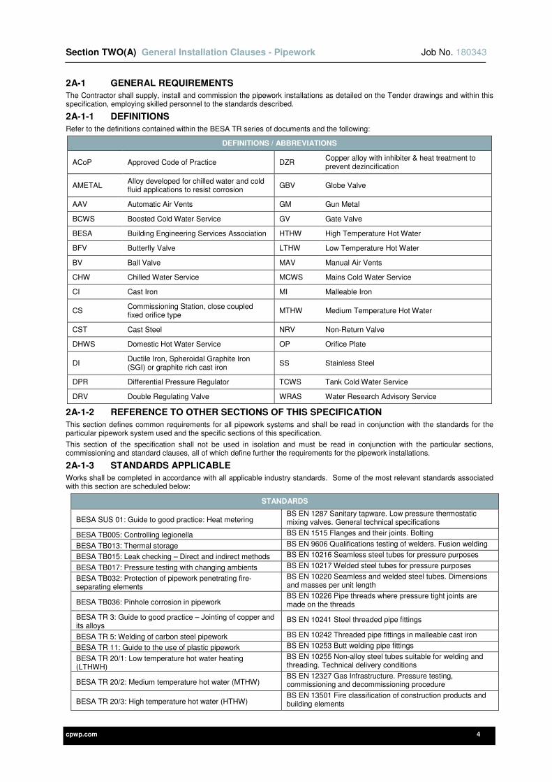
2A-1 GENERAL REQUIREMENTS
The Contractor shall supply, install and commission the pipework installations as detailed on the Tender drawings and within this specification, employing skilled personnel to the standards described.
2A-1-1 DEFINITIONS
Refer to the definitions contained within the BESA TR series of documents and the following:
DEFINITIONS / ABBREVIATIONS
ACoP Approved Code of Practice DZR Copper alloy with inhibiter & heat treatment to prevent dezincification
AMETAL Alloy developed for chilled water and cold fluid applications to resist corrosion
GBV Globe Valve
AAV Automatic Air Vents GM Gun Metal
BCWS Boosted Cold Water Service GV Gate Valve
BESA Building Engineering Services Association HTHW High Temperature Hot Water
BFV Butterfly Valve LTHW Low Temperature Hot Water
BV Ball Valve MAV Manual Air Vents
CHW Chilled Water Service MCWS Mains Cold Water Service
CI Cast Iron MI Malleable Iron
CS Commissioning Station, close coupled fixed orifice type
MTHW Medium Temperature Hot Water
CST Cast Steel NRV Non-Return Valve
DHWS Domestic Hot Water Service OP Orifice Plate
DI Ductile Iron, Spheroidal Graphite Iron (SGI) or graphite rich cast iron
SS Stainless Steel
DPR Differential Pressure Regulator TCWS Tank Cold Water Service
DRV Double Regulating Valve WRAS Water Research Advisory Service
2A-1-2 REFERENCE TO OTHER SECTIONS OF THIS SPECIFICATION
This section defines common requirements for all pipework systems and shall be read in conjunction with the standards for the particular pipework system used and the specific sections of this specification.
This section of the specification shall not be used in isolation and must be read in conjunction with the particular sections, commissioning and standard clauses, all of which define further the requirements for the pipework installations.
2A-1-3 STANDARDS APPLICABLE
Works shall be completed in accordance with all applicable industry standards. Some of the most relevant standards associated with this section are scheduled below:
STANDARDS
BESA SUS 01: Guide to good practice: Heat metering BS EN 1287 Sanitary tapware. Low pressure thermostatic mixing valves. General technical specifications
BESA TB005: Controlling legionella BS EN 1515 Flanges and their joints. Bolting
BESA TB013: Thermal storage BS EN 9606 Qualifications testing of welders. Fusion welding
BESA TB015: Leak checking – Direct and indirect methods BS EN 10216 Seamless steel tubes for pressure purposes
BESA TB017: Pressure testing with changing ambients BS EN 10217 Welded steel tubes for pressure purposes
BESA TB032: Protection of pipework penetrating fire-separating elements
BS EN 10220 Seamless and welded steel tubes. Dimensions and masses per unit length
BESA TB036: Pinhole corrosion in pipework BS EN 10226 Pipe threads where pressure tight joints are made on the threads
BESA TR 3: Guide to good practice – Jointing of copper and its alloys
BS EN 10241 Steel threaded pipe fittings
BESA TR 5: Welding of carbon steel pipework BS EN 10242 Threaded pipe fittings in malleable cast iron
BESA TR 11: Guide to the use of plastic pipework BS EN 10253 Butt welding pipe fittings
BESA TR 20/1: Low temperature hot water heating (LTHWH)
BS EN 10255 Non-alloy steel tubes suitable for welding and threading. Technical delivery conditions
BESA TR 20/2: Medium temperature hot water (MTHW) BS EN 12327 Gas Infrastructure. Pressure testing, commissioning and decommissioning procedure
BESA TR 20/3: High temperature hot water (HTHW) BS EN 13501 Fire classification of construction products and building elements
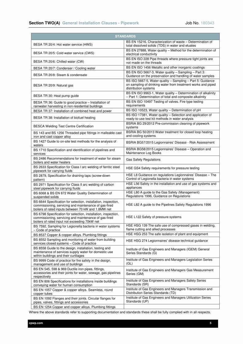
Section TWO(A) General Installation Clauses - Pipework Job No. 180343
cpwp.com 5
STANDARDS
BESA TR 20/4: Hot water service (HWS) BS EN 15216, Characterization of waste – Determination of total dissolved solids (TDS) in water and eluates
BESA TR 20/5: Cold water service (CWS) BS EN 27888, Water quality – Method for the determination of electrical conductivity
BESA TR 20/6: Chilled water (CW) BS EN ISO 228 Pipe threads where pressure tight joints are not made on the threads
BESA TR 20/7: Condenser / Cooling water BS EN ISO 1456 Metallic and other inorganic coatings
BESA TR 20/8: Steam & condensate BS EN ISO 5667-3, Water quality – Sampling – Part 3: Guidance on the preservation and handling of water samples
BESA TR 20/9: Natural gas
BS ISO 5667-5, Water quality – Sampling – Part 5: Guidance on sampling of drinking water from treatment works and piped distribution systems
BESA TR 30: Heat pump guide BS EN ISO 9963-1, Water quality – Determination of alkalinity – Part 1: Determination of total and composite alkalinity
BESA TR 36: Guide to good practice – Installation of rainwater harvesting in non-residential buildings
BS EN ISO 10497 Testing of valves. Fire type testing requirements
BESA TR 37: Installation of combined heat and power BS ISO 10523, Water quality – Determination of pH
BESA TR 38: Installation of biofuel heating BS ISO 17381, Water quality – Selection and application of ready-to-use test kit methods in water analysis
BESCA Welding Test Centre Certification BSRIA BG 29/2012 Pre-commission cleaning of pipework systems
BS 143 and BS 1256 Threaded pipe fittings in malleable cast iron and cast copper alloy
BSRIA BG 50/2013 Water treatment for closed loop heating and cooling systems
BS 1427 Guide to on-site test methods for the analysis of waters
BSRIA BG57/2015 Legionnaires’ Disease - Risk Assessment
BS 1710 Specification and identification of pipelines and services
BSRIA BG58/2015 Legionnaires’ Disease – Operation and Maintenance Log Books
BS 2486 Recommendations for treatment of water for steam boilers and water heaters
Gas Safety Regulations
BS 2633 Specification for Class I arc welding of ferritic steel pipework for carrying fluids
HSE GS4 Safety requirements for pressure testing
BS 2879, Specification for draining taps (screw-down pattern)
HSE L8 Guidance on regulations Legionnaires’ Disease – The Control of Legionella bacteria in water systems
BS 2971 Specification for Class II arc welding of carbon steel pipework for carrying fluids
HSE L56 Safety in the installation and use of gas systems and appliances
BS 6068 & BS EN 872 Water Quality Determination of suspended solids
HSE L80 A guide to the Gas Safety (Management) Regulations 1996, Guidance on Regulations
BS 6644 Specification for selection, installation, inspection, commissioning, servicing and maintenance of gas-fired boilers of rated inputs between 70 kW and 1.8MW net
HSE L82 A guide to the Pipelines Safety Regulations 1996
BS 6798 Specification for selection, installation, inspection, commissioning, servicing and maintenance of gas-fired boilers of rated input not exceeding 70kW net
HSE L122 Safety of pressure systems
BS 7592, Sampling for Legionella bacteria in water systems – Code of practice
HSE HSG 139 The safe use of compressed gases in welding, flame cutting and allied processes
BS 8537 Copper & copper alloys. Plumbing fittings HSE HSG 253 The safe isolation of plant and equipment
BS 8552 Sampling and monitoring of water from building services closed systems – Code of practice
HSE HSG 274 Legionnaires’ disease technical guidance
BS 8558 Guide to the design, installation, testing and maintenance of services supply water for domestic use within buildings and their curtilages
Institute of Gas Engineers and Managers (IGEM) General Series Standards (G)
BS 9999 Code of practice for fire safety in the design, management and use of buildings
Institute of Gas Engineers and Managers Legislation Series (GL)
BS EN 545, 598 & 969 Ductile iron pipes, fittings, accessories and their joints for water, sewage, gas pipelines respectively
Institute of Gas Engineers and Managers Gas Measurement Series (GM)
BS EN 806 Specifications for installations inside buildings conveying water for human consumption
Institute of Gas Engineers and Managers Safety Series Standards (SR)
BS EN 1057 Copper & copper alloys. Seamless, round copper tubes
Institute of Gas Engineers and Managers Transmission and Distribution Series Standards (TD)
BS EN 1092 Flanges and their joints. Circular flanges for pipes, valves, fittings and accessories
Institute of Gas Engineers and Managers Utilization Series Standards (UP)
BS EN 1254 Copper and copper alloys. Plumbing fittings
Where the above standards refer to supporting documentation and standards these shall be fully complied with in all respects.
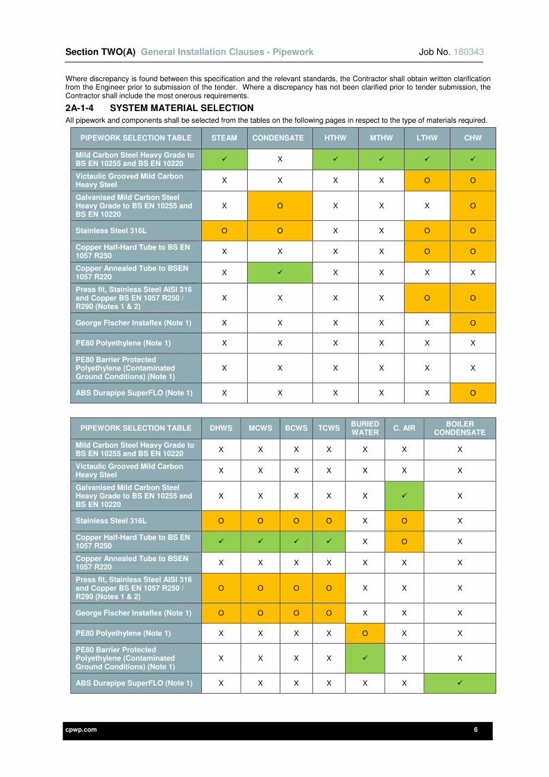
Section TWO(A) General Installation Clauses - Pipework Job No. 180343
cpwp.com 6
Where discrepancy is found between this specification and the relevant standards, the Contractor shall obtain written clarification from the Engineer prior to submission of the tender. Where a discrepancy has not been clarified prior to tender submission, the Contractor shall include the most onerous requirements.
2A-1-4 SYSTEM MATERIAL SELECTION
All pipework and components shall be selected from the tables on the following pages in respect to the type of materials required.
PIPEWORK SELECTION TABLE STEAM CONDENSATE HTHW MTHW LTHW CHW
Mild Carbon Steel Heavy Grade to BS EN 10255 and BS EN 10220
X
Victaulic Grooved Mild Carbon Heavy Steel
X X X X O O
Galvanised Mild Carbon Steel Heavy Grade to BS EN 10255 and BS EN 10220
X O X X X O
Stainless Steel 316L O O X X O O
Copper Half-Hard Tube to BS EN 1057 R250
X X X X O O
Copper Annealed Tube to BSEN 1057 R220
X X X X X
Press fit, Stainless Steel AISI 316 and Copper BS EN 1057 R250 / R290 (Notes 1 & 2)
X X X X O O
George Fischer Instaflex (Note 1) X X X X X O
PE80 Polyethylene (Note 1) X X X X X X
PE80 Barrier Protected Polyethylene (Contaminated Ground Conditions) (Note 1)
X X X X X X
ABS Durapipe SuperFLO (Note 1) X X X X X O
PIPEWORK SELECTION TABLE DHWS MCWS BCWS TCWS BURIED WATER
C. AIR BOILER
CONDENSATE
Mild Carbon Steel Heavy Grade to BS EN 10255 and BS EN 10220
X X X X X X X
Victaulic Grooved Mild Carbon Heavy Steel
X X X X X X X
Galvanised Mild Carbon Steel Heavy Grade to BS EN 10255 and BS EN 10220
X X X X X X
Stainless Steel 316L O O O O X O X
Copper Half-Hard Tube to BS EN 1057 R250
X O X
Copper Annealed Tube to BSEN 1057 R220
X X X X X X X
Press fit, Stainless Steel AISI 316 and Copper BS EN 1057 R250 / R290 (Notes 1 & 2)
O O O O X X X
George Fischer Instaflex (Note 1) O O O O X X X
PE80 Polyethylene (Note 1) X X X X O X X
PE80 Barrier Protected Polyethylene (Contaminated Ground Conditions) (Note 1)
X X X X X X
ABS Durapipe SuperFLO (Note 1) X X X X X X
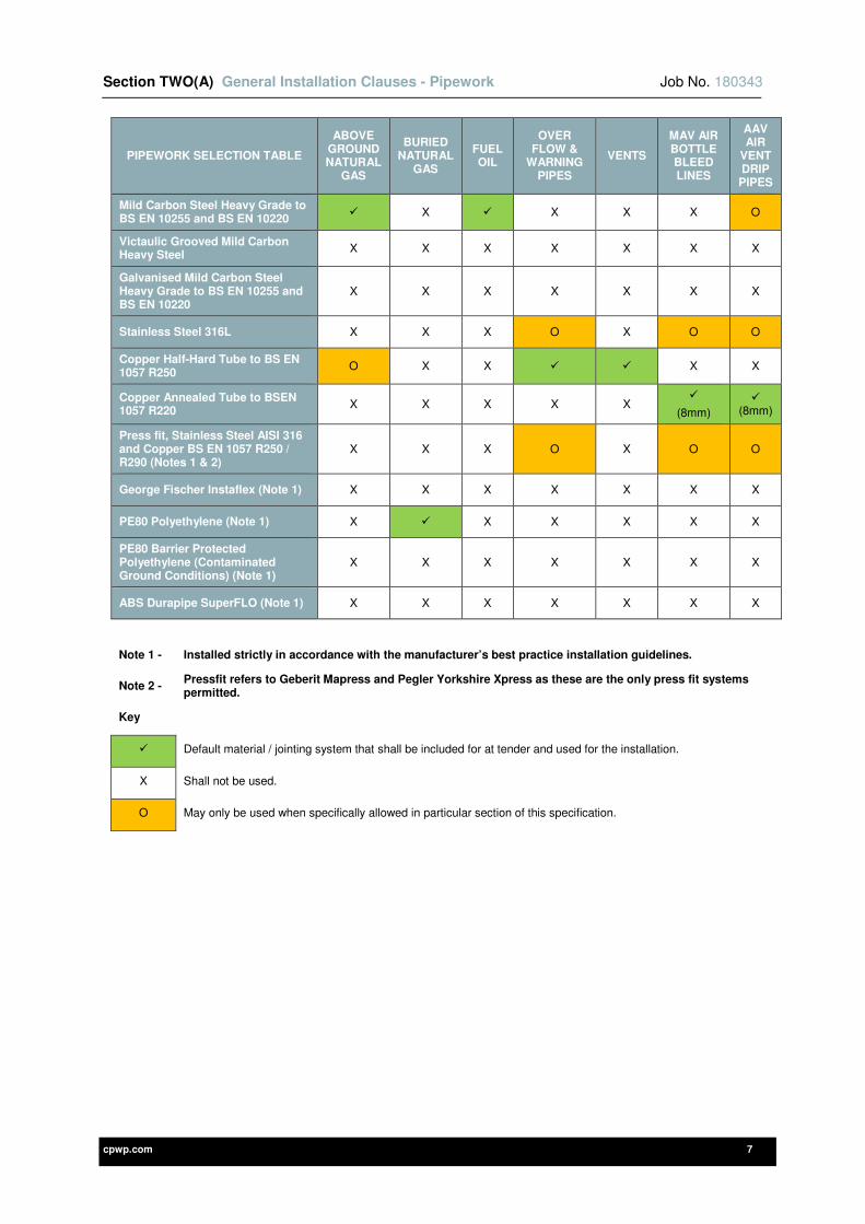
Section TWO(A) General Installation Clauses - Pipework Job No. 180343
cpwp.com 7
PIPEWORK SELECTION TABLE
ABOVE GROUND NATURAL
GAS
BURIED NATURAL
GAS
FUEL OIL
OVER FLOW &
WARNING PIPES
VENTS
MAV AIR BOTTLE BLEED LINES
AAV AIR
VENT DRIP PIPES
Mild Carbon Steel Heavy Grade to BS EN 10255 and BS EN 10220
X X X X O
Victaulic Grooved Mild Carbon Heavy Steel
X X X X X X X
Galvanised Mild Carbon Steel Heavy Grade to BS EN 10255 and BS EN 10220
X X X X X X X
Stainless Steel 316L X X X O X O O
Copper Half-Hard Tube to BS EN 1057 R250
O X X X X
Copper Annealed Tube to BSEN 1057 R220
X X X X X
(8mm)
(8mm)
Press fit, Stainless Steel AISI 316 and Copper BS EN 1057 R250 / R290 (Notes 1 & 2)
X X X O X O O
George Fischer Instaflex (Note 1) X X X X X X X
PE80 Polyethylene (Note 1) X X X X X X
PE80 Barrier Protected Polyethylene (Contaminated Ground Conditions) (Note 1)
X X X X X X X
ABS Durapipe SuperFLO (Note 1) X X X X X X X
Note 1 - Installed strictly in accordance with the manufacturer’s best practice installation guidelines.
Note 2 - Pressfit refers to Geberit Mapress and Pegler Yorkshire Xpress as these are the only press fit systems permitted.
Key
Default material / jointing system that shall be included for at tender and used for the installation.
X Shall not be used.
O May only be used when specifically allowed in particular section of this specification.
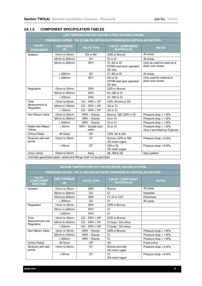
Section TWO(A) General Installation Clauses - Pipework Job No. 180343
cpwp.com 8
2A-1-5 COMPONENT SPECIFICATION TABLES
LOW TEMPERATURE HOT WATER (LTHW) HEATING SYSTEM
PRESSURE RATING – PN 16 UNLESS DETAILED OTHERWISE IN PARTICULAR SECTION
VALVE /
COMPONENT
SIZE RANGE (Ø)
VALVE TYPE VALVE / COMPONENT
MATERIAL(S) NOTES
Isolation 15mm to 50mm GV or BV DZR or Bronze All areas
65mm to 200mm GV DI or CI All areas
65mm to 200mm BFV CI, SS or DI EPDM seat lever operated
SS disc
Only be used for external & plant room areas
> 200mm GV CI, SS or DI All areas
> 200mm BFV SS or DI EPDM seat gear operated
SS disc
Only used for external & plant room areas
Regulation 15mm to 50mm DRV DZR or Bronze
65mm to 200mm DRV DI, GM or CI
> 200mm DRV DI, GM or CI
Flow Measurement & Regulation
15mm to 50mm CS – DRV + OP DZR, Bronze or SS
65mm to 150mm CS – DRV + OP SS or CI
> 150mm CS – DRV + OP SS or CI
Non-Return Valve 15mm to 50mm NRV – Gravity Bronze, GM, DZR or DI Pressure drop < 1 kPa
65mm to 200mm NRV – Gravity DI or CI Pressure drop < 1 kPa
> 200mm NRV – Gravity DI or CI Pressure drop < 1 kPa
Wafer Non-Return Valves
> 50mm NRV – Double door wafer
DI or CI Pressure drop < 1 kPa Only if permitted by Engineer
Orifice Plates All Sizes OP DZR, SS & GM
Strainers with test points
15mm to 50mm ST Bronze, DZR or GM
SS mesh cages
Pressure drop < 2 kPa
> 50mm ST GM or DI SS mesh cages
Pressure drop < 2 kPa
Union Joints 15mm to 65mm Navy MI, GM & SS Navy pattern
Internally galvanised pipes, valves and fittings shall not be permitted.
MEDIUM TEMPERATURE HOT WATER (MTHW) HEATING SYSTEM
PRESSURE RATING – PN 16 UNLESS DETAILED OTHERWISE IN PARTICULAR SECTION
VALVE / COMPONENT
FUNCTION
SIZE RANGE(S)
(Ø) VALVE TYPE
VALVE / COMPONENT MATERIAL(S)
NOTES
Isolation 15mm to 50mm GBV Bronze All areas
65mm to 200mm GV CI Hospitals
65mm to 200mm GBV CI, DI or CST Elsewhere
> 200mm GV CI All areas
Regulation 15mm to 50mm DRV DZR or Bronze
65mm to 200mm DRV CI
> 200mm DRV CI
Flow Measurement and Regulation
15mm to 50mm CS – DRV + OP DZR or Bronze
65mm to 200mm CS – DRV + OP CI body / SS orifice
> 200mm CS – DRV + OP CI body / SS orifice
Non-Return Valve 15mm to 50mm NRV – Gravity DZR or Bronze Pressure drop < 1 kPa
65mm to 200mm NRV – Gravity CI Pressure drop < 1 kPa
> 200mm NRV – Gravity CI Pressure drop < 1 kPa
Orifice Plates All Sizes OP SS Fixed orifice
Strainers with test points
15mm to 50mm ST Bronze and GM SS mesh cages
Pressure drop < 2 kPa
> 50mm ST CI SS mesh cages
Pressure drop < 2 kPa

Section TWO(A) General Installation Clauses - Pipework Job No. 180343
cpwp.com 9
MEDIUM TEMPERATURE HOT WATER (MTHW) HEATING SYSTEM
PRESSURE RATING – PN 16 UNLESS DETAILED OTHERWISE IN PARTICULAR SECTION
VALVE / COMPONENT
FUNCTION
SIZE RANGE(S)
(Ø) VALVE TYPE
VALVE / COMPONENT MATERIAL(S)
NOTES
Union Joints 15mm to 65mm Navy MI Navy pattern
Internally galvanised pipes, valves and fittings shall not be permitted.
HIGH TEMPERATURE HOT WATER (HTHW) HEATING SYSTEM
PRESSURE RATING – PN40 (AS REQUIRED TO ACHIEVE COMBINED PEAK TEMPERATURE AND TEST PRESSURE) UNLESS DETAILED OTHERWISE IN PARTICULAR SECTION
VALVE / COMPONENT
FUNCTION
SIZE RANGE(S)
(Ø) VALVE TYPE
VALVE / COMPONENT MATERIAL(S)
NOTES
Isolation 15mm to 50mm GV Bronze All areas
65mm to 200mm GV CI Hospitals
65mm to 200mm GBV CI, DI or CST Elsewhere
> 200mm GV CI All areas
Regulation 15mm to 50mm DRV DZR or Bronze
65mm to 200mm DRV CI
> 200mm DRV CI
Flow Measurement and Regulation
15mm to 50mm CS – DRV + OP DZR or Bronze
65mm to 200mm CS – DRV + OP CI body / SS orifice
> 200mm CS – DRV + OP CI body / SS orifice
Non-Return Valve 15mm to 50mm NRV – Gravity DZR or Bronze Pressure drop < 1 kPa
65mm to 200mm NRV – Gravity CI Pressure drop < 1 kPa
> 200mm NRV – Gravity CI Pressure drop < 1 kPa
Orifice Plates All Sizes OP SS Fixed orifice
Strainers with test points
15mm to 50mm ST Bronze or GM SS mesh cages
Pressure drop < 2 kPa
> 50mm ST CI SS mesh cages
Pressure drop < 2 kPa
Union Joints 15mm to 65mm Navy MI Navy pattern
Internally galvanised pipes, valves and fittings shall not be permitted.
STEAM SYSTEM
PRESSURE RATING – PN 40 UNLESS DETAILED OTHERWISE IN PARTICULAR SECTION
VALVE / COMPONENT
FUNCTION
SIZE RANGE(S)
(Ø) VALVE TYPE
VALVE / COMPONENT MATERIAL(S)
NOTES
Isolation 15mm to 50mm BV CST or GM All areas
65mm to 200mm GBV DI or CST Bellows sealed
All areas
> 200mm GBV DI or CST Bellows sealed
All areas
Low temperature difference Non-Return Valve
15mm to 50mm NRV SS or CST Pressure drop < 20 kPa
65mm to 200mm NRV SS or CST Pressure drop < 20 kPa
> 200mm NRV SS or CST Pressure drop < 20 kPa
Y-type strainers 15mm to 50mm ST GM or SS SS mesh cages
Pressure drop < 10 kPa
> 50mm ST DI or Steel
SS mesh cages
Pressure drop < 10 kPa
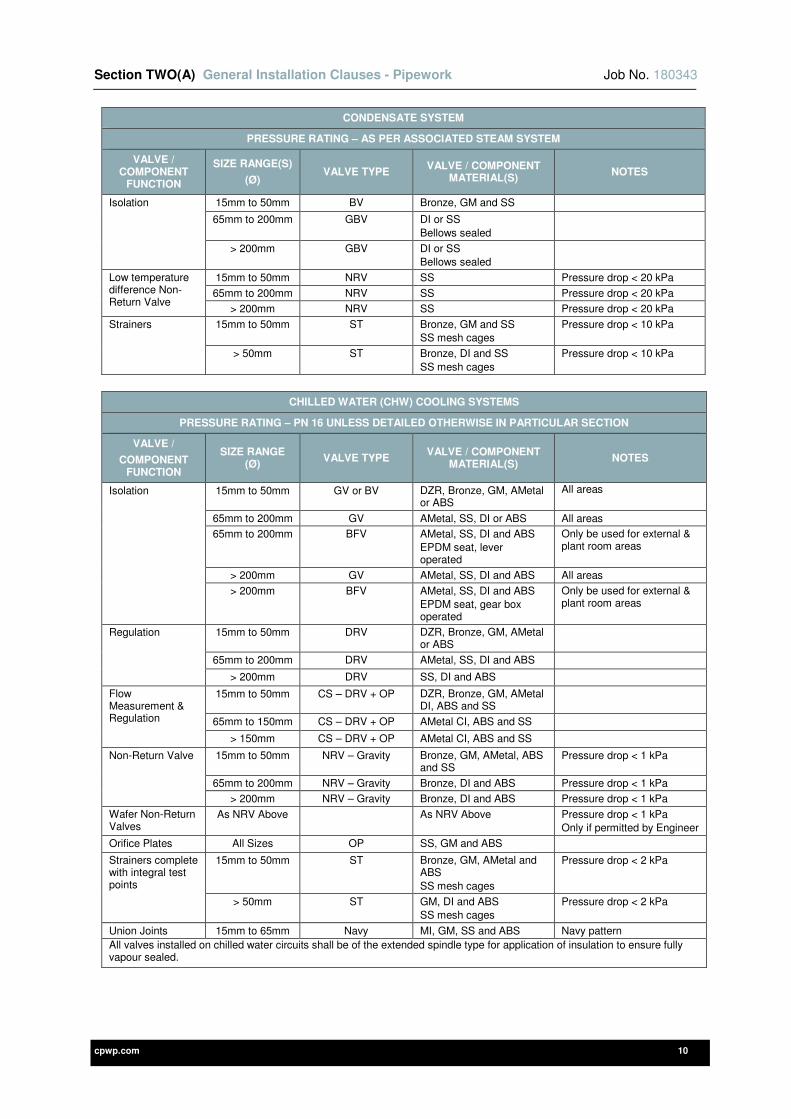
Section TWO(A) General Installation Clauses - Pipework Job No. 180343
cpwp.com 10
CONDENSATE SYSTEM
PRESSURE RATING – AS PER ASSOCIATED STEAM SYSTEM
VALVE / COMPONENT
FUNCTION
SIZE RANGE(S)
(Ø) VALVE TYPE
VALVE / COMPONENT MATERIAL(S)
NOTES
Isolation 15mm to 50mm BV Bronze, GM and SS
65mm to 200mm GBV DI or SS
Bellows sealed
> 200mm GBV DI or SS Bellows sealed
Low temperature difference Non-Return Valve
15mm to 50mm NRV SS Pressure drop < 20 kPa
65mm to 200mm NRV SS Pressure drop < 20 kPa
> 200mm NRV SS Pressure drop < 20 kPa
Strainers 15mm to 50mm ST Bronze, GM and SS SS mesh cages
Pressure drop < 10 kPa
> 50mm ST Bronze, DI and SS
SS mesh cages
Pressure drop < 10 kPa
CHILLED WATER (CHW) COOLING SYSTEMS
PRESSURE RATING – PN 16 UNLESS DETAILED OTHERWISE IN PARTICULAR SECTION
VALVE /
COMPONENT FUNCTION
SIZE RANGE (Ø)
VALVE TYPE VALVE / COMPONENT
MATERIAL(S) NOTES
Isolation 15mm to 50mm GV or BV DZR, Bronze, GM, AMetal or ABS
All areas
65mm to 200mm GV AMetal, SS, DI or ABS All areas
65mm to 200mm BFV AMetal, SS, DI and ABS EPDM seat, lever operated
Only be used for external & plant room areas
> 200mm GV AMetal, SS, DI and ABS All areas
> 200mm BFV AMetal, SS, DI and ABS EPDM seat, gear box operated
Only be used for external & plant room areas
Regulation 15mm to 50mm DRV DZR, Bronze, GM, AMetal or ABS
65mm to 200mm DRV AMetal, SS, DI and ABS
> 200mm DRV SS, DI and ABS
Flow Measurement & Regulation
15mm to 50mm CS – DRV + OP DZR, Bronze, GM, AMetal DI, ABS and SS
65mm to 150mm CS – DRV + OP AMetal CI, ABS and SS
> 150mm CS – DRV + OP AMetal CI, ABS and SS
Non-Return Valve 15mm to 50mm NRV – Gravity Bronze, GM, AMetal, ABS and SS
Pressure drop < 1 kPa
65mm to 200mm NRV – Gravity Bronze, DI and ABS Pressure drop < 1 kPa
> 200mm NRV – Gravity Bronze, DI and ABS Pressure drop < 1 kPa
Wafer Non-Return Valves
As NRV Above As NRV Above Pressure drop < 1 kPa Only if permitted by Engineer
Orifice Plates All Sizes OP SS, GM and ABS
Strainers complete with integral test points
15mm to 50mm ST Bronze, GM, AMetal and ABS
SS mesh cages
Pressure drop < 2 kPa
> 50mm ST GM, DI and ABS SS mesh cages
Pressure drop < 2 kPa
Union Joints 15mm to 65mm Navy MI, GM, SS and ABS Navy pattern
All valves installed on chilled water circuits shall be of the extended spindle type for application of insulation to ensure fully vapour sealed.
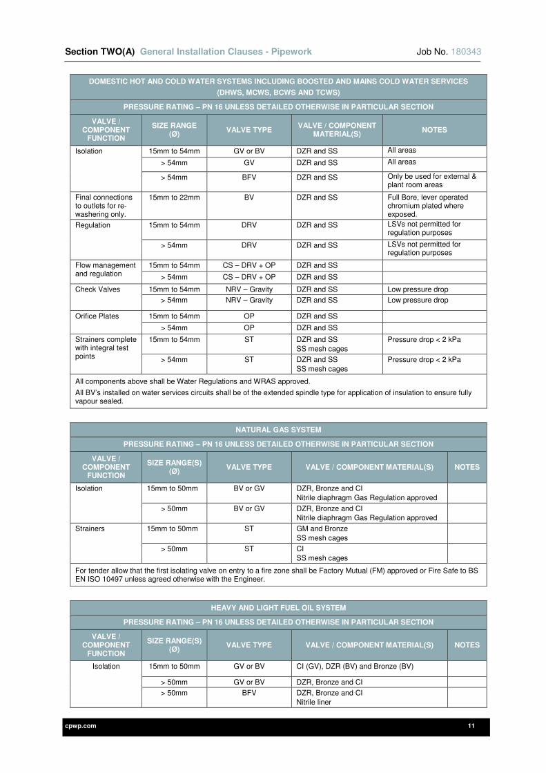
Section TWO(A) General Installation Clauses - Pipework Job No. 180343
cpwp.com 11
DOMESTIC HOT AND COLD WATER SYSTEMS INCLUDING BOOSTED AND MAINS COLD WATER SERVICES
(DHWS, MCWS, BCWS AND TCWS)
PRESSURE RATING – PN 16 UNLESS DETAILED OTHERWISE IN PARTICULAR SECTION
VALVE / COMPONENT
FUNCTION
SIZE RANGE (Ø)
VALVE TYPE VALVE / COMPONENT
MATERIAL(S) NOTES
Isolation 15mm to 54mm GV or BV DZR and SS All areas
> 54mm GV DZR and SS All areas
> 54mm BFV DZR and SS Only be used for external & plant room areas
Final connections to outlets for re-washering only.
15mm to 22mm BV DZR and SS Full Bore, lever operated chromium plated where exposed.
Regulation 15mm to 54mm DRV DZR and SS LSVs not permitted for regulation purposes
> 54mm DRV DZR and SS LSVs not permitted for regulation purposes
Flow management and regulation
15mm to 54mm CS – DRV + OP DZR and SS
> 54mm CS – DRV + OP DZR and SS
Check Valves 15mm to 54mm NRV – Gravity DZR and SS Low pressure drop
> 54mm NRV – Gravity DZR and SS Low pressure drop
Orifice Plates 15mm to 54mm OP DZR and SS
> 54mm OP DZR and SS
Strainers complete with integral test points
15mm to 54mm ST DZR and SS SS mesh cages
Pressure drop < 2 kPa
> 54mm ST DZR and SS SS mesh cages
Pressure drop < 2 kPa
All components above shall be Water Regulations and WRAS approved.
All BV’s installed on water services circuits shall be of the extended spindle type for application of insulation to ensure fully vapour sealed.
NATURAL GAS SYSTEM
PRESSURE RATING – PN 16 UNLESS DETAILED OTHERWISE IN PARTICULAR SECTION
VALVE / COMPONENT
FUNCTION
SIZE RANGE(S) (Ø)
VALVE TYPE VALVE / COMPONENT MATERIAL(S) NOTES
Isolation 15mm to 50mm BV or GV DZR, Bronze and CI
Nitrile diaphragm Gas Regulation approved
> 50mm BV or GV DZR, Bronze and CI Nitrile diaphragm Gas Regulation approved
Strainers 15mm to 50mm ST GM and Bronze
SS mesh cages
> 50mm ST CI SS mesh cages
For tender allow that the first isolating valve on entry to a fire zone shall be Factory Mutual (FM) approved or Fire Safe to BS EN ISO 10497 unless agreed otherwise with the Engineer.
HEAVY AND LIGHT FUEL OIL SYSTEM
PRESSURE RATING – PN 16 UNLESS DETAILED OTHERWISE IN PARTICULAR SECTION
VALVE / COMPONENT
FUNCTION
SIZE RANGE(S) (Ø)
VALVE TYPE VALVE / COMPONENT MATERIAL(S) NOTES
Isolation 15mm to 50mm GV or BV CI (GV), DZR (BV) and Bronze (BV)
> 50mm GV or BV DZR, Bronze and CI
> 50mm BFV DZR, Bronze and CI Nitrile liner

Section TWO(A) General Installation Clauses - Pipework Job No. 180343
cpwp.com 12
HEAVY AND LIGHT FUEL OIL SYSTEM
PRESSURE RATING – PN 16 UNLESS DETAILED OTHERWISE IN PARTICULAR SECTION
VALVE / COMPONENT
FUNCTION
SIZE RANGE(S) (Ø)
VALVE TYPE VALVE / COMPONENT MATERIAL(S) NOTES
Check Valves 15mm to 50mm NRV GM and Bronze High temperature Vitron® seals
> 50mm NRV CI High temperature Vitron® seals
Strainers with mesh area and size suitable for grade of oil used.
15mm to 50mm ST GM and Bronze SS mesh cages
> 50mm ST CI SS mesh cages
Union Joints 15mm to 50mm Navy GM and Bronze
For tender allow that the first isolating valve on entry to a fire zone shall be Factory Mutual (FM) approved or Fire Safe to BS EN ISO 10497 unless agreed otherwise with the Engineer.
2A-1-6 COMPONENT MANUFACTURERS
All components shall be manufactured and supplied by one of the manufacturers scheduled in the table below. All components of the same type shall be from the same manufacturer to ensure consistency across the project.
COMPONENT ACCEPTABLE
MANUFACTURER
Differential Pressure Control and Flow Limiting Valves
Oventrop UK Limited
Samson Controls Limited
Frese Limited Crane / Hattersley
Pegler Yorkshire Group Limited
Thermostatic Mixing Valves
Grohe Caradon Mira Limited
Horne Engineering Limited
Pegler Yorkshire Group Limited
Test Points
Oventrop UK Limited Crane / Hattersley
Pegler Yorkshire Group Limited
End of line DHW temperature controlled return valves / temperature maintaining valves
Oventrop Aquastrom Frese Limited
Pegler Yorkshire Group Limited
Oil components Oventrop UK Limited
Natural gas / LPG components Oventrop UK Limited
End of Line Temperature Limiting Valves Oventrop UK Limited
Automatic Air Vents Spirotech Limited ‘Spirotop’
Expansion bellows
BOA Flexible Solutions Limited Pipe Solutions Ltd
Bellows Technology Ltd
FLEXEJ Ltd
Anti-Vibration Equipment TEK Ltd
Steam & Condensate valves Spirax Sarco Limited TLV Euro Engineering UK Limited
Steam components Spirax Sarco Limited TLV Euro Engineering UK Limited
All others including IV, CS, etc.
Crane / Hattersley Oventrop UK Limited
Pegler Yorkshire Group Limited
2A-2 GENERAL REQUIREMENTS FOR PIPEWORK SYSTEMS
2A-2-1 INTRODUCTION
This Section of the Specification details the general requirements applicable to all pipework systems and shall be read in conjunction with the detailed requirements as specified.
The Contractor shall adhere to the good practice guidelines detailed in the BSRIA pre-commissioning guide in order to minimise the works required at the pre-commissioning stage of the project.
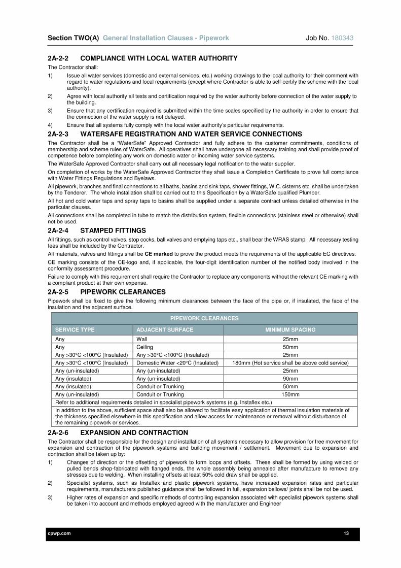
Section TWO(A) General Installation Clauses - Pipework Job No. 180343
cpwp.com 13
2A-2-2 COMPLIANCE WITH LOCAL WATER AUTHORITY
The Contractor shall:
1) Issue all water services (domestic and external services, etc.) working drawings to the local authority for their comment with regard to water regulations and local requirements (except where Contractor is able to self-certify the scheme with the local authority).
2) Agree with local authority all tests and certification required by the water authority before connection of the water supply to the building.
3) Ensure that any certification required is submitted within the time scales specified by the authority in order to ensure that the connection of the water supply is not delayed.
4) Ensure that all systems fully comply with the local water authority’s particular requirements.
2A-2-3 WATERSAFE REGISTRATION AND WATER SERVICE CONNECTIONS
The Contractor shall be a “WaterSafe” Approved Contractor and fully adhere to the customer commitments, conditions of membership and scheme rules of WaterSafe. All operatives shall have undergone all necessary training and shall provide proof of competence before completing any work on domestic water or incoming water service systems.
The WaterSafe Approved Contractor shall carry out all necessary legal notification to the water supplier.
On completion of works by the WaterSafe Approved Contractor they shall issue a Completion Certificate to prove full compliance with Water Fittings Regulations and Byelaws.
All pipework, branches and final connections to all baths, basins and sink taps, shower fittings, W.C. cisterns etc. shall be undertaken by the Tenderer. The whole installation shall be carried out to this Specification by a WaterSafe qualified Plumber.
All hot and cold water taps and spray taps to basins shall be supplied under a separate contract unless detailed otherwise in the particular clauses.
All connections shall be completed in tube to match the distribution system, flexible connections (stainless steel or otherwise) shall not be used.
2A-2-4 STAMPED FITTINGS
All fittings, such as control valves, stop cocks, ball valves and emptying taps etc., shall bear the WRAS stamp. All necessary testing fees shall be included by the Contractor.
All materials, valves and fittings shall be CE marked to prove the product meets the requirements of the applicable EC directives.
CE marking consists of the CE-logo and, if applicable, the four-digit identification number of the notified body involved in the conformity assessment procedure.
Failure to comply with this requirement shall require the Contractor to replace any components without the relevant CE marking with a compliant product at their own expense.
2A-2-5 PIPEWORK CLEARANCES
Pipework shall be fixed to give the following minimum clearances between the face of the pipe or, if insulated, the face of the insulation and the adjacent surface.
PIPEWORK CLEARANCES
SERVICE TYPE ADJACENT SURFACE MINIMUM SPACING
Any Wall 25mm
Any Ceiling 50mm
Any >30°C <100°C (Insulated) Any >30°C <100°C (Insulated) 25mm
Any >30°C <100°C (Insulated) Domestic Water <20°C (Insulated) 180mm (Hot service shall be above cold service)
Any (un-insulated) Any (un-insulated) 25mm
Any (insulated) Any (un-insulated) 90mm
Any (insulated) Conduit or Trunking 50mm
Any (un-insulated) Conduit or Trunking 150mm
Refer to additional requirements detailed in specialist pipework systems (e.g. Instaflex etc.)
In addition to the above, sufficient space shall also be allowed to facilitate easy application of thermal insulation materials of the thickness specified elsewhere in this specification and allow access for maintenance or removal without disturbance of the remaining pipework or services.
2A-2-6 EXPANSION AND CONTRACTION
The Contractor shall be responsible for the design and installation of all systems necessary to allow provision for free movement for expansion and contraction of the pipework systems and building movement / settlement. Movement due to expansion and contraction shall be taken up by:
1) Changes of direction or the offsetting of pipework to form loops and offsets. These shall be formed by using welded or pulled bends shop-fabricated with flanged ends, the whole assembly being annealed after manufacture to remove any stresses due to welding. When installing offsets at least 50% cold draw shall be applied.
2) Specialist systems, such as Instaflex and plastic pipework systems, have increased expansion rates and particular requirements, manufacturers published guidance shall be followed in full, expansion bellows/ joints shall be not be used.
3) Higher rates of expansion and specific methods of controlling expansion associated with specialist pipework systems shall be taken into account and methods employed agreed with the manufacturer and Engineer

Section TWO(A) General Installation Clauses - Pipework Job No. 180343
cpwp.com 14
4) Where natural flexibility free movement solutions cannot be employed, the provision of expansion joints or bellows shall be installed in accordance with the manufacturer’s instructions for both installation details and guiding. Expansion joints or bellows shall only be used when offsets or loops are not possible. Expansion joints shall be pre-cold-drawn with a retaining clip, which must be removed after installation. Expansion joins shall be capable of at least 2,000 complete reversals of movement at the system working conditions. Expansion joints shall be capable of withstanding a pressure 1.5 times their design pressure (or system test pressure if greater) without deformation.
5) Anchors and guides shall be supplied and installed to ensure that all movement is taken up by the method adopted. The anchors shall be of sufficient strength to withstand the anticipated forces and a check shall be made that the building structure, to which the anchors and guides are attached, is adequate for the loads imposed. Anchors shall be provided to prevent excess stresses to pipework joints and equipment.
6) Detailed arrangements of all anchors and guides shall be submitted to the Engineer and Structural Engineer for comment before manufacture commences.
In the event that natural flexibility cannot be used due to building fabric restraints and bellows are required to be installed:
• All bellows shall be thick wall spirally wound multi-layered all stainless steel (316L) quality units with a corrosion resistant inner ply or sleeve for all pipework.
• Additionally, for copper pipework the bellows shall be bronze construction to avoid flux corrosion.
• All steam, HTHW & MTHW shall be twin wall stainless steel type with leak indication.
2A-2-7 BRACKETS AND FIXINGS GENERALLY
The Contractor shall design, supply and install all brackets and fixings, including any secondary steelwork, necessary to make the project complete.
All insulated services shall be provided with proprietary insulated pipe supports as detailed in the thermal insulation standards of this specification where pipework is insulated.
Each pipe support shall:
1) Be arranged as near as possible to joints.
2) Take its due proportion of pipe and component weights.
3) Allow for expansion and contraction.
4) Support the pipework via rollers, chairs and flat iron stirrup guides as appropriate.
5) Meet any structural constraints imposed by the Structural Engineer.
6) Be provided with fixings into structure (i.e. Rawlbolt, Rawlplugs etc.) shall be suitable for the load and the material being fixed to and installed fully in accordance with the manufacturer’s recommendations.
7) Details of all types and makes of brackets and fixings to be used shall be given to the Engineer prior to ordering or manufacturing and their comment obtained.
8) Where proprietary pipework and jointing systems are agreed then all brackets / pipe supports shall be as recommended by the particular system manufacturer in terms of type, design and centres.
9) All supports with protruding bolts or threaded rods shall be provided with proprietary end caps to protect eyes and skin from injury. End caps shall be provided to all bolts and rods irrespective of height due to risk during routine maintenance and servicing.
Pipe rings shall be used on services, which do not require a vapour seal and shall:
1) On plain mild steel tube, up to 50mm (inclusive) be black japanned malleable iron.
2) On chromium plated or stainless tubes shall be of the same material as the pipe.
3) On copper exposed to view be polished cast bronze.
4) In all other cases shall be Munsen ring type.
PIPEWORK SUPPORT METHODS
LOCATION / PIPEWORK TYPE SUPPORT METHOD WHICH SHALL BE EMPLOYED
Within plant rooms, tank rooms, risers Supported on or suspended from rolled steel angles, channel or ‘unistrut’ system either galvanised or painted
Where external to building or within humid environments
Supported on or suspended from rolled steel angles, channel or ‘unistrut’ system all of which shall be hot dip galvanised after manufacture
Un-insulated pipework exposed to view and fixed to partitions / walls
Screw fixed school board brackets
Un-insulated pipework exposed to view and fixed to partitions / walls in clean environments, healthcare premises and catering areas
Screw fixed school board brackets, hospital pattern with extended stem for ease of cleaning
Insulated pipework As detailed in ‘thermal insulation’ section of this specification
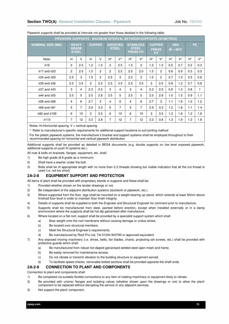
Section TWO(A) General Installation Clauses - Pipework Job No. 180343
cpwp.com 15
Pipework supports shall be provided at intervals not greater than those detailed in the following table:
PIPEWORK SUPPORTS - MAXIMUM INTERVAL BETWEEN SUPPORTS (IN METRES)
NOMINAL SIZE (MM). HEAVY GRADE STEEL
COPPER GROOVED STEEL
STAINLESS STEEL
PRESS FIT
COPPER
PRESS FIT
ABS
@ < 50ºC
PE
Note: H V H V H* V* H* V* H* V* H* V* H* V*
≤16 2 2.5 1.2 1.5 2 2.5 1.5 2 1.2 1.5 0.5 0.7 0.2 0.3
≥17 and ≤23 2 2.5 1.5 2 2 2.5 2.0 2.5 1.5 2 0.6 0.9 0.3 0.5
≥24 and ≤29 2.5 3 1.5 2 2.5 3 2.2 3 1.5 2 0.7 1.0 0.5 0.8
≥30 and ≤36 2.5 3.5 2 2.5 2.5 3.5 2.5 3.5 2 2.5 0.8 1.2 0.7 0.8
≥37 and ≤43 3 4 2.3 2.5 3 4 3 4 2.3 2.5 0.9 1.3 0.8 1
≥44 and ≤55 3.5 5 2.5 2.8 3.5 5 3.5 5 2.5 2.8 1.0 1.5 0.9 1.1
≥56 and ≤68 4 6 2.7 3 4 6 4 6 2.7 3 1.1 1.6 1.0 1.2
≥69 and ≤81 5 7 2.9 3.3 5 7 5 7 2.9 3.3 1.2 1.8 1.1 1.4
≥82 and ≤109 6 10 3 3.5 6 10 6 10 3 3.5 1.2 1.8 1.2 1.6
≥110 7 12 3.3 3.8 7 12 7 12 3.3 3.8 1.3 1.9 1.3 1.8
Notes: H=Horizontal spacing, V = vertical spacing
*- Refer to manufacturer’s specific requirements for additional support locations to suit jointing method
For the plastic pipework systems, the manufacturer’s bracket and support systems shall be employed throughout to their recommended spacing for horizontal and vertical pipework distribution
Additional supports shall be provided as detailed in BESA documents (e.g. double supports on low level exposed pipework, additional supports on push fit systems etc.)
All nuts & bolts on brackets, flanges, equipment, etc. shall:
1) Be high grade (8.8 grade as a minimum).
2) Shall have a washer under the bolt.
3) Bolts shall be of appropriate length with no more than 2-3 threads showing but visible indication that all the nut thread is used (i.e. not too short).
2A-2-8 EQUIPMENT SUPPORT AND PROTECTION
All items of plant shall be provided with proprietary stands or supports and these shall be:
1) Provided whether shown on the tender drawings or not.
2) Be independent of the adjacent distribution systems (ductwork or pipework, etc.).
3) Where supported from the floor, legs shall be mounted on a weight bearing up stand, which extends at least 50mm above finished floor level in order to maintain floor finish integrity.
4) Details of supports shall be supplied to both the Engineer and Structural Engineer for comment prior to manufacture.
5) Supports shall be manufactured from steel, painted before erection, except when installed externally or in a damp environment where the supports shall be hot dip galvanised after manufacture.
6) Where located on a flat roof, support shall be provided by a specialist support system which shall:
a) Bear weight onto the roof membrane without causing damage or undue stress.
b) Be located over structural members.
c) Meet the Structural Engineer’s requirements.
d) Be manufactured by Roof-Pro Ltd, Tel 01234 843790 or approved equivalent.
7) Any exposed moving machinery (i.e. drives, belts, fan blades, chains, projecting set screws, etc.) shall be provided with protective guards which shall:
a) Be manufactured from robust hot dipped galvanised welded steel open mesh and frame.
b) Be easily removed for maintenance access.
c) Do not vibrate or transmit vibration to the building structure or equipment served.
d) To facilitate speed checks, removable bolted sections shall be provided opposite the shaft ends.
2A-2-9 CONNECTION TO PLANT AND COMPONENTS
Connection to plant and components shall:
1) Be completed via suitable flexible connections to any item of rotating machinery or equipment likely to vibrate.
2) Be provided with unions/ flanges and isolating valves (whether shown upon the drawings or not) to allow the plant/ component to be replaced without disrupting the service or any adjacent services.
3) Not support the plant/ component.
Section TWO(A) General Installation Clauses - Pipework Job No. 180343
cpwp.com 16
2A-2-10 ANTI-VIBRATION MOUNTINGS
Specialist anti-vibration mountings and flexible connections shall be designed and provided to all items of rotating or vibration producing plant, these shall:
1) Be selected by the manufacturer making allowance for building structure, weight and characteristics of the equipment supported.
2) Be of the laterally stable steel spring type mounting.
3) In the case of small pumps (<1.5 l/s) neoprene mountings are acceptable.
4) Limit vibration transmission to the structure, degree of isolation (vibration efficiency) shall be at least 95%.
5) Final connections shall be via braided stainless steel flexible connections selected to match the anti-vibration mountings.
6) Prevent any discernible re-radiated noise and vibration to adjacent rooms/ areas either through the building structure or distribution systems.
2A-2-11 FLEXIBLE CONNECTIONS
Flexible connection shall be provided where shown on the drawings, either side of each pump, on all connections to chillers and other centrifugal reciprocating or vibrating equipment and where detailed elsewhere in this specification. They shall:
1) Be line size.
2) Be suitable for working temperatures up to 100°C, the bellows carcass shall be Aramid reinforced throughout or stainless steel hose.
3) Have swivel type flanges/ screwed connections.
4) Be suitable for heating circuits and a design life of 120 months at 100°C and after this time have a minimum burst pressure of 30 bar.
5) The date of manufacture shall be moulded on the bellows. For traceability membranes shall have an indelible identification showing manufacturer, country of origin and the type.
6) Tie bars with rubber top hat washers shall be used where the working pressure exceeds 3 Bar Gauge up to 50mm nominal bore and 2 Bar Gauge for larger sizes. Where untied bellows are used the manufacturers recommendations for anchors and guides shall be followed. Tie bars shall be threaded and their length adjustable.
2A-2-12 FLEXIBLE CONNECTIONS IN DOMESTIC WATER SYSTEMS
On all healthcare and projects where susceptible or high-risk users are present the Contractor shall:
1) Not use flexible connections, except for situations described in HTM04-01A Clause 3.41, specifically:
a) To allow for vibration of equipment;
b) To accommodate vertical displacement of high and low baths and sinks;
c) To facilitate essential maintenance and access of bespoke equipment when no alternative is available.
2) Where fitted, flexible hoses should be kept as short as possible and be kink-free so as not to affect flow.
3) Not use flexible connections to general sanitary ware and taps unless agreed with the Client.
4) Review final connection details and any flexible with the sanitary ware/ tap manufacturer.
5) Review final connection details and any flexible with the Clients Infection Control Officer (or equivalent).
6) Provide an installation that meets the best practice recommendations.
7) Be as short as possible in length.
8) Shall use a suitable alternative to EPDM selected to minimise the forming of biofilms and risk from Pseudomonas/ Legionella, etc.
9) Be WRAS approved.
10) Provide food grade nitrile rubber bellows liner shall with KIWA Watertec Approval for hot water services.
On all other projects, the Contractor shall avoid flexible connections where possible, where unavoidable use of flexible connections shall be agreed with the Design Engineer and shall:
1) Be as short as possible, kink-free and in all cases less than 300mm in length.
2) Shall use a suitable alternative to EPDM selected to minimise the forming of biofilms and risk from Pseudomonas/ Legionella, etc.
3) Be WRAS approved.
4) Provide food grade nitrile rubber bellows liner shall with KIWA Watertec Approval for hot water services.
5) Review final connection details and any flexible with the sanitary ware/ tap manufacturer.
6) Review final connection details and provide a sample flexible connection installation with the Engineer so that the principles of acceptable installation are agreed.
7) Provide an installation that meets the best practice recommendations.
2A-2-13 PIPE CUTTINGS
Piping shall:
1) Be completed in accordance with both the pipe and fitting manufacturer’s recommendations using proprietary tools where required.
2) Be cut clean and square with the axis of the pipe (or bevelled edge as required for welding) using a saw, pipe cutting tool or machine.
3) Any lubrication used during cutting shall be in accordance with both the pipe and fitting manufacturer’s recommendations.
Section TWO(A) General Installation Clauses - Pipework Job No. 180343
cpwp.com 17
4) Be prepared by filing or grinding and all internal burrs shall be removed by filing or reaming.
The Engineer shall require the Contractor to disconnect any pipes for inspection; should inspection reveal any neglect of reaming, the Contractor shall be required to remove, re-fix and retest at their own expense, as much of the pipework as may be deemed necessary by the Engineer.
2A-2-14 TEES AND CROSSES AND BRANCHES
All tees, twin elbows and crosses shall be:
1) Easy sweep pattern.
2) Square pattern on air venting devices.
3) Square pattern on drain cocks.
4) Square pattern on gauges and test points.
5) Square pattern on sensors, if no requirement stated by manufacturer.
2A-2-15 UNIONS
Unions shall:
1) Be generally of malleable iron with two bronze seats, as the Navy pattern.
2) Have galvanised unions for galvanised pipework.
3) Have gunmetal unions for copper pipework.
4) Be fitted on the outlet of each screwed valve except in the case of draw-off points.
2A-2-16 VALVES
All valves shall be consistent across the works, i.e. all isolating valves, regulating valves, etc. on a particular service shall be of the same manufacturer and the same type and appearance.
Wheel or lock shield valves and stopcocks shall be:
1) Fitted where indicated on the drawings.
2) In accordance with the schedules detailed elsewhere in this section of the specification.
3) Fitted with unions adjacent to screwed valves to facilitate maintenance.
4) Complete with a cast iron surface access box indicating service of valve where installed underground.
2A-2-17 MALLEABLE IRON FITTINGS
All malleable iron fittings shall:
1) Be of the banded type, black or galvanised to match pipework material.
2) Be of the easy sweep pattern for all tees.
3) Have inclined angle easy transition pieces not exceeding 30 degrees for reductions and enlargements
4) Have long sweep pattern bends with centreline radius/ nominal bore of not less than 1.5. Where the use of a long sweep fitting would throw the pipework beyond an acceptable distance from the wall when exposed in rooms, short radius fittings can be used after first obtaining the acceptance of the Engineer.
Fabricated fittings shall be used only with written acceptance of the Engineer and if manufacturer's standard fittings are not available.
2A-2-18 FLANGES
Flanges shall be provided on all services for ease of maintenance and for mating to valves, equipment, etc.
Selection of the appropriate flange type, material and specification shall be in accordance with the British Standards detailed at the start of this section and shall:
1) Be at least the same pressure rating as that stated for components elsewhere in this specification.
2) Correlate to the pipework, material, equipment or component as defined in the relevant British Standard material group.
3) Negate any possibility of dezincification of the mating or surrounding materials.
4) Be selected to suit the operating and testing pressures/ temperatures of the system.
5) Have suitable gaskets, refer to BESA TR series documents for relevant service.
2A-2-19 DRAIN COCKS
Drain cocks shall:
1) Be fitted in the following locations:
a) Where indicated on the drawings.
b) As detailed in specific sections of this specification.
c) At all low points on all water systems to ensure complete drainage.
2) Be screw type (removable).
3) Be of a suitable type/ size, refer to table below.
4) Have a chromium plated finish where exposed to view.
5) Be complete with serrated hose connection to retain a rubber hose.
6) Have an operating spindle fitted with a renewable ‘O’ ring gland.
7) Be fitted within 75mm of the floor and be in accordance with the Water Regulations.

Section TWO(A) General Installation Clauses - Pipework Job No. 180343
cpwp.com 18
DRAIN COCK SIZE
PURPOSE / LOCATION PIPEWORK SIZE DRAIN COCK
Plant rooms
(drainage only)
≤50mm dia.
51mm to 150mm
>150mm
15mm dia. oblique (or ‘Y’) renewable washer screw down type
25mm dia. lock shield valve & union adapter to serrated hose connection
50mm dia. lock shield valve & union adapter to serrated hose connection
Exposed to view ≤100mm dia.
> 100mm
15mm dia. lock shield type
25mm dia. lock shield type
Plant Rooms / Risers / Voids used for flushing
All Lock shield Valve and Union adapter to serrated hose connection, larger size as recommended by flushing specialist, 25mm dia. minimum
Plant Rooms / Risers where used for fast fill
All Lock shield Valve and Union adapter to serrated hose connection. Sized to suit system volume, 25mm dia. minimum.
2A-2-20 COMMISSIONING AND BALANCING VALVES
To promote reliable and accurate balancing of water systems, commissioning valves shall be supplied and installed in the pipework systems and shall:
1) Be fitted in the following locations:
a) Where indicated on the drawings.
b) As detailed in specific sections of this specification (Whether indicated on drawings or not).
c) Where required for correct and efficient commissioning.
d) Generally, be installed on the return of:
i) Each heating and cooling primary circuit.
ii) Each heating and cooling secondary circuit.
iii) Each heating, cooling and recovery battery.
iv) Each refrigeration machine chilled water evaporator and condenser.
v) All major plant items e.g. boilers etc.
vi) All mains and sub-mains leaving plant rooms or main risers.
2) Be either combined (i.e. orifice plate plus DRV close coupled) or discreet (orifice plate on flow with DRV on return). All fixed orifice commissioning sets shall be selected to provide an accuracy of measurement of +/- 5% of design flow rate.
3) Use Venturi measurement devices where an accuracy better than +/- 3% of design flow is to be achieved.
4) Where specifically allowed in writing by the Engineer variable orifice plates may be used on less critical circuits where accuracy shall be at least +/- 10% of design flow.
5) Have a maximum velocity through commissioning set of 1.2m/s up to 50mm diameter, 2.0m/s for 65mm diameter and above.
6) Measurement component shall be installed to manufacturer’s recommendations subject to a minimum of 5 pipe diameter of straight pipe upstream, 3 pipe diameters downstream, whichever is the most onerous requirement.
7) All commissioning valves shall be selected such that excessive closing of the valve is not necessary for correct regulation, utilising smaller diameter valves than the adjacent pipework as necessary, Contractor shall include for necessary reducers within their tender. Contractor shall obtain excess pressures and design flow rates from designer prior to ordering commissioning sets.
8) All commissioning valves shall be selected such that they provide sufficient signal for accurate measurement (say 1 – 4.7kPa), low flow units shall be used where necessary to achieve good readings.
9) Where no specific size is indicated, line size commissioning valves shall be included at Tender stage and the final size to be selected when accurate flow rates and pressures are known, the valve sizes shall be confirmed with the Engineer prior to ordering. However, for tender, as the commissioning valve will not necessarily be of full line size, the installation shall provide reducers immediately adjacent to these valves as necessary.
The commissioning stations (CS) shall be installed with sufficient best practice straight run of pipework either side of the valves fully in accordance with the valve manufacturer’s best practice recommendations.
Both the Engineer and the Commissioning Engineer shall review all commissioning valve selections. Valve selection information shall be scheduled. The schedule of information shall include:
1) Pressure drop for each valve, signal strength (between 1 – 4.7kPa).
2) Flow rate.
3) Size of valve.
4) Associated pipeline size.
This schedule shall be provided in sufficient time, minimum of 10 working days, for all comments to be returned and implemented prior to the commissioning valves being ordered.
2A-2-21 DIFFERENTIAL PRESSURE REGULATORS AND DIFFERENTIAL PRESSURE COMMISSIONING STATIONS
Differential pressure regulators (DPR) regulating and differential pressure commissioning stations shall be provided as indicated upon the Tender drawings, which shall:

Section TWO(A) General Installation Clauses - Pipework Job No. 180343
cpwp.com 19
1) Have a worst acceptable accuracy of +/- 5% of design sub-circuit pressure.
2) Have a bronze body on systems operating below 120°C. Cast iron shall be an acceptable alternative on 65mm diameter and above.
3) Have a pressure rating to match system, subject to a minimum pressure rating of PN16 (or greater depending on media fluid).
4) Have a maximum port velocity of 2m/s.
5) Have a minimum available adjustment +/- 25% of design flow rate.
6) Be capable of operating against pressure development of system pump, subject to the following minimums:
a) 200kPa for valves up to 50mm diameter.
b) 350kPA for valves 65mm diameter and above.
7) Have a maximum pressure drop of 5kPa for accurate control.
8) Measure and control pressure imposed on the sub-circuits and as detailed on the Tender drawings.
9) Have a pressure range of 30-60kPa for Tender, confirm final requirement with Engineer prior to ordering of the valves.
10) Be supplied, installed and commissioned in accordance with the manufacturer’s recommendations to achieve above requirements.
11) Be suitable for the system fluid, pressure, temperature and materials (as recommended by manufacturer) where this conflicts with above requirements clarify with Engineer.
Both the Engineer and the Commissioning Engineer shall review all differential pressure regulators and differential pressure commissioning valve selections. Valve selection information shall be scheduled, the schedule of information shall include:
1) Pressure drops for each valve.
2) Flow rate.
3) Size of valve.
4) Associated pipeline size.
This schedule shall be provided in sufficient time, minimum of 10 working days, for all comments to be returned and implemented prior to the commissioning valves being ordered.
2A-2-22 PRESSURE INDEPENDENT CONTROL VALVES
Pressure independent control valves consisting of differential pressure controller, and control valve shall be provided as indicated upon the Tender drawings and these shall:
1) Have valve body and material to suit systems operating below 120°C. Cast iron shall be an acceptable alternative on 65mm diameter and above.
2) Have a pressure rating to match system, subject to a minimum pressure rating of PN16 (or greater depending on media fluid).
3) Have a maximum port velocity of 2m/s.
4) Be designed and provided with integral flow verification metering stations however if metering stations are not integral to the control valves chosen then separate metering stations shall be supplied and installed to verify the actual flow rate of all pressure independent control valves.
5) Have a minimum available adjustment +/- 25% of design flow rate.
6) Maintain a valve authority in the range of 0.8 to 1.0 at all times.
7) Comply with the performance/ selection criteria stated elsewhere in this specification for the differential pressure component of the valve.
8) Have flow rate adjustment that shall:
a) Not reduce the stroke of the control valve on valves of 50mm diameter and below.
b) Not reduce the stroke by more than 30% on valves above 50mm diameter.
9) Be supplied, installed and commissioned in accordance with the manufacturer’s recommendations to achieve above requirements.
10) Be suitable for the system fluid, pressure, temperature and materials (as recommended by manufacturer) where this conflicts with above requirements clarify with Engineer.
2A-2-23 FLOW LIMITING VALVES
Flow limiting valves shall be provided as indicated upon the Tender drawings, which shall:
1) Have a bronze body on systems operating below 120°C, cast iron shall be an acceptable alternative on 65mm diameter and above.
2) Have a minimum pressure rating of PN16 (or greater depending on media fluid).
3) Have a maximum port velocity 2m/s.
4) Have a maximum pressure drop of 20kPa.
5) Have a maximum control tolerance +/- 5%.
6) Have a minimum available adjustment +/- 25% of design flow rate.
7) Be suitable for the system fluid, pressure, temperature and materials (as recommended by manufacturer) where this conflicts with above requirements clarify with Engineer.
8) Have combined isolating and flow limiting valves with the replaceable cartridge type flow setting to limit maximum flow to the individual outlet on final domestic supplies to wash hand basins and the like.

Section TWO(A) General Installation Clauses - Pipework Job No. 180343
cpwp.com 20
2A-2-24 SELF REGULATING TEMPERATURE VALVES
Self-regulating temperature valves shall be provided as indicated upon the Tender drawings, which shall:
1) Have a bronze body on systems operating below 120°C, cast iron shall be an acceptable alternative on 65mm diameter and above.
2) Have a minimum pressure rating of PN16 (or greater depending on media fluid).
3) Have a maximum port velocity 2m/s.
4) Have a minimum valve authority of 0.25.
5) Have a maximum pressure drop of 5kPa.
6) Have a maximum control tolerance +/- 5%.
7) Have a minimum available adjustment +/- 25% of design temperature, factory pre-set non-adjustable valves shall only be used where specifically allowed in writing by the Engineer.
8) Be suitable for the system fluid, pressure, temperature and materials (as recommended by manufacturer) where this conflicts with above requirements clarify with Engineer.
2A-2-25 DOMESTIC HOT WATER RETURN REGULATION
To enable domestic hot water return regulation, valves shall be provided whether shown on drawings or not to all of the following locations:
1) Spine mains.
2) Sub-branches.
3) Final branches.
4) Loops installed for future/ phased expansion.
Regulation shall be achieved as detailed in the specific sections of this specification and shall be by one of the following methods as directed in section M1 of this specification:
1) Double regulating valves which shall be:
a) Installed on the return legs.
b) Line size.
2) Dual function temperature limiting valves shall:
a) Be installed in the returns of final branches and loops with commissioning stations installed in the return of spine mains and sub-branches.
b) Have a primary thermostatic head, factory pre-set at temperature agreed in writing with Engineer, typically in the range of 57°C to 60°C.
c) Have a secondary (pasteurisation) function factory pre-set at 70°C.
d) Have both functions (normal operation and pasteurisation) to be adjustable on site for fine tuning during the commissioning process.
e) Be complete with manufacturer’s integral calibrated temperature gauge and proprietary insulation box cover which when fitted, still allows temperature to be read.
f) Have performance and accuracy of temperature control in each mode, each valve shall be verified on site and recorded in manuals.
Any BMS temperature monitoring points shall be provided separate to these valves unless the selected valve has a tapping provided specifically for either a thermometer or temperature sensor and if so this may be used for the BMS temperature monitoring.
No other valve type (e.g. lock shield, gate, globe, butterfly etc.) shall be used for regulating purposes.
2A-2-26 AIR VENTS AND ELIMINATORS
Automatic Air Vents shall only be used at key points as agreed with the Engineer or shown on the Tender Drawings, where installed, they shall:
1) Be installed where indicated on the tender drawings.
2) Be as detailed in specific sections of this specification.
3) Be installed at all high points on all water systems to ensure complete venting where self-venting through the mains cannot take place or would not prove satisfactory.
4) Be complete with local isolation valve for maintenance purposes.
5) Be Spirotech Spirotop or engineer approved equal with the same 20 year warranty.
6) Be installed fully in accordance with manufacturer’s recommendations such that guarantee is fully maintained.
7) Not be located in sections where they could allow air to be admitted during normal operation of the system.
8) Be clearly marked on ‘as fitted’ drawings showing accurate locations.
9) Have a minimum of a 50mm square branch (or line size if greater) with a 50mm diameter air bottle of a minimum length of 250mm.
10) Be complete with cap and 8mm brass needle type air cock or air valve where there is a risk of scalding.
11) Have 8mm diameter bleed pipe extended from the bottle where the air cock/ valve is fixed out of reach (e.g. steps/ scaffold, etc. would be required to gain access) which shall:
a) Terminate in an air cock / valve 1.4m above finished floor level, ideally over a drain if possible.
b) Have air cock / valve located in a convenient but unobtrusive location.
Section TWO(A) General Installation Clauses - Pipework Job No. 180343
cpwp.com 21
c) Run in heavy quality mild steel tube with malleable iron fittings neatly run on the surface to a local drain where installed in voids, risers, plant rooms etc.
d) Not be installed where exposed to view in rooms unless unavoidable where it shall be installed in copper run within the thickness of a partition wall or in a wall chase. This shall only be adopted with written permission of the Engineer.
12) Be installed with a local isolation valve to allow vent replacement in the case of an automatic air vent, without needing to drain excessive quantities of system water.
In accordance with current British Standards, domestic hot and cold water systems shall avoid the use of air eliminators wherever possible, by using top connections to mains and venting via taps, where this is impossible air eliminators shall be used as a last resort and shall:
1) Be agreed with the Engineer prior to its use.
2) Be complete with check valve and isolation valve for maintenance purposes.
3) Be complete with a 15mm automatic air vent whose outlet shall be piped with an 8mm copper pipe to the nearest foul drain point.
4) Terminate via a tundish arrangement to a trapped waste or over a gulley suitable to accept pipework discharges without obstructing access for cleaning and rodding.
2A-2-27 THERMOMETERS, PRESSURE, ALTITUDE AND VACUUM GAUGES
All Gauges shall:
1) Be mounted with the diameter gauge in the vertical position.
2) Have a minimum diameter of 100mm.
3) Factory calibrated and individually certified in:
a) Temperature: °C (between 2°C and 5°C per division)
b) Pressure: Bar (gauge) or millibar.
c) Altitude: metres head of water.
d) Vacuum: millimetre Hg (gauge).
4) Have a black finished steel case and chromium plated bezel.
5) Have a black pointer and clear black lettering and scale on a white background.
6) Be fitted with a tamperproof loose red pointer that can be set on site to the working condition by removal of the front plate.
7) Be flangeless for direct mounted gauges.
8) Be either back or front flanged to suit either surface or flush mounted panel arrangements respectively for panel mounted pressure gauges.
9) Have either back or bottom entries to suit the mounting arrangements.
10) Carry the name of the manufacturer and shall all be of the same manufacturer and appearance as all other gauges used on the project.
Dial thermometers shall:
1) Have a suitable range for the service connected such that they can be accurately read, i.e. -40°C to +40°C on chilled or cold water, 0°C to 100°C on LTHW.
2) Be of the vapour pressure type with brass bulb.
3) Have a black finished steel case and chromium plated bezel.
4) Be flangeless for direct mounted gauges.
5) Be either black or front flanged to suit either surface or flush mounted panel arrangements. Capillary tube dial thermometers shall have plain bulbs with either loose pockets or flanges to suit the mounting arrangements for panel mounted dial thermometers.
6) Be visible and readable from ground level or permanent access platforms, i.e. no steps or access equipment needed to read gauges.
Pockets shall:
1) Be filled with heat conducting grease.
2) Be installed in a bend with the pocket facing into the fluid flow on domestic water systems.
Pressure, altitude and vacuum gauges shall:
1) Have a suitable range for the service connected such that they can be accurately read, i.e. 0 to 4 bars on a system with a working pressure of 1.5 bar.
2) Be of the bourdon gauge tube type with BSP male thread.
3) Be fitted with a bronze lever handle gauge cock with BSP female thread ends and a chromium plated finish.
4) Have a ‘U’ or ring siphon interposed between the gauge, cock and tapping point, where practical fitted adjacent to the latter.
5) Have a siphon on steam lines, formed from steel tube and shall be filled with water prior to the gauge being put into service.
6) Be visible and readable from ground level or permanent access platforms, i.e. no steps or access equipment needed to read gauges.
Capillary tubes shall:
1) Be of correct length (excess shall be no more than 300mm and shall be neatly coiled and fixed).
2) Have armoured flexible sheath.
3) Have radius bends not less than recommended by the manufacturer.

Section TWO(A) General Installation Clauses - Pipework Job No. 180343
cpwp.com 22
4) Be routed for minimum risk of damage.
5) Be routed as agreed with the Engineer.
6) Be clipped to cable trays provided by the Contractor where cable trays are suitable containment.
2A-2-28 TEST POINTS
Test points, also called Binder Test Points and labelled on drawings as TP or BT, shall:
1) Be fitted in the following locations:
a) Where indicated on the drawings.
b) As detailed in specific sections of this specification (whether shown on drawings or not).
c) Be installed before and after all:
i) Pumps.
ii) Strainers.
iii) Non-return valves.
iv) Heating, cooling and run around coils.
v) Radiant panel, convectors and other emitters, except radiators.
vi) Control devices such as control valves.
vii) Plant items e.g. boilers, chillers etc.
viii) DPR/DPCV/STAP/BPV valves – note also can be integral to valve assemblies if available.
2) Be of the binder type self-sealing test point with screw down cap.
3) Be extended spindle type to protrude above the thermal insulation.
4) Be PN 16 rated (or greater depending on media fluid).
Insulation shall be dressed around test points such that insulation, vapour seals and cladding are not compromised and access can be obtained without damage to finishes/ function. Extended stem type shall be used to all insulated services.
2A-2-29 WALL, FLOOR, ROOF AND CEILING PENETRATIONS
Where pipes penetrate through walls, floors, roof and ceilings, the penetrations shall:
1) Not restrict expansion/ contraction movement.
2) Where insulated services pass through a structure, the provision must accommodate the insulation unless omitted by detail.
3) At fire barriers, the fire integrity of the barrier must be maintained by converting the insulation to a non-combustible type, e.g. mineral wool, all suitably fire stopped. This comment relates to non-fire rated insulation such as phenolic insulation.
4) At fire barriers and structures, the thickness of insulation may be varied but care must be taken to prevent heat transfer sufficient to cause deterioration of the building fabric.
5) All services with a vapour barrier shall be arranged such that the vapour barrier is continuous through the wall / fire barrier by use of oversized sleeve or equivalent.
6) Where phenolic insulation must be installed then fire collars shall be installed over the insulation to maintain continuous vapour barrier and fire rating of the structure.
7) Maintain acoustic properties of the structure being penetrated, this shall be achieved either from detailed provided by an acoustic specialist or if no acoustic specialist employed by packing all air gaps with, suitably fire rated if required, flexible material such as Rockwool FirePro products.
8) Be provided a puddle flange on external walls.
2A-2-30 KEYS AND VALVE HANDLES
At the completion of the work, the following keys and valve handles shall be provided by the Contractor, who shall also obtain a receipt for the same:
1) 4 No. keys of each type and size for lock shield valves, panel doors, equipment access doors, etc., drain cock (each size) and 6 No. air cock keys.
2) External underground valve handles (2 No. per size installed) shall be provided.
2A-2-31 PAINTING AND IDENTIFICATION OF PIPEWORK, BRACKETS ETC
All pipework, including services not insulated, shall be:
1) Identified with colour bands as required by the latest British Standard.
2) Provided with the service description, pipe size and direction of flow.
Where colour identification on existing services are different to latest British Standards, the new services shall be referred to the Engineer for a decision on which standard shall apply.
All cut edges, supports, flanges, nuts and bolts and any other exposed metal shall be painted with one coat of ‘Red Oxide’ paint prior installation and a second coat applied after installation is complete. Where necessary, Red oxide paint to be heat resisting.
All exposed ferrous pipework, brackets and supports in boiler houses, plant rooms, tank rooms and external to buildings shall further be decoratively painted with two coats of an approved colour gloss paint, which shall be heat resisting where applicable (or hot dip galvanised after manufacture) as directed by the Engineer.
Gas pipework shall be painted with primer and two coats of gloss to comply with current gas regulations (yellow ochre).
All plant and equipment with ferrous surfaces shall have at least two coats of protective paint applied at the manufacturer’s works.
If manufacturer’s finishes are damaged on site, these shall be repaired or replaced to an ‘as new’ condition to the satisfaction of the Engineer and the manufacturer who shall confirm that warranties shall not be affected.

Section TWO(A) General Installation Clauses - Pipework Job No. 180343
cpwp.com 23
2A-2-32 CHROMIUM PLATING
All hot and cold water pipes, valves, fittings and pipe clips, where exposed for short runs only in toilet, kitchen, food preparation, shower, bathroom and sluice areas shall be chromium plated unless stated otherwise in the Particular Clauses later in this Specification. Exposed and uninsulated pipework shall be minimised as far as absolutely practical and must be in accordance with current industry standards.
2A-2-33 EQUIPOTENTIAL BONDING
The main incoming piped services shall be bonded by the site electrician as close to the point of entry as possible, all subsequent bonding and cross bonding shall be completed by the Contractor.
2A-2-34 FIRE STOPPING
All pipework passing through fire barriers or cavity barriers shall be fire stopped by the Mechanical Contractor. The fire stopping systems shall be manufactured and installed by Promat Ltd or equal and approved. The fire barriers shall not compromise any vapour seals.
Each fire stopped position shall be provided with a signed and dated approved installer label. This label shall signify that the fire stopping has been installed to the manufacturer’s requirements.
2A-3 COMMON REQUIREMENTS FOR VARIOUS SYSTEM TYPES
2A-3-1 STEEL PIPEWORK
Steel pipework shall be installed as detailed in the BESA TR20 Guide relevant to the service being installed, subject to the following additional requirements/amendments.
Mild steel pipework shall:
1) Be low carbon heavy grade pipe (red band).
2) Mild steel press fit systems are not permitted.
3) Be supplied with standard works anti-corrosive lacquer finish.
4) Be stainless steel on overflows, vents and drains (or alternatively copper).
5) Have a minimum pipe size of 15mm diameter on any part of the circulating system.
6) Jointing shall be:
a) Threaded connections on LTHW and CHW pipework with a working pressure less than or equal to 7 bar (gauge) for 50mm diameter pipework and below.
b) Threaded connections on 65mm pipework shall only be used where this does not compromise the system in terms of the required working / test pressure and operating temperature and only if stated as permitted in the particular clauses of this specification or on the tender drawings.
c) Welded connections in all other cases.
d) Joints in inaccessible locations shall be avoided. Should this not be possible, written permission shall be obtained from the Engineer and welded joints employed.
7) All pipework within non-accessible voids and ceiling spaces shall be of fully welded construction. Note – removable suspended ceiling tiles are classified as accessible voids but services above plasterboard or non-removable ceilings are classified as non-accessible voids.
8) Blank ends shall be formed using welded cap ends on pipework 32mm diameter and below, flanges shall be used in all other cases.
9) All branches shall be formed utilising proprietary fittings, branches welded in square or welded shoes shall not be used.
10) All threads shall be taper type, parallel shall only be used to match control valves and the like where taper threads are not available.
2A-3-2 WELDING
1) Acceptable Welding Certificates for all steel pipes:
a) Steam pipework – Class I welding to BS listed in ‘General Standards Applicable’.
b) All services with a normal operating pressure above 16bar(g) class I welding to BS listed in ‘General Standards Applicable’.
c) Hospital/ Health Projects, all services apart from steam – Class II welding to BS listed in ‘General Standards Applicable’.
d) All services elsewhere up to 16bar(g) and within the temperature range -20°C to +220°C shall be to one of the following:
i) Class I welding to BS listed in ‘General Standards Applicable’.
ii) Class II welding to BS listed in ‘General Standards Applicable’.
iii) BESA TR/5 ‘Welding of carbon steel pipework’ compliant and fully certificated welder who holds a current ‘SKILLcard’ for the welding class and type being undertaken.
2) Supervision/ Quality Control:
a) The Contractor shall ensure that the standard of workmanship is fully in accordance with the standards set out in the specified welding standard/ certificate.
b) The welder’s individual mark shall be stamped adjacent to each weld.
c) A copy of the certificate, individual mark and date of issue shall be issued to the Engineer for each welder employed on the project prior to each welder commencing work on site, copies shall also be included in the O&M manuals.

Section TWO(A) General Installation Clauses - Pipework Job No. 180343
cpwp.com 24
d) Any weld without an individual mark shall be tested by non-destructive testing, then marked by BESA inspector (or cut out and remade) all at Contractor’s own expense.
3) Non-Destructive Testing shall:
a) Be completed outside normal working hours or when site/ area is unoccupied for health and safety reasons.
b) Be completed by an independent BESA / Insurance approved inspector to the standard matching the specified welding certificate.
c) Be radiographic/ ultrasonic as suitable, to be determined by inspector.
d) The decision of the inspector shall be binding on the Contractor at no additional cost to the contract.
e) The following levels of testing shall be included for at tender stage and carried out during the installation:
SERVICE PERCENTAGE TESTED
All buried pipes 100%
Steam and condensate 100%
High Temperature Hot Water (HTHW) 100%
Medium Temperature Hot Water (MTHW) 100%
Low Temperature Hot Water (LTHW) 5%
Chilled Water (CHW) 5%
Domestic Hot Water Services (DHWS) 5%
Domestic Cold Water Services (DCWS) 5%
Low Pressure Natural Gas 5%
Oil 5%
All other services 100%
4) Any production welds that fail the test shall be repaired/ replaced and a further 5% of welds tested, further failures shall require 100% of welder’s work to be tested and made good all at Contractor’s own expense.
5) Welding particulars:
a) Building protection using appropriate materials shall be provided to prevent scorching and fire damage.
b) Where electric welding is employed, the Employer’s supply shall not be used, either temporary power or suitable (power/ noise/ emissions) generator provided.
2A-3-3 VICTAULIC GROOVED PIPEWORK AND FITTINGS
Where Victaulic grooved pipework systems have been specified, the following shall apply to the installation:
1) Victaulic as a term when used within this specification applies to ‘Victaulic Company’ products and not a generic term for other grooved systems. Other grooved systems are not permitted.
2) All references to ‘Victaulic’ detailed in this specification and on all tender drawings applies to the ‘Victaulic Mild Carbon Heavy Steel System’ and not any other systems offered or available.
3) All pipework used with Victaulic couplers, fittings and valves shall be cut or roll grooved fully in accordance with the ‘Victaulic Standard Groove Specification’ submittal documents.
4) Only ‘carbon steel pipe – grooved valves’ shall be permitted and shall be fully as per other clauses of this specification in terms of valves seat materials, extended stems for insulation, construction materials, etc.
5) The entire installation shall adhere strictly to the manufacturers ‘best practice’ guidelines and recommendations including but not limited to ‘Victaulic Installation Procedures – Quality Controls and Quality Assurance Standards’.
6) Be fully compatible with the fluid temperatures and pressures of the systems.
7) Only roll grooving machines manufactured by Victaulic shall be used on the project.
8) All installation personnel shall be fully trained by Victaulic in the correct and safe use and installation of their products. Signed and dated proof of training shall be provided for all installation staff prior to commencing any installation.
9) Regular site inspections shall be carried out by Victaulic personnel and all these visits shall be documented and recorded by both the Victaulic personnel in the form of their ‘Job Walk Reports’ and by the mechanical contractor as part of the installation. All observations and recommendations made by the Victaulic personnel during their site visits shall be adopted and incorporated in the installation to ensure the complete installation is compliant with their recommendations prior to the system be pressured tested or flushed.
10) All documentation recommended in the ‘Victaulic Installation Procedures – Quality Controls and Quality Assurance Standards’ shall be incorporated into the O&M manuals.
2A-3-4 COPPER PIPEWORK
Copper pipework shall be installed as detailed in the BESA TR20 guide relevant to the service being installed, subject to the following additional requirements/amendments.
Copper pipework shall:
1) Be chromium plated after mock up assembly when exposed to view in toilets/ tea points, kitchen, etc.
2) Have a minimum pipe size of 15mm diameter on any part of the circulating system.
3) Jointing shall be:
a) Soft solder on pipework up to and including 54mm diameter that are within the temperature/ pressure limitations for the solder/ fitting.
b) Brazed on pipework 67mm diameter and above, as well as all sizes of condensate (steam systems) services.

Section TWO(A) General Installation Clauses - Pipework Job No. 180343
cpwp.com 25
c) Compression fittings on final connection to equipment and valves where no alternative is available (i.e. ball-o-fix valves) excluding steam condensate systems (where no compression joints are permitted).
4) Joints in inaccessible locations shall be avoided. Should this not be possible, written permission shall be obtained from the Engineer and brazed joints employed.
5) SOFT SOLDER JOINTS - Lead free solders shall be used.
2A-3-5 BRAZED JOINTS
Brazing shall be used for the following copper pipe installations:
1) Water services and chilled water copper pipework 67mm diameter and above.
2) All gravity and pumped (steam) condensate services.
3) All inaccessible copper pipework (e.g. concealed in partitions, etc.)
All brazing shall:
1) Be completed by suitably qualified and experienced fitter who has current certification to demonstrate competence for the particular works being undertaken. Copies of certificates shall be provided prior to works commencing.
2) Bronze brazing shall not be used without the written permission of the Engineer due to the risk of dezincification.
3) Silver brazing shall be used unless agreed otherwise in writing with the Engineer.
4) Fittings shall be Pegler Yorkshire General High Duty fittings. All of which shall be BSI Kite Mark stamped and WRAS approved.
5) Supervision/ Quality Control:
a) The Contractor shall ensure that the standard of workmanship is fully in accordance with the standards set out in the specified brazing standard/ certificate.
b) The blazer’s individual mark shall be stamped adjacent to each joint.
c) A copy of the certificate, individual mark and date of issue shall be issued to the Engineer for each pipe fitter who carries out any brazing work on the project prior to each fitter commencing work on site. Copies of all certificates shall also be included in the O&M manuals.
d) Any joint without an individual mark shall be tested by non-destructive testing, then marked by BESA inspector (or cut out and remade) all at Contractor’s own expense.
6) Non-Destructive Testing shall:
a) Be completed outside normal working hours or when site/area is unoccupied for health and safety reasons.
b) Be completed by an independent BESA /Insurance approved inspector to the standard matching the specified brazing certificate.
c) Be radiographic/ ultrasonic as suitable, determined by inspector.
d) The decision of the inspector shall be binding on the Contractor at no additional cost to the contract.
e) The following levels of testing shall be included for at tender stage and carried out during the installation:
SERVICE PERCENTAGE TESTED
All buried pipes 100%
Steam and condensate 100%
Low Temperature Hot Water (LTHW) 5%
Chilled Water (CHW) 5%
Domestic Hot Water Services (DHWS) 5%
Domestic Cold Water Services (DCWS) 5%
Low Pressure Natural Gas 5%
All other services 100%
f) Any production brazed joint which fails the tests shall be repaired/ replaced and a further 5% of brazed joints tested, further failures shall require 100% of blazer’s work to be tested and made good all at Contractor’s own expense.
7) Brazing particulars:
a) Building protection using appropriate materials shall be provided to prevent scorching and fire damage.
2A-3-6 MAPRESS & XPRESS SYSTEMS
This shall apply to the following systems:
1) Geberit Mapress copper.
2) Geberit Mapress stainless steel.
3) Pegler Yorkshire XPress copper.
4) Pegler Yorkshire XPress stainless steel.
When using above systems the Contractor shall:
1) The manufacturer’s proprietary system components shall be used along with approved components such that the full manufacturer’s warranty is fully maintained. (e.g. Yorkshire Xpress shall only be used with Yorkshire pipework).
2) Not be used for final connection to plant / equipment, except connections to sanitary ware.
3) Be installed fully in accordance with manufacturer’s written instructions.
4) Take into account of the increased requirements for expansion/ contraction using natural flexibility.

Section TWO(A) General Installation Clauses - Pipework Job No. 180343
cpwp.com 26
5) Be of a minimum pressure rating of PN16.
6) When offered as an alternative the system resistance shall not be increased, Contractor shall include for increased pipe sizes as necessary.
7) Ensure that the following is included for and provided by the manufacturer:
a) All fitters to have attended manufacturer’s training course and have appropriate current certification.
b) Site progress inspections with written inspection reports and details of corrective action/ comments to be completed by manufacturer own Engineers.
c) Site completion inspections with written inspection report and details of corrective action/ comments to be completed by manufacturer own Engineers.
d) 25 year installation and materials warranty provided by manufacturer, project specific certificate to be provided.
8) Offsite fabrication shall be employed to the maximum extent, on site jointing shall be the minimum necessary to connect prefabricated sections.
9) Each joint shall be marked with the fitter’s individual symbol/ initials (after joint has been crimped) corresponding with a key included in the O&M manuals to allow quality monitoring of jointing process and visual check that joint has been crimped. Any joints not permanently marked shall be cut out and replaced.
10) Manufacturer’s storage recommendations shall be meticulously complied with due to increased susceptibility of these systems.
11) In areas of high humidity, externally and wherever moisture may be in contact with the system (e.g. chilled water, etc.), the manufacturer’s recommendations with regard to additional corrosion protection such as anti-corrosion tape to fittings shall be complied with in full.
12) Condition of specialist jointing tools and jaws / terminals, etc. shall be continuously monitored and replaced in accordance with manufacturer’s recommendations.
13) Only manufacturers own seals / “O” rings, etc. shall be used, where a choice of material is offered, this shall be selected to give the maximum life for the system as a whole (e.g. Butyl rubber rather than PTFE).
14) Connections to valves and equipment shall be completed in accordance with the fitting/ pipework manufacturer’s recommendations using preparatory fittings wherever they are available.
15) When installed in confined spaces and voids the manufacturer’s minimum recommended spacing around the services shall be provided to enable future connections and repairs to be undertaken without removing adjacent services, etc.
16) Supports for the pipework system shall:
a) Be the manufacturer’s purpose designed support system incorporating pipe carriers.
b) Be suitable for the expansion/ contraction system employed.
c) Prevent stress on joints, particularly when connecting to risers & equipment.
2A-3-7 PLASTIC PIPEWORK SYSTEMS
This shall apply to the following systems:
1) George Fisher Instaflex
2) Polyethylene systems.
3) Protected polyethylene systems.
4) ABS system.
When using above systems, the Contractor shall:
1) Use the manufacturer’s proprietary system components along with approved components such that the full manufacturer’s warranty is fully maintained. (e.g. George Fisher Instaflex shall only be used with Instaflex pipework).
2) Not to be used within plant rooms.
3) Not be used for final connection to plant / equipment.
4) Not be used where exposed to view.
5) Be installed fully in accordance with manufacturer’s written instructions.
6) Take into account of the increased requirements for expansion / contraction using natural flexibility.
7) Be of a minimum pressure rating of PN16.
8) Ensure that the following is included for and provided by the manufacturer:
a) All fitters to have attended manufacturer’s training course and have appropriate current certification.
b) Site progress inspections with written inspection reports and details of corrective action / comments to be completed by manufacturer own engineers (George Fisher only).
c) Site completion inspections with written inspection report and details of corrective action / comments to be completed by manufacturer own engineers (George Fisher only).
d) 12 year installation and materials warranty provided by manufacturer, project specific certificate to be provided (George Fisher only).
9) Any installation concerns raised by Contract Administrator shall be addressed by the manufacturer’s technical representatives attending site to inspect the installation and then provide a definite written statement on the installation being fully in accordance with the manufacturer’s best practice recommendations and if not deemed to be in accordance the installation shall be rectified at no cost to the contract to be fully in accordance with the manufacturer’s recommendations. The Engineer shall be invited to attend site for this manufacturer’s inspection.
10) Maximum off site fabrication and on site jointing shall be the minimum necessary to connect prefabricated sections.
Section TWO(A) General Installation Clauses - Pipework Job No. 180343
cpwp.com 27
11) Employ the following jointing techniques:
a) On site shall be electro fusion using manufacturer’s proprietary fittings and automatic heating and control unit.
b) Off site in manufacturer’s works shall be electro fusion, butt or socket fusion process.
c) Each joint shall be recorded by the operator/ fitter and included in the O&M manuals to allow quality monitoring of jointing process. Any joints not properly recorded shall be cut out and replaced.
12) Manufacturer’s storage recommendations shall be meticulously complied with due to increased susceptibility of these systems.
13) Condition of specialist jointing tools and jaws/ terminals, etc. shall be continuously monitored and replaced in accordance with manufacturer’s recommendations.
14) Connections to valves and equipment shall be completed in accordance with the fitting/ pipework manufacturer’s recommendations using preparatory fittings wherever they are available.
15) When installed in confined spaces and voids, the manufacturer’s minimum recommended spacing around the services shall be provided to enable future connections and repairs to be undertaken without removing adjacent services, etc.
16) Supports for the pipework system shall:
a) Be the manufacturer’s purpose designed support system incorporating pipe carriers (alternatives such as cable tray / basket, etc. shall not be accepted).
b) Be suitable for the expansion/ contraction system employed.
c) Prevent stress on joints, particularly when connecting to risers & equipment.
d) Be provided with brackets at support centres recommended by the manufacturer.
17) Where pipework is supplied pre-insulated with Armaflex insulation, this shall then be supplemented with insulation / covering such that an equivalent thermal performance, physical surface protection and spread of flame rating is provided as that detailed in the thermal insulation section of this specification.
2A-4 AMENDMENTS TO BESA TR SERIES DOCUMENTS
2A-4-1 GENERAL
This Section of the Specification details the unique requirements associated with each system type. The BESA pipework guides are used as the basic requirements with any clarifications/ alterations/ additional requirements set out within this Section of the Specification.
Where the term “should”, “may” “preferably” or “will” is used within the documents, the procedure shall be fully complied with, and included for at tender stage, any deviation from these standards shall only be permitted in exceptional circumstances and with the written permission of the Engineer obtained beforehand.
Where any discrepancy is found between the BESA documents and this Specification, the issue shall be raised and agreed prior to tender submission, where clarification is not obtained prior to tender the most onerous condition shall be included.
General requirements detailed earlier within this Specification show clarifications/ alterations/ additional requirements that are applicable to all of the BESA guides.
2A-4-2 AMENDMENTS
1) Table defining support intervals shall not be applied, refer to an earlier clause of this specification for requirements.
2) Main earth bonding to services at entry point to building shall be provided by the Contractor.
3) Where items are detailed in the specific sections or within this section of the specification, they shall be complied with over and above the requirements in the BESA documents.
4) On variable volume systems, regulation/ balancing shall be provided in accordance with this specification in addition to any pressure differential valves, etc.
5) For thermal insulation, refer to thermal insulation section of this specification and the current building regulations.
6) For testing, flushing, cleaning and water treatment, refer to requirements detailed later in this section of the specification.
7) Identification shall be in accordance with the BESA documents with the additional requirements set out in this specification.
2A-5 PRESSURE TESTING / PURGING
2A-5-1 PRESSURE TESTING
The Contractor shall pressure/ leak test all systems to the following standards:
1) Produce and issue for comment a method statement for pressure/ leak testing which shall:
a) Be fully in accordance with HSE guidance document (Refer to standards at the beginning of this section).
b) State pressure, test duration and testing fluid for each service being tested.
c) Provide a programme for the testing works with dates for witnessing.
d) Confirm that proposed pressures are within the manufacturer’s maximum pressures for the material used.
e) Address each of the requirements detailed in this section of the specification.
f) Incorporate any comments made by Engineer, etc.
2) Pressure / leak tests shall be completed prior to joints being covered / painted to allow a full visual inspection for evidence of leaks.
3) System pressure shall be monitored by calibrated pressure gauges installed at the closest and furthest points from where pressure is introduced. Where distance from highest to lowest point exceeds 15m, gauges shall also be fitted at the highest and lowest point of the system.

Section TWO(A) General Installation Clauses - Pipework Job No. 180343
cpwp.com 28
4) Pre-commissioning shall commence within 48 hours of pressure test to prevent contamination due to untreated water/ water residue remaining in system, where this cannot be achieved either treat water with inhibitor/ biocide or drain down and fully dry system (hot air drying) all as recommended in BSRIA guides.
5) Where pressure test fails, the fault / leak(s) shall be located and repaired and then the pressure tests undertaken again, this process shall continue (at Contractor’s own expense) until a successful test is achieved and witnessed.
6) Systems shall be pressure tested in accordance with the ‘Minimum Requirements for Pressure Testing’ detailed below.
MINIMUM REQUIREMENTS FOR PRESSURE TESTING
Systems shall be pressure tested to whichever is the greater of the following 3 requirements:
a) Minimum pressures detailed in this table or,
b) As detailed in the particular specification sections or,
c) 1.5 times working pressure if greater than those tabulated below.
SERVICE MATERIAL TEST
PRESSURE TIME NOTES
Steam Steel 15 bar(g) 4 hrs
Condense (gravity) Copper 10 bar(g) 4 hrs
Condense (pumped) Copper 15 bar(g) 4 hrs
MTHW & HTHW Heating Steel / Copper 10 bar(g) 4 hrs
LTHW Heating, Chilled Water Steel / Copper 5 bar(g) 4 hrs
Plastic 5 bar(g) 4 hrs Allow for additional expansion of pipe
Domestic Services S/S & Copper 7 bar(g) 4 hrs
Plastic 5 bar(g) 4 hrs Allow for additional expansion of pipe
Domestic Services, below ground S/S & Copper 7 bar(g) 4 hrs
Plastic 5 bar(g) 4 hrs Allow for additional expansion of pipe
All domestic water subject to pressure from utility mains above & below ground
S/S & Copper 14 bar(g) 4 hrs
Plastic 14 bar(g) 4 hrs Allow for additional expansion of pipe
Natural Gas, above ground Steel / Copper In accordance with current gas regulations and H&S approved code
of practice.
Natural Gas, below Ground Steel / Copper In accordance with current gas regulations and H&S approved code
of practice.
Open Vents Copper 5 bar(g) 4 hrs
Oil Lines Steel 2 bar(g) 4 hrs
Drains All 0.7 bar(g) 4 hrs
Specialist 1.5 bar(g) 4 hrs Laboratories, contaminated waste, etc.
Fire mains, dry risers etc. All 15 bar(g) 4 hrs
Thermal solar systems All 7 bar(g) 4 hrs
Compressed air Steel 10 bar(g) 4 hrs
All pressure testing shall incorporate the following:
a) Specialist plant and portions of the works, which cannot be exposed to the main system test pressure shall be tested separately in sections/ phases as required.
b) Where specialist pipework systems are employed (e.g. Geberit Mapress, Pegler Yorkshire Xpress Fit and Instaflex), manufacturer’s requirements shall be adhered to, any conflict shall be brought to the attention of the Engineer.
c) Where materials expand under pressure (i.e. plastic pipework), provide calculations to demonstrate permissible pressure loss during test period.
d) Local authority shall be consulted to confirm pressures meet their minimum requirements (gas, water, etc.).
2A-5-2 PURGING (NATURAL GAS, LPG ETC.)
All pipework shall be purged in accordance with the current ACoP published by Gas Safe as well as current Gas Regulations and HSE guidance.
2A-6 PREPARATION OF SYSTEM FOR COMMISSIONING
The term “pre-commission” is used throughout this section of the specification to mean the flushing, chemical cleaning and dosing of the system.
Where the guides state typical practice, this shall be taken as being required unless particular circumstances allow/ require an alternative approach, the Contractor shall include for the most onerous solution in all cases and only deviate from typical practice when written acceptance of the Engineer is obtained.
Where the guide advocates strainers at all terminal devices, etc., this has not been provided due to the level of increased energy consumption and maintenance required, the Contractor shall therefore ensure that the pre-commissioning of the system is completed to the highest possible standard such that these secondary strainers are not required.
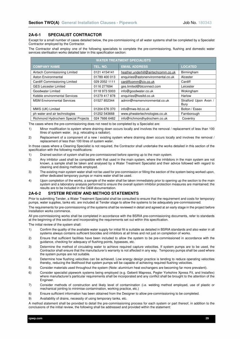
Section TWO(A) General Installation Clauses - Pipework Job No. 180343
cpwp.com 29
2A-6-1 SPECIALIST CONTRACTOR
Except for a small number of cases detailed below, the pre-commissioning of all water systems shall be completed by a Specialist Contractor employed by the Contractor.
The Contractor shall employ one of the following specialists to complete the pre-commissioning, flushing and domestic water services sterilisation works detailed later in this specification section:
The cases where the pre-commissioning does not need to be completed by a Specialist are:
1) Minor modification to system where draining down occurs locally and involves the removal / replacement of less than 100 litres of system water. (e.g. relocating a radiator).
2) Replacement of a component of a new / existing system where draining down occurs locally and involves the removal / replacement of less than 100 litres of system water.
In those cases where a Cleaning Specialist is not required, the Contractor shall undertake the works detailed in this section of the specification with the following modifications:
1) Drained section of system shall be pre-commissioned before opening up to the main system.
2) Any inhibitor used shall be compatible with that used in the main system, where the inhibitors in the main system are not known, a sample shall be taken and analysed by a Water Treatment Specialist and their advice followed with regard to cleaning and dosing methods employed.
3) The existing main system water shall not be used for pre-commission or filling the section of the system being worked upon, either dedicated temporary pumps or mains water shall be used.
4) Upon completion of the works, a sample of the water shall be taken immediately prior to opening up the section to the main system and a laboratory analysis performed to ensure the overall system inhibitor protection measures are maintained; the results are to be included in the O&M documentation.
2A-6-2 SYSTEM REVIEW AND METHOD STATEMENTS
Prior to submitting Tender, a Water Treatment Specialist shall be consulted to ensure that the requirement and costs for temporary pumps, water supplies, tanks etc. are included at Tender stage to allow the systems to be adequately pre-commissioned.
The requirements for pre-commissioning of the systems shall be reviewed in detail and agreed at an early stage in the project before installation works commence.
All pre-commissioning works shall be completed in accordance with the BSRIA pre-commissioning documents, refer to standards at the beginning of this section and incorporating the requirements set out within this specification.
The initial review of the system shall:
1) Confirm the quality of the available water supply for initial fill is suitable as detailed in BSRIA standards and also water in all systems always contains sufficient biocides and inhibitors at all times and not just on completion of works.
2) Ensure that sufficient facilities have been included to allow the system to be pre-commissioned in accordance with the guidance, checking for adequacy of flushing points, bypasses, etc.
3) Determine the method of circulating water to achieve required capture velocities. If system pumps are to be used, the Contractor shall ensure that the manufacturer’s warranty is not affected in any way. Temporary pumps shall be used where the system pumps are not suitable.
4) Determine how flushing velocities can be achieved. Low energy design practice is tending to reduce operating velocities thereby, reducing the likelihood that system pumps will be capable of achieving required flushing velocities.
5) Consider materials used throughout the system (Note: aluminium heat exchangers are becoming far more prevalent).
6) Consider specialist pipework systems being employed (e.g. Geberit Mapress, Pegler Yorkshire Xpress Fit, and Instaflex) where manufacturer’s particular requirements shall be incorporated and any conflict shall be brought to the attention of the Engineer.
7) Consider methods of construction and likely level of contamination (i.e. welding method employed, use of plastic or mechanical jointing to minimise contamination, working practice, etc.)
8) Ensure sufficient information has been obtained from the Designer to allow pre-commissioning to be completed.
9) Availability of drains, necessity of using temporary tanks, etc.
A method statement shall be provided to detail the pre-commissioning process for each system or part thereof, in addition to the conclusions of the initial review, the following shall be addressed and provided within the statement:
WATER TREATMENT SPECIALISTS
COMPANY NAME TEL. NO. EMAIL ADDRESS LOCATED
Airtech Commissioning Limited 0121 4154141 [email protected] Birmingham
Aston Environmental 01789 400 013 [email protected] Alcester
Cardiff Commissioning Limited 029 2052 1111 [email protected] Cardiff
GES Leicester Limited 0116 277694 [email protected] Leicester
Goodwater Limited 0118 973 5003 [email protected] Wokingham
Kebble environmental Services 01279 417 878 [email protected] Harlow
MSM Environmental Services 01527 852344 [email protected] Stratford Upon Avon / Bury
MWS (UK) Limited 01204 676 370 [email protected] Bolton / Essex
ph water and air technologies 01252 543668 www.phwatertechnologies.co.uk Farnborough
Richmond Hydrochem Special Projects 024 7666 6482 [email protected] Coventry
Section TWO(A) General Installation Clauses - Pipework Job No. 180343
cpwp.com 30
1) A schedule of the pre-commissioning stages to be undertaken.
2) Details of all chemicals to be used during the pre-commissioning and reasoning for the selection of the same.
3) A programme for the pre-commissioning works along with dates for witnessing.
4) Method of water circulation to be employed.
5) Confirmation from local water authority that chemical discharge is accepted along with a copy of the temporary license obtained if necessary (Liaison and obtaining temporary license shall be the responsibility of the specialist); where approval cannot be obtained in sufficient time, an alternative disposal method shall be employed that meets current regulations at no additional cost.
6) Marked up drawings to indicate each flushing circuit and process with minimum velocities to be achieved.
7) Details of any temporary plant and equipment to be used along with temporary power supplies/ generators as appropriate.
8) Laboratory results and recommendations of water samples taken prior to pressure testing and if system maintained full for more than 2 weeks, prior to flushing.
9) All necessary health and safety information, risk assessments and COSHH information.
The method statement shall be submitted and reviewed along with any comments incorporated prior to commencement of pre-commissioning works.
2A-6-3 CHEMICAL CLEANING
Chemical cleaning of the system shall:
1) Be completed in accordance with the described guides and method statements.
2) Continue until satisfactory cleanliness is achieved as defined in the described guides.
3) Be witnessed by the Clerk of Works or Commissioning Specialist.
4) Recorded by the Tenderer and certified by the Clerk of Works or Commissioning Specialist.
5) Be completed in the absence of any filters, meters, circulating pumps, traps, valves, controllers, non-return valves and items of equipment which may be damaged or prevent adequate flushing, all of which shall be removed during the flushing process by the Contractor and re-instated upon completion.
2A-6-4 SYSTEM ADDITIVES
Based upon the laboratory results described above and system particulars the appropriated inhibitors, biocides, antifreeze, etc. shall be introduced into the system via a dosing pot or combined pressurisation and dosing tank system.
System additives shall be introduced, via a dosing pot, which shall:
1) Be adequately sized for the system (10 Litres minimum).
2) Be a proprietary pre-fabricated unit with fill funnel, check valve, drain and service valves that shall be positioned in a location agreed by the Engineer.
3) A fill tundish level that allows operatives to safely lift and poor water treatment chemicals.
4) Be provided whether indicated on drawings or not, assuming a distance of 5 metres from its system connection point.
A permanent laminated label shall be fixed adjacent to the dosing pot stating date/quantity/% of system volume used in initial treatment.
The Contractor shall monitor the effectiveness of the additives during initial operation and take all necessary action to ensure that system has sufficient treatment during the initial operation, all at Contractor’s own expense.
The effectiveness of system additives shall be checked at the following intervals:
1) 7 days after system is made operational.
2) 3 Months after practical completion.
3) Immediately prior to the end of defects period.
Each system check shall include the following:
1) Samples shall be taken from representative points in each system to ensure that the treatment has been successful.
2) An analysis of these samples shall be undertaken by an Independent UKAS accredited laboratory.
3) If treatment levels are below recommended levels then additive level shall be topped up as necessary.
4) If treatment levels have dropped below expected levels for normal system operation (i.e. leak or excessive top up with fresh water is occurring), the system shall be inspected and cause identified and repaired before additives are topped up as appropriate, a report shall be provided detailing cause and corrective actions, chemicals added and recommendations for further monitoring.
5) Should alteration, draining down and refilling of system by Client’s maintenance personnel be identified as the cause of low water treatment levels, the Contractor shall immediately inform the Client (in writing) of any corrective action that needs to be undertaken to return the system to recommended levels.
The Contractor’s O&M documentation shall clearly identify the necessity of monitoring and maintaining system water treatment levels in order to prevent system corrosion and not invalidating manufacturers’ guarantees/ warranties.
Any failure of pipework/ equipment occurring due to non-compliance with the above shall be replaced at the Contractor’s own expense.
2A-6-5 DE-AERATION
Removal of air from the system is an on-going process that shall be continued by the Contractor until all air has been removed.
The de-aeration process shall be undertaken at the following times:
1) On a continuous basis during the system fill period and for at least 4 hours thereafter.
Section TWO(A) General Installation Clauses - Pipework Job No. 180343
cpwp.com 31
2) Immediately prior to commencement of commissioning and on a daily basis during commissioning.
3) Twice a day for the first 7 days after the system has been filled.
4) On a weekly basis until no air is released for two consecutive weeks.
Where automatic air vents and air separators are employed these shall be checked on a daily basis for correct operation and any signs of leakage of water.
2A-6-6 STEAM & GASES
Steam and gas installations shall be scavenged with steam or compressed air.
2A-6-7 TRACE HEATING
All external water pipework, including vent and drain lines shall be fully trace heated prior to insulation. The trace heating shall be of the self-regulating type.
The trace heating shall be completed with all necessary junction boxes, fixing tape, warning labels and seals for a complete installation and shall be interfaced with the BMS.
The system shall be installed as follows:
1) One circuit for flow and one for return joined in parallel by a suitable junction box, which shall then connect back to a power supply point.
2) Installed spirally around each pipe to give an output sufficient to prevent pipework from freezing.
3) Adequately wrapped around exposed items such as valves, etc.
4) Provided with correct installation items including entry boxes.
5) Self-regulating to maintain pipe at 4°C at a design ambient of –20°C.
6) Installation shall be Raychem Ltd, their H-watt system or equal and approved.
7) Entire installation shall be fully in accordance with manufacturer’s best practice recommendations.
2A-7 POST CLEANING AND STERILISATION
2A-7-1 FLUSHING AND SAMPLES
Where flushing loops are not indicated on the design drawings, the Contractor shall include for either temporary disconnection and installation flushing hoses or a permanent flushing bypass complete with isolating valve, this shall be provided at no additional cost to the contract.
Flushing and sampling of all systems shall:
1) Be completed in accordance with the described guides and method statements, specifically including but not limited to BSRIA BG29 and BS 8552 for methodology and frequency of both.
2) Continue until satisfactory cleanliness is achieved as defined in the described guides.
3) Be witnessed by the Clerk of Works or Commissioning Specialist.
4) Recorded by the Tenderer and certified by the Clerk of Works or Commissioning Specialist.
5) Be completed in the absence of any filters, meters, circulating pumps, traps, valves, controllers, non-return valves and items of equipment which may be damaged or prevent adequate flushing, all of which shall be removed during the flushing process by the Contractor and re-instated upon completion.
Samples shall be taken 7 days after treatment from representative points in each system to ensure that the treatment has been successful and shall be carried out fully in accordance with the previously listed standards.
An analysis of these samples shall be undertaken by an Independent UKAS accredited laboratory at the Contractor’s expense. The fully satisfactory and compliant results, compliant with above quoted standards, shall be provided within the Operating and Maintenance Manuals. Non-satisfactory or non-compliant results shall be repeated after any necessary remedial works, all remedial works and retesting shall be at the contractor’s expense.
No system shall be left charged with untreated water for a period in excess of 48 hours, where this period is exceeded, the BSRIA recommendations with regard to biocides and cleansing, etc. shall be followed in full at the Contractor’s own expense.
If treatment process proves unsuccessful, the Engineer shall instruct for repeat treatment at the Contractor’s expense.
It may not be practical to achieve sufficient flushing velocities through low loss headers, thermal stores, etc. so these must be kept clean by a combination of:
1) The use of flushing bypasses so that suspended solids do not enter these components.
2) Removable ends on vertical low loss headers complete with bolted blanking plates. Horizontal low loss headers are not permitted.
3) Provision of multiple inspection chambers to allow visual physical inspection of internal surfaces and prove internal cleanliness of all vessels. Dated digital images of the internal condition of all vessels shall be included within the operating and maintenance manuals.
Section TWO(A) General Installation Clauses - Pipework Job No. 180343
cpwp.com 32
2A-7-2 DOMESTIC WATER SERVICES STERILISATION
On all projects, the Contractor shall:
1) Fill, pressure test and flush the system using water from an appropriate source for example:
a) Mains water supply.
b) Temporary site supply.
c) Potable drinking water bowser.
2) Sterilise the complete system including pipework, tanks, etc. in accordance with the British Standard defined in the standards section of this specification.
3) HTM requirements shall also be adhered to on all healthcare and related projects.
4) The Engineer shall be notified 48 hours prior to sterilisation taking place so that arrangements can be made to witness the procedures.
Provide and maintain safety labels and signs in accordance with the British Standard and as follows:
a) Warning signs at every outlet during chlorination process.
b) Warning signs at principle drinking water points and common area such as site canteen, office and entrance stating water on site is not suitable for drinking, these signs to be maintained until satisfactory laboratory results are obtained.
5) After completion of the sterilisation, maintain the service in safe condition by regular flushing out of the systems, until the date of Practical Completion (twice weekly flushing routine for entire system including hose reels, etc. formally recorded and witnessed by the Clerk of Works or the Commissioning Specialist). Calculate the water capacity of the various sections of the systems and the amount water to be drawn off to ensure that completely fresh mains water is drawn into the system twice weekly.
6) Should twice weekly flushing not be adequately completed, the system shall be re-chlorinated and sample taken/ analysed.
7) Provide certification showing the areas/ sections treated, the levels of chorine solution used.
8) Take samples between 2 and 7 days after completion of sterilisation, note this delay is mandatory so samples shall not be taken the same day as sterilisation is completed and obtain laboratory analysis which shall:
a) Be taken at representative locations throughout each system as follows:
i) Incoming mains supply.
ii) Sentinel point on each system (e.g. DHW, MCW, BTCW, etc.).
iii) Each storage tank (where fitted).
iv) In agreed locations throughout the remainder of the systems at the rate of one sample per 20 outlets (or pair of outlets where serving WHB or the like).
b) Be analysed by a UKAS accredited laboratory in accordance with British Standards and Public Health Laboratory Recommendations.
c) Include an 'E' Coli, chemical analysis, copper content, lead content, Pseudomonas aeruginosa and legionella test.
d) Analysis of results and clear statement with regard to suitability for human consumption.
e) Early issue of results (before legionella results are available) where required by local authority in order to connect the new mains water supply.
9) In the event of any of the test results not being acceptable, the Contractor shall flush out, re-chlorinate and re-test as previously specified at no additional cost to the contract.
10) Practical completion of the works shall not be given until chlorination is complete and full satisfactory laboratory results have been obtained.
The Contractor shall employ one of the previously listed ‘Water Treatment Specialists’ to carry out the domestic water services sterilisation.
2A-8 RECORDS AND DOCUMENTATION
On completion of the activities described within this section of the specification complete records of ALL completed works and certificates of compliance shall be provided to both the design team and within the Operating and Maintenance Manuals.
Incomplete, non-compliant or unsatisfactory, in terms of compliance with the Standards listed in this specification, shall require all pre-commissioning, cleaning, flushing and sterilisation to be carried again at no cost to the client.
As an aid to meet this requirement for complete records and documentation all of the following must be provided at the relevant contract programme stages and a complete set of these documents shall be included within the Operating and Maintenance Manuals:
1) Record of all Local Water Authority and WaterSafe Registration to verify the potable water installation is fully WRAS compliant.
2) Pressure test certificates for every services.
3) Non-destructive test certificates for welded and brazed pipework.
4) Gas Safe certificates.
5) Flushing certificates.
6) Water sample test result certificates.
7) Full UKAS certification of EVERY water system to verify the installation are fully compliant with regulations, best practice guideline and industry standards.

Section TWO(A) General Installation Clauses - Pipework Job No. 180343
cpwp.com 33
8) Certificate of manufacturer’s satisfaction of the installations where plastic, press fit or grooved pipework systems have been installed.
9) Records of actual biocides and inhibitors used and concentrations recorded for each system so that the client has a record of how the systems need to be treated, etc.
10) Example record sheets provided in BSRIA BG29 pre-commissioning and cleaning document shall be used as a basis for pre-commissioning and cleaning record keeping.
11) An acceptable water quality certificate of conformity for system cleanliness shall be provided for each water system. A typical example of an acceptable acceptance certificate is provided within BSRIA BG29.
12) Any other relevant documents that will be beneficial to the client over the life of the building.
cpwp.com V3.2
Section Two (B) General Installation Clauses - Ductwork
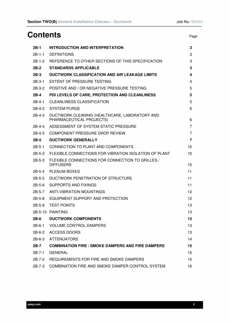
Section TWO(B) General Installation Clauses – Ductwork Job No.180343
cpwp.com 2
Contents Page
2B-1 INTRODUCTION AND INTERPRETATION 3
2B-1-1 DEFINITIONS 3
2B-1-2 REFERENCE TO OTHER SECTIONS OF THIS SPECIFICATION 3
2B-2 STANDARDS APPLICABLE 3
2B-3 DUCTWORK CLASSIFICATION AND AIR LEAKAGE LIMITS 4
2B-3-1 EXTENT OF PRESSURE TESTING 4
2B-3-2 POSITIVE AND / OR NEGATIVE PRESSURE TESTING 5
2B-4 PDI LEVELS OF CARE, PROTECTION AND CLEANLINESS 5
2B-4-1 CLEANLINESS CLASSIFICATION 5
2B-4-2 SYSTEM PURGE 6
2B-4-3 DUCTWORK CLEANING (HEALTHCARE, LABORATORY AND PHARMACEUTICAL PROJECTS) 6
2B-4-4 ASSESSMENT OF SYSTEM STATIC PRESSURE 7
2B-4-5 COMPONENT PRESSURE DROP REVIEW 7
2B-5 DUCTWORK GENERALLY 7
2B-5-1 CONNECTION TO PLANT AND COMPONENTS 10
2B-5-2 FLEXIBLE CONNECTIONS FOR VIBRATION ISOLATION OF PLANT 10
2B-5-3 FLEXIBLE CONNECTIONS FOR CONNECTION TO GRILLES / DIFFUSERS 10
2B-5-4 PLENUM BOXES 11
2B-5-5 DUCTWORK PENETRATION OF STRUCTURE 11
2B-5-6 SUPPORTS AND FIXINGS 11
2B-5-7 ANTI-VIBRATION MOUNTINGS 12
2B-5-8 EQUIPMENT SUPPORT AND PROTECTION 12
2B-5-9 TEST POINTS 13
2B-5-10 PAINTING 13
2B-6 DUCTWORK COMPONENTS 13
2B-6-1 VOLUME CONTROL DAMPERS 13
2B-6-2 ACCESS DOORS 13
2B-6-3 ATTENUATORS 14
2B-7 COMBINATION FIRE / SMOKE DAMPERS AND FIRE DAMPERS 15
2B-7-1 GENERAL 15
2B-7-2 REQUIREMENTS FOR FIRE AND SMOKE DAMPERS 15
2B-7-3 COMBINATION FIRE AND SMOKE DAMPER CONTROL SYSTEM 16

Section TWO(B) General Installation Clauses – Ductwork Job No.180343
cpwp.com 3
2B-1 INTRODUCTION AND INTERPRETATION
The Contractor shall supply, install and commission the ductwork installations as detailed on the tender drawings and within this specification, employing specialist ductwork manufacturers / installers as necessary.
2B-1-1 DEFINITIONS
Please refer to definitions contained in BESA DW documents and:
DEFINITIONS / ABBREVIATIONS
Duct Diameter Diameter of duct section or equivalent diameter of rectangular or flat oval duct.
Specialist Specialist ductwork manufacturer or fitters employed by the Contractor.
FBPP Fabric backed polypropylene sheet
FOAM Rigid polyurethane self-extinguishing foam
GRP Glass reinforced plastic
PP Polypropylene
PPS Self-extinguishing polypropylene
UPVC Unplasticised polyvinyl chloride
2B-1-2 REFERENCE TO OTHER SECTIONS OF THIS SPECIFICATION
This section of the specification shall not be used in isolation and must be read in conjunction with the particular sections, commissioning and standard clauses, all of which define further the requirements for the ductwork installations.
2B-2 STANDARDS APPLICABLE
Works shall be completed in accordance with all applicable industry standards. Some of the most relevant standards associated with this section are scheduled below:
STANDARDS
BESA DW 143 Guide to Good Practice - Ductwork air leakage testing
BS EN 13403 Ventilation for Buildings. Non-metallic ducts. Ductwork made from insulation duct boards
BESA DW 144 Specification for sheet metal ductwork BS EN 15423 Ventilation for buildings. Fire precaution for air distribution systems in buildings
BESA DW145 Guide to Good Practice for the Installation of fire and smoke dampers
BS EN 13501 Fire classification of construction products and building elements
BESA DW154 Specification for plastics ductwork BS EN 15650 Ventilation for buildings. Fire dampers
BESA DW172 Specification for kitchen ventilation systems BS EN 15727 Ventilation for buildings. Ducts and ductwork components, leakage classification and testing
BESA TR 19 Internal cleanliness of ventilation systems BS EN 15780 Ventilation for buildings. Cleanliness of ventilation systems
BESA TR 35 Low Energy Ventilation for Residential Buildings BS EN 16798 Energy performance of buildings. Ventilation for buildings
BS 9999 Code of practice for fire safety in the design, management and use of buildings
BS EN 15882-2 Extended application of results from fire resistance tests for service installations. Fire dampers
BS EN 1366 Fire resistance tests for service installations BS ISO 10294 Fire resistance tests. Fire dampers for air distribution
BS EN 1506 Ventilation for Buildings. Sheet metal air ducts and fittings with circular cross-section
BS ISO 21927-8 Smoke and heat control systems. Smoke control dampers
BS EN 1507 Ventilation for Buildings. Sheet metal air ducts and fittings with rectangular section
CIBSE Guide B2: Ventilation and Ductwork
BS EN 12097 Requirements for ductwork components to facilitate maintenance of ductwork systems
CIBSE TM26 Hygienic maintenance of office ventilation ductwork
BS EN 12101-8 Fire and heat control systems. Smoke control dampers
CIBSE TM30 Improved Life Cycle Performance of Mechanical Ventilation Systems
BS EN 12236 Ventilation for Buildings. Ductwork hangers and supports
LPS 1162 LPCB approval and listing of fire dampers
BS EN 12237 Ventilation for Buildings. Ductwork. Strength and leakage of circular metal ducts
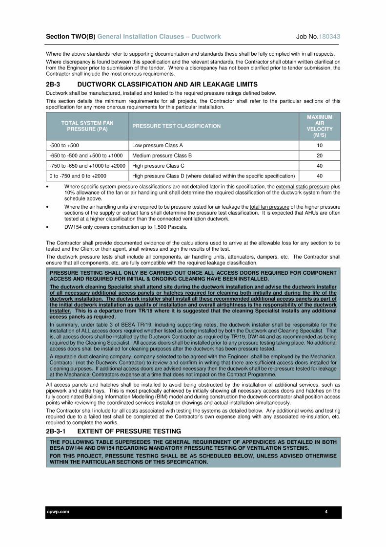
Section TWO(B) General Installation Clauses – Ductwork Job No.180343
cpwp.com 4
Where the above standards refer to supporting documentation and standards these shall be fully complied with in all respects.
Where discrepancy is found between this specification and the relevant standards, the Contractor shall obtain written clarification from the Engineer prior to submission of the tender. Where a discrepancy has not been clarified prior to tender submission, the Contractor shall include the most onerous requirements.
2B-3 DUCTWORK CLASSIFICATION AND AIR LEAKAGE LIMITS
Ductwork shall be manufactured, installed and tested to the required pressure ratings defined below.
This section details the minimum requirements for all projects, the Contractor shall refer to the particular sections of this specification for any more onerous requirements for this particular installation.
TOTAL SYSTEM FAN PRESSURE (PA)
PRESSURE TEST CLASSIFICATION
MAXIMUM AIR
VELOCITY (M/S)
-500 to +500 Low pressure Class A 10
-650 to -500 and +500 to +1000 Medium pressure Class B 20
-750 to -650 and +1000 to +2000 High pressure Class C 40
0 to -750 and 0 to +2000 High pressure Class D (where detailed within the specific specification) 40
• Where specific system pressure classifications are not detailed later in this specification, the external static pressure plus 10% allowance of the fan or air handling unit shall determine the required classification of the ductwork system from the schedule above.
• Where the air handling units are required to be pressure tested for air leakage the total fan pressure of the higher pressure sections of the supply or extract fans shall determine the pressure test classification. It is expected that AHUs are often tested at a higher classification than the connected ventilation ductwork.
• DW154 only covers construction up to 1,500 Pascals.
The Contractor shall provide documented evidence of the calculations used to arrive at the allowable loss for any section to be tested and the Client or their agent, shall witness and sign the results of the test.
The ductwork pressure tests shall include all components, air handling units, attenuators, dampers, etc. The Contractor shall ensure that all components, etc. are fully compatible with the required leakage classification.
PRESSURE TESTING SHALL ONLY BE CARRIED OUT ONCE ALL ACCESS DOORS REQUIRED FOR COMPONENT ACCESS AND REQUIRED FOR INITIAL & ONGOING CLEANING HAVE BEEN INSTALLED.
The ductwork cleaning Specialist shall attend site during the ductwork installation and advise the ductwork installer of all necessary additional access panels or hatches required for cleaning both initially and during the life of the ductwork installation. The ductwork installer shall install all these recommended additional access panels as part of the initial ductwork installation as quality of installation and overall airtightness is the responsibility of the ductwork installer. This is a departure from TR/19 where it is suggested that the cleaning Specialist installs any additional access panels as required.
In summary, under table 3 of BESA TR/19, including supporting notes, the ductwork installer shall be responsible for the installation of ALL access doors required whether listed as being installed by both the Ductwork and Cleaning Specialist. That is, all access doors shall be installed by the Ductwork Contractor as required by TR/19, DW144 and as recommended as being required by the Cleaning Specialist. All access doors shall be installed prior to any pressure testing taking place. No additional access doors shall be installed for cleaning purposes after the ductwork has been pressure tested.
A reputable duct cleaning company, company selected to be agreed with the Engineer, shall be employed by the Mechanical Contractor (not the Ductwork Contractor) to review and confirm in writing that there are sufficient access doors installed for cleaning purposes. If additional access doors are advised necessary then the ductwork shall be re-pressure tested for leakage at the Mechanical Contractors expense at a time that does not impact on the Contract Programme.
All access panels and hatches shall be installed to avoid being obstructed by the installation of additional services, such as pipework and cable trays. This is most practically achieved by initially showing all necessary access doors and hatches on the fully coordinated Building Information Modelling (BIM) model and during construction the ductwork contractor shall position access points while reviewing the coordinated services installation drawings and actual installation simultaneously.
The Contractor shall include for all costs associated with testing the systems as detailed below. Any additional works and testing required due to a failed test shall be completed at the Contractor’s own expense along with any associated re-insulation, etc. required to complete the works.
2B-3-1 EXTENT OF PRESSURE TESTING
THE FOLLOWING TABLE SUPERSEDES THE GENERAL REQUIREMENT OF APPENDICES AS DETAILED IN BOTH BESA DW144 AND DW154 REGARDING MANDATORY PRESSURE TESTING OF VENTILATION SYSTEMS.
FOR THIS PROJECT, PRESSURE TESTING SHALL BE AS SCHEDULED BELOW, UNLESS ADVISED OTHERWISE WITHIN THE PARTICULAR SECTIONS OF THIS SPECIFICATION.
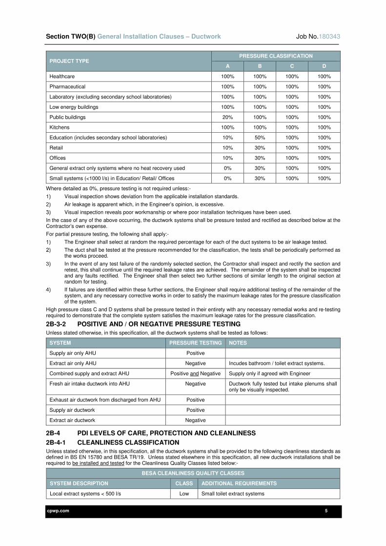
Section TWO(B) General Installation Clauses – Ductwork Job No.180343
cpwp.com 5
PROJECT TYPE PRESSURE CLASSIFICATION
A B C D
Healthcare 100% 100% 100% 100%
Pharmaceutical 100% 100% 100% 100%
Laboratory (excluding secondary school laboratories) 100% 100% 100% 100%
Low energy buildings 100% 100% 100% 100%
Public buildings 20% 100% 100% 100%
Kitchens 100% 100% 100% 100%
Education (includes secondary school laboratories) 10% 50% 100% 100%
Retail 10% 30% 100% 100%
Offices 10% 30% 100% 100%
General extract only systems where no heat recovery used 0% 30% 100% 100%
Small systems (<1000 l/s) in Education/ Retail/ Offices 0% 30% 100% 100%
Where detailed as 0%, pressure testing is not required unless:-
Visual inspection shows deviation from the applicable installation standards.
Air leakage is apparent which, in the Engineer’s opinion, is excessive.
Visual inspection reveals poor workmanship or where poor installation techniques have been used.
In the case of any of the above occurring, the ductwork systems shall be pressure tested and rectified as described below at the Contractor’s own expense.
For partial pressure testing, the following shall apply:-
The Engineer shall select at random the required percentage for each of the duct systems to be air leakage tested.
The duct shall be tested at the pressure recommended for the classification, the tests shall be periodically performed as the works proceed.
In the event of any test failure of the randomly selected section, the Contractor shall inspect and rectify the section and retest, this shall continue until the required leakage rates are achieved. The remainder of the system shall be inspected and any faults rectified. The Engineer shall then select two further sections of similar length to the original section at random for testing.
If failures are identified within these further sections, the Engineer shall require additional testing of the remainder of the system, and any necessary corrective works in order to satisfy the maximum leakage rates for the pressure classification of the system.
High pressure class C and D systems shall be pressure tested in their entirety with any necessary remedial works and re-testing required to demonstrate that the complete system satisfies the maximum leakage rates for the pressure classification.
2B-3-2 POSITIVE AND / OR NEGATIVE PRESSURE TESTING
Unless stated otherwise, in this specification, all the ductwork systems shall be tested as follows:
SYSTEM PRESSURE TESTING NOTES
Supply air only AHU Positive
Extract air only AHU Negative Incudes bathroom / toilet extract systems.
Combined supply and extract AHU Positive and Negative Supply only if agreed with Engineer
Fresh air intake ductwork into AHU Negative Ductwork fully tested but intake plenums shall only be visually inspected.
Exhaust air ductwork from discharged from AHU Positive
Supply air ductwork Positive
Extract air ductwork Negative
2B-4 PDI LEVELS OF CARE, PROTECTION AND CLEANLINESS
2B-4-1 CLEANLINESS CLASSIFICATION
Unless stated otherwise, in this specification, all the ductwork systems shall be provided to the following cleanliness standards as defined in BS EN 15780 and BESA TR/19. Unless stated elsewhere in this specification, all new ductwork installations shall be required to be installed and tested for the Cleanliness Quality Classes listed below:-
BESA CLEANLINESS QUALITY CLASSES
SYSTEM DESCRIPTION CLASS ADDITIONAL REQUIREMENTS
Local extract systems < 500 l/s Low Small toilet extract systems
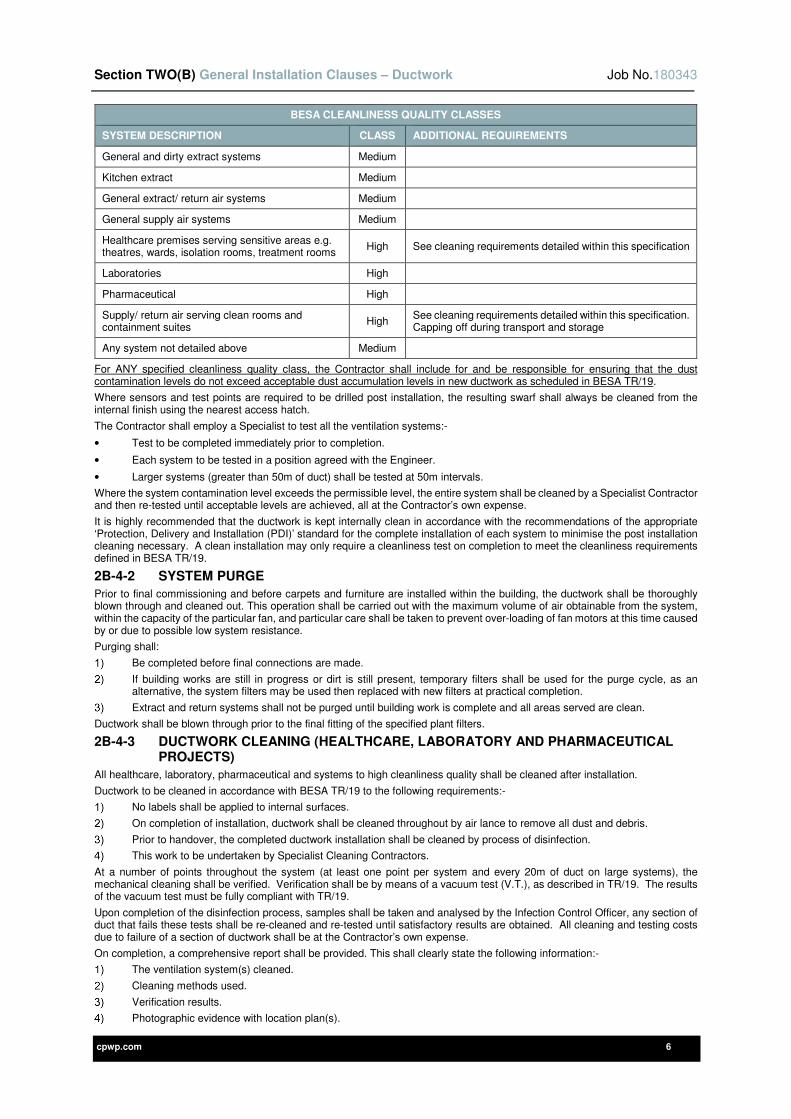
Section TWO(B) General Installation Clauses – Ductwork Job No.180343
cpwp.com 6
BESA CLEANLINESS QUALITY CLASSES
SYSTEM DESCRIPTION CLASS ADDITIONAL REQUIREMENTS
General and dirty extract systems Medium
Kitchen extract Medium
General extract/ return air systems Medium
General supply air systems Medium
Healthcare premises serving sensitive areas e.g. theatres, wards, isolation rooms, treatment rooms
High See cleaning requirements detailed within this specification
Laboratories High
Pharmaceutical High
Supply/ return air serving clean rooms and containment suites
High See cleaning requirements detailed within this specification. Capping off during transport and storage
Any system not detailed above Medium
For ANY specified cleanliness quality class, the Contractor shall include for and be responsible for ensuring that the dust contamination levels do not exceed acceptable dust accumulation levels in new ductwork as scheduled in BESA TR/19.
Where sensors and test points are required to be drilled post installation, the resulting swarf shall always be cleaned from the internal finish using the nearest access hatch.
The Contractor shall employ a Specialist to test all the ventilation systems:-
• Test to be completed immediately prior to completion.
• Each system to be tested in a position agreed with the Engineer.
• Larger systems (greater than 50m of duct) shall be tested at 50m intervals.
Where the system contamination level exceeds the permissible level, the entire system shall be cleaned by a Specialist Contractor and then re-tested until acceptable levels are achieved, all at the Contractor’s own expense.
It is highly recommended that the ductwork is kept internally clean in accordance with the recommendations of the appropriate ‘Protection, Delivery and Installation (PDI)’ standard for the complete installation of each system to minimise the post installation cleaning necessary. A clean installation may only require a cleanliness test on completion to meet the cleanliness requirements defined in BESA TR/19.
2B-4-2 SYSTEM PURGE
Prior to final commissioning and before carpets and furniture are installed within the building, the ductwork shall be thoroughly blown through and cleaned out. This operation shall be carried out with the maximum volume of air obtainable from the system, within the capacity of the particular fan, and particular care shall be taken to prevent over-loading of fan motors at this time caused by or due to possible low system resistance.
Purging shall:
Be completed before final connections are made.
If building works are still in progress or dirt is still present, temporary filters shall be used for the purge cycle, as an alternative, the system filters may be used then replaced with new filters at practical completion.
Extract and return systems shall not be purged until building work is complete and all areas served are clean.
Ductwork shall be blown through prior to the final fitting of the specified plant filters.
2B-4-3 DUCTWORK CLEANING (HEALTHCARE, LABORATORY AND PHARMACEUTICAL PROJECTS)
All healthcare, laboratory, pharmaceutical and systems to high cleanliness quality shall be cleaned after installation.
Ductwork to be cleaned in accordance with BESA TR/19 to the following requirements:-
No labels shall be applied to internal surfaces.
On completion of installation, ductwork shall be cleaned throughout by air lance to remove all dust and debris.
Prior to handover, the completed ductwork installation shall be cleaned by process of disinfection.
This work to be undertaken by Specialist Cleaning Contractors.
At a number of points throughout the system (at least one point per system and every 20m of duct on large systems), the mechanical cleaning shall be verified. Verification shall be by means of a vacuum test (V.T.), as described in TR/19. The results of the vacuum test must be fully compliant with TR/19.
Upon completion of the disinfection process, samples shall be taken and analysed by the Infection Control Officer, any section of duct that fails these tests shall be re-cleaned and re-tested until satisfactory results are obtained. All cleaning and testing costs due to failure of a section of ductwork shall be at the Contractor’s own expense.
On completion, a comprehensive report shall be provided. This shall clearly state the following information:-
The ventilation system(s) cleaned.
Cleaning methods used.
Verification results.
Photographic evidence with location plan(s).
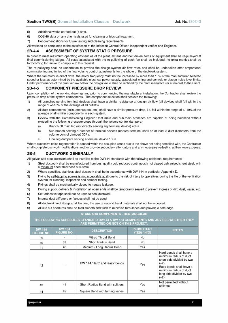
Section TWO(B) General Installation Clauses – Ductwork Job No.180343
cpwp.com 7
Additional works carried out (if any).
COSHH data on any chemicals used for cleaning or biocidal treatment.
Recommendations for future testing and cleaning requirements.
All works to be completed to the satisfaction of the Infection Control Officer, independent verifier and Engineer.
2B-4-4 ASSESSMENT OF SYSTEM STATIC PRESSURE
In order to meet maximum operating efficiencies of the plant, all fans and belt driven items of equipment shall be re-pulleyed at final commissioning stages. All costs associated with the re-pulleying of each fan shall be included, no extra monies shall be forthcoming for failure to comply with this request.
The re-pulleying shall be undertaken to provide the design system air flow rates and shall be undertaken after proportional commissioning and in lieu of the final volume control adjustments for the whole of the ductwork system.
Where the fan motor is direct drive, the motor frequency must not be increased by more than 10% of the manufacturer selected speed or less as determined by the available electrical power supply, associated wiring and controls or design noise level limits. Under performance of the plant airflow below the design value shall be rectified by the plant manufacturer at no cost to the Client.
2B-4-5 COMPONENT PRESSURE DROP REVIEW
Upon completion of the working drawings and prior to commencing the manufacture/ installation, the Contractor shall review the pressure drop of the system components. The component selection shall achieve the following:-
All branches serving terminal devices shall have a similar resistance at design air flow (all devices shall fall within the range of +/-10% of the average of all outlets).
All duct components (coils, attenuators, etc.) shall have a similar pressure drop, i.e. fall within the range of +/-10% of the average of all similar components in each system.
Review with the Commissioning Engineer that main and sub-main branches are capable of being balanced without exceeding the following pressure drops through the volume control dampers:-
a) Branch off main leg (not directly serving any terminal device) 40Pa
b) Sub-branch serving a number of terminal devices (nearest terminal shall be at least 3 duct diameters from the volume control damper) 30Pa.
c) Final leg dampers serving a terminal device 15Pa.
Where excessive noise regeneration is caused within the occupied zones due to the above not being complied with, the Contractor shall complete ductwork modifications and/ or provide secondary attenuators and any necessary re-testing at their own expense.
2B-5 DUCTWORK GENERALLY
All galvanised steel ductwork shall be installed to the DW144 standards with the following additional requirements:-
Steel ductwork shall be manufactured from best quality cold reduced continuously hot dipped galvanised sheet steel, with a minimum sheet thickness of 0.8mm.
Where specified, stainless steel ductwork shall be in accordance with DW 144 in particular Appendix D.
Fixing by self-tapping screws is not acceptable at all due to the risk of injury to operatives during the life of the ventilation system for cleaning, inspection and damper testing.
Fixings shall be mechanically closed to negate leakage.
During supply, delivery & installation all open ends shall be temporarily sealed to prevent ingress of dirt, dust, water, etc.
Self-adhesive tape shall not be used to seal ductwork.
Internal duct stiffeners or flanges shall not be used.
All ductwork and fittings shall be new, the use of second hand materials shall not be accepted.
All site cut apertures shall be filed smooth and flush to minimise turbulence and provide a safe edge.
STANDARD COMPONENTS - RECTANGULAR
THE FOLLOWING SCHEDULES STANDARD DW144 & DW 154 COMPONENTS AND ADVISES WHETHER THEY ARE PERMITTED OR NOT ON THIS PROJECT.
DW 144 FIGURE NO.
DW 154 FIGURE NO.
DESCRIPTION PERMITTED? Y(ES) / N(O)
NOTES
39 - Mitred Throat Bend No
40 39 Short Radius Bend No
41 40 Medium / Long Radius Bend Yes
42 - DW 144 ‘Hard’ and ‘easy’ bends
Yes
Hard bends shall have a minimum radius of duct short side divided by two (÷2). Easy bends shall have a minimum radius of duct long side divided by two (÷2).
43 41 Short Radius Bend with splitters Yes Not permitted without splitters.
44 42 Square Bend with turning vanes Yes
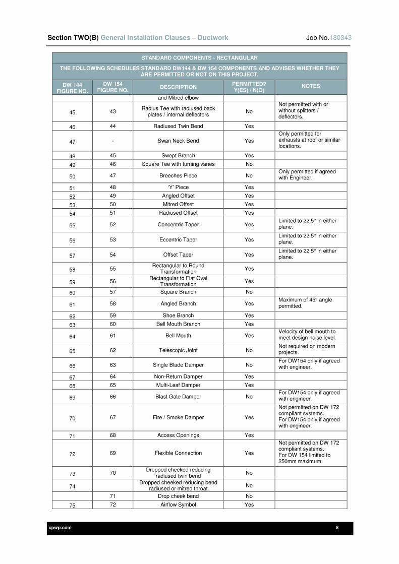
Section TWO(B) General Installation Clauses – Ductwork Job No.180343
cpwp.com 8
STANDARD COMPONENTS - RECTANGULAR
THE FOLLOWING SCHEDULES STANDARD DW144 & DW 154 COMPONENTS AND ADVISES WHETHER THEY ARE PERMITTED OR NOT ON THIS PROJECT.
DW 144 FIGURE NO.
DW 154 FIGURE NO.
DESCRIPTION PERMITTED? Y(ES) / N(O)
NOTES
and Mitred elbow
45 43 Radius Tee with radiused back
plates / internal deflectors No
Not permitted with or without splitters / deflectors.
46 44 Radiused Twin Bend Yes
47 - Swan Neck Bend Yes
Only permitted for exhausts at roof or similar locations.
48 45 Swept Branch Yes
49 46 Square Tee with turning vanes No
50 47 Breeches Piece No Only permitted if agreed with Engineer.
51 48 ‘Y’ Piece Yes
52 49 Angled Offset Yes
53 50 Mitred Offset Yes
54 51 Radiused Offset Yes
55 52 Concentric Taper Yes Limited to 22.5° in either plane.
56 53 Eccentric Taper Yes Limited to 22.5° in either plane.
57 54 Offset Taper Yes Limited to 22.5° in either plane.
58 55 Rectangular to Round
Transformation Yes
59 56 Rectangular to Flat Oval
Transformation Yes
60 57 Square Branch No
61 58 Angled Branch Yes Maximum of 45° angle permitted.
62 59 Shoe Branch Yes
63 60 Bell Mouth Branch Yes
64 61 Bell Mouth Yes Velocity of bell mouth to meet design noise level.
65 62 Telescopic Joint No Not required on modern projects.
66 63 Single Blade Damper No For DW154 only if agreed with engineer.
67 64 Non-Return Damper Yes
68 65 Multi-Leaf Damper Yes
69 66 Blast Gate Damper No For DW154 only if agreed with engineer.
70 67 Fire / Smoke Damper Yes
Not permitted on DW 172 compliant systems. For DW154 only if agreed with engineer.
71 68 Access Openings Yes
72 69 Flexible Connection Yes
Not permitted on DW 172 compliant systems. For DW 154 limited to 250mm maximum.
73 70 Dropped cheeked reducing
radiused twin bend No
74 Dropped cheeked reducing bend
radiused or mitred throat No
71 Drop cheek bend No
75 72 Airflow Symbol Yes
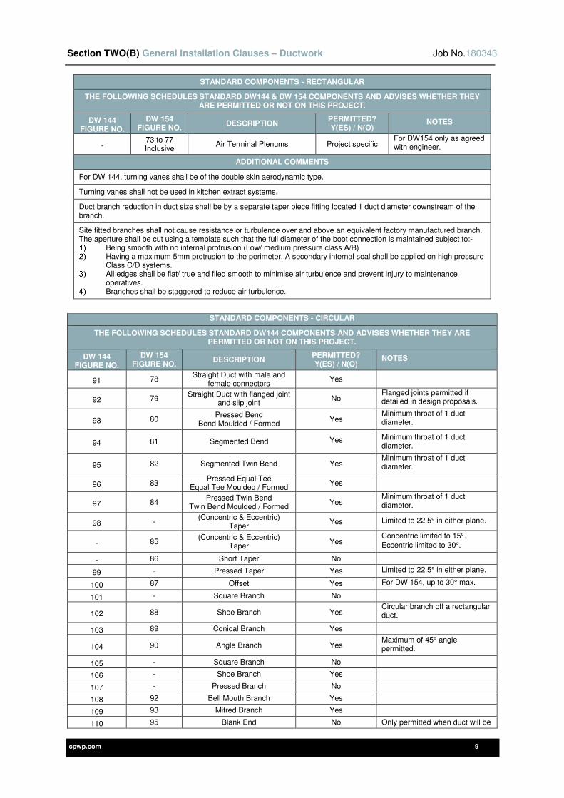
Section TWO(B) General Installation Clauses – Ductwork Job No.180343
cpwp.com 9
STANDARD COMPONENTS - RECTANGULAR
THE FOLLOWING SCHEDULES STANDARD DW144 & DW 154 COMPONENTS AND ADVISES WHETHER THEY ARE PERMITTED OR NOT ON THIS PROJECT.
DW 144 FIGURE NO.
DW 154 FIGURE NO.
DESCRIPTION PERMITTED? Y(ES) / N(O)
NOTES
- 73 to 77 Inclusive
Air Terminal Plenums Project specific For DW154 only as agreed with engineer.
ADDITIONAL COMMENTS
For DW 144, turning vanes shall be of the double skin aerodynamic type.
Turning vanes shall not be used in kitchen extract systems.
Duct branch reduction in duct size shall be by a separate taper piece fitting located 1 duct diameter downstream of the branch.
Site fitted branches shall not cause resistance or turbulence over and above an equivalent factory manufactured branch. The aperture shall be cut using a template such that the full diameter of the boot connection is maintained subject to:-
Being smooth with no internal protrusion (Low/ medium pressure class A/B) Having a maximum 5mm protrusion to the perimeter. A secondary internal seal shall be applied on high pressure
Class C/D systems. All edges shall be flat/ true and filed smooth to minimise air turbulence and prevent injury to maintenance
operatives. Branches shall be staggered to reduce air turbulence.
STANDARD COMPONENTS - CIRCULAR
THE FOLLOWING SCHEDULES STANDARD DW144 COMPONENTS AND ADVISES WHETHER THEY ARE PERMITTED OR NOT ON THIS PROJECT.
DW 144 FIGURE NO.
DW 154 FIGURE NO.
DESCRIPTION PERMITTED? Y(ES) / N(O)
NOTES
91 78 Straight Duct with male and
female connectors Yes
92 79 Straight Duct with flanged joint
and slip joint No
Flanged joints permitted if detailed in design proposals.
93 80 Pressed Bend
Bend Moulded / Formed Yes
Minimum throat of 1 duct diameter.
94 81 Segmented Bend Yes Minimum throat of 1 duct diameter.
95 82 Segmented Twin Bend Yes Minimum throat of 1 duct diameter.
96 83 Pressed Equal Tee
Equal Tee Moulded / Formed Yes
97 84 Pressed Twin Bend
Twin Bend Moulded / Formed Yes
Minimum throat of 1 duct diameter.
98 - (Concentric & Eccentric)
Taper Yes Limited to 22.5° in either plane.
- 85 (Concentric & Eccentric)
Taper Yes
Concentric limited to 15°.
Eccentric limited to 30°.
- 86 Short Taper No
99 - Pressed Taper Yes Limited to 22.5° in either plane.
100 87 Offset Yes For DW 154, up to 30° max.
101 - Square Branch No
102 88 Shoe Branch Yes Circular branch off a rectangular duct.
103 89 Conical Branch Yes
104 90 Angle Branch Yes Maximum of 45° angle permitted.
105 - Square Branch No
106 - Shoe Branch Yes
107 - Pressed Branch No
108 92 Bell Mouth Branch Yes
109 93 Mitred Branch Yes
110 95 Blank End No Only permitted when duct will be
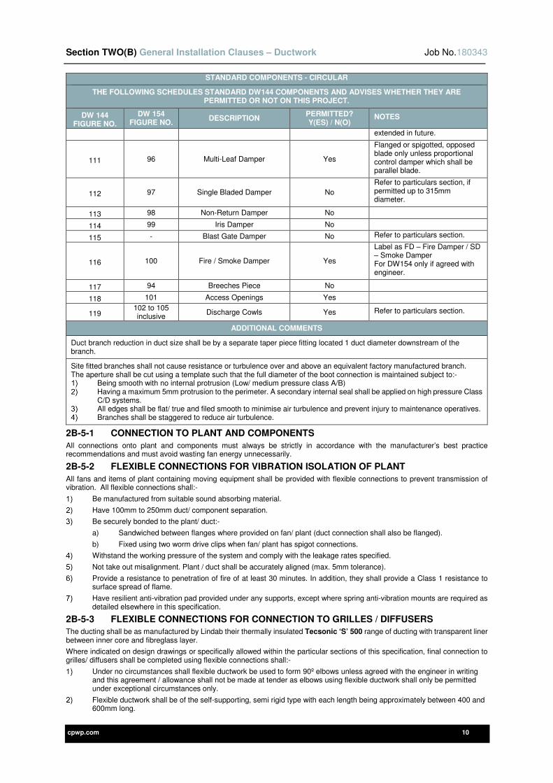
Section TWO(B) General Installation Clauses – Ductwork Job No.180343
cpwp.com 10
STANDARD COMPONENTS - CIRCULAR
THE FOLLOWING SCHEDULES STANDARD DW144 COMPONENTS AND ADVISES WHETHER THEY ARE PERMITTED OR NOT ON THIS PROJECT.
DW 144 FIGURE NO.
DW 154 FIGURE NO.
DESCRIPTION PERMITTED? Y(ES) / N(O)
NOTES
extended in future.
111 96 Multi-Leaf Damper Yes
Flanged or spigotted, opposed blade only unless proportional control damper which shall be parallel blade.
112 97 Single Bladed Damper No
Refer to particulars section, if permitted up to 315mm diameter.
113 98 Non-Return Damper No
114 99 Iris Damper No
115 - Blast Gate Damper No Refer to particulars section.
116 100 Fire / Smoke Damper Yes
Label as FD – Fire Damper / SD – Smoke Damper For DW154 only if agreed with engineer.
117 94 Breeches Piece No
118 101 Access Openings Yes
119 102 to 105 inclusive
Discharge Cowls Yes Refer to particulars section.
ADDITIONAL COMMENTS
Duct branch reduction in duct size shall be by a separate taper piece fitting located 1 duct diameter downstream of the branch.
Site fitted branches shall not cause resistance or turbulence over and above an equivalent factory manufactured branch. The aperture shall be cut using a template such that the full diameter of the boot connection is maintained subject to:-
Being smooth with no internal protrusion (Low/ medium pressure class A/B) Having a maximum 5mm protrusion to the perimeter. A secondary internal seal shall be applied on high pressure Class
C/D systems. All edges shall be flat/ true and filed smooth to minimise air turbulence and prevent injury to maintenance operatives. Branches shall be staggered to reduce air turbulence.
2B-5-1 CONNECTION TO PLANT AND COMPONENTS
All connections onto plant and components must always be strictly in accordance with the manufacturer’s best practice recommendations and must avoid wasting fan energy unnecessarily.
2B-5-2 FLEXIBLE CONNECTIONS FOR VIBRATION ISOLATION OF PLANT
All fans and items of plant containing moving equipment shall be provided with flexible connections to prevent transmission of vibration. All flexible connections shall:-
Be manufactured from suitable sound absorbing material.
Have 100mm to 250mm duct/ component separation.
Be securely bonded to the plant/ duct:-
a) Sandwiched between flanges where provided on fan/ plant (duct connection shall also be flanged).
b) Fixed using two worm drive clips when fan/ plant has spigot connections.
Withstand the working pressure of the system and comply with the leakage rates specified.
Not take out misalignment. Plant / duct shall be accurately aligned (max. 5mm tolerance).
Provide a resistance to penetration of fire of at least 30 minutes. In addition, they shall provide a Class 1 resistance to surface spread of flame.
Have resilient anti-vibration pad provided under any supports, except where spring anti-vibration mounts are required as detailed elsewhere in this specification.
2B-5-3 FLEXIBLE CONNECTIONS FOR CONNECTION TO GRILLES / DIFFUSERS
The ducting shall be as manufactured by Lindab their thermally insulated Tecsonic ‘S’ 500 range of ducting with transparent liner between inner core and fibreglass layer.
Where indicated on design drawings or specifically allowed within the particular sections of this specification, final connection to grilles/ diffusers shall be completed using flexible connections shall:-
Under no circumstances shall flexible ductwork be used to form 90º elbows unless agreed with the engineer in writing and this agreement / allowance shall not be made at tender as elbows using flexible ductwork shall only be permitted under exceptional circumstances only.
Flexible ductwork shall be of the self-supporting, semi rigid type with each length being approximately between 400 and 600mm long.
Section TWO(B) General Installation Clauses – Ductwork Job No.180343
cpwp.com 11
Have a maximum misalignment of 100mm.
Have a core of flame retardant, multiple layer, aluminium/ polyester laminate, permanently bonded to a fully encapsulated high tensile steel spring coil.
Be factory pre-insulated ducts with 25mm high density mineral wool insulation, sheathed with a tough scuff resistant reinforced aluminium/ polyester laminate outer deck where connected to insulated ductwork.
The flexible duct shall extend over the duct/ spigot by at least three helixes and be sealed with adhesive to provide an air tight seal. Two worm drive clips shall then be applied to give mechanical strength to the connection.
Flexible ducts shall not pass through fire rated walls, floors, partitions or any element of the building fabric that provides acoustic separation.
In areas of high fire risk (i.e. flammable liquid stores) flexible connections shall not be used.
Under no circumstances shall flexible ductwork be installed or compressed such that the total cross sectional area of the ductwork is reduced from its true straight cross sectional area.
The Contractor shall coordinate the grille / ductwork installation with all other trades, the building structure and ceiling grid to ensure that the maximum dimensions and tolerances detailed above are not exceeded. Any modifications necessary to fully comply with this specification shall be completed at the Contractor’s own expense.
2B-5-4 PLENUM BOXES
Each grille/ diffuser shall be supplied with a plenum box connection as detailed below or in accordance with the recommendations of the grille/ diffuser manufacturer to achieve optimum performance, whichever are the most onerous requirements shall be adopted: -
Plenum boxes shall be manufactured from galvanised steel.
Spigot connection shall be side entry type of the same diameter as the duct branch or in accordance with manufacturers recommendation whichever are the most onerous requirements.
Plenum boxes shall be manufactured to suit the available ceiling voids, configuration of terminal ductwork and grille or diffuser manufacturer’s requirements for optimum performance.
Plenum box shall have a total minimum height of the duct spigot connection plus 75mm with the top of the spigot set at 25mm from the top of the plenum box and to manufacturer’s requirements whichever is the most onerous.
Top entry plenum boxes shall only be used with the express written permission of the Engineer and shall, as a minimum:
a) Be designed by the grille manufacturer to ensure that pressure loss, flow characteristics and noise regeneration of the grille/ diffuser is not affected.
b) The plenum box shall be of the same size as the grille neck connection which shall extend 200mm before transforming (refer to changes of ductwork section) to the required duct branch size.
Active sections of louvres shall be provided with plenum connections which shall:-
Be manufactured from galvanised steel sheet.
Provide even distribution of air across the active louvre face.
Have transformation pieces to and from the active plenum/ louvres.
Have a minimum depth of 450mm clear.
Incorporate a sloping floor and drain to discharge any water outside the building and prevent any ponding.
Be insulated/ vapour sealed and clad to the same standard as the connecting ductwork for fresh air plenums.
Be insulated/ vapour sealed and clad to the same standard as the fresh air duct for a distance of 2.5 m from the face of the louvre for exhaust air plenums.
Any remaining sections of louvre not used for air transfer or ventilation of the room shall be blanked off by the Contractor and insulated/ vapour sealed and clad to the same standard as the fresh air inlet ductwork. This shall be reinforced as necessary to ensure that the materials used to blank off the louvres are not dislodged or compromised by wind pressure.
Any other connections to external terminals such as roof cowls shall be completed using a short plenum with a minimum depth of 150mm before tapering to the required duct size.
2B-5-5 DUCTWORK PENETRATION OF STRUCTURE
Where ductwork passes through walls and floors other than fire barriers, a sleeve shall be provided, the sleeve shall:-
Be 2 gauges thicker than the associated duct, manufactured from galvanised steel.
Have a galvanised steel trim to prevent distortion.
Have space between sleeve and duct, packed with an approved sound isolation material suitable for the application and match the acoustic performance of the penetrated wall or floor.
Penetrations through roof shall be completely water tight and shall allow water to drain freely on the roof. A suitable fully welded cravat shall be provided with a skirt extending at least 150mm below the building flashing. If any welding is carried out the complete assembly shall be hot dip galvanised after manufacture.
2B-5-6 SUPPORTS AND FIXINGS
Supports shall be provided that are suitable for the weight and construction of the equipment and ductwork being supported. The method of support shall be agreed with the Engineer after assessing the suitability of the various alternative methods, which are compatible with the building structure (the Contractor shall obtain acceptance from the Structural Engineer for any fixing necessary to the building structure).
Suspended support systems shall:-
Have a minimum drop rod diameter of 10mm.
Be provided with two nuts, the second nut being to lock the fixing.
Section TWO(B) General Installation Clauses – Ductwork Job No.180343
cpwp.com 12
Have 25mm by 2mm minimum flat bearing members.
Have 2500mm maximum spacing between supports.
Have filed smooth edges and where protruding into an access or walkway zone be capped or shrouded to prevent any risk of injury, in addition a clear method of hazard warning shall be applied.
Be isolated from the ductwork itself to prevent transmission of vibration (i.e. felt or foam strip).
Be thermally isolated from the duct to the same thermal performance as the adjacent insulation for insulated ductwork.
Continue the vapour seal without compromise of the seal in any way where adjacent to vapour sealed insulation.
On small ducts (up to 1.3m circumference or perimeter) wire type fixing may be used provided that they are suitable for the weight and construction of the ductwork, these shall be to the following minimum requirements:-
Specifically designed as a support system.
Wire shall be a galvanised stranded rope type with a minimum load bearing capacity of 90kg.
Stainless steel wire shall be used in wet environments and food preparation areas.
All wires shall be within 15° of vertical.
Weight shall be evenly distributed across all wires.
Hangers shall be fixed using stud ends which are locked in place with a double nut.
Where the Contractor obtains specific written approval of the Structural Engineer, loop end fixings may be used to fix to building steelwork, the method of fixing shall ensure that lateral movement cannot occur.
Hangers shall not distort the supported duct in any way.
Proprietary corner saddles shall be used on all rectangular ducts.
Lateral movement of the duct shall be fully arrested by means of intermediate conventional supports on straight runs or naturally due to bends/ branches within the system.
In line joints shall not be permitted.
Excess wire at fixings trimmed upon completion leaving a maximum tail of 50mm.
The insulation and vapour seal of the ductwork shall not be compromised.
The system shall be installed in accordance with the manufacturers recommendations, except where less onerous than described in this specification.
Shall not be used in a chlorinated atmosphere.
Other methods of support such as cantilever brackets, goal post brackets, etc. shall:-
Be suitable for the weight supported and fixing method to the building structure.
Be provided with two nuts, the second nut being to lock the fixing.
Have 2500mm maximum spacing between supports.
Have filed smooth edges and where protruding into an access or walkway zone be capped or shrouded to prevent any risk of injury, in addition a clear method of hazard warning shall be applied.
Be isolated from the ductwork itself to prevent transmission of vibration (i.e. felt or foam strip).
Be thermally isolated from the duct to the same thermal performance as the adjacent insulation for insulated ductwork.
Continue the vapour seal without compromise of the seal in any way where adjacent to vapour sealed insulation.
All plant and ductwork components shall be supported independently of the ductwork itself.
Diffusers/ grilles shall be supported independently of the ductwork/ ceiling grid unless stated otherwise within the specific relevant clauses of this specification.
2B-5-7 ANTI-VIBRATION MOUNTINGS
Specialist anti-vibration mountings shall be provided to all items of rotating or vibration producing plant, these mountings shall:-
Be selected by the manufacturer making allowance for building structure, weight and characteristics of the equipment supported.
Be of the laterally stable steel spring type.
May be neoprene mountings in the case of small axial fans (<500 l/s).
Limit vibration transmission to the structure, degree of isolation (vibration efficiency) shall be at least 95%.
Limit re-radiated air-borne noise to a maximum of NR 30 at 1 metre.
The mountings shall be manufactured by Messrs. TEK Ltd or equal and approved by the Engineer.
2B-5-8 EQUIPMENT SUPPORT AND PROTECTION
All plant items shall be provided with proprietary stands or supports that shall be:-
Provided whether shown the design drawings or not.
Independent of the adjacent distribution systems (ductwork or pipework, etc.)
Mounted on a weight bearing upstand which extends at least 50mm above finished floor level in order to maintain floor finish integrity where supported from the floor.
Manufactured from steel, painted before erection, except when installed externally or in a damp environment where the supports shall be hot dip galvanised after manufacture.
Details of supports shall be supplied to both the Engineer and Structural Engineer for comment prior to manufacture.
Any exposed moving machinery (i.e. drives, belts, fan blades, chains, projecting set screws, etc.) shall be provided with protective guards which shall:-

Section TWO(B) General Installation Clauses – Ductwork Job No.180343
cpwp.com 13
Be manufactured from robust galvanised welded steel open mesh within a welded galvanised steel frame.
Be easily removed for maintenance access.
Not vibrate or transmit vibration to the building structure or equipment served.
Have removable bolted sections provided opposite the shaft ends to facilitate speed measurement.
2B-5-9 TEST POINTS
Test points shall be provided by the ductwork installer in all locations detailed within applicable standards to a minimum of before and after fans, filters, batteries, humidifiers, attenuators and volume control devices. All test points shall be plugged using rubber or plastic removable inserts on completion of all testing.
Insulation shall be dressed around test points such that insulation, vapour seals and cladding are not compromised and access can be obtained without damage to finishes/ function.
2B-5-10 PAINTING
All cut edges, supports, flanges, nuts and bolts and any other exposed metal shall be painted with two coats of red oxide paint before erection.
Where during the course of erection, the protective finish has been damaged or has not been effective; any items so affected shall be cleaned down and re-painted to match and suit the adjacent finish.
2B-6 DUCTWORK COMPONENTS
2B-6-1 VOLUME CONTROL DAMPERS
Volume control dampers shall be provided on every duct branch and final leg serving a diffuser or grille whether indicated on design drawings or not, final location and quantity of additional dampers for efficient, proportional balancing without regenerating noise shall be agreed with the Commissioning Specialist prior to tender submission. Dampers shall be:-
Located as far upstream as possible from any diffuser, grille or bell mouth and not less than a minimum of 2 No. duct diameters.
Provided to each grille and diffuser, with a multi-blade opposed blade damper for ‘fine tuning’ (max. 10Pa) only. The damper shall not regenerate noise and shall be provided by the diffuser and grille manufacturer as one unit.
All duct volume control dampers shall:-
Be manufactured with multi-opposed aerodynamic double skin stainless steel blades suitable for balancing and shut off (maximum leakage 27 l/s at 1,000Pa when measured on a 1000mm x 1000mm damper).
Be positioned to minimise noise regeneration and turbulence so that the maximum additive (logarithmic) effect of ‘in duct’ noise level shall not exceed 3 dB, i.e. the noise level purely due to regeneration at the balancing damper shall not be greater than the ‘in duct’ noise level upstream of the balancing damper.
Be securely fixed and free from any vibration.
Have synthetic trailing edge blade seals, synthetic blade end bearings, stainless steel top and side spacing tempered flexible gasketing.
Be installed within a galvanised steel frame with blade drive mechanism outside the air stream.
Be operated by a lockable arm/ knob which shall be locked in place after commissioning.
Include a graduated plate which clearly indicates damper position and is clearly marked with final position after commissioning. It shall be possible to determine damper positions from external visual inspection without special access requirements.
Have extended shafts, motor mounting platforms and linkage where a damper is to be motorised (refer to drawings/ particular sections of this specification). Shaft length shall be sufficient to allow insulation and vapour seal shall be maintained beneath motor platforms, etc.
Be Actionair ‘Air Shield’ Aeroseal series or Engineer approved equal product for low / medium pressure systems
Be Actionair ‘Energy Shield’ air tight series or Engineer approved equal product for high pressure systems.
Not be Iris or single blade dampers.
2B-6-2 ACCESS DOORS
Access doors shall be installed fully in accordance with BESA DW documents, with the additional access doors required for future cleaning also installed during this installation, as required by the relevant standards applicable and shall:-
Not compromise the integrity of the ductwork system in terms of its pressure classification.
All access doors shall be the type and size recommended in BESA TR/19.
Be co-ordinated with all other services to prevent access being obstructed by pipework, cable trays, etc.
Be co-ordinated with building structure, ceiling supports and grids and with access doors in adjacent ceilings, walls, etc. provided by the builder.
Be operable from both within and outside the duct with clamping latches where provided to allow personnel to fully enter the duct.
Be thermally insulated where the ducts are to be thermally insulated, the frame of the access door shall extend beyond the face of the duct by at least the insulation and protection thickness. The door shall be double skin construction completely encapsulating mineral insulation to provide the same thermal and vapour seal characteristics as the adjacent insulated duct.
Shall be either hinged or restrained with braided wire or chain so that the door is connected to the ductwork.
Shall not have any elements that protrude into the air stream or cause additional resistance.
Shall have flush and smooth internal finishes to prevent dust/ dirt collection or bacterial growth.

Section TWO(B) General Installation Clauses – Ductwork Job No.180343
cpwp.com 14
Shall be free from sharp edges.
Access doors shall be manufactured by Actionair Ltd or Engineer approved equal product.
LOCATION OF ACCESS PANELS AND HATCHES FOR INSPECTION, SERVICING AND / OR CLEANLINESS
IN-LINE EQUIPMENT LOCATION NOTES
Volume Control Dampers Both Sides
Zone Isolation Dampers Both Sides
Fire Dampers Both Sides
Smoke Dampers Both Sides
Heating, Cooling and Heat Recovery Coils Both Sides
Reheat Coils Both Sides
Attenuators Both Sides
Filter Units Both Sides
Air Turning Vanes at Bends and Tees Both Sides
Changes in Direction One Side Both sides when change in direction has turning vanes.
In-Duct Fans / Other Devices Both Sides
Inlet / Exhaust Louvres One Side
Required for Cleaning Purposes In accordance with TR/19 and DW/172.
2B-6-3 ATTENUATORS
The specification and design drawings are based on initial attenuator selections only, the Contractor shall select the actual attenuators based on the performance criteria detailed within this specification and or the room data sheets when available.
The Contractor shall supply the following information to their Acoustic Specialist to allow for the correct attenuators to be selected:-
Sound power level for each fan or component selected.
Copy of working drawings.
Specified noise levels within all spaces supplied or passed through by the ductwork system (selection shall be based on break out and terminal noise levels).
Maximum air pressure drop through attenuators.
Drawings showing details of connections to inlet and outlet of attenuator.
In the absence of specific performance data being available, the following shall be assumed for tender purposes only. Final requirements shall be confirmed prior to ordering attenuators.
Required noise level in rooms shall be NR35 at 1m.
Required external noise level shall be NR45 at 3m.
Maximum pressure drop across the attenuators shall be 30Pa.
All Attenuators shall comply with the following:
The casing shall:-
a) Be manufactured from pre-galvanised sheet steel.
b) Shall have a minimum thickness of 1.2mm if either the width, height or diameter exceeds 1200mm.
c) Shall have a minimum thickness of 1.0mm if both the width, height or diameter are less than 1200mm.
d) Either Pittsburgh longitudinal joints or internal standing seam joints, all constructed to the relevant BESA DW Specification.
Splitters shall:-
a) Be constructed from perforated or expanded galvanised steel sheet having a minimum thickness of 0.7mm
b) Be contained within galvanised steel channels having a minimum thickness of 0.8mm, the splitter shall be riveted to the channel.
c) Have aerodynamic fairings riveted or spot welded to the front of each splitter to minimise resistance.
d) Have all fixings to the casing made using blind/ sealed rivets.
e) Be half width at the side walls of the casing.
Infill shall:-
a) Be inorganic mineral wool rigid slabs with a glass fibre tissue face to limit glass fibre erosion to negligible levels.
b) Be inert, vermin, rot, moisture proof, non-combustible and not support bacteriological growth.
c) Be packed to a minimum density of 45 kg/m3.
d) Be tested for fire and have a Class 1 spread of flame.
Connections shall:
a) Have ‘mez’ type ‘slide on’ flange connections to BESA DW Specification.
b) Have rolled angle steel silver leaded flanges fixed to casings with blind/sealed rivets on multi-section attenuators and shall have the casing returned at least 12mm over the end flanges.
c) Be provided with spigot ends for cross talk attenuators.
d) Have matching flanges, cleats, gaskets supplied and installed by the Contractor.
Section TWO(B) General Installation Clauses – Ductwork Job No.180343
cpwp.com 15
A label shall be provided indicating direction of air flow.
A label shall be provided detailing:-
a) Manufacturer
b) Type
c) Size
d) Location
e) Material used to encase mineral wool (glass fibre tissue or Melinex).
Attenuators handling air in clean conditions (i.e. hospitals, clean rooms, etc.) and fume extract shall be have a Melinex lining completely encasing all of the mineral wool or glass fibre rigid slabs.
Attenuators handling air in kitchen ventilation/ extract and saturated atmosphere shall have a Melinex lining completely encasing all of the mineral wool or glass fibre rigid slabs, the perforated/ expanded steel lining shall be hot dip galvanised after manufacture.
2B-7 COMBINATION FIRE / SMOKE DAMPERS AND FIRE DAMPERS
2B-7-1 GENERAL
Fire dampers and combination fire and smoke dampers shall be installed to maintain the fire integrity and rating of the fire and smoke barrier that the ductwork is passing through. A damper shall be provided wherever ductwork penetrates a fire wall, ceiling, floor or compartment/ sub-compartment. Dampers shall be provided at these locations whether or not indicated on tender drawings.
The supply, installation and commissioning fire and combination fire & smoke dampers as necessary for compliance with the latest fire strategy drawings, fire engineering report, the approval of the Fire Officer and Building Control shall be included.
Fire and smoke dampers shall be provided as required plus as below.
Combination fire and smoke dampers shall be provided in the following locations:
Within all plant room walls, floors and ceilings.
All riser walls, floor, ceiling slabs (to suit fire strategy).
All structural floors.
All walls enclosing escape routes.
Fire dampers shall be included based on the following criteria for tender purposes:
Where ducts cross corridor walls but there are no air terminals into or from the corridor itself.
Within extended ceiling voids fire dampers shall be provided at 20 metre centres in all directions.
At intake and exhaust louvres where windows and fire escape routes are adjacent (within 3 metres for tender).
All remaining fire cavity barriers, Contractor to confirm fire cavity barrier locations with the Architect/ Main Contractor.
The Contractor shall confirm the location of all fire cavity barriers with the Architect / Main Contractor during the tender period, if no written clarification is given or received prior to tender, the Contractor shall allow for combined smoke & fire dampers and fire dampers as scheduled above.
THIS SHALL BE CHECKED PRIOR TO INSTALLATION AND VARIATIONS TO REDUCE REQUIREMENTS GIVEN AS NECESSARY.
All dampers must be installed fully in accordance with manufacturer’s recommendations.
2B-7-2 REQUIREMENTS FOR FIRE AND SMOKE DAMPERS
Requirements for ALL combined fire & smoke and fire dampers:-
Galvanised steel casing with continuously welded corners.
Spigot connections to suit ductwork system.
Manufacturer’s installation frame shall protect the structural opening so the ductwork is not distorted during a fire condition. Contractor shall ensure correct frame is supplied for the type of structure penetrated.
External visual indication of damper open/ shut status.
Supported in accordance with the damper manufacturers recommendations to achieve the ratings described.
Each damper shall be provided with a local method of identifying its location, i.e. indicator mark on false ceiling below. Final detail to be agreed with Engineer/ Architect prior to implementation.
Combined Fire and Smoke dampers (mode 6) shall:-
Be manufactured by Actionair Limited, their Smoke Shield range.
Have stainless steel double skin aerofoil blades with double metal seal.
Have synthetic seal.
Have snap lock interface to allow proportional torque control, suitable for accepting various drive actuators.
Be mode 6 operation, 240v motor opening, and spring closing on loss of power or operation of mechanical thermal link rated at 72°C.
Be no more than 200 m3/hr/m2 at 300 Pascals at ambient temperature.
Have volt free contact for remote indication of damper status.
Be provided with a unique reference (mechanically fixed traffolyte label) that mimics the referencing on the smoke control panel.
Section TWO(B) General Installation Clauses – Ductwork Job No.180343
cpwp.com 16
Fire dampers shall:-
Be manufactured by Actionair Limited, their Fire Shield range.
Have a stainless steel folding curtain with blades out of the air stream in the open position.
Have a mechanical release cassette with memory metal spring to close damper at 72°C.
Have stainless steel side gasket to minimise spread of smoke.
Have a mechanism suitable for single handed reset.
Be no more than 200 m3/hr/m2 at 300 Pascals at ambient temperature.
In addition to the damper itself, the following shall be provided for every damper:-
Supplied to site and installed with dampers in closed position.
Vacuumed out and opened immediately prior to commissioning.
Performance tested, witnessed by Commissioning Engineer and certified at commissioning stage.
Damper assembly and all linkages lubricated as recommended by the manufacturer.
The Contractor shall allow for full co-ordination of the installation frame with the Main Contractor during the construction work and ensure that the frame is installed in accordance with manufacturer’s instructions.
2B-7-3 COMBINATION FIRE AND SMOKE DAMPER CONTROL SYSTEM
All of the smoke/ fire dampers shall be individually controlled and continuously monitored by a central panel supplied by the same manufacturer as the combination fire and smoke dampers.
The panel shall have:-
Lockable glazed door.
Number of latching switches to equal total number of installed dampers plus 15% spare capacity.
LED indicator for open/ closed status monitoring of each damper.
Lamp test facility.
Relays, timers, etc. to allow automatic control of system.
Audible alarm and mute facility.
Interfaces with fire alarm (one per compartment/ sub-compartment and plantroom/ riser space).
Interface to BMS using volt free contacts for status and alarm condition.
Interface to motor control centres for hard wired shut down of plant.
Fireman’s key override switch interface (one per compartment/ sub-compartment and plant room space).
The Contractor shall include for all costs associated with the installation of the interconnecting wiring.
All power/ control wiring shall:-
Be halogen free low smoke and flame rated at 600/1000 volt.
Have 3 core cable from each damper to the control panel for status indication.
Have 2 core cable, power from control panel to each damper, with local spur complete with neon indicator.
Be mounted upon/ within suitable carcassing (i.e. cable tray).
Have power supply to spur adjacent to smoke panel by Electrical Contractor, final connections shall be by Contractor.
Have fire alarm interface adjacent to smoke control panel by Electrical Contractor, final connection by Contractor.
Upon completion of the mechanical installation works the dampers and control panel/ wiring shall be fully commissioned by the manufacturer.
cpwp.com V3.2
Section Two (C) General Installation Clauses – Mechanical Commissioning
Section TWO(C) General Installation Clauses – Mechanical Commissioning Job No. 180343
cpwp.com 2
Contents Page
GENERAL REQUIREMENTS 3
DEFINITIONS 3
REFERENCE TO OTHER DESIGN DOCUMENTS 3
STANDARDS APPLICABLE 3
SCOPE OF WORK 4
COMMISSIONING SPECIALIST 5
COMMISSIONING MANAGEMENT 5
HEALTH & SAFETY 5
WITNESSING AND VERIFICATION 5
TESTING AND PRE-COMMISSIONING 6
COMPLIANCE WITH PART L OF THE BUILDING REGULATIONS 6
BUILDING LOG BOOK 6
COMMISSIONING PROGRAMME 6
DESIGN FAMILIARISATION 7
CONTRACTORS WORKING DRAWINGS 7
SITE MEETINGS TO BE INITIATED 7
REVIEW SITE VISITS 7
COMMISSIONING RECORDS & TEST SHEETS 8
FORMAL STAGE GATE REPORTS 8
CALIBRATION OF INSTRUMENTS 10
METHOD STATEMENTS 10
INSPECTION OF MATERIALS 10
FLUSHING AND CHEMICAL CLEANING 10
TOLERANCES 10
PRESSURE TESTING 11
COMMISSIONING OF EQUIPMENT BY MANUFACTURERS 11
OPEN SYSTEM SCAN 12
DOCUMENTATION FOR OPERATING AND MAINTENANCE MANUALS 12
LIAISON WITH STATUTORY AUTHORITIES 12
Section TWO(C) General Installation Clauses – Mechanical Commissioning Job No. 180343
cpwp.com 3
GENERAL REQUIREMENTS
This section of the specification identifies general testing and commissioning requirements applicable to all services and sections within this specification.
DEFINITIONS
Commissioning – The advancement of an installation from the state of static completion to full working order to the specified requirements. It includes the setting to work of an installation, the regulation of the system and the fine tuning of the system.
Commissioning Specialist – The firm (or person) appointed by the Mechanical Contractor to carry out specified duties in connection with commissioning engineering services in accordance with the commissioning specification. The Commissioning Specialist shall be someone with relevant training and experience who is a corporate member of the Commissioning Specialists Association.
Commissioning Manager - The person belonging to or appointed by the Commissioning Specialist to manage the commissioning process, being responsible for overall planning, supervision and witnessing of the results of the integrated Commissioning of all installed building services. The Commissioning Manager shall be someone with relevant training and experience who is a corporate member of the Commissioning Specialists Association
Commissioning Management Organisation (CMO) - The firm (or person) appointed by the Main Contractor to manage the commissioning process, being responsible for overall planning, supervision and witnessing of the results of the integrated commissioning of all installed building services.
Engineer – The Mechanical and Electrical Engineering Design Consultant (CPW)
Controls Specialist – The firm appointed by the Mechanical Contractor to design, install, set to work and commission the automatic controls or Building Energy Management systems (BEMS/BMS)
For all other definitions refer to the relevant CIBSE Commissioning Codes.
REFERENCE TO OTHER DESIGN DOCUMENTS
This section of the specification shall not be read in isolation. It must be read in conjunction with the other sections of this specification, the drawings and other documents referred to therein. The Mechanical Contractor is to ensure that their Commissioning Specialist has access to all of these and any other relevant documents during the tender and afterwards in the following construction phases.
STANDARDS APPLICABLE
Works shall be completed in accordance with all applicable industry standards. Some of the most relevant standards associated with this section are scheduled below:
STANDARDS & GUIDES
PUBLISHER STANDARD SUBJECT
BSRIA AG16/2002 Variable flow water systems
BSRIA AG20/95 Commissioning of pipework systems – Design considerations
BSRIA BG2/2010 Commissioning water systems
BSRIA BG8/2009 Model commissioning plan
BSRIA BG11/2010 Commissioning job book - A framework for managing the commissioning process
BSRIA BG25/2014 HVAC Troubleshooting
BSRIA BG29/2012 Pre-commission cleaning of pipework systems
BSRIA BG44/2013 Seasonal commissioning
BSRIA BG46/2015 Domestic ventilation systems – A guidance for measuring airflow rates
BSRIA BG49/2015 Commissioning air systems
BSRIA BG63/2015 Building Performance Evaluation in Non-Domestic Buildings
BSRIA BG64/2016 Building Performance Evaluation in Domestic Buildings
CIBSE Commissioning Code A Air distribution systems
CIBSE Commissioning Code B Boilers
CIBSE Commissioning Code C Automatic controls
CIBSE Commissioning Code L Lighting
CIBSE Commissioning Code M Management
CIBSE Commissioning Code R Refrigeration
CIBSE Commissioning Code W Water distribution systems
CIBSE KS09 Commissioning variable flow pipework systems
Section TWO(C) General Installation Clauses – Mechanical Commissioning Job No. 180343
cpwp.com 4
STANDARDS & GUIDES
PUBLISHER STANDARD SUBJECT
CIBSE TM31 Building Logbook toolkit
CSA Guidance Note 2 Constant Flow Regulators
CSA Guidance Note 3 Variable Volume Water Systems
CSA Guidance Note 5 Site Safety for Commissioning Engineers
CSA Guidance Note 8 Inverter Drives for Fans and Pumps
CSA Guidance Note 10 Alternative Pipework Systems & Fixed Orifice Flow Measurement
CSA Guidance Note 12 De-aeration in Hot Water Service Systems
CSA TM 1 Standard Specification for the Commissioning of Mechanical Engineering Services Installations for Buildings
CSA TM 2 Guide to Trouble Shooting for Air Distribution Systems
CSA TM 3 Test Sheets
CSA TM 4 Design of Collection Hoods for Testing & Balancing
CSA TM 5 Efficient Control of System Water Quality
CSA TM 7 Commissioning of Steam Systems
CSA TM 8 Trouble Shooting Refrigeration Equipment
CSA TM 9 Water Treatment and the Commissioning Engineer
CSA TM 10 Site Performance Testing of Heating & Cooling Coils
CSA TM 11 Alternative Pipework System & Fixed Orifice Flow Measurement
CSA TM 14 Pressurisation Units, Design, Operation & Maintenance
CSA TM 15 The Theory of Balancing Water Distribution Systems
CSA TM 18 PICVs Function and Commissioning
CSA TM 19 Thermal Balancing of HWS and CWS
Where the above standards refer to supporting documentation and standards these shall be fully complied with in all respects.
Where discrepancy is found between this specification and the relevant standards, the Contractor shall obtain written clarification from the Engineer prior to submission of the tender. Where a discrepancy has not been clarified prior to tender submission, the Contractor shall include the most onerous requirements.
SCOPE OF WORK
The Mechanical Contractor shall allow for a named, suitably qualified, Commissioning Specialist to undertake all commissioning work as detailed in this Specification and as follows:-
1) All management and advice activities during design, installation, pre-commissioning, commissioning and verification stages of the project. The management activities shall be compliant with the guidance given in the above ‘Standards Applicable’. The commissioning activities shall be fully integrated into the construction process from the point of appointment of the Mechanical Contractor, right through to handover and beyond to fine tuning the building services during occupation. Appointing the Commissioning Specialist part way through the construction phase shall not be tolerated.
2) Early involvement in the project to advise on the commissionability of the building services design, whether that design is by the Engineer or the Mechanical Contractor and also advise on the time periods to carry this work so that it can be included in the overall construction programme. It is essential that this activity is undertaken in a timely manner to ensure that the systems can be commissioned satisfactorily without delay or additional cost.
3) Oversee all pre-commissioning activities carried out by the installers as prescribed in the aforementioned commissioning guides and as specified in this and other sections of the specification and drawings. This includes overseeing and verifying the commissioning activities of specialist plant items such as chillers, boilers, DX cooling systems, BMS, etc. which are often specialised in nature and are commissioned by the Manufacturer. The commissioning of specialist equipment, such as those aforementioned, especially where they integrate with the air and water distribution systems shall require careful consideration and integration within the commissioning plan. The Mechanical Contractor and the Commissioning Specialist shall agree any divisions of responsibility to fully appreciate their respective scopes of work.
4) All physical works involved in all commissioning activities including setting to work and dynamic proving in order to achieve the design intent. This includes returning to site for balancing and regulation adjustments during the maintenance period. Performance tests on heating and air conditioning systems shall be undertaken in peak weather conditions, irrespective of when completion takes place.
5) Demonstration to the Engineer a proportion of final system flow rates.
6) Provision of all seven formal stage gate reports.
7) Provision of all necessary documentation, including test records, commentary, diagrams and reports for O & M manuals.

Section TWO(C) General Installation Clauses – Mechanical Commissioning Job No. 180343
cpwp.com 5
8) Give notice to the Building Control Body or Local Authority declaring that a commissioning plan has been followed so that every system has been inspected and commissioned in an appropriate sequence and to a reasonable standard; and the results of the tests confirm that the performance is reasonably in accordance with actual building designs, including written commentaries where excursions are proposed to be accepted.
The Mechanical Contractor shall allow for all costs associated with the above and the foregoing being included within their tender price. It shall be noted that it is the Mechanical Contractor’s responsibility to ensure that the Commissioning Specialist has viewed all tender documents and outline programme during tender stage to ensure that all necessary costs from their Commissioning Specialist have been included.
The Mechanical Contractor shall also include for all fees charged by the Nominated or other Insurance Companies for all supervision and examination at the manufacturers’ works during construction of all pressure vessels and similar equipment and the witnessing of works tests in addition to site tests and the incidental work involved.
Two copies of all test certificates shall be supplied to the Commissioning Specialist.
COMMISSIONING SPECIALIST
All commissioning works, except for equipment covered by ‘Commissioning of Equipment by Manufacturers’, listed at the end of this section, shall be commissioned by one of the following Commissioning Specialists, who are all ‘Corporate Members’ of commissioning Specialists Association (CSA). No other companies will be accepted for this work under any circumstances.
COMPANY NAME TEL. NO. EMAIL ADDRESS LOCATED
Airtech Commissioning Limited 0121 4154141 [email protected] Birmingham
Airtech Premier Limited 01252 873723 [email protected] Hook
Ashfords 01784465 838 [email protected] Staines
Building Services Commissioning Limited 01522 868190 [email protected] Lincoln
Beech Technical Services Limited 0121 4591886 [email protected] Birmingham
Cardiff Commissioning Limited 029 2052 1111 [email protected] Cardiff
Central Commissioning (UK) Limited 01827 251379 [email protected] Tamworth
CML Commissioning Management Limited. 01206 761911 [email protected] Colchester
Cross Count Limited 01279 508204 [email protected] Stansted
End Systems Limited 01942 673229 [email protected] Leigh
GCS Commissioning 0117 9685074 [email protected] Bristol
H & V Commissioning Services 01563 821991 [email protected] Ayrshire
Kebble Environmental Services Limited 01279 417 878 http://www.keslimited.co.uk Harlow
COMMISSIONING MANAGEMENT
Unless specified otherwise, the Commissioning Specialist shall manage their own activities, establish clear lines of communication and be responsible for ensuring the commissioning is completed in accordance with this specification and the agreed programme. For some large or complex projects, it may be necessary for the Main or Principal Contractor to employ a CMO. Should this be necessary, then the Commissioning Specialist would be informed of this intention within the specific section of the specification under the heading “COMMISSIONING MANAGEMENT” or similar. The Commissioning Specialists shall allow for all associated costs and time required where Commissioning Management is proposed for the project.
HEALTH & SAFETY
The Commissioning Specialist has a duty under the Construction Design and Management Regulations to review the commissioning plan and bring any safety matters to the attention of the Main Contractor. Any actions resulting from this Health and Safety review shall be confirmed and managed by the Main Contractor prior to any commissioning work being undertaken. The Commissioning Specialist shall be aware of the general risks associated with building services and be conversant with applicable legislation.
Reference shall be made to Health & Safety Legislation affecting Commissioning and the Safety sections contained within the relevant commissioning codes.
WITNESSING AND VERIFICATION
Witnessing and verification of tests shall be required to enable confidence to be established for the commissioning results. Unless specified otherwise, the witnessing and verification shall be undertaken by one of the following depending on the particular project:
1) Where an additional Commissioning Specialist is employed for the role of Commissioning Management, all witnessing and verification of the complete system shall be carried out by the Commissioning Specialist and fully witnessed in its entirety by the Commissioning Manager.
2) Where a Clerk of Works is employed, all witnessing and verification of the complete system shall be carried out by the Commissioning Specialist and fully witnessed in its entirety by the Clerk of Works. Some of the more simple installations may only require a percentage of the systems to be witnessed by the Clerk of Works. The percentage of the system to be partially witnessed shall be agreed with both the Clerk of Works and Engineer prior to the commissioned systems being offered for witnessing and verification. At tender allow for all systems to be 100% witnessed.

Section TWO(C) General Installation Clauses – Mechanical Commissioning Job No. 180343
cpwp.com 6
3) Where neither of the above applies, the Commissioning Specialist shall also allow for a proportion of tests to be witnessed by the Engineer. The proportion of tests to be witnessed by the Engineer shall be 20%, though this could be reduced to 10% at the discretion of the Engineer on very large systems.
4) For all projects, the Engineer has the right to ask for a higher proportion of witnessing should the verification or witnessing exercise be unsuccessful. In this instance, the Mechanical Contractor shall bare all additional costs associated with this additional work.
5) For all projects, the Commissioning Specialist shall inform the Engineer of the verification programme who shall at their discretion, invite the Client representative.
6) For all projects, the Commissioning Specialist shall obtain counter signatures on all commissioning sheets to obtain certification that the results are within tolerance. No re-writing of test sheets shall be permitted following witnessing by the Commissioning Manager, Clerk of Works or Engineer.
7) For all projects, the commissioning specialist shall witness and verify 100% BMS and controls hardware and software function, integration and performance.
TESTING AND PRE-COMMISSIONING
The Mechanical Contractor shall define and agree with the Engineer the responsibility for testing and pre-commissioning activities, i.e. whether the installer or the Commissioning Specialist is undertaking the activities. In some cases, the installer would undertake these activities and in this case, the Commissioning Specialist shall adopt an overseeing role to ensure the test results are satisfactory and all the pre-commissioning checks have been undertaken, documented and any remedial activities are undertaken to the satisfaction of the Engineer. Reference shall be made to all other sections of this specification, ‘Standards Applicable’ documents and the drawings to fully understand the scope of the overseeing role.
COMPLIANCE WITH PART L OF THE BUILDING REGULATIONS
Part L of the Building Regulations is concerned with the conservation of fuel and power. All works approved under Part L of the Building Regulations shall be commissioned in accordance with the design intent. This applies to heating, ventilation, cooling / refrigeration, lighting, controls and hot & cold water systems. The Commissioning Specialist shall ensure that they are conversant with these Regulations, supporting Second Tier documents, and in particular the criterion that deals with the commissioning of the building services. The Commissioning Specialist shall ensure that they follow the guidance given in the approved procedure. They shall also provide a written notice to the Building Control Body that shall include a declaration confirming that:-
1) The commissioning plan has been followed so that every system has been inspected and commissioned in an appropriate sequence and to a reasonable standard.
2) The results of tests confirm that the performance is sufficiently in accordance with the actual building designs, including written commentaries where excursions are proposed for acceptance.
BUILDING LOG BOOK
A Building Logbook is required under Part L of the Building Regulations to ensure that the building uses no more power than is reasonable. The Main Contractor shall be responsible for the compilation and timely issue of this document to the building owner/ Client to enable them to manage the building’s energy from the date of practical completion.
The Commissioning Specialist shall be responsible for the preparation, completion and timely handover of key elements of this document to the Mechanical Contractor. These include but are not limited to:-
1) Commissioning, handover and compliance
2) Metering, monitoring and targeting strategy
3) Building energy performance records
4) Relevant compliance and test certificates
It is essential that the Commissioning Specialist is conversant with the standard logbook template so they can provide the right level of information in the correct standard format and in a timely manner.
The Mechanical Contractor shall coordinate and obtain all other information necessary to complete the mechanical and electrical elements of the logbook. This includes but is not limited to obtaining information from the Engineer / Design Team, Electrical Contractor and Builder or Main Contractor. This must be programmed in and completed in advance of practical completion.
The logbook shall follow the standard format described within CIBSE TM31 and the guidance from the Carbon Trust which is illustrated within a CD as part of TM31. All information supplied to be incorporated within the logbook shall be provided both electronically and in hard copy.
The logbook shall make reference to other documents such as the O&M manual and the Health & Safety File. The completed logbook shall be issued in hard and electronic versions so that as a living document, it can be amended easily at a later date should it be required. It must be issued to the Main Contractor and Engineer for approval at least 2 weeks before practical completion.
COMMISSIONING PROGRAMME
The Commissioning Specialist shall produce a detailed commissioning programme, which shall be fully integrated into the main contract construction programme. The commissioning programme shall be developed at the same time as the installation programme to ensure that the requirements for commissioning are incorporated in the construction activities.
The commissioning programme shall be broken down into individual services including sub-contract works and shall include but not be limited to the following tasks:
1) Review design drawings and specifications for commissioning requirements (commission-ability).
2) Review installation drawings and technical submissions for commissioning requirements.
3) Review the installation for compliance with specifications and drawings intent for commissioning.
4) Produce detailed commissioning method statements.
Section TWO(C) General Installation Clauses – Mechanical Commissioning Job No. 180343
cpwp.com 7
5) Testing and pre-commissioning.
6) Off-site testing of plant items.
7) Pipework system cleaning and dosing.
8) Pressure testing of ductwork where applicable.
9) Setting to work of plant systems and commissioning and performance testing.
10) Open system scans.
11) Demonstration of flow rates to the Verification Specialist and Engineer.
12) Soak tests.
13) Prepare testing and commissioning reports.
14) Statutory demonstrations of life safety systems, to building end user and statutory authorities.
15) Prepare and complete the relevant sections of the building logbook.
16) Prepare final record documentation.
17) Prepare and submit the commissioning completeness notice to Building Control.
18) Training and awareness sessions with the building owner/ user.
The commissioning activities shall be fully co-ordinated within the programme by the Commissioning Specialist. The Commissioning Specialist shall indicate the resourcing requirements within the programme tasks. The programme shall show critical activities and milestones to enable focus to be maintained on these items in order to minimise the risk of delay. The commissioning programme shall be submitted to the Engineer no later than 6 weeks after the date of contract commencement, for approval. The dates involved shall be kept within the periods originally computed for testing and subsequently inserted as part of the 'Programme of Works'. Following completion and approval of this programme, the Commissioning Specialist shall review the programme in relation to the construction progress at the regular site attendance meetings. The testing shall proceed on the dates given but not less than 14 days following the notification to the Engineers of the state of readiness.
All Specialist Sub-Contractors and Specialist Suppliers to the Mechanical Contractor must note that they shall attend promptly on the times and dates stated. Failure to do so will result in the schedule being extended and any parties failing to attend shall be responsible for reimbursing the other parties involved for loss of time.
Notification of the testing programme commencement shall not be less than 14 days and no cancellations will be allowed.
DESIGN FAMILIARISATION
Immediately following appointment and prior to works commencing on site, the Commissioning Specialist shall:-
1) Inspect the design drawings and this Specification in order to fully familiarise themselves with all the engineering services to be commissioned.
2) Be fully satisfied that all necessary provision has been made for commissioning of the services including items such as volume control dampers, commissioning stations and pressure stabilising valves, etc.
3) The Commissioning Specialist shall issue a report to the Engineer to include:-
a) The details of any additional items that the Commissioning Specialist considers shall be included.
b) Any further information needed to complete the installation.
c) Detailed testing and commissioning program for the works.
CONTRACTORS WORKING DRAWINGS
The Commissioning Specialist review the contractors working drawings as they are produced to ensure system is commissionable reviews to include:
1) Provision of sufficient measurement / regulation devices.
2) Location of regulation and measurement devices in terms of sufficient straight lengths for accurate readings.
3) Confirm flow rate through each device is within the accurate measuring range of said device.
4) Location of test points / test holes.
5) Location of BMS sensors where relevant (i.e. pressure transducers located correctly to achieve good readings).
6) Accessibility to regulation and control devices without obstruction from other services, structure or ceiling / boxing.
7) Adequate provision of access hatches in terms of size & location.
SITE MEETINGS TO BE INITIATED
The Commissioning Specialist shall be required to attend monthly meetings from Contract Commencement to report on all stages of the commissioning, from initial planning / programming through to contract completion.
Two weeks prior to the first pre-commissioning activity, the Commissioning Specialist shall be required to commence attending weekly commissioning meetings, to report on the status of the commissioning, through to contract completion. The frequency of these meetings will be determined by the Engineer but the Contractor shall allow for weekly attendance.
The meetings shall be chaired by the Commissioning Specialist and the Mechanical Contractor shall attend with all their major Sub-Contractors.
The Engineer will not be present at any of these meetings but shall receive minutes of the same issued by the Commissioning Specialist.
REVIEW SITE VISITS
During the installation of the contract works the Commissioning Specialist and the Mechanical Contractor shall visit site on a minimum basis of every two weeks to monitor the commission-ability of every aspect of the services in this Specification.

Section TWO(C) General Installation Clauses – Mechanical Commissioning Job No. 180343
cpwp.com 8
This shall include ensuring that all commissioning stations are installed in accordance with the manufacturer’s instructions and all other items are installed in accordance with the approved working drawings and are fully accessible.
Any aspect of non-compliance with the above shall be reported in writing to the Mechanical Contractor who shall carry out the necessary remedial work. Copies of all reports shall be issued to the Engineer.
During the site visits, the Commissioning Specialist shall carry out an audit of static testing of services to ensure that this work is being carried out satisfactorily. A written log of all static tests audited shall be kept for inspection by the Engineer.
As a part of the on-site inspections, the Commissioning Specialist shall ascertain that all aspects of the services can be fully maintained after handover. A report shall be issued to the Mechanical Contractor detailing any item that cannot be fully maintained and a copy of the report shall be issued to the Engineer.
COMMISSIONING RECORDS & TEST SHEETS
The Commissioning Specialist shall ensure that accurate records are taken for all checks and measurements undertaken within the commissioning scope of works. The records shall be completed at the time of undertaking the commissioning activity and shall include any additional commentary that will support the understanding of the results, either later in the commissioning programme or in the future after the building has been in operation for some time. It is essential that this anecdotal information is included as it will help future fine tuning of the services and enable informed decisions to be made during building modifications and improvements.
Standard commissioning pro forma checklists shall be used to record the results. These shall be based on the criteria and templates in the relevant BSRIA Guides listed earlier in this specification. The Commissioning Specialist shall issue the proposed pro forma to the Engineer for approval prior to undertaking any testing. The completion of these pro forma shall be completed only once (i.e. not subsequently transcribed by typing since this can lead to errors being introduced).
The design of the pro forma shall be well thought out in order to:-
1) Aid the efficient execution of the commissioning tasks.
2) Help the control of quality and progress of the commissioning tasks.
3) Provide a convenient means of comparing test results within design values.
4) Serve as a permanent record of commissioning data to be included in the project’s operating and maintenance manual.
FORMAL STAGE GATE REPORTS
The Commissioning Specialist shall produce formal written reports at the following seven Stage Gates.
Progression from one commissioning stage to the next shall only be allowed following the successful completion and sign off of the preceding stage. Completion of a stage shall be formalised by a Stage Gate Report, produced and signed by the Commissioning Specialist, with counter signatures by the Mechanical Contractor and the Engineer. The stage gate shall not be considered ‘closed’ until the signed off report is issued and duly accepted by the client and their design team.
STAGE REPORTS
STAGE OVERVIEW DETAILED REQUIREMENT INCLUDED IN REPORTS
1 Pre-construction-design is commissionable
• Review mechanical services design and scope of commissioning, provide cost & programme advice.
• Review design for commissioning requirements & feedback any comments. • Confirm comments and recommendations are incorporated into the design. • Sign off and issue report (Design Information Checklist) to confirm system is
commissionable.
2 Installation is acceptable
• Production, review and support development of detailed commissioning programme. • Production of commissioning method statements and pro forma’s for pre-
commissioning, setting to work and balancing / regulation. • Review and support production of detailed method statements. • Undertake regular progress inspections (on & off site) to ensure compliance with
design, commissionability & manufacturer’s installation requirements and ensure defects are rectified prior to setting to work and commissioning.
• Review and comment on progress inspections. • Undertake pressure & leakage testing in a phased approach as the installation
progresses and rectify defects. Undertake whole system pressure & leakage tests immediately after completion. Issue test sheets for approval.
• Review and comment on records/reports. • Confirm any defects rectified to allow final inspection checklist to be signed off. • Undertake a final inspection of all systems in the mechanical specification using pre
agreed pro forma checklist. • Comment on any systems and components that are not ready for pre-commissioning
& follow up with mechanical contractor. • Issue report to confirm final inspection is satisfactory and systems are ready for pre-
commissioning. • Sign off completed system inspection checklist report.
3 Pre Commissioning • Confirm fill, vent, pressure test, flush, clean, chemical clean and provide water treatment to water distribution systems.
• Undertake pre-commissioning activities of all systems in the specification using pre-agreed pro forma checklist.
• Comment on any systems and components that are not ready for pre-commissioning and follow up with mechanical contractor to resolve.
Section TWO(C) General Installation Clauses – Mechanical Commissioning Job No. 180343
cpwp.com 9
STAGE REPORTS
STAGE OVERVIEW DETAILED REQUIREMENT INCLUDED IN REPORTS
• Confirm any defects are rectified to allow pre-commissioning checklist to be signed off.
• Issue report to confirm pre-commissioning inspection is satisfactory and systems are ready for commissioning.
• Sign off pre-commissioning inspection report.
4 Final coordination of all commissioning reports
• Production of report / checklist identifying all relevant steps have been completed prior to setting to work of plant and equipment. Report to include will include but not be limited to the following: Essential design information. Manufacturer’s essential data. Manufacturer’s offsite tests. Pressure / leakage tests. Continuous installation inspections. Final installation inspections. System cleanliness inspections. Pre-commissioning inspections. Setting to work of fans, boilers, refrigeration plant, pressurisation units,
Automatic Controls, pumps, chillers, CHP, natural vent, air compressors etc. BMS point to point checks. Life Safety Systems 100% point to point check. Possession of compliance documents and certificates for pressure systems
regulations and F gas regulations. Sign off completed report for above.
5 Setting to work and open system scans
• Initial start-up of all plant and equipment. • Provision of specialist plant & equipment support as required to ensure effective
operation. • Attendance at start up and subsequently operate all plant & equipment during the
commissioning process. • Advise Mechanical Contractor of any Irregularities. • Produce setting to work checklist and issue to Mechanical Contractor and Engineer
for comment and sign off. • Check plant performance for pumps, fans etc. and document on pro formas. • Undertake a preliminary flow rate check (open system scan) with all regulating
devices fully open prior to regulation. • Investigate and rectify any defects causing low flow rate conditions. • Sign off report.
6 Regulation and balancing – System commissioned
• Confirm any problems with plant & equipment rectified. • Regulate and balance systems to achieve design volumetric flow rates within
specified tolerances. • Prepare & compile all final documentation including:-
Part L commissioning compliance notification. Documentation required for the building logbook. All test sheets. All Formal Stage Gate Reports. Documents for the O&M manuals. Liaise with Fire Officer, Building Control and other authorities for witnessing and
sign off. • Review documentation for completeness, include in O&M manuals and help facilitate
the engagement of statutory authorities. • Issue signed off report.
7 Operation and demonstration
• Undertake system soak tests for at least seven consecutive days. • Monitor soak tests and provide commissioning input to resolve irregularities if
required. • Provision of labour and specialist equipment support, to enable demonstrations to be
completed. • Witness Demonstrations. • Operate and demonstrate the commissioned systems to the engineer and client
representative. • Demonstrate the effective operation of all life safety systems to the engineer and client
representative. • Issue signed off report complete with satisfactory soak test results and witnessed
demonstration sheets.
Each report shall have an executive summary indicating whether the system is compliant or not at that point and if not what follow up action is required.
Pro forma checklists as described above shall be appended to the report to record all the checks and comments made. The reports shall be issued to the Engineer and the Mechanical Contractor at the earliest opportunity for their comment.
Section TWO(C) General Installation Clauses – Mechanical Commissioning Job No. 180343
cpwp.com 10
CALIBRATION OF INSTRUMENTS
The successful Commissioning Specialist must ensure that the instruments used have been correctly calibrated and produce documentation to this effect. Calibration must be carried out against laboratory standards which are either traceable to National Standards or have been derived by approved ratio techniques.
The calibration certificates shall include the following details:
1) Name of Calibration Laboratory.
2) Name of Equipment Manufacturer.
3) Equipment Model.
4) Serial Number of Equipment Being Calibrated.
5) Date of Manufacturer.
6) Date of Calibration.
7) Period of Validity of Calibration i.e. date for next re-calibration.
8) Deviation table where applicable.
If the Engineer has any doubt about the accuracy of any instrument, the Commissioning Specialist must have the instrument re-calibrated by a recognised Specialist.
A current calibration certificate shall be provided for all instruments used during the commissioning. The certificate must cover the duration for which the instrument is used.
Copies of these calibration certificates for all commissioning equipment used for each commissioned system shall be provided appended to relevant the commissioning sheets.
METHOD STATEMENTS
The Commissioning Specialist and the Mechanical Contractor shall be responsible for compiling detailed commissioning method statements for all systems detailed in this Specification, this shall include obtaining method statements from all Commissioning Specialists and all suppliers of plant and equipment being installed on this contract, and amalgamating them into an overall method statement to provide a fully co-ordinated document for each service (including controls).
The document shall be sectionalised for each system to clearly indicate the work that will be carried out for pre-commissioning, commissioning and performance testing.
INSPECTION OF MATERIALS
The Engineer shall be entitled at all reasonable times during the manufacture, to inspect, examine and test the materials and workmanship of all plant to be supplied under this Specification and if part of the said plant is being manufactured on other premises, the Mechanical Contractor shall obtain permission to inspect, examine and test as if the said plant were being manufactured on the Mechanical Contractor’s premises.
Such inspection, examination or testing if made shall not absolve the Mechanical Contractor or release them from any obligation under this Specification.
Written notice shall be given to the Engineer of the date and the place any plant will be ready for testing. Notification of the test shall not be less than 14 days. The Engineer shall give a minimum 24 hour notice in writing of their intention to attend the tests. Such tests shall however, normally be attended solely by the Mechanical Contractor and their Commissioning Specialist, the Mechanical Contractor shall forward to the Engineer a report of the test and the test readings.
Where the Specification requires for tests at outside premises, the Mechanical Contractor, except where otherwise specified, shall provide free of charge, such assistance, labour, materials, electricity, fuel, stores, oils and grease specified by the manufacturers, apparatus and instruments as may be required and as may be reasonable to carry out such tests efficiently.
If after inspecting, examining, or testing the plant, the Engineer decide that such plant or any part thereof is defective and not in accordance with the Specification, they may reject the said plant or any part thereof by giving, within reasonable time, notice in writing of such rejection stating therein the ground upon which the said decision is based. Normally the Commissioning Specialist shall filter out and resolve such problems without recourse to ask for advice from the Engineer.
At the commissioning and practical completion time of the Contract, all moving parts shall be adjusted and lubricated in accordance with the manufacturers' instructions, including the filling of oil wells, greasing of bearings, adjustment of belts, alignment of couplings, etc.
FLUSHING AND CHEMICAL CLEANING
The Commissioning Specialist shall be responsible for ensuring that all pipework is flushed and chemically cleaned by others as detailed elsewhere in this Specification. The Commissioning Specialist shall supervise the flushing and cleaning of all services and be satisfied that all work is being carried out in accordance with the relevant governing documents and the ‘Standards Applicable’ listed in this Specification. The Commissioning Specialist shall issue a report to the Mechanical Contractor detailing any non-compliance with the above and a copy of the report shall be issued to the Engineer.
TOLERANCES
All systems shall be regulated to tolerance bands to ensure that they meet the design intent.
Systems shall be commissioned in accordance with the tolerances detailed in the following table, except where more stringent requirements are detailed in the specific sections of this specification / drawings.
Where a tolerance is not defined in the Tender documents the levels within the CIBSE commissioning codes shall be used for tender and confirmed with the Engineer before commencing work.
Should the Commissioning Specialist be unclear of the performance effect (whether Low, Medium, High) of the systems within this specification then they shall seek advice from the Engineer.
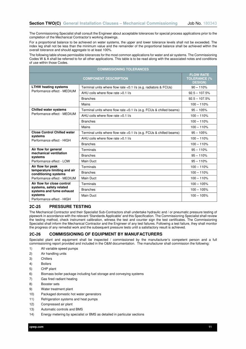
Section TWO(C) General Installation Clauses – Mechanical Commissioning Job No. 180343
cpwp.com 11
The Commissioning Specialist shall consult the Engineer about acceptable tolerances for special process applications prior to the completion of the Mechanical Contractor’s working drawings.
For a proportional balance to be achieved on water systems, the upper and lower tolerance levels shall not be exceeded. The index leg shall not be less than the minimum value and the remainder of the proportional balance shall be achieved within the overall tolerance and should aggregate to at least 100%.
The following table shows permissible tolerances for the most common applications for water and air systems. The Commissioning Codes W & A shall be referred to for all other applications. This table is to be read along with the associated notes and conditions of use within those Codes.
COMMISSIONING TOLERANCES
COMPONENT DESCRIPTION FLOW RATE
TOLERANCE (% DESIGN)
LTHW heating systems
Performance effect - MEDIUM Terminal units where flow rate <0.1 l/s (e.g. radiators & FCUs) 90 – 110%
AHU coils where flow rate >0.1 l/s 92.5 – 107.5%
Branches 92.5 – 107.5%
Mains 100 – 110%
Chilled water systems
Performance effect - MEDIUM Terminal units where flow rate <0.1 l/s (e.g. FCUs & chilled beams) 95 – 105%
AHU coils where flow rate >0.1 l/s 100 – 110%
Branches 100 – 110%
Mains 100 – 110%
Close Control Chilled water systems
Performance effect - HIGH
Terminal units where flow rate <0.1 l/s (e.g. FCUs & chilled beams) 95 – 105%
AHU coils where flow rate >0.1 l/s 100 – 110%
Branches 100 – 110%
Air flow for general mechanical ventilation systems
Performance effect - LOW
Terminals 95 – 110%
Branches 95 – 110%
Main Duct 95 – 110%
Air flow for peak temperature limiting and air conditioning systems
Performance effect - MEDIUM
Terminals 100 – 110%
Branches 100 – 110%
Main Duct 100 – 110%
Air flow for close control systems, safety related systems and fume exhaust systems
Performance effect - HIGH
Terminals 100 – 105%
Branches 100 – 105%
Main Duct 100 – 105%
PRESSURE TESTING
The Mechanical Contractor and their Specialist Sub-Contractors shall undertake hydraulic and / or pneumatic pressure testing of pipework in accordance with the relevant ‘Standards Applicable’ and this Specification. The Commissioning Specialist shall review the testing method, check instrument calibration, witness the test and counter sign the test certificates. The Commissioning Specialist shall inform the Mechanical Contractor and the Engineer of any test failures. Following a test failure, they shall monitor the progress of any remedial work and the subsequent pressure tests until a satisfactory result is achieved.
COMMISSIONING OF EQUIPMENT BY MANUFACTURERS
Specialist plant and equipment shall be inspected / commissioned by the manufacturer’s competent person and a full commissioning report provided and included in the O&M documentation. The manufacturer shall commission the following:
1) All variable speed pumps
2) Air handling units
3) Chillers
4) Boilers
5) CHP plant
6) Biomass boiler package including fuel storage and conveying systems
7) Gas fired radiant heating
8) Booster sets
9) Water treatment plant
10) Packaged domestic hot water generators
11) Refrigeration systems and heat pumps
12) Compressed air plant
13) Automatic controls and BMS
14) Energy metering by specialist or BMS as detailed in particular sections
Section TWO(C) General Installation Clauses – Mechanical Commissioning Job No. 180343
cpwp.com 12
The Commissioning Specialist shall include the commissioning period of all specialist plant and equipment within their plan and ensure that the coordination and timing of these activities fits in with the main commissioning programme and ultimately the construction programme. The Commissioning Specialist shall obtain the commissioning report and verify that all the checks have been completed and signed off with the system being safe prior to setting them to work as part of the overall building services systems.
The Mechanical Contractor shall inform the Commissioning Specialist of the divisions of responsibility between specialist plant manufacturers and the Commissioning Specialist when it comes to commissioning that plant.
OPEN SYSTEM SCAN
An open system scan shall be undertaken prior to the regulation and balancing of all air and water distribution systems. The results shall be recorded and any irregularities rectified prior to adjusting dampers, regulating valves, fan and pump duties. Under no circumstances shall dampers or valves be regulated to rectify any significant under or over volumetric readings.
DOCUMENTATION FOR OPERATING AND MAINTENANCE MANUALS
The Commissioning Specialist shall be responsible for providing the documentation listed below for inclusion in the operating and maintenance documentation:-
1) Fully signed master and copies of all commissioning records and test sheets as detailed earlier in this Specification (hard copy and PDF).
2) Details of any amendments to the installed plant and equipment (e.g. changes to belt and pulley sizes).
3) Details of any off site test sheets as detailed earlier in this Specification.
4) The Commissioning Specialist shall be responsible for programming the progress of compilation of record drawings and manuals and shall ensure these are completed in their entirety PRIOR to handover and Practical Completion.
LIAISON WITH STATUTORY AUTHORITIES
The Commissioning Specialist shall arrange all necessary liaison with the statutory authorities as appropriate. This shall include but not be limited to the Building Control Officer and the Fire Officer. The statutory authorities shall carry out all the required witnessing of the completed systems prior to their handover to the Client.
cpwp.com V3.0
Section Two (D) General Installation Clauses - Thermal Insulation
Section TWO(D) General Installation Clauses – Thermal Insulation Job No. 180343
cpwp.com 2
Contents Page
2D-1 GENERAL REQUIREMENTS 4
2D-1-1 INTRODUCTION 4
2D-1-2 DEFINITIONS 4
2D-1-3 REFERENCE TO OTHER SECTIONS OF THIS SPECIFICATION 4
2D-1-4 STANDARDS APPLICABLE 5
2D-1-5 SCOPE 5
2D-1-6 SERVICES TO BE INSULATED 5
2D-1-7 PIPEWORK CLEARANCES 6
2D-1-8 ALTERNATIVE MAKES 6
2D-1-9 AVAILABILITY OF MATERIALS 6
2D-2 MATERIALS 6
2D-2-1 GENERAL 6
2D-2-2 INSTALLATION REQUIREMENTS 7
2D-2-3 USE OF PHENOLIC FOAM 8
2D-2-4 PHENOLIC FOAM INSULATION PERMITTED USE 8
2D-2-5 FIRE PERFORMANCE 9
2D-2-6 BUILDING REGULATIONS 9
2D-2-7 ELECTRICAL BONDING 9
2D-3 INSULATION OF SUPPORTS 9
2D-4 PROTECTION AND PROTECTIVE COVERING 10
2D-4-1 INTERNAL APPLICATIONS - GENERALLY 10
2D-4-2 INTERNAL APPLICATIONS - PLANTROOMS, BOILER HOUSES 10
2D-4-3 EXTERNAL APPLICATIONS - ALL SERVICES EXPOSED OR IN NON-WEATHERTIGHT DUCTS, RISERS ETC 10
2D-4-4 BURIED SERVICES 11
2D-4-5 ALTERNATIVE COVERINGS 11
2D-4-5-1 INTERNAL APPLICATIONS - PVC SHEET 11
2D-4-5-2 INTERNAL APPLICATIONS - SYNTHETIC SHEET 11
2D-4-5-3 EXTERNAL APPLICATIONS - SYNTHETIC SHEET 12
2D-5 VAPOUR BARRIERS FOR REFRIGERATION, DOMESTIC COLD, CHILLED WATER AND WARM/COOLED AIR SERVICES 12
2D-5-1 VALVES AND FLANGES 12
2D-5-1-1 FLANGE / VALVE BOXES 12
2D-5-1-2 VALVE JACKETS TO VALVES, STRAINERS AND HEAT EXCHANGERS 12
2D-6 WALLS AND FIRE BARRIERS 13
2D-7 EXPANSION BELLOWS 13
2D-8 PLANT ACCESS 13
2D-9 FLOOR DUCTS 13
Section TWO(D) General Installation Clauses – Thermal Insulation Job No. 180343
cpwp.com 3
2D-10 ADHESIVE / SEALANTS 13
2D-11 SLAB INSULATION SUPPORTS 13
2D-12 INSULATION OF STORAGE CISTERNS 14
2D-13 IDENTIFICATION 14
2D-14 GENERAL THICKNESS OF INSULATION 14
2D-15 DUCTWORK INSULATION THICKNESS REQUIREMENTS 15
2D-16 PIPEWORK INSULATION THICKNESS REQUIREMENTS 16
2D-17 COMBINATIONS OF PERMITTED DUCTWORK INSULATION MATERIAL & COVERINGS 21
2D-18 COMBINATIONS OF PERMITTED PIPEWORK INSULATION MATERIAL & COVERINGS 22
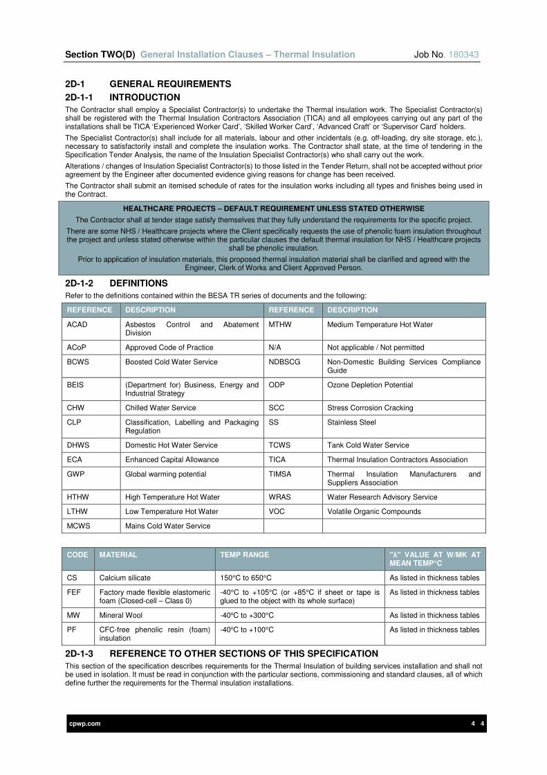
Section TWO(D) General Installation Clauses – Thermal Insulation Job No. 180343
cpwp.com 4 4
2D-1 GENERAL REQUIREMENTS
2D-1-1 INTRODUCTION
The Contractor shall employ a Specialist Contractor(s) to undertake the Thermal insulation work. The Specialist Contractor(s) shall be registered with the Thermal Insulation Contractors Association (TICA) and all employees carrying out any part of the installations shall be TICA ‘Experienced Worker Card’, ‘Skilled Worker Card’, ‘Advanced Craft’ or ‘Supervisor Card’ holders.
The Specialist Contractor(s) shall include for all materials, labour and other incidentals (e.g. off-loading, dry site storage, etc.), necessary to satisfactorily install and complete the insulation works. The Contractor shall state, at the time of tendering in the Specification Tender Analysis, the name of the Insulation Specialist Contractor(s) who shall carry out the work.
Alterations / changes of Insulation Specialist Contractor(s) to those listed in the Tender Return, shall not be accepted without prior agreement by the Engineer after documented evidence giving reasons for change has been received.
The Contractor shall submit an itemised schedule of rates for the insulation works including all types and finishes being used in the Contract.
HEALTHCARE PROJECTS – DEFAULT REQUIREMENT UNLESS STATED OTHERWISE
The Contractor shall at tender stage satisfy themselves that they fully understand the requirements for the specific project.
There are some NHS / Healthcare projects where the Client specifically requests the use of phenolic foam insulation throughout the project and unless stated otherwise within the particular clauses the default thermal insulation for NHS / Healthcare projects
shall be phenolic insulation.
Prior to application of insulation materials, this proposed thermal insulation material shall be clarified and agreed with the Engineer, Clerk of Works and Client Approved Person.
2D-1-2 DEFINITIONS
Refer to the definitions contained within the BESA TR series of documents and the following:
REFERENCE DESCRIPTION REFERENCE DESCRIPTION
ACAD Asbestos Control and Abatement Division
MTHW Medium Temperature Hot Water
ACoP Approved Code of Practice N/A Not applicable / Not permitted
BCWS Boosted Cold Water Service NDBSCG Non-Domestic Building Services Compliance Guide
BEIS (Department for) Business, Energy and Industrial Strategy
ODP Ozone Depletion Potential
CHW Chilled Water Service SCC Stress Corrosion Cracking
CLP Classification, Labelling and Packaging Regulation
SS Stainless Steel
DHWS Domestic Hot Water Service TCWS Tank Cold Water Service
ECA Enhanced Capital Allowance TICA Thermal Insulation Contractors Association
GWP Global warming potential TIMSA Thermal Insulation Manufacturers and Suppliers Association
HTHW High Temperature Hot Water WRAS Water Research Advisory Service
LTHW Low Temperature Hot Water VOC Volatile Organic Compounds
MCWS Mains Cold Water Service
CODE MATERIAL TEMP RANGE "λ" VALUE AT W/MK AT MEAN TEMP°C
CS Calcium silicate 150°C to 650°C As listed in thickness tables
FEF Factory made flexible elastomeric foam (Closed-cell – Class 0)
-40°C to +105°C (or +85°C if sheet or tape is glued to the object with its whole surface)
As listed in thickness tables
MW Mineral Wool -40oC to +300°C As listed in thickness tables
PF CFC-free phenolic resin (foam) insulation
-40oC to +100°C As listed in thickness tables
2D-1-3 REFERENCE TO OTHER SECTIONS OF THIS SPECIFICATION
This section of the specification describes requirements for the Thermal Insulation of building services installation and shall not be used in isolation. It must be read in conjunction with the particular sections, commissioning and standard clauses, all of which define further the requirements for the Thermal insulation installations.

Section TWO(D) General Installation Clauses – Thermal Insulation Job No. 180343
cpwp.com 5
2D-1-4 STANDARDS APPLICABLE
Works shall be completed in accordance with all applicable industry standards. Some of the most relevant standards associated with this section are scheduled below:
STANDARDS
BESA DW 144 Sheet Metal Ductwork BS EN 13941 Pre-insulated bonded pipe systems for district heating
BRE Green guide to specification BS EN 14303 Thermal insulation products for building equipment and industrial installations. Factory made mineral wool (MW) products. Specification.
BS 476 Fire tests on building materials and structures BS EN 14304 Thermal insulation products for building equipment and industrial installations. Factory made flexible elastomeric foam (FEF) products. Specification.
BS 1710 Specification for identification of pipeline & services
BS EN 14305 Thermal insulation products for building equipment and industrial installations. Factory made cellular glass (CG) products. Specification.
BS 3533 Glossary of thermal insulation terms BS EN 14306 Thermal insulation products for building equipment and industrial installations. Factory made calcium silicate (CS) products. Specification.
BS 3958 Thermal insulating materials BS EN 14314 Thermal insulation products for building equipment and industrial installations. Factory made phenolic foam (PF) products. Specification.
BS 4508 Thermally insulated underground pipelines Enhanced Capital Allowance (ECA) Scheme for Energy Efficient Technologies. Energy Technology Criteria List
BS 5422 Method for specifying thermal insulating materials Carbon Trust Pipework insulation equipment
BS 5615 Specification for insulating Jackets for domestic hot water storage cylinders
ESS SD 5073 BREEAM new construction non-domestic building technical manual
BS 5970 Thermal insulation of pipework and ductwork Non-Domestic Building Services Compliance Guide
BS 8313 Accommodation of building services in ducts TIMSA / TICA documents including Guidance for achieving compliance with Part L of the Building Regulations
Note on BS 5422 and achieving Enhanced Capital Allowance
The insulation thicknesses listed in BS5422 are insufficient to achieve Enhanced Capital Allowances. All insulation thicknesses listed in this section of the specification are provided to meet minimum requirements for qualification for Enhanced Capital Allowances.
Where the above standards refer to supporting documentation and standards these shall be fully complied with in all respects.
Where discrepancy is found between this specification and the relevant standards, the Contractor shall obtain written clarification from the Engineer prior to submission of the tender. Where a discrepancy has not been clarified prior to tender submission, the Contractor shall include the most onerous requirements.
2D-1-5 SCOPE
This section describes the thermal insulating materials, coverings (including protective coverings) and installation applied to engineering services.
It excludes sound insulation, chimney, boiler or cold room insulation and insulation of the structure. These requirements will be specified elsewhere, if necessary. Should these excluded insulations be required they shall be described within the specific clauses.
The thickness and finishes of insulation detailed within this Specification are the minimum standard acceptable.
The requirements of ISO 9000 and Thermal Insulation Manufacturers and Suppliers Association (TIMSA) guidance for achieving compliance with Part L of the Building Regulations, including all Second Tier Documents, shall be also apply.
Should any discrepancies become apparent, the most onerous requirement shall be employed.
Preformed/ pre-moulded bends, flanges and valve covers to the respective requirements above (thicknesses same as the pipework) may be used: the overall finish/ covering to be the same as the adjacent pipework.
2D-1-6 SERVICES TO BE INSULATED
Thermal insulation shall be applied to:
• Complete heating systems, including pipework, pipework supports, calorifiers, buffer vessels, feeds and vents, etc., but excluding any pipework or any final connections that are so located and designed as to usefully contribute heat to the space without causing uncontrolled overheating. The room located heat emitters, such as pipe coils, shall not be thermally insulated.
• Heating pipework serving Low Surface Temperature (LST) emitters shall be insulated throughout such that no surface exposed to the users exceeds a temperature of 43°C.
Section TWO(D) General Installation Clauses – Thermal Insulation Job No. 180343
cpwp.com 6
• Complete domestic hot and cold water service systems, including calorifiers, cylinders, storage cisterns / tanks, all flow and return distribution pipework, pipework supports, thermostatic mixing valves and all blended water pipes except for short sections, maximum of 300mm long, of final connections to draw-off points where there is insufficient space to separately insulate hot and cold water pipes. Where these pipes are concealed, in integrated plumbing systems (IPS), in cupboards or otherwise concealed from general user view the pipes shall be fully insulated.
• Large internal and external cold water storage cisterns shall be insulated fully in accordance with WRAS Regulations and shall be certified as being WRAS Approved. Any additional insulation requirements shall be detailed in the specific clauses of this specification.
• Buried water pipes, which rise within 750mm of the outside wall of the building – fully in accordance with WRAS Water Regulations Guide.
• Entire pipework, pipework supports, pumps and vessels, etc. in heat recovery systems.
• Direct Expansion (DX) refrigeration systems throughout. Externally located insulation shall be weather-proof with factory applied ultraviolet radiation protective coating.
• Entire steam and condensate pipework systems, including accumulators, pipework, hot wells, condensate recovery units and boiler blow down pipes. Condensate cooling legs shall not be insulated but these shall be provided with mesh guards or shields to prevent accidental scalding.
• Safety valve discharge pipes for steam, heating and hot water. These pipes shall be fully insulated throughout even if this is not a requirement under the British Standard.
• Boiler flues, smoke boxes, grit arrestors, and ID fans, internal and external.
• Supply air handling plant including heater or cooler batteries and intake ductwork to plant, insulated and then vapour sealed to prevent condensation.
• Ductwork carrying heated, cooled, tempered or conditioned supply air or extracted air for re-use by recirculation or for extracted air forming part of a heat recovery system.
• Air extract ducting to atmosphere - where such ducting passes through occupied areas and contributes to the heat gain / loss of the occupied area.
• Any pipework with heated / cold / chilled fluid, within hollow partition, "boxed-in, floor screeds, concealed and all pipework subject to potential frost conditions.
• Entire chilled water distribution systems including all valves and pipe supports.
• Where heat loss or heat gain to any system or part of a system reduces overall system energy efficiency of an installation.
Any thermal insulation requirements in addition to those detailed above shall be detailed in the specific clauses of this specification.
2D-1-7 PIPEWORK CLEARANCES
It is imperative that there is a minimum of a 25mm clearance all round a completed insulated pipe to enable the insulation to be applied and properly sealed. It is therefore necessary to consider the insulation thickness early in pipework design. Failure to comply with this requirement will require the Contractor to remove newly installed pipework and re-install at their cost.
The Contractor shall leave sufficient clearance between each pipe / service to allow for the thickness of insulation specified in the tables of this section and to give good maintenance access between insulated services.
Where possible, hot water and heating pipes shall be located above cold water and chilled water pipes to minimise heat transfer.
Additional space / clearance may be required where insulated pipe sleeves are used. Examples of such systems shall be steam, condensate, cold and chilled water services.
2D-1-8 ALTERNATIVE MAKES
The use of other forms of insulation, or other manufacturer's products, may be considered provided they comply fully with the requirements laid down in this Specification.
This applies to insulation such as flexible Class 0 rated black flexible elastomeric foam which may be used in confined spaces e.g. between partitions or where plastic pipes are proposed to be continuously supported on cable trays where the hot and cold water pipes are adequately separated to avoid heat transfer between fluids (i.e. the hot water pipes warming the cold water pipes).
They shall also be subject to the approval of the Engineer before including within the tender return, ordering or installing; at least one month's notice is required for approval.
2D-1-9 AVAILABILITY OF MATERIALS
Insulation thickness specified may not always be stock items. Delays to the contract due to lack of or poor availability of materials, etc. shall not be accepted. To avoid delay, the Contractor shall utilise the nearest greater thickness insulation, at no additional cost to the contract.
2D-2 MATERIALS
2D-2-1 GENERAL
All insulation materials shall be:
1) New, clean and undamaged.
2) Totally free of asbestos.
3) Obtained, where available, from a BS EN ISO 9000 ‘Quality Systems’ certified manufacturer.
4) CFC, HFC and HCFC free with a zero ODP and GWP of less than five (number 5).
5) Rot proof, non-hygroscopic, free from animal hair, VOC’s or settling under vibration and resistance to attack and damage by vermin and to the growth of fungi.
6) Provided with fully sealed weather-proof and waterproof quality finish for outdoor (external) situations.

Section TWO(D) General Installation Clauses – Thermal Insulation Job No. 180343
cpwp.com 7
7) Fully resistant from Ultraviolet Radiation degradation, this particularly applies to flexible elastomeric foam and rubber insulation used for refrigeration pipework, which is required to have a factory applied UV coating protection to avoid this issue.
8) So protected, manufactured, constructed and installed to prevent electrolytic action, corrosion or decay.
9) Durable and shall maintain their installed thermal conductivity (λ - value) for the expected life of the installation.
10) Free from objectionable odours at their temperature range band.
11) Free of chemicals that may contribute to corrosion of the insulated surface or surface finish.
12) Delivered to site new and fully dry, stored and maintained throughout the Contract. Damp or wet insulation, even if dried out, shall not be used.
13) The relevant certification undertaken in line with the required EU method, indicating that fibres are not classified under the CHIP 98 Regulations and EU Directive 97/69/EC.
14) Responsibly sourced. Include all evidence provided to BREEAM assessors, where applicable.
15) Low embodied impact relevant to their thermal properties determined by the Green Guide by achieving either A or A+ Green Guide rating.
16) Installed fully in accordance with the best practice recommendations of the thermal insulation manufacturer and pipework manufacturer if specialist pipework systems are installed (for example - any press fit stainless steel system).
17) Entirely suitable for the actual installation.
18) Be CE marked in accordance with the relevant standard that the insulation has been manufactured.
19) Factory Mutual approved to Approval Standard FM 4924.
Insulation material shall only be installed as follows:
1) Only once all external surfaces of pipes and ducts have been cleaned and free from all dust, cement, plaster, etc. All traces of surplus flux shall be completely removed from the surface of copper pipework.
2) Where recommended by the pipework material manufacturer an impermeable barrier shall be installed between the pipework and the thermal insulation.
3) Installations shall ensure that any protective fixings do not penetrate the vapour barrier (e.g. not use pop rivets on Aluminium sheeting unless adequate clearance).
4) Applied to individual pipes or ducts. Adjacent parallel pipes or ducts shall not be married together with one common insulation covering unless specifically detailed on the drawings or specifications e.g. trace heating/ fuel oil.
5) Only after the particular service installation section has been successfully pressure tested.
6) Only after steel pipework painting has been completed by the Contractor.
7) Identified as detailed elsewhere in this specification.
8) When exposed to view internally or externally (excluding plant areas) and below 2 metres from finished floor level, complete with mechanical protection.
9) All insulation within plant areas shall be complete with mechanical protection.
Insulation shall NOT:
1) Be bonded (nor any covering) by any adhesive, sealant or banding which may cause a fire hazard or emit dense smoke or toxic fumes, if subjected to excessive heat such as in a fire.
2) Suffer deterioration at the maximum temperature under the specified conditions of use.
3) Suffer permanent deterioration as a result of contact with moisture due to condensation or other sources.
4) Be supported on wood, cork or polystyrene etc., blocks or segments used as insulating pads / collars.
5) Be applied to condensate cooling legs.
6) Be ‘classified’ under the CLP Regulations.
7) Have adhesive tapes applied to any pipes themselves, specifically at ends of pipe to ‘neaten’ or ‘tidy’ the appearance of the installation. Proprietary end caps of the same material as the rest of the finish shall be used.
Damage Limitation
Insulation and protective coverings shall be:
1) Protected during the progress of the works.
2) Maintained dry as appropriate.
3) Fabricated to allow for expansion, contraction, ease of access for maintenance, testing, operation or replacement of equipment without damage to the service or insulation,
4) Protected against mechanical damage where run exposed on the surface in vulnerable areas, e.g. an installation at low level in a corridor, which may be subject to impact by cleaning machines, trolleys, etc.
5) Only applied after the building is weather tight to avoid risk of rain, snow or ice damaging the thermal insulation.
6) Installed so that the protective covering does not damage or penetrate the vapour barrier of the thermal insulation.
The Specialist shall take appropriate steps to prevent damage to new and existing pipework, ductwork and plant, etc., throughout the progress of the works. This requirement shall also apply to new and existing insulation of services. Any damage shall be rectified at no additional cost to the Contract and to the satisfaction of the Engineer.
2D-2-2 INSTALLATION REQUIREMENTS
The Insulation Specialist Contractor shall:
Section TWO(D) General Installation Clauses – Thermal Insulation Job No. 180343
cpwp.com 8
• Provide proof, prior to installation, to the Site Engineer, Clerk of Works that the insulation proposed complies with this specification and is of the correct thickness, thermal conductivity, fire rating and density of insulation as required in this Specification and relevant ISO/ British Standards. Insulation installed and not complying with these requirements shall be removed and replaced with new insulation to the requirements, all at the Contractor’s own expense with no impact on the contract cost or programme completion date.
• To minimise risks of stress corrosion cracking of stainless steel pipework, irrespective of proposed thermal insulation, pure aluminium foil of minimum thickness 0.06mm shall be applied to any stainless steel pipework, including under pipework supports, that is externally located, may be subject to rainfall, trace heated or otherwise at risk of SCC prior to insulating to protect against chloride induced corrosion of the surface as recommended by the British Stainless Steel Association, British Standards, thermal insulation and pipe manufacturer’s best practice recommendations.
• Ensure that all insulation is firmly secured in accordance with the manufacturers recommendations. e.g. with bands of 50mm reinforced aluminium foil adhesive tape, 25mm MS black lacquered bands, 20mm lightweight aluminium bands, insulation hanger pins and washers; at not greater than 400mm equidistant centres or closer if recommended by the product manufacturer. This requirement exists to maximise the appearance and life expectancy of the installation.
• Apply the insulation strictly in accordance with the insulation manufacturer’s recommendations and instructions; work done failing to comply shall not be accepted.
• Ensure that all insulation is applied to provide a neat, smooth and symmetrical appearance, running true in line with pipe or duct distribution.
• All unused insulation, finishes and packaging, etc., shall be removed from the site before the final acceptance of the works. All fibrous particles remaining after cutting and fabrication shall be removed by suction cleaning at the end of the working day.
• The Contractor shall be responsible for the insulation installations until practical completion (partial or full). Any damage, poor quality, irregular, badly finished or installed insulation and/ or surfaces shall be made good at the Contractor’s expense, so that the installed insulation is handed over in perfect condition.
• Upon completion of the installation, the Engineer may request one section of the insulation on each of the services to be cut out to allow for verification of the thickness and/ or density. The Contractor shall allow to undertake the cut out and reinstatement of the insulation at their own expense.
• If defects are revealed, cut out two further sections of suspect insulation for inspection.
• If further defects are revealed, remove the whole of the installation and provide and fix new insulation to the satisfaction of the Engineer at the Contractor’s own expense.
2D-2-3 USE OF PHENOLIC FOAM
Phenolic foam insulation shall not be used on:
• Steam and condensate systems for any pipework installations.
• HTHW & MTHW operating in excess of 100°C on any pipework installation.
• Domestic cold water systems for copper or stainless steel pipework installations, except for NHS / Healthcare projects.
• Chilled water systems for any pipework installations, except for NHS / Healthcare projects.
The above requirements are mandatory unless stated otherwise under the specific clause sections of this specification.
2D-2-4 PHENOLIC FOAM INSULATION PERMITTED USE
Where the use of Phenolic foam has been agreed, the insulation shall then only be installed as stated below.
Phenolic Foam insulation is acceptable only in the following situations:
• All phenolic foam shall be of a CFC (and/ or HFC, HCFC) free type.
• Bore coated preformed pipe sections having a 25 year aged thermal conductivity of 0.025W/m k at 10ºC mean temperature in accordance with the listed standard.
• Have a factory applied Class 0 reinforced aluminium foil jacket.
• Certification shall be provided.
Where phenolic foam is used on copper and stainless steel pipework, the Specialist Contractor shall additionally:
• Ensure that the phenolic foam pipe insulation is bore-coated (impregnated) with a factory applied passive anti-corrosive agent (as minimum specification for phenolic sections).
• Completely wipe clean all external pipe surfaces to remove all moisture and building materials, dust, surplus soldering jointing flux, etc. immediately prior to applying insulation.
• Cover the copper pipework and fittings with a coating of anti-corrosive gel, e.g. DENSO paste or equivalent. Alternatively a non-metallic plastic tape may be wrapped around all pipework provided it meets the manufacturer’s approval.
• Install insulation to the manufacturer’s recommendations, method statement and British Standards.
• Ensure any aluminium foil over wrap does not make contact with any copper pipework.
• Ensure the vapour barrier is continuous and unbroken. All terminations/ protrusions through the installation shall be vapour sealed.
• Ensure the correct bore insulated sections are used to suit the overall diameter of the pipework being insulated.
• The Specialist Contractor shall liaise with the Contractor to ensure that pipework is installed on insulated pipe supports.
• Ensure that the insulation cannot become wet or water logged, with particular care on any external installations where the outer protective covering shall be fully weather / water proof, the vapour barrier alone shall not be relied upon.
Section TWO(D) General Installation Clauses – Thermal Insulation Job No. 180343
cpwp.com 9
2D-2-5 FIRE PERFORMANCE
The insulation and its covering/ finish shall have a Class 1 rating, minimum to BS 476-6, and be classified Class 0 in accordance with The Building Regulations Approved Document B (Current Edition) Appendix A and current amendments.
All thermal insulation and protective coverings shall meet the requirements of BS 5422 when tested in accordance with BS 476.
Where located in cavities, of a class required by Current Building Regulations, Approved Document B, Appendix A.
Where located in rooms, circulation spaces and protected shafts, of a class equal to the class for walls in Building Regulations, Approved Document B, appendix A. Table 1A.
Class 1 shall be construed and tested in accordance with Building Regulations, Approved Document B, Appendix Tables 7 & 8
Under no circumstances shall insulation be carried through fire compartment walls or floors unless it complies with the current Building Regulations. Fire stop unit(s) as required by the Building Regulations, Approved Document B, wherever the services perforate a compartment wall or floor designed as a fire barrier shall be used. The requirements of BS 476 shall also be complied with.
The above requirement shall apply to all insulated ventilation ductwork except for fire barriers where fire dampers are used.
Attention is drawn to the risk attached to the use of PVC, PIB, foamed rubber, polyurethane, polystyrene or isocyanurate, etc. Even where these materials are claimed to be fire resistant and / or self-extinguishing, they have proven in the past to be highly combustible and produce toxic smoke causing a hazard to personnel.
Foamed rubber, polyurethane, polystyrene, isocyanurate or similar types of insulation/finish shall not be used.
2D-2-6 BUILDING REGULATIONS
TIMSA guidance for achieving compliance with Part L of the Building Regulations also includes measures to prevent condensation and provide frost protection and shall be complied with as a minimum standard.
2D-2-7 ELECTRICAL BONDING
Where insulation with a sheet metal surface finish is used, e.g. aluminium stucco sheeting, etc., it shall comply with IET Regulations, as regards the facility to be electrically bonded to a protective conductor.
Bonding shall be carried out by the Electrical Contractor but the connections shall be included for by the Contractor in their tender. Insulation of pipework, ductwork or plant, finished with aluminium or other metal (accept aluminium foil) shall be bonded.
To ensure electrical continuity, all metal surface finish insulation shall be bonded and earthed in accordance with BS EN standard using stainless steel wire or bands as specified in BS 5422.
2D-3 INSULATION OF SUPPORTS
All steam, condensate, LTHW, MTHW, HTHW, domestic hot, domestic cold, chilled water, refrigeration pipework, condenser water and any other pipes that are thermally insulated shall be fitted with insulated supports whereby the insulation is continuous and not punctured.
Cold feeds, vents and safety valve discharges, although they may be insulated do not need insulated supports. Gas pipework is not insulated and therefore does not require insulated pipe supports.
All pipe supports shall have a rated density in accordance with the manufacturer’s recommendations for the pipe diameter.
All pipe supports shall be the same thickness as the pipe thermal insulation to provide a continuous neat sealed appearance.
Insulated pipework supports for mineral wool insulation shall be phenolic, where permitted and up to 100°C or calcium silicate or Foamglas One above 100°C, to the higher load bearing necessary based on pipe sizes and support centres, due to equivalent insulated block supports not being available in mineral wool form. Where this is the case, the insulated blocks shall be to the same thickness and finish as the adjacent mineral wool pipework.
Where phenolic blocks are proposed to be installed on copper pipework, the Contractor shall install a layer of 0.25mm thick polythene sheet or pipework (not electrical insulation) PVC tape wrapped around the pipe so that 50mm exposed tape or sheet is visible either side of the support blocks on both sides to provide an additional vapour barrier between the block and the pipework.
Suitable PVC tapes for this purpose are as provided by Advance Tapes International Limited (+44116 251 0191), range AT10 PVC Heavy Duty Pipewrap Tape or Directa (UK) Limited (+441621 828882) PVC Heavy Duty Pipe Wrap Insulation Tape.
This additional requirement only applies to cold water, chilled water pipework systems and any system where the fluid is below 50°C where phenolic blocks are used on copper pipework. Note – Stainless steel pipes are required to be wrapped in aluminium foil to minimise risk of SCC as detailed earlier.
The insulated supports shall have a "λ" value not exceeding 0.065 W/mK, be a minimum of 50mm wider than the pipe clip or duct bracket and of a corresponding thickness to that specified for the service. The whole section shall be encased in a reinforced sleeve (GRP or MS galvanised) of greater length then the isolating load bearing section of insulation.
The installation shall be as outlined in BS 5970, except that wood and cork shall not be permitted even when listed or mentioned in BS 5970. In summary, hard wood, cork or polystyrene blocks or segments as an insulating pad or collar are NOT acceptable.
All insulated pipe supports shall follow the preferred principle detailed in BS 5970 Figure 12 ‘Preferred Option – hanger incorporating load bearing insulation (for pipes operating above and below ambient temperature’ where the pipe bracket is around the outside of both the insulation and vapour barrier. BS 5970 figure 18 provides details of ‘Typical proprietary support inserts’ that meet the overall insulated pipe support requirement.
On rare occasions, and only after written permission has been received from the Engineer, will pipe supports in direct contact with the pipe as detailed in BS 5970 figure 13 ‘Non-preferred option – hanger incorporating load bearing insulation (for pipes operating above and below ambient temperature’ be accepted.
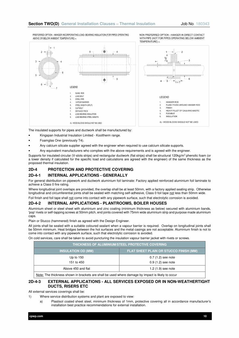
Section TWO(D) General Installation Clauses – Thermal Insulation Job No. 180343
cpwp.com 10
The insulated supports for pipes and ductwork shall be manufactured by:
• Kingspan Industrial Insulation Limited - Kooltherm range.
• Foamglas One (previously T4).
• Any calcium silicate supplier agreed with the engineer when required to use calcium silicate supports.
• Any equivalent manufacturers who complies with the above requirements and is agreed with the engineer.
Supports for insulated circular (V-slots strips) and rectangular ductwork (flat strips) shall be structural 120kg/m3 phenolic foam (or a lower density if calculated for the specific load and calculations are agreed with the engineer) of the same thickness as the proposed thermal insulation.
2D-4 PROTECTION AND PROTECTIVE COVERING
2D-4-1 INTERNAL APPLICATIONS - GENERALLY
For general distribution on pipework and ductwork aluminium foil laminate: Factory applied reinforced aluminium foil laminate to achieve a Class 0 fire rating.
Where longitudinal joint overlaps are provided, the overlap shall be at least 50mm, with a factory applied seating strip. Otherwise longitudinal and circumferential joints shall be sealed with matching self-adhesive, Class 0 foil tape not less than 50mm wide.
Foil finish and foil tape shall not come into contact with any pipework surface, such that electrolytic corrosion is avoided.
2D-4-2 INTERNAL APPLICATIONS - PLANTROOMS, BOILER HOUSES
Aluminium sheet or steel sheet with aluminium and zinc coating (minimum thickness as below) secured with aluminium bands, 'pop' rivets or self-tapping screws at 50mm pitch, end joints covered with 75mm wide aluminium strip and purpose made aluminium caps.
Plain or Stucco (hammered) finish as agreed with the Design Engineer.
All joints shall be sealed with a suitable coloured sealant when a vapour barrier is required. Overlap on longitudinal joints shall be 50mm minimum. Heat bridges between the hot surfaces and the metal casings are not acceptable. Aluminium finish is not to come into contact with any pipework surface, such that electrolytic corrosion is avoided.
On cold services, care shall be taken to avoid puncturing the insulation vapour barrier jacket with rivets or screws.
THICKNESS OF ALUMINIUM/STEEL PROTECTIVE COVERING
INSULATION OD (MM) FLAT SHEET PLAIN OR STUCCO FINISH (MM)
Up to 150
151 to 450
0.7 (1.2) see note
0.9 (1.2) see note
Above 450 and flat 1.2 (1.9) see note
Note: The thickness shown in brackets are shall be used where damage by impact is likely to occur
2D-4-3 EXTERNAL APPLICATIONS - ALL SERVICES EXPOSED OR IN NON-WEATHERTIGHT DUCTS, RISERS ETC
All external services coverings shall be:
1) Where service distribution systems and plant are exposed to view:
a) Plastisol coated sheet steel, minimum thickness of 1mm, protective covering all in accordance manufacturer’s installation best practice recommendations for external installation.
Section TWO(D) General Installation Clauses – Thermal Insulation Job No. 180343
cpwp.com 11
b) Final colour to blend in with building structure and as agreed with Architect.
2) Where services distribution systems and plant not visible:
a) Flat sheet plain or Stucco aluminium sheet as described for plant rooms and boiler houses. All joints fully water proofed in accordance with the manufacturer’s best practice recommendations.
3) For all closed-cell flexible elastomeric foam insulation (e.g. Armaflex) where the surface of the material is exposed to water, sunlight, UV radiation or attack by aggressive chemicals it shall be:
a) Preferred solution of using UV-resistant Armacell Armaflex Tuffcoat /, Kaiflex EPDM plus or approved equivalent to be agreed with the Engineer.
b) Protected using a proprietary paint finish, i.e. Armacell Armafinish 99 paint, applied strictly in accordance with the manufacturer’s recommendations. A minimum of two coats shall be applied with the second coat within 3 days of the first.
c) If additional mechanical protection or protection against severe weather conditions is required, Arma-Chek R covering systems offer a non-metallic cladding option. This will be stated within the particular sections of this specification if required.
2D-4-4 BURIED SERVICES
1) Where services distribution systems and plant are within trenches:
a) The insulation shall be protected by an outer rigid pipe to prevent the insulation being crushed and losing its effective thickness.
b) When buried where it will be in wet or moist ground for long periods, then the sealed material is to be wrapped in a reinforced plastic or waterproof tape, e.g. Denso tape, Fibaroll or approved equivalent to be agreed with the Engineer, prior to being protected by an outer rigid pipe.
c) Any pipework installed in pre-insulated pipework system shall be in accordance with BS EN 13941 complete with leak detection systems.
d) Refer to Specific sections of this specification for installation details.
2D-4-5 ALTERNATIVE COVERINGS
Materials described under clauses 2D4-1 to 2D4-4 inclusive are the default standards required under this specification.
Where specifically stated in the particular clauses of this specification or if the Contractor is requested through the tendering process to provide ‘Value Engineering’ options the following materials will be considered as acceptable:
2D-4-5-1 INTERNAL APPLICATIONS - PVC SHEET
PVC sheet shall be a minimum thickness of 0.35mm and applied with a minimum overlap (lengthways and in circumference) of 30mm. All joints to be secured with plastic push in rivets or special solvent based adhesive. Purpose made cap-ends to pipework shall be provided and the complete installation shall be in accordance with manufacturer’s recommendations.
The PVC sheet shall be:
• Suitable for installation within a temperature range of –20ºC to 65ºC
• Thermal conductivity – 0.16 W/mK
• Impact strength - >400 kJ/m2
• Tensile Strength - >35 N/mm2
• Fire rated Class 1 to BS476
• Colour – Grey (to be confirmed with Architect)
• Manufacturer – Isogenopak or as agreed in writing by the Engineer
2D-4-5-2 INTERNAL APPLICATIONS - SYNTHETIC SHEET
Synthetic sheet shall be a self-adhesive 5-ply laminar construction providing a continuous vapour barrier and applied with a minimum overlap of 75mm. All joints to be secured with VentureClad Insulation Jacketing tape (selected to match the sheet covering), purposed made cap-ends to pipework or ductwork shall be provided and the complete installation shall be in accordance with manufacturer’s recommendations.
The synthetic sheet shall be:
• Suitable for installation within a temperature range of -34ºC to 149ºC
• Provide zero permeability and continuous vapour barrier
• Puncture Resistance – 159.3N
• Tensile Strength – 306N/25mm
• Water permeability – 0.0000 perms (absolute vapour barrier)
• Fire rated Class 0 to BS 476
• Mould resistant
• Colour – White (to be confirmed with Architect)
• Manufacturer – VentureClad 1577cw
These synthetic sheets shall not be used where mechanical protection is required.

Section TWO(D) General Installation Clauses – Thermal Insulation Job No. 180343
cpwp.com 12
2D-4-5-3 EXTERNAL APPLICATIONS - SYNTHETIC SHEET
Synthetic sheet shall be a self-adhesive 13-ply laminar construction providing a continuous vapour barrier and applied with a minimum overlap of 75mm. All joints to be secured with VentureClad insulation jacketing tape (selected to match the sheet covering), purposed made cap ends to pipework or ductwork shall be provided and the complete installation shall be in accordance with manufacturer’s recommendations.
The Contractor shall note that the externally located synthetic sheet is required to be 13-ply and not 5-ply – this shall be verified during the installation and failure to install the thicker 13-ply sheet externally shall require the entire external finish to be replaced to comply with this requirement at no cost to the contract.
The synthetic sheet shall be:
• Suitable for installation within a temperature range of -40ºC to 120ºC
• Provide zero permeability and continuous vapour barrier
• Puncture resistance – 356N
• Tensile strength – 330N/25mm
• Fire rated Class 0 to BS 476.
• Mould resistant
• Colour – White (to be confirmed with Architect)
• Manufacturer – VentureClad Plus 1579cw
2D-5 VAPOUR BARRIERS FOR REFRIGERATION, DOMESTIC COLD, CHILLED WATER AND WARM/COOLED AIR SERVICES
On refrigeration, domestic cold or chilled water or warm / cooled air services the insulation and its covering / finish shall be continuous, maintained dry, completed and sealed as a vapour barrier throughout before reducing the service to its working temperature. Insulated pipe / duct supports shall be used on the above services to ensure continuity of the insulation and vapour barriers.
The vapour permeance of the finished installation shall not exceed the following when tested using the approved method in BS 5970 and BS 5422:
0.002 g/s.m2.Pa for refrigeration work
0.010 g/s.m2.Pa for chilled water installations
0.010 g/s.m2.Pa for cold water supplies
Protection coatings, adhesives, etc., shall be non-toxic and when dry be Class 0 fire rated. All terminations of and protrusions through the insulation vapour barrier shall be provided with vapour seal mastic (including all valve and vent stems, etc.).
2D-5-1 VALVES AND FLANGES
Insulated valve and flange cover boxes or jackets shall be included for on the following services:
SERVICE REQUIREMENT
Chilled water / refrigeration services 15mm pipe and above – All valves, pipes and fittings (insulated and vapour sealed)
Cold water services 15mm pipe and above – All valves, pipes and fittings (insulated and vapour sealed)
Steam, LTHW and HWS services 15mm pipe and above – All valves and flanges
Condensate and fuel oil pipework 25mm pipe and above – All Valves and flanges
All external services and services in “cold” roof spaces 15mm pipe and above – valves and flanges
2D-5-1-1 FLANGE / VALVE BOXES
Where installed, each box shall comprise of aluminium (thickness equal to that on pipework) split casing fitted with spring clip fasteners and lined with an insulation material, suitable for the particular service. The boxes (and insulation) shall be suitable for the size and type of valve or flange and shall be neatly and properly finished.
Boxes shall be installed on all flanges and valves including control valves (but not control motors). All joints in the casings shall be suitably sealed.
Where available, preformed valve and flange insulation mouldings shall be used.
The glands on valve spindles shall project beyond the insulation.
External valve and flange boxes shall be suitably weather proofed and sealed to the pipework to which they are attached. Valve boxes shall include removable covers over hand wheels and stems - refer to BS 5970.
Where required, provision shall be made in the valve and flange boxes to accommodate trace heating of the pipework.
2D-5-1-2 VALVE JACKETS TO VALVES, STRAINERS AND HEAT EXCHANGERS
Where general maintenance or service access is required to plate heat exchangers, strainers, valves or valve sets (including steam trap sets, etc.), fully insulated flexible plate heat exchanger or valve jackets shall be installed.
The valve jackets shall be fixed over valves using Velcro straps with drawstrings at either end of the jacket. The jackets shall have a robust, waterproof fabric finish fully stitched with flexible thermal insulation that meets the overall thermal performance of the insulation applied.
Section TWO(D) General Installation Clauses – Thermal Insulation Job No. 180343
cpwp.com 13
Materials for construction shall be fully suitable for the temperature of the service being insulated, but shall as a minimum meet the following:
ITEM REQUIREMENT
Inner finish Silicone coated glass fibre cloth
Outer finish Woven glass fibre
Insulation Mineral Wool
Insulation thickness 50mm minimum or as per pipework whichever is greater
Stitching Polyester cotton
Draw cords Nylon
Services subject to condensation (including chilled water and cold water services) shall be fully vapour sealed beneath the jackets, with the vapour seal applied directly onto the adjacent pipework and valves (including valve items).
2D-6 WALLS AND FIRE BARRIERS
Where insulated services pass through a structure, the provision must accommodate the insulation unless omitted by detail. At fire barriers, the fire integrity of the barrier must be maintained in accordance with Building Regulations Approved Document B ‘Fire Safety’. Fire integrity details shall be proven by test.
At fire barriers and structures, the thickness of insulation may be varied but care must be taken to prevent heat transfer sufficient to cause deterioration of the building fabric.
All services with a vapour barrier shall be arranged such that the vapour barrier is continuous through the wall / fire barrier by use of oversized sleeve or equivalent.
The above requirements shall apply to all insulated ventilation ductwork except for fire barriers where fire dampers are installed, these are detailed elsewhere.
2D-7 EXPANSION BELLOWS
Expansion bellows shall be insulated with preformed rigid sections of the same thickness, density and thermal conductivity as on the adjacent pipework.
The sections shall be applied over the flanges of the bellows and clear of convolutions and bolts. The sections shall be finished (and where installed externally be weather proofed) as for the adjacent pipe and be constructed as for valve boxes. See also BS 5970.
Note: Insulation shall not be applied until any "cold draw" has been taken up.
2D-8 PLANT ACCESS
Aluminium sheet covering or steel sheet with aluminium and zinc coating shall be securely fixed to the insulation in an approved manner and shall be neatly jointed and shaped to suit plant/ equipment contours. Where removable access or sections are incorporated on the plant, the insulation and covering shall be arranged so that it can be removed from the relevant area without disturbing the remainder of the insulated surface. Removable sections of insulation and coverings shall be fitted with approved quick release type fasteners.
Reference shall be made to the requirements / recommendations of BS 5970.
2D-9 FLOOR DUCTS
Pipework installed within floor screeds shall normally be insulated using preferred pipe insulation sections. However, where space does not permit them to be used, pipes shall be insulated by packing plain finished glass or rock fibre mattress insulation beneath, between and above the services, thereby filling the duct with insulation. This approach is only permitted where pipes are hotter than the surrounding space. Where a variety of pipes or just cold water pipes exist all cooling and cold water pipes must be thermally insulated and vapour sealed using pipe insulation i.e. void filled insulation is not permitted.
2D-10 ADHESIVE / SEALANTS
The adhesives/ sealants shall be suitable for the insulation (and condition of use) they are required for.
The adhesives/ sealants used for bonding the insulation, its finishes/ coverings or in providing a vapour barrier shall not in itself, cause a fire hazard or emit dense smoke or toxic fumes in the event of a fire or excessive heat. The application of adhesives / sealants shall comply with the requirements of the Health and Safety at Work Act.
Adhesives and sealants shall be manufactured by:
1) Temati. Tel. no. 01623 636169.
2) Idenden International. Tel. no. 01785 272 727.
3) Engineer approved equal manufacture.
2D-11 SLAB INSULATION SUPPORTS
The supports for slab insulation, excluding boiler flue supports, shall be as manufactured by:
1) Bighead Bonding Fasteners Limited. Tel. no. 01202 574 601.
2) Idenden International. Tel. no. 01785 272 727.
3) Engineer approved equal manufacture.
Section TWO(D) General Installation Clauses – Thermal Insulation Job No. 180343
cpwp.com 14
2D-12 INSULATION OF STORAGE CISTERNS
The preference is for pre-insulated water storage tanks of proprietary manufacture where possible, however, where this cannot be achieved, the following requirements shall apply.
The thermal insulation requirements for cold water storage cisterns, serving hot and cold water installations shall be to the following minimum requirements:
40mm thick phenolic foam slabs with factory applied aluminium foil giving a Class 0 finish on the outer face shall be applied to all sides/ faces of the cistern. The slabs shall be shaped to clear flanges, access covers, etc., and arranged for removal (all slabs) to facilitate inspection of cistern plates/ panels. Where manholes occur, the covers shall be insulated such that they can be easily removed when required. The insulation slabs shall be secured by fasteners or hangers.
Where the insulation supports penetrate the insulation foil, dead soft aluminium foil tape shall be used. Supports may penetrate the outer surface of the slab where the slabs are fixed to the underside of the cistern. Insulation joints, etc. shall be sealed with dead soft aluminium foil tape.
Care shall be taken to ensure that all punctures, joints, etc., are effectively sealed. Tape shall be 100mm wide self-adhesive. The surface to which the tape is applied shall be clean and dry and the tape pressured firmly into place.
On completion of the above, all tanks and storage cisterns shall be additionally finished with 24 gauge aluminium sheeting or steel sheet with aluminium on zinc coating, fitted overall and arranged with quick release fastenings to facilitate easy removal for inspection of the tank.
2D-13 IDENTIFICATION
All insulated pipework and ductwork services shall be identified with colour bands to BS 1710, unless the colour code at an existing facility is different or if alternatives are detailed elsewhere within this specification, in which case the Engineer shall be consulted.
Identification bands shall be a minimum of 100mm wide and shall be applied on the insulation to each service at 6 metre internals and at all branches and on both sides of any floors and walls through which the service(s) pass.
All services shall be further identified with the name of the pipe/ duct contents on the insulation, adjacent to all valves or dampers, at all changes in direction, at all inlets and exits to ducts and departments and at either side of walls, or floors. The size of lettering shall be a minimum of 25mm high.
Arrows indicating the direction of flow of the pipe/ duct contents shall also be applied adjacent to the name of the contents. The arrows shall be a minimum of 75mm long. On heating, hot, chilled water and refrigeration services, etc., add 'FLOW' to denote flow and 'RETURN' to denote return.
The lettering and arrows shall be black or white to contrast with the colour of the insulation. Warning labels shall be fixed to the insulation on electric trace heated pipelines stating the voltage.
After installation (and insulation where specified), ductwork shall be identified by colour coding, in accordance with BESA DW 144 - Specification for Sheet Metal Ductwork.
Un-insulated pipework, etc. where concealed, shall be left unpainted except for steel pipes, which shall be primed or painted, see Standard Technical Clauses for requirements. In exposed areas, pipework/ ductwork will be painted in normal decorative colours, identification shall be provided at appropriate points, within the building/ department, where the services enter and leave.
Note: Aluminium based paints shall not to be used in the vicinity of flammable liquids or flammable gases due to the possible risk of an explosion.
2D-14 GENERAL THICKNESS OF INSULATION
The insulation thicknesses listed in the following tables shall be used for the project as they exceed the minimum recommendations listed in BS5422 in order to meet the minimum best practice ECA requirements and Non-domestic Compliance Building Services Compliance Guide to not exceed the heat gains and heat losses listed in the tables.
Should the Contractor propose different insulation types or materials they shall ensure that the heat gains and losses for each pipe size are not exceeded as listed in these tables below.
On projects where Value Engineering is proposed, the Contractor shall ensure that any revised thermal insulation allowances meet the minimum requirements detailed in the Non-Domestic Building Services Compliance Guide and NOT simply revert to those thicknesses detailed in BS 5422 as these may in some circumstances, be insufficient to meet all the requirements of Building Regulations. Irrespective of any Value Engineering offered, any reduced thermal insulation performance shall not compromise other legal requirements such as hot and cold water reaching outlets at specific legal temperatures within time limits dictated by other British Standards and other legislations.
The tables on the following pages are derived from current guidance referred to in Building Regulations Part L and British standards but some of the thicknesses have been increased to minimise energy waste and heat transfer between fluids, air and water of different temperature. When using the tables, the Contractor shall note the following:
• Thickness of insulation are calculated against the criteria stated in the particular table, where actual conditions differ the nearest more onerous condition shall be used.
• The thicknesses shown are the minimum required and do not take account of manufacturers standard thicknesses, the Contractor shall select the nearest equal or larger sized insulation from the manufacturers range.
• These tables establish the minimum requirements; refer to specific sections of this specification for particular requirements, which shall be adopted if more onerous.
• Some of the insulation thicknesses calculated are too large to be applied in practice but are included to highlight the difficulty in protecting small diameter pipes against freezing under extreme conditions. In these cases, to provide the appropriate level of frost protection to certain sizes of pipes, it may be necessary to provide additional heat to the system, for example by thermostat controlled circulation of the water or trace heating.
• Thickness calculations ignore the specific heat capacity and surface resistance of the insulation.
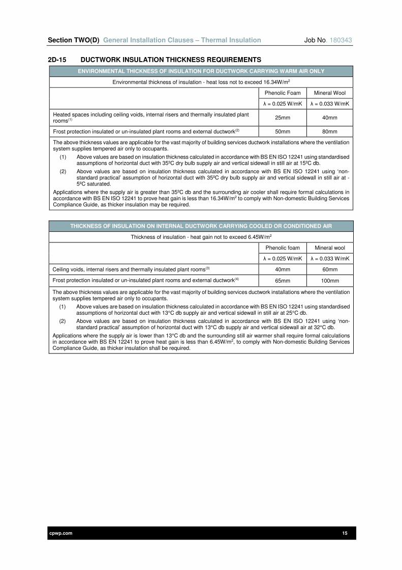
Section TWO(D) General Installation Clauses – Thermal Insulation Job No. 180343
cpwp.com 15
2D-15 DUCTWORK INSULATION THICKNESS REQUIREMENTS
ENVIRONMENTAL THICKNESS OF INSULATION FOR DUCTWORK CARRYING WARM AIR ONLY
Environmental thickness of insulation - heat loss not to exceed 16.34W/m2
Phenolic Foam Mineral Wool
λ = 0.025 W/mK λ = 0.033 W/mK
Heated spaces including ceiling voids, internal risers and thermally insulated plant rooms(1)
25mm 40mm
Frost protection insulated or un-insulated plant rooms and external ductwork(2) 50mm 80mm
The above thickness values are applicable for the vast majority of building services ductwork installations where the ventilation system supplies tempered air only to occupants.
(1) Above values are based on insulation thickness calculated in accordance with BS EN ISO 12241 using standardised assumptions of horizontal duct with 35ºC dry bulb supply air and vertical sidewall in still air at 15ºC db.
(2) Above values are based on insulation thickness calculated in accordance with BS EN ISO 12241 using ‘non-standard practical’ assumption of horizontal duct with 35ºC dry bulb supply air and vertical sidewall in still air at -5ºC saturated.
Applications where the supply air is greater than 35ºC db and the surrounding air cooler shall require formal calculations in accordance with BS EN ISO 12241 to prove heat gain is less than 16.34W/m2 to comply with Non-domestic Building Services Compliance Guide, as thicker insulation may be required.
THICKNESS OF INSULATION ON INTERNAL DUCTWORK CARRYING COOLED OR CONDITIONED AIR
Thickness of insulation - heat gain not to exceed 6.45W/m2
Phenolic foam Mineral wool
λ = 0.025 W/mK λ = 0.033 W/mK
Ceiling voids, internal risers and thermally insulated plant rooms(3) 40mm 60mm
Frost protection insulated or un-insulated plant rooms and external ductwork(4) 65mm 100mm
The above thickness values are applicable for the vast majority of building services ductwork installations where the ventilation system supplies tempered air only to occupants.
(1) Above values are based on insulation thickness calculated in accordance with BS EN ISO 12241 using standardised assumptions of horizontal duct with 13°C db supply air and vertical sidewall in still air at 25°C db.
(2) Above values are based on insulation thickness calculated in accordance with BS EN ISO 12241 using ‘non-standard practical’ assumption of horizontal duct with 13°C db supply air and vertical sidewall air at 32°C db.
Applications where the supply air is lower than 13°C db and the surrounding still air warmer shall require formal calculations in accordance with BS EN 12241 to prove heat gain is less than 6.45W/m2, to comply with Non-domestic Building Services Compliance Guide, as thicker insulation shall be required.

Section TWO(D) General Installation Clauses – Thermal Insulation Job No. 180343
cpwp.com 16
2D-16 PIPEWORK INSULATION THICKNESS REQUIREMENTS
NON-DOMESTIC HEATING WATER SERVICES THERMAL INSULATION
INTERNALLY LOCATED HEATED SPACES - ECA THICKNESSES
Outside pipe diameter
LTHW (≤95ºC) MTHW (96ºC to 120ºC) and
Condensate HTHW (121ºC to 150ºC)
Max. heat loss
Thickness of insulation based on
air at 15ºC
Max. heat loss
Thickness of insulation based on
air at 15ºC
Max. heat loss
Thickness of insulation based on
air at 15ºC
Phenolic Mineral Wool
Phenolic Mineral Wool
Phenolic Mineral Wool
λ = 0.026 W/mK
λ = 0.040 W/mK
N/A λ =
0.045 W/mK
N/A λ =
0.054 W/mK
(mm) (W/m) (mm) (mm) (W/m) (mm) (mm) (W/m) (mm) (mm)
≤17.2 7.78 20 40 10.57 N/A 50 13.27 N/A 70
21.3 8.42 20 40 11.25 N/A 50 14.06 N/A 70
26.9 9.05 25 45 12.06 N/A 65 15.02 N/A 75
33.7 9.86 25 50 13.04 N/A 65 16.07 N/A 80
42.4 10.83 30 55 14.12 N/A 70 17.34 N/A 90
48.3 11.42 30 60 14.8 N/A 75 18.09 N/A 90
60.3 12.61 35 60 16.22 N/A 80 19.62 N/A 100
76.1 14.12 35 65 17.88 N/A 90 21.41 N/A 105
88.9 15.28 35 65 19.2 N/A 90 22.87 N/A 110
114.3 17.51 40 70 21.66 N/A 90 25.53 N/A 115
139.7 19.72 40 70 23.99 N/A 100 27.98 N/A 125
168.3 22.34 45 75 26.63 N/A 100 30.69 N/A 125
219.1 26.61 45 75 31.15 N/A 110 35.25 N/A 135
273 30.91 50 80 35.83 N/A 120 40.05 N/A 140
Vessels & flat surfaces Refer to particulars section Refer to particulars section Refer to particulars section
NON-DOMESTIC HEATING WATER SERVICES THERMAL INSULATION
EXTERNAL AND UNHEATED SPACES
Outside pipe diameter
LTHW (≤95ºC) MTHW (96ºC to 120ºC) and
Condensate HTHW (121ºC to 150ºC)
Max. heat loss
Thickness of insulation based on
air at -5ºC
Max. heat loss
Thickness of insulation based on
air at -5ºC
Max. heat loss
Thickness of insulation based on
air at -5ºC
Phenolic Mineral Wool
Phenolic Mineral Wool
Phenolic Mineral Wool
λ = 0.026 W/mK
λ = 0.040 W/mK
N/A λ =
0.045 W/mK
N/A λ =
0.054 W/mK
(mm) (W/m) (mm) (mm) (W/m) (mm) (mm) (W/m) (mm) (mm)
≤17.2 7.78 30 50 10.57 N/A 65 13.27 N/A 90
21.3 8.42 30 50 11.25 N/A 65 14.06 N/A 90
26.9 9.05 35 60 12.06 N/A 85 15.02 N/A 100
33.7 9.86 35 65 13.04 N/A 85 16.07 N/A 100
42.4 10.83 40 70 14.12 N/A 90 17.34 N/A 120
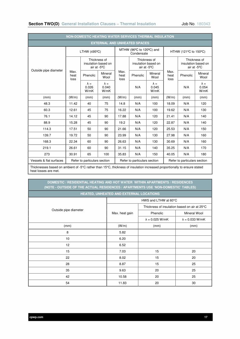
Section TWO(D) General Installation Clauses – Thermal Insulation Job No. 180343
cpwp.com 17
NON-DOMESTIC HEATING WATER SERVICES THERMAL INSULATION
EXTERNAL AND UNHEATED SPACES
Outside pipe diameter
LTHW (≤95ºC) MTHW (96ºC to 120ºC) and
Condensate HTHW (121ºC to 150ºC)
Max. heat loss
Thickness of insulation based on
air at -5ºC
Max. heat loss
Thickness of insulation based on
air at -5ºC
Max. heat loss
Thickness of insulation based on
air at -5ºC
Phenolic Mineral Wool
Phenolic Mineral Wool
Phenolic Mineral Wool
λ = 0.026 W/mK
λ = 0.040 W/mK
N/A λ =
0.045 W/mK
N/A λ =
0.054 W/mK
(mm) (W/m) (mm) (mm) (W/m) (mm) (mm) (W/m) (mm) (mm)
48.3 11.42 40 75 14.8 N/A 100 18.09 N/A 120
60.3 12.61 45 75 16.22 N/A 100 19.62 N/A 130
76.1 14.12 45 90 17.88 N/A 120 21.41 N/A 140
88.9 15.28 45 90 19.2 N/A 120 22.87 N/A 140
114.3 17.51 50 90 21.66 N/A 120 25.53 N/A 150
139.7 19.72 50 90 23.99 N/A 130 27.98 N/A 160
168.3 22.34 60 90 26.63 N/A 130 30.69 N/A 160
219.1 26.61 60 90 31.15 N/A 140 35.25 N/A 170
273 30.91 65 100 35.83 N/A 150 40.05 N/A 180
Vessels & flat surfaces Refer to particulars section Refer to particulars section Refer to particulars section
Thicknesses based on ambient of -5°C rather than 15°C, thickness of insulation increased proportionally to ensure stated heat losses are met.
DOMESTIC / RESIDENTIAL HEATING AND HOT WATER WITHIN APARTMENTS / RESIDENCES
(NOTE - OUTSIDE OF THE ACTUAL RESIDENCES / APARTMENTS USE ‘NON-DOMESTIC’ TABLES)
HEATED, UNHEATED AND EXTERNAL LOCATIONS
Outside pipe diameter
HWS and LTHW at 60°C
Max. heat gain
Thickness of insulation based on air at 25°C
Phenolic Mineral Wool
λ = 0.025 W/mK λ = 0.033 W/mK
(mm) (W/m) (mm) (mm)
8 5.82
10 6.20
12 6.52
15 7.03 15 20
22 8.02 15 20
28 8.87 15 25
35 9.63 20 25
42 10.58 20 25
54 11.83 20 30

Section TWO(D) General Installation Clauses – Thermal Insulation Job No. 180343
cpwp.com 18
CHILLED WATER THERMAL INSULATION
HEATED, UNHEATED AND EXTERNAL LOCATIONS
Outside pipe diameter
CHW Pipes at ≥5°C
Max. heat gain
Thickness of insulation based on air at 25°C
Phenolic Mineral Wool
λ = 0.025 W/mK λ = 0.033 W/mK
(mm) (W/m) (mm) (mm)
≤17.2 2.97 20 25
21.3 3.27 20 30
26.9 3.58 20 30
33.7 4.01 20 30
42.4 4.53 20 35
48.3 4.82 25 35
60.3 5.48 25 35
76.1 6.30 25 35
88.9 6.90 25 35
114.3 8.31 25 40
139.7 9.49 25 40
168.3 10.97 30 40
219.1 13.57 30 40
Vessels and flat surfaces Refer to particulars section
REFRIGERATION PIPEWORK THERMAL INSULATION
HEATED, UNHEATED AND EXTERNAL LOCATIONS
Operating at ≥5°C
Pipe diameter Nominal pipe size Thickness of insulation based on air at 28°C
Metric Imperial λ = 0.035 W/mK
(mm) (“) (mm)
12.7 1/2 19
15.9 5/8 19
19.0 3/4 19
22.2 7/8 19
25.4 1 19
28.6 1 1/8 19
31.8 1 1/4 19
34.9 1 3/8 19
38.1 1 1/2 25
41.3 1 5/8 25
Larger sizes Refer to BS 5422 Annex F
The thermal insulations listed above are for typical IT cooling and for both heat pumps and cooling only comfort systems only. All other refrigeration installations shall be insulated in accordance with BS 5422, in particular Annex F.

Section TWO(D) General Installation Clauses – Thermal Insulation Job No. 180343
cpwp.com 19
NON-DOMESTIC HOT AND COLD WATER SERVICES THERMAL INSULATION
INTERNALLY LOCATED HEATED SPACES - ECA THICKNESSES (HWS ONLY)
Outside pipe diameter
HWS Pipes at 60°C (and 43°C blended) CWS Pipes at >10°C
Max. heat loss
Thickness of insulation based on air at 15°C
Max. heat
gain (1)
Thickness of insulation
(CWS matches HWS)
Phenolic Mineral wool Phenolic Mineral wool
λ = 0.026 W/mK
λ = 0.039 W/mK
λ = 0.025 W/mK
λ = 0.033 W/mK
(mm) (W/m) (mm) (mm) (W/m) (mm) (mm)
≤17.2 6.04 15 30 2.48 15 30
21.3 6.45 20 35 2.72 20 35
26.9 7.00 25 35 3.05 25 35
33.7 7.71 25 40 3.41 25 40
42.4 8.46 25 40 3.86 25 40
48.3 9.01 30 45 4.11 30 45
60.3 9.94 30 45 4.78 30 45
76.1 11.25 30 50 5.51 30 50
114.3 14.29 35 60 7.28 35 60
139.7 16.09 40 60 8.52 40 60
168.3 18.24 40 60 9.89 40 60
219.1 22.06 40 60 12.27 40 60
Vessels and flat surfaces Refer to particulars section Refer to particulars section
(1) – Max heat gain values from table 10 in BS 5422 for cooled and chilled water systems at 10°C.
NON-DOMESTIC HOT AND COLD WATER SERVICES THERMAL INSULATION
UNHEATED AND EXTERNAL SPACES
Outside pipe diameter
HWS Pipes at 60°C (and 43°C blended) CWS Pipes at >10°C
Max. heat loss
Thickness of insulation based on air at -5°C
Max. heat gain
Thickness of insulation (CWS matches HWS)
Phenolic(2) Mineral wool(2) Phenolic(3) Mineral wool(3)
λ = 0.026 W/mK
λ = 0.039 W/mK
λ = 0.025 W/mK
λ = 0.033 W/mK
(mm) (W/m) (mm) (mm) (W/m) (mm) (mm)
≤17.2 (1) 20 35 (1) 20 35
21.3 (1) 25 45 (1) 25 45
26.9 (1) 30 45 (1) 18 45
33.7 (1) 30 50 (1) 24 50
42.4 (1) 30 50 (1) 24 50
48.3 (1) 40 55 (1) 40 55
60.3 (1) 40 55 (1) 40 55
76.1 (1) 40 60 (1) 40 60
114.3 (1) 45 70 (1) 45 70
139.7 (1) 50 70 (1) 50 70
168.3 (1) 50 70 (1) 50 70

Section TWO(D) General Installation Clauses – Thermal Insulation Job No. 180343
cpwp.com 20
NON-DOMESTIC HOT AND COLD WATER SERVICES THERMAL INSULATION
UNHEATED AND EXTERNAL SPACES
Outside pipe diameter
HWS Pipes at 60°C (and 43°C blended) CWS Pipes at >10°C
Max. heat loss
Thickness of insulation based on air at -5°C
Max. heat gain
Thickness of insulation (CWS matches HWS)
Phenolic(2) Mineral wool(2) Phenolic(3) Mineral wool(3)
λ = 0.026 W/mK
λ = 0.039 W/mK
λ = 0.025 W/mK
λ = 0.033 W/mK
(mm) (W/m) (mm) (mm) (W/m) (mm) (mm)
219.1 (1) 50 70 (1) 50 70
Vessels and flat surfaces Refer to particulars section Refer to particulars section
(1) - No specific loss or gain listed under NDBSCG or ECA Guidelines for freezing conditions but maximum permitted heat losses not to exceed values in previous table.
(2) - Thicknesses based on 65K difference (60°C – (-5°C)) rather than 45K (60°C – 15°C).
(3) - Thermal insulation thickness to prevent freezing for 12 hours so all external or at risk cold water pipes MUST also be electrically trace heated.
STEAM SERVICES THERMAL INSULATION
HEATED, UNHEATED AND EXTERNAL LOCATIONS
Outside pipe diameter
Steam Heating (<300°C)
Hot Water Loss
Thickness of insulation based on air at 15°C
Calcium Silicate Mineral Wool
λ = 0.058 W/mK λ = 0.054 W/mK
(mm) (W/m) (mm) (mm)
≤21.3 43.97 80 70
26.9 47.82 95 75
33.7 52.11 100 80
42.4 57.24 110 90
48.3 60.40 110 90
60.3 66.69 120 100
76.1 74.02 125 105
88.9 80.06 130 110
114.3 90.96 135 115
139.7 101.46 140 125
168.3 112.63 140 125
219.1 132.85 160 135
273 & Vessels 152.89 160 140
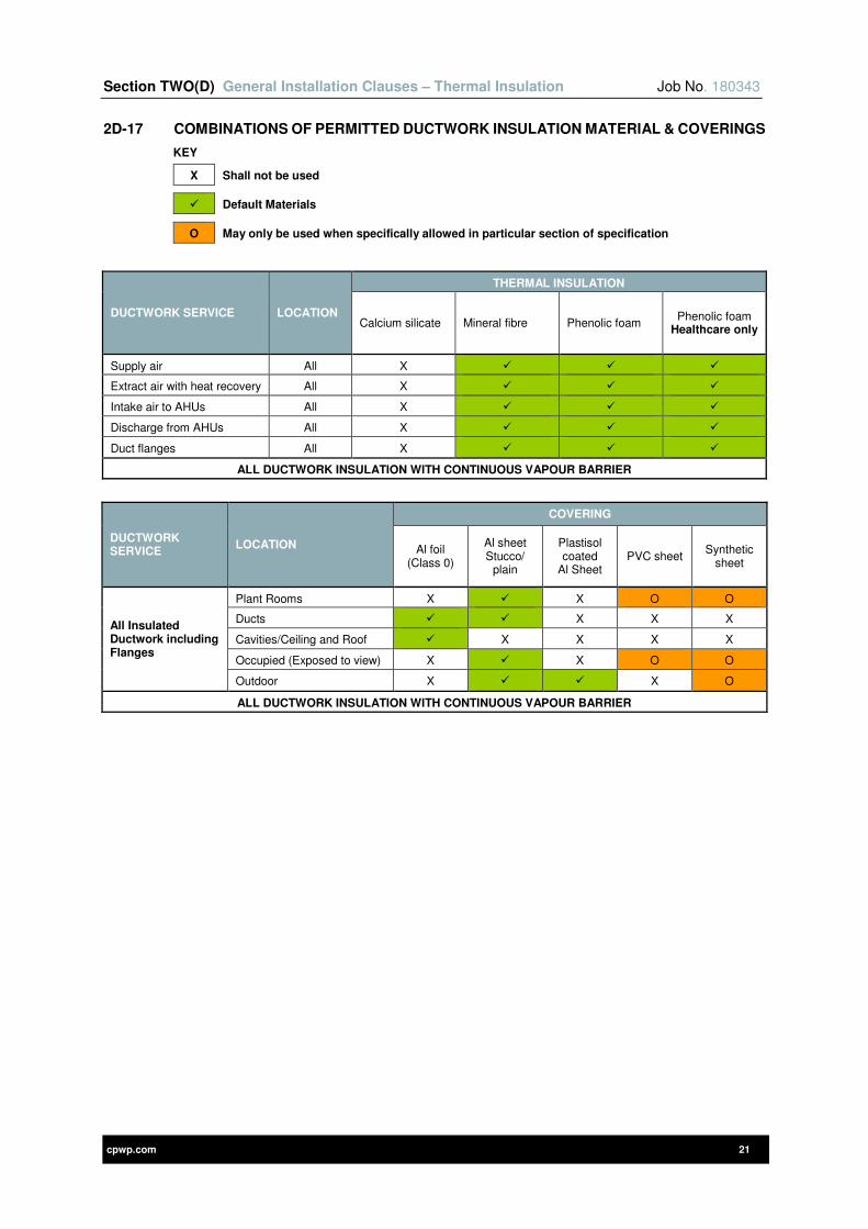
Section TWO(D) General Installation Clauses – Thermal Insulation Job No. 180343
cpwp.com 21
2D-17 COMBINATIONS OF PERMITTED DUCTWORK INSULATION MATERIAL & COVERINGS
KEY
X Shall not be used
Default Materials
O May only be used when specifically allowed in particular section of specification
DUCTWORK SERVICE LOCATION
THERMAL INSULATION
Calcium silicate Mineral fibre Phenolic foam Phenolic foam
Healthcare only
Supply air All X
Extract air with heat recovery All X
Intake air to AHUs All X
Discharge from AHUs All X
Duct flanges All X
ALL DUCTWORK INSULATION WITH CONTINUOUS VAPOUR BARRIER
DUCTWORK SERVICE
LOCATION
COVERING
Al foil (Class 0)
Al sheet Stucco/
plain
Plastisol coated
Al Sheet PVC sheet
Synthetic sheet
All Insulated Ductwork including Flanges
Plant Rooms X X O O
Ducts X X X
Cavities/Ceiling and Roof X X X X
Occupied (Exposed to view) X X O O
Outdoor X X O
ALL DUCTWORK INSULATION WITH CONTINUOUS VAPOUR BARRIER
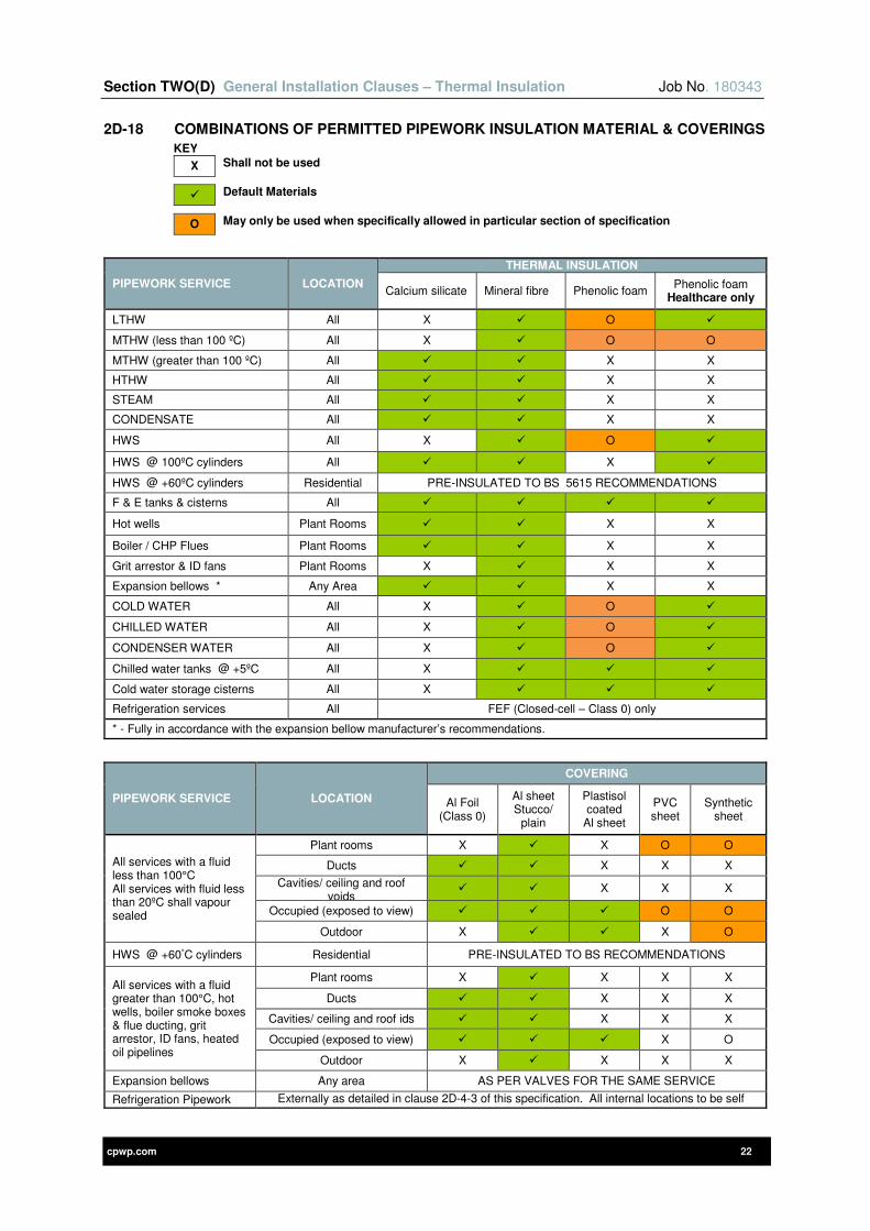
Section TWO(D) General Installation Clauses – Thermal Insulation Job No. 180343
cpwp.com 22
2D-18 COMBINATIONS OF PERMITTED PIPEWORK INSULATION MATERIAL & COVERINGS
KEY
X Shall not be used
Default Materials
O May only be used when specifically allowed in particular section of specification
PIPEWORK SERVICE LOCATION
THERMAL INSULATION
Calcium silicate Mineral fibre Phenolic foam Phenolic foam
Healthcare only
LTHW All X O
MTHW (less than 100 ºC) All X O O
MTHW (greater than 100 ºC) All X X
HTHW All X X
STEAM All X X
CONDENSATE All X X
HWS All X O
HWS @ 100ºC cylinders All X
HWS @ +60ºC cylinders Residential PRE-INSULATED TO BS 5615 RECOMMENDATIONS
F & E tanks & cisterns All
Hot wells Plant Rooms X X
Boiler / CHP Flues Plant Rooms X X
Grit arrestor & ID fans Plant Rooms X X X
Expansion bellows * Any Area X X
COLD WATER All X O
CHILLED WATER All X O
CONDENSER WATER All X O
Chilled water tanks @ +5ºC All X
Cold water storage cisterns All X
Refrigeration services All FEF (Closed-cell – Class 0) only
* - Fully in accordance with the expansion bellow manufacturer’s recommendations.
PIPEWORK SERVICE LOCATION
COVERING
Al Foil (Class 0)
Al sheet Stucco/
plain
Plastisol coated
Al sheet
PVC sheet
Synthetic sheet
All services with a fluid less than 100°C All services with fluid less than 20ºC shall vapour sealed
Plant rooms X X O O
Ducts X X X
Cavities/ ceiling and roof voids
X X X
Occupied (exposed to view) O O
Outdoor X X O
HWS @ +60°C cylinders Residential PRE-INSULATED TO BS RECOMMENDATIONS
All services with a fluid greater than 100°C, hot wells, boiler smoke boxes & flue ducting, grit arrestor, ID fans, heated oil pipelines
Plant rooms X X X X
Ducts X X X
Cavities/ ceiling and roof ids X X X
Occupied (exposed to view) X O
Outdoor X X X X
Expansion bellows Any area AS PER VALVES FOR THE SAME SERVICE
Refrigeration Pipework Externally as detailed in clause 2D-4-3 of this specification. All internal locations to be self finish.

cpwp.com V2.0
Section Two (E) Electrical Workmanship & Materials

Section TWO(E) Electrical Workmanship and Materials Job No. 180343
cpwp.com 1
Contents Page
2E-1 GENERAL DESCRIPTION 4
2E-2 DEFINITIONS 4
2E-3 STANDARDS APPLICABLE 5
2E-4 STATUTORY REGULATIONS AND BS 7671 IET WIRING REGULATIONS 5
2E-5 ELECTRICAL CONTRACTING CERTIFICATION SCHEMES 5
2E-6 THE CONSTRUCTION PRODUCTS REGULATION (CPR) 5
2E-7 ACCESSIBILITY AND MAINTAINABILITY 6
2E-8 PROTECTION AGAINST ELECTRIC SHOCK 6
2E-8-1 AUTOMATIC DISCONNECTION OF SUPPLY 6
2E-9 PROTECTION AGAINST THERMAL EFFECTS 8
2E-9-1 PROTECTION AGAINST IMPACT – CONCEALED CABLING 9
2E-10 IDENTIFICATION, NOTICES AND LABELLING 10
2E-10-1 SAFETY SIGNAGE 10
2E-10-2 IDENTIFICATION, NOTICES AND LABELLING COLOURS / TEXT SIZE 10
2E-10-3 IDENTIFICATION AND LABELLING OF SWITCHGEAR, CONTROLGEAR, ELECTRICAL EQUIPMENT AND WIRING ACCESSORIES 11
2E-10-4 NOTICES AND IDENTIFICATION LABELS – BS 7671 IET WIRING REGULATIONS 15
2E-10-5 DIAGRAMS AND DOCUMENTATION 16
2E-10-6 IDENTIFICATION OF CABLES 18
2E-10-7 IDENTIFICATION OF CONDUCTORS BY COLOUR AND LETTERS / NUMBERS 18
2E-10-8 IDENTIFICATION OF NEW CABLING (HARMONIZED COLOURS) INTERFACED WITH OLD CABLING (NON-HARMONIZED CABLE COLOURS) 20
2E-10-9 TECHNICAL SUBMISSIONS 20
2E-11 EXISTING SUPERVISORY / END-USER MANAGEMENT SOFTWARE 20
2E-12 SELECTION AND ERECTION OF WIRING SYSTEMS TO MINIMIZE THE SPREAD OF FIRE 21
2E-12-1 PRECAUTIONS WITHIN A FIRE SEGREGATED COMPARTMENT 21
2E-12-2 SEALING OF WIRING SYSTEM PENETRATIONS 21
2E-12-3 TECHNICAL SUBMISSIONS 22
2E-13 PROXIMITY OF WIRING SYSTEMS AND MEASURES AGAINST ELECTROMAGNETIC DISTURBANCES 22
2E-13-1 PROXIMITY AND SEGREGATION OF WIRING SYSTEMS 22
2E-13-2 PROXIMITY OF WIRING SYSTEMS TO NON-ELECTRICAL SERVICES 24
2E-13-3 MEASURES AGAINST ELECTROMAGNETIC DISTURBANCES 24
2E-14 EARTHING AND BONDING 25
2E-14-1 EARTHING ARRANGEMENTS 26
Section TWO(E) Electrical Workmanship and Materials Job No. 180343
cpwp.com 2
2E-14-2 PROTECTIVE CONDUCTORS 26
2E-14-3 EARTHING CONDUCTORS 26
2E-14-4 MAIN EARTH TERMINALS (MET) 26
2E-14-5 TELECOMMUNICATION PRIMARY BONDING BUSBARS (PBB) 27
2E-14-6 TELECOMMUNICATION SECONDARY BONDING BUSBARS (SBB) 27
2E-14-7 PROTECTIVE EQUIPOTENTIAL BONDING CONDUCTORS 27
2E-14-8 SUPPLEMENTARY PROTECTIVE EQUIPOTENTIAL BONDING CONDUCTORS 28
2E-14-9 CIRCUIT PROTECTIVE CONDUCTORS 29
2E-15 DEFAULT CABLING AND CABLE SUPPORT / CONTAINMENT SYSTEMS 30
2E-16 CABLE SUPPORT AND CONTAINMENT SYSTEMS 33
2E-16-1 DEFAULT SPARE CAPACITY WITHIN CABLE SUPPORT AND CONTAINMENT SYSTEMS 33
2E-16-2 GENERAL REQUIREMENTS FOR CABLE SUPPORT AND CONTAINMENT SYSTEMS 33
2E-16-3 METAL CHANNEL CABLE SUPPORT SYSTEMS AND OTHER ASSOCIATED SUPPORTS 33
2E-16-4 FIRE RESISTANCE OF CABLE SUPPORT AND CONTAINMENT SYSTEMS 34
2E-16-5 CABLE CLEATS, STRAPPING AND TIES 34
2E-16-6 PROTECTIVE EARTHING (PE) FUNCTION AND ELECTROMAGNETIC DISTURBANCES 35
2E-16-7 CIRCUIT PROTECTIVE CONDUCTORS 35
2E-16-8 CABLE LADDER RACK SYSTEMS 35
2E-16-9 CABLE TRAY SYSTEMS 35
2E-16-10 CABLE BASKET / WIRE MESH TRAY SYSTEMS 36
2E-16-11 CABLE TRUNKING SYSTEMS 36
2E-16-12 DADO, SKIRTING AND BENCH TRUNKING SYSTEMS 37
2E-16-13 CONDUIT AND FITTINGS 38
2E-16-14 BELOW GROUND CABLING 39
2E-16-15 SURFACE / EXPOSED CABLE SUPPORT AND CONTAINMENT SYSTEMS 40
2E-16-16 DESIGN REQUIREMENTS 40
2E-16-17 TECHNICAL SUBMISSIONS 41
2E-17 CABLING AND WIRING SYSTEMS 41
2E-17-1 DEFINITION OF TERMS 41
2E-17-2 GENERAL REQUIREMENTS 41
2E-17-3 MANUFACTURERS’ IDENTIFICATION OF CABLES 41
2E-17-4 GENERAL LV INSTALLATION CABLES 41
2E-17-5 INSTALLATION AND USE OF ‘NON-STANDARD’ CABLES OR CABLES TO BS 8436 42
Section TWO(E) Electrical Workmanship and Materials Job No. 180343
cpwp.com 3
2E-17-6 FIRE RESISTANT CABLES FOR LIFE SAFETY AND FIRE-FIGHTING APPLICATIONS 42
2E-17-7 FIRE PERFORMANCE OF TELECOMMUNICATIONS (VOICE / DATA) CABLING 44
2E-17-8 CABLE SUPPORT AND CONTAINMENT SYSTEMS 44
2E-17-9 CABLE BENDING RADII 44
2E-17-10 CABLE GLANDS 44
2E-17-11 TECHNICAL SUBMISSIONS 45
2E-18 INSTALLATION OF FLAT INSULATED SHEATHED CABLES (FLAT TWIN AND EARTH) 45
2E-19 WIRING ACCESSORIES 47
2E-19-1 DEFAULT WIRING ACCESSORIES 47
2E-19-2 TECHNICAL SUBMISSIONS 49
2E-20 POSITIONING AND MOUNTING HEIGHTS OF ELECTRICAL SERVICES 50
2E-21 FIXINGS TO THE BUILDING STRUCTURE / FABRIC 53
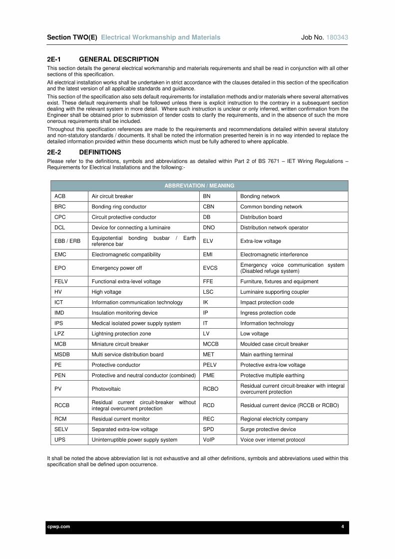
Section TWO(E) Electrical Workmanship and Materials Job No. 180343
cpwp.com 4
2E-1 GENERAL DESCRIPTION
This section details the general electrical workmanship and materials requirements and shall be read in conjunction with all other sections of this specification.
All electrical installation works shall be undertaken in strict accordance with the clauses detailed in this section of the specification and the latest version of all applicable standards and guidance.
This section of the specification also sets default requirements for installation methods and/or materials where several alternatives exist. These default requirements shall be followed unless there is explicit instruction to the contrary in a subsequent section dealing with the relevant system in more detail. Where such instruction is unclear or only inferred, written confirmation from the Engineer shall be obtained prior to submission of tender costs to clarify the requirements, and in the absence of such the more onerous requirements shall be included.
Throughout this specification references are made to the requirements and recommendations detailed within several statutory and non-statutory standards / documents. It shall be noted the information presented herein is in no way intended to replace the detailed information provided within these documents which must be fully adhered to where applicable.
2E-2 DEFINITIONS
Please refer to the definitions, symbols and abbreviations as detailed within Part 2 of BS 7671 – IET Wiring Regulations – Requirements for Electrical Installations and the following:-
ABBREVIATION / MEANING
ACB Air circuit breaker BN Bonding network
BRC Bonding ring conductor CBN Common bonding network
CPC Circuit protective conductor DB Distribution board
DCL Device for connecting a luminaire DNO Distribution network operator
EBB / ERB Equipotential bonding busbar / Earth reference bar
ELV Extra-low voltage
EMC Electromagnetic compatibility EMI Electromagnetic interference
EPO Emergency power off EVCS Emergency voice communication system (Disabled refuge system)
FELV Functional extra-level voltage FFE Furniture, fixtures and equipment
HV High voltage LSC Luminaire supporting coupler
ICT Information communication technology IK Impact protection code
IMD Insulation monitoring device IP Ingress protection code
IPS Medical isolated power supply system IT Information technology
LPZ Lightning protection zone LV Low voltage
MCB Miniature circuit breaker MCCB Moulded case circuit breaker
MSDB Multi service distribution board MET Main earthing terminal
PE Protective conductor PELV Protective extra-low voltage
PEN Protective and neutral conductor (combined) PME Protective multiple earthing
PV Photovoltaic RCBO Residual current circuit-breaker with integral overcurrent protection
RCCB Residual current circuit-breaker without integral overcurrent protection
RCD Residual current device (RCCB or RCBO)
RCM Residual current monitor REC Regional electricity company
SELV Separated extra-low voltage SPD Surge protective device
UPS Uninterruptible power supply system VoIP Voice over internet protocol
It shall be noted the above abbreviation list is not exhaustive and all other definitions, symbols and abbreviations used within this specification shall be defined upon occurrence.

Section TWO(E) Electrical Workmanship and Materials Job No. 180343
cpwp.com 5
2E-3 STANDARDS APPLICABLE
Works shall be completed in accordance with all applicable industry standards. Some of the most relevant standards associated with this section are scheduled below:
STANDARDS AND DOCUMENTS
BS 7671 IET Wiring Regulations – Requirements for Electrical Installations
IET On-Site Guide – BS 7671 – IET Wiring Regulations – Requirements for Electrical Installations
All IET Guidance Notes – BS 7671 – IET Wiring Regulations – Requirements for Electrical Installations
All IET Standards, Codes of Practice & Guidance
All Statutory Regulations (and Associated Memorandum) detailed within Appendix 2 (Informative) ‘Statutory Regulations and Associated Memoranda’ of BS 7671 – IET Wiring Regulations – Requirements for Electrical Installations. Reference shall be made to all official supporting guidance documents
All British Standards detailed within Appendix 1 ‘British Standards To Which Reference Is Made In This Standard’ of BS 7671 – IET Wiring Regulations – Requirements for Electrical Installations
All current and relevant British Standards not detailed within BS 7671 – IET Wiring Regulations – Requirements for Electrical Installations, as referenced throughout this specification
For healthcare projects all current and relevant Health Technical Memorandums (HTM’s) and Health Building Notes (HBN’s), unless clarification / derogation schedules have been produced, agreed and signed off by the Client
All current and relevant Energy Networks Association / ESI publications e.g. Technical Specifications (ENATS), Engineering Recommendations (ER) and Engineering Technical Reports (ETR)
All current and relevant Building Bulletin’s by the DfES (Department for Education and Skills) and other government agencies
All current and relevant CIBSE (Chartered Institution of Building Service Engineers) guides and supporting documentation
NJUG National Joint Utilities Group – NJUG Guidelines – Volumes 1 to 6
The Construction Products Regulation
Construction Products Association – Guidance Note on the Construction Product Regulation
Where the above standards refer to supporting documentation and standards these shall be fully complied with in all respects.
Where discrepancy is found between this specification and the relevant standards, the Contractor shall obtain written clarification from the Engineer prior to submission of the tender. Where a discrepancy has not been clarified prior to tender submission, the Contractor shall include the most onerous requirements.
2E-4 STATUTORY REGULATIONS AND BS 7671 IET WIRING REGULATIONS
The BS 7671 IET Wiring Regulations are non-statutory. However they may be used in a court of law in evidence to claim compliance with a statutory requirement. The principal statutory regulations and associated memorandum with which electrical installations must comply are detailed within Appendix 2 of BS 7671.
All electrical workmanship and materials shall be selected, manufactured, installed, inspected and tested in accordance with the latest version of BS 7671 IET Wiring Regulations – Requirements for Electrical Installations and all supporting IET documentation.
2E-5 ELECTRICAL CONTRACTING CERTIFICATION SCHEMES
The Contractor shall undertake all works in accordance with industry best practice and must be registered with an appropriate certification scheme for the electrical installation works being undertaken. The certification scheme shall provide a six year guarantee on completion of the works to rectify any non-compliance with the Building Regulations and electrical installation standards (including BS 7671 IET Wiring Regulations).
This shall be the National Inspection Council for Electrical Installation Contracting (NICEIC) / ELECSA – Platinum Promise registration scheme, or equivalent.
2E-6 THE CONSTRUCTION PRODUCTS REGULATION (CPR)
The Contractor shall ensure all electrical installation construction products are suitably certified for their intended use and CE marked in strict accordance with the latest requirements of The Construction Products Regulation.
Electrical installation construction products shall be CE marked, accompanied by a declaration of performance (DoP) and covered by a harmonised European product standard (hEN) or European Technical Assessment (ETA).
All power, control and communication cables shall satisfy the requirements of the Construction Products Regulation in respect of their reaction to fire by being provided in strict accordance with their respective European and British Standards e.g. BS 7671, BS 50575, BS 8519, BS 6701, BS 5839, BS 5266 etc.

Section TWO(E) Electrical Workmanship and Materials Job No. 180343
cpwp.com 6
2E-7 ACCESSIBILITY AND MAINTAINABILITY
The accessibility and maintainability of electrical services shall be provided in strict accordance with BS 7671, all supporting IET documentation and manufacturers’ recommendations.
Access and maintainability of electrical equipment shall be provided as follows:-
1) Adequate space shall be provided for the initial installation of equipment and also for its potential replacement at a later date.
2) All equipment shall be installed in such a manner that it is accessible for operation, inspection, testing, fault detection, maintenance and repair.
3) To prevent access by ordinary persons (as defined in BS 7671) equipment shall be located behind lockable doors / covers or shall only be accessible by the use of a tool.
4) Equipment shall be suitably labelled and adequate signage shall be provided e.g. alternative supply or supplies from different sources, installation has wiring colours to two versions of BS 7671 etc. Refer to BS 7671 and the Identification, Notices and Labelling section of this specification for further details.
5) Operating instructions shall be provided adjacent to all items of equipment where their function is not obvious.
6) Where items of equipment have a protective measure in place such as physical protection that may need to be removed or replaced (e.g. the lid of a trunking or conduit box or covers of switchgear), it shall be possible to reinstate the protection to its original state without damaging cabling or equipment.
7) Access shall be provided to all wiring systems and items of equipment where maintenance may be required. Every electrical connection and joint shall be accessible and there shall be adequate working space, except where the following connection types have been made:-
a) Joint designed to be buried in the ground.
b) Compound filled or encapsulated joint.
c) Connection between a cold tail and the heating system e.g. ceiling / floor heating or trace heating system.
d) Joints or connections made in equipment by a manufacturer where access is not required.
e) Equipment complying with BS 5733, suitably marked as a maintenance free accessory and installed in strict accordance with the manufacturer’s recommendations.
8) Suitable access arrangements shall be made for all equipment concealed within roof spaces, ceiling / floor voids and other non-accessible locations e.g. openable or removable access hatches / traps etc. Equipment shall be positioned to suit the access hatches proposed to prevent an unsightly installation.
9) All switchgear and distribution equipment shall be located so that it can be operated and maintained safely.
2E-8 PROTECTION AGAINST ELECTRIC SHOCK
This section of the specification details the general requirements for protection against electric shock which shall be provided in strict accordance with BS EN 61140, BS 7671 and all supporting IET documentation.
Protective measures shall be provided by the following:-
1) Basic protection – Protection against electric shock under fault-free conditions.
2) Fault protection – Protection against electric shock under single fault conditions.
Suitable provisions shall be made in the installation (or installed equipment) where danger or damage is expected to arise due to an interruption of supply.
Additional protection (e.g. RCD’s and supplementary protective equipotential bonding) shall be provided as follows:-
1) Under certain conditions of external influence.
2) Within special locations as detailed within Part 7 of BS 7671.
The following protective measures are permitted which require both basic and fault protection:-
1) Automatic disconnection of supply e.g. protective earthing, protective equipotential bonding, protective devices etc.
2) Double or reinforced insulation e.g. Class II equipment.
3) Electrical separation e.g. safety isolating transformer used to supply equipment (shaver socket).
4) Extra-low voltage (SELV and PELV) e.g. ELV lighting in a special location.
For protection against electric shock automatic disconnection of supply shall be seen as the primary protective measure. However the other forms of protective measure (items 2 to 4 above) shall be provided if required e.g. within special locations.
The following protective measures for application only where the installation is controlled or under supervision of skilled or instructed persons, are not permitted:-
1) Obstacles.
2) Placing out of reach.
3) Non-conducting locations.
4) Protection by earth-free local equipotential bonding.
5) Electrical separation for the supply to more than one item of current-using equipment.
2E-8-1 AUTOMATIC DISCONNECTION OF SUPPLY
The protective measure automatic disconnection of supply shall provide:-
1) Basic protection – Provided by the basic insulation of live parts and/or by barriers or enclosures.
2) Fault protection – Provided by protective earthing, protective equipotential bonding and automatic disconnection in the case of a fault.

Section TWO(E) Electrical Workmanship and Materials Job No. 180343
cpwp.com 7
Where necessary additional protection shall also be provided by RCD’s (RCCB’s or RCBO’s) with rated residual operating current not exceeding 30mA.
BASIC PROTECTION
Basic protection against electric shock under fault-free conditions shall be provided by:-
1) Basic insulation of live parts.
2) Barriers and/or enclosures.
Live parts shall be completely covered with insulation that is suitable for the environment in which it is installed and shall only be removed by destruction. The insulation shall be capable of withstanding the electrical, mechanical, chemical and thermal stresses that it may be subjected to during service.
The insulation to electrical equipment shall comply with the relevant standard(s) for that item of equipment e.g. factory built equipment such as switchgear, control gear, busbars, luminaires, accessories etc.
Basic insulation of live parts shall not be provided by paint, varnish, lacquer or similar products.
Barriers and/or enclosures shall be:-
1) Provided to prevent contact with live parts and shall provide at least the degree of protection (IP code) of IPXXB or IP2X. However a horizontal or top surface of a barrier or enclosure which is readily accessible shall provide at least the degree of protection (IP code) of IPXXD or IP4X.
2) Suitable for the environment in which they are installed.
The removal of barriers, opening of enclosures and removal of parts of enclosures shall only be possible by one of the following:-
1) By the use of a key or tool.
2) After disconnection of the supply to live parts that are protected by the barriers or enclosures e.g. door-interlocked isolators etc.
3) Where an intermediate barrier is provided to IPXXB or IP2X, by the use of a key or tool to remove the barrier.
A suitable warning label shall be provided where behind a barrier or in an enclosure, an item of equipment such as a capacitor may retain a dangerous electrical charge after it has been switched off.
FAULT PROTECTION
The protective measure automatic disconnection of supply shall be provided by:-
1) Protective earthing.
2) Protective equipotential bonding.
3) Automatic disconnection in case of a fault.
Protective earthing and equipotential bonding shall be provided as detailed within the Earthing and Bonding section within this section of the specification.
When an earth fault occurs the resistance of the earth fault loop (Zs = R1 + R2 + Ze) shall be low enough for a large fault current to flow and operate a protective device in the required disconnection time, therefore achieving automatic disconnection of the circuit line conductor.
The disconnection times required by BS 7671 for 230 / 400V circuits can be summarised as follows:-
EARTHING SYSTEM
FINAL CIRCUITS NOT EXCEEDING 63A FOR SOCKET-OUTLETS & 32A FOR FIXED EQUIPMENT (SEE NOTE 1)
DISTRIBUTION CIRCUITS, FINAL CIRCUITS
EXCEEDING 63A FOR SOCKET-OUTLETS & 32A FOR FIXED EQUIPMENT
(seconds)
UO = 230 V AC
(seconds)
UO = 400 V AC
(seconds)
TN-C, TN-S & TN-C-S(PME) 0.4 0.2 5
TT 0.2 0.07 1
The electrical installation shall not rely upon on the operation of residual current devices (RCD’s, RCCB’s and RCBO’s) to achieve the required disconnection time.
ADDITIONAL PROTECTION
Additional protection shall be provided when there is an increased risk of electric shock and shall include:-
1) Residual current devices (RCD’s, RCCB’s and RCBO’s).
2) Supplementary protective equipotential bonding.
Additional protection shall:
1) Not be used as a sole means of protection against electric shock.
2) Be provided by RCD’s (RCCB’s or RCBO’s) with a rated residual operating current not exceeding 30mA and an operating time not exceeding 40ms at a residual current of 5 I∆n (150mA for I∆n = 30mA).
This additional protection shall be provided for:-
1) Socket-outlets with a rated current not exceeding 32A.
Note: A lighting distribution unit complying with BS 5733, luminaire track system, installation coupler, LSC or DCL is not regarded as a socket-outlet with regards to this requirement.
2) Mobile equipment with a current rating not exceeding 32A for use outdoors.
Section TWO(E) Electrical Workmanship and Materials Job No. 180343
cpwp.com 8
3) Within (household) premises, AC final circuits supplying luminaires.
4) Locations containing a bath or shower, all LV final circuits:-
a) Serving a location containing a bath or shower.
b) Passing though zones 1 and/or 2 of a location containing a bath or shower, however not serving the location itself.
5) External lighting LV final circuits to bike stores, telephone kiosks, bus shelters, advertising panels and town plans.
6) Where additional protection is required within special locations as required by Part 7 of BS 7671.
This additional protection for socket outlets with a rated current not exceeding 32A can be excluded where a documented risk assessment determines that RCD protection is not required (not applicable to dwellings).
The documented risk assessment must be undertaken by the building owner / employer of persons within the building.
However this additional protection shall not be excluded unless detailed elsewhere within this specification. If excluded it shall be noted within the ‘FOR DESIGN’ section of the electrical installation certificates and the documented risk assessment shall be appended.
Additional protection shall also be provided by supplementary protective equipotential bonding conductors between simultaneous accessible exposed-conductive-parts and extraneous-conductive parts. This additional protection shall be provided:-
1) Where the automatic disconnection cannot be achieved in the time required by BS 7671.
2) Where additional protection is required within special locations as required by Part 7 of BS 7671.
It shall be noted the supplementary protective equipotential bonding and RCD technical requirements / arrangements (residual operating current, operating time etc.) vary for some of the special locations.
2E-9 PROTECTION AGAINST THERMAL EFFECTS
Arc fault detection devices (AFDD) conforming to BS EN 62606 shall be provided as a means of additional protection against fire caused by arc faults in AC final circuits.
AFDD’s shall be provided for the following locations as recommended by BS 7671 and as specified within this specification and/or drawings:-
1) Premises with sleeping accommodation.
2) Locations with a risk of fire due to the nature of processed or stored materials, i.e. BE2 locations (e.g. barns, woodworking shops, store of combustible materials).
3) Locations with combustible construction materials, i.e. CA2 locations (e.g. wooden buildings).
4) Fire propagating structures, i.e. CB2 locations.
5) Locations with endangering of irreplaceable goods.
AFDD’s shall be installed:-
1) At the origin of the final circuits to be protected, and
2) In AC single-phase circuits not exceeding 230V.
AFDD’s shall be co-ordinated with overcurrent / residual current protective devices and installed in strict accordance with manufacturers’ literature.
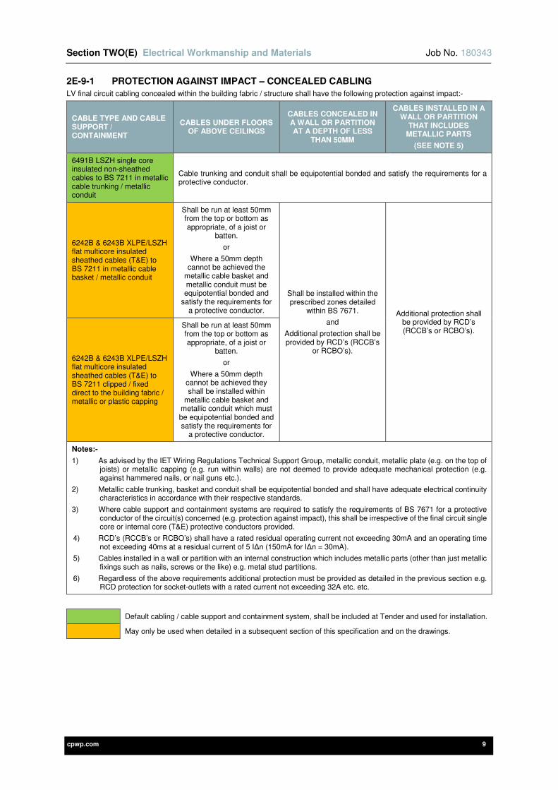
Section TWO(E) Electrical Workmanship and Materials Job No. 180343
cpwp.com 9
2E-9-1 PROTECTION AGAINST IMPACT – CONCEALED CABLING
LV final circuit cabling concealed within the building fabric / structure shall have the following protection against impact:-
CABLE TYPE AND CABLE SUPPORT / CONTAINMENT
CABLES UNDER FLOORS OF ABOVE CEILINGS
CABLES CONCEALED IN A WALL OR PARTITION AT A DEPTH OF LESS
THAN 50MM
CABLES INSTALLED IN A WALL OR PARTITION
THAT INCLUDES METALLIC PARTS
(SEE NOTE 5)
6491B LSZH single core insulated non-sheathed cables to BS 7211 in metallic cable trunking / metallic conduit
Cable trunking and conduit shall be equipotential bonded and satisfy the requirements for a protective conductor.
6242B & 6243B XLPE/LSZH flat multicore insulated sheathed cables (T&E) to BS 7211 in metallic cable basket / metallic conduit
Shall be run at least 50mm from the top or bottom as appropriate, of a joist or
batten.
or
Where a 50mm depth cannot be achieved the
metallic cable basket and metallic conduit must be equipotential bonded and
satisfy the requirements for a protective conductor.
Shall be installed within the prescribed zones detailed
within BS 7671.
and
Additional protection shall be provided by RCD’s (RCCB’s
or RCBO’s).
Additional protection shall be provided by RCD’s (RCCB’s or RCBO’s).
6242B & 6243B XLPE/LSZH flat multicore insulated sheathed cables (T&E) to BS 7211 clipped / fixed direct to the building fabric / metallic or plastic capping
Shall be run at least 50mm from the top or bottom as appropriate, of a joist or
batten.
or
Where a 50mm depth cannot be achieved they shall be installed within
metallic cable basket and metallic conduit which must be equipotential bonded and satisfy the requirements for
a protective conductor.
Notes:-
1) As advised by the IET Wiring Regulations Technical Support Group, metallic conduit, metallic plate (e.g. on the top of joists) or metallic capping (e.g. run within walls) are not deemed to provide adequate mechanical protection (e.g. against hammered nails, or nail guns etc.).
2) Metallic cable trunking, basket and conduit shall be equipotential bonded and shall have adequate electrical continuity characteristics in accordance with their respective standards.
3) Where cable support and containment systems are required to satisfy the requirements of BS 7671 for a protective conductor of the circuit(s) concerned (e.g. protection against impact), this shall be irrespective of the final circuit single core or internal core (T&E) protective conductors provided.
4) RCD’s (RCCB’s or RCBO’s) shall have a rated residual operating current not exceeding 30mA and an operating time not exceeding 40ms at a residual current of 5 I∆n (150mA for I∆n = 30mA).
5) Cables installed in a wall or partition with an internal construction which includes metallic parts (other than just metallic fixings such as nails, screws or the like) e.g. metal stud partitions.
6) Regardless of the above requirements additional protection must be provided as detailed in the previous section e.g. RCD protection for socket-outlets with a rated current not exceeding 32A etc. etc.
Default cabling / cable support and containment system, shall be included at Tender and used for installation.
May only be used when detailed in a subsequent section of this specification and on the drawings.

Section TWO(E) Electrical Workmanship and Materials Job No. 180343
cpwp.com 10
2E-10 IDENTIFICATION, NOTICES AND LABELLING
This section of the specification details the general requirements for the provision of identification, notices and labelling. Identification, notices and labelling shall be provided in strict accordance with site standards, BS 7671, all supporting IET documentation and the respective standards for different systems. The identification, notices and labelling systems shall also be in accordance with any existing site standards and shall be agreed with the Engineer prior to installation.
Where a location is to be defined on labelling, diagrams, schedules / charts the room numbers / names used shall be co-ordinated with the current architectural drawings and the site room referencing system.
2E-10-1 SAFETY SIGNAGE
Safety signage shall be:-
1) Provided as required for the electrical installation in strict accordance with The Health and Safety (Safety and Signals) Regulations – Guidance on Regulations – HSE L64, BS 5499, BS ISO 3864 and BS EN ISO 7010.
2) Clearly visible and adequately illuminated by both general lighting and emergency lighting as required e.g. emergency lighting to fire and safety signage. Illuminated safety signs shall be clearly visible and provided in strict accordance with their respective standards e.g. BS 5266.
3) Provided in the following geometric shapes, safety colours and contrast colours:-
SIGN / NOTICE / IDENTIFICATION MEANING
GEOMETRIC SHAPE
SAFETY COLOUR
CONTRAST COLOUR
GRAPHICAL SYMBOL COLOUR
INSTRUCTION AND INFORMATION
Prohibition sign Circle with
diagonal bar Red White Black
A sign prohibiting behavior likely to increase or cause danger e.g. no access for unauthorised persons etc.
Mandatory sign Circle Blue White White
A sign prescribing specific behavior e.g. eye protection or protective clothing must be worn etc.
Warning sign
Equilateral triangle with
radiused outer corners
Yellow Black Black
A sign giving warning of a hazard or danger e.g. danger: electricity, nominal voltage exceeding 230 V to earth etc.
Emergency escape or first-aid sign
Rectangle (square or
oblong) Green White White
A sign giving information on emergency exits, first aid, or rescue facilities e.g. emergency exit / escape route.
Fire / fire-fighting equipment
Rectangle (square or
oblong) Red White White
A sign giving information on the identification and location of fire equipment e.g. fire alarm call point etc.
2E-10-2 IDENTIFICATION, NOTICES AND LABELLING COLOURS / TEXT SIZE
All labelling used for the identification of electrical services shall be provided in the following colours:-
SIGN / NOTICE / IDENTIFICATION TYPE
BACKGROUND COLOUR
TEXT COLOUR NOTES
General information White Black
Labelling of general switchgear, electrical equipment and wiring accessories
e.g. low voltage switch panels, MCCB panel boards, MCB distribution boards, consumer units, fuse switch and switch fuse disconnectors, isolators, power factor correction and voltage optimization unit, surge protection devices, energy metering, wiring accessories etc.
Fire / fire-fighting equipment
Red White
Labelling of fire / fire-fighting equipment
e.g. fire alarm panels, emergency voice communication system (disabled refuge) panels and associated outstations, voice alarm panels, disabled persons call system indication units / panels, final circuits that feed fire / fire-fighting equipment etc.
Fire alarm devices White Red Labelling of fire alarm devices
e.g. loop number, device number and device type
Section TWO(E) Electrical Workmanship and Materials Job No. 180343
cpwp.com 11
Identification and labelling of electrical services shall be carried out using a mixture of traffolyte or printed adhesive labels, depending on the application, as specified hereafter.
The text to Traffolyte labelling shall be in capital letters and the height of the lettering shall be provided in the following sizes:-
1) 25mm for warning notices.
2) 12mm for primary identification labels.
3) 6mm for secondary identification labels.
Traffolyte labelling shall be fixed by either screws or bolts (not adhesive). Label fixings shall be as follows:-
1) Labels with a height of 25mm or more shall have four fixings one in each corner.
2) Labels with a height of less than 25mm shall have two fixings either side.
The text to printed labelling shall be in capital letters and shall be 6mm in height. Printed labelling shall be of the adhesive tape style (e.g. Brother / DYMO adhesive tape or similar).
2E-10-3 IDENTIFICATION AND LABELLING OF SWITCHGEAR, CONTROLGEAR, ELECTRICAL EQUIPMENT AND WIRING ACCESSORIES
GENERAL REQUIREMENTS
The general requirements are as follows:-
1) Each item of switchgear, controlgear and electrical equipment shall be provided with labelling that indicates its purpose. Wiring systems shall be suitably labelled so that they can be easily identified for inspection, testing, repair or alteration of the installation.
2) Switchgear and controlgear terminals shall be marked in accordance with BS 5472 and BS 6272.
3) Protective devices shall be suitably labelled so that the circuit protected may be easily identified by the user and in strict accordance with BS EN 61439.
4) Indicating equipment shall be provided in strict accordance with BS EN 60073 and BS EN 60447, where the remote operation of switchgear is necessary.
5) All switchrooms (including rooms containing standby battery systems e.g. UPS’s, PV off-grid systems, emergency lighting systems etc.), cupboards and risers shall have suitable warning signs such as no access for unauthorised persons – keep locked at all times, danger electricity etc.
6) A laminated ‘Electric shock: First aid procedures’ (resuscitation) poster shall be provided adjacent to every low voltage switch panel, MCCB panel board and MSDB multi-service distribution board.
7) All switchgear reference numbers / codes shall be coordinated throughout and the same on all identification labels, schedules and drawings.
8) Traffolyte identification labels shall be provided to every termination or joint box and shall indicate the type of service contained e.g. fire alarm etc.
9) Additional labelling shall be provided as required by BS 7671 and detailed below e.g. nominal voltage exceeding 230 V to earth, alternative supply or supplies from different sources or circuits etc. etc.
10) Handwritten notices and identification labels are not acceptable under any circumstances.
Labelling shall be provided as follows:-
LOW VOLTAGE SWITCH PANELS AND FEEDER PILLARS
Traffolyte labelling shall be provided externally to all low voltage switch panels and shall clearly indicate the following:-
1) Switchgear / equipment reference number.
2) General description.
3) Form and type.
4) IP rating.
5) Origin / source of supply (e.g. FED FROM …).
6) Earthing arrangements e.g. TN-C, TN-S, TN-C-S (PME), TT, IT.
7) Nominal voltage, U/Uo in V, Nominal frequency, f in Hz, Rated fault current, Ipf in kA, Busbar rated current, I in A.
8) Incoming device BS (EN) number, type, rated current in A (e.g. disconnector / main switch).
or,
Incoming protective device BS (EN) number, type, rated current in A and settings.
9) Incoming supply cable(s) circuit reference / number, no. of cables, no. of cores, size and type.
10) Incoming protective conductor cable(s) circuit reference / number, no. of cables, no. of cores, size and type (if separate).
11) Weight in kg.
12) Manufacturer’s details.
13) Date of installation in DD/MM/YYYY.
Traffolyte labelling shall also be provided externally to all outgoing ways of low voltage switch panels and internally to all outgoing ways of low voltage feeder pillars. For each outgoing way the labelling shall clearly indicate the following:-
1) Circuit description and the supplied switchgear / equipment reference number (including labelling to all spare ways).
2) Destination location of the outgoing circuit including the building, floor and room number.
3) Protective device BS (EN) number, type, rated current in A and settings (including to all spare ways where a protective device has been provided for future use).
Section TWO(E) Electrical Workmanship and Materials Job No. 180343
cpwp.com 12
4) Outgoing sub-main cable(s) circuit reference / number, no. of cables, no. of cores, size and type (including line conductor if applicable e.g. if single phase L1. etc.).
5) Outgoing protective conductor cable(s) circuit reference / number, no. of cables, no. of cores, size and type (if separate).
6) Date of installation in DD/MM/YYYY.
MCCB PANEL BOARDS, MSDB MULTI SERVICE DISTRIBUTION BOARDS, MCB DISTRIBUTION BOARDS AND CONSUMER UNITS
Traffolyte labelling shall be provided externally to all MCCB panel boards, MSDB multi-service distribution boards, MCB distribution boards and consumer units. It shall clearly indicate the following:-
1) Switchgear / equipment reference number.
2) General description.
3) Form and type (MCCB panel boards only).
4) IP rating.
5) Origin / source of supply (e.g. FED FROM …).
6) Earthing arrangements e.g. TN-C, TN-S, TN-C-S (PME), TT, IT.
7) Nominal voltage, U/Uo in V, Nominal frequency, f in Hz, Rated fault current, Ipf in kA, Busbar rated current, I in A.
8) Incoming device BS (EN) number, type, rated current in A (e.g. disconnector / main switch).
or,
Incoming protective device BS (EN) number, type, rated current in A and settings.
9) Incoming supply cable(s) circuit reference / number, no. of cables, no. of cores, size and type.
10) Incoming protective conductor cable(s) circuit reference / number, no. of cables, no. of cores, size and type (if separate).
11) Date of installation in DD/MM/YYYY.
Printed labelling (e.g. Brother / DYMO adhesive tape or similar) shall also be provided internally to MCCB panels boards, MCB distribution boards and consumer units. Labels shall be fixed to the manufacturer’s internal labelling boxes adjacent to each outgoing way / circuit. For each outgoing way the labelling shall clearly indicate the following:
1) Circuit description and the supplied switchgear / equipment reference number or final circuit type e.g. DB1, DB2, ring circuit, radial circuit etc.
(Including labelling to all spare ways).
2) Destination location of the outgoing circuit including the building, floor and room number.
Further technical details shall be provided on the schedules / charts provided internally for each MCCB panel board, MCB distribution and consumer unit (see section below).
ISOLATORS, FUSE SWITCH / SWITCH FUSE DISCONNECTORS AND OTHER INDUSTRIAL SWITCHGEAR
Traffolyte labelling shall be provided externally to all isolators, fuse switch / switch fuse disconnectors and other industrial switchgear. It shall clearly indicate the following:-
1) Switchgear / equipment reference number.
2) General description.
3) IP Rating.
4) Origin / source of supply (e.g. FED FROM …).
5) Earthing arrangements e.g. TN-C, TN-S, TN-C-S (PME), TT, IT.
6) Nominal voltage, U/Uo in V, Nominal frequency, f in Hz, Rated fault current, Ipf in kA, Busbar rating, I in A.
7) Device BS (EN) number, type, rated current in A (e.g. disconnector / main switch).
or,
Protective device BS (EN) number, type, rated current in A and settings.
8) Circuit description and the supplied switchgear / equipment reference number.
9) Destination location of the outgoing circuit including the building, floor and room number.
10) Date of installation in DD/MM/YYYY.
CONTACTORS
Traffolyte labelling shall be provided externally to all contactor enclosures and shall clearly indicate the following:
1) Switchgear / equipment reference number.
2) General description.
3) No. of poles, Coil control voltage in V, Contactor rating in kW / V / I.
4) Date of installation in DD/MM/YYYY.
POWER FACTOR CORRECTION UNITS
Traffolyte labelling shall be provided externally to all power factor correction units and shall clearly indicate the following:-
1) Switchgear / equipment reference number.
2) General description.
3) Origin / source of supply (e.g. FED FROM …).
4) Rating in kVAr and number of stages e.g. 50 kVAr in 2 x 25 kVAr stages, 300 kVAr in 6 x 50 kVAr stages etc.
5) Date of installation in DD/MM/YYYY.

Section TWO(E) Electrical Workmanship and Materials Job No. 180343
cpwp.com 13
SURGE PROTECTION DEVICES
Traffolyte labelling shall be provided externally to all surge protection device enclosures and shall clearly indicate the following:-
1) Switchgear / equipment reference number.
2) General description.
3) Origin / source of supply (e.g. FED FROM …).
4) Classification e.g. Type 1, Type 2 or Type 3.
5) Date of installation in DD/MM/YYYY.
ENERGY METERING
Traffolyte labelling shall be provided externally to all metering enclosures and shall clearly indicate the following:-
1) Equipment reference number.
2) General description.
3) Date of installation in DD/MM/YYYY.
FIRE-FIGHTING / LIFE SAFETY AND SECURITY EQUIPMENT
Traffolyte labelling shall be provided externally to all fire-fighting / life safety and security control equipment, such as:
1) Fire alarm panels (including repeaters) and fire alarm interfaces.
2) Fire-fighters switches.
3) Emergency voice communication system (disabled refuge) master control panels and outstations.
4) Disabled persons call system control panels (including repeaters).
5) Voice alarm racks and voice alarm / public address (PA) microphone controllers / panel.
6) Emergency lighting control panels and central battery systems.
7) Fire suppression / gas extinguishing system control panels (including repeaters).
8) Smoke and heat control panels.
9) Intruder alarm panels, remote input / output modules and all other security systems equipment (e.g. data racks, NVR’s etc.).
It shall be noted that the above list is not exhaustive and traffolyte labelling shall be provided to all fire-fighting / life safety and security control equipment.
The labelling shall clearly indicate the following:-
1) Equipment reference number.
2) General description.
3) Manufacturer’s details.
4) Date of installation in DD/MM/YYYY.
All standby batteries associated with fire-fighting / life safety equipment shall be labelled with their battery autonomy and the date of installation DD/MM/YYYY.
Every protective device or isolator that supplies life safety / fire-fighting equipment shall be suitably labelled in accordance with the relevant standards and documentation.
For example protective devices or isolators that supply fire alarm, emergency voice communication systems, voice alarms and fire suppression / gas extinguishing systems shall be labelled as follows (suitably changed dependent on the type of system):-
1) “FIRE ALARM”, in the case of a protective device that only serves the fire alarm panel, but incorporates no switch.
Or
2) “FIRE ALARM SYSTEM. DO NOT TURN OFF”, in the case of a switch (whether incorporating a protective device or not) that serves only the fire alarm panel.
Or
3) “WARNING. THIS SWITCH ALSO CONTROLS THE SUPPLY TO THE FIRE ALARM SYSTEM”, in the case any switch that disconnects the mains supply to both the fire alarm system and to other circuits.
Where a protective device or isolating switch common to the fire alarm system and the voice alarm system is used, it shall be labelled ‘FIRE ALARM/VOICE ALARM’.
Junction boxes associated with fire-fighting / life safety equipment shall be labelled with the name of the system e.g. ‘EMERGENCY VOICE COMMUNICATION SYSTEM’ etc.
All emergency voice communication systems outstations shall be labelled with simple pictogram instructions on how to initiate a call.
All fire alarm devices shall be identified by printed adhesive labelling that shall include the loop number, device number and device type.
All fire-fighters switches shall be labelled with:
1) ‘ON’ and ‘OFF’ positions, in letters not less than 10mm high (Note: The ‘ON’ position means powered and the ‘OFF’ position means unpowered).
2) Letters reading ‘FIREFIGHTER’S SWITCH’ or ‘FIRE SWITCH’ in letters not less than 10mm high.
Once installed the fire-fighters switch handle off position shall be up.
Section TWO(E) Electrical Workmanship and Materials Job No. 180343
cpwp.com 14
External fire-fighters switches shall have Traffolyte labelling and shall have lettering that is easily legible from a distance appropriate to the site conditions. Internal fire-fighters switches shall be labelled using manufacturers proprietary labels. Where more than one fire-fighters switch is installed within a building each switch shall be clearly labelled as to its function using Traffolyte labelling.
Disabled persons call system remote indicators shall have printed adhesive labels (e.g. Brother / DYMO adhesive tape or similar) that indicate the location of the alarm e.g. floor / room number. Room numbers shall be co-ordinated with the architectural drawings and the site room referencing system.
All fire suppression / gas extinguishing system devices shall be identified by printed adhesive labelling. Manual extinguishant release devices (e.g. yellow break glass units) shall be labelled ‘EXTINGUISHANT RELEASE’.
Where a time delay facility is provided, the system may be equipped with a single action, biased emergency hold device. Where provided this shall be distinguishable for all other operating devices and shall be white with a red button, labelled ‘EXTINGUISHANT HOLD-OFF’. Cylinders shall be fitted with labels providing handling, maintenance and recharge instructions.
All security devices shall also be identified by printed adhesive labelling that shall include ID references etc.
LIGHTNING PROTECTION SYSTEMS
Manufacturers’ proprietary covers for inspection pits shall be permanently labelled ‘EARTH ROD’.
PHOTOVOLTAIC SYSTEMS
Traffolyte labelling shall be provided externally to all photovoltaic equipment e.g. inverters, PV array charge controllers, battery systems etc. and shall clearly indicate the following:-
1) Equipment reference number.
2) General description.
3) Technical performance data.
4) Manufacturer’s details.
5) Date of installation in DD/MM/YYYY.
MCB distribution boards, isolators, switch disconnectors, contactors and metering shall be labelled as detailed in the above sections.
The following labelling shall also be provided:-
1) DC cabling shall be labelled at 5 to 10m intervals with the warning signage ‘DANGER – SOLAR PV ARRAY CABLE – HIGH VOLTAGE DC – LIVE DURING DAYLIGHT’ or similar.
2) Plugs and socket connectors shall be labelled with the warning signage ‘DO NOT DISCONNECT DC PLUGS AND SOCKETS UNDER LOAD – TURN OFF AC SUPPLY FIRST’ or similar.
3) DC junction boxes shall be labelled with the warning signage ‘DANGER – PV ARRAY DC JUNCTION BOX – CONTAINS LIVE PARTS DURING DAYLIGHT’ or ‘WARNING – PV SYSTEM – PARTS INSIDE THIS BOX OR ENCLOSURE MAY STILL BE LIVE AFTER ISOLATION FROM THE SUPPLY’ or similar.
4) Main switch disconnector(s) for DC isolation and switching shall be labelled with the warning signage ‘DANGER – PV ARRAY DC ISOLATOR’. With labelling also provided to switch enclosures ‘DANGER – PV ARRAY DC ISOLATOR – CONTAINS LIVE PARTS DURING DAYLIGHT’ or similar.
5) Inverters shall be labelled with the warning signage ‘INVERTER – ISOLATE AC AND DC BEFORE CARRYING OUT WORK’ or similar.
6) Main isolators to isolate the entire AC side of the PV system shall be labelled with the warning signage ‘PV SYSTEM – MAIN AC ISOLATOR’ or similar.
7) PV array charge controllers shall be labelled with the warning signage ‘WARNING – PV SYSTEM – PARTS INSIDE THIS BOX OR ENCLOSURE MAY STILL BE LIVE AFTER ISOLATION FROM THE SUPPLY’ or similar.
8) Protective devices for battery systems shall be labelled with the warning signage ‘WARNING – PV SYSTEM – PARTS INSIDE THIS BOX OR ENCLOSURE MAY STILL BE LIVE AFTER ISOLATION FROM THE SUPPLY’ and ‘DC SUPPLY (insert voltage) V DC’.
9) Switch disconnectors for the isolation of battery systems shall be labelled with the warning signage ‘DANGER – PV SYSTEM DC ISOLATOR – CONTAINS LIVE PARTS DURING DAYLIGHT’ and ‘DC SUPPLY (insert voltage) V DC’.
10) Batteries shall be labelled with the warning signage ‘DC SUPPLY (insert voltage) V DC’.
11) Multiple supply warning labels with the signage ‘WARNING – MULTIPLE SUPPLIES – ISOLATE ALL ELECTRICAL SUPPLIES BEFORE CARRYING OUT WORK – ISOLATE MAINS AT … – ISOLATE ALTERNATIVE SUPPLIES AT …’, shall be provided at the following locations:-
a) Electrical intake.
b) Meter positions.
c) All points of isolation between the PV system and the electrical intake e.g. AC isolators, LV switchgear, PV MCB distribution boards etc.
The warning signage shall clearly indicate the location of the PV systems main AC isolator(s).
12) Fire and rescue notification / warning signage ‘SOLAR PV ON ROOF’ shall be provided adjacent to the electrical intake and adjacent to the main fire alarm panel. The warning label shall be at least 100mm x 100mm.
HIDDEN SERVICES
In the case of services that are to be concealed above ceilings, colour coded identification markers shall be provided which shall be fixed to the underside of ceilings. The colour coded markers shall be fully co-ordinated with O&M manuals / as-installed information.
The following services shall be identified:-
Section TWO(E) Electrical Workmanship and Materials Job No. 180343
cpwp.com 15
1) Concealed power supply units.
2) Fire alarm detectors and interfaces.
3) Smoke / fire dampers.
4) Valves / commissioning set etc.
Fire alarm remote indicators shall be clearly labelled to indicate their function. They shall be sited and/or labelled in such a way as to assist in determining the location of the detectors that they serve.
The appearance and use of colour coded markers must be agreed with the Engineer, Architect and Contract Administrator prior to installation.
WIRING ACCESSORIES
Wiring accessories shall be provided as follows:-
1) The face plates of all accessories such as socket outlets, fused connection units, isolators, light switches, scene setting panels, shaver socket outlets, cooker control units etc. shall have printed adhesive labels that indicate the distribution board from which they are fed and their final circuit reference.
e.g. Ground Floor Distribution Board No. 1 = DB/GF1/1L1
2) All final circuit references shall be coordinated throughout and the same on all accessories, schedules and drawings.
3) All fused connection units and isolators shall be labelled as to their purpose. Where available from the specified accessory range, accessories shall have integral labelling e.g. water heater, cooker, isolator (3 pole fans) etc.
4) Socket outlets identified for cleaners use shall have the integral engraved labelling ‘CLEANERS SOCKET’.
5) Light switches and scene setting panels shall be labelled as to their purpose. The buttons of scene setting panels shall be labelled showing all scene setting options / programmes, to provide ease of use e.g. Scene 1 – On etc. Where it is not possible to detail the options / programmes on the scene setting panel buttons, a small laminated clearly legible pictogram shall be permanently fixed adjacent to the devices.
6) Small laminated pictograms shall also be permanently fixed adjacent to all devices where there is sufficient space for printed adhesive labelling e.g. lighting grid switches etc.
7) All data outlets shall have printed adhesive labels that indicate their patch panel ID reference.
Traffoltye labelling shall be used for all external accessories and those located within dedicated electrical switch rooms, plant rooms and service risers.
MECHANICAL CONTROL PANELS
Traffolyte labelling shall be provided to all mechanical control panels and shall clearly indicate the following:-
1) Switchgear / equipment reference number.
2) General description.
3) Form and type.
4) IP rating.
5) Origin / source of supply (e.g. FED FROM …).
6) Earthing arrangements e.g. TN-C, TN-S, TN-C-S (PME), TT, IT.
7) Nominal voltage, U/Uo in V, Nominal frequency, f in Hz, Rated fault current, Ipf in kA, Busbar rated current, I in A.
8) Incoming device BS (EN) number, type, rated current in A (e.g. disconnector / main switch).
or,
Incoming protective device BS (EN) number, type, rated current in A and settings.
9) Incoming supply cable(s) circuit reference / number, no. of cables, no. of cores, size and type.
10) Incoming protective conductor cable(s) circuit reference / number, no. of cables, no. of cores, size and type (if separate).
11) Date of installation in DD/MM/YYYY.
OTHER ITEMS OF ELECTRICAL SWITCHGEAR AND EQUIPMENT
Labelling shall be provided to all other items of electrical switchgear and equipment that form part of the fixed wiring installation that are not detailed above. As a minimum Traffolyte labelling shall be provided that clearly indicates the following:-
1) Switchgear / equipment reference number.
2) General description.
3) Technical performance data.
4) Date of installation in DD/MM/YYYY.
2E-10-4 NOTICES AND IDENTIFICATION LABELS – BS 7671 IET WIRING REGULATIONS
The table below identifies some of the notices and identification labels that shall be provided as required by BS 7671 and all supporting IET documentation:-
IET REGULATION NOTICE, LABEL OR IDENTIFICATION
416.25 Equipment retaining electrical charge after disconnection from the supply whilst behind a barrier or in an enclosure, e.g. capacitor
514.1.1 Purpose of switchgear and controlgear (if not obvious)
514.3 Cable identification in general
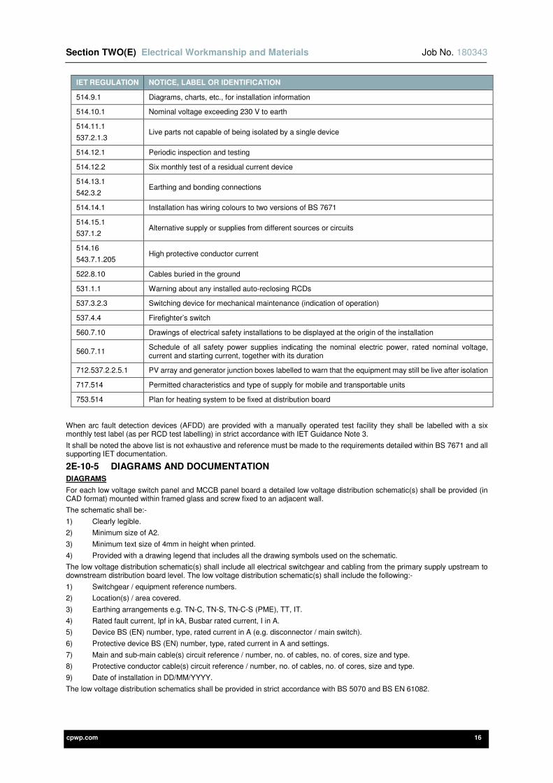
Section TWO(E) Electrical Workmanship and Materials Job No. 180343
cpwp.com 16
IET REGULATION NOTICE, LABEL OR IDENTIFICATION
514.9.1 Diagrams, charts, etc., for installation information
514.10.1 Nominal voltage exceeding 230 V to earth
514.11.1
537.2.1.3 Live parts not capable of being isolated by a single device
514.12.1 Periodic inspection and testing
514.12.2 Six monthly test of a residual current device
514.13.1
542.3.2 Earthing and bonding connections
514.14.1 Installation has wiring colours to two versions of BS 7671
514.15.1
537.1.2 Alternative supply or supplies from different sources or circuits
514.16
543.7.1.205 High protective conductor current
522.8.10 Cables buried in the ground
531.1.1 Warning about any installed auto-reclosing RCDs
537.3.2.3 Switching device for mechanical maintenance (indication of operation)
537.4.4 Firefighter’s switch
560.7.10 Drawings of electrical safety installations to be displayed at the origin of the installation
560.7.11 Schedule of all safety power supplies indicating the nominal electric power, rated nominal voltage, current and starting current, together with its duration
712.537.2.2.5.1 PV array and generator junction boxes labelled to warn that the equipment may still be live after isolation
717.514 Permitted characteristics and type of supply for mobile and transportable units
753.514 Plan for heating system to be fixed at distribution board
When arc fault detection devices (AFDD) are provided with a manually operated test facility they shall be labelled with a six monthly test label (as per RCD test labelling) in strict accordance with IET Guidance Note 3.
It shall be noted the above list is not exhaustive and reference must be made to the requirements detailed within BS 7671 and all supporting IET documentation.
2E-10-5 DIAGRAMS AND DOCUMENTATION
DIAGRAMS
For each low voltage switch panel and MCCB panel board a detailed low voltage distribution schematic(s) shall be provided (in CAD format) mounted within framed glass and screw fixed to an adjacent wall.
The schematic shall be:-
1) Clearly legible.
2) Minimum size of A2.
3) Minimum text size of 4mm in height when printed.
4) Provided with a drawing legend that includes all the drawing symbols used on the schematic.
The low voltage distribution schematic(s) shall include all electrical switchgear and cabling from the primary supply upstream to downstream distribution board level. The low voltage distribution schematic(s) shall include the following:-
1) Switchgear / equipment reference numbers.
2) Location(s) / area covered.
3) Earthing arrangements e.g. TN-C, TN-S, TN-C-S (PME), TT, IT.
4) Rated fault current, Ipf in kA, Busbar rated current, I in A.
5) Device BS (EN) number, type, rated current in A (e.g. disconnector / main switch).
6) Protective device BS (EN) number, type, rated current in A and settings.
7) Main and sub-main cable(s) circuit reference / number, no. of cables, no. of cores, size and type.
8) Protective conductor cable(s) circuit reference / number, no. of cables, no. of cores, size and type.
9) Date of installation in DD/MM/YYYY.
The low voltage distribution schematics shall be provided in strict accordance with BS 5070 and BS EN 61082.
Section TWO(E) Electrical Workmanship and Materials Job No. 180343
cpwp.com 17
A drawing(s) shall be provided that details all electrical safety installations for fire-fighting and life safety services. The drawing(s) shall be located at the origin of the electrical installation and adjacent to any other electrical switchgear (e.g. MCCB panel board, MCB distribution board etc.) to which the fire-fighting / life safety systems relate.
The drawing(s) shall be mounted within framed glass and screw fixed to an adjacent wall. The electrical safety installations drawing shall detail the exact location of the following:-
1) All electrical equipment and switchgear including switchgear / equipment reference numbers.
2) All fire-fighting and life safety equipment including final circuit designation and the particulars / purpose of the equipment.
3) Special switching and monitoring equipment for life safety power supplies.
Documentation shall be provided within or adjacent to all MCB distribution boards and consumer units that supply heating cables and embedded heating systems e.g. underfloor or ceiling heating systems, as required by BS 7671. The documentation shall include:-
1) Manufacturer and type of heating units.
2) Number of heating units installed.
3) Length/area of heating units.
4) Rated power.
5) Surface power density.
6) Layout of the heating units in the form of a sketch, drawing, or picture.
7) Position/depth of heating units.
8) Position of junction boxes.
9) Cables, earthed conductive shields and the like.
10) Rated voltage.
11) Rated resistance (cold) of heating units.
12) Rated current of overcurrent protective device.
13) Rated residual operating current of RCD.
14) The insulation resistance of the heating installation and the test voltage used.
15) Product information containing provisions about approved materials in contact with the heating units, with necessary instructions for installation.
In addition to the above documentation the ‘Information for the user of the installation’ shall also be provided as detailed within BS 7671.
Drawings and documentation for fire-fighting, life safety and other electrical services not detailed above shall be provided as detailed within subsequent sections of this specification.
SCHEDULES / CHARTS
Schedules / charts shall be provided to all low voltage switch panels, MCCB panel boards, MCB distribution boards and consumer units, and shall include the following as a minimum:-
1) Switchgear reference number.
2) General description.
3) Date of installation in DD/MM/YYYY.
4) The schedule shall include:-
a) Circuit number / reference and line / phase.
b) Circuit description and the supplied switchgear / equipment reference number or final circuit type e.g. DB1. DB2, ring circuit, radial circuit etc. Including the destination location of the outgoing circuit including the building, floor and room number.
c) Type of wiring.
d) Reference method from Appendix 4 of BS 7671 – IET Wiring Regulations.
e) Number of points served.
f) Circuit conductor cross sectional area:-
i) Live (mm2)
ii) Circuit protective conductor (mm2)
g) Maximum disconnection time (s) permitted by BS 7671 – IET Wiring Regulations.
h) Overcurrent protective devices:-
i) BS (EN) number.
ii) Type number.
iii) Rating (A).
iv) Short circuit capacity (kA).
i) RCD operating current I∆n (mA).
j) Maximum Zs permitted by BS 7671.
5) Method used to provide protection against electric shock e.g. basic protection and fault protection.
6) Details of all final circuits having a high protective conductor current.

Section TWO(E) Electrical Workmanship and Materials Job No. 180343
cpwp.com 18
7) Details of any equipment or circuit vulnerable to electrical testing e.g. electronic devices that could be damaged by insulation resistance testing.
It shall be noted the above schedules / charts shall be provided within or adjacent to the associated switchgear.
Where they are mounted adjacent to the item of switchgear they shall be mounted within framed glass and screw fixed to the adjacent wall, however when they are mounted inside distribution boards (e.g. inside the front cover) they shall be laminated and suitably placed / attached.
Schedules / charts shall be provided that detail all current using equipment permanently connected to fire-fighting / life safety power supplies indicating:
1) Nominal electric power.
2) Rated nominal voltage, current and starting current.
3) Duration.
The schedules /charts shall be located at the origin of the electrical installation and adjacent to any other electrical switchgear to which the fire-fighting / life safety systems relate. The schedules / charts shall be mounted within framed glass and screw fixed to an adjacent wall. The schedules / charts shall include the nominal power, rated nominal voltage, current, starting current and duration.
All switchgear reference numbers / codes shall be coordinated throughout and the same on all identification labels, schedules and drawings.
All final circuit references shall be coordinated throughout and the same on all wiring accessories, schedules and drawings.
EXISTING DIAGRAMS, SCHEDULES AND CHARTS
Where electrical installation works is undertaken that requires work to existing site LV distribution systems, fire-fighting / life safety systems and final circuit wiring (e.g. refurbishment works, remodelling works, new supplies from existing electrical switch gear, new final circuit wiring from existing MCB distribution boards etc.) diagrams, schedules and charts shall be updated in strict accordance with the above clauses and shall incorporate all existing installed information.
2E-10-6 IDENTIFICATION OF CABLES
All main and sub-main cabling shall be provided with identification labels / markers so that it can be identified for inspection, testing, maintenance, repair or alteration of the installation.
Identification labels shall be fixed as follows at:-
1) Each end of the cable.
2) Convenient inspection locations.
3) Locations where buried cabling enters / exits the ground.
4) Draw pit locations.
5) Building entry points.
Each identification label shall include the following:-
1) Cable reference / circuit number.
2) Source and destination location(s).
3) Indication if the cable is run in parallel with other cables.
4) Date of installation in DD/MM/YYYY.
Cable route markers shall be provided to all underground cabling and shall include:-
1) Depth at which the cable is buried.
2) Cable operating voltage.
Cable markers / sleeves as a minimum shall be made from materials equivalent to that of the cabling being labelled e.g. LSZH, LSOH, OHLS etc. They shall also be selected to suit the environment in which they are installed.
Separate protective conductors that are not part of a multicore cable shall have identification labels as detailed above.
2E-10-7 IDENTIFICATION OF CONDUCTORS BY COLOUR AND LETTERS / NUMBERS
Cores of cables shall be identified by both:-
1) Colour and,
2) Lettering and/or numbers.
At terminations and throughout their length every core of a cable shall be identifiable and where appropriate binding and sleeves for identification purposes shall comply with BS 3858.
Identification by colour or marking is not required for concentric conductors, bare conductors and the following when used as a protective conductor:-
1) Metal sheath or armour of cables.
2) Extraneous-conductive parts.
3) Exposed conductive parts.
Neutral or midpoint conductors shall be blue.
The colours green-and-yellow shall only be used for protective conductors and the colour combination of green-and-yellow shall not be less than 30% or more than 70% for each colour.
Green-and-yellow PEN conductors shall be labelled at the terminations by blue markings and blue PEN conductors shall be labelled at the terminations by green-and-yellow markings.
The single colour green shall not be used for:
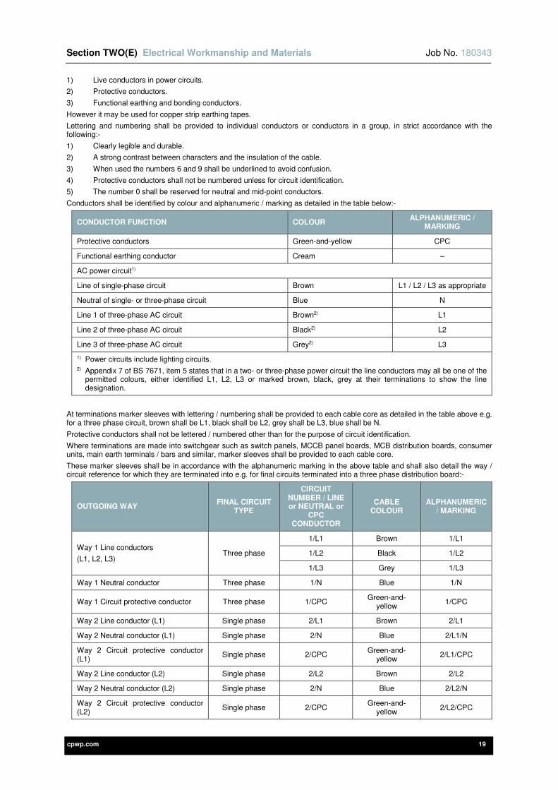
Section TWO(E) Electrical Workmanship and Materials Job No. 180343
cpwp.com 19
1) Live conductors in power circuits.
2) Protective conductors.
3) Functional earthing and bonding conductors.
However it may be used for copper strip earthing tapes.
Lettering and numbering shall be provided to individual conductors or conductors in a group, in strict accordance with the following:-
1) Clearly legible and durable.
2) A strong contrast between characters and the insulation of the cable.
3) When used the numbers 6 and 9 shall be underlined to avoid confusion.
4) Protective conductors shall not be numbered unless for circuit identification.
5) The number 0 shall be reserved for neutral and mid-point conductors.
Conductors shall be identified by colour and alphanumeric / marking as detailed in the table below:-
CONDUCTOR FUNCTION COLOUR ALPHANUMERIC /
MARKING
Protective conductors Green-and-yellow CPC
Functional earthing conductor Cream –
AC power circuit1)
Line of single-phase circuit Brown L1 / L2 / L3 as appropriate
Neutral of single- or three-phase circuit Blue N
Line 1 of three-phase AC circuit Brown2) L1
Line 2 of three-phase AC circuit Black2) L2
Line 3 of three-phase AC circuit Grey2) L3
1) Power circuits include lighting circuits. 2) Appendix 7 of BS 7671, item 5 states that in a two- or three-phase power circuit the line conductors may all be one of the
permitted colours, either identified L1, L2, L3 or marked brown, black, grey at their terminations to show the line designation.
At terminations marker sleeves with lettering / numbering shall be provided to each cable core as detailed in the table above e.g. for a three phase circuit, brown shall be L1, black shall be L2, grey shall be L3, blue shall be N.
Protective conductors shall not be lettered / numbered other than for the purpose of circuit identification.
Where terminations are made into switchgear such as switch panels, MCCB panel boards, MCB distribution boards, consumer units, main earth terminals / bars and similar, marker sleeves shall be provided to each cable core.
These marker sleeves shall be in accordance with the alphanumeric marking in the above table and shall also detail the way / circuit reference for which they are terminated into e.g. for final circuits terminated into a three phase distribution board:-
OUTGOING WAY FINAL CIRCUIT
TYPE
CIRCUIT NUMBER / LINE or NEUTRAL or
CPC CONDUCTOR
CABLE COLOUR
ALPHANUMERIC / MARKING
Way 1 Line conductors
(L1, L2, L3) Three phase
1/L1 Brown 1/L1
1/L2 Black 1/L2
1/L3 Grey 1/L3
Way 1 Neutral conductor Three phase 1/N Blue 1/N
Way 1 Circuit protective conductor Three phase 1/CPC Green-and-
yellow 1/CPC
Way 2 Line conductor (L1) Single phase 2/L1 Brown 2/L1
Way 2 Neutral conductor (L1) Single phase 2/N Blue 2/L1/N
Way 2 Circuit protective conductor (L1)
Single phase 2/CPC Green-and-
yellow 2/L1/CPC
Way 2 Line conductor (L2) Single phase 2/L2 Brown 2/L2
Way 2 Neutral conductor (L2) Single phase 2/N Blue 2/L2/N
Way 2 Circuit protective conductor (L2)
Single phase 2/CPC Green-and-
yellow 2/L2/CPC
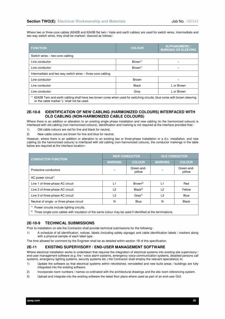
Section TWO(E) Electrical Workmanship and Materials Job No. 180343
cpwp.com 20
Where two or three-core cables (6242B and 6243B flat twin / triple and earth cables) are used for switch wires, intermediate and two way switch wires, they shall be marked / sleeved as follows:-
FUNCTION COLOUR ALPHANUMERIC /
MARKING OR SLEEVING
Switch wires – two-core cabling
Line conductor Brown1) –
Line conductor Brown1) –
Intermediate and two way switch wires – three-core cabling
Line conductor Brown –
Line conductor Black L or Brown
Line conductor Grey L or Brown
1) 6242B Twin and earth cabling shall have two brown cores when used for switching circuits, blue cores with brown sleeving or the cable marker ‘L’ shall not be used.
2E-10-8 IDENTIFICATION OF NEW CABLING (HARMONIZED COLOURS) INTERFACED WITH OLD CABLING (NON-HARMONIZED CABLE COLOURS)
Where there is an addition or alteration to an existing single phase installation and new cabling (to the harmonized colours) is interfaced with old cabling (non-harmonized colours), identification and marking is not required at the interface provided that:-
1) Old cable colours are red for line and black for neutral.
2) New cable colours are brown for line and blue for neutral.
However, where there is an addition or alteration to an existing two or three-phase installation or a d.c. installation, and new cabling (to the harmonized colours) is interfaced with old cabling (non-harmonized colours), the conductor markings in the table below are required at the interface location:-
CONDUCTOR FUNCTION NEW CONDUCTOR OLD CONDUCTOR
MARKING COLOUR MARKING COLOUR
Protective conductors – Green-and-
yellow –
Green-and-yellow
AC power circuit1)
Line 1 of three-phase AC circuit L1 Brown2) L1 Red
Line 2 of three-phase AC circuit L2 Black2) L2 Yellow
Line 3 of three-phase AC circuit L3 Grey2) L3 Blue
Neutral of single- or three-phase circuit N Blue N Black
1) Power circuits include lighting circuits. 2) Three single-core cables with insulation of the same colour may be used if identified at the terminations.
2E-10-9 TECHNICAL SUBMISSIONS
Prior to installation on-site the Contractor shall provide technical submissions for the following:-
1) A schedule of all identification, notices, labels (including safety signage) and cable identification labels / markers along with a physical sample of each label type.
The time allowed for comment by the Engineer shall be as detailed within section 1B of this specification.
2E-11 EXISTING SUPERVISORY / END-USER MANAGEMENT SOFTWARE
Where electrical installation works is undertaken that requires the integration of electrical systems into existing site supervisory / end-user management software (e.g. fire / voice alarm systems, emergency voice communication systems, disabled persons call systems, emergency lighting systems, security systems etc.) the Contractor shall employ the relevant specialist(s) to:
1) Update the software so that electrical systems within refurbished, remodelled and new build areas / buildings are fully integrated into the existing software.
2) Incorporate room numbers / names co-ordinated with the architectural drawings and the site room referencing system.
3) Upload and integrate into the existing software the latest floor plans where used as part of an end-user GUI.

Section TWO(E) Electrical Workmanship and Materials Job No. 180343
cpwp.com 21
2E-12 SELECTION AND ERECTION OF WIRING SYSTEMS TO MINIMIZE THE SPREAD OF FIRE
This section of the specification details the general requirements for the selection and erection of wiring systems to minimize the spread of fire. To minimize the risk of spread of fire appropriate materials and erection methods shall be selected in strict accordance with The Building Regulations – Approved Document B, BS 9999, BS 7671 and all supporting IET documentation.
2E-12-1 PRECAUTIONS WITHIN A FIRE SEGREGATED COMPARTMENT
The general building structural performance and fire safety shall not be reduced by the installation of wiring systems.
All power, control and communication cables shall meet the flame propagation requirements of:-
1) BS EN 60332-1-2 (flame propagation for a single cable).
2) The appropriate part of the BS EN 60332-3 (flame propagation for multiple cables) series.
Cables that meet these requirements are detailed below:-
REFERENCE STANDARDS / DOCUMENTS
BS 6724 694*B XLPE/AWA/LSZH single core armoured cables
694*B XLPE/SWA/LSZH multicore armoured cables
BS 7211
6491B LSZH single core insulated non-sheathed cables
6181B XLPE/LSZH single core insulated sheathed cables
6242B & 6243B XLPE/LSZH flat multicore insulated sheathed cables
BS 7629-1 XLPE/LSZH enhanced fire resistant cables
e.g. Draka FT120, Prysmian FP Plus or similar.
BS 7846 XLPE/SWA/LSZH enhanced fire resistant armoured power cables
e.g. Draka FTP120, Prysmian FP600S or similar.
Notes:
1) The Contractor shall liaise with their cabling manufacturers / suppliers to ensure all cabling meets the necessary flame propagation requirements.
2) Cabling and cable support / containment systems shall be provided as detailed within the Default Cabling and Cable Support / Containment System section of this specification.
3) All power, control and communication cables shall satisfy the requirements of the Construction Products Regulation in respect of their reaction to fire by being provided in strict accordance with their respective European and British Standards e.g. BS 7671, BS 50575, BS 8519, BS 6701, BS 5839, BS 5266 etc.
Where cables do not comply with the flame propagation requirements of BS EN 60332-1-2 or the BS EN 60332-3 series (as appropriate), they shall not pass from one fire segregated compartment to another and they shall be limited to short lengths for connection of appliances to the permanent wiring system.
Where products have the necessary resistance to flame propagation as specified in the standards below, they may be installed without special precautions:-
REFERENCE STANDARDS / DOCUMENTS
BS EN 50085 Cable trunking systems and cable ducting systems for electrical installations
BS EN 60570 Electrical supply track systems for luminaires
BS EN 61386 Conduit systems for cable management
BS EN 61439 Low-voltage switchgear and controlgear assemblies
BS EN 61534 Powertrack systems
BS EN 61537 Cable management – Cable tray systems and cable ladder systems
Other products that also have the necessary resistance to flame propagation (as specified within their respective standards) may also be installed without special precautions.
Additional measures shall be taken where a ‘particular risk of fire’ is identified in strict accordance with BS 7671 and all supporting IET documentation.
2E-12-2 SEALING OF WIRING SYSTEM PENETRATIONS
The sealing of wiring system penetrations shall be provides as follows:-
1) Where wiring systems pass through floors, walls, roofs, ceilings, partitions, cavity barriers and other elements of the building construction, the penetrations through the building fabric shall be suitably sealed (e.g. fire barriers / stopping) to provide the level of fire resistance and acoustic properties required by the building element that has been penetrated.
2) Manufacturers’ proprietary cable transit systems and sleeves shall be utilised.

Section TWO(E) Electrical Workmanship and Materials Job No. 180343
cpwp.com 22
3) Under no circumstances shall expandable foam be used.
4) Cable ducting, cable trunking, conduit and busbar systems etc. shall also be internally sealed to provide the level of fire resistance required by the building element that has been penetrated.
5) Where the wiring system / products are classified as non-flame propagating according to the relevant product standard, internal sealing is not required provided that:-
a) The wiring system has a maximum internal cross-sectional area of 710mm2 e.g. 32mm diameter conduit or smaller, or 25 x 25mm trunking.
b) (However they may require sealing for other reasons, such as to prevent condensation, in classified hazardous areas etc.).
c) The system has the degree of protection of IP33 to BS EN 60529.
d) Any termination of the system in one of the compartments, separated by the building construction being penetrated, has the degree of protection of IP33 to BS EN 60529.
6) Temporary fire stopping arrangements shall be provided if required during the installation works. Existing fire stopping that is disturbed during alteration works shall be reinstated as soon as practical. Temporary sealing arrangements shall provide the level of fire resistance required by the building element that has been penetrated.
7) The fire sealing must also resist external influences to the same degree as the wiring system and shall meet the five requirements e.g. resistance to combustion, ingress protection from water, be from compatible material, permit thermal movement and have adequate mechanical stability.
8) Cable cleats and supports for cable management systems shall be provided within 750mm of all fire barrier / stopping seals and shall be able to withstand the mechanical load induced by the collapse of wiring systems on the fire side of the seal, to prevent strain and damage to the fire seal. This is not required if the seal itself is able to provide adequate support under such conditions.
9) Intumescent gaskets and covers shall be provided where electrical equipment or accessories are installed within ceilings or walls whose fire integrity has been compromised by their installation e.g. recessed luminaires in ceilings to maintain the ceilings fire integrity, accessory boxes in thin skinned walls that form part of a fire compartment etc.
10) Gaskets and covers shall be provided where electrical equipment or accessories are installed within ceilings or walls whose acoustic properties have been compromised by their installation e.g. recessed luminaires, accessory boxes in thin skinned walls etc.
11) Labelling shall be provided at each penetration location and shall have a designated unique reference, include the installation date and details of the specialist installer.
12) On completion of the fire barriers / stopping works fully detailed completion / compliance certification shall be provided along with record drawings that detail all fire barrier / stopping locations.
2E-12-3 TECHNICAL SUBMISSIONS
Prior to installation on-site the Contractor shall provide technical submissions for the following:-
1) Technical specifications for all manufacturers’ proprietary fire stopping systems and materials e.g. cable transit systems and sleeves.
The time allowed for comment by the Engineer shall be as detailed within section 1B of this specification.
2E-13 PROXIMITY OF WIRING SYSTEMS AND MEASURES AGAINST ELECTROMAGNETIC DISTURBANCES
This section of the specification details the general requirements for the proximity of wiring systems and measures against electromagnetic disturbances.
2E-13-1 PROXIMITY AND SEGREGATION OF WIRING SYSTEMS
GENERAL
Electrical services cabling shall be segregated in strict accordance with BS 5266, BS 5839, BS 6701, BS EN 50174, BS EN 62305, NJUG Guidelines, BS 8519, BS 7594, BS 7671 and all supporting IET documentation.
Voltage Band I and Voltage Band II circuits must not be contained in the same wiring system as a circuit of nominal voltage exceeding that of low voltage.
LIGHTNING PROTECTION SYSTEMS
Adequate separation shall be provided between conductors of a lightning protection system and other electrical wiring systems e.g. low voltage systems (general LV wiring), extra-low voltage systems (fire alarm, security, telecommunications and data wiring etc.).
The minimum separation distance in metres shall be calculated by the lightning protection specialist in accordance with BS EN 62305-3.
EMERGENCY LIGHTING SYSTEM WIRING
Emergency lighting system wiring (e.g. central battery systems) shall be segregated from all other electrical circuits and wiring systems to avoid the risk of mechanical damage, in strict accordance with BS 5266-1.
FIRE ALARM SYSTEM, VOICE ALARM SYSTEM AND EMERGENCY VOICE COMMUNICATION SYSTEM WIRING
Fire alarm system and emergency voice communication system (disabled refuge) wiring shall be segregated from all other electrical circuits and wiring systems in strict accordance with BS 5839-1, BS 5839-8 and BS 5839-9, to avoid the risk of mechanical damage and the potential for other circuits to cause malfunction of the these systems, such as:-
1) Breakdown of cable insulation.
2) Fire caused by another circuit.

Section TWO(E) Electrical Workmanship and Materials Job No. 180343
cpwp.com 23
3) Electromagnetic interference.
4) Damage resulting from installation / removal of cabling where fire alarm and emergency voice communication system cabling is contained.
Fire alarm system, voice alarm system and emergency voice communication system (disable refuge) wiring may be installed together within the same cable support / containment system, as permitted by BS 5839.
OTHER LIFE SAFETY / FIRE-FIGHTING WIRING
All other life safety / fire-fighting system wiring systems shall be segregated from each other and all other electrical circuits and wiring systems. Primary and secondary power supplies shall be adequately separated from each other so that a failure in a cable or equipment (e.g. mechanical breakdown, damage by fire etc.), in either supply does not affect the other supply.
Where more onerous requirements are detailed within standards, documents or manufacturers’ literature relating to life safety / fire-fighting systems, these requirements must be adhered to (e.g. diverse routing of primary and secondary power supplies to fire-fighting lifts, evacuation lifts, smoke ventilation systems etc.).
AUDIO FREQUENCY INDUCTION LOOP SYSTEMS (AFILS)
Loop conductor(s), microphone and other signal cables shall be segregated from all other electrical circuits and wiring systems in strict accordance with BS 7594.
1) Loop cabling shall be installed at least 600mm from low voltage (general power wiring) and extra low voltage systems (fire alarm, security, telecommunications and data wiring etc.). However the loop cabling shall be installed at least 1000mm from all other audio wiring systems. These requirements shall be verified with the AFILS equipment manufacturers.
2) Line and neutral conductors or switch feeds and switch wires (e.g. conventional two-way switching) must be grouped / run together in areas where AFILS have been installed.
3) Adjacent loops shall be adequately separated from each other dependent upon their classification / type e.g. A1, A2, A3, A4 etc. as required by BS 7594.
INFORMATION TECHNOLOGY AND TELECOMMUNICATIONS WIRING
Information technology (e.g. data cabling) and telecommunications wiring systems shall be segregated from all other electrical circuits and wiring systems. This shall include any building services systems that may utilise the information technology / telecommunications wiring e.g. access control, CCTV, BMS etc.
Where underground telecommunications cables and underground power cables cross or are in close proximity a minimum clearance of 100mm shall be maintained unless one of the methods is adopted from BS 7671.
These methods are as follows:-
1) The provision of a fire retardant partition shall be provided between the underground telecommunication and power cables.
e.g. bricks, clay / concrete cable protection caps, concrete shaped blocks, protective cable conduit or troughs made of fire retardant materials.
Or,
2) Where underground telecommunication cables and power cables cross, mechanical protection between the cables shall be provided.
e.g. cable conduit, concrete cable protection caps or concrete shaped blocks.
OTHER WIRING
The following wiring systems shall be fully segregated from each other and all other electrical circuits and wiring systems:-
1) Security systems.
2) BMS.
3) ELV mechanical services controls.
HEALTHCARE WIRING
The following healthcare wiring systems shall also be fully segregated from each other and all other electrical circuits and wiring systems, in strict accordance with HTM 06-01 and HTM 08-03:-
1) Emergency lighting system.
2) Essential final circuit wiring.
3) Non-essential final circuit wiring.
4) Medical IT / isolated power supply (IPS) final circuit wiring.
5) Nurse call systems (This includes nurse call, staff emergency call, cardiac call, intruder / attack alarms etc.).
6) Socket outlets and switches shall not be installed within a 200mm radius from the centre of a medical gas outlet.
7) IT cable support and containment systems shall be installed in separate vertical risers to any other building services containment routes.
8) Horizontal IT cable support and containment systems shall be installed at least 300mm from other building services containment systems, subject to the voltage band of any distributed power cabling system.
It shall be noted the above list is not exhaustive and reference shall be made to all of the above requirements e.g. fire alarm, EVCS etc. etc.
GENERAL INSTALLATION REQUIREMENTS
The general installation requirements are as follows:-
1) The default cable support and containment systems detailed within this section of the specification shall be included at tender and used for installation.

Section TWO(E) Electrical Workmanship and Materials Job No. 180343
cpwp.com 24
2) To provide adequate segregation each of the wiring systems may be installed in their own dedicated cable management systems or in common cable management systems (e.g. cable basket / wire mesh tray, cable trunking, cable ducting, dado / skirting trunking etc.) with other electrical wiring systems.
3) Where installed in common cable management systems they shall be provided with their own individual dedicated compartments.
The compartments may be manufactured before delivery to site, however where dividers / partitions are installed on-site they must be from the same manufacturer as the cable management system and the manufacturers proprietary fixings shall be used.
The compartment walls or dividers / partitions within the common cable management system shall be:-
a) Securely fixed and manufactured from the same material as the cable management system.
b) Mechanically strong and continuous throughout the cable management system.
c) The same height as the sides of the common cable management system and without perforations.
d) Equipotential bonded to the cable management system.
4) Signalling and data cabling shall not be installed within a common cable management system that contains low voltage wiring unless the dividers / partitions are manufactured from steel with a minimum thickness of 1.5mm.
5) All wiring systems shall:-
a) Be fully segregated from each other and shall not be installed in the same compartment of a combined cable management system or in the same dedicated cable management system.
b) Have its own cable conduits and shall not be installed in the same conduits as the cables of other wiring systems.
6) Under no circumstances shall any wiring systems be strapped or fixed to the outside of cable management systems.
7) Underground electrical wiring systems shall be buried and separated as detailed by the NJUG National Joint Utilities Group. All buried wiring systems shall be installed within their own dedicated cable ducting systems.
8) Where more onerous requirements are detailed within standards, documents or manufacturers’ literature relating to life safety / fire-fighting systems, these requirements must be adhered to (e.g. diverse routing of primary and secondary power supplies to fire-fighting lifts, evacuation lifts, smoke ventilation systems, diverse routing of fire alarm network cabling for the critical path etc.).
2E-13-2 PROXIMITY OF WIRING SYSTEMS TO NON-ELECTRICAL SERVICES
Wiring systems shall not be located in close proximity to non-electrical services that produce heat (e.g. hot pipework), smoke or fumes, or below services that may cause condensation (e.g. water, steam, gas services), unless adequate precautions are taken to prevent harmful effects to the wiring.
Mechanical / thermal shielding or suitable spacing shall be provided between electrical and non-electrical services to prevent the operation of one service affecting another.
Where wiring systems are located in close proximity to non-electrical services they shall be installed in accordance with BS 7671 and shall meet the following requirements:-
1) Where the presence of non-electrical services may be hazardous to wiring systems, suitable protection of the wiring systems shall be provided.
2) The protective measure automatic disconnection of supply shall be provided in accordance with BS 7671.
Under no circumstances shall wet services (e.g. mains cold water systems, LTHW heating systems etc.) be installed within LV switchrooms and rooms containing standby battery systems e.g. UPS’s, PV off-grid systems, emergency lighting systems etc.
Low pressure gas systems shall be separated from electrical equipment in accordance with BS 6891:-
1) Gas pipework shall be at least 150mm from low voltage equipment such as metering, DNO cut-outs / isolators, distribution boards and consumer units.
2) Gas pipework shall be at least 25mm from switches, sockets and low voltage cabling.
The guidance outlined in IGEM/GM/6 shall also be followed:-
1) Gas metering shall not be installed within rooms that are intended for electricity metering and electrical switchgear.
2) Gas metering shall be located away from electricity metering and electrical switchgear and under no circumstances within 150mm.
The only wiring systems that shall be installed within lift or hoist well shall be those that form part of the lift installation as defined by the BS EN 81 series.
2E-13-3 MEASURES AGAINST ELECTROMAGNETIC DISTURBANCES
To avoid and reduce electromagnetic disturbances good engineering practices shall be followed and the electrical installation works shall be undertaken in strict accordance with BS 7671, all supporting IET documentation and the following standards detailed within BS 7671:-
REFERENCE STANDARDS / DOCUMENTS
BS 6701 Telecommunications equipment and telecommunications cabling – Specification for installation, operation and maintenance
BS EN 50310 Telecommunications bonding networks for buildings and other structures
BS EN 50174 Information technology – Cabling installation
BS IEC 61000-5-2 Electromagnetic compatibility (EMC) – Part 5: Installation and mitigation guidelines – Section 2: Earthing and cabling
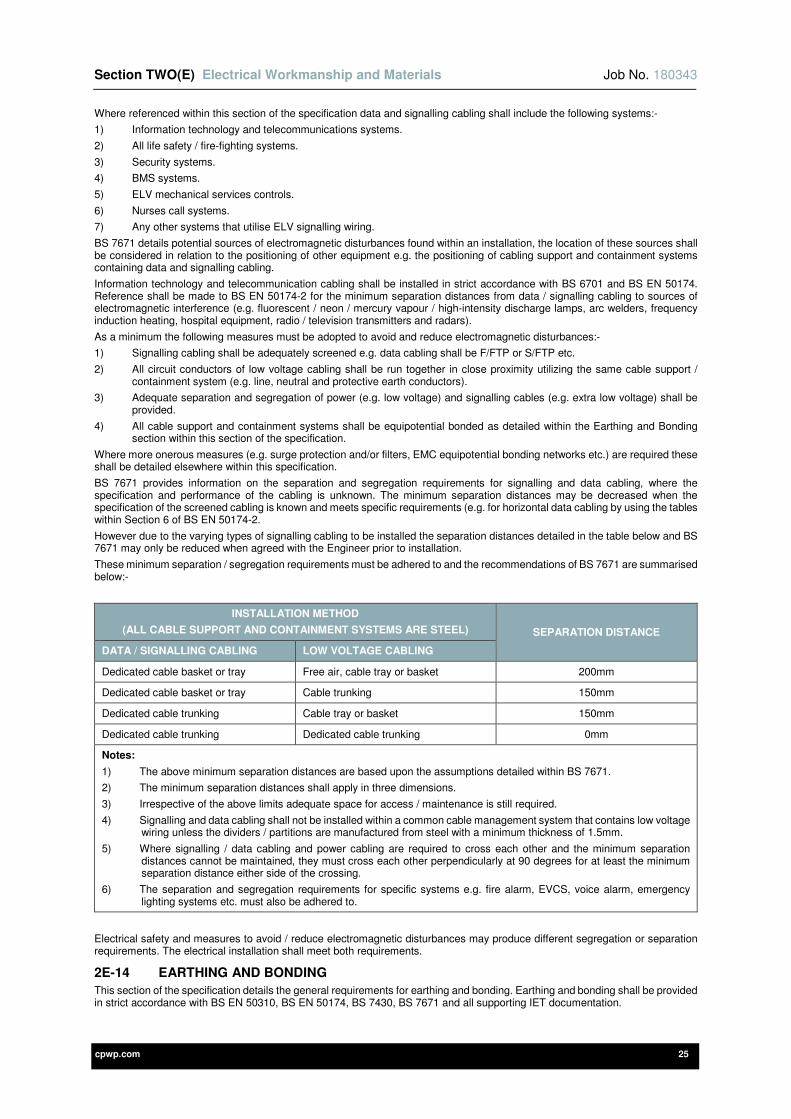
Section TWO(E) Electrical Workmanship and Materials Job No. 180343
cpwp.com 25
Where referenced within this section of the specification data and signalling cabling shall include the following systems:-
1) Information technology and telecommunications systems.
2) All life safety / fire-fighting systems.
3) Security systems.
4) BMS systems.
5) ELV mechanical services controls.
6) Nurses call systems.
7) Any other systems that utilise ELV signalling wiring.
BS 7671 details potential sources of electromagnetic disturbances found within an installation, the location of these sources shall be considered in relation to the positioning of other equipment e.g. the positioning of cabling support and containment systems containing data and signalling cabling.
Information technology and telecommunication cabling shall be installed in strict accordance with BS 6701 and BS EN 50174. Reference shall be made to BS EN 50174-2 for the minimum separation distances from data / signalling cabling to sources of electromagnetic interference (e.g. fluorescent / neon / mercury vapour / high-intensity discharge lamps, arc welders, frequency induction heating, hospital equipment, radio / television transmitters and radars).
As a minimum the following measures must be adopted to avoid and reduce electromagnetic disturbances:-
1) Signalling cabling shall be adequately screened e.g. data cabling shall be F/FTP or S/FTP etc.
2) All circuit conductors of low voltage cabling shall be run together in close proximity utilizing the same cable support / containment system (e.g. line, neutral and protective earth conductors).
3) Adequate separation and segregation of power (e.g. low voltage) and signalling cables (e.g. extra low voltage) shall be provided.
4) All cable support and containment systems shall be equipotential bonded as detailed within the Earthing and Bonding section within this section of the specification.
Where more onerous measures (e.g. surge protection and/or filters, EMC equipotential bonding networks etc.) are required these shall be detailed elsewhere within this specification.
BS 7671 provides information on the separation and segregation requirements for signalling and data cabling, where the specification and performance of the cabling is unknown. The minimum separation distances may be decreased when the specification of the screened cabling is known and meets specific requirements (e.g. for horizontal data cabling by using the tables within Section 6 of BS EN 50174-2.
However due to the varying types of signalling cabling to be installed the separation distances detailed in the table below and BS 7671 may only be reduced when agreed with the Engineer prior to installation.
These minimum separation / segregation requirements must be adhered to and the recommendations of BS 7671 are summarised below:-
INSTALLATION METHOD
(ALL CABLE SUPPORT AND CONTAINMENT SYSTEMS ARE STEEL) SEPARATION DISTANCE
DATA / SIGNALLING CABLING LOW VOLTAGE CABLING
Dedicated cable basket or tray Free air, cable tray or basket 200mm
Dedicated cable basket or tray Cable trunking 150mm
Dedicated cable trunking Cable tray or basket 150mm
Dedicated cable trunking Dedicated cable trunking 0mm
Notes:
1) The above minimum separation distances are based upon the assumptions detailed within BS 7671.
2) The minimum separation distances shall apply in three dimensions.
3) Irrespective of the above limits adequate space for access / maintenance is still required.
4) Signalling and data cabling shall not be installed within a common cable management system that contains low voltage wiring unless the dividers / partitions are manufactured from steel with a minimum thickness of 1.5mm.
5) Where signalling / data cabling and power cabling are required to cross each other and the minimum separation distances cannot be maintained, they must cross each other perpendicularly at 90 degrees for at least the minimum separation distance either side of the crossing.
6) The separation and segregation requirements for specific systems e.g. fire alarm, EVCS, voice alarm, emergency lighting systems etc. must also be adhered to.
Electrical safety and measures to avoid / reduce electromagnetic disturbances may produce different segregation or separation requirements. The electrical installation shall meet both requirements.
2E-14 EARTHING AND BONDING
This section of the specification details the general requirements for earthing and bonding. Earthing and bonding shall be provided in strict accordance with BS EN 50310, BS EN 50174, BS 7430, BS 7671 and all supporting IET documentation.

Section TWO(E) Electrical Workmanship and Materials Job No. 180343
cpwp.com 26
Earthing shall be divided into two separate defined parts:-
1) Supply system earthing – Normally the responsibility of the DNO, where a connection is provided between the source of energy and the general mass of earth via a source electrode.
e.g. typically the distribution transformer secondary winding or generator winding.
2) Electrical installation earthing – Where the exposed-conductive-parts of an installation are connected to an appropriate means of earthing at the origin of the installation.
e.g. Main Earthing Terminal (MET).
Protective earthing and equipotential bonding to the electrical installation shall be provided in strict accordance with the requirements for automatic disconnection of supply, as detailed within BS 7671.
Each building / installation shall be provided with a dedicated telecommunications bonding network in strict accordance with BS EN 50310.
All earthing and bonding cabling shall be LSZH (LSOH, OHLS) with emissions of hydrogen chloride gas < 0.5%.
2E-14-1 EARTHING ARRANGEMENTS
Dependent on the installation earthing arrangements, main earthing terminals (METs) shall be connected to earth by one of the following methods as required by BS 7671:-
1) TN-S, to the earthed point of the source of energy, part of the connection may be formed by the DNO’s lines and equipment.
2) TN-C-S, where protective multiple earthing is provided, by the DNO to the neutral of the source of energy.
3) TT and IT, via an earthing conductor to an earth electrode.
Earth electrodes shall be provided in accordance with BS 7671 and shall be from the following types:-
1) Earth rods or pipes.
2) Earth tapes or wire.
3) Earth plates.
4) Underground structural metalwork embedded in foundations (e.g. piled building foundations) or other metalwork installed in the foundations.
5) Welded metal reinforcement of concrete (except pre-stressed concrete) embedded in the ground.
6) Lead sheaths and other metal coverings of cables (existing installations only).
7) Other suitable underground metalwork.
The following shall not be used as an earth electrode:-
1) Metallic pipework for gases or flammable liquids.
2) Metallic pipework of a water utility supply.
Metal objects immersed into water shall not be used as earth electrodes.
2E-14-2 PROTECTIVE CONDUCTORS
The term protective conductor applies to the following:-
1) Earthing conductors.
2) Protective equipotential bonding conductors.
3) Supplementary protective equipotential bonding conductors.
4) Circuit protective conductors.
Where a protective conductor is a single core cable or the core of a cable it must be identified by the colours green-and-yellow and the colour combination of green-and-yellow shall not be less than 30% or more than 70% for each colour. However copper strip earthing tapes may be a different colour.
The following shall not be used as protective conductors:-
1) Gas pipes.
2) Oil pipes.
3) Flexible or pliable conduits.
4) Support wires or other flexible metallic parts.
5) Constructional parts subject to mechanical stress in normal service.
Although permissible by BS 7671 the metal enclosures or frames of low voltage switch panels, control gear assemblies and busbar trunking systems shall not be used as protective conductors.
2E-14-3 EARTHING CONDUCTORS
Earthing conductors connecting the main earthing terminal (MET) to an earth electrode or other means of earthing, shall comply with BS 7671. Earthing conductors and connections shall be suitably protected against mechanical damage and corrosion.
Connections between earthing conductors and earth electrodes or other means of earthing shall be labelled in strict accordance with BS 7671.
2E-14-4 MAIN EARTH TERMINALS (MET)
Main earthing terminals (MET) shall be provided to all electrical installations for connection of the following to the main earthing conductor:
1) Circuit protective conductors.
2) Main protective bonding conductors.

Section TWO(E) Electrical Workmanship and Materials Job No. 180343
cpwp.com 27
3) Functional earthing conductors (if required).
4) Lightning protection system bonding conductors (if any).
5) Metallic sheath of incoming telecommunications cables (where agreed).
6) Telecommunications bonding conductors from telecommunications primary bonding busbars (PBB) (if required).
Main protective equipotential bonding conductors shall be provided from the following extraneous-conductive-parts to the main earth terminal (MET):-
1) Water installation pipes.
2) Gas installation pipes.
3) Fuel oil pipes.
4) District heating pipes.
5) Steam pipes.
6) Laboratory and medical gases.
7) Mechanical service installation pipework and ducting (e.g. ventilation, heating, chilled water etc.)
8) Central heating and air conditioning systems.
9) Exposed metallic structural parts of the building.
The above shall be applied to each building where the electrical installation serves more than one building.
Where agreed with the service provider / owner, the metallic sheath of incoming telecommunications cables shall also be equipotential bonded to the main earth terminal (MET). Lightning protection systems shall also be connected to the main earth terminal (MET).
Disconnection of the main earthing conductor shall be provided to facilitate measurement of the earthing arrangements. This may be provided as part of the main earthing terminal (MET) in the form of a bolted disconnection test link. It shall only be possible to remove disconnection joints / links by means of a tool.
Metallic pipes entering the building having an insulating section at their point of entry need not be connected to the protective equipotential bonding.
2E-14-5 TELECOMMUNICATION PRIMARY BONDING BUSBARS (PBB)
Each building / installation shall be provided with a telecommunications primary bonding busbar (PBB) which shall be connected to the electrical installation main earthing terminal (MET) as part of a dedicated telecommunications bonding network.
2E-14-6 TELECOMMUNICATION SECONDARY BONDING BUSBARS (SBB)
Each telecommunications, server, equipment, communications room (e.g. main equipment rooms (MER’s) and secondary equipment rooms (SER’s) shall be provided with a secondary bonding busbar (SBB) as part of the dedicated telecommunications bonding network.
2E-14-7 PROTECTIVE EQUIPOTENTIAL BONDING CONDUCTORS
Main protective equipotential bonding conductors shall be provided from extraneous-conductive-parts to the main earth terminal (MET), as detailed above in the section Main Earthing Terminals.
Generally protective equipotential bonding conductors shall be installed on cable support and containment systems, however where they are fixed to the building structure / fabric they shall be supported at spacing’s as detailed within IET Guidance Note 8 – Earthing and Bonding.
METALLIC PIPEWORK
The main bonding connections to water, gas or other services shall be made as near as practicable to the point of entry of that service into the building.
Where there is a meter, isolation point or union the connection shall be made:-
1) To the hard metal pipework and before any branch pipework.
2) Where the meter is within the building – Where practicable within 600mm of the meter outlet union when the meter is installed within the building
3) Where the meter is outside of the building – where the service enters the building.
If an insulating section has been provided to prevent galvanic corrosion the bonding connection shall be to the building side only.
Bonding clamps that comply with BS 951 shall be used to make main bonding connections to metal pipework and shall be selected to suit the environment in which they are installed. Where bonding clamps cannot be used due to the size of the pipework other suitable means of connection shall be provided.
STRUCTURAL STEELWORK
The structural steelwork shall be equipotential bonded using proprietary clamps at regular intervals with final connection to the main earth terminal (MET) by means of a bolted lug type connection.
TELECOMMUNICATIONS PRIMARY BONDING BUSBARS (PBB)
Telecommunications primary bonding busbars (PBB) shall:-
1) Be connected to main earthing terminals (MET) using suitably sized telecommunications bonding conductors (TBC). The TBC shall be sized in strict accordance with BS EN 50310 and shall have a minimum cross sectional area of 16mm2.
2) Provide a central connection point for the building / installation telecommunications bonding backbone (TBB).
SECONDARY BONDING BUSBARS (SBB)
Secondary bonding busbars (SBB) and rack bonding busbars (RBB) shall be provided as follows:-
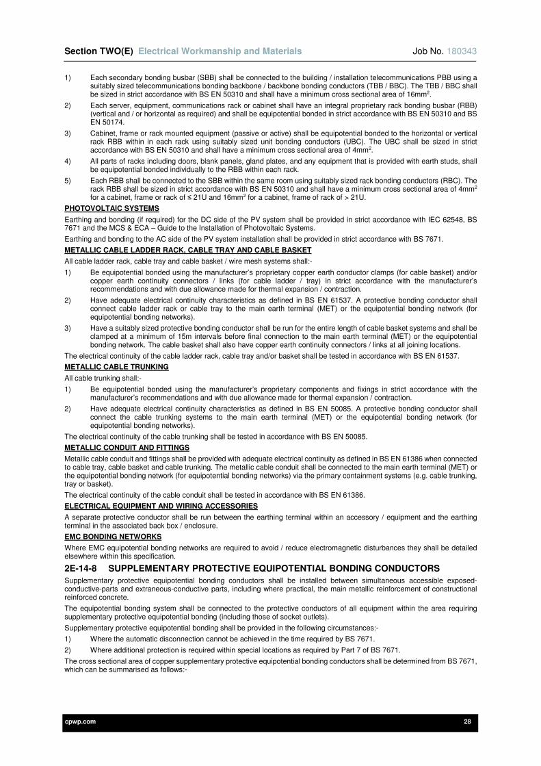
Section TWO(E) Electrical Workmanship and Materials Job No. 180343
cpwp.com 28
1) Each secondary bonding busbar (SBB) shall be connected to the building / installation telecommunications PBB using a suitably sized telecommunications bonding backbone / backbone bonding conductors (TBB / BBC). The TBB / BBC shall be sized in strict accordance with BS EN 50310 and shall have a minimum cross sectional area of 16mm2.
2) Each server, equipment, communications rack or cabinet shall have an integral proprietary rack bonding busbar (RBB) (vertical and / or horizontal as required) and shall be equipotential bonded in strict accordance with BS EN 50310 and BS EN 50174.
3) Cabinet, frame or rack mounted equipment (passive or active) shall be equipotential bonded to the horizontal or vertical rack RBB within in each rack using suitably sized unit bonding conductors (UBC). The UBC shall be sized in strict accordance with BS EN 50310 and shall have a minimum cross sectional area of 4mm2.
4) All parts of racks including doors, blank panels, gland plates, and any equipment that is provided with earth studs, shall be equipotential bonded individually to the RBB within each rack.
5) Each RBB shall be connected to the SBB within the same room using suitably sized rack bonding conductors (RBC). The rack RBB shall be sized in strict accordance with BS EN 50310 and shall have a minimum cross sectional area of 4mm2 for a cabinet, frame or rack of ≤ 21U and 16mm2 for a cabinet, frame of rack of > 21U.
PHOTOVOLTAIC SYSTEMS
Earthing and bonding (if required) for the DC side of the PV system shall be provided in strict accordance with IEC 62548, BS 7671 and the MCS & ECA – Guide to the Installation of Photovoltaic Systems.
Earthing and bonding to the AC side of the PV system installation shall be provided in strict accordance with BS 7671.
METALLIC CABLE LADDER RACK, CABLE TRAY AND CABLE BASKET
All cable ladder rack, cable tray and cable basket / wire mesh systems shall:-
1) Be equipotential bonded using the manufacturer’s proprietary copper earth conductor clamps (for cable basket) and/or copper earth continuity connectors / links (for cable ladder / tray) in strict accordance with the manufacturer’s recommendations and with due allowance made for thermal expansion / contraction.
2) Have adequate electrical continuity characteristics as defined in BS EN 61537. A protective bonding conductor shall connect cable ladder rack or cable tray to the main earth terminal (MET) or the equipotential bonding network (for equipotential bonding networks).
3) Have a suitably sized protective bonding conductor shall be run for the entire length of cable basket systems and shall be clamped at a minimum of 15m intervals before final connection to the main earth terminal (MET) or the equipotential bonding network. The cable basket shall also have copper earth continuity connectors / links at all joining locations.
The electrical continuity of the cable ladder rack, cable tray and/or basket shall be tested in accordance with BS EN 61537.
METALLIC CABLE TRUNKING
All cable trunking shall:-
1) Be equipotential bonded using the manufacturer’s proprietary components and fixings in strict accordance with the manufacturer’s recommendations and with due allowance made for thermal expansion / contraction.
2) Have adequate electrical continuity characteristics as defined in BS EN 50085. A protective bonding conductor shall connect the cable trunking systems to the main earth terminal (MET) or the equipotential bonding network (for equipotential bonding networks).
The electrical continuity of the cable trunking shall be tested in accordance with BS EN 50085.
METALLIC CONDUIT AND FITTINGS
Metallic cable conduit and fittings shall be provided with adequate electrical continuity as defined in BS EN 61386 when connected to cable tray, cable basket and cable trunking. The metallic cable conduit shall be connected to the main earth terminal (MET) or the equipotential bonding network (for equipotential bonding networks) via the primary containment systems (e.g. cable trunking, tray or basket).
The electrical continuity of the cable conduit shall be tested in accordance with BS EN 61386.
ELECTRICAL EQUIPMENT AND WIRING ACCESSORIES
A separate protective conductor shall be run between the earthing terminal within an accessory / equipment and the earthing terminal in the associated back box / enclosure.
EMC BONDING NETWORKS
Where EMC equipotential bonding networks are required to avoid / reduce electromagnetic disturbances they shall be detailed elsewhere within this specification.
2E-14-8 SUPPLEMENTARY PROTECTIVE EQUIPOTENTIAL BONDING CONDUCTORS
Supplementary protective equipotential bonding conductors shall be installed between simultaneous accessible exposed-conductive-parts and extraneous-conductive parts, including where practical, the main metallic reinforcement of constructional reinforced concrete.
The equipotential bonding system shall be connected to the protective conductors of all equipment within the area requiring supplementary protective equipotential bonding (including those of socket outlets).
Supplementary protective equipotential bonding shall be provided in the following circumstances:-
1) Where the automatic disconnection cannot be achieved in the time required by BS 7671.
2) Where additional protection is required within special locations as required by Part 7 of BS 7671.
The cross sectional area of copper supplementary protective equipotential bonding conductors shall be determined from BS 7671, which can be summarised as follows:-
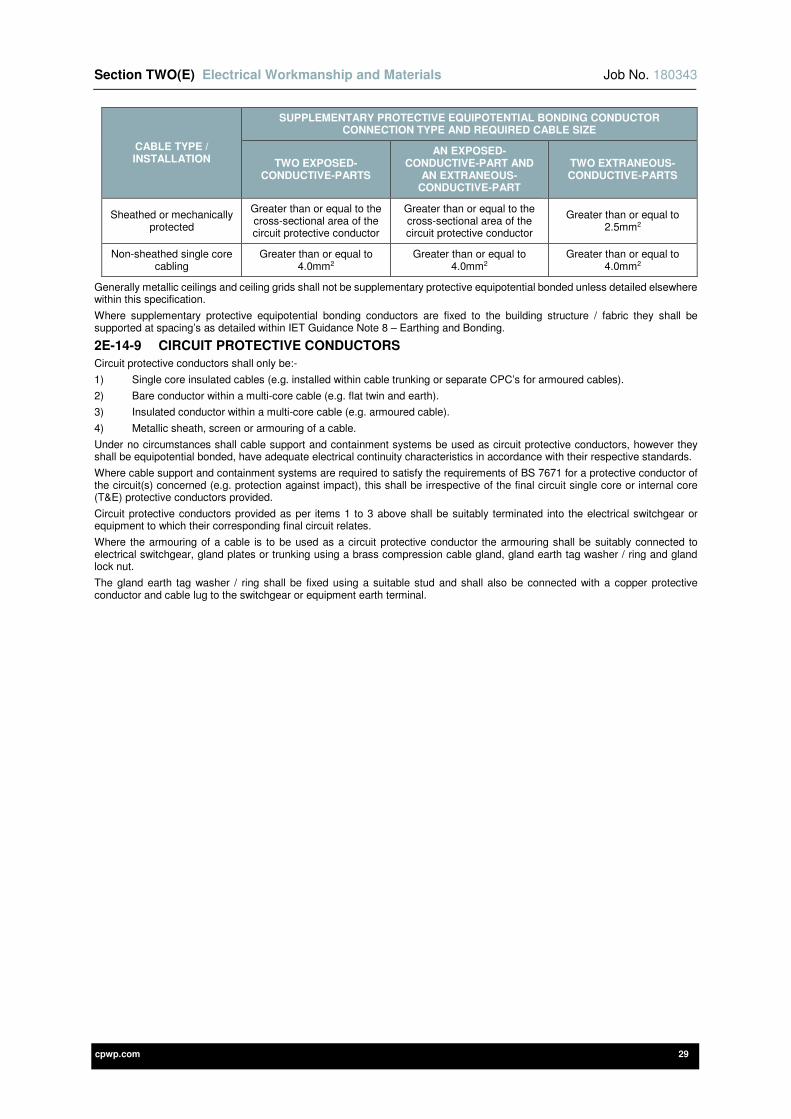
Section TWO(E) Electrical Workmanship and Materials Job No. 180343
cpwp.com 29
CABLE TYPE / INSTALLATION
SUPPLEMENTARY PROTECTIVE EQUIPOTENTIAL BONDING CONDUCTOR CONNECTION TYPE AND REQUIRED CABLE SIZE
TWO EXPOSED-CONDUCTIVE-PARTS
AN EXPOSED-CONDUCTIVE-PART AND
AN EXTRANEOUS-CONDUCTIVE-PART
TWO EXTRANEOUS-CONDUCTIVE-PARTS
Sheathed or mechanically protected
Greater than or equal to the cross-sectional area of the circuit protective conductor
Greater than or equal to the cross-sectional area of the circuit protective conductor
Greater than or equal to 2.5mm2
Non-sheathed single core cabling
Greater than or equal to 4.0mm2
Greater than or equal to 4.0mm2
Greater than or equal to 4.0mm2
Generally metallic ceilings and ceiling grids shall not be supplementary protective equipotential bonded unless detailed elsewhere within this specification.
Where supplementary protective equipotential bonding conductors are fixed to the building structure / fabric they shall be supported at spacing’s as detailed within IET Guidance Note 8 – Earthing and Bonding.
2E-14-9 CIRCUIT PROTECTIVE CONDUCTORS
Circuit protective conductors shall only be:-
1) Single core insulated cables (e.g. installed within cable trunking or separate CPC’s for armoured cables).
2) Bare conductor within a multi-core cable (e.g. flat twin and earth).
3) Insulated conductor within a multi-core cable (e.g. armoured cable).
4) Metallic sheath, screen or armouring of a cable.
Under no circumstances shall cable support and containment systems be used as circuit protective conductors, however they shall be equipotential bonded, have adequate electrical continuity characteristics in accordance with their respective standards.
Where cable support and containment systems are required to satisfy the requirements of BS 7671 for a protective conductor of the circuit(s) concerned (e.g. protection against impact), this shall be irrespective of the final circuit single core or internal core (T&E) protective conductors provided.
Circuit protective conductors provided as per items 1 to 3 above shall be suitably terminated into the electrical switchgear or equipment to which their corresponding final circuit relates.
Where the armouring of a cable is to be used as a circuit protective conductor the armouring shall be suitably connected to electrical switchgear, gland plates or trunking using a brass compression cable gland, gland earth tag washer / ring and gland lock nut.
The gland earth tag washer / ring shall be fixed using a suitable stud and shall also be connected with a copper protective conductor and cable lug to the switchgear or equipment earth terminal.
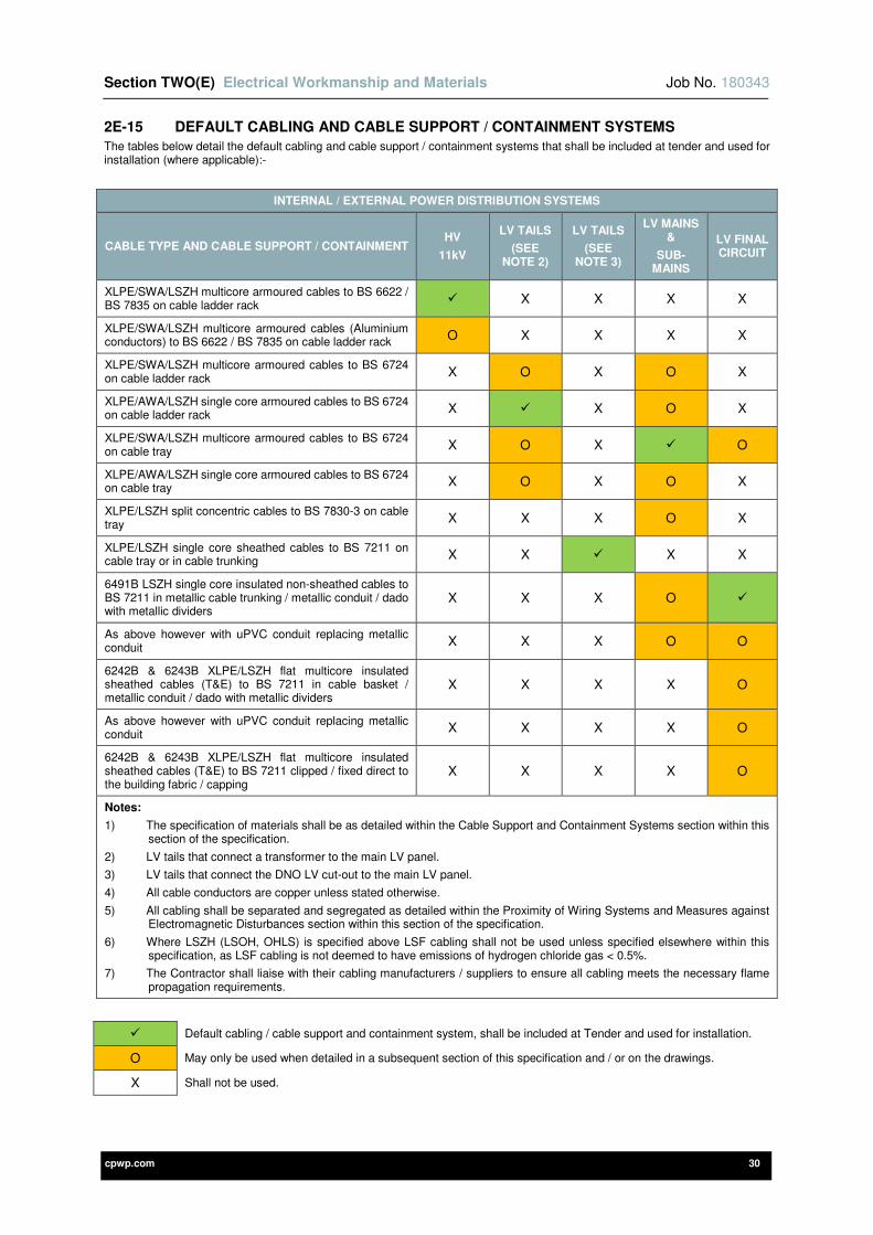
Section TWO(E) Electrical Workmanship and Materials Job No. 180343
cpwp.com 30
2E-15 DEFAULT CABLING AND CABLE SUPPORT / CONTAINMENT SYSTEMS
The tables below detail the default cabling and cable support / containment systems that shall be included at tender and used for installation (where applicable):-
INTERNAL / EXTERNAL POWER DISTRIBUTION SYSTEMS
CABLE TYPE AND CABLE SUPPORT / CONTAINMENT HV
11kV
LV TAILS
(SEE NOTE 2)
LV TAILS
(SEE NOTE 3)
LV MAINS &
SUB-MAINS
LV FINAL CIRCUIT
XLPE/SWA/LSZH multicore armoured cables to BS 6622 / BS 7835 on cable ladder rack
X X X X
XLPE/SWA/LSZH multicore armoured cables (Aluminium conductors) to BS 6622 / BS 7835 on cable ladder rack
O X X X X
XLPE/SWA/LSZH multicore armoured cables to BS 6724 on cable ladder rack
X O X O X
XLPE/AWA/LSZH single core armoured cables to BS 6724 on cable ladder rack
X X O X
XLPE/SWA/LSZH multicore armoured cables to BS 6724 on cable tray
X O X O
XLPE/AWA/LSZH single core armoured cables to BS 6724 on cable tray
X O X O X
XLPE/LSZH split concentric cables to BS 7830-3 on cable tray
X X X O X
XLPE/LSZH single core sheathed cables to BS 7211 on cable tray or in cable trunking
X X X X
6491B LSZH single core insulated non-sheathed cables to BS 7211 in metallic cable trunking / metallic conduit / dado with metallic dividers
X X X O
As above however with uPVC conduit replacing metallic conduit
X X X O O
6242B & 6243B XLPE/LSZH flat multicore insulated sheathed cables (T&E) to BS 7211 in cable basket / metallic conduit / dado with metallic dividers
X X X X O
As above however with uPVC conduit replacing metallic conduit
X X X X O
6242B & 6243B XLPE/LSZH flat multicore insulated sheathed cables (T&E) to BS 7211 clipped / fixed direct to the building fabric / capping
X X X X O
Notes:
1) The specification of materials shall be as detailed within the Cable Support and Containment Systems section within this section of the specification.
2) LV tails that connect a transformer to the main LV panel.
3) LV tails that connect the DNO LV cut-out to the main LV panel.
4) All cable conductors are copper unless stated otherwise.
5) All cabling shall be separated and segregated as detailed within the Proximity of Wiring Systems and Measures against Electromagnetic Disturbances section within this section of the specification.
6) Where LSZH (LSOH, OHLS) is specified above LSF cabling shall not be used unless specified elsewhere within this specification, as LSF cabling is not deemed to have emissions of hydrogen chloride gas < 0.5%.
7) The Contractor shall liaise with their cabling manufacturers / suppliers to ensure all cabling meets the necessary flame propagation requirements.
Default cabling / cable support and containment system, shall be included at Tender and used for installation.
O May only be used when detailed in a subsequent section of this specification and / or on the drawings.
X Shall not be used.
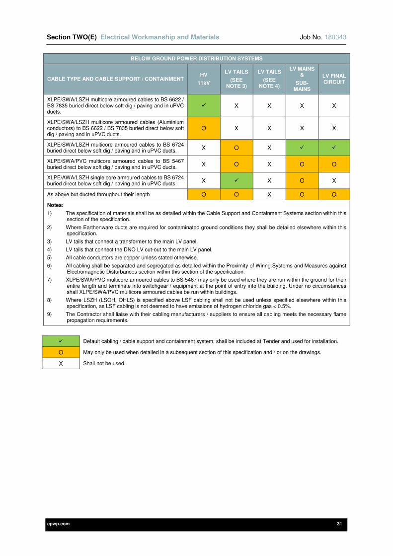
Section TWO(E) Electrical Workmanship and Materials Job No. 180343
cpwp.com 31
BELOW GROUND POWER DISTRIBUTION SYSTEMS
CABLE TYPE AND CABLE SUPPORT / CONTAINMENT HV
11kV
LV TAILS
(SEE NOTE 3)
LV TAILS
(SEE NOTE 4)
LV MAINS &
SUB-MAINS
LV FINAL CIRCUIT
XLPE/SWA/LSZH multicore armoured cables to BS 6622 / BS 7835 buried direct below soft dig / paving and in uPVC ducts.
X X X X
XLPE/SWA/LSZH multicore armoured cables (Aluminium conductors) to BS 6622 / BS 7835 buried direct below soft dig / paving and in uPVC ducts.
O X X X X
XLPE/SWA/LSZH multicore armoured cables to BS 6724 buried direct below soft dig / paving and in uPVC ducts.
X O X
XLPE/SWA/PVC multicore armoured cables to BS 5467 buried direct below soft dig / paving and in uPVC ducts.
X O X O O
XLPE/AWA/LSZH single core armoured cables to BS 6724 buried direct below soft dig / paving and in uPVC ducts.
X X O X
As above but ducted throughout their length O O X O O
Notes:
1) The specification of materials shall be as detailed within the Cable Support and Containment Systems section within this section of the specification.
2) Where Earthenware ducts are required for contaminated ground conditions they shall be detailed elsewhere within this specification.
3) LV tails that connect a transformer to the main LV panel.
4) LV tails that connect the DNO LV cut-out to the main LV panel.
5) All cable conductors are copper unless stated otherwise.
6) All cabling shall be separated and segregated as detailed within the Proximity of Wiring Systems and Measures against Electromagnetic Disturbances section within this section of the specification.
7) XLPE/SWA/PVC multicore armoured cables to BS 5467 may only be used where they are run within the ground for their entire length and terminate into switchgear / equipment at the point of entry into the building. Under no circumstances shall XLPE/SWA/PVC multicore armoured cables be run within buildings.
8) Where LSZH (LSOH, OHLS) is specified above LSF cabling shall not be used unless specified elsewhere within this specification, as LSF cabling is not deemed to have emissions of hydrogen chloride gas < 0.5%.
9) The Contractor shall liaise with their cabling manufacturers / suppliers to ensure all cabling meets the necessary flame propagation requirements.
Default cabling / cable support and containment system, shall be included at Tender and used for installation.
O May only be used when detailed in a subsequent section of this specification and / or on the drawings.
X Shall not be used.
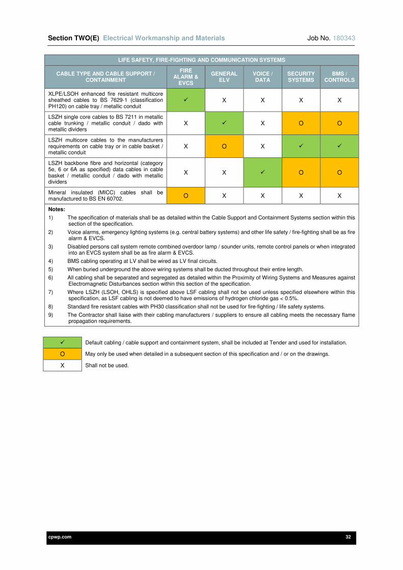
Section TWO(E) Electrical Workmanship and Materials Job No. 180343
cpwp.com 32
LIFE SAFETY, FIRE-FIGHTING AND COMMUNICATION SYSTEMS
CABLE TYPE AND CABLE SUPPORT / CONTAINMENT
FIRE ALARM &
EVCS
GENERAL ELV
VOICE / DATA
SECURITY SYSTEMS
BMS / CONTROLS
XLPE/LSOH enhanced fire resistant multicore sheathed cables to BS 7629-1 (classification PH120) on cable tray / metallic conduit
X X X X
LSZH single core cables to BS 7211 in metallic cable trunking / metallic conduit / dado with metallic dividers
X X O O
LSZH multicore cables to the manufacturers requirements on cable tray or in cable basket / metallic conduit
X O X
LSZH backbone fibre and horizontal (category 5e, 6 or 6A as specified) data cables in cable basket / metallic conduit / dado with metallic dividers
X X O O
Mineral insulated (MICC) cables shall be manufactured to BS EN 60702.
O X X X X
Notes:
1) The specification of materials shall be as detailed within the Cable Support and Containment Systems section within this section of the specification.
2) Voice alarms, emergency lighting systems (e.g. central battery systems) and other life safety / fire-fighting shall be as fire alarm & EVCS.
3) Disabled persons call system remote combined overdoor lamp / sounder units, remote control panels or when integrated into an EVCS system shall be as fire alarm & EVCS.
4) BMS cabling operating at LV shall be wired as LV final circuits.
5) When buried underground the above wiring systems shall be ducted throughout their entire length.
6) All cabling shall be separated and segregated as detailed within the Proximity of Wiring Systems and Measures against Electromagnetic Disturbances section within this section of the specification.
7) Where LSZH (LSOH, OHLS) is specified above LSF cabling shall not be used unless specified elsewhere within this specification, as LSF cabling is not deemed to have emissions of hydrogen chloride gas < 0.5%.
8) Standard fire resistant cables with PH30 classification shall not be used for fire-fighting / life safety systems.
9) The Contractor shall liaise with their cabling manufacturers / suppliers to ensure all cabling meets the necessary flame propagation requirements.
Default cabling / cable support and containment system, shall be included at Tender and used for installation.
O May only be used when detailed in a subsequent section of this specification and / or on the drawings.
X Shall not be used.
Section TWO(E) Electrical Workmanship and Materials Job No. 180343
cpwp.com 33
2E-16 CABLE SUPPORT AND CONTAINMENT SYSTEMS
This section of the specification details the general requirements for cable support and containment systems.
2E-16-1 DEFAULT SPARE CAPACITY WITHIN CABLE SUPPORT AND CONTAINMENT SYSTEMS
Cable support and containment systems shall be provided with 30% spare capacity and also an additional 30% allowance shall be added to the calculated safe working load (SWL) for supports, for the provision of future cabling.
Where 30% spare capacity is provided to cable ladder rack and cable tray, this shall be a dedicated section of the system and shall not be above or between installed cabling.
2E-16-2 GENERAL REQUIREMENTS FOR CABLE SUPPORT AND CONTAINMENT SYSTEMS
All cable support and containment systems shall be provided as follows:-
1) They must be fully continuous throughout and utilise (where applicable) couplers, joint strips, connectors, brackets, bends, gussets, clips, clamps, risers, angles, tees, cross pieces, reducers, bell mouths, end caps, conduit boxes, adaptable boxes, conduit take-off plates and fixing components etc. from the same manufacturer.
2) Where visible, uPVC systems shall be from the same manufacturer so that variations in colour are avoided. uPVC systems shall not be used within environments that have extreme low or high temperatures.
3) Angles, bends, risers, tees, cross pieces etc. shall be adequately sized to accommodate the minimum bending radius of the largest cabling to be installed. Cabling bends shall be sized in accordance with the IET On-Site Guide, IET Guidance Note 1 and in strict accordance with the cabling manufacturer’s recommendations.
4) Where possible cabling shall retain its position through all bends, tees, cross pieces etc. so that cross overs are minimized / eliminated.
5) All proprietary fasteners, screws, bolts, washers, nuts, lock nuts and cover clips shall be from the same material and manufacturer as the system. These fixings and fittings shall not intrude into the system in such a manner that they may cause damage to the cabling.
6) Where covers / lids (closed or ventilated) and dividers / partitions are specified they must be from the same material and manufacturer as the system.
7) Covers / lids and dividers / partitions shall be fully continuous throughout the entire system. All covers / lids and dividers / partitions shall be fixed using the manufacturers proprietary screw fixings and self-tapping screws shall not be used.
8) Where covers / lids are installed, long lengths of covers / lids shall be removable. However where systems pass through the building fabric the covers / lids shall be cut and fixed to project 75mm either side of the obstruction. When the structure is made good, this section of cover shall not be removable.
9) Where dividers / partitions are specified printed labels shall be fixed to each compartment divider at 3m intervals and shall denote the use of the compartment / section.
10) Where galvanised steel systems are cut all burrs must be removed and edges suitably painted with cold galvanise zinc-rich paint before erection. All cuts shall be straight and squared off where required. Where the galvanised coating to systems, fittings and accessories has been damaged the damaged areas must also be painted with cold galvanise zinc-rich paint.
11) Where uPVC systems are cut all burrs must be removed and all cuts shall be straight and squared off where required.
12) Proprietary cutters / croppers shall be used where required (e.g. cable basket, non-metallic conduit etc.) in strict accordance with the manufacturer’s recommendations.
13) Adequate allowance shall be made for changes in length of the systems due to thermal expansion and contraction; this may be in the form of expansion couplers / slip connectors. Expansion as opposed to rigid couplers shall also be used across expansion joints of the building structure. Connections that provide electrical continuity shall also allow for thermal expansion / contraction.
14) Where flexible couplers are used calculations shall be undertaken in strict accordance with the manufacturer’s recommendations.
15) All cabling shall be separated and segregated as detailed within the Proximity of Wiring Systems and Measures against Electromagnetic Disturbances section within this section of the specification.
16) Where systems pass through the building(s) suitable measures shall be undertaken to prevent thermal bridging.
17) Non-metallic systems shall not be installed external to the building(s).
18) Under no circumstances shall slab fixed cable tie support systems be used.
2E-16-3 METAL CHANNEL CABLE SUPPORT SYSTEMS AND OTHER ASSOCIATED SUPPORTS
Metal channel and/or manufacturers proprietary cable support systems shall be used to support the cable management systems. Metal channel cable support systems shall comply with BS 6946. Manufacturer’s proprietary cable support systems shall be provided in strict accordance with the manufacturer’s recommendations.
Metal channel and/or manufacturers’ proprietary cable support systems shall be provided as follows:-
1) All supports, brackets, fixings and suspension components shall be formed from steel compliant with BS 1449-1 and shall be hot dip galvanised after manufacture to the requirements of BS EN ISO 1461.
2) Supports, brackets, fixings, drop rods (minimum 8mm diameter) and suspension components shall be provided at intervals to support an additional 30% allowance added to the calculated safe working load (SWL) for the provision of future cabling.
3) They shall be provided at intervals to prevent excessive deflection of the cable management systems in strict accordance with the manufacturer’s recommendations. In addition to this, no supports shall be installed at centres greater than 2000mm.

Section TWO(E) Electrical Workmanship and Materials Job No. 180343
cpwp.com 34
4) Supports shall be provided within 300mm of couplers, brackets, bends, risers, tees, crosspieces, reducers and all proprietary manufacturers’ fittings. Where cable support and containment systems rise up walls they shall be fixed to metal channel at 1500mm centres.
5) All cut ends of metal channel (e.g. Unistrut) shall be painted with cold galvanise zinc-rich paint and shall have plastic protective caps fitted.
6) Where threaded drop rods (minimum 8mm diameter) are used they shall be secured to brackets or supports by vibration proof lock-nuts. Fixings at an angle shall be achieved by using manufacturers’ proprietary angle brackets and all drop rods shall be vertically suspended. Under no circumstances is it permissible to bend drop rods to suit the rake of a roof.
7) Threaded rod / studding and screws shall be reduced in length so that no more than two threads are exposed. All cut ends shall be painted with cold galvanise zinc-rich paint.
8) Supports for mechanical services shall not be used to support electrical services and vice versa, without the bracketry being designed specifically with this in mind.
9) Under no circumstances shall Gripple wire be used to support primary cable support and containment systems.
2E-16-4 FIRE RESISTANCE OF CABLE SUPPORT AND CONTAINMENT SYSTEMS
The fire resistance of cable support and containment systems shall be as follows:-
1) All wiring systems (not only fire-fighting / life safety cabling) shall be adequately supported to prevent premature collapse under fire conditions in strict accordance with BS 7671. Steel cable support and containment systems are deemed to meet this requirement as stated within BS 7671.
Under no circumstances shall:-
a) Non-metallic cable clips or cables ties be used as the sole means of support where cables are clipped direct to exposed surfaces or suspended under containment systems.
b) Non-metallic cable trunking be used as the sole means of support of the cables therein.
c) Non-metallic cable trunking systems pass through walls, floors or fire compartments.
2) They shall have the same fire survival time as any fire-fighting / life safety cabling that is being supported, in strict accordance with BS 8519 and BS 5839.
3) For life safety / fire-fighting cabling they shall be fully continuous throughout from source to destination and shall be formed from steel that has been hot dip galvanised after manufacture to the requirements of BS EN ISO 1461.
4) Supports, brackets, fixings, drop rods and suspension components shall be sized with consideration that the tensile strength of steel will be significantly reduced in a fire situation and shall be provided at intervals in accordance with manufacturers’ literature. It shall be noted that failure to consider this requirement will result in premature collapse of the cable management system and therefore failure of the cabling installed.
5) The cross sectional area of drops rods shall be calculated in accordance with BS 8519 and manufacturers’ literature.
6) Cable cleats, strapping, ties and fire-rated clips (e.g. saddle and p-clips) for life safety / fire-fighting cabling shall have the same fire survival time as the life safety / fire-fighting cabling that is being supported and shall be provided at intervals in strict accordance with the manufacturer’s recommendations.
7) Cable cleats and supports for cable management systems shall be provided within 750mm of all fire barrier / stopping seals and shall be able to withstand the mechanical load induced by the collapse of wiring systems on the fire side of the seal, to prevent strain and damage to the seal, as required by BS 7671. This is not required if the seal itself is able to provide adequate support under such conditions.
8) Internal fire barriers shall be provided where metallic cable trunking systems pass through walls, floors or fire compartments, these fire barriers shall be rated in accordance with the fire compartmentation. Internal fire barriers shall also be installed within vertical cable trunking systems greater than 5m in height.
9) Fully continuous metallic systems that meet the necessary flame propagation requirements (as specified within their respective standards) shall be utilised as opposed to fire-rated clipping, unless agreed with the Engineer.
2E-16-5 CABLE CLEATS, STRAPPING AND TIES
Cable cleats, strapping and ties shall comply with BS EN 61914 and BS EN 62275, and shall be suitable for the environment in which they are installed. Cable cleats, strapping and ties shall be adequately sized to suit the cabling installed.
Manufacturer’s proprietary cable cleats, strapping and ties shall be used and provided at intervals in strict accordance with the manufacturer’s recommendations.
Where more than one cable is installed the cabling shall run in an orderly manner and retain its position through all changes in direction to minimize / eliminate cross overs. Cable cleats and strapping shall be provided before and after all changes in cabling direction.
Where sheathed and/or armoured cables with an overall diameter up to 40mm are fixed to the building fabric they shall be supported at spacing’s as detailed within the IET On-Site Guide and IET Guidance Note 1 – Selection & Erection. Cables with an overall diameter larger than 40mm shall be supported at spacing’s as recommended by the manufacturer.
Cable cleats, strapping and ties shall be provided as follows:-
CABLING TYPE / SIZE CABLE CLEAT / STRAPPING TYPE FIXING METHOD
Single Core Cables
Aluminium alloy or nylon (LSZH – low smoke zero halogen) trefoil cable cleats – Suitable for clamping three single core cables together
Two or single bolt fixings. Two bolt fixings shall be used for vertical cable runs
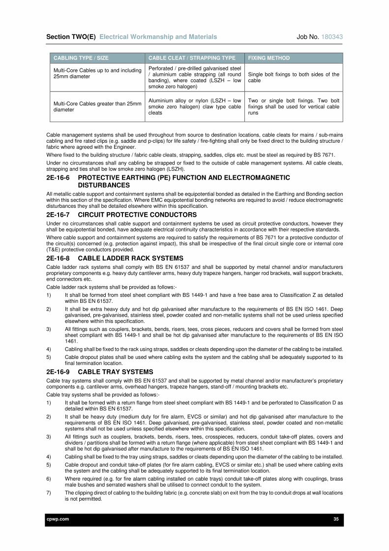
Section TWO(E) Electrical Workmanship and Materials Job No. 180343
cpwp.com 35
CABLING TYPE / SIZE CABLE CLEAT / STRAPPING TYPE FIXING METHOD
Multi-Core Cables up to and including 25mm diameter
Perforated / pre-drilled galvanised steel / aluminium cable strapping (all round banding), where coated (LSZH – low smoke zero halogen)
Single bolt fixings to both sides of the cable
Multi-Core Cables greater than 25mm diameter
Aluminium alloy or nylon (LSZH – low smoke zero halogen) claw type cable cleats
Two or single bolt fixings. Two bolt fixings shall be used for vertical cable runs
Cable management systems shall be used throughout from source to destination locations, cable cleats for mains / sub-mains cabling and fire rated clips (e.g. saddle and p-clips) for life safety / fire-fighting shall only be fixed direct to the building structure / fabric where agreed with the Engineer.
Where fixed to the building structure / fabric cable cleats, strapping, saddles, clips etc. must be steel as required by BS 7671.
Under no circumstances shall any cabling be strapped or fixed to the outside of cable management systems. All cable cleats, strapping and ties shall be low smoke zero halogen (LSZH).
2E-16-6 PROTECTIVE EARTHING (PE) FUNCTION AND ELECTROMAGNETIC DISTURBANCES
All metallic cable support and containment systems shall be equipotential bonded as detailed in the Earthing and Bonding section within this section of the specification. Where EMC equipotential bonding networks are required to avoid / reduce electromagnetic disturbances they shall be detailed elsewhere within this specification.
2E-16-7 CIRCUIT PROTECTIVE CONDUCTORS
Under no circumstances shall cable support and containment systems be used as circuit protective conductors, however they shall be equipotential bonded, have adequate electrical continuity characteristics in accordance with their respective standards.
Where cable support and containment systems are required to satisfy the requirements of BS 7671 for a protective conductor of the circuit(s) concerned (e.g. protection against impact), this shall be irrespective of the final circuit single core or internal core (T&E) protective conductors provided.
2E-16-8 CABLE LADDER RACK SYSTEMS
Cable ladder rack systems shall comply with BS EN 61537 and shall be supported by metal channel and/or manufacturers proprietary components e.g. heavy duty cantilever arms, heavy duty trapeze hangers, hanger rod brackets, wall support brackets, end connectors etc.
Cable ladder rack systems shall be provided as follows:-
1) It shall be formed from steel sheet compliant with BS 1449-1 and have a free base area to Classification Z as detailed within BS EN 61537.
2) It shall be extra heavy duty and hot dip galvanised after manufacture to the requirements of BS EN ISO 1461. Deep galvanised, pre-galvanised, stainless steel, powder coated and non-metallic systems shall not be used unless specified elsewhere within this specification.
3) All fittings such as couplers, brackets, bends, risers, tees, cross pieces, reducers and covers shall be formed from steel sheet compliant with BS 1449-1 and shall be hot dip galvanised after manufacture to the requirements of BS EN ISO 1461.
4) Cabling shall be fixed to the rack using straps, saddles or cleats depending upon the diameter of the cabling to be installed.
5) Cable dropout plates shall be used where cabling exits the system and the cabling shall be adequately supported to its final termination location.
2E-16-9 CABLE TRAY SYSTEMS
Cable tray systems shall comply with BS EN 61537 and shall be supported by metal channel and/or manufacturer’s proprietary components e.g. cantilever arms, overhead hangers, trapeze hangers, stand-off / mounting brackets etc.
Cable tray systems shall be provided as follows:-
1) It shall be formed with a return flange from steel sheet compliant with BS 1449-1 and be perforated to Classification D as detailed within BS EN 61537.
2) It shall be heavy duty (medium duty for fire alarm, EVCS or similar) and hot dip galvanised after manufacture to the requirements of BS EN ISO 1461. Deep galvanised, pre-galvanised, stainless steel, powder coated and non-metallic systems shall not be used unless specified elsewhere within this specification.
3) All fittings such as couplers, brackets, bends, risers, tees, crosspieces, reducers, conduit take-off plates, covers and dividers / partitions shall be formed with a return flange (where applicable) from steel sheet compliant with BS 1449-1 and shall be hot dip galvanised after manufacture to the requirements of BS EN ISO 1461.
4) Cabling shall be fixed to the tray using straps, saddles or cleats depending upon the diameter of the cabling to be installed.
5) Cable dropout and conduit take-off plates (for fire alarm cabling, EVCS or similar etc.) shall be used where cabling exits the system and the cabling shall be adequately supported to its final termination location.
6) Where required (e.g. for fire alarm cabling installed on cable trays) conduit take-off plates along with couplings, brass male bushes and serrated washers shall be utilised to connect conduit to the system.
7) The clipping direct of cabling to the building fabric (e.g. concrete slab) on exit from the tray to conduit drops at wall locations is not permitted.

Section TWO(E) Electrical Workmanship and Materials Job No. 180343
cpwp.com 36
8) The cable tray and conduit shall form a fully continuous containment system throughout from source to destination terminations. Only galvanised steel conduit shall be connected to galvanised steel cable tray.
2E-16-10 CABLE BASKET / WIRE MESH TRAY SYSTEMS
Cable basket / wire mesh tray systems shall comply with BS EN 61537 and shall be supported by metal channel and/or manufacturer’s proprietary components e.g. cantilever arms, central hangers, suspension hangers, stand-off / mounting brackets, floor brackets etc.
Where the term cable basket system is used within this specification it also refers to wire mesh cable tray systems.
Cable basket / wire mesh tray systems shall be provided as follows:-
1) It shall be formed from steel wire welded into a mesh pattern and shall be electro-galvanised after manufacture (electroplated with zinc) to the requirements of BS EN 12329 / BS EN ISO 2081. Deep galvanised, hot dip galvanised, stainless steel, powder coated and non-metallic systems shall not be used unless specified elsewhere within this specification.
2) Bends, risers, tees, cross pieces etc. shall be cut / formed on site using proprietary cutters / croppers in strict accordance with the manufacturer’s recommendations.
3) All fittings such as couplers, joint strips, connectors, brackets, clips, clamps, conduit take-off plates, fixing components and covers / dividers shall be formed from steel sheet and shall be electro-galvanised after manufacture (electroplated with zinc) to the requirements of BS EN 12329 / BS EN ISO 2081, or pre-galvanised before manufacture to the requirements of BS EN 10346.
4) Cabling shall be fixed to the basket using cable straps and ties as required.
5) Cable dropout and conduit take-off plates shall be used where cabling exits the system and the cabling shall be adequately supported to its final termination location.
6) Conduit take-off plates along with couplings, brass male bushes and serrated washers shall be utilised to connect conduit to the system.
7) The clipping direct of cabling to the building fabric (e.g. concrete slab) on exit from the basket to conduit drops at wall locations is not permitted.
8) The basket and conduit shall form a fully continuous containment system throughout from source to destination terminations.
9) Under no circumstances shall systems be used to support single core or multicore armoured cables.
10) It shall not be installed external to the building(s).
2E-16-11 CABLE TRUNKING SYSTEMS
GENERAL REQUIREMENTS
The general requirements for cable trunking systems are as follows:-
1) Where fixed direct to the building fabric it shall be supported at spacing’s as detailed within the IET On-Site Guide, IET Guidance Note 1 – Selection & Erection and in strict accordance with manufacturers’ literature.
2) The systems shall be sized as detailed within the IET On-Site Guide and IET Guidance Note 1 – Selection & Erection.
3) All bends, tees and cross overs used within multi-compartment systems shall be multi-compartment fittings to ensure the full segregation of cabling throughout the cable trunking.
4) Cable retainers shall be installed at intervals of 600mm where cable trunking lid / covers are installed to the bottom or side of the system. Pin racks shall be installed within trunking on vertical runs greater than 3m and shall be installed at 2m intervals to support the cabling installed.
5) Where non-sheathed cables are installed in cable trunking the entire system (including all fittings) shall provide at least the degree of protection (IP code) of IP4X or IPXXD to BS EN 60529, as required by BS 7671. It shall only be possible to secure or remove the trunking lid by means of a tool or deliberate action.
6) It shall not be installed external to the building(s).
METALLIC CABLE TRUNKING SYSTEMS
Metallic cable trunking systems shall comply with BS EN 50085 and shall be supported by metal channel and/or manufacturers proprietary components e.g. trapeze / stirrup / overhead hangers etc.
This section of the specification does not apply to metallic dado trunking systems.
Metallic cable trunking systems shall be provided as follows:-
1) It shall be formed from steel sheet and shall be pre-galvanised before manufacture to the requirements of BS EN 10346. Deep galvanised, hot dip galvanised, stainless steel, powder coated and non-metallic systems shall not be used unless specified elsewhere within this specification.
2) All fittings such as couplers, lid / covers, cover straps, bends (gusset and square), tees, cross overs, reducers, bellmouths, end caps, flanges etc. shall be formed from steel sheet and shall be pre-galvanised before manufacture to the requirements of BS EN 10346.
3) Where recessed covers shall be installed to form a flush finish with the adjacent building fabric.
4) Circular conduit boxes or couplings, brass male bushes and serrated washers shall be utilised to connect conduit to the system.
5) The clipping direct of cabling to the building fabric (e.g. concrete slab) on exit from the trunking to conduit drops at wall locations is not permitted.
6) The trunking and conduit shall form a fully continuous containment system to IP4X or IPXXD, from source to destination terminations.
Section TWO(E) Electrical Workmanship and Materials Job No. 180343
cpwp.com 37
7) Conduits shall not pass through compartments to reach the appropriate destination compartment; they shall connect to the compartment using circular conduit boxes mounted below / adjacent on the outside of the cable trunking. Where multi-compartment trunking is recessed into the building fabric circular conduit boxes shall be mounted behind the appropriate destination compartment.
8) It shall not be used as a circuit protective conductor (CPC) for final circuit wiring, however where required it shall satisfy the requirements of BS 7671 for a protective conductor of the circuit(s) concerned (e.g. protection against impact).
uPVC CABLE TRUNKING SYSTEMS
Non-metallic cable trunking systems shall comply with BS EN 50085 and BS 4678 (BS 4678-2 and BS 4678-4 are still current) and shall be fixed / supported in strict accordance with the manufacturer’s recommendations.
This section of the specification does not apply to non-metallic dado trunking systems.
Non-metallic cable trunking systems shall be provided as follows:-
1) It shall be heavy gauge white uPVC and shall have the following properties:-
a) Corrosion resistance.
b) High impact resistance.
c) Non-flame propagating.
d) Self-extinguishing.
2) It shall not be used unless specified elsewhere within this specification.
3) The cutting and manipulation of trunking lengths to form proprietary components is deemed not acceptable, proprietary manufacturer’s components must be used in all instances e.g. internal / external couplers, end caps, angles, tees, internal / external bends, cross overs etc.
4) All fittings such as internal / external couplers, end caps, angles, tees, internal / external bends, cross overs etc. shall be heavy gauge white uPVC and meet the requirements detailed above (Item 1).
5) Where required conduit boxes or couplings / male bushes shall be utilised to connect conduit to the system.
6) The trunking and conduit shall form a fully continuous containment system to IP4X or IPXXD, from source to destination terminations.
7) Only heavy gauge white uPVC conduit shall be connected to the uPVC cable trunking.
2E-16-12 DADO, SKIRTING AND BENCH TRUNKING SYSTEMS
GENERAL REQUIREMENTS
The general requirements for dado, skirting and bench trunking systems are as follows:-
1) Where applicable the general requirements for cable trunking systems shall also apply.
2) The systems shall be suitable for the category of data cabling to be installed (e.g. Cat 5e, Cat 6 and Cat 6A) and shall not impair the performance of the cabling. It shall also be suitable for the other types of cabling to be installed (e.g. LV final circuits cabling, audio visual cabling etc.).
3) Dado and skirting trunking systems shall have a minimum of three compartments and it shall be possible to install manufacturer’s proprietary 45mmm deep back boxes. Bench trunking systems shall have a minimum of two compartments and it shall be possible to install manufacturer’s proprietary 35mmm deep back boxes.
4) Signalling and data cabling shall not be installed within a compartment that contains LV wiring. Screening dividers shall be provided to adequately segregate LV power cabling from data / signalling cabling. The screening dividers shall be steel and have a minimum thickness of 1.5mm.
5) Dado and skirting trunking shall be provided with cable retainers installed at intervals of 600mm.
6) Generally the dado trunking systems shall be fed from vertical dado trunking lengths which will rise to high level (e.g. ceiling void) and shall terminate in a position adjacent to primary / secondary containment systems for concealed entry into compartments via end caps. Screening dividers shall also be provided throughout the vertical dado trunking drops.
7) Where conduits are used to drop to dado, skirting and bench trunking they shall be concealed within the building fabric and shall be connected to the systems using recessed circular conduit boxes mounted behind the appropriate destination compartment.
8) The vertical trunking lengths and screening dividers shall be from the same manufacturer’s product range as the horizontal trunking systems.
9) Where antibacterial (e.g. silver additive based) systems are required (e.g. healthcare, laboratories etc.) they shall be detailed elsewhere within this specification.
METALLIC DADO, SKIRTING AND BENCH TRUNKING SYSTEMS
Metallic dado, skirting and bench trunking systems shall comply with BS EN 50085 and BS 4678 (BS 4678-2 and BS4678-4 are still current) and shall be fixed / supported in strict accordance with the manufacturer’s recommendations.
Metallic dado, skirting and bench trunking systems shall be provided as follows:-
1) It shall be formed from steel sheet and shall be pre-galvanised before manufacture to the requirements of BS EN 10346.
2) They shall also have a white powder coat finish to RAL 9010 or RAL 9003.
3) Aluminium systems shall not be used unless specified elsewhere within this specification.
4) All fittings such as end caps, angles, tees, internal / external corners etc. shall be formed from steel sheet and shall be pre-galvanised before manufacture to the requirements of BS EN 10346.
5) They shall also have a white powder coat finish to RAL 9010 or RAL 9003.
6) The proprietary components shall be selected to suit either dado trunking, skirting or bench trunking systems.
Section TWO(E) Electrical Workmanship and Materials Job No. 180343
cpwp.com 38
uPVC DADO, SKIRTING AND BENCH TRUNKING SYSTEMS
Non-metallic dado, skirting and bench trunking systems shall comply with BS EN 50085 and BS 4678 (BS 4678-2 and BS4678-4 are still current) and shall be fixed / supported in strict accordance with the manufacturer’s recommendations.
Non-metallic dado, skirting and bench trunking systems shall be provided as follows:-
1) It shall be heavy gauge white uPVC and shall have the following properties:-
a) Corrosion resistance.
b) High impact resistance.
c) Non-flame propagating.
d) Self-extinguishing.
2) The cutting and manipulation of trunking lengths to form proprietary components is deemed not acceptable, proprietary manufacturer’s components must be used in all instances e.g. end caps, angles, tees, internal / external corners etc.
3) All fittings such as end caps, angles, tees, internal / external corners etc. shall be heavy gauge white uPVC and meet the requirements detailed above (Item 1).
4) The proprietary components shall be selected to suit either dado trunking, skirting or bench trunking systems.
2E-16-13 CONDUIT AND FITTINGS
GENERAL REQUIREMENTS
The general requirements for conduit and fittings are as follows:-
1) Where conduit is fixed direct to the building fabric it shall be supported at spacing’s as detailed within the IET On-Site Guide and IET Guidance Note 1 – Selection & Erection.
2) Conduit systems shall be provided with spare capacity so that 30% more cable/s of a similar size and type can be installed.
3) 30% physical spare capacity and conduits less than 20mm diameter shall not be used.
4) Surface conduits shall also be supported within 300mm of floors, ceilings, boxes and at each side of every bend.
5) Fixing of conduits shall be as follows: -
a) Wall chases or floor screed – Crampets or ordinary saddles.
b) Ceiling, roof or floor voids – Spacer bar saddles.
c) Surface mounted on ceiling – Spacer bar saddles.
d) Surface mounted on walls – Distance saddles.
6) Conduits shall be sized as detailed within the IET On-Site Guide and IET Guidance Note 1 – Selection & Erection.
7) Inaccessible conduits shall be arranged on a 'loop-in' system so that all draw in points for cables are accessible at finished surfaces.
8) Proprietary draw points shall be provided to facilitate initial installation, rewiring and future maintenance; the maximum distance between draw points shall be 10m. A maximum of one 90° bend (or the equivalent total of all bends) shall be permitted between draw points.
9) Bends, elbows, tees or u-bands shall not be used. Bends for metallic conduit shall be formed on a proprietary bending machine. uPVC bends shall be formed using a suitably sized spring and by the application of heat.
10) Where conduits are installed for use by third parties, draw wires shall be provided to facilitate the installation of cabling.
11) All conduit boxes and adaptable boxes shall be filled with moisture repelling compound or have drains where there is a risk of condensation and within plantrooms / external locations all box lids shall be fitted with gaskets. In damp environments conduits shall enter wiring accessories from the bottom to prevent the build-up of moisture.
12) Chasing of walls must be carried out in accordance with the Structural Engineer's recommendations where appropriate. Under no circumstances shall horizontal chases exceed 500mm in length. Back to back chasing is also not permitted.
13) Conduit shall not be installed within floor screeds or cast-in unless detailed elsewhere within this specification.
14) Under no circumstances shall metal or plastic capping be used for cabling drops installed within walls.
15) It shall not be installed external to the building(s).
METALLIC CONDUIT AND FITTINGS
Metallic cable conduit shall comply with BS EN 61386 and shall have a resistance to corrosion classification of ‘Class 4’ as detailed within Table 10 of BS EN 61386.
Metallic conduit and fittings shall be provided as follows:-
1) It shall be formed from heavy gauge steel and shall be hot dip galvanised after manufacture to the requirements of BS EN ISO 1461, to provide a high level of corrosion protection both inside and outside to meet the classification 4 requirements.
2) Metal conduit with resistance to corrosion classifications of 1, 2 or 3 shall not be used unless detailed elsewhere within this specification.
3) Connections to accessory boxes on a concealed installation shall be with couplings, brass male bushes and serrated washers. For surfaces installation, flanged couplers with lead washers shall be used.
4) Conduits shall be threaded to butt closely together in couplings and sockets.
5) Except at running couplings, threads shall not be exposed and these shall be cleaned, primed and painted with cold galvanise zinc-rich paint after installation.
6) All conduit drops in chases in plastered walls shall be painted with red oxide paint before plaster is applied and shall have a coupler inserted in the run 300mm from ceiling level.
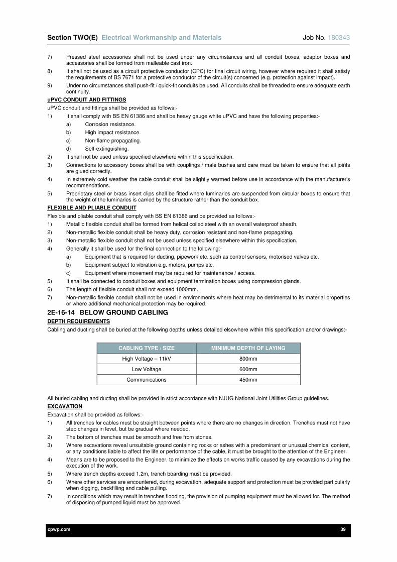
Section TWO(E) Electrical Workmanship and Materials Job No. 180343
cpwp.com 39
7) Pressed steel accessories shall not be used under any circumstances and all conduit boxes, adaptor boxes and accessories shall be formed from malleable cast iron.
8) It shall not be used as a circuit protective conductor (CPC) for final circuit wiring, however where required it shall satisfy the requirements of BS 7671 for a protective conductor of the circuit(s) concerned (e.g. protection against impact).
9) Under no circumstances shall push-fit / quick-fit conduits be used. All conduits shall be threaded to ensure adequate earth continuity.
uPVC CONDUIT AND FITTINGS
uPVC conduit and fittings shall be provided as follows:-
1) It shall comply with BS EN 61386 and shall be heavy gauge white uPVC and have the following properties:-
a) Corrosion resistance.
b) High impact resistance.
c) Non-flame propagating.
d) Self-extinguishing.
2) It shall not be used unless specified elsewhere within this specification.
3) Connections to accessory boxes shall be with couplings / male bushes and care must be taken to ensure that all joints are glued correctly.
4) In extremely cold weather the cable conduit shall be slightly warmed before use in accordance with the manufacturer's recommendations.
5) Proprietary steel or brass insert clips shall be fitted where luminaries are suspended from circular boxes to ensure that the weight of the luminaries is carried by the structure rather than the conduit box.
FLEXIBLE AND PLIABLE CONDUIT
Flexible and pliable conduit shall comply with BS EN 61386 and be provided as follows:-
1) Metallic flexible conduit shall be formed from helical coiled steel with an overall waterproof sheath.
2) Non-metallic flexible conduit shall be heavy duty, corrosion resistant and non-flame propagating.
3) Non-metallic flexible conduit shall not be used unless specified elsewhere within this specification.
4) Generally it shall be used for the final connection to the following:-
a) Equipment that is required for ducting, pipework etc. such as control sensors, motorised valves etc.
b) Equipment subject to vibration e.g. motors, pumps etc.
c) Equipment where movement may be required for maintenance / access.
5) It shall be connected to conduit boxes and equipment termination boxes using compression glands.
6) The length of flexible conduit shall not exceed 1000mm.
7) Non-metallic flexible conduit shall not be used in environments where heat may be detrimental to its material properties or where additional mechanical protection may be required.
2E-16-14 BELOW GROUND CABLING
DEPTH REQUIREMENTS
Cabling and ducting shall be buried at the following depths unless detailed elsewhere within this specification and/or drawings:-
CABLING TYPE / SIZE MINIMUM DEPTH OF LAYING
High Voltage – 11kV 800mm
Low Voltage 600mm
Communications 450mm
All buried cabling and ducting shall be provided in strict accordance with NJUG National Joint Utilities Group guidelines.
EXCAVATION
Excavation shall be provided as follows:-
1) All trenches for cables must be straight between points where there are no changes in direction. Trenches must not have step changes in level, but be gradual where needed.
2) The bottom of trenches must be smooth and free from stones.
3) Where excavations reveal unsuitable ground containing rocks or ashes with a predominant or unusual chemical content, or any conditions liable to affect the life or performance of the cable, it must be brought to the attention of the Engineer.
4) Means are to be proposed to the Engineer, to minimize the effects on works traffic caused by any excavations during the execution of the work.
5) Where trench depths exceed 1.2m, trench boarding must be provided.
6) Where other services are encountered, during excavation, adequate support and protection must be provided particularly when digging, backfilling and cable pulling.
7) In conditions which may result in trenches flooding, the provision of pumping equipment must be allowed for. The method of disposing of pumped liquid must be approved.
Section TWO(E) Electrical Workmanship and Materials Job No. 180343
cpwp.com 40
CABLING IN TRENCHES
Cabling in trenches shall be provided as follows:-
1) Cables must be laid in the trenches using roller, or other approved devices, to prevent dragging, and consequent abrasion.
2) Where more than one cable is to be laid in a trench, a minimum horizontal space of 300mm must exist between adjacent cables unless otherwise specified.
3) Cables must be laid on a bed of not less than 100mm of soft sand and covered with a further 150mm of hand compacted soft sand. Sifted soil may be used as an alternative, subject to approval by the Engineer.
4) Earthenware, concrete or polypropylene interlocking cover tiles must be laid on the sand/earth directly above and 75mm from the cables, to provide covering at least 50mm wider than the space occupied by the installed cables. The cable tiles must be covered with 75mm of hand compacted, excavated material free from stones or other sharp objects.
5) Backfilling must be compacted in layers not deeper than 250mm and the final surface reinstated so that after settlement it must be consistent with the surrounding surface level. Surplus material must be disposed of.
6) The excavation must be inspected 12 weeks after the ground finish has been completed, and any hollows must be filled using approved materials and methods.
7) Where lengths of cable in excess of 100m are required, precautions against thermal expansion and contraction must be taken.
8) Plastic cable marking tape shall be laid at a maximum depth of 200mm below ground level and must be snaked to cover the width occupied by the cables. The tape must be yellow with the black text "CAUTION ELECTRIC CABLE BELOW" printed along its length.
9) Where cables are to be laid along routes on which the ground will not be made up to its final level immediately following the cable installation, the routes must be marked by temporary notices indicating the danger present, over the total length of the route involves.
10) All temporary markers must be of a durable weatherproof nature and be approved.
11) The ground finish on completion must be similar to that in the immediate area.
CABLE DUCTS
Cable ducts shall be provided as follows:-
1) Cable ducts must be of reputable manufacture and must be made from uPVC unless otherwise specified and shall be a minimum 150mm diameter.
2) Earthenware cable ducts shall be used where there are contaminated ground conditions.
3) The ducts must be laid and bedded in such a way as to prevent damage from rocks etc. within the trench or in the back filling materials.
4) Where cable routes are designed to pass under areas of hard standing or through foundations etc, the cables must be enclosed in pipe ducts or sleeve. The protection of ducts running under roads etc. shall be by concrete haunchings or other approved suitable means.
5) The provision of cable draw pits at points of route deviation, and the transition from open ground to ducts must be agreed with the Engineer. Draw pits shall be suitably sized taking into account the number, type and size of cables to be installed. Deep draw pits must be of a sufficient size to allow access to the lowest ducts.
6) High voltage cables must be run in separate ducts to any low voltage cables.
7) Where new ducts clusters are being installed, 25% of the total ways available must be spare, with a minimum of two, unless single way ducts are specified. All spare ducts must be sealed against ingress of water and or vermin, with proprietary products approved by both the duct and cable manufacturer.
8) Cable ducts shall be laid at a gradient away from building entries.
9) A nylon draw cord must be left in each spare duct for its entire length and in any used ducts with spare capacity.
10) Before cables are drawn into any ducts, new or existing, the ducts must be swabbed to ensure that it is free of debris and clean.
11) Before cables are drawn into ducts the entry points must be protected by temporary bellmouths to ensure that there is no damage to the outer serving of the cable during the pulling operation.
12) Following the drawings in of the cable, the duct must be sealed using materials or devices authorised to provide protection against vermin, passage of gases, fire etc.
2E-16-15 SURFACE / EXPOSED CABLE SUPPORT AND CONTAINMENT SYSTEMS
Where surface / exposed primary cable management (e.g. cable ladder, cable tray and cable trunking) and secondary containment systems (e.g. final conduit runs) are acceptable, the location and routing of these systems must be agreed with the Engineer, Architect and Contract Administrator prior to installation.
2E-16-16 DESIGN REQUIREMENTS
The Contractor shall assume design responsibility for the following:-
1) The provision of adequate cable supports, fixings and suspension components to support all cabling management systems.
2) The provision of adequate cable supports, fixings and suspension components to support cabling management systems which are intended to support fire-resistant cabling in a fire condition, to prevent premature collapse of the cable management system and therefore failure of the cabling installed.
3) The provision of adequate bends, risers, tees, cross pieces etc. to accommodate the minimum bending radius of the largest cabling to be installed.
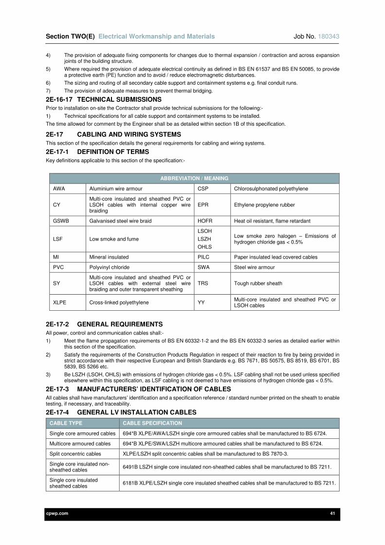
Section TWO(E) Electrical Workmanship and Materials Job No. 180343
cpwp.com 41
4) The provision of adequate fixing components for changes due to thermal expansion / contraction and across expansion joints of the building structure.
5) Where required the provision of adequate electrical continuity as defined in BS EN 61537 and BS EN 50085, to provide a protective earth (PE) function and to avoid / reduce electromagnetic disturbances.
6) The sizing and routing of all secondary cable support and containment systems e.g. final conduit runs.
7) The provision of adequate measures to prevent thermal bridging.
2E-16-17 TECHNICAL SUBMISSIONS
Prior to installation on-site the Contractor shall provide technical submissions for the following:-
1) Technical specifications for all cable support and containment systems to be installed.
The time allowed for comment by the Engineer shall be as detailed within section 1B of this specification.
2E-17 CABLING AND WIRING SYSTEMS
This section of the specification details the general requirements for cabling and wiring systems.
2E-17-1 DEFINITION OF TERMS
Key definitions applicable to this section of the specification:-
ABBREVIATION / MEANING
AWA Aluminium wire armour CSP Chlorosulphonated polyethylene
CY Multi-core insulated and sheathed PVC or LSOH cables with internal copper wire braiding
EPR Ethylene propylene rubber
GSWB Galvanised steel wire braid HOFR Heat oil resistant, flame retardant
LSF Low smoke and fume
LSOH
LSZH
OHLS
Low smoke zero halogen – Emissions of hydrogen chloride gas < 0.5%
MI Mineral insulated PILC Paper insulated lead covered cables
PVC Polyvinyl chloride SWA Steel wire armour
SY Multi-core insulated and sheathed PVC or LSOH cables with external steel wire braiding and outer transparent sheathing
TRS Tough rubber sheath
XLPE Cross-linked polyethylene YY Multi-core insulated and sheathed PVC or LSOH cables
2E-17-2 GENERAL REQUIREMENTS
All power, control and communication cables shall:-
1) Meet the flame propagation requirements of BS EN 60332-1-2 and the BS EN 60332-3 series as detailed earlier within this section of the specification.
2) Satisfy the requirements of the Construction Products Regulation in respect of their reaction to fire by being provided in strict accordance with their respective European and British Standards e.g. BS 7671, BS 50575, BS 8519, BS 6701, BS 5839, BS 5266 etc.
3) Be LSZH (LSOH, OHLS) with emissions of hydrogen chloride gas < 0.5%. LSF cabling shall not be used unless specified elsewhere within this specification, as LSF cabling is not deemed to have emissions of hydrogen chloride gas < 0.5%.
2E-17-3 MANUFACTURERS’ IDENTIFICATION OF CABLES
All cables shall have manufacturers’ identification and a specification reference / standard number printed on the sheath to enable testing, if necessary, and traceability.
2E-17-4 GENERAL LV INSTALLATION CABLES
CABLE TYPE CABLE SPECIFICATION
Single core armoured cables 694*B XLPE/AWA/LSZH single core armoured cables shall be manufactured to BS 6724.
Multicore armoured cables 694*B XLPE/SWA/LSZH multicore armoured cables shall be manufactured to BS 6724.
Split concentric cables XLPE/LSZH split concentric cables shall be manufactured to BS 7870-3.
Single core insulated non-sheathed cables
6491B LSZH single core insulated non-sheathed cables shall be manufactured to BS 7211.
Single core insulated sheathed cables
6181B XLPE/LSZH single core insulated sheathed cables shall be manufactured to BS 7211.
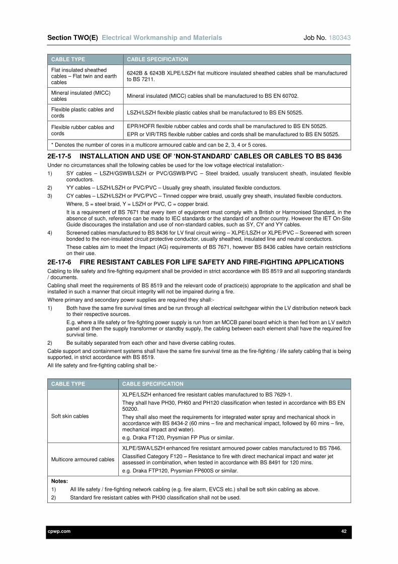
Section TWO(E) Electrical Workmanship and Materials Job No. 180343
cpwp.com 42
CABLE TYPE CABLE SPECIFICATION
Flat insulated sheathed cables – Flat twin and earth cables
6242B & 6243B XLPE/LSZH flat multicore insulated sheathed cables shall be manufactured to BS 7211.
Mineral insulated (MICC) cables
Mineral insulated (MICC) cables shall be manufactured to BS EN 60702.
Flexible plastic cables and cords
LSZH/LSZH flexible plastic cables shall be manufactured to BS EN 50525.
Flexible rubber cables and cords
EPR/HOFR flexible rubber cables and cords shall be manufactured to BS EN 50525.
EPR or VIR/TRS flexible rubber cables and cords shall be manufactured to BS EN 50525.
* Denotes the number of cores in a multicore armoured cable and can be 2, 3, 4 or 5 cores.
2E-17-5 INSTALLATION AND USE OF ‘NON-STANDARD’ CABLES OR CABLES TO BS 8436
Under no circumstances shall the following cables be used for the low voltage electrical installation:-
1) SY cables – LSZH/GSWB/LSZH or PVC/GSWB/PVC – Steel braided, usually translucent sheath, insulated flexible conductors.
2) YY cables – LSZH/LSZH or PVC/PVC – Usually grey sheath, insulated flexible conductors.
3) CY cables – LSZH/LSZH or PVC/PVC – Tinned copper wire braid, usually grey sheath, insulated flexible conductors.
Where, S = steel braid, Y = LSZH or PVC, C = copper braid.
It is a requirement of BS 7671 that every item of equipment must comply with a British or Harmonised Standard, in the absence of such, reference can be made to IEC standards or the standard of another country. However the IET On-Site Guide discourages the installation and use of non-standard cables, such as SY, CY and YY cables.
4) Screened cables manufactured to BS 8436 for LV final circuit wiring – XLPE/LSZH or XLPE/PVC – Screened with screen bonded to the non-insulated circuit protective conductor, usually sheathed, insulated line and neutral conductors.
These cables aim to meet the Impact (AG) requirements of BS 7671, however BS 8436 cables have certain restrictions on their use.
2E-17-6 FIRE RESISTANT CABLES FOR LIFE SAFETY AND FIRE-FIGHTING APPLICATIONS
Cabling to life safety and fire-fighting equipment shall be provided in strict accordance with BS 8519 and all supporting standards / documents.
Cabling shall meet the requirements of BS 8519 and the relevant code of practice(s) appropriate to the application and shall be installed in such a manner that circuit integrity will not be impaired during a fire.
Where primary and secondary power supplies are required they shall:-
1) Both have the same fire survival times and be run through all electrical switchgear within the LV distribution network back to their respective sources.
E.g. where a life safety or fire-fighting power supply is run from an MCCB panel board which is then fed from an LV switch panel and then the supply transformer or standby supply, the cabling between each element shall have the required fire survival time.
2) Be suitably separated from each other and have diverse cabling routes.
Cable support and containment systems shall have the same fire survival time as the fire-fighting / life safety cabling that is being supported, in strict accordance with BS 8519.
All life safety and fire-fighting cabling shall be:-
CABLE TYPE CABLE SPECIFICATION
Soft skin cables
XLPE/LSZH enhanced fire resistant cables manufactured to BS 7629-1.
They shall have PH30, PH60 and PH120 classification when tested in accordance with BS EN 50200.
They shall also meet the requirements for integrated water spray and mechanical shock in accordance with BS 8434-2 (60 mins – fire and mechanical impact, followed by 60 mins – fire, mechanical impact and water).
e.g. Draka FT120, Prysmian FP Plus or similar.
Multicore armoured cables
XLPE/SWA/LSZH enhanced fire resistant armoured power cables manufactured to BS 7846.
Classified Category F120 – Resistance to fire with direct mechanical impact and water jet assessed in combination, when tested in accordance with BS 8491 for 120 mins.
e.g. Draka FTP120, Prysmian FP600S or similar.
Notes:
1) All life safety / fire-fighting network cabling (e.g. fire alarm, EVCS etc.) shall be soft skin cabling as above.
2) Standard fire resistant cables with PH30 classification shall not be used.
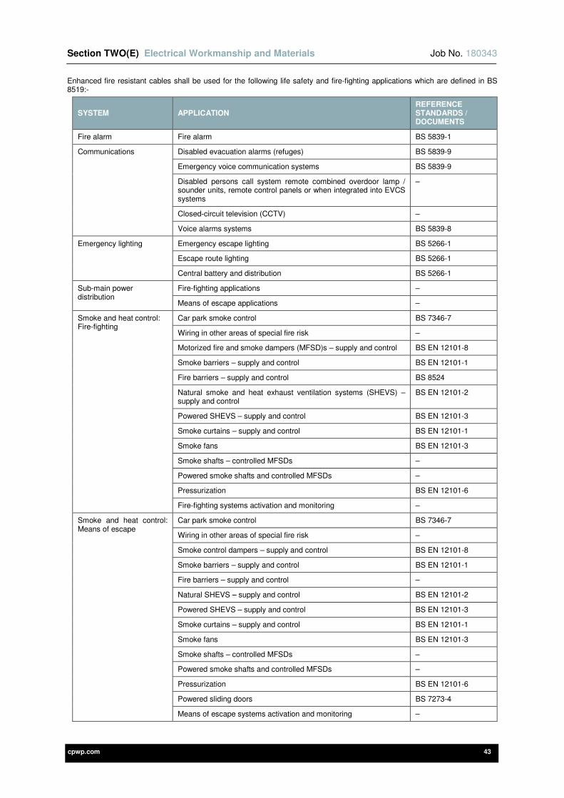
Section TWO(E) Electrical Workmanship and Materials Job No. 180343
cpwp.com 43
Enhanced fire resistant cables shall be used for the following life safety and fire-fighting applications which are defined in BS 8519:-
SYSTEM APPLICATION REFERENCE STANDARDS / DOCUMENTS
Fire alarm Fire alarm BS 5839-1
Communications Disabled evacuation alarms (refuges) BS 5839-9
Emergency voice communication systems BS 5839-9
Disabled persons call system remote combined overdoor lamp / sounder units, remote control panels or when integrated into EVCS systems
–
Closed-circuit television (CCTV) –
Voice alarms systems BS 5839-8
Emergency lighting Emergency escape lighting BS 5266-1
Escape route lighting BS 5266-1
Central battery and distribution BS 5266-1
Sub-main power distribution
Fire-fighting applications –
Means of escape applications –
Smoke and heat control: Fire-fighting
Car park smoke control BS 7346-7
Wiring in other areas of special fire risk –
Motorized fire and smoke dampers (MFSD)s – supply and control BS EN 12101-8
Smoke barriers – supply and control BS EN 12101-1
Fire barriers – supply and control BS 8524
Natural smoke and heat exhaust ventilation systems (SHEVS) – supply and control
BS EN 12101-2
Powered SHEVS – supply and control BS EN 12101-3
Smoke curtains – supply and control BS EN 12101-1
Smoke fans BS EN 12101-3
Smoke shafts – controlled MFSDs –
Powered smoke shafts and controlled MFSDs –
Pressurization BS EN 12101-6
Fire-fighting systems activation and monitoring –
Smoke and heat control: Means of escape
Car park smoke control BS 7346-7
Wiring in other areas of special fire risk –
Smoke control dampers – supply and control BS EN 12101-8
Smoke barriers – supply and control BS EN 12101-1
Fire barriers – supply and control –
Natural SHEVS – supply and control BS EN 12101-2
Powered SHEVS – supply and control BS EN 12101-3
Smoke curtains – supply and control BS EN 12101-1
Smoke fans BS EN 12101-3
Smoke shafts – controlled MFSDs –
Powered smoke shafts and controlled MFSDs –
Pressurization BS EN 12101-6
Powered sliding doors BS 7273-4
Means of escape systems activation and monitoring –
Section TWO(E) Electrical Workmanship and Materials Job No. 180343
cpwp.com 44
SYSTEM APPLICATION REFERENCE STANDARDS / DOCUMENTS
Smoke and heat control: Fire-fighting shafts
Pressurization BS EN 12101-6
Chimneys – controlled (MFSD) dampers –
Powered chimneys and controlled MFSDs –
Fire-fighting shaft emergency lighting BS 9999
Fire-fighting shaft system monitoring BS 9999
Lifts Fire-fighting – Lift supplies BS 9999
Fire-fighting – Communications BS EN 81-72
Evacuation – Lift supplies BS 9999
Evacuation – Communications –
Fire suppression Gaseous extinguishing systems BS EN 12094
Gaseous extinguishing systems BS ISO 14520
Watermist DD 8489
Powder systems BS EN 12416
Sprinkler pumps BS EN 12845
Automatic foam systems BS EN 13565
Hose reel systems BS 5306-1
Water spray systems DD CEN/TS 14816
Suppression system monitoring –
Fire mains Wet riser pumps BS 9990
Valve and equipment monitoring –
2E-17-7 FIRE PERFORMANCE OF TELECOMMUNICATIONS (VOICE / DATA) CABLING
The fire performance of telecommunications (voice / data) cabling shall be in strict accordance with BS 6701 as follows:
1) All internal telecommunications installation cabling shall as a minimum meet the requirements of EuroClass Cca –s1b, d2, a2, in accordance with BS EN 13501-6 and the flame propagation requirements of BS EN 60332-1-2 and the BS EN 60332-3 series.
This shall include cabling run externally where it enters and runs through buildings to equipment locations but does not apply to cabling run externally which terminates into equipment at the point of entry into a building.
2) All other telecommunications cabling shall as a minimum, either:-
a) Meet the requirements of EuroClass Eca, in accordance with BS EN 13501-6, or
b) Meet the requirements of BS EN 60332-1-2.
2E-17-8 CABLE SUPPORT AND CONTAINMENT SYSTEMS
Cable support and containment systems shall be provided in strict accordance with the Cable Support and Containment Systems section of this specification, which also includes the requirements for cable cleats, strapping and ties.
2E-17-9 CABLE BENDING RADII
Cabling bends shall be sized in accordance with the IET On-Site Guide, IET Guidance Note 1 – Selection & Erection and in strict accordance with the cabling manufacturer’s recommendations.
2E-17-10 CABLE GLANDS
Cable glands shall be suitably IP rated to suit the environment in which they are installed and to maintain the IP integrity of equipment.
Cable glands shall be manufactured to BS 6121 and BS EN 62444, and shall be provided as detailed below:-
TECHNICAL DETAILS
CABLE TYPE
STEEL WIRE ARMOUR (SWA) CABLES
ALUMINIUM WIRE ARMOUR (AWA) CABLES
WIRE BRAID ARMOUR (GSWB) CY & SY
CABLES
Gland type CW Brass Gland CW Aluminium Gland RXT Brass Gland
Ingress protection IP66 to BS EN 60529 IP66 to BS EN 60529 IP66 to BS EN 60529

Section TWO(E) Electrical Workmanship and Materials Job No. 180343
cpwp.com 45
TECHNICAL DETAILS
CABLE TYPE
STEEL WIRE ARMOUR (SWA) CABLES
ALUMINIUM WIRE ARMOUR (AWA) CABLES
WIRE BRAID ARMOUR (GSWB) CY & SY
CABLES
Temperature -20°C to 90°C -20°C to 90°C -20°C to 90°C
Gland material Brass to BS 2874 Aluminium Brass to BS 2874
Seal material LSZH silicone LSZH silicone LSZH silicone
Shroud material LSZH silicone LSZH silicone LSZH silicone
Shroud colour Black Black Black
Notes:
1) To achieve the IP66 rating a sealing washer must be provided between the gland and the housing.
2) An earth tag washer / ring must be provided.
Cable glands for single core aluminium wire armour (AWA) cables shall be installed into non-ferromagnetic metal gland plates (e.g. aluminium / brass).
Cable glands for life safety / fire-fighting cabling shall have the same fire survival time as the life safety / fire-fighting cabling being installed, in strict accordance BS 8519. The cable gland shroud shall be the same colour as the life safety / fire-fighting cabling to be installed.
Cable glands for hazardous areas (ATEX and explosive atmospheres) shall be suitably certified for use in the environment in which they are installed.
In other instances cable glands may be manufactured from durable nylon, however they must provide adequate mechanical protection and be suitably IP rated to suit the environment in which they are installed.
All non-metallic parts to cable glands shall be low smoke zero halogen (LSZH) and shall not be low smoke and fume (LSF).
2E-17-11 TECHNICAL SUBMISSIONS
Prior to installation on-site the Contractor shall provide technical submissions for the following:-
1) Technical specifications for all cabling and wiring systems to be installed.
The time allowed for comment by the Engineer shall be as detailed within section 1B of this specification.
2E-18 INSTALLATION OF FLAT INSULATED SHEATHED CABLES (FLAT TWIN AND EARTH)
This section of the specification details the installation requirements for 6242B and 6243B XLPE/LSZH flat insulated sheathed cables (twin / triple and earth) manufactured to BS 7211. The aforementioned cabling shall be referred to as twin and earth and this section shall only apply when called upon elsewhere within this specification.
GENERAL REQUIREMENTS
The general requirements for the installation of flat insulated sheathed cables (flat twin and earth) are as follows:-
1) Twin and earth cabling shall be installed within cable basket and conduit unless the clipping / fixing direct of the cabling is called upon elsewhere within this specification.
2) Regardless of the above installation methods:-
a) Cables that are concealed within walls or partitions at a depth of less than 50mm shall be installed within the prescribed zones detailed within BS 7671 and additional protection shall be provided by RCD’s (RCCB’s or RCBO’s).
b) Cables installed in a wall or partition with an internal construction which includes metallic parts other than just metallic fixings such as nails, screws or the like (e.g. metal stud partitions) shall have additional protection provided by RCD’s (RCCB’s or RCBO’s).
3) The above requirements shall apply to all LV wiring which shall include power and lighting final circuits.
4) All wiring systems shall be adequately supported to prevent premature collapse under fire conditions in strict accordance with BS 7671. Steel cable support and containment systems are deemed to meet this requirement.
Under no circumstances shall:-
a) Non-metallic cable clips or cables ties be used as the sole means of support where cables are clipped direct to exposed surfaces or suspended under containment systems.
b) Non-metallic cable trunking be used as the sole means of support of the cables therein.
c) Non-metallic cable trunking systems pass through walls, floors or fire compartments.
5) The outer sheath of twin and earth cabling shall not be removed by pulling the circuit protective conductor to split the sheath. The exposed circuit protective conductor core shall be provided with green and yellow sleeving to the point of termination which shall be secured in place by means of insulation tape or heat shrink at the transition point where the outer insulation is removed.
6) 6242B twin and earth cabling shall have two brown cores when used for switching circuits, blue cores with brown sleeving or the cable marker ‘L’ shall not be used.
7) 6243B triple and earth cabling shall have brown, black and grey cores when used for intermediate and two way switching circuits. The black and grey cores shall have brown sleeving or the cable marker ‘L’ shall be used.
Section TWO(E) Electrical Workmanship and Materials Job No. 180343
cpwp.com 46
8) All cabling shall be separated and segregated as detailed within the Proximity of Wiring Systems and Measures against Electromagnetic Disturbances section within this section of the specification.
9) Under no circumstances shall twin and earth cabling be laid on suspended ceilings.
CABLE BASKET AND CONDUIT INSTALLATION
Twin and earth cabling within cable basket and conduit shall be provided as follows:-
1) It shall be installed within electro-galvanised steel cable basket and galvanised steel conduit in accordance with the Cable Support and Containment Systems section within this section of the specification.
2) Conduit take-off plates shall be utilised to connect conduit to the cable basket system.
3) The clipping direct of cabling to the building fabric (e.g. concrete slab) on exit from the cable basket to conduit drops at wall locations is not permitted.
4) The cable basket and conduit shall form a fully continuous containment system throughout from source to destination terminations.
5) When a minimum installation depth of 50mm cannot be achieved in joists / battens in ceilings and floors, the cable basket / conduit must be equipotential bonded, have adequate electrical continuity characteristics and satisfy the requirements of BS 7671 for a protective conductor of the circuit concerned (irrespective of the single core or multicore internal circuit protective conductor provided).
6) It shall not be installed within cable basket that contains signalling / data cabling unless fully continuous steel dividers / partitions are provided with a minimum thickness of 1.5mm. When this requirement cannot be met and the cabling is run in separate cable basket to signalling / data cabling there shall be a minimum separation distance of 200mm.
7) It shall also have its own cable conduits and shall not be installed in the same conduits as the cables of other wiring systems e.g. signalling and data cabling.
CLIPPED / FIXED DIRECT INSTALLATION
Twin and earth cabling when clipped / fixed direct shall be provided as follows:-
1) It shall be recessed within the building fabric and shall be adequately supported along its entire length.
2) The cables shall be clipped direct to the building fabric using proprietary cable clips (e.g. to the side of joists and rafters where possible in ceilings / floors / roof spaces) and run through joists / battens as necessary. All cable clips shall be low smoke zero halogen (LSZH).
3) Where cables are fixed to the building fabric they shall be supported at spacing’s in strict accordance with the IET On-Site Guide, IET Guidance Note 1 – Selection & Erection and manufacturer’s recommendations.
4) When cables are fixed to surfaces the cable clips shall be provided at no less than 250mm spacing’s when horizontal and 400mm spacing’s when vertical. Cable clips shall also be provided:-
a) Either side of a cable bend.
b) At all changes in direction.
c) Before entry into back boxes, accessories and the like.
5) Where holes are required in joists for twin and earth cabling the following must be adhered to:-
a) Maximum diameter of the hole shall be 0.25 x the joist depth.
b) Holes on a centreline in a zone between 0.25 and 0.4 x span of the joist.
c) Holes in the same joist shall be at least 3 diameters apart.
6) Under no circumstances shall joists be notched or sawn. Where there are concerns over structural integrity this shall be brought to the attention of the Engineer and Contract Administrator.
7) Steel plates with a minimum thickness of 3mm shall be provided above all holes in joists / battens for traversing cables in ceilings and floors. The steel plates shall not be relied upon as a form of metallic protection where cables are installed at a depth of less than 50mm.
8) Where a minimum installation depth of 50mm cannot be achieved in joists / battens in ceilings and floors, twin and earth cables must be installed within metallic cable basket / conduit and must be equipotential bonded.
9) All holes in boxes and accessories shall have suitably sized rubber grommets.
10) Before entry into boxes and accessories the outer sheath of twin and earth cabling shall be stripped back with a minimum 10mm length allowance of outer sheathing to fully enter the box / accessory. The insulation of internal cores shall not be visible externally on entry into boxes and accessories.
11) It shall be looped from point to point and junction boxes shall not be used unless agreed with the Engineer. There shall be a minimum separation distance of 200mm between twin and earth cabling and signalling / data cabling.
12) Cabling drops on blockwork walls (e.g. to socket outlets / light switches), shall be vertical and secured to the wall by means of a suitably sized proprietary galvanised steel capping. The galvanised steel capping shall be secured to the building fabric by means of galvanised fixings.
13) When installed within partition walls it shall be drawn through suitably sized holes in noggins / vertical studs at the centre line of the partition construction.
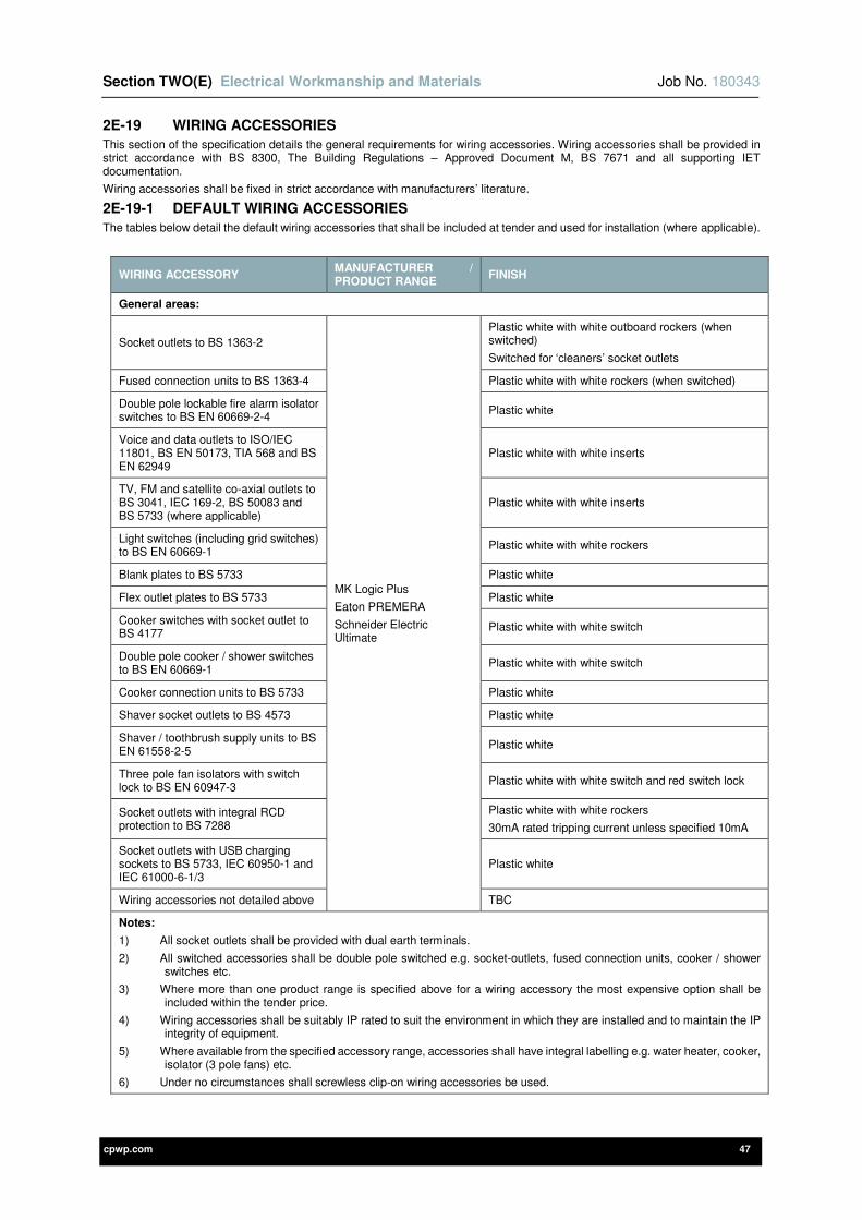
Section TWO(E) Electrical Workmanship and Materials Job No. 180343
cpwp.com 47
2E-19 WIRING ACCESSORIES
This section of the specification details the general requirements for wiring accessories. Wiring accessories shall be provided in strict accordance with BS 8300, The Building Regulations – Approved Document M, BS 7671 and all supporting IET documentation.
Wiring accessories shall be fixed in strict accordance with manufacturers’ literature.
2E-19-1 DEFAULT WIRING ACCESSORIES
The tables below detail the default wiring accessories that shall be included at tender and used for installation (where applicable).
WIRING ACCESSORY MANUFACTURER / PRODUCT RANGE
FINISH
General areas:
Socket outlets to BS 1363-2
MK Logic Plus
Eaton PREMERA
Schneider Electric Ultimate
Plastic white with white outboard rockers (when switched)
Switched for ‘cleaners’ socket outlets
Fused connection units to BS 1363-4 Plastic white with white rockers (when switched)
Double pole lockable fire alarm isolator switches to BS EN 60669-2-4
Plastic white
Voice and data outlets to ISO/IEC 11801, BS EN 50173, TIA 568 and BS EN 62949
Plastic white with white inserts
TV, FM and satellite co-axial outlets to BS 3041, IEC 169-2, BS 50083 and BS 5733 (where applicable)
Plastic white with white inserts
Light switches (including grid switches) to BS EN 60669-1
Plastic white with white rockers
Blank plates to BS 5733 Plastic white
Flex outlet plates to BS 5733 Plastic white
Cooker switches with socket outlet to BS 4177
Plastic white with white switch
Double pole cooker / shower switches to BS EN 60669-1
Plastic white with white switch
Cooker connection units to BS 5733 Plastic white
Shaver socket outlets to BS 4573 Plastic white
Shaver / toothbrush supply units to BS EN 61558-2-5
Plastic white
Three pole fan isolators with switch lock to BS EN 60947-3
Plastic white with white switch and red switch lock
Socket outlets with integral RCD protection to BS 7288
Plastic white with white rockers
30mA rated tripping current unless specified 10mA
Socket outlets with USB charging sockets to BS 5733, IEC 60950-1 and IEC 61000-6-1/3
Plastic white
Wiring accessories not detailed above TBC
Notes:
1) All socket outlets shall be provided with dual earth terminals.
2) All switched accessories shall be double pole switched e.g. socket-outlets, fused connection units, cooker / shower switches etc.
3) Where more than one product range is specified above for a wiring accessory the most expensive option shall be included within the tender price.
4) Wiring accessories shall be suitably IP rated to suit the environment in which they are installed and to maintain the IP integrity of equipment.
5) Where available from the specified accessory range, accessories shall have integral labelling e.g. water heater, cooker, isolator (3 pole fans) etc.
6) Under no circumstances shall screwless clip-on wiring accessories be used.

Section TWO(E) Electrical Workmanship and Materials Job No. 180343
cpwp.com 48
WIRING ACCESSORY MANUFACTURER / PRODUCT RANGE
FINISH
Switch rooms, plant rooms, ceiling voids and ‘back of house’ areas:
Socket outlets to BS 1363-2
MK Metalclad Plus
Eaton XTRA Surface Metalclad
Schneider Electric Metal Clad
Metallic powder coated with white outboard rockers (when switched)
Fused connection units to BS 1363-4 Metallic powder coated with white rockers (when switched)
Voice and data outlets to ISO/IEC 11801, BS EN 50173, TIA 568 and BS EN 62949
Metallic powder coated with white inserts
TV, FM and satellite co-axial outlets to BS 3041, IEC 169-2, BS 50083 and BS 5733 (where applicable)
Metallic powder coated with white inserts
Light switches (including grid switches) to BS EN 60669-1
Metallic powder coated with white rockers
Blank plates to BS 5733 Metallic powder coated
Three pole fan isolators with switch lock to BS EN 60947-3
Metallic powder coated with white switch and red switch lock
Socket outlets with integral RCD protection to BS 7288
Metallic powder coated with white rockers
30mA rated tripping current unless specified 10mA elsewhere within this specification
Surface back boxes to BS 5733 Metallic powder coated
Wiring accessories not detailed above TBC
External areas:
Isolators to BS EN 60947-3
MK Commando Safetyswitch
Eaton MEM RDMP
Schneider Electric – Telemecanique
Complete with lockable operating handle
Industrial plugs and socket outlets to BS EN 60309
MK Commando
MENNEKES
Schneider Electric – Merlin Gerin
Plastic grey – Yellow 110 V single phase, blue 230 V single phase, red 400 V three phase
Socket outlets to BS 1363-2
MK Masterseal Plus
Eaton PREMERA Proof
Schneider Electric Weatherproof
Plastic grey with white internals
Fused connection units to BS 1363-4 Plastic grey with white internals
Light switches (including grid switches) to BS EN 60669-1
Plastic grey
Socket outlets with integral RCD protection to BS 7288
Plastic grey
30mA rated tripping current
Surface back boxes to BS 5733 Plastic grey
Junction boxes Plastic grey
Wiring accessories not detailed above TBC
Notes:
1) Plastic white finishes to be provided for internal areas where accessories require ingress protection. All socket outlets shall be provided with dual earth terminals.
2) All switched accessories shall be double pole switched e.g. socket-outlets, fused connection units, cooker / shower switches etc.
3) Where more than one product range is specified above for a wiring accessory the most expensive option shall be included within the tender price.
4) Wiring accessories shall be suitably IP rated to suit the environment in which they are installed and to maintain the IP integrity of equipment.
5) Where available from the specified accessory range, accessories shall have integral labelling e.g. water heater, cooker, isolator (3 pole fans) etc.
6) Under no circumstances shall screwless clip-on wiring accessories be used.
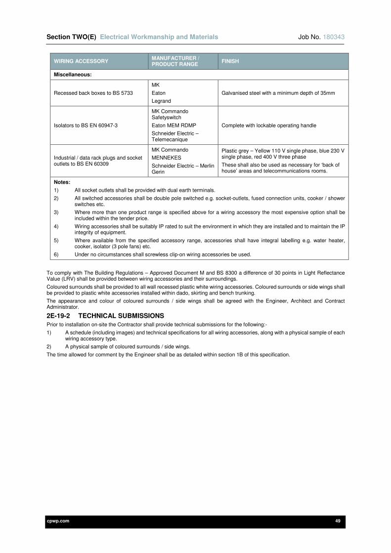
Section TWO(E) Electrical Workmanship and Materials Job No. 180343
cpwp.com 49
WIRING ACCESSORY MANUFACTURER / PRODUCT RANGE
FINISH
Miscellaneous:
Recessed back boxes to BS 5733
MK
Eaton
Legrand
Galvanised steel with a minimum depth of 35mm
Isolators to BS EN 60947-3
MK Commando Safetyswitch
Eaton MEM RDMP
Schneider Electric – Telemecanique
Complete with lockable operating handle
Industrial / data rack plugs and socket outlets to BS EN 60309
MK Commando
MENNEKES
Schneider Electric – Merlin Gerin
Plastic grey – Yellow 110 V single phase, blue 230 V single phase, red 400 V three phase
These shall also be used as necessary for ‘back of house’ areas and telecommunications rooms.
Notes:
1) All socket outlets shall be provided with dual earth terminals.
2) All switched accessories shall be double pole switched e.g. socket-outlets, fused connection units, cooker / shower switches etc.
3) Where more than one product range is specified above for a wiring accessory the most expensive option shall be included within the tender price.
4) Wiring accessories shall be suitably IP rated to suit the environment in which they are installed and to maintain the IP integrity of equipment.
5) Where available from the specified accessory range, accessories shall have integral labelling e.g. water heater, cooker, isolator (3 pole fans) etc.
6) Under no circumstances shall screwless clip-on wiring accessories be used.
To comply with The Building Regulations – Approved Document M and BS 8300 a difference of 30 points in Light Reflectance Value (LRV) shall be provided between wiring accessories and their surroundings.
Coloured surrounds shall be provided to all wall recessed plastic white wiring accessories. Coloured surrounds or side wings shall be provided to plastic white accessories installed within dado, skirting and bench trunking.
The appearance and colour of coloured surrounds / side wings shall be agreed with the Engineer, Architect and Contract Administrator.
2E-19-2 TECHNICAL SUBMISSIONS
Prior to installation on-site the Contractor shall provide technical submissions for the following:-
1) A schedule (including images) and technical specifications for all wiring accessories, along with a physical sample of each wiring accessory type.
2) A physical sample of coloured surrounds / side wings.
The time allowed for comment by the Engineer shall be as detailed within section 1B of this specification.

Section TWO(E) Electrical Workmanship and Materials Job No. 180343
cpwp.com 50
2E-20 POSITIONING AND MOUNTING HEIGHTS OF ELECTRICAL SERVICES
This section of the specification details the general requirements for the mounting heights of electrical services.
Electrical services shall be positioned and mounted in strict accordance with BS 8300, BS 5839, BS 5266, The Building Regulations – Approved Document M, The Building Regulations – Approved Document P, BS 7671 and all supporting IET documentation.
The tables below detail the positioning and mounting height requirements for electrical services:-
EQUIPMENT / ACCESSORY
MOUNTING HEIGHT AFFL (mm) TO THE
CENTRE OF OUTLETS, SWITCHES AND
CONTROLS
NOTES
Metering:
Metering 1200 –1400mm
Readings shall be visible to a person standing or sitting.
Prepay meters shall be accessible but protected to prevent child tamper.
Lighting:
Lighting switches 1000 – 1200mm As far as is practicable, horizontally aligned with door handles when entering a room.
Lighting switches for use by the public
900 – 1100mm As far as is practicable, horizontally aligned with door handles when entering a room.
Lighting scene setting panels 1000 – 1200mm As far as is practicable, horizontally aligned with door handles when entering a room.
Lighting pull cords 1000 – 1200mm Bottom of the pull cord to be located within this range.
Outlets:
Socket outlets 450 – 1000mm Dependent on use.
Generally 450mm for low level socket outlets.
Socket outlets above desks, benching and worktops
150mm Generally 150mm above the desks / benching and worktops, however no higher than 1050mm.
Fused connection units for fixed equipment
750 – 1200mm
Dependent on equipment.
At high level where required and only accessed by skilled persons (electrically).
Flex outlets As required Dependent on use.
Only accessed by skilled persons (electrically).
TV / AV screen outlets 450 – 1000mm
Dependent on location of screen.
At high level where required and only accessed by skilled persons (electrically).
Telephone / data outlets 450 – 1000mm
Dependent on equipment.
At high level where required and only accessed by skilled persons (electrically).
Shaver socket outlets 800 – 1000mm Dependent on location.
Generally to one side of a mirror.
Bathrooms for wheelchair uses:
Switches, sockets, stopcocks and controls
700 – 1000mm Outlets switches and controls shall be a minimum of 300mm from the corners of the room.
BT equipment:
Customer splicing points (CSP), optical network termination units (ONT), battery backup units (BBU), CP equipment, telephone / data outlets
450 – 600mm As required by the BT Openreach Developers Guide and to be confirmed with the BT New Sites Representative requirements.
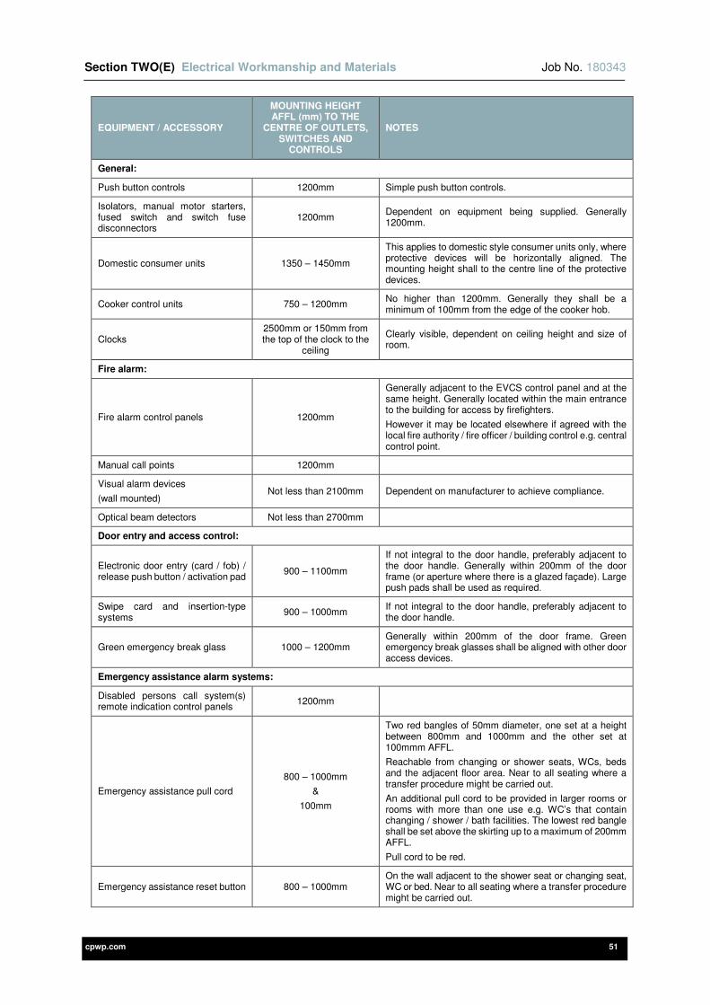
Section TWO(E) Electrical Workmanship and Materials Job No. 180343
cpwp.com 51
EQUIPMENT / ACCESSORY
MOUNTING HEIGHT AFFL (mm) TO THE
CENTRE OF OUTLETS, SWITCHES AND
CONTROLS
NOTES
General:
Push button controls 1200mm Simple push button controls.
Isolators, manual motor starters, fused switch and switch fuse disconnectors
1200mm Dependent on equipment being supplied. Generally 1200mm.
Domestic consumer units 1350 – 1450mm
This applies to domestic style consumer units only, where protective devices will be horizontally aligned. The mounting height shall to the centre line of the protective devices.
Cooker control units 750 – 1200mm No higher than 1200mm. Generally they shall be a minimum of 100mm from the edge of the cooker hob.
Clocks 2500mm or 150mm from the top of the clock to the
ceiling
Clearly visible, dependent on ceiling height and size of room.
Fire alarm:
Fire alarm control panels 1200mm
Generally adjacent to the EVCS control panel and at the same height. Generally located within the main entrance to the building for access by firefighters.
However it may be located elsewhere if agreed with the local fire authority / fire officer / building control e.g. central control point.
Manual call points 1200mm
Visual alarm devices
(wall mounted) Not less than 2100mm Dependent on manufacturer to achieve compliance.
Optical beam detectors Not less than 2700mm
Door entry and access control:
Electronic door entry (card / fob) / release push button / activation pad
900 – 1100mm
If not integral to the door handle, preferably adjacent to the door handle. Generally within 200mm of the door frame (or aperture where there is a glazed façade). Large push pads shall be used as required.
Swipe card and insertion-type systems
900 – 1000mm If not integral to the door handle, preferably adjacent to the door handle.
Green emergency break glass 1000 – 1200mm Generally within 200mm of the door frame. Green emergency break glasses shall be aligned with other door access devices.
Emergency assistance alarm systems:
Disabled persons call system(s) remote indication control panels
1200mm
Emergency assistance pull cord
800 – 1000mm
&
100mm
Two red bangles of 50mm diameter, one set at a height between 800mm and 1000mm and the other set at 100mmm AFFL.
Reachable from changing or shower seats, WCs, beds and the adjacent floor area. Near to all seating where a transfer procedure might be carried out.
An additional pull cord to be provided in larger rooms or rooms with more than one use e.g. WC’s that contain changing / shower / bath facilities. The lowest red bangle shall be set above the skirting up to a maximum of 200mm AFFL.
Pull cord to be red.
Emergency assistance reset button 800 – 1000mm On the wall adjacent to the shower seat or changing seat, WC or bed. Near to all seating where a transfer procedure might be carried out.
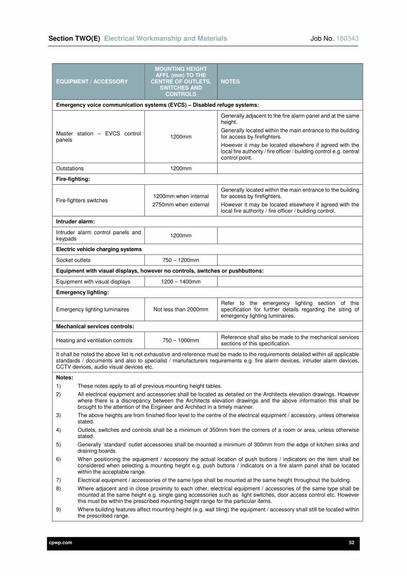
Section TWO(E) Electrical Workmanship and Materials Job No. 180343
cpwp.com 52
EQUIPMENT / ACCESSORY
MOUNTING HEIGHT AFFL (mm) TO THE
CENTRE OF OUTLETS, SWITCHES AND
CONTROLS
NOTES
Emergency voice communication systems (EVCS) – Disabled refuge systems:
Master station – EVCS control panels
1200mm
Generally adjacent to the fire alarm panel and at the same height.
Generally located within the main entrance to the building for access by firefighters.
However it may be located elsewhere if agreed with the local fire authority / fire officer / building control e.g. central control point.
Outstations 1200mm
Fire-fighting:
Fire-fighters switches 1200mm when internal
2750mm when external
Generally located within the main entrance to the building for access by firefighters.
However it may be located elsewhere if agreed with the local fire authority / fire officer / building control.
Intruder alarm:
Intruder alarm control panels and keypads
1200mm
Electric vehicle charging systems
Socket outlets 750 – 1200mm
Equipment with visual displays, however no controls, switches or pushbuttons:
Equipment with visual displays 1200 – 1400mm
Emergency lighting:
Emergency lighting luminaires Not less than 2000mm Refer to the emergency lighting section of this specification for further details regarding the siting of emergency lighting luminaires.
Mechanical services controls:
Heating and ventilation controls 750 – 1000mm Reference shall also be made to the mechanical services sections of this specification.
It shall be noted the above list is not exhaustive and reference must be made to the requirements detailed within all applicable standards / documents and also to specialist / manufacturers requirements e.g. fire alarm devices, intruder alarm devices, CCTV devices, audio visual devices etc.
Notes:
1) These notes apply to all of previous mounting height tables.
2) All electrical equipment and accessories shall be located as detailed on the Architects elevation drawings. However where there is a discrepancy between the Architects elevation drawings and the above information this shall be brought to the attention of the Engineer and Architect in a timely manner.
3) The above heights are from finished floor level to the centre of the electrical equipment / accessory, unless otherwise stated.
4) Outlets, switches and controls shall be a minimum of 350mm from the corners of a room or area, unless otherwise stated.
5) Generally ‘standard’ outlet accessories shall be mounted a minimum of 300mm from the edge of kitchen sinks and draining boards.
6) When positioning the equipment / accessory the actual location of push buttons / indicators on the item shall be considered when selecting a mounting height e.g. push buttons / indicators on a fire alarm panel shall be located within the acceptable range.
7) Electrical equipment / accessories of the same type shall be mounted at the same height throughout the building.
8) Where adjacent and in close proximity to each other, electrical equipment / accessories of the same type shall be mounted at the same height e.g. single gang accessories such as light switches, door access control etc. However this must be within the prescribed mounting height range for the particular items.
9) Where building features affect mounting height (e.g. wall tiling) the equipment / accessory shall still be located within the prescribed range.
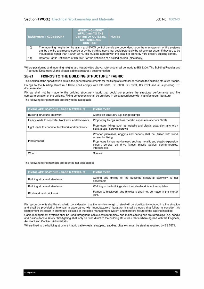
Section TWO(E) Electrical Workmanship and Materials Job No. 180343
cpwp.com 53
EQUIPMENT / ACCESSORY
MOUNTING HEIGHT AFFL (mm) TO THE
CENTRE OF OUTLETS, SWITCHES AND
CONTROLS
NOTES
10) The mounting heights for fire alarm and EVCS control panels are dependent upon the management of the systems e.g. by the fire and rescue service or by the building users that could potentially be wheelchair users. If they are to be mounted at higher than 1200m AFFL this must be agreed with the local fire authority / fire officer / building control.
11) Refer to Part 2 Definitions of BS 7671 for the definition of a skilled person (electrically).
Where positioning and mounting heights are not provided above, reference shall be made to BS 8300, The Building Regulations – Approved Document M and all applicable standards / documentation.
2E-21 FIXINGS TO THE BUILDING STRUCTURE / FABRIC
This section of the specification details the general requirements for the fixing of electrical services to the building structure / fabric.
Fixings to the building structure / fabric shall comply with BS 5080, BS 8000, BS 8539, BS 7671 and all supporting IET documentation.
Fixings shall not be made to the building structure / fabric that could compromise the structural performance and fire compartmentation of the building. Fixing components shall be provided in strict accordance with manufacturers’ literature.
The following fixing methods are likely to be acceptable:-
FIXING APPLICATIONS / BASE MATERIALS FIXING TYPE
Building structural steelwork Clamp-on bracketry e.g. flange clamps
Heavy loads to concrete, blockwork and brickwork Proprietary fixings such as metallic expansion anchors / bolts
Light loads to concrete, blockwork and brickwork Proprietary fixings such as metallic and plastic expansion anchors / bolts, plugs / screws, screws
Plasterboard
Wooden patresses, noggins and battens shall be utilised with wood screws for fixing
Proprietary fixings may be used such as metallic and plastic expansion plugs / screws, self-drive fixings, plastic toggles, spring toggles, intersets etc.
Wood Screws
The following fixing methods are deemed not acceptable:-
FIXING APPLICATIONS / BASE MATERIALS FIXING TYPE
Building structural steelwork Cutting and drilling of the buildings structural steelwork is not acceptable
Building structural steelwork Welding to the buildings structural steelwork is not acceptable
Blockwork and brickwork Fixings to blockwork and brickwork shall not be made in the mortar joint.
Fixing components shall be sized with consideration that the tensile strength of steel will be significantly reduced in a fire situation and shall be provided at intervals in accordance with manufacturers’ literature. It shall be noted that failure to consider this requirement will result in premature collapse of the cable management system and therefore failure of the cabling installed.
Cable management systems shall be used throughout, cable cleats for mains / sub-mains cabling and fire rated clips (e.g. saddle and p-clips) for life safety / fire-fighting shall only be fixed direct to the building structure / fabric where agreed with the Engineer, Architect and Contract Administrator.
Where fixed to the building structure / fabric cable cleats, strapping, saddles, clips etc. must be steel as required by BS 7671.

cpwp.com V3.0
Section Two (F) Electrical Inspection and Testing

Section TWO(F) Electrical Inspection and Testing Job No. 180343
cpwp.com 1
Contents Page
2F-1 GENERAL DESCRIPTION 2
2F-2 DEFINITIONS 2
2F-3 STANDARDS APPLICABLE 2
2F-4 STATUTORY REGULATIONS AND BS 7671 IET WIRING REGULATIONS 3
2F-5 ELECTRICAL CONTRACTING CERTIFICATION SCHEMES 3
2F-6 CERTIFICATION AND REPORTS 3
2F-7 INSPECTION 5
2F-8 TEST EQUIPMENT 5
2F-9 ISOLATION 5
2F-10 TESTING SEQUENCE 6
2F-11 TESTING PROCEDURES 6
2F-12 DEPARTURES FROM AND NON-COMPLIANCES WITH BS 7671 11
2F-13 INSPECTION AND TESTING OF MEDICAL INSTALLATIONS 11
2F-14 CONTINUITY OF CABLE SUPPORT AND CONTAINMENT SYSTEMS 11
2F-15 FIRE BARRIERS / STOPPING 11
2F-16 FACTORY BUILT ASSEMBLIES 11
2F-17 THERMOGRAPHIC SURVEYS 11
2F-18 FORMAL WITNESSING OF TESTING 11
2F-19 APPENDIX I – SCHEDULE OF INSPECTIONS (CHECKLIST) 12
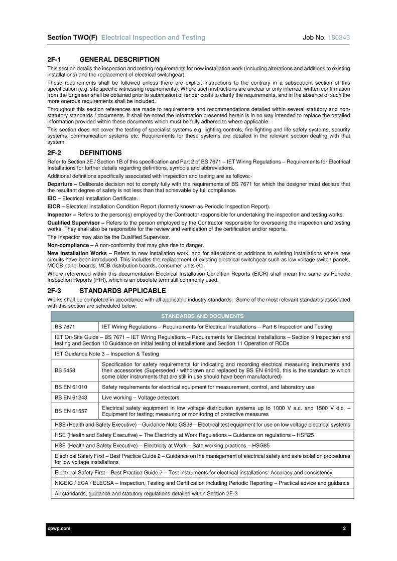
Section TWO(F) Electrical Inspection and Testing Job No. 180343
cpwp.com 2
2F-1 GENERAL DESCRIPTION
This section details the inspection and testing requirements for new installation work (including alterations and additions to existing installations) and the replacement of electrical switchgear).
These requirements shall be followed unless there are explicit instructions to the contrary in a subsequent section of this specification (e.g. site specific witnessing requirements). Where such instructions are unclear or only inferred, written confirmation from the Engineer shall be obtained prior to submission of tender costs to clarify the requirements, and in the absence of such the more onerous requirements shall be included.
Throughout this section references are made to requirements and recommendations detailed within several statutory and non-statutory standards / documents. It shall be noted the information presented herein is in no way intended to replace the detailed information provided within these documents which must be fully adhered to where applicable.
This section does not cover the testing of specialist systems e.g. lighting controls, fire-fighting and life safety systems, security systems, communication systems etc. Requirements for these systems are detailed in the relevant section dealing with that system.
2F-2 DEFINITIONS
Refer to Section 2E / Section 1B of this specification and Part 2 of BS 7671 – IET Wiring Regulations – Requirements for Electrical Installations for further details regarding definitions, symbols and abbreviations.
Additional definitions specifically associated with inspection and testing are as follows:-
Departure – Deliberate decision not to comply fully with the requirements of BS 7671 for which the designer must declare that the resultant degree of safety is not less than that achievable by full compliance.
EIC – Electrical Installation Certificate.
EICR – Electrical Installation Condition Report (formerly known as Periodic Inspection Report).
Inspector – Refers to the person(s) employed by the Contractor responsible for undertaking the inspection and testing works.
Qualified Supervisor – Refers to the person employed by the Contractor responsible for overseeing the inspection and testing works. They shall also be responsible for the review and verification of the certification and/or reports.
The Inspector may also be the Qualified Supervisor.
Non-compliance – A non-conformity that may give rise to danger.
New Installation Works – Refers to new installation work, and for alterations or additions to existing installations where new circuits have been introduced. This includes the replacement of existing electrical switchgear such as low voltage switch panels, MCCB panel boards, MCB distribution boards, consumer units etc.
Where referenced within this documentation Electrical Installation Condition Reports (EICR) shall mean the same as Periodic Inspection Reports (PIR), which is an obsolete term still commonly used.
2F-3 STANDARDS APPLICABLE
Works shall be completed in accordance with all applicable industry standards. Some of the most relevant standards associated with this section are scheduled below:
STANDARDS AND DOCUMENTS
BS 7671 IET Wiring Regulations – Requirements for Electrical Installations – Part 6 Inspection and Testing
IET On-Site Guide – BS 7671 – IET Wiring Regulations – Requirements for Electrical Installations – Section 9 Inspection and testing and Section 10 Guidance on initial testing of installations and Section 11 Operation of RCDs
IET Guidance Note 3 – Inspection & Testing
BS 5458 Specification for safety requirements for indicating and recording electrical measuring instruments and their accessories (Superseded / withdrawn and replaced by BS EN 61010, this is the standard to which some older instruments that are still in use should have been manufactured)
BS EN 61010 Safety requirements for electrical equipment for measurement, control, and laboratory use
BS EN 61243 Live working – Voltage detectors
BS EN 61557 Electrical safety equipment in low voltage distribution systems up to 1000 V a.c. and 1500 V d.c. –Equipment for testing; measuring or monitoring of protective measures
HSE (Health and Safety Executive) – Guidance Note GS38 – Electrical test equipment for use on low voltage electrical systems
HSE (Health and Safety Executive) – The Electricity at Work Regulations – Guidance on regulations – HSR25
HSE (Health and Safety Executive) – Electricity at Work – Safe working practices – HSG85
Electrical Safety First – Best Practice Guide 2 – Guidance on the management of electrical safety and safe isolation procedures for low voltage installations
Electrical Safety First – Best Practice Guide 7 – Test instruments for electrical installations: Accuracy and consistency
NICEIC / ECA / ELECSA – Inspection, Testing and Certification including Periodic Reporting – Practical advice and guidance
All standards, guidance and statutory regulations detailed within Section 2E-3
Section TWO(F) Electrical Inspection and Testing Job No. 180343
cpwp.com 3
Where the above standards refer to supporting documentation and standards these shall be fully complied with in all respects.
Where discrepancy is found between this specification and the relevant standards, the Contractor shall obtain written clarification from the Engineer prior to submission of the tender. Where a discrepancy has not been clarified prior to tender submission, the Contractor shall include the most onerous requirements.
2F-4 STATUTORY REGULATIONS AND BS 7671 IET WIRING REGULATIONS
All persons undertaking the inspection and testing of electrical installations shall comply with relevant requirements of The Electricity at Work Regulations, where particular attention shall be paid to Regulation 12 “Means for cutting off the supply and for isolation’ and Regulation 14 ‘Work on or near live conductors’ and the guidance provided by the HSE (Health and Safety Executive) – Memorandum of guidance on the Electricity at Work Regulations 1989 – Guidance on regulations – HSR25.
The electrical inspection and testing shall be undertaken in accordance with the latest version of BS 7671 IET Wiring Regulations – Requirements for Electrical Installations and all supporting IET documentation.
The Contractor shall be fully responsible for the inspection and testing of the electrical installation, which shall only be undertaken by one or more skilled persons (electrically) as defined in BS 7671 that are competent to undertake the works in such an installation.
Precautions shall be taken to ensure that the inspection and testing of the electrical installation shall not cause danger to persons or livestock and shall not cause damage to property and equipment even if a circuit is defective.
2F-5 ELECTRICAL CONTRACTING CERTIFICATION SCHEMES
The Contractor shall undertake all inspection and testing in accordance with industry best practice and must be registered with an appropriate certification scheme as detailed in Section 2E of this specification. The inspection and testing of the electrical installation shall only be undertaken by persons who meet the minimum requirements to undertake the works as defined by their Electrical Contracting Certification Scheme.
This shall be the National Inspection Council for Electrical Installation Contracting (NICEIC) / ELECSA – Platinum Promise registration scheme, or equivalent.
The Contractor shall directly employ a Qualified Supervisor / Inspector on a full time basis as required by their Electrical Contracting Certification Scheme. The Qualified Supervisor / Inspector shall also meet the minimum requirements as defined by their Electrical Contracting Certification Scheme e.g. relevant education and experience, hold a recognised inspection and testing qualification etc.
The Qualified Supervisor shall oversee the testing and inspection works and shall ensure that the results of inspection and testing are recorded correctly on the appropriate certificates and/or reports. The Qualified Supervisor shall also be responsible for the review, verification, signing and dating of the certification and/or reports.
The person(s) undertaking the inspection and testing works (Inspector) may also be the Qualified Supervisor.
All due allowances shall be made within the tender submission for the Qualified Supervisor and the person(s) undertaking the inspection / testing works (Inspector) to meet on-site when requested by the Engineer at a mutually agreeable time.
2F-6 CERTIFICATION AND REPORTS
Dependent upon the type of works undertaken, certification and reports shall be provided as required by BS 7671 and Electrical Contracting Certification Schemes.
The certification and reports shall be selected from below as required:-
ELECTRICAL INSTALLATION CERTIFICATES
The EIC shall be used for all new installation work, and for all alterations or additions to existing installations where new circuits have been introduced including the replacement of existing main electrical switchgear such as low voltage switch panels, MCCB panel boards, MCB distribution boards, consumer units etc.
The EIC shall include:-
1) Front matter.
2) Schedule of items inspected.
3) Schedule of additional records (these shall be defined and allocated page numbers within the certification e.g. fire alarm system, emergency lighting etc.).
4) Schedule of circuit details.
5) Schedule of test results for every circuit.
It shall not be used for the inspection and testing of an existing electrical installation, where an EICR shall be used.
DOMESTIC ELECTRICAL INSTALLATION CERTIFICATES
The Domestic Electrical Installation Certificate shall be used for all new electrical installation work, and for all alterations or additions to existing installations where new circuits have been introduced including the replacement of existing main electrical switchgear such as MCB distribution boards, consumer units etc.
The certificate shall only be used for new installation work where all of the following conditions apply:-
1) The electrical installation work relates to a single dwelling (house or individual flat).
2) The design, the construction, and the inspection and testing of the electrical installation work are the responsibility of one Contractor with approval by an Electrical Contracting Certification Scheme.
3) The installation forms part of a TT, TN-S or TN-C-S (PME) system.
4) The protective measure for fault protection is provided primarily by Automatic Disconnection of Supply.
The Domestic Electrical Installation Certificate shall include:-
1) Front matter.
Section TWO(F) Electrical Inspection and Testing Job No. 180343
cpwp.com 4
2) Schedule of items inspected.
3) Schedule of circuit details.
4) Schedule of test results for every circuit.
It shall not be used for single dwellings where the Engineer is responsible for the design, as the Domestic Electrical Installation Certificate does not include a separate ‘DESIGN’ section. An EIC shall be used instead.
MINOR ELECTRICAL INSTALLATION WORKS CERTIFICATES
The Minor Electrical Installation Works Certificate shall be used for any alteration or addition to an existing circuit such as:-
1) Addition of a socket-outlet to a ring or radial circuit.
2) Additional of a lighting point.
3) Alterations to lighting switching such as relocation of light switches.
4) Replacement of an accessory or luminaire (not switchgear such as DB’s etc.).
It shall not be used for new circuits or the replacement of existing main electrical switchgear e.g. MCB distribution boards, consumer units etc. Further reference shall be made to Electrical Contracting Certification Schemes to clarify the acceptable and non-acceptable works associated with Minor Electrical Installation Certificates.
ELECTRICAL INSTALLATION CONDITION REPORTS (FORMERLY PERIODIC INSPECTION REPORTS)
The EICR shall only be used for reporting on the condition of an existing installation.
The EICR shall include:-
1) Front matter.
2) Schedule of observations and recommendations for actions to be taken.
3) Inspection schedule for distribution boards and circuits.
4) Schedule of test results for every circuit (unless defined sample rates have been provided).
It shall not be used for new installation work.
The agreed extent of the installation covered by the periodic inspection and testing along with any agreed limitations shall be clearly defined and recorded within the EICR. Where agreed periodic inspection and testing sample rates have been applied these shall be clearly defined and recorded within the EICR.
These should be recorded within the ‘Extent of the Installation and Limitations on the Inspection and Testing’ within the EICR.
GENERAL REQUIREMENTS FOR CERTIFICATION AND REPORTS
The general requirements for certification and reports are as follows:-
1) For new installation work, any defect or omission revealed during the inspection and testing shall be corrected before the certification is issued.
2) For any alterations and/or additions to an electrical installation, any defect or omission that will affect the safety of the alteration or addition that is revealed during inspection and testing shall be corrected before the certification is issued.
The Contractor responsible for the alteration or addition shall record on the certification any other defects observed during the course of the works that may give rise to danger.
3) For all new installation work, and for all alterations or additions to existing installations where new circuits have been introduced, the certification shall include a recommendation for the interval between initial verification and the first periodic inspection e.g. ‘NEXT INSPECTION’ entry box.
4) Where parts of an existing installation are not required to be inspected and tested (i.e. do not form part of the works) any observed departures or non-compliances shall be recorded within the ‘COMMENTS ON THE EXISTING INSTALLATION’ section of the certification.
5) Where existing circuits have not been modified but have been disconnected and re-terminated (e.g. existing final circuits into new or existing MCB distribution boards etc.) they shall be fully inspected and tested as required by BS 7671.
6) They must be completed in accordance with BS 7671, IET Guidance Note 3 and Electrical Contracting Certification Schemes.
7) All entry boxes must be completed and contain accurate information. Where an entry box is not applicable to the works that have been undertaken ‘N/A’ shall be used.
8) When incomplete they are deemed to be invalid by Electrical Contracting Certification Schemes.
9) All switchgear / equipment reference numbers, circuit references and final circuit references shall be coordinated throughout and be the same as those used in the specification schedules / drawings.
10) Where a location is to be defined it shall be co-ordinated with the architectural drawings and the site room referencing system.
11) Where a documented risk assessment has determined that RCDs are not required as additional protection for socket outlets with a rated current not exceeding 32A, this shall be noted within the ‘DESIGN’ section and the documented risk assessment shall be appended.
12) ‘Schedules of additional records’ relating to the electrical installation shall be included and their respective page numbers shall be identified (e.g. fire alarm system, emergency lighting etc.). The requirements for these are detailed in subsequent sections of this specification.
13) The ‘Circuit line and number’ included within the ‘Schedule of test results’ shall be co-ordinated with the ‘Schedule of circuit details’. The ‘Schedule of test results’ shall include test results for every circuit tested.
14) The Contractor / Qualified Supervisor shall be responsible for the review, verification, signing and dating of the certification and/or reports. This shall take into account their respective responsibilities e.g. ‘CONSTRUCTION’, ‘INSPECTION AND TESTING’, ‘DESIGN, CONSTRUCTION, INSPECTION AND TESTING’ entry boxes as necessary.
Section TWO(F) Electrical Inspection and Testing Job No. 180343
cpwp.com 5
15) On completion they shall be issued to the Engineer for comment. When responsible for the design of the electrical installation the Engineer shall sign and date the ‘DESIGN’ entry box.
16) They shall be provided as part of the Operation and Maintenance Manual and Health and Safety File as required by the Construction (Design and Management) Regulations.
17) Schedules / charts shall be provided to all:-
a) Low voltage switch panels.
b) MCCB panel boards.
c) MCB distribution boards.
d) Consumer units.
As detailed within Section 2E of this specification.
2F-7 INSPECTION
The electrical installation shall be inspected to ensure all electrical equipment and materials are of the correct type and comply with the appropriate British or Harmonised Standard, or International (IEC) Standard.
The inspection shall verify that the electrical installation:
1) Has been correctly selected and erected in accordance with BS 7671, all supporting IET documentation and manufacturers’ instructions.
2) Is not visibly damaged or defective or has deteriorated (existing installations) so as to impair safety.
3) Is ready and safe to be used.
The electrical installation shall be inspected throughout the installation period with particular attention paid to any electrical services that may become inaccessible upon completion e.g. concealed cable support and containments systems, cabling, accessories, busbar trunking and power track systems etc. etc.
On completion of the electrical installation works a further inspection shall be undertaken prior to any electrical testing (dead or live testing) taking place.
Appendix I of this section provides an Electrical Installation Certificate checklist of some of the principal items that shall be inspected as a minimum. However it shall be noted that the checklist is not exhaustive and is provided as a guide. The items included within the schedule shall form the Schedule of Inspections to be included with the certification / reports.
The inspection guidance provided in IET Guidance Note 3 Inspection and Testing shall also be followed:
1) Section 2.5.2 Comments on individual items to be inspected.
2) Section 2.5.3 Inspection checklist.
All items shall also be inspected that are included on the ‘Schedules of Items Inspected’ list that form part of the certification required by Electrical Contracting Certification Schemes. All entry boxes on the schedules must be completed:
• ‘’ shall indicate that an inspection was undertaken and the result was satisfactory.
• ‘N/A’ shall indicate that an inspection was not applicable to the installation.
Joint formal inspections shall be undertaken at a mutually agreeable time by the Qualifying Manager, the person(s) undertaking the inspection / testing works and the Engineer.
Any departures from or non-compliances with the requirements of this specification and BS 7671 as a result of inspection(s) must be rectified at no additional cost and in a timely manner to suit the construction programme.
2F-8 TEST EQUIPMENT
Test instruments shall be selected in strict accordance with the performance standards detailed in BS EN 61557 and the safety requirements of BS EN 61010. Test instruments shall also be selected to meet the instrument accuracy and performance criteria detailed within IET Guidance Note 3 Inspection and Testing.
A system shall be in place to ensure the accuracy of test instruments as required by Electrical Contracting Certification Schemes.
As a minimum the accuracy of test instruments shall be confirmed by formal calibration / re-calibration at intervals recommended by the manufacturer and shall be supported by calibration certificates provided by laboratories accredited by the United Kingdom Accreditation Service (UKAS).
More frequent re-calibrations may be required if test instruments are exposed to changes in temperature / humidity and also if they are roughly handled and regularly transported / stored in vehicles. It shall be the Contractor’s responsibility to ensure that the test instruments meet the required accuracy and performance criteria prior to testing.
The model and serial number for each test instrument shall be recorded on the certification, reports and schedules. A copy of the calibration certificate for each test instrument shall be provided as part of the Operation and Maintenance Manual.
Voltage indicators, test probes, clips and leads shall be selected and used in accordance with the guidance outlined in HSE – Guidance Note GS38.
2F-9 ISOLATION
Inspection and dead testing shall be undertaken with the appropriate part of the installation disconnected from the electrical supply by some form of isolation. The isolation of the electrical supply shall be undertaken in accordance with the guidance outlined in HSE – Electricity at Work – Safe working practices – HSG85.
As a minimum the isolation of the electrical supply shall be verified by the following safe working procedure:-
1) Step 1 – Open the means of isolation and secure the isolation device.
2) Step 2 – Prove the correct operation of the voltage detector / indicator to be used against a known source such as a voltage proving unit.
Section TWO(F) Electrical Inspection and Testing Job No. 180343
cpwp.com 6
3) Step 3 – Test all conductors (including protective conductors in case there is a wiring fault) to verify that no dangerous voltage is present and the circuit(s) is safe to be worked upon.
4) Step 4 – Prove the correct operation of the voltage detector / indicator to verify that it was functioning correctly when the circuit(s) where tested.
Inspection and testing shall be undertaken in such a way as to minimise disturbance of the installation and inconvenience to the user.
Where it is necessary to disconnect part or the whole of the installation in order to carry out a test, the disconnection should be made at a time agreed with the Client and for the minimum period needed to carry out the test. Where more than one test necessitates a disconnection, where possible they should be made during one disconnection period.
All shutdowns and disconnections must be agreed with the Client prior to works commencing.
2F-10 TESTING SEQUENCE
The sequence of testing and test methods shall be undertaken in strict accordance with BS 7671, IET Guidance Note 3 Inspection and Testing and the NICEIC / ECA / ELECSA – Inspection, Testing and Certification including Periodic Reporting – Practical advice and guidance.
For new installation works the sequence of initial testing shall be as detailed below (where applicable):-
DEAD TESTING
Before the supply is connected, or with the supply disconnected as appropriate:-
1) Continuity of protective conductors, including main and supplementary equipotential bonding.
2) Continuity of ring final conductors (where present).
3) Insulation resistance.
4) Protection by SELV, PELV or by electrical separation.
5) Basic protection provided by a barrier or an enclosure provided during erection.
6) Insulation resistance / impedance of floors and walls.
7) Polarity.
8) Earth electrode resistance (dependent upon the test method used this may be a live test).
LIVE TESTING
With the supply connected:-
1) Protection by automatic disconnection of supply.
2) Earth fault loop impedance.
3) Prospective fault current.
4) Check of phase sequence.
5) Operation of residual current devices (the test to be independent of any test facility incorporated in the device).
6) Functional testing of residual current devices (RCDs).
7) Functional testing of arc fault detection devices (AFDDs).
8) Other functional testing e.g. functional testing of switchgear and control gear assemblies, drives, controls, interlocks etc.
2F-11 TESTING PROCEDURES
An overview of the testing procedures is provided below:
CONTINUITY OF PROTECTIVE CONDUCTORS, INCLUDING MAIN AND SUPPLEMENTARY EQUIPOTENTIAL BONDING
This is the measurement of one of the following to verify the continuity of the circuit protective conductors:
• Resistance of R1 + R2 (Test method 1 of BS 7671 – R1 + R2 method).
• R2 (Test method 2 of BS 7671 – Wander lead method).
The measurements are to be made by using a low-resistance ohmmeter or by selecting the appropriate range on a multi-function tester. The measurement at the extremity of the circuit (furthest point) for R1 + R2 in Ω (ohms) shall be recorded on the Schedule of Test Results. The measurements shall verify that electrical continuity has been achieved and confirm correct polarity () for the circuit.
Testing shall also be undertaken to verify the electrical continuity of all bonding conductors and earthing conductors.
All metallic cable support and containment systems shall be equipotential bonded for protective earthing and to avoid / reduce electromagnetic disturbances as detailed within Section 2E of this specification. Test method 2 shall be used to measure the resistance across all joints to verify electrical continuity. The measured resistance across joints shall not exceed 0.05 Ω.
The electrical continuity of cable support and containment systems shall also be verified in accordance with their respective standards, as detailed later within this section of the specification.
Test method 2 shall also be used to verify there is a bonding connection between extraneous conductive parts where it is not possible to see the bonding connection (e.g. where bonding clamps are ‘built in’ to metallic pipework). The measured resistance shall not exceed 0.05 Ω.
CONTINUITY OF RING FINAL CIRCUIT CONDUCTORS
This is the measurement of:
1) Step 1:- The resistance of r1, r2 and rn to verify the continuity of all conductors.
2) Step 2:- Having made the L-N cross connection, the resistance between line and neutral conductors at each outlet to verify the resistance is substantially the same at each outlet and equates to (r1 + rn) / 4, (subject to outlets wired as spurs from the ring final circuit).
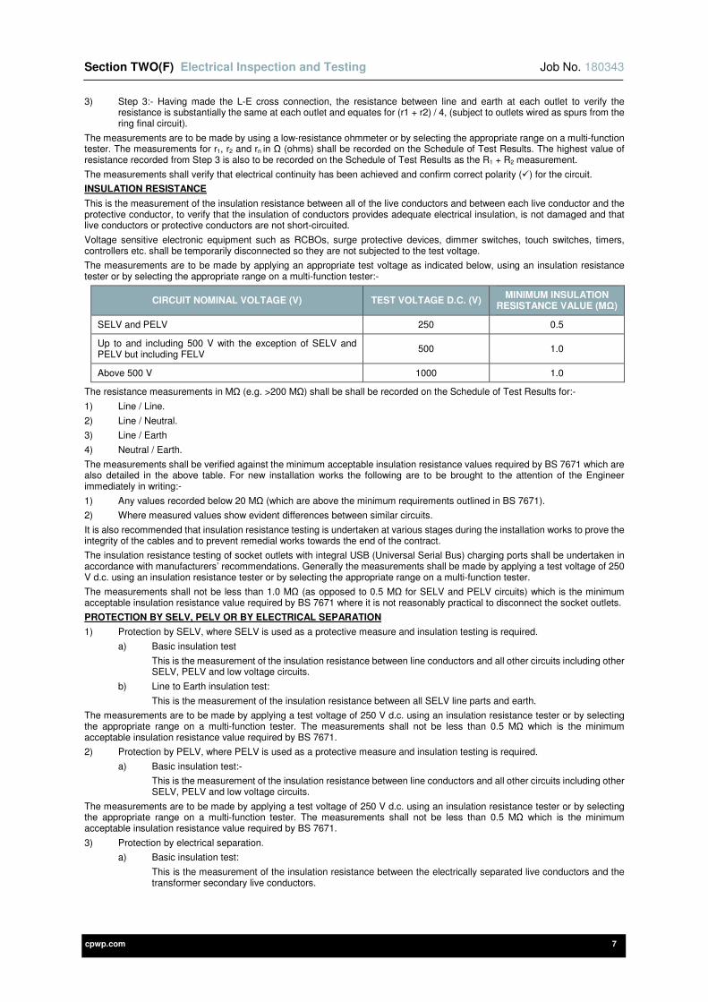
Section TWO(F) Electrical Inspection and Testing Job No. 180343
cpwp.com 7
3) Step 3:- Having made the L-E cross connection, the resistance between line and earth at each outlet to verify the resistance is substantially the same at each outlet and equates for (r1 + r2) / 4, (subject to outlets wired as spurs from the ring final circuit).
The measurements are to be made by using a low-resistance ohmmeter or by selecting the appropriate range on a multi-function tester. The measurements for r1, r2 and rn in Ω (ohms) shall be recorded on the Schedule of Test Results. The highest value of resistance recorded from Step 3 is also to be recorded on the Schedule of Test Results as the R1 + R2 measurement.
The measurements shall verify that electrical continuity has been achieved and confirm correct polarity () for the circuit.
INSULATION RESISTANCE
This is the measurement of the insulation resistance between all of the live conductors and between each live conductor and the protective conductor, to verify that the insulation of conductors provides adequate electrical insulation, is not damaged and that live conductors or protective conductors are not short-circuited.
Voltage sensitive electronic equipment such as RCBOs, surge protective devices, dimmer switches, touch switches, timers, controllers etc. shall be temporarily disconnected so they are not subjected to the test voltage.
The measurements are to be made by applying an appropriate test voltage as indicated below, using an insulation resistance tester or by selecting the appropriate range on a multi-function tester:-
CIRCUIT NOMINAL VOLTAGE (V) TEST VOLTAGE D.C. (V) MINIMUM INSULATION
RESISTANCE VALUE (MΩ)
SELV and PELV 250 0.5
Up to and including 500 V with the exception of SELV and PELV but including FELV
500 1.0
Above 500 V 1000 1.0
The resistance measurements in MΩ (e.g. >200 MΩ) shall be shall be recorded on the Schedule of Test Results for:-
1) Line / Line.
2) Line / Neutral.
3) Line / Earth
4) Neutral / Earth.
The measurements shall be verified against the minimum acceptable insulation resistance values required by BS 7671 which are also detailed in the above table. For new installation works the following are to be brought to the attention of the Engineer immediately in writing:-
1) Any values recorded below 20 MΩ (which are above the minimum requirements outlined in BS 7671).
2) Where measured values show evident differences between similar circuits.
It is also recommended that insulation resistance testing is undertaken at various stages during the installation works to prove the integrity of the cables and to prevent remedial works towards the end of the contract.
The insulation resistance testing of socket outlets with integral USB (Universal Serial Bus) charging ports shall be undertaken in accordance with manufacturers’ recommendations. Generally the measurements shall be made by applying a test voltage of 250 V d.c. using an insulation resistance tester or by selecting the appropriate range on a multi-function tester.
The measurements shall not be less than 1.0 MΩ (as opposed to 0.5 MΩ for SELV and PELV circuits) which is the minimum acceptable insulation resistance value required by BS 7671 where it is not reasonably practical to disconnect the socket outlets.
PROTECTION BY SELV, PELV OR BY ELECTRICAL SEPARATION
1) Protection by SELV, where SELV is used as a protective measure and insulation testing is required.
a) Basic insulation test
This is the measurement of the insulation resistance between line conductors and all other circuits including other SELV, PELV and low voltage circuits.
b) Line to Earth insulation test:
This is the measurement of the insulation resistance between all SELV line parts and earth.
The measurements are to be made by applying a test voltage of 250 V d.c. using an insulation resistance tester or by selecting the appropriate range on a multi-function tester. The measurements shall not be less than 0.5 MΩ which is the minimum acceptable insulation resistance value required by BS 7671.
2) Protection by PELV, where PELV is used as a protective measure and insulation testing is required.
a) Basic insulation test:-
This is the measurement of the insulation resistance between line conductors and all other circuits including other SELV, PELV and low voltage circuits.
The measurements are to be made by applying a test voltage of 250 V d.c. using an insulation resistance tester or by selecting the appropriate range on a multi-function tester. The measurements shall not be less than 0.5 MΩ which is the minimum acceptable insulation resistance value required by BS 7671.
3) Protection by electrical separation.
a) Basic insulation test:
This is the measurement of the insulation resistance between the electrically separated live conductors and the transformer secondary live conductors.
Section TWO(F) Electrical Inspection and Testing Job No. 180343
cpwp.com 8
b) Basic insulation of the separated conductors:-
This is the measurement of the insulation resistance between the electrically separated live conductors and their corresponding exposed-conductive-parts.
c) Basic insulation of any exposed-conductive-parts associated with separated conductors:-
This is the measurement of the insulation resistance between the any exposed-conductive-parts associated with the electrically separated circuits and any protective conductor, other exposed-conductive-parts or Earth.
The measurements are to be made by applying a test voltage of 500 V d.c. using an insulation resistance tester or by selecting the appropriate range on a multi-function tester. The measurements shall not be less than 1 MΩ which is the minimum acceptable insulation resistance value required by BS 7671.
Additional inspections and tests shall also be undertaken for separated circuits supplying more than one item of current using equipment as required by IET Guidance Note 3 Inspection and Testing. This is to verify that two coincidental faults with negligible impedance will disconnect one of the faulty circuits within the disconnection time required by BS 7671.
BASIC PROTECTION BY A BARRIER OR AN ENCLOSURE PROVIDED DURING ERECTION
These tests only apply to barriers or enclosures constructed on-site during the installation works and do not apply to the barriers or enclosures of factory-built equipment.
Barriers and/or enclosures shall be provided to prevent contact with live parts and shall provide at least the degree of protection (IP code) of IPXXB or IP2X. However a horizontal or top surface of a barrier or enclosure which is readily accessible shall provide at least the degree of protection (IP code) of IPXXD or IP4X.
This is to verify that each barrier / enclosure gives adequate protection against the risk of electric shock through contact with live parts by fingers or foreign objects (e.g. conductive tools).
These degrees of protection shall be tested as follows:-
1) IP2X is defined in BS EN 60529 as protection against the entry of ‘Fingers or similar objects not exceeding 80mm in length. Solid objects not exceeding12.5mm in diameter’:-
The test is made with a metallic standard test finger (test finger 1 to BS EN 61032).
2) IP4X is defined in BS EN 60529 as protection against the entry of ‘Wires or strips of thickness greater than 1.0mm, and solid objects of 1.0mm diameter or greater’:-
The test is made with a straight rigid steel wire of 1.0mm diameter applied with a force of 1 N ± 10 per cent.
INSULATION RESISTANCE / IMPEDANCE OF FLOORS AND WALLS
These tests are not required for standard electrical installations however if required reference shall be made to IET Guidance Note 3 Inspection and Testing.
POLARITY
Polarity testing shall verify:-
1) The polarity of the supply shall at the origin of the installation before the installation is energized.
2) That where single-pole switching devices are not permitted in the neutral conductor the devices are connected in the line conductor(s) only.
3) The wiring has been correctly connected throughout the installation.
Polarity of circuits shall be verified by the visual inspection of all termination points (by checking the core colours) or the measurement of the resistance of R1 + R2.
Polarity may be verified during the process of testing by:
1) Continuity of protective conductors – Test method 1 (R1 + R2 method).
2) Continuity of ring final circuit conductors.
Where polarity is verified during the process of testing the measurements are to be made by using a low-resistance ohmmeter or by selecting the appropriate range on a multi-function tester. Upon verification a ‘’ shall be recorded on the Schedule of Test Results.
EARTH ELECTRODE RESISTANCE
This is the measurement of the resistance of earth electrodes to verify the resistance is low enough to assist with disconnection times.
One of the following test methods shall be used:-
1) Test method E1: Measurement using dedicated earth electrode tester (fall of potential, three- or four-terminal type)
The entire installation must be isolated from the supply before the means of earthing is disconnected to perform this test. On completion of testing all bonding and protective conductors must be reconnected prior to the installation being energised (or re-energised).
2) Test method E2: Measurement using dedicated stakeless or clamp-based earth electrode tester.
The earth electrode under test does not need to be disconnected for this method.
3) Test method E3: Measurement using an earth fault loop impedance tester.
(Effectively the same method used for testing external earth fault loop impedance Ze).
The entire installation must be isolated from the supply before the means of earthing is disconnected to perform this test. It shall be noted this method is a live test and the supply shall be re-energised to perform the testing. On completion of testing the supply shall be isolated and all bonding and protective conductors must be reconnected prior to the installation being re-energised.
Section TWO(F) Electrical Inspection and Testing Job No. 180343
cpwp.com 9
Generally the measurement shall verify that the earth electrode resistance is less than 200 Ω, however the required automatic disconnection times of RCDs shall also be verified for TT systems. Earth electrode resistance values above 200 Ω may not be stable due to ground conditions.
The measurement of earth electrode resistance RA shall be recorded in the Supply Characteristics and Earthing Arrangements section of the certification / report. Also the earth electrode type, location and the method of measurement shall be recorded.
PROTECTION BY AUTOMATIC DISCONNECTION OF SUPPLY
The effectiveness of measures for fault protection by automatic disconnection of supply shall be verified for TN systems as follows:-
1) Measurement of earth fault impedance.
2) Visual inspection to confirm that protective devices are suitable.
(e.g. correct setting, type and ratings for circuit breakers and correct type and ratings for fuses).
3) Where used, RCD testing to confirm disconnection times are achieved.
For TT and IT systems reference shall be made to BS 7671 and IET Guidance Note 3 Inspection and Testing.
EARTH FAULT LOOP IMPEDANCE
Electrically continuity testing (as detailed earlier) must have been undertaken prior to the commenced of any earth fault loop impedance measurements.
This is the measurement of earth fault loop impedance (ZS) to verify that when an earth fault occurs the resistance of the earth fault loop (Zs = R1 + R2 + Ze) shall be low enough for a large fault current to flow and operate a protective device in the required disconnection time, therefore achieving automatic disconnection of the circuit line conductor.
Note: Ze may be substituted with Zdb when testing at a downstream distribution board or similar as the value measured is not external to the installation.
One of the following test methods shall be used:-
1) Measurement of total earth fault loop impedance (ZS) using an earth fault loop impedance tester or by selecting the appropriate range on a multi-function tester. It shall be noted that the measured ZS may be less than R1 + R2 + Ze due to parallel earth return paths.
2) Measurement of (R1 + R2) during continuity testing using a low-resistance ohmmeter and addition to the measured external fault loop impedance (Ze) of the same circuit, using an earth fault loop impedance tester.
The latter method is preferred when determining ZS for final circuits and distribution circuits.
The measurement at the extremity of the circuit (furthest point) for ZS in Ω (ohms) shall be recorded on the Schedule of Test Results. For ring final circuits the earth fault impedance (ZS) shall be measured at every outlet / point and the highest value measured shall be recorded on the Schedule of Test Results.
The measurements shall be verified against the maximum earth fault loop impedance (ZS) values required by BS 7671 which must be adjusted for temperature by applying a factor of 0.8 (80%).
e.g. for a 20A Type B circuit breaker to BS EN 60898, BS 7671 provides a maximum earth fault loop impedance of 2.19 Ω. However, this is at operating temperature, so the maximum acceptable measured value shall be 2.19 x 0.8 = 1.752 Ω.
It shall be noted that adjusted for the industry recognised 0.8 ‘rule of thumb’ are contained within the IET On-Site Guide / IET Guidance Note 3 and can also be obtained from Electrical Contracting Certification Schemes, which can then be used for verification of measurements.
Under no circumstances shall the measurements be verified against the maximum earth fault loop impedance (ZS) contained within BS 7671 with no adjustment for temperature.
The maximum permitted earth fault loop impedance (ZS) values included within the ‘Maximum Zs permitted by BS 7671’ column of the ‘Schedule of circuit details’ shall include the ZS values from BS 7671 which have not been adjusted for temperature.
Where supplementary protective equipotential bonding has been provided to satisfy the measured earth fault loop impedance requirements of BS 7671, the effectiveness of the bonding shall be verified.
The external fault loop impedance (Ze) shall also be measured to verify there is an earth connection and to determine the external earth fault loop impedance (Ze) which is part of the earth fault loop (Zs).
The external fault loop impedance (Ze) shall be measured at:-
1) The origin of the installation.
The measurement for Ze in Ω (ohms) shall be recorded in the Supply Characteristics and Earthing Arrangements section of the certification / report.
2) At each item of switchgear within the installation (e.g. LV switch panels, MCCB panel boards, MCB distribution boards, consumer units etc. etc.)
The measurement for ZS (sometimes known as Zs, Zdb or similar) in Ω (ohms) shall be recorded on the Schedule of Test Results (top section) for the item of switchgear.
The measurements are to be made by using an earth fault loop impedance tester or by selecting the appropriate range on a multi-function tester.
PROSPECTIVE FAULT CURRENT
This is the measurement of prospective fault current (Ipf) under both short-circuit and earth fault conditions to verify that the rated short-circuit breaking capacities of protective devices are greater than the prospective fault current (Ipf).
The prospective short circuit current and prospective earth fault current shall be measured at every relevant point of the installation which includes:-
1) The origin of the installation.

Section TWO(F) Electrical Inspection and Testing Job No. 180343
cpwp.com 10
The measurement for Ipf in kA shall be recorded in the Supply Characteristics and Earthing Arrangements section of the certification / report.
2) At each item of switchgear within the installation where a protective device is required to operate under fault conditions.
The measurement for Ipf in kA shall be recorded on the Schedule of Test Results (top section) for the item of switchgear.
The measurements are to be made by using the prospective fault current range of a suitable earth fault loop impedance tester or by selecting the appropriate range on a multi-function tester. Whichever is the greater measurement of prospective short circuit current (PSCC) and prospective earth fault current (PEFC) shall be recorded.
For three phase supplies where a 230V test instrument is used the prospective fault current line to line can be taken as twice that of the prospective fault current line to neutral.
e.g. line to neutral measurement of 4.6 kA x 2 = 9.2 kA (Ipf).
The measurements shall be verified by comparing the measured prospective fault current (Ipf) at the terminals of protective devices with their rated short-circuit breaking capacities. The rated short-circuit breaking capacities of protective devices must be greater than the prospective fault current (Ipf).
CHECK OF PHASE SEQUENCE
Generally this is verified by checking the polarity and connections at all relevant points throughout the installation. However the phase sequence of all three phase equipment such as rotating machines (e.g. motors) shall be verified to ensure correct rotation. This shall be verified by using a phase rotation tester or by selecting the appropriate range on a multi-function tester.
ADDITIONAL PROTECTION – OPERATION OF RESIDUAL CURRENT DEVICES
This is the measurement of RCD (RCCB or RCBO) operating times to verify the correct operation and required disconnection times are achieved. The measurements are to be made by using an RCD tester or by selecting the appropriate range on a multi-function tester. Loads shall be disconnected during testing. All residual current devices shall be tested at:-
1) 50% of the rated operating (tripping) current and shall not operate / open.
2) 100% of the rated operating (tripping) current (I∆n) and shall operate / open.
The measured operating time in ms shall be recorded (where applicable) in the:
a) Particulars of Installation at the Origin section of the certification / report. If the residual current device has a rated time delay this shall also be included.
b) Schedule of Test Results (top section) for the item of switchgear.
c) Schedule of Test Results for a circuit.
The residual current devices shall have an operating time not exceeding that required by their respective product standards at a residual current of I∆n, as detailed in the table below:-
DEVICE TYPE
NON-TIME DELAYED WITH TIME DELAY
NOTES MAXIMUM OPERATING TIME AT 100% RATED TRIPPING
CURRENT, I∆n
(ms)
OPERATING TIME AT 100% RATED TRIPPING
CURRENT, I∆n
(ms)
BS 4293 200 ((0.5 to 1.0) x time delay) +
200
BS 61008 300 130 to 500 S type
BS 61009 (RCBO) 300 130 to 500 S type
BS 7288 (integral socket-outlets) 200 Non-applicable
Residual current devices used for additional protection shall also be tested at 5 I∆n (e.g. 150mA for I∆n = 30mA) and the measured operating time in ms shall be recorded in the:-
1) Schedule of Test Results (top section) for the item of switchgear (if applicable).
2) Schedule of Test Results for a circuit.
Residual current devices for additional protection shall have an operating time not exceeding 40ms at a residual current of 5 I∆n.
Measurements shall be taken on both positive and negative half cycles of the supply waveform and the longer operating time shall be recorded.
ADDITIONAL PROTECTION – SUPPLEMENTARY PROTECTIVE EQUIPOTENTIAL BONDING
Where supplementary protective equipotential bonding has been provided for additional protection the effectiveness of the bonding shall be verified.
FUNCTIONAL TESTING OF RESIDUAL CURRENT DEVICES
Functional testing shall be undertaken on all residual current devices. The integral test device shall be operated by pressing the button marked ‘T’ or ‘Test’, during testing the residual current devices must be energised.
Upon verification a ‘’ shall be recorded on the Schedule of Test Results.
FUNCTIONAL TESTING OF ARC FAULT DETECTION DEVICES (AFDDs)
Functional testing shall be undertaken on arc fault detection devices (AFDDs) when they are provided with a manually operated test facility, in strict accordance with the manufacturers’ recommendations.

Section TWO(F) Electrical Inspection and Testing Job No. 180343
cpwp.com 11
Upon verification a ‘’ shall be recorded on the Schedule of Test Results.
AFDDs that do not have a manually operated test facility cannot be tested for functionality.
OTHER FUNCTIONAL TESTING
All equipment that forms part of the electrical installation shall be subjected to functional testing to verify that it functions correctly and has been properly mounted, adjusted, and installed in accordance with BS 7671.
This shall include:
1) All electrical switchgear used for isolation e.g. main switches, isolators, protective devices etc.
2) All luminaires, switching and control devices, interlocks, adjustable relays, socket-outlets etc.
3) Motors, motor controls and starters, including correct rotation.
It shall be noted the above list is not exhaustive and functional testing must be undertaken on all equipment that forms part of the electrical installation.
2F-12 DEPARTURES FROM AND NON-COMPLIANCES WITH BS 7671
Any departures from or non-compliances with BS 7671 resulting from the inspection and testing of the electrical installation shall be brought to the attention of the Engineer immediately in writing.
2F-13 INSPECTION AND TESTING OF MEDICAL INSTALLATIONS
This section of the specification details the general inspection and testing requirements that shall also apply to medical installations. However it shall be noted that medical installations will have additional inspection, testing and commissioning requirements, for example (but not limited to):
1) Inspection and functional tests of medical IT systems.
2) Measurement of the leakage current for the output circuit and the enclosure of medical IT system isolating transformers.
3) Measurement of the resistance of protective conductors between the earth terminals of any socket outlet (or fixed equipment) and any extraneous conductive parts (e.g. not exceeding 0.2 Ω for Group 1 and 2 locations etc.).
Medical IT systems are also known as medical isolated power supply systems.
Where required the inspection and testing requirements of medical installation shall be detailed within a subsequent section of this specification.
2F-14 CONTINUITY OF CABLE SUPPORT AND CONTAINMENT SYSTEMS
All metallic cable support and containment systems shall be equipotential bonded for protective earthing and to avoid / reduce electromagnetic disturbances as detailed within Section 2E of this specification.
The electrical continuity of cable support and containment systems shall be tested as follows:-
1) Cable ladder rack, cable tray and cable basket shall be tested in accordance with the relevant clauses of BS EN 61537.
2) Cable trunking shall be tested in accordance with the relevant clauses of BS EN 50085.
3) Cable conduit shall be tested in accordance with the relevant clauses BS EN 61386.
It shall also be verified that all connections between cable conduit (e.g. conduit take-off plates, conduit boxes) and cable tray / basket / tray have adequate electrical continuity.
The Contractor shall provide written clarification that the cable support and containment systems have electrical continuity characteristics as defined in the above standards.
2F-15 FIRE BARRIERS / STOPPING
On completion of the fire barriers / stopping works fully detailed completion / compliance certification shall be provided along with record drawings that detail all fire barrier / stopping locations.
2F-16 FACTORY BUILT ASSEMBLIES
The Engineer shall be afforded the opportunity to inspect and formally witness the testing of all bespoke factory built assemblies (e.g. LV switch panels, switchgear etc.) before they are dispatched to site. The required period of notice to attend shall normally be 10 days, but shall be variable at the discretion of the Engineer.
The Engineer shall be provided with a copy of the appropriate inspection and testing certification for each factory built assembly which shall also be included within the Operation and Maintenance Manual.
2F-17 THERMOGRAPHIC SURVEYS
Any requirement for undertaking thermographic surveys shall be detailed within a subsequent section of this specification. The guidelines on thermographic equipment shall be followed within IET Guidance Note 3.
2F-18 FORMAL WITNESSING OF TESTING
The Qualified Supervisor and the person(s) undertaking the inspection / testing works shall give reasonable notice of all tests to permit them to be witnessed by the Engineer. The required period of notice shall normally be 10 days, but shall be variable at the discretion of the Engineer.
Preliminary testing shall be undertaken prior to any formal witnessing by the Engineer. The preliminary test results shall be provided to the Engineer in draft certificates before inviting the Engineer to attend formal witnessing. The Engineer will then witness the formal tests in full or selectively as deemed necessary to verify the draft test results.
The proportion of tests to be witnessed by the Engineer will be 20%, though this could be reduced to 10% at the discretion of the Engineer on very large systems. The Engineer has the right to ask for a higher proportion of witnessing should the verification or witnessing exercise be unsuccessful e.g. the test readings cannot be repeated within a reasonable degree of accuracy. In this instance the Electrical Contractor shall bear all costs associated with this additional work.
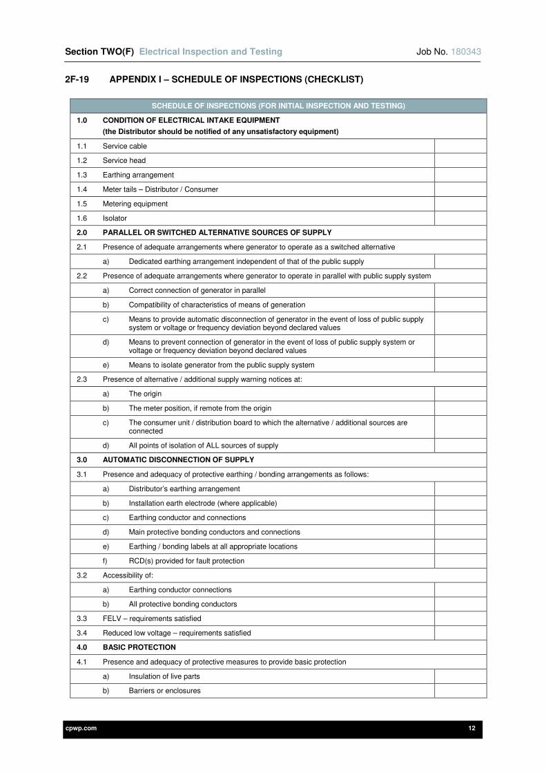
Section TWO(F) Electrical Inspection and Testing Job No. 180343
cpwp.com 12
2F-19 APPENDIX I – SCHEDULE OF INSPECTIONS (CHECKLIST)
SCHEDULE OF INSPECTIONS (FOR INITIAL INSPECTION AND TESTING)
1.0 CONDITION OF ELECTRICAL INTAKE EQUIPMENT
(the Distributor should be notified of any unsatisfactory equipment)
1.1 Service cable
1.2 Service head
1.3 Earthing arrangement
1.4 Meter tails – Distributor / Consumer
1.5 Metering equipment
1.6 Isolator
2.0 PARALLEL OR SWITCHED ALTERNATIVE SOURCES OF SUPPLY
2.1 Presence of adequate arrangements where generator to operate as a switched alternative
a) Dedicated earthing arrangement independent of that of the public supply
2.2 Presence of adequate arrangements where generator to operate in parallel with public supply system
a) Correct connection of generator in parallel
b) Compatibility of characteristics of means of generation
c) Means to provide automatic disconnection of generator in the event of loss of public supply system or voltage or frequency deviation beyond declared values
d) Means to prevent connection of generator in the event of loss of public supply system or voltage or frequency deviation beyond declared values
e) Means to isolate generator from the public supply system
2.3 Presence of alternative / additional supply warning notices at:
a) The origin
b) The meter position, if remote from the origin
c) The consumer unit / distribution board to which the alternative / additional sources are connected
d) All points of isolation of ALL sources of supply
3.0 AUTOMATIC DISCONNECTION OF SUPPLY
3.1 Presence and adequacy of protective earthing / bonding arrangements as follows:
a) Distributor’s earthing arrangement
b) Installation earth electrode (where applicable)
c) Earthing conductor and connections
d) Main protective bonding conductors and connections
e) Earthing / bonding labels at all appropriate locations
f) RCD(s) provided for fault protection
3.2 Accessibility of:
a) Earthing conductor connections
b) All protective bonding conductors
3.3 FELV – requirements satisfied
3.4 Reduced low voltage – requirements satisfied
4.0 BASIC PROTECTION
4.1 Presence and adequacy of protective measures to provide basic protection
a) Insulation of live parts
b) Barriers or enclosures
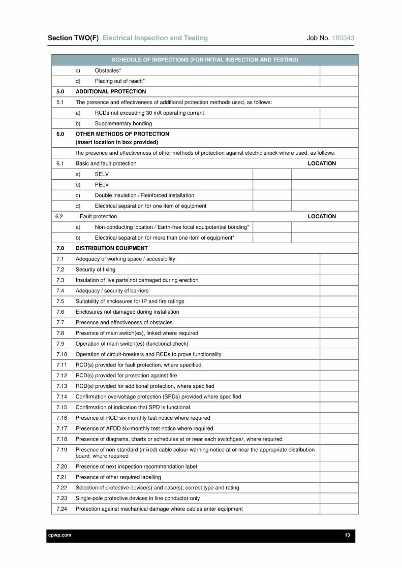
Section TWO(F) Electrical Inspection and Testing Job No. 180343
cpwp.com 13
SCHEDULE OF INSPECTIONS (FOR INITIAL INSPECTION AND TESTING)
c) Obstacles*
d) Placing out of reach*
5.0 ADDITIONAL PROTECTION
5.1 The presence and effectiveness of additional protection methods used, as follows:
a) RCDs not exceeding 30 mA operating current
b) Supplementary bonding
6.0 OTHER METHODS OF PROTECTION
(insert location in box provided)
The presence and effectiveness of other methods of protection against electric shock where used, as follows:
6.1 Basic and fault protection LOCATION
a) SELV
b) PELV
c) Double insulation / Reinforced installation
d) Electrical separation for one item of equipment
6.2 Fault protection LOCATION
a) Non-conducting location / Earth-free local equipotential bonding*
b) Electrical separation for more than one item of equipment*
7.0 DISTRIBUTION EQUIPMENT
7.1 Adequacy of working space / accessibility
7.2 Security of fixing
7.3 Insulation of live parts not damaged during erection
7.4 Adequacy / security of barriers
7.5 Suitability of enclosures for IP and fire ratings
7.6 Enclosures not damaged during installation
7.7 Presence and effectiveness of obstacles
7.8 Presence of main switch(es), linked where required
7.9 Operation of main switch(es) (functional check)
7.10 Operation of circuit-breakers and RCDs to prove functionality
7.11 RCD(s) provided for fault protection, where specified
7.12 RCD(s) provided for protection against fire
7.13 RCD(s) provided for additional protection, where specified
7.14 Confirmation overvoltage protection (SPDs) provided where specified
7.15 Confirmation of indication that SPD is functional
7.16 Presence of RCD six-monthly test notice where required
7.17 Presence of AFDD six-monthly test notice where required
7.18 Presence of diagrams, charts or schedules at or near each switchgear, where required
7.19 Presence of non-standard (mixed) cable colour warning notice at or near the appropriate distribution board, where required
7.20 Presence of next inspection recommendation label
7.21 Presence of other required labelling
7.22 Selection of protective device(s) and base(s); correct type and rating
7.23 Single-pole protective devices in line conductor only
7.24 Protection against mechanical damage where cables enter equipment

Section TWO(F) Electrical Inspection and Testing Job No. 180343
cpwp.com 14
SCHEDULE OF INSPECTIONS (FOR INITIAL INSPECTION AND TESTING)
7.25 Protection against electromagnetic effects where cables enter ferromagnetic enclosures.
7.26 Confirmation that ALL conductor connections, including connections to busbars are correctly located in terminals and are tight and secure
8.0 CIRCUITS
8.1 Identification of conductors
8.2 Cables correctly supported throughout their length
8.3 Examination of cables for signs of mechanical damage during installation
8.4 Examination of insulation of live parts, not damaged during erection
8.5 Non-sheathed cables protected by enclosure in conduit, ducting or trunking
8.6 Suitability of containment systems (including flexible conduit)
8.7 Correct temperature rating of cable insulation
8.8 Adequacy of cables for current-carrying capacity with regard to the type and nature of installation
8.9 Adequacy of protective devices: type and rated current for fault protection
8.10 Presence and adequacy of circuit protective conductors
8.11 Coordination between conductors and overload protective devices
8.12 Wiring systems and cable installation methods / practices appropriate to the type and nature of installation and external influences
8.13 Cables installed under floors, above ceilings, in walls / partitions, adequately protected against damage
a) Installed in prescribed zones
b) Incorporating earthed armour or sheath, or installed within earthed wiring system, or otherwise protected against mechanical damage by nails, screws and the like
8.14 Provision of additional protection by RCDs having a rated residual operating current (I∆n) not exceeding 30mA:
a) For mobile equipment with a current rating not exceeding 32 A for use outdoors
b) For all socket-outlets of rating 32 A or less, unless exempt
c) For cables installed walls / partitions at a depth of less than 50mm
d) For cables installed in walls / partitions containing metal parts regardless of depth
e) Final circuits supplying luminaires within (domestic) household premises
8.15 Provision of fire barriers, sealing arrangements so as to minimize the spread of fire
8.16 Band II cables segregated / separated from Band I circuits
8.17 Cables segregated / separated from non-electrical services
8.18 Termination of cables at enclosures
a) Connection under no undue strain
b) No basic insulation of a conductor visible outside enclosure
c) Connections of live conductors adequately enclosed.
d) Adequately connected at point of entry to enclosure (glands, bushes etc.)
8.19 Suitability of circuit accessories for external influences
8.20 Circuit accessories not damaged during erection
8.21 Single-pole devices for switching in the line conductor only
8.22 Adequacy of connections, including cpcs, within accessories and at fixed and stationary equipment
9.1 Isolators
a) Presence and location of appropriate devices
b) Capable of being secured in the OFF position
c) Correct operation verified (functional check)
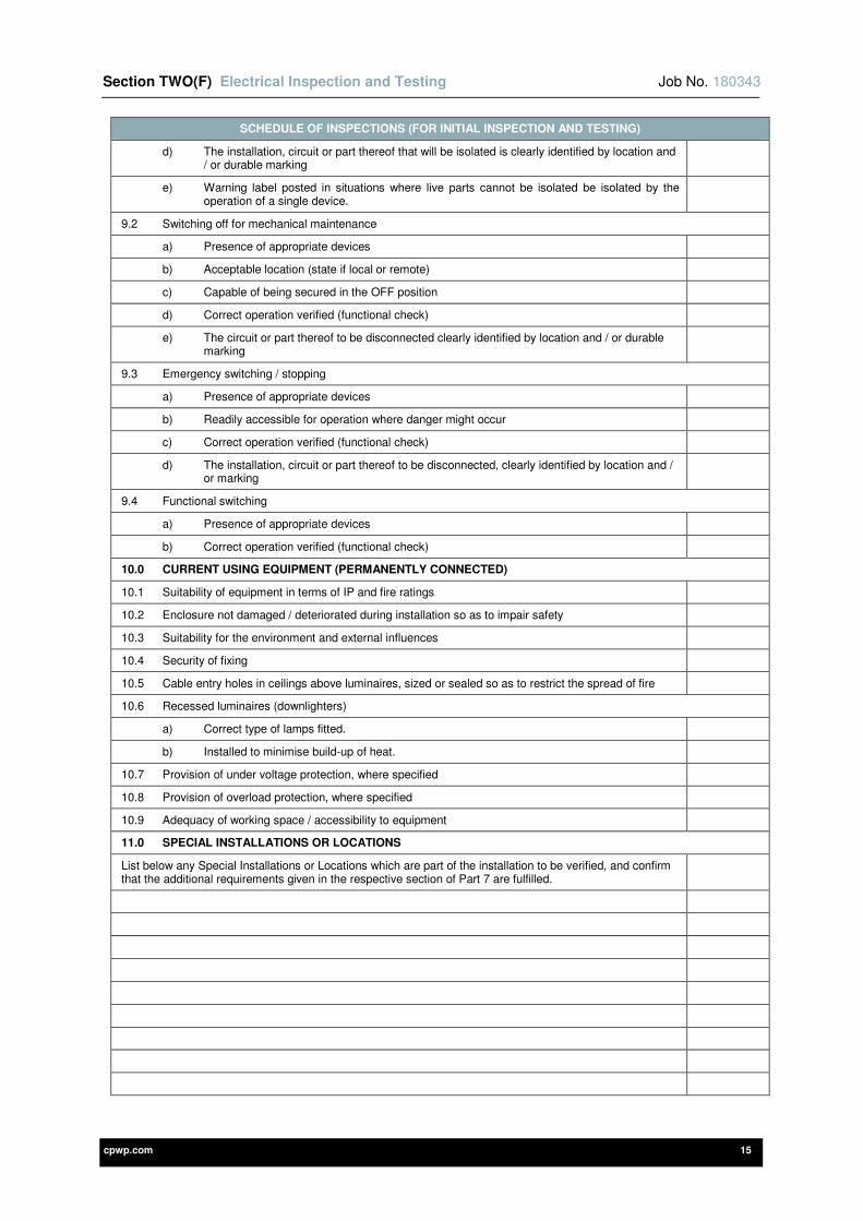
Section TWO(F) Electrical Inspection and Testing Job No. 180343
cpwp.com 15
SCHEDULE OF INSPECTIONS (FOR INITIAL INSPECTION AND TESTING)
d) The installation, circuit or part thereof that will be isolated is clearly identified by location and / or durable marking
e) Warning label posted in situations where live parts cannot be isolated be isolated by the operation of a single device.
9.2 Switching off for mechanical maintenance
a) Presence of appropriate devices
b) Acceptable location (state if local or remote)
c) Capable of being secured in the OFF position
d) Correct operation verified (functional check)
e) The circuit or part thereof to be disconnected clearly identified by location and / or durable marking
9.3 Emergency switching / stopping
a) Presence of appropriate devices
b) Readily accessible for operation where danger might occur
c) Correct operation verified (functional check)
d) The installation, circuit or part thereof to be disconnected, clearly identified by location and / or marking
9.4 Functional switching
a) Presence of appropriate devices
b) Correct operation verified (functional check)
10.0 CURRENT USING EQUIPMENT (PERMANENTLY CONNECTED)
10.1 Suitability of equipment in terms of IP and fire ratings
10.2 Enclosure not damaged / deteriorated during installation so as to impair safety
10.3 Suitability for the environment and external influences
10.4 Security of fixing
10.5 Cable entry holes in ceilings above luminaires, sized or sealed so as to restrict the spread of fire
10.6 Recessed luminaires (downlighters)
a) Correct type of lamps fitted.
b) Installed to minimise build-up of heat.
10.7 Provision of under voltage protection, where specified
10.8 Provision of overload protection, where specified
10.9 Adequacy of working space / accessibility to equipment
11.0 SPECIAL INSTALLATIONS OR LOCATIONS
List below any Special Installations or Locations which are part of the installation to be verified, and confirm that the additional requirements given in the respective section of Part 7 are fulfilled.
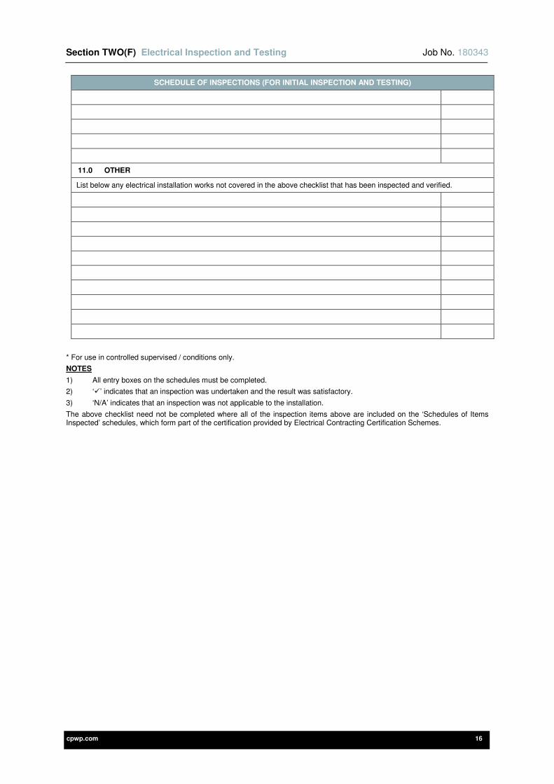
Section TWO(F) Electrical Inspection and Testing Job No. 180343
cpwp.com 16
SCHEDULE OF INSPECTIONS (FOR INITIAL INSPECTION AND TESTING)
11.0 OTHER
List below any electrical installation works not covered in the above checklist that has been inspected and verified.
* For use in controlled supervised / conditions only.
NOTES
1) All entry boxes on the schedules must be completed.
2) ‘’ indicates that an inspection was undertaken and the result was satisfactory.
3) ‘N/A’ indicates that an inspection was not applicable to the installation.
The above checklist need not be completed where all of the inspection items above are included on the ‘Schedules of Items Inspected’ schedules, which form part of the certification provided by Electrical Contracting Certification Schemes.
cpwp.com V2.0
Section Three Site Specific Requirements

Section THREE Site Specific Requirements Job No. 180343
cpwp.com 2
Contents Page
3-1 DEFINITIONS 3
3-2 REFERENCE TO OTHER SECTIONS OF THIS SPECIFICATION 3
3-3 STANDARDS APPLICABLE 3
3-4 SCOPE OF WORKS 3
3-5 MAINTENANCE 3
3-6 COMPLIANCE WITH PART L OF BUILDING REGULATIONS POST COMPLETION 4
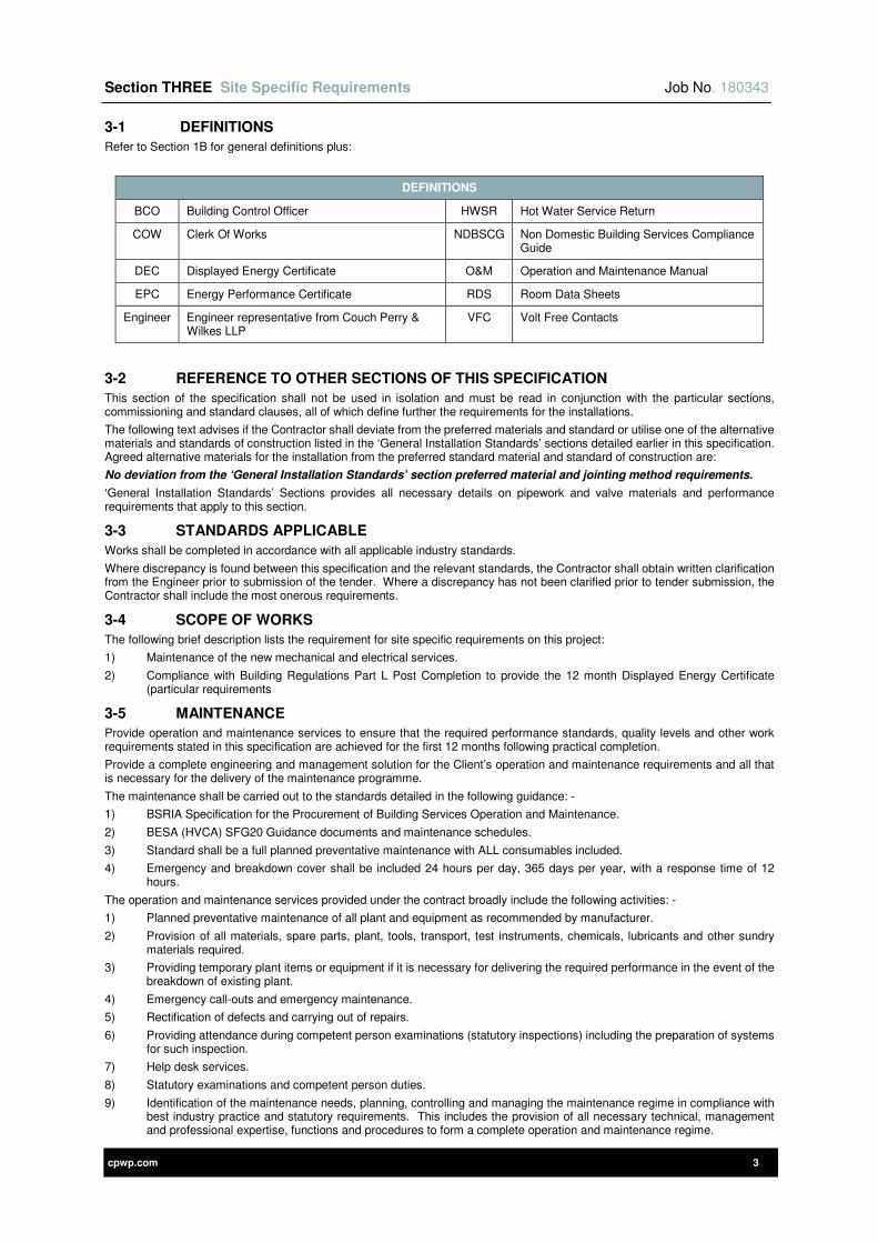
Section THREE Site Specific Requirements Job No. 180343
cpwp.com 3
3-1 DEFINITIONS
Refer to Section 1B for general definitions plus:
DEFINITIONS
BCO Building Control Officer HWSR Hot Water Service Return
COW Clerk Of Works NDBSCG Non Domestic Building Services Compliance Guide
DEC Displayed Energy Certificate O&M Operation and Maintenance Manual
EPC Energy Performance Certificate RDS Room Data Sheets
Engineer Engineer representative from Couch Perry & Wilkes LLP
VFC Volt Free Contacts
3-2 REFERENCE TO OTHER SECTIONS OF THIS SPECIFICATION
This section of the specification shall not be used in isolation and must be read in conjunction with the particular sections, commissioning and standard clauses, all of which define further the requirements for the installations.
The following text advises if the Contractor shall deviate from the preferred materials and standard or utilise one of the alternative materials and standards of construction listed in the ‘General Installation Standards’ sections detailed earlier in this specification. Agreed alternative materials for the installation from the preferred standard material and standard of construction are:
No deviation from the ‘General Installation Standards’ section preferred material and jointing method requirements.
‘General Installation Standards’ Sections provides all necessary details on pipework and valve materials and performance requirements that apply to this section.
3-3 STANDARDS APPLICABLE
Works shall be completed in accordance with all applicable industry standards.
Where discrepancy is found between this specification and the relevant standards, the Contractor shall obtain written clarification from the Engineer prior to submission of the tender. Where a discrepancy has not been clarified prior to tender submission, the Contractor shall include the most onerous requirements.
3-4 SCOPE OF WORKS
The following brief description lists the requirement for site specific requirements on this project:
1) Maintenance of the new mechanical and electrical services.
2) Compliance with Building Regulations Part L Post Completion to provide the 12 month Displayed Energy Certificate (particular requirements
3-5 MAINTENANCE
Provide operation and maintenance services to ensure that the required performance standards, quality levels and other work requirements stated in this specification are achieved for the first 12 months following practical completion.
Provide a complete engineering and management solution for the Client’s operation and maintenance requirements and all that is necessary for the delivery of the maintenance programme.
The maintenance shall be carried out to the standards detailed in the following guidance: -
1) BSRIA Specification for the Procurement of Building Services Operation and Maintenance.
2) BESA (HVCA) SFG20 Guidance documents and maintenance schedules.
3) Standard shall be a full planned preventative maintenance with ALL consumables included.
4) Emergency and breakdown cover shall be included 24 hours per day, 365 days per year, with a response time of 12 hours.
The operation and maintenance services provided under the contract broadly include the following activities: -
1) Planned preventative maintenance of all plant and equipment as recommended by manufacturer.
2) Provision of all materials, spare parts, plant, tools, transport, test instruments, chemicals, lubricants and other sundry materials required.
3) Providing temporary plant items or equipment if it is necessary for delivering the required performance in the event of the breakdown of existing plant.
4) Emergency call-outs and emergency maintenance.
5) Rectification of defects and carrying out of repairs.
6) Providing attendance during competent person examinations (statutory inspections) including the preparation of systems for such inspection.
7) Help desk services.
8) Statutory examinations and competent person duties.
9) Identification of the maintenance needs, planning, controlling and managing the maintenance regime in compliance with best industry practice and statutory requirements. This includes the provision of all necessary technical, management and professional expertise, functions and procedures to form a complete operation and maintenance regime.
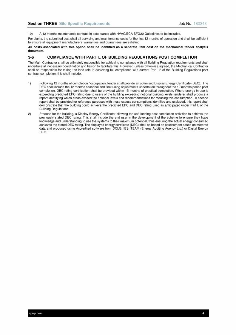
Section THREE Site Specific Requirements Job No. 180343
cpwp.com 4
10) A 12 months maintenance contract in accordance with HVAC/ECA SFG20 Guidelines to be included.
For clarity, the submitted cost shall all servicing and maintenance costs for the first 12 months of operation and shall be sufficient to ensure all equipment manufacturers’ warranties and guarantees are satisfied.
All costs associated with this option shall be identified as a separate item cost on the mechanical tender analysis document.
3-6 COMPLIANCE WITH PART L OF BUILDING REGULATIONS POST COMPLETION
The Main Contractor shall be ultimately responsible for achieving compliance with all Building Regulation requirements and shall undertake all necessary coordination and liaison to facilitate this. However, unless otherwise agreed, the Mechanical Contractor shall be responsible for taking the lead role in achieving full compliance with current Part L2 of the Building Regulations post contract completion, this shall include:
1) Following 12 months of completion / occupation, tender shall provide an optimised Display Energy Certificate (DEC). The DEC shall include the 12 months seasonal and fine tuning adjustments undertaken throughout the 12 months period post completion. DEC rating certification shall be provided within 15 months of practical completion. Where energy in use is exceeding predicted EPC rating due to users of the building exceeding notional building levels tenderer shall produce a report identifying which areas exceed the notional levels and recommendations for reducing this consumption. A second report shall be provided for reference purposes with these excess consumptions identified and excluded, this report shall demonstrate that the building could achieve the predicted EPC and DEC rating used as anticipated under Part L of the Building Regulations.
2) Produce for the building, a Display Energy Certificate following the soft landing post completion activities to achieve the previously stated DEC rating. This shall include the end user in the development of the scheme to ensure they have knowledge and understanding to use the systems to their maximum potential, thus ensuring the actual energy consumed achieves the stated DEC rating. The displayed energy certificate (DEC) shall be based an assessment based on metered data and produced using Accredited software from DCLG, IES, TEAM (Energy Auditing Agency Ltd.) or Digital Energy DEC.

cpwp.com V1.3
Section Four Energy Metering
Section FOUR Energy Metering Job No. 180343
cpwp.com 2
Contents Page
4-1 GENERAL REQUIREMENTS 3
4-2 DEFINITIONS 3
4-3 REFERENCE TO OTHER SECTIONS OF THIS SPECIFICATION 3
4-4 STANDARDS APPLICABLE 3
4-5 SCOPE OF WORKS 3
4-6 INCOMING SERVICES METERING 4
4-7 SUB-METERING 4
4-8 SOFTWARE AND PROGRAMMING 5
4-9 LANDLORD REMOTE READING 5
4-10 METERING COMMISSIONING AND HANDOVER 5
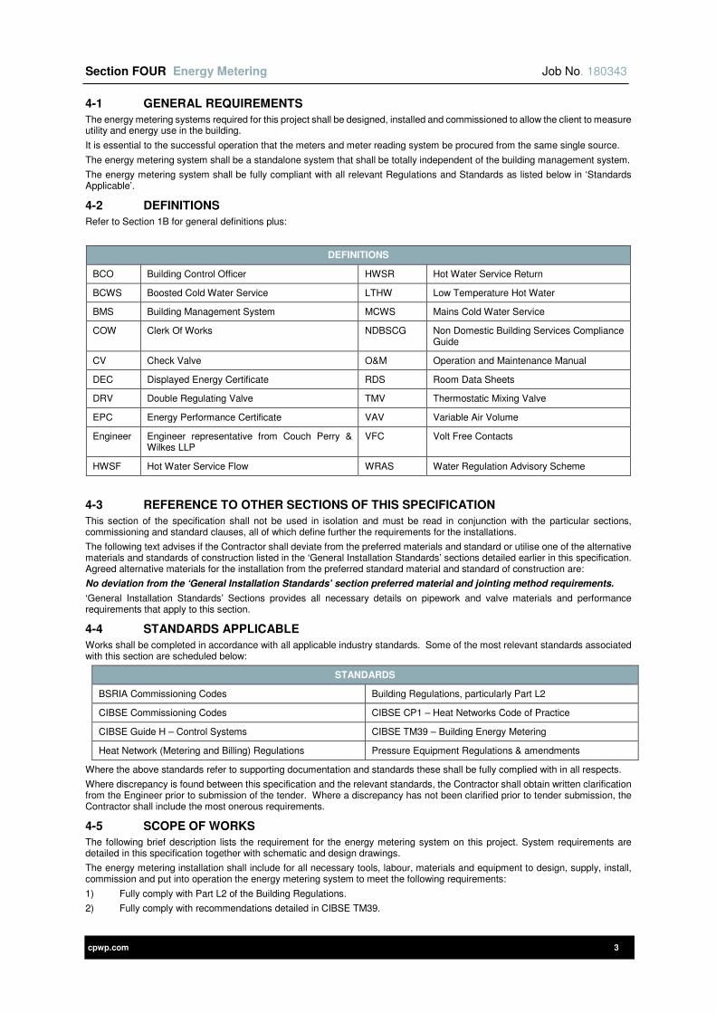
Section FOUR Energy Metering Job No. 180343
cpwp.com 3
4-1 GENERAL REQUIREMENTS
The energy metering systems required for this project shall be designed, installed and commissioned to allow the client to measure utility and energy use in the building.
It is essential to the successful operation that the meters and meter reading system be procured from the same single source.
The energy metering system shall be a standalone system that shall be totally independent of the building management system.
The energy metering system shall be fully compliant with all relevant Regulations and Standards as listed below in ‘Standards Applicable’.
4-2 DEFINITIONS
Refer to Section 1B for general definitions plus:
DEFINITIONS
BCO Building Control Officer HWSR Hot Water Service Return
BCWS Boosted Cold Water Service LTHW Low Temperature Hot Water
BMS Building Management System MCWS Mains Cold Water Service
COW Clerk Of Works NDBSCG Non Domestic Building Services Compliance Guide
CV Check Valve O&M Operation and Maintenance Manual
DEC Displayed Energy Certificate RDS Room Data Sheets
DRV Double Regulating Valve TMV Thermostatic Mixing Valve
EPC Energy Performance Certificate VAV Variable Air Volume
Engineer Engineer representative from Couch Perry & Wilkes LLP
VFC Volt Free Contacts
HWSF Hot Water Service Flow WRAS Water Regulation Advisory Scheme
4-3 REFERENCE TO OTHER SECTIONS OF THIS SPECIFICATION
This section of the specification shall not be used in isolation and must be read in conjunction with the particular sections, commissioning and standard clauses, all of which define further the requirements for the installations.
The following text advises if the Contractor shall deviate from the preferred materials and standard or utilise one of the alternative materials and standards of construction listed in the ‘General Installation Standards’ sections detailed earlier in this specification. Agreed alternative materials for the installation from the preferred standard material and standard of construction are:
No deviation from the ‘General Installation Standards’ section preferred material and jointing method requirements.
‘General Installation Standards’ Sections provides all necessary details on pipework and valve materials and performance requirements that apply to this section.
4-4 STANDARDS APPLICABLE
Works shall be completed in accordance with all applicable industry standards. Some of the most relevant standards associated with this section are scheduled below:
STANDARDS
BSRIA Commissioning Codes Building Regulations, particularly Part L2
CIBSE Commissioning Codes CIBSE CP1 – Heat Networks Code of Practice
CIBSE Guide H – Control Systems CIBSE TM39 – Building Energy Metering
Heat Network (Metering and Billing) Regulations Pressure Equipment Regulations & amendments
Where the above standards refer to supporting documentation and standards these shall be fully complied with in all respects.
Where discrepancy is found between this specification and the relevant standards, the Contractor shall obtain written clarification from the Engineer prior to submission of the tender. Where a discrepancy has not been clarified prior to tender submission, the Contractor shall include the most onerous requirements.
4-5 SCOPE OF WORKS
The following brief description lists the requirement for the energy metering system on this project. System requirements are detailed in this specification together with schematic and design drawings.
The energy metering installation shall include for all necessary tools, labour, materials and equipment to design, supply, install, commission and put into operation the energy metering system to meet the following requirements:
1) Fully comply with Part L2 of the Building Regulations.
2) Fully comply with recommendations detailed in CIBSE TM39.
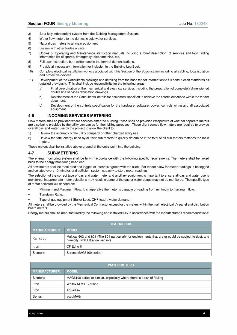
Section FOUR Energy Metering Job No. 180343
cpwp.com 4
3) Be a fully independent system from the Building Management System.
4) Water flow meters to the domestic cold water services.
5) Natural gas meters to all main equipment.
6) Liaison with other trades on site.
7) Copies of Operating and Maintenance instruction manuals including a ‘brief description’ of services and fault finding information list of spares, emergency telephone Nos. etc.
8) Full user instruction, both written and in the form of demonstrations.
9) Provide all necessary information for inclusion in the Building Log Book.
10) Complete electrical installation works associated with this Section of the Specification including all cabling, local isolation and protective devices.
11) Development of the Consultants drawings and detailing from the base tender information to full construction standards as detailed previously. This shall include responsibility for the following areas:-
a) Final co-ordination of the mechanical and electrical services including the preparation of completely dimensioned double line services fabrication drawings.
b) Development of the Consultants' details for equipment specified to achieve the criteria described within the tender documents.
c) Development of the controls specification for the hardware, software, power, controls wiring and all associated equipment.
4-6 INCOMING SERVICES METERING
Flow meters shall be provided where services enter the building, these shall be provided irrespective of whether separate meters are also being provided by the utility companies for their billing purposes. These client owned flow meters are required to provide overall gas and water use by the project to allow the client to:
1) Review the accuracy of the utility company or other charged utility use.
2) Review the total energy used by all their sub-meters to quickly determine if the total of all sub-meters matches the main meters.
These meters shall be installed above ground at the entry point into the building.
4-7 SUB-METERING
The energy monitoring system shall be fully in accordance with the following specific requirements. The meters shall be linked back to the energy monitoring head end.
All new meters shall be monitored and logged at intervals agreed with the client. For tender allow for meter readings to be logged and collated every 10 minutes and sufficient system capacity to store meter readings.
The selection of the correct type of gas and water meter and ancillary equipment is important to ensure all gas and water use is
monitored, inappropriate meter selections may result in some of the gas or water usage may not be monitored. The specific type
of meter selected will depend on:
• Minimum and Maximum Flow. It is imperative the meter is capable of reading from minimum to maximum flow.
• Turndown Ratio.
• Type of gas equipment (Boiler Load, CHP load) / water demand.
All meters shall be provided by the Mechanical Contractor except for the meters within the main electrical LV panel and distribution board meters.
Energy meters shall be manufactured by the following and installed fully in accordance with the manufacturer’s recommendations:
HEAT METERS
MANUFACTURER MODEL
Kamstrup Multical 602 and 801 (The 801 particularly for environments that are or could be subject to dust, and humidity) with Ultraflow sensors
Itron CF Echo II
Siemens Sitrans MAG5100 series
WATER METERS
MANUFACTURER MODEL
Siemens MAG5100 series or similar, especially where there is a risk of fouling
Itron Woltex M MID Version
Itron Aquadis+
Senus accuMAG
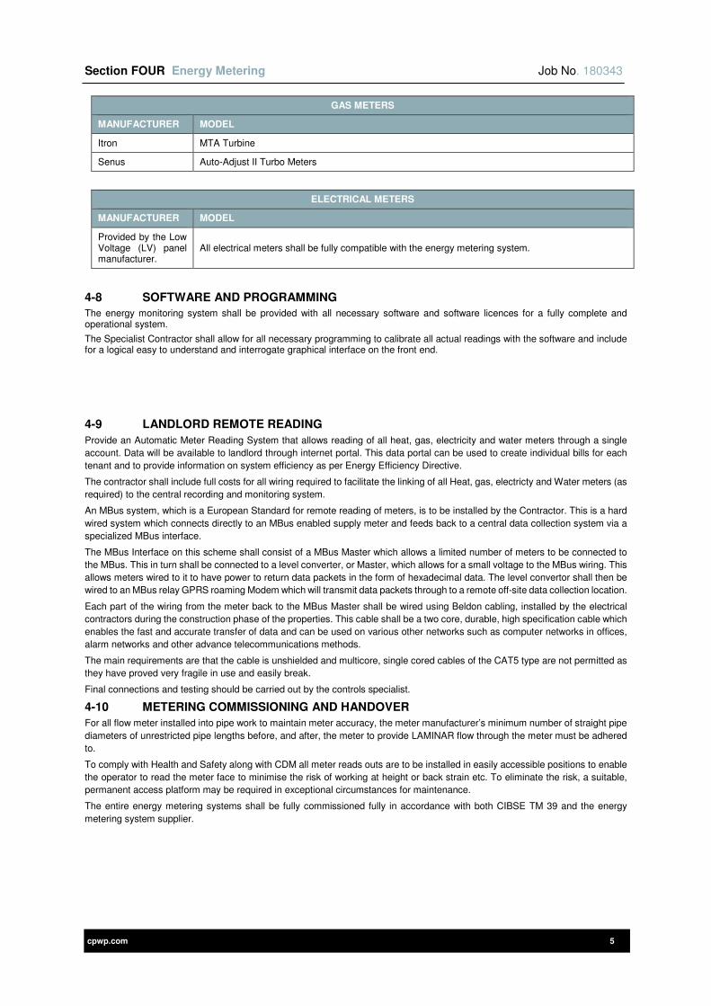
Section FOUR Energy Metering Job No. 180343
cpwp.com 5
GAS METERS
MANUFACTURER MODEL
Itron MTA Turbine
Senus Auto-Adjust II Turbo Meters
ELECTRICAL METERS
MANUFACTURER MODEL
Provided by the Low Voltage (LV) panel manufacturer.
All electrical meters shall be fully compatible with the energy metering system.
4-8 SOFTWARE AND PROGRAMMING
The energy monitoring system shall be provided with all necessary software and software licences for a fully complete and operational system.
The Specialist Contractor shall allow for all necessary programming to calibrate all actual readings with the software and include for a logical easy to understand and interrogate graphical interface on the front end.
4-9 LANDLORD REMOTE READING
Provide an Automatic Meter Reading System that allows reading of all heat, gas, electricity and water meters through a single
account. Data will be available to landlord through internet portal. This data portal can be used to create individual bills for each
tenant and to provide information on system efficiency as per Energy Efficiency Directive.
The contractor shall include full costs for all wiring required to facilitate the linking of all Heat, gas, electricty and Water meters (as
required) to the central recording and monitoring system.
An MBus system, which is a European Standard for remote reading of meters, is to be installed by the Contractor. This is a hard
wired system which connects directly to an MBus enabled supply meter and feeds back to a central data collection system via a
specialized MBus interface.
The MBus Interface on this scheme shall consist of a MBus Master which allows a limited number of meters to be connected to
the MBus. This in turn shall be connected to a level converter, or Master, which allows for a small voltage to the MBus wiring. This
allows meters wired to it to have power to return data packets in the form of hexadecimal data. The level convertor shall then be
wired to an MBus relay GPRS roaming Modem which will transmit data packets through to a remote off-site data collection location.
Each part of the wiring from the meter back to the MBus Master shall be wired using Beldon cabling, installed by the electrical
contractors during the construction phase of the properties. This cable shall be a two core, durable, high specification cable which
enables the fast and accurate transfer of data and can be used on various other networks such as computer networks in offices,
alarm networks and other advance telecommunications methods.
The main requirements are that the cable is unshielded and multicore, single cored cables of the CAT5 type are not permitted as
they have proved very fragile in use and easily break.
Final connections and testing should be carried out by the controls specialist.
4-10 METERING COMMISSIONING AND HANDOVER
For all flow meter installed into pipe work to maintain meter accuracy, the meter manufacturer’s minimum number of straight pipe
diameters of unrestricted pipe lengths before, and after, the meter to provide LAMINAR flow through the meter must be adhered
to.
To comply with Health and Safety along with CDM all meter reads outs are to be installed in easily accessible positions to enable
the operator to read the meter face to minimise the risk of working at height or back strain etc. To eliminate the risk, a suitable,
permanent access platform may be required in exceptional circumstances for maintenance.
The entire energy metering systems shall be fully commissioned fully in accordance with both CIBSE TM 39 and the energy
metering system supplier.

cpwp.com V1.4
Section Five Enabling and Incoming Services Works
Section Five Enabling and Incoming Services Works Job No. 180343
cpwp.com 2
Contents Page
5-1 GENERAL 3
5-2 DEFINITIONS 3
5-3 REFERENCE TO OTHER SECTIONS OF THIS SPECIFICATION 3
5-4 STANDARDS APPLICABLE 3
5-5 SCOPE OF WORKS 3
5-6 DRAWING INFORMATION 4
5-7 EXTERNAL SERVICES 4
5-7-1 NATURAL GAS SUPPLY 4
5-7-2 MAINS COLD WATER SUPPLY 5
5-7-2-1 MAINS COLD WATER PIPEWORK 5
5-7-3 TESTING OF UNDERGROUND PIPELINES 6
5-7-3-1 CHLORINATION AND WATER SAMPLES 6
5-7-4 ELECTRICAL SERVICES 6
5-7-4-1 INCOMING ELECTRICAL SUPPLY 6
5-7-4-2 VOICE AND DATA CABLING 6
5-8 INTERNAL SERVICES 6
5-8-1 STRIPPING OUT/REDUNDANT MATERIALS 6
5-8-2 IMPLICATIONS TO ADJACENCIES 7
5-8-3 ISOLATION OF EXISTING SERVICES 7
5-8-4 SITE SURVEY 7
5-9 TESTING AND COMMISSIONING 7
5-9-1 COMMISSIONING CHECKS 7
5-10 MAINTAINING SAFE ACCESS TO OPERATIONAL AREAS 7
5-11 ASBESTOS 8
5-12 IDENTIFICATION OF EXISTING AND NEW SERVICES 8
5-13 STERILISATION OF PIPEWORK 8
5-14 BUILDERS WORK 8
5-15 TECHNICAL SUBMISSIONS 8
Section Five Enabling and Incoming Services Works Job No. 180343
cpwp.com 3
5-1 GENERAL
This section of the specification identifies the enabling work required for this project as below:-
1) Assess the new Mains Water load and provision and installation of new mains cold water service from the statutory authority supply IF NECESSARY. Provisional Sum allowed for Water Board works in Tender Summary.
2) Assess the Gas load and provision and installation of new natural gas service from the statutory authority supply IF NECESSARY. Provisional Sum allowed for Gas Board works in Tender Summary
3) Provision of new incoming LV Electrical service to the building.
4) Modification of current LV electrical network
5) Isolate and Strip out of all mechanical services installed within existing building to allow for refurbishment
6) Isolate and Strip out of all electrical services installed within existing building to allow for refurbishment.
5-2 DEFINITIONS
Refer to Preliminary Section for general definitions plus below:
DEFINITIONS
MCWS Mains Cold Water Service
HV High Voltage
LV Low voltage
LTHW Low Temperature Hot Water
DNO Distribution Network Operator
5-3 REFERENCE TO OTHER SECTIONS OF THIS SPECIFICATION
This section of the specification shall not be used in isolation and must be read in conjunction with particular sections, commissioning and standard clauses, all of which define further the requirements for this project.
5-4 STANDARDS APPLICABLE
Works shall be completed in accordance with all applicable industry standards. Some of the most relevant standards associated with this section are scheduled below:
STANDARDS
Current Building Regulations Water Regulation Advisor Scheme (WRAS)
CIBSE Guides BS 1710 – Pipework identification
All CIBSE & BSRIA Commissioning Codes BS-EN 13792 – Colour Codes
National Joint Utilities Group Guidelines (NJUG) BS 7671 – Wiring Regulations
Water Industry Specifications including WIS 4-08-01 & WIS 4-08-02
BS EN 12201 – PE 80 pipework (Water)
Institute of Gas Engineers and Managers publications (IGEM)
BS EN 1555 – PE 80 pipework ( Gas)
Health and Safety Executive Approved Code of Practice L8 Control of Legionella Bacteria in Water Systems
BS EN 9990 – Non Automatic Fire Fighting Systems
BS 3251 Indicator plates for fire hydrants BS EN 5041 – Hydrant Systems
BS EN 14339 Underground Fire Hydrants BS EN 14384 Pillar Hydrants
Where the above standards refer to supporting documentation and standards these shall be fully complied with in all respects.
Where discrepancy is found between this specification and the relevant standards, the Contractor shall obtain written clarification from the Engineer prior to submission of the tender. Where a discrepancy has not been clarified prior to tender submission, the Contractor shall include the most onerous requirements.
5-5 SCOPE OF WORKS
The following brief description describes the enabling works required for this project. Comprehensive system(s) requirements are detailed in subsequent clauses of this specification and on tender schematic and drawings. The Contractor shall employ Specialist Contractor(s) for each of the system(s) and shall include for all tools, labour, materials and equipment necessary to undertake all installation, modification and/or strip out works as below inclusive of:
1) Assess the new Mains Water load and Provide new statutory authority water supply to site and extend distribution to building IF NECESSARY. Allow for all liaison with supply authorities.

Section Five Enabling and Incoming Services Works Job No. 180343
cpwp.com 4
2) Assess the new Gas load and Provide a new statutory authority natural gas supply, provide a new gas meter house at boundary of project and all distribution pipework from meter to the building IF NECESSARY. Allow for all liaison with the shipper
3) Provide LV supply into building from DNO
4) Carry out a Subtronic survey to establish any below ground services
5) Carry out full BS7671 test on all services to be retained and re-used
6) Isolate and Strip out of all mechanical services installed within existing building to allow for refurbishment as detailed on the tender drawings
7) Isolate and Strip out of all Electrical services installed within existing building to allow for refurbishment as detailed on the tender drawings.
8) Carry out a survey of the services which are to be stripped out. (i.e. LTHW, domestic services systems, above ground drainage systems, ventilation systems, Natural gas, specialist gases system) prior to any modification works taking place.
9) Identify services to be removed and diverted and become conversant with the distribution and existing installation in order that isolation and removals may be undertaken with the minimum disruption to other connected services.
10) Allow for the removal from site and disposal of all equipment made redundant under this contract. Ensure that any existing equipment to be retained by the Client for future use is carefully isolated and protected for the duration of the works.
5-6 DRAWING INFORMATION
11) There are no record drawings available for this site. The Contractor shall allow to undertake a full survey and include for any associated costs within the submitted tender.
5-7 EXTERNAL SERVICES
The following new supplies shall be provided to serve the building:
5-7-1 NATURAL GAS SUPPLY
1) The existing boiler in the Museum Building is to be retained. The existing boiler in the Stores building is to be removed and a new Boiler installed for the refurbished Stores and New Build elements as shown on the drawings. The contractor is to calculate the load of the existing boiler, new boiler and new catering load with no diversity, to check against the capacity of the existing incoming gas main during Tender.
2) Contact the Catering specialist to determine the Gas Load, as a minimum this shall include a Chargrill, Target Top and 4 zone Hob.
3) IF NECESSARY, a new natural gas supply shall be provided to the site from the existing statutory service within the road adjacent to the site boundary. The Contractor shall allow for liaison with the Client’s shipper to provide and install the new supply, gas meter and suitably sized GRP gas meter house installed on the boundary of the site. All the external mains natural gas pipework from the boundary regulator to the gas incoming position shall be fully installed, tested and commissioned. For details of internal gas requirements refer to Fuel Systems Section of this specification.
4) A Provisional Sum is allowed in the Tender summary for any Gas Board Works, if they are needed.
External below ground pipework and fittings shall be:
1) Laid in yellow medium density polyethylene pipework, recommended for use with natural gas medium pressure installations. (Yellow pipework up to 2 Bar, Orange pipework for 2 Bar to & 7 Bar)
2) Installed fully in accordance with the manufacturers recommendations and in accordance with NJUG and IGEM requirements.
3) Pipework to be provided with necessary purge points.
4) All joints shall be butt-fusion or electrofusion welded.
5) Suitable for the system operating distribution/test pressures.
6) Include for all necessary portable welding/generator equipment and for a representative from the manufacturer to give on-site instruction prior to installation.
7) Stored on site with taped polythene protective end caps to prevent ingress of dirt and debris.
The system jointing shall be:
1) By electro-fusion or butt-fusion methods.
2) All fittings to match the tube and to be IGEM approved standard.
3) The fusion welding of fittings to be installed by engineers with specialist fusion welding equipment and shall be manufactured approved Contractors.
4) Pipes should be cut square to axis and burrs removed and the surface of the pipe to be in contact with fitting shall be scraped to completely remove the surface layer prior to insertion into fitting.
5) On all straight pipes above 180mm diameter welding clamps must be used to minimise the risk of accidental movement. Clamps also to be used on all sizes of coiled pipe and where correct pipe alignment is difficult.
6) Each and every weld (butt or electro-fusion) shall be recorded using fusion automatic welding equipment bigger hard copies detailing each weld shall be included as part of the Operation and Maintenance Manuals.
Trenching requirements:
1) The external trench is excavated having a level base so that the pipework can be laid flat. The trench should be approximately 0.8m deep to provide 600mm of cover where pipework is run under pathways. The trench depth for gas pipework passing beneath hard standing/roadways shall provide a minimum cover of 750mm to the crown of the main.
Section Five Enabling and Incoming Services Works Job No. 180343
cpwp.com 5
2) A 150mm deep bedding of sand or pea gravel shall be laid under the barrel of the pipe. The bedding shall be properly compacted to provide uniformity of support to the pipe.
3) After the pipes have been laid, further bedding material shall be placed around the pipe and compacted in 75mm layers up to a level of 150mm above the top of the pipe.
4) To assist the future location/tracing of plastic pipe, an approved metallic marker tape shall be laid along the line of main and connected at each end to a valve. The marker tape shall be 150mm above pipe and be supplied by the Contractor for installation by the Principal Contractor.
5) The entry position to the building is correctly positioned and an isolating valve is provided on entry to the building
All joints shall be exposed for testing and back filling may only occur after a satisfactory and witnessed pressure test has taken place.
Natural gas pipework and fittings shall be by one of the following manufacturers:
• Fusion Ltd Tel No 0121 585 1079
• Durapipe Tel No 01543 279909
• Wavin Ltd. Tel No 028 9262 1577
5-7-2 MAINS COLD WATER SUPPLY
1) The existing mains water service to the Museum Building is to be retained. The existing mains water service to the Stores building is to be renewed for the refurbished Stores and New Build elements as shown on the drawings. The contractor is to calculate the load of the existing museum, refurbished and new building with new catering loads and new toilets, to check against the capacity of the existing incoming mains water service during Tender.
2) Contact the catering specialist to determine all Hot & Cold Water requirements.
3) IF NECESSARY, a new mains water supply shall be provided to the site from the existing statutory service within the road adjacent to the site boundary. The Contractor shall allow for liaison with the Water Authority to provide and install the new supply and Water meter.
4) A Provisional Sum is allowed in the Tender summary for any Gas Board Works, if they are needed.
5-7-2-1 MAINS COLD WATER PIPEWORK
External below ground pipework shall be:
MDPE – STANDARD PIPEWORK (Non-contaminated ground conditions) shall comply with the following standards:
1) Laid in Blue medium density polyethylene pipework, recommended for pressure pipe for cold potable water use.( for nominal sizes 63mm or below / 90-1000mm for underground installation)
2) Installed fully in accordance with the manufacturers recommendations and in accordance with Water Board requirements.
3) Complete with polyethylene socket and spigot fittings, saddles and drawn bonds for fusion jointing for use with cold potable water PE pressure pipes.
4) Polyethylene electrofusion couplers and fittings for cold potable water supply for nominal sizes up to and including 180. Shall be included.
5) All joints shall be butt-fusion or electrofusion welded.
6) Suitable for the system operating distribution/test pressures.
7) Include for all necessary portable welding/generator equipment and for a representative from the manufacturer to give on-site instruction prior to installation.
8) Stored on site with taped polythene protective end caps to prevent ingress of dirt and debris.
MDPE – STANDARD JOINTING
The system shall be:
1) Jointing system shall be by electro-fusion or butt-fusion methods.
2) All fittings to match the tube and to be Water Board approved standard.
3) The fusion welding of fittings to be installed by engineers with specialist fusion welding equipment and shall be manufactured approved Contractors.
4) Pipes should be cut square to axis and burrs removed and the surface of the pipe to be in contact with fitting shall be scraped to completely remove the surface layer prior to insertion into fitting.
5) On all straight pipes above 180mm diameter welding clamps must be used to minimise the risk of accidental movement. Clamps also to be used on all sizes of coiled pipe and where correct pipe alignment is difficult.
6) Each and every weld (butt or electro-fusion) shall be recorded using fusion automatic welding equipment bigger hard copies detailing each weld shall be included as part of the Operation and Maintenance Documentation.
Cold water pipework and fittings shall be by one of the following manufacturers:
• Fusion Ltd Tel No 0121 585 1079
• Durapipe Tel No 01543 279909
• Wavin Ltd. Tel No 028 9262 1577
Trenching requirements:
1) The external trench is excavated having a level base so that the pipework can be laid flat. The trench depth shall provide a minimum cover of 1000 mm to the crown of the water pipework.
2) A 150mm deep bedding of sand or pea gravel shall be laid under the barrel of the pipe. The bedding should be properly compacted to provide uniformity of support to the pipe.
Section Five Enabling and Incoming Services Works Job No. 180343
cpwp.com 6
3) After the pipes have been laid, further bedding material shall be placed around the pipe and compacted in 75mm layers up to a level of 150mm above the top of the pipe.
4) To assist the future location/tracing of plastic pipe an approved metallic marker tape shall be laid along the line of main and connected at each end to a hydrant. The marker tape shall be 150mm above pipe.
5) The entry positions to the building are correctly positioned.
6) All underground valves are housed within proprietary valve chambers.
7) Liaison with the local Water Company, Fire Officer and Drainage Contractors.
5-7-3 TESTING OF UNDERGROUND PIPELINES
The mains to be tested shall be inspected for compliance with the drawings and specifications significant variations shall be investigated and corrected, where required, before proceeding with the test.
After laying, jointing and anchoring the pipeline shall be tested as described in Standard Installation Section of this specification.
Pressure testing shall be carried out prior to any backfilling of trenches. All new pipework is to be tested before being brought into service.
The pipeline shall be subjected to a site test for the purpose of checking of the following: -
1) Mechanical soundness and leak tightness of pipes and fittings.
2) Leak tightness of joints.
3) Soundness of construction anchorages.
4) Quality of installation and workmanship.
Testing procedure shall be in accordance with the manufacturer’s instructions.
It must be established before tests commence that all anchorages are in position, that concrete anchorages have developed the required strength and that where pipes are deflected to produce large radius curves, the backfill between pipe body and trench wall is well compacted.
Final test of pipelines shall be completed in one length. Sectional testing shall be for the benefit of the Contractor and shall not be considered as final tests.
Where interim section testing is to be performed, special stop ends shall be provided for the safe introduction and disposal of test medium and release of air. The stop ends shall be secured by adequate temporary anchors.
5-7-3-1 CHLORINATION AND WATER SAMPLES
Water samples shall be taken before undertaken modifications to the water mains and upon successful testing of the modified new water main.
All new pipework shall be fully chlorinated from suitable points of demarcation (isolating valve sets etc.) conforming to the requirements of Standard Installation Section of this specification, with water samples taken and tested in accordance with the guidelines of ‘Analysis of Raw, Potable and Waste Waters’, published by D of E, HMSO and/or methods approved and employed by the Public Health Authority.
5-7-4 ELECTRICAL SERVICES
5-7-4-1 INCOMING ELECTRICAL SUPPLY
New intake services shall be provided with the following characteristics:
5) 230 Volts 50 Hz 3 phase 4 wire
Cables entering the building(s) shall be via ducts cast into the slab (min 150mm diameter). For smaller cables these shall rise with slow bends located to allow the cable to rise vertically immediately below the equipment to be served. For larger cables short sections of horizontal ducts shall facilitate a route into cast floor trenches within the electrical plant space, allowing cables to be routed to suit the layout of the space.
Ensure all cable entry points are vermin proof and sealed to prevent water ingress.
5-7-4-2 VOICE AND DATA CABLING
Provide new intake service associated with data and telecommunications with the following characteristics:
6) Reuse the existing connection
Cables entering the building(s) shall be via ducts cast into the slab (min 100mm diameter). These shall rise with slow bends located to allow the cable to rise vertically immediately below the equipment to be served.
Ensure all cable entry points are vermin proof and sealed to prevent water ingress.
.
5-8 INTERNAL SERVICES
5-8-1 STRIPPING OUT/REDUNDANT MATERIALS
Due allowance within this tender for the careful removal, protection and storage of services and equipment to be retained by the Employer for future use shall be included. The Contractor shall be held liable for any damage incurred to equipment to be retained during the removal works associated with this contract.
All redundant plant shall be offered to the Employer / Contract Administrator in the first instance for spares / replacement purposes. Any items not required by the Employer shall be disposed of and removed from site in an appropriate manner.
The removal from site and disposal of all services and equipment made redundant under this contract shall be included within the tender costs
Section Five Enabling and Incoming Services Works Job No. 180343
cpwp.com 7
It should be noted that the Contractor shall not place sole reliance for accuracy of existing service installation on the available record drawings and it will be the Contractor’s responsibility to ‘trace’ and identify all services within the refurbishment areas as part of their remit prior to undertaking any isolation of service.
Should, during the stripping out process, inadvertent disruption to adjacent areas take place the Contractor shall, as a priority provide all necessary labour, materials, temporary / permanent connections to restore service. All costs associated with these works shall be provided by the Contractor.
Where services are removed / stripped out this shall be undertaken in such a manner as to minimise the consequential damage to other services, structures and building fabric. The Contractor shall make all necessary provision for the repair of fixing holes, building etc. Unless indicated otherwise on the accompanying drawings all existing medical trunkings shall be stripped and removed for replacement with new.
In instances where sinks and basins are required to be removed from the areas encompassed by these works, the Contractor shall make all necessary provision for the stripping out of dead legs, provision of suitable valves, and the flushing and chlorination of the system either partially or fully to suit the system architecture.
Electrical circuits shall generally be removed completely back to the associated final distribution board. In exceptional circumstances, and with explicit agreement with the Engineer, services that are likely to cause damage to existing fabric or major disruption to surrounding accommodation may be partially retained. Any such shall be isolated, made safe in a permanent and proprietary manner, clearly labelled and highlighted on the “as fitted” drawings.
5-8-2 IMPLICATIONS TO ADJACENCIES
It should be noted that certain Mechanical and Electrical systems within adjacent occupied areas may be served from infrastructure emanating from the area designated for these contract works. As a consequence these systems within adjacent occupied areas required to be retained and re-fed shall be identified, isolated, stripped out (partially or fully) and re-supplied from the new / revised infrastructure locations identified on the accompanying tender drawings.
In carrying out these works, the Contractor shall be responsible for the provision of all materials, access equipment, and careful removal and re-installing of ceilings / wall panelling’s etc. Prior to carrying out these works the Contractor shall, in conjunction with the Contract Administrator undertake a condition inspection of the affected areas recording and agreeing any inherent damage, faults etc. The Contract Administrator shall, in the case of system faults instruct the Contractor as to how to proceed.
Failure to carry out the inspections indicated above may render the Contractor liable for any damage identified during the post works inspection by the Contract Administrator.
5-8-3 ISOLATION OF EXISTING SERVICES
The following procedures shall be carried out prior to service isolation.
1) Examination of the local site conditions to fully assess the extent and nature of the works. No additional claim from lack of knowledge in these aspects shall be accepted. Following the examination of local site conditions provide detailed method statements of how the intended work is to be undertaken together with all relevant risk assessments.
2) Prior to any isolation/ interruption of any existing service notified in writing as to the extent of the isolation. A minimum of 24 hours notice shall be provided or as dictated by the Employers retained FM systems provider whichever is the greater. No works shall be undertaken until the client has given written approval and a permit to work has been issued.
3) The route of services and extent of interruptions shall be established together with the location of isolation valves, if available.
4) All isolations and modifications shall be pre-planned, labour resourced and materials obtained to ensure interruptions are kept to a minimum in certain instances more than one work team may be required.
5) General work shall take place during normal working hours and to suit the Contractor’s programme.
6) Upon completion of works the existing circuits and supplies shall be reinstated. All services and outlet points connected to the modified services shall be tested to ensure all systems are fully reinstated, re-commissioned and balanced.
7) Prior to making any new connections to existing drainage stacks, the contractor shall carryout a high water pressure jet and CCTV survey all of the existing soil and waste drain points.
5-8-4 SITE SURVEY
The Contractor shall visit the site prior to submitting a tender in order that the total extent of the works involved may be assessed. Due allowance is to be made for any site restrictions, abnormal working heights, problems in dismantling and distributing both items to be re-used and redundant services, and any special bracketing requirements.
It is the Contractor’s responsibility to view the site and the existing services in order that any accurate removal costs may be ascertained and no additional monies shall be considered due to non-compliance with this recommendation.
5-9 TESTING AND COMMISSIONING
Testing and commissioning shall be carried out fully in accordance with Standard installation Section of this Specification.
5-9-1 COMMISSIONING CHECKS
Prior to any works commencing on site the Contractor shall make allowance to pre-record:
LTHW flow rates,
Domestic service flow rates and temperatures.
In addition the Contractor shall take water samples from the existing LTHW system and domestic water systems for laboratory analysis to determine the condition of the existing systems and ensure they are not contaminated in anyway.
5-10 MAINTAINING SAFE ACCESS TO OPERATIONAL AREAS
Access to operational areas shall be maintained at all times including all general and emergency access/exit routes. No materials or waste/debris shall be allowed to obstruct these routes.
Section Five Enabling and Incoming Services Works Job No. 180343
cpwp.com 8
5-11 ASBESTOS
The Contractor shall note the building may contain asbestos particularly pipe joints/ flanges, service risers (This is not an exhaustive list).
The Contractor shall refer to the Employer’s asbestos register and shall obtain all necessary certificates prior to the commencement of the services strip out works to fully understand the extent of any asbestos present on site.
Should the Contractor come in to contact with materials during the refurbishment process that they suspect is asbestos they shall immediately cease works and bring it to the Contractor Administrators attention to arrange analysis.
5-12 IDENTIFICATION OF EXISTING AND NEW SERVICES
The existing services may not be suitably identified; the Contractor shall trace all services to ensure of its identity prior to undertaking any works out on that service/system.
All new and modified services shall be installed with adequate identification to BS 1710 to colour code, label (description of service) and identify direction of flow on all plant and services
5-13 STERILISATION OF PIPEWORK
Sterilisation work on all new and modified cold water services, fittings, valves etc., all fully in accordance with Standard Installation Station of this Specification.
Certificates of sterilisation shall be submitted to the Contract Administrator prior to practical completion. It shall be noted that practical completion will not occur in the absence of said certificates.
All mains prior to use shall be chlorinated and flushed out.
The potable water main shall be pressure tested as stated in the standard specification sections but not chlorinated until the building becomes live.
5-14 BUILDERS WORK
All builders work associated with the services strip out, including making good of any existing penetrations through walls and floors shall be included within the tender submission.
5-15 TECHNICAL SUBMISSIONS
Refer to contact preliminaries for the Technical Submissions requirements.

cpwp.com V1.9
Section Six
Design Standards
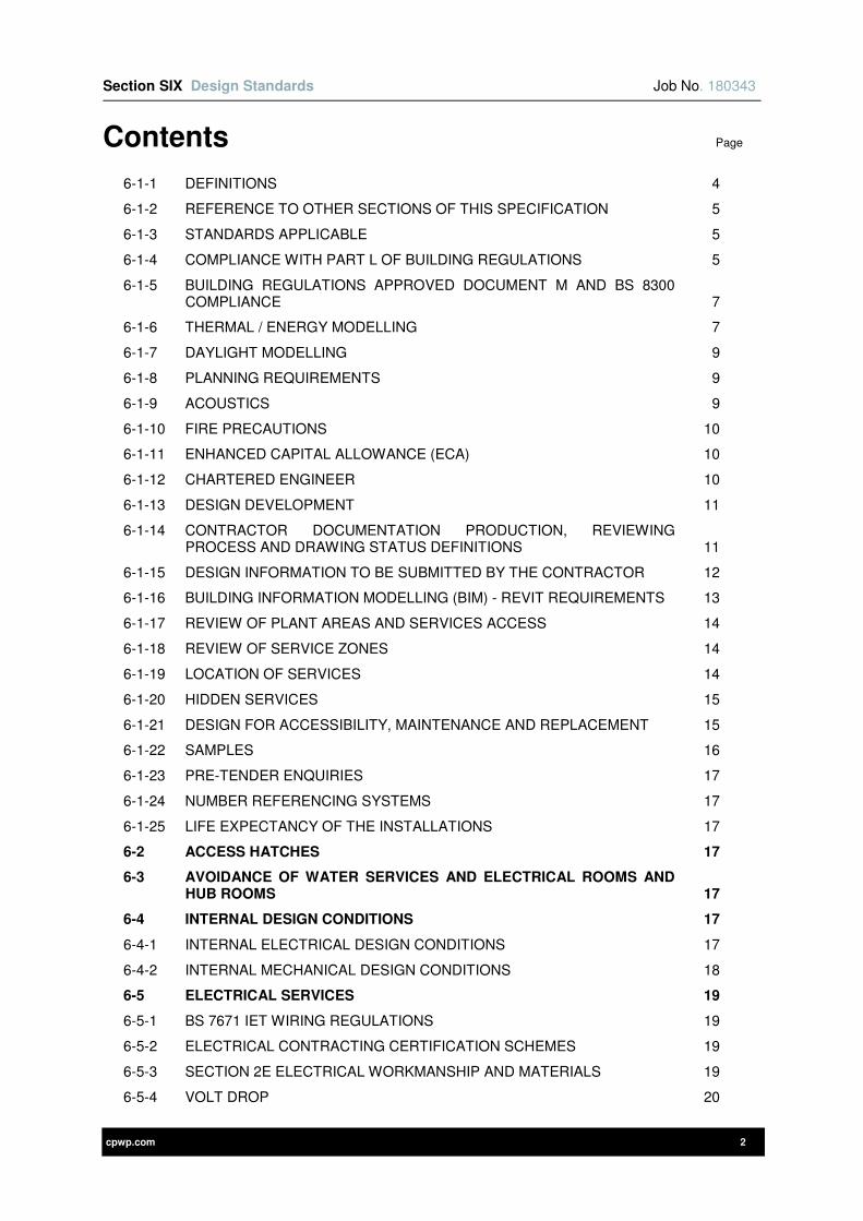
Section SIX Design Standards Job No. 180343
cpwp.com 2
Contents Page
6-1-1 DEFINITIONS 4
6-1-2 REFERENCE TO OTHER SECTIONS OF THIS SPECIFICATION 5
6-1-3 STANDARDS APPLICABLE 5
6-1-4 COMPLIANCE WITH PART L OF BUILDING REGULATIONS 5
6-1-5 BUILDING REGULATIONS APPROVED DOCUMENT M AND BS 8300 COMPLIANCE 7
6-1-6 THERMAL / ENERGY MODELLING 7
6-1-7 DAYLIGHT MODELLING 9
6-1-8 PLANNING REQUIREMENTS 9
6-1-9 ACOUSTICS 9
6-1-10 FIRE PRECAUTIONS 10
6-1-11 ENHANCED CAPITAL ALLOWANCE (ECA) 10
6-1-12 CHARTERED ENGINEER 10
6-1-13 DESIGN DEVELOPMENT 11
6-1-14 CONTRACTOR DOCUMENTATION PRODUCTION, REVIEWING PROCESS AND DRAWING STATUS DEFINITIONS 11
6-1-15 DESIGN INFORMATION TO BE SUBMITTED BY THE CONTRACTOR 12
6-1-16 BUILDING INFORMATION MODELLING (BIM) - REVIT REQUIREMENTS 13
6-1-17 REVIEW OF PLANT AREAS AND SERVICES ACCESS 14
6-1-18 REVIEW OF SERVICE ZONES 14
6-1-19 LOCATION OF SERVICES 14
6-1-20 HIDDEN SERVICES 15
6-1-21 DESIGN FOR ACCESSIBILITY, MAINTENANCE AND REPLACEMENT 15
6-1-22 SAMPLES 16
6-1-23 PRE-TENDER ENQUIRIES 17
6-1-24 NUMBER REFERENCING SYSTEMS 17
6-1-25 LIFE EXPECTANCY OF THE INSTALLATIONS 17
6-2 ACCESS HATCHES 17
6-3 AVOIDANCE OF WATER SERVICES AND ELECTRICAL ROOMS AND HUB ROOMS 17
6-4 INTERNAL DESIGN CONDITIONS 17
6-4-1 INTERNAL ELECTRICAL DESIGN CONDITIONS 17
6-4-2 INTERNAL MECHANICAL DESIGN CONDITIONS 18
6-5 ELECTRICAL SERVICES 19
6-5-1 BS 7671 IET WIRING REGULATIONS 19
6-5-2 ELECTRICAL CONTRACTING CERTIFICATION SCHEMES 19
6-5-3 SECTION 2E ELECTRICAL WORKMANSHIP AND MATERIALS 19
6-5-4 VOLT DROP 20
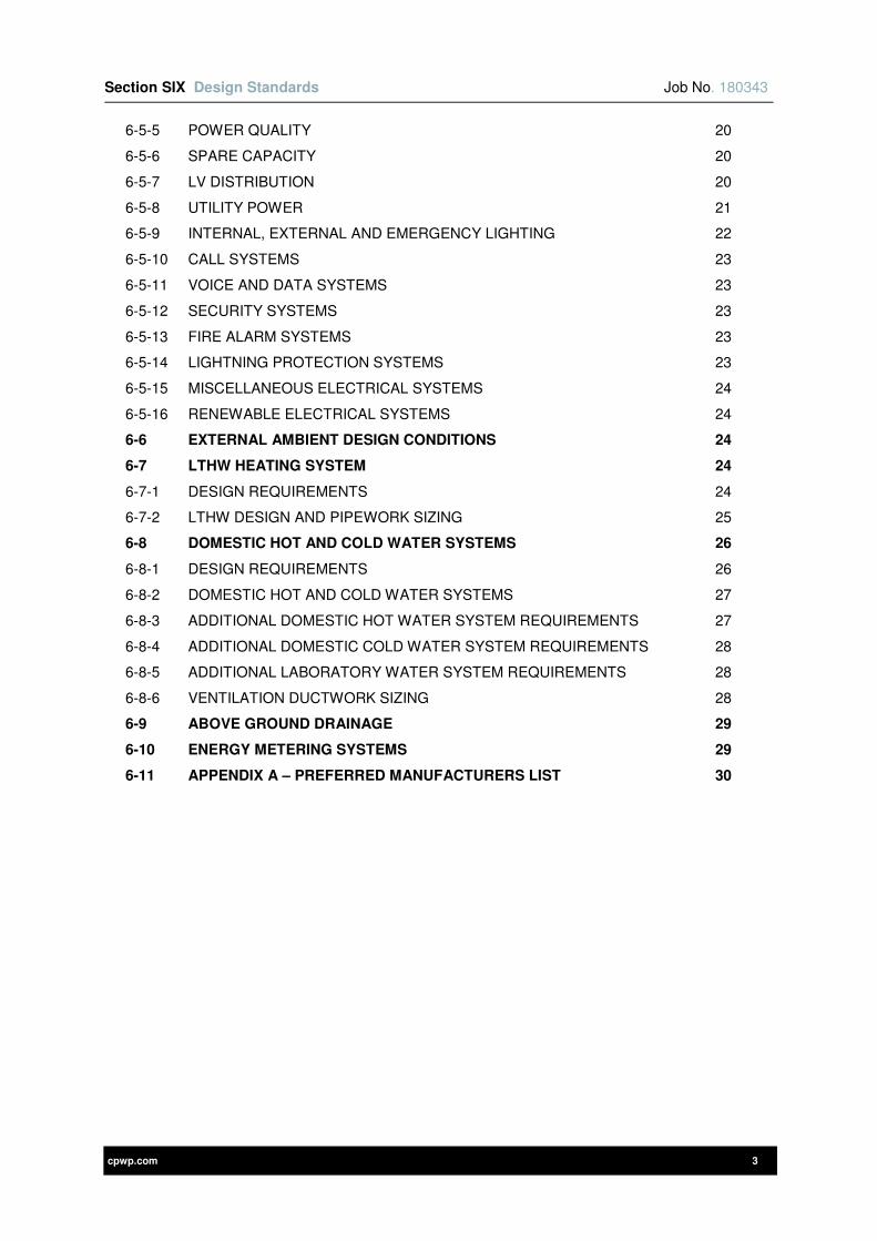
Section SIX Design Standards Job No. 180343
cpwp.com 3
6-5-5 POWER QUALITY 20
6-5-6 SPARE CAPACITY 20
6-5-7 LV DISTRIBUTION 20
6-5-8 UTILITY POWER 21
6-5-9 INTERNAL, EXTERNAL AND EMERGENCY LIGHTING 22
6-5-10 CALL SYSTEMS 23
6-5-11 VOICE AND DATA SYSTEMS 23
6-5-12 SECURITY SYSTEMS 23
6-5-13 FIRE ALARM SYSTEMS 23
6-5-14 LIGHTNING PROTECTION SYSTEMS 23
6-5-15 MISCELLANEOUS ELECTRICAL SYSTEMS 24
6-5-16 RENEWABLE ELECTRICAL SYSTEMS 24
6-6 EXTERNAL AMBIENT DESIGN CONDITIONS 24
6-7 LTHW HEATING SYSTEM 24
6-7-1 DESIGN REQUIREMENTS 24
6-7-2 LTHW DESIGN AND PIPEWORK SIZING 25
6-8 DOMESTIC HOT AND COLD WATER SYSTEMS 26
6-8-1 DESIGN REQUIREMENTS 26
6-8-2 DOMESTIC HOT AND COLD WATER SYSTEMS 27
6-8-3 ADDITIONAL DOMESTIC HOT WATER SYSTEM REQUIREMENTS 27
6-8-4 ADDITIONAL DOMESTIC COLD WATER SYSTEM REQUIREMENTS 28
6-8-5 ADDITIONAL LABORATORY WATER SYSTEM REQUIREMENTS 28
6-8-6 VENTILATION DUCTWORK SIZING 28
6-9 ABOVE GROUND DRAINAGE 29
6-10 ENERGY METERING SYSTEMS 29
6-11 APPENDIX A – PREFERRED MANUFACTURERS LIST 30
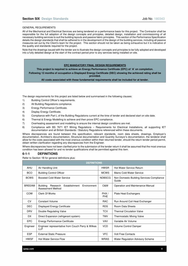
Section SIX Design Standards Job No. 180343
cpwp.com 4
GENERAL REQUIREMENTS
All of the Mechanical and Electrical Services are being tendered on a performance basis for this project. The Contractor shall be responsible for the full adoption of the design concepts and principles, detailed design, installation and commissioning of all necessary building services to suit the building layouts and passive fabric principles. This section of the Performance Specification details the design standards that shall be adhered to in the development of the design of the building services, including all passive measures set out by the Client’s team for the project. This section should not be taken as being exhaustive but it is indicative of the quality and standards required for the project.
Note that the drawings issued with the tender are to illustrate the design concepts and principles to be fully adopted and developed into a fully detailed design at the start of the contract period prior to any services being installed on site.
EPC MANDATORY FINAL DESIGN REQUIREMENTS
This project is required to achieve an Energy Performance Certificate (EPC) of ‘A’ on completion.
Following 12 months of occupation a Displayed Energy Certificate (DEC) showing the achieved rating shall be provided.
All costs associated with these fundamental requirements shall be included for at tender.
The design requirements for this project are listed below and summarised in the following clauses:
1) Building Control Officer’s requirements.
2) All Building Regulations compliance.
3) Energy Performance Certificate.
4) Display Energy Certificate.
5) Compliance with Part L of the Building Regulations current at the time of tender and declared start on site date.
6) Thermal & Energy Modelling to achieve and then prove EPC compliance.
7) Overheating assessment and modelling to ensure the internal design conditions are met.
8) Compliance with BS 7671 IET Wiring Regulations – Requirements for Electrical Installations, all supporting IET documentation and all British Standards / Statutory Regulations referenced within these documents.
Where discrepancies are found between this specification, relevant standards, room data sheets, drawings, Employer’s documentation, Architect’s documentation, Structural documentation and Quantity Surveyor’s documentation, the tenderer shall allow for the costs associated with the most onerous condition within their returned tender, should the return tender period permit, obtain written clarification regarding any discrepancies from the Engineer.
Where discrepancies have not been clarified prior to the submission of the tender return it shall be assumed that the most onerous condition has been allowed for and no tender qualifications shall be permitted against this item.
6-1-1 DEFINITIONS
Refer to Section 1B for general definitions plus:
DEFINITIONS
AHU Air Handling Unit HWSR Hot Water Service Return
BCO Building Control Officer MCWS Mains Cold Water Service
BCWS Boosted Cold Water Service NDBSCG Non Domestic Building Services Compliance Guide
BREEAM Building Research Establishment Environment Assessment Method
O&M Operation and Maintenance Manual
COW Clerk Of Works PHX / PHE
Plate Heat Exchangers
CV Constant Volume RAC Run Around Coil Heat Exchanger
DEC Displayed Energy Certificate RDS Room Data Sheets
DRV Double Regulating Valve TCV Thermal Circulation Valve
DX Direct Expansion (refrigerant system) TMV Thermostatic Mixing Valve
EPC Energy Performance Certificate VAV Variable Air Volume
Engineer Engineer representative from Couch Perry & Wilkes LLP
VCD Volume Control Damper
ESP External Static Pressure VFC Volt Free Contacts
HWSF Hot Water Service Flow WRAS Water Regulation Advisory Scheme
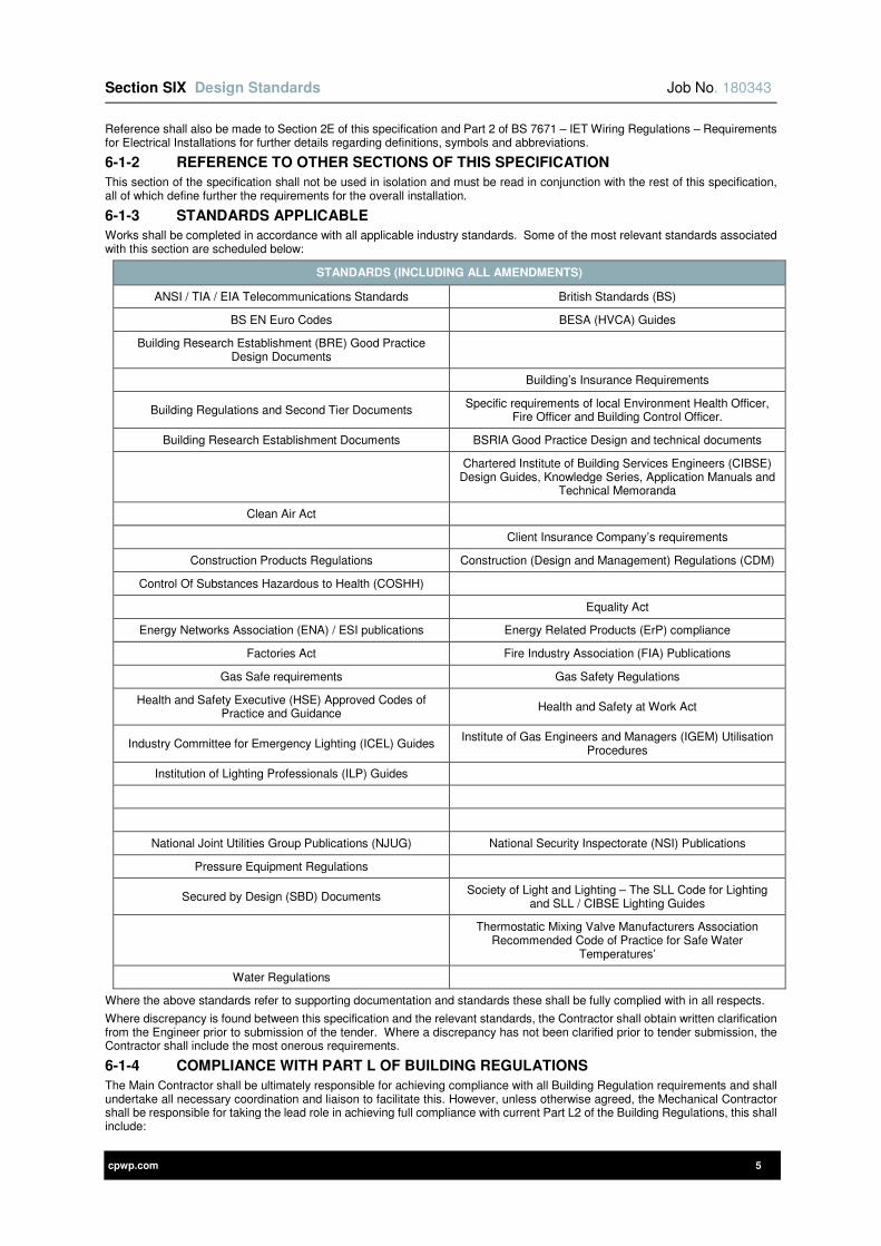
Section SIX Design Standards Job No. 180343
cpwp.com 5
Reference shall also be made to Section 2E of this specification and Part 2 of BS 7671 – IET Wiring Regulations – Requirements for Electrical Installations for further details regarding definitions, symbols and abbreviations.
6-1-2 REFERENCE TO OTHER SECTIONS OF THIS SPECIFICATION
This section of the specification shall not be used in isolation and must be read in conjunction with the rest of this specification, all of which define further the requirements for the overall installation.
6-1-3 STANDARDS APPLICABLE
Works shall be completed in accordance with all applicable industry standards. Some of the most relevant standards associated with this section are scheduled below:
STANDARDS (INCLUDING ALL AMENDMENTS)
ANSI / TIA / EIA Telecommunications Standards British Standards (BS)
BS EN Euro Codes BESA (HVCA) Guides
Building Research Establishment (BRE) Good Practice Design Documents
Building’s Insurance Requirements
Building Regulations and Second Tier Documents Specific requirements of local Environment Health Officer,
Fire Officer and Building Control Officer.
Building Research Establishment Documents BSRIA Good Practice Design and technical documents
Chartered Institute of Building Services Engineers (CIBSE)
Design Guides, Knowledge Series, Application Manuals and Technical Memoranda
Clean Air Act
Client Insurance Company’s requirements
Construction Products Regulations Construction (Design and Management) Regulations (CDM)
Control Of Substances Hazardous to Health (COSHH)
Equality Act
Energy Networks Association (ENA) / ESI publications Energy Related Products (ErP) compliance
Factories Act Fire Industry Association (FIA) Publications
Gas Safe requirements Gas Safety Regulations
Health and Safety Executive (HSE) Approved Codes of Practice and Guidance
Health and Safety at Work Act
Industry Committee for Emergency Lighting (ICEL) Guides Institute of Gas Engineers and Managers (IGEM) Utilisation
Procedures
Institution of Lighting Professionals (ILP) Guides
National Joint Utilities Group Publications (NJUG) National Security Inspectorate (NSI) Publications
Pressure Equipment Regulations
Secured by Design (SBD) Documents Society of Light and Lighting – The SLL Code for Lighting
and SLL / CIBSE Lighting Guides
Thermostatic Mixing Valve Manufacturers Association
Recommended Code of Practice for Safe Water Temperatures’
Water Regulations
Where the above standards refer to supporting documentation and standards these shall be fully complied with in all respects.
Where discrepancy is found between this specification and the relevant standards, the Contractor shall obtain written clarification from the Engineer prior to submission of the tender. Where a discrepancy has not been clarified prior to tender submission, the Contractor shall include the most onerous requirements.
6-1-4 COMPLIANCE WITH PART L OF BUILDING REGULATIONS
The Main Contractor shall be ultimately responsible for achieving compliance with all Building Regulation requirements and shall undertake all necessary coordination and liaison to facilitate this. However, unless otherwise agreed, the Mechanical Contractor shall be responsible for taking the lead role in achieving full compliance with current Part L2 of the Building Regulations, this shall include:
Section SIX Design Standards Job No. 180343
cpwp.com 6
1) Initial meetings to agree the final fabric performance and building air tightness with the design team that shall be equal or better to those stated within the this section to meet project performance requirements given.
2) Production of dynamic Thermal, Energy and Carbon Part L model utilising level 5 accredited IES Virtual Environment software.
3) Review / development of model with design team to achieve compliant scheme with a margin to ensure that compliance can still be achieved at completion. Margin required to ensure compliance should the design and installation change from initial detailed design to completion.
4) Produce summertime ‘operative’ (as defined in CIBSE) temperature reports for every room and space using thermal modelling. Thermal model to demonstrate compliance with summertime ‘operative’ temperatures i.e. as listed elsewhere in this section / maximum 28°C is not exceeded by more than 1% of occupied time.
5) Full Part L2 compliance is mandatory on completion irrespective of any installation and construction issues. All measures required to comply with the current Part L2 Building Regulations shall be deemed to be included within the tender.
6) Produce a report for issue to Building Control covering all current Part L2 criteria.
7) Meet with Building Control to present and agree report, providing clarification as necessary.
8) Provide advice to the design and employer’s teams on any changes through the contract period where these will impact upon the building with regard to Part L compliance, any compromises with one element must be negated by improvements elsewhere within the overall design such that the building as a whole remains fully compliant.
9) Update model and report to incorporate as constructed details and test results and submit to Building Control at completion.
10) Provide an Energy Performance Certificate (EPC), and recommendation report for the building to the Client, issued via the Main Contractor, and the Building Control Body with notice to that effect. The EPC shall achieve at least the previously stated rating.
11) The person responsible for conducting the energy assessment and producing the EPC must be an accredited Energy Assessor qualified for the level of building being assessed and listed on the national register at www.ndepcregister.com and a member of an Accreditation Scheme approved by Department of Communities and Local Government (CLG).
12) Following 12 months of completion / occupation, tender shall provide an optimised Display Energy Certificate (DEC). The DEC shall include the 12 months seasonal and fine tuning adjustments undertaken throughout the 12 months period post completion. DEC rating certification shall be provided within 15 months of practical completion. Where energy in use is exceeding predicted EPC rating due to users of the building exceeding notional building levels tenderer shall produce a report identifying which areas exceed the notional levels and recommendations for reducing this consumption. A second report shall be provided for reference purposes with these excess consumptions identified and excluded, this report shall demonstrate that the building could achieve the predicted EPC and DEC rating used as anticipated under Part L of the Building Regulations.
13) Ensure that a fully certified and trained person undertakes the assessment utilising certified level 5 accredited software for Building Regulations Part L compliance (Carbon and overheating all rooms) and EPC/DEC.
14) Fully liaise with all members of the design team and provide details of what technical input is required from each party, including time allowances for meetings/development, technical details and design development to fully complete the L2 and EPC calculations.
15) The updated legislation places more impetus on providing lower delivered energy consumption and reduced building CO2 emission rates in accord with the Government commitment to satisfy the European Energy Performance of Buildings Directive.
16) Ensure that the relevant electrical services are designed, installed and commissioned to comply with current Part L2.
17) The performance of the building, as built, shall be consistent with the prediction made in the design Target Emissions Rating (TER).
18) A final calculation of the Building Emission Rating shall be provided to reflect any changes in performance between design and construction, and the achieved / measured air permeability, ductwork leakage, and commissioned fan performance etc. The final calculation shall demonstrate that the building ‘as constructed’ remains compliant and consistent with the predicted design building energy rating. Any works required to bring the building back into compliance shall be completed at no additional cost to the Employer.
19) Produce, and include within the building log book, a notice confirming that all fixed building services have been properly commissioned. The notice shall include a declaration signed by a suitably qualified person, confirming that:
a) A commissioning plan has been followed such that each system has been inspected and commissioned to a satisfactory standard.
b) The results of the commissioning tests confirm that the performance is in accordance with the proposed design.
The notice should be signed a member of either the Membership of the Commissioning Specialists Association or the Commissioning Group of the HVCA.
Provide a concise building log book in accordance with this specification and current at handover version of CIBSE TM31.
The building log book shall be provided in addition / as a separate document to, the Building Manual / Operating and Maintenance Manuals.
The following provides a summary of some salient compliance criteria and sets out minimum performance requirements for the same for development by the Mechanical Contractor as part of the Design and Build Team via detailed design, installation and commissioning of the works should better performance be required to achieve the primary energy and carbon emissions performance then those shall be included with the Main Contractor’s tender:
1) The predicted rate of energy and CO2 emissions from the building shall not be greater than the agreed value set out within the planning submission report and to the standards given in this specification, when determined in accordance with the procedure set out within Approved Document Part L2.

Section SIX Design Standards Job No. 180343
cpwp.com 7
The following values provide an indication of the requirements needed to comply with this criterion and also set out minimum performance parameters for the design of the building and the engineering systems agreed with the Project Team to promote operational efficiency.
New Build Refurb Workshops Existing Museum
Minimal Works
Wall 0.25 0.3 Existing
Floor 0.2 0.22 Existing
Roof 0.18 0.18 Existing
Air Perm 5 10 Existing
Glazing U 1.6 1.8 Existing
• Glazing Solar Spec - G-Value <=0.33, Ltr-Value >=0.7
• Thermal Bridges - DCLG accredited robust details for (PSI) 0.03 W/mK or better
• Lighting:
Lighting Controls:
a) Presence detection for transiently occupied areas.
b) Absence detection in all other areas.
c) Main switching within plantrooms
• Power factor correction - > 0.95
• Energy monitoring with monitoring and alarms for out of normal range values to all systems.
All systems are to be provided with smart metering, in compliance with current Part L2 of the Building Regulations. These meters shall be networked to provide automatic monitoring and collection facilities at a central computer station and public energy display screen.
2) The performance of the building fabric and the heating, hot water and fixed lighting systems shall be no worse than the minimum design limits of current Approved Document L2 and that referred above.
6-1-5 BUILDING REGULATIONS APPROVED DOCUMENT M AND BS 8300 COMPLIANCE
The Building Regulations – Approved Document M and BS 8300 detail recommendations for the design of buildings and their approaches to meet the needs of disabled people. The detailed design shall comply with both the Building Regulations – Approved Document M and BS 8300.
6-1-6 THERMAL / ENERGY MODELLING
Provide a detailed thermal / energy model using the latest version of the IES Limited VE accredited software package and certified and accredited software modeller.
The following procedure shall be adopted:
3) The outline model shall be generated by the engineer and verified by IES Ltd (software provider). The IES Ltd engineer shall be employed to undertake any adjustments required to the model to demonstrate that the requirements of Part L2 are met. Upon completion of any design development adjustments it is the responsibility of the tenderer to employ IES Ltd to provide a detailed model service. The final checked electronic model shall be submitted to the whole design team for comment. Upon completion of the verification, tenderer shall provide a BRUKL document, along with an EPC for the building that demonstrates compliancy with this specification.
4) Ensure any changes made to the model are verified by IES Ltd and the designer and then provided to the Engineer for comment.
5) Full ownership of the model completing any checks / validation they deem necessary to allow them to take full responsibility for the model shall be included within the tender return.
The IES Level 5 model shall:
1) Be an accurate representation of the building form and structure including all material thermal and solar performance properties.
2) Include local shading such as adjacent buildings, obstructions and trees etc.
3) Include actual occupancy profiles as detailed in the performance specification, Room Data Sheets (RDS) or agreed with the Client / Engineer.
4) Include actual lighting installation including actual power, efficacy, switching / dimming control etc.

Section SIX Design Standards Job No. 180343
cpwp.com 8
5) Occupancy, small power and lighting gains shall not be considered for beneficial heat gains as the equipment and lighting will not be operational when the rooms are initially occupied at the start of occupancy when the rooms shall be required to already be at the design operative temperatures.
6) Include all process power loads and energy gains.
7) Diversity of the systems shall be conservatively assessed and only included in the model where they have been agreed in writing with the Engineer.
8) Any renewable systems shall be included, with any benefit assessed conservatively based on actual site conditions / systems and manufacturers lowest predicted performance. No benefit shall be taken for importing from the grid on green or renewable tariffs.
9) The thermal model shall be tested with the current CIBSE .DSY file weather file for the most suitable region for the project.
The small power loads used within the model shall be assessed based on furniture layouts and room data sheets. Loads less than those scheduled below shall not be adopted unless agreed in writing with the Engineer:
SMALL POWER & GENERAL LOADS
DESCRIPTION CONDITION
Standard PCs c/w Flat Screen 90W
Laptops 36W
Printers (small commercial type in typical office) 135W
Photocopiers (small commercial type in typical office) 500W Projectors 200W
Audio Visual Equipment 4,000W
General Office Areas
Preference shall always be to base IT loads based on Room Data Sheets, where these are not provided allow the following: IT equipment shall be based upon furniture layout with one standard PC per person based on the number of seats plus 1 small commercial type printer per cellular room or per 10 occupants in open plan offices. Photocopiers shall be provided as indicated in dedicated zones and if not indicated allow photocopier heat gains for tender based on one photocopier per 50 persons.
Standard fridge (A++ Rated) 150W
Standard freezer (A++ Rated) 300W
Communication and Server Rooms To be calculated in accordance with IT
requirements (8,000Watts for tender)
People (Light Work) Refer to CIBSE Guide A Table 6.3 (in Appendix)
General office lighting, where actual value not known. 12 W/m²
Generic benchmark heat gains, that is W/m2, shall not be used for equipment and occupancy gains unless adequate information is not available and these are agreed to be used in writing by the Engineer.
A detailed report shall be produced and submitted to the Engineer for comment to include:
1) Schedule of all materials and their thermal and / or solar properties.
2) Schedule of all profiles used.
3) Schedule of all heat gains and occupancies per room.
4) Schedule of services plant, equipment and lighting systems, their efficiencies, controls, and operating times etc.
5) Hours report detailing number of hours and percentage of occupied time that the Research and Production Laboratories
6) Schedule of all improvements made as a result of the modelling process in order to achieve a compliant building. All improvements to meet the criteria shall deemed to be included in the tender.
7) Estimated primary energy consumption and CO2 emissions broken down by service and end use in GJ, kWh and kgCO2 with an overall assessment in kWh/m², GJ/100m3 and kgCO2/m
2 for the following:
a) Fossil fuels
b) Grid imported electricity
c) Renewables (individual) from the thermal and energy model
8) An image of each floor and elevation of the building to demonstrate the same has be configured correctly
9) An isometric image of the building from the four principal directions of view.
10) Details of person whom completed the model including experience and qualifications.
11) Summary of whether the design complies with Part L requirements and proposals if non-compliant.
The report shall be submitted for comment in both electronic (colour PDF) and software export version, this will be subject to the commenting procedure set out for all documents in section one of this specification.
The Mechanical Contractor shall allow for the Part L Overheating models and EPC compliance to be run as many times as required to comply with Employer’s Requirements.
Copies of the final design and construction models (electronic IES data and run files) shall be issued to the engineer at each stage described.
Section SIX Design Standards Job No. 180343
cpwp.com 9
6-1-7 DAYLIGHT MODELLING
The Contractor shall design the building to achieve following regarding daylight transmission:
1) Daylight factor of 5% average (2% minimum) in teaching spaces
2) Daylight factor of 5% average (2% minimum) in occupied spaces
3) Average daylight factor of 10% on the floor of atria.
4) Light transmission values for primary and secondary (internal) glazing shall be in excess of 65% (externally) and 80% (internally).
A detailed daylight model for every room and space in the building shall be carried out by the Electrical Contractor for the whole building. This is required to:
1) Confirm accurate values for the client
The daylight modelling shall be undertaken using Dynamic Simulation Modelling in conjunction with a recognised industry accredited advanced computer software package. The software package to be used shall be agreed with the Engineer prior to modelling commencing.
The following factors shall be included within the model:-
1) The correct geographical location and building orientation shall be used.
2) The modelling shall be undertaken based on the CIE standard diffused daylight on an overcast day.
3) Room geometry, including floor area, room heights, extent of primary and secondary (internal) glazing, shall be taken from the Architectural floor plans and sections.
4) The reflectance of surfaces shall be based on finishes specified by the architect but shall at least achieve:-
a) 70% ceilings.
b) 50% walls.
c) 20% floors.
5) The model shall include for all external obstructions e.g. solar shading, window reveals, canopies, adjacent structures, landscaping and other obstructions etc.
6) All areas and rooms of the building shall be modelled with the exception of plantrooms, switch rooms and services risers.
7) The atrium shall be included in order to accurately model the extent of borrowed lighting into the deep plan areas with secondary glazing.
8) The working plane height shall be dimensioned from the furniture elevations on the room data sheets. In the absence of room data sheets, a working plane height of 0.8m shall be taken within occupied spaces where work surfaces are used.
9) Calculation points shall be at 0.3m spacing on the working plane.
10) Internal glare control (e.g. blinds) shall be excluded from the model.
11) Maintenance factors for glazing and room surfaces shall be incorporated in the model.
A detailed report shall be produced and submitted to the Engineer for comment to include:
1) Isometric images of all rooms.
2) Schedule of glazing used and associated light transmission properties.
3) Summary schedule for all areas of the building including the following information as a minimum for each space:
a) Ceiling height.
b) Boundary zone.
c) Working plane height.
d) Average daylight factor.
e) Maximum daylight factor.
f) Minimum daylight factor.
g) Minimum / average uniformity ratio.
h) Minimum / maximum uniformity ratio.
i) Rear room illuminance.
4) Calculation of the overall area-weighted average daylight factor.
Where this modelling is required to validate results from the initial daylight analysis, the report shall also include:
1) A summary of changes from the previous daylight report
2) Schedule of all improvements made as a result of the modelling process in order to achieve a compliant building.
The report shall be submitted to the Engineer for comment in electronic format (colour PDF), software export version and hard copy formats.
The Electrical Contractor shall allow for the model to be run as many times as required to comply with specified criteria.
6-1-8 PLANNING REQUIREMENTS
The planning requirements for this project are issued as part of the main contract documentation and shall be fully complied with along with supporting information and tests as necessary to fully discharge all conditions that may be affected by (or influenced by) the building services.
6-1-9 ACOUSTICS
The Building Services installation shall be designed to meet the acoustic requirements as given in:

Section SIX Design Standards Job No. 180343
cpwp.com 10
1) Design noise ratings listed in this section of specification.
2) Relevant CIBSE design guides.
Particular attention must be paid to:
1) The design of rotating machinery anti-vibration mountings to ensure noise is not transferred through the structure. Vibration isolation shall be provided to limit noise levels to those given and required by the user equipment within the building.
2) Air borne noise from all ventilation systems shall be carefully limited to meet the low noise levels required by this type of project.
3) The design of fan units to limit noise breakouts from both fan boxes and ductwork components prior to any attenuation. Breakouts shall be limited to ensure noise levels do not exceed levels detailed elsewhere in this brief.
4) The strict requirements for eliminating cross talk potential in various locations.
5) Externally located plant shall be subject to the requirements of the acoustic report/specification, the Planning Authority and the Client and these requirements shall be incorporated into the overall design by Mechanical and Electrical Contractors. The external plant and other existing plant from existing buildings shall not contribute to internal noise levels. Acoustic enclosures and attenuation shall be provided to all the external plant to comply with the acoustic criteria.
Acoustic treatment to building fabric and all services shall be provided to achieve the room specified Noise Ratings.
Upon Completion of the project and acoustic performance of the scheme shall be measured and verified by an independent Acoustic Consultant.
6-1-10 FIRE PRECAUTIONS
Due allowance shall be made for the inclusion of all necessary fire and smoke dampers, pipe fire collars/sleeves and the like where services pass through fire and smoke compartments, cavity barriers, void barriers and floors to maintain full fire and smoke integrity of the barriers.
Ensure all items are included to comply with Building Control, Fire Engineer Consultant, Client Insurance, Client Fire Officer and Fire Department requirements.
The provisions for fire detection control and fire extinguishing shall be in accordance with this document, the concept drawings, fire compartment strategy, statutory standards and in addition shall meet any requirements of the local Building Control, local Fire Officers and Client’s Fire Officer.
The systems shall be designed to provide the following:
1) Fully compliant with all local standards including but not limited to BS 9999.
2) All ductwork systems penetrating fire barriers shall be provided with fire or combined fire and smoke dampers to a specification to meet the requirements of the Building Control and Fire Officer. All requirements to be agreed with Building Control and Fire Officer during the detailed design. These dampers shall be either fire or combined fire and smoke dampers controlled via the fire alarm system for the method of evacuation in accordance with the requirements of the Fire/Building Control Officer and BS 9999.
3) For tender purposes in addition to the fire dampers shall be provided at every 20 metre intervals in the ceiling voids in accordance with the Building Regulations (Part B) ceiling void fire barrier requirements.
4) Should combination fire and smoke dampers be required to meet the project fire strategy and evacuation plan then provide the individual damper and zone control and indication panels in accordance with the clauses contained elsewhere within this Specification. In the event that combination dampers are required the control, monitoring and indication panel(s) shall interface with the fire alarm system to enable control necessary for smoke containment and evacuation as determined necessary. All of this equipment shall be deemed to be included within the tender.
5) Override control of the ventilation systems (and fire/smoke dampers as necessary) shall be provided by means of a fireman’s override switch panel that shall provide normal, extract only or off control of each individual ventilation system by the fire officer upon arrival on site. This facility/control panel shall be located adjacent to the main fire alarm repeater panel within a glass fronted lockable enclosure, flush mounted to the wall within the main entrance (refer to the Architect’s elevation proposal for fire alarm panels requirements setting out requirements).
6) All drainage and rainwater pipework that pass through a fire compartment or barrier or floor plate shall be complete with a fire collar. Refer to the above ground drainage section of the Specification for full details.
All services passing through fire compartments shall be fully fire stopped to maintain the integrity of the same.
6-1-11 ENHANCED CAPITAL ALLOWANCE (ECA)
Where available, plant and machinery shall be selected from the Energy Technology List or the Water Technology List provided on the Government website www.eca.gov.uk.
Products selected must meet the eligibility criteria as detailed on the website.
Where practical, the Contractor is to provide a list of the plant and machinery items included in the tender that Qualify for ECA’s.
Provide all supporting information from manufacturers/suppliers as necessary for the claiming of ECA’s, together with cost details of all qualifying items.
6-1-12 CHARTERED ENGINEER
The Building Services shall be designed by engineers with suitable qualifications and appropriate experience in accordance with
the following:
1) All design work shall be undertaken by Engineers and Technicians with sufficient specific and relevant experience of the engineering systems concerned and the building type in terms of its use, size and complexity.
2) All design work shall be supervised by Engineers with at least 10 years specific and relevant experience of the engineering systems concerned and the building type in terms of its use, size and complexity.

Section SIX Design Standards Job No. 180343
cpwp.com 11
3) Final checking and validation of all design work shall be undertaken by Chartered Engineers, who are members of the Chartered Institute of Building Services Engineers (CIBSE) / The Institution of Engineering and Technology (IET).
The successful contractor shall submit proposals detailing the design process, with CVs for all personnel undertaking supervisory and validation work, to demonstrate compliance with the above. These CVs shall include Technical & Professional Qualifications, years of relevant experience for each type of system, etc.
In addition, the Engineer(s) who have checked/validated the design shall visit site at monthly intervals (minimum) to ensure that the installation is progressing in accordance with the agreed design, review the commissioning process and check all results.
6-1-13 DESIGN DEVELOPMENT
The tender shall be compliant with information detailed within this Performance Specification, information from the Main Contract and any relevant design guides stated, all of which shall not be taken as being exhaustive, but as indicative of the minimum quality and standards required for the project.
Should any of the tender information be found to be incompatible or ambiguous with other design information, then this shall be raised as a query during the tender period, if no response is provided prior to the tender return date, the tender return shall include for the most onerous option available.
A number of project schematic details and layouts have been incorporated within the Tender, these are provided to demonstrate the design intent only. These drawings shall be developed both during the tender period to inform and complete the tender return and during the detailed design stage to provide a completed design.
Include at tender for the contractual requirements including:
1) Design, installation and commissioning to achieve specified requirements.
2) Lead mechanical and electrical co-ordination role shall be undertaken by the Mechanical Contractor for all mechanical and electrical services except for services installed into the reflected ceiling or suspended from the structural soffit (where not suspended ceiling is proposed), which shall be managed by the Electrical Contractor (due to the importance of the lighting design uniformity, et cetera). Overall co-ordination shall be managed by the Main Contractor, unless agreed otherwise, with the Main Contractor, during the tender period. The party undertaking role of service coordination duties shall be advised at tender return.
3) Develop a fully co-ordinated 3D services model in Revit. 2D fabrication / fully co-ordinated fabrication drawings shall be extracted from this model for onsite installation for all areas. Enhanced detail shall be provided in the format of 3D drawings for co-ordination within plant rooms, ceiling and floor voids, risers and other congested areas of services.
4) Production of detailed design drawings, installation drawings, record drawings, builder’s work drawings and ‘As Fitted’ drawings as detailed elsewhere in this Specification.
5) Design of the building services, including mechanical, electrical, plumbing, et cetera and join the Main Contractor’s design team consisting of a Main Contractor, Structural Engineer and Architect (and all other design professionals), all with full design responsibility.
6) Detailed design work associated with producing builder’s work drawings and all builder’s work information associated with the mechanical and electrical installations.
7) Attending all meetings necessary to provide full detailed design and co-ordination of the services with all other trades.
8) Obtain from the Main Contractor, during the tender period, the latest room data sheets for the design and costing processes to ensure that the tender submission is fully compliant with the latest information available.
9) Allow for full co-ordination with the fabric of the building, user ergonomic requirements, structure of the building, existing trees, landscaping etc. and co-ordinating the installation with other trades. Where services routes or similar are shown on the drawings, these are indicative routes only.
10) Assess at tender all plant room sizes, riser sizes, ceiling and floor void depths and service routes ensuring that the Architect and Main Contractor are fully aware of their requirements and accommodate them. All voids, risers and service routes shall offer suitable access in compliance with current CDM requirements and are suitably sized for periodic maintenance to be successfully performed.
6-1-14 CONTRACTOR DOCUMENTATION PRODUCTION, REVIEWING PROCESS AND DRAWING STATUS DEFINITIONS
Produce design, co-ordinated installation and record drawings for all building services systems including schematics, layouts, installation details etc. for all new installations and builders work in connection (BWIC) works associated with the contracted works.
Copies of the aforementioned drawings shall be issued to all parties listed on the Document Issue Sheet.
All drawing information shall be issued in the following formats:
AutoCAD format (.dwg) Compatible with all Autodesk versions to latest edition, bound & zipped.
Revit format In the agreed project BIM Revit file format.
PDF format (.pdf) In colour and to scale at relevant paper size (A0, A1, A3 or A4 etc.)
All reports, technical submissions, documentation issue sheets, construction programmes, commissioning programmes, calculations, etc. shall be issued in the following formats:
PDF format (.pdf) In colour and to scale at relevant paper size (A0, A1, A3 or A4 etc.)
All drawings and documents shall be issued to the aforementioned parties (above) prior to any works commencing on site and in accordance with this specification. Upon receipt of all technical submissions, design and working drawings, Couch Perry & Wilkes LLP and the design team, detailed above, shall return in full comments within 10 working days upon receipt of information.
All drawings, calculations, technical submissions, programmes etc. will be awarded either A, B or C status on completion of the commenting process. The following provides the definition of each status:

Section SIX Design Standards Job No. 180343
cpwp.com 12
Status A Denotes no comment and proceed to the production of co-ordinated installation drawings for construction issue.
Status B
Denotes provided all comments made are incorporated proceed to the production of co-ordinated installation drawings for construction issue/installation. On completion and incorporation of all comments the drawings shall be issued to all parties for record purposes prior to commencing the site installation.
Status C Denotes re-issue drawings incorporating all comments before any works commence on site.
ALL COMMENTS RECEIVED FROM ALL PARTIES, STATED ABOVE, SHALL BE INCORPORATED INTO THE DOCUMENT / DRAWINGS PRIOR TO THE FINAL STATUS BEING GRANTED. ALL PARTIES MUST AWARD EITHER
A STATUS A OR B TO ENABLE THE DOCUMENT / DRAWING TO PROCEED. STATUS B DRAWINGS SHALL BE RESUBMITTED WITH ALL COMMENTS INCORPORATED PRIOR TO INSTALLATION COMMENCING.
IF ANY PARTY ISSUES AWARD STATUS C THEN ALL THE COMMENTS MUST BE INCORPORATED AND RE-ISSUED TO ALL PARTIES FOR FURTHER COMMENT UNTIL EITHER STATUS A OR B IS ACHIEVED.
6-1-15 DESIGN INFORMATION TO BE SUBMITTED BY THE CONTRACTOR
Building Services Design Drawings and Documents
In addition to the documents detailed in this specification, for each service, including works designed by Specialists, provide:
1) Programme of works with first and second fix and commissioning clearly highlighted.
2) Detailed design philosophy statement along with any assumptions made.
3) Detailed calculations to determine size of plant/equipment/distribution, etc.
4) Detailed and complete schematic drawings.
5) Detailed design layout drawings.
6) Detailed distribution systems design drawings to include design values, e.g. peak loading, fault levels, fire stopping, flow rate, velocity, resistance and reference for each section/leg.
7) Schedule or notes on schematics giving full sizing details and calculations of all major items of plant and equipment to include:
a) LV Switchgear
b) Lighting Control Schematic
c) Heat Emitters
d) Plate Heat Exchangers
e) Pumps
f) Fans
g) Motors
h) Water Tanks and Booster Sets
i) Valves
j) Controls Interfaces
k) Zone Controls
l) Switchgear, Switch Panels, Panel Boards, Distribution Boards, Consumer Units and Motor Control Centres
m) Energy Metering and Metering Systems
8) Philosophy drawings to demonstrate detailed design. For example preliminary plant room layouts, pressure cascades, etc.
9) Commissioning engineer’s report on commissionability of the concepts and solutions proposed.
10) Results from latest design packages, such as Amtech, Hevacomp, IES, TAS, et cetera with sufficient information to demonstrate input data and a summary of results.
11) BIM to LOD 4 prior to construction starting which shall be continuously developed to LOD 6 at construction completion for inclusion in the operating and maintenance documentation.
12) All 2D and 3D drawings.
13) Full co-ordinated and detailed Autodesk Revit model, using the latest Architectural and structure Revit models.
14) Detailed controls (BMS) descriptions in plain, clear and concise English.
15) Full technical submissions to the components proposed complete with a specification compliance confirmation.
16) Technical submissions as requested within all other sections of this specification.
17) Detailed schedules of all equipment with duties, sizes, redundancy and any other pertinent information.
18) The proprietary names of all significant products to be included in the Works but not covered by the above items.
19) Any other written or drawn information the Contractor considers necessary to submit to further explain their proposals.
20) Identification of any ambiguities, inconsistencies or errors found by the Contractor in the documents provided by the Employer and a statement of how these issues have been dealt with.
Section SIX Design Standards Job No. 180343
cpwp.com 13
21) Identification of any items or work not included in the tender sum but which are necessary for the completion of the Project.
22) Produce a schedule of all comments received along with details of agreed actions taken or clarification to resolve any issues raised. The schedule shall be a “live” document updated on a regular basis as the design develops and the commenting procedure progresses.
The whole design and client team, including the Engineer, shall be given the opportunity to comment upon each of the above documents (allow 10 days for comments to be made), the commenting procedure shall be as set out for all documents in section one of this specification.
Drawings shall not be re-issued for further comment until all previous comments have been satisfactorily resolved and any necessary amendments incorporated, referenced and clouded on the drawing local to the amendments for ease of identification. Title blocks shall also be amended as required.
The above process shall be fully completed prior to commencing the production of the fully detailed and co-ordinated working drawings all as detailed elsewhere within this specification.
Any work that commences without the submission of the relevant calculations, schedules and drawings being submitted shall be deemed to have been undertaken at the Contractor’s risk and any installations subsequently found to be non-compliant with the design parameters shall be rectified at the tendering Contractor’s own expense with no detriment to the programme.
A statement as to whether or not, in each case, products specified by proprietary name in the Employer’s Requirements (either, stated as specifically required or, specified as examples meeting the requirements) are included in the Contractor’s Proposals and if not the alternative offered. Any departure from design intent shall be highlighted to be easily identified.
Design Calculations / Schedules
Provide the following design calculations and schedules for comment, in line with the reviewable Design Data Schedule:
1) Internal, external and emergency lighting design calculations and summary schedule.
2) Cylindrical illuminance calculations (where required).
3) Lighting efficacy calculations.
4) Calculations for the sizing of all cables (including mains, sub-mains, final circuits, emergency lighting, call systems, fire alarm, security, renewables etc.).
5) Schedule of all electrical cables.
6) Fault level analysis.
7) Grading / discrimination study of all HV and LV electrical protective devices for the complete project.
8) Load assessment / analysis schedule.
9) Calculations for the sizing of all cable support and containment systems.
10) Fire alarm audibility calculations.
11) Fire alarm visual alarm devices (VAD’s) calculations.
12) Calculations for the category of the lightning protection and surge suppression system.
13) Power factor study.
14) Power quality study.
15) Sizing and schedules of all equipment/plant and terminal devices
16) Schedule of all heat losses and heat gain calculations for each room or space within the building
17) Pipework System by System Sizing
18) Ventilation rates and air trends for each room or space within the building
19) Ventilation system sizing
20) Heating system sizing
21) Hot and cold water system(s) sizing
22) Results from thermal and overheating modelling, Energy Modelling, Part L2.
23) EPC assessment report and compliance statement
24) Calculations as requested within the Technical Submission sub-sections of all other sections of this specification.
Builders Work Drawings
These shall be as described in the ‘Preliminaries, M&E Requirements’ section of this specification.
Record Drawings
These shall be as described in the ‘Preliminaries, M&E Requirements’ section of this specification.
Specialist Suppliers Drawings
These shall be as described in the ‘Preliminaries, M&E Requirements’ section of this specification.
O & M Manuals and Log Book (separate documents)
These shall be as described in the ‘Preliminaries, M&E Requirements’ section of this specification.
CDM Regulations
These shall be as described in the ‘Preliminaries, M&E Requirements’ section of this specification.
6-1-16 BUILDING INFORMATION MODELLING (BIM) - REVIT REQUIREMENTS
All to be based on the Architect’s BIM standards and protocol.
In addition, co-ordination of all services installations with all other trades on site, the building structure and fabric including the development of a 3D Revit model (LOD 4 or better standard) shall demonstrate effective co-ordination measures have been taken.

Section SIX Design Standards Job No. 180343
cpwp.com 14
The latest version of Autodesk Revit shall be used in the development of the detailed design, co-ordination and installation of mechanical and electrical services.
The model shall be continually developed during the project so that LOD 6 standard model is provided as part of the Operating and Maintenance Manual.
The Revit model, provided at tender, is indicative only and shall be fully developed as part of the detailed design to provide a fully designed, co-ordinated installation prior to works commencing on site.
Include for the following meetings to present the mechanical and electrical services REVIT model elements:
1) 2 no. (full working days) meetings during the detailed design stage.
2) 2 no. (full working day) meeting during the construction phase.
3) 2 no. (full working day) at practical completion identifying the ‘As built’ building installations.
The parties listed in the Document Comment Sheet shall be invited to the Revit presentation meetings.
Near completion of the installation, develop the “As Fitted” records for all services including specialist trades within the 3D Revit modelling software. The 3D model shall be developed and issued at practical completion in hard copy and electronic format forming part of the O&M documentation.
Enhanced details shall be provided in the format of 3D drawings for co-ordination within plant rooms, ceiling and floor voids, risers and other congested areas of services.
6-1-17 REVIEW OF PLANT AREAS AND SERVICES ACCESS
Review the Architectural proposed drawings, including all other designer proposals, during the tender process to ensure that adequate space is provided for services installations in terms of initial installation, maintenance and future replacement.
Adequate allowances shall be made when locating services to allow easy and safe access for maintenance and inspection, to fully comply with current Health and Safety Regulations and Construction Design and Management (CDM) Regulations.
6-1-18 REVIEW OF SERVICE ZONES
The various zones detailed on the tender drawings are those that have been agreed with the Client and design team as representing the minimum number of zones according to orientation and occupancy profiles, the final design shall review these zones, and if necessary further sub-divide, if determined necessary during the detailed design stage of the project.
Any additional costs incurred for the building services to be contained within the provided service zones shall be included at tender.
6-1-19 LOCATION OF SERVICES
All plant and equipment shall be located in plant rooms and risers provided for this purpose. Services distribution shall be generally concealed in risers, in ceiling voids and floor voids. Services that are exposed at high level have been detailed on the tender and architectural drawings
Exposed distribution pipework / ductwork / containment shall not be accepted except for where specifically indicated on the Tender drawings or detailed elsewhere in this specification.
All rooms where services are planned to be exposed under the Architectural Philosophy and as detailed on the tender drawings shall be installed to a high standard and shall be set out in a logical manner to provide an acceptable symmetry. Fully detailed 3D CAD modelling, using Revit model, shall be provided prior to installation, within a sufficient time frame, for the design team to comment. The routing of the services to meet this requirement shall not have a negative effect of the energy consumption of the building.
Mechanical services final design shall ensure:
1) All pipework shall be run in ceiling voids, service ducts, floor voids and discreetly hidden from view.
2) Good access shall be required to all main valves and commissioning stations.
3) All ductwork to run within ceiling voids and to drop and rises in given riser locations only.
4) General routing of services is to be undertaken in accordance with other sections of this Document maximising use of voids and rising shafts.
5) Sanitary accommodation is indicated on the Architect’s Drawings, these shall be served by hot and/or cold services as required.
6) Louvres shall only be permitted in the areas indicated on the tender drawings.
7) Full co-ordination with all other services, building fabric, structural designs and architectural aesthetic requirements.
Summarised below are some of the items that require liaison with other trades, this list is not exhaustive and is provided to indicate the type of items that require detailed co-ordination.
Electrical services final design shall ensure:
1) Co-ordination of all services in boxings, risers and external ducts.
2) Co-ordination of all services within false ceiling.
3) Interfaces with fire alarm.
4) Co-ordination of wall mounted equipment to ensure common heights.
5) Location of mains electrical supplies.
6) Capacity and type of power supplies to mechanical control panels.
7) Co-ordination with luminaires within the suspended ceiling with special attention to positions of diffusers, pipework and ductwork due to ceiling void restrictions.
Building final design shall ensure:
1) Access to services in risers, voids, etc.

Section SIX Design Standards Job No. 180343
cpwp.com 15
2) Boxing requirements for pipework, etc.
3) Weights and structural implications.
4) External trenches.
5) Location and finish of all exposed equipment and pipework etc.
The coordinated drawings shall include for providing fully co-ordinated reflected ceiling plans (Scale 1:50).
6-1-20 HIDDEN SERVICES
Where services are concealed which required either regular maintenance or provide emergency isolation within ceiling voids and at access panels et cetera circular coloured plastic labels be secured by screw fixing in a discrete but readable position. Labels shall typically be affixed to suspended ceiling tee bars or access door frames. The final design and locations of the labels shall be agreed with the Architect, Client and Engineer prior to installation.
The following services colour indication is provided for tender only:
ORANGE Fan coil units
BLUE Variable air volume dampers
BLACK Fans
GREEN Main / zonal commissioning stations
MAGENTA Main / zonal isolation valves
LIGHT BLUE Void mounted smoke detectors
YELLOW Lighting control modules
Prior to purchasing the above disks the Mechanical Contractor shall liaise with Engineer and Client to confirm colour selection and fixing locations.
6-1-21 DESIGN FOR ACCESSIBILITY, MAINTENANCE AND REPLACEMENT
The complete services installation shall be designed to facilitate current and future maintenance operations plus future replacement of the service / plant. The details below give minimum standards to be adopted in the design for various items. The list is not exhaustive and does not detract from the designer’s obligation to meet current guidance such as the CDM Regulations, H&S requirements, Building Regulations etc.
FOR SERVICES, PLANT AND EQUIPMENT THE FOLLOWING SHALL BE PROVIDED:
DEDICATED
PLANT AREAS
SERVICES RISERS,
BULKHEADS, CEILING
VOIDS AND FLOOR VOIDS
OCCUPIED AREAS
1) Where services require frequent inspection / maintenance (i.e. every 0-12 months):
a) Access shall be easy and accomplished via purpose made panels without the need for special tools etc. (except where locking devices are used for safety purposes).
b) Where practical, access shall be from a level surface avoiding the need for steps or the like wherever feasible (i.e. avoid routing services above staircases where access would be difficult).
c) Access shall be from a level surface without the need for steps or the like.
d) Space shall be provided such that any consumable item can be easily removed and replaced without the use of any specialist lifting equipment.
e) Access shall not be via ladders – staircases or preferably lifts shall be provided to all plant areas.
f) Access for cleaning / inspection shall not be obstructed by adjacent services (e.g. do not route cable trays such that they obstruct duct access doors).
g) Replacement shall be achieved without the need to damage the building fabric or finishes.
2) Where services require less frequent inspection / maintenance (i.e. every 1-5 years):
a) Access shall be unobstructed by adjacent services / plant.
b) Access shall be achieved without the need for specialist plant or machinery.
Section SIX Design Standards Job No. 180343
cpwp.com 16
FOR SERVICES, PLANT AND EQUIPMENT THE FOLLOWING SHALL BE PROVIDED:
DEDICATED
PLANT AREAS
SERVICES RISERS,
BULKHEADS, CEILING
VOIDS AND FLOOR VOIDS
OCCUPIED AREAS
c) Servicing / replacement shall be achievable without dismantling or affecting adjacent systems.
d) Maintenance and replacement terms shall not be located above user activity and operating zones within rooms, e.g. above laboratory benching, fixed equipment, fixed benching and desks etc.
3) Where services require infrequent inspection / maintenance and for replacement of complete items of plant:
a) A practical and safe method of replacement shall be provided along with suitable location for crane or the like.
b) A practical and safe method of replacement shall be provided (such as removable bulkheads) along with suitable location for scaffolding or the like.
c) Replacement shall be achieved in a cost effective manner, i.e. without excessive dismantling of the building facade, adjacent plant and services or disruption to the normal operation of the building.
d) The works shall be able to be completed in a relatively short period of time (less than 48 hours).
e) The works shall be able to be completed in a relatively short period of time (less than 4 hours). This shall be in a phased manner if necessary.
f) Maintenance and replacement terms shall not be located above end user activity and operating zones within rooms e.g. above laboratory benching, fixed equipment, fixed benching and desks etc.
g) Access shall be achieved from less sensitive spaces where feasible (i.e. from service corridors rather than the main entrance lobby).
Details of access for maintenance and replacement shall be provided in a design statement during the design process for comment and the agreed philosophies included in the O&M manuals upon completion of the works.
6-1-22 SAMPLES
To ensure that the quality of services fittings provided for the project is appropriate for the use of the facility, prior to any items being ordered the following samples shall be provided such that the Client may give any comments on the same.
If samples are provided that are deemed to be unsatisfactory as regards quality, aesthetics or robustness then provide alternative samples until an agreed solution is achieved.
Samples are required, at a very early stage of the project, for ALL services that will be exposed when the installation is complete. The following shall be provided for comment and the list is not exhaustive:
1) Each type of luminaire
2) Each type of electrical accessory including sockets and data points
3) Grilles and Diffusers
4) Beverage water boiler / water chiller point of use unit
5) Each type of radiator and radiator valves
6) Bracket details – pipework and ductwork. This is particularly important where services are exposed.
7) Louvres
8) TMV3 mixing valve
In addition to the above it will be impractical to obtain samples of certain items and therefore full manufacturer’s literature shall be provided in lieu of the same for the same agreement process. Items that fall under this heading are as follows:
9) Switchgear
10) Twin dirty extract fans and any other fans
11) Boiler plant
Section SIX Design Standards Job No. 180343
cpwp.com 17
12) Heat exchangers
13) Central water heaters
14) Attenuators
15) Pumps
16) Cold water storage tanks
6-1-23 PRE-TENDER ENQUIRIES
Prior to issue of this tender enquiry to the marketplace, Couch Perry & Wilkes LLP have in some cases received quotations and budget costs from suppliers, manufacturers and specialist installers etc. If for any reason the tenderers receive a copy of this correspondence, please be aware that the contents of these have not been checked technically or commercially so shall be considered inaccurate and out of date.
All quotation enquiries to suppliers, manufacturers, specialist suppliers etc. shall be based on the tender design carried out by each tenderer.
6-1-24 NUMBER REFERENCING SYSTEMS
A number referencing system shall be established with the Engineer and Client, and where applicable be based upon the Client’s facilities management System, for the switchgear, distribution boards, main plant, valves etc.
Individual circuit identification shall also be developed with the Engineer and Client.
6-1-25 LIFE EXPECTANCY OF THE INSTALLATIONS
The different systems provided for this project, including all equipment selected and installed, shall be chosen to at least meet the target life years listed in CIBSE Guide M section 12. Equipment which has obviously been selected purely on low capital cost shall not be permitted.
The preferred manufacturers list has been provided to indicate the type and standard of equipment required to be installed on this project. This preferred manufacturer’s list shall not be deviated from unless agreed in writing from the design team.
6-2 ACCESS HATCHES
Include and provide all due allowance of access hatches in ceiling and walls to provide free and easily access to all valves, dampers, fan coil units, fire dampers and other service requiring maintenance. Design out all access hatches where possible where accessible ceilings are provided.
All services running through raised access floors shall also be fully accessible for future maintenance. Where raised access floors are not accessible the design for maintainable elements shall have careful consideration for complete and free maintenance.
All access hatches shall be suitable for the fire rating of the building element installed and shall be fire sealed where necessary. The access hatches shall be hinged type with secondary safety wire to prevent the accidental failing of hatches from high level.
The Access hatches shall be fully co-ordinated with the architect and the reflective ceiling plans generated for comment prior to installations commencing on site. The RAL colour of all hatches shall be confirmed with the project architect prior to procurement.
6-3 AVOIDANCE OF WATER SERVICES AND ELECTRICAL ROOMS AND HUB ROOMS
No wet services shall be installed or pass through rooms that are either electrically intensive or house electronic panels / racks, this includes, but is not limited to, data rooms, hub rooms, data centres, high voltage (HV) rooms and low voltage (LV) rooms.
To clarify this point, no piped rainwater or soil drainage, DHWS, heating or chilled water pipes shall be within these areas, with the exception of refrigerant and condensate piped that serve local cooling installed to cool these rooms only. With regards to refrigerant and condensate services that must be brought into some of these rooms, these will take a direct route in e.g. will enter the room back entry into the wall mounted units.
6-4 INTERNAL DESIGN CONDITIONS
6-4-1 INTERNAL ELECTRICAL DESIGN CONDITIONS
The lighting systems shall be designed, selected, installed, tested and commissioned in strict accordance with the standards and guidance detailed within the Internal, External and Emergency Lighting section of this specification.
In the absence of room data sheets / drawings the lighting design criteria below shall apply:-
INTERNAL DESIGN CONDITIONS – LIGHTING
TYPE OF AREA, TASK OR ACTIVITY
MAINTAINED ILLUMINANCE
Em
lx
UNIFIED GLARE RATING
LIMIT
UGRL
MINIMUM ILLUMINANCE UNIFORMITY
Uo
MINIMUM COLOUR
RENDERING INDEX
Ra
SPECIFIC REQUIREMENTS
Restaurant 200 22 0.6 85
The lighting should aim to provide a relaxed but interesting atmosphere
In food storage areas luminaires should be capable of being washed or hosed down in safety
Rest rooms 100 22 0.6 85 Lighting should be different in style from the work areas
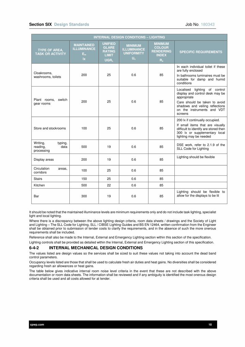
Section SIX Design Standards Job No. 180343
cpwp.com 18
INTERNAL DESIGN CONDITIONS – LIGHTING
TYPE OF AREA, TASK OR ACTIVITY
MAINTAINED ILLUMINANCE
Em
lx
UNIFIED GLARE RATING
LIMIT
UGRL
MINIMUM ILLUMINANCE UNIFORMITY
Uo
MINIMUM COLOUR
RENDERING INDEX
Ra
SPECIFIC REQUIREMENTS
Cloakrooms, washrooms, toilets
200 25 0.6 85
In each individual toilet if these are fully enclosed
In bathrooms luminaires must be suitable for damp and humid conditions
Plant rooms, switch gear rooms
200 25 0.6 85
Localised lighting of control display and control desk may be appropriate
Care should be taken to avoid shadows and veiling reflections on the instruments and VDT screens
Store and stockrooms 100 25 0.6 85
200 lx if continually occupied.
If small items that are visually difficult to identify are stored then 300 lx or supplementary local lighting may be needed
Writing, typing, reading, data processing
500 19 0.6 85 DSE work, refer to 2.1.9 of the SLL Code for Lighting
Display areas 200 19 0.6 85 Lighting should be flexible
Circulation areas, corridors
100 25 0.6 85
Stairs 150 25 0.6 85
Kitchen 500 22 0.6 85
Bar 300 19 0.6 85
Lighting should be flexible to allow for the displays to be lit
It should be noted that the maintained illuminance levels are minimum requirements only and do not include task lighting, specialist light and local lighting.
Where there is a discrepancy between the above lighting design criteria, room data sheets / drawings and the Society of Light and Lighting – The SLL Code for Lighting, SLL / CIBSE Lighting Guides and BS EN 12464, written confirmation from the Engineer shall be obtained prior to submission of tender costs to clarify the requirements, and in the absence of such the more onerous requirements shall be included.
Reference shall also be made to the Internal, External and Emergency Lighting section within this section of the specification.
Lighting controls shall be provided as detailed within the Internal, External and Emergency Lighting section of this specification.
6-4-2 INTERNAL MECHANICAL DESIGN CONDITIONS
The values listed are design values so the services shall be sized to suit these values not taking into account the dead band control parameters.
Occupancy levels listed are those that shall be used to calculate fresh air duties and heat gains. No diversities shall be considered regarding fresh air allowances or heat gains.
The table below gives indicative internal room noise level criteria in the event that these are not described with the above documentation or room data sheets. The information shall be reviewed and if any ambiguity is identified the most onerous design criteria shall be used and all costs allowed for at tender.
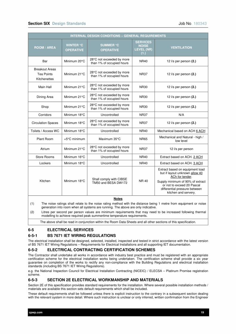
Section SIX Design Standards Job No. 180343
cpwp.com 19
INTERNAL DESIGN CONDITIONS – GENERAL REQUIREMENTS
ROOM / AREA WINTER °C
OPERATIVE
SUMMER °C
OPERATIVE
SERVICES NOISE
LEVEL (NR) (1.)
VENTILATION
Bar Minimum 20°C 28°C not exceeded by more than 1% of occupied hours
NR40 12 l/s per person (2.)
Breakout Areas
Tea Points
Kitchenettes
Minimum 21°C 28°C not exceeded by more than 1% of occupied hours
NR37 12 l/s per person (2.)
Main Hall Minimum 21°C 28°C not exceeded by more than 1% of occupied hours
NR30 12 l/s per person (2.)
Dining Area Minimum 21°C 28°C not exceeded by more than 1% of occupied hours
NR30 12 l/s per person (2.)
Shop Minimum 21°C 28°C not exceeded by more than 1% of occupied hours
NR30 12 l/s per person (2.)
Corridors Minimum 18°C Uncontrolled NR37 N/A
Circulation Spaces Minimum 18°C 28°C not exceeded by more than 1% of occupied hours
NR37 12 l/s per person (2.)
Toilets / Access WC Minimum 18°C Uncontrolled NR40 Mechanical based on ACH 6 ACH
Plant Room +5°C minimum Maximum 35°C NR65 Mechanical and Natural - high /
low level
Atrium Minimum 21°C 28°C not exceeded by more than 1% of occupied hours
NR37 12 l/s per person
Store Rooms Minimum 16°C Uncontrolled NR40 Extract based on ACH. 2 ACH
Lockers Minimum 18°C Uncontrolled NR40 Extract based on ACH. 3 ACH
Kitchen Minimum 18°C Shall comply with CIBSE TM50 and BESA DW172
NR 40
Extract based on equipment load but if layout unknown allow 40
ACh for tender.
Supply minimum of 90% of extract or not to exceed 20 Pascal
differential pressure between kitchen and servery.
Notes
(1) The noise ratings shall relate to the noise rating method with the distance being 1 metre from equipment or noise generation into room when all systems are running. The above are only indicative.
(2) Litres per second per person values are minimum requirements that may need to be increased following thermal modelling to achieve required peak summertime temperature requirements.
The above shall be read in conjunction within the Room Data Sheets and all other sections of this specification.
6-5 ELECTRICAL SERVICES
6-5-1 BS 7671 IET WIRING REGULATIONS
The electrical installation shall be designed, selected, installed, inspected and tested in strict accordance with the latest version of BS 7671 IET Wiring Regulations – Requirements for Electrical Installations and all supporting IET documentation.
6-5-2 ELECTRICAL CONTRACTING CERTIFICATION SCHEMES
The Contractor shall undertake all works in accordance with industry best practice and must be registered with an appropriate certification scheme for the electrical installation works being undertaken. The certification scheme shall provide a six year guarantee on completion of the works to rectify any non-compliance with the Building Regulations and electrical installation standards (including BS 7671 IET Wiring Regulations).
e.g. the National Inspection Council for Electrical Installation Contracting (NICEIC) / ELECSA – Platinum Promise registration scheme.
6-5-3 SECTION 2E ELECTRICAL WORKMANSHIP AND MATERIALS
Section 2E of this specification provides standard requirements for the installation. Where several possible installation methods / materials are available this section sets default requirements which shall be included.
These default requirements shall be followed unless there is explicit instruction to the contrary in a subsequent section dealing with the relevant system in more detail. Where such instruction is unclear or only inferred, written confirmation from the Engineer

Section SIX Design Standards Job No. 180343
cpwp.com 20
shall be obtained prior to submission of tender costs to clarify the requirements, and in the absence of such the more onerous requirements shall be included.
6-5-4 VOLT DROP
The volt drop between the origin of the installation and any load point shall not be greater than the values detailed within Appendix 4 of BS 7671, with respect to the value of the nominal voltage of the installation. The calculated volt drop shall include any effects due to harmonic currents.
6-5-5 POWER QUALITY
The Contractor shall be fully cognisant of the power quality of the building(s) with regards to:-
1) Power factor.
2) Harmonics and mains quality.
3) Frequency fluctuation.
4) Voltage fluctuation.
5) Earthing.
Where the power quality is of concern to the Contractor this shall be brought to the attention of the Engineer immediately.
6-5-6 SPARE CAPACITY
The Contractor shall ensure that the following spare current carrying capacity is allowed for each main / sub-main cable, in addition to the calculated maximum demand:-
1) 10% to loads where the likelihood of increased demand is marginal e.g. lift supplies, external lighting feeder pillars / distribution boards.
2) 25% to loads where the likelihood of increased demand is possible during the building’s life cycle e.g. main and sub-main switch panels, rising main busbar trunking, panel boards, feeder pillars, multi-service distribution boards, distribution boards, consumer units, mechanical control panels, chillers etc.
The Contractor shall ensure 25% spare capacity is provided to the following systems and equipment:
1) LV distribution e.g. switch panels, rising main busbar trunking, panel boards, feeder pillars, multi-service distribution boards, distribution boards, consumer units etc.
2) Call systems e.g. disabled persons call systems remote indication control panels, emergency voice communication systems (EVCS) master control panels, nurse / staff call systems control panels etc.
3) Voice and data systems e.g. server racks, equipment racks, comms racks.
4) Security systems e.g. intruder alarm panels, CCTV network / digital video recorders (NVR’s / DVR’s) etc.
5) Fire alarm systems e.g. fire alarm control panels etc.
6) Cable support and containment systems shall be provided with 30% spare capacity and also an additional 30% allowance shall be added to the calculated safe working load (SWL) for supports, for the provision of future cabling.
7) Where 30% spare capacity is provided to cable ladder rack and cable tray, this shall be a dedicated section of the system and shall not be above or between installed cabling.
8) Conduit systems shall be provided with spare capacity so that 30% more cable/s of a similar size and type can be installed. Conduits less than 20mm diameter shall not be used.
6-5-7 LV DISTRIBUTION
The LV distribution shall be designed, selected, installed, inspected and tested in strict accordance with the standards and guidance detailed within the LV Distribution section of this specification.
Mains and sub-mains cabling shall be sized in strict accordance with the latest version of BS 7671 IET Wiring Regulations – Requirements for Electrical Installations and all supporting IET documentation.
The competed design shall be coordinated with all other services and the building requirements. The design shall be fully compliant with the entire documentation package issued.
Detailed design drawings shall be provided showing the setting out of all equipment included underground services, ducts and cable pits. The Electrical Contractor shall advise on the design of pits and cableways and these shall be provided in such a manner to prevent water ingress and to allow removal and re-installation of all services. In principle, cables shall be installed in ducts below all road and pathways and shall be suitably de-rated to suit.
Undertake cable sizing calculations to achieve full compliance with BS 7671 with the following assumptions:
1) Cables to be installed “flat touching” on tray/ladder (in practice larger cables shall be spaced by at least the width of the cable cleat.)
2) All protective devices shall be from a common manufacturer
3) Devices with standard trip characteristics shall be used where possible
4) All equipment shall be sized with spare capacity for future growth of 25%
Undertake a detailed protection study for the complete LV distribution network to verify all cables sizes and protective devices to fully comply with the BS 7671 IET Regulations. This shall include, but not be limited to, analysis of prospective short circuit currents, operating times, discrimination, allowed voltage drop, withstand current of devices and switchboards, protection settings. The completed study shall be issued to the Employer for comment before implementation.
Where the incoming supply is provided by the DNO the Contractor shall be responsible for all necessary liaison, including programme, timing, technical coordination etc. and for obtaining any necessary consents for co-generation.
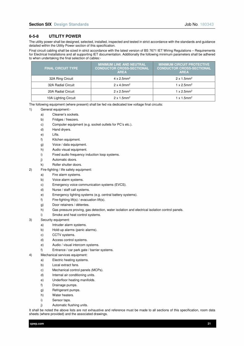
Section SIX Design Standards Job No. 180343
cpwp.com 21
6-5-8 UTILITY POWER
The utility power shall be designed, selected, installed, inspected and tested in strict accordance with the standards and guidance detailed within the Utility Power section of this specification.
Final circuit cabling shall be sized in strict accordance with the latest version of BS 7671 IET Wiring Regulations – Requirements for Electrical Installations and all supporting IET documentation. Additionally the following minimum parameters shall be adhered to when undertaking the final selection of cables:-
FINAL CIRCUIT TYPE MINIMUM LINE AND NEUTRAL
CONDUCTOR CROSS-SECTIONAL AREA
MINIMUM CIRCUIT PROTECTIVE CONDUCTOR CROSS-SECTIONAL
AREA
32A Ring Circuit 4 x 2.5mm2 2 x 1.5mm2
32A Radial Circuit 2 x 4.0mm2 1 x 2.5mm2
20A Radial Circuit 2 x 2.5mm2 1 x 2.5mm2
10A Lighting Circuit 2 x 1.5mm2 1 x 1.5mm2
The following equipment (where present) shall be fed via dedicated low voltage final circuits:
1) General equipment:-
a) Cleaner’s sockets.
b) Fridges / freezers.
c) Computer equipment (e.g. socket outlets for PC’s etc.).
d) Hand dryers.
e) Lifts.
f) Kitchen equipment.
g) Voice / data equipment.
h) Audio visual equipment.
i) Fixed audio frequency induction loop systems.
j) Automatic doors.
k) Roller shutter doors.
2) Fire-fighting / life safety equipment:
a) Fire alarm systems.
b) Voice alarm systems.
c) Emergency voice communication systems (EVCS).
d) Nurse / staff call systems.
e) Emergency lighting systems (e.g. central battery systems).
f) Fire-fighting lift(s) / evacuation lift(s).
g) Door retainers / détentes.
h) Gas pressure proving, gas detection, water isolation and electrical isolation control panels.
i) Smoke and heat control systems.
3) Security equipment:
a) Intruder alarm systems.
b) Hold-up alarms (panic alarms).
c) CCTV systems.
d) Access control systems.
e) Audio / visual intercom systems.
f) Entrance / car park gate / barrier systems.
4) Mechanical services equipment:
a) Electric heating systems.
b) Local extract fans.
c) Mechanical control panels (MCPs).
d) Internal air conditioning units.
e) Underfloor heating manifolds.
f) Drainage pumps.
g) Refrigerant pumps.
h) Water heaters.
i) Sensor taps.
j) Automatic flushing units.
It shall be noted the above lists are not exhaustive and reference must be made to all sections of this specification, room data sheets (where provided) and the associated drawings.
Section SIX Design Standards Job No. 180343
cpwp.com 22
Socket outlets for cleaners use shall be fed via dedicated low voltage ring / radial final circuits and shall be clearly labelled as ‘CLEANERS SOCKET’. All final circuits for cleaners socket outlets shall be protected by 30mA RCBO’s. Cleaners socket outlets shall be provided in sufficient quantities throughout to serve a maximum 8m radius.
All final circuits within the same room shall be from the same phase.
Final circuit cabling shall be sized in strict accordance with the latest version of BS 7671 IET Wiring Regulations – Requirements for Electrical Installations and all supporting IET documentation.
6-5-9 INTERNAL, EXTERNAL AND EMERGENCY LIGHTING
The internal, external and emergency lighting shall be designed, selected, installed, tested and commissioned in strict accordance with the standards and guidance detailed herein.
Some basic design parameters are as follows:
1) The efficiency of the lighting scheme shall afford compliance with the necessary standards (Part L etc.) but shall also, as a minimum, achieve an efficiency of 60 luminaire-lumens per watt for general applications and 22 luminaire-lumens per watt for display lighting.
2) Maintenance factor shall be calculated as outlined in CIBSE/SLL guidance. Room cleaning frequency shall be taken as 24 months. Lumen depreciation shall be based on 20% (L80).
3) All occupied spaces shall be designed in accordance with the principles outlined in CIBSE Lighting Guide 7 to ensure that walls and ceilings are well illuminated.
4) All spaces shall achieve an average illuminance level on the walls that is at least 50% of the average illuminance level on the working plane.
5) Unless otherwise stated, the design shall achieve the BREEAM credits associated with energy efficiency and light pollution.
6) The emergency lighting system shall be based on separate LED fittings.
7) Lighting controls shall be provided as detailed within the Internal, External and Emergency Lighting section of this specification
The drawings provide guidance on the lighting concepts, styles, controls and illuminance levels that are required. The tenderer shall note that these are conceptual only and do not represent accurate quantities or locations. It is the Contractor’s responsibility to design the lighting layout using these concept ideas to meet the performance criteria given. The Contractor shall not use the quantities shown on the lighting layout drawings but ascertain their own quantities by design.
The Contractor shall adopt the luminaire types detailed in this specification and the associated drawings for the various locations and provide a complete lighting design detailing quantities, mounting heights, installation methods, switching, automatic controls etc.
Where the project has an associated BIM model populated with lighting information in the 3D environment using REVIT software, it shall be noted that this also represents conceptual information, notwithstanding the level of detail shown.
Not all manufacturers’ products are available as .RVT families and therefore other manufacturers models may have been inserted to assist. However whilst these manufacturers may be named in the Revit model, the Contractor must only use the products that are specified within the luminaire schedules along with this specification. Alternatives will not be accepted for tender.
Indicative emergency lighting is also shown on the layout drawings. The Contractor shall be required to design the entire emergency lighting installation including all exit signage. The Contractor shall be required to obtain from the Architect, the fire exit strategy to enable them to design the signage. Illuminated signs shall be used and shall only be LED type. As a minimum guide, illuminated exits shall be allowed for every final exit door, every exit to a staircase and 2qty for each corridor bounded by doors and at each change of level or direction to suit the ceiling. This must comply with BS 5266. Emergency exit luminaires shall also be required on the roof levels where mechanical plant are located and the access routes to such plant. This includes internal and external spaces of the plant as shown on the layout drawings.
No photo-luminescent signage shall be accepted, all exits shall be LED self-illuminated and served from the central battery system.
Over and above standards, emergency Lighting shall be installed within all stores, LV switch rooms, plant rooms, electrical riser cupboards, over external emergency exit doors, roof maintenance route & mechanical riser cupboards.
The Contractor shall provide the Engineer with a detailed project lighting report, including isolux plots for all areas of the building, technical and photometric data for each type of luminaire and a lighting schedule which summarises the following data as a minimum for every room:-
1) Floor area (m2), wall area (m2), and wall-to-floor area ratio.
2) Room surface reflectances.
3) Working plane height (m).
4) Target illuminance level on the working plane (lux), vertical planes and ceiling/ soffit plane.
5) Calculated illuminance levels on the working plane, walls and ceiling (lux).
6) Calculated emergency lighting levels including those for specific locations outlined in Annex E and Table E.1 of BS 5266
7) Cylindrical illuminance levels (lux).
8) Uniformity on the working, ceiling and vertical planes.
9) Uniformity on all known or likely task areas
10) Luminaire-lumens per circuit watt (Lm/W).
11) Room power density (W/m2).
12) Room lighting power density (W/m2/100 lux).
13) Overall building average area-weighted luminaire lumens per circuit watt (Lm/W).
14) Overall building average area-weighted power density (W/m2).

Section SIX Design Standards Job No. 180343
cpwp.com 23
15) Overall building average area-weighted lighting power density (W/m2/100 lux).
Power densities are an inter-related function between the photometric light distribution of the luminaires and the room geometry and room surface reflectances. In calculating the room by room and the average lighting power densities (w/m²/100 lx) above, the Contractor shall ensure that their design values are equal to or below the NCM template values which are based on individual room geometry.
1) Calculations shall utilise industry standard software and methodology.
2) The required illuminance levels shall be as defined on the room data sheets (where provided) and / or this specification and the associated drawings, subject to the minimum levels given in the SLL Code for Lighting, SLL / CIBSE Lighting Guides and BS EN 12464.
3) Illuminance levels are taken to be maintained averages i.e. following reduction due to a calculated room maintenance factor.
4) Task lighting uniformity levels of 0.6 or better shall be achieved by all installations where the working plane is taken as floor level. For areas where the working plane is taken as being work surface height a uniformity of 0.7 or better shall be achieved.
5) The working plane height shall be dimensioned from the furniture elevations on the room data sheets. In the absence of room data sheets, a working plane height of 0.8m shall be taken within occupied spaces where work surfaces are used.
6) The quantity of calculation points used shall be as defined within BS EN 12464.
7) Maximum spacing to height ratios as quoted by selected luminaire manufacturer’s photometric data shall not be exceeded.
8) When calculating average illuminance the boundary zone shall generally be taken as 0.5m, except within small or narrow spaces (e.g. WCs, stores, circulation / corridors) or areas where tasks are to be undertaken within the room perimeter / boundary zone (e.g. desks against walls in offices or similar). The boundary zone shall be clearly stated on the isolux plot.
9) In calculating uniformity, the task area shall be derived from agreed furniture layouts and clearly indicated on the isolux layouts provided.
10) The reflectance of room surfaces shall be determined from the schedule of materials and finishes which shall be obtained from the Architect and Main Contractor. The target minimum design values of 70% (ceilings), 50% (walls) and 20% (floors) shall be taken although these shall still be reviewed on a room by room basis to ensure that they represent a reasonable basis in each case.
The Contractor shall submit the lighting report to the Engineer. The time allowed for comment by the Engineer shall be as detailed within section 1B of this specification.
Intumescent gaskets and covers shall be provided where luminaires are installed within ceilings or walls whose fire integrity has been compromised by their installation e.g. recessed luminaires in ceilings to maintain the ceilings fire integrity etc.
The installation of luminaires shall not compromise the acoustic integrity of the building structure / fabric and appropriate measures shall be undertaken to reinforce the required acoustic properties.
Lighting final circuit cabling shall be sized in strict accordance with the latest version of BS 7671 IET Wiring Regulations – Requirements for Electrical Installations and all supporting IET documentation. The number of luminaires connected so a single circuits shall restrict the running current to less than 3 Amps, the protective conductor current (leakage current) to less than 10mA and shall in any event not exceed 20.
6-5-10 CALL SYSTEMS
The call systems shall be designed, selected, installed, tested and commissioned in strict accordance with the standards and guidance detailed within the Call Systems section of this specification.
6-5-11 VOICE AND DATA SYSTEMS
The voice and data systems shall be designed, selected, installed, tested and commissioned in strict accordance with the standards and guidance detailed within the Voice and Data Systems section of this specification.
The Voice / Data Specialist(s) shall directly employ a Certified Network Infrastructure Design Professional (CNIDP®) or equivalent on a full time basis, who shall project manage the voice and data systems installation.
The Voice / Data Specialist(s) shall also employ Certified Network Cable Installers (CNCI®) or equivalent technicians who shall be assigned to the voice and data systems installation. The CNCI® or equivalent technicians shall be present on-site at all times during the installation works to act as lead technicians providing leadership and technical support for the remaining installers undertaking the works.
6-5-12 SECURITY SYSTEMS
The security systems shall be designed, selected, installed, tested and commissioned in strict accordance with the standards and guidance detailed within the Security Systems section of this specification.
The Security Specialist(s) must be NSI Gold certified.
6-5-13 FIRE ALARM SYSTEMS
The fire alarm systems shall be designed, selected, installed, tested and commissioned in strict accordance with the standards and guidance detailed within the Fire Alarm Systems section of this specification.
The Fire Alarm Specialist(s) must be an NSI Fire Gold certified and therefore BAFE registered. The Fire Alarm Specialist(s) must also be Loss Prevention Certification Board (LPCB) / Building Research Establishment (BRE) – Loss Prevention Standards – LPS 1014 certified.
6-5-14 LIGHTNING PROTECTION SYSTEMS
The lightning protection systems shall be designed, selected, installed, tested and commissioned in strict accordance with the standards and guidance detailed within the Lightning Protection Systems section of this specification.
The Lightning Protection Specialist(s) must be a member of the Association of Technical Lightning & Access Specialists (ATLAS).
Section SIX Design Standards Job No. 180343
cpwp.com 24
6-5-15 MISCELLANEOUS ELECTRICAL SYSTEMS
The miscellaneous electrical systems shall be designed, selected, installed, tested and commissioned in strict accordance with the standards and guidance detailed within the Miscellaneous Electrical Systems section of this specification.
6-5-16 RENEWABLE ELECTRICAL SYSTEMS
The renewable electrical systems shall be designed, selected, installed, tested and commissioned in strict accordance with the standards and guidance detailed within the Renewable Electrical Systems section of this specification.
Where photovoltaic (PV) systems are to be provided the PV Specialist must be a certified MCS (The Microgeneration Certification Scheme) installer.
6-6 EXTERNAL AMBIENT DESIGN CONDITIONS
The mechanical services installations shall be designed to provide the specified internal environmental parameters when the building is subject to the following external conditions:
EXTERNAL AMBIENT DESIGN STANDARDS
DESCRIPTION CONDITION
Winter external (fabric)
As per CIBSE Guide A table 2.5 for external temperatures not exceeded for more than 0.4% of year (use the 99.6% not exceeded column).
For example for Birmingham use -5.1ºC dry bulb / -5.2ºC wet bulb.
Winter external (design condition for plant selection)
As per CIBSE Guide A table 2.5 for external temperatures not exceeded for more than 0.4% of year (use the 99.6% not exceeded column).
For example, for Birmingham use -5.1ºC dry bulb / -5.2ºC wet bulb.
Summer external for design condition for chiller and refrigeration plant capacity
selection
As per CIBSE Guide A table 2.6 for external temperatures not exceeded for more than 0.4% of year (use the 99.6% not exceeded column).
For example, for Birmingham use 26.3ºC dry bulb / 18.9ºC wet bulb.
Summer external for design condition for cooling coil selection
As per CIBSE Guide A table 2.6 for external temperatures not exceeded for more than 0.4% of year (use the 99.6% not exceeded column) PLUS 2ºC.
For example, for Birmingham use 28.3ºC dry bulb / 20.9ºC wet bulb.
External conditions for output from chillers and condensing units
Winter: minus 10°C / Summer: 35°C dry bulb due to enclosed chiller compound causing local climate extremes.
Maximum noise level (With all plant operating at peak output, 3m from building
perimeter)
5 dB below current ambient level or Building Control OR Acoustic Report OR Planning requirements, use lowest value whichever is the most onerous.
Carbon emissions modelling for Part L and energy calculations
CIBSE Test Reference Year, nearest geographical location of similar conditions available.
Summertime thermal analysis CIBSE Design Summer Year, nearest geographical location of similar
conditions available.
Summertime temperature CIBSE Design Summer Year, nearest geographical location of similar
conditions available.
Climate Change Impact Assessment CIBSE Test Reference Year, nearest geographical location of similar
conditions available for 2020 and 2050.
All the above design values shall be corrected for altitude where the project site is at a significantly different altitude to the reference data (significant defined as 300m for this assessment) – Refer to CIBSE Design Guides A and B1 for guidance.
6-7 LTHW HEATING SYSTEM
6-7-1 DESIGN REQUIREMENTS
LTHW systems shall be designed to achieve a number of criteria including:
1) Boiler plant efficiencies to meet the specified building energy performance requirements.
2) Maintain design conditions within the spaces served.
3) Provide an acceptable and comfortable environment.
4) Minimise energy use and waste.
5) Maximise efficiency.
6) Ensure simple / practical operation and maintenance.
7) Satisfy peak simultaneous LTHW load requirements.
CENTRAL LTHW HEATING EQUIPMENT DESIGN REQUIREMENTS
DESCRIPTION REQUIREMENT
Central boilers quantity and capacity
2 Boilers each rated at 66% of total heat load

Section SIX Design Standards Job No. 180343
cpwp.com 25
CENTRAL LTHW HEATING EQUIPMENT DESIGN REQUIREMENTS
DESCRIPTION REQUIREMENT
Boiler thermal efficiencies As required to meet the EPC requirements.
The following temperatures / efficiencies shall be adopted for the various systems design unless advised otherwise in the particular sections of this specification:
LTHW HEATING SYSTEMS DESIGN OPERATING CONDITIONS
DESCRIPTION FLOW ºC RETURN ºC
Primary LTHW Circuit 70°C < 50°C
LTHW Radiator Panels 60°C 45°C
LTHW DHW Plate Heat Exchangers 70°C 35°C
Where secondary circuits are hydraulically separated from the primary circuit by a plate heat exchanger the secondary temperatures shall be reduced by the exchange approach (ideally 2 kelvin).
The project specific requirements section of this specification shall be referred to as it may modify some of the above design criteria.
Peak heating loads shall be calculated for each space and an appropriate emitter selected taking account of margins for flexibility, transient use, warm up, etc. Pipework distribution shall be designed to supply the necessary flow rate for the above plus allowance for distribution system losses and design margins.
The total heating load for central plant shall be calculated by assessing the maximum simultaneous heat demand of all heating emitters served together with all pipework heat losses, construction errors, early morning boost and any redundancy / expansion specified.
Margins etc. shall be calculated in accordance with CIBSE guides subject to the following minimums:
MINIMUM MARGINS FOR LTHW HEATING DESIGN
DESCRIPTION MARGIN TO BE INCLUDED IN DESIGN
Construction errors To be assessed by the designer
Flexibility, added to base room heat loss
+10%
Boost, applicable when area is not occupied 24 Hours.
+5%
Pipework distribution losses +5%
Pipework Sizing Capacity
Maximum simultaneous load of loads shall be allowed assuming that only the largest heat recovery unit has degraded or failed (as appropriate) so the corresponding LTHW coil output has increased to compensate and including all margins for construction error, flexibility, boost and pipework losses.
Central Plant Capacity Central plant shall be sized to meet the normal design operation including construction error, flexibility, boost and pipework losses margins with no allowance for the failure or degradation of the ventilation heat recovery systems.
6-7-2 LTHW DESIGN AND PIPEWORK SIZING
The heating pipework installations shall be designed to the recommendations laid down in the CIBSE guide to current practice and in particular the following:
1) Based on the design principles detailed in the tender schematics.
2) Variable speed pumping and two port control shall be employed wherever practical following the principles laid down in the CIBSE Knowledge Series.
3) Heating system maximum pipework velocities shall be as detailed in the CIBSE guide dependent upon pipe size.
4) Heating system maximum pipework pressure drop shall be limited to 200 Pascal per metre, except after DPCVs.
5) Maximum setting downstream of all DPCV valves shall be 30kPa differential pressure. All pipework distribution downstream of the DPCV shall be a low pressure loss design typical no more than 100 Pascal per metre.
6) Any pressure independent control valves (PICVs) shall not be operating within the upper 25% of their preferred maximum differential pressure.
7) Circulating pumps shall vary flow rate via differential pressure transducers and a proportional pressure control methodology. Small systems, with a flow rate of 1.5kg/s or less, shall have integral inverters and pressure control. Larger systems shall be provided with inverters that are separate from the pumps.
8) Have a method of reducing flow to very low levels (less than 5%) by using multiple pumps, a jockey pump or other manufacturer’s recommended method.
9) Any minimum flow requirements shall not be provided by permanent bypass pipes, with or without manual adjustable valves. Automatic bypass valves shall only be used to satisfy minimum pump flow rate.
Section SIX Design Standards Job No. 180343
cpwp.com 26
10) Temperature maintaining valves, set at design return temperature, shall be provided at strategic locations on large systems or systems incorporating combined heat and power (CHP) systems to ensure that mains are maintained at a sufficiently high temperature to ensure heat is available to all terminal devices and is provided in a timely manner and ensure the return water temperature is as low as possible.
11) Any flow maintaining devices proposed to satisfy minimum pump flow rate requirements shall be installed before any local zone valves.
12) Coils shall be piped counter flow and not parallel flow configuration.
13) All best practice design guidelines from equipment and valve manufacturers shall be adopted in the overall design.
14) Water pipes shall not be routed within 2 metres of any control panel or distribution board in plant rooms.
15) Ensure that minimum flow requirements are achieved at all emitters that require turbulent and therefore minimum flow rates to operate correctly and meet the required emitter outputs. Generally, for the emitters used in the building services industry this means:
a) Radiators and natural convectors are not subject to any minimum flow requirements to meet their required outputs.
b) Trench heating, radiant panels, fan convectors, unit heaters and door curtains are subject to achieving minimum flow rates to ensure turbulent flow occurs so both variable heat output and design heat output can be achieved. This is a known issue with smaller radiant panels where flow rates are calculated without considering the minimum flow rate requirements advised by the panel manufacturers.
c) Fan assisted or forced draught emitters shall not produce draughts when operating due to laminar flow of the heating fluid through the emitters.
d) Air handling unit coils flow rates and coil selections are determined by the AHU manufacturer to ensure turbulent flow so laminar flow should not be a concern for the range of control valve control.
e) The designer must always obtain specific design advise from the emitter manufacturer to determine if any minimum flow requirements for the proposed emitter and must incorporate this information into the detailed design.
6-8 DOMESTIC HOT AND COLD WATER SYSTEMS
6-8-1 DESIGN REQUIREMENTS
The hot and cold water services shall be designed to satisfy the following requirements:
1) The design philosophy for the domestic hot and cold water services shall be as detailed on the tender schematic. The overall philosophy for the design have been agreed with the design team and client prior to tender so the detailed design shall be developed on this basis and alternative design solutions shall not be adopted.
2) Provide potable drinking water to all drinking water outlets.
3) Review hot and cold Water requirements of the new kitchen shown in Appendix A.
4) Water to drinking points shall be fed direct from the utility mains.
5) All wash hand basins and sinks shall be thermostatically blended to TMV3 standards throughout the project. The only exception shall be some sinks such as cleaners and other non-public sinks. Where no TMV is provided a sign shall be provided to state ‘Caution Hot Water’.
6) Local pressure static and dynamic type combined reducing valves shall be provided to limit pressure and supply to outlets. Pressure reducing valves shall be fail closed type and shall be installed at each floor to ensure even and equal pressure at all outlets. It is expected that flow restrictor isolation valves shall aid in meeting this requirement.
7) Hot and cold water is readily available to all outlets to satisfy guidelines regarding the risk of legionella growth in relation to minimal dead legs.
8) The whole design must be in accordance with the HSE Approved Code of Practice L8.
9) Ensure discharge flow rates are maintained at all outlets during peak predicted demand.
10) Cold water distribution shall be designed to ensure that the cold water outlet achieves 20ºC or less within 2 minutes of the outlet being fully open. This is a statutory requirement (where the incoming mains cold water is 20ºC or less).
11) On unblended circuits, hot water distribution shall be designed to ensure that the hot water outlet achieves at least 50ºC within 1 minute of the outlet being fully open. This is a statutory requirement.
12) On thermostatically blended circuits, hot water distribution shall be designed to ensure the hot water outlet achieves the set point temperature of the thermostatic mixing valve within 1 minute AND the unblended hot water achieves 50ºC at the same time. This is a statutory requirement. Testing shall be carried out in accordance with the methodology detailed in Thermostatic Mixing Valve Manufacturers Association their document ‘Recommended Code of Practice for Safe Water Temperatures’.
13) On circulating systems, non-circulating dead legs shall not exceeding 0.5 litre to the outlet in accordance with BS8558 so although the ‘traditional’ dead leg limit of 3 metres, for 15mm copper pipe, is compliant with this requirement all larger pipe dead legs will need to be shorter to achieve the 0.5 litre limit in the British Standard.
14) Hot water circulating systems shall be provided with a combination of thermostatic circulating valves (also known as self-acting thermostatic recirculation valves) shall be installed throughout the hot water return installation fully in accordance with the manufacturers recommendations. Thermostatic circulating valves are specified outright for the project as they automatically compensate and self-balance circuits when initially installed and also if circuits are modified at a later date. Thermostatic circulating valves shall have integral facility to fully open at increased temperatures to allow for regular system pasteurisation.
15) Under no circumstances shall lock shield valves be installed for hot water recirculation regulation as they cannot be easily or accurately reset to commissioned flow rates following routine isolation and this represents an unacceptable risk of poor circulation and bacteria propagation.
Section SIX Design Standards Job No. 180343
cpwp.com 27
16) Hot water branches shall normally be designed so that only a single thermostatic circulating valves is required on each branch with the necessary dead legs to multiple outlets designed within the dead leg limits listed above. Where this is NOT possible and sub-branch circuits are required then each of the sub-branch circuits shall be fitted with double regulating valves to allow thermal balancing of these sub-circuits only. On this basis no circuit should need more than two double regulating valves on any one branch that already has a thermostatic circulating valve. Double regulating valves shall not be used as a cost saving in place of thermostatic circulation valves.
17) Where cold water pipes are routed adjacent to hot water and heating pipes the cold water pipes shall be located a minimum of 100mm clear of the hot pipes. Clear distance is between the fully insulated pipes and not bare / un-insulated pipes.
18) Where cold water pipes are routed horizontally adjacent to hot water and heating pipes the cold water pipes shall be located below the hot pipes.
19) When designing the bracket arrangement for the hot and cold water services ensure that thermal transfer between the pipes is minimised. For example, known thermal transfer issues occur where insulated plastic pipes are installed on galvanised steel cable tray for continuous support so this type of design shall be avoided.
20) Booster sets, where used, shall incorporate measures to prevent excessive surge / velocity pressures when re-starting after a fault condition / mains failure.
21) Back flow and back pressure prevention shall comply with current water regulations based on the fluid category. Note that reduced pressure zone (RPZ) valves shall NOT BE USED.
22) Outlets to be provided with means of adjusting pressure to prevent splash over or overflow of sanitary ware. Flow restrictor valves shall meet this requirement provided those chosen are pressure independent at the expected peak operating pressure.
23) Complete system shall be protected against excessive pressure during periods of low demand where utility mains pressure may exceed.
24) Maximise system and pipework distribution efficiency.
25) Minimise water waste and energy use.
26) Ensure simple and practical operation for ease of use and maintenance.
27) BMS monitored temperature sensors shall be provided as detailed on the tender drawings and in accordance with the industry best practice guidelines (e.g. HTM 04-01).
28) Flushing and disinfection points shall be provided based on the guidance within PD 855468.
29) Within plant rooms, no water pipes shall be routed within 2 metres of any electrical switch panel or BMS control panel and as advised later in this section no water services are permitted at all in certain electrical rooms.
6-8-2 DOMESTIC HOT AND COLD WATER SYSTEMS
The following conditions shall be adopted for the domestic hot and cold water systems design unless advised otherwise in the particular sections of this specification:
DOMESTIC HOT AND COLD WATER SYSTEMS OPERATING & SIZING CONDITIONS
DESCRIPTION CONDITION
Minimum pressure at outlets 0.5 Bar (g) (or sanitary ware manufacturer’s minimum requirement whichever
is greater)
Maximum pressure at outlets As dictated by the height of the building and booster sets. Flow Restrictor Isolation Valves shall be installed to prevent excessive flow and pressure.
Differential pressure between hot and cold water outlets when mixing
Not to exceed that recommended by the thermostatic mixing valve manufacturer and should be as equal pressure as practical.
Pressure available from utilities mains 0.7 Bar (g) (unless guaranteed in writing to be higher by utility company)
Flow rates
For residential projects only, BS EN 806-3 shall be used to calculate flow rates.
For all other projects Loading Units as detailed on Annex C of BS 8558 shall be used to calculate flow rates.
Where outlets are blended the hot water use shall be amended to suit the blended temperature.
Pipe Sizing CIBSE guide to determine all pipe sizes based on calculated flow rates.
Maximum pipework velocities. As detailed in CIBSE guide dependent upon pipe size.
Pipework pressure drop Calculated according to the available head on the system and as required to give correct flow at terminal outlets and the avoidance of below atmospheric
pressure conditions in return circuits.
6-8-3 ADDITIONAL DOMESTIC HOT WATER SYSTEM REQUIREMENTS
The following conditions shall be adopted for the domestic hot water systems design unless advised otherwise in the particular sections of this specification:
DOMESTIC HOT WATER SYSTEMS ADDITIONAL OPERATING & SIZING CONDITIONS
DESCRIPTION CONDITION
Hot Water Flow Temperature 60°C
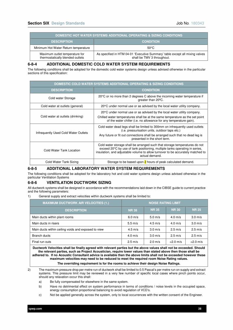
Section SIX Design Standards Job No. 180343
cpwp.com 28
DOMESTIC HOT WATER SYSTEMS ADDITIONAL OPERATING & SIZING CONDITIONS
DESCRIPTION CONDITION
Minimum Hot Water Return temperature 50°C
Maximum outlet temperature for thermostatically blended outlets
As specified in HTM 04-01 ‘Executive Summary’ table except all mixing valves shall be TMV 3 throughout.
6-8-4 ADDITIONAL DOMESTIC COLD WATER SYSTEM REQUIREMENTS
The following conditions shall be adopted for the domestic cold water systems design unless advised otherwise in the particular sections of this specification:
DOMESTIC COLD WATER SYSTEMS ADDITIONAL OPERATING & SIZING CONDITIONS
DESCRIPTION CONDITION
Cold water Storage 20°C or no more than 2 degrees C above the incoming water temperature if
greater than 20ºC.
Cold water at outlets (general) 20°C under normal use or as advised by the local water utility company.
Cold water at outlets (drinking)
20°C under normal use or as advised by the local water utility company.
Chilled water temperatures shall be at the same temperature as the set point of the water chiller (i.e. no allowance for any temperature gain).
Infrequently Used Cold Water Outlets
Cold water dead legs shall be limited to 300mm on infrequently used outlets (i.e. pressurisation units, outdoor taps etc.)
Any future or fit out connections shall be arranged such that no dead leg is presented in the short term.
Cold Water Tank Location
Cold water storage shall be arranged such that storage temperatures do not exceed 20°C by use of tank positioning, multiple tanks operating in series,
insulation, and adjustable volume to allow turnover to be accurately matched to actual demand.
Cold Water Tank Sizing Storage to be based upon 2 hours of peak calculated demand.
6-8-5 ADDITIONAL LABORATORY WATER SYSTEM REQUIREMENTS
The following conditions shall be adopted for the laboratory hot and cold water systems design unless advised otherwise in the particular Ventilation Systems
6-8-6 VENTILATION DUCTWORK SIZING
All ductwork systems shall be designed in accordance with the recommendations laid down in the CIBSE guide to current practice and the following parameters:
1) General supply and extract velocities within ductwork systems shall be limited to:
MAXIMUM DUCTWORK AIR VELOCITIES (1.) NOISE RATING LIMIT
DESCRIPTION NR 38 NR 35 NR 30 NR 25
Main ducts within plant rooms 6.0 m/s 5.0 m/s 4.0 m/s 3.0 m/s
Main ducts in risers 5.5 m/s 4.5 m/s 4.0 m/s 3.0 m/s
Main ducts within ceiling voids and exposed to view 4.5 m/s 3.0 m/s 2.5 m/s 2.5 m/s
Branch ducts 4.0 m/s 3.0 m/s 2.5 m/s 2.5 m/s
Final run outs 2.5 m/s 2.0 m/s <2.0 m/s <2.0 m/s
Ductwork Velocities shall be finally agreed with relevant parties but the above values shall not be exceeded. Should the relevant parties, such as Project Acoustician, require lower values than stated above then those shall be
adhered to. If no Acoustic Consultant advice is available then the above limits shall not be exceeded however these maximum velocities may need to be reduced to meet the required room Noise Rating values.
The overriding requirement is for the rooms to achieve their design Noise Ratings.
2) The maximum pressure drop per metre run of ductwork shall be limited to 0.5 Pascal’s per metre run on supply and extract systems. This pressure limit may be reviewed in a very few number of specific local cases where pinch points occur, should any relaxation occur this shall:
a) Be fully compensated for elsewhere in the same system.
b) Have no detrimental effect on system performance in terms of conditions / noise levels in the occupied space, energy consumption proportional balancing to avoid regulation of VCD’s.
c) Not be applied generally across the system, only to local occurrences with the written consent of the Engineer.

Section SIX Design Standards Job No. 180343
cpwp.com 29
3) Ductwork shall be sized on a constant pressure drop basis throughout all systems with balancing dampers as required. Ensure that all final dampers’ locations do not cause noise regeneration that is audible in the rooms.
4) Should the above criteria need to be improved upon (i.e. lower velocities and pressure drops per unit length) to meet Part L carbon, energy and project criteria then these shall be adopted for the design allowance at tender.
5) Any variable air volume (VAV) systems shall not incorporate any diversity when the ductwork is sized as the VAV is provided to save energy and not to limit occupancy or use of the building due to insufficient airflows or non-compliant noise levels when the ventilation system is required to operate at peak airflow.
6-9 ABOVE GROUND DRAINAGE
The above ground drainage shall be designed to be fully in accordance with BS EN 12056. Material and type of systems are detailed on the tender drawings and Above Ground Drainage Section of this Specification.
6-10 ENERGY METERING SYSTEMS
The design criteria for the energy metering systems are detailed in the Energy Metering Section of this Specification as the metering shall be designed by the energy metering specialist.

Section SIX Design Standards Job No. 180343
cpwp.com 30
6-11 APPENDIX A – PREFERRED MANUFACTURERS LIST

Section SIX Design Standards Job No. 180343
cpwp.com 31
PREFERRED MANUFACTURERS LIST
MECHANICAL SERVICES
Air Handling Units: Dalair / Birmingham Air conditioning /
Volume Control Dampers: Actionair Air Shield and Aeroseal Range
VAV Boxes: Trox/Advanced Air/Krantz
Fire / Smoke Dampers: Actionair Fire Shield and Smoke Shield PTC Range
Pumps: Holden and Brooke / Pullen / Grundfos
Air Cooled free cooled Chillers: Airdale / Daikin / Carrier /
DX units: Daikin or Denco
Water Valves and commissioning sets: Crane / Hattersley / Tour and Anderson/Oventrop
Radiators: Stelrad, Zehnder, MHS
Dirty Extract Fans: Nuaire / Vent Axia
Pressurisation Units: Same as manufacturer of pumps
Ceiling Grilles and general Diffusers: TEK Limited or direct equivalent
Displacement Diffusers: Krantz
Attenuators: TEK Limited or direct equivalent
Boiling/Chilled water units/fountains: ZIP
Air / dirt Separators: TA Hydronics
Expansion bellows: BOA group
Note – Where multiple quantities of the same type of equipment is required such as pumps, air handling units, etc. the same manufacturer shall be used throughout the installation.
ELECTRICAL SERVICES
Preferred manufacturers lists are contained within the subsequent sections of the specification.
cpwp.com V1.4
Section E1A Low Voltage Distribution
Section E1A Low Voltage Distribution Job No. 180343
cpwp.com 1
Contents Page
E1A-1 GENERAL REQUIREMENTS 2
E1A-2 DEFINITIONS 2
E1A-3 REFERENCES TO OTHER SECTIONS OF THIS SPECIFICATION 2
E1A-4 STANDARDS APPLICABLE 2
E1A-5 DESIGN REQUIREMENTS 2
E1A-6 PERFORMANCE PARAMETERS AND TECHNICAL REQUIREMENTS 3
E1A-7 SCOPE OF WORKS 3
E1A-8 INCOMING SUPPLIES 3
E1A-9 LV PANEL BOARD(S) 3
E1A-10 MOULDED CASE CIRCUIT BREAKERS 4
E1A-11 METERS 5
E1A-12 SURGE PROTECTION 6
E1A-13 SUB-MAINS CABLING 6
E1A-14 FINAL DISTRIBUTION BOARDS 6
E1A-15 EARTHING AND BONDING 6
APPENDIX II – LOW VOLTAGE DISTRIBUTION MATERIALS 7
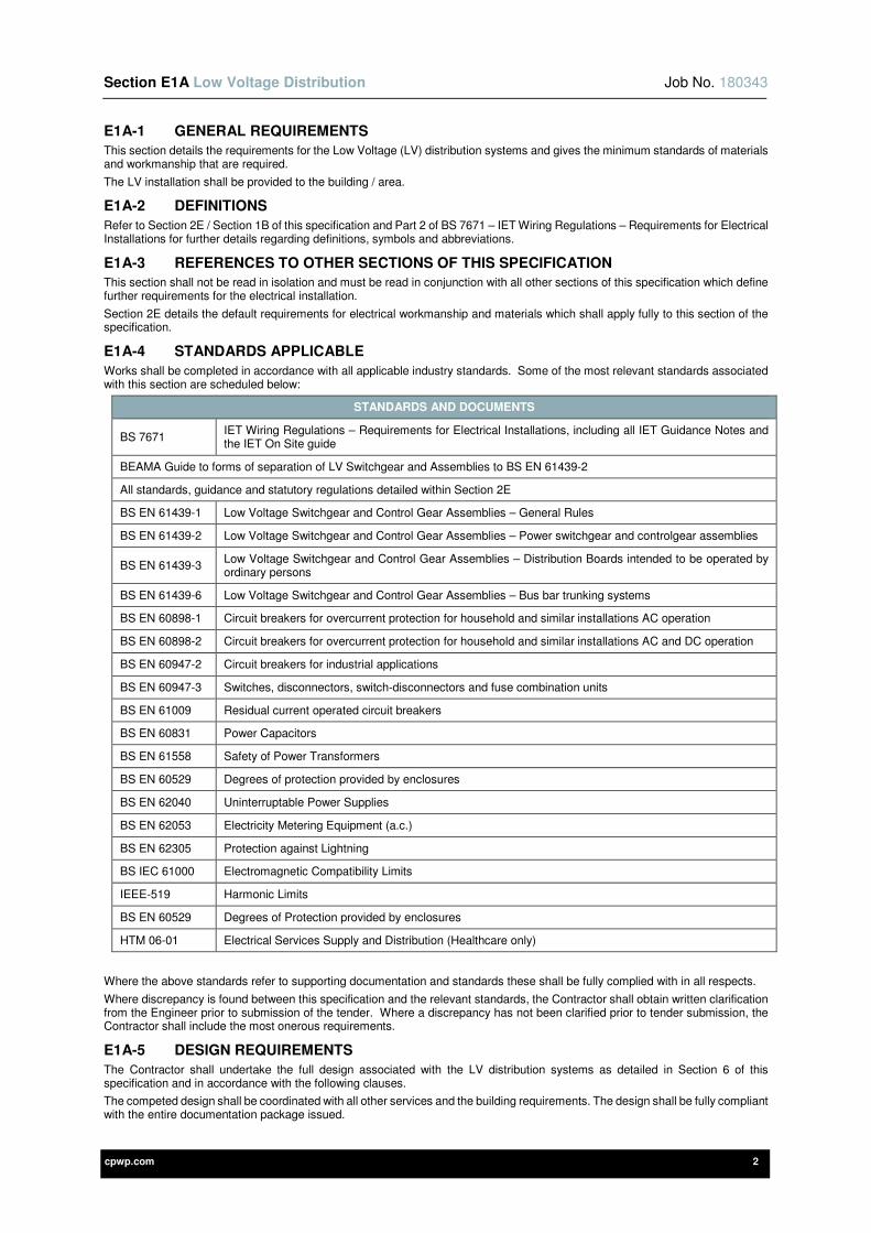
Section E1A Low Voltage Distribution Job No. 180343
cpwp.com 2
E1A-1 GENERAL REQUIREMENTS
This section details the requirements for the Low Voltage (LV) distribution systems and gives the minimum standards of materials and workmanship that are required.
The LV installation shall be provided to the building / area.
E1A-2 DEFINITIONS
Refer to Section 2E / Section 1B of this specification and Part 2 of BS 7671 – IET Wiring Regulations – Requirements for Electrical Installations for further details regarding definitions, symbols and abbreviations.
E1A-3 REFERENCES TO OTHER SECTIONS OF THIS SPECIFICATION
This section shall not be read in isolation and must be read in conjunction with all other sections of this specification which define further requirements for the electrical installation.
Section 2E details the default requirements for electrical workmanship and materials which shall apply fully to this section of the specification.
E1A-4 STANDARDS APPLICABLE
Works shall be completed in accordance with all applicable industry standards. Some of the most relevant standards associated with this section are scheduled below:
STANDARDS AND DOCUMENTS
BS 7671 IET Wiring Regulations – Requirements for Electrical Installations, including all IET Guidance Notes and the IET On Site guide
BEAMA Guide to forms of separation of LV Switchgear and Assemblies to BS EN 61439-2
All standards, guidance and statutory regulations detailed within Section 2E
BS EN 61439-1 Low Voltage Switchgear and Control Gear Assemblies – General Rules
BS EN 61439-2 Low Voltage Switchgear and Control Gear Assemblies – Power switchgear and controlgear assemblies
BS EN 61439-3 Low Voltage Switchgear and Control Gear Assemblies – Distribution Boards intended to be operated by ordinary persons
BS EN 61439-6 Low Voltage Switchgear and Control Gear Assemblies – Bus bar trunking systems
BS EN 60898-1 Circuit breakers for overcurrent protection for household and similar installations AC operation
BS EN 60898-2 Circuit breakers for overcurrent protection for household and similar installations AC and DC operation
BS EN 60947-2 Circuit breakers for industrial applications
BS EN 60947-3 Switches, disconnectors, switch-disconnectors and fuse combination units
BS EN 61009 Residual current operated circuit breakers
BS EN 60831 Power Capacitors
BS EN 61558 Safety of Power Transformers
BS EN 60529 Degrees of protection provided by enclosures
BS EN 62040 Uninterruptable Power Supplies
BS EN 62053 Electricity Metering Equipment (a.c.)
BS EN 62305 Protection against Lightning
BS IEC 61000 Electromagnetic Compatibility Limits
IEEE-519 Harmonic Limits
BS EN 60529 Degrees of Protection provided by enclosures
HTM 06-01 Electrical Services Supply and Distribution (Healthcare only)
Where the above standards refer to supporting documentation and standards these shall be fully complied with in all respects.
Where discrepancy is found between this specification and the relevant standards, the Contractor shall obtain written clarification from the Engineer prior to submission of the tender. Where a discrepancy has not been clarified prior to tender submission, the Contractor shall include the most onerous requirements.
E1A-5 DESIGN REQUIREMENTS
The Contractor shall undertake the full design associated with the LV distribution systems as detailed in Section 6 of this specification and in accordance with the following clauses.
The competed design shall be coordinated with all other services and the building requirements. The design shall be fully compliant with the entire documentation package issued.
Section E1A Low Voltage Distribution Job No. 180343
cpwp.com 3
Detailed design drawings shall be provided showing the setting out of all equipment included underground services, ducts and cable pits. The Electrical Contractor shall advise on the design of pits and cableways and these shall be provided in such a manner to prevent water ingress and to allow removal and re-installation of all services. In principle, cables shall be installed in ducts below all road and pathways and shall be suitably de-rated to suit.
Undertake full cable sizing calculations to achieve full compliance with BS 7671 with the following assumptions:
• Cables to be installed “flat touching” on tray/ladder (in practice larger cables will be spaced by at least the width of the cable cleat.)
• All protective devices shall be from a common manufacturer
• Devices with standard trip characteristics shall be used where possible
• All equipment shall be sized with spare capacity for future growth of 25%
Undertake a detailed protection study for the complete LV distribution network to verify all cables sizes and protective devices to fully comply with the BS 7671 IET Regulations. This shall include, but not be limited to, analysis of prospective short circuit currents, operating times, discrimination, allowed voltage drop, withstand current of devices and switchboards, protection settings. The completed study shall be issued to the Employer for comment before implementation.
Where the incoming supply is provided at LV by the DNO the Contractor shall be responsible for all necessary liaison, including programme, timing, technical coordination etc. and for obtaining any necessary consents for co-generation.
E1A-6 PERFORMANCE PARAMETERS AND TECHNICAL REQUIREMENTS
The following fundamental performance parameters shall apply:
• All equipment associated with the LV distribution shall be suitable for the system voltage which is 400V 3 phase, 4 wire 50Hz.
• The neutral conductor/bus bar in all cables/distribution equipment shall be fully rated.
E1A-7 SCOPE OF WORKS
The LV systems installation shall include the provision of the following (where required), as indicated on the LV schematic drawings:-
1) Liaison with provider of intake service.
2) Connection to intake service provided by DNO
3) Coordination with all other electrical systems and the associated Specialist providers
4) Low Voltage Panel board(s)
5) Meters
6) Surge Protection Devices
7) Main and sub-main cabling
8) Cable support and containment systems
9) Final Distribution boards/Consumer Units
10) Main Earthing Terminal
11) Main equipotential bonds
12) Inspection, testing and commissioning.
13) All necessary identification, notices and labelling.
14) All necessary O&M information.
It shall be noted the above lists are not exhaustive and reference must be made to all sections of this specification and the associated drawings.
The systems shall be complete and fully operational at the point of handover, including all items detailed in this specification and the associated standards together with any additional items necessary for completion. The systems shall be fully commissioned with protection settings of all devices checked against the agreed Protection Study.
E1A-8 INCOMING SUPPLIES
As indicated elsewhere in this specification and the associated drawings, the incoming electrical supply to this scheme is derived from
• The local DNO
E1A-9 LV PANEL BOARD(S)
Provide LV panelboard(s) as indicated on the schematic drawings and in accordance with this specification. The specific parameters for each switchboard are given in the schedules forming Appendix 1 to this section, and required manufacturers of the boards and relevant components are given in Appendix 2
In all cases LV panelboards shall:
1) Be designed and constructed to achieve >25 year life under the anticipated operating conditions
2) Provide separation between bus bar chambers, functional units and associated cable terminations to Form 3b Type 2 classification under BS EN 61439-2.
3) Be suitable for wall mounting with top and bottom cable entry/exit.
4) Use pan assemblies that are be type tested and ASTA certified.
5) Use totally enclosed, fully rated bus bars
Section E1A Low Voltage Distribution Job No. 180343
cpwp.com 4
6) Have a minimum fault withstand rating as detailed in Appendix 1
7) Utilise moulded case breakers for all switching and protective devices
8) Utilise 4 pole devices for all intakes or bus couplers
9) Be provided with 20% spare outgoing ways, fitting with devices of appropriately mixed ratings
10) Be located in plant areas
All MCCB panel boards and MCCB’s shall be of the same component manufacturer as the main low voltage switchgear (if present) and shall fully conform to the requirements of BS EN 60439-1 (panel board) and BS EN 60947-2 (MCCB’s).
The Contractor shall ensure that all protective devices have an appropriate short circuit withstand capacity for their intended use.
The Contractor shall check that the load is evenly distributed across all phases with a maximum allowable 10% differential following connection of all final equipment.
ENCLOSURES
All MCCB switchboards shall be constructed from sheet steel casings painted to the manufacturers standard colour finish. They shall be surface fixed, including all support brackets etc., required to ensure such.
All MCCB panel boards shall have hinged lockable front covers to prevent unauthorised access complete with 2 No. spare keys for each lock. All locks shall be suited where possible.
Extension boxes shall be fitted to the MCCB panel as required to accommodate the cable sizes specified, and these shall be included in the tender.
In instances where MCCB switchboards or associated distribution equipment is located within areas subject to damp or dusty ambient conditions or in external locations they shall be enclosed within a suitable weather resistant enclosure rated at least IP54. In addition the enclosure shall incorporate suitable thermostatically controlled ventilation and anti-condensation heating facilities as well as lockable access doors.
TERMINALS
All MCCB boards shall be equipped with sufficient neutral and earth bar terminals to accommodate each circuit outgoing way (including spares) within the distribution board. A protective cover to the neutral bar and terminal shrouds to outgoing ways shall be provided.
METERING
The Contractor shall ensure that all MCCB distribution boards incorporate appropriate multi-function metering in accordance with the details given elsewhere in this specification.
E1A-10 MOULDED CASE CIRCUIT BREAKERS
GENERAL
The moulded case circuit breakers shall:
• Comply with BS EN 60947-2.
• Comply with BS EN 60947-3 where used as switch disconnectors
• Have a rated service breaking capacity (lcs) equal to or greater than 50 kA.
• Have a rated operational voltage of 690V AC (50/60Hz).
• Have a rated insulation voltage of 800V AC (50/60Hz).
• Have rated impulse withstand voltage of 8kV
• Be suitable for isolation, with positive contact indication and lockable in the on and off position
• Be available in fixed or plug-in /withdrawable versions as well as in 3-pole and 4-pole versions.
• Be designed for both vertical and horizontal mounting, without any adverse effect on electrical performance. It shall be possible to supply power either from the upstream or downstream side.
• Provide Class II insulation (according to IEC 60664 standard) between the front and internal power circuits.
CONSTRUCTION, OPERATION, ENVIRONMENT
For maximum safety, the power contacts shall be insulated in an enclosure made of a thermosetting material from other functions such as the operating mechanism, the case, the trip unit and auxiliaries.
The operating mechanism of the moulded case circuit breakers shall be of the quick make, quick break type with fault tripping overriding manual operation. All poles shall operate simultaneously for circuit breaker opening, closing and tripping.
The moulded case circuit breakers shall be actuated by a toggle or handle that clearly indicates the three positions: ON, OFF and TRIPPED.
The moulded case circuit breakers shall be equipped with a “push to trip” button in front to test operation and the opening of the poles.
The circuit breaker rating, the “push to trip” button, outgoing circuit identification and the contact position indication must be clearly visible and accessible from the front, through the front panel or the door of the switchboard.
The moulded case circuit breakers, the current ratings of which are identical with the ratings of their trip units shall ensure discrimination for any fault current up to at least 50kA RMS, with any downstream circuit breaker having a current rating less or equal to 0.4 times that of the upstream circuit breaker.
Following tripping due to electrical faults (overload, short circuit) remote reset shall be inhibited. It shall however, be possible if opening was initiated by a voltage release.
The operating mechanism shall be of the stored energy type only.

Section E1A Low Voltage Distribution Job No. 180343
cpwp.com 5
The addition of the motor mechanism or a rotary handle shall in no way affect circuit breaker characteristics and shall not mask or block device settings. Only three stable tripping mechanism positions (ON, OFF and TRIPPED) shall be possible with the motor mechanism.
The moulded case circuit breakers shall be designed to enable safe on-site installation of auxiliaries such as voltage releases (shunt and under-voltage releases) and indication switches as follows:-
They shall be separated from power circuits.
1) All electrical auxiliaries shall be of the snap-in type and fitted with terminal blocks.
2) All auxiliaries shall be common for the entire range.
3) Auxiliary function and terminals shall be permanently engraved on the case of the circuit breaker and the auxiliary itself.
4) The addition of auxiliaries shall not increase the volume of the circuit breaker.
5) The moulded case breakers shall be suitable for operation in an environment that is between -20°C and 40°C without de-rating.
PROTECTION FUNCTIONS
Moulded case circuit breakers above 250A rating shall be equipped with trip units of the electronic type. Below 250A either thermal magnetic or electronic trip units can be employed.
The trip units shall not augment overall circuit breaker volume.
Electronic trip units shall be adjustable and it shall be possible to fit seals to prevent unauthorised access to the settings.
Protection settings shall apply to all circuit breaker poles.
It shall be possible to ensure neutral protection. The tripping threshold shall be equal to that of the phases, or to a reduced value (generally half of that of the phases).
Electronic trip units shall possess the following characteristics as a minimum:
1) Long time protection (LT) selectable Ir threshold.
2) Short time protection (ST) Im threshold fixed.
3) Instantaneous protection with the threshold fixed
4) Remotely change status of breaker. Transmit measurements, signal cause of alarms and tripping.
Thermal-magnetic trip units shall be adjustable and it shall be possible to fit lead seals to prevent unauthorised access to the settings.
Protection settings shall apply to all circuit breaker poles.
1) Thermal-magnetic units shall have the following minimum characteristics:-
2) Adjustable thermal protection.
3) Fixed magnetic protection for current ratings up to 100A.
4) Adjustable (from 5 to 10 times the current rating) for current ratings greater than 100A.
E1A-11 METERS
Metering shall be provided as indicated on the LV schematic(s) and in accordance with this specification.
Metering shall be:
1) Integrated into the main LV switchboard/panel board
2) Integrated into the sub distribution boards
Information from the metering shall be
1) Read manually by the client
Electricity energy meters shall be of the digital type capable of displaying, logging and outputting the following:
1) Phase and line voltages
2) Phase and neutral currents
3) Frequency per phase
4) Instantaneous kVA, kW and kVAr
5) Import kVA, kW and kVAr
6) Export kVA, kW and kVAr
7) Power factor
8) Consumption in kWh
9) kW maximum demand peak
10) kVA maximum demand peak
11) kVAr maximum demand peak
All meters shall comply with BS EN 62053 and be suitable for billing purposes with accuracy class 0.5s for active energy metering. All meters shall be provided with Modbus output.
Where the meters are to be located within the low voltage switch panel, the Contractor shall ensure that the panel manufacturer and all stakeholders have carried out all necessary liaison to ensure a fully integrated and co-ordinated installation.
Where the meters are located at distribution boards these shall be enclosed within a proprietary meter housing as part of the distribution board forming one unit. Meter housing to be supplied by the distribution board manufacturer as part of a complete, factory constructed unit.
Meters shall be as follows:
Section E1A Low Voltage Distribution Job No. 180343
cpwp.com 6
1) LV switchgear – Schneider PowerLogic PM5000 range (5110 for general use, 5111 for billing purposes)
2) Distribution boards – Schneider Acti 9 iRM3000 range
E1A-12 SURGE PROTECTION
Devices to protect against transient over-voltage shall be provided as indicated on the LV schematics and as detailed in this specification. These shall fully comply with BS 7671 and the recommendations of BS EN 62305.
As a minimum, transient over-voltage protectors shall be provided on all main switchboards and the intake sub-distribution boards in all separate buildings or external locations.
These Surge Protection Devices shall be classed as enhanced SPDs to BS EN 62305, providing:
1) Combined equipotential bonding and transient overvoltage protection (Type 1+2 & Type 1+2+3)
2) Full mode (common and differential mode) protection, essential to safe guard sensitive electronic equipment from all types of transient overvoltage - lightning & switching (524.2.2 NOTE 1)
3) Effective SPD coordination within a single unit versus installation of multiple standard Type SPDs to protect terminal equipment
Transient over-voltage protectors must not interfere with, or restrict the system’s normal operation. They shall not:-
1) Corrupt the normal mains power supply during operation.
2) Break or shut down the power supply during operation.
3) Have an excessive earth leakage current.
E1A-13 SUB-MAINS CABLING
A complete system of mains and sub-mains distribution cabling shall be provided in accordance with this specification and the associated drawings.
The required standards for sub-mains cabling are given in Section 2E
E1A-14 FINAL DISTRIBUTION BOARDS
Provide final distribution boards for final circuits as detailed on the drawings and this specification, in particular the requirements of Section 2E and of BS EN 61439 Parts 1 & 3.. They shall be from a single manufacturer, with MCB/RCBOs from the same manufacturer.
All boards shall be provided with a main isolator/switch disconnector breaking all phases present AND the neutral.
Where three phase boards are provided these shall be of a type and pattern to allow three phase outgoing breakers to be fitted.
Miniature circuit breakers shall be of the same manufacturer the ACB/MCCB’s and shall comply with BS 60898. They shall have a minimum short circuit withstand rating of 10kA.
Residual current circuit breakers with overcurrent (RCBO) shall comply with BS EN 61009 and shall be interchangeable with MCBs, thus taking up a single outgoing single pole way on the board. For tendering purposes it shall be assumed that all outgoing ways may need to be fitted with RCBOs.
A selection of both standard and split load distribution boards shall be provided to enable separate metering of lighting and power loads in accordance with the metering strategy.
All boards shall be fitted with sufficient neutral bar terminals to allow separate connection of the neutral conductor from each outgoing way, including spare ways. All boards shall be fitted with duplicate earth terminal bars to allow separate connection of two circuit protective conductors from each outgoing way, including spare ways.
All boards shall be provided with 25% spare ways which shall be fitted with MCBs of mixed ratings.
All distribution boards shall preferably by mounted at a height to allow access to all devices without operatives needing to stoop or use stepladders. Any situations where this is not possible shall be brought to the attention of the Engineer.
Where necessary to accommodate the cable sizes detailed, extension chambers and/or additional terminal capacity shall be provided.
E1A-15 EARTHING AND BONDING
Supply, install and test an earthing installation as detailed in this specification as the associated drawings.
A main earth bar shall be provided adjacent to the main LV panel. This shall be interlinked to the panel earth bar using cables sized as indicated on the drawings. The earth bar shall be 50mm x 6mm flat tinned copper appropriately labelled, including labelling of all bonds. The earth bar shall be provided with test links to allow external earth fault loop impedance testing.
Provide main equipotential bonds from the main earth bar to each of the main services detailed in section 2E.

Section E1A Low Voltage Distribution Job No. 180343
cpwp.com 7
APPENDIX II – LOW VOLTAGE DISTRIBUTION MATERIALS
ITEMS MANUFACTURER
Switchboards, Generator Panels Schneider Ltd, GR Electrical Services, AF Switchgear
Panelboards Schneider Ltd, Eaton Ltd
Air Circuit Breakers Schneider – Masterpact NW (H1 & H2 Frame to suit required breaking capacity)
Moulded Case Circuit Breakers Schneider – Compact NSX (N & S Frame to suit required breaking capacity)
Electronic Protection Trip Unit for ACB’s Schneider – Micrologic 6.0a
Electronic Protection Trip Unit for MCCB’s Schneider – Micrologic 5.0a
Restrictive Earth Fault Relay Alstom – MCAG14
Breaker Tripping Battery Charger Richard Wilson (Dencol) Ltd, Bardic
Power Factor Correction Equipment By switchboard manufacturer
Harmonic Filtration Equipment Power Quality Management Ltd
Surge Protection Devices Omega Red Group
Rising Main Busbar Trunking Schneider - Canalis
LV Cables, Glands & Lugs BICC, AEI, Pirelli
Cable Markers Critchley
Distribution Boards Schneider Ltd, Eaton Ltd
MCB’s and RCBO’s Schneider

cpwp.com V1.1
Section E2 Utility Power
Section E2 Utility Power Job No180343
cpwp.com 1
Contents Page
E2-1 GENERAL REQUIREMENTS 2
E2-2 DEFINITIONS 2
E2-3 REFERENCES TO OTHER SECTIONS OF THIS SPECIFICATION 2
E2-4 STANDARDS APPLICABLE 2
E2-5 SCOPE OF WORKS 3
E2-6 ENGINEERS AND ARCHITECTS DRAWINGS 4
E2-7 ROOM DATA SHEETS 4
E2-8 IDENTIFICATION, NOTICES AND LABELLING 4
E2-9 CABLE SUPPORT AND CONTAINMENT SYSTEMS / CABLING AND WIRING SYSTEMS 4
E2-10 WIRING ACCESSORIES 4
E2-11 POSITIONING AND MOUNTING HEIGHTS OF ELECTRICAL SERVICES 4
E2-12 INSTALLATION RESPONSIBILITY 5
E2-13 INSPECTION AND TESTING 5
APPENDIX II – UTILITY POWER – INSTALLATION RESPONSIBILITY SCHEDULES 6
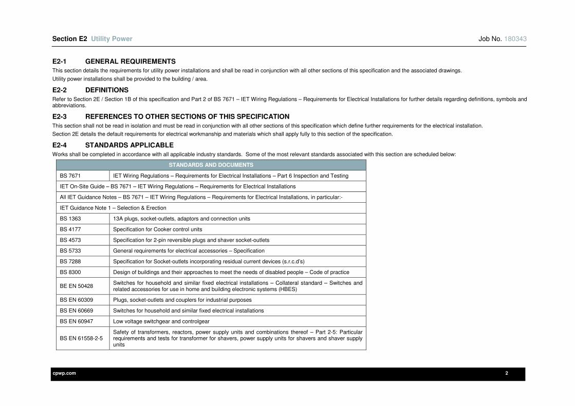
Section E2 Utility Power Job No. 180343
cpwp.com 2
E2-1 GENERAL REQUIREMENTS
This section details the requirements for utility power installations and shall be read in conjunction with all other sections of this specification and the associated drawings.
Utility power installations shall be provided to the building / area.
E2-2 DEFINITIONS
Refer to Section 2E / Section 1B of this specification and Part 2 of BS 7671 – IET Wiring Regulations – Requirements for Electrical Installations for further details regarding definitions, symbols and abbreviations.
E2-3 REFERENCES TO OTHER SECTIONS OF THIS SPECIFICATION
This section shall not be read in isolation and must be read in conjunction with all other sections of this specification which define further requirements for the electrical installation.
Section 2E details the default requirements for electrical workmanship and materials which shall apply fully to this section of the specification.
E2-4 STANDARDS APPLICABLE
Works shall be completed in accordance with all applicable industry standards. Some of the most relevant standards associated with this section are scheduled below:
STANDARDS AND DOCUMENTS
BS 7671 IET Wiring Regulations – Requirements for Electrical Installations – Part 6 Inspection and Testing
IET On-Site Guide – BS 7671 – IET Wiring Regulations – Requirements for Electrical Installations
All IET Guidance Notes – BS 7671 – IET Wiring Regulations – Requirements for Electrical Installations, in particular:-
IET Guidance Note 1 – Selection & Erection
BS 1363 13A plugs, socket-outlets, adaptors and connection units
BS 4177 Specification for Cooker control units
BS 4573 Specification for 2-pin reversible plugs and shaver socket-outlets
BS 5733 General requirements for electrical accessories – Specification
BS 7288 Specification for Socket-outlets incorporating residual current devices (s.r.c.d’s)
BS 8300 Design of buildings and their approaches to meet the needs of disabled people – Code of practice
BE EN 50428 Switches for household and similar fixed electrical installations – Collateral standard – Switches and related accessories for use in home and building electronic systems (HBES)
BS EN 60309 Plugs, socket-outlets and couplers for industrial purposes
BS EN 60669 Switches for household and similar fixed electrical installations
BS EN 60947 Low voltage switchgear and controlgear
BS EN 61558-2-5 Safety of transformers, reactors, power supply units and combinations thereof – Part 2-5: Particular requirements and tests for transformer for shavers, power supply units for shavers and shaver supply units
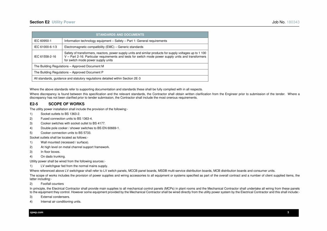
Section E2 Utility Power Job No. 180343
cpwp.com 3
STANDARDS AND DOCUMENTS
IEC 60950-1 Information technology equipment – Safety – Part 1: General requirements
IEC 61000-6-1/3 Electromagnetic compatibility (EMC) – Generic standards
IEC 61558-2-16 Safety of transformers, reactors, power supply units and similar products for supply voltages up to 1 100 V – Part 2-16: Particular requirements and tests for switch mode power supply units and transformers for switch mode power supply units
The Building Regulations – Approved Document M
The Building Regulations – Approved Document P
All standards, guidance and statutory regulations detailed within Section 2E-3
Where the above standards refer to supporting documentation and standards these shall be fully complied with in all respects.
Where discrepancy is found between this specification and the relevant standards, the Contractor shall obtain written clarification from the Engineer prior to submission of the tender. Where a discrepancy has not been clarified prior to tender submission, the Contractor shall include the most onerous requirements.
E2-5 SCOPE OF WORKS
The utility power installation shall include the provision of the following:-
1) Socket outlets to BS 1363-2.
2) Fused connection units to BS 1363-4.
3) Cooker switches with socket outlet to BS 4177.
4) Double pole cooker / shower switches to BS EN 60669-1.
5) Cooker connection units to BS 5733.
Socket outlets shall be located as follows:-
1) Wall mounted (recessed / surface).
2) At high level on metal channel support framework.
3) In floor boxes.
4) On dado trunking.
Utility power shall be wired from the following sources:-
1) LV switchgear fed from the normal mains supply.
Where referenced above LV switchgear shall refer to LV switch panels, MCCB panel boards, MSDB multi-service distribution boards, MCB distribution boards and consumer units.
The scope of works includes the provision of power supplies and wiring accessories to all equipment or systems specified as part of the overall contract and a number of client supplied items, the latter including:-
2) Footfall counters
In principle, the Electrical Contractor shall provide main supplies to all mechanical control panels (MCPs) in plant rooms and the Mechanical Contractor shall undertake all wiring from these panels to the equipment they control. However some equipment provided by the Mechanical Contractor shall be wired directly from the utility power system by the Electrical Contractor and this shall include:-
3) External condensers.
4) Internal air conditioning units.

Section E2 Utility Power Job No. 180343
cpwp.com 4
5) Water heaters.
6) Automatic flushing units.
7) Local extract fans.
8) Kitchen supplies
Where standalone local extract fans are provided the Electrical Contractor shall be responsible for all power and control wiring e.g. standalone extract fans controlled from local lighting circuits / fan speed controllers.
Generally wiring accessories, final connections, cabling and containment systems shall be recessed within the building fabric to provide a flush finish with the exception of surface mounted equipment (e.g. surface dado trunking / bench trunking). However wiring accessories, final connections, cabling and containment systems shall be surface mounted within electrical switch rooms, ceiling voids, service risers, plant rooms and external plant areas.
It shall be noted the above lists are not exhaustive and reference must be made to all sections of this specification and the associated drawings.
All due allowances shall be made within the tender submission to ensure all necessary power supplies, wiring accessories, final connections and associated equipment is provided for the electrical installation, with particular attention paid to electrical systems where the Contractor has design responsibility (where it shall be the Contractor’s responsibility to provide all necessary power supplies e.g. additional power supplies for security systems / fire-fighting and life safety systems).
Where discrepancy is found between the utility power requirements detailed within this specification / drawings and Specialist specifications / drawings (e.g. Kitchen / Laboratory Specialists), written clarification shall be obtained from the Engineer prior to submission of tender. Where a discrepancy has not been clarified prior to tender submission the most onerous requirements shall be included within the tender price.
E2-6 ENGINEERS AND ARCHITECTS DRAWINGS
All power supplies, electrical equipment and wiring accessories shall be set out as detailed on the agreed Architects / Specialists elevation drawings. Where these are not available from the Architect or Specialists, the Electrical Contractor shall produce elevation drawings for approval by the Engineer in a timely manner to suit the construction programme.
However where there is a discrepancy between the Architects / Specialist elevation drawings and the information provided within this specification (e.g. mounting heights) this shall be brought to the attention of the Engineer and Architect / Specialist in a timely manner.
The drawing symbols used on the Engineer’s drawings are not to scale and therefore an allowance shall be made for any of the aforementioned to be relocated within a 1000mm radius of the indicated position at no further cost. These positions shall then be agreed with the Engineer and Architect / Specialist in a timely manner during the contract period.
E2-7 ROOM DATA SHEETS
Room data sheets have not been produced for this works.
E2-8 IDENTIFICATION, NOTICES AND LABELLING
Refer to Section 2E of this specification.
E2-9 CABLE SUPPORT AND CONTAINMENT SYSTEMS / CABLING AND WIRING SYSTEMS
Refer to Section 2E of this specification.
E2-10 WIRING ACCESSORIES
Utility power wiring accessories shall exactly match the appearance of those associated with voice / data, light switches and the like. Thus a common manufacturer and range shall be used for all such, and the Contractor shall inform the Engineer of any anomalies in this respect prior to installation.
Refer to Section 2E of this specification.
E2-11 POSITIONING AND MOUNTING HEIGHTS OF ELECTRICAL SERVICES
Refer to Section 2E of this specification.
Section E2 Utility Power Job No. 180343
cpwp.com 5
E2-12 INSTALLATION RESPONSIBILITY
Appendix II of this section provides a Utility Power – Installation Responsibility Schedule which details the installation responsibilities and methods of connection for the utility power installations.
The Electrical Contractor shall provide all:-
1) Power supplies (including wiring, terminations and cable support / containment systems).
2) Wiring accessories.
3) Final connections from wiring accessories to fixed equipment (including wiring, terminations and cable support / containment systems).
All final connections shall be undertaken using LSZH (LSOH, OHLS) cabling with emissions of hydrogen chloride gas < 0.5%.
Fire-fighting, life safety and security final connections must be installed concealed and / or recessed within the building fabric to provide a flush finish.
Installation responsibilities and final connection details provided within subsequent sections of this specification or detailed on the drawings, shall take precedence over the information provided within Appendix II – Utility Power – Installation Responsibility Schedule.
Where discrepancy is found between the installation responsibilities / methods of final connection detailed in Appendix II and Specialist specifications / drawings, written clarification shall be obtained from the Engineer prior to submission of tender. Where a discrepancy has not been clarified prior to tender submission the most onerous requirements shall be included within the tender price.
E2-13 INSPECTION AND TESTING
The utility power installations shall be inspected and tested in strict accordance with BS 7671 and Section 2F of this specification.
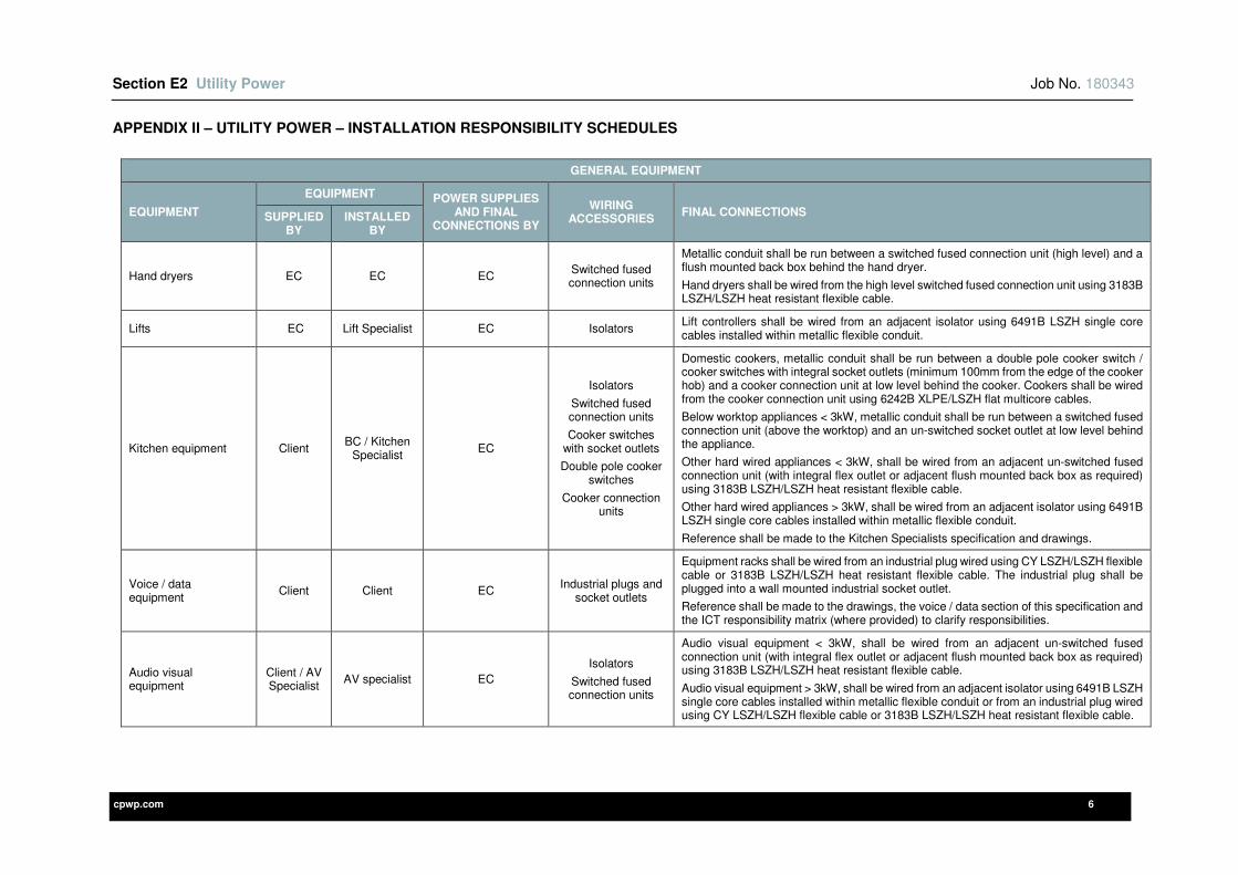
Section E2 Utility Power Job No. 180343
cpwp.com 6
APPENDIX II – UTILITY POWER – INSTALLATION RESPONSIBILITY SCHEDULES
GENERAL EQUIPMENT
EQUIPMENT
EQUIPMENT POWER SUPPLIES AND FINAL
CONNECTIONS BY
WIRING ACCESSORIES
FINAL CONNECTIONS SUPPLIED BY
INSTALLED BY
Hand dryers EC EC EC Switched fused connection units
Metallic conduit shall be run between a switched fused connection unit (high level) and a flush mounted back box behind the hand dryer.
Hand dryers shall be wired from the high level switched fused connection unit using 3183B LSZH/LSZH heat resistant flexible cable.
Lifts EC Lift Specialist EC Isolators Lift controllers shall be wired from an adjacent isolator using 6491B LSZH single core cables installed within metallic flexible conduit.
Kitchen equipment Client BC / Kitchen
Specialist EC
Isolators
Switched fused connection units
Cooker switches with socket outlets
Double pole cooker switches
Cooker connection units
Domestic cookers, metallic conduit shall be run between a double pole cooker switch / cooker switches with integral socket outlets (minimum 100mm from the edge of the cooker hob) and a cooker connection unit at low level behind the cooker. Cookers shall be wired from the cooker connection unit using 6242B XLPE/LSZH flat multicore cables.
Below worktop appliances < 3kW, metallic conduit shall be run between a switched fused connection unit (above the worktop) and an un-switched socket outlet at low level behind the appliance.
Other hard wired appliances < 3kW, shall be wired from an adjacent un-switched fused connection unit (with integral flex outlet or adjacent flush mounted back box as required) using 3183B LSZH/LSZH heat resistant flexible cable.
Other hard wired appliances > 3kW, shall be wired from an adjacent isolator using 6491B LSZH single core cables installed within metallic flexible conduit.
Reference shall be made to the Kitchen Specialists specification and drawings.
Voice / data equipment
Client Client EC Industrial plugs and
socket outlets
Equipment racks shall be wired from an industrial plug wired using CY LSZH/LSZH flexible cable or 3183B LSZH/LSZH heat resistant flexible cable. The industrial plug shall be plugged into a wall mounted industrial socket outlet.
Reference shall be made to the drawings, the voice / data section of this specification and the ICT responsibility matrix (where provided) to clarify responsibilities.
Audio visual equipment
Client / AV Specialist
AV specialist EC
Isolators
Switched fused connection units
Audio visual equipment < 3kW, shall be wired from an adjacent un-switched fused connection unit (with integral flex outlet or adjacent flush mounted back box as required) using 3183B LSZH/LSZH heat resistant flexible cable.
Audio visual equipment > 3kW, shall be wired from an adjacent isolator using 6491B LSZH single core cables installed within metallic flexible conduit or from an industrial plug wired using CY LSZH/LSZH flexible cable or 3183B LSZH/LSZH heat resistant flexible cable.
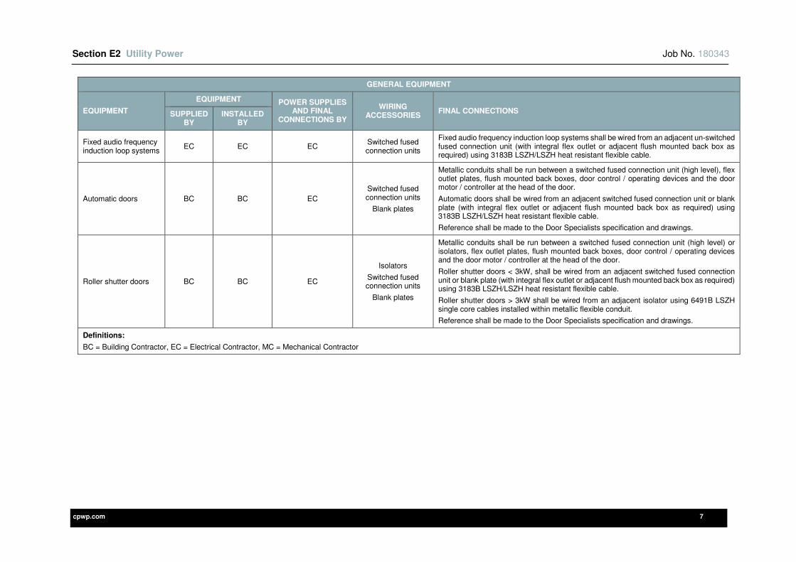
Section E2 Utility Power Job No. 180343
cpwp.com 7
GENERAL EQUIPMENT
EQUIPMENT
EQUIPMENT POWER SUPPLIES AND FINAL
CONNECTIONS BY
WIRING ACCESSORIES
FINAL CONNECTIONS SUPPLIED BY
INSTALLED BY
Fixed audio frequency induction loop systems
EC EC EC Switched fused connection units
Fixed audio frequency induction loop systems shall be wired from an adjacent un-switched fused connection unit (with integral flex outlet or adjacent flush mounted back box as required) using 3183B LSZH/LSZH heat resistant flexible cable.
Automatic doors BC BC EC
Switched fused connection units
Blank plates
Metallic conduits shall be run between a switched fused connection unit (high level), flex outlet plates, flush mounted back boxes, door control / operating devices and the door motor / controller at the head of the door.
Automatic doors shall be wired from an adjacent switched fused connection unit or blank plate (with integral flex outlet or adjacent flush mounted back box as required) using 3183B LSZH/LSZH heat resistant flexible cable.
Reference shall be made to the Door Specialists specification and drawings.
Roller shutter doors BC BC EC
Isolators
Switched fused connection units
Blank plates
Metallic conduits shall be run between a switched fused connection unit (high level) or isolators, flex outlet plates, flush mounted back boxes, door control / operating devices and the door motor / controller at the head of the door.
Roller shutter doors < 3kW, shall be wired from an adjacent switched fused connection unit or blank plate (with integral flex outlet or adjacent flush mounted back box as required) using 3183B LSZH/LSZH heat resistant flexible cable.
Roller shutter doors > 3kW shall be wired from an adjacent isolator using 6491B LSZH single core cables installed within metallic flexible conduit.
Reference shall be made to the Door Specialists specification and drawings.
Definitions:
BC = Building Contractor, EC = Electrical Contractor, MC = Mechanical Contractor
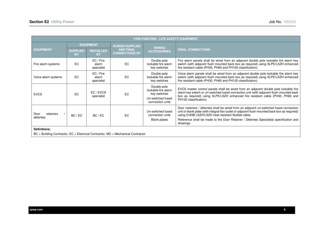
Section E2 Utility Power Job No. 180343
cpwp.com 8
FIRE-FIGHTING / LIFE SAFETY EQUIPMENT
EQUIPMENT
EQUIPMENT POWER SUPPLIES AND FINAL
CONNECTIONS BY
WIRING ACCESSORIES
FINAL CONNECTIONS SUPPLIED BY
INSTALLED BY
Fire alarm systems EC EC / Fire
alarm specialist
EC Double pole
lockable fire alarm key switches
Fire alarm panels shall be wired from an adjacent double pole lockable fire alarm key switch (with adjacent flush mounted back box as required) using XLPE/LSZH enhanced fire resistant cable (PH30, PH60 and PH120 classification).
Voice alarm systems EC EC / Fire
alarm specialist
EC Double pole
lockable fire alarm key switches
Voice alarm panels shall be wired from an adjacent double pole lockable fire alarm key switch (with adjacent flush mounted back box as required) using XLPE/LSZH enhanced fire resistant cable (PH30, PH60 and PH120 classification).
EVCS EC EC / EVCS specialist
EC
Double pole lockable fire alarm
key switches
Un-switched fused connection units
EVCS master control panels shall be wired from an adjacent double pole lockable fire alarm key switch or un-switched fused connection unit (with adjacent flush mounted back box as required) using XLPE/LSZH enhanced fire resistant cable (PH30, PH60 and PH120 classification).
Door retainers / détentes
BC / EC BC / EC EC
Un-switched fused connection units
Blank plates
Door retainers / détentes shall be wired from an adjacent un-switched fused connection unit or blank plate (with integral flex outlet or adjacent flush mounted back box as required) using 3183B LSZH/LSZH heat resistant flexible cable.
Reference shall be made to the Door Retainer / Détentes Specialists specification and drawings.
Definitions:
BC = Building Contractor, EC = Electrical Contractor, MC = Mechanical Contractor
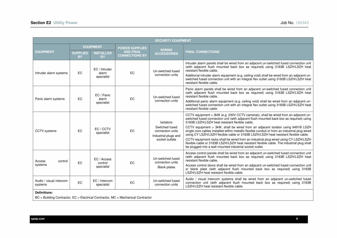
Section E2 Utility Power Job No. 180343
cpwp.com 9
SECURITY EQUIPMENT
EQUIPMENT
EQUIPMENT POWER SUPPLIES AND FINAL
CONNECTIONS BY
WIRING ACCESSORIES
FINAL CONNECTIONS SUPPLIED BY
INSTALLED BY
Intruder alarm systems EC EC / Intruder
alarm specialist
EC Un-switched fused connection units
Intruder alarm panels shall be wired from an adjacent un-switched fused connection unit (with adjacent flush mounted back box as required) using 3183B LSZH/LSZH heat resistant flexible cable.
Additional intruder alarm equipment (e.g. ceiling void) shall be wired from an adjacent un-switched fused connection unit with an integral flex outlet using 3183B LSZH/LSZH heat resistant flexible cable.
Panic alarm systems EC EC / Panic
alarm specialist
EC Un-switched fused connection units
Panic alarm panels shall be wired from an adjacent un-switched fused connection unit (with adjacent flush mounted back box as required) using 3183B LSZH/LSZH heat resistant flexible cable.
Additional panic alarm equipment (e.g. ceiling void) shall be wired from an adjacent un-switched fused connection unit with an integral flex outlet using 3183B LSZH/LSZH heat resistant flexible cable.
CCTV systems EC EC / CCTV specialist
EC
Isolators
Switched fused connection units
Industrial plugs and socket outlets
CCTV equipment < 3kW (e.g. 230V CCTV cameras), shall be wired from an adjacent un-switched fused connection unit (with adjacent flush mounted back box as required) using 3183B LSZH/LSZH heat resistant flexible cable.
CCTV equipment > 3kW, shall be wired from an adjacent isolator using 6491B LSZH single core cables installed within metallic flexible conduit or from an industrial plug wired using CY LSZH/LSZH flexible cable or 3183B LSZH/LSZH heat resistant flexible cable.
CCTV equipment racks shall be wired from an industrial plug wired using CY LSZH/LSZH flexible cable or 3183B LSZH/LSZH heat resistant flexible cable. The industrial plug shall be plugged into a wall mounted industrial socket outlet.
Access control systems
EC EC / Access
control specialist
EC
Un-switched fused connection units
Blank plates
Access control panels shall be wired from an adjacent un-switched fused connection unit (with adjacent flush mounted back box as required) using 3183B LSZH/LSZH heat resistant flexible cable.
Access control doors shall be wired from an adjacent un-switched fused connection unit or blank plate (with adjacent flush mounted back box as required) using 3183B LSZH/LSZH heat resistant flexible cable.
Audio / visual intercom systems
EC EC / Intercom
specialist EC
Un-switched fused connection units
Audio / visual intercom systems shall be wired from an adjacent un-switched fused connection unit (with adjacent flush mounted back box as required) using 3183B LSZH/LSZH heat resistant flexible cable.
Definitions:
BC = Building Contractor, EC = Electrical Contractor, MC = Mechanical Contractor

Section E2 Utility Power Job No. 180343
cpwp.com 10
MECHANICAL SERVICES EQUIPMENT
EQUIPMENT
EQUIPMENT POWER SUPPLIES AND FINAL
CONNECTIONS BY
WIRING ACCESSORIES
FINAL CONNECTION SUPPLIED BY
INSTALLED BY
Electric heating systems < 3kW
EC EC EC Switched fused connection units with flex outlets
Electric heaters shall be wired from an adjacent switched fused connection unit with an integral flex outlet using 3183B LSZH/LSZH heat resistant flexible cable or manufacturers’ proprietary cabling.
Local extract fans MC MC EC Flex outlets
Metallic conduit shall be run between a three pole fan isolator (above the entrance door to the room) and a flex outlet within the ceiling void adjacent to the extract fan.
Local extract fans shall be wired from an adjacent flex outlet using 3183B LSZH/LSZH heat resistant flexible cable or manufacturers’ proprietary cabling.
Mechanical control panels (MCPs) > 3kW
MC MC EC Isolators Mechanical control panels > 3kW shall be wired from an adjacent isolator using 6491B LSZH single core cables installed within metallic flexible conduit.
Mechanical control panels < 3kW
MC MC EC Switched fused connection units
Mechanical control panels < 3kW shall be wired from an adjacent switched fused connection unit (with adjacent flush mounted back box as required) using 3183B LSZH/LSZH heat resistant flexible cable.
External condensers MC MC EC Isolators External condensers shall be wired from an adjacent isolator using 6491B LSZH single core cables installed within metallic flexible conduit.
Internal air conditioning units
MC MC EC Switched fused connection units with flex outlets
Internal air conditioning units shall be wired from an adjacent switched fused connection unit with an integral flex outlet using 3183B LSZH/LSZH heat resistant flexible cable.
Water heaters MC MC EC Switched fused connection units with flex outlets
Water heaters shall be wired from an adjacent switched fused connection unit (with integral flex outlet or adjacent flush mounted back box as required) using 3183B LSZH/LSZH heat resistant flexible cable.
Sensor taps MC MC EC Flex outlets
Metallic conduit shall be run between a switched fused connection unit (high level) and a flex outlet below the wash basin.
Sensor taps shall be wired from an adjacent flex outlet using 3183B LSZH/LSZH heat resistant flexible cable or manufacturers’ proprietary cabling.
Automatic flushing units
MC MC EC Flex outlets
Metallic conduit shall be run between a switched fused connection unit (high level) and a flex outlet behind the IPS.
Automatic flushing units shall be wired from an adjacent flex outlet using 3183B LSZH/LSZH heat resistant flexible cable or manufacturers’ proprietary cabling.
Definitions:
BC = Building Contractor, EC = Electrical Contractor, MC = Mechanical Contractor

cpwp.com V2.1
Section E3 Internal, External and Emergency Lighting
Section E3 Internal, External and Emergency Lighting Job No. 180343
cpwp.com 1
Contents Page
E3-1 GENERAL REQUIREMENTS 2
E3-2 DEFINITIONS 2
E3-3 REFERENCES TO OTHER SECTIONS OF THIS SPECIFICATION 2
E3-4 STANDARDS APPLICABLE 2
E3-5 DESIGN REQUIREMENTS 3
E3-6 LUMINAIRE SCHEDULE / DOCUMENTATION 3
E3-7 3D BIM 4
E3-8 PLANNING CONDITIONS / BREEAM 4
E3-9 SCOPE OF WORKS 4
E3-10 INTERNAL LIGHTING 4
E3-11 EMERGENCY LIGHTING 6
E3-12 EXTERNAL LIGHTING 7
E3-13 LIGHTING CONTROLS 7
E3-14 COMMISSIONING, MAINTENANCE FAMILIARISATIONS AND TRAINING 8
E3-15 ENGINEERS AND ARCHITECTS DRAWINGS 8
E3-16 ROOM DATA SHEETS 8
E3-17 IDENTIFICATION, NOTICES AND LABELLING 8
E3-18 CABLE SUPPORT AND CONTAINMENT SYSTEMS 8
E3-19 WIRING ACCESSORIES 8
E3-20 POSITIONING AND MOUNTING HEIGHT OF ELECTRICAL SERVICES 8
E3-21 INSPECTION AND TESTING 9

Section E3 Internal, External and Emergency Lighting Job No. 180343
cpwp.com 2
E3-1 GENERAL REQUIREMENTS
This section details the requirements for internal, external and emergency lighting and shall be read in conjunction with all other sections of this specification and the associated drawings.
The lighting systems shall be selected, installed, tested and commissioned in strict accordance with manufacturer’s recommendations and the standards detailed below.
The Contractor shall supply, install, test and commission lighting systems that are complete and fully functional.
Reference shall be made to the complete tender documentation package including architect’s layouts, ceiling types/finishes, room dimensions, wall finishes and other relevant specifications.
The lighting systems required for this project shall be as follows:-
1) Internal lighting.
2) External lighting.
3) Emergency lighting.
E3-2 DEFINITIONS
Refer to Section 2E / Section 1B of this specification and Part 2 of BS 7671 – IET Wiring Regulations – Requirements for Electrical Installations for further details regarding definitions, symbols and abbreviations.
Other definitions specifically associated with Lighting are as follows:
Absence detection Where lights that have been turned on via a user interface are automatically turned off once an area has been vacated
Architectural lighting control
A control system that is used in conjunction with light sources to enhance a buildings architectural features or to create a particular ambiance in a space
DALI Digital Addressable Lighting Interface
DALI broadcast Where Dali signals are transmitted from a device in an unaddressed format
Daylight harvesting A technique where natural daylight passing into a space through windows and skylights is used to allow a reduction in the amount of artificial light provided
Illuminance The density of the luminous flux incident on a surface, measured in lux
LED tell back A visible indication of the selected button of a control panel by the use of an LED
Grouping A number of luminaires or circuits which are configured in software to work cooperatively
Luminaire A light fixture containing one or more light sources
Presence Detection Where a sensor is used to turn lights on when presence is detected within the sensor coverage area, and off again once the area is vacated
Scene Control Panels Programmable multi button user interface
Scheduler An automatic programme which generates system event commands according to the time of day
Sensors Devices for detecting presence or light level etc.
E3-3 REFERENCES TO OTHER SECTIONS OF THIS SPECIFICATION
This section shall not be read in isolation and must be read in conjunction with all other sections of this specification which define further requirements for the electrical installation.
Section 2E details the default requirements for electrical workmanship and materials which shall apply fully to this section of the specification.
E3-4 STANDARDS APPLICABLE
Works shall be completed in accordance with all applicable industry standards. Some of the most relevant standards associated with this section are scheduled below:
STANDARDS AND DOCUMENTS
BS 7671 IET Wiring Regulations – Requirements for Electrical Installations
IET On-Site Guide – BS 7671 – IET Wiring Regulations – Requirements for Electrical Installations
All IET Guidance Notes – BS 7671 – IET Wiring Regulations – Requirements for Electrical Installations
The Society of Light and Lighting – The SLL Code for Lighting
All current and relevant SLL / CIBSE Lighting Guides
BS 5266 Emergency lighting
BS 5489 Car Park Lighting

Section E3 Internal, External and Emergency Lighting Job No. 180343
cpwp.com 3
STANDARDS AND DOCUMENTS
BS 5499 Safety signs and fire safety notices
BS 8206-2 Lighting for buildings – Part 2: Code of practice for daylighting
BS 8300 Design of buildings and their approaches to meet the needs of disabled people – Code of practice
BS 8493 Lighting reflectance value (LRV) of a surface – Method of test
BS 8519 Selection and installation of fire-resistant power and control cable systems for life safety and fire-fighting applications – Code of practice
BS 9999 Code of practice for fire safety in the design, management and use of buildings
BS EN 1838 Lighting applications – Emergency lighting
BS EN 12193 Lighting and lighting – Sports lighting
BS EN 12464 Lighting and lighting – Lighting of work places
BS EN 13201 Road lighting
BS EN 15193 Energy performance of buildings – Energy requirements for lighting
BS EN 60598 Luminaires
BS EN 60669 Switches for household and similar fixed electrical installations
BS EN 62031 LED modules for general lighting (Safety Specification)
BS EN 62717 LED modules for general lighting (Performance requirements)
ICEL 1006 Emergency lighting design guide
Building Bulletin 90 – Lighting design for schools by the DfEE (Department for Education and Employment)
BRE (Building Research Establishment) – Digest 529 – Obtrusive lighting from proposed developments
ILP (Institution of Lighting Professionals) – Guidance notes for the reduction of obtrusive light GN01
ILP (Institution of Lighting Professionals) / SBD (Secured by Design) – Lighting against crime – A guide for crime reduction professionals
National Calculation Methodology (NCM) modelling guide
Sport England – Design guidance note – Artificial sports lighting
The Building Regulations – Approved Document L
The Building Regulations – Approved Document M
The Building Regulations – Non-Domestic and Domestic Building Services Compliance Guides
All current and relevant Building Bulletin’s by the DfES (Department for Education and Skills) and other government agencies
All current and relevant BRE (Building Research Establishment), EFA (Education Funding Agency), ICEL (The industry Committee for Emergency Lighting), ILP (Institution of Lighting Professionals) and SBD (Secured by Design) publications
All standards, guidance and statutory regulations detailed within Section 2E-3
Where the above standards refer to supporting documentation and standards these shall be fully complied with in all respects.
Where discrepancy is found between this specification and the relevant standards, the Contractor shall obtain written clarification from the Engineer prior to submission of the tender. Where a discrepancy has not been clarified prior to tender submission, the Contractor shall include the most onerous requirements.
E3-5 DESIGN REQUIREMENTS
The Contractor shall provide manufacturer’s lighting design calculations for any proposed luminaire selections that differ from the ones shown in the tender documentation to demonstrate an equivalent level of performance.
Any such alternatives shall only be used if agreed in writing with the Engineer.
E3-6 LUMINAIRE SCHEDULE / DOCUMENTATION
Manufacturers, product ranges and materials given in the appendices to this section shall be included in the tender submission.
Where possible a number of suppliers have been given for items of equipment to give a reasonable choice to the Contractor. However where a single specialist, manufacturer, product range or material is specified, this may be due to:-
1) Alternatives not being available which are equivalent.
2) The need to match existing standards.
3) Outright specification by the Client.
Therefore alternatives shall not be acceptable without written agreement from the Engineer. Reference shall also be made to Section 1B with regards to the proposal of alternative equipment.
Section E3 Internal, External and Emergency Lighting Job No. 180343
cpwp.com 4
E3-7 3D BIM
The Contractor shall refer to the complete tender package including, where provided, 3D BIM models. These may also contain specifications for finishes, reflectances, room dimensions (including heights) and ceiling types/finishes. The Contractor shall also refer to Architect's models and tender information.
The Contractor shall review the tender information as noted above and refer any anomalies to the Engineer for clarification during the tender period.
The Contractor shall note that not all manufacturers’ products are available as .RVT families and therefore other manufacturers’ models may have been inserted to assist. However whilst these manufacturers may be named in the Revit model, the Contractor must only use the products that are specified within the luminaire schedules along with this specification.
E3-8 PLANNING CONDITIONS / BREEAM
The Contractor shall provide all necessary information to confirm that planning conditions and/or required BREEAM credits have been achieved.
E3-9 SCOPE OF WORKS
The lighting systems installation shall include the provision of the following (where required):-
1) Internal lighting including:-
a) Luminaires.
b) Lighting controls (e.g. presence / absence detection, daylight sensors etc.).
c) Scene selection switch panels / plates.
d) Lighting control modules (LCM’s).
e) Handheld programmers.
2) External lighting.
a) Building mounted perimeter luminaires.
b) Bollard luminaires.
3) Emergency lighting:-
a) Luminaires.
4) All systems shall include the following:-
a) All necessary attachments, fixings and connectors.
b) All necessary wiring accessories e.g. light switches, data outlets, switched fused connection units etc.
c) All necessary power and signalling cabling.
d) All necessary earthing and bonding.
e) All necessary cable support and containment systems.
f) Inspection, testing and commissioning.
g) All necessary identification, notices and labelling.
h) All necessary O&M information.
It shall be noted the above lists are not exhaustive and reference must be made to all sections of this specification and the associated drawings.
All due allowances shall be made within the tender submission to ensure that all necessary power supplies, wiring accessories and associated equipment are provided for the electrical installation, with particular attention paid to electrical systems where the Contractor has design responsibility.
E3-10 INTERNAL LIGHTING
GENERAL REQUIREMENTS
The internal lighting installation shall be as detailed in this specification and the associated drawings.
The basic requirements are as follows:
LUMINAIRES
All luminaires shall be supplied complete with the necessary attachments to enable them to be installed and operated as intended. Attachments refers to all fixings such as clips, wall brackets, ceiling brackets, column spigots, gaskets, seals, frames, flanges, toggles and locks, covers, diffusers, glassware, reflectors and optical components.
All reflectors shall be iridescent free.
All luminaires shall be fully compatible with the ceiling type. The Contractor shall provide information on the ceiling types to luminaire manufacturers and ensure that the correct flanges, gaskets, frames, fixings etc. are included. Any incompatible luminaires shall be highlighted to the Engineer to enable re-specification.
Any gaskets shall be non-perishable type and shall provide the ingress protection level specified and be fit for the required purpose. Gaskets shall fit securely within the products and be retained during lamp replacements when covers are removed.
All optical components such as reflectors and louvers shall be correctly earthed as appropriate, and be securely fixed to the body by retainers such that it is impossible for any attachment to fall free from the body. These retainers and fixings shall not be visible when the luminaire is assembled in its installed position.
All luminaires shall be complete with lamps/light engines.
All light sources shall:
1) Be from leading manufacturers/brands
Section E3 Internal, External and Emergency Lighting Job No. 180343
cpwp.com 5
2) Have a correlated colour temperature of 4000K unless otherwise detailed.
3) Have a colour rendering index >Ra80 unless otherwise detailed
4) If fluorescent, have tri-phosphor coatings
5) If linear fluorescent, have a minimum life expectancy of 40,000 hours e.g. Aura T5 Eco Saver long life
6) If fluorescent, be from a common manufacturer across the entire project
7) If LED, be selected from bins within 3 MacAdam steps for consistent colour appearance
All luminaires shall be manufactured and tested in full compliance with BS EN 60598. All LED modules for general lighting shall comply with BS EN 62031 and BS EN 62717.
All LED products shall have longevity of at least L80 @ 50,000 hours (20% lumen depreciation), tested to LM80 and TM21 calculation process. Failure rate expectancy shall be less than 50% at 50,000 hours.
All LED lighting products shall be covered by a minimum 5 year warranty provided by the Contractor. This shall include the luminaire, lamps and LED driver electronics.
All luminaires shall be complete with compatible control gear which shall:
1) Have a power factor of 0.9 or better
2) Limit protective conductor current to <0.7mA per luminaire
3) Be integral to the luminaire unless otherwise detailed
4) If fluorescent, be of high frequency type
5) Be digital addressable, DALI type
6) Facilitate dimming down to 1% of full output
7) Be fully compatible with the lighting control system/lighting control devices
The Contractor shall provide 1No. sample of each of the luminaires specified for consideration by the Client/Architect. This procedure shall be completed early in the contract period to ensure delivery of all luminaires to suit the Main Contractor’s programme.
INSTALLATION REQUIREMENTS
Prior to commencing any first fix operations, exact setting out of all components forming the lighting system shall be agreed and confirmed with the Engineer and the Architect. The Contractor shall allow within their tender for relocating items of equipment within 3m of the positions detailed on the layout drawings.
The Contractor shall ensure that no luminaires, switches, sensors etc. are damaged / spoiled by decoration, finishes or other trades. In the event of any damage, the units shall be replaced at no cost to the Employer such that the installation is new at the day of handover. The Contractor is thus advised not to install luminaires prior to decoration.
All optical components and decorative glassware etc. shall be in perfect condition upon project completion and thus clean and free from any blemishes / fingerprints. Gloves must be worn when handling luminaires and lamps.
The installation shall not be used for temporary / site lighting.
All luminaires and lighting controls shall be installed in strict accordance with the individual lighting manufacturer’s literature, wiring schematics and recommendations. Where cable connections are made into equipment, a numbered marker sleeve shall be fitted to the cable-core, which shall correspond to the wiring diagram.
Cable tails to terminals shall be of sufficient length and be neatly dressed and arranged to prevent development of tension in the cable or on the termination. All cables shall be securely tethered within enclosures. Ensure that all wiring connections are correctly made before any equipment is set to work.
The Contractor shall supply and install all light switches and lighting control modules as shown on the layout drawings and room data sheets (where provided). Switches shall:
1) Be 20 Amp rated if operating at 230V
2) Include proprietary phase barriers and DANGER 400V labels where more than one phase present
All wiring, containment and accessory boxed shall be flush, i.e. concealed within the building fabric, apart from plantrooms, risers, ceiling voids and other specifically noted areas.
All power and signalling cabling shall be LSZH (LS0H, 0HLS) with emissions of hydrogen chloride gas < 0.5%.
Fixing arrangements for luminaires shall be as follows:
3) Modular or linear luminaires within suspended ceilings shall be fixed using manufacturers’ proprietary side arm brackets. Modular or linear luminaires below suspended ceilings shall be fixed using proprietary T bar clips. In both cases a supplementary steel wire fixing (gripple wire) back to the soffit shall be provided to prevent the luminaire from falling if the ceiling is removed.
4) Small recessed luminaires e.g. downlights located in suspended ceilings shall be supported by means of a plywood pattress fitted to the back of the ceiling tile. A suitable hole shall be provided through the tile and liner so that the fitting can be fixed using the standard manufacturers support clip.
5) Suspended luminaires shall be supported using luminaire manufacturers’ proprietary fixings in strict accordance with their recommendations, in particular regarding spacings. Where suspended luminaires are continuous linear systems the Contractor shall provide all necessary proprietary coupler joints and infills to ensure a continuous installation.
6) Surface luminaires below plasterboard ceilings shall be supported from the conduit system. The conduit boxes shall finish flush with the underside of the ceiling and additional extension rings shall be provided as necessary to achieve this.
7) Recessed luminaires in plasterboard ceilings shall be supported from the ceiling using spring clips or bracket arms on the luminaire. To spread the weight and prevent damage to the plasterboard, the aperture shall be trimmed using plywood panels (small aperture) or wooden battens (large aperture).
8) Wall mounted luminaire shall be fixed directly to conduit boxes flushed into the wall behind.
Section E3 Internal, External and Emergency Lighting Job No. 180343
cpwp.com 6
9) Surface luminaires in plantrooms, risers and other locations when a surface conduit system is present shall be fixed directly to conduit boxes.
In plantrooms the luminaire locations shall be determined on site to suit the final plant layout and optimise illumination at locations of equipment that require maintenance. Where this requires suspension, conduit drops from ball joints shall be used to support the luminaires.
Care shall be taken to carefully co-ordinate all ceiling mounted equipment with the Building Contractor, particularly those that require cutting of the ceiling tile. In all cases a plywood support shall be provided behind the ceiling tile, supported from the grid.
Final connection of power and data to luminaires shall be as follows:
1) Luminaires in areas with suspended ceilings shall be fed via plug-in devices and multi-core heat resisting 0.5mm² flexes, connected directly to individual conduit boxes located within the ceiling voids no more than 300mm horizontally or vertically from the luminaire.
2) Luminaires on walls or non-demountable ceilings shall be connected directly to the fixed wiring, using UV stabilised heat proof sheathing where recommended by the manufacturer.
3) Luminaires in plantrooms and other areas with surface conduit shall be connected directly to the fixed wiring systems via the conduit.
4) Suspended luminaire shall be connected via flex or as detailed on the drawings. Where continuous, the luminaire system shall include through wiring and proprietary connectors to minimise feed points from the fixed wiring. Additional dummy lengths shall be provided to conceal these feed points to the extent possible.
Where a plug-in device is used this shall provide both power and data connection from a single plug/socket, with insulation suitable for LV on all cores. However the data wiring shall be contained in separate containment up to a point immediately adjacent to the connector.
Where wired direct from the containment system the power and data shall have separate entry points into the luminaire.
E3-11 EMERGENCY LIGHTING
Emergency lighting shall be provided in strict accordance with BS 5266, BS EN 1838, ICEL 1006 and CIBSE Lighting Guide 12: Emergency Lighting Design Guide. The installation shall comply with relevant clauses on the IET Wiring Regulations. The mode of operation i.e. non-maintained and maintained shall be in full compliance with the current British Standards
A 3 hour duration system shall be provided throughout.
The Contractor shall employ the system manufacturer to validate the design for the entire emergency lighting system.
This shall include calculations to check that illumination levels and uniformity limits recommended by BS 5266 will be achieved in both horizontal and vertical planes on all:
• Escape routes
• Hazard locations
• Open plan areas
• Fire alarm panels
• Reception areas
• Points of emphasis
• All other key areas listed in BS 5266.
Luminous intensity and mounting heights shall be checked to ensure that the limits given BS 1838 are not exceeded
In larger open areas the emergency luminaires shall have open area optics and in circulation routes then the corridor optics shall be used.
At least one self-contained emergency luminaire shall be provided at each external muster point around the building/site and along the access route to the same. They may be on a car park lighting column or similar so it illuminates when the power to the lighting column is lost. Note that this may need an additional cable to the column to provide a permanent live from the external lighting feeder pillar so the emergency light is not on during the day.”
The layout drawings and/or REVIT model show indicative locations for emergency lighting but the Contractor is fully responsible for setting these out accurately as part of the working drawings to ensure that the limiting distances and illumination levels required by the stated standards are achieved.
Commissioning shall be carried out in accordance with the recommendations of the standards listed above and the system manufacturer. This shall include:
• Illumination levels check based on authenticated design data
• Visual check that a luminaire is provided close to all points of emphasis listed in BS 5266
• Functional test of all luminaires on failure of local circuit
• Duration test for all luminaires
At a date to be agreed the Contractor shall repeat the full test on the emergency lighting installation in the presence of the Employer and the consulting engineer.
For the escape routes, exit signage is to be internally illuminated such that viewing distances are increased compared to non-self-illuminated signage. These shall be provided in accordance with the signage requirements detailed on the agreed Fire Plan.
Emergency lighting shall be provided throughout the installation by means of self-contained fittings, or by conversion units fitted to the main fittings.
All emergency luminaires shall be provided within a clearly visible light to indicate that the fitting is in a healthy condition. In the case of luminaires containing conversion units, this shall be securely fitted to the flange or other location such that it is clearly visible when the luminaire is normally energised.
Section E3 Internal, External and Emergency Lighting Job No. 180343
cpwp.com 7
Final connections to emergency light fittings shall be by 4 pole plug-in ceiling roses and 4-core heat resisting flex.
Where conversion units are used, these shall be factory assembled by the manufacturer of the general luminaire. It shall not be permissible for the units to be made up on site. Interconnections between remote conversion units and light fittings shall be via factory made looms, not by loose wiring.
A label shall be fixed to the face of the internal reflector for each emergency luminaire which shall read ‘DANGER – ISOLATE ELSEWHERE BEFORE REMOVING COVER’ this shall also be repeated on the cover plate of each remote conversion pack.
Manufacturer’s recommendations / restrictions regarding distances between luminaires and remote conversion units are to be strictly adhered to, as are all other manufacturers’ recommendations relating to cabling, etc.
The Contractor shall be responsible for ensuring compatibility of conversion units to luminaires prior to tendering. Any discrepancies shall be reported to the Engineer.
Test and isolation key switches shall be provided for the emergency lighting installation and shall isolate the pilot live cable only, enabling testing while normal lights are still operating. These shall be located:
• Adjacent to the distribution board
Each emergency luminaire will require a test sheet on completion. These shall be incorporated into the O & M documentation and shall cover a projected 12 month period. Each luminaire shall be given a unique number referenced on the sheet.
E3-12 EXTERNAL LIGHTING
The Contractor shall provide a complete and operational external lighting installation as described and in the clauses below.
The installation shall consist of a combination of building mounted luminaires to illuminate entrances, perimeter of the buildings and the main circulation routes throughout the proposed site. The lighting design provides a low energy, low pollution and low glare solution. This shall be achieved by using the specified high quality lighting products.
All external lighting (except for safety and security lighting) shall be automatically switched off between 23:00 and 07:00. Safety and security lighting is provided and will be used between 23:00 and 07:00, during these hours this shall be dimmed down to ensure they are in accordance with Table 2 of the ILP’s Guidance notes.
The external lighting installations shall be controlled via photocell and time switch arrangements, such that the lighting will come on and off at pre-set levels and can be over-ridden ‘off’ by the time switch, if required. An override ‘on’ switch shall also be provided where necessary within the associated electrical switch room. The time clock(s) shall be of the Sangamo solar dial range complete with automatic daylight savings facility.
INSTALLATION
The Electrical Contractor shall co-ordinate with the Main Contractor during the tender period, the builders work requirements associated with the external Lighting layouts.
The luminaires shall be installed in line with the manufacturer’s recommendations and the details given below. In the event of any anomalies, the Electrical Contractor shall bring these to the Engineer’s attention during the tender period and in the absence of clarification shall allow for the more onerous option.
In general, column luminaires shall be root mounted and shall be cast into suitable concrete bases complete with slow radius bend PVC ducts allowing cables to be routed through the bottom of the luminaires. A sleeve shall first be installed and concreted into place then the columns installed into the sleeve and backfilled.
All columns, bollards and buried up lights shall be provided with drainage even if they are provided with gaskets. This shall consist of 300mm of screed below the fitting or as otherwise advised by the luminaire manufacturer.
All ducting installations required out from the building and to serve all external Lighting points shall be co-ordinated by the Electrical Contractor with the Main Contractor. All penetrations through the building fabric shall be fully and neatly sealed at both ends and be as small cross sectional area as possible. All ducts shall be water and vermin sealed.
All underground cabling shall be XLPE/SWA/PVC type with copper conductors. Underground cabling shall be installed within a ducting system with strategically sited access chambers. The cabling and ducting shall be buried the depths indicated in this specification and associated drawings and as a minimum be in accordance with National Joint Utilities Guidance suitable for the voltages of the installation.
The armoured cables shall be terminated at each column by the proprietary cable accessories and fused street Lighting cut outs in each column. Final connections to control gear and lamps shall be via flexible heat resistant cables.
Access chamber pits shall be provided, one for each lighting column to allow future maintenance. The pits may have lids that match the surface treatment of the surrounding paving / ground finish.
The exact location of all external lighting shall be agreed on site, prior to installation, taking into account the Architect’s scheme.
The Contractor shall allow within tender to demonstrate the lighting system to the Engineer during a night period, to verify the correct system of operation and lighting levels by measurement.
E3-13 LIGHTING CONTROLS
GENERAL REQUIREMENTS
The Contractor shall supply, install, test and commission a complete lighting control system as detailed on the drawings and the clauses below:
All spaces shall include light level sensing and automatic adjustment of the luminaire light output to maintain the lux levels given. Where possible combined presence/light level sensors shall be used.
The Contractor shall coordinate the sensors with the luminaire manufacturers to ensure compatibility.
The Contractor shall, in conjunction with their lighting controls specialist, validate all sensor locations shown to ensure that detection is optimised and dead spots avoided. He shall advise if any additional detectors are needed. All sensors shall have adjustable detection patterns. Ceiling mounted sensor shall give 360° coverage.
Section E3 Internal, External and Emergency Lighting Job No. 180343
cpwp.com 8
Where possible sensors shall be recessed into the ceiling systems. Where continuous runs of luminaires are shown the sensors shall be incorporated into the infill panels. Surface mounted sensors shall be used in spaces with surface mounted conduit.
Where microwave sensors are shown in corridors these shall be positioned to ensure that a person entering the corridor at any point along its length will be detected.
STANDALONE CONTROLS
The lighting control system shall utilise a combination of manual switching, retractive switching and programmable intelligent devices (e.g. presence detectors, daylight sensors etc.), without the need for full network interconnection or PC based end-user management software.
COMMISSIONING
The Contractor shall ensure that the lighting controls manufacturer is employed to test and commission the entire lighting control system in accordance with client’s operational requirements. Provide a full schedule of options and parameters enable discussion and agreement of these operational requirements.
The range and detection pattern on each sensor shall be adjusted to suit the location and minimise erroneous detection from adjacent areas.
Following successful commissioning and prior to Practical Completion, the lighting controls manufacturer shall also undertake demonstrations and teaching to the Client’s nominated staff to enable them to make minor changes as and when required.
E3-14 COMMISSIONING, MAINTENANCE FAMILIARISATIONS AND TRAINING
All equipment shall be tested and inspected prior to the systems being offered to the Engineer and the Client. A fully functional test shall be demonstrated before any certification is accepted on behalf of the Client.
The lighting systems and associated controls will require a considerable period of time to commission. The Electrical Contractor shall ensure that sufficient time is allowed in the Main Contractor’s programme to fully commission the systems in line with this specification and to the satisfaction of the Engineer. The control system manufacturer (specialist) shall be employed to set up and commission their controls and it is emphasised that this shall not be undertaken until all other works in the spaces have been completed, (thus allowing the spaces to be cleared of other workers.)
The Contractor shall, immediately following handover, carry out familiarisations and training to Client staff and maintenance personnel. At least 2 full days shall be allowed for both the Electrical Contractor and their specialists to carry out systems familiarisations (Day 1), followed by system training (Day 2). The Contractor shall co-ordinate these dates with the Client, and to supervise each training day session given. The Contractor shall also manage his specialists on each day, provide an agenda for training to be given 1 week prior to the site visit, and on each day formally record all those in attendance, and at the end of each session record Q&A.
The Contractor shall also allow for 2 whole day visits by the controls specialist for any programming modification/adaptation to the installed systems around the time just after handover. This will enable any Client fine tuning required to complete the system. After this a further 3 days float shall be allowed for. These 3 days may not be taken up immediately after handover and allowance should be made for them during the first year. These are for any Client adaptations that are currently unforeseen as the Clients’ energy policies adapt to ever changing climates. This is described above in the Lighting Control section.
E3-15 ENGINEERS AND ARCHITECTS DRAWINGS
All power supplies, electrical equipment and wiring accessories shall be set out as detailed on the agreed Architects / Specialists elevation drawings. Where these are not available from the Architect or Specialists, the Electrical Contractor shall produce elevation drawings for approval by the Engineer in a timely manner to suit the construction programme.
However where there is a discrepancy between the Architects / Specialist elevation drawings and the information provided within this specification (e.g. mounting heights) this shall be brought to the attention of the Engineer and Architect / Specialist in a timely manner.
The drawing symbols used on the Engineer’s drawings are not to scale and therefore an allowance shall be made for any of the aforementioned to be relocated within a 1000mm radius of the indicated position at no further cost. These positions shall then be agreed with the Engineer and Architect / Specialist in a timely manner during the contract period.
E3-16 ROOM DATA SHEETS
Room data sheets have not been produced for this works.
E3-17 IDENTIFICATION, NOTICES AND LABELLING
Refer to Section 2E of this specification.
E3-18 CABLE SUPPORT AND CONTAINMENT SYSTEMS
Refer to Section 2E of this specification.
E3-19 WIRING ACCESSORIES
Lighting wiring accessories shall exactly match the appearance of those associated with utility power, voice / data and the like. Thus a common manufacturer and range shall be used for all such, and the Contractor shall inform the Engineer of any anomalies in this respect prior to installation.
Refer to Section 2E of this specification.
E3-20 POSITIONING AND MOUNTING HEIGHT OF ELECTRICAL SERVICES
Refer to Section 2E of this specification.

Section E3 Internal, External and Emergency Lighting Job No. 180343
cpwp.com 9
E3-21 INSPECTION AND TESTING
The lighting system(s) shall be inspected, tested and commissioned in strict accordance with manufacturer’s recommendations and the standards detailed earlier within this specification as appropriate.
The electrical installation works associated with the lighting system(s) shall be inspected and testing in strict accordance with BS 7671 and Section 2F of this specification. All circuits / test results shall be recorded on the ‘Schedule of circuit details / Schedule of test results’ provided within the Electrical Installation Certificates).
Formal witnessing of testing and commissioning shall be undertaken in strict accordance with Section 2F of this specification.
Upon completion the system(s) shall be demonstrated to the Engineer and the Client. The Contractor / Lighting Specialist(s) shall provide training to the Client until they fully understand the operation of the system.
Commissioning certification shall be provided to verify the correct installation and operation of the lighting system(s). The commissioning certification and as-installed drawings for the lighting system(s) shall be included within the O&M manual.

cpwp.com V1.3
Section E4 Call Systems
Section E4 Call Systems Job No. 180343
cpwp.com 1
Contents Page
E4-1 GENERAL REQUIREMENTS 2
E4-2 DEFINITIONS 2
E4-3 REFERENCES TO OTHER SECTIONS OF THIS SPECIFICATION 2
E4-4 STANDARDS APPLICABLE 2
E4-5 DESIGN REQUIREMENTS 2
E4-6 SCOPE OF WORKS 2
E4-7 DISABLED PERSONS CALL SYSTEM(S) 3
E4-8 EMERGENCY VOICE COMMUNICATION SYSTEM (EVCS) 4
E4-9 ENGINEERS AND ARCHITECTS DRAWINGS 7
E4-10 ROOM DATA SHEETS 7
E4-11 IDENTIFICATION, NOTICES AND LABELLING 7
E4-12 CABLE SUPPORT AND CONTAINMENT SYSTEMS 7
E4-13 POSITIONING AND MOUNTING HEIGHTS OF ELECTRICAL SERVICES 7
E4-14 TECHNICAL SUBMISSIONS 7
E4-15 ELECTRICAL EQUIPMENT AND SPECIALISTS SCHEDULE 7
APPENDIX I – CALL SYSTEMS – ELECTRICAL EQUIPMENT AND SPECIALISTS SCHEDULE 8
Section E4 Call Systems Job No. 180343
cpwp.com 2
E4-1 GENERAL REQUIREMENTS
This section details the requirements for call systems and shall be read in conjunction with all other sections of this specification and the associated drawings.
The call systems required for this project shall be as follows:-
1) Disabled persons call system(s).
2) Emergency voice communication system(s) (EVCS).
E4-2 DEFINITIONS
Refer to Section 2E / Section 1B of this specification and Part 2 of BS 7671 – IET Wiring Regulations – Requirements for Electrical Installations for further details regarding definitions, symbols and abbreviations.
Where referenced within this section of the specification emergency voice communication system(s) (EVCS) shall mean the same as disable refuge system(s), which is an obsolete term still commonly used.
Where referenced within this section of the specification disabled person call system(s) shall mean the same as disabled WC alarms. However it shall be noted these alarm systems are often not installed in WC’s and are therefore known as the aforementioned within this specification.
E4-3 REFERENCES TO OTHER SECTIONS OF THIS SPECIFICATION
This section shall not be read in isolation and must be read in conjunction with all other sections of this specification which define further requirements for the electrical installation.
Section 2E details the default requirements for electrical workmanship and materials which shall apply fully to this section of the specification.
E4-4 STANDARDS APPLICABLE
Works shall be completed in accordance with all applicable industry standards. Some of the most relevant standards associated with this section are scheduled below:
STANDARDS AND DOCUMENTS
BS 7671 IET Wiring Regulations – Requirements for Electrical Installations – Part 6 Inspection and Testing
IET On-Site Guide – BS 7671 – IET Wiring Regulations – Requirements for Electrical Installations
All IET Guidance Notes – BS 7671 – IET Wiring Regulations – Requirements for Electrical Installations
BS 5839-9 Fire detection and fire alarm systems for buildings – Part 9: Code of practice for the design, installation, commissioning and maintenance of emergency voice communication systems
BS 8300 Design of buildings and their approaches to meet the needs of disabled people – Code of practice
BS 8519 Selection and installation of fire-resistant power and control cable systems for life safety and fire-fighting applications – Code of practice
BS 9999 Code of practice for fire safety in the design, management and use of buildings
HTM 06-01 Electrical Services – Health Technical Memorandum 06-01: Electrical services supply and distribution – Part A: Design considerations
HTM 08-03 Specialist services – Health Technical Memorandum 08-03: Bedhead services
The Building Regulations – Approved Document M
All standards, guidance and statutory regulations detailed within Section 2E-3
Where the above standards refer to supporting documentation and standards these shall be fully complied with in all respects.
Where discrepancy is found between this specification and the relevant standards, the Contractor shall obtain written clarification from the Engineer prior to submission of the tender. Where a discrepancy has not been clarified prior to tender submission, the Contractor shall include the most onerous requirements.
E4-5 DESIGN REQUIREMENTS
The Contractor shall employ a Call System Specialist to design, supply, install, test and commission the call systems. The Call System Specialist(s) shall be fully responsible for the design of the call systems.
E4-6 SCOPE OF WORKS
The call system installation shall include the provision of the following:-
1) Disabled persons call system(s), including the following:-
a) Emergency assistance pull cords.
b) Emergency assistance reset units / buttons.
c) Combined overdoor lamp / sounder units.
d) All necessary power supply / controller units.
Section E4 Call Systems Job No. 180343
cpwp.com 3
e) Local repeater combined overdoor lamp / sounder units.
2) Emergency voice communication system (EVCS), including the following:-
a) Master control panel(s).
b) Type B outstations – Disabled refuges.
c) Connections between the fire alarm panel and EVCS master control panel to activate communications (where agreed as a deviation from BS 5839-9 and recorded on the EVCS commissioning certification).
d) All necessary expansion panels, network expansion panels (NEP), network exchange units and charger units.
e) Location drawing(s).
3) All systems shall include the following:-
a) All necessary wiring accessories e.g. wiring accessories e.g. un-switched fused connection units, double pole lockable key switches etc.
b) All necessary power and signalling cabling.
c) All necessary earthing and bonding.
d) All necessary cable support and containment systems.
e) Inspection, testing and commissioning.
f) All necessary identification, notices and labelling.
g) All necessary O&M information.
It shall be noted the above lists are not exhaustive and reference must be made to all sections of this specification and the associated drawings.
All due allowances shall be made within the tender submission to ensure all necessary power supplies, wiring accessories and associated equipment is provided for the electrical installation, with particular attention paid to electrical systems where the Contractor has design responsibility.
E4-7 DISABLED PERSONS CALL SYSTEM(S)
GENERAL REQUIREMENTS
Disabled persons call system(s) shall be provided in strict accordance with BS 8300 and The Building Regulations – Approved Document M.
Disabled persons call system(s) shall be provided to the following locations indicated on the Architects drawings:-
1) Disabled / wheelchair accessible WC’s.
Emergency assistance pull cords, reset units and over door combined indicator lamp / sounder units shall be provided to each location.
The operation of each system shall be as follows:-
1) Call is initiated using the pull cord.
2) Overdoor lamp illuminates.
3) Integral sounder emits alarm tone.
4) Reassurance lamp on the reset unit shall illuminate.
5) Reassurance sounder integral to the reset unit shall operate (if provided).
6) Remote / repeater indication / alarms operate (if provided).
7) Alarm cancelled from the reset button within the space.
The alarm shall only be reset using the reset unit button from the within the alarm location.
Combined indicator lamp / sounder units shall be visually and audibly distinguishable from the fire alarm system and any other life safety / fire-fighting systems.
For standalone systems all power and signalling cabling shall be LSZH (LSOH, OHLS) with emissions of hydrogen chloride gas < 0.5%.
However where systems are connected to remote combined overdoor lamp / sounder units, remote control panels or are integrated into EVCS systems, the power and signalling cabling from the local system to the remote equipment shall be:-
1) 1.5mm2 XLPE/LSZH enhanced fire resistant cables manufactured to BS 7629-1 (PH30, PH60 and PH120 classification) e.g. Draka FT120, Prysmian FP Plus or similar.
At least 2No. spare cores shall be provided within each cable.
Emergency assistance reset units / buttons shall be recessed to provide a flush finish with the building fabric.
Reference shall be made to the diagrams contained within BS 8300 and The Building Regulations – Approved Document M to confirm the exact positioning of pull cords and reset units / buttons.
All disabled persons call system equipment and cabling shall be installed in strict accordance with manufacturers’ literature. All equipment shall be from the same manufacturer.
Provide all necessary equipment, programming / commissioning, LV power supplies, signalling cabling and containment to ensure all systems are fully functional on completion of the works.
EMERGENCY ASSISTANCE PULL CORDS
1) Pull cords shall be ceiling mounted, coloured red and located as close to a wall as possible.
2) Two red bangles / ‘G’ ring / triangular handles of 50mm diameter shall be provided to each pull cord, one set at a height between 800mm and 1000mm AFFL and the other set at 100mm AFFL.
Section E4 Call Systems Job No. 180343
cpwp.com 4
3) Pull cords shall be located as follows (where applicable):-
a) WC’s – Located so they can be operated from the WC and an adjacent floor area.
b) Bedrooms – Located to they can be operated from the bed and an adjacent floor area.
c) Changing / shower facilities – Located so they can be operated from the shower / changing tip-up seat and an adjacent floor area.
d) Bath facilities – Located so they can be operated from the bath transfer seat and an adjacent floor area.
4) It shall be noted more than one pull cord will be required in larger rooms or rooms with more than one use e.g. WC’s that contain changing / shower / bath facilities.
5) Where an additional pull cord is required in larger rooms, the lowest red bangles / ‘G’ ring / triangular handle shall be set above the skirting up to a maximum of 200mm AFFL.
6) In rooms of more than one use, the pull cords shall be located as required for each area within the room e.g. WC containing a shower – One pull cord adjacent to the WC and one pull cord adjacent to the shower tip-up seat (see above requirements).
EMERGENCY ASSISTANCE RESET UNITS / BUTTONS
1) Reset units / buttons shall be wall mounted and generally located adjacent to emergency assistance pull cords.
2) They shall be mounted between 800mm and 1000mm AFFL.
3) The reset button shall be clearly labelled, visually contrasting and tactile in strict accordance with BS 8300.
4) Reset units / buttons shall be located as follows (where applicable):-
a) WC’s – Located so they can be operated from a wheelchair and the WC.
b) Bedrooms – Located so they can be operated from a wheelchair and the bed.
c) Changing / shower facilities – Located so they can be operated from a wheelchair and the shower / changing tip-up seat.
d) Bath facilities – Located so they can be operated from a wheelchair and the bath transfer seat.
5) Each reset unit shall have an integral reassurance indicator lamp.
6) To prevent discomfort to the occupier of the room, reset units shall not have integral sounders unless they are part of system that includes a remote indication control panel with reassurance capability e.g. upon acknowledgment change in the audible and visual alarms at the point of call.
COMBINED OVERDOOR LAMP / SOUNDER UNITS
1) Over door combined indicator lamp / sounder units shall be mounted externally above the entrance door to the room containing the disabled persons call system(s).
2) Only one over door lamp / sounder unit shall be provided externally to rooms that contain more than one pull cord / reset unit.
3) Indicator lamps and sounders shall be combined units and not separate.
POWER SUPPLY / CONTROLLER UNITS
1) Power supply / controller units shall be provided as required for each disabled persons call system.
2) Where they are not integral to the system components they shall be mounted in a concealed accessible location (e.g. electrical service riser, plant room, switch room / DB cupboard, ceiling void etc.), usually adjacent to the un-switched fused connection unit that shall provide power to the disabled persons call system.
POWER SUPPLY
1) Power supplies to the disabled persons call system(s) shall be provided by dedicated low voltage final circuits and un-switched fused connection units.
REMOTE INDICATION
The disabled persons call system(s) shall be standalone systems and remote indication shall not be provided.
INSPECTION, TESTING AND COMMISSIONING
The disabled persons call system(s) shall be inspected, tested and commissioned in strict accordance with the manufacturer’s recommendations.
The electrical installation works associated with the disabled persons call system(s) shall be inspected and testing in strict accordance with BS 7671 and Section 2F of this specification. All circuits / test results shall be recorded on the ‘Schedule of circuit details / Schedule of test results’ provided within the Electrical Installation Certificates).
Formal witnessing of testing and commissioning shall be undertaken in strict accordance with Section 2F of this specification.
Test equipment shall be provided in strict accordance with the test equipment requirements of Section 2F of this specification.
Upon completion the system(s) shall be demonstrated to the Engineer and the Client. The Contractor / Call System Specialist shall provide training to the Client until they fully understand the operation of the system.
Commissioning certification shall be provided to verify the correct installation and operation of the disabled persons call system(s). The commissioning certification and as-installed drawings for the disabled persons call system(s) shall be included within the O&M manual.
E4-8 EMERGENCY VOICE COMMUNICATION SYSTEM (EVCS)
GENERAL REQUIREMENTS
Emergency voice communication system(s) (EVCS) shall be provided in strict accordance with BS 5839-9 and BS 9999.
The master control panel(s) shall be located adjacent to the fire alarm panel, subject to Fire Officer / Building Control Officer approval.
Section E4 Call Systems Job No. 180343
cpwp.com 5
All necessary expansion panels, network expansion panels (NEP) , network exchange units and charger units shall be provided for the EVCS systems and master control panel(s) to achieve the required number of zones / ways.
Outstations shall be provided as follows, to locations indicated on the Architects drawings:-
2) Type B outstations – Disabled refuges.
Connections shall be provided between the fire alarm panel and EVCS master control panel to activate communications.
Where fire, steward / marshals telephones and roaming telephones are required they shall provide communications between each other and the master control panel.
Individual radial circuits shall be run from the master control panel (or network expansion panel / network exchange units) to each individual outstation (or disabled persons call system if required). Each individual circuit shall be addressable and provided with fault indication at the master control panel.
The EVCS master control panel LCD screen shall be programmed so each zone indicates the location of each outstation e.g. floor / room / area number.
Where the EVCS master control panel has dedicated LED status indicators for each outstation location, each LED indicator shall have an adjacent printed adhesive label (e.g. Brother / DYMO adhesive tape or similar) that indicates the location of the outstation e.g. floor / room / area number.
The room / area numbers to be displayed on the programmable LCD screen or adjacent to LED status indicators shall be co-ordinated with the architectural drawings and the site room referencing system.
All power and signalling cabling shall be (as required):-
1) EVCS system to fire alarm panel cabling e.g. connection between systems to activate the EVCS:-
1.5mm2 XLPE/LSZH enhanced fire resistant cables manufactured to BS 7629-1 (PH30, PH60 and PH120 classification) e.g. Draka FT120, Prysmian FP Plus or similar (for activation of the EVCS where agreed as a deviation from BS 5839-9 and recorded on the EVCS commissioning certification).
2) EVCS system cabling e.g. radial wiring from the master control panel(s) to outstation(s) or disabled persons call systems:-
1.5mm2 XLPE/LSZH enhanced fire resistant cables manufactured to BS 7629-1 (PH30, PH60 and PH120 classification) e.g. Draka FT120, Prysmian FP Plus or similar.
3) EVCS network cabling e.g. for network wiring between master control panel(s), network expansion panels (NEP) and network exchange units:-
1.5mm2 XLPE/LSZH enhanced fire resistant cables manufactured to BS 7629-1 (PH30, PH60 and PH120 classification) e.g. Draka FT120, Prysmian FP Plus or similar.
4) EVCS power supply cabling e.g. power supplies to master control units, network expansion panels (NET), network exchange units etc.:-
2.5mm2 XLPE/LSZH enhanced fire resistant cables manufactured to BS 7629-1 (PH30, PH60 and PH120 classification) e.g. Draka FT120, Prysmian FP Plus or similar.
Or,
4mm2 XLPE/SWA/LSZH enhanced fire resistant armoured power cables manufactured to BS 7846 (Classified Category F120) e.g. Draka FTP120, Prysmian FP600S or similar.
At least 2No. spare cores shall be provided within each of the above cables.
Where possible EVCS equipment shall be recessed to provide a flush finish with the building fabric e.g. master control panels and outstations etc.
All EVCS equipment and cabling shall be installed in strict accordance with manufacturers’ literature. All equipment shall be from the same manufacturer.
Provide all necessary equipment, programming / commissioning, LV power supplies, signalling cabling and containment to ensure all systems are fully functional on completion of the works.
MASTER CONTROL PANELS
The master control panel(s) shall have the following minimum features:-
1) Power healthy indication LED.
2) Panel fault indication LCD screen / LEDs (e.g. battery, power, processor, handset).
3) Integral telephone handset with hearing aid compatible earpiece (T-coil).
4) Volume control.
5) Conference facility / speak to all outstations controls.
6) Programmable addressable LCD screen / controls or dedicated control buttons / LED status indicators for each outstation location.
7) Digital audio – Full duplex voice communications.
8) All necessary expansion kits / network expansion panels (NEP) / network exchange units / charger units to achieve the aforementioned number of zones / ways.
9) Fully installed network capability for the connection to multiple master control panels, including all necessary network cards, network expansion modules, exchange units / chargers etc.
10) Outputs for connection to the fire alarm panel(s) to activate communications, including all necessary fire alarm network cards etc. (for activation of the EVCS where agreed as a deviation from BS 5839-9 and recorded on the EVCS commissioning certification).
11) Disabled persons call system capability and indication.
12) 24 hour battery back-up, including all necessary charger / battery units.
Section E4 Call Systems Job No. 180343
cpwp.com 6
13) Housed within wall mounted enclosure.
14) Lockable front cover / door.
15) Flush mounted with a bezel where possible.
TYPE B OUTSTATIONS (REMOTE DISABLED REFUGE INTERCOM UNITS)
1) Labelled ‘Fire Refuge’, ‘Emergency Call Point’ or ‘Emergency Help’ or similar.
2) ‘Press for Help / Call’ tactile push button.
3) High volume ringer.
4) Digital audio – Full duplex voice communications.
5) Reset capability from the master control panel.
6) Hands free communication.
7) Audio frequency induction loop output to feed an external amplifier.
8) Flush mounted with a bezel where possible.
DIAGRAMS AND DOCUMENTATION
Diagrams and documentation shall be provided in strict accordance with BS 5839-9.
A drawing (in CAD format) shall be provided for the EVCS master control panel, indicating the locations of each outstation. It shall be mounted within framed glass and screw fixed to an adjacent wall. The drawing shall be:-
1) Clearly legible.
2) Minimum size of A2.
3) Minimum text size of 4mm in height when printed.
4) Provided with a drawing legend that includes all the drawing symbols used on the drawing.
5) Utilise the current building / area layout.
6) Indicate room numbers that are co-ordinated with the architectural drawings and the site room referencing system.
The drawings and documentation shall include:-
1) Certificates for the design, installation, testing, commissioning, acceptance and verification (where applicable) of the emergency voice communication system(s).
2) An adequate operation and maintenance manual for the system; this shall provide information regarding the following:-
a) The equipment provided and its configuration.
b) The meaning of all indications and the use of all controls.
c) Routine testing of the system.
d) Servicing of the system.
3) As-fitted drawings indicating at least the following:-
a) The positions of all outstations.
b) The position of the master station(s).
c) Wiring schematic drawings for all emergency voice communications systems installed, generic manufacturer’s schematics will not be accepted.
d) The type, sizes and actual routes of cables.
The above drawings and documentation shall be included within the O&M manual.
INSPECTION, TESTING AND COMMISSIONING
The emergency voice communication systems (EVCS) shall be inspected, tested and commissioned in strict accordance with BS 5839-9, Section 2F of this specification and the manufacturer’s recommendations.
The electrical installation works associated with the emergency voice communication system(s) shall be inspected and testing in strict accordance with BS 7671 and Section 2F of this specification. All circuits / test results shall be recorded on the ‘Schedule of circuit details / Schedule of test results’ provided within the Electrical Installation Certificates).
Formal witnessing of testing and commissioning shall be undertaken in strict accordance with Section 2F of this specification.
The EVCS installation shall be inspected and tested in accordance with the recommendations of BS 5839-9:-
1) Insulation resistance tests:-
a) All insulated cables shall be subject to insulation testing at 500 V d.c. Prior to this test, cables shall be disconnected from all equipment that could be damaged by the test.
b) Insulation resistance, measured in the above test, between conductors, between each conductor and earth, shall be at least 10 MΩ.
2) Continuity of protective conductors and, for mains supply circuits, earth fault loop impedance, shall be tested to ensure compliance with BS 7671 and Section 2F of this specification.
3) The following tests shall also be undertaken where required:-
a) Where maximum circuit resistance for any circuit is specified by the manufacturer or supplier, measurement of the resistance of every such circuit.
b) Any other test specified by the manufacturer of the system.
Test equipment shall be provided in strict accordance with the test equipment requirements of Section 2F of this specification.
The emergency voice communication system(s) shall be commissioned in strict accordance with the recommendations of Section 22 Commissioning of BS 5839-9.
Section E4 Call Systems Job No. 180343
cpwp.com 7
Commissioning certification shall be provided to verify the correct installation and operation of the emergency voice communication system(s). The following separate certification shall be provided:-
1) Design certificate.
2) Installation certificate.
3) Commissioning certificate.
4) Acceptance certificate provided for completion by the client.
Upon completion the system(s) shall be demonstrated to the Engineer and the Client. The Contractor / Call System Specialist shall provide training to the Client until they fully understand the operation of the system.
The commissioning certification and as-installed drawings for the emergency voice communication systems (EVCS) shall be included within the O&M manual.
E4-9 ENGINEERS AND ARCHITECTS DRAWINGS
All power supplies, electrical equipment and wiring accessories shall be set out as detailed on the agreed Architects / Specialists elevation drawings. Where these are not available from the Architect or Specialists, the Electrical Contractor shall produce elevation drawings for approval by the Engineer in a timely manner to suit the construction programme.
However where there is a discrepancy between the Architects / Specialist elevation drawings and the information provided within this specification (e.g. mounting heights) this shall be brought to the attention of the Engineer and Architect / Specialist in a timely manner.
The drawing symbols used on the Engineer’s drawings are not to scale and therefore an allowance shall be made for any of the aforementioned to be relocated within a 1000mm radius of the indicated position at no further cost. These positions shall then be agreed with the Engineer and Architect / Specialist in a timely manner during the contract period.
E4-10 ROOM DATA SHEETS
Room data sheets have not been produced for this works.
E4-11 IDENTIFICATION, NOTICES AND LABELLING
Refer to Section 2E of this specification.
E4-12 CABLE SUPPORT AND CONTAINMENT SYSTEMS
Refer to Section 2E of this specification.
E4-13 POSITIONING AND MOUNTING HEIGHTS OF ELECTRICAL SERVICES
Refer to Section 2E of this specification.
E4-14 TECHNICAL SUBMISSIONS
In accordance with the agreed programme and the requirements of Section 1B, the Contractor shall provide technical submissions for the following:-
1) Technical specifications for all call systems equipment and cabling to be installed.
2) Wiring schematic drawings for all call systems to be installed, generic manufacturer’s schematics will not be accepted.
3) Layout drawings detailing the locations of all call systems equipment.
4) Schedule of all identification, notices, labels (including safety signage) and cable identification labels / markers along with a physical sample of each label type.
The time allowed for comment by the Engineer shall be as detailed within section 1B of this specification. The time allowed for comment by the Structural Engineer must be agreed.
E4-15 ELECTRICAL EQUIPMENT AND SPECIALISTS SCHEDULE
Appendix I of this section provides a Calls Systems – Electrical Equipment and Specialists Schedule which details specialists, manufacturers, product ranges and materials (where applicable) that shall be included in the tender submission.
Where possible a number of suppliers have been provided for items of equipment to give a reasonable choice to the Contractor.
However where one specialist, manufacturer, product range or material is specified, this may be due to:-
1) Alternatives not being available which are equivalent.
2) To match existing site installations or site standards.
3) Specification by the client.
Reference shall be made to Section 1B with regards to the proposal of alternative equipment.

Section E4 Call Systems Job No. 180343
cpwp.com 8
APPENDIX I – CALL SYSTEMS – ELECTRICAL EQUIPMENT AND SPECIALISTS SCHEDULE
ELECTRICAL EQUIPMENT SPECIALIST / MANUFACTURER / PRODUCT RANGE/ MATERIAL
Disabled persons call systems:-
Emergency assistance pull cords
Baldwin Boxall – Finish white / stainless steel
C-TEC – Finish white / stainless steel
Wandsworth – Finish stainless steel
Notifier by Honeywell – Finish white and blue
Emergency assistance panic strips
Emergency assistance reset units / buttons.
Combined overdoor lamp / sounder units.
Power supply / controller units.
Emergency assistance pull cords
Baldwin Boxall – Finish white / stainless steel
Notifier by Honeywell – Finish white and blue
Emergency assistance panic strips
Emergency assistance reset units / buttons.
Combined overdoor lamp / sounder units.
Power supply / controller units.
Type B outstation – Remote disabled refuge intercom unit
Baldwin Boxall CARE2 – Finish green with white text / stainless steel with green text
Notifier EVCS Network 8 by Honeywell – Finish green with white text / stainless steel with green / black text
cpwp.com V1.2
Section E5 Voice and Data Systems

Section E5 Voice and Data Systems Job No. 180343
cpwp.com 1
Contents Page
E5-1 GENERAL REQUIREMENTS 2
E5-2 DEFINITIONS 2
E5-3 REFERENCES TO OTHER SECTIONS OF THIS SPECIFICATION 2
E5-4 STANDARDS APPLICABLE 2
E5-5 DESIGN REQUIREMENTS 2
E5-6 THE CONSTRUCTION PRODUCTS REGULATIONS 3
E5-7 CERTIFIED NETWORK DESIGN PROFESSIONALS AND INSTALLERS 3
E5-8 WARRANTY 3
E5-9 VOICE AND DATA SYSTEMS – RESPONSIBILITY MATRIX 3
E5-10 CLIENTS VOICE AND DATA SYSTEMS DOCUMENTATION 3
E5-11 SCOPE OF WORKS 3
E5-12 TECHNICAL REQUIREMENTS 4
E5-13 INCOMING TELECOMMUNICATION SERVICES 4
E5-14 SERVER, EQUIPMENT AND COMMS RACKS 4
E5-15 ACTIVE EQUIPMENT 4
E5-16 HORIZONTAL STRUCTURED DATA CABLING – PATCH PANELS 4
E5-17 HORIZONTAL STRUCTURED DATA CABLING – CONNECTORS AND PATCH LEADS 4
E5-18 HORIZONTAL STRUCTURED DATA CABLING 5
E5-19 WIRELESS ACCESS POINTS 6
E5-20 TELEPHONE CABLING 6
E5-21 ENGINEERS AND ARCHITECTS DRAWINGS 6
E5-22 ROOM DATA SHEETS 6
E5-23 IDENTIFICATION, NOTICES AND LABELLING 6
E5-24 EARTHING AND BONDING 6
E5-25 CABLE SUPPORT AND CONTAINMENT SYSTEMS 6
E5-26 WIRING ACCESSORIES 6
E5-27 POSITIONING AND MOUNTING HEIGHT OF ELECTRICAL SERVICES 7
E5-28 TECHNICAL SUBMISSIONS 7
E5-29 DIAGRAMS AND DOCUMENTATION 7
E5-30 INSPECTION, TESTING AND COMMISSIONING 7

Section E5 Voice and Data Systems Job No. 180343
cpwp.com 2
E5-1 GENERAL REQUIREMENTS
This section details the requirements for voice and systems and shall be read in conjunction with all other sections of this specification and the associated drawings.
The voice and data systems shall be provided to the building / area.
E5-2 DEFINITIONS
Refer to Section 2E / Section 1B of this specification and Part 2 of BS 7671 – IET Wiring Regulations – Requirements for Electrical Installations for further details regarding definitions, symbols and abbreviations.
E5-3 REFERENCES TO OTHER SECTIONS OF THIS SPECIFICATION
This section shall not be read in isolation and must be read in conjunction with all other sections of this specification which define further requirements for the electrical installation.
Section 2E details the default requirements for electrical workmanship and materials which shall apply fully to this section of the specification.
E5-4 STANDARDS APPLICABLE
Works shall be completed in accordance with all applicable industry standards. Some of the most relevant standards associated with this section are scheduled below:
STANDARDS AND DOCUMENTS
BS 7671 IET Wiring Regulations – Requirements for Electrical Installations
IET On-Site Guide – BS 7671 – IET Wiring Regulations – Requirements for Electrical Installations
All IET Guidance Notes – BS 7671 – IET Wiring Regulations – Requirements for Electrical Installations
ANSI/TIA/EIA-568-B Commercial building telecommunications cabling standard
BS 6701 Telecommunications equipment and telecommunications cabling – Specification for installation, operation and maintenance
BS EN 50173 Information technology – Generic cabling systems
BS EN 50174 Information technology – Cabling installation
BS EN 50310 Telecommunications bonding networks for buildings and other structures
BS EN 60874-1 Fibre optic interconnecting devices and passive components – Connectors for optical fibres and cables
BS IEC 61000-5-2 Electromagnetic compatibility (EMC) – Part 5: Installation and mitigation guidelines – Section 2: Earthing and cabling
BS ISO/IEC 14763 Information technology – Implementation and operation of customer premises cabling – Testing of fibre optic cabling
DIN 41494 Equipment practices for electronic equipment; mechanical structures of the 482.6mm (19 inch) series
IEC 60297 Mechanical structures for electronic equipment – Dimensions of mechanical structures of the 482.6mm (19 inch) series
IEC 60603-7 Connectors for electronic equipment
IEC 61156 Multicore and symmetrical pair/quad cables for digital communications
ISO/IEC 11801 Information technology – Generic cabling for customer premises
The Construction Products Regulations
BICSI – Telecommunications Distribution Methods Manual
All current and relevant ANSI/TIA standards
All standards, guidance and statutory regulations detailed within Section 2E-3
Where the above standards refer to supporting documentation and standards these shall be fully complied with in all respects.
Where discrepancy is found between this specification and the relevant standards, the Contractor shall obtain written clarification from the Engineer prior to submission of the tender. Where a discrepancy has not been clarified prior to tender submission, the Contractor shall include the most onerous requirements.
E5-5 DESIGN REQUIREMENTS
The Contractor shall employ a Voice / Data Specialist to design, supply, install, test and commission the voice and data systems. The Voice / Data Specialist(s) shall be fully responsible for the design of the voice and data systems.

Section E5 Voice and Data Systems Job No. 180343
cpwp.com 3
E5-6 THE CONSTRUCTION PRODUCTS REGULATIONS
The Contractor and Voice / Data Specialists shall ensure all voice / data cabling is suitably certified, tested and CE marked in strict accordance with the latest requirements of The Construction Products Regulations, which came into effect on the 1st July 2016.
To confirm compliance with the latest requirements of The Construction Products Regulations, the Contractor and Voice / Data Specialist(s) shall provide technical submission for all voice / data cabling (refer to the Technical Submissions section within this specification).
E5-7 CERTIFIED NETWORK DESIGN PROFESSIONALS AND INSTALLERS
The Voice / Data Specialist(s) shall directly employ a Certified Network Infrastructure Design Professional (CNIDP®) or equivalent on a full time basis, who shall project manage the voice and data systems installation.
The CNIDP® / project engineer have shall sufficient qualifications and experience to project manage the works and provide technical support to the installers during installation, during the warranty period and during any extended warranty periods or maintenance contracts.
A CV for the responsible CNIDP® / project engineer shall be submitted as part of the tender return for evaluation by the Engineer and the client’s voice / data specialists. Should the CNIDP® / project engineer assigned to the works change during the contract, the new CNIDP® / project engineer must also submit a CV for review by the Engineer and the client’s voice / data specialists.
If, in the opinion of the Engineer and client the CNIDP® / project engineer does not possess sufficient experience and qualifications, they reserve the right to request that the Voice / Data Specialist(s) assigns a CNIDP® / project engineer, who in the opinion of the Engineer and client, possesses the necessary qualifications and experience required for the works.
The Voice / Data Specialist(s) shall also employ Certified Network Cable Installers (CNCI®) or equivalent technicians who shall be assigned to the voice and data systems installation. The CNCI® or equivalent technicians shall be present on-site at all times during the installation works to act as lead technicians providing leadership and technical support for the remaining installers undertaking the works.
Prior to commencement of the works CV’s for the Certified Network Cable Installers (CNCI®) / equivalent technicians shall be submitted for evaluation by the Engineer and the client’s voice / data specialists.
The Voice / Data Specialist(s) shall also be an accredited, approved designer and installer for the chosen equipment supplier / manufacturer.
E5-8 WARRANTY
A complete solution inclusive of all voice / data systems equipment and cabling shall be provided from a single manufacturer and covered by a single manufacturers 25 year warranty.
E5-9 VOICE AND DATA SYSTEMS – RESPONSIBILITY MATRIX
The design, supply and installation responsibilities for the voice and data systems are detailed within Appendix II – Voice and Data Systems – Responsibility Matrix. The responsibility matrix outlines the obligations of all parties engaged in the voice and data systems installation.
All due allowances shall be made within the tender submission for all necessary liaison with the clients voice and data specialists and incoming telecommunication service providers, to ensure the voice and data systems are fully functional on completion of the works.
E5-10 CLIENTS VOICE AND DATA SYSTEMS DOCUMENTATION
The client does not have any voice and data systems documentation.
E5-11 SCOPE OF WORKS
The voice / data systems installation shall include the provision of the following (where required):-
1) Incoming telecommunications services.
2) Internal CAT 6 wiring
3) Wireless access points.
4) Audio visual (AV) systems
a) Displays / screens.
b) Audio systems.
5) Equipment rack(s).
6) All necessary connectors, pigtails and patch leads.
7) All necessary wiring accessories e.g. data outlets, industrial plugs and socket outlets etc.
8) All necessary power and signalling cabling.
9) All necessary earthing and bonding.
10) All necessary cable support and containment systems.
11) Inspection, testing and commissioning.
12) All necessary identification, notices and labelling.
13) All necessary O&M information.
It shall be noted the above lists are not exhaustive and reference must be made to all sections of this specification and the associated drawings.
Section E5 Voice and Data Systems Job No. 180343
cpwp.com 4
All due allowances shall be made within the tender submission to ensure all necessary power supplies, wiring accessories and associated equipment is provided for the electrical installation, with particular attention paid to electrical systems where the Contractor has design responsibility.
E5-12 TECHNICAL REQUIREMENTS
The voice and data systems shall be designed, selected, installed, tested and commissioned in strict accordance with manufacturer’s recommendations and the standards detailed earlier within this specification.
The technical requirements for the voice and data systems shall be as follows:-
TECHNICAL REQUIREMENTS
Horizontal structured data cabling
Horizontal structured data cabling patch leads
Category 6 (U/UTP) Class E
Data outlet provision – General use As indicated on the drawings and room data sheets (where provided).
Voice / data systems equipment and cabling warranty 25 years
E5-13 INCOMING TELECOMMUNICATION SERVICES
Incoming telecommunication systems shall be provided from the existing connection
E5-14 SERVER, EQUIPMENT AND COMMS RACKS
Server, equipment and communications racks shall comply with ANSI/EIA-310, IEC 60297 and DIN 41494. Server, equipment and communications racks shall be provided as indicated on the drawings and as required by the client’s voice / data documentation (where provided).
The table below details the default server, equipment and communication rack requirements that shall be included at tender and used for installation (where applicable):-
Racks used to distribute horizontal structured cabling shall be located so that the horizontal cabling runs do not exceed 90 metres.
Where more than one rack is required within the same location it shall be possible to bay together adjacent cabinets using manufacturers proprietary baying kits.
Each rack or cabinet shall have an integral proprietary earth bar kit (vertical and / or horizontal as required) and shall be equipotential bonded in strict accordance with BS EN 50310 and BS EN 50174.
Rack mounted equipment (passive or active) shall be equipotential bonded to a sub-TGB (telecommunications grounding bar) within in each rack and the sub-TGB shall be equipotential bonded to the main TMGB / TGB located with the same room.
All parts of racks including doors, blank panels, gland plates, and any equipment that is provided with earth studs, shall be equipotential bonded individually to the sub-TGB within each rack.
E5-15 ACTIVE EQUIPMENT
Generally active equipment (e.g. servers, routers, switches, uninterruptible power supplies (UPS), wireless access points, computer equipment, interactive whiteboards / screens, displays / screens, audio systems, MDP’s / DP’s, telephones etc.) shall be supplied and installed by the client’s specialist(s).
E5-16 HORIZONTAL STRUCTURED DATA CABLING – PATCH PANELS
Horizontal structured data cabling shall be terminated into patch panels installed within server, equipment and communications racks.
Patch panels shall have the following minimum features:-
1) Screened19” rack mountable, in multiples of 1U (44mm) in height.
2) 1U units shall provide 24 ports.
3) 2U units shall provide 48 ports.
4) Front connections shall be made via RJ45 jacks with:-
a) 50 microinch gold plated contact pins.
b) A minimum life expectancy of 700 insertions.
5) Rear connections shall be made by insulation displacement connector (IDC) termination with:-
a) A maximum of 100 re-terminations.
6) Cable tie bridges between the IDC blocks to relieve cable stress.
7) Integral labelling fields above each port.
8) Be from the same manufacturer as the server, equipment and communications racks.
A minimum of 1U of manufacturer’s proprietary cable management shall be installed for every 48 ports of copper horizontal structured data cabling and for every 1U of fibre patching.
E5-17 HORIZONTAL STRUCTURED DATA CABLING – CONNECTORS AND PATCH LEADS
Horizontal structured data cabling shall be terminated into data outlets using insulation displacement connectors (IDC). The data outlets shall be provided with flat shuttered RJ45 connectors.

Section E5 Voice and Data Systems Job No. 180343
cpwp.com 5
Patch leads shall be provided for each data outlet and shall have the same performance criteria as the horizontal structured data cabling detailed in the technical requirements section of this specification. Each patch lead shall be screened and provided with strain relief boots / RJ45 connectors.
All patch leads shall be LSZH (LSOH, OHLS) with emissions of hydrogen chloride gas < 0.5%.
The connectors and patch leads must have current independent third party approval status at component level and include specification references.
E5-18 HORIZONTAL STRUCTURED DATA CABLING
Horizontal data cabling shall be provided from server, equipment and communications racks to data outlets as indicated on the drawings and room data sheets (where provided). Cable runs shall be continuous without joins or splices and shall not exceed 90 metres in length.
The type of horizontal data cabling to be installed shall be as detailed in the technical requirements section of this specification and shall comply with the following performance criteria as appropriate:-
HORIZONTAL DATA
CABLING TYPE
CLASS SUPPORTED FREQUENCY
(MHz)
APPLICATION
10BASE-T 100BASE-TX 1000BASE-T 10GBASE-T
ETHERNET FAST
ETHERNET GIGABIT
ETHERNET 10 GIGABIT ETHERNET
Category 5e D 100 X
Category 6 E 250 X
Category 6A EA 500
Category 7 F 600
Category 7A FA 1000
Notes:
1) Horizontal structured data cabling shall comply with the performance criteria detailed within BS EN 50173.
The horizontal structured data cabling must have current independent third party approval status at component level and include specification references.
All internal horizontal structured data cabling shall be LSZH (LSOH, OHLS) with emissions of hydrogen chloride gas < 0.5%.
Where horizontal structured data cabling is to be installed externally it shall be UV stable (commonly black in colour), moisture resistant (polyethelene outer sheath) and designated as external grade (PE).
The table below details the minimum installed bending radii for cabling and the maximum number of cables to be installed in conduit:-
HORIZONTAL DATA CABLING TYPE
CABLE DIAMETER
(MM)
MINIMUM INSTALLED BENDING
RADIUS (MM)
MAXIMUM NO. OF CABLES TO BE INSTALLED
(FROM BICSI TDMM)
CONDUIT DIAMETER (MM)
20 25 32
Category 5e (U/UTP) Class D 5.2 TBC 3 6 10
Category 5e (F/UTP) Class D 6.4 TBC 2 3 6
Category 6 (U/UTP) Class E 5.86 45 2 4 7
Category 6 (F/UTP) Class E 7.2 TBC 1 2 5
Category 6A (U/UTP) Class EA 8.3 33 1 2 3
Category 6A (U/FTP) S-Foil Class EA 6.7 27 2 3 6
Category 6A (F/FTP) S-Foil Class EA 6.9 31 1 3 5
Category 7A (S/FTP) Class FA 7.8 32 1 2 4
Category 7A Plus S/FTP Class FA 8.5 32 1 1 3
Notes:
1) The above technical information has been obtained from horizontal structured data cabling manufacturers.
2) The Contractor and Voice / Data Specialist shall verify the above technical information with the cable manufacturer prior to installation.
3) TBC – To be confirmed with the horizontal structured data cabling manufacturer.
Section E5 Voice and Data Systems Job No. 180343
cpwp.com 6
HORIZONTAL DATA CABLING TYPE
CABLE DIAMETER
(MM)
MINIMUM INSTALLED BENDING
RADIUS (MM)
MAXIMUM NO. OF CABLES TO BE INSTALLED
(FROM BICSI TDMM)
CONDUIT DIAMETER (MM)
20 25 32
4) The installation of horizontal data cabling shall be undertaken with consideration of the minimum cable being radii e.g. forming of cable basket, cable entries into conduit take-off plates / dado trunking, back box depths, conduit bends etc.
5) Cable basket and conduit shall be provided in strict accordance with Section 2E of this specification.
The installation of horizontal data cabling shall be undertaken with consideration of the minimum cable bending radii e.g. forming of cable basket, cable entries into conduit take-off plates / dado trunking, back box depths, conduit bends etc.
Back box depths shall be selected in strict accordance with manufacturer’s recommendations to accommodate the minimum installed bending radii of the cabling with consideration of the following:-
1) Data outlet type specified.
2) Shutter type specified.
3) Dado trunking (where applicable) type specified.
Where horizontal structured data cabling is installed upon cable basket or tray, cables shall be bundled such that a maximum of 96 cables are contained in any one bundle. Where cables are run vertically on cable basket or tray, the cable bundles shall contain no more than 48 cables. In both cases cables shall be Velcro tied every 500mm and secured to the cable basket at 600mm intervals.
E5-19 WIRELESS ACCESS POINTS
Wireless access points shall be provided in the form of single data outlets located at high level as indicated on the drawings and room data sheets (where provided). The wireless access points shall utilise power over Ethernet (PoE) technology.
E5-20 TELEPHONE CABLING
The Contractor and Voice / Data Specialist(s) shall provide all necessary internal multi-pair CW1308 cabling and telephone outlets as required for:-
4) Telephones.
5) Fire alarm system(s) – Fire alarm panel(s) only.
6) Intruder alarm system(s) – Intruder alarm panel(s) only.
7) Lift(s).
All telephone cabling shall be LSZH (LSOH, OHLS) with emissions of hydrogen chloride gas < 0.5%.
E5-21 ENGINEERS AND ARCHITECTS DRAWINGS
All power supplies, electrical equipment and wiring accessories shall be set out as detailed on the agreed Architects / Specialists elevation drawings. Where these are not available from the Architect or Specialists, the Electrical Contractor shall produce elevation drawings for approval by the Engineer in a timely manner to suit the construction programme.
However where there is a discrepancy between the Architects / Specialist elevation drawings and the information provided within this specification (e.g. mounting heights) this shall be brought to the attention of the Engineer and Architect / Specialist in a timely manner.
The drawing symbols used on the Engineer’s drawings are not to scale and therefore an allowance shall be made for any of the aforementioned to be relocated within a 1000mm radius of the indicated position at no further cost. These positions shall then be agreed with the Engineer and Architect / Specialist in a timely manner during the contract period.
E5-22 ROOM DATA SHEETS
Room data sheets have not been produced for this works.
E5-23 IDENTIFICATION, NOTICES AND LABELLING
Refer to Section 2E of this specification.
E5-24 EARTHING AND BONDING
Refer to Section 2E of this specification.
E5-25 CABLE SUPPORT AND CONTAINMENT SYSTEMS
Refer to Section 2E of this specification.
E5-26 WIRING ACCESSORIES
Voice and data wiring accessories shall exactly match the appearance of those associated with utility power, light switches and the like. Thus a common manufacturer and range shall be used for all such, and the Contractor shall inform the Engineer of any anomalies in this respect prior to installation.
Refer to Section 2E of this specification.
Section E5 Voice and Data Systems Job No. 180343
cpwp.com 7
E5-27 POSITIONING AND MOUNTING HEIGHT OF ELECTRICAL SERVICES
Refer to Section 2E of this specification.
E5-28 TECHNICAL SUBMISSIONS
Prior to installation on-site the Contractor shall provide technical submissions for the following:-
1) Technical specifications and certification for all voice and data cabling to confirm compliance with the latest requirements of The Construction Products Regulations.
2) Technical specifications for all voice and data equipment and cabling to be installed.
3) Wiring schematic drawings for all voice / data systems to be installed, generic manufacturer’s schematics will not be accepted.
4) Layout drawings for all MER’s and SER’s.
5) Layout drawings / elevations for all server, equipment and communications racks.
6) Schedule of all identification, notices, labels (including safety signage) and cable identification labels / markers along with a physical sample of each label type.
7) Full cross connected patching schedules.
The time allowed for comment by the Engineer and the clients voice and data specialist(s) shall be as detailed within section 1B of this specification.
E5-29 DIAGRAMS AND DOCUMENTATION
Diagrams and documentation shall be provided in strict accordance with BS EN 50174 and BS 6701.
The drawings shall include:-
1) Wiring schematic drawings for all voice / data systems to be installed, generic manufacturer’s schematics will not be accepted.
2) Layout drawings detailing the locations of all voice and data equipment, telephone outlets and data outlets etc. (every telephone / data outlet shall be shown with its unique references).
3) Layouts drawings indicating all backbone fibre optic cabling routes.
4) Layout drawings for all MER’s and SER’s.
5) Layout drawings / elevations for all server, equipment and communication racks.
6) Full cross connected patching schedules.
The documentation shall include:-
1) Certification for all voice and data cabling to confirm compliance with the latest requirements of The Construction Products Regulations.
2) Current independent 3rd party component compliance certification for all items supplied and installed, indicating manufacturer and component references.
3) Technical specifications for all voice and data equipment and cabling to be installed.
4) Test certification for all horizontal structured data cabling and backbone fibre optic cabling (including patch leads).
5) Certification for a single manufacturer’s 25 year warranty.
The above drawings and documentation shall be included within the O&M manual.
E5-30 INSPECTION, TESTING AND COMMISSIONING
The voice and data system(s) shall be inspected, tested and commissioned in strict accordance with manufacturer’s recommendations and the standards detailed earlier within this specification as appropriate.
The electrical installation works associated with the voice and data system(s) shall be inspected and testing in strict accordance with BS 7671 and Section 2F of this specification. All circuits / test results shall be recorded on the ‘Schedule of circuit details / Schedule of test results’ provided within the Electrical Installation Certificates).
Formal witnessing of testing and commissioning shall be undertaken in strict accordance with Section 2F of this specification.
Upon completion the system(s) shall be demonstrated to the Engineer and the Client. The Contractor / Voice / Data Specialist(s) shall provide training to the Client until they fully understand the operation of the system.
Commissioning certification shall be provided to verify the correct installation and operation of the voice and data system(s). The commissioning certification and as-installed drawings for the voice and data system(s) shall be included within the O&M manual.

cpwp.com V2.1
Section E6 Security Systems

Section E6 Security Systems Job No. 180343
cpwp.com 1
Contents Page
E6-1 GENERAL REQUIREMENTS 2
E6-2 DEFINITIONS 2
E6-3 REFERENCES TO OTHER SECTIONS OF THIS SPECIFICATION 2
E6-4 STANDARDS APPLICABLE 2
E6-5 DESIGN REQUIREMENTS 3
E6-6 THE NATIONAL SECURITY INSPECTORATE (NSI) 3
E6-7 SCOPE OF WORKS 3
E6-8 INTRUDER ALARM SYSTEMS 4
E6-9 CLOSED-CIRCUIT TELEVISION (CCTV) SYSTEMS 5
E6-10 ENGINEERS AND ARCHITECTS DRAWINGS 9
E6-11 ROOM DATA SHEETS 9
E6-12 IDENTIFICATION, NOTICES AND LABELLING 9
E6-13 CABLE SUPPORT AND CONTAINMENT SYSTEMS 10
E6-14 POSITIONING AND MOUNTING HEIGHT OF ELECTRICAL SERVICES 10
E6-15 TECHNICAL SUBMISSIONS 10
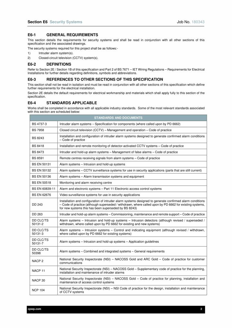
Section E6 Security Systems Job No. 180343
cpwp.com 2
E6-1 GENERAL REQUIREMENTS
This section details the requirements for security systems and shall be read in conjunction with all other sections of this specification and the associated drawings.
The security systems required for this project shall be as follows:-
1) Intruder alarm system(s).
2) Closed-circuit television (CCTV) system(s).
E6-2 DEFINITIONS
Refer to Section 2E / Section 1B of this specification and Part 2 of BS 7671 – IET Wiring Regulations – Requirements for Electrical Installations for further details regarding definitions, symbols and abbreviations.
E6-3 REFERENCES TO OTHER SECTIONS OF THIS SPECIFICATION
This section shall not be read in isolation and must be read in conjunction with all other sections of this specification which define further requirements for the electrical installation.
Section 2E details the default requirements for electrical workmanship and materials which shall apply fully to this section of the specification.
E6-4 STANDARDS APPLICABLE
Works shall be completed in accordance with all applicable industry standards. Some of the most relevant standards associated with this section are scheduled below:
STANDARDS AND DOCUMENTS
BS 4737-3 Intruder alarm systems – Specification for components (where called upon by PD 6662)
BS 7958 Closed circuit television (CCTV) – Management and operation – Code of practice
BS 8243 Installation and configuration of intruder alarm systems designed to generate confirmed alarm conditions – Code of practice
BS 8418 Installation and remote monitoring of detector-activated CCTV systems – Code of practice
BS 8473 Intruder and hold-up alarm systems – Management of false alarms – Code of practice
BS 8591 Remote centres receiving signals from alarm systems – Code of practice
BS EN 50131 Alarm systems – Intrusion and hold-up systems
BS EN 50132 Alarm systems – CCTV surveillance systems for use in security applications (parts that are still current)
BS EN 50136 Alarm systems – Alarm transmission systems and equipment
BS EN 50518 Monitoring and alarm receiving centre
BS EN 60839-11 Alarm and electronic systems – Part 11 Electronic access control systems
BS EN 62676 Video surveillance systems for use in security applications
DD 243 Installation and configuration of intruder alarm systems designed to generate confirmed alarm conditions – Code of practice (although superseded / withdrawn, where called upon by PD 6662 for existing systems, for new systems this has been superseded by BS 8243)
DD 263 Intruder and hold-up alarm systems – Commissioning, maintenance and remote support – Code of practice
DD CLC/TS 50131-2
Alarm systems – Intrusion and hold-up systems – Intrusion detectors (although revised / superseded / withdrawn, where called upon by PD 6662 for existing and new systems)
DD CLC/TS 50131-3
Alarm systems – Intrusion systems – Control and indicating equipment (although revised / withdrawn, where called upon by PD 6662 for existing systems)
DD CLC/TS 50131-7
Alarm systems – Intrusion and hold-up systems – Application guidelines
DD CLC/TS 50398
Alarm systems – Combined and integrated systems – General requirements
NACP 2 National Security Inspectorate (NSI) – NACOSS Gold and ARC Gold – Code of practice for customer communications
NACP 11 National Security Inspectorate (NSI) – NACOSS Gold – Supplementary code of practice for the planning, installation and maintenance of intruder alarms
NACP 30 National Security Inspectorate (NSI) – NACOSS Gold – Code of practice for planning, installation and maintenance of access control systems
NCP 104 National Security Inspectorate (NSI) – NSI Code of practice for the design, installation and maintenance of CCTV systems

Section E6 Security Systems Job No. 180343
cpwp.com 3
STANDARDS AND DOCUMENTS
NCP 109 National Security Inspectorate (NSI) – NSI Code of practice for the design, installation and maintenance of access control systems
PD 6662 Scheme for the application of European standards for intrusion and hold-up alarm systems
All current and relevant National Security Inspectorate (NSI) publications.
Data Protection Act
Where the above standards refer to supporting documentation and standards these shall be fully complied with in all respects.
Where discrepancy is found between this specification and the relevant standards, the Contractor shall obtain written clarification from the Engineer prior to submission of the tender. Where a discrepancy has not been clarified prior to tender submission, the Contractor shall include the most onerous requirements.
E6-5 DESIGN REQUIREMENTS
The Contractor shall employ one of the Security Specialist named in Appendix 1 to design, supply, install, test and commission the security systems. The Security Specialist(s) shall be fully responsible for the design of the security systems.
It is emphasised that the tender submission must include all necessary additional / alternative equipment necessary to achieve a fully compliant installation. Thus, in the absence of tender clarification between alternative methods of compliance, the most onerous compliant option shall be included.
E6-6 THE NATIONAL SECURITY INSPECTORATE (NSI)
The Security Specialist(s) must be NSI Gold certified.
E6-7 SCOPE OF WORKS
The security systems installation shall include the provision of the following:-
3) Intruder alarm system(s), including the following:-
a) Intruder alarm panel(s).
b) LCD keypad(s).
c) Remote input / output modules.
d) Motion detectors / sensors.
e) Door contacts.
f) Sounders / strobes.
g) Remote monitoring.
4) Closed-circuit television (CCTV) system(s), including the following:-
a) Internal CCTV cameras.
b) External CCTV cameras.
c) Power over Ethernet (PoE) network switches.
d) Data racks.
e) Network video recorders (NVR).
f) Video management system(s).
g) Desktop PC(s), monitors, keyboard and mouse.
h) Monitor(s), keyboards and mouse.
i) Remote monitoring.
5) All systems shall include the following:-
a) All necessary end-user management software.
b) All necessary wiring accessories e.g. data outlets, telephone outlets, un-switched fused connection units, double pole lockable key switches etc.
c) All necessary power and signalling cabling.
d) All necessary earthing and bonding.
e) All necessary cable support and containment systems.
f) Inspection, testing and commissioning.
g) All necessary identification, notices and labelling.
h) All necessary O&M information.
It shall be noted the above lists are not exhaustive and reference must be made to all sections of this specification and the associated drawings.
All due allowances shall be made within the tender submission to ensure all power supplies, wiring accessories and associated equipment is provided for the electrical installation, with particular attention paid to electrical systems where the Contractor has design responsibility.
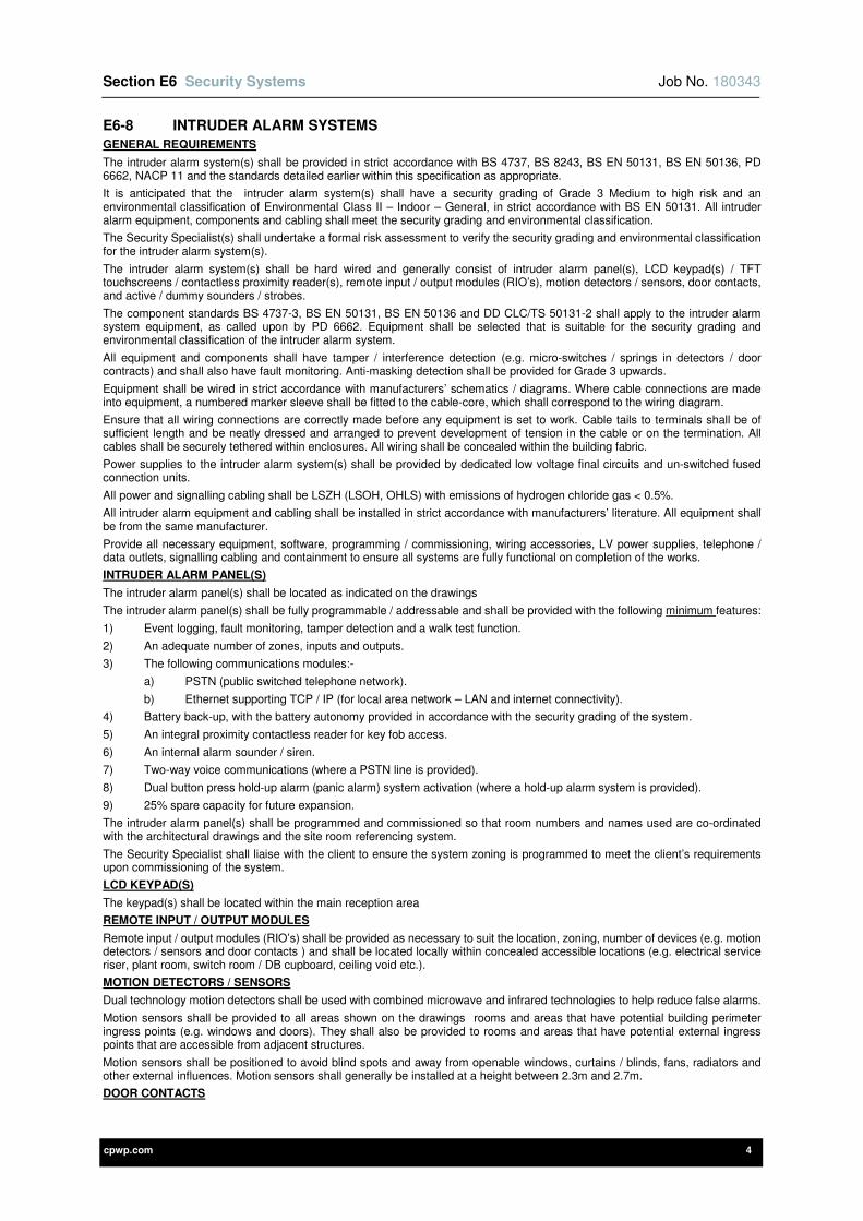
Section E6 Security Systems Job No. 180343
cpwp.com 4
E6-8 INTRUDER ALARM SYSTEMS
GENERAL REQUIREMENTS
The intruder alarm system(s) shall be provided in strict accordance with BS 4737, BS 8243, BS EN 50131, BS EN 50136, PD 6662, NACP 11 and the standards detailed earlier within this specification as appropriate.
It is anticipated that the intruder alarm system(s) shall have a security grading of Grade 3 Medium to high risk and an environmental classification of Environmental Class II – Indoor – General, in strict accordance with BS EN 50131. All intruder alarm equipment, components and cabling shall meet the security grading and environmental classification.
The Security Specialist(s) shall undertake a formal risk assessment to verify the security grading and environmental classification for the intruder alarm system(s).
The intruder alarm system(s) shall be hard wired and generally consist of intruder alarm panel(s), LCD keypad(s) / TFT touchscreens / contactless proximity reader(s), remote input / output modules (RIO’s), motion detectors / sensors, door contacts, and active / dummy sounders / strobes.
The component standards BS 4737-3, BS EN 50131, BS EN 50136 and DD CLC/TS 50131-2 shall apply to the intruder alarm system equipment, as called upon by PD 6662. Equipment shall be selected that is suitable for the security grading and environmental classification of the intruder alarm system.
All equipment and components shall have tamper / interference detection (e.g. micro-switches / springs in detectors / door contracts) and shall also have fault monitoring. Anti-masking detection shall be provided for Grade 3 upwards.
Equipment shall be wired in strict accordance with manufacturers’ schematics / diagrams. Where cable connections are made into equipment, a numbered marker sleeve shall be fitted to the cable-core, which shall correspond to the wiring diagram.
Ensure that all wiring connections are correctly made before any equipment is set to work. Cable tails to terminals shall be of sufficient length and be neatly dressed and arranged to prevent development of tension in the cable or on the termination. All cables shall be securely tethered within enclosures. All wiring shall be concealed within the building fabric.
Power supplies to the intruder alarm system(s) shall be provided by dedicated low voltage final circuits and un-switched fused connection units.
All power and signalling cabling shall be LSZH (LSOH, OHLS) with emissions of hydrogen chloride gas < 0.5%.
All intruder alarm equipment and cabling shall be installed in strict accordance with manufacturers’ literature. All equipment shall be from the same manufacturer.
Provide all necessary equipment, software, programming / commissioning, wiring accessories, LV power supplies, telephone / data outlets, signalling cabling and containment to ensure all systems are fully functional on completion of the works.
INTRUDER ALARM PANEL(S)
The intruder alarm panel(s) shall be located as indicated on the drawings
The intruder alarm panel(s) shall be fully programmable / addressable and shall be provided with the following minimum features:
1) Event logging, fault monitoring, tamper detection and a walk test function.
2) An adequate number of zones, inputs and outputs.
3) The following communications modules:-
a) PSTN (public switched telephone network).
b) Ethernet supporting TCP / IP (for local area network – LAN and internet connectivity).
4) Battery back-up, with the battery autonomy provided in accordance with the security grading of the system.
5) An integral proximity contactless reader for key fob access.
6) An internal alarm sounder / siren.
7) Two-way voice communications (where a PSTN line is provided).
8) Dual button press hold-up alarm (panic alarm) system activation (where a hold-up alarm system is provided).
9) 25% spare capacity for future expansion.
The intruder alarm panel(s) shall be programmed and commissioned so that room numbers and names used are co-ordinated with the architectural drawings and the site room referencing system.
The Security Specialist shall liaise with the client to ensure the system zoning is programmed to meet the client’s requirements upon commissioning of the system.
LCD KEYPAD(S)
The keypad(s) shall be located within the main reception area
REMOTE INPUT / OUTPUT MODULES
Remote input / output modules (RIO’s) shall be provided as necessary to suit the location, zoning, number of devices (e.g. motion detectors / sensors and door contacts ) and shall be located locally within concealed accessible locations (e.g. electrical service riser, plant room, switch room / DB cupboard, ceiling void etc.).
MOTION DETECTORS / SENSORS
Dual technology motion detectors shall be used with combined microwave and infrared technologies to help reduce false alarms.
Motion sensors shall be provided to all areas shown on the drawings rooms and areas that have potential building perimeter ingress points (e.g. windows and doors). They shall also be provided to rooms and areas that have potential external ingress points that are accessible from adjacent structures.
Motion sensors shall be positioned to avoid blind spots and away from openable windows, curtains / blinds, fans, radiators and other external influences. Motion sensors shall generally be installed at a height between 2.3m and 2.7m.
DOOR CONTACTS
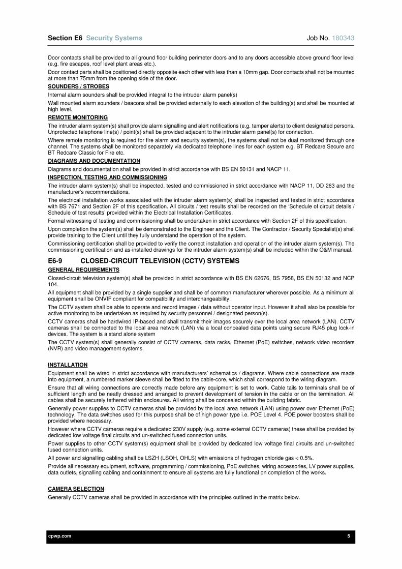
Section E6 Security Systems Job No. 180343
cpwp.com 5
Door contacts shall be provided to all ground floor building perimeter doors and to any doors accessible above ground floor level (e.g. fire escapes, roof level plant areas etc.).
Door contact parts shall be positioned directly opposite each other with less than a 10mm gap. Door contacts shall not be mounted at more than 75mm from the opening side of the door.
SOUNDERS / STROBES
Internal alarm sounders shall be provided integral to the intruder alarm panel(s)
Wall mounted alarm sounders / beacons shall be provided externally to each elevation of the building(s) and shall be mounted at high level.
REMOTE MONITORING
The intruder alarm system(s) shall provide alarm signalling and alert notifications (e.g. tamper alerts) to client designated persons. Unprotected telephone line(s) / point(s) shall be provided adjacent to the intruder alarm panel(s) for connection.
Where remote monitoring is required for fire alarm and security system(s), the systems shall not be dual monitored through one channel. The systems shall be monitored separately via dedicated telephone lines for each system e.g. BT Redcare Secure and BT Redcare Classic for Fire etc.
DIAGRAMS AND DOCUMENTATION
Diagrams and documentation shall be provided in strict accordance with BS EN 50131 and NACP 11.
INSPECTION, TESTING AND COMMISSIONING
The intruder alarm system(s) shall be inspected, tested and commissioned in strict accordance with NACP 11, DD 263 and the manufacturer’s recommendations.
The electrical installation works associated with the intruder alarm system(s) shall be inspected and tested in strict accordance with BS 7671 and Section 2F of this specification. All circuits / test results shall be recorded on the ‘Schedule of circuit details / Schedule of test results’ provided within the Electrical Installation Certificates.
Formal witnessing of testing and commissioning shall be undertaken in strict accordance with Section 2F of this specification.
Upon completion the system(s) shall be demonstrated to the Engineer and the Client. The Contractor / Security Specialist(s) shall provide training to the Client until they fully understand the operation of the system.
Commissioning certification shall be provided to verify the correct installation and operation of the intruder alarm system(s). The commissioning certification and as-installed drawings for the intruder alarm system(s) shall be included within the O&M manual.
E6-9 CLOSED-CIRCUIT TELEVISION (CCTV) SYSTEMS
GENERAL REQUIREMENTS
Closed-circuit television system(s) shall be provided in strict accordance with BS EN 62676, BS 7958, BS EN 50132 and NCP 104.
All equipment shall be provided by a single supplier and shall be of common manufacturer wherever possible. As a minimum all equipment shall be ONVIF compliant for compatibility and interchangeability.
The CCTV system shall be able to operate and record images / data without operator input. However it shall also be possible for active monitoring to be undertaken as required by security personnel / designated person(s).
CCTV cameras shall be hardwired IP-based and shall transmit their images securely over the local area network (LAN). CCTV cameras shall be connected to the local area network (LAN) via a local concealed data points using secure RJ45 plug lock-in devices. The system is a stand alone system
The CCTV system(s) shall generally consist of CCTV cameras, data racks, Ethernet (PoE) switches, network video recorders (NVR) and video management systems.
INSTALLATION
Equipment shall be wired in strict accordance with manufacturers’ schematics / diagrams. Where cable connections are made into equipment, a numbered marker sleeve shall be fitted to the cable-core, which shall correspond to the wiring diagram.
Ensure that all wiring connections are correctly made before any equipment is set to work. Cable tails to terminals shall be of sufficient length and be neatly dressed and arranged to prevent development of tension in the cable or on the termination. All cables shall be securely tethered within enclosures. All wiring shall be concealed within the building fabric.
Generally power supplies to CCTV cameras shall be provided by the local area network (LAN) using power over Ethernet (PoE) technology. The data switches used for this purpose shall be of high power type i.e. POE Level 4. POE power boosters shall be provided where necessary.
However where CCTV cameras require a dedicated 230V supply (e.g. some external CCTV cameras) these shall be provided by dedicated low voltage final circuits and un-switched fused connection units.
Power supplies to other CCTV system(s) equipment shall be provided by dedicated low voltage final circuits and un-switched fused connection units.
All power and signalling cabling shall be LSZH (LSOH, OHLS) with emissions of hydrogen chloride gas < 0.5%.
Provide all necessary equipment, software, programming / commissioning, PoE switches, wiring accessories, LV power supplies, data outlets, signalling cabling and containment to ensure all systems are fully functional on completion of the works.
CAMERA SELECTION
Generally CCTV cameras shall be provided in accordance with the principles outlined in the matrix below.

Section E6 Security Systems Job No. 180343
cpwp.com 6
Camera Selection Matrix
Typical Application BSIA
Objective Min FOV FOV Minimum
Resolution Type Target
fps IVA ROI PA
Pixels/m H
Pix V
Pix MP
Internal
Entrance Lobby/Door Identify 250 Narrow 1280 960 1.3 Fixed 20 to 25 x x x
Reception Desk Identify 250 Medium 1920 1080 2 Fixed 20 to 25 x x x
Waiting area Recognise 125 Medium 1920 1080 2 Fixed 10 to 15 x x
Small Atrium Recognise 125 Medium 1920 1080 2 Fixed 10 to 15 x x
Large Atrium Recognise 125 Wide 2592 1944 5 Fixed 10 to 15 x x
Corridor Recognise 125 Narrow 1280 960 1.3 Fixed 10 to 15 x x x
Corridor Intersection Recognise 125 Panoramic 1792 1792 3.2 E-PTZ 10 to 15 x x
Stairwell Identify 250 Narrow 1280 960 1.3 Fixed 10 to 15 x x x
Lift Car Identify 250 Narrow 1280 960 1.3 Fixed 10 to 15 x x x
External
Building Entrance Identify 250 Medium 1920 1080 2 Fixed 10 to 15 x
Building Perimeter 1 Observe 62.5 Narrow 1280 960 1.3 Fixed 10 to 15 x
Building Perimeter 2 Recognise 125 Narrow 1280 960 1.3 Fixed 10 to 15 x
Building Perimeter 3 Identify 250 Medium 1920 1080 2 PTZ (30x) 25 to 30 x x
Small Car Park Observe 62.5 Wide 2592 1944 5 Fixed 10 to 15 x x
Large Car Park Observe 62.5 Very wide 4000 3000 12 Fixed 10 to 15 x x
Vehicle Entrance Identify 250 Narrow 1280 960 1.3 Fixed 25 to 60 x x
Pedestrian Path Recognise 125 Medium 1920 1080 2 PTZ (30x) 25 to 30 x x
General Site Recognise 125 Medium 1920 1080 2 PTZ (30x) 26 to 30 x x x
Pedestrian Gate Identify 250 Narrow 1280 960 1.3 Fixed 20 to 25 x x x
Abbreviations on matrix
FOV Field of View
ROI Video Encoder 'Region of Interest' to give enhanced image quality for part of the FOV
PTZ Pan, Tilt and Zoom (with optical zoom at range given)
E-PTZ Electronic Pan, Tilt and Zoom
Resolution Minimum camera resolution; Specialist to enhance where necessary to meet camera objective.
H Pix Horizontal pixels
V Pix Vertical pixels
MP Megapixel
fps Frames per second
IVA Intelligent Video Analytics (on camera type) to provide alarms for loitering, object added etc. See below
PA Public Address audio output on camera
Other Abbreviations
DOF Depth of Field
AR Aspect Ratio
Day/Night Day/night camera with automatic IR cut filter
IR Infra-red illumination (matched to camera distance and FOV)
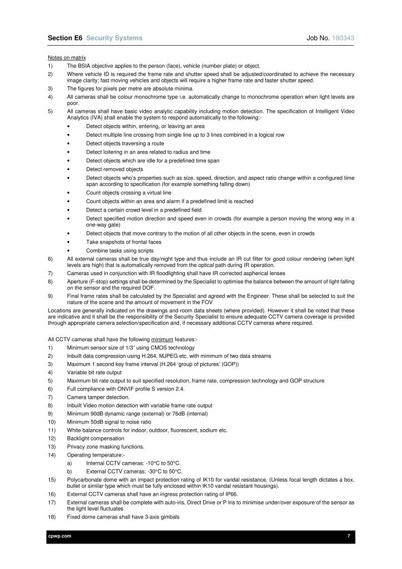
Section E6 Security Systems Job No. 180343
cpwp.com 7
Notes on matrix
1) The BSIA objective applies to the person (face), vehicle (number plate) or object.
2) Where vehicle ID is required the frame rate and shutter speed shall be adjusted/coordinated to achieve the necessary image clarity; fast moving vehicles and objects will require a higher frame rate and faster shutter speed.
3) The figures for pixels per metre are absolute minima.
4) All cameras shall be colour monochrome type i.e. automatically change to monochrome operation when light levels are poor.
5) All cameras shall have basic video analytic capability including motion detection. The specification of Intelligent Video Analytics (IVA) shall enable the system to respond automatically to the following:-
• Detect objects within, entering, or leaving an area
• Detect multiple line crossing from single line up to 3 lines combined in a logical row
• Detect objects traversing a route
• Detect loitering in an area related to radius and time
• Detect objects which are idle for a predefined time span
• Detect removed objects
• Detect objects who’s properties such as size, speed, direction, and aspect ratio change within a configured time span according to specification (for example something falling down)
• Count objects crossing a virtual line
• Count objects within an area and alarm if a predefined limit is reached
• Detect a certain crowd level in a predefined field
• Detect specified motion direction and speed even in crowds (for example a person moving the wrong way in a one-way gate)
• Detect objects that move contrary to the motion of all other objects in the scene, even in crowds
• Take snapshots of frontal faces
• Combine tasks using scripts
6) All external cameras shall be true day/night type and thus include an IR cut filter for good colour rendering (when light levels are high) that is automatically removed from the optical path during IR operation.
7) Cameras used in conjunction with IR floodlighting shall have IR corrected aspherical lenses
8) Aperture (F-stop) settings shall be determined by the Specialist to optimise the balance between the amount of light falling on the sensor and the required DOF.
9) Final frame rates shall be calculated by the Specialist and agreed with the Engineer. These shall be selected to suit the nature of the scene and the amount of movement in the FOV
Locations are generally indicated on the drawings and room data sheets (where provided). However it shall be noted that these are indicative and it shall be the responsibility of the Security Specialist to ensure adequate CCTV camera coverage is provided through appropriate camera selection/specification and, if necessary additional CCTV cameras where required.
All CCTV cameras shall have the following minimum features:-
1) Minimum sensor size of 1/3” using CMOS technology
2) Inbuilt data compression using H.264, MJPEG etc. with minimum of two data streams
3) Maximum 1 second key frame interval (H.264 ‘group of pictures’ (GOP))
4) Variable bit rate output
5) Maximum bit rate output to suit specified resolution, frame rate, compression technology and GOP structure
6) Full compliance with ONVIF profile S version 2.4.
7) Camera tamper detection.
8) Inbuilt Video motion detection with variable frame rate output
9) Minimum 90dB dynamic range (external) or 76dB (internal)
10) Minimum 50dB signal to noise ratio
11) White balance controls for indoor, outdoor, fluorescent, sodium etc.
12) Backlight compensation
13) Privacy zone masking functions.
14) Operating temperature:-
a) Internal CCTV cameras: -10°C to 50°C.
b) External CCTV cameras: -30°C to 50°C.
15) Polycarbonate dome with an impact protection rating of IK10 for vandal resistance. (Unless focal length dictates a box, bullet or similar type which must be fully enclosed within IK10 vandal resistant housings).
16) External CCTV cameras shall have an ingress protection rating of IP66.
17) External cameras shall be complete with auto-iris, Direct Drive or P Iris to minimise under/over exposure of the sensor as the light level fluctuates
18) Fixed dome cameras shall have 3-axis gimbals

Section E6 Security Systems Job No. 180343
cpwp.com 8
Each CCTV camera shall be of suitable build quality and strength to withstand its environment without detrimental effect to its operation or appearance. CCTV cameras shall not be affected by electromagnetic disturbances and radio frequency interference that is liable to be present.
Where required to avoid misting or water damage, CCTV cameras shall incorporate thermostatically controlled integral heating elements / blowers to prevent condensation within the camera housing.
All CCTV camera brackets shall be of suitable strength, including robust and tamper proof fixings to withstand their environment, vandalism and wind loading. All CCTV cameras shall be mounted at a height as to minimise vandalism whilst maintaining a clear identifiable image of individuals and their features.
CCTV cameras may be mounted to external lighting columns where CCTV camera operation will not be affected by wind loads and vibration.
CCTV cameras shall be wired back to power over Ethernet (PoE) network switches contained within local data racks using data cabling of the type specified within the Voice and Data Systems section within this specification.
The Contractor and Security Specialist shall provide dedicated low voltage final circuits, un-switched fused connection units and power supplies where required for PTZ mechanisms and for integral CCTV camera heaters.
DATA CABLING, ETHERNET (POE) NETWORK SWITCHES AND DATA RACKS
The Contractor and Security Specialist shall provide all necessary horizontal / backbone data cabling, power over Ethernet (PoE) network switches, data racks and other active equipment necessary to ensure the CCTV system(s) are fully functional.
NETWORK VIDEO RECORDERS (NVR) AND VIDEO MANAGEMENT SYSTEMS
Combined recording, playback and video management functions shall be provided using intelligent IP storage device(s) with integral software rather than separate video recorders, digital storage and servers. These devices shall use a modular system architecture that allows expansion of the CCTV system by fitting additional storage within the devices AND/OR additional devices to the network.
Storage security and redundancy shall be provided using RAID arrays in a configuration to suit the requirements of the system. (RAID-5 with one hot spare as a minimum.) The system as installed shall provide sufficient storage for all the cameras provided plus a 25% allowance for future,
The storage/video management device(s) shall be fully compatible with the cameras specified and shall provide recording and playback at the full resolution of the same. All necessary software components shall be pre-installed and licenced.
Each network video recorders (NVR’s) shall have the following minimum features:-
Performance
a) Record and monitor all cameras (at frame rates indicated on the camera matrix)
b) Instant, real time access to video
c) System wide event and alarm management
Hardware:-
a) Intel core processor
b) Memory: 8GB minimum
c) On-line UPS back-up
d) Up to 32 TB raw storage.
e) Optical: 22 x DVD-RW.
f) Network: Dual 1 Gigabit Ethernet.
g) Rack mounting
Software:
a) Live and recorded video monitoring, configuration and system management.
b) Support for Web Client on Microsoft Windows PC – Support live, playback / search of recorded video for up to 1080p resolution on all cameras, taking snapshots and viewing presets for PTZ cameras.
c) Support for mobile monitoring (iOS and Android) by security personnel / designated person(s).
d) Auto-configuration and auto-discovery of IP cameras, recording and monitoring configuration.
e) Multi-zoom views on HD video.
f) Ability to investigate events and alarms by simultaneously viewing alarm videos at various stages.
g) Remote PC based monitoring.
h) IP PTZ control and digital zoom on fixed cameras.
i) Fast search by date / time, time line, time jump, bookmaker, calendar preview, film strip view and events.
j) Event history and operator log reporting.
k) Email notification on camera, system and operator events.
l) Flexible motion detection.
m) Keyboard control.
Connections:-
a) Mouse and keyboard: 2 x USB.
b) USB: 2 x Front, 4 x Back.
c) Network: 2 x RJ45.
Section E6 Security Systems Job No. 180343
cpwp.com 9
d) Monitor output:
Data security
a) Three-level password protection
b) Web browser access protected with HTTPS
c) Firmware updates protected with authenticated secure uploads
d) Trusted Platform Module (TPM)
e) Public Key Infrastructure (PKI)
f) 802.1x network authentication with EAP/TLS, supports TLS 1.2 with updated cipher suites including AES 256 encryption
The number of network recorders (NVR’s) required shall be calculated dependent upon the number of cameras to be provided.
The network video recorders (NVR’s) hard drive storage shall be sized to provide a minimum of 30 days continuous recording of all CCTV cameras (operational 24 hours 7 days a week) at their full resolution and using the target frame rates given earlier, but taking account reduced data streams due to on-camera data compression based on the amount of movement (change) in the image.
The network video recorders (NVR’s) shall be sized with 25% spare camera and storage capacity for future expansion.
For live and recorded video monitoring, configuration and system management the CCTV system(s) shall be provided with:-
1) 1No. 32” 1080p HD wall mounted monitors, keyboard and mouse located within the office.
2) 1No. desktop PC’s with video management software (compatible with the NVR), 2No. 1080p HD monitors per desktop PC, keyboards and mouse. The video management software shall be installed upon a desktop PC(s) provided by the Security Specialist / client which shall be located in a secure location agreed with the client.
All necessary cabling and terminations shall be provided for the connection of the above equipment.
The end-user software shall also have the ability to become part of an integrated security solution that shall incorporate access control, intruder / hold-up alarm systems and CCTV.
The end-user software shall be programmed and commissioned so that room numbers and names used are co-ordinated with the architectural drawings and the site room referencing system.
All necessary software and hardware shall be provided for the programming of the CCTV system. All system passwords shall be provided.
REMOTE MONITORING
DIAGRAMS AND DOCUMENTATION
Diagrams and documentation shall be provided in strict accordance with BS EN 62676 and NCP 104.
INSPECTION, TESTING AND COMMISSIONING
The CCTV system(s) shall be inspected, tested and commissioned in strict accordance with NCP 104 and the manufacturer’s recommendations.
External cameras and associated IR lighting shall be commissioned at night and during daytime. Cameras shall be focused using IR with the aperture fully open so that focus shift during daytime, (caused by the shorter wavelength of visible light), is offset by the increased DOF associated with the smaller daytime aperture.
Test targets shall be used to demonstrate that the required BSIA category is achieved for each camera.
The electrical installation works associated with the CCTV system(s) shall be inspected and tested in strict accordance with BS 7671 and Section 2F of this specification. All circuits / test results shall be recorded on the ‘Schedule of circuit details / Schedule of test results’ provided within the Electrical Installation Certificates.
Formal witnessing of testing and commissioning shall be undertaken in strict accordance with Section 2F of this specification.
Upon completion the system(s) shall be demonstrated to the Engineer and the Client. The Contractor / Security Specialist(s) shall provide training to the Client until they fully understand the operation of the system.
Commissioning certification shall be provided to verify the correct installation and operation of the CCTV system(s). The commissioning certification and as-installed drawings for the CCTV system(s) shall be included within the O&M manual.
E6-10 ENGINEERS AND ARCHITECTS DRAWINGS
All power supplies, electrical equipment and wiring accessories shall be set out as detailed on the agreed Architects / Specialists elevation drawings. Where these are not available from the Architect or Specialists, the Electrical Contractor shall produce elevation drawings for approval by the Engineer in a timely manner to suit the construction programme.
However where there is a discrepancy between the Architects / Specialist elevation drawings and the information provided within this specification (e.g. mounting heights) this shall be brought to the attention of the Engineer and Architect / Specialist in a timely manner.
The drawing symbols used on the Engineer’s drawings are not to scale and therefore an allowance shall be made for any of the aforementioned to be relocated within a 1000mm radius of the indicated position at no further cost. These positions shall then be agreed with the Engineer and Architect / Specialist in a timely manner during the contract period.
E6-11 ROOM DATA SHEETS
Room data sheets have not been produced for this works.
E6-12 IDENTIFICATION, NOTICES AND LABELLING
Refer to Section 2E of this specification.

Section E6 Security Systems Job No. 180343
cpwp.com 10
E6-13 CABLE SUPPORT AND CONTAINMENT SYSTEMS
Refer to Section 2E of this specification.
E6-14 POSITIONING AND MOUNTING HEIGHT OF ELECTRICAL SERVICES
Refer to Section 2E of this specification.
E6-15 TECHNICAL SUBMISSIONS
Prior to installation on-site the Contractor shall provide technical submissions for the following:-
1) Technical specifications for all security equipment and cabling to be installed.
2) Wiring schematic drawings for all security systems to be installed, generic manufacturer’s schematics will not be accepted.
3) Layout drawings detailing the locations of all security system equipment.
4) Formal risk assessment to verify the security grading and environmental classification for the intruder alarm system(s).
5) Field of view drawings for the CCTV system(s).
6) Schedule of all identification, notices, labels (including safety signage) and cable identification labels / markers along with a physical sample of each label type.
7) Desktop PC technical requirements where the Security Specialist is to install software on desktop PC(s) provided by the client.
The time allowed for comment by the Engineer shall be as detailed within section 1B of this specification.

cpwp.com V1.3
Section E7A Fire Alarm Systems

Section E7A Fire Alarm Systems Job No. 180343
cpwp.com 1
Contents Page
E7A-1 GENERAL REQUIREMENTS 2
E7A-2 DEFINITIONS 2
E7A-3 REFERENCES TO OTHER SECTIONS OF THIS SPECIFICATION 2
E7A-4 STANDARDS APPLICABLE 2
E7A-5 DESIGN REQUIREMENTS 2
E7A-6 CERTIFICATION SCHEMES 3
E7A-7 FIRE CONSULTANT & FIRE STRATEGY DOCUMENTATION 3
E7A-8 SCOPE OF WORKS 3
E7A-9 TECHNICAL REQUIREMENTS 3
E7A-10 MODE OF OPERATION 5
E7A-11 CONTROL AND INDICATING EQUIPMENT (CIE) 5
E7A-12 POWER SUPPLIES 6
E7A-13 FIRE ALARM DEVICES 7
E7A-14 VOID AND PITCHED ROOF FIRE DETECTION 8
E7A-15 FIRE DOOR RETAINERS / DETENTES 8
E7A-16 FIRE ALARM INTERFACES 8
E7A-17 REMOTE MONITORING 8
E7A-18 NETWORKED SYSTEMS 8
E7A-19 ENGINEERS AND ARCHITECTS DRAWINGS 9
E7A-20 ROOM DATA SHEETS 9
E7A-21 IDENTIFICATION, NOTICES AND LABELLING 9
E7A-22 CABLE SUPPORT AND CONTAINMENT SYSTEMS / CABLING AND WIRING SYSTEMS 9
E7A-23 POSITIONING AND MOUNTING HEIGHT OF ELECTRICAL SERVICES 9
E7A-24 TECHNICAL SUBMISSIONS 9
E7A-25 DIAGRAMS AND DOCUMENTATION 9
E7A-26 INSPECTION, TESTING AND COMMISSIONING 10
E7A-27 SOAK TEST PERIOD 11
E7A-28 MAINTENANCE 11
Section E7A Fire Alarm Systems Job No. 180343
cpwp.com 2
E7A-1 GENERAL REQUIREMENTS
This section details the requirements for fire alarm systems and shall be read in conjunction with all other sections of this specification and the associated drawings.
The fire alarm systems shall be provided to the building / area.
E7A-2 DEFINITIONS
Refer to Section 2E / Section 1B of this specification and Part 2 of BS 7671 – IET Wiring Regulations – Requirements for Electrical Installations for further details regarding definitions, symbols and abbreviations.
E7A-3 REFERENCES TO OTHER SECTIONS OF THIS SPECIFICATION
This section shall not be read in isolation and must be read in conjunction with all other sections of this specification which define further requirements for the electrical installation.
Section 2E details the default requirements for electrical workmanship and materials which shall apply fully to this section of the specification.
E7A-4 STANDARDS APPLICABLE
Works shall be completed in accordance with all applicable industry standards. Some of the most relevant standards associated with this section are scheduled below:
STANDARDS AND DOCUMENTS
BS 7671 IET Wiring Regulations – Requirements for Electrical Installations
IET On-Site Guide – BS 7671 – IET Wiring Regulations – Requirements for Electrical Installations
All IET Guidance Notes – BS 7671 – IET Wiring Regulations – Requirements for Electrical Installations
BS 5839-1 Fire detection and fire alarm systems for buildings – Part 1: Code of practice for the design, installation, commissioning and maintenance of systems in non-domestic premises
BS 5839-6 Fire detection and fire alarm systems for buildings – Part 6: Code of practice for the design, installation, commissioning and maintenance of fire detection and fire alarm systems in domestic premises
BS 5839-8 Fire detection and fire alarm systems for buildings – Part 8: Code of practice for the design, installation, commissioning and maintenance of voice alarm systems
BS 7273-4 Code of practice for the operation of fire protection measures – Part 4: Actuation of release mechanisms for doors
BS 8519 Selection and installation of fire-resistant power and control cable systems for life safety and fire-fighting applications – Code of practice
BS 9999 Code of practice for fire safety in the design, management and use of buildings
BS EN 54 Fire detection and fire alarm systems
HTM 05-03 Firecode – fire safety in the NHS – Health Technical Memorandum 05-03: Operational provisions – Part B: Fire detection and alarm systems
LPS 1014 Loss Prevention Certification Board (LPCB) / Building Research Establishment (BRE) – Loss Prevention Standards – LPS 1014: Requirements for certificated fire detection and alarm system firms
All current and relevant Loss Prevention Certification Board (LPCB) / Building Research Establishment (BRE) Loss Prevention Standards.
All current and relevant Fire Industry Association (FIA) publications.
All current and relevant National Security Inspectorate (NSI) publications.
All standards, guidance and statutory regulations detailed within Section 2E-3
Where the above standards refer to supporting documentation and standards these shall be fully complied with in all respects.
Where discrepancy is found between this specification and the relevant standards, the Contractor shall obtain written clarification from the Engineer prior to submission of the tender. Where a discrepancy has not been clarified prior to tender submission, the Contractor shall include the most onerous requirements.
E7A-5 DESIGN REQUIREMENTS
The Contractor shall employ a Fire Alarm Specialist to design, supply, install, test and commission the fire alarm systems. The Fire Alarm Specialist(s) shall be fully responsible for the design of the fire alarm systems.
This design validation shall take place during the tender period. It shall include an assessment of whether:
1) Equipment specifications shown meet the overall design intent of this specification.
2) Equipment quantities shown meet the overall design intent of this specification.
3) The design intent of this specification is fully compliant with the Guides and Standards listed in this document.
Section E7A Fire Alarm Systems Job No. 180343
cpwp.com 3
Based on this assessment, the Fire Alarm Specialist(s) shall, during the tender period, provide written clarification to the Engineer of any non-compliances and / or additional requirements. They shall obtain from the Engineer any necessary guidance if the method of compliance is open to interpretation.
It is emphasized that the tender submission must include all necessary additional / alternative equipment necessary to achieve a fully compliant installation. Thus, in the absence of tender clarification between alternative methods of compliance, the most onerous compliant option shall be included.
E7A-6 CERTIFICATION SCHEMES
The Fire Alarm Specialist(s) must be an NSI Fire Gold certified and therefore BAFE registered. The Fire Alarm Specialist(s) must also be Loss Prevention Certification Board (LPCB) / Building Research Establishment (BRE) – Loss Prevention Standards – LPS 1014 certified.
E7A-7 FIRE CONSULTANT & FIRE STRATEGY DOCUMENTATION
No fire strategy documentation has been provided.
E7A-8 SCOPE OF WORKS
1) Fire alarm control panel.
2) Fire alarm repeater panel
3) Touchscreen(s).
4) Power supplies (including standby power supplies and chargers).
5) Fire detection.
6) Visual alarm devices (VAD’s).
7) Sounders.
8) Manual call points.
9) Short circuit line isolator modules / devices.
10) Fire alarm interfaces.
11) Remote monitoring.
12) Networking of fire alarm systems.
13) All necessary supervisory / end-user management software.
14) All necessary wiring accessories e.g. data outlets, telephone outlets, un-switched fused connection units, double pole lockable key switches etc.
15) All necessary power and signalling cabling.
16) All necessary earthing and bonding.
17) All necessary cable support and containment systems.
18) Inspection, testing and commissioning.
19) Soak testing.
20) All necessary identification, notices and labelling.
21) All necessary O&M information.
It shall be noted the above lists are not exhaustive and reference must be made to all sections of this specification and the associated drawings.
All due allowances shall be made within the tender submission to ensure all necessary power supplies, wiring accessories and associated equipment is provided for the electrical installation, with particular attention paid to electrical systems where the Contractor has design responsibility.
E7A-9 TECHNICAL REQUIREMENTS
The fire alarm system(s) shall be designed, selected, installed, tested and commissioned in strict accordance with BS 5839, BS EN 54, BS 7273, BS 8519, BS 9999 and the standards detailed earlier within this specification as appropriate.
The technical requirements for the fire alarm systems shall be as follows:-
TECHNICAL REQUIREMENTS
Installation location Building / area
Type of building / area Non-domestic premises to BS 5839-1
Category of system Category L1
Type of system(s)
Non-domestic ‘open protocol’ analogue addressable and fully programmable
Fire alarm panel(s) location(s) As indicated on the layout and schematic drawings

Section E7A Fire Alarm Systems Job No. 180343
cpwp.com 4
TECHNICAL REQUIREMENTS
Fire alarm repeater panel(s) / remote terminal(s) location(s) As indicated on the layout and schematic drawings
Networked fire alarm system Yes – Networked across the site
Type of networked system Master / slave
Mode of operation Single stage operation with single phase evacuation
Where the fire alarm systems are required to be ‘open protocol’ the fire alarm panel(s) shall be compatible with fire alarm devices (e.g. fire detectors, sounder, visual alarm devices, manual call points etc.) provided by other manufacturers. Open protocol fire alarm systems shall not be programmed, tested and commissioned by only one manufacturer / specialist.
Fire alarm equipment shall comply with the relevant parts of BS EN 54 and BS 5839. The fire alarm system(s) installation must be undertaken in strict accordance with the recommendations of BS5839.
The wiring of all fire alarm devices from the fire alarm control panel(s) shall be carried out as continuous loops. Each input / output for fire alarm devices on the loop shall have an individual address. Each loop shall not exceed 75% of its address capacity to allow for future modifications or expansion.
Detection zones shall be provided in strict accordance with BS 5839, the Fire Officer and Building Control requirements.
Short circuit line isolator modules / devices shall be installed at regular intervals on the fire alarm loop wiring to enable the automatic disconnection of loop sections under short circuit conditions. The short circuit line isolator modules / devices shall be provided as separate standalone units or incorporated into fire alarm devices installed on the loop wiring.
Short circuit line isolator modules / devices must be installed on the boundaries of all fire alarm zones.
Where ceiling mounted fire detectors are required on plasterboard or suspended ceiling areas, these shall be installed directly on to galvanised steel conduit boxes flushed to the ceiling surface.
Exact positions of all devices shall be agreed on site, particularly where fire detectors are mounted on ceilings adjacent to light fittings, ventilation diffusers, etc. (e.g. to ensure they are not in direct air flows).
Equipment shall be wired in strict accordance with manufacturers’ schematics / diagrams. Where cable connections are made into equipment, a numbered marker sleeve shall be fitted to the cable-core, which shall correspond to the wiring diagram.
Ensure that all wiring connections are correctly made before any equipment is set to work. Soldered ends shall be provided for termination.
Cable tails to terminals shall be of sufficient length and be neatly dressed and arranged to prevent development of tension in the cable or on the termination. All cables shall be securely tethered within enclosures. All wiring shall be concealed within the building fabric.
Power supplies to the fire alarm system(s) shall be provided by dedicated low voltage final circuits and double pole lockable key switches.
All power and signalling cabling shall be (as required):-
1) Fire alarm systems cabling e.g. loop wiring:-
XLPE/LSZH enhanced fire resistant cables manufactured to BS 7629-1 (PH30, PH60 and PH120 classification) e.g. Draka FT120, Prysmian FP Plus or similar.
2) Fire alarm network cabling e.g. for network wiring between fire alarm control panel(s), fire alarm repeater panels / remote terminals:-
XLPE/LSZH enhanced fire resistant cables manufactured to BS 7629-1 (PH30, PH60 and PH120 classification) e.g. Draka FT120, Prysmian FP Plus or similar.
3) Fire alarm power supply cabling e.g. power supplies to fire alarm control panel(s), fire alarm repeater panels / remote terminals etc.:-
XLPE/LSZH enhanced fire resistant cables manufactured to BS 7629-1 (PH30, PH60 and PH120 classification) e.g. Draka FT120, Prysmian FP Plus or similar.
Or,
4mm2 XLPE/SWA/LSZH enhanced fire resistant armoured power cables manufactured to BS 7846 (Classified Category F120) e.g. Draka FTP120, Prysmian FP600S or similar.
The above cabling requirements shall apply to all non-domestic systems to BS 5839-1 and domestic Grade A and B systems to BS 5839-6.
All power and signalling cabling for domestic Grade D and E systems to BS 5839-6, shall be LSZH (LSOH, OHLS) with emissions of hydrogen chloride gas < 0.5%.
Where possible fire alarm equipment shall be semi-recessed into the building fabric e.g. fire alarm control panels (with bezel), fire alarm repeater panels / remote terminals (with bezel), manual call points etc.
All fire alarm equipment and cabling shall be installed in strict accordance with manufacturers’ literature. All fire alarm devices shall be from the same manufacturer.
Section E7A Fire Alarm Systems Job No. 180343
cpwp.com 5
Provide all necessary equipment, software, programming / commissioning, wiring accessories, LV power supplies, telephone / data outlets signalling cabling and containment to ensure all systems are fully functional on completion of the works.
E7A-10 MODE OF OPERATION
The fire alarm systems shall operate on a single stage basis with single phase evacuation.
Therefore upon activation of a single fire alarm device (e.g. fire detector or manual call point), all sounders will operate and the fire alarm system shall automatically evacuate the building(s) / area(s).
Also upon activation mechanical plant will shut down (where required) and other devices interfaced with the fire alarm system will de-activate / activate as necessary.
This mode of operation for the fire alarm system(s) shall be agreed prior to final programming / commissioning with the client, Fire Officer, Building Control and Fire Consultant (where applicable). No programming / commissioning shall be undertaken prior to agreement of the cause and effect with the aforementioned parties.
Notwithstanding the anticipated requirements for a single stage / single phase evacuation fire alarm system, the system shall be capable of being programmed for an alternative mode of operation such as two stage / phased / progressive horizontal evacuation etc.
External flashing beacons and illuminated signs shall be provided adjacent to each access point to the building(s) / area(s) to identify that the building(s) / area(s) are in fire condition. A suitably worded notice shall be provided below each beacon indicating ‘BUILDING IN FIRE CONDITION – DO NOT ENTER’.
E7A-11 CONTROL AND INDICATING EQUIPMENT (CIE)
Fire alarm control and indicating equipment shall comply with BS EN 54-2 and BS 5839. Power supplies to control and indicating equipment shall be provided by dedicated low voltage final circuits and double pole lockable key switches as required by BS 5839.
FIRE ALARM CONTROL PANEL(S)
The fire alarm panel(s) shall be located as indicated on the drawings
The fire alarm control panel(s) shall be compliant with BS EN 54-2, BS EN 54-4 and BS EN 54-13. The fire alarm control panel(s) shall be ‘open protocol’, fully programmable / analogue addressable and shall have the following minimum features:-
1) Power healthy indication LED.
2) Panel fault indication LCD screen and LED.
3) An adequate number of loops – 1, 2, 4 or 8 loop formats.
4) Up to 254 devices per loop.
5) Built in oscilloscope, voltage and current meters.
6) Battery temperature sensor.
7) 20 built-in, fully programmable LED’s.
8) 5000 event log entries.
9) 200 programmable false alarm management areas.
10) Time enablement of isolated zones, input and output devices.
11) Auto-learn and loop detection.
12) Simple select and click programming / configuration.
13) Programmable screen logo.
14) Up to 8 programmable key-switches.
15) Support intelligent / programmable remote terminals, BMS interface, IP gateways and I/O drivers.
16) Support public switched telephone network (PSTN) communications e.g. for ‘BT Redcare Classic for Fire’ and remote monitoring by an alarm receiving centre (ARC).
17) Direct USB and RS 232 PC connections.
18) Peripheral expansion built-in.
19) Compatible with fire alarm devices from the following manufacturers / product ranges:-
a) Apollo Discovery and XP95.
b) Argus Vega.
c) Hochiki ESP.
d) Nittan Evolution.
20) Provided with suitably rated internal batteries (where external batteries are required they shall be provided in strict accordance with BS 5839).
21) Lockable glass front cover / door.
22) Flush mounted with a bezel where possible.
23) 25% spare capacity for future expansion.
The fire alarm control panel(s) shall also have the following minimum networking features:-
24) Circuit monitoring from any fire alarm panel or repeater.
25) Complete device history from each fire alarm panel.
The fire alarm control panel(s) shall be programmed and commissioned so that room numbers and names used are co-ordinated with the architectural drawings and the site room referencing system.
Section E7A Fire Alarm Systems Job No. 180343
cpwp.com 6
FIRE ALARM REPEATER PANEL(S) / REMOTE TERMINAL(S)
The fire alarm remote repeater panel shall be located within the existing entrance to replace the existing panel
The fire alarm repeater panel(s) / remote terminal(s) shall be from the same product range and ‘open protocol’ manufacturer as the fire alarm control panel(s). The fire alarm repeater panel(s) / remote terminal(s) shall be ‘open protocol’, fully programmable / analogue addressable and shall have the following minimum features:-
1) Remote display terminal(s):-
a) Optional level 2 access enable key switch.
b) Integrated standard or fault-tolerant network interface with screen termination port.
c) Programmable display for up to 2,000 zones along with sector base controls.
d) Lockable glass front cover / door.
e) Flush mounted with a bezel where possible.
f) 25% spare capacity for future expansion.
2) Remote control terminal(s):-
a) Integrated standard or fault-tolerant network interface with screen termination port.
b) Programmable display for up to 2,000 zones along with sector base controls.
c) Lockable glass front cover / door.
d) Flush mounted with a bezel where possible.
e) 25% spare capacity for future expansion.
3) Remote control terminal(s):-
a) Integrated standard or fault-tolerant network interface with screen termination port.
b) Programmable display for up to 2,000 zones along with sector base controls.
c) Lockable glass front cover / door.
d) Flush mounted with a bezel where possible.
e) 25% spare capacity for future expansion.
The fire alarm repeater panel(s) / remote terminal(s) shall be programmed and commissioned so that room numbers and names used are co-ordinated with the architectural drawings and the site room referencing system.
E7A-12 POWER SUPPLIES
Power supplies to fire alarm system(s) equipment shall be provided by dedicated low voltage final circuits and double pole lockable key switches as required by BS 5839.
Power supply units shall comply with BS EN 54-4 and BS 5839. The selection of power supply units must be undertaken in strict accordance with the recommendations of BS5839.
Power supply units shall incorporate standby supplies in the form of secondary (rechargeable) batteries complete with an automatic charger. All power supply units containing secondary batteries or external secondary battery units, shall be labelled with their date of installation.
Secondary (rechargeable) batteries shall be selected to conform to the battery autonomy requirements of BS 5839.
The charging rate of the batteries shall be such, that having being discharged to its final voltage, the battery can be charged sufficiently to conform to the battery autonomy requirements of BS 5839 after a charging period of 24 hours. The requirements of BS 5839 are dependent upon:-
1) Category of system.
2) Other secondary supplies e.g. standby generators.
3) Building occupation.
VALVE-REGULATED LEAD ACID BATTERIES
The minimum capacity of valve regulated lead acid batteries shall be calculated in accordance with the following formula:-
1) Cmin = 1.25 (T1I1 + DI2 / 2).
Where,
Cmin = minimum capacity of the battery when new at the 20 h discharge rate and at 20°C in ampere hours;
T1 = total battery standby period in amperes;
I1 = total battery standby load in amperes.
I2 = total battery alarm load in amperes.
D = a derating factor.
Where Cmin/20 will be equal to or greater than I2, it can be assumed that D = 1.
When Cmin/20 is less than I2, the value of D shall either be based on the battery manufacturer’s data or shall be 1.75.
In practice, Cmin is unlikely to correspond exactly to an available battery capacity and therefore the next highest available capacity size shall be used.
BATTERIES OTHER THAN VALVE-REGULATED LEAD ACID BATTERIES
The minimum capacity of batteries, other than valve regulated lead acid batteries shall be determined by consultation with the battery manufacturer and shall take into account:-
1) Standby load.
2) Alarm load
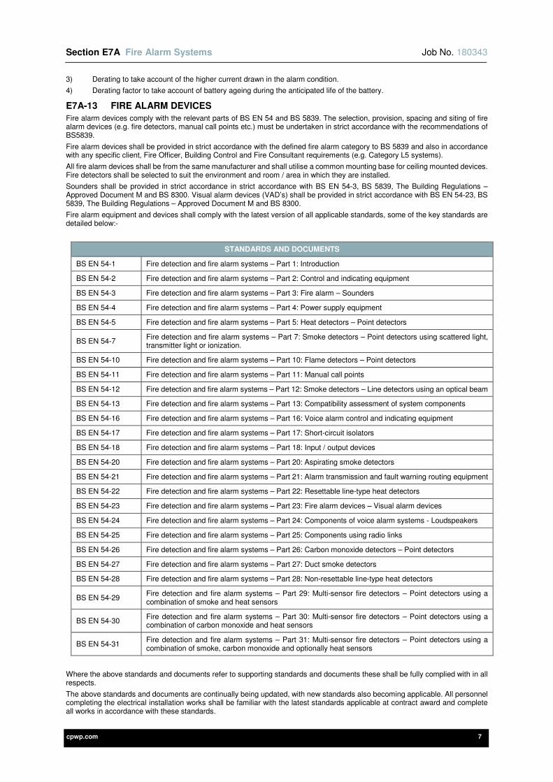
Section E7A Fire Alarm Systems Job No. 180343
cpwp.com 7
3) Derating to take account of the higher current drawn in the alarm condition.
4) Derating factor to take account of battery ageing during the anticipated life of the battery.
E7A-13 FIRE ALARM DEVICES
Fire alarm devices comply with the relevant parts of BS EN 54 and BS 5839. The selection, provision, spacing and siting of fire alarm devices (e.g. fire detectors, manual call points etc.) must be undertaken in strict accordance with the recommendations of BS5839.
Fire alarm devices shall be provided in strict accordance with the defined fire alarm category to BS 5839 and also in accordance with any specific client, Fire Officer, Building Control and Fire Consultant requirements (e.g. Category L5 systems).
All fire alarm devices shall be from the same manufacturer and shall utilise a common mounting base for ceiling mounted devices. Fire detectors shall be selected to suit the environment and room / area in which they are installed.
Sounders shall be provided in strict accordance in strict accordance with BS EN 54-3, BS 5839, The Building Regulations – Approved Document M and BS 8300. Visual alarm devices (VAD’s) shall be provided in strict accordance with BS EN 54-23, BS 5839, The Building Regulations – Approved Document M and BS 8300.
Fire alarm equipment and devices shall comply with the latest version of all applicable standards, some of the key standards are detailed below:-
STANDARDS AND DOCUMENTS
BS EN 54-1 Fire detection and fire alarm systems – Part 1: Introduction
BS EN 54-2 Fire detection and fire alarm systems – Part 2: Control and indicating equipment
BS EN 54-3 Fire detection and fire alarm systems – Part 3: Fire alarm – Sounders
BS EN 54-4 Fire detection and fire alarm systems – Part 4: Power supply equipment
BS EN 54-5 Fire detection and fire alarm systems – Part 5: Heat detectors – Point detectors
BS EN 54-7 Fire detection and fire alarm systems – Part 7: Smoke detectors – Point detectors using scattered light, transmitter light or ionization.
BS EN 54-10 Fire detection and fire alarm systems – Part 10: Flame detectors – Point detectors
BS EN 54-11 Fire detection and fire alarm systems – Part 11: Manual call points
BS EN 54-12 Fire detection and fire alarm systems – Part 12: Smoke detectors – Line detectors using an optical beam
BS EN 54-13 Fire detection and fire alarm systems – Part 13: Compatibility assessment of system components
BS EN 54-16 Fire detection and fire alarm systems – Part 16: Voice alarm control and indicating equipment
BS EN 54-17 Fire detection and fire alarm systems – Part 17: Short-circuit isolators
BS EN 54-18 Fire detection and fire alarm systems – Part 18: Input / output devices
BS EN 54-20 Fire detection and fire alarm systems – Part 20: Aspirating smoke detectors
BS EN 54-21 Fire detection and fire alarm systems – Part 21: Alarm transmission and fault warning routing equipment
BS EN 54-22 Fire detection and fire alarm systems – Part 22: Resettable line-type heat detectors
BS EN 54-23 Fire detection and fire alarm systems – Part 23: Fire alarm devices – Visual alarm devices
BS EN 54-24 Fire detection and fire alarm systems – Part 24: Components of voice alarm systems - Loudspeakers
BS EN 54-25 Fire detection and fire alarm systems – Part 25: Components using radio links
BS EN 54-26 Fire detection and fire alarm systems – Part 26: Carbon monoxide detectors – Point detectors
BS EN 54-27 Fire detection and fire alarm systems – Part 27: Duct smoke detectors
BS EN 54-28 Fire detection and fire alarm systems – Part 28: Non-resettable line-type heat detectors
BS EN 54-29 Fire detection and fire alarm systems – Part 29: Multi-sensor fire detectors – Point detectors using a combination of smoke and heat sensors
BS EN 54-30 Fire detection and fire alarm systems – Part 30: Multi-sensor fire detectors – Point detectors using a combination of carbon monoxide and heat sensors
BS EN 54-31 Fire detection and fire alarm systems – Part 31: Multi-sensor fire detectors – Point detectors using a combination of smoke, carbon monoxide and optionally heat sensors
Where the above standards and documents refer to supporting standards and documents these shall be fully complied with in all respects.
The above standards and documents are continually being updated, with new standards also becoming applicable. All personnel completing the electrical installation works shall be familiar with the latest standards applicable at contract award and complete all works in accordance with these standards.
Section E7A Fire Alarm Systems Job No. 180343
cpwp.com 8
Where discrepancy is found between this specification, specialist quotations and the relevant standards, written clarification shall be obtained from the Engineer prior to submission of tender. Where a discrepancy has not been clarified prior to tender submission the most onerous requirements shall be included within the tender price.
E7A-14 VOID AND PITCHED ROOF FIRE DETECTION
Fire detection shall be provided to any area that contains a horizontal void greater than 800mm in height. Voids less than 800mm in height need not be protected unless either:-
1) The void is such that extensive spread of fire or smoke, particularly between rooms and compartments, can take place before detection.
or,
2) On the basis of a fire risk assessment, the fire risk in the void is such as to warrant protection of the void.
Fire detection shall be located within voids and pitched roofs in strict accordance with the recommendations of BS 5839. Ceiling obstructions, such as structural beams, deeper than 10% of the overall ceiling height shall be treated as walls and additional fire detection shall be provided as required.
The Contractor and Fire Alarm Specialist responsible for the design of the fire alarm system(s) shall obtain all necessary Architects and Structural Engineering drawings to ensure all due allowances are made within the tender submission to provide fire detection to all void / pitched roof areas and as necessary for ceiling obstructions.
E7A-15 FIRE DOOR RETAINERS / DETENTES
Fire door retainers / détentes shall be provided in strict accordance with BS 7273-4. Fire door retainers / détentes shall be provided as indicated on the Architects fire strategy documentation and as required by the Fire Officer, Building Control and Fire Consultant (where applicable).
Generally fire retainers / détentes units shall be of the over door, electromagnetic type, and shall be provided as part of the ironmongery package. Fire door retainers / détentes shall be installed in strict accordance with manufacturers’ recommendations and wired as detailed within Section E2 Utility Power of this specification.
Provide all necessary equipment, power supply units, wiring accessories, LV power supplies, fire alarm interfaces, local release buttons, cabling and containment to ensure all fire door retainers are fully functional on completion of the works.
E7A-16 FIRE ALARM INTERFACES
Loop wired analogue addressable fire alarm interfaces shall be provided for connection to the following systems:-
1) Mechanical control panels – shutdown ventilation systems.
2) Building management systems (BMS) control panels.
3) Lifts – return to ground floor and doors open.
4) Access controlled doors, car park barriers and entrance gates – fail open.
5) Automatic doors – fail open.
6) Fire shutters / curtains – fail shut.
7) Fire alarm systems for people with impaired hearing e.g. Deaf Alerter or similar – activated.
It shall be noted the above lists are not exhaustive and reference must be made to all sections of this specification and the associated drawings.
The control and indicating equipment (CIE) shall be provided with programmable key switches to prevent the activation of selected fire alarm interfaces when the fire alarm system is being tested. The selected fire alarm interfaces shall be agreed prior to final programming / commissioning with the client, Fire Officer, Building Control and Fire Consultant (where applicable).
Instructions for the key switch operation (and the fire alarm interfaces not activated) shall be mounted within framed glass and screw fixed to the wall adjacent to the control and indicating equipment.
Fire alarm interfaces shall be located locally within concealed accessible locations (e.g. electrical service riser, plant room, switch room / DB cupboard, ceiling void etc.).
Provide all necessary equipment, power supply units, wiring accessories, LV power supplies, fire alarm interfaces, cabling and containment to ensure the fire alarm interfaces and associated systems are fully functional on completion of the works.
E7A-17 REMOTE MONITORING
The fire alarm system(s) shall provide alarm signalling and alert notifications to client designated persons. Unprotected telephone line(s) / point(s) shall be provided adjacent to the fire alarm panel(s) for connection.
Where remote monitoring is required for fire alarm and security system(s), the systems shall not be dual monitored through one channel. The systems shall be monitored separately via dedicated telephone lines for each system e.g. BT Redcare Secure and BT Redcare Classic for Fire etc.
E7A-18 NETWORKED SYSTEMS
The fire alarm system(s) across the site / buildings shall be connected together to form a true ‘peer to peer’ networked fire alarm system.
It should be noted that a ‘master / slave’ networked fire alarm system shall NOT be acceptable. The fire alarm system must have true ‘peer to peer’ network communications for the ‘critical signal path’ and to facilitate primary functions, in strict accordance with the recommendations of BS5839 Section 24 Networked Systems.
The networked fire alarm system(s) are to have ‘open protocol’ analogue addressable fire alarm control panels that are capable of true ‘peer to peer’ network communications. All fire alarm control panels shall be from the same ‘open protocol’ manufacturer and shall be connected to the networked fire alarm system.
Section E7A Fire Alarm Systems Job No. 180343
cpwp.com 9
Networked fire alarm cabling shall run between all fire alarm control panels in ring / closed loop formation and shall be diversely routed over their entire length (except in the immediate vicinity of control panels) for resilience.
The networked fire alarm cabling shall be:-
1) XLPE/LSZH enhanced fire resistant cables manufactured to BS 7629-1 (PH30, PH60 and PH120 classification) e.g. Draka FT120, Prysmian FP Plus or similar.
At least 2No. spare cores shall be provided within each of the cables.
The Contractor / Fire Alarm Specialist(s) shall also supply and install a telephone outlet for remote monitoring (e.g. BT Redcare Classic for Fire) and a data outlet (for IP gateway connection) adjacent to the fire alarm control panel located within the reception area
However it shall be noted the networked fire alarm system MUST still be a true ‘peer to peer’ system regardless of these provisions.
PC based software shall be provided for supervisory / end-user management of the fire alarm systems, this shall be achieved by connection of networked fire alarm system IP gateways to the local area network (LAN).
Provide all necessary equipment, programming / commissioning, LV power supplies, signalling cabling and containment to ensure all systems are fully functional on completion of the works.
E7A-19 ENGINEERS AND ARCHITECTS DRAWINGS
All power supplies, electrical equipment and wiring accessories shall be set out as detailed on the agreed Architects / Specialists elevation drawings. Where these are not available from the Architect or Specialists, the Electrical Contractor shall produce elevation drawings for approval by the Engineer in a timely manner to suit the construction programme.
However where there is a discrepancy between the Architects / Specialist elevation drawings and the information provided within this specification (e.g. mounting heights) this shall be brought to the attention of the Engineer and Architect / Specialist in a timely manner.
The drawing symbols used on the Engineer’s drawings are not to scale and therefore an allowance shall be made for any of the aforementioned to be relocated within a 1000mm radius of the indicated position at no further cost. These positions shall then be agreed with the Engineer and Architect / Specialist in a timely manner during the contract period.
E7A-20 ROOM DATA SHEETS
Room data sheets have not been produced for this works.
E7A-21 IDENTIFICATION, NOTICES AND LABELLING
Refer to Section 2E of this specification.
E7A-22 CABLE SUPPORT AND CONTAINMENT SYSTEMS / CABLING AND WIRING SYSTEMS
Refer to Section 2E of this specification.
E7A-23 POSITIONING AND MOUNTING HEIGHT OF ELECTRICAL SERVICES
Refer to Section 2E of this specification.
E7A-24 TECHNICAL SUBMISSIONS
Prior to installation on-site the Contractor shall provide technical submissions for the following:-
1) Cause and effect schedule / chart.
2) Technical specifications for all fire alarm equipment and cabling to be installed.
3) Wiring schematic drawings for all fire alarm systems to be installed, generic manufacturer’s schematics shall not be accepted.
4) Layout drawings detailing the locations of all fire alarm system equipment.
5) Technical data to verify the adequate provision of sounders and visual alarm devices (VAD’s).
6) Technical specifications for all secondary (rechargeable) batteries, detailing the selected battery autonomy.
7) Schedules itemising all addressable points and descriptor references (e.g. pre-alarm, fault conditions etc.) to be displayed on control and indicating equipment.
8) Schedule of all identification, notices, labels (including safety signage) and cable identification labels / markers along with a physical sample of each label type.
The time allowed for comment by the Engineer shall be as detailed within section 1B of this specification.
E7A-25 DIAGRAMS AND DOCUMENTATION
Diagrams and documentation shall be provided in strict accordance with BS 5839.
The drawings and documentation shall include:-
1) Certificates for the design, installation, testing, commissioning, acceptance and verification (where applicable) of the fire alarm system(s).
2) Zone plans / drawings (mimic diagrams) shall be mounted within framed glass and screw fixed to the wall adjacent to all control and indicating equipment (with the exception of repeater / remote touchscreens provided with interactive maps and zone plans).
3) An adequate operation and maintenance manual for the system; this should provide information, specific to the system in question, regarding the following:-
a) The equipment provided and its configuration.
Section E7A Fire Alarm Systems Job No. 180343
cpwp.com 10
b) Use of controls.
c) Recommendation for investigation of a fire alarm or fault signal after the incident is over and the building declared safe for reoccupation.
d) Recommendations for investigation in the event of a false alarm
e) Routine weekly and monthly testing of the systems by the user or his / her appointed agent.
f) Service and maintenance of the system.
g) Avoidance of false alarms.
h) The need to keep clear space around all fire detectors and manual call points.
i) The need to avoid contamination of detectors during Contractors’ activities.
j) The importance of ensuring that changes to the building, such as relocation of partitions, do not affect the standard of protection.
k) Other user responsibilities described within BS 5839.
4) As-fitted drawings indicating at least the following:-
a) The positions of all control, indicating and power supply equipment.
b) The positions of all manual call points, fire detectors and fire alarm devices.
c) The positions of all equipment that might require routine attention or replacement (e.g. short circuit isolators and remote indicators).
d) Wiring schematic drawings for all fire alarm systems installed, generic manufacturer’s schematics shall not be accepted.
e) The type, sizes and actual routes of cables.
5) A logbook in which all events, including fire alarm signals, faults signals, system tests and maintenance visits, can be recorded.
6) A record of any agreed variations from the original design specification.
The above drawings and documentation shall be included within the O&M manual.
E7A-26 INSPECTION, TESTING AND COMMISSIONING
The fire alarm system(s) shall be inspected, tested and commissioned in strict accordance with BS 5839, BS 7671, Section 2F of this specification and the manufacturer’s recommendations.
The electrical installation works associated with the fire alarm system(s) shall be inspected and testing in strict accordance with BS 7671 and Section 2F of this specification. All circuits / test results shall be recorded on the ‘Schedule of circuit details / Schedule of test results’ provided within the Electrical Installation Certificates).
Formal witnessing of testing and commissioning shall be undertaken in strict accordance with Section 2F of this specification.
The fire alarm installation shall be inspected and tested in accordance with the recommendations of BS 5839:-
1) Insulation resistance tests:-
a) All insulated cables with a manufacturer’s voltage rating suitable for main use shall be subject to insulation testing at 500 V d.c. Prior to this test, cables shall be disconnected from all equipment that could be damaged by the test.
b) Insulation resistance, measured in the above test, between conductors, between each conductor and earth, and between each conductor and any screen, shall be at least 2 MΩ.
2) Continuity of protective conductors and, for mains supply circuits, earth fault loop impedance, shall be tested to ensure compliance with BS 7671 and Section 2F of this specification.
3) The following tests shall also be undertaken where required:-
a) Where maximum circuit resistance for any circuit is specified by the manufacturer or supplier, measurement of the resistance of every such circuit.
b) Any other test specified by the manufacturer of the system.
c) Check correct polarity of circuits where this is required for correct monitoring (to ensure operation of any manual call point while all detectors on a circuit are removed).
Test equipment shall be provided in strict accordance with the test equipment requirements of Section 2F of this specification.
The fire alarm system shall be commissioned in strict accordance with the recommendations of Section 39 Commissioning of BS 5839 and to achieve the mode of operation required by the client, Fire Officer, Building Control and Fire Consultant (where applicable).
No programming / commissioning shall be undertaken prior to agreement of the cause and effect with the aforementioned parties.
Audibility tests shall be undertaken during the testing and commissioning of the fire alarm system(s) to verify the correct sound pressure levels are achieved. In areas with mechanical plant audibility tests shall be carried out prior to the mechanical plant being put into operation and after all the plant is operational.
The Contractor / Fire Alarm Specialist shall undertake these tests using a suitable sound level meter.
Commissioning certification shall be provided to verify the correct installation and operation of the fire alarm system(s). The following separate certification shall be provided:-
1) Design certificate.
2) Installation certificate.
3) Commissioning certificate.
4) Acceptance certificate provided for completion by the client.
Section E7A Fire Alarm Systems Job No. 180343
cpwp.com 11
The Contractor / Fire Alarm Specialist shall supply the client with any special tools required for the operation and testing of the fire alarm system(s) in sufficient quantity (minimum quantity of 3No. for each item).
Upon completion the system(s) shall be demonstrated to the Engineer and the Client. The Contractor / Fire Alarm Specialist shall provide training to the Client until they fully understand the operation of the system.
The commissioning certification and as-installed drawings for the fire alarm system(s) shall be included within the O&M manual.
E7A-27 SOAK TEST PERIOD
After inspection, testing and commissioning where the fire alarm system(s) incorporate more than 50 automatic fire detectors, the Contractor and Fire Alarm Specialist shall provide a soak test period of at least one week (with the building / area occupied) in strict accordance with BS 5839.
This period shall be determined by the Fire Alarm Specialist responsible for the design of the fire alarm system(s). During the soak test period 24/7 monitoring of the fire alarm system(s) shall be undertaken to identify any unwanted false alarms and each manual call point shall bear an indication that it is not to be used.
Until successful completion of the soak test the fire alarm system(s) shall not be regarded as fully operational and therefore all necessary building insurances shall be in place to cover the use of the building / area during the soak test period.
The soak test shall only be regarded as successfully completed if:-
1) No false alarms occurred during the soak test period,
or,
2) If false alarms occurred during the soak test period, the Fire Alarm Specialist (during the soak test period) identified the cause of these false alarms and undertook measures to rectify or minimise the potential for similar false alarms to occur in the future.
If any unwanted false alarms are not rectified by the Fire Alarm Specialist during the soak test period, the soak test period shall be repeated from the beginning for a period of one week, until the fire alarm system(s) function accurately and correctly.
All due allowances shall be made within the tender submission for all necessary supervision, testing, commissioning and attendances by the Contractor and Fire Alarm Specialist during the soak test period.
Any costs incurred as a result of or a consequence of having to restart the soak test shall be at the Contractor’s / Fire Alarm Specialist’s expense. Practical completion shall not be awarded until the soak test has been completed successfully.
E7A-28 MAINTENANCE
The Fire Alarm Specialist shall be required to provide full maintenance of the installation for a period of 12 months from the handover of the building. This shall be in accordance with the quarterly and annual recommendations presented by BS 5839 and shall be in addition to any items which would normally be dealt with under the twelve months defects period.

Section E7A Fire Alarm Systems Job No. 180343
cpwp.com 12

cpwp.com V1.2
Section E8 Lightning Protection Systems
Section E8 Lightning Protection Systems Job No. 180343
cpwp.com 1
Contents Page
E8-1 GENERAL REQUIREMENTS 3
E8-2 DEFINITIONS 3
E8-3 REFERENCES TO OTHER SECTIONS OF THIS SPECIFICATION 3
E8-4 STANDARDS APPLICABLE 3
E8-5 DESIGN REQUIREMENTS 3
E8-6 MEMBERSHIP SCHEMES 4
E8-7 SCOPE OF WORKS 4
E8-8 RISK ASSESSMENT 4
E8-8-1 SCOPE 4
E8-8-2 IDENTIFICATION OF TOLERABLE RISK 4
E8-8-3 LIGHTNING PROTECTION LEVEL (LPL) 5
E8-8-4 LIGHTNING PROTECTION ZONE (LPZ) 5
E8-9 STRUCTURAL LIGHTNING PROTECTION 5
E8-9-1 SCOPE 5
E8-9-2 AIR TERMINATION NETWORK 6
E8-9-3 DOWN CONDUCTORS 7
E8-9-4 EARTH TERMINATION 8
E8-9-5 CONDUCTOR JOINTS AND CONNECTIONS 8
E8-9-6 TEST JOINTS 8
E8-9-7 CONNECTION TO EQUIPMENT 9
E8-9-8 SURGE PROTECTION DEVICE (SPD) FOR STRUCTURAL PROTECTION 9
E8-10 ELECTRICAL AND ELECTRONIC PROTECTION SYSTEMS 9
E8-10-1 ELECTRICAL AND ELECTRONIC SYSTEMS – PROTECTION WHERE THERE IS NO STRUCTURAL LIGHTNING PROTECTION SYSTEM 9
E8-10-2 ELECTRICAL AND ELECTRONIC SYSTEMS – PROTECTION WHERE THERE IS A STRUCTURAL LIGHTNING PROTECTION SYSTEM 9
E8-10-3 INSTALLATION OF SURGE PROTECTION DEVICES (SPD’S) 9
E8-11 PRE-INSTALLATION REQUIREMENTS 10
E8-12 INSTALLATION PROCEDURE 10
E8-13 PROXIMITY AND SEGREGATION OF WIRING SYSTEMS 10
E8-14 ENGINEERS AND ARCHITECTS DRAWINGS 10
E8-15 IDENTIFICATION, NOTICES AND LABELLING 11
E8-16 CABLE SUPPORT AND CONTAINMENT SYSTEMS / CABLING AND WIRING SYSTEMS 11
E8-17 TECHNICAL SUBMISSIONS 11
E8-18 DIAGRAMS AND DOCUMENTATION 11
E8-19 INSPECTION, TESTING AND COMMISSIONING 11
E8-19-1 STRUCTURAL LIGHTNING PROTECTION SYSTEM 11
Section E8 Lightning Protection Systems Job No. 180343
cpwp.com 2
E8-19-2 ELECTRICAL AND ELECTRONIC SYSTEMS 11
E8-19-3 ELECTRICAL INSTALLATION 11
E8-19-4 FINAL ACCEPTANCE TESTS 12
E8-20 MAINTENANCE 12
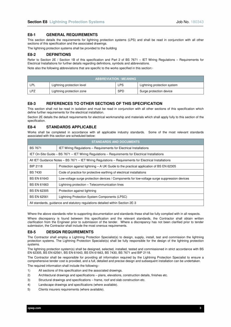
Section E8 Lightning Protection Systems Job No. 180343
cpwp.com 3
E8-1 GENERAL REQUIREMENTS
This section details the requirements for lightning protection systems (LPS) and shall be read in conjunction with all other sections of this specification and the associated drawings.
The lightning protection systems shall be provided to the building
E8-2 DEFINITIONS
Refer to Section 2E / Section 1B of this specification and Part 2 of BS 7671 – IET Wiring Regulations – Requirements for Electrical Installations for further details regarding definitions, symbols and abbreviations.
Note also the following abbreviations that are specific to the works specified in this section:-
ABBREVIATION / MEANING
LPL Lightning protection level LPS Lightning protection system
LPZ Lightning protection zone SPD Surge protection device
E8-3 REFERENCES TO OTHER SECTIONS OF THIS SPECIFICATION
This section shall not be read in isolation and must be read in conjunction with all other sections of this specification which define further requirements for the electrical installation.
Section 2E details the default requirements for electrical workmanship and materials which shall apply fully to this section of the specification.
E8-4 STANDARDS APPLICABLE
Works shall be completed in accordance with all applicable industry standards. Some of the most relevant standards associated with this section are scheduled below:
STANDARDS AND DOCUMENTS
BS 7671 IET Wiring Regulations – Requirements for Electrical Installations
IET On-Site Guide – BS 7671 – IET Wiring Regulations – Requirements for Electrical Installations
All IET Guidance Notes – BS 7671 – IET Wiring Regulations – Requirements for Electrical Installations
BIP 2118 Protection against lightning – A UK Guide to the practical application of BS EN 62305
BS 7430 Code of practice for protective earthing of electrical installations
BS EN 61643 Low-voltage surge protection devices / Components for low-voltage surge suppression devices
BS EN 61663 Lightning protection – Telecommunication lines
BS EN 62305 Protection against lightning
BS EN 62561 Lightning Protection System Components (LPSC)
All standards, guidance and statutory regulations detailed within Section 2E-3
Where the above standards refer to supporting documentation and standards these shall be fully complied with in all respects.
Where discrepancy is found between this specification and the relevant standards, the Contractor shall obtain written clarification from the Engineer prior to submission of the tender. Where a discrepancy has not been clarified prior to tender submission, the Contractor shall include the most onerous requirements.
E8-5 DESIGN REQUIREMENTS
The Contractor shall employ a Lightning Protection Specialist(s) to design, supply, install, test and commission the lightning protection systems. The Lightning Protection Specialist(s) shall be fully responsible for the design of the lightning protection systems.
The lightning protection system(s) shall be designed, selected, installed, tested and commissioned in strict accordance with BS EN 62305, BS EN 62561, BS EN 61643, BS EN 61663, BS 7430, BS 7671 and BIP 2118.
The Contractor shall be responsible for providing all information required by the Lightning Protection Specialist to ensure a comprehensive tender cost is provided, and a full, detailed and precise design and subsequent installation can be undertaken.
The required information shall include the following:-
1) All sections of this specification and the associated drawings.
2) Architectural drawings and specifications – plans, elevations, construction details, finishes etc.
3) Structural drawings and specifications – frame, roof and slab construction etc.
4) Landscape drawings and specifications (where available).
5) Clients insurers requirements (where available).
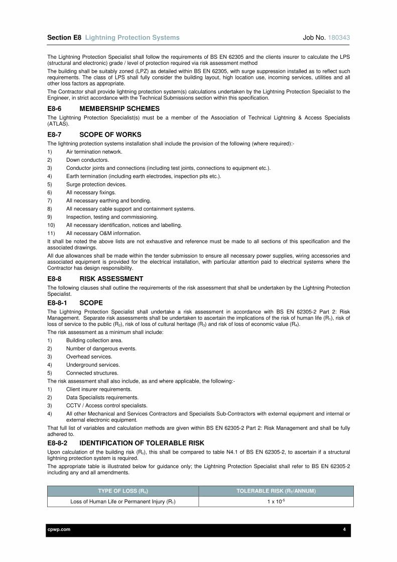
Section E8 Lightning Protection Systems Job No. 180343
cpwp.com 4
The Lightning Protection Specialist shall follow the requirements of BS EN 62305 and the clients insurer to calculate the LPS (structural and electronic) grade / level of protection required via risk assessment method
The building shall be suitably zoned (LPZ) as detailed within BS EN 62305, with surge suppression installed as to reflect such requirements. The class of LPS shall fully consider the building layout, high location use, incoming services, utilities and all other loss factors as appropriate.
The Contractor shall provide lightning protection system(s) calculations undertaken by the Lightning Protection Specialist to the Engineer, in strict accordance with the Technical Submissions section within this specification.
E8-6 MEMBERSHIP SCHEMES
The Lightning Protection Specialist(s) must be a member of the Association of Technical Lightning & Access Specialists (ATLAS).
E8-7 SCOPE OF WORKS
The lightning protection systems installation shall include the provision of the following (where required):-
1) Air termination network.
2) Down conductors.
3) Conductor joints and connections (including test joints, connections to equipment etc.).
4) Earth termination (including earth electrodes, inspection pits etc.).
5) Surge protection devices.
6) All necessary fixings.
7) All necessary earthing and bonding.
8) All necessary cable support and containment systems.
9) Inspection, testing and commissioning.
10) All necessary identification, notices and labelling.
11) All necessary O&M information.
It shall be noted the above lists are not exhaustive and reference must be made to all sections of this specification and the associated drawings.
All due allowances shall be made within the tender submission to ensure all necessary power supplies, wiring accessories and associated equipment is provided for the electrical installation, with particular attention paid to electrical systems where the Contractor has design responsibility.
E8-8 RISK ASSESSMENT
The following clauses shall outline the requirements of the risk assessment that shall be undertaken by the Lightning Protection Specialist.
E8-8-1 SCOPE
The Lightning Protection Specialist shall undertake a risk assessment in accordance with BS EN 62305-2 Part 2: Risk Management. Separate risk assessments shall be undertaken to ascertain the implications of the risk of human life (R1), risk of loss of service to the public (R2), risk of loss of cultural heritage (R3) and risk of loss of economic value (R4).
The risk assessment as a minimum shall include:
1) Building collection area.
2) Number of dangerous events.
3) Overhead services.
4) Underground services.
5) Connected structures.
The risk assessment shall also include, as and where applicable, the following:-
1) Client insurer requirements.
2) Data Specialists requirements.
3) CCTV / Access control specialists.
4) All other Mechanical and Services Contractors and Specialists Sub-Contractors with external equipment and internal or external electronic equipment.
That full list of variables and calculation methods are given within BS EN 62305-2 Part 2: Risk Management and shall be fully adhered to.
E8-8-2 IDENTIFICATION OF TOLERABLE RISK
Upon calculation of the building risk (Rn), this shall be compared to table N4.1 of BS EN 62305-2, to ascertain if a structural lightning protection system is required.
The appropriate table is illustrated below for guidance only; the Lightning Protection Specialist shall refer to BS EN 62305-2 including any and all amendments.
TYPE OF LOSS (Rn) TOLERABLE RISK (RT/ANNUM)
Loss of Human Life or Permanent Injury (R1) 1 x 10⁻⁵
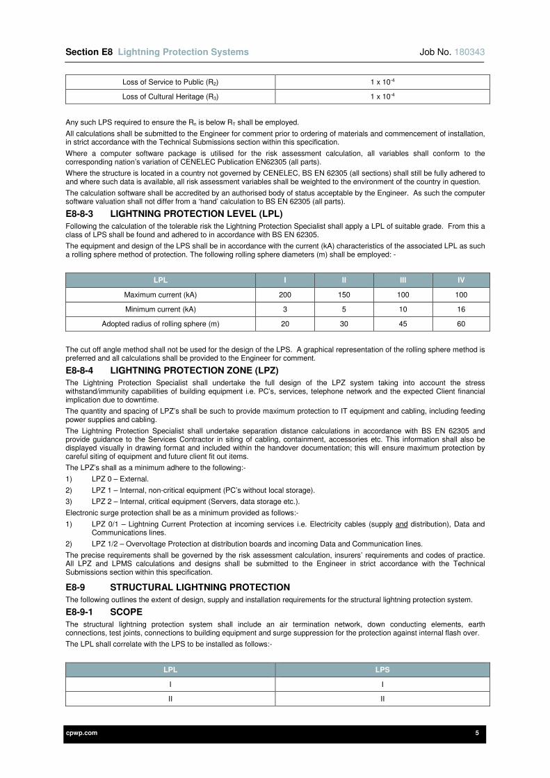
Section E8 Lightning Protection Systems Job No. 180343
cpwp.com 5
Loss of Service to Public (R2) 1 x 10⁻⁴
Loss of Cultural Heritage (R3) 1 x 10⁻⁴
Any such LPS required to ensure the Rn is below RT shall be employed.
All calculations shall be submitted to the Engineer for comment prior to ordering of materials and commencement of installation, in strict accordance with the Technical Submissions section within this specification.
Where a computer software package is utilised for the risk assessment calculation, all variables shall conform to the corresponding nation’s variation of CENELEC Publication EN62305 (all parts).
Where the structure is located in a country not governed by CENELEC, BS EN 62305 (all sections) shall still be fully adhered to and where such data is available, all risk assessment variables shall be weighted to the environment of the country in question.
The calculation software shall be accredited by an authorised body of status acceptable by the Engineer. As such the computer software valuation shall not differ from a ‘hand’ calculation to BS EN 62305 (all parts).
E8-8-3 LIGHTNING PROTECTION LEVEL (LPL)
Following the calculation of the tolerable risk the Lightning Protection Specialist shall apply a LPL of suitable grade. From this a class of LPS shall be found and adhered to in accordance with BS EN 62305.
The equipment and design of the LPS shall be in accordance with the current (kA) characteristics of the associated LPL as such a rolling sphere method of protection. The following rolling sphere diameters (m) shall be employed: -
LPL I II III IV
Maximum current (kA) 200 150 100 100
Minimum current (kA) 3 5 10 16
Adopted radius of rolling sphere (m) 20 30 45 60
The cut off angle method shall not be used for the design of the LPS. A graphical representation of the rolling sphere method is preferred and all calculations shall be provided to the Engineer for comment.
E8-8-4 LIGHTNING PROTECTION ZONE (LPZ)
The Lightning Protection Specialist shall undertake the full design of the LPZ system taking into account the stress withstand/immunity capabilities of building equipment i.e. PC’s, services, telephone network and the expected Client financial implication due to downtime.
The quantity and spacing of LPZ’s shall be such to provide maximum protection to IT equipment and cabling, including feeding power supplies and cabling.
The Lightning Protection Specialist shall undertake separation distance calculations in accordance with BS EN 62305 and provide guidance to the Services Contractor in siting of cabling, containment, accessories etc. This information shall also be displayed visually in drawing format and included within the handover documentation; this will ensure maximum protection by careful siting of equipment and future client fit out items.
The LPZ’s shall as a minimum adhere to the following:-
1) LPZ 0 – External.
2) LPZ 1 – Internal, non-critical equipment (PC’s without local storage).
3) LPZ 2 – Internal, critical equipment (Servers, data storage etc.).
Electronic surge protection shall be as a minimum provided as follows:-
1) LPZ 0/1 – Lightning Current Protection at incoming services i.e. Electricity cables (supply and distribution), Data and Communications lines.
2) LPZ 1/2 – Overvoltage Protection at distribution boards and incoming Data and Communication lines.
The precise requirements shall be governed by the risk assessment calculation, insurers’ requirements and codes of practice. All LPZ and LPMS calculations and designs shall be submitted to the Engineer in strict accordance with the Technical Submissions section within this specification.
E8-9 STRUCTURAL LIGHTNING PROTECTION
The following outlines the extent of design, supply and installation requirements for the structural lightning protection system.
E8-9-1 SCOPE
The structural lightning protection system shall include an air termination network, down conducting elements, earth connections, test joints, connections to building equipment and surge suppression for the protection against internal flash over.
The LPL shall correlate with the LPS to be installed as follows:-
LPL LPS
I I
II II
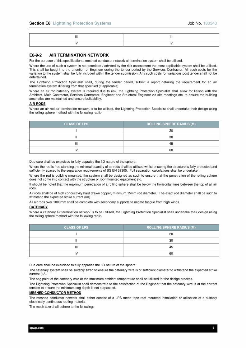
Section E8 Lightning Protection Systems Job No. 180343
cpwp.com 6
III III
IV IV
E8-9-2 AIR TERMINATION NETWORK
For the purpose of this specification a meshed conductor network air termination system shall be utilised.
Where the use of such a system is not permitted / advised by the risk assessment the most applicable system shall be utilised. This shall be bought to the attention of Engineer during the tender period by the Services Contractor. All such costs for the variation to the system shall be fully included within the tender submission. Any such costs for variations post tender shall not be entertained.
The Lightning Protection Specialist shall, during the tender period, submit a report detailing the requirement for an air termination system differing from that specified (if applicable).
Where an air rod/catenary system is required due to risk, the Lightning Protection Specialist shall allow for liaison with the Architect, Main Contractor, Services Contractor, Engineer and Structural Engineer via site meetings etc. to ensure the building aesthetics are maintained and ensure buildability.
AIR RODS
Where an air rod air termination network is to be utilised, the Lightning Protection Specialist shall undertake their design using the rolling sphere method with the following radii:-
CLASS OF LPS ROLLING SPHERE RADIUS (M)
I 20
II 30
III 45
IV 60
Due care shall be exercised to fully appraise the 3D nature of the sphere.
Where the rod is free standing the minimal quantity of air rods shall be utilised whilst ensuring the structure is fully protected and sufficiently spaced to the separation requirements of BS EN 62305. Full separation calculations shall be undertaken.
Where the rod is building mounted, the system shall be designed as such to ensure that the penetration of the rolling sphere does not come into contact with the structure or roof mounted equipment etc.
It should be noted that the maximum penetration of a rolling sphere shall be below the horizontal lines between the top of all air rods.
Air rods shall be of high conductivity hard drawn copper, minimum 15mm rod diameter. The exact rod diameter shall be such to withstand the expected strike current (kA).
All air rods over 1000mm shall be complete with secondary supports to negate fatigue from high winds.
CATENARY
Where a catenary air termination network is to be utilised, the Lightning Protection Specialist shall undertake their design using the rolling sphere method with the following radii:-
CLASS OF LPS ROLLING SPHERE RADIUS (M)
I 20
II 30
III 45
IV 60
Due care shall be exercised to fully appraise the 3D nature of the sphere.
The catenary system shall be suitably sized to ensure the catenary wire is of sufficient diameter to withstand the expected strike current (kA).
The sag point of the catenary wire at the maximum ambient temperature shall be utilised for the design process.
The Lightning Protection Specialist shall demonstrate to the satisfaction of the Engineer that the catenary wire is at the correct tension to ensure the minimum sag depth is not surpassed.
MESHED CONDUCTOR METHOD
The meshed conductor network shall either consist of a LPS mesh tape roof mounted installation or utilisation of a suitably electrically continuous roofing material.
The mesh size shall adhere to the following:-
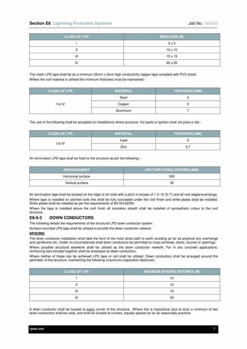
Section E8 Lightning Protection Systems Job No. 180343
cpwp.com 7
CLASS OF LPS MESH SIZE (M)
I 5 x 5
II 10 x 10
III 15 x 15
IV 20 x 20
The mesh LPS tape shall be as a minimum 25mm x 3mm high conductivity copper tape complete with PVC sheaf.
Where the roof material is utilised the minimum thickness must be maintained:-
CLASS OF LPS MATERIAL THICKNESS (MM)
I to IV
Steel 4
Copper 5
Aluminium 7
The use of the following shall be accepted on installations where puncture, hot spots or ignition shall not pose a risk:-
CLASS OF LPS MATERIAL THICKNESS (MM)
I to IV Lead 2
Zinc 0.7
Air termination LPS tape shall be fixed to the structure as per the following:-
ARRANGEMENT LPS TAPE FIXING CENTRES (MM)
Horizontal surface 500
Vertical surface 30
Air termination tape shall be located on the ridge of all roofs with a pitch in excess of 1 in 10 (5.7o) and all roof edges/overhangs.
Where tape is installed on pitched roofs this shall be fully concealed under the roof finish and strike plates shall be installed. Strike plates shall be installed as per the requirements of BS EN 62305.
Where the tape is installed above the roof finish all insulation sheath shall be installed of sympathetic colour to the roof structure.
E8-9-3 DOWN CONDUCTORS
The following details the requirements of the structural LPS down conductor system.
Surface mounted LPS tape shall be utilised to provide the down conductor network.
SPACING
The down conductor installation shall take the form of the most direct path to earth avoiding as far as practical any overhangs and cantilevers etc. Under no circumstances shall down conductors be permitted to cross windows, doors, louvres or openings.
Where possible structural steelwork shall be utilised as the down conductor network. For in situ concrete applications, reinforcing bars bonded together shall be employed as down conductors.
Where neither of these can be achieved LPS tape or rod shall be utilised. Down conductors shall be arranged around the perimeter of the structure, maintaining the following (maximum) separation distances:-
CLASS OF LPS MAXIMUM SPACING DISTANCE (M)
I 10
II 10
III 15
IV 20
A down conductor shall be located at every corner of the structure. Where this is impractical (due to size) a minimum of two down conductors shall be used, and shall be located at corners, equally spaced as far as reasonably practical.
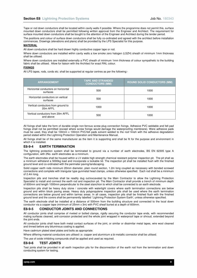
Section E8 Lightning Protection Systems Job No. 180343
cpwp.com 8
Tape or rod down conductors shall be located within cavity walls if possible. Where the programme does not permit this, surface mounted down conductors shall be permitted following written approval from the Engineer and Architect. The requirement for surface mounted down conductors shall be bought to the attention of the Engineer and Architect during the tender period.
The positions and colour of surface down conductors shall be fully co-ordinated and agreed with the architect before installation commences. Drawings (elevations and plans) shall be provided by the LPS Specialist for this purpose.
MATERIAL
All down conductors shall be hard drawn highly conductive copper tape or rod.
Where down conductors are installed within cavity walls a low smoke zero halogen (LSZH) sheath of minimum 1mm thickness shall be utilised.
Where down conductors are installed externally a PVC sheath of minimum 1mm thickness of colour sympathetic to the building fabric shall be utilised. Allow for liaison with the Architect for exact RAL colour.
FIXINGS
All LPS tapes, rods, cords etc. shall be supported at regular centres as per the following:-
ARRANGEMENT TAPE AND STRANDED
CONDUCTORS (MM) ROUND SOLID CONDUCTORS (MM)
Horizontal conductors on horizontal surfaces
500 1000
Horizontal conductors on vertical surfaces
500 1000
Vertical conductors from ground to 20m AFFL
1000 1000
Vertical conductors from 20m AFFL and above
500 1000
All fixings shall take the form of durable single non-ferrous screw plug connection fixings. Adhesive PVC weldable and felt pad fixings shall not be permitted (except where screw fixings would damage the waterproofing membrane). Were adhesive pads must be used, they shall be 100mm x 100mm PVC/felt pads solvent welded to the roof finish with the adhesive degradation period stated within the Lightning Protection Operation and Maintenance Manual.
All fixings shall be of the same manufacturer as the item it is supporting and shall be fit for the purpose and environment in which it is installed.
E8-9-4 EARTH TERMINATION
The lightning protection system shall be terminated to ground via a number of earth electrodes, BS EN 62305 type A configuration, with 2No. earth electrodes as a minimum.
The earth electrodes shall be housed within a LV stable high strength chemical resistant polymer inspection pit. The pit shall as a minimum withstand a 5000kg load and incorporate a lockable lid. The inspection pit shall be installed flush with the finished ground level and co-ordinated with the perimeter paving/landscaping.
Solid copper earth rods minimum 20mm diameter, plain round section, 1.2m long coupled as necessary with bonded screwed connections and complete with triangular type gunmetal head clamps, unless otherwise specified. Each rod shall be a minimum of 2.4m long.
Inspection pits and trenches shall be readily dug out/excavated by the Main Contractor to allow the Lightning Protection Specialist to install and connect the earth rod and inspection pit. The Main Contractor shall provide a trench of minimum depth of 600mm and length 1000mm perpendicular to the steel stanchion to which shall be connected to an earth electrode.
Inspection pits shall be heavy duty stone / concrete with watertight covers where earth termination connections are below ground and within block paving areas. Heavy duty polypropylene inspection pits shall be used where the earth termination connections are below ground and within tarmac areas. In all cases, inspection pits shall be finished flush with the finished ground level and the covers shall be permanently labelled `Lightning Protection System Earth', unless otherwise specified.
The earth electrode shall be installed at a distance of 500mm from the building structure and connected to the local down conductor via a copper tape (minimum of 25mm x 3m) with PVC sheaf buried at a depth of 600mm.
E8-9-5 CONDUCTOR JOINTS AND CONNECTIONS
All conductor joints shall comprise of riveted or bolted clamps, rigidly securing the conductor tape ends, with recommended mating surfaces cleaned, anti-corrosion protected and the whole joint wrapped in waterproof tape or shroud, extended beyond the joint ends.
All conductor joints shall have both metal contact surfaces of the joint, or similar or dissimilar metal tapes, wire wool cleaned and tinned before any bituminous coating is applied.
Have cadmium plated steel plates and bolts as appropriate.
Where differing material conductors are utilised i.e. copper and aluminium a bi-metallic connector shall be utilised.
The use of oxide inhibiting compounds shall be applied and used as required.
E8-9-6 TEST JOINTS
Test joints shall be provided in all earth inspection pits for the disconnection of the earth rod from the termination and down conducting system for testing.

Section E8 Lightning Protection Systems Job No. 180343
cpwp.com 9
Where it is found that the resistance to earth for the system is greater than 10Ω, earth electrode lengths shall be increased until
a satisfactory resistance is achieved.
The use of moisture retaining aggregates shall not be permitted.
E8-9-7 CONNECTION TO EQUIPMENT
Earth electrode connections shall be concealed within the brickwork, connecting tapes from the down conductor to earth pits shall be concealed within the cavity of the brickwork. All passes through brickwork shall be made good to maintain the thermal and structural integrity of the wall. The tape shall be laid by the Builder through a duct through the wall.
Bonding as directly as possible, preferably below ground, to all buried services (entering the structure) having exposed metal in the form of sheathing, armouring or piping shall be undertaken. The complete system shall be further bonded back to the main building earth bar.
Bonds to all exposed extraneous metalwork shall be undertaken, including access hatches, ladders, roof lights, vents, sun pipes, flues, PV panel supports etc.
All equipment that cannot stand a direct lightning strike i.e. AHU’s, chillers, aerials, CCTV etc. that are required to be constantly operational shall be protected via an air rod connected to the LPS via a conducting tape. The air rod shall be sufficiently sized and located, including adequate separator distance to fully shield the equipment from a direct strike.
All connections throughout the system shall be fully electrically continuous and in good appearance and suitably connecting using adequate connections with correct torque levels applied.
E8-9-8 SURGE PROTECTION DEVICE (SPD) FOR STRUCTURAL PROTECTION
For the prevention of internal flash over due to differing potentials an internal SPD installation shall be installed for structural protection (outbreak of fire due to flash over/risk of electrocution).
An earthing array, consisting of a main earth bar, earthing of equipment and supplementary bonding shall be installed. Refer to the specific sections of this specification for details.
All earth connections shall comply with the minimum cable diameters outlined within BS EN 62305-3, tables 8 and 9. Cable diameters shall be calculated in-line with BS 7671 and BS 7430.
The Lightning Protection Specialist shall undertake the sizing, design and installation of bonding the structural LPS to the buildings main earthing installation.
The Lightning Protection Specialist shall design, supply and install surge suppression devices at incoming services as necessary to reduce the risk of internal flash over. Surge suppression devices shall be of the 10/350 µs waveform type and installed as above as reasonably practical to the incoming service, whilst being mounted in a visually and manually accessible location. All SPD’s shall be installed downstream of any metering equipment (where the metering equipment is located within the structure).
E8-10 ELECTRICAL AND ELECTRONIC PROTECTION SYSTEMS
The following section shall detail the surge protection requirements to protect electrical and electronic systems within the building / structure dependent on its requirement for structural lightning protection.
E8-10-1 ELECTRICAL AND ELECTRONIC SYSTEMS – PROTECTION WHERE THERE IS NO STRUCTURAL LIGHTNING PROTECTION SYSTEM
Where the risk evaluation identifies a structural LPS is not required, but there is an intolerable indirect risk i.e. RP < RT < RJ, then surge suppression is required.
All overhead lines serving the building (power / telecom etc.) shall be protected via a suitably sized Type 1 SPD, as a minimum 12.5kA 10/350µs waveform.
All underground lines serving the building (power / telecom etc.) shall be protected via a suitably sized Type 2 SPD, as a minimum 12.5kA 8/20µs waveform.
E8-10-2 ELECTRICAL AND ELECTRONIC SYSTEMS – PROTECTION WHERE THERE IS A STRUCTURAL LIGHTNING PROTECTION SYSTEM
Where the risk assessment identifies a risk of lightning strike this dictates an assumed maximum strike current. A LPMS system shall be designed and installed to ensure this lightning current and voltage is safely discharged to earth whilst protecting vital electrical and electronic systems.
The building/structure shall be zoned as such to ensure co-ordination between electronic equipment withstand voltages and the expected induced over voltages.
A maximum over voltage limit of 600V shall be maintained throughout.
The external/structure lightning protection zone shall employ SPD’s on all incoming modes. The SPD current kA rating shall be as such that the total rating across all modes is 50% of the expected direct structure strike current (maximum 200kVA strike for LPL1). The SPD’s shall be of a Class 1 10/350µs waveform.
All subsequent downstream SPD’s shall be installed at LPZ boundaries and of either 10/350µs or 8/20µs waveform type dependent on the characteristics of the vital equipment being protected. The kA rating of the SPD’s shall decrease as the zones progress to other greater protection i.e. lower let through voltages.
The SPZ design and layout shall be undertaken by the Lightning Protection Specialist. All design drawings and calculations (including all critical equipment characteristics assumptions) shall be forwarded to the Engineer for comment/review in strict accordance with the Technical Submissions section within this specification.
E8-10-3 INSTALLATION OF SURGE PROTECTION DEVICES (SPD’S)
All surge protection devices shall be installed to the requirements of the manufacturer to ensure design operation is maintained.
SERIES INSTALLED SPD’S
Section E8 Lightning Protection Systems Job No. 180343
cpwp.com 10
SPD’s shall be installed in series to lines of less than 16A, typically telecommunications, CCTV etc. The SPD devices shall be dependent on the location on SPZ (Surge Protection Zone).
The SPD shall be installed in an accessible location with the status lamps in a suitable viewing position. Units shall be installed in “service areas” such as plantrooms, store cupboards, risers, data rooms etc.
SPD’s shall be fixed to the building fabric at suitable distances from conductive structural elements.
SPD earth connections shall be suitably sized to carry the expected surge current voltage and shall conform to the minimum diameters outlined in Table 1 of BS EN 62305-4.
Earth loads shall be connected to a local earth box, connection loads shall not exceed 10m.
PARALLEL INSTALLED SPD’S
SPD’s shall be installed in parallel to lines greater than 16A and shall be protected via a suitably sized protective device (MCB/MCCB). The SPD class shall be dependent on the location and SPZ (Surge Protection Zone).
The SPD shall be installed in an accessible location with the status lamps in a suitable viewing position. Units shall be installed in “service areas” such as plantrooms, store cupboards, risers, data rooms etc.
SPD’s shall be fixed to the building fabric at suitable distances from conductive structural elements.
SPD connection loads shall be maintained at lengths no greater than 0.5m.
The leads shall be bound together utilising cable ties/spiral wraps along their entire length. Live and neutral loads shall be of the same length (within practical reason).
The SPD shall be connected to the local earth bar utilising leads of suitable diameter to carry the expected surge current/voltage and conform to the minimum requirements of BS EN 62305-4 Table 1.
E8-11 PRE-INSTALLATION REQUIREMENTS
The Lightning Protection Specialist shall allow for fully liaising with all other specialists (Mechanical and Electrical) to ascertain the extent of all extraneous metal work/equipment that shall require connection to the structural LPS and all electronic items that require surge protective measures, i.e. CCTV, Fire Alarm panels etc.
All such items raised by the specialist installers shall be included within the Lightning Protection calculations, design, drawings and the Services Contractor’s tender submission.
The appointed Specialist shall be responsible for the production of proposed installation drawings for the system which are to be submitted to the design team for comment in strict accordance with the Technical Submissions section within this specification.
Drawings shall include extent of the air termination network, spacing and location of down conductors, all connections and connections to equipment and a fully co-ordinated SPD layout and schematic.
The appointed specialist shall submit any and all alterations to the specification and drawings including materials to be used to the design team for comment in strict accordance with the Technical Submissions section within this specification.
E8-12 INSTALLATION PROCEDURE
The complete installation, both structural and electronic, shall be fully co-ordinated by the Services Contractor to ensure all key items collate with main build programme i.e. the Services Contractor shall ensure the Lightning Protection Specialist attends site on specified days to ensure other trades are not delayed.
The installation of the complete structural and electronic lightning protection system shall be installed by the nominated specialist, with the exception of SPD devices to be installed by the Services Contractor or equipment manufacturer, as detailed within specific sections of this specification.
The complete design and installation shall comply with the Construction (Design and Management) Regulations ensuring all items installed are located in fully accessible locations with sufficient working area for maintenance.
The Lightning Protection Specialist shall identify on their ‘Working Drawings’ and ‘As Fitted’ drawings and all associated risks concerning the installation and future maintenance. All risks shall be designed out as far as reasonably practical, where risks cannot be removed, industry approved and recommended safety procedures shall be employed.
Under no circumstances shall any installation works take place during, or sufficient threat of, a thunderstorm. Any such delays occurred shall be submitted to the Main Contractor in a timely fashion to maintain programme completion and co-ordination.
E8-13 PROXIMITY AND SEGREGATION OF WIRING SYSTEMS
Adequate separation shall be provided between conductors of a lightning protection system and other electrical wiring systems e.g. low voltage systems (general LV wiring), extra-low voltage systems (fire alarm, security, telecommunications and data wiring etc.).
The minimum separation distance in metres shall be calculated by the Lightning Protection Specialist in accordance with BS EN 62305-3.
E8-14 ENGINEERS AND ARCHITECTS DRAWINGS
All power supplies, electrical equipment and wiring accessories shall be set out as detailed on the agreed Architects / Specialists elevation drawings. Where these are not available from the Architect or Specialists, the Electrical Contractor shall produce elevation drawings for approval by the Engineer in a timely manner to suit the construction programme.
However where there is a discrepancy between the Architects / Specialist elevation drawings and the information provided within this specification (e.g. mounting heights) this shall be brought to the attention of the Engineer and Architect / Specialist in a timely manner.
The drawing symbols used on the Engineer’s drawings are not to scale and therefore an allowance shall be made for any of the aforementioned to be relocated within a 1000mm radius of the indicated position at no further cost. These positions shall then be agreed with the Engineer and Architect / Specialist in a timely manner during the contract period.
Section E8 Lightning Protection Systems Job No. 180343
cpwp.com 11
E8-15 IDENTIFICATION, NOTICES AND LABELLING
Refer to Section 2E of this specification.
E8-16 CABLE SUPPORT AND CONTAINMENT SYSTEMS / CABLING AND WIRING SYSTEMS
Refer to Section 2E of this specification.
E8-17 TECHNICAL SUBMISSIONS
In accordance with the agreed programme and the requirements of Section 1B, the Contractor shall provide technical submissions for the following:-
1) Full lightning protection system calculations in strict accordance with BS EN 62305 and this specification.
2) Formal risk assessment and economic loss calculations.
3) Technical specifications for all lightning protection materials, equipment and cabling to be installed.
4) Technical specifications for all surge protection devices to be installed.
5) Layout drawings for all lightning protection systems (including elevations where surface down conductors are used).
6) Schedule of all identification, notices, labels (including safety signage) and cable identification labels / markers along with a physical sample of each label type.
The time allowed for comment by the Engineer shall be as detailed within section 1B of this specification.
E8-18 DIAGRAMS AND DOCUMENTATION
BS EN 62305 specifies that the following records shall be kept on site by the person responsible for the upkeep of the installation. The Lightning Protection Specialist shall ensure the following is provided as part of the Operating and Maintenance documentation:-
1) Scale drawings showing the nature, dimensions, materials and position of all component parts of the LPS and LMPS.
2) The nature of the soil and any special earthing arrangements.
3) The type and position of the earth electrodes, including reference electrodes.
4) The test conditions and results obtained.
5) General condition of the air termination network.
6) General level of corrosion and condition of corrosion protection.
7) General condition of fixings.
8) Any and all deviations from the standard.
9) Documentation of all danger both to the LPS and LMPS.
10) Design information.
11) Testing regime.
The above drawings and documentation shall be included within the O&M manual.
E8-19 INSPECTION, TESTING AND COMMISSIONING
E8-19-1 STRUCTURAL LIGHTNING PROTECTION SYSTEM
The inspection and testing shall be carried out in full accordance with the requirements of BS EN 62305 Lightning Protection and BS 7430 Code of Practice for Earthing and include the provision of the necessary test equipment for the measurements required. The installation is to be complete with all electrical continuity and mechanical efficiency tests carried out before handover of remedial works.
BS EN 62305 specifies that on completion of installation or any modifications to it, the necessary measurements and/or checks shall be made by the specialist and the results recorded in a lightning protection system logbook.
1) The resistance to earth of the earth termination network and each earth electrode.
2) The results of a visual check of all conductors, bonds and joints or their measured electrical continuity.
The full inspection and testing of the structural and electronic LPS shall ensure the systems are in full compliance with all applicable British standards, code of practice and insurers requirements.
E8-19-2 ELECTRICAL AND ELECTRONIC SYSTEMS
The inspection and testing shall be carried out in full accordance with the requirements of BS EN 62305 Lightning Protection.
Visual inspections shall be carried out by the Specialist to ensure there are no loose connections, breaks in connections, cable shields are intact, no additions to the system, SPZ are not compromised and safety distances maintained. A full list of requirements is detailed within BS EN 62305 and shall be fully adhered to.
Following the visual inspection the Specialist shall fully assess the equipment and its installation, position, rating etc. to ensure the LPMS complies with the design and is fully capable of performing as such. Any additional devices required shall be included for and installed by the Specialist.
E8-19-3 ELECTRICAL INSTALLATION
The electrical installation works associated with the fire alarm system(s) shall be inspected and testing in strict accordance with BS 7671 and Section 2F of this specification. All circuits / test results shall be recorded on the ‘Schedule of circuit details / Schedule of test results’ provided within the Electrical Installation Certificates).
Section E8 Lightning Protection Systems Job No. 180343
cpwp.com 12
E8-19-4 FINAL ACCEPTANCE TESTS
The following shall be undertaken by the Specialist to prove to the satisfaction of the Engineer the complete LPS and LPMS.
The testing of the structural protection system shall be undertaken at a select number of earth electrodes nominated by the Engineer. The resistance to earth shall be measured in isolation of the test point between the down conductor and earth electrode in the disconnected position.
Formal witnessing of testing and commissioning shall be undertaken in strict accordance with Section 2F of this specification.
It shall be ensured that if the resistance to earth of a lightning protection system exceeds 10 Ω, the value shall be reduced, if the resistance is less than 10 Ω, but significantly higher than the previous reading, the cause shall be investigated and any necessary remedial action taken.
Include for the tests and accuracy of such tests to be demonstrated to the satisfaction of the Engineer and copies of recorded test results made available.
The visual inspection of a select number of SPS’s nominated by the Engineer shall be undertaken to ensure the connection cabling, visual appearance and feeding protective device are adequate for use. An inspection of the SPZ shall also be undertaken to ensure they have not been compromised.
The commissioning certification and as-installed drawings for the lightning protection system(s) shall be included within the O&M manual.
E8-20 MAINTENANCE
The Lightning Protection Specialist shall include for 12 months visual inspection and testing as required by BS EN 62305. This shall as a minimum include 1 No. revisit 12 months from practical completion (maximum 15 months from completion of LPS and LMPS) to fulfil the following: -
1) Visual inspection of LPS air termination network.
2) Visual inspection of earth connections.
3) Earth resistance testing of the complete LPS network.
4) Visual inspection of SPD’s, feeding protective devices and cabling.
cpwp.com V1.3
Section E9 Miscellaneous Electrical Systems
Section E9 Miscellaneous Electrical Systems Job No180343
cpwp.com 1
Contents Page
E9-1 MISCELLANEOUS ELECTRICAL SYSTEMS 2
E9-2 DEFINITIONS 2
E9-3 REFERENCES TO OTHER SECTIONS OF THIS SPECIFICATION 2
E9-4 AUDIO FREQUENCY INDUCTION LOOP SYSTEMS 2
E9-4-1 DEFINITIONS 2
E9-4-2 STANDARDS APPLICABLE 2
E9-4-3 DESIGN REQUIREMENTS 2
E9-4-4 SCOPE OF WORKS 2
E9-4-5 GENERAL REQUIREMENTS 3
E9-4-6 TECHNICAL SUBMISSIONS 4
E9-4-7 DIAGRAMS AND DOCUMENTATION 4
E9-4-8 INSPECTION, TESTING AND COMMISSIONING 5
E9-4-9 DEFINITIONS 5
E9-5 ENGINEERS AND ARCHITECTS DRAWINGS 5
E9-6 ROOM DATA SHEETS 6
E9-7 IDENTIFICATION, NOTICES AND LABELLING 6
E9-8 CABLE SUPPORT AND CONTAINMENT SYSTEMS 6
E9-9 POSITIONING AND MOUNTING HEIGHT OF ELECTRICAL SERVICES 6

Section E9 Miscellaneous Electrical Systems Job No180343
cpwp.com 2
E9-1 MISCELLANEOUS ELECTRICAL SYSTEMS
This section details the requirements for miscellaneous electrical systems and shall be read in conjunction with all other sections of this specification and the associated drawings.
The miscellaneous electrical systems required for this project shall be as follows:-
1) Audio frequency induction loop systems (AFILS).
2) Footfall counters locations as indicated on the drawings
E9-2 DEFINITIONS
Refer to Section 2E / Section 1B of this specification and Part 2 of BS 7671 – IET Wiring Regulations – Requirements for Electrical Installations for further details regarding definitions, symbols and abbreviations.
E9-3 REFERENCES TO OTHER SECTIONS OF THIS SPECIFICATION
This section shall not be read in isolation and must be read in conjunction with all other sections of this specification which define further requirements for the electrical installation.
Section 2E details the default requirements for electrical workmanship and materials which shall apply fully to this section of the specification.
E9-4 AUDIO FREQUENCY INDUCTION LOOP SYSTEMS
This section details the requirements for audio frequency induction loop systems (AFILS) and shall be read in conjunction with all other sections of this specification and the associated drawings.
E9-4-1 DEFINITIONS
Refer to Section 2E / Section 1B of this specification and Part 2 of BS 7671 – IET Wiring Regulations – Requirements for Electrical Installations for further details regarding definitions, symbols and abbreviations.
E9-4-2 STANDARDS APPLICABLE
Works shall be completed in accordance with all applicable industry standards. Some of the most relevant standards associated with this section are scheduled below:
STANDARDS AND DOCUMENTS
BS 7671 IET Wiring Regulations – Requirements for Electrical Installations
IET On-Site Guide – BS 7671 – IET Wiring Regulations – Requirements for Electrical Installations
All IET Guidance Notes – BS 7671 – IET Wiring Regulations – Requirements for Electrical Installations
BS 7594 Code of practice for audio-frequency induction-loop systems (AFILS)
BS 8300 Design of buildings and their approaches to meet the needs of disabled people – Code of practice
BS EN 60118-4 Electroacoustics – Hearing aids – Part 4: Induction-loop systems for hearing aid purposes – System performance requirements
BS EN 60268-4 Sound system equipment – Part 4: Microphones
BS EN 62489 Electroacoustics – Audio-frequency induction loop systems for assisted hearing
The Building Regulations – Approved Document M
Building Bulletin 91 – Access for Disabled People to School Buildings – Management and Design Guide by the DfEE (Department for Education and Employment)
All current and relevant ‘Action on Hearing Loss’ (formerly RNID) guidance and publications
All current and relevant Building Bulletin’s by the DfES (Department for Education and Skills) and other government agencies
All standards, guidance and statutory regulations detailed within Section 2E-3
Where the above standards refer to supporting documentation and standards these shall be fully complied with in all respects.
Where discrepancy is found between this specification and the relevant standards, the Contractor shall obtain written clarification from the Engineer prior to submission of the tender. Where a discrepancy has not been clarified prior to tender submission, the Contractor shall include the most onerous requirements.
E9-4-3 DESIGN REQUIREMENTS
The Contractor shall employ one of the Audio Frequency Induction Loop Specialist(s) named in Appendix I to design, supply, install, test and commission the audio frequency induction loop systems. The Audio Frequency Induction Loop Specialist(s) shall be fully responsible for the design of the audio frequency induction loop systems.
E9-4-4 SCOPE OF WORKS
The miscellaneous electrical systems installation shall include the provision of the following (where required):-
1) Audio frequency induction loop systems (AFILS) including amplifier to the main reception desk.

Section E9 Miscellaneous Electrical Systems Job No180343
cpwp.com 3
2) Desk-top microphone.
3) All necessary wiring accessories e.g. data outlets, telephone outlets, un-switched fused connection units, double pole lockable key switches etc.
4) All necessary power and signalling cabling.
5) All necessary earthing and bonding.
6) All necessary cable support and containment systems.
7) Inspection, testing and commissioning.
8) All necessary identification, notices and labelling.
9) All necessary O&M information.
It shall be noted the above lists are not exhaustive and reference must be made to all sections of this specification and the associated drawings.
All due allowances shall be made within the tender submission to ensure all necessary power supplies, wiring accessories and associated equipment is provided for the electrical installation, with particular attention paid to electrical systems where the Contractor has design responsibility.
E9-4-5 GENERAL REQUIREMENTS
The audio frequency induction system(s) shall be designed, selected, installed, tested and commissioned in strict accordance with BS 7594, BS EN 60118-4, BS EN 60268-4, BS EN 62489, BS 8300 and The Building Regulations – Approved Document M.
Fixed audio frequency induction loop system(s) (not portable systems) shall be provided as indicated on the drawings and room data sheets (where provided). These AFILS shall be provided to the following areas / rooms (where applicable):-
1) Service or reception desks / counters.
2) Emergency voice communication system(s) (EVCS) / Disabled refuge system(s) – Provided to all outstations.
3) Lifts.
The following factors must be considered at design stage by the Audio Frequency Specialist(s), as required by BS 7594 to ensure all AFILS are fully functional on completion of the works:-
1) Magnetic noise interference.
2) Effect of metal in the building structure and within the coverage area.
3) Magnetic field overspill.
The AFILS shall be classified and meet the following features / performance requirements in strict accordance with BS 7594 and:-
CLASSIFICATION
ALLOWABLE BACKGROUND
NOISE
(dB L)
FIELD VARIATION IN THE USEFUL MAGNETIC
FIELD VOLUME
(dB)
LOOP SEPARATION
USER CONTROLS (MINIMUM)
INDICATIONS
A1: Portable or hand held self-contained equipment
-32
-22 for short time periods
12 2m Power, loop
current
A2: Small volume system for us in counters, signage, emergency voice communication systems (EVCS)
-32
-22 for short time periods
12
Width of loop x2 e.g. 2m for
counters using 1m wide loops
Input gain, loop drive
Power, loop current, input signal present or automatic gain control
active
A3: Area coverage systems for a single volume where other AFILS are not present in the vicinity and where security or overspill or overcoming significant metal losses is of no importance
-32
-22 for short time periods
6 Width of loop x2 e.g. 10m for 5m
wide loop
Input gain, loop drive
Power, loop current, input signal present or automatic gain control
active
A4: Multi-loop / low overspill systems
-32
-22 for short time periods
6
As recommended by the Audio Frequency
Induction Loop Specialist(s), typically 2m
Input gain, loop drive
Power, loop current, input signal present or automatic gain control
active
Section E9 Miscellaneous Electrical Systems Job No180343
cpwp.com 4
The Audio Frequency Induction Loop Specialist(s) shall suitably classify and design the AFILS to suit the environment and area / room in which they are installed.
The Audio Frequency Induction Loop Specialist(s) shall provide classification A4 multi-loop / low overspill systems:-
1) Where required for security / confidentiality purposes.
2) Where other AFILS are installed in close proximity (e.g. classrooms / teaching spaces, meeting rooms or cinemas with multiple AFILS).
3) To overcome significant metal content (e.g. reinforced concrete construction, metallic ceilings / raised access floors etc.).
AFILS amplifiers shall have the following minimum features:-
1) Input signal detection / indication and associated gain control (input level).
2) Output current detection / indication and associated gain control (drive).
3) Limited bandwidth, 100 Hz to 5 kHz.
4) Automatic gain control (AGC).
In certain locations where adjacent rooms have their own AFILS, but are constructed with moveable partition walls (e.g. folding / sliding doors) such that the rooms may function as individual or combined areas, the AFILS will be required to be switchable to suit the flexible use of the space.
The switching capability will enable the AFILS to operate as individual or combined systems via simple controls operated by the end-user. The AFILS shall be tested and commissioned to suit all room / area configurations.
Signage shall be provided to each room / area where AFILS have been installed to make the hearing impaired aware that the AFILS is present. The signage shall be a minimum size of 100mm x 100mm and indicate ‘T’ in strict accordance with BS 7594.
The signage shall also be provided on AFILS equipment, loop cable junction boxes and adjacent to the loop cable itself for maintenance purposes and to prevent accidental disturbance / damage.
Prior to permanent installation the Audio Frequency Induction Loop Specialist(s) shall temporarily install the loop cabling as close as possible to its final installation route and location within the room / area. Where AFILS are to be installed in adjacent rooms / areas these shall also be temporarily installed for testing purposes.
The AFILS shall then be tested prior to permanent installation to verify the correct operation of all AFILS.
Loop cabling shall be installed in one complete length with joints / connections only acceptable at AFILS equipment terminations (e.g. AFILS amplifiers). The loop cabling shall be installed within dedicated uPVC conduit (loop cabling only, not low voltage power supplies) which shall be fully continuous throughout its entire length in strict accordance with Section 2E of this specification.
Loop cabling shall be installed at least 600mm from low voltage (general power wiring) and extra low voltage systems (fire alarm, security, telecommunications and data wiring etc.). However the loop cabling shall be installed at least 1000mm from all other audio wiring systems. These requirements shall be verified with the AFILS equipment manufacturers.
Equipment shall be wired in strict accordance with manufacturers’ schematics / diagrams. Where cable connections are made into equipment, a numbered marker sleeve shall be fitted to the cable-core, which shall correspond to the wiring diagram.
Ensure that all wiring connections are correctly made before any equipment is set to work. Soldered ends shall be provided for termination.
Cable tails to terminals shall be of sufficient length and be neatly dressed and arranged to prevent development of tension in the cable or on the termination. All cables shall be securely tethered within enclosures. All wiring shall be concealed within the building fabric.
Power supplies to AFILS shall be provided from local low voltage final circuits and un-switched fused connection units.
All power and signalling cabling shall be LSZH (LSOH, OHLS) with emissions of hydrogen chloride gas < 0.5%.
All AFILS equipment and cabling shall be installed in strict accordance with manufacturers’ literature. All equipment shall be from the same manufacturer.
Provide all necessary equipment, commissioning, LV power supplies, signalling cabling and containment to ensure all systems are fully functional on completion of the works.
E9-4-6 TECHNICAL SUBMISSIONS
Prior to installation on-site the Contractor shall provide technical submissions for the following:-
1) Technical specifications for all AFILS equipment and cabling to be installed.
2) Wiring schematic drawings for all AFILS to be installed, generic manufacturer’s schematics will not be accepted.
3) Confirmation of the classification of each AFILS (e.g. A1, A2, A3, A4 etc.).
4) Layout drawings detailing the locations of all AFILS equipment.
5) Schedule of all identification, notices, labels (including safety signage) and cable identification labels / markers along with a physical sample of each label type.
The time allowed for comment by the Engineer shall be as detailed within section 1B of this specification.
E9-4-7 DIAGRAMS AND DOCUMENTATION
Diagrams and documentation shall be provided in strict accordance with BS 7594.
The drawings and documentation shall include:-
1) Certificates for the design, installation, testing, commissioning, acceptance and verification (where applicable) of the audio frequency induction loop system(s).
2) An adequate operation and maintenance manual for the system; this should provide information, specific to the system in question, regarding the following:-
a) A list of equipment provided and its configuration (e.g. schematic diagram).
Section E9 Miscellaneous Electrical Systems Job No180343
cpwp.com 5
b) Use and operation of the system.
c) Service and maintenance of the system.
d) The importance of ensuring that changes to the building, such as relocation of partitions, and new metal structures do not affect the standard of coverage in the space.
3) As-fitted drawings indicating at least the following:-
a) The positions of all AFILS equipment.
b) The positions of all microphones.
c) Wiring schematic drawings for all audio frequency induction loop systems installed (using symbols from BS 7594 where the AFILS classification is shown) generic manufacturer’s schematics will not be accepted.
d) The type, sizes and actual routes of cables.
4) A logbook for recording the information as recommended herein.
5) A record of any agreed variations from the original design specification.
The above drawings and documentation shall be included within the O&M manual.
E9-4-8 INSPECTION, TESTING AND COMMISSIONING
The audio frequency induction loop system(s) shall be inspected, tested and commissioned in strict accordance with BS 7594, BS 7671, Section 2F of this specification and the manufacturer’s recommendations.
The electrical installation works associated with the audio frequency induction loop system(s) shall be inspected and testing in strict accordance with BS 7671 and Section 2F of this specification. All circuits / test results shall be recorded on the ‘Schedule of circuit details / Schedule of test results’ provided within the Electrical Installation Certificates).
Formal witnessing of testing and commissioning shall be undertaken in strict accordance with Section 2F of this specification.
The audio frequency induction loop installation shall be inspected and tested in accordance with the recommendations of BS 7594:-
1) Insulation resistance tests:-
a) All insulated cables with a manufacturer’s voltage rating suitable for main use shall be subject to insulation testing at 500 V d.c. prior to this test, cables shall be disconnected from all equipment that could be damaged by the test.
b) Insulation resistance, measured in the above test, between conductors, between each conductor and earth, and between each conductor and any screen, shall be at least 2 MΩ.
2) Continuity of all circuits shall be tested.
3) Continuity of protective conductors and, for mains supply circuits, earth fault loop impedance, shall be tested to ensure compliance with BS 7671 and Section 2F of this specification.
4) The following tests shall also be undertaken on completion of the installation works, after connection of all loops:-
a) If possible, the 1 kHz impedance of each loop circuit in type A3, and type A4 systems; if not possible, the DC resistance of each loop circuit shall be measured and recorded:-
b) Correct polarity of circuits where this is required in type A4 systems.
c) Any other test specified by the manufacturer of the system.
Test equipment shall be provided in strict accordance with the test equipment requirements of Section 2F of this specification.
The audio frequency induction loop system(s) shall be commissioned in strict accordance with the recommendations of Section 17 Commissioning of BS 7594.
Commissioning certification shall be provided to verify the correct installation and operation of the audio frequency induction loop system(s). The following separate certification shall be provided:-
1) Design certificate.
2) Installation certificate.
3) Commissioning certificate.
4) Acceptance certificate provided for completion by the client.
Upon completion the system(s) shall be demonstrated to the Engineer and the Client. The Contractor / Audio Frequency Induction Loop Specialist shall provide training to the Client until they fully understand the operation of the system.
The commissioning certification and as-installed drawings for the audio frequency induction loop system(s) shall be included within the O&M manual.
E9-4-9 DEFINITIONS
Refer to Section 2E / Section 1B of this specification and Part 2 of BS 7671 – IET Wiring Regulations – Requirements for Electrical Installations for further details regarding definitions, symbols and abbreviations.
E9-5 ENGINEERS AND ARCHITECTS DRAWINGS
All power supplies, electrical equipment and wiring accessories shall be set out as detailed on the agreed Architects / Specialists elevation drawings. Where these are not available from the Architect or Specialists, the Electrical Contractor shall produce elevation drawings for approval by the Engineer in a timely manner to suit the construction programme.
However where there is a discrepancy between the Architects / Specialist elevation drawings and the information provided within this specification (e.g. mounting heights) this shall be brought to the attention of the Engineer and Architect / Specialist in a timely manner.

Section E9 Miscellaneous Electrical Systems Job No180343
cpwp.com 6
The drawing symbols used on the Engineer’s drawings are not to scale and therefore an allowance shall be made for any of the aforementioned to be relocated within a 1000mm radius of the indicated position at no further cost. These positions shall then be agreed with the Engineer and Architect / Specialist in a timely manner during the contract period.
E9-6 ROOM DATA SHEETS
Room data sheets have not been produced for this works.
E9-7 IDENTIFICATION, NOTICES AND LABELLING
Refer to Section 2E of this specification.
E9-8 CABLE SUPPORT AND CONTAINMENT SYSTEMS
Refer to Section 2E of this specification.
E9-9 POSITIONING AND MOUNTING HEIGHT OF ELECTRICAL SERVICES
Refer to Section 2E of this specification.
cpwp.com V1.6
Section M1 Domestic Water Services
Section M1 Domestic Water Services Job No. 180343
cpwp.com 2
Contents Page
M1-1 GENERAL REQUIREMENTS 3
M1-2 DEFINITIONS 3
M1-3 REFERENCE TO OTHER SECTIONS OF THIS SPECIFICATION 3
M1-4 STANDARDS APPLICABLE 3
M1-5 SCOPE OF WORKS 4
M1-6 SYSTEM PRESSURE RATING 4
M1-7 INCOMING MAINS COLD WATER SUPPLY 4
M1-8 INCOMING MAINS COLD WATER METERS 5
M1-9 INCOMING MAINS PHYSICAL WATER CONDITIONER 5
M1-10 DOMESTIC HOT WATER PLATE HEAT EXCHANGERS 5
M1-11 STORAGE / SEMI-STORAGE CALORIFIERS 5
M1-12 HOT WATER CIRCULATING PUMPS 6
M1-13 EXPANSION VESSEL(S) 6
M1-14 THERMOSTATIC MIXING VALVES 7
M1-15 PIPEWORK, VALVES AND FITTINGS 7
M1-15-1 SECONDARY SUPPORTS 7
M1-15-2 WATER MANAGEMENT SYSTEM FOR URINALS 7
M1-15-3 FINAL CONNECTIONS TO SANITARY WARE 7
M1-15-4 BACK FLOW PREVENTION 8
M1-15-5 DRAIN VALVES AND AIR VENTS 8
M1-15-6 COLD WATER DEAD LEGS 8
M1-15-7 HOT WATER CIRCULATING SYSTEM DEAD LEGS 8
M1-15-8 HOT WATER SYSTEM DEAD LEGS 9
M1-16 THERMAL INSULATION 9
M1-17 CHEMICAL DOSING, TESTING AND COMMISSIONING 9
M1-18 FREEZING PROTECTION TRACE HEATING 9
M1-19 EXPANSION AND CONTRACTION 9
Section M1 Domestic Water Services Job No. 180343
cpwp.com 3
M1-1 GENERAL REQUIREMENTS
The domestic hot and cold water services shall serve all sanitary ware and other outlets.
Cold water services shall be distributed under main water pressure to all outlets.
Hot water shall be generated centrally at the plate heat exchangers plus a Thermal Store
To ensure that hot water is supplied quickly to all outlets the hot water system shall be a recirculating system with return pump
Thermostatic mixing valves shall be provided throughout the project only to those outlets that need thermostatic mixing valves to comply with Building Regulations Approved Document G.
All sanitary ware shall be supplied by the Main Contractor but shall be piped up by the ‘Water Safe’ certified Mechanical Contractor. The entire installation shall be fully in accordance with best practice to minimise the risks of legionella bacteria growth in accordance with the industry ‘Standards Applicable’ listed below.
On completion the whole installation shall be flushed and sterilised.
M1-2 DEFINITIONS
Refer to Section 1B for general definitions plus:
DEFINITIONS
BCWS Boosted Cold Water Service
DRV Double Regulating Valve
HIU Heat Interface Unit
HWSF Hot Water Service Flow
HWSR Hot Water Service Return
MCWS Mains Cold Water Service
PHX / PHE Plate Heat Exchangers
TCV Thermal Circulation Valve
TMV Thermostatic Mixing Valve
WRAS Water Regulation Advisory Scheme
VFC Volt Free Contacts
M1-3 REFERENCE TO OTHER SECTIONS OF THIS SPECIFICATION
This section of the specification shall not be used in isolation and must be read in conjunction with the particular sections, commissioning and standard clauses, all of which define further the requirements for the installations.
The following text advises if the Contractor shall deviate from the preferred pipework material and standard or utilise one of the alternative materials and standards of construction listed in the ‘General Installation Standards’ sections detailed earlier in this specification. Agreed alternative materials for the installation from the preferred standard material and standard of construction are:
No deviation from the ‘General Installation Standards’ section preferred material and jointing method requirements.
‘General Installation Standards’ Sections provides all necessary details on pipework and valve materials and performance requirements that apply to this section.
M1-4 STANDARDS APPLICABLE
Works shall be completed in accordance with all applicable industry standards. Some of the most relevant standards associated with this section are scheduled below:
STANDARDS
BESA Standards BS 1710 Identification of pipelines and services
BS 6068 Water quality BS 6920 Suitability of non-metallic materials and products for use with water intended for human consumption
BS 7671 Requirements for electrical installations. IET Wiring Regulations
BS 8558 Design, installation, testing and maintenance of water for domestic use
BS EN 806 Water for human consumption
BS EN 1057 Copper tubes BS EN 1254 Plumbing Fittings
BS EN 1287 Thermostatic mixing valves BS EN 12236 Hangers and Supports
BSRIA Standards and Commissioning Codes Building Regulations, particularly Approved Document Part
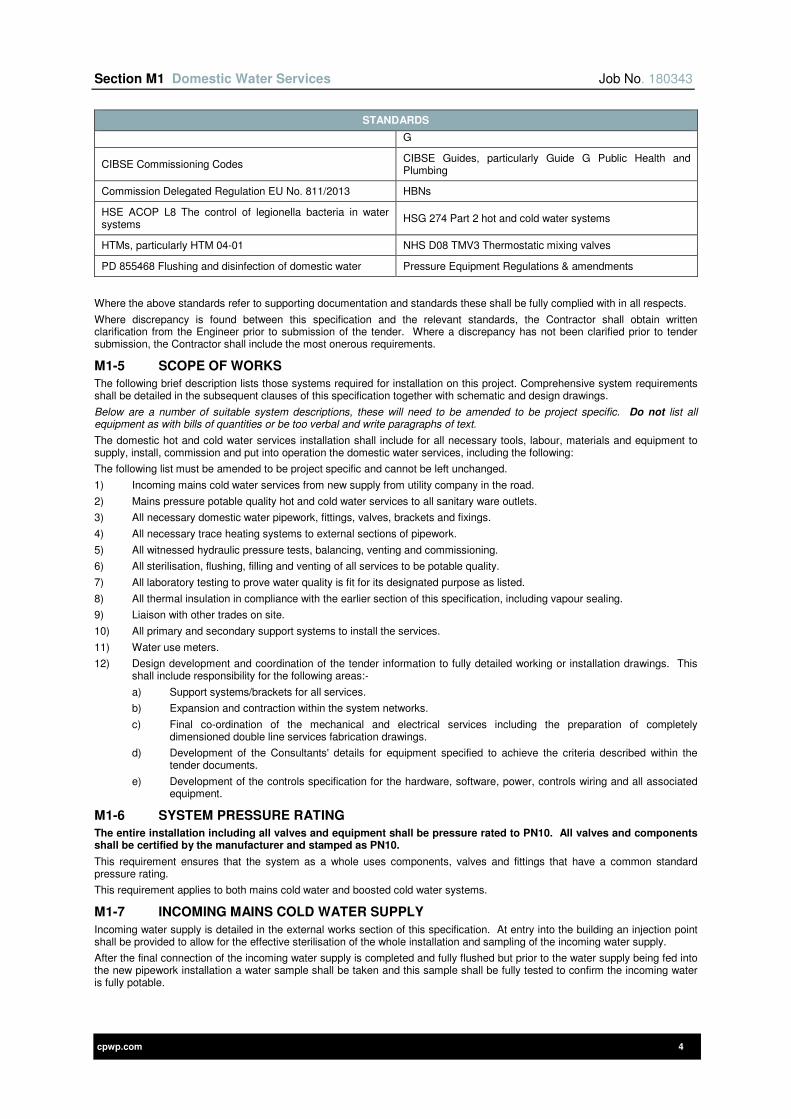
Section M1 Domestic Water Services Job No. 180343
cpwp.com 4
STANDARDS
G
CIBSE Commissioning Codes CIBSE Guides, particularly Guide G Public Health and Plumbing
Commission Delegated Regulation EU No. 811/2013 HBNs
HSE ACOP L8 The control of legionella bacteria in water systems
HSG 274 Part 2 hot and cold water systems
HTMs, particularly HTM 04-01 NHS D08 TMV3 Thermostatic mixing valves
PD 855468 Flushing and disinfection of domestic water Pressure Equipment Regulations & amendments
Where the above standards refer to supporting documentation and standards these shall be fully complied with in all respects.
Where discrepancy is found between this specification and the relevant standards, the Contractor shall obtain written clarification from the Engineer prior to submission of the tender. Where a discrepancy has not been clarified prior to tender submission, the Contractor shall include the most onerous requirements.
M1-5 SCOPE OF WORKS
The following brief description lists those systems required for installation on this project. Comprehensive system requirements shall be detailed in the subsequent clauses of this specification together with schematic and design drawings.
Below are a number of suitable system descriptions, these will need to be amended to be project specific. Do not list all equipment as with bills of quantities or be too verbal and write paragraphs of text.
The domestic hot and cold water services installation shall include for all necessary tools, labour, materials and equipment to supply, install, commission and put into operation the domestic water services, including the following:
The following list must be amended to be project specific and cannot be left unchanged.
1) Incoming mains cold water services from new supply from utility company in the road.
2) Mains pressure potable quality hot and cold water services to all sanitary ware outlets.
3) All necessary domestic water pipework, fittings, valves, brackets and fixings.
4) All necessary trace heating systems to external sections of pipework.
5) All witnessed hydraulic pressure tests, balancing, venting and commissioning.
6) All sterilisation, flushing, filling and venting of all services to be potable quality.
7) All laboratory testing to prove water quality is fit for its designated purpose as listed.
8) All thermal insulation in compliance with the earlier section of this specification, including vapour sealing.
9) Liaison with other trades on site.
10) All primary and secondary support systems to install the services.
11) Water use meters.
12) Design development and coordination of the tender information to fully detailed working or installation drawings. This shall include responsibility for the following areas:-
a) Support systems/brackets for all services.
b) Expansion and contraction within the system networks.
c) Final co-ordination of the mechanical and electrical services including the preparation of completely dimensioned double line services fabrication drawings.
d) Development of the Consultants' details for equipment specified to achieve the criteria described within the tender documents.
e) Development of the controls specification for the hardware, software, power, controls wiring and all associated equipment.
M1-6 SYSTEM PRESSURE RATING
The entire installation including all valves and equipment shall be pressure rated to PN10. All valves and components shall be certified by the manufacturer and stamped as PN10.
This requirement ensures that the system as a whole uses components, valves and fittings that have a common standard pressure rating.
This requirement applies to both mains cold water and boosted cold water systems.
M1-7 INCOMING MAINS COLD WATER SUPPLY
Incoming water supply is detailed in the external works section of this specification. At entry into the building an injection point shall be provided to allow for the effective sterilisation of the whole installation and sampling of the incoming water supply.
After the final connection of the incoming water supply is completed and fully flushed but prior to the water supply being fed into the new pipework installation a water sample shall be taken and this sample shall be fully tested to confirm the incoming water is fully potable.

Section M1 Domestic Water Services Job No. 180343
cpwp.com 5
M1-8 INCOMING MAINS COLD WATER METERS
Incoming water supply meters are detailed in the Energy Metering section of this specification.
M1-9 INCOMING MAINS PHYSICAL WATER CONDITIONER
Supply, install, test, commission and put into operation physical water conditioners, all in accordance with the manufacturer’s requirements and accommodations, in the locations detailed on the schematic.
The conditioner shall be provided to inhibit hard scale formation, via the use of an electromagnetic field.
Each unit shall:
1) Be WRAS approved.
2) Comprise a 110V DC electrical coil for generating the magnetic field, incorporating a design flow path that enable all the water to cross the magnetic field line at an angle of 90ºC with PTFE plated body.
3) Power supply (control box) shall have a polarity reversal mechanism to eliminate routine maintenance of the unit and shall be connected to a 220V/1ph/50Hz power supply through a local fused spur.
4) Have visual indication of normal operation (green LED) and visual/ audible indication of malfunction.
The units shall be manufactured by one of the following:
1) Hydrotec UK Limited, their Hydromag model.
2) Best Water Technology (BWT) UK Ltd, their Powermag model.
M1-10 DOMESTIC HOT WATER PLATE HEAT EXCHANGERS
Each domestic hot water plate heat exchanger shall be fully compliant with the technical requirements detailed in the schedule at the end of this section and:
1) Compliant with Commission Regulation EU No. 811/2013 and certified as energy rating of A or better (i.e. A, A+, A++ or A+++).
2) Temperature control of the DHW secondary circuit is achieved by a two / three port mixing control valve to the primary side of the PHE and variable speed LTHW pump.
3) The overall casing shall be manufactured from epoxy coated steel and shall be suitable to accept the insulation proprietary removable insulation jackets that shall insulate all hot surfaces.
4) Heat exchange plates shall be stainless steel 316L with gaskets suitable for fluids handled; all components shall be WRAS approved.
5) Valves and component detailed on the schematic and to provide a complete system including:
a) Safety valve.
b) Expansion vessel.
c) Secondary return.
d) Valves.
6) For future flexibility, the unit shall support frames and threaded rods to allow 20% spare capacity to be added by the installation of additional plates to the steel frame with associated increase in pressure loss limited to 20% increase.
7) Complete with run/and standby primary pumps.
8) Complete with secondary shunt pump between plate heat exchanger and the hot water store. A spare pump shall be provided; this shall be mounted on a local wall.
9) Fully integrated controls as detailed in the schedule.
10) Fully thermally insulated as detailed in ‘General Installation Clauses – Thermal Insulation’ and shall be fully compliant with the non-domestic building services compliance guide. Insulation jackets shall be provided with Velcro and draw string fixing for ease of removal and reinstatement.
11) Two plate heat exchangers are provided to provide resilience and allow routine servicing and maintenance without interruption of hot water supply. These are provided so that each exchanger can be isolated and the other exchanger remains in operation. In normal use both heat exchangers shall be configured to operate simultaneously to avoid dead legs.
PHE shall be as manufactured by one of the plate heat exchanger manufacturers listed in the schedule at the end of this section.
M1-11 STORAGE / SEMI-STORAGE CALORIFIERS
Each calorifier shall be fully compliant with the technical requirements detailed in the schedule at the end of this section and shall include:
1) Compliant with Commission Regulation EU No. 811/2013 and certified as energy rating of A or better (i.e. A, A+, A++ or A+++).
2) Temperature control of the DHW secondary circuit is achieved by a control valve to the primary side of the PHE and variable speed LTHW pump as detailed on the schematic.
3) The overall support casing shall be manufactured from copper or stainless steel and shall be suitable to accept the insulation proprietary removable insulation jacket that shall insulate all hot surfaces. No carbon steel material shall come into contact with the domestic water.
4) All components shall be WRAS approved.
5) Complete with run/and standby primary pumps.
6) Complete with pressure relief safety valve and combined temperature and pressure relief safety valve.
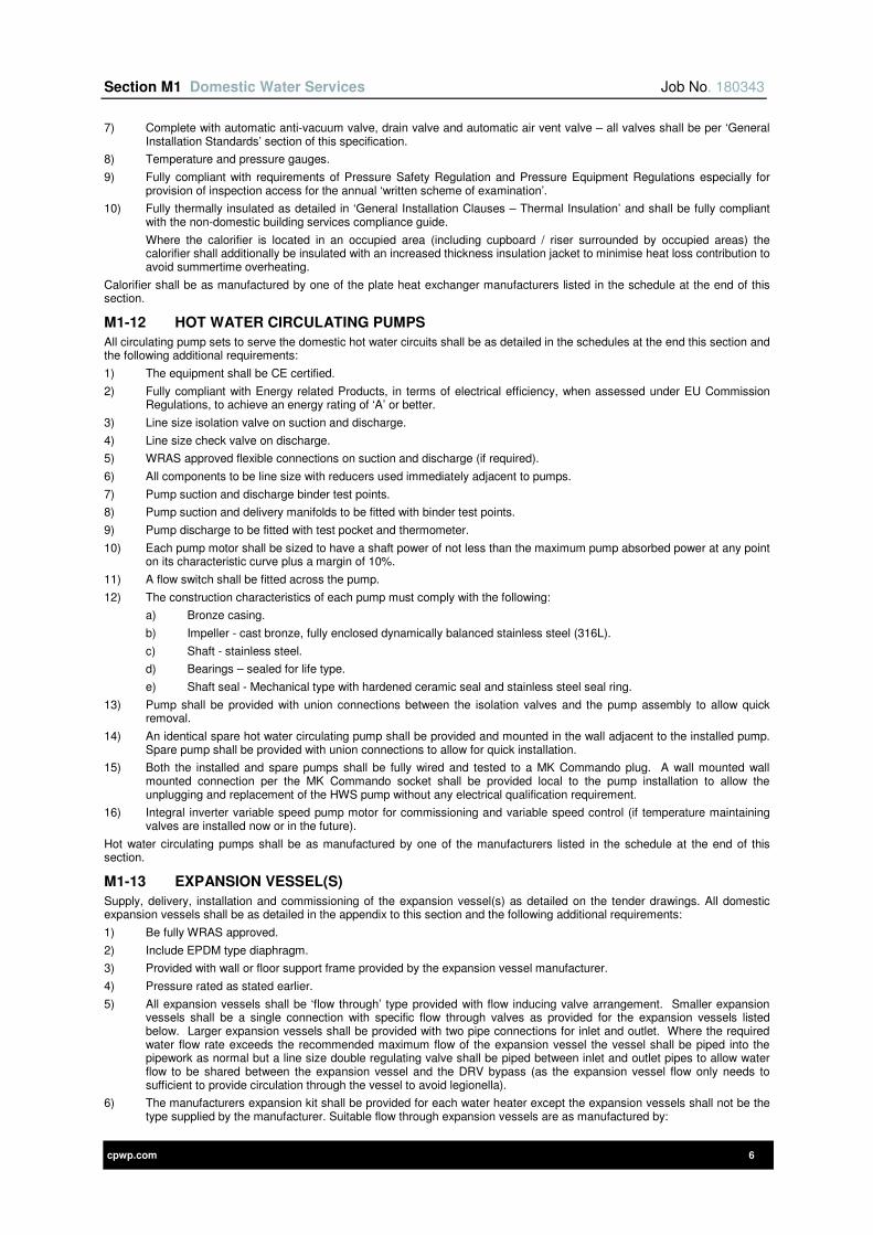
Section M1 Domestic Water Services Job No. 180343
cpwp.com 6
7) Complete with automatic anti-vacuum valve, drain valve and automatic air vent valve – all valves shall be per ‘General Installation Standards’ section of this specification.
8) Temperature and pressure gauges.
9) Fully compliant with requirements of Pressure Safety Regulation and Pressure Equipment Regulations especially for provision of inspection access for the annual ‘written scheme of examination’.
10) Fully thermally insulated as detailed in ‘General Installation Clauses – Thermal Insulation’ and shall be fully compliant with the non-domestic building services compliance guide.
Where the calorifier is located in an occupied area (including cupboard / riser surrounded by occupied areas) the calorifier shall additionally be insulated with an increased thickness insulation jacket to minimise heat loss contribution to avoid summertime overheating.
Calorifier shall be as manufactured by one of the plate heat exchanger manufacturers listed in the schedule at the end of this section.
M1-12 HOT WATER CIRCULATING PUMPS
All circulating pump sets to serve the domestic hot water circuits shall be as detailed in the schedules at the end this section and the following additional requirements:
1) The equipment shall be CE certified.
2) Fully compliant with Energy related Products, in terms of electrical efficiency, when assessed under EU Commission Regulations, to achieve an energy rating of ‘A’ or better.
3) Line size isolation valve on suction and discharge.
4) Line size check valve on discharge.
5) WRAS approved flexible connections on suction and discharge (if required).
6) All components to be line size with reducers used immediately adjacent to pumps.
7) Pump suction and discharge binder test points.
8) Pump suction and delivery manifolds to be fitted with binder test points.
9) Pump discharge to be fitted with test pocket and thermometer.
10) Each pump motor shall be sized to have a shaft power of not less than the maximum pump absorbed power at any point on its characteristic curve plus a margin of 10%.
11) A flow switch shall be fitted across the pump.
12) The construction characteristics of each pump must comply with the following:
a) Bronze casing.
b) Impeller - cast bronze, fully enclosed dynamically balanced stainless steel (316L).
c) Shaft - stainless steel.
d) Bearings – sealed for life type.
e) Shaft seal - Mechanical type with hardened ceramic seal and stainless steel seal ring.
13) Pump shall be provided with union connections between the isolation valves and the pump assembly to allow quick removal.
14) An identical spare hot water circulating pump shall be provided and mounted in the wall adjacent to the installed pump. Spare pump shall be provided with union connections to allow for quick installation.
15) Both the installed and spare pumps shall be fully wired and tested to a MK Commando plug. A wall mounted wall mounted connection per the MK Commando socket shall be provided local to the pump installation to allow the unplugging and replacement of the HWS pump without any electrical qualification requirement.
16) Integral inverter variable speed pump motor for commissioning and variable speed control (if temperature maintaining valves are installed now or in the future).
Hot water circulating pumps shall be as manufactured by one of the manufacturers listed in the schedule at the end of this section.
M1-13 EXPANSION VESSEL(S)
Supply, delivery, installation and commissioning of the expansion vessel(s) as detailed on the tender drawings. All domestic expansion vessels shall be as detailed in the appendix to this section and the following additional requirements:
1) Be fully WRAS approved.
2) Include EPDM type diaphragm.
3) Provided with wall or floor support frame provided by the expansion vessel manufacturer.
4) Pressure rated as stated earlier.
5) All expansion vessels shall be ‘flow through’ type provided with flow inducing valve arrangement. Smaller expansion vessels shall be a single connection with specific flow through valves as provided for the expansion vessels listed below. Larger expansion vessels shall be provided with two pipe connections for inlet and outlet. Where the required water flow rate exceeds the recommended maximum flow of the expansion vessel the vessel shall be piped into the pipework as normal but a line size double regulating valve shall be piped between inlet and outlet pipes to allow water flow to be shared between the expansion vessel and the DRV bypass (as the expansion vessel flow only needs to sufficient to provide circulation through the vessel to avoid legionella).
6) The manufacturers expansion kit shall be provided for each water heater except the expansion vessels shall not be the type supplied by the manufacturer. Suitable flow through expansion vessels are as manufactured by:
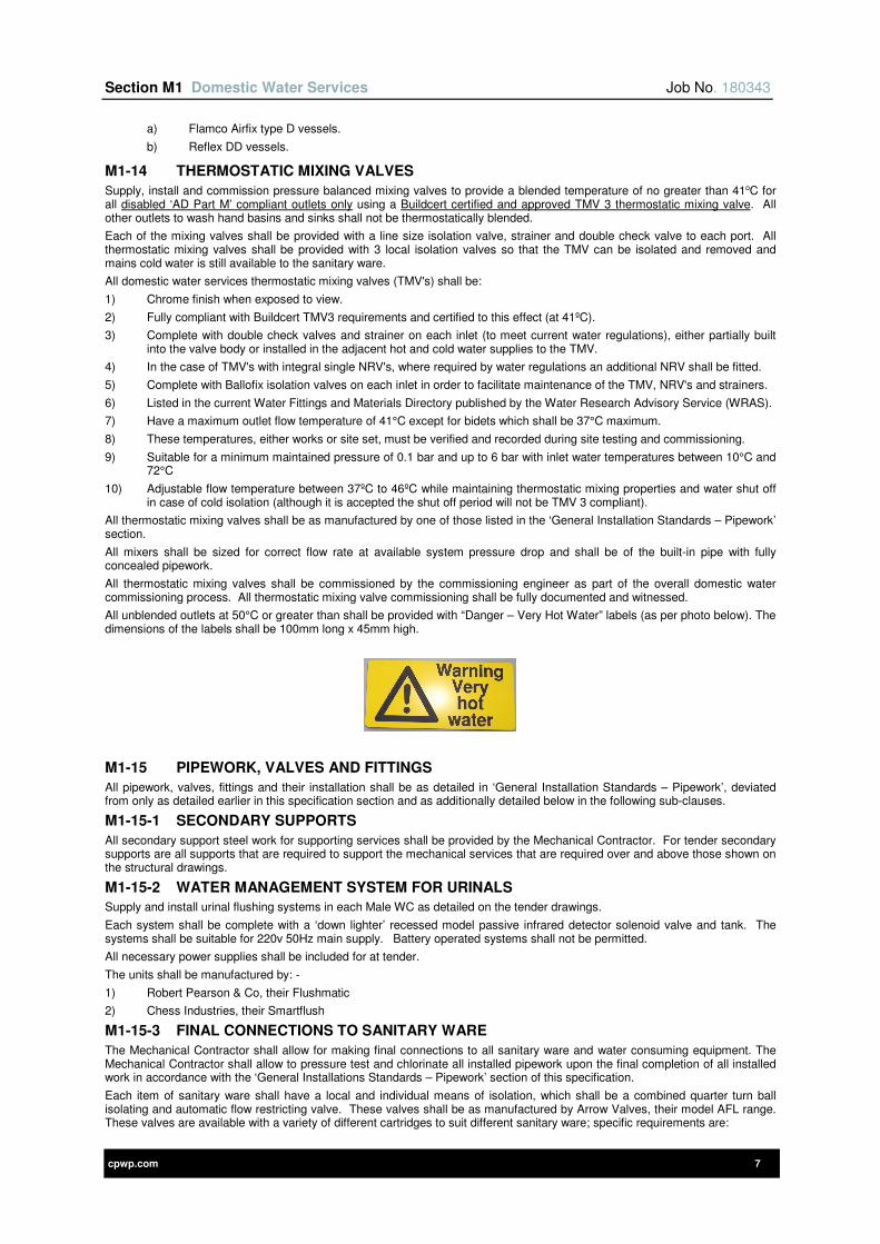
Section M1 Domestic Water Services Job No. 180343
cpwp.com 7
a) Flamco Airfix type D vessels.
b) Reflex DD vessels.
M1-14 THERMOSTATIC MIXING VALVES
Supply, install and commission pressure balanced mixing valves to provide a blended temperature of no greater than 41oC for all disabled ‘AD Part M’ compliant outlets only using a Buildcert certified and approved TMV 3 thermostatic mixing valve. All other outlets to wash hand basins and sinks shall not be thermostatically blended.
Each of the mixing valves shall be provided with a line size isolation valve, strainer and double check valve to each port. All thermostatic mixing valves shall be provided with 3 local isolation valves so that the TMV can be isolated and removed and mains cold water is still available to the sanitary ware.
All domestic water services thermostatic mixing valves (TMV's) shall be:
1) Chrome finish when exposed to view.
2) Fully compliant with Buildcert TMV3 requirements and certified to this effect (at 41ºC).
3) Complete with double check valves and strainer on each inlet (to meet current water regulations), either partially built into the valve body or installed in the adjacent hot and cold water supplies to the TMV.
4) In the case of TMV's with integral single NRV's, where required by water regulations an additional NRV shall be fitted.
5) Complete with Ballofix isolation valves on each inlet in order to facilitate maintenance of the TMV, NRV's and strainers.
6) Listed in the current Water Fittings and Materials Directory published by the Water Research Advisory Service (WRAS).
7) Have a maximum outlet flow temperature of 41°C except for bidets which shall be 37°C maximum.
8) These temperatures, either works or site set, must be verified and recorded during site testing and commissioning.
9) Suitable for a minimum maintained pressure of 0.1 bar and up to 6 bar with inlet water temperatures between 10°C and 72°C
10) Adjustable flow temperature between 37ºC to 46ºC while maintaining thermostatic mixing properties and water shut off in case of cold isolation (although it is accepted the shut off period will not be TMV 3 compliant).
All thermostatic mixing valves shall be as manufactured by one of those listed in the ‘General Installation Standards – Pipework’ section.
All mixers shall be sized for correct flow rate at available system pressure drop and shall be of the built-in pipe with fully concealed pipework.
All thermostatic mixing valves shall be commissioned by the commissioning engineer as part of the overall domestic water commissioning process. All thermostatic mixing valve commissioning shall be fully documented and witnessed.
All unblended outlets at 50°C or greater than shall be provided with “Danger – Very Hot Water” labels (as per photo below). The dimensions of the labels shall be 100mm long x 45mm high.
M1-15 PIPEWORK, VALVES AND FITTINGS
All pipework, valves, fittings and their installation shall be as detailed in ‘General Installation Standards – Pipework’, deviated from only as detailed earlier in this specification section and as additionally detailed below in the following sub-clauses.
M1-15-1 SECONDARY SUPPORTS
All secondary support steel work for supporting services shall be provided by the Mechanical Contractor. For tender secondary supports are all supports that are required to support the mechanical services that are required over and above those shown on the structural drawings.
M1-15-2 WATER MANAGEMENT SYSTEM FOR URINALS
Supply and install urinal flushing systems in each Male WC as detailed on the tender drawings.
Each system shall be complete with a ‘down lighter’ recessed model passive infrared detector solenoid valve and tank. The systems shall be suitable for 220v 50Hz main supply. Battery operated systems shall not be permitted.
All necessary power supplies shall be included for at tender.
The units shall be manufactured by: -
1) Robert Pearson & Co, their Flushmatic
2) Chess Industries, their Smartflush
M1-15-3 FINAL CONNECTIONS TO SANITARY WARE
The Mechanical Contractor shall allow for making final connections to all sanitary ware and water consuming equipment. The Mechanical Contractor shall allow to pressure test and chlorinate all installed pipework upon the final completion of all installed work in accordance with the ‘General Installations Standards – Pipework’ section of this specification.
Each item of sanitary ware shall have a local and individual means of isolation, which shall be a combined quarter turn ball isolating and automatic flow restricting valve. These valves shall be as manufactured by Arrow Valves, their model AFL range. These valves are available with a variety of different cartridges to suit different sanitary ware; specific requirements are:
Section M1 Domestic Water Services Job No. 180343
cpwp.com 8
1) Wash Hand Basins shall be fitted with flow restricting cartridges to limit the peak flow rate to 6 litres / minute for a water pressure of 0.3MPa
2) Sinks shall be fitted with flow restricting cartridges to limit the peak flow rate to 8 litres / minute.
3) Showers shall not be fitted with flow restricting cartridges (if the shower hose flow restricting limiters are fitted) but if not then the hot and cold water connections shall each be limited to 8 litres / minute.
4) WCs shall not be fitted with flow restricting valves but shall instead be fitted with strainers as is required for all compact WC float valves under WRAS Regulation Guidance and Recommendation reference 25.6.
The flow rates are preliminary for tender purposes and the design engineer shall allow for liaising with the design team and client to agree on the final cartridge selections prior to ordering.
Alternative manufacturers are acceptable provided they provide the same performance and standard criteria as the above valve, this shall include (but not be limited to):
1) Suitable for the maximum water pressure previously specified.
2) Maintain design flow rates between 90 and 110% at all pressures between 1 Bar and maximum specified peak pressure as specified in this specification.
3) Have full WRAS approval.
4) Provided with both strainers and flow restricting cartridges as standard.
5) Suitably temperature rated.
6) Provided with extended spindle lever handles for isolation without any tools (as pipe and valve shall be thermally insulated).
7) Cartridges and strainers can be removed / changed without additional isolation or draining down of the system.
All local isolation, with flow restrictors, strainers or neither, shall be the same manufacturer and model range throughout to maximize ease of servicing and maintaining spares. Mixed manufacturers and model ranges shall not be acceptable.
All final connections to sanitaryware shall be solid pipework connections. The use of flexible braided hoses shall not be acceptable on this project. Any flexible hoses installed on site shall be removed at the cost of the Mechanical Contractor, inclusive of programme implications that result in non-compliance of this clause.
M1-15-4 BACK FLOW PREVENTION
Single and double check valves shall be provided to all necessary branch pipes as required by the current water regulations including:
1) Vending machines shall be a double check valve.
2) Drinking fountains shall be a double check valve.
3) Branches where it is reasonable to assume the services will be infrequently used including kitchens, kitchenettes and showers (these examples are listed in BS8558). Single check valves shall be installed as close to the branch valve as possible.
4) Pressurisation units (unless the feed pipe to the pressurisation unit is looped design in which case check valves shall not be required). Looped cold feed design to pressurisation units is the preferred option that shall be adopted unless technically not possible – cost is not a technical reason for non-compliance. Single check valve shall be installed where a looped design is not installed.
5) HTM compliant thermostatic mixing valves (where single check valves are integrated into the thermostatic mixing valve) shall be installed with additional single check valves to provide double check valves on both hot and cold supplies.
6) All other non-healthcare thermostatic mixing valves to be fitted with single check valves unless the check valves are integrated into the thermostatic mixing valve.
7) Unblended mixer taps – single check valves in hot and cold connections.
8) At entry into buildings – double check valve for all buildings.
Single and double check valves shall NOT be installed in the following situation:
1) In mains cold water pipes serving ball valves that fill cold water tanks.
M1-15-5 DRAIN VALVES AND AIR VENTS
Air vents shall not be provided in the domestic hot and cold water system to avoid dead legs and comply with BS 8558. Both hot and cold water connections shall be self-venting, this shall be achieved by providing the branch connections from the top of the pipes at all necessary strategic points to ensure complete venting. Where hot water pipes need to be looped vertically to ensure the dead leg water content remains less than 0.5 litre limit, the design shall be installed with smaller branch connections provided between the vertical loops to ensure the pipes are automatically vented of air through the smaller branch connections.
M1-15-6 COLD WATER DEAD LEGS
Cold water branch pipes shall be limited in length to the following circuits to minimise dead legs and maintain optimum water quality:
1) Branch pipe to water boilers for beverage preparation shall not exceed 300mm long.
2) Branch pipe to water chillers for beverage preparation shall not exceed 300mm long.
3) Branch pipe to drinking fountains shall not exceed 300mm long.
4) Branch pipe to vending machines shall not exceed 300mm long.
M1-15-7 HOT WATER CIRCULATING SYSTEM DEAD LEGS
In accordance with BS8558, the maximum permitted hot water dead legs, including the blended pipework, on the hot water circulating systems shall be limited to 0.5 litre or 3 metres, whichever is the lower value.
Section M1 Domestic Water Services Job No. 180343
cpwp.com 9
For information only, this means that:
1) Where the hot water flow pipe is 22mm diameter after the HWS return connection to sinks, etc the dead leg shall not exceed 1.7 metres.
2) Where the hot water flow pipe is 15mm diameter after the HWS return connection the dead leg shall not exceed 3.0 metres (maximum permitted to meet the 0.5 litre only is 3.4 metre).
3) Where the hot water flow pipe is 22mm after the HWS return connection but reduces to 15mm after a branch the hot water pipe shall be limited to 2 metres (to stay safely within the 0.5 litre volume).
Any singular references to lengths of 3 or 5 metre long hot water dead legs are superseded by this clause as the dead leg limit is a combination of the no more than 0.5 litre and 3 metre limit, whichever is the lower value.
All outlets shall be tested, proven and documented to be compliant with the above requirement by the Commissioning Engineer.
Any non-compliant systems shall be modified to comply by the Mechanical Contractor at their expense and retested until compliance is proven.
M1-15-8 HOT WATER SYSTEM DEAD LEGS
For unblended hot water outlets, the hot water pipe length shall limited to ensure that the hot out water at the furthest outlet on a system shall achieve at least 50ºC within 1 minute of the outlet being fully open. Attention is drawn to the fact that the system shall be installed with flow restrictor isolation valves so the flow rate from the tap will be limited accordingly.
For thermostatically blended outlets, the hot water pipe length shall limited to ensure that the hot out water at the furthest thermostatic mixing valve on a system shall achieve at least 50ºC within less than 1 minute of the outlet being fully open and the blended hot water from the outlet shall achieve its regulated temperature, nominally 41ºC within one minute. Attention is drawn to the fact that the system shall be installed with flow restrictor isolation valves so the flow rate from the tap will be limited accordingly.
The hot water from the heater shall be at a minimum of 60ºC for design, installation and testing purposes detailed above.
All outlets shall be tested, proven and documented to be compliant with the above requirement by the commissioning engineer.
Any non-compliant systems shall be modified to comply by the Mechanical Contractor at their expense and retested until compliance is proven.
M1-16 THERMAL INSULATION
The whole of the domestic hot and cold water pipework shall be thermally insulated and vapour sealed. All insulation shall be as detailed in ‘General Installation Standards – Insulation’ section.
M1-17 CHEMICAL DOSING, TESTING AND COMMISSIONING
The system shall be pressure tested, commissioned, chemically dosed and sterilised as described within ‘General Installation Standards’ sections of this specification.
All water testing necessary to determine what level of treatment is to be provided shall be included within the tender.
The Commissioning Specialist shall complete all commissioning, except equipment shall be commissioned by the equipment manufacturer.
M1-18 FREEZING PROTECTION TRACE HEATING
All pipework at risk of freezing shall be electrically trace heated. Pipework at risk of freezing includes (but is not limited to):
1) External pipework.
2) Pipework routed through unheated spaces, rooms and voids.
3) Buried pipework but where specified buried depth is not achievable.
4) Plant rooms even if provided with back ground heating the cold water pipe shall be trace heated (unless proven not at risk).
The trace heating shall be of the self-regulating type with its heat output varying in response to the surrounding temperature.
The trace heating element shall be applied directly to the pipework beneath the required insulation and associated external weathering finish.
All associated ancillary items including power connection boxes shall be included for the enable a fully functioning trace heating system.
All power feeds to the trace heating control boxes shall be via the mechanical control panel.
The outer casing of all trace heated pipework shall have a vinyl based caution label applied (suitable for external application) identifying that trace heating is installed. The frequency of the labels shall be a maximum of 3m.
Trace heating shall be supplied by Messrs Raychem Ltd or equal and approved.
All electric trace heating installations shall be monitored by the BMS for fault and run signals.
M1-19 EXPANSION AND CONTRACTION
The Mechanical Contractor shall make due allowance within their Tender for expansion and contraction. This shall be in the form of loops, bellows, anchors, guides, offsets, rollers/chairs and cold draw. Wherever feasible natural flexibility solutions shall be employed. All provisions for expansion and contraction shall be indicated on the fabrication drawings submitted with the supporting calculations to the Engineer for comment prior to installation taking place.
In the event when bellows are necessary due to building fabric restraints, multi-layered 316L stainless steel only quality units shall bellows be allowed for at tender. EPDM flexible bellows are not acceptable under any circumstances.
cpwp.com V1.5
Section M2 Heating
Section M2 Heating Job No. 180343
cpwp.com 2
Contents Page
M2-1 GENERAL REQUIREMENTS 3
M2-2 REDUNDANCY REQUIREMENTS 3
M2-3 DEFINITIONS 3
M2-4 REFERENCE TO OTHER SECTIONS OF THIS SPECIFICATION 3
M2-5 STANDARDS APPLICABLE 4
M2-6 SCOPE OF WORKS 4
M2-7 INCOMING SUPPLY 5
M2-8 GAS FIRED BOILERS 5
M2-9 BOILER FLUES 6
M2-10 SYSTEM PRESSURE 6
M2-11 PRESSURISATION SET 6
M2-12 LTHW CHEMICAL DOSING POT 7
M2-13 PLATE HEAT EXCHANGERS 7
M2-14 DE-AERATOR AND DIRT SEPARATOR 8
M2-15 LOW TEMPERATURE HOT WATER HEATING PUMPS 8
M2-16 THERMAL STORE 9
M2-17 STANDARD RADIATORS 10
M2-18 LOW SURFACE TEMPERATURE RADIATORS 10
M2-19 OVER DOOR HEATERS 11
M2-20 AUTOMATIC CONTROLS 11
M2-21 THERMOSTATIC RADIATOR VALVES 11
M2-22 LOCKSHIELD RADIATOR VALVES 12
M2-23 PIPEWORK, VALVES AND FITTINGS 12
M2-24 THERMAL INSULATION 12
M2-25 TESTING AND COMMISSIONING 12
M2-26 EXPANSION AND CONTRACTION 12
Section M2 Heating Job No. 180343
cpwp.com 3
M2-1 GENERAL REQUIREMENTS
The existing heating installation in the Museum is to be left alone and fully operational.
A new heating system is to be installed to serve existing Stores Building being remodelled and the new build areas.
The new heating systems required for this project shall be as follows:-
1) A new LTHW system to serve the building, radiator installation, and domestic water primary supply. The system shall comprise all central generating plant, high efficient low Nox gas fired boilers, distribution and control systems all as detailed on the design schematic drawing and following clauses.
M2-2 REDUNDANCY REQUIREMENTS
To ensure acceptable operation of the building systems are maintained in the event of boiler failure, the main plant shall be designed and installed to provide 2No units at 66% load. This requirement shall apply to:-
1) Boilers
In addition all pumps shall be provided as run and standby configuration. Where a twin head installation is detailed each of the pumps is sized to provide 100% load capacity. For additional requirements refer to design schematic drawings.
M2-3 DEFINITIONS
Refer to Section 1B for general definitions plus:
DEFINITIONS
VFC Volt free contact
DPR Stabilising differential pressure regulators
BPV Automatic Bypass Valve
PHX / PHE Plate heat exchanger
CHP Combined Heat and Power Unit
CS Commissioning Station
LT Low Temperature
HT High temperature
LST Low surface temperature Radiators
TRV Thermostatic Radiator Valve
LSV Lock shield valve
M2-4 REFERENCE TO OTHER SECTIONS OF THIS SPECIFICATION
This section of the specification shall not be used in isolation and must be read in conjunction with the particular sections, commissioning and standard clauses, all of which define further the requirements for the installations.
The following text advises if the Contractor shall deviate from the preferred pipework material and standards or utilise one of the alternative materials and standards of construction listed in section 2A clause 2A-1-4 detailed earlier in this specification.
The agreed alternative materials from the preferred standard material and standards for this project are:-
No deviation from Section 2 preferred material requirements
Please note that under no circumstances shall galvanised steel pipework be installed in closed loop heating systems. On inspection of installation, should it be found that this type of pipework has been installed, it shall be removed and replaced at the Contractor’s expense.
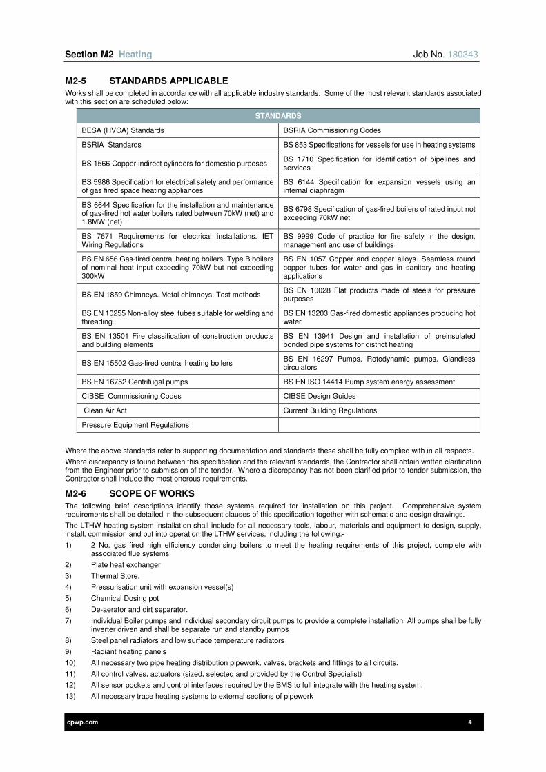
Section M2 Heating Job No. 180343
cpwp.com 4
M2-5 STANDARDS APPLICABLE
Works shall be completed in accordance with all applicable industry standards. Some of the most relevant standards associated with this section are scheduled below:
STANDARDS
BESA (HVCA) Standards BSRIA Commissioning Codes
BSRIA Standards BS 853 Specifications for vessels for use in heating systems
BS 1566 Copper indirect cylinders for domestic purposes BS 1710 Specification for identification of pipelines and services
BS 5986 Specification for electrical safety and performance of gas fired space heating appliances
BS 6144 Specification for expansion vessels using an internal diaphragm
BS 6644 Specification for the installation and maintenance of gas-fired hot water boilers rated between 70kW (net) and 1.8MW (net)
BS 6798 Specification of gas-fired boilers of rated input not exceeding 70kW net
BS 7671 Requirements for electrical installations. IET Wiring Regulations
BS 9999 Code of practice for fire safety in the design, management and use of buildings
BS EN 656 Gas-fired central heating boilers. Type B boilers of nominal heat input exceeding 70kW but not exceeding 300kW
BS EN 1057 Copper and copper alloys. Seamless round copper tubes for water and gas in sanitary and heating applications
BS EN 1859 Chimneys. Metal chimneys. Test methods BS EN 10028 Flat products made of steels for pressure purposes
BS EN 10255 Non-alloy steel tubes suitable for welding and threading
BS EN 13203 Gas-fired domestic appliances producing hot water
BS EN 13501 Fire classification of construction products and building elements
BS EN 13941 Design and installation of preinsulated bonded pipe systems for district heating
BS EN 15502 Gas-fired central heating boilers BS EN 16297 Pumps. Rotodynamic pumps. Glandless circulators
BS EN 16752 Centrifugal pumps BS EN ISO 14414 Pump system energy assessment
CIBSE Commissioning Codes CIBSE Design Guides
Clean Air Act Current Building Regulations
Pressure Equipment Regulations
Where the above standards refer to supporting documentation and standards these shall be fully complied with in all respects.
Where discrepancy is found between this specification and the relevant standards, the Contractor shall obtain written clarification from the Engineer prior to submission of the tender. Where a discrepancy has not been clarified prior to tender submission, the Contractor shall include the most onerous requirements.
M2-6 SCOPE OF WORKS
The following brief descriptions identify those systems required for installation on this project. Comprehensive system requirements shall be detailed in the subsequent clauses of this specification together with schematic and design drawings.
The LTHW heating system installation shall include for all necessary tools, labour, materials and equipment to design, supply, install, commission and put into operation the LTHW services, including the following:-
1) 2 No. gas fired high efficiency condensing boilers to meet the heating requirements of this project, complete with associated flue systems.
2) Plate heat exchanger
3) Thermal Store.
4) Pressurisation unit with expansion vessel(s)
5) Chemical Dosing pot
6) De-aerator and dirt separator.
7) Individual Boiler pumps and individual secondary circuit pumps to provide a complete installation. All pumps shall be fully inverter driven and shall be separate run and standby pumps
8) Steel panel radiators and low surface temperature radiators
9) Radiant heating panels
10) All necessary two pipe heating distribution pipework, valves, brackets and fittings to all circuits.
11) All control valves, actuators (sized, selected and provided by the Control Specialist)
12) All sensor pockets and control interfaces required by the BMS to full integrate with the heating system.
13) All necessary trace heating systems to external sections of pipework
Section M2 Heating Job No. 180343
cpwp.com 5
14) All pressure by-pass and pressure regulating valves to maximise the energy saving potential of the variable speed pumps.
15) All necessary flushing, filling and venting of all services
16) All necessary commissioning stations for system balancing
17) All testing, witnessing hydraulic pressure tests, balancing, venting and commissioning.
18) All thermal insulation in compliance with earlier section of this specification.
The following are the requirements that are common to all of the systems described above:
1) Liaison with other trades on site.
2) Copies of Operating and Maintenance instruction manuals including a ‘brief description’ of services and fault finding information list of spares, emergency telephone Nos. etc.
3) Full user instruction, both written and in the form of demonstrations.
4) All primary and secondary support systems to install the services.
5) Complete electrical installation works associated with this Section of the Specification including all cabling, local isolation and protective devices.
6) Development of the Consultants drawings and detailing from the base tender information to full construction standards as detailed previously. This shall include responsibility for the following areas:-
a) Support systems/brackets for all services.
b) Expansion and contraction within the system networks.
c) Final co-ordination of the mechanical and electrical services including the preparation of completely dimensioned double line services fabrication drawings.
d) Development of the Consultants' details for equipment specified to achieve the criteria described within the tender documents.
e) Development of the controls specification for the hardware, software, power, controls wiring and all associated equipment.
M2-7 INCOMING SUPPLY
Incoming gas supply is detailed in the enabling works section of this specification.
At entry into the building the supply shall be provided with an emergency isolation valve.
M2-8 GAS FIRED BOILERS
A series of fully condensing, gas fired boilers shall be supplied and installed within the plant room
2no Boilers rated at 60% of the peak load shall be Worcester Bosch FS CDi Regular.
Performance criteria are scheduled within the appendix to this section of the specification
Each boiler shall be:
Low NOx (less than 40mg/kWh @ 0% excess dry oxygen) and shall be CE certified.
7) Fully modulating, the control flow temperature shall be determined by a 0-10V signal. The boiler high limit controls thermostat shall be set at approximately 95°C. (hand reset)
8) Complete with remote lock out indication
9) Complete with Greenstar system Filtration
10) Complete with Bosch EasyControl
11) Complete with burners supplied, assembled and pre-wired.
12) Fully automatic burner operation comprising spark ignition for an intermittent pilot with full flame proving via a flame rectification probe and shall have automatic high/low fire output control.
13) Suitable for an electrical supply of 230 Volts, single phase, 50Hz
14) Complete with integral draught diverting outlet
15) Complete with mineral wool insulating jacket
16) Complete with stove enamelled common boiler casing
17) Mounted on 150mm high concrete plinth
18) Factory pressure tested to the maximum working pressure detailed in the appendix and certified accordingly.
19) Complete with radiant baffle to minimise boiler standing losses.
20) Complete with the following connections:-
1 – Flow water connection
1 – Return water connection (Low Temperature)
1 - Return water connection (High Temperature)
1 – Nabic safety valve on flow pipe before any isolating valve. This safety valve shall be set to discharge at a pressure of 0.7bar/m2 above the working pressure of the boiler. Discharge of the safety valve shall terminate 150mm above the plantroom foul floor drain.
1 – gas inlet connection (minimum gas pressure = 18mbar).
1 – drain cock to be provided such that the boiler can be isolated and drained down if necessary.
1 – Boiler control box complete with hand reset high limit thermostat
1 – 100mm dial thermometer graded from 20°C to 125°C.
Section M2 Heating Job No. 180343
cpwp.com 6
1 – 100mm diameter altitude gauge graded from 0 to 6 bar gauge.
1 – set of cleaning tools.
1 – hours run meter.
The boiler operation is to be controlled via an energy management system and all boiler/burner/BMS interface shall be included. Therefore the boilers shall be fully compatible with the controls system as detailed later in the specification.
The fully automatic (including gas sequencing) burner controls shall ensure that the boiler shuts down under the following conditions:
a) Flame failure.
b) In response to limit sensors.
The equipment shall be supplied, installed and commissioned to meet all manufacturer’s requirements/ recommendations.
Each boiler shall be supplied, tested and commissioned by the boiler manufacture.
M2-9 BOILER FLUES
The flue systems shall be designed to run to the rear elevation, supplied and installed by one of the following Specialist Companies:
1) A1 Flues, Tel No. 01623 860578
2) SFL Flues and Chimneys, Tel No. 01271 326633
3) Midtherm Flue Systems Ltd, Tel No. 01384 458800
Each flue systems shall comprise of the following: -
1) A stainless steel internal lining, manufactured from Grade 316 stainless steel of 1mm thickness. (minimum)
2) External flue casing manufactured from Grade 304 stainless steel of 0.6mm thickness (minimum)
3) The internal and external casings shall be separated by a 25mm annular which shall be insulated with a thermal insulation material compatible with the working temperature of the flue gases and to maintain safe surface temperatures.
4) The materials used for accessories and fittings shall be durable, compatible and not cause electrolytic action on any part of the flue or chimney system.
5) Internal stainless steel liner with continuously welded seam and integral flange at each end.
6) Jointing by means of an inner vee band sealed to ensure a gas and moisture proof fire rated joint.
7) External casing covered using channel bands to give a clean and smooth external appearance and finish. Suitable for serving fully condensing boilers i.e. ‘Europa’ SFL flue range or equal and approved.
8) Laid to a fall of at least 1:80 (or to manufacture’s recommendations)
9) Incorporate a drain tee piece complete with a 25mm socket for condensate draw off.
10) Boiler flue connector shall also incorporate 2 No 25mm diameter sockets local to the boiler flue outlet which shall be adapted for flue gas sampling and temperature monitoring.
11) All necessary flashing plates/collars and fixings to ensure that the roof penetration of each flue is secure and weatherproof.
12) Approved inverted cowl rain cap type terminal for the flue termination, powder coated to a colour to match the roof cladding. All external components shall be powder coated to match the roof cladding. Colour to be agreed with the Architect.
13) Individual flue drainage pipework complete with trap (that can be replenished). The drains shall terminate 100mm above the plant room floor drain or pacification vessel
14) The Specialist Contractor shall include for all fabrication/working drawings detailing full construction details which shall be submitted for comment by the Engineer prior to manufacture.
Flue systems shall be supplied, installed and commissioned to meet all requirements/ recommendations stated within the boiler manufacturer's current literature.
M2-10 SYSTEM PRESSURE
The entire installation including all valves, pipework and pipeline components shall be pressure rated to PN16. All valves and components shall be certified by the manufacturer and stamped as PN16. Refer to section 2. All equipment shall be rated to a minimum of 6 Bar.g. This allows for the requirements of pressure testing of system.
Normal working pressure shall be in the range of 0.5 to 4 Bar.g
Refer to Pressurisation Unit schedule for system working pressure requirements.
M2-11 PRESSURISATION SET
Supply, delivery, installation and commissioning of the heating system water pressurisation unit and expansion vessel(s) The pressurisation unit shall be complete with the following features:-
1) Performance as detailed in the appendix to this section.
2) Back flow pressure prevention to suit water in system (Category 4 as minimum)
3) Break tank, ball valve and float.
4) Drain valves and means of isolation for all components.
5) All interconnecting wiring and a control panel suitable for connection to a 1 phase, 240 volts, 50Hz electrical supply.
6) Local electrical isolator.
7) All interconnecting pipework valves and fittings.
Section M2 Heating Job No. 180343
cpwp.com 7
8) Test button.
9) Pump start frequency/leakage detector.
10) High and low pressure alarm.
11) LCD Display on the front of the control pan
12) Controlled to automatically share duty between run and standby pumps for even wear.
13) All components shall be suitable to allow for system fill in 4 Hours
The pressurisation unit is to be compatible with the Controls system, as detailed later in the Specification. Should the pressure switches be activated this shall deactivate the plant via the controls (hard wire interlocked) and shall provide the alarm conditions detailed within the appendix.
The pressurisation unit control panel shall incorporate a programmable microprocessor which shall, on demand, indicate the following settings on the fascia: -
1) System working pressure.
2) Cold fill pressure setting.
3) High pressure alarm setting.
4) Low pressure alarm setting.
5) Minimum pump running time (delay between pump starts).
6) High system pressure.
7) Low system pressure.
8) System ‘leakage’ (frequent pump starts).
9) Transducer failed.
10) Run and tripped lamps for each pump.
11) Panel live lamp.
Volt free contacts shall be fitted within the pressurisation unit control panel to allow remote monitoring by the BMS as detailed in the equipment schedule.
The expansion vessel(s) shall:
1) Have sufficient volume to take the expansion of the entire system from ambient to highest working possible temperature.
2) Final system volumes to be verified.
3) Include EPDM type diaphragm. (suitable for 1000C)
4) Be complete with wall or floor support frame provided by the expansion vessel manufacturer.
5) Be provided by the pressurisation manufacturer.
6) System shall be installed with anti-gravity loop on discharge.
M2-12 LTHW CHEMICAL DOSING POT
To enable water treatment to be added to each heating system, a dosing pot shall be provided and connected across the system flow and return to enable maintenance doses of chemicals to be added.
The dosing pot shall be:
1) Of at least 13.5 litre capacity.
2) Manufactured from same material as the pipework, fully welded or brazed as appropriate.
3) Complete with pre-mounted gate valves and non-return valve in the filling line.
Note – the non-return valve is a mandatory requirement to minimise health and safety risk of incorrect use of the dosing pot.
Chemical dosing shall be:
1) Shall be completed in accordance with section 2 of this specification.
2) Initial test/dosing shall be completed prior to first application of heat.
3) Second test dosing shall take place immediately prior to end of defects period.
4) All water testing necessary to determine what level and type of treatment is to be provided shall be included.
Water treatment dosing pot shall be by:
• Arrow Valves Limited.
• N. Minikin & Sons Limited.
• Water Treatment Products.
• Stourflex (J&P Supplies Limited).
• Messrs. Houseman Ltd.
• Flex EJ Limited.
M2-13 PLATE HEAT EXCHANGERS
The plate heat exchangers shall interface between the primary heating circuit/district heating circuit and the LTHW heating systems serving the building to provide full hydraulic separation.
Each packaged hot water plate heat exchanger shall be fully compliant with the technical requirements detailed in the schedule at the end of this section and be complete with the following:
Section M2 Heating Job No. 180343
cpwp.com 8
1) The overall casing shall be manufactured from epoxy coated steel and shall be suitable to accept the insulation proprietary removable insulation jackets that shall insulate all hot surfaces.
2) Complete with removable insulated jacket to insulate all surfaces.
3) Heat exchange plates shall be stainless steel 316L with gaskets suitable for fluids handled.
4) Temperature control of the secondary circuit is achieved by a two port/ three port mixing control valve to the primary side of the PHE and variable speed LTHW pump(s).
5) The unit shall have 20% spare capacity that can be added by the installation of additional plates to the steel frame with associated increase in pressure loss limited to 20% increase.
6) Be designed for single pass opposing direction.
PHE shall be as manufactured by one of the plate heat exchanger manufacturers listed in the schedule at the end of this section.
M2-14 DE-AERATOR AND DIRT SEPARATOR
As detailed on the tender drawings a separate de-aerator and dirt separator unit shall be provided as shown on the tender drawings.
De-aerator
The unit shall be:
1) Installed at the point of highest temperature/lowest pressure to aid air removal.
2) Installed with isolation valve and binder test points either side of unit.
3) Made from 5mm thick high grade heavy carbon steel (or better) with flanged connections.
4) Be suitable for maximum working temperature of 110°C.
5) Suitably pressure rated.
6) Installed to the recommendation of the manufacturer.
7) Complete with 1 No. high quality automatic air vent (c/w NRV connection for ease of replacement) with threaded connection for vent pipe
8) Complete with 1 No. 25mm releasing valve for purging through installation stage.
9) Complete with 1 No. 32mm drain valve.
10) Refer to manufacturer’s recommendations for Maximum Static Head pressure
Dirt Separator
The unit shall be:
1) Installed to ensure the heating equipment is protected from suspended products to ensure all equipment manufacturer’s warranties are maintained.
2) Made of Steel or Brass.
3) Suitably pressure rated.
4) Installed in pipework where the velocity of 3m/s maximum is not exceeded.
5) Installed on return pipework prior to boilers.
6) Provide filtration down to 20 microns.
7) Provided with Isolation drain valve and suitable connections for draining/cleaning.
Components shall be installed fully in accordance with the manufacturer’s requirements in terms of position in the pipework installation to ensure maximum efficiency of removing air and ‘dirt’ from the system.
Manufactured by:
Hamworthy Ltd
Spirotech
BSS
M2-15 LOW TEMPERATURE HOT WATER HEATING PUMPS
In the positions indicated on the schematic drawing(s) system pumps shall be supplied, installation and full commissioned. Pumps shall comply with the technical details as described in the appended schedules.
All pumps shall be variable speed controlled by inverters. Where pumps are required to operate at a constant speed these also shall be provided as variable speed to allow for accurate setting of flow rates during commissioning.
All Pump Motors to be IE 3 rated
Inverters shall be separate from the pumps, either built into the control panels or local to the pumps on free standing supports as detailed in the controls section of this specification and not be incorporated into the pump assembly.
Unless detailed otherwise in the appendix pressure transducers shall be provided as follows:
a) Flow rate below 0.5l/s, integral pressure transducer and integral controller to maintain constant pressure or proportional pressure, selectable at commissioning
b) Flow rate above 0.5l/s, external pressure transducer(s) installed half way along each main index circuit, set to maintain constant pressure and to comply with Building Regulations carbon compliance model.
c) Where an electronic commissioning / programming device is available from the manufacturer one of these shall be supplied and handed over to the Engineer / Client at handover stage.
All circulating pump sets to serve the LTHW water circuits shall be as detailed below:

Section M2 Heating Job No. 180343
cpwp.com 9
1) The equipment shall be CE certified.
2) Fully compliant with Energy related Products, in terms of electric efficiency, and
3) Compliant with EU 547/2012,EU 640/2009 & EU641/2009
4) Fully suitable for the pumped water/ fluid (in terms of inhibitor and temperature etc.)
5) The equipment shall comply with latest European Legislation relating to mains borne interference/harmonize and the isolation of the same.
6) Line size isolation valve on suction and discharge.
7) Line size strainers on suction and non-return valves on discharge where separate run/standby pumps installed.
8) Flexible connections on suction and discharge.
9) All components to be line size with reducers used immediately adjacent to pumps.
10) Pump suction and discharge binder test points.
11) Pump suction and delivery manifolds to be fitted with 100mm dial pressure gauges fitted with a 9mm syphon and valve.
12) Each pump motor shall be sized to have a shaft power of not less than the maximum pump absorbed power at any point on its characteristic curve plus a margin of 10%.
13) Each pump shall be suitable for operating within a temperature range of minus 10°C – 110°C for LTHW and with a positive pressure available from the pressurisation unit as detailed on the pressurisation schedule and the schematic drawing(s).
14) Pairs of single head run /standby pumps shall be provided with line size non-return valve on discharge.
15) A differential Pressure sensor shall be fitted across each pump set
16) The construction characteristics of each pump must comply with the following:-
a) Cast iron casing.
b) Impeller - cast bronze, fully enclosed dynamically balanced (pumps shall be selected for mid impeller size)
c) Shaft - stainless steel.
d) Bearings – sealed for life type.
e) Shaft seal - Mechanical type with hardened ceramic seal and carbon seal ring.
f) Pump connections - flanged.
g) Each size of twin head pump set shall be complete with a single set of blanking plates for isolation and maintenance of the motor heads. Plates shall be wall mounted adjacent to the pumps.
h) A common base shall be provided for each pump and motor assembly
i) Each pump shall be provided with an inertia base. The inertia bases are to be provided with spring anti-vibration mountings with a vibration efficiency of 98% minimum to limit vibration transmission to the building.
Each inertia base shall be manufactured by:
TEK Ltd.
Ormandy Ltd
AVC Ltd.
Pumps shall be controlled via the BMS to respond to system requirements. All invertor control settings shall be recorded and included in the O & M Manuals.
All variable speed pumps shall be commissioned by the pump and inverter manufacturer.
M2-16 THERMAL STORE
A thermal store shall be installed within the plantroom as detailed on the design drawings. The store shall be a low temperature hot water thermal stratification store as detailed on the appended schedule and shall be:
1) Vertical type construction to encourage the greatest amount of stratification possible.
2) Be manufactured from fully welded heavy grade Carbon Steel construction.
3) Be manufactured in accordance with current British Standards
4) Be fully corrosion treated internally and externally
5) Pre-insulated including the inspection hatch, necks etc. with minimum of 125mm thick high density mineral wool having a thermal conductivity of 0.04(W/m·K) and be complete with stucco aluminium finish.
6) Complete with baffles, sparge pipes, diffusers and internal pipework to optimise stratification and ensure entire volume of vessel is used. Refer to schedule.
7) Be provided with all necessary thermal sensor pockets at regular height intervals as required to provide accurate temperature monitoring and control
8) Fabrication drawings shall be issued to the Engineer and Insurer for comment prior to commencing manufacture. Information shall include Pressure Certification
9) Testing shall be completed at the manufacturer’s works including:
a) Full hydraulic pressure test with specific test certificate (type testing shall not be accepted).
b) Minimum 50% X-ray of each longitudinal and circumferential butt joint.
c) Insurer’s requirements for testing.
10) Vessel Painted externally with two coats of red oxide primer.
11) Complete with welded fixing lugs for horizontal and vertical transportation / positioning.
Section M2 Heating Job No. 180343
cpwp.com 10
12) Supplied, installed, tested and commissioned in accordance with the manufacturers recommendations.
13) The thermal store shall be sized to smooth/even out the peaks in demand. Calculations for store capacity shall be submitted to the Engineer prior to ordering. The capacity shall maximise the benefit of the solar collectors such that the ventilation reheat demands (and domestic hot water) are fully met 24 hours per day during the spring, summer and early autumn without the need to top up the heat availability via the boilers.
M2-17 STANDARD RADIATORS
All radiators to be MHS TUBI HORIZONTAL with GYRO Chrome angled TRV’s and matching lockshield valves.
The radiators shall be selected to meet the fabric heat losses of each space and shall be positioned in conjunction with the Architect to suit the proposed layout.
All radiators shall be:
14) Be supplied with manufacturers matched standard fixing brackets.
15) Complete with any secondary supports necessary.
16) Fixed using rawlbolt fixings, plastic or fibre plugs shall not be used.
17) Provided with a thermostatic radiator valve on the flow connection.
18) Provided with a lockshield valve on the return.
19) Installed level and plumb, a common height to the top of all radiators shall be maintained when more than one radiator is fixed within a single room / space.
20) Taken down and reinstated up to two times for decoration purposes.
21) Pressure tested to system requirements
22) No radiator shall project above the top of the window sill beneath which it is fitted.
23) Protect each of the radiators after installation by means of manufacturer’s packing or polythene sheets, maintained throughout the installation period, this shall only be removed when the decorations have been completed.
24) Provided with a maximum of three top brackets and two bottom brackets to each radiator.
25) Provided with a recessed air vent which shall be provided at the high point on the radiator, accessible externally to the radiator.
26) Radiator connections shall be at least 15mm in size and top bottom opposite ends (TBOE) unless otherwise stated in schedules
Prior to ordering any radiators site measurements of the area applicable, shall be undertaken to ensure that the specified radiators can be installed when building work is far enough progressed.
Any discrepancies shall be identified to the Engineer at the earliest opportunity.
M2-18 LOW SURFACE TEMPERATURE RADIATORS
All LST radiators to be MHS Ambiguard Style A
LST radiators shall be installed in all Disabled WC’s and shower accommodation.
All radiators shall be:
1) Selected to have a low surface temperature (i.e. 43°C) when supplied with LTHW stated flow and return temperatures.
2) Supplied with matched top and side grilles.
3) Supplied with manufacturers matched standard fixing brackets.
4) Complete with any secondary supports necessary.
5) Fixed using rawlbolt fixings, plastic or fibre plugs shall not be used.
6) Provided with a thermostatic radiator valve on the flow connection with remote TRV sensor head positioned to accurately detect actual room temperature.
7) Provided with a lockshield valve on the return.
8) Installed level and plumb, a common height to the top of all radiators shall be maintained when more than one radiator is fixed within a single room / space.
9) Taken down and reinstated up to two times for decoration purposes.
10) Pressure tested to system requirements.
11) Provided with a recessed air vent shall be provided at the high point on the radiator, accessible externally to the radiator.
12) Radiator connections shall be at least 15mm in size unless indicated otherwise.
13) Provided with a maximum of three top brackets and two bottom brackets to each radiator.
14) No radiator shall project above the top of the window sill beneath which it is fitted.
15) Extended casing to floor level to cover pipework etc.
16) Provided with removable/or hinged covers to allow for cleaning.
17) External covers/grille shall be to RAL colour detailed by Architect.
18) Have front facing outlet grilles.
19) Provide an earthing bond on the tube and casing of each heater cabinet, connected by means of copper tape.
20) Protect each of the heaters after installation by means of manufacturers packing or polythene sheets, maintained throughout the installation period, this shall only be removed when the decorations have been completed.
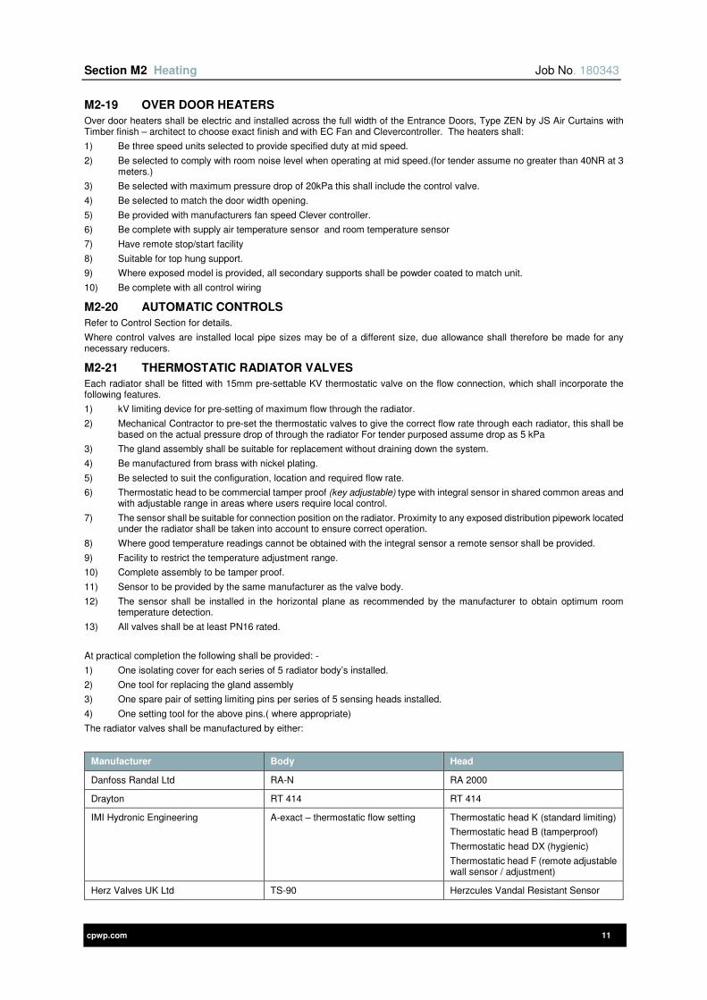
Section M2 Heating Job No. 180343
cpwp.com 11
M2-19 OVER DOOR HEATERS
Over door heaters shall be electric and installed across the full width of the Entrance Doors, Type ZEN by JS Air Curtains with Timber finish – architect to choose exact finish and with EC Fan and Clevercontroller. The heaters shall:
1) Be three speed units selected to provide specified duty at mid speed.
2) Be selected to comply with room noise level when operating at mid speed.(for tender assume no greater than 40NR at 3 meters.)
3) Be selected with maximum pressure drop of 20kPa this shall include the control valve.
4) Be selected to match the door width opening.
5) Be provided with manufacturers fan speed Clever controller.
6) Be complete with supply air temperature sensor and room temperature sensor
7) Have remote stop/start facility
8) Suitable for top hung support.
9) Where exposed model is provided, all secondary supports shall be powder coated to match unit.
10) Be complete with all control wiring
M2-20 AUTOMATIC CONTROLS
Refer to Control Section for details.
Where control valves are installed local pipe sizes may be of a different size, due allowance shall therefore be made for any necessary reducers.
M2-21 THERMOSTATIC RADIATOR VALVES
Each radiator shall be fitted with 15mm pre-settable KV thermostatic valve on the flow connection, which shall incorporate the following features.
1) kV limiting device for pre-setting of maximum flow through the radiator.
2) Mechanical Contractor to pre-set the thermostatic valves to give the correct flow rate through each radiator, this shall be based on the actual pressure drop of through the radiator For tender purposed assume drop as 5 kPa
3) The gland assembly shall be suitable for replacement without draining down the system.
4) Be manufactured from brass with nickel plating.
5) Be selected to suit the configuration, location and required flow rate.
6) Thermostatic head to be commercial tamper proof (key adjustable) type with integral sensor in shared common areas and with adjustable range in areas where users require local control.
7) The sensor shall be suitable for connection position on the radiator. Proximity to any exposed distribution pipework located under the radiator shall be taken into account to ensure correct operation.
8) Where good temperature readings cannot be obtained with the integral sensor a remote sensor shall be provided.
9) Facility to restrict the temperature adjustment range.
10) Complete assembly to be tamper proof.
11) Sensor to be provided by the same manufacturer as the valve body.
12) The sensor shall be installed in the horizontal plane as recommended by the manufacturer to obtain optimum room temperature detection.
13) All valves shall be at least PN16 rated.
At practical completion the following shall be provided: -
1) One isolating cover for each series of 5 radiator body’s installed.
2) One tool for replacing the gland assembly
3) One spare pair of setting limiting pins per series of 5 sensing heads installed.
4) One setting tool for the above pins.( where appropriate)
The radiator valves shall be manufactured by either:
Manufacturer Body Head
Danfoss Randal Ltd RA-N RA 2000
Drayton RT 414 RT 414
IMI Hydronic Engineering A-exact – thermostatic flow setting Thermostatic head K (standard limiting)
Thermostatic head B (tamperproof)
Thermostatic head DX (hygienic)
Thermostatic head F (remote adjustable wall sensor / adjustment)
Herz Valves UK Ltd TS-90 Herzcules Vandal Resistant Sensor
Section M2 Heating Job No. 180343
cpwp.com 12
Design Remote Control (remote adjustable wall sensor / adjustment)
M2-22 LOCKSHIELD RADIATOR VALVES
Each radiator shall be fitted with 15mm Lockshield valve on the return connection unless otherwise stated and shall incorporate the following features: -
1) Complete assembly to be tamper proof.
2) Complete with a rubber sealed nickel plated cover.
3) Complete with a connection to fit an adapter for draining / filling the radiator.
4) Be manufactured from brass with nickel plating, to exactly match the thermostatic radiator valve.
5) All valves shall be at least PN16 rated.
At practical completion the following shall be provided: -
1) One draining adapter per series of 20 lockshield valves installed (min=1No.)
2) One isolating tool / Allen key per series of 20 lockshield valves installed (min=1No.)
The lockshield valves shall be as manufactured by Danfoss Limited, their RLV-S Angle pattern for radiators and RLV-S straight pattern for ceiling radiant panels and trench heating or Herz Valves UK Ltd or equivalent or equal and approved.
M2-23 PIPEWORK, VALVES AND FITTINGS
All valves and fittings shall be as detailed in General Installation Standards.
M2-24 THERMAL INSULATION
The whole of the heating pipework shall be thermally insulated. All insulation shall be as detailed in General Installation Standards.
M2-25 TESTING AND COMMISSIONING
Testing and commissioning shall be carried out fully in accordance with General Installation Standards of this Specification.
M2-26 EXPANSION AND CONTRACTION
The selection and installation of all measures to allow for expansion and contraction shall be included for this project. This shall be in the form of loops, bellows, anchors, guides, offsets, rollers/chairs and cold draw.
Wherever feasible, natural flexibility solutions shall be employed. All provisions for expansion and contraction shall be indicated on the fabrication drawings submitted with the supporting calculations to the Engineer for comment prior to installation taking place.
In the event that natural flexibility cannot be used due to building fabric restraints, bellows shall be installed which shall:
1) Be multi-layered stainless steel (316L) quality units
2) As manufactured by:
a) Pipe Solutions (01423 878888)
b) Bellows Technology Ltd (01663 745873)
c) FLEXEJ Ltd (01384 881188)
9 cpwp.com V1.12
Section M3 Mechanical Ventilation Systems

Section M3 Mechanical Ventilation Systems Job No. 180343
cpwp.com 2
Contents Page
M3-1 GENERAL REQUIREMENTS 3
M3-2 REDUNDANCY REQUIREMENTS 3
M3-3 DEFINITIONS 3
M3-4 REFERENCE TO OTHER SECTIONS OF THIS SPECIFICATION 3
M3-5 STANDARDS APPLICABLE 3
M3-6 SCOPE OF WORKS 4
M3-7 CENTRAL ‘DIRTY’ EXTRACT SYSTEM 4
M3-8 DECENTRALISED LOCAL EXTRACT SYSTEMS (WALL / WINDOW FANS) 5
M3-9 KITCHEN EXTRACT SYSTEM 5
M3-10 MECHANICAL VENTILATION HEAT RECOVERY VENTILATION UNITS 5
M3-11 ATTENUATORS 6
M3-12 VOLUME CONTROL DAMPERS 6
M3-13 GENERAL SUPPLY DIFFUSERS AND EXTRACT GRILLES 6
M3-14 DUCTWORK CONSTRUCTION 7
M3-14-1 GENERAL 7
M3-14-2 LOUVRES 7
M3-15 FLEXIBLE CONNECTIONS 7
M3-16 FIRE AND COMBINATION FIRE & SMOKE DAMPERS 7
M3-17 THERMAL INSULATION 7
M3-18 TESTING AND COMMISSIONING 7
Section M3 Mechanical Ventilation Systems Job No. 180343
cpwp.com 3
M3-1 GENERAL REQUIREMENTS
The mechanical ventilation systems required for this project shall be as follows:
1) 2No. Supply and extract MVHR units with heat recovery to occupied areas of the building.
2) Separate Kitchen Supply and Extract
3) Allow for contacting Catering specialist to determine air flows and pressure drops need for canopies.
4) Separate local extract system serving toilets and associated areas. Local extract fans shall be provided to each WC, shower and cleaners cupboards.
5)
Kitchen Canopies and Fire Suppression is to be detailed by the Catering Specialist.
M3-2 REDUNDANCY REQUIREMENTS
No redundant capacity is provided for the mechanical ventilation systems.
M3-3 DEFINITIONS
Refer to Section 1B for general definitions plus:
DEFINITIONS
AHU Air Handling Unit
BCO Building Control Officer
CV Constant Volume
DX Direct Expansion (refrigerant system)
PHE Plate Heat Exchanger
RAC Run Around Coil Heat Exchanger
SFP Specific Fan Power
VAV Variable Air Volume
VCD Volume Control Damper
VFC Volt Free Contacts
VRF Variable Refrigerant Flow
VRV Variable Refrigerant Volume
M3-4 REFERENCE TO OTHER SECTIONS OF THIS SPECIFICATION
This section of the specification shall not be used in isolation and must be read in conjunction with the particular sections, commissioning and standard clauses, all of which define further the requirements for the installations.
Sections 2 Standards provides all necessary details on Ductwork, Mechanical Commissioning and Thermal Insulation requirements that apply to this section. The following text advises if the Contractor shall deviate from the preferred requirements detailed in standard sections. Agreed amendments from the preferred standards are:
All ductwork shall be galvanised steel fully in accordance with DW144.
No deviation from the section 2 preferred requirements.
M3-5 STANDARDS APPLICABLE
Works shall be completed in accordance with all applicable industry standards. Some of the most relevant standards associated with this section are scheduled below:
STANDARDS
BESA guides including DW series. BS EN 60038 CENELEC standard voltages
BS 7671 Requirements for electrical installations. IET Wiring Regulations
Building Regulations
BS 9999 Code of practice for fire safety in the design, management and use of buildings
BSRIA Commissioning Codes
BS EN 1751 Ventilation for buildings BSRIA Publications, including Commissioning Codes
BS EN 1886 Ventilation for buildings. Air handling units. Mechanical performance
CIBSE Commissioning Codes in particular R – Refrigeration and M – Management
Section M3 Mechanical Ventilation Systems Job No. 180343
cpwp.com 4
STANDARDS
BS EN 13501 Fire classification of construction products and building elements
Non-Domestic Building Services Compliance Guide
Eco-design Directives, in particular Commission Regulations in particular EU No 1253/2014 and 1254/2014
Where the above standards refer to supporting documentation and standards these shall be fully complied with in all respects.
Where discrepancy is found between this specification and the relevant standards, the Contractor shall obtain written clarification from the Engineer prior to submission of the tender. Where a discrepancy has not been clarified prior to tender submission, the Contractor shall include the most onerous requirements.
M3-6 SCOPE OF WORKS
The following brief description identifies those systems required for installation on this project. Comprehensive system requirements shall be detailed in the subsequent clauses of this specification together with schematic and design drawings.
The mechanical ventilation installations shall include for all necessary tools, labour, materials and equipment to supply, install, commission and put into operation the ventilation system, including the following:
1) 2 No. MVHR units at high level in the spaces
2) All ductwork, support brackets and secondary steelwork supports into and from AHUs to grilles and diffusers.
3) Variable air volume boxes and constant volume boxes.
4) Thermal insulation as detailed in the standards section.
5) All associated ductwork and fire dampers in accordance with the fire consultant and Building Control Officer.
6) All main, secondary and crosstalk attenuators and acoustic treatment.
7) All grilles and diffusers.
8) Include for witness pressure testing of all systems by the project M&E Clerk of Works, if appointed, and Engineer. The dates for witnessing mechanical services installation shall be fully included within the construction programme and updated as the project progresses to provide reliable dates for witnessing activities in a timely fashion (minimum of 10 working days’ notice).
9) All primary and secondary support systems to install the air handling units and all associated services.
10) Development of the Consultants drawings and detailing from the base tender information to full construction standards as detailed previously. Liaise and co-ordinate mechanical works with all other trades on site.
11) Provide development of the drawings and detailing from the base tender information to fully designed and constructed standards as detailed previously. This shall include full design responsibility (but not limited to) as follows: -
a) Support systems/brackets for all services.
b) Expansion and contraction within the system networks.
c) Detailed design and full co-ordination of the mechanical and electrical services including the preparation of completely dimensioned double line three dimensional services fabrication drawings using proprietary BIM modelling software e.g. Revit etc.
d) Development and adoption of the Consultants' concept for equipment and the systems specified to achieve the criteria described within the tender documents.
e) Design development of the Controls Performance Specification for the hardware, software, power, controls wiring and all associated equipment.
f) Preparation of co-ordinated ceiling and elevation drawings (1:50) showing all mechanical and electrical services outlets including the Specialist(s) Contractor's equipment.
M3-7 CENTRAL ‘DIRTY’ EXTRACT SYSTEM
The central extract ventilation systems shall provide extract ventilation to the areas detailed on the tender drawings shall:
• Include twin fans operating on a duty and standby basis.
• Be fully compliant with Ecodesign Directive for fans, particularly Commission Regulation EU No. 327/2011 requirements.
• Have a motor efficiency of at least IE3 only. For clarity, although IE2 fans and variable speed drives are permitted in the Ecodesign Directive, where the fan motors are inverter speed controlled the motors shall be IE3 standard.
• Be supplied and installed with the control gear and local electrical wiring necessary to provide fully functional systems.
• Have fan casings manufactured from heavy gauge corrosion resistant steel complete with internal high density acoustic treatment generally to the same overall construction standards as the main ventilation air handling units.
• Have backward curved high efficiency centrifugal fans supplied and installed complete with circular spigots with acoustic flexible connections.
• Have 98% efficient anti-vibration mountings and acoustic enclosure.
• Be fully suitable for their intended locations.
• Have attenuators on inlet and outlet as detailed on the Tender drawings.
• Include integral controls shall also provide automatic duty share and changeover on fault.
• Include back-draught dampers.
Central extract fans shall be manufactured by one of the manufacturers listed in the schedule at the end of this section.

Section M3 Mechanical Ventilation Systems Job No. 180343
cpwp.com 5
M3-8 DECENTRALISED LOCAL EXTRACT SYSTEMS (WALL / WINDOW FANS)
As detailed on the tender drawings small single / twin fan extract fans shall be installed. Ventilation rates shall be as per the Design Standards.
The fans shall:
1) CE Certified and Marked.
1) Incorporate DC motors to minimise energy consumption.
2) Include sealed for life bearings.
3) Include integral backdraught dampers / shutters.
4) Include thermally protected motors.
5) Be fully interfaced with the BMS for time scheduling.
6) Be provided with at least two speed operation of ‘low speed’ and ‘boost’. Low speed shall normal operating mode during occupied hours, when occupancy is detected the ‘boost’ shall be activated.
7) Occupancy shall be detected by the passive infrared detectors.
8) The fans shall discharge to outside via local exhaust louvres.
9) Each fan assembly shall have local motorised isolation damper to seal the system when the fan is not running.
Local extract fans shall be manufactured by one of the manufacturers listed in the schedule at the end of this section.
M3-9 KITCHEN EXTRACT SYSTEM
The kitchen extract ventilation systems shall provide extract ventilation to the areas detailed on the tender drawings shall:
• Be fully compliant with Ecodesign Directive for fans, particularly Commission Regulation EU No. 327/2011 requirements. It is fully understood that the kitchen extract fans do not need to comply with EU No. 327/2011 however compliance is a requirement on this project to maximise energy efficiency.
• Have a motor efficiency of at least IE3 only. For clarity, although kitchen extract fans do not need to comply with being IE3 standard this is a requirement on this project to maximise energy efficiency.
• Be supplied and installed with the control gear and local electrical wiring necessary to provide fully functional system.
• Have fan casings manufactured from heavy gauge corrosion resistant steel complete with internal high density acoustic treatment generally to the same overall construction standards as the main ventilation air handling units.
• Be bifurcated design with the fan motor out of the airstream.
• Be fully suitable for continuous operation at a temperature of 60ºC.
• Be fully suitable for continuous operation at 100% humidity.
• Be fire rated to ensure the whole ventilation installation is certified as fire rated.
• Have 98% efficient anti-vibration mountings.
• Be fully suitable for their intended locations.
• Shall be fully compliant with BESA DW 172.
• Be manufactured and installed in accordance with BS9999 and comply with the performance stated within BS 476 Part 24 (ISO 6944). The fire resistance from either within or outside the duct shall be a minimum of two hours.
• Fire rated fan shall be a Type A and Type B certified fire system compliant with performance characteristics to BS 476, Part 24 (ISO 6944) of: STABILITY INSULATION AND INTEGRITY.
• Include motorised damper to seal the building when the fan is not running.
• Be linked to the local gas proving system.
• Provided with a local control and monitoring panel to provide fan enable, fan speed adjustment, fan run status lamp, fan trip lamp and low airflow lamp.
• Linked to the supply air fan so that neither fan runs in case of either fan failing / linked to hold off the supply fan if the extract fan has failed.
Kitchen extract fan shall be manufactured by one of the manufacturers listed in the schedule at the end of this section.
.
M3-10 MECHANICAL VENTILATION HEAT RECOVERY VENTILATION UNITS
Provide local heat recovery ventilation units as detailed on the tender drawings, provided in the schedules and below:
• Be fully insulated providing excellent thermal and acoustic characteristics.
• Be complete with a multi plate counter flow high efficiency heat exchanger block, with a thermal efficiency of up to 95%
• Be protected by G3 grade filters on fresh air inlet and system extract.
• All components including fans, heat exchanger and filters shall be accessible via the front access panel, enabling quick and easy maintenance.
• Utilise low energy, high efficiency EC fan/motor assemblies with sealed for life bearings, the impellers shall be backward curved centrifugal type.
• All motors shall be suitable of an ambient temperature of 40°C.
• Be supplied complete with a condensate drip tray and 21.5mm drain connection.
Section M3 Mechanical Ventilation Systems Job No. 180343
cpwp.com 6
• Breakout noise level and power requirements shall be as detailed by the unit manufacturer and in accordance with the ventilation equipment schedule.
• Provided within a white pre-painted or coated steel acoustic enclosure lined with a minimum of 20mm class '0' acoustic foam insulation to reduce breakout noise.
• Should the breakout noise levels exceed the parameters with the use of steel acoustic enclosure the Mechanical contractor shall include to provide enhanced performing enclosure to meet the design criteria set within the acoustic report.
• In-duct noise shall be attenuated as required to meet the design noise levels.
• Flexible duct connections shall be within the enclosure, pre-fitted between the attenuator section and the connection spigots on the top face of the enclosure.
• Wall mounted on 3mm (minimum) prefabricated steel cantilever wall brackets or other suitable fabricated steel supporting frame.
• Provided with a 5 year warranty.
• Each ventilation unit shall vary its speed and therefore the ventilation rate, as it receives signals from the switched live signal from light / remote switches or any ancillary sensors. When signals are received, the fan shall alter its speed to adjustable, normal and boost rates.
• Each unit shall have the facility to commission the supply and extract fans independently on minimum speed (continuous background ventilation), and boost speed, via inbuilt minimum and maximum speed adjustment. The fans shall have infinitely variable speed control.
• Include Automatic SUMMER BYPASS where intake and return air temperatures shall be measured so that supply air temperatures can be maximised during winter months and minimised as external ambient temperature rises. The Summer Bypass damper shall be opened by a wax actuator. Supply and Extract air shall be filtered irrespective of the bypass setting (open or closed).
• MVHR units shall include a sealed condensate drain with a dry seal trap, e.g. HepVO, sealed to waste, as it is under negative pressure, connected to the above ground drainage system via the tundish and air gap arrangement.
• Each unit shall have the following functions integrally mounted within the fan unit on a purpose made PCB, all such components prewired and factory fitted by the manufacturer:
a) Independent control of background supply and extract flow rates.
b) Independent control of boost speed supply and extract flow rates.
c) Integral fan failure indication.
d) Integral S/L terminal for boost from remote switch, e.g. light switch,
e) Integral heat exchanger frost protection.
f) Discreet daily run monitor.
• Each system shall be provided with a remote monitoring unit for ease of viewing run and fault conditions of the MVHR unit.
M3-11 ATTENUATORS
Attenuators shall be provided as indicated on drawings and fully in accordance with the Design Standards of this specification to limit noise transmission and noise breakout such that the maximum design room noise levels are satisfied.
Ensure that all attenuators are installed in accordance with manufacturer’s instructions and that all necessary transformation pieces are included for at 30 degrees maximum.
All attenuators shall be:
• Vapour sealed.
• Fully self-supporting.
• Constructed from same material as rest of ductwork (i.e. galvanised steel for galvanised steel ductwork).
• Thermally insulated.
• The attenuators shall be inspected for dirt ingress when manufactured, cleaned, sealed during transit and prior to installation.
• All attenuator manufacturer’s shall under write the acoustic performance of the attenuators and hold professional Indemnity Insurance (to the project’s level) for 12 years from practical completion.
Attenuators shall be manufactured by one of the manufacturers listed in the schedule at the end of this section.
M3-12 VOLUME CONTROL DAMPERS
All volume control dampers shall be installed in the positions where required to allow the proportional balancing of each system. After the balancing and commissioning of the systems all quadrants arms/control knobs shall be locked and permanently marked to aid the system to be re-balanced after maintenance. Aerofoil opposed blade type dampers shall be used, with quadrant lockable handles.
All volume control dampers shall be compliant with Ductwork Standards section of this specification.
M3-13 GENERAL SUPPLY DIFFUSERS AND EXTRACT GRILLES
General supply diffusers and extract grilles shall be provided as detailed on the tender drawings and schedules provided.
The designer shall liaise with the project architect to agree all grilles and diffusers based on the currently agreed requirements.
All diffusers and grilles shall comply with the following:

Section M3 Mechanical Ventilation Systems Job No. 180343
cpwp.com 7
1) All grilles and diffusers shall be easily cleaned and removable.
2) Be provided with a side entry spigot plenum boxes (supply and extract). Top entry shall only be accepted in exceptional circumstances and with written agreement of Engineer.
3) Plenum boxes shall be acoustically lined.
4) Provided with integral opposed blade volume control dampers (unless a duct mounted VCD is provided that solely serves the grille / diffuser).
5) Installed fully in accordance with the manufacturers recommendations.
6) Be finished in a powder coat finish, RAL colour to be agreed with Architect.
7) All supply and extract terminals shall be sized and selected with a maximum velocity of 2.0m/s or lower to meet the design noise limit criteria.
8) All extract grilles to be provided with hinged and shoot bold retained removable cores, plenums and volume control
dampers.
9) Selected to suit the type of ceiling.
10) Positions to be co-ordinated with light fittings and all other services.
11) Unless the ductwork design is deemed self-balancing (and agreed by the Engineer) all plenum boxes shall be provided with volume control dampers. Consideration must be given to access to the dampers so pull cord adjustment shall be required to some plenum boxes.
M3-14 DUCTWORK CONSTRUCTION
M3-14-1 GENERAL
All ductwork systems shall be installed and erected in full accordance with ‘General Installation Clauses – Ductwork’ of this Specification.
Note – some requirements of this section supersedes standards detailed in BESA DW and TR Guides.
The principal duct runs shall be located below the structure in order to evenly distribute weight onto the building structure all in accordance with Structural Engineer’s requirements.
Where ductwork passes through the insulation line of the building a thermal break within the ductwork shall be provided. This shall be via a change in material (i.e. galvanised ductwork to suitable plastic (PPs) thermal break) with fully overlapped insulation to maintain the thermal integrity of the envelope.
M3-14-2 LOUVRES
All external louvers shall be provided and installed by the Main Contractor for final connection by the Mechanical Contractor. Mechanical Contractor shall coordinate with the Main Contractor to ensure the correctly specified louvers are used i.e. grade of weather protection, materials, pressure drops, airflow volume, etc.
The louvers shall comply with category ‘B’ rain defence and shall have minimum of 50% free area, providing pressure drop of 10 to 15 Pa on intake and 30 to 35 pa on exhaust with maximum velocity of 1.7m/sec.
The Main Contractor shall include for:
• Blanking off un-used sections of louvre with pre-insulated sandwich powder coated steel panels (proprietary system manufactured by louvre manufacturer) to the fabric thermal performance criteria for the plantroom walls (i.e. U value and air tightness). Details of unused sections of louvres to be provided by the Mechanical Contractor.
• Full co-ordination of louvre positions / connection arrangements, details to be provided by Mechanical Contractor.
• All blanking plates shall be carried out prior to the Building Regulations Part L air leakage testing for the building.
M3-15 FLEXIBLE CONNECTIONS
Flexible ductwork shall be in accordance with ‘General Installation Clauses – Ductwork’ section of this Specification.
M3-16 FIRE AND COMBINATION FIRE & SMOKE DAMPERS
Fire dampers and combination fire and smoke dampers shall be in accordance with ‘General Installation Clauses – Ductwork’ section of this Specification.
The supply, installation and commissioning fire and combination fire & smoke dampers as necessary for compliance with the latest fire strategy drawings, fire engineering report, the approval of the Fire Officer and Building Control shall be included.
M3-17 THERMAL INSULATION
All supply and extract ductwork, shall be thermally insulated in accordance with ‘General Installation Clauses – Thermal Insulation’ section of this Specification.
All insulation shall be compliant with BREEAM credit requirements.
M3-18 TESTING AND COMMISSIONING
Each system shall be tested and commissioned as described within section 2 of this specification.
cpwp.com V1.3
Section M4 Fuel Systems

Section M4 Fuel Systems Job No. 180343
cpwp.com 2
Contents Page
M4-1 GENERAL REQUIREMENTS 3
M4-2 DEFINITIONS 3
M4-3 REFERENCE TO OTHER SECTIONS OF THIS SPECIFICATION 3
M4-4 STANDARDS APPLICABLE 3
M4-5 SCOPE OF WORKS 3
M4-6 GAS SYSTEMS 4
M4-7 INCOMING NATURAL GAS SUPPLY 4
M4-8 INCOMING GAS METERS 4
M4-9 INTERNAL PIPEWORK 4
M4-10 GAS COCKS 4
M4-11 GAS SAFETY AUTOMATIC SHUTDOWN SYSTEM 4
M4-11-1 PLANT ROOM 4
M4-11-2 KITCHENS 4
M4-12 TESTING AND COMMISSIONING 5
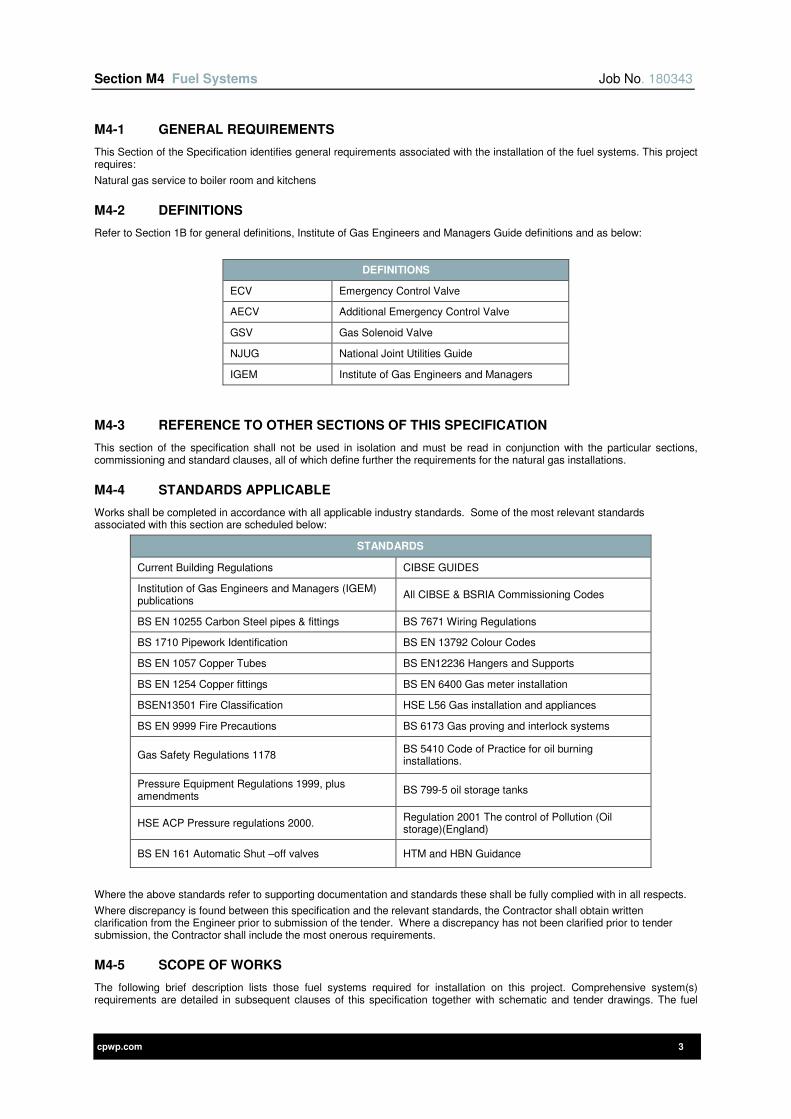
Section M4 Fuel Systems Job No. 180343
cpwp.com 3
M4-1 GENERAL REQUIREMENTS
This Section of the Specification identifies general requirements associated with the installation of the fuel systems. This project requires:
Natural gas service to boiler room and kitchens
M4-2 DEFINITIONS
Refer to Section 1B for general definitions, Institute of Gas Engineers and Managers Guide definitions and as below:
DEFINITIONS
ECV Emergency Control Valve
AECV Additional Emergency Control Valve
GSV Gas Solenoid Valve
NJUG National Joint Utilities Guide
IGEM Institute of Gas Engineers and Managers
M4-3 REFERENCE TO OTHER SECTIONS OF THIS SPECIFICATION
This section of the specification shall not be used in isolation and must be read in conjunction with the particular sections, commissioning and standard clauses, all of which define further the requirements for the natural gas installations.
M4-4 STANDARDS APPLICABLE
Works shall be completed in accordance with all applicable industry standards. Some of the most relevant standards associated with this section are scheduled below:
STANDARDS
Current Building Regulations CIBSE GUIDES
Institution of Gas Engineers and Managers (IGEM) publications
All CIBSE & BSRIA Commissioning Codes
BS EN 10255 Carbon Steel pipes & fittings BS 7671 Wiring Regulations
BS 1710 Pipework Identification BS EN 13792 Colour Codes
BS EN 1057 Copper Tubes BS EN12236 Hangers and Supports
BS EN 1254 Copper fittings BS EN 6400 Gas meter installation
BSEN13501 Fire Classification HSE L56 Gas installation and appliances
BS EN 9999 Fire Precautions BS 6173 Gas proving and interlock systems
Gas Safety Regulations 1178 BS 5410 Code of Practice for oil burning installations.
Pressure Equipment Regulations 1999, plus amendments
BS 799-5 oil storage tanks
HSE ACP Pressure regulations 2000. Regulation 2001 The control of Pollution (Oil storage)(England)
BS EN 161 Automatic Shut –off valves HTM and HBN Guidance
Where the above standards refer to supporting documentation and standards these shall be fully complied with in all respects.
Where discrepancy is found between this specification and the relevant standards, the Contractor shall obtain written clarification from the Engineer prior to submission of the tender. Where a discrepancy has not been clarified prior to tender submission, the Contractor shall include the most onerous requirements.
M4-5 SCOPE OF WORKS
The following brief description lists those fuel systems required for installation on this project. Comprehensive system(s) requirements are detailed in subsequent clauses of this specification together with schematic and tender drawings. The fuel
Section M4 Fuel Systems Job No. 180343
cpwp.com 4
system(s) supply shall include for all plant, equipment and labour to carry out the installation, testing, commissioning and setting into operation of the following works.
1) Provide new underground gas main to the building from statutory meter.
2) Provide new internal pipework from building entry to serve the new boilers within plantroom.
3) Provide and install new statutory gas meter and supply.(refer to enabling section for details)
4) Provide and install all solenoid valves and gas proving systems within kitchen and fire valve in boiler room,
5) Provide all riser/room ventilation grilles to in accordance with best practice and the gas regulations.
6) Provide gas safety equipment.
7) Provide all gas pipework, including valves and fittings.
8) Painting all of the gas services
9) All necessary system(s) purging, testing and commissioning.
10) All primary and secondary support systems to install the services.
11) Design development and coordination of the tender information to fully detailed working or installation drawings. This shall include responsibility for the following areas:-
a) Support systems/brackets for all services.
b) Expansion and contraction within the system networks.
c) Final co-ordination of the mechanical and electrical services including the preparation of completely dimensioned double line services fabrication drawings.
d) Development of the Consultants' details for equipment specified to achieve the criteria described within the tender documents.
e) Development of the controls specification for the hardware, software, power, controls wiring and all associated equipment.
12) Liaise with all other trades.
M4-6 GAS SYSTEMS
M4-7 INCOMING NATURAL GAS SUPPLY
The incoming natural gas supply is detailed in the Enabling section of this specification. Where a new statutory supply is required the Contractor shall be responsible for all liaison with the necessary authority to provide this service.
At entry into the building the supply shall be provided with an emergency isolation valve together with required additional emergency control valves fully in accordance with IGEM recommendations.
M4-8 INCOMING GAS METERS
The incoming meters are detailed in the Energy Metering section of this specification.
M4-9 INTERNAL PIPEWORK
Pipework shall be installed to the requirements set out in “General Installation Clauses” section of this specification.
Where the pipework distribution is within concealed voids or risers ventilation shall be provided via necessary ventilation grilles as recommended by gas regulations.
M4-10 GAS COCKS
All items of equipment shall be provided with line size lever operated gas cock.
M4-11 GAS SAFETY AUTOMATIC SHUTDOWN SYSTEM
The following gas safety systems are required.
M4-11-1 PLANT ROOM
A new automatic re-set line sized gas solenoid valve shall be provided as the pipework enters the plantroom. The valve shall be interlocked to the automatic control system and close when any of the below are activated:
1) Thermal sensors inter-wired and installed above each boiler, burner or water heater
2) Emergency knock-off button installed locally to plantroom entrance door
3) Fire alarm
Valve shall automatically open on re-instatement of power.
M4-11-2 KITCHENS
A new automatic gas proving system shall be installed to the kitchen(s) service, which shall provide isolation of the gas supply if the electrical supply to the valve is interrupted or the gas pressure is too low. The system shall include:-
1) line size solenoid valve(s)
2) Control Panel
3) All interconnecting wiring, sensors and pressure differential switches.
Section M4 Fuel Systems Job No. 180343
cpwp.com 5
The valve(s) shall be activated when linked to the operation of the emergency isolation system and automatic gas proving system as detailed below:-
1) Shall be interlocked to the kitchen ventilation system monitored via pressure differential switches and shall prevent gas flow to cooking equipment if the ventilation system is not functional. (ie held off until extract ventilation is proven)
2) Emergency stop activated
3) Fire suppression system activated
4) The system shall also provide a single point of isolation for the electrical power to kitchen appliances.
Once the valve has been shut it shall be manually reset from the panel provided as part of the gas proving system and located within the kitchen.
The Gas proving system shall:-
1) Check for any open burners, if the downstream gas pressure from the valve is below the expected value then the valve will not open until all gas cocks have been closed.
2) Be complete with key switch and reset facility. This shall isolate the gas supply overnight to prevent leakage and require the unit to prove the gas supply before opening the valve in the morning.
3) Ensure the gas solenoid valve installation is complete with a 24V battery rectifier unit to ensure valve remains open during power failure or alarm test.
4) Provide a battery with a duration of 4 hours and guaranteed life expectancy of 5 year
M4-12 TESTING AND COMMISSIONING
All testing and commissioning required to be carried out fully in accordance with “General installation Clauses” section of this Specification and also in accordance with Gas Board requirements.

cpwp.com V1.4
Section M6 Above Ground Drainage
Section M6 Above Ground Drainage Job No. 180343
cpwp.com 2
Contents Page
M6-1 PIPEWORK INSTALLATIONS 4
M6-2 DEFINITIONS 4
M6-3 REFERENCE TO OTHER SECTIONS OF THIS SPECIFICATION 4
M6-4 STANDARDS APPLICABLE 4
M6-5 SCOPE OF WORKS 4
M6-6 DRAWINGS 5
M6-7 GRAVITY DRAINAGE SYSTEM 5
M6-7-1 MATERIAL SELECTION 6
M6-8 GENERAL REQUIREMENTS FOR PIPEWORK SYSTEM 7
M6-8-1 INTRODUCTION 7
M6-8-2 COMPLIANCE WITH LOCAL WATER AUTHORITY 7
M6-8-3 PROTECTION 7
M6-8-4 HANDLING AND CUTTING OF PIPE 7
M6-8-5 INSTALLATION 7
M6-9 MATERIALS 8
M6-9-1 PVC-U PIPEWORK 8
M6-9-2 CAST IRON PIPEWORK 9
M6-9-3 ABS SUPERFLO 9
M6-9-4 CHEMICAL PIPEWORK 10
M6-9-5 COPPER PIPEWORK 10
M6-9-6 STAINLESS STEEL PIPEWORK 11
M6-9-7 PVC-C PIPEWORK 11
M6-9-8 HDPE PIPEWORK 11
M6-9-9 PIPEWORK SYSTEM MANUFACTURERS 12
M6-10 ACCESSORIES 12
M6-10-1 TRAPS 12
M6-10-2 SHOWER CHANGING ROOM CHANNELS (SPORTS HALLS ETC.)ERROR! BOOKMARK NOT DEFI
M6-11 TESTING 12
M6-11-1 GENERAL 12
M6-11-2 PROCEDURES FOR TESTING 12
M6-11-3 TEST CERTIFICATE 12
M6-12 KITCHEN WASTE SYSTEMS 12
M6-13 DRAINAGE TRACE HEATING ERROR! BOOKMARK NOT DEFINED.
M6-14 CAR PARK - CAST IRON DRAINAGE ERROR! BOOKMARK NOT DEFINED.
M6-14-1 ACCESSORIES ERROR! BOOKMARK NOT DEFINED.
M6-14-1-1 RAINWATER & CHANNEL OUTLETS ON CAR PARK DECKSERROR! BOOKMARK NOT DEFINED.
Section M6 Above Ground Drainage Job No. 180343
cpwp.com 3
M6-14-1-2 RAINWATER OUTLETS FOR STAIR ROOFS AND TOP DECKS OF
CAR PARK ERROR! BOOKMARK NOT DEFINED.
M6-15 WASTE WATER SUMP PUMPS ERROR! BOOKMARK NOT DEFINED.
M6-16 SEWAGE PUMP UNITS ERROR! BOOKMARK NOT DEFINED.
M6-17 ALUMINIUM PIPEWORK AND FITTINGS (FOR EXTERNAL RAINWATER INSTALLATIONS) 13
M6-18 WASTE DISPOSAL UNITS ERROR! BOOKMARK NOT DEFINED.
M6-19 BUILDERSWORK ERROR! BOOKMARK NOT DEFINED.
M6-20 APPENDIX 14
M6-20-1 PIPEWORK SYSTEM MANUFACTURERS 14
M6-20-2 WASTE WATER SUMP PUMP ERROR! BOOKMARK NOT DEFINED.
M6-20-3 SEWAGE PUMPSET ERROR! BOOKMARK NOT DEFINED.
<On completion of the section, right click on the above table of contents and click UPDATE FIELD>
Section M6 Above Ground Drainage Job No. 180343
cpwp.com 4
M6-1 PIPEWORK INSTALLATIONS
The Contractor shall supply, install and commission the pipework installations as detailed on the Tender drawings and within this specification, employing skilled personnel to the standards described. All pipework shall be entirely suitable for operation with the particular fluids conveyed and pressures involved. Materials for specific systems are detailed later in this section
M6-2 DEFINITIONS
Refer to section 2 for general definitions plus the following:
DEFINITIONS
FCU Fan Coil Unit
PVC-u Polyvinyl Chloride (Un-plasticised)
uPVC See above
ABS Acrylonitrile Butadiene Styrene
PP Polypropylene
Supervising Officer Where this term is used it shall mean the person undertaking the inspection of installed work, and shall be equally Client Clerk of works or Engineer.
M6-3 REFERENCE TO OTHER SECTIONS OF THIS SPECIFICATION
This section of the specification shall not be used in isolation and must be read in conjunction with the particular sections, commissioning and standard clauses, all of which define further the requirements for the installations.
M6-4 STANDARDS APPLICABLE
Works shall be completed in accordance with all applicable industry standards. Some of the most relevant standards associated with this section are scheduled below:
STANDARDS
Current Building Regulations CIBSE GUIDE G Public Health Engineering
BS 12056, Parts 1,2,3,4 and 5 Gravity drainage systems All CIBSE & BSRIA Commissioning Codes
BSEN13501 Fire Classification BSEN 5588 Fire Precautions
BS 1710 Pipework Identification BS EN 877 Cast Iron Pipework
BS EN 1057 Copper Tubes BS EN 1329 PVC-u, HDPE and Polypropylene Pipework
BS EN 681 Elastomeric Seals BS 416 – Cast Iron (Sand cast /Spun)
BS EN 1124 Stainless Steel BS 6465 parts 1 and 2 Sanitary Appliances
BS 6959 Jointing materials BS 10226 Threaded pipes and fittings
Where the above standards refer to supporting documentation and standards these shall be fully complied with in all respects.
Where discrepancy is found between this specification and the relevant standards, the Contractor shall obtain written clarification from the Engineer prior to submission of the tender. Where a discrepancy has not been clarified prior to tender submission, the Contractor shall include the most onerous requirements.
M6-5 SCOPE OF WORKS
The following brief descriptions identify those systems required for installation on this project.
The above ground drainage system(s) installation shall include for all necessary tools, labour, materials and equipment to design, supply, install, test, commission and put into operation the sanitation and drainage services, including the following:-
1) Main gravity domestic soil, waste and ventilation system in PVC-u.
2) Low level branch soil and waste system in PVC-u.
3) Ventilation pipework in PVC-u
4) Plantroom mechanical waste system in cast iron and PVC-u.
5) Kitchen Waste Drainage
6) Plantroom gullies in cast iron.
7) Grease removal machines for Hot kitchens
8) Gravity internal rainwater systems in Cast iron
9) Fire sleeves for PVC-u in metal.
10) Unicollar fire protection for Vulcathene pipework.

Section M6 Above Ground Drainage Job No. 180343
cpwp.com 5
11) All testing, witnessing hydraulic pressure tests and commissioning.
12) All internal vertical drains and rainwater to be complete with Thermal/sound insulation.
13) Liaison with other trades on site.
14) Copies of Operating and Maintenance instruction manuals including a ‘Brief Description’ of services and fault finding information list of spares, emergency telephone Nos. etc.
15) Full user instruction, both written and in the form of demonstrations.
16) All primary and secondary support systems to install the services.
17) Development of the Consultants drawings and detailing from the base tender information to full construction standards as detailed previously. This shall include responsibility for the following areas:-
18) Support systems/brackets for all services.
19) Expansion and contraction within the system networks.
20) Final co-ordination of the mechanical and electrical services including the preparation of completely dimensioned double line services fabrication drawings.
21) Development of the Consultants' details for equipment specified to achieve the criteria described within the tender documents
Items excluded from this specification are as follows: -
1) Underground drainage.
2) Weathering of all pipework and outlets through the roof.
3) Rainwater pipework.
4) Sanitary ware.
5) Effluent waste plant
6) Builders Work
M6-6 DRAWINGS
Piping systems shown on the Drawings are designed to comply with the requirements of BS EN 12056 (except where otherwise specifically stated) and are diagrammatic to indicate the general routing and sizes required. They need not necessarily show all components in their true positions.
The Contractor shall be responsible for the proper erection of piping systems suitable in every respect for the design and application intent.
Any alteration to equipment installation/positioning arising during construction which may alter the run and size of piping to accommodate situations shall be reviewed with the Engineer.
M6-7 GRAVITY DRAINAGE SYSTEM
Drainage from all general sanitary appliances shall be achieved by a single pipe “Gravity Drainage System”. This shall be an independent drainage system connecting directly to the local foul drainage system.
The drainage system shall be vented to atmosphere via “single stack venting” to atmosphere above the roof. Vertical stacks shall be located within the services ducts.
All soil and waste branch pipes shall be rigid with no flexible connections being permitted; this shall particularly apply to WC connections.
Emphasis shall be given to ensure that very good pipe gradients are achieved with access doors and caps positioned for ease of maintenance and testing.
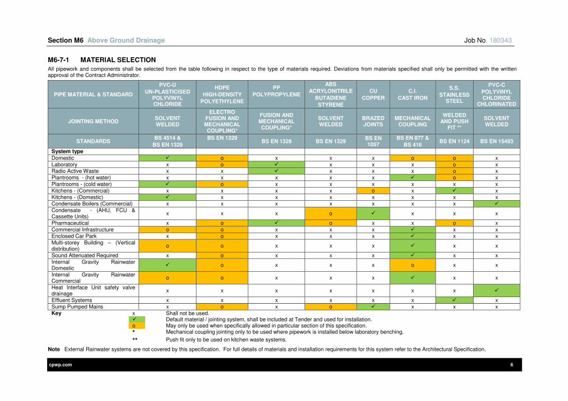
Section M6 Above Ground Drainage Job No. 180343
cpwp.com 6
M6-7-1 MATERIAL SELECTION
All pipework and components shall be selected from the table following in respect to the type of materials required. Deviations from materials specified shall only be permitted with the written approval of the Contract Administrator.
PIPE MATERIAL & STANDARD
PVC-U
UN-PLASTICISED POLYVINYL CHLORIDE
HDPE
HIGH-DENSITY
POLYETHYLENE
PP
POLYPROPYLENE
ABS
ACRYLONITRILE
BUTADIENE
STYRENE
CU
COPPER
C.I.
CAST IRON
S.S.
STAINLESS STEEL
PVC-C
POLYVINYL CHLORIDE
CHLORINATED
JOINTING METHOD SOLVENT WELDED
ELECTRO FUSION AND MECHANICAL COUPLING*
FUSION AND MECHANICAL COUPLING*
SOLVENT WELDED
BRAZED JOINTS
MECHANICAL COUPLING
WELDED AND PUSH
FIT **
SOLVENT WELDED
STANDARDS BS 4514 &
BS EN 1329
BS EN 1329
BS EN 1329 BS EN 1329
BS EN 1057
BS EN 877 &
BS 416 BS EN 1124 BS EN 15493
System type
Domestic o x x x o o x
Laboratory x o x x x o x Radio Active Waste x x x x x o x
Plantrooms - (hot water) x x x x x o x
Plantrooms - (cold water) o x x x x x x
Kitchens - (Commercial) x x x x o x x
Kitchens - (Domestic) x x x x x x x Condensate Boilers (Commercial) x x x x x x x
Condensate - (AHU, FCU & Cassette Units)
x x x o x x x
Pharmaceutical x o o x x o x
Commercial Infrastructure o o x x x x x Enclosed Car Park x o x x x x x
Multi-storey Building – (Vertical distribution)
o o x x x x x
Sound Attenuated Required x o x x x x x
Internal Gravity Rainwater Domestic
o x x x o x x
Internal Gravity Rainwater Commercial
o o x x x x x
Heat Interface Unit safety valve drainage
x x x x x x x
Effluent Systems x x x x x x x
Sump Pumped Mains x o x o x x x Key x Shall not be used.
Default material / jointing system, shall be included at Tender and used for installation. o May only be used when specifically allowed in particular section of this specification.
* Mechanical coupling jointing only to be used where pipework is installed below laboratory benching.
** Push fit only to be used on kitchen waste systems.
Note External Rainwater systems are not covered by this specification. For full details of materials and installation requirements for this system refer to the Architectural Specification.
Section M6 Above Ground Drainage Job No. 180343
cpwp.com 7
M6-8 GENERAL REQUIREMENTS FOR PIPEWORK SYSTEM
M6-8-1 INTRODUCTION
The general requirements are applicable to all pipework systems and shall be read in conjunction with the detailed requirements as specified later in this section.
M6-8-2 COMPLIANCE WITH LOCAL WATER AUTHORITY
The Contractor shall:
1) Issue all working drawings to the local authority for their comment with regard to water regulations and local requirements (except where Contractor is able to self-certify the scheme with the local authority)
2) Ensure that any certification required is submitted within the time scales specified by the authority in order to ensure that the connection of the water supply is not delayed.
3) Ensure that all systems fully comply with the local water authorities particular requirements.
M6-8-3 PROTECTION
All pipes stored at site prior to installation shall be kept clean, properly racked clear of the ground and covered. Sites selected for storage shall be flat and level and free from sharp stones and flints etc. Pipework storage shall:
1) Utilise off-loading operations which shall only use rope or web slings and provide adequate man or machine power to accommodation this activity. (Materials shall not be thrown haphazardly from vehicles by reason of size or lightness or dropped violently)
2) Be stored to prevent dirt and foreign matter entering open ends of pipes. (Wood, rag, paper, wood shavings or other inadequate plugs shall not be permitted).
3) Be stored so that stacks shall not exceed seven layers of pipes or two metres in height whichever is the lesser.
4) Not exceed a height of ten times the pipe size (up to 75mm diameter) when stacking ABS pipe.
5) Be in locations protected from direct sunlight, properly racked and supported clear of the ground for Acrylonitrite Butadiene Styrene (ABS) polypropylene and PVC pipework and components at all times.
6) Where any lining or coating has been applied ensure no other pipe or material of any kind shall be placed inside the pipework.
7) When spigot and socket pipes are stacked, ensure the bottom layer of sockets shall be prevented from making direct contact with the ground. Succeeding pipe layers shall have sockets protruding at alternate ends of the stack
8) Shall only allow smaller pipes to be rested inside larger pipes which are adjacent to the ground.
9) Be such that when transporting of pipe lengths subsequent to off-loading the arrangement ensures that neither spigot nor socket ends or flanges become damaged by dragging along surfaces. The pipe supporting surfaces of site vehicles used for handling shall have no sharp projections, and shall provide uniform support to the pipe lengths
The use of any corroded pipes shall not be allowed. Any such pipework shall be removed and replaced by the Contractor at his expense.
M6-8-4 HANDLING AND CUTTING OF PIPE
All cutting of pipes required shall be carried out by the Contractor in a neat and workmanlike manner without damage to the pipe. Cutting shall be carried out in accordance with the manufacturer’s recommendations and shall be made with an approved type mechanical cutter. Wheel cutters shall be used when practicable.
Necessary cuts in pipes shall be made square to the axis of pipes and all burrs and other irregularities removed by reaming and filing before installing.
Pipes shall be inspected for defects. Material found to be defective shall be replaced with sound material prior to installing. Any defective pipework found to be installed shall be replaced at the Contractor's cost.
Pipes and accessories shall be handled so as to ensure delivery to the installation position in sound, undamaged condition as the following:
1) Pipes shall be carried into position and not dragged.
2) The interiors of pipes and accessories shall be thoroughly cleaned of foreign matter before being placed in position
3) Pipes shall be kept clean during fixing operations by plugging or other approved method.
4) Where required the use of pinch bars and tongs for aligning or turning pipe shall be permitted only on the barrel of the pipe
5) Particular care shall be taken not to injure the pipe lining and coating. If the coating or lining of any pipe or fitting is damaged, the repair shall be made by the Contractor, at his expense
6) Any Rubber or compound gaskets or sleeves which are not to be installed immediately shall be stored in a cool area protected from direct sunlight.
M6-8-5 INSTALLATION
Pipework shall be installed as recommended by the current BS standard, particular care shall be taken to ensure the following installation is provided:
1) All pipework is erected and secured truly parallel and plumb with vertical surfaces.
2) All horizontal pipework shall be arranged with a minimum fall from traps of 1 in 40, or rise in the case of anti-syphon pipework.
3) All bends shall be long radius or 2No. 45 deg. bends and all tees long sweep patterns.

Section M6 Above Ground Drainage Job No. 180343
cpwp.com 8
4) Long runs of pipework shall be erected so that stresses of expansion and contraction, due to temperature variation, are taken up by expansion joints. Where small bore branches are made to mains remote from anchor points, the branches shall be arranged to form a radius arm so that the axial movement of the main does not stress the connecting fittings.
5) Expansion devices shall be of similar material to the pipe, installed in line with the axis of the pipe and shall be free from compression, tension or torsion. The female member of the expansion devices shall be firmly anchored to allow the male member to take all movement.
6) Jointing rings, couplings and adaptors shall be of types recommended by the manufacturer of the pipes being jointed.
7) Rubber joint rings they shall be stored in their delivery bags and not exposed to sunlight. These shall comply with Building Standard for Elastomeric Seals
8) Where pipes pass through walls and floors, sleeves shall be fitted to allow free axial movement of the pipes. Sleeves shall be of a material compatible with the pipes they protect, non-combustible and of a minimum bore to allow such movement.
9) The length of sleeve shall be sufficient to finish flush with the finished wall or, where passing through floors to protrude 6mm above and below the finished floor and underside level (soffit). The annular space between pipe and sleeve shall be packed with intumescent material so as to prevent the passage of fire.
10) Slip-on cover plates shall be provided as a finish to pipework, up to and including 50mm diameter, in occupied areas where pipe work is emerging from a wall. Samples shall be first submitted to the Contract Administrator for approval
11) Any concealed pipework shall be installed neatly and as close as possible to the building structure, with due allowance made for supports, brackets, adjacent services and thermal insulation which may be required.
12) Union type fittings shall be provided to make up to outlets of basin and sink wastes, drip cups and dilution receivers etc. on pipework up to and including 50mm diameter.
13) Any joints in pipework shall not be made within the thickness of walls, floor or roof, or where they would later be built in.
14) Jointing material shall not project into the bore of pipes, fittings or appliances.
15) Adjustable WC connectors shall not be permitted.
16) All connections between soil pipe branches and spigots of ceramic WC fitments shall be made with flexible connectors "Multikwik".
17) Access plates shall be provided at:
18) The foot of each vertical stack and immediately above the point where a stack passes through subsequent floor levels;
19) All 50mm diameter vertical discharge pipes shall have an access point/cap above FFL within appliance panelling to enable the complete disposal system to be internally cleaned and rodded. Access plates/rodding eyes at FFL level shall not be permitted.
20) Ventilating and anti-syphon pipes above their highest branches shall be continued upwards, at their full diameter, to such a height as to afford a safe outlet for foul air, all as detailed on the relevant drawing.
21) Automatic air admittance valves shall not be permitted.
22) All roof level penetrations shall be provided with water seal and weather protected installation
23) Any cast iron stacks balloon vent discharge shall be of copper wire.
24) All drainage and rainwater pipework that pass through a fire compartment or barrier or floor plate shall be complete with an intumescent fire collar to maintain the fire barrier rating.
Should leaks develop in any system after being set in operation, it shall be the responsibility of the Contractor to repair the leak points and, if damage to the building structure or any item of contents has occurred as a result of such leakage, rectification of the damage shall be carried out by the Contractor at his own expense.
M6-9 MATERIALS
M6-9-1 PVC-U PIPEWORK
All pipes and fittings shall be in Unplasticised Polyvinyl Chloride PVC-u and shall be jointed by solvent welding.
The jointing procedure shall be strictly in accordance with the manufacturer’s sequence of requirements. Joints between PVC-u and the underground drainage system shall be made using a suitable drain adaptor.
Horizontal pipework suspended from the underside of floor slabs shall be supported by means of an approved corrosion resistant suspended bracketing system.
Bracket spacing shall be in accordance with the following table which indicates the maximum recommended bracket centres for low gradient and vertical PVC-u pipes.
BRACKETS CENTRES FOR PVC-U PIPEWORK
DIAMETER SIZE (NOMINAL) HORIZONTAL SPACING (M) VERTICAL SPACING (M)
32mm 500 1200
40mm 500 1200
50mm 900 1200
82mm 900 2000
110mm 1000 2000

Section M6 Above Ground Drainage Job No. 180343
cpwp.com 9
Precautions shall be taken to accommodate linear movements within the suspended pipework system. Expansion joints shall be incorporated at approximately 4m centres and rigidly anchored.
Where changes of direction are at angles less than 45o the bend shall be formed by two close coupled adjustable bends.
The branch angle at a junction shall be 45°, an adjustable bend is then cut to the required angle of the side connection.
The change of direction from vertical to low gradient pipework is to be achieved by using two 45o bends or a long radius bend, and shall be fully supported.
M6-9-2 CAST IRON PIPEWORK
All pipes and fittings shall be in cast iron, without sockets and carry BS Kitemark and DN numbering.
All above ground soil, vent and rainwater pipework shall be coated both externally and internally.
PIPEWORK COATING
Location / Item Coating Description
Pipe externally Acrylic, anti-corrosion primer coating, red-brown colour, average dry thickness 40
Pipe internally Two part epoxy coating, ochre colour, with an average thickness of 130 microns
Fittings red powder epoxy resin electrostatically applied to an average thickness of 150 microns, externally coated to an average thickness 70 microns
Couplings / brackets
Protected with a red water based semi-gloss paint, average thickness of 40 microns
The jointing system to be by two-piece ductile iron couplings incorporating built-in electrical continuity.
Bracket spacing generally as below table or to conform to manufacturer’s requirements whichever is the most onerous:
BRACKETS CENTRES FOR CAST IRON PIPEWORK
DIAMETER SIZE (NOMINAL) HORIZONTAL SPACING (M) VERTICAL SPACING (M)
All sizes 1.5 3.0
Stack supports located in accordance with manufacturer’s requirements.
M6-9-3 ABS SUPERFLO
All pipes and fittings shall be joined by using ABS solvent cement, no other solvents are to be used.
The jointing procedure shall be strictly in accordance with the manufacturer’s sequence of requirements.
Pipework and fittings shall be WRAS approved. Pipework and fittings shall be manufactured by Durapipe Superflo range.
Horizontal pipework suspended from the underside of floor slabs shall be supported by means of a manufacturers approved corrosion resistant suspended bracketing system and shall be sufficiently rigid to provide lateral restraint to the pipework.
Bracket spacing shall be in accordance with the following table.
BRACKETS CENTRES FOR ABS PIPEWORK
DIAMETER SIZE (NOMINAL) HORIZONTAL SPACING (M) VERTICAL SPACING (M)
16mm 0.8 1.2
20mm 0.9 1.35
25mm 1.0 1.5
32mm 1.1 1.65
40mm 1.2 1.8
50mm 1.3 1.95
63mm 1.4 2.1
75mm 1.5 3.25
90mm 1.6 2.4
110mm 1.8 2.7

Section M6 Above Ground Drainage Job No. 180343
cpwp.com 10
M6-9-4 CHEMICAL PIPEWORK
All pipes and fittings to be in Polypropylene (Pp) to DIN 19535, DIN 19537, DIN 8074, DIN 8075 and carry a BBA certificate. All materials and manufacture shall carry BBA certification.
Systems within concealed ducts and voids shall be joined by means of electrofusion welding. Mechanical jointing system shall be installed where system is exposed to view.
All component parts of the system shall be covered by a manufacturer’s warranty.
Bracket spacing and fixings shall be in accordance with the manufacturer’s requirements.
Precautions shall be taken to accommodate linear movements within the suspended pipework system. Expansion joints shall be incorporated at approximately 4m and rigidly anchored.
Where changes of direction are at angles less than 45o the bend shall be formed by two close coupled adjustable bends.
The branch angle at a junction shall be 45o, and adjustable bend is then cut to the required angle of the side connection.
The change of direction from the vertical to low gradient pipework is to be achieved by using two 45o bends or a long radius bend, and shall be fully supported.
Pipe supports shall be positioned at the maximum intervals, indicated in the following table:
BRACKETS CENTRES FOR CHEMICAL PIPEWORK
DIAMETER SIZE (NOMINAL) HORIZONTAL SPACING (M) VERTICAL SPACING (M)
38mm 1.22 1.5
51mm 1.37 1.5
76mm 1.52 1.5
100mm 1.83 1.5
M6-9-5 COPPER PIPEWORK
Pipework up to and including 75mm shall table R 250.
Bends and sets in Table R 250 piping, up to and including 54mm diameter, may be made on site where standard fittings cannot be used or where this method will give a neater appearance. Pulled bends or offsets which show flattening, rippling or constriction of the bore will not be accepted.
Fittings, including traps, on piping up to and including 54mm diameter shall be of copper or copper alloy specifically designed to carry the flow of non-corrosive waste water under conditions of gravity head. The fittings shall incorporate capillary type joints having either an integral solder ring or facility for introducing solder by means of heat.
Fittings incorporating screwed threads to shall be jointed using jointing compounds complying together with hemp, or with PTFE tape.
Joints between copper tubes and capillary type fittings shall be made in accordance with the manufacturer's recommendations.
Joints between copper pipes and cast iron shall be made by the use of a suitable copper alloy connector with integral capillary fitting to receive the copper pipe.
Pipes within rooms shall be supported by means of single or double ring brass clips with malleable iron back plates plugged and screwed to the walls or floor.
Pipes within ducts and voids shall be supported by means of single or double ring brass clips with malleable iron back plates either rigidly bolted to mild steel channel bearers or plugged and screwed direct to the structure.
Horizontal pipes shall be suspended by purpose-made pipe hangers comprising mild steel drop rod, the top end threaded and fixed to the structural slab by means of a proprietary fixing, the opposite end threaded to receive a brass single pipe ring.
Alternatively, the drop rod shall pass through a hole drilled through the soffit and secured by means of a 150mm x 150mm x 6mm back plate and nut. The nut being tack welded to the rod after final adjustments have been made.
Pipe supports shall be positioned at the maximum intervals, indicated in the following table:
BRACKETS CENTRES FOR COPPER PIPEWORK
DIAMETER SIZE (NOMINAL) HORIZONTAL SPACING (M) VERTICAL SPACING (M)
22mm-28mm 1.8 2.4
35mm-42mm 2.4 3.0
54mm 2.7 3.0
67mm-108mm 3.0 3.7
159mm 3.6 4.2

Section M6 Above Ground Drainage Job No. 180343
cpwp.com 11
M6-9-6 STAINLESS STEEL PIPEWORK
Stainless steel drainage system shall be used for Commercial Kitchen Wastes
All pipes and fitting’s to be in Stainless Steel drainage system and carry a BBA certificate.
Where changes of direction are at angles less than 45o the bend shall be formed by two close coupled adjustable bends.
The branch angle at a junction shall be 45o.
The change of direction from vertical to low gradient pipework is to be achieved by using two 45o bends or a long radius bend, and shall be fully supported.
Any cutting/jointing of pipework shall be undertaken only by use of manufacturer’s approved tools.
Bracket spacing’s and fixings shall be in accordance with the manufacturer’s requirements
All component parts of the system shall be covered by a manufacturer’s warranty.
M6-9-7 PVC-C PIPEWORK
All pipes and fittings shall be jointed in accordance with manufacturer’s PVC-u jointing instructions and only using their solvent cement.
Pipework shall be supported by means of manufacturers approved corrosion resistant bracketing systems.
PRESSURE RATING
SIZE RATING
15mm to 160mm PN 16
> 160mm PN10
All pipes and fittings shall be jointed in accordance with manufacturer’s PVC-u jointing instructions and only using their welding polymer and allowing for commissioning of the welds.
Pipework supports shall be in accordance with the manufacturer’s recommendations and shall have the required supports and spacing to account for expansion.
M6-9-8 HDPE PIPEWORK
All pipework and fittings shall be installed in high density polyethylene and jointed by electrofusion couplings. The jointing procedure shall be strictly in accordance with manufacturer’s sequence of requirements and using the manufacturer’s approved electrofusion machine.
Pipework shall be installed to minimise stress on system and shall incorporate:
1) As a minimum requirement an expansion fitting at each floor. Installed above the highest branch connection.
2) The expansion fitting shall be installed with anchor bracket around coupling.
3) Guide brackets location from the anchor bracket shall generally be:
Vertical stacks = 15 times the pipe diameter
Horizontal pipe = 10 times the pipe diameter.
4) All expansion joints and guide brackets in accordance with the manufacturer’s requirements.
5) Drop rod distances and diameters must be in accordance with manufacturer’s requirements.
Pipe work supports shall be position at maximum interval as below table:
BRACKETS CENTRES FOR HDPE PIPEWORK
DIAMETER SIZE (NOMINAL) HORIZONTAL SPACING (M) VERTICAL SPACING (M)
40 0.5 1.2
50 0.8 1.2
56 0.8 1.5
63 0.8 1.5
75 0.8 1.5
90 1.0 2.0
110 1.5 2.0
125 1.5 2.0
160 1.5 2.0
200 2.0 2.0
250 3.0 3.0
315 3.0 3.0

Section M6 Above Ground Drainage Job No. 180343
cpwp.com 12
M6-9-9 PIPEWORK SYSTEM MANUFACTURERS
Refer to appendix for list of required manufacturers for specific systems. These manufacturers shall be included within tender returns.
M6-10 ACCESSORIES
M6-10-1 TRAPS
General
Traps to lavatory basins, sinks and urinals shall be 75mm seal, re-sealing bottle with detachable base made from Polypropylene.
Ceramic soil appliances shall have 50mm deep seal integral traps.
Anti-syphonic traps
Anti-syphonic traps shall be installed where syphonic conditions may develop and as detailed on the drawings. These traps shall be complete with automatic air release valve to neutralise pressure and prevent any effect on the water seal within the trap.
Air Handling Coils and Recuperators
Drainage from Air handling unit shall be via a Glass trap and tundish dish direct to drain.
M6-11 TESTING
All pipe work systems shall be subject to the inspection and testing procedures specified herein. No covering or enclosing of pipework whatsoever shall be applied until such inspection and testing is satisfactorily concluded.
M6-11-1 GENERAL
All above ground drainage and vent pipes within buildings shall be tested as specified and to the satisfaction of the Supervising Officer/Local Authority Representative.
Testing shall be carried out after main stacks have been fixed in position and all branch piping installed (but before the piping has been concealed and equipment fixtures and fittings have been set and connected).
The test for soundness shall be by air.
The Contractor shall provide clean water and all assistance and apparatus for the tests to be carried out.
It is the responsibility of the Contractor to notify the Supervising Officer and others concerned when the installation is ready for testing.
The Contractor shall ensure that each section of the above ground drainage system is completely clear of any obstruction, debris or superfluous matter before any tests are applied to a section and upon completion of the contract.
Upon completion of the contract, the entire installation shall be thoroughly flushed with clean water to prove the efficiency of the system in the presence of the Supervising Officer.
All testing shall be carried out in the presence of the Supervising Officer/Local Authority Representative and a signed certificate obtained as proof of witness. This in no way absolves the Contractor of his obligations under the Contract.
M6-11-2 PROCEDURES FOR TESTING
The procedures for air testing shall be as follows: -
Prior to testing, all access covers and cleaning eyes shall be removed and greased where appropriate, replaced and sealed.
Prior to testing, the section of the installation to be tested shall be sealed off by the insertion of expanding rubber or inflatable canvas stoppers into ends of all pipework to be included in the test.
Where possible, these stoppers shall be further sealed with water sufficient only to cover the internal face of the stopper.
The stopper at the top of the section of pipework to be tested shall be fitted with a 'tee' fitting complete with an efficient and serviceable air cock on each of the two free ends of the fitting.
One of the air cocks shall be connected by means of a flexible tube to a manometer. The other air cock shall be connected to a tube for applying the air pressure to the system.
Air pressure shall then be applied to the whole section of pipework and fittings under test. This shall be equal to 50mm water gauge and shall be held constant for a period of five minutes. No additional pressure shall be applied during this time.
The tests will be deemed to be satisfactory if the 50mm water gauge pressure is held.
Leaks shall be detected by the application of soap solution to the joints whilst the system on test is under pressure, the presence of bubbles indicating the affected joint.
M6-11-3 TEST CERTIFICATE
An interim test certificate form shall be completed by the Contractor and presented for signing by the Supervising Officer as witness to the successful testing of each section of the work as the Contract proceeds.
A final test certificate form shall be completed by the Contractor and presented for signing by the Supervising Officer as witness to the successful testing of the system in its entirety immediately prior to the completion of the Contract and commencement of the maintenance period.
Test certificates shall show date of test, description of pipeline, or section of pipeline undergoing test, pressure applied, duration test pressure was maintained, number of leaks observed, leakage rate observed, persons present.
M6-12 KITCHEN WASTE SYSTEMS
A robust easy cleanable, metal waste system suitable to receive constant high temperature discharges shall be installed. The system shall provide the following features:
Section M6 Above Ground Drainage Job No. 180343
cpwp.com 13
Sink traps shall be two piece tubular with 75mm water seal and sump drain plug.
No flat gradient will be accepted
Branch discharges from macerators shall be as short as possible and connect directly to main discharge pipe or stack.
Wastes from Pot wash sinks, Pre-rinse sinks and Combi-ovens shall be piped through grease removal machines.( to comply with Building Regulations Part H)
Grease removal machine outlets must be provided with a vent pipe to prevent siphonage of the machine.
Grease Removal Machines
The unit shall be capable of automatically skimming off the grease into a container in readiness for removal and re-cycling.
.
M6-13 ALUMINIUM PIPEWORK AND FITTINGS (FOR EXTERNAL RAINWATER INSTALLATIONS)
All pipes and fittings shall be in aluminium with polyester powder coated to outside surfaces to BS 6496 and standard RAL colours refer to architect for confirmation of detail.
All component parts of the system shall be covered by the manufacturer’s warranty and installed strictly in accordance with the manufacturers fixing and jointing requirements.
All pipework and fittings as supplied by Guttermaster.
The pipework and fittings shall be square or rectangular slimline flush-fix security system incorporating the following:
The system shall be fixed using No. 10 x 50mm zinc plated or stainless steel countersunk twin threaded screws and wall plugs.
Provide to each RWP a flush fix access pipe at ground level.
Provide to each RWP a flush fix offset with drain adapter.
Provide a flush fix shoe where pipework discharges onto another roof area.
Provide for each RWP a rectangular box hopper size 450 x 180 x 180mm.
All pipework to allow for thermal expansion.
All external pipework installation to be fixed by means of anti-vandal brackets.
Section M6 Above Ground Drainage Job No. 180343
cpwp.com 14
M6-14 APPENDIX
M6-14-1 PIPEWORK SYSTEM MANUFACTURERS
SYSTEM MANUFACTURER
PVC-U PIPEWORK AND FITTINGS Polypipe Terrain Limited
Newhythe Business Park
Newhythe Lane
Aylesford
Kent
ME20 7PJ
Tel No. 01622 717 811
Fax No. 01622 716 920
Wavin Ltd
Parsonage Way
Chippenham
SN15 5PN
Tel No. 01249 766600
C-PVC PIPEWORK Durapipe UK
Walsall Road,
Cannock,
Staffordshire.
WS11 9NS
Tel No. 01543 279909
Fax. No. 011543 279450
HDPE PIPEWORK Polypipe Terrain Limited
Newhythe Business Park
Newhythe Lane
Aylesford
Kent
ME20 7PJ
Tel No. 01622 717 811
Fax No. 01622 716 920
CAST IRON PIPEWORK AND FITTINGS
Saint-Gobain Pipelines PLC
Lows Lane
Stanton-by-Dale
Ilkeston
Derbyshire
DE7 4QH
Tel No. 0115 930 5000
ABS PIPEWORK SUPERFLO Durapipe UK
Walsall Road
Cannock
Staffordshire
WS11 9NS
Tel No. 01543 279909
Fax No. 01543 279450
CHEMICAL PIPEWORK (VULCATHENE)
Durapipe UK
Walsall Road
Cannock
Staffordshire
WS11 9NS
Tel No. 01543 279909
Fax No. 01543 279450
CPV Ltd. (ZURN)
Woodington Mill
Woodington Road
East Wellow
Romsey
Hants
SO51 6DQ
Tel No. 01794 322884
STAINLESS STEEL PIPEWORK AND FITTINGS
Blucher UK
Station Road Industrial Estate
Tadcaster
North Yorkshire
LS24 9SG
Section M6 Above Ground Drainage Job No. 180343
cpwp.com 15
SYSTEM MANUFACTURER
Tel No 01937 838000
Fax No 01937 832454
STAINLESS STEEL GULLIES & CHANNELS
(in kitchens, plaster rooms and channels in wet change areas)
Component Developments
Unit A Halesfield 10,
Telford,
Shropshire,
TF7 4QP
Tel No. 01952 588488
SEDIMENT TRAPS Component Developments
Unit A Halesfield 10,
Telford,
Shropshire,
TF7 4QP
Tel No. 01952 588488
GREASE REMOVAL MACHINES FS Engineering
70, Burners Lane,
Kiln Farm,
Milton Keynes,
Buckinghamshire.
MK11 3HD
Tel No. 07966 899025
FIRE SLEEVES FOR PVC-U Dufaylite Developments Limited
Cromwell Road
St Neots
Cambridgeshire
PE19 1QW
Tel No. 01480 215000
Fax No. 01480 405526
PLANTROOM GULLIES Wade International Limited
Third Avenue
Halstead
Essex
CO9 2SX
Tel No. 01787 475151
Fax No. 01787 475579
WC CONNECTORS Multikwik
Nathan Way
London
SE28 OAE
Tel No. 0208 855 9851
Fax No. 0208 317 7764
WASTE WATER PUMPS Flow Mech
Unit 18, Barham Business Park
Eltham Valley Road
Barham
Kent
CT4 6DQ
Tel No. 01227832389
Mobile No. 07977 911790

Section M6 Above Ground Drainage Job No. 180343
cpwp.com 16
SYSTEM MANUFACTURER
ALUMINIUM PIPEWORK AND FITTINGS
Guttermaster
Shawclough Trading Estate
Shawclough Road
Rochdale
Lancashire
OL12 6ND
Tel No. 01706 869550
RAINWATER OUTLETS (INTERNAL) ACO Building Drainage
ACO Business Centre
Caxton Road
Bedford
MK41 0LF
Tel No. 01462 816666
cpwp.com V1.7
Section M7 Building Controls System
Section M7 Building Management System Job No. 180343
cpwp.com 2
Contents Page
M7-1 GENERAL REQUIREMENTS 4
M7-2 DEFINITIONS 4
M7-3 REFERENCE TO OTHER SECTIONS OF THIS SPECIFICATION 4
M7-4 STANDARDS APPLICABLE 4
M7-5 SCOPE OF WORKS 5
M7-6 MANUFACTURERS AND SUPPLIERS 5
M7-6-1 SPARE SYSTEM CAPACITY 6
M7-6-2 INTERNAL AND EXTERNALLY LOCATED EQUIPMENT, SENSORS AND CONTAINMENT 6
M7-7 POWER SUPPLIES 6
M7-8 INTERLOCK TO BUILDING FIRE ALARM SYSTEM 7
M7-9 ALL CONTROL AND INTERFACE WIRING AND CABLES 7
M7-9-1 FIXING OF EQUIPMENT 7
M7-9-2 DESIGN AND LABELLING OF USER CONTROLS 7
M7-9-3 MOTOR INVERTERS 7
M7-9-4 LOCAL ISOLATION FOR ALL MOTORS 8
M7-9-5 DETECTORS AND SENSORS 8
M7-9-6 SELECTION AND SIZING OF CONTROL VALVES 8
M7-9-7 PRESSURE, FLOW AND VELOCITY SWITCHES AND SENSORS 9
M7-9-8 OTHER PERIPHERAL AND SENSORS 9
M7-10 TIME PROGRAMME AND DATE PROGRAMME 9
M7-11 GRAPHICS CAPABILITY 9
M7-12 SPECIAL TOOLS AND LICENCES 10
M7-13 COLLATERAL WARRANTY 10
M7-14 SITE SUPERVISION & MEETINGS 10
M7-15 INSTALLATION DOCUMENTATION 10
M7-16 TESTING AND COMMISSIONING OF AUTOMATIC CONTROL SYSTEM 10
M7-17 SOAK TEST PERIOD 11
M7-18 CONTROL OF ENERGY CONSUMPTION (SEASONAL COMMISSIONING AND SOFT LANDING) 11
M7-19 ADDITIONAL INFORMATION FOR O&M MANUAL / LOG BOOK 12
M7-20 PERFORMANCE DESCRIPTIONS 12
M7-20-1 GENERAL REQUIREMENTS 12
M7-20-2 ALARMS 12
M7-20-3 SUMMER / WINTER MODE 12
M7-20-4 GENERAL SYSTEMS AND EQUIPMENT CONTROL REQUIREMENTS 13
M7-20-5 HEATING PERFORMANCE DESCRIPTIONS 13
M7-20-6 DOMESTIC HOT WATER SERVICES DESCRIPTION 15
Section M7 Building Management System Job No. 180343
cpwp.com 3
M7-20-7 CENTRAL VENTILATION SYSTEMS 16
M7-20-8 VENTILATION SYSTEMS COMPONENT CONTROL STRATEGIES 16
M7-20-9 DIRTY EXTRACT FANS 20
M7-20-10 ENERGY METERING 20
M7-20-11 ISOLATION OF AND MONITORING OF KITCHEN GAS SUPPLY 21
M7-20-12 TRACE HEATING SYSTEMS 21
M7-20-13 FIREMAN’S OVERRIDE PANEL 21
M7-20-14 LOCAL KITCHEN FAN USER CONTROL PANEL 21
M7-21 MOTOR CONTROL PANELS 22
M7-21-1 CONTROL PANEL CONSTRUCTION 22
M7-21-2 INTELLIGENT PROGRAMMABLE OUT-STATIONS 22
M7-21-3 EARTHING 22
M7-21-4 PADLOCKING 23
M7-21-5 PHASE COLOURING 23
M7-21-6 WIRING IDENTIFICATION 23
M7-21-7 LABELLING 23
M7-21-8 CABLE BOXES AND GLANDS 23
M7-21-9 TERMINATIONS AND CABLE SOCKETS 23
M7-21-10 FOUNDATIONS 23
M7-21-11 PANEL COMPONENTS AND FEATURES 23
M7-21-12 CONTROL PANEL LAMP INDICATION AND SWITCHING REQUIREMENTS 25
Section M7 Building Management System Job No. 180343
cpwp.com 4
M7-1 GENERAL REQUIREMENTS
This section of the specification details the design, supply, installation, testing, commissioning and setting to work of the complete controls system, including control panels, wiring, containment and sensors, for the project.
This work is specified on a performance basis with design development from the performance requirements listed in this controls section being developed to provide a completed design that is fully installed and commissioned by the Controls Specialist. The Building Management System shall control all mechanical and electrical equipment detailed within these tender documents.
M7-2 DEFINITIONS
Refer to Section 1B for general definitions plus:
DEFINITIONS
Automatic control system Building energy management system and/or automatic control system
BMS Refers to the building management system and/or automatic control system as a whole.
Control Panel Control panel, outstation, motor control centre associated with the system being described
Controls Specialist Controls specialist employed to complete the automatic controls installation as described in these tender documents including all descriptions in other sections of this specification
ELV Extra Low Voltage
LSOH / LSZH Low Smoke Zero Halogen (and Fume)
MCC Motor Control Centre
Outstation Programmable controller usually housed in an MCC or integrated into an item of plant
PC Personal Computer
VFC Volt Free Contacts
M7-3 REFERENCE TO OTHER SECTIONS OF THIS SPECIFICATION
This section of the specification shall not be used in isolation and must be read in conjunction with the particular sections, commissioning and standard clauses, all of which define further the requirements for the installations.
The following text advises if the Contractor shall deviate from the preferred materials and standards or utilise one of the alternative materials and standards of construction listed in the ‘General Installation Standards’ sections detailed earlier in this specification. Agreed alternative materials for the installation from the preferred standard material and standard of construction are:
No deviation from the ‘General Installation Standards sections 2A to 2F inclusive’.
WIRING AND CONTAINMENT OF THE ENTIRE BUILDING MANAGEMENT SYSTEM
The wiring and containment installation shall be carried out, by the Controls Specialist, fully in accordance with Section Standards 2E (Electrical Workmanship and Materials) and 2F (Electrical Inspection and Testing) of this
specification.
This is required to ensure that the projects entire installation is carried out to the same standard throughout (specifically the installations by the Electrical Contractor and the Controls Electrical Contractor are to identical
standards).
M7-4 STANDARDS APPLICABLE
Works shall be completed in accordance with all applicable industry standards. Some of the most relevant standards associated with this section are scheduled below:
STANDARDS
BS 5424 Specification for Control Gear for Voltages up to and including 1000 Volt a.c. and 1200 Volt d.c.
BS 5472 Specification for low voltage switchgear and control gear for industrial use
BS EN 12098 Controls for heating systems BS EN 13601 Copper and copper alloys. Copper rod, bar and wire for electrical purposes
BS EN 15232 Energy performance of buildings BS EN 60038 CENELEC standard voltages
BS EN 60051 Direct acting indicating analogue electrical measuring instruments and their accessories
BS EN 60073 Basis and safety principles for man-machine interface, marking and identification
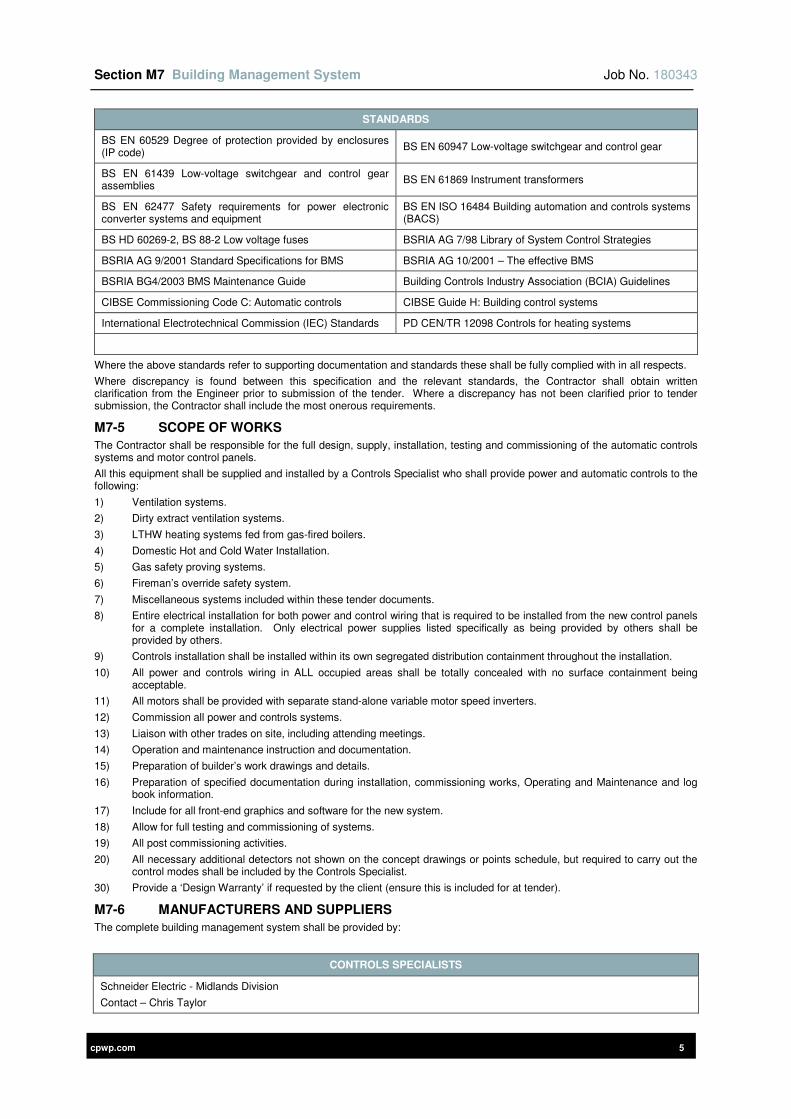
Section M7 Building Management System Job No. 180343
cpwp.com 5
STANDARDS
BS EN 60529 Degree of protection provided by enclosures (IP code)
BS EN 60947 Low-voltage switchgear and control gear
BS EN 61439 Low-voltage switchgear and control gear assemblies
BS EN 61869 Instrument transformers
BS EN 62477 Safety requirements for power electronic converter systems and equipment
BS EN ISO 16484 Building automation and controls systems (BACS)
BS HD 60269-2, BS 88-2 Low voltage fuses BSRIA AG 7/98 Library of System Control Strategies
BSRIA AG 9/2001 Standard Specifications for BMS BSRIA AG 10/2001 – The effective BMS
BSRIA BG4/2003 BMS Maintenance Guide Building Controls Industry Association (BCIA) Guidelines
CIBSE Commissioning Code C: Automatic controls CIBSE Guide H: Building control systems
International Electrotechnical Commission (IEC) Standards PD CEN/TR 12098 Controls for heating systems
Where the above standards refer to supporting documentation and standards these shall be fully complied with in all respects.
Where discrepancy is found between this specification and the relevant standards, the Contractor shall obtain written clarification from the Engineer prior to submission of the tender. Where a discrepancy has not been clarified prior to tender submission, the Contractor shall include the most onerous requirements.
M7-5 SCOPE OF WORKS
The Contractor shall be responsible for the full design, supply, installation, testing and commissioning of the automatic controls systems and motor control panels.
All this equipment shall be supplied and installed by a Controls Specialist who shall provide power and automatic controls to the following:
1) Ventilation systems.
2) Dirty extract ventilation systems.
3) LTHW heating systems fed from gas-fired boilers.
4) Domestic Hot and Cold Water Installation.
5) Gas safety proving systems.
6) Fireman’s override safety system.
7) Miscellaneous systems included within these tender documents.
8) Entire electrical installation for both power and control wiring that is required to be installed from the new control panels for a complete installation. Only electrical power supplies listed specifically as being provided by others shall be provided by others.
9) Controls installation shall be installed within its own segregated distribution containment throughout the installation.
10) All power and controls wiring in ALL occupied areas shall be totally concealed with no surface containment being acceptable.
11) All motors shall be provided with separate stand-alone variable motor speed inverters.
12) Commission all power and controls systems.
13) Liaison with other trades on site, including attending meetings.
14) Operation and maintenance instruction and documentation.
15) Preparation of builder’s work drawings and details.
16) Preparation of specified documentation during installation, commissioning works, Operating and Maintenance and log book information.
17) Include for all front-end graphics and software for the new system.
18) Allow for full testing and commissioning of systems.
19) All post commissioning activities.
20) All necessary additional detectors not shown on the concept drawings or points schedule, but required to carry out the control modes shall be included by the Controls Specialist.
30) Provide a ‘Design Warranty’ if requested by the client (ensure this is included for at tender).
M7-6 MANUFACTURERS AND SUPPLIERS
The complete building management system shall be provided by:
CONTROLS SPECIALISTS
Schneider Electric - Midlands Division
Contact – Chris Taylor
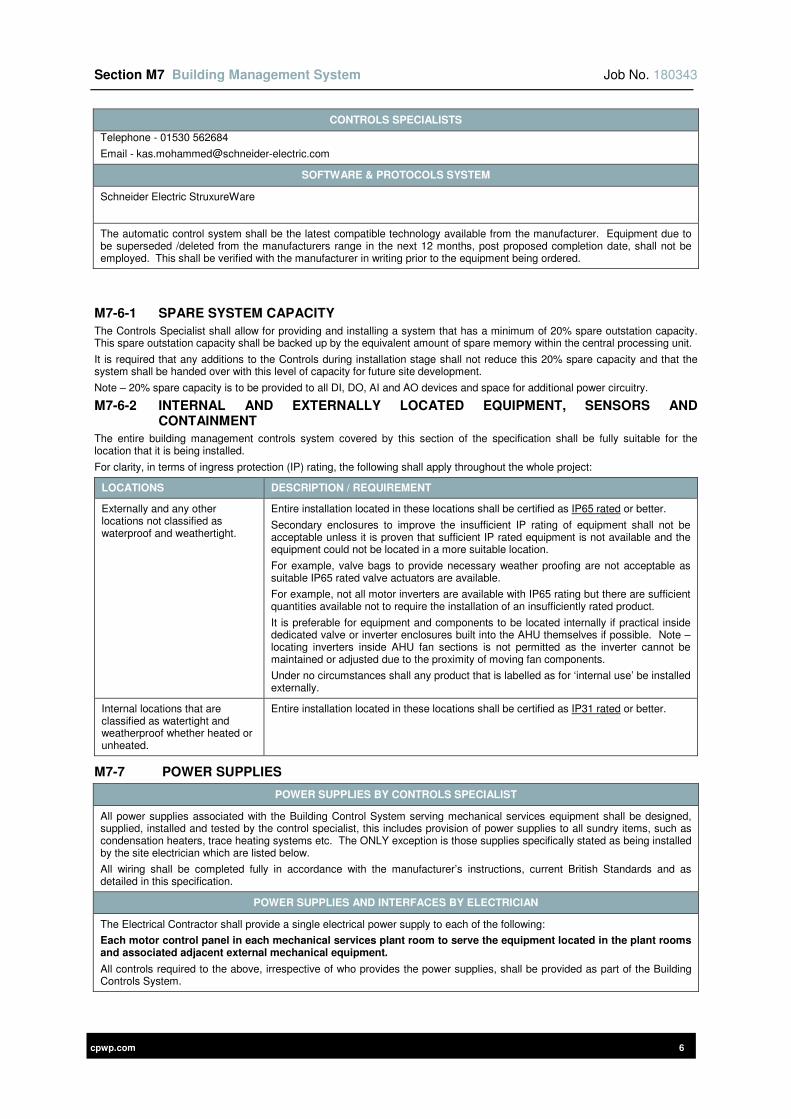
Section M7 Building Management System Job No. 180343
cpwp.com 6
CONTROLS SPECIALISTS
Telephone - 01530 562684
Email - [email protected]
SOFTWARE & PROTOCOLS SYSTEM
Schneider Electric StruxureWare
The automatic control system shall be the latest compatible technology available from the manufacturer. Equipment due to be superseded /deleted from the manufacturers range in the next 12 months, post proposed completion date, shall not be employed. This shall be verified with the manufacturer in writing prior to the equipment being ordered.
M7-6-1 SPARE SYSTEM CAPACITY
The Controls Specialist shall allow for providing and installing a system that has a minimum of 20% spare outstation capacity. This spare outstation capacity shall be backed up by the equivalent amount of spare memory within the central processing unit.
It is required that any additions to the Controls during installation stage shall not reduce this 20% spare capacity and that the system shall be handed over with this level of capacity for future site development.
Note – 20% spare capacity is to be provided to all DI, DO, AI and AO devices and space for additional power circuitry.
M7-6-2 INTERNAL AND EXTERNALLY LOCATED EQUIPMENT, SENSORS AND CONTAINMENT
The entire building management controls system covered by this section of the specification shall be fully suitable for the location that it is being installed.
For clarity, in terms of ingress protection (IP) rating, the following shall apply throughout the whole project:
LOCATIONS DESCRIPTION / REQUIREMENT
Externally and any other locations not classified as waterproof and weathertight.
Entire installation located in these locations shall be certified as IP65 rated or better.
Secondary enclosures to improve the insufficient IP rating of equipment shall not be acceptable unless it is proven that sufficient IP rated equipment is not available and the equipment could not be located in a more suitable location.
For example, valve bags to provide necessary weather proofing are not acceptable as suitable IP65 rated valve actuators are available.
For example, not all motor inverters are available with IP65 rating but there are sufficient quantities available not to require the installation of an insufficiently rated product.
It is preferable for equipment and components to be located internally if practical inside dedicated valve or inverter enclosures built into the AHU themselves if possible. Note – locating inverters inside AHU fan sections is not permitted as the inverter cannot be maintained or adjusted due to the proximity of moving fan components.
Under no circumstances shall any product that is labelled as for ‘internal use’ be installed externally.
Internal locations that are classified as watertight and weatherproof whether heated or unheated.
Entire installation located in these locations shall be certified as IP31 rated or better.
M7-7 POWER SUPPLIES
POWER SUPPLIES BY CONTROLS SPECIALIST
All power supplies associated with the Building Control System serving mechanical services equipment shall be designed, supplied, installed and tested by the control specialist, this includes provision of power supplies to all sundry items, such as condensation heaters, trace heating systems etc. The ONLY exception is those supplies specifically stated as being installed by the site electrician which are listed below.
All wiring shall be completed fully in accordance with the manufacturer’s instructions, current British Standards and as detailed in this specification.
POWER SUPPLIES AND INTERFACES BY ELECTRICIAN
The Electrical Contractor shall provide a single electrical power supply to each of the following:
Each motor control panel in each mechanical services plant room to serve the equipment located in the plant rooms and associated adjacent external mechanical equipment.
All controls required to the above, irrespective of who provides the power supplies, shall be provided as part of the Building Controls System.
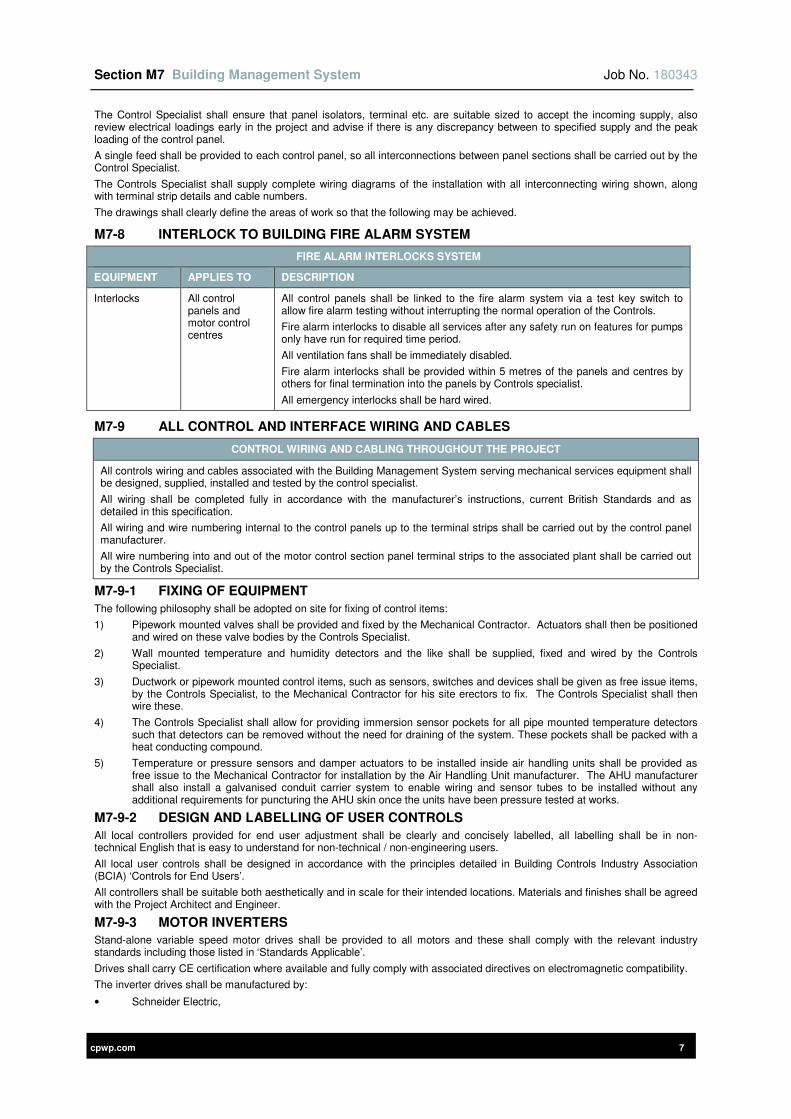
Section M7 Building Management System Job No. 180343
cpwp.com 7
The Control Specialist shall ensure that panel isolators, terminal etc. are suitable sized to accept the incoming supply, also review electrical loadings early in the project and advise if there is any discrepancy between to specified supply and the peak loading of the control panel.
A single feed shall be provided to each control panel, so all interconnections between panel sections shall be carried out by the Control Specialist.
The Controls Specialist shall supply complete wiring diagrams of the installation with all interconnecting wiring shown, along with terminal strip details and cable numbers.
The drawings shall clearly define the areas of work so that the following may be achieved.
M7-8 INTERLOCK TO BUILDING FIRE ALARM SYSTEM
FIRE ALARM INTERLOCKS SYSTEM
EQUIPMENT APPLIES TO DESCRIPTION
Interlocks All control panels and motor control centres
All control panels shall be linked to the fire alarm system via a test key switch to allow fire alarm testing without interrupting the normal operation of the Controls.
Fire alarm interlocks to disable all services after any safety run on features for pumps only have run for required time period.
All ventilation fans shall be immediately disabled.
Fire alarm interlocks shall be provided within 5 metres of the panels and centres by others for final termination into the panels by Controls specialist.
All emergency interlocks shall be hard wired.
M7-9 ALL CONTROL AND INTERFACE WIRING AND CABLES
CONTROL WIRING AND CABLING THROUGHOUT THE PROJECT
All controls wiring and cables associated with the Building Management System serving mechanical services equipment shall be designed, supplied, installed and tested by the control specialist.
All wiring shall be completed fully in accordance with the manufacturer’s instructions, current British Standards and as detailed in this specification.
All wiring and wire numbering internal to the control panels up to the terminal strips shall be carried out by the control panel manufacturer.
All wire numbering into and out of the motor control section panel terminal strips to the associated plant shall be carried out by the Controls Specialist.
M7-9-1 FIXING OF EQUIPMENT
The following philosophy shall be adopted on site for fixing of control items:
1) Pipework mounted valves shall be provided and fixed by the Mechanical Contractor. Actuators shall then be positioned and wired on these valve bodies by the Controls Specialist.
2) Wall mounted temperature and humidity detectors and the like shall be supplied, fixed and wired by the Controls Specialist.
3) Ductwork or pipework mounted control items, such as sensors, switches and devices shall be given as free issue items, by the Controls Specialist, to the Mechanical Contractor for his site erectors to fix. The Controls Specialist shall then wire these.
4) The Controls Specialist shall allow for providing immersion sensor pockets for all pipe mounted temperature detectors such that detectors can be removed without the need for draining of the system. These pockets shall be packed with a heat conducting compound.
5) Temperature or pressure sensors and damper actuators to be installed inside air handling units shall be provided as free issue to the Mechanical Contractor for installation by the Air Handling Unit manufacturer. The AHU manufacturer shall also install a galvanised conduit carrier system to enable wiring and sensor tubes to be installed without any additional requirements for puncturing the AHU skin once the units have been pressure tested at works.
M7-9-2 DESIGN AND LABELLING OF USER CONTROLS
All local controllers provided for end user adjustment shall be clearly and concisely labelled, all labelling shall be in non-technical English that is easy to understand for non-technical / non-engineering users.
All local user controls shall be designed in accordance with the principles detailed in Building Controls Industry Association (BCIA) ‘Controls for End Users’.
All controllers shall be suitable both aesthetically and in scale for their intended locations. Materials and finishes shall be agreed with the Project Architect and Engineer.
M7-9-3 MOTOR INVERTERS
Stand-alone variable speed motor drives shall be provided to all motors and these shall comply with the relevant industry standards including those listed in ‘Standards Applicable’.
Drives shall carry CE certification where available and fully comply with associated directives on electromagnetic compatibility.
The inverter drives shall be manufactured by:
• Schneider Electric,
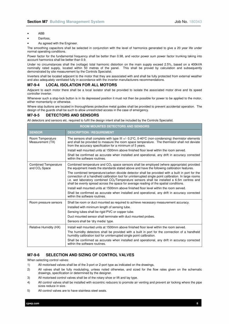
Section M7 Building Management System Job No. 180343
cpwp.com 8
• ABB
• Danfoss,
• As agreed with the Engineer.
The smoothing capacitors shall be selected in conjunction with the level of harmonics generated to give a 20 year life under normal operating conditions.
Power factor for the fundamental frequency shall be better than 0.98, and vector power sum power factor trunking taking into account harmonics shall be better than 0.9.
Under no circumstances shall the (voltage) total harmonic distortion on the main supply exceed 2.5%, based on a 400kVA nominally rated supply, located within 50 metres of the panel. This shall be proved by calculation and subsequently demonstrated by site measurement by the Controls Specialist.
Inverters shall be located adjacent to the motor that they are associated with and shall be fully protected from external weather and also adequately ventilated fully in accordance with the inverter manufacturers recommendations.
M7-9-4 LOCAL ISOLATION FOR ALL MOTORS
Adjacent to each motor there shall be a local isolator shall be provided to isolate the associated motor drive and its speed controller inverter.
Whenever such a stop-lock button is in its depressed position it must not then be possible for power to be applied to the motor, either momentarily or otherwise.
Where stop buttons are located in thoroughfares protective metal guides shall be provided to prevent accidental operation. The design of the guards shall be such to allow unrestricted access in the case of emergency.
M7-9-5 DETECTORS AND SENSORS
All detectors and sensors etc. required to fulfil the design intent shall be included by the Controls Specialist.
ROOM MOUNTED DETECTORS AND SENSORS
SENSOR DESCRIPTION / REQUIREMENT
Room Temperature Measurement (TX)
The sensors shall complete with type III +/- 0.2°C, 0-40°C (non-condensing) thermistor elements and shall be provided to measure the room space temperature. The thermistor shall not deviate from the accuracy specification for a minimum of 5 years.
Install wall mounted units at 1500mm above finished floor level within the room served.
Shall be confirmed as accurate when installed and operational, any drift in accuracy corrected within the software routines.
Combined Temperature and CO2 Space
Combined temperature and CO2 space sensors shall be employed (where appropriate) provided the equipment meets the standards stated above and have the following calibration features.
The combined temperature/carbon dioxide detector shall be provided with a built in port for the connection of a handheld calibration tool for uninterrupted single point calibration. In large rooms i.e. wet laboratory combined CO2/Temperature sensors shall be installed a 6.5m centres and shall be evenly spread across the space for average reading of the spatial conditions.
Install wall mounted units at 1500mm above finished floor level within the room served.
Shall be confirmed as accurate when installed and operational, any drift in accuracy corrected within the software routines.
Room pressure sensors Shall be room or duct mounted as required to achieve necessary measurement accuracy.
Installed with minimum length of sensing tube.
Sensing tubes shall be rigid PVC or copper tube.
Duct mounted sensor shall terminate with duct mounted probes.
Sensors shall be ‘dry media’ type.
Relative Humidity (HX) Install wall mounted units at 1500mm above finished floor level within the room served.
The humidity detectors shall be provided with a built in port for the connection of a handheld humidity calibration tool for uninterrupted single point calibration.
Shall be confirmed as accurate when installed and operational, any drift in accuracy corrected within the software routines.
M7-9-6 SELECTION AND SIZING OF CONTROL VALVES
When selecting control valves:
1) All motorised valves shall be of the 3-port or 2-port type as indicated on the drawings.
2) All valves shall be fully modulating, unless noted otherwise, and sized for the flow rates given on the schematic drawings, specification or determined by the designer.
3) All motorised control valves shall be of the rotary shoe or lift and lay type.
4) All control valves shall be installed with eccentric reducers to promote air venting and prevent air locking where the pipe sizes reduce in size.
5) All control valves are to have stainless steel seats.
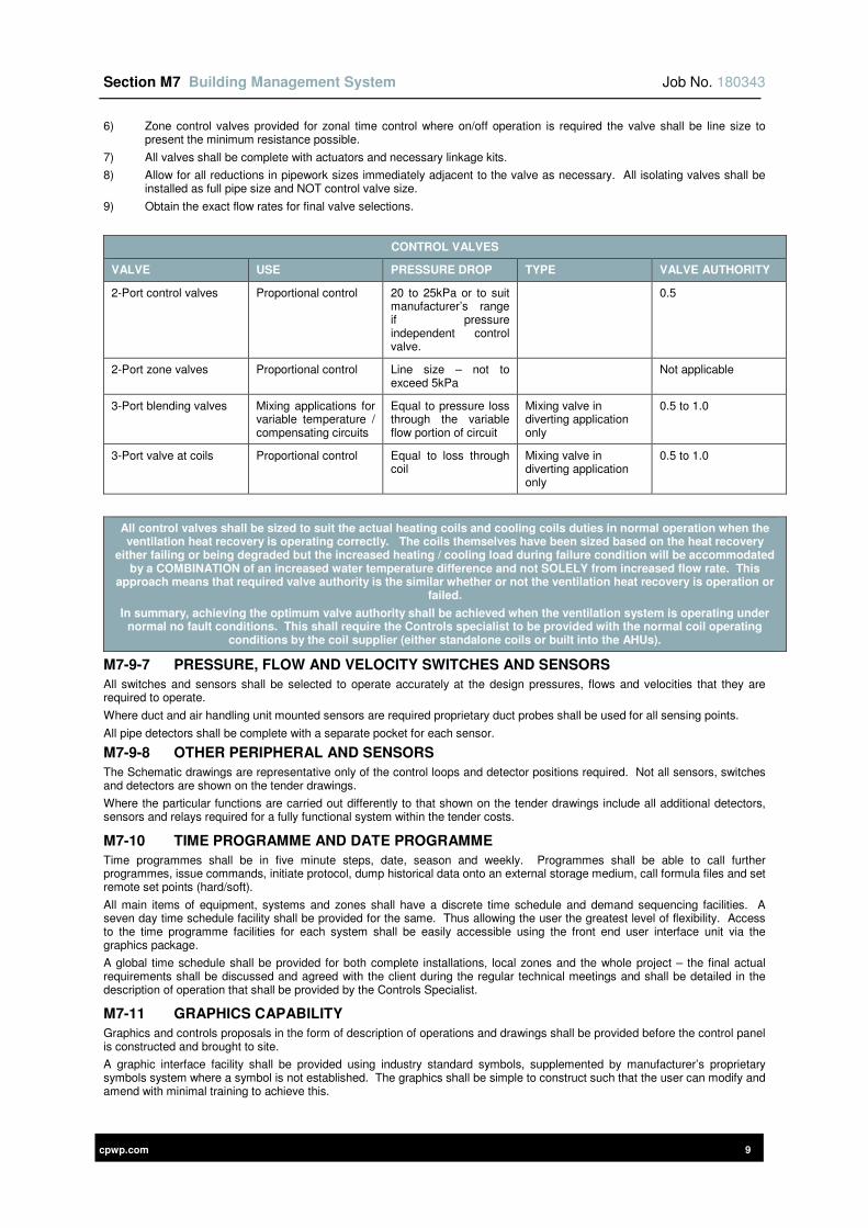
Section M7 Building Management System Job No. 180343
cpwp.com 9
6) Zone control valves provided for zonal time control where on/off operation is required the valve shall be line size to present the minimum resistance possible.
7) All valves shall be complete with actuators and necessary linkage kits.
8) Allow for all reductions in pipework sizes immediately adjacent to the valve as necessary. All isolating valves shall be installed as full pipe size and NOT control valve size.
9) Obtain the exact flow rates for final valve selections.
CONTROL VALVES
VALVE USE PRESSURE DROP TYPE VALVE AUTHORITY
2-Port control valves Proportional control 20 to 25kPa or to suit manufacturer’s range if pressure independent control valve.
0.5
2-Port zone valves Proportional control Line size – not to exceed 5kPa
Not applicable
3-Port blending valves Mixing applications for variable temperature / compensating circuits
Equal to pressure loss through the variable flow portion of circuit
Mixing valve in diverting application only
0.5 to 1.0
3-Port valve at coils Proportional control Equal to loss through coil
Mixing valve in diverting application only
0.5 to 1.0
All control valves shall be sized to suit the actual heating coils and cooling coils duties in normal operation when the ventilation heat recovery is operating correctly. The coils themselves have been sized based on the heat recovery
either failing or being degraded but the increased heating / cooling load during failure condition will be accommodated by a COMBINATION of an increased water temperature difference and not SOLELY from increased flow rate. This
approach means that required valve authority is the similar whether or not the ventilation heat recovery is operation or failed.
In summary, achieving the optimum valve authority shall be achieved when the ventilation system is operating under normal no fault conditions. This shall require the Controls specialist to be provided with the normal coil operating
conditions by the coil supplier (either standalone coils or built into the AHUs).
M7-9-7 PRESSURE, FLOW AND VELOCITY SWITCHES AND SENSORS
All switches and sensors shall be selected to operate accurately at the design pressures, flows and velocities that they are required to operate.
Where duct and air handling unit mounted sensors are required proprietary duct probes shall be used for all sensing points.
All pipe detectors shall be complete with a separate pocket for each sensor.
M7-9-8 OTHER PERIPHERAL AND SENSORS
The Schematic drawings are representative only of the control loops and detector positions required. Not all sensors, switches and detectors are shown on the tender drawings.
Where the particular functions are carried out differently to that shown on the tender drawings include all additional detectors, sensors and relays required for a fully functional system within the tender costs.
M7-10 TIME PROGRAMME AND DATE PROGRAMME
Time programmes shall be in five minute steps, date, season and weekly. Programmes shall be able to call further programmes, issue commands, initiate protocol, dump historical data onto an external storage medium, call formula files and set remote set points (hard/soft).
All main items of equipment, systems and zones shall have a discrete time schedule and demand sequencing facilities. A seven day time schedule facility shall be provided for the same. Thus allowing the user the greatest level of flexibility. Access to the time programme facilities for each system shall be easily accessible using the front end user interface unit via the graphics package.
A global time schedule shall be provided for both complete installations, local zones and the whole project – the final actual requirements shall be discussed and agreed with the client during the regular technical meetings and shall be detailed in the description of operation that shall be provided by the Controls Specialist.
M7-11 GRAPHICS CAPABILITY
Graphics and controls proposals in the form of description of operations and drawings shall be provided before the control panel is constructed and brought to site.
A graphic interface facility shall be provided using industry standard symbols, supplemented by manufacturer’s proprietary symbols system where a symbol is not established. The graphics shall be simple to construct such that the user can modify and amend with minimal training to achieve this.
Section M7 Building Management System Job No. 180343
cpwp.com 10
Provide a colour graphic for each and every system displaying all set points, functions, time zones, alarms etc. These shall be provided early in the project for review with users prior to installation.
All graphics shall be produced and tested prior to the soak period, control specialist shall present the graphics to the client in sufficient time to allow review and incorporation of any comments such that a fully operational graphics system is operating throughout the soak test period.
M7-12 SPECIAL TOOLS AND LICENCES
Any special tools, licences, operating handles or other equipment necessary for installation, maintenance or operation of the equipment, shall be provided in suitable quantities.
M7-13 COLLATERAL WARRANTY
During the tender period determine if a collateral warranty also referred to as a ‘Design Warranty’ is required to be provided for the overall design and if required then this shall be included for within the tender return. It shall not be acceptable exclude this if it is required as part of the Main Contract preliminaries.
M7-14 SITE SUPERVISION & MEETINGS
Include for necessary number of site visits to be attended by the Controls Specialist to:
1) Coordinate all controls, power and controls containment and all wiring between all parties, which shall be needed during the course of construction.
2) Agree all system description of operations with the Client and Engineer.
3) Attendance of all commissioning meetings.
4) Post contract completion, the Controls Specialist shall liaise with the Commissioning Manager to ascertain programme for meetings. For tender allow for attending fortnightly commissioning meetings, each lasting ½ day.
These regular technical Controls Meetings during the construction phase to agree all necessary documentation procedures and documentation compilations shall be included for. These meetings shall be held during the early building construction phase, well in advance of the Controls installation commencing on site and attended by both Contract and Controls Specialist.
M7-15 INSTALLATION DOCUMENTATION
In addition to the information required detailed elsewhere of this specification the following shall be provided:
1) Panel sizes, weights and noise levels.
2) Detailed panel fascia layouts of all control panels, user interface panels etc. drawn to scale and indicating all components, finishes, locking arrangements etc.
3) All controls and instrumentation drawings and software logic compilation drawings shall be provided during the construction period for comment prior to any work being undertaken on site.
4) Detailed description of controls operation to demonstrate full understanding of the performance specification and show how system will achieve these criteria.
5) Schedule recording as commissioned settings for all programmable components such as inverters etc.
6) Appended to the above shall be any suggestions / comments on how system performance could be improved / energy consumption reduced.
7) Manufacturers data on control items, sensors etc.
8) Verify all working drawings to ensure that automatic control system items are indicated and correctly located for optimum performance.
9) Include all tag referencing and point to point wiring diagrams.
10) Final full documentation shall be provided in accordance with the Contract Preliminaries requirement and as a minimum all documentation shall be provided 14 days prior to handover.
M7-16 TESTING AND COMMISSIONING OF AUTOMATIC CONTROL SYSTEM
The Control specialist shall test and commission the automatic control system fully in accordance with recommendations of all industry standards including ‘Standards Applicable’ and to prove that 100% of the installation has been proven to be operating correctly and in accordance with the overall services design.
The Controls Specialist must take account of the proposed programme of works and allow sufficient costs and resources for the full commissioning and demonstration of the system to the design intent (both on-site and off-site).
The commissioning process shall be fully and comprehensively tested and proven with each individual system proven for correct operation, this testing and proving exercise shall be fully documented by the Controls Specialist and these documents shall be provided to the Contract Administrator.
All safety related interlocks and controls procedures shall, initially be tested by the Controls Specialist and then be fully witnessed and signed off by persons nominated by the Contract Administrator (e.g. commissioning manager if one is employed) to ensure all safety requirements are 100% proven and witnessed.
The Controls Specialist shall allow for pre-commissioning the MCC's at the panel manufacturers premises prior to delivery to site and this shall include for the following:
• Wiring validation checks.
• Software loading.
• Software programming proving checks.
• Software and hardware communication checks.
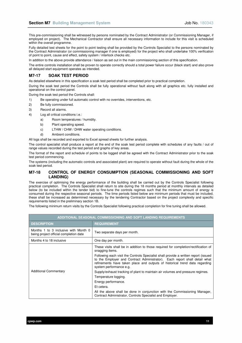
Section M7 Building Management System Job No. 180343
cpwp.com 11
This pre-commissioning shall be witnessed by persons nominated by the Contract Administrator (or Commissioning Manager, if employed on project). The Mechanical Contractor shall ensure all necessary information to include for this visit is scheduled within the overall programme.
Fully detailed test sheets for the point to point testing shall be provided by the Controls Specialist to the persons nominated by the Contract Administrator (or commissioning manager if one is employed) for the project who shall undertake 100% verification of point to point, cause and effect, safety system / interlock checks etc.
In addition to the above provide attendance / liaison as set out in the main commissioning section of this specification.
The entire controls installation shall be proven to operate correctly should a total power failure occur (black start) and also prove all delayed start equipment operates as intended.
M7-17 SOAK TEST PERIOD
As detailed elsewhere in this specification a soak test period shall be completed prior to practical completion.
During the soak test period the Controls shall be fully operational without fault along with all graphics etc. fully installed and operational on the control panel.
During the soak test period the Controls shall:
1) Be operating under full automatic control with no overrides, interventions, etc.
2) Be fully commissioned.
3) Record all alarms.
4) Log all critical conditions i.e.:
a) Room temperatures / humidity.
b) Plant operating speed.
c) LTHW / CHW / DHW water operating conditions.
d) Ambient conditions.
All logs shall be recorded and exported to Excel spread sheets for further analysis.
The control specialist shall produce a report at the end of the soak test period complete with schedules of any faults / out of range values recorded during the test period and graphs of key areas.
The format of the report and schedule of points to be logged shall be agreed with the Contract Administrator prior to the soak test period commencing.
The systems (including the automatic controls and associated plant) are required to operate without fault during the whole of the soak test period.
M7-18 CONTROL OF ENERGY CONSUMPTION (SEASONAL COMMISSIONING AND SOFT LANDING)
The exercise of optimising the energy performance of the building shall be carried out by the Controls Specialist following practical completion. The Controls Specialist shall return to site during the 18 months period at monthly intervals as detailed below (to be included within the tender bid) to fine-tune the controls regimes such that the minimum amount of energy is consumed during the respective seasonal periods. The time periods listed below are minimum periods that must be included, these shall be increased as determined necessary by the tendering Contractor based on the project complexity and specific requirements listed in the preliminary section 1B.
The following minimum return visits by the Controls Specialist following practical completion for fine tuning shall be allowed.
ADDITIONAL SEASONAL COMMISSIONING AND SOFT LANDING REQUIREMENTS
DESCRIPTION REQUIREMENT
Months 1 to 3 inclusive with Month 0 being project official completion date
Two separate days per month.
Months 4 to 18 inclusive One day per month.
Additional Commentary
These visits shall be in addition to those required for completion/rectification of snagging items.
Following each visit the Controls Specialist shall provide a written report (issued to the Employer and Contract Administrator). Each report shall detail what refinements have taken place and outputs of historical trend data regarding system performance e.g.
Supply/exhaust tracking of plant to maintain air volumes and pressure regimes.
Temperature logging.
Energy performance.
Et cetera.
All the above shall be done in conjunction with the Commissioning Manager, Contract Administrator, Controls Specialist and Employer.
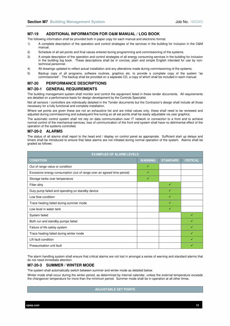
Section M7 Building Management System Job No. 180343
cpwp.com 12
M7-19 ADDITIONAL INFORMATION FOR O&M MANUAL / LOG BOOK
The following information shall be provided both in paper copy for each manual and electronic format:
1) A complete description of the operation and control strategies of the services in the building for inclusion in the O&M manual.
2) Schedule of all set points and final values entered during programming and commissioning of the systems.
3) A simple description of the operation and control strategies of all energy consuming services in the building for inclusion in the building log book. These descriptions shall be in concise, plain and simple English intended for use by non-technical personnel.
4) All drawings updated to reflect actual installation and any alterations made during commissioning of the systems.
5) Backup copy of all programs, software routines, graphics etc. to provide a complete copy of the system “as commissioned”. The backup shall be provided on a separate CD, a copy of which shall be included in each manual.
M7-20 PERFORMANCE DESCRIPTIONS
M7-20-1 GENERAL REQUIREMENTS
The building management system shall monitor and control the equipment listed in these tender documents. All requirements are detailed on a performance basis for design development by the Controls Specialist.
Not all sensors / controllers are individually detailed in the Tender documents but the Contractor’s design shall include all those necessary for a fully functional and complete installation.
Where set points are given these are not an exhaustive list and are initial values only, these shall need to be reviewed and adjusted during commissioning and subsequent fine tuning so all set points shall be easily adjustable via user graphics.
The automatic control system shall not rely on data communication over IT network or connection to a front end to achieve normal control of the mechanical services, loss of communication of the front end system shall have no detrimental effect of the operation of the systems controlled.
M7-20-2 ALARMS
The status of all alarms shall report to the head end / display on control panel as appropriate. Sufficient start up delays and timers shall be introduced to ensure that false alarms are not initiated during normal operation of the system. Alarms shall be graded as follows:
EXAMPLES OF ALARM LEVELS
CONDITION WARNING STANDARD CRITICAL
Out of range value or condition
Excessive energy consumption (out of range over an agreed time period)
Storage tanks over temperature
Filter dirty
Duty pump failed and operating on standby device
Low flow condition
Trace heating failed during summer mode
Low level in water tank
System failed
Both run and standby pumps failed
Failure of life safety system
Trace heating failed during winter mode
Lift fault condition
Pressurisation unit fault
The alarm handling system shall ensure that critical alarms are not lost in amongst a series of warning and standard alarms that do not need immediate attention.
M7-20-3 SUMMER / WINTER MODE
The system shall automatically switch between summer and winter mode as detailed below.
Winter mode shall occur during the winter period, as determined by internal calendar, unless the external temperature exceeds the changeover temperature for more than the minimum period. Summer mode shall be in operation at all other times.
ADJUSTABLE SET POINTS
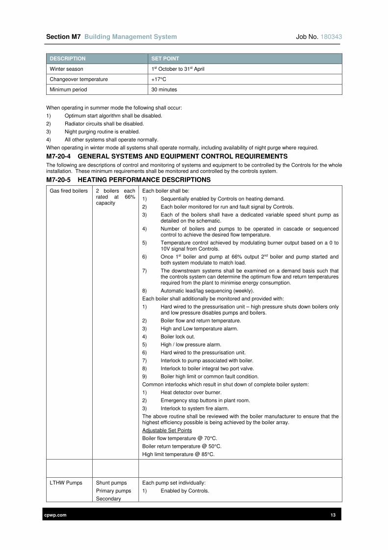
Section M7 Building Management System Job No. 180343
cpwp.com 13
DESCRIPTION SET POINT
Winter season 1st October to 31st April
Changeover temperature +17°C
Minimum period 30 minutes
When operating in summer mode the following shall occur:
1) Optimum start algorithm shall be disabled.
2) Radiator circuits shall be disabled.
3) Night purging routine is enabled.
4) All other systems shall operate normally.
When operating in winter mode all systems shall operate normally, including availability of night purge where required.
M7-20-4 GENERAL SYSTEMS AND EQUIPMENT CONTROL REQUIREMENTS
The following are descriptions of control and monitoring of systems and equipment to be controlled by the Controls for the whole installation. These minimum requirements shall be monitored and controlled by the controls system.
M7-20-5 HEATING PERFORMANCE DESCRIPTIONS
Gas fired boilers 2 boilers each rated at 66% capacity
Each boiler shall be:
1) Sequentially enabled by Controls on heating demand.
2) Each boiler monitored for run and fault signal by Controls.
3) Each of the boilers shall have a dedicated variable speed shunt pump as detailed on the schematic.
4) Number of boilers and pumps to be operated in cascade or sequenced control to achieve the desired flow temperature.
5) Temperature control achieved by modulating burner output based on a 0 to 10V signal from Controls.
6) Once 1st boiler and pump at 66% output 2nd boiler and pump started and both system modulate to match load.
7) The downstream systems shall be examined on a demand basis such that the controls system can determine the optimum flow and return temperatures required from the plant to minimise energy consumption.
8) Automatic lead/lag sequencing (weekly).
Each boiler shall additionally be monitored and provided with:
1) Hard wired to the pressurisation unit – high pressure shuts down boilers only and low pressure disables pumps and boilers.
2) Boiler flow and return temperature.
3) High and Low temperature alarm.
4) Boiler lock out.
5) High / low pressure alarm.
6) Hard wired to the pressurisation unit.
7) Interlock to pump associated with boiler.
8) Interlock to boiler integral two port valve.
9) Boiler high limit or common fault condition.
Common interlocks which result in shut down of complete boiler system:
1) Heat detector over burner.
2) Emergency stop buttons in plant room.
3) Interlock to system fire alarm.
The above routine shall be reviewed with the boiler manufacturer to ensure that the highest efficiency possible is being achieved by the boiler array.
Adjustable Set Points
Boiler flow temperature @ 70°C.
Boiler return temperature @ 50°C.
High limit temperature @ 85°C.
LTHW Pumps Shunt pumps
Primary pumps
Secondary
Each pump set individually:
1) Enabled by Controls.
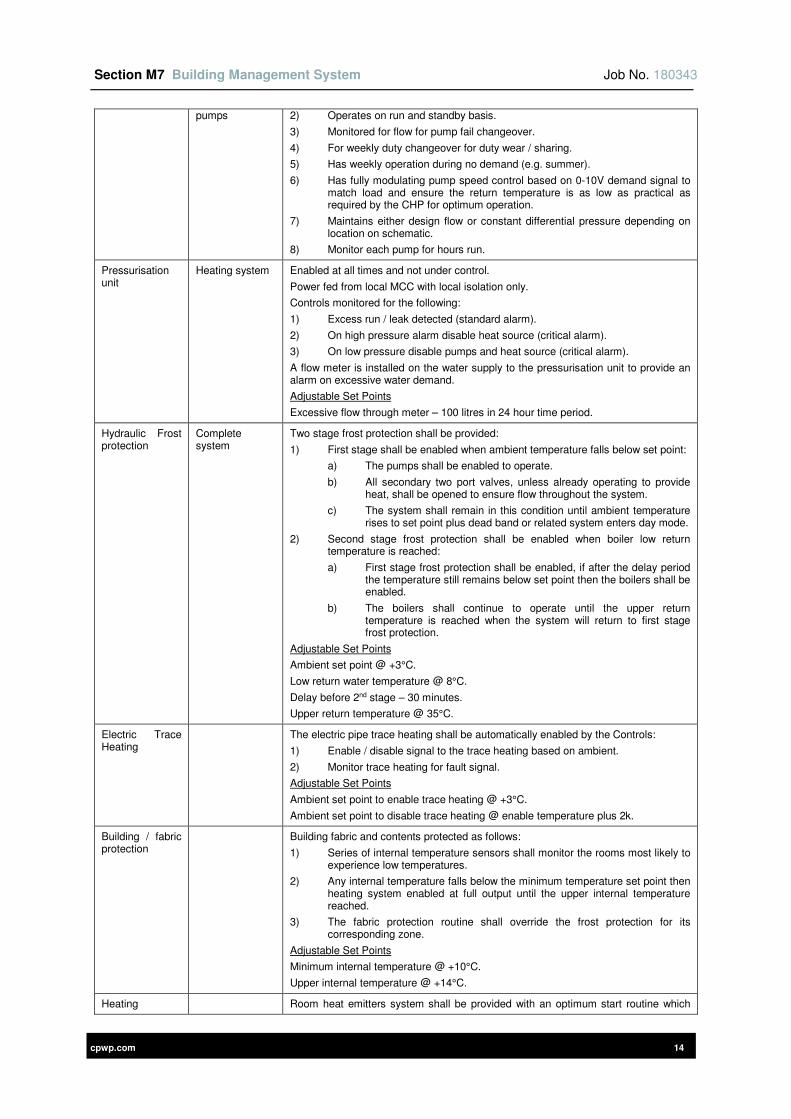
Section M7 Building Management System Job No. 180343
cpwp.com 14
pumps 2) Operates on run and standby basis.
3) Monitored for flow for pump fail changeover.
4) For weekly duty changeover for duty wear / sharing.
5) Has weekly operation during no demand (e.g. summer).
6) Has fully modulating pump speed control based on 0-10V demand signal to match load and ensure the return temperature is as low as practical as required by the CHP for optimum operation.
7) Maintains either design flow or constant differential pressure depending on location on schematic.
8) Monitor each pump for hours run.
Pressurisation unit
Heating system Enabled at all times and not under control.
Power fed from local MCC with local isolation only.
Controls monitored for the following:
1) Excess run / leak detected (standard alarm).
2) On high pressure alarm disable heat source (critical alarm).
3) On low pressure disable pumps and heat source (critical alarm).
A flow meter is installed on the water supply to the pressurisation unit to provide an alarm on excessive water demand.
Adjustable Set Points
Excessive flow through meter – 100 litres in 24 hour time period.
Hydraulic Frost protection
Complete system
Two stage frost protection shall be provided:
1) First stage shall be enabled when ambient temperature falls below set point:
a) The pumps shall be enabled to operate.
b) All secondary two port valves, unless already operating to provide heat, shall be opened to ensure flow throughout the system.
c) The system shall remain in this condition until ambient temperature rises to set point plus dead band or related system enters day mode.
2) Second stage frost protection shall be enabled when boiler low return temperature is reached:
a) First stage frost protection shall be enabled, if after the delay period the temperature still remains below set point then the boilers shall be enabled.
b) The boilers shall continue to operate until the upper return temperature is reached when the system will return to first stage frost protection.
Adjustable Set Points
Ambient set point @ +3°C.
Low return water temperature @ 8°C.
Delay before 2nd stage – 30 minutes.
Upper return temperature @ 35°C.
Electric Trace Heating
The electric pipe trace heating shall be automatically enabled by the Controls:
1) Enable / disable signal to the trace heating based on ambient.
2) Monitor trace heating for fault signal.
Adjustable Set Points
Ambient set point to enable trace heating @ +3°C.
Ambient set point to disable trace heating @ enable temperature plus 2k.
Building / fabric protection
Building fabric and contents protected as follows:
1) Series of internal temperature sensors shall monitor the rooms most likely to experience low temperatures.
2) Any internal temperature falls below the minimum temperature set point then heating system enabled at full output until the upper internal temperature reached.
3) The fabric protection routine shall override the frost protection for its corresponding zone.
Adjustable Set Points
Minimum internal temperature @ +10°C.
Upper internal temperature @ +14°C.
Heating Room heat emitters system shall be provided with an optimum start routine which
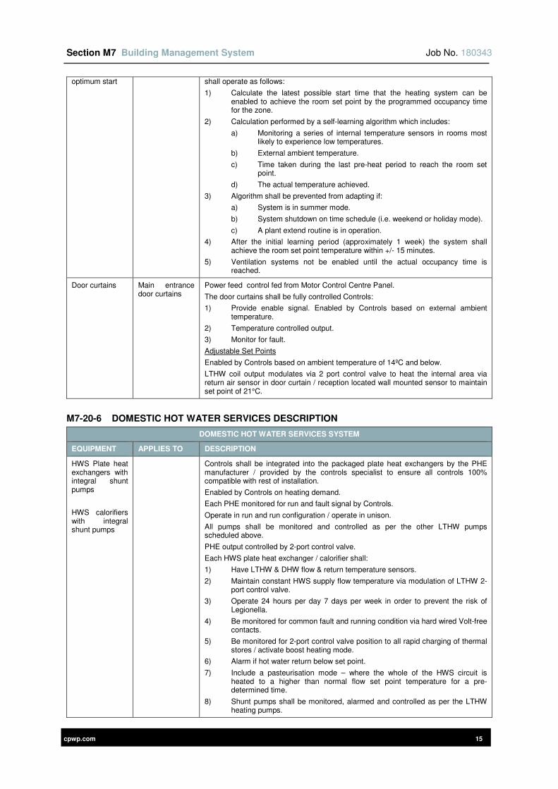
Section M7 Building Management System Job No. 180343
cpwp.com 15
optimum start shall operate as follows:
1) Calculate the latest possible start time that the heating system can be enabled to achieve the room set point by the programmed occupancy time for the zone.
2) Calculation performed by a self-learning algorithm which includes:
a) Monitoring a series of internal temperature sensors in rooms most likely to experience low temperatures.
b) External ambient temperature.
c) Time taken during the last pre-heat period to reach the room set point.
d) The actual temperature achieved.
3) Algorithm shall be prevented from adapting if:
a) System is in summer mode.
b) System shutdown on time schedule (i.e. weekend or holiday mode).
c) A plant extend routine is in operation.
4) After the initial learning period (approximately 1 week) the system shall achieve the room set point temperature within +/- 15 minutes.
5) Ventilation systems not be enabled until the actual occupancy time is reached.
Door curtains Main entrance door curtains
Power feed control fed from Motor Control Centre Panel.
The door curtains shall be fully controlled Controls:
1) Provide enable signal. Enabled by Controls based on external ambient temperature.
2) Temperature controlled output.
3) Monitor for fault.
Adjustable Set Points
Enabled by Controls based on ambient temperature of 14ºC and below.
LTHW coil output modulates via 2 port control valve to heat the internal area via return air sensor in door curtain / reception located wall mounted sensor to maintain set point of 21°C.
M7-20-6 DOMESTIC HOT WATER SERVICES DESCRIPTION
DOMESTIC HOT WATER SERVICES SYSTEM
EQUIPMENT APPLIES TO DESCRIPTION
HWS Plate heat exchangers with integral shunt pumps
HWS calorifiers with integral shunt pumps
Controls shall be integrated into the packaged plate heat exchangers by the PHE manufacturer / provided by the controls specialist to ensure all controls 100% compatible with rest of installation.
Enabled by Controls on heating demand.
Each PHE monitored for run and fault signal by Controls.
Operate in run and run configuration / operate in unison.
All pumps shall be monitored and controlled as per the other LTHW pumps scheduled above.
PHE output controlled by 2-port control valve.
Each HWS plate heat exchanger / calorifier shall:
1) Have LTHW & DHW flow & return temperature sensors.
2) Maintain constant HWS supply flow temperature via modulation of LTHW 2-port control valve.
3) Operate 24 hours per day 7 days per week in order to prevent the risk of Legionella.
4) Be monitored for common fault and running condition via hard wired Volt-free contacts.
5) Be monitored for 2-port control valve position to all rapid charging of thermal stores / activate boost heating mode.
6) Alarm if hot water return below set point.
7) Include a pasteurisation mode – where the whole of the HWS circuit is heated to a higher than normal flow set point temperature for a pre-determined time.
8) Shunt pumps shall be monitored, alarmed and controlled as per the LTHW heating pumps.
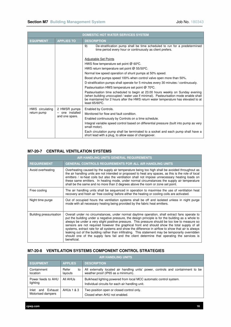
Section M7 Building Management System Job No. 180343
cpwp.com 16
DOMESTIC HOT WATER SERVICES SYSTEM
EQUIPMENT APPLIES TO DESCRIPTION
9) De-stratification pump shall be time scheduled to run for a predetermined time period every hour or continuously as client prefers.
Adjustable Set Points
HWS flow temperature set point @ 60ºC.
HWS return temperature set point @ 55/50ºC.
Normal low speed operation of shunt pumps at 50% speed.
Boost shunt pumps speed 100% when control valve open more than 50%.
D-stratification pumps shall operate for 5 minutes every 30 minutes / continuously.
Pasteurisation HWS temperature set point @ 70ºC.
Pasteurisation time scheduled to begin at 23.00 hours weekly on Sunday evening (when building unoccupied / water use if minimal). Pasteurisation mode enable shall be maintained for 2 hours after the HWS return water temperature has elevated to at least 65/60ºC.
HWS circulating return pump
2 HWSR pumps – one installed and one spare.
Enabled by Controls.
Monitored for flow and fault condition.
Enabled continuously by Controls on a time schedule.
Integral variable speed control based on differential pressure (built into pump as very small motor).
Each circulation pump shall be terminated to a socket and each pump shall have a short lead with a plug, to allow ease of changeover.
M7-20-7 CENTRAL VENTILATION SYSTEMS
AIR HANDLING UNITS GENERAL REQUIREMENTS
REQUIREMENT GENERAL CONTROLS REQUIREMENTS FOR ALL AIR HANDLING UNITS
Avoid overheating Overheating caused by the supply air temperature being too high shall be avoided throughout as the air handling units are not intended or proposed to heat any spaces, as this is the role of local emitters / re-heat coils but also the ventilation shall not impose unnecessary heating loads on these same emitters. In heating mode, under normal circumstances the supply air temperature shall be the same and no more than 2 degrees above the room or zone set point.
Free cooling The air handling units shall be sequenced in operation to maximise the use of ventilation heat recovery and fresh air ‘free cooling’ before either the heating or cooling coils are activated.
Night time purge
Out of occupied hours the ventilation systems shall be off and isolated unless in night purge mode with all necessary heating being provided by the fabric heat emitters.
Building pressurisation Overall under no circumstances, under normal daytime operation, shall extract fans operate to put the building under a negative pressure, the design principle is for the building as a whole to always be under a very slight positive pressure. This pressure should be too low to measure so sensors are not required however the graphical front end should show the total supply of all systems, extract rate for all systems and show the difference in airflow to show that air is always leaking out of the building rather than infiltrating. This statement may be temporarily overridden should one of the supply fans fail and the client determine that operating the services is beneficial.
M7-20-8 VENTILATION SYSTEMS COMPONENT CONTROL STRATEGIES
AIR HANDLING UNITS
EQUIPMENT APPLIES DESCRIPTION
Containment location
Refer to layouts
All externally located air handling units’ power, controls and containment to be weather proof (IP65 as a minimum).
Power feeds to AHU lighting
All AHUs Bulkhead lighting powered from local MCC automatic control system.
Individual circuits for each air handling unit.
Inlet and Exhaust Motorised dampers
AHUs 1 & 3 Two position open or closed control only.
Closed when AHU not enabled.

Section M7 Building Management System Job No. 180343
cpwp.com 17
AIR HANDLING UNITS
EQUIPMENT APPLIES DESCRIPTION
Open when AHU enabled.
Proven open by end switch before any fan runs.
Proven closed by end switch when fans not running.
AHU enabled but end switch not switching to prove dampers open enables alarm.
Inlet, exhaust and bypass motorised dampers
AHU 2 All dampers closed when AHU not enabled.
Proven open by end switch before any fan runs.
AHU enabled but end switch does not prove dampers open enables alarm.
Fully modulating control for temperature / air quality control by modulating bypass with corresponding reduction in %age of intake and exhaust airflow.
LTHW frost coils AHUs 1 & 3 Control valve fully operational when AHUs are:
1) Not running, frost thermostat not tripped and external ambient below 3ºC (adjustable).
2) AHU running, frost thermostat not tripped & heat recovery not performing to design and operating at 100%.
3) AHU running, frost thermostat not tripped, rapid increase in pressure loss across pre-filters and ambient less than 1°C.
Frost thermostat All AHUs Frost protection thermostat shall:
1) Be hard wired/operated through the automatic control system.
2) Be fitted downstream of the frost coil.
3) be set at 3°C (adjustable)
4) If the temperature falls to set point stop the supply fan and generate an alarm.
5) Take priority over all automatic control system plant operational signals and over the hand/off/auto selection switch of the supply fan.
6) Prevent fan from re-starting until the temperature has risen above the thermostat set point.
All heat recovery systems
All AHUs All fully adjustable from 0-100% for total compliance with EU Regulation No. 1253/2014.
Provide 1st stage of either heating or free cooling depending on the AHU mode of operation.
Monitor all heat recovery for %age bypass.
Monitor all thermal wheels for rotation speed.
Monitor all heat recovery systems for supply side on and off temperature.
Run around coils AHU 1 Fully modulating control via 2-port / 3-port control valve and variable speed drive pumps.
Monitor all valves for %age open reporting.
Plate heat exchangers
AHU 2 Fully modulating face and bypass dampers to maximise heat recovery.
Thermal wheels AHU 3 Fully modulating variable speed wheel to maximise heat recovery.
LTHW heating coils All AHUs Fully modulating control valve modes are:
1) Closed or fully bypass when AHU not running and ambient above 3ºC.
2) Partially open position when AHU not running and ambient is below 3ºC.
3) AHU running then modulate to supply air at set point temperature using sequenced control of heating coil.
4) Heating held off to not operate within 4 hours (adjustable) of cooling coil.
5) Monitor all valves for %age open reporting.
Supply fans – variable speed
All AHUs Enabled by Controls.
Enable by Controls time schedule / manual push button / selection switch.
Fans held off until motorised dampers proven open by end switch monitoring.
Airflow signal proven utilising pressure differential switch. Delay of fault for 30 seconds (adjustable) on start up. No signal after 30 seconds then airflow failed alarm.
Variable speed controlled fans shall modulate to ensure constant duct pressure via pressure sensors (one per AHU system).
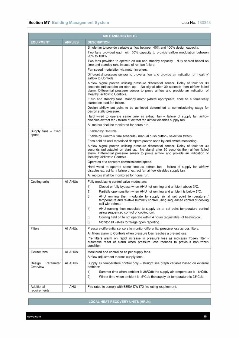
Section M7 Building Management System Job No. 180343
cpwp.com 18
AIR HANDLING UNITS
EQUIPMENT APPLIES DESCRIPTION
Single fan to provide variable airflow between 40% and 100% design capacity.
Two fans provided each with 50% capacity to provide airflow modulation between 20% to 100%.
Two fans provided to operate on run and standby capacity – duty shared based on time and standby runs in case of run fan failure.
Fan speed modulation via motor inverters.
Differential pressure sensor to prove airflow and provide an indication of ‘healthy’ airflow to Controls.
Airflow signal proven utilising pressure differential sensor. Delay of fault for 30 seconds (adjustable) on start up. No signal after 30 seconds then airflow failed alarm. Differential pressure sensor to prove airflow and provide an indication of ‘healthy’ airflow to Controls.
If run and standby fans, standby motor (where appropriate) shall be automatically started on lead fan failure.
Design airflow set point to be achieved determined at commissioning stage for design static pressure.
Hard wired to operate same time as extract fan – failure of supply fan airflow disables extract fan / failure of extract fan airflow disables supply fan.
All motors shall be monitored for hours run.
Supply fans – fixed speed
Enabled by Controls.
Enable by Controls time schedule / manual push button / selection switch.
Fans held off until motorised dampers proven open by end switch monitoring.
Airflow signal proven utilising pressure differential sensor. Delay of fault for 30 seconds (adjustable) on start up. No signal after 30 seconds then airflow failed alarm. Differential pressure sensor to prove airflow and provide an indication of ‘healthy’ airflow to Controls.
Operates at a constant commissioned speed.
Hard wired to operate same time as extract fan – failure of supply fan airflow disables extract fan / failure of extract fan airflow disables supply fan.
All motors shall be monitored for hours run.
Cooling coils All AHUs Fully modulating control valve modes are:
1) Closed or fully bypass when AHU not running and ambient above 3ºC.
2) Partially open position when AHU not running and ambient is below 3ºC.
3) AHU running then modulate to supply air at set point temperature / temperature and relative humidity control using sequenced control of cooling coil with reheat.
4) AHU running then modulate to supply air at set point temperature control using sequenced control of cooling coil.
5) Cooling held off to not operate within 4 hours (adjustable) of heating coil.
6) Monitor all valves for %age open reporting.
Filters All AHUs Pressure differential sensors to monitor differential pressure loss across filters.
All filters alarm to Controls when pressure loss reaches a pre-set loss.
Pre filters alarm on rapid increase in pressure loss as indicates frozen filter - automatic reset of alarm when pressure loss reduces to previous non-frozen condition.
Extract fans All AHUs Monitored and controlled as per supply fans.
Airflow adjustment to track supply fans.
Design Parameter Overview
All AHUs Supply air temperature control only – straight line graph variable based on external ambient:
1) Summer time when ambient is 28ºCdb the supply air temperature is 16°Cdb.
2) Winter time when ambient is -5ºCdb the supply air temperature is 23°Cdb.
Additional requirements
AHU 1 Fire rated to comply with BESA DW172 fire rating requirement.
LOCAL HEAT RECOVERY UNITS (HRUs)
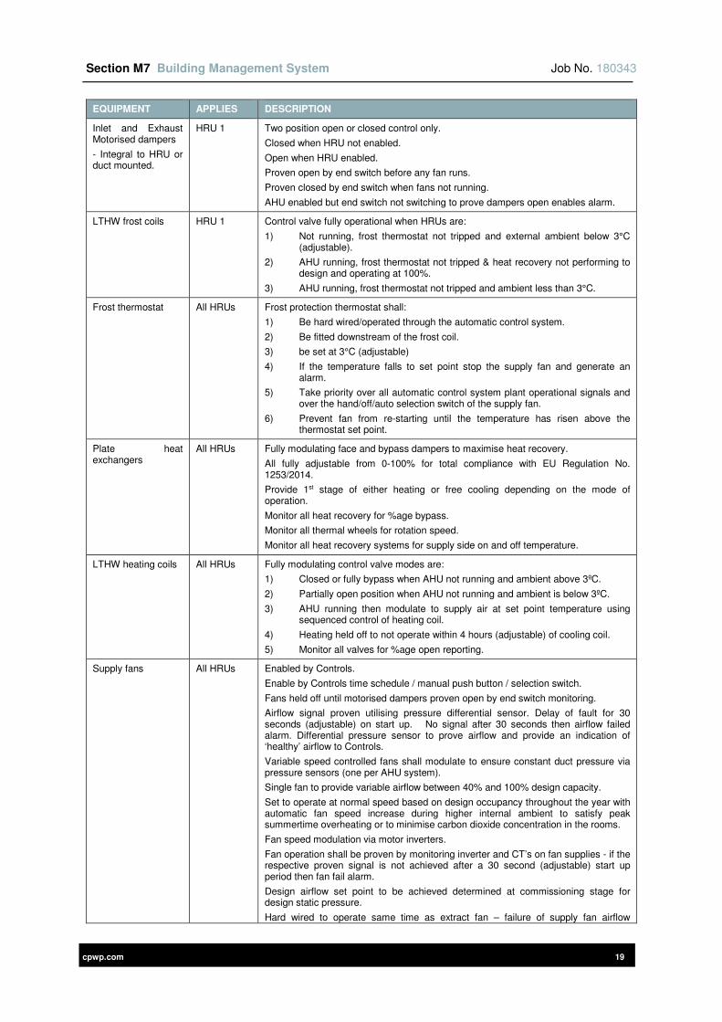
Section M7 Building Management System Job No. 180343
cpwp.com 19
EQUIPMENT APPLIES DESCRIPTION
Inlet and Exhaust Motorised dampers
- Integral to HRU or duct mounted.
HRU 1 Two position open or closed control only.
Closed when HRU not enabled.
Open when HRU enabled.
Proven open by end switch before any fan runs.
Proven closed by end switch when fans not running.
AHU enabled but end switch not switching to prove dampers open enables alarm.
LTHW frost coils HRU 1 Control valve fully operational when HRUs are:
1) Not running, frost thermostat not tripped and external ambient below 3°C (adjustable).
2) AHU running, frost thermostat not tripped & heat recovery not performing to design and operating at 100%.
3) AHU running, frost thermostat not tripped and ambient less than 3°C.
Frost thermostat All HRUs Frost protection thermostat shall:
1) Be hard wired/operated through the automatic control system.
2) Be fitted downstream of the frost coil.
3) be set at 3°C (adjustable)
4) If the temperature falls to set point stop the supply fan and generate an alarm.
5) Take priority over all automatic control system plant operational signals and over the hand/off/auto selection switch of the supply fan.
6) Prevent fan from re-starting until the temperature has risen above the thermostat set point.
Plate heat exchangers
All HRUs Fully modulating face and bypass dampers to maximise heat recovery.
All fully adjustable from 0-100% for total compliance with EU Regulation No. 1253/2014.
Provide 1st stage of either heating or free cooling depending on the mode of operation.
Monitor all heat recovery for %age bypass.
Monitor all thermal wheels for rotation speed.
Monitor all heat recovery systems for supply side on and off temperature.
LTHW heating coils All HRUs Fully modulating control valve modes are:
1) Closed or fully bypass when AHU not running and ambient above 3ºC.
2) Partially open position when AHU not running and ambient is below 3ºC.
3) AHU running then modulate to supply air at set point temperature using sequenced control of heating coil.
4) Heating held off to not operate within 4 hours (adjustable) of cooling coil.
5) Monitor all valves for %age open reporting.
Supply fans All HRUs Enabled by Controls.
Enable by Controls time schedule / manual push button / selection switch.
Fans held off until motorised dampers proven open by end switch monitoring.
Airflow signal proven utilising pressure differential sensor. Delay of fault for 30 seconds (adjustable) on start up. No signal after 30 seconds then airflow failed alarm. Differential pressure sensor to prove airflow and provide an indication of ‘healthy’ airflow to Controls.
Variable speed controlled fans shall modulate to ensure constant duct pressure via pressure sensors (one per AHU system).
Single fan to provide variable airflow between 40% and 100% design capacity.
Set to operate at normal speed based on design occupancy throughout the year with automatic fan speed increase during higher internal ambient to satisfy peak summertime overheating or to minimise carbon dioxide concentration in the rooms.
Fan speed modulation via motor inverters.
Fan operation shall be proven by monitoring inverter and CT’s on fan supplies - if the respective proven signal is not achieved after a 30 second (adjustable) start up period then fan fail alarm.
Design airflow set point to be achieved determined at commissioning stage for design static pressure.
Hard wired to operate same time as extract fan – failure of supply fan airflow
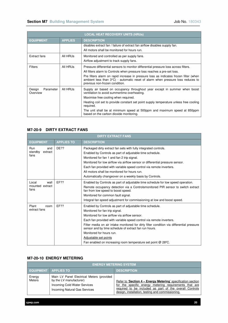
Section M7 Building Management System Job No. 180343
cpwp.com 20
LOCAL HEAT RECOVERY UNITS (HRUs)
EQUIPMENT APPLIES DESCRIPTION
disables extract fan / failure of extract fan airflow disables supply fan.
All motors shall be monitored for hours run.
Extract fans All HRUs Monitored and controlled as per supply fans.
Airflow adjustment to track supply fans.
Filters All HRUs Pressure differential sensors to monitor differential pressure loss across filters.
All filters alarm to Controls when pressure loss reaches a pre-set loss.
Pre filters alarm on rapid increase in pressure loss as indicates frozen filter (when ambient less than 3°C) - automatic reset of alarm when pressure loss reduces to previous non-frozen condition.
Design Parameter Overview
All HRUs Supply air based on occupancy throughout year except in summer when boost ventilation to avoid summertime overheating.
Maximise free cooling when required.
Heating coil set to provide constant set point supply temperature unless free cooling required.
The unit shall be at minimum speed at 500ppm and maximum speed at 850ppm based on the carbon dioxide monitoring.
M7-20-9 DIRTY EXTRACT FANS
DIRTY EXTRACT FANS
EQUIPMENT APPLIES TO DESCRIPTION
Run and standby extract fans
DE?? Packaged dirty extract fan sets with fully integrated controls.
Enabled by Controls as part of adjustable time schedule.
Monitored for fan 1 and fan 2 trip signal.
Monitored for low airflow via airflow sensor or differential pressure sensor.
Each fan provided with variable speed control via remote inverters.
All motors shall be monitored for hours run.
Automatically changeover on a weekly basis by Controls.
Local wall mounted extract fans
EF?? Enabled by Controls as part of adjustable time schedule for low speed operation.
Remote occupancy detection via a Controlsmonitored PIR sensor to switch extract fan from low speed to boost speed.
Monitored for common fault signal.
Integral fan speed adjustment for commissioning at low and boost speed.
Plant room extract fans
EF?? Enabled by Controls as part of adjustable time schedule.
Monitored for fan trip signal.
Monitored for low airflow via airflow sensor.
Each fan provided with variable speed control via remote inverters.
Filter media on air intake monitored for dirty filter condition via differential pressure sensor and by time schedule of extract fan run hours.
Monitored for hours run.
Adjustable set points
Fan enabled on increasing room temperature set point @ 28ºC.
M7-20-10 ENERGY METERING
ENERGY METERING SYSTEM
EQUIPMENT APPLIES TO DESCRIPTION
Energy Meters
Main LV Panel Electrical Meters (provided by the LV manufacturer)
Incoming Cold Water Services
Incoming Natural Gas Services
Refer to ‘Section 4 – Energy Metering’ specification section for the specific energy metering requirements that are required to be included as part of the overall Controls design, installation, testing and commissioning.
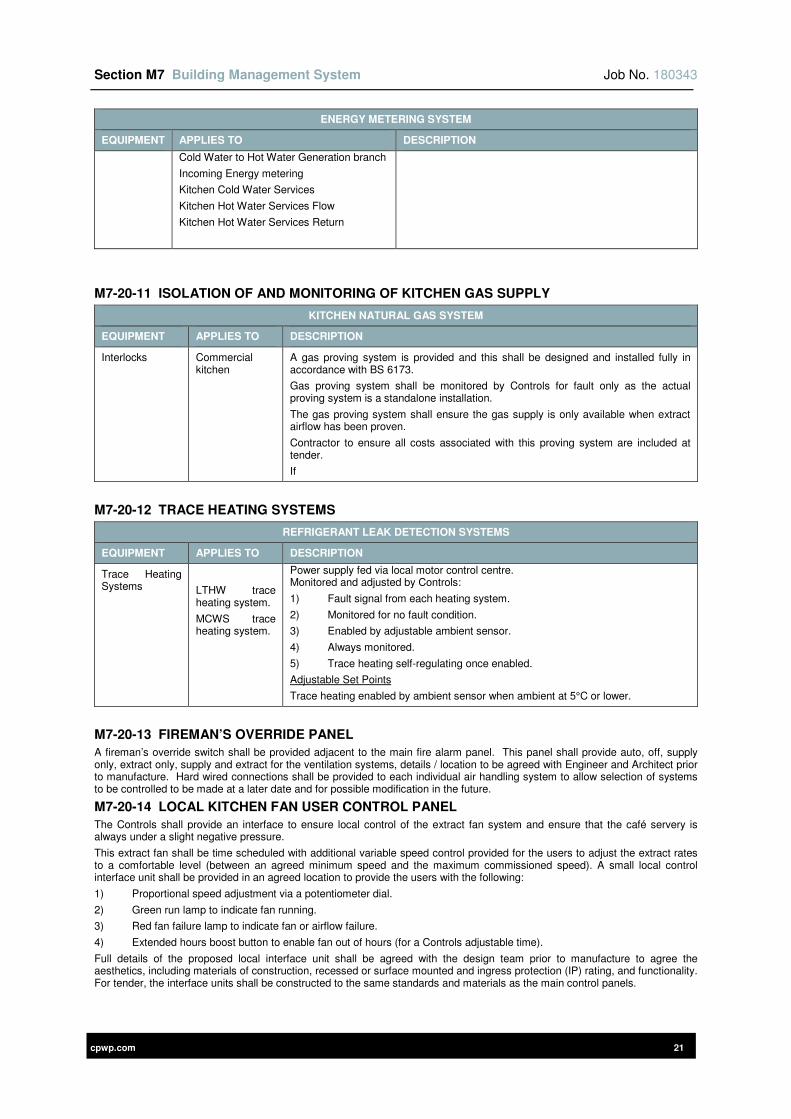
Section M7 Building Management System Job No. 180343
cpwp.com 21
ENERGY METERING SYSTEM
EQUIPMENT APPLIES TO DESCRIPTION
Cold Water to Hot Water Generation branch
Incoming Energy metering
Kitchen Cold Water Services
Kitchen Hot Water Services Flow
Kitchen Hot Water Services Return
M7-20-11 ISOLATION OF AND MONITORING OF KITCHEN GAS SUPPLY
KITCHEN NATURAL GAS SYSTEM
EQUIPMENT APPLIES TO DESCRIPTION
Interlocks Commercial kitchen
A gas proving system is provided and this shall be designed and installed fully in accordance with BS 6173.
Gas proving system shall be monitored by Controls for fault only as the actual proving system is a standalone installation.
The gas proving system shall ensure the gas supply is only available when extract airflow has been proven.
Contractor to ensure all costs associated with this proving system are included at tender.
If
M7-20-12 TRACE HEATING SYSTEMS
REFRIGERANT LEAK DETECTION SYSTEMS
EQUIPMENT APPLIES TO DESCRIPTION
Trace Heating Systems
LTHW trace heating system.
MCWS trace heating system.
Power supply fed via local motor control centre. Monitored and adjusted by Controls:
1) Fault signal from each heating system.
2) Monitored for no fault condition.
3) Enabled by adjustable ambient sensor.
4) Always monitored.
5) Trace heating self-regulating once enabled.
Adjustable Set Points
Trace heating enabled by ambient sensor when ambient at 5°C or lower.
M7-20-13 FIREMAN’S OVERRIDE PANEL
A fireman’s override switch shall be provided adjacent to the main fire alarm panel. This panel shall provide auto, off, supply only, extract only, supply and extract for the ventilation systems, details / location to be agreed with Engineer and Architect prior to manufacture. Hard wired connections shall be provided to each individual air handling system to allow selection of systems to be controlled to be made at a later date and for possible modification in the future.
M7-20-14 LOCAL KITCHEN FAN USER CONTROL PANEL
The Controls shall provide an interface to ensure local control of the extract fan system and ensure that the café servery is always under a slight negative pressure.
This extract fan shall be time scheduled with additional variable speed control provided for the users to adjust the extract rates to a comfortable level (between an agreed minimum speed and the maximum commissioned speed). A small local control interface unit shall be provided in an agreed location to provide the users with the following:
1) Proportional speed adjustment via a potentiometer dial.
2) Green run lamp to indicate fan running.
3) Red fan failure lamp to indicate fan or airflow failure.
4) Extended hours boost button to enable fan out of hours (for a Controls adjustable time).
Full details of the proposed local interface unit shall be agreed with the design team prior to manufacture to agree the aesthetics, including materials of construction, recessed or surface mounted and ingress protection (IP) rating, and functionality. For tender, the interface units shall be constructed to the same standards and materials as the main control panels.
Section M7 Building Management System Job No. 180343
cpwp.com 22
M7-21 MOTOR CONTROL PANELS
The work covered by this section of the specification details additional requirements associated with the Control Panels required as part of the overall Automatic Controls (Building Management System) works.
The control panels shall be suitable for use with a nominal system voltage of 400 volts phase/phase with variations of + 10%, - 6% from the supply authority, and a further maximum volt drop on the Client’s installation of 4%.
All equipment, including any proprietary or other components, must be suitable for use in the site conditions.
The system control panels shall be provided with microprocessor direct digital controllers complete with battery back-up for 72 hour duration and integral on line UPS (4 hour on line) and outstation and central graphic p.c. to monitor interrogate all equipment, sensors etc.
M7-21-1 CONTROL PANEL CONSTRUCTION
The panel shall be two compartments with one utilised for controls (all less than 110V) and one for power. The compartments shall be housed in two completely separate sections to reduce the risk of fire damage. The equipment shall comprise of a damp and dust protecting, vermin proof, sheet steel housing, framed and braced as necessary to form a rigid structure for floor or frame mounting suitably ingress protected to suit the panel location.
Specifically, control panels shall be rated at IP31 where located internally and IP65 or better where located externally or not fully weatherproof enclosure.
Except where the front cover forms part of draw-out equipment, hinged doors permitting unrestricted access to the interior, shall be provided for all compartments requiring entry for routine inspection or to perform manipulation functions during normal use of the equipment. Elsewhere bolted covers for compartments are required. The limit of travel of opening of doors must be positively controlled, and in no case shall there be fouling of items such as switches, instruments, relays, indicator lamps etc., mounted on adjacent panels or on the door being opened.
Flexible wiring to items mounted on hinged doors must not be subjected to strain or kinking when the door is moved. Any through wiring between compartments shall be so arranged or protected that abrasion of insulation cannot occur.
Where cut-outs may be necessary for the fitting of items in sheet steel panels or doors, adequate rigidity must be preserved, with additional stiffening for the purpose where necessary.
The main MCC shall be suitable for extension at one end. Confirm with Engineer preferred end before construction.
All components of the same design shall be interchangeable.
Each control panel shall have an anti-condensation heater.
M7-21-2 INTELLIGENT PROGRAMMABLE OUT-STATIONS
The outstations shall be an integral part of the relevant control panel and shall be of a suitable size to undertake all the functions specified.
Although forming part of the main control panel the outstation shall be fully accessible such that isolation of the motor control panel is not required in order to gain access to the outstation.
Each outstation shall be of the fully intelligent type containing its own microprocessor, power supply and programmes to handle measurements, alarms, quantity counting, single and multi-stage commands and remote set point commands. Inputs and outputs shall be capable of interfacing with standard industrial signals i.e. 0-10V, 2-10V, 0-1mA, 4-20mA, NI200, NI1000, PT130, POT130, OHM, POT 2.5k OHM.
The programs contained within the outstation shall give full DDC which shall be programmable on site without the knowledge of any process language by the user. The DDC shall consist of all normal H & V control loops such as P, P+I, P+PI, schedules, shifts and limit values. All loops shall be fully integrated to give complex control functions. These shall be constructed into simple software modules to give user definable logic controls such as sequence start, auto change over and system interlocking etc.
In the event of a power failure the out-station must retain its memory for a period of 72 hours and be capable of normal operation for a period of 3-6 hours. If this period is exceeded than all parameters must be retained and automatically reloaded when power returns.
No main voltages, other than a shielded power supply, shall be present at the outstation. All commands and Status/Alarm signals shall be limited to 24 Volt. Interface relays shall be incorporated at the point of mains voltage.
Each outstation shall be capable of performing its control, monitoring and alarm function of a standalone basis. It shall be independent in operation and of other system components. Each out-station shall be self-diagnosis and shall be capable of storing and recording all faults and alarms.
M7-21-3 EARTHING
A copper earth bar, of section appropriate to the system prospective fault level, and equipment Class, shall be provided, extending along length of the MCC. The jointing techniques applied to the earth bar shall be to the same standard of construction of those of the bus bars as described for the LV switch panels within this Employer’s Requirement Specification.
Lugs for external connections shall be provided and fitted towards each end of the earth bar.
All non-current carrying metal parts of the equipment must be bonded to this earth bar. Metal cases of instruments, relays and the like shall each have an earthing wire, and in no event must reliance be placed on hinges of doors as constituting an earth part for such items. Earthing connections of wiring shall be taken to the earth bar via a removable bolted link or easily removable connection in each instance.
Gland plates or cable boxes and their mounting shall be so designed and constructed as to provide or permit an effective earth path for the armouring and/or metal sheaths of external cables. Painted surfaces or gaskets must not interpose in the earth path of such items, and additional bonding connections are required as may be necessary to avoid this.
Section M7 Building Management System Job No. 180343
cpwp.com 23
M7-21-4 PADLOCKING
Provision for padlocking is to be available for safety shutters, isolating switches, cubicle doors, and any operating handles or mechanisms where necessary.
M7-21-5 PHASE COLOURING
Phase colours are to be marked for all main connections, and as necessary for ancillary wiring.
Whilst the standard colours and phase progression are Brown, Black, Grey, colouring must not proceed without prior confirmation from the Engineer.
All phase colourings must be painted, plastic sleeved, taped or otherwise permanently marked by means which are non-deteriorating.
M7-21-6 WIRING IDENTIFICATION
All wiring of equipment must have a numbered ferrule, bearing the same one identifying reference at each end and along every branch of any one connection. Such numbers attributed to any one wire in a particular unit must each be unique and carried out to a co-ordinated system throughout.
The numbers used, together with wire references provided by the Engineer for connections to other equipment, must appear on the diagrams. Where connections are made to proprietary items having standard terminal block numbering then the wire numbers and the associated terminal numbers are both to be shown on the comprehensive diagrams.
For D.C. supply circuits the symbols + and - must be used throughout in addition to any other references.
M7-21-7 LABELLING
All components whether mounted on external surfaces or internally, including instruments, switches, control handles, push buttons, contactors, relays, resistors, terminals, fuses and other devices, must have identifying labels or references either on or adjacent to the items in question.
It is not considered sufficient that, for example, a proprietary relay shall bear only the maker's reference 'XYZ Relay', and a further label for function identification is required in such cases.
Circuit titles for compartments are required on the front door or cover, and on the equipment within the compartment as may be necessary, also on the rear where cable terminations or covers require this. All bolted covers whose removal gives access to 'live' parts shall have warning labels fitted.
Labels are preferred in laminated plastic with black lettering on a white ground, except for any 'danger' labels where red letters on a white background are preferred.
All labelling of internal components where the use of laminated plastic may not be practicable must nevertheless be marked and legible manner. Where use of adhesive labels is contemplated care is essential to ensure that the long term adhesive properties are suited to the surface and other conditions of application.
M7-21-8 CABLE BOXES AND GLANDS
For all items of equipment, cable sealing boxes with glands, compression glands and gland plates, must be provided and fitted as necessary.
Where external cables are plastic insulated, (as distinct from impregnated paper insulated), sealing boxes shall still be required if the clearances from live parts, either between phases or to earth would otherwise be insufficient. The manufacturer is to advise the recommended quantity and grade of sealing compound.
The types and details of cabling attachments shall be subject to prior comment by the Engineer.
Gland plates must be sufficiently above the base of the cubicle, according to the size of cable, to facilitate making-off cables, and without impeding access to other equipment. Attention is particularly drawn to that fact that, where the use of cables having aluminium conductors is specified, increased space requirements may be necessary because of the larger dimensions as compared with copper conductors.
M7-21-9 TERMINATIONS AND CABLE SOCKETS
Terminals for multi-core and control cabling must each be of size suitable for receiving not less than two cores consisting of 2.5mm2 conductors. Where more than two cable cores are required to be connected, looping terminals must be provided.
On multi-way terminal boards not less than 20% spare ways must be provided.
Cable lugs suitable for crimped termination of external cabling are to be provided and fitted throughout for all power cables with conductors up to 185mm2 except where any special cases are drawn to the attention of, and agreed with the Engineer. For cable conductors larger than 185mm2 sweating sockets are required. The types of lugs in each case are to be agreed with the Engineer prior to commitment to purchase or supply.
The minimum size of conductor to be used shall be 1.5mm2. The minimum size used for internal flexible wiring is preferred as 1.5mm2, but in any case shall not be less than 1.0mm2. Terminals must be suitably disposed in relation to the floor or base of the compartment and/or the gland plate(s) to facilitate ready connection of cables without impeding access to other equipment.
Terminals must not be of a type relying on the pressure of a screw in direct contact with the conductor.
M7-21-10 FOUNDATIONS
Foundation bolts and any sub-frames or other metallic foundation materials necessary for mounting and alignment of the MCC and ancillary equipment on prepared concrete, are to be specified and provided by the manufacturer.
All panels shall be fixed to the structure to ensure they are rigidly supported and cannot topple.
All panels must be designed to be self-supporting and not rely on the building walls for support.
M7-21-11 PANEL COMPONENTS AND FEATURES
ITEM DESCRIPTION
Section M7 Building Management System Job No. 180343
cpwp.com 24
ITEM DESCRIPTION
Circuit Breakers Each circuit breaker on the MCC shall be of the air-break, trip free, triple pole type, with additional pole or neutral link where required.
Circuit breakers shall comply with industry standards including those listed in ‘Standards Applicable’ and must have been tested at an approved testing station to confirm that short circuit capacity and the rated breaking capacity (Ics) shall be at least 50kA rms for O-CO-CO cycle.
Every circuit-breaker must have a mechanically operated direct acting trip device which is always available for emergency tripping of a breaker which is closed and in its 'service' (normal duty) position.
Whenever a circuit breaker is in any other than its normal service position, every means of initiation not at the circuit breaker must be rendered inoperative.
Isolating switches All isolating switches shall be capable of breaking not less than the rated continuous current of the circuit being fed through that switch, and of making on to a three phase bolted fault when fuses of the appropriate rating are in position.
Fuse switches shall be of double break pattern, with the fuse links mounted on the moving carrier. With the switch open, the fuse links shall be disconnected from the supply and load circuits and so arranged such that fuse replacement is readily possible without danger of contact with 'live' parts.
All motor circuit isolating switches shall be capable of interrupting stalled motor current.
All isolating switches shall be mechanically interlocked so that access to the interior of a compartment cannot be obtained unless the isolator is in the off position, and the main supply within that compartment is removed. Any parts of the isolator which remain 'live' must be completely shrouded to prevent accidental contact by personnel when the compartment is open.
Where this may not be practicable in any particular instance, then the 'live' supplies remaining must be completely shrouded with warning labels fitted as required. The details of all such arrangements must be submitted to the Engineer for approval prior to commitment to manufacture.
Fuses All fuses, including those for control circuits, must be of HRC type of appropriate class.
Wiring to fuse holders and the fixed contacts of removable fuses must be shrouded to prevent accidental contact with live parts.
Auxiliary Switches, Contacts and Indication
Auxiliary switches are to be provided whether for circuit breakers, contactors or isolating switches.
These switches (for contactors these may be termed 'auxiliary contacts') are to cater both for correct operation of the main switching device, and also for signals associated with remote equipment for interlocking, alarm and indication, as necessary.
Where insufficient auxiliaries are available, then a reliable repeat relay, or relays, must be provided.
Spare auxiliary switches are to be provided with each circuit breaker to give at least one normally open and one normally closed way for each circuit-breaker position.
A common 'lamp test' push-button shall be provided for all indication lamps.
Miniature and Moulded Case Circuit Breakers
MCB's or MCCB's ratings and breaking capacity must always exceed the fault level that can occur.
In suitable circumstances fuses shall be fitted in the live side of the switching device for the purpose of limiting the I2t let through. The operating characteristic of the highest fuse rating which can be fitted (not necessarily the rating of fuse which shall be fitted) must, in all cases, cross the operating characteristic of the breaker at a point within the breaking capacity of the latter.
Lamps All lamps shall be LED type as follows:
• Colours as scheduled below.
• Restriction of Hazardous Substances Directive (2002/95/EC) (ROHS) compliant.
• Ingress protection (IP) 65 rated.
• Minimum life expectancy of 30,000 hours.
• 22mm diameter lamp.
• Same lamp model for all bezel colours.
• Same diameter as all panel mounted switches.
For appearance and performance as per:
• Schneider Electric XB4 Series.
• Multicomp 22mm Pilot LED lamps Series.
• Tranilamp JY 22.5mm Series.
Section M7 Building Management System Job No. 180343
cpwp.com 25
M7-21-12 CONTROL PANEL LAMP INDICATION AND SWITCHING REQUIREMENTS
ITEM LAMP INDICATION CONTROL SWITCH PROVISION
For Each Fan Fan Running (Green)
Fan Airflow Failure (Red)
Fan Thermal Overload Trip (Red)
Auto/Off/Hand Switch
For Each Motorised Damper Shut Off Damper Failure (Red) (Controls monitors dampers’ end switches)
None
For Each Air Handling Unit Supply Fan Running (Green)
Return Fan Running (Green)
Airflow Failure - Return Fan (Red)
Airflow Failure - Supply Fan (Red)
Supply Fan Thermal Overload Trip (Red)
Return Fan Thermal Overload Trip (Red)
Frost Thermostat Alarm (Red)
Filter Dirty Indicator (Orange)
Heat Recovery Active (Green)
Heat Recovery Failed (Red)
Auto/Off/Hand Switch for EACH Fan
For Each Twin Fan Extract System
Fan 1 Running (Green)
Fan 2 Running (Green)
Fan 1 Thermal Overload Trip (Red)
Fan 2 Thermal Overload Trip (Red)
Airflow Failure (Red)
Auto/Off/Hand Switch for EACH Fan
For Each Heating System Boiler
Boiler Enabled (White)
Boiler Firing (Green)
Boiler tripped (Red)
Boilers held off from running due to pressurisation unit or pump fault (Red)
Auto/Off/Hand Switch for EACH Boiler
For Each Cooling Air Conditioning System
Room Cooling Unit Failure (each) (Red) (via Room Temperature Sensor)
None
For Each Chiller For Each Chiller:
Chiller Enabled (White)
Chiller Running (Green)
Chiller Fault (Red)
Auto/Off/On switch for each chiller
On shall enable the chiller for manual override and testing purposes.
For Each Pressurisation Unit Pressurisation Unit Power (White)
Common Fault (Red)
None
For Each Pump (and Set)
(Including DHWSR pump).
Pump Set Water Flow Failure (Red).
One pressure differential switch per pump set.
Pump Thermal Overload Trip (Red)
Pump Running (Green)
Auto/Off/Hand switch for EACH pump
For Each Hot Water Generation Equipment whether Heating or HWS
High Temperature Limit (Red)
Low Temperature Limit (Red)
Within design tolerances (Green)
None
For Each Water Booster Set
Water Booster Set Enabled (Green)
Common Fault Alarm (Red)
Disabled (White)
Auto/Off/Hand selector switch
For high limit valve System Operation Normal (Green)
Activation of high limit valve (Red)
None

Section M7 Building Management System Job No. 180343
cpwp.com 26
ITEM LAMP INDICATION CONTROL SWITCH PROVISION
For Safety Valves for each area to enable maintenance to locate problematic valve.
Activation of safety valve (Red) None
For Each Water Tank
High Water Level (Red)
Low Water Level (Red)
For Each Panel
Panel live lamp.
Fire Alarm Condition Lamp (Red).
Door interlocked isolator.
Lamp test button.
Birmingham | Nottingham | Huntingdon | Leeds | Bristol | Leicester | London | Manchester | Derby | India | Poland
cpwp.com © Couch Perry Wilkes
Whitaker Museum
The Whitaker Museum and Art Gallery
180343
Mechanical and Electrical Tender Analysis
DOCUMENT REVISION HISTORY Ref: 180343 Whitaker Museum
Rev Author Verification By Date Comments / Status
T1 Ts JH 30.10.19 Tender

cpwp.com V1.4
©2019 Couch Perry Wilkes LLP
Couch Perry Wilkes shall not be liable in whole or part for any use of this document beyond such purpose(s) as the same was
originally prepared or provided nor shall Couch Perry Wilkes be liable for any misinterpretation as to such intended purpose.
Mechanical & Electrical Tender Analysis Job No.180343
cpwp.com 1
Contents Page
1-0 PROJECT TENDER COSTS 2
2-0 PROVISIONAL SUMS 5
3-0 SPECIFIED COST OPTIONS (NOT TO BE INCLUDED WITHIN TENDER SUM) 5
4-0 SCHEDULE OF DAY WORK RATES 6
5-0 CONSTRUCTION (DESIGN AND MANAGEMENT) REGULATIONS 2015 7
6-0 SCHEDULE OF ADDENDUMS 8
7-0 SCHEDULE OF WORK TO BE SUB-LET 8
8-0 TENDER SUMMARY 9

Mechanical & Electrical Tender Analysis Job No.180343
cpwp.com 2
1-0 PROJECT TENDER COSTS
PROJECT TENDER COSTS
Item Description Item Cost Section Cost
1 For all costs associated with Section 1 – Preliminaries
a) General requirements £
b) Soft landing requirements £
c) Heat load testing £
Section Total £ £
2 Standard Installation Clauses
2A For all costs associated with Section 2A - General Installation Clauses - Pipework
£
2B For all costs associated with section 2B - General Installation Clauses - Ductwork
£
2C For all costs associated Section 2C – General Installation Clauses - Mechanical Commissioning
£
2D For all costs associated Section 2D – General Installation Clauses – Thermal Insulation
£
2E For all costs associated Section 2E – Electrical Workmanship and Materials
£
2F For all costs associated Section 2F – Electrical Inspection and Testing
£
Section Total £ £
3 For all costs associated Section 3 – Site Specific Requirements
a) 12 months planned & corrective maintenance including consumables
£
b) Mechanical £
c) Electrical £
Section Total £ £
4 For all costs associated with Section 4 – Energy Metering
Section Total £ £
5 For all costs associated with Section 5 – Enabling and Incoming Services Works
a) Incoming Main Cold Water supply if needed from site boundary £
b) Incoming Natural Gas Supply if needed from site boundary £
c) Mechanical Enabling works to Stores Building (Stripping Out/Re-routing works)
£
d) Electrical Enabling works to Stores Building (Stripping Out/Re-routing works)
£
e) Other £
Section Total £ £
6 For all costs associated with Section 6 – Design Standards
a) Mechanical £
b) Electrical £
Section Total £ £
E1A For all costs associated Section E1A – LV Distribution
a) Supply and Installation of Switchgear £
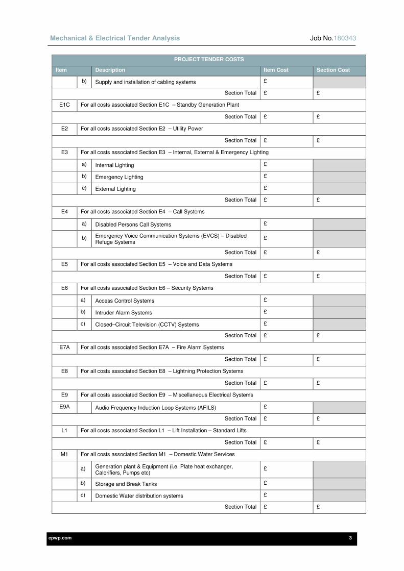
Mechanical & Electrical Tender Analysis Job No.180343
cpwp.com 3
PROJECT TENDER COSTS
Item Description Item Cost Section Cost
b) Supply and installation of cabling systems £
Section Total £ £
E1C For all costs associated Section E1C – Standby Generation Plant
Section Total £ £
E2 For all costs associated Section E2 – Utility Power
Section Total £ £
E3 For all costs associated Section E3 – Internal, External & Emergency Lighting
a) Internal Lighting £
b) Emergency Lighting £
c) External Lighting £
Section Total £ £
E4 For all costs associated Section E4 – Call Systems
a) Disabled Persons Call Systems £
b) Emergency Voice Communication Systems (EVCS) – Disabled Refuge Systems
£
Section Total £ £
E5 For all costs associated Section E5 – Voice and Data Systems
Section Total £ £
E6 For all costs associated Section E6 – Security Systems
a) Access Control Systems £
b) Intruder Alarm Systems £
c) Closed–Circuit Television (CCTV) Systems £
Section Total £ £
E7A For all costs associated Section E7A – Fire Alarm Systems
Section Total £ £
E8 For all costs associated Section E8 – Lightning Protection Systems
Section Total £ £
E9 For all costs associated Section E9 – Miscellaneous Electrical Systems
E9A Audio Frequency Induction Loop Systems (AFILS) £
Section Total £ £
L1 For all costs associated Section L1 – Lift Installation – Standard Lifts
Section Total £ £
M1 For all costs associated Section M1 – Domestic Water Services
a) Generation plant & Equipment (i.e. Plate heat exchanger, Calorifiers, Pumps etc)
£
b) Storage and Break Tanks £
c) Domestic Water distribution systems £
Section Total £ £

Mechanical & Electrical Tender Analysis Job No.180343
cpwp.com 4
PROJECT TENDER COSTS
Item Description Item Cost Section Cost
M2 For all costs associated Section M2 – Heating
a) Heat Generation Plant (Boilers, Flues, Pumps, Pressurisation sets, Thermal Storage, Plate heat exchangers etc.)
£
c) LTHW distribution system(s) £
d) Other £
Section Total £ £
M3 For all costs associated Section M3 – Mechanical Ventilation Systems
a) Kitchen Ventilation £
b) Hall, Bar, Dining Ventilation £
c) Toilet Extract system £
d) Galvanised Ductwork distribution systems £
e) Attenuators £
f) Other £
Section Total £ £
M4 For all costs associated Section M4 – Fuel Systems
a) Natural gas system £
Section Total £ £
M5 For all costs associated Section M5 – Cooling Systems
a) Not Applicable £
Section Total £ £
M6 For all costs associated Section M6 – Drainage
a) Above Ground Drainage £
b) Other £
Section Total £ £
M7 For all costs associated Section M7 – Controls/BMS System
Not Applicable £
Section Total £ £
M9 For all costs associated Section M9 – Fire Fighting – Sprinklers
Not Applicable £
Section Total £ £
For any other mechanical costs not detailed above, add description / cost below:
A £
B £
C £
Section Total £ £
For any other electrical costs not detailed above, add description / cost below:
A £
B £

Mechanical & Electrical Tender Analysis Job No.180343
cpwp.com 5
PROJECT TENDER COSTS
Item Description Item Cost Section Cost
C £
Section Total £ £
SUB TOTAL CARRIED FORWARD TO TENDER SUMMARY £
2-0 PROVISIONAL SUMS
PROVISIONAL SUMS
Item Description Item Cost Section Cost
1) Staff room sink etc £ 1,500.00
2) Utility Company Incoming Electricity £ 18,595.40
3) Disconnection of existing Electrical service £2,945.63
4) Utility Company Incoming Gas – IF NEEDED £ 15,000.00
5) Utility Company Incoming Water – IF NEEDED £ 15,000.00
Sub Total £53,041.03 £
SUB TOTAL CARRIED FORWARD TO TENDER SUMMARY £53,041.03
3-0 SPECIFIED COST OPTIONS (NOT TO BE INCLUDED WITHIN TENDER SUM)
SPECIFIED COST OPTIONS
Item Description Item Cost
1 Path lighting
TOTAL £
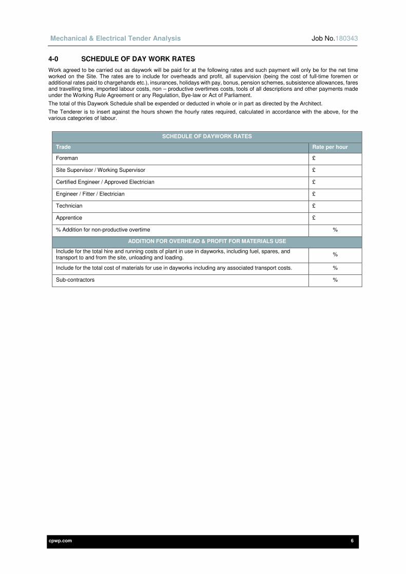
Mechanical & Electrical Tender Analysis Job No.180343
cpwp.com 6
4-0 SCHEDULE OF DAY WORK RATES
Work agreed to be carried out as daywork will be paid for at the following rates and such payment will only be for the net time worked on the Site. The rates are to include for overheads and profit, all supervision (being the cost of full-time foremen or additional rates paid to chargehands etc.), insurances, holidays with pay, bonus, pension schemes, subsistence allowances, fares and travelling time, imported labour costs, non – productive overtimes costs, tools of all descriptions and other payments made under the Working Rule Agreement or any Regulation, Bye-law or Act of Parliament.
The total of this Daywork Schedule shall be expended or deducted in whole or in part as directed by the Architect.
The Tenderer is to insert against the hours shown the hourly rates required, calculated in accordance with the above, for the various categories of labour.
SCHEDULE OF DAYWORK RATES
Trade Rate per hour
Foreman £
Site Supervisor / Working Supervisor £
Certified Engineer / Approved Electrician £
Engineer / Fitter / Electrician £
Technician £
Apprentice £
% Addition for non-productive overtime %
ADDITION FOR OVERHEAD & PROFIT FOR MATERIALS USE
Include for the total hire and running costs of plant in use in dayworks, including fuel, spares, and transport to and from the site, unloading and loading.
%
Include for the total cost of materials for use in dayworks including any associated transport costs. %
Sub-contractors %

Mechanical & Electrical Tender Analysis Job No.180343
cpwp.com 7
5-0 CONSTRUCTION (DESIGN AND MANAGEMENT) REGULATIONS 2015
We confirm that we are able to allocate sufficient and adequate resources to perform the duties as assigned to the Contractor under the Construction (Design and Management) Regulations 2015.
We have enclosed evidence which demonstrates our competence to perform the duties as set in Appendix 4 of the Construction (Design and Management) Regulations 2015 Approved Code of Practice.
SCHEDULE OF ENCLOSED DOCUMENTATION
Stage 1, Organisation and Arrangements for Health & Safety Management: -
Stage 2, Experience and Track Record : -

Mechanical & Electrical Tender Analysis Job No.180343
cpwp.com 8
6-0 SCHEDULE OF ADDENDUMS
During the course of preparing our tender for the Works details in this Tender Analysis and described in the Associated Specification and drawings, the following Addendums were issued by the Engineer.
We hereby agree that all costs have been included in our tender for the items detailed in the Addendums, including any costs associated with Sections 1 and 2 of this Specification.
SCHEDULE OF ADDENDUMS
Addendum Number Date Issued
7-0 SCHEDULE OF WORK TO BE SUB-LET
The Tenderer shall indicate below the names of all Firms for which he proposes to sub-let any part of the works.
SCHEDULE OF WORKS TO BE SUB LET
Work to be sub-let Name of Sub Contractor
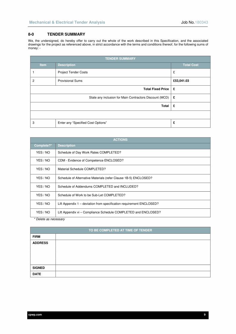
Mechanical & Electrical Tender Analysis Job No.180343
cpwp.com 9
8-0 TENDER SUMMARY
We, the undersigned, do hereby offer to carry out the whole of the work described in this Specification, and the associated drawings for the project as referenced above, in strict accordance with the terms and conditions thereof, for the following sums of money: -
TENDER SUMMARY
Item Description Total Cost
1 Project Tender Costs £
2 Provisional Sums £53,041.03
Total Fixed Price £
State any inclusion for Main Contractors Discount (MCD) £
Total £
3 Enter any “Specified Cost Options” £
ACTIONS
Complete?* Description
YES / NO Schedule of Day Work Rates COMPLETED?
YES / NO CDM - Evidence of Competence ENCLOSED?
YES / NO Material Schedule COMPLETED?
YES / NO Schedule of Alternative Materials (refer Clause 1B-5) ENCLOSED?
YES / NO Schedule of Addendums COMPLETED and INCLUDED?
YES / NO Schedule of Work to be Sub-Let COMPLETED?
YES / NO Lift Appendix 1 – deviation from specification requirement ENCLOSED?
YES / NO Lift Appendix vi – Compliance Schedule COMPLETED and ENCLOSED?
* Delete as necessary
TO BE COMPLETED AT TIME OF TENDER
FIRM
ADDRESS
SIGNED
DATE