
The Ultimate Guide to Retroreflection - RoadVista
37
SPEED LIMIT 50 Guide To Retroreflection Safety Principles and Retrorereflective Measurements
-
Upload
khangminh22 -
Category
Documents
-
view
0 -
download
0
Transcript of The Ultimate Guide to Retroreflection - RoadVista
SPEEDLIMIT
50
Guide To Retroreflection Safety Principles and Retrorereflective Measurements
Guide To Retroreflection Safety Principles and Retrorereflective Measurements
Richard L. Austin Robert J. Schultz
RoadVista, San Diego, California 858-279-6044888-637-2758www.roadvista.com
© Copyright 2002, 2006, 2009, 2020 ISBN 0-9710215-0-3
Table of Contents
Page
Introduction 1
Applications of Retroreflectivity to Highway Safety 2
What is Retroreflection and How Is It Used? 3
5
6 Glass Beads for Pavement Markings
Prismatic Cube-Corner Retroreflection
Micro-Prismatic Cube Corner Retroreflection
Quality Assurance of Retroreflectors 7
Measuring Retroreflection 8
9
11 Measurement of Roadway Markings
Measurement of Road Signs
Practical Applications of Retroreflectometers
Learn from the experts
13
13
13
13
Photometric Range Goniometer Laboratory Retroreflectometers
Pavement Markings
Signs and Sheeting Materials
Raised Pavement Markers
14
18
19
21
Minimum Sign Retroreflectivity Guidelines
ASTM Standards Dealing with Retroreflection
References on Light and Color Measurement of Traffic Safety Materials Bibliography
Glossary of Terms
6
11
RoadVista Retroreflectometers 25
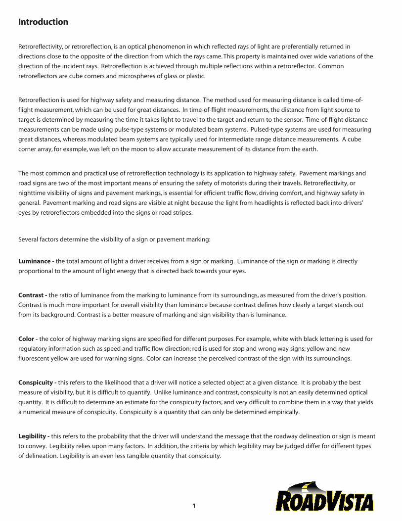
Introduction
Retroreflectivity, or retroreflection, is an optical phenomenon in which reflected rays of light are preferentially returned in
directions close to the opposite of the direction from which the rays came. This property is maintained over wide variations of the
direction of the incident rays. Retroreflection is achieved through multiple reflections within a retroreflector. Common retroreflectors are cube corners and microspheres of glass or plastic.
Retroreflection is used for highway safety and measuring distance. The method used for measuring distance is called time-of-
flight measurement, which can be used for great distances. In time-of-flight measurements, the distance from light source to
target is determined by measuring the time it takes light to travel to the target and return to the sensor. Time-of-flight distance
measurements can be made using pulse-type systems or modulated beam systems. Pulsed-type systems are used for measuring
great distances, whereas modulated beam systems are typically used for intermediate range distance measurements. A cube
corner array, for example, was left on the moon to allow accurate measurement of its distance from the earth.
The most common and practical use of retroreflection technology is its application to highway safety. Pavement markings and
road signs are two of the most important means of ensuring the safety of motorists during their travels. Retroreflectivity, or
nighttime visibility of signs and pavement markings, is essential for efficient traffic flow, driving comfort, and highway safety in
general. Pavement marking and road signs are visible at night because the light from headlights is reflected back into drivers'
eyes by retroreflectors embedded into the signs or road stripes.
Several factors determine the visibility of a sign or pavement marking:
Luminance - the total amount of light a driver receives from a sign or marking. Luminance of the sign or marking is directly
proportional to the amount of light energy that is directed back towards your eyes.
Contrast - the ratio of luminance from the marking to luminance from its surroundings, as measured from the driver's position. Contrast is much more important for overall visibility than luminance because contrast defines how clearly a target stands out
from its background. Contrast is a better measure of marking and sign visibility than is luminance.
Color - the color of highway marking signs are specified for different purposes. For example, white with black lettering is used for
regulatory information such as speed and traffic flow direction; red is used for stop and wrong way signs; yellow and new
fluorescent yellow are used for warning signs. Color can increase the perceived contrast of the sign with its surroundings.
Conspicuity - this refers to the likelihood that a driver will notice a selected object at a given distance. It is probably the best
measure of visibility, but it is difficult to quantify. Unlike luminance and contrast, conspicuity is not an easily determined optical
quantity. It is difficult to determine an estimate for the conspicuity factors, and very difficult to combine them in a way that yields
a numerical measure of conspicuity. Conspicuity is a quantity that can only be determined empirically.
Legibility - this refers to the probability that the driver will understand the message that the roadway delineation or sign is meant
to convey. Legibility relies upon many factors. In addition, the criteria by which legibility may be judged differ for different types
of delineation. Legibility is an even less tangible quantity that conspicuity.
1
Visibility Distance - the range at which a marking or sign can be seen. Visibility distance only specifies the distance at which a
given driver is capable of seeing a marking. It is not a guarantee that the driver will see it.
It is important that you keep the visibility factor in mind as you move into the application of retroreflectivity to highway safety.
Application of Retroreflectivity to Highway Safety
A popular saying in the light measurement industry is retroreflectivity is the optical equivalent of the phrase "right back at you". Basically, retroreflectivity is the measurement of efficiency of a highway safety marking to return light in the general direction from
which it came. It is simply a ratio of the light visible to the driver compared to the light entering the highway marker.
Retroreflective sheeting was first introduced in the 1930's. However, it was not until the 1950's that the enclosed lens
retroreflective sheeting became available and retroreflective signs became universally recognized. Since then, technological
improvements have led to newer products with increased retroreflectivity and angularity. The types of sheeting material differ
with regard to their level of intensity and method of retroreflection (e.g. enclosed, encapsulated or microprismatic materials).
Recognition by highway agencies of the importance of retroreflectivity has made the use of retroreflective highway markings
nearly universal. According to the "Manual on Uniform Traffic Control Devices (MUTCD)," markings that must be visible at night
should be retroreflective unless ambient illumination assures adequate visibility. Because the percentage of well-illuminated
roadways is so small, the trend among highway agencies is to make all highway and pavement markings retroreflective.
Over time, retroreflective paints and materials degrade due to the effects of traffic and weather. In addition, we have a large aging
driver population that needs brighter signs and pavement markings to maintain its mobility, especially at night. Unfortunately, inadequate and poorly maintained signs and markings are often cited as the contributing factor to nighttime accidents. To assess
the effectiveness of safety measures, the Federal Highway Administration (FHWA) and others use the Highway Safety Information
System (HSIS), a multi-state database that contains accident information and an inventory of road conditions and markings. This
database and others show that while only 25 percent of travel occurs at night, it is then that about 55 percent of the fatal
accidents occur.
It is not always easy to determine the best time to replace the retroreflected surfaces. If replaced too soon, maintenance costs are
increased. If replaced too late, safety and driving comfort are compromised. Thus, strategies have to be developed and
implemented to cost-effectively maintain minimum nighttime visibility requirements. There are four basic strategies that you can
use to maintain a minimum level of highway reflectivity:
1. Total Replacement - every sign is replaced after a set interval of time.
2. Sign Inspection - all signs are periodically checked, those not up to standards are replaced.
3. Sign Management - a computerized database is used to monitor and predict when replacement is needed.
4. Sign Inspection combined with Sign Management - the collected field data is stored in a database to more economicallymanage the minimum nighttime visibility requirements.
2
Sample sign inspection combined with a database and predictive algorithms seem to be the least costly method of maintenance.
There are two methods of evaluating traffic sign retroreflectivity under highway conditions. One is measurement using sensors
and integrated documentation equipment (retroreflectometer). The other is making "measurements" using human observers. Research has been done to evaluate the accuracy of human observers in making retroreflectivity observations. Observer sign
ratings and the sign rating calculated using a retroreflectometer were incorporated into a sign replacement decision model. The
individual trained observers only made the correct observation/decision 74% of the time for warning signs and 75% for stop signs. This is a low number where human lives and traffic safety are concerned. In addition to being more accurate, instrument records
can be used quantitatively by an agency to assist in defending tort claims.
What is Retroreflection and How It Is Used
Drivers and highway department personnel have long recognized that good pavement markings and legible road signs are
essential for efficient traffic flow, driving comfort, and highway safety. This is especially true at night and during inclement
weather.
A technology that has contributed significantly to improving the visibility of pavement marking and road signs is retroreflectivity. Many highway signs and pavement markings use special sign sheeting and pavement marking materials that send a large portion
of the light from a car's headlights straight back along the same path from which it came. This is what retroreflection is all about. Retroreflection makes objects shine much brighter than those without the retroreflective surface.
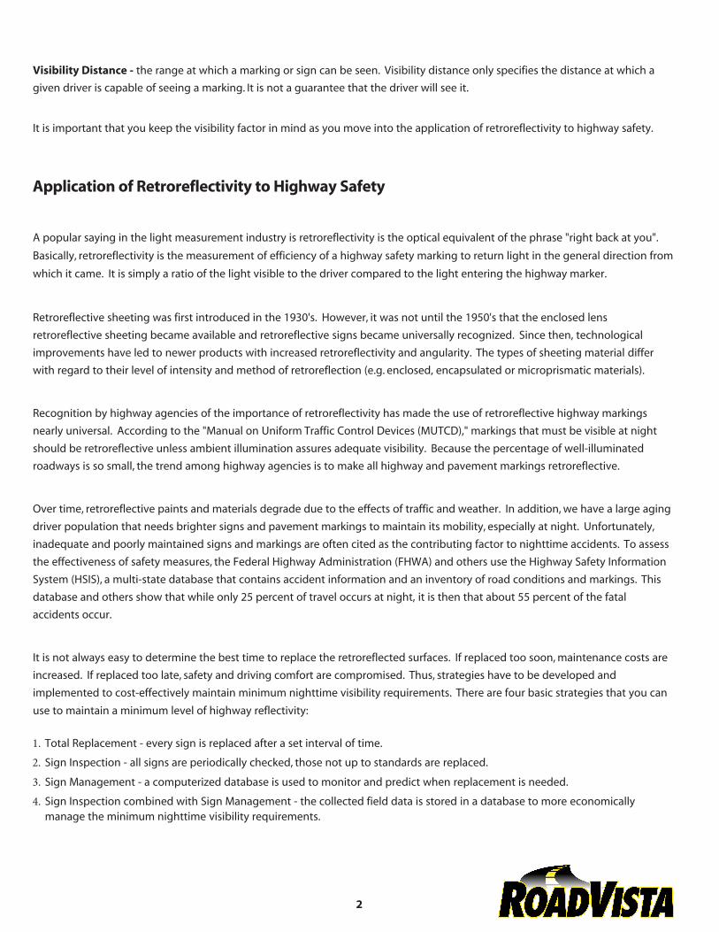
The three types of reflection (mirror reflection, diffuse reflection and retroreflection) are illustrated in Figure 1. Retroreflection, as can be seen in the bottom illustration, is the phenomenon of light rays striking a surface and being redirected back to the
source of light. By definition, light sources emit some amount of their energy in the
form of visible light. An ideal point light source directs its light equally in all directions. If a perfect sphere light source were enclosed in a perfect sphere, every
point on the sphere would be illuminated by an equal amount of brightness or
light intensity.
A directed light source, such as a car's headlights, directs its light in a cone around
the direction that it is pointed. If one of your headlights put out a total amount of
light energy equal to the point source, and it was enclosed in the same perfect
sphere, the points on which your headlight shines would be brighter than each point illuminated by the point source.
This brings us to the discussion of light flux and brightness or light intensity. Light
flow rate of light energy. Light flux can be compared to the flow rate of water; it
describes how much light is flowing per unit of time. Brightness or light intensity is like the velocity of water flow.
3
Figure 1 - Retroreflection returns thelight to its source.
If there are two pipes that discharge equal amounts of water every second and the diameter of one pipe is half that of the other
pipe, then the velocity of water in the smaller pipe must be twice as great as the water flowing through the larger pipe.
The same is true for light. If there are two directed light sources that release the same total light flux in the same angular
distribution pattern and the first source radiating area is twice the area of the second, then the intensity of the second source will
be twice that of the first. The radiating area of the second source will appear brighter, just as the water in the smaller pipe will
have a higher velocity, thus flowing with more water per unit of area. This is the concept of radiance or luminance.
Now, if you move away from these two light sources to a distance over ten times the size of the source and look back at them, the
two sources will be the same brightness. This is because the total amount of light filling the cone angle defined by your eye pupil
and the apex at the surface of the light (now a point source for both lights) is the same for both lights. This is the concept of
radiant intensity or luminous intensity.
Understanding these concepts will help you understand the phenomenon of retroreflectivity. It was stated that the point light
source would have a uniform distribution of light flux in all directions around it. A perfect retroreflector, as shown in the bottom
of Figure 1, would simply reverse the direction of the light that fell upon it. In this idealized case, the intensity of the light emitted
from the reflector would be zero in all directions except that of the source.
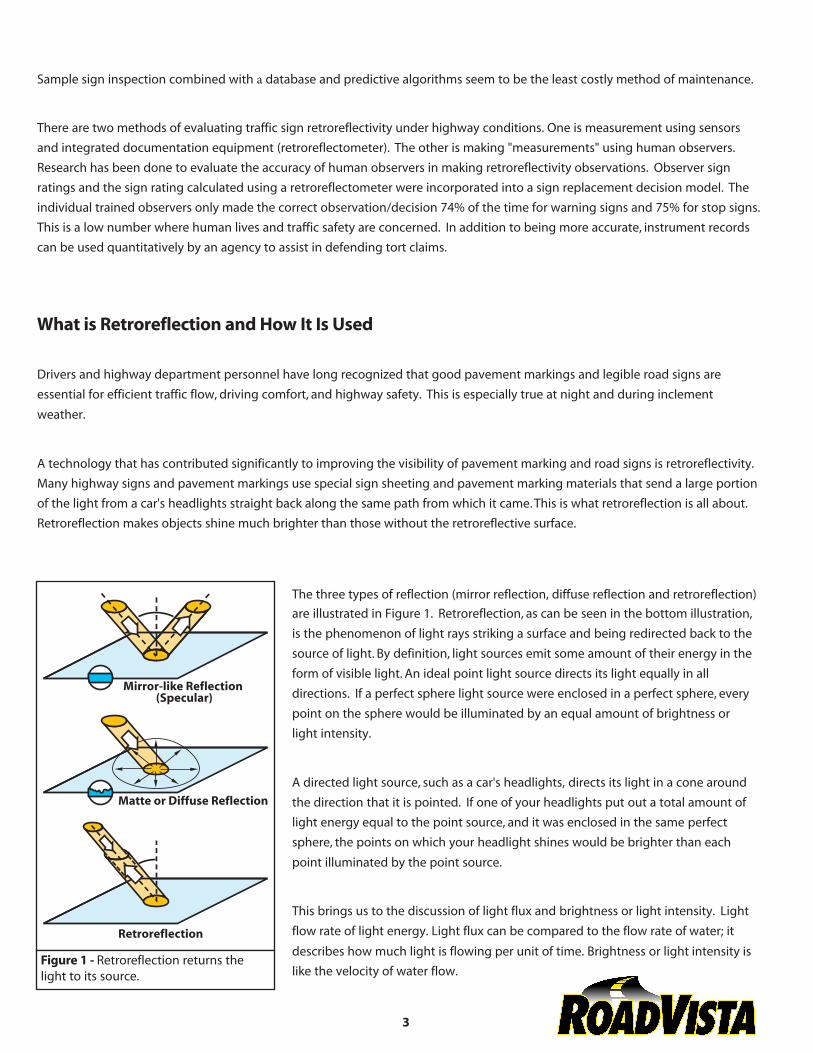
A perfect retroreflector would not be useful for highway signs and lane markings, since all reflected light would be returned directly back to the headlights. The reality is that retroreflectors are not perfect. The distribution of this retroreflected light depends on the type of retroreflective material. In the case of retroreflectors
that use beads, some light is absorbed by the reflector, and more importantly, light
is scattered in the general direction of the light source. In the case of prismatic and microprismatic retroreflectors, light is reflected back toward the headlights in an
pattern determined by the design and orientation of the microprismatic corner
cubes and scattered from imperfections. This occurrence is depicted in Figure 2. It
is this imperfectly retroreflected light that is useful for highway signage and stripes
(delineation).
What does this mean to the driver? It means that signs can be clearly seen from greater distances at night, giving drivers more
time to plan lane changes and prepare for exits. It also means that road markings appear brighter and can be seen more clearly. All of this is making our highways much easier and safer to navigate at night
4
Figure 2 - General principle ofretroreflection use.
Glass Beads for pavement markings
Retroreflective highway signs and lane markers use special kinds of paints and materials. Most retroreflective paints and other
pavement marking materials (PMM) contain many thousands of glass beads per square foot that are bonded to the highway with
a strong binder. Instead of scattering light, as normal paints do, retroreflective paints containing glass beads turn the light around
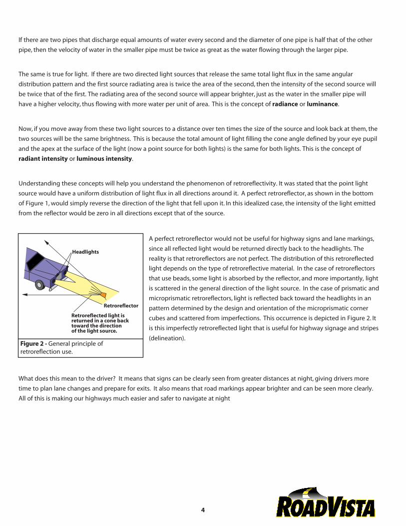
and send it back in the direction of your headlights. Figure 3 portrays how glass beads perform retroreflection.
For beads to retroreflect light, two properties are necessary: transparency and
roundness. Beads made of glass have both of these properties. The need for transparency and roundness can be seen to be important if you follow the path of
light as it enters a bead embedded in an applied roadway marking. The glass bead
must be transparent so that light can pass into and out of the sphere. As the light
ray enters the bead it is bent (refracted) downward by the rounded surface of the bead to a point below where the bead is embedded in the paint or PMM. Light striking the back of the paint-coated bead surface is reflected from the paint surface, with only a small fraction of the light going back toward the illumination source.
The glass beads are applied to pavement marking materials in one of three ways. They can be premixed in marking materials
before application, or they can be dropped or sprayed into the wet paint directly behind the paint sprayer, or a portion can be
dropped onto premixed two-part epoxy or thermoplastic materials. The top surface of beads is enveloped by the paint, with the
wicking action of the paint rising up to above the midpoint of the bead.
This provides two actions. It locks the glass beads into the paint and allows the paint to act as a diffuse reflecting surface for
retroreflection, with the paint color affecting the color of the retroreflected light. The light entering the glass bead is bent and
focused towards the back of the bead and reflected back out towards the headlights and driver.
A good application of beads results in the top layer of glass beads being embedded to about 60% of the diameter of the bead. There should be consistent quality of both glass beads and paint so that the paint thickness and bead coverage promotes even
retroreflectivity across both directions of road travel. Too little paint results in under-embedded beads. This will result in
improperly anchored beads that will fall out prematurely, and thus will not be effective retroreflectors. Under-embedded beads
cause a large percentage of the light that enters them to exit out the back. Too much paint results in over-embedded beads. While
over-embedded beads may remain in the binder, light cannot enter them and thus no retroreflection can occur.
The retroreflected light from glass beads is a function of three variables:
• Index of refraction of the glass beads
• Bead shape, size, and surface characteristics
• The number of beads present and exposed to light rays
The bead's Refractive Index (RI) is an important physical parameter. The higher the RI of the bead and the fewer impurities in the
glass material, the more costly it is to manufacture. The RI is a function of the chemical makeup of the beads. The higher the RI, the more light is retroreflected. Beads used in traffic paint commonly have a RI of 1.5. There are some 1.65 RI
5
Figure 3 - Glass beads or microspheresembededded in paint provide effectiveretroreflective surfaces.
beads used with thermoplastics, and 1.9 RI beads are often used in retroreflective airport markings. Despite the increased
brightness gained with the higher refractive index, most state and local highway agencies find it is more cost-effective to use 1.5
RI beads.
Glass beads range in size from 60 micrometers (0.0024 inches) to 850 micrometers (0.034 inches). Bead size is usually expressed in
terms of U.S. sieve number, or the size of mesh screen that a bead will pass through. For example, a U.S. Sieve Number 20 will
permit beads with a diameter of 840 micrometers (0.033 inches) or less to pass through the mesh, whereas a Number 200 mesh
will allow only those beads of 74 micrometers (0.0029 inches) or less to pass. A typical application of drop-on beads will use from
20 to 100 mesh. The specified mix of bead size (called in the industry gradation) is usually a local policy decision based on several
factors:
• Uncertainties in material control: there is always some spread in the size of beads in any production run.
• Drying time of the marking material (affects settlement of beads in to the binder): a distribution of sizes assures that some
of the beads will have an optimum binding in the marking material.
• Uncertainties of weather control: another factor affecting drying time.
• Service life requirements: as the pavement marker wears, beads that were too deep in the binder will increase in their
retroreflectance ability.
• Number of beads applied: a mix of sizes increases the possible coverage.
6
Prismatic Cube Corner Retroreflection for pavement markings
The most common use of prismatic cube corner retroreflection is in Raised
Pavement Markers (RPMs). Prismatic materials are also used for retroreflective
buttons for post-mounted delineators and sign lettering. Raised Pavement Markers
take on a variety of configurations. Some have the characteristic wedge shape, some
have round or oval markers, and some have markers with and without replaceable
retroreflective inserts. Most RPMs employ prismatic cubecorner reflectors to achieve
retroreflectivity.
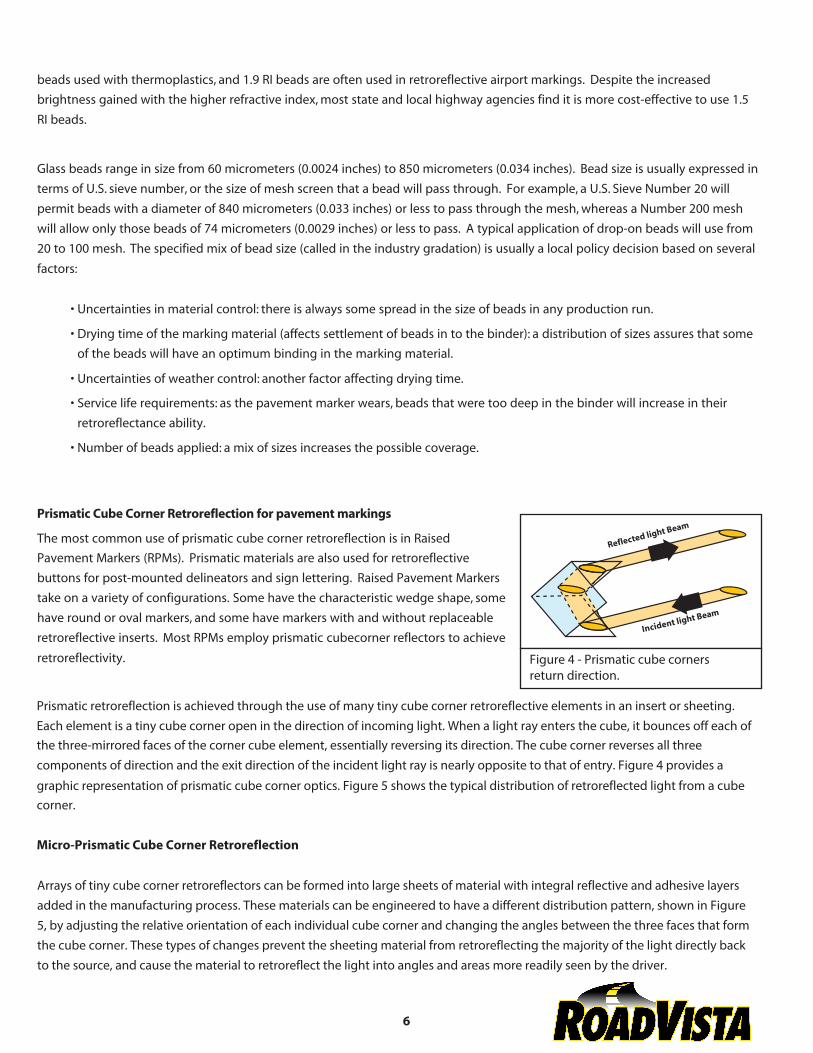
Prismatic retroreflection is achieved through the use of many tiny cube corner retroreflective elements in an insert or sheeting. Each element is a tiny cube corner open in the direction of incoming light. When a light ray enters the cube, it bounces off each of the three-mirrored faces of the corner cube element, essentially reversing its direction. The cube corner reverses all three components of direction and the exit direction of the incident light ray is nearly opposite to that of entry. Figure 4 provides a
graphic representation of prismatic cube corner optics. Figure 5 shows the typical distribution of retroreflected light from a cube corner.
Micro-Prismatic Cube Corner Retroreflection
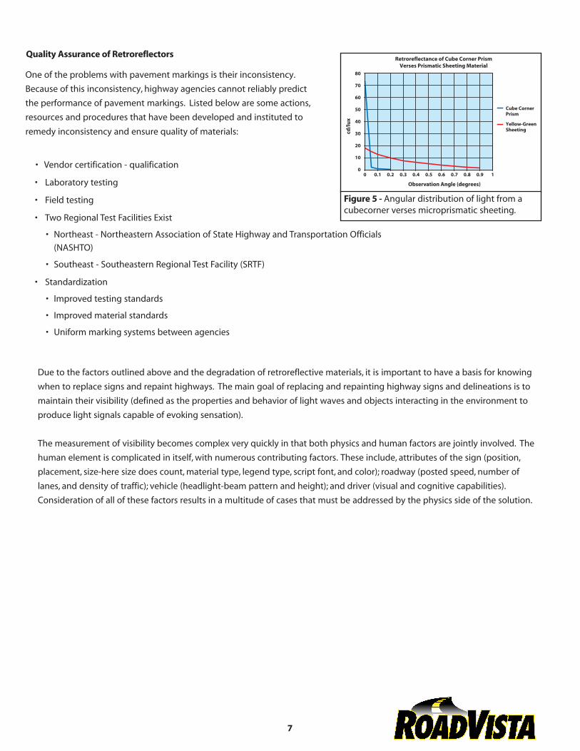
Arrays of tiny cube corner retroreflectors can be formed into large sheets of material with integral reflective and adhesive layers added in the manufacturing process. These materials can be engineered to have a different distribution pattern, shown in Figure 5, by adjusting the relative orientation of each individual cube corner and changing the angles between the three faces that form the cube corner. These types of changes prevent the sheeting material from retroreflecting the majority of the light directly back to the source, and cause the material to retroreflect the light into angles and areas more readily seen by the driver.
Figure 4 - Prismatic cube corners return direction.
Quality Assurance of Retroreflectors
One of the problems with pavement markings is their inconsistency. Because of this inconsistency, highway agencies cannot reliably predict
the performance of pavement markings. Listed below are some actions, resources and procedures that have been developed and instituted to
remedy inconsistency and ensure quality of materials:
• Vendor certification - qualification
• Laboratory testing
• Field testing
• Two Regional Test Facilities Exist
• Northeast - Northeastern Association of State Highway and Transportation Officials
(NASHTO)
• Southeast - Southeastern Regional Test Facility (SRTF)
• Standardization
• Improved testing standards
• Improved material standards
• Uniform marking systems between agencies
Due to the factors outlined above and the degradation of retroreflective materials, it is important to have a basis for knowing
when to replace signs and repaint highways. The main goal of replacing and repainting highway signs and delineations is to
maintain their visibility (defined as the properties and behavior of light waves and objects interacting in the environment to
produce light signals capable of evoking sensation).
The measurement of visibility becomes complex very quickly in that both physics and human factors are jointly involved. The
human element is complicated in itself, with numerous contributing factors. These include, attributes of the sign (position, placement, size-here size does count, material type, legend type, script font, and color); roadway (posted speed, number of
lanes, and density of traffic); vehicle (headlight-beam pattern and height); and driver (visual and cognitive capabilities). Consideration of all of these factors results in a multitude of cases that must be addressed by the physics side of the solution.
7
Figure 5 - Angular distribution of light from acubecorner verses microprismatic sheeting.
Measuring Retroreflection
It seems intuitively correct to measure retroreflection as a ratio of the intensity of light returned in the direction of the driver to
the intensity of their car's headlights. This ratio would give a scale for retroreflection that consisted of a similitude (dimensionless
number) between 0 and 1. Unfortunately there are practical problems with this approach. In addition, there must be a system of
units to define light flux, intensity and other optical quantities.
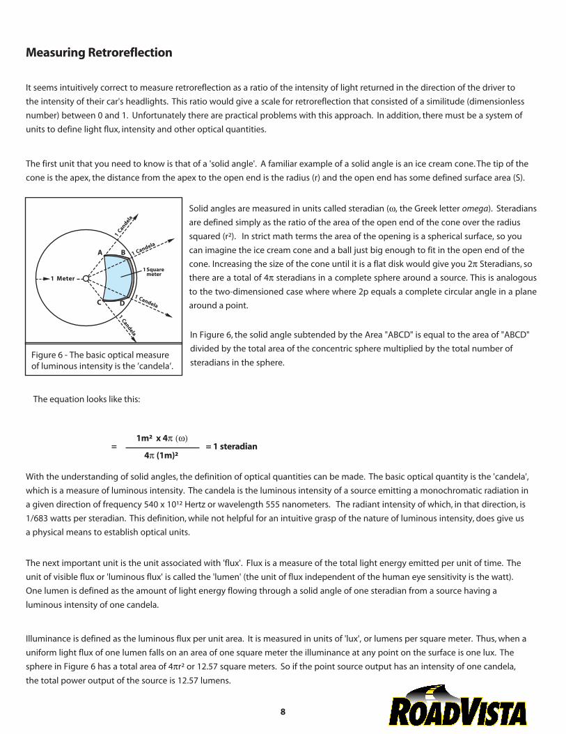
The first unit that you need to know is that of a 'solid angle'. A familiar example of a solid angle is an ice cream cone. The tip of the
cone is the apex, the distance from the apex to the open end is the radius (r) and the open end has some defined surface area (S).
1m² x 4p (w)
4p (1m)²
With the understanding of solid angles, the definition of optical quantities can be made. The basic optical quantity is the 'candela', which is a measure of luminous intensity. The candela is the luminous intensity of a source emitting a monochromatic radiation in
a given direction of frequency 540 x 10¹² Hertz or wavelength 555 nanometers. The radiant intensity of which, in that direction, is
1/683 watts per steradian. This definition, while not helpful for an intuitive grasp of the nature of luminous intensity, does give us
a physical means to establish optical units.
The next important unit is the unit associated with 'flux'. Flux is a measure of the total light energy emitted per unit of time. The
unit of visible flux or 'luminous flux' is called the 'lumen' (the unit of flux independent of the human eye sensitivity is the watt). One lumen is defined as the amount of light energy flowing through a solid angle of one steradian from a source having a
luminous intensity of one candela.
Illuminance is defined as the luminous flux per unit area. It is measured in units of 'lux', or lumens per square meter. Thus, when a
uniform light flux of one lumen falls on an area of one square meter the illuminance at any point on the surface is one lux. The
sphere in Figure 6 has a total area of 4pr² or 12.57 square meters. So if the point source output has an intensity of one candela, the total power output of the source is 12.57 lumens.
8
Solid angles are measured in units called steradian (w, the Greek letter omega). Steradians
are defined simply as the ratio of the area of the open end of the cone over the radius
squared (r²). In strict math terms the area of the opening is a spherical surface, so you
can imagine the ice cream cone and a ball just big enough to fit in the open end of the
cone. Increasing the size of the cone until it is a flat disk would give you 2p Steradians, so
there are a total of 4p steradians in a complete sphere around a source. This is analogous
to the two-dimensioned case where where 2p equals a complete circular angle in a plane around a point.
In Figure 6, the solid angle subtended by the Area "ABCD" is equal to the area of "ABCD"
divided by the total area of the concentric sphere multiplied by the total number of
steradians in the sphere.
= 1 steradian=
Figure 6 - The basic optical measure of luminous intensity is the ’candela’.
The equation looks like this:
The next terms to work with are intensity and illuminance. Intensity measures the flux of a source in a given direction. Illuminance
measures the flux density of light on a surface that is illuminated. These are not the same because the emitted light spreads out
over a larger and larger region as it radiates through space. The intensity remains constant since the same amount of flux fills the
same angular cone, but because the light is spread out with distance over a larger and larger region of space, illuminance gets
smaller as the distance to the illuminated surface increases. For a spatially uniform point source the illuminance decreases proportionately to the square of the distance from the source.
Candelas and lumens are identical in the metric and English measurement systems. Illuminance, however, is measured with units
of lumens per square foot rather that per square meter. One lumen per square foot is a foot-candle and one foot-candle equals
10.76 lux (lumens per square meter).
Measurement of Roadway Markings
Coefficient of Retroreflected Luminance (RL ) is the most commonly used measurement of retroreflectance in highway marking. RL
is the ratio of the luminance (L) of a surface to the normal illuminance (E) on the surface. In the laboratory this definition works
well with testing procedures.
In the applied world of roadway marker measurements, life is not so simple. In this situation RL translates into measuring the
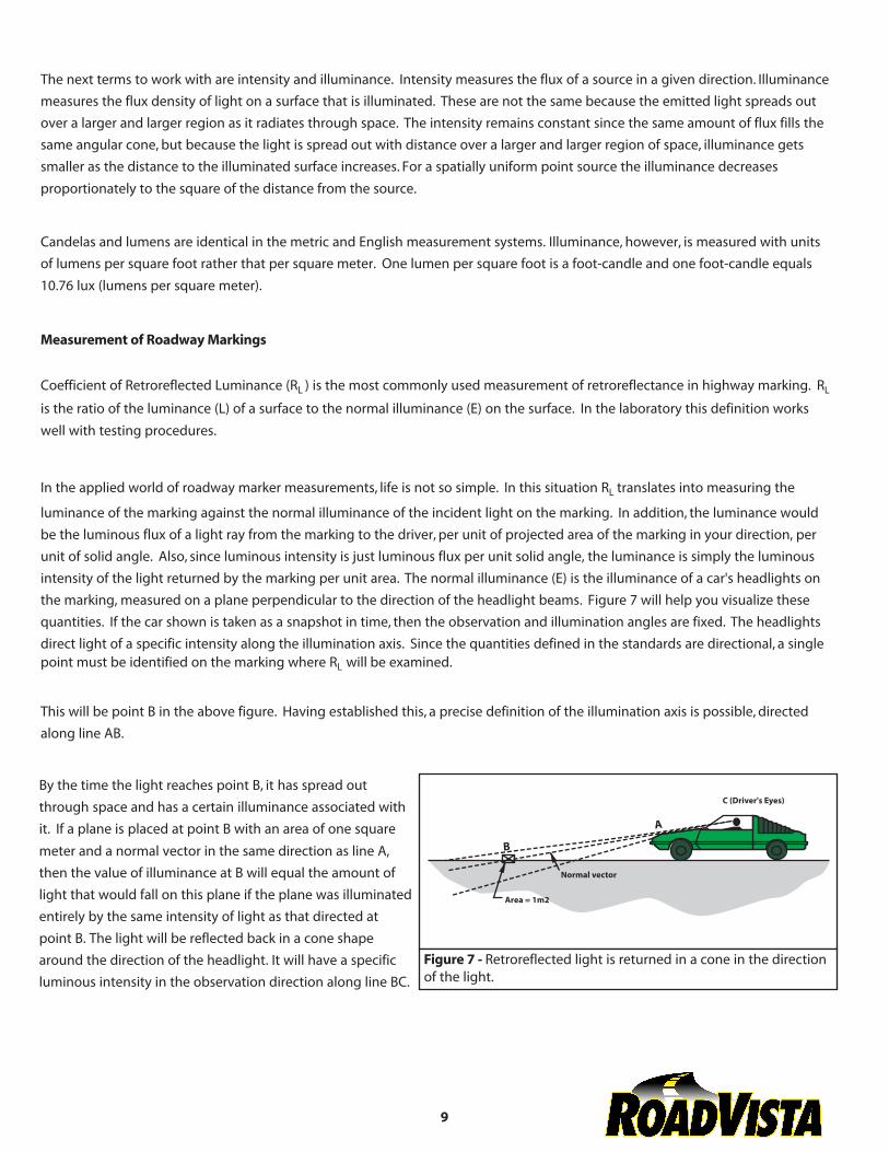
luminance of the marking against the normal illuminance of the incident light on the marking. In addition, the luminance would be the luminous flux of a light ray from the marking to the driver, per unit of projected area of the marking in your direction, per unit of solid angle. Also, since luminous intensity is just luminous flux per unit solid angle, the luminance is simply the luminous intensity of the light returned by the marking per unit area. The normal illuminance (E) is the illuminance of a car's headlights on the marking, measured on a plane perpendicular to the direction of the headlight beams. Figure 7 will help you visualize these quantities. If the car shown is taken as a snapshot in time, then the observation and illumination angles are fixed. The headlights direct light of a specific intensity along the illumination axis. Since the quantities defined in the standards are directional, a single point must be identified on the marking where RL will be examined.
This will be point B in the above figure. Having established this, a precise definition of the illumination axis is possible, directed along line AB.
By the time the light reaches point B, it has spread out through space and has a certain illuminance associated with
it. If a plane is placed at point B with an area of one square
meter and a normal vector in the same direction as line A, then the value of illuminance at B will equal the amount of light that would fall on this plane if the plane was illuminated entirely by the same intensity of light as that directed at point B. The light will be reflected back in a cone shape around the direction of the headlight. It will have a specific luminous intensity in the observation direction along line BC.
9
Figure 7 - Retroreflected light is returned in a cone in the directionof the light.
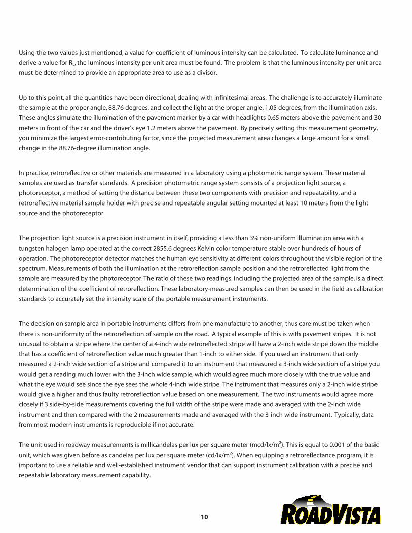
Using the two values just mentioned, a value for coefficient of luminous intensity can be calculated. To calculate luminance and
derive a value for RL, the luminous intensity per unit area must be found. The problem is that the luminous intensity per unit area
must be determined to provide an appropriate area to use as a divisor.
Up to this point, all the quantities have been directional, dealing with infinitesimal areas. The challenge is to accurately illuminate
the sample at the proper angle, 88.76 degrees, and collect the light at the proper angle, 1.05 degrees, from the illumination axis. These angles simulate the illumination of the pavement marker by a car with headlights 0.65 meters above the pavement and 30 meters in front of the car and the driver's eye 1.2 meters above the pavement. By precisely setting this measurement geometry, you minimize the largest error-contributing factor, since the projected measurement area changes a large amount for a small
change in the 88.76-degree illumination angle.
In practice, retroreflective or other materials are measured in a laboratory using a photometric range system. These material
samples are used as transfer standards. A precision photometric range system consists of a projection light source, a
photoreceptor, a method of setting the distance between these two components with precision and repeatability, and a retroreflective material sample holder with precise and repeatable angular setting mounted at least 10 meters from the light
source and the photoreceptor.
The projection light source is a precision instrument in itself, providing a less than 3% non-uniform illumination area with a tungsten halogen lamp operated at the correct 2855.6 degrees Kelvin color temperature stable over hundreds of hours of
operation. The photoreceptor detector matches the human eye sensitivity at different colors throughout the visible region of the
spectrum. Measurements of both the illumination at the retroreflection sample position and the retroreflected light from the
sample are measured by the photoreceptor. The ratio of these two readings, including the projected area of the sample, is a direct
determination of the coefficient of retroreflection. These laboratory-measured samples can then be used in the field as calibration
standards to accurately set the intensity scale of the portable measurement instruments.
The decision on sample area in portable instruments differs from one manufacture to another, thus care must be taken when
there is non-uniformity of the retroreflection of sample on the road. A typical example of this is with pavement stripes. It is not
unusual to obtain a stripe where the center of a 4-inch wide retroreflected stripe will have a 2-inch wide stripe down the middle
that has a coefficient of retroreflection value much greater than 1-inch to either side. If you used an instrument that only
measured a 2-inch wide section of a stripe and compared it to an instrument that measured a 3-inch wide section of a stripe you
would get a reading much lower with the 3-inch wide sample, which would agree much more closely with the true value and
what the eye would see since the eye sees the whole 4-inch wide stripe. The instrument that measures only a 2-inch wide stripe
would give a higher and thus faulty retroreflection value based on one measurement. The two instruments would agree more closely if 3 side-by-side measurements covering the full width of the stripe were made and averaged with the 2-inch wide
instrument and then compared with the 2 measurements made and averaged with the 3-inch wide instrument. Typically, data
from most modern instruments is reproducible if not accurate.
The unit used in roadway measurements is millicandelas per lux per square meter (mcd/lx/m²). This is equal to 0.001 of the basic unit, which was given before as candelas per lux per square meter (cd/lx/m²). When equipping a retroreflectance program, it is important to use a reliable and well-established instrument vendor that can support instrument calibration with a precise and repeatable laboratory measurement capability.
10

Measurement of Road Signs
The standard used for signs is the Coefficient of Retroreflection (RA). A description of this can be found in ASTM Standard
E808. It is defined as the ratio of the coefficient of luminous intensity, RI , of a plane retroreflecting surface to its area. The metric
unit for RA is candelas per lux per square meter (cd/lx/m²).
The coefficient of luminous intensity is the ratio of the luminous intensity of the retroreflector in the direction of observation, Eˆ, to
the illuminance at the retroreflector on a plane perpendicular to the direction of the incident light. After taking into account all of
the units and other considerations, RA is conceptually identical to the coefficient of retroreflected luminance but simpler to implement for signs. One must note that the English units for RA (candelas per foot-candle per square foot) are often used. It is
also often referred to as Specific Intensity per unit Area (SIA) in older documents and specifications; use of this term should be discouraged.
RA is still a ratio of returned intensity to incident illumination divided by the area of the retroreflector. Signs make the
measurement of these quantities simpler because they have a fixed area. In addition, the measured geometry is arranged so that
the plane of the sign is perpendicular to car headlights, thus the area does not change as fast as angles near horizontal. This
makes the measurement much simpler and more accurate.
Practical Applications of Retroreflectometers
Laboratory measurement of retroreflective materials is accomplished using tightly controlled procedures. These procedures are
defined and controlled by the American Society for Testing of Materials (ASTM). The ASTM procedures for laboratory
measurements require the use of a tungsten lamp operated at a correlated color temperature of 2855.6 degrees Kelvin.
The spectral power distribution of a tungsten lamp operated at this color temperature approaches the ideal CIE (the international
standards generating organization for illumination and color) Illuminant A, which is an internationally agreed upon standard type
of illumination used for comparison and specification of colors. The photoreceptor used to measure the illuminated retroreflective surfaces must match the CIE 1931 human eye response function within a tolerance of 3% defined by the f1' (f-one-
prime) analysis method given in CIE publication 69. The CIE 1931 human eye response function is also called the photopic
response, photometric response function or the Y-bar function.
This level of precision in the measurement instruments yields a precision and bias of about 6% between well-maintained and well-
staffed laboratories. It is not practical to apply these very rigorous standards in the field. ASTM has developed standard
procedures that provide for the use of portable instrumentation for measurement of retroreflective materials in the field. These
standard procedures allow the use of illumination sources quite different than those used in the laboratory. The procedures allow compensating the detector response by the amount the light source deviates from 2855.6 degrees Kelvin. Field measurements
and laboratory measurements taken over many years
11
• Accuracy - this is the bottom line for measurements. If they aren't accurate, they tell nothing, so don't take them.
12
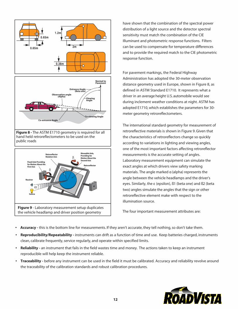
Figure 8 - The ASTM E1710 geometry is required for allhand held retroreflectometers to be used on the public roads
have shown that the combination of the spectral power
distribution of a light source and the detector spectral sensitivity must match the combination of the CIE Illuminant and photometric response functions. Filters
can be used to compensate for temperature differences
and to provide the required match to the CIE photometric
response function.
For pavement markings, the Federal Highway Administration has adopted the 30-meter observation
distance geometry used in Europe, shown in Figure 8, as
defined in ASTM Standard E1710. It represents what a
driver in an average height U.S. automobile would see
during inclement weather conditions at night. ASTM has
adopted E1710, which establishes the parameters for 30-
meter geometry retroreflectometers.
The international standard geometry for measurement of retroreflective materials is shown in Figure 9. Given that
the characteristics of retroreflectors change so quickly
according to variations in lighting and viewing angles, one of the most important factors affecting retroreflector measurements is the accurate setting of angles. Laboratory measurement equipment can simulate the exact angles at which drivers view safety marking materials. The angle marked α (alpha) represents the
angle between the vehicle headlamps and the driver's eyes. Similarly, the ε (epsilon), ß1 (beta one) and ß2 (beta
two) angles simulate the angles that the sign or other retroreflective element make with respect to the illumination source.
The four important measurement attributes are:Figure 9 - Laboratory measurement setup duplicates the vehicle headlamp and driver position geometry
• Reproducibility/Repeatability - instruments can drift as a function of time and use. Keep batteries charged, instruments
clean, calibrate frequently, service regularly, and operate within specified limits.
• Reliability - an instrument that fails in the field wastes time and money. The actions taken to keep an instrument
reproducible will help keep the instrument reliable.
• Traceability - before any instrument can be used in the field it must be calibrated. Accuracy and reliability revolve around
the traceability of the calibration standards and robust calibration procedures.

Types of field instruments include:
• Pavement marking retroreflectometers - this tool is used for measuring pavement-marking retroreflectivity. It measures or
determines how bright the markings appear at night to motorists. There are two types:
• Handheld - employed widely in field to spot-check the condition of selected retroreflective pavement markings.
• Mobile equipment - takes continuous retroreflective readings while driving down the road at highway speeds
• Sign retroreflectometers - this tool is used for measuring sign retroreflectivity. It determines if the sign meets nighttime
retroreflectivity requirements. There are two types:
• Handheld - this is an instrument capable of accurately and reliably measuring the retroreflection properties of road signs
and retroreflective sheeting materials.
• Mobile - mobile sign retroreflectometers are in the development stage and are not yet commercialized.
• Raised Pavement Marker (RPM) retroreflectometers - this tool measures the retroreflectance of these important roadway
delineators in their regular and snowplowable mounting configurations.
Learn from the experts
For over three decades Gamma Scientific and Advanced Retro Technology developed innovative products to measure
retroreflective materials. The companies forged their leadership position in cooperation with the Federal Highway
Administration and through active membership in ASTM, ASHTO, ITE and other organizations associated with the measurement
of retroreflective materials.
Today the consolidated product lines of both companies are sold under a new name, RoadVista. The unique union of precision
laboratory measurements, design expertise, manufacturing capability and commitment to highway safety places RoadVista as
the premier supplier of retroreflective measurement equipment. We manufacture and distribute the only complete line of
retroreflectometers on the market today.
13
14
Minimum Sign Retroreflectivity Guidelines
The United Stated Department of Transportation Federal Highway Administration funded research to determine what level of sign
sheeting retroreflectivity provides adequate visibility. As with all studies involving subjective assessments of what was considered
"adequate visibility", this study showed a statistical distribution of the responses of the people participating in the study.
Research teams used a three-stage model known as CARTS (Computerized Analysis Retroreflective Traffic Sign) to help develop the
Minimum Sign Retroreflectivity Guidelines. In the first stage, CARTS calculates the shortest distance at which a sign must be visible
enough to enable the driver to respond safely and appropriately. This distance is called the Minimum Required Visibility Distance
(MRVD).
The second stage determines the sign luminance required at the MRVD. This determination uses DETECT, a visibility model. This
model is based on contrast threshold data; it calculates the luminance needed for a driver to detect and recognize a specified sign
at a specified distance. In the third and final stage, the CARTS model converts the calculated sign luminance to an equivalent
retroreflectivity value at a standard measurement geometry. This stage takes into account the characteristics of the sheeting
material type and headlight-beam pattern and does not involve the human factors considerations.
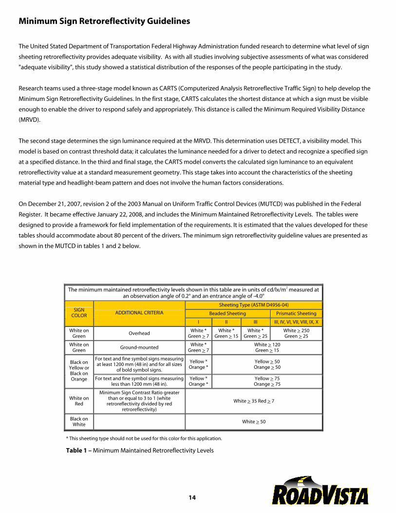
On December 21, 2007, revision 2 of the 2003 Manual on Uniform Traffic Control Devices (MUTCD) was published in the Federal
Register. It became effective January 22, 2008, and includes the Minimum Maintained Retroreflectivity Levels. The tables were
designed to provide a framework for field implementation of the requirements. It is estimated that the values developed for these
tables should accommodate about 80 percent of the drivers. The minimum sign retroreflectivity guideline values are presented as
shown in the MUTCD in tables 1 and 2 below.
The minimum maintained retroreflectivity levels shown in this table are in units of cd/lx/m2 measured at an observation angle of 0.2° and an entrance angle of -4.0°
Sheeting Type (ASTM D4956-04)
Beaded Sheeting Prismatic Sheeting SIGN
COLOR ADDITIONAL CRITERIA
I II III III, IV, VI, VII, VIII, IX, X
White on Green
Overhead White *
Green > 7 White *
Green > 15 White *
Green > 25 White > 250 Green > 25
White on Green
Ground-mounted White *
Green > 7 White > 120 Green > 15
For text and fine symbol signs measuring at least 1200 mm (48 in) and for all sizes
of bold symbol signs.
Yellow * Orange *
Yellow > 50 Orange > 50
Black on Yellow or Black on Orange For text and fine symbol signs measuring
less than 1200 mm (48 in). Yellow * Orange *
Yellow > 75 Orange > 75
White on Red
Minimum Sign Contrast Ratio greater than or equal to 3 to 1 (white
retroreflectivity divided by red retroreflectivity)
White > 35 Red > 7
Black on White
White > 50
* This sheeting type should not be used for this color for this application.
Table 1 – Minimum Maintained Retroreflectivity Levels
15
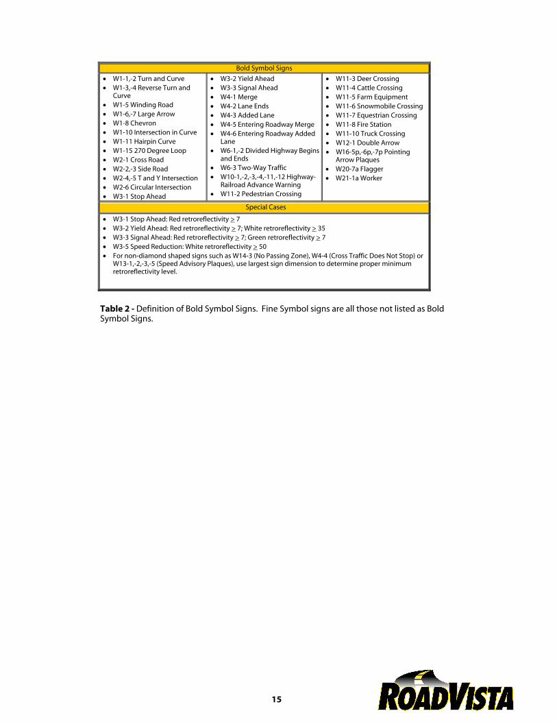
Bold Symbol Signs
• W1-1,-2 Turn and Curve • W1-3,-4 Reverse Turn and
Curve • W1-5 Winding Road • W1-6,-7 Large Arrow • W1-8 Chevron • W1-10 Intersection in Curve • W1-11 Hairpin Curve • W1-15 270 Degree Loop • W2-1 Cross Road • W2-2,-3 Side Road • W2-4,-5 T and Y Intersection • W2-6 Circular Intersection• W3-1 Stop Ahead
• W3-2 Yield Ahead • W3-3 Signal Ahead • W4-1 Merge • W4-2 Lane Ends • W4-3 Added Lane• W4-5 Entering Roadway Merge • W4-6 Entering Roadway Added
Lane • W6-1,-2 Divided Highway Begins
and Ends • W6-3 Two-Way Traffic • W10-1,-2,-3,-4,-11,-12 Highway-
Railroad Advance Warning • W11-2 Pedestrian Crossing
• W11-3 Deer Crossing • W11-4 Cattle Crossing • W11-5 Farm Equipment • W11-6 Snowmobile Crossing • W11-7 Equestrian Crossing • W11-8 Fire Station• W11-10 Truck Crossing • W12-1 Double Arrow • W16-5p,-6p,-7p Pointing
Arrow Plaques• W20-7a Flagger • W21-1a Worker
Special Cases
• W3-1 Stop Ahead: Red retroreflectivity > 7• W3-2 Yield Ahead: Red retroreflectivity > 7; White retroreflectivity > 35 • W3-3 Signal Ahead: Red retroreflectivity > 7; Green retroreflectivity > 7 • W3-5 Speed Reduction: White retroreflectivity > 50 • For non-diamond shaped signs such as W14-3 (No Passing Zone), W4-4 (Cross Traffic Does Not Stop) or
W13-1,-2,-3,-5 (Speed Advisory Plaques), use largest sign dimension to determine proper minimumretroreflectivity level.
Table 2 - Definition of Bold Symbol Signs. Fine Symbol signs are all those not listed as Bold Symbol Signs.
Recommended minimum performance of newly installed pavement marking materials.In May 1999, Jonathan Dan Turner gave a presentation at the annual conference of the Council of Optical Radiation Measurement
(CORM) in Gaitherburg, Maryland. In his presentation Mr. Turner outlined the Federal Highway Administration recommendations
for minimum values for retroreflectance of newly installed pavement markings.
Section 406(a) of the 1993 Department of Transportation Appropriation Act required the Secretary of Transportation to revise the Manual on Uniform Traffic Control Devices to include a standard for a minimum level of retroflectivity that must be maintained for traffic signs and pavement markings. The Federal Highway Administration (FHWA) R&D made recommendations for proposed levels of retroreflectivity for signs in 1994, and recommendations for levels of retroreflectivity for pavement markings was recently submitted to the FHWA policymakers.
Two FHWA sponsored studies were conducted to address the issue of pavement marking retroreflectivity. The first study entitled "Evaluation of All-Weather Pavement Markings" was an effort designed to assess the current state of pavement markings in the U.S. and to determine the impact of recommended retroreflectivity values. Graham-Migletz Enterprises submitted a draft report in February 1998 entitled, "Field Surveys of Pavement Marking Retroreflectivity."
The final report dated October 2000 summarizes an exhaustive field survey conducted in 21 states. Over a span of nearly four
years, about 2,660,000 individual measurements were made with a vehicle mounted Laserlux retroreflectometer. The average
level of retroreflectivity in the fall of 1994 was 170.4 mcd/m²/lux with standard deviation of 123.6. The retroreflectivity readings
were found to be 15-24% less in the spring than in the fall.
The second study entitled "Enhancements to the CARVE Computer Model for Pavement Marking Visibility" was an effort aimed at determining the amount of retroreflectivity required to support adequate driver performance. Ohio University's Helmut Zwahlen has finalized his pavement marking visibility model, CARVE (Computer Aided Road-Marking Visibility Evaluator), which predicts visibility requirements for various pavement marking types for measurements at 30 m. The underlying assumptions of the model were tested using an eye-scanning study, and the model was calibrated with a series of end detection field experiments. The research recommended a retroreflectivity level of 170 mcd/m²/lux at 55mph and 340 mcd/m²/lux at 65 mph. These values would accommodate both young and old drivers.
A report that included an overview of supporting research and a recommendation for minimum pavement marking
retroreflectivity was presented to FHWA's Office of Highway Safety on December 2, 1998. The supporting research and
recommendations were presented at three workshops across the United States in 1999. As with the sign retroreflectivity workshops, the input of the workshop participants will be considered in the final recommendation leading to rulemaking. A
summary report generated by Hawkins Engineering describes the concerns raised at the workshops.
ASTM Standards Dealing With Retroreflection
E 808 Practice for Describing Retroreflectivity
E 809 Practice for Describing Measuring Photometric Characteristics of
Retroreflectometers
E 810 Test Method for Coefficients of Retroreflection for Retroreflective Sheeting
D 4061 Test Method for Retroreflectance of Horizontal Coatings
E 811 Practice for Measuring Colorimetric Characteristics of Retroreflectometers Under
Night Time Conditions
E 1896 Specifications for Daytime Pedestrian Visibility Enhancement
18
E 1709 Test Method for Measurement of Retroreflective Signs Using a Portable Retroreflectometer
E 1809 Test Method for Measurement of High-Visibility Retroreflective-Clothing Marking Material Using a
Portable Retroreflectometer
E 1696 Test Method for Field Measurement of Raised Retroreflective Pavement Markers Using a Portable
Retroreflectometer
E 1743 Practice for Selection and Use of Portable Retroreflectometers for Pavement Marking Measurement
E1710 Test Method for Measurement of Retroreflective Pavement Marking Materials with CEN-Prescribed
Geometry Using a Portable Retroreflectometer
D 4280 Specification for Extended Life-Type, Nonplowable, Prismatic, Raised Retroreflective Pavement Markers
D 4383 Specification for Plowable, Raised, Retroreflective Pavement Markers
D 4505 Specification for Preformed Plastic Pavement Marking Tape of Extended Service Life
D 4592 Specification for Preformed Plastic Pavement Marking Tape of Limited Service Life
D 4956 Specification for Retroreflective Sheeting for Traffic Control
E 1501 Specification for Nighttime Photometric Performance of Retroreflective Pedestrian Markings for Visibility
Enhancement
D 6359 Specifications for Minimum Retroreflectance of Newly Applied Pavement Marking Using Portable hand-
Operated Instruments
F 923 Guide to Properties of High Visibility Materials Used to Improve Individual Safety
References on Light and Color Measurements of Traffic SafetyMaterials
1. Handbook of Applied Photometry, American Institute of Physics, AIP Press, ISBN 1-56396-416-3
2. Minimum Retroreflectivity Requirements for Traffic Signs, FHWA-RD-93-077
3. Service Life of Retroreflective Traffic Signs, FHWA-RD-90-101
4. Implementation Strategies for Sign Retroreflectivity Standards, NCHRP #346
5. An Implementation Guide for Minimum Retroreflectivity Requirements for Traffic Signs, FHWA-RD-97-052
6. Impacts on State and Local Agencies for Maintaining Traffic Signs within Minimum Retroreflectivity Guidelines, FHWA-
RD-97-053
7. CIE Publication:
#39: Surface Colors for Visual Signaling
#54: Retroreflection: Definitions and Measurements (revision 54.2 undergoing voting) #72: Guide to the Properties and Uses of
Retroreflectors at Night
#73: Visual Aspects of Road Markings
#74: Road Signs
#100: Fundamentals of Night Driving
#107: Colors of Signal Lights
19
#113: Maintained Night-time Visibility of Retroreflective Road Signs
#115: Recommendation for the Lighting of Roads for Motor and Pedestrian Traffic
Bibliography
1) Austin, Richard L, "A Description of the MX30 Illumination and Detector Functions", Gamma Scientific, March 23, 2000
2) Rennilson, J.J. "Retroreflection Measurements: a review" in Applied Optics Volume 19, No. 8, April 15, 1980
3) Hawkins, Gene, et al., "Impact of Minimum Retroreflectivity Values on Sign Replacement Practices", Texas Transportation
Institute, Texas A&M University, October 1996
4) Lagergren, Edwin, "Traffic Sign Retroreflectivity Measurements Using Human Observers", December 1987
5) U.S. Department of Transportation, "Manual on Uniform Traffic Control Devices", U.S. Government Printing Office, Washington
DC, 1988
6) U.S. Department of Transportation, "Summary Report - Minimum, Sign Retroreflective Guidelines", Publication No. FHWA-
RD-97-074, June 1997
7) U.S. Department of Transportation, "Roadway Delineation Practices Handbook", Publication No. FHWA-SA-93-001, August 1994
8) "Uniform Vehicle Code and Model Traffic Ordinance", National Committee on Uniform Traffic Laws and Ordinances
9) U.S. Department of Transportation, "Standard Highway Signs Book", Stock No. 950-044-00000-4
10) Federal Test Method Standard 370, "Instrumental Photometric Measurements of Retroreflective Materials and Retroreflective
Devices", General Services Administration, March 1977
11) Hatzi, Peter, "TE-29 Retroreflectivity", Power Point Presentation, FHWA - Office of Technology Applications
12) Hatzi, Peter, "Retroreflectivity: Raising the Nighttime Brightness of Traffic Sign and Markings", Power Point Presentation, FHWA
- Office of Technology Applications
13) "Sign Retroreflectometers, How Do They Work?" Power Point Presentation, FHWA
14) Nelson, Eric J. and Austin, Richard L., "Comparison of Spectral Measurement Systems for Retroreflectance Color", Power Point
Presentation, Council of Optical Radiation Measurements (CORM) Annual Conference May 1999, Gaithersburg, Maryland
15) Turner, J. Dan, "Update on Pavement Marking Retroreflectivity Research and Recommendations Leading to Rulemaking",
Power Point Presentation, Council of Optical Radiation Measurements (CORM) Annual Conference May 1999, Gaithersburg,
Maryland
16) Austin, Richard L., "A Short Look at a Long History of Retroreflection Measurement", Power Point Presentation, Gamma
Scientific, February 2000
17) Migletz, J. and Harwood, D. W. et al, "Field Surveys of Pavement Marking Retroreflectivity", U.S. Department of Transportation,
Federal Highway Administration, April 2000
20
RETROREFLECTION GLOSSARY OF TERMS
Abrasion: A condition manifested in highway markings by more or less gradual surface erosion, thinning, and degradation due to
wind, water, sand and/or vehicle tire ware.
Applied Lines: Pavement marking material in place on the substrate.
Binder: In painted markings, the binder is the hard base material that is left on the road after the solvent has evaporated. Common paint binders are alkyd resins and chlorinated rubber materials. In thermoplastic markings, the binder is the actual
thermo-plastic material that melts when heated and hardens into the film that is left on the road. Binders are also often referred
to as the base material or base vehicle.
Bisymmetric: Having double symmetry, i.e. in floating bead context it means that the bead surface embedded in the paint is
symmetrical with the exposed surface.
Brightness: The quality of radiating or reflecting light. The continuous visual ordering from light to dark which is correlated to
light intensity. This term refers to human perception of luminance. Whereas luminance is a photometrically measured quantity, brightness describes how intense a light source or lighted surface appears to the human eye. Brightness of most retroreflective
materials is maximum when the observation angle is zero.
Candela: The basic unit for optical quantities in the visible, the candela is a measure of luminous intensity. One candela is
defined as the luminous intensity in a given direction of a source emitting a monochromatic radiation of frequency 540 x 10¹²
Hertz, the radiant intensity of which in that direction is 1683 watts per steradian.
CIE, Commission Internationale de l'Ecairage: the International Commission on Illumination is the worldwide organization of
experts in light and color perception and measurements. The CIE is responsible for the generation of standards in Illumination
and Color used world wide and adopted as ISO (International Standards Organization) standards.
CIE Illuminant A or CIE Standard Illuminant A: The ideal colorimetric illuminant, representing a full blackbody radiator at 2855.6
degrees Kelvin, defined by the CIE in terms of a relative spectral power distribution, normalized to 100 at 560 nanometers.
CIE Illuminant A Standard Source: A gas-filled tungsten filament lamp operated at a correlated color temperature of 2855.6
degrees Kelvin.
Coefficient of Line Retroreflection - (Rm) of a retroreflection stripe: The ratio of the coefficient of luminous intensity (RI) of a
retroreflecting stripe to its length expressed in candelas per lux per meter.
Coefficient of Luminous Intensity (RI): The ratio of the luminous intensity (I) of a retroreflector in the direction of observation to
the illuminance E at the retroreflector on a plane perpendicular to the direction of the incident light, expressed in candelas per
lux. Also called coefficient of (retroreflected) luminous intensity.
Coefficient of Retroreflected Luminance (RL): A measure of retroreflection most often used to describe the retroreflectivity of
pavement markings. Coefficient of retroreflected luminance is the ratio of the luminance of a projected surface of retroreflective
material to the normal illuminance at the surface on a plane normal to the incident light. It is expressed in candelas per square
meter per lux.
Coefficient of (Retroreflected) Luminous Flux, R: The ratio of the flux per unit solid angle coming from the retroreflector
measured at the observation point to the total flux incident on the effective retroreflective surface. It is expressed in candelas per
lumen.
21

Coefficient of Retroreflection (RA): A measure of retroreflection used often to refer to the retroreflectivity of highway signs. Coefficient of retroreflection is defined as the ratio of the
coefficient of luminous intensity (R1) of a plane retroreflecting surface to its area (A), expressed in candelas per lux per square
meter.
Conspicuity: A measure of the likelihood that a driver will notice a certain target at a given distance against a certain
background.
Contrast: The ratio of luminance from a target to the luminance from the target's surroundings.
Cooperative Target: A target that is designed to reflect light to the detector of a sensor. Cooperative targets include glass
corner cube retroreflectors and retroreflective tape made by several manufactures. In some applications mirrors may be used
as cooperative targets.
Corner Cube: Three mutually perpendicular plane surfaces brought together to form the corner of a cube. A light ray striking
one of these three planes will reflect off of the other two planes and the final reflected ray direction is in the opposite direction
of the original ray direction.
Co-viewing Angle: The complement of the entrance angle.
Datum Mark: An indication on the retroreflector that is used to define the orientation of the retroreflector with respect to
rotation about the retroreflector axis.
Depth of Field: The span of distances over which a sensor can accurately measure. This is limited by the focal length and the
diameter of the light collection optics. These two factors will determine how the sensor's sensitivity changes with distance.
Detector Spectral Response: The sensitivity of a detector at each wavelength throughout the range of wavelengths where it
has sensitivity.
Diffuse Reflection: When light strikes a target and is scattered over a wide angle. Plain white paper or flat (not glossy) wall
paint are good diffuse materials. Diffuse targets are the best uncooperative targets, and may be measured to over a wide
range of incident angles (up to 80 degrees for some materials).
Durability: A measure of traffic lines' resistance to the wear and deterioration associated with abrasion and chipping. For
standard methods of evaluation of durability, refer to the ASTM Bulletins D913 for Chipping and D821 for Abrasion (erosion).
Entrance Angle (or Incidence angle): The angle between the light source to a point on the retroreflector and a line normal
(perpendicular, forming a 90-degree angle) with the retroreflector surface. Defined by b1 (beta one) and b2 (beta two) in the
CIE system of geometry.
European Geometry (for sign sheeting material): Entrance angle (b1) -5 degrees, observation angle (a) 0.33 degrees.
European 30-meter Geometry: Represents what a driver from an average U.S. automobile height would see during
inclement weather conditions at night. This is also called the "30 meter observation distance geometry". The Federal Highway
Administration (FHWA) and American Society for Testing of Materials (ASTM) have adopted this geometry as the standard for
measuring retroreflection of pavement markings.
First Axis: The axis through the retroreflector center and perpendicular to the observation half-plane.
22
Floatation Bead: A retroreflective glass bead coated with a special chemical substance so that it will float to half of its diameter in
a pavement marking.
Foot-candle: The English system's unit of illuminance, one foot-candle is the illuminance on a surface that is everywhere one foot
from a uniform point source of light of one candle and equal to one lumen per square foot. One foot-candle equals 10.76 lux
(lumen per square meter).
Fractional Retroreflectance, RT: The fraction of unidirectional flux illuminating a retroreflector that is received at observation
angles less than designated value, max.
Glass Beads: Spheres used in conjunction with binder to produce retroreflectivity in pavement markings and some sign sheeting
materials
a) Conventional - glass composition with approximate refractive index of 1.52 with no surface treatment.
b) Low refractive index - spheres with refractive index between 1.5 and 1.64.
c) Medium refractive index - spheres with refractive index between 1.65 and 1.89.
d) High refractive index - spheres with refractive index greater than 1.89.
e) Plastic - spheres manufactured from organic materials.
f ) Glass - spheres manufactured from a soda lime glass material.
g) Retroreflective - spheres that return light along a path nearly parallel to the entrance path
Goniometer: An instrument for measuring or setting angles.
Illuminance, E: Luminous flux falling on a surface per unit area.
Illuminance Axis: A line from the effective center of the source aperture to the retroreflector center.
Incidence Angle (or Entrance Angle): The angle between the light source and a line normal to the retroreflector surface.
Incident Light: The total (amount of ) light from a specified light source striking an object or target that is available for reflecting.
Index of Refraction: For a given material, the index of refraction is equal to the ratio of the speed of light in a vacuum to the
speed of light as it travels through the material. Describes the 'light bending' property of a glass as the light wave passes from the
air to the glass or vice versa.
Laser Power: The optical power level emitted by the laser in a sensor. The power may be specified as an average power or as a
peak power as well as an average if the laser emits pulses or intermittent light output. All other factors being equal, the maximum
range increases in proportion to the square root of the laser power. If the power is quadrupled, the maximum range will be
doubled. Laser power is expressed in milliwatts (mW) or Watts.
Light: The visible part of an electromagnetic radiation, which travels in a vacuum with a speed of about 186,000 miles per second. The electromagnetic radiation, which is included in the same wavelength range as visible light, is infrared, ultraviolet, and X-rays. To humans it is the sensation aroused by stimulation of the visual receptors.
Lumen: The unit of luminous flux, one (1) lumen is equal to the luminous flux emitted within one (1) steradian by a point source
having a spatially uniform luminous intensity of one (1).
23
Luminance: The luminous flux in a light ray emanating from a surface in a given direction, per unit of projected area of the
surface as viewed from that direction, per unit of solid angle.
Luminance contrast: The ratio of luminance from a target to the luminance from the target's surroundings.
Luminous intensity: Light flux per unit solid angle.
Lux: The metric unit of illumination, one (1) lux is equal to the illuminance corresponding to a luminous flux density of one (1)
lumen per square meter.
Manual on Uniform Traffic Control Devices (MUTCD): A Federal Highway Administration publication intended to standardize
traffic control devices throughout the nation.
Marking: That portion of an object that retroreflects.
Maximum Range: The maximum distance to which a sensor can pick up reflected light and obtain an accurate distance
measurement. The maximum range will depend upon the power of the light source, the amount of light reflected, and the
sensitivity of the detection device.
Microsphere: A minute sphere (a glass sphere approximately 30 microns in diameter).
Monochromatic: A light source consisting of one color or consisting of radiation of a single wavelength or very small range of
wavelengths.
Nanometer: A unit of measurement used in measuring wavelength of light. A nanometer is 1 billionth of a meter.
Normal Illuminance (E): The illuminance on a retroreflective surface measured in the plane that passes through the
retroreflective center and is perpendicular to the axis of incident light (illumination axis).
Observation Angle: The angle (CIE definition a, alpha) formed by a line extending from the light source to a point on the
retroreflector and a line extending from the eye to the same point on the retroreflector (light-sign-eye angle). Brightness is
maximum when observation angle is zero.
Orientation Angle, (see also Rotation Angle): This angle (CIE definition w, omega) is related to rotation of the retroreflective unit
in its own plane relative to the plane normal to the line of illumination.
Photometer: An instrument for measuring light similar to the way the eye "sees" light.
Photoreceptor: The sensor portion of a photometer -that is used to detect and measure the amount of light in a
retroreflectometer. For retroreflection measurements, photoreceptors must match the CIE 1931 human eye response function
(also called the Ybar, photopic or photometric function).
Presentation Angle: The dihedral angle from the entrance half-plane to the observation half-plane, measured counter-clockwise
from the viewpoint of the source.
Preview Distance: The distance that the delineation provides the driver to see upcoming changes in roadway alignment.
Prismatic Cube Corner Marker: A raised pavement marker that employs prismatic cube corner elements to achieve
retroreflection.
Receiver: The portion of the photometric instrument that receives the viewing beam from the specimen, including a collector
such as an integrating sphere, the monochromator or spectral filters, the detector, and associated optics and electronics.
24
Reflectance: The amount of light an object or "target" reflects, expressed as a percentage of the incident light. Reflectance will
depend upon the object or target color and composition and on the wavelength of the light being reflected.
Reflected Illuminance, ER: Illuminance at the receiver measured on a plane perpendicular to the observation axis.
Refraction: The deflection from a straight path undergone by a light ray in passing obliquely from one medium (such as air) into
another medium (such as glass) in which its velocity is different.
Response Time: The delay between the time of a change in the target position and the time the sensor's output changes. This
can be longer than one sample interval, if the sensor is processing or calibrating intermediate samples while transmitting the
previous sample and taking the next measurement.
Refractive Index (RI): For a given material, the index of refraction is equal to the ratio of the speed of light in a vacuum to the
speed of light as it travels through the material. Describes the "light bending" property of a glass as the light wave passes from
the air to the glass or vice versa.
Retroreflectance Factor of a Retroreflecting Surface, RF: The dimensionless ration of the coefficient of luminous intensity of a
plane retroreflecting surface having an area "A" to the coefficient of luminous intensity of a perfect reflecting diffuser of the same
area under the same conditions of illumination and observation.
Retroreflection: The reflection of light off an object or "target" back in the direction from which it came, for a wide range of
angles or direction of the incident rays. Retroreflection is achieved through multiple reflections within a retroreflector. Retroreflectors include corner cubes or microspheres. A high-quality corner cube retroreflector will return virtually all the light
entering it to its source. Some types of retroreflectors will return more than 1000 times the light returned by typical surfaces or
targets. A corner cube retroreflector array was left on the moon to allow accurate measurement of its distance from the earth.
Retroreflective: Capable of returning light to its source.
Retroreflective Element: A single optical unit, which, by refraction or reflection, or both, produces the phenomenon of
retroreflection.
Retroreflective Material: A material that has a thin, continuous layer of small retroreflective elements on or vary near its exposed
surface (for example: retroreflective sheeting, beaded paints, highway sign surfaces, pavement striping).
Retroreflective Sheeting: A retroreflective material pre-assembled as a thin film ready for use.
Retroreflectivity: The efficiency of a highway marking to return light in the general direction from whence it came. When
expressed for nighttime visibility, it is simply a ratio of the light visible to the driver compared to the light entering the pavement.
Retroreflectometer: An instrument designed to measure reflectivity of a target. Typically, a retroreflectometer sends a laser
beam to a target where the light is retroreflected (reflected back towards the light source) by glass beads or corner cubes. An
internal sensor measures the retroreflected light.
25
Retroreflector: A reflecting surface or device from which, when directionally irradiated, the reflected rays are preferentially
returned in directions close to the opposite direction of the incident rays, this property being maintained over wide variations of
the direction of the incident rays.
Retroreflector Axis: A designated line segment from the retroreflector center that is used to describe the angular position of the
retroreflector.
Retroreflector Center: A point on or near a retroreflector that is designated to be the center of the device for the purpose of
specifying its performance.
Rotation Angle: The angle indicating the orientation of the specimen when it is rotated about the retroreflection axis.
Sample Rate: The frequency with which a sensor updates its range output. The sample rate capability of distance sensors varies
widely, depending on the measurement method and design of the device. Sample rates may be as low as one sample every few
seconds and run up to millions of samples per second.
Sensitivity: A measure of the ability to obtain a reading on a dark target or with low laser powers. Sensitivity decreases at long
ranges.
Silica: Silicon dioxide is one of the major oxide constituents of glass used for manufacturing glass beads.
Source: An object that produces light or other radiant flux.
Specific Intensity per Unit Area (SIA): An old term replaced by coefficient of retroreflectance
RA. Coefficient of retroreflection is defined as the ratio of the coefficient of luminous intensity (RI) of a plane retroreflecting surface
to its area (A), expressed in candelas per lux per square meter.
Specular Reflection: Specular reflection occurs when light strikes a shiny or mirror-like surface and is reflected away at one angle. Glass, liquid surfaces, and polished metals are specular, and generally require a sensor configured specifically for specular surfaces.
Steradian: The unit by which solid angles are measured. There are 4p steradians in a complete sphere.
Target: The surface that a light source hits, or radiates to, from which light is reflected to the detector in an optical sensor.
Threshold Contrast: The minimum difference in luminance of a target and luminance of that target's background at which the
target is visible.
Viewing Angle: The angle between the retroreflector axis and the observation axis.
Visibility: The properties and behavior of light waves and objects interacting in the visual environment to produce light signals
capable of evoking visual sensation.
Visible Spectral Region: The range in nanometers that the human eye can detect light. Light can be visibly seen in the range of
360 to 830 nanometers.
Wavelength: The distance in the line of advance of a wave from any one point to the next point of corresponding phase.
26

[email protected] | +1.858.279.6044 | www.roadvista.com
Agencies continue to recognize the important correlation between pavement markings’ visibility, retroreflectivity and roadway safety. These agencies are embarking on the challenge of assessing and managing the pavement markings of their entire roadway system.
The Laserlux® G7 is the safe, smart and simple solution to meet this challenge. The Laserlux G7 provides continuous pavement marking assessment and evaluation within the flow of traffic. It is the only commercially available instrument that does not require a dedicated vehicle or vehicle modifications to operate.
Safe Workers & Motorists
• No static work zones or feet on the street
• Daylight or nighttime measurement
• Continuous measurement at highway speeds
The Latest in Laser & Optics Technology
• Solid-state lasers scan > 400 times per second
• Retroreflectivity, contrast, line width, location, RPMcount, and much more
• Auto-positioning system for continuous measurementand geometry management
Simple Setup to Reporting
• Operates with virtually any handheld device or computer– no software or apps to install
• Adapts to nearly any vehicle in minutes
• Easy data storage and transfer via USB flash drive
Versatility in a Field-Proven Platform
Laserlux® G7 Vehicle Mounted Pavement Retroreflectometer

San Diego, CA. USA | +1.858.279.6044 | www.roadvista.com
© Gamma Scientific, All Rights Reserved
Laserlux® G7 Retroreflectometer
SQUID-MOUNT™
Securely attaches to virtually any vehicle
Wi-Fi OPERATION
From any handheld device or computer
NIGHTTIME COLOR
ASSESSMENTOptional ability to assess
night-time color
PROVEN LASER-DIODE SYSTEMScans pavement more than
400 times per second
Retroreflectivity Width Contrast RPM Infrared Color
LLG7 P P P P
LLG7-Vision P P P P P
LLG7-Color P P P P P
SpecificationsGeometry CEN 30-meter 15-meter
Entrance Angle88.76° ± 0.01°(ASTM E1710)
86.50° ± 0.01°
Illumination Angle1.24° ± 0.01°(EN 1436)
N/A
Observation Angle1.05° ± 0.01°(ASTM E1710)
1.50° ± 0.01°
Observation Angle2.29° ± 0.01°(EN 1436)
N/A
Receiver Aperture 0.24° 0.33°
Measurement Distance6 meters (19 feet, 8.22 inches)
4.2 meters (13 feet, 9.35 inches)
Measurement Width 1 meter (39.4 inches)
Longitudinal resolution of measurement
> 7.6-cm. (3-in.) at 110 km/h (68 mph)> 3.5-cm. (1.4-in.) at 50 km/h (31 mph)
Operating Temp -7° to 50°C (20° to 122°F)
Operating Humidity 5% to 95% RH non-condensing
Size 10” X 10.5” X 20” (255mm X 265mm X 505mm)
WeightLLG7: <11 kg (23 lbs)LLG7-Vision: <12.3 kg (27 lbs)LLG7-Color: <14.1 kg (31 lbs)
GPS72-channel WAAS-enabled w/ dead-reckoningPosition accuracy < 2 m CEP
Wireless control via multiple platforms
iPad, Android, Windows, etc.
Vehicle PlatformMounts to almost any vehicle using removable vacuum mounting bracket
Performance
• Solid-state laser based – maintenance free
• Counts and inventories reflective pavement markers
• Automatically provides line contrast
• Measures double lines individually• Measures the nighttime perceived line width
• Use with any wireless device - phone, computer, tablet
• No software or apps to install
• Auto-positioning system for continuous measurement /geometry management
• High definition video recording
• Squid-Mount™ attachment to virtually any vehicle
• Provides continuous retroreflectivity measurement athighway speeds
• Onboard data storage with removable USB drive
• Operation via standard 12-volt vehicle power outlet
• Fast, easy, accurate calibration• No need to measure distances or find level ground
Complies with ASTM E1710 and EN1436 - 30 METER
GEOMETRY
15 METER GEOMETRY available as an option
Rev 2.23 Specifications are subject to change without notice.
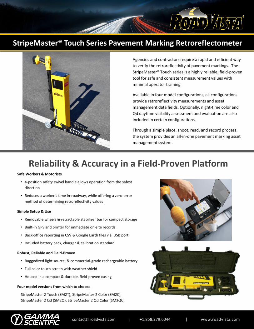
[email protected] | +1.858.279.6044 | www.roadvista.com
Reliability & Accuracy in a Field-Proven Platform
StripeMaster® Touch Series Pavement Marking Retroreflectometer
Agencies and contractors require a rapid and efficient way
to verify the retroreflectivity of pavement markings. The
StripeMaster® Touch series is a highly reliable, field-proven
tool for safe and consistent measurement values with
minimal operator training.
Available in four model configurations, all configurations
provide retroreflectivity measurements and asset
management data fields. Optionally, night-time color and
Qd daytime visibility assessment and evaluation are also
included in certain configurations.
Through a simple place, shoot, read, and record process,
the system provides an all-in-one pavement marking asset
management system.
Safe Workers & Motorists
• 4-position safety swivel handle allows operation from the safest
direction
• Reduces a worker’s time in-roadway, while offering a zero-error
method of determining retroreflectivity values
Simple Setup & Use
• Removable wheels & retractable stabilizer bar for compact storage
• Built-in GPS and printer for immediate on-site records
• Back-office reporting in CSV & Google Earth files via USB port
• Included battery pack, charger & calibration standard
Robust, Reliable and Field-Proven
• Ruggedized light source, & commercial-grade rechargeable battery
• Full color touch screen with weather shield
• Housed in a compact & durable, field-proven casing
Four model versions from which to choose
StripeMaster 2 Touch (SM2T), StripeMaster 2 Color (SM2C),
StripeMaster 2 Qd (SM2Q), StripeMaster 2 Qd Color (SM2QC)
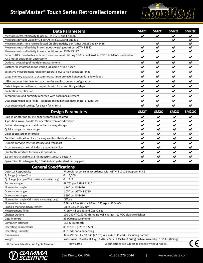
San Diego, CA. USA | +1.858.279.6044 | www.roadvista.com
© Gamma Scientific, All Rights Reserved
StripeMaster® Touch Series Retroreflectometer
Rev 9.19.1 Specifications are subject to change without notice.
Data Parameters SM2T SM2C SM2Q SM2QC
Measures retroreflectivity RL per ASTM E1710 and EN1436 ✔️ ✔️ ✔️ ✔️
Measures daylight visibility Qd per ASTM E2302 and EN1436 ✔️ ✔️
Measures night-time retroreflected CIE chromaticity per ASTM D6628 and EN1436 ✔️ ✔️
Measures retroreflectivity in continuous wetting (rain) per ASTM E2832 ✔️ ✔️ ✔️ ✔️
Measures retroreflectivity in wet conditions per ASTM E2177 ✔️ ✔️ ✔️ ✔️
Records GPS coordinates with each measurement utilizing 56-Channel WAAS-, EGNOS-, MSAS- enabled for <2.5 meter position fix uncertainty.
✔️ ✔️ ✔️ ✔️
Optional averaging of multiple measurements ✔️ ✔️ ✔️ ✔️
Custom file information for storing job name / type / user ✔️ ✔️ ✔️ ✔️
Extensive measurement range for accurate low to high precision range ✔️ ✔️ ✔️ ✔️
Large memory capacity to accommodate large projects between data downloads ✔️ ✔️ ✔️ ✔️
USB computer interface for data transfer and instrument configuration ✔️ ✔️ ✔️ ✔️
Data integration software compatible with Excel and Google Maps ✔️ ✔️ ✔️ ✔️
Calibration certification ✔️ ✔️ ✔️ ✔️
Temperature and humidity recorded with each measurement ✔️ ✔️ ✔️ ✔️
User customized data fields – location on road, install date, material type, etc. ✔️ ✔️ ✔️ ✔️
User customized settings for pass / fail criteria ✔️ ✔️ ✔️ ✔️
General SpecificationsDetector Responsivity Photopic response in accordance with ASTM E1710 paragraph 6.3.2
RL Range (mcd/m²/lx) 0 to 3,500
Qd Range (mcd/m²/lx) (SM2Q and SM2QC only) 0 to 318
Entrance angle 88.76° per ASTM E1710
Illumination angle 1.24° per EN1436
Observation angle 1.05° per ASTM E1710
Observation angle 2.29° per EN1436
Illumination angle Qd (SM2Q and SM2QC only) Diffuse
Illumination Area 2.4in. x 7.9in. (6cm x 20cm); 186 sq-in (120cm²)Profiled marking measurement Up to 0.59-in (15 mm)
Measurement Time RL only: <1 sec; RL and Qd: <2 sec
Charger Options 100-240 VAC, 50-60 Hz mains wall charger; 12 VDC cigarette lighter
Data Memory 25,000 measurements
Computer Interface USB & Bluetooth
Operating Temperature 0° to 50° C (32° to 122° F)
Operating Humidity 0 to 95% non-condensing
Dimensions 37-in (93 cm) L x 10.5-in (27 cm) W x 4.4-in (11 cm) H including battery
Weight Instrument: 18.4 lbs (8.4 kg); Battery Pack: 1.45 lbs (0.66 kg); Wheel Assembly: 1.10 lbs (0.5 kg)
Design Parameters SM2T SM2C SM2Q SM2QC
Built-in printer for on-site paper records as required ✔️ ✔️ ✔️ ✔️
4-position swivel handle for operation from any direction ✔️ ✔️ ✔️ ✔️
Retractable magnetic stabilizer bar for easy storage ✔️ ✔️ ✔️ ✔️
Quick change battery charger ✔️ ✔️ ✔️ ✔️
Color touch screen interface ✔️ ✔️ ✔️ ✔️
Certified calibration block for easy and fast field calibration ✔️ ✔️ ✔️ ✔️
Durable carrying case for storage and transport ✔️ ✔️ ✔️ ✔️
Accurately measures all industry standard colors ✔️ ✔️ ✔️ ✔️
Bluetooth interface for wireless operation ✔️ ✔️ ✔️ ✔️
12-volt rechargeable, 3.3 Ah industry-standard battery ✔️ ✔️ ✔️ ✔️
Spare 12-volt rechargeable, 3.3 Ah industry-standard battery pack ✔️ ✔️ ✔️ ✔️
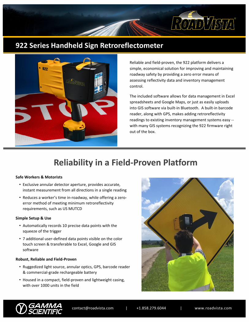
[email protected] | +1.858.279.6044 | www.roadvista.com
Reliability in a Field-Proven Platform
922 Series Handheld Sign Retroreflectometer
Reliable and field-proven, the 922 platform delivers a simple, economical solution for improving and maintaining roadway safety by providing a zero error means of assessing reflectivity data and inventory management control.
The included software allows for data management in Excel spreadsheets and Google Maps, or just as easily uploads into GIS software via built-in Bluetooth. A built-in barcode reader, along with GPS, makes adding retroreflectivity readings to existing inventory management systems easy --with many GIS systems recognizing the 922 firmware right out of the box.
Safe Workers & Motorists• Exclusive annular detector aperture, provides accurate,
instant measurement from all directions in a single reading
• Reduces a worker’s time in-roadway, while offering a zero-error method of meeting minimum retroreflectivityrequirements, such as US MUTCD
Simple Setup & Use• Automatically records 10 precise data points with the
squeeze of the trigger
• 7 additional user-defined data points visible on the colortouch screen & transferable to Excel, Google and GISsoftware
Robust, Reliable and Field-Proven
• Ruggedized light source, annular optics, GPS, barcode reader& commercial-grade rechargeable battery
• Housed in a compact, field-proven and lightweight casing,with over 1000 units in the field

San Diego, CA. USA | +1.858.279.6044 | www.roadvista.com
© Gamma Scientific, All Rights Reserved
922 Series Handheld Sign Retroreflectometer
Rev 2.23 Specifications are subject to change without notice.
USER-FRIENDLY OPERATIONFull color touchscreen
COMPREHENSIVE DATA17 crucial data points
PROVEN DURABILITY1000’s of units in the field
ULTRA ACCURATE OPTICSOmni-directional measurements
GeometryModel 922 922D
Applicable StandardsASTM E1709ASTM E2540AS/NZS 1906.1
EN 12899-1DIN 67520
Entrance Angle: -4o +5o
Observation Angle: 0.2o and 0.5o 0.33o
Light Source angular aperture 0.1o 0.1o
Receiver angular aperture (annular) 0.1o 0.1o
Field of Measurement 1 inch (25 mm) diameter spot 1 inch (25 mm) diameter spot
General SpecificationsDetector Responsivity
Photopic response in accordance with ASTM E1709 paragraph 6.4.2 and ASTM E2540 paragraph 6.4.2
Range (cd/lx/m2) 0-2000
Data Memory 5600 measurements (enough for 2-3 months of normal use)
Computer Interface USB and Bluetooth
GPS 12-Channel WAAS Enabled for <3 meter positionfix uncertainty
Barcode Reader Programmable Symbologies Laser Scanner
Power Supply Removable 12 VDC, 2.4 Ah battery (DeWalt P/N DC9071)
Charger 100-240 VAC, 50/60 Hz (add -1 to model no.)12 VDC cigarette lighter (add -2 to model no.)
Operating Temperature
0o to 50o C (32o to 122o F)
Operating Humidity 0 to 95% non-condensing
Dimensions 11.5-in (290 mm) L x 4.5-in (115 mm) W x 12.75-in (325mm) H including battery
Weight 5.9 lbs (2.7 kg) with battery
Performance
• Measures beaded and prismatic type signs• Any sign material color without adjustments or filters• Dual observation angles of 0.2° and 0.5° (or 0.33°)
simultaneously, for current and future needs• Auto-averaging of legend and background separately for
installed signs and MUTCD compliance• Measurements are omnidirectional, reducing the number
of measurements required for accurate analysis• Reads & records barcodes for simplified inventory
management• Determines and records global positioning (GPS) for clear
location and mapping• Communicates with other devices via Bluetooth for use
with Trimble and other GPS Systems• Full color display with high-visibility touch screen• Full-day operation with two rechargeable, 12-volt batteries• Included lightweight, ergonomic, durable protective case• Meets ASTM, CIE, CEN & DIN specifications

[email protected] | +1.858.279.6044 | www.roadvista.com
Reliability in a Field-Proven Platform
932 Series Multi-Geometry Handheld Retroreflectometer
The use of retrofeflective materials has expanded
beyond traffic signs and roadway markings. From
safety apparel to athletic wear; from emergency
vehicles to rail cars, improved visibility is a key to
safety.
The 932 Series product is ideal in both field and
laboratory applications. Featuring fully adjustable
illumination and observation angles and a fully
calibrated photopic-corrected sensor, measurements
per ASTM, CIE, ANSI, BS, EN & DIN specifications
are possible. On-board storage of up to 32,000
readings, Bluetooth connectivity and multi-channel
GPS come as standard.
Safe Workers & Motorists
• Accurately measures visibility of sign sheeting,
construction apparel, athletic wear or vehicle markings
or essentially any other retroreflective material
Simple Setup & Use
• With a press of a button, provides both retroreflectivity
and color verification
• All-in-one attached adjustable angle apparatus
eliminates need for additional components
• Operate with built-in color touch-screen, Bluetooth or
USB computer interface
Smart Optics and Analytics
• Integrated photometric filter for high-precision
measurements
• Internal memory stores up to 32,000 readings
• Tri-stimulus sensor suitable for nighttime measurement
parameters
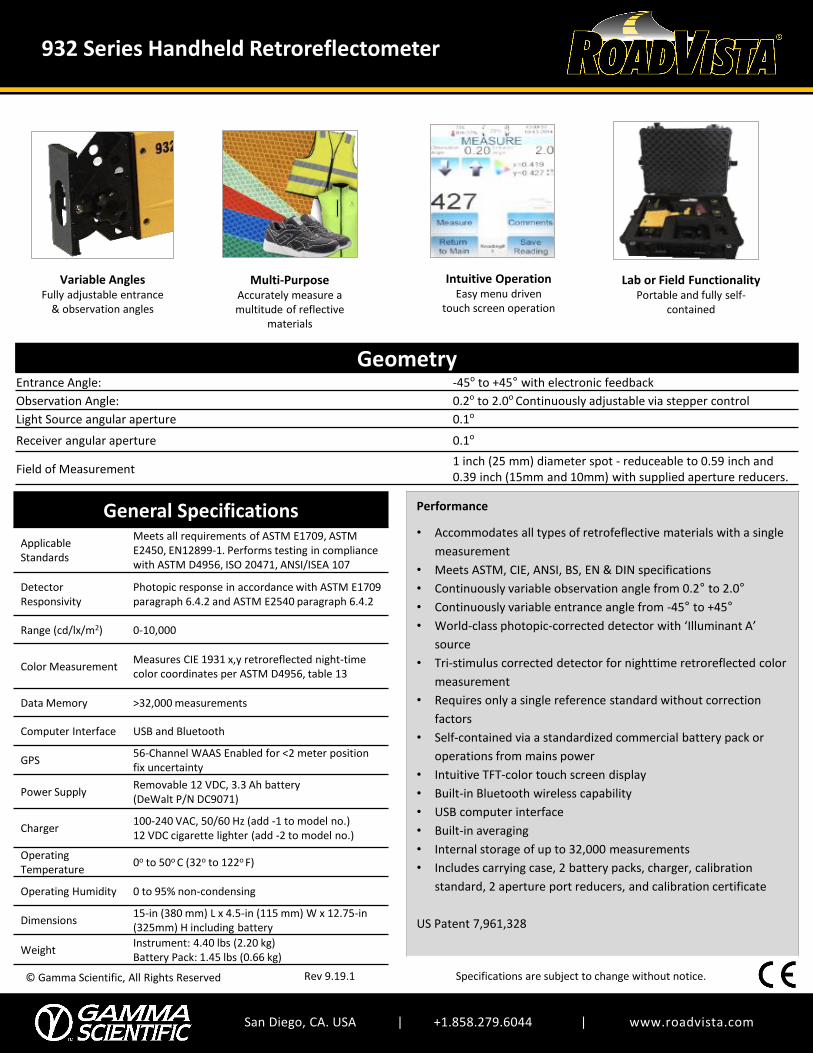
San Diego, CA. USA | +1.858.279.6044 | www.roadvista.com
© Gamma Scientific, All Rights Reserved
932 Series Handheld Retroreflectometer
Rev 9.19.1 Specifications are subject to change without notice.
Variable AnglesFully adjustable entrance
& observation angles
Multi-PurposeAccurately measure a multitude of reflective
materials
Intuitive OperationEasy menu driven
touch screen operation
Lab or Field FunctionalityPortable and fully self-
contained
GeometryEntrance Angle: -45o to +45° with electronic feedback
Observation Angle: 0.2o to 2.0o Continuously adjustable via stepper control
Light Source angular aperture 0.1o
Receiver angular aperture 0.1o
Field of Measurement1 inch (25 mm) diameter spot - reduceable to 0.59 inch and 0.39 inch (15mm and 10mm) with supplied aperture reducers.
General Specifications
Applicable Standards
Meets all requirements of ASTM E1709, ASTM E2450, EN12899-1. Performs testing in compliance with ASTM D4956, ISO 20471, ANSI/ISEA 107
Detector Responsivity
Photopic response in accordance with ASTM E1709 paragraph 6.4.2 and ASTM E2540 paragraph 6.4.2
Range (cd/lx/m2) 0-10,000
Color MeasurementMeasures CIE 1931 x,y retroreflected night-time color coordinates per ASTM D4956, table 13
Data Memory >32,000 measurements
Computer Interface USB and Bluetooth
GPS56-Channel WAAS Enabled for <2 meter position fix uncertainty
Power SupplyRemovable 12 VDC, 3.3 Ah battery (DeWalt P/N DC9071)
Charger100-240 VAC, 50/60 Hz (add -1 to model no.)12 VDC cigarette lighter (add -2 to model no.)
Operating Temperature
0o to 50o C (32o to 122o F)
Operating Humidity 0 to 95% non-condensing
Dimensions15-in (380 mm) L x 4.5-in (115 mm) W x 12.75-in (325mm) H including battery
WeightInstrument: 4.40 lbs (2.20 kg)Battery Pack: 1.45 lbs (0.66 kg)
Performance
• Accommodates all types of retrofeflective materials with a single
measurement
• Meets ASTM, CIE, ANSI, BS, EN & DIN specifications
• Continuously variable observation angle from 0.2° to 2.0°
• Continuously variable entrance angle from -45° to +45°
• World-class photopic-corrected detector with ‘Illuminant A’
source
• Tri-stimulus corrected detector for nighttime retroreflected color
measurement
• Requires only a single reference standard without correction
factors
• Self-contained via a standardized commercial battery pack or
operations from mains power
• Intuitive TFT-color touch screen display
• Built-in Bluetooth wireless capability
• USB computer interface
• Built-in averaging
• Internal storage of up to 32,000 measurements
• Includes carrying case, 2 battery packs, charger, calibration
standard, 2 aperture port reducers, and calibration certificate
US Patent 7,961,328
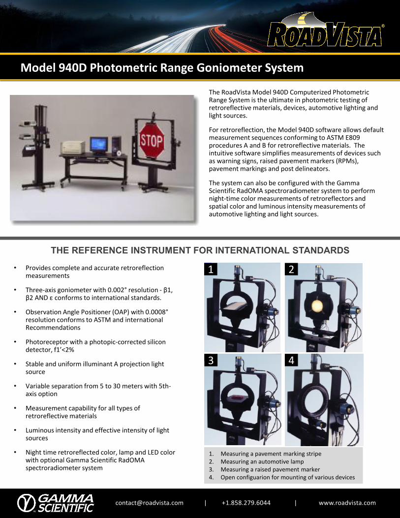
[email protected] | +1.858.279.6044 | www.roadvista.com
Model 940D Photometric Range Goniometer System
The RoadVista Model 940D Computerized Photometric Range System is the ultimate in photometric testing of retroreflective materials, devices, automotive lighting and light sources.
For retroreflection, the Model 940D software allows default measurement sequences conforming to ASTM E809 procedures A and B for retroreflective materials. The intuitive software simplifies measurements of devices such as warning signs, raised pavement markers (RPMs), pavement markings and post delineators.
The system can also be configured with the Gamma Scientific RadOMA spectroradiometer system to perform night-time color measurements of retroreflectors and spatial color and luminous intensity measurements of automotive lighting and light sources.
THE REFERENCE INSTRUMENT FOR INTERNATIONAL STANDARDS
• Provides complete and accurate retroreflection measurements
• Three-axis goniometer with 0.002° resolution - β1, β2 AND ε conforms to international standards.
• Observation Angle Positioner (OAP) with 0.0008°resolution conforms to ASTM and international Recommendations
• Photoreceptor with a photopic-corrected silicon detector, f1’<2%
• Stable and uniform illuminant A projection light source
• Variable separation from 5 to 30 meters with 5th-axis option
• Measurement capability for all types of retroreflective materials
• Luminous intensity and effective intensity of light sources
• Night time retroreflected color, lamp and LED color with optional Gamma Scientific RadOMAspectroradiometer system
1 2
3 4
1. Measuring a pavement marking stripe2. Measuring an automotive lamp3. Measuring a raised pavement marker4. Open configuarion for mounting of various devices
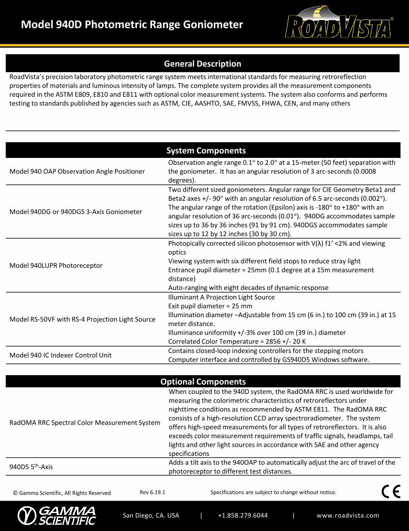
San Diego, CA. USA | +1.858.279.6044 | www.roadvista.com
© Gamma Scientific, All Rights Reserved
Model 940D Photometric Range Goniometer
Rev 6.19.1 Specifications are subject to change without notice.
General Description
RoadVista’s precision laboratory photometric range system meets international standards for measuring retroreflection properties of materials and luminous intensity of lamps. The complete system provides all the measurement components required in the ASTM E809, E810 and E811 with optional color measurement systems. The system also conforms and performs testing to standards published by agencies such as ASTM, CIE, AASHTO, SAE, FMVSS, FHWA, CEN, and many others
System Components
Model 940 OAP Observation Angle PositionerObservation angle range 0.1° to 2.0° at a 15-meter (50 feet) separation with the goniometer. It has an angular resolution of 3 arc-seconds (0.0008 degrees).
Model 940DG or 940DGS 3-Axis Goniometer
Two different sized goniometers. Angular range for CIE Geometry Beta1 and Beta2 axes +/- 90° with an angular resolution of 6.5 arc-seconds (0.002°). The angular range of the rotation (Epsilon) axis is -180° to +180° with an angular resolution of 36 arc-seconds (0.01°). 940DG accommodates sample sizes up to 36 by 36 inches (91 by 91 cm). 940DGS accommodates sample sizes up to 12 by 12 inches (30 by 30 cm).
Model 940LUPR Photoreceptor
Photopically corrected silicon photosensor with V(λ) f1’ <2% and viewing opticsViewing system with six different field stops to reduce stray lightEntrance pupil diameter = 25mm (0.1 degree at a 15m measurement distance) Auto-ranging with eight decades of dynamic response
Model RS-50VF with RS-4 Projection Light Source
Illuminant A Projection Light SourceExit pupil diameter = 25 mmIllumination diameter –Adjustable from 15 cm (6 in.) to 100 cm (39 in.) at 15 meter distance.Illuminance uniformity +/-3% over 100 cm (39 in.) diameter Correlated Color Temperature = 2856 +/- 20 K
Model 940 IC Indexer Control Unit Contains closed-loop indexing controllers for the stepping motorsComputer interface and controlled by GS940D5 Windows software.
Optional Components
RadOMA RRC Spectral Color Measurement System
When coupled to the 940D system, the RadOMA RRC is used worldwide for measuring the colorimetric characteristics of retroreflectors under nighttime conditions as recommended by ASTM E811. The RadOMA RRC consists of a high-resolution CCD array spectroradiometer. The system offers high-speed measurements for all types of retroreflectors. It is also exceeds color measurement requirements of traffic signals, headlamps, tail lights and other light sources in accordance with SAE and other agency specifications
940D5 5th-AxisAdds a tilt axis to the 940OAP to automatically adjust the arc of travel of the photoreceptor to different test distances.