The Substitution Of IvD Aluminum For Cadmium - CiteSeerX
203
THE S.UBSTITUTION OF IVD ALUMINUM FOR CADMIUM V.L. HOLMES, D.E. MUEHLBERGER, J.J. REILLY McDONNELL AIRCRAFT COMP. P. 0. BOX 516 MCDONNELL DOUGLAS CORP. ST LOUIS MO 63166-0516 AUGUST 1989 FINAL REPORT FEBRUARY 1988 - JANUARY 1989 AIR FORCE ENGINEERING & SERVICES CENTER ENGINEERING .& SERVICES LABORATORY TYNDALL AIR FORCE BASE, FLORIDA 32403
-
Upload
khangminh22 -
Category
Documents
-
view
4 -
download
0
Transcript of The Substitution Of IvD Aluminum For Cadmium - CiteSeerX

THE S.UBSTITUTION OF IVD ALUMINUM FOR CADMIUM
V.L. HOLMES, D.E. MUEHLBERGER, J.J. REILLY
McDONNELL AIRCRAFT COMP.
P. 0. BOX 516 MCDONNELL DOUGLAS CORP.
ST LOUIS MO 63166-0516
AUGUST 1989
FINAL REPORT
FEBRUARY 1988 - JANUARY 1989
AIR FORCE ENGINEERING & SERVICES CENTER ENGINEERING .& SERVICES LABORATORY TYNDALL AIR FORCE BASE, FLORIDA 32403

NOTICE
PLEASE DO NOT R E Q U E S T COPIES OF THIS R E P O R T FROM
HQ AFESC/RD (ENGINEERING AND SERVICES LABORATORY) I
ADDiT IONAL COPIES MAY BE PURCHASED FROM:
NATIONAL TECHNICAL INFORMATION SERVICE
5285 PORT R O Y A L ROAD
SPRINGFIELD, VIRGINIA 22161
FEDERAL G O V E R N M E N T AGENCIES AND THEIR C O N T R A C T O R S
REGISTERED WITH DEFENSE TECHNICAL INFORMATION C E N T E R
SHOULD DIRECT REQUESTS FOR COPIES OF T H I S REPORT T O :
DEFENSE TECHNICAL INFORMATION C E K T E R
C A M E R O N STAT ION
ALEXANDRIA, VIRGINIA 22314

JNCLASSIFIED :ITY CLASSIFICATION OF THIS PAGE
Form Approved REPORT DOCUMENTATION PAGE O M 8 NO 0704-0188
.PORT SECURITY CLASSIFICATION
NCLASSIFIED iCURlTY CLASSIFICATION AUTHORITY
ECLASSIFICATION I DOWNGRADING SCHEDULE
WORMING ORGANIZATION REPORT NUMBER(S)
87-101602 4ME OF PERFORMING ORGANIZATION I 6 b . OFFICE SYMBOL cDonnell Aircraft Comp. [lf applicable)
cDonnell Douglas Corp. MCAIR )DRESS (City, State, and ZIP Code)
. O . Box 516 t. Louis MO 63166-0516 4ME OF FUNDING /SPONSORING I 8 b . OFFICE SYMBOL RG NlZATl N ep%. 08 the Air Force )DRESS (City, State, and ZIP Code)
1 b. RESTRICTIVE MARKINGS
3 , DISTRIBUTION /AVAILABILITY OF REPORT
Approved for public release. Distribution unlimited.
5. MONITORING ORGANIZATION REPORT NUMBER(S)
ESL-TR-8 8-75 7a. NAME OF MONITORING ORGANIZATION Air Force Engineering and Services Center
HQ AFESC/RDVS Tyndall AFB FL 32403-6001
7b. ADDRESS (City, State, and ZIP Code)
9. PROCUREMENT INSTRUMENT IDENTIFICATION NUMBER
Contract # DE-AC07-76ID01570
10 SOURCE OF FUNDING NUMBERS PROGRAM PROJECT TASK WORK UNIT ELEMENT NO. NO NO ACCESSION NO 63723F 2103 71 02
TLE (Include Security Classification)
he Substitution of IVD Aluminum for Cadmium (UNCLASSIFIED)
.L. Holmes, D.E. Muehlberger, and J.J. Reilly
inal FROM 2/88 TO 1/89 August 1989
wailability of this report is specified on reverse of front cover.
IELD GROUP SUB-GROUP Cadmium, Cyanide, Aluminum, Hazardous Waste
‘3 \u, 2-37 wC7d-3 i RSONAL AUTHOR(S)
rYPE OF REPORT 13b TIME COVEREG 14 DATE OF REPORT (Year, Month, Day)
JPPLEMENTARY NOTATION
COSATI CODES 18 SUBJECT TERMS (Continue on reverse t f necessary and identify by block number)
3 08 Minimization, Ion Vapor Deposition, Electroplating
BSTRACT (Continue on reverse i f necessary and identify by block number)
he U.S. Air Force is concerned about the use of toxic processing at the Air Dgistics Centers (ALCs)-. To reduce hazardous waste generation from cadmium lectroplating, McDonnell Aircraft Division (MCAIR) of McDonnell Douglas, hrough EG&G Idaho, was requested to determine the feasibility of substituting 3n vapor deposition (IVD) of aluminum, across the board, for cadmium lectroplating processes. The IVD aluminum coating and process does not enerate hazardous wastes. The current phase of this contract required echnical, environmental, and economical comparisons between IVD of aluminum nd cadmium electroplating. This report provides that information. ecommended research and development to be conducted in Phase I1 of the mtract is also included. This document is the final report for Phase I of he project.
)ISTRIBUTION /AVAILABILITY OF ABSTRACT 1 UNCLASSIFIEDNNLIMITED c] SAME AS RPT. DTlC USERS NAME OF RESPONSIBLE INDIVIDUAL
21. ABSTRACT SECURITY CLASSIFICATION UNCLASSIFIED
22b. TELEPHONE (Include Area Code) I 22c. OFFICE SYMBOL
I HQ AFESC/RDVS r. Charles J. Carpenter I 904 2832942 orm1473, JUN 86 Previous editions are qbsolete SECURITY CLASSIFICATION OF THIS PAGE
1 UNCLAS S I n ED / T h o r a i i n r c n n f t h i c nann < C h l a n k )

E X E C U T l V E SUMMARY
Dur ing t h e p e r i o d o f 1 February 1988 t o 31 January 1989, McDonnell
A i r c r a f t Company (MCAIR) completed Phase I o f a tnree-phase program t o
demonstrate t h a t I o n Vapor Deposi ted (IVU) aluminum c o a t i n g can r e p l a c e t o x i c
cadmium p r o c e s s i n g a t t h e A i r L o g i s t i c s Centers ( A L C s ) . The t h r u s t o f t h e
program i s t o reduce hazardous waste p r o d u c t i o n . Research and developriient cons ide red necessary f o r an across- the-board rep lacement o f cadmium w i l l be conducted d u r i n g Phase I 1 o f t n e program. Procurement o f an I V D aluminum
c o a t e r w i l l be suppor ted d u r i n g Phase 11. The c o a t e r w i l l be i n s t a l l e d a t an
ALC s i t e f o r t h e demons t ra t i on o f t h e I V D aluminum process a u r i n y Phase I 1 1
o f t h e program.
A c o m p i l a t i o n o f d a t a comparing t h e I V D aluminum process t o t h e v a r i o u s
cadmium processes has been assemblea i n t o a d a t a base handbook. Th is
handbook p r o v i d e s t h e des igne r o r process engineer w i t h a t e c h n i c a l d a t a
source when c o n s i d e r i n g a s u b s t i t u t e f o r caamium. I t a l s o i n c l u d e s a r e v i e w
o f a i r c r a f t p a r t s now processed w i t n cadmium a t t h e f i v e ALCs t o i d e n t i f y
p a r t s f o r whicn I V D aluminum can immediate ly r e p l a c e cadmium w i t h o u t concern
ana i a e n t i f y p a r t s whicn e x h i b i t "areas o f concern." Research and
development recommendations a re made f o r supplemental p rocess ing t o b e used
w i t h 1 V D aluminum t o e n m l e aaequate replacement of cadmium p r o c e s s i n g f o r
p a r t s e x h i b i t i n g "areas o f concern." Process ing c o s t s ana env i ronmenta l
impact comparisons a r e made between I V D aluminum and cadmium. I b u aluminum
p rocess ing was g e n e r a l l y l e s s expensive t h a n cadmium, and t h e I V D aluminum
process i s n o n p o l l u t i n g . PILAIR and t h e Oklanorna C i t y ALC coa ted " t y p i c a l "
ALC p a r t s w i t h I V D aluminum t h a t a re now processed w i t h cadmium. These p a r t s
passed ano exceeaed t h e m i li t a r y s p e c i f i c a t i o n c o r r o s i o n r e s i s t a n c e
requi rements. The g e n e r i c n a t u r e o f I V D aluminum was f u r t n e r demonstrated by
t e s t i n g coatea pane ls and comparing r e s u l t s t o t h e compl ied d a t a book. Phase I v e r i f i e s t h a t 1VD aluminum can be s u b s t i t u t e d f o r cadmium w i t h o u t concern f o r most a p p l i c a t i o n s . For those a p p l i c a t i o n s where t h e s u b s t i t u t i o n i s n o t
s t r a i g h t f o r w a r a o r where o t h e r t e c h n i c a l i ssues must be considerea, t h e
reader i s a l e r t e d and s p e c i f i c research programs a re recommendeu.
iii
(The r e v e r s e o f t h i s page i s b l a n k . )


PREFACE
This report was prepared by McDonnell Aircraft Company (MCAIR), McDonnell Douglas Corporation, St. Louis, Missouri, as part of Phase I of Contract C87-101602, "Demonstration of Ion Vapor Deposition Aluminum Coatings.Il The program was conducted by the Material and Process Development Department at MCAIR, St. Louis. The program was administered by EG&G, Idaho for the Air Force Engineering and Services Center (AFESC). Mr. C.J. Carpenter (AFESC) was the Government technical and administrative program manager. This report summarizes work accomplished between 1 February 1988 and 31 January 1989.
This report has been reviewed by the Public Affairs Office and is releasable to the National Technical Information Service (NTIS). At NTIS it will be available to the general public, including foreign nations.
This technical publication has been reviewed and is approved for publication.
CHARLES ceeI%+J J. CARP TER Project Officer ~ n
F&K P. olonel, USAF
KENNETH Ti DENBLEYkER, Maj, USAF JAMES R. VAN ORMAN Chief, Environmental Sciences Deputy Director Branch Engineering and Services Laboratory
U
(The reverse o f t h i s page i s b l a n k . )

I

TABLE OF COkTENTS
S e c t i o n T i t l e P a g e
I . INTRODUCTION . . . . . . . . . . . . . . . . . . . . . . . . . . 1
A . O B J E C T I V E . . . . . . . . . . . . . . . . . . . . . . . . . 1 6 . BACKGROUFvD . . . . . . . . . . . . . . . . . . . . . . . . . 1 C . SCO?E/APPROACH . . . . . . . . . . . . . . . . . . . . . . 3
I 1
I11
1v
COATING PROPERTIES . . . . . . . . . . . . . . . . . . . . . . . 5
A . CUATIiVG A D H E S I O h . . . . . . . . . . . . . . . . . . . . . 5 6 . COATING COVERAGE. UNIFORMITY. AiVU THICKNESS . . . . . . . . 8
C . SURFACE SMOOTHNESS . . . . . . . . . . . . . . . . . . . . 11 D . TEMPERATURE . . . . . . . . . . . . . . . . . . . . . . . . 1 7
E . E L E C T R I C A L . . . . . . . . . . . . . . . . . . . . . . . . 21 F . C O M P A T I B I L I T Y . . . . . . . . . . . . . . . . . . . . . . . 22
6 . TOPCOAT ADHESION . . . . . . . . . . . . . . . . . . . . . L S H . EROSION RESISTANCE . . . . . . . . . . . . . . . . . . . . 27
CORkOSION RESISTANCE . . . . . . . . . . . . . . . . . . . . . . 30
A . M I L - S P E C REQUIREMENTS AN0 T Y P I C A L TEST R ~ S U L T S . . . . . . 30 B . COMPARISONS TO CADMIUM PROCESSES . . . . . . . . . . . . . 34
1 . N e u t r a l S a l t F o g E x p o s u r e . . . . . . . . . . . . . . 35 2 . A c i d i c S a l t Fog E x p o s u r e and S p e c i a l i z e a E n v i r o n m e n t s JY
3 . O u t d o o r E x p o s u r e I n c l u d i n g S e r v i c e R e p o r t s . . . . . . . 43
C . 6 A L V A h I C C O M P A T I B I L I T Y OF I V D ALUMINUM-COATED ALLOY
STEEL FASTLNERS I N ALUMlkUlY ALLOY STRUCTURE . . . . . . . . 47
EFFECT ON MECHANICAL PROPERTIES (SUBSTRATE) . . . . . . . . . . 55
A . HYDR0G;EN EMBKlTTLEMENT/STRESS CORROSION CRACKING . . . . . 55
B . F A T I G U E . . . . . . . . . . . . . . . . . . . . . . . . . . 56
v i i

TABLE OF CONTENTS
( CONT I NU ED)
S e c t i o n T i t l e
V FASTENER INSTALLATION CHARACTERISTICS . . . . . . . . . . . . .
A . TORQUE-TENSION . . . . . . . . . . . . . . . . . . . . . . B . REUSE TESTING . . . . . . . . . . . . . . . . . . . . . . .
V I COATING VERSATILITY . . . . . . . . . . . . . . . . . . . . . .
8 . ALUMlNUM ALLOY SUBSTRATES . . . . . . . . . . . . . . . . .
1 . F a t i g u e C r i t i c a l . . . . . . . . . . . . . . . . . . . Z . E l e c t r i c a l Bonding/EMlC . . . . . . . . . . . . . . . 3 . E l e c t r i c a l Connectors . . . . . . . . . . . . . . . .
b . T I T A N I U M SUBSTRATES . . . . . . . . . . . . . . . . . . . . C . NONMETALLIC SUBSTKAlES . . . . . . . . . . . . . . . . . . 0 . N E O U Y N l U M - I ~ O N - ~ O K O N SUBSTRATES . . . . . . . . . . . . . . E . DEPLETED URANIUM SUbSPKATES . . . . . . . . . . . . . . . . F . SUBSTKATLS I N CONTACT WITH FUEL AND OTHER FLUIDS . . . . .
VI1 REWORK AND FIELD R E P A I R . . . . . . . . . . . . . . . . . . . .
A . IN-HOUSE REWORK AND K E P A I R . . . . . . . . . . . . . . . .
1 . Poor Coat ing Adhesion . . . . . . . . . . . . . . . . 2 . I n c o r r e c t Coat ing Thickness . . . . . . . . . . . . . 3 . Scratches i n tne Coat ing . . . . . . . . . . . . . . . 4 . bare Area i n t h e Coat ing . . . . . . . . . . . . . . . 5 . Scheduled ALC Maintenance . . . . . . . . . . . . . .
Page
b 2
62 68
73
7 3
73 75 78
73
84 80
a7 90
91
91
93 93 94
94
v i i i

TABLE OF CONTENTS
( CONTINUED)
S e c t i o n T i t l e P a g e
. . . . . . . . . . . . . . . . . . . . . . . 94 B. F I E L D R E P A I R
1. S c r a t c h e s i n t h e C o a t i n g . . . . . . . . . . . . . . . . 94 2 . B a r e A r e a s i n the C o a t i n g . . . . . . . . . . . . . . 94
VI11 PROCESSING COST . . . . . . . . . . . . . . . . . . . . . . . . 1 oz
I X ENVIRONMENTAL IMPACT. . . . . . . . . . . . . . . . . . . . . . 114
A. PRECLEANING. . . . . . . . . . . . . . . . . . . . . . . . 114
B. C O A T I h G I P L A T I N G . . . . . . . . . . . . . . . . . . . . . . 116 C. POSTCOAT PROCESSING. . . . . . . . . . . . . . . . . . . . 120
0 . OSHA STANDAKDS . . . . . . . . . . . . . . . . . . . . . . 1 LO E. P A I N T S T R I P P I N G . . . . . . . . . . . . . . . . . . . . . . 1 il
1 L3 X DATA GENERATED DURING CONTRACT P E R 1 0 0 . . . . . . . . . . . . .
A. CORRO5ION RESISTANCE T E S T I h G OF ALC D E T A l L S . . . . . . . . 123
1. B y MCAIR. . . . . . . . . . . . . . . . . . . . . . . 123
2. B y the O k l a h o m a C i t y ALC. . . . . . . . . . . . . . . 1 2 9
b. K E V I t W OF CADMIUM-PROCESSED ALC D E T A I L S . . . . . . . . . . 137
C. DEMONSTRATION OF THE G E M R I C NATURE OF I V D ALUMINUM. . . . 156
X I CONCLUSIOhS . . . . . . . . . . . . . . . . . . . . . . . . . . 161
X I I RESEARCH AND DEVELOPMENT RECOMMENDHTIOhS. . . . . . . . . . . . 162

Section
TABLE OF CONTENTS (CONTINUED )
Title Page
A . .COVERAGE OF INTERNAL SURFACES . . . . . . . . . . . . . . .
1 . Problem . . . . . . . . . . . . . . . . . . . . . . . L . Proposed Solution . . . . . . . . . . . . . . . . . .
Recommended R&D Program . . . . . . . . . . . . . . . 3 . B . IMPROVED EROSION RESISTANCE . . . . . . . . . . . . . . . .
1 . Problem . . . . . . . . . . . . . . . . . . . . . . . 2 . Proposed Solution . . . . . . . . . . . . . . . . . . 3 . Recommended R&D Program . . . . . . . . . . . . . . .
C . IMPROVED LUBRICITY . . . . . . . . . . . . . . . . . . . .
1 . Problem . . . . . . . . . . . . . . . . . . . . . . . 2 . Proposed Solution . . . . . . . . . . . . . . . . . . 3 . Recommended R&U Program . . . . . . . . . . . . . . .
D . IMPROVED COKKOSIOk RESISTANCE . . . . . . . . . . . . . . .
1 . Problem . . . . . . . . . . . . . . . . . . . . . . . 2 . Proposed Solution . . . . . . . . . . . . . . . . . . 3 . Recommended R&D Program . . . . . . . . . . . . . . .
E . ZIRCONIUM COMPOUNDS AS A SUBSTITUTE FOR CHROMATE CONVERSION . . . . . . . . . . . . . . . . . . . . . . . .
1 . Problem . . . . . . . . . . . . . . . . . . . . . . . 2 . Proposed Solution . . . . . . . . . . . . . . . . . . 3 . Recommended R&D Program . . . . . . . . . . . . . . .
162
162 162 164
165
165 165 165
166
1bb 16b 167
167
167 168 170
170
170 171 171
X

Sect i o n
TABLE OF CONTENTS
( CONCLUDE 0 )
T i t l e Page
. . . . . . . . . . . . . . . . . . . . . . 172 F. COST REDUCTION
1. P r o b l e m . . 172
3 . Recommenaed R&D Program . . . . . . . . . . . . . . .
. . . . . . . . . . . . . . . . . . . . . 2. Proposed S o l u t i o n . . . . . . . . . . . . . . . . . . 1 7 ~
172
173 REFEkENCES . . . . . . . . . . . . . . . . . . . . . . . . . .
Xl

LIST OF FIGURES
F i g u r e Pay e
1 Schematic o f an I o n Vapor D e p o s i t i o n System . . . . . . . . . . 1
2 Demonstrat ion o f I V D Aluminum Coa t ing Adhesion. . . . . . . . . 6
3 I V D Aluminum Coa t ing Thickness and U n i f o r m i t y on a C y l i n d r i c a l
D e t a i l . . . . . . . . . . . . . . . . . . . . . . . ., . . . . . 9
4 I V D Aluminum Coa t ing U n i f o r n i i t y on a T u r b i n e Blade. . . . . . . 10
5 T y p i c a l I V D Aluminum Coat ing U n i f o r m i t y o f Ba r re l -Coa ted Fasteners . . . . . . . . . . . . . . . . . . . . . . . . . . 12
6 T y p i c a l Specimens f o r Po l i shed I V D Aluminum Coat ings. . . . . . 17
7 Smoothness o f I V D Aluminum Sur faces Be fo re and A f t e r P o l i s h i n g . 18
8 I V D Aluminum-Coated DC-10 A f t Engine hanger . . . . . . . . . . zu
9 Scanning E l e c t r o n Photomicrograph o f t h e I V O Aluminum Columnar
S t r u c t u r e . . . . . . . . . . . . . . . . . . . . . . . . . . . 25
1U h l l o y S t e e l Fastener Wi th 1VD Aluminum and Xyla @ Topcoat A f t e r
1 7 , 9 5 ~ Hours o f N e u t r a l S a l t f o g Exposure . . . . . . . . . . . 26
11 Eros ion Res is tance o f I V D Aluminum Versus Vacuum Caaniium. . . . 28
12 Average Test R e s u l t s Versus Minimum Requirements o f MIL-C-83488 3~
13 Cor ros ion Res is tance o f I V D Aluminum I n N e u t r a l S a l t Fog. . . . 33
14 I V D Aluminum- and Vacuum-Cadmium-Finished A l l o y S t e e l
-
Fasteners A f t e r 500 hours o f h e u t r a l S a l t Fog Exposure. . . . . 37
x i i

LIST OF FIGURES (CONTINUED)
F i gure Page
15 IVD Aluminum- and Electroplated-Cadmium-finished Fasteners 40 After 58 Hours in SO2 Salt Fog Exposure . . . . . . . . . . .
16 IVD Aluminum- and Vacuum-Cadmium-Finished Steel Panels After 41 144 hours of SO2 S a l t Fog Exposure. . . . . . . . . . . . . .
1 7 IVD Aluminum- and Diffused Nickel-Cadmium-Finished Alloy Steel Panels After 336 Hours of Cyclic Neutral Sa l t Fog/Oven Exposure. 42 . . . . . . . . . . . . . . . . . . . . . . . . . . .
18 IVD Aluminum- and Cadmium-Finished Alloy Steel Panels After 44 S t . Louis Outdoor Exposure. . . . . . . . . . . . . . . . . . .
19 A 1 umi num A1 1 oy Specimens ( W i t h A 1 umi num- Coat ed/ Cadmi u m - P1 ated Fasteners Instal led) After 2,500 Hours of Neutral S a l t Fog
. . . . . . . . . . . . . . . . . . . . . . . . . . . 48 Exposure.
20 Aluminum Alloy CountersinKs After 2,500 Hours o f Neutral Salt Fog Exposure. . . . . . . . . . . . . . . . . . . . . . . . . . 49
21 Aluminum Alloy Specimens (With Aluminum-Coated/Cadmium-Plated Fasteners Installed) After 1 6 8 Hours of SUz S a l t fog Exposure. . . . . . . . . . . . . . . . . . . . . . . . . . . . 50
2 2 Aluminum Alloy Countersinks After 168 Hours o f SO2 Salt Fog Exposure. . . . . . . . . . . . . . . . . . . . . . . . . . . . 51
2 3 Corrosion Stains in Recess Area of IVD Aluminum-Finished Fasteners After 24 Months of S t . Louis Outdoor txposure. . . . s z -
24 Cadmium Depletion on Periphery o f Fastener Head . . . . . . . . 53
xi.i i

LIST OF FIGURES ( CONT I W E D )
Figure
2s
26
27
28
29
30
31
32
33
34
35
36
Cadmium Depletion Advancing on Fastener Head . . . . . . . . .
Corrosion Resistance of IVD Aluminum-Versus Electroplated- Cadmium-Finished Fasteners. . . . . . . . . . . . . . . . . . .
Typical IVD Aluminum-Coated High-Strength Steel Details . . . .
Tension Fatigue Test o f IVD Aluminum- and Cadmium-Finished Fasteners . . . . . . . . . . . . . . . . . . . . . . . . . . .
Torque-lension Test Results for IVD Alumin.um- and Cadmium- Finished Fasteners. . . . . . . . . . . . . . . . . . . . . . .
Torque-Tension Relationship Using IVD Aluminum-Finished Fasteners . . . . . . . . . . . . . . . . . . . . . . . . . . .
Torque-Tension Relationship Using Diffused Nickel-Cadmium- Finished Fasteners. . . . . . . . . . . . . . . . . . . . . . .
Reuse Kelationsnips for IVD Aluminum- ana Cadmium-Finished Fasteners . . . . . . . . . . . . . . . . . . . . . . . . . . .
Fifteen Cycle Reuse Test Comparing IVD Aluminum- and Cadmium-Finished Fasteners. . . . . . . . . . . . . . . . . . .
Effect on Fatigue Properties by IVD Aluminum and Anoaize Finishes. . . . . . . . . . . . . . . . . . . . . . . . . . . .
F-15 IVD Aluminum-Coated Fatigue-Critical Aluminum Alloy Wing S k i n . . . . . . . . . . . . . . . . . . . . . . . . . . . . . .
F-18 IVD Aluminum-Coated Fatigue-Critical Aluminum Alloy Bulkhead. . . . . . . . . . . . . . . . . . . . . . . . . . . .
Page
53
54
58
59
62
64
65
159
71
74
74
75
x i v

LIST OF FIGURES (CONTINUED)
F i gure Page
37 IVD Aluminum-Coated Aluminum Alloy Fuel and Pneumatic Line Fittings. . . . . . . . . . . . . . . . . . . . . . . . . . . . 76
76 38 IVD Aluminum-Provided Conductive Path and Corrosion Resistance.
39 Aluminum Alloy Casting Coated with IVD Aluminum ana Black Anodized.. . . . . . . . . . . . . . . . . . . . . . . . . . 79
40 IVD Aluminum- and Cadmium-Finished Connectors After 1,000 Hours of Neutral Salt fog Exposure. . . . . . . . . . . . . . . . . . 80
41 Test Panels After 28 Days o f SO2 Salt Fog Exposure. . . . . . 81
42 Photomicrographs of Test Panel Countersinks . . . . . . . . . . 82
43 Cadmium-Induced Embrittlement Failure . . . . . . . . . . . . . 83
t;b 44 IVD Aluminum-Coated Plastic Enclosure . . . . . . . . . . . . . 45 IVD Aluminum-Coated heodymium-Iron-Boron Magnets After 100
Hours of Neutral Salt fog Exposure. . . . . . . . . . . . . . . 88
46 Loose Oxide Formed on Depleted Uranium. . . . . . . . . . . . . 85
47 IVD Aluminum-Coated Depleted Uranium Penetrator Core. . . . . . 90
48 Prime and Paint Repair of IVD Aluminu,n-Coated Panels After 28 Days of SOz Salt fog Exposure . . . . . . . . . . . . . . . .
Days o f Neutral Salt fog Exposure . . . . . . . . . . . . . . . 99
97 -
49 Brush Cadmium Repair of IVD Aluminum-Coated Panels After 28
xv

LIST OF FILURES
(CONCLUDED)
F i g u r e Page
50 Cor ros ion Res is tance o f S e r m e t a p 2 4 Y / S e r m e t a P 273 Repai r . . . . . . . . . . . . . . . . . . . . . . . . . . . . . 100
51 P o l l u t i o n C o n t r o l - Flow Chart f o r Hazaraous h’aste Treatment and Disposal o f Cadmium . . . . . . . . . . . . . . . . . . . . 107
52 R o t a r y F i x t u r e F o r I V D Aluminum Processing. . . . . . . . . . . 110
53 Dual B a r r e l Accessory Fo r I V D Aluminum Process ing . . . . . . . 110
54 E f f e c t o f Cryopump on Punipdown Times. . . . . . . . . . . . . . 111
55 I V D Aluminuni P roduc t i on Work Area . . . . . . . . . . . . . . . 11 7
5b T y p i c a l E l e c t r o p l a t e o Cadmium Work Area . . . . . . . . . . . . 118
57 I b U Aluminum-Coated Case and Vane Assembly ( P / N 2173320). . . . 1 Z8
58 I V D Aluminum-Coated Engine Sec t ions A f t e r b72 Hours o f h e u t r a l
S a l t Fog E x p o s u r e . . . . . . . . . . . . . . . . . . . . . . . 130
55
60
61
62
I V D Aluminum-Coated Small HLC Par ts A f t e r 672 hours o f k e u t r a l
S a l t Fog Exposure. . . . . . ; . . . . . . . . . . . . . . . . . 131
I V D Aluminum-Coated ALL Par t s A f t e r 6 7 ~ Hours o f I l e u t r a l S a l t Fog Exposure . . . . . . . . . . . . . . . . . . . . . . . 132
Average Test R e s u l t s f o r t h e Gener ic Panels Versus Minimum Requirements of Ml~-C-83488 and t n e Database Averages . . . . . 160 -
M a g n i f i e d Cross-Sect ion o f I V D Aluminum and X y l a p 101. . . . 169
x v i ,

L I S T OF TABLES
Page Tab1 e
1
i!
3
4
5
6
7
10
11
12
13
14
EFFECT OF PEENING AND CHROMATING ON I V D ALUMINUM COATING ADHESION. . . . . . . . . . . . . . . . . . . . . . . . . . . . 7
ADHESIVE T E N S I L E STRENGTH OF I V D ALUMINUM COATING . . . . . . . 7
8 ADHESION OF I V D ALUMINUM VERSUS CADMIUM F I N I S H L S . . . . . . . .
9 I V D ALUMINUM COATING T t i ICKNESS AND U N I F O R M I T Y . . . . . . . . .
I V D ALUMINUM COATING T h I C K N E S S V A R I A T I O N THROUGHOUT A PRODUCTION S I Z E LOAD OF FASTENERS . . . . . . . . . . . . . . . 1 3
COMPAKISON OF I V D ALUMllVUM AND CADMIUM PROCESSING . . . . . . . 13
EFFECT OF SUBSTRATE SURFACE PREPARATION ON I V D ALUMINUM COATING SMOOTHNESS. . . . . . . . . . . . . . . . . . . . . . . 14
SURFACE F I N I S H DATA FOR I V D ALUMINUM PROCESSINt i . . . . . . . . 1 5
EFFECT OF POSTCOATING TREATMENT ON T h E SMOOTHNESS OF CADMIUM P L A T I N G . . . . . . . . . . . . . . . . . . . . . . . . . . . . 1 6
P O L I S H I N G UATA FOR I V D ALUMINUM COATIFUGS. . . . . . . . . . . . 19
E L E C T R I C A L RESISTANCE MEASUREMENTS TAKEN O N VANE SPECIMENS. . . 22
C O M P A T I B I L I T Y OF I V D ALUMIlVUM AfiD LADMIUM F I N I S h E S . . . . . . . 24
M I K I M U M REQUlKEMENTS OF M I L - C - 8 3 4 8 8 FOR NEUTRAL S A L T FOG E X P O S U R E . . . . . . . . . . . . . . . . . . . . . . . . . . . . 51
COMPARATIVE CORKOSION RESISTANCE PERFORMANCE. . . . . . . . . . 46
x v i i

L I S T OF TABLES
(CONTINUED)
P a g e Tab 1 e
15
16
1 7
18
19
f0
21
22
23
24
25
26
I V D ALUMINUM COMPARED TO ELECTROPLATED CADMIUM ON STEEL
FASTENERS I N S T A L L E D I N ALUMINUM ALLOY STRUCTURES. . . . . . . . 54 __
PROCESSES R E Q U I R I N G HYDROGEN EMBRITTLEMENT R E L I E F . . . . . . . 56
SUMMARY OF HYDROGEN EMt iRITTLEMENT AND STRESS CORROSION CRACKIhG TESTS ON HIGH-STRENGTH STEEL D E T A I L S . . . . . . . . . 5 7
EFFECT OF I V D ALUMINUM COATING ON SUBSTRATE F A T I G U E PROPERTIES. 59
TENSION-TENSION F A T I G U E T E S T OF I V D ALUMINUM- AhD CADMIUM- F I N I S H E D FASTENERS. . . . . . . . . . . . . . . . . . . . . . . 60
EFFECT ON F A T I G U E PROPERTIES OF ALLOY STEEL STEAM TURBINE
B L A U E S . . . . . . . . . . . . . . . . . . . . . . . . . . . . . 60
TORQUE-TENSION VALUES U S I N G
N I C K E L - C A D M I U M - F I N I S h E D FASTENERS . . . . . . . . . . . . . . . 46 1VD ALUMINUPI- AND D I F F U S E D
TORQUE-TENSION VALUES U S I N G I V D ALUMINUM- AND D I F F U S E D N I C K E L -
CADMIUM-F IN ISHED FASTENERS. . . . . . . . . . . . . . . . . . . 66
TORQUE-TENSION K E L A T I O N S H I P U S I N G I V D ALUMINUM VERSUS CADPIIUM AFiD D I F F U S E D NICKEL-CADMIUM F I IU ISHES. . . . . . . . . . . . . . 67
REUSE T E S T RESULTS COMPARING I V D ALUMINUM- AND C A D M I U M - F I N l S H L D
F A S T E N E R S . . . . . . . . . . . . . . . . . . . . . . . . . . . 69
- REUSE CHARACTERISTICS COMPARED TO S P E C I F I C A T I O N L I M I T S . . . . . 72
I V D ALUMINUM VERSUS ELECTROPLATED T I N FOR E M I C - ST. L O U I S OUTDOOR EXPOSURE. . . . . . . . . . . . . . . . . . . . . . . . 7 7
x v i i i

L I S T OF TABLES
( CONT I NU ED)
Table
27
28
29
30
31
32
33
24
35
36
37
38
39
I V D ALUMINUM VERSUS ELECTROPLATED T I N FOR E M I C - 1 YEAR SHIPBOARD EXPOSURE (USS CONSTELLATION) . . . . . . . . . . . . . 78
F I E L D R E P A I R T E C h h I Q U E S . . . . . . . . . . . . . . . . . . . . 101
R E L A T I V E COSTS OF I V D ALUMINUM VERSUS CADMIUM PROCESSING. . . . 103
PROCESSING FLOW CHARTS AND LABOR RE()UIKEPIENTS FOR I V D
ALUMINUM AND CADMIUM PROCESSES. . . . . . . . . . . . . . . . . 104
D I R E C T PROCESSING C A P I T A L COSTS . . . . . . . . . . . . . . . . 105
WASTE TREATMENT PLANT COSTS . . . . . . . . . . . . . . . . . . 108
P O L L U T I O N CONTROL COST PER U E T A I L . . . . . . . . . . . . . . . 106
PRECLEANING REQUIREMENTS. . . . . . . . . . . . . . . . . . . . 11s
C O A T I h G / P L A T I N G REQUIREMENTS. . . . . . . . . . . . . . . . . . 116
ENVIRONMENTAL IMPACT OF I V D ALUMINUM AND CADMIUM'PROCESSIhG . . 1 2 2
NEUTRAL S A L T FOG T E S T RESULTS FUR I V D ALUMINUM-COATED, T Y P I C A L
ALC PARTS A T MCAIR. . . . , . . . . . . . . . . . . . . . . . . 124
NEUTRAL S A L T FOC; TEST RESULTS COMPARING I V D ALUMINUM- AND
N I C K E L - C A D M I U M - F I N I S H E D PARTS A T THE OKLAHOMA C I T Y ALC. . . . . 133
I V D ALUMINUM-COATING CHARACTERIZATION bY THE OKLAHOMA C I T Y
A L C . . . . . . . . . . . . . . . . . . . . . . . . . . . . . . 135
x i x

L I S T OF TABLES
(CONCLUDED)
T a b 1 e Page
40 REVIEW OF PARTS FOR THE S U B S T I T U T I O N OF I V D ALUMINUM FOR
CADMIUM A T THE WARNER ROBINS ALC. . . . . . . . . . . . . . . . 138
41 REVIEW OF PARTS FOR THE S U B S T I T U T I O N OF I V D ALUMINUM FOR CADMIUM A T THE OGDEN ALC. . . . . . . . . . . . . . . . . . . . 1 4 0
42 REVIEW OF PARTS FOR THE S U B S T I T U T I O N OF IVD ALUMINUM FOR
CADMIUM A T THE SACRAMENTO ALC . . . . . . . . . . . . . . . . . 1 4 5
43 REVIEW OF PARTS FOR T h E S U B S T I T U T I O N OF I V U ALUMINUM FOR
CADMIUM A T THE OKLAHOMA C I T Y ALC. . . . . . . . . . . . . . . . 1 4 7
4 4 REVIEW OF PARTS FOR THE S U B S T I T U T I O N OF I V D ALUMINUM FOR
CADMIUM AT THE SAN ANTONIO ALC. . . . . . . . . . . . . . . . . 152
45 TEST MATRIX FOR DEMONSTRATION OF THE GENERIC NATURE OF I V D
ALUMIEUUM. . . . . . . . . . . . . . . . . . . . . . . . . . . . 1 5 7
46 I V D ALUMINUM COATED THICKNESS AND UNIFORMITY ON THE 6 E N E R l C
P A N E L S . . . . . . . . . . . . . . . . . . . . . . . . . . . . . 158
xx

SECTION I
INTRODUCTION
A. OBJECTIVE
The objective of this report is to verify the applicability o f
ion-vapor-deposited (IVD) aluminum as a replacement for cadmium processing at the Air Force Air Logistics Centers (ALCs). Whereas cadmium has been widely used as a corrosion-resistant finish on steel, the substitution with I V D aluminum provides acceptable or improved performance in virtually all applications. More importantly, the substitution will make a major contribution to reducing hazardous waste production and its associated adverse effect on the envi ronnient.
B. BACKGROUND
The I V D a1 inum coating is applied in production coating equipment called Ivadizer fl The basic equipment consists of a steel chamber, a puiriping system, a parts holaer, an evaporation source, and a high-voltage power supply. A schematic of an I V D coater is shown in Figure 1. The IVG
Boat Rack
Wire Feeders
Figure 1. Schematic of an Ion Vapor Deposition System.
1

p r o c e s s i n g sequence c o n s i s t s o f pumping t h e vacuum chamber down t o about
To r r . The chamber i s t hen b a c k f i l l e d w i t h argon gas t o about 10 microns, and a h i g h n e g a t i v e p o t e n t i a l i s a p p l i e d between t h e p a r t s b e i n g
coa ted and t h e e v a p o r a t i o n source. The argon gas becomes i o n i z e d and c r e a t e s
a glow d i s c h a r g e around t h e p a r t s . The p o s i t i v e l y charged gas i o n s bombara
t h e n e g a t i v e l y charged s u r f a c e o f t h e p a r t s and p e r f o r m a f i n a l c l e a n i n g ,
which c o n t r i b u t e s t o good c o a t i n g adhesion.
F o l l o w i n g g low d i s c h a r g e c l e a n i n g , aluminum w i r e i s evaporated by b e i n g
c o n t i n u o u s l y f e d i n t o res i s tance -hea ted c r u c i b l e s . As t h e aluminum vapor
passes t h r o u g h t h e glow d i scha rge , a p o r t i o n o f i t becomes i o n i z e d . This , i n
a d d i t i o n t o c o l l i s i o n w i t h t h e i o n i z e d argon gas, a c c e l e r a t e s t h e aluminum
vapor toward t n e p a r t su r face , r e s u l t i n g i n e x c e l l e n t c o a t i n g adhesion ana
u n i f o r m i t y . Both t h e aluminum c o a t i n g and t h e I V D process a re e n v i r o n m e n t a l l y c lean .
Caamium, on t n e o t h e r hand, i s a heavy me ta l and i s t o x i c t o humans. Once it
escapes i n t o t h e environment, i t can f i n d i t s way i n t o t h e water supp ly o r
f o o d cha in . A lso, w i t h e l e c t r o p l a t e d caamium process ing, t h e r e a r e a d d i t i o n a l
hazards assoc ia ted w i t h cyan ide p roduc ts i n t h e p l a t i n g ba th . On t h e economic
s iae , a s u i t a b l e replacement can b o t h reduce l i f e - c y c l e c o s t s and p r o v i u e an
immediate r e t u r n on investment by e l i m i n a t i n g those p rocess ing c o s t s
a s s o c i a t e d w i t h hazardous waste c o l l e c t i o n , s torage, and d i s p o s a l .
There a r e i n h e r e n t advantages t o t h e s u b s t i t u t i o n o f I V D aluminum f o r
cadmium, i n a d d i t i o n t o hazardous waste r e d u c t i o n . I V D aluminum ou tpe r fo rms cadmium i n p r e v e n t i n g c o r r o s i o n i n a c i d i c environments and a c t u a l s e r v i c e
t e s t s . Also, aluminum c o a t i n g s can be used a t temperatures up t o 95OoF, whereas caamium i s l i m i t e d t o 4 5 O O F . I V D aluminum c o a t i n g s can be a p p l i e d t o
h i g h - s t r e n g t h s t e e l w i t h o u t f e a r o f hydrogen e m b r i t t l e m e n t . Aluminum c o a t i n g s
can be used i n c o n t a c t w i t h t i t a n i u m w i t h o u t caus ing s o l i d metal
e ,nh r i t t l emen t , and t h e y can a l s o be used i n c o n t a c t w i t h f u e l s ; cadmium i s p r o h i b i t e d f o r t hese a p p l i c a t i o n s . A d d i t i o n a l l y , I V U aluminum can be used i n
space a p p l i c a t i o n s , whereas cadmium i s l i m i t e d because o f suD l ima t ion . -
2

The coating requirements for IVD aluminum are specified in MIL-C-8~488, the tri-service specification for pure aluminum coatings. After coating, the parts are general ly chromate-treated in accordance with MI L-C-5541 . This provides additional protection against corrosion, forms a good base for paint adhesion, and is a common treatment for aluminum alloy surfaces. In virtually all applications, IVD aluminum can replace cadmium of equal thicknesses. It can also be applied thicker than cadmium where part tolerance permits; this results in additional corrosion resistance.
C. SCOPE/APPROACH
The Air Force corrosion control document, MIL-STD-1568, allows the general substitution of IVD aluminum for cadmium on steel. However, the designer or process engineer who considers a substitute for cadmium is invariably faced with uncertainties which are specific to its application. Without first-hand knowledge of all technical ramifications or reference to a readily available technical source, he may be reluctant to change to a different finish. It is often easier to maintain the status quo and thus lose the advantages the substitution may offer such as improved performance and/or the elimination o f hazardous waste production. This report, therefore, will provide a readily accessible technical data source on the IVL) aluminum and cadmium processes.
Technical information from multiple sources is compiled in this report to provide a comprehensive comparison of the performance of IVD alurninum to both tne requirements of MIL-C-83488 and the performance of specific cadmium processes. "Bright," low-embrittlement, vacuum, and diffused nickel-caamiurn processes are included in the comparisons as are several different corrosive environments. The inherent properties of IVD aluminum are discussed as well as its effect on substrate mechanical properties and fastener installation characteristics. Information on the versatility of the IVD aluminum coating and rework procedures is also provided,
3

I n a d d i t i o n t o t h e t e c h n i c a l d a t a p resented i n t h i s r e p o r t , p rocess ing
c o s t s a r e addressed and an env i ronmenta l impact summary i s p rov ided. F i n a l l y ,
research and development programs a r e recommended f o r t hose few a p p l i c a t i o n s
where d a t a i s inadequate o r a d d i t i o n a l research i s r e q u i r e d . As a s i n g l e d a t a
source o r handbook, t h i s r e p o r t shou ld p r o v i d e v i r t u a l l y a l l t h e i n f o r m a t i o n
necessary t o make an in formed, sound judgement on t h e rep lacement o f cadmium
p rocess ing w i t h I V D aluminum.
~
4

S E C T I O N I 1
CUAT I NG PROPERT I E S
A. COATING ADHESION
The b a s i c requ i remen t f o r good adhesion o f any f i n i s h i s p roper c l e a n i n g . The c l e a n i n g procedures f o r I V D aluminum and cadmium p r o c e s s i n g a re
e s s e n t i a l l y t h e same; b o t h a r e adequate and shou ld r e s u l t i n c l e a n su r faces .
I V D aluminum, however, has t h e advantage o f an a d d i t i o n a l , f i n a l c l e a n i n g
procedure which t a k e s p l a c e d u r i n g process ing. T h i s glow d i scha rge c l e a n i n g
( i o n bombardment), d e s c r i b e d i n S e c t i o n I ( B ) , c o n t r i b u t e s t o t h e e x c e l l e n t adhesion e x h i b i t e d b y I V D c o a t i n g .
The c o a t i n g adhesion requ i remen t o f m i l i t a r y s p e c i f i c a t i o n MIL-C-83488 f o r
I V D aluminum i s comparable t o t h e requi rements f o r e l e c t r o p l a t e d cadmium and
vacuum cadmium found i n m i l i t a r y s p e c i f i c a t i o n s QQ-P-416 and MIL-C-8837,
r e s p e c t i v e l y . A l l t h r e e s p e c i f i c a t i o n s s t a t e t h a t adhesion s h a l l be
determined by s c r a p i n g t h e s u r f a c e o f t h e p l a t e d a r t i c l e t o expose t h e base
me ta l and examin ing a t a minimum o f f o u r d iamete rs m a g n i f i c a t i o n f o r ev idence
of nonadhesion. As an a l t e r n a t i v e , a coa ted t e s t coupon can be clamped i n a
v i s e and b e n t back and f o r t h u n t i l coupon f r a c t u r e occu rs . I f t h e edge o f t h e
f r a c t u r e d c o a t i n g can be peeled back, o r i f s e p a r a t i o n between t h e c o a t i n g and
t h e base me ta l can be seen a t t h e p o i n t o f f r a c t u r e when examined a t f o u r
d iamete rs m a g n i f i c a t i o n , adhesion i s n o t s a t i s f a c t o r y . Most meta l f i n i s h p rocesso rs use t n e bena-to-break coupon t e s t method. Under normal c o n d i t i o n s ,
b o t h I V D aluminum and cadmium f i n i s h e s meet t h e m i l i t a r y s p e c i f i c a t i o n requi rements.
Fo r p a r t s such as f a s t e n e r s t h a t a r e coated by b a r r e l t umb l ing , t h e
s u b s t i t u t i o n o f a randomly s e l e c t e d sample i n p l a c e o f a t e s t coupon i s a l l owed (Reference 1 ) . The coated f a s t e n e r head i s crushed i n a bench v i s e . The adhesion requ i remen t i s t h a t t h e r e be no c o a t i n g s e p a r a t i o n f rom t h e base me ta l . I V D aluminum-coated f a s t e n e r s e a s i l y meet t h i s requi rement ; see F i g u r e 2.
5

3.6~
IVD Aluminum Coating
in Alloy Steel Adhered to Ripples
6 . 4 ~
--_* ; -*: n 4, - <- -
Figure 2.-Demonstration of IVD Aluminum Coating Adhesion. '
I n a d d i t i o n t o t h e r e q u i r e d adhesion t e s t s , most I V U aluminum processors
b u r n i s h (peen) t h e a s - a p p l i e d I V D aluminum c o a t i n g w i t h g l a s s beads a t 40 p s i ;
t h i s serves as a s imple, supplemental adhesion check. I V D aluminum c o a t i n g s
e a s i l y w i t h s t a n d b u r n i s h i n g p ressu res up t o 90 p s i whereas o n l y 40 p s i r e a d i l y
removes vacuum cadmium c o a t i n g s (Reference 2 ) . Therefore, a l t h o u g h I V D
aluminum and vacuum cadmium t e s t e q u a l l y w e l l u s i n g bend-to-break coupons, I V U
aluminum i s f a r s u p e r i o r t o vacuum cadmium i n r e s i s t i n g p a r t i c l e impact.
Abras ion r e s i s t a n c e i s d i scussed i n more d e t a i l l a t e r i n S e c t i o n I I ( h ) .
Table 1 shows a d d i t i o n a l r e s u l t s o f adhesion t e s t s on I V D aluminum-coated
s t e e l and aluminum a l l o y panels . The t e s t was conducted t o e v a l u a t e t h e
e f f e c t o f ch romat ing on peened and unpeened c o a t i n g su r faces . R e s u l t s show
e x c e l l e n t adhesion under a1 1 c o n d i t i o n s (Reference 3 ) .
Another measure o f adhesion i s t h e bond t e n s i l e s t r e n g t h between t h e I V D
aluminum c o a t i n g and t h e s u b s t r a t e . The t e n s i l e s t r e n g t h o f I V D aluminum, as
6

TABLE 1. EFFECTOF PEENING ANDCHROMATING ON IVD ALUMINUM COATING ADHESION.
60
Test ;pecimen/Chromate Conversion Coating 80
E E E E E E E E E E E E
E E E E E E E E E E E E
Alodine 1200 Steel No. 1
Steel No. 2
Aluminum
lridite 14-2 Steel
Aluminum No. 1
Aluminum No. 2
E E E E
E E E E E E
Key: E - Excellent Adhesion S - Trace Non-Adhesion M- Marginal Non-Adhesion
E E E E
E E E E E E
Coating Condition
Unpeened Peened
Unpeened Peened
Unpeened Peened
Unpeened Peened
Unpeened Peened
Unpeened Peened
Adhesion Test
E
E E
Peen Pressure (psi) - 20 - E E E E E E
E E E E E E -
shown i n Table 2, ranges f r o m 8,240 p s i t o va lues
- 40 - E E E E E E
E E E E E E -
- 100 - M E S E E E
E E
E E E E -
g r e a t e r t h a n 10,000 p s i u s i n g a Sebas t ian p u l l t e s t e r . I n t h i s t e s t (Reference 4) , two s tuas were
bonded t o each t e s t panel for e x e r t i n g t e n s i l e l oads . l w o pane ls were t e s t e d
f o r each c o a t i n g t h i c k n e s s and s u b s t r a t e m a t e r i a l . TABLE 2. ADHESIVE TENSILE STRENGTH OF IVD
ALUMINUM COATING.
I Specimen I Tensile Strength (ksi) I al 0.28 al 0.27 al 0.32 I El 1 1 98% 1 a10.31 1 !U3: 1 a10.32 1 Panel a10.30 8.80 9.94 b6.82 a10.32
Two 9.66 9.27 a10.30 al 0.31
a The Sebastian adherence tester has a nominal upper limit of 10 ksi. A recorded adherence value of greater than 10 ksi indicates that the stud/coating/specimen interface did not fail.
b A microscopic inspection indicated that this specimen failed due to substrate surface roughness. The coating did not fail. The stud could not be bonded properly to the surface.
7

In summary, Table 3 compares the adhesion performance o f IVD aluminum and cadmium finishes for various test procedures. In general, IVD aluminum is equal t o electroplated cadmium and superior to vacuum caamium.
Adhesion IVD Electroplated Vacuum Test Aluminum Cadmium Cadmium
Bend-to-Break Excellent Excellent Acceptable
Tape Test Excellent Excellent Acceptable
40 psi Glass Excellent Excellent Fail Bead Peening
TABLE 3. ADHESION OF IVD ALUMINUM VERSUS CADMIUM FINISHES.
6. COATING COVERAGE, UNIFORMITY, AlvD THICKNESS
The IVD process provides excellent coating coverage and uniformity. It is not limited to line-of-sight coverage and can proauce coatings with thicknesses up to several mils. The IVD aluminum coating does not build up or run off sharp edges regardless o f coating thickness. Conversely, electroplated cadmium builas up on sharp edges ana is normally limited to under 1 mil o f plating thickness. Vacuum cadmium is limited to about 1 mil o f
coating thickness due to stress buildup on sharp edges.
Table 4 shows the typical uniformity of IVD aluminum on 4- x 6-inch alloy steel certification panels coated in the IVD aluminum coater at the Warner Robins ALC (Reference 5). The details were affixed to a stationary parts holding rack. MIL-C-83488 requires a minimum coating thickness o f 0.3 mil for Class 3 coatings (nominally 0.3 to 0.5 mil), a minimum of 0.5 rriil for Class 2 coatings (nominally 0.5 to 1.0 mil), and a minimum o f 1.0 mil for Class 1 coatings (nominally 1.0 to 2.0 mils).
Figure 3 shows the uniformity diameter by 15-inch long warhead Laser-Guided Projectile. The detai rack.
-~
of IVD aluminum coating on the 5-inch detail for the Navy's 5-inch Semiactive 1 was fixtured to a rotary parts holding -
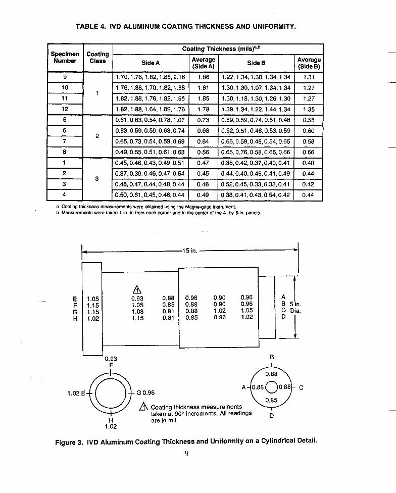
TABLE 4. IVD ALUMINUM COATING THICKNESS AND UNIFORMITY.
1.70,1.76,1.82,1.88,2.16
1.76,1.88,1.70,1.82,1.88
1.82,1.88,1.76,1.82,1.95
Specimen Number
1.86 1.22,1.34,1.30,1.34,1.34 1.31 1.81 1.30,1.30,1.07,1.34,1.34 1.27 1.85 1.30,1.18,1.30,1.26,1.30 1.27
9
12 5 6
10
1.82,1.88,1.64,1.82,1.76 1.78 1.39,1.34,1.22,1.44,1.34 1.35 0.61,0.63,0.54,0.78,1.07 0.73 0.59,0.59,0.74,0.51,0.48 0.58
- 0.83,0.59,0.59,0.63,0.74 0.68 0.92,0.51,0.46,0.53,0.59 0.60 -
1 1
7 8 1
I
Coating Class
- 0.65,0.73,0.54,0.59,0.69 0.64 0.65,0.59,0.48,0.54,0.65 0.58 0.49,0.55,0.51,0.61,0.63 0.56 0.65,0.76,0.58,0.66,0.66 0.66 0.45,0.46.0.43.0.49,0.51 0.47 0.38.0.42.0.37.0.40,0.41 0.40
Coating Thickness (mils)87b I Side A Average I (SideA) I Side 6 Average I (SideB) I
. 1 I 1
- 9 I I
0.37,0.39,0.46,0.47,0.54 0.45 0.44,0.40,0.46,0.41,0.49 0.44 0.48,0.47,0.44,0.48,0.44 0.46 0.52,0.45,0.33,0.38,0.41 0.42
a Coating thickness measurements were obtained using the Magne-gage instrument. b Measurements were taken 1 in. in from each corner and in the center of the 4- by 6-in. panels.
ss 15 in.
- E F G H
I 1
0.90 0.96 0.96 0.90 0.96
::88: 1 ::8888 1.02 1.05
A n a? 1.05 1.08
I E B -
0.93 F
1.02 E
H 1.02
G 0.96
at B 5 in.
C Dia.
A Coating thickness measurements taken at 90" Increments. All readings n
I
are in mil.
C
Figure 3. IVD Aluminum Coating Thickness and Uniformity on a Cylindrical Detail.
9

The uniformity of IVD aluminum on regular surfaces is approximately - +10
percent of the median thickness. Of equal importance is that the I V D aluminum coating thickness on the edge of a detail is virtually the same as that on the rest of the detail. Figure 4 shows the excellent thickness uniformity between the flat surface and the edge of a gas turbine engine blade. As shown in the figure, there is no buildup or thinning of the coating on sharp edges. The excellent uniformity of I V D aluminum does not depend on coating thickness - (Reference 6).
__
Blade Surface Blade Edge
Figure 4. IVD Aluminum Coating Uniformity on a Turbine Blade.
10

M e t a l l i c p r o c e s s i n g i n genera l i s l i m i t e d i n t h e coverage o f i n t e r n a l
s u r f a c e s . E l e c t r o p l a t e d cadmium, however, can g e n e r a l l y be f i x t u r e d w i t h i n t e r n a l anodes f o r coverage o f i n t e r n a l s u r f a c e s e a s i e r and more economica l l y
t h a n I V D aluminum. The I V D aluminum process w i t h o u t s p e c i a l f i x t u r i n g , w i l l e f f e c t i v e l y c o a t i n t e r n a l su r faces t o a dep th o f a t l e a s t one d iamete r
(Reference 7 ) . An e f f e c t i v e c o a t i n g f o r most a p p l i c a t i o n s i s cons ide red t o be
a 0.3 m i l (C lass 3 ) c o a t i n g o r t h i c k e r .
The use o f a complementary process, such as s a c r a f i c i a l aluminum-based
p a i n t s , i s recommended f o r complete coverage o f t h o s e recess su r faces which
exceed t h e p r a c t i c a l l i m i t a t i o n s o f I V D aluminum p rocess ing . The use o f I V D
aluminum i n comb ina t ion w i t h o t h e r compa t ib le processes t o p r o t e c t i n t e r n a l
su r f aces i s a recommended research program d iscussed i n S e c t i o n X I I (A) .
A b a r r e l accessory f o r t h e rack c o a t e r can be used f o r economica l l y
c o a t i n g sma l l d e t a i l s such as f a s t e n e r s . The e x c e l l e n t I V D aluminum c o a t i n g
u n i f o r m i t y of i n d i v i d u a l f a s t e n e r s and t h e t h i c k n e s s v a r i a t i o n th roughou t t h e
l o a a a re shown i n F i g u r e 5 and Table 5, r e s p e c t i v e l y (References 8 and 9 ) .
Table 6 summarizes t h e comparison o f coverage, u n i f o r m i t y , anci t h i c k n e s s between I V D aluminum and cadmium. I V D aluminum i s c l e a r l y s u p e r i o r i n t h e
area o f c o a t i n g u n i f o r m i t y on edges. It can a l s o be e a s i l y a p p l i e d t h i c k e r
t h a n cadmium which c o n t r i b u t e s t o c o r r o s i o n r e s i s t a n c e .
C. SURFACE SMOOTHNESS
With t h e I V U process, t h e aluminum vapor c l o u d i s p a r t i a l l y i o n i z e d i n t h e
argon gas glow d i s c h a r g e t h a t surrounas t h e p a r t b e i n g coated. This, i n a d d i t i o n t o c o l l i s i o n s w i t h t h e p o s i t i v e l y charged argon gas i o n s , a c c e l e r a t e s
t h e aluminum toward t h e p a r t su r face . The r e s u l t i s an adherent c o a t i n g t h a t
r e p l i c a t e s t h e s u r f a c e o f t h e p a r t ana m i r r o r s i t s s u r f a c e smoothness. T h i s
tendency b e g i n s t o d i m i n i s h s l i g h t l y , however, as t h e c o a t i n g t h i c k n e s s i nc reases and i t s columnar s t r u c t u r e becomes more pronounced. There fo re ,
11

Thickness Uniformity on Individual Fasteners 3M387-4-11 3M387-5-11
Recess 0.00050 in. Recess 0.00037 in.
Head 0.00055 in.
Shank 0.00050 in. Shank 0.00050 in.
Crest 0.00051 in. I I Crest 0.00049 in.
qUY Root 0.00037 in. I
Note: Fasteners randomiy selected from production coating run.
Root 0.00037 in. I
Figure 5. Typical IVD Aluminum Coating Uniformity of Barrel-Coated Fastners.
1 2
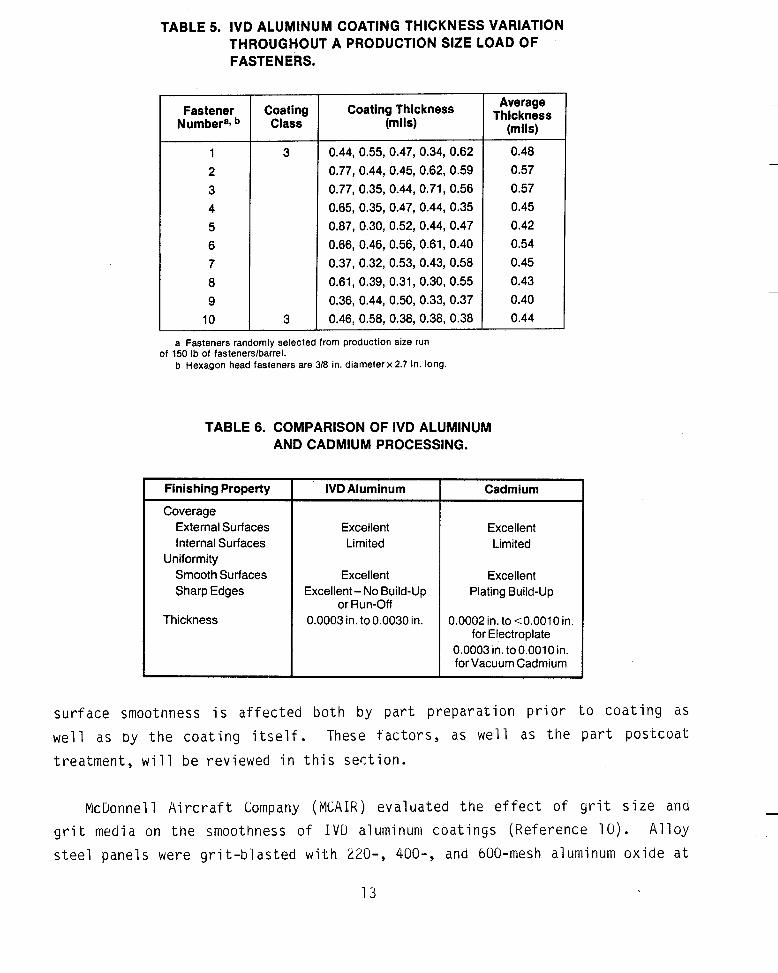
TABLE 5. IVD ALUMINUM COATING THICKNESS VARIATION THROUGHOUT A PRODUCTION SIZE LOAD OF FASTENERS.
Fastener Coating Coating Thickness Numbera* Class (mils)
1 3 0.44, 0.55, 0.47, 0.34, 0.62 2 0.77, 0.44, 0.45, 0.62, 0.59 3 0.77, 0.35, 0.44, 0.71, 0.56 4 0.65, 0.35, 0.47, 0.44, 0.35 5 0.87, 0.30, 0.52, 0.44, 0.47 6 0.66, 0.46, 0.56, 0.61, 0.40 7 0.37, 0.32, 0.53, 0.43, 0.58 8 0.61, 0.39, 0.31, 0.30, 0.55 9 0.36, 0.44, 0.50, 0.33, 0.37 10 3 0.46,0.58,0.38,0.38,0.3a
Average Thickness
(mils)
0.48 0.57 0.57 0.45 0.42 0.54 0.45 0.43 0.40 0.44
a Fasteners randomly selected from production size run
b Hexagon head fasteners are 318 in. diameter x 2.7 in. long. of 150 Ib of fastenerslbarrel.
TABLE 6. COMPARISON OF IVD ALUMINUM AND CADMIUM PROCESSING.
Finishing Property
Coverage External Surfaces Internal Surfaces
Smooth Surfaces Sharp Edges
Uniformity
Thickness
IVD Aluminum I Cadmium
Excellent Limited
Excellent Excellent- No Build-Up
or Run-Off 0.0003 in. to0.0030 in.
Excellent Limited
Excellent Plating Build-Up
0.0002 in. to <0.0010 in. for Electroplate
0.0003 in. to 0.001 0 in. for Vacuum Cadmium
surface smoothness i s affected b o t h by pa r t preparation prior t o coating as well as by the coating i t s e l f . These factors , as well as the p a r t postcoat treatment, will be reviewed in th i s section.
McUonnell Aircraft Company ( M C A I R ) evaluated the effect of g r i t s i ze a n d g r i t media on the smoothness of I V D aluminum coatings (Reference 10) . Alloy s teel panels were grit-blasted w i t h 220-, 400-, and 600-mesh aluminum oxide a t
13

a pressure of 50 psi . I n addition, some panels were gr i t -blasted w i t h 220-
mesh aluminum oxide, then peened w i t h e i ther BT-10 or the f ine r BT-13 glass beads. Al l panels were then IVD aluminum-coated t o an average thickness of 0.4 mil. The surface roughness, before and a f t e r 1 V D a l u m i n u m coating for various surface preparations, i s presented i n Table 7. These t e s t s showed tha t :
Before IVD
o Surface smoothness was v i r tua l ly unchanged by the re la t ive ly t h i n (0.4 mil) I V D a l u m i n u m coating.
After IVD
o The columnar s t ructure of the IVD a l u m i n u m coating became closer k n i t w i t h smoother substrate surfaces.
Average Roughness
Heighta
36
TABLE 7. EFFECT OF SUBSTRATE SURFACE PREPARATION ON IVD ALUMINUM COATING SMOOTHNESS.
Total Average Total Profile Roughness Profile Heightb Heighta Heightb
250 34 180
Surface Preparation
Grit Blasted, 220 Aluminum Oxide Grit, 50 psi Grit Blasted, 400 Aluminum Oxide Grit, 50 psi Grit Blasted, 600 Aluminum Oxide Grit, 50 psi Grit Blasted, 220 Aluminum Oxide Grit, 50 psi: Glass Bead Peen BT-1 0,40 psi Grit Blasted, 220 Aluminum Oxide Grit, 50 psi; Glass Bead Peen, 3T-13,40 psi 32 I 220 1 30 1 205
a Average Roughness Height is the RMS averagedeviation in pinches measured no;mal to the roughness centerline. b Total Profile Height is the distance in pinches from the lowest point to the highest F9int on the surface.
f i ner and
1 4

In another t e s t , MCAIK determined the e f fec t of g r i t blast ing, IVD coating, and subsequent glass bead peening on the smoothness of I V D a l u m i n u m coatings deposited upon smooth s teel plates (Reference 1 1 ) . The s tee l plates were 16.25 inches i n diameter and were machined t o a f in i sh h a v i n g a surface roughness o f less t h a n 20 microinches. The surface roughness before and a f t e r gri t blasting, a f t e r coating t o approximately 0.6 mi l , and a f t e r glass bead peening a t var ious pressures i s presented i n Table 8. These t e s t s demonstrated t h a t :
20
o Grit blast cleaning w i t h 400-mesh aluminum oxide g r i t had v i r t u a l l y no e f fec t on the surface f inish of the pa r t whereas the standard 220-mesh a l u m i n u m oxide g r i t increased the surface roughness.
30
o The IVD aluminum coating tended to mirror the surface f inish of the p a r t a l t h o u g h surface roughness increased on the average 22 percent a f t e r coating; t h i s increase i s n o t significant for most applications.
40
o The surface roughness of the coating increased w i t h glass bead peening because the relat ively large i m p i n g i n g glass beads cratered the aluminum coating.
TABLE 8. SURFACE FINISH DATA FOR IVD ALUMINUM PROCESSING.
60
I GritBlastData I Surface Roughness (win. RMS)'
40140 43/43 34/43 - -
35/43 38/40
Grit Size
- 400 400 220 220
- - - 53/55 50152
- -
I I Substrate
400
220 400
Blast Pressure
(Psi)
35 19/27 18/24
60 - 24/28 60 - 20121
35 35 35 35
After Coating
I After Glass Bead Peening (psi)
22/22 27/26 -
39/35 26/28
22123 25/29 52/56 I 63/76
Average Coating
Thickness (mils)"
0.5410.55 0.5110.54 b0.57/0.59 b0.59/0.56 0.5310.56
0.5710.60 0.5710.58
a First number given is Side 1 of each plate: second number is Side 2 b The four measurements from the outside edge of these plates were not used to calculate
the average thickness since they were not representative due to coating wraparound
15

A f t e r an I V D aluminum c o a t i n g i s glass-bead-peened , t h e s u r f a c e roughness
i s more dependent on t h e bead s i z e and peening p r e s s u r e t h a n on p a r t
p r e p a r a t i o n o r t h e c o a t i n g . BT-10 g l a s s beads produce I V D c o a t i n g s h a v i n g a
roughness o f app rox ima te l y 50 - 70 m ic ro inches a t 40 p s i . Smoother c o a t i n g s
can be o b t a i n e d b y r e d u c i n g t h e g l a s s bead peening p r e s s u r e and/or media s i z e .
Before Plating* After Plating
MCAIR e v a l u a t e d t h e smoothness o f 0.5 m i l t h i c k " b r i g h t " and
low-embr i t t l emen t cadmium f i n i s h e s on 4150 a1 loy s t e e l pane ls . The s t e e l
pane ls were g r i t - b l a s t e d w i th 120-mesh aluminum o x i d e g r i t p r i o r t o p l a t i n g .
The s u r f a c e roughness o f t h e s t e e l panels b e f o r e and a f t e r cadmium p l a t i n g and a f t e r a hand b u r n i s h i n g w i t h an ab ras i ve ' n y l o n web pad i s p resen ted i n Table
9. These t e s t s showed t h a t t h e s u r f a c e roughness o f t h e p a r t s a f t e r p l a t i n g ~
was n o t s i g n i f i c a n t l y changed, and hand b u r n i s h i n g improved s u r f a c e smoothness
approx ima te l y 10 - 40 pe rcen t .
After Plating Before Platinga and Burnishingd
TABLE 9. EFFECT OF POSTCOATING TREATMENT ON THE SMOOTHNESS OF CADMIUM PLATING.
Bright Cadmium Average Roughness Heightb Total Profile Height'
Low-Embrittlement Cadmium Average Roughness Heightb Total Profile Height'
I Surface Roughness (pin.)
87 85 87 79 526 51 9 550 473
a3 87 56 32 474 61 1 374 21 5
Plating
Smooth c o a t i n g s , o r t hose t h a t can be p o l i s h e d u n t i l t h e y a re smooth, a re
i m p o r t a n t i n j e t engine a p p l i c a t i o n s . P r o t e c t i v e f i n i s h e s w i t h low drag c h a r a c t e r i s t i c s m i n i m i z e f u e l consumption ana e r o s i o n i n t h e a i r f l o w s e c t i o n s
o f engines. MCAIK e v a l u a t e d s e v e r a l methods o f p o l i s h i n g I V D aluminum
c o a t i n g s (Reference 12 ) . Compressor b lades, s e c t i o n s o f a s t a t o r assembly,
and a l l o y s t e e l pane ls were IVD aluminum-coated and then p o l i s h e d as shown i n - F i g u r e 6. Photomicrographs o f an "as-coated" I V D aluminum su r face , a
glass-bead-peened I V D aluminum su r face , and two p o l i s h e d I V D aluminum su r faces
1 6

Compressor Blade - 1.5 x 3.5 in. Section of Stator Assembly - 2 x 3.5 in.
Steel Panel - 1 x 4 in.
Figure 6. Typical Specimens for Polished IVD Aluminum Coatings.
a r e presented i n F i g u r e 7. Sur face f i n i s h i n f o r m a t i o n and comments on t n e
p o l i s h i n g techn ique used a r e g i v e n i n Table 10. These t e s t s demonstrated t h a t
I V D aluminum c o a t i n g can be p o l i s n e d t o a s u r f a c e f i n i s h o f l e s s t h a n L O
m ic ro inches . Th is e a s i l y s a t i s f i e s requi rements such as P r a t t and Whitney
S p e c i f i c a t i o n 110-4 f o r c o a t i n g smoothness on compressor and s t a t o r b lades.
The t e s t s a l s o showed t h a t I V D aluminum c o a t i n y s can be p o l i s h e d t o a s u r f a c e f i n i s h of 10 t o 20 m i c r o i n c h e s w i t h o u t s i g n i f i c a n t removal o f t h e c o a t i n g ,
even on t h e sharp l e a d i n g o r t r a i l i n g edges o f t h e compressor b lades.
I n summary, I V D aluminum c o a t i n g and cadmium p l a t i n g r e p l i c a t e t h e s u r f a c e f i n i s h o f t h e s u b s t r a t e . The e f f e c t on s u r f a c e smoothness o f 0.5 m i l t n i c k o r
l e s s I V D aluminum o r cadmium f i n i s h e s i s smal l . Sur face smoothness o f 1 V D aluminum c o a t i n g s decreases as t h i c k n e s s increases. Both I V D aluminum c o a t i n g
and caamium p l a t i n g can be p o l i s h e d t o produce smoother f i n i s h e s .
0. TEMPERATURE
I V D aluminum can be used i n a p p l i c a t i o n s where s e r v i c e tempera tu re requi rements a re c o n s i d e r a b l y h i g h e r t h a n t h a t a l l owed f o r cadmium. 1VD
aluminum can be used a t temperatures up t o 9 2 5 O F w i t h o u t any adverse e f f e c t s .
17

IVD Aluminum Coating at 39 Microinch Finish (Substrate Surface Cleaned
with 220 Aluminum Oxide Grit at 80 psi)
IVD Aluminum Coating Glass Bead Burnished to 62 Microinch Finish
(Wiih BT-1 0 Beads at 20 psi) - -
IVD Aluminum Coating Polished to '1 8 Microinch Finish
IVD Aluminum Coating Polished to 10 Microinch Finish - "
Figure 7. Smoothness of IVD Aluminum Surfaces Before and After Polishing.
18

TABLE 10. POLISHING DATA FOR IVD ALUMINUM COATINGS.
7
Finish
18 (Fin.) -
36
36
10
10
24
40
62
Polishing Media
1/8 in. Microbrite
Ceramic "F-50%, 118 in. Cylinders and 50%, 3/16 in. Cylinders
Plastic Cone-314 in. Base, 314 in. High, Tumbled
Steel Balls, Tumbled
Porcelain; 3/16 in. by 1/2 in. Cone
Steel Diagonals-3/16 in.
None
BT-IO Glass Beads
Polishing Compound
BBOI 0
550 Flowthrough
Acid Burnishing Compound
Unknown
MA-30
Soap
Comments
Highly Reflective Surface- No Coating Removal on Edges or Corners
Some Removal of Coating at Edges
Moderate Polish -No Surface or Edge Damage
Removed of Coating at Edges - Excellent Surface Polish
Some Removal of Coating at Edges
Severe Edge and Corner Coating Removal
IVD Surface as Coated
Burnished at 20 psi
Cadmium melts at 600°F but is usually limited to a 450°F service temperature because o f embri ttl ement that can occur at higher temperatures. Above 6GO"F, molten cadmium embrittles high-strength steel by grain boundary penetration. It has been shown, however, that cadmium plating can also cause cadmium embrittlement at temperatures as low as 450°F on highly stressed parts.
The hiyher I V D aluminum service temperature has been a solution to numerous finishing problems involving applications above the 450°F limit for cadmium. The following examples are provided:
o DC-9 Main Lanaing Gear Piston Brake Flange Bolt - For this high-strength steel detail, it was found that cadmium plating melted, chrome plating galled, anu nickel plating imposed hydrogen embrittlement problems. The selection of IVD aluminum for this detail provided:
- Acceptable service temperature - Acceptable installation characteristics - No hydrogen embrittlement - Acceptable corrosion resistance
15

o DC-10 Aft Engine Hangers - For t h i s 4130 alloy s teel de ta i l subjected t o a 800-9OO0F service temperature, an aluminum-fil led paint-type coating was or iginal ly selected over diffused nickel-cadmium as the best available h i g h temperature protective coating. However, one air1 ine reported (Reference 13) tha t i t was necessary t o remove and refurbish these mounts every 1500 t o 3000 f l i g h t hours to retain adequate corrosion resistance. The amount of time the a i r c r a f t was o u t of service for refurbishment was deemed t o be prohibitive. As a r e su l t , United Airline was the f i r s t ca r r i e r t o i n s t a l l an IVD a1 uminum-coated moun t (see Figure 8) .
Figure 8. IVD Aluminum-Coated DC10 Aft Engine Hanger.
Their f i r s t report a f t e r one year of service, about 3500 f l i g h t hours, stated sat isfactory performance. This same moun t now has over 10,000 f l i g h t hours o f service without being refurbished (Reference 1 4 ) . As a resul t
suggesting t h a t the engine mounts be refurbished w i t h IVD a l u m i n u m (Reference 1 5 ) . United Airlines, f o r one, nas h a d t he i r complete DC-10 f l e e t refurbished w i t h IVD a l u m i n u m , and Boeing i s using IVD a l u m i n u m on the engine mounts of - t h e i r newest commercial a i r c ra f t .
of t h i s performance, Douglas Aircraft issued a l e t t e r t o a l l DC-10 car r ie rs .~

o F-15E Landing Gear Assemblies - The F-15 lanaing gear components had been cadmium-plated before the F-15E model which is heavier than preceding models. This added weight increased the temperature of some landing gear components during braking action to approximately 4 5 O O F . When testing indicated possible cadmium embrittlement conditions, MCAIR recommended a change from cadmium to IVD ?luminum. The selection of IVD aluminum eliminated embrittlement concerns wit ‘id metals as well as with hydrogen.
In summary, I V D and there is no elr’
-e the temperature capabi 1 ity of cadnii um,
E. ELECTRICP.
IVD aluminum dpplemental chromate conversion coating is electrically conducti, ne coating meets the requirements specified in MIL-C-81706 for the elec-rical contact resistance of aluminum alloy panels. This specification requires that an aluminum alloy substrate treated with a class 3 material per MIL-C-5541 shall not have a contact resistance greater than 5,000 microhms per square inch as applied, and 10,000 microhms per square inch after exposure to 5 percent salt spray for 168 hours. The electrical measurements are made with an electrode pressure of 200 pounds per square inch (psi) applied to the treated area.
In an effort to further quantify the electrical characteristics of IVD aluminum, conductivity tests were performed by PICAIR (Reference Ib). IVD aluminum was applied to glass sliaes and the conductivity was compared to that of 1100-alloy aluminum wire that had been melted and polisned to provide a standard reference. These tests showed that the IVD aluminum coating has approximately 48 percent of the conauctivity of the bulk 1100 alloy. Tnis is significant in that bulk aluminum is approximately three times more conductive than caamium.
The Pratt & Whitney Aircraft Group also performed electrical tests on IVD aluminum and other commercially available finishes (Reference 17). The IVD aluminum coating displayed the lowest electrical resistance within the tested
21

group which included diffused nickel-cadmium. These finishes had to meet a temperature requirement o f 5 0 O O F which is above the 450°F temperature limit of standard electroplated cadmium. The rough order of magnitude readings were unable t o pick up any resistance in the IVD aluminum coatings as shown by a portion of the data presented in Table 11.
Finish
IVD Aluminum #I (With Conversion Coat)
IVD Aluminum #2 (With Conversion Coat)
IVD Aluminum (Without Conversion Coat)
Diffused Nickel-Cadmium
E-Nickel-Cadmium
TABLE 11. ELECTRICAL RESISTANCE MEASUREMENTS TAKEN ON VANE SPECIMENS.
Nominal Thickness Electrical Resistance (mils) (ohms)
1.5 0
1.5 0
2.0 0
0.3-0.5 0.7 0.7-0.8 0.3
Electrical conductivity coupled with the proven corrosion resistance of IVD aluminum coatings has led to its use in applications requiring both capabilities. These are discussed in detail in Section V I ( A ) . IVD aluminum is used for electrical bonding and electromagnetic interference compatibility (E IYIC) . F . COMPATI BI L I TY
The aluminum coating deposited by the IVD process exhibits the same alloy composition as the basic 1100 aluminum alloy evaporant (Reference 18). The
1100 alloy aluminum ana cadmium have similar electrolytic solution potentials, -0.83 and -0.82 volts, respectively, when measured against tne standard calomel electrode (Reference 19). Since mild cirbon steel has a solution potential of 4 . 5 8 volts, both IVD aluminum and cadmium provide sacrificial corrosion protection in aqueous environments. Section I11 compares the corrosion protection provided to alloy steel substrates by IVD aluminurn coatings and various cadmium platings.
-

Cadmium f i n i s h e s a r e p r o h i b i t e d on f a s t e n e r s , f u e l l i n e s , ana o t h e r
components where t h e y may come i n t o c o n t a c t w i t h a i r c r a f t f u e l s (Reference
20). I n c o n t r a s t , I V D aluminum c o a t i n g i s c o m p a t i b l e w i t h a i r c r a f t f u e l s and
o i l s . A d d i t i o n a l i n f o r m a t i o n on t h e usage o f I V D aluminum i n c o n t a c t w i t h
fue l s , o i l s , and o t h e r f l u i d s i s f ound i n S e c t i o n V I ( F ) .
Cadmium c o a t i n g s a re a l s o p r o h i b i t e d f rom b e i n g i n c o n t a c t w i t h t i t a n i u m
because s o l i d me ta l e m b r i t t l e m e n t may r e s u l t . I V D aluminum i s c o m p a t i b l e w i t h
t i t a n i u m and i s used on a i r c r a f t t o e l i m i n a t e d i s s i m i l a r meta l problems
between aluminum and t i t a n i u m s t r u c t u r e s . A d d i t i o n a l i n f o r m a t i o n on t h e usage o f I V D aluminum on t i t a n i u m s u b s t r a t e s i s found i n S e c t i o n V I (B ) .
I V D aluminum c o a t i n g s a re more compa t ib le f o r h i g h e r tempera tu re
a p p l i c a t i o n s t h a n cadmium p l a t i n g s . I V D aluminum c o a t i n g s can be used a t temperatures up t o 525'F (compared t o 450'F f o r cadmium). A lso I V D aluminum
c o a t i n g s a r e more compa t ib le f o r h i g h - s t r e n g t h s t e e l a p p l i c a t i o n s because
e l e c t r o p l a t e d cadmium causes hydrogen e m b r i t t l e m e n t problems; h i g h - s t r e n g t h
s t e e l p a r t s must be e m b r i t t l e m e n t r e 1 i eved by a long, h igh - tempera tu re bake.
No hydrogen i s generated d u r i n g t h e I V D c o a t i n g process. D iscuss ions on h igh - tempera tu re usage and on hydrogen e m b r i t t l e m e n t can be found e a r l i e r i n
S e c t i o n I I ( D ) and S e c t i o n IV(A), r e s p e c t i v e l y .
I V D aluminum c o a t i n g s and cadmium f i n i s h e s a r e b o t h compa t ib le w i t h
a i r c r a f t p a i n t systems. A a d i t i o n a l i n f o r m a t i o n on p a i n t adhesion o f I V D
aluminum and cadmium f i n i s h e s i s found i n S e c t i o n I I ( G ) .
Table 12 summarizes t h e c o m p a t i b i l i t y o f I V D aluminum and cadmium f i n i s h e s
f o r t h e v a r i o u s a p p l i c a t i o n s reviewed. As shown, I V D aluminum i s more compa t ib le than cadmium.
G. TOPCOAT ADHESION
Topcoats such as p a i n t s , sea lan ts , l u b r i c a n t s , e t c . a r e used t o improve t h e performance of t h e u n d e r l y i n g basecoat. For example, t opcoa ts a re used t o improve c o r r o s i o n r e s i s t a n c e , improve e r o s i o n r e s i s t a n c e , o r change t h e

TABLE 12. COMPATIBILITY OF IVD ALUMINUM AND CADMIUM FINISHES.
Compatible With
Jet Fuel
Titanium
Hydraulic Fluids and Oils
Temperature Low (Up to 450°F) High (450°F-950°F)
Alloy Steel Low Strength High Strength
Aluminum Alloy Structure
Cadmium Plating
No
No
No
Yes No
Yes Yes
(Ernbrittlement Relief Required)
Yes
Yes
IVD Aluminum Coating
Yes
Yes
Yes
Yes Yes
Yes Yes
Yes
Yes
c o e f f i c i e n t o f f r i c t i o n o f a f i n i s h system. The a p p l i c a t i o n ana success fu l
performance o f any t o p c o a t i s dependent on basecoat q u a l i t i e s such as coverage, u n i f o r m i t y , and adhesion. I V U aluminum i s c n a r a c t e r i z e d by
e x c e l l e n t adhesion, coverage (non l i n e - o f - s i g h t ) , and u n i f o r m i t y (no b u i l d u p o r r u n - o f f on edges) as d iscussed i n Sec t i ons I I ( A ) and ( B ) .
P a i n t p r i m e r and t o p c o a t adhesion a r e g e n e r a l l y o f t h e most i n t e r e s t t o
m i l i t a r y and i n d u s t r i a l users. Aluminum a l l o y s u r f a c e s r e q u i r e a chromate
c o n v e r s i o n c o a t i n g f o r accep tab le p a i n t adhesion. Therefore, p a i n t adhesion
t o t h e I V D aluminum 1100 a l l o y m igh t be expected t o be approx ima te l y t h e same
as p a i n t adhesion t o any o t h e r aluminum a l l o y as l o n g as b o t h a re chromate
c o n v e r i o n coated. I n f a c t , p a i n t adhesion t o I V D aluminum i s b e t t e r t h a n t o a
wrought aluminum s u r f a c e because o f t h e s t r u c t u r e o f t h e c o a t i n g . I V D
aluminum condenses f rom t h e aluminum vapor c l o u d o n t o t h e p a r t s u r f a c e t o f o r m
l a y e r s of aluminum a r e dense ana r e l a t i v e l y homogeneous, m inu te spaces betweeli
a d j a c e n t columns a r e formed as t h e columnar s t r u c t u r e grows. As a r e s u l t , t h e
p a i n t system (and o t h e r t o p c o a t s ) can p e n e t r a t e i n t o these spaces. Because i t
has many anchor p o i n t s , t h e p a i n t t o p c o a t w i l l adhere t o t h e aluminum basecoat.
a c o a t i n g w i t h a un i fo rm, columnar s t r u c t u r e ; see F i g u r e 9. A l tnough t h e base .~
-
24

Surface of Aluminum Coating
Edge (Thickness) of Fractured
Aluminum Coating
Fractured Steel Substrate
Figure 9. Scanning Electron Photomicrograph of the IVD Aluminum Columnar Structure.
M C A I R e v a l u a t e d t h e p e n e t r a t i o n o f an epoxy p r i m e r i n t o t h e columnar
s t r u c t u r e o f an I V D aluminum-coated f a s t e n e r (Reference 21). The f a s t e n e r was
s e c t i o n e d th rough t h e t h r e a d s and one p i e c e was etched i n a 1 0 p e r c e n t sodium
h y d r o x i d e s o l u t i o n t o d i s s o l v e t h e aluminum. k scanning e l e c t r o n microscope
examina t ion of t h i s e tched system showed a s k e l e t o n o f p r i m e r e x t e n d i n g w e l l
i n t o t h e I V D aluminum c o a t i n g . This t e s t v e r i f i e d t h a t t o p c o a t p e n e t r a t i o n
i n t o t h e I V D aluminum columnar s t r u c t u r e d i d occu r t o enhance adhesion.
The Boeing Company e v a l u a t e d p a i n t adhesion on f l u s h head f a s t e n e r s
i n s t a l l e d i n an aluminum a l l o y panel . A 0.5-0.8 m i l t h i c k l a y e r o f BMS 10-79
p r i m e r f o l l o w e d by a 1.5-2.0 m i l t h i c k l a y e r o f BMS 10-60, Type I 1 enamel was a p p l i e d t o t h e heads o f I V D aluminum-coated and cadmium-plated f a s t e n e r s . Tne
p i i n t system was cured f o r seven days a t 70 - + 5°F and 40 pe rcen t r e l a t i v e h u m i d i t y . The adhesion o f t h e p a i n t system was eva lua ted d r y and wet, a f t e r a
7 - day soak i n d i s t i l l e d water a t 70°F. Boeing r e p o r t e d s a t i s f a c t o r y p a i n t adhesion on t h e I V D aluminum- and cadmium-f in ished f a s t e n e r heads, b o t h b e f o r e
and a f t e r t h e w a t e r soak (Reference 2 2 ) .
25

The real ver i f ica t ion of paint adhesion i s the tens of thousands of a i r c r a f t par ts coated w i t h IVD aluminum now i n service. Production experience has shown t ha t adhesion o f the various paint systems t o IVD aluminum basecoats required v i r tua l ly no in-house rework. In the 1 2 years painted par t s have been ins ta l led on a i r c r a f t , few, i f any, paint adhesion problems have been reported t o MCAIK from the mili tary services.
Sometimes cetyl alcohol or dry fi lm lubricants are used on IVD aluminum-coated, threaded par t s d u r i n g the in s t a l l a t ion of nuts or d u r i n g the in s t a l l a t ion of the coated fas teners into close tolerance holes. These and most other commonly used a i r c r a f t lubricants are compatible w i t h aluminum. The use of lubricants i s discussed i n more de t a i l i n Section V and XII(C).
Another example where IVD aluminum i s used as a basecoat i s tne application of ceramic sealcoats. Metallic-ceramic coatings per MIL-C-81751 are used t o protect s tee l par t s from corrosion by both the A L C s on engine par ts and NAVSEA fo r various marine applications. The two-part coating system consists of a s a c r i f i c i a l aluminum paint basecoat and a ceramic sealcoat. Such co ings include those under the commercial names AlseaQ X y l a D a n d S e r m B B The use of IVD aluminum as the s a c r i f i c i a l aluminum basecoat and Xyla 101 as the ceramic sealcoat produces a metallic-ceramic coating tha t ea s i ly meets the 1000 hour corrosion resistance i n neutral s a l t fog required by MIL-C-81751. Figure 10 shows two alloy s tee l fas teners , s t i l l protected w i t h IVD aluminumlxyla @ 101 a f t e r 18,000 hours i n 5 percent neutral s a l t fog.
Figure 10. Alloy Steel Fastener With IVD Aluminum and Xylar@Topcoat After 17,952 Hours of Neutral Salt Fog Exposure.
26

I V D aluminum p r o v i d e s a s u p e r i o r basecoat because i t c o v e r s u n i f o r m l y , does
n o t b u i l d up o r r u n o f f edges and adheres s i g n i f i c a n t l y b e t t e r t h a n t h e
aluminum p a i n t basecoats. I n s u f f i c i e n t coverage on edges and poor adhesion
a r e f i e l d prob ems f o r many m e t a l l i c - c e r a m i c c o a t i n g s . I n i t i a l t e s t i n g o f I V D
i t s use t o i n c r e a s e c o r r o s i o n r e s i s t a n c e and enhance e r o s i o n r e s i s t a n c e .
aluminum/Xyla b 101 b y M C A I K (References 23, 24 and 25 ) shows promise f o r
I n summary, t h e adhesion o f t opcoa ts t o I V D aluminum can be c a t e g o r i z e d as
e x c e l l e n t . T h i s i s due t o t h e i n h e r e n t q u a l i t i e s o f t h e I V D aluminum c o a t i n g
i n c l u d i n g i t s coverage, u n i f o r m i t y , adhesion, as w e l l as i t s columnar
s t r u c t u r e which a l l o w s t o p c o a t p e n e t r a t i o n .
H. EROSION RESISTANCE
Bo th I V D aluminum and cadmium a r e s o f t c o a t i n g s and a r e n o t p a r t i c u l a r l y
w e l l s u i t e d f o r e r o s i o n r e s i s t a n c e when used by themselves. Never the less , I V D
aluminum w i l l o u t p e r f o r m vacuum cadmium i n r e s i s t i n g a b r a s i v e f o r c e s and
d i f f u s e d n icke l -cadmium when s u b j e c t e d t o an e r o s i o n / c o r r o s i o n env i ronment . I n a a d i t i o n , I V D aluminum has advantages over cadmium f o r such an
a p p l i c a t i o n . F i r s t , I V D aluminum can be economica l l y a p p l i e d t h i c K e r than cadmium and, t h e r e f o r e , o u t l a s t cadmium when s u b j e c t e d t o a b r a s i v e f o r c e s .
Second, I V D aluminum i s w e l l s u i t e d t o b e i n g overcoated w i t h ab ras ion
r e s i s t a n t m a t e r i a l s . Research t o improve t h e e r o s i o n r e s i s t a n c e o f I V c l
aluminum w i t h t o p c o a t s i s d i scussed i n S e c t i o n XII( t3) .
A l though t h e adhesion o f I V D aluminum and vacuum cadmium t e s t e q u a l l y w e l l u s i n g bena-to-break coupons, I V D i s f a r s u p e r i o r i n r e s i s t i n g a b r a s i v e
p a r t i c l e s . Th is i s i m p o r t a n t i n t h a t I V D aluminum and vacuum cadmium c o a t i n g s
a re o f t e n used on f i x e d and r o t a r y wing a i r c r a f t l a n d i n g gears, because
n e i t h e r process causes hydrogen en ib r i t t l emen t o f t h e h i g h - s t r e n g t h s t e e l
d e t a i l s . However, f o r such a p p l i c a t i o n s , t h e c o a t i n g s a re suDjected t o
a b r a s i v e media d u r i n g takes3ff and l a n d i n g opera t i ons , and t h e s u p e r i o r I V D
aluminum c o a t i n g w i l l r e q u i r e l e s s maintenance. MCAlR compared t h e e r o s i o n
r e s i s t a n c e of vacuum cadmium and I V D aluminum u s i n g b o t h g l a s s beads and aluminum o x i d e g r i t (Reference 26 ) . F i g u r e 11 shows t h e s u p e r i o r i t y of 1VD
aluminum i n r e s i s t i n g a b r a s i v e p a r t i c l e s .
L7

Nozzle 6 in. away at 40 psi
Figure 11. Erosion Resistance of IVD Aluminum Versus Vacuum Cadmium.
I n t e s t s conducted by P r a t t and N h i t n e y (Reference 17 ) , I V D aluminum w i t h
a s tandard chromate c o n v e r s i o n c o a t i n g was shown t o erode f a s t e r t h a n t h e
comb ina t ion c o a t i n g o f d i f f u s e d nickel-caamium. However, because t h e I V D aluniinum c o a t i n g was a p p l i e d t h i c k e r (1.5 m i l s vs 0.7 m i l s ) , t h e r e was
adequate I V D aluminum rema in ing a t t h e c o n c l u s i o n o f t h e t e s t . More
e r o s i o n process Imcur red . With d i f f u s e d nickel-cadmium, t h e cadmium erodes
v e r y r a p i d l y , l e a v i n g o n l y t h e n i c k e l c o a t i n g which o f f e r s no anodic
p r o t e c t i o n t o t h e s u b s t r a t e . I n f a c t , subsequent t e s t i n g b y P r a t t and Whitney
showed I V D aluminum t o be t h e b e s t c o a t i n g t e s t e d on 4 1 0 - a l l o y s t e e l .
S p e c i f i c a l l y , I V D aluminum outperformed b o t h d i f f u s e d n icke l -cadmium and
i m p o r t a n t l y , I V D aluminum p r o v i d e d b e t t e r p r o t e c t i o n t o t h e s u b s t r a t e as t h e .~

Emplate n i c k e l -422/cadmium i n an e r o s i o n / c o r r o s i o n env i ronment . T h i s was t r u e
f o r I V D aluminum samples s u p p l i e d b o t h w i t h and w i t h o u t a s tandard chromate c o n v e r s i o n c o a t i n g , and a sample s u p p l i e d w i t h a Chromal loy p r o p r i e t a r y
c o n v e r s i o n c o a t i n g .
I n o t h e r t e s t i n g o f c o a t i n g s f o r f i r e r e t a r d a t i o n o f t i t a n i u m t u r b i n e
eng ine b lades (Reference 27) , t h e e r o s i o n r a t e o f I V D aluminum was shown t o be
s l i g h t l y h i g h e r t h a n a comb ina t ion c o a t i n g o f p l a t i n u m / c o p p e r / n i c K e l f o r
90-degree and 60-degree angles o f inc idence, b u t a c t u a l l y l ower f o r t h e
30-degree angle. Erosion, t h e r e f o r e , was n o t d e t r i m e n t a l t o t h e p o t e n t i a l use
o f I V D aluminum f o r t h a t a p p l i c a t i o n .
I n a d d i t i o n t o t h e above, I V D aluminum was s u c c e s s f u l l y t e s t e d i n b o t h t h e
l a b o r a t o r y and i n f i e l d s e r v i c e by Westinghouse f o r use on steam t u r b i n e b laues (Reference 26 and 29). I V D aluminum has subsequent ly been p u t i n t o
p r o d u c t i o n f o r t h i s c o r r o s i o n / e r o s i o n a p p l i c a t i o n . These t e s t s a re d i scussed i n more d e t a i l i n S e c t i o n I l I ( B ) .
The f o r e g o i n g e s t a b l i shes t h a t I VIJ a1 umi num, a1 though n e i t h e r i t n o r
cadmium should be cons ide red an a b r a s i v e r e s i s t a n t c o a t i n g , does i n f a c t
o u t p e r f o r m cadm um i n sucn a p p l i c a t i o n s . F u r t h e r , I V D aluminum i s equal t o o r
b e t t e r t h a n t h e comb ina t ion d i f f u s e d nickel-cadmium c o a t i n g f o r
c o r r o s i o n / e r o s i n a p p l i c a t i o n s . The p r i m a r y reason f o r i t s s u p e r i o r
performance i s t h a t i t can be a p p l i e d t h i c k e r , and a l s o i t p r o v i d e s
s a c r i f i c i a l c o r r o s i o n p r o t e c t i o n th roughou t i t s e n t i r e th i cKness d u r i n g t h e
e r o s i o n process. Therefore, t h e s u b s t i t u t i o n o f I V D aluniinum f o r cadmium
shou ld n o t be impeded because of an e r o s i o n r e s i s t a n t requ i remen t except where
t h i n I V c l aluminum i s r e q u i r e d because o f t o l e r a n c e requi rements. I n t h i s case, ab ras ion r e s i s t a n c e supplemental t o p c o a t s o f f e r p o t e n t i a l as d i scussea
i n S e c t i o n X I I ( B ) .

SECTION I11
COKROSIO h RES I STANCE
A. MIL-SPEC REQUIREMENTS AND TYPICAL TEST RESULTS
M i l i t a r y S p e c i f i c a t i o n MIL-C-83488 e s t a b l i s h e s t h e requ i remen ts f o r
c o a t i n g low a l l o y s t e e l , s t a i n l e s s s t e e l , aluminum a l l o y , and t i t a n i u m a l l o y
p a r t s w i t h h i g h p u r i t y aluminum u s i n g t h e i o n vapor d e p o s i t i o n process. I t
i d e n t i f i e s t h r e e c lasses and two t y p e s o f c o a t i n g s . Class 1 c o a t i n g s a re t h e
t h i c k e s t and a re g e n e r a l l y used because t h e y p r o v i d e t h e b e s t c o r r o s i o n r e s i s t a n c e . Class 2 and 3 c o a t i n g s a r e t h i n n e r and a re g e n e r a l l y used f o r
p a r t s w i t h t o l e r a n c e l i m i t a t i o n s such as f a s t e n e r th reads . Type I i s "as
coated." Type I 1 has a supplementary chromate t r e a t m e n t i n accordance w i t h
MiL-C-5541 and i s recommended because t h e chromate p r o v i d e s a d d i t i o n a l
c o r r o s i o n p r o t e c t i o n . It a l s o forms a good base f o r p a i n t adhesion aria i s a
common t r e a t m e n t f o r aluminum su r faces .
MIL-C-83488 r e q u i r e s t h a t ''a ranaom sample o f two a r t i c l e s s h a l l be taken
f r o m any i n s p e c t i o n l o t a t a minimum o f once pe r month o r two s e p a r a t e l y
coated specimens ( o f 4130 a l l o y s t e e l ) s h a l l be prepared (c leaned and coated
as a t y p i c a l p r o d u c t i o n l o a d ) t o r e p r e s e n t an i n s p e c t i o n l o t . " The s e l e c t e a
specimens a re t e s t e d i n a n e u t r a l s a l t f o g environment p e r ASTM Method b117 t o e s t a b l i s h t h e c o r r o s i o n r e s i s t a n c e o f t h e aluminum c o a t i n g . MIL-C-83488
s p e c i f i e s t h a t t h e t e s t specimens " s h a l l show no ev idence o f c o r r o s i o n o f t h e
b a s i c me ta l when exposed f o r t h e p e r i o d o f t i m e shown i n Table 13."
Dur ing t h e e a r l y 1570s, t h e I V D aluminum c o a t i n g process had advanced a t
t h e McDonnell A i r c r a f t Company (MCAIR) f r o m a l a b o r a t o r y t o a p i l o t p r o d u c t i o n s t a t u s . F u l l p r o a u c t i o n use began i n 1976. S ince t h a t t ime, thousands o f
p a r t s f o r t h e F-4, F-15, F-18 and AV-8B t i r c r a f t have been processed. MCAIk has t h r e e p r o d u c t i o n c o a t e r s in-house t o suppor t t h e i r e x t e n s i v e use o f I V D
aluminum c o a t i n g s . Once a month f o r each coa te r , two 4- by 6 - inch , 4130 s t e e l
specimens a r e I V D aluminum Coated t o each of t h e t h r e e t h i c k n e s s c lasses .
These process c o n t r o l specimens a re s e n t t o t h e q u a l i t y Assurance L a b o r a t o r y
30

TABLE 13. MINIMUM REQUIREMENTS OF MIL.C-83488 FOR NEUTRAL SALT FOG EXPOSURE.
Salt Fog Minimum
Thickness 'lass
0.0010 0.0005 0.0003 336
a Type I - as coated b Type II -with supplementary chromate
treatment
for corrosion resistance testing. Some 2000 specimens have been tested since 1976 (Reference 30). A11 of the specimens have met MIL-C-83488 requirements.
In addition to monthly in-house corrosion testing in support o f aircraft production, MCAIH also requires that all new suppliers of the IVD aluminum coating process provide specimens for testing. Four IVD aluminum-coated 4-inch by 6-inch, 4130 steel panels are required for each of the three tnicmess classes. The specimens are submitted to the laboratory to verify that the supplier can produce coatings tnat will satisfy the corrosion resistance requirements of MIL-C-83488. Since 1976, over 30 supplier coaters have been certified (Reference 31). Unce a supplier becomes certified as an approved source, he must perform monthly corrosion resistance tests to the NIL-SPEC requirements. Suppliers have not reported any problems meeting these conditions.
MCAIK's laboratory research with IVD aluminum coatings provides an additional source of corrosion test data. Corrosion resistance has been measured and recorded for most coating cycles conducted in the 1aDoratory. .These coating cycles include large numbers of steel prototype parts for MCAIR, other companies, ana the military services. Subsequent reports on corrosion performance by these external sources provide an important substantiation of MCAIR testing.
31

e
The compilation of information over the past decade from production activities, laboratory evaluations, and independent testing has produced a unique and extensive data base on the corrosion resistance of IVD aluminum. From this data base, a well substantiated, typical performance level for each class of the IVD aluminum coating can be established.
An examination of the MCAIR data base was made for those specimens tested to failure in a 5 percent neutral salt fog environment. Failure is considered to have occurred at the first sign of red rust which results when the IVD aluminum coating is depleted to the extent it can no longer sacrificially protect the steel substrate. Some 900 data points were randomly extracted for 4130 steel test panels representing hand-fixtured details and alloy steel NAS 584 fasteners representing barrel-fixtured details. For the test panels, there are 148 data points for Class 1 coatings, 167 for Class 2, and 56 for Class 3 . For the test fasteners, there are 13 data points for Class 1, 237 for Class 2 , and 284 for Class 2.
The MIL-C-83488 corrosion resistance requirement and the average time to failure for the three IVD aluminum coating classes are shown in Figure 12. IVD aluminum performs extremely well. Class 1 coatings average approximately
Hours In
Neutral Salt Fog (1,000)
9
8
7
6
5
4
3
2
1
0
MlL-C-83488 a Test Fasteners
Class 3 Class 2 Class 1 Neutral Salt Fog Resistance
Figure 12. Average Test Results Versus Minimum Requirements of Mil-C-83488.

9000 hours and Class I 1 1 coatings about 1000 hours in the 5 percent neutral salt fog environment. On the test panels, the average corrosion resistance of Class 1, 2, and 3 I V D aluminum coatings exceeds the requirements o f
MIL-C-83488 by a factor of 13.2, 5.8, and 2.4, respectively. For the test fasteners, the average corrosion resistance of Class 1 , 2, ana 3 I V D aluminum coatings exceeds the requirements of MIL-C-83488 by a factor of 12.2, 5.1, and 3.0, respectively. The correlation between the test panels and fasteners close and provides an additional level of confidence in the test data. Figure 13 shows a plot of corrosion-resistance data points for the neutral
Hours in Neutral Salt Fog (1,000)
20 L
l 8 t 10
8
6
4
2
0
+ + + +
+ + * U-
+ . + + + / + + + +
+ + + + + /
+ * ++t + + + + + + +++ / +). + + + +
t
++ + + + *++: + + - I I I
+ /
+ + + + +
0.3 0.5 0.7 0.9 1.1 1.3 1.5 1.7 1.9 2.1 2.3 Aluminum Coating Thickness (Mils)
Figure 13. Corrosion Resistance of IVD Aluminum In Neutral Salt Fog.
salt fog environment. The curve fitting the data gives average values of
corrosion resistance for the I V D aluminum coating over a wide range of thicknesses. One advantage of IVD aluminum versus cadmium is that it can easily be applied much thicker ana therefore provides increased corrosion resistance. As shown from the curve, typical corrosion resistance o f I V D aluminum ranges from approximately 5000 hours at 1 mil to 14,000 hours at
33

2.3 m i l s . A l s o n o t e t h a t t h e l o w e s t d a t a p o i n t s f o r t h e Class 1, 2, and 3
t h i c k n e s s ranges a re 2088 hours, 576 hours and 336 hours, r e s p e c t i v e l y .
These a r e a l l equal t o o r above t h e MIL-SPEC requ i remen t . The c u r v e i s a
u s e f u l d e s i g n t o o l and a l s o can be used t o check t h e q u a l i t y o f p r o c e s s i n g
procedures. Fo r example, i f q u a l i t y c o n t r o l t e s t v a l u e s f o r a p a r t i c u l a r
t h i c k n e s s c o n s i s t e n t l y f a l l below t h e c u r v e value, i t m i g h t be surmisea t h a t
p r o c e s s i n g procedures a r e n o t up t o s tandard.
6. COMPARISONS TO CADMIUM PROCESSES
The c o r r o s i o n r e s i s t a n c e performance o f I V D aluminum has been compared t o
t h e v a r i o u s cadmium processes on a l l o y s t e e l s u b s t r a t e s by M C A I R and o t h e r s , i n c l u d i n g t h e m i l i t a r y se rv i ces . The comparisons have g e n e r a l l y been made
f o r e i t h e r n e u t r a l s a l t f og , a c i d i c s a l t fog, o r ou tdoor env i ronmenta l
exposures. I n a d d i t i o n , I V D aluminum and cadmium f i n i s h e s have been compared
i n s e v e r a l s p e c i a l i z e d t e s t environments. These comparisons, l e a d t o t n e
c o n c l u s i o n t h a t I V D aluminum can r e p l a c e a l l caamium processes w i t h o u t
excep t ion .
E l e c t r o p l a t e d cadmium ( " b r i g h t cad") p r o v i d e s t h e b e s t c o r r o s i o n
r e s i s t a n c e o f t h e cadmium processes and i s used f o r most genera l
a p p l i c a t i o n s . The more porous e l e c t r o p l a t e d cadmium process, l o w - embri t t l e m e n t caami um ( " d u l l cad") , and vacuum cadnii um a re normal l y useu i n
p l a c e o f " b r i g h t cad" on h i g h - s t r e n g t h s t e e l d e t a i l s t o c o n t r o l hydrogen
e m b r i t t l e m e n t . The d i f f u s e d nickel-cadmium process i s n o r m a l l y used f o r
h i g h e r - t e m p e r a t u r e a p p l i c a t i o n s (up t o 900°F) and/or f o r a p p l i c a t i o n s
r e q u i r i n g b e t t e r e r o s i o n r e s i s t a n c e . Other cadniium processes, such as
t i tanium-cadmium, u s u a l l y f a l l w i t h i n t h e range o f t hese f o u r f i n i s h e s .
The f o l l o w i n g genera l s ta tement can be made when comparing t h e c o r r o s i o n r e s i s t a n c e of I V D aluminum t o t h e most c o r r o s i o n r e s i s t a n t cadmium process,
" b r i g h t cad":
-
34

For equal thicknesses, "bright cad" protects alloy s teel bet ter t h a n IVD aluminum in the neutral s a l t f o g environment. IVD aluminum, however, performs well in t h i s environment and protects alloy s teel bet ter t h a n "bright cad" in acidic s a l t f o g environments and in most outdoor environments.
Major advantages of IVD aluminum are i t s 950°F service temperature and
the fac t t h a t i t does n o t cause hydrogen embrittlement. Therefore, i t can be applied t o s teel de ta i l s of a l l strength levels without l imitation. I n addition, with the IVD aluminum process, coating thicknesses u p t o several mils can be applied. ThicKnesses are generally limited t o a mil or less with the cadmium processes. The added corrosion resistance of thicker IVD a l u m i n u m for those applications where p a r t tolerance permits adds t o i t s merits.
1 . Neutral Sal t Fog Exposure
IVD aluminum performs well i n neutral s a l t f o g as documented i n Section I I I ( u ) . However, " b r i g h t cad" a t equal thickness performs even bet ter . On examining t e s t reports comparing the corrosion resistance of IVD aluminum versus the other three cadmium processes, some conflicting conclusions were encountered. I n general, however, i t can be concluded t h a t the performance of IVD a l u m i n u m i s essent ia l ly equal t o those processes i n the neutral s a l t f o g environment.
o IVD aluminum versus "bright cad" - The f o l l o w i n g abbreviated summaries of t e s t resul ts reported by others show sat isfactory performance for b o t h f inishes i n the ASTM 8117 neutral s a l t f o g environment:
( 1 ) SPS Technologies compared " b r i g h t cad" and IVD aluminum on M521250-04-018 alloy s teel bolts for 500 hours i n neutral s a l t f o g . SPS
reported t h a t the IVD a l u m i n u m c o a t i n g and the cylnide ( b r i g h t ) cadmium p l a t i n g provided equal protection t o the alloy s teel bolts (Reference 32) .
( 2 ) The Carter Carburetor Division of ACF Industries exposed a l l o y s teel springs protected by b o t h IVD a l u m i n u m and " b r i g h t cad" t o
35

n e u t r a l s a l t f o g f o r a t o t a l o f 920 hours. S i m i l a r t o t h e SPS r e p o r t , C a r t e r
Carbu re to r r e p o r t e d t h a t I V D aluminum and b r i g h t cadmium c o a t i n g s p r o v i d e d
equal p r o t e c t i o n t o t h e s p r i n g s (Reference 33).
o I V D aluminum versus l ow-embr i t t l emen t cadmium - Vacuum processes
such as I V D aluminum ana vacuum cadmium do n o t cause hydrogen e m b r i t t l e m e n t
and a r e o f t e n used t o p r o t e c t h i g h s t r e n g t h s t e e l p a r t s f r o m c o r r o s i o n . A
" d u l l cad" p l a t i n g w i t h p r o p e r postprocess b a k i n g f o r e m b r i t t l e m e n t r e l i e f i s a l s o s a t i s f a c t o r y . Landing gears a re t y p i c a l o f t h e h i g h - s t r e n g t h components
p r o t e c t e d w i t h these processes.
Landing gear f i n i s h e s a r e o f t e n s u b j e c t e d t o s c r a t c h e s o r t h e
development o f v o i d s f r o m deDr i s h i t t i n g t h e years d u r i n g t a k e o f f s and
land ings . These damaged areas can t h e n Decome c o r r o s i o n s i t e s . M C A I K t e s t e d I V D aluminum and " a u l l cad" f i n i s h e d pane ls w i t h d e f e c t s o f v a r i o u s s i z e s
p u r p o s e l y i n t r o d u c e d t o s i m u l a t e what m i g h t occu r on l a n d i n g gears. These
p a r t s were t h e n sub jec ted t o n e u t r a l s a l t f o g t e s t i n g f o r 5 ~ 8 hours. MCAIK
r e p o r t e d i n Reference 34 t h a t I V D aluminum was s l i g h t l y s u p e r i o r t o t h e " d u l l cad" p l a t i n g .
o I V U aluminum versus vacuum cadmium - L i k e " d u l l cad," vacuum
cadmium i s p r i m a r i l y used f o r h i g h - s t r e n g t h s t e e l a p p l i c a t i o n s . The
performance o f I V D aluminum. compares f a v o r a b l y w i t h vacuum cadmium i n n e u t r a l
s a l t f o g . The f o l l o w i n g a r e t e s t r e p o r t summaries:
( 1 ) SPS Technologies compared I V D aluminum and vacuum cadmium on H-11 b o l t s f o r 500 hours. They r e p o r t e d i n Reference 32 t h a t t h e I V D
aluminum c o a t i n g p r o v i d e d b e t t e r p r o t e c t i o n t o t h e h i g h s t r e n g t h s t e e l
b o l t s . The t e s t specimens a f t e r exposure a re shown i n F i g u r e 14.
( 2 ) M C A l R compared I V D a1 umi num- and vacuum-cadmi urn-coated 41 30
a l l o y s t e e l pane ls i n n e u t r a l s a l t f o g f o r 500 hours. A p o r t i o n o f t h e c o a t i n g s had been p u r p o s e l y removed i n a d iagona l s t r i p across each panel
s u r f a c e t o observe t h e s a c r i f i c i a l n a t u r e o f t h e c o a t i n g s . I n t h i s case, t h e
t e s t r e s u l t s showed t h a t t h e vacuum caamium c o a t i n g p r o v i d e d more p r o t e c t i o n
t o t h e s t e e l pane ls t h a n t h e I V D aluminum c o a t i n g (Reference 35) .
36

IVD Aluminum-Coated H-11 Bolts
Vacuum-Cadmium-Coated H-11 Bolts
Figure 14. IVD Aluminum- and Vacuum-Cadmium-Finished Alloy Steel Fasteners After 500 Hours of Neutral Salt Fog Exposure.
37

o IVD aluminum versus diffused nickel-cadmium - Nickel-cadmium i s primarily used for engine applications. The f o l l o w i n g abbreviated summaries are from company reports comparing IVD a luminum a n d nickel-cadmium i n the neutral s a l t f o g environment:
( 1 ) P r a t t & Whitney Aircraft tested IVD aluminum and
nickel-cadmium f inishes on AMS 6322 bolts f o r 1800 hours per ASTM 8117. They reported i n ,Reference 36 t h a t the nickel-cadmium plated fastener was severely corroded. Corrosion of the IVD a l u m i n u m coated fastener d i d occur, b u t i t was n o t as severe.
( 2 ) In another t e s t , P r a t t & Whitney compared IVD a l u m i n u m and
nickel-cadmium f inishes on AMS 6322 and AMS 6304 bolts. The bol ts were exposed t o neutral s a l t f o g for 768 hours. Again , IVD a l u m i n u m provided be t te r protection.
(3) Boeing tested IVD a luminum and nickel-cadmium finished H-11 s teel bolts for 336 hours i n neutral s a l t fog. They reported t h a t IVD a l u m i n u m and nickel-cadmium provided equal protection t o the H-11 bolts. I n the same report (Reference 37), i t was stated t h a t f o r longer-term s a l t f o g exposures, nickel-cadmium provided bet ter corrosion protection t h a n IVD a1 umi num.
( 4 ) Westinghouse Electric and Southern C a l i f o r n i a Edison ran a 4-year study fo r the Electric Power Research Ins t i tu te t o identify f i n i s h i n g systems t h a t would a1 leviate corrosion-related fatigue f a i lu re s of low-pressure steam turbine components. IVD a l u m i n u m and nickel-cadmium were two of the 26 protective f inishes evaluated on s tee l panels i n a neutral s a l t f o g environment. In a d d i t i o n , IVD aluminum and nickel-cadmium were evaluated on steam turbine blades for 1 year i n a Southern C a l i f o r n i a Edison power p l a n t .
Westinghouse and Southern C a l i f o r n i a Edison reported t h a t IVD a l u m i n u m provided the best corrosion protection of a l l the finishes evaluated (Reference 28). (IVD a l u m i n u m provided s l igh t ly bet ter protection
38

t h a n t h e nickel-cadmium). Subsequently, I V D aluminum was judged b e t t e r t h a n
n icke l -cadmium a f t e r 1 y e a r o f exposure i n t h e o p e r a t i n g steam t u r b i n e
(Reference 29).
2 . A c i d i c S a l t Fog Exposure ana S p e c i a l i z e d Environments
The a c t u a l i n - s e r v i c e environment i s n o t always b e s t s i m u l a t e d b y
t e s t i n g i n n e u t r a l s a l t f og . A t many commercial and m i l i t a r y i n d u s t r i a l s i t e s , f o r example, t h e r e a re emiss ions o f s u l f u r d i o x i d e f r o m smokestacks.
The s u l f u r d i o x i d e emissions, i n t h e presence o f e i t h e r f r e s h o r s a l t water,
a c c e l e r a t e s t h e c o r r o s i o n r a t e due t o t h e f o r m a t i o n o f ac ids . One o f t h e
more severe env i ronments i s t h a t f o r an a i r c r a f t c a r r i e r o p e r a t i n g i n a
t r o p i c a l zone where t h e combinat ions o f h i g h temperatures, s u l f u r d i o x i d e
emission, and s a l t wa te r a r e e x t r e m e l y c o r r o s i v e .
MCAIR uses a s u l f u r d i o x i d e ( S O 2 ) s a l t f o g environment developed
by t h e Naval A i r Development Center (NADC) t o r e p r e s e n t a c i d i f i e d s a l t
environments. Tes t c o n d i t i o n s a r e c r e a t e d by i n j e c t i n g SO2 gas i n t o a 5
pe rcen t n e u t r a l s a l t f o g chamber f o r one hour each s i x hours. The s a l t fog
chamber i s ma in ta ined a t a tempera tu re o f 9 5 O F .
For equal t h i cknesses , 1VD aluminum s i g n i f i c a n t l y ou tpe r fo rms a1 1
t y p e s o f cadmium f i n i s h e s i n t n e SOz s a l t f o g environment. T h i s i s
e x e m p l i f i e d by t h e f o l l o w i n g t e s t r e p o r t summaries:
a. M C A I R t e s t e d Class 3, Type 11, I V D aluminum coated and Class 2,
Type 11, " b r i g h t cad" p l a t e d NAS 584 s t e e l f a s t e n e r s f o r 58 hours i n SOL s a l t fog. They r e p o r t e d t h a t I V D aluminum p r o v i d e d b e t t e r p r o t e c t i o n t o t h e
s t e e l f a s t e n e r s (Reference 38). Test specimens a r e shown i n F i g u r e 15.
b. NAOC t e s t e d I V D aluminum coated and " b r i g h t cad" p l a t e d s t e e l
f a s t e n e r s from Navy s tock i n SO, s a l t f o g f o r 504 hours. They r e p o r t e d t h a t I V D aluminum p r o v i d e d b e t t e r c o r r o s i o n r e s i s t a n c e (Reference 39).

1-
Figure 15. IVD Aluminum- and Electroplated-Cadmium-Finished Fasteners After 58 Hours of SO Salt Fog Exposure.
c. I n another t e s t (Reference 401, M C A I R compared I V D aluminum and
vacuum cadmium on 4130 a l l o y s t e e l pane ls exposed f o r 144 hours t o S O 2 s a l t
fog. The vacuum cadmium coated panel had c o m p l e t e l y r u s t e d w e l l b e f o r e t h e
c o n c l u s i o n o f t h e t e s t . I n c o n t r a s t , t h e same t h i c k n e s s I V D aluminum coated panel showed no c o r r o s i o n . The pane ls a f t e r 144 hour exposure a re shown i n
F i g u r e 16.
d. M C A I R a l s o compared Class 1 and 2, Type 11, I V D aluminum and
Class 1, Type 11, vacuum cadmium coated panels w i t h and w i t h o u t a
supplemental t o p c o a t o f p a i n t i n SOz s a l t f o g exposure. The p a i n t system
c o n s i s t e d o f an epoxy p r i m e r and two c o a t s o f po l yu re thane t o p c o a t . I n t h i s
t e s t , I V D aluminum p r o v i d e d more t h a n t w i c e (384 hours versus 168 h o u r s ) t h e
p r o t e c t i o n t o t h e low a l l o y s t e e l panels t n a t were n o t p a i n t e d . On t h e
p a i n t e d vacuum cadmium coa ted panels , r e d r u s t was observed l e a c h i n g f rom a
s p o t a f t e r 3973 hours i n t h e a c i d i c s a l t f o g . No r e d r u s t was observed on t h e p a i n t e d I V D aluminum coated panel and t h e t e s t was concluded (Reference 41 ) .
40

4130 Steel 4130 Steel
Vacu u m-Cad mi u m (0.0008 in)
IVD Aluminum (0.0008 in)
Figure 16. IVD Aluminum- and Vacuum-Cadmium-Finished Steel Panels After 144 Hours of SO2 Salt Fog Exposure.
Some companies have eva lua ted I V D aluminum and o t h e r c o r r o s i o n
r e s i s t a n t f i n i s h e s under s p e c i a l t e s t c o n d i t i o n s designed f o r t h e i r s p e c i f i c
a p p l i c a t i o n s . I n these s p e c i a l i z e d environnients, I V D aluminum has been found
t o p e r f o r m as gooa as o r b e t t e r t h a n o t h e r f i n i s h e s . The f o l l o w i n g t e s t
r e p o r t summaries compare t h e performance o f I V D aluminum and cadmium:
a. P r a t t & Wnitney A i r c r a f t conducted a program (Reference 17) t o
i n v e s t i g a t e t n e performance of 16 c o r r o s i o n r e s i s t a n t f i n i s h e s f o r AMs5504 s t a t o r s . These f i n i s h e s were a p p l i e d t o 410 s t e e l panels and exposea t o t h e
f o l l o w i n g s p e c i a l i z e d t e s t env i ronment :
( l ) ( a ) 168 hours i n n e u t r a l s a l t f o g pe r ASTM B117
( 2 ) ( b ) 24 hours i n a i r a t 500°F ( 3 ) ( c ) 1 j8 hours i n n e u t r a l s a l t f o g p e r ASTM d117
P r a t t & Whitney r e p o r t e d t h a t I V D aluminum was t h e b e s t o f t h e 16 c o r r o s i o n r e s i s t a n t f i n i s h e s e v a l u a t e d f o r t h i s a p p l i c a t i o n . F i g u r e 17
shows panels w i t h I V D aluminum and nickel-cadmium a t t h e c o n c l u s i o n o f t h e
t e s t . 41

Diffused Nickel-Cadmium IVD Aluminum, Type II
Figure 17. IVD Aluminum- and Diffused Nickel-Cadmium-Finished Alloy Steel Panels After 336 Hours of Cyclic Neutral Salt Fog/Oven Exposure.
b. I n o t h e r t e s t s , P r a t t & Whitney compared I V U aluminum ana
n icke l -cadmium on b o t h vane and shroud segments, and on f a s t e n e r s . The t e s t specimens were s u b j e c t e d t o t h e f o l l o w i n g n e u t r a l s a l t f o y / h e a t exposure c y c l e :
( l ) ( a ) 168 hours i n n e u t r a l s a l t f o g p e r ASTM b117
( 2 ) i b ) 20 hours i n a i r a t 400°F
T e s t i n g ended a f t e r a t o t a l o f 535 nours f o r t h e vane and shroud
segments and a f t e r 544 hours f o r t h e f a s t e n e r s . P r a t t 8, Whitney r e p o r t e d t h a t
I V D aluminum and nickel-cadmium p r o v i d e d equal p r o t e c t i o n t o t h e segments b u t
t h a t n ickel-cadmium appearea t o p r o t e c t t h e f a s t e n e r s b e t t e r (Reference 36).
42

c. C a r t e r Carbu re to r D i v i s i o n o f ACF I n d u s t r i e s exposed I V D
aluminum and " b r i g h t cad" processed a l l o y s t e e l s p r i n g s t o a c o r r o s i v e o i l
env i ronmen ta l t e s t f o r 700 hours. For t h i s s p e c i a l i z e d environment, C a r t e r
Carbu re to r r e p o r t e d t h a t I V D aluminum p r o v i d e d b e t t e r p r o t e c t i o n (Reference
33).
3. Outdoor Exposure I n c l u d i n g S e r v i c e Repor ts
Because o f t h e i r " r e a l -wor l d" na tu re , ou tdoor exposure t e s t s and
i n - s e r v i c e r e p o r t s p r o v i d e some o f t h e most i m p o r t a n t c o r r o s i o n r e s i s t a n c e comparisons between I V D aluminum and cadmium. I V D aluminum i s compared most
o f t e n t o " b r i g h t cad" i n t h e s e t e s t s . R e s u l t s v a r y depending on env i ronment ; bu t , i n genera l , an equal t h i c k n e s s o f I V D aluminum ou tpe r fo rms " b r i g h t cad."
S ince " b r i g h t cad" i s n o r m a l l y t h e b e s t p e r f o r m i n g cadmium process, i t can De
i n f e r r e d t h a t I V D aluminum would have performed even b e t t e r compared t o o t h e r
cadmium processes. The f o l l o w i n g summaries a r e p r o v i d e d f r o m t e s t r e p o r t s :
a. I n 1968 MCAIR began a l o n g t e r m comparison o f t h e c o r r o s i o n
r e s i s t a n c e o f I V D aluminum, vacuum cadmium, and " b r i g h t cad" f i n i s h e s on 4130 a l l o y s t e e l pane ls i n an outdoor environment (Reference 42 ) . The s u b s t r a t e
me ta l was p u r p o s e l y exposed i n a d iagona l s t r i p across each panel s u r f a c e t o
observe t h e " s a c r i f i c i a l " p r o t e c t i o n p r o v i d e d by t h e f i n i s h e s . The pane ls were p laced on t h e r o o f t o p o f a b u i l d i n g a d j a c e n t t o t h e S t . L o u i s a i r p o r t and
exposed f o r ove r 12 yea rs .
A f t e r 6 months, i t became obv ious t h a t I V D aluminum was
p r o v i d i n g t h e b e s t p r o t e c t i o n . A f t e r 4 years, t h e vacuum cadmium c o a t i n g was
t o t a l l y depleted, and t h e " b r i g h t cad" p l a t i n g was n e a r l y d e p l e t e d which
a l l owed most o f t h e panel s u r f a c e t o r u s t . The I V l l aluminum c o a t i n g c o n t i n u e d
t o p r o t e c t t h e pane ls as shown i n F i g u r e 18.
A f t e r 12 years, I V D aluminum con t inued t o p r o v i d e e x c e l l e n t
p r o t e c t i o n a g a i n s t c o r r o s i o n . Long be fo re t h a t t ime , t h e vacuum cadmium and
" b r i g h t cad" f i n i s h e s had been t o t a l l y d e p l e t e d a l l o w i n g t h e 4130 panel t o s e v e r e l y r u s t . The pane ls a f t e r 1 2 y e a r s a r e a l s o shown i n F i g u r e 18.
43

\ * M A * - \
Aluminum-Coated
Figure 18. IVD Aluminum- and Cadmium-Finished Alloy Steel Panels After St. Louis Outdoor Exposure.
44

b. The A i r Force M a t e r i a l s L a b o r a t o r y conducted an i n - s e r v i c e
e v a l u a t i o n o f a v a r i e t y o f c o r r o s i o n r e s i s t a n t f i n i s h e s a p p l i e d t o NAS 1203
a l l o y s t e e l f as tene rs . The t e s t f a s t e n e r s were i n s t a l l e d o n f o u r o p e r a t i o n a l
C-141 a i r c r a f t . The pane ls c o n t a i n i n g t h e f a s t e n e r s were l o c a t e d e i t h e r on
t h e top, s ide , or bot tom o f t h e C-141 a i r c r a f t t o p r o v i d e a v a r i a t i o n of i n - s e r v i c e env i ronmenta l exposures. The t e s t p e r i o d was f o r two years. Tne
A i r Force r e p o r t (Reference 43) s t a t e d t h a t t h e I V D aluminum coa ted f a s t e n e r s
showed a marked s u p e r i o r i t y ove r " b r i g h t cad" p l a t e d f a s t e n e r s .
c . A second e v a l u a t i o n (Reference 44) o f d i f f e r e n t c o r r o s i o n
p r e v e n t i v e f i n i s n e s on f a s t e n e r s was performed by t h e USAF A i r l i f t Center f o r
t h e A i r Force Wr igh t A e r o n a u t i c a l Labora to ry . NAS 1203 a l l o y s t e e l f a s t e n e r s
were aga in i n s t a l l e d on a C-141 a i r c r a f t . The t e s t p e r i o d was f o r two y e a r s
and n i n e months. The f o u r C-141 a i r c r a f t accumulated an average f l i g h t t i m e
o f 2309 hours. The t e s t aga in showed t h a t I V D aluminum p r o v i d e d more
p r o t e c t i o n .
d. The Naval Sh ip System Eng ineer ing S t a t i o n eva lua ted n i n e
f i n i s h e s a p p l i e a t o f a s t e n e r s and exposed t o b o t h c o a s t a l and sh ipboard
environments. They r e p o r t e d t h a t I V D aluminum p r o v i a e d more p r o t e c t i o n t o t h e
s t e e l f a s t e n e r s t h a n " b r i g h t cad" (Reference 45 ) .
e. I n s i m i l a r b u t u n r e l a t e d t e s t s , FIADC had seve ra l c o r r o s i o n
r e s i s t a n t f i n i s h e s a p p l i e d t o s t e e l pane ls which were a l s o exposed t o a
sh ipboard environment. T h e i r t e s t showed t h a t b o t h " b r i g h t cad" and " d u l l
cad" p r o v i d e d b e t t e r p r o t e c t i o n t o t h e s t e e l panels t h a n IVL, aluminum
(Reference 46) .
f . I n a l a t e r t e s t (Reference 47) , NADI: compared I V D aluminum and
" b r i g h t caa" f o r two d i f f e r e n t sh ipboard exposures. " I C r e p o r t e d t h a t i n
t h i s l a t e r t e s t , I V D aluminum p r o v i d e d b e t t e r p r o t e c L i o n t o t h e s t e e l
f a s t e n e r s than " b r i g h t cad."
y. Douglas A i r c r a f t and U n i t e d A i r l i n e s e v a l u a t e d I V D aluminum and d i f f u s e d n icke l -cadmium on engine mounts d u r i n g a i r l i n e s e r v i c e . They found
t h a t f o r t h i s h i g h temperature a p p l i c a t i o n ( o v e r 800°F exposure), I V D aluminum
o f f e r e d c o n s i d e r a b l y more p r o t e c t i o n (Reference 48). 45

The following general conclusions regarding the comparative corrosion resistance provided by equal thicknesses of IVD aluminum and cadmium on alloy steel substraLes are reiterated:
Excellent
Poor
Good
o "Bright cad" performs best in neutral salt fog. IVD aluminum also performs well in this environment.
Good
Poor
Fai rlGood
o IVD aluminum outperforms all of the cadmium processes in acidic environments. It also provided better protection in the specialized environments reviewed.
o IVD aluminum outperforms the cadmium processes in most outdoor exposure tests. IVD aluminum excels in those service environments where atmospheric pollutants form acidic conditions.
It should also be restated that IVD aluminum can easily be applied thicker where part tolerance permits, and that thicker IVLJ aluminum coatings provide aaditional corrosion resistance.
Table 14 summarizes the findings in comparing I V D aluminum ana cadmium for the three most familiar test environments. It snows that IVD aluminum easily satisfies the demands of a corrosion resistance finish to replace all cadmium processes, including the "bright cad," "dull cad," vacuum cadmium, and diffused nickel-cadmium finishes.
TABLE 14. COMPARATIVE CORROSION RESISTANCE PERFORMANCE.
Environmeni
Neutral Salt Fog
SO, Salt Fog
Outdoor Exposures
IVD Aluminum
Good
Excellent
Excel lent
Vacuum Cadmium
Good
Poor
FairlGood
Nickel- Cadmium
Good
Poor
FairlGood
46

C. GALVANIC COMPATIBILITY OF I V D ALUMINUM-COATED ALLOY STEEL FASTErVERS I N
ALUMINUM ALLOY STRUCTURE
Numerous t e s t s have been conducted showing t h e e x c e l l e n t c o r r o s i o n
r e s i s t a n c e o f I V D aluminum coated a l l o y s t e e l s u b s t r a t e s , i n c l u d i n g f a s t e n e r s ;
see p reced ing d i s c u s s i o n . However, t h e r e i s an equal i f n o t more i m p o r t a n t
c o n s i d e r a t i o n when s e l e c t i n g a f i n i s h f o r a l l o y s t e e l f a s t e n e r s i n s t a l l e d i n
aluminum a1 l o y s t r u c t u r e . T h i s i m p o r t a n t c o n s i d e r a t i o n i s g a l v a n i c
c o m p a t i b i l i t y o f t h e coated f a s t e n e r t o t h e aluminum s t r u c t u r e . W i thou t
g a l v a n i c c o m p a t i b i l i t y , p i t t i n g o r e x f o l i a t i o n c o r r o s i o n o f t e n o c c u r s i n such
areas as t h e f a s t e n e r coun te rs inks . This c o r r o s i o n problem i s ha rd t o d e t e c t ,
expensive t o r e p a i r , and can l e a d t o s t r u c t u r a l f a i l u r e .
The use o f I V D aluminum on s t e e l (and t i t a n i u m ) f a s t e n e r s p r o v i d e s optimum g a l v a n i c c o m p a t i b i l i t y w i t h aluminum a l l o y s t r u c t u r e . T h i s has been v e r i f i e d
i n t e s t s comparing t h e r e l a t i v e p r o t e c t i o n p r o v i d e d by aluminum and e l e c t r o p l a t e d cadmium. As i s normal w i t h c o r r o s i o n t e s t i n g , t h e r e i s some
v a r i a t i o n and s c a t t e r i n t h e t e s t data. D e f i n i t e conc lus ions can be drawn, however, comparing b o t h t h e p r o t e c t i o n o f t n e i n s t a l l e d f a s t e n e r and t h e
p r o t e c t i o n a f f o r d e d t h e aluminum a l l o y s t r u c t u r e .
I n t e s t s conducted b y M C A I R (Reference 38), I V D aluminum and e l e c t r o p l a t e d
cadmium f i n i s h e d NAS 584 a l l o y s t e e l f a s t e n e r s were i n s t a l l e d i n anodized,
71 78 a1 uminum a1 l o y b l o c k s .
The f a s t e n e r s were f r o m t h e same l o t , had t h e same f i n i s h t h i c k n e s s , and
t h e same i n s t a l l a t i o n to rques . The f a s t e n e r - b l o c k assembl ies were then
exposed t o e i t h e r a 5 pe rcen t n e u t r a l s a l t f o g o r t o an a c i d i c , s u l f u r d i o x i d e
( S O z ) s a l t f o g environment .
I n t h e ASTM 9117 n e u t r a l s a l t f o g environment, t h e t e s t r e s u l t s showed
t h a t :
o I V D aluminum p r o t e c t s t h e aluminum a l l o y c o u n t e r s i n k b e t t e r t han cadmium; I V D aluminum i s more g a l v a n i c a l l y compat ib le .
47

o Cadmium protects the s tee l fastener bet ter t h a n I V D a l u m i n u m ; b o t h f inishes exceeded MIL-SPEC requirements.
Figure 15 shows the fastener-block assemblies a f t e r 2500 hours o f exposure. The heads of the I V D aluminum coated fasteners are more corroded than the heads of the cadmium plated fasteners. However, the countersinks i n
Sulfuric Acid Anodized 7178 Aluminum Specimens
Cadmium-Plated Alloy Steel Fasteners
IVD Aluminum- Coated Alloy Steel Fasteners
All Fasteners Installed in Bare Countersinks Without Primer or Sealant
Figure 19. Aluminum Alloy Specimens (Wlth Aluminum-Coated/Cadmium-Pl~~ Fasteners Installed) After 2,500 Hours of Neutral Salt Fog Exposure.
the a l u m i n u m a l l o y panels i n which the IVD aluminum-coated fasteners were instal led are n o t nearly as corroded (p i t t ed ) as those countersinks i n w h i c h the caamium plated fasteners were instal led; see Figure 20. Most of tne corrosion was down i n the countersink and very l i t t l e around the periphery. Only two of the countersinks occupied by I V D aluminum coated fasteners showed s ignif icant amounts o f corrosion. A l l f i ve of the countersinks occupied by
cadmium plated fasteners were severely corroded. I n t h i s case and most service applications, i t would be easier t o replace fasteners t h a n t o repair or replace structure.
In the SOL s a l t f o c environment established by tne Naval Air Development Center, t e s t resu l t s showed tha t :
48

100 x 100 x
6 x
Countersink Occupied by Cadmium-Plated Fasteners
100 x 100 x
6 x
Countersink Occupied by IVD Aluminum-Coated Fastener
Figure 20. Aluminum Alloy Countersinks After 2,500 Hours of Neutral Salt Fog Exposure.
49

o I V D aluminum
cadmi um.
o I V D aluminum
p r o t e c t s t h e aluminum a1 l o y c o u n t e r s i n k b e t t e r t h a n
p r o t e c t s t h e s t e e l f a s t e n e r b e t t e r t h a n cadmium.
F i g u r e 21 shows t h a t t h e cadmium p l a t e d f a s t e n e r s a r e
co r roded t h a n t h e I V D aluminum coated f a s t e n e r s a f t e r 168 hours.
more s e v e r e l y
These
Sulfuric Acid Anodized 71 78 Aluminum Specimens
Cadmium-Plated Alloy Steel Fasteners
All Fasteners Installed in Bare Countersinks Without Primer or Sealant
IVD Aluminum- Coated Alloy Steel Fasteners
Figure 21. Aluminum Alloy Specimens (With AlumInum-Coated/Cadmium-Plated Fasteners installed) After 168 Hours of SO2 Salt Fog Exposure.
f a s t e n e r s were f r o m t h e same l o t o f cadmium p l a t e d f a s t e n e r s t h a t w i t h s t o o d
2500 hours i n n e u t r a l s a l t f o g . F i g u r e 2~ shows s u b s t a n t i a l p i t t i n g i n and
around t h e p e r i p h e r y o f t h e c o u n t e r s i n k s occupied by cadmium p l a t e d f a s t e n e r s
and o n l y m ino r de fec ts i n t h e c o u n t e r s i n k s occupied b y t h e I V D aluminum coa ted
f a s t e n e r s a f t e r 168 hours.
I n a d d i t i o n t o t e s t i n g i n n e u t r a l ana SO, s a l t f o g environments, M C A I R
a l s o completed f o u r outdoor exposure t e s t s comparing t h e c o r r o s i o n r e s i s t a n c e o f I V D aluminum and e l e c t r o p l a t e d cadmium on s t e e l f a s t e n e r s i n s t a l l e d i n
anodized, 7075 aluminum a l l o y b l o c k s (Reference 49) . Ranaomly s e l e c t e d NAS
584 a l l o y s t e e l f a s t e n e r s f r o m v a r i o u s l o t s were used i n two o f t h e t e s t s .
NAS 1203 a l l o y s t e e l f a s t e n e r s were used i n t h e o t h e r two t e s t s . Thicknesses and i n s t a l l a t i o n to rques were equal f o r b o t h t h e aluminum and cadmium
p r o t e c t e d f a s t e n e r s .
50

100 x 100 x
6x
Countersink Occupied by Cadmium-Plated Fasteners
100 x 100 x
6 x
Countersink Occupied by IVD Aluminum-Coated Fastener
Figure 22. Aluminum Alloy Countersinks After 168 Hours of SO2 Salt Fog Exposure.
51

I n a d d i t i o n t o t e s t i n g i n n e u t r a l and SO2 s a l t f o g env i ronments, M C A I R
a l s o completed f o u r ou tdoor exposure t e s t s comparing t h e c o r r o s i o n r e s i s t a n c e o f I V D aluminum and e l e c t r o p l a t e d cadmium on s t e e l f a s t e n e r s i n s t a l l e d i n
anodized, 7075 aluminum a1 loy b l o c k s (Reference 49). Randomly s e l e c t e d NAS
584 a l l o y s t e e l f a s t e n e r s f r o m v a r i o u s l o t s were used i n two o f t h e t e s t s .
NAS 1203 a l l o y s t e e l f a s t e n e r s were used i n t h e o t h e r two t e s t s . Thicknesses
and i n s t a l l a t i o n t o r q u e s were equal f o r b o t h t h e aluminum and cadmium
p r o t e c t e d f a s t e n e r s .
I n t h e S t . L o u i s ou tdoor ( i n d u s t r i a l ) env i ronment , t e s t r e s u l t s showed
t h a t :
o I V D aluminum p r o t e c t s t n e aluminum a l l o y c o u n t e r s i n k b e t t e r t han
cadmi um.
o I V D aluminum p r o t e c t s t h e s t e e l f a s t e n e r b e t t e r t h a n cadmium.
Whereas t h e t i m e t o f a i l u r e ( d e p l e t i o n o f p r o t e c t i v e f i n i s h ) v a r i e d , t h e f o l l o w i n g f a i l u r e sequence was i d e n t i c a l i n a l l f o u r t e s t s :
F i r s t : Co r ros ion s t a i n i n g i n t h e recess area o f t h e aluminum
coated f a s t e n e r s , F i g u r e 23
IVD Aluminum - Static
IVD Aluminum - Reuse
Cadmium - Static
Cadmium - Reuse
Figure 23. Corrosion Stains in Recess Area of IVD Aluminum-Finished Fasteners After 24 Months of St. Louis Outdoor Exposure.
52

Second: D e p l e t i o n o f t h e cadmium p l a t i n g around t h e p e r i p h e r y o f t h e f a s t e n e r head, F i g u r e 24
. Periphery (Bare Fastener)
Countersink Area (Cadmium Intact)
25 x
Figure 24. Cadmium Depletion on Periphery of Fastener Head.
T h i r d : D e p l e t i o n o f t h e cadmium p l a t i n g f r o m t h e p e r i p h e r y o f t h e
head inward towards t h e head recess area, F i g u r e 25
Figure 25. Cadmium Depletion Advancing on Fastener Head.
Four th : T o t a l d e p l e t i o n o f t h e cadmium p l a t i n g on t h e fas tene r
head, F i g u r e i lb
53

Electroplated Cad mi u m
5% Neutral Salt Fog SO, Salt Fog Industrial Outdoor
IVD Aluminum
Cadmium Best IVD Aluminum Best IVD Aluminum Best IVD Aluminum Best IVD Aluminum Best IVD Aluminum Best
Figure 26. Corrosion Resistance of IVD Aluminum- Versus Electroplated- Cadmium-Finished Fasteners.
I n a l l f o u r t e s t s , t h e o n l y damage t o t h e aluminum-coated f a s t e n e r s a t t h e t i m e t h e cadmium-plated f a s t e n e r heads were c o m p l e t e l y corroded were s t a i n s i n
t h e head recess . I n a l l cases, t h e IVD aluminum c o a t i n g was i n t a c t on t h e
c r i t i c a l o u t e r p e r i p h e r y of t h e f a s t e n e r head and had comp le te l y p r o t e c t e d t h e aluminum a l l o y c o u n t e r s i n k . I n c o n t r a s t , t h e r e was c o n s i d e r a b l e damage t o t h e
aluminum c o u n t e r s i n k s occupied by t h e cadmium-plated f a s t e n e r s . Tab le 15
summarized t n e t e s t r e s u l t s .
TABLE 15. IVD ALUMINUM COMPARED TO ELECTROPLATED CADMIUM ON STEEL FASTENERS INSTALLED IN ALUMINUM ALLOY STRUCTURES.
Relative Protection by Fastener Finish
Steel Fastener I Aluminum Countersink Environment
54
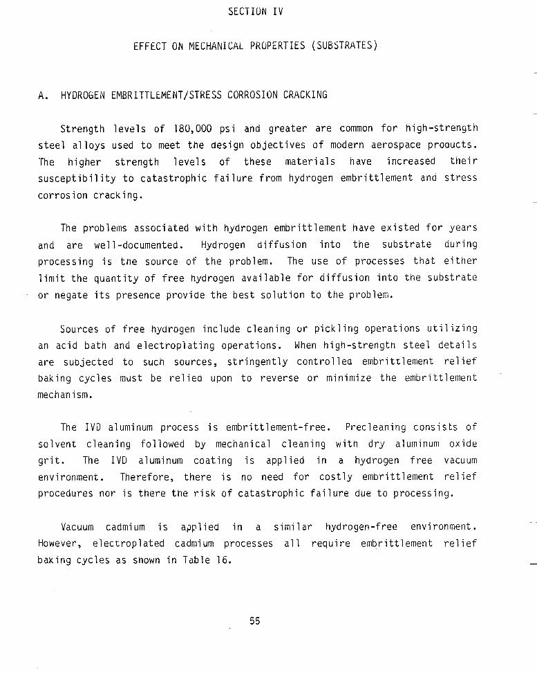
SECTION IV
EFFECT ON MECHANICAL PROPERTIES (SUBSTRATES)
A. HYDROGEN EMBRITTLEMENT/STRESS CORROSION CRACKING
Strength levels of 180,000 psi and greater are common for high-strength steel alloys used to meet the design objectives of modern aerospace products. The higher strength levels of these materials have increased their susceptibility to catastrophic failure from hydrogen embrittlement and stress corrosion cracking.
The problems associated with hydrogen embrittlement have existed for years and are well-documented. Hydrogen diffusion into the substrate during processing is the source of the problem. The use of processes that either limit the quantity of free hydrogen available for diffusion into the substrate or negate its presence provide the best solution to the problem.
Sources of free hydrogen include cleaning or pickling operations utilizing an acid bath and electroplating operations. When high-strength steel detai 1s are subjected to such sources, stringently controlled embrittlement relief baking cycles must be relied upon to reverse or minimize the embrittlement mechanism.
The IVD aluminum process is embrittlement-free. Precleaning consists of solvent cleaning followed by mechanical cleaning with dry aluminum oxide grit. The IVD aluminum coating is applied in a hydrogen free vacuum environment. Therefore, there is no need for costly embrittlement relief procedures nor is there the risk of catastrophic failure due to p
Vacuum cadmium is a?plied in a similar hydrogen-free However, electroplated cadmium processes a1 1 require embritt baking cycles as shown in Table 16.
ocessi ng.
environment . ement relief
55

TABLE 16. PROCESSES REQUIRING HYDROGEN EMBRITT’LEMENT RELIEF.
Process
IVD Aluminum
Vacuum Cadmium “Bright” Cadmium
Low-Embrittlement Cadmium
Diffused Nickel-Cadmium
Type of Free Hydrogen Embrittlement Relief Process Available Required
Vacuum No No
Vacuum No No
Electroplate Yes Yes
Electroplate Yes Yes
Electroplate Yes Yes
I n a d d i t i o n t o t h e absence o f hydrogen d u r i n g i t s a p p l i c a t i o n , I V D
aluminum has a l s o been shown t o r e s i s t p o s t hydrogen e m b r i t t l e m e n t and s t r e s s
c o r r o s i o n c r a c k i n 5 . I n comparat ive t e s t i n g , I V D aluminum g e n e r a l l y i s equal
t o o r b e t t e r t h a n o t h e r m e t a l l i c c o a t i n g s . Th is t e s t i n g i s summarized i n
Table 17. Even more impor tan t , t h e r e have been no r e p o r t e d f a i l u r e s
a t t r i b u t e d t o p o s t hydrogen e m b r i t t l e m e n t o r s t r e s s c o r r o s i o n c r a c k i n g of I V D
aluminum coated p r o d u c t i o n p a r t s i n o v e r 12 y e a r s o f f i e l d s e r v i c e exper ience .
As shown i n S e c t i o n 111, t h e success fu l use o f I V D aluminum on h i g h s t r e n g t h s t e e l d e t a i Is i s we1 1 e s t a b l i shed . Tens o f thousands o f p roduc t i o n
p a r t s have been processed and p u t i n t o s e r v i c e w i t h no r e p o r t e d problems. Numerous t e s t r e p o r t s by M C A I R and o t h e r companies c o n t i n u e t o show I V D aluminum p r o v i d i n g o u t s t a n d i n g c o r r o s i o n r e s i s t a n c e w i t h no e m b r i t t l e m e n t concerns and, t h e r e f o r e , no c o s t s due t o e m b r i t t l e m e n t r e l i e f . F i g u r e ~7
shows t y p i c a l h i g h s t r e n g t h s t e e l p r o d u c t i o n p a r t s coated w i t h I V D aluminum.
They range f r o m sma l l , b a r r e l - c o a t e d s p r i n g s t o l a r g e r , i n d i v i d u a l l y racked
p a r t s l i k e l a n d i n g gear d e t a i l s and r o c k e t motor cases.
B. F A T I G U E
Aluminum c o a t i n g s a p p l i e d by t h e I V D process have no d e t r i m e n t a l e f f e c t on
f a t i g u e o r o t h e r s u b s t r a t e mecnanical p r o p e r t i e s . The c o a t i n g has a t i g h t l y - _____
k n i t columnar s t r ~ t u r e and i s s o f t ana d u c t i l e w i t h p r o p e r t i e s v i r t u a l l y i d e n t i c a l t o t h o s e o f pu re aluminum; see S e c t i o n 1 I ( G ) . A lso, t h e depos i ted aluminum c o a t i n g forms a mechanical bond r a t h e r than an i n t e r m e t a l l i c bond which can reduce f a t i g u e p r o p e r t i e s . L a s t l y , t h e r e a r e no d i s c e r n a b l e
ba tch - to -ba tcn v a r i a t i o n s i n t h e p r o p e r t i e s o f t h e I V O aluminum c o a t i n g s i n c e
-
56

TABLE 17. SUMMARY OF HYDROGEN EMBRITTLEMENT AND STRESS CORROSION CRACKING TESTS ON HIGH-STRENGTH STEEL DETAILS.
References E - Specimen
340 tress Ring
-
- W M otchTensil
- )OM
330V
lBV40
)OM
330V
lBV40
1tchTensilt
- Heal Treat (ksi)
260-28t -
- 280 - 3Oc
- 280-300
220-240
280-300
280-300
220-240
280-300
- 280-300
- :onvarsloi
Coated
Yes -
Yes
- imbrinlemenl
Relieve
NO -
No
- No. 01
ipecimei
2 -
3
- Average Timelo Failure
30 Days (No Failure)! 9 hr 30 Days (No Failure)/ 7 hr
- -
Tesled BY -
Douglas 1973
Load - 10% Ultimate lensile Strength UTS)
I Coating
Followed by 5% Neutral
L.E. Cad
10% Notch 'ensile Strength NTS)
Yes No Yes
- Yes
Yes
Yes
No
No
No
- Yes
Yes
Yes
- Yes
3 3 3 3
- 6
6
6
3
3
3
- 3
3
3
2
- 12
McDonnell Aircraft 1975
- McDonnell Aircran 1975
- McDonnell Aircran 1976
- Boeing 1981
Alternate IVD AI Immersion IVDAI sow VacCad Adjusted topHof3 With Acetic Acid
Bare
No No No
3016
3016
30f6
Yes
Yes
Yes
Yes
Yes
NO
No
15 6hr 2 7h r 2 0 h r 6 4 0 h r
- 200 hr (NoFailures 200 hr (No Failures) 1 Failure a t 3 5 h r 200 hr (No Failures) 200 hr (No Failures) 200 hr (NO Failures)
512hr t t 90% NTS 487 hr 89% NTS 444 hr (a 87% NTS 385 hr(n 82% NTS
200 hr (No Failures)
- 52
- 53
'5% NTS
1 IVDAl
IVD AI
VacCad
I VacCad
VacCad 4 l8V40 itch Tensili
5% NTS ilith 1% icrease ach 7 hr
I VacCad
IVDAl ;+ 260-280
- 280 - 300
- 304 - 31 5
840M )tch Tensilt
- 10 M itch Tensilt
- 8TM-A-401 oy Steel rings
- BO Alloy ?el Snap- 9s
- TM A-228 oy Steel rings
- )OM Steel Springs
5% NTS 54
55 Alternate 1 IVDAl Yes Yes
- Yes Yes Yes Yes Yes
Yes Yes Yes Yes Yes
-
3 3 3
McDonnell 4ircraft 1981
- ?MC 1980
- 'MC 1980
5% NTS nmersion .5% eutral
No No
No Yes No Yes No
No Yes No Yes No
123hr 89 hr 6 hr
100% Failed 3% Failed 100% Failed 3% Failed 3% Failed
No Failures 'do Failures 23 Failures NoFailures UoFailures
Immersion L E Cad izral Salt
Bare
all
ompression :yclicand taw)
- Room -
E P Cad E P Cad E P Zinc E P Zinc IVD AI
4 4 4 4 8
50 50 50 50 100
-
56
- 56
57
58
cpanded nto Bar itaticl
IVD AI
E P Cad
- 306-339
- 280-300
Yes Yes Yes Yes Yes Yes
Yes
Yes
- Yes
Yes
:arter :arbure- ltor 1982
- Fairchild 1982
3P Bend '2 hr) impression
22 hr) :ompression 1,ODO hr)
:ompression 1.000hr)
No Yes NO Yes NO Yes
No
Yes
No
NO
4 4 4 4 4 4
4
4
- 3
3
UoFailure go Failure UoFailure NoFailure No Failure NoFailure
3 (No Failure) 1 Failed at 223 hr 1 Failed at 60 hr 1 Failedat 220 hr 1 Failed at 100 hr 1 Failed at 700 hr
11.23 Days 30 Days (No Failure) 9 ,14 Days 16Days (Test Stopped) -
E P Cad
Immersion 3 5%
ompression
57

High-Strength Steel Springs (320 Ksi)
Figure 27. Typical IVD Aluminum-Coated High-Strength Steel Details.
t h e m i l i t a r y s p e c i f i c a t i o n , MIL-C-83488, r e q u i r e s t h a t t h e compos i t i on o f b o t h
t h e 1100 a l l o y aluminum w i r e evaporant and t h e as-deposi ted c o a t i n g be a minimum o f 99 pe rLen t pu re aluminum. An e x m i n a t i o n o f t h e w i r e and c o a t i n g
(Reference 59). A sampl ing o f t h e t e s t i n g conducted t o v e r i f y t h a t t h e I V D aluminum process has no adverse e f f e c t on f a t i g u e p r o p e r t i e s i s presentea i n Table 18.
u s i n g an energy d i s p e r s i o n x - ray techn ique showed o n l y t h e element aluminum -
58

TABLE 18. EFFECT OF IVD ALUMINUM COATING ON SUBSTRATE FATIGUE PROPERTIES.
Company
Pratt & Whitney (Reference 27 and 36)
Westinghouse (Reference 28)
SPS Technologies (Reference 32)
McDonnell Douglas (Reference 60)
Turbine Support (Reference 62)
I Substrate
8-1 -1 -Titanium 6-4-Titanium 41 0 Steel
A276 Steel A276 Steel 403 Stainless Steel
Steel
2024 Aluminum Alloy
Steel
High Cycle High Cycle Peak Strain
I Fatigue I Effect on Fatiguea Test
None None Sliaht-Same as Nickel-Cadmium
20 KHz 20 KHz 20 KHz
Tension-Tension
6 g Symmetric
High Cycle
None
Slight - Same as “Bright” Cadmium
None
None
As with I V D aluminum, the various cadmium processes produce a soft, ductile finish and have little or no effect on fatigue properties. Figure 28 shows fatigue data for I V D aluminum and electroplated cadmium on alloy steel
7,200
4,800
High Tensile Load
Sb)
2,400
0 .
-
Aluminum Coated
-
Cadmium Plated
I I I I I I I I I I I I I I I I
I o3 I o4 I o5 1 o6 10‘ Note: Cycles to Failure
1. Twelve NAS 1954 alloy steel fasteners were used. 2. The test method was MIL-STD-1312, test no. 11.
Figure 28. Tension Fatigue Test of IVD Aluminum- and Cadmium-Finished Fasteners. 59

fasteners from t e s t s conducted by MCUIK (Reference 6 2 ) . S imi la r d a t a i s presented i n Table 1 9 from t e s t s conducted by SPS Technologies (Reference 3 2 ) . In a t h i r d comparison, Table 20 shows IVD a l u m i n u m and diffused nickel
TABLE 19. TENSION-TENSION FATIGUE TEST OF IVD ALUMINUM- AND CADMIUM-FINISHED FASTENERS.
Bare
135,400
102,000
72,200
1 18,800
178,600
Bolt Descriptiona and Test Loads IVD Cadmium
173,000 83,000
109,400 11 4,000
107,700 125,000
90,400 128,000
102,100 123,000
MS21250-04-018 Per MIL-6-8831
Alloy Steel
(Maximum Load-3,210 Ib,
Minimum Load -321 Ib)
Ranking From the s ~ ~ ~ p r a y
Ranking From the 20 kHz Fatigue Test
Values)
Combined Rank (Decreasing Endurance (Equal Weight)
I Average I 121,500 I 116,520 I 114,600 I a NAS 1271 -1 6 alloy steel fasteners b Test method - MIL-STD-1312 test no 1 - speed 8.000 cycles per min
cadmium (amoung 25 f inishes tes ted) ranked f i r s t and second, respectively, f o r having the leas t e f fec t on fatigue properties of a l l o y s teel turbine blades. Table 20 was taken from a Westinghouse Electric report (Reference 28).
TABLE 20. EFFECT ON FATIGUE PROPERTIES OF ALLOY STEEL STEAM TURBINE BLADES.
Coating System
Aluminum, Wire Gun Aluminum, Pack Cementation Aluminum-Nickel, Pack Cementation Aluminum, Ion-Vapor-Deposition Zinc-Silicate Binder (Inorganic Zinc Paint) Nickel-Cadmium, Electroplate Aluminum-Phosphate Binder (Spray and Bake) Nickel-Aluminide High Energy Plasma Spray Chromium, Chromate Conversion Chromium, Diffusion (Chromizing) Zirconium, Physical Vapor Deposition Nickel-Chromium,Conventional Plasma Spray Chromium Boride, Pack Cementation Iron-Chromium Boride, Pack Cementation Silicon Diamine PTFE Powder Nickel, Chemical Vapor Deposition Suifamate-Nickel, Electroplate (Thin Coating) Sulfamate-Nickel, Electroplate (Thick Coating)
~
18 7
5 1 3 2 4 13 16 12 19 17 14 15 11 6 8 10
9
16 8 3 1 18 2 18 7 6 13 14 9 17 12 4 5 10 14
11
19 6 3 1 10 2
12 9 11 14 18 15 17 16 5 4 7
13
8
I I
60

I n summary, t e s t i n g has v e r i f i e d t h a t I V D aluminum c o a t i n g s have no e f f e c t
on t h e f a t i g u e o r o t h e r mechanical p r o p e r t i e s o f t h e base meta l . I n a d d i t i o n ,
a f t e r more t h a n a decade of p r o d u c t i o n use, t h e r e have been no f i e l d r e p o r t s
o f mechanical p r o p e r t y d e g r a d a t i o n o r r e s u l t i n g p a r t f a i l u r e .
61

SECTION V
FASTENER INSTALLATION CHARACTERISTICS
A. TORQUE-TENSION
Aluminum has a higher coefficient of f r i c t ion t h a n cadmium. Therefore, a
higher torque i s required t o ins ta l l a luminum coated fasteners t o a given tension preload t h a n i f the fastener was cadmium plated. The use of a lubricant on the aluminum-coated fastener and/or n u t , however, eliminates or greatly reduces torque-tension differences. Th i s section compares
torque-tension values for IVD aluminum, cadmium, and diffused nickel-cadmium finished fasteners w i t h and w i t h o u t the use o f supplemental lubricants.
Figure 29 shows the resul ts of a torque-tension t e s t conducted by SPS The torque on the alloy-steel locknuts i s shown Technologies (Reference 32).
versus the average induced tension load on the H-11 bolts used i n the t e s t s .
7,000
6,000
5,000
2,000
1,000
0
Bolt and Nut With IVD and Cetyl Alcohol Bolt With Cadmium
and Nut With Cadmium - and Nut With Cadmium
-
H-1 1 EBW 22-4-22 Fasteners With Alloy-Steel FN22 Locknuts
0 100 200 300 400 500 600 7 Torque (in.-lb)
Figure 29. Torque-Tension Test Results for IVD Aluminum- and Cadmium-Finished Fasteners.
62

When both the bolt and nut were coated with IVD aluminum, approximately 60 percent more torque was needed to produce a 2000-pound tension load than when both were cadmium-plated. Using a cadmium-plated nut with the IVD aluminum-coated bolt reduced the difference to approximately 15 percent. When the IVD-coated nuts and bolts were lubricated with cetyl alcohol, the torque for a given induced tension load was actually 70 percent less than if the nut and bolt were cadmium-plated. In this test, therefore, the effect of the lower lubricity of the IVD aluminum coating was more than offset by tne addition of a lubricant.
MCAIK compiled data from two series of torque-tension tests (Reference 63) conducted during formal qualification of IVD aluminum as an acceptable alternative to cadmium. In the first series of tests, the initial torque required to develop a 1200-pound tension load in 3/16 inch diameter nonlubricated, IVD aluminum-coated or cadmium-plated bolts was measured for various nut configurations. The relative torque differences, based on an average of 8 tests for each condition, are as follows:
o An 8 percent higher torque was required using IVD aluminum versus cadmium when the torque was applied to caamium plated, nonlocking, nonlubricated nuts.
o An 8 percent higher torque was required cadmium when the torque was applied to cadmium p self-locking nuts.
using IVD aluminum ated, dry-film-lubr
versus cated,
o The same torque was required using IVD aluminum- and cadmium-finished . bolts when the torque was applied to the bolts with cadmium-plated, dry-film-lubricated, self-locking nuts.
o A 36 percent higher torque was required using IVD aluminum versus cadmium when the torque was applied to the bolts with cadmium-plated, dry-film-lubricated, self-locKing gang channel nuts,
63

In the second series of tests, the initial torque required to induce a specific tension load in 3/16-inch diameter, IVD aluminum-coated or cadmium-plated bolts was measured. Some of t he bolts were lubricated and the torque was applied to cadmium-plated, dry-f i lm-lubricated, self -locking nuts. The test results are as follows:
o A 10 percent higher torque was required using IVD aluminum versus cadmium to attain a 560 pound load in a nonlubricated bolt.
o An 8 percent higher torque was required using IVD aluminum versus cadmium to attain a 560-pound load in a lubricated bolt.
o The torques required using IVD aluminum and cadmium finishes were approximately the same to attain a 2000-pound load in a lubricated bolt.
Boeing conducted torque-tension tests comparing IVD aluminum and diffused nickel-cadmium on nonlubricated H-11 steel bolts (Reference 37). Figures 30
9,000
8,000
7,000
6,000
5,000 Tension
(Ib) 4,000
3,000
2,000
1,000
0
+ Average of Twelve Tests - High and Low Data Points Washer on Anodized and
Primed Surface
50% Tensile Strength = 7,050 Ib /
33% Tensile Strength = 4,653 Ib
0 80 160 240 320 400 480 560 Torque (in. - Ib)
Figure 30. Torque-Tension Relationship Using IVD Aluminum-Finished Fasteners.
64

and 31 show t h e t o r q u e - t e n s i o n curves produced u s i n g t h e I V D aluminum f i n i s h
were n e a r l y i d e n t i c a l t o those produced u s i n g d i f f u s e d nickel-cadmium.
9,000 + Average of Twelve Tests - Hiah and Low Data Points
/ I Wkher on Anodized and Primed Surface 8,000 t
7,000
6,000
5,000
4,000
3,000
2,000
1,000
0
50% Tensile Strength E 7,050 Ib -
- - 33% Tensile
Strength = 4,653 Ib
-
-
-
H-11 Bolts
0 80 160 240 320 400 480 560 Torque (in. - Ib)
Figure 31. Torque-Tension Relationship Using Diffused Nickel-Cadmium-Finished Fasteners.
The Hi-Shear Company a l s o eva lua tea t o r q u e - t e n s i o n u s i n g I V D a1 urni num and
d i f f u s e d nickel-cadmium on l u b r i c a t e d H-11 p i n and c o l l a r t y p e f a s t e n e r s
(Reference 64). They r e p o r t e d t h a t t o r q u e - t e n s i o n was e s s e n t i a l l y u n a f f e c t e d
by any d i f f e r e n c e s i n t h e two f i n i s h e s (Tables 21 and 2 2 ) .
I n c o n t r a s t however, P r a t t & Whitney r e p o r t e d t h a t a c o n s i d e r a b l y h i g h e r
t o r q u e was r e q u i r e d w i t h I V D aluminum i n comparison t o d i f f u s e d nickel-caamiurn
(Reference 65) . A x i a l l o a d versus a p p l i e d t o r q u e f o r 31) b o l t s (MS9210-21)
f i n i s h e d w i t h I V D aluminum ana d i f f u s e d nickel-cadmium was eva lua ted . The e f f e c t of engine o i l on t h e b o l t s was a l s o measured s i n c e i t was common
p r a c t i c e t o d i p t h e b o l t i n o i l b e f o r e assembly. I n a l l cases, t n e I V D a luminum-f in ished b o l t s r e q u i r e d a h i g h e r t o r q u e t o produce t h e same a x i a l l o a d than d i d t h e d i f f u s e d n i cke l - cadmium- f i n i shed b o l t s . For example, t h e
65

TABLE 21. TORQUE-TENSION VALUES USING IVD ALUMINUM- AND DIFFUSED NICKEL- CADMIUM-FINISHED FASTENERS.
IVD+Cetyl HL117-8-16 Pins
With HL86 Coilars
Sample No.
Diffused Ni-Cd+Cetyl
HL117-8-16 Pins With HL86 Collars
1 2 3 4 5
Mean Standard Deviation Required
lVD+Cetyl HL117-8-16 Pins
With HL70 Collars
Torque-Off (in.-ib)
~~
69 71 68 68 67
68.6 1.5
60-80
Preload (Ib)
2,700 2,700 2,500 2,500 2,500
2,600 100 1,600
Diffused Ni-Cd+ Cetyl
HL117-8-16 Pins With HL70 Collars
Torque-Off (in.-lb)
67 73 71 68 69
69.6 2.4
60-8
Preload
2,225 2,650 2,400 2,250 2,550
2,415 185 1,600
(W -
TABLE 22. TORQUE-TENSION VALUES USING IVD ALUMINUM- AND DIFFUSED NICKEL- CADMIUM-FINISHED FASTENERS.
Sample No.
Mean Standard Deviation Required
Torque-Off (in.-lb)
120 118 120 121 123
120.4 1.8
115-130
3,900 3,450 3,650 3,500 3,725
3,645 180 2,600
Torque-Off (in.-lb)
1 1 1 124 116 120 118
117.8 4.8
115-130
3,825 4,400 3,850 4,050 4,200
4,065 242 2,600
diffused nickel-cadmium finished bolt was torqued to 70 inch-pounds to produce a load of 1000 pounds while the aluminum finished bolt required 168 inch -pounds.
66

In the P r a t t & Whitney t e s t s , coating thickness i s the probable cause f o r the considerably higher torque required u s i n g IVD a l u m i n u m . Most fasteners threads are designed t o accept 0.0003-0.0005 inches o f coating. Tnis i s the normal Class 3 thickness range for IVD aluminum finished fasteners. however, P r a t t & Whitney reported the t e s t fasteners were finished w i t h Class 2 (0.0005-inch m i n i m u m ) IVD aluminum.
Table 23 summarizes the cnanges t o torque-tension relationships when using IVD a l u m i n u m versus cadmium and nickel-cadmium finishes. Because of the sca t te r i n the t e s t data and the variation i n parameters for the d i f fe ren t t e s t s , Table 23 should be used only as a rough guide as t o what m i g h t be expected. I t i s clear from the data reviewed, however, t n a t the higher
TABLE 23. TORQUE-TENSION RELATIONSHIP USING IVD ALUMINUM VERSUS CADMIUM AND DIFFUSED NICKEL-CADMIUM FINISHES.
Component Torqued - Finish
Locknut-Bolt and Nut IVD Coated With No Lubrication
Locknut - Bolt and Nut IVD Coated and Lubricated
Locknut - IVD Coated Bolt With Cadmium Plated Nut and No Lubrication Locknut -IVD Coated Bolt With Cadmium Plated and Lubricated Nut
Locknut - Lubricated, IVD Coated Bolt With Cadmium Plated and Lubricated Nut
Locknut - Lubricated IVD Coated Bolt With Cadmium Plated and Lubricated Locknut
NQn-Locking Nut- IVD Coated Bolt With Cadmium Plated Nut and No Lubrication
Bolt - Bolt and Nut IVD Coated With No Lubrication
Bolt - IVD Coated Bolt With Cadmium Plated and Lubricated Locknut
Collar- Pin and Collar IVD Coated and Lubricated
Changes in Torque Using IVD Aluminum
vs Cadmium
+ 60%
-70%
+ 15%
+9%
+ 4%
+ 4%
+ 8%
+ 18%
vs Nickel-Cadmium
No Change
+ 140%
No Change
67

c o e f f i c i e n t o f f r i c t i o n o f I V D aluminum inc reases t h e t o r q u e r e q u i r e d f o r a
g i v e n p re load ; i t i s a l s o c l e a r t h a t l u b r i c a t i o n reduces o r e l i m i n a t e s t h i s
increase.
A r e v i e w o f p r o d u c t i o n o p e r a t i o n s i n v o l v i n g t h e use o f I V D aluminum as a
replacement f o r cadmium on f a s t e n e r s v e r i f i e s t h e r e l a t i v e ease t h a t such a
changeover can be accompl ished f o r most a p p l i c a t i o n s . Some o f t hese
o p e r a t i o n s have been ongoing f o r t h e p a s t 12 years. F o r t h e most p a r t , t h e y have been accompl ished w i t n no more t h a n t h e use o f a l u b r i c a n t and w i t h o u t
s i g n i f i c a n t changes t o i n s t a l l a t i o n procedures, t o o l s , o r h o l e s i z e s .
A l though I V D aluminum has been s u c c e s s f u l l y used on m i l l i o n s o f aerospace
f a s t e n e r s , t o r q u e - t e n s i o n r e l a t i o n s h i p s a re a l e g i t i m a t e concern f o r some a p p l i c a t i o n s . M C A I R has proposed a r e s e a r c h and development program,
desc r ibed i n S e c t i o n ) r I I ( C ) , t o demonstrate t h a t accep tab le r e s u l t s can be
ob ta ined w i t h t h e s e l e c t i o n o f a p roper l u b r i c a n t .
B. REUSE T E S T I N G
S e r v i c e doors and pane ls on a i r c r a f t a r e u s u a l l y secured w i t h removable
t y p e f a s t e n e r s and l o c k n u t s . The f a s t e n i n g system i s r e q u i r e d t o meet reuse
s tandards t o accommodate p e r i o d i c door o r panel removal and r e i n s t a l l a t i o n .
A c c e p t a b i l i t y l i m i t s a re s e t i n accordance w i t h MlL-N-25027 which e s t a b l i s h e s
maximum l o c k i n g and minimum breakaway t o r q u e s o v e r a number o f i n s t a l l a t i o n
c y c l e s . This s e c t i o n p r e s e n t s d a t a generated by MCAIR and SPS Technologies on
t h e r e u s e c h a r a c t e r i s t i c s o f I V D aluminum and e l e c t r o p l a t e d cadmiurn f i n i s h e d
f a s t e n i n g systems.
SPS r a n a 15 c y c l e reuse t e s t on 1 /4 i n c h d iamete r f a s t e n e r s
(Reference 32) . Each c y c l e i n v o l v e d t i g h t e n i n g a n u t o n t o a b o l t w i t h 100 inch-pounds o f t o rque , t hen removing t h e n u t . h e i t h e r t h e n u t n o r t h e b o l t
were l u b r i c a t e d . MIL-N-25027 e s t a b l ishec a maximum l o c k i n g to rq l re o f SO
inch-pounds and a minimum breakaway t o r q u e o f 3.5 inch-pounds. Wi th no l u b r i c a t i o n , i n i t i a l l o c k i n g to rques f o r b o t h aluminum- and cadmium-f in ished hardware were over t h e maximum. Table 24 shows t h a t t h e I V D aluminum-coated
68

TABLE 24. REUSE TEST RESULTS COMPARING IVD ALUMINUM- AND CADMIUM-FINISHED FASTENERS.
Finish
IVD Aluminum
IVD Aluminum
Cadmium
IVD Aluminum
Cadmium
Aluminum
Cadmium
IVD Aluminum
cycle 1 Cycle 3 Cycle 6 Cycle 9 Cycle 12 Cycle 15 Maximum Minimum Maximum Minimum Maximum Minimum Maximum Minimum Maximum Minimum Maximum Minimum Locking Breakaway Locking Breakaway Locking Breakaway Locking Breakaway Locking Breakaway Locking Breakaway
60 50 46 42 30 34 26 26 26 26 21 23
56 52 28 28 21 22 21 21 25b 24b 22b 24b
lesignations: Nut - 42FIW: Fastener - MS21250-04-018
17
42 38 37 36 24 26 24 24 21 21 21
Iesignatians: Nut - FN22; Fastener - EWE 22-4-21
56 55 30 31 21 21 19 1 9 1 9 20 16
16
a This was an average of two iesults per condition b One result only the nut seized alter the 11th cycle an the second test
- Alloy Steel With IVD
8 -
I I I I
Testing was Conducted per MIL-N 250270
n u t - a n d - b o l t combinat ions had h i g h e r t o r q u e va lues f o r t h e i n i t i a l
i n s t a l l a t i o n c y c l e t h a n t h e cadmium-plated nu t -and -bo l t combinat ions; t o r q u e
va lues were much c l o s e r f o r subsequent c y c l e s . F i g u r e 32 shows t h a t as t h e number o f i n s t a l l a t i o n c y c l e s increases, t h e d r o p - o f f i n maximum l o c k i n g t o r q u e u s i n g I V D aluminum-coated f a s t e n i n g systems i s s i m i l a r t o t h e d r o p - o f f u s i n g cadmium p l a t i n g .
80
0 Alloy Steel With Cadmium 0 0
Maximum 48 Locking Torque 40
32 (in.-lb)
24
Figure 32. Reuse Relationships for IVD Aluminum- and Cadmium-Finished Fasteners.
69

MCAIR a l s o conducted a 15 -cyc le reuse t e s t d u r i n g f o r m a l q u a l i f i c a t i o n o f
IVD aluminum as an accep tab le a l t e r n a t i v e t o cadmium (Reference b 3 ) . The
r e u s e t e s t compared 1 / 4 - i n c h d iamete r IVD aluminum-coated and cadmium-plated
a l l o y s t e e l b o l t s i n s t a l l e d i n t o cadmium-plated a l l o y s t e e l gang channels and l o c k n u t s . The l o c k n u t s were l u b r i c a t e d w i t h molybdenum d i s u l f i d e and a t t a c h e d
t o t y p i c a l a i r c r a f t s u b s t r u c t u r e t o s i m u l a t e removable door i n s t a l l a t i o n s .
MCAIR t e s t e d an IVD a1 uminum-coated bo1 t ana a cadmi um-pl a ted n u t comb ina t ion
because aluminum on t h e b o l t s p r o v i d e s b e t t e r c o r r o s i o n r e s i s t a n c e , e s p e c i a l l y
f o r m o l d l i n e a p p l i c a t i o n s , and b e t t e r c o m p a t i b i l i t y t o t h e a i r c r a f t s t r u c t u r e ;
see d i s c u s s i o n i n S e c t i o n III(C). The cadmium-plated l o c k n u t s a r e o f l i t t l e
concern f r o m a c o r r o s i o n o r c o m p a t i b i l i t y s t a n d p o i n t . S ince cadmium-plated
f a s t e n e r s used on t h e a i r c r a f t were p a i n t e d w i t h f l u i d r e s i s t a n t (FR) p r i m e r on t h e f a s t e n e r heads ana shanks f o r a d d i t i o n a l c o r r o s i o n p r o t e c t i o n ,
s i m i l a r l y f i n i s h e d f a s t e n e r s were used i n t h e t e s t s . The IVD aluminum-coated
f a s t e n e r s were n o t p a i n t e d . Each c y c l e i n v o l v e d i n s t a l l i n g t h e f a s t e n e r i n t o
t h e nu t , t o r q u i n g t h e f a s t e n e r t o 50 inch-pounds, and removing t h e f a s t e n e r .
About h a l f t n e f a s t e n e r s were i n s t a l l e d u s i n g hand t o r q u e wrenches, and t h e
rema in ing f a s t e n e r s were i n s t a l l e d w i t h c o n t r o l l e d - t o r q u e power s c r e w d r i v e r s .
F i g u r e 33 shows t h a t b o t h f i n i s h e s were w i t h i n t h e l i m i t s o f MIL-N-25027.
By u s i n g l u b r i c a n t s , reuse c h a r a c t e r i s t i c s can be improved, and t h e e f f e c t
caused by d i f f e r e n c e s i n f i n i s h e s can be min imized. T h i s i s demonstrated by
comparing t h e i n i t i a l l o c k i n g to rques i n t h e SPS t e s t i n which no l u b r i c a n t s
were used t o t h o s e i n t h e MCAlR t e s t i n which t h e l o c k n u t s were l u b r i c a t e d .
Fo r example, t h e f i r s t i n s t a l l a t i o n c y c l e i n t h e S t 3 t e s t f o r t h e comb ina t ion
of aluminum-coated f a s t e n e r s and cadmium-plated l o c k n u t s r e q u i r e d a l o c k i n g
t o r q u e o f 60 inch-pounds versus 20 inch-pounds i n t h e PICAIR t e s t . The
m i l i t a r y s p e c i f i c a t i o n maximum i s 30 inch-pounds. Th is l i m i t was a l s o exceeded i n t h e SPS t e s t by t h e caamium - cadmium comb ina t ion (4L inch-pounas) w i t h o u t a l u b r i c a n t .
. ~~
Tab le 25 summarizes reuse c h a r a c t e r i s t i c s o f f a s t e n i n g systems w i t h
d i f f e r e n t f i n i s h comb ina t ions compared t o t h e l i m i t s e s t a b l i s h e d i n MIL-h-25027. Reuse c h a r a c t e r i s t i c s o f IVD aluminum-coated b o l t s w i t h -
70

32 I I
24
Installation Locking Torque 16
(in.-lb)
0
Maximum Locking Torque
. *. Cadmium-Plated, FR Primed Bolts
-
- - _ ---.* = - - - - * * - - - = - - * - - * _ _ _ _ ~ * ~ = IVD Aluminum-Coated Bolts
8 -
I I I I
Notes : 1. Fastener : NAS584-8 flush head bolt, alloy steel, IVD aluminum, or 3MFR584-8 flush head bolt, alloy steel, cadmium plated, FR primed. 3M143A4-2 plate nuts or 3M150N4-8-10 gang channel. Nut :
2. Maximum locking torque per MIL-N-25027 for 1/4 in. diameter fasteners. 3. Torque applied to fastener by hand toque wrench or power screwdriver. 4. Fastener tightened to 50 in.-lb each cycle. 5. Data shown is average of 20 tests.
Minimum Breakaway Torque *t I I I I I 3 6 9 12 15
Installation Cycle
Notes : 1 .
2. 3. 4. 5.
Fastener : NAS584-8 flush head bolt, alloy steel, IVD aluminum, or 3MFR584-3 flush head bolt, alloy steel, cadmium plated, FR primed.
Nut : 3M143A4-2 plate nuts or 3Mt "4-8-10 gang channel. Minimum breakaway torque per MIL-N-25027 for t /4 in. diameter fasteners. Torque applied to fastener by hand torque wrench or power screwdriver. Fastener tightened to 50 in.-lb each cycle. Data shown is average of 36 to 40 tests.
Figure 33. Fifteen Cycle Reuse Test Comparing IVD Aluminum- and Cadmium-Finished Fasteners.
71

TABLE 25. REUSE CHARACTERISTICS COMPARED TO SPECIFICATION LIMITS.
Fastening System
Finish
(Nut-Bolt) Combination Lubrication
Cd-Cd No Cd -A I No
Reuse Characteristics
1 st Cycle 15th Cycle
Locking Breakaway Locking Breakaway Torque Torque Torque Torque
+ r / + r /
+ r / r / r /
AI-AI No. r / r / *
Cd-Cd 1 Yes Cd-AI Yes r / IC r / I I
lubricated locmuts fall within the limits. The program proposed by M C A I K to broaden the data base for acceptable lubricants relevant to torque-tension characteristics, discussed in Section XII (C) , will also provide u s e f u l
information about reuse characteristics.
72

SECTION V I
COATIhC; VERSATILITY
A. ALUMINUM ALLOY SUBSTRATES
I V D aluminum c o a t i n g s a r e e a s i l y a p p l i e d t o a l l m e t a l l i c s u b s t r a t e s
i n c l u d i n g aluminum a l l o y s . E l e c t r o p l a t e d cadmium, on t h e o t h e r hand, can n o t be a p p l i e d d i r e c t l y t o aluminum a l l o y s u b s t r a t e s w i t h accep tab le adhesion.
MCAIR began a p p l y i n g I V D aluminum c o a t i n g s t o aluminum a l l o y p r o d u c t i o n p a r t s
i n 1976. I n i t i a l l y , I V D c o a t i n g s r e p l a c e d anodize c o a t i n g s on f a t i g u e
c r i t i c a l aluminum s t r u c t u r e . I n more r e c e n t a p p l i c a t i o n s , t h e y r e p l a c e
e l e c t r o p l a t e d t i n on a1 umi num a1 l o y components r e q u i r i n g a c o n d u c t i v e p a t h as
w e l l as c o r r o s i o n r e s i s t a n c e . The pu re I V D aluminum c o a t i n g i s i a e a l l y
compa t ib le w i t h aluminum a l l o y s t r u c t u r e . I t i s l e s s n o b l e t h a n t h e a l l o y s
and t h e r e f o r e p r o v i d e s s a c r i f i c i a l c o r r o s i o n r e s i s t a n c e . C u r r e n t l y , more t h a n
800 aluminum a l l o y p a r t s a r e coated on t h r e e M C A I K p r o d u c t i o n a i r c r a f t . I n
a l l a p p l i c a t i o n s , t h e I V D c o a t i n g has improved performance and reducea e i t h e r
p rocess ing c o s t s o r l i f e c y c l e c o s t s , o r both. O f t h e thousands of a i r c r a f t
p a r t s coated and more t h a n a decade o f i n - s e r v i c e a i r c r a f t exposure, no
problems have been r e p o r t e d .
1. F a t i g u e C r i t i c a l
The s o f t d u c t i l e I V D aluminum i s used on f a t i g u e c r i t i c a l aluminum
a1 l o y s t r u c t u r e ; i t p r o v i d e s e x c e l l e n t s a c r i f i c i a l c o r r o s i o n r e s i s t a n c e and
does n o t reduce f a t i g u e p r o p e r t i e s . Hard, b r i t t l e f i n i s h e s , however, can
a f f e c t t h e mechanical p r o p e r t i e s o f t h e base meta l . MCAIR t e s t s (Reference 60) showed f a t i g u e r e d u c t i o n s o f 30 p e r c e n t o r more w i t h t h e use o f anodize on
a 2024-T851 aluminum a l l o y t e s t specimen ( F i g u r e 34) . On e x i s t i n g s t r u c t u r e s ,
t h e use o f I V D aluminum c I n extend f a t i g u e l i f e and e l i m i n a t e t h e need f o r
f a t i g u e enhancement, such as shot peening, and t h e r e b y reduce cos ts . F o r new
designs, t h e h i g h e r f a t i g u e p r o p e r t i e s achieved th rough t h e use o f I V D aluminum a l l o w f o r a l e s s bee fy s t r u c t u r e ; t h i s saves weight . I n a d d i t i o n ,
73

Surface Finish
I Peenand Taper-Loks 45,700 I 44,500 I Anodize I I 43.700
Average Fatigue Fatigue
Llfe Life (hr) (hr)
Type of Fastener
2024-T851 Aluminum
3/16 in. Diameter Holes 0 0 0 0 0 0 0
~ Note: Specimens tested to spectrum developed from
fatigue stress = 24.3 ksi gross section. flight test strain gage data with 6g symmetric
GPW-0398-7-D
Figure 34. Effect on Fatigue Properties by IVD Aluminum and Anodize Finishes.
I V D aluminum improves the resis tance t o stress corrosion cracking. h i g h - s t r e n g t h , aluminum shown i n Figures 35 and 36.
Typical
a l loy s t ruc tura l par t s coated w i t h I V I J aluminum are
Figure 35. F-15 Aluminum-Coated FatigueCritical Aluminum Alloy Wing Skin.
74

Figure 36. F-18 IVD AluminumCoated FatlgueCrRical Aluminum Alloy Bulkhead.
2. E 1 ec trical Bond i ng/EiVI C
Many aluminum alloy coinponents such as fuel and pneumatic line fittings, shown in Figure 37, require a conductive path across joints to dissipate static electrical charges generated by fluid o r air f l o w .
Typically, these components are anodized making them nonconductive. Therefore, an electrical bonding strap or jumper is required to establish the conductive patn. I V U aluminum is highly conductive and remains so in service when treated with a standard chromate conversation coating; electrical properties are discussed in Section I I ( E ) . I V P aluminum, instead of anodizing, on the fittings provides corrosion resistance and an inherent electrical bond across the joint interface. The weight penalty is eliminated, and substantial costs are saved by eliminating the labor-intensive step of installing the bonding strap (Figure 38).
75

Inherent Electrical Bond Compatibility with Fuel Cost Effectiveness
Figure 37. IVD Aluminum-Coated Aluminum Alloy Fuel and Pneumatic Line Fittings.
Anodized Fitting Bonding Jumpsr Required for
Electrical Bond
IVD Aluminum-Coated Fitting Inherent Electrical Bond
Figure 38. IVD Aluminum-Provided Conductive Path and Corrosion Resistance.
76

E l e c t r o p l a t e d t i n i s sometimes used on aluminum a l l o y components t o
p r o v i d e a l ow- res i s tance , c o n d u c t i v e p a t h a t t h e i n t e r f a c e w i t h o t h e r
components f o r e l e c t r o m a g n e t i c i n t e r f e r e n c e c o m p a t i b i l i t y (ENIC). However, i t
i s d i f f i c u l t t o achieve good adhesion o f t h e t i n t o t h e aluminum a l l o y . Also, t e s t s have shown t h a t t h e t i n p r o v i d e s r e l a t i v e l y poor p r o t e c t i o n o f t h e
s u b s t r a t e i n a c o r r o s i v e environment (References 67 and 68); c o r r o s i o n causes t h e e l e c t r i c a l r e s i s t a n c e t o i nc rease . I V D aluminum o f f e r s f a r s u p e r i o r c o r r o s i o n r e s i s t a n c e . The aluminum c o a t i n g i s s a c r i f i c i a l t o t h e s u b s t r a t e , whereas t i n i s more noble. Tables 26 and 27 show t h a t I V D aluminum-coated
d e t a i l s have a much lower j o i n t r e s i s t a n c e a f t e r exposure t o c o r r o s i v e
environments t h a n t i n - p l a t e d d e t a i l s . I n t h i s a p p l i c a t i o n , I V D aluminum
o f f e r s h i g h e r performance, reduced p rocess ing problems, and lower maintenance
cos ts .
Test Condition
Typical Resistance Before Exposure Resistance After 2 Years Resistance After 3 Years Resistance After 4 Years Resistance After 5 Years
TABLE 26. IVD ALUMINUM VERSUS ELECTROPLATED
EXPOSURE. TIN FOR EMlC - ST. LOUIS OUTDOOR
Joint Electrical Resistance (milliohms)
Electroplated IVD Tin Aluminum
Less Than 1 Less Than 1
800 22 1
2 2 *
77

TABLE 27. IVD ALUMINUM VERSUS ELECTROPLATED TIN
(USS CONSTELLATION). FOR EMlC - 1 YEAR SHIPBOARD EXPOSURE
Specimen t- Number
A- i (1) A-1 (2) A-2 (1) A-2 (2) A-3 (1) A-3 (2) B-1 (1) B-1 (2) 8-2 (1) B-2 (2) B-3 (1) B-3 (2)
EMlC Assemblies
Resistance Measurements Imilliohms) I Interfacing Coatings
Alclad to Alclad Tin to Alclad iVD AI to Alclad Tin to IVD AI IVD AI to IVD AI Tin to Tin
Resistance Before Exposure
I Resistance After EXDOSUre
0.12 - 0.13
0.07 - 0.09
0.45 - 0.78 0.22 - 0.54 0.22 - 0.62
0.25 - 1.3
0.03 - 0.05
0.35 2.82 - 2.85 195,000 - 198,000 520 - 540 0.82 - 0.84 6.10 - 6.13 2.0 - 2.1 199,000 - 200,000 0.32 4.9 200,000
Figure 39 shows an aluminum alloy cast ing coated witn IVD aluminum, masked along areas required t o be e l e c t r i c a l l y conductive fo r E M I C , then black-anodized t o meet cocKpit color requirements. Whereas IVD aluminum i s n o t normally anodized, i t can be when applied t o aluininum alloy substrates . This application shows the v e r s a t i l i t y o f the IVD coating.
3. Electr ical Connectors
I V D aluminum has a d i s t inc t advantage over cadmium and nickel on aluminum alloy connectors. To meet adhesion requirements, cadmium must be electroplated over a copper o r nickel s t r ike . Nickel plating i s used for h i g h
temperature applications. IVD aluminum can replace b o t h the cadmium p l a t i n g ( w i t h s t r i k e ) and the nickel plating. Nickel by i t s e l f and the combination of
cadmium with copper or nickel are both more noble than the aluminum alloy connector she l l . They do n o t provide sac r i f i c i a l corrosion resis tance, and . ___
pits i n the connector she l l s are common i n corrosive environments In t e s t s conducted by MCAIR (References 69 and 70), IVD a l u m i n u m provided t h e needed e l ec t r i ca l conductivity, in aadition t o corrosion protection, tha t would a1 low the 500-hour sal t-spray requirements o f common connector specif icat ions 1 ike
-
78

IVD Aluminum Electrically
Conductive Path --,
Figure 39. Aluminum Alloy Casting Coated With IVD Aluminum and Black Anodized.
MIL-C-38599 to be increased to 1,000 hours (Figure 40). The connectors shown in Figure 40 were also mated and unmated 150 times per MIL-C-38999 -- 50 times each before exposure, after 500 hours of exposure, and after 1,000 hours o f
exposure. Nickel plated connectors cannot normally be unmated clue to corrosion after 500 hours of exposure.
6. TITANIUM SUBSTRATES
IVD aluminum coatings are easily applied to titanium alloy substrates. They are most often used to provide galvanic compatibility with aluminum alloy structure and/or provide improved electrical conductivity. MIL-STD-1568 prohibits the use of cadmium, either on or in direct contact with titanium because of the possibility of solid metal embrittlement.
An example of the use of IVD aluminum for galvanic compatibility is on titanium fasteners. Whereas the fasteners do not corrode, they are galvanically more noble than the aluminum alloy structure in which they are
79

IVD Aluminum Cadmium
No Substrate Pitting
Severe Substrate Pitting
Figure 40. IVD Alumlnum- and Cadmium-Finished Connectors After 1 ,OOO Hours of Neutral Salt Fog Exposure.
ins ta l led . Consequently i n a corrosive environment, a galvanic c e l l w i l l form between the aluminum alloy s t ructure and bare t i t a n i u m fastener . S t r u c t u r a l p i t t i ng or corrosion of the aluminum will r e su l t . These same fasteners when coated w i t h IVD aluminum are galvanically compatible with the a lun i inum alloy s t ructure . Sometimes p a i n t ana sealant are used on bare titanium fasteners t o form a "bar r ie r" between the two diss imilar metals, However, as demonstrated i n t e s t s conducted by MCAIK (References 71 a n d 7 2 ) , the "bar r ie r" coatings were n o t as e f fec t ive as IVD aluminum in protecting the aluminum s t ruc ture . Figure 41 shows b o t h IVD aluminum-coated and sealant-coated (wet-instal l e d ) titanium fasteners i n a 7075-T6 aluminum alloy block. The fastener and b lock assembly was painted, then instal led i n a corrosive SGz s a l t f o g environment. After 2 8 aays of exposure, the a l l o y aluminum block was sectioned a t the countersinks. The photomicrographs in Figure 42 proviae a comparison of the protection given t o the countersinks and shows the obvious superior i ty of IVD aluminum.
Another advantage o f IVD aluminum coatings compared t o "bar r ie r" type coatings on titanium fasteners i s tha t the aluminum coating i s e l ec t r i ca l ly conductive. In contrast , the bar r ie r coatings form an e l ec t r i ca l insulator . Some users of IVD aluminum on titanium fasteners require a conductive coating t o help disperse lightning s t r ikes .
80

Wet-Installed Titanium Fasteners
IVD Aluminum-Coated Titanium Fasteners
0 I
1 I
2 I
3 I 3
inches
Figure 41. Test Pannels After 28 Days of SO2 Salt Fog Exposure.
81

Panel 1, Countersink 2 Wet-Installed Titanium Fastener
(Paint Seal Broken)
Panel 2, Countersink 2 IVD Aluminum-Coated Titanium Fastener
Figure 42. Photomicrographs of Test Panel Countersinks.
82

As mentioned, cadmium i s n o t n o r m a l l y used on o r i n c o n t a c t w i t h t i t a n i u m
because o f t h e p o s s i b i l i t y o f s o l i d meta l e m b r i t t l e m e n t . F i g u r e 43 shows a f r a c t u r e d Ti-6A1-4V t i t a n i u m a l l o y s u r f a c e a f t e r exposure t o cadmium a t
30OOF. Boeing compared I V D aluminum and cadmium i n an environment conducive t o t h e occurrence o f s o l i d me ta l e m b r i t t l e m e n t . I n t h i s t e s t (Reference 3 7 ) ,
f o u r 1VD aluminum-coated and f o u r cadmium-plated f a s t e n e r s were i n s t a l l e d i n
aluminum a l l o y pane ls d r i l l e d t o p r o v i d e a 0.001 - 0.003-inch i n t e r f e r e n c e
f i t. The f a s t e n e r s were t h e n s t r e s s e d up t o 80 pe rcen t o f t h e i r u l t i m a t e l o a d w h i l e t h e pane ls were exposed t o e l e v a t e d temperatures. A l l o f t h e
cadmium-plated f a s t e n e r s f a i l e d . None o f t h e I V D aluminum-coated f a s t e n e r s
f a i l e d a t exposure temperatures up t o 650OF.
Mixture of Separated-Grain Facets and Transgranular Cleavage Facets on the Surface of a Fracture in Titaiiun Alloy
TI-6A14V That Was Exposed to Solid Cadmium at 149" C (300O F).
Figure 43. Cadmium-Induced Embrittlement Failure.
83

C. NONMETALLIC SUBSTRATES
Nonmetallic materials such as ceramics, thermoplastics, and composites can be IVD aluminum coated. These materials are used extensively in modern aircraft, spacecraft, and missiles. Applications range from primary structure to electronic enclosures and components. Because these materials are generally dielectric, they may neea a conductive coating on exterior surfaces or a t selected points for applications requiring electrical grounding or EMIC. IVD aluminum can pravide the electrical continuity required for such appl i cat i ons.
Modifications are requirea to the IVD aluminum process when coating nonmetallic substrates. These modifications are necessary because nonmetallics are generally more temperature sensitive, they produce more outgassing products in the vacuum chambers, and/or their nonconductive nature affects the glow discharge cleaning operation. Processing modifications to apply IVD aluminum to nonmetallic substrates have been successfully demonstrated.
Temperature sensitive nonmetallic substrates can be alternately coated and coolea with gaseous nitrogen while in the vacuum chamber. All IVD aluminum coaters have this cooling capability. An IVD aluminum coating ot any desired thickness can be obtained by simply repeating this alternating coating and cooling prpcedure. The coating performs equally well whether produced in a single coating cycle or from multiple coating and cooling cycles.
Outgassing from nonmetallic substrates is controlled in several ways. The coater's pumping system is sufficient to handle most gas loads. However, if a substrate produces a large outgassing load, it can be baked prior t o coating. Also, by limiting the substrate's temperature during coating, the gas load to the pumping system is reduced. Steps should always be taken to prevent excessive outgassing which can adversely affect coating-to-substrat? adhesion.
84

With nonmetallic parts, normal glow discharge cleaning does not take place. To circumvent this problem, the glow discharge can be eliminated and the aluminum coating applied by physical vapor deposition (PVD). PVD processing produces an acceptable coating, - but adhesion of the coating is normally not as good as it would be with IVD. An alternate approach is to place a metallic screen behind the nonmetallic part. The metallic screen is then maintained at high voltage, so that the part is within a glow discharge (Reference 7 3 ) .
Nonmetallic parts are normally solvent-cleaned ana lightly grit-blasted before coating. If desired, the part can be lightly glass-bead-peened for an adhesion verification after coating. The adhesion of IVD aluminum on nonmetallic parts is generally acceptable, but not as tenacious as it is on metal parts.
An example of a nonmetallic production part being coated with IVD aluminum is a Raytheon-produced radar wave guide formed by two pieces of ceramic material adhesively bonded together. Thousands of these fragile, ceramic elements have been processed to produce a conductive surface without thermal degradation of the adhesive bond. In a different application, selected areas of quartz lenses were successfully coated with IVD aluminum to produce a reflective surface.
MCAIR has demonstrated that IVD aluminum can be applied to plastic enclosures (Reference 21). A 6-mil coating was deposited without damaging the temperature sensitive plastic material (Figure 44). An IVD copper coating was also deposited onto a plastic enclosure. It provided an electrically conductive basecoat for subsequent electroplating.
IVD aluminum coatings have also been deposited onto carbon-epoxy composites. I t is more difficult to obtain a uniform, pinhole-free coating on this substrate than on ceramics or plastics. The carbon fiber is fragile and can be broken if the voltage on the part is too high during glow discharge cleaning or during coating. hevertheless, acceptable coating adhesion has been obtained on a repeatable basis.
85

Figure 44. IVD Aluminum-Coated Plastic Enclosure.
I n summary, many nonmetal 1 i c m a t e r i a l s have been success fu l l y coated w i t h
I V O aluminum. Process ing procedures r e q u i r e m o d i f i c a t i o n , b u t good c o a t i n g
adhesion can be o b t a i n e d w i t h no s u b s t r a t e deg rada t ion .
D. NEODYMIUM-IKON-BORON SUBSTRATES
The use o f new m a t e r i a l s t h a t g r e a t l y i n c r e a s e magnet ic p r o p e r t i e s i s
changing t h e permanent magnet i n d u s t r y . L i g h t e r , smal l e r , and s i m p l e r motors
a re p o s s i b l e u s i n g r a r e - e a r t h a1 l o y s 1 i k e neodymium-iron-boron (NdFeB) as
permanent magnet m a t e r i a l . Magnets made f r o m t h i s m a t e r i a l d i s p l a y t h e h i g h e s t magnet ic s t r e n g t h eve r a t t a i n e d i n permanent magnets w h i l e o f f e r i n g
s i g n i f i c a n t sav ings i n raw m a t e r i a l s c o s t ( i n r e l a t i o n t o o t h e r r a r e - e a r t h a l l o y s ) . A 1987 s tudy (Reference 74) r e p o r t e d t h a t NdFeB has t h e p o t e n t i a l t o
c a p t u r e 50-95 percen t o f markets shared by c o n v e n t i o n a l a l n i c o , f e r r i t e , and r a r e - e a r t h samari um-cobal t maynets.
86

Cor ros ion i s a ma jo r problem, however, w i t h NdFeB magnets. The m a t e r i a l
c o n s t i t u e n t s themselves f o r m a g a l v a n i c c e l l which r e a d i l y co r rodes .
Neodymium i s one o f t h e l e a s t nob le m e t a l s and, t h e r e f o r e , i s s a c r i f i c i a l t o
a lmost e v e r y o t h e r me ta l . Also, neodymium r e a d i l y forms a l oose o x i d e i n t h e
presence o f m o i s t u r e . F i n i s h e s a p p l i e d ove r an o x i d i z e d NdFeB s u r f a c e r e a d i l y
f l a k e o f f . Th i s p r e v e n t s t h e use o f most s tandard f i n i s h e s i n c l u d i n g "wet"
p r o c e s s i n g l i k e cadmium e l e c t r o p l a t e and t h e more permeable c o a t i n g s such as
p a i n t s . Adequate p r o t e c t i o n o f t h e s e magnets i s a ma jo r c h a l l e n g e ,
p a r t i c u l a r l y i n t h e more c o r r o s i v e environments.
A l though neodymium i s a l s o s a c r i f i c i a l t o b o t h aluminum and cadmium, I V D
aluminum has been found t o be an e f f e c t i v e c o r r o s i o n - p r e v e n t i o n , b a r r i e r
c o a t i n g f o r NdFeB magnets. The IVD process ing a l l o w s t h e magnets t o s t a y d r y
d u r i n g p r e c l e a n i n g (aluminum o x i d e g r i t b l a s t ) and d u r i n g c o a t i n g i n t h e
vacuum chamber. I V D aluminum alone has been shown t o p r o v i d e adequate
c o r r o s i o n r e s i s t a n c e f o r a p p l i c a t i o n s such as D a t a p r o d u c t ' s 3-monthY 124"F, 95 pe rcen t r e l a t i v e h u m i d i t y t e s t .
I n a d d i t i o n , I V D aluminum p r o v i d e s an e x c e l l e n t base f o r subsequent
t o p c o a t i n g because o f i t s columnar s t r u c t u r e , adhesion, e x c e l l e n t coverage, and u n i f o r m i t y . As shown i n F i g u r e 45, t h e c o r r o s i o n r e s i s t a n c e performance
o f I V D aluminum on NdFeB magnets i n a 5 pe rcen t n e u t r a l s a l t f o g environment
can be enhancea w i t topcoats . MCAIR subsequent ly developed an I V D aluminum
p r o t e c t i o n i n a 5 pe rcen t n e u t r a l s a l t fog environment (Reference 7 5 ) . basecoat and Xyl a rd 101 ceramic sea l c o a t system which p r o v i d e d 1 000-hour
The use of I V D aluminum on NdFeB magnets has become a s tandard f o r s e v e r a l
o f t h e l a r g e s t magnet manufacturers . I n a d d i t i o n t o p r o v i d i n g needed
c o r r o s i o n r e s i s t a n c e , c o a t i n g c o s t s a r e r e l a t i v e l y low as most magnet s i z e s
can be batch-processed i n b a r r e l s r a t h e r t h a n h a n d - f i x t u r e d .
E . DEPLETED URANIUM SUBSTiiATES
Depleted uranium (DU) i s an abundant byp roduc t o f t h e n u c l e a r energy
i n d u s t r y . M i l i t a r y a p p l i c a t i o n s f o r t h i s dense, m a l l e a b l e m a t e r i a l i n c l u d e b a l l a s t we igh ts and a rmor -pene t ra t i ng m u n i t i o n s . DU i s c l a s s i f i e d as a
87

IVD Aluminum Coating
(Slight Corrosion on Edges)
IVD Aluminum Ove rcoated with Epoxy
Primer (No Corrosion)
IVD Aluminum Overcoated with
Epoxy Primer and Polyurethane
Topcoat (No Corrosion)
Figure 45. IVD Aluminum-Coated Neodymium-Iron-Boron Magnets after 100 Hours of Neutral Salt Fog Exposure.
" c o n t r o l l e d m a t e r i a l " because o f i t s r a d i o a c t i v i t y and, t h e r e f o r e , r e q u i r e s
s p e c i a l h a n d l i n g . It i s a l s o s u s c e p t i b l e t o c o r r o s i o n and forms a l oose o x i d e
when exposed t o t h e genera l environment ( F i g u r e 46) . T h i s o x i d e i s b o t h t o x i c
and r a d i o a c t i v e .
I n a d d i t i o n t o h a n a l i n g problems, t h e r e i s a l s o concern f o r t h e a b i l i t y o f
DU components t o f u n c t i o n as designed a f t e r extended p e r i o d s i n s to rage and r e s u l t i n g c o r r o s i o n . A U.S. Army workshop on DU c o r r o s i o n (Reference 7 6 ) r e p o r t e d t h a t hydrogen and c h l o r i d e i o n mechanisms r e l a t e d t o c o r r o s i o n
a d v e r s e l y a f f e c t s u r f a c e appearance, cause a loss o f m a t e r i a l , a decrease i n d u c t i l i t y , and a loss o f s t r e n g t h . These f a c t o r s i n d i c a t e t h e need f o r a h i g h
performance c o a t i n g t o p r o v i d e l o n g t e r m p r o t e c t i o n .
Reference 76 concluded t h a t I V D aluminum was t h e b e s t o f t h e f i n i s h e s eva lua ted f o r DU. Var ious e l e c t r o p l a t e d and e l e c t r o l e s s depos i ted c o a t i n g s
were i n c l u d e d i n t h e e v a l u a t i o n . Both h u m i d i t y and s a l t spray t e s t s
88

Figure 46. Loose Oxide Formed on Depleted Uranium.
were conducted. The U . S . Army subsequently performed another evaluation of protective f in i shes f o r D U (Reference 7 7 ) . Again, the i r conclusion was t h a t IVD aluminum provided protection f a r superior t o tha t of any of the other f in i shes .
In 1985, the U. S. Army contracted with MCAIR t o demonstrate t h a t l V l i
aluminum was a f eas ib l e Froauction process t o protect D U penetrator cores f o r several p ro j ec t i l e programs (Reference 78). The prograni was successfully concluded; a D U penetrator core coated with IVD aluminum i s shown in Figure 47. Tne IVD aluminum process was shown t o provide acceptable performance in the following c r i t i c a l areas:
89

o C o r r o s i o n r e s i s t a n c e I
o o Cost e f f e c t i v e p r o d u c t i o n f i x t u r i n g
o Rework c a p a b i l i t y
Coa t ing adhesion and u n i f o r m i t y th roughou t a p r o d u c t i o n l o t
. , .
Figure 47. IVD Aluminum-Coated Depleted Uranium Penetrator Core.
R e v i s i o n B o f MIL-STD-l568(USAF), " M a t e r i a l s and Processes f o r Cor ros ion
P reven t ion and C o n t r o l i n Aerospace Weapons Systems," i s i n app rova l r o u t i n g
and l i s t s I V D aluminum and n i c k e l as t h e o n l y two accep tab le f i n i s t i e s f o r DU.
F. SUBSTRATES IN CONTACT WITH FUEL AND OTHER FLUIDS
MIL-STD-1568B p r o h i b i t s t h e use o f cadmium on f u e l system components t h a t
may c o n t a c t f u e l d u r i n g o p e r a t i o n o f t h e a i r c r a f t . The use o f cadmium i s a l s o
p r o h i b i t e d wnere i t may c o n t a c t f u e l o r h y d r a u l i c f l u i d by t h e Navy document
MIL-S-5002, "Sur face Treatments and I n o r g a n i c Coat ings f o r Fletal Sur faces o f
Weapons Systems." I V D aluminum has no such p r o h i b i t i o n and has been
s u c c e s s f u l l y used i n these a p p l i c a t i o n s .
A t e s t was conducted by Amphenol (Reference 79) i n which mated p a i r s o f
I V D aluminum coa ted p l u g and r e c e p t a c l e assembl ies were immersed i n v a r i o u s l u b r i c a n t s , h y d r a u l i c f l u i d s , and f l i e l s . These f l u i d immersion t e s t s were
conducted w i t h c o n t r o l l e d immersion t imes and f l u i d temperatures as r e q u i r e d
by t h e a p p r o p r i a t e m i l i t a r y s p e c i f i c a t i o n s (Reference 80). Amphenol s t a t e d t h a t a l l specimens were s a t i s f a c t o r y and t h a t t h e r e was no ev iaence o f any s u r f a c e c o r r o s i o n o r any e l e c t r o l y t i c a c t i o n between t h e ma t ing s h e l l s .

Boeing t e s t e d t h e r e s i s t a n c e o f I V D aluminum t o h y d r a u l i c f l u i d and p a i n t
s t r i p p e r (Reference 81). The h y d r a u l i c f l u i d r e s i s t a n c e t e s t c o n s i s t e d o f
immersing f a s t e n e r s i n BMS 3-11 f l u i d f o r 30 days a t 70+ - 5 O F . The c o a t i n g
adhesion and v i s u a l appearance were n o t a f f e c t e d b y t h e t e s t . Fas teners were a l s o immersed i n Turco 5351 p a i n t s t r i p p e r a t 70+5"F - f o r 24 hours, and a g a i n
no adverse e f f e c t s were found.
P r a t t & Whitney t e s t e d v a r i o u s c o r r o s i o n r e s i s t a n t f i n i s h e s i n c l u d i n g I V U
aluminum and d i f f u s e d nickel-cadmium on 410 a1 l o y s t e e l s t a t o r s (Reference
17). As p a r t o f t h e i r t e s t s , t n e f i n i s h e d s t a t o r s were immersed i n f u l l - s t r e n g t h B&B 3100 engine c l e a n e r f o r 4 nours. A l though none o f t h e f i n i s h e s
appeared t o be harmed, t h e eng ine c l e a n e r was analyzed b y atomic a b s o r p t i o n
spect rophotometry . No aluminum was found i n t h e c l e a n i n g s o l u t i o n i n d i c a t i n g
a l l aluminum based c o a t i n g s r e s i s t e d a t t a c k b y t h e c l e a n e r . However, t h e y d i d
f i n d cadmium f r o m t h e d i f f u s e d n icke l -caamium-plated s t a t o r .
91

SECTION VI1
REWORK AND F I E L D R E P A I R
The incidence of in-house rework a n d f i e l d repa i r of IVD a l u m i n u m coated par ts i s minimal. As previously discussed i n Section I1 ( A ) , coating-to-substrate aahesion for IVD processing i s excel lent . In addition, most processors glass-bead-peen the coating which provides a 100 percent nondestructive adhesion t e s t . Poor t o marginal coatings a re detected w i t h t h i s procedure which i s a more t h o r o u g h qual i ty check t h a n standard tape and bend-to-break tes t ing . Also, the coating i s s o f t and duc t i l e ; i t therefore r e s i s t s cnipping and w i l l n o t rip-off w i t h mechanical abuse. however, a s i s the case for any f i n i s h , incorrect processing procedures can necessi ta te the need f o r in-house rework. Also because the IVO a l u m i n u m coating i s s o f t , l ike cadmium, coated parts i n service are subject t o scratches and can be abrasively damaged. Rework and repair techniques are therefore necessary.
A. IN-HOUSE REWliRK A N D R E P A I R
Procedures have been established covering poor coating adhesion, incorrect thickness, repair of scratches, bare areas i n the coating, and scheduled A L C maintenance. These procedures are summarized below.
1 . Poor Coa t ing Adhesion
a. For general or extensive non-adhesion:
( I ) S t r i p exis t ing IVD a l u m i n u m coating by chemical (sodium hydroxide) or mechanical (glass bead or a l u m i n u m oxide g r i t ) procedures.
NOTE: Embrittlement r2l ief baking (375OF f o r 24 hours) i s required on h i g h strength s t ee l parts a f t e r chemical s t r ipping. Mechanical s t r ipping of a normally adherent IVD aluminum coating i s d i f f i c u l t .
( 2 ) Recoat w i t h IVD aluminum.
92

b. For l o c a l c o a t i n g non-adhesion:
( 1 ) Peen c o a t i n g s u r f a c e w i t h g l a s s beads a t 60 p s i .
( 2 ) L i g h t l y g r i t b l a s t c o a t i n g s u r f a c e a t 30 p s i w i t h aluminum
o x i d e g r i t .
( 3 ) Recoat ove r b a r e area ana e x i s t i n g c o a t i n g (mask o n l y as
r e q u i r e d t o m a i n t a i n t o l e r a n c e s ) .
2. I n c o r r e c t Coat ing Thickness
a. When t h e c o a t i n g i s t o o t h i n :
( 1 ) Overcoat t o c o r r e c t t h i c k n e s s w i t h I V D aluniinum.
b. When t h e c o a t i n g i s t o o t h i c k :
( 1 ) S t r i p e x i s t i n g I V D aluminum c o a t i n g b y chemical (sodium
h y d r o x i d e ) o r mechanical (aluminum o x i d e g r i t ) procedures.
( 2 ) Recoat w i t h I V D aluminum.
3. Scratches I n t h e Coa t ing
a. When sc ra tches occur b e f o r e assembly:
( 1 ) B lend i n s c r a t c h ( e s ) by g l a s s bead peening a t 40 p s i .
( 2 ) Chromate o r rechromate t h e bu rn i shed area. Brush
ch romat ing i s acceptable.
b. When sc ra tches occur a f t e r assembly:
( 1 ) F o l l o w an a p p l i c a b l e f i e l d r e p a i r procedure.
93

4.
5.
hyd r o x
Bare Area i n t h e Coa t ing
a. S t r i p
de) o r mechan
b. Recoat
B. FIELD REPAIR
Procedures have
a. F o l l o w procedure 1. f o r l o c a l c o a t i n g non-adhesion.
Scheduled ALC Maintenance
e x i s t i n g I V D aluminum c o a t i n g by chemical (sodium
c a l (aluminum Oxide g r i t ) procedures.
w i t h I V D aluminum.
been e s t a b l i s h e d c o v e r i n g s c r a t c h e s i n t n e c o a t i n g and
b a r e areas i n t h e c o a t i n g . For b a r e areas, t h e r e p a i r can be made u s i n g
s e v e r a l methods, i n c l u a i n g p r i m e r and p a i n t , b rush cadmium, and s a c r i f i c i a l
aluminum-based p a i n t systems. These procedures a re p resen ted below.
1. Scratches I n t h e Coa t ing
a. Ellend i n s c r a t c h ( e s ) b y b u r n i s h i n g t h e damaged a rea and an area
1 /4 - inch wide around t h e p e r i p h e r y o f t h e damaged area w i t h an a b r a s i v e pad.
b. Brush-chromate t h e bu rn i shed area.
2. Bare Areas I n t h e Coa t ing
a. The f o l l o w i n g genera l procedures a r e a p p l i c a b l e t o a l l f i e l d
r e p a i r s o f b a r e areas:
( I ) Remove p a i n t f r o m a 1 /4 - inch wide s e c t i o n and s c u f f around
t h e p e r i p h e r y o f t h e damaged area.
( 2 ) S o l v e n t c l e a n t h e r e p a i r a rea t o remove o i l and greases.
( 3 ) A b r a s i v e l y remove any c o r r o s i o n products .
94

(4) Repair area u s i n g appropriate method presented below.
( 5 ) Check the adhesion o f the repair by tape tes t ing.
b. For prime and paint repair :
( 1 ) Brush-chromate the repair area.
( 2 ) Apply 1 coat of epoxy primer.
( 3 ) Apply 1 coat o f polysulfide.
(4) Apply 2 coats o f polyurethane topcoat.
c. For b r u s h cadmium repair :
( 1 ) Brush cadmium plate t o a m i n i m u m thickness o f 0.75 mil where tolerances allow.
( 2 ) Embrittlement re l ieve (375°F f o r 24 hours) as applicable.
( 3 ) Brush-chromate the repaired area.
(4) Apply paint primer and topcoat as applicable.
d . For Alsea @ 518 ( s a c r i f i c i a l aluminum based paint) repa i r :
( 1 ) Apply Alsea @ 518 per the manufacturer-'s specif icat ion.
( 2 ) After curing (requires elevated temperature), burnish ra ther than bake the coating t o make i t e l e c t r i c a l l y conductive. Hand burnish i f there i s no access t o a glass bead peener.
( 3 ) Brush-chromate the repaired area.
( 4 ) Apply paint primer and topcoat as applicable.
95

e. For Sermete @ 249/Sermete @ 273 ( s a c r i f i c i a l aluminum-based pa in t ) repair :
( 1 ) Blend any sharp edges between the undamaged coating and the substrate .
( 2 ) Apply 0.8-1.0 mil of Sermete P 249 per the manufacturer's specif icat ion. Cure a t room temperature fo r a t l ea s t 1 / 2 hour.
( 3 ) Apply Sermete P 273 ca ta lys t over the dried Sermete i@
249. Allow the ca ta lys t t o s e t fo r 1 hour and r inse w i t h deionized water.
( 4 ) Smooth o u t any roughness between the IVD coating a n d Se rme t e l@
( 5 ) Brush-chromate the repaired area.
(6) Apply p a i n t primer and topcoat as applicable.
MCAIR tes ted the corrosion resis tance of the "prime and p a i n t repa i r" on
s ix 3- by 6-inch 4130 alloy s tee l panels (Reference 82). The panels had t h e i r p a i n t and IVD a luminum coatings removed from a 0.5- by 1.0-incn area i n the center of the panel and the "prime and p a i n t repair" applied. A aiagional l i ne was scratched i n the c o a t i n g systems on three panels. The panels were then subjected t o the Naval Air Development Center SO2 s a l t f o g exposure t e s t for 28 days. As shown i n Figure 48, there were no signs of corrosion.
MCAIR evaluated brush cadmium plating as a f i e l d repair f o r IVD a l u m i n u m on twelve 1 - by 4-inch 4130 a l l o y s tee l panels (Reference 83) . The IVD aluminum was removed from the center section of each pariel and replaced w i t h brush-applied cadmium i n thicknesses of 0.5 and 0.75 mil. S i x of the brush cadmium repair specimens were chromated (Type 11); the others were riot (Type
- 1 ) .
96

Epoxy Primer-Polysulfide Sealant - Polyurethane Topcoat
Figure 48. Prime and Paint Repair of IVD Aluminum-Coated Panels After 28 Days of SO 2 Salt Fog Exposure.
97

H a l f o f t h e specimens r e p r e s e n t i n g each b r u s h Cadmium p l a t i n g c a t e g o r y
were exposed t o a n e u t r a l s a l t f o g exposure f o r e i t h e r 19 o r 28 days and t h e rema in ing specimens were exposed t o an so2 s a l t f o g env i ronment f o r 6 days.
The chromated, 0.75-mil t h i c k cadmium f i n i s h o f f e r e d t h e b e s t c o r r o s i o n r e s i s t a n c e i n n e u t r a l s a l t (see F i g u r e 49) .
Two 0.5 m i l , nonchromated cadmium r e p a i r specimens f a i l e d ( r e d r u s t ) i n 19
days i n n e u t r a l s a l t and a l l of t h e cadmium r e p a i r specimens f a i l e d t h e 6-day, SO2 s a l t f o g exposure. However, cadmium i s known t o p e r f o r m p o o r l y i n
a c i d i c environments as d iscussed i n S e c t i o n I I I ( B ) . Also, i t shou ld be no ted
t h a t t h e t e s t panels were n o t p a i n t e d a f t e r a p p l i c a t i o n o f t h e b rush cadmium,
and p a i n t i n g would be a normal p a r t c f f i e l d r e p a i r .
MCHIR d i d n o t conduct a fo rma l t e s t o f A l sea @ 518 as a r e p a i r procedure. However, t h e y d i d demonstrate t h a t A l sea @ 518 can be
succes f u l l y a p p l i e d t o damaged I V D aluminum-coated s t e e l panels . Also,
p e r c e n t n e u t r a l s a l t fog environment f o r 9,000 hours w i t h o u t r e d r u s t
(Reference 84).
A l sea 6 518 was a p p l i e d t o an a l l o y s t e e l panel , s c r i b e d and exposed t o a 5
Cleveland Pneumatic Company (CPC) e v a l u a t e d t h e c o r r o s i o n r e s i s t a n c e o f
v a r i o u s I V D r e p a i r procedures recommend b y MCAIR as w e l l as s e v e r a l o t h e r
s t e e l pane ls (Reference 85). The r e p a i r i n a t e r i a l was a p p l i e d t o an area
1 - i n c h i n d iameter . The pane ls were t h e n exposed t o a 5 pe rcen t n e u t r a l s a l t
f o g environment f o r 4 weeks. CPC r e p o r t e d t h a t :
p o t e n t i a l techniques, n o t a b l y Sermete 6 249, on 4- by 6 - i n c h 4150 a l l o y
o A lsea i@ 518 i s n o t a f e a s i b l e r e p a i r f o r them because i t does n o t
c u r e a t room temperature.
o Three r e p a i r methods
brush-cadrl,ium p l a t i n g u s i n g t h e
p r i m e r , s e a l a n t , and p a i n t ,
p r o t e c t i o n .
which were t e s t e d , namely, S e r m e t e p 249,
D a l i @ 2U23 s o l u t i o n , ana t h e a p p l i c a t i o n of p r o v i d e d accep tab le c o r r o s i o n - r e s i s t a n c e -
98

Figure 49. Brush Cadmium Repair of IVD Aluminum-Coated Panels After 28 Days of Neutral Salt Fog Exposure.
99

001:

In addition t o the repair procedures discussed above, arc-spray a l u m i n u m may also be a feas ib le f i e l d repair . MCAIR o r ig ina l ly tested 4- by 6-inch IVD aluminum-coated a1 loy s tee l panels t h a t had arc-spray a luminum applied t o bare areas i n the form of d i a g o n a l s t r i p s ranging i n w i d t h from 1/16 t o 1 / 4 inch (Reference 86). MCAIR reported a t the time of these ear ly t e s t s t h a t the corrosion resistance of the repaired panels was acceptable i n 5 percent neutral s a l t (2,164 t o 7,248 hours before red r u s t ) , b u t local nonadhesion of
the arc-sprayed coating was present on a l l the panels a t the interface w i t h the IVD a1 u m i n u m coating. MCAIR 1 a te r re tes ted arc-sprayed a1 umi num (Reference 84) . In t h i s l a t e r t e s t , the IVD aluminum coated a l l o y s tee l panels were pa r t i a l ly stripped by g r i t blasting t o simulate damage. The areas around the damaged sections were masked, and the damaged areas were coated w i t h arc-sprayed a l u m i n u m . After glass bead peening a t 40 p s i , the arc-sprayed coating was smooth, adherent and uniform i n thickness ( 7 mils) . After chromating, the panels were exposed t o 2,184 hours of 5 percent neutral s a l t spray w i t h o u t substrate corrosion. MCAIR reported tha t a d d i t i o n a l t e s t ing , including the development of application procedures, should be conducted before t h i s method could be recommended for f i e l d repair . Table L8 summarizes the various f i e l a repairs for bare areas i n IVD a l u m i n u m coatings.
TABLE 28. FIELD REPAIR TECHNIQUES.
I Repair Method I Comment I Prime and Paint Brush Cadmium Alseal 518 Sermetel 2491273 Arc-Sp ray A Iu m i n u m
Acceptable, But No Sacrificial Finish on Substrate Embrittlement Relief Required for High Strength Steel Requires Minimum of 400°F Curing Temperature Cures at Room Temperature With 273 Catalyst Displays Potential, But More Work Required
101

SECTION VI11
PROCESSING COST
In an effort to compare I V D aluminum and cadmium, the recurring labor ana material costs involved in processing a given type generic part were examined. This examination included a study of hazardous waste treatment, collection, and disposal costs. An estimate of the capital costs involved was added to obtain a comparative picture of one process versus another.
Processing costs can be affected by many different variables. In the first place, there are many different cadmium processes. Large variation in part sizes and shapes, different quantities of parts being processed at any one time, different equipment or accessories being used, different proficiencies of operators, different states of facility modernization, etc., are examples of variables which significantly affect processing costs. Even if all of these variables were held constant, costs will still vary among processors. Tnere are aifferent local regulations affecting processing procedures as well as aifferent accounting methods for allocating costs. For this reason, the effort reported herein is necessarily limited to providing only a general idea of the relative costs of the commonly used cadrrtiurii processes and the I V G aluminum process.
In comparing the I V D aluminum process with the "bright" cadmium, low-embrittlement cadmium, vacuum cadmium, and diffused nickel-cadm processes, tne following general conclusions can be drawn:
o The airect processing costs required for IVD aluminum i s genera
um
1Y higher than that required for vacuum and "bright" cadmium and less than that required for low-embrittlement cadmium and diffused nickel-cadmium.
o I V G aluminum processing has no recurring pollution-related costs. The pollution control costs for all cadmium processing (including capital, treatment, collection, and disposal of hazardous wastes) are major cost factors .
-
102

o The capi ta l equipment o u t l a y for I V D aluminum processing i s i n the same general category as t ha t required for cadmium processing i f the pollution control equipment required for cadmium i s included.
IVD Aluminum
$1 05 65% 35%
-
$1 05
1
o When the d i rec t processing costs , recurring p o l l u t i o n control cos ts , and capi ta l costs are combined, I V D a luminum appears t o cost more t h a n vacuum cadmium, approximately the same as " b r i g h t " cadmium, and less t h a n low-embrittement cadmium and diffused nickel-caamium.
Diffused Vacuum "Bright" Low-Embrittlement Cadmium Cadmium Cadmium Nickel-Cadmium
$70 $ ao $1 26 $1 21 76% 68% 84% 60% 24% 32% 16% 40%
$ 4 $ 25 $ 16 $ 14 67% 67% 67% 67% 33% 33% 33% 33%
$74 $1 05 $1 42 $1 35
t t t t
In surveying d i f fe ren t metal f inishing operations t o o b t a i n cost information on I V D a l u m i n u m versus cadmium processing, the most meaningful data was obtained from independent contractors or "job-shopsii (Reference 87). Two f a c i l i t i e s were vis i ted and b o t h were prof ic ient i n I V D a l u m i n u m ana cadmium processing. A variety of parts were being processed; operators were well-trained, a n d equipment/accessories were r e l a t ive ly s ta te-of- the-ar t . Also, meaningful information on the contribution t o to ta l cost o f the various cost fac tors was obtained. These costs were then averaged w i t h M C A I R in-nouse costs . Table 29 i s a summary of the re la t ive costs for cadmium and I V D aluminum processing of a generic p a r t w i t h an envelope of approximately 36 x
1 2 x 8 inches including recesses and protrusions.
TABLE 29. RELATIVE COSTS OF IVD ALUMINUM VERSUS CADMIUM PROCESSING.
Cost Factor
Direct Processing - Labor - Capital
Pollution Control - Recurring - Capital
Total
Future Direction
The d i rec t processing costs shown i n Table 29 are a combination o f recurring and capi ta l costs . The major recurring cost i s l a b o r which const i tutes a b o u t 65 percent of the t o t a l cos t . Other recurring costs such as
103

u t i l i t i e s , chemicals, a l u m i n u m , cadmium, e tc . are about equal f o r the various processes and are n o t shown i n the comparison. Table 30 i s a flow chart showing t h e processing s teps required by rvlCAIR specif icat ions f o r the various processes. An approximate l abor requirement f o r each s tep i s shown i n
TABLE 30. PROCESSING FLOW CHARTS AND LABOR REQUIREMENTS FOR IVD ALUMINUM AND CADMIUM PROCESSES.
IVD Aluminum
Mlnutes/Detail)
lapor Degrease (14)*
jrit Blast (32)
(136 Person-
\luminum Coat (52) 4 Details Per Y O min Cycle)
:lass Bead Peen (1 8)
nspect (6) ,Adhesion and Thickness)
2hromate Conversion ;oat (4)
;old Water Rinse (2)
Blow Dry (4)
Inspect (4)
Vacuum Cadmium (106 Person-
Minutes/Detail)
Japor Degrease (1 4)
3it Blast (32)
2admium Coat (40) :2 Details Per 30 min Cycle)
Inspect (6) [Adhesion and Thickness)
Chromate Conversion :3at (4)
Cold Water Rinse (2)
Blow Dry (4)
Inspect (4)
Electroplated “Bright” Cadmium
(107 Person- Minutes/Detail)
VaporDegrease (14)’
Grit Blast (16)
Alkaline Clean (IO) 3-Step Water Rinse (IO) (Hot, Cold, Deionized)
Pickle (2) (Hydrochloric Acid)
Cold Water Rinse (3)
Cadmium Plate (IO) (4 Details Per 40 min Cycle)
2-Step Water Rinse (3) (Cold, Hot)
Blow Dry (4)
Inspect (6) (Adhesion and Thickness)
Alkaline Clean (4)
2-Step Water Rinse (6)
Dip in Cadmium Plating Solution (3)
Cold Water Rinse (2)
Chromate Conversion Coat (4)
Cold Water Rinse (2)
Blow Dry (4)
Inspect (4)
Low-Embrittlement Cadmium
(211 Person- Minutes/Detail)
VaporDegrease (14)*
Grit Blast (32)
Water Wash (2)
Cadmium Plate (30) 4 Details Per 120 min Cycle)
4-Step Water Rinse (6) (Cold, Neutralizing, Cold, Hot)
Blow Dry (4)
Inspect (6) (Adhesion and Thickness)
Apply Temperature Spot Indicator (1)
Embrittlement Relieve (1 5) (24 Hour Cycle)
Inspect (5) (Monthly Embrittlement Relief Test)
Magnetic Particle Inspection (40)
Vapor Degrease (1 4)
Wet Abrasive Clean (28)
Chromate Conversion Coat (4)
Cold Water Rinse (2)
Blow Dry (4)
Inspect (4)
Diffused Nickel-Cadmium
(140 Person- Minutes/Detail)
Vapor Degrease (14)’
Grit Blast (16)
Anodic Clean (IO) 3-Step Water Rinse (IO) (Hot, Cold, Deionized)
Pickle (2) (Hydrochloric Acid)
Cold Water Rinse (3)
Nickei Plate (IO) (3 Details Per 30 min Cycle)
2-Step Water Rinse (3) (Cold, Hot)
Bright Cadmium Plate (IO)
2-Step Water Rinse (3) (Cold, Hot)
Blow Dry (4)
Inspect (6) (Adhesion and Thickness)
Alkaline Clean (4)
2-Step Water Rinse (6) (Hot, Cold)
Dip in Cadmium Plating Solution (3)
Cold Water Rinse (2)
Chromate Conversion Coat (4)
Cold Water Rinse (2)
Blow Dry (4)
Inspect (4)
Diffuseat63O0F(15)
Inspect (5)
,e! Number in parenthesls IS labor in person-mlnutes
104

person-minutes on t h e f l o w c h a r t . Process ing s teps t h a t , when r e q u i r e d , would
be common t o a l l o f t h e processes such as masking a r e n o t shown. I t i s
assumed t h a t t h e " b r i g h t " cadmium process i s usea f o r l o w - s t r e n g t h s t e e l
a p p l i c a t i o n s (no hydrogen e m b r i t t l e m e n t r e l i e f ) , and low-embr i t t l emen t cadmium
i s used f o r h i g h - s t r e n g t h s t e e l a p p l i c a t i o n s (hyarogen e m b r i t t l e n i e n t r e l i e f
r e q u i r e d ) . Both t h e I V D aluminum and vacuum cadmium processes can be used f o r h i g h - s t r e n g t h s t e e l s w i t h o u t t h e hydrogen e m b r i t t l e m e n t r e l i e f s tep .
Low-embri t t lernent cadmium i s t h e most l a b o r i o u s process because o f s t e p s taken
such as bak ing and magnet ic p a r t i c l e i n s p e c t i o n t o assure t h e p a r t i s n o t
a f f e c t e d by hydrogen embr i t t l emen t . D i f f u s e d n icke l -cadmium r e q u i r e s t h e most
p r o c e s s i n g s teps; vacuum cadmium t h e l e a s t . The l a b o r c o s t p e r d e t a i l was
d e r i v e d by m u l t i p l y i n g t h e t o t a l person-minute requ i remen t f o r each process by
30 d o l l a r s pe r hour. Th is amount i s t hough t t o be r e p r e s e n t a t i v e o f A L L anu
M C k I K l a b o r c o s t s .
The approximate d i r e c t p rocess ing c a p i t a l c o s t s f o r t n e v a r i o u s processes
a re shown i n Table 31. The I V D aluminum c a p i t a l c o s t i n c l u d e s t h e c o a t e r and
d e d i c a t e d equipment such as a g r i t b l a s t e r and g l a s s bead peener. The vacuum
cadmium c o s t i n c l u d e s t h e c o a t e r and a ded ica ted g r i t b l a s t e r . Tne b r i g h t
caamium c a p i t a l c o s t i n c l u d e s wet tanks, r e c t i f i e r s , an overhead crane, an
exnaust system, sump pumps, and plumbing expenses. The low-embr i t t l emen t
caamium c a p i t a l c o s t i s s i m i l a r t o b r i g h t cadmium w i t h t h e a u d i t i o n o f a
f u r n a c e f o r e m b r i t t l e m e n t r e l i e f . The d i f f u s e d n icke l -caamium c a p i t a l c o s t i s
s i m i l a r t o t h a t f o r l ow-embr i t t l emen t cadmium ( f u r n a c e f o r nickel-cadmium
TABLE 31. DIRECT PROCESSING CAPITAL COSTS.
Process
Capital Cost
Cost Per HouP
Cycle Time (hr) Per Detail
Cost Per Detail
IVD A I u m i n u m
$600,000
$43
0.87b
$37
Vacuum Cadmium
$360,000
$26
0.67b
$1 7
"Bright" Cadmium
$320,000
$23
1.15'
$26
Low-Embrittlement Cadmium
$350,000
$25
0.80'
- $20
Diffused Nickel-Cadmium
$480,000
$34
1 .37'
$47
a Cost per hour represents the capital cost amortized over 7 years at 2000 hours per year. b Capital cycle time for the vacuum processes is coater cycle time divided by the number of details per cycle (Table 30). c Capital cycle time for the wet processes is the sequence of processing steps (Table 30) requiring the continual use of the
overhead crane. - For "bright" cadmium, it starts with alkaline clean and ends with chromate conversion coating. - For low-embrittlement cadmium, it starts with water wash and ends with inspection of adhesion and thickness. - For diffused nickel-cadmium, it starts with anodic cleans and ends with chromate conversion coating.
105
diffusion) with the addition of tanks f o r nickel plating. These costs r e f l ec t new, s ta te-of- the-ar t equipment. Capital costs fo r tne wet processes have been adjusted t o r e f l ec t common usage of such items as gr i t b las te rs , overhead cranes, s t r i p tanks, ana plumbing. Equipment common t o a l l of the processes and/or common t o a number of other processes S u c h as vapor degreasers, chromate tanks, and magnetic par t ic le inspection booths are n o t included. C a p i t a l cost per hour was derived by amortizing capi ta l costs over seven years on a one s h i f t basis. Please note tha t t h i s cost per hour can vary widely according t o accounting methods and equipment u t i l i za t ion . A two s h i f t usage over seven years, f o r instance, would reduce tne cdpital cost per hour by 50 percent.
Figure 51 i s a flow chart representing the typical hazardous waste treatment cycle fo r cadinium. The r inse water arid overflow from cadmium plating tanks and cadmium s t r i p tanks flow i n t o a holding t ank where the waste water i s analyzed, The waste water i s then t ransferred i n t o a treatment t a n k for cyaniue destruction t h r o u g h a se r ies of chemical steps. The metal hydroxides are precipitated t o the bottom of the tanks. The clean l i y u i u on t o p of the t ank i s then tested a n d discharged i n t o the sewer. The metal sludge i s transferred i n t o a f i l t e r press or centrifuge. 7he f i l t r a t e (clean l i q u i d portion coming from the f i l t e r press) i s fur ther analyzeu before release t o the sewer. The dewatered metal sluuye i s then fur tner reauceci i n volume by d r y i n g before b e i n g placed i n approved containers for disposal as hazardous waste.
The p o l l u t i o n control cost shown i n Table 29 i s the cost associated w i t h
the Figure 51 waste treatment cycle. Table 32 i s an approxiinate breakuown o f
these costs w n i c h are a n average of M C A I R a n d "job-shop" cos ts . Labor once a g a i n i s the major recurring cost f a c t o r . However, for pollution control, the combination of chemical , u t i l i t y , waste disposal, and miscellaneous costs are a s ign i f icant recurring cost factor . C a p i t a l cost per hour was derived by a m o r t i z i n g capi ta l costs over seven years on a one-shift basis.
- The t o t a l cost shown i n Table 3.2 i s typical f o r waste treatment plants i n w h i c n several metal f inishing processes i n a d d i t i o n t o the cadmium process are t rea ted . As a r e su l t , the pollution control costs for the various cadmium

Precipitate Carbonates
Filter Solution
Remove Filter Elements
Collect Filters in Drums
I
1 Drum Disposal I
Parts Stripping
Maintain NH3N03 Stripping Solution
I Drain 1 - 2 Times 1 Yr
I
Industrial Sewer
I
I
Holding Tank Analyse Waste Water
Treatment Plant Cyanide Destruction
I
Precipitate Cadmium
Centrifuge
" Drier
I Sludge Disposal I Figure 51. Pollution Control - Flow Chart For Hazardous Waste
Treatment and Disposal of Cadmium.
107

TABLE 32. WASTE TREATMENT PLANT COSTS.
Recurring
Labor
Chemicals
Utilities
Disposal
Miscellaneous
Cost of Waste Treatment Facility
$ 86 38% -Tank Maintenance, Analysis, Records
16% -Cyanide Destruction, Cadmium Precipitation
26% -Water, Electricity
17% -Hazardous Waste: Cadmium Sludge, Tank Filters
3% -OSHA Compliance, Permits, Insurance
Total
I Capital ~ ~ 1 $ 42 -Amortized on 7 Year, 2,000 Houriyear Basis
$1 28 -Combination of Recurring and Capital Costs
IVD Vacuum "Bright" Low-Embrittlement Process Aluminum Cadmium Cadmium Cadmium
Cost Per Hour(') - $6 $22 $20
Cycle Time (hr) 0.87 0.67 1.15 0.80 Per Detail
Cost Per Detail - $4 $25 $1 6
processes are factored based on estimated usage of the waste treatment f a c i l i t y . The factored cost per hour i s shown i n i n Table 33. The Table L9 pollution control cost i s derived from Table 33.
Diffused Nickel-Cadmium
$1 0
1.37
$14
TABLE 33. POLLUTION CONTROL COST PER DETAIL.
108

P o l l u t i o n c o n t r o l cos ts , e s p e c i a l l y c a p i t a l c o s t , would be c o n s i d e r a b l y
h i g h e r f o r a p l a t i n g shop w i t h a l i m i t e d number o f processes r e q u i r i n g
p o l l u t i o n c o n t r o l . I t shou ld a l s o be no ted t h a t t h e c a p i t a l c o s t average i s
c o n s e r v a t i v e . MCAIR, f o r i ns tance , i n v e s t e d b625,OOO t o t r e a t r i n s e w a t e r from s e v e r a l me ta l f i n i s h i n g o p e r a t i o n s i n 1970 (Reference 90). S ince then, t h e
system has been up-graded w i t h a d ra inage c o n t r o l system ($13,480), backup g e n e r a t o r ($4,625), c e n t r i f u g e ($200,000), and new s t o r a g e tank ($35,000).
None o f t hese c o s t s were i nc reased t o c u r r e n t d o l l a r s . There a re no p o l l u t i o n c o n t r o l c o s t s assoc ia ted w i t h I V D aluminum.
The c o s t s a n a l y s i s presented i n t h i s s e c t i o n i s f o r a g i ven p o i n t i n
t ime. Regardless o f t h e e f f o r t t o p r e s e n t d a t a as c u r r e n t as p o s s i b l e , i t
became e v i d e n t t h a t t h e f i n i s h i n g i n d u s t r y i s e x p e r i e n c i n g a r a p i d l y changing
bus iness env i ronment which w i l l g r e a t l y a f f e c t f u t u r e c o s t s . The consensus
o p i n i o n , however, on t h e d i r e c t i o n o f t hese c o s t s i s unequivocal - - - t he c o s t s
of a l l cadmium p r o c e s s i n g i s i n c r e a s i n g r a p i d l y r e l a t i v e t o I V D aluminum
p rocess ing due t o env i ronmenta l p o l l u t i o n - r e l a t e d laws and r e g u l a t i o n s .
Besides b e i n g p o l l u t i o n - f r e e , I V D aluminum p r o c e s s i n g has an a d d i t i o n a l
c o s t - r e l a t e d advantage over cadmium p rocess ing . Cadmium i s a mature process w i t n i n t h e f i n i s h i n g i n d u s t r y , whereas I V D aluminum p r o c e s s i n g i s i n a growth
phase and i s e x p e r i e n c i n g major p r o d u c t i v i t y improvements as i t s acceptance and usage increases. W i t n i n t h e p a s t few yea rs , f o r example, a r o t a r y r a w
accessory was developed t o r o t a t e p a r t s i n s i a e t h e I V D vacuum chamber d u r i n g t h e c o a t i n g c y c l e . T h i s e l i m i n a t e s t h e need t o t u r n some p a r t s o v e r b y hand
a f t e r c o a t i n g one s ide , and then go th rough a second pumpdown and c o a t i n g
c y c l e . Wi th t h i s accessory, p r o c e s s i n g t i m e i s reduced by approx ima te l y 50
pe rcen t . The r o t a r y rack accessory i s shown i n F i g u r e 52.
A d u a l - b a r r e l accessory, shown i n F i g u r e 53, f o r c o a t i n g l a r g e numbers o f
sma l l p a r t s by b a r r e l t u m b l i n g was a l s o r e c e n t l y developed. This accessory
i n c i e a s e s t h e amount of p a r t s processed i n a s i n g l e c o a t i n g c y c l e by
approx ima te l y 100 pe rcen t . A t h i r d example o f r e c e n t p r o d u c t i v i t y improvements i s t h e use of a cryopumping system t o s h o r t e n pumpdown t imes.
Wi thout t n e cryopump, pumpdown t imes under humid atmospher ic c o n d i t i o n s may be
109

,- Main Support Frame
/
Part
L Adjustable Support
Rotary Shafts
Figure 52. Rotary Fixture for IVD Aluminum Processing.
Barrel Outer Shield -Y
Door Opening 7
in. Long
Figure 53. Dual Barrel Accessory for IVD Aluminum Processing.
110

as l o n g as 1 1/2 hours and r e p r e s e n t 75 p e r c e n t o f a two hour p r o c e s s i n g
c y c l e . Wi th t h e cyropump, t h e t o t a l c y c l e t i m e can be shor tened t o about 1
hour, a r e d u c t i o n o f 50 pe rcen t . F i g u r e 54 shows puinpaown t imes w i t h ana
w i t h o u t a cryopumping system.
Pressure
(Torr)
1 o2
1 o1
1 oo
1 0-1
1 o-2
1 o - ~
1 o - ~ 5 1
lo- 0 20 40 60 80 100 120 140 Time (Min)
Figure 54. Effect of Cryopump on Pumpdown Times.
The above improvements t r a n s l a t e d i r e c t l y i n t o c o s t r e d u c t i o n s f o r I V D
aluminurn p rocess ing . They a re recommendea f o r b o t h e x i s t i n g and f u t u r e ALC c o a t i n g o p e r a t i o n s . However, t hese p r o d u c t i v i t y improvements have y e t t o be
exper ienced e x t e n s i v e l y th roughou t t h e f i n i s h i n g i n d u s t r y .
The c o a t e r c y c l e t i m e f o r I V D aluminum i n ou r c o s t comparison example, f o r
i ns tance , i s 210 minutes. This t i m e r e f l e c t s t h e need t o pumpaown t n e c o a t e r ( 4 5 m inu tes ) ana c o a t t h e 36 x 12 x 8 i n c h d e t a i l s once, and then t o open t h e
c o a t e r , t u r n t h e p a r t s over by nand, and repea t t h e pumpaown (45 m inu tes ) arid
c o a t i n g c y c l e aga in t o o b t a i n accep tab le u n i f o r m i t y . The use o f t h e r o t a r y
p a r t s h o l d i n g accessory woulcj r o t a t e t h e p a r t s a u r i n g c o a t i n g , e l i m i n a t i n g t h e
need t o open t h e chamber t o t u r n t h e p a r t s and e l i m i n a t i n g a second c o a t e r
pumpdown. Coater pumpaown, t h e l o n g e s t p o r t i o n o f t h e c o a t i n g c y c l e , i s
t h e r e b y reduced 50 pe rcen t . That t i m e c o u l d then be reduced by an a d d i t i o n a l
50 pe rcen t w i t h t h e use o f t h e cryopump accessory. With t h e a d d i t i o n a l
e f f i c i e n c i e s of one c o a t i n g c y c l e r a t h e r than two and t h e use o f a cryopuriip,
t h e 210 m inu te t o t a l c y c l e would be reduced t o app rox ima te l y 107 minutes, a 49
pe rcen t p r o d u c t i v i t y improvement.
111

F u r t h e r improvements shou ld c o n t i n u e as t h e process becomes more o f an
i n d u s t r y s tandard. T h i s bodes w e l l f o r f u t u r e I V D aluminum c o s t r e d u c t i o n s r e l a t i v e t o cadmium p rocess ing .
The use of I V D aluminum i n p l a c e o f .cadmium shou ld a l s o p r o v i d e l i f e - c y c l e
c o s t sav ings. These sav ings r e s u l t f r o m reduced maintenance, l ower s t r u c t u r a l
we igh t , and l o n g e r p r o d u c t l i f e . I n a s t u d y conducted f o r t h e F-18 program
(Reference 8 8 ) , f o r example, t h e replacement i n t e r v a l f o r I V D aluminum-coated
f a s t e n e r s was p r o j e c t e d t o be approx ima te l y double t h e i n t e r v a l f o r
cadmium-plated f a s t e n e r s . A t t h e same t ime, reduced damage t o t h e
c o u n t e r s i n k s of t h e aluminum s t r u c t u r e was p r o j e c t e d . T h i s would r e s u l t i n
a d d i t i o n a l sav ings f r o m lower s t r u c t u r a l r ? f u r b i s h m e n t cos ts . Performance
d a t a s u b s t a n t i a t i n g t h e s e p r o j e c t i o n s i s p resen ted i n S e c t i o n 111.
-
~
I n a d d i t i o n t o l o n g e r i n t e r v a l s between r e q u i r e d maintenance, t h e r e i s a l s o c o s t sav ings assoc ia ted w i t h t h e ove rhau l procedures themselves when I V D
aluminum r a t h e r t h a n cadmium p rocess ing i s i n v o l v e a . As p o i n t e d o u t i n
S e c t i o n I X ( E ) , t h e s t r i p p i n g o f cadmium-plated p a r t s d u r i n g r e f u r b i s h m e n t proauces hazardous wastes and r e s u l t s i n a d d i t i o n a l c o l l e c t i o n and d i s p o s a l
cos ts . I n c o n t r a s t , t h e r e a r e no hazardous waste problems o r c o s t a s s o c i a t e d
w i t h t h e removal o f aluminum c o a t i n g s d u r i n g re fu rb i shmen t .
The use of I V D aluminum i n p l a c e o f anodize c o a t i n g s on f a t i g u e - c r i t i c a l
aluminum s t r u c t u r e reduces t h e we igh t o r i nc reases t h e l i f e o f t hese s t r u c t u r e s ; see S e c t i o n VI(A) f o r t e c h n i c a l d e t a i 1s. These b e n e f i t s t r a n s l a t e
i n t o l i f e - c y c l e c o s t sav ings by reduc ing a i r c r a f t s i z e and r e l a t e d o p e r a t i n g
c o s t s o r by r e d u c i n g t h e n e c e s s i t y t o r e p l a c e s t r u c t u r a l components. Cadmium
i s n o t an accep tab le a l t e r n a t i v e f o r t h i s a p p l i c a t i o n .
I n summary, t o d a y ' s c o s t o f I V D alum
l e s s expensive, t hen cadmium p rocess ing .
cadmium p rocess ing i s i n c r e a s i n g r a p i d l y
and changes procedures t o c o n t r o l h
num p r o c e s s i n g i s c o m p e t i t i v e , i f n o t
as t h e f i n i s h i n g i n d u s t r y f a c i l i t i z e s
zardous waste p r o d u c t i o n and meet
A t t h e same t ime, t h e t o t a l c o s t o f -
- heal t h - r e l a t e d 1 aws and r e g u l a t i o n s . Conversely, t h e c o s t o f I V D a1 umi num p rocess ing i s b e i n g reduced as a r e s u l t o f p r o d u c t i v i t y improvements
112

assoc ia ted w i t h i t s expanding usage. I V D aluminum o f f e r s advantages r e g a r d i n g
l i f e - c y c l e c o s t s as w e l l . Therefore, c o s t c o n s i a e r a t i o n shou ld i n no way
impede t h e s u b s t i t u t i o n o f I V D aluminum f o r cadmium. I n f a c t , c o s t
c o n s i d e r a t i o n , s i m i l a r t o t e c h n i c a l performance and env i ronmenta l o r h e a l t h
cons ide ra t i ons , p r o v i d e s an a d d i t i o n a l i n c e n t i v e t o s u b s t i t u t e I V D aluminum
p rocess ing f o r cadmium process ing .
113

SECTlGN IX
ENVIRONNENTAL IMPACT
The functional merits of IVD aluminum versus cadmium processing have been thoroughly discussed in other sections o f this report. However, the most important reason for replacing cadmium with IVD aluminum at the A L C s may be found in an examination of how the two metals and their respective processing procedures impact upon the environment.
Both aluminum and cadmium as metallic finishes require a similar processing sequence of precleaning, coating or plating, and postcoat processing. Because must of the precleaning and post-coat processing steps are common to both finishes, it is the nature of the two metals ana the actual plating or coating process that exhibits most of their environmental impact differences. Aluminum is a nontoxic substance, and the IVD vacuum-coating process is a dry, environmentally clean process. Caamium, on the other hand, is classified as toxic to humans; waste cadmium must be hanaled and disposed of by approved Occupational Safety and Health Administration (0SHA)ana Environmental Protection Agency (EPH) procedures. In addition, electroplated cadmium processing introduces additional nazardous waste materials, such as cyanide in the plating bath, which must be controlled.
A. PRECLEANING
The IVD aluminum and the various cadmium processes require part precleaning prior to application o f the finish. These part precleaniny processes for alloy steel parts are shown in Table 34. Precleaning basically consists of:
o Solvent cleaning to remove organic contamin3qts froni the part surface such as grease and oil films, cutting fluids, and corrosion prevention compounds.
o Chemical or rnechanical cleaning to remove surface oxides.
114

TABLE 34. PRECLEANING REQUIREMENTS.
Solvents Chemicals
Alcohol None Acetone MEK Chlorinated Solventsa
Alcohol None Acetone MEK Chlorinated Solventsa
Alcohol Sodium Cyanide (Option) Acetone Sodium Hydroxide MEK Hydrochloric Acid (20"Be) Chlorinated Solventsa
Alcohol None Acetone MEK Chlorinated Solventsa
Proesss Others
Abrasive (Al,O3 & Air)
Abrasive (A1203 & Air)
None
Abrasive (Al20, & Air)
IVD Aluminum
Vacuum Cadmium
Electroplated Cadmium Nickel-Cadmium
Low-Embrittlement Cadmium
Key: a 1, 1, 1 Trichloroethane
Trichloroethylene Perchloroethylene
3r degreasing is t generally used with either IVD aluminum or cadmium processing. degreasers use a chlorinated solvent as the cleaning agent.
and i s
Vapor Various
regulatory agencies have determined that chlorinated solvents contribute varying degrees of harm to a worker's health and the environment (ozone layer and ground water). Both IVD aluminum and cadmium processing allow the use of 1, 1, 1, Trichloroethane which has higher acceptable OSHA vapor exposure limits than some o f the commonly used solvents and is exempt from air pollution regulations in most states.
For the application of IVD aluminum, alloy steel parts are required to be mecnanically cleaned after solvent cleaning. Surface oxides are abrasively removed by a process that requires clean dry air and aluminum oxide (Al2O3) grit. This dry process is nontoxic and has no environmental impact.
The cacimium processes used for high-strength steel applications, vacuum cadmium and low-embrittlement cadmium, normally specify the part to be mechanically cleaned also. This is because chemical precleaning can cause
115

hydrogen e m b r i t t l e m e n t o f h i g h - s t r e n g t h s t e e l . However, t h e lower a1 l o y s t e e l
p a r t s which a re " b r i g h t " caamium- and d i f f u s e d n icke l -cadmium-plated a r e
n o r m a l l y c h e m i c a l l y c leaned. M a t e r i a l s such as sodium cyan ide (an o p t i o n a l
desmut t i ng s t e p ) i n t h e chemical c l e a n i n g process a re t o x i c and r e q u i r e
s p e c i a l h a n d l i n g and d i s p o s a l procedures.
Electroplated Cadmium Low Embrittlement Cadmium Nickel-Cadmium Diffused
Electroplated Nickel (For Diffused Nickel-Cadmium)
B. COATING/PLATING
Sodium Cyanide Sodium Hydroxide Cadmium Oxide Sodium Carbonate
Nickiel Sulfate
The m a t e r i a l s r e q u i r e d f o r t h e p r o c e s s i n g o f I V D aluminum, vacuum cadmium,
e l e c t r o p l a t e d cadmium, d i f f u s e d nickel-cadmium, and low-embr i t t l emen t cadmium a r e g i v e n i n Table 35.
TABLE 35. COATING/PLATING REQUIREMENTS.
Process I
IVD Aluminum I Aluminum
I Vacuum Cadmium I Cadmium I
I V D aluminum ana vacuum cadmium p r o c e s s i n g does n o t r e q u i r e any o u t s i d e .~
chemica ls o r compounds. Bo th processes u t i l i z e e n v i r o n m e n t a l l y c l e a n vacuum
e v a p o r a t i o n t o a p p l y t h e c o a t i n g t o t h e s u b s t r a t e . F i g u r e 55 shows a t y p i c a l
I V D aluminum work area. The env i ronmenta l d i f f e r e n c e between t h e two i s t h a t aluminum i s a n o n t o x i c element. Cadmium i s a heavy me ta l and i s t o x i c t o
humans. Cadmium fumes o r d u s t b rea thed o r i n g e s t e d by humans can cause
116
-

Figure 55. IVD Aluminum Production Work Area.
i l l n e s s ana even death. Extreme c a r e must be taken when c l e a n i n g e x c e s s
cadmium b u i l d u p f r o m t h e i n t e r i o r s u r f a c e s o f t h e vacuum c o a t i n g chambers due
t o t h e p o t e n t i a l h e a l t h hazards f rom t h e cadmium d u s t . Even b r i e f exposure t o
h i g h c o n c e n t r a t i o n s have been known t o r e s u l t i n pulmonary edema and dea th
(Reference 89). These symptoms a r e u s u a l l y de layed f o r some hours a f t e r
exposure and
d i s c o m f o r t t o
f o r t h e Ogden
f a t a l c o n c e n t r a t i o n s may be b rea thed w i t h o u t s u f f i c i e n t
TRW performed a S tudy ( * ) warn t h e worker t o l e a v e t h e exposure.
ALC and i ssued a r e p o r t i n which t h e y s t a t e d :
"Shehan, D. J . , Modern i za t i on P lan S e c t i o n o f t h e F i n a l Report on Modern i za t i on o f t h e USAF Landing Gear Technica l Kepai r Center (TKC), L e t t e r No. U471.18.83-001 f r o m Defense and Space Systems Group o f TRW Inc. , 2 7 January 1983.
117

" P o s s i b l y t h e most i m p o r t a n t reason f o r i n c r e a s i n g t h e use o f I V D i n
t h e l a n d i n g gear t e c h n i c a l r e p a i r c e n t e r i s t h e i n i t i a l r e d u c t i o n and
subsequent e l i m i n a t i o n o f h i g h l y t o x i c cadmium systems used i n MAN. A f t e r m o d i f i c a t i o n o f t h e e x i s t i n g I V D system and t h e procurement o f a
new I V D system, one h a l f o f t h e p r e s e n t vacuum cadmium work load c o u l d
be processed by aluminum I V D . A f t e r o p e r a t o r s become f a m i l i a r w i t h t h e
o p e r a t i o n and c a p a b i l i t i e s of t h e new equipment, t h e r e m a i n i n g f i f t y
per c e n t of t h e vacuum cadmium work load c o u l d be processed by I V D , t h u s e l i m i n a t i n g t h e hazardous cadmium vapors."
The cadmium processes i n v o l v i n g e l e c t r o p l a t i n g , " b r i g h t " cadmium, low-
e m b r i t t l e m e n t cadmium, and d i f f u s e a nickel-cadmium, r e q u i r e t h e use o f p l a t i n g
s o l u t i o n s t h a t a r e cyan ide based t o generate t h e cadmium f i n i s h . Cyanide i s
h i g h l y t o x i c t o humans and animal l i f e , and c a r e must be t a k e n i n t h e h a n d l i n g
and use o f t h i s m a t e r i a l . A t y p i c a l e l e c t r o p l a t e d cadmium work area i s shown
i n F i g u r e 56. Process ing w i t h chemical s o l u t i o n s can be s a f e i f p roper
procedures a r e f o l l o w e d . I f an a c i d a c c i d e n t a l l y comes i n t o c o n t a c t w i t h
Figure 56. Typical Electroplated Cadmium Work Area.
118

cyanide, however, dead ly hydrogen cyan ide gas i s generated. S ince a c i d s a r e
commonly used f o r p r e c l e a n i n g i n most p l a t i n g f a c i l i t i e s , t h e p o t e n t i a l e x i s t s f o r a c c i d e n t a l m i x i n g .
The use o f e l e c t r o p l a t e d n i c k e l i n t h e nickel-cadmium process i n v o l v e s an
a d d i t i o n a l hazardous m a t e r i a l , n i c k e l su l famate. It decomposes when heated
and e m i t s t o x i c fumes c o n s i s t i n g o f t h e ox ides o f n i t r o g e n (NOx) and s u l f u r
(SO,). Th is compound r e q u i r e s s p e c i a l hand1 i n g and s t o r a g e procedures t o p r e v e n t t h e g e n e r a t i o n o f t o x i c fumes i n t h e work p l a c e .
s o l u t i o n a t
Tne e f f
s a f e l i q u i d
Waste d i s p o s a l i s a major problem f o r t h e cadmium processes b u t n o t f o r
t h e I V D aluminum process. Treatment o f cadmium p l a t i n g s o l u t i o n s and
r i n s e w a t e r s i s r e q u i r e d . This i s u s u a l l y a two s t e p process r e q u i r i n g t h e
d e s t r u c t i o n o f c y a n i d e f o l l o w e d by p r e c i p i t a t i o n o f t h e cadmium. Both s t e p s
r e q u i r e separa te tanks, i n s t r u m e n t a t i o n , chemicals, and man-hours. ?he cyan ide d e s t r u c t i o n i s genera l l y perforrried by t h e a1 k a l i ne
c h l o r i n a t i o n - o x i d a t i o n process. This process i s a two-stage o p e r a t i o n i n
which t h e cyan ide i s f i r s t conve r ted t o a cyana te and t h e n t h e cyana te i s
o x i d i z e d t o carbon d i o x i d e ( u s u a l l y as sodium b i c a r b o n a t e ) and n i t r o g e n . Sodium hyd rox ide i s used w i t h a c h l o r i n e source t o m a i n t a i n t h e pH o f t h e
t h e p roper l e v e l s i n o r d e r f o r t h e o x i a a t i o n r e a c t i o n s t o occu r .
u e n t f r o m these processes can be d i l u t e d o r b u f f e r e d t o o b t a i n a
t h a t can be dumped i n a d r a i n w i t h no f u r t h e r t r e a t m e n t a f t e r t h e
f i l t r a t i o n of t h e p r e c i p i t a t e d cadmium compound. T h i s rema in ing hazardous
Sludge must be d r i e d and d isposed o f i n a hazardous waste d i s p o s a l s i t e . Even
then, t h e env i ronmenta l impact problems have n o t endea. Cadmium can be
e x t r e m e l y hazardous i f i t ge ts i n t o t h e ground water system; t h e a l l o w a b l e c o n c e n t r a t i o n i n waste water i s o n l y o n e - f i f t h t h a t f o r a r s e n i c . As a r e s u l t
o f t hese problems and t h e assoc ia ted l i a b i l i t y , d i s p o s a l c o s t s are h i g h and
a re c o n t i n u i n g t o r i s e . Land d i s p o s a l o f cadmium may be banned i n t h e near
f u t u r e .
119

C. POSTCOAT PROCESSING
The p o s t c o a t p rocess ing s teps f o r b o t h I V D aluminum and t h e v a r i o u s
cadmium processes a re e s s e n t i a l l y t h e same. B o t h use a chromate convers ion
t r e a t m e n t which p r o v i d e s a d d i t i o n a l c o r r o s i o n p r o t e c t i o n and a base f o r subsequent p a i n t adhesion. The use o f chromates i s under s c r u t i n y by
r e g u l a t o r y agencies because o f t h e p o s s i b i l i t y t h a t l u n g cancer may be caused
b y hexava len t chrome and ground water p o l l u t i o n f r o m t r i v a l e n t chrome. The main concern w i t h t h e chrome compounds i s w i t h i n h a l a t i o n o f d u s t o r powders.
The chromate convers ion process can be a c l o s e d - l o o p system which l i m i t s t h e amount o f waste p roduc ts . To reduce t h e p o s s i b i l i t y o f p o l l u t i o n even
f u r t h e r , processes i n v o l v i n g n o n p o l l u t i n g m a t e r i a l s such as z i r c o n i u m a re
b e i n g eVa1uated as p o t e n t i a l replacements f o r chromate c o n v e r s i o n c o a t i n g s .
F u r t h e r research and development i s recommended t o f i n d a replacement
convers ion c o a t i n g t h a t i s env i ronmenta l l y accep tab le and has no d e t r i m e n t a l
e f f e c t on t h e o t h e r c o a t i n g p r o p e r t i e s ; see S e c t i o n X I I ( E ) .
D. OSHA STANDARDS
Cadmium p rocesse rs must comply w i t h OSHA Standards as w e l l as t P A
r e g u l a t i o n s . I n h a l i n g sma l l q u a n t i t i e s o f cadmium d u s t o r fumes may cause a d r y t h r o a t , cough, headache, sho r tness o f b rea th , and vomi t i ng . More severe
exposure c o u l d r e s u l t i n death. OSHA i s i n t h e process o f deve lop ing s tanaards f o r t h e l e v e l s and m o n i t o r i n g o f cadmium i n t h e work p l a c e ( * ) . OSHA has proposed a personal exposure l i m i t (PEL) o f 5 micrograms o f cadmium per c u b i c meter as an average o v e r 8 hours. Leve ls as l ow as 1 microgram p e r
c u b i c meter as an average, over 8 hours, a re proposed t o be c l a s s i f i e d as
a c t i o n l e v e l s . Medica l s u r v e i l l a n c e would be r e q u i r e d f o r a l l exposures a t o r
above a c t i o n l e v e l s . Warning s i g n s and s t e p by s t e p t r a i n i n g would be r e q u i r e d . I n i t i a l r e p r e s e n t a t i v e m o n i t o r i n g would be per formed upon eve ry . ~
f u l l s h i f t employee i n eac? job c l a s s i f i c d t i o n and v:ork area w i t h i n 1 L O days.
*Proposed Code o f Federa l Regu la t i ons , 29CFR1910.102.7.
120

Regulated areas would be e s t a b l i s h e d f o r c o n c e n t r a t i o n s above t h e PEL.
Processers would be r e q u i r e d t o have a w r i t t e n p l a n t o dea l w i t h emergencies
i n c l u d i n g a change room w i t h showers f o r exposures above t h e PEL. P r i v a t e
i n d u s t r y and ALCs a l i k e w i l l be r e q u i r e d t o meet t h e s e s t r i n g e n t r e g u l a t i o n s which w i l l be an added c o s t t o cadmium p rocess ing . The use o f c y a n i d e
s o l u t i o n s i n t h e cadmium p l a t i n g process a l s o has an impact on t h e s a f e t y i n
t h e work area. A s p r e v i o u s l y o u t l i n e d , a t o x i c gas would be generated i f an
a c i d was i n a d v e r t e n t l y added t o a cyanide s o l u t i o n . The p r e s e n t OSHA s tandard has a t h r e s h o l d l i m i t v a l u e (TLV) o f 10 PPM i n a i r and t h e Department o f
T r a n s p o r t a t i o n r e q u i r e s l a b e l l i n g t o s t a t e "Poison A, Poison tias and
Flammable" on a l l shipments o f cyan ide concen t ra te .
Conversely, aluminum i s n o n t o x i c and i s s a f e t o handle, s t o r e , ana d i spose
of w i t h s tandard shop p r a c t i c e s . There a r e no OSHA Standards r e g u l a t i n g t h e
use o f aluminum e i t h e r as s t r u c t u r a l components o r i n i t s p u r e f o r m as a p r o t e c t i v e c o a t i n g .
E. P A I N T S T R I P P I N G
Cadmium and aluminum a re b o t h s o f t me ta l s and as such may m i x w i t h
s o l u t i o n s o r b l a s t media used t o s t r i p p a i n t f r o m f i n i s h e d p a r t s . Tne env i ronmenta l d i f f e r e n c e once aga in i s i n t h e n a t u r e o f t h e me ta l s . The
cadmium-contaminated s t r i p p i n g s o l u t i o n o r b l a s t media i s r e q u i r e d t o be
d isposed o f as hazardous waste. Proposed OSHA PELS f o r cadmium, p r e v i o u s l y
discussed, may w e l l l i m i t t h e e f f e c t i v e n e s s o f t h e newer b l a s t media p a i n t
s t r i p p i n g proceaures. Unacceptable l i m i t s o f cadmium have been found i n t h e
b l a s t media a t t h e Ogden ALC. The source o f t h e cadmium i s p r i m a r i l y froin
caamium-plated a l l o y s t e e l f a s t e n e r s i n s t a l l e d i n aluminum a l l o y s t r u c t u r e .
The replacement o f cadmium w i t h I V D aluminum would e v e n t u a l l y e l i m i n a t e t h i s
env i ronmenta l concern.
I n summary, t h e use o f I V D aluminum t o r e p l a c e t h e v a r i o u s cadmium
processes would p r o v i d e an accep tab le way t o improved t h e p r o d u c t w h i l e e l i m i n a t i n g a l l env i ronmenta l problems assoc ia ted w i t h t h e use o f cadmium w i t h o u t i n t r o d u c i n g new ones. Aluminum i s n o t a hazardous m a t e r i a l . The
1 2 1

process does n o t require chemical solutions, tanks, special vent i la t ion , or rinsewater. I t produces no hazardous wastes and, therefore , requires no waste treatment f a c i l i t i e s .
I Process
IVD Aluminum Electroplated Cadmium Low Embrittlement Cadmium Diffused Nickel-Cadmium Vacuum Cadmium
As discussed i n Section V I I I , IVD a l u m i n u m cos ts a r e decreasing W i t h
improved coater throughput while the cost o f processing w i t h cadmium continues t o increase because of environmental concerns. Pol 1 ution control and hazardous waste disposal associated w i t h the various cadmium processes i s now costing the A L C s millions of do l la rs each year. These cos ts will continue t o r i s e as more s t r ingent € P A and OSHA Standards are enacted. "Craale t o Grave" leg is la t ion wil l continue t o make the A L C s responsible f o r any cleanup and
l i ab l e f o r b o t h past and present waste disposal. For these reasons, some of the A L C s have procured I V D aluminum coating equipment a n d aerospace and other manufacturers have been converting from cadmium processing t o IVD a l u m i n u m . This change over w i l l accelerate as more emphasis t o eliminate hazardous waste i s b r o u g h t t o bear on the processors. As examples, NcDonnell Douglas Corporation has continually increased i t s use of IVD a l u m i n u m w i t h a corresponding decrease i n the use of cadmium f in ishes , and General Dynamics, Fort h o r t h , i s b r i n g i n g t h e i r f i r s t IVD a l u m i n u m in s t a l l a t ion in-house w i t h the goal t o replace cadmium processing.
Table 36 summarizes the environmental impact o f the IVD a l u m i n u m process and the various cadmium processes.
TABLE 36. ENVIROMENTAL IMPACT OF IVD ALUMINUM AND CADMIUM PROCESSING.
Preclean
None
P, H None
T, P, H None
Process Sequence
Coatinglplating I Post-Coat
Key: T - Toxic materials P - Polution control required
0 - OSHA standards imposed H - Hazardous waste disposal
122

SECTIOlv X
DATA GENERATED DURING CONTRACT PERIOD
D u r i n g t h e Phase I c o n t r a c t pe r iod , M C A I R generated c o r r o s i o n r e s i s t a n c e
d a t a f r o m " t y p i c a l " ALC d e t a i l s t h a t were coated w i t h I V D aluminum. Data i s
p resen ted on p a r t s t h a t were coated and t e s t e d b y M C A I R as w e l l as d e t a i l s
t h a t were coa ted and t e s t e d by t h e Oklahoma City ALC. MCAIR a l s o rev iewed ALC
d e t a i l s t h a t a r e now processed w i t h cadmium t o de te rm ine t h e approx imate
p e r c e n t o f t h o s e t h a t can be e a s i l y changed t o 1VD aluminum w i t h o u t concern as
opposed t o t h o s e p r e s e n t i n g an "area o f concern." Research and development
w i l l be d i r e c t e d a t "areas o f concern" d u r i n g Phase 11. IvlCAIR a l s o t e s t e d I V D
aluminum-coated coupons t o demonstrate t h e g e n e r i c n a t u r e o f t h e c o a t i n g as
p resen ted i n S e c t i o n s I 1 th rough V I I .
~
A. COKROSIOi l RESISTANCE TESTING OF ALC DETAlLS
1. By MCAIR
MCAIR coa ted 15 scrapped (condemned) ALC p r o d u c t i o n p a r t s (Tab le 3 7 )
r e c e i v e d f r o m t h e San An ton io and Oklahoma City ALCs w i t h I V D aluminum and t e s t e d t n e i r c o r r o s i o n r e s i s t a n c e . The p a r t s were coa ted w i t h I V D aluminum t o
t h e requi rements o f Mil-C-83488 (Coat ing, Aluminum, High P u r i t y ) i n t h e M C A I R p r o d u c t i o n f a c i l i t y . A Class 1 (one m i l minimum) I V D aluminum c o a t i n g was
a p p l i e d t o a l l p a r t s excep t i n t h e threaded areas. The threaded area of a
p a r t r e c e i v e d a Class 3 c o a t i n g , n o m i n a l l y 0.3-0.5 m i l s . P a r t s h a v i n g
recesses o r i n t e r n a l s u r f a c e s were coated u s i n g s tandard M C A I R procedures,
such as p r o p e r p a r t o r i e n t a t i o n , t o o p t i m i z e c o a t i n g coverage. A l l o f t h e
p a r t s were chromate convers ion-coated t o produce a Type I 1 c o a t i n g . F i g u r e 57
i s t y p i c a l of t h e appearance o f a p r o p e r l y processed p a r t . The 20 - inch
d iamete r Care and Vane Assembly has been I V D aluminum-coated, glass-bead-
peened f o r c o a t i n g adhesion v e r i f i c a t i o n , and chromate convers ion-coated.
Coa t ing t h i c k n e s s e s f o r t h e v a r i o u s d e t a i l s i s shown i n Table 37.
123

TABLE 37. NEUTRAL SALT FOG TEST RESULTS FOR IVD ALUMINUM-COATED, TYPICAL ALC PARTS AT MCAIR.
Part Number
4N 103812
3 7 3 5 8 9 2
6 7 0 9 7 6 8
6723224
681 9694
6826935
359439
Part Name
Bolt
Double Bracket
Washer
Nut
Bolt
Arm, Power Control
Seat Turbine Shaft Coupling Lock Spring
Average Coating
Thickness (mils)
Faces of Hexagon Head 1.6 Top of Head 1.3 Threads -0.45
Top Side 1 .I Bottom Side 1.4
External Surfaces -2.3
External Surfaces -2.3
External Surfaces -2.3 Threads -0.45
External Surfaces -2.3
Top Edge 1.4 I.D. Center 1.8 O.D. Center 2.2
Test Iuration (Days)
28 67
28 67
28 67
28 67
28
67
28
67
28
67
_ _ _ _ ~
Remarks
Coating appearance is excellent. Coating appearance is good. Some coating depletion has occurred on two faces of the hexagonal bolt head. Rust has not occurred.
Coating appearance is excellent. Coating appearance is very good. Coating depletion is starting at two spots on the edges. Rust has not occurred.
Coating appearance is excellent. Coating appearance is very good. Coating depletion is starting on some lands at the corners. Rust has not occurred.
Coating appearance is excellent. Coating appearance is very good. Minor coating depletion is starting at three spots. Rust has not occurred.
Coating appearance is very good. Minor coating depletion is starting on the O.D. and in the I.D. recess. Coating appearance is fair to good. Coating depletion is occurring at several spots on the O.D. The I.D. is showing considerable coating depletion. Rust has not occurred.
Coating appearance is very good. Minor coating depletion is occurring in one area. Coating appearance is good. Some coating depletion is occurring at three spots. Rust has not occurred.
Coating appearance is fair to good. Part showed early coating depletion in one area on the O.D. I.D. showed no coating depletion. Coating appearance is fair to poor. There is a large areaover which coating depletion is occurring on the O.D. On the I.D. there is coating depletion along part of the rim of the part. Rust has not occurred.
124

TABLE 37. NEUTRAL SALT FOG TEST RESULTS FOR IVD ALUMINUM-COATED, TYPICAL ALC PARTS AT MCAIR (CONTINUED).
Part Number
201616
3859604
$859606
Part Name
>ollar, Front Compressor Split Into Two Havles)
O.D. Test Section
I.D. Test Section
>ompressor Vane
>ompressor Vane
Average Coating
Thickness (mils)
Top Edge 1.4 O.D. Center 2.0
Top Edge 1.4 I.D. Top Half 1.0 I.D. Bottom Half 1.2
Blade/Side Convex 1.4 Concave 1.2
Outer Ring O.D. 2.0 Inner-Ring I.D. 1.7
Blade/Side Convex 1.4 Concave 0.9
Outer Ring O.D. 2.1 Inner-Ring I.D. 1.7
Test Duration (Days)
28
64
28
64
28
63
28
63
Remarks
Coating appearance is fair to good. Part showed early coating depletion in two areas on the O.D. Coating appearance is poor. There are two large areas over which coating depletion is occurring. Rust has not occurred.
Coating appearance is very good. There is one minor spot starting to show coating depletion. Coating appearance is good. There are four small spots over which coating depletion is occurring. Rust has not occurred.
Coating appearance is fair to good. Some coating depletion is occurring at assembled faying surfaceson the compressor vane inner-ring I.D. Coating appearance is poor. The coating on the inner-ring I.D. is almost totally depleted due to the coating sacrificing to the assembled faying surfaces. The coating on the blades is also sacrificing to the faying surfaces to protect them from corrosion. Rust has not occurred.
Coating appearance is good. Some coating depletion is occurring at faying surfaces on the compressor vane inner-ring I.D. Coating appearance is fair. The coating on the inner-ring I.D. is partially depleted due to the coating sacrificing to the faying surfaces. The coating on the blades is also beginning to sacrifice to the faying surfaces to protect them from corrosion. Rust has not occurred.
125

TABLE 37. NEUTRAL SALT FOG TEST RESULTS FOR IVD ALUMINUM-COATED, TYPICAL ALC PARTS AT MCAlR (CONTINUED).
Part Number
!173320
!47346
3841 21 2
6792768
Part Name
~~~ ~~~
Case and Vane Assembly
Coupling, Front Compressor Drive Turbine (Longer Part) (Split IntoTwo Halves)
I.D. Test
O.D. Test
Wheel, Compressor 2nd Stage
Wheel, Compressor 8th Stage
Average Coating
Thickness (mils)
BladeJSide Convex 1 .o Concave 0.7
At Center of I.D. Gear Teeth 0.4
O.D. Wall 1 .o
TOP 1.6 Bottom 0.9
TOP 1.4 Bottom 1 .o
Test Duration (Days)
28
63
14
17
14
28
28
28
Remarks
Coating appearance is good. There is some coating depletion at the faying surface in a recess adjacent to the inner-ring O.D. Coating appearance is fair. The coating in a recess adjacent to the inner-ring O.D. is partially depleted due to the coating sacrificing to the faying surfaces. The coating on the blades is also beginning to sacrifice to the faying surfaces to protect the faying surfaces from corrosion. The O.D. of the outer ring is showing some coating depletion at the blade attachment points. Rust has not occurred.
Coating appearance is fair to good on the I.D. The coating passed the Class 3, Type II requirement. The coating isdepleting at several spots on the I.D. gearteeth. The depleted area on the I.D. gear teeth began to show rust.
Coating appearance is good. Some coating depletion is occurring adjacent to the area on the I.D. that showed coating depletion. The coating appearance is fair. The coating is depleting adjacent to the cut edge of the part. The early depletion area on the O.D. is thought to have occurred from the coating sacrificing itself to help protect the depleted area on the I.D. Rust has not occurred.
Coating appearance is excellent. There is one spot showing some coating depletion. The test will continue until failure occurs.
Coating appearance is very good. There are a few spots on the O.D. lands between blade installation slots that show some coating depletion starting. The test will continue until failure occurs.
126

TABLE 37. NEUTRAL SALT FOG TEST RESULTS FOR IVD ALUMINUM-COATED, TYPICAL ALC PARTS AT MCAlR (CONCLUDED).
Part Number
247346
Part Name
Coupling, Front Compressor Drive Turbine (Shorter Part) (Split Into Two Halves)
I.D. Test
O.D. Test
Average Coating
Thickness (mils)
I.D. Gear Teeth 0.5
0.13. Wall 1 .o
Test Duration (Days)
14
14
Remarks
Coating appearance is good. The coating passed the Class 3, Type I I requirement. The coating is depleting at several spots on the I.D. gear teeth. The test will continue until failure occurs.
Coating appearance is excellent. There is no coating depletion on the O.D. The test will continue until failure occurs.
Note: 1. The MIL-(2-83488 corrosion resistance requirement is 672 hours (28 days) for Class 1 coatings (1 .O mil minimum) and 336 hours (1 4 days) for
Class 3 coatings (0.3 mil minimum).
127

Bottom
Figure 57. IVD Aluminum-Coated Case and Vane Assembly (P/N 2173320).
128

The IVD aluminum-coated par ts were exposed t o an ASTM B-117 neutral s a l t fog environment unt i l f a i l u r e occurred ( subs t ra te corrosion) o r un t i l the tes t ing was terminated. All of the par ts passed MIL-C-83488 s a l t fog exposure times which are 14 days fo r Class 3 coatings and 28 days fo r Class 1 coatings. Figures 58 through 60 shows several of the par ts a f t e r 6 7 ~ hours o f exposure. Table 37 gives a verbal description of the par t s beginning with e i t h e r 14 days or 28 days of exposure.
Substi tution of IVD aluminum fo r cadmium provided the required corrosion protection t o 15 typical A L L par ts . This task demonstrates t h a t the majority of t h e A L C par ts can be coated with IVD aluminum without s ac r i f i c ing coating qua l i ty or performance. Parts having "areas of concern" will be addressed in fu ture research and development as noted i n Section XII.
1 . By the Oklahoma City A L C
The Oklahoma City A L C ( O C - A L C ) has approved IVD aluminum coating by demonstrating the corrosion resis tance adequacy and process f e a s i b i l i t y on some of t h e i r production a e t a i l s t ha t are now f inished with e i t h e r cadmium or nickel-cadmium. Twenty-four ALC d e t a i l s were coated with IVD aluminum t o MIL-C-83488, Type I1 (chromated). The coating thicknesses are shown in Table 38. Seventeen of the same H L C d e t a i l s were plated with diffused nickel-cadmium f o r d i rec t comparisons. The nickel -cadmium plated par ts were processed as follows:
Nickel p la te - 0.0002 t o 0.0004 in. thick Cadmium plate - 0.0001 t o 0.0002 in. thick Supplemental chromate treatment - optional
All of the d e t a i l s were exposed t o an ASTM 8-117 neutral s a l t fog environment unt i l f a i l u r e occurred (substrate corrosion) o r u n t i l termination o f the t e s t . Sa l t f o g duration times and remarks about the appearance o f the par ts are presented in Table 38. Table 38 also shows a comparison between IVcl aluminum, nickel-caamiuni, and Sermetel fo r one OC-ALC par t . The coating thicknesshurface roughness charac te r i s t ic fo r three O C - A L C par ts i s shown in Table 39.

Figure 58. IVD Aluminum-Coated Engine Sections After 672 Hours of Neutral Salt Fog Exposure.
130

Bolt AN 103812
Double Bracket PIN 6735892
Nut P/N 6723224
Washer PIN 6709768
Figure 59. IVD Aluminum-Coated Small ALC Parts After 672 Hours of Neutral Salt Fog Exposure.
131

Seat, Turbine Shaft Coupling Lock Spring P/N 359439
Arm, Power Control P/N 6826935
Figure 60. IVD Aluminum-Coated ALC Parts After 672 Hours of Neutral Salt Fog Exposure.

TABLE 38. NEUTRAL SALT FOG TEST RESULTS COMPARING IVD ALUMINUM- AND NICKEL-CADMIUM-FINISHED PARTS AT THE OKLAHOMA CITY ALC.
Engine Number
30531 R
33354R or 57369Y
33350R
Part Number
559378
157532
359439
~-
Part Name
Tierod Bolts, Front Compressor
Ring-Retaining US Compressor
Lock, Front Compressor Turbine
Average Muminum Coating
Thickness (mils)
1.3
1.4
1.4
- Coating
- IVD AI Ni-Cd
IVD AI Ni-Cd
IVD AI IVD AI Ni-Cd
IVD AI Ni-Cd IVD AI
Ni-Cd
Test luration (Daw) -
92 48
92 23
102 92 66
102 10
160
8
Note: Ni-Cd plating on parts above was noted to be nonuniform with white spots.
33348Y or 57372Y
33897Y or 57723Y or 057723
57670Y or 57743Y or 3351 1 UY or 57479N & Y
30737Y
30737G
30723G
41 763R
30670R
2081 78
403326 308892 277092 1781 24 403327
334974
5021 78
5021 84
6 8 6 5 3 2 6
51 0790
Spring, Front Compressor Turbine
Nut Assembly, Accessory Drive Pad
Water lnjet Screen
Housing, Bearing, Inner Gearbox
LinUBell Crank Assembly
Large Bracket
1.4
O.D. 1.3 I.D. 0.5
1.3
Face 0.9 Recess 0.3 Face 1.5 Recess 0.5
1.4
1.3
IVD AI Ni-Cd
IVD AI
Ni-Cd
IVD AI Ni-Cd
IVD AI
IVD AI
Ni-Cd
IVD AI
IVD AI Ni-Cd -
55 99
26
6
55 14
26
53
14
30
55 15 -
Remarks
Pits Forming but No Rust Small Amount of Rust on Threads and Head Pits Forming but No Rust Small Rust Spot Forming - Entire Length
No Rust No Rust Rust Beginning to Form
No Breaks in Coating or Rust Severe Rust Remains in Cabinet, Good Condition Severe Rust - Began After Two Days
Some Discoloration, No Breaks Dark Area on One End - No Rust. Rust on Internal Surfaces, Around Nut Rust on Internal Surfaces, Around Nut
No Breaks Small Rust Spots on Screen
Rust
Pits Beginning, No Rust
Rust Rust
No Breaks or Rust One Large Rust Spot -Bend

TABLE 38. NEUTRAL SALT FOG TEST RESULTS COMPARING IVD ALUMINUM- AND NICKEL-CADMIUM-FINISHED PARTS ATTHE OKLAHOMA CITY ALC (CONTINUED).
Engine Number
33670
41900R
3071 5G
307326
-
-
30320X
30320R
A00034
3031 8R
33346R
33348Y
Part Number
464162 -
6861 241
739635
61 8865
-
-
559824
204104
565084
247346
359439 364827 71 41 65
Part Name
~~
Sort Items Plate Small Bracket
Fitting
Regulator Air Flow 2ontrol
Housing Gearbox, 3rive Bearing
Housing Assembly, Searbox Bearing
Housing, Inner Bearing
Nuts and Bolts (Barreled)
Coupling Gearbox, Drive Gear
Carrier
Tube, Sealing RR Compressor
Coupling, Front Compressor
Test Strips Four With Alodine One Without Alodine
Seat, Turbine Shaft Coupling
Average 4luminum Coating
Thickness (mils)
1.4 1.4
1.4
O.D. 1.8 I.D. 0.3
O.D. 0.7 - 1.0
O.D. 1.5
O.D. 1.3
O.D. 1.5
O.D. 1.2 Groove 0.5 O.D. 1.3 Inside 0.1 - 0.3 and Threaded
2.0
O.D. 1.6 I.D. 1 .o Recess 0.1 -0.3
- :eating
- IVD AI IVD AI Ni-Cd IVD AI Ni-Cd
IVD AI
IVD AI
IVD AI
Ni-Cd
IVD Ai
IVD AI
IVD AI
IVD AI Ni-Cd
IVD AI
IVD AI
Ni-Cd
IVD AI
IVD AI
Ni-Cd -
30 96 61 117 154
55
53
53
1
41 58
53
41
53 1
41
16
29
140
41
8
Remarks
Rust Forming Two Small Breaks in Coating Small Rust Spot, Surface Black Small Rust Spot Several Small Rust Spots No Rust
No Rust or Discoloration
Pits Beginning, No Rust
Red Spots on Nonpiated Surfaces
Majority Removed, No Rust LastTwo Removed, Rust Forming
Rust, Began to Form After 45 Days. Rust on Internal Uncoated Surface No Rust or Discoloration
Pits and Rust Beginning Rust on Nonplated Surface AI-IVD Parts Had Entire Surface Coated
No Rust or Discoloration
Rust
Rust
Some With Dark Areas and Breaks in the Coating and Pits Beginning to Form
Breaks in Coating, Gray Surface
Rust on 1/4 of Internal Surface
134

TABLE 38. NEUTRAL SALT FOG TEST RESULTS COMPARING IVD ALUMINUM- AND NICKEL-CADMIUM-FINISHED PARTS AT THE OKLAHOMA CITY ALC (CONCLUDED).
30531 R
33354R or 57369Y
33350R
Engine Number
_.
-
-
(mils)
559378 Tierod Bolts, 1.3
157532 Ring-Retaining US 1.4
Front Compressor
Compressor Coupling
359439 Lock, Front 1.4 Compressor Turbine
Part Number
TF30 -
500756
7396358
Part Name
Stator
Bracket, Ignition Exciter
AB Cylinder
Average 4luminum Coating
Thickness (mils)
Face 1.5 Ring 1 .o Blade 0.5 - 1 .O Recess 0.3-0.5
1.6
1.0-1.5
- Coating
- IVD AI
Ni-Cd
IVD AI
Ni-Cd
IVD AI
iermetel
Ni-Cd
-
Test Duration (Days)
27
28
41
41
41
41
72
Remarks
Pits and Rust Forming/Black Spots, Breaks in Coating After 17 Days Numerous Small Rust Spots or Outer Ring - in Much Better Condition Than AI-IVD After 27 Days
Small Breaks in Coating/ Gray Areas Marbled Area-Galvanic Reaction With Aluminum Masking Tape
Breaks in Coating 1/10 of Surface Dark Gray Spots Over Most of Surface Extensive Marbled Area- Galvanic Reaction With Aluminum Masking Tape, Small Rust Spots
Notes: 1. Nickel-Cadmium plating per AMS 241 6
Nickel plate - 0.0002 to 0.0004 in. thick Cadmium plate - 0.0001 to 0.0002 in. thick
2. The MIL-C-83488 corrosion resistance requirement is 672 hours (28 days) for Class 1 coatings (1 .O mil minimum) and 336 hours (14 days) for Class 3 coatings (0.3 mil minimum).
TABLE 39. IVD ALUMINUM-COATING CHARACTERIZATION BY THE OKLAHOMA CITY ALC.
I Average
Engine I Part I PartName Number Number
Surface Roughness
(win-)
72 I
Notes: 1. Thickness was measured used Fisherscope nondestructive coating thickness gauge. 2. Surface roughness was measured by QVC laboratory.
135

In the OC-ALC t e s t s , there were 16 d i r ec t comparisons between IVD aluminum and nickel -cadmium. IVD aluminum equaled or exceeded the protection against corrosion provided by nickel-cadmium on 13 of 1 6 par ts (Reference 91). The Front Compressor Coupling ( P / N 247546) was one of the three par ts for which nickel-cadmium provided bet ter protection. This p a r t has a threaded internal surface (ID) were the IVD aluminum coating thickness was less (0.1 - 0.3 mils) than the m i n i m u m coating tnickness for sa t i s fac tory protection against corrosion. The s a c r i f i c i a l , a luminum coating was r a p i d l y depleted and led t o an ear ly b u t normal f a i l u r e fo r a par t w i t h a t h i n IVD aluminum coating. This par t icular p a r t is an example of one "area of concern" where the length-to-diameter r a t i o i s such t h a t i t i s d i f f i c u l t t o
~ o b t a i n adequate ID coverage. This part was l a t e r coated a t MCAIK where i t was demonstrated t h a t a Class 3 c o a t i n g (0.3 mils m i n i m u m ) on the ID can be
obtained as well as acceptable corrosion resistance. In another p a r t , a TF30 s t a to r , the corrosion resis tance of nickel-cadmium barely exceeded tha t o f
a l u m i n u m (28 days versus 2 7 days). Again i t i s thougnt t h a t t h e IVD a l u m i n u m was t h i n i n the blade root areas a n d i n other recesses. A section from a s imilar p a r t , the Case and Vane Assemble coated a t MCAIK and shown in Figures 57 and 58, has eas i ly passed the Class 1 corrosion resis tance requirement of 28 days a t PICAIR. In f a c t , t h i s p a r t i s s t i l l i n t e s t a f t e r bJ days. I t i s beginning t o exhibit coating depletion i n recesses a n d i n the blade r o o t areas b u t has n o t f a i l ed . A similar coating depletion pattern was observed on the TF30 Stator tes ted by the O C - A L L .
A l l o f the 24 IVD aluminum-coated par ts met the corrosion resistance requirements of MIL-C-83488 d u r i n g i n i t i a l t es t ing . Twenty-one of t h e 2 4 parts met the 28 day Class 1 requirement. The other three d e t a i l s were Class 3 coatings t h a t met the 14 day requirement. Improvement i n s a l t f o g d u r a t i o n times have subsequently been shown for these three par ts by increasing t h e coating thickness on internal surfaces or i n recesses. Sett ing an a rb i t ra ry m i n i m u m s a l t f o g d u r a t i o n goa l o f 28 days, the OC-ALC more t h a n doublea the p r i o r 26 days exposure t o neutral s a l t f o g fo r the Inner Gearbox Housing. Complex shaped par ts w i t h recesses and/or internal surfaces mlrst have aaequate IVD a l u m i n u m coverage i n these areas f o r the desired corrosion
136

r e s i s t a n c e . As no ted i n t h e p r e v i o u s paragraph, t h e F r o n t Conipressor
Coupl ing and TF30 S t a t o r were coated t h i c k e r a t M C A I R and were a b l e t o exceed
28 days o f s a l t f o g d u r a t i o n .
I n conc lus ion , t h e M C A I R and t h e OC-ALC c o r r o s i o n r e s i s t a n c e t e s t i n g o f
39 " t y p i c a l " ALC p a r t s demonstrates t h e adequacy o f I V D aluminum t o p r o v i d e
accep tab le c o r r o s i o n r e s i s t a n c e f o r i n s e r v i c e a p p l i c a t i o n s .
B. REVIEW OF CADMIUM-PROCESSED ALC DETAILS
MCAIR v i s i t e d each o f t h e ALCs t o r e v i e w t h e v a r i o u s s t e e l d e t a i l s t n a t a re now f i n i s h e d w i t h cadmium. I n c o n j u n c t i o n w i t h ALC personnel , t hese
p a r t s were examined t o de te rm ine those where I V D aluminum c o u l d r e p l a c e
cadmium w i t h o u t concern. "Area o f concern" were a l s o i d e n t i f i e d . Fo r these a p p l i c a t i o n s , supplemental p rocess ing i s r e q u i r e d t o be used w i t h 1 V D
aluminum t o enab le adequate replacement o f t h e cadmium process. These ' 'areas
of concern" i n c l u d e adequate coverage o f i n t e r n a l su r faces , a need f o r
improved l u b r i c i t y t o meet a e s i r e d t o r q u e - t e n s i o n va lues, and a need f o r improved e r o s i o n r e s i s t a n c e .
A d e t a i l e d l i s t of t h e p a r t s rev iewed a t t h e ALCs i s presented i n Tables
40 th rough 44. I n these t a b l e s t h e p a r t s t n a t a re i d e n t i f i e d as "Problem
Free" a re p a r t s t n a t c o u l d be immed ia te l y changed t o I V D aluminum c o a t i n g
w i t h no known p rocess ing o r o p e r a t i n g problems. A t some o f t h e ALCs, I V D
aluminum has a l r e a d y been approved f o r some p a r t s . These p a r t s a r e
i d e n t i f i e d i n t h e t a b l e s as " I V D Use Approved." Those p a r t s t h a t p r e s e n t
problems w i t h i n s u f f i c i e n t coverage, t h a t may have p o t e n t i a l t o r q u e - t e n s i o n
problems, o r t h a t may be s u b j e c t t o e r o s i o n o f t h e c o a t i n g a re i d e n t i f i e d as
"Areas of Concern." Whenever m u l t i p l e p a r t numbers e x i s t s f o r t h e same
v e r b a l d e s c r i p t o r f o r a p a r t , t y p i c a l l y engine components, t h e b a s i s f o r changing a l l of t h e p a r t s t o I V D aluminum c o a t i n g was based upon an
examina t ion o f one o r more o f t h e s i m i l a r p a r t s .
There were 70, 156, 58, 141, and 119 p a r t s reviewed, r e s p e c t i v e l y , a t t h e
Warner Robins, Ogden, Sacramento, Oklahoma City, and San An ton io ALCs. There
were 65 s p e c i f i c p a r t s i d e n t i f i e d w i t h "areas of concern" o r 11.9 p e r c e n t o f
137

TABLE 40. REVIEW OF PARTS FOR THE SUBSTITUTION OF IVD ALUMINUM FOR CADMIUM AT THE WARNER ROBINS ALC.
I Part
Number I I
69C32794 3P61553-101 3P61540-101 3P61558-101 3P61558-102 3P61552-101
3P61591-103 7561 02-1 03 7561 01 -1 03 7561 00- 1 03 78550 7855 1 78350 78553 3G10202-103 3G10202-104 3P61610-105 3P61610-107 3WO1020-101 3WO1021-101 3WO1020-102 3WO1021-102 3G11520-127 3G11520-128 3F32086-103 3F32087-103 3G11508-109 3F31009-109 3P61551-105 31361551 -1 07 3P61554-101
526385-1 526385-2 537034 537035 537036
Part Name
C141 Thrust Link Bulkhead Assy. Thrust Link Ath Mount Aft Engine Mount (L) Aft Engine Mount (R) Bracket Pylon (Female Align. Fitting Bellmouth) Bellcrank Bolt Bolt Bolt Ball and Socket Ball and Socket Ball and Socket Ball and Socket Drive Assy., Bellmouth Drive Assy., Bellmouth Pylon E Fitting Pylon E Fitting Strut Assembly Strut Assembly Strut Assembly Strut Assembly Bellcrank Bellcrank Landing Gear Nut Landing Gear Nut Landing Gear Nut Link Attach Drag Brace Side Load Fitting Side Load Fitting Bulkhead
Barrel Barrel, Mating Part Barrel Bolt Barrel Bolt Internally Relieved Extension Stud
Z130
IVD Substitution for Cadmium
Part Reviewed
X X X X X X
X X X X X X X X X X X X X X X X X X X X X X X X X
X X X X X
Problem Free
X X X X X X
X X X X X X X X X X X X X X X X X X X X X
X X X
X X X X X
IVD Use Approved
Area of Concerr
ID
Key: ID - Insufficient IVD aluminum coverage on the inside diameter of the part
138

TABLE 40. REVIEW OF PARTS FOR THE SUBSTITUTION OF IVD ALUMINUM FOR CADMIUM ATTHE WARNER ROBINS ALC (CONCLUDED).
Part Number
MS20392-5C123 MS20392-7C111 1471 1-203-1 1471 1 -203-2 1471 1-208 1471 1-209 14711-212 1471 1-213 14711-217 14711-218 14711-219 14527-21 9 14527-224 54641 9 537297 54641 8 MS21250-08024 42F-W820 80-388 370484-1
70321 92-1 0 70321 92-20 37051 6-2R 37051 6-2L 37051 6-7 37051 6-8 370516-13 37051 6-1 4 37051 6-20 370516-21 37051 6-22 377048- 1 7 377048- 1 8 - Key:
Part Name
C130 (Continued) Pin Pin Rocker Arm Rocker Arm
Plunger Spacer Insert Calibration Disc
Pin
Pin Thrust Ring Dome Cap Dome Retaining Nut Bolt Nut Washer Shelf Bracket
stop
-
-
Miscellaneous Parts Flap Outer Wing Flap Outer Wing Flap Wing Landing Flap Wing Landing Flap Wing Landing Flap Wing Landing Flap Wing Landing Flap Wing Landing Flap Assembly Skin Aircraft Skin Aircraft Flap Assembly Flap Assembly Bolts a i d Nuts
IVD Substitution for Cadmium
Part Reviewed
X X X X X X X X X X X X X X X X X X X X
X X X X X X X X X X X X X X
Problem Free
X X X X X X X X X x . X X X X X X X X X X
X X X X X X X X X X X X X X
IVD Use Approved
Area of Concerr
ID - Insufficient IVD aluminum coverage on the inside diameter of the part
139
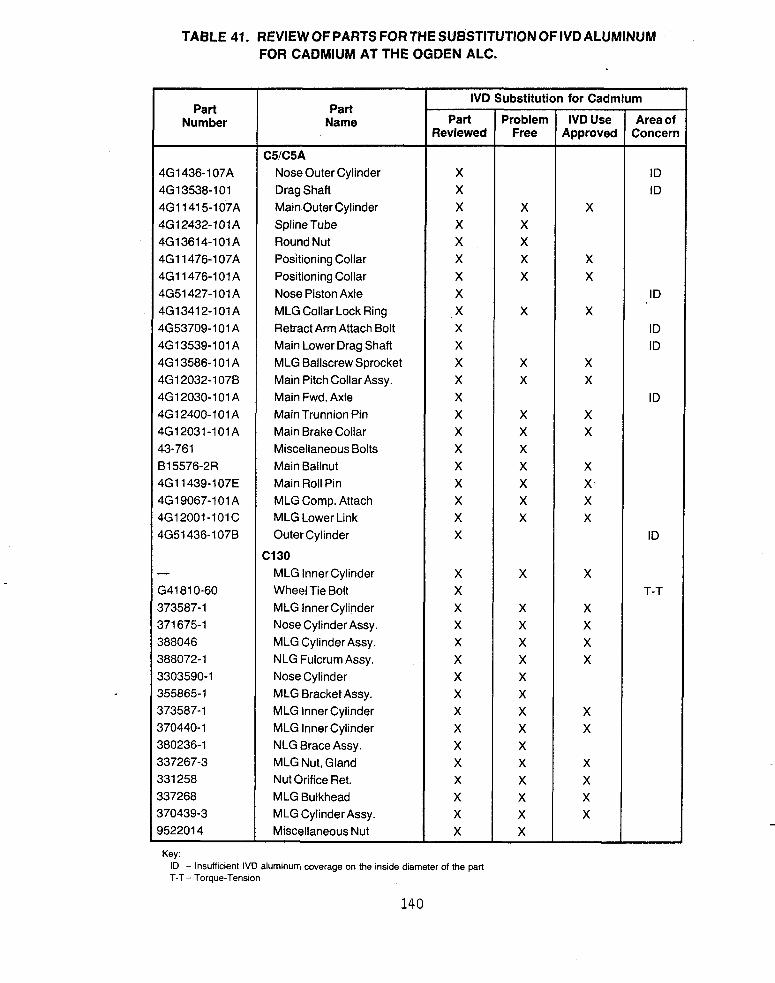
TABLE 41. REVIEW OF PARTS FOR THE SUBSTITUTION OF IVD ALUMINUM FOR CADMIUM AT THE OGDEN ALC.
Part Number
4G1436-107A 4G13538-101 4G11415-107A 4G 1 2432- 101 A 4G13614-101 A 4G11476-107A 4G11476-101A 4G51427-101 A 4G 1 341 2-1 01 A 4G53709-101 A 4G 1 3539-1 01 A 4G13586-101A 4G12032-1078 4G12030-101 A 4G12400-I 01 A 4G12031-101A 43-761 815576-2R 4G11439-107E 4G19067-101 A 4G12001-101 C 4G51436-1078
- G41810-60 373587-1 371 675-1 388046 388072-1 3303590-1 355865- 1 373587-1 370440- 1 380236-1 337267-3 331 258 337268
952201 4 370439-3
Part Name
C5/C5A Nose Outer Cylinder Drag Shaft Main Outer Cylinder Spline Tube Round Nut Positioning Collar Positioning Collar Nose Piston Axle MLG Collar Lock Ring Retract Arm Attach Bolt Main Lower Drag Shaft MLG Ballscrew Sprocket Main Pitch Collar Assy. Main Fwd. Axle Main Trunnion Pin Main Brake Collar Miscellaneous Bolts Main Ballnut Main Roll Pin MLG Comp. Attach MLG Lower Link Outer Cylinder
MLG Inner Cylinder Wheel Tie Bolt MLG Inner Cylinder Nose Cylinder Assy. MLG Cylinder Assy. NLG Fulcrum Assy. Nose Cylinder MLG Bracket Assy. MLG Inner Cylinder MLG Inner Cylinder NLG Brace Assy. MLG Nut, Gland Nut Orifice Ret. MLG Bulkhead MLG Cylinder Assy. Miscellaneous Nut
C130
IVD Substitution for Cadmium
Part Reviewed
X X X X X X X X X X X X X X X X X X X X X X
X X X X X X X X X X X X X X X X
Key: ID - Insufficient IVD aluminum coverage on the inside diameter of the part T-T- Torque-Tension
140
Problem Free
X X X X X
X
X X
X X X X X X X
X
X X X X X X X X X X X X X X
IVD Use Approved
X
X X
X
X X
X X
X X X X
X
X X X X
X X
X X X X
Area of Conceri
ID ID
ID
ID ID
ID
ID
T-T

TABLE 41. REVIEW OF PARTS FORTHE SUBSTITUTION OF IVD ALUMINUM FOR CADMIUM AT THE OGDEN ALC (CONTINUED).
Part Number
762-7675-80 53G41420-3 32-41 672-6 32-41 081 -7 32-41 669-7 32-41 632-5 7027675-30 53-41 420-301 32-41 675-5 7027675-70 53641 420-4 32-41 672-3 32-41 672-4 32-41 672-5 32-41 672-6 32-45703-1 32-41 669-1 3 53-41 441 -3
2006803-1 05 20061 01 -1 03
9861 18-1
14-40646-3
-
68A410615-2001 68A450726-2001 68A410792-1001 68A410790-2001 MS14163-09024 68A410756-1001 68A410735-2001 68A410755-2005 68A450614-2001
Part Name
F-4 Inner Cylinder Assy. MLG Outer Cylinder MainTorque Pin MLG Ring Tiedown MLG Torque Arm Lower Main Drag Brace MLG Inner Cylinder Assy. MLG Outer Cylinder Main Torque Pins MLG Inner Cylinder Assy. MLG Outer Cylinder Main Torque Pins (Lower) Main Torque Pins (Lower) Main Torque Pins (Lower) Main Torque Pins (Lower) Nose Outer Cylinder Assy. MLG Torque Arm Lower MLG Axle Nut
NLG Upper Drag Brace MLG Piston Assy.
Main Outer Cylinder
Main Torque Arm
Main Outer Cylinder Main Collar Nut NLG Orifice Tube Main Lower Drag Brace MLG High Pressure Piston Bolts Main Jury Link Pin Main Trunnion Pin Main Jury Brace Appx. Pin NLG Miscellaneous
F-16
A7D
F-5
F-15
Key: ID - Insufficient IVD aluminum coverage on the inside diameter of the part T-T - Torque-Tension
1 4 1

TABLE 41. REVIEW OF PARTS FORTHE SUBSTITUTION OF IVD ALUMINUM FOR CADMIUM AT THE OGDEN ALC (CONTINUED).
Part Number
121 095-7 9931 02-1 11301 21 -1 01
5-851 23-6 4 - 8 0 5 3 6 25-421 1 1-8061 4 1-8061 5 5-68457-5 3-8061 6 1-80721 -1 5-36035-3 6-35 1 61 - 1 6-351 61 -4 4-80728 6-34595-1 63-21 4 4 - 8 0 7 2 0 9-52976 9-52977
19064-1
NAS14882 63832436
952561 1 3G10018-113 3G11098-105 3G61097-107 3G61344 3G61303-101 3G61342-101 3G61345 3G 1 1098-1 05 3G111125-103
Part Name
F-1 1 1 MLG Aft Hinge Pin Main Inner Position Main Inner Cylinder
Main Inner Cylinder Drag Brace Pin, Toggle Fork Main Lower Tripod Assy. Drag Strut - Upper Link Drag Strut - Upper Link Steering Plate Drag Strut Main Torque Arm Main Outboard Tripod Link MLG Bolt MLG Bolt MLG Nut, Special MLG Bolt Miscellaneous Parts MLG Pin Special Main CapTrunnion Main Cap Trunnion
Main Pin Socket Sub Assy.
Tie Bolt - Large Allen Head Nut
C141 Washer Main Piston Assy Main Axle Nose Aft Drag Brace Mooring Ring Nut Bolt (M.R.) Spring (M.R.) Main Axle Main Knee Bolt
852
A1 0
F-1 00
IVD Substitution for Cadmium
Part Reviewed
X X X
X X X X X X X X X X X X X X X X X
X
X X
X X X X X X X Y X X
Problem Free
X X X
X X X X X X
X
X X X X
X X
X
X X X X X
IVD Use Approved
X X
X X X X X X
X
X X
X X X X
Area of Concern
ID ID
ID ID ID
ID
ID
ID ID
ID ID
Key: ID - Insufficient IVD aluminum coverage on the inside diameter of the part T-T- Toraue-Tension
142
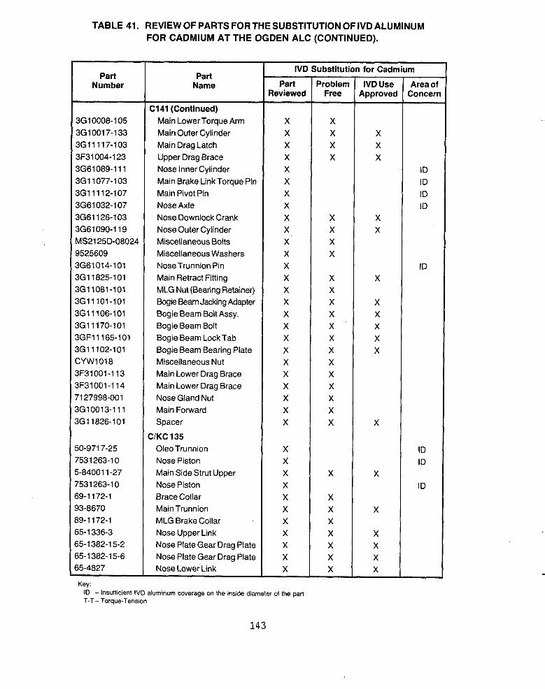
TABLE 41. REVIEW OF PARTS FOR THE SUBSTITUTION OF IVD ALUMINUM FOR CADMIUM AT THE OGDEN ALC (CONTINUED).
~
IVD Substitution for Cadmium
Number Name Part Problem IVDUse Areaof Reviewed Free Approved Concern
Part Part
C141 (Continued) 3G10008-105 Main Lower Torque Arm X X 3610017-133 Main Outer Cylinder X X X 3G11117-103 Main Drag Latch X X X 3F31004-123 Upper Drag Brace X X X 3G61089-111 Nose Inner Cylinder X ID 3G11077-103 Main Brake Link Torque Pin X ID
Main Pivot Pin X ID I ::;:;;::E Nose Axle X ID ,3G61126-103 Nose Downlock Crank X X X 3G61090-119 Nose Outer Cylinder X X X MS2125D-08024 Miscellaneous Bolts X X 9525609 Miscellaneous Washers X X 3661014-1 01 NoseTrunnion Pin X ID 3G11825-101 Main Retract Fitting X X X 3G11081-101 MLG Nut (Bearing Retainer) X X 3G 1 1 1 01 -1 01 Bogie Beam Jacking Adapter X X X 3G11106-101 Bogie Beam Bolt Assy. X X X 3G11170-101 Bogie Beam Bolt X X X 3GF11165-101 Bogie Beam Lock Tab X X X 3G11102-101 Bogie Beam Bearing Plate X X X CYW1018 Miscellaneous Nut X X 3F31001-113 Main Lower Drag Brace X X 3F31001-114 Main Lower Drag Brace X X 71 27998-001 Nose Gland Nut X X 3G10013-111 Main Forward X X 3G11826-101 Spacer X X X
C/KC 135 50-971 7-25 Oleo Trunnion X ID 7531 263-1 0 Nose Piston X ID 5-84001 1-27 Main Side Strut Upper X X X 7531 263-1 0 Nose Piston X ID 69-1 172-1 Brace Collar X X 93-8670 Main Trunnion X X X 89-1 172-1 MLG Brake Collar X X 65-1 336-3 Nose Upper Link X X X 65-1 382-1 5-2 Nose Plate Gear Drag Plate X X X 65-1 382-1 5-6 Nose Plate Gear Drag Plate X X X 65-4827 Nose Lower Link X X X
~~ ~~
Key. ID - Insufficient IVD aluminum coverage on the inslde diameter of the part
143
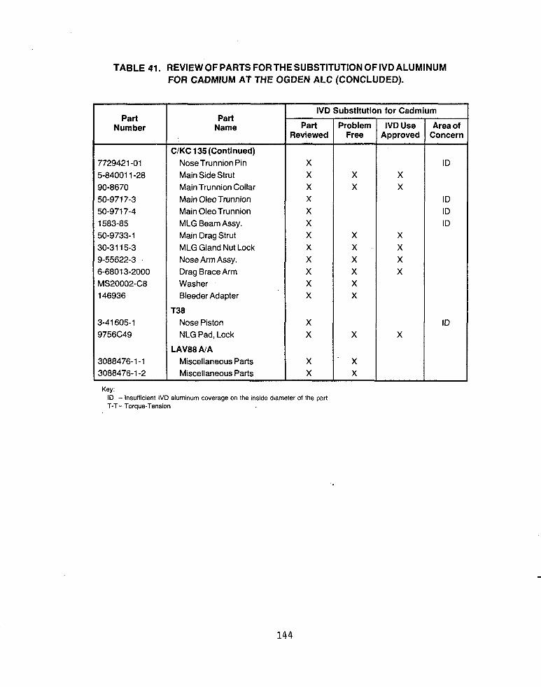
TABLE 41. REVIEW OF PARTS FORTHE SUBSTITUTION OFIVDALUMINUM FOR CADMIUM AT THE OGDEN ALC (CONCLUDED).
Part Number
7729421 -01 5-84001 1-28 90-8670 50-971 7-3 50-971 7-4 1583-85 50-9733-1 30-31 15-3 9-55622-3 6-6801 3-2000 MS20002-C8 146936
3-41605-1 9756C49
3088476-1-1 3088476-1 -2
Key
IVD Substitution for Cadmium Part
Name Part Problem IVDUse Areaof Reviewed Free Approved Concern
C/KC 135(Continued) Nose Trunnion Pin X ID Main Side Strut X X X Main Trunnion Collar X X X Main Oleo Trunnion X ID Main OleoTrunnion X ID MLG Beam Assy. X ID Main Drag Strut X X X MLG Gland Nut Lock X X X Nose Arm Assy. X X X Drag Brace Arm X X X Washer X X Bleeder Adapter X X
T38 Nose Piston X ID NLG Pad, Lock X X X
Miscellaneous Parts X - x Miscellaneous Parts X X
mvaa AIA
144

TABLE 42. REVIEW OF PARTS FOR THE SUBSTITUTION OF IVD ALUMINUM FOR CADMIUM AT THE SACRAMENTO ALC.
Part Number
5-86077 5-86079 581 C5 5-86397-2 5-86077 9-1 0386 NAS1305-9H 9-60396 69-51 56 66-13798-1 65-651 6-2 65-1 2228-1
- 12W415-1 12T9201
37351 1-1
506826
5-36060-2 5-35988-1 65-0431 15 65-0431 16
177269 17791 0 177219 17751 5 177386 177246
19731 6
Key:
Part Name
C135 Terminal
Barrel Rod End Terminal Nut Miscellaneous Hardware Nut Rod End Ext. Sleeve Head End Bearing
Miscellaneous Fasteners Wing Pivot Pin Hub Assy
Hub O/B Bearing Intercoastal -9 Intercoastal - 7
Cap
F-1 1 1
PP-65831T Power Supply Cabinet
Cylinder
Piston Rod Barrel Side Plate Side Plate
Carrier Output 1 FR Large Carrier Output Retainer Ring Bevel Adaptor Center Spur Gear
1 /2 Details 112 Details
Adapter Spline
E-3A
352
25
IVD Substitution for Cadmium
Part Reviewed
X X X X X X X X X X X X
X X
X X X X
X
X
X X X X
X X X X X
X X X
Problem Free
X X
X X X X X X X X X
X
X X X
X
X
X
X X
X X X X X
X
IVD Use Approved
Area of Concern
ID
ID
ID
ID
ID ID
ID - Insufficient IVD aluminum coverage on the inside diameter of the part
145

TABLE 42. REVIEW OF PARTS FOR THE SUBSTITUTION OF IVD ALUMINUM FOR CADMIUM AT THE SACRAMENTO ALC (CONCLUDED).
Key: ID - Insufficient IVD aluminum coverage on the inside diameter of the part
146


TABLE 43. REVIEW OF PARTS FORTHE SUBSTITUTION OF IVDALUMINUM FOR CADMIUM AT THE OKLAHOMA CITY ALC (CONTINUED).
Engine Number
30467R 30467R 30467R 30467R 30467R 30467R 30467R 30467R 30467R 30468R 30468R 30468R 30468R 30450R 30450R 30450R 30450R 30450R 30450R 30450R 30450R 30450R 30450R 30450R 30584 30584 30568R 307376 30732G 30732G 30732G 30732G 30320R 3031 8R 30594R 307556 30334R 30334R 30670R
Part Number
21 7331 8 NBN 049229 2 1 73353 NBN 049378 21 73354 NBN 049379 538085 61 8286 61 6997 668668 21 73320 NBN 049230 557678
577339 577340 577341 577342 577343 623760 623761 623762 57261 3 57261 4 559380 61 5992 697032 502 1 78 61 8865 502366 502098 5021 84 559824 565084 500756 666882 61 7855 563559 51 0790
577338
Part Name
rF30 (Continued) Compressor Stator, 5 - 7th Stage Compressor Stator, 5-7th Stage Compressor Stator, 5 - 7th Stage Compressor Stator, 5 - 7th Stage Compressor Stator, 5 - 7th Stage Compressor Stator, 5 - 7th Stage Compressor Stator, 5- 7th Stage Compressor Stator, 5-7th Stage Compressor Stator, 5 - 7th Stage Compressor Stator, 8th Stage Compressor Stator, 8th Stage Compressor Stator, 8th Stage Compressor Stator, 8th Stage Ring, Air Sealing, Compressor Ring, Air Sealing, Compressor Ring, Air Sealing, Compressor Ring, Air Sealing, Compressor Ring, Air Sealing, Compressor Ring, Air Sealing, Compressor Ring, Air Sealing, Compressor Ring, Air Sealing, Compressor Ring, Air Sealing, Compressor Ring, Air Sealing, Compressor Ring, Air Sealing, Compressor Tierod Bolts, Front Compressor Tierod Bolts, Front Compressor Tierod Bolts, Rear and Front Compressor Housing - Bearing Inter Gearbox Housing Assembly Gearbox Bearing Housing Assembly Gearbox Bearing Housing Assembly Gearbox Bearing Housing Assembly Gearbox Bearing Coupling, Gearbox Drive Gear Tube-Sealing Rear Compressor Bracket, Ignition Exciter, Upper Housing Assembly Gearbox Bearing Shait N-1 Turbine Shaft N-1 Turbine Bracket
Key: ID - Insufficient IVD aluminum coverage on the inside diameter of the pari
148
IVD Substitution for Cadmium
Part Reviewed
X X X X X X X X X X X X X X X X X X X X X X X X X
X X X X X X X X X X X X X
x .
Problem Free
X X X X X X X X X X X X X X X X X X X X X X X X X X X X X X X X X X X X
X
IVD Use Approved
X X X X X X X X X X X
Area of Concern
ID ID

TABLE 43. REVIEW OF PARTS FORTHE SUBSTITUTION OF IVD ALUMINUM FOR CADMIUM AT THE OKLAHOMA CITY ALC (CONTINUED).
739635 559378 702805 513799 504245 Sub 697220 Sub 504241 51 3798 69721 8 504255 69721 9
Engine Number
TF30 (Continued) Housing Gearbox Drive Bearing Tierod Bolts, Front Compressor Nut Gearbox Quick Disconnect Nut Gearbox Quick Disconnect Nut Gearbox Quick Disconnect Nut Gearbox Quick Disconnect Nut Gearbox Quick Disconnect Nut Gearbox Quick Disconnect Adapter - Gearbox Quick Disconnect Adapter- Gearbox Quick Disconnect Adapter- Gearbox Quick Disconnect
I 3071 56 30531 R 3070EG 307026 30702G 307026 30702G 30702G 30642G 30642G 30642G
33342R 33342R 33342R 33342R 33342R 33342R 33342R 33342R 33342R 33342R 33342R 33342R 33342R 33342R 33342R 33342R 33342R 33346R
33346R
33346R
3321 8R 3321 8R 33218R 33354R
Part Number
Part Name
703556 71 41 47 393540 399032 428335 463547 463553 463554 71 41 49 494399 431 122 463557 71 41 45 714162 629236 703558 635508 247346
432595
576584
483277 679747 769553 157532
TF33 Tierod, Front Compressor Tierod, Front Compressor Tierod, Front Compressor Tierod, Front Compressor Tierod, Front Compressor Tierod, Front Compressor Tierod, Front Compressor Tierod, Front Compressor Tierod, Front Compressor Tierod, Front Compressor Tierod, Front Compressor Tierod, Front Compressor Tierod, Front Compressor Tierod, Front Compressor Tierod, Front Compressor Tierod, Front Compressor Tierod, Front Compressor Coupling, Front Compressor Drive Turbine Coupling, Front Compressor Drive Turbine Coupling, Front Compressor Drive Turbine Housing No. 1 Bearing Housing No. 1 Bearing Housing No. 1 Bearing Ring-Retaining US Compressor Coupling
I IVD Substitution for Cadmium I
Key: ID - Insufficient IVD aluminum coverage on the inside diameter of the part

TABLE 43. REVIEW OF PARTS FORTHE SUBSTITUTION OFIVD ALUMINUM FOR CADMIUM AT THE OKLAHOMA CITY ALC (CONTINUED).
I Engine Number I
I--- 33352R 33352R 33352R 33897
33348R 33348R 33348R 33348R 33897 33670
-
-
57322R 57322R 57322R 57322R 57322R 57322R 57322R 57322R 57322R 57322R 57322R 57322R 57322R 57322R 57306R 57306R 57306R 57373R
57373R
57373R
57370R
57370R
Part Number
286079 201 61 5 71 41 63 403326 799599 359439 364827 71 41 65 2081 78 403326 4641 62 51 5970
740005 206931 74001 3 31 0978 74001 2 21 691 5 74001 1 21 691 3 740006 206935 740007 206935 740008 206936 1831 54 201 61 3 369479 201 61 5
71 41 63
286079
201 61 6
331 450
Part Name
TF33 (Continued) Lock, Front Compressor Drive Turbine Lock, Front Compressor Drive Turbine Lock, Front Compressor Drive Turbine Accessory Drive Pad Retainer Seat, Turbine, Shaft Coupling Seat, Turbine, Shaft Coupling Seat, Turbine, Shaft Coupling Spring, Front Compressor Turbine Shaft Nut Assembly, Accessory Drive Pad Sort items (Bracket, Plate, Etc.) support
TF57 Spacer, High Speed Compressor Spacer, High Speed Compressor Spacer, High Speed Compressor Spacer, High Speed Compressor Spacer, High Speed Compressor Spacer, High Speed Compressor Spacer, High Speed Compressor Spacer, High Speed Compressor Spacer, High Speed Compressor Spacer, High Speed Compressor Spacer, High Speed Compressor Spacer, High Speed Compressor Spacer, High Speed Compressor Spacer, High Speed Compressor Tierod, Front and Rear Compressor Tierod, Front and Rear Compressor Tierod, Front and Rear Compressor Coupling, Front Compressor Drive Turbine Shaft Coupling, Front Compressor Drive Turbine Shaft Coupling, Front Compressor Drive Turbine Shaft Collar, Front Compressor Drive Turbine Shaft Coupling Collar, Front Compressor Drive Turbine Shaft Coupling
I
Key:
IVD Substitution for Cadmium
Part Reviewed
X X X X X X X X X X X X
X X X X X X X X X X X X X X X X X X
X
X
X
X
Problem Free
X X X X X X X X X X X
X X X X X X X X X X X X X X X X X
X
X
IVD Use Approved
X X X
X
X X X
Area of Concern
ID
ID
ID
ID

TABLE 43. REVIEW OF PARTS FOR THE SUBSTITUTION OF IVD ALUMINUM FOR CADMIUM AT THE OKLAHOMA CITY ALC (CONCLUDED).
Engine Number
57373M
57373M
57743R
57670Y
57743R
57723Y 57723M 57723M 57369Y 57372Y 57327R 575078
- - 41 763R 41 900R A00094
Key:
Part Number
71 41 63
201 61 2
334974
334974
321 530
403326 403326 308892 157532 2081 78
739635B 2081 78
- - 6865326 6861 241 2041 04
Part Name
TF57 (Continued) Lock, Front Compressor DriveTurbine Shaft Coupling Lock, Front Compressor DriveTurbine Shaft Coupling Screen Assembly, Water Injector Control Inlet Screen Assembly, Water Injector Control Inlet Screen Assembly, Water Injector Control Inlet Nut Assembly, Accessory Drive Pad Nut Assembly, Accessory Drive Pad Nut Assembly, Accessory Drive Pad Ring-Retaining US Compressor Coupling Spring, Front Compressor Turbine Shaft Spring, Front Compressor Turbine Shaft AB Cylinder
Seat, Turbine Shaft, Coupling Lock Spring P&W Ring, 6th Stage LinUBell CranWRod Assembly Rear Mounting - Regular Airflow Control Carrier
Miscellaneous Parts
IVD Substitution for Cadmium
Part Reviewed
X
X
X
X
X
X X X X X X X
X X X X X
Problem Free
X
X
X
X
X
X X X X X X X
X X X X X
IVD Use Approved
X X X
Area of Concern
ID - Insufficient IVD aluminum coverage on the inside diameter of the part
151

TABLE 44. REVIEW OF PARTS FOR THE SUBSTITUTION OF IVD ALUMINUM FOR CADMIUM AT THE SAN ANTONIO ALC.
Part Part Number Name
T56 6829896 6841 21 2 6841 21 3 6841 214 6841 21 5 6847091 6875201 6876251
Pin Reduction Gear Eye Bolt Compressor Wheel, Stage 2 Compressor Wheel, Stage 3 Compressor Wheel, Stage 4 Compressor Wheel, Stage 5 Vane Compressor, 1 st Stage Vane Compressor, 1 st Stage Vane Compressor, 1 st Stage
6847093 Vane Compressor, 3rd Stage 6875203 Vane Compressor, 3rd Stage 6875206 Vane Compressor, 6th Stage 6809436 Vane Compressor, 6th Stage 687521 0 687521 1 6809441 6846291 6855041 685961 1 6871 381
Vane Compressor, 10th Stage Vane Compressor, 11 th Stage Vane Compressor, 11 th Stage Vane Compressor, 1 1 th Stage Vane Compressor, 1 1 th Stage Vane Compressor, 1 1 th Stage Vane Compressor, 11 th Stage
6809432 Vane Compressor, 2nd Stage 6846872 Vane Compressor, 2nd Stage 6855032 Vane Compressor, 2nd Stage 6859602 Vane Compressor, 2nd Stage 6846672 Vane Compressor, 2nd Stage 6846282 Vane Compressor, 2nd Stage 6871 372 Vane Compressor, 2nd Stage 6847091 Vane Compressor, 1 st Stage 6875201 Vane Compressor, 1 st Stage 6876251 Vane Compressor, 1 st Stage 6859604 Vane Compressor, 4th Stage 6809434 Vane Compressor, 4th Stage 6846871 Vane Compressor, 4th Stage 6855034 Vane Compressor, 4th Stage 6846674 Vane Compressor, 4th Stage 6846284 Vane Compressor, 4th Stage
Vane Compressor, 4th Stage 6809435 Vane Compressor, 5th Stage 6846875 Vane Compressor, 5th Stage
6871 374
Key ID - Insufficient IVD aluminum coverage on the inside diameter of the
IVD Substitution for Cadmium
Part Problem IVDUse Areaof Reviewed Free Approved Concern
X X X X X X X X X X X X X X X X X X X X X X X X X X X X X X X X X X X X X X X X X X X X X X X X X X X X X X X X X X X X X X X X X X X X X X X X X X X X X X X X
part
152

TABLE 44. REVIEW OF PARTS FOR THE SUBSTITUTION OF IVD ALUMINUM FOR CADMIUM AT THE SAN ANTONIO ALC (CONTINUED).
I
Part Number
6875204 6847094 6847095 6875205 6847077 6875207 6875208 6875209 687521 2 687521 3 681 4423 681 2539 681 9691 681 9697 681 9694 681 9698 6821 487 6824774 6826933 6826934 6826935 6827298 6780854 6781 501 6783838 6854756 6855286 6858624 6824074 6875958 6789474 6731 01 4 6791 891 6792254 6 7 9 2 7 6 7 6792768 6792770 6792771
Part Name
T56 (Continued) Vane Compressor, 4th Stage Vane Compressor, 4th Stage Vane Compressor, 5th Stage Vane Compressor, 5th Stage Vane Compressor, 7th Stage Vane Compressor, 7th Stage Vane Compressor, 8th Stage Vane Compressor, 9th Stage Vane Compressor, 12th Stage Vane Compressor, 13th Stage Rear Lever Propeller Control Shaft Propeller Control Lever, Intermediate Shaft Propeller Control Lever, Intermediate Shaft Propeller Control Lever, Intermediate Bolt Propeller Control Pivot Clevis Arm Propeller Control, Intermediate Bolt Reduction Gear Arm Propeller Control, Front Bell Crank PC1 Arm Propeller Control, Rear Link Propeller Control, Rear Rod, Threaded Level FUFl Rod, Threaded Level FUFl Fitting Reduction Gear Power Compressor Wheel, Stage 6 Compressor Wheel, Stage 6 Compressor Wheel, Stage 14 Compressor Wheel, Stage 14 Propeller Shaft Vane Compressor, 14th Stage Vane Compressor, 14th Stage Engine Mount Bracket Assembly Seal, Labyrinth Rotating Compressor Compressor Wheel, Stage 14 Compressor Wheel, Stage 8 Compressor Wheel, Stage 9 Compressor Wheel, Stage 11
IVD Substitution for Cadmium
Part Reviewed
X X X X X X X X X X X X X X X X X X X X X X X X X X X X X X X x X X X X X X
Problem Free
X X X X X X X X X X X X X X
X X X X X X
X X X X X X X
X X X X X X X X
IVD Use Approved
X
X X X X
X X X X X X
Area of Concern
T-T
ID
ID
Key: ID - Insufficient IVD aluminum coverage on the inside diameter of the part T-T- Torque-Tension
7 53
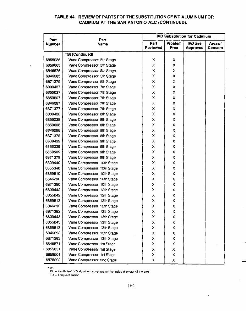
TABLE 44. REVIEW OF PARTS FORTHE SUBSTITUTION OF IVD ALUMINUM FOR CADMIUM AT THE SAN ANTONIO ALC (CONTINUED).
IVD Substitution for Cadmium
Number Name Part Problem IVDUse Areaof Reviewed Free Approved Concern
1 Part Part
T56 (Continued) 6855035 Vane Compressor, 5th Stage X X 6859605 Var?e Compressor, 5th Stage X X
I 6846285 Vane Compressor, 5th Stage X X , 6871 375 Vane Compressor, 5th Stage X X 6809437 Vane Compressor, 7th Stage X X 6855037 Vane Compressor, 7th Stage X X 6859607 Vane Compressor, 7th Stage X X 6846287 Vane Compressor, 7th Stage X X 6871 377 Vane Compressor, 7th Stage X X 6809438 Vane Compressor, 8th Stage X X 6855038 Vane Compressor, 8th Stage X X 6859608 Vane Compressor, 8th Stage X X 6846288 Vane Compressor, 8th Stage X X 6871 378 Vane Compressor, 8th Stage X X 6809439 Vane Compressor, 9th Stage X X 6855039 Vane Compressor, 9th Stage X X 6859609 Vane Compressor, 9th Stage X X 6871 379 Vane Compressor, 9th Stage X X 6809440 Vane Compressor, 10th Stage X X 6855040 Vane Compressor, 10th Stage X X 685961 0 Vane Compressor, 10th Stage X X 6846290 Vane Compressor, 10th Stage X X 6871 380 Vane Compressor, 10th Stage X X 6809442 Vane Compressor, 12th Stage X X 6855042 Vane Compressor, 12th Stage X X 685961 2 Vane Compressor, 12th Stage X X 6846292 Vane Compressor, 12th Stage X X 6871 382 Vane Compressor, 12th Stage X X 6809443 Vane Compressor, 13th Stage X X 6855043 Vane Compressor, 13th Stage X X 6859613 Vane Compressor, 13th Stage X X 6846293 Vane Compressor, 13th Stage X X 6871 383 Vane Compressor, 13th Stage X X 6846871 Vane Compressor, 1 st Stage X X
6859601 Vane Compressor, 1 st Stage X X 6875202 Vane Compressor, 2nd Stage X X
~ 6846675 Vane Compressor, 5th Stage X X
I
' 6855031 Vane Compressor, 1st Stage X X
Key. ID - Insufficient IVD aluminum coverage on the inside diameter of !he pari
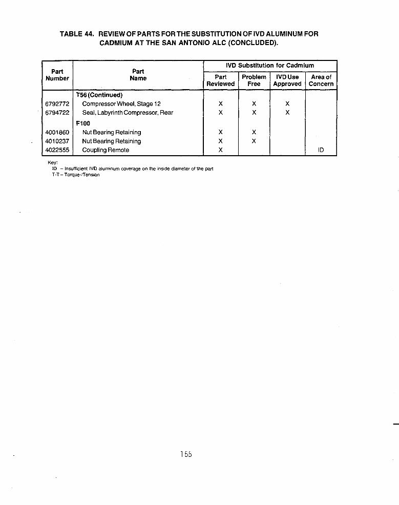
TABLE 44. REVIEW OF PARTS FORTHE SUBSTITUTION OF IVD ALUMINUM FOR CADMIUM AT THE SAN ANTONIO ALC (CONCLUDED).
X X
X X X
Part Number
X X
X X
6792772 6794722
4001 860 401 0237 4 0 2 2 5 5 5
Part Name
T56 (Continued) Compressor Wheel, Stage 12 Seal, Labyrinth Compressor, Rear
Nut Bearing Retaining Nut Bearing Retaining Coupling Remote
F1OO
IVD Substitution for Cadmium
Part j Pr;::m Reviewed
X X
ID
Key: ID - Insufficient IVD aluminum coverage on the inside diameter of.the part T-T- Torque-frension
155

t n e t o t a l number o f p a r t s reviewea. The percentage o f p a r t s e x h i b i t i n g "areas o f concern" i s somewhat l e s s than what was i n i t i a l l y suspected, n o m i n a l l y LO percen t . The t o t a l number of p a r t s i d e n t i f i e d w i t h p o s s i b l e t o r q u e - t e n s i o n o r
e r o s i o n problems may be l o h . but , t h e percentage o f p a r t s w i t h "areas o f
concern" i s n o t expected t o exceea 15-18 pe rcen t .
A l though a l l o f t h e p a r t s processed by t h e A L C s a r e n o t a v a i l a b l e f o r
r e v i e w a t any g i v e n t ime, t h e m a j o r i t y o f t h e p a r t c o n f i g u r a t i o n s were
rev iewed a t each ALC. From t h i s rev iew, t h e m a j o r i t y o f cadmium processed
p a r t s c o u l d now be I V D aluminum coated. Even though t t h e percentage o f p a r t s
w i t h "areas o f concern" i s r e l a t i v e l y low, adequate s o l u t i o n s f o r t h e problem
p a r t s must be e s t a b l i s h b e f o r e I V D aluminum can r e p l a c e caamium p r o c e s s i n g
across- the-board a t t h e ALCs. Research ana development d i r e c t e d a t r e s o l v i n g
these "areas o f concern" i s d iscussed i n S e c t i o n X I I . A h i g h p r o b a b i l i t y o t
success i s p r o j e c t e d .
C. DEMOhbTkATIOh OF THE GEhERIC NATURE OF I V D ALUMlNUM
M C A I R demonstrated t h e gener i c p r o p e r t i e s o f 1Vb aluminuni (Reference 52) as d iscussed n Sec t ions I 1 t h rough VI1 by t e s t i n g I V D aluminum-coatea pane l .
T h i r t y - s i x 1- by 4 - i n c h and 12, 3- by 6 - i n c h pane ls were IVb aluminum coatea
pe r t n e t e s t m a t r i x i n Table 45. Three s u b s t r a t e m a t e r i a l s were used k i t h
t h r e e c o a t i n g t h i c k n e s s c lasses f o r each s u b s t r a t e m a t e r i a l .
l h e adhesion o f t h e I V D aluminum c o a t i n g was v e r i f i e d on t h e 36, 1- by
4 - i n c h bend-to-break panels. Paragraph 4.5.2 o f M 1 L - C - 8 3 4 8 6 d e f i n e s
adhesion. "Adhesion s h a l l be determined by s c r a p i n g t h e s u r t a c e o f t h e p l a t e o
a r t i c l e t o expose t h e b a s i s meta l and examining a t a minimum o f f o u r u iameters
m a g n i f i c a t i o n f o r ev idence o f nonaanesion. A l t e r n a t e l y , t h e t e s t s t r i p s n a l l
be clamped i n a v i s e and bent back and f o r t h u n t i l s t r i p r u p t u r e occu rs . I f
t n e edge o f t h e r u p t u r e d c o a t i n g can be peeled back o r i f s e p a r a t i o n between
t h e c o a t i n g and t h e b a s i s me ta l can be seen a t t h e p o i n t of r u p t u r e wnen
exarninea a t f o u r d iameters m a g n i f i c a t i o n , adnesion i s n o t s a t i s t a c t o r y . " A l l
36 I V D aluminum-coated panels passea t h e bend-to-break t e s t . I n dUdit iOn, d 1
.~
3b panels were t a p e - t e s t e d and glass-bead-peened f o r adhesion v e r i f i c a t i o n , - ana s i x panels had t h e adhesive s t r e n g t h o f t h e c o a t i n g measured.
156

TABLE 45. TEST MATRIX FOR DEMONSTRATION OFTHE GENERIC NATURE OF IVD ALUMINUM.
Test
1 Corrosion Resistance Class 1 Coating Class 2 Coating Class 3 Coating
2 Adhesion Class 1 Coating Class 2 Coating Class 3 Coating
3 Uniformity
4 Coverage
5 Conductivity
Number of Coupons Required to Be Coated
Alloy Steel
Specimen Size
3 x 6 (in.)
1 x 4 (in.) - - - -
4 4 4
4
4
4
Aluminum Alloy
Specimen Size
3 x 6 (in.)
1 X 4 (in.)
- - -
4 4 4
4
4
4
Titanium Alloy
Specimen Size
3 x 6 (in.)
1 x 4 (in.) - - - -
4 4 4
4
4
4
Notes: 1. Corrosion resistance testing will be conducted per ASTM B-117 (5 percent neutral salt fog environment). 2. Coating adhesion shall pass bend-to-brake testing and 40 psi glass bead peening. 3. Coating uniformity shall be measured on the 3- by 6-in. alloy steel panel prior to corrosion
4. Coating coverage shall be verified by 4x visual inspection on all of the 1- by 4-in. coupons prior to
5. Electrical conductivity shall be measured on all the 1- by 4-in. coupons prior to adhesion testing. 6. Dash (-) indicates no test specimen.
resistance testing.
adhesion testing.
The tape t e s t was performed by firmly a p p l y i n g Number 250, 3M Company, inspection tape t o the fractured edge of the bend-to-break panels a n d
removing w i t h a quick p u l l . No coating was removed from the fractured edge of the panels.
Prior t o the bend-to-break and tape t e s t s , the panels were glass-beaa- peened a t 40 psi w i t h Number 10 glass beads. The i m p i n g i n g glass beads produce shear s t resses i n the c o a t i n g suf f ic ien t t o remove poorly adherent coatings. iko coa t ing was removed by glass bead peening.
A p u l l t e s t was performed on s ix o f the 1 - by 4-inch s tee l panels, two from each coating thickness c lass . A Sebastian I Coating Adherence Tester w i t h a 10 KPSI range was used for these t e s t s . The adhesive t ens i l e strength of the IVD aluminum coating was greater t h a n 8 KPSI for a l l three classes o f
coatings.
157

In conclusion, the adhesion of the IVD aluminum coating on these panels is representative of IVD aluminum-coated parts that are properly processed. These adhesion tests demonstrate the generic nature of the coating adhesion reported in Section II(A).
Specimen Coating Number 'lass
1 2 3 ' 4
5 6 7 8
9 10 1 1 12
Coating coverage was verified for each o f the 1 - by 4-inch panels by a visual inspection prior to adhesion testing. A Bausch & Lomb Stereo microscope, Model 31-270-01, was used to examine the coating for bare areas, blisters, and voids in the coating. The IVD aluminum completely covered the panel s.
Coating Thickness (milsp
-Individual Measurements Average
1.35,1.39,1.54,1.59,1.49 1.47 1.49,1.49,1.39,1.39,1.49 1.45 1.59,1.65,1.49,1.39,1.39 1.50 1.49,1.44,1.49,1.54,1.54 1.50
0.93,0.93,0.96,0.99,0.90 0.94 0.99,0.99,0.90,0.85,0.85 0.96 0.99,0.99,0.99,0.90,0.90 0.95 0.93,0.83,0.85,0.93,0.99 0.91
0.48,0.49,0.48,0.48,0.47 0.48 0.50,0.47,0.47,0.47,0.48 0.48 0.50,0.48,0.46,0.47,0.50 0.48 0.49,0.50,0.46,0.47,0.49 0.48
The coating uniformity was measured on the 12, 4130 alloy steel test The IVD aluminum-coating thicknesses are presented in Table 46. panels.
TABLE 46. IVD ALUMINUM COATING THJCKNESS AND UNIFORMITY ON THE GENERIC PANELS.
In conclusion, the coba-age, uniformity, and thickness on these panels is representative o f I V O aluminum-coated parts that are properly processed. The coverage and uniformity measurements demonstrate the generic nature o f the process reported in Section I I ( t 5 ) .
-
158

The electrical conductivity of the IVD aluminum coating was calculated from 4-point probe voltage, current, and probe characteristics. Four-point probe measurements were made using a Keithley model 181 nanovoltmeter, in conjunction with an Alessi 4 point probe head and fixture. A nonmetallic panel was coated with a Class 1 IVD aluminum coating, and its electrical conductivity was compared to a bulk specimen of 1100 aluminum alloy which nas a 99 percent minimum aluminum content. The IVD aluminum coati-ng has an electrical conductivity of 47.6 percent that of bulk aluminum transverse to the surface. This is significant in that bulk aluminum is approximately three times more conductive than cadmium.
In conclusion, IVD aluminum coating on these panels is electrically conductive and provides a low resistant path. The electrical conducti measurements demonstrate the generic nature of the coating reported Section II(E).
IVD aluminum corrosion resistance was tested on the l ~ , 3- by 6-
alloy steel panels in neutral salt fog per ASTM 8-117. All the specimens each coating class exceeded the minimum requirements of MIL-C-83488.
i ty i 11
nch for The
average time to failure (rea rust) for the Class 3 panels was 1,424 hours. The average time to failure for the Class 2 panels is more than 7,300 hours (one panel is still in test). The average time to failure for the Class 1 coating is more than 7,800 hours (all four panels are still in test). The MIL-C-83488 corrosion-resistance requirements, the average time to failure for tne large database shown in Figure 12, Section III(A), and the average time to failure for the generic, aluminum-coated panels are shown in Figure 61. The average corrosion-resistance time of the generic, IVD aluminum-coated panels exceed the average times shown for the database in Figure 12.
In conclusion, IVD aluminum satisfied the minimum corrosion-resistance requirement of MIL-C-83488 and is representative of, to better than, the corrosion resistance expected for properly processed IVD aluminum-coated parts reported in Section III(A).
159

1
Hours In
Neutral Salt Fog (1,000)
Neutral Salt Fog Resistance
Requirements of MIL-(2-83488 and the Database Averages. Figure 61. Average Test Results for the Generic Panels Versus Minimum
160

SECTION X I
CONCLUSIONS
I V D aluminum f u l l - s c a l e c o a t i n g equipment i s p r o d u c t i o n proven; i t was
i n t r o d u c e d f o r use i n t h e manufacture o f a i r c r a f t ove r 12 y e a r s ago. The
c o a t i n g has s u c c e s s f u l l y undergone e x t e n s i v e 1 a b o r a t o r y and i n - s e r v i c e t e s t i n g as a s u b s t i t u t e f o r cadmium -- many o f t h e t e s t r e s u l t s a re documented
h e r e i n . I V D aluminum i s an e x c e l l e n t c o r r o s i o n r e s i s t a n t f i n i s h and, i n f a c t ,
o f f e r s performance advantages over cadmium. Perhaps more impor tan t , aluminum
i s n o n t o x i c , and t h e I V D process i s e n v i r o n m e n t a l l y c lean .
Because t h e I V D aluminum o p e r a t i o n i s c lean , s imple, and
n o n - l a b o r - i n t e n s i v e , and because f a c i l i t y and space requi rements a r e min imal
and r e q u i r e no s p e c i a l p o l l u t i o n - r e l a t e d systems, i t i s a c o s t - c o m p e t i t i v e
process. Cadmium c o s t s a re i n c r e a s i n g because of env i ronmenta l ana neal t h r e l a t e d laws and r e g u l a t i o n s . A t t h e same t ime , I V D aluminum c o s t s a re dec reas ing because o f p r o d u c t i v i t y advances a s s o c i a t e d w i t h i t s i nc reased
usage.
The c o n t e n t s of t h i s r e p o r t v e r i f y t h a t , f o r most a p p l i c a t i o n s , I V c i
aluminum can be s u b s t i t u t e d f o r cadmium w i t h o u t concern. F o r those
a p p l i c a t i o n s where t h e s u b s t i t u t i o n i s n o t s t r a i g h t f o r w a r d o r where o t h e r
t e c h n i c a l i ssues must be considered, t h e reader i s a l e r t e d ana s p e c i f i c research programs a re recommended. A h i g h p r o b a b i l i t y o f success i s
p r o j e c t e d . The c o n t e n t s of t h i s r e p o r t , t h e r e f o r e , s t r o n g l y suppor t s t h e
e l i m i n a t i o n of t h e v a r i o u s hazardous-waste-producing cadmium processes,
161

SECTION XI1
RESEARCH ANO OEVELUPMENT RECOMMENDATIONS
A. COVERAGE OF INTERNAL SURFACES
1. Problem
Whereas t h e I V D aluminum process i s n o t c o n f i n e d t o l i n e - o f - s i g h t
a p p l i c a t i o n , i t does have l i m i t a t i o n s r e g a r d i n g t h e a b i l i t y t o c o a t i n t o deep recesses; see S e c t i o n I I ( B ) . G e n e r a l l y speaking, t h e process can be used
e f f e c t i v e l y t o c o a t i n t o a b o r e o r recess f o r a d i s t a n c e equal t o
app rox ima te l y one t i m e t h e d iamete r o f t h e opening. There fo re , f o r p a r t s w i t h
a l eng th - to -d iamete r r a t i o g r e a t e r t h a n 1 : l ( o r 2 : l i f open a t b o t h ends), t h e I V D c o a t i n g coverage on p o r t i o n s o f t h e i n t e r n a l s u r f a c e may be inadequate.
Fo r example, t h e .bore o f a 5 - i nch d iamete r c y l i n d e r 20- inches l o n g and open a t
b o t h encis would be coated e f f e c t i v e l y f o r a p p r o x i m a t e l y 5- inches f r o m b o t h
ends. The rema in ing 1G-inches o f i n t e r n a l s u r f a c e i n t h e n i i da le o f t h e
c y l i n d e r would have a t h i n c o a t i n g o r no c o a t i n g a t a l l .
Even though tecnniques may be a v a i l a b l e t o evaporate aluminum w i t h i n
deep recesses u s i n g an i n t e r n a l anode, f o r most a p p l i c a t i o n s t h i s procedure
c o u l d be p r o h i b i t i v e l y expensive. Therefore, I V D aluminum cannot be a a i r e c t
cadmium s u b s t i t u t e f o r some ALC p a r t s , such as l a n d i n g gear d e t a i l s and
t u r b i n e s h a f t s , because o f i n t e r n a l s u r f a c e c o a t i n g requi rements. However,
t h e r e a re c o a t i n g s t h a t a re compa t ib le w i t h I V D aluminum and a r e recommended
a l t e r n a t i v e s t o cadmium f o r i n t e r n a l su r faces .
2. Proposed S o l u t i o n
Combined I V D aluminum w i t h another c o a t i n g t o p r o v i d e complete
coverage o f i n t e r n a l su r faces . Candidate m a t e r i a l s i n c l u d e :
a. A l u m i n u m - f i l l e d MIL-C-81517 basecoats. b. Ceramic sea lcoa ts . c. Pr imers, t opcoa ts , ana sea lan ts .
162

Aluminum-fi 1 led MIL-C-81517 basecoats - These are paint-type materials current ly in use by the A L C s . The coatings can be b r u s h - or spray-applied t o internal surfaces. The aluminum-fi l led coating becomes e l ec t r i ca l ly conductive when e i ther cured a t a su f f i c i en t ly high temperature or burnished w i t h g lass beads. The e l ec t r i ca l ly conductive coating then provides adequate sac r i f i ca l , c rrosion-resistance protection t o al loy s tee l substrates . are tradenames of avai lable aluminum f i l l e d coatings sui table f o r t h i s application.
A1 sea@ Sermete 6) and Xyla
Ceramic sealcoats - The MIL-C-81517 aluminum-fil led coatings a re often used as a s ac r i f i c i a l metall ic basecoat i n combination w i t n a ceramic sealcoat t o improve corrosion resistance. DoD agencies such as the haval Sea Systems Command make extensive use of these metallic-ceramic combination coatings t o protect alloy s teel hardware fo r various marine applications. The combination of IVD aluminum as the sac r i f i c i a l aluminum basecoat enhanced w i t h a ceramic sealcoat should provide adequate corrosion resis tance t o internal surfaces for those case where there i s IVD aluminum coating coverage b u t thickness i s l ess than desired.
Primer, topcoats, a n d sealants - Combinations of various priniers, topcoats, and sealants have shown promise i m preliminary tes t ing and may afford acceptable corrosion-resistance protection t o internal surfaces. Standard materials i n use by the ALCs l i ke epoxy primers, polyurethane topcoats, ana sprayable sealants are candidates.
The question may be asked, " I f a complementary coating i s adequate fo r an internal surface, why not use tha t coating over the en t i r e component rather t h a n i n combination w i t h IVD aluminuni, thus eliminating two-step processing?" The answer is t ha t what may be adequate fo r internal surfaces rny not be adequate for external surfaces. fo r example, the sac r i f i c i a l aluminum-filled paint-type coatings provide excellent corrosion resis tance and s h o u l d be more than adequate t o protect internal surfaces. However, internal surf aces are n o t normal ly subjected t o the more harsh corrosive environments nor t o the same harsh demands on coating adhesion as external surfaces. Therefore, the IVD aluminum process i s recommended on a l l external surfaces
163

and on as l a r g e a p o r t i o n o f t h e i n t e r n a l s u r f a c e s as p o s s i b l e . The reasons
a r e t h a t i n a d a i t i o n t o c o r r o s i o n r e s i s t a n c e , IVD aluminum p r o v i d e s s u p e r i o r
c o a t i n g adhesion and s u p e r i o r u n i f o r m i t y and coverage on p a r t edges.
As an example, t h e e x t e r n a l su r faces o f l a n d i n g gear d e t a i l s ana
t u r b i n e s h a f t s a r e exposed t o more ha rsh c o n d i t i o n s t h a n i n t e r n a l su r faces .
The ab ras i ve e f f e c t s o f t a k e - o f f s and l a n d i n g s r e q u i r e a c o a t i n g t h a t adheres
w e l l and i s r e s i s t a n t t o c h i p p i n g . The IVD aluminum c o a t i n g does n o t c h i p ; i t
i s r e q u i r e d t h a t I V D c o a t i n g adhesion pass t h e s t r i n g e n t bend-to-break coupon
t e s t . I n c o n t r a s t , t h e a l u m i n u m - f i l l e d p a i n t t y p e c o a t i n g s a r e h i g h l y
s u s c e p t i b l e t o t h e c h i p p i n g t y p e o f nonadhesion. T y p i c a l l y , t h e s e c o a t i n g s
w i l l n o t meet t h e bend-to-break adhesion requ i remen t .
IVD aluminum a l s o p r o v i d e s e x c e l l e n t c o a t i n g u n i f o r m i t y and coverage
on d e t a i l s i n t h e t r a n s i t i o n area between e x t e r n a l and i n t e r n a l su r faces .
These areas o f t e n a re threaded and/or c o n t a i n sharp edges. IVD aluminum does n o t b u i l d up on o r r u n o f f o f sharp edges o r t h r e a d c r e s t s / r o o t s r e g a r d l e s s o f t n i c k n e s s . The p a i n t and sp ray - t ype c o a t i n g s w i l l r u n o f f o f edges and b u i l d up i n recesses.
3. Recommendea R&D Program
MCHIR proposes t o i a e n t i f y and s e l e c t c a n d i a a t e m a t e r i a l s where
r e q u i r e d f o r i n t e r n a l s u r f a c e s t o complement IVD aluminum. Process ing
procedures f o r combining t h e s e m a t e r i a l s w i t h IVD aluminum and a p p l y i n g them
t o i n t e r n a l su r faces w i l l be developed. T e s t i n g f o r c o r r o s i o n r e s i s t a n c e w i l l be performed. MCAIk w i l l i s s u e a r e p o r t v e r i f y i n g t h a t t h e cand iaa te
m a t e r i a l s and developed procedures w i 11 :
a.
b. Meet a p p l i c a b l e adhesion requi rements.
c . Comply w i t h env i ronmenta l s tanoards.
Meet MIL-C-83488 c o r r o s i o n r e s i s t a n c e requi rements.
164

8. IMPROVED EROSION RESISTANCE
1. Problem
IVD aluminum is relatively soft, as is cadmium. Neither is well suited for applications requiring a high degree of erosion resistance. Nickel-cadmium is more erosion resistant than cadmium by itself and is commonly used by the ALCs on engine details. IVD aluminum can easily be applied thicker than is normal for nickel-cadmium, and this advantage may result in comparable erosion resistance or even improved erosion/corrosion resistance. Thicker IVD aluminum coatings may not always be possible, however, because of tolerance limitations. Therefore, an improvement in erosion resistance is needed when using thinner IVD aluminum coatings.
2. Proposed Solution
Preliminary erosion resistance testing of an IVD aluminum basecoat enhanced by an erosion resistant topcoat has been encouraged. It is proposed that this work be continued. Work by Chromalloy Compressor Technologies, for example, demonstratea the erosion-resistant characteristics of an I V D aluminurn basecoat with their specially formulate conversion topcoat (Reference 61). Although the comparison was not With a cadmium process, it aoes indicate the potential for such combination coatings.
Another area that may be investigated is the erosion resistance of various aluminum alloys applied in the IVD process. An aluminum alloy different than the soft, basically pure, 1100 aluminum alloy that is normally used may well provide improved erosion resistance, either by itself or in combination with a topcoat.
3 . Recommended R&D Program
a. Identify canaidate topcoats m d aluminum alloys for improved
b. Establish processing procedures. erosion resistance.
165

c. Test for erosion resistance and the effect on corrosion resistance.
d. Verify environmental compliance.
A report will be issued comparing results with currently used processing, including nickel-cadmium.
C. IMPROVED LUBRICITY
1. Problem
Fasteners are often installed at particular torques that have been determined to give desired preloads. These torque values zre usually required by the technical manuals Supplied by the original equipment manufacturers (OEMs). Since aluminum is not as lubricious as cadmium, higher torque i s required to install IVD aluminum-coated fasteners to a given preload than to instal 1 cadmium-plated fasteners. The OEMs are naturally reluctant to approve plating substitutions that do not provide similar torque/tension characteristics. The following excerpt exemplifies the problem. It i s from the OEM report rejecting the use of IVD aluminum because of different torquejtension relationsnips. An ALC had asked for concurrence to change from electroplated cadmium and nickel-cadmium to IVD aluminum for turbine engine bo1 ts.
"A change in coatings changes the coefficient of friction thus affecting a torque required to achieve a given axial load. k
significant change in torque requirements, as a result of Ivadize, would be unacceptable since production parts would continue t o be
coated with cadmium. It would be impractical and confusing to have two sets of torque values in assembly instructions and overhaul manuals. This author recommends that IVD aluminum not be used on the parts listed in Attachment 1."
16b

2. Proposed Sol ut ion
The difference in torque/tension characteristics between a1 uminum and cadmium can be minimized by the use of lubricants; see Section V(A). The use of acceptable lubricants with the aluminum coating appears to be a better solution than changing technical manuals to reflect different torque requirements for different finishes. MCAIR proposes that with appropriate lubrication, IVD aluminum will meet any torque/tension requirement for any application.
IVD aluminum has already been demonstrated to be an acceptable substitution for cadmium on alloy steel fasteners. There is extensive laboratory and field service data supporting this position, much of it compiled in this report. MCAIR has long held that an IVD aluminum coating is, in fact, the best overall coating available for steel fasteners. Further, it has been demonstrated for MCAIR applications that the use of correct lubrication precludes the need to alter installation procedures and/or torque/tension values. The selection ana use of proper lubricants should allow acceptable installation of IVD aluminum coated fasteners for any application, airframe or engine.
3 . Recommended R&D Program
MCAIK proposes to identify various acceptable lubricants, depending upon the application. Detail parts will then be coatea to required thicknesses, lubricated, and then tested for torque/tension characteristics. MCAIK proposes to issue a report compiling the above information which will show that the coating/lubricant combination:
a. Meets technical manual torque/tension requirements. b. Complies with environmental standards.
MCAIR also proposes to coordinate the lubricant selection and data with appropriate OEMS.
167

D. IMPROVED CORROSION RESISTANCE
1 . Problem
A l t h o u g h IVD a l u m i n u m i an excellent improvements are always being sought t o expana i t s
orrosion-resis tant f i n i sh , usage ana t o solve chronic
a i r c r a f t corrosion problems. Much research and development has been conducted toward t h i s end. Except for the most recent several years, most of t h i s research and development had been directed a t increasing corrosion resis tance by improving the IVD a l u m i n u m coating s t ructure . A columnar s t ruc ture i s inherent w i t h the IVD a l u m i n u m process. Efforts were directea primarily a t m a k i n g t h i s columnar s t ructure more amorphous a n d dense. Some of t h i s research has shown promise. Increasing the i o n i z a t i o n level o f t he a l u m i n u m vapor or increasing substrate temperature are examples. However, for the most p a r t , production processing changes cou ld n o t be j u s t i f i e d on tne basis o f a cost benefit analysis.
More recent research has been directed a t enhancing the corrosion resistance of the IVD a l u m i n u m basecoat by penetrating a n d sealing i t s columnar s t ructure w i t h a commercially available topcoat. Preliminary resu l t s have been promising. Therefore, i t appears research i n t h i s a rea w i l l provide the greatest gains i n corrosion resis tance, w i t h the l ea s t adverse impact on cost or productivity.
2 . Proposed Solution
Evaluate topcoats which w i 11 s ign i f icant ly improve corrosion resistance and can be ju s t i f i ed on the basis of a cost benefit analysis. Preliminary research using Xyla @ 101, commercially available ceramic topcoat, has shown considerable promise. Figure 62 i s a photomicrograh of an a l l o y s teel fastener processed w i t h IVD a l u m i n u m plus Xyla @ 101 a f t e r 9,000 hours i n a 5 percent neutral f o g environment. The fastener i s s t i l l completely protected. The topcoat has penetrated and sealed the IVD a l u m i n u m c o a t i n g .
1 68

NAS 584 Alloy Steel Fastener Protected With
IVD Aluminum Plus Xylar@ 101 After
9,000 Hours of Neutral Salt Fog Exposure I
Air Gap Bakelite
" I. -, * s,""--,
IVD Aluminum
Air Gap Xylar@'lOl
IVD Aluminum
500X
Figure 62. Magnified Cross-Section of IVD Aluminum and Xylar'lOl. In 1987, MCAIR conducted s tudies which confirmed t h a t the use o f a
Xyla @ 101 topcoat enhanced the corrosion resis tance o f IVD aluminum coated fasteners and hardware. In a d d i t i o n t o improve corrosion resis tance, t h e combination c o a t i n g meets a l l of the requirements o f the metal lic-ceramic coating specif icat ion, MIL-C-81751, while p r o v i d i n g the following advantages:
a . Superior coating coverage a n d un i formi ty - Current MIL-C-81751 basecoats are e i the r sprayed or dip-appliea. B o t h procedures r e su l t i n coating run-off on edges and coating build-up in recesses. The IVU a l u m i n u m coating does n o t have these problems.
b. Superior coating adhesion - The current MIL-C-81751 adhesion requirement i s l ess severe t h a n the adhesion requirement for IVD a l u m i n u m . IVD aluminum will routinely pass the crushed fastener head adhesion t e s t or the standard coupon bend-to-breaK t e s t . Current MIL-C-81751 coatings w i 1 1 chip and f lake. Poor adhesion i s a pers is tent f i e l d problem f o r these coatings.
c . IVD/Xyla t@ i s commercially available; t h i s should lead t o multiple, convenient sources of supply w i t h competitive pricing.
169

3 . Recommended R&D Program
M C A I R proposes t o ident i fy the most promising topcoat(s) by screening and tes t ing additional candidates. Processing procedures w i l l be established t o produce the most cost e f fec t ive f in i sh system. Testing f o r corrosion resis tance w i l l be performed. MCAIR w i l l issue a report verifying t h a t the candidate topcoat( s ) and developed procedures w i 11 :
a , Enhance the corrosion resistance of IVD a l u m i n u m . b ,
c . Meet applicable adhesion requirements. d .
e . Comply w i t h environmental standards.
Exceed MIL-C-83488 corrosion resis tance requirements.
Provide a base for acceptable p a i n t adhesion.
E . Z I R C O N I U M COMPOUNDS AS A SUBSTITUTE FOR ChROMATE CONVEKSIOh
1. Problem
Chromate conversion coatings s ign i f icant ly improve the corrosion resis tance of b o t h a l u m i n u m and cadmium protective f in i shes . Of equal importance i s the f ac t t h a t aahesion of p a i n t coatings i s a lso enhanced by the chromate complex on the a l u m i n u t n surface. The conversion coating process involves immersing the par ts i n a t a n k of acidif ied chromate solution f o r a short period of time, .As discussed i n Section IX(C), chromate are an environmental problem. However, the chromate conversion treatment of b o t h aluminum and cadmium f inishes can be performed i n an environmentally compliant manner. W i t h good f i l t r a t i o n systems, the amount o f waste generated i s minimal. Some of the current production tanks a t lvlCAIR have operated 4-6 years w i t h o u t the need t o cnange or dis-pose of solutions, which a re handled as hazardous waste. As a r e su l t , there have been few economic pressures t o f i n d a more a p o l l u t i o n f r ee process.
However, because there i s a potential for chromium compounds t o escape manufacturing f a c i l i t i e s ( t h r o u g h exhaust stacks or sewers) and
contaminate the ground water, tough legis la t ion such as Cal i fornia 's Proposition 65 i s now being enacted. This law l imi t s exposure levels of many
-
170

compounds, i n c l u d i n g chromium, and s e t s s tandards o f d i s p o s a l f o r some
compounds lower t h a n those a l l owed i n p u b l i c d r i n k i n g water. Such laws w i l l i n c r e a s e t h e c o s t s o f p rocess ing w i t h a chromate c o n v e r s i o n s o l u t i o n .
P o l l u t i o n c o n t r o l w i l l have t o be i nc reased t o p r e v e n t even min imal leakage
i n t o t h e environment. Both p r i v a t e i n d u s t r y and t h e ALCs shou ld r e v i e w a l l
processes and make changes t h a t r e s u l t i n t h e use o f l e s s t o x i c m a t e r i a l s and
genera te l i t t l e o r no hazardous waste. T h i s i n t u r n w i l l m in im ize t h e
p o t e n t i a l f o r adverse e f f e c t s on t h e environment and improve c o s t e f f i c i e n c y .
2 . Proposed S o l u t i o n
Eva lua te p o t e n t i a l s t a t e - o f - t h e - a r t replacements f o r chromates.
Severa l companies a re recommending z i r c o n i u m compounds as replacements f o r
chromates on aluminum. T h e i r d a t a shows i t i s p o s s i b l e t o meet t h e 168 hour
s a l t spray requi rement o f MIL-C-5541 ,. "Chemical Conversion Coat ing o f Aluminum
A l l o y s , " w i t h o u t t h e use o f chromium compounds. I t may a l s o be p o s s i b l e t o
use phosphate c o a t i n g s i n c o n j u n c t i o n w i t h o t h e r c o a t i n g s on I V D aluminum t o
p r o v i d e a c o r r o s i o n p r o t e c t i o n system equal t o t h e c u r r e n t ch romate /pa in t
systems. Another p o s s i b l e s o l u t i o n i s t h e use o f z i r c o n a t e o r t i t a n a t e
c o u p l i n g agents as a s u r f a c e t rea tmen t . A l l t h e above s o l u t i o n s would a l s o
se rve as a base f o r p a i n t adhesion.
3. Recommended R&D Program
M C A I R proposes t o i d e n t i f y s p e c i f i c z i r c o n i u m convers ion c o a t i n g s ,
phosphate c o a t i n g s , and coup1 i n g agents and app ly them t o I V D aluminum-coated t e s t specimens. Tests w i l l be conducted t o de te rm ine t h e f o l l o w i n g :
a. Cor ros ion r e s i s t a n c e
b. E l e c t r i c a l c o n d u c t i v i t y
c . P a i n t adhesion
d. S e r v i c e tempera tu re
e. Res is tance t o common a i r c r a f t f l u i d s
f. Envi ronmenta l compl iance
171

A f l i g h t e v a l u a t i o n i s proposed f o r t h e b e s t system as determined by
l a b o r a t o r y t e s t s . Cost A n a l y s i s w i l l a l s o be performed.
F. COST REDUCTION
1. Problem
I n genera l , I V D aluminum has been shown t o b e a c o s t e f f e c t i v e
s u b s t i t u t e f o r cadmium, see S e c t i o n V I I I . However, a d e d i c a t e d c o s t r e d u c t i o n e f f o r t would have s i g n i f i c a n t p a y o f f . Such an e f f o r t i s e s p e c i a l l y t i m e l y
s i n c e I V D aluminum i s i n t h e e a r l y s tages o f growing acceptance and use by
m i l i t a r y ove rhau l f a c i l i t i e s and major government c o n t r a c t o r s .
2. Proposed S o l u t i o n
Analyze c u r r e n t o p e r a t i o n s t o e s t a b l i s h t h e i r c o n t r i b u t i o n t o t o t a l
c o s t and t h e i r p o t e n t i a l f o r improvement. A top-down approach should be f o l l o w e d which s t a r t s a t t h e overhaul o r c o a t i n g f a c i l i t y l e v e l and i s
p r o g r e s s i v e l y broken down t o t h e d e t a i l e d p r o c e s s i n g s teps f o r a s e l e c t group
of g e n e r i c a i r f r a m e or engine p a r t s . A c t i v i t i e s t h a t a r e l a b o r i n t e n s i v e , use
c r i t i c a l m a t e r i a l s , and i n v o l v e e x t e n s i v e p l a n n i n g and c o n t r o l w i l l r e c e i v e h i g h p r i o r i t y f o r modern i za t i on . From t h i s a n a l y s i s , an automated, f u l l y
i n t e g r a t e d p r o d u c t i o n c e l l w i l l be designed and implemented. The c e l l w i l l be f l e x i b l e t o changes i n work load requi rements and p a r t c o n f i g u r a t i o n .
3. Recommended K & D Program
M C A I R proposes t o s e l e c t an ALC w i t h a h i g h l e v e l o f c u r r e n t o r
p o t e n t i a l I V D c o a t i n g work and conduct a d e t a i l e d top-down c o s t a n a l y s i s .
P roduc t i on o p e r a t i o n s w i t h a c o s t sav ings p o t e n t i a l w i l l be i d e n t i f i e d . A
s tudy w i l l be made t o s e l e c t between e i t h e r an improved manual o p e r a t i o n o r
f u l l automat ion. Changes w i l l be implemented and compared w i t h c u r r e n t
o p e r a t i o n s as t o t h e i r c o n t r i b u t i o n t o c o s t and/ol* q u a l i t y . The f i n a l r e p o r t w i l l r e f l e c t t o t a l c o s t sav ings ana se rve as a g u i d e f o r s i m i l a r improvements
t o o t h e r ALC o p e r a t i ons . -
172
REFERENCES
1. McDonnell Douglas Process S p e c i f i c a t i o n (P.S.), I o n Vapor D e p o s i t i o n of
Aluminum, P.S. 13143, R e v i s i o n E, McDonnell A i r c r a f t Company (MCAIK),
S t . Louis , M i s s o u r i , May 1985.
2. Steube, K. E., I o n Vapor Deposi ted ( IVD) Alurninum Coa t ing Development, McDonnell Douglas C o r p o r a t i o n (MDC) Independent Research and Development Report (IRAD), MDC 40877-7, v o l 2, page 23, McDonnell A i r c r a f t Company, S t . Louis , M i s s o u r i , 15 February 1986.
3. R e i l l y , J. J., Chromating E f f e c t s on Coa t ing Adhesion, B a r r e l Coater,
MCAIR I V D Note, McDonnell A i r c r a f t Company, S t . Lou is , M i s s o u r i ,
A p r i l 1977.
4. Murphy, K. P., Q u a l i f i c a t i o n o f , I V D France t o Coat T i t a n i u m and CRES
M a t e r i a l s , M C A I K Techn ica l Memo (TM) 256.87.0410.01 , PlcDonnell A i r c r a f t Company, S t . Louis , M i s s o u r i , 2 3 October 1987.
5. Wilson, B. C., S a l t Spray q u a l i f i c a t i o n Panels (Class 1, 2 & 3 ) f o r
Robins AFB, A i r L o g i s t i c s Center, M C A I K TM 256.67.045Z.01 , McDonnell
A i r c r a f t Company, S t . Louis , M i s s o u r i , 4 December 1987.
6. Long, L. L . , D e t e r m i n a t i o n o f t h e Evaporant D i s t r i b u t i o n f r o m a Moving
Evaporant Source i n a 6 ' x 1 2 ' Rack Coater, MCAII? Ti\I 256.86.0540.01,
McDonnell A i r c r a f t Company, S t . Louis , M i s s o u r i , 30 December 1986.
7. Car lson, L. F., Throwing Power o f I V D Aluminum, M C A I R I V D Note, McDonnell A i r c r a f t Company, S t . Louis , M i s s o u r i , 26 J u l y 1977.
8. R e i l l y , J . J . , F-4 P r o d u c t i o n Fasteners -- 3M387 - Notes on Coa t ing
E f f o r t , M C A I R I V D Note, McDonnell A i r c r a f t Company, S t . Louis , M i s s o u r i , 3 December 1976.
173

9. F r i t z , D. J., Determine C a p a b i l i t y o f B a r r e l Coater t o Per fo rm P r o d u c t i o n
Type Runs w i t h 300 Pound Loads, M C A I R TM 256.85.8663, McDonnell A i r c r a f t
Company, S t . Louis , M i s s o u r i , 10 June 1985.
10. T h i e l e , T. M., E f f e c t s o f Sur face P r e p a r a t i o n o f S t e e l on I V D Coa t ing Cor ros ion P reven t ion , MCAIR TM 256.6657, McDonnell A i r c r a f t Company,
S t . Louis , M i s s o u r i , March 1981. ~
11. F r i t z , 0. J., Sur face Roughness o f I V D Aluminum A p p l i e d t o Smooth S u r f aces , M C A I R Repor t TM 256.7556, McDonnel 1 A i r c r a f t Company,
S t . Louis , M i s s o u r i , October 1982.
12. Gregory, C. A., Smooth (Low Drag) I o n Vapor Deposi ted Aluminum Coat ings,
McDonnell Douglas C o r p o r a t i o n Repor t MDC A6735, S t . Lou is , M i s s o u r i , 15 September 1980.
13. Fannin, E. R,, I v a d i z e - U n i t e d A i r l i n e s , M C A I R Telecon, McDonnell
A i r c r a f t Company, S t . Louis , M i s s o u r i , 20-21 November 1979.
14. R e i l l y , J. J., I V D - U n i t e d A i r l i n e s , M C A I R Telecon, McDonnell A i r c r a f t
Company, S t . Louis , M i s s o u r i , 29 November 1982.
15. Eng l i sh , D. I., Wing and T a i l Py lon Engine A f t Mount Suppor t Assembl ies,
Douglas A i r c r a f t L e t t e r C l -750-b2/TS/bLB, Doug1 as H i r c r a f t Company,
Long Beach, C a l i f o r n i a , 10 A p r i l 1981.
16. Murphy, K. P., Suppor t o f T y n d a l l A i r f o r c e Base I V D Developmental Work, M C A I R TM 256.88.0194.01, McDonnell A i r c r a f t Company, S t . Lou is , M i s s o u r i ,
1 June 1988.
17. McDaniel, P. L . and C e l l i c h , N. A., E v a l u a t i o n o f P r o p e r t i e s o f
Commercial ly A v a i l a b l e Coat ings S u i t a b l e f o r Use on 410 S t e e l (AMS5504)
Compressor Components, Lab No. 24714, Account bo. E991 -01 -500-72, P r a t t &
Whitney A i r c r a f t Group, H a r t f o r d , Connect icut , November 1982. -
174

18.
19.
20.
21.
22
23.
24.
25.
Munsel l , M. B., E v a l u a t i o n o f C e r t i f i c a t i o n Fas teners Coated i n t h e Tokyo
Rashi Coater, M C A I R TM 256.6547, McDonnell A i r c r a f t Company, S t . Louis ,
M i s s o u r i , September 1981.
H o l l i n g s w o r t h , E. H. and Hunsicker, H. Y . (Aluminum Company o f America),
"Cor ros ion Res is tance o f Aluminum and Aluminum A l l o y s , " Me ta l Handbook,
9 t h ed., v o l 2, pp. 204-207, American S o c i e t y f o r Me ta l s , M e t a l s Park,
Ohio, 1979.
M i l i t a r y S p e c i f i c a t i o n MIL-S-5002CY Sur face Treatments and I n o r g a n i c
Coat ings F o r Me ta l Sur faces o f Weapon Systems, 26 J u l y 1971.
Steube, K. E., I o n Vapor Deposi ted Aluminum Coat ing Development P r o j e c t
Number 310, M C A I R I R A D Report MDC 40874-7, v o l 2, page 24, McDonnell
A i r c r a f t Company, S t . Louis , M i s s o u r i , 15 February 1985.
McCann, T. J., E v a l u a t i o n o f Aluminum P l a t i n g f o r Replacement o f Cadmium
P l a t i n g on Non-aluminum Fasteners, Report rUo. 06-47111 , The 6oeing
Company Commercial A i r p l a n e D i v i s i o n , Renton, Washington, January 1575.
F r i t z , D. J., E v a l u a t e Sea le r f o r I V D : Dupon t ' s T e f l o n 554-h-66188, and
W h i t f o r d Corp . ' s X y l a r 101 and 201 , M C A I R TM 256.85.0568.01, McDonnell
A i r c r a f t Company, S t . Lou is , M i s s o u r i , January 198b.
Luksich, J., E f f e c t s o f a X y l a r Coa t ing on t h e Cor ros ion P r o t e c t i o n o f
I V D Aluminum on S t e e l Fasteners, M C A I R TM 256.87.04O6.01 , McDonnell
A i r c r a f t Company, S t . Louis , M i s s o u r i , February 1988.
Luks ich, J., E f f e c t s o f a X y l a r 101 Coat ing on t h e Cor ros ion P r o t e c t i o n
o f I V D Aluminum on S t e e l Panels, M C A I R TM 256.87.0417.01, McDonnell A i r c r a f t Company, S t . Lou is , M i s s o u r i , March 1988.
26. Steube, K. t . , I c n Vapor Deposi ted Aluminum Coa t ing Development P r o j e c t
Number 310, M C A I R I R A D Report MDC 00877-7, v o l 2 , page 23, McDonnell - A i r c r a f t Company, S t . Lou is , M i s s o u r i , February 1986.
175

27. Anderson, V . G. and Funkhouser, M. E., Coa t ing f o r P r e v e n t i o n o f T i t a n i u m
Combustion, NASA CR-165360, P r a t t & Whitney A i r c r a f t Group, h a r t f o r d ,
Connect icut .
28. Kramer, L. D., K r a t z , J . L., Or to land , R. J . , and S y r e t t , 5. C.,
Exper ience w i t h Blade Coat ings t o Improve L P Steam T u r b i n e R e l i a b i l i t y ,
Westinghouse E l e c t r i c Corpo ra t i on Steam T u r b i n e Generator D i v i s i o n , E P K I
Con t rac t RPl408-1 , Orlando, F l o r i d a , S t a r t e d 1979.
29. E P R I F i r s t Use Repor t RP1408-1, Cor ros ion R e s i s t a n t L P T u r b i n e Blade
Coat ings, October 1985.
30. McDonnell A i r c r a f t Techn ica l Memorandums, Q u a l i t y Assurance L a b o r a t o r y
Test Requests, and I v a d i z e r S a l t Fog Resu l t s , McDonnell A i r c r a f t Company,
S t . Louis , M i s s o u r i , 1976 - 1988.
31. Wilson, B. C. and Marzaloes, J. C., I o n Vapor D e p o s i t i o n ( IVD) Coater
Q u a l i f i c a t i o n Reports, IvlCAIR TM, McDonnell A i r c r a f t Company, S t . L o u i s ,
M i s s o u r i , 1979 - 1988.
32. L e i s t e r , T. C., E v a l u a t i o n o f Ion-Vapor-Deposi ted Aluminum Coa t ing on
Fasteners, SPS L a b o r a t o r i e s Repor t No. 6237, P h i l a d e l p h i a , Pennsylvania, September 1983.
33. Z i v i c , J. E., I v a d i z e r Aluminum P l a t i n g (Cadmium S u b s t i t u t e ) , C a r t e r
Carbu re to r D i v i s i o n o f ACF I n d u s t r i e s , I nco rpo ra ted , Repor t No. A-2607,
June 1982,
34. Keeser, H. M., S a c r i f i c i a l C h a r a c t e r i s t i c s o f Cadmium E l e c t r o p l a t e v s I o n
Vapor Deposi ted Aluminum, M C A I R TM 256.15.0250, McDonnell A i r c r a f t
Company, S t . Louis , M i s s o u r i , September 1985.
35. h; i lson, B. C., E v a l u a t i o n o f Aluminum and Cadmium Coat ings i n Humid i t y
and Outdoor Exposures , M C A I R Repor t 51 3-748.10, McDonnel 1 A i r c r a f t - Company, S t . Louis , M i s s o u r i , August 1969.
176

36 .
37.
38.
39.
40.
41.
42.
43.
44.
45.
F i s c h e r , R., I V D Aluminum Coat ings f o r P r o t e c t i o n o f S t e e l T u r b i n e Components, Repor t No. FR 9865, P r a t t & Whitney A i r c r a f t Group, H a r t f o r d ,
Connect icut .
McCann, T. J., E v a l u a t i o n o f Aluminum P l a t i n g F o r Replacement o f Cadmium
P l a t i n g on Non-Aluminum Fasteners, Report No. D6-47111, The Boeing
Company, Renton, Washington, 1978.
Car lson, L y l e F., Fas tener C o r r o s i o n Test , M C A I R I V D Note, McDonnell
A i r c r a f t Company, S t . Louis , M i s s o u r i , August 1977.
De Luccia, J. J., L e t t e r , Naval A i r Development Center, 11 September 1975.
Steube, K. E., I o n Vapor Deposi ted (IVD) Aluminum Coat ing Development, M C A I R IRA0 Report Q0877-7, pp. 7-31 0.22-23, McDonnell A i r c r a f t Company,
S t . Louis , M i s s o u r i , February 1986.
A c i d i c S a l t Fog Data Sheet, MCAIK M a t e r i a l and Process Development, 1988.
Wilson, B. C., E v a l u a t i o n o f Aluminum and Cadmium Coat ings i n Four-Year
Outdoor Exposure Tes t and Photographs t o 12 Years, M C A I R Repor t 513-964, McDonnell A i r c r a f t Company, S t . Louis , M i s s o u r i , November 1972.
Meyer, F. H. Jr. and Jankowsky, E. J., Cor ros ion Performance o f New
Fastener Coat ings on Opera t i ona l M i l i t a r y A i r c r a f t , Presented a t t h e
N a t i o n a l A s s o c i a t i o n o f Cor ros ion Engineers I n t e r n a t i o n a l Cor ros ion
Forum, Anaheim, Cal i f o r n i a , March 1973.
S u r r a t t , SMSgt, L o g i s t i c s S e r v i c e Tes t o f t h e C-141 A i r c r a f t Fas tener
Coat ing I n t e g r i t y , USAF A i r l i f t Center, J u l y 1986.
Clayton, N. J., Test and E v a l u a t i o n o f Fastener Coat ings f o r Cor ros ion P r o t e c t i o n , Naval Sh ip Systems Eng ineer ing S t a t i o n , Repor t No. A-2503,
October 1984.
-
46. Jankowsky, E. J., Shipboard Exposure T e s t i n g - USS America, Naval A i r
177 Development Center, Repor t No. NADC-82101-60, August 1982.

47. Jankowsky, E. J. NADC and Reilly, J. J. MCAIR, Telecon, October 1986.
48. Brinkmann, V. O., Engine Aft Mount Protective Coatings - DC-10-10 Wing and Tail Tylons and DC-10-40 Wing Pylons, Douglas Aircraft Memorandum C1-762-M373/CCS/GLBY Long Beach, California, 26 February 1981.
49. Steube, K. E., Ion Vapor Deposited (IVD) Aluminum Coating Development, -
MCAIR IRAO Report 40877-7, vol 2 , pages 19-21, McDonnell Aircraft Company, St. Louis, Missouri, February 1986.
50. Douglas Test Report MDC-31564, High Strength Steel Coating Systems, December 1973.
51. Wilson, 6. C., Comparisons of IVD and Cadmium as Protective Coatings for High Strength Steel, MCAIR TM 256.381 1 , McDonnell Aircraft Company, S t . Louis, Missouri, 8 October 1975.
52. Wilson, 5. C., Study of Effects of IVD Aluminum on Embrittlement of High Strength Steels, MCAIR TM 256.4148, McDonnell Aircraft Company, St. Louis, Missouri, 7 1 August 1976.
53. Reeves, R., Investigation of Fracture Surfaces of Bare, IVD Aluminum Coated, and Vacuum Cadmium Coated 98BV4CI Speel Specimens, IvlCAIR Tlvl 256.4LL8, McDonnell Aircraft Company, S t . Louis, Missouri , 3 November 1976.
54. t3oeing Aerospace Letter 2-3621 -JH81-668, Effect o f IVD on Hi-Strength Steel, 9 July 1981.
55. Wilson, 6 . C., Evaluation of the Protective Properties of IVD Aluminum and Low Embrittlement Cadmium on 300M Steel, MCAIK TM 256.6863, McDonnell Aircraft Lompany, St. Louis, Missouri, 20 July 1981.
- 56. FMC Test Report E-l8,57, Investigation o f Effectiveness of Ion Vapor Deposited Aluminum as a Replacement for Cadmium and Zinc Coatings in Naval Ordinance Applications.
178

57.
5%.
59.
60.
61.
62.
63.
64.
65.
6 6 .
67.
Zivic, 3. E . , Ivadizer Aluminum Plating (Cadmium Subs t i tu te ) , Carter Carburetor Division of ACF Industries Report A-2607, 1 7 June 1982.
Fairchi I d Control System Company Document #ER 81426-26, Comparison of Stress Corrosion Resistance of Ion Vapor Deposited Aluminum and Vacuum Deposited Cadmium Coated Bel levi l le Springs - P/N 74339090, 14 October 1982.
Munsell, M. E., Evaluation of Cert i f icat ion Fasteners Coated in the Tokyo Nashi Coater, MCAIR TM 256.6947, McDonnell Aircraf t Company, S t . Louis, Missouri , 29 September 1981.
Impellizzeri , L . F . , IVD Plating Fatigue Tests , MCUIR Memorandum 237-588, McDonnell Aircraft Company, S t . Louis, Missouri , 20 September 1974.
Speirs, K., Blaise, J . and Johnson, B . , Chromalloy IVD On Gisks and Spacers, Chromalloy Compressor Technologies, Dallas, Texas, April 1982.
Fannin, E. R . and Muehlberger, D . E., Ivadizer Appliea Aluminum Coating Improves Corrosion Protection of Aircraf t , IVCAIR Report 78-006, McDonnel 1 Aircraf t Company, S t . Louis, Missouri, April 1978.
Paleen, M. J . , Summary of Tests on Ivadizer A l u m i n u m Coated Fasteners, MGC Report A5517, McDonnell Aircraft Company, S t . Louis, Missouri.
HiShear Corporation, A Comparison of IVD Coating.
Fischer, K . , IVD A1 Coatings for Protection o f Steel Turbine Components, P&W Report FR9865, Pra t t & Whitney Aircraf t Group, Hartford, Connecticut.
Deleted.
Fr i tz , D . J . , Compar-ison of IVD Tin a n d IVD Aluminum Coatings t o Electroplated Tin on Aluminum Alloy Substrate, MCAIR Tlvi 256.85.8243 Seq. 4, McDonnell Aircraf t Company, S t . Louis, Missouri, August 1987.
179

68. Shipboard Exposure T e s t i n g o f F/A-18 A i r c r a f t f i n i s h Systems, Department
o f t h e Navy (NAOC) Repor t 6062, 1 December 1982.
69. F r e i b e r g e r , H. C., F i n a l Repor t - I v a d i z e r MIL-C-38999 Connector Test ,
MCAIR Repor t Number 514-755, McDonnell A i r c r a f t Company, S t . Lou is ,
M i s s o u r i , 17 June 1980.
70. F r e i b e r g e r , H. C. , I v a d i z e r MIL-C-38999 Connector Test , M C A I K
Memorandum 257-277, McDonnell A i r c r a f t Company, S t . Lou is , M i s s o u r i , 13 October 1981.
71. Wilson, B. C., E v a l u a t i o n of I V D Aluminum Coated T i and PH 13-8 Fasteners
i n C o r r o s i v e Environment, M C A I K TM 256.4532, McDonnell A i r c r a f t Company,
S t . Louis , M i s s o u r i , June 1977.
72. Wilson, B. C., Co r ros ion Test o f IVG Aluminum Coated T i and 13-8 Fastener I n s t a l l a t i o n i n 7075-T6 A l c l a d Aluminum Sheet, M C A I K TM ~56 .4207 ,
McDonnell A i r c r a f t Company, S t . Louis , M i s s o u r i , September 197b.
73. Luks ich, J . , E f f e c t s o f Glow Discharge C lean ing Techniques on t h e
Adhesion o f I V G Aluminum To Carbon F i b e r s , M C A I R TM 256.87.0348.01,
McDonnell A i r c r a f t Company, S t . Louis , M i s s o u r i , hovember 1987.
74. Summary o f Gorham I n t e r n a t i o n a l , I n c . Study, Machine Design,
22 January 1987.
75. R e i l l y , J. J., I V D Sample Coat ing f o r Tohoku Me ta l , M C A I R L e t t e r t o
Nissho I w a i American Corpo ra t i on , McUonnell A i r c r a f t Company, S t . Lou is , M i s s o u r i , 18 November 1587.
76. G i g l i o t t i , A. P., Synopsis o f Workshop - Cor ros ion and C o r r o s i o n
P r o t e c t i o n o f Stabal l o y Pene t ra to rs , U.S. Army ARRADCOM, Dover, New Jersey, i4-15 March 1979.
77. P r o t e c t i v e F i n i s h Requirements f o r DU Pene t ra to rs , U.S. Army DKDAR-LCU-CV
I n f o r m a t i o n Paper, Dover, New Jersey, 2 June 1982.
180

78.
79.
80.
81.
82.
83.
84.
85.
86.
87.
R e i l l y , J. J . , I o n Vapor Deposi ted Aluminum Coa t ing Study f o r t h e 105MM, ME33 and APFSDS-T, M C A I K Report Technica l DAAK10-84-M-2533, McDonnell
A i r c r a f t Company, S t . Louis , M i s s o u r i , J u l y 1986.
Murphy, C. D., F l u i d Immersion T e s t i n g p e r MIL-C-38999GY Amphenol,
M a t e r i a l s L a b o r a t o r y Repor t No. 5745.
M i l i t a r y S p e c i f i c a t i o n s used: . MIL-L-7803, MIL-L-23699, MIL-H-5606, MIL-C-25769, MIL-T-5624, MIL-Std-202.
McCann, T. J . , E v a l u a t i o n o f Aluminum P l a t i n g f o r Replacement o f Cadmium
P l a t i n g on Non-Aluminum Fasteners, Boeing Commercial A i r p l a n e D i v i s i o n ,
Renton, Washington.
Wilson, B. C., E v a l u a t i o n o f a Repai r Procedure f o r I V D Aluminum Coated S t e e l Pa r t s , M C A I R TM 256.7281, McDonnell A i r c r a f t Company, S t . Lou is ,
M i s s o u r i , 16 A p r i l 1982.
Wilson, B. C., E v a l u a t i o n o f Brush P l a t i n g as an I V D Repa i r Technique, MCAIK TM 256.4602, McDonnell A i r c r a f t Company, S t . Lou is , M i s s o u r i , 8 August 1977.
Holmes, V . L., I o n Vapor Deposi ted ( IVD) Aluminum Coat ing Gevelopment,
MDC Repor t QOSSS-11 , McDonnell A i r c r a f t Company, S t . Louis , lv l issour i , 31 March 1987.
Piartuch, C . L., E v a l u a t i o n o f C o r r o s i o n P r o t e c t i o n o f Var ious Methods o f Repa i r o f I V D Coat ings, Cleveland Pneumatic Lab Repor t 88-01 , Cleveland,
Ohio, 2 February 1988.
Marzaloes, J. C., E v a l u a t i o n o f Arc Spray Aluminum Repai r o f I V D Aluminum
Coat ings, M C A I R TM 256.6870, McDonnell A i r c r a f t Company, S t . Louis ,
M i s s o u r i , 5 August 1981.
Muehlberger, D. E., Comparison o f 1 V D Aluminum and Cadmium Process ing ( P r o p r i e t a r y ) - Subcon t rac to r Survey, McOonnel1 A i r c r a f t Company, S t . Louis , M i s s o u r i , 1988.
181

88. Use o f I V D Aluminum Coated Fasteners on t h e F-18, F-18 Study, MCAIR
Memorandum, McDonnell A i r c r a f t Company, S t . Louis , M i s s o u r i .
139. Sax, N. I . , "Cadmium Compounds," Dangerous P r o p e r t i e s o f I n d u s t r i a l
M a t e r i a l s , 6 t h ed. p. 612, Van Nostrand R e i n h o l d Company, New York, 1984.
90. McDonnell A i r c r a f t Company L e t t e r , 5 / 2 Water, MDC P r e t r e a t m e n t System a t ~
B u i l d i n g 14, 28 June 1988.
91. Oklahoma City A i r L o g i s t i c s Center L e t t e r , T i n k e r A i r Force base, Oklahoma, Cor ros ion T e s t i n g Vs I V D Coat ing a t T i n k e r AFB, 19 January 1989.
92. Skorat , J. E . , Support o f T y n d a l l A i r Force Base I V D Development Work,
MCAIR TM 25b.88.0194.02, McDonnell A i r c r a f t Company, S t . Lou is , M i s s o u r i , 3 February 1989.
182