Where have all the passengers gone? - Southern African Bus ...
Upload
khangminh22Category
view
1download
0
8CEU
ISSN 2077-2793
Carving of a master cast to •obtain a posterior palatal seal of a complete maxil-lary denture as performed by four prosthodontists: a pilot studyThe Dynamax System: A •new orthopaedic appliance and case report Fracture resistance of direct •inlay-retained adhesive bridges: Effect of pontic material and occlusal mor-phology
December 2013 • Vol 4 Issue 3
The Southern African Dental Technology JournalSADTJ

SADTJ Vol 4 Issue 2
Invitation to write articles and case presentations
The Southern African Dental Technology Journal invites all dental technicians/technologists and dentists, who have original articles or case presentations to submit their work. The SADTJ is a peer review publication, and all original articles will be reviewed by our Associate Editors. Do not let this scare you off, you will receive constructive criticism and suggestions on how to improve your writing, should your article not be published the first time round.
Length of Manuscripts:Technical Article: 1500-2000 words and 15-20 photos or diagrams. These articles should be up-to-date •
accounts of interesting and noteworthy developments in techniques. They should be case specific and engage the intermediate and advanced-level technologies as well as new techniques. Articles should give step by step information on how to do something, but also provide insight on the why and how of a particular technique or product. Please include a 10 question, multiple choice quiz, about the contents of the article, when submitting a technical article. All technical articles submitted to the journal must be written or co-written by a Certified Dental Technician, a foreign technician with a SADTC approval to work in South Africa, or a dentist.Photo Technical Article (Case presentation): 1000 words maximum and 10-26 photos. These articles should be •
up-to-date accounts of interesting and noteworthy developments in techniques. This kind of article is usually a case presentation sharing tips or a quick technique with others. The photos should be accompanied by a written explanation (maximum 1000 words) of how the final results were accomplished. Research Article: 6000 words. Here the criteria of intelligibility and wider interest are strictly applied.•
Review Articles: up to 6000 words long. These articles should be up-to-date surveys of important current •
developments in dentistry.News Articles: 250-700 words, photos optional. We are interested in all news-worthy events that involved or •
impact dental technicians, or their laboratories. Please keep us up to date so we can share the news.
Manuscripts and Photo Requirements:Articles submitted should be in the proper format for scientific papers. •
All submissions should be the original work of the author/s as noted.•
Articles should be submitted in Microsoft Word. •
Images should be in JPEG format. It should have a resolution of no less than, 300dpi, should be uncompressed, •
be of high quality and clarity and should have no copyright. You are not allowed to reproduce any images without the proper copyright releases. If the images are not your own, please make sure that you obtain the copyright release on the images before submitting it to the SADTJ, as this remains your responsibility.The journal reserves the right to edit your article, for the sake of clarity.•
Articles that have been submitted to the Journal of Dental Technology in Southern Africa, may not be submitted •
to another publication for a period of four months.Include a photograph of the authors as well as a short biography.•
Include copies of the completed authors release form, conflict of interest and photo release forms with the •
submission, of your article.Include the cover page for your article.•
Presentation of Content:Use Arial or Times Roman as font.•
Number each page clearly.•
No footnotes will be allowed.•
Keep your presentation clear and simple.•
Tables, figures and images (including photographs), should be presented on a separate page at the end of the •
document, separate from other documents.All tables, figures and images must be clearly marked using Arabic numerals.•
All manuscripts must be submitted in English. Remember to include all your contact details when submitting your work. Make use of this invitation, and submit your work today, we
look forward to hear from you.
SADTJ Vol 4 Issue 2
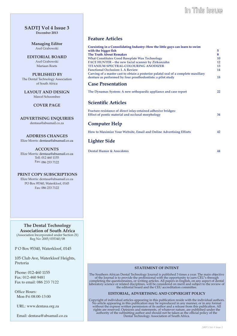
Feature Articles
Coexisting in a Consolidating Industry: How the little guys can learn to swim withthebiggerfish 5The Truth About Remakes 8What Constitutes Good Baseplate Wax Technology 10FACE HUNTER – the new facial scanner by Zirkonzahn 12TITANIUM SPECTRAL-COLOURING ANODIZER 13Functional Occlusion: I. A Review 14Carving of a master cast to obtain a posterior palatal seal of a complete maxillary denture as performed by four prosthodontists: a pilot study 18 Case Presentation
The Dynamax System: A new orthopaedic appliance and case report 22
ScientificArticles
Fracture resistance of direct inlay-retained adhesive bridges: Effect of pontic material and occlusal morphology 34
Computer Help
How to Maximize Your Website, Email and Online Advertising Efforts 42
Lighter Side
Dental Humor & Anecdotes 44
In This Issue
SADTJ Vol 4 Issue 3December 2013
Managing EditorAxel Grabowski
EDITORIAL BOARDAxel GrabowskiMariaan Roets
PUBLISHED BY
The Dental Technology Association of South Africa
LAYOUT AND DESIGNMarcel Schoombee
COVER PAGE
ADVERTISING [email protected]
ADDRESS CHANGES
Elize Morris: [email protected]
ACCOUNTSElize Morris: [email protected]
Tell: 012 460 1155Fax: 086 233 7122
PRINT COPY SUBSCRIPTIONSElize Morris: [email protected]
PO Box 95340, Waterkloof, 0145Fax: 086 233 7122
STATEMENT OF INTENT
The Southern African Dental Technology Journal is published 3 times a year. The main objective of the Journal is to provide the professional with the opportunity to earn CEU’s through
completing the questionnaires, or writing articles. All papers in English, on any aspect of dental laboratory science or related disciplines, will be considered on merit and subject to the review of
the editorial board and the CEU accreditation committee.
EDITORIAL, ADVERTISING AND COPYRIGHT POLICY
Copyright of individual articles appearing in this publication reside with the individual authors. No article appearing in this publication may be reproduced in any manner, or in any format without the express written permission of its author and a release from this publication. All rights are reserved. Opinions and statements, of whatever nature, are published under the
authority of the submitting author and should not be taken as the official policy of the Dental Technology Association of South Africa.
The Dental Technology Association of South Africa
(Association Incorporated under Section 21)Reg No: 2005/035340/08
P O Box 95340, Waterkloof, 0145
105 Club Ave, Waterkloof Heights, Pretoria
Phone: 012-460 1155Fax: 012-460 9481Fax to email: 086 233 7122
Office Hours: Mon-Fri 08:00-13:00
URL: www.dentasa.org.za
Email: [email protected]

SADTJ Vol 4 Issue 34
Axel Grabowski
Editorial
DECEMBER 2013
Another year has come and gone. This was a year, that was very dif-ficult and one which I would not put down as my favourite. We at DENTASA have however, through sheer perseverance, achieved a tre-mendous amount for the betterment of the profession.
The most of my energy went into the very flawed SADTC election. This is something which I did not plan for, but had to be done. Like everything in life, there is give and take. I am of the opinion that we at DENTASA have insured that the best available candidates from our profession are now elected Councillors.
I would like to introduce the Councillors to you, and at the same time wish them everything of the best at the huge task at hand.
President: Ms Catherine Mokgatle MakwakaVice President: Mr. Louis Adriaan SteynDirector Oral Health , DoH: Dr Johan SmitDental Technician Contractor: Mr. Patrick BriscoeDental Technician Contractor: Mr. David Warren van EykDental Technician Employee: Mr. Khutso Moloko Petrus TsitaDental Technician Employee: Ms Boitumelo RammilaDentist: Dr. Nosipho Admire BaloyiCommunity Rep.versed in law: Adv. Rebaone Nimrod GaoraelweCommunity Rep: Ms. Tsinyalani Charlotte MavhunguDentist attached to a University: Dr .Matshediso Maria Mothopi
Congratulations to all the above mentioned , and I would like to insure you that DENTASA will be actively involved in the future of Dental Technology.
DENTASA once again had a very successful Summit and AGM in Sep-tember, held in the warm and friendly KZN. To all the Traders, Speak-ers, and of course the stars of the AGM, the members, thank you for your continued support. This is after all your association.
To all the organizers, job well done.
One of the main discussion points and active participation by all del-egates lead by the very able facilitator Mr. Rob Pluke, was the “New Technologies Indaba” This affects all technicians, regardless of your discipline.
These were the main points that were raised by the delegates them-selves.
1. TECHNOLOGY DEVELOPMENTS
Phase of vulnerability• Illegal Practices• Council must do Policing• Learn new technology• Teamwork is essential• Fear• Untrained technicians doing our work, the quality of work de-• creasesStandard of work must be regulated• Regulation Framework• Urgency of working together with DENTASA and SADTC• Policing of unregistered labs and technicians• Quality of work• Regulate Suppliers• Courage• Work together•
Development in technology leads to unemployment• Different qualities for different prices, eg. As in UK NHS, Inde-• pendent and private products all with different pricesQuality will fall away• Decreased abilities• No codes for new technologies, different skills required• Chinese• Legislation to protect technicians• New technology (machines) must be registered as laboratories • and operators also registered as techniciansDenturism must be pushed• Team players with dentists• Keep quality of work high• Traders must sell certain equipment only to technicians and cer-• tain other ones only to dentists
2. CO-ORDINATION/ COMMUNICATION
Dignity of the profession must be increased• Market the profession to the public• Professional marketing• Communal marketing of oral profession• Increased political lobbying• Council for dental technicians by dental technicians• Increase DENTASA members – stronger Association• SADTC must start policing unregistered labs/technicians• DENTASA market the Association should increase• SADTC must regulate the profession• Money will increase when membership increases• Funding for different ways of marketing – use students eg.• SADTC must be efficient in what they need to do• Root out bad advertisement and market for the whole oral profes-• sionLabs must use debit order system to ensure increased member-• shipMake Medical aids aware of our profession: cleaning up and mak-• ing more efficientMarket Lab owners• Generate income by marketing for suppliers’ courses• DENTASA is good• March to promote profession• Involve SADA, DENTASA & SADTC• Promote volume of work in the whole dental profession• SADTC: Website must be better and more interactive• DENTASA: Better represent employees• Set roles of DENTASA and SADTC clearly out• Increase communication with dentists – Use technology• Carte Blanche for exposure of illegal labs• Study groups with dentists and technicians•
3. GOING FORWARD
SADTC MUST regulate• Forgive the past and build on the future• New commitments from both SADTC and technicians•
I would like take to take this opportunity to thank the Exco and mem-bers of DENTASA ,and wish you all a blessed fest of seasons and a wonderful 2014. May our profession go from strength to strength. b
Editorially YoursAxel Grabowski

SADTJ Vol 4 Issue 3 5
Every industry experiences structural changes as it matures and adapts. These changes can occur from both within and from with-out, as outside forces press the industry to readjust. During its more than 100-year existence, dental technology has been largely immune to these forces, existing as a largely fractured industry composed of small, independently run businesses. However, the convergence in the last two decades of major factors such as the rapid adoption of auto-mated production technologies, looming industry regulation, and, to an extent, globalization, may be moving the industry toward a major structural shift.
As a $7 billion industry, dental technology has drawn the attention of a number of capital investment and private equity firms. In the 1990s, there was an acquisition frenzy in the laboratory space as these firms vied for the most valuable real estate. Although buying activity has slowed, Bennett Napier, Executive Director of the National Associa-tion of Dental Laboratories, still regularly fields inquiries from new players. “I get at least three calls each week from private equity firms looking to enter the laboratory market,” says Napier. “They are look-ing at this industry as an opportunity. So depending on how many of these firms actively enter our market, it could change the landscape of dental technology significantly.”
Currently, large corporate laboratory groups, plus independently owned Glidewell Laboratories, account for only 6% to 12% of the in-dustry’s total $7 billion in annual sales. The remaining 88% of market share is held by small, independently owned laboratory businesses. “We still are a fragmented industry,” says Warren Rogers, CEO of Knight Dental Group, CDL, DAMAS, ISO. “Although we have seen major consolidation on the distribution and manufacturing side of dentistry, we are still a long way away on the laboratory side.”
Mark Murphy, Clinical Director of Micro-Dental, agrees. The flurry of merger-and-acquisition activity experienced in the 1990s, he says, has slowed to “a snail’s pace.” However, as the industry matures and labo-ratories adopt automated technologies for setting up large centralized manufacturing facilities, the pace of acquisition will intensify. “We are becoming a more mature professional industry that is ripening for consolidation, more so today than 10 years ago.”
As an example of how quickly an industry can restructure, the consoli-dation tipping point hit the optical laboratory industry in the 1990s and completely changed the industry landscape, from optical outlets and laboratories to distribution channels, suppliers, and manufactur-ers. Prior to consolidation, highly skilled optical laboratory techni-cians would grind lenses to prescription by hand, and the majority of laboratories were family-owned operations.1 Today, however, these independent laboratories are a scarcity. Ed Greene, CEO of The Vi-sion Council, an organization that represents the manufacturers and suppliers of the optical industry, says that in their case, consolidation happened extremely rapidly. “It peaked very quickly,” says Greene. “There were a number of large optical laboratories as well as small and medium independently owned labs, mostly entrepreneurial in nature.
When it began, one large company started purchasing businesses and others followed suit. The initial process targeted geographical loca-tions, focusing on regionally strategic acquisitions. Today, there are still companies making acquisitions, but those are happening on a na-tional and international scale, rather than at a local level,” he explains.The Harvard Business Review identified a lifecycle pattern that all large industries undergo, from industry emergence and maturity to consoli-dation and final structure.2 In the beginning, there are no large busi-ness leaders in the industry and market share is more or less equally owned. As the industry begins to mature, major players emerge and start to buy up the competition. In the third stage of the lifecycle, the major players emphasize their core competencies and focus on profit-ability, tending to move away from weak business endeavors. In the final stage of the lifecycle, the major players claim 70% to 90% of the market share and smaller companies find it increasingly difficult to stay in business.
Is this the lifecycle dentistry may face? As the CEO of one of the ma-jor players in the dental technology industry, Kimberly Bradshaw of MicroDental is not sure. “While it is hard to predict who the major players ultimately will be and what total market share they will own, the industry will likely mirror the HBR lifecycle pattern,” she says. “We are, however, in the very early stages of consolidation and a lot is yet to be determined relative to the technologies and outputs as well as the regulatory forces that are going to get us to our final destination.”
Primed for Consolidation
While it is unclear whether or not, or when, the dental technology industry will find itself in the second stage of the Harvard lifecycle pattern, there are indicators it is an industry that may be primed for consolidation. A number of capital investment groups have already been strategically buying laboratories or large laboratory groups and building networks that operate under the management of a single par-ent company.
Jennifer Stewart, Managing Partner at the private investment firm Bea-con Bay Holdings, says that dental technology is a draw for investors because it is both highly fragmented and developing at an extremely rapid pace. “The sheer volume of technological advances in terms of materials, equipment, and software over the last many years has really helped dental technology come of age, as well as increase the benefits that investment groups could potentially reap from consolidation in the industry.”
In addition, Stewart sees the currently fragmented nature of the dental technology industry as an opportunity. “There is still room for lead-ers to emerge, and that’s one of the reasons capital investment groups are so interested in the industry,” she explains. Currently, Beacon Bay Holdings is actively seeking acquisitions to add to its laboratory port-folio company, which currently owns the da Vinci, Nu-Life, and Cal Ceram dental laboratories, and is one of a handful of groups trying to
Coexisting in a Consolidating IndustryHow the little guys can learn to swim
withthebiggerfishBy Kate Hughes
Feature Article

SADTJ Vol 4 Issue 36
establish a foothold in the industry.
However, until one or more of these groups becomes an influencing factor in the dental technology space, the industry will remain in its fragmented state. Rogers, who spent 25 years on the dental manufac-turing side, heading up Bayer aspirin’s dental division, has witnessed firsthand consolidation on the dental distribution and manufactur-ing sides of the industry. “Twenty years ago there were more than 500 players on the dental distribution side of the dental industry,” he says. “Today you probably have only four or five major players in that space. Currently, in the laboratory industry, there is only one major player that is actually influencing the direction of the industry. The impact of the equity partner groups is still relatively small.” But Rogers concedes that could change in the next decade as major players emerge and be-gin to influence the market.
An industry composed primarily of small players and undergoing ma-jor structural changes from within is extremely attractive to outside in-vestors who understand how disruption within an industry can foster unrest and create interest among small- and medium-sized players to sell their businesses. One of the major disruptive and influencing fac-tors in the laboratory space has been the rise of automated production technologies. Many laboratories are finding it necessary to invest large sums of capital in their production processes and extensive technician training in order to effectively compete. Smaller laboratories without access to liquid capital, but wishing to enter the digital dentistry arena, are at a disadvantage, unless they ally with a larger company or labora-tory. According to Bradshaw, many laboratory owners in this situation are now playing an active role in industry self-consolidation. “I prob-ably receive four or five phone calls a month from laboratory owners looking to sell ownership of their business,” says Bradshaw. “While I very rarely accept offers like this, it shows me that laboratory owners are open to this new type of business model.”
Self-consolidation is also taking place in a much less public arena and on a much smaller scale. Bennett Napier says that some dental technology industry consolidation is happening at an extremely local level, with moderate-sized, 10-to- 20 technician laboratories buying out small, one- to two-technician operations. “Essentially, the bigger laboratory is able to expand their business and inherit the smaller lab-oratory’s accounts, while the previous owner of the smaller laboratory becomes an employee of the bigger laboratory,” explains Napier, who adds that low-profile consolidation such as this is happening much more often than most people in the laboratory industry realize. “Be-cause this is on such a small scale we don’t hear about it in the indus-try, but pretty much every week I’m on the phone with someone who has gone out and acquired a couple of smaller satellite laboratories.” For the acquired laboratory, acquisition by a larger entity allows the owner and technicians to focus on their work, rather than the business aspects of running a laboratory. It also pushes them into an environ-ment that is much more likely to have the capital necessary to pur-chase the technologies and training they need to remain competitive in a globalized market.
Staying competitive in a globalized market has become ever more critical as increased price competition forces the average smaller op-eration to invest capital in expensive technologies and creates a barrier of entry for technicians wanting to break away and start their own businesses. In an industry like dental technology, where the price of the final product continues to be challenged downward, small opera-tions making restorations by hand are unable to function on the level of their much larger counterparts. They cannot afford the equipment and production setup, let alone support the customer base that would allow them to compete with the bigger corporations on price. This situation gives laboratories backed by a larger company an advantage unavailable to smaller independent equivalents.
The Potential for Industry Change
As an industry matures, indicators emerge that further impact its move toward a structural shift. Regulatory standards from within the industry and from government agencies play a larger role in business operations and day-to-day manufacturing activities, technologies re-place key skill sets that were once highly prized and new skill sets are created, and larger businesses within the industry begin to focus in-tently on best-practices manufacturing principles. These changes chal-lenge the average small business to react sufficiently either in the capi-tal required or operational sophistication that is needed to compete.Warren Rogers believes that if the industry does mature to this level and truly consolidate, it will be the result of the disappearance of the smaller businesses within the dental laboratory industry and growth of the larger operations. As the larger players get bigger, the industry will become a blip on the radar of regulatory forces and, in the end, make the industry healthier and more profitable overall. “I think regu-lation is good for the industry, and it’s good for the patient, because ultimately, he or she will get a better product with a higher degree of consistency,” says Rogers.
Regulation is exactly what Kimberly Bradshaw is anticipating for her network of laboratories. In her mind, regulation is just around the cor-ner. “As someone who came to dental technology from the medical device industry, it is hard for me to comprehend that we had to get a 510(k) for an electrode that was taped to a cardiology patient for a 3-minute reading, yet a crown can be placed in a patient’s mouth for 10 years with minimal FDA requirement,” she remarks. Bradshaw has taken a proactive approach to what she considers the inevitable en-forcement of regulatory standards, and has insisted that every Micro-Dental branded laboratory move to become DAMAS certified. While this will be a costly and time-consuming endeavor for any laboratory, the support of a large company helps shoulder the burden. Bradshaw explains that while the process has sometimes been arduous, she will continue to make this a requirement of MicroDental laboratories. “We have proven to ourselves that DAMAS certification has increased the quality, consistency, and reproducibility of our products, because now we have standard operating procedures.”
A Changing Distribution Model
A smaller more unified industry also has the potential to upend the supplier/buyer relationship, which can have far-reaching effects. Again using the example of the optical industry, as the bigger players began purchasing laboratories, they gained buying power and saw an opportunity to further control their space in the industry. “By owning a laboratory, you control the quality of your product, as well as your brand and its identity,” explains Ed Greene. “It removes the third-party manufacturer. Laboratories were able to go straight to the supplier, re-ceive raw materials, and make the product themselves onsite. It com-pletely changed the distribution model.”
Warren Rogers sees some of these changes already taking place in the dental space, as well as their effect on the end product delivered to patients. “Laboratories are no longer dealing with the local dentist but with a purchasing agent that wants to get the best price,” explains Rog-ers. “It is changing how these groups purchase laboratory products and often results in that work going offshore.”
On the other side of the spectrum, some of the larger, more entrepre-neurial laboratories in the dental technology space have by-passed the traditional buyer/supplier relationship by purchasing raw materials directly from the manufacturer and producing the materials they need to manufacture the end product, such as zirconia milling blocks.
Feature Article

SADTJ Vol 4 Issue 3 7
The Dentist/Technician Relationship
If smaller players in the industry continue to diminish and larger play-ers grow in size, the levels of service local dentists are accustomed to receiving from their local laboratory partners would be impacted. “The average dentist is a small business owner himself and likes deal-ing with local laboratories that can respond to their needs, especially when it comes to an emergency case or repair,” says Rogers. “I’m not sure many dentists would be happy with a scenario that reduced these types of services.” With fewer laboratories left on a local level, and the majority of dental laboratory work being done in larger manufactur-ing facilities, it may be much more difficult for clinicians to find local laboratories to partner with. In Bennett Napier’s opinion a reduction in the number of physical laboratories will definitely affect the close relationship many dentists have with their laboratory partners. “It will almost certainly be an issue for dentists that once had six to 10 labora-tories in an area to choose from, and now they may only have one or two,” he says. Napier also notes that while the number of laboratories to choose from may decrease, this constriction may help the labora-tory industry as a whole. “It could potentially drive up business for the laboratories that still exist. Their services will be in much higher demand, which will increase their profitability.”
Conclusion
While consolidation through mergers and acquisitions is not the only path the industry could take, it is certainly one possibility. Both fragmented and profitable, the dental technology industry represents an opportunity for capital investment groups and larger laboratories determined to invest time and money to move the industry toward
a more unified business structure. While the major players vie for a larger portion of market share, there remains the probability that a sig-nificant number of the smaller, independently owned laboratories that have always made up the majority of dental technology’s demograph-ics could exist with them, side-by-side. Mark Murphy believes that the future of the dental laboratory industry has room for both business models. “There will always be a fairly large number of small laborato-ries, because they will be able to offer a level of personalized service that the big players won’t be able to match. Small laboratories with expertly-honed personalized service will definitely survive,” he says. The dental technology industry is, as Rogers puts it, “feeling the birth pains of consolidation” and may be on the cusp of major structural changes. However, the final form of these changes is yet to be seen. b
Article Sourced From: Inside Dental Technology, www.dentalae-gis.com/idt
References
Sutherlin S. The Optical Laboratory: What’s Emerging from a 1. Decade of Consolidation. Refractive Eyecare. Updated May, 2012. Accessed August 6, 2013. http://www.refractiveeyecare.com/2012/05/the-optical-laboratory-what%E2%80%99s-emerg-ing-from-a-decade-of-consolidation/.Deans GK, Kroeger F, Zeisel S. The Consolidation Curve. Harvard 2. Business Review. Updated December, 2002. Accessed August 6, 2013. http://hbr.org/2002/12/the-consolidation-curve/ar/1.
for Dental Technicians
Designed

SADTJ Vol 4 Issue 38
ASK A DENTAL LAB-ORATORY OWNER ABOUT WHAT HIS REMAKES RATE IS AND MORE THAN LIKELY, THE AN-
SWER YOU’ll GET IS: TOO HIGH
Even those laboratories that have remakes in the low single digits want a zero remake rate. After all, remakes eat money out of the bottom line, no mat-ter whether they were caused by internal or external errors.
A zero remake rate may be an unachievable goal, considering the average for dental laboratories is about 4 percent to 5 percent. The fact is, humans take impressions and fabricate restorations and humans are fallible. Nonetheless, there are ways to reduce the rate to a more reasonable level, keeping the money wasted on remakes in your bank account.
Pervasive Problem
Of all the processes in a dental laboratory, remak-ing a product has the broadest reaching impact on the business. A high number of remakes mean that some element of your quality control process is be-ing missed. Regardless, it means that your restora-tions are costing you part of your overall margin.
Consider the cost of wasted material and produc-tivity: If you are using the newer digital technology, the laboratory is milling and pressing out of a mate-rial block that may cost between $12 and $20. That block is not reusable. If the restoration made out of that block is somehow wrong and not paid for, that was material wasted, explained Chuck Yenkner who owns Business Depelopment Associates, a consulting firm that works with dental laboratories. Yhe techni-cian in a traditional laboratory makes about 3.5 units per day. Remaking even one item immediately drops that productivity rate. and labor costs increase.
Also, each remake is shipped or delivered to the cus-tomer, which costs money. An unhappy customer won’t order again, which you see in your retention rate and sales per customer rates.
“Frequently an excess remakes rate basically stalls the growth of the business,” said Yenkner. “ If you’re on a 10 percent net, and you are doing 200 units, that’s 20 percent margin. With a remake, you have to do a fair amount of units to make up that profit.”
Gary Iocco, incoming NADL president and owner of Dimension Dental Design, CDL, in Hastings, Minn., shoots for 2.5 percent remake rate. He’d love to have
Feature Article

SADTJ Vol 4 Issue 3 9
a zero rate, he said, because remakes gobbles up your profits.
Every laboratory should have a built-in percentage remake rate, just as retail stores count shrinkage-inventory that’s damaged, shoplifted or otherwise not sold. Iocco compared it to an auto insurance company’s loss ratio. Even with a remakes percentage built into the bottom line, every laboratory needs to strive for 100 percent quality. It may not be possible but the process of trying to remake will force you to look closely at many aspects of the dental laboratory operation.
Begin at the Beginning
To get a clear picture of your real remakes rate, count internal and external remakes separately. That way you can hone in on whether the remakes are a dentist problem or a process problem, or both.
External remakes, or those where the problem occurred because of dentist error, are the more costly of the two remakes, because, said Yenkner, the dentist receives the product and it may not fit in the pa-tient’s mouth. Then you’re remaking the whole case from scratch.
“Maybe the prep they have is not suitable for the restoration,” said Yenkner. “Then you have to go to them and say, ‘Doctor this is not right, we can’t see the margin’. The idea is to try and make sure the impression they got in from the doctor is going to allow them to do the work.”Talking to the dentist about poor margins or impressions is a hard conversation to have, but that’s essential to reducing your remakes rates. Communication, early and often, is, according to Yenkner, the best way to nip precentagepoints off the external remake rate. Still, such conversations need to be handled with care.
“You can’t just say, “Hey, dude you’re an idiot.” They are the doctor, and many labs try to avoid having that conversation. The way I try and coach is that you have to communicate with the doctor if you are having problems. You need to address the elephant in the room. Hope-fully he is a reasonable person. And frequently it’s communication and knowing what they are really looking for.”
At Dimention Dental Design, Iocco’s technicians call the doctor im-mediately if they see a problem. Remakes cost money, said Iocco, and taking an impression continue through the manufacturing process, there is a high probability they’ll be a making the product again.
As part of a quality process, Iocco added an area on the prescription for technicians notes. The technicians use green ink to write on the prescription if they called the doctor, what date, what time and a de-scription of the discussion.
“The green ink is so you know [at a glance] that there has been a con-versation between the dentist and the laboratory.” Iocco said.
Internal Affairs
Reducing internal remakes is really about taking a deep and detailed look at your process, said Yenkner. If your laboratory does not yet have a quality process in place, Yenkner recommends to start by imple-menting standard operating procedures sooner rather than later.
“I ask labs if they have documentation for each step of the process,” he said. “I frequently find that without documentation, the techni-cians start freelancing, and that may not be what the doctor wants. Of course, that leads into training your staff. They need to understand what it is to follow the process.”
Yenkner is a disciple of lean manufacturing principles. Originally developed by Toyota in Japan, lean manufacturing aims to remove all waste out of making an item, while at the same time ensuring a smooth flowing process and removing defects (defects cause waste). One major element of lean manufacturing is consistancy of process. And satisfied dentist customers often cite consistency as a reason to continue to work with a laboratory.
“I’m working on getting that introduced into laboratories; that can re-ally help the remake rate,” he said. “Let’s stop the mistakes at the front end, not quality control at the back.”
Iocco is in the process of implementing DAMAS, and at the time of this writing had completed about 25 percent of the process. He explained that DAMAS doesn’t dictate what you should do but it demands that the laboratory write down processes and follow them consistently.
“When the impression first comes in, we check it.” Iocco said. “The per-son die trimming it will check it. Every step of the way it’s checked.”
Althought Iocco can’t yet say how implementing DAMAS has im-proved remakes rates, he can point to the fact that staff are asking more questions and calling the doctors more frequently. The dentist, too, are realizing that there’s been a change in procedure. Perhaps most
importantly, there’s been an attitude change among the staff. Now, in-stead of just letting not-quite-perfect work go through the process, the staff stops and asks questions.
To Charge or Not?
When it comes to external remakes, you have to consider the source of the problem before you can determine how and what to charge. For example, if you’ve had a customer for years, and remakes are a con-stant issue with that doctor, that’s not a profitable client.
“Figure out how to recoup costs of those remakes or choose not to do business with him,” said Yenkner. “You can’t keep absorbing the cost indefinitely. You have to have some kind of charge policy.”
Dimension Dental Design’s policy is pretty clear. If the laboratory calls the doctor with a problem and he says go ahead and proceed, but it ends up as a remake, the laboratory charges for that remake.
“If the doctor should have been called and we made the case, anyway we don’t charge,” he said.
The most important thing about remakes, said Yenkner, is not to ig-nore them. Figure out the source of the problem and work on pro-cesses until you’re reduced your rate to lower than 4 percent.
“I’ve never seen a dental lab with above-average profitability that has above average remake rates.” he said. b
Article Sourced From: JDT Unbound, http://digital.unbound.com
“Frequently an excess remake rate basi-cally stalls the growth of the business”- Chuck Yenkner
“Let’s stop the mistakes at the front end, not quality control at the back”- Chuck Yenkner

SADTJ Vol 4 Issue 310
What Constitutes Good Baseplate Wax Technology
by Martin Young
A few years ago our laboratory was introduced to Anutex Highh Stability Baseplate Wax sheets which we have continued to use exclusively to this very day. The manufacturer concerned, As-siciated Dental Products Ltd, who are based in Wiltshire in the United Kingdom, state that the wax we have been using has similar handling characteristics to their market leading Anutex Toughened Basaplate Wax, but that their new product offers even greater stability and strength.
Constituencies of the Wax
Being a prosthetic laboratory, we use the higher end wax for all of our denture cases. We have had excellent results with this product and have even had favorable comments from some of our cliens. They too have noticed how stable this wax has been when taking bite registra-tions and assessing the wax try-in of dentures.
Overall, the results have been superb, as the wax does not flake while trimming down for contouring. It also pin flames extremely well tak-ing on a very smooth appearance, which you can then buff using cot-ton wool and cold water for enhancement.
One of the primary reasons for this quality is the hardness and tough-ness of the wax. This has been achieved by the fact that the manufac-turer rolls their sheets to sizi, which I believe, creates a uniform, dense, and toughened sheet, undoubtedly reinforcing the aforementioned reasons for this quality. It is these qualities that have led to greater job satisfaction, as the wax is always reliable. Additionally, the wax is also quite competitively priced for this quality of product and represents excellent value for money.
At .06 inches thick, I have found these basaplate wax sheets to be the optimum thichness for the palate of the final denture.
Basic guide to using this advanced baseplate wax:
In order to fit the sheet to the model, gently warm the wax and 1. then adapt its properties without overheating. Make sure that you do not stretch and thin the sheet too much.
Final fitting to the denture model is generally achieved by slight 2. warming with a pin flame which facilitates enough softness to produce the required finishing touches with a wax knife.The base or trial set-up can be polished to a brilliant mirror-like 3. finish using the normal technique of cotton wool and cold water.I Personally use the same manufacturer’s straight was bite blocks, 4. as these can also be easily adapted, especially after being im-mersed in warm water for a feew minutes to soften them.
Baseplate Wax Research
During some research I carried out, several years ago, I found that baseplate wax sheets were manufactured in various ways, which of course can lead to them having very different characteristics and qual-ities. Consequently an industry standard for wax materials has been developed.
The ISO standard for baseplate wax sheets is BS EN ISO 15854:2005. This standard was defined by testing various market leading brands in differing situations and at different temperatures.
At the present time there are three classifications for Type 2 baseplate waxes:
Class 1 Soft•Class 2 Hard•Class 3 Exstra Hard•
Each manufacturer decides which categories their waxes conform to. This process ensures that they can supply waxes that meet wide rang-ing differences in performance. Baseplate Wax Class 1 and 2 are the only relevant products for use in the dental laboratory.
Knowing what the tests are, coupled with how a particular wax per-formed in the standard ISO test, is certainly an indication of how it was likely to perform in practice. I have indicated below the standard flow tests used for these types of wax.
BS EN ISO 15854:2005 Tests
This standard tests the wax’s properties and performance. The clas-sification (i.e. Class 1, 2 and 3) of a particular Type 2 baseplate wax is determined by its flow properties at different temperature:
Room Temperature (23°C +/-1ºC)Mouth Temperature (37ºC +/- 1ºC)Above mouth temperature (47º +/- 1ºC)
Tests are carried out in a tempeature controlled water bath using the equipment illustrated on the opposite page.
Naturally it is easy to understand what you are purchasing if you are given this information in the first place. However most customers find that the wax manufacturer does not supply this type of technical infor-mation, instead they find it necessary to rely on the ISO number to be the indication of an adequate source of quality control.
In addition to the above information, I also use a further series of tests
Feature Article

SADTJ Vol 4 Issue 3 11
for the evaluation of materials used in my own laboratory. In the case of baseplate wax, I use the chart below:
The desirable properties of baseplate wax could be stated as follows:
High strength and rigidity at mouth temperature.1. Wide softening range above mouth temperature.2. Easily moldable in the softened state, without flaking, cracking 3. or tearing.Low thermal constraction.4. Easily carved at room temperature without flaking or chipping.5. Little change in properties melting and re-solidification.6. No residue on boiling out.7.
The list I have produced demonstrates just a few considerations. There are two other factors that you could also consider: color and cost.
True Cost
Some waxes may be less expensive to buy, but they can end up costing you a lot more in terms of lost time. Therefore, readapting wrong bite registrations to the model together with distortions of wax try-ins, are just two problems that may be encountered during this process.
True Color
Considering the color of the wax is very subjective. What you might consider as the right color; someone else could and probably will find completely inappropriate. It is for you and your client to decide what color is acceptable. On saying this, it is up to the dental laboratory to evaluate the suitability of a particular baseplate wax.
One way of doing this is to complete a series of simple tests as fol-lows:
Soften a wax sheet ober a Bunsen flame and observe its charac-1. teristics. Compare it with other waxes of a similar style. Note the result i.e. is the wax easily moldable in the softened state, without flaking, cracking or tearing? Is there low thermal constraction of the wax on the model? Did the wax perform in accordance with your expectations for this type of product?Soften the wax sheet and mould into a block suitable for wax 2. registration. Compare as previous with other waxes. Once again, note the result: i.e. did the wax mould well and was is easily carved at room temperature without flaking or chipping? Did the wax perform in accordance with your expectation for this type of product?Carve, trim and pin flame the wax blocks; polish with cold water 3. and cotton wool. As before, compare with other waxes. Finally, note the result: i.e. did the wax carve and trim easily? Did the wax take a good surface polish?Set a few teeth into position on the wax. Did the teeth stay in po-4. sition after the wax had cooled down? Were the teeth easy to re-position and did the wax carve easily with a good surface finish?
Baseplate waxes vary in their consistancy and strength. It is easy to criticize products just because the don’t come up to your expectations. However, we have noticed quite a major difference over many of the waxes we have tried previously. The manufacturer’s wax, that we have case studied in this article, has a slightly higher melting point and greater toughness than many other products in the market.
All this said, it is worth bearing in mind that manufacturers who have attained ISO status, are without a doubt, the best companies in the the market to purchase your waxes from. In this case, the manufacturer concerned, also demonstrated their expertise in this niche market sec-tor, by displaying technical information in the form of comparison graphs. Our laboratory has continued to use this manufactures’s wax, and will continue to do so. This is until a better product is introduced. b
About the Author:
Young has been a qualified dental technician since 1971 and is a direc-tor of Cotsworld Dental Laboratory which is a specialist prosthetic laboratory. He attended the Matthew Boulton Technical College in Bermingham, England, studying dental technology. Afte achieving his qualifications, he continued at the college for an additional two years learning about advanced prosthetic techniques.
Article Sourced From: JDT Unbound, http://digital.unbound.com

SADTJ Vol 4 Issue 312
Feature Article
FACE HUNTER – the new facial scanner by ZirkonzahnThe technical progress always brings forth innovations that can ideally be integrated into the workflow for the manufacture of dental restorations.
With the Face Hunter, Zirkonzahn offers a new scanner for photo-realistic 3D-digitalisation of pa-tient’s faces.
It is possible to work on the basis of physiognomy, which allows axis-related positioning of the facial scan data with the models in the virtual articulator. This way, even the facial arc can be “controlled virtually” and, if necessary, be readjusted in the mock-up software.
The facial 3D scan data offers a number of advantages for dental technicians, dentists as well as pa-tients. While the technician is allowed to create the restoration on the basis of the face, the dentist gets an almost photo-realistic preview of the final result. Not only does this serve as a marketing instru-ment, but it can also be used for patient counselling so they can get a more concrete idea of what the final work will look like.
Via a patent-pending transferring system and in conjunction with the Scanner S600 ARTI, the facial scans are deposited in the Zirkonzahn.Modellier software. There, the image of the face and the situa-tion are matched together to be able to work on the basis of the facial features. If combined with the Software-Module CAD/CAM Reality Mode, the work can even be previewed extremely close to real-ity.
The facial scans are ideally combined with the Plain Finder invented by master dental technician Udo Plaster. This is an important part of Plaster’s concept of holistic tooth restorations and takes into ac-
count new facial features as alignment points for model transferring.
The Face Hunter is also very easy to handle: It takes only one click to digitalise the face within 0.3 seconds, the scanner is also ready for mobile use with laptops. b
For more information contact: Nova Dental Lab Supplies (PTY)39-43 Giles Street2135 JohannesburgTel: +27 112100400Fax: +27 [email protected]

SADTJ Vol 4 Issue 3 13
Feature Article
TITANIUM SPECTRAL-COLOURING ANODIZERMetallic primary constructions always slightly shine through zirconia bridges on titan bars and individual zirconia abutments. This results to a high grey value of all works that is hard to minimise. Silver implant screws also cast a slight grey shadow onto the occlusal surface.
With the new Titanium Spectral-Colouring Anodizer, metal bases and screws can now be colourised in one’s own laboratory in a multitude of colours, e.g. gold. This has the advantage that the metal bases shine through less due to the new colour. The device is very easy to handle, which allows colourisation of multiple titanium elements without changing their bio-compatible properties and strengths. Scientifical studies have even shown that the coloured oxide layer increases the bio-compatibility and osseointegra-tion of titanium. In addition to the grey value reduction, the procedure can also be used for colour coding.
In this way, analogue screws can, for example, be marked with a certain colour and im-plant screws with a different colour. This has the advantage that screws can be separated from each other at first sight. b
For more information and example cases, visit www.zirkonzahn.com
For more information contact: Nova Dental Lab Supplies (PTY)39-43 Giles Street2135 JohannesburgTel: +27 112100400Fax: +27 [email protected]

SADTJ Vol 4 Issue 314
Functional Occlusion: I. A Review1. J. R. Clark, B.D.S.,M.SC.,F.D.S.(ORTH.), M.ORTH., R.C.S.(ENG.)1 and
2. R. D. Evans, B.SC., B.D.S., M.SC.D., F.D.S.R.C.S.(ENG.), D.ORTH., M.ORTH., R.C.S.(ED.)2
1. 1Department of Child Dental Health, Bristol Dental Hospital, Lower Maudlin Street, Bristol BS1 2LY, UK 2. 2Orthodontic Department, Guys Dental School, London SE1 9RT, UK
Abstract: The features that constitute an ‘ideal’ functional occlusion have not been conclusively established.Orthodontic treatment has the capacity to change static and functional occlusal relationships fundamentally.In this article, we present the evidence on which features of the occlusion are reported to be detrimental to the teeth and masticatory system Deficiencies in this research area are highlighted, together with the need for prospective longitudinal trials to clarify the requirements of an ideal functional occlusion Based on the exist-ing evidence this paper suggests which occlusal features may be significant in producing an ‘ideal’ functional occlusion As no long-term studies exist to measure the impact of non-ideal occlusal relationships on the dentition, it is debatable whether orthodontic treatment should be prolonged in order to ensure that ‘ideal’ occlusal contacts are achieved As the occlusion tends to ‘settle’ in the period following appliance removal, we propose that it may be more appropriate to examine the functional occlusal relationships after retention has ceased rather than prolong active orthodontic treatment to achieve ‘ideal’ functional occlusal goals.
Key words: Canine Guidance, Functional Occlusion, Group function, Occlusal Interference, Occlusion.
Introduction
The ‘ideal’ occlusion described by orthodontists today, which is used as the basis upon which to judge outcome following orthodontic treat-ment, is derived from the work published by Angle (1900) and An-drews (1972, 1989), and focuses on specific anatomical relationships of the teeth and dental arches. It is generally assumed (Andrews, 1976; Roth, 1976) that an ideal static occlusal relationship is compatible with an ideal functional occlusion, but this is not necessarily so (Tipton and Rinchuse, 1991). The purpose of this article is to present the cur-rent evidence on the features that are thought to contribute to an ideal functional occlusion and those which are thought to be detrimental.
Terminology
There is considerable confusion in the literature on occlusion, and one of the reasons for this is the excessive number of definitions and their different interpretation. The terms used in this paper are defined here and represent the authors’ interpretation of the literature:
Occlusion is each static contact between one or more lower teeth •with one or more upper teeth. Functional occlusion refers to the occlusal contacts of the maxil-•lary and mandibular teeth during function, i.e. during speech, mastication, and swallowing. Intercuspal position is the occlusal position with the teeth in •maximum intercuspation. The term intercuspal position (ICP) is
synonymous with many other terms, including centric occlusion, habitual occlusion, acquired occlusion, and habitual centric. Retruded axis position is the position the condyle adopts during •the terminal hinge movement of opening or closing. Synonyms for the retruded axis position (RAP) are centric relation, termi-nal hinge relation, and hinge axis position. Confusion arises from the lack of consensus on the exact location of the condyles in the glenoid fossa when they describe a pure hinge movement. Early definitions described the condyles as being in their most retruded position (Academy of Denture Prosthetics, 1956). More recently, the majority of authors describe the condyles as being located in the most superior-posterior position in the glenoid fossa (Academy of Denture Prosthetics, 1987). The exact position of the condyles when the mandible is in the retruded axis posi-tion is probably of little practical significance. The significance of the retruded axis position lies in the fact that it is a border posi-tion of the mandible, said to be highly reproducible for several subsequent jaw registrations and, therefore, an important refer-ence point for occlusal diagnosis and rehabilitation. Retruded contact position is the occlusal position when the first •tooth contact occurs on the mandibular path of closure with the condyles in the retruded axis position. Working side is the side that the mandible moves towards in a •lateral excursion. Non-working side is the side that the mandible moves away from •during a lateral excursion.
Tooth Contact Patterns during Function
During mastication and swallowing, tooth contacts occur posterior, lateral, and anterior to the intercuspal position (Graf and Zander, 1963; Glickman et al., 1970; Pameijer et al., 1970)
The Retrusive Range (RCP–ICP)
The mandible can hinge about a horizontal axis through the condyles
Feature Article
This is an open access article licensed under the terms of the Creative Com-mons Attribution Non-Commercial License (http://creativecommons.org/li-censes/by-nc/3.0/) which permits unrestricted, non-commercial use, distribu-tion and reproduction in any medium, provided the work is properly cited.

SADTJ Vol 4 Issue 3 15
called the retruded axis. This permits an incisal opening of 20–25 mm with the condyles in the retruded axis position. When the mandible closes on the retruded axis, its position when the first tooth contact occurs is referred to as the retruded contact position.
It is generally accepted that in most individuals with a natural denti-tion there is a short path of movement between the retruded contact position and the intercuspal position in an antero-posterior direc-tion, and that both these occlusal positions are used frequently during function.Numerousstudieshaveshownthatadiscrepancyof0•5–1•5mm exists between the retruded contact position and the intercuspal position as measured at the lower incisor point in adults (Hildebrand, 1931, cited in Bates et al., 1975; Heath, 1949; Posselt, 1952; Shefter and McFall, 1984; Agergberg and Sandstrom, 1988; Utt et al., 1995 ) and children (Ingervall, 1964; Kirveskari et al., 1986).
Coincidence of the retruded contact position and the intercuspal posi-tion was found in 22 per cent of the sample examined by Shefter and McFall (1984) and one-third of the patients investigated by Solberg et al. (1979), but in only 12 per cent of the sample used by Posselt (1952) and 8 per cent of a group studied by Reynolds (1970).
Clinically, the difference between the two occlusal positions can usu-ally be easily determined by closing the mandible in its rearmost (and uppermost) position by manual guidance until the first contact is es-tablished. This is the retruded contact position. If the patient is then asked to squeeze the teeth together, a protrusive movement, some-times with a lateral component, allows the mandible to slide towards the intercuspal position. In some patients, however, location of the retruded axis position can prove more difficult. Habitual closing movements, because they are performed repeatedly, will tend to end in the intercuspal position, rather than the retruded contact position. The precision with which ICP can be located on each successive clo-sure is the result of a conditioned reflex, generated by a ‘memory’ in the neuromuscular system, known as an engram. In some individuals, the conditioned reflex makes manipulation of the condyles into the retruded axis position very difficult to achieve. This ‘memory’ must be constantly reinforced by tooth contacts in the intercuspal posi-tion, and if tooth contact is prevented by using an anterior jig or bite plane for a short period of time (approximately 10 minutes is usually adequate; Lucia, 1964) the proprioceptive feedback leading to reflex closure in ICP is broken. The mandible can then be more easily guided into the retruded axis position.
Much of the orthodontic literature promotes the concept of an ideal treatment goal being coincidence of the retruded contact position and intercuspal position (Williams, 1971; Aubrey, 1978; Parker, 1978; Roth, 1981; Williamson, 1981). As epidemiological studies fail to find this type of occlusion in natural dentitions, the question arises as to why this should be the goal following orthodontic treatment? The argument put forward is that non-coincidence of the two posi-tions (RCP and ICP) is associated with temporomandibular disorders (Solberg et al., 1979; Ingervall et al., 1980). However, the evidence is inconclusive. Early workers in this field examined electromyographic activity in the muscles of mastication in individuals with occlusal interferences (Ramfjord, 1961). The use of EMG was centred on the concept that muscle activity during function should be equal bilat-erally. In Ramfjord’s study (1961) an occlusal discrepancy between the retruded contact position and intercuspal position demonstrated asymmetrical, so-called unharmonious patterns of muscular contrac-tion during swallowing. However, as no proper description of ‘normal’ EMG activity in masticatory muscles exists, the interpretation of data from such studies is of very limited value.
Cross-sectional population studies have been carried out by a number of authors to clarify the relationship between occlusal discrepancies in the RCP–ICP range and temporomandibular disorders (Geering,
1974; Solberg et al., 1979; Ingervall et al., 1980; Egermark-Eriksson et al., 1983; De Laat et al, 1986; Pullinger et al., 1988, 1993). Again, the evidence is inconclusive. Few of these studies have used control groups, and the signs and symptoms used to describe temporoman-dibular disorders (TMD) are inconsistent and diverse. Furthermore, the definition of and evaluation of occlusal discrepancies in these studies lack consensus agreement. Our interpretation of the currently available evidence leads us to suggest that an intercuspal position that does not exactly coincide with the retruded contact position can be considered normal. Conversely, there is no evidence that there is any disadvantage to the patient of having a retruded contact position that coincides with the intercuspal position, but treatment need not be un-duly lengthened to achieve this goal.
Posterior Tooth Relationships during Lateral Excursion
Three different types of posterior tooth relationship can occur during lateral excursion of the mandible.
Balanced occlusion.
During the entire lateral movement posterior teeth on both the work-ing side and the non-working side are in contact. Early workers in the field of occlusion assumed that this type of occlusal construction was necessary to achieve the best results for both complete dentures and the natural dentition (Monson, 1932; Schuyler, 1935). Present day thinking has completely dismissed this concept for restoring the natu-ral dentition, although it is still useful in complete denture construc-tion.
Group function occlusion.
During the entire lateral movement the buccal cusps of the posterior teeth on the working side are in contact. There is no tooth contact on the non-working side.
Canine protected occlusion.
During the lateral excursion contact occurs only between the upper and lower canine, and first premolar on the working side. There is no contact between the teeth on the non-working side. The theory of ca-nine protected occlusion is attributed to Nagao (1919), Shaw (1924) and D’Amico (1958), and is based on the impression that the canine tooth is the most appropriate tooth to guide the mandibular excur-sion. There are a number of reasons why this might be so:
the canine has a good crown:root ratio, capable of tolerating high 1. occlusal forces; the canine root has a greater surface area than adjacent teeth, 2. providing greater proprioception; the shape of the palatal surface of the upper canine is concave and 3. is suitable for guiding lateral movements.
In the specialty of restorative dentistry, where it is possible to intro-duce a specific occlusal scheme during occlusal rehabilitation, attempts have been made to establish a rational basis for choosing between ca-nine guidance and group function by examining epidemiological data and carrying out physiological studies. Epidemiological studies have attempted to discover which type of lateral occlusal scheme is found in untreated natural dentitions. Beyron’s work (1964) was some of the earliest and showed quite conclusively that adult Australian aborigines had group function occlusion. Weinberg (1964) found that 81 per cent of his sample had group function, while only 5 per cent had canine guided occlusion. By contrast, Scaife and Holt (1969) examined 1200 individuals, and discovered that the majority had either unilateral or bilateral canine protected occlusion. Ingervall (1972) found that the majority of subjects had multiple tooth contacts on at least one of the

SADTJ Vol 4 Issue 316
Feature Article
working sides. However, the most striking finding in this study was the high frequency of non-working side contacts. A number of other studies involving natural populations also found occlusal relationships in which non-working side contacts were present (De Laat and van Steerberge, 1985; Droukas et al., 1985; Egermark-Eriksson et al., 1987; Yaffe and Ehrlich, 1987; Ingervall et al., 1991; Tipton and Rinchuse, 1991; Takai et al., 1993).
These studies on occlusal contact patterns during lateral excursions report contradictory results, but this may reflect the different method-ologies. Ideally, such investigations should consider the tooth contacts from the intercuspal position through the entire range of functional lateral movement, but this is difficult to achieve clinically and tooth contact patterns have therefore been recorded at various static man-dibular positions. Tipton and Rinchuse (1991) recorded the tooth contact pattern with the mandible in the lateral cusp tip to cusp tip position. Droukas et al. (1985) and Egermark-Eriksson et al., (1987) recorded tooth contacts at a distance 3 mm lateral to ICP, as mea-sured at the incisors. Ingervall et al. (1991) stated that a lateral excur-sion of this magnitude is probably rarely used during natural function and a tooth contact pattern at a position closer to ICP would be more relevent. They, together with Yaffe and Ehrlich (1987) and Takai et al. (1993),recordedthetoothcontactpatternat1•5and3.0mmoflateralexcursion. As it is common to find lateral excursions that are initiated by group function, but terminate in canine contact only at the lateral edge-to-edge position, it is essential that investigators specify at which tooth position tooth contact recordings are made.
Inconsistent results of occlusal contact pattern may also be related to the influence of the materials used to register the contacts (Takai et al., 1993). Methods used to record the tooth contacts have included impression material, occlusal indicator wax, articulating paper, dental floss, and direct vision. Takai et al. (1993), using three of these tech-niques, demonstrated that the number of recorded tooth contacts var-ies with the material used to record registrations.
Berry and Singh (1983) revealed that the location and severity of oc-clusal contacts in a given individual change throughout the day and this added factor contributes to the inconsistencies seen in the stud-ies of tooth contact patterns. Disappointingly, there are probably too many uncontrollable variables in these studies to draw meaningful conclusions.
As no one type of occlusal pattern has been shown to occur in natural dentitions, a number of physiological studies have been designed in an attempt to clarify whether one particular occlusal scheme is preferable to another. Williamson and Lundquist (1983) examined electromyo-graphic activity of the temporalis and massester muscles during lateral excursions in individuals with canine guidance and group function. Considerably less activity was observed in those individuals with ca-nine guidance. These findings were confirmed by MacDonald and Hannam (1984) and Shupe et al. (1984). Belser and Hannam (1985) conducted a similar study and concluded that canine protected occlu-sions do not significantly alter muscle activity during mastication, but do significantly reduce muscle activity during parafunctional clench-ing.
The evidence in favour of one type of occlusal scheme over another is therefore scarce. Pragmatically, however, it is worth considering that a canine protected occlusion is far less likely to be associated with oc-clusal interferences on the non-working side than a group function occlusion due to the steeply inclined palatal surface of the canine.
Occlusal Interferences
The term occlusal interference has been defined in a number of ways. Posselt (1968) described an occlusal interference as a cuspal contact forcing the mandible to deviate from a normal pattern of movement. The sixth edition of the glossary of prosthodontic terms (VanBlar-com, 1994) defines an occlusal interference as any tooth contact that inhibits the remaining occluding surfaces from achieving stable and harmonious contacts. Ash and Ramfjord (1996) wrote ‘the term oc-clusal interference refers to an occlusal contact relationship that in-terferes in a meaningful way with function or parafunction’. None of these definitions is precise, but early workers in this field reached on a consensus on which features of the occlusion were likely to ‘interfere’ with function or parafunction by giving rise to signs or symptoms of TMD. These features were:
Occlusal contacts on the non-working side (Geering, 1974; In-1. gervall et al., 1980; DeBoever and Adriaens, 1983; Mohlin and Thilander, 1984; De Laat et al., 1986; Nilner, 1986). Unilateral contacts in the retruded contact position (Ingervall et 2. al., 1980; Egermark-Eriksson et al., 1983; Nilner, 1986; Seligman and Pullinger, 1991). Long slides (greater than 1 mm) between the retruded contact 3. position and the intercuspal position (De Laat et al., 1986; Pull-inger et al., 1988, 1993). Asymmetry in the slide between the retruded contact position 4. and the intercuspal position (Solberg et al., 1979; De Laat et al., 1986; Pullinger et al., 1988; Seligman and Pullinger, 1991).
The limitations of these studies include the lack of agreement among authors on which features constitute TMD, lack of consistency in di-agnosing occlusal interferences, and lack of any control groups. Un-doubtedly, research in this area is fraught with practical difficulties, but future studies must address these issues. Until such time as pro-spective, longitudinal data is available it will be impossible to verify the claims made by these authors regarding the relationship between occlusal interferences and TMD.
Epidemiological studies have shown that the presence of occlusal in-terferences is widespread in all population groups, and that there are more people with non-ideal functional occlusal relationships than people with signs or symptoms of functional disorders (Agerberg and Sandstrom, 1988; Heikinheimo et al., 1990; Ingervall et al., 1991). Should this evidence lead to a practice of disregarding basic function-al principles during orthodontic treatment? Our reservation against adopting this approach is that the gradual adaptation of muscles and joints, which occurs during the slow development of a specific occlu-sion during growth, is less likely to occur following the much quicker change related to orthodontic treatment. Other possible consequences of occlusal interferences, such as bruxism and tooth wear (Faulkner, 1990), and relapse of tooth position (Sved, 1960; Storey, 1993; Wei-land, 1994) may only occur some time after completion of orthodontic treatment, but may nevertheless be triggered by interferences intro-duced during appliance therapy.

SADTJ Vol 4 Issue 3 17
Conclusions
The criteria that denote an ‘ideal’ functional occlusion have not been conclusively established. The currently available evidence is drawn from research that has a number of serious limitations. Until such time as further work in this area clarifies the issues, the following features must be as-sumed to be compatible with an ‘ideal’ functional occlusion:
Bilateral occlusal contacts in the retruded contact position.1. Coincidence in the position of the retruded contact position and the intercuspal position or a short slide between the two positions (<1 2. mm). Contact between opposing teeth on the working side during lateral jaw movements. Contact may be limited to the canines (canine protection) 3. or extend posteriorly to include one or more pairs of adjacent posterior teeth (group function). No contact between teeth on the non-working side during lateral excursions.4.
As there are no prospective controlled trials that conclusively establish the consequences of ‘non-ideal’ occlusal relationships on the dentition, it is impossible to gauge whether active orthodontic treatment should be prolonged to ensure that the objectives of an ‘ideal’ functional occlusion are achieved. Orthodontists are familiar with the occlusal changes which occur following the removal of appliances (a process described as occlusal ‘settling’) and a final assessment of functional occlusal contacts following orthodontic treatment can only be made after retention has ceased. b
ReferencesAcademy of Denture Prosthetics (1956) Glossary of prosthodontic terms, Journal of Prosthetic Dentistry, 6, Appendix, 6–34. CrossRef1. Academy of Denture Prosthetics (1978) Glossary of prosthodontic terms, Journal of Prosthetic Dentistry, 58, 717–762.2. Agerberg, G. and Sandstrom, R. (1988) Frequency of occlusal interferences: a clinical study in teenagers and young adults, Journal of Prosthetic Dentistry, 59, 212–217. CrossRefMedline3. Andrews, L. F. (1972) The six keys to normal occlusion, American Journal of Orthodontics, 62, 296–309. CrossRefMedline4. Andrews, L. F. (1976) The straight-wire appliance. Origin, controversy, commentary, Journal of Clinical Orthodontics, 10, 99–114.5. Andrews, L. F. (1989)Straight-wire. The Concept and Appliance,L. A. Wells, San Diego. 6. Angle, E. H. (1900)In: Treatment of Malocclusion of the Teeth and Fractures of the Maxillae, Angle’s System,S.S. White Dental Manufacturing. 7. Ash, M. M. and Ramfjord, S. (1996)Occlusion,W. B. Saunders Co., Philadelphia. 8. Aubrey, R. B. (1978) Occlusal objectives in orthodontic treatment, American Journal of Orthodontics, 74, 162–175. CrossRefMedline9. Bates, J. F., Srafford, G. D. and Harrison, A. (1975) Masticatory function—review of the literature I. The form of the masticatory cycle, Journal of Oral Rehabilitation, 2, 281–301. Medline10. Berry, D. C. and Singh, B. P. (1983) Daily variations in occlusal contacts, Journal of Prosthetic Dentistry, 50, 386–391. Medline11. Belser, U. C. and Hannam, A. G. (1985) The influence of altered working-side occlusal guidance on masticatory muscles and related jaw mov ment, Journal of Prosthetic Dentistry, 53, 406–413. CrossRefMedline12. Beyron, H. L. (1964) Occlusal relations and mastication in Australian aborigines, Acta Odontologica Scandinavica, 22, 597–678. Medline13. D’Amico, A. (1958) The canine teeth—normal functional relation of the natural teeth of man, Journal of the Californian Dental Association, 26, 6–23, 49–60, 127–142, 175–182, 194–208, 239–241.14. De Boever, J. A. and Adriaens, P. A. (1983) Occlusal relationship in patients with pain-dysfunction symptoms in the temporomandibular joints, Journal of Oral Rehabilitation, 10, 1–7. Medline15. De Laat, A. and Van Steerberge, D. (1985) Occlusal relationships and temporomandibular joint dysfunction. Part I: epidemiological findings, Journal of Prosthetic Dentistry, 54, 835–842. CrossRefMedline16. De Laat, A., Van Steenberghe, D. and Lesaffre, E. (1986) Occlusal relationships and temporomandibular joint dysfunction. Part II: correlations between occlusal and articular parameters and symptoms of TMJ 17. dysfunction by means of stepwise logistic progression, Journal of Prosthetic Dentistry, 55, 116–121. CrossRefMedlineDroukas, B., Lindee, C. and Carlsson, G.E. (1985) Occlusion and mandibular dysfunction: a clinical study of patients referred for functional disturbances of the masticatory system, Journal of Prosthetic Dentistry, 18. 53, 402–406. CrossRefMedlineEgermark-Eriksson, I., Ingervall, B. and Carlsson, G.E. (1983) The dependence of mandibular dysfunction in children on functional and morphologic malocclusion, American Journal of Orthodontics, 83, 187–194. 19. CrossRefMedlineEgermark-Eriksson, I., Carlsson, G.E. and Magnusson, T. (1987) A long-term epidemiologic study of the relationship between occlusal factors and mandibular dysfunction in children and adolescents, Journal of 20. Dental Research, 66, 67–71. Abstract/FREE Full TextFaulkner, K. D. B. (1990) Bruxism: a review of the literature, Australian Dental Journal, 35, 266–276, 355–361. Medline21. Geering, A. H. (1974) Occlusal interferences and functional disturbances of the masticatory system, Journal of Clinical Periodontology, 1, 112–119. CrossRefMedline22. Glickman, I., Martigoni, M., Haddad, A. and Roeber, F. W. (1970) Further observations on human occlusion monitored by intraoral telemetry,International Association of Dental Research, 201, Abstract 612.23. Graf, H. and Zander, H. A. (1963) Functional tooth contacts in lateral and centric occlusion, Journal of Prosthetic Dentistry, 13, 1055–1066. CrossRef24. Heath, J. (1949) A fact-finding investigation concerning the dentures and relevant matters of pure blood aboriginal children in central Australia, British Dental Journal, 86, 287–293. Medline25. Heikinheimo, K., Salmi, K., Myllarniemi, S. and Kirveskari, P. (1990) A longitudinal study of occlusal interferences and signs of craniomandib lar disorder at the ages of 12 and 15 years, European Journal of Or-26. thodontics, 12, 190–197. Abstract/FREE Full TextIngervall, B. (1964) Retruded contact position of the mandible. A comparison between children and adults, Odontologica Revy, 15, 130–149.27. Ingervall, B. (1972) Tooth contacts on the functional and non-functional side in children and young adults, Archives of Oral Biology, 17, 191–200 CrossRefMedline28. Ingervall, B., Mohlin, B. and Thilander, B. (1980) Prevalence of symptoms of functional disturbances of the masticatory system in Swedish men, Journal of Oral Rehabilitation, 7, 185–197. Medline29. Ingervall, B., Hahner, R. and Kessi, S. (1991) Pattern of tooth contacts in eccentric mandibular positions in young adults, Journal of Prosthetic Dentistry, 66, 169–176. CrossRefMedline30. Kirveskari, P., Alanen, P. and Jamsa, T. (1986) Functional state of the stomatognathic system in 5,10 and 15 year old children in southwestern Finland, Proceedings of the Finnish Dental Association, 82, 3–8.31. Lucia, V. O. (1964) A technique for recording centric relation, Journal of Prosthetic Dentistry, 14, 492–505. CrossRef32. MacDonald, J. W. C. and Hannam, A. G. (1984) Relationship between occlusal contacts and jaw-closing muscle activity during tooth clenching,Journal of Prosthetic Dentistry, 52, 718–728 (Part I), 862–867 (Part 33. II). CrossRefMedlineMohlin, B. and Thilander, B. (1984) The importance of the relationship between malocclusion and mandibular dysfunction and some clinical applications in adults, European Journal of Orthodontics, 6, 192–204. 34. Abstract/FREE Full TextMonson, G. S. (1932) Applied mechanics to the theory of mandibular movements, Dental Cosmos, 74, 1039–1053.35. Nagao, M. (1919) Comparative studies on the curve of Spee in mammals, with a discussion of its relation to the form of the fossa mandibularis, Journal of Dental Research, 1, 159–202. FREE Full Text36. Nilner, M. (1986) Functional disturbances and diseases of the stomatognathic system. A cross-sectional study, Journal of Pedodontics, 10, 211–235.37. Pameijer, J. H. (1970) Intraoral occlusal telemetry V. Effect of occlusal adjustment upon tooth contact during chewing and swallowing, Journal of Prosthetic Dentistry, 24, 492–497. CrossRefMedline38. Parker, W. S. (1978) Centric relation and centric occlusion—an orthodontic responsibility, American Journal of Orthodontics, 74, 481–500. CrossRefMedline39. Posselt, U. (1952) Studies in the mobility of the mandible, Acta Odontologica Scandinavica, 10 (Supplement), 1–160. Medline40. Posselt, U. (1968)Physiology of Occlusion and Rehabilitation,Blackwell Scientific Publications, Oxford. 41. Pullinger, A. G., Seligman, D. A. and Solberg, W. K. (1988) Temporomandibular disorders: Part II: occlusal factors associated with temporoma dibular joint tenderness and dysfunction, Journal of Prosthetic Den-42. tistry, 59, 363–367. CrossRefMedlinePullinger, A. G., Seligman, D. A. and Gornbein, J. A. (1993) A multiple logistic regression analysis of the risk and relative odds of temporoma dibular disorders as a function of common occlusal features, Journal of 43. Dental Research, 72, 968–979. Abstract/FREE Full TextRamfjord, S. P. (1961) Bruxism, a clinical and electromyographic study, Journal of the American Dental Association, 62, 21–44.44. Reynolds, J. M. (1970) Occlusal wear facets, Journal of Prosthetic Dentistry, 24, 367–372. CrossRefMedline45. Roth, R. H. (1976) Five year clinical evaluation of the Andrews Straight-Wire Appliance, Journal of Clinical Orthodontics, 10, 836–850.46. Roth, R. H. (1981) Functional occlusion for the orthodontist, Journal of Clinical Orthodontics, 15, 32–51, 100–123, 174–198, 246–265.47. Scaife, R. R. Jr and Holt, J. E. (1969) Natural occurrence of cuspid guidance,Journal of Prosthetic Dentistry, 22, 225–229. CrossRefMedline48. Schuyler, C. H. (1935) Fundamental principles in the correction of occlusal disharmony, natural and artificial, Journal of the American Dental Association, 22, 1193–1202.49. Seligman, D. A. and Pullinger, A. G. (1991) The role of functional occlusal relationships in temporomandibular disorders. A review, Journal of Craniomandibular Disorders, 5, 265–279.50. Shaw, D. M. (1924) Form and function in teeth and a rational unifying principle applied to interpretation, International Journal of Orthodontics, 10, 703–718.51. Shefter, G. J. and McFall, W. T. (1984) Occlusal relations and periodontal status in human adults, Journal of Periodontology, 55, 368–374. Medline52. Shupe, R. J., Mohamed, S. E., Christensen, L. V., Finger, I. M. and Weinberg, R. (1984) Effects of occlusal guidance on jaw muscle activity, Journal of Prosthetic Dentistry, 51, 811–818. CrossRefMedline53. Solberg, W. K., Woo, M. W. and Houston, J. B. (1979) Prevalence of mandibular dysfunction in young adults, Journal of the American Dental Association, 98, 25–34. Abstract54. Storey, A. T. (1993)Functional stability of orthodontic treatment—occlusion as a cause of temporomandibular disorders,In: Retention and St bility in Orthodontics,W. B. Saunders Co., Philadelphia, pp. 203–215. 55. Sved, A. (1960) Equilibration as a post-retention measure, Dental Clinics of North America, 815–820.56. Takai, A., Nakano, M., Bando, E. and Hewlett, E. R. (1993) Evaluation of three occlusal examination methods used to record tooth contacts in lateral excursive movement, Journal of Prosthetic Dentistry, 70, 500–505. 57. CrossRefMedlineTipton, R. T. and Rinchuse, D. J. (1991) The relationship between static occlusion and functional occlusion in a dental school population, Angle Orthodontist, 61, 57–66. Medline58. Utt, T. W., Meyers, C. E., Wierzba, T. F. and Hondrum, S. O. (1995) A three-dimensional comparison of condylar position between centric relation and centric occlusion using the mandibular position indicator, 59. American Journal of Orthodontics and Dentofacial Orthopedics, 107, 298–308. CrossRefMedlineVanBlarcom, C. W. (1994) The glossary of prosthodontic terms, Journal of Prosthetic Dentistry, 71, 43–112. CrossRef60. Weiland, F. J. (1994) The role of occlusal discrepancies in the long-term stability of the mandibular arch, European Journal of Orthodontics, 16, 521–529. Abstract/FREE Full Text61. Weinberg, L. A. (1964) A cinematic study of centric and eccentric occlusions, Journal of Prosthetic Dentistry, 14, 290–293. CrossRef62. Williams, R. L. (1971) Occlusal treatment for the postorthodontic patient, American Journal of Orthodontics, 59, 431–442. CrossRefMedline63. Williamson, E. H. (1981) Occlusion and TMJ dysfunction. Part I, Journal of Clinical Orthodontics, 15, 333–350.64. Williamson, E. H. and Lundquist, D. O. (1983) Anterior guidance: its effect on electromyographic activity of the temporal and masseter muscles, Journal of Prosthetic Dentistry, 49, 816–823. CrossRefMedline65. Yaffe, A. and Ehrlich, J. (1987) The functional range of tooth contact in lateral gliding movements, Journal of Prosthetic Dentistry, 57, 730–733. CrossRefMedline66.

SADTJ Vol 4 Issue 318
Feature Article
Introduction
It has been well proven that physical factors play a decisive role in the retention of a maxillary complete denture, at least before the patient has learned muscular control. Successful physical retention is most im-portantly determined by achieving a valve-like border seal, preventing saliva and air from being drawn beneath the denture. Along the pos-terior border of a maxillary complete denture, such a seal is obtained either by scratching a groove into the master cast or by applying easy mouldable wax or compound to the secondary impression (1-10). In this way the posterior border of the finished denture becomes embed-ded into the palatal mucosa. In the first technique described above, the dentist needs to carve the groove to a proper depth, width, and shape in accordance with the clinically estimated compressibility, i.e. the de-gree to which the soft palatal tissues yield in a particular patient.
According to Avant (2) the most effective way of achieving complete circular valve sealing of the maxillary denture borders is by producing a posterior palatal seal using the technique applied by Swenson (9). In this method the posterior line of the seal runs identical to that in other methods, i.e. along the vibrating line. However, the depth and the an-terior extension of the seal outline depend on the compressibility of the soft tissues covering the palate anteriorly to the vibrating line. The frontal contour of the palatal seal has a Cupid’s bow shape (11), i.e. it approaches the vibrating line along the midsagittal line and comes close to the right and left pterygomaxillary notches. Into the interme-diate spaces the seal areas extend anteriorly in a tapering manner de-pending on the gradual decrease of compressibility of the soft tissues. In the method described above, both the compressibility of the soft tissues, which is most often defined in a simple clinical manner in the
Carving of a master cast to obtain a posterior palatal seal ofa complete maxillary denture as performed by four
prosthodontists: a pilot studyZdzis aw J. Krysi´nski1) and Mariusz Pryli´nski2)
1) Department of Prosthodontics, Pozna´n University of Medical Sciences, Pozna´n, Poland2) Department of Biomaterials and Experimental Dentistry, Pozna´n University of Medical Sciences, Pozna´n, Poland
palatal seal area, as well as the carving of the master cast performed accordingly by maximal approximation, are left to the dentist’s subjec-tive discretion.
The purpose of the present study was to clarify the degree to which carving of the master cast to obtain a posterior palatal seal according to Swenson differed when performed by four dental practitioners.
Materials and Methods
This laboratory study was carried out using a maxillary master cast boxed, poured and trimmed carefully following a routine procedure. The base and side walls of the cast were trimmed on a model trimmer TR II (Schütz-Dental, Rosbach, Germany).
In order to obtain 13 identical casts of the edentulous maxilla, an orig-inal master cast considered as a reference one was duplicated using a silicone impression material, Profisil 15/24 (Kettenbach, Eschenburg,
Abstract: This study was conducted to clarify the degree to which a master cast needs to be carved to obtain a posteri-or palatal seal according to Swenson, based on a comparison among four dental practitioners. Sections of the casts with the seal scraped were made, and an optical microscope was used to measure the sagittal and vertical dimensions. It was found that the sagittal dimension may show a smaller difference in carving of the master cast in the posterior palatal seal area. The present results also suggest that the clinical experience of the prosthodontist in applying this method seems to have an effect on the carved shape and depth of the posterior palatal seal. (J. Oral Sci. 49, 129-132, 2007)
Keywords: posterior palatal seal; post dam; depth; width.
Fig. 1 Topographic points indicating the planes of sectioning of the master cast. All sections run parallel to the midsagittal line. A and B: points positioned in the middle of the right and left hamular notches; C: point positioned on the midsagittal plane; D and E: points located halfway between the midline and points A and B, respectively.
Correspondence author Dr. Mariusz Pryli´nski, Bukowska 70 st, PL60-812 Pozna´n, PolandTel: +48-061-8547-101Fax: +48-061-8547-102E-mail: [email protected]
This is an open access article licensed under the terms of the Creative Com-mons Attribution Non-Commercial License (http://creativecommons.org/li-censes/by-nc/3.0/) which permits unrestricted, non-commercial use, distribu-tion and reproduction in any medium, provided the work is properly cited.

SADTJ Vol 4 Issue 3 19
Germany), following the manufacturer’s directions. Four impressions of the original master cast were made, and from each impression three further casts were prepared. Having carried out a routine clinical test of the compressibility of the soft tissues covering the posterior pala-tal seal area, four prosthodontists made three scratched negatives of the seals (which later would facilitate pressure contact of the posterior border of the denture against the palate), each according to Swenson’s pattern, on duplicate casts poured from hard Dentaloc III-type plaster (Dr B”ohme and Sch”ops, Goslar, Germany). Two dental practitioners who took part in the study were graduates in prosthodontics with over 25 years of work experience, whereas the other two had graduated from dental school six months prior to the study.
The next stage involved making 5 longitudinal parallel sections of the 12 duplicate casts (Fig. 1). The location of each section was established so that it was identical on all casts and comparable within the great-est practically possible approximation. For the location of the section-ings, three topographic points were assumed as a reference base. Two points, A and B, were located 12 mm anteriorly from the base wall of the cast in a central position between the right and left pterygomaxil-lary notch, whereas the third point, C, was located at the intersection between the line connecting points A and B and the midsagittal line, which is determined by the position of the middle of the incisive pa-pilla and the fovea palatinae. After the essential anatomic topographic points had been marked out, two further points, D and E, were deter-mined half way between the mid-line of point C and points A and B (Fig. 1). In order to transfer topographic points onto all the duplicated 12 casts, a template was made from a 2-mm thick transparent plastic plate, Imprelon S (Scheu-Dental, Iserlahn, Germany). The borders of the template were filed off to a degree sufficient to enable a collision-free transfer of the template onto a cast on which the topographic points had been marked out earlier. These points were then trans-ferred onto the template, and in their place holes 0.1 mm in diameter were drilled (Fig. 1). After the template had been transferred from the master cast onto each of the 12 duplicated test casts, it was possible to
establish the points that had been marked out on the same locations of the section. The casts were sectioned parallel along the marked lines using a saw designed for accurate cutting of casts (MOC; Schütz-Den-tal, Germany). The measurements from each test cast were recorded to the nearest 0.01 mm using a universal microscope (Zeiss Jena, Jena, Germany). The difference between the values obtained from the origi-nal master cast (without the seal scratching) and the values obtained at given measurement points from the duplicate casts with the carved negative of the seal were expressed in millimeters, with vertical di-mensions representing the depth of the seal and sagittal dimensions the length of the seal.
Results
The measured data enabled comparison of the depth and width of carvings in the given profiles, i.e. sections of the casts, expressed jointly for the four dentists involved in the study as well as for the individual practitioner. It appeared that the depth of scratchings measured along the vibrating line in sections A1 and B1, the pterygomaxillary notches in Fig. 1, ranged from 0.17 mm to 0.99 mm for the group of four den-tists as a whole, from 0.86 mm to 0.99 mm for the more experienced practitioners, and from 0.17 mm to 0.44 mm for their two less expe-rienced colleagues. In section C1, the midline, the respective ranges were 0.24 mm to 0.95 mm, 0.92 mm to 0.95, and 0.24 mm to 0.35 mm. On the line halfway between the midsagittal line and the pterygomax-illary notches, points D1 and E1, the respective ranges were 0.17 mm to 0.99 mm, 0.76 mm to 0.99 mm, and 0.17 mm to 0.44 mm. The width of the scratching measured from the anterior extent of the so-called Cupid’s bow to the vibrating line for all four dentists ranged from 1.87 mm to 4.69 mm in sections A2 and B2, whereas those for carvings made by the more experienced practitioners ranged from 2.49 mm to 2.77 mm, and those made by the less experienced dentists ranged from 1.87 mm to 4.69 mm. In section C2, the midline, the respective values ranged from 2.93 mm to 3.36 mm, from 3.35 mm to 3.36 mm,

SADTJ Vol 4 Issue 320
Feature Article
and from 2.93 mm to 3.02 mm. On the line halfway between the mid-sagittal line and the pterygomaxillary notches, points D2 and E2, the data varied between 6.33 mm and 8.06 mm, 7.49 mm and 7.94 mm, and 6.33 mm and 8.06 mm, respectively.
From the figures given in Table 1, it is clear that the data for vertical di-mensions were distinctly higher, and for certain measurement points several times higher, than for sagittal dimensions. The biggest differ-ences between the extreme values were noted in the vertical dimen-sions at points A1 and B1, and ranged from 0.17 mm to 0.99 mm. The differences recorded in the sagittal dimensions at the same measure-ment points, A2 and B2, ranged from 1.87 mm to 4.69 mm. The values referring to vertical dimensions in the midline (C1) showed values ranging from 0.24 mm to 0.95 mm. The measurement data describing the width at point C1 ranged from 2.93 mm to 3.36 mm. The extreme values for vertical dimensions at points D1 and E1 ranged from 0.17 mm to 0.99 mm and were distinctly higher than the figures recorded in the sagittal dimensions, which ranged from 6.33 mm to 8.06 mm. Thus, it was evident that the differences between the analyzed data tended to decrease in the sagittal dimensions and increase in the verti-cal dimensions. The figures describing the posteriorpalatal seal cut by the two experienced prosthodontists show a stron-ger tendency to be similar with respect to all dimensions in the anal-ysed casts than in the case of seals made by the practitioners with shorter clinical experience. There was a considerably wider variation in the measurement data for both dimensions at points A and B, cor-responding to the right and left pterygomaxillary notches, and at point C, which defines the median palatine raphe near the fovea palatinae.
Discussion
As reported by Ansari (1), the fact that the majority of dental schools in the USA and Canada teach scratching of the posterior palatal seal
on dental casts can be explained by the simplicity and effectiveness of this technique. Its simplicity is based on the acceptance of subjective factors affecting the shaping of the master cast in the posterior palatal seal area. Namely, the research conducted in this study throws some light on the combined effect of the subjective factors influencing the estimation of mucosal compressibility in the post-dam area, and in the manual carving skills of practitioners who use the method as de-scribed by Swenson. As expected, all of these factors were reflected in the results for each individual dentist who made the posterior palatal seal and also in the interindividual comparisons of the data for all four dentists who carved this area of the master cast.
Analysis of the mean values and the range of the measurement data showed that the sagittal dimension had a significantly greater simi-larity of master cast carvings in the posterior palatal seal area. It was also evident that the clinical experience of the prosthodontists seems to be a factor influencing the scope of carving similarity in terms of the shape and size of the posterior palatal seal. The distinctively wid-er range of measurement data based on the scratchings made by the young practitioners at points A, B, and C, can probably be related to the fact that these measurement points are more difficult to evaluate clinically than the softer glandular area, which runs in an anterior di-rection bilaterally sideways from the fovea palatinae. However, studies of a larger number of subjects will be needed to confirm these obser-vations and whether this explanation is correct.
Since the specialist literature includes no available data devoted to the issue investigated in this study, it is unfortunately not possible to make a comparison with the present results. However, it is hoped that the present findings will prompt further research in this field, especially involving a larger sample of material and incorporating other tech-niques for producing a posterior palatal seal. b
ReferencesAnsari IH (1997) Establishing the posterior palatal seal during the final impression stage. J Prosthet Dent 78, 324-3261. Avant WE (1973) A comparison of the retention of complete denture bases having different types of posterior palatal seal. J Prosthet Dent 29, 484-4932. Calomeni AA, Feldmann EE, Kuebker WA (1983) Posterior palatal seal location and preparation on the maxillary complete denture cast. J Prosthet Dent 49, 3. 628-630Colon A, Kotwal K, Mangelsdorff AD (1982) Analysis of the posterior palatal seal and the palatal form as related to the retention of complete dentures. J Prosthet 4. Dent 47, 23-27Halperin AR, Graser GN, Rogoff GS, Plekavich EJ (1988) Mastering the art of complete dentures. Quintessence, Chicago, 77-785. Hardy IR, Kapur KK (1958) Posterior boarder seal – its rationale and importance. J Prosthet Dent 8, 386-3976. Miller TH (1984) Obtaining the posterior palatal seal. J Prosthet Dent 51, 717-7187. Millsap CH (1964) The posterior palatal seal area for complete dentures. Dent Clin North Am, November, 663-6738. Swenson MG (1959) Complete dentures. 4th ed, The CV Mosby, St Louis, 390-3979. Zarb GA, Bolender CL, Carlsson GE (1997) Boucher’s prosthodontic treatment for edentulous patients. 11th ed, Mosby, St Louis, 293-29710. Mitchell L, Mitchell DA (1991) Oxford handbook of clinical dentistry. Oxford University Press, Oxford, 33411.

SADTJ Vol 4 Issue 3 21
CEU
Carving of a master cast to obtain a posterior palatal seal of a complete maxillary denture.
1. Physical retention of a maxilla denture is achieved by: a. Achieving a valve like border seal. b. Muscular control. c. Scratching a groove into a master cast. d. None of the above. e. All of the above.
2. Who applied the technique of achieving a posterior palatal seal? a. Swanson. b. Swenson. c. Stevenson. d. Avant.
3. Name the first topographic points used as a reference base. a. Midsagittal line. b. Incisive Papilla. c. Pterygomaxillary notch. d. Fovea palatinae.
4. The width of the scratching of all 4 dentists ranged from: a. 2,49 mm-2,77mm. b. 2,93-3,6mm. c. 2,93-3,02mm. d. 1.87mm-4,96mm.
5. Since the specialist literature includes no available data devoted to the issue investigated in this study, it is not possible to make a comparison with present results. a. True. b. False.
Over 400 members on facebookBenefits:
Immediate notification of the • latest industry newsInvitations to events • Job opportunities• Discussions• Stay in touch with colleagues •
Join DENTASA on facebook and twitter

SADTJ Vol 4 Issue 322
Case Presentation
The Dynamax System: A new orthopaedic appliance and case report
N. M. Bass1
1. Eastman Dental Hospital, London, UK
Abstract: The Dynamax appliance is a treatment modality for the correction of the Skeletal II malocclusion characterized by a mandibular retrusion. Progressive mandibular advancement, maxillary expansion, control of maxillary growth, incisor torque and control of vertical facial development are incorporated into a two-part appliance. The design facilitates laboratory construction, clini-cal handling and patient acceptability.
A prefabricated spring module forms the basis of the appliance, allowing both maxillary expansion and mandibular advancement. An easily adjustable progressive forward position of the lower jaw makes a construction bite unnecessary.
The spring module provides most of the structure of the appliance so that minimal acrylic is required and the appliance is fully contained within the freeway space. Contact between the upper and lower parts of the appliance occurs posteriorly in the lingual sulcus. Here the depth permits an extended vertical contact, to maintain a protrusive mandibular position throughout the range of mandibular opening, including during sleep. The lower portion of the appliance may be fixed or removable and multibracket treat-ment can be carried out in one or both arches at the same time as the orthopaedics.
Key words: Skeletal II malocclusion, Dynamax, orthopaedic, two-part appliance, progressive mandibular advancement, simultane-ous multibracket treatment
Introduction
In the correction of a Skeletal II malocclusion, the clinician has three choices to reduce the overjet; by bodily retraction of the maxillary incisors, bringing the lower incisors forward or a combination of both. However, simply tipping the lower incisors forward will generally result in an unstable situation and bodily retraction of the upper incisors, in most Skel-etal II cases, leaves the upper labial segment too far back in the face for full exposure in the smile.1,2 Ad-ditionally, the retrusive appearance of the chin will
not be corrected.
In a growing patient, a better aesthetic result would ideally be obtained by using an orthopaedic appli-ance to accelerate the development of the mandi-ble3–10 by acceleration of growth at the condyles11,12 and bone apposition in the condylar fossae.13–17 This orthopaedic phase is generally followed by a separate stage of fixed appliance therapy to align the denti-tion and establish an optimal occlusion. Efficiency in treatment delivery is significantly improved by the ability to place a full multi-bracket fixed appliance to level and align the arches, concurrent with the or-thopaedic phase. Not many orthopaedic appliances are able to achieve this objective, although the origi-nal Bass appliance system5–7,17–19 does approach this. However, this system relies on hand-made modu-lar components, requires a skilled technician in the laboratory and is not as patient-friendly as would be desirable. For these reasons, and to be cost-effective by using components manufactured to a consistent specification on fully automated machinery, the sys-
Correspondence author
Dr Neville M Bass4 Queen Anne St, London W1G9LQUKEmail: [email protected]
This is an open access article licensed under the terms of the Creative Com-mons Attribution Non-Commercial License (http://creativecommons.org/li-censes/by-nc/3.0/) which permits unrestricted, non-commercial use, distribu-tion and reproduction in any medium, provided the work is properly cited.

SADTJ Vol 4 Issue 3 23
tem has been redesigned to provide the new Dyna-max appliance (Figures 1, 2 and 3) which is simple to construct and intuitive to use,20 while still retaining the positive features of the old appliance.
From a clinical perspective, the Dynamax appliance offers the following advantages:
•Theneedfortwoseparatestagesintreatmenthasbeen eliminated. Bracketed appliances can easily be utilized at the same time, either in one or both arches. (Figures 4 and 9). This allows the use of the Dynamax to be continued for several months after the initial orthopaedic correction has been achieved, either full-time or at night only. This is a significant feature and eliminates a major drawback in the use of many orthopaedic or functional appliances, where there is often a need for an additional interim stabi-lising phase, to avoid the relapse which may be seen if the orthopaedic phase is abruptly discontinued. Extrapolation from experimental primate studies16,21 to humans indicates that the newly formed cartilage in the joint begins to develop into immature woven bone only after at least 6 months of advancement therapy, continuing for 9 months or more. If the ad-vancement therapy is discontinued too early, a par-tial relapse can be expected, due to the stretch of the anterior digastric muscles and perimandibular con-nective tissues tending to seat the condyles back in the fossae.16 Maintaining mandibular advancement, while aligning the dentition with fixed appliances, gives time for the new bone to consolidate, without delaying the progress of treatment.
• Incremental mandibular advancement. This iscarried out in small steps from an initial 3–4 mm protrusion, permitting the patient to easily hold the mandible forward of the protrusive contact. The ap-pliance encourages the development of an ‘avoid-ance reflex’ and the mandible is held forward by the patient’s own musculature rather than by the appli-ance. This is the opposite of most functional appli-ances, where considerable forces are developed in the dental arches as the musculature pulls the man-dible back against the appliance.22 When an appli-ance forces the protrusion of the mandible, only the retracting muscles are active and the mandibular protraction muscles appear to be inactive.23 Stimu-lating the patient to position the mandible forward by an ‘avoidance reflex’ means that very little force, if
any, is exerted on the lower dentition. In contrast, the forces generated by the retraction muscles can cause considerable proclination of the lower incisors. For example, in a prospective study of 36 patients, the Twin Block appliance resulted in an average 8° pro-clination of the lower incisors.24 Stepwise advance-ment has also been shown by some to promote skel-etal change, rather than dento-alveolar change.22,25,26 This approach is supported by experimental animal research.27
• Upper incisor inclination is controlled and tip-ping prevented. A torque spring attached to the an-terior part of the appliance (Figure 5) is a feature of the original Bass appliance28 and has been shown to prevent unwanted retroclination of the incisors9,17
avoiding any restriction to maximum forward devel-opment of the mandible.
• Amodifiedfixed lingualarchas the lowercom-ponent makes the appliance comfortable and conve-nient for the patient. Patients who perceive an ap-pliance to be bulky or uncomfortable are unlikely to wear it sufficiently for it to be effective. Studies have shown between 34 and 49% of patients failing to use removable functional appliances as directed.29,30 Dur-ing mixed dentition treatment, the modified lingual arch serves to maintain the leeway space,
• Extraoral tractionmaybeadded, tocontrol thegrowth of the maxilla. This can be achieved both horizontally and vertically.17,32,33 Control over the vertical dimension is an important aspect of ortho-paedic therapy34 particularly in a long-face case.
Appliance design
The orthopaedic appliance consists of 2 parts (Fig-ures 1 and 6). The upper is removable; the lower is cemented to the first molars (Figures 1, 2 and 3). A removable version of the lower can also be used (Fig-ure 6). The fixed lingual arch is the preferred design as it allows the concurrent use of a multibracket ap-pliance. It is also an advantage in the late mixed den-tition stage, when loose deciduous teeth may create a problem with a removable appliance. Retention
• Adams’claspsonthefirstmolars.Claspson

SADTJ Vol 4 Issue 324
Case Presentation
the deciduous second molars or second premolars are optional.
• Ananteriortorquespring4–6,28
• Cappingofthebuccalsegmentsandincisorsmay also be used for retention, particularly if a ‘pull-down’ construction process is used.
Expansion of the upper arch is often indicated to avoid the development of cross-bites and is achieved by the spring incorporated into the palatal part of the appliance. It also aids maxillary development, providing more space in the arch for dental align-ment.
Mandibular advancement is stimulated by verti-cal spring projections in the first molar area, which come into intermittent contact with shoulders or steps formed on the lingual aspect of the mandibular part of the appliance (Figures 1, 2 and 6). The contact between the two prevents the mandible displacing backwards from the predetermined protrusive posi-tion, generally 3–4 mm forward of centric relation. The projections are on the lingual side of the teeth (Figures 2, 4 and 6) to avoid interference in the in-ter-occlusal space. This reduces the possibility of an unwanted increase in lower face height, which may accompany the use of appliances such as the Acti-vator or Twin Block.24,35 The sulcus depth between the tongue and the mandible permits the use of 14 mm vertical springs, which allow the protrusive ac-tion of the appliance to act over the range of man-dibular opening (Figures 4 and 9). This overcomes the problem of loss of activation which occurs when the mandible drops back as the mouth is opened.35 A majority of children sleep with the mouth open,35 losing the protrusive action of an orthopaedic ap-pliance. The Dynamax design maintains mandibu-lar advancement throughout the night and during speech, this contrasts with appliances that only hold the protruded mandibular position over a range of a few millimetres of mandibular opening.
Figure 1 (a) The Dynamax appliance, upper component. (b) Lower component, fixed lingual arch with ‘shoulders’. (c) Intra oral view of appliance
Figure 2 (a–c) The contact between the vertical portion of the spring and the shoulder on the lingual arch provides a protrusive mandibular position
Figure 3 Intra oral view of fixed lower component
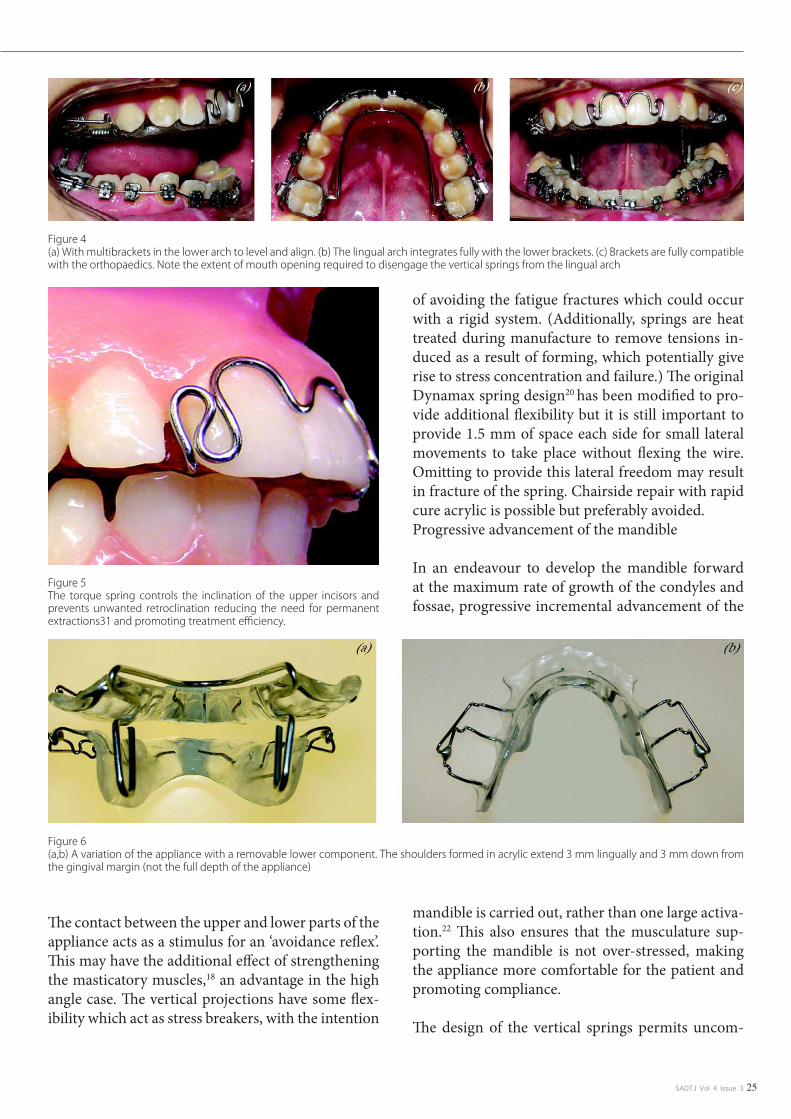
SADTJ Vol 4 Issue 3 25
The contact between the upper and lower parts of the appliance acts as a stimulus for an ‘avoidance reflex’. This may have the additional effect of strengthening the masticatory muscles,18 an advantage in the high angle case. The vertical projections have some flex-ibility which act as stress breakers, with the intention
of avoiding the fatigue fractures which could occur with a rigid system. (Additionally, springs are heat treated during manufacture to remove tensions in-duced as a result of forming, which potentially give rise to stress concentration and failure.) The original Dynamax spring design20 has been modified to pro-vide additional flexibility but it is still important to provide 1.5 mm of space each side for small lateral movements to take place without flexing the wire. Omitting to provide this lateral freedom may result in fracture of the spring. Chairside repair with rapid cure acrylic is possible but preferably avoided. Progressive advancement of the mandible
In an endeavour to develop the mandible forward at the maximum rate of growth of the condyles and fossae, progressive incremental advancement of the
mandible is carried out, rather than one large activa-tion.22 This also ensures that the musculature sup-porting the mandible is not over-stressed, making the appliance more comfortable for the patient and promoting compliance.
The design of the vertical springs permits uncom-
Figure 4 (a) With multibrackets in the lower arch to level and align. (b) The lingual arch integrates fully with the lower brackets. (c) Brackets are fully compatible with the orthopaedics. Note the extent of mouth opening required to disengage the vertical springs from the lingual arch
Figure 5 The torque spring controls the inclination of the upper incisors and prevents unwanted retroclination reducing the need for permanent extractions31 and promoting treatment efficiency.
Figure 6 (a,b) A variation of the appliance with a removable lower component. The shoulders formed in acrylic extend 3 mm lingually and 3 mm down from the gingival margin (not the full depth of the appliance)

SADTJ Vol 4 Issue 326
plicated forward reactivation at the chairside, using standard orthodontic pliers (Figure 7).
Extra-oral traction may be utilized by adding a short facebow and posterior highpull headgear to tubes in the second premolar region. The acrylic capping of the buccal segments allows heavy forces up to 1500 g per side to be used without any discomfort to the pa-tient, in order to establish control over vertical and horizontal development of the face. A facebow with a built in safety catch36 provides effective security against accidental detachment and is efficient and simple for the patient to use.
Posterior capping
The occlusal surfaces of the upper posterior teeth are covered with a 1 mm thickness of acrylic (Figure 1), to give the following effects:
• Unlocking the occlusion, permitting themandible to develop, without interference from the cusps of the posterior teeth.• Heavy extra-oral force is distributed moreevenly throughout the arch, reducing it to a comfort-able level on individual teeth.• Verticalforcescanbeappliedtothemaxilla,which may inhibit its normal downgrowth, promot-ing mandibular advancement by allowing the man-dible to hinge forward.
Case Presentation
Figure 7 (a–d) Reactivation of the spring is carried out every 6–8 weeks, depending on progress. The 2 mm advancement is made by bending the front leg forward and then bending the rear leg forward until the front leg is parallel to its original slope. This can be checked by sighting across to the spring on the other side. It is important to leave the free end close to the acrylic to avoid the possibility of it snagging on the lingual arch. The same procedure is then repeated on the opposite side. To prevent fatigue fracture, the wire must be handled carefully and damage to the outer layer avoided. Flat beak pliers should be used on the flat part of the spring and not on the curved sections

SADTJ Vol 4 Issue 3 27
Anterior torque control
The torque spring fitted to the original Bass appli-ance5–7 has been modified to lie flat against the sur-face of the incisors (Figure 5) increasing patient comfort.
Anterior Bite Plane
This is usually placed 2 mm short of the level of the incisal edges, to control eruption of the lower incisors and contributes to levelling of the curve of Spee.
Mandibular Appliance
The fixed mandibular appliance (Figures 1, 2 and 3) is made in a similar manner to a standard lingual arch with 1.0 mm wire, modified with 3 mm ‘shoul-ders’ in front of the bands. The shoulders should be at right angles to the mid-line. Occasionally, where more anchorage of the lower dental arch is needed or soft tissue modification is desirable, a lip bumper may be added to the lingual arch.
Alternatively a removable type of lower appliance (Figure 6) can be used if the clinician prefers.
Appliance construction
Laboratory construction is based around a prefabri-cated wire form (Forestadent, 21 Carters Lane, Kiln Farm Milton Keynes MK11 3HL). This wire form provides the vertical springs, the expansion element and the framework for the acrylic baseplate (Figure
10). Adjustment is simple and generally only the width requires adaptation. In most cases, the techni-
cian does not require a construction bite or articu-lator mounting. The models generally only require marking for centric occlusion. The exception is with a high angle malocclusion, where a posterior con-tact with the appliance occurs. A construction bite in these cases will avoid the need to trim the posterior capping at the chairside.
The initial forward activation is standardized at 3–4 mm from centric and the indication for this mea-surement is readily transferred to the lower model during construction, to mark the position of the ‘shoulders’ on the lower appliance.
Clinical procedure
Alginate impressions are taken, with a wax bite in centric occlusion. For the fixed lower component, molar bands are selected and placed in position, be-fore the impression is taken. To avoid the possibility of bands splitting, these should preferably be 0.007-inch thickness (e.g. Forestadent)
Fitting the appliance in the clinic
The upper and lower parts are placed together by hand to check that the width of the vertical springs has been correctly adjusted; there should be approxi-mately 1.5 mm of space each side, to allow for lat-eral movement without flexing the wires. If a lingual arch has been made, this is cemented into place. The upper component is then fitted and the patient will automatically close comfortably into the protrusive position in response to the action of the vertical
springs.
Figure 8 (a,b) The appliance is trimmed down in the later stages of treatment and is retained only on the first molars
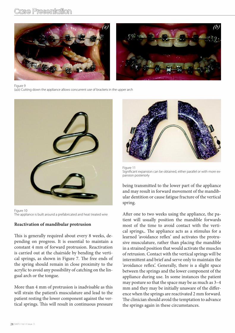
SADTJ Vol 4 Issue 328
Reactivation of mandibular protrusion
This is generally required about every 8 weeks, de-pending on progress. It is essential to maintain a constant 4 mm of forward protrusion. Reactivation is carried out at the chairside by bending the verti-cal springs, as shown in Figure 7. The free ends of the spring should remain in close proximity to the acrylic to avoid any possibility of catching on the lin-gual arch or the tongue.
More than 4 mm of protrusion is inadvisable as this will strain the patient’s musculature and lead to the patient resting the lower component against the ver-tical springs. This will result in continuous pressure
being transmitted to the lower part of the appliance and may result in forward movement of the mandib-ular dentition or cause fatigue fracture of the vertical spring.
After one to two weeks using the appliance, the pa-tient will usually position the mandible forwards most of the time to avoid contact with the verti-cal springs,. The appliance acts as a stimulus for a learned ‘avoidance reflex’ and activates the protru-sive musculature, rather than placing the mandible in a strained position that would activate the muscles of retrusion. Contact with the vertical springs will be intermittent and brief and serve only to maintain the ‘avoidance reflex’. Generally, there is a slight space between the springs and the lower component of the appliance during use. In some instances the patient may posture so that the space may be as much as 3–4 mm and they may be initially unaware of the differ-ence when the springs are reactivated 2 mm forward. The clinician should avoid the temptation to advance the springs again in these circumstances.
Case Presentation
Figure 9 (a,b) Cutting down the appliance allows concurrent use of brackets in the upper arch
Figure 10 The appliance is built around a prefabricated and heat treated wire
Figure 11 Significant expansion can be obtained, either parallel or with more ex-pansion posteriorly

SADTJ Vol 4 Issue 3 29
Expansion of the maxillary arch is obtained by pull-ing the two halves of the upper appliance apart by approximately 2–3 mm at the posterior edge. Activa-
tion can be parallel, with expansion of the canines as well as molars, or non-parallel with more expansion at the posterior of the arch. Lateral adjustment of the vertical springs will be required if the maxillary
Figure 12 (a,b) Patient age 12 years 10 months. Note significant mandibular retrusion and abnormal lower lip function. (c–e) Permanent dentition fully erupt-ed into one unit Class II molar occlusion. Overjet is increased and the overbite is increased. (f,g) Upper arch is crowded and the lower incisors are tipped labially
Figure 13 (a,b) Age 13 years 7 months. After 9 months of treatment with the Dynamax appliance. The facial profile is improving well and the soft tissue func-tion now harmonised with the dentition. (c–e) After 9 months treatment. Canine occlusion is now Class I. The buccal segments at this stage still require more time to erupt

SADTJ Vol 4 Issue 330
arch is widened significantly. If this adjustment is not made, the appliance may become unwearable or possibly cause fracture of a vertical spring. If further expansion is required and mandibular advancement
is complete, the vertical springs may be removed al-together (Figure 11).
Figure 14 (a–c) 3 months later, the buccal segments are now erupted into occlusion. Lower arch is bonded and the orthopaedic correction stabilized with ap-pliance used at night only. Expansion of the upper arch is continued, to provide space for alignment
Figure 15 (a–c) After 15 months treatment, the upper arch is bonded for final alignment. The appliance is reduced in size and now contacts only the upper molars
Figure 16 (a–c) Molars are now bonded for final adjustments in rotation and levelling
Case Presentation

SADTJ Vol 4 Issue 3 31
Co-ordination with multibracket treatment
With a fixed lingual arch in place, brackets can be bonded on the lower arch and levelling and align-ment carried out at any time during the orthopaedic phase (Figure 4). The lower incisors may be actively intruded to avoid an increase in lower face height as the curve of Spee is levelled.
Figure 17 After 22 months, immediately prior to debond
Figure 18 (a) Cephalometric tracing prior to treatment. Age 12 years 10 months SNA 82° SNB 74° ANB 8°. Upper Incisor inclination 110° to maxillary plane. Lower incisor inclination 110.5° to mandibular plane. MMPA 25°. (b) After 11 months orthopaedic treatment and 3 months night-time stabilisation. Age 14 years 0 months SNA 81° SNB 76° ANB 5°. Upper Incisor inclination 110° to maxillary plane. Lower incisor inclination 110° to mandibular plane. MMPA 25°. (c) Superimposition on cranial base at S point. Initial tracing solid line, dashed line indicates post-orthopaedic treatment. Change with 11 months full time appliance wear and 3 months night-time stabilisation. Accelerated mandibular growth has enhanced the skeletal correction in this case. The new mandibular position improves the facial profile, corrects the Skeletal II malocclusion and allows the lower lip to function normally. (d) Maxillary superimposition on best anatomical fit. Incisor position and torque are fully controlled. (e) Mandibular superimposition on stable structures (Bjork). The improvement in the overjet is almost entirely due to skeletal change in this
If there is significant irregularity of the upper teeth, particularly if a lateral incisor is instanding, the torque bar may be omitted from the construction and brackets can be placed from the premolars for-ward, from the start of treatment. Generally brack-ets are placed in the upper arch towards the end of the orthopaedic phase. The front part of the appli-ance is removed and the appliance retained with the clasps on the first molars only (Figures 8 and 9). The reduced appliance is usually worn at night for several months after the orthopaedic correction has
been achieved, in order to enhance stability and dur-ing this time fixed appliance therapy is carried on as normal. Generally, torque of the upper incisors is not required, except in Class II division 2 cases, and the first molars are only banded to finalize levelling and rotations at the end of treatment. This simulta-neous use of orthopaedics and fixed appliance ther-apy allows maximum Skeletal II correction without extending treatment time.

SADTJ Vol 4 Issue 332
Case report
A case report is shown in figures 12–19 and dem-onstrates the use of a Dynamax appliance in a 12 year old boy. This patient presented with a skeletally-based Class II division 1 malocclusion. Treatment was undertaken with the Dynamax appliance com-
bined with fixed appliances to obtain final alignment and maximal interdigitation. The total treatment time was 24 months. A maxillary wrap around re-tainer was used for six months full-time followed by six months nighttime wear. A mandibular 3-3 fixed retainer is in place.
Figure 19 (a–c) One month after treatment completion. The occlusion is well settled. (d–g) Facial appearance following 24 months treatment. Note the harmo-nious soft tissue profile and the dentition well placed in the face. The advancement of the mandble has avoided the need for incisor retraction in the correction of the malocclusion
Conclusion
The Dynamax orthopaedic appliance features:
straightforward construction around a prefabricated spring component.•a fixed lingual arch allows concurrent use of a multibracket appliance to align and level the lower arch. •The lingual arch also maintains the leeway space from deciduous second molars, reducing the need for the extraction of permanent teeth. control of maxillary development by means of extra-oral traction, expansion of the maxillary arch, control •of molar eruption and torque control of the maxillary incisors. brackets may be placed on the upper arch at any stage of treatment and the orthopaedic therapy can be •maintained for as long as necessary, to allow stabilisation of the new mandibular position. the appliance is comfortable and unobtrusive for the patient, with minimal speech interference. The design •of the vertical spring eliminates loss of forward activation during sleep or speech. readily adjusted at the chairside to progressively advance the mandible.•correction of the Skeletal II malocclusion can be carried out at any stage in the dental development of a •growing individual.The author acknowledges a financial interest in the Dynamax appliance. • b
Case Presentation

SADTJ Vol 4 Issue 3 33
CEU
The Dynamax System: A new orthopaedic appliance and case Report.
6. The dynamax appliance is used in the treatment of the following: a. Skeletal ii malocclusion. b. Progressive mandibular advancement. c. Maxillary contraction. d. Vertical facial development. e. a, b and d.
7. Clinician has 3 choices to reduce the overjet: a. Retraction of maxillary incisors. b. Bringing the lower incisors forward. c. Mandibular expansion. d. a and c. e. a and b.
8. The Dynamax appliance offer the following advantages: a. One stages in treatment has been eliminated. b. Incremental Mandibular advancement. c. Mandibular incisors inclination is uncontrolled and tipping is progressive. d. Extra oral traction may be reduced to control growth of maxilla.
9. The Interior bite plane is placed how many mm short of the level of the incisal edges? a. 1mm. b. 3mm. c. 2mm. d. 4mm.
10. How is retention obtained by the dynamax system? a. Cementing maxillary and mandibular components on arches. b. Adams clasps on first molars. c. An Anterior torque spring. d. b and c
References
Bass NM. The aesthetic analysis of the face. Eur J Orthod 1991; 13: 343–50. Abstract/FREE Full Text1. Arnett GW, Bergman RT. Facial Keys to orthodontic diagnosis and treatment planning – Parts I and II, Am J Orthod Dentofacial Orthop 1993; 103: 299–312, 395–411. Medline2. Frankel R. Decrowding during eruption under the screening influence of vestibular shields. Am J Orthod 1974; 65: 372–406. CrossRefMedline3. Graber TM, Rakosi T, Petrovic A. Dentofacial orthopedics with functional appliances. St. Louis: Mosby, 1997.4. Bass NM. Dento-facial orthopaedics in the correction of Class II malocclusion. Br J Orthod 1982; 9: 3–31. Abstract5. Bass NM. Orthopedic co-ordination of dento-facial development in skeletal class II malocclusion in conjunction with edgewise therapy. Part I. Am J Orthod 1983; 84: 361–83. CrossRefMedline6. Bass NM. Orthopedic co-ordination of dento-facial development in skeletal class II malocclusion in conjunction with edgewise therapy. Part II. Am J Orthod 1983; 84: 466–90. CrossRefMedline7. Clark WJ. Twin block functional therapy: applications in dento-facial orthopaedics. London: Mosby-Wolf, 1995; 265–67.8. Cura N, Saraç M, Öztürk Y, Sürmeli N. Orthodontic and orthopedic effects of Activator, Activator – HG Combination and Bass appliances: a comparative study. Am J Orthod Dentofacial Orthop 1996; 110: 36–45. 9. CrossRefMedline Pancherz H. The Herbst appliance- its biological effects and clinical use. Am J Orthod 1985; 87: 1–20. CrossRefMedline10. Pancherz H, Hansen K. Occlusal changes during and after Herbst treatment: a cephalometric investigation. Eur J Orthod 1986; 8: 215–28.Abstract/FREE Full Text11. Pancherz H. The mechanism of Class II correction in Herbst appliance treatment. A Cephalometric investigation. Am J Orthod 1982; 82: 104–13. CrossRefMedline12. Woodside DG, Metaxas A Altuna G. The influence of functional appliance therapy on glenoid fossa remodelling. Am J Orthod Dentofacial Orthop 1987; 92: 181–98. CrossRefMedline13. Ruf S, Pancherz H. Temporomandibular joint remodelling in adolescents and young adults during Herbst treatment: a prospective longitudinal magnetic resonance imaging and cephalometric radiographic inves-14. tigation. Am J Orthod Dentofacial Orthop 1999; 115: 607–18. CrossRefMedlineVoudouris JC, Woodside DG, Altuna G, et al. Condyle-fossa modifications and muscle interactions during Herbst treatment, Part 1. New technological methods. Am J Orthod Dentofacial Orthop 2003; 123: 604–13. 15. CrossRefMedlineVoudouris JC, Woodside DG, Altuna G, Kuftinec MM, Angelopolous G, Bourke PJ. Condyle-fossa modifications and muscle interactions during Herbst treatment Part 2. Results and conclusions. Am J Orthod 16. Dentofacial Orthop 2003; 124: 13–29. CrossRefMedlineCura N, Sarac M. The effect of treatment with the Bass appliance on skeletal Class II malocclusions: a cephalometric investigation. Eur J Orthod 1997; 19: 691–702. Abstract/FREE Full Text17. Cura N, Sarac M. Influence of Bass orthopaedic appliance system on electomyographic activity of masticator muscles. Eur J Orthod 1990; 12: 484 (Abstract).18. Pancherz H. Malmgren O, Hagg U, Omblus J, Hansen K. Class II correction in Herbst and Bass therapy. Eur J Orthod 1989; 11: 17–30. Abstract/FREE Full Text19. Bass NM. The Dynamax System: A New Orthopedic Appliance. J Clin Orthod 2003; 37: 268–77. Medline20. Rabie ABM, Hagg U. Factors Regulating mandibular condylar growth. Am J Orthod Dentofacial Orthop 2002; 122: 401–09. CrossRefMedline21. Falck F, Frankel R. Clinical relevance of step-by-step mandibular advancement in the treatment of mandibular retrusion using the Frankel appliance. Am J Orthod 1989; 96: 333–41.22. Sessle BJ, Woodside DG, Bourque P, et al. Effect of functional appliances on jaw muscle activity. Am J Orthod Dentofacial Orthop 1990; 98: 222–30. Medline23. Lund IL, Sandler PJ. The effects of Twin Blocks: A prospective controlled study. Am J Orthod Dentofacial Orthop 1998, 113: 104–10. CrossRefMedline24. Du X, Hagg U,Rabie ABM. Effects of headgear Herbst and mandibular step-by-step advancement versus conventional Herbst appliance and maximal jumping of the mandible. Eur J Orthod 2002; 24: 167–74. 25. Abstract/FREE Full TextHagg U; Rabie ABM. Initial and late treatment effects of headgear-Herbst appliance with mandibular step-by-step advancement. Am J Orthod Dentofacial Orthop 2002; 122: 477–85. CrossRefMedline26. Bakr A, Rabie M, Chayaanupatkul A, Hagg U. Stepwise advancement using fixed functional appliances: Experimental perspective. Semin Orthod 2003; 9: 41–46.27. Bass NM. Innovation in Skeletal II Treatment including effective incisor root torque in a preliminary removable appliance phase. Br J Orthod 1976; 3: 223–30. Medline28. O Brien K, Wright J, Conboy F, et al. Effectiveness of early orthodontic treatment with thr Twin Block appliance; a multicenter, randomised, controlled trial. Part I; Dental and skeletal effects. Am J Orthod Dento-29. facial Orthop 2003; 123: 234–43.Caldwell S, Cook P. Predicting the outcome of twin block functional appliance treatment: a prospective study, Eur J Orthod 1999; 21: 533–53. Abstract/FREE Full Text30. Brennan MM, Gianelly AA. The use of the lingual arch in the mixed dentition to resolve incisor crowding. Am J Orthod Dentofacial Orthop 2000; 117: 81–85. CrossRefMedline31. Teuscher U. An appraisal of growth and reaction to extra oral anchorage. Am J Orthod 1986; 89: 113–21.CrossRefMedline32. Bendeus M, Hagg U, Rabie ABM. Growth and treatment changes in patients treated with headgear-activator appliance. Am J Orthod Dentofacial Orthop 2002; 121: 376–84. CrossRefMedline33. McDonagh S, Moss JP, Goodwin P, Lee RT. A prospective optical surface scanning and cephalometric assessment of the effect of functional appliances on the soft tissues. Eur J Orthod 2001; 23: 115–26. Abstract/34. FREE Full TextSander FG. Der Nachteffekt bei der Anwenndung der Vorschubdoppelplatte. Prakt Kieferorthop. 1989; 3: 97–106.35. Samuels, R. A Clinical evaluation of a locking orthodontic facebow. Am J Orthod Dentofacial Orthop 2000; 117: 344–50.36.
SADTJ Vol 4 Issue 334
Scientific Article
INTRODUCTION
With the developments in the fi eld of reinforced polymers, the use of pre-impregnated fi ber-reinforced composites (FRC) has increased in dentistry. Today, FRCs are usually indicated for periodontal or traumatic splinting1), as endodontic posts2), for intraoral repair of metal-ceramic crowns3), for reinforcement of direct or indirect fi xed dental prostheses (FDP)1), and in or-thodontics for fi xed retainers4). Various types of fi bers such as glass fi ber5), polyester fi ber6), carbon/graphite fi ber7), aramid (Kevlar) fi ber8) and ultra high molecular weight polyethylene fi ber (UHMWPE)9) are added into the composite materials in order to improve mechanical properties. The amount of fi bers in the matrix, diameter and length of fi bers10), fi ber form6), adhesion of fi bers to the polymer matrix11), water sorption of FRC matrix12), location, orientation13) and impregnation of fi bers12) infl uence the mechanical properties of FRCs.
FRCs have suitable fl exural modulus and flexural strength for functioning successfully in the mouth as a restorative mate-rial14). The average masticatory forces are reported to range between 155 and 222 N for anterior and up to 830 N for poste-rior teeth15). In a previous in-vitro study, it was reported that FRC application increased the fracture load of resin crowns to the level of intact crowns16). In another study, fracture strength of FRC FDPs exceeded the reported highest masticatory force
values of 1000 N15). For that reason, such restorations are con-sidered strong enough for clinical applications17). Certainly, adhesion to dental tissues and other restorative materials using adhesive promoters increased their potential indications18).
Among all other applications, inlay-retained FRC FDPs are considered as alternative therapy options to conventional full-coverage FDPs, resin-bonded FRCs and implants. Inlay-retained FRC FDPs can be made directly in the mouth or indi-rectly in the laboratory. The indirect technique is time consum-ing and more expensive than the direct application due to the laboratory procedures. Moreover, limited clinical information on their survival is unfortunately not promising19-22). On the other hand, adhesion of resin-based materials to enamel and dentin is superior in direct application since these restora-tions do not require temporarization that eventually eliminates contamination on the enamel and/or dentin17). The limiting factors of chair-side direct FRC FDP applications is that their quality highly depends on the operator’s clinical skills during establishing the anatomical form of the pontic. With the use of prefabricated pontics, the application of FRC FDPs for re-placement of missing teeth may be simplifi ed and perhaps in-crease their indications23). For this purpose, extracted teeth24), acrylic resin denture teeth25) and porcelain denture teeth can be used as pontic materials for direct FRC FDPs. Various occlu-sion concepts have been developed in dentistry over the years with the claim that they signifi cantly infl uence the technical complications of FDPs26-28). Such pontic materials present dif-ferent occlusal morphologies and free-hand constructed ones of course vary in each case. It can be anticipated that with the increase in surface area, increased chewing forces could be ex-pected on the pontics. In addition, deep cusp morphologies may be more prone to wedging effect. Limited information is available on the effect of pontic types for FRC FDPs23-25) and to the authors’ best knowledge the effect of occlusal morpholo-gies is unknown.
The objectives of this study therefore were to evaluate the effect of different pontic materials and occlusal morphologies on the fracture resistance of FRC FDPs. The hypothesis tested were that different pontic materials would not, but variations in oc-
Correspondence author
Mutlu ÖZCAN; E-mail: [email protected]
This is an open access article licensed under the terms of the Creative Com-mons Attribution Non-Commercial License (http://creativecommons.org/li-censes/by-nc/3.0/) which permits unrestricted, non-commercial use, distribu-tion and reproduction in any medium, provided the work is properly cited.
Fracture resistance of direct inlay-retained adhesive bridges: Effect of pontic material and occlusal
morphology
Mutlu ÖZCAN 1, Marijn BREUKLANDER2 and Esra SALIHOGLU-YENER3
Dental Materials Unit, University of Zürich, Center for Dental and Oral Medicine, Clinic for Fixed and Removable Prosthodontics and Dental Materials Science, Plattenstrasse 11, CH-1. 8032 Zürich, SwitzerlandDepartment of Fixed and Removable Prosthodontics, Center for Dentistry and Oral Hygiene, University Medical Center Groningen, The University of Groningen, PO Box: 30006 9700 2. RB Groningen, The NetherlandsFaculty of Dentistry, Department of Prosthodontics, University of Yeditepe, Bagdat Cad. No: 238, Goztepe, 34728, Istanbul, Turkey Corresponding author, Mutlu ÖZCAN; E-mail: 3. [email protected]
ABSTRACT: This study evaluated the effect of a) pontic materials and b) occlusal morphologies on the fracture resistance of fi ber-reinforced com-posite (FRC) inlay-retained fixed dental prostheses (FDP). Inlay-retained FRC FPDs (N=45, n=9) were constructed using a) resin composite (deep anatomy), b) natural tooth, c) acrylic denture tooth, d) porcelain denture tooth and e) resin composite (shallow anatomy), as pontic materials. In ad-dition resin composite beams were fabricated (N=30, n=10): i) ‘circular’, ii) ‘elliptic I’, and iii) ‘elliptic II’. There was no signifi cant difference between the fracture resistance of Groups a, b, c, and d (598, 543, 539, 509 N, respectively) (p>0.05) (One-way ANOVA). Fracture resistance of Group e (1,186 N) was signifi cantly higher than those of other groups (p<0.05) (Tukey’s test). No signifi cant difference was found between Group i (1,750 N) and Group ii (1,790 N). Not the pontic material but the occlusal morphology affects the fracture resistance of FRC FDPs.
Keywords: Fiber-reinforced composite, Fracture strength, Occlusal morphology, Pontic, Resin-bonded bridge
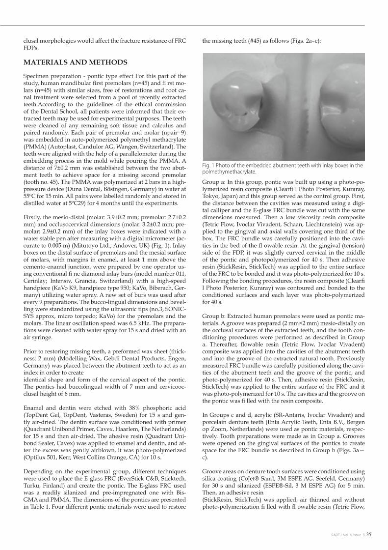
SADTJ Vol 4 Issue 3 35
clusal morphologies would affect the fracture resistance of FRC FDPs.
MATERIALS AND METHODS
Specimen preparation - pontic type effect For this part of the study, human mandibular first premolars (n=45) and fi rst mo-lars (n=45) with similar sizes, free of restorations and root ca-nal treatment were selected from a pool of recently extracted teeth.According to the guidelines of the ethical commission of the Dental School, all patients were informed that their ex-tracted teeth may be used for experimental purposes. The teeth were cleaned of any remaining soft tissue and calculus and paired randomly. Each pair of premolar and molar (npair=9) was embedded in auto-polymerized polymethyl methacrylate (PMMA) (Autoplast, Candulor AG, Wangen, Switzerland). The teeth were aligned with the help of a parallelometer during the embedding process in the mold while pouring the PMMA. A distance of 7±0.2 mm was established between the two abut-ment teeth to achieve space for a missing second premolar (tooth no. 45). The PMMA was polymerized at 2 bars in a high-pressure device (Duna Dental, Bösingen, Germany) in water at 55ºC for 15 min. All pairs were labelled randomly and stored in distilled water at 5ºC29) for 4 months until the experiments.
Firstly, the mesio-distal (molar: 3.9±0.2 mm; premolar: 2.7±0.2 mm) and occlusocervical dimensions (molar: 3.2±0.2 mm; pre-molar: 2.9±0.2 mm) of the inlay boxes were indicated with a water stable pen after measuring with a digital micrometer (ac-curate to 0.005 m) (Mitutoyo Ltd., Andover, UK) (Fig. 1). Inlay boxes on the distal surface of premolars and the mesial surface of molars, with margins in enamel, at least 1 mm above the cemento-enamel junction, were prepared by one operator us-ing conventional fi ne diamond inlay burs (model number 011, Cerinlay; Intensiv, Grancia, Switzerland) with a high-speed handpiece (KaVo K9, handpiece type 950; KaVo, Biberach, Ger-many) utilizing water spray. A new set of burs was used after every 9 preparations. The bucco-lingual dimensions and bevel-ling were standardized using the ultrasonic tips (no.3, SONIC-SYS approx, micro torpedo; KaVo) for the premolars and the molars. The linear oscillation speed was 6.5 kHz. The prepara-tions were cleaned with water spray for 15 s and dried with an air syringe.
Prior to restoring missing teeth, a preformed wax sheet (thick-ness: 2 mm) (Modelling Wax, Gebdi Dental Products, Engen, Germany) was placed between the abutment teeth to act as an index in order to createidentical shape and form of the cervical aspect of the pontic. The pontics had buccolingual width of 7 mm and cervicooc-clusal height of 6 mm.
Enamel and dentin were etched with 38% phosphoric acid (TopDent Gel, TopDent, Vasteras, Sweden) for 15 s and gen-tly air-dried. The dentin surface was conditioned with primer (Quadrant Unibond Primer, Cavex, Haarlem, The Netherlands) for 15 s and then air-dried. The ahesive resin (Quadrant Uni-bond Sealer, Cavex) was applied to enamel and dentin, and af-ter the excess was gently airblown, it was photo-polymerized (Optilux 501, Kerr, West Collins Orange, CA) for 10 s.
Depending on the experimental group, different techniques were used to place the E-glass FRC (EverStick C&B, Sticktech, Turku, Finland) and create the pontic. The E-glass FRC used was a readily silanized and pre-impregnated one with Bis-GMA and PMMA. The dimensions of the pontics are presented in Table 1. Four different pontic materials were used to restore
the missing teeth (#45) as follows (Figs. 2a–e):
Group a: In this group, pontic was built up using a photo-po-lymerized resin composite (Clearfi l Photo Posterior, Kuraray, Tokyo, Japan) and this group served as the control group. First, the distance between the cavities was measured using a digi-tal calliper and the E-glass FRC bundle was cut with the same dimensions measured. Then a low viscosity resin composite (Tetric Flow, Ivoclar Vivadent, Schaan, Liechtenstein) was ap-plied to the gingival and axial walls covering one third of the box. The FRC bundle was carefully positioned into the cavi-ties in the bed of the fl owable resin. At the gingival (tension) side of the FDP, it was slightly curved cervical in the middle of the pontic and photopolymerized for 40 s. Then adhesive resin (StickResin, StickTech) was applied to the entire surface of the FRC to be bonded and it was photo-polymerized for 10 s. Following the bonding procedures, the resin composite (Clearfi l Photo Posterior, Kuraray) was contoured and bonded to the conditioned surfaces and each layer was photo-polymerized for 40 s.
Group b: Extracted human premolars were used as pontic ma-terials. A groove was prepared (2 mm×2 mm) mesio-distally on the occlusal surfaces of the extracted teeth, and the tooth con-ditioning procedures were performed as described in Group a. Thereafter, flowable resin (Tetric Flow, Ivoclar Vivadent) composite was applied into the cavities of the abutment teeth and into the groove of the extracted natural tooth. Previously measured FRC bundle was carefully positioned along the cavi-ties of the abutment teeth and the groove of the pontic, and photo-polymerized for 40 s. Then, adhesive resin (StickResin, StickTech) was applied to the entire surface of the FRC and it was photo-polymerized for 10 s. The cavities and the groove on the pontic was fi lled with the resin composite.
In Groups c and d, acrylic (SR-Antaris, Ivoclar Vivadent) and porcelain denture teeth (Enta Acrylic Teeth, Enta B.V., Bergen op Zoom, Netherlands) were used as pontic materials, respec-tively. Tooth preparations were made as in Group a. Grooves were opened on the gingival surfaces of the pontics to create space for the FRC bundle as described in Group b (Figs. 3a—c).
Groove areas on denture tooth surfaces were conditioned using silica coating (CoJet®-Sand, 3M ESPE AG, Seefeld, Germany) for 30 s and silanized (ESPE®-Sil, 3 M ESPE AG) for 5 min. Then, an adhesive resin(StickResin, StickTech) was applied, air thinned and without photo-polymerization fi lled with fl owable resin (Tetric Flow,
Fig. 1 Photo of the embedded abutment teeth with inlay boxes in the polmethymethacrylate.

SADTJ Vol 4 Issue 336
Scientific Article
Ivoclar Vivadent). The pontic with the FRC bundle in the groove was placed in position (Figs. 4a–d). The excess was removed using microbrushes and a dental probe.
Group e: An additional group was created identical to Group a to test whether location of the loading point affects the fracture resistance of FRC FDPs. While load was exerted on the mesial and distal marginal ridges with the steel sphere in Group e hav-ing a shallow anatomy, the steel sphere was in contact with the buccal and lingual cusp tips in Group a having a deep anatomy (Fig. 5). In Group a the distance between the highest point of the buccal cusp and the fi ssure was 3.5 mm and in Group e it was 2 mm.
The bonded FRC FDP was photo-polymerized for 40 s per side. Finally, fi nishing and polishing procedures were performed using silicone brushes (Astropol, Ivoclar Vivadent).
Fracture resistance test
The samples were positioned in the jig of the universal test-ing machine (Z2.5/TS1S, Zwick/Roell Nederland, Venlo, The Netherlands) at a constant speed of 1 mm/min until fracture occurred. The force (N) was applied from the occlusal direc-tion to the central fossa with a steel loading sphere, 5 mm in diameter that started moving from a distance of 2 mm from the occlusal surface (Fig. 5). The initial distance of 2 mm served for easy access to position the specimen under the loading sphere easier. The loading sphere was later positioned 1 mm above the specimen.
Specimen preparation - occlusal morphology effect
To test the effect of occlusal morphology on the fracture resis-tance, three aluminium beams (15 mm×7 mm×4 mm) with dif-ferent surface shapes and contact points in relation to the load-ing sphere were prepared andreplicated in resin composite (Clearfi l Photo Posterior, Kura-
Fig. 2 Photos of different pontic materials a) resin composite (deep anatomy), b) natural tooth, c) acrylic denture tooth, d) porcelain denture tooth and e) resin composite (shallow anatomy) from occlusal view.
Fig. 3 Photos of a) the groove on the gingival side of the acrylic denture tooth (width: 2 mm, depth: 2 mm), b) FRC bundle in the bed of the flowable resin at the gingival aspect, c) FRC bundle in the groove from the occlusal aspect.
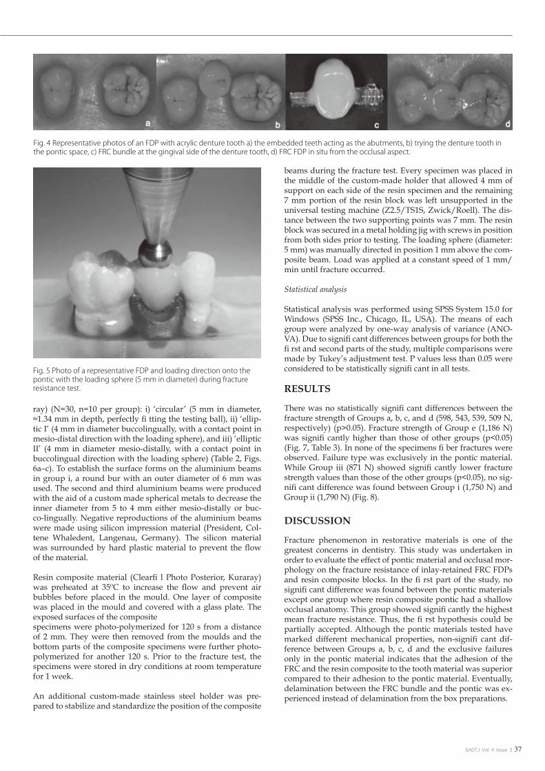
SADTJ Vol 4 Issue 3 37
ray) (N=30, n=10 per group): i) ‘circular’ (5 mm in diameter, ≈1.34 mm in depth, perfectly fi tting the testing ball), ii) ‘ellip-tic I’ (4 mm in diameter buccolingually, with a contact point in mesio-distal direction with the loading sphere), and iii) ‘elliptic II’ (4 mm in diameter mesio-distally, with a contact point in buccolingual direction with the loading sphere) (Table 2, Figs. 6a–c). To establish the surface forms on the aluminium beams in group i, a round bur with an outer diameter of 6 mm was used. The second and third aluminium beams were produced with the aid of a custom made spherical metals to decrease the inner diameter from 5 to 4 mm either mesio-distally or buc-co-lingually. Negative reproductions of the aluminium beams were made using silicon impression material (President, Col-tene Whaledent, Langenau, Germany). The silicon material was surrounded by hard plastic material to prevent the flow of the material.
Resin composite material (Clearfi l Photo Posterior, Kuraray) was preheated at 35ºC to increase the flow and prevent air bubbles before placed in the mould. One layer of composite was placed in the mould and covered with a glass plate. The exposed surfaces of the compositespecimens were photo-polymerized for 120 s from a distance of 2 mm. They were then removed from the moulds and the bottom parts of the composite specimens were further photo-polymerized for another 120 s. Prior to the fracture test, the specimens were stored in dry conditions at room temperature for 1 week.
An additional custom-made stainless steel holder was pre-pared to stabilize and standardize the position of the composite
beams during the fracture test. Every specimen was placed in the middle of the custom-made holder that allowed 4 mm of support on each side of the resin specimen and the remaining 7 mm portion of the resin block was left unsupported in the universal testing machine (Z2.5/TS1S, Zwick/Roell). The dis-tance between the two supporting points was 7 mm. The resin block was secured in a metal holding jig with screws in position from both sides prior to testing. The loading sphere (diameter: 5 mm) was manually directed in position 1 mm above the com-posite beam. Load was applied at a constant speed of 1 mm/min until fracture occurred.
Statistical analysis
Statistical analysis was performed using SPSS System 15.0 for Windows (SPSS Inc., Chicago, IL, USA). The means of each group were analyzed by one-way analysis of variance (ANO-VA). Due to signifi cant differences between groups for both the fi rst and second parts of the study, multiple comparisons were made by Tukey’s adjustment test. P values less than 0.05 were considered to be statistically signifi cant in all tests.
RESULTS
There was no statistically signifi cant differences between the fracture strength of Groups a, b, c, and d (598, 543, 539, 509 N, respectively) (p>0.05). Fracture strength of Group e (1,186 N) was signifi cantly higher than those of other groups (p<0.05) (Fig. 7, Table 3). In none of the specimens fi ber fractures were observed. Failure type was exclusively in the pontic material. While Group iii (871 N) showed signifi cantly lower fracture strength values than those of the other groups (p<0.05), no sig-nifi cant difference was found between Group i (1,750 N) and Group ii (1,790 N) (Fig. 8).
DISCUSSION
Fracture phenomenon in restorative materials is one of the greatest concerns in dentistry. This study was undertaken in order to evaluate the effect of pontic material and occlusal mor-phology on the fracture resistance of inlay-retained FRC FDPs and resin composite blocks. In the fi rst part of the study, no signifi cant difference was found between the pontic materials except one group where resin composite pontic had a shallow occlusal anatomy. This group showed signifi cantly the highest mean fracture resistance. Thus, the fi rst hypothesis could be partially accepted. Although the pontic materials tested have marked different mechanical properties, non-signifi cant dif-ference between Groups a, b, c, d and the exclusive failures only in the pontic material indicates that the adhesion of the FRC and the resin composite to the tooth material was superior compared to their adhesion to the pontic material. Eventually, delamination between the FRC bundle and the pontic was ex-perienced instead of delamination from the box preparations.
Fig. 4 Representative photos of an FDP with acrylic denture tooth a) the embedded teeth acting as the abutments, b) trying the denture tooth in the pontic space, c) FRC bundle at the gingival side of the denture tooth, d) FRC FDP in situ from the occlusal aspect.
Fig. 5 Photo of a representative FDP and loading direction onto the pontic with the loading sphere (5 mm in diameter) during fracture resistance test.

SADTJ Vol 4 Issue 338
The clinical performance of FRC FDPs in dental applications depends not only on their physical properties, but also on the handling characteristics of these materials and the clinical skills of the operator30).Since the resin composite pontics are built-up free hand under rubber dam, morphological features of these pontics may vary. In this study, mean fracture resistance of the FRC FDPs with pontics having shallow anatomy (Group a) presented signifi cantly lower results compared to those with deeper anatomy (Group e). In Group a, the loading sphere ex-erted pressure primarily on the buccal and lingual cusps of the pontic which possibly yielded to a kind of wedging effect be-tween the cusps. When the pontics are loaded on the cusp tips initially shear forces take place. This is then accompanied by tensile stresses in the bulk of the pontic material and ultimately the cervical area of the pontic contributes to the cohesive frac-ture of the pontic30).
When the veneering composite at the cusp area breaks earlier than the whole construction, this indicates that the cohesive strength of the material is less than the FRC-pontic adhesion. In such a situation from the reinforcement effect of the FRC could be profi ted. In both Groups a and e, cusp tips of the abutment teeth were considered as reference points. The inclination of the cusp tip in Group a (buccal cusp tip-fi ssure distance 3.5 mm), towards the main fi ssure was created less deeper than in Group e (buccal cusp tip-fi ssure distance 2 mm). Failures
in clinical or in-vitro studies seldom mentioned FRC fracture but reported more often separation of the veneering compos-ite from the FRC surface13,16,17). The occlusal anatomy could be one of the reasons for such failures, which requires closer attention in clinical studies in the future. Perhaps a more flat contact point on the buccal and lingual cusp tips may increase the survival rate.
Inlay-retained FRC FDPs should be ideally reinforced at the gingival side of the pontic because the tensile stresses are the highest in this region31). In this study, grooves were opened at the gingival sites of the denture teeth but at the occlusal side of the natural teeth pontics. Acrylic and porcelain denture teeth presented similar occlusal morphologies wheras the natural teeth showed different occlusal morphologies although ana-tomically similar teeth were selected. When the natural teeth were decapitated, the location of the pulp chamber did not always allow standard groove preparation. For this reason, in this group, grooves were opened at the occlusal side. Interest-ingly, no signifi cant difference was found between the frac-ture resistances of the FRC FDPs when different pontics were used and when even the fi ber bundle was placed either at the compressive or tensile sides of the pontics. Possibly, the good adhesion of the fiber and the resin composite onto enamel and dentin exceeded that of the cohesive strength of the pontic ma-terial and thereby no debonding but only fractures in the pontic
Scientific Article
Fig. 6 Photos of the aluminium beams and the composite specimens produced from the silicone replicas of these beams (length: 15 mm, width: 7 mm, thickness: 4 mm) representing occlusal surfaces of the pontics with different occlusal morphologies a) ‘circular’ (r=5 mm in vertical and horizontal direction, ≈1.34 mm in depth), b) ‘elliptic I’ (r=4 mm in vertical and r=5 mm in horizontal direction, ≈1.34 mm in depth), c) ‘elliptic II’ (r=5 mm in vertical and r=4 mm in horizontal direction, ≈1.34 mm in depth) in relation to the loading sphere. The loading sphere used was the same as presented in Fig. 4.

SADTJ Vol 4 Issue 3 39
causes early fracture of the composite, forces applied in the me-sio-distal direction or in the middle of the occlusal curvature may dissipate the forces and reduces stresses in the volume of the composite. In a study that focused on the stress analysis of all-ceramic FDPs, it has been shown that the number and the location of contact points infl uence the induced stresses32). In another study that focused on the stress distribution on the tooth-implant supported FDPs, it was reported that the load-ing condition is the main factor affecting stress distribution on the prosthetic components33). Similarly, occlusal contact points affected the results in the resin composite tested in this study. The results of the present study indicate that while adjusting the occlusion, the occlusal contact points should be created on the mesial and distal sides of the occlusal surface of the pontic
materials were observed. Nevertheless, the location of the fi ber bundle in high reconstructions requires further investigations. Among other factors such as pontic type and even the fi ber location, the loading point seems to have a dominant effect on the fracture resistance of the whole FRC FPDs. From the clinical point of view, it can be stated that while adjusting the occlu-sion, no deep fi ssures should be created.
In the second part of this study, when the loading sphere ap-plied force in the bucco-lingual direction on the resin composite block, signifi cantly lower results were obtained. Since occlusal morphologies presented an effect on the overall resistance of composites, the second hypothesis could be accepted. This fi nding indicates that while loading in bucco-lingual direction
Fig. Fig. 7 The mean fracture resistance and standard deviations of the inlay-retained FRC FDPs with different pontic materials: a) resin com-posite with deep anatomy, b) natural tooth, c) acrylic denture tooth, d) porcelain denture tooth, e) resin composite with shallow anatomy.
Fig. 8 The mean fracture resistance and standard deviations of resin composite specimens representing occlusal surfaces of the pontics with different morphologies: i) ‘circular’, ii) ‘elliptic I’, iii) ‘elliptic II’. See Table 2 for group descriptions.

SADTJ Vol 4 Issue 340
in order to increase the fracture resistance of an inlayretained FRC FDP.
In this part of the study, resin composite blocks were not re-inforced with a fi ber bundle and the height of the specimens was less than the pontic heights used in the fi rst part of the study. On the other hand, the depth of the curves was kept standard by approximately 1.34 mm. Therefore, a direct corre-lation between the first part of the study was not made. Yet, the morphology created in Group (i) with ‘circular’ morphology showed similar contact with the loading sphere as in Group e where resin composite pontic had shallow anatomy and deliv-ered the highest mean fracture strength values. In both parts of the study, fracture strength values showed similarities. On the other hand, Groups (ii and (iii) with ‘elliptic’ morphologies may resemble to Groups a, b, c and d. However, since all pontic
materials, such as the acrylic denture teeth, porcelain denture teeth, natural teeth and free-hand constructed composite resin, used in the study do not have identical occlusal morphologies, it is diffi cult to compare the fracture strength values among the pontic materials with different morphologies. This could be perceived as the limitation of this study. In spite of that, in clinical situations a similar situation also exists.
In future studies, affect of pontic materials and pontic morphol-ogy in combination with FRC FDPs should be tested under dynamic loading34). Also, invitro studies should mention the loading area, occlusal morphology, and loading conditions in similar studies in order to make direct comparisons with this study.
CONCLUSION
Within the limitations of this study, the following conclusions were drawn:
Natural teeth, acrylic, porcelain denture teeth or resin composite can all be used as pontic materials for inlay-retained FRC FDPs 1. without affecting the static fracture resistance.Forces applied on bucco-lingual occlusal contact points signifi cantly decreased the fracture resistance of composite blocks.2. The occlusal morphology of the pontic signifi cantly affects the fracture resistance of FRC FDPs. 3. b
REFERENCESKumbuloglu O, Aksoy G, User A. Rehabilitation of advanced periodontal problems by using a combination of a glass fi berreinforced composite resin bridge and splint. J Adhes Dent2008; 10: 1. 67-70.Terzioglu H, Yilmaz B. Restoration of endodontically compromised anterior teeth with fi ber posts and zirconia allceramic system. Case study. N Y State Dent J 2009; 75: 46-48.2. Özcan M, van der Sleen JM, Kurunmaki H, Vallittu PK. Comparison of repair methods for ceramic-fused-to-metal crowns. J Prosthodont 2006; 15: 283-238.3. Topouzelis N, Gkantidis N. An alternative for postorthodontic labial retention in an unusual case. World J Orthod 2008; 9: 366-370.4. Vallittu PK. Glass fi ber reinforcement in repaired acrylic resin removable dentures: preliminary results of a clinical study. Quintessence Int 1997; 28: 39-44.5. Chen SY, Liang WM, Yen PS. Reinforcement of acrylic denture base resin by incorporation of various fi bers. J Biomed Mater Res 2001; 58: 203-208.6. Vichi A, Ferrari M, Davidson CL. Infl uence of ceramic and cement thickness on the masking of various types of opaque posts. J Prosthet Dent 2000; 83: 412-417.7. Berrong JM, Weed RM, Young JM. Fracture resistance of Kevlar-reinforced poly(methyl methacrylate) resin: a preliminary study. Int J Prosthodont 1990; 3: 391-395.8. Ladizesky NH, Ho CF, Chow TW. Reinforcement of complete denture bases with continuous high performance polyethylene fibers. J Prosthet Dent 1992; 68: 934-939.9. Stipho HD. Repair of acrylic resin denture base reinforced with glass fi ber. J Prosthet Dent 1998; 80: 546-550.10. Vallittu PK. The effect of void space and polymerization time on transverse strength of acrylic-glass fi bre composite. J Oral Rehabil 1995; 22: 257-261.11. Lassila LV, Nohrstrom T, Vallittu PK. The infl uence of shortterm water storage on the fl exural properties of unidirectional glass fi ber-reinforced composites. Biomaterials 2002; 23: 2221-2229.12. Dyer SR, Lassila LV, Jokinen M, Vallittu PK. Effect of fiber position and orientation on fracture load of fi ber-reinforced composite. Dent Mater 2004; 20: 947-955.13. Alander P, Lassila LV, Tezvergil A, Vallittu PK. Acoustic emission analysis of fi ber-reinforced composite in fl exural testing. Dent Mater 2004; 20: 305-312.14. Vallittu PK, Kononen M. Biomechanical aspects and material properties. In: Karlsson S, Nilner K, Dahl BL, editors. A textbook of fi xed prosthodontics: The Scandinavian approach. Stockholm: 15. Gothia; 2000. p. 116-130.Behr M, Rosentritt M, Taubenhansl P, Kolbeck C, Handel G. Fracture resistance of fi ber-reinforced composite restorations with different framework design. Acta Odontol Scand 2005; 63: 153-16. 157.Özcan M, Breuklander MH, Vallittu PK. The effect of box preparation on the strength of glass fi ber-reinforced composite inlay-retained fi xed partial dentures. J Prosthet Dent 2005; 93 : 337-17. 345.Fritz UB, Finger WJ, Uno S. Resin-modifi ed glass ionomer cements: bonding to enamel and dentin. Dent Mater 1996; 12: 161-166.18. Gohring TN, Roos M. Inlay-fi xed partial dentures adhesively retained and reinforced by glass fi bers: clinical and scanning electron microscopy analysis after fi ve years. Eur J Oral Sci 200; 19. 113: 60-69.Vallittu PK, Sevelius C. Resin-bonded, glass fi ber-reinforced composite fi xed partial dentures: a clinical study. J Prosthet Dent 2000; 84: 413-418.20. van Heumen CC, van Dijken JW, Tanner J, Pikaar R, Lassila LV, Creugers NH, Vallittu PK, Kreulen CM. Five-year survival of 3-unit fi ber-reinforced composite fi xed partial dentures in the 21. anterior area. Dent Mater 2009; 25: 820-827.van Heumen CC, Tanner J, van Dijken JW, Pikaar R, Lassila LV, Creugers NH, Vallittu PK, Kreulen CM. Five-year survival of 3-unit fi ber-reinforced composite fi xed partial dentures in the 22. posterior area. Dent Mater 2010; 26: 954-960.Belli S, Ozer F. A simple method for single anterior tooth replacement. J Adhes Dent 2000; 2: 67-70.23. Antonson DE. Immediate temporary bridge using an extracted tooth. Dent Surv 1980; 56: 22-25.24. Littman H, Regan D, Rakow B. Provisional temporization witH acid-etch resin technique. Clin Prev Dent 1980; 2: 14-15.25. Thomas P. Syllabus on full mouth waxing technique for rehabilitation. Tooth-to-tooth, cusp-fossa concept of organic occlusion. 3rd ed. San Francisco: School of Dentistry, Postgraduate Educa-26. tion, University of California; 1967.Ramfjord S, Ash MM. Occlusion. 3rd ed. Philadelphia, London, Toronto, Sydney: W B Saunders; 1983.27. Pjetursson BE, Tan K, Lang NP, Bragger U, Egger M, Zwahlen M. A systematic review of the survival and complication ratesof fixed partial dentures (FPDs) after an observation period of at 28. least 5 years. Clin Oral Implants Res 2004; 15: 667-676.Heintze S, Forjanic M, Cavalleri A. Microleakage of Class II restorations with different tracers—comparison with SEM quantitative analysis. J Adhes Dent 2008; 10: 259-267. Dent Mater J 2012; 29. 31(4): 514–522 521Ellakwa AE, Shortall AC, Marquis PM. Infl uence of different techniques of laboratory construction on the fracture resistance of fi ber-reinforced composite (FRC) bridges. J Contemp Dent Pract 30. 2004; 5: 1-13.Shi L, Fok AS. Structural optimization of the fi bre-reinforced composite substructure in a three-unit dental bridge. Dent Mater 2009; 25: 791-801.31. Dittmer MP, Kohorst P, Borchers L, Schwestka-Polly R, Stiesch M. Stress analysis of an all-ceramic FDP loaded according to different occlusal concepts. J Oral Rehabil 2011; 38: 278-285.32. Lin CL, Wang JC, Chang WJ. Biomechanical interactions in tooth-implant-supported fi xed partial dentures with variations in the number of splinted teeth and connector type:a finite element 33. analysis. Clin Oral Implants Res 2008; 19: 107-117.
Scientific Article
SADTJ Vol 4 Issue 3 41
CEU
Fracture resistance of direct inlay-retained adhesive bridges: Effect of pontic material and occlusal morphology.
11. Name the various types of fibres that are added into composite materials in order to improve mechanical properties. a. Glass fibre. b. Polycarbonate fibre. c. Carbon /graphite fibre. d. Resin fibre. e. a, b and c. f. a and b.
12. Inlay retain FRC FDP’s are alternatives to: a. Conventional full coverage FDP’s. b. Resin bonded FRS’s. c. Implants . d. None of the above. e. All of the above.
13. The pontics had buccolingual width and servicoocclusal heights of how many mm respectively? a. 6mm and 7mm. b. 7mm and 6mm. c. 7mm each. d. 6mm each.
14. Name the four different pontic composite materials that were used to restore the missing teeth in the study. a. Ultra high molecular weight polyethylene fibre. b. Polyester fibre. c. Photo-polymerized resin composite. d. Polycarbonate fibres.
15. Which group had the highest fracture strength? a. Group a. b. Group b. c. Group c. d. Group d. e. Group e.
BOOKMARK:
The DENTASA Summit & AGM 2014, 1st Weekend in August 2014 at the
Birchwood Hotel in Gauteng.
SADTJ Vol 4 Issue 342
About three years ago our laboratory—Thayer Dental Lab in Mechan-icsburg, PA—began to notice a sharp decline in the response rate to our direct mail efforts. In an effort to bolster our marketing strategy, we embraced digital marketing by revising our website, building an opt-in email database, creating electronic advertisements and getting involved with social media.
Website
We implemented the following strategies to better manage our website and increase traffic; the site currently gets about 27 dentist hits a day, for a total of over 800 unique dentist visits per month. However, it’s not just about the number of visits, it’s about the quality of the visit, including time spent on the site, etc. For instance on our website, visi-tors spend an average of two minutes and view at least three pages. To achieve similar results on your own website, here are my recommen-dations:
Use a user-friendly content management system (CMS). To create a website 10 years ago, you had to work with a programmer who knew html. Today, user-friendly CMS programs have templates that allow you to create and maintain a website very easily; you can add, edit and organize content in an environment similar to Microsoft Office.One popular program I recommend for beginners is WordPress. It of-fers a simple format as well as several different features you can choose from—some free and some paid—like a smart phone app that allows you to manage your website from anywhere. Many web hosting com-panies also offer their own CMSs. Optimize your website for all browsers, like Mozilla Firefox, Google Chrome, Internet Explorer® and Safari. Your site will look different on each one and will need some programming tweaking to look its best on each. Keep in mind that you also want it to look as good on a smart-phone as it does on a desktop. If you’re using WordPress, a number of templates are optimized for most browsers, but you’ll need to install a
plugin for mobile devices like WP Mobile Detector.
To get your name out to a wider audience, place “social sharing” but-tons on every page so users can instantly promote or share what they think is interesting or valuable on social media sites like Facebook, Twitter or Pinterest.
Have ways to capture users contact information. For instance, our lab offers white papers and educational information on various subjects and in order to download the PDF, the dentist must first provide his contact information.
Once he does, the web server automatically sends two emails: one to the dentist thanking him for his interest in Thayer Dental Laboratory, and a second to me so I can alert a customer service rep to follow up. For instance, we can call and say, “I see you requested some informa-tion on our implant services. Do you have any questions or problems we can help you with?” If he does, we put him touch with our implant coordinator.
Last year, I received an email from a dentist requesting a restorative guide. Since a salesperson happened to be in that dentist’s area, I im-mediately notified him and the salesperson arrived at the dentist’s of-fice that very afternoon with the information he wanted. That day, we got five cases from him and, within one year, he became one of our top 10 accounts. It doesn’t always work like that, but it’s possible when you have the right mechanisms in place.
Take advantage of Google Analytics, a free service that provides web-site stats like how many hits you get a day, where users are located geographically, which browsers they’re using most and which pages get the most traffic. You can then use that information to help improve your site. For instance, if you see that a page isn’t getting any interest, ask yourself what you need to change: do you need to add information,
How to Maximize Your Website, Email and Online Advertising Efforts
Bob Gitman
ABOUT THE AUTHOR: Marketing guru Robert Gitman is the Company Administrator at Thayer Dental Laboratory, a full service laboratory in Mechanicsburg, PA, where he spearheads the lab’s promotional efforts. He has been active in the dental business for over 30 years as a consultant, lecturer and author on a variety of topics including marketing and laboratory profitability.
Computer Help

SADTJ Vol 4 Issue 3 43
a video or a testimonial?
To sign up, visit http://www.google.com/analytics/; you’ll receive a programming code that needs to be embedded in your website.
Maximize search engine optimization (SEO). SEO is the process of improving the visibility of your website in search engines like Google; in general, the higher on the page and more frequently a site appears in a search results list, the more visitors it will receive. When it comes to SEO, there’s no one factor that will work best, it’s about several things working in unison. For example:
Content is king. The more pages you have for Google to index, •the better off your SEO will be. So rather than listing all your product offerings on one page, for example, break them into separate pages.Each page of your website should have page titles and keywords •that describe their content. Use unique titles for each page, limit them to 70 characters or less, and avoid using more than four keywords. For instance, one page on our site is titled “Metal Free Restorations” and its associated keywords are “ceramic, compos-ite, esthetic and metal free.”Include external links. For example, we offer Captek restorations, •so we include a link to Captek.com: it’s a reputable site and gets more traffic than we do, so it makes us look good to Google’s web crawling algorithms. Another tip: check links often to be sure they work; bad links can negatively affect your SEO.’On every page of your website, include your laboratory name •somewhere in the text. Don’t only have your lab name in a logo or graphic because it can’t be “crawled” by Google search engines.If your website is more than four years old, it may be built on •frame architecture which inhibits SEO. If this is the case, your entire website needs to be created from scratch, which can be costly.
To find out if your site is built on frames, check with your webmaster or perform these simple steps: open your web browser, click the “View” menu, then select “Page Source” for Firefox or “Source” for Internet Explorer. Look through the HTML code for either “< FRAME >” or “ < FRAMESET >.” If you see them, your website is built on frames.
When compiling search results, Google looks at the time period for which you’ve registered your domain name—the registered name of your website, like the “LMTmag” in LMTmag.com—and the longer the timeframe, the better. For instance, if you register for 10 years in-stead of one, it will be viewed as a more valid site.
Online Advertising
In 2011 and 2012 we did a fair amount of electronic advertising with mixed results. We received a lot of requests for information, but not a lot of on-going sales revenue. These efforts did, however, increase attendance at our continuing educational programs for dentists, hy-gienists and assistants. Currently, we are only running one electronic advertisement. Here are the strategies that worked best for us:Get a free Google Places page. Once you have a page, when a dentist in your area does a Google search for “dental lab,” your laboratory’s name will appear on a map that the dentist can then click on for more details, including contact information, products, photos and a link to your website. To sign up, visit http://www.google.com/business/plac-esforbusiness/.
Use landing pages—essentially a one-page website—to track the effec-tiveness of your advertising, whether they’re print ads or digital. For instance, if Thayer Dental Laboratory is advertising an upcoming
implant seminar, rather than referring people to the lab’s main site we use a unique landing page, like ThayerImplantCourse.com, so we can track how many hits the ad generates. The landing page also includes a link to Thayer’s main website so the user can get more information on the laboratory and its other services.
You can create landing pages through your CMS program as you would for any other page on your site, but select an option that makes that page “non-public” and only available to certain users using a par-ticular link.
Add QR codes to your advertising and marketing materials. A QR or Quick Response code is a type of barcode that allows smartphone us-ers to scan the code and immediately be taken to a website or landing page. Since we added QR codes to our direct mail pieces and every printed piece of literature we use, we can track the effectiveness of each printed piece of collateral material that’s used in a particular market-ing area—as well as the response rate and our ROI. There are several websites that allow you to create and download a QR code for free, such as http://www.qrstuff.com/.
Email Campaigns
We frequently use email campaigns to invite dentists to courses or dis-seminate information and, while we’ve rented lists from dental pub-lications, we’ve gotten the best response by building our own e-mail database of current and potential clients. We like using our Microsoft Exchange (Outlook) server for this purpose since the simple text for-mat of an email will show up equally well on all devices, load quickly and send us a delivery receipt. The only limitation is that Exchange allows you to send a single email to a maximum of 500 recipients.To comply with the CAN-SPAM Act, you must build an “opt-in email” database where users give you permission to send them emails. And, even once you have their permission, you must also include an “un-subscribe” link, or you can be suspected of spamming and have your email privileges suspended.
We offer three main ways for dentists to opt in—via our website, through our sales reps and at our seminars—and we now have an email database of about 500 dentists.
To maximize the success of your email marketing:In your subject line, use less than 55 characters; don’t use all caps; and avoid the words “free,” “credit,” “offers” and “act now” to prevent being mistaken for spam.
Include multiple calls to action. For instance, one recent email cam-paign gave recipients five different opportunities to respond: links to download an implant restorative guide, the implant coordinator’s email, our website, pricing information and links to implant restora-tions.
Track the days and times you’re getting highest click-throughs so you can refine the timing of future campaigns; we get the best response to our eblasts between 4:45-5:45pm. Most dentists check their email right before they leave for the day and, since most inboxes are setup to list the most recent emails first, ours is right at the top. b
Article Sourced From: LMT Communications, www.lmtmag.com

SADTJ Vol 4 Issue 344
The False TeethA Pastor goes to the dentist for a set of false teeth.
The first Sunday after he gets his new teeth, he talks for only eight minutes.
The second Sunday, he talks for only ten minutes.
The following Sunday, he talks for 2 hours and 48 minutes.
The congregation had to mob him to get him down from the pulpit and they asked him what happened.
The Pastor explains the first Sunday his gums hurt so bad he couldn’t talk for more than 8 minutes. The second Sunday his gums hurt too much to talk for more than 10 minutes. But, the third Sunday, he put his wife’s teeth in by mistake and he couldn’t shut up... b
Dental Humor & Anecdotes
Disclaimer - this is a collection of stories presented for entertainment only. Some of the stories are based on published journal articles, some are purely fictional, and any material involving people has been altered to protect their privacy.
The cutest dental emergency of all time - An 8-year old girl was •brought to our office for a dental emergency. I asked a staff mem-ber what the symptoms were, and they said “just take a look in the waiting room.” The little girl was playfully running in a circle around the room with a bicycle streamer stuck between her front teeth. The mother said that her husband “just jerked it out the first time it happened”, and I replied that we would find a gentle way to take care of it. The streamer had a spiral-shaped metal spring, so we simply turned it like a screw to remove it.
No charge for this extraction! - An elderly gentleman who •spoke broken English came in with a very loose tooth, explaining that he had tried to remove it himself but it was just too painful. After determining that the tooth had lost nearly all bony support from gum disease, we numbed it up and allowed five minutes to complete anesthesia. The patient discovered that he was numb enough to wiggle the tooth out himself, so he made a quick exit out the back door without saying anything! We heard some of this, and made it to a window in time to wave goodbye. We fig-ured that the patient probably had a financial hardship, so we never billed him.
What is this ringing in my head? A gentleman had a ringing •sound in his head, that occurred only when he was running. He was bothered by this, and went through several years of psycho-therapy with no improvement. A dentist told him that a stainless steel crown on a lower molar was leaking, and that he should
replace it. Tooth structure inside the crown had decayed, and dissolved away, leaving a large space inside the metal shell of the crown. A small filling had been placed in the tooth before the crown was placed, and the loose filling in the tooth rattled around like the striker in a bell. The tooth was restored with a new crown and the ringing was cured. This story was printed years ago in the Journal of the American Dental Association.
A patient called from Palm Springs to complain that she had •a toothache, and that the dentists there all had Mercedes in their parking lots, and they were too expensive. Sure enough our fees were substantially lower. Within a few days, a staff member re-ceived a vintage Mercedes from her husband as a gift, and I began to worry about people seeing it in our parking lot every day. I offered to buy a NOTDOCS license vanity plate for the car, but so far the staff member and her husband have turned me down. We keep a paper copy of the plate on the wall so people get the message when they look out our windows at the car.
We don’t need to brush! - While still a dental student, I took •a walk and encountered three little girls playing with a ball. The ball got away from them, and I retrieved it. We played ball for a few minutes, and the conversation turned to Halloween coming up soon. One of the girls said she wanted to try leaving candy in her mouth all night, and I told her that was a bad idea, likely to cause cavities. She said that you don’t need to brush your teeth, and that her friend only brushed her teeth the day before visit-ing the dentist, and she never got cavities. When I disagreed she said “How do you know”. I said “I am a dentist”, then the girls dropped the ball and ran away.
Be sure to hide the cupcakes from Mrs. Collins. - I have a bit of •a sweet tooth, so we published a recipe for volcano cupcakes on an internal web site that works like an office manual. I was sup-posed to be on a diet, so we asked that no one tell Mrs. Collins. We handed the recipe out to many patients, friends, and even Mrs. Collins mother, yet she did not find out for several years. I will never have another woman, but I had a diet on the side. Bake these cupcakes and everyone will worship you. Bring them to our office and there will be a reward. b
Article sourced from: Collins Family Dentistry, www.cfdonline.com
Lighter Side

SADTJ Vol 4 Issue 3 45
Participation in CEU activities on our web site is completely free and can be used by students and practitioners to update and improve their professional knowledge and skills without acquiring credits. A very reasonable fee is, however, charged for the issuing and processing of CEU credits. Please note an 70% pass rate is required.
You will receive your marks once proof of payment has been received and your questionnaire marked. Please use this code to identify the question-naire: Vol 4 Q3Be sure to include your Initials and Surname as well.
Submit answers online at www.dentasa.org.za or Fax to: 086 233 7122
R30 per credit.
You can pay per: • Direct Deposit: ABSA Brooklyn Branch code: 630345 Account name: DENTASA CPD Account number: 407 434 8626
(Please quote Vol 4 Q3 and initials + surname as reference)
CEU
PLEASE NOTE:All questionnaires MUST be completed and submitted online from the DENTASA Website: www.dentasa.org.za > Members Only > SADTJ VOL4 Q3 (eg.)
The DENTASA executive has, after many requests from its members, decided that as from 2012 the questionnaires in the SADTJ, regarding the CEU’S will be available for DENTASA members only.

Southern African Dental Technology JournalCOPYRIGHT©
www.dentasa.org.za
Copyright © 2022 FDOKUMEN