The-Shell-Bitumen-Handbook-5ed_Read.pdf - ISEC
463
UNITED STATES PATENT AND TRADEMARK OFFICE ______________________________ BEFORE THE PATENT TRIAL AND APPEAL BOARD ______________________________ Asphalt Products Unlimited, Inc. Petitioner, v. Blacklidge Emulsions, Inc. Patent Owner ______________________________ U.S. Patent No. 7,918,624 Case No. TBD ______________________________ EXHIBIT 1008 SHELL BITUMEN HANDBOOK Asphalt Product EXHIBIT 1008 Page 1
-
Upload
khangminh22 -
Category
Documents
-
view
0 -
download
0
Transcript of The-Shell-Bitumen-Handbook-5ed_Read.pdf - ISEC

UNITED STATES PATENT AND TRADEMARK OFFICE
______________________________
BEFORE THE PATENT TRIAL AND APPEAL BOARD
______________________________
Asphalt Products Unlimited, Inc.
Petitioner,
v.
Blacklidge Emulsions, Inc.
Patent Owner
______________________________
U.S. Patent No. 7,918,624
Case No. TBD
______________________________
EXHIBIT 1008
SHELL BITUMEN HANDBOOK
Asphalt Product EXHIBIT 1008 Page 1

Asphalt Product EXHIBIT 1008 Page 2

The Shell Bitumen Handbook
Fifth Edition
Asphalt Product EXHIBIT 1008 Page 3

The authors
Dr John Read
John began his career working for a consultant testing housebefore moving on to Lafarge Aggregates. After a period oftime running asphalt plants on mobile contracts he beganstudying for his PhD at the University of Nottingham andafter graduating he was appointed as a full time academicmember of staff.
In 1997 John became the Technical Manager for CrodaBitumen where he was responsible for managing both theQC and R&D laboratories and in 1998 John became the Tech-nical Development Engineer for Shell Bitumen where he was
responsible for the development and commercialisation of new innovative products.He was also involved in the day-to-day support of customers.
John is currently the Cluster Technology Manager for Shell Bitumen with responsibil-ity for supplying technical services within the UK and Ireland.
John sits on many asphalt and bitumen related committees and has published over 50technical papers, publications and articles.
Mr David Whiteoak
David has worked in the road construction industry for over 30years. He began his career with Lothian Regional Councilworking in a wide variety of areas, from traffic managementto site supervision. In 1977 he left Lothian Region to studyCivil Engineering at Heriot-Watt University graduating witha BSc Honours Degree in 1980.
He joined Shell in 1980 working in the Bitumen Group atThornton Research Centre where he investigated variousaspects of the performance of bitumen and asphalt, carryingout technical service activity for customers and the develop-ment of new products including Cariphalte DM.
In 1986 he joined the technical department of Shell Bitumen UK and it was during thistime that David wrote the 4th edition of the Shell Bitumen Handbook. Following thepublication of the handbook in 1990 David had a three-year assignment in the Elastomersgroup of Shell International Chemical Company before returning to Shell Bitumen as theTechnical Manager in 1994.
David is currently the New Technology Manager for Shell Bitumen responsible for anumber of activities including the execution of technical service and R&D activity carriedout at the Pavement Research Building. This is a purpose-built laboratory established inconjunction with the University of Nottingham and opened September 2001.
Asphalt Product EXHIBIT 1008 Page 4

The Shell BitumenHandbookFifth Edition
Asphalt Product EXHIBIT 1008 Page 5

Published for Shell Bitumen by
Thomas Telford Ltd, 1 Heron Quay, London E14 4JD
www.thomastelford.com
Distributors for Thomas Telford books are
USA: ASCE Press, 1801 Alexander Bell Drive, Reston, VA 20191-4400
Japan:Maruzen Co. Ltd, BookDepartment, 3–10 Nihonbashi 2-chome, Chuo-ku, Tokyo 103
Australia: DA Books and Journals, 648 Whitehorse Road, Mitcham 3132, Victoria
This title has been previously published as
Mexphalte Handbook, First Edition, 1949
Mexphalte Handbook, Second Edition, JarmanA.W. (ed), Shell-Mex and B.P. Ltd, London, 1955
Mexphalte Handbook, Third Edition, 1963
The Shell Bitumen Handbook, Fourth Edition,Whiteoak, D., Shell Bitumen UK, Chertsey, 1990
A catalogue record for this book is available from the British Library
ISBN: 0 7277 3220 X
# Shell UK Oil Products Limited, 2003
All rights, including translation, reserved. Except as permitted by the Copyright, Designs and
Patents Act 1988, no part of this publication may be reproduced, stored in a retrieval system or
transmitted in any form or by any means, electronic, mechanical, photocopying or otherwise,
without the prior written permission of the Publishing Director, Thomas Telford Publishing,
Thomas Telford Ltd, 1 Heron Quay, London E14 4JD.
This book is published on the understanding that the authors are solely responsible for the state-
ments made and opinions expressed in it and that its publication does not necessarily imply that
such statements and/or opinions are or reflect the views or opinions of the publishers. While
every effort has been made to ensure that the statements made and the opinions expressed in
this publication provide a safe and accurate guide, no liability or responsibility can be accepted
in this respect by the authors or publishers.
Typeset by Academic þ Technical Typesetting
Printed and bound in Great Britain by The University Press, Cambridge
Asphalt Product EXHIBIT 1008 Page 6

Foreword
In editing the text of this book, I have had considerable assistance frommany people. They are listed in the acknowledgements. However, anumber of people warrant special mention. David Rockliff of Rock40Cand Ian Walsh of Babtie were pestered by me on a number of occasionsand always responded with expertise, courtesy and efficiency and I amvery grateful to these two giants of the industry. However, there aretwo other gentleman without whom this enterprise would never havebeen completed. The first is Dr John Read who never failed to helpme through either his own encyclopaedic knowledge or his vast networkof contacts on the many occasions when I needed answers or text orwhatever. The other is the main reason why this book came intobeing, Dave Whiteoak. Dave is known in our industry as the font ofknowledge on all subjects associated with bitumen. In addition, allwho have met him consider him to be the nicest guy you could wishto meet. He produced the 1990 edition and without him this new bookand the opportunity which it affords all of us to enhance our knowledgeof asphalt technology would simply not exist.Whilst editing this text, I was constantly reminded of the enormous
contribution which has been made by Shell Bitumen to asphalt tech-nology. Indeed, this book demonstrates that continued commitment.This new edition reflects many of the very significant advances whichhave taken place in the period since the last edition was published. Iam confident that you will feel that this is a worthy addition to yourasphalt book shelf.
Dr Robert N HunterTechnical EditorNovember 2003
v
Asphalt Product EXHIBIT 1008 Page 7

Acknowledgements
John and David would personally like to acknowledge all of the help given to themin writing this book by their colleagues in the Shell European Bitumen TechnicalTeam:
Mr Theo TerlouwDr Martin VodenhofMr Pierre-Jean Cerino
Mr Eivind Olav AndersenMr Koen SteernbergMr Mike Southern
The authors and editor also wish to gratefully acknowledge the contributionsmade by the following people:
Mr Fredrik AkessonMr John AtkinsMr John Baxter of the Road Surface
Dressing AssociationMr Andy BroomfieldDynapac International High Comp
Centre, SwedenMr Jack Edgar of Hunter & EdgarMr Terry FabbMr Jeff FarringtonMr Derek FordyceDr Mike GibbMr Ray GuthrieDr Tony Harrison of the Refined
Bitumen AssociationMr Bryan HaytonMs Delia HarversonMr Alistair JackMr Colin Loveday of TarmacMr John Moore of Gencor
International LtdDr Cliff Nicholls of TRL Ltd
Dr Mike NunnMr Tony PakenhamMr Mike PhillipsMr John Richardson of
Colas LimitedMr David Rockliff of Rock40CMr Robert Thomas of the Institution
of Civil Engineers LibraryDr Todd ScholeMr Martin SchoutenMr Andrew Scorer of Miles
Macadam LtdMr Andy SelfMr Dave StricklandMr Nick ToyMr Colin UnderwoodMr Willem VonkMr Ian Walsh of BabtieMr Maurice White of the Quarry
Products AssociationProfessor Alan WoodsideDr David Woodward
The Shell Bitumen Handbook
vi
Asphalt Product EXHIBIT 1008 Page 8

Contents
Chapter 1 Introduction 1
1.1 Preamble 11.2 The earliest uses of bituminous binders 11.3 The growth of bitumen consumption in
Europe 21.4 Sources of binder 3
Chapter 2 Manufacture, storage, handling and
environmental aspects of bitumens 11
2.1 The manufacture of bitumen 112.2 Delivery, storage and handling temperatures
of bitumens 162.3 Health, safety and environmental aspects of
bitumens 20
Chapter 3 Constitution, structure and rheology of
bitumens 29
3.1 Bitumen constitution 293.2 Bitumen structure 353.3 The relationship between constitution
and rheology 373.4 The relationship between broad chemical
composition and physical properties 38
Chapter 4 Specifications and quality of bitumens 43
4.1 Penetration grade bitumens 434.2 Oxidised bitumens 454.3 Hard bitumens 464.4 Cutback bitumens 464.5 Bitumen quality 474.6 The CEN bitumen specifications 544.7 The SHRP/SUPERPAVE bitumen
specification 54
vii
Asphalt Product EXHIBIT 1008 Page 9

Chapter 5 Polymer modified and special bitumens 61
5.1 The role of bitumen modifiers in asphalt 625.2 The modification of bitumen 645.3 Multigrade bitumens 815.4 Pigmentable binders 845.5 Fuel-resisting binders 865.6 Thermosetting binders 875.7 Cost–performance relationships for modified
binders 89
Chapter 6 Bitumen emulsions 91
6.1 Emulsifiers 926.2 The manufacture of bitumen emulsions 966.3 Properties of bitumen emulsions 976.4 Classification and specification of bitumen
emulsions 1066.5 Modification of bitumen emulsion properties 1076.6 Uses of bitumen emulsions 1116.7 Bibliography 117
Chapter 7 Mechanical testing and properties of bitumens 119
7.1 Standard specification tests for bitumens 1197.2 The Fraass breaking point test 1247.3 Viscosity 1257.4 The bitumen test data chart 1297.5 Temperature susceptibility –
penetration index (PI) 1367.6 Engineering properties of bitumen 1377.7 Other bitumen tests 152
Chapter 8 Durability of bitumens 157
8.1 Bitumen hardening 1578.2 Hardening of bitumen during storage, mixing
and in service 1598.3 Bitumen ageing tests 168
Chapter 9 Adhesion of bitumens 171
9.1 The principal factors affectingbitumen/aggregate adhesion 171
9.2 The main disbonding mechanisms 1749.3 Methods of measuring and assessing
adhesion 1779.4 Improving bitumen/aggregate adhesion 185
The Shell Bitumen Handbook
viii
Asphalt Product EXHIBIT 1008 Page 10

Chapter 10 Influence of bitumen properties on the
performance of asphalts 189
10.1 The influence of bitumen properties duringconstruction 191
10.2 The influence of bitumen properties on theperformance of asphalts in service 195
Chapter 11 Aggregates in asphalts 219
11.1 Origins and types of rock 21911.2 Aggregate extraction 22211.3 The European aggregate Standard 222
Chapter 12 Types and applications of different asphalts 231
12.1 Coated macadams 23412.2 Hot rolled asphalt 23812.3 Thin surfacings 23912.4 Choice of asphalts on major carriageways 242
Chapter 13 Specification, composition and design of asphalts 245
13.1 Recipe specifications for bases and bindercourses 246
13.2 Recipe specifications for surface courses 25013.3 Design of bases and binder courses 25513.4 Design of surface courses 25913.5 Guidance on the selection of mixtures 265
Chapter 14 Asphalt production plants 267
14.1 Types of mixing plant 26814.2 The addition of recycled asphalt pavement 27514.3 Additive systems 27614.4 Production control testing of asphalts 276
Chapter 15 Transport, laying and compaction of asphalts 279
15.1 Transportation 27915.2 Use of tack coats 27915.3 Pavers 28015.4 Additional screed systems 28515.5 Paving operations 28615.6 Compaction 29215.7 Specification and field control 302
Chapter 16 Testing of asphalts 305
16.1 Fundamental tests 307
ix
Asphalt Product EXHIBIT 1008 Page 11

16.2 Simulative tests 32216.3 Empirical tests 32916.4 Determination of recovered bitumen properties 332
Chapter 17 Properties of asphalts 337
17.1 Stiffness of asphalts 33717.2 Permanent deformation of asphalts 34017.3 Fatigue characteristics of asphalts 344
Chapter 18 Design of flexible pavements 351
18.1 The importance of stiffness 35318.2 The structural elements of a flexible pavement 35318.3 Factors involved in pavement design 35618.4 Empirical and semi-empirical pavement design 35818.5 Analytical pavement design using the
Shell Pavement Design Method 366
Chapter 19 Surface dressing and other specialist treatments 371
19.1 Surface dressing 37119.2 Slurry surfacings/microsurfacings 40319.3 High-friction surfaces 40619.4 Foamed bitumen 40719.5 Application of a coloured surface treatment 41119.6 Recycling asphalts 41319.7 Grouted macadams 415
Chapter 20 Other important uses of bitumens and asphalts 419
20.1 Airfield pavements 41920.2 Railway applications 42420.3 Bridges 42620.4 Recreational areas 42720.5 Motor racing tracks 42820.6 Vehicle testing circuits 42820.7 Hydraulic applications 42920.8 Coloured surfacings 43020.9 Kerbs 432
Appendix 1 Physical constants of bitumens 433
A1.1 Specific gravity 433A1.2 Coefficient of cubical expansion 433A1.3 Electrical properties 433A1.4 Thermal properties 436
The Shell Bitumen Handbook
x
Asphalt Product EXHIBIT 1008 Page 12

Appendix 2 Conversion factors for viscosities 437
Appendix 3 Blending charts and formulae 438
Appendix 4 Calculation of bitumen film thickness in
an asphalt 442
Index 445
xi
Asphalt Product EXHIBIT 1008 Page 13

Shell Bitumen’s polymer modified plant at Stanlow, Cheshire, UK
The Shell Bitumen Handbook
xii
Asphalt Product EXHIBIT 1008 Page 14

Chapter 1
Introduction
1.1 PreambleBitumen is defined in theOxfordEnglish Reference Dictionary as ‘a tarlikemix-ture of hydrocarbons derived from petroleum naturally or by distillation,and used for road surfacing and roofing’. However, as will be seen, itsuse is not restricted to these applications. This chapter considers the historyof this material and the various sources from which it can be derived.It is widely believed that the term ‘bitumen’ originated in the ancient
and sacred language of Hindus in India, Sanskrit, in which ‘jatu’ meanspitch and ‘jatu-krit’ means pitch creating. These terms referred to thepitch produced by some resinous trees. The Latin equivalent is claimedby some to be originally ‘gwitu-men’ (pertaining to pitch) and by othersto be ‘pixtu-men’ (bubbling pitch) which was subsequently shortened to‘bitumen’ then passing via French into English.There are several references to bitumen in the Bible, although the
terminology used is confusing. In Genesis, Noah’s ark is ‘pitched withinand without with pitch’, and Moses’ juvenile adventure is in ‘an ark ofbulrushes, daubed with slime and with pitch’. Even more perplexingare the descriptions of the building of the Tower of Babel. TheAuthorisedVersion of the Bible says ‘they had brick for stone, and slime had they formortar’; theNew International Version states that ‘they used bricks insteadof stone and tar instead of mortar’; Moffat’s 1935 translation says ‘theyhad bricks for stone and asphalt for mortar’; but the New English Biblestates that ‘they used bricks for stone and bitumen for mortar’. Eventoday, the meanings of the words bitumen, tar, asphalt and pitch varybetween users.
1.2 The earliest uses of bituminous binders
Surface seepage may occur at geological faults in the vicinity of subterra-nean crude oil deposits. The amount and constitution of this naturallyoccurring material depends on a number of processes that modify the
1Asphalt Product EXHIBIT 1008 Page 15

properties of the substance. This product may be considered to be a‘natural’ bitumen, often being accompanied by mineral matter, theamount and nature of which will depend upon the circumstanceswhich caused such an admixture to occur.There are, of course, extensive crude oil deposits in the Middle East
and for thousands of years there has been corresponding surface seepageof ‘natural’ bitumen. The ancient inhabitants of these parts were quick toappreciate the excellent waterproofing, adhesive and preservative proper-ties of the material which was so readily placed at their disposal. For over5000 years[1], bitumen, in one form or another, has been used as a water-proofing and/or bonding agent; the earliest recorded use was by theSumerians whose empire existed from around 3500 BC to approximately2000 BC. At Mohenjo Daro, in the Indus Valley, there is a particularlywell-preserved water tank which dates back to around 3000 BC. In thewalls of this tank, not only are the stone blocks bonded with a ‘natural’bitumen but there is also a vertical bituminous core in the centre of thewall. This same principle is used in modern dam design. It is believed thatNebuchadnezzar was an able exponent of the use of bitumen becausethere is evidence that he used the product for waterproofing the masonryof his palace and as a grout for stone roads. The process of mummifica-tion used by the ancient Egyptians also testifies to the preservativequalities of bitumen, although it is a matter of dispute as to whetherbitumens or resins were actually used.The ancient uses of ‘natural’ bitumens undoubtedly continued in those
inhabited parts of the world where deposits were readily available. How-ever, there seems to have been little development of usage elsewhere. Inthe UK, none of the present major uses of bitumen was introduced untilthe end of the nineteenth century. However, there would appear to havebeen some knowledge of alternative binders in earlier days as it isrecorded that Sir Walter Raleigh, in 1595, proclaimed the lake asphalthe found in Trinidad to be ‘most excellent good’ for caulking (water-proofing) the seams of ships. In the middle of the nineteenth century,attempts were made to utilise rock asphalt from European deposits forroad surfacing and, from this, there was a slow development of the useof natural products for this purpose, followed by the advent of coal tarand later of bitumen manufactured from crude oil.
1.3 The growth of bitumen consumption in Europe
Bitumen was imported into the UK on a small scale early in the twentiethcentury but it was not until 1920, when the Shell Haven refinery opened,
1 ABRAHAM H.Asphalts and allied substances, their occurrence, modes of production, uses inthe arts and methods of testing, 5th ed, vol 1, 1945. Van Nostrand, New York.
The Shell Bitumen Handbook
2
Asphalt Product EXHIBIT 1008 Page 16

that major bitumen production began in the UK. Subsequent develop-ment in the UK and other parts of Europe was rapid and, with the facil-ities for bulk distribution, the basis was laid for bitumen to be used in awide range of modern applications, as illustrated in Table 1.1.In the early 1920s, bitumen consumption in the UK was around 200 000
tonnes per annum. Demand increased rapidly, reaching 1 million tonnesper annum by 1960, and with the start of the motorway building pro-gramme in the early 1960s, the demand for bitumen soared to 2 milliontonnes per annum by 1970, reaching a peak of 2.4 million tonnes in 1973.Since 1973, government views on allocating budgets to new constructionand/or maintenance works have resulted in the demand for bitumenbeing variable. Bitumen consumption from 1990 is illustrated in Fig. 1.1.No equivalent consumption levels for Europe are available but there isno reason to suppose that they have not followed similar trends.
1.4 Sources of binder
The word ‘asphalt’ has different meanings in Europe and North America.In Europe, it means a mixture of bitumen and aggregate, e.g. thinsurfacings, high modulus mixtures, mastic asphalt, gussasphalt, etc. Incontrast, in North America, the word ‘asphalt’ means bitumen. Thefollowing descriptions of binders, which can be obtained from varioussources, may help to clarify the different uses.
1.4.1 Lake asphaltThis is the most extensively used and best known form of ‘natural’asphalt. It is found in well-defined surface deposits, the most importantof which is located in Trinidad. It is generally believed that this depositwas discovered in 1595 by Sir Walter Raleigh. However, it is now knownthat the Portuguese and possibly the Spaniards knew of the existence ofthe deposit before this date. The earliest recorded reference to lakeasphalt relates to Sir Walter Raleigh’s cousin, Robert Dudley, whovisited Trinidad and ‘discovered’ the asphalt deposit just three monthsbefore Raleigh’s arrival. Since the intervening country was dense andvirtually impenetrable jungle, it is doubtful if either Raleigh or Dudleysaw the ‘pitch lake’ or ‘Trinidad Lake Asphalt’ (TLA) during their initialvisits. They probably only found some overflow material on the seashoreapproximately one kilometre north of the lake itself.There are several small deposits of asphalt on the island of Trinidad
but it is the lake in the southern part of the island which constitutesone of the largest deposits in the world. The lake occupies an area ofapproximately 35 hectares and is estimated to be some 90m deep contain-ing well in excess of 10 million tonnes of material. The surface of the lakeis such that it can support the weight of the crawler tractors and dumper
Introduction
3
Asphalt Product EXHIBIT 1008 Page 17

Table 1.1 Some 250 uses of bitumen[2,3]
AgricultureDampproofing andwaterproofing buildings,structures
DisinfectantsFence post coatingMulchesMulching paperPaved barn floors,barnyards, feedplatforms, etc.
Protecting tanks, vats, etc.Protection for concretestructures
Tree paintsWater and moisturebarriers (above andbelow ground)
Wind and water erosioncontrol
Weather modificationareas
BuildingsFloorsDampproofing andwaterproofing
Floor compositions, tiles,coverings
Insulating fabrics, papersStep treads
RoofingBuilding papersBuilt-up roof adhesives,felts, primers
Caulking compoundsCement waterproofingcompounds
Cleats for roofingGlass wool compositionsInsulating fabrics, felts,papers
Joint filler compoundsLaminated roofing shinglesLiquid-roof coatingsPlastic cementsShingles
Walls, siding, ceilingsAcoustical blocks,compositions, felts
Architectural decorationBricksBrick sidingBuilding blocks, papersDampproofing coatings,compositions
Insulating board, fabrics,felts, paper
Joint filler compoundsMasonry coatingsPlaster boardsPuttySiding compositionsSoundproofingStucco baseWallboard
MiscellaneousAir-drying paints, varnishesArtificial timberEbonised timberInsulating paintsPlumbing, pipesTreated awnings
Hydraulics and erosioncontrol
Canal linings, sealantsCatchment areas, basinsDam groutingsDam linings, protectionDyke protectionDitch liningsDrainage gutters, structuresEmbankment protectionGroynesJettiesLevee protectionMattresses for levee andbank protection
Membrane linings,waterproofing
Reservoir liningsRevetmentsSand dune stabilisationSewage lagoons, oxidationponds
Swimming poolsWaste pondsWater barriers
IndustrialAluminium foil compositionsusing bitumen
Backed feltsConduit insulation,lamination
Insulating boardsPaint compositionsPapersPipe wrappingRoofing, shingles
AutomotiveAcoustical compositions,felts
Brake liningsClutch facingsFloor sound deadenersFriction elementsInsulating feltsPanel boardsShim stripsTacking stripsUnderseal
ElectricalArmature carbons,windings
Battery boxes, carbonsElectrical insulatingcompounds, papers,tapes, wire coatings
Junction box compoundsMoulded conduits
CompositionsBlack greaseBuffing compoundsCable splicing compoundCoffin liningsEmbalmingEtching compositionsExtendersExplosivesFire extinguishercompounds
Joint fillersLap cementLubricating greasePipe coatings, dips, jointseals
Plastic cementsPlasticisersPreservativesPrinting inksWell drilling fluidWooden cask liners
Impregnated, treatedmaterials
Armoured bituminisedfabrics
Burlap impregnationCanvas treatingCarpeting mediumDeck cloth impregnationFabrics, feltsMildew preventionPacking papersPipes and pipe wrappingPlanksRugs, asphalt baseSawdust, cork, asphaltcompositionTreated leatherWrapping papers
Paints, varnishes, etc.Acid-proof enamels,mastics, varnishes
Acid-resistant coatingsAir-drying paints,varnishes
Anti-corrosive andanti-fouling paints
Antioxidants and solventsBase for solventcompositions
Baking and heat-resistantenamels
Boat deck sealingcompound
Lacquers, japansMarine enamels
MiscellaneousBeltingBlasting fusesBriquette bindersBurial vaultsCasting mouldsClay articlesClay pigeons
DepilatoryExpansion jointsFlower potsFoundry coresFriction tapeFuelGasketsGramophone recordsImitation leatherMirror backingRubber, mouldedcompositions
Shoe fillers, solesTable tops
Paving(See also Agriculture,Hydraulics, Railways,Recreation)
Airport runways, taxiways,aprons, etc.
Asphalt blocksBrick fillersBridge deck surfacingCrack fillersFloors for buildings,warehouses, garages, etc.
Highways, roads, streets,shoulders
Kerbs, gutters, drainageditches
Parking lots, drivewaysPortland cement concreteunderseal
Roof-deck parkingPavements, footpathsSoil stabilisation
RailwaysBallast treatmentCurve lubricantDust layingPaved ballast, sub-ballastPaved crossings, freightyards, station platforms
Rail fillersRailway sleepersSleeper impregnating,stabilisation
RecreationPaved surfaces for:Dance pavilionsDrive-in moviesGymnasiums, sports arenasPlaygrounds, school yardsRace tracksRunning tracksSkating rinksSwimming and wadingpools
Tennis courts, handballcourts
Bases for:Synthetic playing field andrunning track surfaces
The Shell Bitumen Handbook
4
Asphalt Product EXHIBIT 1008 Page 18

trucks that transport excavated material from the surface of the lake torailway trucks that run along the edge of the lake.Several theories have been put forward to explain the origin of the
pitch lake. However, it is generally considered to have originated as asurface seepage of a viscous bitumen in the late Miocene epoch (24.6to 5.1 million years ago). Lowering of the Earth’s surface led to an incur-sion of the sea and, as a result, silt and clay were deposited over thebitumen. Some of the silt and clay penetrated the bitumen, forming aplastic mixture of silt, clay, water and bitumen. Subsequently, the landwas elevated above sea level, lateral pressure deforming the materialinto its present lens-like shape. Erosion removed the overlying silt andclay, exposing the surface of the lake.The enormous mass of the lake appears to be in constant, very slow,
circulatory movement from the centre outwards at the surface. It isassumed that material returns to the centre within the body of the lake.The level of the lake falls significantly less than would be expected
2 SHELL BRIEFING SERVICE. Shell in the bitumen industry, Jun 1973. Shell Inter-national Petroleum Company Ltd, London.
3 ASPHALT INSTITUTE. The asphalt handbook, Manual Series No 4, 1989. AI,Kentucky.
Fig. 1.1 Bitumen consumption in the UKCourtesy of the Refined Bitumen Association
Introduction
5
Asphalt Product EXHIBIT 1008 Page 19
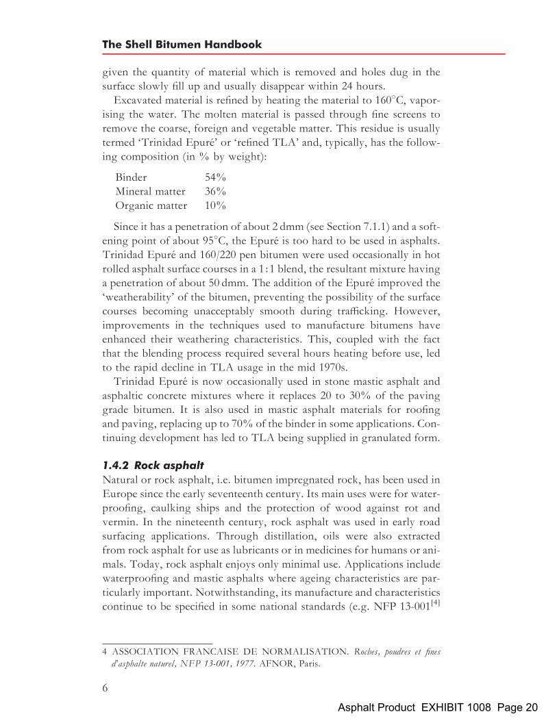
given the quantity of material which is removed and holes dug in thesurface slowly fill up and usually disappear within 24 hours.Excavated material is refined by heating the material to 1608C, vapor-
ising the water. The molten material is passed through fine screens toremove the coarse, foreign and vegetable matter. This residue is usuallytermed ‘Trinidad Epure’ or ‘refined TLA’ and, typically, has the follow-ing composition (in % by weight):
Binder 54%Mineral matter 36%Organic matter 10%
Since it has a penetration of about 2 dmm (see Section 7.1.1) and a soft-ening point of about 958C, the Epure is too hard to be used in asphalts.Trinidad Epure and 160/220 pen bitumen were used occasionally in hotrolled asphalt surface courses in a 1:1 blend, the resultant mixture havinga penetration of about 50 dmm. The addition of the Epure improved the‘weatherability’ of the bitumen, preventing the possibility of the surfacecourses becoming unacceptably smooth during trafficking. However,improvements in the techniques used to manufacture bitumens haveenhanced their weathering characteristics. This, coupled with the factthat the blending process required several hours heating before use, ledto the rapid decline in TLA usage in the mid 1970s.Trinidad Epure is now occasionally used in stone mastic asphalt and
asphaltic concrete mixtures where it replaces 20 to 30% of the pavinggrade bitumen. It is also used in mastic asphalt materials for roofingand paving, replacing up to 70% of the binder in some applications. Con-tinuing development has led to TLA being supplied in granulated form.
1.4.2 Rock asphaltNatural or rock asphalt, i.e. bitumen impregnated rock, has been used inEurope since the early seventeenth century. Its main uses were for water-proofing, caulking ships and the protection of wood against rot andvermin. In the nineteenth century, rock asphalt was used in early roadsurfacing applications. Through distillation, oils were also extractedfrom rock asphalt for use as lubricants or in medicines for humans or ani-mals. Today, rock asphalt enjoys only minimal use. Applications includewaterproofing and mastic asphalts where ageing characteristics are par-ticularly important. Notwithstanding, its manufacture and characteristicscontinue to be specified in some national standards (e.g. NFP 13-001[4]
4 ASSOCIATION FRANCAISE DE NORMALISATION. Roches, poudres et finesd’asphalte naturel, NFP 13-001, 1977. AFNOR, Paris.
The Shell Bitumen Handbook
6
Asphalt Product EXHIBIT 1008 Page 20
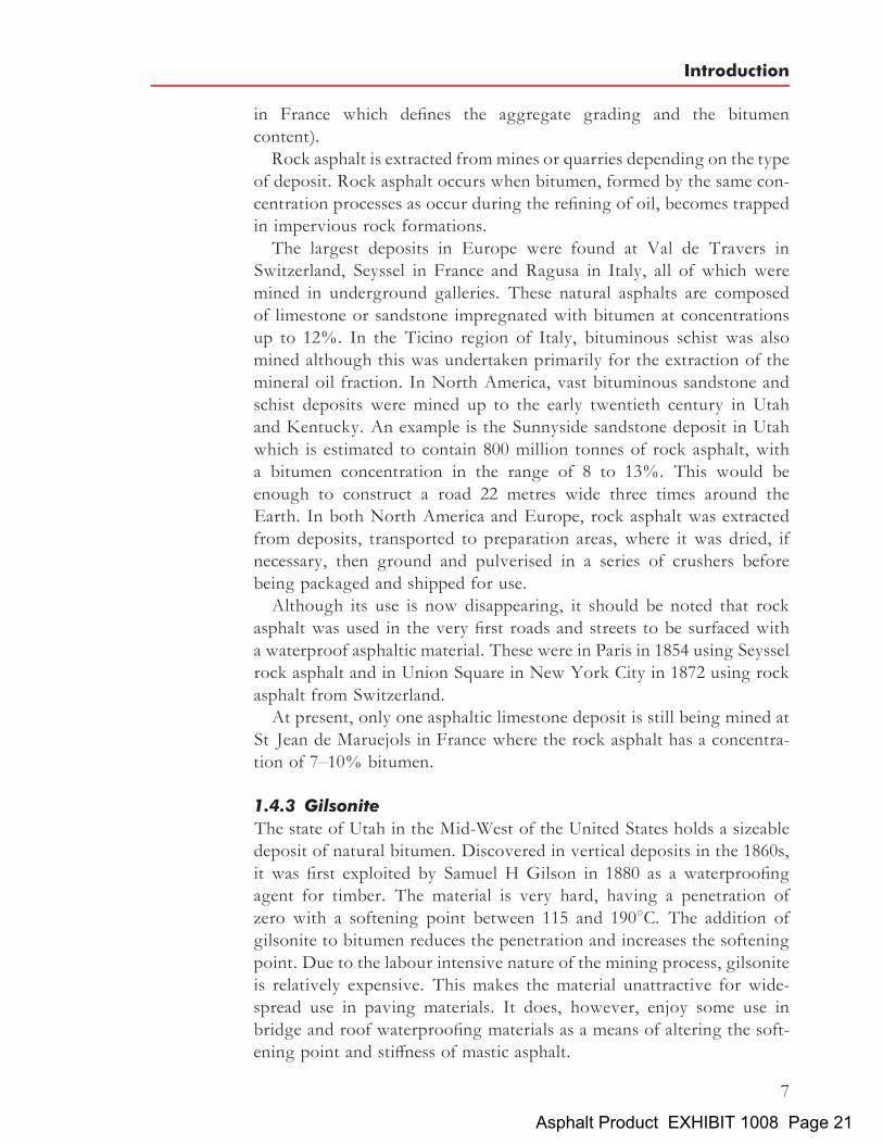
in France which defines the aggregate grading and the bitumencontent).Rock asphalt is extracted frommines or quarries depending on the type
of deposit. Rock asphalt occurs when bitumen, formed by the same con-centration processes as occur during the refining of oil, becomes trappedin impervious rock formations.The largest deposits in Europe were found at Val de Travers in
Switzerland, Seyssel in France and Ragusa in Italy, all of which weremined in underground galleries. These natural asphalts are composedof limestone or sandstone impregnated with bitumen at concentrationsup to 12%. In the Ticino region of Italy, bituminous schist was alsomined although this was undertaken primarily for the extraction of themineral oil fraction. In North America, vast bituminous sandstone andschist deposits were mined up to the early twentieth century in Utahand Kentucky. An example is the Sunnyside sandstone deposit in Utahwhich is estimated to contain 800 million tonnes of rock asphalt, witha bitumen concentration in the range of 8 to 13%. This would beenough to construct a road 22 metres wide three times around theEarth. In both North America and Europe, rock asphalt was extractedfrom deposits, transported to preparation areas, where it was dried, ifnecessary, then ground and pulverised in a series of crushers beforebeing packaged and shipped for use.Although its use is now disappearing, it should be noted that rock
asphalt was used in the very first roads and streets to be surfaced witha waterproof asphaltic material. These were in Paris in 1854 using Seysselrock asphalt and in Union Square in New York City in 1872 using rockasphalt from Switzerland.At present, only one asphaltic limestone deposit is still being mined at
St Jean de Maruejols in France where the rock asphalt has a concentra-tion of 7–10% bitumen.
1.4.3 GilsoniteThe state of Utah in the Mid-West of the United States holds a sizeabledeposit of natural bitumen. Discovered in vertical deposits in the 1860s,it was first exploited by Samuel H Gilson in 1880 as a waterproofingagent for timber. The material is very hard, having a penetration ofzero with a softening point between 115 and 1908C. The addition ofgilsonite to bitumen reduces the penetration and increases the softeningpoint. Due to the labour intensive nature of the mining process, gilsoniteis relatively expensive. This makes the material unattractive for wide-spread use in paving materials. It does, however, enjoy some use inbridge and roof waterproofing materials as a means of altering the soft-ening point and stiffness of mastic asphalt.
Introduction
7
Asphalt Product EXHIBIT 1008 Page 21

1.4.4 Tar‘Tar’ is a generic word for the liquid obtained when natural organicmaterials such as coal or wood are carbonised or destructively distilledin the absence of air½5�. It is customary to prefix the word tar with thename of the material from which it is derived. Thus, the products ofthis initial carbonisation process are referred to as crude coal tar, crudewood tar, etc. Two types of crude coal tar are produced as a by-productof the carbonisation of coal–coke oven tar and low temperature tar.Since the 1970s, dramatic changes have occurred in the supply of crude
coal tar in the UK. In the mid 1960s, over 2 million tonnes of crude coaltar were produced per annum of which around half was manufactured asa by-product of the operation of carbonisation ovens which were used toproduce town gas. However, the introduction of North Sea Gas in thelate 1960s resulted in a rapid reduction of tar production from thissource and by 1975 it had disappeared completely.
1.4.5 Refined bitumenBitumen is manufactured from crude oil. It is generally agreed that crudeoil originates from the remains of marine organisms and vegetable matterdeposited with mud and fragments of rock on the ocean bed. Overmillions of years, organic material and mud accumulated into layerssome hundreds of metres thick, the substantial weight of the upper layerscompressing the lower layers into sedimentary rock. Conversion of theorganisms and vegetable matter into the hydrocarbons of crude oil isthought to be the result of the application of heat from within the Earth’scrust and pressure applied by the upper layers of sediments, possiblyaided by the effects of bacterial action and radioactive bombardment.As further layers were deposited on the sedimentary rock where the oilhad formed, the additional pressure squeezed the oil sideways andupwards through porous rock. Where the porous rock extended to theEarth’s surface, oil seeped through to the surface. Fortunately, the major-ity of the oil and gas was trapped in porous rock which was overlaid byimpermeable rock, thus forming gas and oil reservoirs. The oil remainedhere until its presence was detected by seismic surveys and recovered bydrilling through the impermeable rock.The four main oil producing areas in the world are the United States,
the Middle East, Russia and the countries around the Caribbean. Crudeoils differ in their physical and chemical properties. Physically, theyvary from viscous black liquids to free-flowing straw coloured liquids.
5 ABRAHAM H.Asphalts and allied substances, their occurrence, modes of production, uses inthe arts and methods of testing, 5th ed, vol 1, 1945. Van Nostrand, New York.
The Shell Bitumen Handbook
8
Asphalt Product EXHIBIT 1008 Page 22

Chemically, they may be predominantly paraffinic, naphthenic or aro-matic with combinations of the first two being most common. Thereare nearly 1500 different crudes produced throughout the world. Basedon the yield and the quality of the resultant product, only a few ofthese are considered suitable for the manufacture of bitumen.
Introduction
9
Asphalt Product EXHIBIT 1008 Page 23

Chapter 2
Manufacture, storage,handling and environmentalaspects of bitumens
2.1 The manufacture of bitumenCrude oil is a complex mixture of hydrocarbons differing in molecularweight and, consequently, in boiling range. Before it can be used, crudeoil has to be separated, purified, blended and, sometimes, chemically orphysically changed.
2.1.1 Fractional distillation of crude oilThe first process in the refining of crude oil is fractional distillation. Thisis carried out in tall steel towers known as fractionating or distillationcolumns. The inside of the column is divided at intervals by horizontalsteel trays punctured with holes to allow vapour to rise up the column.Over these holes are small domes called bubble caps which deflect thevapour downwards so that it bubbles through liquid condensed on thetray. This improves the efficiency of distillation and also has the advan-tage of reducing the height of the column.On entering the distillation plant, the crude oil is heated in a furnace to
temperatures between 350 and 3808C before being passed into the lowerpart of the column operating at a pressure slightly above atmospheric.The material entering the column is a mixture of liquid and vapour;the liquid comprises the higher boiling point fractions of the crude oiland the vapour consists of the lower boiling point fractions. The vapoursrise up the column through the holes in the trays losing heat as they rise.When each fraction reaches the tray where the temperature is just belowits own boiling point, it condenses and changes back into a liquid. As thefractions condense on the trays, they are continuously drawn off viapipes.The lightest fractions of the crude oil remain as vapour and are taken
from the top of the distillation column; heavier fractions are taken offthe column as side-streams; the heaviest fractions remain as liquidswhich, therefore, leave at the base of the column. The lightest fractions
11Asphalt Product EXHIBIT 1008 Page 24
produced by the crude distillation process include propane and butane,both of which are gases under atmospheric conditions. Moving downthe column, naphtha – a slightly heavier material – is produced. Naphthais used as a feedstock for gasoline production and the chemical industry.Further down the column, kerosene is produced. Kerosene is usedprimarily for aviation fuel and, to a lesser extent, domestic fuel. Heavieragain is gas oil which is used as a fuel for diesel engines and central heat-ing. The heaviest fraction taken from the crude oil distillation process isknown as the long residue, a complex mixture of high molecular weighthydrocarbons, which requires further processing before it can be used asa feedstock for the manufacture of bitumen.The long residue is further distilled at reduced pressure in a vacuumdis-
tillation column. This is carried out under a vacuum of 10 to 100mmHg ata temperature between 350 and 4258C to produce gas oil, distillates andshort residue. If this second distillation was carried out by simply increas-ing the temperature, cracking or thermal decomposition of the longresidue would occur, hence the need to vary the pressure.The short residue is the feedstock used in the manufacture of over 20
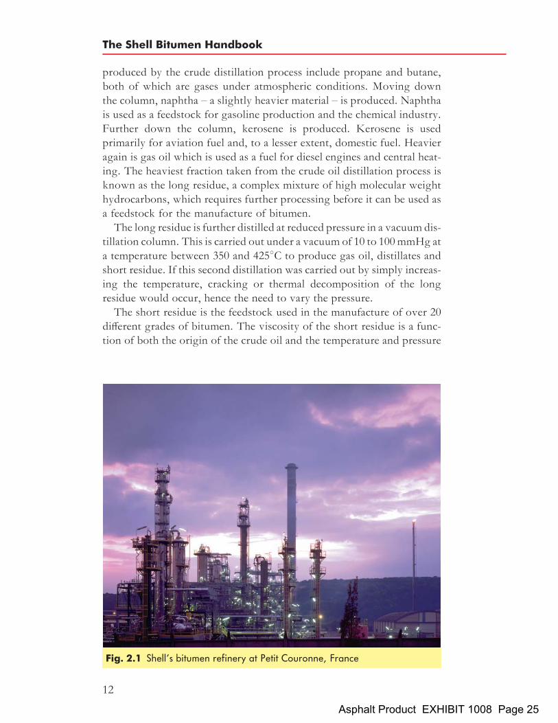
different grades of bitumen. The viscosity of the short residue is a func-tion of both the origin of the crude oil and the temperature and pressure
Fig. 2.1 Shell’s bitumen refinery at Petit Couronne, France
The Shell Bitumen Handbook
12
Asphalt Product EXHIBIT 1008 Page 25

in the vacuum column during processing. Depending on the origin of thecrude oil, the conditions in the column are adjusted to produce a shortresidue with a penetration in the range 35 to 300 dmm. A modernbitumen refinery is shown in Fig. 2.1.Figure 2.2 shows a schematic representation of the distillation process
and its relationship with other fundamental refining processes such asreforming and cracking for the manufacture of motor gasoline, and luboil plants for the manufacture of lubricating oils, waxes, etc.
2.1.2 Air blowing of short residuesThe physical properties of the short residue may be modified further by‘air blowing’. This is an oxidation process that involves passing airthrough the short residue, either on a batch or a continuous basis, withthe short residue at a temperature between 240 and 3208C. The maineffect of blowing is that it converts some of the relatively low molecularweight ‘maltenes’ into relatively higher molecular weight ‘asphaltenes’(these bitumen components are described in detail in Chapter 3). The
Fig. 2.2 Schematic representation of the crude oil distillation process
Manufacture, storage, handling and environmental aspects of bitumens
13
Asphalt Product EXHIBIT 1008 Page 26

result is a reduction in penetration, a comparatively greater increase insoftening point and a lower temperature susceptibility.
The continuous blowing processAfter preheating, the short residue is introduced into the blowingcolumn just below the normal liquid level. Air is blown through thebitumen by means of an air distributor located at the bottom of thecolumn. The air acts not only as a reactant but also serves to agitateand mix the bitumen thereby increasing both surface area and rate ofreaction. The bitumen absorbs oxygen as air ascends through thematerial. Steam and water are sprayed into the vapour space above thebitumen level, the former to suppress foaming and dilute the oxygen con-tent of waste gases and the latter to cool the vapours in order to preventafter-burning and the resulting formation of coke.The blown product passes through heat exchangers to achieve the
desired ‘rundown’ temperatures and to provide an economical meansof preheating the short residue, before pumping the product to storage.The penetration and softening point of the blown bitumen are affected bythe following factors:
. viscosity of the feedstock
. temperature in the blowing column
. residence time in the blowing column
. origin of the crude oil used to manufacture the feedstock
. air-to-feed ratio.
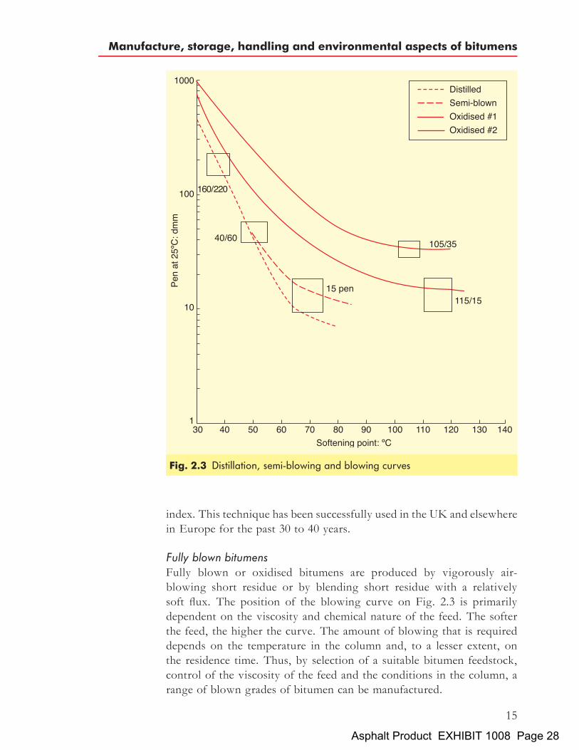
Figure 2.3 shows distillation and blowing ‘curves’ for a bitumen feed-stock. In both the distillation and blowing processes, the softening pointincreases and the penetration falls. However, in the distillation process,the temperature susceptibility (or penetration index) of the material islargely unchanged. Thus, the distillation line on Fig. 2.3 is a relativelystraight line whereas the curves for the blown bitumen flatten substan-tially as the softening point of the bitumen increases. This demonstratesthat the temperature susceptibility of the material is substantiallyreduced, i.e. the penetration index is increased (the penetration index isdescribed in detail in Section 7.5).
Air-rectified or semi-blown bitumensSome crude oils produce bitumens that require a limited amount of airblowing in order to generate penetration grade bitumens that are suitablefor road construction. This process is termed semi-blowing or air-rectification. Used judiciously, semi-blowing can be applied to reducethe temperature susceptibility of the bitumen, i.e. increase its penetration
The Shell Bitumen Handbook
14
Asphalt Product EXHIBIT 1008 Page 27
index. This technique has been successfully used in the UK and elsewherein Europe for the past 30 to 40 years.
Fully blown bitumensFully blown or oxidised bitumens are produced by vigorously air-blowing short residue or by blending short residue with a relativelysoft flux. The position of the blowing curve on Fig. 2.3 is primarilydependent on the viscosity and chemical nature of the feed. The softerthe feed, the higher the curve. The amount of blowing that is requireddepends on the temperature in the column and, to a lesser extent, onthe residence time. Thus, by selection of a suitable bitumen feedstock,control of the viscosity of the feed and the conditions in the column, arange of blown grades of bitumen can be manufactured.
Fig. 2.3 Distillation, semi-blowing and blowing curves
Manufacture, storage, handling and environmental aspects of bitumens
15
Asphalt Product EXHIBIT 1008 Page 28

The chemistry of the blowing processThe blowing of bitumen can be described as a conversion process in whichoxidation, dehydrogenation and polymerisation take place. The result is anincrease in the overall molecular size of the asphaltenes which are alreadypresent in the feed and the formation of additional asphaltenes from themaltene phase. The reaction is exothermic which means that the processrequires close control of temperatures. This is achieved by regulatingthe air to short residue ratio in the blowing column.
2.2 Delivery, storage and handling temperatures of bitumensWhen handled properly, bitumens can be reheated or maintained atelevated temperatures for a considerable time without adversely affectingtheir properties. However, mistreatment of bitumens by overheating orby permitting the material to be exposed to conditions that promoteoxidation can adversely affect the properties of the bitumen and mayinfluence the long-term performance of mixtures that contain bitumen.The degree of hardening (or, under certain circumstances, softening)that is produced as a result of mishandling is a function of a number ofparameters such as temperature, the presence of air, the surface tovolume ratio of the bitumen, the method of heating and the durationof exposure to these conditions.
2.2.1 Safe delivery of bitumenOver 50% of bitumen-related accidents and incidents that result in lostworking days occur during the delivery of bitumen. In the UK, theRefined Bitumen Association (RBA) has produced a detailed Code ofPractice[6] designed to assist in reducing the frequency of incidents andaccidents by raising awareness of their causes. Personnel involved inthe delivery and receipt of bitumen are strongly advised to read thisdocument.
2.2.2 Bitumen tanksAll bitumens should be stored in tanks specifically designed for the pur-pose[7]. In order to minimise the possible hardening of the bitumenduring storage, certain aspects of the design of the tank should beconsidered.
. In order to minimise the risk of overheating the bitumen, the tankshould be fitted with accurate temperature sensors and gauges.
6 REFINED BITUMEN ASSOCIATION. Code of practice for the safe delivery of petro-leum bitumens, 2001. RBA, London.
7 INSTITUTE OF PETROLEUM. Model code of safe practice in the petroleum industry,Bitumen Safety Code, part 11, 3rd ed, 1991. IP, London.
The Shell Bitumen Handbook
16
Asphalt Product EXHIBIT 1008 Page 29

These should be positioned in the region of the heaters and prefer-ably be removable to facilitate regular cleaning and maintenance.
. Oxidation and the loss of volatile fractions from bitumen are bothrelated to the exposed surface to volume ratio of the storage tankwhich, for a cylindrical vessel, equals the reciprocal height of thefilled part of the tank and is given by:
surface area
volume¼ �r2
�r2h¼ 1
h
where h ¼ height of bitumen and r ¼ radius of the tank.
Thus, the dimensions of the bulk storage tank should be such that thesurface to volume ratio is minimised. Accordingly, vertical storagetanks with a high height to radius ratio are preferable to horizontal tanks.It is common practice for bitumen in bulk storage tanks at mixing
plants to be recirculated around a ring main in order to heat the pipeworkthat carries the bitumen to the processing point. Return lines in arecirculation system should re-enter the storage tank below the bitumensurface to prevent hot bitumen cascading through the air. Often, thebitumen is returned to the bulk storage tank through a pipe fittedinto the upper part of the tank, flush with the side, roof or protrudingjust into the air space at the top of the tank. If the bitumen entersthe tank above the bitumen all the factors that promote oxidation arepresent:
. high temperature
. access to oxygen
. high exposed surface to volume ratio.
Fortunately, the residence time of bitumen in the tank is usually suffi-ciently low for any hardening to be insignificant. However, if materialis stored for a prolonged period, recirculation should be used only inter-mittently and the bitumen should be tested before use to ensure its con-tinued suitability for the proposed application. A recommended layoutfor a bitumen storage tank is shown in Fig. 2.4.Bitumen storage tanks should be fitted with automatic level indicators
together with low- and high-level alarms to avoid having to dip manu-ally. Such an approach avoids exposing the hot heater tubes to a poten-tially combustible or explosive atmosphere should the bitumen level fallbelow that of the heater tubes. Automatic level control also ensures thatthe tank is not overfilled. Regardless of whether a high-level alarm isfitted, a maximum safe filled level for the tank should be predeterminedtaking into account the effects of thermal expansion of the bitumen in thetank.
Manufacture, storage, handling and environmental aspects of bitumens
17
Asphalt Product EXHIBIT 1008 Page 30

Before ordering additional bitumen, it is obviously essential to checkthat the ullage in the tank is capable of taking the delivery withoutexceeding the maximum safe working level.Every tank should be clearly labelled with the grade of bitumen it
contains. When the grade of bitumen in a tank is changed, it is importantto ensure that the tank is empty and relabelled before the new grade isdelivered.
Fig. 2.4 Recommended format for a bitumen storage tank
The Shell Bitumen Handbook
18
Asphalt Product EXHIBIT 1008 Page 31

2.2.3 Bitumen storage and pumping temperaturesConventional bitumenBitumen should always be stored and handled at the lowest temperaturepossible, consistent with efficient use. As a guide, working temperaturesfor specific operations are given in the RBA’s Technical Bulletin No 7[8].These temperatures have been calculated on the basis of viscosity measure-ments and are supported by operational experience. For normal operations,i.e. the blending and transferring of liquid bitumen, temperatures of 10 to508C above the minimum pumping temperature are recommended, but themaximum safe handling temperature of 2308C must never be exceeded.The period during which bitumen resides in a storage tank at elevated
temperatures and is recirculated should be minimised to prevent harden-ing of the bitumen. If bitumen must be stored for an extended period, sayfor a period exceeding one week without the addition of fresh material,the temperature should be reduced to approximately 20 to 258C above thesoftening point of the bitumen and, if possible, recirculation stopped.When bitumen is being reheated in bulk storage, care must be taken to
heat the bitumen intermittently over an extended period to prevent local-ised overheating of the product around the heating pipes or coils. This isparticularly important where direct flame tube heating is used becausesurface temperatures in excess of 3008C may be reached. In such installa-tions, the amount of heat that is applied should be limited, sufficient onlyto raise the temperature of the product to just above its softening point.This will allow the material to soften after which further heat can beapplied to raise the temperature of the product to the required workingvalue. This technique is beneficial because when the bitumen is a fluid,albeit a viscous fluid, convection currents dissipate the heat throughoutthe material and localised overheating is thus less of a problem.Circulation of the tank contents should begin as soon as the product issufficiently fluid, thereby further reducing the likelihood of local over-heating. With hot oil, steam or electric heaters that are designed properly,reheating from cold should not cause these problems.
Polymer modified and special bitumensA wide variety of polymer modified and process modified bitumens areavailable (see Chapter 5). Different polymers and different polymer/bitumen combinations require different storage regimes and pumpingtemperatures. Not all polymer modified bitumens are stable in storageand the management of these binders can be radically different to themanagement of bitumens that are stable in storage.
8 REFINED BITUMEN ASSOCIATION. Safe handling of petroleum bitumens, TechnicalBulletin No 7, 1998. RBA, London.
Manufacture, storage, handling and environmental aspects of bitumens
19
Asphalt Product EXHIBIT 1008 Page 32

All polymer modified and special bitumens that are currently suppliedby Shell Bitumen can be stored in conventional bitumen tanks. Usersshould always check with their supplier whether this is true of thematerials they are purchasing. Essential information on storage shouldalways be ascertained from the relevant product information sheet andsuch advice must be applied rigidly. Where required, additional informa-tion will almost certainly be available from suppliers.
2.3 Health, safety and environmental aspects of bitumensBitumen has a long history of being used safely in a wide range of appli-cations. Although it is primarily used in road construction, it can also beemployed in roofing felts, reservoir linings and also as an internal liningfor potable water pipes. Bitumen presents a low order of potential hazardprovided that good handling practices are observed. (These are describedin detail in part of the Model Code of Safe Practice[9] which is publishedby the Institute of Petroleum and are also described in the material safetydata sheets. A substantial amount of health, safety and environmentaldata on bitumen and its derivatives are detailed in the CONCAWEproduct dossier number 92/104[10].) Notwithstanding, bitumens aregenerally applied at elevated temperatures and this brings with it anumber of hazards that are considered below.
2.3.1 Health aspects of bitumenPotential hazards associated with the handling and application of hotbitumen
. Elevated temperatures. The main hazard associated with bitumen isthat the product is held at elevated temperatures during transporta-tion, storage and processing. Thus, it is critical that appropriate per-sonal protective equipment (PPE) is worn and any skin contact withhot bitumen is avoided. Some guidance is given below but detailedadvice is available in a number of publications[9–11] and the relevantmaterial safety data sheet for bitumen[12,13].
9 INSTITUTE OF PETROLEUM. Model code of safe practice in the petroleum industry,Bitumen Safety Code, part 11, 3rd ed, 1991. IP, London.
10 CONCAWE. Bitumens and bitumen derivatives, Product Dossier No 92/104, Dec 1992.CONCAWE, The Hague.
11 REFINED BITUMEN ASSOCIATION. Code of practice for the safe delivery ofpetroleum bitumens, 2001. RBA, London.
12 EUROBITUME. Material safety data sheet template for paving grade bitumen, Jul 2001.Eurobitume, Brussels.
13 SHELL BITUMEN.Material safety data sheet for Shell paving grade bitumen, Dec 2001.Shell International Petroleum Company Ltd.
The Shell Bitumen Handbook
20
Asphalt Product EXHIBIT 1008 Page 33

. Vapour emissions. Bitumens are complex mixtures of hydrocarbonsthat do not have well defined boiling points because their compo-nents boil over a wide temperature range. Visible emissions orfumes normally start to develop at approximately 1508C. Theamount of fume generated doubles for each 10 to 128C increase intemperature. Fumes are mainly composed of hydrocarbons[14] andsmall quantities of hydrogen sulphide (H2S). The latter is of particu-lar concern as it can accumulate in enclosed spaces such as the tops ofstorage tanks. Exposure to this gas at concentrations as little as500 ppm can be fatal so it is essential that any space where H2Smay be present is tested and approved as being gas-free beforeanyone enters the area. Bitumen fumes also contain small quantitiesof polycyclic aromatic compounds (PACs); these are discussed below.
. Combustion. Very high temperatures are required to make bitumenburn. Certain materials, if hot enough, will ignite when exposed toair, and are sometimes described as being ‘pyrophoric’. In the caseof bitumens, this auto-ignition temperature is generally around4008C. However, fires in bitumen tanks have occurred only occa-sionally. Under conditions of low oxygen content, H2S frombitumen can react with rust (iron oxide) on the roof and walls ofstorage tanks to form ‘pyrophoric iron oxide’. This materialreacts readily with oxygen and can self-ignite if the oxygen contentof the tank increases suddenly which, in turn, can ignite cokedeposits on the roof and walls of the tank. Coke deposits are theresult of condensate from the bitumen which has been depositedon the roof and walls of a tank degrading over a period of timeforming carbonaceous material. Under conditions of high tempera-ture and in the presence of oxygen or a sudden increase in availableoxygen, an exothermic reaction can occur leading to the risk of fireor explosion. Accordingly, manholes in bitumen tanks should bekept closed and access to tank roofs should be restricted.
. Contact with water. It is essential that water does not come into con-tact with hot bitumen. If this does happen, the water is converted intosteam. In the process, its volume increases by a factor of approxi-mately 1400, resulting in spitting, foaming and, depending on theamount of water present, possible boil-over of the hot bitumen.
Composition of bitumenBitumens are complex hydrocarbon materials containing componentsof many chemical forms, the majority of which have relatively high
14 BRANT H C A and P C DE GROOT. Emission and composition of fumes from currentbitumen types, Eurasphalt/Eurobitume Congress, 1996.
Manufacture, storage, handling and environmental aspects of bitumens
21
Asphalt Product EXHIBIT 1008 Page 34

molecular weight. Crude oils normally contain small quantities ofpolycyclic aromatic compounds (PACs), some of which end up in thebitumen. These chemicals consist of a number of benzene rings thatare grouped together. Some of these with three to seven (usually fourto six) fused rings are known to cause or suspected of causing cancerin humans. However, the concentrations of these carcinogens in bitumenare extremely low[15].
Potential hazards through skin contactOther than thermal burns, the hazards associated with skin contact ofmost bitumens are negligible. Studies by the International Agency forResearch on Cancer (IARC)[16], part of the World Health Organization,concluded that there was no direct evidence to associate bitumen withlong-term skin disorders in humans despite bitumens having beenwidely used for many years. Nevertheless, it is prudent to avoid intimateand prolonged skin contact with bitumen.Cutback bitumens and bitumen emulsions are handled at lower tem-
peratures, which increases the chance of skin contact. If personal hygieneis poor, regular skin contact may occur. However, studies carried outby Shell[17,18] have demonstrated that bitumens are unlikely to be bio-available (skin penetration and body uptake) and bitumens diluted withsolvents are unlikely to present a carcinogenic risk. Nevertheless,bitumen emulsions can cause irritation to the skin and eyes and canproduce allergic responses in some individuals.
First aid for skin burnsThe following text is taken from the Eurobitume notes for guidance offirst aid and medical personnel. (Eurobitume is the European BitumenAssociation and comprises a number of bitumen companies and bitumenassociations in Europe.) This advice is produced in the form of A5 sizedcard, copies of which are available from Eurobitume, the RBA andbitumen suppliers. It is intended that the card should accompany a
15 CONCAWE. Bitumens and bitumen derivatives, Product dossier no 92/104, Dec 1992.CONCAWE, The Hague.
16 BOFFETTA P T. Cancer risk in asphalt workers and roofers: Review and meta-analysis ofepidemiologic studies, Am J Ind Med, vol 26, pp 721–740, 2001.
17 BRANDT H C A, E D BOOTH, P C DE GROOT and W P WATSON. Develop-ment of a carcinogenic potency index for dermal exposure to viscous oil products, Arch Toxicol,vol 73, pp 180–188, 1999.
18 POTTER D, E D BOOTH, H C A BRANDT, R W LOOSE, R A J PRISTON,A S WRIGHT and W P WATSON. Studies on the dermal and systemic bioavailabilityof polycyclic aromatic compounds in high viscosity oil products, Arch Toxicol, vol 73,pp 129–140, 1999.
The Shell Bitumen Handbook
22
Asphalt Product EXHIBIT 1008 Page 35

burns victim to the hospital to provide immediate advice on propertreatment.
First aidWhen an accident has occurred, the affected area should be cooledas quickly as possible to prevent the heat causing further damage.The burn should be drenched in cold water for at least ten minutesfor skin and at least five minutes for eyes. However, body hypo-thermia must be avoided. No attempt should be made to removethe bitumen from the area of the burn.
Further treatment, first aid and medical careThe bitumen layer will be firmly attached to the skin and removalshould not be attempted unless carried out at a medical facilityunder the supervision of a doctor. The cold bitumen will form awaterproof, sterile layer over the burn which will prevent theburn from drying out. If the bitumen is removed from thewound, there is the possibility that the skin will be damagedfurther, bringing with it the possibility of further complications.In addition, by exposing a second degree burn in order to treatit, there is the possibility that infection or drying out will makethe wound deeper.
Second degree burnsThe bitumen should be left in place and covered with a Tulledressing containing paraffin or a burn ointment containing paraffin,e.g. Flammazine (silver sulphadiazine). Such treatment will havethe effect of softening the bitumen enabling it to be gently removedover a period of days. As a result of the skin reforming naturally (re-epithelialisation), any remaining bitumen will peel off in time.
Third degree burnsActive removal of the bitumen should be avoided unless primarysurgical treatment is being considered due to the location anddepth of the wound. In such cases, removal of the bitumen isbest carried out in the operating theatre between the second andfifth day after the burn occurred. By the second day, the capillarycirculation has usually recovered and the bed of the wound issuch that a specialist can assess the depth to which the burn haspenetrated. There are normally no secondary problems such asinfections to contend with before the sixth day. However, it isessential that treatment is started using paraffin-based substancesfrom the day of the accident to facilitate removal during surgery.
Manufacture, storage, handling and environmental aspects of bitumens
23
Asphalt Product EXHIBIT 1008 Page 36

Circumferential burnsWhere hot bitumen completely encircles a limb or other body part,the cooled and hardened bitumen may cause a tourniquet effect. Inthe event of this occurring, the adhering bitumen must be softenedand/or split to prevent restriction of blood flow.
Eye burnsNo attempt should be made to remove the bitumen by unqualifiedpersonnel. The patient should be referred urgently for specialistmedical assessment and treatment.
Potential hazards via inhalationGenerally, when bitumens are heated in bulk or mixed with hot aggre-gate, fumes are emitted. The fumes contain particulate bitumen, hydro-carbon vapour and very small amounts of hydrogen sulphide.The UK occupational exposure standards[19] for bitumen fumes in the
working atmosphere are:
long-term exposure limit (8 h time weighted average)¼ 5mg/m3
short-term exposure limit (10min time weighted average)¼10mg/m3.
Under normal operating conditions, exposure is well below these limits.The UK occupational exposure[19] standards for hydrogen sulphide in
the working atmosphere are:
long-term exposure limit (8 h time weighted average)¼ 10 ppm(14mg/m3)
short-term exposure limit (10min time weighted average)¼ 15 ppm(21mg/m3).
Exposure to bitumen fumes can result in irritation to the eyes, nose andrespiratory tract, headaches and nausea. The symptoms are usually mildand temporary. Removal of the affected personnel from the source resultsin rapid recovery. Even though the irritation is usually mild, exposure tobitumen fumes should be minimised and, where there is any doubt, tests,e.g. Drægar tube analysis or personal exposure monitoring, should beundertaken to determine the concentration of bitumen fume or hydrogensulphide in the working atmosphere.
19 HEALTH and SAFETY EXECUTIVE. Occupational exposure limits 2002, GuidanceNote EH 40, 2001. HSE Books, London.
The Shell Bitumen Handbook
24
Asphalt Product EXHIBIT 1008 Page 37
First aid for inhalation of bitumen fumesPersons affected by inhalation of bitumen fumes should be removed tofresh air as soon as possible. If the symptoms are severe or if symptomspersist, medical help should be sought without delay.
Studies into health of workers in the asphalt industryThere have been many studies of the health of workers in the asphalt androad construction industry. Despite the known presence of PACs inbitumen and bitumen fume, experience in the asphalt industry hasshown that bitumen and bitumen fume do not present a health risk tostaff when good working practices are adopted. To provide further sup-port for this view, the asphalt industry is collaborating with independentepidemiological research currently being carried out by the InternationalAgency for Research on Cancer (IARC).
2.3.2 Safe use of bitumen — recommended precautions forpersonnel
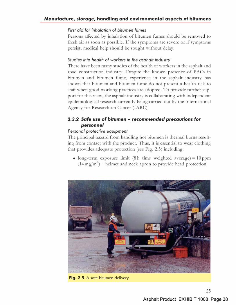
Personal protective equipmentThe principal hazard from handling hot bitumen is thermal burns result-ing from contact with the product. Thus, it is essential to wear clothingthat provides adequate protection (see Fig. 2.5) including:
. long-term exposure limit (8 h time weighted average)¼ 10 ppm(14mg/m3) – helmet and neck apron to provide head protection
Fig. 2.5 A safe bitumen delivery
Manufacture, storage, handling and environmental aspects of bitumens
25
Asphalt Product EXHIBIT 1008 Page 38

. short-term exposure limit (10min time weighted average)¼ 15 ppm(21mg/m3) – visor to protect the face (goggles only protect eyes)
. heat-resistant gloves (with cuffs worn inside coverall sleeves)
. safety boots
. coveralls (with coverall legs worn over boots).
Personal hygieneGarments soiled with bitumen should either be replaced or dry cleaned inorder to avoid permeation of the product to underclothing. Soiled ragsor tools should not be placed in the pockets of overalls as contaminationof the lining of the pocket will result.Personnel handling bitumen and asphalts should be provided with and
use barrier creams to protect exposed skin, particularly hands and fingers.Skin should be thoroughly washed after any contamination and alwaysbefore going to the toilet, eating or drinking.The application of barrier creams, prior to handling bitumen, assists in
subsequent cleaning should accidental contact occur. However, barriercreams are no substitute for gloves or other impermeable clothing.Consequently, they should not be used as the sole form of protection.Solvents such as petrol, diesel oil, white spirit etc., should not be usedfor removing bitumen from the skin and may spread the contamination.An approved skin cleanser together with warm water should be used.
Fire prevention and fire fightingThe adoption of safe handling procedures will substantially reduce therisk of fire. However, if a fire occurs, it is essential that personnel areproperly trained and well equipped to extinguish the fire thereby ensur-ing that the risk of injury to personnel and damage to plant is minimised.Detailed advice on fire prevention and fire fighting is given in a code ofpractice published by the Institute of Petroleum[20] and in individualmaterial safety data sheets.Small bitumen fires can be extinguished using dry chemical powder,
foam, vaporising liquid or inert gas extinguishers, fog nozzle sprayhoses and steam lances. Direct water jets must not be used because froth-ing may occur which tends to spread the hot bitumen and, therefore, thefire.Injection of steam or a ‘fog’ of water into the vapour space can
extinguish internal tank fires where the roof of the tank is largelyintact. However, only trained operatives should use this method as thewater vaporises instantly on contact with the hot bitumen. This initiates
20 INSTITUTE OF PETROLEUM. Model code of safe practice in the petroleum industry,Bitumen safety code, part 11, 3rd ed, 1991. IP, London.
The Shell Bitumen Handbook
26
Asphalt Product EXHIBIT 1008 Page 39

foaming which may result in the tank overflowing, creating an additionalhazard. Alternatively, foam extinguishers may be used. The foam ensuresthat the water is well dispersed, thereby reducing the risk of froth-over.The disadvantage of using this type of extinguisher is that the foambreaks down rapidly when applied to hot bitumen.Portable extinguishers containing either aqueous film-forming foam or
dry chemical powder are suitable for dealing with small bitumen fires, atleast initially. In bitumen handling areas, these should be placed atstrategic, permanent and conspicuous locations. The type and locationof equipment to be used if initial attempts fail should be discussedwith the local fire brigade before installation.
SamplingSampling of hot bitumen is particularly hazardous because of the risk ofheat burns from spills and splashes of the material. It is therefore essentialthat appropriate protective clothing is worn. The area should be well litand safe access to and egress from the sample point should be provided.Gantry access should be provided where samples are required from thetanks of vehicles.
Dip samplingIn this process a sample of bitumen is obtained by dipping a weighted canor ‘thief’ on the end of a rope or rod through the access lid into bitumenstored in a bulk tank. The sample is then transferred to a suitable perma-nent container. The method is simple but is only appropriate for smallsamples. Dip sampling from cutback tanks should be avoided becauseof the presence of flammable atmospheres in tank vapour spaces.
Sample valvesProperly designed sample valves are very useful for sampling from pipe-lines or from tanks. Their design should ensure that they are kept hot bythe product in the pipeline or tank in order to avoid blockage when in theclosed position.Sample valves should preferably be the screw-driven plunger type.
When closed, the plunger of this type of valve extends into the fresh pro-duct. Thus when the valve is opened, a representative sample of productis obtained without ‘fore-runnings’. With ball and plug type valves, fore-runnings have to be collected and disposed of before a representativesample can be obtained. Designs for bitumen sample valves are describedin detail by the British Standards Institution[21].
21 BRITISH STANDARDS INSTITUTION. Methods for sampling petroleum products,Method for sampling bituminous binders, BS 3195-3: 1987. BSI, London.
Manufacture, storage, handling and environmental aspects of bitumens
27
Asphalt Product EXHIBIT 1008 Page 40
2.3.3 Environmental aspects of bitumenLife cycle assessment of bitumenLife cycle assessment (LCA) is a tool to investigate the environmentalaspects and potential impact of a product, process or activity by identify-ing and quantifying energy and material flows. LCA covers the entire lifecycle including extraction of the raw material, manufacturing, transportand distribution, product use, service and maintenance and disposal(recycling, incineration or landfill). It is a complete cradle-to-graveanalysis focusing on the environmental input (based on ecological effects)and resource use.LCA can be divided into two distinct parts – life cycle inventory (LCI)
and life cycle impact. Eurobitume has carried out a partial life cycleinventory of bitumen[22] to generate inventory data on the productionof paving grade bitumen for use in future LCI studies where bitumenis used.
Leaching of components from bitumenBitumen and asphalt have been used for many years for applications incontact with water, such as reservoir linings, dams and dykes[23]. Anumber of studies have been carried out both in the USA and Europeto determine if components are leached out of asphalt and bitumenwhen in prolonged contact with water.Shell has carried out laboratory studies of leaching on a range of
bitumens and asphalt mixtures[24]. These concluded that although pro-longed contact with water will result in PACs being leached intowater, the levels rapidly reach an equilibrium level that is well belowthe surface water limits that exist in a number of EU countries andmore than an order of magnitude below the EU limits for potable water.
22 EUROBITUME. Partial life cycle inventory or ‘‘Eco-profile’’ for paving grade bitumen,Eurobitume report 99/007, May 1999. Eurobitume, Brussels.
23 SCHONIAN E. The Shell Bitumen Hydraulic Engineering Handbook, 1999. Shell Inter-national Petroleum Company Ltd, London.
24 BRANT H C A and P C DE GROOT. Aqueous leaching of polycyclic aromatic hydro-carbons from bitumen and asphalt, Water Res, vol 35, no 17, pp 4200–4207, 2001.
The Shell Bitumen Handbook
28
Asphalt Product EXHIBIT 1008 Page 41

Chapter 3
Constitution, structure andrheology of bitumens
Rheology is the science that deals with the flow and deformation ofmatter. The rheological characteristics of a bitumen at a particular tem-perature are determined by both the constitution (chemical composition)and the structure (physical arrangement) of the molecules in the material.Changes to the constitution, structure or both will result in a change tothe rheology. Thus, to understand changes in bitumen rheology, it isessential to understand how the structure and constitution of a bitumeninteract to influence rheology.
3.1 Bitumen constitution
The configuration of the internal structure of a bitumen is largely deter-mined by the chemical constitution of the molecular species present.Bitumen is a complex chemical mixture of molecules that are pre-dominantly hydrocarbons with a small amount of structurally analogousheterocyclic species and functional groups containing sulphur, nitrogenand oxygen atoms[25–27]. Bitumen also contains trace quantities ofmetals such as vanadium, nickel, iron, magnesium and calcium, whichoccur in the form of inorganic salts and oxides or in porphyrine struc-tures. Elementary analysis of bitumens manufactured from a variety ofcrude oils shows that most bitumens contain:
. carbon 82–88%
. hydrogen 8–11%
. sulphur 0–6%
29
25 TRAXLER R N. The physical chemistry of asphaltic bitumen, Chem Rev, vol 19, no 2,1936.
26 ROMBERG JW, S D NESMITTS and R N TRAXLER. Some chemical aspects of thecomponents of asphalt, J Chem Eng Data, vol 4, no 2, Apr 1959.
27 TRAXLER R N and C E COOMBS. The colloidal nature of asphalt as shown by its flowproperties, 13th Colloid Symp, St Louis, Missouri, June 1936.
Asphalt Product EXHIBIT 1008 Page 42

. oxygen 0–1.5%
. nitrogen 0–1%.
The precise composition varies according to the source of the crude oilfrom which the bitumen originates, modification induced by semi-blowing and blowing during manufacture and ageing in service.The chemical composition of bitumen is extremely complex. Thus, a
complete analysis of bitumen (if it were possible) would be extremelylaborious and would produce such a large quantity of data that correlationwith the rheological properties would be impractical, if not impossible.However, it is possible to separate bitumen into two broad chemicalgroups called asphaltenes and maltenes. The maltenes can be further sub-divided into saturates, aromatics and resins. The four groups are not welldefined and there is some overlap between the groups. However, this doesenable bitumen rheology to be set against broad chemical composition.The methods available for separating bitumens into fractions can be
classified as:
. solvent extraction
. adsorption by finely divided solids and removal of unadsorbed solu-tion by filtration
. chromatography
. molecular distillation used in conjunction with one of the abovetechniques.
Solvent extraction is attractive as it is a relatively rapid technique[28] but theseparation obtained is generally poorer than that which results from usingchromatography where a solvent effect is combined with selective adsorp-tion. Similarly, simple adsorption methods[29] are not as effective as columnchromatography in which the eluting solution is constantly re-exposed tofresh adsorbent and different equilibrium conditions as it progresses downthe column. (An eluting solution is one that is used to remove an adsorbedsubstance by washing.) Molecular distillation is lengthy and has limitationsin terms of the extent to which type separation and distillation of highmolecular weight components of bitumen can be effected.Chromatographic techniques[30–32] have, therefore, been most widely
used to define bitumen constitution. The basis of the method is to initially
28 TRAXLER R N and H E SCHWEYER. Oil Gas J, vol 52, p 158, 1953.29 MARCUSSON J and Z AGNEW. Chem, vol 29, p 346, 1916.30 SCHWEYER H E, H CHELTON and H H BRENNER.A chromatographic study of
asphalt, Proc Assoc Asph Pav Tech, vol 24, p 3, 1955. Association Asphalt PavingTechnologists, Seattle.
31 MIDDLETON W R. American Chemistry Society Symp, vol 3, A-45, 1958.32 CORBETT L W and R E SWARBRICK. Clues to asphalt composition, Proc Am Assoc
Asph Pav Tech, vol 27, p 107, 1958.Association Asphalt Paving Technologists, Seattle.
The Shell Bitumen Handbook
30
Asphalt Product EXHIBIT 1008 Page 43

precipitate asphaltenes using n-heptane followed by chromatographicseparation of the remaining material. Figure 3.1 shows a schematic repre-sentation of the chromatographicmethod. Using this technique, bitumenscan be separated into the four groups: asphaltenes, resins, aromatics andsaturates. The main characteristics of these four broad componentgroups and the metallic constituents are now discussed.
3.1.1 AsphaltenesThese are n-heptane insoluble black or brown amorphous solids contain-ing, in addition to carbon and hydrogen, some nitrogen, sulphur andoxygen. Asphaltenes are generally considered to be highly polar andcomplex aromatic materials of fairly high molecular weight. Differentmethods of determining molecular weights have led to different valuesranging widely from 600 to 300 000 depending on the separation tech-nique employed. However, the majority of test data indicates that themolecular weights of asphaltenes range from 1000 to 100 000; theyhave a particle size of 5 to 30 nm and a hydrogen/carbon (H/C) atomicratio of about 1.1. The asphaltene content has a large effect on the rheo-logical characteristics of a bitumen. Increasing the asphaltene contentproduces a harder, more viscous bitumen with a lower penetration,higher softening point and, consequently, higher viscosity. Asphaltenesconstitute 5 to 25% of the bitumen. Figure 3.2 shows a typical chemicalstructure of an asphaltene.
Fig. 3.1 Schematic representation of the analysis for broad chemicalcomposition of bitumen
Constitution, structure and rheology of bitumens
31
Asphalt Product EXHIBIT 1008 Page 44

3.1.2 ResinsResins are soluble in n-heptane. Like asphaltenes, they are largely com-posed of hydrogen and carbon and contain small amounts of oxygen, sul-phur and nitrogen. They are dark brown in colour, solid or semi-solidand, being polar in nature, they are strongly adhesive. Resins are disper-sing agents or peptisers for the asphaltenes. The proportion of resins toasphaltenes governs, to a degree, the solution (SOL) or gelatinous (GEL)type character of the bitumen. Resins separated from bitumens are foundto have molecular weights ranging from 500 to 50 000, a particle size of1 to 5 nm and a H/C atomic ratio of 1.3 to 1.4.
3.1.3 AromaticsAromatics comprise the lowest molecular weight naphthenic aromaticcompounds in the bitumen and represent the major proportion of thedispersion medium for the peptised asphaltenes. They constitute 40 to65% of the total bitumen and are dark brown viscous liquids. Theaverage molecular weight range is in the region of 300 to 2000. They con-sist of non-polar carbon chains in which the unsaturated ring systems(aromatics) dominate and they have a high dissolving ability for otherhigh molecular weight hydrocarbons (see Fig. 3.3).
3.1.4 SaturatesSaturates consist of straight and branch chain aliphatic hydrocarbonstogether with alkyl-naphthenes and some alkyl-aromatics. They are non-polar viscous oils which are straw or white in colour. The average mole-cular weight range is similar to that of aromatics and the components
Fig. 3.2 Asphaltene structure
The Shell Bitumen Handbook
32
Asphalt Product EXHIBIT 1008 Page 45

include both waxy and non-waxy saturates. This fraction forms 5 to 20%of the bitumen. Figure 3.4 shows two different saturate structures.An elemental analysis of the above four groups from a 100 pen
bitumen is detailed in Table 3.1.
3.1.5 Metallic constituents of bitumenIt was known that bitumens contain metalloporphyrins in the 1930s[33]
from analytical work that identified iron and vanadium and, conse-quently, established the link between marine plant chlorophyll andpetroleum genesis. Ash from fuel oil on examination by UV emission
Fig. 3.4 Saturate structures
Fig. 3.3 Aromatic structures
33 TRIEBS A. Ann der Chem, vol 42, p 510, 1934.
Constitution, structure and rheology of bitumens
33
Asphalt Product EXHIBIT 1008 Page 46

spectrography has been shown to contain the following metallic ele-ments[36].
aluminium barium calciumchromium copper galliumiron lanthanum leadmagnesium manganese molybdenumnickel potassium siliconsilver sodium strontiumtantalum tin uraniumvanadium zinc zirconium
These elements occur principally in the heavier or involatile componentsof the oils, some as inorganic contaminants, possibly in colloidal form,
Table 3.1 Typical elemental analysis of the four groups of a 100 pen bitumen[34]
Yield onbitumen:
%w
Carbon:%w
Hydrogen:%w
Nitrogen:%w
Sulphur:%w
Oxygen:%w
Atomicratio:H/C
Molecularweight
Asphaltenes(n-heptane)
5:7 82:0 7:3 1:0 7:8 0:8 1:1 11300
Resins 19:8 81:6 9:1 1:0 5:2 – 1:4 1270Aromatics 62:4 83:3 10:4 0:1 5:6 – 1:5 870Saturates 9:6 85:6 13:2 0:05 0:3 – 1:8 835
34 CHIPPERFIELD E H. Bitumen production properties and uses in relation to occupationalexposures, IARC review on bitumen carcinogenicity, Institute of Petroleum Report IP 84-006, 1984. IP, London.
35 GOODRICH J L, J E GOODRICH andW J KARI.Asphalt composition tests: Theirapplication and relation to field performance, Transportation Research Record 1096,pp 146–167, 1986.
36 CRUMP G B. Black but such as in esteem – the analytical chemistry of bitumen, Chairman’sretiring address to the N W Region Analytical Division of the Royal Society of Chemistry,Jan 1981.
Table 3.2 Elemental analysis of bitumens from various sources[35]
Carbon:%w
Hydrogen:%w
Nitrogen:%w
Sulphur:%w
Oxygen:%w
Nickel:ppm
Vanadium:ppm
Range 80.2–84.3 9.8–10.8 0.2–1.2 0.9–6.6 0.4–1.0 10–139 7–1590Average 82.8 10.2 0.7 3.8 0.7 83 254
Iron:ppm
Manganese:ppm
Calcium:ppm
Magnesium:ppm
Sodium:ppm
Atomic ratio:H/C
Range 5–147 0.1–3.7 1–335 1–134 6–159 1.42–1.50Average 67 1.1 118 26 63 1.47
The Shell Bitumen Handbook
34
Asphalt Product EXHIBIT 1008 Page 47

but also as salts (e.g. of carboxylic acids), transition metal complexes andporphyrin-type complexes. An analysis of bitumens from various sourcesis shown in Table 3.2.The predominant metals present in most fuel oils are sodium, vana-
dium, iron, nickel and chromium with most of the sodium present assodium chloride. Vanadium and nickel are largely present as porphyrinstructures, which also represent large numbers of different moleculesdepending upon ring substituents and structural isomerism. Bitumenand fuel oil are related products and Crump[37] surmises that similarelements will be present in bituminous compounds.
3.2 Bitumen structure
Bitumen is traditionally regarded as a colloidal system[38] consisting ofhigh molecular weight asphaltene micelles dispersed or dissolved in alower molecular weight oily medium (maltenes). The micelles are con-sidered to be asphaltenes together with an absorbed sheath of highmolecular weight aromatic resins which act as a stabilising solvatinglayer. Away from the centre of the micelle, there is a gradual transitionto less polar aromatic resins, these layers extending outwards to the lessaromatic oily dispersion medium.In the presence of sufficient quantities of resins and aromatics of
adequate solvating power, the asphaltenes are fully peptised and theresulting micelles have good mobility within the bitumen. These areknown as ‘SOL’ type bitumens and are illustrated in Fig. 3.5.If the aromatic/resin fraction is not present in sufficient quantities to
peptise the micelles, or has insufficient solvating power, the asphaltenescan associate together further. This can lead to an irregular openpacked structure of linked micelles in which the internal voids arefilled with an intermicellar fluid of mixed constitution. These bitumensare known as ‘GEL’ types, as depicted in Fig. 3.6, the best examplesbeing the oxidised grades used for roofing purposes. In practice, mostbitumens are of intermediate character.The colloidal behaviour of the asphaltenes in bitumens results from
aggregation and solvation. The degree to which they are peptised willhave a considerable influence on the resultant viscosity of the system.Such effects decrease with increasing temperature and the GEL character
37 CRUMP G B. Black but such as in esteem – the analytical chemistry of bitumen, Chairman’sretiring address to the N W Region Analytical Division of the Royal Society of Chemistry,Jan 1981.
38 GIRDLER R B. Proc Assoc Asph Pav Tech, vol 34, p 45, 1965. Association AsphaltPaving Technologists, Seattle.
Constitution, structure and rheology of bitumens
35
Asphalt Product EXHIBIT 1008 Page 48

Fig. 3.5 Schematic representation of a SOL type bitumen
Fig. 3.6 Schematic representation of a GEL type bitumen
The Shell Bitumen Handbook
36
Asphalt Product EXHIBIT 1008 Page 49

of certain bitumens may be lost when they are heated to high temperatures.The viscosities of the saturates, aromatics and resins depend on the mole-cular weight distribution. The higher the molecular weight, the higher theviscosity. The viscosity of the continuous phase, i.e. the maltenes, impartsan inherent viscosity to the bitumen that is increased by the presence of thedispersed phase, i.e. the asphaltenes. The saturates fraction decreases theability of the maltenes to solvate the asphaltenes because high saturatecontents can lead to marked agglomeration of the asphaltenes. Accord-ingly, an increase in GEL character and a lower temperature dependencefor bitumens results not only from the asphaltene content but also fromthe saturates content.
3.3 The relationship between constitution and rheologySystematic blending of saturates, aromatics, resins and asphaltene frac-tions separated from bitumen has demonstrated the effect that constitu-tion has on rheology[39–43]. By holding the asphaltene content constantand varying the concentration of the other three fractions, it has beendemonstrated that:
. increasing the aromatics content at a constant saturates to resinsratio has little effect on rheology other than a marginal reductionin shear susceptibility;
. maintaining a constant ratio of resins to aromatics and increasingthe saturates content softens the bitumen; and
. the addition of resins hardens the bitumen, reduces the penetrationindex and shear susceptibility but increases the viscosity.
It has also been shown that the rheological properties of bitumensdepend strongly on the asphaltene content. At constant temperature,the viscosity of a bitumen increases as the concentration of the asphal-tenes blended into the parent maltenes is increased. However, theincrease in viscosity is substantially greater than would be expected if
39 MCKAY J R et al. Petroleum asphaltenes: Chemistry and composition, ACS advances inchemistry series no 170, Paper 9.
40 REERINK H. Size and shape of asphaltene particles in relationship to high temperatureviscosity, Ind Eng Chem Prod Res Deve, vol 12, no 1, 1973.
41 GRIFFIN R L and T K MILES. Relationship of asphalt properties to chemical constitu-tion, J Chem Eng Data, vol 6, Jul 1961.
42 GRIFFIN R L et al. Influence of composition of paving asphalt on viscosity, Viscosity/temperature, susceptibility and durability, J Chem Eng Data, vol 4, no 4, Oct 1959.
43 AMERICAN SOCIETY for TESTING and MATERIALS. The influence of asphaltcomposition on rheology, Papers on road and paving materials (bituminous), ASTM Specialtechnical publication no 294, 1960. ASTM, Philadelphia.
Constitution, structure and rheology of bitumens
37
Asphalt Product EXHIBIT 1008 Page 50

the asphaltenes were spherical, non-solvated entities. This suggests thatthe asphaltenes can interact with each other and/or the solvatingmedium. Even in a dilute toluene solution, the viscosity increaseobserved with increasing asphaltenes corresponds to a concentration ofnon-solvated spheres, some five times higher than the amount of asphal-tenes used. Bitumen asphaltenes are believed to be stacks of plate-likesheets formed of aromatic/naphthenic ring structures. The viscosity ofa solution, in particular a dilute solution, depends on the shape of theasphaltene particles. Size is important only if shape changes significantlyas size increases. At high temperatures, the hydrogen bonds holding thesheets/stacks together are broken, resulting in a change in both the sizeand shape of the asphaltenes. Dissociation of the asphaltene entities con-tinues until the limiting moiety, the unit sheet of condensed aromatic andnaphthenic rings, is reached. Consequently, viscosity falls as temperatureincreases. However, as a hot bitumen cools, associations between asphal-tenes occur to produce extended sheets. These, in turn, interact withother chemical types present (aromatics and resins) as well as stackingtogether to form discrete asphaltene particles.The marked increase in non-Newtonian behaviour as a bitumen cools
is a consequence of the inter-molecular and intra-molecular attractionsbetween asphaltenes and other entities. Under shear, these extended asso-ciations will deform or even dissociate in a way that is not adequatelydescribed by classical Newtonian concepts. Consequently, at ambientand intermediate temperatures, it is reasonable to conclude that the rheol-ogy of bitumens is dominated by the degree of association of asphalteneparticles and the relative amount of other species present in the system tostabilise these associations.
3.4 The relationship between broad chemical composition and
physical propertiesAtmospheric and vacuum distillation removes the lighter componentsfrom the bitumen feedstock. The loss of distillates leads to the preferen-tial removal of saturates and concentration of asphaltenes. Air-blowingof bitumens from a given vacuum residue or fluxed vacuum residueresults in a considerable increase in the asphaltene content and decreasein the aromatics content. Saturate and resin contents remain substan-tially of the same order as before blowing; this is shown graphically inFig. 3.7. Table 3.3 shows a comparison of the chemical compositionsbetween bitumens derived by distillation and blowing of the samefeedstock.Long-term full-scale road trials have been undertaken to determine if
the chemical composition of bitumen changes with time using a fullrange of practical conditions, i.e. different mixture types, aggregates
The Shell Bitumen Handbook
38
Asphalt Product EXHIBIT 1008 Page 51

and bitumen contents[45]. The results of the studies are shown in Fig. 3.8in terms of the ageing index (ratio of the viscosity of recovered bitumen,�r, to the viscosity of the original bitumen, �o, at 258C) and also thechemical components. The major changes in viscosity are associatedwith the mixing and laying process. Changes in the viscosity of thebinder are small over time. For the chemical composition, the asphaltene
44 LUBBERS H E. Bitumen in de weg- en waterbouw, April 1985. Nederlands Adviesbur-eau voor Bitumentoepassingen, Gouda.
45 CHIPPERFIELD E H, J L DUTHIE and R B GIRDLER. Asphalt characteristicsin relation to road performance, Proc Am Assoc Asph Pav Tech, vol 39, p 575, 1970.Association Asphalt Paving Technologists, Seattle.
Fig. 3.7 Relationship between broad chemical composition and penetrationindex[44]
Constitution, structure and rheology of bitumens
39
Asphalt Product EXHIBIT 1008 Page 52

Table 3.3 Comparison of the broad chemical compositions of distilled and blown bitumensmanufactured from a single short residue[46]
Vacuumresidue
Distillation����������������������"
Blowing���������������"
Penetration at 25 8C: dmm 285 185 99 44 12 84 46 9
Asphaltenes: %w 9:1 9:9 10:5 11:3 12:5 15:2 17:3 22:9Resins: %w 18:6 16:7 18:2 17:7 21:3 21:0 22:1 21:5Aromatics: %w 51:2 53:0 52:4 58:4 53:8 47:6 45:0 40:5Saturates: %w 16:2 15:1 14:1 11:2 9:4 16:2 15:6 15:1
Note: The recovery of components is incomplete because of the techniques used.
Fig. 3.8 Changes in bitumen composition during mixing, laying and inservice[47]
The Shell Bitumen Handbook
40
Asphalt Product EXHIBIT 1008 Page 53

content increases with mixing and shows a gradual increase with time.The resin and aromatic content decrease with time. Although littlechange was expected in the saturates content, some increase was notedprobably due to oil spillage from vehicles on the road. Overall changesafter mixing are very small even though the initial void contents of themixtures studied were relatively high (5 to 8%). Recovered bitumensamples were obtained from the top 3mm of cores extracted from thetest sections and service temperatures were high.Whilst chemical composition can be related to physical properties
given specific components, it should be noted that bitumens of very dif-ferent chemical compositions can have very similar physical properties ifderived from different crude oils[48]. It is, therefore, impossible todescribe bitumens generally in terms of chemical component concentra-tions and defining individual components (such as a minimum asphaltenecontent) has little, if any, relevance.
46 CHIPPERFIELD E H. Bitumen production properties and uses in relation to occupationalexposures, IARC Review on bitumen carcinogenicity, Institute of Petroleum Report IP 84-006, 1984. IP, London.
47 CHIPPERFIELD E H, J L DUTHIE and R B GIRDLER.Asphalt characteristics inrelation to road performance, Proc Am Assoc Asph Pav Tech, vol 39, pp 575–613, 1970.Association Asphalt Paving Technologists, Seattle.
48 CHIPPERFIELD E H, J L DUTHIE and R B GIRDLER. Research on road bitumen,J Inst Mun Eng, vol 95, no 7, pp 216–222, Jul 1968.
Constitution, structure and rheology of bitumens
41
Asphalt Product EXHIBIT 1008 Page 54

Chapter 4
Specifications and quality ofbitumens
In the UK, bitumens are manufactured to three standards; BSEN12591:2000[49] (which applies throughout Europe), BS 3690-2: 1989[50] and BS3690-3: 1983[51]. BSEN12591: 2000 covers bitumens for road purposes,BS 3690-2: 1989 covers bitumens for industrial uses and BS 3690-3: 1983covers blends of bitumen with coal tar, lake asphalt and pitch.Four types of bitumen are manufactured by Shell Bitumen which are
characterised by a combination of penetration, softening point andviscosity, namely
. penetration grades, characterised by penetration and softening point
. oxidised and hard grades, characterised by softening point andpenetration
. cutback grades, characterised by viscosity.
In addition to the tests specified in the Standards cited above, ShellBitumen carries out a further range of laboratory tests to ensure thatbitumens are manufactured to a consistent standard maintaining suit-ability for purpose.
4.1 Penetration grade bitumens
Penetration grade bitumens are specified by the penetration[52] and
43
49 BRITISH STANDARDS INSTITUTION. Bitumen and bituminous binders, Specifica-tions for paving grade bitumens, BSEN 12591: 2000. BSI, London.
50 BRITISH STANDARDS INSTITUTION. Bitumens for building and civil engineering,Specification for bitumens for industrial purposes, BS 3690-2: 1989. BSI, London.
51 BRITISH STANDARDS INSTITUTION. Bitumens for building and civil engineering,Specification for bitumen mixtures, BS 3690-3: 1983. BSI, London.
52 BRITISH STANDARDS INSTITUTION. Methods of test for petroleum and itsproducts, Bitumen and bituminous binders, Determination of needle penetration, BSEN1426: 2000. BSI, London.
Asphalt Product EXHIBIT 1008 Page 55

Table
4.1
Specifica
tions
forpa
ving
grad
ebitumen
swith
pene
trations
from
20to
330dm
m[53]
Unit
Testmetho
dGrade
design
ation
20/30
30/45
35/50
40/60
50/70
70/100
100/15
016
0/22
025
0/33
0
Pene
trationat
258C
�0. 1
mm
EN14
2620
–30
30–4
535
–50
40–6
050
–70
70–1
0010
0–15
016
0–22
025
0–33
0
Softe
ning
point
8CEN
1427
55–6
352
–60
50–5
848
–56
46–5
443
–51
39–4
735
–43
30–3
8
Resistan
ceto
harden
ing,
at16
38C
EN12
607-1or
–chan
geof
mass,
max
imum
,�
%EN
1260
7-3
0.5
0.5
0.5
0.5
0.5
0.8
0.8
1.0
1.0
–retained
pene
tration,
minim
um%
5553
5350
5046
4337
35–softe
ning
pointa
fterha
rden
ing,
minim
um8C
EN14
2757
5452
4948
4541
3732
Flashpo
int,minim
um8C
EN22
592
240
240
240
230
230
230
230
220
220
Solubility,
minim
um%
(m/m
)EN
1259
299
. 099
. 099
. 099
. 099
. 099
. 099
. 099
. 099
. 0
The Shell Bitumen Handbook
44
Asphalt Product EXHIBIT 1008 Page 56

softening point[54] tests. Designation is by penetration range only, e.g.40/60 pen bitumen has a penetration that ranges from 40 to 60 inclusiveand a softening point of 48 to 568C. The unit of penetration is given asdecimillimetre (dmm). This is the unit that is measured in the penetrationtest (discussed, along with the softening point test, in detail in Chapter 7).Notwithstanding, penetration grade bitumens are usually referred towithout stating units. Table 1 of BSEN12591: 2000 gives details ofkey performance parameters. It is summarised here as Table 4.1. Itrefers to a number of European Standards which are relevant to theperformance of paving grade bitumens[55–58].The majority of penetration grade bitumens produced are used in road
construction. The tendency over the last decade of the twentieth centurywas to adopt harder bitumens that produce asphalts which have superiorproperties to those that are manufactured using the softer grades.
4.2 Oxidised bitumens
Oxidised bitumens are used almost entirely for industrial applications,e.g. roofing, flooring, mastics, pipe coatings, paints, etc. They are speci-fied and designated by reference to both softening point and penetrationtests, e.g. 85/40 is an oxidised grade bitumen with a softening point of85� 58C and a penetration of 40� 5 dmm. Oxidised bitumens alsohave to comply with solubility and loss on heating criteria. Table 1 ofBS 3690-2: 1989 details the specification requirements for the six oxidisedgrade bitumens specified in the UK, reproduced here as Table 4.2. Thesoftening points of oxidised grades of bitumen are much higher thanthose of the corresponding penetration grade bitumen and therefore
53 BRITISH STANDARDS INSTITUTION. Bitumen and bituminous binders, Specifica-tions for paving grade bitumens, BSEN 12591: 2000. BSI, London.
54 BRITISH STANDARDS INSTITUTION. Methods of test for petroleum and itsproducts, Bitumen and bituminous binders, Determination of softening point, Ring and ballmethod, BSEN 1427: 2000. BSI, London.
55 BRITISH STANDARDS INSTITUTION. Bitumen and bituminous binders, Determi-nation of the resistance to hardening under influence of heat and air, RTFOT method, BSEN12607-1: 2000. BSI, London.
56 BRITISH STANDARDS INSTITUTION. Bitumen and bituminous binders, Determi-nation of the resistance to hardening under influence of heat and air, RFT method, BSEN12607-3: 2001. BSI, London.
57 BRITISH STANDARDS INSTITUTION. Methods of test for petroleum and itsproducts, Petroleum products, Determination of flash and fire points, Cleveland open cupmethod, BSEN 22592: 1994. BSI, London.
58 BRITISH STANDARDS INSTITUTION. Methods of test for petroleum and itsproducts, Bitumen and bituminous binders, Determination of solubility, BSEN 12592:2000. BSI, London.
Specifications and quality of bitumens
45
Asphalt Product EXHIBIT 1008 Page 57
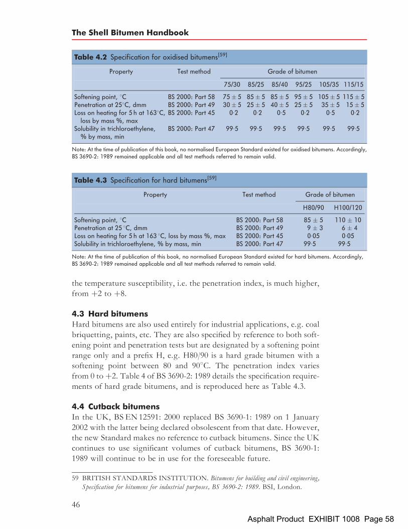
the temperature susceptibility, i.e. the penetration index, is much higher,from þ2 to þ8.
4.3 Hard bitumensHard bitumens are also used entirely for industrial applications, e.g. coalbriquetting, paints, etc. They are also specified by reference to both soft-ening point and penetration tests but are designated by a softening pointrange only and a prefix H, e.g. H80/90 is a hard grade bitumen with asoftening point between 80 and 908C. The penetration index variesfrom 0 toþ2. Table 4 of BS 3690-2: 1989 details the specification require-ments of hard grade bitumens, and is reproduced here as Table 4.3.
4.4 Cutback bitumensIn the UK, BSEN12591: 2000 replaced BS 3690-1: 1989 on 1 January2002 with the latter being declared obsolescent from that date. However,the new Standard makes no reference to cutback bitumens. Since the UKcontinues to use significant volumes of cutback bitumens, BS 3690-1:1989 will continue to be in use for the foreseeable future.
Table 4.2 Specification for oxidised bitumens[59]
Property Test method Grade of bitumen
75/30 85/25 85/40 95/25 105/35 115/15
Softening point, 8C BS 2000: Part 58 75� 5 85� 5 85� 5 95� 5 105� 5 115� 5Penetration at 258C, dmm BS 2000: Part 49 30� 5 25� 5 40� 5 25� 5 35� 5 15� 5Loss on heating for 5 h at 1638C,
loss by mass %, maxBS 2000: Part 45 0:2 0:2 0:5 0:2 0:5 0:2
Solubility in trichloroethylene,% by mass, min
BS 2000: Part 47 99:5 99:5 99:5 99:5 99:5 99:5
Note: At the time of publication of this book, no normalised European Standard existed for oxidised bitumens. Accordingly,BS 3690-2: 1989 remained applicable and all test methods referred to remain valid.
59 BRITISH STANDARDS INSTITUTION. Bitumens for building and civil engineering,Specification for bitumens for industrial purposes, BS 3690-2: 1989. BSI, London.
Table 4.3 Specification for hard bitumens[59]
Property Test method Grade of bitumen
H80/90 H100/120
Softening point, 8C BS 2000: Part 58 85 � 5 110 � 10Penetration at 25 8C, dmm BS 2000: Part 49 9 � 3 6 � 4Loss on heating for 5 h at 163 8C, loss by mass %, max BS 2000: Part 45 0:05 0:05Solubility in trichloroethylene, % by mass, min BS 2000: Part 47 99:5 99:5
Note: At the time of publication of this book, no normalised European Standard existed for hard bitumens. Accordingly,BS 3690-2: 1989 remained applicable and all test methods referred to remain valid.
The Shell Bitumen Handbook
46
Asphalt Product EXHIBIT 1008 Page 58

Cutback bitumens are manufactured by blending either 70/100 pen or160/220 pen bitumen with kerosene to comply with a viscosity specifica-tion. In the UK, cutback bitumens are specified and designated by theflow time (in seconds) through a standard tar viscometer (STV)[61] (seeFig. 7.7). Three grades are available: 50 sec, 100 sec and 200 sec. Themajority of cutback bitumen is used in surface dressing (discussed indetail in Chapter 19) but a significant amount is also used for the manu-facture of both standard and deferred set asphalts. Table 2 of BS 3690-1:1989 details the specification requirements for cutback bitumens andthese are shown here in Table 4.4.In addition to STV tests and solubility, cutback bitumens have to comply
with a distillation specification[62] and a penetration requirement on theresidual bitumen. This ensures that during application and in service, thediluent will evaporate at a consistent and predictable rate and that theresidual bitumen will have the appropriate properties in service.The suffix X on the SHELPHALT range of cutback bitumens indi-
cates that they have been doped with a specially formulated heat-stablepassive adhesion agent. This additive assists ‘wetting’ of the aggregateand resists stripping of the binder from the aggregate in the presenceof water.
4.5 Bitumen qualityOver many years, Shell has investigated the relationship betweenlaboratory measured properties of penetration grade bitumens and
60 BRITISH STANDARDS INSTITUTION. Bitumens for building and civil engineering,Specification for bitumens for roads and other paved areas, BS 3690-1: 1989. BSI, London.
61 BRITISH STANDARDS INSTITUTION. Methods of test for petroleum and itsproducts, Determination of viscosity of cutback bitumen, BS 2000-72: 1993. BSI, London.
62 BRITISH STANDARDS INSTITUTION. Methods of test for petroleum and itsproducts, Determination of distillation characteristics of cutback bitumen, BS 2000-27:1993. BSI, London.
Table 4.4 Specification for cutback bitumens[60]
Property Test method Grade of cutback
50 sec 100 sec 200 sec
Viscosity (STV) at 40 8C, 10mm cup, secs BS 2000: Part 72 50� 10 100� 20 200� 40Distillation BS 2000: Part 27
(a) distillate to 225 8C, % by volume, max360 8C, % by volume
110� 3
19� 3
17� 3
(b) penetration at 25 8C of residue fromdistillation to 360 8C, dmm
BS 2000: Part 49 100 to 350 100 to 350 100 to 350
Solubility in trichloroethylene, % by mass, min BS 2000: Part 47 99:5 99:5 99:5
Note: At the time of publication of this book, no normalised European Standard existed for cutback bitumens. Accordingly,BS 3690-2: 1989 remained applicable and all test methods referred to remain valid.
Specifications and quality of bitumens
47
Asphalt Product EXHIBIT 1008 Page 59
their performance in asphalt mixtures on the road. The ability to predictthe long-term behaviour of asphalts becomes more important as trafficloading increases and performance requirements become ever moredemanding. Performance on the road depends on many factors includingthe design, the nature of the application and the quality of the individualcomponents. In volumetric terms, bitumen is a relatively minor compo-nent of an asphalt but it has a crucial role acting both as a durable binderand conferring visco-elastic properties on the asphalt.Essentially, satisfactory performance of a bitumen on the road can be
ensured if four properties are controlled:
. rheology
. cohesion
. adhesion
. durability.
The rheology of the bitumen at service temperatures is adequately char-acterised by the values of penetration and penetration index[63].By studying the correlation between field performance and measured
properties of experimental and commercial bitumens, Shell GlobalSolutions has developed a set of laboratory tests to assess the qualityof a bitumen. The set of tests includes six on the bitumen and three onthe asphalt. For ease of assessment, these nine results are presented inthe form of a regular polygon, called the bitumen QUALAGON#,depicted in Fig. 4.1 and explained further in Section 4.5.3. There aretests within the QUALAGON# that cover the three remaining keyperformance elements:
. cohesion – low-temperature ductility
. adhesion – retained Marshall
. durability – rolling thin-film oven test (oxidation stability)true boiling point – gas liquid chromatography(volatility)exudation droplet test (homogeneity)field trials (oxidation stability).
4.5.1 CohesionThe cohesive strength of bitumen is characterised by its ductility at lowtemperature, see Fig. 4.2. In this test, three ‘dumb-bells’ of bitumen areimmersed in a water bath and stretched at a constant rate of 50mm perminute until fracture occurs. The distance the specimen is stretched
63 DEBATS FTH andGVANGOOSWILLIGEN. Practical rheological characterisationof paving grade bitumens, Proc 4th Eurobitume Symp, Madrid, pp 304–310, Oct 1989.
The Shell Bitumen Handbook
48
Asphalt Product EXHIBIT 1008 Page 60

Fig. 4.1 The penetration grade QUALAGON#[64]
64 VANGOOSWILLIGENG, F THDE BATS and T HARRISON.Quality of pavinggrade bitumen – a practical approach in terms of functional tests, Proc 4th Eurobitume Symp,Madrid, pp 290–297, Oct 1989.
65 AMERICAN SOCIETY for TESTING and MATERIALS. Standard test method forductility of bituminous materials, D113-99, 1 Nov 1999. ASTM, Philadelphia.
Fig. 4.2 The ductility test[65]
Specifications and quality of bitumens
49
Asphalt Product EXHIBIT 1008 Page 61
before failure is reported as the ductility. The test temperature isadjusted, depending on the penetration of the bitumen under test, e.g.108C for 80 to 100 pen, 138C for 60 to 70 pen and 178C for 40 to50 pen. Under these conditions, the test has been found to discriminatebetween bitumens of different cohesive strengths.
4.5.2 AdhesionIn the QUALAGON#, the adhesion characteristics of a bitumen areassessed by a retained Marshall test[66]. In the test, eight Marshall speci-mens are manufactured using a prescribed aggregate, aggregate gradingand bitumen content. The eight specimens are divided into two groups offour such that the average void content of the two groups are equal. Onegroup of four is tested immediately using the standard Marshall test andthe remaining four specimens are vacuum treated under water at a tem-perature of between 0 and 18C to saturate, as far as possible, the porevolume of the mixture with water. Subsequently, the specimens arestored in a water bath at 608C for 48 hours. The Marshall stability ofthese four specimens is then determined. The ratio of the Marshallstability of the treated specimens to the initial Marshall stability istermed the ‘retained Marshall stability’.Although a relatively wide scatter in absolute stability values and poor
reproducibility are inherent in Marshall testing, it has been found thatconsideration of the percentage relative to the result from the standardprocedure reduces the differences between results from different labora-tories.The results of laboratory tests together with observations of perfor-
mance in practice have identified key links between functional propertiesand the constitution of the bitumen. This work has indicated that if themolecular weight distribution and chemical constitution of the bitumenis unbalanced, it can exhibit inhomogeneity which may adversely affectboth the cohesive and adhesive properties of the bitumen[67].
4.5.3 DurabilityDurability can be defined as the ability to maintain satisfactory rheology,cohesion and adhesion in long-term service. As a part of the qualitycriteria for bitumen, the following have been identified as the prime
66 MARSHALL CONSULTING & TESTING LABORATORY. The Marshallmethod for the design and control of bituminous paving mixtures, 1949.Marshall Consultingand Testing Laboratory, Mississippi.
67 VANGOOSWILLIGENG, F THDE BATS and THARRISON.Quality of pavinggrade bitumen – a practical approach in terms of functional tests, Proc 4th Eurobitume Symp,Madrid, pp 290–297, Oct 1989.
The Shell Bitumen Handbook
50
Asphalt Product EXHIBIT 1008 Page 62

durability factors:
. oxidative hardening
. evaporative hardening
. exudative hardening.
Oxidative and evaporative hardeningHardening due to oxidation has long been held to be the main cause ofageing. In mixtures where the finely structured voids are interconnected,hardening in situ by oxidation is important. However, under suchcircumstances, hardening due to evaporation of the more volatile com-ponents of the bitumen can also be significant.
Tests on the bitumen The rolling thin-film oven test[68] (RTFOT) is anageing test and measures hardening by both oxidation and evaporation.The apparatus for this test is shown in Fig. 4.3. In this test, a thin film ofbitumen is continuously rotated around the inner surface of a glass jar at
68 AMERICAN SOCIETY FOR TESTING and MATERIALS. Standard test methodfor effect of heat and air on a moving film of asphalt (Rolling thin-film oven test), D2872-97,1 Nov 1997. ASTM, Philadelphia.
Fig. 4.3 The rolling thin-film oven test[68]
Specifications and quality of bitumens
51
Asphalt Product EXHIBIT 1008 Page 63

1638C for 75 minutes, with an injection of hot air into the jar every 3 to 4seconds. The amount of bitumen hardening during the test, i.e. drop inpenetration and increase in softening point, correlates well with thatobserved during the manufacture of an asphalt. The oxidation stabilityof bitumens is plotted on the QUALAGON# as the percentage retainedpenetration and the increase in softening point.Evaporative hardening can be assessed by measuring the front-end
volatility of the bitumen by true boiling point gas liquid chromatography(TBP-GLC). In this test, a small sample of bitumen (150mg) is dissolvedin carbon disulphide and is separated on two chromatographic columns.The first column separates the heavy end components such as asphal-tenes, heavy polar aromatics, etc. from the bitumen. The hydrocarbonseluted from this column are then separated on a second column.TBP-GLC is a rapid and accurate method of front-end volatility ana-
lysis and is plotted on the QUALAGON# as the percentage by massrecovered at 450 and 5008C, thus taking account of the shape of thevolatility curve. The loss of 0.2% of the mass in the RTFOT correlateswell with the TBP-GLC recovery limits at 450 and 5008C[69].
Tests on the mixture The hardening due to oxidation and evaporationof a thin film of bitumen in contact with aggregate is assessed by twomixture tests: the hot mixture storage test[69] and the change in the soft-ening point of the bitumen during commercial asphalt manufacture.The hot mixture storage test simulates ageing conditions during mixingand hot storage. A prescribed mixture is manufactured in the laboratoryand a specified quantity of this mixture is stored for 16 hours at 1608C ina sealed tin. Thus, the volume of air entrained in the sample is known andis constant from test to test. The bitumen is recovered from both themixed and stored material and the penetration and softening points aredetermined from samples of bitumen recovered from these two materials.The ageing of the bitumen during mixing and storage is expressed as thedifference between the softening point of the bitumen after storage andthat of the original bitumen.At laboratory scale, this is a very severe test and the change in soften-
ing point is very much larger than that which would be found duringactual bulk storage. Nevertheless, the test correlates with the hardeningtendency of a mixture at high temperature when in prolonged contactwith air.
69 VANGOOSWILLIGENG, F THDE BATS and THARRISON.Quality of pavinggrade bitumen – a practical approach in terms of functional tests, Proc 4th Eurobitume Symp,Madrid, pp 290–297, Oct 1989.
The Shell Bitumen Handbook
52
Asphalt Product EXHIBIT 1008 Page 64

Exudative hardeningIf the constitution of a bitumen is unbalanced, it may, when in contactwith a porous aggregate, exude an oily component into the surfacepores of the aggregate. This may result in a hardening of the bitumenfilm remaining on the surface of the aggregate. Exudation is primarilya function of the amount of low molecular weight paraffinic componentspresent in the bitumen relative to the amount and type of asphaltenes.Shell Global Solutions has developed the exudation droplet test[70]
to quantitatively measure the exudation tendency of a bitumen. In thistest, bitumen droplets are applied to the recesses in custom-made whitemarble plates. The plates are stored at 608C for 4 days under a nitrogenblanket. During this period, oily rings develop around the bitumendroplet that can be measured under ultraviolet light using a microscope.Ring widths vary from a few tenths of a millimetre for a balancedbitumen to several millimetres for an unbalanced bitumen.Hardening in service as a result of exudation can be substantial and
depends not only on the exudation tendency of the bitumen but alsoon the porosity of the aggregate. If the aggregate possesses low porosity,the quantity of exudate absorbed is negligible, irrespective of the exuda-tion tendency of the bitumen. Similarly, if the exudation tendency of thebitumen is low, the quantity of exudate absorbed will be negligible,irrespective of the porosity of the aggregate.
4.5.4 Verification of the QUALAGON# tests and test criteriaMany years’ experience using the QUALAGON# in conjunction withrheological data have confirmed that the set of criteria upon which it isbased provides a satisfactory quantitative measure of bitumen qualityand its performance in service.Good-quality bitumens generally have properties within the ‘pre-
ferred’ area of the QUALAGON#. However, this does not mean thata bitumen which is partially outside the preferred area is necessarily abad bitumen or one of poor quality. The QUALAGON# limits arenot pass/fail criteria and the whole figure must be interpreted with careand judgement. For this reason, the QUALAGON# is not suitable forspecification purposes but it is an invaluable assessment tool providingan excellent guide to performance in service.
70 VANGOOSWILLIGENG, F THDE BATS and T HARRISON.Quality of pavinggrade bitumen – a practical approach in terms of functional tests, Proc 4th Eurobitume Symp,Madrid, pp 290–297, Oct 1989.
Specifications and quality of bitumens
53
Asphalt Product EXHIBIT 1008 Page 65

4.6 The CEN bitumen specifications
Harmonisation of European Standards for petroleum products was set asa target by the ‘Comite Europeen de Normalisation’ (CEN) during themid 1980s to eliminate barriers to trade within the member states ofthe European Union. One of the first steps in achieving this aim wasthe publication of the ‘Construction Products Directive’ (CPD) inDecember 1988. The CPD requires that construction products used inmember states must be fit for their intended use, satisfying certain essen-tial requirements:
. mechanical resistance and stability
. safety in case of fire
. hygiene, health and environmental criteria
. safety in use
. protection against noise
. energy, economy and heat retention.
These essential requirements have to be taken into account when draftingEuropean Standards (often described as ‘ENs’). The task of producingENs has been entrusted to the CEN and, in turn, to the CEN technicalcommittees (TCs) and working groups (WGs). It was the CEN workinggroup dealing with paving grade bitumens, TC227 WG1, which pro-posed a pan-European specification that has resulted in the publicationof BSEN12591: 2000[71]. This is based on the traditional tests that areused for characterising bitumens. The specification, shown in Table4.5, includes a series of mandatory tests and properties that must beadopted by all members of the EC. It also includes optional propertiesthat can be adopted or rejected by each national body (for the UK thisis BSI Subcommittee B/510/19, Bitumen and related products). Of theoptional tests, the UK has adopted kinematic viscosity at 1358C as amandatory test.
4.7 The SHRP/SUPERPAVE bitumen specificationThe Strategic Highways Research Program (SHRP), initiated in the USAin 1987, was a coordinated effort to produce rational specifications forbitumens and asphalts based on performance parameters. The motivationwas to produce pavements which performed well in service. These pave-ments were subsequently called ‘SUPERPAVE’ (SUperior PERformingPAVEments).One of the results of this work was the ‘Superpave asphalt binder
specification’ which categorises grades of bitumen according to their
71 BRITISH STANDARDS INSTITUTION. Bitumen and bituminous binders, Specifica-tions for paving grade bitumens, BSEN 12591: 2000. BSI, London.
The Shell Bitumen Handbook
54
Asphalt Product EXHIBIT 1008 Page 66

Table
4.5
CEN
specifica
tionforpa
ving
grad
ebitumen
s[71]
Grade
20/30
30/45
35/50
40/60
50/70
70/100
100/15
016
0/22
025
0/33
0
MANDATORYPROPERTIES
Pene
trationat
258C
,�0
: 1mm
20–3
030
–45
35–5
040
–60
50–7
070
–100
100–
150
160–
220
250–
330
Softe
ning
point,8C
55–6
352
–60
50–5
848
–56
46–5
443
–51
39–4
735
–43
30–3
8
Resistanceto
harden
ing:
Cha
ngeof
mass,%
max
imum
�0: 5
�0: 5
�0.5
�0.5
�0.5
�0: 8
�0: 8
�1: 0
�1: 0
Retained
pene
tration,
%minim
um55
5353
5050
4643
3735
Softe
ning
pointa
fterha
rden
ing,
8C,minim
um57
5452
4948
4541
3732
Flashpo
int;8C
,minim
um24
024
024
023
023
023
023
022
022
0So
lubility,
%minim
um99
: 099
: 099
: 099
: 099
: 099
: 099
: 099
: 099
: 0
OPTIO
NALPROPERTIES
Paraffinwax
conten
t.%
max
imum
2:2
2:2
2:2
2:2
2:2
2:2
2:2
2:2
2:2
4:5
4:5
4:5
4:5
4:5
4:5
4:5
4:5
4:5
Dyn
amicviscosity
at60
8C,Pa
s,minim
um44
026
022
517
514
590
5530
18
Kine
maticviscosity
at13
58C,mm
2/s,minim
um53
040
037
032
529
523
017
513
510
0
Fraa
ssbrea
king
point,8C
,max
imum
�5�5
�7�8
�10
�12
�15
�16
Resistanceto
harden
ing:
(Noteon
eof
thefollo
wingalternatives
may
bechosen
)(1)Increa
sein
softe
ning
point,8C
,max
imum
88
89
99
1011
11(2)Increa
sein
softe
ning
point,8C
,max
imum
andFraa
ssbrea
king
point,8C
,max
imum
1011
1111
1111
1212
12�5
�5�7
�8�1
0�1
2�1
5�1
6(3)Increa
sein
softe
ning
point,8C
,max
imum
andpe
netrationinde
x10
1111
1111
1112
1212
�1: 5
min
�1: 5
min
�1: 5
min
�1: 5
min
�1: 5
min
�1: 5
min
�1: 5
min
�1: 5
min
þ0: 7
max
þ0: 7
max
þ0: 7
max
þ0: 7
max
þ0: 7
max
þ0: 7
max
þ0: 7
max
þ0: 7
max
(4)Increa
sein
softe
ning
point,8C
,max
imum
1011
1111
1111
1212
12
Specifications and quality of bitumens
55
Asphalt Product EXHIBIT 1008 Page 67

Table
4.6
Theco
mpleteSU
PERP
AVEbind
erspecifica
tion[
72]
Performan
cegrad
e
PG52
PG58
PG64
�10
�16
�22
�28
�34
�40
�46
�16
�22
�28
�34
�40
�10
�16
�22
�28
�34
�40
Ave
rage
7-da
ymax
imum
pave
men
tde
sign
tempe
rature,8C
<52
<58
<64
Minim
umpa
vemen
tdesign
tempe
rature,8C
>�1
0>�1
6>�2
2>�2
8>�3
4>�4
0>�4
6>�1
6>�2
2>�2
8>�3
4>�4
0>�1
0>�1
6>�2
2>�2
8>�3
4>�4
0
Originalbinder
Minim
umfla
shpo
int,8C
230
Visco
sity,ASTM
D44
02Max
3Pa
s,testtempe
rature,8C
135
Dyn
amicshea
rTP
5:G
� /sin�,
minim
um,1.00
kPa
Testtempe
rature
@10
rad/s,
8C
5258
64
Binderafterro
llingth
in-fi
lmoventest
Massloss,max
imum
,%
1.00
Dyn
amicshea
rTP
5:G
� /sin�,
minim
um,2.20
kPa
Testtempe
rature
@10
rad/s,
8C
5258
64
Binderafterpre
ssure
ageingvessel
PAVag
eing
tempe
rature,8C
9010
010
0
Dyn
amicshea
rTP
5:G
� /sin�,
max
imum
,50
00kP
aTe
sttempe
rature
@10
rad/s,
8C
2522
1916
1310
725
2219
1613
3128
2522
1916
Physical
harden
ing
Report
Creep
stiffne
ss,TP
1:S,
max
imum
,30
0MPa
m-value
,max
imum
,0.30
Testtempe
rature
@60
s,8C
0�6
�12
�18
�24
�30
�36
�6�1
2�1
8�2
4�3
00
�6�1
2�1
8�2
4�3
0
Directten
sion
,TP
3:Fa
ilure
strain,minim
um,1.0%
Testtempe
rature
@1.0mm/m
in,8C
0�6
�12
�18
�24
�30
�36
�6�1
2�1
8�2
4�3
00
�6�1
2�1
8�2
4�3
0
The Shell Bitumen Handbook
56
Asphalt Product EXHIBIT 1008 Page 68

performance characteristics in different environmental conditions. Thespecification was intended to limit the potential of a bitumen to contri-bute to permanent deformation, fatigue failure and low-temperaturecracking of asphalt pavements.Table 4.6 shows the complete SUPERPAVE binder specification. It is
intended to control permanent deformation, low-temperature crackingand fatigue in asphalt pavements. This is achieved by controlling variousphysical properties measured with the equipment described above. In thisspecification, the physical properties remain constant for all grades butthe temperature at which these properties must be achieved variesdepending on the climate in which the binder is to be used. For example,a PG 52-40 grade is designed to be used in an environment where theaverage seven day maximum pavement temperature is 528C and a mini-mum pavement design temperature of �408C.
4.7.1 Rotational viscometerThe rotational viscometer is specified to ensure that the viscosity of thebitumen, at normal application temperatures, will be pumpable, coat theaggregate and enable satisfactory compaction of the asphalt.
4.7.2 The bending beam rheometerThe bending beam rheometer[73] (BBR) is a simple device which meas-ures how much a beam of bitumen will deflect under a constant load attemperatures corresponding to its lowest pavement service temperaturewhen bitumen behaves like an elastic solid. The creep load is intendedto simulate the stresses that gradually increase in a pavement as thetemperature falls.Two parameters are determined in this test, the creep stiffness is a
measure of the resistance of the bitumen to constant loading and thecreep rate is a measure of how the asphalt stiffness changes as loads areapplied.If the creep stiffness is too high, the asphalt will behave in a brittle
manner and cracking will be more likely. A high creep rate (sometimesdenoted as the ‘m’ value) is desirable because, as the temperature changesand thermal stresses accumulate, the stiffness will change relativelyquickly. A high value of creep rate indicates that the binder will tend
72 ASPHALT INSTITUTE. Superpave performance graded asphalt binder specification andtesting, Superpave Series No 1, pp 15–19, 1997. AI, Kentucky.
73 BAHIA H U, D A ANDERSON and D W CHRISTENSEN. The bending beamrheometer: a simple device for measuring low-temperature rheology of asphalt binders, ProcAssoc Asph Pav Tech, pp 117–135, 1991. Association of Asphalt Paving Technolo-gists, Seattle.
Specifications and quality of bitumens
57
Asphalt Product EXHIBIT 1008 Page 69

to disperse stresses that would otherwise accumulate to a level wherelow-temperature cracking could occur.The dynamic shear rheometer (DSR)[74] (see Section 7.6.2) and BBR
provide information relating to the stiffness behaviour of bitumen overa wide range of temperatures. Although stiffness can be used to estimatefailure properties, for modified binders the relation between stiffness andfailure is less well defined. Accordingly, an additional test to measurestrength and strain at break has been included, the direct tension test.
4.7.3 The direct tension testBitumens that can be stretched long distances before failure are termed‘ductile’ and those that break before significant stretching has occurredare termed ‘brittle’. Unfortunately, the BBR is unable to fully characterisethe ability of some bitumens to stretch before failure. The direct tensiontest[75] measures ultimate tensile strain of a bitumen at low temperatures(between 0 and �368C). A dumb-bell specimen is loaded in tension at aconstant rate and the failure strain, the change in length divided by theoriginal length, is determined. In the test, failure is defined by thestress where the load on the specimen reaches its maximum value. Atthis failure stress, the minimum strain at failure must be 1%.
4.7.4 Bitumen ageing testsIn the SUPERPAVE specification, two ageing tests are carried out, therolling thin-film oven test[76] (RTFOT) which simulates ageing duringasphalt manufacture and the pressure ageing vessel[77] (PAV) which isbelieved to simulate in-service ageing.The PAV test was developed to evaluate long-term in-service ageing.
The device uses pressure and temperature to compress time so that verylong-term ageing can be simulated in only 20 hours. A sample of thebitumen under test is aged in the RTFOT and then placed in the PAVfor further ageing. In the PAV test, bitumen in a thin film on a tray isplaced in a sample rack in the PAV and the material is aged at a pressure
74 ASPHALT INSTITUTE. Superpave performance graded asphalt binder specification andtesting, Superpave series no 1, pp 15–19, 1997. AI, Kentucky.
75 AMERICAN ASSOCIATION OF STATE HIGHWAY OFFICIALS. Standardtest method for determining the fracture properties of asphalt binder in direct tension,D6723-02. AASHTO, Washington DC.
76 AMERICAN SOCIETY FOR TESTING and MATERIALS. Standard test methodfor effect of heat and air on a moving film of asphalt (Rolling thin-film oven test), D2872-97,1 Nov 1997. ASTM, Philadelphia.
77 AMERICAN SOCIETY FOR TESTING and MATERIALS. Standard practice foraccelerated aging of asphalt binder using a pressurized aging vessel (PAV), D6521-00, 1Nov2000. ASTM, Philadelphia.
The Shell Bitumen Handbook
58
Asphalt Product EXHIBIT 1008 Page 70

of 2070 kPa at a temperature of 90, 100 or 1108C. (Within the industrythere is considerable concern that ageing materials at temperatures inthis range is too far removed from the temperature experienced in serviceand that such an approach may give misleading results.) After the PAVtest, the residue is used for DSR, BBR and direct tension tests.
Specifications and quality of bitumens
59
Asphalt Product EXHIBIT 1008 Page 71

Chapter 5
Polymer modified andspecial bitumens
On the majority of roads, conventional asphalts perform well. However,demands made upon roads increase year by year. Ever increasing num-bers of commercial vehicles with super single tyres and increased axleloads take their toll and it is clear that this trend will continue in thefuture. To assist the Highway Engineer to meet this growing challenge,there now exists a wide range of proprietary asphalts made with polymermodified bitumens and a range of polymer modified bitumens for genericasphalts, all of which have been proven in service.Good basic design, stage construction and timely maintenance enable
asphalt roads not only to withstand all the demands that are made of thembut also to provide the high standards of safety and comfort that havebecome synonymous with bitumen-bound road materials. However,certain areas of a road are much more highly stressed than others.Accordingly, if the entire network is to perform satisfactorily duringthe design life, these areas may require special attention. There is ageneral awareness of the need for special materials on bridge decks, forexample, but the needs of other critical areas can often be overlookedduring construction or maintenance. It is clearly advantageous that main-tenance or strengthening work be required along the entire length at agiven point in time, rather than attention being repeatedly required atcertain locations at shorter intervals. Disruption to traffic flow duringmaintenance work constitutes a significant proportion of the cost ofundertaking roadworks. The use of modified bitumens offers a solutionto reducing the frequency of maintenance required at particular locationsand provides a much longer service life for maintenance treatments atdifficult sites.The degree of improvement required, and hence the cost, will depend
upon the needs of the site to be treated. Modest improvements in defor-mation resistance can be achieved using reclaimed tyre rubber. Sulphurand thermoplastic polymers can improve both the workability of the
61Asphalt Product EXHIBIT 1008 Page 72

asphalt during compaction and its deformation resistance in service andspecially processed binders such as Multiphalte offer substantiallyimproved deformation resistance. Moving further up the performancecurve thermoplastic elastomers improve both deformation resistanceand fatigue characteristics and thermosetting systems offer the ultimateperformance of exceptional deformation resistance coupled with out-standing flexibility.
5.1 The role of bitumen modifiers in asphalt
As the bitumen is responsible for the visco-elastic behaviour characteris-tic of asphalt, it plays a large part in determining many aspects of roadperformance, particularly resistance to permanent deformation andcracking. In general, the proportion of any induced strain in asphaltthat is attributable to viscous flow, i.e. non-recoverable, increases withboth loading time and temperature. The effect of this is illustrated inFigs. 5.1(a) and (b). Figure 5.1(a) shows the response of an asphaltsample in a simple creep test (this is discussed further in Chapter 16).The strain resulting from the applied loading shows an instantaneouselastic response followed by a gradual increase in strain with time untilthe load is removed. The change in strain with time is caused by the vis-cous behaviour of the material. On removal of the load, the elastic strainis recovered instantaneously and some additional recovery occurs withtime. This is known as ‘delayed elasticity’. Ultimately, a permanentresidual strain remains, which is irrecoverable and is directly caused byviscous behaviour.The response to a load pulse induced in an element of an asphalt due to
moving traffic loads is shown in Fig. 5.1(b). Here it is not possible todistinguish between the two components of elastic response but thesmall permanent strain and larger elastic strain are shown. Althoughthe permanent strain illustrated in Fig. 5.1(b) is small for a single pulseload, when many millions of load applications are applied to a pavement,a large accumulation will develop. It is this component that results insurface deformation. From the above, it is clear why more deformationoccurs at high ambient temperatures and where traffic is slow movingor stationary.One of the prime roles of a bitumen modifier is to increase the resist-
ance of the asphalt to permanent deformation at high road temperatureswithout adversely affecting the properties of the bitumen or asphalt atother temperatures. This is achieved by one of two methods, both ofwhich result in a reduction in permanent strain. The first approach isto stiffen the bitumen so that the total visco-elastic response of the asphaltis reduced. The second option is to increase the elastic component of thebitumen thereby reducing the viscous component.
The Shell Bitumen Handbook
62
Asphalt Product EXHIBIT 1008 Page 73

Fig. 5.1 Visco-elastic responses of an asphalt under (a) a static load and (b) a moving wheelload
Polymer modified and special bitumens
63
Asphalt Product EXHIBIT 1008 Page 74

Increasing the stiffness of the bitumen is also likely to increase thedynamic stiffness of the asphalt. This will improve the load-spreadingcapability of the material, increase the structural strength and lengthenthe expected design life of the pavement. Alternatively, it may be possibleto achieve the same structural strength but with a thinner layer. Increas-ing the elastic component of the bitumen will improve the flexibility ofthe asphalt; this is important where high tensile strains are induced.
5.2 The modification of bitumen
For many years, researchers and development chemists have experimen-ted with modified bitumens, mainly for industrial uses, adding asbestos,special fillers, mineral fibres and rubbers. In the last thirty years manyresearchers have looked at a wide spectrum of modifying materials forbitumens used in road construction. Table 5.1 details the majority ofbitumen modifiers and additives that have been examined.Table 5.2 contains a summary of some of the modifiers used with
bitumens and asphalts in service situations and (X) indicates wherethey enhance the performance of the asphalt.For the modifier to be effective and for its use to be both practicable
and economic, it must[78]:
. be readily available
. resist degradation at asphalt mixing temperatures
. blend with bitumen
. improve resistance to flow at high road temperatures withoutmaking the bitumen too viscous at mixing and laying temperaturesor too stiff or brittle at low road temperatures
. be cost effective.
The modifier, when blended with bitumen, should:
. maintain its premium properties during storage, application and inservice
. be capable of being processed by conventional equipment
. be physically and chemically stable during storage, application andin service
. achieve a coating or spraying viscosity at normal application tem-peratures.
78 DENNING J H and J CARSWELL. Improvements in rolled asphalt surfacings by theaddition of organic polymers, Laboratory Report 989, 1981. Transport and RoadResearch Laboratory, Crowthorne.
The Shell Bitumen Handbook
64
Asphalt Product EXHIBIT 1008 Page 75

Table 5.1 Some additives used to modify bitumen
Type of modifier Example
Thermoplastic elastomers Styrene–butadiene–styrene (SBS)Styrene–butadiene–rubber (SBR)Styrene–isoprene–styrene (SIS)Styrene–ethylene–butadiene–styrene (SEBS)Ethylene–propylene–diene terpolymer (EPDM)Isobutene–isoprene copolymer (IIR)Natural rubberCrumb tyre rubberPolybutadiene (PBD)Polyisoprene
Thermoplastic polymers Ethylene vinyl acetate (EVA)Ethylene methyl acrylate (EMA)Ethylene butyl acrylate (EBA)Atactic polypropylene (APP)Polyethylene (PE)Polypropylene (PP)Polyvinyl chloride (PVC)Polystyrene (PS)
Thermosetting polymers Epoxy resinPolyurethane resinAcrylic resinPhenolic resin
Chemical modifiers Organo-metallic compoundsSulphurLignin
Fibres CelluloseAlumino-magnesium silicateGlass fibreAsbestosPolyesterPolypropylene
Adhesion improvers Organic aminesAmides
Antioxidants AminesPhenolsOrgano-zinc/organo-lead compounds
Natural asphalts Trinidad Lake Asphalt (TLA)GilsoniteRock asphalt
Fillers Carbon blackHydrated limeLimeFly ash
Polymer modified and special bitumens
65
Asphalt Product EXHIBIT 1008 Page 76

Table 5.2 Benefits of different types of modifiers[79]
Modifier Permanentdeformation
Thermalcracking
Fatiguecracking
Moisturedamage
Ageing
Elastomers[80–82] X X X XPlastomers[83,84] XTyre rubber[85] X XCarbon black[86,87] X XLime[88,89] X XSulphur[90,91] XChemical modifiers XAntioxidants XAdhesion improvers X XHydrated lime[92] X X
79 BROWN S F, R D ROWLETT and J L BOUCHER. Asphalt modification, Highwayresearch: sharing the benefits. Proceedings of the conference: The United States strategichighway research program, pp 181–203, 1990. Thomas Telford, London.
80 LITTLE D N, J W BUTTON, R M WHITE, E K ENSLEY, Y KIM and S JAHMED. Investigation of asphalt additives, FHWA/RD-87-001, Nov 1986. TexasTransportation Institute, Texas A&M University, College Station, Texas,
81 CALTABIANOMA.Reflection cracking in asphalt overlays, M Phil Thesis, University ofNottingham, 1990.
82 MONISMITH C L and A A TAYEBALI. Behaviour of mixes containing a conventionaland a polymer modified (styrelf) asphalt, University of California at Berkeley, Feb 1988.
83 TREMELIN S S. Neoprene modified asphalt, E I Du Pont de Nemours & Company Inc,121st Meeting, Philadelphia, Pennsylvania, May 1982.
84 SHULER T S and R D PAVLOVICH. Characterization of polymer modified binders,New Mexico State Highway Department, Research Report 52001-1F, Jan 1987.
85 SCHNORMEIER R H. Time proves asphalt–rubber seals cost effective, National seminaron asphalt–rubber, San Antonio, Texas, 1981.
86 ROSTLER F S R, R M WHITE and E M DANNENBURG. Carbon black as areinforcing agent for asphalt, Proc Assoc Asph Pav Tech, vol 55, pp 376–401, 1986. Asso-ciation of Asphalt Paving Technologists, Seattle.
87 YAO Z and C L MONISMITH. Behaviour of asphalt mixtures with carbon blackreinforcement, Proc Assoc Asph Pav Tech, vol 55, pp 564–585, 1986. Association ofAsphalt Paving Technologists, Seattle.
88 KIM O K, J MONTALVO, C A BELL, R G HICKS, and J E WILSON. Effect ofmoisture and aging on asphalt pavement life: Part 1 – Effect of moisture, Oregon StateUniversity, Department of Civil Engineering, Corvallis, Oregon, Report no FHWA-OR-RD-86-01, Jan 1986.
89 PLANCHERH, E L GREEN, and J C PETERSEN.Reduction to oxidative hardeningof asphalts by treatment with hydrated lime, a mechanistic study, Proc Assoc Asph Pav Tech,vol 45, pp 1–24, 1976. Association of Asphalt Paving Technologists, Seattle.
90 DENNING J H and J CARSWELL. Improvements in rolled asphalt surfacings by theaddition of sulphur, Laboratory Report 963, 1981. Transport and Road ResearchLaboratory, Crowthorne.
91 DEME I. Shell sulphur asphalt products and processes, International Road Federation Sympon sulphur asphalt in road construction, Bordeaux, France, Feb 1981.
The Shell Bitumen Handbook
66
Asphalt Product EXHIBIT 1008 Page 77

5.2.1 The modification of bitumen using thermoplasticelastomers
Of the four main groups of thermoplastic elastomers – polyurethane,polyether–polyester copolymers, olefinic copolymers and styrenic blockcopolymers – it is the styrenic block copolymers that have proved topresent the greatest potential when blended with bitumen[93–95].Styrenic block copolymers, also termed thermoplastic rubbers or
thermoplastic elastomers, may be produced by a sequential operationof successive polymerisation of styrene–butadiene–styrene (SBS) orstyrene–isoprene–styrene (SIS). Alternatively, a di-block precursor canbe produced by successive polymerisation of styrene and mid-blockmonomer, followed by a reaction with a coupling agent. Thus, notonly linear copolymers but also multi-armed copolymers can be pro-duced; these are often referred to as radial or branched copolymers, asshown in Fig. 5.2.
92 KENNEDY T W, F L ROBERTS and K W LEE. Evaluation of asphalt mixturesusing the Texas freeze–thaw pedestal test, Proc Assoc Asph Pav Tech, vol 51, pp 327–341, 1982. Association of Asphalt Paving Technologists, Seattle.
93 BULL A L andW CVONK. Thermoplastic rubber/bitumen blends for roof and road, ShellChemicals Technical Manual TR 8.15, 1984. Shell International Petroleum CompanyLtd, London.
94 HENDERSON J F and M SZWARC. The use of living polymers in the preparationof polymer structures of controlled architecture, Rev Macromolecular Chem, 1968, vol 3,pp 317–401.
95 BONEMAZZI et al. Correlation between the properties of polymers and polymer modifiedbitumens, Eurobitume and Eurasphalt Conf, Strasbourg, Brussels, 1996.
Fig. 5.2 A linear and branched thermoplastic elastomer[93]
Polymer modified and special bitumens
67
Asphalt Product EXHIBIT 1008 Page 78

Thermoplastic elastomers derive their strength and elasticity from aphysical cross-linking of the molecules into a three-dimensional network.This is achieved by the agglomeration of the polystyrene end-blocks intoseparate domains, as shown schematically in Fig. 5.3, providing the phy-sical cross-links for a three-dimensional polybutadiene or polyisoprene
Fig. 5.3 Schematic structure of thermoplastic elastomers at ambienttemperature
The Shell Bitumen Handbook
68
Asphalt Product EXHIBIT 1008 Page 79

rubbery matrix. It is the polystyrene end-blocks that impart strength tothe polymer and the mid-block that gives the material its exceptionalelasticity[96]. At temperatures above the glass transition point of poly-styrene (1008C) the polystyrene softens as the domains weaken and willeven dissociate under stress, thus allowing easy processing. Upon cool-ing, the domains re-associate and the strength and elasticity is restored,i.e. the material is thermoplastic.The quality of the polymer dispersion achieved is influenced by a
number of factors:
. the constitution of the bitumen
. the type and concentration of the polymer
. the shear rate applied by the mixer[97].
When the polymer is added to the hot bitumen, the bitumen immediatelystarts to penetrate the polymer particles causing the styrene domains ofthe polymer to become solvated and swollen. Once this has occurred,the level of shear exerted on the swollen particles is critical if a satisfac-tory dispersion is to be achieved within a realistic blending time. Thus,medium or, preferably, high shear mixers are required to adequatelydisperse thermoplastic elastomers into the bitumen.As discussed in Chapter 3, bitumens are complex mixtures that can be
subdivided into groups of molecules that have common structures:
. saturates
. aromatics
. resins
. asphaltenes.
Saturates and aromatics can be viewed as carriers for the polar aromatics,i.e. the resins and asphaltenes. The polar aromatics are responsible for thevisco-elastic properties of the bitumen at ambient temperatures. This isdue to association of the polar molecules that leads to large structures,in some cases even to three-dimensional networks, i.e. ‘GEL’ typebitumen. The degree to which this association takes place depends onthe temperature, the molecular weight distribution, the concentrationof the polar aromatics and on the solvency power of the saturates andaromatics in the maltenes phase. If the concentration and molecularweight of the asphaltenes is relatively low, the result will be a ‘SOL’type bitumen.
96 VONK W C and G VAN GOOSWILLIGEN. Improvement of paving grade bitumenswith SBS polymers, Proc 4th Eurobitume Symp, Madrid, pp 298–303, 1989.
97 COLLINS J H, M G BOULDIN, R GELLES and A BERKER. Improved per-formance of paving asphalt by polymer modification, Proc Assoc Asph Pav Tech, vol 60,pp 43–79, 1991. Association of Asphalt Paving Technologists, Seattle.
Polymer modified and special bitumens
69
Asphalt Product EXHIBIT 1008 Page 80

The addition of thermoplastic elastomers with a molecular weightsimilar to or higher than that of the asphaltenes disturbs the phase equi-librium. The polymer and the asphaltene ‘compete’ for the solvencypower of the maltenes phase and if insufficient maltenes are available,phase separation may occur. Figure 5.4 shows the microscopic structuresof (a) ‘compatible’ and (b) ‘incompatible’ bitumen/polymer systems. Thecompatible system has a homogeneous ‘sponge-like’ structure whereasthe incompatible system has a coarse discontinuous structure. Phaseseparation or incompatibility can be demonstrated by a simple hotstorage test[98] in which a sample of the polymer modified bitumen isplaced in a cylindrical container and stored at elevated temperature,usually 1508C, in an oven for up to seven days. At the end of the storageperiod, the top and bottom of the sample are separated and tested.Incompatibility is usually assessed by the difference in softening pointbetween the top and bottom samples – if the difference is less than 58Cthe binder is considered to be storage stable.The main factors influencing storage stability and binder properties
are:
. the amount and molecular weight of the asphaltenes
. the aromaticity of the maltene phase
. the amount of polymer present
. the molecular weight and structure of the polymer
. the storage temperature.
Shell Bitumen has developed a number of compatible SBS modifiedbinders for a variety of surfacing applications including deformation-resistant hot rolled asphalt, stone mastic asphalt and thin surfacings.
(a) (b)
Fig. 5.4 The microscopic structures of (a) compatible and (b) incompatiblebitumen/polymer systems
98 EUROPEAN COMMITTEE FOR STANDARDIZATION. Bitumen and bitumi-nous binders, Determination of storage stability of modified bitumen, EN 13399, 1998.CEN, Brussels.
The Shell Bitumen Handbook
70
Asphalt Product EXHIBIT 1008 Page 81

The philosophy of producing a compatible system is based on the practi-calities and user friendliness of the bitumen to facilitate the medium-termstorage that is often required. The effect of compatibility on storagestability is demonstrated in Fig. 5.5. It shows the numerical differencein softening point of the top and bottom samples of two bitumens con-taining 7% of SBS thermoplastic rubber after 1, 3, 5 and 7 days’ storage at1408C. The results clearly show that the compatible system is extremelystable whereas the incompatible system has separated dramatically withvirtually no polymer remaining in the bottom sample after 7 days’storage. The implications of this for storage are obvious. In practice, itis possible to use polymer modified binders that are not storage stable.However, they must be handled with great care and stored in tankswith stirrers or extended circulation to prevent separation of thepolymer.The polymer content of a sample of a polymer modified bitumen can
be determined using an infrared spectrophotometer of the type shownin Fig. 5.6. The accuracy of the determination depends on a number offactors but usually the polymer content can be determined within�0.5%.
Fig. 5.5 Effect of the compatibility of the system on the storage stability ofbitumen/thermoplastic elastomer blends
Polymer modified and special bitumens
71
Asphalt Product EXHIBIT 1008 Page 82
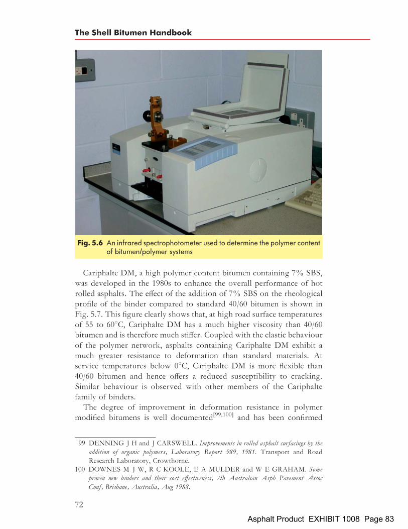
Cariphalte DM, a high polymer content bitumen containing 7% SBS,was developed in the 1980s to enhance the overall performance of hotrolled asphalts. The effect of the addition of 7% SBS on the rheologicalprofile of the binder compared to standard 40/60 bitumen is shown inFig. 5.7. This figure clearly shows that, at high road surface temperaturesof 55 to 608C, Cariphalte DM has a much higher viscosity than 40/60bitumen and is therefore much stiffer. Coupled with the elastic behaviourof the polymer network, asphalts containing Cariphalte DM exhibit amuch greater resistance to deformation than standard materials. Atservice temperatures below 08C, Cariphalte DM is more flexible than40/60 bitumen and hence offers a reduced susceptibility to cracking.Similar behaviour is observed with other members of the Cariphaltefamily of binders.The degree of improvement in deformation resistance in polymer
modified bitumens is well documented[99,100] and has been confirmed
Fig. 5.6 An infrared spectrophotometer used to determine the polymer contentof bitumen/polymer systems
99 DENNING J H and J CARSWELL. Improvements in rolled asphalt surfacings by theaddition of organic polymers, Laboratory Report 989, 1981. Transport and RoadResearch Laboratory, Crowthorne.
100 DOWNES M J W, R C KOOLE, E A MULDER and W E GRAHAM. Someproven new binders and their cost effectiveness, 7th Australian Asph Pavement AssocConf, Brisbane, Australia, Aug 1988.
The Shell Bitumen Handbook
72
Asphalt Product EXHIBIT 1008 Page 83

through many commercial contracts which included the rigorousrequirements which are prescribed for sites accorded Classification No2 in Clause 943 of the Specification for Highway Works[101]. Figures5.8(a) and (b) demonstrate that the addition of Cariphalte DM improvesthe deformation resistance of hot rolled asphalt. These photographs weretaken on the slow lane of the A14 Trunk Road at Bury St Edmunds andare at locations within 100m of each other. The conventional material (a)has developed ruts in excess of 40mm deep over a five year period com-pared to the modified asphalt (b) that exhibits only minor deformation ofabout 7mm and clearly retains good texture[102].The degree of improvement in the flexibility of asphalt has been
quantified by constant strain fatigue tests again carried out by both thethen Transport and Road Research Laboratory[103] and Shell Global
Fig. 5.7 Relationship between viscosity and temperature
101 HIGHWAYS AGENCY et al. Manual of contract documents for highway works,Specification for highway works, vol 1, cl 943, 2002. The Stationery Office, London.
102 PRESTON J N. Shell Cariphalte DM, The A14 – a case history, Shell Bitumen Tech-nical Brochure, 1996. Shell International Petroleum Company Ltd, London.
103 DENNING J H and J CARSWELL. Improvements in rolled asphalt surfacings by theaddition of organic polymers, Laboratory Report 989, 1981. Transport and RoadResearch Laboratory, Crowthorne.
Polymer modified and special bitumens
73
Asphalt Product EXHIBIT 1008 Page 84

Solutions[104]. Fatigue tests carried out on hot rolled asphalt at 58C and ata frequency of 50Hz show that, over a wide range of applied strain levels,Cariphalte DM improves fatigue life by a factor of at least three as shownin Fig. 5.9. Thus, this material is eminently suitable for locations whererepeated high tensile strains are present.In the late 1970s, research at the Shell Global Solutions laboratory in
Germany resulted in the development of the SBS modified binderCaribit. The very first section built with Caribit was laid in Leimen, atown near the city of Heidelberg in Germany in 1981. Caribit 65 was
(a)
(b)
Fig. 5.8 Deformation in HRA surface course made with (a) 40/60 bitumen and(b) Cariphalte DM
104 DOWNES M J W, R C KOOLE, E A MULDER and W E GRAHAM. Someproven new binders and their cost effectiveness, 7th Australian Asphalt Pavement Associa-tion Conf, Brisbane, Australia, Aug 1988.
The Shell Bitumen Handbook
74
Asphalt Product EXHIBIT 1008 Page 85

used for the surface course, a 0/11 asphalt concrete. As this site was thefirst to use Caribit, there have been a number of examinations of thematerial over the past twenty years to assess the performance of thematerial in service. In particular, the elastic behaviour and the ageingof the binder were monitored. The susceptibility to ageing was measuredby the increase in the softening point of the binder recovered from theasphalt and the elastic behaviour was measured by the elastic recoveryof the recovered binder. At irregular intervals, cores were taken toshow the performance of the binder and the road. Figures 5.10(a) and(b) show the ageing and elastic recovery of the asphalt over a 20 yearperiod.Figure 5.10(a) shows that, as expected, during mixing and laying of the
asphalt, the softening point increased. During the following 18 years,there was no significant change in the softening point. One of the advan-tages of using polymer modified binders is the achievement of thickbinder films. The thicker the binder film, the smaller the risk of oxidativehardening of the binder. Obviously, the aggregate has been coated withan adequate binder film thickness because the softening point remained atthe same level for 18 years after mixing.
Fig. 5.9 Relationship between strain level and fatigue life[105]
105 WHITEOAK C D. Broadening the boundaries of binder technology, Highways, vol 56,no 1942, p 35, Oct 1988. Alad Ltd, St Albans, Herts.
Polymer modified and special bitumens
75
Asphalt Product EXHIBIT 1008 Page 86

In Germany, the minimum requirement for elastic recovery of thefresh binder is 50%. Figure 5.10(b) shows that both the fresh and agedbinder comfortably fulfil this requirement, indicating significant ageingresistance of this binder.In well compacted asphalt concrete manufactured using penetration
grade bitumen, the softening point typically increases by 18C per
Fig. 5.10 Changes in (a) softening point and (b) elastic recovery of an asphalt made withCaribit over a 20 year period in service
The Shell Bitumen Handbook
76
Asphalt Product EXHIBIT 1008 Page 87

annum. With the use of polymer modified bitumen, it is possible to sub-stantially reduce the ageing of the binder as a result of the thicker binderfilms on the aggregate.In theUK, similar investigations have been carried out on the hot rolled
asphalt surface course laid on the A38 at Burton-on-Trent as part of anational evaluation of modified binders[106]. The level of deformationand in situ binder properties were monitored over a period of 10 yearsand the results of this study are detailed in Table 5.3. After 18 years onthe road, the hot rolled asphalt made with Cariphalte DM is in excellentcondition and is markedly outperforming the material made with penetra-tion grade 40/60 bitumen.
5.2.2 The modification of bitumen by the addition ofnon-rubber thermoplastic polymers
Polyethylene, polypropylene, polyvinyl chloride, polystyrene and ethyl-ene vinyl acetate (EVA) are the principal non-rubber thermoplasticpolymers that have been examined in modified road binders. As thermo-plastics, they are characterised by softening on heating and hardeningon cooling. These polymers tend to influence the penetration morethan the softening point, which is the opposite tendency of thermoplasticelastomers.Thermoplastic polymers, when mixed with bitumen, associate below
certain temperatures increasing the viscosity of the bitumen. However,they do not significantly increase the elasticity of the bitumen and,
Table 5.3 Properties of the Cariphalte DM and 40/60 bitumens recovered from the A38
Binder Age of sample Deformation:mm
Void contentof cores: %
Binder properties
Penetration@ 25 8C: dmm
Softeningpoint (IP): 8C
Cariphalte DM Initial binder properties – – 89 88:0after 1 year – 4:0 79 (11%) 83:0after 412 years 1:1 4:2 83 (7%) 81:0after 7 years 1:9 3:8 88 (1%) 80:0after 10 years 3:3 3:5 73 (18%) 80:0
40/60 Initial binder properties – – 52 50:5after 1 year 2:2 3:9 42 (19%) 53:5after 412 years 4:1 3:6 36 (31%) 56:0after 7 years 5:1 3:2 34 (35%) 56:0after 10 years 6:3 3:4 35 (33%) 56:0
Note. Percentage change in parentheses.
106 DAINESME. Trials of porous asphalt and rolled asphalt on the A38 at Burton, ResearchReport 323, 1992. Transport and Road Research Laboratory, Crowthorne.
Polymer modified and special bitumens
77
Asphalt Product EXHIBIT 1008 Page 88

when heated, they can separate which may give rise to a coarse dispersionon cooling.EVA copolymers are thermoplastic materials with a random structure
produced by the copolymerisation of ethylene with vinyl acetate. Co-polymers with low vinyl acetate content possess properties similar tolow density polyethylene. As the level of vinyl acetate increases, so theproperties of the copolymer change. The properties of EVA copolymersare classified by molecular weight and vinyl acetate content as follows.
. Molecular weight. The molecular weights of many polymers aredefined in terms of an alternative property; standard practice forEVAs is to measure the melt flow index (MFI), a viscosity testthat is inversely related to molecular weight; the higher the MFI,the lower the molecular weight and viscosity; this is analogous tothe penetration test for bitumen; the higher the penetration, thelower the average molecular weight and viscosity of the bitumen;
. Vinyl acetate content. In order to appreciate the main effects of vinylacetate on the properties of the modified binder, it is useful toconsider a simple illustration of its structure as shown in Fig.5.11; this shows how the regular polyethylene segments of thechain can pack closely together and form what are known as ‘crys-talline regions’; it also shows how the bulky vinyl acetate groupsdisrupt this closely packed arrangement to give non-crystalline oramorphous rubbery regions; the crystalline regions are relatively
Fig. 5.11 Packing of polyethylene in EVA
The Shell Bitumen Handbook
78
Asphalt Product EXHIBIT 1008 Page 89

stiff and give a considerable reinforcing effect whereas the amor-phous regions are rubbery; quite obviously, the more vinyl acetategroups (or the higher the vinyl acetate content) the higher theproportion of rubbery regions and, conversely, the lower the pro-portion of crystalline regions.
A wide range of EVA copolymers is available, specified by both MFIand vinyl acetate content. EVA copolymers are easily dispersed in, andhave good compatibility with, bitumen. They are thermally stable atthe temperatures at which asphalt is normally mixed. However, duringstatic storage, some separation may occur and it is therefore recom-mended that the blended product should be thoroughly circulatedbefore use.
5.2.3 The modification of bitumen by the addition of rubbersPolybutadiene, polyisoprene, natural rubber, butyl rubber, chloroprene,random styrene–butadiene–rubber amongst others have all been usedwith bitumen but their effect is mainly to increase viscosity. In someinstances, the rubbers have been used in a vulcanised (cross-linked)state, e.g. reclaimed tyre crumb, but this is difficult to disperse in bitumen.Successful dispersion requires high temperatures and long digestion timesand can result in a heterogeneous binderwith the rubber actingmainly as aflexible filler.
5.2.4 The modification of bitumen by the addition of viscosityreducers
Several performance properties of asphalt can be improved by addinglow molecular weight polyethylene or paraffin wax to bitumen. At tem-peratures above the melting point of the additive, the viscosity of thebitumen is significantly reduced compared with that of bitumen modifiedwith sulphur (see Section 5.2.5). This, in turn, allows for a reduction inasphalt mixing and laying temperatures by up to 308C, thereby savingenergy and reducing fume emissions. Also, critical applications wherehand laying may be required or laying material at low ambient tempera-tures may be facilitated as a result of the longer time period availablebetween asphalt mixing and compaction.At the crystallisation temperature of the additive, the viscosity of the
modified bitumen rises sharply which in turn may lead to enhancedasphalt stiffness thereby reducing the permanent deformation of thecarriageway. However, the low-temperature properties may be adverselyaffected. Figure 5.12 shows typical viscosity/stiffness–temperature rela-tionship of a penetration grade bitumen modified with a selected paraffinwax.
Polymer modified and special bitumens
79
Asphalt Product EXHIBIT 1008 Page 90

5.2.5 The modification of bitumen by the addition of sulphurSulphur is used to modify both bitumen and asphalt. In relatively lowconcentrations, 2 to 3%, it reduces the high-temperature viscosity ofbitumen improving the workability of asphalt when hot and the deforma-tion resistance when cold[107]. It is also used in some polymer modifiedbitumens to cross-link the bitumen and the polymer to improve storagestability.At higher concentrations, the sulphur substantially reduces the viscos-
ity of asphalt making it virtually self-compacting. This makes it possibleto lay this material through a paver without the need for roller compac-tion. Alternatively, it can be made sufficiently free-flowing that it canbe used for filling potholes and levelling by hand with a trowel. As thematerial cools, the excess sulphur partially fills and conforms to theshape of the voids in the compacted material keying together the aggre-gate particles. When this material is cold, the resulting friction betweenparticles within the asphalt makes it very resistant to deformation andvery durable. The major weakness of this material is that above 1508Chydrogen sulphide is emitted and this requires the use of specialistequipment[107].
Fig. 5.12 The effect on the viscosity of a bitumen of adding a selected paraffin wax
107 DEME I. Shell sulphur asphalt products and processes, International Road FederationSymp on sulphur asphalt in road construction, Bordeaux, France, Feb 1981.
The Shell Bitumen Handbook
80
Asphalt Product EXHIBIT 1008 Page 91

5.3 Multigrade bitumensThe ideal road binder would have uniform stiffness and creep behaviourthroughout the whole range of service temperatures. Multigradebitumens are a step in this direction as they are less temperature suscept-ible than penetration grade bitumens.In the mid 1980s, Shell introduced Multiphalte, a range of multigrade
bitumens. These are manufactured by means of a special refining pro-cess[108,109]. Multiphalte bitumens have low-temperature susceptibilityresulting in improved performance at high temperatures and betterlow-temperature characteristics than hard grades, making them idealfor use in surface courses.Figure 5.13 illustrates the Multiphalte bitumen concept. This shows
the complex modulus of four bitumens at 108C. In the high frequency(or low temperature) range, the stiffness of the Multiphalte bitumen isless than that of penetration grade bitumen of the same grade. In thelow frequency (or high temperature) zone, the Multiphalte has a highermodulus than the penetration grade bitumen. These results clearlyshow that Multiphalte bitumens possess better rutting resistance than
Fig. 5.13 Comparison of the master curves of Multiphalte and penetrationgrade bitumens
108 KOOLE R, K VALKERING and D LANCON. Development of a multigradebitumen to alleviate permanent deformation, Australian Pacific Rim AAPA AsphaltConf, Sydney, Australia, Nov 1991.
109 MAIA A F. Multiphalte: A cost effective bitumen to combat rutting, 1st Malaysian RoadConf, Kuala Lumpur, Malaysia, Jun 1994.
Polymer modified and special bitumens
81
Asphalt Product EXHIBIT 1008 Page 92

penetration grade bitumens while still retaining good low-temperaturebehaviour.Shell Bitumen launched Multiphalte HM (High Modulus) in France in
the mid 1990s. This 20/30 grade performs better at low temperature thanpenetration grade hard bitumen thus minimising the risk of thermalfatigue cracking. Multiphalte HM also has excellent anti-rutting andstructural properties.Several studies have also been conducted in the laboratory to
characterise Multiphalte bitumens and asphalts in order to predict theirperformance on the road in terms of both their rutting resistance andlow-temperature cracking. Most deformation-resistance tests with Multi-phalte bitumens have involved use of the French Laboratoires Centraldes Ponts et Chaussees (LCPC) wheel-track tester. This test continuouslymeasures the rut depth generated by a loaded wheel at 608C. Figure 5.14shows the deformation in this test on Multiphalte 35/50, Multiphalte HMand a penetration grade 35/50 bitumen. The deformation after 30 000cycles is more than halved using the Multiphalte binders.Along with the laboratory tests, two rutting trials were conducted in
1992 and 1993 on the LCPC circular test track in Nantes, France. Figures5.15(a) and (b) show the rut depth as a function of the total number ofaxle passes for the two trials[110].These two trials show that the asphalt mixture based on Multiphalte
60/80 is twice as resistant to rutting as the asphalt made with the
Fig. 5.14 Comparison of the deformation resistance of Multiphalte 35/50,Multiphalte HM and conventional 35/50 bitumens
110 CORTE J F, J P KERZREHO, Y BROSSEAUD and A SPERNOL. Study ofrutting of wearing courses on the LCPC test track, Proc 8th Int Conf on Asphalt Pave-ments, Seattle, WA, USA, Article no. 191, Aug 1997.
The Shell Bitumen Handbook
82
Asphalt Product EXHIBIT 1008 Page 93
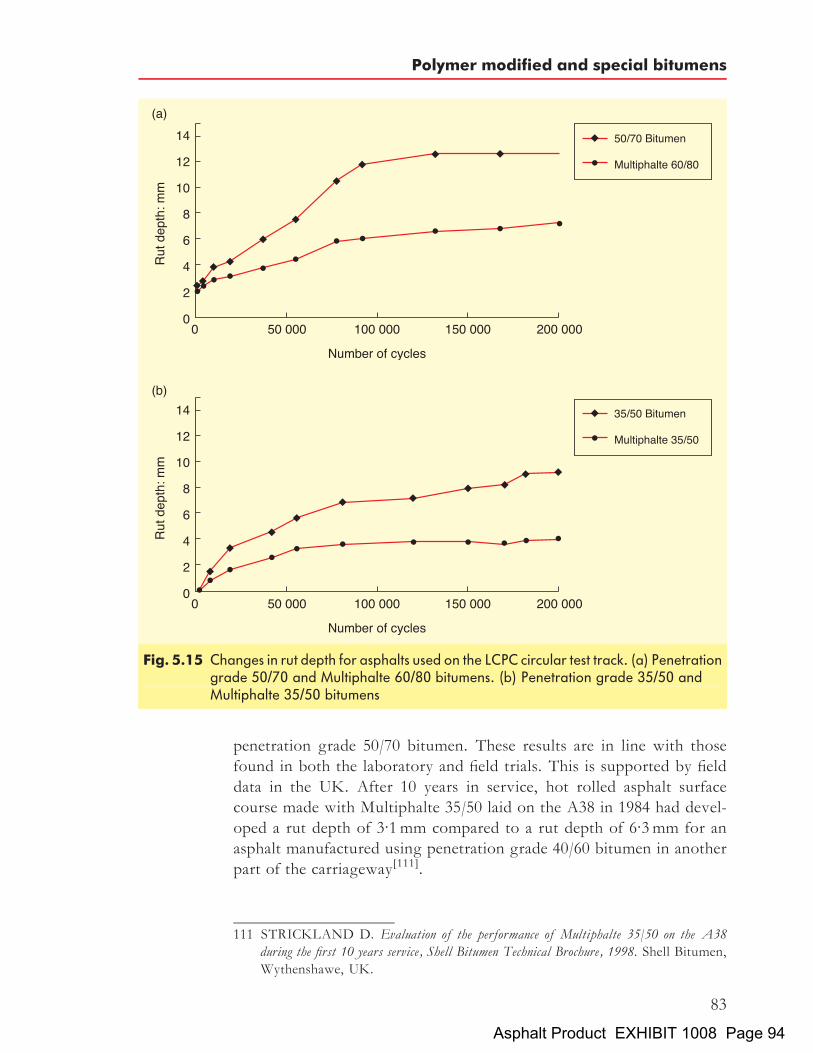
penetration grade 50/70 bitumen. These results are in line with thosefound in both the laboratory and field trials. This is supported by fielddata in the UK. After 10 years in service, hot rolled asphalt surfacecourse made with Multiphalte 35/50 laid on the A38 in 1984 had devel-oped a rut depth of 3.1mm compared to a rut depth of 6.3mm for anasphalt manufactured using penetration grade 40/60 bitumen in anotherpart of the carriageway[111].
Fig. 5.15 Changes in rut depth for asphalts used on the LCPC circular test track. (a) Penetrationgrade 50/70 and Multiphalte 60/80 bitumens. (b) Penetration grade 35/50 andMultiphalte 35/50 bitumens
111 STRICKLAND D. Evaluation of the performance of Multiphalte 35/50 on the A38during the first 10 years service, Shell Bitumen Technical Brochure, 1998. Shell Bitumen,Wythenshawe, UK.
Polymer modified and special bitumens
83
Asphalt Product EXHIBIT 1008 Page 94
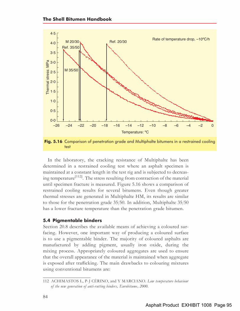
In the laboratory, the cracking resistance of Multiphalte has beendetermined in a restrained cooling test where an asphalt specimen ismaintained at a constant length in the test rig and is subjected to decreas-ing temperature[112]. The stress resulting from contraction of the materialuntil specimen fracture is measured. Figure 5.16 shows a comparison ofrestrained cooling results for several bitumens. Even though greaterthermal stresses are generated in Multiphalte HM, its results are similarto those for the penetration grade 35/50. In addition, Multiphalte 35/50has a lower fracture temperature than the penetration grade bitumen.
5.4 Pigmentable binders
Section 20.8 describes the available means of achieving a coloured sur-facing. However, one important way of producing a coloured surfaceis to use a pigmentable binder. The majority of coloured asphalts aremanufactured by adding pigment, usually iron oxide, during themixing process. Appropriately coloured aggregates are used to ensurethat the overall appearance of the material is maintained when aggregateis exposed after trafficking. The main drawbacks to colouring mixturesusing conventional bitumens are:
Fig. 5.16 Comparison of penetration grade and Multiphalte bitumens in a restrained coolingtest
112 ACHIMASTOS L, P-J CERINO, and Y MARCIANO. Low temperature behaviourof the new generation of anti-rutting binders, Eurobitume, 2000.
The Shell Bitumen Handbook
84
Asphalt Product EXHIBIT 1008 Page 95

. the only acceptable colour that can be achieved is red; and
. the quantity of iron oxide required to achieve an acceptable red isfairly high, which significantly increases the cost of the mixture.
To enable asphalt to be pigmented in colours other than red, Shell devel-oped Mexphalte C. This synthetic binder was produced specifically forthis purpose and now polymer modified versions of Mexphalte C areavailable. Mexphalte C is a ‘synthetic’ binder which, because it containsno asphaltenes, is readily pigmented to virtually any colour[113,114]. Itpossesses rheological and mechanical properties similar to penetrationgrade bitumen with the exception that the high-temperature equi-viscoustemperature of this binder is about 158C lower than the correspondingpenetration grade. Coloured asphalts manufactured using this binderrequire 1 to 2% of pigment to achieve a satisfactory colour, whereasonly red can be achieved with penetration grade bitumen using up to5% or more of iron oxide in the mixture. Figures 5.17 and 5.18 illustratethe dramatic results that can be achieved using Mexphalte C.There are a number of novel applications for coloured asphalt includ-
ing the following.
. The application of red pigmented asphalt, usually sand carpet, as aprotective layer over waterproof membranes laid on bridge decks.When the surfacing on the bridge deck is to be replaced, contractorsplaning off the old material will only mill down to the red sand carpet,thereby avoiding damage to the expensive waterproof membrane.
. When surfacing tunnels, a light coloured asphalt will improvedriver visibility and reduce the electrical energy required to illumi-nate the tunnel[115].
. For bus lanes and other lanes requiring demarcation[116].
. For recreational and other areas to improve visual impact[117,118].
113 SCHELLEKENS J C A and J KORENSTRA. Shell Mexphalte C brings colour toasphalt pavements, Shell Bitumen Review 62, pp 22–25, Jun 1987. Shell InternationalPetroleum Company Ltd, London.
114 LE COROLLER A and R HERMENT. Shell Mexphalte C and Colas Colclair, Arange of products for all road surfacing processes, Shell Bitumen Review 64, pp 6–10, Sep1989. Shell International Petroleum Company Ltd, London.
115 GENARDINI C.Mexphalte C – For road surfacing in tunnels, Shell Bitumen Review 67,pp 20–21, Feb 1994. Shell International Petroleum Company Ltd, London.
116 O’CONNOR G.Mexphalte C – Bus lane differentiation in Sydney, Shell Bitumen Review69, pp 12–13, Feb 1999. Shell International Petroleum Company Ltd, London.
117 LOHAN G.Mexphalte C – Adding colour to Ireland’s history, Shell Bitumen Review 69,p 11, Feb 1999. Shell International Petroleum Company Ltd, London.
118 GUSTAFSSEN P. Shell MEXPHALTE C, Liseburg amusement park in Gothenburg,Sweden opened for the 1987 season in Shell colours, Shell Bitumen Review 63, pp 12–14,Apr 1988. Shell International Petroleum Company Ltd, London.
Polymer modified and special bitumens
85
Asphalt Product EXHIBIT 1008 Page 96

5.5 Fuel-resisting binders
Mexphalte and Cariphalte Fuelsafe are two of the most recent additionsto the Shell family of polymer modified binders. The binders improveboth the low- and high-temperature performance of asphalt but it isthe resistance to the effects of contact with fuels and lubricants that isdramatically improved. Cariphalte Fuelsafe is a further development onMexphalte Fuelsafe that was developed in the mid 1990s. Comparativeimmersion tests with A1 jet fuel show that the weight loss during immer-sion is an order of magnitude less with Cariphalte Fuelsafe than withMexphalte Fuelsafe.
Fig. 5.17 The Zenith in Toulouse, France[119]
119 CERINO P-J. Mexphalte C reaches its zenith in the ‘‘Pink City’’, Shell Bitumen Review70, p 19, 2001. Shell International Petroleum Company Ltd, London.
The Shell Bitumen Handbook
86
Asphalt Product EXHIBIT 1008 Page 97
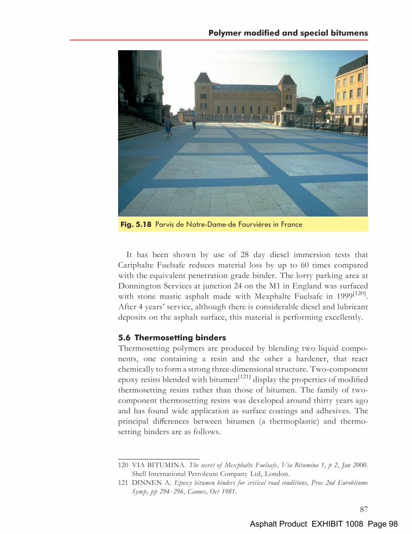
It has been shown by use of 28 day diesel immersion tests thatCariphalte Fuelsafe reduces material loss by up to 60 times comparedwith the equivalent penetration grade binder. The lorry parking area atDonnington Services at junction 24 on the M1 in England was surfacedwith stone mastic asphalt made with Mexphalte Fuelsafe in 1999[120].After 4 years’ service, although there is considerable diesel and lubricantdeposits on the asphalt surface, this material is performing excellently.
5.6 Thermosetting bindersThermosetting polymers are produced by blending two liquid compo-nents, one containing a resin and the other a hardener, that reactchemically to form a strong three-dimensional structure. Two-componentepoxy resins blended with bitumen[121] display the properties of modifiedthermosetting resins rather than those of bitumen. The family of two-component thermosetting resins was developed around thirty years agoand has found wide application as surface coatings and adhesives. Theprincipal differences between bitumen (a thermoplastic) and thermo-setting binders are as follows.
Fig. 5.18 Parvis de Notre-Dame-de Fourvieres in France
120 VIA BITUMINA. The secret of Mexphalte Fuelsafe, Via Bitumina 1, p 2, Jun 2000.Shell International Petroleum Company Ltd, London.
121 DINNEN A. Epoxy bitumen binders for critical road conditions, Proc 2nd EurobitumeSymp, pp 294–296, Cannes, Oct 1981.
Polymer modified and special bitumens
87
Asphalt Product EXHIBIT 1008 Page 98

. When the two components in a thermosetting binder are mixed theusable life of the binder is limited.
. The amount of time available is strongly dependent on temperature– the higher the temperature the shorter the usable life.
. After a thermoset product is applied it continues to cure andincrease in strength, cf. organo-manganese compounds.
. The rate of curing on the road is dependent on the ambient tempera-ture.
. As temperature increases bitumen softens and flows.
. Thermosetting binders are much less temperature susceptible andare virtually unaffected by the temperature changes experiencedon a road.
. The cured thermosetting binder is an elastic material and does notexhibit viscous flow.
. When cured, thermosetting binders are very resistant to attack bychemicals, including solvents, fuels and oils.
Well-known examples of thermosetting systems are high-strength sur-faces such as Shell Grip, Spray Grip and Shell Epoxy Asphalt.High-strength surfacings are discussed in Chapter 19 but it is Shell
Epoxy Asphalt, in particular, that most clearly demonstrates the com-bination of strength and flexibility that can be achieved using thermo-setting binders. Table 5.4 gives a comparison of the properties of two
Table 5.4 Comparison of typical properties of Shell epoxy asphalt and conventionalasphalt[122]
Test parameter Shell epoxyasphalt
Conventionalasphalt
Marshall stability: kN 45 7:5Marshall flow: mm 4:0 4:0Marshall quotient: kN/mm 11:2 1:9Wheel-tracking rate at 458C: mm/h 0 3:2Stiffness modulus: N/m2
(3 point blending, frequency 10Hz, strain 1:8� 10�4):08C 2:0� 1010 1:5� 1010
208C 1:2� 1010 3:0� 109
408C 3:3� 109 4:0� 108
608C 9:5� 108 –Flexural fatigue resistance, cycles to failure(Composite specimen: 50mm asphalt on 10mm steel plate,constant deflection 1:0mm, 258C, 5Hz haversine loading):
6% binder 1:0� 106 3:0� 104
7% binder >2:0� 106 2:0� 105
122 DINNEN A. Epoxy bitumen binders for critical road conditions, Proc 2nd EurobitumeSymp, pp 294–296, Cannes, Oct 1981.
The Shell Bitumen Handbook
88
Asphalt Product EXHIBIT 1008 Page 99

hot rolled asphalt mixtures, one containing bitumen and the other con-taining the epoxy asphalt binder. The wheel tracking results show nomeasurable rutting on the epoxy asphalt, demonstrating its superb resist-ance to permanent deformation and the Marshall stability of the epoxyasphalt can be up to ten times greater than that of conventional asphalt.The dynamic stiffness of the epoxy asphalt is significantly higher thanthe conventional material, particularly at high ambient temperatures.Additionally, flexural fatigue tests using asphalt bonded to a steel plate(simulating flexing of an orthotropic bridge deck) showed that in thistest the fatigue life of the epoxy asphalt was at least an order of magnitudegreater than that of conventional asphalt.Since its introduction in the 1960s, Shell Epoxy Asphalt has been used
in a variety of situations all over the world[123]. In 1986, a full-scale roadtrial using the epoxy binder in a hot rolled asphalt mixture was laid on theM6 at Keele, Staffordshire, UK. The evaluation of this trial is continuingand to date the material is performing well. More recently, the ErskineBridge in Scotland was surfaced with epoxy asphalt[124].
5.7 Cost—performance relationships for modified bindersFor any premium product to gain credence with Highway Engineers, itmust be shown to be cost effective. Total life or life cycle costing is aneconomic evaluation technique that is increasingly being used to justifynew construction or maintenance expenditure. In this technique, all thecosts are considered in terms of discounted costs and benefits over theperiod of time that the road is required (net present cost concept).Downes et al.[125] considered it particularly appropriate to apply the
principles of life cycle costing to the consideration of the cost effective-ness of polymer modified bitumens vis-a-vis penetration grade bitumens.Cariphalte DM was one of the modified materials evaluated and it wasshown that at a discount rate of 7%, the net saving using CariphalteDM was marginally above 20%. If user costs and accidents were takeninto account then the savings increased to 45%.Although much has been done already there is, perhaps, still more to
be done. That the majority of polymer modified bitumens provide tech-nically sound solutions to a number of road construction problems is
123 REBBECHI J J. Epoxy asphalt surfacing of the Westgate Bridge, Proc, Australian RoadResearch Board, vol 10, pp 136–146, 1980.
124 CLUETT C. Epoxy asphalt, Erskine Bridge refurbishment 1994, Shell Bitumen Review68, pp 20–23, 1996. Shell International Petroleum Company Ltd, London.
125 DOWNES M J W, R C KOOLE, E A MULDER and W E GRAHAM. Someproven new binders and their cost effectiveness, 7th Australian Asphalt Pavement Associa-tion Conf, Brisbane, Australia, Aug 1988.
Polymer modified and special bitumens
89
Asphalt Product EXHIBIT 1008 Page 100

proven. That most of them achieve this with only minimal changes toestablished working practices is equally sure. The next step must befor all sectors of the industry to work together to develop a greaterunderstanding of the potential of these materials in order to providebetter, more cost effective roads for the benefit of both the industryand the community as a whole.
The Shell Bitumen Handbook
90
Asphalt Product EXHIBIT 1008 Page 101

Chapter 6
Bitumen emulsions
Whatever the end use, application conditions usually require bitumen tobehave as a mobile liquid. In principle, there are three ways to make ahighly viscous bitumen into a low-viscosity liquid:
. heat it
. dissolve it in solvents
. emulsify it.
Bitumen emulsions are two-phase systems consisting of bitumen, waterand one or more additives to assist in formation and stabilisation andto modify the properties of the emulsion. The bitumen is dispersedthroughout the water phase in the form of discrete globules, typically0.1 to 50mm in diameter, which are held in suspension by electrostaticcharges stabilised by an emulsifier.Bitumen emulsions can be divided into four classes. The first two are,
by far, the most widely used:
. cationic emulsions
. anionic emulsions
. non-ionic emulsions
. clay-stabilised emulsions.
The terms anionic and cationic stem from the electrical charges on thebitumen globules. This identification system originates from one of thefundamental laws of electricity – like charges repel, unlike charges attract.If an electrical potential is applied between two electrodes immersed in anemulsion containing negatively charged particles of bitumen, they willmigrate to the anode. In that case, the emulsion is described as ‘anionic’.Conversely, in a system containing positively charged particles ofbitumen, they will move to the cathode and the emulsion is describedas ‘cationic’. The bitumen particles in a non-ionic emulsion are neutral
91Asphalt Product EXHIBIT 1008 Page 102

and, therefore, will not migrate to either pole. These types of emulsion arerarely used on highways.Clay-stabilised emulsions are used for industrial rather than for road
applications. In these materials, the emulsifiers are fine powders, oftennatural or processed clays and bentonites, with a particle size much lessthan that of the bitumen particles in the emulsion. Although the bitumenparticles may carry a weak electrical charge, the prime mechanism thatinhibits their agglomeration is the mechanical protection of the surfaceof the bitumen by the powder together with the thixotropic structureof the emulsion which hinders movement of the bitumen particles.Clay-stabilised emulsions are discussed in more detail in the Shell BitumenIndustrial Handbook[126].In 1906, the first patent covering the application of bituminous disper-
sions in water for road building[127] was taken out. Initially, efforts weremade to form emulsions by purely mechanical means. However, itrapidly became apparent that mechanical action alone was insufficientand, since these pioneering days, emulsifiers have been used[128]. Atfirst, the naturally occurring organic acids in the bitumen were utilisedby adding sodium or potassium hydroxide to the aqueous phase. Thesubsequent reaction formed an anionic soap that stabilised the disper-sion[129]. A great variety of acidic chemicals have been used to promotethe stability of anionic bitumen emulsions. These include residues fromfatty acid distillation, rosin acids, hydroxystearic acid and lignin sulpho-nates, all of which may be blended with the bitumen prior to emulsifica-tion or dissolved in the alkaline aqueous phase.Since the early 1950s, cationic emulsifiers have become increasingly
popular because of their affinity to many solid surfaces. This is an impor-tant property in road construction because good adhesion of bitumen todifferent types of mineral aggregate is essential. The cationic emulsifiersmost widely used are amines, amidoamines and imidazolines[130].
6.1 Emulsifiers
The emulsifier performs several functions within the bitumen emulsion.It:
. makes emulsification easier by reducing the interfacial tensionbetween bitumen and water
126 MORGAN P and A MULDER. The Shell Bitumen Industrial Handbook, 1995. ShellBitumen, Wythenshawe, UK.
127 VAN WESTRUM S. German Patent 173.6391, 1906.128 ALBERT K and L BEREND. Chem. Fabrik. Austrian Patent 72451, 1916.129 BRADSHAW L C. Paint Technol, vol 24, pp 19–23, 1960.130 SCHWITZER M K. Chem Ind, vol 21, pp 822–831, 1972.
The Shell Bitumen Handbook
92
Asphalt Product EXHIBIT 1008 Page 103
. determines whether the emulsion formed is water-in-oil or oil-in-water type
. stabilises the emulsion by preventing coalescence of droplets
. dictates the performance characteristics of the emulsion such assetting rate and adhesion.
The emulsifier is the single most important constituent of any bitumen-in-water emulsion. In order to be effective, the emulsifier must be watersoluble and possess the correct balance between hydrophilic and lipo-philic properties. Emulsifiers can be used singly or in combination toprovide special properties.In the emulsion, the ionic portion of the emulsifier is located at the sur-
face of the bitumen droplet whilst the hydrocarbon chain orientates itselfon the surface of the bitumen and is firmly bound to it. This is illustratedin Fig. 6.1.Emulsions may also contain unbound emulsifier which can influence
the final properties of the emulsion. The ionic portion of the emulsifierimparts a charge to the droplets themselves and counter-ions likesodium or chloride diffuse into the water phase.In anionic surfactants, the electrovalent and polar head group is nega-
tively charged and imparts a negative charge to the surface of thebitumen droplets.
R�COO�Naþ
In cationic emulsifiers, the electrovalent and polar head group is posi-tively charged and imparts a positive charge to the surface of the bitumendroplets.
R�NHþ3 Cl
�
In non-ionic emulsifiers, the hydrophilic head group is covalent, polarand dissolves without ionisation. Any charge on the bitumen emulsiondroplets is derived from ionic species in the bitumen itself.
R�COOðCH2CH2OÞxHIn simple emulsifiers of the above chemical structures, R represents thehydrophobic portion of the emulsifier and is usually a long chain hydro-carbon consisting of 8 to 22 carbon atoms derived from naturals fats andoils such as tallow or from petroleum such as alkylbenzenes. The hydro-philic head group can variously contain amines, sulphonates, carboxy-lates, ether and alcohol groups. Emulsifiers with polyfunctional headgroups containing more than one of these types are widely used.Complex wood-derived emulsifiers include Vinsol Resin1, tannins and
ligninsulphonates which contain polycyclic hydrophobic portions and
Bitumen emulsions
93
Asphalt Product EXHIBIT 1008 Page 104

several hydrophilic centres. Proteinaceous materials such as blood andcasein have also been used in bitumen emulsifiers. In general, the struc-ture of these molecules is complex, as can be seen by the structure forlignosulphonate illustrated in Fig. 6.2.Cationic emulsions constitute the largest volume of emulsions pro-
duced worldwide, they are produced from the following types ormixtures: monoamines, diamines, quaternary ammonium compounds,
Fig. 6.1 Schematic diagram of charges on bitumen droplets
The Shell Bitumen Handbook
94
Asphalt Product EXHIBIT 1008 Page 105

alkoxylated amines, amidoamines, and can be represented structurally asfollows.
Example of chemical structure Chemical type
(R¼C8–C22)
R�NH2 Monoamine
R�NH2CH2CH2CH2NH2þ3 2Cl� Diamine
RCONHCH2CH2CH2NHðCH3Þþ2 Cl� AmidoamineCH3�
R�Nþ�CH3Cl�
�
CH3
Quaternary ammoniumcompound
Fig. 6.2 The structure of lignosulphonate
Bitumen emulsions
95
Asphalt Product EXHIBIT 1008 Page 106

Example of chemical structure Chemical type
ðCH2CH2OÞxH�
R�N�ðCH2CH2OÞyH
Alkoxylated amine
Most of these are supplied in neutral basic form and need to be reactedwith an acid to become water soluble and cationic in nature. Therefore,cationic emulsions are generally acidic with a pH <7. Hydrochloric acidis normally used which reacts with the nitrogen atom to form an ammo-nium ion, this reaction can be represented as follows:
R�NH2 þHCl��"R�NHþ3 Cl
�
Amineþ Acid��"Alkylammonium chloride
Quaternary ammonium compounds do not require any reaction withacids as they are already salts and water soluble but the water phasepH can be adjusted with acid if required to modify the performance ofthe emulsion.Anionic emulsifiers constitute the second largest volume of emulsion
produced worldwide and are usually stabilised with fatty acids or sulpho-nate emulsifiers.Fatty acids are insoluble in water and are made soluble by reacting with
an alkali, normally sodium or potassium hydroxide, so that anionicemulsions are alkaline with a pH >7.
R�COOHFatty acid
þ NaOHSodium hydroxide
��"R�COO�Soap
Naþ þH2OWater
Sulphonates are usually supplied as water soluble sodium salts. Furtherneutralisation is not required but an excess of sodium hydroxide isused in order to keep the pH of the emulsion higher than seven andalso to ionise the natural acids contained in the bitumen.Non-ionic emulsifiers are not produced in significant quantities and are
normally only used to modify both anionic or cationic emulsions. Typicalnon-ionic emulsifiers include nonylphenolethoxylates and ethoxylatedfatty acids.
6.2 The manufacture of bitumen emulsions
Most bitumen emulsions are manufactured by a continuous process usinga colloid mill. This equipment consists of a high-speed rotor whichrevolves at 1000 to 6000 revs/min in a stator. The clearance between therotor and the stator is typically 0.25 to 0.50mm and is usually adjustable.Hot bitumen and emulsifier solutions are fed separately but simulta-
neously into the colloid mill, the temperatures of the two components
The Shell Bitumen Handbook
96
Asphalt Product EXHIBIT 1008 Page 107

being critical to the process. The viscosity of the bitumen entering thecolloid mill should not exceed 0.2 Pa s (2 poise). Bitumen temperaturesin the range 100 to 1408C are used in order to achieve this viscositywith the penetration grade bitumens that are normally used in emulsions.To avoid boiling the water, the temperature of the water phase isadjusted so that the temperature of the resultant emulsion is less than908C. As the bitumen and emulsifier solutions enter the colloid millthey are subjected to intense shearing forces that cause the bitumen tobreak into small globules. The individual globules become coated withthe emulsifier which gives the surface of the droplets an electricalcharge. The resulting electrostatic forces prevent the globules fromcoalescing.When the bitumen is not a soft penetration grade bitumen, the process
is more difficult. Higher temperatures are needed to allow the bitumen tobe pumped to and dispersed in the mill; dispersion of the bitumenrequires more power input to the mill which further increases the pro-duct temperature. Pressurised mills are used with bitumens having ahigh viscosity at normal emulsification temperatures and to allowhigher throughput with normal bitumens. Emulsions with temperaturesup to 1308C are produced under high pressure and the emulsion outputmust be cooled below 1008C before being discharged into normal storagetanks.As an alternative to a colloid mill, a static mixer may be used. This con-
tains no moving parts. The high shear necessary to produce an emulsionis generated by pumping the input materials at high speed through aseries of baffles designed to produce highly turbulent flow. The benefitsof having no moving parts and no shaft seals are obvious; additionalbenefits claimed are closer control of the bitumen particle size in theemulsion produced with consequent closer control of critical emulsionproperties (discussed in Section 6.5).A batch process can be used for the production of small volumes of
emulsion. The type of mixer which is used is chosen to suit the consis-tency of the end product; it may be a high-speed propeller for low-viscosity road emulsions or a slow Z-blade mixer for paste-like industrialemulsions.Schematic diagrams of continuous and batch emulsion manufacturing
facilities are shown in Figs. 6.3(a) and (b).
6.3 Properties of bitumen emulsionsSurface dressing applications are, by far, the largest use for bitumenemulsions. Hence, emulsion properties discussed here are with particularreference to surface dressing requirements. Notwithstanding, the princi-ples have general application. The most important properties of bitumen
Bitumen emulsions
97
Asphalt Product EXHIBIT 1008 Page 108

Fig. 6.3 Schematic diagrams of (a) a continuous emulsion plant and (b) a batch emulsion plant
The Shell Bitumen Handbook
98
Asphalt Product EXHIBIT 1008 Page 109

emulsions are:
. stability
. viscosity (or, more accurately, rheology)
. breaking
. adhesivity.
There are conflicting requirements for the properties of bitumen emul-sions. The ideal emulsion would be stable under storage, transport andapplication conditions but would break rapidly very soon after applica-tion leaving a binder having the properties of the original bitumenadhering strongly to the road and the chippings. It would have a lowviscosity for ease of handling and application and would flow to minimiseirregular spraying but would not flow due to road irregularities, camberor gradient.It is generally assumed that the bitumen produced when an emulsion
breaks is the same as the bitumen that was used to produce the emulsion,but there are exceptions. The emulsifier used may modify the recoveredbitumen, particularly properties that are surface dependent such as adhe-sion. Clay-stabilised emulsions can be formulated to produce bitumenfilms that have non-flow properties even at very high temperatures.These are useful for roofing and insulating applications. Modifiers inthe form of an emulsion can be added to a bitumen emulsion. The twodisperse phases remain separate until the emulsion breaks after whichthe coagulated material is an intimate mixture at the micron level of thetwo previously emulsified materials.
6.3.1 Emulsion stabilitySettlementEmulsions, particularly those having low bitumen content and low vis-cosity, are prone to settlement. At ambient temperatures, the grades ofbitumen normally used in emulsions have a density that is slightly greaterthan that of the aqueous phase of the emulsion. Consequently, thebitumen particles tend to fall through the aqueous phase, resulting ina bitumen rich lower layer and a bitumen deficient upper layer. Thevelocity of the downward movement of the particles can be estimatedusing Stokes’ law[131]:
v ¼ 2
9
gr2ð�1 � �2Þ�
131 STOKES GG. On the effect of internal friction of fluids on the motion of pendulums, TransCambridge Phil Soc, vol 9, pp 8–106, 1851.
Bitumen emulsions
99
Asphalt Product EXHIBIT 1008 Page 110

where g ¼ gravitational force, r ¼ particle radius, �1 ¼ specific gravityof the bitumen, �2 ¼ specific gravity of the aqueous phase and � ¼viscosity of the aqueous phase.However, Stokes’ law applies to particles that are free to move and
have no inter-particular forces, conditions that are frequently not metin a bitumen emulsion.Settlement can be reduced by equalising the densities of the two
phases. One way of achieving this is to add calcium chloride to theaqueous phase. However, because the coefficients of thermal expansionof bitumen and the aqueous phase are not the same, their densities canbe made equal only at one specific temperature. Since large particlessettle more rapidly than do small ones, settlement can be abated byreducing either the mean particle size or the range of particle sizes thatare present. Increasing the viscosity of the aqueous phase will alsoreduce the rate of settlement. Indeed, if the aqueous phase behaviourcan be made non-Newtonian by introducing a yield value, settlementcan be eliminated completely. In addition to gravity, there are repulsiveand attractive forces between the bitumen droplets caused by the layers ofemulsifier on the droplets that impede or accelerate settlement.Coalescence follows settlement in two stages. Firstly, bitumen droplets
agglomerate into clumps; this reversible phenomenon is called floccula-tion. Secondly, the resultant flocks fuse together to form larger globules;this irreversible process is called coalescence. This can be spontaneous orit can be induced by mechanical action.
Pumping, heating and transport stabilityTwo bitumen particles in an emulsion will coalesce if they come into con-tact. Contact is prevented by electric charge repulsion and the mechanicalprotection offered by the emulsifier. Any effect that overcomes theseforces will induce flocculation and coalescence. Flow of the emulsion,caused by pumping, heating (convection currents) or transport is onesuch effect. Some emulsifiers have a tendency to foam which is, itself, apotential cause of coalescence since bitumen particles in the thin filmof a bubble are subjected to the forces of surface tension.
6.3.2 Emulsion viscositySince surface dressing emulsions are almost always applied by spray, theirviscosity under spraying conditions is of prime importance. Unfortunately,it is almost impossible to measure. Spraying of K1-70 emulsion involveshigh shear rates and temperatures up to 908C, which initiate the emulsionbreaking process. This is good from a practical point of view but a majorproblem from the rheologist’s standpoint. Emulsion viscosity is usuallymeasured with an orifice viscometer (Engler, Redwood II or standard
The Shell Bitumen Handbook
100
Asphalt Product EXHIBIT 1008 Page 111

tar viscometer, see Section 7.3) in which the shear rate is relatively low.However, any given portion of emulsion passes through the region ofshear once only and effects caused by the evaporation of water from thesurface of the emulsion (in extreme cases, skinning) do not affect theemulsion flow from the bottom of the viscometer.Emulsions having a high concentration of disperse phase (bitumen)
rarely have Newtonian viscosity characteristics, i.e. the apparent viscositychanges with the shear rate at which the viscosity is measured. In addi-tion, the rate of change of viscosity with temperature is not the samefor different emulsions. When comparing two different emulsions, it ispossible for one of them to have a lower viscosity and better spraydistribution at the spraying temperature of 858C while also showinghigher viscosity and less run-off from the road at a road temperature of308C. Single-point viscosity measurements can, therefore, be misleadingalthough more data are difficult to obtain.In principle, there are three ways of increasing the viscosity of an
emulsion:
. by increasing the concentration of the disperse phase (bitumen)
. by increasing the viscosity of the continuous phase
. by reducing the particle size distribution range.
The converse changes will, similarly, decrease the viscosity of anemulsion. Emulsion viscosity is almost independent of the viscosity ofthe disperse phase (bitumen). It is possible to produce emulsions ofhard bitumen (<10 pen) which are readily pourable at 108C.
Increasing the bitumen contentAt low bitumen contents, the effect is small. At high bitumen contents, asmall increase in concentration can induce a dramatic change in viscositywhich may be uncontrollable.
Modification of the aqueous phaseThe viscosity of a bitumen emulsion is highly dependent on the aqueousphase composition. It has been shown that, in the case of conventionalcationic road emulsions, viscosity can be increased by decreasing theacid content or increasing the emulsifier content. Additives intendedspecifically as viscosity modifiers can also be used.
Increasing the flow rate though the millBy increasing the flow rate through the mill, the particle size distributionof the emulsion will be changed. At bitumen contents less than 65%, theviscosity of the emulsion is virtually independent of flow rate. However,at bitumen contents greater than 65% where the globules of bitumen are
Bitumen emulsions
101
Asphalt Product EXHIBIT 1008 Page 112

packed relatively closely together, inducing a change in the particle sizedistribution by changing the flow rate has a marked effect on viscosity asshown in Fig. 6.4.
Decreasing the viscosity of the bitumen in the millIf the viscosity of the bitumen entering the colloid mill is reduced, theparticle size of the emulsion will be reduced which, in turn, tends toincrease the viscosity of the emulsion.
6.3.3 Breaking of emulsionsThere are, in principle, six parameters that can be used to change thebreaking properties of emulsions:
Fig. 6.4 Emulsion viscosity (in degrees Engler) as a function of flow rate fordifferent bitumen contents
The Shell Bitumen Handbook
102
Asphalt Product EXHIBIT 1008 Page 113

. bitumen content
. aqueous phase composition
. particle size distribution
. environmental conditions
. chippings
. the use of breaking agents.
Bitumen contentAt high bitumen contents, the bitumen particles are more likely tocome into contact with each other resulting in an increase in the rateof break.
Aqueous phase compositionThe breaking rate of a bitumen emulsion has been shown to be increasedby reducing the acid content, increasing the emulsifier content or bydecreasing the ratio between the acid and emulsifier contents.
Particle size distributionThe smaller the size of the bitumen particles, the finer will be the disper-sion, resulting in a slower breaking rate of the emulsion.
Environmental conditionsEvaporation of water is influenced by wind velocity, humidity and tem-perature in that order. Temperature and humidity are related: as the airtemperature falls, relative humidity increases. Working at night withemulsions can therefore be difficult with low temperature and relativehumidity reaching 100% causing the loss of water to cease entirely.At higher temperatures, the bitumen particles in the emulsion are more
mobile and the bitumen is softer. In such circumstances, particles aremore likely to come into contact and, therefore, more likely to coalesce.
ChippingsAs stated above, the spraying conditions for K1-70 emulsion initiate theemulsion breaking process. Therefore, it is imperative that chippings areapplied very soon after the emulsion has been applied to the surface of theroad. This is necessary to ensure that the emulsion is still capable ofwetting the chippings. When the chippings are applied, breaking is accel-erated by absorption of emulsifier onto the aggregate and evaporation ofwater. The former can be completely inhibited by the use of coatedchippings. Conversely, dust can cause rapid breaking of the emulsiononto the dust with no adhesion of bitumen to the chippings. Withinthese extremes, the surface area of the chippings (i.e. their size andshape) has a considerable influence on the rate of break of the emulsion.
Bitumen emulsions
103
Asphalt Product EXHIBIT 1008 Page 114

The emulsion contains emulsifier molecules in both the water and on thesurface of the droplets. Some of the emulsifier ions form micelles and, in astable emulsion, an equilibrium exists as shown in Fig. 6.5. If some of theemulsifier ions are removed from the solution, the balance is restored byions from the micelles and the surface of the droplets. This occurs whenan emulsion comes into contact with a mineral aggregate. The negativelycharged aggregate surface rapidly absorbs some of the ions from thesolution weakening the charge on the surface of the droplets. This initiatesthe breaking process as shown in Fig. 6.6. A point is reached where thecharge on the surface of the droplets is so depleted that rapid coalescencetakes place. The aggregate is now covered in hydrocarbon chains and,therefore, the liberated bitumen adheres strongly to its surface.
The use of breaking agentsThe use of breaking agents can accelerate the breaking of an emulsion.For surface dressing emulsions, it is possible to spray a chemical breakingagent either simultaneously with the emulsion or just after the emulsionhas been applied to the road. Care is required in the use of breakingagents. Applying too little will have no effect, applying too much maybreak the emulsion but adversely affect its adhesivity. Poor distributionof a breaking agent can have similar effects.
6.3.4 Emulsion adhesivityIt is very important in all applications where bitumen is used as anadhesive between solid surfaces that the bitumen ‘wets’ the surface to
Fig. 6.5 Emulsifier ions forming micelles in a stable solution
The Shell Bitumen Handbook
104
Asphalt Product EXHIBIT 1008 Page 115

create the maximum contact area. With dry substrates, the ‘critical surfacetension of wetting’ of the aggregate must be high enough to ensure thatthe bitumen spreads easily over the surface. The resultant adhesion gen-erally exceeds the cohesion of the bitumen. However, when the surface ofan aggregate is covered with water, the wetting of the aggregate becomesa three-phase phenomenon that can occur only if the balance of the inter-facial energies favours wetting by the bitumen. Cationic emulsifiers areparticularly efficient at reducing free surface energy of a polar aggregateforming a thermodynamically stable condition of minimum surfaceenergy resulting from the emulsifier being attracted to the aggregatesurface[132,133].Most cationic emulsifiers are also anti-stripping agents; consequently
initial bonding is assured. However, the quality of the bond betweenthe bitumen and the aggregate depends on a number of factors:
. the type and amount of emulsifier
. the bitumen grade and constitution
. the pH of the emulsifier solution
. the particle size distribution of the emulsion
. the aggregate type.
132 HIGHWAYS RESEARCH BOARD. Effect of water on bitumen–aggregate mixtures,Special Report no 98, 1968. Highway Research Board, Washington.
133 HEUKELOM W and P W O WIJGA. Bitumen testing, 1973. Koninklijke/ShellLaboratorium, Amsterdam.
Fig. 6.6 Schematic diagram of the breaking process
Bitumen emulsions
105
Asphalt Product EXHIBIT 1008 Page 116

6.4 Classification and specification of bitumen emulsions6.4.1 BS 434-1: 1984Bitumen emulsions are classified in BS 434-1: 1984[134] by a three-partalphanumeric designation. The first part, either A or K, indicates anionicor cationic emulsion. The second, 1 to 4, indicates the breaking rate orstability (the higher the number, the greater the stability or the slowerthe break). The third part of the code indicates the bitumen content ofthe emulsion as a percentage of the total. For example:
K1-70 is a cationic emulsion, rapid breaking with a bitumen content of70%
A2-50 is an anionic emulsion, semi-stable with a bitumen content of50%.
BS 434 specifies bitumen emulsions in terms of:
. particle charge;
. sieve residue (coarse sieve, 710 mm);
. sieve residue (fine sieve, 150mm);
. viscosity as an efflux time from a flow cup (degrees Engler orRedwood II seconds);
. ‘bitumen content’ – the term used is in quotation marks because thetest method specified in fact measures water content with ‘bitumencontent’ defined as the difference between water content and 100%,thus ‘bitumen content’ includes emulsifier and solvent;
. coagulation at low temperature;
. storage stability (short period test);
. storage stability (long period test);
. stability of mixing with coarse aggregate; and
. stability of mixing with cement.
However, only particle charge, binder content and viscosity are specifiedfor K1-70 emulsion, the grade most widely used for surface dressing.The viscosity limits are not mandatory provided the emulsion givessatisfactory performance in a sprayer, i.e. meets transverse distributionrequirements of BS 1707: 1989[135].In common with many other facets of highway specifications, there is a
trend towards performance specifications for surface dressing workrather than the recipe specifications that have historically predominated.This does not remove the need for laboratory test methods – these arestill required for quality control and quality assurance purposes.
134 BRITISH STANDARDS INSTITUTION. Bitumen road emulsions (anionic andcationic), Specification for bitumen road emulsions, BS 434-1: 1984. BSI, London.
135 BRITISH STANDARDS INSTITUTION. Specification for hot binder distribution forroad surface dressing, BS 1707: 1989. BSI, London.
The Shell Bitumen Handbook
106
Asphalt Product EXHIBIT 1008 Page 117

6.4.2 European specificationsA European specification for the properties of bitumen emulsions iscurrently being drafted based upon harmonisation of the existingnational standards of member countries. While this is being developed,BS 434, the current specification, will remain unchanged.
6.4.3 Specifications for emulsions containing polymermodified bitumens
There is no British Standard specifically covering emulsions which havebeen manufactured using polymer modified bitumens. Given that theseemulsions are normally used in the same way and for the same purposesas emulsions made with normal bitumens, no special properties arerequired for the emulsions. Such emulsions are generally used on sitesthat have more difficult service conditions where there would be ahigher probability of failure if a normal bitumen was used.It would be reasonable to require some form of evidence that emulsion
supplied to a particular contract truly contains bitumen that has beenmodified. Since many binder tests cannot be applied directly to emulsions,a binder recovery procedure is required. Natural drying, even for 1mmfilms, requires a period of several days. Alternatives are accelerateddrying at high temperature with forced air flow or distillation.
6.5 Modification of bitumen emulsion properties6.5.1 Particle size distributionThis is one property of bitumen emulsions for which there is no BritishStandard and no standard test method. The user does not see the prop-erty directly but it influences many of the emulsion properties that arecritical to success in application and service.Mean particle diameter can be determined, laboriously, using a Thoma
cell and microscope. However, automatic equipment that can measureboth mean particle size and particle size distribution of emulsions is avail-able, but bitumen emulsions can present difficulties because they usuallycontain a few particles that are very large and may contain some that arevery small.The strong influence of particle size distribution on the properties of
bitumen emulsions is due to the facts that the surface area of a sphericalparticle is proportional to the square of its diameter and its mass isproportional to the cube of its diameter. Many performance propertiesof an emulsion are influenced by the amount of ‘free’ emulsifier in theaqueous phase, i.e. the amount of emulsifier that has not been absorbedonto the bitumen particles. The amount of emulsifier that is absorbedonto the bitumen particles depends on the total surface area of those
Bitumen emulsions
107
Asphalt Product EXHIBIT 1008 Page 118

particles. Even a small mass proportion of bitumen present as submicronparticles can create a large surface area.The distribution of emulsion droplet size is dependent on the interfacial
tension between the bitumen and the aqueous phase (the lower the inter-facial tension, the easier the bitumen disperses) and on the energy used indispersing the bitumen. For a given mechanical energy input, harderbitumens will produce coarser emulsions and high penetration or cutbackbitumens will produce finer emulsions. It is possible to influence theparticle size and distribution by modifying the materials and processused to make an emulsion.
The addition of acid to the bitumenThe addition of naphthenic acids to a non-acidic bitumen is important forthe production of anionic emulsions. The acids react with the alkalineaqueous phase to form soaps that are surface active and which stabilisethe dispersion. The addition of naphthenic acids causes a decrease in themean particle size of the emulsion without changing its size distribution.
Manufacturing conditionsManufacturing conditions substantially influence the particle size distri-bution of the emulsion:
. Temperature. Increasing the temperature of either the aqueousphase or the bitumen normally increases the mean particle size ofthe emulsion.
. Bitumen content. Increasing the bitumen content increases the meanparticle size and tends to reduce the range of particle sizes.
. Composition of the aqueous phase. For cationic emulsions manufac-tured using hydrochloric acid and an amine emulsifier, the particlesize can be decreased by increasing either the acid or the emulsifiercontent; if the ratio of acid to amine is kept constant, the particle sizecan also be reduced by increasing the amine/acid content; the sizedistribution does not appear to be related to the concentration ofthese two components.
. Operating conditions of the colloid mill. The gap and rotational speedof the colloid mill strongly influence the particle size and distribu-tion of the emulsion; a small gap will result in a small particle sizewith a relatively narrow range of sizes; high rotational speed willproduce a small particle size.
. Increasing the flow rate through the mill. By increasing the flow ratethrough the mill the particle size distribution of the emulsion willbe changed; at bitumen contents less than 65%, the viscosity ofthe emulsion is virtually independent of flow rate; however, at
The Shell Bitumen Handbook
108
Asphalt Product EXHIBIT 1008 Page 119
bitumen contents greater than 65% where globules of bitumen arepacked relatively closely together, inducing a change in the particlesize distribution by changing the flow rate has a marked effect onviscosity as shown in Fig. 6.4.
. Decreasing the viscosity of the bitumen. If the viscosity of the bitumenentering the colloid mill is lowered, the particle size of the emulsionwill be reduced which will tend to increase the viscosity of theemulsion.
6.5.2 Effects of bitumen propertiesElectrolyte content of the bitumenBitumens usually contain a small amount of electrolyte, principallysodium chloride. The amount varies from a few parts per million up toa few hundred parts per million, i.e. less than 0.1%. It is present as verysmall crystals thoroughly dispersed in the bitumen. This small amountof electrolyte can exert considerable influence on the viscosity ofemulsions produced from the bitumen. At levels up to 20 ppm, the elec-trolyte has little or no effect. As the amount increases, the viscosity ofemulsions produced from the bitumen rises (for a given bitumencontent) to a maximum, then at an electrolyte level of about 300 ppmthe emulsion viscosity suddenly falls again. The effect is due to osmosis.Although bitumen is an excellent waterproofing agent, films of bitumenare not completely impermeable to water when they are less than amicron in thickness, often the case in bitumen emulsions. At such a thick-ness, a film of bitumen acts as a semi-permeablemembrane. In the bitumenemulsion, some particles contain a crystal of electrolyte that causes areduction in osmotic pressure. Water diffuses into the particle to equalisethe internal pressure with the external pressure. This has the effect ofincreasing the volume of the bitumen particle and reducing the amountof water in the continuous phase. If large numbers of particles are affected,the result is a significant increase in emulsion viscosity.At high electrolyte concentrations, the process of water diffusion
continues to the point where the water-filled bitumen particle bursts,releasing all of the trapped water. This is where the emulsion viscositysuddenly falls, as the true continuous phase volume content returns tothe nominal value. This is not desirable as the bitumen from the burstparticles can initiate coagulation of other particles.Moderate salt content is usually considered beneficial by emulsion manu-
facturers since it allows production of emulsions at a given viscosity with aslightly lower bitumen content. The electrolyte content of bitumens,having a naturally low level, can be artificially increased by addingelectrolyte to the bitumen. The electrolyte must be present in the bitumenas very small well dispersed crystals to have any useful effect. The effect of a
Bitumen emulsions
109
Asphalt Product EXHIBIT 1008 Page 120

high natural electrolyte content can be reduced by adding electrolyte (e.g.calcium chloride) to the aqueous phase of the emulsion.
Bitumen densityHigh bitumen density can cause rapid settlement in emulsions, leading tocoagulation during static storage. The problem can be alleviated byadding a high boiling point solvent (e.g. kerosene) to bitumen which isa grade harder than would normally be used, or by increasing the specificgravity of the aqueous phase (e.g. by adding calcium chloride or by usingan emulsifier which imparts a yield value to the aqueous phase).
Acid valueThe presence of natural naphthenic acids in the bitumen is beneficial tothe production of most anionic emulsions. The acids react with theexcess of alkali in the aqueous phase during emulsification, acting as anefficient natural emulsifier. However, some industrial emulsions cannotbe made with acidic bitumens; the naphthenic acids take preference atthe particle surface over the emulsifiers in the aqueous phase and givean emulsion which is unstable.
6.5.3 Emulsions containing polymer modified bitumen
ManufactureOne of the main reasons for using polymer modified binders is improvedhigh-temperature performance. Thus, it is inevitable that the manufac-ture of emulsions from these binders will prove more difficult thanfrom unmodified bitumens. The processes require higher temperaturesand greater power input. Fortunately, polymer levels are usually lessthan would be used for an asphalt binder which mitigates the problemto some extent.
Emulsion propertiesThere is one emulsion property that changes significantly when apolymer modified bitumen is used, the bitumen content needed toachieve a given viscosity. K1-70 emulsion, based on penetration gradebitumen, is generally made at a bitumen content of 67 to 70%, atwhich it has satisfactory performance in most spraying equipment. It isdifficult to achieve a higher bitumen content without increasing theviscosity of the emulsion beyond the point where adequate distributionfrom typical spray bars can be obtained. However, emulsions of polymermodified bitumens with bitumen contents up to 80% can be manufac-tured whose performance in spraying is as good as that of a standardK1-70 emulsion.
The Shell Bitumen Handbook
110
Asphalt Product EXHIBIT 1008 Page 121

This effect is apparent even at low levels of modification, down to 1%of polymer in bitumen for some polymers. It is a benefit in its own right(independent of any performance benefit that may be obtained from themodified binder) since it represents a 30% reduction in the amount ofwater that must be transported with the required bitumen to evaporatefrom the road surface after application. The reason for the effect is thechange in particle size distribution of the emulsion containing modifiedbinder compared with that in a standard binder. The former often hasa much wider spread of particle size distribution than the latter.Other emulsion properties are generally similar to those of standard
bitumen emulsion.
Method of useEmulsions of polymer modified bitumen are generally used in exactly thesame way as their unmodified equivalents. It must not be assumed thatthe use of polymer modified products provides a safety margin forpoor contracting practices. On the contrary, the modified productsusually require greater care in their use and are less tolerant of unsuitablesite and weather conditions. Their benefits are in the performance levelsthat can be obtained under high traffic stress conditions from a well-executed application.
6.5.4 Manufacturing variables and emulsion propertiesPrevious sections have given an overview of the factors that influence theproperties of emulsions and a number of alternative approaches are avail-able to the emulsion manufacturer to adjust emulsion properties. How-ever, it is clear that it is virtually impossible to adjust one property ofthe emulsion without influencing others. This interdependence is illu-strated in Fig. 6.7.
6.6 Uses of bitumen emulsions[136]
The vast majority of bitumen emulsions are used in surface dressingapplications and are discussed in detail in Chapter 19. However, theirversatility makes them suitable for a wide variety of applications. TheRoad Emulsion Association Ltd publishes a range of data sheets on appli-cations for emulsions.
6.6.1 Slurry sealsSlurry seals are a mixture of bitumen emulsion and graded aggregate ofpourable consistency. In practice, the materials are mixed and screededusing a purpose-built vehicle. The process was first developed over
136 ROAD EMULSION ASSOCIATION LTD. Bitumen road emulsion, Technical DataSheet no 1, Mar 1998. REAL, Clacton-On-Sea.
Bitumen emulsions
111
Asphalt Product EXHIBIT 1008 Page 122

fifty years ago as a maintenance treatment for airfield runways. At thetime, semi-stable anionic emulsions were used, the applied thicknesswas 3mm maximum and the curing time was many hours. Proprietaryformulations and cationic emulsions have reduced the curing times tominutes, thicker layers can be applied and a degree of surface texturecan be obtained making the process suitable for road maintenance.
6.6.2 Bitumen emulsions in road mixtures[137]
Growing concern about energy conservation and environmental protec-tion has generated an interest in the production of cold asphalts. The UKEnvironmental Protection Act of 1990 continues to have an increasingeffect on the highway industry in terms of tightening controls on emis-sions from asphalt manufacturing plants. Similar legislation is likely tobecome enforced in most, if not all, developed countries. Although theidea of widescale production of cold materials is relatively recent incountries like the UK, elsewhere, the manufacture and utilisation of‘emulsified asphalts’ has been commonplace for a number of years.
Fig. 6.7 Interrelationships between manufacturing variables and properties forbitumen emulsions
137 BRADSHAW L C. Bitumen emulsion in road mixes, Shell Bitumen Review no 45, pp8–11, 1974. Shell International Petroleum Company Ltd, London.
The Shell Bitumen Handbook
112
Asphalt Product EXHIBIT 1008 Page 123

France has been using cold materials since the 1960s for strengtheningand reprofiling lightly trafficked roads and collaborative work betweencontractors and authorities led to the development of a material called‘grave emulsion’. Although traditionally a continuously-graded 20mmmaterial, modern grave emulsion typically comprises a 14mm gradationwith a bitumen content of 4 to 4.5%. Grave emulsion can be stockpiled,laid using conventional paving equipment or by a blade grader andcompacted at ambient temperatures. Although the material wasoriginally used for minor maintenance works, more recently it has beenapplied in structural layers of moderately trafficked roads. A nationalstandard for grave emulsion was introduced in France in 1993[138].Similar developments have taken place in the USA where environmen-
tal issues and the remoteness of some sites from asphalt plants providedthe impetus for using cold mixtures. The Asphalt Institute published ABasic Emulsion Manual, MS-19 in 1986[139] and a third edition of itsAsphalt Cold Mix Manual,MS-14 in 1989[140] and included cold mixturescalled ‘Emulsified Asphalt Materials’ (EAMs) in its Thickness DesignManual MS-1 in 1991[141]. In 1992, approximately 50 million tonnes ofcold mixed asphalts were laid in the USA representing about 10% ofthe total asphalt production.Cold mixture technology presents a new set of challenges to engineers
who have traditionally relied upon hot asphalts. Whereas hot mixturesrely on the visco-elastic properties of bitumen, emulsion mixtures intro-duce a new series of conditions that must be met in order that suchmaterials can be successfully produced and laid. The surface chemistryof the aggregate begins to have an important role and emulsions mustbe tailored to the mineralogy of different rock types.
Cold mixture theoryThe classical concept of how cold mixtures work is that the emulsionbreaks, either during mixing or compaction, coating the aggregateafter which there is an increase in strength over time. The strength devel-opment is a result of the expulsion of water from the aggregate matrixand the coalescence and subsequent cohesion of the bitumen particles.
138 ASSOCIATION FRANCAISE de NORMALISATION. Assises de chaussees,Graves-emulsion, NF P 98-121, Nov 1993. AFNOR, Paris.
139 ASPHALT INSTITUTE. A basic emulsion manual, Manual Series no 19 (MS-19),1986. AI, Kentucky.
140 ASPHALT INSTITUTE. Asphalt cold mix manual, Manual Series no 14 (MS-14),3rd ed, 1989. AI, Kentucky.
141 ASPHALT INSTITUTE. Thickness design, Asphalt pavements for highways & streets,Manual Series no 1 (MS-1), 1991. AI, Kentucky.
Bitumen emulsions
113
Asphalt Product EXHIBIT 1008 Page 124

However, the characteristics of initial workability or being able to stock-pile the material and the subsequent development of mechanical strengthin situ form conflicting requirements. By tailoring the emulsion to pro-duce a mixture that will remain workable for days or weeks, the develop-ment of cohesion in the compacted mixture and, hence, the strength gainof the matrix will also be retarded. If the emulsion is tailored to produce arapid break then the mixture will quickly exhibit developing stiffness and,hence, will only have a brief workability window. Therefore, there existsthe potential for innovative technology to address such problems anddevelop cold mixtures which perform in a manner which is similar tothat of hot mixed products.
The HAUC specificationCold lay macadams have been used in the UK since the early part of thetwentieth century for the surfacing of roads and the reinstatement ofcarriageway openings. Such materials were produced by fluxing thebitumen with light oils causing a reduction in the viscosity of the binder.This results in materials remaining workable for indefinite periods depend-ing on the quantity of flux oil that is added to the mixture. Shortcomings inthe performance of such cutback materials restricted their use primarily tothe trench reinstatement market where fluxed macadams were laid astemporarymaterials prior to being replacedwith conventional hotmixtureswhen the lower layers of the trench had fully consolidated.The Highway Authorities and Utilities Committee (HAUC) intro-
duced a specification in 1992[142] that required the immediate permanentreinstatement of carriageway excavations. Due to the relatively smallquantities of materials required for such works and the remotenessof some sites, it is frequently impossible to use hot mixed materials.Therefore, HAUC has created demand for the use of permanent coldlay surfacing materials (PCSMs) and specified their use in terms ofperformance criteria based on the characteristics of hot mixtures.Hot mixture equivalence is characterised by measuring the stiffness and
resistance to permanent deformation of 150mm diameter cores extractedfrom trials of the proposed mixtures. As PCSMs are materials that cureover time, hot mixture equivalence is not expected to be achieved untilafter a period of two years. The criteria that must be met by PCSMs atthe end of such time are given in Tables 6.1 and 6.2.A general ‘condition indicator’ of the material is also given by measur-
ing the residual void content of the cores. Materials suitable for use on
142 DEPARTMENT OF TRANSPORT. Specifications for the reinstatement of openings inhighways: A code of practice, Highway Authority and Utilities Committee (HAUC),1992. HMSO, London.
The Shell Bitumen Handbook
114
Asphalt Product EXHIBIT 1008 Page 125
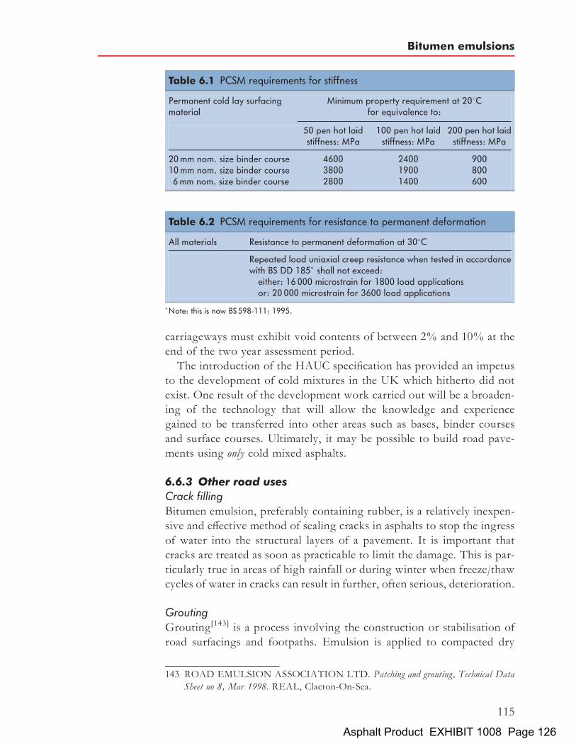
carriageways must exhibit void contents of between 2% and 10% at theend of the two year assessment period.The introduction of the HAUC specification has provided an impetus
to the development of cold mixtures in the UK which hitherto did notexist. One result of the development work carried out will be a broaden-ing of the technology that will allow the knowledge and experiencegained to be transferred into other areas such as bases, binder coursesand surface courses. Ultimately, it may be possible to build road pave-ments using only cold mixed asphalts.
6.6.3 Other road usesCrack fillingBitumen emulsion, preferably containing rubber, is a relatively inexpen-sive and effective method of sealing cracks in asphalts to stop the ingressof water into the structural layers of a pavement. It is important thatcracks are treated as soon as practicable to limit the damage. This is par-ticularly true in areas of high rainfall or during winter when freeze/thawcycles of water in cracks can result in further, often serious, deterioration.
GroutingGrouting[143] is a process involving the construction or stabilisation ofroad surfacings and footpaths. Emulsion is applied to compacted dry
Table 6.1 PCSM requirements for stiffness
Permanent cold lay surfacingmaterial
Minimum property requirement at 208Cfor equivalence to:
50 pen hot laidstiffness: MPa
100 pen hot laidstiffness: MPa
200 pen hot laidstiffness: MPa
20mm nom. size binder course 4600 2400 90010mm nom. size binder course 3800 1900 8006mm nom. size binder course 2800 1400 600
Table 6.2 PCSM requirements for resistance to permanent deformation
All materials Resistance to permanent deformation at 308C
Repeated load uniaxial creep resistance when tested in accordancewith BS DD 185� shall not exceed:either: 16 000 microstrain for 1800 load applicationsor: 20 000 microstrain for 3600 load applications
�Note: this is now BS 598-111: 1995.
143 ROAD EMULSION ASSOCIATION LTD. Patching and grouting, Technical DataSheet no 8, Mar 1998. REAL, Clacton-On-Sea.
Bitumen emulsions
115
Asphalt Product EXHIBIT 1008 Page 126

or damp aggregate, the low viscosity of the emulsion permitting in-depthpenetration through the void structure of the aggregate. The techniqueinvolves the construction of a combined base/surface course from athickness of between 50 and 75mm in one course or up to 100mm intwo courses, as may be specified. Suitable emulsion types for differentapplications are given below.
Surface dressing K1-70, K1-60Bond coats K1-40, K2-40Slurry seals K3-60Open graded macadams K2-60, K2-70Retreading K2-60Mist spraying K1-40, K2-40Concrete curing K1-40, K2-40
Tack/bond coatsThis is an established technique for ensuring that an adhesive and cohe-sive bond develops between the layers in a road pavement[144]. The use ofsuch coats may be essential in some surfacing operations to ensure suc-cess of the process. Tack coats are often used where a base or bindercourse has been subjected to traffic, perhaps on a construction site. Inaddition, their use may contribute significantly to the assessed value of‘residual life’ returned by deflection techniques.
6.6.4 Miscellaneous uses of bitumen emulsionsDetails of miscellaneous applications for emulsions have been publishedby the Road Emulsion Association[145]. Industrial applications ofbitumen emulsions are discussed in the Shell Bitumen Industrial Hand-book[146]. Bitumen emulsions are also used in other civil engineeringworks, horticultural and agricultural applications. Some examples aregiven below.
Soil stabilisation[147]
Fresh topsoil on embankments or ploughed agricultural land is sus-ceptible to surface erosion and slippage on embankments. It is essential,
144 ROADEMULSIONASSOCIATIONLTD.Tack coating, Technical Data Sheet no 5,Mar 1998. REAL, Clacton-On-Sea.
145 ROAD EMULSION ASSOCIATION LTD. Miscellaneous uses of bitumen roademulsions, Technical Data Sheet no 12, Mar 1998. REAL, Clacton-On-Sea.
146 MORGAN P and A MULDER. The Shell Bitumen Industrial Handbook, 1995. ShellBitumen, Wythenshawe, UK.
147 BUTCHTA H. Terrafix in agricultural applications, Shell Bitumen Review no 61, pp 7–8,Jun 1986. Shell International Petroleum Company Ltd, London.
The Shell Bitumen Handbook
116
Asphalt Product EXHIBIT 1008 Page 127

therefore, to either stabilise the surface with a binding agent or establish avegetation root system. Bitumen emulsion sprayed on the surface of thetopsoil binds the surface together and assists seed germination by retain-ing moisture in the soil, improving thermal insulation and protectingseeds from the elements and birds.
Slip layers and concrete curingBitumen emulsions are used to create a membrane between layers ofconcrete, the objective being to retain the strength of the upper layerby preventing water seepage into the lower layers. This avoids rigidadhesion between layers of different ages and strengths and helps toproduce a stronger upper layer by preventing water absorption intothe lower layers. Bitumen emulsion is also sprayed onto the top surfaceof freshly laid concrete to prevent the evaporation of water.
Protective coatsBitumen emulsions are used for protecting buried concrete, pipelines andironwork. To enhance the adhesive and cohesive characteristics of thecured binder film, a polymer modified emulsion is normally used.
6.7 BibliographyFor further information on the subject of bitumen emulsions, see BitumenEmulsions – General Information and Applications[148] which is available inboth French and English.
148 SYNDICAT DES FABRICANTS D’EMULSIONS ROUTIERES DEBITUMES. Bitumen emulsions – General information and applications, 1991. SFERB,Paris.
Bitumen emulsions
117
Asphalt Product EXHIBIT 1008 Page 128

Chapter 7
Mechanical testing andproperties of bitumens
Bitumen is a complex material with a complex response to stress. Theresponse of a bitumen to stress is dependent on both temperature andloading time. Thus, the nature of any bitumen test and what it indicatesabout the properties of a bitumen must be interpreted in relation to thenature of the material.A wide range of tests are performed on bitumens, from specification
tests to more fundamental rheological and mechanical tests. A numberof these were described in Chapter 4. This chapter considers categorisa-tion tests and important properties of bitumens.
7.1 Standard specification tests for bitumens
Since a wide variety of bitumens are manufactured, it is necessary to havetests to characterise different grades. The two tests used in the UK tospecify different grades of bitumen are penetration and softening pointtests. Although they are arbitrary empirical tests, it is possible to estimateimportant engineering properties from the results, including high-temperature viscosity and low-temperature stiffness. The use of thepenetration test for characterising the consistency of bitumen datesfrom the late nineteenth century[149].As the penetration and softening point tests are empirically derived, it is
essential that they are always carried out under exactly the same con-ditions. The Institute of Petroleum (IP)[150], the American Society forTesting and Materials (ASTM)[151,152] and British Standards Institution
119
149 BAVEN H C. School of Mines Quart, vol 10, p 297, 1889.150 INSTITUTE OF PETROLEUM. Methods for analysis and testing, vol 1, part 1.151 AMERICAN SOCIETY for TESTING and MATERIALS. Standard test method for
penetration of bituminous materials, D5-97, 1 Nov 1997. ASTM, Philadelphia.152 AMERICAN SOCIETY for TESTING and MATERIALS. Standard test method
for softening point of bitumen (Ring and ball method), D36-95, 1 Nov 1997. ASTM,Philadelphia.
Asphalt Product EXHIBIT 1008 Page 129

(BSI)[153,154] publish standard methods of testing bitumen. In many cases,the methods are identical and, therefore, methods are published jointly.However, some methods differ in detail, for example the IP and ASTMsoftening point method, and in these cases a correction factor is providedto relate test results obtained using these two test methods.The majority of the methods quote limits for assessing the acceptability
of test results. Limits of variability of results obtained by a single opera-tor (repeatability) and by different operators in different laboratories(reproducibility) are specified. Thus, tolerance is given to allow fordifferences between operators and equipment at different locations.
7.1.1 The penetration testThe consistency of a penetration grade or oxidised bitumen is measuredby the penetration test[153,155]. In this test, a needle of specified dimen-sions is allowed to penetrate a sample of bitumen, under a known load(100 g), at a fixed temperature (258C), for a known time (5 s). The testapparatus is shown in Fig. 7.1.The penetration is defined as the distance travelled by the needle into
the bitumen. It is measured in tenths of a millimetre (decimillimetre,dmm). The lower the value of penetration, the harder the bitumen. Con-versely, the higher the value of penetration, the softer the bitumen. Thistest is the basis upon which penetration grade bitumens are classified intostandard penetration ranges.It is essential that the test methods are followed precisely as even a
slight variation can cause large differences in the result. The mostcommon errors are:
. poor sampling and sample preparation;
. badly maintained apparatus and needles; and
. incorrect temperature and timing.
Temperature control is critical, control to �0.18C being necessary.Needles must be checked regularly for straightness, correctness of profileand cleanliness. Automatic timing devices are also necessary for accuracyand these must be checked regularly. Penetrations less than 2 dmm andgreater than 500 dmm cannot be determined with accuracy.
153 BRITISH STANDARDS INSTITUTION. Methods of test for petroleum and itsproducts, Bitumen and bituminous binders. Determination of needle penetration, BSEN1426: 2000, BS 2000-49: 2000. BSI, London.
154 BRITISH STANDARDS INSTITUTION. Methods of test for petroleum and itsproducts, Bitumen and bituminous binders. Determination of softening point. Ring and ballmethod, BSEN 1427: 2000, BS 2000-58: 2001. BSI, London.
155 AMERICAN SOCIETY for TESTING and MATERIALS. Standard test method forpenetration of bituminous materials, D5-97, 1 Nov 1997. ASTM, Philadelphia.
The Shell Bitumen Handbook
120
Asphalt Product EXHIBIT 1008 Page 130

For each test, three individual measurements of penetration are made.The average of the three values is recorded to the nearest whole unit. Therecorded penetration is reported if the difference between the individualthree measurements does not exceed a specified limit.The acceptable repeatability and reproducibility quoted in BS 1426:
2000[156] for the penetration test are as follows:
. Repeatability. If the penetration <50 2 dmm. If the penetration �50 4% of the mean of the two results
. Reproducibility. If the penetration <50 4 dmm. If the penetration �50 8% of the mean of the two results
7.1.2 The softening point testThe consistency of a penetration grade or oxidised bitumen can also bemeasured by determining its softening point[157,158]. In this test, a steel
Fig. 7.1 The penetration test
156 BRITISH STANDARDS INSTITUTION. Methods of test for petroleum and itsproducts, Bitumen and bituminous binders. Determination of needle penetration, BSEN1426: 2000, BS 2000-49: 2000. BSI, London.
157 BRITISH STANDARDS INSTITUTION. Methods of test for petroleum and itsproducts, Bitumen and bituminous binders. Determination of softening point. Ring andball method, BSEN 1427: 2000, BS 2000-58: 2001. BSI, London.
158 AMERICAN SOCIETY for TESTING and MATERIALS. Standard test methodfor softening point of bitumen (Ring and ball method), D36-95, 1 Nov 1997. ASTM,Philadelphia.
Mechanical testing and properties of bitumens
121
Asphalt Product EXHIBIT 1008 Page 131

ball (weight 3.5 g) is placed on a sample of bitumen contained in a brassring that is then suspended in a water or glycerine bath. The apparatus isshown in Fig. 7.2.Water is used for bitumen with a softening point of 808C or below and
glycerine is used for softening points greater than 808C. The bath tem-perature is raised at 58C per minute, the bitumen softens and eventuallydeforms slowly with the ball through the ring. At the moment thebitumen and steel ball touch a base plate 25mm below the ring, the tem-perature of the water is recorded. The test is performed twice and themean of the two measured temperatures is reported to the nearest0.28C for a penetration grade bitumen and 0.58C for an oxidised bitumen.If the difference between the two results exceeds 1.08C, the test must berepeated. The reported temperature is designated the softening point of
Fig. 7.2 The softening point test
The Shell Bitumen Handbook
122
Asphalt Product EXHIBIT 1008 Page 132

the bitumen and represents an equi-viscous temperature. In the ASTMversion of the softening point test, the bath is not stirred whereas inthe IP version the water or glycerine is stirred. Consequently, the soften-ing points determined by these two methods differ. The ASTM resultsare generally 1.58C higher than for the IP or BS method[159].As with the penetration test, the procedure for carrying out the soft-
ening point test must be followed precisely to obtain accurate results.Sample preparation, rate of heating and accuracy of temperature meas-urement are all critical. For example, it has been shown[160] that byvarying the heating rate from 4.5 to 5.58C per minute, the tolerancepermitted by the IP 58 test method, can result in a difference of 1.68Cin the measured softening point. Automatic softening point machinesare available and these ensure close temperature control and automati-cally record the result at the end of the test.The acceptable repeatability and reproducibility limits quoted in
BSEN1427: 2000[161] for the softening point test are as follows:
. Repeatability. For unmodified bitumens in water: 1.08C. For modified bitumens in water: 1.58C. For oxidised bitumens in glycerol: 1.58C
. Reproducibility. For unmodified bitumens in water: 2.08C. For modified bitumens in water: 3.58C. For oxidised bitumens in glycerol: 5.58C
The consistency of bitumen at the softening point temperature has beenmeasured by Pfeiffer and Van Doormaal[162] in terms of penetrationvalue. Using a specifically prepared, extra-long penetration needle theyfound a value of 800 pen for many but not all bitumens. The exactvalue was found to vary with penetration index and wax content. It hasalso been demonstrated by direct measurement that the viscosity at thesoftening point temperature of the majority of bitumens is 1200 Pa s(12 000 poise).
159 KROM C J. Determination of the ring and ball softening point of asphaltic bitumens withand without stirring. J Inst Pet, vol 36, 1950. Institute of Petroleum, London.
160 PFEIFFER J P H (Ed). The properties of asphaltic bitumen, vol 4, Elsevier’s PolymerSeries, 1950. Elsevier Science, Amsterdam.
161 BRITISH STANDARDS INSTITUTION. Methods of test for petroleum and itsproducts, Bitumen and bituminous binders, Determination of softening point, Ring andball method, BSEN 1427: 2000. BSI, London.
162 PFEIFFER J P H and VAN DOORMAAL P M. The rheological properties ofasphaltic bitumens, J Inst Pet, vol 22, pp 414–440, 1936. Institute of Petroleum,London.
Mechanical testing and properties of bitumens
123
Asphalt Product EXHIBIT 1008 Page 133

7.2 The Fraass breaking point test
The Fraass breaking point test[163] is one of very few tests that can beused to describe the behaviour of bitumens at very low temperatures(as low as �308C). The test was developed by Fraass[164] in 1937. It isessentially a research tool that determines the temperature at whichbitumen reaches a critical stiffness and cracks. A number of countrieswith very low winter temperatures, for example Canada, Finland,Norway and Sweden, have maximum allowable Fraass temperaturesfor individual grades of bitumen.In the Fraass test, shown in Fig. 7.3, a steel plaque 41mm� 20mm
coatedwith 0.5mmof bitumen is slowly flexed and released. The tempera-ture of the plaque is reduced at 18C per minute until the bitumen reaches acritical stiffness and cracks. The temperature at which the sample cracks istermed the breaking point and represents an equi-viscous or equi-stiffness
Fig. 7.3 The Fraass breaking point test
163 BRITISH STANDARDS INSTITUTION. Methods of test for petroleum and itsproducts, Bitumen and bituminous binders. Determination of the Fraass breaking point,BSEN 12593: 2000, BS 2000-8: 2001. BSI, London.
164 FRAASS A. Test methods for bitumen and bituminous mixture with specific reference to lowtemperature, Bitumen, pp 152–155, 1937.
The Shell Bitumen Handbook
124
Asphalt Product EXHIBIT 1008 Page 134

temperature. It has been shown that, at fracture, the bitumen has a stiffnessof 2:1� 109 Pa[165] which is approaching the maximum stiffness of2:7� 109 Pa (discussed further in Section 7.6.4). The Fraass temperaturecan be predicted from penetration and softening point for penetrationgrade bitumens because it is equivalent to the temperature at which thebitumen has a penetration of 1.25.
7.3 ViscosityThis is a fundamental characteristic of a bitumen as it determines how thematerial will behave at a given temperature and over a temperature range.The basic unit of viscosity is the pascal second (Pa s). The absolute ordynamic viscosity of a bitumen measured in pascal seconds is the shearstress applied to a sample of bitumen in pascals divided by the shearrate per second; 1 Pa s¼ 10 P (poise). The absolute viscosity of a bitumencan be measured using a sliding plate viscometer.Viscosity can also be measured in units of m2=s, or more commonly
mm2=s (1mm2=s ¼ 1 centistoke (cSt)). These units relate to kinematic vis-cosity. Kinematic viscosity is measured using a capillary tube viscometer.Kinematic viscosity is related to dynamic viscosity by the equation:
kinematic viscosity ¼ dynamic viscosity
density
For many purposes, it is usual to determine the viscosity of a bitumen bymeasuring the time required for a fixed quantity of material to flowthrough a standard orifice. These methods are useful for specificationand comparative purposes and, if required, the results can be convertedinto more fundamental units of viscosity.
7.3.1 Sliding plate viscometerA fundamental method of measuring viscosity is the sliding plate visco-meter. This apparatus applies the definition of absolute or dynamicviscosity, i.e. it takes the shear stress (Pa) applied to a film of bitumen(5 to 50mm thick) sandwiched between two flat plates and measures theresulting rate of strain (s�1). The viscosity in pascal seconds (Pa s) isgiven by the shear stress divided by the rate of strain. The apparatus com-prises a loading system that applies a uniform shear stress during a meas-urement and a device to produce a record of the flow as a function of time.Generally, the records show a curved toe due to visco-elastic behaviour
165 THENOUXG, G LEES and C A BELL.Laboratory investigation of the Fraass brittletest, Asphalt Technol, no 39, pp 34–46, July 1987. Institute of Asphalt Technology,Dorking.
Mechanical testing and properties of bitumens
125
Asphalt Product EXHIBIT 1008 Page 135

passing into a linear form whose slope is a direct measure of viscosity.Depending on the load and the size of the specimen, viscosities in therange of 105 to 109 Pa s can be measured. A special feature is that theshear stress is the same throughout the specimen making this instrumentparticularly suitable for investigating the phenomenon of shear stressdependence. Shear stress dependence is the variation in measured viscos-ity with the magnitude of the applied shear stress.
7.3.2 Capillary viscometerCapillary viscometers are essentially narrow glass tubes through whichthe bitumen flows. The tube has narrow and wide sections and is pro-vided with two or more marks to indicate a particular volume or flowas shown in Figs. 7.4 and 7.5.The value of kinematic viscosity is measured by timing the flow of
bitumen through a glass capillary viscometer at a given temperature.Each viscometer is calibrated and the product of flow time and viscometercalibration factor gives the kinematic viscosity in mm2=s. Temperature–viscosity curves are obtained by measuring kinematic viscosity at anumber of different temperatures, and plotting the viscosity on alogarithmic scale against temperature on a linear scale (discussed furtherin Section 7.4).
Fig. 7.4 U tube reverse flow viscometer
The Shell Bitumen Handbook
126
Asphalt Product EXHIBIT 1008 Page 136

7.3.3 Rotational viscometerRotational viscometers are normally used to determine, and in some casesspecify, the viscosity of bitumens at application temperatures. An exam-ple of a Brookfield rotational viscometer and Thermocel[166] is shown inFig. 7.6. Essentially, the device consists of a thermostatically controlledchamber containing a sample of hot bitumen. The spindle is loweredinto the bitumen and rotated. The torque required to rotate the spindleat a pre-specified shear rate is measured and converted into the viscosityof the bitumen. A direct reading of viscosity in Pa s is given on thedisplay.The rotational viscosity of bitumen is usually determined at 1508C
but with this type of apparatus the viscosity can be determined over arelatively wide range of temperatures, between 1208C and 1808C, andshear rates.
7.3.4 Cup viscometerCutback bitumens and emulsions are both specified by viscosity. Cutbackbitumens are specified using the standard tar viscometer[167] (STV,
Fig. 7.5 Kinematic viscometer
166 AMERICAN SOCIETY for TESTING and MATERIALS. Standard test methodfor viscosity determination of asphalt at elevated temperatures using a rotationalviscometer, D4402-02, 1 Jul 2002. ASTM, Philadelphia.
167 BRITISH STANDARDS INSTITUTION. Methods of test for petroleum and itsproducts, Determination of viscosity of cutback bitumen, BS 2000-72: 1993. BSI, London.
Mechanical testing and properties of bitumens
127
Asphalt Product EXHIBIT 1008 Page 137

shown in Fig. 7.7). The viscosity of emulsions can be determined usingeither the Engler viscometer or the Redwood II viscometer[168]. In thesetests, a metal cup is filled with cutback bitumen or emulsion at a standardtemperature and the time is recorded in seconds for a standard volume ofmaterial to flow out through the orifice in the bottom of the cup.There are several cup-type viscometers available which differ mainly in
the size of opening through which the bitumen is drained. Since the stressis provided by gravity, the absolute viscosity, �, in Pa s is given by:
� ¼ flow time (in s)� density (in g/ml)� constant
In the above equation, the value of the constant depends on the instru-ment used; these are listed in Table 7.1. The test results may also be
Fig. 7.6 Rotational viscometer
168 BRITISH STANDARDS INSTITUTION. Bitumen road emulsions (anionic andcationic), Specification for bitumen road emulsions, BS 434-1: 1984. BSI, London.
The Shell Bitumen Handbook
128
Asphalt Product EXHIBIT 1008 Page 138

expressed as the kinematic viscosity, �, in m2=s, or more commonlymm2=s, defined as:
� ¼ flow time� constant
7.4 The bitumen test data chart
In the late 1960s, Heukelom developed a system that permitted penetra-tion, softening point, Fraass breaking point and viscosity data to bedescribed as a function of temperature on one chart[169]. This is known
Table 7.1 Constants used according to type of cup viscometer
Viscometer Constant
Saybolt Universal 0.000218Redwood I 0.000247Saybolt Furol 0.00218Redwood II 0.00247Engler 0.00758Standard tar viscometer (4mm) 0.0132Standard tar viscometer (10mm) 0.400
Fig. 7.7 Standard tar viscometer
169 HEUKELOM W. A bitumen test data chart for showing the effect of temperature on themechanical behaviour of asphaltic bitumens, J Inst Pet, vol 55, pp 404–417, 1969. Instituteof Petroleum, London.
Mechanical testing and properties of bitumens
129
Asphalt Product EXHIBIT 1008 Page 139

Fig.7.8
Bitumen
testda
tachartc
ompa
ring
pene
trationgrad
ebitumen
sman
ufac
turedfrom
onecrud
e[170]
The Shell Bitumen Handbook
130
Asphalt Product EXHIBIT 1008 Page 140

as the bitumen test data chart (BTDC). The chart consists of one hori-zontal scale for the temperature and two vertical scales for the penetra-tion and viscosity. The temperature scale is linear, the penetration scaleis logarithmic and the viscosity scale has been devised so that penetrationgrade bitumens with ‘normal’ temperature susceptibility or penetrationindices (PIs, discussed in Section 7.5) give straight-line relationships. Atypical bitumen test data chart is shown in Fig. 7.8.The BTDC shows how the viscosity of a bitumen depends on tempera-
ture but it does not take account of the loading time. However, as theloading times for penetration, softening point and the Fraass breakingpoint tests are similar, these test data can be plotted with kinematicviscosity test data on the BTDC, as shown in Fig. 7.8. As the test resultson this chart form a straight-line relationship, it is possible to predict thetemperature–viscosity characteristics of a penetration grade bitumenover a wide range of temperatures using only the penetration and soften-ing point.During the manufacture and compaction of an asphalt there are
optimum bitumen viscosities. This is illustrated in Fig. 7.9 for a densebitumen macadam mixture manufactured using 200 pen bitumen. If theviscosity of the bitumen is too high during mixing, the aggregate willnot be properly coated and if the viscosity is too low, the bitumen willcoat the aggregate easily but may drain off the aggregate during storageor transportation. For satisfactory coating, the viscosity should beapproximately 0.2 Pa s.During compaction, if the viscosity is too low, the mixture will be
excessively mobile, resulting in pushing of the material in front of theroller. High viscosities will significantly reduce the workability of themixture and little additional compaction will be achieved. It is widelyrecognised that the optimal bitumen viscosity for compaction is between2 and 20 Pa s.Thus, the BTDC is a useful tool for ensuring that appropriate operat-
ing temperatures are selected to achieve the appropriate viscosity for anygrade of bitumen. Consideration of the viscosity requirements duringmanufacture and application has led to the operating temperaturesgiven in Fig. 7.9. Particular mixtures or circumstances may dictateother operating temperatures.The chart can also be used for comparing the temperature/viscosity
characteristics of different types of bitumens. Three classes of bitumen
170 HEUKELOMW.An improved method of characterizing asphaltic bitumens with the aid oftheir mechanical properties, Proc Assoc Asph Pav Tech, vol 42, pp 62–98, 1973. Associa-tion of Asphalt Paving Technologists, Seattle.
Mechanical testing and properties of bitumens
131
Asphalt Product EXHIBIT 1008 Page 141

Fig.7.9
Bitumen
testda
tachartsho
wing‘id
eal’bitumen
viscosities
forop
timal
mixingan
dco
mpa
ctionof
ade
nsebitumen
mac
adam
The Shell Bitumen Handbook
132
Asphalt Product EXHIBIT 1008 Page 142

can be distinguished using the BTDC: class S, class B and class Wbitumens.
7.4.1 Class S bitumensThe test data for a large group of bitumens can be represented by straightlines on the BTDC, within the repeatability of the test. This group, whichhas been designated class S (S for straight line), comprises penetrationbitumens of different origins with limited wax content. Figure 7.8shows a chart with straight lines for a number of different penetrationgrade bitumens manufactured from one base crude. The lines movetowards the left of the chart as the bitumens become softer. However,their slopes are equal, indicating that temperature susceptibilities aresimilar. Bitumens with the same penetration at 258C but from differentorigins, are shown in Fig. 7.10. The origin may influence the temperaturesusceptibility which is reflected by the slope of the line. Accordingly, thetemperature viscosity characteristics of S type bitumens may be deter-mined from their penetration and softening point only.
7.4.2 Class B bitumensThe test data of class B (B for blown) bitumens give curves on the chartas shown in Fig. 7.11. The curves can be represented by two intersectingstraight lines. The slope of the line in the high-temperature range is aboutequal to that of an unblown bitumen of the same origin, but the line inthe lower temperature range is less steep. Physically, there is no transitionpoint, but it is very convenient that they are still straight lines in thepenetration and viscosity regions. Each of them can be characterisedwith two test values. Thus, in all, four tests are required for a completedescription; penetration, softening point and two high-temperatureviscosity measurements.
7.4.3 Class W bitumensClass W (W for waxy) bitumens also give curves consisting of twostraight lines which, however, are dissimilar to those of blown bitumens.The two branches of the curve give slopes that are similar but are notaligned. Figure 7.11 shows an example of an S type bitumen togetherwith a curve for a similar bitumen with a wax content of 12 per cent.At low temperatures, when the wax is crystalline, there is hardly anydifference between the two curves. At higher temperatures, where thewax is molten, the curve for the waxy bitumen is significantly lowerdown on the chart. Between the two straight branches, there is a transi-tion range in which the test data are scattered because the thermal historyof the sample influences the viscosity result obtained over this range oftemperatures.
Mechanical testing and properties of bitumens
133
Asphalt Product EXHIBIT 1008 Page 143

Fig.7.10
Bitumen
testda
tachartc
ompa
ring
seve
ral1
00pe
nbitumen
sman
ufac
turedfrom
differen
tcrude
s[171]
171HEUKELOM
W.A
bitumentestdatachartforshowingtheeffectoftemperatureon
themechanicalbehaviour
ofasphalticbitumens,JInstPet,vol55,pp
404–417,
1969.Institute
ofPetroleum,London.
The Shell Bitumen Handbook
134
Asphalt Product EXHIBIT 1008 Page 144

Fig.7.11
Bitumen
testda
tachartc
ompa
ring
classS,
Ban
dW
type
bitumen
s[172]
172HEUKELOM
W.A
bitumentestdatachartforshowingtheeffectoftemperatureon
themechanicalbehaviour
ofasphalticbitumens,JInstPet,vol55,pp
404–417,
1969.Institute
ofPetroleum,London.
Mechanical testing and properties of bitumens
135
Asphalt Product EXHIBIT 1008 Page 145

7.5 Temperature susceptibility — penetration index (PI)
All bitumens display thermoplastic properties, i.e. they become softerwhen heated and harden when cooled. Several equations exist thatdefine the way that the viscosity (or consistency) changes with tem-perature. One of the best known is that developed by Pfeiffer and VanDoormaal[173]. If the logarithm of penetration, P, is plotted againsttemperature, T, a straight line is obtained such that:
logP ¼ AT þ K
where A ¼ the temperature susceptibility of the logarithm of the pene-tration and K ¼ a constant.The value ofA varies from about 0.015 to 0.06 showing that there may
be a considerable difference in temperature susceptibility. Pfeiffer andVan Doormaal developed an equation for the temperature susceptibilitythat assumes a value of about zero for road bitumens. For this reason,they defined the penetration index (PI) as:
20� PI
10þ PI¼ 50A
or, explicitly,
PI ¼ 20ð1� 25AÞ1þ 50A
The value of PI ranges from around �3 for highly temperature suscep-tible bitumens to around þ7 for highly blown low-temperature suscep-tible (high PI) bitumens. The PI is an unequivocal function of A andhence it may be used for the same purpose. The values of A and PIcan be derived from penetration measurements at two temperatures,T1 and T2, using the equation:
A ¼ log pen at T1 � log pen at T2
T1 � T2
The consistency at the softening point can be expressed in terms of pene-tration, both by linear extrapolation of logarithm of pen versus tempera-ture and by direct measurement with an extra-long penetration needle atthe ASTM softening point temperature. Pfeiffer and Van Doormaalfound that most bitumens had a penetration of about 800 dmm at theASTM softening point temperature. Replacing T2 in the above equationby the ASTM softening point temperature and the penetration at T2 by
173 PFEIFFER J P H and P M VAN DOORMAAL. The rheological properties ofasphaltic bitumens, J Inst Pet, vol 22, pp 414–440, 1936. Institute of Petroleum,London.
The Shell Bitumen Handbook
136
Asphalt Product EXHIBIT 1008 Page 146

800 they obtained the equation:
A ¼ log pen T1 � log 800
T1 � ASTM softening point
Substituting this equation in the equation for PI on the previous pageand assuming a penetration test temperature of 258C gives:
PI ¼ 1952� 500 log pen� 20SP
50 log pen� SP� 120
The assumption of penetration of 800 at the softening point temperatureis not valid for all bitumens. It is therefore advisable to calculate thetemperature susceptibility using the penetration at two temperatures,T1 and T2.The nomographs shown in Figs. 7.12 and 7.13 enable the approximate
value of PI to be deduced from either the penetration at 258C and thesoftening point temperature, or the penetration of the bitumen at two dif-ferent temperatures. Due to the spread of the actual value of penetrationat the softening point temperature, the value of PI calculated from onepenetration and one softening point may vary from the precise value cal-culated from two penetrations. However, since the form of properties isgenerally determined for control of bitumen in terms of the specification,it is normally the case that these figures are used.One drawback of the PI system is that it uses the change in bitumen
properties over a relatively small range of temperatures to characterisebitumen. Extrapolations to extremes of temperature can sometimes bemisleading. The PI can be used to give a good approximation of thebehaviour to be expected, but confirmation using stiffness or viscositymeasurements is desirable.
7.6 Engineering properties of bitumenBitumen is widely used as a construction material in civil engineering,building and for industrial applications but its mechanical propertiesare more complex than materials such as steel or concrete. However,the mechanical properties of bitumens, which are of considerable valueto both the civil engineer and the industrial bitumen user, can be definedin terms that are analogous to the elasticity moduli of solid materials.
7.6.1 The concept of stiffnessA viscous material is one that is semi-fluid in nature. When stressed, itwill deform or tend to deform, any deformation being unrecoveredwhen the loading is removed. Elastic materials also deform or tend todeform when stressed. However, when the loading is removed, anydeformation is fully recovered. Bitumens are visco-elastic materials.
Mechanical testing and properties of bitumens
137
Asphalt Product EXHIBIT 1008 Page 147

The degree to which their behaviour is viscous and elastic is a function ofboth temperature and period of loading (usually referred to as ‘loadingtime’). At high temperatures or long times of loading, they behave asviscous liquids whereas at very low temperatures or short times ofloading they behave as elastic (brittle) solids. The intermediate rangeof temperature and loading times, more typical of conditions in service,results in visco-elastic behaviour.
Fig. 7.12 Nomograph for penetration index (SP/pen)
The Shell Bitumen Handbook
138
Asphalt Product EXHIBIT 1008 Page 148

In order to define the visco-elastic properties, Van der Poel[174] intro-duced, in 1954, the concept of stiffness modulus as a fundamental para-meter to describe the mechanical properties of bitumens by analogywith the elastic modulus of solids. Thus, if a tensile stress, �, is appliedat loading time t ¼ 0, a strain, ", is instantly attained that does notincrease with loading time. The elastic modulus, E, of the material is
Fig. 7.13 Nomograph for penetration index (pen/pen)
174 VAN DER POEL C. A general system describing the visco-elastic properties of bitumenand its relation to routine test data, J App Chem, vol 4, pp 221–236, 1954.
Mechanical testing and properties of bitumens
139
Asphalt Product EXHIBIT 1008 Page 149

expressed by Hooke’s law:
E ¼ �
"
In the case of visco-elastic materials such as bitumen, a tensile stress, �,applied at loading time t ¼ 0, causes a strain, ", that increases, but notproportionately, with loading time. The stiffness modulus, St, at loadingtime t, is defined as the ratio between the applied stress and the resultingstrain at loading time t:
St ¼�
"t
It follows from the above that the value of the stiffness modulus is depen-dent on the loading time that is due to the special nature of bitumen.Similarly, the stiffness modulus will also depend on temperature, T. Con-sequently, it is necessary to state both temperature and time of loading ofany stiffness measurement:
St;T ¼ �
"t;T
The effect of changes in temperature and loading time on the stiffnessmodulus of three different bitumens are shown in Figs. 7.14, 7.15 and7.16. Figure 7.14 shows a bitumen of low PI,�2.3. At very short loading
Fig. 7.14 The effect of temperature and loading time on the stiffness of a low PIbitumen
The Shell Bitumen Handbook
140
Asphalt Product EXHIBIT 1008 Page 150

Fig. 7.15 The effect of temperature and loading time on the stiffness of 115=15bitumen
Fig. 7.16 The effect of temperature and loading time on the stiffness of a100pen bitumen
Mechanical testing and properties of bitumens
141
Asphalt Product EXHIBIT 1008 Page 151

times, the stiffness modulus is virtually constant, asymptotic towards 2.5to 3:0� 109 Pa, and is, in this region, largely independent of temperatureand loading time, i.e. S ¼ E. The effect of PI is clearly illustrated by com-paring Figs. 7.14 and 7.15. The bitumen with the higher PI (þ5) (Fig.7.15) is considerably stiffer at higher temperatures and longer loadingtimes, i.e. it is less temperature susceptible.Figure 7.16 shows the relationship for a 100 pen bitumen. At a loading
time of 0.02 s (which equates to a vehicle speed of around 50 km/h) thestiffness modulus is approximately 107 Pa at 258C but falls to approxi-mately 5� 104 Pa at 608C. At low temperatures, the stiffness modulusis high and therefore permanent deformation does not occur. However,at higher temperature or longer loading times (stationary traffic), the stiff-ness modulus is substantially reduced and, under these conditions, per-manent deformation of the road surface is much more likely to occur.In order to fully appreciate the significance of the stiffness modulus and
its measurement, it is necessary to consider the deformation under stressof simple solids and liquids. The deformation behaviour of visco-elasticmaterials can then be derived.
7.6.2 Determination of the stiffness modulus of bitumenThe methods used to measure the stiffness modulus of bitumen are basedon shear deformation, as shown in Fig. 7.17. The resistance to shear is
Fig. 7.17 A creep test in shear
The Shell Bitumen Handbook
142
Asphalt Product EXHIBIT 1008 Page 152

expressed in terms of the shear modulus, G, which is defined as:
G ¼ �
¼ shear stress
shear strain
The elastic modulus and shear modulus are related by the equation:
E ¼ 2ð1þ ÞGwhere ¼ Poisson’s ratio. The value of depends on the compressibil-ity of the material and may be assumed to be 0.5 for almost incompres-sible pure bitumens while values of <0.5 have to be considered forasphalt mixtures. Thus:
E � 3G
Shear stress can be determined statically in a creep test or dynamically byapplication of a sinusoidal load. In a creep test, the shear stress is appliedfrom the beginning of the test. The deformation at loading times fromabout 1 to 105 s or longer can be measured. In dynamic tests, the shearstress is usually applied as a sinusoidally varying stress of constant ampli-tude and fixed frequency. The deformation of the material under test alsovaries sinusoidally with the same frequency as the applied stress. This isillustrated in Fig. 7.18.The shear modulus, Gf , at frequency f , is given by the ratio of the
amplitudes of shear stress, � , and shear strain, , according to:
Gf ¼��
�f
Fig. 7.18 A dynamic test in shear
Mechanical testing and properties of bitumens
143
Asphalt Product EXHIBIT 1008 Page 153
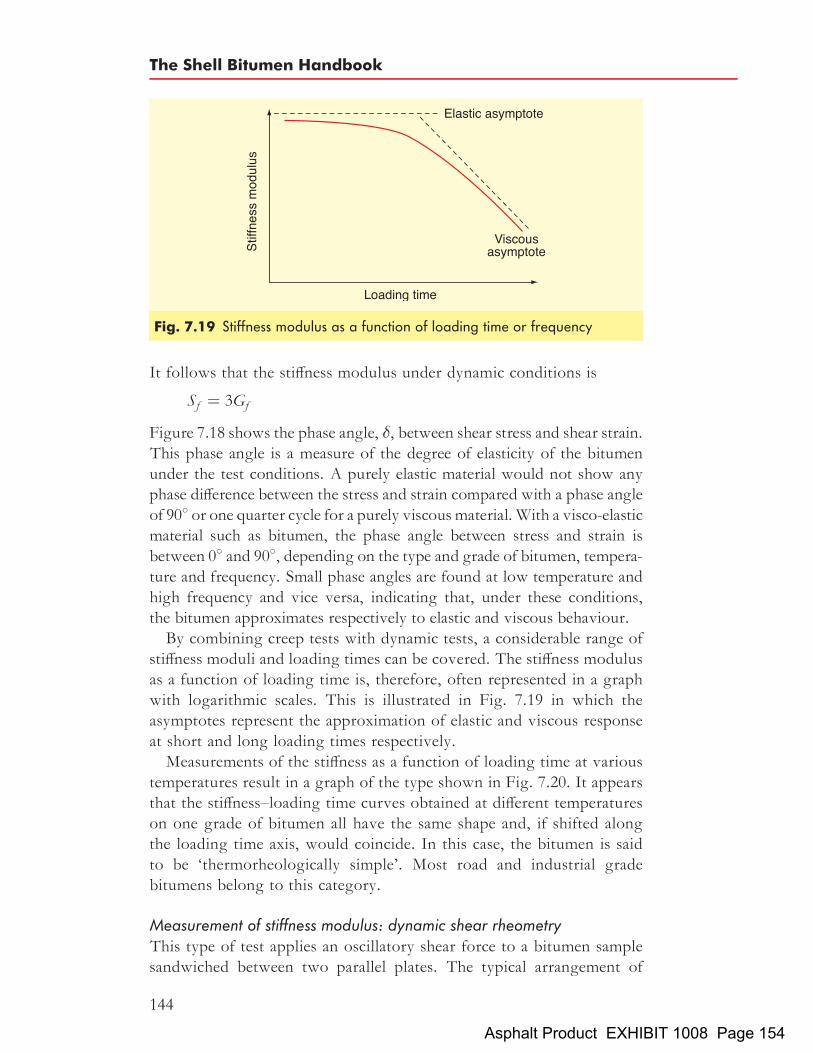
It follows that the stiffness modulus under dynamic conditions is
Sf ¼ 3Gf
Figure 7.18 shows the phase angle, �, between shear stress and shear strain.This phase angle is a measure of the degree of elasticity of the bitumenunder the test conditions. A purely elastic material would not show anyphase difference between the stress and strain compared with a phase angleof 908 or one quarter cycle for a purely viscousmaterial.With a visco-elasticmaterial such as bitumen, the phase angle between stress and strain isbetween 08 and 908, depending on the type and grade of bitumen, tempera-ture and frequency. Small phase angles are found at low temperature andhigh frequency and vice versa, indicating that, under these conditions,the bitumen approximates respectively to elastic and viscous behaviour.By combining creep tests with dynamic tests, a considerable range of
stiffness moduli and loading times can be covered. The stiffness modulusas a function of loading time is, therefore, often represented in a graphwith logarithmic scales. This is illustrated in Fig. 7.19 in which theasymptotes represent the approximation of elastic and viscous responseat short and long loading times respectively.Measurements of the stiffness as a function of loading time at various
temperatures result in a graph of the type shown in Fig. 7.20. It appearsthat the stiffness–loading time curves obtained at different temperatureson one grade of bitumen all have the same shape and, if shifted alongthe loading time axis, would coincide. In this case, the bitumen is saidto be ‘thermorheologically simple’. Most road and industrial gradebitumens belong to this category.
Measurement of stiffness modulus: dynamic shear rheometryThis type of test applies an oscillatory shear force to a bitumen samplesandwiched between two parallel plates. The typical arrangement of
Fig. 7.19 Stiffness modulus as a function of loading time or frequency
The Shell Bitumen Handbook
144
Asphalt Product EXHIBIT 1008 Page 154

dynamic shear rheometers (DSRs) is of a fixed lower plate and an oscil-lating upper plate through which the shear force is applied to the speci-men as shown in Fig. 7.21 (the apparatus is shown in Fig. 7.22). Thecentre line of the upper plate, described by point A in Fig. 7.21, movesto point B then passes through its original position to point C andthen returns to point A, representing one cycle. This movement isthen repeated continuously throughout the duration of the test.Two types of DSR exist, controlled stress and controlled strain. In a
controlled stress arrangement, a fixed torque is applied to the upperplate to generate the oscillatory motion between points B and C. Becausethe applied stress level is fixed, the distance the plate moves on its oscil-latory path may vary between cycles. In controlled strain testing, theupper plate moves precisely between the extremities of amplitude atthe specified frequency and the torque necessary to maintain the oscilla-tion is measured.
Fig. 7.20 Stiffness modulus as a function of loading time at differenttemperatures
Fig. 7.21 Schematic representation of the DSR mode of testing
Mechanical testing and properties of bitumens
145
Asphalt Product EXHIBIT 1008 Page 155

DSRs can be used to characterise both viscous and elastic behaviour ofbitumens by measuring the complex shear modulus, G�, and the phaseangle, �, from a single test run. For visco-elastic materials like bitumen,the shear modulus is composed of a loss modulus (viscous component,G00) and a storagemodulus (elastic component,G0), the relativemagnitudeof which dictates how the material responds to applied loads. The twocomponents are linked by the phase angle to the complex moduluswhich can be simply shown by drawing vector arrows as in Fig. 7.23.Hence, the different components can be described by the followingequation:
G� ¼ffiffiffiffiffiffiffiffiffiffiffiffiffiffiffiffiffiffiffiffiffiffiffiffiffiffiffiffiðG00Þ2 þ ðG0Þ2
q
The values of G� and � for bitumens are dependent on temperature andfrequency of loading, so very accurate temperature control of the speci-men must be maintained throughout the duration of the test. This is nor-mally achieved by a circulating fluid bath that prevents any temperaturegradient from developing within the sample.
Fig. 7.22 Dynamic shear rheometer
The Shell Bitumen Handbook
146
Asphalt Product EXHIBIT 1008 Page 156

Under normal pavement temperatures and traffic loading, bitumenswill exhibit both viscous and elastic characteristics, the relative responseof which will vary as conditions change. By identifying the linear visco-elastic range of the bitumen, frequency sweeps can be performed at aseries of different temperatures to build up a ‘master curve’ for thebitumen under test. The master curve showing G�and � gives a full rheo-logical profile of the bitumen describing the behaviour of bitumen over awide range of conditions.DSR testing provides fundamental data on the properties of bitumens
and such data can be used as guidelines to the performance of thebitumens under test. In Section 4.7, the SHRP philosophy for the speci-fication of binders was outlined where binders are categorised accordingto their fundamental properties when tested at different temperatureswith dynamic shear rheometry being used for all high service tempera-ture testing.
Prediction of stiffness modulusIf direct measurement of stiffness modulus is not feasible, it can be pre-dicted using the Van der Poel nomograph[175]. Van der Poel showedthat two bitumens of the same PI at the same time of loading haveequal stiffnesses at temperatures that differ from their respective softeningpoints by the same amount. Over forty bitumens were tested whose PIsvaried from þ6.3 to �2.3 at many temperatures and frequencies usingboth creep and dynamic tests. From the test data, Van der Poel produceda nomograph from which, using only penetration and softening
Fig. 7.23 Relationship between G�, G0, G00 and �
175 VAN DER POEL C. A general system describing the visco-elastic properties of bitumenand its relation to routine test data, J App Chem, vol 4, pp 221–236, 1954.
Mechanical testing and properties of bitumens
147
Asphalt Product EXHIBIT 1008 Page 157

point[176], it is possible to predict, within a factor of 2, the stiffnessmodulus of a bitumen for any conditions of temperature and time ofloading. Figure 7.24 shows a Van der Poel nomograph with the stiffnessmodulus determined for a 40/60 pen bitumen at a loading time of 0.02 sand a test temperature of 58C.
7.6.3 Tensile strengthAnother important engineering property of bitumen is its breaking stressand/or tensile strain at break. The tensile properties of bitumen are, likestiffness modulus, dependent on both temperature and loading time.Assuming that the breaking properties of bitumen are dependent on itsrheology at the instant of failure, its behaviour can be expressed interms of the amounts of elastic, delayed elastic and viscous strain asdepicted in Fig. 7.25. This shows, accepting the above assumption,that at stiffnesses greater than 5� 106 Pa, strain at break is a functionof stiffness modulus. Only at low stiffness, where viscous deformationis large, is PI a significant factor. At high stiffness, S ¼ E. As thestrain at break is defined as the ratio between change in length and theinstantaneous length, it will be equal to the elongation, i.e. increase inlength divided by the initial length, as long as the increase in lengthremains low.In practice, break takes place under conditions of large stress. Large
stresses normally occur at low temperature, i.e. at high stiffness. Strainat break is then at its minimum. At higher temperatures, i.e. at low stiff-ness moduli, there will normally be no break at the same load but therewill be deformation.Strain at break can be predicted using the Heukelom nomograph[177],
shown in Fig. 7.26, that has been derived from the Van der Poel nomo-graph. In the example, strain at break of a bitumen with a softening point(IP) of 53.58C and a PI of zero is given at 128C. At a loading time of0.02 s, strain at break is 0.075 (7.5%) and at 10 s is 1.00 (100%).
7.6.4 Fatigue strengthLike many other materials, the strength of bitumen can be reduced byrepeated loading, i.e. it fatigues. This is illustrated in Fig. 7.27 where
176 AMERICAN SOCIETY for TESTING and MATERIALS. Standard test methodfor softening point of bitumen (Ring and ball apparatus), D36-95, 1 Nov 1995.ASTM, Philadelphia.
177 HEUKELOM W. Observations on the rheology and fracture of bitumens and asphaltmixes, Proc Assoc Asph Pav Tech, vol 35, pp 358–399, 1966. Association of AsphaltPaving Technologists, Seattle.
178 VAN DER POEL C. A general system describing the visco-elastic properties of bitumenand its relation to routine test data, J App Chem, vol 4, pp 221–236, 1954.
The Shell Bitumen Handbook
148
Asphalt Product EXHIBIT 1008 Page 158

Fig.7.24
Nom
ograph
forde
term
iningthestiffne
ssmod
ulus
ofbitumen
s[178]
Mechanical testing and properties of bitumens
149
Asphalt Product EXHIBIT 1008 Page 159

the curves for fatigue strength and breaking strength are shown as afunction of stiffness modulus. All the tests have been carried out bybending at constant stress amplitude. The fatigue strength is the stressthat causes failure after 103, 104, 105, and 106 load cycles while the break-ing strength corresponds to one cycle. The strength is reduced as thenumber of loading cycles increases. This figure shows that, at highstiffness moduli, the effect of load repetitions is significantly reducedand, at the maximum stiffness modulus (S ¼ E ¼ 2:7� 109 Pa), fatiguestrength is independent of the number of load repetitions. For a single
Fig. 7.25 Strain at break as a function of stiffness modulus and penetrationindex[179]
179 HEUKELOM W and P W O WIJGA. Bitumen testing, 1973. Koninklijke/Shell-Laboratorium, Amsterdam.
180 HEUKELOM W. Observations on the rheology and fracture of bitumens and asphaltmixes, Proc Assoc Asph Pav Tech, vol 35, pp 358–399, 1966. Association of AsphaltPaving Technologists, Seattle.
The Shell Bitumen Handbook
150
Asphalt Product EXHIBIT 1008 Page 160

Fig.7.26
Nom
ograph
forde
term
iningstrain
atbrea
kof
bitumen
s[180]
Mechanical testing and properties of bitumens
151
Asphalt Product EXHIBIT 1008 Page 161

bend, the fatigue strength is virtually constant, around 4� 106 Pa forstiffness moduli greater than 5� 107 Pa.
7.7 Other bitumen tests7.7.1 Force ductility testIn Section 4.5.1, the traditional ductility test[182] was described. It wasexplained that the cohesive strength of bitumen is characterised by its
Fig. 7.27 Fatigue ‘strength’ as a function of stiffness modulus[181]
181 HEUKELOM W. Observations on the rheology and fracture of bitumens and asphaltmixes, Proc Assoc Asph Pav Tech, vol 35, pp 358–399, 1966. Association of AsphaltPaving Technologists, Seattle.
182 AMERICAN SOCIETY for TESTING and MATERIALS. Standard test methodfor ductility of bituminous materials, D113-99, 1 Nov 1999. ASTM, Philadelphia.
The Shell Bitumen Handbook
152
Asphalt Product EXHIBIT 1008 Page 162

ductility at low temperature. A European version has been developedand is called the force ductility test[183].The procedure is very similar to that adopted in the traditional
method. Samples of bitumen under test are formed into ‘dumb-bells’and immersed in a water bath and stretched at a constant rate of50mm per minute until fracture occurs. The distance the specimen isstretched before failure is reported as the ductility. The test temperatureis adjusted depending on the penetration of the bitumen under test. Inthese conditions, the test has been found to discriminate betweenbitumens of different cohesive strengths.However, some standard bitumens form a very thin thread at large
values of strain. This produces misleading test results since the cohesivestrength is essentially zero. It has been shown that the modification ofbitumen with elastomers produces much thicker threads in the forceductility test, indicating a greater cohesion in such binders comparedto that found in unmodified bitumens.To quantify this effect, the force required to stretch the bitumen sample
is recorded during the measurement phase. The area below the resultingforce–distance function can be calculated and represents the cohesiveenergy. Penetration grade bitumen and polymer modified bitumen pro-duce significantly different force–ductility curves and this is illustratedin Figs. 7.28(a) and (b).
7.7.2 Toughness and tenacity testPolymer modified bitumen emulsions for surface dressing in the UKbegan to enjoy significant usage in the 1980s and the early part of the1990s. Throughout that period, there was little by way of laboratorytesting available to assist in predicting the likely performance of thesebinders on site.The development of the toughness and tenacity test enabled the indus-
try to quantitatively differentiate not only between both modified andunmodified bitumens but also between levels and the nature of modifica-tion. It was therefore one of the first ‘specialist’ tests to be included intender documents for proprietary surface dressing programmes.Developed from an American test[184], the procedure involves the pull-
ing of a tension head assembly test piece with a semi-submerged sphericalhead from within a pre-prepared sample of bitumen (either recoveredfrom the emulsion or sampled pre-emulsification) at constant speed and
183 EUROPEAN COMMITTEE FOR STANDARDIZATION. Bitumen and bitumi-nous binders, Determination of the tensile properties of modified bitumen by the force ductilitymethod, prEN 13589. CEN, Brussels.
184 BENSON J R. New concepts for rubberised asphalts, Roads and Streets, vol 98, no 4,pp 138–142, Apr 1955.
Mechanical testing and properties of bitumens
153
Asphalt Product EXHIBIT 1008 Page 163

at a specified temperature. A load–extension graph is recorded, fromwhich areas under the curve (i.e. work done) can be calculated.Essentially, the curve is split into two parts, defining two modes of
behaviour of the bitumen. An initial peak describes the yielding of thebitumen under tensile force. This part of the curve is primarily due tothe behaviour of the base bitumen and results in a low area under thecurve. The second part of the graph reflects the elastomeric behaviourof the bitumen and is primarily dependent on the level and type ofpolymer modification. This portion of the curve may show a secondaryincrease in force over a prolonged extension, significantly increasing
Fig. 7.28 Force–ductility curves for (a) penetration grade bitumen and(b) polymer modified bitumen
The Shell Bitumen Handbook
154
Asphalt Product EXHIBIT 1008 Page 164

the extension prior to break, therefore substantially increasing the areaunder the curve.Toughness is defined as the area under the total curve, i.e. the total
work done in removing the test piece from the sample, whereas thetenacity is represented by the area under the curve after the bitumencontribution has been removed.In 1994, the method was formalised and entered into the Institute of
Petroleum ‘Standard methods for analysing and testing of petroleumand related products’ as a proposed method PM/BQ94, at which levelit remained. The method lost favour within the wider industry in themid to late 1990s for two key reasons; firstly, the correlation between pre-dicted and actual performance for surface dressing binders was notproven and secondly, significant difficulty was encountered in achievingan acceptable level of reproducibility between laboratories. Other tests,such as the Vialit cohesion and DSR began to find favour. As a result,the toughness and tenacity test has been dropped from tender documentssince the latter part of the 1990s.
7.7.3 Vialit cohesionThe Vialit pendulum test[185] assesses the degree of adhesion betweenan aggregate and a bitumen when subjected to a sudden impact. The
Fig. 7.29 The Vialit pendulum test
185 EUROPEAN COMMITTEE FOR STANDARDIZATION. Bitumen andbituminous binders, Determination of cohesion of bituminous binders for surface dressings,prEN 13588, 1999. CEN, Brussels.
Mechanical testing and properties of bitumens
155
Asphalt Product EXHIBIT 1008 Page 165

apparatus used for carrying out the test is shown in Fig. 7.29. Theprocedure involves placing a thin film of binder between two cubesand measuring the energy required to remove the upper block. It is ofgreatest significance in situations where aggregate is placed in directcontact with traffic stresses, for example in surface dressings and thechippings in hot rolled asphalt surface courses. The maximum impactenergy is usually significantly increased by polymer modification as isthe overall energy across the entire temperature range (see Fig. 7.30).Its significance for other materials has yet to be fully evaluated[186].In addition, this test can be used to assess the effect on the degree of
cohesion of variables such as the amount and type of dust, moisture,the type of binder, adhesion agents, etc.
Fig. 7.30 Comparison of cohesion curves for a penetration grade bitumen anda polymer modified bitumen
186 LANCASTER I M. (R NHUNTER, ed).Asphalts in Road Construction, pp 45–106,2000. Thomas Telford, London.
The Shell Bitumen Handbook
156
Asphalt Product EXHIBIT 1008 Page 166

Chapter 8
Durability of bitumens
Long-term studies have shown that if an asphalt surfacing is to achieve itsdesign life, it is important that the bitumen is not excessively hardenedduring hot storage, the asphalt manufacturing process or in service onthe road. Bitumen, in common with many organic substances, is affectedby the presence of oxygen, ultraviolet radiation and by changes intemperature. In bitumen, these external influences cause it to harden,resulting in a decrease in penetration, an increase in softening pointand, usually, an increase in penetration index (PI). In recent years, thephenomenon of the hardening of bitumen and, hence, the hardening ofan asphalt mixture has been viewed as being beneficial in the pavementlayers as it increases the stiffness of the material and, therefore, theload spreading capabilities of the structure. This hardening is knownas ‘curing’ and is believed to extend the life of a pavement[187].In the surface course, where the material is exposed to the environ-
ment, hardening of the bitumen can have a detrimental effect on itsperformance and can lead to fretting and/or cracking. This effect is stillreferred to as ‘hardening’, the term implying that the change in bitumenproperties is detrimental to the service life of the surface course.
8.1 Bitumen hardening
The tendency for bitumen to harden under the influence of the atmos-phere has been known and studied for many years. As many as fifteendifferent factors that influence bitumen ageing have been identified andthese are detailed in Table 8.1.The most important of these fifteen mechanisms of bitumen hardening
are:
157
187 NUNN M E, A BROWN, D WESTON and J C NICHOLLS. Design of long-lifeflexible pavements for heavy traffic, Report 250, 1997. TRL, Crowthorne.
Asphalt Product EXHIBIT 1008 Page 167

. oxidation
. volatilisation
. steric or physical factors
. exudation of oils.
8.1.1 OxidationLike many organic substances, bitumen is slowly oxidised when in con-tact with atmospheric oxygen. Polar groups containing oxygen areformed and these tend to associate into micelles of higher micellarweight thereby increasing the viscosity of the bitumen. Polar hydroxyl,carbonyl and carboxylic groups are formed, resulting in larger andmore complex molecules that make the bitumen harder and less flexible.The degree of oxidation is highly dependent on the temperature, timeand the thickness of the bitumen film. The rate of oxidation doublesfor each 108C increase in temperature above 1008C. Hardening due tooxidation has long been held to be the main cause of ageing to theextent that other factors have been given scant consideration. However,it has been shown that although other factors are generally less importantthan oxidation, they are measurable.
Table 8.1 Mechanisms of bitumen ageing[188]
Factors that influencebitumen ageing:
Influenced by: Occurring:
Time Heat Oxygen Sunlight Beta andgammarays
At thesurface
In themixture
Oxidation (in dark) X X X XPhoto-oxidation (direct light) X X X X XVolatilisation X X X XPhoto-oxidation (reflected light) X X X X XPhoto-chemical (direct light) X X X XPhoto-chemical (reflected light) X X X X XPolymerisation X X X XSteric or physical X X XExudation of oils X X XChanges by nuclear energy X X X X XAction by water X X X X XAbsorption by solid X X X XAbsorption of components at a solid
surfaceX X X
Chemical reactions X X X XMicrobiological deterioration X X X X X
188 TRAXLER R N. Durability of asphalt cements, Proc Assoc Asph Pav Tech, vol 32,pp 44–63, 1963. Association of Asphalt Paving Technologists, Seattle.
The Shell Bitumen Handbook
158
Asphalt Product EXHIBIT 1008 Page 168

8.1.2 Loss of volatilesThe evaporation of volatile components depends mainly upon tem-perature and the exposure conditions. Penetration grade bitumens arerelatively involatile and therefore the amount of hardening resultingfrom loss of volatiles is usually fairly small.
8.1.3 Steric or physical hardeningPhysical hardening occurs when the bitumen is at ambient temperatureand is usually attributed to reorientation of bitumen molecules and theslow crystallisation of waxes. Physical hardening is reversible in that,upon reheating, the original viscosity of the bitumen is obtained.This phenomenon can be easily reproduced in the laboratory by meas-
uring the penetration of a sample of bitumen (without reheating) over aperiod of time. As time passes, the penetration of the sample will fall.
8.1.4 Exudative hardening[189]
Exudative hardening results from the movement of oily components thatexude from the bitumen into the mineral aggregate. It is a function ofboth the exudation tendency of the bitumen and the porosity of theaggregate.
8.2 Hardening of bitumen during storage, mixing and in
serviceThe circumstances under which hardening occurs vary considerably.During storage, the bitumen is in bulk at a high temperature for aperiod of days or weeks. During mixing, hot storage, transport andapplication, the bitumen is a thin film at high temperature for a relativelyshort period. In service, the bitumen is a thin film at a low or moderatetemperature for a very long time. The degree of exposure to the air ofasphalts in service is important and dependent upon the void contentof the mixture. In dense, well compacted mixtures, the amount of hard-ening is relatively small whilst asphalts that have a more open constitu-tion, such as porous asphalt, will undergo significant hardening.
8.2.1 Hardening of bitumen in bulk storageVery little hardening occurs when bitumen is stored in bulk at high tem-perature. This is because the surface area of the bitumen that is exposedto oxygen is very small in relation to the volume. However, if thebitumen is being circulated and is falling from the pipe entry at the top
189 VAN GOOSWILLIGEN G, F TH DE BATS and T HARRISON. Quality ofpaving grade bitumen – a practical approach in terms of functional tests, Proc 4th Euro-bitume Symp, pp 290–297, Madrid, Oct 1989.
Durability of bitumens
159
Asphalt Product EXHIBIT 1008 Page 169

of the tank to the surface of the bitumen, significant hardening mayoccur. This arises because the surface area of the bitumen will be rela-tively large as it falls from the entry pipe exposing it to the action ofthe oxygen. This effect can be minimised using the storage tank layoutshown in Figure 2.4.
8.2.2 Hardening of bitumen during mixing with aggregateThis is described as ‘short-term ageing’, a term that is also applied tohardening which occurs during laying. During the mixing process, allthe aggregate and filler is coated with a thin film of bitumen usuallybetween 5 and 15mm thick. If the bitumen from 1 tonne of densecoated macadam was spread at 10mm thick, it would occupy an area ofaround 10 000m2, the equivalent of over one and a half average-sizedfootball pitches. Thus, when bitumen is mixed with hot aggregate andspread into thin films in an asphalt pugmill, conditions are ideal for theoccurrence of oxidation and the loss of volatile fractions within thebitumen. Hardening of bitumen during this process is well known andis taken into account when selecting the grade of bitumen to be used.As a very rough approximation, during mixing with hot aggregate in aconvention pugmill, the penetration of a paving grade bitumen falls byabout 30%. However, the amount of hardening depends on a numberof factors such as temperature, duration of mixing, bitumen film thick-ness, etc. The minimisation of hardening during mixing depends oncareful control of all these factors. Control of the temperature and thebitumen content are particularly critical. Figure 10.2 clearly showsincreasing bitumen hardening, measured by higher values of softeningpoint, as mixing temperatures are raised. Similarly, Fig. 8.1 shows thatreducing the thickness of the bitumen film significantly increases theviscosity of the bitumen. The latter is measured by the ageing indexwhich is defined as the ratio of the viscosity of the aged bitumen, �a,to the viscosity of the virgin bitumen, �o.The type of mixer used also affects the amount of hardening during
mixing. It has been recognised for some time that the amount of harden-ing in a drum mixer is often less than that which occurs in a conventionalbatch mixer[190]. This is probably the result of shorter bitumen/aggregatemixing times and the presence of steam in the drum, which limits theavailability of oxygen. However, the multiplicity of different designs ofdrum mixers means that variation in the amount of hardening betweendifferent designs of plant is almost inevitable. Notwithstanding, a studycarried out by Shell Bitumen on two different drum mixers showed
190 HAAS S.Drum-dryer mixes in North Dakota, Proc Assoc Asph Pav Tech, vol 34, p 417,1974. Association of Asphalt Paving Technologists, Seattle.
The Shell Bitumen Handbook
160
Asphalt Product EXHIBIT 1008 Page 170

that, for equivalent mixing temperatures, the overall reduction in pene-tration and increase in softening point can be less than half of thatwhich occurs in a conventional batch mixer.
8.2.3 Hardening of bitumen in asphalts during hot storage,transport and laying
Drum mixers, which produce large volumes of asphalts, require silostorage for the mixed material to account for peaks and troughs indemand. In such circumstances, mixtures are stored in hot silos as wellas in the delivery vehicle during transportation.Some hardening of the bitumen will take place during hot storage
whether it is in a silo or in a truck. It was stated above that theamount of hardening will depend principally upon the duration of expo-sure to oxygen, the thickness of the bitumen film and the temperature ofthe mixture. When a mixture is discharged into a storage silo, air enterswith the mixture and some is trapped in the voids of the material. Duringthe storage period, some of the oxygen in this entrained air will react withthe bitumen. If no additional air enters the silo, oxidation of the bitumenwill cease.
191 GRIFFIN R L, T K MILES and C J PENTHER. Microfilm durability test forasphalt, Proc Assoc Asph Pav Tech, vol 24, p 31, 1955. Association of AsphaltPaving Technologists, Seattle.
Fig. 8.1 Effect of bitumen thickness on the ageing index[191]
Durability of bitumens
161
Asphalt Product EXHIBIT 1008 Page 171

It is important that the entry and discharge gates are airtight and thatthere are no other openings where air can enter the silo. If the dischargegate is not airtight, the silo may behave like a chimney drawing air in atthe discharge gate (which exits the loading gate) resulting in oxidationand cooling of the stored material. In addition, the silo should be asfull as practicable in order to minimise the amount of free air at thetop of the silo. Air remaining at the top of the silo will react with thetop surface of the material. This reaction forms carbon dioxide that,because it is heavier than air, tends to blanket the surface of the mixtureprotecting it from further oxidation. In the USA, some silos have thefacility to be pressurised with exhaust gases, containing no oxygen,from a burner. These exhaust gases purge the silo of entrained air andprovide a slight positive pressure preventing more air entering the silo.Studies carried out in the USA[192] suggest that if oxidation in the silo
is limited to that induced by entrained air then little or no additionaloxidation will occur during transportation and laying. It is hypothesisedthat this is because no significant quantity of fresh air is entrained in themixture during discharge into the truck. Thus, little or no additional airis available for oxidation. In fact, it was observed that if the mixture wasdischarged directly from the pugmill into the delivery vehicle, theamount of hardening during transportation was very similar to thatwhich occurs during silo storage.If materials are being laid at low ambient temperatures or if the mixture
has to be retained for a period in hot storage, there is a temptation toincrease mixing temperatures to offset these two factors. However,increasing the mixing temperature will considerably accelerate the rateof bitumen oxidation, resulting in an increase in bitumen viscosity.Thus, a significant proportion of the reduction in viscosity achieved byincreasing the mixing temperature will be lost because of additionaloxidation of the bitumen which may adversely affect the long-termperformance of the material.
8.2.4 Hardening of bitumen on the roadAs explained above, a significant amount of bitumen hardening occursduring mixing and, to a lesser extent, during hot storage and transporta-tion. However, hardening of the binder will continue on the road untilsome limiting value is reached. This behaviour is described as ‘long-term ageing’ and is illustrated in Fig. 8.2 which shows the ageingindex of the bitumen after mixing, storage, transport, paving and subse-quent service.
192 BROCK J D. Oxidation of asphalt, Astec Industries Technical Bulletin T-103, 1986.
The Shell Bitumen Handbook
162
Asphalt Product EXHIBIT 1008 Page 172

Bitumen hardening in asphalt surface coursesThe main factor that influences bitumen hardening on the road is thevoid content of the mixture. Table 8.2 shows the properties of bitumensrecovered from three asphaltic concrete mixtures after 15 years’ service.The bitumen recovered from the mixture with the lowest void contenthad hardened very little. However, where the void content was high,allowing constant ingress of air, substantial hardening had occurred.The PI of the material with the highest void content had increasedappreciably. This limits the amount of stress relaxation that can occurand may result in cracking of the compacted material. Similarly,Fig. 8.3 shows the in situ bitumen properties of five year old asphalticconcrete with void contents ranging from 3 to 12%[193]. At void contentsless than 5%, very little hardening occurred in service. However, atvoid contents greater than 9%, the in situ penetration fell from 70 toless than 25.
Fig. 8.2 Ageing of bitumen during mixing, subsequently during storage,transportation and application and in service.Note that ageing index is not a fundamentally defined parameter – it is usually a ratio oftwo values (e.g. viscosity, stiffness, penetration) measured at different times
193 LUBBERS H E. Bitumen in de weg- en waterbouw, Apr 1985. Nederlands Advies-bureau voor Bitumentoepassingen, Gouda.
Durability of bitumens
163
Asphalt Product EXHIBIT 1008 Page 173

The bitumen at the surface of the road hardens much more quicklythan the bitumen in the bulk of the pavement. There are three reasonsfor this:
. the existence of a constant supply of fresh oxygen;
. the occasional incidence of high temperatures at the road surface;and
. the occurrence of photo-oxidation of the bitumen by ultravioletradiation.
Photo-oxidation causes a skin, 4 to 5 mm thick, to be rapidly formed onthe surface of the bitumen film. This is induced by natural ultravioletradiation that, it is believed, is absorbed into the upper 10 mm of a filmof bitumen. It has been shown that the skin formation can retardoxygen absorption and loss of volatiles. However, the oxidised material
Table 8.2 Hardening of bitumen in service[194]
Road A B C
Voids in mix, % 4 5 7
Properties after mixing and layingSoftening point (IP), 8C 64 63 66Penetration at 258C, dmm 33 33 30Penetration index (Pen, SP) þ0:7 þ0:7 þ0:9Stiffness (S0), Pa (calc)104 s, 258C 1:4�103 1:4�103 2:5� 103
104 s, 08C 5:0�105 5:0�105 7:0� 105
10�2 s, 258C 2:5�107 3:0�107 3:0� 107
10�2 s, 08C 3:0�108 3:0�108 3:0� 108
Properties after 15 years’ service:Softening point (IP), 8C 68 76 88Penetration at 258C, dmm 24 15 11Penetration index (Pen, SP) þ0:8 þ1:1 þ2:1Stiffness (S15), Pa (calc)104 s, 258C 4�103 20�103 150�103
104 s, 08C 13�105 40�105 80� 105
10�2 s, 258C 4�107 7� 107 8�107
10�2 s, 08C 4�108 6� 108 6�108
Ageing index (S15/S0)104 s, 258C 2:8 14 60104 s, 08C 2:6 8 1110�2 s, 258C 1:6 2:3 2:710�2 s, 08C 1:3 2:0 2:0
Note: Ageing index is not a fundamentally defined parameter. It is usually a ratio of two values (e.g.viscosity, stiffness, penetration) measured at different times.
194 EDWARDS JM.Dense bituminous mixes, Paper presented to the Conf on road engineeringin Asia and Australasia, Kuala Lumpur, Jun 1973.
The Shell Bitumen Handbook
164
Asphalt Product EXHIBIT 1008 Page 174

is soluble in rainwater and can be abraded away resulting in the exposureof fresh bitumen[196].Although both continuously-graded and gap-graded surface course
mixtures are regarded as dense, gap-graded materials are considered tobe more durable. One factor that affects the durability is the permeabilityof the mixture to air. It is considered that gap-graded mixtures are gen-erally less permeable to air than continuously-graded mixtures for similarair void contents[197]. This is because the voids in gap-graded mixturesare generally discrete and not interconnecting as may be the case withcontinuously-graded mixtures.The speed of surface oxidation is illustrated in Fig. 8.4 in which pene-
tration, softening point and PI of bitumens recovered from the surfaceand bulk of an asphaltic concrete mix over a number of years areplotted[195]. After seven years, the penetration at the surface is 25 whereasthe bitumen in the bulk of the mixture has a penetration of 45. Similarly,
Fig. 8.3 The effect of void content on the hardening of bitumen on the road[195]
195 LUBBERS H E. Bitumen in de weg- en waterbouw, Apr 1985. Nederlands Advies-bureau voor Bitumentoepassingen, Gouda.
196 DICKINSON E J, J H NICHOLAS and S BOAS-TRAUBE. Physical factorsaffecting the absorption of oxygen by thin films of bituminous binders, J App Chem, vol 8,p 673, 1958.
197 MARAIS, C P.Gap-graded asphalt surfacings – the South African scene, Proc 2nd Conf onasphalt paving for Southern Africa, vol 3, 1974.
Durability of bitumens
165
Asphalt Product EXHIBIT 1008 Page 175

there is a substantial difference in the PI. In the bulk of the mixture, the PIhas only marginally changed whereas the PI of the bitumen at the surfacehas increased to above 4. Surface oxidation is, in fact, desirable because itenables bitumens to be eroded away relatively quickly exposing newaggregate surfaces and thereby improving the skid resistance of theroad surface.Bitumen content (bitumen film thickness) also plays a very important
role in the speed of bitumen hardening on the road. Laboratory work hasshown[199] that the oxidation of a film of bitumen at high ambient tem-peratures, i.e. between 40 and 608C, is limited to a depth of about4 mm as shown in Fig. 8.5. The significance of this will depend on theaverage bitumen film thickness that, as stated earlier, can range from5 to 15mm. It has been suggested[200] that a minimum bitumen film
Fig. 8.4 Hardening of bitumen at the surface and at mid-depth of an asphaltconcrete surface course[198]
198 LUBBERS H E. Bitumen in de weg- en waterbouw, Apr 1985. Nederlands Advies-bureau voor Bitumentoepassingen, Gouda.
199 BLOKKER P C and H VAN HOORN. Durability of bitumen in theory and practice,Proc 5th World Petroleum Congress, paper 27, p 417, 1959.
200 CAMPENWH, J R SMITH, L G ERICKSON and L RMERTZ. The relationshipbetween voids, surface area, film thickness and stability in bituminous paving mixtures, ProcAssoc Asph Pav Tech, vol 28, p 149, 1959. Association of Asphalt Paving Technol-ogists, Seattle.
The Shell Bitumen Handbook
166
Asphalt Product EXHIBIT 1008 Page 176

thickness of between 6 and 8 mm is required for satisfactory performanceof both continuously-graded and gap-graded mixtures. Thus, in general,the lower the bitumen content, the thinner the bitumen film and the fasterhardening will occur.The bitumen film thickness can be determined using the methods
given in Appendix 4. Typical bitumen film thicknesses are as follows:
. dense coated macadam >5 mm
. hot rolled asphalt >7 mm
. porous asphalt >12mm
This method of calculating bitumen film thickness determines surfacearea factors for the aggregate down to 75mm. Clearly, some of thematerial passing this sieve will be substantially finer than 75 mm,particularly for materials where limestone filler is added to the mixture.Therefore, for high filler content materials such as hot rolled asphalt,the bitumen film thickness will be lower than the value given above.However, if it is assumed that the bitumen and filler coat the coarse
Fig. 8.5 Relationship between oxygen absorbed at 508C and film thickness[201]
201 MARAIS, C P.Gap-graded asphalt surfacings – the South African scene, Proc 2nd Conf onasphalt paving for Southern Africa, vol 3, 1974.
Durability of bitumens
167
Asphalt Product EXHIBIT 1008 Page 177

and fine aggregate then the above values underestimate the binder filmthickness.
Bitumen curing in asphalt basesContrary to the effects of bitumen hardening in the surface course, agradual hardening of the main structural layers of the pavement appearsto be beneficial and is described as ‘curing’. As with all hot mixedasphalts, the penetration of the bitumen in a base will harden by approxi-mately 30% during the mixing and laying process and, despite asphaltbases being locked inside the pavement construction and shielded fromexposure to the environment, the penetration of the bitumen will con-tinue to exhibit varying rates of hardening.The Transport Research Laboratory (TRL) has carried out an investi-
gation into the curing of bases using small scale untrafficked test pave-ments comprising a granular foundation over which was laid a 100 pendense bitumen macadam (DBM) base overlaid by a surfacing[202]. Overa two year period, cores were taken from the trial section and propertiesof both the macadam and recovered bitumen were measured. Stiffnessvalues of the cores and recovered binder penetrations were obtained tomonitor the effect of curing on the materials.Although the observed curing behaviour was variable, the test pave-
ments showed that the stiffness modulus of the DBM base coulddouble over the first 12 months of service – a feature largely attributableto binder hardening. Information from the trial sections was complemen-ted with data obtained by the TRL from a large number of live pave-ments that showed that after 15 years’ service, the bitumen penetrationhad fallen from an initial value of 100 to lie in a range between 20 and50. Corresponding increases in the stiffness values of cores from theaged pavements illustrated that after 20 years’ service, stiffnessesranged from 3 to 15GPa compared to initial values of 1.25 to 3GPa.Clearly, the increase in stiffness of asphaltic bases over time will
improve the structural competence of a road pavement and has implica-tions with respect to the structural design of flexible roads (see Chapter18).
8.3 Bitumen ageing testsIt is clearly desirable that there should be laboratory tests that quantita-tively determine the resistance of bitumens to hardening at the variousstages during the production process. A number of tests already existto measure the effect of heat and air on bitumen. The main aim of
202 NUNN M E, A BROWN, D WESTON and J C NICHOLLS. Design of long-lifeflexible pavements for heavy traffic, Report 250, 1997. TRL, Crowthorne.
The Shell Bitumen Handbook
168
Asphalt Product EXHIBIT 1008 Page 178

these tests is to identify bitumens that are too volatile or are too suscep-tible to oxidation to perform well in service.The thin-film oven test (TFOT)[203] simulates practical conditions. In
this test, the bitumen is stored at 1638C for five hours in a layer 3.2mmthick. It is claimed that in this test, the amount of hardening that takesplace is about the same as that which occurs in practice. However, diffu-sion in the bitumen film is also limited and it is not possible to obtainhomogeneous hardening or ageing. Accordingly, the test is far fromideal. This test was adopted initially by the American Society for TestingMaterials (ASTM) in 1969 as method ASTM D1754 and has beenmodified since that time to include improvements[204].In 1963, the State of California Department of Public Works, Division
of Highways, developed a test that more accurately simulates whathappens to a bitumen during mixing. It is called the rolling thin-filmoven test (RTFOT)[205,206]. In this test, eight cylindrical glass containerseach containing 35 g of bitumen are fixed in a vertically rotating shelf.During the test, the bitumen flows continuously around the inner surfaceof each container in a relatively thin film with preheated air blownperiodically into each glass jar. The test temperature is normally 1638Cfor a period of 75 minutes. The method ensures that all the bitumen isexposed to heat and air and continuous movement ensures that no skindevelops to protect the bitumen. A homogeneously aged material, similarto that which is produced during full-scale mixing, is obtained. Clearly,the conditions in the test are not identical to those found in practicebut experience has shown that the amount of hardening in the RTFOTcorrelates reasonably well with that observed in a conventional batchmixer.The RTFOT was accepted in 1970 by the ASTM as method ASTM
D2872 and was included as part of the European specification forpaving grade bitumens in BSEN12591[207].
203 LEWIS R H and J YWELBORN. Report on the properties of the residues of 50-60 and85-100 penetration asphalts from oven tests and exposure, Proc Assoc Asph Pav Tech, vol11, pp 86–157, 1940. Association of Asphalt Paving Technologists, Seattle.
204 AMERICAN SOCIETY for TESTING and MATERIALS. Standard test methodfor effect of heat and air on asphaltic materials, D1754-97, 1 Jan 1997. ASTM, Philadel-phia.
205 HVEEM F N, E ZUBE and J SKOG. Proposed new tests and specifications for pavinggrade asphalts, Proc Assoc Asph Pav Tech, 1963. Association of Asphalt PavingTechnologists, Seattle.
206 SHELL BITUMEN. The rolling thin-film oven test, Shell Bitumen Review 42, p 18,1973. Shell International Petroleum Company Ltd, London.
207 BRITISH STANDARDS INSTITUTION. Bitumen and bituminous binders, Specifi-cations for paving grade bitumens, BSEN 12591: 2000. BSI, London.
Durability of bitumens
169
Asphalt Product EXHIBIT 1008 Page 179

Over the years there have been a number of attempts to simulate thelong-term ageing of bitumen in situ. This has proved to be extremelydifficult because of the number of variables that affect binder ageing –void content, mixture type, aggregate type, etc. The US Superpavespecification[208] uses the RTFOT to simulate initial ageing followedby ageing over 20 hours at elevated temperature (90, 100 or 1108C) andpressure 2070 kPa in a pressure ageing vessel (PAV)[209,210]. After thisageing procedure, the residue is used for dynamic shear rheometry, bend-ing beam rheometry and direct tension testing. The PAV using modifiedconditions is currently being considered in Europe as a method forageing bitumens in the laboratory. The artificial ageing of binders inthe PAV to simulate ageing in situ has still to be fully validated.
208 ASPHALT INSTITUTE. Superpave performance graded asphalt binder specification andtesting, Superpave Series No 1, pp 15–19, 1997. AI, Kentucky.
209 ANDERSON D A, D W CHRISTIANSEN, H U BAHIA, R DONGRE, M GSHARMA, C E ANTLE and J BUTTON. Binder characterization, vol 3: Physicalcharacterization, SHRP-A-369, Strategic Highways Research Program, 1994. NationalResearch Council, Washington DC,
210 HARRIGAN E T, R B LEAHY and J S YOUTCHEFF. The SUPERPAVEmixdesign system manual of specifications, Test methods and practices. SHRP-A-379, StrategicHighways Research Program, 1994. National Research Council, Washington DC,
The Shell Bitumen Handbook
170
Asphalt Product EXHIBIT 1008 Page 180
Chapter 9
Adhesion of bitumens
The primary function of bitumen is to act as an adhesive. It is requiredeither to bind aggregate particles together or to provide a bondbetween particles and an existing surface. Although the incidence ofpremature failure attributed to adhesion is relatively rare, failureswhen they occur may involve considerable expense. The need toensure adhesion between the aggregate and the bitumen is veryimportant. In the UK, the traditional dense, high bitumen contentmixtures, such as hot rolled asphalt, have now been replacedby high stone content materials that contain less bitumen. Thesematerials tend to be laid in thinner layers where in situ stressingplaces more demand on the adhesive properties of the bitumen inthe mixture.The adhesion of bitumen to most types of dry and clean aggregate pre-
sents few problems. However, aggregate is easily wetted by water, thepresence of which can result in unexpected problems. These may occurat any time during the life of an asphalt from the initial coating of theaggregate during the mixing process to maintaining an adequate bondbetween the bitumen and aggregate under trafficking conditions. Theaim of this chapter is to draw attention to aggregate/bitumen adhesionand how it may be possible to limit the likelihood of associated prematurefailures in service.
9.1 The principal factors affecting bitumen/aggregateadhesion
Table 9.1 summarises the main factors that influence bitumen/aggregateadhesion. It is considered that approximately 80% of these factors arecontrollable during production and construction. The importance ofaggregate mineralogical composition has been recognised for many
171Asphalt Product EXHIBIT 1008 Page 181

years[211,212]. The physico-chemical character of the aggregate is impor-tant with adhesion related to chemical composition, shape, structure,residual valency and surface area. Generalisations about the influenceof mineralogy are difficult because of the effects of grain size, shapeand texture.The majority of adhesive failures have been associated with siliceous
aggregates such as granites, rhyolites, quartzites, cherts etc. The fact thatsatisfactory performance is achieved with these same aggregates and thatfailures occur using aggregates that have good resistance to stripping,e.g. limestone, emphasises the complexity of bitumen/aggregate adhesionand the possibility that some other factors may play a role in the failure.Failure of the aggregate/bitumen bond is commonly referred to as
‘stripping’. One of the main factors is the type of aggregate. This has aconsiderable influence on bitumen adhesion due to differences in thedegree of affinity for bitumen. The vast majority of aggregates areclassified as ‘hydrophilic’ (water loving) or ‘oleophobic’ (oil hating).Aggregates with a high silicon oxide content, e.g. quartz and granite(i.e. acidic rocks) are generally more difficult to coat with bitumen thanbasic rocks such as basalt and limestone.The residual valence or surface charge of an aggregate has been shown
to be important[213,214]. Aggregates with unbalanced surface charges
Table 9.1 Material properties and external factors that can affect the bitumen/aggregatebond
Aggregate properties Bitumen properties Mixture properties External factors
Mineralogy Rheology Void content RainfallSurface texture Electrical polarity Permeability HumidityPorosity Constitution Bitumen content Water pHDust Bitumen film thickness Presence of saltsDurability Filler type TemperatureSurface area Aggregate grading Temperature cyclingAbsorption Type of mixture TrafficMoisture content DesignShape WorkmanshipWeathering Drainage
211 SAAL R N J.Adhesion of bitumen and tar to solid road building materials, Bitumen, vol 3,p 101, 1933.
212 WINTERKORN H F. Surface chemical aspects of the bond formation between bituminousmaterials and mineral surfaces, Proc Assoc Asph Pav Tech, vol 17, pp 79–85, 1936.Asso-ciation of Asphalt Paving Technologists, Seattle.
213 LEEAR and J HNICHOLAS. The properties of asphaltic bitumen in relation to its use inroad construction, J Inst Pet, vol 43, pp 235–246, 1957. Institute of Petroleum, London.
214 ORCHARD D F. Properties and testing of aggregates, Concrete Technology, vol 3, 3rd ed,p 281, 1976. Applied Science Publications, London.
The Shell Bitumen Handbook
172
Asphalt Product EXHIBIT 1008 Page 182

possess a surface energy. If the aggregate surface is coated with a liquid ofopposite polarity, the surface energy demands can be satisfied and anadhesive bond will result. Where two liquid phases are present, e.g. bitu-men and water, the liquid that can best satisfy the energy requirementwill adhere most tenaciously to the aggregate. The phenomenon of strip-ping of the bitumen in the presence of water can therefore be related tothe surface charges. Where water equilibrates the surface charge betterthan bitumen, the bitumen may separate from the aggregate surface infavour of the water.Physico-mechanical adsorption of bitumen into the aggregate depends
on several factors including the total volume of permeable pore space, thesize of the pore openings[215], the viscosity and surface tension of thebitumen. The presence of a fine microstructure of pores, voids andmicro-cracks can bring about an enormous increase in the adsorptive sur-face available to the bitumen. It has also been shown[216,217] that fractionsof the bitumen are strongly adsorbed in the aggregate surface to a depthof approximately 180 A (18� 10�9 m).Other factors affecting the initial adhesion and subsequent bond are the
surface texture of the aggregate, the presence of dust on the aggregateand, to a lesser extent, the pH of the water in contact with the interface.It is generally agreed that rougher aggregate surfaces have better adhe-sion characteristics. However, a balance is required between wetting ofthe aggregate (smooth surfaces being more easily wetted) and roughersurfaces which hold the bitumen more tenaciously once wetting hasbeen achieved.It has been suggested that the good mechanical bond achieved on a
rough aggregate can be more important than the aggregate mineralogyin maintaining bitumen/aggregate adhesion[218]. As shown in Table9.1, the properties of the bitumen are also important in the acquisitionand subsequent retention of the bitumen/aggregate bond. In particular,the viscosity of the bitumen during coating and in service, polarity and
215 THELAN E. Surface energy and adhesion properties in asphalt/aggregate systems, HighwayResearch Board Bulletin, vol 192, pp 63–74, 1958. Transportation Research Board,Washington.
216 PLANCHER H, S M DORRENE and J C PETERSEN. Identification of chemicaltypes strongly absorbed at the asphalt-aggregate interface and their displacement by water,Proc Assoc Asph Pav Tech, vol 46, pp 151–175, 1977. Association of AsphaltPaving Technologists, Seattle.
217 SCOTT J A N. Adhesion and disbonding mechanisms of asphalt used in highway construc-tion and maintenance, Proc Assoc Asph Pav Tech, vol 47, pp 19–48, 1978.Association ofAsphalt Paving Technologists, Seattle.
218 LEE A R and J H NICHOLAS. The properties of asphaltic bitumen in relation to its usein road construction, J Inst Pet, vol 43, pp 235–246, 1957. Institute of Petroleum,London.
Adhesion of bitumens
173
Asphalt Product EXHIBIT 1008 Page 183

constitution all influence adhesion characteristics. However, it is thenature of the aggregate that is, by far, the most dominant factor influen-cing bitumen/aggregate adhesion.
9.2 The main disbonding mechanisms[219]
Many studies have been carried out to determine the mechanism ofbitumen disbonding in asphalts[220,221]. There are two main methodsby which the bitumen/aggregate system may fail, i.e. adhesive andcohesive mechanisms. If the aggregate is clean and dry and the mixtureis effectively impermeable, the mode of failure will be cohesive. How-ever, in the presence of water, the failure mode will almost certainly bedue to a loss of adhesion caused by stripping of the bitumen from theaggregate surface. Several mechanisms of disbonding are possible andthese are discussed below.
9.2.1 DisplacementThe displacement theory[222] relates to the thermodynamic equilibrium ofthe three-phase bitumen/aggregate/water system. If water is introducedat a bitumen/aggregate interface then consideration of the surface ener-gies that are involved shows that the bitumen will retract along the sur-face of the aggregate. Figure 9.1 shows an aggregate particle embeddedin a bitumen film with point A representing the equilibrium contact posi-tion when the system is dry. When in contact with water, the equilibriumpoint shifts and the new interface moves or retracts over the surface topoint B. This new equilibrium position has a contact angle that willdepend on the type and viscosity of the bitumen used.
9.2.2 DetachmentDetachment occurs when a thin film of water or dust separates the bitu-men and aggregate with no obvious break in the surface of the bitumenfilm being apparent. Although the bitumen film completely encapsulatesthe aggregate particle, no adhesive bond exists and the bitumen can easilybe peeled from the aggregate surface. This process may be reversible, i.e.
219 ASPHALT INSTITUTE. Cause and prevention of stripping in asphaltic pavements,Educational Series No 10, 1981. AI, Kentucky.
220 HUGHES R I, D R LAMB and O PORDES. Adhesion of bitumen macadam, J AppChem, vol 180, pp 433–440, 1960.
221 TAYLOR M A and N P KHOSLA. Stripping of asphalt pavements: State of the art,Transportation Research Record 911, pp 150–157, 1983. Transportation ResearchBoard, Washington.
222 BLOTT J F T, D R LAMB and O PORDES. Weathering and adhesion in relation tothe surface dressing of roads with bituminous binder, Adhesion and adhesives: Fundamentalsand practice, 1954. Society of Chemical Industry, London.
The Shell Bitumen Handbook
174
Asphalt Product EXHIBIT 1008 Page 184

if the water is removed the bitumen may re-adhere to the aggregate. Asecond mechanism of disbonding must occur to allow the ingress ofwater between the bitumen and the aggregate.
9.2.3 Film ruptureFilm rupture may occur despite the fact that the bitumen fully coats theaggregate. At sharp edges or asperities on the aggregate surface wherethe bitumen film is thinnest, it has been shown[224] that water canpenetrate through the film to reach the surface of the aggregate. Thismovement of water to the aggregate surface may occur with the waterin either a vapour or liquid form. Once this process has started, it ispossible for the water to spread between the bitumen and aggregate sur-face to produce a detached film of bitumen.The speed with which the water can penetrate and detach the bitumen
film will depend on the viscosity of the bitumen, the nature of the aggre-gate surface, the thickness of the bitumen film and the presence of fillerand other components such as surface active agents. Once significantdetachment of the bitumen film from the aggregate has occurred, stressesimposed by traffic will readily rupture the film and the bitumen willretract, exposing water-covered aggregate.
223 ASPHALT INSTITUTE. Cause and prevention of stripping in asphaltic pavements,Educational Series No 10, 1981. AI, Kentucky.
224 HUGHES R I, D R LAMB and O PORDES. Adhesion of bitumen macadam, J AppChem, vol 180, pp 433–440, 1960.
Fig. 9.1 Retraction of the bitumen/water interface in the presence ofwater[223]
Adhesion of bitumens
175
Asphalt Product EXHIBIT 1008 Page 185
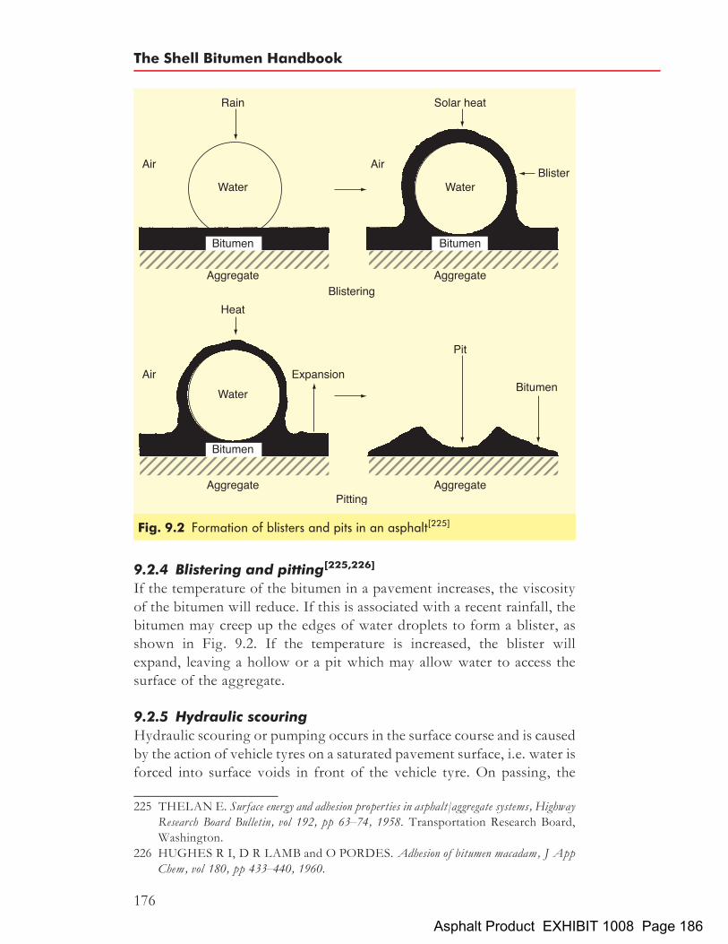
9.2.4 Blistering and pitting[225,226]
If the temperature of the bitumen in a pavement increases, the viscosityof the bitumen will reduce. If this is associated with a recent rainfall, thebitumen may creep up the edges of water droplets to form a blister, asshown in Fig. 9.2. If the temperature is increased, the blister willexpand, leaving a hollow or a pit which may allow water to access thesurface of the aggregate.
9.2.5 Hydraulic scouringHydraulic scouring or pumping occurs in the surface course and is causedby the action of vehicle tyres on a saturated pavement surface, i.e. water isforced into surface voids in front of the vehicle tyre. On passing, the
Fig. 9.2 Formation of blisters and pits in an asphalt[225]
225 THELAN E. Surface energy and adhesion properties in asphalt/aggregate systems, HighwayResearch Board Bulletin, vol 192, pp 63–74, 1958. Transportation Research Board,Washington.
226 HUGHES R I, D R LAMB and O PORDES. Adhesion of bitumen macadam, J AppChem, vol 180, pp 433–440, 1960.
The Shell Bitumen Handbook
176
Asphalt Product EXHIBIT 1008 Page 186

action of the tyre sucks up this water, thereby inducing a compression–tension cycle in these surface voids, which may result in disbonding ofthe bitumen from the aggregate. Suspended dust and silt in the watercan act as an abrasive and can accelerate disbonding.
9.2.6 Pore pressureThis type of disbonding mechanism is most important in open or poorlycompacted mixtures where it is possible for water to be trapped as thematerial is compacted by traffic. Once the material becomes effectivelyimpermeable, subsequent trafficking induces a pore water pressure[227].This creates channels around the bitumen/aggregate interface leadingto loss of bond. Higher temperatures acting on the entrapped waterresult in expansive stresses accelerating water migration and disbonding.Low temperatures may also lead to the formation of ice, which is equallydestructive.
9.2.7 Chemical disbondingDiffusion of water through a bitumen film can lead to double layers ofwater at the aggregate surface. The presence of the water causes theaggregate surface to exhibit a negative surface charge against a slightlynegatively charged bitumen. This results in two negatively charged sur-faces in contact and repulsion is the result. As more water is attracted tothe aggregate surface, disbonding of the bitumen film will finallyoccur[228].
9.3 Methods of measuring and assessing adhesionGiven the potential for premature failure due to adhesion-relatedproblems, the need for a predictive laboratory test is self-evident. Anumber of different types of test have been developed to compare com-binations of aggregate, bitumen and water. However, the problem withmany of these methods is a lack of information relating the laboratoryprediction to performance in practice.Typically, aggregate is coated with bitumen, immersed in water under
controlled conditions and the effect of stripping determined after a periodof time. The various methods differ in the type of specimen used, the con-ditions under which the sample is immersed in water and the method thatis used to assess the degree of stripping.
227 LEE A R and J H NICHOLAS. The properties of asphaltic bitumen in relation to its usein road construction, J Inst Pet, vol 43, pp 235–246, 1957. Institute of Petroleum,London.
228 GUSFELT K H and J A N SCOTT. Factors governing adhesion in bituminous mixes.Proc 2nd Int Symp devoted to tests on bitumens and bituminous materials, vol 1, pp 45–65,Budapest, 1975.
Adhesion of bitumens
177
Asphalt Product EXHIBIT 1008 Page 187

In the majority of these tests, the coated aggregate is immersed inwater. However, salt-based or de-icing solutions and those containingfuel oils may also be used. Certain types of test may tend to coat an aggre-gate in the presence of water. In such cases, the degree of coatingobtained is used as an index of adhesivity.Adhesion tests fall into a number of categories. There may be several
different tests within each type but, in most cases, the individual tests ofone type differ in detail rather than in principle. The categories are:
. static immersion tests
. dynamic immersion tests
. chemical immersion tests
. immersion mechanical tests
. immersion trafficking tests
. coating tests
. adsorption tests
. impact tests
. pull-off tests.
Each is now discussed in more detail.
9.3.1 Static immersion testsThis is the simplest type of test and consists of aggregate being coatedwith bitumen that is then immersed in water. The degree of strippingis estimated by a visual inspection after a period of time. For example,in the total water immersion test (a test carried out by Shell in-house)14mm single-size chippings are coated with a known quantity of bitu-men. The coated aggregate is then immersed in distilled water at 258Cfor 48 hours. The percentage of bitumen stripped off the aggregate isassessed visually.The fundamental problem with this method is its subjective nature,
resulting in poor reproducibility. However, the experienced operatormay be capable of ranking the aggregates in relation to their performancein situ. It must be recognised that in some cases, an aggregate with goodlaboratory performance may perform poorly occasionally on the road andthose with poor static immersion test results may perform satisfactorily inpractice.
9.3.2 Dynamic immersion testsThis type of test is very similar to the static immersion test but the sampleis agitated mechanically by shaking or kneading. Again, the degree ofstripping is estimated visually together with a subjective judgement ofwhether the mixture remains cohesive or separates into individual particlesof aggregate. The reproducibility of this type of test is also very poor.
The Shell Bitumen Handbook
178
Asphalt Product EXHIBIT 1008 Page 188

9.3.3 Chemical immersion testsIn this type of test, aggregate coated in bitumen is boiled in solutionscontaining various concentrations of sodium carbonate. The strengthof sodium carbonate solution in which stripping is first observed isused as a measure of adhesivity. However, the artificial conditions ofthe test are unlikely to predict the likely performance on the road.
9.3.4 Immersion mechanical testsImmersion mechanical tests involve the measurement of a change in amechanical property of a compacted asphalt after it has been immersedin water. Thus, the ratio of the property after immersion divided bythe initial property is an indirect measure of stripping (usually expressedas a percentage).Different types of mechanical properties can be measured and these
include shear strength, flexural strength and compressive strength. Thetwo most common are known as the retained Marshall stability testand the retained stiffness test. Given the increasing availability of asphaltstiffness test apparatus, the retained stiffness test is now the most popularmethod in the UK.
Retained Marshall stability testThere are a number of different versions of each type of test. In Shell’sretained Marshall test, at least eight Marshall specimens are manufacturedusing a prescribed aggregate type, aggregate gradation, bitumen contentand void content. Four specimens are then tested using the standardMarshall method to give a standard stability value. The four remainingspecimens are vacuum treated under water at a temperature of between0 and 18C to saturate the pore volume of the mixture with water. Theyare then stored in a water bath at 608C for 48 hours after which theirMarshall stability is determined. The ratio of the Marshall stability ofthe soaked specimens to the standard Marshall stability is termed the‘retained Marshall stability’. A value >75% retained Marshall stabilityis usually regarded as acceptable.
Retained stiffness testThe principle of the retained stiffness test is similar to that of the retainedMarshall test. The major difference is that the test specimens are assessedusing the indirect tensile stiffness modulus (ITSM) test[229] carried outusing a Nottingham asphalt tester (NAT) or similar. This has the addi-tional benefit in that the method is non-destructive allowing the same
229 BRITISH STANDARDS INSTITUTION. Method for determination of the indirecttensile stiffness modulus of bituminous mixtures, DD 213, 1993. BSI, London.
Adhesion of bitumens
179
Asphalt Product EXHIBIT 1008 Page 189

test specimens to be used after soaking. A number of versions of themethod exist where the soaking period and water temperature may bevaried.
Retained Cantabro testThe Cantabro test was originally developed to measure particle loss forporous asphalts. It can also be used for testing water sensitivity[230]. Aminimum of five moulds of 101mm diameter� 63.5mm height areabraded, one at a time in a Los Angeles machine. The loss in massexpressed as a percentage after 300 turns is termed the ‘dry particleloss’ (Pld). When measuring water sensitivity, a further five moulds aresoaked in water for 68 hours followed by 24 hours in an oven at 258C.Again, these are subjected to 300 revolutions and the loss in massexpressed as a percentage termed the ‘wet particle loss’ (Plw). Thisgives the ‘particle loss index’ (PLI) from the equation:
PLI ¼ 100� PlwPld
9.3.5 Immersion trafficking testsA major problem with most types of adhesion tests is that they do notconsider the effect of trafficking in causing stripping. A method thatconsiders this is the immersion wheel-tracking test[231] as shown inFig. 9.3. In this test, a specimen is immersed in a water bath and traversedby a loaded reciprocating solid rubber tyre. In the standard method, threespecimens that have been compacted in moulds are tracked using a 20 kgload at 25 cycles per minute at a water temperature of 408C until failureoccurs.The development of the rut that forms is measured until stripping
starts to occur. As shown in Fig. 9.4, this is typically marked by asteep increase in the rut depth and surface ravelling of the test specimen.Good correlation has been shown to exist for stripping failures of heavilytrafficked roads. It has been found that factors such as aggregate shape,aggregate interlock, bitumen viscosity and sample preparation affectfailure times.Dry wheel-track testing using air to control temperature superseded
the original method of wet wheel-track testing. This dry methoddoes not assess stripping but rather considers permanent deformation.
230 EUROPEAN COMMITTEE FOR STANDARDIZATION Testing bituminousmaterials, Test: Particle loss from porous asphalt, CEN TC 227/WG1, TG2 referencenumber 1.15, TC 227. CEN, Brussels.
231 MATHEWS D H and D M COLWILL. The immersion wheel-tracking test, J AppChem, pp 505–509, 1962.
The Shell Bitumen Handbook
180
Asphalt Product EXHIBIT 1008 Page 190

However, in more open and thinner mixtures with a high coarse aggre-gate content, the possibility for stripping-related failure rather thanrutting failure is more prevalent.The wet wheel-track test is now being reconsidered as a means of
assessing asphalts such as porous asphalts and high stone content thinsurfacings. The method is easily adaptable where temperature, immersion
Fig. 9.3 Immersion wheel-track test equipment
Fig. 9.4 Typical immersion rut depth plot showing adhesion failure
Adhesion of bitumens
181
Asphalt Product EXHIBIT 1008 Page 191

medium and loading may be varied. The test may be performed for aspecific time or until failure occurs.A locked-wheel method was developed to assess the likelihood of
ravelling due to the presence of moisture[232]. The only alteration tothe equipment involved the provision of a locking ratchet that allowedthe wheel to travel freely in one direction but also to be locked in positionas it is dragged back across the specimen surface on the remainder of thecycle. Surface ravelling has been related to grading, compaction, bitumenand aggregate characteristics. This method is, however, very aggressiveand may be most suitable for highly stressed trafficking locations.
9.3.6 Coating testsThis type of testing attempts to assess adhesion between aggregate andbitumen when water is also present. For example, in the immersiontray test[233], aggregate chippings are applied to a tray of bitumen coveredwith a layer of water. By careful examination of the chippings, it may bepossible to determine whether surface active agents improve adhesionunder wet conditions.
9.3.7 Adsorption testsThe Strategic Highways Research Program (SHRP) in the USA investi-gated the effect of moisture damage as one of six major distress areasrequiring further investigation. The result was the net adsorption testmethod[234]. This test combined a fundamental measurement of aggre-gate/bitumen adhesion with a measure of moisture sensitivity. Themethod was able to match an aggregate and bitumen to give optimumperformance conditions.In the test, a stock solution of bitumen is first prepared by adding 1 g of
bitumen to 1000ml of toluene. The aggregate is crushed to produce 50 gtest samples of 5mm to dust grading, then 140ml of the stock solution isadded to a conical flask containing the graded aggregate placed on arotating table to agitate the mix. After 6 hours, a 4ml sample is removedand diluted to 25ml using toluene. The absorbance is measured using aspectrophotometer at 410 nm.
232 MCKIBBEN D C. A study of the factors affecting the performance of dense bitumenmacadam wearing courses in Northern Ireland, PhD Thesis, University of Ulster, 1987.
233 NICHOLLS J C et al. Design guide for road surface dressing, Appendix D, Road Note39, 5th ed, 2002. TRL Ltd, Crowthorne.
234 CURTIS C W, K ENSLEY and J EPPS. Fundamental properties of asphalt-aggregateinteractions including adhesion and adsorption, Strategic Highway Research Program, ReportSHRP-A-341, 1993. National Research Council, Washington DC.
The Shell Bitumen Handbook
182
Asphalt Product EXHIBIT 1008 Page 192

The reading is compared to that obtained from the stock solution andthe percentage initial adsorption calculated. The flask then has 2ml ofdistilled water added and is agitated overnight. Another 4ml is removedand assessed as before. The value obtained at this stage is the percentagenet adsorption and should be lower than the percentage initial adsorptionvalue as some of the bitumen will have been removed from the aggregatedue to the introduction of moisture into the system.Figure 9.5 shows net adsorption data for four aggregates and a single
160/220 pen bitumen. The effect of aggregate type on both initial adsorp-tion and the reduction due to addition of moisture is apparent.
9.3.8 Impact testsThere are basically two impact tests that may be used to assess the adhe-sive qualities of bitumen – the Vialit pendulum test and the Vialit platetest. Both methods are readily adaptable to predict a wide range ofin situ conditions and are of the greatest significance in situationswhere the aggregate is in direct contact with trafficking stresses such assurface dressings.The Vialit pendulum test was discussed in Section 7.7.3.In the Vialit plate test, aggregate particles are pressed onto a tray of
bitumen. This is turned upside down and a steel ball is dropped ontothe reverse side. The impact of the ball may cause detachment of theaggregate particles depending on test conditions. The number ofdetached aggregate particles together with an increasing number ofimpacts may be used as an indication of performance. Visual inspectionof the detached aggregate can usually determine the type of failure.A wide range of variables may be assessed using this simple equipment.
For example, Fig. 9.6 shows aggregate chipping loss for a dry clean and a
Fig. 9.5 Net adsorption data for four aggregates and a single 160/220 penbitumen
Adhesion of bitumens
183
Asphalt Product EXHIBIT 1008 Page 193

dry dusty dolerite aggregate[235]. Different binder types and applicationrates may be applied to the steel plate. The test specimens may besubjected to a wide range of conditioning procedures such as high/lowtemperatures, ageing or hardening, etc.
9.3.9 Pull-off testsBitumen adhesion may be assessed using different types of pull-off tests.The Instron pull-off test[235] uses an Instron tensile apparatus to extractaggregate test specimens from containers of bitumen under controlledlaboratory conditions. Test variables such as rock type, dust coatings,test temperature, rate of loading, bitumen type, etc. have been shownto alter the results. An example of the data obtained for four differentrock types with increasing dust contents is shown in Fig. 9.7 and demon-strates how the maximum stress during testing varied for the differentaggregates.The limpet pull-off test[235] was developed to measure, quantitatively,
the bond strength between the aggregate of a surface dressing and theunderlying surface. This uses a limpet apparatus that was originallydeveloped for measuring the tensile strength of concrete. A 50mm dia-meter metal plate is fixed to the road surface and the maximum load toachieve pull-off determined. The method may be used both in the labora-tory and on the actual road surface.Figure 9.8 shows data obtained for both dusty and clean chippings
with both a K1-70 and 100 sec bitumen. The effect of both dust contentand bitumen type on the adhesion bond can be seen. It was found that thedust content of an aggregate could adversely affect adhesion between
Fig. 9.6 Simple example showing Vialit plate data for a dry, clean and a dry,dusty dolerite aggregate
235 CRAIG C. A study of the characteristics and role of aggregate dust on the performance ofbituminous materials. PhD Thesis, University of Ulster, 1991.
The Shell Bitumen Handbook
184
Asphalt Product EXHIBIT 1008 Page 194

aggregate and bitumen. Flaky chippings had better adhesion than cubicchippings due to the lower value of average least dimension. Washedaggregate or the use of adhesion agents was shown to improve adhesionof a surface dressing and, as expected, the poorest adhesion resultsoccurred when dusty chippings and low bitumen spray rates were usedtogether.
9.4 Improving bitumen/aggregate adhesionTypically, the adhesion of bitumen to aggregate is not a problem. How-ever, in the presence of water, unexpected adhesion-related problemsmay occur. There are a number of traditional methods used to reducethe likelihood of this happening, i.e. by using higher viscosity bitumen,
Fig. 9.7 Instron pull-off data showing the effect of dust content for fourdifferent aggregates
Fig. 9.8 Vialit plate test using K1-70 and 100 sec binders and clean and dustychippings
Adhesion of bitumens
185
Asphalt Product EXHIBIT 1008 Page 195

hydrated lime or surface active agents that improve the bond between thebitumen and the aggregate. Whilst modifying bitumen viscosity may beeasily achieved, this may result in workability and compaction relatedproblems particularly for high stone content thin surfacing mixtures.The use of 1 to 3% hydrated lime as part of the filler content has tradi-
tionally been used as an anti-stripping agent. It has been suggested[236] thatthe hydrated lime reacts with the carboxyl acids present in the bitumenand allows other carbonyl groups such as ketones to attach themselvesto the aggregate surface. These ketones are not as easily removed bywater as the acids and so the mixture is less susceptible to stripping.It has also been suggested[237] that a hydrated lime solution will result
if water is present at the bitumen/aggregate interface. The calcium ions inthis solution cause the surface of the aggregate to become basic. Theelectro-chemical balance forces the water away from the aggregate andinto an emulsion in the bitumen. The balance will then force attachmentto the hydrophobic surface of the aggregate. Bitumen/aggregateadhesion may also be improved by the addition of chemical additives.These act in two main ways:
. they may change the interfacial conditions between the aggregateand the bitumen so that the bitumen preferentially wets the aggre-gate which improves adhesion; or
. they may improve the adhesive bond between the aggregate and thebitumen, thus increasing the long-term resistance to bitumendetachment due to water.
Typically, 0.1 to 1.0% fatty amines is the main type of additive that isused to improve adhesion. It is believed that the amine groups areattracted to the surface of an aggregate whilst the fatty groups remainin the bitumen. The result is an ionically bonded cross-link betweenaggregate and bitumen. However, these additives may be relativelyunstable at bitumen storage temperatures and can become deactivated.It is also possible that a given additive will not improve the adhesionof all aggregate types, i.e. they may be rock type specific. There is alsothe issue that whilst they may improve initial adhesion they may haveno or limited long-term effect.It is recommended that prior to their use, laboratory testing should be
carried out to optimise the type and amount of additive used for a given
236 PLANCHER H, E GREEN and J C PATERSON. Reduction of oxidative hardeningof asphalts by treatment with hydrated lime – a mechanistic study, Proc Assoc Asph PavTech, vol 45, pp 11–24, 1976. Association of Asphalt Paving Technologists, Seattle.
237 ISHAI I and J CRAUS. Effect of the filler on aggregate-bitumen adhesion properties inbituminous mixtures, Proc Assoc Pav Tech, vol 46, pp 228–257, 1977. Association ofAsphalt Paving Technologists, Seattle.
The Shell Bitumen Handbook
186
Asphalt Product EXHIBIT 1008 Page 196

aggregate/bitumen combination. This may be undertaken using the widerange of the test methods already mentioned in this chapter. For example,Table 9.2 shows data obtained using the net adsorption test for twodifferent aggregates and a 100 pen bitumen with and without 0.5%adhesion agent. It can be seen that while the adhesion agent increasedinitial adsorption by 10.9% for the quartz dolerite, the adsorptiononly improved 3% for the greywacke. In terms of improving moisturesensitivity, there was a small improvement for the quartz doleriteand no improvement for the greywacke. This example shows howaggregate properties influence attempts at improving adhesion. For thegreywacke, the addition of adhesion agents essentially did little toimprove performance.
Table 9.2 Net and initial adsorption results with different binders
Aggregate type Initial adsorption, % Net adsorption, %
100pen bitumen 100pen bitumen with0:5% adhesion agent
100pen bitumen 100pen bitumen with0:5% adhesion agent
Quartz dolerite 52:2 63:1 46:4 49:6Greywacke 64:6 67:6 54:3 50:4
Adhesion of bitumens
187
Asphalt Product EXHIBIT 1008 Page 197

Chapter 10
Influence of bitumenproperties on theperformance of asphalts
Despite the enormous range of applications to which asphalts are put andthe substantial variations in weather and loading to which they are sub-jected, the vast majority of asphalt pavements perform well for manyyears. However, failures do occur. In some cases, these arise as a resultof some fault in the construction process. An understanding of themechanisms that cause asphalt pavements to fail is important if designers,contractors and producers are to employ specifications, manufacturingtechniques, equipment and methods that will minimise the possibilityof defects occurring.The performance of asphalts in service is significantly influenced by the
rheological (or mechanical) properties and, to a lesser extent, the chemicalconstitution of the bitumen. The latter is particularly important at the roadsurface because the constitution of the bitumen influences the rate of oxida-tion and, thereby, how rapidly the bitumen is eroded by traffic. Thesefactors are, in turn, influenced by changes due to the effect of air, tempera-ture and water on the bitumen. There are, of course, many other factorsinfluencing behaviour, including the nature of the aggregate, mixture com-position, bitumen content (i.e. bitumen film thickness), degree of compac-tion, etc. – all of which influence long-term durability (see Chapter 8).Bitumens are visco-elastic materials and their behaviour varies from
purely viscous to wholly elastic depending upon loading time and tem-perature. During the mixing and compaction of asphalts and at highservice temperatures, the properties can be considered in terms of viscos-ity but for most service conditions, bitumens behave visco-elastically andtheir properties can be considered in relation to their stiffness modulus.The rheological requirements for bitumen during mixing, compaction
and in service are illustrated in Fig. 10.1 and the critical requirements aresummarised in Table 10.1. This chapter considers a number of failuremechanisms with particular emphasis on the role that is played by thebitumen in avoiding their development.
189Asphalt Product EXHIBIT 1008 Page 198

Fig. 10.1 Properties of penetration grade bitumens during construction andsubsequently in service
Table 10.1 Engineering requirements for bitumens during application and in service[238]
Behaviour during: Condition Significant property of thebitumen in the mix
Temperature: 8C Time of loading: s
ApplicationMixing High (>1008C) – Viscosity, approximately 0:2 Pa sLaying High – ViscosityCompaction High – Viscosity, minimum 5Pa s,
maximum 30 Pa sIn servicePermanentdeformation
High road temperature(30–608C)
Long >10�2 �Minimum viscosity determinedby penetration index and the
Fatting up High road temperature(30–608C)
Long >10�2 softening point of the bitumen
Cracking– Traffic stresses Low road temperature Short (10�2)– Thermal stresses Low road temperature Long
�Maximum bitumen stiffness
Fretting Low road temperature Short (10�3)
238 DORMON G M. Some observations on the properties of bitumen and their relation toperformance in practice and specifications, Shell Construction Service Report, 1969. ShellInternational Petroleum Company Ltd, London.
The Shell Bitumen Handbook
190
Asphalt Product EXHIBIT 1008 Page 199

10.1 The influence of bitumen properties during construction10.1.1 Mixing and transportDuring mixing, the dried hot aggregate has to be coated by the hotbitumen in a relatively short mixing time (typically 30 to 90 s). Whilstthe mixing temperature must be sufficiently high to allow rapid distribu-tion of the bitumen on the aggregate, the use of the minimum mixingtime at the lowest temperature possible is advocated. The higher themixing temperature, the greater the tendency of the bitumen exposedin thin films on the surface of the aggregate to oxidise. This is illustratedin Fig. 10.2 where an increase of 5.58C in the mixing temperature, for astandard mixing time of 30 s, results in an increase of 18C in the softeningpoint of the bitumen[239]. There are, therefore, upper and lower limits ofmixing temperature. If macadams are mixed too hot, drainage of bitumenfrom the aggregate may occur during hot storage or transport to site,leading to variations in bitumen content. In such circumstances, thefiller serves an important function. As it is generally added to the mixture
Fig. 10.2 Relationship between the temperature of the mixture and change insoftening point[239]
239 WHITEOAK C D and D FORDYCE.Asphalt workability, its measurement, and howit can be modified, Shell Bitumen Review 64, pp 14–17, Sep 1989. Shell InternationalPetroleum Company Ltd, London.
Influence of bitumen properties on the performance of asphalts
191
Asphalt Product EXHIBIT 1008 Page 200

after coating of the aggregate has been completed, it ‘stabilises’ orincreases the apparent viscosity of the bitumen, reducing drainage. Inthin surfacings, stone mastic asphalts and porous asphalts, binderdrainage can be prevented by the addition of fibres to the mixture orby using a polymer modified bitumen.These different considerations combine to give an optimal bitumen
viscosity of 0.2 Pa s (2 poise) at the mixing temperature. It has beenshown[240] that the temperature required to achieve a viscosity of0.2 Pa s can be crudely estimated by simply adding 1108C to the softening
240 JACOBS F A. Hot rolled asphalt: Effect of binder properties on resistance to deformation,Laboratory Report 1003, 1981. Transport and Road Research Laboratory,Crowthorne.
Fig. 10.3 Relationship between the softening point of the bitumen andequi-viscous temperatures for mixing and rolling of hot rolledasphalt surface course[240]
The Shell Bitumen Handbook
192
Asphalt Product EXHIBIT 1008 Page 201

point of the bitumen (see Fig. 10.3). The disadvantage of this method isthat it does not take account of the penetration index (PI) of the bitumen.A more precise estimate can be determined using both the penetrationand softening point of the bitumen on the bitumen test data chart (seeFig. 7.8). The various conditions described above are summarised inFig. 10.1.When materials are being laid at low ambient temperatures, or if
haulage over long distances is necessary, mixing temperatures are oftenincreased to offset these factors. However, increasing the mixing tem-perature will tend to accelerate the rate at which the bitumen oxidisesand this increases the viscosity of the bitumen. Thus, a significant pro-portion of the reduction in viscosity achieved by increasing the mixingtemperature may be lost because of additional oxidation of the bitumen.If asphalts are transported in properly sheeted, well insulated vehicles,the loss in temperature is very low, about 28C per hour.
10.1.2 Laying and compactionIn discharging the mixture into a paver, a loss of temperature of up to208C will be experienced; spreading the material into a mat will furtherreduce the temperature. The temperature loss will be dependent on anumber of factors, including the thickness of the layer, ambient tempera-ture, wind speed and the temperature of the substrate upon which thenew material is being placed. The two most crucial factors influencingthe cooling of the layer are wind speed and layer thickness[241]. Oncethe mat has been spread, it must be sufficiently workable to enable thematerial to be satisfactorily compacted with the available equipment.For effective compaction to take place, the viscosity of the bitumenshould be between 5 Pa s (50 poise) and 30 Pa s (300 poise). At viscositieslower than 5 Pa s, the material will probably be too mobile to compactand at viscosities greater than 30 Pa s, the material will be too stiff toallow further compaction. The minimum rolling temperature can beestimated by adding 508C to the softening point of the bitumen[242]
(see Fig. 10.3).The slope of the viscosity/temperature relation or PI in this tem-
perature region is particularly important because it determines thetemperature range over which the viscosity of the bitumen remains ata suitable level for compaction. Figure 10.4 clearly shows that bitumens
241 DAINES M E. Cooling of bituminous layers and time available for their compaction,Research Report 4, 1985. Transport and Road Research Laboratory, Crowthorne.
242 JACOBS F A. Hot rolled asphalt: Effect of binder properties on resistance to deformation,Laboratory Report 1003, 1981. Transport and Road Research Laboratory,Crowthorne.
Influence of bitumen properties on the performance of asphalts
193
Asphalt Product EXHIBIT 1008 Page 202

Fig.10.4
Theinflu
ence
ofpe
netrationinde
xon
beha
viou
rdu
ring
constructio
nan
dsubseq
uent
performan
cein
service
The Shell Bitumen Handbook
194
Asphalt Product EXHIBIT 1008 Page 203

with a high temperature susceptibility, i.e. a low PI, have a muchnarrower temperature ‘window’ within which satisfactory compactionof the material can be achieved.
10.2 The influence of bitumen properties on the performance
of asphalts in serviceAfter the mixture has been manufactured, laid and compacted, itsbehaviour in service can be considered, in particular by consideringthe circumstances surrounding the occurrence of specific types offailures.
10.2.1 CrackingPavement cracking is a complex phenomenon that can be caused byseveral factors. It is associated with stresses induced in the asphaltlayers by wheel loads, temperature changes or a combination of thetwo. Furthermore, the volume of bitumen in the mixture and its rheo-logical behaviour has a major bearing on the susceptibility of the asphaltto cracking. An asphalt mixture, by virtue of the bitumen it contains,displays visco-elastic behaviour. If an asphalt test specimen is strainedto a predetermined point, and held constant, a stress will be induced.Depending on temperature, this stress will dissipate more or less quickly.This process is called ‘relaxation’. At high temperatures, the viscouscomponent dominates and total stress relaxation may take a few minutes.At very low temperatures, relaxation can take many hours or evendays.Cracking occurs when the tensile stress and related strain induced by
traffic and/or temperature changes exceeds the breaking strength of themixture. At elevated temperatures, stress relaxation will prevent thesestresses reaching a level that can cause cracking. On the other hand, atlow temperatures, the tensile condition will persist and, therefore, pave-ment cracking is more likely.It is also recognised that bitumen in a mixture ages during its service
life. This results in a progressive increase in the stiffness modulus of theasphalt, together with a reduction in its stress relaxation capability. Thiswill further increase the likelihood of pavement cracking.During mixing and laying, the penetration of bitumen generally
reduces to about 70% of the pre-mixed value. This is known as ‘short-term ageing’. This ageing continues during its service life, albeit at alower rate, and is known as ‘long-term ageing’. Several processes con-tribute to long-term ageing and these are described in more detail inChapter 8. The most dominant of these mechanisms is oxidative harden-ing and this is influenced by the thickness of the binder film, the air voidscontent in the mixture and the temperatures experienced.
Influence of bitumen properties on the performance of asphalts
195
Asphalt Product EXHIBIT 1008 Page 204

Pavement cracking can take several forms. The most frequent are:
. longitudinal cracking, occurring generally in the wheel track;
. transverse cracking, which can be in any area and it is not necessarilyassociated with the wheel path;
. alligator or crocodile cracking, where longitudinal and transversecracks link up forming a network of cracks; and
. reflective cracking, resulting from an underlying defect (typicallyjoints in concrete layers).
Traditionally, pavement design has only considered load-associatedcracking in which cracks are initiated in the underside of the asphaltbase caused by repeated pavement flexure under traffic. This has led tothe design of pavements of greater thickness to withstand the higherflow rates predicted for future commercial traffic. A programme ofresearch carried out at the Transport Research Laboratory[243] to inves-tigate how these thicker asphalt pavements were performing revealedthat cracks in thick asphalt pavements invariably initiate at the surfaceand propagate downwards. Similar observations have been made byother organisations[244,245].
Thermal crackingCracking that results from extreme cold is generally referred to as low-temperature cracking whereas cracking that develops from thermalcycling is normally referred to as thermal fatigue cracking. Thermalcracking will occur when the bitumen becomes too stiff to withstandthe thermally induced stress and it is related to the coefficient of thermalexpansion and the relaxation characteristics of the mixture. Both theseproperties are related to the nature of the bitumen and the risk of thermalcracking increases with the age of the pavement as the binder hardens as aresult of oxidation or time-dependent physical hardening.The coefficient of thermal expansion of bitumen is an order of magni-
tude higher than that of the aggregate in the mixture. A rough estimatefor the thermal expansion coefficient of the mixture can be determined
243 NUNN M E, A BROWN, D WESTON and J C NICHOLLS. Design of long-lifeflexible pavements for heavy traffic, Report 250, 1997. TRL, Crowthorne.
244 SCHORAK N and A VAN DOMMELEN. Analysis of the structural behaviour ofasphalt concrete pavements in SHRP-NL test sections, International Conf: SHRP andTraffic Safety, Prague, 1995.
245 UHLMEYER J F, L M PIERCE, KWILLOUGHBY and J P MAHONEY. Top-down cracking in Washington State asphalt concrete wearing courses, TransportationResearch Board 79th annual meeting, Washington, 2000. TRB, Washington.
The Shell Bitumen Handbook
196
Asphalt Product EXHIBIT 1008 Page 205

using the equation[246]:
am ¼ abvb þ aavavb þ va
where am ¼ the coefficient of expansion of the mixture, vb ¼ proportionof the bitumen by volume, va ¼ proportion of the aggregate by volume,ab ¼ coefficient of thermal expansion of the bitumen and aa ¼ coefficientof thermal expansion of the aggregate. The coefficient of volumetricexpansion of bitumen is approximately 6� 10�4/8C. Typically, thelinear coefficient of thermal expansion of an asphalt mixture is between2 and 3� 10�5/8C.Two different thermal cracking mechanisms can occur. At low pave-
ment temperatures, transverse cracks that run the full depth of thepavement can suddenly appear. Pavement temperatures generally haveto fall below about �308C to induce this form of cracking. Accordingly,documented cases of ‘low-temperature cracking’ in the UK are extremelyrare.For milder conditions, cracks may develop at a slower rate, taking
several seasons to propagate through the asphalt layers. This form ofcracking initiates at the surface and propagates relatively slowly witheach thermal cycle. This is generally described as ‘thermal fatiguecracking’.The general mechanism responsible for these two forms of cracking is
considered to be similar. The main differences are:
. low-temperature cracking is a single-event phenomenon that is theresult of the full depth of asphalt being put into thermal tensionunder conditions where stress relaxation cannot occur;
. thermal fatigue cracking is more dependent on the properties of thesurface course material, and cracks first have to initiate at the surfaceand propagate through the surface course before they affect thelower asphalt layers.
Low-temperature cracking. The mechanism of low-temperaturecracking is illustrated in Fig. 10.5. The asphalt layer is subjected to atensile stress distribution with depth. These stresses are caused by thecontraction of the asphalt as it cools and they are a function of thetemperature change and the relaxation characteristics, stiffness modulusand coefficient of expansion of the asphalt. They are not necessarily uni-form because pavement temperature can vary with depth. These stressescan, potentially, cause a crack to propagate down from the surface.
246 EUROPEAN COST ACTION 333. Development of new bituminous pavement designmethod, Final report of the action, 1999.
Influence of bitumen properties on the performance of asphalts
197
Asphalt Product EXHIBIT 1008 Page 206

As asphalt becomes colder, its tensile strength (�z) increases initiallyand then begins to decrease as a result of micro-cracking in the bindermatrix. This is caused by the differential contraction that results fromthe large difference between the coefficients of thermal expansion ofthe aggregate and bitumen. These fractures can be detected as acousticevents using a sensitive microphone to record their increasing occurrencewith falling temperature[247].At the same time, thermal stress (�) builds up as the material loses its
relaxation ability and, at some point, the thermal stress will exceed thestrength of the material. This defines the probable low-temperature frac-ture temperature (spontaneous cracking). The difference between thetensile strength and the low-temperature stress is known as the tensilestrength reserve (��z) and it is this reserve that is available to accommo-date additional superimposed stresses (for example, traffic-inducedstresses). This is illustrated in Fig. 10.6.The curves shown in Fig. 10.6 can be derived using the thermal stress
restrained specimen test (TSRST) and the isothermal direct tensile testover a range of low temperatures. These tests were developed withinthe US Strategic Highways Research Program (SHRP)[248]. Althoughexpensive and time consuming, these tests are considered[249] to offera reliable means of predicting the temperature at which a pavementwill crack due to excessive thermal stresses. The results are reasonablyreproducible and the relative ranking of materials is consistent withfield performance. Various studies of low-temperature cracking havegenerally concluded that, in order to reduce cracking, the binder stiffness
Fig. 10.5 Thermal cracking mechanism
247 VALKERING C P and D J JONGENEEL. Acoustic emission for evaluating therelative performance of asphalt mixes under thermal loading conditions, Proc Assoc AsphPav Tech, vol 60, 1991. Association of Asphalt Paving Technologists, Seattle.
248 JUNGDH and T S VINSON. Final report on test selection – low temperature cracking,SHRP, 1992. National Research Council, Washington DC.
249 KING G N, H W KING, O HARDERS, W ARAND and P-P PLANCHE.Influence of asphalt grade and polymer concentration on the low temperature performance ofpolymer modified asphalt, Proc Assoc Asph Pav Tech, vol 62, 1993. Association ofAsphalt Paving Technologists, Seattle.
The Shell Bitumen Handbook
198
Asphalt Product EXHIBIT 1008 Page 207

must not exceed some defined limit at the coldest pavementtemperature[250,251].In SHRP, the bending beam rheometer (BBR) is used to produce a
master curve for the bitumen stiffness as a function of loading timeand temperature. This is used to predict the temperature at which thebitumen has a stiffness of 200MPa at a loading time of 60 s. This wasthe SHRP specification limit for binders in cold climates[252]. However,after the SHRP programme was completed, initial experience suggestedthat this specification was restrictive and the specification limit was raisedto 300MPa[253].
Fig. 10.6 Low-temperature stress (�) and tensile strength of asphalt (�z) as afunction of temperature
250 RUTH B E, L A K BLOY and A A AVITAL. Prediction of pavement cracking at lowtemperatures, Proc Assoc Asph Pav Tech, vol 51, 1982. Association of Asphalt PavingTechnologists, Seattle.
251 BAHIA H U. Low temperature physical hardening of asphalt cements, Research Report,Pennsylvania State University, 1991.
252 ANDERSON D, D CHRISTENSEN, H BAHIA, R DONGRE, M SHARMA,C ANTLE and J BUTTON. Binder characterization and evaluation, SHRP A-369,vol 3, Physical characterization and evaluation, SHRP, 1994. National ResearchCouncil, Washington DC.
253 ANDERSOND, L CHAMPION-LAPALU,MMARASTEANU, Y LEHIR, J-PPLANCHE and M DIDIER. Low temperature thermal cracking of asphalt binders asranked by strength and fracture properties, Transport Research Board 80th Annual Meeting,Washington, 2001. TRB, Washington.
Influence of bitumen properties on the performance of asphalts
199
Asphalt Product EXHIBIT 1008 Page 208

Jung and Vinson[254] concluded that the TSRST provided an excellentindicator of low-temperature cracking. Furthermore, King et al.[255]
demonstrated that results using the TSRST correlated very well withthe temperature prediction using the BBR (R2 ¼ 0:96) and that theBBR is certainly a better performance indicator. However, recentwork[256] suggests that fracture toughness should be included in thecriteria to account for the performance of polymer modified bitumen.Low-temperature cracking is of particular concern in Canada, North
America, Northern and Eastern Europe and Northern Asia wheretemperatures can fall as low as �408C. To counter this problem, softerbinders are often used. It is recognised that the risk of low-temperaturecracking is related primarily to the properties of the bitumen, with vis-cosity and temperature susceptibility of the binder being the most impor-tant properties. The risk increases as the hardness of the bitumen rises.Variations in the grading and type of aggregate have very little effectand increasing the binder content reduces the mixture susceptibility tothermal cracking only slightly.
Thermal fatigue and load associated surface cracking. Cracking inthe surface of asphalt pavements is relatively common. These crackscan be transverse or longitudinal and are usually located in the wheeltracks. Longitudinal wheel-track cracking has often been regarded asevidence of conventional fatigue in which cracks are assumed to haveinitiated at the bottom of the base and then propagated to the surface.However, investigation by coring strong asphalt pavements has invari-ably found that either the cracks partially penetrate the thickness ofasphalt or if the crack is full depth, the propagation is downwardsrather than upwards. A typical example of this type of cracking in amajor UK motorway is shown in Fig. 10.7. This crack extended forseveral hundred metres. Coring showed that only at the most seriouslycracked locations had cracks progressed further than the top 100mmof asphalt. None of the cracks had penetrated the full thickness ofasphalt.
254 JUNGDH and T S VINSON. Final report on test selection – low temperature cracking,SHRP, National Research Council, Washington DC, Oct 1992.
255 KING G N, H W KING, O HARDERS, W ARAND and P-P PLANCHE.Influence of asphalt grade and polymer concentration on the low temperature performance ofpolymer modified asphalt, Proc Assoc Asph Pav Tech, vol 62, 1993. Association ofAsphalt Paving Technologists, Seattle.
256 ANDERSOND, L CHAMPION-LAPALU, MMARASTEANU, Y LEHIR, J-PPLANCHE and M DIDIER. Low temperature thermal cracking of asphalt binders asranked by strength and fracture properties, Transport Research Board 80th Annual Meeting,Washington, 2001. TRB, Washington.
The Shell Bitumen Handbook
200
Asphalt Product EXHIBIT 1008 Page 209

Investigations of a number of relatively thick UK Motorways showedthat this behaviour was typical. However, crack investigations by coringin the USA and Holland have shown that in fully flexible pavements withless than 160mm of asphalt, the cracking is likely to be full depth[257,258].Above this thickness, an increasing proportion of the pavements havecracks that are confined to the asphalt surfacing, i.e. the binder courseand the surface course. In the Dutch study, all pavements less than160mm thick had full-depth cracking and all pavements with 300mm
Fig. 10.7 Longitudinal crack in the wheel track
257 SCHORAK N and A VAN DOMMELEN. Analysis of the structural behaviour ofasphalt concrete pavements in SHRP-NL test sections. International Conf: SHRP andTraffic Safety, Prague, 1995.
258 UHLMEYER J F, L M PIERCE, KWILLOUGHBY and J P MAHONEY. Top-down cracking in Washington State asphalt concrete wearing courses, TransportationResearch Board 79th Annual Meeting, Washington, 2000. TRB, Washington.
Influence of bitumen properties on the performance of asphalts
201
Asphalt Product EXHIBIT 1008 Page 210

or more of asphalt had cracks that were confined to the top 100mm ofasphalt.Penetration tests on the binder recovered from the hot rolled asphalt
surface course in the UK study showed somewhat lower values incracked areas compared with uncracked lengths. However, binderpenetration is not always a good indicator of the susceptibility of thesurface course to surface cracking and it is evident that more detailedstudies will be required to understand the loading, material andenvironmental factors that determine the initiation and propagation ofcracks.Surface cracking is not always longitudinal; transverse or block crack-
ing can occur. This is not confined to wheel tracks and it can occur at anylocation across the carriageway. Figure 10.8 shows an example of trans-verse cracks in a UK motorway that had carried traffic totalling some30msa (million standard axles, discussed in Section 18.3.1) since it waslaid 24 years previously. During this time, it had not been resurfacedor overlaid. The penetration of recovered binder from the surfacingwas 15 dmm and it was concluded that the cracking was not traffic relatedbut due to brittle surfacing resulting from aged binder. As with longitu-dinal cracking, transverse cracks generally only penetrated to a depth ofabout 100mm.The phenomenon of surface cracking has received relatively little
attention. However, there are a considerable number of observationsof surface cracking of flexible pavements that span all climatic regions,from cold to tropical regions. This suggests that higher temperaturesassociated with the warmer season cause binder to harden with age andthis reduces its capacity to withstand the thermal stresses generatedduring the cooler nights, particularly during the coldest season.With all types of surface cracking, age hardening of the binder in the
surface course will play a part. As stated above, this hardening over timeprogressively reduces the ability of the surface course to withstand thethermal and traffic generated stresses at the surface. Recent binder rheo-logical studies[259] have shown that the binder in the top few millimetresof the surface course becomes particularly hard with age. Figure 10.9gives an example of the results obtained using a DSR on testing binderextracted from the top 10mm of the surface course and from between20 and 30mm below the surface.Figure 10.9 shows that the binder close to the surface is substantially
harder than binder that is deeper in the layer. Investigations of four
259 NUNN M E, A BROWN, D WESTON and J C NICHOLLS. Design of long-lifeflexible pavements for heavy traffic, Report 250, 1997. TRL, Crowthorne.
The Shell Bitumen Handbook
202
Asphalt Product EXHIBIT 1008 Page 211

sites that were 18 to 24 years old indicated that the penetration of thebinder recovered from the top 10mm of surface course was approxi-mately 50% of that obtained from the lower layer. This aged, andhence hard, upper skin of the surface course is considered to be amajor factor in the initiation of surface cracks.
Modelling surface crackingThe mechanism of surface cracking is complex and, to date, there is nocompletely satisfactory explanation of this phenomenon. It is nowbeing recognised that tyre stresses can induce a tensile condition at the
Fig. 10.8 Transverse cracks in the M32
Influence of bitumen properties on the performance of asphalts
203
Asphalt Product EXHIBIT 1008 Page 212

pavement surface and this can initiate a crack. De Beer et al.[260] haveshown that the tyre can transmit non-uniform horizontal and verticalstresses to the pavement, and pavement stresses in the locality of thetyre need to be taken into account in modelling crack behaviour.Finite element modelling predicts that a tensile condition can be createdin the surface course close to the edge of the tyre as shown in Fig. 10.10.Similar conditions are also predicted near the edge of tyre treads[261].These near-tyre tensile stresses, shown in red, extend only approxi-
mately 10mm into the asphalt. Consequently, they may initiate alongitudinal crack in the wheel track but another mechanism is requiredto account for crack propagation to any depth. There is increasingconviction that these surface cracks are propagated by thermal stresses.
Fig. 10.9 DSR master curves at 258C, illustrating increased binder ageing nearsurface
260 DE BEER M, C FISHER and F JOOSTE. Determination of pneumatic tyre/pavementinterface contact stresses under moving loads and some effects on pavements with thin asphaltsurfacing layers, Proc 8th Int Conf on asphalt pavements, Seattle, Washington, 1997.
261 MYERS A L and R ROQUE. Evaluation of top-down cracking in thick asphalt pave-ments and implications for pavement design, TRB/NRC, Transport Research CircularNo 503, Washington 2001. Transportation Research Board, Washington.
The Shell Bitumen Handbook
204
Asphalt Product EXHIBIT 1008 Page 213

Thermal fatigue is the mechanism responsible for the development oftransverse surface cracks with crack propagation resulting from thecyclic, diurnal thermal stresses. However, transverse rolling cracks,sometimes seen at the time of compaction, are likely to play a majorpart in the initiation of transverse cracks.The models predict[262] that, for a thick asphalt pavement, a thermally
propagated crack will stabilise at some point and will not propagatethrough the full thickness of asphalt. On the other hand, the predictionfor a thin pavement is that the rate of crack propagation will accelerate asthe remaining thickness of asphalt is subjected to greater thermal andtraffic loading.
Fatigue crackingFatigue cracking has received more attention from the research commu-nity than any other deterioration mechanism. Fatigue is the phenomenonof cracking under the repeated application of a stress that is less than thetensile strength of the material.When a wheel load passes over a point in an asphalt pavement, the
pavement flexes and a tensile strain is induced at the underside of thebase layer. Continuous flexure and relaxation over many years produces
Fig. 10.10 Pavement stresses induced by tyre loading
262 NESNAS N and DMMERRILL.Development of advanced models for the understandingof deterioration in long-life pavements, 6th Bearing Conf on roads and airfields, Workshop onmodelling materials and structures, 2002.
Influence of bitumen properties on the performance of asphalts
205
Asphalt Product EXHIBIT 1008 Page 214

the possibility of fatigue cracks initiating at the underside of the asphaltbase and propagating upwards.Fatigue is a major component of all modern analytical pavement
design methods (see Chapter 18). These methods use a simple shiftfactor, or calibration factor, to relate the laboratory determined fatiguelife to the performance of the material in the road. The conditions andthe behaviour of material in service are much more complex[263] thanthose used in laboratory studies. For example, the nature of the stresssystem and long-term physico-chemical changes in the bitumen are notconsidered.The development of the long-life pavement concept[264] has demon-
strated that long-term changes in the bitumen properties can result inan increased fatigue life of the pavement. Also, in the USA where thisconcept is also being developed, it has been suggested that, at lowstrain amplitudes, asphalt has a fatigue endurance limit[265,266].The fatigue resistance of an asphalt mixture is especially sensitive to
binder volume. The simplest means of increasing the predicted fatiguelife of the pavement is to construct the pavement using a binder-richlower asphalt layer[267].
Reflective crackingA composite pavement consists of a continuously laid cementitious baseunder asphalt surfacing. A regular pattern of thermally induced trans-verse cracks can appear in the cementitious base soon after laying andthese begin to appear as reflection cracks in the asphalt surfacing severalyears later, as shown in Fig. 10.11.Until recently, these cracks were assumed to be caused either by the
crack in the cementitious layer opening and closing as the result ofthermal expansion and contraction or by a flexing and shearing actioncaused by wheel loads passing over the crack. These mechanisms will
263 THROWER E N. A parametric study of a fatigue prediction model for bituminous pave-ments, Laboratory Report 892, 1979. Transport Research Laboratory, Crowthorne.
264 NUNN M E, A BROWN, D WESTON and J C NICHOLLS. Design of long-lifeflexible pavements for heavy traffic, Report 250, 1997. TRL, Crowthorne.
265 NEWCOMBE D E, I J HUDDLESTON and M BRUNCHER. US perspective ondesign and construction of perpetual asphalt pavements, Proc 9th Int Conf on asphalt pave-ments, Copenhagen, 2002.
266 NISHIZAWA T, S SHIMENO and M SEKIGUCHI. Fatigue analysis of asphaltpavements with thick asphalt mixture layer, Proc 8th Int Conf on asphalt pavements, Seattle,1997.
267 HARM E and D LIPPERT. Developing Illinois’ extended life hot-mix asphalt pave-ment specifications, Transportation Research Board 81st Annual Meeting, 2002. TRB,Washington.
The Shell Bitumen Handbook
206
Asphalt Product EXHIBIT 1008 Page 215

induce a stress concentration in the asphalt immediately above the crackand this causes a crack in the asphalt to initiate and propagate towards thesurface. However, extensive coring of in-service roads in the UK hasshown that reflection cracks often start at the surface of the road and pro-pagate downwards to meet an existing crack or joint in the underlyingconcrete layer (Fig. 10.12). Furthermore, this study[268] has shown thatenvironmental effects rather than traffic loading cause reflection cracksin as-laid composite pavements. When the pavement is new, the surfacecourse is ductile enough to withstand thermally induced stresses but asthe pavement ages it will progressively lose this capability. The studyshowed that the occurrence of reflection cracking in as-laid pavementscorrelated with the strain that the surface course could accommodatebefore cracking. This reduced with age and it is related to the type andvolume of binder used.
Fig. 10.11 Reflection cracks on a Motorway with a composite pavement
268 NUNNME.An investigation of reflection cracking in composite pavements, Proc RILEMConf on reflective cracking, Liege, 1989.
Influence of bitumen properties on the performance of asphalts
207
Asphalt Product EXHIBIT 1008 Page 216

In their early stages of development, the cracks are not considered topresent a structural problem. Once they propagate through the asphaltlayer, water infiltration and the pumping action of the traffic willweaken the foundation layers. At the same time, the load transferacross the slab will deteriorate, and under these conditions, the cementi-tious slabs will move under heavy traffic and further cracking, spallingand general deterioration will result. The reflection cracking of astrengthening overlay over a crack of this nature will be dependent ontraffic-induced forces and the severity of the crack.Modelling reflection cracking in as-laid composite pavements has
generally treated the asphalt as a passive layer that has to respond tomovements in the concrete layer. These models either assume that thethermal opening and closing of the crack in the cement bound layer orshearing caused by traffic will induce a high stress concentration in the
Fig. 10.12 Core of reflection crack initiating from surface[269]
269 NUNNME.An investigation of reflection cracking in composite pavements, Proc RILEMConf on reflective cracking, Liege, 1989.
The Shell Bitumen Handbook
208
Asphalt Product EXHIBIT 1008 Page 217

asphalt immediately above the crack causing it to initiate and propagateupwards. These models have not considered that:
. the thermal coefficient of expansion of the asphalt surfacing isseveral times greater than that of concrete;
. larger diurnal temperature changes occur close to the surface;
. age hardening of the bitumen is more severe close to the surface.
The latest development in modelling[270] takes into consideration allthese factors and uses the finite element technique to model the behaviourof the asphalt and cement bound layers as a single system as illustrated inFig. 10.13(a). Figure 10.13(b) shows the thermally induced stress con-tours predicted by this model. It predicts that the highest thermal stresseswill occur at the surface immediately above the crack in the cementbound base. Furthermore, it predicts that a compressive stress conditionwill exist at the underside of the asphalt layer adjacent to the crack in thecement bound layer. This implies that it is not possible for a crack topropagate upwards. This model provides a qualitative explanation forthe observed manner in which cracks initiate at the surface and propagatedownwards.
10.2.2 DeformationDeformation (often called ‘rutting’) may be restricted to one or more ofthe asphalt layers or it may extend throughout the entire pavement andinto the subgrade. In practice, however, the majority of deformationdefects result from plastic deformation of the surface course or thesurfacing. An example is shown in Fig. 5.8(a). This can occur undermoving or stationary traffic and particularly under the high shearingstresses imposed by braking, accelerating or turning traffic. The primaryfactor influencing plastic deformation is the composition of the mixture.Plastic deformation is greatest at high service temperatures, for which608C may be taken as a maximum in situ temperature. At such tempera-tures, the cumulative effect of repeated loadings of short duration will bedetermined by bitumen viscosity. It has been estimated that during thelong hot summer experienced in the UK during 1976, deformation inthe wheel tracks of hot rolled asphalt surface courses was between twoand four times the rate of an average UK summer.The significance of the PI of the bitumen was confirmed by an exten-
sive full-scale road trial carried out on the Colnbrook bypass. Bitumensof widely differing rheological characteristics were employed in hot
270 BENSALEM A. Private communication, 2001. TRL Ltd, Crowthorne.
Influence of bitumen properties on the performance of asphalts
209
Asphalt Product EXHIBIT 1008 Page 218

rolled asphalt surface course mixtures used in this project. Figure 10.14shows the relationship between rut depth on the road after 8 years andthe PI of the bitumen. The advantage of using higher PI bitumens isevident.Work in several laboratories has shown that deformation occurring in
a wheel-tracking test can be predicted using the uniaxial unconfined creepcompression test. Creep curves of mixture stiffness (Smix) plotted againstbitumen stiffness (Sbit) can be used to compare different mixtures and topredict their relative deformations if subjected to the same temperatureand loading conditions.
Fig. 10.13 (a) Schematic model of surface-initiated reflection cracking. (b) Predicted thermallyinduced stress contours
The Shell Bitumen Handbook
210
Asphalt Product EXHIBIT 1008 Page 219
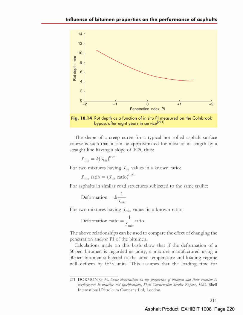
The shape of a creep curve for a typical hot rolled asphalt surfacecourse is such that it can be approximated for most of its length by astraight line having a slope of 0.25, thus:
Smix ¼ kðSbitÞ0:25
For two mixtures having Sbit values in a known ratio:
Smix ratio ¼ ðSbit ratioÞ0:25
For asphalts in similar road structures subjected to the same traffic:
Deformation ¼ k1
Smix
For two mixtures having Smix values in a known ratio:
Deformation ratio ¼ 1
Smixratio
The above relationships can be used to compare the effect of changing thepenetration and/or PI of the bitumen.Calculations made on this basis show that if the deformation of a
50 pen bitumen is regarded as unity, a mixture manufactured using a30 pen bitumen subjected to the same temperature and loading regimewill deform by 0.75 units. This assumes that the loading time for
Fig. 10.14 Rut depth as a function of in situ PI measured on the Colnbrookbypass after eight years in service[271]
271 DORMON G M. Some observations on the properties of bitumen and their relation toperformance in practice and specifications, Shell Construction Service Report, 1969. ShellInternational Petroleum Company Ltd, London.
Influence of bitumen properties on the performance of asphalts
211
Asphalt Product EXHIBIT 1008 Page 220

determination of viscosity and stiffness are the same. Conversely, if a100 pen bitumen is used, 1.5 units of deformation will occur (see Table10.2(a)). Clearly little improvement in deformation resistance is achievedpurely by using a harder bitumen.Increasing the PI of the bitumen significantly improves resistance to
deformation. For example, at 408C a bitumen with a penetration of 40and a PI of �0.5 has a viscosity of 4� 104 Pa s, whereas a bitumenwith the same penetration but having a PI of þ2.0 has a viscosity of6� 105 Pa s at 408C. This gives a factor of 15 in the viscosity and,hence, in the stiffness of the two bitumens. Thus, applying the 0.25power formula stated above gives an increase of approximately 2 in mix-ture stiffness. Accordingly, deformation using a mixture made with abitumen having a PI of þ2.0 would be half of one made with a standardbitumen (see Table 10.2(b)). Figure 10.15 shows the above theoreticalrelationship for relative deformation plotted as a function of PI. Thisclearly shows that the theoretical relationship is supported by both simu-lative laboratory wheel-tracking tests and full-scale road trials.Correlation of bitumen properties with both Marshall and wheel-
tracking tests[272] shows that the relationship between bitumen penetra-tion and Marshall stability is poor, whereas softening point relates very
Table 10.2(a) Relative deformation of mixtures at 408C, effect of bitumenpenetration
Bitumenpenetration
PI Viscosity at408C: Pa s
RelativeSbit
RelativeSmix
Relativedeformation
100 �0:8 6� 103 0:2 0:67 1:560 �0:6 18�103 0:6 0:88 1:150 �0:5 30�103 1 1 140 �0:5 40�103 1:3 1:07 0:9430 �0:4 90�103 3:0 1:32 0:75
Table 10.2(b) Relative deformation of mixtures at 408C, effect of bitumenpenetration index
Bitumenpenetration
PI Viscosity at408C, Pa s
RelativeSbit
RelativeSmix
Relativedeformation
40 �0:5 4�104 1 1 140 þ0:5 1:5�105 3:8 1:41 0:7140 þ2:0 6�105 15 1:97 0:50
272 JACOBS F A. Hot rolled asphalt: Effect of binder properties on resistance to deformation,Laboratory Report 1003, 1981. Transport and Road Research Laboratory,Crowthorne.
The Shell Bitumen Handbook
212
Asphalt Product EXHIBIT 1008 Page 221

well to both Marshall stability and deformation in the wheel-tracking test(see Fig. 10.16). For every 58C increase in softening point, the Marshallstability increased by over 1.3 kN (Fig. 10.16(b)) and the wheel-trackingrate almost halved (Fig. 10.16(c)).
The zero shear viscosity conceptIn terms of permanent deformation, it is thought that the binder contri-bution to this mode of distress is primarily associated with viscosity.However, identifying the relevant viscosity in terms of shear, shearrate and stress is a complex problem and a single quantifiable regimemust be established for assessment purposes. Pavement design is basedon the assumption that the material response to traffic loading iswithin the linear regime and to remain consistent with this premise,the corresponding linear viscosity of the binder should be examined.This is the zero shear viscosity, �0, sometimes termed ‘Newtonian viscos-ity’ as stress is proportional to shear. In this regime, stress and strain arelinearly proportional to each other so the stiffness modulus is indepen-dent of stress or strain level and the resultant viscosity, �0, is independentof the shear rate.By measuring binder properties within the linear regime, conclusions
can be made as to the likelihood of a bitumen contributing to or mitigat-ing the rutting process. Zero shear viscosities can be measured using adynamic shear rheometer, which also permits the elastic and viscous
Fig. 10.15 Relative deformation as a function of penetration index
Influence of bitumen properties on the performance of asphalts
213
Asphalt Product EXHIBIT 1008 Page 222

Fig.10.16
Relatio
nshipbe
twee
nbitumen
prop
ertie
san
dMarshallstabilityan
dwhe
el-trac
king
rate
[273]
The Shell Bitumen Handbook
214
Asphalt Product EXHIBIT 1008 Page 223

components to be identified. The higher the value of zero shear viscosity,the lower the influence of the bitumen in relation to permanent deforma-tion. Research has shown that the useful upper limit on zero shear viscos-ity of unaged bitumen is 105 Pa s, above which further resistance todeformation gives diminishing returns[274]. For bitumens that exhibitzero shear viscosities below this value, the relative value of the zeroshear viscosity coupled with the elastic component of the binder canbe used to interpret the deformation behaviour of the bitumen.The SHRP deliberations arrived at a similar parameter in their
methodology for providing a guideline on a ‘rutting factor’ designatedby the value of G�= sin �, which represents a measure of the high-temperature stiffness (for more on the SHRP specification, see Section4.7).
10.2.3 Fatting-upOne reason why fatting-up occurs is as a result of secondary compactionof the aggregate in the mixture by traffic. The void content is reduced,eventually squeezing bitumen from within the structure to the surface.This will be exacerbated if the bitumen content is too high or if thevoid content, after full compaction, is too low. Migration of bitumento the surface results in a smooth, shiny surface that has poor resistanceto skidding in wet weather. Fatting-up is most likely to occur at highservice temperatures. Accordingly, reducing the softening point orviscosity of the bitumen at 608C will limit this failure mechanism.
10.2.4 FrettingFretting is the progressive loss of interstitial fines from the road surface.It occurs when traffic stresses exceed the breaking strength of the asphaltitself or the asphalt mortar depending on the nature of the mixture.Fretting is more likely to occur at low temperatures and at short loadingtimes when the stiffness of the bitumen is high.The major factors influencing fretting are the bitumen content of the
mixture and the degree of compaction. Loss of aggregate can be dueeither to the loss of adhesion between the aggregate and the bitumen orto brittle fracture of the bitumen film connecting particles of aggregate.The first condition should not arise if suitable aggregates/bitumen are
273 JACOBS F A. Hot rolled asphalt: Effect of binder properties on resistance to deformation,Laboratory Report 1003, 1981. Transport and Road Research Laboratory,Crowthorne.
274 PHILLIPS M and C ROBERTUS. Binder rheology and asphalt pavement permanentdeformation: the zero shear viscosity concept, Proc Eurasphalt–Eurobitume Congress,Session 5 paper 134, 1996.
Influence of bitumen properties on the performance of asphalts
215
Asphalt Product EXHIBIT 1008 Page 224

selected. In the majority of cases, fretting is associated with a low degreeof compaction or inadequate bitumen content. The choice of bitumengrade may control the degree of compaction that can be achieved. Thisis especially true if operations are being conducted in adverse weatherconditions or if compaction is effected at inappropriate temperatures.The higher the penetration of the bitumen or the lower the stiffness atlow temperatures, the greater will be the resistance to fretting.
Fretting of macadam surface courseFor coated macadam mixtures, the following three different forms offretting are identifiable.
. Superficial fretting. This involves the loss of interstitial fines fromthe road surface. The material subsequently closes up under trafficwithout further deterioration or detrimental effect on performance.
. Severe fretting. If superficial fretting does not close up under traffic,the loss of interstitial fines results in a reduction of the level ofmechanical interlock that is likely to lead to the loss of coarse aggre-gate on the surface and a substantial reduction of internal cohesiondue to the ingress of water. The presence of water breaks down theadhesive bond between the bitumen and the aggregate resulting instripping of the bitumen. In addition, the uncoated fines and waterform a slurry that is pumped through the material, as a result of porepressures induced by moving traffic, abrading the coarse aggregateand exacerbating the problem. This will eventually lead to collapseof the material and a lack of internal stability, often visible on theroad as slight rutting or as potholes. Bitumen/aggregate adhesionand the effect of prolonged contact with water is discussed indepth in Chapter 9.
. Ravelling. Ravelling differs from the two modes described above inthat it involves plucking out of surface aggregate by traffic withoutany loss of cohesion of internal fines. It occurs when individualaggregate particles move under the action of traffic. If the tensilestress (induced in the bitumen as a result of the movement) exceedsthe breaking strength of the bitumen, cohesive fracture of thebitumen will occur and the aggregate particle will be detachedfrom the road surface. Thus, ravelling is most likely to occur atlow temperatures and at short loading times when the stiffness ofthe bitumen is high.
Fretting of hot rolled asphalt surface courseIn 1984, a survey was carried out by the British Aggregate ConstructionMaterials Industries (BACMI – now the Quarry Products Association,
The Shell Bitumen Handbook
216
Asphalt Product EXHIBIT 1008 Page 225
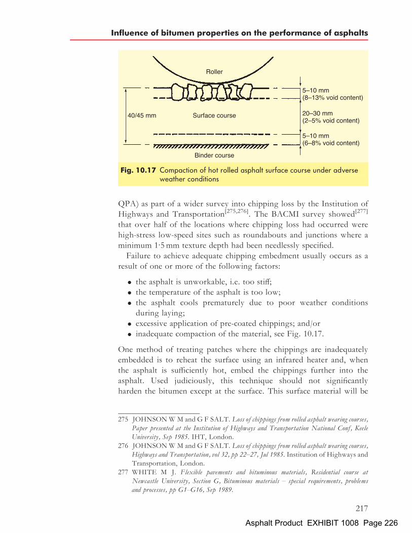
QPA) as part of a wider survey into chipping loss by the Institution ofHighways and Transportation[275,276]. The BACMI survey showed[277]
that over half of the locations where chipping loss had occurred werehigh-stress low-speed sites such as roundabouts and junctions where aminimum 1.5mm texture depth had been needlessly specified.Failure to achieve adequate chipping embedment usually occurs as a
result of one or more of the following factors:
. the asphalt is unworkable, i.e. too stiff;
. the temperature of the asphalt is too low;
. the asphalt cools prematurely due to poor weather conditionsduring laying;
. excessive application of pre-coated chippings; and/or
. inadequate compaction of the material, see Fig. 10.17.
One method of treating patches where the chippings are inadequatelyembedded is to reheat the surface using an infrared heater and, whenthe asphalt is sufficiently hot, embed the chippings further into theasphalt. Used judiciously, this technique should not significantlyharden the bitumen except at the surface. This surface material will be
Fig. 10.17 Compaction of hot rolled asphalt surface course under adverseweather conditions
275 JOHNSONWM and G F SALT. Loss of chippings from rolled asphalt wearing courses,Paper presented at the Institution of Highways and Transportation National Conf, KeeleUniversity, Sep 1985. IHT, London.
276 JOHNSONWM and G F SALT. Loss of chippings from rolled asphalt wearing courses,Highways and Transportation, vol 32, pp 22–27, Jul 1985. Institution of Highways andTransportation, London.
277 WHITE M J. Flexible pavements and bituminous materials, Residential course atNewcastle University, Section G, Bituminous materials – special requirements, problemsand processes, pp G1–G16, Sep 1989.
Influence of bitumen properties on the performance of asphalts
217
Asphalt Product EXHIBIT 1008 Page 226

eroded by traffic over time to expose the aggregate in the asphalt, a situa-tion that will not threaten the long-term integrity of the surface.Some chipping loss may occur as a result of a failure to achieve or
maintain bond between the pre-coated chippings and the asphalt. It hasbeen found that the bitumen on pre-coated chippings can be ‘coked’and made non-adhesive by storage of the chippings in large stockpilesimmediately after manufacture. The adhesivity of the bitumen coatingcan be checked using the hot sand test[278].When the chippings have been plucked out of the asphalt, it exposes
the asphalt mortar to traffic. It is likely that this material will be poorlycompacted and, as a result, it will fret rapidly.
278 BRITISH STANDARDS INSTITUTION. Sampling and examination of bituminousmixtures for roads and other paved areas, Methods for determination of the condition of thebinder on coated chippings and for measurement of the rate of spread of coated chippings,BS 598-108: 1990. BSI, London.
The Shell Bitumen Handbook
218
Asphalt Product EXHIBIT 1008 Page 227

Chapter 11
Aggregates in asphalts
Behavioural aspects of bitumen are dealt with throughout this book.However, bitumen is frequently mixed with aggregates to produceasphalts. Thus, an appreciation of how aggregates behave is importantif the performance of asphalts is to be understood. This chapter considersthe origins, types and key parameters of aggregates.
11.1 Origins and types of rockAsphalts consist primarily of aggregates. The properties of aggregates(sometimes described as ‘mineral aggregates’) have a significant influenceon the behaviour of asphalts. Thus, an appreciation of the origins andproperties of aggregates is one of the key elements to understandingasphalt technology.
11.1.1 Natural aggregatesRock is as old as the Earth itself, having been formed as part of thecreation of the planet. The exact development of the Earth is still not com-pletely understood but, according to current knowledge, it is believed ared hot gas ball developed in space about three billion years ago. Theaction of cooling down to a temperature between 1000 and 20008Ccaused the initial stages of a crust to form on the surface of the Earth.Further cooling took place, reaching the inner parts of the planet and
the thickness of the solid zone increased. Large stresses developedbetween the hotter and the cooler zones and, at the same time, thesolidified rock further compressed the inner, liquid parts of the planet.This resulted in deformation followed by rearrangement of the Earth’scrust.Clods and blocks of rock developed and shifted towards each other,
sometimes remelting. This continuous change of the surface of theEarth was accelerated by weathering since further cooling led to theformation of water.
219Asphalt Product EXHIBIT 1008 Page 228

The thickness of the Earth’s crust is estimated to be around 15 km. Themelted rock in this zone is called magma. It is subdivided into threeclassifications according to how each was formed:
. igneous rock resulting from solidification;
. sedimentary rock resulting from sedimentation;
. metamorphic rock resulting from transformation.
‘Minerals’ means, in literal terms, any material that is mined but in thecontext of this book refers to natural aggregates. Minerals consist ofchemical elements or combinations of chemical elements. Some mineralshave a uniform composition and structure whilst others consist ofmixtures of different minerals and have heterogeneous structures.Aggregates are classified according to their chemical composition,
their mineral contents and the structure of the minerals. ‘Structure’denotes the mineral composition and ‘texture’ means the arrangementof the minerals. The characteristics of the three main rock types interms of these properties are illustrated in Table 11.1.‘Porphyric’ indicates a special kind of structure of igneous rock. Por-
phyric rocks are formed when aggregates are pushed up suddenly fromthe deeper parts of the Earth’s crust to the surface. Slow cooling isthen followed by very rapid cooling which leads to a finely grained struc-ture. Traditionally, porphyry was a hard rock quarried in ancient Egyptcomposed of crystals of white or red feldspar in a red matrix. However, itnow denotes an igneous rock with large crystals scattered in a matrix ofmuch smaller crystals.Sedimentary rocks cannot be classified easily using the system illu-
strated in Table 11.1. If the constituents are angular and cementedtogether by finer material, the term ‘breccia’ is used for the structure. Ifthe material is composed of coarse but rounded grains that are cementedtogether, it is called ‘conglomerate’. Sandstones are composed of finergrains.
Igneous rocksIgneous rocks were formed by volcanic or magmatic action. (‘Magma’is a fluid or semi-fluid material under the Earth’s crust from whichlava and other igneous rocks are formed.) Igneous rocks are divided
Table 11.1 Structure and texture of rock types
Category Structure Texture
Igneous Glassy, fine to coarse, crystalline, porphyric Dense, smoothSedimentary Varies according to type and size of the components Less dense, rough textureMetamorphic Crushed minerals Variable according to origin
The Shell Bitumen Handbook
220
Asphalt Product EXHIBIT 1008 Page 229

into three subgroups:
. plutonic
. dike
. volcanic.
Plutonic rocks cooled down slowly in deeper parts of the Earth’s crust,below other, older minerals. They were named after the Greek god of theunderworld. Examples are granite, syenite, diorite, and gabbro.Dike rocks were probably formed when liquid magma poured into
cracks and crevices in cooled rock. These cracks and crevices arisebecause of temperature stress. In the cracks, rapid cooling took place.This category comprises all stones with porphyric structure such asgranite porphyry, syenite porphyry and diabase porphyry.Volcanic rock, in contrast to the formation of plutonic rock, emerged
from the Earth’s crust and cooled on the surface of the Earth. This stillhappens nowadays at active volcanoes. Very often, porphyric structuresare formed in this process. This group includes diabase, basalt, phono-lithe and, in part, porphyry.
Sedimentary rocksSedimentary rocks are subdivided into mechanical sedimentary (gravel,breccia, conglomerate), chemical sedimentary (dolomite), and biogeneticsedimentary (coal). Only rocks that evolved from the first two of thoseprocesses are used in road construction.Mechanically formed sedimentary rocks can originate either from mag-
matic rock or from chemical sediments like moraine exposed to weatheringafter their formation. Rainwater and melted snow transported loosenedparticles into river beds, seas, and oceans where they were deposited.Chemically formed sedimentary rocks are residual or precipitated stones.Their suitability for road construction depends on their hardness.The most remarkable feature of this type of structure is the layering. It
is for this reason that sedimentary rocks are sometimes described asbedded rock.
Metamorphic rocksMetamorphic rocks originated as igneous rocks because the first phase oftheir formation was volcanic. However, rearrangement of the Earth’scrust shifted the materials back to deeper layers where higher tempera-tures existed. Remelting and mixing formed a variety of structureswith a slate-like appearance. Typical examples of metamorphic rock aregneiss and amphibolite. There are numerous types of metamorphicrock and the suitability of any single variety for road constructionshould be checked carefully.
Aggregates in asphalts
221
Asphalt Product EXHIBIT 1008 Page 230

11.1.2 Synthetic aggregatesIndustrial by-products like blast furnace slag or recycled buildingmaterials are utilised in the manufacture of asphalts. The properties ofthese synthetic aggregates vary substantially according to their origin.The technical suitability and environmental properties have to betested in every case before they can be considered as suitable for use inan asphalt.
11.2 Aggregate extraction
Natural sand and gravel can be obtained with relatively simple, inexpen-sive equipment. Since single grains are unbound, they can be separatedwith ease. For dry extraction, an excavator is adequate. Where materialextraction is undertaken below water, a floating excavator is needed.The gravel is separated into granular classes or broken down to producecrushed gravel sand.More effort is required to crush bedrock. In modern quarries, complete
walls are blasted at different locations at the same time. The resultantlarge boulders are crushed and screened to the required granular sizes.Blast furnace slags are formed from the hot liquid in large tubs and are
subsequently crushed and screened.
11.3 The European aggregate StandardIn January 2004 the UK quarrying industry made one of the biggestchanges to the way aggregates were called and categorised since metrica-tion was introduced. The changes were introduced as a direct result ofEU Directives to remove barriers to trade, and form part of the nationalstandards of all countries within the EU community. The changesimpacted on all aggregates that used size as a means of categorisingthem and aggregates that complied with a European Standard. It isimportant to remember that the changes were designed to only impacton the way that aggregates are described or categorised and that theaggregates should require only slight changes to processing to meetthe new Standard.For this Standard to work across European countries it has been
written in a ‘menu’ style, providing sieve sizes, categories, propertiesand test methods for all countries to select appropriate limiting values.BSEN13043 Aggregates for bituminous mixtures and surface treatments forroads, airfields and other trafficked areas[279] is not an easy document to use.To aid the understanding of the European Standard, the UK adopted the
279 BRITISH STANDARDS INSTITUTION. Aggregates for bituminous mixtures andsurface treatments for roads, airfields and other trafficked areas, BS EN 13043: 2002.BSI, London.
The Shell Bitumen Handbook
222
Asphalt Product EXHIBIT 1008 Page 231

use of guidance documents, known as the PD 6682 series (PD stands forpublished document) and these are published by BSI. The PD 6682 seriescan only recommend categories and limiting values in line with therelevant European Standard and does not replace it. The guidance docu-ment for BSEN13043 is PD 6682-2: 2003,[280] and the two documentsshould be read together.PD 6682-2: 2003 recommends the properties of aggregates and filler
obtained by processing natural, manufactured or recycled materials foruse in bituminous mixtures and surface treatments. PD 6682-2: 2003contains recommended grading tables, previously found in the super-seded British Standards specifications BS 63 and BS 1047. These gradingtables show the recommended new aggregate size, grading category andgrading limits.PD 6682-2: 2003 also recommends the use of new test methods, detail-
ing the key differences between previous British Standards such as theBS 812 series with the new European Standards. For a clear step bystep approach to the changes in test methods, PD 6682-9: 2003[281]
provides guidance on all European test method Standards.
11.3.1 Quality control and CE markingThe European aggregate Standard also introduces quality control, requir-ing the producer to demonstrate Factory Production Control (FPC) to athird party, leading ultimately to certification from a notified body.This is one of the biggest implications of the European Standard for
the aggregate producer requiring CE Marking. CE Marking is a legaldeclaration by the producer indicating the properties of their aggregates,enforced by Trading Standards and constituting a criminal offence iffalsely declared. Previously, suppliers of aggregates would have provideddata sheets to customers showing the most recent suite of physical,mechanical and chemical test results undertaken on the aggregatessourced from a quarry. CE Marking requires that this is undertakenfor each size of aggregate at each source and declared as per the require-ments of Annex ZA of the relevant European Standard.
11.3.2 Size and grading categorySize was originally described using one dimension, such as 10mm singlesize. However since the introduction of the European Standard, size now
280 BRITISH STANDARDS INSTITUTION. Aggregates for bituminous mixtures andsurface treatments for roads, airfields and other trafficked areas – Guidance on the use ofBSEN13043, PD 6682-2: 2003. BSI, London.
281 BRITISH STANDARDS INSTITUTION. Guidance on the use of European testmethod standards, PD 6682-9: 2003. BSI, London.
Aggregates in asphalts
223
Asphalt Product EXHIBIT 1008 Page 232

follows the convention of using two dimensions, small ‘d ’ and large ‘D’,such as 4=10mm single size. Also introduced with the EuropeanStandard is the way aggregates are categorised with the use of GradingCategories, expressed as GC for coarse aggregate, GF for fine aggregateand GA for all-in aggregate. A grading category gives more informationabout the grading of an aggregate. Grading categories work by indicat-ing the oversize and undersize of the two sieve sizes ‘d=D’ used todescribe the aggregate size. Table 11.2, shows how the BS 63 size istranslated into the BSEN13043 size.Other changes brought about from the implementation of the Euro-
pean aggregate Standard can be seen in Table 11.2. Firstly, the37.5mm sieve is replaced by the 40mm sieve, the 28mm sieve is replacedby the 31.5mm sieve. The UK has taken a pragmatic approach and the31.5mm size may be described as 32mm.All fine sieves are replaced by a new set. Asphalts will use the 2mm
sieve as the controlling sieve for fine aggregate, and the 75mm sieve isreplaced by a fines category, expressing the fines content as fx, where x
Table 11.2 Recommended BS EN13043 grading categories and corresponding grading limitsfor coarse aggregates used in the manufacture of asphalt.[282]
RecommendedBS EN13043 aggregate(mm)
20/40 20/31.5 10/20 6.3/14 4/10 2/6.3 1/4
Equivalent BS 63 singlesized aggregate (mm)
40 28 20 14 10 6 3
RecommendedBS EN13043 gradingcategory
GC85/20 GC85/35 GC85/20 GC85/20 GC85/20 GC80/20 GC90/10
Sieve size (mm) Percentage by mass passing ISO 565 sieve80 100 – – – – – –63 98 to 100 100 – – – – –40 85 to 99 98 to 100 100 – – – –31.5 – 85 to 99 98 to 100 100 – – –20 0 to 20 0 to 35 85 to 99 98 to 100 100 – –14 – – – 85 to 99 98 to 100 100 –10 0 to 5 0 to 5 0 to 20 – 85 to 99 98 to 100 –8 – – – – – – 1006.3 – – – 0 to 20 – 80 to 99 98 to 1004 – – 0 to 5 – 0 to 20 – 90 to 992.8 – – – 0 to 5 – – –2 – – – – 0 to 5 0 to 20 –1 – – – – – 0 to 5 0 to 100.500 – – – – – – 0 to 2
282 BRITISH STANDARDS INSTITUTION. Aggregates for bituminous mixtures andsurface treatments for roads, airfields and other trafficked areas – Guidance on the use ofBS EN 13043, Table 3, PD 6682-2: 2003. BSI, London.
The Shell Bitumen Handbook
224
Asphalt Product EXHIBIT 1008 Page 233

is the maximum percentage passing the 0.063mm sieve. Finally the use ofmicrons (micrometres) has gone and mm used for all sizes.
11.3.3 Key properties of aggregatesProperties of aggregates have, in the past, been expressed as actual meas-ured values. European aggregate standards require the use of categoriesand classes to define an aggregate property.As mentioned above, BS 812 test methods are replaced with new EN
test methods listed above in Table 11.3. A key change is the measurementof aggregate strength, where the ten per cent fines value, the aggregatecrushing value and the aggregate impact value have been replaced bythe Los Angeles coefficient (LA). LA values are expressed as categoriessuch as LA30, setting a requirement for a maximum LA value of 30. Inthis way an actual measured value of 27 would be expressed as LA30.There are occasions when the actual measured value exceeds the
highest category available in the European Standard. In these cases thesupplier declares the found value, such as LADeclared55. The PSV valuesin BS EN 13043 Table 13, Categories for minimum values of resistance topolishing, are the only exception to this rule, allowing intermediatevalues to be expressed as a supplier declared value, such as PSVDeclared65.One other key aggregate property fundamental to the performance of
asphalt is shape. Shape has, in the past, been reported as the flakinessindex, and continues to be so. But, confusion comes when comparingresults from the previous BS 812 Part 105.1: 1989 method with thereplacement BS EN 933-3.[283] Both methods measure the percentagepassing a slot width specified for that particle size fraction, the flakyparticles are those which pass through the slots. This is as far as thesimilarity goes. The new BS EN 933-3 method categorises a particle asflaky if its minimum dimension is less than half its upper sieve size ðDÞ.The size fractions used in the new test method are significantly different
Table 11.3 BS EN test method groups
BS EN test method Group
BS EN 932 (all parts) General properties of aggregatesBS EN 933 (all parts) Tests for geometrical properties of aggregatesBS EN 1097 (all parts) Tests for mechanical and physical properties of aggregatesBS EN 1367 (all parts) Tests for thermal and weathering properties of aggregatesBS EN 1744 (all parts) Tests for chemical properties of aggregates
283 BRITISH STANDARDS INSTITUTION. Tests for geometrical properties ofaggregates. Determination of particle shape. Flakiness index, BSEN933-3: 1997. BSI,London.
Aggregates in asphalts
225
Asphalt Product EXHIBIT 1008 Page 234

from those previously used in the BS 812 method resulting in a flakinessindex value lower than previously found. As required by the Europeanstandard the flakiness index is reported as a category, FI20, setting arequirement for a maximum flakiness index value of 20. Previousflakiness index requirements of 25% for surface dressing aggregatesare now specified as FI20, indicating a drop of 5% to allow for thedifferences in test methods.The behavior of individual aggregates in relation to a number of key
properties is important in ensuring that a particular asphalt performsadequately in service. These key properties are as follows.
. Shape. Shape is an important determinant in asphalts. If individualpieces of aggregate are elongated or very flat they can form inherentweaknesses in the mixture.
. Strength. In strength terms, the aggregate has to be able to with-stand the applied loads without crushing and should be able toresist stresses created by the sudden imposition of loads.
. Roughness. The surface roughness of pieces of aggregate is a majorcontributor to the frictional characteristics of a pavement. Thisroughness, or rugosity as it is sometimes called, has to be main-tained if safety is not to be compromised, hence the need for aggre-gates to be resistant to abrasion in service.
. Susceptibility to polishing. It is a fact that all aggregates polish withthe action of traffic. However, this polishing should take place at arate such that the carriageway provides acceptable braking charac-teristics for a reasonable period of time. Thus, the degree andspeed of polishing is important.
. Soundness. Some aggregates that were thought to have sufficientinitial strength have been found to have failed whilst in the pave-ment. Soundness seeks to deal with such materials and may bedescribed as a measure of the durability of aggregates in service.
All of the above properties are now expressed as categories and defined inBS EN 13043. Specifiers are required to implement the European Stan-dard in full and need to define BS EN 13043 categories for propertiesthat are relevant to a particular end use. Table 11.4 shows the preferredspecification for aggregates for surface treatments. At all times it isrecommended the PD 6682 tables be used to define categories for theproperties of aggregates.An option to use a ‘No Requirement’ category is also provided. For
example, a resistance to abrasion from studded tyres category ofANNR, NR for no requirement, is included in BS EN 13043 and itmeans that there is no specified requirement for this test, particularlyapt in the UK where studded tyres are not permitted. When a specifier
The Shell Bitumen Handbook
226
Asphalt Product EXHIBIT 1008 Page 235

does not want to dictate a property that is not relevant for an end use the‘No Requirement’ designation should be used.
11.3.4 Implications for other StandardsBS EN 13043 supersedes BS 63-1: 1987, BS 63-2: 1987, and BS 1047: 1983but has implications on current British Standards for asphalt, BS 594, BS4987, BS 5273 and the Specification for Highway Works (SHW), all of whichcontain requirements for aggregates. In 2003, these asphalt Standardswere updated to incorporate the changes. Key changes were the intro-duction of new sieves, the replacement of 3.35mm and 2.36mm sievesin coated macadam and hot rolled asphalt respectively with the 2mmsieve. This triggered the amendment of binder correction tables in BS598 used for analysis.40mm dense base mixtures, which used the 37.5mm sieve to control
upper size, have been replaced by 0/32mm size mixtures, as the37.5mm sieve is no longer part of the sieve series used in the UK.0=32mm size mixtures have replaced all 28mm base and binder coursemixtures, as the 28mm sieve is also no longer available.The way asphalts are described by size also changed, following the
same rules as aggregates, d=D. Examples are given in Table 11.5.
11.3.5 Assessment of key propertiesIn the UK, the major arterial highways (called ‘Trunk Roads’, whichincludes motorways) are the responsibility of national government.The executive agencies that look after the Trunks Roads are the High-ways Agency in England, the National Assembly for Wales (Cynulliad
Table 11.4 Example specification for 6/10mm aggregate for surfacetreatments[284]
Property Category
Grading 6.3/10mm GC85/20Fines content f1Flakiness index FI20Resistance to fragmentation LA30PSV PSV62 (Contract Specific)AAV AAVDeclared (Contract Specific)Durability:Water absorption to BS EN 1097-6:2000, Clause 7For WA > 2%, magnesium sulphate soundness
WA242MS25
284 BRITISH STANDARDS INSTITUTION. Aggregates for bituminous mixtures andsurface treatments for roads, airfields and other trafficked areas – Guidance on the use ofBS EN 13043, annex A, table A.1, PD 6682-2: 2003. BSI, London.
Aggregates in asphalts
227
Asphalt Product EXHIBIT 1008 Page 236

Cenedlaethol Cymru), the Department for Regional Development inNorthern Ireland and, in Scotland, the Scottish Executive DevelopmentDepartment. Trunk Roads represent some 4% by length of the road net-work but they carry some 30% of the total traffic and some 50% of theheavy goods vehicles. Contracts for works of new construction or main-tenance on Trunk Roads are contained within a suite of documentsentitled the Manual of Contract Documents for Highway Works[285]
(MCHW). Specification requirements for asphalts including aggregatesare contained in Volumes 1 and 2 of this suite (entitled the Specificationfor Highway Works[286] and the Notes for Guidance on the Specification forHighway Works[287] respectively). These documents are also used by themajority of local authorities for works on the remaining 96% of the high-way network. Table 11.6 lists some of the current requirements foraggregates used on Trunk Road schemes. Typical testing requirementsfor UK Trunk Roads are set out in Table 11.7.
Table 11.5 Examples of size designation for asphalts specified in BS 4987 and BS 594
Previous Description Revised Description
BS 4987-1: 2003 Coated macadam28mm DBM designed base 0/32mm DBM designed base6mm medium graded surface course 0/6mm medium graded surface course20mm porous asphalt 6/20mm porous asphalt
BS 594-1: 2003 Hot rolled asphalt50/14 HRA binder course 50% 0/14 HRA binder course35/14 HRA Type F design surface course 35% 0/14 HRA Type F design surface course20mm pre-coated chippings 14/20mm pre-coated chippings
285 HIGHWAYS AGENCY et al. Manual of contract documents for highway works, vols0–6, Various dates. The Stationery Office, London.
286 HIGHWAYS AGENCY et al. Manual of contract documents for highway works,Specification for highway works, vol 1, 2002. The Stationery Office, London.
287 HIGHWAYS AGENCY et al. Manual of contract documents for highway works, Notesfor guidance on the specification for highway works, vol 2, 2002. The Stationery Office,London.
The Shell Bitumen Handbook
228
Asphalt Product EXHIBIT 1008 Page 237

288 WOODWARD D (R N HUNTER, ed). Assessing aggregates for use in asphalts,Asphalts in Road Construction, p 13, 2000. Thomas Telford, London.
289 HIGHWAYS AGENCY et al. Manual of contract documents for highway works, Notesfor guidance on the specification for highway works, vol 2, table NG1/1 (part only), 2002.The Stationery Office, London.
Table 11.6 Some of the current requirements for aggregates on UK TrunkRoads[288]
Property European Standard test Limiting value
Size Sieve analysis (dry or wet) —
ShapeFlakiness Flakiness index (FI) Fl35
StrengthCrushing Los Angeles coefficient (LA) LA30
Abrasion Aggregate abrasion value (AAV) AAVDeclared
Polishing Polished stone value (PSV) PSVDeclared
Soundness Magnesium sulphate soundness value (MSSV) MS25
Table 11.7 Typical testing requirements for UK Trunk Roads[289]
SHW clause Type of material Property tobe assessed
Test Frequency oftesting
901, 925, 937,938
Aggregate forbituminous materials
Hardness LA (N) Monthly†
Durability MSSV (N)WA (N)
1 per sourceas required
Cleanness Sieve test(%<0:075mm) (N)
Monthly
Shape FI (N) MonthlySkid resistance PSV (N)� 1 per sourceAbrasion AAV (N)� 1 per source
915, 925 Coated chippings Grading Grading (N) 1 per stockpileBinder content Binder content (N) 1 per stockpileShape FI (N) 1 per sourceSkid resistance PSV (N) 1 per sourceAbrasion AAV (N) 1 per source
NotesAll tests to be carried out by the contractor.The frequency of testing is given for general guidance and is only indicative of the frequency that may be appropriate.(N) indicates that UKAS (United Kingdom Accreditation Service) sampling and a test report or certificate is required.WA – water abrasion.�Applicable to coarse aggregates for surface courses only.†To be introduced in 2004.
Aggregates in asphalts
229
Asphalt Product EXHIBIT 1008 Page 238

Chapter 12
Types and applications ofdifferent asphalts
Despite the fact that asphalts are little more than a mixture of aggregateand bitumen, there are many different mixtures available and theircharacteristics can vary quite significantly.For the majority of the last half of the twentieth century, standard
practice on major roads in the UK was to construct the base andbinder course using either hot rolled asphalt or dense coated maca-dam. The surface course was invariably constructed using chippedhot rolled asphalt, a material that was virtually unique to the UK.However, in the last decade of the twentieth century, a number ofnew materials, mainly variants of mixtures used in France andGermany, began to enjoy more widespread use. The availability ofthese materials, together with a vastly improved understanding ofthe failure mechanisms in flexible pavements, led to a move towardswhat are termed ‘stiff ’ mixtures. Such mixtures produce pavementsthat have a very long structural life, providing distress in theform of cracking or rutting is addressed in a timely and effectivemanner.Traditionally, asphalts were designated as either gap graded or
continuously graded. This referred to the constitution of the asphalt interms of the size of the individual aggregate fractions within mixtures.Size is measured by passing a sample of aggregate through a series ofsieves. Thus, a continuously graded mixture was one that containedfractions of various (but not necessarily all) sizes throughout the range.An example of a continuously graded mixture is dense coated macadambase. A gap graded mixture is one where sizes are discontinuous. Anexample of a gap graded material is a hot rolled asphalt surface courseconsisting of 6/14mm aggregate with the next size down being smallenough to pass a 2mm sieve.Examples of the gradings of these materials are shown in Table 12.1,
with two of the grading envelopes depicted in Fig. 12.1.
231Asphalt Product EXHIBIT 1008 Page 239

The traditional British Standards that specify asphalts emerged fromthe description of an asphalt as being gap graded or continuouslygraded. BS 594 deals with asphalts (gap graded materials) whilstBS 4987 applies to coated macadams (continuously graded materials).This definition was never particularly scientific, somewhat inconsistentand thus was never satisfactory. An example is fine cold asphalt whichwas categorised as being continuously graded. Nowadays, Europeanharmonisation requires that the term ‘asphalt’ is used to describeall bituminous mixtures. Thus, grading is irrelevant, in terms ofdescription.Recently, the adoption of relatively hard bitumens and the emergence
of new materials combined with an improved understanding of thebehaviour of asphalts has resulted in a vast increase in the usage ofwhat were traditionally called continuously graded mixtures, the coatedmacadams. Nowadays there are numerous asphalts available to thepurchaser. Some are general purpose, such as bases or binder courses,whilst others are produced for particular applications, e.g. fuel-resistingor deferred-set asphalts.For non-proprietary mixtures, two British Standards govern all aspects
of asphalt production and laying in the UK. These are BS 4987 andBS 594 and they are concerned with coated macadams and hot rolledasphalts respectively. Each of these Standards is split into two Parts,
Table 12.1 Gradings for common asphalts
Sieve size Percentage by weight passing each sieve
Coated macadams Hot rolled asphalts
0/20mm size densebinder course
0/10mm size closegraded surface
course
Designation 50%0/14mm base,
binder course andregulating course
Designation 35%0/14mm type Fsurface course
31:5mm 10020mm 95 to 100 100 10014mm 65 to 85 100 90 to 100 87 to 10010mm 52 to 72 95 to 100 65 to 100 55 to 886:3mm 39 to 55 55 to 752mm 24 to 36 19 to 33a 30 to 55 55 to 671mm 15 to 300:500mm 13 to 50 40 to 670:250mm 7 to 21 6 to 31 15 to 550:063mm 2 to 9 3 to 8 1 to 8 6:0 to 10:0
aMay be increased to 38 when sand fine aggregate is used.
The Shell Bitumen Handbook
232
Asphalt Product EXHIBIT 1008 Page 240

Fig. 12.1 Grading envelopes for a continuously graded and a gap gradedasphalt. (a) 0/20mm size dense binder course coated macadam.(b) Designation 35% 0/14mm type F surface course hot rolled asphalt
Types and applications of different asphalts
233
Asphalt Product EXHIBIT 1008 Page 241

one dealing with the specification and manufacture[290,291] and the otherwith transporting, laying and compaction[292,293].The following three sections describe a number of these mixtures in
terms of their properties and applications.
12.1 Coated macadams12.1.1 Bases and binder coursesCoated macadams are, by far, the most common mixtures in use as bindercourses and bases in road pavements in the UK. In the USA, suchmaterials are described as asphaltic concretes or, formerly, Marshallasphalts. The key difference between these mixtures is the penetrationof the bitumen although, as discussed below, that is not always thecase. These materials are continuously graded and are manufacturedwith relatively low bitumen contents. Their strength is derived fromthe interlock of the coated aggregate. A number of different UKmixtureshave evolved, primarily from mixtures used in other EC countries.In the UK, high-performance base and binder course materials are
required, particularly for the reconstruction of heavily trafficked roadswhere the available construction depth is often restricted by bridge clear-ance and drainage levels. In order to enhance the performance of thepavement without increasing the depth of construction, improvedmaterials were developed. Appropriate design curves for these materialscan be derived by the measurement of their properties in relation to thoseof the standard dense coated macadam base. One of the most importantproperties is that of the stiffness modulus, which strongly affects thecritical strains generated in both the base and subgrade.One of the improved dense coated macadam base and binder course
materials is heavy duty macadam (HDM)[294–296]. In this material, thetraditional 100/150 pen bitumen is replaced by 40/60 pen bitumen andthe target filler content is increased from a range of 2 to 9% to a rangeof 7 to 11%. A significant increase in stiffness is obtained by using the40/60 pen bitumen and a further, albeit smaller, rise results from the
290 BRITISH STANDARDS INSTITUTION.Coated macadam for roads and other pavedareas, Specification for constituent materials and for mixtures, BS 4987-1: 2003. BSI,London.
291 BRITISH STANDARDS INSTITUTION. Hot rolled asphalt for roads and otherpaved areas, Specification for constituent materials and asphalt mixtures, BS 594-1:2003. BSI, London.
292 BRITISH STANDARDS INSTITUTION.Coated macadam for roads and other pavedareas, Specification for transport, laying and compaction, BS 4987-2: 2003. BSI, London.
293 BRITISH STANDARDS INSTITUTION. Hot rolled asphalt for roads and otherpaved areas, Specification for transport, laying and compaction, BS 594-2: 2003. BSI,London.
The Shell Bitumen Handbook
234
Asphalt Product EXHIBIT 1008 Page 242

higher filler content. Laboratory fatigue tests have demonstrated that theharder bitumen and higher filler content had an insignificant effect onfatigue life. This increased stiffness reduces the strains induced at thebottom of the base where fatigue cracking has traditionally been assumedto originate. Tests using a pneumatic-tyred wheel-tracking machine at308C showed that adding 3% more filler reduced deformation byabout 40% in mixtures that had been properly compacted.During 1986, a number of proving trials were carried out on heavily
trafficked roads using this material to identify any problems thatmight arise during manufacture or laying. The only significant difficultyexperienced was that some types of mixing plant required longer mixingtimes than those necessary with conventional dense macadam. This isdue to the higher filler content. This reduced the output and increasedthe cost of production. Experience with this material has shown thatincreasing the bitumen content slightly can do much to overcomethis problem without significantly affecting the performance of themixture.Appropriate design thicknesses have been determined by the TRL[294].
For a given design life, the introduction of HDM in place of the conven-tional material leads to a reduction in design thickness, typically between15 and 20%. This curve is included in the Highways Agency’s designstandard[297]. A specification for HDM is included in Cl 930 (base) andCl 933 (binder course) of the SHW[298].High modulus base (HMB) was developed by the TRL as a result of
the evaluation of a French mixture called ‘enrobe a module eleve’(EME) which was introduced as an economic measure to reduce thethickness of the main structural layer of the pavement. Tests were under-taken on a mixture with a grading that complied with BS 4987. Theperformance of a trial pavement confirmed that a bitumen macadam
294 NUNNM E, C J RANT and B SCHOEPE. Improved roadbase macadams: road trialsand design considerations, Research Report 132, 1987. Transport and Road ResearchLaboratory, Crowthorne.
295 HIGHWAYS AGENCY et al. Manual of contract documents for highway works,Specification for highway works, vol 1, Cls 930 & 933, 2002. The Stationery Office,London.
296 LEECH D and M E NUNN. Substitution of bituminous roadbase for granular sub-base,3rd Eurobitume Symp, The Hague, pp 249–255, 1985. Also reprinted in Asphalt Tech-nology, J Inst Asph Tech, Feb 1986. Institute of Asphalt Technology, Dorking.
297 HIGHWAYS AGENCY et al. Design manual for roads and bridges, Pavement design andmaintenance, Pavement design, vol 7, HD 26/01, 2001. The Stationery Office, London.
298 HIGHWAYS AGENCY et al. Manual of contract documents for highway works,Specification for highway works, vol 1, 2002. The Stationery Office, London.
Types and applications of different asphalts
235
Asphalt Product EXHIBIT 1008 Page 243

binder course with a grading complying with BS 4987 and made with a10/20 pen bitumen had very similar properties to EME[299].Currently, it is more common for HMB materials to be manufactured
with 30/45 pen bitumen. This mixture offers increased stiffness over moreconventional materials and, as a result, can be laid thinner. It can be laidand compacted over a wide range of weather conditions with little adjust-ment to the mixing temperatures and compaction techniques employedwith materials using a 40/60 pen bitumen.A recent development with HMBs has been the incorporation of a
high-stiffness polymer modified binder. The bitumen in this mixturehas been designed to give improved flexibility, adhesion and durabilitywhilst the mixture has a very high stiffness meaning that a thinnerlayer is required than would have been the case with conventionalasphalts.In the UK, base and binder course materials are being developed based
on stone mastic asphalt (SMA) technology. SMA was originally devel-oped in Germany and Scandinavia as a surfacing course in the 1960sfor resisting studded tyres, and is now widely used through most ofEurope[300]. SMA is a gap graded asphalt that has a coarse aggregateskeleton, similar to porous asphalt, but the voids are filled with a fineaggregate/filler/bitumen mortar.BS 4987-1: 2003[301] also contains details of 0/20mm size open graded
binder course and 0/32mm size single course. Open graded bindercourses are used in lightly trafficked situations (technically where trafficis250 commercial vehicles per lane per day). The single course mixturecan be used as a base or as a binder course but it is most commonly usedas a combined binder course and surface course on roads that carry lighttraffic. It should be sealed with bituminous grit soon after laying andbefore being subjected to traffic.
12.1.2 Surface coursesGenerally speaking, coated macadam surface courses are used on roadsthat carry light traffic. Open graded mixtures were widely used in theUK, particularly in England, prior to the emergence of heavier commer-cial vehicles. Having an open texture means that they are accessible to
299 NUNN M E and T SMITH. Evaluation of enrobe a module eleve (EME), A Frenchhigh modulus roadbase material, Project Report 66, 1994. Transport Research Labora-tory, Crowthorne.
300 EUROPEAN ASPHALT PAVEMENT ASSOCIATION. Heavy duty surfaces: thearguments for SMA, 1998. EAPA, The Netherlands.
301 BRITISH STANDARDS INSTITUTION.Coated macadam for roads and other pavedareas, Specification for constituent materials and for mixtures, BS 4987-1: 2003. BSI,London.
The Shell Bitumen Handbook
236
Asphalt Product EXHIBIT 1008 Page 244

water and are likely to degrade rapidly where there are frequent freeze/thaw weather cycles. Their durability is a function of the nature of thepavement itself and the nature of the incident traffic. The use of a surfacedressing may be necessary as a sealant. Close graded, dense and mediumgraded surface courses are less susceptible to intrusion and damage bysurface water. However, they are only suitable for light traffic or applica-tions such as footways, car parks, playgrounds, etc. Fine graded surfacecourse was previously described as ‘fine cold asphalt’ and it is only suit-able for footways, etc. A photograph of a 0/6mm size dense coatedmacadam surface course is shown in Fig. 12.2.One particularly important coated macadam asphalt is porous asphalt
(PA). Although PA has not enjoyed widespread use in the UK, it is usedin significant quantities in other EC states. PA is a gap graded materialwith interconnecting voids that allow water to flow freely through thematerial to the binder course. The water finds its way through to thebinder course and then flows on top of the binder course into a channelwhere it is collected in a drain. The disadvantage is that the bitumen isexposed to oxygen in the atmosphere and is thus subject to oxidationand consequent embrittlement. Thicker, softer bitumen coating is, there-fore, desirable and so the use of modified binders or fibres is necessary to
Fig. 12.2 Coated macadam – 0/6mm size dense surface courseCoin shown¼ 1 Euro, 23mm diameter
Types and applications of different asphalts
237
Asphalt Product EXHIBIT 1008 Page 245

prevent the binder draining through the mixture. A useful source ofinformation on PA is TRL Report 264[302].PA has benefits in terms of particularly low noise and spray generation.
In addition, glare in wet conditions is reduced.PA with 100/150 pen bitumen has a life of 7 to 10 years with traffic of
6000 cv per lane per day. The tack coat is important as it adds to thewaterproofing of the binder course; a polymer modified tack coatshould be considered.PA is the standard surface course used in the Netherlands. Dutch
Engineers accept that the characteristics of PA outweigh the need toreplace it rather more often than would be the case with other asphalts.
12.2 Hot rolled asphalt12.2.1 Bases and binder coursesHot rolled asphalts are gap graded mixtures that were not uncommon asbase and binder courses until the last decade of the twentieth centurywhen the stiffer coated macadams became available. They have higherbitumen contents than coated macadams and thus were comparativelyunattractive from a financial standpoint. Their strength is derived fromthe characteristics of the bitumen/sand/filler mortar. Use of hot rolledasphalts has been largely restricted to the UK with other countriesopting for coated macadams/asphalt concretes. However, nowadays,most UK contracts designate the use of coated macadams. In terms ofpavement design in the UK, HRA bases are regarded as being equivalentto DBM made with 100/150 grade bitumen.
12.2.2 Surface coursesHot rolled asphalt surface course with 14/20mm pre-coated chippings wasthe standard UK surface course until the late 1990s. The mixture has some30%of 6/14mm aggregate but that element of themixture plays a relativelyminor role in the performance of the asphalt – again it is the bitumen/sand/filler mortar which predominates. Since the majority of the mixture is sandand filler, the finished surface is very smooth. Whilst this is ideal in someapplications, it is wholly unsuitable on carriageways because of its verypoor skid resistance. Accordingly, pre-coated chippings are added toimpart texture to the running surface. These are placed by means of acustom-built chipping machine that follows immediately behind thepaver depositing, typically, 12 kg/m2 of 14/20mm size chippings that havebeen coated in bitumen onto the partially compacted asphalt. The rollersthen push the chippings into the surface whilst compacting the asphalt.
302 NICHOLLS J C. Review of UK porous asphalt trials, Report 264, 1997. TRL,Crowthorne.
The Shell Bitumen Handbook
238
Asphalt Product EXHIBIT 1008 Page 246

It can be laid 40mm thick but layers are generally 45mm thick.Replacement is generally necessary because of cracks or deformation orbecause it has lost its skid resistance. It is generally expected to have alife of 10 to 20 years but areas where the surface is 25 or more yearsold are not uncommon, particularly in urban areas where texture is notas critical as it is on some high-speed roads.
12.3 Thin surfacingsThin surfacings are now the standard materials of choice when specifyingsurface courses on roads of any size and capacity in the UK. It is thisgroup of mixtures that were the reason for a revolution in the types ofsurface course mixtures specified on major UK highway contracts.They are proprietary mixtures that are provided against a specificationwhich is a combination of recipe and end-product requirements.Thin surfacings were introduced into the UK in the early 1990s using
French technologies. Subsequently, German experience with stonemastic asphalts (SMAs) was adapted to meet UK conditions and specifi-cations, in particular the requirement to exhibit adequate levels of skidresistance.Although the early thin surfacings were well received by clients, there
was a contractual difficulty since the standard UK specification did noteasily recognise these asphalts as being acceptable for use on majorroads. Hence the emergence of HAPAS (‘Highway Authorities ProductApproval Scheme’). This initiative came about following action by theEnglish Highways Agency in conjunction with the County SurveyorsSociety. The HAPAS system requires all aspects of production andlaying to be controlled. This includes constituent materials, equipmentand the surfacing procedures. Monitoring and certification is undertakenby the British Board of Agrement (BBA). Testing by the BBA is carriedout on the laid asphalts and their performance monitored over a signifi-cant period of time. Success leads to the award of a HAPAS certificateand assessment is likely to have taken a period of two to three years.The standard UK specification requires that any thin surfacingsemployed are covered by a HAPAS certificate. This system gives theclient confidence that materials will perform as required and has beenparticularly successful in the UK. The existence of HAPAS certificationhas allowed the client to adopt a much less rigorous specification. Thisspecification can be found in Cl 942 of the SHW[303]. Thin surfacingsare discussed further in Section 13.4.3.
303 HIGHWAYS AGENCY et al. Manual of contract documents for highway works, vol 1,cl 942, Specification for highway works, 2002. The Stationery Office, London.
Types and applications of different asphalts
239
Asphalt Product EXHIBIT 1008 Page 247

Fig. 12.3 A thin surfacing – 0/14mm sizeCoin shown¼1 Euro, 23mm diameter
Table 12.2 Flexible options for bases and binder courses on UK TrunkRoads[304]
Country Options for binder courses and bases
England, Northern Ireland & Wales DBM 125DBM 50HDM 50HMB 35SMAHRA�
Scotland DBM 125DBM 50HDM 50HMB 35�
SMA�
� On UK Trunk Roads including Motorways, approval is needed from the client before these can beused.
304 HIGHWAYS AGENCY et al. Design manual for roads and bridges, Pavement design andmaintenance, Pavement design, vol 7, HD 26/01, 2001. The Stationery Office, London.
The Shell Bitumen Handbook
240
Asphalt Product EXHIBIT 1008 Page 248
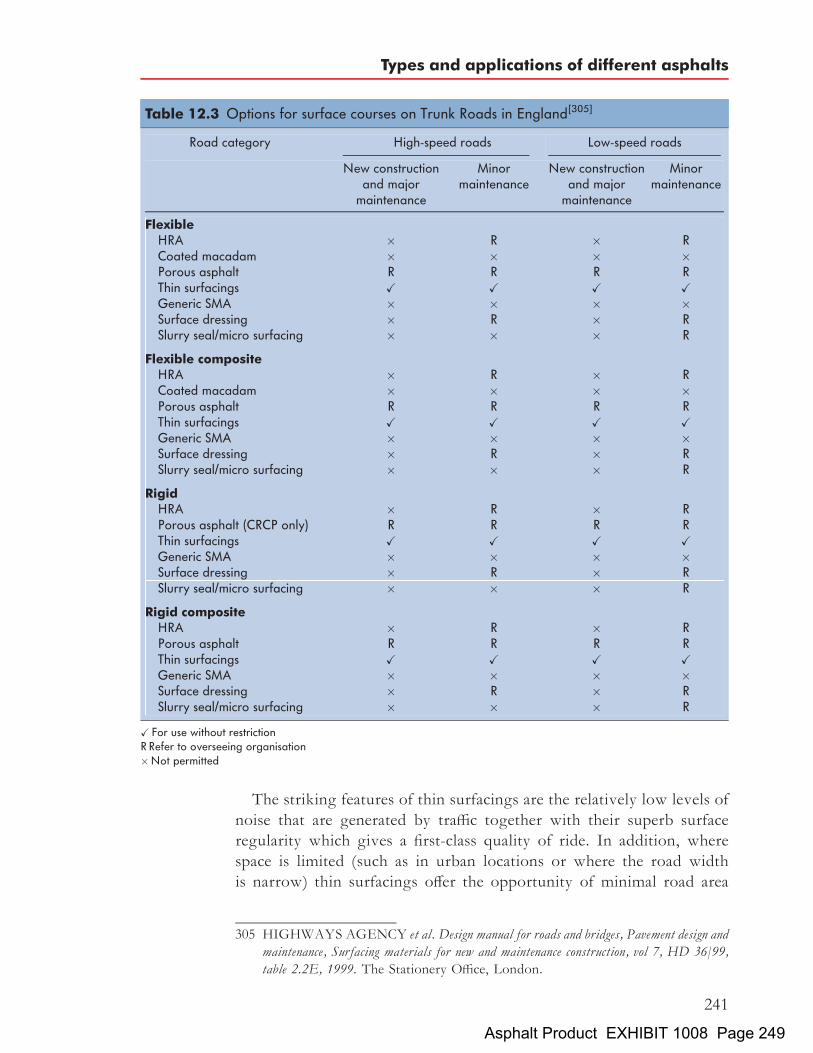
The striking features of thin surfacings are the relatively low levels ofnoise that are generated by traffic together with their superb surfaceregularity which gives a first-class quality of ride. In addition, wherespace is limited (such as in urban locations or where the road widthis narrow) thin surfacings offer the opportunity of minimal road area
Table 12.3 Options for surface courses on Trunk Roads in England[305]
Road category High-speed roads Low-speed roads
New constructionand major
maintenance
Minormaintenance
New constructionand major
maintenance
Minormaintenance
FlexibleHRA � R � RCoated macadam � � � �Porous asphalt R R R RThin surfacings X X X XGeneric SMA � � � �Surface dressing � R � RSlurry seal/micro surfacing � � � R
Flexible compositeHRA � R � RCoated macadam � � � �Porous asphalt R R R RThin surfacings X X X XGeneric SMA � � � �Surface dressing � R � RSlurry seal/micro surfacing � � � R
RigidHRA � R � RPorous asphalt (CRCP only) R R R RThin surfacings X X X XGeneric SMA � � � �Surface dressing � R � RSlurry seal/micro surfacing � � � R
Rigid compositeHRA � R � RPorous asphalt R R R RThin surfacings X X X XGeneric SMA � � � �Surface dressing � R � RSlurry seal/micro surfacing � � � R
X For use without restrictionR Refer to overseeing organisation�Not permitted
305 HIGHWAYS AGENCY et al. Design manual for roads and bridges, Pavement design andmaintenance, Surfacing materials for new and maintenance construction, vol 7, HD 36/99,table 2.2E, 1999. The Stationery Office, London.
Types and applications of different asphalts
241
Asphalt Product EXHIBIT 1008 Page 249

occupation since no chipping machinery and supporting plant arerequired. A further advantage is the speed of laying that may reducethe period during which the road needs to be closed – an important con-sideration in modern highway management.A photograph of a 0/14mm size thin surfacing is shown in Fig. 12.3.
Note that a 0/14mm stone mastic asphalt would look identical to a0=14mm thin surfacing.
12.4 Choice of asphalts on major carriageways
As has been demonstrated above, there are numerous applications towhich asphalts are put. However, the bulk of these mixtures are usedin works of highway construction and maintenance. The options forbase and binder courses that are acceptable on Trunk Roads includingmotorways and then the acceptable surface courses are now considered.As explained above, the same design guide and specification documentsare also used for the vast majority of non-Trunk Road carriageways. Theimportance of these options is obvious.Table 12.2 illustrates the materials that are acceptable for use in the
UK in binder courses and bases in flexible road pavements on Trunk
Fig. 12.4 Chipped hot rolled asphalt surface courseCoin shown¼1 Euro, 23mm diameter
The Shell Bitumen Handbook
242
Asphalt Product EXHIBIT 1008 Page 250

Roads. The numbers indicate the penetration of the bitumen used in themixture.With regard to the surface course, the options for UKTrunk Roads are
set out in HD36. There are separate tables for each of the countries in theUK. Those that apply to England are shown in Table 12.3. ‘High-speedroads’ are defined as those with an 85th percentile speed exceeding90 km/h. The designation ‘R’ requires the designer to check that the pro-posed surface course material is acceptable to the Highways Agency orclient, as appropriate.Photographs of a chipped hot rolled asphalt surface course and a porous
asphalt surface course are shown in Figs. 12.4 and 12.5 respectively.
Fig. 12.5 Porous asphalt surface courseCoin shown¼ 1 Euro, 23mm diameter
Types and applications of different asphalts
243
Asphalt Product EXHIBIT 1008 Page 251

Chapter 13
Specification, compositionand design of asphalts
For most of the last century, the composition of UK asphalt mixtures wasdictated by recipes that were included in various British Standard publica-tions. However, with the passage of time, Highway Engineers have recog-nised that such an approach did notmaximise the use of the precious limitedresources in an asphalt. Furthermore, suchmixtures are not appropriate forall situations, particularly those where heavy levels of traffic will act uponthe carriageway. Thus, a number of methods of design have evolved toproduce mixtures that are appropriate for particular situations.In order to meet the rigours imposed on them by modern traffic
conditions, asphalt pavement layers must:
. be able to resist permanent deformation;
. be able to resist fatigue cracking;
. be workable during laying, enabling the material to be satisfactorilycompacted with the available equipment;
. be impermeable, to protect the lower layers of the road structurefrom water;
. be durable, resisting abrasion by traffic and the effects of air and water;
. contribute to the strength of the pavement structure;
. be easily maintained; and most importantly
. be cost effective.
In addition to the above, surface course materials must also:
. be skid resistant under all weather conditions;
. generate low noise levels; and
. provide a surface of acceptable riding quality.
This is a formidable list of requirements demonstrating the need for aninformed approach to be made when specifying a particular mixture inorder to ensure that the required performance is achieved without wast-ing valuable and limited resources. When it comes to heavily trafficked
245Asphalt Product EXHIBIT 1008 Page 252

roads, the use of traditional recipe mixtures without consideration oftheir properties is very unlikely to be appropriate. Consequently, high-ways subjected to light or moderate traffic levels use recipe-basedmixtures whilst more heavily trafficked roads (including all UK TrunkRoads) employ asphalts with properties that are specifically chosen fora particular carriageway.This chapter considers the various methods used to specify asphalt
mixtures. In respect of the applicable standards and other documents,this chapter can only discuss relevant matters in outline. Accordingly,users are strongly advised to refer to source documents for full details.
13.1 Recipe specifications for bases and binder courses
A recipe specification defines a mixture in terms of a target aggregategrading and a target binder content. Recipe specifications for bases andbinder courses are simple to use and are applicable to both types of mix-ture if the traffic level is light or moderate. They are generally based onknown compositions that have performed successfully in practice and,provided there is widespread experience of different compositions, it isnot difficult for the customer to specify the mixture that is consideredsuitable. Modern asphalt production plants are fully computerised andoften operate under the control of a quality management system. Thus,customers can be confident that mixtures will be manufactured to meetthe requirements of the specification.However, recipe formulations have a number of severe limitations.
The conditions of traffic, climate, etc, to which the asphalt is to be sub-jected will almost certainly not be the same as those existing when therecipe formulation was developed. Variations in the components of amixture may occur that are outside previous experience. If this necessi-tates modification to the recipe, there is no means of assessing whatthese changes should be or what their effect will be.Checking for compliance with mixture recipes is relatively simple. How-
ever, there is no means of assessing the seriousness or the practical impli-cations of a minor failure to comply with the specification. Whilst it isimportant for contractors to comply with the specification, in caseswhere deviation occurs there is no certainty that such deviation willadversely affect the performance of the mixture in situ. There is perhapstoo ready an assumption that any mixture failing to meet the specificationis defective in some respect. An evaluation of the degree and nature of thedeviation from the recipe supported by some laboratory and/or field assess-ment of the engineering properties of the mixture in question will often beappropriate. Reliance on a recipe specification alone may lead to theunnecessary and expensive removal of newly-laid material which margin-ally fails to comply with the specification but is entirely fit for purpose.
The Shell Bitumen Handbook
246
Asphalt Product EXHIBIT 1008 Page 253

In addition, recipe specifications tend to be restrictive towards newdevelopments and the use of less expensive locally available materials –a restriction that may result in unnecessary costs. The basis of recipespecifications is the aggregate grading curve and as these curvescannot, except in a very general way, take account of the aggregateproperties and packing characteristics, they are not always reliable, parti-cularly where a mixture of different aggregate sources is used.In the UK, two Standards predominate in the specification of asphalt
mixtures, BS 594-1: 2003[306] and BS 4987-1: 2003[307]. Both theseStandards contain recipes for a range of asphalts and reference todesign procedures.
13.1.1 Recipe specifications for coated macadam (asphaltconcrete) bases and binder courses
Coated macadams, also referred to as asphalt concretes, particularly in theUSA, are continuously graded mixtures and are, by far, the mostcommon formulations for asphalts. They depend on the interlock ofthe aggregate particles for their strength. BS 4987-1: 2003[307] containsa range of recipe mixtures for all types of coated macadam (asphaltconcrete) to be laid as:
. base Group one
. binder course Group two
. surface course Group three
. porous asphalt surface course Group four.
The recipe specification for porous asphalt surface course is rarely used inthe UK. The standard is divided into sections including individualsections entitled ‘Group one’, ‘Group two’, etc. Mixtures are oftendescribed by reference to the nominal aggregate size, i.e. the nominalsize of the largest aggregate fraction in the mixture, e.g. 0/32mm baseor 0/20mm binder course or 0/14mm surface course. With the introduc-tion of the European Standard, the use of ‘nominal size’ is replaced by theuse of ‘grading categories’.Generic mixtures that are included in this standard include dense
coated macadam, heavy duty macadam (HDM) and high modulus base
306 BRITISH STANDARDS INSTITUTION. Hot rolled asphalt for roads and otherpaved areas, Specification for constituent materials and asphalt mixtures, BS 594-1:2003. BSI, London.
307 BRITISH STANDARDS INSTITUTION. Coated macadam (asphalt concrete) forroads and other paved areas, Specification for constituent materials and for mixtures, BS4987-1: 2003. BSI, London.
Specification, composition and design of asphalts
247
Asphalt Product EXHIBIT 1008 Page 254

(HMB). The Standard now requires that the bitumen penetration used inthe mixture is specified, examples being:
. DBM 50 – dense coated macadam made with grade 40/60 penbitumen;
. HMB 35 – high modulus base made with grade 30/45 pen bitumen.
For base and binder course asphalts, no 40mm recipe mixtures are nowincluded in BS 4987-1: 2003. This came about because of the tendency of
308 BRITISH STANDARDS INSTITUTION. Coated macadam (asphalt concrete) forroads and other paved areas, Specification for constituent materials and for mixtures,table 3, BS 4987-1: 2003. BSI, London.
309 BRITISH STANDARDS INSTITUTION. Coated macadam (asphalt concrete) forroads and other paved areas, Specification for constituent materials and for mixtures, table 4,BS 4987-1: 2003. BSI, London.
Table 13.1 Aggregate grading for 0/32mm size dense base recipemixtures[308]
Test sieve aperture size Aggregate: crushed rock, slag orgravel, % by mass passing
40mm 10031:5mm 90 to 10020mm 71 to 9514mm 58 to 826:3mm 44 to 602mm 24 to 360:250mm 6 to 200:063mm (DBM and HMB) 2 to 90:063mm (HDM) 7 to 11
Table 13.2 Bitumen content and grade for 0/32mm size dense base recipemixtures[309]
Aggregate Bitumen grade–30/45pen,40/60pen, 100/150pen or 160/220pen,
% by mass of total mixture (�0:6%)
Crushed rock (including limestone) 4:0
Blast furnace slag of bulk density (in Mg/m3):1:44 4:51:36 4:81:28 5:21:20 5:81:12 6:2
Steel slag 4:0
Gravel 4:5
Note: 40/60 pen is the preferred grade for machine-laid DBM.
The Shell Bitumen Handbook
248
Asphalt Product EXHIBIT 1008 Page 255
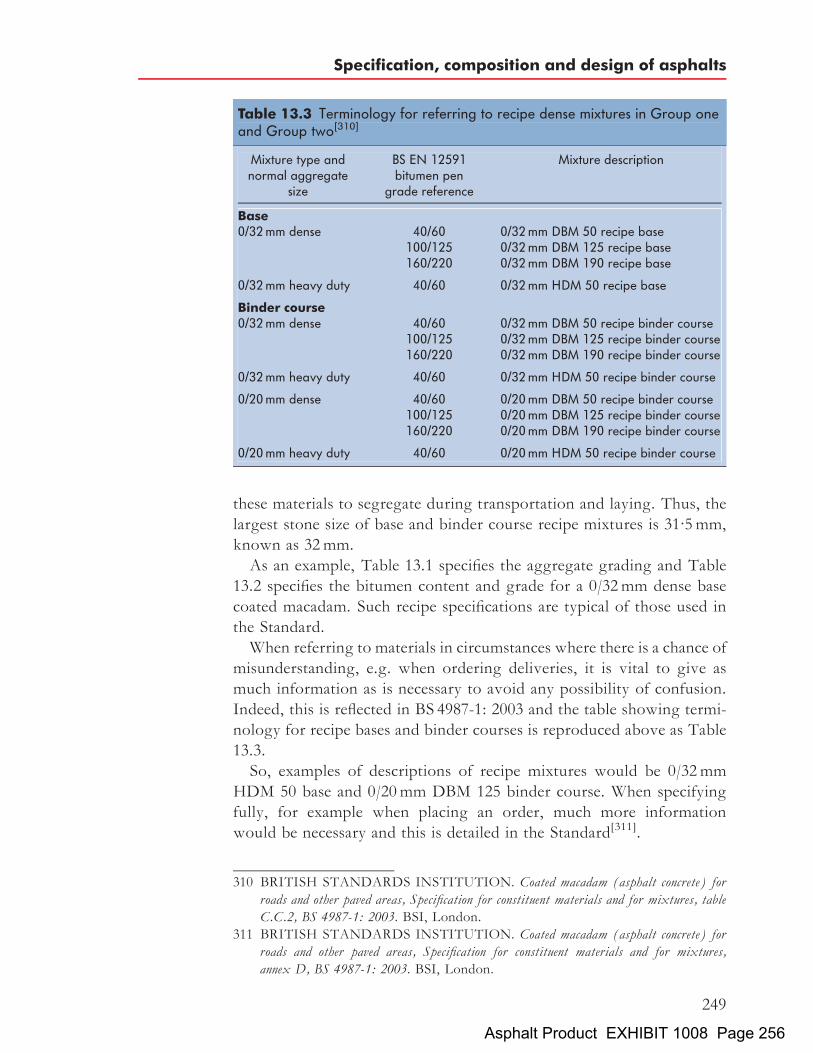
these materials to segregate during transportation and laying. Thus, thelargest stone size of base and binder course recipe mixtures is 31:5mm,known as 32mm.As an example, Table 13.1 specifies the aggregate grading and Table
13.2 specifies the bitumen content and grade for a 0/32mm dense basecoated macadam. Such recipe specifications are typical of those used inthe Standard.When referring to materials in circumstances where there is a chance of
misunderstanding, e.g. when ordering deliveries, it is vital to give asmuch information as is necessary to avoid any possibility of confusion.Indeed, this is reflected in BS 4987-1: 2003 and the table showing termi-nology for recipe bases and binder courses is reproduced above as Table13.3.So, examples of descriptions of recipe mixtures would be 0/32mm
HDM 50 base and 0/20mm DBM 125 binder course. When specifyingfully, for example when placing an order, much more informationwould be necessary and this is detailed in the Standard[311].
310 BRITISH STANDARDS INSTITUTION. Coated macadam (asphalt concrete) forroads and other paved areas, Specification for constituent materials and for mixtures, tableC.C.2, BS 4987-1: 2003. BSI, London.
311 BRITISH STANDARDS INSTITUTION. Coated macadam (asphalt concrete) forroads and other paved areas, Specification for constituent materials and for mixtures,annex D, BS 4987-1: 2003. BSI, London.
Table 13.3 Terminology for referring to recipe dense mixtures in Group oneand Group two[310]
Mixture type andnormal aggregate
size
BS EN 12591bitumen pen
grade reference
Mixture description
Base0/32mm dense 40/60 0/32mm DBM 50 recipe base
100/125 0/32mm DBM 125 recipe base160/220 0/32mm DBM 190 recipe base
0/32mm heavy duty 40/60 0/32mm HDM 50 recipe base
Binder course0/32mm dense 40/60 0/32mm DBM 50 recipe binder course
100/125 0/32mm DBM 125 recipe binder course160/220 0/32mm DBM 190 recipe binder course
0/32mm heavy duty 40/60 0/32mm HDM 50 recipe binder course
0/20mm dense 40/60 0/20mm DBM 50 recipe binder course100/125 0/20mm DBM 125 recipe binder course160/220 0/20mm DBM 190 recipe binder course
0/20mm heavy duty 40/60 0/20mm HDM 50 recipe binder course
Specification, composition and design of asphalts
249
Asphalt Product EXHIBIT 1008 Page 256

13.1.2 Recipe specifications for hot rolled asphalt bases andbinder courses
Hot rolled asphalts (HRAs) are gap graded mixtures and their usage inasphalt pavements reduced dramatically in the last decade of the twenti-eth century. They depend on the characteristics of the mortar (themixture of fine aggregate, filler and bitumen) for their strength.BS 594-1: 2003[312] contains details of a range of mixtures for hot rolledasphalt bases, binder courses, regulating courses and surface courses.In regard to hot rolled asphalt recipe bases and binder courses, compo-
sitional details from BS 594-1: 2003 are reproduced in Table 13.4. (Thesedata also apply to regulating courses that are used to raise the level oflayers and/or smooth out any irregularities in existing surfaces.)Over the years, a wide range of mixtures have evolved. In an attempt
to limit the number and introduce a degree of rationalization, some of theasphalts are designated as a ‘preferred mixture’. Users are encouraged bythe Standard to use these whenever possible.Table 13.4 gives details of aggregate grading and binder content but
does not address the issue of grade of binder. Guidance on the selectionand use of different grades of binder is given in Annex A of the Standard.It states that the grade of binder for bases should be:
. 40/60 pen for most applications;
. 70/100 pen where traffic loading is ‘unlikely to be intense’.
In the case of binder courses, it advises that:
. 40/60 pen is generally satisfactory for most applications;
. 30/45 pen may provide greater resistance to deformation in areas ofchannelised traffic in southern England;
. 70/100 pen may be satisfactory for less heavily trafficked roads inScotland and Northern Ireland.
13.2 Recipe specifications for surface courses13.2.1 Recipe specifications for coated macadam (asphalt
concrete) surface coursesUK contracts for maintenance or new construction on major roads,including Trunk Roads, now invariably require that the surface courseis to be a thin surfacing. These are proprietary materials and are discussedbelow. For smaller schemes and where the client prefers, a mixture fromBS 4987-1: 2003 may be specified. All surface course mixtures specified by
312 BRITISH STANDARDS INSTITUTION. Hot rolled asphalt for roads and otherpaved areas, Specification for constituent materials and asphalt mixtures, BS 594-1:2003. BSI, London.
The Shell Bitumen Handbook
250
Asphalt Product EXHIBIT 1008 Page 257

the Standard are recipe based. Available mixtures are:
. 0/14mm size open graded surface course
. 0/10mm size open graded surface course
. 0/14mm size close graded surface course (preferred mixture)
. 0/10mm size close graded surface course (preferred mixture)
Table 13.4 Composition of base, binder course and regulating course mixtures[313]
Column number 2/1 2/2a 2/3 2/4 2/5a
Designationb 50% 0/10c 50% 0/14c 50% 0/20c 60% 0/20 60% 0/32
Nominal layer thickness (mm) 25 to 50 35 to 65 45 to 80 45 to 80 60 to 120
Percentage (m/m) oftotal aggregatepassing test sieve:
50mm – – – – 10031:5mm – – 100 100 90 to 10020mm – 100 90 to 100 90 to 100 50 to 8014mm 100 90 to 100 65 to 100 30 to 65d 30 to 6510mm 90 to 100 65 to 100 35 to 75 – –6:3mm – – – – –2mm 30 to 50 30 to 50 30 to 50 25 to 39 25 to 390:500mm 13 to 50 13 to 50 13 to 50 8 to 39 8 to 390:250mm 6 to 31 6 to 31 6 to 31 4 to 26 4 to 260:063mm 1 to 8 1 to 8 1 to 8 1 to 7 1 to 7
Binder content percentage(m/m) of total mixture for:
Crushed rock or steel slag 6:5 6:5 6:5 5:7 5:7Gravel 6:3 6:3 6:3 5:5 5:5Blast furnace slag of bulkdensity (in Mg/m3):1:44 6:6 6:6 6:6 5:7 5:71:36 6:7 6:7 6:7 5:9 5:91:28 6:8 6:8 6:8 6:0 6:01:20 6:9 6:9 6:9 6:1 6:11:12 7:1 7:1 7:1 6:3 6:3
NoteFor mixtures containing crushed rock fine aggregate, and in some instances sands or blends of sand and crushed rock fines,the binder contents given above may be reduced by up to 0:5%, where experience shows this to be advisable to avoid anover-rich mixture.a Preferred mixtures in bold type.b The mixture designation numbers (e.g. 50% 0/10 in column 2/1) refer to the nominal coarse aggregate content of themixture and the size of the coarse aggregate in the mixture respectively.c Suitable for regulating course.d The value of 65 can be extended to 85 where evidence is available that the mixture so produced is suitable. To ensureconsistency of finish of the laid mixture, supplies from any one source should be controlled within a 35% band within thispermitted range.
313 BRITISH STANDARDS INSTITUTION. Hot rolled asphalt for roads and otherpaved areas, Specification for constituent materials and asphalt mixtures, table 2, BS594-1: 2003. BSI, London.
Specification, composition and design of asphalts
251
Asphalt Product EXHIBIT 1008 Page 258

. 0/6mm size dense surface course (preferred mixture)
. 0/6mm size medium graded surface course (preferred mixture)
. 0/4mm size fine graded surface course
. 6/20mm size porous asphalt surface course
. 2/10mm size porous asphalt surface course.
As in the case of hot rolled asphalts, users are encouraged by the Standardto use ‘preferred mixtures’ whenever possible.The recipes for the asphalts listed above are given in tables that dictate
the grading of the aggregate, the bitumen content and the grade ofbitumen. Those for 0/14mm size close graded surface course are repro-duced as Tables 13.5, 13.6 and 13.7.
13.2.2 Recipe specifications for hot rolled asphalt surfacecourses
As explained above, thin surfacings are the default choice for surface courseon most works of maintenance or new construction on UK carriageways.They are discussed in Section 13.4.3. However, for most of the second halfof the twentieth century, chipped hot rolled asphalt was the default UKsurface course. It was the UK’s creditable preoccupation with skiddingresistance and the availability of suitable coarse aggregates and fine sandsthat caused it to adopt this material. It has enjoyed little use in Europeand elsewhere although it was/is used in Denmark and South Africa.BS 594-1: 2003[315] specifies surface course mixtures in three ways.
These are:
Table 13.5 Aggregate grading for 0/14mm size close graded surfacecourse[314]
Test sieve aperture size Aggregate: crushed rock, slag orgravel % by mass passing
20mm 10014mm 95 to 10010mm 70 to 906:3mm 45 to 652mm 19 to 33a
1mm 15 to 300:063mm 3 to 8
a May be increased to 38 when sand fine aggregate is used.
314 BRITISH STANDARDS INSTITUTION. Coated macadam (asphalt concrete) forroads and other paved areas, Specification for constituent materials and for mixtures, table23, BS 4987-1: 2003. BSI, London.
315 BRITISH STANDARDS INSTITUTION. Hot rolled asphalt for roads and otherpaved areas, Specification for constituent materials and asphalt mixtures, BS 594-1:2003. BSI, London.
The Shell Bitumen Handbook
252
Asphalt Product EXHIBIT 1008 Page 259

. conventional recipe;
. designed mixtures where the aggregate grading is fixed but theoptimum value of binder content is determined by testing the com-ponents in the laboratory; and
. performance-specified mixtures for areas of heavy traffic.
Section 13.4.2 deals with designed and performance-specified mixtures.The Standard suggests that use of the recipe surface course mixtureswill generally give mixtures of satisfactory performance whilst recognis-ing that a general specification cannot cover all suitable aggregates. In
Table 13.6 Bitumen content for 0/14mm size close graded surface course[316]
Aggregatea Bitumen content,% by mass of total mixture (�0:5%)
Crushed rock (excluding limestone) 5:1Limestone 4:9Blast furnace slag of bulk density (in Mg/m3):1:44 5:51:36 6:01:28 6:61:20 7:01:12 7:5
Steel slag 4:8Gravelb –
a See Annex B.b The information on the bitumen contents required for these mixtures made with gravel is not sufficientfor a single target value to be specified. The bitumen content to be used should be chosen within therange 5:5 to 6:5% and should be approved by the specifier. As a guide, lower values should be selectedfor pavements designed to carry category B traffic and higher values for footway work. The tolerance of�0:5% should apply to the selected and approved bitumen content.
Table 13.7 Grade of bitumen for 0/14mm size close graded surface course[317]
Aggregate Grade of bitumen
Category A traffic Category B traffic
Crushed rock, slag 100/150pen 160/220pen or 250/330pen160/220pen or 250/330pen –
Gravel – 160/220pen or 250/330pen
Note100/150 or 160/220 pen are the preferred grades.
316 BRITISH STANDARDS INSTITUTION. Coated macadam (asphalt concrete) forroads and other paved areas, Specification for constituent materials and for mixtures, table24, BS 4987-1: 2003. BSI, London.
317 BRITISH STANDARDS INSTITUTION. Coated macadam (asphalt concrete) forroads and other paved areas, Specification for constituent materials and for mixtures, table25, BS 4987-1: 2003. BSI, London.
Specification, composition and design of asphalts
253
Asphalt Product EXHIBIT 1008 Page 260
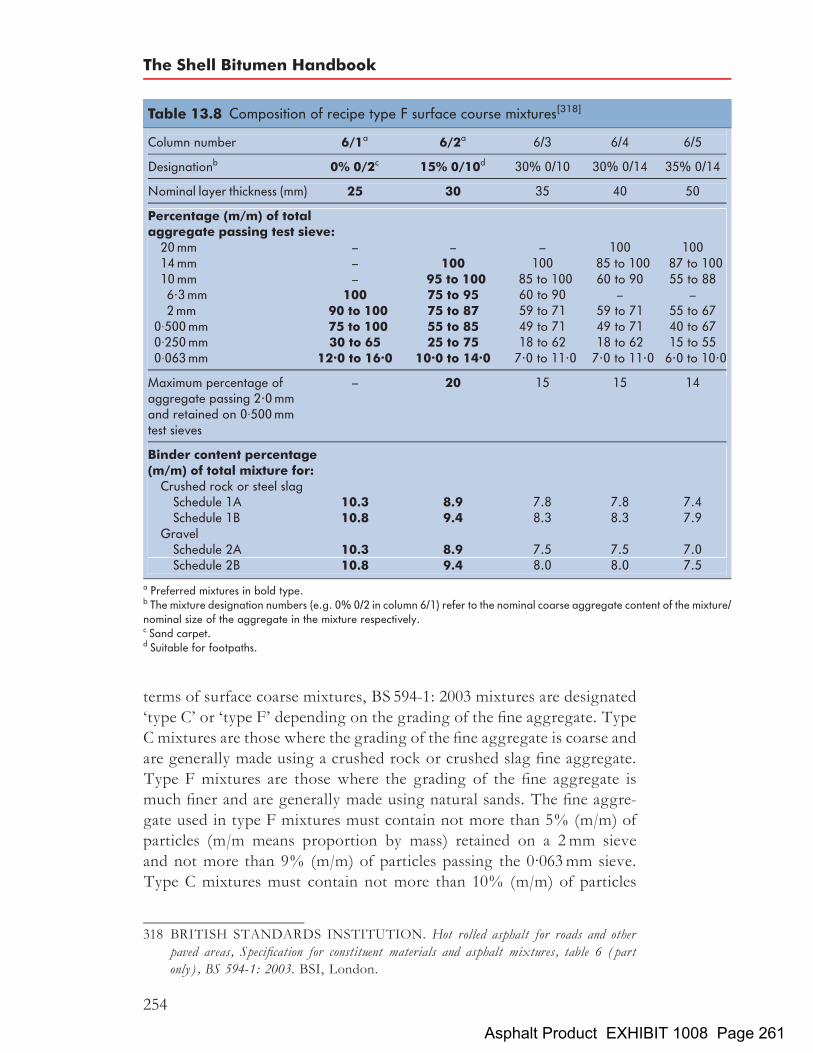
terms of surface coarse mixtures, BS 594-1: 2003 mixtures are designated‘type C’ or ‘type F’ depending on the grading of the fine aggregate. TypeC mixtures are those where the grading of the fine aggregate is coarse andare generally made using a crushed rock or crushed slag fine aggregate.Type F mixtures are those where the grading of the fine aggregate ismuch finer and are generally made using natural sands. The fine aggre-gate used in type F mixtures must contain not more than 5% (m/m) ofparticles (m/m means proportion by mass) retained on a 2mm sieveand not more than 9% (m/m) of particles passing the 0:063mm sieve.Type C mixtures must contain not more than 10% (m/m) of particles
Table 13.8 Composition of recipe type F surface course mixtures[318]
Column number 6/1a 6/2a 6/3 6/4 6/5
Designationb 0% 0/2c 15% 0/10d 30% 0/10 30% 0/14 35% 0/14
Nominal layer thickness (mm) 25 30 35 40 50
Percentage (m/m) of totalaggregate passing test sieve:
20mm – – – 100 10014mm – 100 100 85 to 100 87 to 10010mm – 95 to 100 85 to 100 60 to 90 55 to 886.3mm 100 75 to 95 60 to 90 – –2mm 90 to 100 75 to 87 59 to 71 59 to 71 55 to 67
0:500mm 75 to 100 55 to 85 49 to 71 49 to 71 40 to 670:250mm 30 to 65 25 to 75 18 to 62 18 to 62 15 to 550:063mm 12.0 to 16.0 10.0 to 14.0 7.0 to 11.0 7.0 to 11.0 6.0 to 10.0
Maximum percentage ofaggregate passing 2.0mmand retained on 0:500mmtest sieves
– 20 15 15 14
Binder content percentage(m/m) of total mixture for:
Crushed rock or steel slagSchedule 1A 10.3 8.9 7.8 7.8 7.4Schedule 1B 10.8 9.4 8.3 8.3 7.9
GravelSchedule 2A 10.3 8.9 7.5 7.5 7.0Schedule 2B 10.8 9.4 8.0 8.0 7.5
a Preferred mixtures in bold type.b The mixture designation numbers (e.g. 0% 0/2 in column 6/1) refer to the nominal coarse aggregate content of the mixture/nominal size of the aggregate in the mixture respectively.c Sand carpet.d Suitable for footpaths.
318 BRITISH STANDARDS INSTITUTION. Hot rolled asphalt for roads and otherpaved areas, Specification for constituent materials and asphalt mixtures, table 6 (partonly), BS 594-1: 2003. BSI, London.
The Shell Bitumen Handbook
254
Asphalt Product EXHIBIT 1008 Page 261

retained on a 2mm sieve and not more than 19% (m/m) of particles pas-sing the 0:063mm sieve. Designed mixtures may be type C or type F butrecipe mixtures can only be type F. The composition of recipe mixtures isdepicted in Table 13.8.Guidance on the selection and use of different grades of binder is given
in Annex A of the Standard. It states that the grade of binder for surfacecourses:
. in traditional mixtures has been 40/60 pen; but
. if crushed fines or harsh sands are used, softer bitumen may be suit-able (but caution should be exercised before so doing, particularlyon heavily trafficked roads);
. 30/45 pen bitumen or crushed fines may be considered where trafficis ‘more intense’;
. 70/100 pen or 100/150 pen may be used, even with sand fines, onlightly trafficked roads and other lightly stressed areas (it is routinein some areas with 0% 0/2mm and 15% 0/10mm mixtures).
The use of 100/150 pen with sand fines in 0% 0/2mm and 15% 0/10mmmixtures for use in footways is routine in some parts of the UK.When referring to recipe mixtures, as with all asphalts, it is vital that a
full description is used. Referring to Table 13.8, an example would beTable 6, Column 6/4, 30% 0/14mm recipe type F with 40/60 pen bitumensurface course. When specifying fully, for example when placing anorder, much more information would be necessary and this is detailedin the Standard[319].
13.3 Design of bases and binder courses13.3.1 Design of coated macadam (asphalt concrete) bases
and binder coursesBS 4987-1: 2003[320] does not contain a design procedure per se. Essen-tially, it requires that the design shall comply with the requirements ofCl 929 of the Specification for Highway Works[321] (SHW). The SHW isVolume 1 of the Manual of Contract Documents for Highway Works[322]
319 BRITISH STANDARDS INSTITUTION. Hot rolled asphalt for roads and otherpaved areas, Specification for constituent materials and asphalt mixtures, annex C, BS594-1: 2003. BSI, London.
320 BRITISH STANDARDS INSTITUTION. Coated macadam (asphalt concrete) forroads and other paved areas, Specification for constituent materials and for mixtures, BS4987-1: 2003. BSI, London.
321 HIGHWAYS AGENCY et al. Manual of contract documents for highway works, vol 1,cl 929, Specification for highway works, 2002. The Stationery Office, London.
322 HIGHWAYS AGENCY et al. Manual of contract documents for highway works, vols 0–6,Various dates. The Stationery Office, London.
Specification, composition and design of asphalts
255
Asphalt Product EXHIBIT 1008 Page 262

(MCHW). Whenever the SHW is consulted, users are strongly encour-aged to refer to Volume 2, Notes for Guidance on the Specification forHighway Works[323] (NG). One of the major functions of the NG is togive guidance on the reasons for and background to the requirementsof the SHW. Most of the Clauses in the SHW have an equivalent inthe NG, e.g. ClNG929 contains guidance on the contents of Cl 929.Use of the MCHW and, therefore, the SHW is mandatory on UK
Trunk Roads. The UK Trunk Road network represents some 4% bylength of the major routes in the UK. Responsibility for the remaining96% falls to the councils within whose areas the roads lie. The vastmajority of councils also use the MCHW for works of highway construc-tion or maintenance. Thus, the contents of the SHW including Cl 929 arewidely applied throughout the UK.Cl 929 is entitled Design, compaction assessment and compliance of base and
binder course macadams. Notwithstanding this title, Cl 929 does not containa true design procedure, it simply sets a number of parameters withwhich the mixture must comply. Cl 929 is an ‘end-product’ specification.What it seeks to do is ensure that the void content of the placed mixture issomewhere between 1% and 7 to 8%. The reason for the former is thatexperience has shown that if the asphalt is overcompacted then thebitumen may act as a lubricant, forcing the coarse aggregate apart andcausing the mixture to deform prematurely. The reason for the upperlimit on air voids arises to ensure that the asphalt has adequate stiffnessto perform as expected.The Clause 929 procedure requires the Contractor to nominate a target
aggregate grading and target binder content for each of the mixturesintended for use in the works. These target values have to fall withinthe limits set out in the appropriate table in BS 4987-1: 2003, but thetolerances applied to the target values may produce a control specifica-tion that lies to one side of the limits in the Standard.The nominated design of the target values for the mixture is developed
by the asphalt producer, working with the laying contractor to ensurethat the mixture can be laid and compacted at the required thicknessusing the plant and equipment expected on site. Development of thedesign is a balance between conflicting needs. Increasing bitumen contentaids compaction but reduces the air voids content and often the stiffnessof the compacted mixture. Using a lower bitumen content will increasestiffness but may make the mixture more liable to segregation. Too
323 HIGHWAYS AGENCY et al. Manual of contract documents for highway works, Notesfor guidance on the specification for highway works, vol 2, cl NG 929, 2002. The StationeryOffice, London.
The Shell Bitumen Handbook
256
Asphalt Product EXHIBIT 1008 Page 263

great a proportion of the largest aggregate fraction can also lead tosegregation.Most suppliers will start from a similar proven mixture and initially
minimise the proportion of ‘oversize’ particles. If the air voids value isknown to be low, increasing the proportion of ‘middle size’ aggregatecan help to create more voids within the packed coarse aggregatewhich, in turn, can allow more fine aggregate and bitumen to beadded. For some mixtures, adding a proportion of sand or similarmaterial to modify the grading of the fine aggregate fraction can improveworkability and help control bitumen content. If filler (particles passingthe 0:063mm sieve) needs to be added, the type, grading and bulk densityof the chosen added filler may also influence mixture characteristics.The design process provides an opportunity for an asphalt producer to
make the best use of available resources. However, once the design of themixture has been established, it is important that the grading and charac-teristics of the aggregates and any added filler used are consistent for theduration of the works.The compaction of bases and binder courses is assessed by measuring
the in situ and refusal air void contents of cores using the percentagerefusal density (PRD) test[324] and in situ density using a nuclear densitygauge. Nuclear density gauges assess density by means of what is calledthe ‘backscatter method’. Photons from a nuclear source are scatteredthrough the material under test. One or more photon detectors thenassess the photons scattered back towards the gauge from differingdepths. These data allow the density to be determined although propercalibration is vital for accuracy. ‘Non-nuclear’ electronic densitygauges have been introduced in Germany, the USA and the UK inrecent years with some success.A ‘job mixture approval trial’ is then carried out. The purpose of this
trial is to demonstrate the suitability of the designed asphalt and theeffectiveness of the compaction plant and the rolling techniques. A trialarea of the proposed asphalt is constructed using the compaction plantand procedures proposed for the works. In size, it is between 30 and60m long and of a width and depth specified in the contract. Averagevalues of in situ air void content and air void content at refusal areobtained by procedures specified in Cl 929. The mixture, compactionplant and compaction procedures are acceptable if the following criteriaare met.
324 BRITISH STANDARDS INSTITUTION. Sampling and examination of bituminousmixtures for roads and other paved areas, Methods of test for the determination of density andcompaction, BS 598-104: 1989. BSI, London.
Specification, composition and design of asphalts
257
Asphalt Product EXHIBIT 1008 Page 264

. The average in situ air void content of the core samples taken for thePRD test must be 7.0% in binder course or upper base without abinder course or 8.0% in other base layers.
. The average in situ air void content of a pair of core samples fromeach location taken for the PRD test must be 8.0% in bindercourse or upper base without a binder course or 9.0% in otherbase layers.
. The average air void content at refusal density of the core samplessubjected to the PRD test must �1.0%.
. The minimum binder volume at each location must be as set out in atable similar to Table 13.9.
. Compositionally, the asphalt must comply with the limits set out inthe appropriate table in BS 4987-1: 2003 with adjustments to reflectthe chosen target grading and binder content.
. The horizontal alignments, surface levels and surface regularityspecified in Cl 702 must be met.
Having had the proposed materials, compaction plant and compactionprocedure approved, a similar testing regime is applied to the materialslaid in the permanent works using a nuclear density gauge and cores.Once again, in order to avoid confusion, the Standard defines descrip-
tions to be used for designed asphalts. The table that provides thisinformation is reproduced here as Table 13.10. When specifying fully,for example when placing an order, much more information would benecessary and this is detailed in the Standard[325].So, examples of descriptions of designed mixtures would be 0/32mm
DBM50 designed base and 0/32mm HMB35 designed binder course.
13.3.2 Design of hot rolled asphalt bases and binder coursesIn the UK, hot rolled asphalt bases and binder courses are all normallyspecified by means of recipe formulations. There is no doubt that a
Table 13.9 Aggregate size and minimum binder volume
Aggregate size: mm Minimum binder volume of thetotal volume of the mixture: %
0/32 8.00/20 9.4
325 BRITISH STANDARDS INSTITUTION. Hot rolled asphalt for roads and otherpaved areas, Specification for constituent materials and asphalt mixtures, annex D, BS594-1: 2003. BSI, London.
The Shell Bitumen Handbook
258
Asphalt Product EXHIBIT 1008 Page 265

good design method would produce mixtures that are more appropriateto particular tasks. However, the dominance of continuously gradedmixtures in the UK and elsewhere makes the emergence of such amethod unlikely in the foreseeable future.
13.4 Design of surface courses13.4.1 Design of coated macadam (asphalt concrete) surface
coursesThe use of traditional continuously graded mixtures for surface coursesis relatively rare, with most being restricted to very lightly traffickedlocations. Thus, methods for designing such mixtures are no longer incommon use.
13.4.2 Design of hot rolled asphalt surface coursesTraditional HRA surface coursesFor the last thirty years or so of the twentieth century, the UK’s hotrolled asphalt standard has referred to a laboratory method for designingthe bitumen content of a chipped HRA surface course. However, theaggregate grading itself was a recipe-based formulation. The currentedition of the Standard, BS 594-1: 2003, continues that approach.Hot rolled asphalt mixtures complying with BS 594-1: 2003 may be
type C or type F, as discussed above. The composition of HRA surface
Table 13.10 Terminology for referring to designed dense mixtures in Group one and Grouptwo[326]
Mixture type andnormal aggregate size
BS EN 12591bitumen pen grade reference
Mixture description
Base0/32mm dense 40/60 0/32mm DBM 50 designed base0/32mm heavy duty 40/60 0/32mm HDM 50 designed base0/32mm high modulus 30/45 0/32mm HMB 35 designed base
Binder course0/32mm dense 40/60 0/32mm DBM 50 designed binder course0/32mm heavy duty 40/60 0/32mm HDM 50 designed binder course0/32mm high modulus 30/45 0/32mm HMB 35 designed binder course0/20mm dense 40/60 0/20mm DBM 50 designed binder course0/20mm heavy duty 40/60 0/20mm HDM 50 designed binder course0/20mm high modulus 30/45 0/20mm HMB 35 designed binder course
326 BRITISH STANDARDS INSTITUTION. Coated macadam (asphalt concrete) forroads and other paved areas, Specification for constituent materials and for mixtures, tableC.C.1, BS 4987-1: 2003. BSI, London.
Specification, composition and design of asphalts
259
Asphalt Product EXHIBIT 1008 Page 266

course mixtures are to be as defined in tables given in the standard (repro-duced here as Tables 13.11 and 13.12). Tables 13.11 and 13.12 containvalues for minimum binder contents but the target binder content is tobe assessed by means of the procedures contained in BS 598-107:1990[328]. Determined values of stability and flow (see Section 16.3.1)are to be within specified limits.
Performance-related design mixturesIn the late twentieth century (particularly after the summers of 1976and 1981), a significant number of traditional chipped HRA surfacecourses failed early in their service life because of deformation. Thesecases occurred primarily during the summer on uphill sections of
Table 13.11 Composition of design type F surface course mixtures[327]
Column number 3/1 3/2a 3/3a 3/4 3/5
Designationb 0% 0/2c 30% 0/14 35% 0/14 55% 0/10 55% 0/14
Nominal layer thickness (mm) 25 40 45 or 50 40 45
Percentage (m/m) of totalaggregate passing testsieve:
20mm – 100 100 – 10014mm – 85 to 100 87 to 100 100 90 to 10010mm – 60 to 90 55 to 88 90 to 100 35 to 706.3mm 100 – – 35 to 70 –2mm 90 to 100 59 to 71 55 to 67 35 to 47 35 to 470:500mm 75 to 100 44 to 71 40 to 67 25 to 47 25 to 470:250mm 30 to 85 18 to 62 15 to 55 5 to 35 5 to 350:063mm 12.0 to 16.0 7.0 to 11.0 6.0 to 10.0 4.0 to 8.0 4.0 to 8.0
Maximum percentage ofaggregate passing 2mmand retained on 0:500mm testsieves
– 15 14 10 10
Minimum target binder contentpercentage (m/m) of total mixture
9.0 6.5 6.4 5.5 5.5
a Preferred mixtures in bold type.b The mixture designation numbers (e.g. 0% 0/2 in column 3/1) refer to the nominal coarse aggregate content of the mixture/nominal size of the aggregate in the mixture respectively.c Suitable for regulating course.
327 BRITISH STANDARDS INSTITUTION. Hot rolled asphalt for roads and otherpaved areas, Specification for constituent materials and asphalt mixtures, table 3, BS594-1: 2003. BSI, London.
328 BRITISH STANDARDS INSTITUTION. Sampling and examination of bituminousmixtures for roads and other paved areas, Methods of test for the determination of thecomposition of design wearing course rolled asphalt, BS 598-107: 1990. BSI, London.
The Shell Bitumen Handbook
260
Asphalt Product EXHIBIT 1008 Page 267

south-facing carriageways where slow-moving traffic predominated. Inorder to combat such failures, a specification for performance-relateddesign HRA mixtures was introduced. This is contained in Cl 943 ofthe SHW[330]. These mixtures are 35% stone content HRA surfacecourses with a specified maximum value of wheel-tracking rate. Mostmixtures manufactured to meet this specification employ polymer mod-ified bitumen in order to meet this wheel-tracking requirement.The contractor is responsible for nominating the design of the mixture
but the asphalt producer does the detailed work. The starting point is anassessment of the stability and flow of conventional design-type mixturesmade with the aggregates available to the producer to identify those withhigher stability and flow values. The constituent proportions, gradingand bitumen content of the conventional design-type mixtures are gener-ally used for the equivalent performance-related design mixture. Usually,the bitumen grade or type is the only change that is needed.Testing is then carried out on specimens prepared in the laboratory or,
if possible, road cores from material which has been laid recently. This
Table 13.12 Composition of design type C surface course mixtures[329]
Column number 4/1 4/2 4/3 4/4 4/5
Designationa 0% 0/2 30% 0/14 35% 0/14 55% 0/10 55% 0/14
Nominal layer thickness (mm) 25 40 45 or 50 40 45
Percentage (m/m) of totalaggregate passing test sieve:
20mm – 100 100 – 10014mm – 85 to 100 87 to 100 100 90 to 10010mm – 60 to 90 55 to 88 90 to 100 35 to 706.3mm 100 – – 35 to 70 –2mm 90 to 100 59 to 71 50 to 62 32 to 44 32 to 440:500mm 30 to 65 25 to 45 20 to 45 15 to 35 15 to 350:250mm 20 to 50 20 to 40 15 to 35 5 to 35 5 to 350:063mm 12.0 to 16.0 7.0 to 11.0 6.0 to 10.0 4.0 to 8.0 4.0 to 8.0
Minimum target binder contentpercentage (m/m) of total mixture
9.0 6.5 6.4 5.5 5.5
NoteThere is no preferred mixture for design type C.a The mixture designation numbers (e.g. 0% 0/2 in column 4/1) refer to the nominal coarse aggregate content of the mixture/nominal size of the aggregate in the mixture respectively.
329 BRITISH STANDARDS INSTITUTION. Hot rolled asphalt for roads and otherpaved areas, Specification for constituent materials and asphalt mixtures, table 4, BS594-1: 2003. BSI, London.
330 HIGHWAYS AGENCY et al. Manual of contract documents for highway works, vol 1,cl 943, Specification for highway works, 2002. The Stationery Office, London.
Specification, composition and design of asphalts
261
Asphalt Product EXHIBIT 1008 Page 268

testing is detailed in BS 598-110: 1998[331] and assesses compliance withthe specified wheel-tracking requirements. Depending upon the results,an alternative bitumen is then selected and the wheel-tracking assessmentrepeated.A job mixture approval trial may then be carried out. However, Cl 943
recognises that information from a previous contract may be the sourceof key parameters which can be provided to the client for approval.Despite the emergence of thin surfacings, performance-related design
mixtures have a useful role in modern surfacing practice. They can beused where matching the existing materials is important but heavyslow traffic may deform a conventional mixture at an unacceptablerate. It may also be appropriate for use over a structure where themuch lower permeability of rolled asphalt provides desirable additionalprotection to the expensive structure, working with the waterproofingsystem to prevent corrosion due to the ingress of water.
13.4.3 Thin surfacingsIt was explained above that thin surfacings and SMAs now predominateas the surface course normally used on most trafficked roads of any size inthe UK and most of Europe.The UK national specification is contained in Cl 942 of the SHW ‘Thin
Surface Course Systems’ (TSCS). It requires thin surfacings to have aBritish Board of Agrement (BBA) HAPAS Roads and Bridges Certificateapplicable to the traffic level and site classification given in the contract.In fact, the entire clause is written around the requirement that HAPAScertification is in place. This approval system for thin surface coursesystems has been adopted in the UK to permit the development ofnew surfacing asphalts whilst providing the customer with assurancethat the surface course will provide the expected level of performance.Thin surfacing asphalts are not easily controlled and specified using
the conventional recipe approach. Volumetric proportions are oftenmore important than aggregate grading and binder content. The perfor-mance of the finished layer is also related to a range of factors, includingthe laid thickness and the type and application rate of the tack/bond coatused to ensure adhesion to the layer below. For these reasons, theapproval applies to the properties of the finished layer, not just the com-position of the mixture used. Mixture composition is controlled duringproduction by an approved quality plan, often involving a register ofrecipes for particular combinations of coarse and fine aggregate.
331 BRITISH STANDARDS INSTITUTION. Sampling and examination of bituminousmixtures for roads and other paved areas, Method of test for the determination of wheel-tracking rate and depth, BS 598-110: 1998. BSI, London.
The Shell Bitumen Handbook
262
Asphalt Product EXHIBIT 1008 Page 269

A demonstration of this change in approach is that the previous editionof the SHW contained wide grading envelopes whereas there are nograding requirements in the current edition. Table 13.13 gives a typicalgrading for SMA type proprietary mixtures, to permit comparisonswith earlier tables.In common with all mixtures specified in the Series 900 clauses
of the SHW, the manufacture of mixtures for thin surfacings is controlledby a quality management system complying with the ‘Sector QAScheme for the Production of Asphalt Mixes’ based on BSEN9001:2000[332].Details of each thin surfacing system approved by BBA/HAPAS are
published as a uniquely numbered certificate and copies are availableon the internet[333]. A ‘Detail Sheet’ covers each variant of the approvedsystem; generally aggregate size and binder type are the variables. TheDetail Sheet declares typical test results and performance levels for anumber of mandatory parameters. Performance levels for selectedoptional parameters may also be declared – if the producer has chosenso to do.The mandatory parameters are coarse aggregate properties, wheel-
tracking rate, bond strength, sensitivity to water and initial texturedepth. The data for each mandatory parameter from different certificatescan be compared and evaluated, helping the specifier to choose a systemthat suits the requirements of the particular works.Coarse aggregate properties are defined in terms of polished stone
value (PSV) and aggregate abrasion value (AAV) in the same way asany other surfacing.
Table 13.13 Grading of typical proprietary 0/14mm thinsurfacings
BS sieve size Percent by mass of total aggregate passing
20mm 10014mm 90–10010mm 35–556.3mm 25–402mm 18–300:500mm 12–200:063mm 9–11
332 BRITISH STANDARDS INSTITUTION. Quality management systems, Require-ments, BSEN ISO 9001: 2000. BSI, London.
333 www.bbacerts.co.uk
Specification, composition and design of asphalts
263
Asphalt Product EXHIBIT 1008 Page 270

There are four levels of wheel-tracking rate specified by the SHW anddeclared in BBA/HAPAS certificates – Level 3 to Level 0[334]. Generally,thin surfacing systems will meet the most onerous Level 3 required forheavily trafficked roads, particularly if a polymer modified bitumen isused. Level 3 sets the maximum value of the mean of the wheel-trackingrates as 5.0mm/h with an upper limit of 7.5mm/h for mixtures laid at30mm thick or more. There are equivalent values for thinner layers.These values are set to give a wheel-tracking performance about thesame as that of performance-related design rolled asphalt. However, itshould be noted that, perhaps more so than with HRA, the wheel-tracking performance of thin layers can be influenced by the characteris-tics of the underlying layers. The use of a rut-resistant stone masticasphalt (SMA) binder course[335] is becoming more common.Bond strength is a measure of the degree of bonding between the com-
pacted mixture and the layer below. The effectiveness of the bonddepends on many factors, particularly the type of bond coat used andthe weather conditions at the time of laying. It is tested in the laboratoryusing a core extracted from the surface. This is a complex test that isusually only done as part of the initial BBA/HAPAS system approvalprocess.Sensitivity to water is assessed as part of the initial laboratory design of
individual mixtures by evaluating the loss (in practice, often a gain) in thestiffness of specimens after vacuum saturation and three cycles in hot(608C) and cold (58C) water. The results reflect the affinity between thebitumen and the aggregates used. Polymer modified bitumens can helpto improve the results.A feature of good thin surfacing systems is that the initial texture depth
is highly consistent because the composition of the mixture is closely con-trolled at the asphalt plant. The requirement for untrafficked texturedepth is to be measured in accordance with BSEN13036-1: 2002[336].For high-speed roads, texture depth is generally prescribed as an average1.5mm minimum for each lane kilometre with an individual minimumvalue of 1.2mm. For low-speed situations, a lower value will permitthe choice of a wider range of systems, including those with a smaller
334 HIGHWAYS AGENCY et al. Manual of contract documents for highway works, table9/28, Series 900, vol 2, Notes for guidance on the specification for highway works, 2002. TheStationery Office, London.
335 HIGHWAYS AGENCY et al. Manual of contract documents for highway works, vol 1,cl 937, Specification for highway works, 2002. The Stationery Office, London.
336 BRITISH STANDARDS INSTITUTION. Road and airfield surface characteristics,Test methods, Measurement of pavement surface macrotexture depth using a volumetricpatch technique, BSEN 13036-1: 2002. BSI, London.
The Shell Bitumen Handbook
264
Asphalt Product EXHIBIT 1008 Page 271

size aggregate that may give other important benefits such as greaternoise reduction and better resistance to moisture ingress.Table 9/29[337] gives levels and values for road/tyre noise levels based
on a comparison with the noise generated on HRA surface courses.Because road/tyre noise is difficult and expensive to test in a statisticallyvalid way, this is an optional parameter that is not declared on everyBBA/HAPAS Detail Sheet. Most thin surfacing systems with ‘negative’surface texture compare well against HRA surface course and that is allthat is required in most circumstances. Smaller size aggregates willgive a lower level of road/tyre noise in urban situations but probably alower texture depth that may reduce skidding resistance at high speed.Mixtures that are more porous will also reduce the level of road/tyrenoise by dissipating the air pressure that builds up in front of the rollingtyre but may not protect the underlying layers from the ingress ofmoisture.A feature of the BBA/HAPAS approval system is that it requires the
supplier’s quality plan to control transport, laying and compaction – aseries of steps called installation by the approval body. Preparation ofthe underlying surface is also to be in accordance with the ‘InstallationMethod Statement’ that forms part of the BBA/HAPAS certificate.Thin surfacings require the contractor to provide a guarantee of two
years for performance, surfacing materials and workmanship. Thiswarranty excludes failure due to ‘settlement, subsidence or failure ofthe carriageway on which the material has been laid’ but includes‘fretting, stripping and loss of chippings’. Also included is a requirementfor trafficked texture depth measured in accordance with BSEN13036-1:2002. For high-speed roads, this is usually prescribed as 1.0mm mini-mum for each lane kilometre with an average minimum value of 1.2mm.
13.5 Guidance on the selection of mixturesA key question for those preparing contracts is the choice of asphalts tobe specified for the works. Both BS 4987-1: 2003 and BS 594-1: 2003contain useful information in this regard[338,339].
337 HIGHWAYS AGENCY et al. Manual of contract documents for highway works, vol 2,table 9/29, Notes for guidance on the specification for highway works, 2002. The StationeryOffice, London.
338 BRITISH STANDARDS INSTITUTION. Coated macadam (asphalt concrete) forroads and other paved areas, Specification for constituent materials and for mixtures,annex B, BS 4987-1: 2003. BSI, London.
339 BRITISH STANDARDS INSTITUTION. Hot rolled asphalt for roads and otherpaved areas, Specification for constituent materials and asphalt mixtures, annex A, BS594-1: 2003. BSI, London.
Specification, composition and design of asphalts
265
Asphalt Product EXHIBIT 1008 Page 272

Chapter 14
Asphalt production plants
The manufacture of an asphalt involves mixing aggregate in pre-determined proportions with bitumen to produce a homogeneousmixture that complies with the specified composition and temperatureor end-product criteria. Before mixing, the aggregate must be blendedto ensure that the required grading is achieved. It is then heated toremove any moisture and to raise it to a temperature suitable for coatingwith bitumen.The earliest known method of producing coated aggregate (circa 1850)
was effected by means of a shallow steel tray mounted over a closed-gratecoal fire. Broken and roughly graded aggregate was heated and dried onthe tray before hot tar was poured over it and mixed manually[340].Mechanical means of drying and mixing were developed by the end ofthe nineteenth century. These machines were based on concrete mixersand cylindrical dryers using coal fires to dry and heat the aggregate. Sub-sequently, the paddle mixer or pugmill was developed and employed asingle shaft with blades; the first types of these mixers remained in useuntil the 1920s.Three types of aggregate dryer were developed in the UK: the long
rotating cylinder; a tower dryer in which the aggregate is slowlypassed downwards whilst hot gases are forced upwards through it; andthe short drum type of batch dryer which is the forerunner of thebatch-heater mixer. In the late 1930s and early 1940s, oil started to replacecoal as the fuel for heating. Initially, hot burner gases were ducted intothe drums and further development brought the burner inside thedrum; a similar system is still in use.
267
340 JONES L. Recent developments in coating plant technology, Quarry Management, vol 13,no 10, pp 25–30, Oct 1986.
Asphalt Product EXHIBIT 1008 Page 273
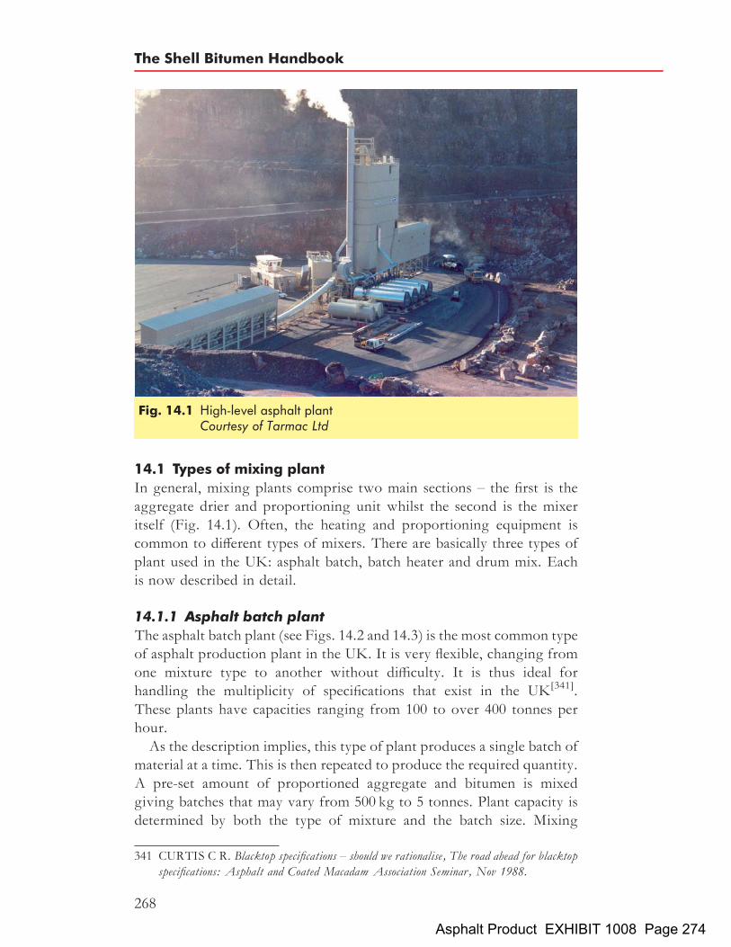
14.1 Types of mixing plant
In general, mixing plants comprise two main sections – the first is theaggregate drier and proportioning unit whilst the second is the mixeritself (Fig. 14.1). Often, the heating and proportioning equipment iscommon to different types of mixers. There are basically three types ofplant used in the UK: asphalt batch, batch heater and drum mix. Eachis now described in detail.
14.1.1 Asphalt batch plantThe asphalt batch plant (see Figs. 14.2 and 14.3) is the most common typeof asphalt production plant in the UK. It is very flexible, changing fromone mixture type to another without difficulty. It is thus ideal forhandling the multiplicity of specifications that exist in the UK[341].These plants have capacities ranging from 100 to over 400 tonnes perhour.As the description implies, this type of plant produces a single batch of
material at a time. This is then repeated to produce the required quantity.A pre-set amount of proportioned aggregate and bitumen is mixedgiving batches that may vary from 500 kg to 5 tonnes. Plant capacity isdetermined by both the type of mixture and the batch size. Mixing
Fig. 14.1 High-level asphalt plantCourtesy of Tarmac Ltd
341 CURTIS C R. Blacktop specifications – should we rationalise, The road ahead for blacktopspecifications: Asphalt and Coated Macadam Association Seminar, Nov 1988.
The Shell Bitumen Handbook
268
Asphalt Product EXHIBIT 1008 Page 274

times vary with the type of mixture. A 2.5 tonne batch, for example,requiring a mixing cycle time of 60 s, will give a maximum plant capacityof 150 tonnes per hour.The cold aggregate feed is the first major component of any mixing
plant. The aggregate is collected from a stockpile and loaded into a
Fig. 14.2 Asphalt batch plantCourtesy of Foster Yeoman Ltd
Fig. 14.3 Sectional flow diagram of an asphalt batch plantCourtesy of Gencor International Ltd
Asphalt production plants
269
Asphalt Product EXHIBIT 1008 Page 275

cold feed holding bin; eight or more cold feed bins are normally used.Some mixing plants have 12 or more bins, each charged with a differentaggregate (see Fig. 14.4). Feeder units are located under the bins tocontrol the flow of aggregate onto a conveyor belt. Alternatively, theaggregate can be supplied by feeders mounted directly under crushedstone bins. The feeders can be controlled individually or in combinationto provide a proportional arrangement whereby the ratio of one feeder toanother is maintained but the total flow rate of all the feeders can bevaried. A conveyor belt transports the combined aggregates to thedrying and heating unit.A basic part of any mixing plant is the aggregate dryer/heater. Its func-
tion is twofold – to ensure that water is removed from the aggregatebefore it is mixed with the bitumen and to heat the aggregate to therequired mixing temperature. The removal of moisture is necessary toallow adhesion of the bitumen to the aggregate (discussed in Chapter9). Since the moisture content of the aggregate can be as high as 5%of the dry weight, i.e. around 50 kg of water per tonne of aggregate[342],this part of the plant plays a vital role in assuring the ultimate quality ofthe finished mixture. It normally consists of a large rotating metal drumthat is mounted at an angle of between 3 and 48 along its axis (see
342 GRANT R M. Flexible pavements and bituminous materials, Residential course at theUniversity of Newcastle upon Tyne, section J, Manufacture of coated materials, pp J1–J12,Sep 1989.
Fig. 14.4 Cold feed binsCourtesy of Tarmac Ltd
The Shell Bitumen Handbook
270
Asphalt Product EXHIBIT 1008 Page 276

Fig. 14.5). A gas or oil burner at the lower end causes hot gases to risethrough the drum and emerge at the upper end. The cold aggregateenters the rotating drum from the upper end and is carried throughthe hot gas and flame by means of steel angles or flights fitted to theinside, aided by the downward inclination of the drum, finallydischarging onto an elevator. The length of time during which the aggre-gate remains in the drum is known as the ‘retention time’. The drying andheating process is very fuel intensive and, consequently, costly. It takessome 10 litres of fuel per tonne of aggregate to remove 5% moistureand increase the temperature of the aggregate by 1608C[343]. At thelower end of the drum, the temperature of the aggregate is measuredby a radiation pyrometer. The value is compared to the specified tempera-ture and the burner is adjusted accordingly.To eliminate dust from the dryer exhaust, dust collectors are fitted. In
general, there are three types of dust collector – cyclone, fabric filters orwet collectors (although the last of these is almost redundant). Two ormore of these devices – a primary collector and one or more final orsecondary collectors – may be fitted. Provision is usually made for thecoarse dust to be returned to the hot aggregate. However, if the dustis unsuitable or is produced in excessive quantities, it can be removedfrom the collector and disposed of elsewhere.
343 GRANT R M. Flexible pavements and bituminous materials, Residential course at theUniversity of Newcastle upon Tyne, section J, Manufacture of coated materials, pp J1–J12,Sep 1989.
Fig. 14.5 Aggregate drier with burner
Asphalt production plants
271
Asphalt Product EXHIBIT 1008 Page 277
When the aggregate is discharged from the dryer/heater, it is trans-ported vertically to a screening unit housed at the top of the tower asshown in Fig. 14.2. Here, the aggregate is separated into fractions(usually between 4 and 6 in number) of specified size and stored tempora-rily in hot storage bins. Material is withdrawn from each bin in pre-determined amounts and charged into a weigh hopper. Each aggregateis individually weighed to the quantity determined by the formulationof the mixture as a proportion of the batch size.The bitumen binder is kept in a storage tank and fed into a recirculat-
ing system of pipes that returns it to the tank. When bitumen is neededfor the mixer, a valve in the system is opened permitting the requiredquantity of bitumen to flow from the tank. A weigh bucket is the pre-dominant method of measuring binder quantity.The dust collected from the dryer exhaust can be reintroduced into the
hot aggregate if the gradation of this dust complies with the specifiedaggregate grading. If not, the dust may be collected in a fines silo thatfeeds fines into the batch in controlled amounts. Where collected dustis unsuitable for addition to the mixture, mineral filler will be usedinstead. This is normally limestone filler, supplied in bulk into a siloand added to the mixture in the same way as the collected dust.The weighed aggregate, fines and bitumen are discharged into the
pugmill. This is usually a large semi-circular bowl with two shafts thathave angled mixing blades. These blend the hot aggregate andwhen the bitumen is added the movement of the aggregate ensuresthat all the aggregate surfaces are coated with a thin film of bitumen.Depending on the efficiency of the pugmill and the material beingmixed, the duration of mixing varies from 30 to 60 s. The mixing timeshould be as short as possible to minimise oxidation of the bitumen.However, it is important that the mixing time is long enough toensure that uniform distribution of the aggregate sizes and uniformcoating of the aggregate is achieved. The mixed material is then dis-charged directly into the delivery vehicle or transported by skip into ahot storage bin.In order to meet environmental regulations, the mixing section and
mixed material system are generally sheeted with angular profile claddingor positioned inside a large building. The feed hoppers are equipped witha canopy and the conveyor belts are covered to protect the feed aggre-gates from wind. Emissions from the exhaust stack cannot be seenwith the naked eye, particulate emission levels of less than 20mg/m3
can be easily achieved.Freestanding versions of asphalt batch plants, which need no concrete
foundations providing the ground is level and stable, are available. Suchplants are designed to be moved quickly from contract to contract.
The Shell Bitumen Handbook
272
Asphalt Product EXHIBIT 1008 Page 278

Mobile versions of the asphalt batch plant are also available. Again theseneed no foundations and they can be readily relocated. Mobile plants aresmall in height and are useful in cases where a height restriction isencountered.A variation of the asphalt batch plant is the multiple hot stone bin
version. A diverter chute is positioned under the vibrating screen toenable two different types of aggregate to be stored concurrently. Typi-cally, there are 12 or more hot stone bin compartments. The multiple hotstone bin plant enables a variety of mixtures to be produced withouthaving to clean out the plant when different aggregates are required.
14.1.2 Batch heaterThis type of plant is unique to the UK. It is called a batch heater becausethe aggregates are dried and heated in batches prior to being mixed withbitumen and filler. Batch heaters allow rapid changes in mixture specifi-cations and are not limited by hot aggregate storage capacity. Plantoutputs vary from some 50 tonnes per hour to more than 200 tonnesper hour. However, aggregates having moisture contents exceeding2% cannot be dried economically in these plants and a separate dryerwould normally be used. They are better suited to low- and medium-temperature materials, such as coated macadams, than to mixtures withhigh sand contents, such as rolled asphalt.The cold aggregate feed is almost identical to that of the asphalt batch
plant; the proportional cold feed is charged into a hopper for checkweighing before drying. The proportions of aggregate cannot bechanged in the process, which means that the feed control of the coldaggregate has to be very accurate. From the weigh hopper, the aggre-gates are charged into the batch heater, in effect a shortened version ofthe aggregate dryer, and the batch is dried and heated. The heated aggre-gate is discharged into a conventional pugmill and is mixed with thebitumen and filler.
14.1.3 Drum mixDrum mix plants are so called because the aggregates are dried andheated in a large drum on a continuous basis just prior to mixing withthe bitumen. This type of plant is not very flexible and requires consider-able effort to change the mixture type. However, the increased use ofcomputerised control is beginning to overcome this problem. Theseplants are relatively simple and the smaller models are ideal for contractswhere a portable plant is required (Fig. 14.6). Their simplicity alsoreduces maintenance costs and improves reliability. However, the over-riding advantage of drum mix plants is their production capacity. Plantscan produce anything between 100 tonnes per hour to some 700 tonnes
Asphalt production plants
273
Asphalt Product EXHIBIT 1008 Page 279

per hour, making this type of equipment ideal for large contracts wherelarge quantities of the same material are required over a long period.This type of plant produces asphalts without the use of screens, hot
aggregate storage bins, weigh hoppers or pugmill mixers. In principle,the cold aggregate feed system is similar to that which is used in anasphalt batch plant, described above. The aggregate proportioningmust be precise as any error in the feed ratio will only be detectedwhen samples of the mixed material are analysed in the laboratory.The cold feed bins discharge the aggregate onto a collecting conveyor
that, in turn, feeds them into a charging conveyor. This is provided witha belt weigher enabling the aggregate flow rate to be maintained (in sodoing, a correction is made to take account of the amount of moisturein the aggregate). This allows the calculation of the amount of fine aggre-gate/filler and bitumen that have to be added to the mixture.The drum used in a drum mix plant differs from that used in an asphalt
batch plant dryer in three respects:
. the burner is at the top end of the drum and the aggregate thus flowsaway from the flame;
. the configuration of the flights inside the drum is more complex;
. the drum is longer.
Fig. 14.6 Mobile drum mix plantCourtesy of Lafarge Aggregates Ltd
The Shell Bitumen Handbook
274
Asphalt Product EXHIBIT 1008 Page 280

The drum interior has two zones. The first zone dries and heats the pro-portioned aggregate and the second zone mixes the hot aggregate withthe bitumen. The mixing zone is protected by either a flame shield or adevice that increases the density of the aggregate curtain in order toprotect the coated aggregate from the radiant heat of the heating unit.The bitumen is injected into the drum at the start of the second zone.
The flow rate of the bitumen is proportional to the aggregate flow rateand is controlled by either variable-speed fixed-displacement pumps orvariable orifice control valves.Exhaust gases from drum mix plants contain less dust than those from
other types of mixing plant[344]. This is because most of the airborne dustgenerated in the heating and drying zone is absorbed by the bitumen-coated aggregate in the second zone. UK environmental legislation,however, still requires dust collection. The collected dust may beblown pneumatically into the drum or simply screwed into the mixingzone. Either method may also be used to introduce controlled amountsof mineral filler into the drum. The final mixture flows continuouslyfrom the bottom of the drum; bulk storage is normally in the form ofwell-insulated high-capacity hot storage silos[345] (discussed in Section8.2.3).Developments have led to a new breed of drum mix plants, termed
counterflow drum mix plants. The ancillary equipment – such as thefeeders, conveyors, bag filter, bitumen system, filter system and hotstorage silos – is identical to that used in a drum mix plant. The counter-flow drum mix incorporates a dryer similar to the asphalt batch plantdryer with the burner mounted at the discharge end and a separatemixing chamber for the bitumen and filler. The mixing chamber can bemounted directly after the dryer using an extended burner. Alternatively,the mixing chamber can envelope the dryer as an outer skin, this istermed a double drum. The counterflow drum mix is more fuel efficientthan the parallel flow drum mix since the incoming aggregates are pre-heated by the hot exhaust gases.
14.2 The addition of recycled asphalt pavement
Recycled asphalt pavement (RAP) can be added to each of the differenttypes of mixing plants. By superheating the virgin aggregates, percen-tages between 10 and 30% can be accommodated, dependent upon the
344 GRANT R M. Flexible pavements and bituminous materials, Residential course at theUniversity of Newcastle upon Tyne, section J, Manufacture of coated materials, pp J1–J12,Sep 1989.
345 BAXTER J. Hot storage of bituminous mixes, Problems and advantages, Quarry Manage-ment and Products, pp 213–218, Aug 1977.
Asphalt production plants
275
Asphalt Product EXHIBIT 1008 Page 281

moisture content in the RAP. A rejuvenating agent may need to be addedto the mixture if the RAP is severely oxidised.If the RAP is in large sections then a RAP breaker will have to be
employed prior to processing. On an asphalt batch plant, or a batchheater plant, the most common method is to convey the RAP over abelt weigher and feed directly into the pugmill. The conveyor operateson a start/stop basis. An alternative operational method in an asphaltbatch plant is to feed the RAP into the aggregate weigh hopper. Thecontrol system acknowledges it as an additional ingredient. The dis-advantage with this method is the potential contamination of theaggregate weigh hopper.Between 50 and 60% RAP can be added to an asphalt batch plant by
incorporating a recycling or ‘black’ drum. This consists of an inclinedsteel drum (the angle of inclination is between 38 and 48) with theburner mounted at the higher end. The RAP is dried and heated toremove moisture, weighed in a separate weigh hopper and then trans-ferred to the pugmill.A counterflow drum mix plant can accommodate up to 60% RAP by
adding it to the isolated mixing chamber. The virgin aggregates aresuperheated. The RAP is introduced over a separate belt weigher, thecontrol signal being taken from the charging conveyor weigh system.
14.3 Additive systems
All types of mixing plant can be fitted with a variety of additive systems.The mixture can be coloured, most commonly by the addition of redoxide. Blue, green and gold coloured mixtures can also be produced.The employment of a clear binder such as Mexphalte C results in anatural looking mixture. The addition of latex into the pugmill bymeans of a peristaltic pump is also an option. Deferred-set asphalts canbe produced by the addition of flux metered via a spray bar into thepugmill.Fibres are used in some SMAs and thin surfacings. They can be added
to the mixture by volume or weight directly into the pugmill. An alter-native method is to weigh the fibres in a separate weigh hopper. Thefibres are introduced in small fibre ‘strings’ or in pellet form.
14.4 Production control testing of asphalts
Production control testing is used to ensure that the asphalt, as manu-factured, complies with the specified aggregate grading and bitumen con-tent. Representative samples of the material are taken at prescribedintervals since it is impractical to test every batch of material that isproduced. Clearly, it is essential that the sample is representativeotherwise the data generated will be meaningless and misleading. It is
The Shell Bitumen Handbook
276
Asphalt Product EXHIBIT 1008 Page 282

equally important that the test methods are carried out by trained andexperienced staff using well maintained and properly calibrated equip-ment.A procedure for sampling the mixture during discharge at the produc-
tion plant is included in BS 598-100: 1987[347]. Once the material has beensampled, it requires some preparatory treatment before testing. Thistreatment is detailed in BS 598-101: 1987[348]. Three test methods fordetermination of the composition of the mixture with regard to aggre-gate grading and bitumen content are detailed in BS 598-102: 1996[346];all three methods involve the separation of the bitumen from the aggre-gate using chlorinated hydrocarbon solvents as shown in Table 14.1.Having removed the bitumen from the material, the residual aggregate
is graded into its individual fractions. The majority of asphalts can beanalysed by any of the methods. Collection and direct determination offiller content and direct determination of bitumen content provides acheck on the results but it also increases the duration of the test.Determining the bitumen content directly involves evaporation of
solvent from a known quantity of bitumen/solvent solution (known asan aliquot) and weighing the recovered bitumen. The percentage ofbitumen can then be calculated from the mass of the sample and thevolume of solvent originally used. The procedure is relatively compli-cated. The most common sources of error are:
. loss of solvent by evaporation;
. incomplete separation of the insolvable matter from the bitumen/solvent when centrifugal methods are used;
Table 14.1 Test methods for the analysis of asphalts[346]
Method Solvent Bitumen content Filler content
Extraction bottle (bitumen by difference) Trichloroethylene ormethylene chloride
By difference ordirectly
Directly
Extraction bottle (bitumen directly determined) Methylene chloride Directly By difference
Hot extractor Trichloroethylene By difference Directly
346 BRITISH STANDARDS INSTITUTION. Sampling and examination of bituminousmixtures for roads and other paved areas, Analytical test methods, BS 598-102: 1996. BSI,London.
347 BRITISH STANDARDS INSTITUTION. Sampling and examination of bituminousmixtures for roads and other paved areas, Methods for sampling for analysis, BS 598-100:1987. BSI, London.
348 BRITISH STANDARDS INSTITUTION. Sampling and examination of bituminousmixtures for roads and other paved areas, Methods for preparatory treatments of samples foranalysis, BS 598-101: 1987. BSI, London.
Asphalt production plants
277
Asphalt Product EXHIBIT 1008 Page 283

. incomplete removal of the solvent during recovery;
. dust entering the bitumen/solvent solution.
All of the errors cited above are likely to increase the calculated bitumencontent.A pressure filter is used when the filler fraction is determined directly.
The disadvantage with this procedure is that it is slow and great caremust be taken to avoid leaks from the pressure filter seals and tears inthe filter paper. A powder additive is used to aid flow of the solvent/bitumen mixture.Correction factors are applied to bitumen and filler contents of base
and binder course coated macadam mixtures and to all hot rolled asphaltmaterials. These factors are included to allow for the experimental errorsresulting from variations in aggregate grading.Ignition furnace methods are used by some laboratories to determine
bitumen content and grading. This method involves subjecting thesample to high temperatures that ‘burn’ the bitumen off the sample.The advantage of this method is that it requires no solvent and usesless equipment. Disadvantages include the need to assess aggregates todetermine a correction factor for each aggregate type/source. Thisvalue has to be programmed into the software of the machine used toensure accuracy of results. At present, this method is the subject of adraft European Standard[349].
349 EUROPEAN COMMITTEE FOR STANDARDIZATION. Bituminous mixtures– test methods for hot mix asphalt–binder content by ignition, prEN 12697-39. CEN,Brussels.
The Shell Bitumen Handbook
278
Asphalt Product EXHIBIT 1008 Page 284

Chapter 15
Transport, laying andcompaction of asphalts
15.1 TransportationThere are three distinct phases in transporting the mixed asphalt to thesite where it is to be laid. These are loading into a truck, transportingto the site and tipping into the hopper of the paver. In order to minimisedisruption, transportation must be well planned and executed efficiently.During loading, it is important to minimise the risk of segregation.
Loading has to be undertaken quickly in order to avoid undue heatloss. Lorries should be loaded as evenly as possible over the entire trailer.If the asphalt in the trailer is loaded with steep sides, this may causesegregation of the asphalt. Covered trailers (Fig. 15.1) are required tokeep the mixture hot during transportation and a rounded base in thetrailer helps reduce the risk of aggregate and temperature segregation.The phasing and frequency of transport to the site must be well coordi-nated. If a paver has to stop to await the arrival of the next load, thequality of the surfaced road will suffer. It can lead to unevenness andreduced levels of compaction, both of which may shorten the serviceablelife of the road. In contrast, a convoy of lorries waiting at the site shouldbe avoided. The asphalt mixtures may cool whilst waiting which maylead to unsatisfactory compaction results or, in severe cases, having todiscard the load. The unloading of the asphalt mass requires skill toavoid both separation and stoppages.
15.2 Use of tack coatsThe function of a tack coat is to promote adhesion between two layers ofasphalt. An example would be where a new surface course is to be laid ona previously paved road or a binder course that has been opened to traffic.Tack coating is an important stage in road surfacing and is often requiredby highway specifications.It is essential in terms of the overall stiffness of the pavement that the
layers bind well together. In addition, the improved adhesion afforded by
279Asphalt Product EXHIBIT 1008 Page 285

tack coating means there will be less tendency towards displacement ofthe mixture or crack formation when rolling takes place.
15.3 Pavers
These machines, occasionally described as ‘asphalt finishers’, lay the hotasphalt to form the pavement. A number of published texts summariseexperiences related to asphalt paving and compaction[350,351].A paver has to provide homogeneous pre-compaction to give the
mixture sufficient stability such that the roller can commence the compac-tion process. It also has to provide a level surface with a homogeneoustexture. The performance of the paver is the single most importantfactor in achieving these two requirements. All modern asphalt paversconsist of two main units, a tractor and a floating screed.
15.3.1 Tractor unitThe tractor unit provides forward propulsion to the paver and power toother elements of the equipment. It is driven by either pneumatic wheels(Fig. 15.2) or crawler tracks (Fig. 15.3).
Fig. 15.1 A modern asphalt delivery lorryCourtesy of Tarmac Ltd
350 DYNAPAC. Compaction and paving, theory and practice, Svedala Dynapac pub no IHCC-CAPEN1, 2000. Svedala Industri AB, Sweden.
351 FORSSBLAD L and S GESSLER. Vibratory asphalt compaction, 1975. Dynapac,Sweden.
The Shell Bitumen Handbook
280
Asphalt Product EXHIBIT 1008 Page 286

Wheeled pavers are easy to transport. Their relatively high travellingspeeds allow them to move about the work site rapidly and to moveeasily between different sites on public roads.The good traction of tracked pavers makes them suitable for use on
unbound surfaces. They are also particularly suited to laying extrawide sections and working on steep sites. Tracked pavers produce
Fig. 15.2 Wheeled paver
Fig. 15.3 Tracked paver
Transport, laying and compaction of asphalts
281
Asphalt Product EXHIBIT 1008 Page 287

layers which possess better surface regularity than those placed bywheeled pavers.Having released the rear gate of the trailer, delivery trucks reverse into
the front of the paver. The trailer of the truck is lifted by a ram at thefront of the trailer resulting in the asphalt mixture being dischargedinto the receiving hopper of the paver (Fig. 15.4). The rear tyres of thetruck, and therefore the truck itself, are then pushed forward by thepaver. Twin or single slat conveyors carry the asphalt from the hopperto the rear of the machine and then onto the auger (screw conveyor)which distributes the asphalt laterally over the entire working width ofthe screed. The height of the auger is adjustable to allow for differentlayer thicknesses.The rate at which the asphalt flows through the paver is controlled by
the speed of the slat conveyor and the augers. The conveyor speed isautomatically linked to the forward speed of the paver and the heightof the material that is spread out ahead of the screed. It is essential thatthe height is maintained at a constant level.Figure 15.5 shows how asphalt flows through the paver. The material
passes from the hopper (1), via the conveyors (2), on to the auger (3) andunder the screed (4). Smooth flow is essential to achieving good pavingresults.
15.3.2 Screed unitThe screed levels and pre-compacts the asphalt to a specified thickness,grade and cross slope and crown profile. The self-levelling floating
Fig. 15.4 Laying a macadam baseCourtesy of Aggregate Industries UK
The Shell Bitumen Handbook
282
Asphalt Product EXHIBIT 1008 Page 288

screed is attached to the tractor by side arms at tow points located oneach side of the tractor near its central point. Here, vertical movementscaused by any surface unevenness are at a minimum. This allows thescreed to produce an even surface despite the fact that the underlyingbase may be somewhat irregular. As each successive asphalt layer isplaced, irregularities become less and less apparent.The tow points are set to give the required thickness of the mat. Their
position may be finely adjusted by electronic systems on a continuousbasis as the asphalt is laid.
15.3.3 Angle of attackThe concept of the ‘angle of attack’ is illustrated in Fig. 15.6. This is theangle between the bottom plate of the screed and the surface being paved.The angle varies from screed to screed according to the weight of the
Fig. 15.5 Material flow through a paver – from the hopper (1), via theconveyors (2), on to the auger (3) and under the screed (4) – isessential to good paving results
Fig. 15.6 The ‘angle of attack’ is the angle between the bottom plate of thescreed and the surface being paved
Transport, laying and compaction of asphalts
283
Asphalt Product EXHIBIT 1008 Page 289

screed, the contact area of the bottom plate and the shape of the front partof the screed.Figure 15.6 illustrates the importance of the angle of attack. Any
change in the level of the tow points results in a corresponding adjust-ment of this angle. The desired surface regularity is obtained if all theforces acting on the screed are in equilibrium, only then will the screedsettle into its angle of attack.The angle of attack can be increased or decreased by raising or
lowering the level of the tow point. Any movement of the tow pointupsets the equilibrium and results in a rise or fall of the screed. Oncethe screed has attained the new level, the angle of attack is restoredand the forces revert to a state of equilibrium.
15.3.4 Heating of the screed bottom platesScreeds are heated by diesel, propane gas or electrically powered elements.This is necessary to prevent the bottom plate picking up the hot asphalt.
15.3.5 Fixed or variable paving widthThe most common type of screed is the telescopic screed that has ahydraulically variable laying width (Fig. 15.7). In some applications, afixed screed is the most economical option.
Fig. 15.7 Hydraulic screed extensions
The Shell Bitumen Handbook
284
Asphalt Product EXHIBIT 1008 Page 290

15.4 Additional screed systems
The main factor that dictates the effectiveness of a screed in pre-compacting an asphalt is its weight. The heavier the screed, the greaterwill be the degree of pre-compaction that is achieved. Additional systemssuch as tampers and vibration generators are usually attached to improvethe flow of material underneath the screed.The choice of a tamping and/or vibrating screed depends on the
application as well as the type/s of asphalt, maximum aggregate size inthe asphalt, layer thickness as well as local preferences and specifications.
15.4.1 TamperThe tamping mechanism uses a vertical, high-amplitude movement atcomparatively low frequencies. The main purpose of the tamper is to facil-itate the flow of material below the screed plate. A static or vibrating screedplate follows the tamping unit. The width of the tamper and the tampingfrequency limit the maximum paving speed since no part of the mat mustbe left untamped. Figure 15.8 illustrates the action of the tamper. Thetamper bar (1) feeds material under the screed plate and the vibrator (2)reduces the friction between the screed plates and the material.
15.4.2 VibratorsThe screed plate is equipped with a vibration generating system.Vibrating the asphalt reduces the friction between the screed plate and
Fig. 15.8 Action of the tamper
Transport, laying and compaction of asphalts
285
Asphalt Product EXHIBIT 1008 Page 291

the mixture. This allows the screed to float more easily over the asphalt.The vibrations also tend to cause a small amount of bitumen to rise to thesurface of the asphalt, providing additional lubrication.
15.4.3 Tamping and vibrating screedsA screed that is capable of being both tamped and vibrated is extremelyversatile since it affords the choice of using either mode independently orboth in combination. The weight of the two systems also increases thetotal weight of the screed which, in turn, results in higher levels ofpre-compaction.
15.4.4 High-compaction screedsFor some applications, such as cement-stabilised layers and thickerasphaltic bases, special high-compaction screeds have been developed.These screeds have additional mass and are equipped with doubletampers and vibration systems.
15.5 Paving operations
Careful planning of asphalt production and transportation to the site iscrucial in maintaining a continuous paving operation. Any stoppagesin the operation will result in a pavement of inferior quality. Thepaver speed should be constant. The rate of supply should be such thatthe paver can maintain the highest speed that is consistent with layingthe asphalt to the required specification. In ensuring that an adequaterate of supply is maintained, key elements will be the capacity of theasphalt manufacturing plant or plants and the number of trucks thatare available to deliver material.In order to meet the requirements of the specification, a number of
points must be taken into consideration. The required paving widthhas to be set and the screed must be heated to prevent the asphalt stickingto the underside of the screed. The tow points must be set to the heightthat corresponds to the desired thickness of the finished mat. Wherenecessary, the screed must be adjusted to allow for a crown profile.The height of the auger is also crucial to the outcome. If it is set toolow, it will restrict the material flow under the screed which will resultin an open texture and cause the mat to tear. If it is set too high, theasphalt may not extend to the outer edges of the screed. Ideally, thedistance between the surface of the mat and the lower edge of the augerflights should be equivalent to roughly five times the maximum aggre-gate size in the mixture.There are a number of factors that must be controlled during a paving
operation. These include:
. head of material in front of the screed
The Shell Bitumen Handbook
286
Asphalt Product EXHIBIT 1008 Page 292

. speed of the paver
. layer thickness
. regularity of the surface being covered
. paving width
. joints in the surface being covered
. laying temperature
. mixture segregation.
15.5.1 Head of materialThe height of the asphalt in front of the screed is called the ‘head ofmaterial’. It should be maintained at a constant level over the entire work-ing width. It has a decisive influence on the vertical position of the screedand, thus, the regularity of the finished mat. The levelling action of ascreed relies on there being a state of equilibrium between all the forcesacting on it. Any change in these forces causes the screed to move upor down to compensate. If the head of material rises, the resistance toforward travel increases and, in an attempt to overcome this resistance,the screed starts to rise (Fig. 15.9(a)). A ridge will then appear in themat and/or the layer thickness will increase. Excessive material alsoaccelerates wear on the augers. If, in contrast, the head of material istoo low, the screed settles because there is insufficient material to supportit (Fig. 15.9(b)). Many pavers can be fitted with an automatic system thatmonitors and controls the material flow through the paver and, thus, thelevel of the screed. These systems will significantly reduce the likelihoodof the occurrence of the adverse effects described above.As illustrated in Fig. 15.9(c), if the supply of material to the auger is
correct, the forces acting on the screed are in equilibrium and thescreed is able to maintain the required level.
15.5.2 Paving speedThe paver should travel at a constant speed since variations will result inan uneven surface. An automatic system to pre-set and maintain speedsunder varying load conditions is recommended.Stoppages are also a problem. Not only are they likely to leave a
blemish on the surface, they also result in temperature segregation.Every time the paver stops, the screed tends to sink into the mat. Theareas in front of the screed and just behind the paver, both of whichare inaccessible to the rollers, cool down while the material below thescreed remains hot. When the paver starts moving again, the screedwill lift slightly to overcome the cooler material ahead of the screedleaving a ridge in the mat.If the paver is forced to stop, the screed can be locked in position with
a special ‘screed stop system’, which is powered by hydraulic lift
Transport, laying and compaction of asphalts
287
Asphalt Product EXHIBIT 1008 Page 293

cylinders. This prevents the screed from sinking into the mat and reducesthe problems associated with paver stoppages.Normal paving speeds range from 4m/min up to 20m/min depending
on the type of asphalt being laid and the performance of the equipmentitself. A minimum speed is necessary in order to keep the screed floating.If the paving speed falls below this value, the screed will settle. The layerwill then be too thin. When using high compaction screeds, speed shouldbe maintained around 2 to 4m/min in order to achieve the very highdensities for which these screeds were designed.
15.5.3 Layer thickness and surface regularityIn the UK, national requirements for finished tolerances, etc. are con-tained in the SHW[352]. In terms of the finished road level, requirements
Fig. 15.9 The importance of the head of material
352 HIGHWAYS AGENCY et al. Manual of contract documents for highway works,Specification for highway works, vol 1, cl 702, 2002. The Stationery Office, London.
The Shell Bitumen Handbook
288
Asphalt Product EXHIBIT 1008 Page 294

are stated in terms of the maximum number of surface irregularities. Inorder to achieve the specified surface regularity, the layer thicknessmay vary to take account of any irregularities in the underlying surface.Where necessary, electronic levelling devices, such as grade controllers
and/or slope controllers should be used to automatically adjust the matthickness so that a level surface is maintained. If the paver is beingoperated manually, the surfacing gang must refrain from making frequentcorrections to the height of the screed.
15.5.4 Paving widthMost modern pavers are fitted with a telescopic screed that allows thepaving width to be varied. Normally, the width is set prior to the startof laying. However some works, e.g. tie-ins at roundabouts, may involvelaying a variable width which requires the paver driver to vary the pavingwidth during laying. This has to be undertaken with care and should aimto minimise the amount of asphalt that has to be laid by hand.
15.5.5 JointsAn important contributory factor in achieving good surface regularityand appearance is the quality of the longitudinal and transverse joints.Accordingly, due care is necessary when laying and compacting materialthat is close to the joints.When laying asphalt adjacent to an existing lane, the height of the
screed above the surface must be carefully adjusted to allow for thereduction in height that occurs as the material is compacted. An allow-ance of 15 to 20% is not uncommon but the actual value depends onthe nature of the material, temperature of the mixture, compactiveeffort, etc. An automatic grade controller that operates off the adjacentlane is very useful for joint matching.The side overlap of the joint should be about 25 to 50mm. There
should be as little raking of the joints as possible, so laying must beprecise.To create a smooth transverse joint, the paver screed should be placed
on top of the mat placed previously, just in front of the joint. As theforces on the screed need to be in equilibrium when the paver resumesits work, only enough asphalt to cover the auger shaft should beconveyed to the auger box before the paver moves forward. (The‘auger box’ is the area immediately in front of the screed.)In order to ensure a good bond at joints and to seal the area, a coating
of bitumen must be applied to the exposed surface. Open joints are afairly common failure on mats that are only a few years old. Goodpractice in painting the joints and in compacting them will significantlyreduce the possibility of this occurring.
Transport, laying and compaction of asphalts
289
Asphalt Product EXHIBIT 1008 Page 295

15.5.6 Type of mixture and laying temperatureAsphalts having low workability (sometimes described as ‘stiff mixtures’),require heavy screeds. Asphalts that are more workable require relativelylight screeds. Stiff mixtures tend to lift the screed above the requiredlevel whilst mixtures having high workability very often do not havethe resistance to adequately support the weight of the screed.The load of the screed on high-workability mixtures can be reduced
with the help of a ‘screed unload system’ which transfers the weight ofthe screed to the tractor. This not only allows heavy screeds to be usedon high-workability mixtures, it also improves traction and helps toobtain an even surface and uniform degree of compaction.Another factor that has a significant effect on the quality of the finished
mat is the temperature at which the asphalt is laid (time of day is thereforealso important and account should be taken of cooler night temperatures,Fig. 15.10). Variations in temperature can cause irregularities in thesurface and result in varying levels of compaction being achieved. Asan asphalt cools, it becomes more resistant to compaction. The tractorunit must be able to provide the tractive force necessary to overcomethis resistance. Accordingly, successful laying of cooler mixtures requiresthe use of pavers with good traction and relatively heavy screeds. Coldermaterial may tear under the screed as it is laid.
Fig. 15.10 Night laying on an airfieldCourtesy of Lafarge Contracting Ltd
The Shell Bitumen Handbook
290
Asphalt Product EXHIBIT 1008 Page 296
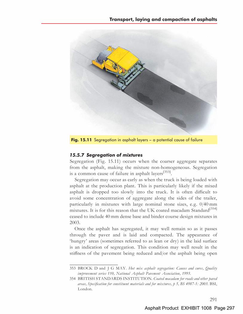
15.5.7 Segregation of mixturesSegregation (Fig. 15.11) occurs when the coarser aggregate separatesfrom the asphalt, making the mixture non-homogeneous. Segregationis a common cause of failure in asphalt layers[353].Segregation may occur as early as when the truck is being loaded with
asphalt at the production plant. This is particularly likely if the mixedasphalt is dropped too slowly into the truck. It is often difficult toavoid some concentration of aggregate along the sides of the trailer,particularly in mixtures with large nominal stone sizes, e.g. 0/40mmmixtures. It is for this reason that the UK coated macadam Standard[354]
ceased to include 40mm dense base and binder course design mixtures in2003.Once the asphalt has segregated, it may well remain so as it passes
through the paver and is laid and compacted. The appearance of‘hungry’ areas (sometimes referred to as lean or dry) in the laid surfaceis an indication of segregation. This condition may well result in thestiffness of the pavement being reduced and/or the asphalt being open
353 BROCK D and J G MAY. Hot mix asphalt segregation: Causes and cures, Qualityimprovement series 110, National Asphalt Pavement Association, 1993.
354 BRITISH STANDARDS INSTITUTION. Coated macadam for roads and other pavedareas, Specification for constituent materials and for mixtures, p 5, BS 4987-1: 2003. BSI,London.
Fig. 15.11 Segregation in asphalt layers – a potential cause of failure
Transport, laying and compaction of asphalts
291
Asphalt Product EXHIBIT 1008 Page 297

to the rigours of the weather. Either of these factors may result in asurface defect in the form of a pothole or cracking appearing relativelyearly in the life of the pavement.If the material appears non-homogeneous at the edges of the lanes, this
may be caused by segregation along the sides of the trailer or poormixture distribution by the augers such as may occur if the head ofmaterial in the auger box is incorrect. For example, if the material levelis too high, it will slope towards the outer edges where the aggregatecan separate. The height setting of the auger is another importantfactor in this respect.A segregated strip in the middle of the lane occurs if the auger drive
unit is located at the centre of the augers. This phenomenon does notoccur if the auger drives are located at the outer ends of the drive shafts.Transverse areas of segregated material normally arise from the
separation of materials at the front and rear ends of the trailer.
15.6 CompactionProper compaction is necessary if the asphalt is to perform to its fullpotential. A well-compacted, homogeneous asphalt layer will be resistantto rutting and crack initiation and propagation. It is also, in most cases,substantially impermeable, flexible and resistant to wear. If the compac-tive effort is not applied equally throughout the mat and the resultant airvoids content is variable, there may be problems with the pavementearlier in its life than would otherwise have been the case. Thus, theapplication of the appropriate level of compaction uniformly throughoutthe mat is an important determinant of the life of the pavement.There are a number of types of roller that are currently available
for asphalt compaction. The choice of machine depends on the typeand size of the job and is often related to local preferences. Factorsaffecting asphalt compaction have been summarized by the AsphaltInstitute[355]. In general terms, factors that affect asphalt compactioncan be classified as those relating to the asphalt itself, the laying plantand the environment.There is also a range of lightweight compaction equipment that is
suitable for a variety of asphalt applications including vibratory platecompactors, double-drum walk-behind rollers and lightweight vibratorytandem rollers. The compactive effort applied by a deadweight roller isprimarily dependent on its static weight but is also influenced by thediameter of its steel wheels or drums.
355 ASPHALT INSTITUTE. Factors affecting compaction, Educational Series ES-09,1980. AI, Kentucky.
The Shell Bitumen Handbook
292
Asphalt Product EXHIBIT 1008 Page 298

Pneumatic-tyred rollers rely on static weight and tyre pressures fortheir compactive effort. They are often used in combination with staticsmooth drum or vibratory rollers for finish rolling to remove drummarks and for sealing the surface. Finish rolling is generally used togive a smooth finish rather than to provide any increase in the level ofcompaction in the mat.Vibratory rollers combine the static load of the drum with dynamic
loads. The effect of the vibration is to reduce internal friction in theasphalt and improve the effect of the compactive effort even when usedwith comparatively low static linear loads.Roller capacities are usually expressed in terms of tonnes of asphalt laid
per hour. A vibratory asphalt roller will always have a higher capacitythan a static roller of the same weight. On asphalts with relativelypoor workability, this difference is even more pronounced. A range ofrollers is illustrated in Figs. 15.12 to 15.19.
15.6.1 Rolling proceduresAsphalt compaction can be divided into three stages:
. initial rolling
. main compaction
. finish rolling.
Fig. 15.12 Static three-wheeled roller
Transport, laying and compaction of asphalts
293
Asphalt Product EXHIBIT 1008 Page 299
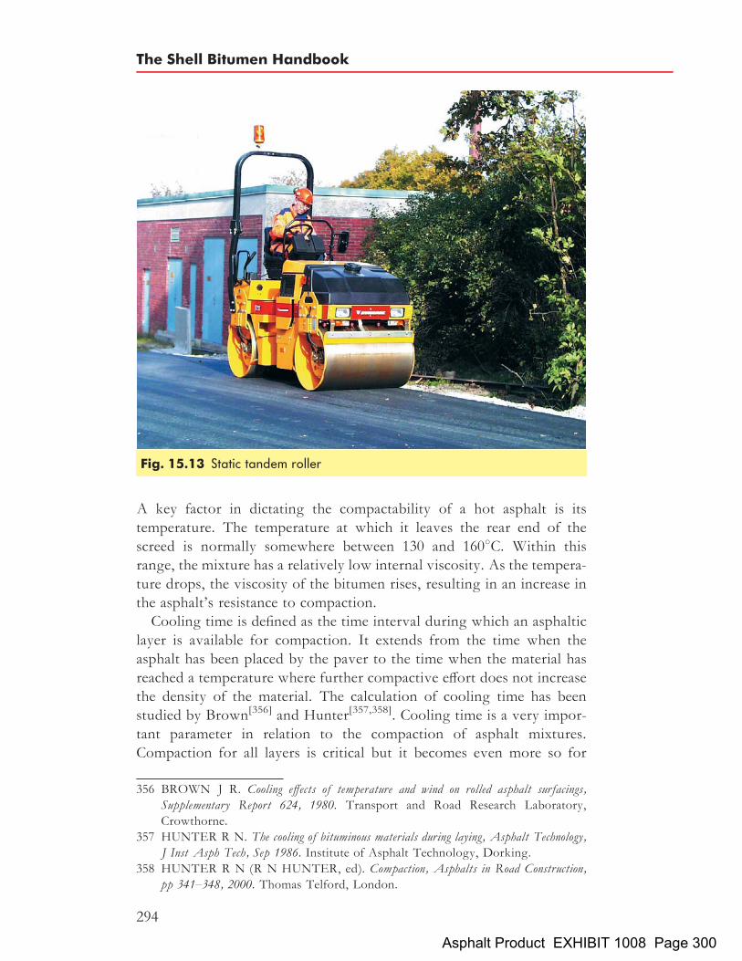
A key factor in dictating the compactability of a hot asphalt is itstemperature. The temperature at which it leaves the rear end of thescreed is normally somewhere between 130 and 1608C. Within thisrange, the mixture has a relatively low internal viscosity. As the tempera-ture drops, the viscosity of the bitumen rises, resulting in an increase inthe asphalt’s resistance to compaction.Cooling time is defined as the time interval during which an asphaltic
layer is available for compaction. It extends from the time when theasphalt has been placed by the paver to the time when the material hasreached a temperature where further compactive effort does not increasethe density of the material. The calculation of cooling time has beenstudied by Brown[356] and Hunter[357,358]. Cooling time is a very impor-tant parameter in relation to the compaction of asphalt mixtures.Compaction for all layers is critical but it becomes even more so for
Fig. 15.13 Static tandem roller
356 BROWN J R. Cooling effects of temperature and wind on rolled asphalt surfacings,Supplementary Report 624, 1980. Transport and Road Research Laboratory,Crowthorne.
357 HUNTER R N. The cooling of bituminous materials during laying, Asphalt Technology,J Inst Asph Tech, Sep 1986. Institute of Asphalt Technology, Dorking.
358 HUNTER R N (R N HUNTER, ed). Compaction, Asphalts in Road Construction,pp 341–348, 2000. Thomas Telford, London.
The Shell Bitumen Handbook
294
Asphalt Product EXHIBIT 1008 Page 300

Fig. 15.14 Pneumatic-tyred roller
Fig. 15.15 Vibratory tandem roller
Transport, laying and compaction of asphalts
295
Asphalt Product EXHIBIT 1008 Page 301
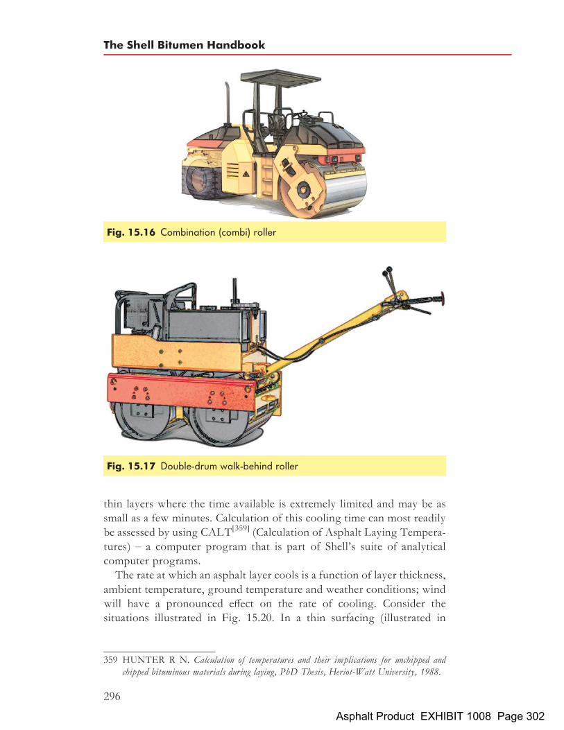
thin layers where the time available is extremely limited and may be assmall as a few minutes. Calculation of this cooling time can most readilybe assessed by using CALT[359] (Calculation of Asphalt Laying Tempera-tures) – a computer program that is part of Shell’s suite of analyticalcomputer programs.The rate at which an asphalt layer cools is a function of layer thickness,
ambient temperature, ground temperature and weather conditions; windwill have a pronounced effect on the rate of cooling. Consider thesituations illustrated in Fig. 15.20. In a thin surfacing (illustrated in
Fig. 15.16 Combination (combi) roller
Fig. 15.17 Double-drum walk-behind roller
359 HUNTER R N. Calculation of temperatures and their implications for unchipped andchipped bituminous materials during laying, PhD Thesis, Heriot-Watt University, 1988.
The Shell Bitumen Handbook
296
Asphalt Product EXHIBIT 1008 Page 302

Fig. 15.20(a)) in unfavourable conditions, the time available for compac-tion may be as little as five minutes or less. Under the same conditions, athick layer may well retain its temperature for over an hour. Accordingly,the thinner the layer, the less time there is available for compaction.In general, compaction rolling should start as soon as possible after the
material has been placed. With a vibratory roller, compaction can usually
Fig. 15.18 Vibratory plate compactor
Fig. 15.19 Single-drum asphalt compactor
Transport, laying and compaction of asphalts
297
Asphalt Product EXHIBIT 1008 Page 303

start with vibrating passes. On mixtures with high workability, it may bemore appropriate to start with two static passes that should be made atlow rolling speed, say 1 to 2 km/h. The roller should follow as close aspossible behind the paver so that compaction can take place whilst theasphalt is above the minimum compaction temperature. This is necessaryto ensure that the degree of compaction achieved is adequate. However,if the roller runs repeatedly over the same area at very short intervalswhen the temperature of the asphalt is high, the surface may crack result-ing in a reduction in density.Finish rolling is effective down to around 608C. The main purpose of
finish rolling is to remove roller marks and other surface blemishes. It
Fig. 15.20 Cooling time in asphalt layers of (a) 20mm thickness and(b) 150mm thickness
The Shell Bitumen Handbook
298
Asphalt Product EXHIBIT 1008 Page 304

improves the appearance of the surface. Finish rolling may also increasethe density of the mat especially if the asphalt is comparatively hot.It is common practice in many countries to use pneumatic-tyred rollers
to seal the surface although traffic tends to achieve this in time. However,this effect obviously does not occur on airport runways which explainswhy pneumatic-tyred rollers are often specified for finish rolling onairport contracts.
15.6.2 Number and types of rollerThe number and types of rollers required on a particular job are deter-mined by the rate at which the asphalt is placed, normally expressed inthe number of square metres per hour. In order to arrive at this figure,a number of elements have to be taken into consideration.Every paving job can be expressed in terms of the asphalt tonnage that
has to be placed on an hourly basis. On larger contracts, this tonnage isusually governed by the capacity of the asphalt production plant.The combination of the mixture tonnage, the paving width and the
layer thickness determines the speed of the paver. The speed multipliedby the paving width gives the laying rate in square metres per hour.This can be used to calculate the compaction plant that will be requiredfor a particular job. Allowance should be made for temporary peaks inthe supply of hot material.Rolling speeds range from 2 to 6 km/h. Low speeds are used on thicker
layers and when the material requires substantial compactive effort. Thenumber of roller passes depends on several factors. These are, primarily,the compaction properties of the asphalt and the degree of compactionthat is required. Static linear load and vibration characteristics of therollers also have a decisive influence.Thin layers with a high stone content are best compacted with a
combination of high frequency and low amplitude to reduce the risk ofcrushing the aggregate. Asphalts having low workability and thicklayers are best compacted at high amplitude and low frequency.It is advisable to compact a test strip in order to determine a suitable
rolling procedure that will result in achieving the specified degree of com-paction. Nuclear density gauges give an instantaneous reading of thedensity of the compacted mat. They can be a useful asset in determiningthe degree of compaction that has been achieved and are particularly help-ful at the start of a contract when establishing an effective rolling regime.
15.6.3 Rolling patternsRolling patterns are illustrated in Figs. 15.21 and 15.22. The paved widthin Fig. 15.22 is divided into rolling lanes and zones. The number ofrolling lanes depends on the drum width and paving width. The drum
Transport, laying and compaction of asphalts
299
Asphalt Product EXHIBIT 1008 Page 305

width should be related to the paving width so that, for example, threeparallel rolling lanes are sufficient to cover the paving width.When switching rolling lanes, the roller should only travel on material
that has been compacted in order to avoid marking the mat. In addition,the roller should never be allowed to stand still on a hot mat.A rolling pattern normally consists of three parallel rolling lanes
divided into zones, these zones being 30 to 50m in length. In eachzone, the roller moves forward and backward until it has executed therequired number of passes. However, the roller may start working onthe next zone before completing the previous one. The roller strokes(the distance the roller moves from the point at which it changes direc-tion behind the paver to the change in direction at the end of the lane)then cover two zones.The rolling pattern for conventional deadweight rollers is more
complicated than that illustrated in Fig. 15.22. This is because the two
Fig. 15.21 A vibratory tandem roller will achieve uniform compaction over theentire paving area by following a simple pattern
Fig. 15.22 Rolling lanes and zones
The Shell Bitumen Handbook
300
Asphalt Product EXHIBIT 1008 Page 306

rear drums have a significantly different linear load than that exerted bythe front drum. In practice, rolling with a conventional deadweight rolleroften results in higher densities in the middle of a lane than thoseachieved along the edges of the lane.When compacting joints, there are two different approaches. Either
the joint is compacted with the roller working on the cold lane with a100 to 200mm overlap on the hot lane or the drum extends 100 to200mm onto the finished lane while the rest of the drum passesover the newly laid mat. As discussed above, efficient joint compactionis particularly important in determining the quality of the finishedpavement.
15.6.4 Low-workability mixturesIncreases in traffic loads on major highways in the UK has led to thedevelopment of the concept of ‘long-life pavements’ and materials thatare appropriate for such roads. As a consequence, asphalt mixturescontaining low penetration bitumen and crushed aggregate with highstone content are now commonplace. Their high mechanical resistanceto compaction requires efficient methods of rolling. In this respect, vibra-tory rollers are the best choice to achieve specified densities.
15.6.5 High-workability mixturesAsphalts that possess high workability are prone to lateral displacementduring compaction which may result in small transverse cracks on thesurface some 3 to 5mm deep. These can normally be closed by suitablefinish rolling or by subsequent traffic action. If longitudinal cracksappear, they are often deep and very difficult to close completely.The rolling of asphalts with high workability requires special measures.
Often, they must be allowed to cool down before rolling starts. This meansthat the roller has to operate a relatively long distance behind the paver. Inmany cases, it may be best to work with long rolling lanes (100m or more).In order to stabilise the mixture, it is often advisable to start the compac-tion with two passes using a static mode or by means of a pneumatic-tyredroller. A large drum diameter and a slow approach also help to preventshoving or the appearance of cracks. It is often a good idea to select alow amplitude and high frequency on these mixtures. A pneumatic-tyredroller is suitable for finishing the surface.Figure 15.23 illustrates the difficulties associated with compacting
high-workability mixtures. Such materials have very low viscosity intheir hot state and may be squeezed out under the drum during rolling,resulting in hairline cracks and the risk of lateral displacement of theasphalt. Adequate compaction can be imparted if the material is allowedto cool.
Transport, laying and compaction of asphalts
301
Asphalt Product EXHIBIT 1008 Page 307

15.6.6 Thin layersThin layers are placed at fast paving speeds resulting in high surfacelaying capacities. The compaction capacity should be adjusted to reflectthese higher outputs. Simply increasing the speed of rollers is not asatisfactory answer, the danger being that the asphalt is inadequatelycompacted. In order to achieve sufficient compaction, the number ofrollers has to be increased. To avoid crushing the aggregate, a lowamplitude and a higher frequency should be employed. In addition,thin layers cool rapidly which is why the rollers must be able to attainspecified densities in a timely and efficient manner.
15.6.7 Thick layersIt is possible to achieve high densities on asphalt layers up to 200mmthick. However, rolling on very thick layers may create undulations inthe surface. On thick layers, rolling should start at some distance fromthe edge of the lane. Successive roller passes should move closer to theedge to prevent it being displaced. A large drum diameter togetherwith a high-amplitude setting is particularly apt in such circumstances.High-amplitude vibration ensures that good compaction is achievedthroughout the layer thickness.
15.7 Specification and field controlIn general, a method specification or an end-product specification is usedfor asphalt compaction. A combination of the two is also frequentlycited. A method specification lists the type and size of rollers to beused, number of rollers to be used and, sometimes, the way in whichthey are to be used. In an end-product specification, the client decreesa minimum level of compaction that has to be achieved. This is thenchecked by laboratory and field tests.In the UK, the specification is a mixture of method and end-
product[360]. End-product specifications are widely used throughoutEurope for large projects.
Fig. 15.23 Rolling mixtures with high workability
360 HIGHWAYS AGENCY et al. Manual of contract documents for highway works,Specification for highway works, vol 1, 2002. The Stationery Office, London.
The Shell Bitumen Handbook
302
Asphalt Product EXHIBIT 1008 Page 308

On many modern contracts, the client will check that the requirementsof end-product density specifications have been met by testing based onMarshall tests[361,362]. The density requirements normally fall in the rangeof 95 to 98% Marshall (50 or 75 blows on the asphalt sample). Some-times, requirements also include a given range of air void content andthe UK has adopted just such an approach in its national specification[363]
(discussed in Section 13.3.1).Civil engineering contracts, including those that involve an element of
asphalt construction, often contain penalty clauses that stipulate sums tobe deducted from payment if the pavement as constructed fails to meetspecified densities.The normal method for field density control is to remove a core sample
with a diamond-tipped coring bit. Density and air void content aredetermined on the sample cores in a laboratory.
Fig. 15.24 Tandem paving on the M40 Motorway, UKPhotograph courtesy of Tarmac Ltd
361 MARSHALL CONSULTING & TESTING LABORATORY. The MarshallMethod for the design and control of bituminous paving mixtures, 1949.Marshall Consult-ing & Testing Laboratory, Mississippi.
362 ASPHALT INSTITUTE. Mix design methods for asphalt concrete and other hot-mixtypes, Manual series no 2 (MS-2), 1988. AI, Kentucky.
363 HIGHWAYS AGENCY et al. Manual of contract documents for highway works,Specification for highway works, vol 1, cl 929, 2002. The Stationery Office, London.
Transport, laying and compaction of asphalts
303
Asphalt Product EXHIBIT 1008 Page 309

Nuclear density gauges can be used for rapid density testing on site. Asindicated previously, they are very practical when establishing suitablerolling procedures at the start of a job. Modified gauges have now beendeveloped to give more accurate density readings on thin asphalt layers.The final approval of the density level is, however, generally based onthe assessment of cores.Other quality controls that are applied to asphalt layers include check-
ing the surface regularity, texture depth (see Sections 13.4.3 and 19.1.2)and, most importantly, skid resistance (see Section 19.1.2).
The Shell Bitumen Handbook
304
Asphalt Product EXHIBIT 1008 Page 310

Chapter 16
Testing of asphalts
An analytical approach to pavement design is based on a knowledge ofthe various materials used in the layers of a pavement structure. Labora-tory testing has been used extensively in research and this has resulted ina fundamental understanding of the mechanical behaviour of asphalts.There are two aspects of material properties relevant to pavement
design: firstly, the load–deformation or stress–strain characteristicsrequired for the analysis of the structure; secondly, the performancecharacteristics that determine the mode of failure. The main performancecriteria are fatigue cracking and permanent deformation.Ideally, the mechanical properties of the material in situ are required
for design purposes. However, in situ testing of full-scale trial sectionsis impractical in most cases. Consequently, engineers have to rely onlaboratory testing. These tests should reproduce the anticipated in situconditions as closely as possible, i.e. temperature, loading time, stressconditions, degree of compaction, etc. However, the in situ conditionsare continually changing and selection of appropriate testing conditionsis therefore extremely difficult.The stress condition can be reproduced in the laboratory only with
great difficulty. Figure 16.1 depicts a representation of a pavementelement showing the stresses that occur in it when a wheel load isapproaching. This is, of course, a very simplified model. In practice,the stresses are applied three-dimensionally: horizontal and shear stressesoccur on planes that are perpendicular to those shown in Fig. 16.1. As thewheel passes over the element, these stresses change with time and this isshown in Fig. 16.2.It has not yet been possible to reproduce this complex stress regime
accurately in the laboratory. The repeated load triaxial test comes closebut does not reproduce the shear reversal effect. Hence, simplified testshave been introduced that can reproduce certain aspects of the in situbehaviour. These tests can be divided into the following three groups.
305Asphalt Product EXHIBIT 1008 Page 311
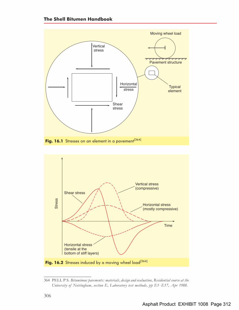
Fig. 16.1 Stresses on an element in a pavement[364]
Fig. 16.2 Stresses induced by a moving wheel load[364]
364 PELL P S. Bituminous pavements: materials, design and evaluation, Residential course at theUniversity of Nottingham, section E, Laboratory test methods, pp E1–E17, Apr 1988.
The Shell Bitumen Handbook
306
Asphalt Product EXHIBIT 1008 Page 312

(1) Fundamental:. repeated load triaxial test. unconfined static uniaxial creep compression test. repeated load indirect tensile test. dynamic stiffness and fatigue tests.
(2) Simulative:. wheel-tracking test. gyratory compactor. durability testing.
(3) Empirical:. Marshall test.
16.1 Fundamental tests16.1.1 Repeated load triaxial testThis test most closely reproduces the stress conditions in a pavement. Itis extensively used in research to study permanent deformation as well asthe elastic properties of asphalt[366]. It has the advantage that bothvertical and horizontal stresses can be applied at the levels predicted inthe pavement, as shown in Fig. 16.3. Deformation monitoring devicesto measure vertical and horizontal strains induced by the imposed stressesare mounted on the specimens. In view of the complex nature of the
Fig. 16.3 The repeated load triaxial test[365]
365 PELL P S. Bituminous pavements: materials, design and evaluation, Residential course at theUniversity of Nottingham, section E, Laboratory test methods, pp E1–E17, Apr 1988.
366 BROWN S F and K E COOPER. The mechanical properties of bituminous materials forroad bases and basecourses, Proc Assoc Asph Pav Tech, vol 53, pp 415–437, 1984. Asso-ciation of Asphalt Paving Technologists, Seattle.
Testing of asphalts
307
Asphalt Product EXHIBIT 1008 Page 313

apparatus and testing procedures, this type of test is only suitable forresearch investigations, although it is the subject of a draft Europeantest method.
16.1.2 Unconfined static uniaxial creep compression testingThe use of a static unconfined uniaxial compression test, termed the‘creep test’, for assessing the permanent deformation resistance of asphaltwas developed in the 1970s by Shell[367]. This test gained wide acceptancedue to the ease of specimen preparation, the simplicity of the testprocedure and the low cost of test equipment. The only requirementsfor the test specimen are that it should be prismatic with flat and parallelends normal to the axis of the specimen while the test procedure com-prises the application of a constant stress to the specimen for one hourat a constant temperature and measurement of the resultant deformation.The test equipment was, therefore, very simple and early versions of theequipment generally applied the load as a dead weight via a mechanicallever arm[368].Shell developed a rut prediction procedure based on the creep test but
it was found that the method underestimated rut depths measured in trialpavements[369]. This was attributed to the effects of dynamic loadingproducing higher deformations in the wheel-tracking tests[370]. Anexperimentally derived empirical correction factor that varied accordingto mixture type was, therefore, subsequently introduced into the creepanalysis to account for these effects.In 1983 Finn et al.[371], in an assessment of the creep test and analysis
procedures during investigations of pavement rutting, recommendedthat consideration be given to the development of a repeated load test.The development of plastic strains in the skeleton of an aggregate con-tributes significantly to permanent deformation. The effect of this formof loading in inducing plastic strains had already been recognised by
367 HILLS J F. The creep of asphalt mixes, J Inst Pet, vol 59, no 570, pp 247–262. Nov1973. Institute of Petroleum, London.
368 DE HILSTER E and P J VAN DE LOO. The creep test: influence of test parameters,Proc. Colloquium 77 Plastic deformability of bituminous mixes, pp 173–215, Institut furStrassen, Eisenbahn und Felsbau an der Eidgenossischen Technischen Hochschule, 1977.Zurich.
369 HILLS J F, D BRIEN and P J VAN DE LOO. The correlation of creep and rutting,Paper IP 74-001, 1974. Institute of Petroleum, London.
370 VANDE LOO P J. Creep testing, a simple tool to judge asphalt mix stability, Proc AssocAsph Pav Tech, vol 43, pp 253–284, 1974. Association of Asphalt Paving Technol-ogists, Seattle.
371 FINN F N, C L MONISMITH and N J MARKEVICH. Pavement performance andasphalt concrete mix design, Proc Assoc Asph Pav Tech, vol 52, pp 121–150, 1983.Association of Asphalt Paving Technologists, Seattle.
The Shell Bitumen Handbook
308
Asphalt Product EXHIBIT 1008 Page 314

Goetz et al.[372] who had developed an early version of a rapid cyclerepeated load test by 1957. Further concerns over the use of static loadinghave arisen more recently. Evidence suggests that static loading does notreflect the improved performance of binder modifiers that enhance theelastic recovery properties of an asphalt whereas, in contrast, this canbe demonstrated under repeated loading[373].Triaxial testing on asphalt has shown that the application of a confining
pressure has a significant positive effect on the permanent deformationperformance of axially loaded specimens[372,374,375]. Results of repeatedload (sinusoidal) triaxial tests on various mixtures[376] suggest that theuse of confinement is more beneficial for continuously graded materialsthat rely on the aggregate interlock load transfer mechanism. Morerecent work in France[377] on gussasphalt, porous asphalt and asphalticconcrete also indicates that confinement is very important for mixturetypes whose resistance to deformation comes from the aggregate skeletonbut less so, if at all, for those whose deformation resistance is based on thestiffness of the binder/filler mortar.The use of a triaxial cell necessarily makes test equipment more
expensive and test procedures more complex. However, it is consideredthat the facility to confine specimens during testing is important if anaxial test is to gain acceptance and be used. This is particularly so asaxial testing is being advanced for adoption in European Standards[377].This has led to the development of a simple system for applying a partialvacuum through the use of latex membrane. This is termed the vacuumrepeated load axial test (VRLAT) and is described in detail below.
372 GOETZ, W H, J F MCLAUGHLIN and L EWOOD. Load–deformation character-istics of bituminous mixtures under various conditions of loading, Proc Assoc Asph Pav Tech,vol 26, pp 237–296, 1957. Association of Asphalt Paving Technologists, Seattle.
373 VALKERING, C P, D J L LANCON, E DE HILSTER and D A STOKER.Rutting resistance of asphalt mixes containing non-conventional and polymer modified binders,Proc Assoc Asph Pav Tech, vol 59, pp 590–609, 1990. Association of Asphalt PavingTechnologists, Seattle.
374 MONISMITH C L and A A TAYEBALI. Permanent deformation (rutting) considera-tions in asphalt concrete pavement sections, Proc Assoc Asph Pav Tech, vol 57, pp 414–463,1988. Association of Asphalt Paving Technologists, Seattle.
375 BROWN S F and M S SNAITH. The permanent deformation characteristics of adense bitumen macadam subjected to repeated loading, Proc Assoc Asph Pav Tech, vol 43,pp 224–252, 1974. Association of Asphalt Paving Technologists, Seattle.
376 BROWN S F and K E COOPER. The mechanical properties of bituminous materials forroad bases and basecourses, Proc Assoc Asph Pav Tech, vol 53, pp 415–437, 1984.Association of Asphalt Paving Technologists, Seattle.
377 BONNOT J.Discussion paper on uniaxial and triaxial repeated load testing of bituminousmixtures, Paper presented to CEN Committee TC227 (WG1 TG2 – Test Methods),Vienna, 1994.
Testing of asphalts
309
Asphalt Product EXHIBIT 1008 Page 315

Uniaxial creepThe uniaxial creep (UC) test (Figs. 16.3 and 16.4) is the simplest method ofassessing the resistance to permanent deformation. Specimens up to200mm long are normally tested with axial stresses of up to 500 kPa on a100mm diameter specimen. An optional pre-test conditioning period(0 to 60 minutes) is followed by a test period of up to 10 000 s. There isalso the option for a post-test relaxation period (10 to 100 minutes). Testdata is stored automatically and can be printed out if required. Duringthe test, the relationship between axial strain and elapsed time is normallyplotted on the computer screen. Typical results are shown in Fig. 16.5.This method is described in a British Standard[378].
Fig. 16.4 Uniaxial creep test and RLAT
378 BRITISH STANDARDS INSTITUTION. Sampling and examination of bituminousmixtures for roads and other paved areas, Method for determination of resistance to deforma-tion of bituminous mixtures subject to unconfined uniaxial loading, BS 598-111: 1995. BSI,London.
The Shell Bitumen Handbook
310
Asphalt Product EXHIBIT 1008 Page 316

Standard test conditions and requirements for the UC test are:
conditioning stress 10 kPaconditioning period 600 stest stress 100 kPatest duration 3600 stest temperature 30 or 408C
Repeated load axial testThe repeated load axial test (RLAT) is increasingly used in preference tothe UC test as the pulsed load is more simulative of traffic loading. Thespecimen is subjected to repeated load pulses of 1 s duration separated by1 s duration rest periods (up to 10 000 pulses). An optional pre-testconditioning period (selectable 0 to 60 minutes) is available. As withthe creep test, test data are automatically stored and can be printedout, if required. During the test, the relationship between axial strainand number of load pulses is plotted on the computer screen. How thetest is set up is as shown in Fig. 16.4 and typical results are shown inFig. 16.6. This test method is currently being developed[379].
Fig. 16.5 Typical uniaxial creep test result
379 BRITISH STANDARDS INSTITUTION. Method for determining resistance to per-manent deformation of bituminous mixtures subject to unconfined dynamic loading, DD 226:1996. BSI, London.
Testing of asphalts
311
Asphalt Product EXHIBIT 1008 Page 317

Standard test conditions and requirements for the RLAT are:
conditioning stress 10 kPaconditioning period 600 stest stress 100 kPatest duration 1800 cyclestest cycle square wave pulse 1 s on, 1 s offtest temperature 30 or 408C
In the vacuum repeated load axial test (VRLAT), the specimen isevacuated through one of the loading platens (via a porous stone orslots machined into the platen). The loading platen is ported throughits body to a vacuum pump. The latex sealing membrane, of the typeused in triaxial testing of soils, is fitted over the specimen and both theupper and lower platens. It is then secured using rubber ‘O’ rings thatlocate in a groove machined around the circumference of each platenin the plane of the surface of the platen. This configuration is shownin Fig. 16.7.The test conditions are the same as those used for the RLAT and the
confining pressure is, at present, the subject of investigation at TRL Ltd.
16.1.3 Repeated load indirect tensile testsVarious methods have been employed to measure the stiffness of anasphalt. Conventional techniques have principally included uniaxial and
Fig. 16.6 Typical repeated load axial test result
The Shell Bitumen Handbook
312
Asphalt Product EXHIBIT 1008 Page 318

triaxial compression and/or tension tests and flexural beam tests. However,in the late 1960s, Hudson and Kennedy[380] developed an indirect tensiontest based on the Brazilian splitting test[381] that is used to measure thetensile strength of concrete. In the early 1980s, the test was accepted as astandard method by the American Society for Testing and Materials[382].Cooper and Brown[383] introduced the method to the UK with the devel-opment of the Nottingham Asphalt Tester (NAT) which has subsequentlygained widespread use in much of Europe and has formed the basis of anumber of British Standards.This section presents a brief overview of the theory supporting the
indirect tensile test for asphalt.
Fig. 16.7 Vacuum repeated load axial test
380 HUDSONWR and TWKENNEDY.An indirect tensile test for stabilized materials,Research Report 98-1, Center for Highway Research, January 1968. University of Texas,Austin.
381 CARNIERO F L L B and A BARCELLUS. RILEM Bulletin, no 13, 1953.382 AMERICAN SOCIETY for TESTING and MATERIALS. Standard test method
for indirect tension test for resilient modulus of bituminous mixtures, D4123-82, 1 Jan1982. ASTM, Philadelphia.
383 COOPER K E and S F BROWN. Development of a simple apparatus for the measure-ment of the mechanical properties of asphalt mixes, Proceedings, Eurobitume Symp, pp 494–498, Madrid, Spain, 1989.
Testing of asphalts
313
Asphalt Product EXHIBIT 1008 Page 319

A repeated line loading is applied across the vertical diameter of acylindrical specimen as shown in Fig. 16.8. This vertical loading pro-duces both a vertical compressive stress and a horizontal tensile stresson diameters of the specimen. The magnitudes of the stresses varyalong the diameters as shown in Fig. 16.8 but are at a maximum in thecentre of the specimen.The situation, as depicted in Fig. 16.8, enables the calculation of strain
but depends on the following assumptions.
. The specimen is subjected to plane stress conditions (�z ¼ 0).
. The material behaves in a linear elastic manner.
. The material is homogeneous.
. The material behaves in an isotropic manner.
. Poisson’s ratio (�) for the material is known.
. The force (P) is applied as a line loading.
When all of these conditions are met, or assumed, then the stressconditions in the specimen are given by the closed form solution ofthe theory of elasticity, that has been derived by various authorities inthe field of stress analysis[384–387]. These theories all show that when
Fig. 16.8 Stress distribution in the indirect tensile mode of test
384 TIMOSHENKO S. Theory of Elasticity, pp 104–108, 1934. McGraw Hill, NewYork.
385 FROCHT M M. Photoelasticity, vol 2, pp 121–129, 1948. John Wiley, New York386 MUSKHELISHVILI N I. Some basic problems of the mathematical theory of elasticity,
pp 324–328, 1953. P Noordhoff, Groningen.387 SOKOLNIKOFF I S. Mathematical theory of elasticity, pp 280–284, 1956. McGraw
Hill, New York.
The Shell Bitumen Handbook
314
Asphalt Product EXHIBIT 1008 Page 320

the width of the loading strip is less than or equal to 10% of the diameterof the specimen and the distance of the element of material from thecentre is very small then:
�xmax ¼2P
�dtð1Þ
�ymax ¼ � 6P
�dtð2Þ
where P ¼ applied vertical force (in N), d ¼ diameter of the specimen(in m), t ¼ thickness of the specimen (in m), � ¼ Poisson’s ratio, Sm ¼stiffness modulus of the specimen (in Pa), �xmax ¼ maximum horizontaltensile stress at the centre of the specimen (in N/m2), �ymax ¼ maximumvertical compressive stress at the centre of the specimen (in N/m2) and"xmax ¼ maximum initial horizontal tensile strain at the centre of thespecimen.As the analysis of the indirect tensile test, for calculation of the strain,
is concerned with an element of material at the centre of the specimen,Equations (1) and (2) hold true.By simple linear elastic stress analysis (Hooke’s law):
"xmax ¼�xmax
Sm� ��ymax
Smð3Þ
where Sm is the stiffness modulus (in Pa).Substituting Equations (1) and (2) into Equation (3) gives:
"xmax ¼2P
�dtSmþ �6P
�dtSmð4Þ
Substituting Equation (1) into Equation (4) gives:
"xmax ¼�xmax
Smð1þ 3�Þ ð5Þ
Equation (5) is then used for the calculation of the maximum tensilestrain ("xmax).Hadley et al.[388] and Anagnos and Kennedy[389] developed equations
that permit the calculation of the tensile strength, tensile strain, modulusof elasticity and Poisson’s ratio for a homogeneous, isotropic, linearelastic cylinder subjected to a diametrically applied static ‘line’ load.The equations were extended to allow calculation of the ‘instantaneous
388 HADLEY W O, W R HUDSON and T W KENNEDY. A method of estimatingtensile properties of materials tested in indirect tension, Research Report 98-7, Center forHighway Research, Jul 1970. The University of Texas, Austin.
389 ANAGNOS J N and T W KENNEDY. Practical method of conducting the indirecttensile test, Research report, Center for Highway Research, Aug 1972. The Universityof Texas, Austin.
Testing of asphalts
315
Asphalt Product EXHIBIT 1008 Page 321

resilient Poisson’s ratio’ and the ‘instantaneous resilient modulus ofelasticity’ for a cylinder subjected to repeated loading as follows:
� ¼�v�h
c1 þ c2
�v�h
c3 þ c4
ð6Þ
where � ¼ instantaneous resilient Poisson’s ratio, �v ¼ instantaneousresilient (elastic) vertical deformation (in m), �h ¼ instantaneous resilient(elastic) horizontal deformation (in m) and c1, c2, c3 and c4 ¼ constantsdepending on the specimen diameter and loading strip width and
ER ¼ Pðc5 � �c6Þ�ht
ð7Þ
where ER ¼ instantaneous resilient modulus of elasticity (in Pa),P ¼ applied load (in N), � ¼ instantaneous resilient Poisson’s ratio,�h ¼ instantaneous resilient (elastic) horizontal deformation (in m),t ¼ thickness (height) of specimen (in m) and c5 and c6 ¼ constantsdependent on the specimen diameter and loading strip width.Calculation of the above elastic properties for an asphalt requires
measurement of the load and elastic (recoverable) deformations. Intheory, determination of the load and deformations appears to be quitesimple and straightforward. However, in practice, this may not be thecase. The difficulty lies in determination of the inflection point on theunloading section of the deformation curves, which may not be readilydiscernible, or could be virtually non-existent, depending on thefrequency and duration of the load, test temperature, material type, etc.Therefore, it could be reasoned that the indirect tensile test is not areliable method for the determination of the modulus of elasticity of anasphalt. As a result, the theory has been adapted to allow measurementof the load and total instantaneous horizontal deformation. The verticaldeformation is not measured so a value of Poisson’s ratio has to beassumed. As the deformation consists of both the elastic (recoverable)and viscous (time-dependent) components, a resilient modulus ofelasticity cannot be calculated. Instead, a stiffness modulus is calculatedas follows:
Sm ¼ Pðc5 � �c6Þ�ht
ð8Þ
where Sm ¼ stiffness modulus, resilient modulus or total modulus (inPa), P ¼ applied repeated load (in N), � ¼ resilient Poisson’s ratio,�h ¼ resilient total horizontal deformation (in m), t ¼ thickness(height) of specimen (in m), c5 and c6 ¼ constants dependent on the
The Shell Bitumen Handbook
316
Asphalt Product EXHIBIT 1008 Page 322

specimen diameter and loading strip width. For example, for a 101.6mmdiameter specimen and a 12.7mm loading strip width, c5 ¼ 0:2692 andc6 ¼ �0:9974.
Indirect tensile stiffness modulusThe indirect tensile stiffness modulus (ITSM) test, defined in DD 213[390],is the most commonly used test method in the NAT (Fig. 16.9) and isused for the determination of the stiffness modulus of a specimen. Thetest is simple and can be completed quickly. The operator selects thetarget horizontal deformation and a target load pulse rise time (timefrom start of load application to peak load). The force applied to thespecimen is then automatically calculated by the computer and anumber of conditioning pulses are applied to the specimen. Theseconditioning pulses are used to make any minor adjustments to themagnitude of the force needed to generate the specified horizontal
Fig. 16.9 Indirect tensile stiffness modulus test
390 BRITISH STANDARDS INSTITUTION. Method for determination of the indirecttensile stiffness modulus of bituminous mixtures, DD 213: 1993. BSI, London.
Testing of asphalts
317
Asphalt Product EXHIBIT 1008 Page 323

deformation and to seat the loading strips correctly on the specimen.Once the conditioning pulses have been completed, the system appliesfive load pulses. This generates an indirect movement on the horizontaldiameter and, since the diameter of the specimen is known beforehand,the strain can be calculated. As the cross-sectional area of the specimenis also known and the force applied is measured, the applied stress canbe calculated. Thus, since the stress and the strain are now known, thestiffness modulus of the material can be calculated. A typical test resultis shown in Fig. 16.10.Standard test conditions and requirements for the ITSM test are:
horizontal strain 0.005% of the specimen diameterrise time 124ms – equivalent to a frequency of 1.33Hzspecimen diameter 100mm, 150mm and 200mmspecimen thickness between 30mm and 70mmtest temperature 208C
Resilient modulusThe resilient modulus (RESMOD) test, defined in an ASTM publica-tion[391], details how instantaneous and total Poisson’s ratio and modulus
Fig. 16.10 Typical indirect tensile stiffness modulus test result
391 AMERICAN SOCIETY for TESTING and MATERIALS. Standard test methodfor indirect tension test for resilient modulus of bituminous mixtures, D4123-82, 1 Jan1982. ASTM, Philadelphia.
The Shell Bitumen Handbook
318
Asphalt Product EXHIBIT 1008 Page 324

may be calculated from the recovered vertical and horizontal deformations.In the NAT, two vertical and two horizontal deformation transducers areused for the RESMOD test. To the operator, the software appears to bevery similar to that used in the ITSM test but a comprehensive data acqui-sition routine is employed with five test pulses continuously scanned overa period of 12 s. The software then analyses each test pulse, calculatingPoisson’s ratio and stiffness modulus for loading, instantaneous recoveryand total recovery.
16.1.4 Dynamic stiffness and fatigue testsFor the measurement of the dynamic stiffness and fatigue characteristicsof asphalt, researchers have developed a number of tests that areillustrated diagrammatically in Fig. 16.11. Bending tests using beamsor cantilevers involving repeated applications of load have been usedto determine both dynamic stiffness and fatigue resistance[392–395]. Inbending tests, the maximum stress occurs at a point on the surface ofthe specimen and its calculation, using the standard beam bendingformula, depends on the assumption of linear elasticity.In the USA, a repeated load uniaxial test involving only compressive
stresses has been adopted by ASTM as a standard method[396] for evalu-ating the dynamic stiffness or ‘resilient modulus’ of asphalt.Figure 16.12 shows a three-point bending test where a beam of asphalt
200mm long by 40mm wide by 30mm deep is held at its ends and themid-point is vibrated at relatively low strains or deflections. By measur-ing the force required to achieve the level of strain, the dynamic stiffnessof the material can be calculated using the following standard beambending formula:
� ¼ WL3
48EI! E ¼ WL3
48�I
392 BROWN S F. Practical mechanical tests for the design and control of asphaltic mixes,RILEM 3rd Int Symp on the testing of hydrocarbon binders and materials, Belgrade, 1983.
393 MONISMITH C L, J A EPPS and F N FINN. Improved asphalt mix design, ProcAssoc Asph Pav Tech, vol 54, pp 347–391, 1985. Association of Asphalt PavingTechnologists, Seattle.
394 BONNAURE F, G GEST, A GRAVOIS and P A UGE.A new method of predictingthe stiffness of asphalt paving mixtures, Proc Assoc Asph Pav Tech, vol 46, pp 64–104,1977. Association of Asphalt Paving Technologists, Seattle.
395 COOPER K E and P S PELL. The effect of mix variables on the fatigue strength ofbituminous materials, Laboratory Report 633, 1974. Transport and Road ResearchLaboratory, Crowthorne.
396 AMERICAN SOCIETY FOR TESTING and MATERIALS. Standard test methodfor indirect tension test for resilient modulus of bituminous mixtures, D4123-82, 19 Jan1982. ASTM, Philadelphia.
Testing of asphalts
319
Asphalt Product EXHIBIT 1008 Page 325

where E ¼ dynamic stiffness, L ¼ length of beam, � ¼ deflection, I ¼second moment of area ¼ bd3=12 (b ¼ breadth, d ¼ depthÞ and W ¼applied load.Most laboratory fatigue tests are carried out under uniaxial conditions,
either bending or direct loading[397,398]. Fatigue tests are carried out byapplying a load to a specimen in the form of an alternating stress orstrain and determining the number of load applications required toinduce ‘failure’ of the specimen. ‘Failure’ is an arbitrary end point, notwhere the sample literally fails. In a constant strain test, the sample isusually deemed to have ‘failed’ when the load required to maintain thatlevel of strain has fallen to 50% of its initial value. Because of the scatterof test results associated with fatigue testing, it is normal to test severalspecimens at each stress or strain level and the results are plotted as stressor strain against cycles to failure on a log–log graph as shown in Fig.16.13[398].
Fig. 16.11 Tests for measuring dynamic stiffness and fatigue
397 PELL P S. Characterization of fatigue behaviour, Special Report 140, pp 49-64, 1973.Transportation Research Board, Washington.
398 READ J M. Fatigue cracking of bituminous paving mixtures, PhD Thesis, University ofNottingham, 1996.
The Shell Bitumen Handbook
320
Asphalt Product EXHIBIT 1008 Page 326

Fig. 16.12 The three-point bending test
Fig. 16.13 Typical indirect tensile fatigue test results
Testing of asphalts
321
Asphalt Product EXHIBIT 1008 Page 327

Indirect tensile fatigue testThe indirect tensile fatigue test (ITFT) uses a repeated controlled stresspulse to damage the specimen and the accumulation of vertical deforma-tion against number of load pulses is plotted. As with other indirecttensile tests the duration of the load pulse and also the magnitude ofthe stress is specified by the operator, however, this test is presentlybeing considered by a British Standard committee. The first draft testmethod was published in 1996[399] and is currently being revised. Atypical set of results is shown in Fig. 16.13. A schematic of the test isshown in Fig. 16.14.Standard test conditions and requirements for the ITFT are:
stress level between 50 and 600 kPa (determined by the user)target rise time 120ms – equivalent to a frequency of 1.33Hzfailure criterion 9mm vertical deformationtest temperature 208C
16.2 Simulative testsAs the stress conditions in a pavement loaded by a rolling wheel areextremely complex and cannot be replicated in a laboratory test on asample of asphalt with any precision, simulative tests have been usedto compare the performance of different materials.
Fig. 16.14 Schematic of the indirect tensile fatigue test
399 BRITISH STANDARDS INSTITUTION.Method for the determination of the fatiguecharacteristics of bituminous mixtures using indirect tensile fatigue, Draft for DevelopmentABF, 1996. BSI, London.
The Shell Bitumen Handbook
322
Asphalt Product EXHIBIT 1008 Page 328

16.2.1 Wheel-tracking testsThe equipment ranges from large full-scale pavement test facilities such asthose at the TRL[400] and the Laboratoire Central des Ponts et Chaussees(LCPC) Test Track at Nantes or the mid-scale pavement test facility atthe University of Nottingham[401] to the smaller laboratory-scale wheel-tracking test (see Fig. 16.15). Full-scale and mid-scale facilities can beused to test entire pavement structures whereas laboratories can evaluatethe resistance of asphalt to permanent deformation[402]. In the UK, thelaboratory-scale test is usually carried out at either 458C or 608C, thewheel applying a load of 520N to the surface of the sample. The perfor-mance of the material is assessed by measuring the resultant rut depthafter a given number of passes or rate of tracking (in millimetres perhour). Work carried out by the TRL has shown that a good correlationexists between permanent deformation on open stretches of road and theperformance in the laboratory-scale wheel-tracking test[403].
Fig. 16.15 UK wheel-tracking apparatus
400 OECD. Full-scale pavement tests: report by the OECD Scientific Expert Group, Paris,1985. OECD Scientific Expert Group, Paris.
401 BROWN S F and B V BRODRICK.Nottingham pavement test facility, TransportationResearch Record 810, 1981, pp 67- 72. Transportation Research Board, Philadelphia.
402 ROAD RESEARCH LABORATORY. The wheel-tracking test, Leaflet LF 50, Issue2, 1971. RRL, Crowthorne.
403 SZATKOWSKI W S and F A JACOBS. Dense wearing courses in Britain with highresistance to deformation, Proc Int Symp on plastic deformability of bituminous mixes,pp 63–76, Zurich, 1977.
Testing of asphalts
323
Asphalt Product EXHIBIT 1008 Page 329

The method for the determination of the wheel-tracking rate in coresof asphalt surface courses was developed at the TRL. The equipment wasoriginally devised for testing 305mm square by 50mm deep slabsmanufactured using a laboratory roller compactor. This method hasnow been adapted for testing 200mm diameter cores cut from thecarriageway and is the subject of a full British Standard[404].The wheel-tracking test is normally carried out on surface courses
although there is no reason why other layers cannot be tested. Cores ofdiameter 200mm are cut and the surface course is separated from theunderlying material, by sawing if necessary. When dealing with a chippedsurface course such as hot rolled asphalt, the material is tracked on theunderside.Standard test conditions and requirements for the UK wheel-tracking
test are as follows:
Tyre The tyre should have an outside diameter between200 and 205mm. The tyre should be of rectangularsection 50� 1mm, treadless and 10 to 13mmthick. It should be made of solid rubber with ahardness number of 80 IRHD units.
Wheel load The wheel load should be 520� 5N.Test temperature The test temperature should be 45 or 608C.Test duration The test is continued until a rut depth of 15mm is
achieved or for 45 minutes, whichever is thesooner.
Results The vertical displacement of the loaded wheel isplotted against time. The mean rate of ruttingduring the last third of the test is determined andexpressed in mm/hour to the nearest 0.1mm/hour.
However, the conditions for such tests vary from country to country.The UK method[404] is not applicable to laboratory-prepared and com-pacted specimens for compliance testing although some other countriespermit such testing.Clearly, the method used to prepare and compact specimens will have a
significant effect on the test results. Typical test conditions are, for example,set out in a German procedure called the Hamburg wheel-tracking test[405].
404 BRITISH STANDARDS INSTITUTION. Sampling and examination of bituminousmixtures for roads and other paved areas, Method of test for the determination of wheel-tracking rate and depth, BS 598-110: 1998. BSI, London.
405 FORSCHUNGSGESELLSCHAFT FUR STRAßEN- UND VERKEHRSWE-SEN. Technische Prufvorschriften fur Asphalt im Straßenbau (TP A-StB), 1997.FGSV, Cologne, Germany.
The Shell Bitumen Handbook
324
Asphalt Product EXHIBIT 1008 Page 330

Either laboratory-produced test specimens (320mm� 260mm) or largecores (diameter>300mm)may be used for the test. A steel wheel (diameter203.5mm, breadth 47mm) passes the asphalt slab under water at 508C. Theload is 700N, the wheel pass distance is 230mm and the frequency is53 cycles/min. After 20 000 passes, the test is halted. The deformationcurve (rut depth) during the test is recorded. The test is carried outsimultaneously with two asphalt slabs.Provided that the mixture design of the asphalt is stable, the deformation
of the specimen generally correlates with the viscosity of the binder. In thecase of polymer modified bitumens, the zero shear viscosity of the bindergives a good correlation with rutting behaviour. However, stripping of thebinder can also lead to failure in wheel-tracking testing carried out in thepresence of water.
16.2.2 Gyratory compactionThis tool (Fig. 16.16) is a routine test for mixture design in France andthe USA and is becoming standard in the rest of Europe. The test
Fig. 16.16 Gyratory compactor
Testing of asphalts
325
Asphalt Product EXHIBIT 1008 Page 331

itself consists of placing a sample of hot asphalt in a mould and applying astatic pressure of a controlled magnitude. The mould is then gyratedthrough a small angle in order to allow the aggregate particles to re-orientate themselves under the loading. A schematic diagram of thegyratory motion is shown in Fig. 16.17. This method is considered tosimulate, to a reasonable degree, compaction that actually takes placein service.The gyratory compactor also allows a measure of the compactability of
a mixture to be assessed by monitoring the vertical movement of theloading ram and the number of gyrations of the mould. Hence, if onemixture takes fewer gyrations in comparison to another mixture forthe same vertical movement of the loading ram then the former wouldbe said to be more easily compacted.Standard test conditions and requirements for the gyratory compactor
are:
stress level 600 kPaangle of gyration 1.258speed of gyration 30 revs/min
Additionally, slab compaction is becoming more widespread and aphotograph for reference purposes is given as Fig. 16.18.
Fig. 16.17 Schematic diagram of gyratory motion
The Shell Bitumen Handbook
326
Asphalt Product EXHIBIT 1008 Page 332

16.2.3 Durability testingIn order to develop tests to characterise durability, an appropriate defini-tion has to be established. Scholz[406] suggested the following.
Durability as it applies to bituminous paving mixtures is defined asthe ability of the materials comprising the mixture to resist theeffects of water, ageing and temperature variations, in the contextof a given amount of traffic loading, without significant deteriora-tion for an extended period.
This definition, therefore, implies the need to be able to artificially agematerials in order to assess the effects on the mechanical properties. Inaddition, there is also the need to be able to simulate the effect of waterdamage on the specimens. Many attempts have been made to establishmethods that do one or other of these but none has been widely adoptedand Bell[407] stated that ‘Compared to research on asphalt cement, there hasbeen little research on the ageing of asphalt mixtures, and, to date, there is
Fig. 16.18 Slab compactor
406 SCHOLZ T V. Durability of bituminous paving mixtures, PhD thesis, University ofNottingham, 1995.
407 BELL C A. Summary report on aging of asphalt-aggregate systems, SHRP-A/IR-89-004,Strategic Highway Research Program, 1989. National Research Council, WashingtonD C.
Testing of asphalts
327
Asphalt Product EXHIBIT 1008 Page 333

no standard test’. With this in mind, the LINK Bitutest project[408] under-took to establish standard methods for simulating the ageing that occurs inan asphalt subsequent to compaction and for assessing the water sensitivityof asphalts. This research culminated in a series of Standards[408] beingwritten that addressed the issue of durability. In essence, durability isdealt with by two procedures.
(1) Standard practice for long-term oven ageing of compactedasphalts. This standard practice is used to simulate the long-term ageing of compacted asphalt. Long-term ageing considersthe hardening of the bitumen in the mixture subsequent to con-struction. The practice should result in ageing that is representa-tive of 5 to 10 years in service for dense, continuously gradedmixtures.
(2) Test method for measurement of the water sensitivity of com-pacted asphalts. This test method determines the water sensitiv-ity of compacted asphalt under warm and cold climatic conditions.This method is applicable to laboratory-moulded specimens andcore specimens obtained from existing roads.
The first procedure defines a method that allows a specimen to beartificially aged. This permits the properties of the specimen to beassessed before and after ageing in order to determine any changes.The second procedure is a stand-alone method in which the stiffnessmodulus of a specimen is measured after which it is vacuum saturatedin water. The specimen is then subjected to thermal cycles of 608C(6 hours) and 58C (16 hours) with the stiffness modulus being measuredbetween each complete cycle of hot and cold. This permits the calculationof a ratio that gives an indication of the water sensitivity of the asphalt.The lower the ratio, the more sensitive is the asphalt to the effects ofwater.These protocols are now gaining widespread use in the UK, particularly
as they form the backbone of the durability testing in the BBA/HAPAS(British Board of Agrement/Highway Authorities Product ApprovalScheme) for thin surfacings[409].
408 BROWN S F, J M GIBB, J M READ, T V SCHOLZ and K E COOPER. Designand testing of bituminous mixtures, vol 3, Experimental procedures, Report to DOT/EPSRC LINK programme on transport infrastructure and operations, Jan 1995. Univer-sity of Nottingham.
409 BRITISH BOARD OF AGREMENT. Guidelines document for the assessment andcertification of thin surfacing systems for highways, SG3/00/173, SG3, 2000. BBA/HAPAS, Watford.
The Shell Bitumen Handbook
328
Asphalt Product EXHIBIT 1008 Page 334

16.3 Empirical tests
The current UK empirical pavement design procedure specifies threetests for the evaluation of the mechanical properties of pavementmaterials. These are the Marshall test, the California bearing ratio(CBR) test (discussed in Section 18.4.3), which is used for soils andunbound granular material, and the uniaxial compression test, which isused for the determination of the crushing strength of cement boundmaterials[410].The Marshall and CBR tests are carried out to failure under continuous
loading. In both cases, the complex stress system set up in the material isquite unrelated to the actual pavement condition in situ under trafficloading. Neither of these two tests provides basic information on thestress–strain characteristics of the material because each has its originin an empirical method – mixture design as far as the Marshall test isconcerned, and pavement thickness in the case of the CBR test.
16.3.1 The Marshall testThe concepts of the Marshall test were developed by Bruce Marshall,formerly Bituminous Engineer with the Mississippi State HighwayDepartment. In 1948, the US Corps of Engineers improved and addedcertain features to Marshall’s test procedure and ultimately developedmixture design criteria[411]. Since 1948, the test has been adopted byorganisations and government departments in many countries, some-times with modifications either to the procedure or to the interpretationof the results. Asphaltic concrete mixtures for airfield runways and taxi-ways have been designed using the Marshall test for the last 20 years andthe option to design the mortar fraction of hot rolled asphalt was firstpublished in BS 594: 1973[412]. This was extended to an option fordesigning the entire mixture in BS 598-3: 1985[413].The Marshall test entails the manufacture of cylindrical specimens
102mm in diameter� 64mm high using a standard compactionhammer (see Fig. 16.19) and a cylindrical mould. The specimens aretested for their resistance to deformation at 608C at a constant rate of50mm/min. The jaws of the loading rig confine the majority but not
410 BRITISH STANDARDS INSTITUTION. Testing concrete, Method for determina-tion of compressive strength of concrete cubes, BS 1881-116: 1985. BSI, London.
411 ASPHALT INSTITUTE. Mix design methods for asphalt concrete and other hot-mixtypes, Manual series no 2 (MS-2), 1988. AI, Kentucky.
412 BRITISH STANDARDS INSTITUTION. Hot rolled asphalt for roads and otherpaved areas, BS 594: 1973. BSI, London.
413 BRITISH STANDARDS INSTITUTION. Sampling and examination of bituminousmixtures for roads and other paved areas, Methods for design and physical testing, BS 598-3:1985. BSI, London.
Testing of asphalts
329
Asphalt Product EXHIBIT 1008 Page 335

all of the circumference of the specimen, the top and bottom of thecylinder being unconfined. Thus, the stress distribution in the specimenduring testing is extremely complex. Two properties are determined: themaximum load carried by the specimen before failure (‘Marshallstability’) and the amount of deformation of the specimen before failureoccurred (‘Marshall flow’). The ratio of stability to flow is known as the‘Marshall quotient’.Although the Marshall test is very widely used, it is important to
recognise its limitations. Research at the University of Nottingham[414]
compared the mechanical properties of various mixtures, using repeatedload triaxial tests, triaxial creep tests, uniaxial unconfined creep tests andMarshall tests. The result of this work, shown in Fig. 16.20, suggests that
Fig. 16.19 Impact compactor
414 BROWN S F, K E COOPER and GR POOLEY.Mechanical properties of bituminousmaterials for pavement design, Proc Eurobitume Symp, Cannes, France, pp 143–147, 1981.Reprinted in a special publication of Asphalt Technology, Jan 1982. Institute of AsphaltTechnology, Dorking.
The Shell Bitumen Handbook
330
Asphalt Product EXHIBIT 1008 Page 336

Fig.16.20
Rank
ingof
mixture
stiffne
ssby
variou
stests[409] :(a)triaxial
cree
p,(b)un
confi
nedcree
pan
d(c)Marshall
Testing of asphalts
331
Asphalt Product EXHIBIT 1008 Page 337

the Marshall test is a poor measure of resistance to permanent deforma-tion and does not rank mixtures in order of their deformation resistance.Repeated load triaxial tests give more realistic results.
16.4 Determination of recovered bitumen propertiesIn addition to routine production control tests, there are a number ofprocedures available to assist highway engineers in the investigation ofunsatisfactory performance. One useful test is to recover the bitumenfrom the mixture and determine its properties, usually the penetrationand softening point.In this test, a sample of the asphalt is soaked in dichloromethane
(methylene chloride) to remove the bitumen from the aggregate intosolution. The bitumen/solvent solution is separated from the fine mineralmatter by filtration and centrifuging. The solvent is then evaporatedunder controlled conditions, using the apparatus shown in Fig. 16.21,ensuring that all of the solvent is removed without taking away any ofthe lighter components of the bitumen. When the recovery procedurehas been completed, the penetration and softening point of the recoveredbitumen can be determined using the standard tests. The method is
Fig. 16.21 Distillation apparatus used for recovery of bitumen[415]
415 BRITISH STANDARDS INSTITUTION. Sampling and examination of bituminousmixtures for roads and other paved areas, Method of recovery of soluble bitumen forexamination, BS 598-103: 1990. BSI, London.
The Shell Bitumen Handbook
332
Asphalt Product EXHIBIT 1008 Page 338

described in detail in BSEN12697-4: 2000[416]. Alternatively, the solventcan be removed using a rotary evaporator (Fig. 16.22), described inBSEN12697-3: 2000[417], which has the advantage that it removes thesolvent very rapidly from the solution.The precision for the BSEN12697-4: 2000[416] test method is as
follows.
. Repeatabilitypenetration 5 dmmsoftening point 2.58C
. Reproducibilitypenetration 0.19x1=2 dmmsoftening point 3.58C
where x is the mean of the two results.These precision values only apply to bitumens with a penetration up to
120 dmm although indications are that they would apply to bitumenswith a higher penetration value.
Fig. 16.22 Rotary evaporator
416 BRITISH STANDARDS INSTITUTION. Bituminous mixtures, Test methods forhot mix asphalt, Bitumen recovery: Fractionating column, BSEN 12697-4: 2000. BSI,London.
417 BRITISH STANDARDS INSTITUTION. Bituminous mixtures, Test methods forhot mix asphalt, Bitumen recovery: Rotary evaporator, BSEN 12697-3: 2000. BSI,London.
Testing of asphalts
333
Asphalt Product EXHIBIT 1008 Page 339

The Shell Bitumen Handbook
334
Asphalt Product EXHIBIT 1008 Page 340

Fig.16.23
Chrom
atog
raph
icplotsof
bitumen
(a)with
outd
iesela
nd(b)with
diesel
Testing of asphalts
335
Asphalt Product EXHIBIT 1008 Page 341

The test is very operator sensitive and deviation from the standardmethod will almost certainly result in misleading data[418]. For thesereasons, the test is not suitable for contractual purposes but is a veryuseful tool for investigating defects in service. With sensible interpretationof test results, the bitumen recovery method can be used to determine if thebitumen in the mixture is abnormally hard or soft.In addition to penetration and softening point determination, chromato-
graphic examination of the recovered bitumen can be useful to detect thepresence of any contaminants. Figures 16.23(a) and (b) show chromato-graphic plots, without and with the presence of diesel respectively,generated using a combination of gas chromatography and mass spectro-scopy. The presence of the contaminant is very clear. Identification,however, is less precise because diesel can weather losing lighter fractionsand the composition can change between summer and winter. Althoughthe technique is only qualitative and not quantitative, it is a useful toolfor examining recovered bitumens that are abnormally soft.
418 WADELIN F A.Workshop on binder recovery from asphalt and coated macadam, AsphaltTechnology, no 32, pp 28–42, Aug 1982. Institute of Asphalt Technology, Dorking.
The Shell Bitumen Handbook
336
Asphalt Product EXHIBIT 1008 Page 342

Chapter 17
Properties of asphalts
The analytical design of asphalt or flexible pavements involves considerationof two aspects of material properties. These are (i) the load–deformationor stress–strain characteristics used to analyse critical stresses and strainsin the structure and (ii) the performance characteristics of the materialsthat show the mode, or modes, of failure. The two principal structuraldistress modes are cracking and permanent deformation. The formerapplies to bound materials only in the pavement whilst the latter isvalid for all materials in the pavement, both bound and unbound.
17.1 Stiffness of asphaltsAs discussed previously, asphaltic mixtures behave visco-elastically, i.e.they respond to loading in both an elastic and viscous manner. Theproportion of each depends on the time of loading and on the tempera-ture at which the load was applied. The complexity of this behaviour isincreased by the heterogeneity of the mixture components, the bitumenbeing responsible for the visco-elastic properties whilst the mineralskeleton influences elastic and plastic properties. Mixture componentsand compositions can be extremely diverse, which makes prediction ofthe properties of a particular mixture difficult.Asphalt stiffness can be divided into elastic stiffness that occurs under
conditions of low temperatures or short loading times; and viscous stiff-ness that occurs at high temperatures or long loading times. The formeris used to calculate critical strains in the structure in analytical design.The latter is used to assess the resistance of the material to deformation.It has also been shown that, at intermediate temperatures where the stiff-ness has both an elastic and viscous component, the stiffness is stressdependent[419]. High stresses result in lower stiffness and low stresses
337
419 READ J M. Fatigue cracking of bituminous paving mixtures, PhD Thesis, University ofNottingham, 1996.
Asphalt Product EXHIBIT 1008 Page 343

result in higher stiffness making the assessment of performance evenmore difficult. However, this stress dependency is less importantcompared to the effects of both the time of loading and temperature.Stiffness at a particular temperature and time of loading can be meas-
ured by a variety of methods:
. bending or vibration tests on a beam specimen (see Section 16.1.4);
. direct uniaxial or triaxial tests on cylindrical specimens (see Section16.1.1);
. indirect tensile tests on cylindrical specimens (see Section 16.1.3).
Different types of loading can be used in the tests but for elastic stiffnessrelevant to moving traffic, sinusoidal or pseudo-sinusoidal repeatedloading at high frequency is most appropriate[420].
17.1.1 The prediction of asphalt stiffnessAsphalt stiffness can be measured quickly and easily using tests such asthe indirect tensile stiffness modulus[421] (ITSM) test. However, whentesting is not feasible, such as in the design office, then the stiffness ofa particular mixture at any temperature and time of loading can beestimated by empirical methods to an accuracy that is acceptable formost purposes.In 1977, Shell produced a nomograph (shown in Fig. 17.1) for predict-
ing the stiffness of an asphalt[422]. The data required for this nomographare:
. the stiffness modulus of the bitumen (in Pa)
. the percentage volume of bitumen
. the percentage volume of the mineral aggregate.
The University of Nottingham has also developed a method for calculat-ing mixture stiffness[423] and the data required are:
. the stiffness modulus of the bitumen (in Pa� 106)
. the voids in the mineral aggregate, VMA (%).
420 RAITHBY K D and A B STERLING. Some effects of loading history on the fatigueperformance of rolled asphalt, Laboratory Report 496, 1972. Transport and RoadResearch Laboratory, Crowthorne.
421 BRITISH STANDARDS INSTITUTION. Method for the determination of theindirect tensile stiffness modulus of bituminous mixtures, DD 213: 1993. BSI, London.
422 BONNAURE F, G GEST, A GRAVOIS and P A UGE.A new method of predictingthe stiffness of asphalt paving mixtures, Proc Assoc Asph Pav Tech, vol 46, pp 64–104,1977. Association of Asphalt Paving Technologists, Seattle.
423 BROWN S F and J M BRUNTON. An introduction to the analytical design ofbituminous pavements, 3rd ed, University of Nottingham, 1986.
The Shell Bitumen Handbook
338
Asphalt Product EXHIBIT 1008 Page 344

Fig. 17.1 Nomograph for predicting the stiffness modulus of asphalts[424]
424 BONNAURE F, G GEST, A GRAVOIS and P A UGE.A new method of predictingthe stiffness of asphalt paving mixtures, Proc Assoc Asph Pav Tech, vol 46, pp 64–104,1977. Association of Asphalt Paving Technologists, Seattle.
Properties of asphalts
339
Asphalt Product EXHIBIT 1008 Page 345

These two procedures can only be applied when the stiffness modulus ofthe bitumen exceeds 5MPa, i.e. under high-stiffness conditions appropriateto moving traffic where the response is predominantly elastic and, for theNottingham method, values of VMA between 12% and 30%. These twomethods assume that the grading, type and characteristics of the aggregateaffect only the elastic stiffness of the mixture since they influence thepacking characteristics of the aggregate and, thus, the state of compactionof the material.
17.2 Permanent deformation of asphalts
In order to determine the permanent deformation characteristics of anasphalt, the low-stiffness response of the material, i.e. its response athigh temperature or long loading times, must be analysed. When thestiffness of the bitumen is <0.5MPa, mixture behaviour is much morecomplex than it is in the elastic zone. Under these conditions, the stiffnessof the mixture not only depends on that of the bitumen and the volume ofaggregate and bitumen, but also on a variety of other factors. Theseinclude the aggregate grading, its shape, texture and degree of interlock,and the degree of compaction. This is illustrated in Fig. 17.2.The simplest test used to study the deformation behaviour of asphalts
is the creep test (described in Section 16.1.2). Figure 17.3(a) shows the
Fig. 17.2 Mixture stiffness as a function of temperature or loading time[425]
425 BROWN S F. Bituminous pavements: materials, design and evaluation, Residential courseat the University of Nottingham, Section 1, Bituminous materials: elastic stiffness andpermanent deformation, pp 1–13, Apr 1988.
The Shell Bitumen Handbook
340
Asphalt Product EXHIBIT 1008 Page 346

426 HILLS J F, D BRIEN and P J VAN DE LOO. The correlation of rutting and creeptests on asphalt mixes, J Inst Pet, Paper IP74-001, 1974. Institute of Petroleum,London.
Fig. 17.3 Results from a creep test[426]. (a) Effect of temperature ondeformation. (b) ‘Master curve’ for a particular mixture
Properties of asphalts
341
Asphalt Product EXHIBIT 1008 Page 347

deformation behaviour of a mixture tested at different temperatures. Ifthese same results are plotted on a graph of mixture stiffness (Smix) againstbitumen stiffness (Sbit), the test results form a single continuous ‘mastercurve’ for the mixture as shown in Fig. 17.3(b). Thus, the effect of testingat different temperatures is combined in a single curve. Similarly, theeffect of using different grades of bitumen or the application of differentstress levels can also be combined.Thus, the Smix versus Sbit curve is a means of assessing the resistance to
permanent deformation that is independent of arbitrarily chosen testvariables for a particular asphalt. For example, Fig. 17.4 shows thedeformation characteristics of two asphalt mortar mixtures havingidentical aggregate gradings but containing 5% and 11% bitumen respec-tively. It can be seen that the stiffness of the leaner mixture levels out withdecreasing bitumen stiffness. In contrast, the stiffness of the richer mixturecontinues to decrease with decreasing bitumen stiffness. Clearly, therefore,maintaining a high value of Smix when Sbit is decreasing is a desirablecharacteristic for long-term resistance to permanent deformation. Similarly,Fig. 17.5 demonstrates the effect of aggregate shape on an asphalt mortarhaving the same aggregate grading and bitumen content[428]. As wouldbe expected, crushed aggregate increases the degree of aggregate interlockand this results in an increase in the value of Smix and higher resistance topermanent deformation.
427 SHELL INTERNATIONAL PETROLEUM CO LTD. The Shell pavement designmanual, 1978. Shell International Petroleum Company Ltd, London.
428 HILLS J F. The creep of asphalt mixes, J Inst Pet, vol 59, no 570, Nov 1973. Institute ofPetroleum, London.
Fig. 17.4 The effect of bitumen content on creep properties[427]
The Shell Bitumen Handbook
342
Asphalt Product EXHIBIT 1008 Page 348

The resistance of mixtures to permanent deformation can be deter-mined by tests such as the unconfined creep test and the repeated loaduniaxial or triaxial test; their results being plotted as Smix versus Sbit.These tests reproduce stress conditions on the road more accuratelyand, as a result, are gaining widespread popularity. National Standardshave been developed[430] and end product performance-specificationshave been trialled in the UK[431].
17.2.1 The prediction of permanent deformationWhen attempting to calculate deformation on a highway, account has tobe taken of a range of wheel load spectra, contact areas and pressures,lateral distribution of the wheel loads and ambient temperature gradientswithin the asphalt layers. Clearly, the situation is very complex. The finalstep in the Shell Pavement Design Manual [432,433] when layer thicknesses
Fig. 17.5 The effect of aggregate shape on creep properties[429]
429 HILLS J F. The creep of asphalt mixes, J Inst Pet, vol 59, no 570, Nov 1973. Institute ofPetroleum, London.
430 BRITISH STANDARDS INSTITUTION. Method for determining resistance topermanent deformation of bituminous mixtures subject to unconfined dynamic loading,DD 226: 1996. BSI, London.
431 NUNN M E and SMITH T. Evaluation of a performance specification in road construc-tion, Project Report 55, 1994. Transport Research Laboratory, Crowthorne.
432 SHELL INTERNATIONAL PETROLEUM CO LTD. The Shell pavement designmanual, 1978. Shell International Petroleum Company Ltd, London.
433 CLAESSEN A I M, J M EDWARDS, P SOMMER and P C UGE. Asphaltpavement design – the Shell method, Proc 4th Int. Conf. on the structural design of asphaltpavements, vol 1, pp 39–74, 1977.
Properties of asphalts
343
Asphalt Product EXHIBIT 1008 Page 349

have been determined, is to predict the rut depth from:
Rut depth ¼ Cm � h� �aveSmix
where Cm ¼ empirical correction factor, h ¼ thickness of the layer,�ave ¼ average stress and Smix ¼ stiffness of the mixture.However, as temperature gradients occur within the asphalt layers and
different mixture types are often used in the surface course, binder courseand base, the total asphalt thickness must be subdivided and each sub-layer considered individually. The rut depth is the sum of the deforma-tions in each of these sublayers. An alternative method for predictingthe total rut depth in a pavement is to take the results from simplerepeated load uniaxial testing[434] and to use the permanent deformationprogram[435] (PDP) developed at the Transport Research Laboratory.
17.3 Fatigue characteristics of asphaltsFatigue can be defined as: ‘The phenomenon of fracture under repeatedor fluctuating stress having a maximum value generally less than thetensile strength of the material’[436]. However, this has been generallyaccepted as referring to tensile strains induced by traffic loading and,since other means of generating tensile strains in a pavement exist, abetter definition may be: ‘Fatigue in bituminous pavements is thephenomenon of cracking. It consists of two main phases, crack initiationand crack propagation, and is caused by tensile strains generated in thepavement by not only traffic loading but also temperature variationsand construction practices’[437].Under traffic loading, the layers in a flexible pavement are subjected to
flexing that is virtually continuous. The size of the strains is dependent onthe overall stiffness and nature of the pavement construction, but analysisconfirmed by in situ measurements has suggested that tensile strains ofthe order of 30� 10�6 to 200� 10�6 for a standard wheel load occur.Under these conditions, the possibility of fatigue cracking exists[436].As described in Section 16.1.4, dynamic bending tests are normally used
to measure the fatigue characteristics of asphalts. The constant-stress
434 BRITISH STANDARDS INSTITUTION. Method for determining resistance topermanent deformation of bituminous mixtures subject to unconfined dynamic loading,DD 226: 1996. BSI, London.
435 NUNNME. Prediction of permanent deformation in bituminous pavement layers, ResearchReport 26, 1986. Transport and Road Research Laboratory, Crowthorne.
436 PELL P S. Bituminous pavements: materials, design and evaluation, Residential course at theUniversity of Nottingham, Section J, Bituminous materials: fatigue cracking, pp J1–J13,Apr 1988.
437 READ J M. Fatigue cracking of bituminous paving mixtures, PhD Thesis, University ofNottingham, 1996.
The Shell Bitumen Handbook
344
Asphalt Product EXHIBIT 1008 Page 350

fatigue life characteristics for the same mixture at different temperaturesare shown in Fig. 17.6. The lines are essentially parallel and show longerfatigue lives at lower temperatures. If the tests are carried out at a differentfrequency, the result is similar. Thus, fatigue lives are longer at higherfrequencies. If the fatigue results are replotted in terms of constantstrain, "t, results from different stiffnesses coincide and this is shownin Fig. 17.7. Thus, the criterion of failure is strain and temperatureand time of loading affect stiffness. This effect is known as ‘the straincriterion’[439].The general relationship defining the fatigue life, in terms of initial
tensile strain, is:
Nf ¼ c��
1
"f
�m
where Nf ¼ number of load applications to initiate a fatigue crack, "f ¼maximum value of applied tensile strain, c and m ¼ factors depending on
Fig. 17.6 Typical fatigue lines – stress criterion[438]
438 PELL P S. Bituminous pavements: materials, design and evaluation, Residential course at theUniversity of Nottingham, Section J, Bituminous materials: fatigue cracking, pp J1–J13,Apr 1988.
439 PELL P S and I F TAYLOR.Asphaltic road materials in fatigue, Proc Assoc Asph PavTech, vol 38, pp 371–422, 1969. Association of Asphalt Paving Technologists,Seattle.
Properties of asphalts
345
Asphalt Product EXHIBIT 1008 Page 351

the composition and properties of the mixture; m is the slope of thestrain/fatigue life line.However, the strain criterion does not account for the differences in
fatigue characteristics predicted using controlled stress and controlledstrain experiments. Accordingly, researchers have tried to find alternativefailure criteria that do take account of the differences in fatigue character-istics.It has been suggested by Van Dijk et al.[441–443] that the differences in
the fatigue life of an asphalt determined under conditions of stress andstrain control can be explained by the dissipated energy concept. Thisis the amount of energy that is lost from the system, due to fatiguedamage, per cycle summed for the entire life of the specimen. VanDijk stated that, for a given mixture, the relationship between dissipatedenergy and the number of load repetitions to failure is valid, independentof testing method and temperature. This work has been progressed by
Fig. 17.7 Fatigue lines from Fig. 17.6 – strain criterion[440]
440 PELL P S. Bituminous pavements: materials, design and evaluation. Residential course at theUniversity of Nottingham, Section J, Bituminous materials: fatigue cracking, pp J1–J13,Apr 1988.
441 VAN DIJK W. Practical fatigue characterization of bituminous mixes, Proc Assoc AsphPav Tech, vol 44, pp 38–74. 1975. Association of Asphalt Paving Technologists,Seattle.
442 VAN DIJK W and W VISSER. The energy approach to fatigue for pavement design,Proc Assoc Asph Pav Tech, vol 46, pp 1–41, 1977. Association of Asphalt PavingTechnologists, Seattle.
443 VAN DIJK W, H MOREAUD, A QUEDIVILLE and P UGE. The fatigue ofbitumen and bituminous mixes, 3rd Int Conf on structural design of asphalt pavements,vol 1, pp 354–366, London, 1972.
The Shell Bitumen Handbook
346
Asphalt Product EXHIBIT 1008 Page 352

Himeno et al.[444], who developed the dissipated energy concept forthree-dimensional stress conditions and applied it to the failure of anasphaltic layer in a pavement, and by Rowe[445], who has shown thatdissipated energy can be used to predict the life to crack initiationaccurately. The dissipated energy concept shows considerable promiseas a failure criterion that completely encompasses all the variables offatigue. However, widespread support for the strain criterion stillexists as research into dissipated energy is still in its infancy.The fatigue characteristics of a mixture can be influenced significantly
by its composition. Mixture stiffness is also influenced by the composi-tion of an asphalt and distinguishing between the two is important.For example, adding filler or reducing the void content will increasemixture stiffness, resulting in increased fatigue life at a given level ofstress since the resulting strain is smaller. In other words, a point hasbeen reached lower down on the strain–fatigue life line. At a particularstrain level however, it has been found that the entire line moves tothe right[446], i.e. the fatigue life is improved if, for example, thevolume of bitumen is increased. Basic fatigue performance is influencedby other mixture variables only insofar as these affect the volume ofbitumen in the mixture. If rounded aggregate is used, for instance, adenser mixture with a lower void content will result and this will increasethe relative volume of bitumen and, thus, improve the fatigue perfor-mance.
17.3.1 The prediction of fatigue performanceTraditionally, the establishment of the fatigue line for a particularmixture required involved and specialised testing equipment. A simplerprocedure to predict fatigue performance with sufficient accuracy forpavement design purposes was clearly needed. A method for predictingthe fatigue life of asphalts was developed by Shell[447] using the nomo-graph shown in Fig. 17.8. The required data are:
444 HIMENO K, T WATANABE and T MARUYAMA. Estimation of fatigue life ofasphalt pavements, 6th Int Conf on structural design of asphalt pavements, Ann Arbor,pp 272–288, 1987.
445 ROWE G M. Performance of asphalt mixtures in the trapezoidal fatigue test, Proc AssocAsph Pav Tech, vol 62, pp 344–384, 1993. Association of Asphalt Paving Technol-ogists, Seattle.
446 PELL P S and K E COOPER. The effect of testing and mix variables on the fatigueperformance of bituminous materials, Proc Assoc Asph Pav Tech, vol 44, pp 1–37,1975. Association of Asphalt Paving Technologists, Seattle.
447 BONNAURE F, A GRAVOIS and J UDRON. A new method for predicting thefatigue life of bituminous mixes, Proc Assoc Asph Pav Tech, vol 49, pp 499–529,1980. Association of Asphalt Paving Technologists, Seattle.
Properties of asphalts
347
Asphalt Product EXHIBIT 1008 Page 353

Fig.17.8
Nom
ograph
forpred
ictin
gthelabo
ratory
fatig
uepe
rforman
ceof
asph
alts[448]
The Shell Bitumen Handbook
348
Asphalt Product EXHIBIT 1008 Page 354

. the percentage volume of bitumen
. the penetration index of the bitumen
. the stiffness modulus of the mixture (in Pa)
. the initial strain level.
Other prediction techniques based on some or all of the above inputdata[449,450] have also been developed but these empirical techniquesare unable to deal with material developments such as polymer modifiedmixtures as they are based on historical data. This has led to the need fora quick and simple fatigue test. The indirect tensile fatigue test[451],discussed previously, has been developed to the status of a nationalStandard[452] at the University of Nottingham and offers an economicalmethod of determining the life to crack initiation.The application of laboratory-determined fatigue lives to predict actual
pavement performance in practice is a complex problem that is likely toyield conservative results. This happens because simple continuous cyclesof loading neglect the beneficial effects of rest periods that occur inpractice between axle loads. Longer lives are also likely in practicebecause of the lateral distribution of wheel loads in the wheel-trackand the fact that a degree of crack propagation will occur before theperformance of the pavement is adversely affected. As a result of theseproblems, laboratory fatigue lives have to be calibrated to correlatewith actual pavement performance and the calibration factor is likelyto depend on environmental and loading conditions. However, thesefactors have been incorporated into a new prediction technique[451] foruse in analytical pavement design, based around work carried out atthe University of Nottingham.
448 BONNAURE F, A GRAVOIS and J UDRON. A new method for predicting thefatigue life of bituminous mixes, Proc Assoc Asph Pav Tech, vol 49, pp 499–529,1980. Association of Asphalt Paving Technologists, Seattle.
449 ASPHALT INSTITUTE. Thickness design, Asphalt pavements for highways & streets,Manual Series No 1 (MS-1), Sep 1981. AI, Kentucky.
450 COOPER K E and P S PELL. The effect of mix variables on the fatigue strength ofbituminous materials, Laboratory Report 633, 1974. Transport and Road ResearchLaboratory, Crowthorne.
451 READ J M. Fatigue cracking of bituminous paving mixtures, PhD Thesis, University ofNottingham, 1996.
452 BRITISH STANDARDS INSTITUTION.Method for the determination of the fatiguecharacteristics of bituminous mixtures using indirect tensile fatigue, DD ABF, 1996. BSI,London.
Properties of asphalts
349
Asphalt Product EXHIBIT 1008 Page 355

Chapter 18
Design of flexible pavements
The objective of pavement design is to produce an engineering structurethat will distribute traffic loads efficiently whilst minimising the whole-life cost of the pavement. The term ‘whole-life’ when applied to apavement, refers to all costs incurred in connection with a pavementand throughout its life. Thus, it includes the works costs (construction,maintenance and residual value) and user costs (traffic delays, accidentsat roadworks, skidding accidents, fuel consumption/tyre wear and residualallowance). Pavement design is essentially a structural evaluation process,needed to ensure that traffic loads are distributed such that the stresses andstrains developed at all levels in the pavement and the subgrade are withinthe capabilities of the materials at those levels. It involves the selection ofmaterials for the different layers and the calculation of the required thick-ness. The load-carrying capacity of a pavement is a function of both thethickness of the material and its stiffness. Consequently, the mechanicalproperties of the materials that constitute each of the layers in a pavementare important for designing the structure. Since moisture may affect thesubgrade and the sub-base (and also the base if it is unbound) and tempera-ture affects the bitumen-bound layers, it is essential that the design processtakes account of the climatic conditions.The loading exerted by a car does not contribute to any structural
deterioration in a pavement. Only commercial vehicles, which are definedas vehicles having an unladen weight >15 kN, cause any structuraldeterioration. Figure 18.1 diagrammatically illustrates the two classicalmodes of failure caused by trafficking of a pavement. It assumes twofailure modes:
. fatigue cracking at the underside of the base
. cumulative deformation.
It is the modes illustrated in Fig. 18.1 that pavement engineers havetraditionally sought to hold to acceptable limits within the design life.
351Asphalt Product EXHIBIT 1008 Page 356

The concept of a design life was regarded as being particularly importantfor pavements since it was thought that they do not fail suddenly butgradually deteriorate over a period of time. In fact, revolutionaryresearch carried out in the UK and published as TRL Report 250[453]
towards the end of the last century has proven that this approach wasnot borne out by fact in thicker pavements.The TRL research project examined a substantial number of pavements
that had been in service for several decades. It was from one of the manyimportant findings of this project that the concept of ‘long-life’ pavementsemerged. TRL 250 describes its main conclusions as follows[454].
A well-constructed, flexible pavement, built above a defined thresh-old strength, will have a very long structural life provided thatdistress, in the form of cracks and ruts appearing at the surface, isdetected and remedied before it begins to affect the structuralintegrity of the road. There is no evidence that structural deteriora-tion due to fatigue or cracking of the asphalt base, or deformationoriginating deep within the pavement structure exists in roads thatconform with the criteria for long-life.
In practical terms, this translates into a pavement that is designed to copewith a loading of 80msa (million standard axles) or more having at least300mm thickness of asphalt.
Fig. 18.1 Traditional pavement failure modes
453 NUNN M E, A BROWN, D WESTON and J C NICHOLLS. Design of long-lifeflexible pavements for heavy traffic, Report 250, 1997. TRL, Crowthorne.
454 NUNN M E, A BROWN, D WESTON and J C NICHOLLS. Design of long-lifeflexible pavements for heavy traffic, Report 250, p 4, 1997. TRL, Crowthorne.
The Shell Bitumen Handbook
352
Asphalt Product EXHIBIT 1008 Page 357
This chapter considers the development and current status of empiricaland analytical methods for designing pavements.
18.1 The importance of stiffnessStiffness may be defined as a measure of the load-spreading ability of amaterial and applies whether it is granular, asphaltic or cementitious. Itis a fundamental and important parameter that must be fully understoodby the Pavement Engineer. It can be readily understood by consideringthe situations depicted in Figs. 18.2(a) and (b).In Fig. 18.2(a), assume that Material 1 has a lower stiffness value than
Material 2. If both are laid at the same thickness then the pressure result-ing from a particular load will be higher at the underside of the layer ofMaterial 1. This, in turn, subjects the layer underneath to a higher valueof stress. If this value exceeds that which can be tolerated by the under-lying layer then it will fail. In order to get the same pressure on theunderside it will be necessary to lay a greater thickness of Material 2which has a lower stiffness. Compare that situation with that shown inFig. 18.2(b), where a thicker layer of the material having a lower stiffnessis required to produce an acceptable value of resultant pressure at theunderside.This explains why different materials require different thicknesses for a
particular design. Another important facet of material behaviour isexplained by considering the situation where the underlying layer isgranular and is moisture susceptible. If the area becomes saturated,then the stiffness of the underlying layer may be reduced. The outcomemay be that the reduced value of stiffness is such that the imposed stressesnormally taken by the dry material cause the layer to fail. This problemwill not occur if drainage is installed such that groundwater never reachesthe pavement layers.
18.2 The structural elements of a flexible pavementIt is convenient to consider a pavement as consisting of three components:
. the foundation, made up of the capping (if present) and the sub-base
. the base
. the surfacing, made up of the binder course and the surface course.
These layers are depicted in Fig. 18.3.
18.2.1 The foundationThe combination of capping and sub-base is described as the ‘foundation’.The foundation is the platform upon which the more expensive layersare placed. The function of the foundation is to transmit the stressesgenerated by the traffic loading to the subgrade without causing any
Design of flexible pavements
353
Asphalt Product EXHIBIT 1008 Page 358

Fig. 18.2 Stiffness of pavement layers. (a) Equal thicknesses, different materialstiffnesses, different resultant pressures. (b) Different thicknesses,different material stiffnesses, equal resultant pressures.
The Shell Bitumen Handbook
354
Asphalt Product EXHIBIT 1008 Page 359
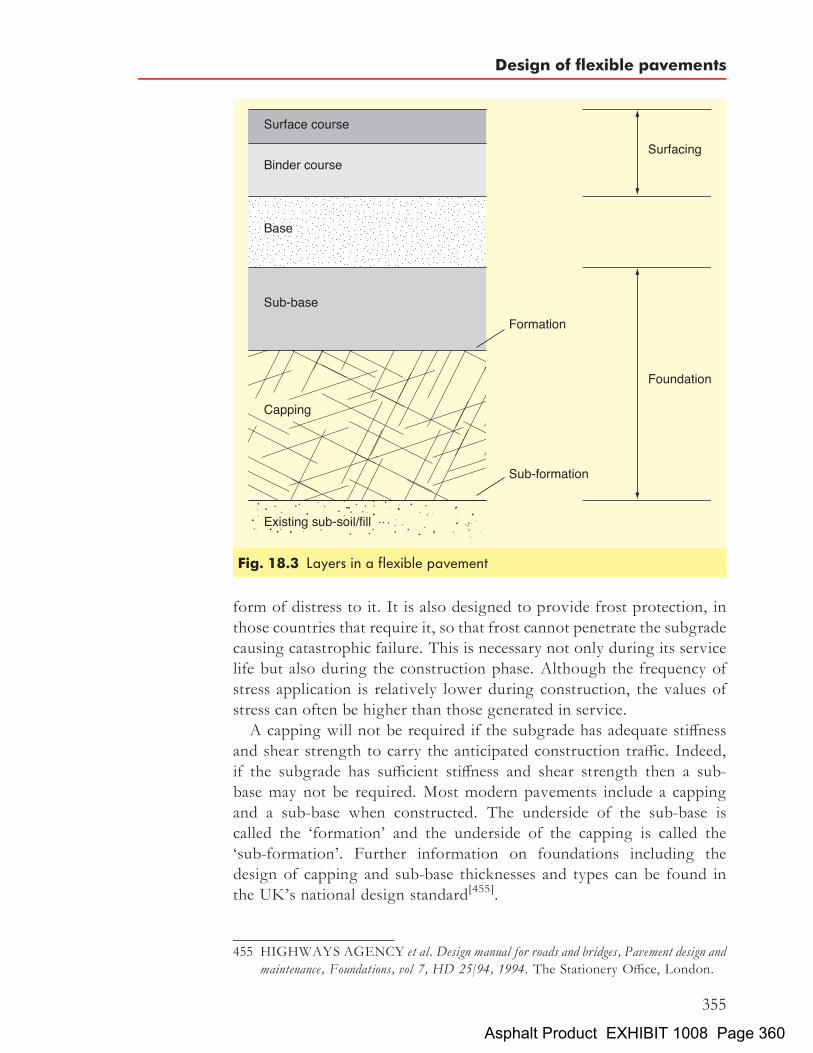
form of distress to it. It is also designed to provide frost protection, inthose countries that require it, so that frost cannot penetrate the subgradecausing catastrophic failure. This is necessary not only during its servicelife but also during the construction phase. Although the frequency ofstress application is relatively lower during construction, the values ofstress can often be higher than those generated in service.A capping will not be required if the subgrade has adequate stiffness
and shear strength to carry the anticipated construction traffic. Indeed,if the subgrade has sufficient stiffness and shear strength then a sub-base may not be required. Most modern pavements include a cappingand a sub-base when constructed. The underside of the sub-base iscalled the ‘formation’ and the underside of the capping is called the‘sub-formation’. Further information on foundations including thedesign of capping and sub-base thicknesses and types can be found inthe UK’s national design standard[455].
Fig. 18.3 Layers in a flexible pavement
455 HIGHWAYS AGENCY et al. Design manual for roads and bridges, Pavement design andmaintenance, Foundations, vol 7, HD 25/94, 1994. The Stationery Office, London.
Design of flexible pavements
355
Asphalt Product EXHIBIT 1008 Page 360
18.2.2 The baseThe base is the main structural element in the pavement. Its function is todistribute the imposed loading so that the underlying materials are notoverstressed. It must resist permanent deformation and crackingcaused by fatigue through repeated loading. It must also be capable ofwithstanding stresses induced by temperature gradients through thestructure. The base is usually a dense asphalt material but wet leanconcrete or cement-bound material may also be used. For lightlytrafficked applications, an unbound granular base may be perfectlyadequate.
18.2.3 The surfacingThe surfacing consists of two layers. The lower layer is termed the‘binder course’. Its primary function is to distribute the stresses fromthe surface course to the base without overstressing. It also provides alayer with good surface regularity upon which the surface course canbe constructed. The tolerance at the top of the surface course is often�6mm from the design levels.The upper layer of the surfacing is termed the surface course. It is this
layer and this layer only that is visible to the road user. The surface coursehas to meet a formidable list of requirements. It must:
. resist deformation by traffic
. be durable, resisting the effects of weather, abrasion by traffic andfatigue
. provide a skid-resistant surface
. generate acceptable levels of noise
. provide a surface of acceptable riding quality
. except in the case of porous asphalt, be impervious thus protectingthe lower layers of the pavement
. contribute to the strength of the pavement structure
. generate acceptable levels of spray.
18.3 Factors involved in pavement design18.3.1 Pavement loadingLoads are applied to the pavement through contact between vehicle tyresand the surface course. Obviously the degree and nature of the trafficloading is one of the major factors affecting the design and performanceof pavements. Both the magnitude and the number of loadings contri-bute to the overall damage in the pavement. The tyre pressure primarilyaffects the stresses (and strains) developed at the surface and within theupper layers of the pavement. (In road pavement design, a typicalcommercial vehicle tyre pressure would be 0.5MPa, whereas aircraft
The Shell Bitumen Handbook
356
Asphalt Product EXHIBIT 1008 Page 361

tyres inflict pressures up to 3.0MPa. These values have a significantinfluence on the design of the materials used as surfacings of roadand airfield pavements.) The structural effects of multiple-wheel con-figurations are also primarily confined to the upper layers of thepavement.Although a great deal of publicity has been given to the physical size
and gross weight of commercial vehicles, it is the double wheel or axleload that is critical in pavement design and performance. Heavier vehiclesare usually carried on a larger number of axles, thereby maintaining orreducing the axle load.Most countries limit the axle loadings that can be carried on their
carriageways. However, these limits are difficult to enforce and over-loaded vehicles are commonplace.Normal traffic on conventional roads is mixed in composition and
magnitude of axle loads and it is therefore necessary for design purposesto simplify the real situation by converting actual axle loads to an ‘equiva-lent’ loading system. This idea originated with the American Associationof State Highway Officials (AASHO) road test in the USA in the early1960s[456] and was adopted in the UK with the publication of the thirdedition of Road Note 29 in 1970[457]. The mixed axle load spectrum isconverted to an equivalent number of standard axles, the standardadopted in the UK being 80 kN. This is based on a concept of equivalentdamage to the pavement. (The concept of a ‘standard axle’ was intro-duced in Laboratory Report 833[458] as that exerting or applying aforce of 80 kN.) The loading exerted (and thus the damage) for eachvehicle can then be computed in terms of a number of equivalentstandard axles by using the ‘fourth power law’ given below. Althoughthe relative damage inflicted by wheel loads of different magnitudesdepends on a variety of factors, for design calculations, the ‘fourthpower law’ is normally used, viz:
Equivalence factor ¼�W
80
�4
where W ¼ axle load in kN.
456 LIDDLEW J.Application of AASHO road test results to the design of flexible pavementstructures, Proc 1st Int Conf on the structural design of asphalt pavements, Ann Arbor,Michigan, pp 42–51, 1962.
457 DEPARTMENT OF THE ENVIRONMENT. A guide to the structural design ofpavements for new roads, Road Note 29, 3rd ed, 1970. The Stationery Office, London.
458 KENNEDY C K and NW LISTER. Prediction of pavement performance and the designof overlays, Laboratory Report 833, 1978. Transport and Road Research Laboratory,Crowthorne.
Design of flexible pavements
357
Asphalt Product EXHIBIT 1008 Page 362
It has been shown[459] that on weak pavements the exponential powercan be as high as 6 if trafficked by heavy axle loads at or above the currentlegal limit. However, the value of 4 is accepted in the UK’s nationaldesign standard[460] and has proven to lead to the construction ofhighways that have successfully withstood the enormous growth intraffic in the UK.Thus, under normal conditions, it takes the application of sixteen
40 kN axle loads to cause the same damage as a single application of an80 kN axle load. Furthermore, one application of a 160 kN axle loadinduces 16 times the damage of a standard 80 kN axle load.
18.3.2 Environmental effectsThe two environmental effects that influence pavement design aremoisture, in particular the water table which influences subgrade perfor-mance, and temperature, which strongly affects the properties of asphalts.The properties of subgrade soils should be determined for the
existence of critical conditions after the construction of the pavement.The relationship between elastic modulus and moisture content of thesubgrade is important. In addition, frost can significantly affect soilsand unbound pavement materials. By choosing materials that have alow susceptibility to the effects of frost and ensuring that any whichmight be so affected are located below the depth to which frost islikely to penetrate, frost damage can be minimised. A more effectiveapproach is to construct the pavement such that water is kept out ofthe pavement by the judicious construction of effective drainage. Theeffect of temperature on the stiffness of asphalt materials has beendiscussed in depth in previous chapters.
18.4 Empirical and semi-empirical pavement design
There are two approaches to pavement design, empirical and analytical.Most design methods in current practice around the world are empirical,being based on experience accumulated in practice and from speciallyconstructed test sections. This approach to pavement design is somewhatremoved from engineering principles and cannot cope with circum-stances beyond those included in the trial section upon which themethod is based. In contrast, the analytical approach uses theoreticalanalysis of the mechanical properties of materials and is capable, inprinciple, of dealing with any design situation.
459 CURRER E W H and M G D CONNOR. Commercial traffic: its estimated damagingeffect, 1945–2005, Laboratory Report 910, 1979. Transport and Road ResearchLaboratory, Crowthorne.
460 HIGHWAYS AGENCY et al. Design manual for roads and bridges, Pavement design andmaintenance, Traffic assessment, vol 7, HD 24/96, 1996. The Stationery Office, London.
The Shell Bitumen Handbook
358
Asphalt Product EXHIBIT 1008 Page 363
18.4.1 Development of empirical and semi-empiricalpavement design methods in the UK
An early UK attempt to provide a basis for designing pavements byanalysing layer stresses was published in 1948[461]. However, formaladvice on the structural design of pavements for use on Trunk Roadsfirst appeared in Road Note 29, published in three editions in 1960,1965 and 1970[462]. Its approach was based on measurements that weretaken on a number of experimental highways constructed in the publichighway network. Design curves related traffic loading to the strengthof the subgrade. As traffic levels grew, the approach propagated byRoad Note 29 was found to be flawed. This led to work by the Transportand Road Research Laboratory that enhanced the empirical approachadopted previously with theoretical analysis. This culminated in thepublication in 1984 of Laboratory Report 1132[463].Advice on all aspects of the preparation and design of road schemes for
Trunk Roads has been provided to agent authorities since 1965. Thistook the form of technical memoranda, advice notes and standards thatwere issued as and when the Department of Transport deemed necessary.The problem was that the system was uncontrolled and not all offices orindividual engineers had copies of or access to all documents that hadbeen published. Thus, contracts were prepared to differing procedures.In order to overcome this major shortcoming, a composite system,called the Design Manual for Roads and Bridges (DMRB), was issued in1992. It was achieved very simply by combining all the technical memor-anda, etc. together in one suite of documents under a unified system ofcontrol.The DMRB is divided into 15 volumes each of which is accorded a
different title. Volume 7 is entitled Pavement Design and Maintenance andis the document that is of greatest interest to Pavement Engineers.Those elements of Volume 7 that dictate the design of a pavement are:
. HD 24 Traffic assessment[464]
461 FOX L. Computation of traffic stresses in a simple road structure, Dept of Scientific andIndustrial Research, Road Research Technical Paper no 9, 1948. The StationeryOffice, London.
462 DEPARTMENT OF THE ENVIRONMENT. A guide to the structural design ofpavements for new roads, Road Note 29, 3rd ed, 1970. The Stationery Office, London.
463 POWELL W D, J F POTTER, H C MAYHEW and M E NUNN. The structuraldesign of bituminous roads, Laboratory Report 1132, 1984. Transport and RoadResearch Laboratory, Crowthorne.
464 HIGHWAYS AGENCY et al. Design manual for roads and bridges, Pavement design andmaintenance, Traffic assessment, vol 7, HD 24/96, 1996. The Stationery Office,London.
Design of flexible pavements
359
Asphalt Product EXHIBIT 1008 Page 364

. HD 25 Foundations[465]
. HD 26 Pavement design[466].
The design method contained in Volume 7 is the most common approachused in the UK for the design of pavements.
18.4.2 Assessment of the load on a pavementThe size of any structural element is, amongst other factors, a function ofthe loading that is applied to that structural element. When it comes to theempirical design of pavements, the total traffic loading over the antici-pated life of the pavement is assessed and expressed in terms of millionsof standard axles (msa). The pavement necessary to support that loadingis designed as a unit, that unit being the base plus binder course plus sur-face course. Thus, the pavement is designed as if it was a single layer. Sincethe thicknesses of the binder course and the surface course are generallyknown, the thickness of the base can be determined by deduction.HD 24 deals with assessing the loading on the structure to be applied
to the pavement throughout its useful life, i.e. the cumulative commercialvehicle traffic (the ‘design traffic’). It confirms that lighter vehicles, i.e.cars, contribute very little to the loading of a pavement. Thus, the assess-ment is restricted to a calculation of the number of commercial vehiclesthat are defined as vehicles having an unladen vehicle weight that exceeds15 kN (kN is, of course, a unit of force, 15 kN is equivalent to an unladenweight of 1.5 tonnes). There are three classifications of commercialvehicles – PSV (public service vehicle), OGV1 (other goods vehicle)and OGV2. These are defined as:
. PSV Buses and coaches
. OGV1 2 axle rigid3 axle rigid3 axle articulated
. OGV2 4 axle rigid4 axle articulated5 axle or more
Assessment of the design traffic is achieved by one of two methods:
(1) the ‘standard method’ in the case of new roads although it canbe used, in certain circumstances, for maintenance schemes orrealignment; or
465 HIGHWAYS AGENCY et al. Design manual for roads and bridges, Pavement design andmaintenance, Foundations, vol 7, HD 25/94, 1994. The Stationery Office, London.
466 HIGHWAYS AGENCY et al. Design manual for roads and bridges, Pavement design andmaintenance, Pavement design, vol 7, HD 26/01, 2001. The Stationery Office, London.
The Shell Bitumen Handbook
360
Asphalt Product EXHIBIT 1008 Page 365

(2) the ‘structural assessment and maintenance method’ for main-tenance schemes although it may be appropriate for certain newroads where non-standard traffic exists.
The standard method determines the design traffic by means of trafficstudies for new roads. For maintenance schemes or realignment, a 12,16 or 24 hour traffic count is carried out. The results are converted toan average annual daily flow (AADF). Using this value, the design trafficcan then be read from one of four charts in HD 24[467] and these are usedto obtain design traffic for:
. flexible (20 year life) and flexible composite – single carriageway
. flexible (20 year life) and flexible composite – dual carriageway
. rigid, rigid composite and flexible (40 year life) – singlecarriageway
. rigid, rigid composite and flexible (40 year life) – dualcarriageway.
The thinner lines on the graphs are used for higher percentages ofOGV2. Note that a minimum value of design traffic of 1msa on lightlytrafficked roads is to be assumed. These figures include a bias to reflectthe increased proportion of traffic in lane 1 (lanes should be describedas lane 1, lane 2, etc. and not nearside lane, middle lane, etc).The structural assessment and maintenance method caters for both the
assessment of past traffic and the prediction of future design traffic. Itallows a more detailed assessment than the standard method for newroads.A simple formula is then applied to each category of traffic. The total
design traffic is the sum of the cumulative traffic in each category.In the case of dual carriageways, the proportion of vehicles in the most
heavily trafficked lane (usually, but not always, lane 1) is used in design.This value of design traffic is to be applied to all lanes including the hardshoulder. In other words, the pavement layer thicknesses are to be thesame in all lanes.It is sometimes necessary to estimate the traffic in other lanes for main-
tenance purposes and a method of distributing traffic between lanes isdescribed.It should be noted that due to the application of a cut-off line to the
charts in the standard method, the two methods will not always producecomparative results.
467 HIGHWAYS AGENCY et al. Design manual for roads and bridges, Pavement design andmaintenance, Traffic assessment, vol 7, HD 24/96, figs 2.1–2.4, 1996. The StationeryOffice, London.
Design of flexible pavements
361
Asphalt Product EXHIBIT 1008 Page 366

18.4.3 Designing the foundationHD 25[468] is concerned with the design of the foundation. As explainedabove, the foundation consists of the capping and the sub-base.The properties of the subgrade, in particular the stiffness modulus and
shear strength, are seldom known at all or with any certainty. Thus, it isnecessary to use other simple test methods that, with experience, can beused to design a foundation. Such tests are often called ‘index tests’. TheCalifornia bearing ratio (CBR) test is an example. The CBR value isusually quoted as an integer percentage (although some documentssuggest that it should be quoted to two figures of decimals, which iswholly impractical in most cases). One method of obtaining a CBRvalue is to drive a piston, 1932mm2 in area, into the material at a specifiedrate. The load acting on the piston is recorded and that corresponding toa penetration of 2.5mm is determined. The ratio of that load to 1360 kg(the value obtained with a standard crushed stone sample) expressed as apercentage is designated as the CBR value of the material under test. Thetotal thickness of the pavement is related to the CBR of the subgrade forparticular wheel loads by curves of the type shown in Fig. 18.4.HD 25[468] suggests that assessment of the true value of CBR on site or
in the laboratory is the preferred approach. If that is not possible then itprovides two very simple tables that allow a value to be read off if thesoil type is known. Once the CBR has been assessed, the thickness ofthe sub-base and, if necessary, the capping can be determined from asingle chart[469]. The CBR of a weak soil would be in single figures. Ifthe subgrade has a CBR of 15% or more then no capping is necessary.If the value is less than 15% then it will be necessary to add a cappingor to thicken the sub-base. (The sub-base is normally 150mm thick.)In order to ensure that the pavement can be constructed with confidence,the value of CBR at the top of the sub-base should be �30%. Wherecracking of the sub-base occurs, the material (and perhaps the materialin the layer below) should be removed and replaced with uncontaminatedsub-base or some other measure taken to ensure the integrity of the sub-base.The casual observer may conclude that the condition of the subgrade
and the thickness of the foundation need be no more than adequate sincethey will have little effect on the life of a pavement. Such a conclusionwould be singularly incorrect. Research published late in the 1990s
468 HIGHWAYS AGENCY et al. Design manual for roads and bridges, Pavement design andmaintenance, Foundations, vol 7, HD 25/94, 1994. The Stationery Office, London.
469 HIGHWAYS AGENCY et al. Design manual for roads and bridges, Pavement design andmaintenance, Foundations, vol 7, HD 25/94, fig 3.1, 1994. The Stationery Office,London.
The Shell Bitumen Handbook
362
Asphalt Product EXHIBIT 1008 Page 367

demonstrates the importance of constructing a firm foundation bycomparing the traffic taken on roads where the CBR was <5% andthat where the CBR was >5% before a rut of depth of 10mm wasgenerated (see Table 18.1). Accordingly, the usually relatively modestcosts of ensuring that a foundation is adequate is money that is likelyto enhance the useful life of the pavement.
Table 18.1 Comparison of rates of rutting[470]
Base type Rate of rutting (mm/msa) Life for 10mmrut: msa
Mean Standarddeviation
Samplesize
HRA or DBM (subgrade CBR <5%) 0:58 0:18 20 17HRA or DBM (subgrade CBR >5%) 0:36 0:12 21 28
Fig. 18.4 California bearing ratio design curves
470 NUNN M E, A BROWN, D WESTON and J C NICHOLLS. Design of long-lifeflexible pavements for heavy traffic, table A1, Report 250, 1997. TRL, Crowthorne.
Design of flexible pavements
363
Asphalt Product EXHIBIT 1008 Page 368

18.4.4 Designing the pavementHD 26[471] sets out the UK Highways Agency’s method for designingpavements. It is based on the approach that is contained in LR 1132[472].LR 1132 contains design recommendations, derived from the structural
performance of experimental roads, for pavements with different types ofbinder course. The extrapolation from about 20msa carried by full-scaleroad trials to 200msa has been based on analysis. The basic designs providereference structures, having a 0.85 probability of survival, which can bemodified, using the analytical approach, to cater for new materials or alter-native designs. Thus, the LR 1132 approach to pavement design recognisesthe variability in the road structure and the uncertainties of traffic forecasts.The concept of probability of survival certainly offers a challenge to theengineer who is aiming to achieve a minimum whole-life cost.In LR 1132, the estimation of the cumulative number of equivalent
standard 80 kN axles to be carried during the design life is similar tothe modified methods used as part of Road Note 29 but allowances aremade for further increases in vehicle damage factors.The ‘design traffic’, which is the only output from HD 24, is used to
calculate the total thickness of the layers above the sub-base in fourdifferent generic types of pavement:
. flexible – surfacing and base are bound with a bitumen
. flexible composite – surfacing and upper base (if used) are bound witha bitumen whereas the lower base is bound with cement
. rigid – surfacing and base are concrete which may be jointed unrein-forced (URC) or jointed reinforced (JRC)
. rigid composite – Continuously reinforced (CRCP) or continuouslyreinforced concrete base (CRCR) with asphaltic surface course/surfacing.
Figure 2.1 of HD 26/01 is reproduced here as Fig. 18.5. The parameter‘design traffic’ enables the ‘design thickness of asphalt layers’ to beascertained. This design thickness is the total thickness of the pavement,i.e. the sum of the thicknesses of the base, binder course and surface course.This is the first attempt to include an element of an end-product
specification into pavement construction. It includes asphalt ‘grades’.
471 HIGHWAYS AGENCY et al. Design manual for roads and bridges, Pavement design andmaintenance, Pavement design, vol 7, HD 26/01, 2001. The Stationery Office, London.
472 POWELL W D, J F POTTER, H C MAYHEW and M E NUNN. The structuraldesign of bituminous roads, Laboratory Report 1132, 1984. Transport and RoadResearch Laboratory, Crowthorne.
473 HIGHWAYS AGENCY et al. Design manual for roads and bridges, Pavement design andmaintenance, Pavement design, vol 7, HD 26/01, fig 2.1, 2001. The Stationery Office,London.
The Shell Bitumen Handbook
364
Asphalt Product EXHIBIT 1008 Page 369

Fig.18.5
Designthickn
essforfle
xiblepa
vemen
ts:pe
rforman
ce-spe
cifie
dgrad
esof
base
[473]
Design of flexible pavements
365
Asphalt Product EXHIBIT 1008 Page 370

These grades indicate the ‘characteristic stiffness’ of the mixture which is akey determinant of the thickness of the asphalt which is required to supportthe calculated loading.Attached to Fig. 2.1 in HD 26 is a series of Notes. These contain
important matters affecting the design process and it is vital that usersapply the points therein. Advice on the materials that can be used inthe pavement layers is given in HD 36[474], HD 37[475] and HD 38[476],all of which can be found in Volume 7 of the DMRB.
18.5 Analytical pavement design using the Shell PavementDesign Method
The philosophy of the analytical approach to pavement design is that thestructure should be treated in the same way as other civil engineeringstructures. The basic procedure is as follows:
(1) assume a form for the structure; this will usually involve rationalsimplification of the actual structure to facilitate analysis
(2) specify the loading(3) estimate the size of the components(4) carry out a structural analysis to determine the stresses, strains and
deflections at critical points in the structure(5) compare these values with the maximum allowable values to assess
whether the design is satisfactory(6) adjust the materials or geometry repeating steps (3), (4) and (5)
until a satisfactory design is achieved(7) consider the economic feasibility of the result.
In the late 1950s, there was great interest in analytically-based designprocedures. Accordingly, in 1963 and subsequently, Shell publishedsets of design charts[477–479] that permitted engineers to calculate stresses
474 HIGHWAYS AGENCY et al. Design manual for roads and bridges, Pavement design andmaintenance, Surfacing materials for new and maintenance construction, vol 7, HD 36/99,1999. The Stationery Office, London.
475 HIGHWAYS AGENCY et al. Design manual for roads and bridges, Pavement design andmaintenance, Bituminous surfacing materials and techniques, vol 7, HD 37/99, 1999. TheStationery Office, London.
476 HIGHWAYS AGENCY et al. Design manual for roads and bridges, Pavement design andmaintenance, Concrete surfacing and materials, vol 7, HD 38/97, 1997. The StationeryOffice, London.
477 SHELL INTERNATIONAL PETROLEUM COMPANY LTD. Shell design chartsfor flexible pavements, 1963. Shell International Petroleum Company Ltd, London.
478 SHELL INTERNATIONAL PETROLEUM COMPANY LTD. Shell pavementdesign manual, 1978. Shell International Petroleum Company Ltd, London.
479 SHELL INTERNATIONAL PETROLEUMCOMPANY LTD.Addendum to theShell pavement design manual 1985. Shell International Petroleum Company Ltd,London.
The Shell Bitumen Handbook
366
Asphalt Product EXHIBIT 1008 Page 371

and strains in a structure based upon a multi-layer linear elastic analysis.In 1978, this system was extended to incorporate all relevant majordesign parameters that were derived from empirical design methods,the AASHO Road Test and laboratory data and published as the ShellPavement Design Manual (SPDM). SPDM allowed for the effects on thepavement of temperature, traffic density and the physical properties ofthe bitumen and aggregates whilst standardising the asphalt mixturesin regard to stiffness and fatigue properties. It was presented in theform of graphs, charts and tables. In order to keep the quantity ofgraphs, etc. down to a manageable level, the number of variable para-meters used was limited and engineers were expected to interpolatewhere necessary.In keeping with the substantial increase in computing power that is now
available to every individual within an organisation, the manual pro-cedures were updated to provide user-friendly computer-based packagesthat are integrated with other computer-based applications. Accordingly,the Shell Pavement Design Manual became the Shell Pavement DesignMethod to recognise the fact that it is no longer a paper-based system.In 1992, SPDM-PC (a version of SPDM designed for use on a desktop
or laptop) was published. The package followed the same design methodas the 1978 version but was enhanced to permit the use of a wide varietyof data without the need for cumbersome interpolations.In 1998, Shell launched SPDM 3.0 which operates within Windows#.
It is described in a paper published subsequently[480]. Again, thisprogram followed the same design method as the 1978 manual butwith an improved graphical user interface.SPDM is based on a three-layered structure consisting of an asphalt
pavement on a base of unbound granular material overlying the existingsubgrade, as depicted in Fig. 18.6.For convenience, the traffic loads imposed on the structure are con-
verted to an equivalent number of standard 80 kN axle loads. The life ofthe structure is expressed as the number of standard axle loads applied tothe structure before a given level of damage occurs. In this context, thedesign method distinguishes between structural damage, i.e. fatigue failureof the asphalt, and permanent deformation resulting from deformation ofthe subgrade and permanent (plastic) deformation of the asphaltic layers.These mechanisms are illustrated in Figs. 18.7(a) and (b).The principal criterion for asphalt fatigue is the value of horizontal
strain at the bottom of the asphaltic layer; for subgrade deformation itis the vertical strain at the top of the subgrade. Cracking of the asphaltic
480 STRICKLAND D. Shell pavement design software for Windows, 2000. Shell Inter-national Petroleum Company Ltd, London.
Design of flexible pavements
367
Asphalt Product EXHIBIT 1008 Page 372

layer arises from repeated tensile strains, the maximum value of whichoccurs at the bottom of the base, as shown in Fig. 18.7(b). In thinnerpavements, the crack, once initiated, propagates upwards causing gradualweakening of the structure. Development of a rut arises from the
Fig. 18.6 Structured layers with analytical design criteria[481]
481 SHELL INTERNATIONAL PETROLEUM COMPANY LTD. Shell pavementdesign manual, 1978. Shell International Petroleum Company Ltd, London.
The Shell Bitumen Handbook
368
Asphalt Product EXHIBIT 1008 Page 373

accumulation of permanent strain throughout the structure. The calcula-tion of rut depth using analytical procedures is a complicated process.However, if the vertical strain in the subgrade is kept below a specificlevel, experience has shown that excessive rutting will not occur,unless the material is poorly designed or inadequately compacted.Accordingly, the design problem is to proportion the pavement struc-
ture so that the critical level of strain will not be exceeded in the designlife for the chosen material. To achieve this, the mechanical properties of
Fig. 18.7 (a) Permanent deformation and (b) fatigue cracking in asphaltpavements
Design of flexible pavements
369
Asphalt Product EXHIBIT 1008 Page 374

the materials must be known to analyse the structure. The simplifiedthree-layered structure used as part of SPDM is regarded as a linearelastic multi-layered system in which the materials are characterised byYoung’s modulus of elasticity (stiffness modulus) and Poisson’s ratio.The materials are assumed to be homogeneous and isotropic. It was onthe basis of this model that, in the late 1960s, Shell Global Solutionsdeveloped BISTRO (BItumen STructures in ROads), a computer pro-gram that calculates stresses, strains and displacements at any positionin a multi-layer system. This program has been enhanced and renamedBISAR[482,483] (BItumen Stress Analysis in Roads). In 1998, Shelllaunched BISAR 3.0 which works within Windows#. It is described ina paper published subsequently[484]. This program followed the sameprinciples as previous versions of BISAR but again has an improvedgraphical user interface.Using BISAR, the horizontal tensile strain at the bottom of an asphalt
layer and the vertical compressive strain at the surface of a subgrade canbe determined for various pavement configurations and these two valuescompared with permissible values.Considerable effort has been made to reduce the number of variables
involved in the analysis of pavements in order to keep the process assimple as possible. Therefore, a number of assumptions have beenmade. The first assumption is based on results from materials testingwhich demonstrated that Poisson’s ratio does not vary greatly and avalue of 0.35 can be assumed for the asphalt layer, sub-base and subgrade.The second assumption is that the thickness of the subgrade is infinite.These assumptions leave only five variables for any particular system.These are:
. the elastic modulus of the asphalt layer
. the thickness of the asphalt layer
. the elastic modulus of the granular sub-base layer
. the thickness of the granular sub-base layer
. the elastic modulus of the subgrade.
Therefore, as these five variables are linked by analytical relationships, ifany four are known, or assumed, the fifth can be calculated with relativeease.
482 PEUTZ M G F, H P M VAN KEMPEN and A JONES. Layered systems undernormal surface loads, Highway Research Record no 228, pp 34-45, 1968.
483 DE LONG D L, M G F PEUTZ and A R KORSWAGEN. Computer programBISAR, Layered systems under normal and tangential surface loads, Koninklijke/ShellLaboratorium Amsterdam, external report AMSR.0006.73, 1973.
484 STRICKLAND D. Shell pavement design software for Windows, 2000. Shell Bitumen,Wythenshawe, UK.
The Shell Bitumen Handbook
370
Asphalt Product EXHIBIT 1008 Page 375

Chapter 19
Surface dressing and otherspecialist treatments
19.1 Surface dressingSurface dressing is a very useful and cost effective process for restoringskid resistance to a road surface that is structurally sound. In a newroad, adequate surface texture is designed into the running surface byspecifying requirements for both aggregate properties and texturedepth. However, during its service life, the surface becomes polishedunder the action of traffic and the skid resistance will eventually fallbelow the minimum specified value. A major benefit of surface dressingis that the process restores skid resistance to a surface that has becomesmooth under traffic.Surface dressing is the most extensively used form of surface treatment.
In the UK, data suggest that local authorities spend approximately 20% oftheir maintenance budget on this process[485]. In 2001, approximately75 million square metres of road were surface dressed in the UK. Withcare, surface dressing can be used on roads of all types from the countrylane carrying only an occasional vehicle to Trunk Roads carrying tens ofthousands of vehicles per day. However, in some locations, particularlythose where vehicles undertake sudden or sharp turning manoeuvres,surface dressing may not be the appropriate surface treatment. This isdue to the relatively poor ability of the process to resist tangential forces.Additionally, the durability of a surface dressing does not match that of aroad resurfaced with a traditional asphalt. Some large cities, Hamburgfor example, prohibit the use of surface dressings on their carriageways.Surface dressing as a maintenance process has three major aims:
. to provide both texture and skid resistance to the road surface
. to stop the disintegration and loss of aggregate from the roadsurface
371
485 DEPARTMENT OF TRANSPORT. Local road maintenance in England and Wales1994/95, Transport Statistics Report, 1996. DTp, London.
Asphalt Product EXHIBIT 1008 Page 376

. to seal the surface of the road against the ingress of water and, thus,protect its structure from damage resulting therefrom.
In addition, it can be used as a treatment to provide:
. a distinctive colour to the road surface
. a more uniform appearance to a patched road.
However, surface dressing cannot restore evenness to a deformed roadnor will it contribute to the structural strength of the road structure.Basic surface dressing consists of spraying a film of binder onto the
existing road surface followed by the application of a layer of aggregatechippings as shown in Fig. 19.1. The chippings are then rolled to
Fig. 19.1 Surface dressingCourtesy of Colas Ltd
The Shell Bitumen Handbook
372
Asphalt Product EXHIBIT 1008 Page 377

promote contact between the chippings and the binder and to initiate theformation of an interlocking mosaic.
19.1.1 The design of surface dressingsThe design of surface dressings primarily addresses the retention ofsurface texture. The skill lies in designing a system that, taking accountof the hardness of the existing road, is adequately embedded by rollingand subsequently incident traffic.
The design of surface dressings in GermanyIn Germany, a set of guidelines[486] prescribe the type of road main-tenance that is to be applied and this depends on the condition of theoriginal pavement. These guidelines invariably form part of the contractbetween employer and contractor in German contracts. Surface dressingscompete with thin surfacings (both hot and cold applied), in reshapingand wholesale replacement of the surface course. The German guidelinessuggest which surface dressing should be applied in terms of the type,volume of binder and quantity of chippings. This depends on thestructure of the existing road and the nature of the surface dressing.Three different surface dressing systems are listed:
. single application of binder and one layer of chippings;
. single application of binder and two layers of chippings of differentsizes (racked-in surface dressing);
. application of a layer of chippings, subsequent single application ofbinder followed by a further application of a layer of chippings.
Recommendations for binder and chipping rates are given according tothe condition of the road surface.
The design of surface dressings in the UKIn the UK, Road Note 39[487] and the Code of Practice for SurfaceDressing[488] are commonly used to provide guidance on the appropriatetype of dressing, its design and execution. The principles in Road Note39 are as follows:
486 FORSCHUNGSGESELLSCHAFT FUR STRAßEN- UND VERKEHRS-WESEN. Zusatzliche Technische Vertragsbedingungen und Richtlinien fur die BaulicheErhaltung von Verkehrsflachen – Asphaltbauweisen (ZTV BEA-StB 98) (BaulicheErhaltung von Verkehrsflachen), 1998. FGSV, Cologne, Germany.
487 NICHOLLS J C et al. Design guide for road surface dressing, Road Note 39, 5th ed, 2002.TRL Ltd, Crowthorne.
488 ROAD SURFACE DRESSING ASSOCIATION. RSDA code of practice forsurface dressing, 3rd ed, Oct 2002. RSDA, Colchester.
Surface dressing and other specialist treatments
373
Asphalt Product EXHIBIT 1008 Page 378

. select the size and type of dressing that is appropriate for theparticular site and the time of application;
. identify the chipping size and basic binder application rate and typeof binder;
. refine the binder application rate to match the source of chippingsselected;
. further refine the binder application rate on site immediately beforework commences.
Road Note 39 is set out in such a way that the application rate of thebinder is only obtainable after the above stages have been completed.The tables in Road Note 39 provide coefficients for application ratesfor binders for single, racked-in, double, sandwich, inverted doublesurface dressings. These coefficients are then adjusted by reference totables that take into account the type of aggregate and its shape, thecondition of the road surface, the gradient, the degree to which thesite is shaded by trees and structures and for sites where traffic volumesare exceedingly light. The coefficients are then translated into actualtarget application rates of the binder expressed in litres per square metre.
19.1.2 Factors that influence the design and performance ofsurface dressings
The principal factors that influence the design, performance and theservice life of a surface dressing are:
. traffic volumes and speeds
. condition and hardness of the existing road surface
. size and other chipping characteristics
. surface texture and skid resistance
. type of binder
. adhesion
. geometry of site, altitude, latitude and local circumstances
. time of year.
Traffic volumes and speedsIn the UK, a commercial vehicle is defined as having an unladen weightexceeding 1.5 tonnes for design purposes. As the rate of chipping embed-ment is dependent on the number of commercial vehicles using each lane,it is necessary to establish the number of such vehicles using a road that isto be surface dressed and the speed of traffic using the carriageway.
Condition and hardness of the existing road surfaceIf the existing road surface is rutted, cracked or in need of patching,these defects must be corrected before surface dressing can be
The Shell Bitumen Handbook
374
Asphalt Product EXHIBIT 1008 Page 379

undertaken[489]. Other surface conditions that require special considera-tion are those where the binder has flushed up resulting in a binder-rich surface and, conversely, surfaces that have become very dry, lackingin binder.The hardness of the road surface affects the extent to which the applied
chippings become embedded into the road surface during the life of thedressing. The choice of chipping size is directly related to the hardness ofthe existing road surface. The use of chippings that are too small willresult in early embedment of the chippings into the surface leading toa rapid loss of texture depth and, in the worst cases, ‘fatting up’ of thebinder which may cover the entire surface of the road. The use ofchippings that are too large may result in immediate failure of the treat-ment due to stripping of the binder from the aggregate under the appliedstresses of the traffic and can also result in excessive surface texture and anincrease in the noise generated between the tyre and the road surface. Thehardness of the road surface also influences the rate of application ofbinder required for a given size of chipping. The rate of spread mustbe decreased where the road surface is soft in order to compensate forthe greater embedment of chippings into the road surface under theaction of traffic.In the UK, the categories of hardness of the existing road surfaces for
the purposes of surface dressing design are described in Road Note 39.Four graphs take account of the geographical location within the UKand the altitude of the site. The geographical location is not strictlyrelated to latitude but also takes account of climatic conditions partlycaused by the Gulf Stream. The method of measuring hardness on thesite is by use of a road hardness probe[490]. This device measures thedepth of penetration of a probe with a 4mm semi-spherical head afterthe exertion of a force of 340N for a period of 10 s. Ten or moreprobe tests taken at approximately 0.5m intervals in the nearsidewheel-track of the lane under consideration are taken and the averagecalculated. The road surface temperature is also recorded. Experiencehas shown that tests are only significant within the temperature rangeof 15 to 358C.Having measured the depth of penetration and the surface temperature
and identified whether the site lies in the southern, central or northernregion, the hardness category of the road can be established by referenceto the appropriate graph, as shown in Fig. 19.2.
489 ROAD SURFACE DRESSING ASSOCIATION. RSDA guidance note on prepar-ing roads for surface dressing, Oct 2002. RSDA, Colchester.
490 BRITISH CARBONISATION RESEARCH ASSOCIATION. The CTRA roadhardness probe, Carbonisation research report 7, Jun 1974.
Surface dressing and other specialist treatments
375
Asphalt Product EXHIBIT 1008 Page 380

The Shell Bitumen Handbook
376
Asphalt Product EXHIBIT 1008 Page 381
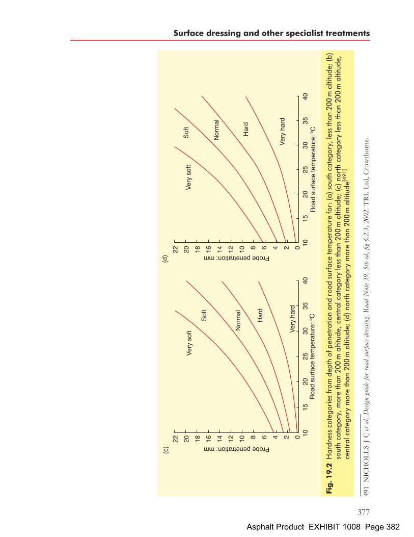
Fig.19.2
Hardn
essca
tego
ries
from
depthof
pene
trationan
droad
surfac
etempe
rature
for:(a)sou
thca
tego
ry,lessthan
200m
altitud
e;(b)
southca
tego
ry,morethan
200m
altitud
e,centralcateg
oryless
than
200m
altitud
e;(c)no
rthca
tego
ryless
than
200m
altitud
e,centralcateg
orymorethan
200m
altitud
e;(d)no
rthca
tego
rymorethan
200m
altitud
e[491]
491NICHOLLSJCetal.Designguideforroad
surfacedressing,RoadNote39,5thed,fig
6.2.3,
2002.TRLLtd,Crowthorne.
Surface dressing and other specialist treatments
377
Asphalt Product EXHIBIT 1008 Page 382
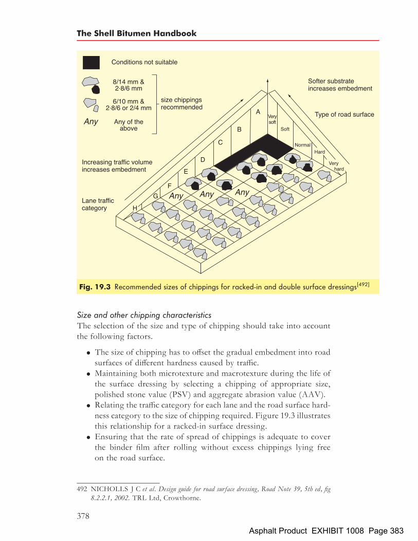
Size and other chipping characteristicsThe selection of the size and type of chipping should take into accountthe following factors.
. The size of chipping has to offset the gradual embedment into roadsurfaces of different hardness caused by traffic.
. Maintaining both microtexture and macrotexture during the life ofthe surface dressing by selecting a chipping of appropriate size,polished stone value (PSV) and aggregate abrasion value (AAV).
. Relating the traffic category for each lane and the road surface hard-ness category to the size of chipping required. Figure 19.3 illustratesthis relationship for a racked-in surface dressing.
. Ensuring that the rate of spread of chippings is adequate to coverthe binder film after rolling without excess chippings lying freeon the road surface.
Fig. 19.3 Recommended sizes of chippings for racked-in and double surface dressings[492]
492 NICHOLLS J C et al. Design guide for road surface dressing, Road Note 39, 5th ed, fig8.2.2.1, 2002. TRL Ltd, Crowthorne.
The Shell Bitumen Handbook
378
Asphalt Product EXHIBIT 1008 Page 383

. Binder type and viscosity must be appropriate for the time of year,traffic category and degree of stress that is likely to be encountered.Similarly, the rate at which it is applied must be appropriate for thetraffic category, road hardness and nominal size of chipping.
In the UK, chippings for surface dressing should meet the requirementsof BSEN13043: 2002[493]. Usually, chippings have a nominal size of2.8/6, 6/10 or 8/14mm. Extreme caution should be exercised whenusing chippings larger than 8/14mm nominal size due to the risk ofpremature failure.The presence of dust can delay or even prevent adhesion and is parti-
cularly acute at low temperatures and with the smaller sizes of chipping.As well as being of nominal single size and dust free, surface dressingchippings need to satisfy other characteristics. They should:
. not crush under the action of traffic or shatter on impact
. resist polishing under the action of traffic
. not have an extreme value of ‘flakiness index’ (the ratio of length tothickness).
Chippings are rarely cubical and when they fall onto the binder film andare rolled, they tend to lie on their longest dimension. If the chippingsused for a surface dressing have a large proportion of flaky chippings,less binder will be required to hold them in place and the excess bindermay ‘flush up’ onto the surface of the dressing. Such a dressing willhave a reduced texture and life. It is for this reason that the UK sets amaximum limit of flakiness for single-size chippings for use in surfacedressing. Typical requirements for surface dressing chippings areshown in Table 19.1.Gritstones, basalts, quartzitic gravels and artificial aggregates such as
slag constitute the majority of chippings used for surface dressing. How-ever, not all aggregates with a high PSV are suitable for surface dressingdue to insufficient strength. The PSV of the aggregate defines itsresistance to polishing. In the UK, its determination is defined inBSEN1097-8: 2002[494] and the relationship between PSV, traffic andskid resistance is detailed in HD 36[495].
493 BRITISH STANDARDS INSTITUTION. Aggregates for bituminous mixtures andsurface treatments for roads, airfields and other trafficked areas, BSEN13043: 2002.BSI, London.
494 BRITISH STANDARDS INSTITUTION. Tests for mechanical and physical proper-ties of aggregates. Determination of the polished stone value, BSEN1097-8: 2000. BSI,London.
495 HIGHWAYS AGENCY et al. Design manual for roads and bridges, Pavement design andmaintenance, Surfacing materials for new and maintenance construction, vol 7, HD 36/99,1999. The Stationery Office, London.
Surface dressing and other specialist treatments
379
Asphalt Product EXHIBIT 1008 Page 384

Coated chippings have a thin film of bitumen applied at an asphalt plant.This bitumen film eliminates surface dust and promotes rapid adhesionto the bitumen. Coated chippings are used to improve adhesion withcutback bitumens particularly in the cooler conditions that occur at theextremes of the season. They should not be used with emulsions as theshielding effect of the binder will delay ‘breaking’ of the emulsion.
Surface texture and skid resistanceIn the UK, two machines are used for monitoring the skid resistance ofroads – SCRIM and the GripTester.SCRIM is the acronym for the ‘sideways-force coefficient routine
investigation machine’ that was introduced into the UK in the 1970s.It provides a measure of the wet road skid-resistance properties of abound surface by measurement of a sideways-force coefficient at acontrolled speed. A freely rotating wheel fitted with a smooth rubbertyre, mounted mid-machine in line with the nearside wheel-track andangled at 208 to the direction of travel of the vehicle, is applied to theroad surface under a known vertical load. A controlled flow of waterwets the road surface immediately in front of the test wheel which rotatesbut also slides in the direction of travel onto the wetted surface. The forceset up by the resistance to sliding is proportional to the skid resistanceand measurement of this force allows the sideways force coefficient(SFC) to be calculated.The GripTester was introduced in the 1980s and is a braked-wheel
fixed-slip trailer. It has two drive wheels and a single test wheel that ismounted on a stub axle and is mechanically braked to give a relativeslip speed between the drive wheels and the test wheel of just over15%. A controlled flow of water from a tank in the tow vehicle wetsthe road surface immediately in front of the test wheel, which skidsover the wetted surface. The resulting horizontal drag and the verticalload on the measuring wheel are continuously measured and thecoefficient of friction, known as the GripNumber, is calculated.
Table 19.1 Typical properties of surface dressing chippings
Property Value
Los Angeles coefficient (LA) LA30Flakiness index (FI) FI20Polished stone value (PSV) PSVDeclared
a
Aggregate abrasion value (AAV) AAV10
a The required PSV value is usually stated in individual contracts. Because the PSVcategories in BS EN13043 do not always use values that correspond withestablished UK practice, the Standard allows an aggregate supplier to declare anintermediate value.
The Shell Bitumen Handbook
380
Asphalt Product EXHIBIT 1008 Page 385

Both SFC and the GripNumber vary with speed. Testing is normallycarried out at 50 km/h; corrections may be made to allow for variations inspeed but for these to be reliable it is necessary that the macrotexture ofthe surface is known. Tight radii, such as roundabouts, are normallytested at 20 km/h.SFC and GripNumber also vary with traffic flow, temperature and time
of year. Network testing is restricted to May to September, with threetests carried out at fairly similar intervals throughout the season. Theaverage is defined as the ‘mean summer SCRIM coefficient’ (MSSC)and skid resistance is normally expressed in terms of the MSSC.In 1973, the TRL[496] introduced the concept of ‘risk rating’, which is a
measure of the relative skidding accident potential at an individual siteand is determined by its geometry and location. Within each category,there is a range of target SFC values with the target value for each sitedepending on its risk rating. A road will need to be surface dressed ifthe measured skid resistance (MSSC value) is inadequate for the riskrating of the site. The ‘investigatory levels’ of skid resistance forTrunk Roads including Motorways are given in HD 28[497]. In thisdocument, the investigatory levels are those at which the measuredskid resistance of the road has to be reviewed. In the review process, itmay be decided to restore skid resistance by surface dressing or, in certaincircumstances, the risk rating of the site may warrant change.The skidding resistance of a road surface is determined by two basic
characteristics, the microtexture and macrotexture, as shown in Fig.19.4. Microtexture is the surface texture of the aggregate. A significantlevel of microtexture is necessary to enable vehicle tyres to penetratethin films of water and thus achieve dry contact between the tyre andthe aggregate on the carriageway. Macrotexture is the overall textureof the road surface. An adequate value of macrotexture is necessary toprovide drainage channels for the removal of bulk water from the roadsurface.TRL Research Report 296[498] considered the relationship between
accident frequency and surface texture on roads. It concluded that, on
496 SALT G F and W S SZATKOWSKI.A guide to levels of skidding resistance for roads,Laboratory Report 510, 1973. Transport and Road Research Laboratory,Crowthorne.
497 HIGHWAYS AGENCY et al. Design manual for roads and bridges, Pavement design andmaintenance, Skidding resistance, vol 7, HD 28/94, 1994. The Stationery Office,London.
498 ROE P G, D C WEBSTER and G WEST. The relation between the surface texture ofroads and accidents, Research Report 296, 1991. Transport and Road Research Labora-tory, Crowthorne.
Surface dressing and other specialist treatments
381
Asphalt Product EXHIBIT 1008 Page 386

asphalt road surfaces with speed limits greater than 64 km/h and probablyon roads with lower speed limits:
. skidding and non-skidding accidents, in both wet and dry condi-tions, are less if the microtexture is coarse;
. the texture level below which accident risk begins to increase is asensor-measured texture depth (SMTD, see later) of around 0.7mm;
. all major types of surfacing provide texture depths across thepractical range;
. macrotexture has a similar influence on accidents whether theyoccur near hazards such as junctions or elsewhere.
Microtexture is the dominant factor in determining the level of skidresistance at speeds up to 50 km/h. Thereafter, macrotexture predomi-nates, particularly in wet conditions. Traditionally, macrotexture hasbeen measured using the sand patch method[500]. A standard volume ofa specified type of sand is spread by circular motion on the road surface.On contracts carried out under the SHW, which require a two yearguarantee period, the test is generally carried out along the wheeltrack[501]. The texture depth can then be calculated by dividing thevolume of sand by the cross sectional area of the patch. The testcannot be carried out on a wet or sticky surface.
Fig. 19.4 Microtexture and macrotexture[499]
499 NICHOLLS J C et al. Design guide for road surface dressing, fig 2.1.2, Road Note 39,5th ed, 2002. TRL Ltd, Crowthorne.
500 BRITISH STANDARDS INSTITUTION. Road and airfield surface characteristics,Test methods, Measurement of pavement surface macrotexture depth using a volumetricpatch technique, BSEN 13036-1: 2002. BSI, London.
501 HIGHWAYS AGENCY et al. Manual of contract documents for highway works,Specification for highway works, vol 1, cl 922, 2002. The Stationery Office, London.
The Shell Bitumen Handbook
382
Asphalt Product EXHIBIT 1008 Page 387

Mature surface dressings in good condition typically have texturedepths between 1.5mm and 2.0mm; double dressings usually haveslightly lower values. Double surface dressings, however, usually stayabove intervention levels particularly on hard surfaces such as thosesurfaced with hot rolled asphalt surface course.Laser texture measurement (technically, sensor-measured texture
depth (SMTD)) is a technique that covers areas much more quicklythan sand patch testing. Accordingly, it is used as a screening method.The technique is illustrated in Fig. 19.5. This method is not directlycomparable with measurements resulting from sand patch tests. Thus,when quoting texture depth values, the method used to measure theparameter should be stated. For compliance testing on contracts preparedunder the SHW, it is usual to quote sand patch texture, correlate the sandpatch test results to the values returned by SMTD, check as requiredduring the two year guarantee period by SMTD and carry out additionalsand patch tests if necessary.It is the petrographic characteristics of the aggregate that largely
influence its resistance to polishing and this property is measured usingthe PSV test[503]. This test subjects the aggregate to simulated trafficking
Fig. 19.5 Principle of the laser-based contactless sensor for measuring texturedepth[502]
502 ROE P G, L W TUBEY and G WEST. Surface texture measurements on someBritish roads, fig 1, Research Report 143, 1988. Transport and Road Research Labora-tory, Crowthorne.
503 BRITISH STANDARDS INSTITUTION. Tests for mechanical and physical proper-ties of aggregates. Determination of the polished stone value, BSEN1097-8: 2000. BSI,London.
Surface dressing and other specialist treatments
383
Asphalt Product EXHIBIT 1008 Page 388

in an accelerated polishing machine. A high value of PSV (say 65 orhigher) indicates good resistance to polishing. The majority of roadaggregates have a good microtexture prior to trafficking and, conse-quently, most road surfaces have a high skid resistance when new,particularly after the bitumen has worn off the aggregate. The timerequired for the bitumen to be abraded from the aggregate at the roadsurface depends upon a number of factors including the type of mixtureand, in particular, the thickness of the film of bitumen. Until the latter hasbeen removed by traffic, the microtexture of the aggregate will not befully exposed to vehicle tyres. Subsequently, the exposed aggregatesurfaces become polished and, within a year, the skid resistance normallyfalls to an equilibrium level.The macrotexture is determined by the nominal size of aggregate used
and the nature of the asphalt mixture. However, resistance to abrasion isalso important. Aggregates with poor abrasion resistance, determined bythe AAV test[505], will quickly be worn away with a consequent loss ofmacrotexture. The lower the value of AAV, the greater the resistanceto abrasion. High-speed roads normally require an AAV of 14 or less.Surface dressings generally give better value, i.e. last longer, where thechippings have a lower value of AAV.The rate at which skid resistance falls with increasing vehicle speed is
influenced by the macrotexture. The TRL has shown that there is acorrelation between macrotexture, expressed in terms of average texturedepth, and skid resistance, measured by percentage reduction in brakingforce coefficient (BFC) between 130 km/h and 50 km/h, as shown inTable 19.2.
Table 19.2 The effect of macrotexture on the change in skidding resistancewith speed[504]
Drop in skidding resistance with speedchange from 50 to 130 km/h: %
Average texture depth: mm
Flexible Concretea
0 2:0 0:810 1:5 0:720 1:0 0:530 0:5 0:4
a When textured predominantly transversely.
504 SALT G F and W S SZATKOWSKI.A guide to levels of skidding resistance for roads,table 4, Laboratory Report 510, 1973. Transport and Road Research Laboratory,Crowthorne.
505 BRITISH STANDARDS INSTITUTION. Tests for mechanical and physical proper-ties of aggregates. Determination of the polished stone value, BSEN1097-8: 2000. BSI,London.
The Shell Bitumen Handbook
384
Asphalt Product EXHIBIT 1008 Page 389

The skid resistance necessary at any site will depend on the stresseslikely to be induced. Sections of road with minor road junctions andwith low traffic volumes are unlikely to require a high value of skidresistance whereas sharp bends on roads carrying heavy volumes of trafficwill require significantly higher skid resistance characteristics. It isimportant to note that roads carrying high volumes of traffic will requireaggregates with higher values of PSV than roads where traffic levels arelow or moderate.
Type of binderThe essential functions of the binder are to seal surface cracks and toprovide the initial bond between the chippings and the road surface.The viscosity of the binder must be such that it can wet the chippingsadequately at the time of application, prevent dislodgement of chippingswhen the road is opened to traffic, not become brittle during periods ofprolonged low temperature and function effectively for the design life ofthe dressing.The subsequent role of the binder is dependent on the traffic stresses
applied to the surface dressing from low-stressed, lightly traffickedcountry roads to highly stressed sites carrying large volumes of traffic.Clearly a range of binders is necessary if optimal performance is to beachieved under these widely differing circumstances.The following five types of surface dressing bitumen binders are
available; each is described in more detail below.
. conventional bitumen emulsions
. fluxed or cutback bitumens
. polymer modified emulsions
. polymer modified fluxed or cutback bitumens
. epoxy resin thermoset binders.
The relative amounts of the modified and unmodified emulsion andfluxed/cutback bitumen used in Germany and the UK are given inTable 19.3.
Table 19.3 Usage of surface dressing binder by type in Germany and the UK
Type of binder Use in Germany, % Use in UK, %
Conventional emulsion 35 22Modified emulsion 40 67Conventional fluxed/cutback 0 6Modified fluxed/cutback 25 5
Total usage in 2001, tonnes >90000 113000
Surface dressing and other specialist treatments
385
Asphalt Product EXHIBIT 1008 Page 390

. Conventional bitumen emulsions. In the UK, conventional bitumenemulsions are produced to BS 434-1: 1984[506]. The most commonmaterial is K1-70 bitumen emulsion, which is a cationic emulsioncontaining approximately 29% of water, 70% of 160/200 pen or250/330 pen bitumen to which, approximately, 1% by weight ofkerosene has been added. The relatively low viscosity of bitumenemulsions enables them to be sprayed at temperatures between 75and 858C through either swirl or slot jets.K1-70 emulsions will flow on road surfaces at the time of
spraying because they have a relatively low viscosity. Whilst thisis helpful in some respects, migration of the binder from thecentre to the side of cambered roads, or downhill on gradients,requires the application of chippings to the binder film as quicklyas possible after spraying. After spraying, the water migrates fromthe emulsion leaving a film of bitumen, a process known as ‘break-ing’. This can take from as little as 10 minutes to over an hourdepending on ambient temperature, humidity, aggregate waterabsorption, wind speed and the extent to which the dressing issubject to slow-moving traffic. Humidity is one of the mostimportant of these factors and the use of emulsions when humidityis above 80% should only be undertaken on very minor roads andwhere traffic speeds can be kept within the range of 10 to 20mphuntil the emulsion has fully broken. In conditions of high humidity,work can continue with emulsions, particularly where the binder ispolymer modified, by varying the type of dressing. Good results canbe obtained with double and sandwich surface dressings. Pre-coatedchippings should not be used with emulsions as the coating delaysbreaking and serves no tangible benefit but carries additional cost.Binder manufactures are able to control the rate at which emul-
sions break within certain limits, but these have to be compatiblewith the storage, transport and application of the emulsion. Onsite, breaking can be accelerated by spraying the binder film witha mist of a breaking agent before the application of the chippings.However, this usually requires specially adapted spray bars andthe fitting of storage tanks for the breaking agent.
. Conventional fluxed or cutback bitumens. Fluxed or cutback bitumenfor surface dressing is usually 70/100 pen or 160/220 pen bitumenthat has been diluted with kerosene. In the UK, the use of a suffixX in the description of cutback bitumens, e.g. 100X, indicatesthat they have been doped with a specially formulated, thermally
506 BRITISH STANDARDS INSTITUTION. Bitumen road emulsions (anionic andcationic), Specification for bitumen road emulsion, BS 434-1: 1984. BSI, London.
The Shell Bitumen Handbook
386
Asphalt Product EXHIBIT 1008 Page 391

stable, passive adhesion agent. This additive assists wetting of theaggregate and the road surface during application and resistsstripping of the binder from the aggregate in the presence ofwater. Either the immersion tray test[507] or the total water immer-sion test (a test carried out by Shell in house, see Section 9.3.1) candemonstrate the effectiveness of this additive. If surface dressing isbeing carried out in marginal weather conditions or if the aggregateis wet, it is recommended that an active wetting agent is added tocutback bitumens immediately prior to spraying.Cutback bitumens are typically sprayed at temperatures in the
range of 130 to 1708C. During spraying, between 10 and 15% ofthe kerosene evaporates and a further 50% dissipates from thesurface dressing in the first few years after application. At thesetemperatures, wetting of the road surface and the applied chippingsis achieved rapidly. Cutback bitumens, once applied to the roadsurface, cool quickly and it is important to ensure that the chippingsare applied as soon as possible after spraying to ensure satisfactorywetting of the chippings.During the surface dressing season (see Section 19.1.7), as
temperatures rise, binder suppliers may recommend the use ofdifferent viscosity cutback binders in order to promote adhesionand avoid the fatting-up of new dressings. Both cutback andemulsion manufacturers may also make minor changes to theirformulations within the ranges covered by the appropriatestandards to meet changes in road and ambient temperatures.The advantages and disadvantages of fluxed/cutback and emul-
sion binders are listed in Tables 19.4 and 19.5 respectively.There has been a trend with the introduction of ‘best value’ assess-
ments based on whole-life costing to opt for modified binders ratherthan using binders that are cheaper in operational terms alone.
. Proprietary polymer modified binders. The relentless increase in thevolume of all types of vehicles on roads throughout Europe has
507 NICHOLLS J C et al. Design guide for road surface dressing, appendix D, Road Note 39,5th ed, 2002. TRL Ltd, Crowthorne.
Table 19.4 Advantages and disadvantages of fluxed/cutback binders
Advantages Disadvantages
Rapid adhesion High spraying temperatureLow risk of brittle failure Early-life bleeding
Environmental & health and safety issuesRequires dry chippings
Surface dressing and other specialist treatments
387
Asphalt Product EXHIBIT 1008 Page 392

led to the development of modified binders with improved adhesivityand substantially higher cohesive strengths than traditional fluxed/cutback and emulsion binders. These characteristics are particularlyimportant immediately after chippings have been applied to thebinder film and mean that they are less likely to be plucked fromthe road surface by passing traffic than would be the case withconventional unmodified binders. As well as greater adhesive andcohesive strength, modified binders perform satisfactorily over agreater temperature range than is the case with traditional binders.The result is that they do not flush up as rapidly in hot conditionsas traditional binders and are not subject to the same degree ofbrittleness in winter conditions.A high proportion of the European road network can be
classified as easy or average and many of these roads can be surfacedressed using bitumen emulsion or cutback bitumen. However,enhanced treatment may be necessary on certain highly stressedsections such as at sharp bends, road junctions and, in shadedareas, under trees and bridges. At these locations, it is probablethat the same binder can be used but the specification will changein respect of one or more of the following:
. rate of application of binder
. chipping size and rate of spread
. double chip application
. double binder, double chip application.
These latter techniques are widely practised in France on relativelyheavily trafficked roads, and with correct procedures, their use cansignificantly reduce the risk of flying chippings and consequentialwindscreen breakage. Conventional emulsions and cutbacks havethe lowest cost and with careful workmanship, compliance withspecification and appropriate aftercare, good results can beobtained.
Table 19.5 Advantages and disadvantages of emulsion binders
Advantages Disadvantages
Low spraying temperature Low initial adhesionLow risk of early bleeding Skinninga
Environmentally friendly Risk of brittle failure in first winterb
May be used on higher-viscosity base bitumenMay be used on damp (not wet) surfacesDo not require pre-coated chippings
a The use of a sandwich or, preferably, a double surface dressing will reduce the film thickness and, thus,the possibility of skinning.b Employing modified binders will reduce this risk considerably.
The Shell Bitumen Handbook
388
Asphalt Product EXHIBIT 1008 Page 393

As a further aid to consistent performance under variable weatherconditions, a number of proprietary adhesion agents are availablethat act in two basic ways. Some types (active) modify surfacetension at the stone/binder interface to improve the preferentialwetting of chippings by the binder in the presence of water.Other types (passive) improve the adhesion characteristics of thebinder and give an improved resistance to the subsequent detach-ment of the binder film in the presence of water throughout theearly life of the dressing. The effectiveness of the former type ofadhesion agent reduces after a few hours at elevated temperatureand so it is generally mixed with the binder a few hours beforespraying. The latter type of adhesion agent is more temperature-stable and is generally added to the binder by the supplier.Bearing these performance requirements in mind, it is possible to
examine the ways in which the various polymers can be used withbitumen to modify its performance. The bitumen propertieswhere improvement would be sought through the addition of amodifier are set out below.
. Reduced temperature susceptibility, which can loosely bedefined as the extent to which a binder softens over a giventemperature range. It is clearly desirable for a binder to exhibita minimum variation in viscosity over a wide range of ambienttemperatures.
. Cohesive strength enables the binder to hold chippings in placewhen they are subject to stress by traffic. This property can alsobe coupled with the elastic recovery properties of the binder,to enable a surface dressing to maintain its integrity evenwhen it is subjected to high levels of strain.
. Adhesive power or ‘tack’ is an essential property of binders butit is difficult to define. This is especially true in the early life of asurface dressing before any mechanical interlock or embed-ment of the chippings has taken place.
In addition, it is desirable for the modified binder to:
. maintain its premium properties for long periods in storageand subsequently during its service life;
. be physically and chemically stable at storage, spraying and in-service temperatures;
. be applied using conventional spraying equipment;
. be cost effective.
Choosing between an emulsion or cutback formulation for modifiedbinders is not easy. Generally speaking, emulsions are more
Surface dressing and other specialist treatments
389
Asphalt Product EXHIBIT 1008 Page 394

vulnerable during the early life of the dressing before the emulsionhas fully broken. The rate at which breaking occurs is influenced bya number of factors including emulsion formulation, weather andmechanical agitation during rolling and trafficking. As discussedabove, under certain conditions the emulsion goes through a stateduring cure where the bitumen droplets have agglomerated butnot coalesced and the dressing is extremely vulnerable. Thetiming of this condition is variable and is generally worsened bythe presence of high polymer contents that can cause skinningand retard breaking of the emulsion. It is essential that the emulsionis completely broken before uncontrolled traffic is allowed on thedressing. This can be a serious disadvantage on heavily traffickedroads or where work is executed under lane rental contracts.Chemical after-treatment sprays have been shown to be effectivein promoting breaking.Cutback bitumens have benefits in terms of immediate cohesive
grip of the road and chippings, but generally the residual binderproperties are more variable due to the differences in the evolutionof the diluent and its absorption into the road surface. Nevertheless,polymer modified formulations are the preferred choice for high-speed and heavily trafficked roads because of their better cohesionproperties and resistance to bleeding.The development of polymer modified surface dressing binders
to complement conventional and epoxy resin systems offers theHighway Engineer a range of binders suitable for all categories ofsite. Regardless of the improved properties of a particular binder,it is the performance of the aggregate binder system and applicationmode that will dictate the success or otherwise of the dressing.
. Epoxy resin thermoset binders. These are bitumen-extended epoxyresin binders used with high PSV aggregates such as calcinedbauxite. Epoxy resin based binders are used in high-performancesystems such as Spraygrip1 that are fully capable of resisting thestresses imposed by traffic on the most difficult sites, e.g. round-abouts or approaches to traffic lights and designated accidentblack spots. It is these systems that are often described as ‘Shellgrip’but are more correctly generically described as ‘high-frictionsurfacings’. Binders used in such systems are classified as ‘thermo-setting’ (see Section 5.6) as the epoxy resin components cause thebinder to cure by chemical action and harden and it is not subse-quently softened by high ambient temperatures or by the spillageof fuel. The dressing thus acts as an effective seal against the ingressof oil and fuel, which is particularly important on roundaboutswhere spillages regularly occur. Very little embedment of the
The Shell Bitumen Handbook
390
Asphalt Product EXHIBIT 1008 Page 395

chippings into the road surface takes place with this type of binderand the integrity of the surface dressings is largely a function of thecohesive strength of the binder.The extended life of this binder justifies the use of a durable
aggregate with an exceptionally high value of PSV. The initialcost of these surface dressing systems is high compared withconventional binders. However, their exceptional wear-resistantproperties and the ability to maintain the highest levels of skidresistance throughout its life make it a cost effective solution forvery difficult sites by significantly reducing the number of skiddingaccidents. Statistics suggest that the average value of prevention perserious accident in the UK is £141 490 whilst that for a fatal accidentis £1 207 670[508].
AdhesionSome aggregates adhere more rapidly to binder than others and it is wiseto avoid problems by testing the compatibility of the selected binder andchippings. When using cutback binder, this can be checked using thetotal water immersion test (carried out by Shell in house). In this test,clean 8/14mm chippings are totally coated with cutback bitumen.After 30 minutes of curing at ambient temperature, the chippings areimmersed in demineralised water at 408C for 3 hours. After soaking,the percentage of binder that is retained on the binder is assessed visually.The extent to which the base of the chipping has been coated with thebinder after 10 minutes is then assessed visually. If the coated area is con-sidered to be below 70%, serious consideration should be given to lightlypre-coating the chippings as it is much easier to obtain a bond betweenthe binder film and a light coating of binder on the chippings than isthe case with uncoated chippings.The amount of binder required to lightly coat surface dressing
chippings varies according to the type of binder and the size of thechipping but it is typically around 1% by weight. A thick coating ofbinder, e.g. as used in chipped hot rolled asphalt surface course, willmake the chippings sticky and will inhibit free flow through chippingmachines. When lightly coated chippings are used, this free-flowingproperty is critical to a satisfactory surface dressing. Minor pinholes inthe coating of the chippings are not detrimental. It is particularly impor-tant that the amount of filler is less than the specified level (usually 1%passing the 0.063mm sieve).Once the chippings have been lightly coated, it is important that they
are not allowed to come into contact with dust as this will impair the
508 www.roads.dft.gov.uk/roadsafety/hen198/index.htm table 4a accessed on 19 Feb 2003.
Surface dressing and other specialist treatments
391
Asphalt Product EXHIBIT 1008 Page 396

bond between the chippings and the applied binder film on the roadsurface.
Geometry of site, altitude and latitude and local circumstancesSections of road that include sharp bends induce increased traffic stresseson a surface dressing. Two categories of bend are identified in Road Note39[509] – less than 250m radius and less than 100m radius. Gradients thatare steeper than 10% will affect the rate at which the binder should beapplied due to the fact that on the ascent side of the road, traffic loadingwill be present for longer than on the descent side. Typically, there is adifference of 0.2 l/m2 in rate of binder application between the ascentand the descent sides.
Time of yearSee Section 19.1.7.
19.1.3. Surface dressing specificationsSurface dressing specifications in GermanyPolymer modified binders for surface dressing in Germany are specifiedaccording to a set of material guidelines[510]. These guidelines invariablyform part of the contract between employer and contractor in Germancontracts.Included therein are specifications for:
. polymer modified bitumen
. polymer modified fluxed bitumen
. cationic emulsions of polymer modified bitumen
. cationic emulsions of polymer modified fluxed bitumen.
In all cases, special attention is given to the adhesion properties of thebinder. Recommendations for the exact composition of the surfacedressing and for the properties of the chippings are given in anotherset of national guidelines[511].
509 NICHOLLS J C et al. Design guide for road surface dressing, Road Note 39, 5th ed, 2002.TRL Ltd, Crowthorne.
510 FORSCHUNGSGESELLSCHAFT FUR STRAßEN- UND VERKEHRS-WESEN. Technische Lieferbedingungen fur gebrauchsfertige polymermodifizierte Binde-mittel fur Oberflachenbehandlungen (TL PmOB), 1997. FGSV, Cologne, Germany.
511 FORSCHUNGSGESELLSCHAFT FUR STRAßEN- UND VERKEHRS-WESEN. Zusatzliche Technische Vertragsbedingungen und Richtlinien fur die BaulicheErhaltung von Verkehrsflachen – Asphaltbauweisen (ZTV BEA-StB 98) (BaulicheErhaltung von Verkehrsflachen), 1998. FGSV, Cologne, Germany.
The Shell Bitumen Handbook
392
Asphalt Product EXHIBIT 1008 Page 397

Surface dressing specifications in the UKThe role of theManual of Contract Documents for Highway Works (MCHW)and the involvement of the Highways Agency, etc. was explained inSection 11.3. Volumes 1 (SHW) and 2 (NG) thereof contain provisionsrelating to surface dressing. Two clauses in the SHW are of particularinterest to those involved in surface dressing. They are Clause 919(Surface Dressing: Recipe Specification) and Clause 922 (SurfaceDressing: Design, Application and End Product Performance). Theequivalent Clauses in the NG (NG 919 and NG 922) are also worthyof consultation.In the past, individual clauses have tended to call up British Standard
tests and then give some guidance as to their use. However, a number ofnew end-performance specifications have recently been developed. Theprincipal differences between Clause 919 and Clause 922 are that theresponsibility for the design of the dressing is transferred from the High-ways Agency, etc. to the contractor and performance measurement of thesurface dressing is undertaken at time intervals specified in the contract.
19.1.4 Types of surface dressingThe original concept of a normal single-layer surface dressing has beendeveloped over the years and there are now a number of techniquesavailable that vary according to the number of layers of chippings andapplications of binder. Each of these techniques has its own particularadvantages and associated cost and it is quite feasible that along thelength of a road, a variety of techniques would be used depending onthe stresses at any particular feature. Figure 19.6 provides diagrams ofthe different types of surface dressing that are available.
Pad coatsA pad coat consists of a single dressing with small chippings and isapplied to a road that has uneven surface hardness possibly due to exten-sive patching by the utilities. The pad coat is used to provide a moreuniform surfacing that can subsequently be surface dressed. The chippingsize for a pad coat is traditionally 2.8/6mm with a slight excess ofchippings. Pad coats can also be used on very hard road surfaces (suchas concrete or heavily chipped asphalts) to reduce the effective hardnessof the surface although using a racked-in system with a polymer modifiedbinder is now the preferred option.After laying and compaction by traffic, excess chippings should be
removed before the road is opened to unrestricted traffic. Pad coatsmay be left for several months before the application of the main dressingthat may be either a single dressing or a racked-in system. Either systemwill embed into the pad coat and have immediate significant mechanical
Surface dressing and other specialist treatments
393
Asphalt Product EXHIBIT 1008 Page 398

Fig. 19.6 Schematic representation of different types of surface dressing priorto embedment[512]
512 NICHOLLS J C et al. Design guide for road surface dressing, fig. 2.2, Road Note 39,5th ed, 2002. TRL Ltd, Crowthorne.
The Shell Bitumen Handbook
394
Asphalt Product EXHIBIT 1008 Page 399

strength, reducing the risk of failure. All loose material should beswept from the surface of the road prior to the application of the finaldressing.
Single surface dressingThe single surface dressing system is still the most widely used andcheapest type of surface dressing. It consists of one application ofbinder followed by one application of single-size chippings. Its advan-tages are that it has the least number of operations, uses the leastamount of material and is sufficiently robust for minor roads and somemain roads where excessive braking and acceleration are unlikely tooccur and where speeds are unlikely to exceed 100 km/h.
Racked-in surface dressingThis type of dressing uses a single application of binder. A first applica-tion of 6/10mm or 8/14mm chippings (called the ‘principal chippings’) isspread at approximately 80 to 90% cover which leaves a window ofbinder between the chippings. This window is filled with small chippingsof size 2/4mm (for the 10mm principal chipping) or 2.8/6mm (for the14mm principal chipping) to achieve high mechanical interlock (calleda ‘mosaic’). Generally speaking, 3mm chippings are not readily availablein the UK. The rate of application of binder on this type of surfacedressing is usually slightly higher than that which would be requiredfor a single-size dressing.The initial surface texture and mechanical strength of a racked-in
dressing are high. The configuration of the principal chippings is differ-ent from that which is achieved with a single dressing. The mosaic,referred to above, cannot be formed because the principal chippingsare locked in place. In time, small chippings that are not in contactwith binder are lost to the system without damaging vehicles or wind-screens, resulting in increasing surface texture despite some coincidentembedment of the larger chipping.On a racked-in dressing, vehicle tyre contact is principally on the large
aggregate with little contact on the small aggregate. Thus, the micro-texture of the small aggregate is less critical and consideration shouldbe given to the use of cheaper lower PSV aggregates, such as limestone,for the small chippings.The advantages of the racked-in system are:
. virtual elimination of ‘flying’ 8/14mm or 6/10mm chippings,thereby reducing the incidence of broken car windscreens
. early stability of the dressing through good mechanical interlock
. good adhesion of larger size chippings
Surface dressing and other specialist treatments
395
Asphalt Product EXHIBIT 1008 Page 400

. a rugous surface texture with an initial texture depth exceeding3.0mm.
Double surface dressingIn this technique, two surface dressings are laid consecutively, thefirst consisting of 6/10mm or 8/14mm chippings and the second of2.8/6mm chippings. It is used on main roads as an alternative to theracked-in system to provide a mechanically strong dressing with a texturethat is marginally less than a racked-in dressing, and therefore quieter.The method is also suitable for minor roads that have become very dryand lean in binder.
Inverted double surface dressingIn this system, two surface dressings are carried out consecutively.The first uses 2.8/6mm chippings followed by a second application of6/10mm or 8/14mm chippings. This technique is appropriate for useon minor concrete roads where chipping embedment does not occurand surface texture is not an important issue or on sections of roadthat have been widely patched.
Sandwich surface dressingSandwich surface dressing is used in situations where the road surfacecondition is very rich in binder. The first layer of 8/14mm or 6/10mmchippings is spread onto the existing road surface before any binder isapplied. The binder is then sprayed over these chippings followed byan application of 2.8/6mm chippings.Sandwich dressings can be considered as double dressings in which the
first binder film has already been applied. The degree of binder richness atthe surface has to be sufficient to hold the first layer of chippings in placeuntil the remainder of the operation has been completed. The sizes of thechippings must be chosen such that they are appropriate for the quantityof excess binder on the surface and the rate of application of the secondcoat of binder.
19.1.5 Surface dressing equipmentImprovements in the design of surface dressings and advances in bindertechnology and aggregate quality have been major contributory factorsin improving the performance of surface dressings. Developments inapplication machinery in conjunction with the above system develop-ments have enabled the whole process to be improved in terms of thespeed of operation, compliance with specification and continuedimprovements in standards of safety.
The Shell Bitumen Handbook
396
Asphalt Product EXHIBIT 1008 Page 401

SprayersIn the UK, surface dressing sprayers must satisfy the requirements of BS1707: 1989[513]. This sets requirements for evenness of distribution of thespray bar, heat retention, capacity of heaters and other important issues.In the UK, it has been traditional for spray bars to have swirl jets.
However, the increased use of polymer modified binders has resultedin some sprayers being equipped with bars having slot jets. The needto undertake work quickly on main roads with the minimum numberof longitudinal joints has led to the use of expanding spray bars oflength up to 4.2m. In the UK, the usual way of checking that the rateof spread across the bar is uniform within 15% or better has been bythe depot tray test that is detailed in BS 1707. This is normally checkedbefore the start of the surface dressing season.Figure 19.7 shows a modern surface dressing sprayer. Programmable
bitumen distributors have been developed. These are extremely sophisti-cated spray machines using two bars to achieve differential rates of spreadacross the width of the machine. Application rates can be changed forareas of patching, wheel tracks, binder-rich fatty areas and binder-leanareas. The rate of spread is automatically reduced by up to 30% in thewheel tracks and can be increased between wheel tracks or in shaded
Fig. 19.7 A modern surface dressing sprayerCourtesy of Colas Ltd
513 BRITISH STANDARDS INSTITUTION. Specification for hot binder distributors forroad surface dressing, BS 1707: 1989. BSI, London.
Surface dressing and other specialist treatments
397
Asphalt Product EXHIBIT 1008 Page 402

areas. Both longitudinal and transverse binder distributions can be pre-programmed. Vehicle speed, binder temperature, spray bar width andapplication rates are controlled by an on-board computer.A third type of spray bar is now available. Being computer controlled,
it is very accurate. The computer controls the management of the barpump and the forward speed of the sprayer. If sensors indicate thatconditions have changed outwith certain parameters, e.g. up or downsteep hills, then spraying stops. Accuracy of this equipment has beenshown to be �5%.
Chipping spreadersFigure 19.8 shows an example of a self-propelled forward-drivenchipping spreader. These machines not only allow work to proceedrapidly but also spread the chippings more evenly and accurately at therequired rate of spread. The chippings are released much closer to theroad surface reducing the likelihood of chippings bouncing either else-where on the road surface or off the road surface altogether and exposingbinder.
Fig. 19.8 A modern chipping spreaderCourtesy of Colas Ltd
The Shell Bitumen Handbook
398
Asphalt Product EXHIBIT 1008 Page 403

The latest developments in self-propelled chipping spreaders include:
. a four-wheel drive for pulling heavy tippers up steep inclines with-out juddering;
. a mechanism for breaking lumps of lightly coated chippings withinthe hopper;
. methods for spraying additive onto the binder film;
. incorporation of a pneumatic-tyred roller to ensure that thechippings are pressed into the binder film at the earliest possiblemoment while it is still hot.
RollersRubber-covered steel-drummed vibratory rollers (see Fig. 19.9) are nowregarded as the best method of establishing a close mosaic and ensuringinitial bond of the chipping to the binder film without crushing the care-fully selected aggregate. Pneumatic-tyred rollers are also used and somerolling is still carried out using steel-wheeled rollers. One of the risks ofusing this type of roller is that chippings can be crushed as a result ofpoint loading. It should be noted that rolling is largely a preliminaryprocess undertaken before the main stabilisation of the dressing bysubsequent trafficking at slow speed.
SweepersIt is necessary to remove surplus chippings before a surface dressing isopened to traffic travelling at uncontrolled speed. This is normally
Fig. 19.9 Rubber-covered steel-drummed vibratory rollerCourtesy of Colas Ltd
Surface dressing and other specialist treatments
399
Asphalt Product EXHIBIT 1008 Page 404

achieved with full-width sweepers that often have a full-width suckingcapability. Where sections of motorways or other major roads havebeen closed to allow surface dressing to take place, sweepers are oftenused in echelon in order to ensure the rapid removal of surplus chippings.Sweeping that is properly organised and implemented will do much toalleviate the damage caused to surface dressings in their early life throughchipping loss.
Traffic control and aftercareTraffic control and aftercare are vital if the dressing is to be properlyembedded. Ideally, when traffic is first allowed onto the new dressing,it should be behind a control vehicle that travels at a speed of about15 km/h. If there are gaps in the traffic, it may be necessary to introduceadditional control vehicles. The objectives should be to ensure thatvehicles do not travel at more than 15 km/h on the new dressing andto prevent sharp braking and acceleration of these vehicles.The length of time for which control is necessary will depend largely
on the type of binder used and the prevailing weather conditions. It islikely to be longest where emulsions are being used and the weatherconditions are humid. The use of wet or dusty chippings or the earlyonset of rain delays adhesion and necessitates a longer period of trafficcontrol. Thus, ensuring that the chippings are clean, by washing if neces-sary, and that they comply with grading requirements will minimise theperiod necessary for traffic control and reduce disruption. Traffic passingslowly over a dressing immediately after completion creates a stronginterlocking mosaic of chippings, a result only otherwise obtained bylong periods of rolling.
19.1.6 Types of surface dressing failuresThe majority of surface dressing failures fall into one of the followingfive categories:
. loss of chippings immediately or soon after laying
. loss of chippings during the first winter
. loss of chippings in later years
. bleeding during the first hot summer
. fatting-up in subsequent years.
The type and rate of application of the binder and size of chippings has alarge influence on performance. Incorrect application rates are a frequentcause of premature failure. Every care should be taken to ensure that theselected application rates are maintained throughout the surface dressingoperation.
The Shell Bitumen Handbook
400
Asphalt Product EXHIBIT 1008 Page 405

Very early loss of chippings may be due to slow breaking in the case ofemulsions or poor wetting in the case of cutback bitumens. The use ofcationic rapid setting emulsions with high binder contents (more than70%binder) largely overcomes the former problem and the use of adhesionagents and/or pre-coated chippings should negate the latter difficulty.Many surface dressing failures only become apparent at the onset of the
first prolonged frosts when the binder is very stiff and brittle. These cannormally be attributed to a combination of inadequate binder applicationrate, the use of too large a chipping or inadequate embedment of thechippings into the old road due to the surface being too hard and/orthere being insufficient time between applying the dressing and theonset of cold weather. Inadequate binder application and/or the use ofexcessively large chippings will exacerbate this problem. Loss ofchippings in the long term usually results from a combination of low-durability binders and, again, poor embedment of chippings.Bleeding may occur within a few weeks in dressings laid early in the
season or during the following summer in dressings that were laid latethe previous year. It results from the use of binders that have a viscositythat is too low for the high ambient temperatures or from the use ofbinders that have high temperature susceptibility.Fatting-up is complex in nature and may result from one or more of the
following factors.
. Application of excessive binder.
. Embedment of chippings. Gradual embedment of chippings into theroad surface causing the relative rise of binder between the chip-pings to a point where the chippings disappear beneath the surface.This is largely dependent on the intensity of traffic particularly theproportion of heavy commercial vehicles in the total traffic. Thecomposition of the binder also affects the process. Cutbackbitumens that have a high solvent content can soften the old roadsurface and accelerate embedment.
. Crushing of chippings. Most chippings will eventually split or crushunder heavy traffic with the loss from the dressing of many smallfragments. The binder-to-chipping ratio therefore tends to increaseadding to the process of fatting-up. A dilemma here is that many ofthe best aggregates for skid resistance often have a poor resistanceto crushing.
. Absorption of dust by the binder. Binders of high durability tend toabsorb dust that falls upon them. Soft binders can absorb largequantities of dust thereby increasing the effective volume of thebinder. This effect coupled with chipping embedment, leads tothe eventual loss of surface texture.
Surface dressing and other specialist treatments
401
Asphalt Product EXHIBIT 1008 Page 406

19.1.7 Surface dressing seasonIt is clear from the above that the success of a surface dressing operationmaywell depend on the weather conditions during and following the appli-cation of the dressing. Generally speaking, surface dressing is undertakenfrom May to September in the UK. This varies throughout Europe andthere are areas where the period is much shorter. In the Western Isles ofScotland, surface dressing using both conventional and polymer modifiedemulsions can only be carried out from mid May until the end of June.At the start of the surface dressing season, environmental factors are
critical. The weather conditions during the early life of the dressinghave a significant influence on performance. For example, high humiditycan significantly delay the break of a surface dressing emulsion that, inturn, delays opening the road to traffic. Heavy rainfall immediatelyafter a road has been surface dressed can have a detrimental effect onthe bond between the binder and the aggregate, which can result instripping of the binder from the aggregate.In the first summer, it is important that some chipping embedment into
the existing road surface occurs as this will aid chipping retention duringthe first winter when the binder is at its stiffest and most vulnerable tobrittle failure. Therefore, the later in the season the dressing is appliedthe more likely it is that chipping loss will occur during the firstwinter, particularly where the traffic volumes are insufficient to promoteinitial embedment. This explains why, in areas such as the Western Islesof Scotland, the season finishes at the end of June rather than September.
19.1.8 SafetyThe following briefly highlights some of the potential hazards associatedwith the handling of surface dressing binders. However, this informationis no substitute for the health and safety information available fromindividual suppliers or the advice contained in the relevant codes ofpractice[514,515].
Handling temperaturesCutback bitumens are commonly handled at temperatures that are well inexcess of their flash points, i.e. the temperature at which the vapour givenoff will burn in the presence of air and an ignition source. Accordingly, itis essential to exclude sources of ignition in the proximity of cutbackhandling operations by displaying suitable safety notices.
514 ROAD SURFACE DRESSING ASSOCIATION. RSDA code of practice forsurface dressing, 3rd ed, Oct 2002. RSDA, Colchester.
515 INSTITUTE OF PETROLEUM. The Institute of Petroleum bitumen safety code,Model code of safe practice, part 11, 3rd ed, 1991. IP, London.
The Shell Bitumen Handbook
402
Asphalt Product EXHIBIT 1008 Page 407

Every operation should be carried out at a temperature that is as low aspossible to minimise the risks from burns, fumes, flammable atmosphereand fire. Such temperatures must always be less than the maxima given inTable 19.6. Some bitumen emulsions are applied at ambient temperaturesbut the majority of high bitumen content cationic emulsions are appliedat temperatures up to 858C.
Precautions, personal protective clothing and hygiene for personnelAll operatives should wear protective outer clothing when sprayingemulsions or cutback bitumen binders. This includes eye protection,clean overalls and impervious shoes and gloves to protect againstsplashes and avoid skin contact. In addition, operatives working nearthe spraybar should wear orinasal fume masks.Although bitumen emulsions are applied at relatively low tempera-
tures, the protection prescribed above is essential because emulsifiersare complex chemical compounds and prolonged contact may result inallergic reactions or other skin conditions. In addition, most surfacedressing emulsions are highly acidic and, therefore, require the use ofappropriate personal protective equipment (PPE). Barrier creams,applied to the skin prior to spraying, assist in subsequent cleaningshould accidental contact occur but these are no substitute for glovesand other PPE. If any bitumen comes into contact with the skin,operatives should wash thoroughly as soon as practicable and alwaysbefore going to the toilet, eating or drinking.
19.2 Slurry surfacings/microsurfacings
Slurry surfacing was first introduced into the UK in the late 1950s andwas primarily used as a preservative treatment for airfield runways.
Table 19.6 Recommended handling temperatures for cutback binders[516]
Grade of cutbackbinder: sec
Temperature: 8C
Minimum pumpinga Sprayingb Maximum safehandlingc
50 65 150 160100 70 160 170200 80 170 180
aBased on a viscosity of 2000 cSt (2 Pa s).bBased on a viscosity of 30 cSt (0.03 Pa s). Conforms with the maximum spraying temperaturesrecommended in Road Note 39.cBased on generally satisfactory experience of the storage and handling of cutback grades in contact withair. Subject to the avoidance of sources of ignition in the vicinity of tank vents and open air operations.
516 INSTITUTE OF PETROLEUM. The Institute of Petroleum bitumen safety code,Model code of safe practice, part 11, 3rd ed, 1991. IP, London.
Surface dressing and other specialist treatments
403
Asphalt Product EXHIBIT 1008 Page 408

The introduction of quick-setting cationic emulsions and the develop-ment of polymer modified emulsions for thick film slurry applications,now termed microsurfacings, has broadened their use in highwaymaintenance. Development of slurry surfacings has largely been on aproprietary basis with individual companies producing their own formu-lations, specifications, manufacturing and laying techniques. The basicspecifications are included in both BS 434-1: 1984[517] and the SHW[518].The purpose of slurry surfacing is to:
. seal surface cracks and voids from the ingress of air and water
. arrest disintegration and fretting of an existing surface
. fill minor surface depressions to provide a more regular surface
. provide a uniform surface appearance to a paved area.
19.2.1 Applications. Footway slurry. Usually this is mechanically mixed and hand-applied using a brush to provide surface texture. This protects thefootway and is aesthetically pleasing. Modifiers can be used togive the material greater cohesive strength and coloured slurriescan be used to denote cycle tracks.
. Thin carriageway slurries. These are usually laid 3mm thick and areapplied by a continuous-flow machine. This type of slurry can belaid rapidly with minimal disruption to traffic. The texture depththat is achieved with this material is relatively low so it is onlysuitable for sites carrying relatively slow-moving traffic.
. Thick carriageway slurries. These are normally single treatmentsusing 2.8/6mm aggregates blended with fast-breaking polymermodified emulsions. They are more durable than thin slurries andare, therefore, suitable for more heavily trafficked locations.
. Micro-asphalts. Micro-asphalts typically use aggregates up to6=10mm and are placed in two layers. The first layer regulatesand reprofiles whilst the second layer provides a dense surfacewith reasonable texture.
. Airfield slurries. Slurry surfacing has been used for runways andtaxiways for many years. It is an ideal maintenance technique forairfields as the application is relatively rapid and the aggregatesused are too small to present significant foreign object damagehazard to jet engines.
517 BRITISH STANDARDS INSTITUTION. Bitumen road emulsions (anionic andcationic), Specification for bitumen road emulsion, BS 434-1: 1984. BSI, London.
518 HIGHWAYS AGENCY et al. Manual of contract documents for highway works,Specification for highway works, vol 1, cl 918, 2002. The Stationery Office, London.
The Shell Bitumen Handbook
404
Asphalt Product EXHIBIT 1008 Page 409

19.2.2 Usage, materials and developmentsThe texture depth achieved with slurry surfacing is relatively lowand therefore the material is not suitable for roads carrying high-speedtraffic. Slurry surfacing only provides a thin veneer treatment to anexisting paved area. Consequently, it does not add any significantstrength to the road structure nor will it be durable if laid on aninadequate substrate. The process has been restricted to lightly traffickedsituations such as housing estate roads, footways, light airfield runways,car parks, etc. although specially designed slurry surfacings providinga higher texture depth have been used on the hard shoulders of motor-ways.The mixed slurry comprises aggregate (crushed igneous rock, lime-
stone or slag), an additive and a bitumen emulsion. All the componentshave to be chosen very carefully as each affects the setting time andperformance of the mixture. Accordingly, it is often the case that adedicated emulsion is developed for each aggregate source and size.The additive is usually Portland cement or hydrated lime which isadded to the mixture to control its consistency, setting rate and degreeof segregation. It normally represents about 2% of the total aggregate.Where rapid setting is required to permit early trafficking or to guardagainst early damage from wet weather, a rapid-setting anionicemulsion (Class A1) or cationic emulsion (Class K3) is used. Wheresetting time is not critical a slow-setting anionic emulsion (Class A4)can be used. Depending on the characteristics of the aggregate, between180 and 250 litres of emulsion are required per tonne of aggregate. Thecomposition of the cured material is about 80% aggregate and 20%bitumen.Specialist continuous-flow machines that meter and deliver
aggregate and emulsion and lay the mixture are used. In these machines,the ingredients are transported into a mixer that feeds a spreaderbox towed behind the machine. They are capable of laying up to8000m2/day. Light compaction with a pneumatic-tyred roller may berequired depending on the composition of the slurry. Rolling is appliedas soon as the material has set sufficiently to support the compactionplant.Recent developments in binder technology utilising polymer modifica-
tion are now rapidly changing the scope and use of slurry sealing andfurther development work continues to enable the use of larger aggregateand thicker layers. Aggregate grading up to 6/10mm has been tried andthicknesses up to 20mm have been laid successfully. The use of fibrereinforcement is being developed and it seems likely that increasing theuse of this technique will help to overcome some of the problems ofheavily cracked surfaces.
Surface dressing and other specialist treatments
405
Asphalt Product EXHIBIT 1008 Page 410

19.3 High-friction surfaces
A study carried out by the Greater London Council (GLC) in 1965showed that 70% of all road accidents occurred at or within 15m ofconflict locations such as road junctions, pedestrian crossings[519]. LesHatherly, then the Chief Engineer of the GLC, approached Shell toproduce a surfacing suitable for this type of site. Shell developed abitumen-extended epoxy resin system and, following various successfulroad trials, the result was Shellgrip1.In recent years, alternative systems have been developed including
polyurethane resin, acrylic resin and thermoplastic rosin ester materials.A resin is generally a manufactured material or a natural secretion fromcertain plants whereas rosin is a hard residue from the distillation ofturpentine.
. Bitumen-extended epoxy resins. These are produced by blending twocomponents, one containing a resin and the other a hardener. Whencombined, they react chemically to form a very strong three-dimensional structure. A specially designed machine applies thematerial onto the road followed by the application of calcined bauxite.The curing time is usually between 2 and 4 hours. The excess aggregateis swept off the surface and the road can be opened to traffic.
. Epoxy resin. Such systems are a comparatively recent develop-ment. They have the advantages that they set very rapidly andadhere well to most surfaces including concrete.
. Polyurethane resin. These resins are normally two- or three-partbinder systems with good adhesion to most surfaces. Some systemsrequire a primer to be applied prior to application of the resin. Theyare normally applied by hand.
. Acrylic resins. These are fast-setting two-component systems thatadhere well to most surfaces. They are transparent, which makesthem ideal for pigmenting.
. Thermoplastic rosin esters. These are normally blended with calcinedbauxite and heated and hand-screeded onto the road surface. Thematerial cures rapidly and may be pigmented.
The UK’s national road construction and maintenance specificationrecognises the benefits of these materials and permits the use of systemscovered by HAPAS certification[520].
519 HATHERLY L W and D R LAMB. Accident prevention in London by road surfaceimprovements, Reprint of a paper given to the International Road Federation 6th WorldHighway Conf, Montreal, Oct 1970. Shell International Petroleum Company, London.
520 HIGHWAYS AGENCY et al. Manual of contract documents for highway works,Specification for highway works, vol 1, series 900, cl 924, 2002. The Stationery Office,London.
The Shell Bitumen Handbook
406
Asphalt Product EXHIBIT 1008 Page 411

19.4 Foamed bitumen
In order to mix bitumen with aggregates, it is necessary for the bitumento have a viscosity around 0.2 Pa s. Traditionally, this is done by heatingthe bitumen and mixing it with heated aggregates to produce hotmix asphalt. To reduce the binder viscosity a number of methods canbe used:
. addition of solvents, e.g. cutbacks (see Section 19.1.2), but this mayhave disadvantages in relation to health and safety considerations;
. emulsification of bitumen, a dispersion of bitumen, in very smalldroplets, in a bitumen-in-water emulsion as discussed in Chapter 6;
. foaming of bitumen.
Foaming of bitumen is a means of temporarily reducing the binderviscosity and increasing the binder volume.
19.4.1 Foam productionFoaming of bitumen and its application was first introduced at the end ofthe 1950s. Professor Csanyi at the Engineering Experiment Station ofIowa State University studied the potential of foamed bitumen in coldasphalt applications[521]. At that time, steam was injected under pressureinto hot bitumen through specially designed nozzles yielding bitumen inthe form of foam. This process was found to be impractical due to thecomplexity of the equipment and the difficulties in accurately meteringthe steam. Mobil Oil refined the foaming technology in the 1960s anddeveloped an expansion chamber in which cold water at a level between1 and 5% by weight of bitumen is injected under pressure into hotbitumen to produce foam[522–524].
19.4.2 Foam characterisationThe rapid evaporation of water produces a very large volume of foamthat slowly collapses with time. The foam is usually characterised in
521 CSANYI L H. Foamed asphalt in bituminous paving mixtures, Bulletin 160, pp 108-122,1957. Highway Research Board, Washington DC.
522 BOWERING R H and C L MARTIN. Foamed bitumen production and application ofmixtures evaluation and performance of pavements, Proc Assoc Asph Pav Tech, vol 45,pp 453–477, 1976. Association of Asphalt Paving Technologists, Seattle.
523 MACCARRONE S, G HOLLERAN and A KEY. Cold asphalt systems as an alter-native to hot mix, 9th AAPA Int Asphalt Conf, 1995.
524 MACCARONE S, G HOLLERAN, D J LEONARD and S HEY. Pavementrecycling using foamed bitumen, Proc 17th ARRB Conf, Australia, vol 17, part 3,pp 349–365, 1994.
Surface dressing and other specialist treatments
407
Asphalt Product EXHIBIT 1008 Page 412

terms of its expansion ratio and its lifetime (or half-life)[525,526]. Theexpansion ratio is defined as the ratio of the volume of foam producedto the volume of liquid bitumen injected. The lifetime is expressed asthe ‘half-life’ of the foam, defined as the time after which the maximumvolume of foam is reduced by a factor of two. It is measured in seconds.More recently, a ‘foamindex’ has been proposed. This is the area underthe curve of a plot of expansion ratio v. the half-life of the foam. A mini-mum expansion ratio for determining the foamindex has been proposedat a value of 4[525]. Laboratory foam equipment can be used to determinethe ‘foamability’ of the bitumen.An important factor in foaming is the design of the nozzle and the
injection pressure necessary to obtain a good water droplet spray incontact with the hot bitumen. The foaming characteristics of a specificbitumen are further influenced by the following.
. The temperature of the bitumen. For most bitumens, the foamingcharacteristics improve with higher temperatures.
. The expansion ratio. As more water is added the expansion ratioincreases whilst the half-life decreases. The water helps in creatingthe foam but the foam can collapse quickly due to rapidly escapingsteam.
. Addition of compounds. Some compounds can be effective anti-foaming agents, e.g. silicone compounds. In contrast, some com-pounds can increase the half-life of the foam from seconds to minutes.
An example of the relationship between expansion ratio and watercontent and also half-life and water content is shown in Fig. 19.10.
19.4.3 Mixing foamed bitumen and aggregateThe foamed bitumen exits through nozzles and can be mixed directlywith the mineral aggregate. It is widely used in stabilising granularmaterials and for cold-in-place recycling[526–529]. In these applications,
525 JENKINS K J, J L A DE GROOT, M F C VAN DE VEN. Characterizationof foamed bitumen, 7th Conf on asphalt pavements for Southern Africa, CAPSA ’99,Victoria Falls, Aug–Sep 1999.
526 WIRTGEN GROUP. Foamed bitumen – the innovative technology for road construction,Wirtgen cold recycling manual, Windhagen, Germany, Nov 1998.
527 BROSSEAUD Y, J-C GRAMSAMMER, J-P KERZREHO, H GOACOLOUand F LE BOURLOT. Experimentation (premiere partie) de la Grave-Mousse sur lemanege de fatigue, RGRA no 752, Jun 1997, no 754.
528 BONVALLET J. La mousse de bitume, une technique emergente, probablement incontourn-able, Rev Gen des Routes et Aer, no 789, Nov 2000.
529 KHWEIR K, D FORDYCE and G MCCABE.Aspects influencing the performance offoamed bitumen, Asphalt Yearbook 2001, pp 27–34. Institute of Asphalt Technology,Dorking.
The Shell Bitumen Handbook
408
Asphalt Product EXHIBIT 1008 Page 413

the foamed bitumen is applied to cold, moist aggregate. The bitumen‘bubbles’ burst into tiny ‘patches’ that adhere, mainly, to the fineaggregate fraction. The resulting mortar of fine aggregate and bitumenbinds the coarse aggregate particles after compaction. The foamingcharacteristics, the moisture content and aggregate grading curvetogether with adequate compaction are key factors in maximising theperformance of aggregate mixtures stabilised with foamed bitumen.Mixtures with low fines content will not mix well with foamed
bitumen because the bitumen will not disperse properly. The expansionratio of the foam should be high enough to coat as much of the aggregateas possible after the introduction of the foam into the mixer. The typeand size of the mixer is important in order to obtain a homogeneousasphalt. The half-life of the foam is an important parameter for thedistribution of the foam into the aggregate mixture. If the half-life istoo short, the bitumen reverts to a high-viscosity liquid, with the riskof lumps of bitumen or pieces of mortar/mastic being formed. A highvalue of half-life may produce a mixture that has good workability.The lifetime of the bitumen foam can range from about 20 s up to afew minutes. Long lifetimes are obtained through additives. Optimumvalues of expansion ratio and foam half-life will depend on the applica-tion. A key determinant is the residence time in the pugmill[530].
Fig. 19.10 Example of the relationship between expansion ratio/water contentand half-life/water content for a bitumen
530 BONVALLET J. Fabrication industrielle et controlee d’enrobes a froid avec des mousses debitume, IRF congress, paper O027, Paris, Jun 2001.
Surface dressing and other specialist treatments
409
Asphalt Product EXHIBIT 1008 Page 414

Traditional mixing procedures that are adequate for the production ofhot mixed (and cold mixed) materials have to be adapted in order toaccommodate the different characteristics of foamed bitumen.
. In mixing with hot bitumen or bitumen emulsions, the actualmixing has to ensure good coverage. This consumes mixingenergy and time.
. Foam properties and mixing times must be set to ensure a homo-geneous mixture. Good distribution of the bitumen in the mixtureis obtained very quickly as a result of high expansion of the bitumenfoam.
. The volume expansion must be such that the bitumen is distributedevenly in the asphalt mixture.
19.4.4 Uses of foamed bitumenThe use of foamed bitumen in base stabilisation and in situ recycling inbase layers is widely accepted as an effective technique[531–535]. Theprocess is adaptable to treat virgin materials and recycled aggregateswithout heating and drying, thus saving energy compared to traditionalhot mix production.Mixed material can be stockpiled for a period before being used,
reducing the amount of waste. Although foamed bitumen is suitablefor stabilisation and recycling work, it cannot be objectively regardedas being equivalent to traditional hot mixed asphalts. In general terms,most cold products are currently inferior to hot mixed asphalts. Threefactors will influence the possibility of a move from traditional asphaltsto cold mixed mixtures – cost, market demand and the performance ofthe cold mixed materials.
19.4.5 Warm asphalt mixturesRecent developments have resulted in improvements to the efficiency ofthe foammixing process. This has been achieved by warming the mixture
531 WIRTGEN GMBH. Foamed bitumen – the innovative technology for road construction,Wirtgen cold recycling manual, Windhagen, Germany, Nov 1998.
532 BROSSEAUD Y, J-C GRAMSAMMER, J-P KERZREHO, H GOACOLOUand F LE BOURLOT. Experimentation (premiere partie) de la Grave-Mousse sur lemanege de fatigue, Rev Gen des Routes et Aer, no 752, Jun 1997, no 754.
533 BONVALLET J. La mousse de bitume, une technique emergente, probablement incontourn-able, Rev Gen des Routes et Aer, no 789, Nov 2000.
534 KHWEIR K, D FORDYCE and G MCCABE.Aspects influencing the performance offoamed bitumen, Asphalt Yearbook 2001, pp 27–34. Institute of Asphalt Technology,Dorking.
535 BONVALLET J. Fabrication industrielle et controlee d’enrobes a froid avec des mousses debitume, IRF congress, paper O027, Paris, Jun 2001.
The Shell Bitumen Handbook
410
Asphalt Product EXHIBIT 1008 Page 415

during manufacture to temperatures of between 80 and 1008C and byusing two bitumen components to achieve full coating while maintainingworkability during paving operations[536–540].Increasing the temperature to an intermediate level improves the
degree of coating. This is particularly true in regard to the largeraggregate fraction. Further handling and quality improvements areunder investigation using two bitumen components. Laboratory studiesin conjunction with small-scale and large-scale site trials show promisingresults in achieving a high degree of coating and a performance matchingthat of hot mixtures.Reduction of operating temperatures results in lower fuel consump-
tion and reduced emission of carbon dioxide. Energy savings obtainedat 1008C are in the range of some 25 to 30% but are dependent on themoisture content of the aggregates. Significant further reductions canbe obtained at temperatures below 1008C. This offers opportunities inthe design of asphalt production plants in optimising intermediate-temperature processes. A secondary benefit of lower asphalt operatingtemperatures is the reduction of emissions from the plant.
19.5 Application of a coloured surface treatmentThere are four surface treatments that can be applied to an asphaltsurfacing to provide a decorative finish:
. pigmented slurry surfacings
. pigmented thermosetting or thermoplastic systems
. surface dressing
. coloured paints.
536 KOENDERS B G, D A STOKER, C BOWEN, P DE GROOT, O LARSEN,D HARDY and K P WILMS. Innovative process in asphalt production and applicationto obtain lower operating temperatures, 2nd Eurasphalt & Eurobitume Congress, Barcelona,Book 2, Session 3, pp 831–840, 20–22 Sep 2000.
537 DE GROOT P C, C BOWEN, B G KOENDERS, D A STOKER, O LARSENand J JOHANSEN. A comparison of emissions from hot mixture and warm asphaltmixture production, Proc IRF congress, paper O022, Paris, Jun 2001.
538 JENKINS K J, A A A MOLENAAR, J L A DE GROOT and M F C VAN DEVEN. Foamed bitumen treatment of warmed aggregates, 2nd Eurasphalt & EurobitumeCongress, Barcelona, Book 2, Session 2, pp 280–288, 20–22 Sep 2000.
539 JENKINS K J, J L A DE GROOT, M F C VAN DE VEN and A A AMOLENAAR. Half-warm foamed bitumen treatment, a new process, 7th Conf on asphaltpavements for Southern Africa, CAPSA ’99, Victoria Falls, Aug–Sep 1999.
540 JENKINS K J, M F C VAN DE VAN. Mix design considerations for foamed bitumenmixes, 7th Conf on asphalt pavements for Southern Africa, CAPSA ’99, Victoria Falls,Aug–Sep 1999.
Surface dressing and other specialist treatments
411
Asphalt Product EXHIBIT 1008 Page 416

Pigmented slurry surfacings are available as proprietary products in arange of colours. They are applied in a very thin layer, about 3mm,and are only suitable for pedestrian and lightly trafficked areas.Thermosetting and thermoplastic materials are probably the most
common method used to produce a coloured contrast for traffic calming,bus and cycle delineation. Thermosetting systems are two-componentepoxy or polyurethane resin adhesives with a naturally coloured ordyed bauxite applied to the surface. Thermoplastic systems are hotapplied with pigment and aggregate dispersal within the system that isscreeded by hand onto the surface. A summary of the uses, benefitsand disadvantages of these two systems is given in Table 19.7.Surface dressings are suitable for most categories of road application
but are less suitable for pedestrian situations. The final colour of thesurface dressing will be that of the aggregate used. Proprietary colouredpaints are available for overpainting conventional black surface courses.These are only suitable for pedestrian and games areas, e.g. tenniscourts.
Table 19.7 The uses, benefits and disadvantages of thermosetting and thermoplastic colouredsurfacings[541]
Thermosetting systems Thermoplastic systems
Uses Suitable for coloured anti-skidsurfacing and all trafficcalming and delineationschemes
Most traffic calming and traffic delineation schemes
Benefits Suitable for high-stress sites Anti-skid coloured surfacing
to Cl 924 specification Machine or hand application Provides continuous
seam-free textured surface
Versatile material extensively used in traffic calmingand low-cost accident remedial measures
Can be used all year round and can be applied attemperatures as low as 08C
Fast setting – can normally be trafficked within 15 to45minutes
Good retention of colour as these systemsencapsulate the pigment-enhancing colour durability
Lower initial cost than thermosetting systems
Disadvantages Extended curing times at lowambient temperature
Loss of colour under heavytrafficking
Relatively high initialinstallation cost
Not as durable as thermosetting systems and tend towear faster at locations subjected to high densities ofcommercial vehicles
As it is hand-screeded butt joints and screed lines areregarded by some as aesthetically undesirable
Careful control of heating required to avoidoverheating of the material resulting in degradationof the pigment and possible colour changes
541 LILES P A. Delivering value – coloured surfacings, CSS Conf Value Engineering inMaintenance, Leamington Spa, Nov 1999.
The Shell Bitumen Handbook
412
Asphalt Product EXHIBIT 1008 Page 417

19.6 Recycling asphalts
A limited amount of re-use or recycling of old asphalt mixtures has beencarried out in the UK for many years. Material removed from roads priorto resurfacing has been used as a fill material and for regulating layers forpaved areas carrying light traffic. A form of in situ recycling involvingthe scarification of the existing road surface, mixing this material withfresh bitumen, followed by profiling and compaction, was carried outin the UK as early as 1937.Recycling of asphalts can be broadly divided into two categories –
in situ (or surface) recycling and off-site (or hot mix) recycling.
19.6.1 In situ recyclingIn the UK, in situ recycling can be further subdivided into four processesknown as ‘repaving’, ‘remixing’, ‘retread’ and ‘deep recycling’. Repavingand remixing are hot in situ recycling processes whereas retread and deeprecycling are cold processes.The repave process, which was introduced into the UK in 1975,
involves heating and scarifying the existing surface to a depth of about20mm. Approximately 20mm of new asphalt is laid directly onto thehot scarified material and then the material is compacted. These opera-tions can be completed by a single pass of a purpose-built machine. Asboth layers are hot when compacted, a good bond is achieved betweenthe recycled material and the new material. In the remixing process, ahot scarified material is mixed with new material in the pugmill mixerof a machine and the blended mixture is paved and compacted on thescarified surface. A report on the surface characteristics of roads usingthe repave process has been published by the TRL[542]. The currentUK national design and specification standards contain provisionsrelating to the use of the repave and remix processes[543,544].Retread, a cold in situ procedure, has been established UK practice
since the middle of the twentieth century. This process consists ofscarifying the existing road to a depth of approximately 75mm, breakingdown the scarified material to the required size and reshaping of the roadprofile. The material is then oversprayed two or three times with abitumen emulsion. After each application of emulsion the material is
542 COOPER D R C and J C YOUNG. Surface characteristics of roads resurfaced using therepave process, Supplementary Report 744, 1982. Transport and Road ResearchLaboratory, Crowthorne.
543 HIGHWAYS AGENCY et al. Design manual for roads and bridges, Pavement design andmaintenance, Traffic assessment, vol 7, HD 31/94, ch 6, 1996. The Stationery Office,London.
544 HIGHWAYS AGENCY et al. Manual of contract documents for highway works,Specification for highway works, vol 1, cl 926, 2002. The Stationery Office, London.
Surface dressing and other specialist treatments
413
Asphalt Product EXHIBIT 1008 Page 418

harrowed to distribute the emulsion. When harrowing has been com-pleted, the material is compacted with an 8 to 10 tonne dead weightroller and finally the surface is sealed with a surface dressing. This processhas been successfully carried out on minor roads, housing estate roads,etc. for many years. Currently, approximately 1 million m2 of this typeof carriageway are annually recycled using the retread process. Furtherinformation on the process is available in the literature[545,546]. Deeprecycling is a cold in situ process for full-depth reconstruction of pave-ments. The road is pulverised, graded if necessary and mixed withcement as stabiliser and bitumen, usually with compaction betweeneach stage of the process. The binder can be foamed bitumen, producedin situ by injecting a very small proportion of water and additives into thebitumen causing it to expand to 10 to 15 times its original volume. Theresulting low viscosity makes it easy for the binder to mix with cold ordamp aggregates. Alternatively, a bitumen emulsion can be used. Deeprecycling is suitable for treating material depths between 125 and300mm.
19.6.2 Off-site plant recyclingIn this process, material removed from the surface of an existing road istransported to a hot mix plant where it may be stockpiled for future useor processed immediately. Both batch and continuous plants have beensuccessfully converted to produce recycled mixtures[547] utilising arange of methods to heat the reclaimed material prior to mixing (seeSection 14.2). This success manifests itself in the fact that recycling cannow be undertaken without excessive fuming and blue smoke emissionsduring manufacture and laboratory performance tests on asphalt contain-ing a proportion of recycled material were found to be identical tomixtures using virgin components[548].Recycling in batch plants is achieved by superheating the virgin
aggregate and then adding the material to be recycled either immediatelyafter the drier or directly into the pugmill. Heat transfer takes placeduring the mixing cycle. Although this method successfully overcomesthe problem of blue smoke, it entails keeping aggregate in the heatingdrum for longer, which means that the output from the plant is reduced.
545 ROAD EMULSION ASSOCIATION LTD. The retread process, Technical DataSheet No 10, Mar 1998. REAL, Clacton-On-Sea.
546 DINNEN A. Recycling – the retread process, Shell Bitumen Review 60, p 12, Mar 1983.Shell International Petroleum Company Ltd, London.
547 SERVAS V. Hot mix recycling of bituminous pavement materials, The Highway Engineer,vol 27, no 12, pp 2–8, Dec 1980.
548 STOCK A F. Structural properties of recycled mixes, Highways and Transportation,vol 32, pp 8–12, Mar 1985. Institution of Highways & Transportation, London.
The Shell Bitumen Handbook
414
Asphalt Product EXHIBIT 1008 Page 419

As it is not possible to obtain adequate heat transfer with high percent-ages of recycled material, it is widely accepted that the maximum quantityof recycled material that can be economically added is between 25 and40%. Other disadvantages using batch plants for recycling are high heat-ing costs and accelerated wear and tear on the drum and dust collectorsdue to the higher manufacturing temperatures.Recycling using continuous mixers involves introduction of the
reclaimed material into the drum itself. During early trials using thistype of plant, environmentally unacceptable blue smoke was produced.Blue smoke is produced when vapourised bitumen condenses. Thecondensate takes the form of particles that are too small to be removedby conventional emission control equipment and so escape through thestack. Bitumen vaporises at about 4508C and as gas temperatures in thedrum of a continuous mixer can reach 20008C, the introduction ofreclaimed material has to be carefully controlled. By various modifica-tions, continuous mixers that can take up to 60% recycled materialwithout exceeding statutory pollution standards have been designed.The entry point for the recycled material is approximately half waydown the drum. The flights in the drum have been modified to producea homogeneous mixture of virgin and recycled material prior to theaddition of the bitumen and filler. In addition, the redesigned flightsshield the recycled material from the intense radiant heat originatingfrom the heating unit.Environmental and governmental pressures are certain to continue to
encourage industries to increase the amount of material that it regularlyrecycles. Consequently, technology associated with recycling will con-tinue to develop.
19.7 Grouted macadamsGrouted macadams are proprietary products, the most well known being‘Hardicrete’. They are not controlled by a British Standard but are thesubject of an Agrement Certificate. Grouted macadams are available intwo variants, cementitious grouted macadams and asphaltic groutedmacadams.
19.7.1 Cementitious grouted macadamsGrouted macadams are used in areas where loading is particularly heavyor concentrated, where there is likely to be spillages of aggressivematerials or in areas that require high surface rigidity.Typical uses include:
. container handling and storage areas and docks
. vehicle maintenance and refuelling areas
Surface dressing and other specialist treatments
415
Asphalt Product EXHIBIT 1008 Page 420
. runway thresholds and areas subjected to jet blast
. areas used by tracked vehicles
. bus lanes
. industrial areas and flooring
. roundabouts
. car parks.
19.7.2 Asphaltic grouted macadamsAsphaltic grouted macadams evolved from the long-term use of cemen-titious grouted macadams. The essential difference between asphaltic andcementitious grouted macadams is the nature of the grout which, in theformer, is based on bitumen rather than cement. Manufacturers claimthat the materials, when laid, improve flexibility and resistance topermanent deformation whilst, via increased bitumen content, posses-sing increased resistance to oxidisation leading to longer life. Thematerial is marketed as a carriageway surface course and is particularlysuited to use on airfields.
19.7.3 DevelopmentGrouted macadams originated in France where development of the first‘Salviacim’ took place in the early 1950s. ‘Gercim’ appeared in the early1960s and others were developed and appeared over time. The use ofthese French materials has now spread to other countries throughlicensing agreements. Their use in the UK started in the mid 1960s,mostly for industrial flooring and areas subject to oil spillage. UK useremained relatively constant until the late 1990s when a need for materialscapable of withstanding more severe working conditions prompted a risein their usage.
19.7.4 LayingThere are two stages in laying these materials. The first stage is to lay asingle layer of open textured coated macadam designed with a controlledvoid content. A resin/cementitious grout or asphaltic grout is thenvibrated into this ‘receiving coat’, filling the voids and sealing thesurface. The resulting product, in the case of the cementitious groutedmacadam, exhibits properties that lie between those of a flexible asphalticlayer and one constructed of rigid concrete.Grouted macadams may be laid onto any existing clean, sound and
level surface. A layer of regulating course is normally required over anirregular surface.When laying over existing concrete, all joints should be inspected and
any loose joint compound removed. Where edges have spalled, theseshould first be treated with a suitable material such as fine graded asphalt
The Shell Bitumen Handbook
416
Asphalt Product EXHIBIT 1008 Page 421

or bituminous sealant before the application of the receiving coat. Fornew construction, grouted macadams should be considered as analternative surface course.Grouted macadams are generally laid at a nominal thickness of 40mm
but this may be varied to suit the particular application. The thickness ofthis layer and the necessary void content controls the aggregate size usedin the receiving course. The design of the traditional matrix can bealtered to produce a range of material strengths suitable for use fromgeneral carriageways to heavy industrial areas.The type of coarse aggregate used is governed by the application.
However, it is essential to use an aggregate that is hard and durable.Thus, if polishing of the aggregate is not a consideration then macadamscontaining carboniferous limestone can be successfully used. However,in locations where severe abrasion is likely, igneous rock sourceswould produce a superior material.Normally 100/150 penetration grade bitumen is used as the binder,
although 160/220 penetration grade bitumen may be used where ambienttemperatures so warrant. Use of a softer bitumen will assist where thematerial is laid by hand. Conversely, the use of a harder grade of bitumensuch as 40/60 pen may be adopted in areas where high ambient tempera-tures occur.
Surface dressing and other specialist treatments
417
Asphalt Product EXHIBIT 1008 Page 422

Chapter 20
Other important uses ofbitumens and asphalts
The UK produces some 26 million tonnes of asphalt each year and thebulk of this is used in the construction of roads and airfield runwaysand taxiways. However, in addition to these well-known applications,asphalts are also employed for a wide range of specialist uses. Thischapter considers the use of asphalts in airfields and other less orthodoxuses. Some of the text in this chapter [549–552] was taken from a series ofpublications produced by the Quarry Products Association. These can bedownloaded from the internet[553].
20.1 Airfield pavementsIn Europe, there are some 635 airports with roughly 9 million take-offs andlandings each year. Uninterrupted flow of air traffic and safe traffic con-ditions are essential for all airport owners and their customers. The com-bination of the large number of airports and the increase in air travelencouraged by low-cost flights means that construction works are ongoingat many of those airports. This is necessary for reasons of expansion andmaintenance to keep the taxiways and runways in a serviceable condition.In airports, both asphalt pavements and concrete pavements are used.
Consideration of a number of factors related to cost, performance andenvironment will assist in explaining the increasing use of asphaltpavements on airfields.
419
549 QUARRY PRODUCTS ASSOCIATION. Decorative and coloured finishes for asphaltsurfacings, Asphalt Applications 4, 2001. QPA, London.
550 QUARRY PRODUCTS ASSOCIATION. Use of asphalt in the construction of gamesand sport areas, Asphalt Applications 7, 2001. QPA, London.
551 QUARRY PRODUCTS ASSOCIATION. Miscellaneous uses of asphalts, AsphaltApplications 9, 2001. QPA, London.
552 QUARRY PRODUCTS ASSOCIATION. Airfield uses of asphalts, Asphalt Appli-cations 10, 2001. QPA, London.
553 www.qpa.org
Asphalt Product EXHIBIT 1008 Page 423

In matters of cost, flexible pavements have the following characteristics.
. Initial construction costs for flexible pavements are lower than thosefor concrete pavements.
. Less time is required for curing before the facility can be opened totraffic.
. Although, in general, maintenance costs for asphalt pavements areslightly higher than those for concrete pavements, repair of flexiblepavements is far easier and quicker than repair of concrete pavementsmeaning less downtime for airport operation. This latter considera-tion may completely reverse the maintenance cost argument.Maintenance of concrete slabs is not cheaper than asphalt.
. Whole-life costs of an asphalt pavement compared to those of aconcrete pavement show that flexible pavements are the most costeffective solution.
In relation to performance and environmental issues, asphalt pavementsexhibit the following characteristics in comparison to concrete pave-ments:
. lower noise levels;
. less cracking and thus less ravelling or loss of aggregate, an impor-tant safety aspect for aircraft;
. lower spray and aquaplaning risks particularly with negativelytextured asphalts;
. higher friction when wet;
. vastly superior surface regularity;
. recycling of existing asphalt in new construction is easy and alreadycommon practice whereas concrete recycling is uncommon;
. less energy is required to build asphalt-based works; and
. life cycle inventory studies have shown that CO2 emissions whenconstructing asphalt pavements are roughly 50% of those emanat-ing from a similar concrete construction.
The use of flexible pavements manufactured with polymer modifiedbitumen has become much more common in airfield works. Traditionalmixture design and flexible pavement design procedures do not takeaccount of the improved characteristics of asphalts that are modified inthis manner.Many UK airports now use an open graded macadam[554] for the
surface course. This material, known as the ‘friction course’, allows
554 BRITISH STANDARDS INSTITUTION.Coated macadam for roads and other pavedareas, Specification for constituent materials and for mixtures, BS 4987-1: 2003. BSI,London.
The Shell Bitumen Handbook
420
Asphalt Product EXHIBIT 1008 Page 424

water to permeate through the layer, thus maximising the frictionalcharacteristics of the running surface. An impervious binder course isused thereunder and laid to falls to take the water away from the pave-ment. On airfields carrying aircraft that are relatively light the use ofthe standard road mixtures may well be quite adequate.
20.1.1 Design of flexible airfield pavementsThe design of airfield pavements differs significantly from the design ofroads due to the fact that the traffic and loading cycles are entirely differ-ent from those that are typically encountered on highways. The numberof loads or passes on airfields is, in general, much lower than that foundon roads carrying high volumes of traffic but the loads and tyre pressureson aircraft can be significantly higher. This has important consequencesfor the pavement design and choice of materials. Figure 20.1 illustratesthe significant difference in loading and tyre pressures on roads andairfields.The high loads on airfields will produce critical stresses and strains in
the subgrade and lower layers of the pavements if not properly designed.The extent to which critical stresses and strains are produced in the upperlayers of the pavement is dependent on the wheel configuration of theaircraft.For design purposes, aircraft loads are transformed into ‘equivalent
single wheel loads’ (ESWLs). An ESWL is defined as that single wheelload that will produce the same stresses and strains, in a given pavement
Fig. 20.1 Loading and tyre pressures on roads and airfields
Other important uses of bitumens and asphalts
421
Asphalt Product EXHIBIT 1008 Page 425

structure, as would be produced by the wheel groups and wheel config-uration of real aircraft given realistic wheel loads and tyre pressures.Examples of aircraft loads and wheel configurations are shown inTable 20.1.The traffic situation and loading severity varies greatly at different
locations in an airfield with the ends of runways and taxiways beingsubject to the greatest concentrations of traffic. In particular, design oftaxiways that are used for departing traffic, is critical. In taxiways,channelisation of fully loaded aircraft occurs. Runways are more criticalwith respect to cracking and adhesion but have a lesser priority from adesign perspective. Detached pieces of aggregate may lead to severedamage to aircraft engines and, consequently, present a significantsafety risk.
Design methodsThe International Civil Aviation Organization (ICAO) classifies thebearing capacity of airfield pavements in terms of a ‘pavement classifica-tion number’ (PCN). Similarly, the severity of loading from aircraft isexpressed in terms of an ‘aircraft classification number’ (ACN). Severaldesign procedures can be used to select materials, layer thickness, mixturetype, etc. that will provide a pavement structure with PCN values thatexceed the ACN values required by the ICAO.Some of the most commonly used design procedures for flexible pave-
ments on military and civilian airfields are:
. FAA method (Federal Aviation Administration, USA)
. LCN method (UK load classification number system)
. The French method (ICAO French practice)
. Canadian Ministry of Transportation method
. Corps of Engineers method (CBR method)
. Asphalt Institute method
. Shell Pavement Design Method (SPDM).
Table 20.1 Examples of aircraft loads and wheel configurations
Boeing 747-200C Boeing 737 Illyushin 62
Gross weight: t 373 65 161Tyre pressure: bar 13.2 12.5 16.8Wheel configuration Double dual tandem/
complexDual Dual tandem
Main wheel Nose wheel Main wheel Nose wheel Main wheel Nose wheel
The Shell Bitumen Handbook
422
Asphalt Product EXHIBIT 1008 Page 426

Most of these systems are empirical with strong links to the Californianbearing ratio (CBR) method. (The CBR test has been discussedpreviously, in particular in Section 18.4.3.) Exceptions are the AsphaltInstitute method and SPDM, which are analytical pavement designmethods based on calculations and criteria for stresses and strains inthe various pavement layers (see Chapter 18).These design systems recommend a minimum thickness of asphalt
pavement. The methods listed above have few or no specific require-ments for the asphalt layers. For this reason, theoretical models forpavement responses are often utilised as a supplementary tool to optimisethe pavement construction and selection of materials. In relation thereto,analytical software such as BISAR is often used (BISAR is discussed inSection 18.5).
20.1.2 Requirements for airfield pavementsAirfield pavements must perform certain functions in line with agreedinternational standards. The consequences of a pavement that performspoorly may be dangerous and very costly. Detached pieces of aggregatemay be ingested by jet engines or strike aircraft moving at speed causingserious and possibly fatal foreign object damage (FOD). As a consequence,maintenance on airfield pavements is often focused on minimising the riskof FOD.The most important requirements for asphalt pavements on airfields
are:
. adequate wet friction for landing aircraft
. resistance to ravelling and cracking to minimise the risk of FOD
. surface regularity
. surface water drainage
. resistance to rutting and fatigue
. pavement bearing capacity
. resistance to deterioration due to spilled fuel (especially on militaryairfields), de-icing chemicals and other chemicals
. sufficient bonding strength between asphalt layers to avoid slippagecracking.
The asphalt/bitumen solutions used to meet specific airport requirementswill vary substantially from location to location depending on severalfactors such as climate, traffic intensity, types of aircraft, etc. Asphaltsoffer great flexibility in their composition and physical characteristicsand may be specially designed to meet the needs at individual airports.Bitumen, obviously a very important component in relation to the prop-erties of the asphalt, can be selected in different stiffness grades, speciallydesigned to meet climatic challenges, improved resistance to damage
Other important uses of bitumens and asphalts
423
Asphalt Product EXHIBIT 1008 Page 427

resulting from fuel spillage and improved rutting, low-temperaturecracking and fatigue properties. Conventional bitumens cannot meetthese demands. Thus, the use of polymer modified bitumens is, inmost cases, necessary to meet the specific needs of an airport pavement.Asphalt concrete with specification requirements for Marshall stability,
flow and void content has normally been used for airfields in the past.The surfaces of these pavements were usually grooved to providesufficient macrotexture and to create drainage channels leading toimproved frictional characteristics. However, the introduction of stonemastic asphalt and porous asphalt on airfields has resulted in improvedwet friction properties. Grooves, which often lead to prematureravelling, are unnecessary when stone mastic asphalt or porous asphaltis used as the surface course. The use of an optimised and adequateasphalt composition may offer improved pavement service life. Polymermodified binders based on SBS (styrene–butadiene–styrene) are generallyused in stone mastic asphalt and porous asphalts, e.g. Shell’s CariphalteTS and Cariphalte DA. These bitumens provide the best possible aggre-gate adhesion to prevent cracking and ravelling while at the same timeproviding the pavement with an improved anti-rutting performance.The development of new asphalt mixtures has been followed by
improvements in mechanical tests for bitumen and asphalts as well as inspecifications and mixture design procedures. Specifications for somerecent airport works have been based on various sets of special binderspecifications (Kuala Lumpur in Malaysia, Gardermoen Airport inNorway, Schiphol Airport in the Netherlands, Arianda Airport inSweden and various airports in Greenland). At Schiphol Airport, specifi-cations for rutting and crack resistance were used based on the dynamiccreep test and indirect tensile test while the binder for Gardermoen Airportwas specified using SHRP specifications (see Section 4.7). These develop-ments in tests and test criteria for airports have led to new asphalt andbitumen solutions that will further encourage clients to choose asphaltsfor airfield applications.The nature of the loading on airfield pavements may produce critical
shear stresses in the interface between asphalt layers and result in slippagecracking if the bonding strength is insufficient. For main airfields withsevere traffic, it is advisable to use polymer modified tack coat with anapplication rate resulting in 300 g/m2 residual binder.
20.2 Railway applicationsIn the USA, Japan and many European countries, asphalts have beentested and used in the construction of railway track beds for manyyears. One of the earliest known applications dates back to 1894 whenan asphalt base, approximately 150mm thick surfaced with a 30mm
The Shell Bitumen Handbook
424
Asphalt Product EXHIBIT 1008 Page 428

surface course, was laid as a tramway bed in Visalia, California. In Japan,asphalt has been used in railway construction since the late 1950s and hasbeen the subject of numerous tests and commercial applications inEurope.In railway construction, asphalts are used in one of four ways[555]:
. to stabilise the aggregate ballast
. as an asphalt layer below the aggregate ballast
. as a direct base for the track sleepers
. as a direct base for the rails.
The reason for using asphalts is to improve the stability of the track,providing an improved running surface for the carriages which requiresless maintenance.In 1974, an experimental length of track incorporating an asphalt layer
was laid in the UK at Radcliffe-on-Trent[556]. The experimental trackconsisted of a 230mm thick rolled asphalt base onto which varioustypes of concrete superstructures were laid to support the rails. Sinceinstallation, the performance of the asphalt track bed has been verygood. Despite this, widespread use of asphalt-based railway tracks hasbeen limited by the higher initial costs compared with those of a conven-tional ballasted track.Germany now has a number of railway sections where asphalt has been
used as a direct base for the rails. One of the main disadvantages of ballast,traditionally used to fix rails, is that it is damaged by erosion and thisaffects the position of sleepers and rails. Accordingly, building solid railbeds and replacing ballast with asphalt leads to a considerable reductionin maintenance costs. These savings mean that the higher initial costs ofasphalt rail beds are recovered in the short to medium term.Constructing solid rail beds requires the use of the usual items of
paving equipment but particular skills are necessary for success. Thereare numerous systems for fixing sleepers on an asphalt base layer.Modern practice is to place the sleepers directly on the asphalt layer.Such layers require very close control in terms of height, evenness andbearing. For example, the tolerance in Germany is 0.1mm for theheight and 2mm for the bearing. The bearing and the height have tobe controlled constantly by a surveyor. The lifespan of an asphaltsolid rail bed is expected to be as long as 60 years. In order to meet
555 BEECKENG.Asphaltic base course for railway track construction, Shell Bitumen Review61, pp 10–21, Jun 1986. Shell International Petroleum Company Ltd, London.
556 COPE D L. Construction and experience of asphalt based track on British railways, Proc2nd Eurobitume Symp, Cannes, pp 241–244, Oct 1981, Reprinted in a special publicationof Asphalt Technology, Jan 1982. Institute of Asphalt Technology, Dorking.
Other important uses of bitumens and asphalts
425
Asphalt Product EXHIBIT 1008 Page 429

this requirement, adequate stability and durability of the asphalt are vital.For durability, it is important to have thick binder films and a low voidcontent which would normally compromise the stability of the mixture.However, optimisation is achieved by undertaking a special mixturedesign that balances the long-term durability and stability of the asphalt.These asphalts use polymer modified bitumens.In Germany, several stretches of rail track have been constructed with
a solid asphalt track bed and the use of solid asphalt rail beds hasexpanded over recent years. Such growth will continue because it isinnovative and, in whole-life terms, it is economic. It also makes travel-ling by train safer and more comfortable.
20.3 BridgesBridges can be divided into two classes, those that have steel decks andthose that have concrete decks. Apart from the standard requirements forasphalt layers, bridge deck surfacings have to meet additional specifica-tions. Some asphalts on bridge decks undergo large deflections due todynamic traffic loading and this is particularly true of asphalt on steelbridge decks. At low ambient temperatures, high tensile stresses occur,resulting in the formation of cracks. In bridges over sea water or thosewhose decks are salted to treat frost and snow, the water containingsalt can make its way to the steel deck or the reinforcement. This cyclewill threaten not only the asphalt but also the deck or the reinforcement,thus requiring an expensive repair. Accordingly, the asphalt layer has tohave adequate rut resistance and also be sufficiently flexible to avoidcracking. An excellent material to meet these criteria is gussasphalt(mastic asphalt) in combination with polymer modified bitumen. Theadvantages of such a combination are as follows.
. Gussasphalt is free of voids so there is no penetration by water. Itcan, therefore, be used not only for the surface course but also forthe waterproofing.
. The use of a hard polymer modified bitumen maximises the stabilityof the gussasphalt. At the same time, good low-temperaturebehaviour (flexibility) is achieved which means that crackingshould not occur.
. From a physical perspective, gussasphalt can be regarded as a fluid.Thus, it is unnecessary to compact the layer with rollers, whichremoves the possibility of the bridge deck waterproofing beingdamaged by aggregate indentation during compaction.
The system cited above is a means of extending maintenance intervals.Given the great expense associated with the replacement or repair ofwaterproofing, this is a very attractive feature. However, gussasphalt is
The Shell Bitumen Handbook
426
Asphalt Product EXHIBIT 1008 Page 430

not the only possible solution. Other asphalts, particularly stone masticasphalt, are also suitable for bridge deck surfacings.Regardless of the type of asphalt layer, protection of the bridge deck
waterproofing and the deck itself is of paramount importance.
20.4 Recreational areasAsphalts are used extensively for recreational areas, e.g. tennis, netballand volleyball courts, five-a-side football pitches, etc. They are used intwo ways:
. as the final surfacing over an appropriate base which may itself beasphalt
. as a firm base beneath a synthetic surfacing.
By choosing an appropriate mixture, a pleasing and durable finish requir-ing little maintenance over long periods can be obtained. Asphalts aregenerally black or dark grey, providing a good contrast for line paints.If a coloured surfacing is required this can be achieved by using a specialpigmentable binder (discussed in Section 5.4) or by painting the surfacewith a special proprietary paint.Synthetic sports surfaces are very popular for athletic tracks, football
pitches and other specialised applications. Asphalts have been found tobe ideal for forming the base for these applications.Impact absorbing asphalt (IAA) is a patented technology[557] consist-
ing of a relatively conventional asphalt macadam with a large proportionof the aggregate (typically up to 30%) replaced by dry crumb rubberobtained from the recycling of truck tyres. It has many potential applica-tions. One example is as a surface layer for play areas, which has resultedin significant reductions in injurious incidents. Another is its use as ashock pad underneath artificial sports surfaces where it provides therequired impact absorption, longitudinal and transverse regularity.The technology is based on the dry process developed in the late
1960s in Sweden and traded in Europe under the name Rubit[558–560].
557 European patent application no. 828 893 (claiming a priority date of 26.5.1995; title:Impact Absorbing Macadam)
558 HEITZMAN M. Design and construction of asphalt paving materials with crumb rubbermodifier, Transportation Research Record 1339, 1992. Transportation Research Board,Washington.
559 GREEN E L and W J TOLONEN. The chemical and physical properties of asphalt–rubber mixtures, Arizona Department of Transport, Report ADOT-RS-14 (162), Jul1977.
560 TAKALLOU H B. Development of improved mix and construction guidelines for rubbermodified asphalt pavements, Transport Research Record 1171, Jan 1988. TransportationResearch Board, Washington.
Other important uses of bitumens and asphalts
427
Asphalt Product EXHIBIT 1008 Page 431

Production of the material involves addition of crumb rubber to hotaggregate prior to mixing with bitumen. The material is then mixedand maintained at a high temperature. It is laid and compacted usingconventional paving techniques.
20.5 Motor racing tracksInternational motor racing circuits are generally surfaced with asphalt.The main requirements are very good surface regularity, a high valueof skid resistance and sufficient cohesion to resist the high tangentialforces exerted by wide racing tyres. This last property is normallyachieved with dense asphalt mixtures such as asphalt concrete. However,stone mastic asphalt has also found its way onto racing track surfacecourses. Cohesion of the asphalt is greatly improved by using polymermodified binders. Use of these binders may permit the use of porousasphalt on racing tracks which would result in a significant improvementin safety during races held during inclement weather.
20.6 Vehicle testing circuitsMany vehicle testing circuits have steep banked curves and special tech-niques have been developed, by experienced contractors, to ensure thatthe finished pavement is fully compacted, meets the surface tolerancesand has a high degree of surface regularity. Figure 20.2 shows a surfacing
Fig. 20.2 Surfacing the Rockingham speedway trackCourtesy of Colas Ltd
The Shell Bitumen Handbook
428
Asphalt Product EXHIBIT 1008 Page 432

being laid on the Rockingham Speedway track where considerable skilland expertise was required to satisfactorily lay and compact materialsunder the prevailing conditions.
20.7 Hydraulic applications
The waterproofing properties of bitumen and asphalts have beenrecognised from ancient times. The ancient civilisations of Ur, Egypt,Babylon, Assyria and the Indus all used the naturally occurring surfaceseepages of bitumen for waterproofing and building. The reservoirdam at Mohenjo Daro in the Indus basin is particularly well preservedand demonstrates that, in this field, asphalt can claim a life of 5000years[561]!Bitumens and asphalts have been used effectively for a range of
hydraulic applications such as canal lining, reservoir lining, sea wall con-struction, coastal groynes, dam construction and the lining of leisurelakes. In the UK, dams at Dungonnell, Colliford, Winscar, Marchlynand Sulby incorporate asphalt mixtures. So too, does the Megget dam,shown in Fig. 20.3. Reservoirs at Shotton, Leamington and Toweyalso contain asphalts.The two principal properties that make bitumen ideal for hydraulic
applications are its impermeability and the fact that it is chemically
561 MENZIES I.Waterproofing with asphalt, Water and Waste treatment, vol 31, pp 20–21,44, Nov 1988.
Fig. 20.3 Bituminous grouting on the face of Megget dam in Scotland
Other important uses of bitumens and asphalts
429
Asphalt Product EXHIBIT 1008 Page 433

inert. In combination with suitable aggregates in mixtures that arespecifically designed for particular applications, bitumen can impartthese properties to the structures in which the asphalt is used. In manyof these structures, it is essential to have impermeability under pressureand asphalt mixtures with void contents below 3% can successfullycontain water column pressures up to 200m.Reservoir and canal embankments normally have a slope of 1:1.75 but
can be as steep as 1:1.25. Thus, asphalts used in such applications musthave sufficient stability to be laid and compacted on such slopes withoutcracking during application and in service. The material must be flexibleenough to accommodate differential settlement of the substrate.One great advantage of asphalt is that it can be laid on the dam or
reservoir face in a continuous manner thus eliminating joints. Anyjoint constitutes a discontinuity and, at the high pressures that exist atthe base of dams and reservoirs, a joint provides the opportunity forthe water to find an outlet. A book published by Shell provides substan-tial detail on hydraulic applications[562].
20.8 Coloured surfacingsThe appearance of traditional asphalts, especially when finished with thenormal contrasting white lines, is generally very pleasing to the eye.However, there are some locations where a specific colour is desiredand there are a number of ways in which this can be achieved:
. incorporation of coloured pigments into the mixture during manu-facture
. application of suitably coloured chippings to the surfacing duringlaying
. application of a coloured surface treatment after laying
. use of a conventional bitumen with a coloured aggregate
. use of a suitably coloured aggregate with a translucent binder.
20.8.1 Incorporating coloured pigmentsThese are discussed in Chapter 5.
20.8.2 Application of coloured chippingsHot rolled asphalt and fine graded macadam (previously termed fine coldasphalt) can have decorative coloured chippings rolled into the surfaceduring compaction. Hot rolled asphalt is suitable for most traffic condi-tions but fine graded macadam is only appropriate for lightly traffickedareas, private drives and pedestrian areas.
562 SCHONIAN E. The Shell Bitumen Hydraulic Engineering Handbook, 1999. Shell Inter-national Petroleum Company Ltd, London.
The Shell Bitumen Handbook
430
Asphalt Product EXHIBIT 1008 Page 434

To provide a decorative finish to both of these types of surfacing,pigmented bitumen coated or clean resin coated chippings can be appliedduring laying. The bitumen or resin coating promotes adhesion to thesurfacing and it is not recommended that uncoated chippings are used.However, in the case of fine graded macadam that is laid on areas subjectto little traffic, a light application of uncoated chippings, e.g. white spar,produces a very attractive finish if they are uniformly applied andproperly embedded. Many footways in Scotland are finished with a20mm thick layer of hot rolled asphalt surface course into which whitelimestone chippings are added. Decorative chippings cannot be success-fully rolled into the surface of high stone content mixtures such as densemacadams or high stone content rolled asphalts.
20.8.3 Application of a coloured surface treatmentThere are three surface treatments that can be applied to an asphaltsurface course to provide a decorative finish:
. pigmented slurry seals
. surface dressing
. application of a coloured paint.
Pigmented slurry seals are available as proprietary products in a range ofcolours. However, as they are applied in a very thin coat, approximately3mm thick, they are only suitable for pedestrian and lightly traffickedareas.Surface dressings are suitable for most categories of road applica-
tion[563] but are less suitable for pedestrian situations. The final colourof the surface dressing will be that of the aggregate used.Proprietary coloured paints are available for overpainting conven-
tional black surface courses. These are only suitable for pedestrian andgames areas, e.g. tennis courts.
20.8.4 Coloured aggregate bound by a conventional bitumenWhen a conventional bitumen is used, the depth of colour achieved isdependent upon:
. the colour of the aggregate itself
. the thickness of the binder film on the aggregate
. the rate at which the binder exposed on the road surface is eroded bytraffic.
563 NICHOLLS J C et al. Design guide for road surface dressing, Road Note 39, 5th ed, 2002.TRL Ltd, Crowthorne.
Other important uses of bitumens and asphalts
431
Asphalt Product EXHIBIT 1008 Page 435

In medium and heavily trafficked situations, the natural aggregate colourwill start showing through fairly quickly but in lightly traffickedsituations, where coloured surfacings are often specified, it may take asignificant time for the aggregate colour to become apparent.
20.8.5 Coloured aggregate bound by a translucent binderSeveral proprietary macadams are available in which the binder is aclear resin rather than a bitumen. A range of coloured surfacings canbe manufactured by selecting appropriately coloured aggregates. Themajor advantage of such a system is that the colour is obtainedimmediately.
20.9 Kerbs
Extruded asphalt kerbs are very simple to construct. They are producedby extruding a rolled asphalt mixture through specialised equipmentdirectly onto a binder course or surface course which has been treatedwith tack coat. They are unsuitable for the edge of carriageways carryingheavy traffic as they may be damaged if hit by vehicles, particularlycommercial vehicles. However, they do provide a convenient means ofproducing a raised edge on other paved areas, e.g. perimeter kerbingto drives or car parks. In the UK, BS 5931: 1980[564] gives guidance onthe use of asphalt for producing kerbs in situ.
564 BRITISH STANDARDS INSTITUTION. Code of practice for machine laid in situedge details for paved areas, BS 5931: 1980. BSI, London.
The Shell Bitumen Handbook
432
Asphalt Product EXHIBIT 1008 Page 436

Appendices
Appendix 1Physical constants ofbitumens[565]
A1.1 Specific gravityThe specific gravity of a bitumen is primarily dependent on the grade ofthe bitumen and temperature. Typical values of specific gravity for arange of grades of bitumen are given in Table A1.1 and the effect oftemperature on specific gravity is detailed in Table A1.2. The conversionfrom volume of bitumen in litres to weight in tonnes at various tempera-tures and values of specific gravity is detailed in Table A1.3.
A1.2 Coefficient of cubical expansionThe coefficient of cubical expansion of bitumen is effectively independentof the grade and is virtually constant at 0.00061/8C over the temperaturerange 15 to 2008C.
A1.3 Electrical propertiesElectrical conductivityBitumen has a low electrical conductivity and is therefore an idealinsulating material. Hard grades of bitumen have slightly lower valuesof electrical conductivity than soft grades. However, these differencesare insignificant. The electrical conductivity of all grades increases withincreasing temperature, as shown in Table A1.4.The influence of fillers on electrical conductivity is negligible unless
conductive fillers such as graphite, coke or metal powders are used insignificant quantities.
Dielectric strengthThe dielectric strength is measured in kilovolts per millimetre anddepends upon the conditions of measurement and the shape of the
433
565 PFEIFFER J P H (Ed). The properties of asphaltic bitumen, vol 4, Elsevier’s PolymerSeries, 1950. Elsevier Science, Amsterdam.
Asphalt Product EXHIBIT 1008 Page 437

Table A1.1 Typical specific gravities of bitumens at 258C
Grade of bitumen Typical specific gravity at 258C
Penetration grades250/330 1.010–1.020160/220 1.015–1.025100/150 1.020–1.03050/70 1.020–1.03040/60 1.025–1.03530/45 1.025–1.03520/30 1.030–1.040
Oxidised grades75/30 1.015–1.03085/25 1.020–1.03585/40 1.010–1.02595/25 1.015–1.030105/35 1.000–1.015115/15 1.020–1.035
Hard gradesH 80/90 1.045–1.055H 110/120 1.055–1.065
Cutback grades50 sec 0.992–1.002100 sec 0.995–1.005200 sec 0.997–1.007
Table A1.2 Typical specific gravities of bitumen at various temperatures
Temperature, 8C Specific gravity at 258C
1.00 1.01 1.02 1.03 1.04 1.05
15.5 1.006 1.016 1.026 1.036 1.046 1.05625 1.000 1.010 1.020 1.030 1.040 1.05045 0.988 0.998 1.008 1.018 1.028 1.03860 0.979 0.989 0.999 1.009 1.019 1.02990 0.961 0.971 0.981 0.991 1.001 1.011100 0.955 0.965 0.975 0.985 0.995 1.005110 0.949 0.959 0.969 0.979 0.989 0.999120 0.943 0.953 0.963 0.973 0.983 0.993130 0.937 0.947 0.957 0.967 0.977 0.987140 0.931 0.941 0.951 0.961 0.971 0.981150 0.925 0.935 0.945 0.955 0.965 0.975160 0.919 0.929 0.939 0.949 0.959 0.969170 0.913 0.923 0.933 0.943 0.953 0.963180 0.907 0.917 0.927 0.937 0.947 0.957190 0.901 0.911 0.921 0.931 0.941 0.951200 0.895 0.905 0.915 0.925 0.935 0.945
The Shell Bitumen Handbook
434
Asphalt Product EXHIBIT 1008 Page 438

electrodes. Hard grades of bitumen tend to have a higher dielectricstrength than soft grades. The dielectric strength of all grades decreaseswith increasing temperature, as shown in Table A1.5.
Dielectric constant (permittivity)The dielectric constant (or permittivity) of bitumen is about 2.7 at 258Crising to about 3.0 at 1008C. The dielectric losses in bitumen rise withincreasing temperature but fall with increasing frequency. The Transportand Road Research Laboratory showed that the rate at which bitumen
Table A1.3 Conversion factors linking volume to weight for bitumen at varioustemperatures and specific gravities
Temperature:8C
Specific gravity at 258C
1.00 1.01 1.02 1.03 1.04 1.05litres/tonne litres/tonne litres/tonne litres/tonne litres/tonne litres/tonne
25 995 984 973 963 953 94345 1010 999 988 978 968 95860 1020 1009 998 988 978 96890 1041 1030 1019 1009 999 989100 1047 1036 1026 1015 1005 995110 1054 1043 1032 1022 1011 1001120 1060 1049 1038 1028 1017 1007130 1067 1056 1045 1034 1024 1013140 1074 1063 1052 1041 1030 1019150 1081 1070 1058 1047 1036 1026160 1088 1076 1065 1054 1043 1032170 1095 1083 1072 1060 1049 1038180 1103 1091 1079 1067 1056 1045190 1110 1098 1086 1074 1063 1052200 1117 1105 1093 1082 1070 1058
Table A1.4 Relationship between temperature and electrical conductivity
Temperature, 8C Conductivity, S/cm
30 10�14
50 10�13
80 10�12
Table A1.5 Relationship between temperature and dielectric strength
Temperature: 8C Dielectric strength: kV/mm(flat electrodes)
20 20–3050 1060 5
Appendix 1
435
Asphalt Product EXHIBIT 1008 Page 439

weathers under the combined effects of oxygen, rain and oil depositionfrom traffic and ultraviolet light in sunlight is related to the dielectricconstant of the bitumen[566].
A1.4 Thermal propertiesSpecific heatThe specific heat of bitumen is dependent on both the grade ofthe bitumen and the temperature. Values of specific heat vary from1675 to 1800 J/kg/8K at 08C. The specific heat is increased by 1.67 to2.51 J/kg for every 18C increase in temperature.
Thermal conductivityBitumen is a good thermal insulating material and typically has a thermalconductivity of 0.15 to 0.17W/m/8K.
566 GREEN E H. An acceptance test for bitumen for rolled asphalt wearing courses, Labora-tory Report 777, 1977. Transport and Road Research Laboratory, Crowthorne.
The Shell Bitumen Handbook
436
Asphalt Product EXHIBIT 1008 Page 440

Appendix 2Conversion factors forviscosities
The viscosity of bitumen is usually measured by either capillary(kinematic viscosity) or cup viscometers (see Section 7.3). Kinematicviscosity is determined by timing the flow of bitumen through a glasscapillary viscometer at a given temperature. The product of flow timeand a calibration factor gives the kinematic viscosity in centistokes(cSt) or mm2/s. In cup viscometers, the time is recorded in seconds fora standard volume of bitumen to flow out through the orifice in thebottom of the cup. The values given in Table A2.1 enable conversionof cup viscosities to kinematic viscosity for a number of different typesof cup viscometer and vice versa.
437
Table A2.1 Conversion factors for viscosities
Known viscosity To obtain unknown viscosity multiply by:
Kinematic:mm2/s
Redwood I:s
Redwood II:s
SayboltUniversal: s
SayboltFurol: s
Engler:8E
Standard tarviscometer: s
Kinematic: mm2/s – 4.05 0.405 4.58 0.458 0.132 0.0025Redwood I: s 0.247 – 0.1 1.13 0.113 0.0326 –Redwood II: s 2.47 10 – 11.3 1.13 0.326 0.0062Saybolt Universal: s 0.218 0.885 0.0885 – 0.1 0.0287 –Saybolt Furol: s 2.18 8.85 0.885 10 – 0.287 0.0054Engler: 8E 7.58 30.7 3.07 34.81 3.48 – –Standard tarviscometer(10mm cup): s
400 – 162 – 183 528 –
Asphalt Product EXHIBIT 1008 Page 441
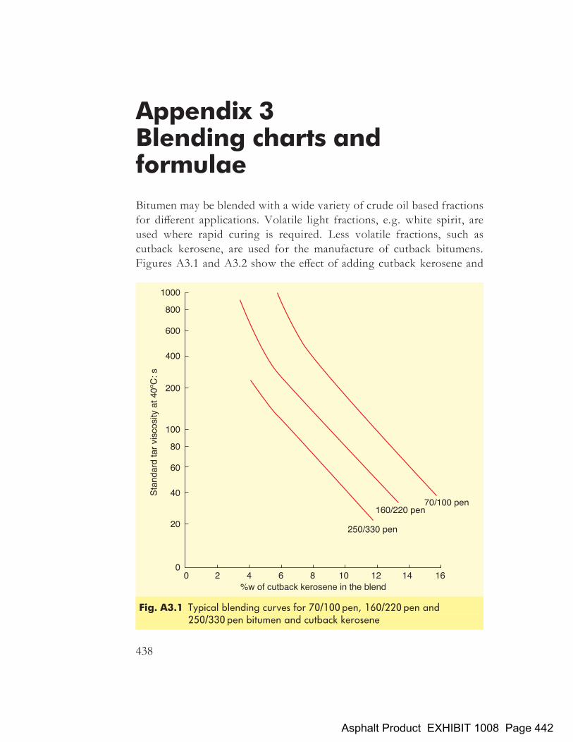
Appendix 3Blending charts andformulae
Bitumen may be blended with a wide variety of crude oil based fractionsfor different applications. Volatile light fractions, e.g. white spirit, areused where rapid curing is required. Less volatile fractions, such ascutback kerosene, are used for the manufacture of cutback bitumens.Figures A3.1 and A3.2 show the effect of adding cutback kerosene and
438
Fig. A3.1 Typical blending curves for 70/100 pen, 160/220 pen and250/330 pen bitumen and cutback kerosene
Asphalt Product EXHIBIT 1008 Page 442

diesel respectively to 70/100 pen, 160/220 pen and 250/330 pen bitumen.Similarly, Fig. A3.3 shows the effect on penetration when diesel isadded to 40/60 pen bitumen.Bitumens are miscible with each other in all proportions. The penetra-
tion and softening point of a blend of two bitumens can be estimated
Fig. A3.2 Typical blending curves for 70/100 pen, 160/220 pen and250/330 pen bitumen and diesel
Fig. A3.3 Typical blending curve for 40/60 pen bitumen and diesel
Appendix 3
439
Asphalt Product EXHIBIT 1008 Page 443
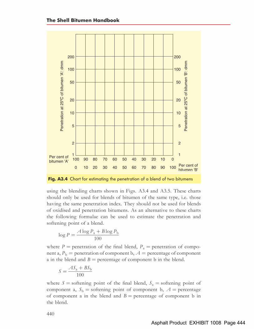
using the blending charts shown in Figs. A3.4 and A3.5. These chartsshould only be used for blends of bitumen of the same type, i.e. thosehaving the same penetration index. They should not be used for blendsof oxidised and penetration bitumens. As an alternative to these chartsthe following formulae can be used to estimate the penetration andsoftening point of a blend.
logP ¼ A logPa þ B logPb
100
where P ¼ penetration of the final blend, Pa ¼ penetration of compo-nent a, Pb ¼ penetration of component b,A ¼ percentage of componenta in the blend and B ¼ percentage of component b in the blend.
S ¼ ASa þ BSb100
where S ¼ softening point of the final blend, Sa ¼ softening point ofcomponent a, Sb ¼ softening point of component b, A ¼ percentageof component a in the blend and B ¼ percentage of component b inthe blend.
Fig. A3.4 Chart for estimating the penetration of a blend of two bitumens
The Shell Bitumen Handbook
440
Asphalt Product EXHIBIT 1008 Page 444

Fig. A3.5 Chart for estimating the softening point of a blend of two bitumens
Appendix 3
441
Asphalt Product EXHIBIT 1008 Page 445

Appendix 4Calculation of bitumen filmthickness in an asphalt
It is possible to estimate the surface area of a sample of aggregate bycoating it with an oil and measuring the quantity of oil required forcomplete coating. Alternatively, the surface area of an aggregate can becalculated by assuming a specific aggregate particle shape. Hveem[567]
calculated surface area factors, assuming a spherical particle shape anda specific gravity of 2.65. Typical surface area factors are shown inTable A4.1.The surface area of the aggregate is calculated by multiplying the total
mass expressed as a percentage passing each sieve size by the appropriatesurface area factor and adding the resultant products together. All thefactors must be used and if different sieves are used, different factorsare necessary. The theoretical bitumen film thickness is then calculated as:
T ¼ b
100� b� 1
�b� 1
SAF
where T ¼ bitumen film thickness (in mm), �b ¼ density of bitumen (inkg/m3), SAF ¼ surface area factor (in m2/kg) and b ¼ bitumen content(in %).Another method, developed in France[568], gives an approximation of
the binder film thickness using the formula:
T ¼ b
a� 5ffiffiffiffiffiffiPp
where T ¼ bitumen film thickness (in mm), b ¼ bitumen contentexpressed as the percentage by total mass of the mixture, a is a correction
442
567 AMERICAN SOCIETY for TESTING and MATERIALS. Standard test methodsfor resistance to deformation and cohesion of bituminous mixtures by means of Hveemapparatus, D1560-92, 1 Jan 1992. ASTM, Philadelphia.
568 NORME FRANCAISE. Couches d’assis: Enrobe a eleve, NF P 98-140, Dec 1991.NF,Paris.
Asphalt Product EXHIBIT 1008 Page 446

coefficient taking into account the density of the aggregate and is givenby
a ¼ 2650
SGa
where SGa ¼ density of the aggregate (in kg/m3),� is the specific surfacearea of the aggregate and is given by
� ¼ 0:25Gþ 2:3Sþ 12sþ 135f
where G ¼ proportion by mass of aggregate over 6.3mm, S ¼proportion by mass of aggregate between 6.3 and 3.15mm,s ¼ proportion by mass of aggregate between 3.15 and 0.80mm andf ¼ proportion by mass of aggregate smaller than 0.80mm.
Table A4.1 Typical surface area factors
Sieve size: mm Surface area factor: m2/kg
0.075 32.770.150 12.290.300 6.140.600 2.871.18 1.642.36 0.82
>4.75 0.41
Appendix 4
443
Asphalt Product EXHIBIT 1008 Page 447

Index
Note: Figures and Tables are indicated by italic page numbers
acid value of bitumen, effect onemulsions 110
acrylic resins, in surfacings 406adhesion agents, in surface dressing 389adhesion between aggregate and bitumen
171�87determination of 155�6factors affecting 171�4failures 174�7improving 185�7measurement of 177�85, 391in surface dressing 391�2
adhesion characteristics of bitumen 50in QUALAGON# 49
adhesion improvers, as bitumenmodifiers 65
adhesivity of emulsions 104�5adsorption tests 182�3ageing of bitumen, tests 51�2, 58�9,
168�70ageing indexduring various processes 163relationship to chemical composition
39, 40in service 163, 164
aggregate abrasion value (AAV), ofsurface dressing chippings 378, 384
aggregate drying/heating, in asphaltplants 270�1, 273, 274�5
aggregate properties 225�9adhesion affected by 172�3, 183, 185,
187assessment of 227�9key properties 226
aggregates 219�29artificial/synthetic 222
categorisation of 222, 223, 225coloured 431�2extraction of 222grading categories 223, 224igneous 220�1metamorphic 221�2natural 219�22origins 219�20quality control 223sedimentary 220, 221size 223–5Standard 222surface area factors 442typical values 443types 220�2
aggregate crushing value 225aggregate impact value 225air blowing of bitumens 13�16effect on chemical composition 38
air-blown bitumens 14�15aircraftloads and wheel configurations 422tyre pressures 421
airfield pavements 419�24asphalt compared with concrete
pavements 420design 421�23design methods 422�23requirements 422�24
airfield runway maintenance 112, 403,404
alligator cracking 196American Association of State
Highway Officials (AASHO) roadtest 357
D6723-02 58
445
Asphalt Product EXHIBIT 1008 Page 448

American Society for Testing andMaterials (ASTM)
methods 120, 123, 169, 313, 318, 319D5-97 119, 120D36-95 119, 121, 148D113-99 49, 152D1560-92 442D1754-97 169D2872-97 51, 58D4123-82 318, 319D4402-01 127D6521-00 58
anionic emulsifiers 93, 96anionic emulsions 91production of 108
antioxidants, as bitumen modifiers 65aromatics in bitumen 32chemical structure 33, 69content of various bitumens 40
asphalt; see also cold mixed asphalt;coloured asphalt; epoxy asphalt; hotrolled asphalt; mastic asphalt
analysis of bitumen content 277�8blistering in 176choice on major highways 240, 241,
242�3compaction of 292�302cooling time between laying and
compaction 294, 296�7, 298determination of recovered bitumen
properties 332�6empirical tests for 329�36engineering properties 337�49fatigue characteristics 344�9fundamental tests 307�22gradings for 232, 233guidance on selection of mixtures 265high-workability mixtures 290, 301,
302influence of bitumen properties during
construction phase 191�5influence of bitumen properties on in-
service performance 195�218laying of 280�92low-workability/‘stiff’ mixtures 290,
301meaning of term 3, 232minimum rolling temperature 192, 193,
298mixing of 160�1, 191�3, 272, 273,
274�5permanent deformation characteristics
340�4pitting in 176production control testing of 276�8
production of, see asphalt productionplants
recycling of 275�6, 413�15role of bitumen modifiers in 62�4segregation of mixtures 191, 291�2simulative tests 50, 180�2, 322�28sources 3, 5�7stiffness properties 337�40stresses in 306testing of 305�36transportation of 160, 161, 193, 279trial laying 257types 231�42UK production 419
asphalt bases and binder courses,hardening of bitumen in 172
asphalt batch plant 268�72aggregate dryer/heater 270�1aggregate feed system 269�70dust collection in 272freestanding versions 272�3mixing section 272mobile versions 273multiple hot stone bin version 273recycled asphalt pavement added 276throughput capacities 268
Asphalt Institute, airfield pavementdesign method 422, 423
asphalt production plants 267�78additive systems 276batch heater plant 273batch plant 268�72control testing for 276�8drum mix plant 273�75early techniques 267recycled asphalt pavement added
275�6asphalt surface courses, hardening of
bitumen in 163�8asphaltenes 31chemical structure 32content of various bitumens 40effect on rheology of bitumens 37�8formation in blowing process 13, 16
asphaltic concretes 234, 247, 424; see alsocoated macadams
auto-ignition temperature of bitumen 21average least dimension, effect on
adhesion 185axle load equivalence factor 357
barrier creams 26, 403bases in pavements 355, 356coated macadams in 234�6design of 255�9
The Shell Bitumen Handbook
446
Asphalt Product EXHIBIT 1008 Page 449
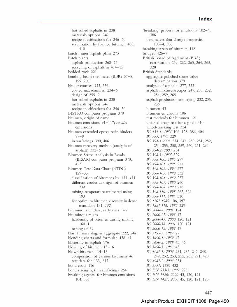
hot rolled asphalts in 238materials options 240recipe specifications for 246�50stabilisation by foamed bitumen 408,
410batch heater asphalt plant 273batch plantsasphalt production 268�73recycling of asphalt in 414�15
bedded rock 221bending beam rheometer (BBR) 57�8,
199, 200binder courses 355, 356coated macadams in 234�6design of 255�9hot rolled asphalts in 238materials options 240recipe specifications for 246�50
BISTRO computer program 370bitumen, origin of name 1bitumen emulsions 91�117; see also
emulsionsbitumen extended epoxy resin binders
87�9in surfacings 390, 406
bitumen recovery method (analysis ofasphalt) 332�6
Bitumen Stress Analysis in Roads(BISAR) computer program 370,423
Bitumen Test Data Chart (BTDC)129�35
classification of bitumens by 133, 135different crudes as origin of bitumen
134mixing temperature estimated using
193for optimum bitumen viscosity in dense
macadam 131, 132bituminous binders, early uses 1�2bituminous mixeshardening of bitumen during mixing
160�1testing of 52
blast furnace slag, as aggregate 222, 248blending charts and formulae 438�41blistering in asphalt 176blowing of bitumen 13�16blown bitumens 14�15composition of various bitumens 40test data for 133, 135
bond coats 116bond strength, thin surfacings 264breaking agents, for bitumen emulsions
104, 386
‘breaking’ process for emulsions 102�4,386
parameters that change properties103�4, 386
breaking stress of bitumen 148bridges 426�7British Board of Agrement (BBA)
certification 239, 262, 263, 264, 265,328
British Standardsaggregate polished stone value
determination 379analysis of asphalts 277, 333asphalt mixtures/recipes 247, 250, 252,
254, 259, 265asphalt production and laying 232, 235,
236bitumen 43bitumen emulsions 106test methods for bitumen 121uniaxial creep test for asphalt 310wheel-tracking test 324BS 434-1: 1984 106, 128, 386, 404BS 593: 1973 329BS 594-1:2003 234, 247, 250, 251, 252,
254, 255, 258, 259, 260, 261, 294BS 594-2: 2003 234BS 598-3: 1985 329BS 598-100: 1996 277BS 598-101: 1996 277BS 598-102: 1996 277BS 598-103: 1990 332BS 598-104: 1989 257BS 598-107: 1990 260BS 598-108: 1990 218BS 598-110: 1998 262, 324BS 598-111: 1995 310BS 1707:1989 106, 397BS 1881-116: 1985 329BS 2000-8: 2001 124BS 2000-27: 1993 47BS 2000-49: 2000 120, 121BS 2000-58: 2001 120, 121BS 2000-72: 1993 47BS 3195-3: 1987 27BS 3690-1: 1989 47BS 3690-2: 1989 43, 46BS 3690-3: 1983 43BS 4987-1: 2003 234, 236, 247, 248,
249, 252, 253, 255, 265, 291, 420BS 4987-2: 2003 234BS 5931: 1980 432BS EN 933-3: 1997 225BS EN 1426: 2000 43, 120, 121BS EN 1427: 2000 45, 120, 121, 123
Index
447
Asphalt Product EXHIBIT 1008 Page 450

British Standards continuedBS EN 1097-8: 2000 349, 383, 384BS EN 12591: 2000 43, 45, 54, 169BS EN 12592: 2000 45BS EN 12593: 2000 124BS EN 12607-1: 2000 45BS EN 12607-3: 2000 45BS EN 12697-3: 2000 333BS EN 12697-4: 2000 333BS EN 13036-1: 2002 246, 382BS EN 13043: 2002 222, 379BS EN 22592: 1994 45BS EN ISO 9001: 2000 263PD 6682-2:2003 223, 224, 227PD 6682-9:2003 223
bulk storage tanks; see also storagefor asphalt 161�2for bitumen 17, 19hardening of bitumen in 159�60
burns due to hot bitumen, first aid for22�4
Calculation of Asphalt LayingTemperatures (CALT) computerprogram 296
California bearing ratio (CBR) 362airfield pavement design based on
423design curves 363test method 329, 362
canal construction applications 429, 430Cantabro test 180capillary viscometer 126capping 355carcinogenic risks 22Caribit 74�5elastic recovery of asphalt affected by
76softening point of asphalt affected by
75, 76Cariphalte DM 72deformation resistance of asphalt
affected by 73, 74fatigue flexibility of asphalt affected by
74, 75properties on ageing 77
Cariphalte Fuelsafe 86�7categorisation tests 119�35cationic emulsifiers 93, 94�6, 105cationic emulsions 91, 92applications 386, 392, 404
cementitious grouted macadams 415�16CE marking 223CEN bitumen specifications 54, 55chemical additives
as anti-stripping agents 186modification of bitumen by 65, 66
chemical composition of bitumen 21�2,29�35
relationship to ageing index 38, 40relationship to penetration index 39, 40relationship to physical properties
38�41chemical disbonding 177chemical immersion tests 179chemical modifiers 65, 66chipped hot rolled asphalt 231, 238, 242,
252chippings, coloured 430�1chippings for surface dressingcoated chippings 379�80coloured chippings 412, 430�1and emulsions 103�4requirements 379spreaders 398�9typical properties 380
chromatographic techniques 30�1Class B/S/W bitumens 133, 135clay-stabilised emulsions 92coal tar 8coated macadam bases and binder courses
234�6design of 255�8recipe specifications for 247�9
coated macadam surface courses 236�8design of 259fretting of 216recipe specifications for 250�2
coated macadams 234�8, 247gradings for 232, 233
coating tests (for adhesion under wetconditions) 182
cohesion 48, 50cohesive strength of bitumen,
determination of 48, 49, 50, 155�6cold mixed asphalt 112�15HAUC specification 114�15theory 113
coloured asphalt 84�5, 276applications 85, 86
coloured surface treatments 411�2coloured surfacings 404, 411�2, 430�2thermoplastic compared with
thermosetting systems 412combustion of bitumen 21compaction of asphalt 1973�5, 292�302and cooling time 294, 296�7, 298determination of density 257, 303�304minimum rolling temperature 192, 193,
298
The Shell Bitumen Handbook
448
Asphalt Product EXHIBIT 1008 Page 451
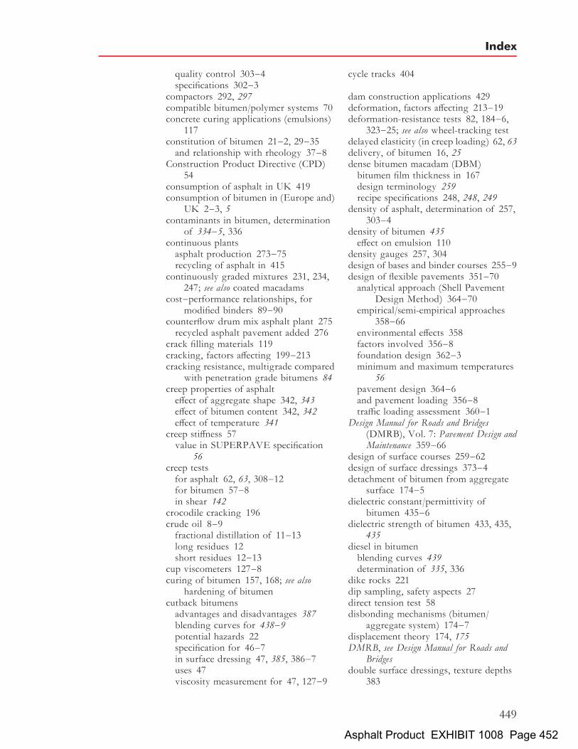
quality control 303�4specifications 302�3
compactors 292, 297compatible bitumen/polymer systems 70concrete curing applications (emulsions)
117constitution of bitumen 21�2, 29�35and relationship with rheology 37�8
Construction Product Directive (CPD)54
consumption of asphalt in UK 419consumption of bitumen in (Europe and)
UK 2�3, 5contaminants in bitumen, determination
of 334�5, 336continuous plantsasphalt production 273�75recycling of asphalt in 415
continuously graded mixtures 231, 234,247; see also coated macadams
cost�performance relationships, formodified binders 89�90
counterflow drum mix asphalt plant 275recycled asphalt pavement added 276
crack filling materials 119cracking, factors affecting 199�213cracking resistance, multigrade compared
with penetration grade bitumens 84creep properties of asphalteffect of aggregate shape 342, 343effect of bitumen content 342, 342effect of temperature 341
creep stiffness 57value in SUPERPAVE specification
56creep testsfor asphalt 62, 63, 308�12for bitumen 57�8in shear 142
crocodile cracking 196crude oil 8�9fractional distillation of 11�13long residues 12short residues 12�13
cup viscometers 127�8curing of bitumen 157, 168; see also
hardening of bitumencutback bitumensadvantages and disadvantages 387blending curves for 438�9potential hazards 22specification for 46�7in surface dressing 47, 385, 386�7uses 47viscosity measurement for 47, 127�9
cycle tracks 404
dam construction applications 429deformation, factors affecting 213�19deformation-resistance tests 82, 184�6,
323�25; see also wheel-tracking testdelayed elasticity (in creep loading) 62, 63delivery, of bitumen 16, 25dense bitumen macadam (DBM)bitumen film thickness in 167design terminology 259recipe specifications 248, 248, 249
density of asphalt, determination of 257,303�4
density of bitumen 435effect on emulsion 110
density gauges 257, 304design of bases and binder courses 255�9design of flexible pavements 351�70analytical approach (Shell Pavement
Design Method) 364�70empirical/semi-empirical approaches
358�66environmental effects 358factors involved 356�8foundation design 362�3minimum and maximum temperatures
56pavement design 364�6and pavement loading 356�8traffic loading assessment 360�1
Design Manual for Roads and Bridges(DMRB), Vol. 7: Pavement Design andMaintenance 359�66
design of surface courses 259�62design of surface dressings 373�4detachment of bitumen from aggregate
surface 174�5dielectric constant/permittivity of
bitumen 435�6dielectric strength of bitumen 433, 435,
435diesel in bitumenblending curves 439determination of 335, 336
dike rocks 221dip sampling, safety aspects 27direct tension test 58disbonding mechanisms (bitumen/
aggregate system) 174�7displacement theory 174, 175DMRB, see Design Manual for Roads and
Bridgesdouble surface dressings, texture depths
383
Index
449
Asphalt Product EXHIBIT 1008 Page 452

drum mix asphalt plants 273�75bulk storage silos 161, 275compared with batch plants 274counterflow plant 275dust collection in 275hardening of bitumen in mixer 160�1mobile version 273, 274throughput capacities 273
ductility of bitumen 50; see also cohesivestrength
testing of 48�50, 152�3durability, definition 327durability of asphalt, tests 327�8durability of bitumen 50, 157�70factors affecting 50�3, 157�9tests 51�2, 53, 168�70
dynamic bending tests (asphalt) 319�21,344�5
dynamic immersion tests 178dynamic shear rheometry (DSR) 58,
144�7binder ageing near asphalt surface 206,
208and SHRP/SUPERPAVE specification
56, 147zero shear viscosities measured by 217
dynamic stiffness tests for asphalt319�21
dynamic viscosity 125
elastic modulus 139�40relationship to shear modulus 143
elastic stiffness of asphalt 337elastomers 65, 67�9modification of bitumen using 66,
69�77electrical conductivity of bitumen 431,
435electrical properties of bitumen 433,
435�7electrolyte content of bitumen 109effects on emulsions 109�10
elemental analysis of bitumens andconstituents 29�30, 34
elevated-temperature hazards 20empirical design methods, for airfield
pavements 423empirical testsfor asphalt 329�32for bitumen 119�24
emulsified asphalts 113; see also coldmixed asphalts
emulsifiers 92�6chemical structures 93�6role in bitumen emulsions 92�3, 94
emulsions 91�117adhesivity 104�5advantages and disadvantages 388bibliography 117breaking properties 102�4, 386classification of 91�2, 106effects of bitumen properties 109�10effects of manufacturing conditions on
particle size distribution 108�9emulsifiers in 92�6first patent on use 92interdependence of manufacturing
variables and emulsion properties111, 112
manufacture of 96�7, 98modification of properties 107�11particle size distribution 103, 107�9with polymer modified bitumens 107,
110�11emulsion properties 110�11manufacture of 110method of use 111in surface dressing 389�90
potential hazards 22properties 97, 99�105pumping, heating and transport
stability 100in road mixtures 112�15road uses 112�16settlement in 99�100, 110specifications 106�7stability 99�100in surface dressing 97, 111, 385, 386uses (miscellaneous) 116�17viscosity 100�2ways of increasing viscosity 101�2
end result specifications, for compactionof asphalt 302�3
engineering properties of asphalts337�49
engineering properties of bitumen137�52
enrobe a module eleve (EME) 235�6environmental aspects of bitumen 28environmental effects on pavement
design 357Environmental Protection Act (1990)
112epoxy asphalt 88�9epoxy resins 87blends with bitumen 87�9, 390�1,
406in surfacings 390�1, 406
equivalent single wheel loads (ESWLs)421�2
The Shell Bitumen Handbook
450
Asphalt Product EXHIBIT 1008 Page 453

ethylene vinyl acetate (EVA) copolymers77, 78�9
chemical structure 78modification of bitumen by 79molecular weight 78vinyl acetate content 78�9
Eurobitume, first aid guidance notes22�4
European specifications, emulsions107
European Standards (ENs) 43, 54, 169,333
prEN 13588 155prEN 13589 153prEN 12697-39 278EN 13399, 1998 70CEN TC 227/WG1 180
European Union 222evaporative hardening of bitumen 51,
158, 159tests 51, 52
exudation droplet test 53exudative hardening of bitumen 53, 158,
159
Factory Production Control 223failuresadhesion 174�7in fatigue testing of asphalt 321surface dressing 400�1
fatigue, definition 344fatigue cracking 205�6fatigue lifeepoxy asphalt 88polymer modified bitumen 74, 75relationship to tensile strain 345�6
fatigue performance of asphalts 344�9factors affecting 347prediction of 347�9tests 321�2
fatigue ‘strength’ of bitumen 148, 150,152
fatting-up of binder 215, 375in surface dressing 401
fibresas bitumen modifiers 65as ‘stabilisers’ in asphalt 192
fillersas anti-stripping agents 186as bitumen modifiers 65, 66role in asphalt 191�2
film rupture 175�6film thickness in asphaltscalculation of 442�3determination of 442�3
effect on oxidation of bitumen 166�7,167
typical thicknesses 167fine graded surface courses 232, 237with coloured chippings 430
finish rolling 293, 298�9, 301fire fighting 26�7fire prevention 26first aidfor inhalation of fumes 25for skin burns 22�4
flakiness index (FI) 225, 226flash point, values listed for various
bitumens 44, 55, 56flexible pavementsdesign 351�70failure modes 351stiffness of layers 353, 354structural elements 353, 355�6
flexural fatigue resistancetest 89values listed for various bitumens 88
fluxed bitumens, see cutback bitumensfoam index 408foamed bitumen 407�11foam characterisation 407�8mixing with aggregate 408�10uses 408, 410, 414warm asphalt mixes used 410�11
footways, surfacings for 404, 431force ductility test 152�3penetration grade and polymer
modified bitumens compared154
foundation of flexible pavement 355designing 362�3importance of firm construction 363
fourth power law 357Fraass breaking pointtest method 124�5values for various bitumens 55, 73
Francegrouted macadams 416surface dressing techniques 388wheel tracking tests 82, 323
fretting 215�18factors affecting 215�16of hot rolled asphalt surface course
216�18of macadam surface course 216
fuel-resistant binders 86�7fully blown bitumens 15; see also oxidised
bitumensfumes from bitumen 21first aid treatment after inhalation 25
Index
451
Asphalt Product EXHIBIT 1008 Page 454

fumes from bitumen continuedhazards via inhalation 24occupational exposure standards 24
gap-graded mixtures 231, 238, 250; see alsohot rolled asphalt
durability 165gas oil 12GEL type bitumens 35, 36, 37, 69Germanyguidelines on surface dressing systems
373railway applications 425�6stone mastic asphalts 236, 239surface dressing binders 385surface dressing specifications 392
gilsonite 7grave emulsion 113GripNumber 380, 381GripTester 380grouted macadams 415�17asphaltic 416cementitious 415�16development of 412laying of 416-17
grouting, emulsions used in 115�16gussasphalt 426gyratory compaction test 325�6
Hamburg wheel-tracking test 324�5hard bitumens, specification for 46hardening of bitumen 157�9in asphalt bases 168in asphalt surface courses 163�8in asphalts during hot storage,
transport and laying 161�2causes 51, 53, 157�9during mixing with aggregate 160�1during storage 159�60effect of void content 163, 165on road 162�8tests 51�2, 53
Hardicrete 415hazards associated with bitumeninhalation of fumes 24skin contact 22thermal burns 20�1
HD 24 360�1HD 25 362�3HD 26 364�6HD 28 381HD 36 37health aspects 20�5heavy duty macadam (HDM) 234�5design terminology 259
recipe specifications 248, 249Heukelom nomograph (for strain at
tensile break) 148, 151high-friction surfacings 390�1, 406high-modulus base (HMB) materials
235�6design terminology 259recipe specifications 248, 248
Highway Authorities Product ApprovalScheme (HAPAS) certification 239,262, 263, 264, 265, 328
highway maintenanceslurry surfacing 404surface dressing 371�403
Highways Authorities and UtilitiesCommittee (HAUC) specificationfor cold lay surfacing materials114�15
history of bitumen 1�9, 429Hooke’s law 140, 315hot mixture storage test 52hot rolled asphalt 238�9, 250bitumen film thickness in 167gradings for 232, 233
hot rolled asphalt bases and bindercourses 238
design of 258�9recipe specifications for 250
hot rolled asphalt surface courses23�9
with coloured chippings 430, 431design of 259�62fretting of 220�2performance-related design mixtures
260�2recipe specifications for 252�55
hydrated lime, as filler 65, 66, 186hydraulic applications 429�30hydraulic scouring, disbonding caused by
180�1hydrogen sulphideemissions from sulphur asphalt 80occupational exposure standards 24
igneous rocks 220�1ignition furnace methods, for analysis of
asphalts 278immersion mechanical tests 50, 179�80immersion testschemical 179dynamic 178static 178
immersion trafficking tests 180�2locked-wheel method 182
impact absorbing asphalt (IAA) 427�8
The Shell Bitumen Handbook
452
Asphalt Product EXHIBIT 1008 Page 455

impact tests 155�6, 183�4index tests 362indirect tensile fatigue test (ITFT) 322,
349standard test conditions 322typical results 321
indirect tensile stiffness modulus (ITSM)test 179, 317�18
standard test conditions 318typical results 318
indirect tensile tests 312�19stress distribution in 314theory 313�17
infrared spectrophotometer, for polymercontent of bitumen/polymer systems71, 72
inhalation of fumesfirst aid treatment after 25as hazard 24
Institute of PetroleumModel Code of Safe Practice 20test methods 127, 159
International Civil Aviation Organization(ICAO), on bearing capacity ofairfield pavements 422
job mixture approval trial 257�8, 262joints when laying asphalt 289
K1-70 emulsion 100, 103, 106, 110compared with emulsions containing
polymer modified bitumen 110use in surface dressing 103, 386
kerbs 432kerosene 12kinetic viscosity 125measurement of 126, 127, 128�9, 437
Laboratoires Central des Ponts etChaussees (LCPC) wheel track tester82, 323
lake asphalt 2, 3, 5�6laser texture measurement technique 383laying of asphalt 193leaching of components from bitumen 28life cycle assessment (LCA) 28life cycle costing 89for modified binders 89
lignosulphonate, chemical structure 95limpet pull-off test 184LINK Bitutest project 328long-life pavement concept 210, 301,
352�3long-term ageing of bitumen 162, 195longitudinal cracking 196, 200�2, 201
Los Angeles (LA) coefficient 225low-temperature cracking 196, 197�200
maltenes 35conversion to asphaltenes 13, 16
Manual of Contract Documents for HighwayWorks (MCHW) 228, 255�6, 393;see also Specification for HighwayWorks
manufacture of bitumen 11�16Marshall asphalts 234; see also coated
macadamsMarshall stability 50, 179; see also retained
Marshall stability testdetermination of 329�30for epoxy asphalts 88relationship with bitumen properties
212�13, 214Marshall test 50, 303, 329�30compared with other tests 331limitations 330�2
MCHW, see Manual of ContractDocuments for Highway Works
mean summer SCRIM coefficient (MSSC)381
melt flow index (MFI) 78metallic constituents of bitumen 33�5metamorphic rocks 221�2method specifications, for compaction of
asphalt 302Mexphalte C pigmentable binder 85, 86Mexphalte Fuelsafe 86, 87micro-asphalts 404microsurfacings 403�405minerals 220; see also aggregatesmixes, see bituminous mixesmixinghardening of bitumen during 160�1influence of bitumen properties 191�3temperature 192�3
modification of bitumen 64�80additives used 65benefits of various modifiers 66by rubbers 79by sulphur 80by thermoplastic elastomers 69�77by thermoplastic polymers 77�9by viscosity reducers 79modifiers used 65requirements of modifiers 64
modified bitumens 61�90in surface dressing 387�8
motor racing tracks 428moving wheel load, visco-elastic response
of asphalt under 62, 63, 306
Index
453
Asphalt Product EXHIBIT 1008 Page 456

multigrade bitumens 81�4compared with penetration grade
bitumens 81, 82, 83, 84Multiphalte range 62, 81�4
naphtha 12naphthenic acids, in bitumen 108, 110natural aggregates 219�22natural bitumens 3, 5�7; see also gilsonite;
lake asphalt; rock asphalt; TrinidadLake Asphalt
as bitumen modifiers 65night working 103nomographsstiffness modulus of asphalt 338, 339stiffness modulus of bitumen 147�8,
149non-ionic emulsifiers 93, 96non-ionic emulsions 91�2Nottingham Asphalt Tester (NAT) 179,
313, 317, 319nuclear density gauges 257, 304
open graded binder courses 236open graded surface courses 236, 237for airfield runways 420�1
origin of name ‘bitumen’ 1oxidation of bitumen, factors affecting 17oxidation stabilityfor bitumens 19tests 51�2
oxidative hardening of bitumen 51, 158,158
oxidised bitumens 15, 35specification for 45�6
pad coats (surface dressing) 392, 395paraffin wax, modification of bitumen by
79, 80particle loss index (PLI) 180particle size distributionaggregates 225emulsions 103, 107�9
pavement classification number (PCN)for airfields 422
pavement cracking 195�209types 196
pavement design 361�70; see also designof flexible pavements
pavers 280�84‘angle of attack’ of screed 283�4auger box on 289fixed/variable paving width 284flow of material through 282, 283heating of screed 284
height setting of auger 292high-compaction screeds 286screed unit 282�84tamping screeds 285tamping/vibrating screeds 286tractor unit 280�2vibrating screeds 285�6
paving grade bitumens, specifications 44,55
paving operations 286�92factors to be controlled 286�7head of material 287, 288joints 289layer thickness 288�9laying temperature 290mixture types 290paving speeds 287�8paving width 284, 289segregation of mixtures 291�2surface regularity 288�9
PD 6682-2:2003 223, 224, 227PD 6682-9:2003 223penetrationdefinition 120effect of on-road service 164prediction for blends of bitumens 440values listed for various bitumens 44,
46, 55, 164penetration grade bitumenscompared with polymer modified
bitumens 73, 74, 75, 77, 154, 156modified with paraffin wax 79, 80specification for 43�5
penetration index (PI)deformation-resistance affected by
209�12determination of 136�7, 138, 139effect on laying and compaction of
asphalt 193�5nomographs for prediction 138, 139and on-road service 164, 166, 194relationship to chemical composition
39, 40typical values for various bitumens 46,
136penetration test 120�1repeatability and reproducibility limits
121percentage refusal density (PRD) test
257, 258performance-related design hot rolled
asphalt mixtures 260�2permanent cold lay surfacing materials
(PCSMs), HAUC specification for114�15
The Shell Bitumen Handbook
454
Asphalt Product EXHIBIT 1008 Page 457

permanent deformation of asphalt340�44
determination of 308�12, 343prediction of 343�4
personal protective equipment 25�6, 403photo-oxidation of bitumen 158, 164�5physical constants of bitumen 433�36physical hardening of bitumen 158, 159physical properties of bitumenaggregate/bitumen bond affected by
172, 173�4relationship to chemical composition
38�41pigmentable binders 84�5, 86pitting in asphalt 176plutonic rocks 221pneumatic-tyred rollers 293, 295, 301uses 399, 405
polished stone value (PSV)of chippings for surface dressing 380determination of 379, 383�4
polycyclic aromatic compounds (PACs)21, 22
polymer modified bitumens 61�90advantages 61in airfield pavements 420, 424cohesion curve 156compared with penetration grade
bitumens 73, 74, 75, 77, 154compatible and incompatible bitumen/
polymer systems 70�1deformation resistance 74determination of polymer content 71,
72emulsions containing 107, 110�11emulsion properties 110�11manufacture of 110method of use 111in surface dressing 389�90
factors affecting storage stability 70, 71fatigue behaviour 75force ductility curve 154modifiers used 65�6storage and pumping temperatures
19�20in surface dressing 387�90viscosity�temperature relationship 73
polyurethane resins, in surfacings 406pore pressure, disbonding caused by 177porous asphalt 237�8, 243in airfield pavements 424bitumen film thickness in 167
porphyry 220, 221pressure ageing vessel (PAV) test 58�9,
170
in SUPERPAVE specification 56protective coats (emulsions) 117Published Documents (British Standards)PD 6682-2:2003 223, 224, 227PD 6682-9:2003 223
pugmill (for mixing asphalt) 272pull-off tests 184�5pumping temperatures, for bitumens 19
QUALAGON# 48, 49, 50, 52verification of 53
quality of bitumen 47�53quality control, compaction of asphalt
301�304
railway applications 424�6ravelling of macadam surface course 216recipe specificationsfor bases and binder courses 246�50for surface courses 250�56
recreational areas 427�8recycled asphalt pavement (RAP),
addition in asphalt mixing plant275�6
recycling of asphalts 413�15cold in situ recycling procedures 408,
410, 413�14hot in situ recycling procedures 413in off-site plants 414�15in situ recycling 413�14
refined bitumen 8�9Refined Bitumen Association (RBA),
Code of Practice on Safe Delivery 16refined lake asphalt 6reflective cracking 196, 206�9modelling 208�9, 210
remixing to recycle asphalt 275�6, 413repave process 413repeated load axial test (RLAT) 310�12standard test conditions 312typical curves 312
repeated load indirect tensile tests 312�19repeated load triaxial test 307�8compared with Marshall test results
331requirements for asphalts 245�6reservoir construction applications
429�30resilient modulus of asphaltcalculation 316determination of 318�19
resilient modulus (RESMOD) test318�19
resins in bitumen 32content of various bitumens 40
Index
455
Asphalt Product EXHIBIT 1008 Page 458

restrained cooling test 84results for multigrade bitumens 84
retained Cantabro test 180retained Marshall stability test 50, 179retained stiffness test 179�80retread process 413�14rheological properties of bitumens 48;
see also stiffness; viscosityfactors affecting 37�8requirements in construction and
service 194road hardness probe 375Road Note 29 357, 359Road Note 39 373�4, 375, 392road traffic accidents, costs 391rock asphalt 2, 6�7rollers 292�3, 294�6number and type required 299for surface dressing 399
rolling patterns 299�301rolling procedures 293�9rolling speeds 298, 299rolling thin-film oven test (RTFOT)
51�2, 58, 169�70rotational viscometer 57, 127, 128rubbers, modification of bitumen using
79Rubit impact absorbing asphalt 427�8rutting, see deformationrutting factor, in SHRP specification
219rutting resistancetests 82, 180�2, 308, 323�25values for various bitumens 82�3
safety aspects 25�7, 402�3sample valves 27sampling, safety aspects 27sand patch test (for macrotexture of road
surface) 382saturates in bitumen 32�3chemical structure 33content of various bitumens 40
SCRIM 380sedimentary rocks 224, 225segregation of mixtures 191, 291�2semi-blown bitumens 14�15sensor-measured texture depth (SMTD)
383shear modulusloss modulus component 146relationship to elastic modulus 143storage modulus component 146
Shell Epoxy Asphalt, compared withconventional asphalt 88
Shell Pavement Design Manual 367rut prediction procedure 308, 343�4
Shell Pavement Design Method (SPDM)366�70
for airfield pavement design 422, 423assumptions 370three-layered model used 367, 368variables in 370
Shellgrip 88, 390, 406SHELPHALT range of cutback
bitumens 47short-term ageing of bitumen 160, 195SHRP, see Strategic Highways Research
ProgramSHRP bitumen specification 54, 56,
57�9, 199, 215SHW, see Specification for Highway
Workssideways force coefficient (SFC) 380,
381sideways force coefficient routine
investigation machine (SCRIM) 380sieve sizes 224, 227simulative tests for asphalt 50, 180�2,
322�28skid resistance of roadshigh-friction binders in surface
dressing 390�1relationship with surface macrotexture
384�5tests 380�1
skin burns, first aid for 22�4skin contact, potential hazards through
22slab compaction test 326, 327sliding plate viscometer 125�6slip layers, emulsions used 117slurry seals 111�12slurry surfacings 403�405applications 404coloured surfacings 404, 412, 431developments 405materials 405purpose 404usage 405
softening point, prediction for blends ofbitumens 441
softening point of bitumenchanges after hardening 44, 52, 55, 75,
76, 191changes on ageing 75, 76, 77changes during storage testing of
mixes 52changes in service 163, 164definition 122�3
The Shell Bitumen Handbook
456
Asphalt Product EXHIBIT 1008 Page 459

polymer modified bitumens 75, 76values listed for various bitumens 44,
46, 55, 76viscosity at softening point 123
softening point test 121�3ASTM version compared with other
methods 123repeatability and reproducibility limits
123soil stabilisation applications (emulsions)
116�17SOL type bitumens 35, 36, 69solubility, values listed for various
bitumens 44, 46, 55solvent extraction 30sources of binders 3�9SPDM, see Shell Pavement Design
Methodspecial bitumens 61�90storage and pumping temperatures for
19�20specific gravity of bitumen 433, 434�5specific heat of bitumen 436Specification for Highway Works (SHW)
227, 255�6Clause 702 288Clause 919 393Clause 922 393Clause 929 255, 256Clause 930 235Clause 933 235Clause 942 239, 262Clause 943 261Notes for Guidance 256
specifications; see also recipe specificationsasphalts 246�55bitumens 43�7, 54�9cold lay surfacing materials 114�15compaction of asphalt 302�3emulsions 106�7
speedway tracks 428SprayGrip 88, 390standard axle, meaning of term 357standard tar viscometer (STV) 47, 127�8,
129conversion factors for other viscometry
methods 437standards; see also specificationsfor bitumens 43
static immersion tests 178static load, visco-elastic response of
asphalt under 62, 63steric hardening of bitumen 158, 159stiffening of bitumen, effects 62, 64stiffness of asphalts 337�40
determination of 317�18, 319�21prediction of 338�40
stiffness concept 137�42, 353stiffness modulus of asphaltcalculation 316epoxy asphalt 88experimental determination of 317�18prediction of 338�40
stiffness modulus of bitumen 140�2determination of 142�7effect of penetration index 140�1, 142effect of temperature and loading time
140�1, 142, 190fatigue ‘strength’ as function of 152as function of loading time 144, 145in-service data 164maximum values 125, 142measurement of 144�7prediction of 147�8, 149strain at break as function of 150
Stokes’ law 99�100stone mastic asphalt (SMA) 236non-road uses 424, 427
storage of bitumen 16�18hardening of bitumen during 159�60temperatures 19
strain criterion (in fatigue testing)345�6
Strategic Highways Research Program(SHRP)
adsorption test 182�3bitumen specification 54, 56, 57�9,
199, 215low-temperature cracking tests 198
stress relaxation 195stripping (failure of aggregate/bitumen
bond) 172, 173structure of bitumen 35�7styrene�butadiene�styrene (SBS) block
copolymers 67modification of bitumen by 70�1, 72,
74styreneic block copolymers 67�9sub-base of flexible pavement 355sulphur, modification of bitumen by
addition of 65, 66, 80SUPERPAVE asphalt binder
specification 54, 56, 57�9, 170surface courses 355, 356coated macadams in 236�8design of 259�62hot rolled asphalts in 238�9materials options 241recipe specifications for 250�55requirements 356
Index
457
Asphalt Product EXHIBIT 1008 Page 460

surface cracking 202�3modelling 203�5
surface dressing 371�303adhesion agents used 389aims 371�2basic procedure 372�3benefits 371bleeding 401coloured dressings 412cutback bitumens in 47, 385, 386�7design, in Germany 373design, in UK 373�4emulsions in 97, 111, 385, 386enhanced treatments 388�9equipment 396�400chipping spreaders 398�9rollers 399sprayers 397�8sweepers 399�400traffic control and aftercare 400
factors affecting design andperformance 374�92
bend severity 392binder type 385�91chipping characteristics 378�80condition of road surface 374geographical location and climatic
conditions 375geometry of site 392gradient of road 392hardness of road surface 374�5,
376�7seasonal effects 402size and type of chippings 378�80skid resistance 380�1, 384�5surface texture 381�84traffic volumes and speeds 374
failures 400�1fatting-up in 401handling temperatures 402�3modified binders in 387�8polymer modified binders in 387�8safety aspects 402�3season 402specifications 392�3in Germany 392in UK 393
types 393�96double surface dressing 395, 396inverted double surface dressing 394,
396pad coats 393, 395racked-in surface dressing 394, 395�6sandwich double surface dressing
394, 396
single surface dressing 394, 395surface oxidation of bitumen in asphalt
165�6synthetic aggregates 222
tack coats 116, 279�80tamping of asphalt 285tar 8temperature susceptibility of bitumen
136�7temperature(s), for storage and pumping
of bitumens 19�20tensile strain test 58tensile strength of bitumen 148test methodsadhesion 50, 177�85ageing 51�2, 58�9, 169�70analysis of asphalts 277for asphalts 50, 305�36cohesion 155�6creep of asphalt 308�11creep of bitumen 57�8, 62deformation-resistance of asphalt 82,
180�2, 308�11, 323�25ductility of bitumen 48�50durability of asphalt 327�8durability of bitumen 51�2, 53, 168�70dynamic stiffness of asphalt 319elastic properties of asphalt 307�8empirical tests for asphalt 329�36fatigue resistance of asphalt 319�22fundamental tests for asphalt 307�22low-temperature cracking 198�200rutting resistance of asphalt 82, 180�2,
308�11, 323�25simulative tests for asphalt 50, 180�2,
322�28skid resistance of roads 380�1stiffness of asphalt 312�19stiffness of bitumen 58, 144�7tensile fatigue of asphalt 322tensile strain in bitumen 58viscosity of bitumen 47, 57, 100�1,
125�9volatility of bitumen 52
thermal conductivity of bitumen 436thermal cracking 196�200thermal expansion coefficient of bitumen
433thermal fatigue cracking 196, 197, 200,
205thermal properties of bitumen 436thermal stress restrained specimen test
(TSRST) 198, 200thermoplastic elastomers 65, 67�9
The Shell Bitumen Handbook
458
Asphalt Product EXHIBIT 1008 Page 461

modification of bitumen using 66,69�77
thermoplastic polymers 65, 77in coloured surfacings 412modification of bitumen by addition of
66, 77�9thermoplastic rosin esters, in surfacings
402thermorheologically simple bitumen 144thermosetting binders 87�8in coloured surfacings 412compared with conventional asphalt
88�9, 88differences with thermoplastics 87�8
thin surfacings 239, 240, 241�2, 262�5aggregate properties 263bond strength 264compaction of 302cooling time between laying and
compaction 296�7, 298durability test 328grading of 263initial texture depth 264road/tyre noise 265sensitivity to water 264wheel-tracking rate 264
thin-film oven test (TFOT) 169toughness and tenacity test 153�5traffic loading assessment, in pavement
design 360�1Transport and Road Reseach LaboratoryLaboratory Report 496, 1972 338Laboratory Report 510, 1973
381, 384Laboratory Report 633, 1974 319, 349Laboratory Report 777, 1977
436Laboratory Report 833, 1978 357Laboratory Report 910, 1979 358Laboratory Report 989, 1981 64, 72, 73Laboratory Report 963, 1981 66Laboratory Report 1003, 1981 192, 193,
212, 215,Laboratory Report 1032, 1984 359, 364Research Report 4, 1985 193Research Report 26, 1986 344Research Report 132, 1987 235Research Report 296, 1991 381Research Report 323, 1992 77Report 624, 1980 294Supplementary Report 744, 1982 413
transportation of asphalt 279hardening of bitumen during 161, 162,
193Transport Research Laboratory
Laboratory Report 892, 1979 206Project Report 55, 1994 343Project Report 66, 1994 236
transverse cracking 196, 202, 203, 205trench reinstatement applications 114triaxial testing of asphalt 309Trinidad Epure 6Trinidad Lake Asphalt (TLA) 2, 3, 5�6TRLReport 250, 1997 157, 168, 196, 202,
206, 352, 363Report 264, 1997 238
TRL LtdRoad Note 39, 5th ed, 2002 182, 378,
382, 387, 392, 394, 431true boiling point�gas liquid
chromatography (TBP-GLC) 52tyre pressures 421tyre rubber, as bitumen modifier 61, 65,
66
UKchipped hot rolled asphalt 231, 238,
242, 252design of surface dressing 373�4hardness of road surfaces 375, 376�7skid-resistance testing 380�1surface dressing specifications 393use of surface dressing 371
UK Trunk Roads 227, 228, 256empirical design advice 359mandatory use of MCHW 228, 256options for bases and binder courses
240options for surface courses 241requirements for 228, 229testing requirements for aggregates
228, 229unconfined static uniaxial creep
compression testing 308�12uniaxial creep (UC) test 310�11standard test conditions 311typical results 311
uses of asphalt 419�32uses of bitumen 2, 4, 419�32
vacuum repeated load axial test(VRLAT) 309, 312, 313
Van der Poel nomograph (for stiffnessmodulus) 147�8, 149
vapour emissions from bitumen 21vehicle testing circuits 428�9Vialit pendulum test 155�6, 183Vialit plate test 183�4vibratory compaction of asphalt 285�6
Index
459
Asphalt Product EXHIBIT 1008 Page 462

vibratory rollers 293, 295compared with static rollers 293for surface dressing 399
visco-elastic behaviour 189, 337viscosityat softening point of bitumen 123of bitumens 47, 55, 73conversion factors 537of emulsions 100�2measurement of 47, 57, 100�1, 125�9requirements during construction
phase 190units 125
viscosity reducers, modification ofbitumen by addition of 79
viscous stiffness of asphalt 337volatility of bitumenin QUALAGON# 49
tests 52volcanic rock 221
water contact with bitumen 21waxy bitumens, test data for 133, 135wheel-tracking test 82, 180�2, 323�25epoxy asphalt compared with
conventional asphalt 88in immersion trafficking tests 180�2,
325multigrade bitumen asphalts 82, 83standard test conditions for UK test
324thin surfacings 264
wood-derived emulsifiers 93�4, 95working temperatures 19
zero shear viscosity concept 213, 215
460
The Shell Bitumen Handbook
Asphalt Product EXHIBIT 1008 Page 463