The S/390 G5/G6 binodal cache
10
by P. R. Turgeon P. Mak M. A. Blake M. F. Fee C. B. Ford III P. J. Meaney R. Seigler W. W. Shen The S/390 G5/G6 binodal cache The IBM S/390 ® fifth-generation CMOS-based server (more commonly known as the G5) produced a dramatic improvement in system-level performance in comparison with its predecessor, the G4. Much of this improvement can be attributed to an innovative approach to the cache and memory hierarchy: the binodal cache architecture. This design features shared caching and very high sustainable bandwidths at all points in the system. It contains several innovations in managing shared data, in maintaining high bandwidths at critical points in the system, and in sustaining high performance with unparalleled fault tolerance and recovery capabilities. This paper addresses several of these key features as they are implemented in the S/390 G5 server and its successor, the S/390 G6 server. Introduction The IBM S/390* G5 server represents a significant breakthrough in terms of high-end mainframe performance and throughput. The single most important contributor to this dramatic performance improvement is the architecture and design of the binodal cache. Although it builds upon key internal cache management concepts first developed for the G4 [1], the G5 binodal cache represents a major step forward in system organization and symmetrical multiprocessor (SMP) design. The cache and memory hierarchy presented here features large, high- frequency, 256KB unified private L1 caches, an 8MB binodal, shared L2 cache, a nonblocking crosspoint data switch, and a novel system controller managing all coherency and data transfer operations. These features, when combined with the significantly more powerful G5 microprocessor [2– 4], have resulted in the unprecedented system-level performance improvements demonstrated by the G5 server. The primary design objectives behind the creation of the binodal cache architecture were to minimize access latencies at all stages of the cache hierarchy and to control critical system resource utilization. Experience gained with the S/390 G3 and G4 servers has taught that S/390 SMP performance is particularly sensitive to system bus utilization and the queuing which can ensue if this utilization reaches unsustainable levels. An optimal design approach, as demonstrated in the bipolar ES/9021, involves the use of a large, fully shared L2 cache structure. Such a design offers the benefit of optimized cache latencies and efficiencies, but is not easily implementable in today’s CMOS technologies. The binodal cache architecture is an alternative approach, offering more modularity and compatibility with CMOS design. This architecture features a split- transaction bus design in which address and command information is managed on separate, dedicated buses. This approach eliminates multiplexing operations on the performance-critical data bus. Further, the crosspoint switch elements are now embedded into the system controller function. The number of cache/switch nodes in the system has been optimized at two, as compared to 12 in the S/390 G3 and four in the S/390 G4. The total number of chips comprising the system/bus controls and L2 cache functions has been reduced as well—from 20 rCopyright 1999 by International Business Machines Corporation. Copying in printed form for private use is permitted without payment of royalty provided that (1) each reproduction is done without alteration and (2) the Journal reference and IBM copyright notice are included on the first page. The title and abstract, but no other portions, of this paper may be copied or distributed royalty free without further permission by computer-based and other information-service systems. Permission to republish any other portion of this paper must be obtained from the Editor. 0018-8646/99/$5.00 © 1999 IBM IBM J. RES. DEVELOP. VOL. 43 NO. 5/6 SEPTEMBER/NOVEMBER 1999 P. R. TURGEON ET AL. 661
-
Upload
independent -
Category
Documents
-
view
0 -
download
0
Transcript of The S/390 G5/G6 binodal cache

by P. R. TurgeonP. MakM. A. BlakeM. F. FeeC. B. Ford IIIP. J. MeaneyR. SeiglerW. W. Shen
The S/390G5/G6 binodalcache
The IBM S/390® fifth-generation CMOS-basedserver (more commonly known as the G5)produced a dramatic improvement insystem-level performance in comparisonwith its predecessor, the G4. Much ofthis improvement can be attributed to aninnovative approach to the cache and memoryhierarchy: the binodal cache architecture. Thisdesign features shared caching and very highsustainable bandwidths at all points in thesystem. It contains several innovations inmanaging shared data, in maintaining highbandwidths at critical points in the system,and in sustaining high performance withunparalleled fault tolerance and recoverycapabilities. This paper addresses several ofthese key features as they are implemented inthe S/390 G5 server and its successor, theS/390 G6 server.
IntroductionThe IBM S/390* G5 server represents a significantbreakthrough in terms of high-end mainframeperformance and throughput. The single most importantcontributor to this dramatic performance improvement isthe architecture and design of the binodal cache. Althoughit builds upon key internal cache management conceptsfirst developed for the G4 [1], the G5 binodal cacherepresents a major step forward in system organizationand symmetrical multiprocessor (SMP) design. The cacheand memory hierarchy presented here features large, high-frequency, 256KB unified private L1 caches, an 8MB
binodal, shared L2 cache, a nonblocking crosspointdata switch, and a novel system controller managing allcoherency and data transfer operations. These features,when combined with the significantly more powerful G5microprocessor [2– 4], have resulted in the unprecedentedsystem-level performance improvements demonstrated bythe G5 server.
The primary design objectives behind the creation ofthe binodal cache architecture were to minimize accesslatencies at all stages of the cache hierarchy and tocontrol critical system resource utilization. Experiencegained with the S/390 G3 and G4 servers has taught thatS/390 SMP performance is particularly sensitive to systembus utilization and the queuing which can ensue if thisutilization reaches unsustainable levels. An optimal designapproach, as demonstrated in the bipolar ES/9021,involves the use of a large, fully shared L2 cachestructure. Such a design offers the benefit of optimizedcache latencies and efficiencies, but is not easilyimplementable in today’s CMOS technologies.
The binodal cache architecture is an alternativeapproach, offering more modularity and compatibilitywith CMOS design. This architecture features a split-transaction bus design in which address and commandinformation is managed on separate, dedicated buses.This approach eliminates multiplexing operations on theperformance-critical data bus. Further, the crosspointswitch elements are now embedded into the systemcontroller function. The number of cache/switch nodes inthe system has been optimized at two, as compared to 12in the S/390 G3 and four in the S/390 G4. The totalnumber of chips comprising the system/bus controls andL2 cache functions has been reduced as well—from 20
rCopyright 1999 by International Business Machines Corporation. Copying in printed form for private use is permitted without payment of royalty provided that (1) eachreproduction is done without alteration and (2) the Journal reference and IBM copyright notice are included on the first page. The title and abstract, but no other portions,of this paper may be copied or distributed royalty free without further permission by computer-based and other information-service systems. Permission to republish any other
portion of this paper must be obtained from the Editor.
0018-8646/99/$5.00 © 1999 IBM
IBM J. RES. DEVELOP. VOL. 43 NO. 5/6 SEPTEMBER/NOVEMBER 1999 P. R. TURGEON ET AL.
661

(G3) to 16 (G4) to 10 (G5)—a 50% reduction in CMOScomponents in only two years. Measurements on memory-intensive S/390 workloads have indicated that the designchanges introduced in the G5 binodal cache architecturehave reduced the cache and memory hierarchy componentof the CPI (cycles per instruction, a processor speedmetric) from two thirds in G4 to less than half of thetotal in G5. System bus utilization has also improvedsignificantly. Where average utilizations in the G4approach the 60% range, average utilizations on similarworkloads are less than 30% in the G5.
This paper describes a number of the unique aspects ofthe binodal cache architecture, with an emphasis on thosefunctions which contributed significantly to either systemperformance or system functionality. We begin with anoverview of the binodal cache itself, then describe theinternal controls used in shared cache and shared resourcemanagement. The next section discusses bus management
and control, and is followed by brief sections describinghardware assist capabilities and main memoryconsiderations. The unique RAS characteristics of the G5are described next. The paper concludes with a briefdescription of the binodal extensions implemented in theS/390 G6 as well as possible future enhancements.
Binodal cache structureThe G5 binodal cache architecture is depicted in Figure 1.The key components of this SMP architecture are the L1cache (embedded in the G5 microprocessor chip), the L2cache, the system controller (SC), the memory, and theprocessor, memory, and internode buses. The L1 cache isdescribed in [2]. The L2 cache chip, of which there areeight in a fully configured system, is a 17.36-mm 3 17.43-mmCMOS 6S2 chip containing the peripherally laid out 1MBcache array (Figure 2). This chip contains slightly morethan 59 million transistors, making it one of the densest
P. R. TURGEON ET AL. IBM J. RES. DEVELOP. VOL. 43 NO. 5/6 SEPTEMBER/NOVEMBER 1999
662
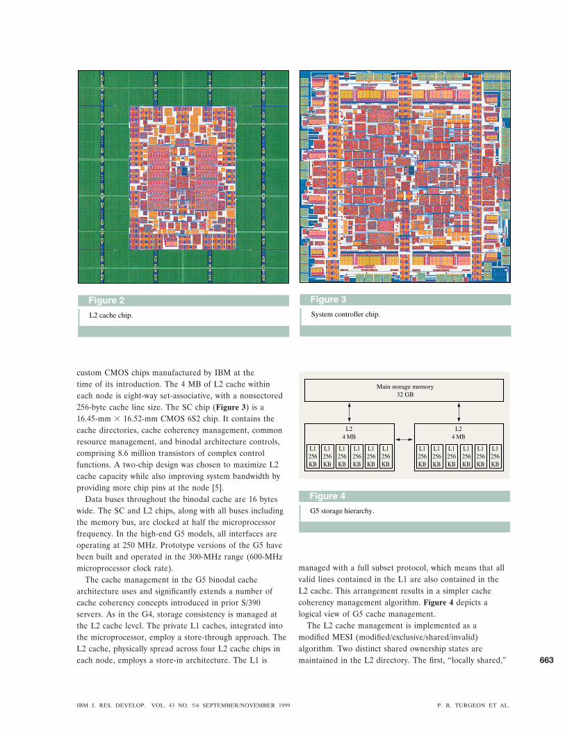
custom CMOS chips manufactured by IBM at thetime of its introduction. The 4 MB of L2 cache withineach node is eight-way set-associative, with a nonsectored256-byte cache line size. The SC chip (Figure 3) is a16.45-mm 3 16.52-mm CMOS 6S2 chip. It contains thecache directories, cache coherency management, commonresource management, and binodal architecture controls,comprising 8.6 million transistors of complex controlfunctions. A two-chip design was chosen to maximize L2cache capacity while also improving system bandwidth byproviding more chip pins at the node [5].
Data buses throughout the binodal cache are 16 byteswide. The SC and L2 chips, along with all buses includingthe memory bus, are clocked at half the microprocessorfrequency. In the high-end G5 models, all interfaces areoperating at 250 MHz. Prototype versions of the G5 havebeen built and operated in the 300-MHz range (600-MHzmicroprocessor clock rate).
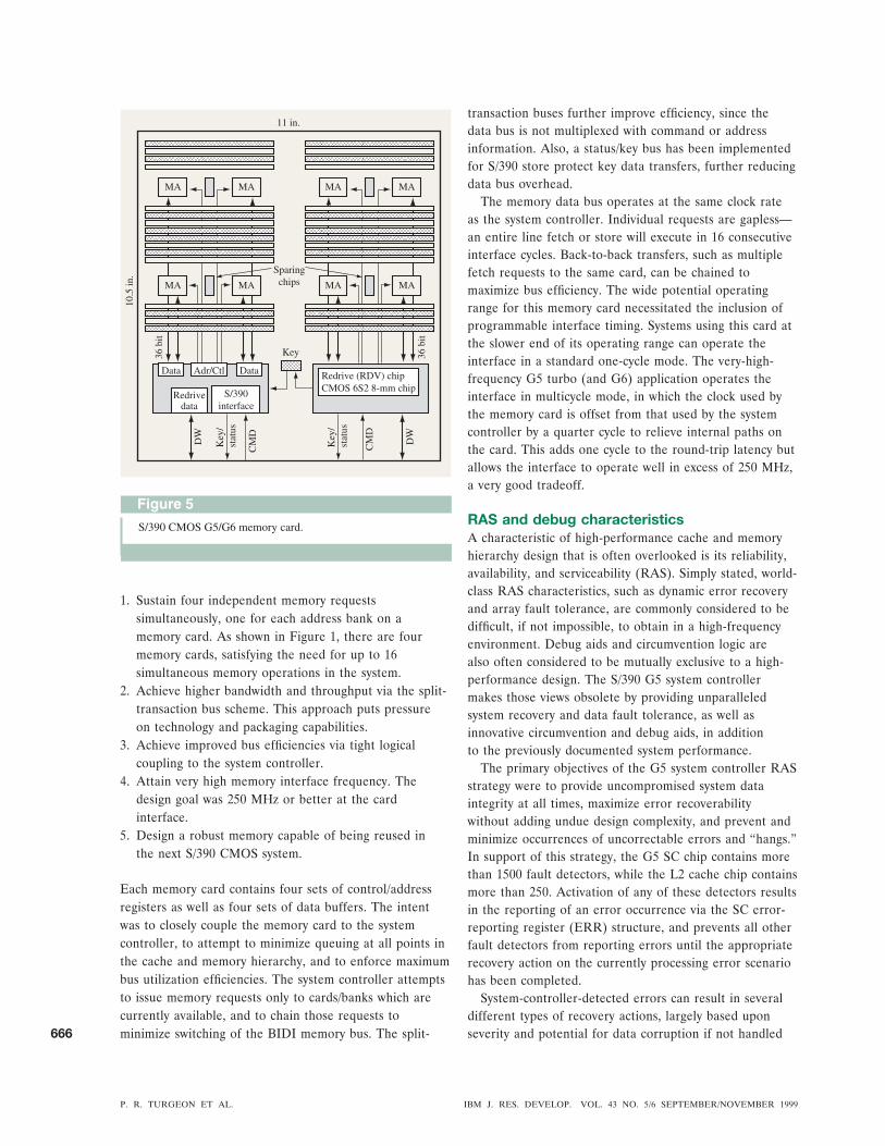
The cache management in the G5 binodal cachearchitecture uses and significantly extends a number ofcache coherency concepts introduced in prior S/390servers. As in the G4, storage consistency is managed atthe L2 cache level. The private L1 caches, integrated intothe microprocessor, employ a store-through approach. TheL2 cache, physically spread across four L2 cache chips ineach node, employs a store-in architecture. The L1 is
managed with a full subset protocol, which means that allvalid lines contained in the L1 are also contained in theL2 cache. This arrangement results in a simpler cachecoherency management algorithm. Figure 4 depicts alogical view of G5 cache management.
The L2 cache management is implemented as amodified MESI (modified/exclusive/shared/invalid)algorithm. Two distinct shared ownership states aremaintained in the L2 directory. The first, “locally shared,”
IBM J. RES. DEVELOP. VOL. 43 NO. 5/6 SEPTEMBER/NOVEMBER 1999 P. R. TURGEON ET AL.
663

means that the referenced data is shared by multiplemicroprocessors within the same node, while the second,“globally shared,” indicates that data may be shared bymicroprocessors in each node. This distinction becomesimportant when a microprocessor requires exclusiveownership of a line already stored in the L2 cache. If“locally shared,” the exclusive state will be granted morequickly, since only local L1 copies must be invalidated.A “globally shared” exclusive request cannot be granteduntil both the local and remote copies have been properlyinvalidated.
A critical design feature of the binodal cache is thesource for data requests which miss the local L2 cachenode. Since the memory access latency is significantlyhigher than that of the remote node, each node in theG5 provides “modified,” “shared,” and “exclusive” dataintervention. This can be contrasted with the G4, whichused only a “modified” intervention scheme. Main memoryaccesses are reserved for those situations in which thedata does not reside in either L2 cache node.
Another new feature of the G5 system controller is itsdual-pipeline design. As in G4, shared resource utilizationwithin the system controller is serialized via a pipelinedarchitecture [1]. Each G5 cache node now actuallycontains two distinct pipelines, each with its own cache,directory, main memory, and internode interfaces andcontrols. The pipelines are interleaved across mainmemory addresses, with each directly controlling two L2cache chips. Because of technology constraints, the twopipes are not completely independent. Some operations,such as the cross invalidate (XI) function, are shared bythe two pipelines.
Pipeline selection is address-based, not availability-based, thereby avoiding address collisions between thepipelines during coherency checking. An address-basedselection mechanism provides an additional advantageby enabling a simple dual-resource layout. While notperfectly mirrored and symmetrical owing to the sharedfunctions, each pipeline effectively occupies half of the SCchip. This simplified chip layout localizes critical controlpaths to approximately half of the chip area. The chiplayout would have been much more difficult to achievewith a single pipeline or with a more complex resource-based selection mechanism.
Another primary objective leading to the dual-pipelineapproach was the goal of minimizing the performanceimpact of bursty data store rates. This is an importantconsideration, given store-through L1 caches spread acrossa 12-microprocessor SMP system design. Accordingly, eachmicroprocessor is allowed to queue up to eight data storeoperations per pipeline within the node while waiting forSC or L2 cache facilities to become available. The dual-pipeline, binodal cache can also sustain a maximum offour store operations to the L2 cache each cycle—this
translates to a cache store bandwidth of 16 GB/s whenrunning in a fully configured high-end system.
Bandwidth and performanceA major design focus during the development of thebinodal cache was to improve the CPI of the G5 serverthrough attention to average system latencies and systembus utilization. The improved switch fabric in the G5system design is critical to the attainment of this goal.Eliminating the G3/G4 discrete bus switch layer andintegrating the crosspoint switching function into thesystem controller significantly reduces main memory andXI latencies. Introducing dedicated address/command andresponse buses reduces data bus overhead, significantlyincreasing available data bandwidth. Independent busesfurther improve bandwidth by enabling more concurrentdata transfer operations to be active in the system. Theend result of these improvements is that queuing isvirtually eliminated, while very high sustainablebandwidths are enabled at all points in theinterconnection network. Average L1 cache misspenalties have been improved by 33% or more. Thesefactors—larger, more efficient caches with a high-bandwidth switch fabric—are the single greatest reason forthe twofold performance improvement demonstrated bythe G5 over its predecessor.
The interface between the microprocessors and the L2caches remains largely unchanged from the prior G4implementation. Each microprocessor has the ability tosend a fetch or store request on each cycle. However, databandwidth has improved, since each microprocessor nowhas a 16-byte-wide BIDI data bus to each pipeline in itslocal system controller and can therefore simultaneouslytransfer 16 bytes of fetch data and 16 bytes of store dataon every bus cycle. To simplify processor design, only oneof the two buses can be actively returning fetch data. Inaddition to the request and data buses, a dedicated set ofinvalidation buses from the system controller to its localprocessors are used to independently manage coherencybetween the L1 and L2 caches. Because the processor-to-L2 data buses are private, the G5 binodal cache provides atotal of 192 bytes of processor fetch bandwidth per cyclealong with 192 bytes of store capacity. This translates to apeak processor data bandwidth of 96 GB/s in a maximallyconfigured system.
As with the processor/system controller interface, eachsystem controller node [6] can issue a data fetch or storerequest to the other node on each bus cycle. However, theinternode buses are implemented as four 16-byte-wideunidirectional buses, with each node driving one busper pipeline. Unidirectional buses were used in thisapplication to avoid BIDI switchover penalties, therebymaking each internode bus capable of sustaining its peakbandwidth of 16 GB/s, regardless of the direction of
P. R. TURGEON ET AL. IBM J. RES. DEVELOP. VOL. 43 NO. 5/6 SEPTEMBER/NOVEMBER 1999
664

dataflow requests. This was a critical factor in helping toreduce the average cache hierarchy latencies in the system.
The interface between the system controller andmemory, like the processor and internode interfaces, is asplit-transaction, 16-byte-wide data bus clocked at half themicroprocessor frequency. Physical packaging limitationsrequired the use of a BIDI bus. However, because thetime of flight of this bus is significantly longer becausethese nets originate on the MCM, cross the system board,and enter the memory card, a multicycle clocking schemewas adopted [7]. This approach enabled retention of the2:1 frequency ratio, a critical design consideration. Lowergearing, such as 3:1 or slower, is often employed in thesesituations to relieve the memory bus. However, this wasconsidered undesirable because of the adverse effects theless-aggressive gearing has on total bus utilization, as ittakes proportionately more cycles to transfer the sameamount of data. Therefore, the G5 memory interface gainsthe advantage of very high frequency without unwantedoverhead in the form of dead or unused bus cycles. TheG5 memory interface supports a peak data bandwidth of16 GB/s, very nearly the sustainable rate.
The I/O subsystem is not addressed in this discussion ofthe G5 binodal cache architecture. However, the system-controller-to-MBA (I/O memory bus adapter) interfaceshould be mentioned, since it had somewhat differentdesign considerations. Because the ratio of commands todata is much lower than on the other buses, the SC-to-MBA bus was designed as an eight-byte-wide BIDI, witheach MBA commanding two of these buses. To furthersave signal pins, the command, address, and responsebuses share the same BIDI. Despite this, and because thesystem-controller-to-MBA data buses are completelyindependent of each other and of all other system databuses, the G5 features a peak-I/O-to-memory bandwidthof 16 GB/s.
With all of this available bandwidth, the internalprocessing capacities of each node in the binodalarchitecture must be very robust. With 12 microprocessorsand four MBAs capable of issuing a total of 28 possiblerequests to the two system controller nodes, each nodemust have adequate internal resources, along with a largeswitch to keep data transfers moving concurrently. Thecache associated with each of the four pipelines is four-way interleaved, allowing a 16-byte data access in eachinterleave on each cycle. This adds up to 256 bytes of L2cache capacity per cycle, more than enough to satisfy thetheoretical 224 bytes per cycle peak required if all possiblerequesters hit in the L2.
L2 misses can be rather bursty, depending upon thetypes of transactions being processed. Therefore, thesystem controller nodes have sufficient resources toprocess 16 local L2 fetch miss operations and 16 memorystore operations simultaneously. Because main memory
is organized into 16 independent banks, a combinationof 16 fetch and store operations to main memory can beserviced simultaneously. In addition, each system controllernode can concurrently service four XI castouts (a total ofeight per system).
Hardware-assisted move engineAnother important consideration in the design ofthe G5 cache and memory hierarchy was improving theperformance of the rich S/390 set of data movementoperations and instructions. Prior CMOS generations hadimplemented these functions using microcode and existingsystem resources. While execution of these instructionswas correct and coherent, the prior implementations alsocommandeered a disproportionate share of critical systemresources. The G5 response was to develop a series ofhardware assists for these types of functions, the mostnotable of which is the hardware-assisted move engine.
The hardware-assisted move engine enables movementof blocks of data from one area in main memory toanother, with minimal microprocessor and microcodeactivity, allowing the system to perform other tasks whilethe data movement is underway. Data blocks may range insize from 256 bytes to 4K bytes in a single operation. Theengine makes use of line buffers within the L2 cache chip,using these as a staging area for retrieving data from mainmemory, then storing to a new location in main memory.The L2 cache itself is not disturbed by the data movementoperation unless a portion of the destination address existsin the L2.
The move engine takes advantage of the memorycontroller function, one of the key controllers which makeup the system controller. Because the memory controllerinitiates and monitors all memory transactions, theavailability of each memory bank on each memory cardis known. The move engine takes advantage of this bybeginning the data movement operation in an availablepart of the block to be moved, avoiding queuing for memoryresources. The resulting data fetches can also be overlapped,again to make optimum use of the memory bus.
The net effect of this dedicated hardware assist is asevenfold improvement in page-moving efficiency(measured in processor cycles required to successfullycomplete a 4KB page move) in comparison with predecessorS/390 CMOS systems. The improvement can be attributedto the more efficient use of memory buses, avoidanceof cache thrashing, and reduced microprocessor andmicrocode overhead for performing page move operations.
Memory cardThe G5 memory card (Figure 5) had to meet anaggressive set of design objectives in order to matchthe performance of the cache hierarchy, including thefollowing:
IBM J. RES. DEVELOP. VOL. 43 NO. 5/6 SEPTEMBER/NOVEMBER 1999 P. R. TURGEON ET AL.
665
1. Sustain four independent memory requestssimultaneously, one for each address bank on amemory card. As shown in Figure 1, there are fourmemory cards, satisfying the need for up to 16simultaneous memory operations in the system.
2. Achieve higher bandwidth and throughput via the split-transaction bus scheme. This approach puts pressureon technology and packaging capabilities.
3. Achieve improved bus efficiencies via tight logicalcoupling to the system controller.
4. Attain very high memory interface frequency. Thedesign goal was 250 MHz or better at the cardinterface.
5. Design a robust memory capable of being reused inthe next S/390 CMOS system.
Each memory card contains four sets of control/addressregisters as well as four sets of data buffers. The intentwas to closely couple the memory card to the systemcontroller, to attempt to minimize queuing at all points inthe cache and memory hierarchy, and to enforce maximumbus utilization efficiencies. The system controller attemptsto issue memory requests only to cards/banks which arecurrently available, and to chain those requests tominimize switching of the BIDI memory bus. The split-
transaction buses further improve efficiency, since thedata bus is not multiplexed with command or addressinformation. Also, a status/key bus has been implementedfor S/390 store protect key data transfers, further reducingdata bus overhead.
The memory data bus operates at the same clock rateas the system controller. Individual requests are gapless—an entire line fetch or store will execute in 16 consecutiveinterface cycles. Back-to-back transfers, such as multiplefetch requests to the same card, can be chained tomaximize bus efficiency. The wide potential operatingrange for this memory card necessitated the inclusion ofprogrammable interface timing. Systems using this card atthe slower end of its operating range can operate theinterface in a standard one-cycle mode. The very-high-frequency G5 turbo (and G6) application operates theinterface in multicycle mode, in which the clock used bythe memory card is offset from that used by the systemcontroller by a quarter cycle to relieve internal paths onthe card. This adds one cycle to the round-trip latency butallows the interface to operate well in excess of 250 MHz,a very good tradeoff.
RAS and debug characteristicsA characteristic of high-performance cache and memoryhierarchy design that is often overlooked is its reliability,availability, and serviceability (RAS). Simply stated, world-class RAS characteristics, such as dynamic error recoveryand array fault tolerance, are commonly considered to bedifficult, if not impossible, to obtain in a high-frequencyenvironment. Debug aids and circumvention logic arealso often considered to be mutually exclusive to a high-performance design. The S/390 G5 system controllermakes those views obsolete by providing unparalleledsystem recovery and data fault tolerance, as well asinnovative circumvention and debug aids, in additionto the previously documented system performance.
The primary objectives of the G5 system controller RASstrategy were to provide uncompromised system dataintegrity at all times, maximize error recoverabilitywithout adding undue design complexity, and prevent andminimize occurrences of uncorrectable errors and “hangs.”In support of this strategy, the G5 SC chip contains morethan 1500 fault detectors, while the L2 cache chip containsmore than 250. Activation of any of these detectors resultsin the reporting of an error occurrence via the SC error-reporting register (ERR) structure, and prevents all otherfault detectors from reporting errors until the appropriaterecovery action on the currently processing error scenariohas been completed.
System-controller-detected errors can result in severaldifferent types of recovery actions, largely based uponseverity and potential for data corruption if not handled
P. R. TURGEON ET AL. IBM J. RES. DEVELOP. VOL. 43 NO. 5/6 SEPTEMBER/NOVEMBER 1999
666

properly. The recovery scenarios, in increasing order ofseverity and/or system disruption, are as follows:
1. Correctable error (CE) recovery. The detected error hasalready been, or is in the process of being, corrected.Normal system operation continues. Hardwareindicators are set to reflect that a CE event hasoccurred. Correctable errors are most commonlyassociated with an ECC correction in the L2 cacheor directory. In the G5, faults detected in interfacecommands or in the pipeline are also categorized asCE, because these faults result in immediate,transparent retry upon detection.
2. Processor retry recovery. The detected error can beisolated to an operation associated with a knownprocessor. The nature of the error is such that queuedstore operations previously issued by this processor arenot affected. These pending store operations to the L2cache will be completed, after which the processor willbe reset in order to attempt to retry the operationwhich failed. System operation continues unaffectedfor all other processors in the system.
3. Processor instruction processing damage (IPD) recovery.The detected error can be isolated to an operationassociated with a known processor. The nature of theerror indicates that previously queued store operationsby this processor may be suspect. The offendingprocessor is immediately reset in order to perform IPDrecovery. This involves notifying the operating systemthat the task at hand must be aborted and retried.System operation continues unaffected for all otherprocessors in the system.
4. Processor checkstop recovery. The detected error canbe isolated to an operation associated with a knownprocessor, but cannot be categorized as a processorretry or processor IPD type of failure. The failingprocessor is immediately checkstopped and removedfrom the active system configuration. System operationcontinues unaffected for all other processors in thesystem.
5. System checkstop. The detected error does not satisfyany of the above recoverable criteria. System data maybe compromised if processing is allowed to continue.All system clocks are stopped immediately.
To provide for maximum design flexibility and to allowfor the possibility of refining recovery actions defined for aparticular type of fault, recovery actions are programmableand maskable. For example, an error associated with aparticular recovery class can be escalated to a more severerecovery class via changes to initialization data. Anextreme case involves escalating all detected errors tosystem checkstop, a feature which can prove very usefulin early hardware debug.
In terms of fault tolerance, the G5 system controllerand L2 cache contain several improvements over the priorCMOS systems. The L2 cache, the L2 directory, the L2fetch and store buffers, and the remote XI buffers are allECC-protected. In addition, all of the data buses betweenthe processors and the L2 cache and between the L2cache and main memory are ECC-protected. Single-biterrors in any of these areas are corrected, on the fly, withno loss in performance. In many cases, even errors whichare uncorrectable via the ECC function can be recoveredsuccessfully by invoking one of the recovery scenariosdescribed above.
The dataflow fault tolerance strategy involves localizingthe source of the error as much as possible to increase thecorrection success, while also minimizing the chances ofaccumulating errors into an uncorrectable scenario.Correctable errors are corrected immediately upondetection. ECC correction stations exist at the outputs ofthe main memory, the L2 cache, and the store stacks, aswell as at the internode interface. When a CE is detectedin the L2 cache, the location is tagged for purge. Thisaction, under hardware control, invalidates the cachelocation and, if the data was in “modified” state, correctsand writes the line back into main memory. Thisasynchronous activity prevents CEs from accumulatingin the L2, thereby minimizing the probability for futureuncorrectable errors (UE). On the basis of projected soft-fail rates of the CMOS technology used, the performancedegradation associated with this premature invalidation ofcache lines is negligible.
When an ECC station detects an uncorrectable error,propagation of that data is blocked [8]. For example, aUE detected leaving main memory is not installed in theL2, but rather is returned to the processor and tagged toinitiate a memory recovery action. A UE detected in theL2 cache will not be cast out to main memory unlessthe line is in “modified” state. This avoids overlayingpotentially good data in memory. However, if the line is“modified,” it is stored to memory as a “special UE,” aunique syndrome that identifies the cache, and not mainmemory, as the original source of the error. This willprevent an unneeded memory error recovery scenariofrom occurring the next time this location is accessed.
The G5 system controller also contains logic used toproactively prevent certain types of errors and lockoutconditions from occurring. Three important examples ofthese functions are the purge function, the fast hangquiesce controller, and the priority dither function.
The purge function is invoked each time a CE or UE isdetected in the L2 cache or its directory. Upon detectionof an error, the address, directory compartment, andsyndrome are trapped. This information is compared tothe information trapped during the previous CE or UE. Aperfect match indicates that the array cell in question has
IBM J. RES. DEVELOP. VOL. 43 NO. 5/6 SEPTEMBER/NOVEMBER 1999 P. R. TURGEON ET AL.
667

failed before and is likely a hard fail. The entry is purgedas described earlier, and the line deleted from activesystem use. When the current failure is correctable but notidentical to the previous failure, the line is simply purged,but the compartment remains available for future use.
The fast hang quiesce controller [9] identifies andresolves common resource lockouts before more drasticrecovery scenarios are needed. The system controller usesa global hang-detect signal to determine whether a lockoutsituation exists. A shorter hang-detect signal is also usedto monitor processing progress through the systemcontroller. If a requester for SC resources (a processor,for example) has been ready and queued for two entireshort hang periods, but has not yet been processed, allsubsequent requesters will be temporarily forced inactiveto allow all currently active operations to complete. Thisaction increases the probability that all requesters willcomplete by reducing contention for shared resourceswhile ensuring that the requester which detected thelockout will itself process through the pipeline unimpeded.
Priority dither is a means by which requesters for thesystem controller pipeline can be prevented from gainingaccess to the pipe for some number of cycles. Prioritydither reorders the priority arbitration logic to forceoperations facing lockout to gain access to the pipeline.This minimizes the opportunity for resource contention,breaking the lockout scenarios. The number of cycles andthe triggering mechanism of the priority dither functionare programmable for maximum flexibility.
The G5 binodal cache also features a logic tracefunction which is actually a “logic analyzer on the chip.”The logic trace is a series of nonintrusive buffers whichcapture the states of critical signals on each SC cycle. Asimplemented in the G5, approximately 700 critical signalsare trapped in buffers which are 256 entries deep. Thetrace buffers can be stopped and extracted at any time,providing the design engineers with the most recent 256-cycle snapshot of SC activity. The logic trace function mayalso be programmed to operate in “compression mode.”In this mode, buffer entries are updated only if the signalsbeing traced have changed, providing an opportunity forlogic tracing across a wider window of operation. Thelogic trace function has proven invaluable in analyzingthe complex system interactions of the binodal cache.
G6 binodal cache and future extensionsThe relatively simple modularity offered by the binodalarchitecture enabled a significant extension to itsfunctionality by applying a more advanced CMOStechnology. Specifically, the G6 server introduces thebinodal cache architecture in an IBM “coppertechnology,” CMOS 7S, implementation. The newtechnology offering provides twice the density of that usedin G5, doubling the L2 cache size to 2 MB per L2 chip,
for a total of 16 MB per system, while maintaining thesame associativity and line size as the G5. The additionallevel of metallization available in CMOS 7S enableschanging the cache organization, doubling the number ofinterleaves to eight. This doubles the available L2 cachebandwidth to 512 bytes per cycle.
The other significant change introduced by the G6server is an increase in the SMP size, a trend expectedto continue. The internal resources and controls of thesystem controller were extended to support an additionalmicroprocessor per node, for a total of 14 microprocessorsin a fully configured system. The SMP size was morelimited by technology constraints than by design—thereis evidence that the basic structure of the binodal cachearchitecture, with appropriate modifications, can supportan even larger tightly coupled SMP. The above logicalchanges, coupled with operating frequency improvements(maximum microprocessor frequency is 637 MHz,maximum cache hierarchy frequency is 318.5 MHz),have led to the 50% system performance improvementsmeasured in the G6, a mere nine months following theintroduction of the G5!
The performance and operation of the G5/G6 binodalcache have been extensively measured and analyzed.Despite the overwhelming success of the architecture thusfar, significant improvements are still possible withoutnecessitating complete redesign. In addition to theaforementioned potential for SMP size and cache sizegrowth, concepts such as additional hardware assistengines, completely independent pipelines, and multipleoutstanding fetch requests per requester are currentlybeing evaluated and designed for subsequent S/390CMOS servers.
AcknowledgmentsThe successful design and implementation of the G5/G6binodal cache architecture was in every sense a teameffort. The authors wish to thank the other members ofthe S/390 Custom SC/L2 design team: Bob Adkins, DeanBair, Chris Berry, Yuen Chan, Tim Charest, Bill Dachtera,Joe Eckelman, Mark Fischer, Tom Foote, Cara Hanson,Glenn Holmes, Dave Hough, Christine Jones, Kevin Kark,Ed Kaminski, Anuj Kohli, Aaron Ma, Frank Malgioglio,Pradip Patel, Ed Pell, Don Plass, Tom Ruane, Bill Scarpero,Jim Schafer, Wojciech Taraszkiewicz, Gary Van Huben,George Wellwood, Bill Wollyung, Eric Young, andAdrian Zuckerman.
*Trademark or registered trademark of International BusinessMachines Corporation.
References1. P. Mak, M. A. Blake, C. C. Jones, G. E. Strait, and P. R.
Turgeon, “Shared-Cache Clusters in a System with a Fully
P. R. TURGEON ET AL. IBM J. RES. DEVELOP. VOL. 43 NO. 5/6 SEPTEMBER/NOVEMBER 1999
668

Shared Memory,” IBM J. Res. Develop. 41, No. 4/5,429 – 448 (1997).
2. M. A. Check and T. J. Slegel, “Custom S/390 G5 and G6Microprocessors,” IBM J. Res. Develop. 43, No. 5/6,671– 680 (1999, this issue).
3. G. Northrop, R. Averill, K. Barkley, S. Carey, Y. Chan,Y. H. Chan, M. Check, D. Hoffman, W. Huott, B. Krumm,C. Krygowski, J. Liptay, M. Mayo, T. McNamara, T.McPherson, E. Schwarz, L. Sigal, T. Slegel, C. Webb, D.Webber, and P. Williams, “600MHz G5 S/390Microprocessor,” International Solid-State CircuitsConference Digest of Technical Papers, February 1999,pp. 88 – 89.
4. T. J. Slegel, R. M. Averill III, M. A. Check, B. C. Giamei,B. W. Krumm, C. A. Krygowski, W. H. Li, J. S. Liptay,J. D. MacDougall, T. J. MacPherson, J. A. Navarro, E. M.Schwarz, K. Shum, and C. F. Webb, “IBM’s S/390 G5Microprocessor Design,” IEEE Micro 19, No. 2, 12–23(March/April 1999).
5. P. Turgeon, P. Mak, D. Plass, M. Blake, M. Fee, M.Fischer, C. Ford, G. Holmes, K. Jackson, C. Jones, K.Kark, F. Malgioglio, P. Meaney, E. Pell, W. Scarpero,A. E. Seigler, W. Shen, G. Strait, G. Van Huben, G.Wellwood, and A. Zuckerman, “A Storage Hierarchyto Support a 600 MHz S/390 G5 Microprocessor,”International Solid-State Circuits Conference Digest ofTechnical Papers, February 1999, pp. 90 –91.
6. P. Mak, M. Blake, and G. Van Huben, “High SpeedRemote Storage Cluster Interface Controller,” filed9/23/97, U.S. patent pending.
7. P. Meaney, G. Ingenio, T. McNamara, and P. Muench,“Method for Supporting 11⁄2 Cycle Data Paths via PLLBased Clock System,” filed 2/13/97, U.S. patent pending.
8. P. Mak, P. Meaney, W. Shen, and G. Strait, “ComputerSystem UE Recovery Logic,” filed 11/6/97, U.S. patentpending.
9. P. Mak, M. Blake, M. Fee, C. Jones, and G. Strait,“Computer System Deadlock Request Resolution,” filed2/2/98, U.S. patent pending.
Received January 7, 1999; accepted for publicationMay 24, 1999
Paul R. Turgeon IBM System/390 Division, 522 SouthRoad, Poughkeepsie, New York 12601 ([email protected]).Mr. Turgeon is currently the manager of S/390 I/O andConnectivity Development. During the development ofthe S/390 G5 and G6 servers, he had design and projectmanagement responsibility for the high-performance cache,memory hierarchy, and processor subsystem designs describedhere. He has held various design and design managementpositions on the IBM 8100 Information System, ES/3090,ES/9121, and the S/390 G4, G5, and G6 systems, and hasreceived several IBM formal awards including OutstandingTechnical Achievement Awards for both the G4 and G5designs. He holds a B.S. in electrical engineering fromRensselaer Polytechnic Institute (1979) and a Master’sCertificate in project management from George WashingtonUniversity (1996).
Pak-kin Mak IBM System/390 Division, 522 South Road,Poughkeepsie, New York 12601 ([email protected]). Mr. Makis a Senior Technical Staff Member in S/390 CustomHardware Design. He received his B.S.E.E. degree fromPolytechnic Institute of New York and his M.B.A. degreefrom Union College. Mr. Mak joined IBM Poughkeepsie in1981, working on the ES/3090 BCE cache design. He hasdesigned high-end system controllers and L2 caches forES/9021 bipolar-based systems and was the technical teamleader for the S/390 G4, G5, and G6 shared L2 cache designs.Mr. Mak currently holds three patents and has received threeIBM Invention Achievement Awards, two IBM OutstandingInnovation Awards, two IBM Outstanding TechnicalAchievement Awards, and two Division Awards.
Michael A. Blake IBM System/390 Division, 522 SouthRoad, Poughkeepsie, New York 12601 ([email protected]).Mr. Blake is an Advisory Engineer in S/390 Custom HardwareDesign. He was the SC Chip Logic Team Leader for the G5and G6 systems. In addition, he designed the internodecontrollers used in these systems. He previously held designpositions on the IBM ES/3090, ES/9021, and S/390 G4systems. He has received several IBM formal awards,including an Outstanding Technical Achievement Award forthe G4 design and an Outstanding Innovation Award for theG5 design. Mr. Blake holds one U.S. patent and has threepatents pending. He holds a B.S. in electrical engineeringfrom Rensselaer Polytechnic Institute (1981).
Michael F. Fee IBM System/390 Division, 522 South Road,Poughkeepsie, New York 12601 ([email protected]). Mr. Fee isan Advisory Engineer in S/390 Custom Hardware Design.He was the primary designer of the G5 system controller’smicroprocessor controller, cross invalidate, and store bufferingfunctions. He developed and implemented logic synthesis andtiming methodologies for the SC and L2 cache chips, and wasresponsible for achieving required cycle time targets. He hasreceived IBM Outstanding Technical Achievement Awards forhis contributions to the G4 and G5 products, and has threepatents pending. Mr. Fee has worked exclusively on shared-cache system designs for IBM since receiving his B.S. inelectrical engineering from Manhattan College (1989).
Carl B. Ford III IBM System/390 Division, 522 South Road,Poughkeepsie, New York 12601 (carl_ [email protected]).Mr. Ford is an Advisory Engineer in the S/390 development
IBM J. RES. DEVELOP. VOL. 43 NO. 5/6 SEPTEMBER/NOVEMBER 1999 P. R. TURGEON ET AL.
669

organization. He received his B.S. in electrical engineeringfrom Rutgers University in 1983. Since joining IBM inPoughkeepsie, New York, in 1983, he has worked onprocessor controller code and logic design for the ES/3090and ES/9021 bipolar mainframes and logic design for theS/390 G4, G5, and G6 CMOS mainframes. Mr. Ford wasresponsible for the hardware-assisted move engine andnumerous other controller functions. He holds one patent andhas received an IBM Invention Achievement Award and threeOutstanding Technical Achievement Awards.
Patrick J. Meaney IBM System/390 Division, 522 SouthRoad, Poughkeepsie, New York 12601 ([email protected]).Mr. Meaney is an Advisory Engineer in S/390 CustomHardware Design. He is the SC/L2 Timing Leader responsiblefor design and simulation to meet frequency goals. Mr.Meaney is also responsible for definition of SC RAS andrecovery features for future S/390 CMOS systems. He was theL2 Cache Chip Design Leader for the G5/G6. Mr. Meaneyholds ten U.S. patents and has six patents pending. He hasheld design positions on the ES/9021 and the S/390 G4, G5,and G6 systems, and has received several IBM formal awards,including an Outstanding Technical Achievement Award forthe G4 and an Outstanding Innovation Award for the G5design. He holds a B.S. in electrical and computer engineeringfrom Clarkson University (1986) and an M.S. in computerengineering from Syracuse University (1991).
Rick Seigler IBM System/390 Division, 522 South Road,Poughkeepsie, New York 12601 ([email protected]). Mr.Seigler joined IBM Poughkeepsie in 1980 after receivingB.S.E.E. and M.S.E.E. degrees from Rensselaer PolytechnicInstitute. He worked as a Logic Designer and Systems TestEngineer on ES/3090 systems, and as a Recovery/ServiceabilitySystems Test Manager for ES/3090 and ES/9021 systems. In1992 he joined S/390 Custom Hardware Design, where he nowworks as an Advisory Engineer; prior to that, he served oneyear on an IBM Faculty Loan assignment at the GeorgiaInstitute of Technology in Atlanta. Mr. Seigler holds fivepatents and has received IBM Outstanding TechnicalAchievement Awards for his work on the G4 and G5 systems.
William Wu Shen IBM System/390 Division, 522 SouthRoad, Poughkeepsie, New York 12601 ([email protected]). Dr.Shen is a Senior Engineer in S/390 Custom Hardware Design,currently responsible for memory subsystem architecture andmemory controller interface design implementation. He holdseight U.S. patents and has ten patents pending. He joinedIBM in 1978 and has held design engineering positionsworking on the memory subsystems of the IBM 8100Information System, ES/3090, ES/9021, and S/390 CMOSG4, G5, and G6 systems. Dr. Shen has received severalIBM formal awards, including an Outstanding TechnicalAchievement Award for G4 and an Outstanding InnovationAward for G5. He holds a Master of Science degree (1974)and a Doctor of Science degree (1981), both from ClarksonUniversity. In addition to memory subsystem design, Dr. Shenis also interested in fault-tolerant design, system testing, andperformance modeling.
P. R. TURGEON ET AL. IBM J. RES. DEVELOP. VOL. 43 NO. 5/6 SEPTEMBER/NOVEMBER 1999
670