The RTDEVS/CORBA Environment for Simulation-Based Design of Distributed Real-Time Systems
18
The RTDEVS/CORBA Environment for Simulation-Based Design Of Distributed Real-Time Systems Young K. Cho** ,Xiaolin Hu*, and Bernard P. Zeigler* * Arizona Center for Integrative Modeling and Simulation, Dept. of Electrical and Computer Engineering, University of Arizona, Tucson, AZ, USA 85721 ** Republic of Korea Air Force, Nonsan city, Choongnam, Korea 320-913 Abstract The increasing complexity of large-scale distributed real time systems demands powerful real time object computing technologies. Furthermore, systematic design approaches are needed to support analysis, design, test, and implementation of these systems. In this paper, we discuss RTDEVS/CORBA, an implementation of DEVS modeling and simulation theory based on real time CORBA communication middleware. With RTDEVS/CORBA, the software model of a complex distributed real time system can be designed and then tested in a virtual testing environment and finally executed in a real distributed environment. This model continuity and simulation-based design approach effectively manages software complexity and consistency problems for complex systems and increases the flexibility for test configurations as well as reduces the time and cost for testing. In the paper, the layered architecture and different implementation issues of RTDEVS/CORBA are studied and discussed. An example application is then given to show how RTDEVS/CORBA supports a framework for model continuity in distributed real time modeling and simulation. Key Words Distributed real time systems, modeling and simulation, DEVS, CORBA, model continuity, simulation-based design, virtual testing environment 1. Introduction Distributed real-time object computing technologies have been attracting lots of attention in the real-time computing area during recent years. Because of the effective object-oriented methodologies which enable engineers to reduce the development complexity and maintenance costs of large scale software applications, object-oriented computing technology has been successfully applied to non-real-time software systems. However, real-time system engineering techniques have not fully adopted the concept of modular design and analysis which are the main virtues of object-oriented design technologies. As a consequence, the demand for object-oriented analysis, design, and implementation of large-scale real-time applications has been growing. This paper proposes that a DEVS-based real-time modeling and simulation environment can provide capabilities required by real-time system engineering.
Transcript of The RTDEVS/CORBA Environment for Simulation-Based Design of Distributed Real-Time Systems

The RTDEVS/CORBA Environment for Simulation-Based Design Of Distributed Real-Time Systems
Young K. Cho** ,Xiaolin Hu*, and Bernard P. Zeigler*
* Arizona Center for Integrative Modeling and Simulation, Dept. of Electrical and Computer Engineering, University of Arizona, Tucson, AZ, USA 85721
** Republic of Korea Air Force, Nonsan city, Choongnam, Korea 320-913 Abstract The increasing complexity of large-scale distributed real time systems demands powerful real time object computing technologies. Furthermore, systematic design approaches are needed to support analysis, design, test, and implementation of these systems. In this paper, we discuss RTDEVS/CORBA, an implementation of DEVS modeling and simulation theory based on real time CORBA communication middleware. With RTDEVS/CORBA, the software model of a complex distributed real time system can be designed and then tested in a virtual testing environment and finally executed in a real distributed environment. This model continuity and simulation-based design approach effectively manages software complexity and consistency problems for complex systems and increases the flexibility for test configurations as well as reduces the time and cost for testing. In the paper, the layered architecture and different implementation issues of RTDEVS/CORBA are studied and discussed. An example application is then given to show how RTDEVS/CORBA supports a framework for model continuity in distributed real time modeling and simulation. Key Words Distributed real time systems, modeling and simulation, DEVS, CORBA, model continuity, simulation-based design, virtual testing environment
1. Introduction Distributed real-time object computing technologies have been attracting lots of
attention in the real-time computing area during recent years. Because of the effective object-oriented methodologies which enable engineers to reduce the development complexity and maintenance costs of large scale software applications, object-oriented computing technology has been successfully applied to non-real-time software systems. However, real-time system engineering techniques have not fully adopted the concept of modular design and analysis which are the main virtues of object-oriented design technologies. As a consequence, the demand for object-oriented analysis, design, and implementation of large-scale real-time applications has been growing.
This paper proposes that a DEVS-based real-time modeling and simulation environment can provide capabilities required by real-time system engineering.

DEVS (Discrete Event System Specification) is a sound formal modeling and simulation (M&S) framework based on generic dynamic systems concepts [1]. DEVS is a mathematical formalism with well-defined concepts of hierarchical and modular model construction, coupling of components, support for discrete event approximation of continuous systems and an object-oriented substrate supporting repository reuse. DEVS is not, however, a just mathematical framework but also a practical M&S tool implemented in various object-oriented languages such as Scheme, C++, and Java. Recently DEVS modeling and simulation environments also have been combined with midddlewares like HLA (High Level Architecture) RTI (Runtime Infrastructure) and CORBA (Common Object Request Broker Architecture) to support fast and easy construction of distributed models, and simulation of such models. These DEVS-based modeling and simulation environments have been shown to support an effective modeling and simulation methodology in various application areas including design and implementation of real-time control systems [2].
Real-time systems design connotes an approach to software design in which timeliness (or timing correctness) is as important as the correctness of the outputs (or logical correctness) [3, 4]. Timeliness of response does not necessarily imply speed -- although, this may be important -- as much as predictability of response and reliable conformance to deadlines. For real time systems, performance estimation to guarantee the system under design to meet performance requirements are crucial. Performance analysis often concerns schedulability, checking of the task schedule for feasibility or conformance with the required timing constraints. In distributed networked systems, quality of service (QoS) characteristics, such as the timely delivery of events between system components or priority-based bandwidth utilization, must necessarily be included in performance evaluation. To support the design and performance evaluation for distributed real time system, modeling and simulation technologies are developed.
Real-time considerations enter into the world of modeling and simulation in various ways. A real-time simulation is a real-time system where some portion of the environment or portions of the real-time system itself, are realized by simulation models [5]. When a simulation model interacts with a surrounding environment, such as software modules, hardware components or human operators, the simulator must handle external events from its environment in a timely manner [6]. In more general terms, interfacing of abstract models with real world processes requires that the (logical) time base of the simulation be synchronized as closely as possible to the clock time of the underlying computer system [2]. Work related to real-time simulation and control includes early research in DEVS-Scheme [2], the extension of the Discrete Event System Specification (DEVS) formalism to the DEVS Real-time Formalism [6] and its application to process control [17]. Current projects include PORTS: A Parallel, Optimistic, Real-Time Simulation [5], OPERA (Operators Training Distributed Real-Time Simulation) [7], Ptolemy (Concurrent Discrete Event Simulation) [8,9], Time-triggered Message-triggered Object (TMO) based Distributed Real-Time System Development Environment [10,11], and Cluster Simulation – Support for Distributed Development of Hard Real-Time Systems using

TDMA-Based Communication [12]. One concern of using modeling and simulation technology to support system
design of distributed real time systems is how to maintain a model’s continuity during system’s development process. This continuity means the same model can be reused with minimal change during different design stages, from model design, to performance evaluation, and even to final execution. To support model continuity, techniques have to be developed so that the modeling and simulation framework can treat the development of distributed real time systems in a systematic way.
In this paper, we will present how a distributed modeling and simulation framework, the Real-Time DEVS/CORBA (RTDEVS/CORBA) is developed to support the design of distributed real time systems. To set the stage we will review the concept of model continuity and show how RTDEVS/CORBA supports model continuity when traversing through different design stages. We then discuss different layers of the RTDEVS/CORBA modeling and simulation environment. With this background we proceed to discuss in detail the implementation issues of RTDEVS/CORBA. Finally an example will be presented showing how a complex distributed real time system can be developed using the framework of RTDEVS/CORBA and how model continuity is supported during the development process.
2. Support Model Continuity with RTDEVS/CORBA Model continuity refers to the ability to use the same model of a system
throughout its design phases. For the RTDEVS/CORBA environment, model continuity (or model transferability) means that models developed in any DEVS-based M&S environments such as the DEVS-JAVA, DEVS/HLA, or DEVS/CORBA should be able to run in the RTDEVS/CORBA environment with minimal changes as long as they maintains the same interfaces [13]. With model continuity, distributed real-time systems can be designed, analyzed, and tested through DEVS-based modeling and simulation studies, and then migrated with minimal additional effort to be executed in the distributed network. In other words, this framework provides generic supports to develop models of distributed real time systems, evaluating their performance and timing behavior through DEVS-based modeling and simulation, and easing the transition from the simulation to actual executions.
Real-time systems deal with external stimuli from outside of the systems with time constraints. Therefore, real-time systems usually interact with environmental systems which could be hardware, software, human operators, etc. that want to get timely responses from the real-time systems. When a real-time system is developed, the best way to evaluate and test the system under design might be for the system to interact directly with the existing environmental. However, this is usually limited by cost and some other limitations such as safety and availability. Hence, it is good to provide a real-time modeling and simulation environment in which the environment model can be developed so that the system under design can be simulated along with

the environment model. Once the system has been tested by the simulation, it should be easily deployed in the execution environment, in which the interfaces to the system are the same as those between the environment model and the system.
Figure 1. Real-Time Simulation and Execution
Figure 1 illustrates a conceptual overview of the relationship between real-time
simulation and real-time execution in the RTDEVS/CORBA environment. High level abstract models that provide logical and timing behaviors like the real environment systems can be developed and simulated in this environment so that real-time systems can be developed based on the interactions with the environment models. After finishing the development, the real-time systems could be easily migrated into the execution environment with minimal modifications.
Figure 2. Model continuity during different development stages
Figure 2 shows in detail how this process works. In the modeling stage, the modeler defines DEVS models which capture the logic behavior and temporal behavior of the system under design. Then these models will be simulated in the DEVSJava environment, which run logic simulation thus can check models’ logical behavior. After the models are checked by DEVSJava, these same models can be distributed on different computers and simulated by DEVS/CORBA, which is a distributed logical simulation environment. With DEVS/CORBA, the model under design’s logical behavior can be further checked in the distributed environment. As DEVS/CORBA can check models’ logical correctness in the distributed environment, it cannot check models’ temporal behavior. So the next stage of the development is
Modeling
Implementation/Logical
Simulation
Checks Model Logical Behavior
Model Distribution/Distributed Simulation
Checks Model Logical Behavior
in DistributedEnvironment
DEVS Formalism DEVSJava DEVS/CORBA
Real-TimeDistributed Simulation/Execution
Checks Model Temporal Behavior
RTDEVS/CORBA

simulating the models in RTDEVS/CORBA, a real time distributed simulation environment. Because RTDEVS/CORBA provides time sensitive and QoS supported distributed real time simulations, the models’ temporal behavior can be checked in this environment. Furthermore, after the models under design pass all these design and test stages, the same models can also be executed by the RTDEVS/CORBA real time execution engine in a distributed environment.
As can be seen, during the whole process, model’s continuity is maintained, as the same model go through different development stages, from modeling, to testing, and to the final execution. This model continuity is supported in the DEVS methodology by chosen different simulation and execution environments during different development stages, while keeping the same model unchanged.
3 A Layered Modeling and Simulation Framework To address design issues for real time systems in the distributed computing
environment, a layered architecture is adopted to support software design in which there is a separation of concerns underlying each layer. Figure 3 shows these layers of the RTDEVS/CORBA modeling and simulation environment.
The heterogeneous network, or the lowest layer in Figure 3, represents the actual physical hardware, computers, cables, routers, and so forth.
Figure 3. Layers of RTDEVS/CORBA environment The second, or the real-time middleware layer, refers to newly emerging software
that provides services to mediate the communication among nodes in the network with some degree of assured performance levels. In the RTDEVS/CORBA implementation, the real time middleware is ACE/TAO, which is an extension of CORBA developed to demonstrate the feasibility of using CORBA for real-time applications [14]. Because conventional CORBA lacks of real time programming features and QoS support, it is not suited for high-performance, real-time applications. To overcome these shortcomings, The ACE ORB (TAO) is developed as a real-time CORBA-compliant ORB endsystem developed based on the ACE framework, which is a highly portable object-oriented middleware communication framework [15]. Since TAO is a ACE based ORB, it runs on a wide range of OS platforms and is compliant with most of the features and components in the CORBA 2.4 specification. In addition, TAO also provides real-time CORBA services like the real-time Event Service, the real-time Scheduling Service. Among these services, the real-time Event
Heterogeneous Network
Real-Time Middleware (ACE/TAO)
Simulation/Execution (RTDEVS/CORBA)
Modeling (RTDEVS)
User Defined Models

Service, and the Scheduling Service are used to support the RTDEVS/CORBA environment.
On the top of the real-time middleware layer, the DEVS-based modeling layer (RTDEVS) and the simulation/execution layer (RTDEVS/CORBA) are residing. As the RTDEVS modeling layer provides a modeling environment in which real time control models can be specified and implemented, the RTDEVS/CORBA layer provides the simulation/execution capability in which DEVS models can be simulated and executed in real time. Finally, based on specific applications, a user can develop his models and use the services of the underline layers to simulate, test and execute the models under design.
Note that without this separation of concerns, one would have much greater difficulty in trying to formulate and disentangle the control and network response issues just mentioned. Moreover, the layering makes it possible to reuse the software developed at the layers, or indeed to purchase COTS (commercial-off-the-shelf) software if that is available.
4. Implementation of Distributed RTDEVS/CORBA Implementation of Distributed Real-Time DEVS/CORBA (RTDEVS/CORBA) is
based on the previous framework for the DEVS/CORBA distributed modeling and simulation environment [18]. As DEVS/CORBA is a logical simulation environment, RTDEVS/CORBA is a real time simulation environment. In the logical DEVS simulation environment, generation and delivery of events occur at the same logical time. In the distributed real-time simulation environment, however, this is not the case any more. There exist some time differences between event schedule, event generation, and event delivery in a real time context. In a distributed simulation environment, time differences also exist between different distributed computers. Thus the main concerns about the design and implementation of the real-time simulator in RTDEVS/CORBA are how to handle time in a distributed environment, how to synchronize simulation time with the physical time and how to manage time differences in generating events at the scheduled time which is defined in the model and delivering them to the destination models in valid time boundaries, which requires QoS capabilities. In this section, these design and implementation issues are discussed.
4.1 Real-time Simulator
In the distributed real-time DEVS simulation/execution context, running models in real time means that a model must be able to generate an ‘event’ at the scheduled time and change its state based on the calculation caused by events. Furthermore, events generated by a model should be delivered to a remote model within some valid time boundaries specified as QoS by a modeler. The design and implementation of a real-time simulator is focusing on this fact.
The RTDEVS formalism defines two kinds of events, internal and external which are handled by the internal transition function (δint) and the external transition function (δext) respectively. An internal event is an event generated by a model

itself according to the time schedule specified in the model whereas an external event is an event delivered from other models or from the external environment.
Figure 4. Real-time Simulator and its Model
In Figure 4, the real-time simulator is illustrated as a model which shows the state
transition flow of the simulator. The upper box in the figure represents the real-time simulator and the other box is a DEVS model. The real-time simulator basically behaves almost the same as the previously implemented simulators except that the time base is synchronized with the physical time. When a simulation cycle begins, the simulator initializes and goes into the nextTN phase in which the simulator calculates a time-of- next-event (tN) based on the schedule specified in the DEVS model. Once the simulator gets the time-of-next-event it determines an amount of wait time by subtracting the current time from the time-of-next-event and then goes into the waitFor phase where the real-time simulator performs a synchronization step. In this phase the simulator waits for either the time-of-next-event (an internal event) or an external event. Either event triggers the real-time simulator to move out of the waitFor phase. Getting out of the waitFor phase is handled by two different simulator algorithms as shown in Figure 5.
Figure 5. Simulator Algorithm
Figure 5(a) shows the internal transition handling algorithm whereas Figure 5(b)

shows the external transition handling algorithm. In the beginning of each algorithm, the simulator moves into the confluent phase in which the simulator is supposed to handle confluent problems caused by clock and network delay jitter. To compensate jitter the real-time simulator wait for a certain amount of time before it goes into the next step. This is explained in detail in the next section. After the confluent phase the simulator goes through the same simulation steps such as computeInputOutput, wrapDelFunc, and nextTN as in the simulator of DEVS/CORBA.
The real time simulator iterates one cycle of phases from waitFor to nextTN while the simulator keeps interacting with the DEVS model whenever an event, either an internal or external event, arrives to the real-time simulator. In ideal case, this iteration takes a zero time unit as in the logical simulation. In the real world, however, each step of the iteration takes non-zero time units, which introduces the time discrepancy problem between the time of event and the actual transition in the model. One aspect of this problem is delay accumulation. For example, suppose that a real time simulator has reached time t1 and gets an internal event. So it needs to execute the internal transition handling algorithm. Since executing this algorithm takes non-zero time ε1, the actual internal transition of the model is carried out at time t1+ε1. Therefore, if the model calculates its new time-of-next-event tN from this moment, then tN would be t1+ε1+ta, which is not t1+ta, the ideal time according to the original schedule. To make tN is scheduled at t1+ta, the simulator should calculate the delay ε1 and compensate this time-of-next-event for the delay. Without delay compensation, accumulation of delay would continue to build up during the simulation cycle until the simulator misses the event schedule. Similar situation exists when an external event comes in and the external transition function needs to be called.
To compensate the erroneous delays in the simulator, we record the time t1 when an internal or external event happens and set the last event time tL as t1. Then we execute the event transition handling algorithm and when it is finished, schedule tN = tL+ta. By this way, even the actual event transition happens at time t1+ε1, tN is set to t1+ta instead of t1+ε1+ta. This is because tN is calculated from tL, which is independent on ε1, the time it takes to process the event transition handling algorithm.
4.2 Time Synchronization and Confluent Problem 4.2.1 Time Synchronization
In logical time DEVS simulation, the coordinator maintains the logical DEVS time and strictly controls the entire simulation cycle. All the participating simulators are closely synchronized with the logical DEVS time under the control of the coordinator. It is the same story for any conservative parallel DEVS implementation in the distributed computing environment, i.e., DEVS/HLA and DEVS/CORBA, which performs logical simulation. As this central control approach manage the time by using one central coordinator, it brings problems such as response latency and central bottleneck. To avoid this disadvantage, in the RTDEVS/CORBA implementation, each computer has its own simulator/executor which simulates/executes the model of that computer autonomously. This autonomous timer approach supports fast response and scalability, but it brings the time synchronization

problem in which time consistency has to be maintained among different simulators. For distributed real time simulation or execution, synchronization usually includes
two aspects: one is how to keep clocks synchronized with each other, which is referred as internal synchronization; another is how to keep them synchronized with the world standard time, which is referred as external synchronization. External synchronization provides distributed systems with the use of a synchronized time base on a global scale, and enables the systems synchronized with its surrounding environment. Two ways for time synchronization have been studied in [13]. The first one is “soft” synchronization in which simulators or executors use TAO’s Time Service for time synchronization. The other one is “hard” synchronization in which a utility such as “AboutTime” is used to reset the hardware clock of the computer and to synchronize with the world standard time. With this approach, simulators or executors can get synchronized time reference directly from the local machine’s clock through system calls. RTDEVS/CORBA has chosen using the second approach for time synchronization. 4.2.2 Time Confluence
In real time simulation or execution, due to the non-deterministic delay or delay jitter, it is hard to get event messages as scheduled. According to the International Telecommunications Union (ITU-T) definition, jitter is defined as those phase variations with respect to a perfect reference that happens in a clock or data signal as a result of noise, patterns, or other causes. Jitter refers to delay variations in the network context. It describes the variations in latency of a message transmission. In data networks, too many packet jitter causes voice to sound garbled. Network components usually compensate for jitter with buffers. Jitter buffers store incoming packets and send them in a more constant stream. In this case, the size of jitter buffers affects the performance of the network. However, there is no optimal size of jitter buffer because the buffer size will vary from network to network.
Figure 6. Confluent problem in real-time simulation or execution
The similar concept is used in RTDEVS/CORBA to control time jitter in real time
active active
J0 J1 J2
?J0
?J0
t0 t1 t2
J0’
!J1!J0
?J1
!J0’
T (sec)
T (sec)
T (sec)
G
P
T?J1
?J0’
!J2
J1’?J2
!J1’
?J2
?J1’
active active
J0 J1 J2
?J0
?J0
t0 t1 t2
J0’
!J1!J0
?J1
!J0’
T (sec)
T (sec)
T (sec)
G
P
T?J1
?J0’
!J2
J1’?J2
!J1’
?J2
?J1’
active active
J0 J1 J2
?J0
?J0
t0 t1 t2
J0’
!J1!J0
?J1
!J0’
G
P
T?J1
?J0’
!J2
J1’?J2
!J1’
?J2
?J1’
T (sec)
T (sec)
T (sec)
active active
J0 J1 J2
?J0
?J0
t0 t1 t2
J0’
!J1!J0
?J1
!J0’
G
P
T?J1
?J0’
!J2
J1’?J2
!J1’
?J2
?J1’
T (sec)
T (sec)
T (sec)
scheduled event
actual event
? input
! output
Jn: unsolved job
Jn’: solved job
LEGEND
confluent windowscheduled event
actual event
? input
! output
Jn: unsolved job
Jn’: solved job
LEGEND
confluent window
Generator Processor Transducer
GPT
out in
solved
arrived
outGenerator Processor Transducer
GPT
out in
solved
arrived
out
(a)
(b) (c)

simulation or execution. Sources of jitter in RTDEVS/CORBA environment vary. One of the main sources of jitter is the instability in the computer clock. Other sources could be general purpose OS, network configuration, and other software configurations that are used in the environment. Any system involved in the environment could be the source of jitter. The goal here is not to identify the major sources of jitter nor to control the sources, but to identify problems that jitter could introduce and to provide the simulators or executors with a capability to handle jitters in a proper way.
Jitter hinders the real time simulators or executors from getting messages as scheduled. To explain this situation, the GPT model shown in Figure 6(a) will be used. This coupled GPT model has three atomic models, a Generator model, a Processor model and a Transducer model. The Generator produces jobs every one second and then sends them to the Processor and the Transducer. The Processor accepts incoming jobs when it is passive and then processes the job and sends the finished job to Transducer. The processing time for every job is one second too. The Transducer collects unprocessed and processed jobs and calculates the performance statistics of the Processor.
In this example, the Generator generates a job every one second, which is the same as the processing time of the Processor. This means, in the ideal case, the Processor will get an internal event and external event at the same time. However, job generation in the Generator does not occur at the exact moment that is scheduled in practice. Furthermore, it takes non-zero time to deliver the job to the Processor. Therefore, as shown in Figure 6(b), an external event can be delivered right before or after the internal transition has been executed, which forces the Processor model to make unnecessary transitions. In the Transducer, same thing happens. Two external events scheduled to arrive at the same time could be delivered with small interval.
To reduce this kind of undesirable behavior, a confluent time window is introduced to act like the jitter buffer discussed earlier. Either an external or an internal event can trigger the simulator to perform a confluent checking routine. In the beginning of this confluent checking routine, the simulator or executor sets the confluent time window and waits for any successive events during this period. Figure 6(c) shows the confluent time windows set forth by an internal or an external event in the Processor and the Transducer. At the end of the confluent checking routine, the real time simulator or executor executes the confluent function which specifies the state transition order between internal and external events that occur together.
The size of the confluent time window is provided by the modeler, and this size determines the time granularity of real time simulation or execution. It is desirable for the modeler to provide an optimal size of the confluent window based on the delay characteristics of the network environment. If the size of the confluent window is too small compared to jitter, it would not handle all the confluent problems. On the other hand, if the size is too lager, this could result in overlapping with next scheduled event. 4.3 Delivering Messages in Real-Time

Delivering messages in real time is crucial for the RTDEVS/CORBA framework. To enable this feature, the real-time Event Service in TAO is used. The TAO’s real-time Event Service provides end-to-end QoS guarantees between objects communicating over the network. To get the desired QoS, the real-time requirements for each operation must be provided on the supplier side. A real-time scheduler propagates this information to consumer RT_Infos based on the dependency graph. The scheduler then uses the propagated information to order dispatches within a set of operations whose dependencies have been met.
We mapped DEVS ports to suppliers and consumers in the real-time Event Service as shown in Figure 7. All the DEVS models which participate in a simulation session are coupled by DEVS ports so that messages generated by a source model can be routed correctly to the destination model based on the RT_Info specified. DEVS ports consist of two port classes: input ports and output ports. Output ports are mapped into suppliers and input ports are mapped into consumers of the Event Service architecture. To incorporate these mapping relations in the framework, pushInPort class and pushOutPort class were created. These two classes maintain port-name, source id, and RT_Info associated with an event to be handled as their member variables. When the coordinator downloads the coupling information at the initialization phase, the coordinator retrieves coupling information and the RT_Info table from the top coupled model and downloads it to simulators. The RT_Info table contains real-time parameters associated with each event, and the events are distinguished by the name which is created by combining the model-name and port-name. The modeler must identify QoS information for each event before the assignment, and provide the required QoS information through this RT_Info table. The coordinator parses the RT_Info table and then creates an event list based on the QoS information specified in the table before downloading the coupling information to the simulators. Upon receipt of the coupling information, each simulator creates pushOutPort and pushInPort accordingly, and makes connection to the Event Service, which makes a virtual event channel between the pair of pushOutPort and pushInPort. This virtual event channel is identified by the source id assigned to the supplier connected to the event channel.
Figure 7. Mapping Suppliers/Consumers to DEVS ports

After downloading the coupling information, the coordinator requests the Scheduler to compute priorities based on the given RT_Info and assigns dispatching priorities to each event. In this framework, each pushOutPort and pushInPort pair handles only one event, so that the priority assigned to the event can be inherited to the virtual event channel created between the pushOutPort and the pushInPort.
To deliver DEVS messages through the real-time Event Channel, the DEVS message must be converted into TAO’s Event format. The Event consists of two fields: the event header and the payload. The Event header contains routing information and the data goes into the payload. The data is serialized into a byte stream before it goes into payload. 4.4 Getting Data from External Environment Systems
For the real-time simulation and execution, there need means to get external input data from the sensors and to send out data to actuators. It is desirable for the real-time model to handle all the external events in the same external transition function in the same manner regardless of their type. In RTDEVS/CORBA, a modeler can specify an external interface type using the setExternalInterface() method. When the simulator initializes the model, the simulator checks the specified external interface types and configures the interfaces accordingly. For example, as depicted in Figure 8, if the model expects external data through socket connections from the sensors, the modeler can specify a socket interface in the model, and the simulator sets up the connection. The real-time simulator creates proxies: sensor proxy and actuator proxy. These proxies are waiting for any data stream, and once data arrives, then they call the simulator’s external input handling method immediately. This method converts a socket stream data into DEVS message and puts it into the model as an external event message so that the model handles the external sensor data as a DEVS message. Of course, a model still can be coupled with other models while receiving data from external environment.
Figure 8. Design of External Interface for Real-Time Simulator
To enable user friendly external interfaces, a specialized coupling concept is
employed, namely Reserved Internal Coupling (RIC). The reserved internal coupling couples the ports attached to the model with the simulator. The real-time simulator has

reserved internal ports like: extInputFromSocket, extInputFromKeyboard as input ports, and extOutputToSocket, extOutputToScreen as output ports. The interface between activities and the model is defined in the same manner. In this case the simulator starts an activity thread instead of proxies, and these are connected through other reserved internal couplings like resultFromActivity, cancelActivity, etc. 4.5 Implementation of Activity
An activity is defined to incorporate real computations within simulation models in the Real-Time DEVS formalism. Such an activity is implemented as an activityThread in RTDEVS/CORBA so that a modeler can assign any computation tasks to the thread.
In the DEVS formalism, a model schedules the next event time using the hold_in method which has the format of hold_in(phase, sigma), where the phase is the control state in which the model must be kept for the amount of time specified by sigma. The hold_in method is also used in the RTDEVS/CORBA environment to schedule the next event time. In this case, however, sigma is mapped into the real-time clock, i.e., the value of 5 for sigma means 5 seconds in the physical real time clock. To assign an activity to a certain state for a certain time period, the modeler can use the extended version of the hold_in method, which has the format of hold_in(phase, sigma, activity). The activity is a real computation that must be performed to get some results. For example, this could be a DEVS simulation or a piece of computing software which takes some time to get the result. Through this version of the hold_in method, the modeler can assign a deadline to be associated with the activity. In this case, the modeler must make sure that the computation can be performed within the specified time window before he/she assigns the activity to the model.
The two versions of the hold_in methods also help to maintain the model continuity of the system under design. This is because when a real-time model is developed in the logical simulation environment such as DEVS-JAVA, the model can use the old version of the hold_in method. When the logical behavior of the model is verified and the model moves to the execution stage, the model can be migrated in the RTDEVS/CORBA environment with the extended hold_in method with activity.
5. An Example of Distributed Temperature Control with Hierarchical
Scheduling In this example we show ability of the distributed RTDEVS/CORBA environment
to support development of a complex distributed real-time system using real-time simulation. We show how model continuity may be maintained from the very beginning of the development stage to the execution of the model. The example is a distributed intelligent temperature control applied to a building using a hierarchical scheduling scheme. The building could be a hotel, an office structure, a hospital or any other buildings that have many floors with multiple rooms on each floor. The requirement calls for each room in this building to be controlled individually as
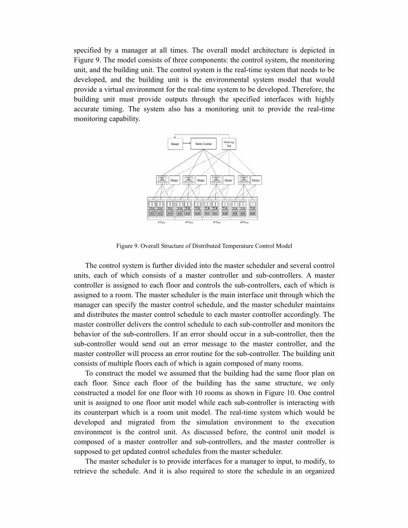
specified by a manager at all times. The overall model architecture is depicted in Figure 9. The model consists of three components: the control system, the monitoring unit, and the building unit. The control system is the real-time system that needs to be developed, and the building unit is the environmental system model that would provide a virtual environment for the real-time system to be developed. Therefore, the building unit must provide outputs through the specified interfaces with highly accurate timing. The system also has a monitoring unit to provide the real-time monitoring capability.
Figure 9. Overall Structure of Distributed Temperature Control Model
The control system is further divided into the master scheduler and several control
units, each of which consists of a master controller and sub-controllers. A master controller is assigned to each floor and controls the sub-controllers, each of which is assigned to a room. The master scheduler is the main interface unit through which the manager can specify the master control schedule, and the master scheduler maintains and distributes the master control schedule to each master controller accordingly. The master controller delivers the control schedule to each sub-controller and monitors the behavior of the sub-controllers. If an error should occur in a sub-controller, then the sub-controller would send out an error message to the master controller, and the master controller will process an error routine for the sub-controller. The building unit consists of multiple floors each of which is again composed of many rooms.
To construct the model we assumed that the building had the same floor plan on each floor. Since each floor of the building has the same structure, we only constructed a model for one floor with 10 rooms as shown in Figure 10. One control unit is assigned to one floor unit model while each sub-controller is interacting with its counterpart which is a room unit model. The real-time system which would be developed and migrated from the simulation environment to the execution environment is the control unit. As discussed before, the control unit model is composed of a master controller and sub-controllers, and the master controller is supposed to get updated control schedules from the master scheduler.
The master scheduler is to provide interfaces for a manager to input, to modify, to retrieve the schedule. And it is also required to store the schedule in an organized
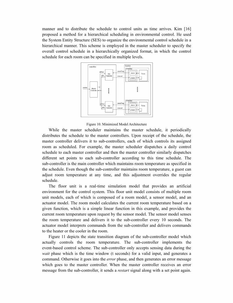
manner and to distribute the schedule to control units as time arrives. Kim [16] proposed a method for a hierarchical scheduling in environmental control. He used the System Entity Structure (SES) to organize the environmental control schedule in a hierarchical manner. This scheme is employed in the master scheduler to specify the overall control schedule in a hierarchically organized format, in which the control schedule for each room can be specified in multiple levels.
Figure 10. Minimized Model Architecture
While the master scheduler maintains the master schedule, it periodically distributes the schedule to the master controllers. Upon receipt of the schedule, the master controller delivers it to sub-controllers, each of which controls its assigned room as scheduled. For example, the master scheduler dispatches a daily control schedule to each master controller and then the master controller similarly dispatches different set points to each sub-controller according to this time schedule. The sub-controller is the main controller which maintains room temperature as specified in the schedule. Even though the sub-controller maintains room temperature, a guest can adjust room temperature at any time, and this adjustment overrides the regular schedule.
The floor unit is a real-time simulation model that provides an artificial environment for the control system. This floor unit model consists of multiple room unit models, each of which is composed of a room model, a sensor model, and an actuator model. The room model calculates the current room temperature based on a given function, which is a simple linear function in this example, and provides the current room temperature upon request by the sensor model. The sensor model senses the room temperature and delivers it to the sub-controller every 10 seconds. The actuator model interprets commands from the sub-controller and delivers commands to the heater or the cooler in the room.
Figure 11 depicts the state transition diagram of the sub-controller model which actually controls the room temperature. The sub-controller implements the event-based control scheme. The sub-controller only accepts sensing data during the wait phase which is the time window (t seconds) for a valid input, and generates a command. Otherwise it goes into the error phase, and then generates an error message which goes to the master controller. When the master controller receives an error message from the sub-controller, it sends a restart signal along with a set point again.

The master controller also provides a set point to the sub-controller at the beginning of every day.
Figure 11. Sub-Controller Model
First we built the model in DEVS-Java and checked its behavior to see if it
worked correctly in terms of logical dynamics. Then the model was moved into the real-time DEVS/CORBA environment to check its timing behavior. In this example a control schedule is provided to the master controller in a table format, which contains 10 different set points for each room. For the purpose of the example, we scaled down the time schedule for the master controller to distribute each set point at every 10 minutes. This time schedule can be adjusted up later on as needed. The model was executed in two ways: with and without user interruption. User interruption refers to the change of the set point by the user of the room. While running the model we attached a monitoring window to each room to see room temperature changes in real-time. One monitoring window is connected to the output port of each sensor model of the room unit so that the current room temperature can be monitored. Figure 12 shows the result of the temperature control of the first room without any interruption by the user whereas Figure 13 shows the result with interruption. These results indicate that all the models are working correctly in terms of both logic and timing.
Figure 12. Result of Temperature Control without User Interruption

Figure 13. Result of Temperature Control with User Interruption
6. Conclusion In this paper, a modeling and simulation framework, RTDEVS/CORBA is
presented to support the development of distributed real time systems. The framework supports model continuity for software development so that the same model can be reused with minimal change during different design stages, from model design, to performance evaluation, and even to final execution. To support model continuity, RTDEVS/CORBA adopted a layered architecture in which there is a separation of concerns underlying each layer. This layered architecture facilitates the reuse of the software developed at different layers and makes it possible to choose different simulation and execution environments during different design stages, while keeping the upper layer model unchanged.
To enable modeling and simulation in a distributed real time environment, RTDEVS/CORBA has chosen ACE/TAO as the communication middleware, which supports distributed programming as well as real time communication features such as real time event service, real time scheduling service, and QoS capabilities. Based on ACE/TAO, different implementation issues of RTDEVS/CORBA such as the real time simulator, time management techniques, and the real time message delivery method are studied and discussed in the paper.
7. Reference
1. B.P. Zeigler, T.G. Kim, and H. Praehofer, Theory of Modeling and Simulation. 2nd ed., Academic Press, New York, NY, 2000.
2. B.P. Zeigler and J. Kim, “Extending the DEVS-Scheme Knowledge-Based Simulation Environment for Real-Time Event-Based Control,” IEEE Trans. On Robotics and Automation, vol. 9, no. 3, pp.351-356, June 1993.
3. Phillip A. Laplante, Real-time systems: Design and Analysis, 2nd Ed. IEEE Press, Piscataway, NJ, 1997.
4. C.M. Krishna and K.G. Shin, Real-time systems, McGraw-Hill, New York, 1997.

5. K. Ghosh, et al., “PORTS: A Parallel, Optimistic, Real-Time Simulator,” in Proceedings of Workshop on Parallel and Distributed Simulation, pp.24-31, July 1994.
6. J.S. Hong, and T.G. Kim, “Real-time Discrete Event System Specification Formalism for Seamless Real-time Software Development,” Discrete Event Dynamic Systems: Theory and Applications, vol. 7, pp.355-375, 1997.
7. T. Uslander, “OPERA: A CORBA-based Architecture Enabling Distributed Real-Time Simulation,” in Proceedings of ISORC ’99, May 1999.
8. E. A. Lee, “Modeling Concurrent Real-Time Processes using Discrete Events,” UCB/ERL Memorandum M98/7, March 1998.
9. S. A. Edwards, “The Specification and Execution of Heterogeneous Synchronous Reactive Systems,” Ph.D. Thesis, University of California, Berkeley, May 1997.
10. K.H. Kim, “Object Structures for Real-Time Systems and Simulators,” IEEE Computer, pp.62-80, August 1997.
11. K.H. Kim, J. Liu, and M.H. Kim, “Deadline Handling in Real-Time Distributed Objects,” Proc. ISORC 2000 (IEEE CS 3rd International Symposium on Object-oriented Real-Time Distributed Computing), pp.7-15, Newport Beach, CA, March 2000.
12. T.M. Galla and R. Pallierer, “Cluster Simulation – Support for Distributed Development of Hard Real-Time Systems using TDMA-Based Communication,” in Proc. Of 11th Euromicro Conference on Real-Time Systems, York, England, June 1999.
13. Cho, Y.K., RTDEVS/CORBA: A Distributed Object Computing Environment For Simulation-Based Design Of Real-Time Discrete Event Systems. Ph.D. thesis, University of Arizona, Tucson, AZ 2001.
14. D.C. Schmidt, D.L. Levine, and S. Mungee, “The Design of the TAO Real-Time Object Request Broker,” Computer Communications, vol. 21, no. 4, pp.294-324, April, 1998.
15. D.C. Schmidt, “ACE: an Object-Oriented Framework for Developing Distributed Application,” in Prodeedings of the 6th USENIX C++ Technical Conference, Cambridge, Massachusetts, April, 1994.
16. T. G. Kim, “Hierarchical Scheduling in an Intelligent Environmental Control Systems,” Journal of Intelligent and Robotic Systems, vol. 3, pp. 183-193, 1990.
17. S.M. Cho and T.G. Kim, “Real-Time DEVS Simulation: Concurrent, Time-Selective Execution of Combined RT-DEVS Model and Interactive Environment,” in Proceedings of SCSC '98, pp.410-415, Reno, Nevada, 1998.
18. D. Kim, S.J. Buckley, and B.P. Zeigler. “Distributed Supply Chain Simulation in a DEVS/CORBA Execution Environment,” in Proceeding of WSC. Phoenix, Arizona, 1999.