The Royal Ship of Cheops - Harvard University
154
The Royal Ship of Cheops Paul Lipke National Maritime Museum, Greenwich. Archaeological Series No. 9 BAR International Series 225 1984
-
Upload
khangminh22 -
Category
Documents
-
view
0 -
download
0
Transcript of The Royal Ship of Cheops - Harvard University
The Royal Ship of Cheops
Paul Lipke
National Maritime Museum, Greenwich. Archaeological Series No. 9
BAR International Series 225 1984
The Royal Ship of Cheops
A retrospective account of the discovery, restoration and
reconstruction. Based on interviews with
Hag Ahmed Youssef Moustafa
Paul Lipke
National Maritime Museum, Greenwich. Archaeological Series No. 9
BAR International Series 225 1984
B.A.R. 5, Centremead, Osney Mead, Oxford OX2 OES, England.
GENERAL EDITORS
A.R Hands, B.Sc, M.A., D.Phil. D.R Walker, M.A.
B.A.R.-S225, 1984: 'The Royal Ship of Cheops'.
Price £ 12.00 post free throughout the world. Payments made in dollars must be calculated at the current rate of exchange and $3.00 added to cover exchange charges. Cheques should be made payable to B.A.R and sent to the above address.
(g) Paul Lipke and the National Maritime Museum, Greenwich, 1984
ISBN 0 86054 293 9
For details of all B.A.R. publications in print please write to the above address. Information on new titles is sent regularly on request, with no obligation to purchase.
Volumes are distributed from the publisher. All B.A.R prices are inclusive of postage by surface mail anywhere in the world.
Printed in Great Britain
National Maritime Museum, Greenwhich, Archaeological Series
General Editor - Sean McGrail, B.A., Ph.D. F.S.A., M.I.F.A., Master Mariner
1. Sources and Techniques in Boat Archaeology (BAR-S29)
2. Logboats of England and Wales (BAR 51)
3. The Graveney Boat (BAR 53)
4. Dendrochronology in Europe (BAR-S51)
5. The Archaeology of Ships and Harbours in Northern Europe (BAR-S66)
6. The Brigg 'Raft' and her Prehistoric Environment (BAR 89)
7. Woodworking Techniques before Ad 1500 (BAR-S129)
8. The Cattewater Wreck (Bar 131)

pmanuelian
Typewritten Text
[This page is intentionally blank.]
Contents
List of Illustrations.
List of Tables.
Foreword by Dr. Sean McGrail.
Author's Dedication and Acknowledgements.
Introduction.
Synopis of discovery. Principal personnel.
Excavation of the covering stones.
Excavation of the Ship.
Procedures. The pit's contents.
Arrangement and identification.
Condition of the ship's timbers.
Conservation and Restoration. Preservatives. Adhesives. Fillers. Stains. Other materials. Restoration Techniques.
Reconstruction.
Records.
Construction.
Principal Dimensions of 5th Reconstruction. Principal Elements of 5th Reconstruction. Joints and Fastenings. Construction Sequence.
Purpose and Useage.
Notes.
References.
Glossary.
(iii)
iv
vili
ix
X
1
2 2 5
7
7 14 24
27
34
34 36 37 37 39 39
63
95
97
97 105 112 117
125
127
133
137
List of Illustrations
Fig. 1. Model of a 9 m., 2-3 man, produce and livestock market 4 boat.
Fig. 2. Grid for Layer 4, eastern end of the boat pit. 8
Fig. 3. Adjustable platform used to suspend workmen above 9 timbers.
Fig. 4. Deckhouse panel being raised with cross bracing. 10
Fig. 5. Plank entering the restoration shed. 11
Fig. 6. Door no. 59 in situ. 10
Fig. 7. Card for piece no. 203, showing hieratic signs. 13
Fig. 8. a) Piece 220, the bow port backing timber 15 b) Miscellaneous damaged battens and stanchions.
Fig. 9. Pieces no. 35 and no. 36. 16
Fig. 10. "Fenders" of layer "A", zone 4. 18
Fig. 11. Construction view, forward. 21
Fig. 12. Unchafed cordage of layer no. 12. 22
Fig. 13. Miscellaneous items. 23
Fig. 14. Desiccated battens. 23
Fig. 15. Temperature, relative humidity and dew point 28 figures for Giza.
Fig. 16. Sample from working quantities of the dry, tinted 38 base compared to correct test sample.
Fig. 17. Hassagoz demonstration showing 5 of the many 38 shades used to "paint in the grain" over glue and patches.
Fig. 18. Damaged bottom plank. 41
Fig. 19. Four separate ennab subsections in place and 41 planed fair.
Fig. 2 0. Detail of patching method "2". 42
Fig. 21. Detail of patching method "3". 43
Fig. 22. Fragmented oar bored for aluminium rod. 45
Fig. 23. Oar fragments arranged on the rod. 45
(iv)
Fig. 24. Fragmented, forward port upper backing timber cover. 46
Fig. 25. Backing timber covers. 48
Fig. 26. Backing timber cover, detail of dadoed fragments 48 and mould.
Fig. 27. Backing timber covers, ennab grid glued to 49 fragments with mould removed.
Fig. 28. Backing timber cover; cotton fabric backing. 49
Fig. 29. Backing timber covers; small fragments with 50 "enmeshed edges" outlined in chalk.
Fig. 30. Forward, port and starboard, upper backing timber 51 covers before and after treatment.
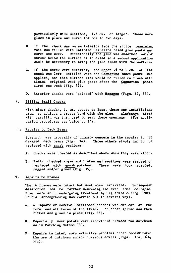
Fig. 31. Garboard plank with 2 slash knots opposite each other. 53
Fig. 32. Extreme checking of a plank. 53
Fig. 33. Planks with all checks filled. 53
Fig. 34. 13 damaged deck beams. 54
Fig. 35. Exploded view of a deck beam repair. 55
Fig. 36. Damaged frames. 54
Fig. 37. Fragments treated by pinning and reinforcement with 56 dutchmen.
Fig. 38. Cupped plank of a roof panel prepared for rebending. 58
Fig. 39. Reconstruction 1. 60
Fig. 40. The sheer strake lashed in place. 61
Fig. 41. Stern backing timbers and upper backing timber covers. 65
Fig. 42. Rough plank diagram numbered to indicate probable 66 original planking sequence.
Fig. 43. Starboard bow garboard plank being used to adjust the 65 rocker of the keel planks.
Fig. 44. Tenon/lashing hole/plank diagram. 68
Fig. 45. The deck beams. 67
Fig. 46. The third reconstruction. 71
Fig. 47. Interior of the main chamber in the reconstructed 73 deckhouse.
Fig. 48. Construction view at midship. 75
(v)
Fig. 49. A working sketch noting the second and third 77 reconstructions' differences in beam.
Fig. 50. Stern, port view of ship. 80
Fig. 51. Construction view aft. 81
Fig. 52. Construction plan profile and section view. 83
Fig. 53. The ship's interior from the fifth reconstruction. 85
Fig. 54. Card for piece no. 207. 86
Fig. 55. The orientation signs used to indicate in which 86 quarter of the ship a timber was to be used.
Fig. 56. Diagram showing the pairing of some of the hieracics 87 in the hull.
Fig. 57. Hag Ahmed checks the alignment of the bow backing 89 timbers during the first part of the fifth "reconstruction".
Fig. 58. Fifth "reconstruction". 89
Fig. 59. Gangway in place with temporary crosspiece holding 90 inboard edge.
Fig. 60. 13 lashings found in layer no. 13. 91
Fig. 61. Pieces no. 341 and no. 343. 93
Fig. 62. Lines plan of Cheops ship. 99
Fig. 63. 1:20 model used to develop lines plan. 101
Fig. 64. Exposed fore deck. 101
Fig. 65. Detail of rabbet; 106
Fig. 66. Backing timbers lashed in place. 108
Fig. 67. Detail of stern backing timber, garboard and 109 second strake.
Fig. 68. Wide deck beam with 2 short deck beams. 110
Fig. 69. Long, aft deck panel being raised from the pit. Ill
Fig. 7 0. Detail of deckhouse construction. 113
Fig. 71. Fifth "reconstruction". Ill
Fig. 72. Initial phase of construction. 123
Fig. 73. Second phase. 123
(vi)
Fig. 74. Third phase. 123
Fig. 75. Computer drawn body plan. 132
Fig. 76. Hydrostatic curves. 132
Note. All illustrations courtesy of the Egyptian Antiquities Service, unless otherwise noted in the caption.
(vii)
List of Tables
Timbers damaged before excavation.
Timbers sustaining damage after excavation.
Joints used in the Cheops ship.
Fastenings used in the Cheops ship.
(viii)
29
31
115
116
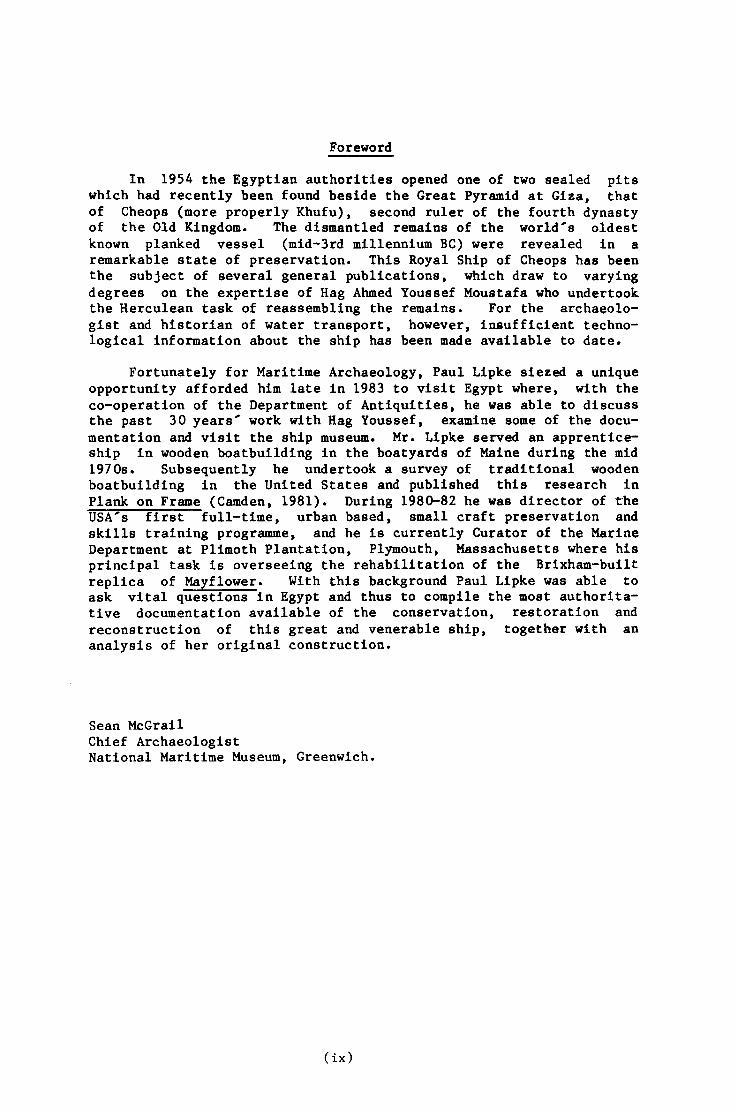
Foreword
In 1954 the Egyptian authorities opened one of two sealed pits which had recently been found beside the Great Pyramid at Giza, that of Cheops (more properly Khufu), second ruler of the fourth dynasty of the Old Kingdom. The dismantled remains of the world's oldest known planked vessel (mid-3rd millennium BC) were revealed in a remarkable state of preservation. This Royal Ship of Cheops has been the subject of several general publications, which draw to varying degrees on the expertise of Hag Ahmed Youssef Moustafa who undertook the Herculean task of reassembling the remains. For the archaeologist and historian of water transport, however, insufficient technological information about the ship has been made available to date.
Fortunately for Maritime Archaeology, Paul Lipke siezed a unique opportunity afforded him late in 1983 to visit Egypt where, with the co-operation of the Department of Antiquities, he was able to discuss the past 30 years' work with Hag Youssef, examine some of the documentation and visit the ship museum. Mr. Lipke served an apprenticeship in wooden boatbuilding in the boatyards of Maine during the mid 1970s. Subsequently he undertook a survey of traditional wooden boatbuilding in the United States and published this research in Plank on Frame (Camden, 1981). During 1980-82 he was director of the USA's first full-time, urban based, small craft preservation and skills training programme, and he is currently Curator of the Marine Department at Plimoth Plantation, Plymouth, Massachusetts where his principal task is overseeing the rehabilitation of the Brixham-built replica of Mayflower. With this background Paul Lipke was able to ask vital questions in Egypt and thus to compile the most authoritative documentation available of the conservation, restoration and reconstruction of this great and venerable ship, together with an analysis of her original construction.
Sean McGrail Chief Archaeologist National Maritime Museum, Greenwich.
(ix)
Dedication and Acknowledgements
This publication is dedicated to Leona Baumgartner and Alexander Langmuir, whose extraordinary selflessness, creativity and enthusiasm have inspired a great many people, but none more than the author.
Too many people have helped In too many ways to list their contributions in full. However, the following people and organizations must not go unmentioned.
Gehanne Amin Abdel-Malek Translator
American Research Centre in Egypt All staff and Directors
Professor George Bass
Edward Brovarski
Arthur Beai
Phillip Briggs
Egyptian Antiquities Service
Norman Doe!ling
Arthur Eldredge
Fulvio Fabrizi
Sameh H. Gayed
Robert Greene
Dr. K. Lai Gauri
Dr. Nabil Hadidi
William Harrison
Zahi Hawas
Neseim Henein
Nautical Archeology Texas A & M University
Egyptian and Near East Dept., Boston's Museum of Fine Arts
Fogg Conservation Lab., Harvard University
ADD Inc.
Dr. Ahmed Kadry, Director
Sea Grant College Program, Massachusetts Institute of Technology
Weather Services International
Technical Adaptation Program, Massachusetts Institute of Technology
Stone Conservation Lab., University of Louisville
Täckolm Herbarium, Cairo University
International Business Assoc.
Egyptian Department, University of Pennsylvania
Institut francais d'archeologie orientale
(x)

Don and Marian Holshouser
Nancy Jenkins
Dr. Timothy Kendal
Mark Lehner
Margarette Leveque
Barbara, Mary and the late Herbert Lipke
Lawrence MacKinnon
Dr. Sean McGrail
Professor Francis Ogilvie
Kevin 0'Toole
Wilson Pollock
Dr. Phillip Rury
Magued el Sabbagh
Dr. Nabiel A.M. Saleh
Peter Schmid
Warren Seamens
Arthur F.F. Snyder
Richard Steffy
Mai Trad
Professor F. Van Doorninck
Egyptian and Near East Dept., Boston's Museum of Fine Arts
American Research Centre in Egypt
Conservation Lab., Boston's Museum of Fine Arts
Sea Grant College Program, Massachusetts Institute of Technology
National Maritime Museum, Greenwich, England
Dept. of Ocean Engineering Massachusetts Institute of Technology
Technology Adaptation Program, Massachusetts Institute of Technology
ADD Inc.
Bailey Wetmore Lab., Harvard Botanical Museum
Egyptian National Research Centre
Technical Illustrator, Cheops Project
MIT Museum, Massachusetts Institute of Technology
Co-author, Knots and Lines Illustrated
Nautical Archeology, Texas A & M University
American Research Centre in Egypt
Nautical Archeology., Texas A & M University
(xi)
John Waterhou.se Technical Consultant, Cheops Project Hart Nautical Collections, Massachusetts Institute of Technology
Wesley Wong Economic Botany Library, Harvard
Fatma Youssef Technology Adaptation Program, Massachusetts Institute of Technology
Dr. B. van Zelst Conservation Lab., Boston's Museum of Fine Arts
Special mention must go to Hag Ahmed Youssaf Moustafa for his patience with his mut' lb (tiring) colleage. This project is a tribute to his remarkable efforts; half a century's work has left Egypt immeasurably richer. Last but never least, my thanks to Marcelle Lipke. Without her endless support and assistance everyone's efforts would have been for nothing.
Paul Lipke
(xii)
INTRODUCTION
In 1954, the beautifully preserved timbers of a 43.m (143.97') funerary vessel were discovered stacked in a limestone pit carved from the bedrock beside the Great Pyramid at Giza, Egypt. Dated by cartouche to the Fourth Dynasty reigns of Khufu (Cheops) and his son Djedefre some 4,500 years ago, most of the details of this historic discovery and the work that followed have remained unknown. The material published in this retrospective is based primarily on just 100 hours of recorded conversation with Hag Ahmed Youssef Moustafa, retired Chief of Restoration and Khufu Ship Restorer for the Egyptian Antiquities Service (known hereafter as the Service). Between February 1st and April 30th of 1983, the author and Hag Ahmed worked exclusively from the latter's remarkable memory, a few hundred photographs, numerous drawings and notes, administrative reports from the years 1954 - 1962 and a 1:20 display model of the Khufu ship. For the record, at no time were they able to visit the ship together; at no time during the author's nine month stay in Egypt was it possible to arrange to go on board the ship or into artifact storage areas for detailed examinations. Access to the museum and its contents was no greater than that available to any paying visitor. Conversation between Hag Ahmed and the author was made possible by a translator, Miss Gehanne Arain Abdel-Malek, and was augmented by the frequent use of sketches and demonstrations .
The Project came about as a result of a chance meeting between Hag Ahmed and the author in May of 1981. Administrative support for the one year effort was provided by Massachusetts Institute of Technology's Sea Grant Program while the author was Visiting Lecturer in the Institute's Department of Ocean Engineering. Funding was provided by private contributors.
The purpose of the Project was fourfold: to update, expand upon, clarify and/or correct earlier publications on the Fourth Dynasty vessel; to document (for the first time) the restoration and reconstruction of the ship in order to help the Service plan and execute Its long term conservation; to document what records exist and by implication, what remains to be researched from the ship itself; to increase the knowledge and understanding of this unique ship among professionals in Egypt and elsewhere. The purpose has not been to pass judgement on the excavation and post excavation techniques used or the ship's current condition.
This report is intended to augment, not replace, the four principal published works on the Khufu ship (see Bibliography). In cases where this report differs from these works the reader should understand that this text represents Hag Ahmed's specified corrections. Readers who have the four works at hand to study related figures and text will find their understanding accordingly increased. (Wherever
1
possible, I have indicated the relevant item in a footnote.) Since the texts of the published works do not provide the professional with much detail beyond the discovery and early excavation, this article will commence in some detail where the earlier publications stop.
Synopsis of discovery
In the early spring of 1954, workmen of the Egyptian Antiquities Service were nearing completion of a two year project removing 20 metres of debris from the south face of Khufu's (Cheops') Great Pyramid at Giza, Egypt. Under the direction of Kamal el Mallakh the routine excavation uncovered a section of the original, mud brick boundary wall of the pyramid complex. Two unusual points were noted: the wall was 5.1 metres closer to the base of the pyramid than the known boundary walls of the northern and western faces; unlike these others it was not built upon the bedrock, but rather upon a base composed of compressed, powdered limestone, wood scraps (cedrus and acacia) small, irregular chunks of limestone, charcoal fragments and earth. This dakkah, as it is called in Arabic, extended beyond the wall some distance to the north and south, and in fact some Sixth Dynasty mastabas (tombs) had also been built over it. Near the base of the boundary wall a small area of the dakkah, 10. to 40. cm thick, was removed revealing two large lime-stone blocks. Interest in the "routine" excavation increased as Kamal el Mallakh became more and more convinced that beneath the stones lay an undisturbed boat pit similar to the three others (long since plundered) on the pyramid's eastern side.
In order to learn the extent of the find, the entire dakkah was removed from around the base of the wall, and a row of two sets of blocks (40 to the west, 41 to the east) became visible. Great care had clearly been taken in their original handling (pp. 5, 6) so that when Mallakh broke open the 22nd block of the eastern group on May 26th, 1954 he found the contents of the pit underneath in near perfect condition. The wooden parts of the ship "looked as hard and as new as if they had been placed there but a year ago." Mallakh maintains the smell of cedar was very apparent when he peered into the hole. Carbon 14 testing of a piece of rope from the find dated it to about 2040 be 105 (BM-332: 3990 105 BP). While Egyptologists generally place the Fourth Dynasty earlier, between about 2610 and 2500 BC, these descriptions of the timbers are still nothing short of extraordinary.
Amid mounting publicity a committee was formed to oversee the excavation, and the best men the Service had available were pooled into a team.
Principle Personnel
Kamal el Mallakh, now an editor for the respected daily al-Ahram, was then an architect and Egyptologist in the Service. He directed the excavation that led to the pit's discovery, and was the first person to publicly recognize the wonder and importance of finding a 4,500 year old ship beside the Great Pyramid.
Mohammed Zaki Nour, then Director of the Service's Giza Region, was involved first with the excavation of debris over the site and
2
again with measurement, description and recording of the ship's timbers as they were removed from the pit.
Mohammed Salah Osman, Chief Engineer for the Service, directed the construction of the necessary buildings throughout the summer of 1954 and the removal of the mammoth limestone blocks beginning that fall.
The consolidation of the mats and ropes in the find, the initial testing and use in restoration and conservation of various petroleum based materials, and the careful material analysis of the pit's covering and contents were undertaken under the direction of the late Dr. Zaki Iskander, head of the Service's Chemistry Department. He was a student, and later a successor to the late Anthony Lucas, author of the classic Ancient Egyptian Materials and Industries.
The excavation of the ship's timbers, their restoration and reconstruction were directed by Hag Ahmed Youssef Moustafa, Chief of the Restoration Department. Given his importance in this work, his background warrants elucidation. Educated at al-Azhar University and Cairo's Institute of Applied Arts, by 1954 he had risen through the Service and even then was something of a legendary figure. He likes to tell the story of how he taught himself patience and a gentle touch. "I had a large bowl of very tiny pieces for inlay work, many different colours and shapes but all very small. I would sit and sort them, one by one, and when I had it all separated, I'd dump them all back into the bowl, mix them up and start again." Known also for his religious conviction, determination, and familiarity with an enormous range of materials, he was the first to realize "this job perhaps needed a shipwright more than it did a restorer, at least for reconstruction." He took an aggressive approach towards acquiring a ship-wright's "way of thinking."
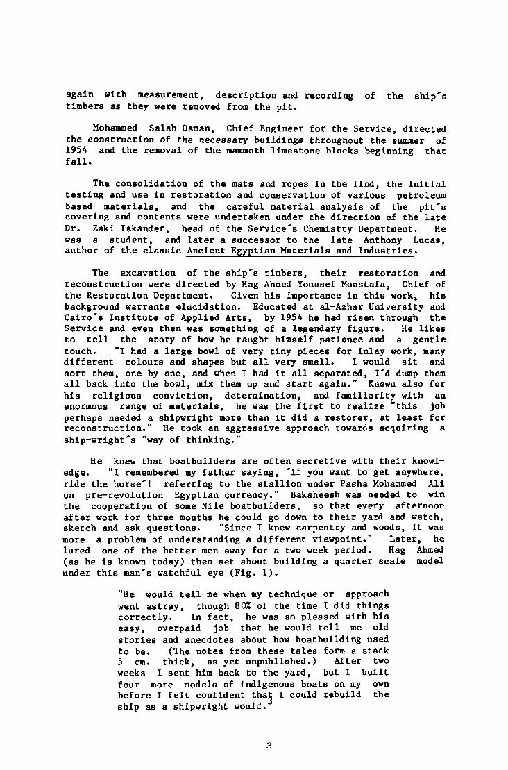
He knew that boatbuilders are often secretive with their knowledge. "I remembered my father saying, 'if you want to get anywhere, ride the horse'! referring to the stallion under Pasha Mohammed All on pre-revolution Egyptian currency." Baksheesh was needed to win the cooperation of some Nile boatbuilders, so that every afternoon after work for three months he could go down to their yard and watch, sketch and ask questions. "Since I knew carpentry and woods, it was more a problem of understanding a different viewpoint." Later, he lured one of the better men away for a two week period. Hag Ahmed (as he is known today) then set about building a quarter scale model under this man's watchful eye (Fig. 1).
"He would tell me when my technique or approach went astray, though 80% of the time I did things correctly. In fact, he was so pleased with his easy, overpaid job that he would tell me old• stories and anecdotes about how boatbuilding used to be. (The notes from these tales form a stack 5 cm. thick, as yet unpublished.) After two weeks I sent him back to the yard, but I built four more models of indigenous boats on my own before I felt confident tha| I could rebuild the ship as a shipwright would.
3

1. Model of a 9 m., 2-3 man, produce and livestock market boat,
built by Hag Ahmed to study contemporary construction.
As will become clear, Hag Ahmed used this new found perspective throughout his 28 year (plus) involvement with the ship.
The work crew whose sure hands and patient determination excavated, recorded, restored and reconstructed the ship along with the men above consisted of five carpenters, a dozen draftsmen and five to 20 semi-skilled men. Hag Ahmed remarked,
"Even the least skilled of these had to show proper patience and care. I once dismissed one for carrying two 20 cm. long pieces at once. There was no question of him being able to handle them, but I didn't want anyone working with divided attention."
Excavation of the covering stones
On November 13th, 1954, the excavation of the eastern pit began in earnest under the shed that had been built over the site; the eastern part of the boundary wall having been recorded and removed. (The Service has taken the wise position that the western site can wait until the ship's timbers (from the eastern pit) are stabilized.) At the western end of the eastern row a group of six key stones had been exposed when the dakkah had been cleared away. They were easily removed, being fairly small, with pries and log rollers. Two 10 cm. thick shutters were then removed from the space between the first block and the pit wall; this block was then forced away from its neighbour using narrow wooden wedges. Rope slings and two 25 ton, hand operated winches lifted the block and set it on log rollers, whereupon it was rolled outside the shed for measuring, cleaning, tracing of quarry marks, and storage. The remaining blocks were removed using the winches and a pair of iron "pickers". As each block was removed, the opening it left was covered with a wooden panel wrapped in fire resistant cloth in order to preserve the cool, damp atmosphere within the nit. This was initially measured at 22°C and 88% relative humidity. When the last block of the eastern pit was removed on January 28th, 1955, the following statistics were recorded.
The covering blocks averaged 4.31 x 1.59 x .78 m in dimensions and 14 tons in weight. Presumably cut from the same nearby quarries that supplied materials for the pyramids, their handling bears detailing. While their upper surfaces were very uneven, being neither leveled off nor set flush with the surrounding bedrock, their sides had been carefully worked square and flat with copper tools to give them a close fit to the adjacent blocks. The blocks rested on a metre-wide ledge running around the perimeter of a rectangular pit 31.2 x 2.6 x 3.5 m, and 37 of them were additionally wedged in place with smaller stones or "shutters." Blemishes, deep gouges and semicircular notches (presumably used as pry points in the blocks' original placing) had been filled with a coarse, pinkish white gypsum plaster made from the Giza strata. A very fine white plaster, 99% pure, had been poured between the blocks in order to form an airtight seal. This material has been tentatively identified as coming from the Fayoum Oasis, 100 km. to the south of Giza.
In summary, to achieve a near-perfect container the Fourth
5

Dynasty Egyptians carved the pit and blocks, stored the parts of a ship within the pit, worked each covering stone into place (having filled its' blemishes with the local gypsum), and then poured pure gypsum into the joints to fill any voids. Finally a layer of dakkah was laid down and compressed to smooth over the uneven tops oT the blocks and provide a base for the boundary wall.
6
EXCAVATION OF THE SHIP
Procedures
For the excavation of the pit's wooden contents between December 17th, 1955 and August 5th, 1957 the crew used these procedures:
1. The excavation was divided into 14 layers to facilitate record keeping. The topmost layer of mats, cordage and fabric was called "A", subsequent layers of wooden timbers were numbered 1 - 13 working from the top downward. These layers are arbitrary, not based on any Ancient Egyptian division of the pit.
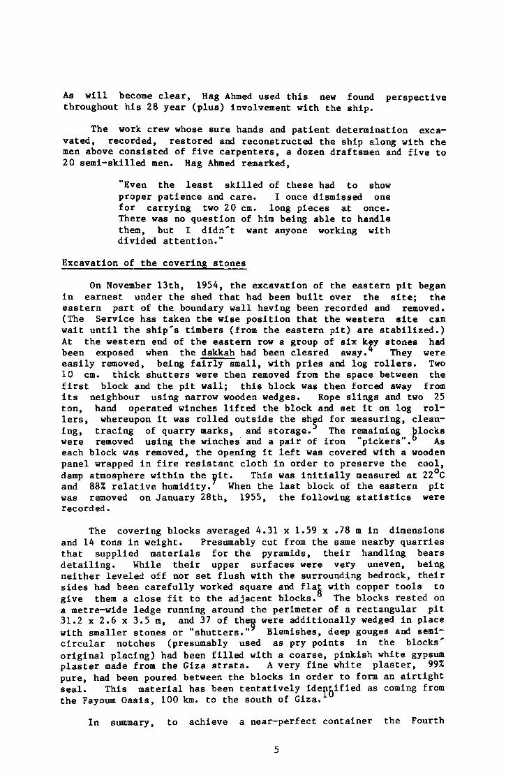
2. A composite photograph of a given layer was made by placing the camera (p. 95) on the rolling "dolly truck" 9 m above the pit. 1 1
The prints were then arranged In sequence and a scale grid 3 by 31 metres was drawn over it to give a coordinate location for each item (Fig. 2).
3. Each piece to be removed from a given layer was photographed once in situ from as close as possible.
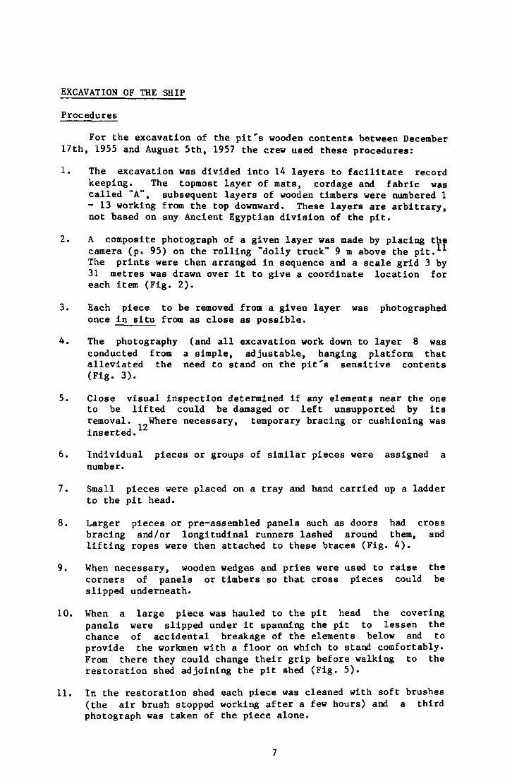
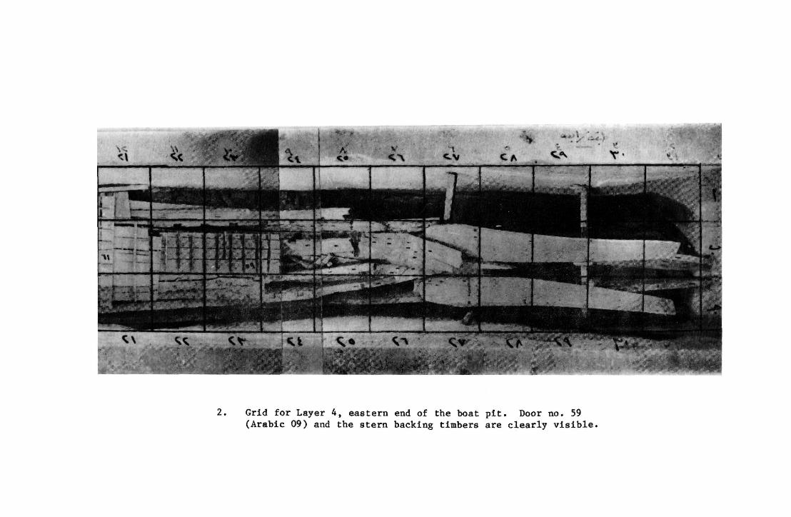
4. The photography (and all excavation work down to layer 8 was conducted from a simple, adjustable, hanging platform that alleviated the need to stand on the pit's sensitive contents (Fig. 3).
5. Close visual inspection determined if any elements near the one to be lifted could be damaged or left unsupported by its removal. Where necessary, temporary bracing or cushioning was inserted.
6. Individual pieces or groups of similar pieces were assigned a number.
7. Small pieces were placed on a tray and hand carried up a ladder to the pit head.
8. Larger pieces or pre-assembled panels such as doors had cross bracing and/or longitudinal runners lashed around them, and lifting ropes were then attached to these braces (Fig. 4).
9. When necessary, wooden wedges and pries were used to raise the corners of panels or timbers so that cross pieces could be slipped underneath.
10. When a large piece was hauled to the pit head the covering panels were slipped under it spanning the pit to lessen the chance of accidental breakage of the elements below and to provide the workmen with a floor on which to stand comfortably. From there they could change their grip before walking to the restoration shed adjoining the pit shed (Fig. 5).
11. In the restoration shed each piece was cleaned with soft brushes (the air brush stopped working after a few hours) and a third photograph was taken of the piece alone.
7
2. Grid for Layer 4, eastern end of the boat pit. Door no. 59 (Arabic 09) and the stern backing timbers are clearly visible.
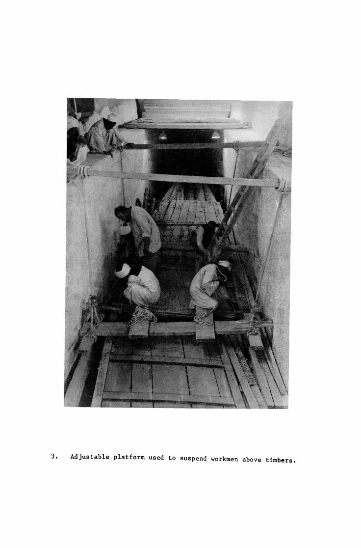
Adjustable platform used to suspend workmen above timbers.
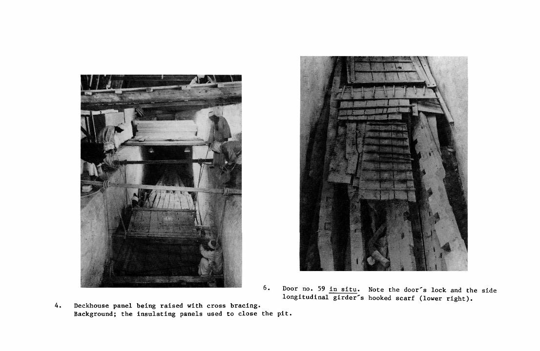
6. Door no. 59 in situ. Note the door's lock and the side longitudinal girder's hooked scarf (lower right).
4. Deckhouse panel being raised with cross bracing. Background; the insulating panels used to close the pit.
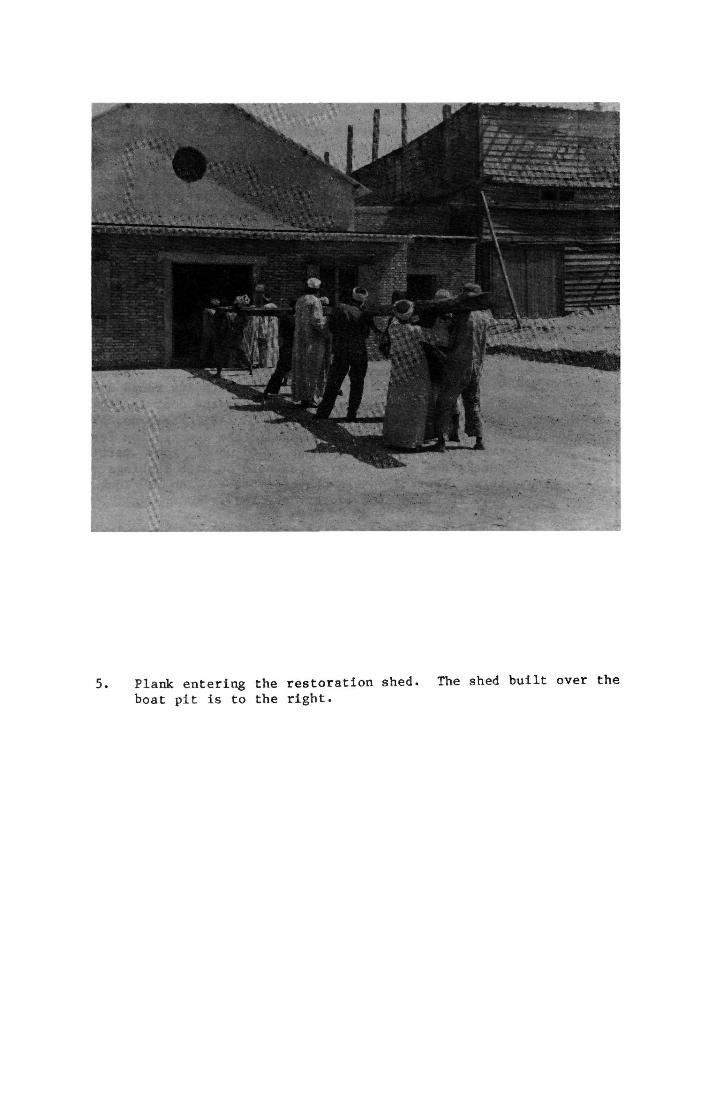
5. Plank entering the restoration shed. The shed built over the boat pit is to the right.
12. The original stacking sequence was maintained in storage but the layers were arranged in reverse order, bottom to top. Small timbers were placed on racks corresponding to their layer number (layer 1 on bottom shelf, layer 2 on second shelf up, etc.) and location (pieces from the north side of the pit were stored on the north side of their respective rack). Large pieces were arranged in sequence on the shed floor, lowermost timbers at the centre, with the preceeding layers spread north and south around these. 1 3
13. Two index cards for each piece were made containing the following information:
a. Layer number, location in grid system b. Timber identification number c. A sketch of the piece d. A copy of the photo taken upon its entry into the shed e. A verbal description of the piece with its rough dimen
sions. For example, the card for the door in Fig. 6 contains: Layer 4, location 22-24B; Piece no. 59; a sketch and a photo (not shown); the description freely translated as, "one door made up of four vertical panels and nine cross-braces held on with lashings and three tapered dowels per crossbrace. An "s" lock is held in place with copper "staples".
One copy of the card was placed on file, the second was kept with its timber. Initially, a third index card with the same information in English was put on file, but this practice was dropped after a short time.
14. Another set of cards and tracings recorded the precise shape and location of 1,131 small heeroglyphic and hieratic signs that were carved or painted in black on 305 of the timbers (Fig. 7).
15. Some contents of Layer "A" (pp. 14-17) were treated with unspecified preservatives and consolidants in situ; all the wooden timbers of Layers 1 - 1 3 were treated after excavation, that is in the restoration shed (pp. 34-39).
16. Starting in October of 1956, (during the excavation of the seventh layer) it was decided to proceed with the reconstruction by producing scale drawings of each piece. A scale model could then be used for testing proposed arrangements, keeping the handling of the original timbers to a minimum. Twelve draftsmen were immediately brought in and began the task, though a year later the plan was modified. In September of 1957, a new Director of the Service made a tour of the project and was distressed to learn that in almost a year "only" about 300 pieces had been drawn and 90 scale timbers prepared. Pressure was mounting from the Ministry of Culture and the public for more dramatic results. It was decided that Hag Ahmed would work directly on the timbers, and he was relieved of some of his administrative duties to allow him more time to do so. (In the intervening year, he had been studying and practicing his shipbuilding skills and by September felt certain of his abilities (pp. 3-5). The recording crew was reduced to a single draftsman and two assistants so that the work continued, but at a greatly
12
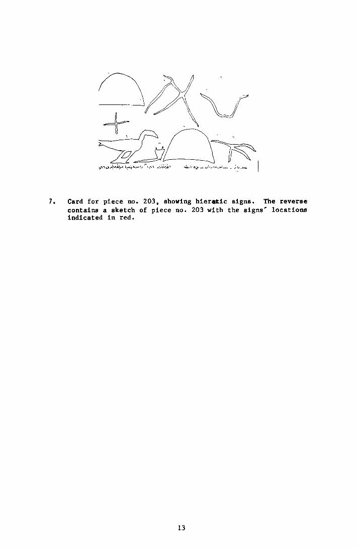
7. Card for piece no. 203, showing hieratic signs. The reverse contains a sketch of piece no. 203 with the signs' locations indicated in red.
13
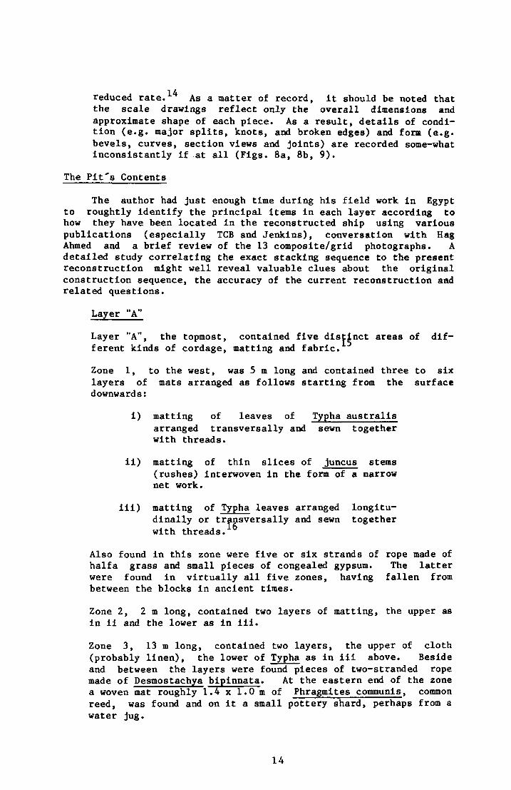
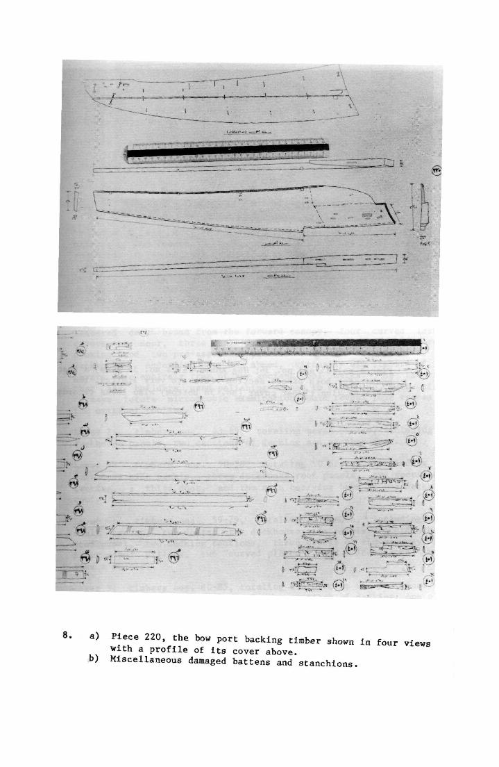
reduced rate. As a matter of record, it should be noted that the scale drawings reflect only the overall dimensions and approximate shape of each piece. As a result, details of condition (e.g. major splits, knots, and broken edges) and form (e.g. bevels, curves, section views and joints) are recorded some-what inconsistantly if at all (Figs. 8a, 8b, 9).
The Pit's Contents
The author had just enough time during his field work in Egypt to roughtly identify the principal items in each layer according to how they have been located in the reconstructed ship using various publications (especially TCB and Jenkins), conversation with Hag Ahmed and a brief review of the 13 composite/grid photographs. A detailed study correlating the exact stacking sequence to the present reconstruction might well reveal valuable clues about the original construction sequence, the accuracy of the current reconstruction and related questions.
Layer "A"
Layer "A", the topmost, contained five distinct areas of different kinds of cordage, matting and fabric.
Zone 1, to the west, was 5 m long and contained three to six layers of mats arranged as follows starting from the surface downwards:
i) matting of leaves of Typha austrails arranged transversally and sewn together with threads.
ii) matting of thin slices of juncus stems (rushes) interwoven in the form of a narrow net work.
ill) matting of Typha leaves arranged longitudinally or transversally and sewn together with threads.
Also found in this zone were five or six strands of rope made of halfa grass and small pieces of congealed gypsum. The latter were found in virtually all five zones, having fallen from between the blocks in ancient times.
Zone 2, 2 m long, contained two layers of matting, the upper as in ii and the lower as in ill.
Zone 3, 13 m long, contained two layers, the upper of cloth (probably linen), the lower of Typha as in ill above. Beside and between the layers were found pieces of two-stranded rope made of Desmostachya bipinnata. At the eastern end of the zone a woven mat roughly 1.4 x 1.0 m of Phragmites communis, common reed, was found and on it a small pottery shard, perhaps from a water jug.
14
8. a) Piece 220, the bow port backing timber shown in four views with a profile of its cover above,
b) Miscellaneous damaged battens and stanchions.
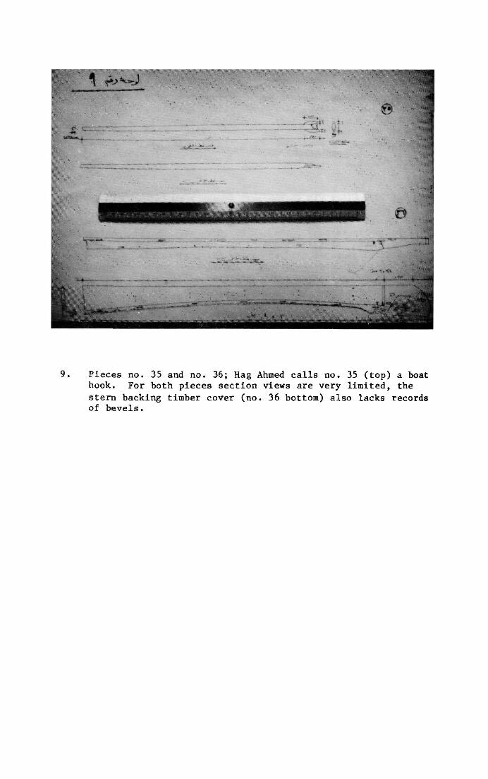
9. Pieces no. 35 and no. 36; Hag Ahmed calls no. 35 (top) a boat hook. For both pieces section views are very limited, the stern backing timber cover (no. 36 bottom) also lacks records of bevels.
Zone 4, 4 m long, contained "some objects in the form of cushions made of numerous layers of cloth impregnated with a resinous substance", and "some remains of matting and cordage". Iskander proposes that the resin impregnated cloth may have been fenders, but does not state on what grounds (Fig. 10). Others have noted that Egyptian boat models were sometimes equipped with fenders.
Zone 5, 7 m long, contains "some of the ropes which are still showing that they served for lashing some parts of the boat together."19
No attempt was made to calculate the total original area of the matting or the length of the cordage. Neither was their arrangement recorded in any detail other than in the initial composite photograph. Hag Ahmed notes that the three-strand halfa grass line was laid left to right and is beautifully clean of stray ends and broken fibres, "much better than the rope made today."
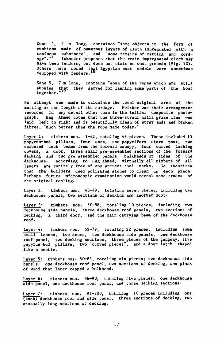
Layer 1; timbers nos. 1-42, totaling 47 pieces. These included 15 papyrus-bud pillars, four oars, the papyriform stern post, two cambered deck beams from the forward canopy, four curved lashing covers, a door, three small pre-assembled sections of the forward decking and two pre-assembled panels - bulkheads or sides of the deckhouse. According to Hag Ahmed, virtually all timbers of all layers are entirely free of any ancient tool marks. He theorizes that the builders used polishing stones to clean up each piece. Perhaps future microscopic examination would reveal some traces of the original tooling.
Layer 2: timbers nos. 43-49, totaling seven pieces, including two deckhouse panels, two sections of decking and another door.
Layer 3: timbers nos. 50-58, totaling 10 pieces, including two deckhouse side panels, three deckhouse roof panels, two sections of decking, a third door, and the main carrying beam of the deckhouse roof.
Layer 4: timbers nos. 59-79, totaling 22 pieces, including some small tenons, two doors, two deckhouse side panels, one deckhouse roof panel, two decking sections, three pieces of the gangway, five papyrus-bud pillars, two "curved pieces", and a door latch shaped like a beetle.
Layer 5: timbers nos. 80-85, totaling six pieces; two deckhouse side panels, one deckhouse roof panel, two sections of decking, one plank of wood that later capped a bulkhead.
Layer 6: timbers nos. 86-90, totaling five pieces; one deckhouse side panel, one deckhouse roof panel, and three decking sections.
Layer 7: timbers nos. 91-100, totaling 10 pieces including one (each) deckhouse roof and side panel, three sections of decking, two unusually long sections of decking.
17
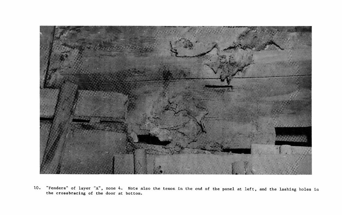
10. "Fenders" of layer "A", zone 4. Note also the tenon in the end of the panel at left, and the lashing holes in the crossbracing of the door at bottom.

Through Layers 1 - 7 the size and weight of the timbers increased steadily. As a consequence, beginning with Layer no. 8 the workmen often stood directly on the timbers (instead of on the suspended platform) and commencing with Layer no. 8 the timbers had to be raised with a 25 ton winch and a steel "I" beam instead of by hand. 2 0
Layer 8: timbers nos. 101-104, totaling four pieces; two planks from the sheer strakes, two side longitudinal girders. One of the latter was badly cracked and had to be sandwiched between two 5 x 30 cm. support planks before being moved.
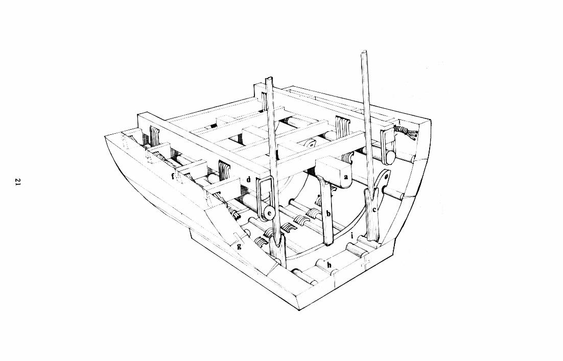
Layer 9: timbers nos. 105-167, totaling 63 pieces including the central longitudinal girder or "spine" (see Fig. 11), 18 shallowly cambered beams that would form the arched shell of the canopy over the deckhouse, (Fig. 69) some planking, many deck beams and some small tenons.
Layer 10: timbers nos. 168-183, totaling 16 pieces including some large deck beams, planking and more tenons.
Layer 11: timbers nos. 184-210, totaling 30 pieces, including more deck beams and planking, the papyriform stem post, some loose piles of cordage and the four backing timbers (two each at bow and stern) with their ends just overlapping the bottom planking (Fig. 66). 1 It is remarkable that the backing timbers, the ship's most unusual features and ones with which Hag Ahmed might have had the most trouble, were virtually the only pieces to be precisely stored in antiquity to reflect not only their general location and orientation, but also the way they joined with adjacent pieces; their lashing holes aligned, bevels set together, etc.
Layer 12: timbers nos. 211-263, totaling 53 pieces including the eight bottom planks (two to the west at the bow, three to the east at the stern and all of these overlapping a central group of three), some frames (one of which had five short lengths of "two-stranded rope" through one of its lashing holes), some tenons, two baskets of "new", unchaffed cordage (Fig. 12), six stanchions, a boathook (Fig. 9), a pole for tightening lashings, (Fig. 13) and some tapered stakes with notches near the tops (Fig. 13?. Hag Ahmed thinks the latter might have been used as bitts, driven into the ground to hold the bow and stern lines when the ship was drawn up to the river bank.
Layer 13: timbers nos. 264-407, totaling 378 pieces including 65 marline hitched bundles and stacks of seam battens (totaling approximately 300 pieces (Fig. 14), some stanchions to support papyrus-bud pillars, some small blocks of limestone that had supported the bow and stern sections of the bottom planking, more deck beams, fragments of mats and ropes, 10 stanchions to support the spine, two hemispherical socketed beams to support the canopy pillars beside the deckhouse, the side longitudinal girders' hold downs, one oar, eight "L" shaped, pre-assembled covers, known hereafter as "backing timber covers" that support the planking, stem and stern posts, a flint knife, a black basalt pounder, some badly chaffed cordage, 13 lashings piled together in a corner, and many tenons.
19
11. Construction view, forward; "spine" 'a', the central girder of the ship, supported by stanchion 'b'; "c" stanchions supporting forward papyrus bud pillars; 'd' side longitudinal girders; 'e' side longitudinal girder hold downs; 'i" tenon in end of deck beam notched into sheer strake; '%' tenon for plank alignment; "h" batten over plank seam; 'i' frame. Peter Schmid/Paul Lipke.
20
21
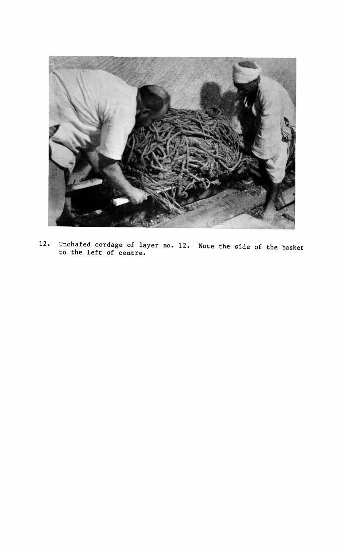
12. Unchafed cordage of layer no. 12. Note the side of the basket to the left of centre.
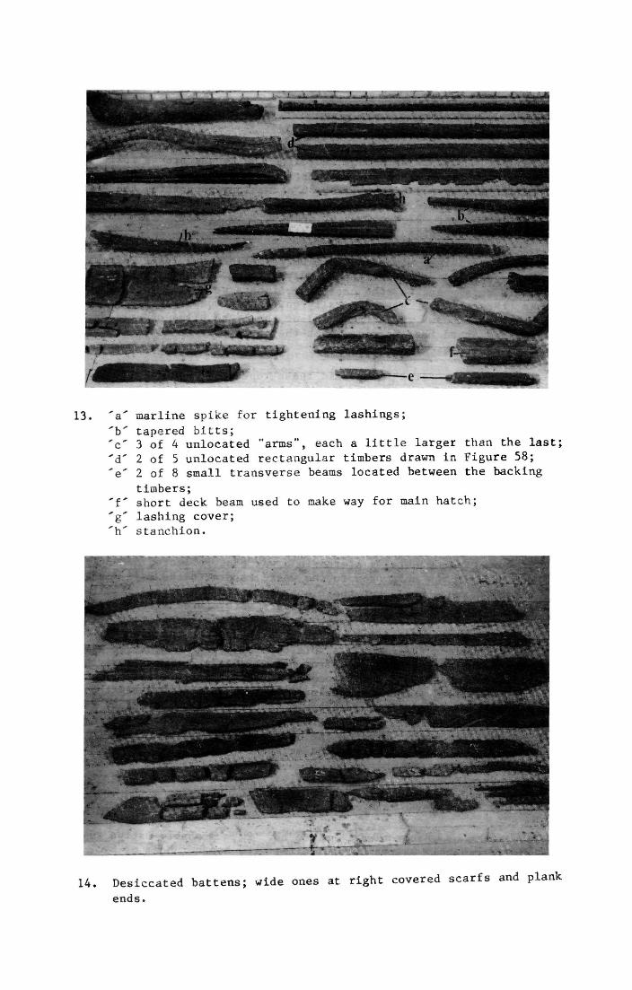
13. 'a' marline spike for tightening lashings;
'b' tapered bitts; 'c' 3 of 4 unlocated "arms", each a little larger than the last; 'd' 2 of 5 unlocated rectangular timbers drawn in Figure 58; 'e' 2 of 8 small transverse beams located between the backing
timbers; ' f short deck beam used to make way for main hatch; 'g' lashing cover; 'h' stanchion.
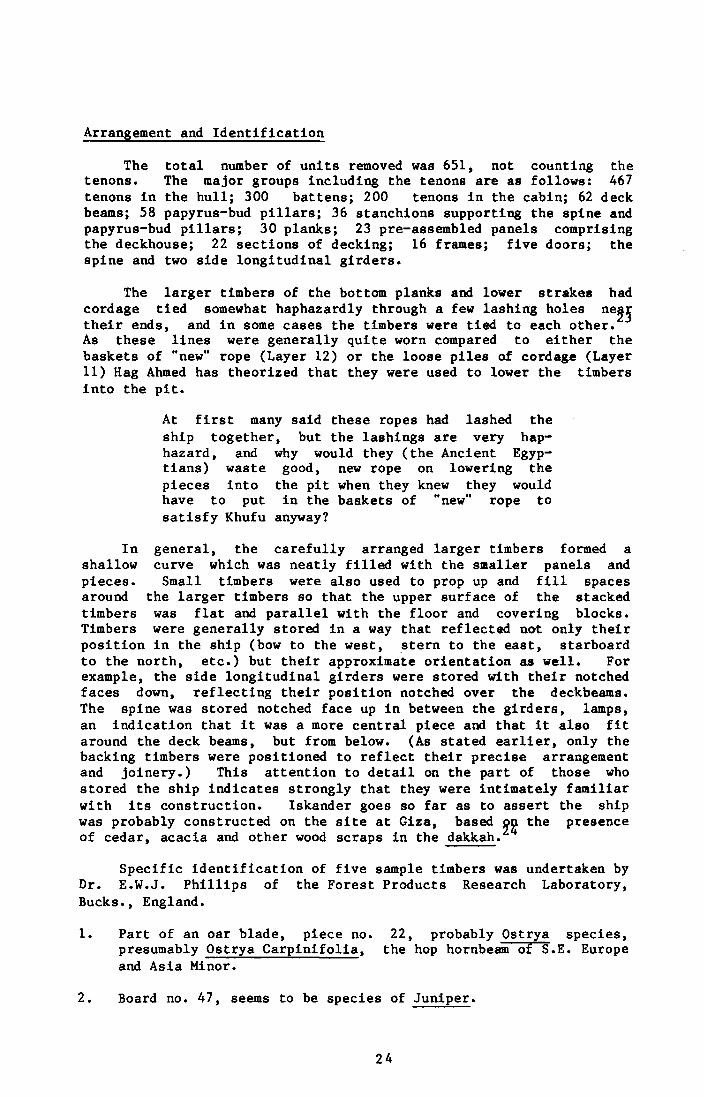
14. Desiccated battens; wide ones at right covered scarfs and plank
ends.
Arrangement and Identification
The total number of units removed was 651, not counting the tenons. The major groups including the tenons are as follows: 467 tenons in the hull; 300 battens; 200 tenons in the cabin; 62 deck beams; 58 papyrus-bud pillars; 36 stanchions supporting the spine and papyrus-bud pillars; 30 planks; 23 pre-assembled panels comprising the deckhouse; 22 sections of decking; 16 frames; five doors; the spine and two side longitudinal girders.
The larger timbers of the bottom planks and lower strakes had cordage tied somewhat haphazardly through a few lashing holes near their ends, and in some cases the timbers were tied to each other. As these lines were generally quite worn compared to either the baskets of "new" rope (Layer 12) or the loose piles of cordage (Layer 11) Hag Ahmed has theorized that they were used to lower the timbers into the pit.
At first many said these ropes had lashed the ship together, but the lashings are very haphazard, and why would they (the Ancient Egyptians) waste good, new rope on lowering the pieces into the pit when they knew they would have to put in the baskets of "new" rope to satisfy Khufu anyway?
In general, the carefully arranged larger timbers formed a shallow curve which was neatly filled with the smaller panels and pieces. Small timbers were also used to prop up and fill spaces around the larger timbers so that the upper surface of the stacked timbers was flat and parallel with the floor and covering blocks. Timbers were generally stored in a way that reflected not only their position in the ship (bow to the west, stern to the east, starboard to the north, etc.) but their approximate orientation as well. For example, the side longitudinal girders were stored with their notched faces down, reflecting their position notched over the deckbeams. The spine was stored notched face up in between the girders, lamps, an indication that it was a more central piece and that it also fit around the deck beams, but from below. (As stated earlier, only the backing timbers were positioned to reflect their precise arrangement and joinery.) This attention to detail on the part of those who stored the ship indicates strongly that they were intimately familiar with its construction. Iskander goes so far as to assert the ship was probably constructed on the site at Giza, based on the presence of cedar, acacia and other wood scraps in the dakkah.
Specific identification of five sample timbers was undertaken by Dr. E.W.J. Phillips of the Forest Products Research Laboratory, Bucks., England.
1. Part of an oar blade, piece no. 22, probably Ostrya species, presumably Ostrya Carpinifolia, the hop hornbeam of S.E. Europe and Asia Minor.
2. Board no. 47, seems to be species of Juniper.
24
3. Beam no. 14, probably Balanites Aegyptlaca, the lalob, soapberry or thorn tree.
4. Oar no. 4, Cedrus species, cedar of Lebanon or allied species.
5. Wooden pegs from door no. 23, possibly an Acacia species, identity very uncertain in this case.
Hag Ahmed goes further on the basis of his familiarity with wood as a carpenter and his intimate knowledge of the ship's timbers; their feel, appearance, etc.
The tenons that align the planks are sidder (Ziziphus spina-christi) which is a very hard wood. Sycamore (Ficus sycamorus) was used in small quantities for battens, pegs and other details. Acacia (probably Acacia nilotica) was used for crossbracing in some of the deck sections. All told, 95% of the ship is cedar from Lebanon. It's very hard, and even in the most infested parts of the Nile the worms (marine borers) will not eat it.
The author hastens to point out that the identity of the majority of the ship's timbers has never been positively ascertained. While cedar of Lebanon is probably correct, Jenkins' assertion (p.80) that the British Museum made positive identification of it being Cedrus libani "coming from that part of Syria that we know today as Lebanon..."could not be confirmed.
Snow (1903) and Uphof (1968) provide the following additional data on distribution and characteristics of the relevant species.
Ostrya Carplnlfolia: very tough, hard and close grained, 45 lbs. per cubic foot.
Balanites Aegytiaca: Northern Tropics, Africa, Arabia and Palestine; hard, compact, fine grained.
Acacia Nilotica: Tropical Africa; hard, durable, close grained and heavy; resistant to water and white ants.
Ziziphus spina-christi: North Africa, Arabia; very hard wood, small tree.
Ficus sycamorus: North Africa; Hadidi (1979) adds "sycamore wood is light but durable, was used in Ancient Egypt for sarcophagi and for agricultural tools. The tree is native of southern Arabian peninsula and Tropical East Africa."
Cedrus libani: Palestine; Chaney (1978) states that the tree averages 24 m mature, though examples are known of 36 m. Its diameter varies from 1.5 to 2.4 m. Gamble (1922) adds that the wood is moderately hard with a coarse grain, sap wood of reddish white and heart wood of light yellowish brown. Well seasoned it weighs about 35 lbs. per cubic foot (15.75 kg.) though the branches may be as much as 48 lbs. (21.6 kg.) due to their
25

higher resin content. Howard (1920) states that the wood does not possess any resin passages and as it is a conifer, the wood shows no pores.
Virtually all these species have been found in use in other sites of the Old Kingdom.
26
CONDITION OF THE SHIP'S TIMBERS:
Virtually every person on the scene in 1954 made frequent reference to the remarkable condition of the ship's timbers. (Even today, knowing the extensive restoration that has been necessary, the ship's appearance is nothing short of extraordinary.) Clearly the pit's airtight seal and the careful stacking of its contents were critical in preserving the timbers. Insects and fungi, if their ever were any within the pit, apparently found the resinous cedar fatal. In addition, closer examination of the climate within the pit is appropriate.
In November of 1954, Zaki Iskander took readings for temperature and relative humidity over a six day period, a level 22' C. and 88% relative humidity being recorded. This reading must be considered in light of the fact that the pit's seal had been broken since May of that year; the precise details of how the hole in the 22nd block was covered being unknown today. For comparison, this project saught but was unable to find temperature and relative humidity readings from the opening of other tombs in the Giza area. Only the roughest approximation of conditions within the pit can be suggested by the following figures and factors. Figure 15 shows the November 1954 pit readings in comparison to those for monthly mean maximum/minimum temperatures, dew point temperature and relative humidity of the ambient for "Cairo West". . The November 1954 pit temperature of 71.6° F falls well within the ambient average, and the relative humidity is well below that necessary for drops to form. Dr. K. Lai Gauri, consultant to the Giza Sphinx Project has suggested in conversation that the pit's dew point was probably considerably lower than that of the ambient due to the hygroscopy of salts (in the Giza bedrock) and the depth of the pit. In short, it is possible that the timbers were subjected to temperatures consistantly below 60° F so that adequate moisture had condensed to keep the wood in a wet state throughout the period of its burial.
Many timbers that lay against the floor or walls of the pit exhibited soft areas and cross shakes, perhaps the result of some interaction between the atmosphere, the salt in the bedrock, and the cedar. Clearly a great deal more could be learned in all these areas through further study and experimentation, with obvious curatorial ramifications. Table 1 gives a complete list of timbers that sustained significant damage in 4,500 years of storage.
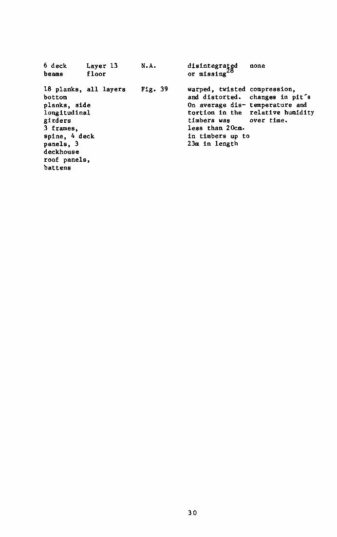
As the ever larger timbers of the lower layers were excavated, it became increasingly difficult to maintain the atmosphere within the pit since the covering panels had to be removed for hours at a time. Air conditioning/humidification units were frequently requested for the excavation shed and later for the restoration and storage buildings, but these only became operational in the museum building in the early 1980's. Under the circumstances, it was inevitable that some desiccation occurred. Additional problems developed due to a lack of proper storage compartments and shelving between the third and fourth reconstructions. Table 2 provides a nearly complete, if not totally precise listing of damage occuring after excavation.
27
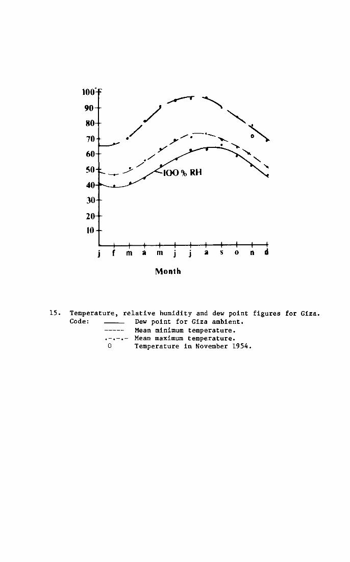
15. Temperature, relative humidity and dew point figures for Giz Code: Dew point for Giza ambient.
Mean minimum temperature. Mean maximum temperature.
0 Temperature in November 1954.
Month
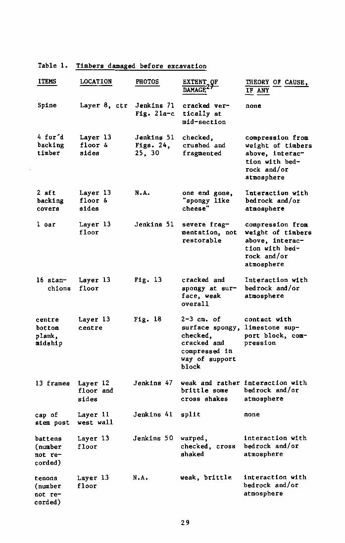
Table 1. Timbers damaged before excavation
ITEMS
Spine
4 for'd backing timber
2 aft backing covers
1 oar
16 stanchions
LOCATION
Layer 8, ctr
Layer 13 floor & sides
Layer 13 floor & sides
Layer 13 floor
Layer 13 floor
PHOTOS
Jenkins 71 Fig. 21a-c
Jenkins 51 Figs. 24, 25, 30
N. A.
Jenkins 51
Fig. 13
EXTENT OF DAMAGE 2*"
cracked vertically at mid-section
checked, crushed and fragmented
THEORY OF CAUSE, IF ANY
one end gone, "spongy like cheese"
severe fragmentation, not restorable
cracked and spongy at surface, weak overall
none
compression from weight of timbers above, interaction with bedrock and/or atmosphere
Interaction with bedrock and/or atmosphere
compression from weight of timbers above, interaction with bedrock and/or atmosphere
Interaction with bedrock and/or atmosphere
centre Layer 13 Fig. 18 2-3 cm. of contact with bottom centre surface spongy, limestone sup-plank, checked, port block, com-mldshlp cracked and presslon
compressed In way of support block
13 frames
cap of stem post
battens (number not recorded)
tenons (number not recorded)
Layer 12 floor and sides
Layer 11 west wall
Layer 13 floor
Layer 13 floor
Jenkins 47 weak and rather interaction with brittle some bedrock and/or cross shakes atmosphere
Jenkins 41 split
Jenkins 50
N. A.
warped, checked, cross shaked
weak, brittle
none
interaction with bedrock and/or atmosphere
interaction with bedrock and/or atmosphere
29
6 deck Layer 13 N.A. beams floor
18 planks, all layers Fig. 39 bottom planks, side longitudinal girders 3 frames, spine, 4 deck panels, 3 deckhouse roof panels, battens
disintegrated none or missing
warped, twisted compression, and distorted, changes in pit's On average dis- temperature and tortion in the relative humidity timbers was over time, less than 20cm. in timbers up to 23m in length
30
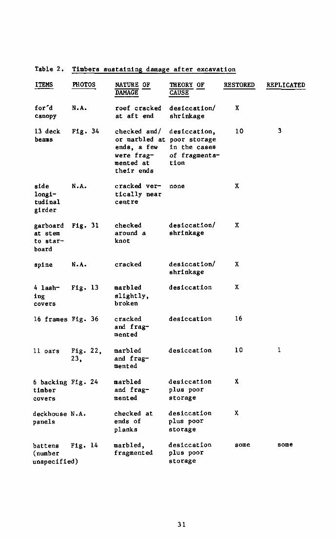
Table 2. Timbers sustaining damage after excavation
ITEMS PHOTOS
for'd canopy
13 deck beams
N.Â.
Fig. 34
NATURE OF DAMAGE
roof cracked at aft end
THEORY OF CAUSE
desiccation/ shrinkage
RESTORED REPLICATED
checked and/ desiccation, or marbled at poor storage ends, a few were fragmented at their ends
in the cases of fragmentation
10
side N.A. longitudinal girder
garboard Fig. 31 at stem to starboard
spine N. A.
4 lash- Fig. 13 ing covers
16 frames Fig. 36
11 oars Fig. 22, 23,
6 backing Fig. 24 timber covers
deckhouse N.A. panels
battens Fig. 14 (number unspecified)
cracked vertically near centre
none
31
checked desiccation/ X around a shrinkage knot
cracked desiccation/ X shrinkage
marbled desiccation X slightly, broken
cracked desiccation 16 and fragmented
marbled desiccation 10 1 and fragmented
marbled desiccation X and frag- plus poor mented storage
checked at desiccation X ends of plus poor planks storage
marbled, desiccation some some fragmented plus poor
storage
X
3
X
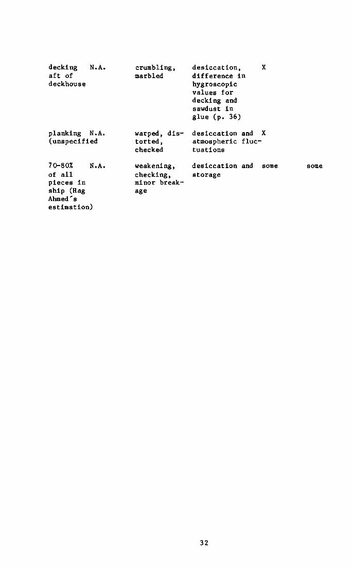
decking aft of deckhouse
N. A.
planking N.A. (unspecified
crumbling, marbled
warped, distorted, checked
desiccation, X difference in hygroscopic values for decking and sawdust in glue (p. 36)
desiccation and X atmospheric fluctuations
70-80% of all pieces in ship (Hag Ahmed's estimation)
N.A. weakening, checking, minor breakage
desiccation and storage
some some
32
Several incidents deserve mention, though what effect on the timbers they may have had, if any, is not completely clear.
1. Rain leaked into the shed over the pit. "Water soaked through some of the matting and even onto some of the upper timbers".
2. Some stones blew off the pyramid during a sandstorm and punctured the restoration shed roof, "shook small pieces on shelves and may have hit a large timber".
3. Unseasonably hot weather in October of 1963 and late September of 1964 (while the timbers were in storage between reconstructions) led to wholesale desiccation and checking. It is to this period tbat Hag Ahmed attributes the damage to "70 - 80% of all pieces". 2 9
4. "Small pieces on the deck of the ship were displaced, washed into the hold and even off the deck onto the floor of the
30 museum...by the rain that leaked through the museum roof".
33
CONSERVATION AND RESTORATION
Preservative treatment of the timbers upon excavation, and materials and techniques used in the restoration of damage occurring before and after 1954 are covered in some detail below. As no record exists of exactly what work was done on each timber, these details should be taken as general examples of Hag Ahmed's approach. As he often remarked,
Every piece requires its own precise solution and what with responsibilities in administration, total supervision of the crew, much of the photographic documentation and general direction/ decision making for the restoration and reconstruction, it was impossible for me to record everything.
He is also aware that his approach to restoration and reconstruction may be considered somewhat dramatic and radical by the standards of the 1980's.
My approach to the ship was appropriate to the situation and the resources available, and as such was not necessarily scientific in the strictest sense at all times. Still, several of the world's most respected restorers have called the ship's restoration and reconstruction 'a miracle'.
The restoration and reconstruction processes overlapped at virtually every stage, though for purposes of clarity they have been reported separately here.
We would first conduct any structural restorations such as large cracks and breaks, then test a plank's location, rebend it if necessary (see below pp. 56, 61), put it back in position and leave it for a time and only come back for the final touch up near the end of the reconstruction process.
For tools and equipment the project relied upon the common hand tools of twentieth century carpentry; saws, chisels, mallets, planes, rasps, drills, augers, light hammers, measuring tapes, putty knives, pallet knives, and soft brushes. Two "heavy duty" chain falls suspended from a rolling gantry, a steel "I" beam, linen rope of 2-4 cm. diameter and army surplus blankets cut up for padding were used to move the larger timbers around the restoration sheds.
Preservatives
Hag Ahmed and Dr. Zaki Iskander, acting upon advice from specialists in Europe, tested several materials before selecting polyvinyl acetate and an animal hide glue as their basic preservative and adhesive. Bedacryl 122 was applied by brush or with the immersion of small pieces in a basin. Its penetration appeared acceptable (by rudimentary visual inspection) but it was rejected on the grounds
34
that it appeared to have little effect in sealing the free water within the timbers. Polymerised polyvinyl acetate (PVA) was tested and found more satisfactory and so was used throughout the project in the following solution:
PVA 25. or 50.g (depending on whether a 2.5% or 5.0% concentration was desired)
Amyl Acetate 100 ml
Acetone 900 ml
Dichloro-dlphenyl-trichloroethane (DDT) 10 g
Para-Dicholobenzene (only until 1956) 10 g
A simple test was conducted to decide between immersion and brushing as the means of application. Two pieces of identical dimensions and weight were selected. One was immersed three times: for 6 hours and then removed for 18 hours; for 24 hours and then removed for 18 again; for 2 - 3 hours and allowed to dry completely. The second timber was simply brushed repeatedly over the course of two days with an identical 2.5% solution until visual inspection indicted that the PVA had just begun to build up on the surface. When the two were weighedi the second piece was heavier (no exact weights available) so the brush technique was used, with the exceptions of the matting and cloth in layer "A" aad the quarry marks. The PVA was dripped through a pipette to "consolidate" the matting and cloth. The quarry marks on the pit's covering stones were sprayed with a 7% solution of PVA.
In the initial application of PVA to the excavated timbers a 2.5% solution would be used. "If the wood seemed able to absorb more, we would mix a little of the 5. % solution with the 2.5%, or even use the 5. % straight if possible." Working with large timbers, a roughly 5 0 cm. square area was brushed at a time, with the workman going back over the first portion of the square as quickly as the liquid was absorbed. As the rate of absorption slowed with repeated applications, an adjacent area would receive its first treatment. In this manner an entire timber would be treated on its top and sides before being turned over for treatment of its bottom. this process was repeated once a year for the first three years after excavation, and every two years throughout reconstruction and storage until the climate control unit was installed in the museum.
In certain cases it became necessary to remove the PVA temporarily.
The PVA tended to fill the surface pores of the timbers and make them stiff. When it came time to take the distortion out (see below pp. 56, 61) it was impossible for the boiling water to penetrate the PVA. For this reason we would soften the PVA on the timber with pure acetone, and then scrape it off with a wide putty knife. It was sometimes necessary to repeat this process two or three times in order to get a timber to
35

the point where we could rehumidify it. Of course, this sort of work is easier said than done... After we had reshaped the timbers, the PVA would be re-applied.
The consensus among Western conservators today is that PVA is relatively stable, and that initial concerns over a possible propensity for it to break down into acedic acid were probably unwarranted. Furthermore, the practice of removing the surface layers with acetone (as mentioned above) would have the effect of reducing the surface gloss.
Adhesives
In the first repairs to small pieces on the upper layers,
Markon Resin 9 Low Viscosity (Scott and Bader Co. Ltd.) and its solution in acetone was used for the conservation of very disintegrated pieces. Marcon Resin with sawdust was also used for sticking some of the broken pieces together.
Then material analysis of the original timbers indicated that the Fourth Dynasty shipwrights had filled a few small lashing holes with a paste based on a nitrogenous organic adhesive (probably animal glue) tinted with ferric oxide (ochre common to Egypt in the colours red, brown and yellow.
Since the Marcon Resin was, in Hag Ahmed's words,
"...too hard and strong and stiff for the work we were doing, we switched to an animal glue that has been in use in Egypt for millenia."
This animal glue and ferric oxide tints were (are) used quite extensively throughout the restoration/reconstruction period in a variety of combinations. Hag Ahmed kindly demonstrated their preparation for the author.
1. For straight gluing, no filler needed, the glue pellets (.5 cm. in diameter) are set to soak in water just covered for 2-3 hours, then heated and stirred over a double boiler until uniform. Applied to both surfaces to be glued and clamped, it takes 24 hours to dry but only a few minutes to set.
2. For gluing "open" joints that will be visible to the public, the glue is doctored as follows.
A powder made from crushed unidentifiable fragments or repaired areas of original timbers is mixed with finely ground charcoal taken from a local shlsh-kebab pit. This base comprises 40-60% (depending on viscosity desired) of a glue paste which also contains 30-40% glue, 5-8% calcium carbonate, and 1-2% yellow, red and/or brown ochre in combination to match the wood being glued, if necessary. (Usually this paste did not need to be adjusted for colour).
36
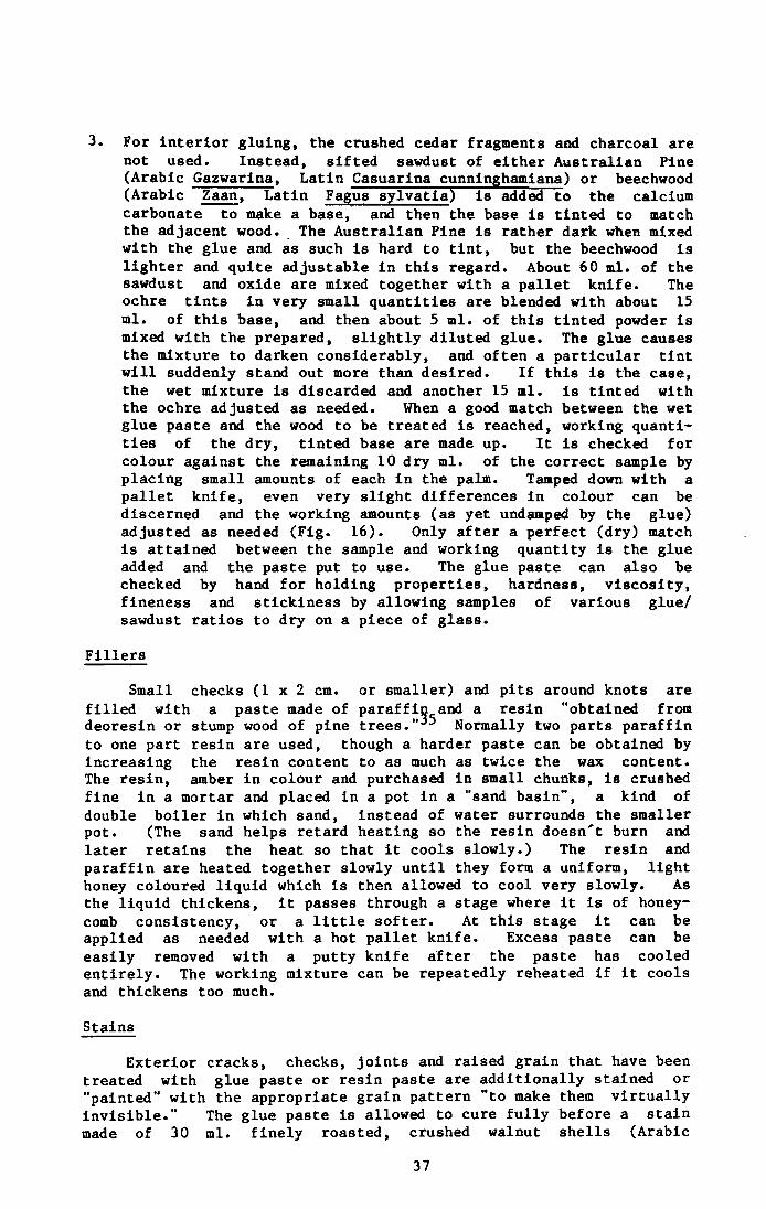
3. For interior gluing, the crushed cedar fragments and charcoal are not used. Instead, sifted sawdust of either Australian Pine (Arabic Gazwarina, Latin Casuarina cunninghamiana) or beechwood (Arabic Zaan, Latin Fagus sylvatia) is added to the calcium carbonate to make a base, and then the base is tinted to match the adjacent wood. The Australian Pine is rather dark when mixed with the glue and as such is hard to tint, but the beechwood is lighter and quite adjustable in this regard. About 60 ml. of the sawdust and oxide are mixed together with a pallet knife. The ochre tints in very small quantities are blended with about 15 ml. of this base, and then about 5 ml. of this tinted powder is mixed with the prepared, slightly diluted glue. The glue causes the mixture to darken considerably, and often a particular tint will suddenly stand out more than desired. If this is the case, the wet mixture is discarded and another 15 ml. is tinted with the ochre adjusted as needed. When a good match between the wet glue paste and the wood to be treated is reached, working quantities of the dry, tinted base are made up. It is checked for colour against the remaining 10 dry ml. of the correct sample by placing small amounts of each in the palm. Tamped down with a pallet knife, even very slight differences in colour can be discerned and the working amounts (as yet undamped by the glue) adjusted as needed (Fig. 16). Only after a perfect (dry) match is attained between the sample and working quantity is the glue added and the paste put to use. The glue paste can also be checked by hand for holding properties, hardness, viscosity, fineness and stickiness by allowing samples of various glue/ sawdust ratios to dry on a piece of glass.
Small checks ( 1 x 2 cm. or smaller) and pits around knots are filled with a paste made of paraffin and a resin "obtained from deoresin or stump wood of pine trees. 5 Normally two parts paraffin to one part resin are used, though a harder paste can be obtained by increasing the resin content to as much as twice the wax content. The resin, amber in colour and purchased in small chunks, is crushed fine in a mortar and placed in a pot in a "sand basin", a kind of double boiler in which sand, instead of water surrounds the smaller pot. (The sand helps retard heating so the resin doesn't burn and later retains the heat so that it cools slowly.) The resin and paraffin are heated together slowly until they form a uniform, light honey coloured liquid which is then allowed to cool very slowly. As the liquid thickens, it passes through a stage where it is of honeycomb consistency, or a little softer. At this stage it can be applied as needed with a hot pallet knife. Excess paste can be easily removed with a putty knife after the paste has cooled entirely. The working mixture can be repeatedly reheated if it cools and thickens too much.
Exterior cracks, checks, joints and raised grain that have been treated with glue paste or resin paste are additionally stained or "painted" with the appropriate grain pattern "to make them virtually invisible." The glue paste is allowed to cure fully before a stain made of 30 ml. finely roasted, crushed walnut shells (Arabic
Fillers
Stains
37
16. Sample from working quantities of the dry, tinted base compared to correct test sample by tamping down in palm; difference enhanced for publication. Paul Lipke (1983).
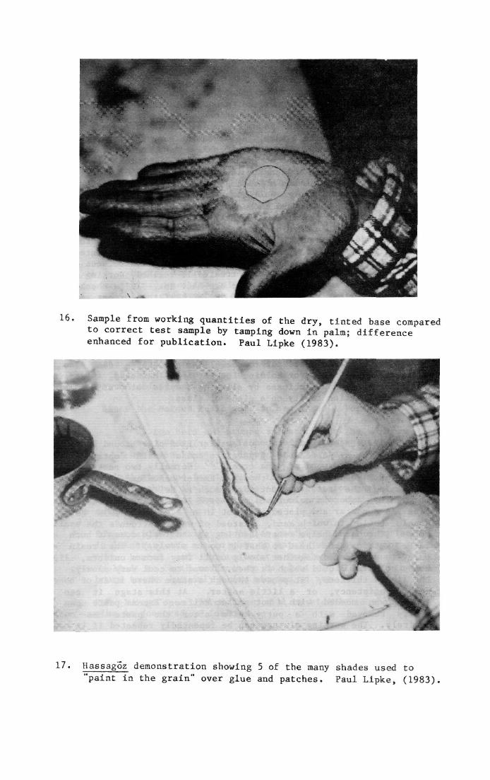
17' Hassagoz demonstration showing 5 of the many shades used to "paint in the grain" over glue and patches. Paul Lipke, (1983),
hassagoz) dissolved in 180 ml. water is applied.
An artist's touch is needed to paint in the grain pattern; adjusting the tone of the stain like a watercolour painter, and blending in the affected area with a light wash (Fig. 17). The stain is very stable, can be purchased in any tone from light to dark brown, depending on how much it has been roasted, and is easily handled with a fine brush. Sometimes I cannot find my own repairs after I've "painted" them!
The resin/wax paste is painted in similar fashion using artists' oil based tints in turpentine.
Other materials
In the restoration Hag Ahmed also used cotton gauze; aluminium foil, pipe and sheet stock; 1 and 2 mm. veneers of African mahogany and beechwood; and various unidentified woods (for patches). Hag Ahmed could not Identify the species used for patches, saying only that he was told they were called "ennab". Extensive inquiries in Cairo failed to clarify the meaning of the word "ennab". Hag Ahmed regreted being unable to provide any samples for precise identification in time for publication. In any case, the patches came from timbers as large as 30 x 40 cm. in section salvaged from mosque repair projects around the old city of Cairo. On average, the balks had been seasoning for 500 to 1,000 years in the floors, roofs and foundations of these buildings before Hag Ahmed used then to patch the 4,500 year old wooden parts of the ship. (He hastened to point out there had been very few problems of shrinkage or warpage in these patches to date.) From the Service's storerooms Hag Ahmed would select balks to match the ship's timbers based on colour, clearness of grain, density and overall dimension. Perhaps 10% of the ship's timbers have "significant patches of ennab inserted in the timbers as follows:
Restoration Techniques: 14 examples
1. Patching Method
The midship centre plank of the bottom planking (Fig. 18) was badly damaged at one end, and largely on one side. There was no fragmentation or crumbled wood dust evident, just compression, desiccation and softness.
A. Visual examination determined the area to be removed, and this area was outlined in chalk.
B. The outlined section was cut away in steps by working outward from the most badly affected area. The practice was always to remove the minimum amount possible of the original timber by removing shallow slices (1 cm. at a time). As a slice was cut away, the underlying area would be visually and tactually examined to determine if patching materials and adhesives would hold, or if further cuts were necessary.
39
C. Multiple pieces of ennab were cut to fit the various subsections (Fig. 19). All pieces, both ennab and original, were interocked with splines, dowels, mortise and tenons, scarfs and/or rabbets. Each layer of ennab was fitted, glued, fastened in place and then allowed to cure for three or four days before the next layer was added. This particular repair spanned 15 working days.
D. If the ennab repaired section would be visible to the public it was stained with hassagoz, if not it was left unstained. The stained wood was left slightly lighter than the adjoining section so as not to confuse future curators and scholars as to which parts were original and which were repairs.
2. Patching Methods
Timbers having compound curves and bevels in their damaged sections were treated with much the same materials and techniques as in method "1". However the sequence used was one designed to insure that the timber's original dimensions and form were preserved.
A. A pattern was taken of the curves and/or bevels that had to be repaired.
B. In this case the corners were cut out and replaced with over-sized, rabbeted dutchmen, clamped and glued. When cured, excess wood was planed down till fair with the sides and upper surface using patterns and/or a fairing batten as references (Fig.20a, 20b).
C. The damaged midsection was cut away in three steps, and the lowest section was replaced with a piece of ennab and left to cure (Fig. 20c).
D. The next sections were replaced as in "C" (Fig. 20d).
E. The remainder of the damaged surface was cut away and replaced oversized, then planed down to fair with the corner dutchmen and repaired midsections (Fig. 20d).
F. During the subsequent reconstructions it was possible to determine the approximate original dimensions of any piece whose edges had been poorly defined and consequently had been repaired over-size. The excess ennab was simply cut away to fit the adjacent timbers.
G. Visible repairs were stained.
3. Patching Method
Large timbers with structural weak points, §g c n a s t n e cracked
spine were also repaired with ennab section.
A. A section of the surface area around the crack was removed from both sides of the timber (Fig. 21a).
40
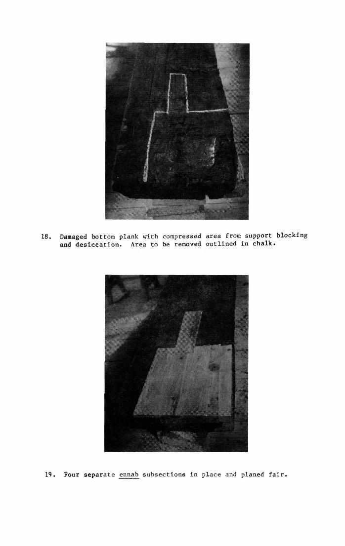
18. Damaged bottom plank with compressed area from support blocking and desiccation. Area to be removed outlined in chalk.
19. Four separate ennab subsections in place and planed fair.
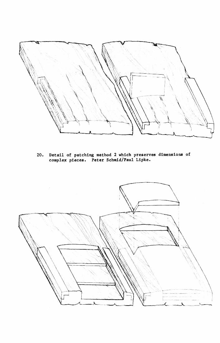
20. Detail of patching method 2 which preserves dimensions of complex pieces. Peter Schmid/Paul Lipke.
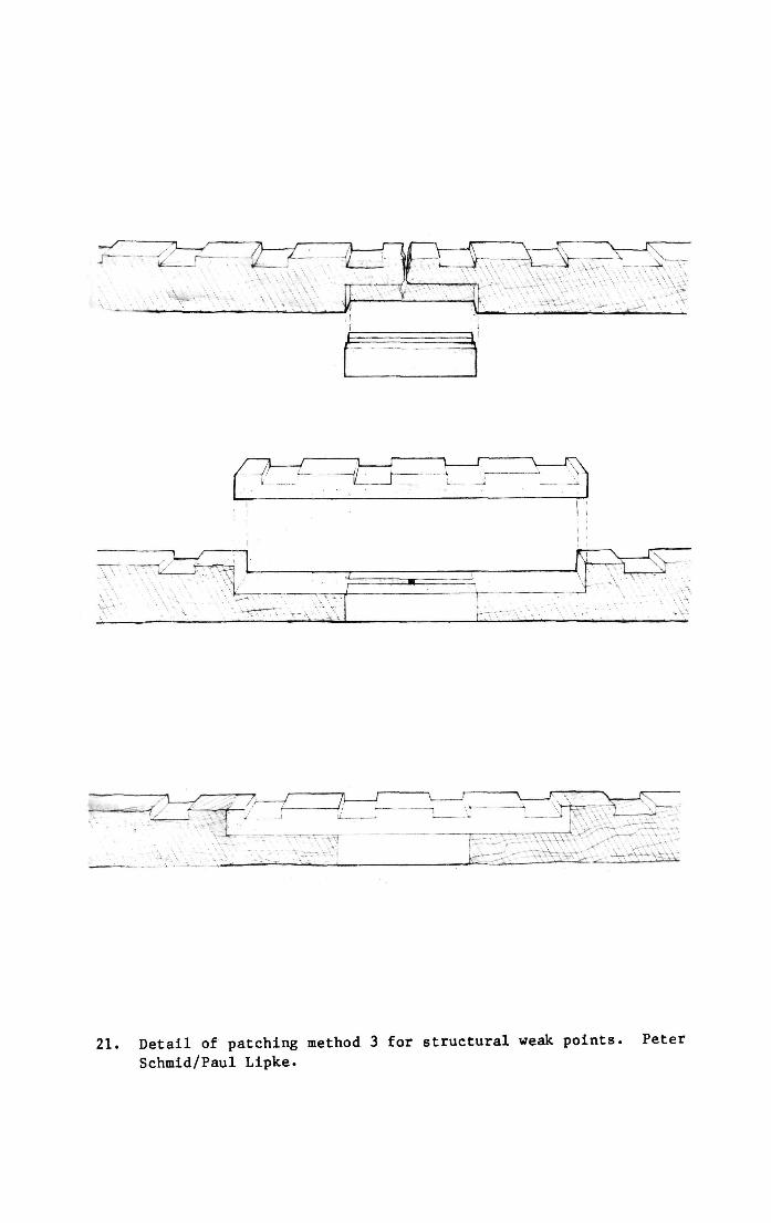
21. Detail of patching method 3 for structural weak points. Peter Schmid/Paul Lipke.
B. The exposed crack was filled with glue paste, and allowed to cure.
C. The side sections that had been removed were replaced using ennab dutchman (Figs. 21a, 21b).
D. The upper surface was removed and replaced in the way of the crack in the same manner (Fig. 21c).
4. Aluminium Reinforcement
One oar was beyond restoration at the time of excavation, a second became so in 1964. Both of these were replicated in ennab. All ten others required major attention at about this date, the procedure being as follows:
A. The fragments were treated first with 2.5% and then with 5. % solutions of PVA to harden and stabilize them.
B. Fragments were arranged in proper sequence.
C. Each fragment of the shaft and upper blade was then bored out 1.5 cm. to take a 1.25 cm. aluminium rod. A long shaft auger (Fig. 22) or 1.5 cm. bit and brace were used for this, often drilling from both ends of the fragment.
D. The fragments were then arranged loosely on the rod (Fig. 23).
E. Starting near the blade, each fragment was glued to the rod and its neighbour. Adjustments for alignment were maintained by filling the spaces between the shaft wall and the aluminium rod with slivers of wood and/or glue paste with original wood powder, preferably from unrepairable fragments of the same oar.
F. Restorable fragments from the blade were mortised to receive tenons of aluminium sheet stock individually cut to average dimensions of 1.5 x 5. x .1 cm., and then glued in place.
G. Very small fragments or fragments that crumbled completely were replaced with ennab patches fastened as in "F".
H. All glue joints were gouged out after curing with a "V" cut chisel to .5 cm. depth. The tinted glue paste was then used to fill in and fair the joints between fragments, and was painted for grain after curing.
5. Fibre Reinforcement
All four of the "L" shaped forward backing timber covers and two of the six aft covers needed restoration upon excavation and some were restored twice more during the 1960's (Fig. 41). The example shown is the forward, port, upper cover.
A. The fragments were collected and arranged In sequence (Fig. 24).
44
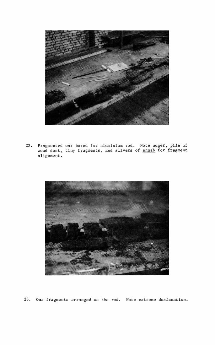
22. Fragmented oar bored for aluminium rod. Note auger, pile of wood dust, tiny fragments, and slivers of ennab for fragment alignment.
23. Oar fragments arranged on the rod. Note extreme desiccation.

24. Fragmented, forward port upper backing timber cover. Note part of mortise for stem post at top.
B. They were traced and measured individually and the covers' original dimensions were calculated on this basis.
C. A mould was made to fit the inside dimensions and covered with aluminium foil (Fig. 25, middle and bottom frames).
D. A grid of ennab strips 2. x 1.5 cm. was made to extend the length of the mould (Fig. 25).
E. Fragments were dadoed with a saw and chisel to receive the grid (Fig. 26).
F. Fragments were laid over the mould and grid, and the whole assembly was turned over and the mould removed (Fig. 27).
G. Fragments were glued to each other and the grid using glue paste with powdered charcoal, and the whole was allowed to cure four days.
H. All voids and joints between the grid and the fragments were filled with charcoal glue paste and the entire interior surface was covered with a 1. - 2.mm. film of glue. This cured for one week.
I. A light weave cotton fabric was soaked in a straight glue solution, and layed over the dried glue film on the timber's interior. All the air bubbles were rolled out, and the glue was allowed to cure one week.
J. Opposing layers of 1. - 2. mm. African Mahogany and/or Beechwood veneers were glued to the cloth layer and allowed to cure one week (Fig. 28).
K. The mould was slipped into the "L" and the whole tuned over.
L. Fragments were laid in the large voids of the exterior and tamped down with a light mallet "to enmesh their edges". Glue paste with powdered original timber was used to fill voids and glue these fragments to the reinforced cover (Fig. 29). The assembly was allowed to cure for two weeks, and then the mould was removed.
M. The glue paste in five or six layers was used to build up the dessicted forward end of the cover (Figs. 30a, 30b).
N. Alafonaya and parafin were used to fill any remaining small cracks or raised grain.
0. Hasagoz and tints in turpentine were used to paint in grain.
6. Filling Large Checks
The glue pastes were used to fill large checks, both straight grained and those around knots (Fig. 31).
A. After being brushed clean, the check was visually examined and a filler strip of original fragments was made for any
47
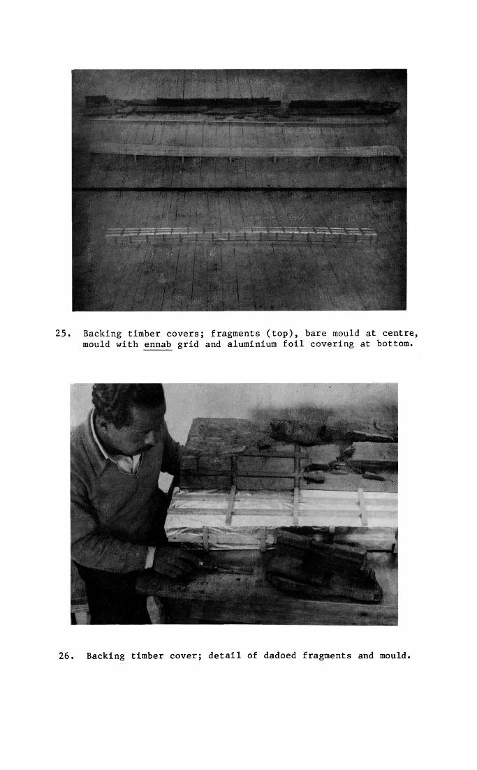
25. Backing timber covers; fragments (top), bare mould at centre, mould with ennab grid and aluminium foil covering at bottom.
26. Backing timber cover; detail of dadoed fragments and mould.
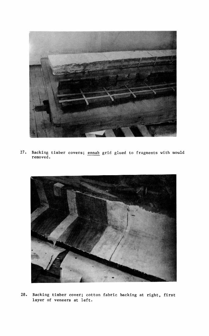
27. Backing timber covers; ennab grid glued to fragments with mould removed.
28. Backing timber cover; cotton fabric backing at right, first layer of veneers at left.
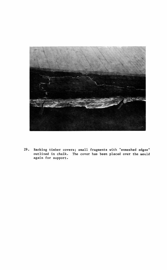
29. Backing timber covers; small fragments with "enmeshed edges" outlined in chalk. The cover has been placed over the mould again for support.
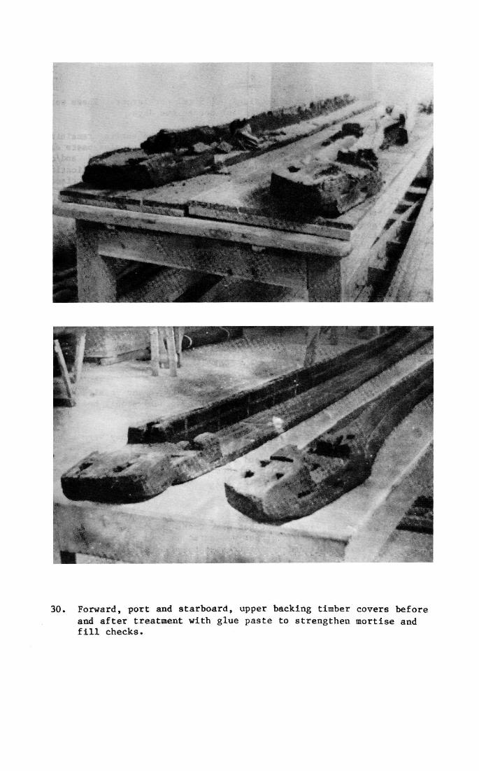
30. Forward, port and starboard, upper backing timber covers before and after treatment with glue paste to strengthen mortise and fill checks.
particularly wide sections, 1.5 cm. or larger. These were glued in place and cured for one to two days.
B. If the check was on an interior face the entire remaining void was filled with untinted Casuarina based glue paste and cured one week. Occasionally the glue was absorbed and/or shrunk below the surface as it dried so a second application would be necessary to bring the glue flush with the surface.
C. If the check were exterior, the upper .5 to 1 cm. of the check was left unfilled when the Casuarina based paste was applied, and this surface area would be filled to flush with tinted original wood glue paste after the Casuarina paste cured one week (Fig. 32).
D. Exterior checks were "painted" with Hasagos (Figs. 17, 33).
7. Filling Small Checks
With minor checks, 1. cm. square or less, there was Insufficient area to achieve a proper bond with the glue. Alafonaya mixed with paraffin was then used to seal these openings. (For application procedures see below p. 37).
8. Repairs to Deck Beams
Strength was naturally of primary concern in the repairs to 13 damaged deck beams (Fig. 34). Three others simply had to be replaced with ennab replicas.
A. Checks were treated as described above when they were minor.
B. Badly checked areas and broken end sections were removed or replaced with ennab patches. These were hook scarfed, pegged and/or glued (Fig. 35).
9. Repairs to Frames
The 16 frames were intact but weak when excavated. Subsequent dessiction led to further weakening and even some collapse. Five were still undergoing treatment by Hag Ahmed during 1983. Initial strengthening was carried out in several ways.
A. A square or dovetail sectioned channel was cut out of the fore and aft faces of the frame. An ennab spline was then fitted and glued in place (Fig. 36).
B. Especially weak points were sandwiched between two dutchmen as in Patching Method "3".
C. Repairs to later, more extensive problems often necessitated the use of dutchmen and/or numerous dowels (Figs. 37a, 37b, 37c).
52
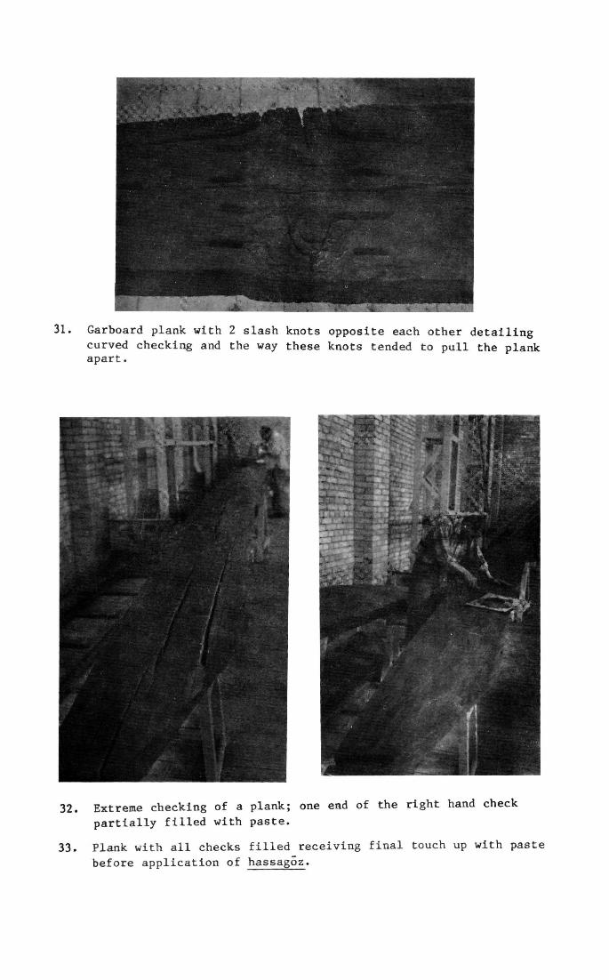
31. Garboard plank with 2 slash knots opposite each other detailing curved checking and the way these knots tended to pull the plank apart.
32. Extreme checking of a plank; one end of the right hand check
partially filled with paste.
33. Plank with all checks filled receiving final touch up with paste
before application of hassagoz.
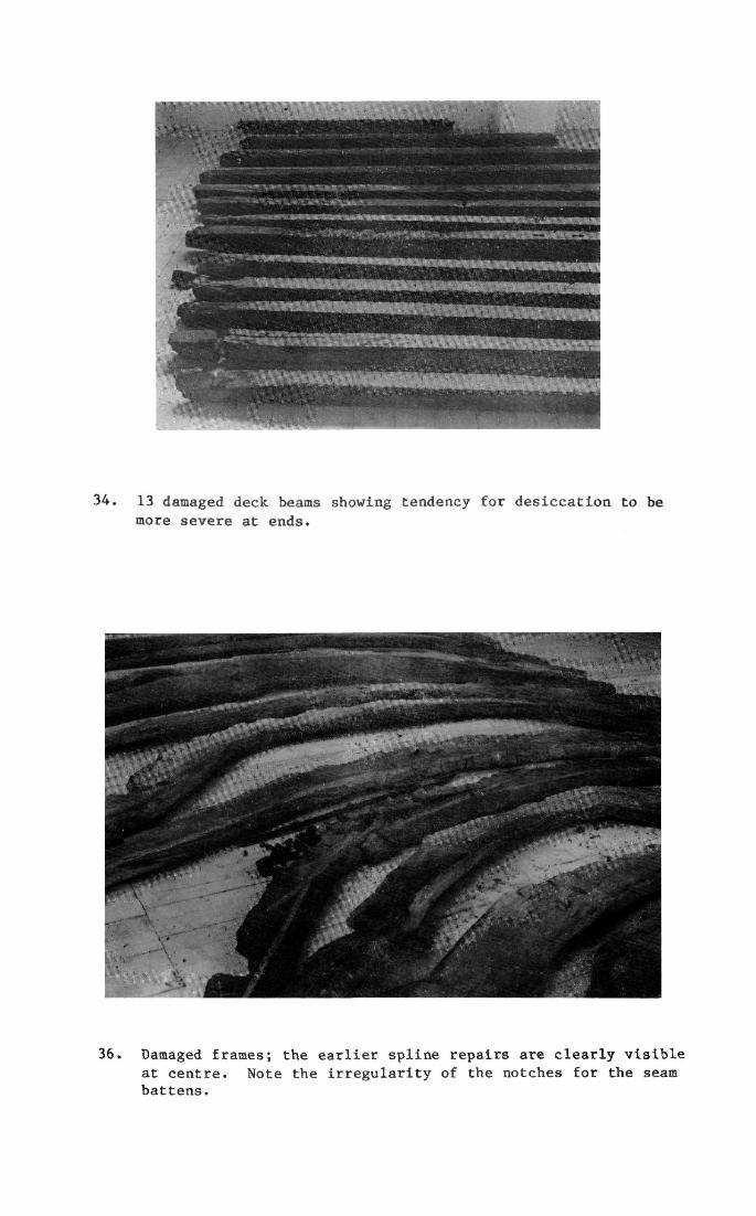
34. 13 damaged deck beams showing tendency for desiccation to be
more severe at ends.
36. Damaged frames; the earlier spline repairs are clearly visible at centre. Note the irregularity of the notches for the seam battens.
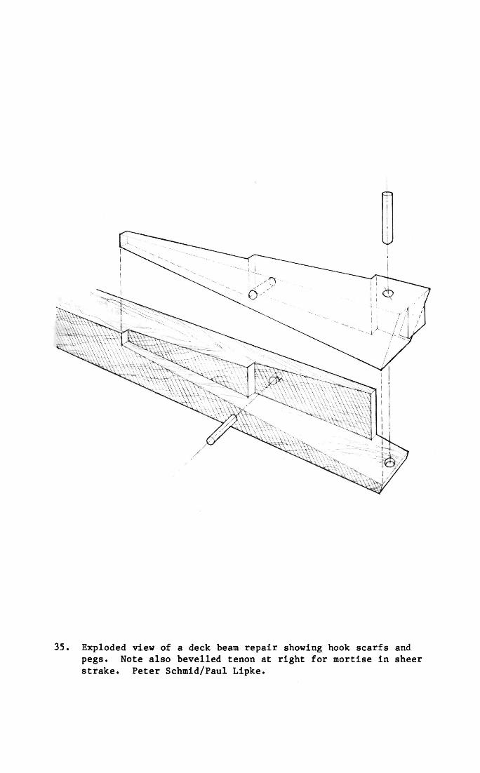
35. Exploded view of a deck beam repair showing hook scarfs and pegs. Note also bevelled tenon at right for mortise in sheer strake. Peter Schmid/Paul Lipke.
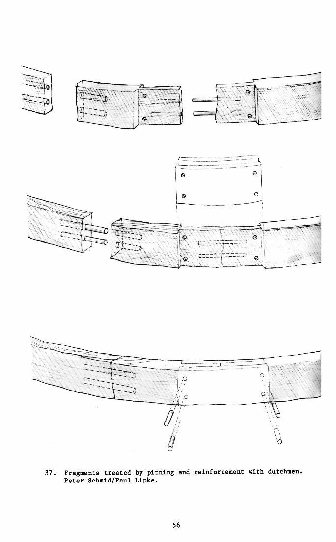
37. Fragments treated by pinning and reinforcement with dutchmen. Peter Schmid/Paul Llpke.
56
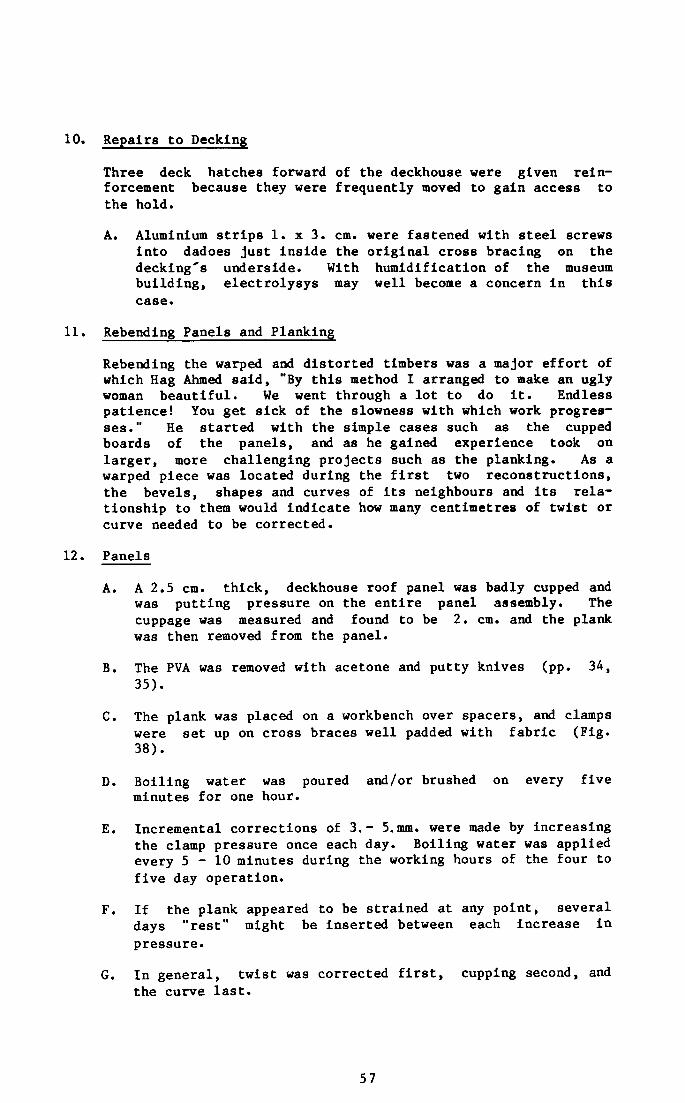
10. Repairs to Decking
Three deck hatches forward of the deckhouse were given reinforcement because they were frequently moved to gain access to the hold.
A. Aluminium strips 1. x 3. cm. were fastened with steel screws into dadoes just inside the original cross bracing on the decking's underside. With humidification of the museum building, electrolysys may well become a concern in this case.
11. Rebending Panels and Planking
Rebending the warped and distorted timbers was a major effort of which Hag Ahmed said, "By this method I arranged to make an ugly woman beautiful. We went through a lot to do it. Endless patience! You get sick of the slowness with which work progresses." He started with the simple cases such as the cupped boards of the panels, and as he gained experience took on larger, more challenging projects such as the planking. As a warped piece was located during the first two reconstructions, the bevels, shapes and curves of its neighbours and its relationship to them would indicate how many centimetres of twist or curve needed to be corrected.
12. Panels
A. A 2.5 cm. thick, deckhouse roof panel was badly cupped and was putting pressure on the entire panel assembly. The cuppage was measured and found to be 2. cm. and the plank was then removed from the panel.
B. The PVA was removed with acetone and putty knives (pp. 34, 35).
C. The plank was placed on a workbench over spacers, and clamps were set up on cross braces well padded with fabric (Fig. 38).
D. Boiling water was poured and/or brushed on every five minutes for one hour.
E. Incremental corrections of 3.- 5.mm. were made by increasing the clamp pressure once each day. Boiling water was applied every 5 - 1 0 minutes during the working hours of the four to five day operation.
F. If the plank appeared to be strained at any point, several days "rest" might be inserted between each increase in pressure.
G. In general, twist was corrected first, cupping second, and the curve last.
57
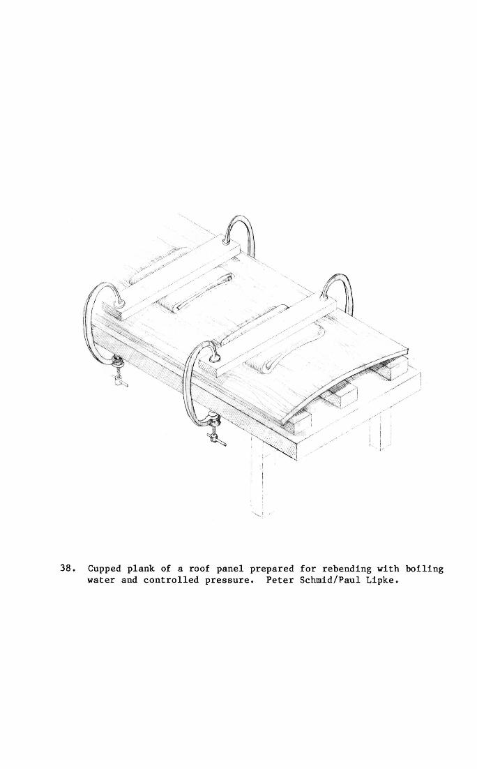
38. Cupped plank of a roof panel prepared for rebending with boiling water and controlled pressure. Peter Schmid/Paul Lipke.
13. Planking
The 14 cm. thick, starboard sheer strake needed about 15 cm. of detwisting and perhaps 25. cm. of additional curve at several points along its 23 metre length (Fig. 39). (Photographic documentation of the reshaping process is extremely limited. Hag Ahmed remarked, "I was far too busy to take photographs at this stage. Every moment between realigning sessions was spent working on the reconstruction of other parts of the ship.")
A. After measuring for readjustment, the crew removed the sheer strake from the reconstruction, and the PVA from the sheer strake.
B. The sheer strake was lashed to the bending posts and the end to be untwisted was bracketed with heavy wooden beams and braced to the floor at its lower edge (Fig. 40).
C. A Spanish windlass was prepared using 3 cm. diameter linen rope running from the upper end of the bracketing beams to a bending post some 3 metres away.
D. The entire sheer strake from the bracketed end to the lashed midsection was wrapped in 3 - 4 layers of burlap and large quantities of boiling water were poured over the whole every five to ten minutes during working hours for the next three weeks.
Day 1. No pressure applied for the first three hours; after this slight pressure was applied just to tighten the linen cordage.
Day 2. .83 cm. of twist removed by increasing the pressure on the windlass.
Days 3 - 1 8 . More twist removed as in day 2.
Days 19 - 21. Pressure was maintained but not increased. Boiling water bath was terminated on day 19 to allow the sheer strake to dry out and stiffen.
E. The brackets were removed, and the Spanish windlass was moved from the end to a section needing more curve.
F. Windlasses were run to any other areas needing more curve, shores were set up, and hot water and pressure were applied as in "D" with incremental changes averaging 1 cm. per day.
G. In all cases, twist was adjusted first and curve second.
H. With realignment complete, the burlap was removed, the timber released from the bending jig, PVA reapplied and the timber replaced in the ongoing reconstruction.
I. "90% of the reshaping was done in this way. The last 10% (2. to 3. cm. of corrections) were made with the timbers in place on the ship. This was done without boiling water
59
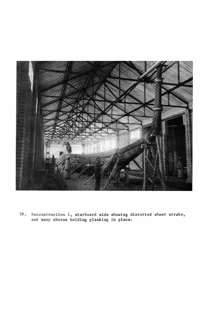
39. Reconstruction 1, starboard side showing distorted sheer strake, and many shores holding planking in place.
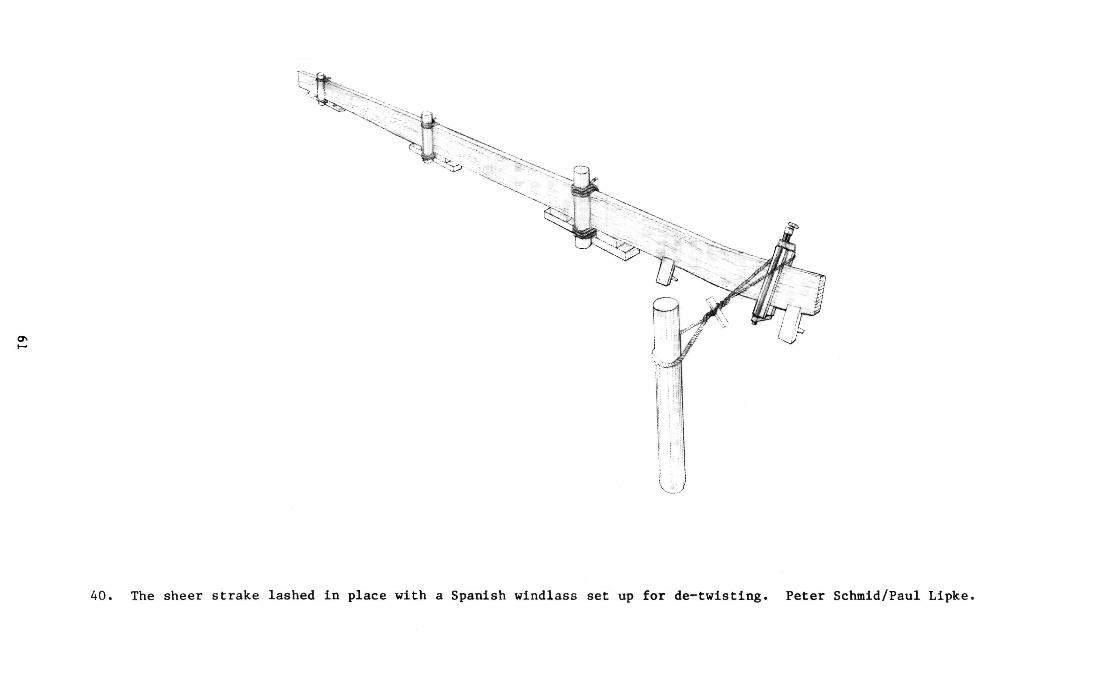
ON
40. The sheer strake lashed In place with a Spanish windlass set up for de-twisting. Peter Schmid/Paul Lipke.

usually simply by tightening up on the lashings, and the liberal use of shores, wedges and windlasses."
14. Ennab Replication
Hag Ahmed guesses from memory that 5% of the ship's timbers were or became unrestorable and so have been replicted in ennab. The pieces replaced have been mostly battens; with deck beams, an oar and unspecified other timbers making up a small part of the 5%.
62
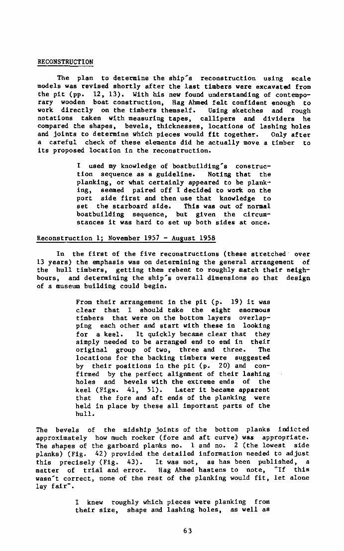
RECONSTRUCTION
The plan to determine the ship's reconstruction using scale models was revised shortly after the last timbers were excavated from the pit (pp. 12, 13). With his new found understanding of contemporary wooden boat construction, Hag Ahmed felt confident enough to work directly on the timbers themself. Using sketches and rough notations taken with measuring tapes, callipers and dividers he compared the shapes, bevels, thicknesses, locations of lashing holes and joints to determine which pieces would fit together. Only after a careful check of these elements did he actually move a timber to its proposed location in the reconstruction.
I used my knowledge of boatbuilding's construction sequence as a guideline. Noting that the planking, or what certainly appeared to be planking, seemed paired off I decided to work on the port side first and then use that knowledge to set the starboard side. This was out of normal boatbuilding sequence, but given the circumstances it was hard to set up both sides at once.
Reconstruction 1; November 1957 - August 1958
In the first of the five reconstructions (these stretched over 13 years) the emphasis was on determining the general arrangement of the hull timbers, getting them rebent to roughly match their neighbours, and determining the ship's overall dimensions so that design of a museum building could begin.
From their arrangement in the pit (p. 19) it was clear that I should take the eight enormous timbers that were on the bottom layers overlapping each other and start with these in looking for a keel. It quickly became clear that they simply needed to be arranged end to end in their original group of two, three and three. The locations for the backing timbers were suggested by their positions in the pit (p. 20) and confirmed by the perfect alignment of their lashing holes and bevels with the extreme ends of the keel (Figs. 41, 51). Later it became apparent that the fore and aft ends of the planking were held in place by these all important parts of the hull.
The bevels of the midship joints of the bottom planks indicted approximately how much rocker (fore and aft curve) was appropriate. The shapes of the garboard planks no. 1 and no. 2 (the lowest side planks) (Fig. 42) provided the detailed information needed to adjust this precisely (Fig. 43). It was not, as has been published, a matter of trial and error. Hag Ahmed hastens to note, "If this wasn't correct, none of the rest of the planking would fit, let alone lay fair".
I knew roughly which pieces were planking from their size, shape and lashing holes, as well as
63
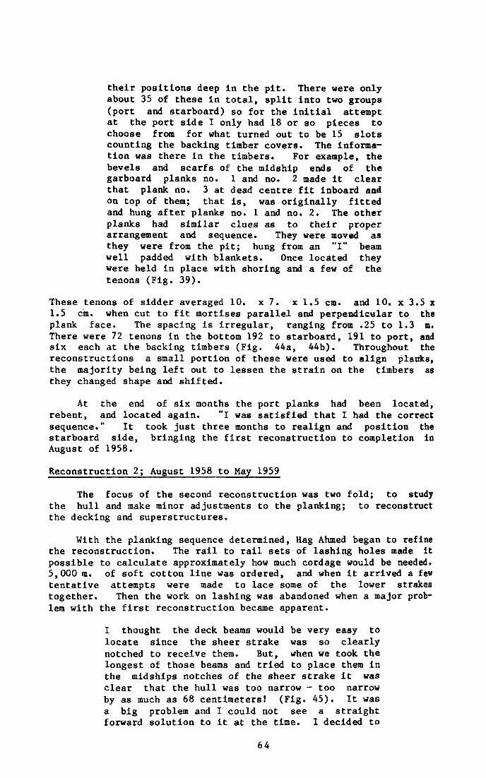
their positions deep in the pit. There were only about 35 of these in total, split into two groups (port and starboard) so for the initial attempt at the port side I only had 18 or so pieces to choose from for what turned out to be 15 slots counting the backing timber covers. The information was there in the timbers. For example, the bevels and scarfs of the midship ends of the garboard planks no. 1 and no. 2 made it clear that plank no. 3 at dead centre fit inboard and on top of them; that is, was originally fitted and hung after planks no. 1 and no. 2. The other planks had similar clues as to their proper arrangement and sequence. They were moved as they were from the pit; hung from an "I" beam well padded with blankets. Once located they were held in place with shoring and a few of the tenons (Fig. 39).
These tenons of sidder averaged 10. x 7. x 1.5 cm. and 10. x 3.5 x 1.5 cm. when cut to fit mortises parallel and perpendicular to the plank face. The spacing is irregular, ranging from .25 to 1.3 m. There were 72 tenons in the bottom 192 to starboard, 191 to port, and six each at the backing timbers (Fig. 44a, 44b). Throughout the reconstructions a small portion of these were used to align planks, the majority being left out to lessen the strain on the timbers as they changed shape and shifted.
At the end of six months the port planks had been located, rebent, and located again. "I was satisfied that I had the correct sequence." It took just three months to realign and position the starboard side, bringing the first reconstruction to completion in August of 1958.
Reconstruction 2; August 1958 to May 1959
The focus of the second reconstruction was two fold; to study the hull and make minor adjustments to the planking; to reconstruct the decking and superstructures.
With the planking sequence determined, Hag Ahmed began to refine the reconstruction. The rail to rail sets of lashing holes made it possible to calculate approximately how much cordage would be needed. 5,000 m. of soft cotton line was ordered, and when it arrived a few tentative attempts were made to lace some of the lower strakes together. Then the work on lashing was abandoned when a major problem with the first reconstruction became apparent.
I thought the deck beams would be very easy to locate since the sheer strake was so clearly notched to receive them. But, when we took the longest of those beams and tried to place them in the midships notches of the sheer strake it was clear that the hull was too narrow - too narrow by as much as 68 centimeters! (Fig. 45). It was a big problem and I could not see a straight forward solution to it at the time. I decided to
64
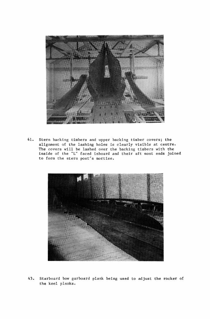
41. Stern backing timbers and upper backing timber covers; the alignment of the lashing holes is clearly visible at centre. The covers will be lashed over the backing timbers with the inside of the "L" faced inboard and their aft most ends joined to form the stern post's mortise.
43. Starboard bow garboard plank being used to adjust the rocker of
the keel planks.
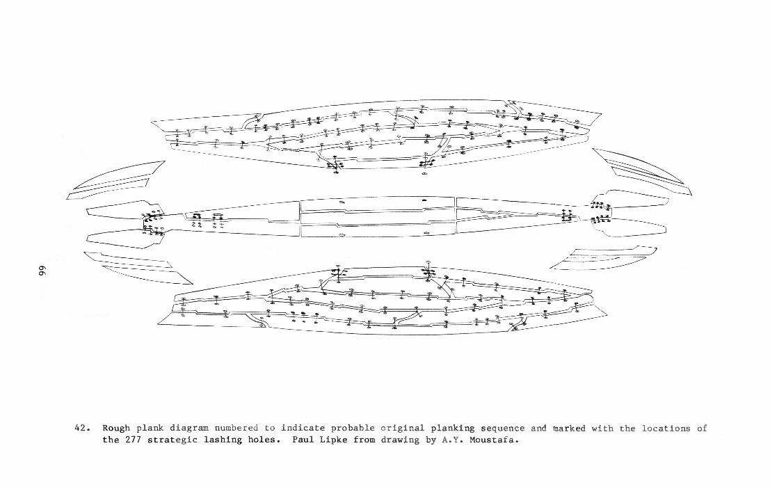
66
42. Rough plank diagram numbered to indicate probable original planking sequence and marked with the locations of the 277 strategic lashing holes. Paul Lipke from drawing by A.Y. Moustafa.
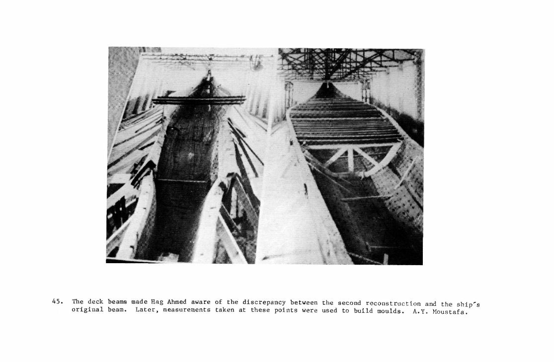
45. The deck beams made Hag Ahmed aware of the discrepancy between the second reconstruction and the ship's original beam. Later, measurements taken at these points were used to build moulds. A.Y. Moustafa.
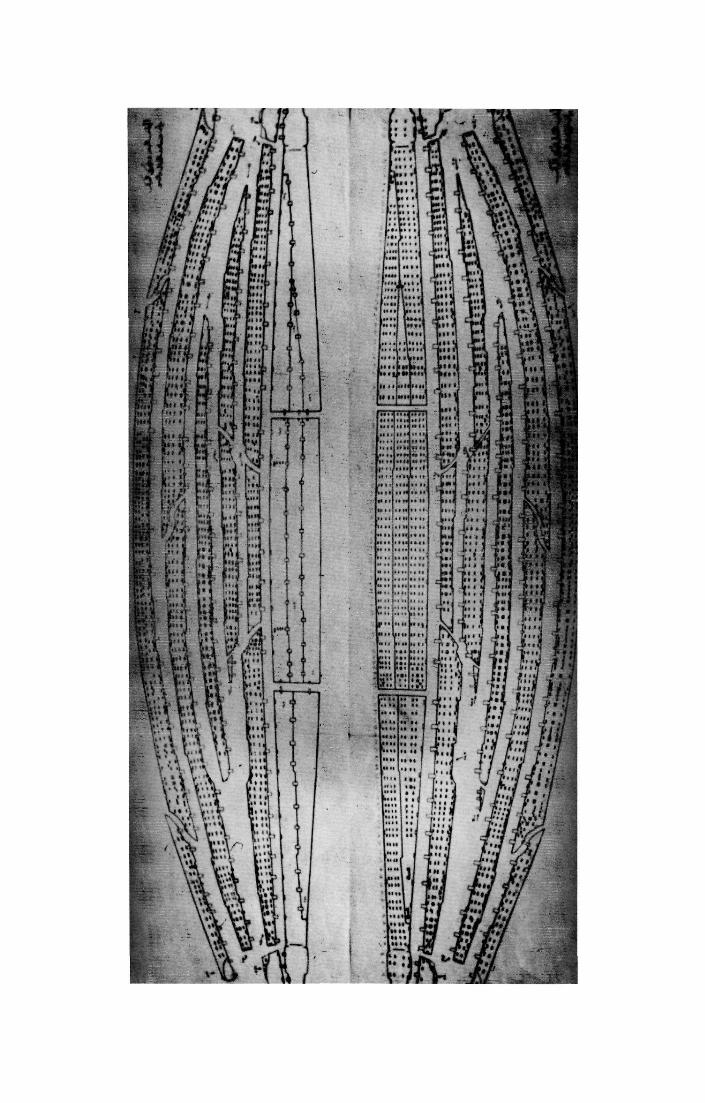

44. Tenon/lashing hole/plank diagram; the spacing of the tenons, alignment of the lashing holes and planking's shape are recorded. Paul Lipke photo of a drawing by A.Y. Moustafa, 1983.
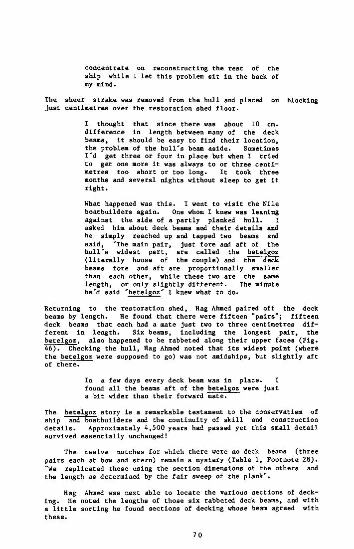
concentrate on reconstructing the rest of the ship while I let this problem sit in the back of my mind.
The sheer strake was removed from the hull and placed on blocking just centimetres over the restoration shed floor.
I thought that since there was about 10 cm. difference in length between many of the deck beams, It should be easy to find their location, the problem of the hull's beam aside. Sometimes I'd get three or four in place but when I tried to get one more it was always to or three centimetres too short or too long. It took three months and several nights without sleep to get it right.
What happened was this. I went to visit the Nile boatbuilders again. One whom I knew was leaning against the side of a partly planked hull. I asked him about deck beams and their details and he simply reached up and tapped two beams and said, 'The main pair, just fore and aft of the hull's widest part, are called the betelgoz (literally house of the couple) and the deck beams fore and aft are proportionally smaller than each other, while these two are the same length, or only slightly different. The minute he'd said 'betelgoz' I knew what to do.
Returning to the restoration shed, Hag Ahmed paired off the deck beams by length. He found that there were fifteen "pairs"; fifteen deck beams that each had a mate just two to three centimetres different in length. Six beams, including the longest pair, the betelgoz, also happened to be rabbeted along their upper faces (Fig. 46). Checking the hull, Hag Ahmed noted that its widest point (where the betelgoz were supposed to go) was not amidships, but slightly aft of there.
In a few days every deck beam was in place. I found all the beams aft of the betelgoz were just a bit wider than their forward mate.
The betelgoz story is a remarkable testament to the conservatism of ship and boatbuilders and the continuity of skill and construction details. Approximately 4,500 years had passed yet this small detail survived essentially unchanged!
The twelve notches for which there were no deck beams (three pairs each at bow and stern) remain a mystery (Table 1, Footnote 28). "We replicated these using the section dimensions of the others and the length as determined by the fair sweep of the plank".
Hag Ahmed was next able to locate the various sections of decking. He noted the lengths of those six rabbeted deck beams, and with a little sorting he found sections of decking whose beam agreed with these.
70
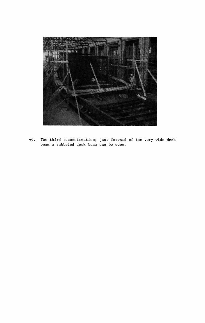
46. The third reconstruction; just forward of the very wide deck beam a rabbeted deck beam can be seen.
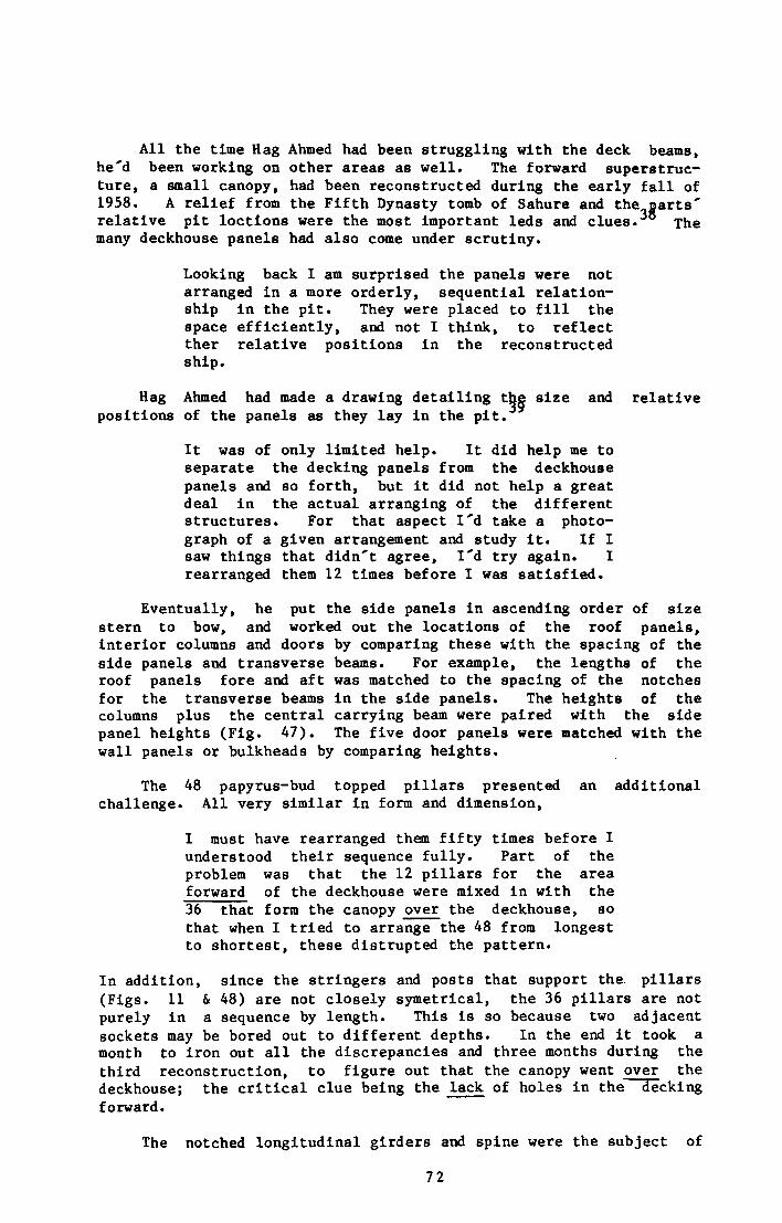
All the time Hag Ahmed had been struggling with the deck beams, he'd been working on other areas as well. The forward superstructure, a small canopy, had been reconstructed during the early fall of 1958. A relief from the Fifth Dynasty tomb of Sahure and the parts' relative pit loctions were the most important leds and clues. The many deckhouse panels had also come under scrutiny.
Looking back I am surprised the panels were not arranged in a more orderly, sequential relationship in the pit. They were placed to fill the space efficiently, and not I think, to reflect ther relative positions in the reconstructed ship.
Hag Ahmed had made a drawing detailing the size and relative positions of the panels as they lay In the pit.
It was of only limited help. It did help me to separate the decking panels from the deckhouse panels and so forth, but it did not help a great deal in the actual arranging of the different structures. For that aspect I'd take a photograph of a given arrangement and study it. If I saw things that didn't agree, I'd try again. I rearranged them 12 times before I was satisfied.
Eventually, he put the side panels in ascending order of size stern to bow, and worked out the locations of the roof panels, interior columns and doors by comparing these with the spacing of the side panels and transverse beams. For example, the lengths of the roof panels fore and aft was matched to the spacing of the notches for the transverse beams in the side panels. The heights of the columns plus the central carrying beam were paired with the side panel heights (Fig. 47). The five door panels were matched with the wall panels or bulkheads by comparing heights.
The 48 papyrus-bud topped pillars presented an additional challenge. All very similar in form and dimension,
I must have rearranged them fifty times before I understood their sequence fully. Part of the problem was that the 12 pillars for the area forward of the deckhouse were mixed in with the 36 that form the canopy over the deckhouse, so that when I tried to arrange the 48 from longest to shortest, these distrupted the pattern.
In addition, since the stringers and posts that support the. pillars (Figs. 11 & 48) are not closely symetrical, the 36 pillars are not purely in a sequence by length. This is so because two adjacent sockets may be bored out to different depths. In the end it took a month to iron out all the discrepancies and three months during the third reconstruction, to figure out that the canopy went over the deckhouse; the critical clue being the lack of holes in the decking forward.
The notched longitudinal girders and spine were the subject of
72
47. Interior of the main chamber in the reconstructed deckhouse. Note palmette columns, "S" door lock, tenons in roof panels, rabbeted deck beam (foreground) and side panels' proportion to height of carrying beam.
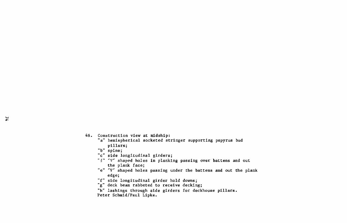
48. Construction view at midship: "a" hemispherical socketed stringer supporting papyrus bud
pillars; "b" spine; "c" side longitudinal girders; "d" ' V shaped holes in planking passing over battens and out
the plank face; "e" ' V shaped holes passing under the battens and out the plank
edge; "f" side longitudinal girder hold downs; "g" deck beam rabbeted to receive decking; "h" lashings through side girders for deckhouse pillars. Peter Schmid/Paul Lipke.
74
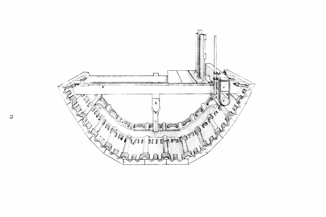
75
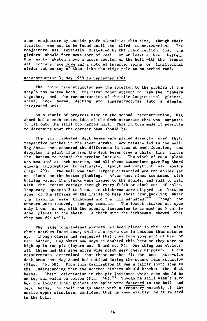
some conjecture by outside professionals at this time, though their location was not to be found until the third reconstruction. The conjecture was initially misguided by the preconception that the girders should form some sort of keel, or at least a keel batten. One early sketch shows a cross section of the hull with the frames set concave face down and a notched inverted spine or lingitudinal girder set on top of them, like the ridge pole to an arched roof.
Reconstruction 3; May 1959 to September 1961
The third reconstruction saw the solution to the problem of the ship's too narrow beam, the first major attempt to lash the timbers together, and the reconstruction of the side longitudinal girders, spine, deck beams, decking and superstructures into a single, integrated unit.
As a result of progress made in the second reconstruction, Hag Ahmed had a much better idea of the deck structure that was supposed to fit onto the still-too-narrow hull. This in turn made it possible to determine what the correct beam should be.
The six rabbeted deck beams were placed directly over their respective notches in the sheer strake, now reinstalled in the hull. Hag Ahmed then measured the difference in beam at each location, and dropping a plumb line from the deck beams drew a chalk line across the bottom to record the precise loction. The width of each plank was measured at each station, and all these dimensions gave Hag Ahmed enough information to calculate, layout and construct six moulds (Fig. 49). The hull was then largely dismantled and the moulds set up plumb on the bottom planking. After some minor treatment with boiling water, the planks were lashed to the moulds, and rail to rail with the cotton cordage through every fifth or sixth set of holes. Temporary spacers 2 to 5 cm. in thickness were slipped in between some of the strakes on the inside to keep these from^buckling while the lashings were tightened and the hull adjusted. Though the spacers were removed, the gap remains. The lowest strakes are open only 1 cm. or so, with the opening Increasing to as much as 5 cm. in some places at the sheer. A check with the deckbeams showed that they now fit well.
The side longitudinal girders had been placed in the pit with their notches faced down, while the spine was in between them notches up. Though others had suggested that they form some sort of keel or keel batten, Hag Ahmed now says he doubted this because they were so high up in the pit (layers no. 8 and no. 9). One thing was obvious; all three had the same extra wide notch near their midpoint. A few measurements determined that these notches fit the one extra-wide deck beam that Hag Ahmed had noticed during the second reconstruction (Figs. 46, 68). From this realization it was a fairly short step to the understanding that the notched timbers should bracket the deck beams. Their orientation in the pit indicated which ones should be on top and which on bottom (Fig. 46). 1 Though he still wasn't sure how the longitudinal girders and spine were fastened to the hull and deck beams, he could now go ahead with a temporary assembly of the entire upper structure, confident that he knew exactly how it related to the hull.
76
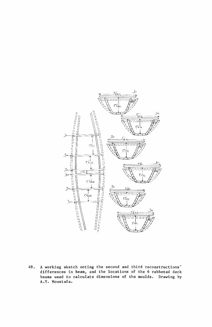
49. A working sketch noting the second and third reconstructions' differences in beam, and the locations of the 6 rabbeted deck beams used to calculate dimensions of the moulds. Drawing by A.Y. Moustafa.
Once again the sheer strak.es were removed from the hull and placed just above the restoration shed floor, this time with the spine between them. One by one the deck beams were laid in between the sheer strakes (over the spine) and the side longitudinal girders were placed over the deck beams. The side longitudinal girders had been realigned to run almost parallel with the sheer strakes, relieving the strain their distortion placed on the deck beams. The deckhouse and canopy were eventually set up on the decking between the longitudinal girders (Fig. 46). The ship as a whole was becoming more and more coherent to the untrained eye.
A report to the Ministry of Culture during September of 1961 clearly implies how fully Hag Ahmed felt he understood the construction details, and that he considered his work well advanced. It reads in part, "...this last reconstruction being to know the timbers' placement, measure for some reshaping and do some restoration prior to the final reconstruction in the Museum." In fact, there were to be two lengthy delays of three years each and a fourth reconstruction before the fifth and final reconstruction began to take shape in the museum. Still, by late November of 1961 the separate hull and deck reconstructions had been dismantled and placed in a small storage shed to the east of the pit so that the restoration shed could be torn down to make room for the museum building. Five sites around the necropolis and as many designs for a building had been considered. It was decided to utilize the area immediately over and adjacent to the pit with a design by Italian Architect F. Minissi.
Storage conditions over the next three years were not ideal. As before, no climate controls were available, and the lack of spa^e meant that the timbers were often stacked on top of each other. The unseasonably hot weather of 1963 and 1964 led to a decision to build a second shed along the west face of the Great Pyramid so that the repair of this damage and a fourth attempt at reconstruction could be undertaken. (The original restoration shed's roof had been restrictively low. Hag Ahmed, having now experimented with the newly finished 1:10 scale model wished to confirm his new findings by placing the decking and superstructures on the hull.) As work on the museum building progressed, Hag Ahmed and his assistants set to work to repair the damage and refine still further their understanding of the ship's construction.
Reconstruction 4; 1964 to 1967
The mould design used in the third reconstruction was modified so that the upper cross bracing would not interfere with the spine. As in the third reconstruction, the moulds were used to set the planking in its now familiar sequence.
Hag Ahmed had been dissatisfied with the way the cotton cordage stretched, so for the fourth reconstruction he ordered linen. Close study had revealed there were five major different kinds of lashing holes in the planking.
There were, approximately every 25 cm. longitudinally and every 10 cm. transversely, "V" shaped holes 2 x 7 cm. cut at 45 degrees into the planking's interior surface (Figs. 44, 48). Over 4,000 of
78
these holes were carefully aligned so that a line could be passed through them rail to rail: 901 slots in the bottom planking 1,656 to starboard; 1,602 to port; 15 in each of the four backing timbers.
Secondly, at strategic locations there were 277 holes in sets of two or three: 55 in the bottom planking, 104 to starboard and 118 to port (Fig. 42). Hag Ahmed theorizes that this smaller group was used to hold the planks In place as they were set up, and the rail to rail group were the "permanent ones", intended to give the hull its strength.
Thirdly, there was a small group of seven holes 1.5 cm. in diameter board all the way through each sheer strake in the aft quarter (Fig. 50). Hag Ahmed has laced line through these to create "rope deck beams (Fig. 51) that help hold the stern together against the strain of the steering oars."
Fourth, the hooked scarfs of the sheer strakes, four in all, are held together by pairs of lashing holes that extend all the way through the planking (Fig. 50).
Lastly, at the aft end of plank no. 5 port and starboard the rail to rail lashings run outside the hull to hold the end of the plank inboard by passing through a wide notch.
When the linen cordage arrived, and lengths of 5 0 to 60 metres were passed rail to rail five or six times through every slot, Hag Ahmed found he still could not get the planking to set up as firmly as seemed necessary. Noting that the lashings did not lie flat against the wood where they crossed from one plank to the next, he fashioned a few battens from some scrap wood and worked them under tha lashings at these joints.
Immediately that section of planking was much stronger and more stable. And then I laughed. I realized that I'd come up with precisely the ancient Egyptians' technique in an independent way. We already had, stored in boxes and racks and to date not understood or utilized, some 300 seam battens; the contents of the 65 bundles of the 13th layer. Even skipping every other set of lashing holes, with these ba^ens we got the hull much more rigid than before.
With the battened hull stable, Hag Ahmed had the spine placed inside over the moulds, and the deck beams laid in. The spine was then raised into place under the deck beams, and new steel and wood stanchions (replacing the original weak ones (Fig. 13)) were run up from the bottom planks to support it. The side longitudinal girders, decking and superstructures followed in short order. There were only a few minor delays.
Two of the smallest panels of decking, which appeared to be made for the extreme ends of the ship did not fall into place until they had been reversed from their original, pit oriented location. "I'm not saying the ancient Egyptians made a mistake, but when I took the piece that had been located at the bow end of the pit and tried it in
79

50. Stern, port view of Khufu ship showing "a" 7 lashing holes; "b" scarf joint lashings; "c" side longitudinal girder lashings; "d' steel supports. Paul Lipke (1981).
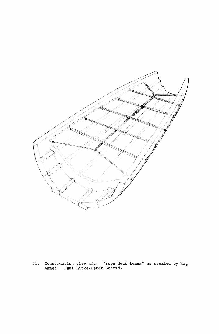
51. Construction view aft: "rope deck beams" as created by Hag Ahmed. Paul Lipke/Peter Schmid.
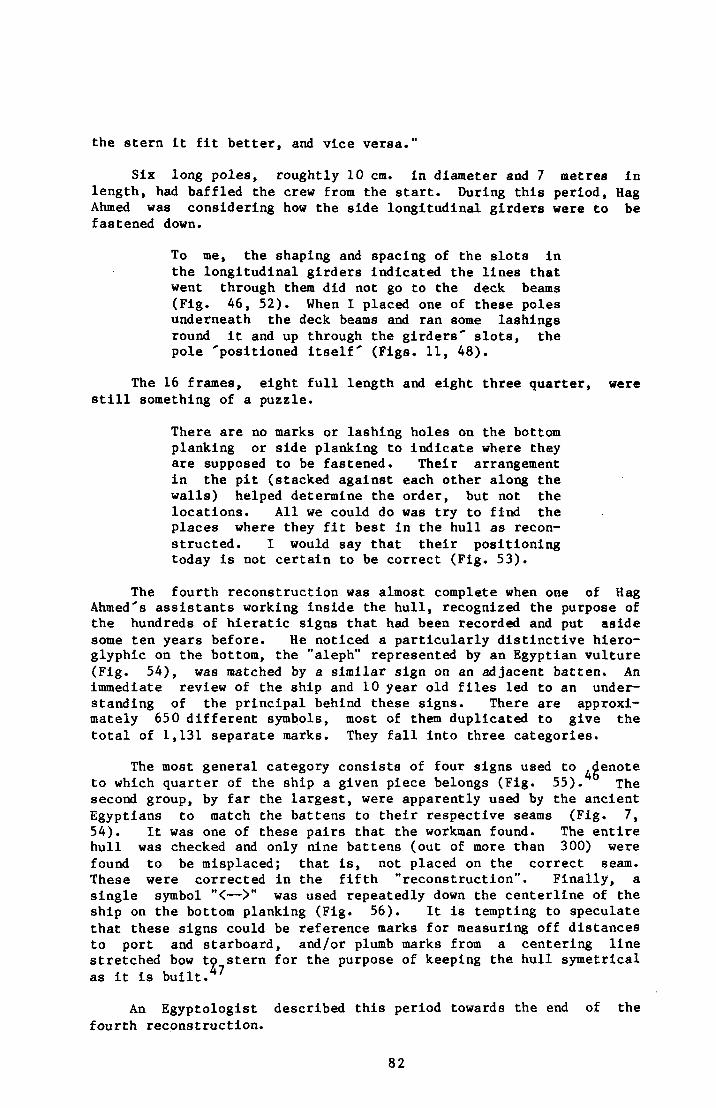
the stern it fit better, and vice versa."
Six long poles, roughtly 10 cm. in diameter and 7 metres in length, had baffled the crew from the start. During this period, Hag Ahmed was considering how the side longitudinal girders were to be fastened down.
To me, the shaping and spacing of the slots in the longitudinal girders indicated the lines that went through them did not go to the deck beams (Fig. 46, 52). When I placed one of these poles underneath the deck beams and ran some lashings round it and up through the girders' slots, the pole 'positioned itself (Figs. 11, 48).
The 16 frames, eight full length and eight three quarter, were still something of a puzzle.
There are no marks or lashing holes on the bottom planking or side planking to indicate where they are supposed to be fastened. Their arrangement in the pit (stacked against each other along the walls) helped determine the order, but not the locations. All we could do was try to find the places where they fit best in the hull as reconstructed. I would say that their positioning today is not certain to be correct (Fig. 53).
The fourth reconstruction was almost complete when one of Hag Ahmed's assistants working inside the hull, recognized the purpose of the hundreds of hieratic signs that had been recorded and put aside some ten years before. He noticed a particularly distinctive hieroglyphic on the bottom, the "aleph" represented by an Egyptian vulture (Fig. 54), was matched by a similar sign on an adjacent batten. An immediate review of the ship and 10 year old files led to an understanding of the principal behind these signs. There are approximately 650 different symbols, most of them duplicated to give the total of 1,131 separate marks. They fall into three categories.
The most general category consists of four signs used to ^denote to which quarter of the ship a given piece belongs (Fig. 55). The second group, by far the largest, were apparently used by the ancient Egyptians to match the battens to their respective seams (Fig. 7, 54). It was one of these pairs that the workman found. The entire hull was checked and only nine battens (out of more than 300) were found to be misplaced; that is, not placed on the correct seam. These were corrected in the fifth "reconstruction". Finally, a single symbol "<—>" was used repeatedly down the centerline of the ship on the bottom planking (Fig. 56). It is tempting to speculate that these signs could be reference marks for measuring off distances to port and starboard, and/or plumb marks from a centering line stretched bow to stern for the purpose of keeping the hull symetrical as it is built. 7
An Egyptologist described this period towards the end of the fourth reconstruction.
82
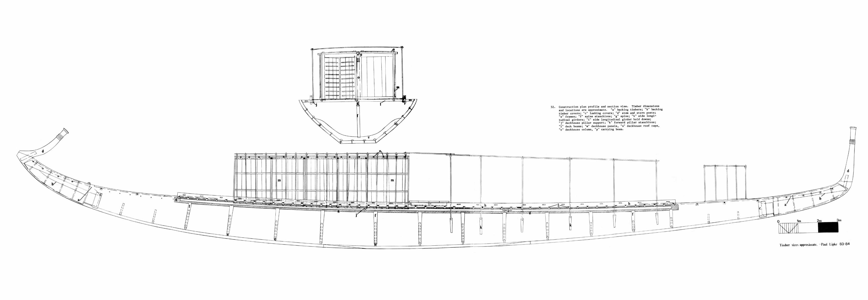
52. Construction plan profile and section view. Timber dimensions and locations are approximate, "a" backing timbers; "b" backing timber covers; "c" lashing covers; "d" stem and stern posts; "e" frames; "f" spine stanchions; "g" spine; "h" side longitudinal girders; "i" side longitudinal girder hold downs; "j " deckhouse pillar support; "k" forward pillar stanchions; "1" deck beams; "m" deckhouse panels, "n" deckhouse roof caps, "o" deckhouse column, "p" carrying beam.
Timber sizes approximate. Paul Lipke 83-84

pmanuelian
Typewritten Text
[This page is intentionally blank.]

53. The ship's interior from the fifth reconstruction showing the distorted frames in their uncertain locations, the rail to rail lashings, and battens.
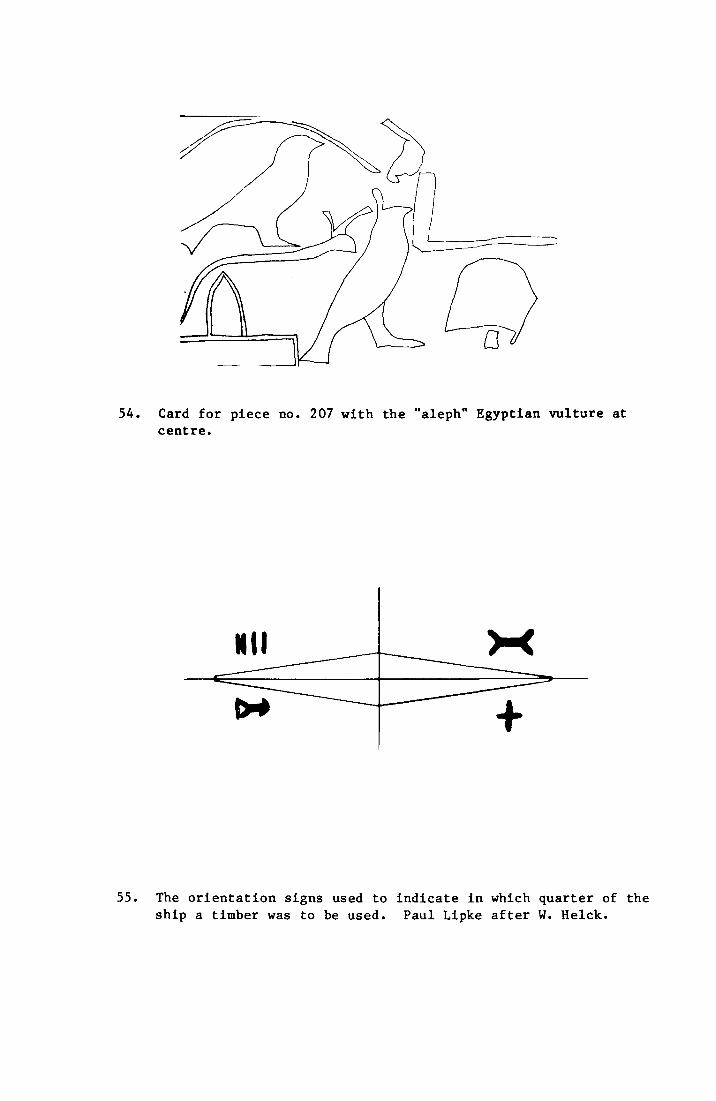
55. The orientation signs used to indicate in which quarter of the ship a timber was to be used. Paul Lipke after W. Helck.
54. Card for piece no. 207 with the "aleph" Egyptian vulture at centre.
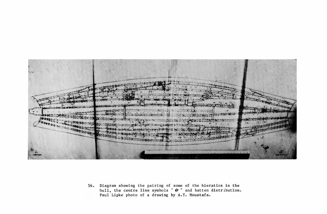
56. Diagram showing the pairing of some of the hieratics in the hull, the centre line symbols " if " and batten distribution. Paul Lipke photo of a drawing by A.Y. Moustafa.
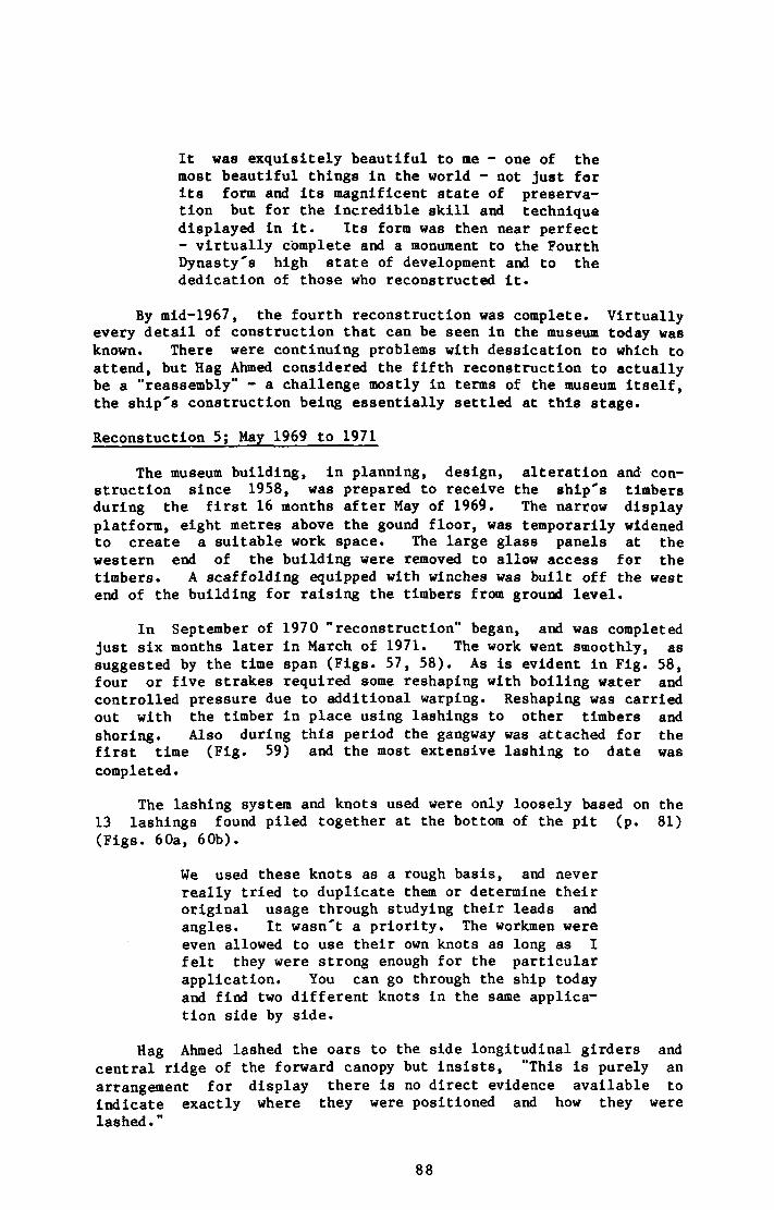
It was exquisitely beautiful to me - one of the most beautiful things in the world - not just for its form and its magnificent state of preservation but for the incredible skill and technique displayed in it. Its form was then near perfect - virtually complete and a monument to the Fourth Dynasty's high state of development and to the dedication of those who reconstructed it.
By mid-1967, the fourth reconstruction was complete. Virtually every detail of construction that can be seen in the museum today was known. There were continuing problems with dessication to which to attend, but Hag Ahmed considered the fifth reconstruction to actually be a "reassembly" - a challenge mostly in terms of the museum itself, the ship's construction being essentially settled at this stage.
Reconstuction 5; May 1969 to 1971
The museum building, in planning, design, alteration and construction since 1958, was prepared to receive the ship's timbers during the first 16 months after May of 1969. The narrow display platform, eight metres above the gound floor, was temporarily widened to create a suitable work space. The large glass panels at the western end of the building were removed to allow access for the timbers. A scaffolding equipped with winches was built off the west end of the building for raising the timbers from ground level.
In September of 1970 "reconstruction" began, and was completed just six months later in March of 1971. The work went smoothly, as suggested by the time span (Figs. 57, 58). As is evident in Fig. 58, four or five strakes required some reshaping with boiling water and controlled pressure due to additional warping. Reshaping was carried out with the timber in place using lashings to other timbers and shoring. Also during this period the gangway was attached for the first time (Fig. 59) and the most extensive lashing to date was completed.
The lashing system and knots used were only loosely based on the 13 lashings found piled together at the bottom of the pit (p. 81) (Figs. 60a, 60b).
We used these knots as a rough basis, and never really tried to duplicate them or determine their original usage through studying their leads and angles. It wasn't a priority. The workmen were even allowed to use their own knots as long as I felt they were strong enough for the particular application. You can go through the ship today and find two different knots in the same application side by side.
Hag Ahmed lashed the oars to the side longitudinal girders and central ridge of the forward canopy but insists, "This is purely an arrangement for display there is no direct evidence available to indicate exactly where they were positioned and how they were lashed."
88
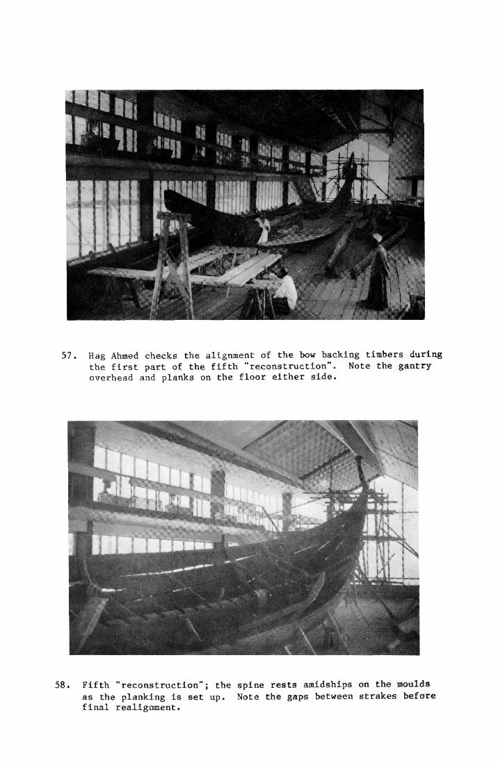
57. Hag Ahmed checks the alignment of the bow backing timbers during the first part of the fifth "reconstruction". Note the gantry overhead and planks on the floor either side.
58. Fifth "reconstruction"; the spine rests amidships on the moulds as the planking is set up. Note the gaps between strakes before final realignment.
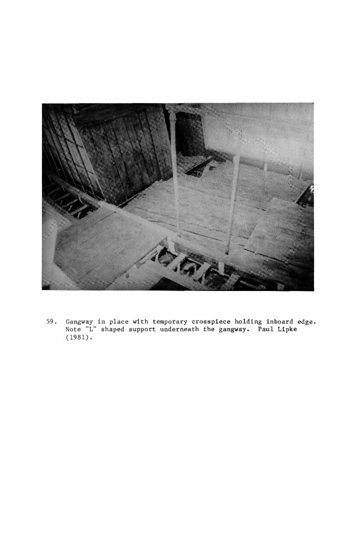
59. Gangway in place with temporary crossplece holding inboard edge. Note "L" shaped support underneath the gangway. Paul Lipke (1981).
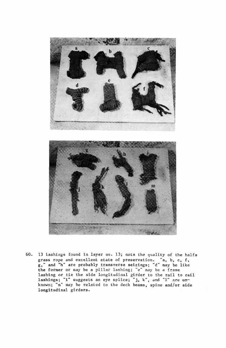
60. 13 lashings found in layer no. 13; note the quality of the halfa grass rope and excellent state of preservation. "a, b, c, f, g," and "h" are probably transverse seizings; "d" may be like the former or may be a pillar lashing; "e" may be a frame lashing or tie the side longitudinal girder to the rail to rail lashings; "i" suggests an eye splice; " j , k", and "1" are unknown; "m" may be related to the deck beams, spine and/or side longitudinal girders.
At least nine timbers remained unlocated at the end of the fifth reconstruction, and are still "unsolved" today. (Unfortunately, they were not available to the author for study.) These timbers are of two types. The first four are made from natural crooks, shaped like a human arm. Two of them have a small peg inserted in their "palms", and all four appear to have a groove cut diagonally across the "upper arm" on two faces (Fig. 13).
The other five (Figs. 13, 61) are straight timbers roughly a metre in length and 6 cm. square in section. At each end is a diagonal groove cut into two faces. Hag Ahmed remarked, "They are still a mystery to me. I have not yet discovered their purpose or found a place they can go."
Finally, there are an unspecified number of objects thought by Hag Ahmed to be associated equipment such as the "boathook" and "bitts" (Figs. 9 & 13).
With the reconstruction complete, the scaffolding supporting the bottom planking and shoring to the side planking were removed, the former being replaced with the following system.
17 steel stanchions are capped with a steel plate approximately 12 cm. wide and as long as the bottom planking's width at their particular location. The end of each plate is turned up in a flange to cup the bottom planking and a pad of foam rubber, 1 cm. when compressed, has been inserted between the bottom planking and plate as a cushion. Except for some internal bracing there are no other supports for the ship. It is held together as it was 4,500 years ago with its own lashings (Figs. 50, 64).
Post Reconstruction Events: March 1971 to March 1982
In these eleven years, only a few events are worth noting. The glass panels in the museum's eastern and western walls and northern roof were replaced with solid panels to reduce the ship's exposure to natural light. Other changes were continually being made in an effort to improve the environment and appearance. Hag Ahmed continued to restore pieces as required by the changing temperature and humidity, and to take preventative action when possible. In 1976, nine galvinized "U" beam frames (5 x 2.5 cm.) were shaped to fit the planking under the six rabbeted deck beams and further towards the ends. All were fastened with steel screws 5 to 6 cm. in length. The intent was to provide the planking with additional support as insurance against any lashing failure and/or a failure on the staff's part to replace the linen cordage every seven years, as Hag Ahmed has done in the past. During the winter of 1982-1983, a section of decking just aft of the cabin began to disintegrate, probably due to environmental changes and the difference in rates of expansion between the cedar and beechwood sawdust in the glue. Small portions of the affected area were treated with
1. a thinned epoxy mixed with PVA,
92
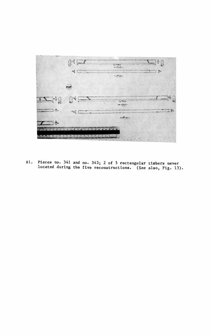
61. Pieces no. 341 and no. 343; 2 of 5 rectangular timbers never located during the five reconstructions. (See also, Fig. 13).
2. animal glue and calcium carbonate thinned out with enough water to get decent penetration,
3. alafonaya and paraffin with a high alafonaya content.
The results are being observed to determine the best method to conserve this piece.
In March of 1982, almost eleven years after the fifth reconstruction was completed and almost 28 years after the first covering blocks were removed, the museum was opened to the general public. Problems with the museum building persist, but there is reason for hope. The Antiquities Service is better staffed and funded than ever before, and is embarking on a major campaign to improve all its museums and sites. In the 197O's, the Ship Museum's climate ranged from 8. to over 40. degrees centigrade and relative humidity from 75% to 10%. During the author's stay in Egypt it varied between 10 and 30'C and RH 40 to 65%. The gap is closing. It is expected that the ship's environment and structural supports will continue to improve in accordance with recommendations by consultants and the Museum's staff.
RECORDS
The work undertaken since 1954 and the details of the ship's construction are recorded as follows.
1. 1:1 tracings of the quarry marks, one complete set (not seen by the author), samples published in FBK.
2. Index cards for each timber (p. 12), cross indexed by piece number and layer, unpublished. One copy of each.
3. Index cards for the 1,131 hieratic signs. Each card details the location of each mark on a specified timber with a small line drawing, and details each sign with a 1:1 rendering. Indexed by piece number, one copy exists. In addition, there are 1:1 tracings of each sign, unindexed. Lastly, there is the plank diagram (Fig. 56) recording the location of the principal signs on the hull. All are unpublished save this last.
4. 6,000 photographic negatives, uncaptioned, unindexed, largely unpublished (See TCB, Jenkings, Landstrom and FBK) all in varying states of deteriorization. These were taken with a Zeizz Ikon "Compur" on the following material: until 1964 Kodak Ortho X Sheet film with Developer D. 61a.; until 1972 Fortepan Forte 32 glossy; since 1972 Kodak Planfilm NP 20 Panchromatic.
5. The excavation log, developed from the index cards on each timber, but with each entry abbreviated. For example, multiple items such as papyrus-bud pillars are entered once, verbal descriptions are largely omitted, overall dimensions are given, but there are no sketches, only a very small photograph. Should be considered secondary to the index cards as source material.
6. Six photographic reports partially captioned and unindexed, detailing in photographs and a few drawings some important details of the restoration and reconstruction. By no means comprehensive, they are still the best overview of the work undertaken by Hag Ahmed, and were of great value to the author in deciding what questions to ask. One copy of each, unpublished.
7. Two sets of scale drawings of each timber. One set (the original) varies in scale from 1:1 to 1:20, the second set (made from the originals, not from the timbers) is entirely 1:20. See page 14 for comments on the accuracy of these drawings, and degree of detail. Indexed by piece number, unpublished, one copy of each.
8. "Countless" perspective and line drawings (not to scale) made by Hag Ahmed to test possible reconstructions and detail successful ones. Unindexed, unpublished, one copy.
9. Published articles and books; see bibliography.
95
10. Quarterly administrative reports to the Antiquities Service and Ministry of Culture, 1954 to present. Almost entirely administrative in content, they do contain some details of the excavation of the timbers from the pit, and sporadic references to restorations and reconstructions. The reports for 1954 and 1955, for example, contain significant quantities of information about which pieces have been excavated, cleaned, recorded, etc. After this period the administrative complexities increase, and less and less space is devoted to details of the work in progress. Like all documents of this type, they do provide an excellent protrait of the conditions under which Hag Ahmed, his co-workers and the Service operated.
Funding for the Service and hence for the ship was often extremely limited. Money for basic items such as electrical service, proper lighting, and typewriters (let alone climate control) was usually lacking. The work crew often complained of being interupted by visitors, and requests from other departments to put work on the ship aside to make room for other projects. In short, the crew faced all the problems usually found in such work but on a more severe level than most Western professionals would consider acceptable. This and Hag Ahmed's numerous responsibilities explain occasional lapses in documentation, such as the lack of photographs of the reshaping process and complete failure to record the restoration techniques and materials used on each timber.
11. The author's records are as follows: 31 hours of cassette tapes with 200 pages of notes (keyed to the tapes) covering the material published here; 468 colour slides of the scale drawings, restoration demonstrations, plank diagrams, and 1:20 model; approximately 20 slides taken of the ship during a visit in 1981; the prints (and black and white prints of prints), of the restoration/reconstruction stages published here (property of the Service); and the original drawings published here. By the time of publication duplicates of these materials will be in the Hart Nautical Collections of the MIT Museum, Cambridge, Ma. 02139, U.S.A.
All in all, the author's principal concerns are:
1. There are few duplicates of the Service's material in case of accident;
2. no one on the scene appears to be familiar with the minutiae of the restoration and reconstructions (and/or the records of these) other than Hag Ahmed who is well into his seventies and retired;
3. as far as the author is aware, no one in the Service has or is acquiring specific training in maritime preservation.
96
CONSTRUCTION
The dimensions and details that follow in text and drawings (Figs. 11, 52, 62) have been assembled from sources ranging from the 1:20 scale model, photographs and scale drawings of particular timbers to Hag Ahmed's notes and memory. As a result, some details such as the dimensions and locations of specific timbers are approximate. Still, they are based on more reliable sources than those published previously and should be more than sufficient as a general guide. Dimensions given in the text have been checked against Hag Ahmed's original notations and supercede any figures published previously.
The lines drawing (Fig. 62) was developed from the precise measurement of the 1:20 scale model. Stations every 10 cm., and waterlines every 2 cm. with additional measurements taken as needed proved to be sufficient to the task. Details such as the bow and stern posts were recorded 1:1 on graph paper and later scaled down for these drawings. Unfortunately, this model, like the 1:10 model currently on display in the museum, is not altogether accurate either in form or in construction (Fig. 63). Several adjustments have been made by the author in an attempt to publish a more realistic drawing without departing from the model completely.
Waterlines no. 8 through no. 20 aft of station no. 7 are quite hollow in the model. In the present publication these lines have been drawn as almost flat, more In keeping with the reconstructed ship as measured "by eye" by the author. Secondly, the bevel of the bottom planking's edge does not run fair with the rise of the gar-board for most of the ship's length, though in the model this important detail is lost (pp. 105, 106). This too has been corrected in the lines.
Lastly, both models are at variance with the ship in the matter of sheer. The ship as reconstructed appers to have very pronounced sheer, with the ends overhanging as much as several metres above the eyeballed loadwater line, whereas the models have considerably less, as shown. To increase the sheer of *.he model's lines "by eye" would be so radical a change that it would destroy the value of the lines, in the author's opinion. Until such time as the lines are taken directly off the reconstructed ship, the lines published here will have to do, with the caveat that the reconstructed vessel appears to be somewhat different in this regard.
PRINCIPAL DIMENSIONS OF "RECONSTRUCTION"
Length without stem and stern posts 43.32 Metres
Length over all 43.63 Metres
Maximum beam, 22.45 m. aft of forward perpendicular 5.66 Metres
Sheer height above bottom planking at maximum beam: 1.78 Metres
97

pmanuelian
Typewritten Text
[This page is intentionally blank.]
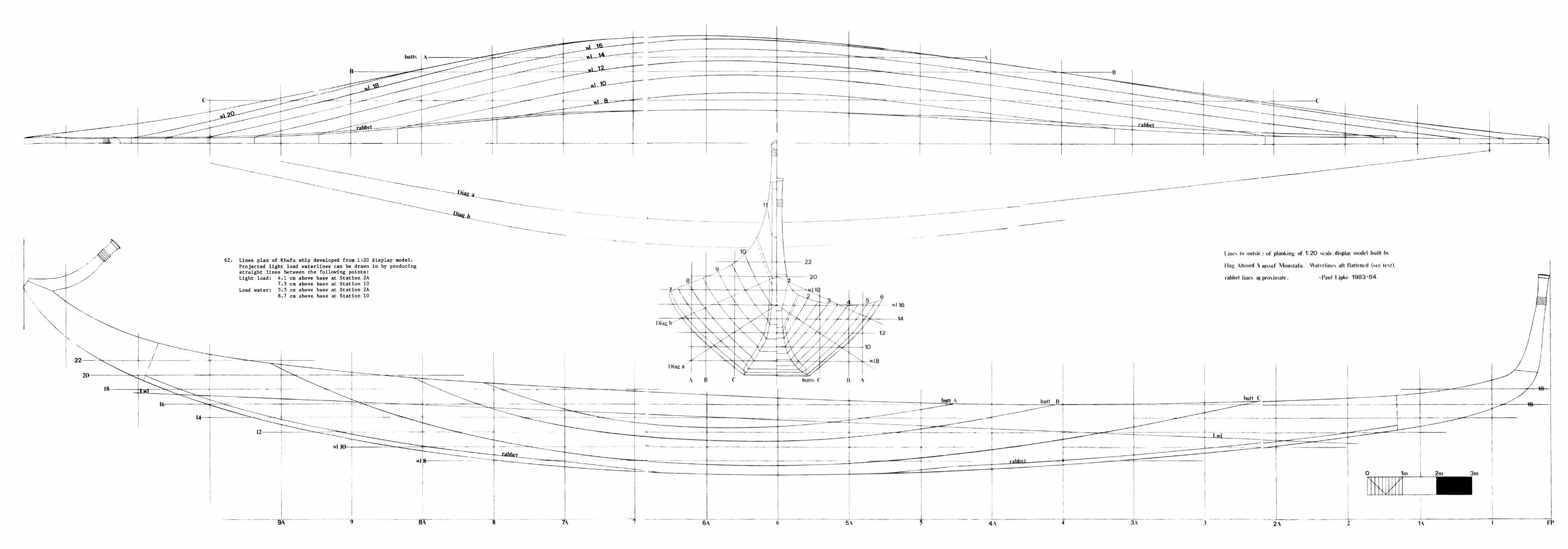
62. Lines plan of Khufu ship developed from 1:20 display model. Projected light load waterlines can be drawn in by producing straight lines between the following points: Light load: 4.1 cm above base at Station 2A
7.3 cm above base at Station 10 Load water: 5.5 cm above base at Station 2A
8.7 cm above base at Station 10
Lints to outsio; of planking of 1:20 scale,display model built h>
Hag Ahmed \ wssef Moustafa. Waterlines aft flattened (see text),
rabbet lines a| proximate. -Paul l.ipke 1 9 8 3 - 8 4 .

pmanuelian
Typewritten Text
[This page is intentionally blank.]
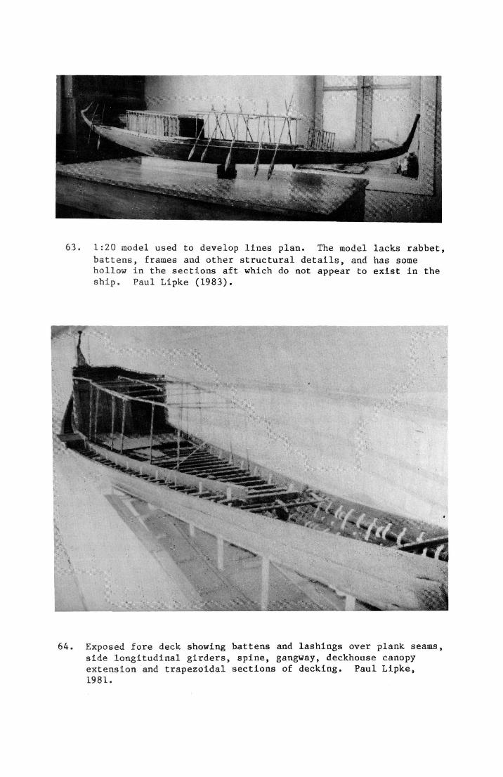
63. 1:20 model used to develop lines plan. The model lacks rabbet, battens, frames and other structural details, and has some hollow in the sections aft which do not appear to exist in the ship. Paul Lipke (1983).
64. Exposed fore deck showing battens and lashings over plank seams, side longitudinal girders, spine, gangway, deckhouse canopy extension and trapezoidal sections of decking. Paul Lipke, 1981.
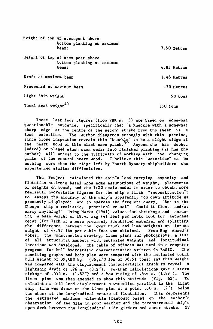
Height of top of sternpost above bottom planking at maximum beam: 7.50 Metres
Height of top of stem post above bottom planking at maximum beam: 6.81 Metres
Draft at maximum beam 1.48 Metres
Freeboard at maximum beam .30 Metres
Light Ship weight 5 0 tons
Total dead weight 49 150 tons
These last four figures (from FBK p. 3) are based on somewhat questionable evidence, specifically that "a knuckle with a somewhat sharp edge" at the centre of the second strake from the sheer is a load waterline. The author disagrees strongly with this premise, since close inspection reveals this "knuckle" to be a slight ridge at the heart wood of this slash sawn plank. Anyone who has dubbed (adzed) or planed slash sawn cedar into finished planking (as has the author) will attest to the difficulty of working with the changing grain of the central heart wood. I believe this "waterline" to be nothing more than the ridge left by Fourth Dynasty shipbuilders who experienced similar difficulties.
The Project calculated the ship's load carrying capacity and flotation attitude based upon some assumptions of weight, placements of weights on board, and the 1:20 scale model in order to obtain more realistic hydrostatic figures for the ship's fifth "reconstruction"; to assess the accuracy of the ship's apparently Nsw-down attitude as presently displayed; and to address the frequent query, "But is the Cheops ship a realistic, practical vessel? Could it float and/or carry anything?" Using Marks (1941) values for shrinkage and assuming a base weight of 18.45 skg (41 lbs) per cubic foot for Lebanese cedar (for lack of a more precisely identified material and splitting the difference between ti\e lower trunk and limb weights) an in-use weight of 47.97 lbs per cubic foot was obtained. From Hag Ahmed's notes, the construction drawing, lines plans and photographs, a list of all structural members with estimated weights and longitudinal locations was developed. The table of offsets was used in a computer program for hull hydrostatic characteristics written In BASIC. The resulting graphs and body plan were compared with the estimated total hull weight of 39,080 kg. (86,270 lbs or 38.51 tons) and this weight was compared with the displacement c'.iaracteristics graph to reveal a lightship draft of .96 m. (3.2'). further calculations gave a stern sinkage of .554 m. (1.82'^ and a bow rising of .606 m. (1.99'). The lines plan was then amended to show this attitude (Fig. 62). To calculate a full load displacement a waterline parallel to the light ship line was drawn on the lines plan at a point .60 m. (2') below the sheer at the longitudinal centre of floatation. This represents the estimated minimum allowable freeboard based on the author's observation of the Nile in poor weather and the reconstructed ship's open deck between the longitudinal side girders and sheer strake. By
102
applying the new heights above base to the Bonjean curves a section area for each station was integrated with a Simpson's rule formula to achieve a total hull volume at the full load waterline. Multiplying this volume by the weight density of freshwater yielded the final full load displacement of 93.8 metric tons (92.4 long tons at 2240 lbs per long ton) and consequently a maximum load carrying capacity of 54.7 metric tons (53.9 long tons) for the hull.
Aft panel of deckhouse from aft perpendicular 11.58 Metres
Deckhouse length 9.00 Metres
Deckhouse height for'd 2.50 Metres
Deckhouse height aft 2.17 Metres
Deckhouse width for'd 4.14 Metres
Deckhouse width aft 2.42 Metres
Deckhouse antechamber length, fore and aft 2.22 Metres
Deckhouse inner chamber length, fore and aft 6.78 Metres
Deckhouse canopy arches, height over roof panels .15 Metres
Extension of deckhouse canopy forward or deckhouse for'd panel 12.85 Metres
For'd canopy from forward perpendicular 5.71 Metres
For'd canopy length fore and aft 2.20 Metres
For'd canopy height above deck 1.78 Metres
Steering oar starboard 6.81 Metres
Steering oar port 6.67 Metres
Ten remaining oars vary in length between 8.35 and 6.58 Metres^ 1
Gangway fore and aft 2.08 Metres
Gangway athwart ships .84 Metres
Spine and side longitudinal girders (approx. section) 11. x 26. cm.
Deck beams for'd of wide beam (approx. section) 10. x 10. cm.
Deck beams aft of wide beam to deckhouse (approx. section) 12. x 12. cm.
Deck beams aft of cabin (approx. section) 11. x 11. cm.
103

Planking length varies from 7. - 23. m. (stealers excluded), thickness 12 - 15 cm.
Bottom planks length 12. - 14. m. thickness 13. cm.
104
Principle elements of the Fifth Reconstruction
The 4,500 year old Khufu ship is built in a manner known today as batten seam construction (Fig. 64). Watertight integrity is probably provided not by caulking, but by tight planking and a system of thin strips, or "battens" that cover the inboard face of the seam between any two planks. The hull is built around a planked bottom made up in three sections of eight timbers (averaging 13 metres in length and 13 cm. in thickness), the bow section having two timbers, and the centre and stern sections three each, the sections being aligned by exposed tenons. Two nearly symetrical sets of planking (11 timbers and two stealers to port, 11 and one stealer to starboard) form the remainder of the shell. The joint between the bottom planks and garboard strake deserves some comment.
The Fourth Dynasty shipbuilders appear to the author to have dealt with the universal problems of abrasion and stress in this joint in three ways.
1. The joint is tenoned, and some of the lashing holes are let out the planks' and bottom planking's edges (not interior faces) so as to hold the planks firmly in place (Fig. 48).
2. For more than two thirds of the ship's length, the garboard rests on top of the bottom planking (Fig. 65a). However, towards midships as the angle between the bottom planking and garboard increases towards 140 degrees, the shipbuilders apparently recognized that to continue this construction would lead to a very fine and fragile edge for the garboard, since its edge would have to be beveled to 140 degrees. Working towards midship from the fore and aft joints of the centre section of the bottom planking, a 70 degree angle is cut into the bottom planking's edge, effectively splitting the difference between the garboard and bottom planking (Figs. 65b, 65c). The garboard is rabbeted accordingly, so that at the hull's beamiest section, the two sections are, in effect, joined with a mitre (Fig. 65d) and the problem of a weak joint is eliminated. The garboard's exposure to abrasion is minimized, and the difficulties of getting a changing bevel watertight are virtually nonexistent.
3. The ancient shipbuilders did not attempt to make the bottom planks' edges run fair with the garboard's rise. The edge has apparently been deliberately left more square, since to fair it in would have weakened the bottom planking's resistance to abrasion and its support for the garboard (Fig. 65a-d).
Over the slightly open bottom planking and plank seams on the inside of the hull, 300 + hemispherical battens are held in place by 16 frames, and by lashings running rail to rail. The planks are additionally secured with 467 tenons set both parallel and perpendicular to the planks' faces. It should be pointed out that with the seams slightly open on the inside, the shipbuilders may have been able to get a much more watertight hull than otherwise. As the rail lashings shrank and the wood swelled (when wet) the hull would be drawn in on itself. With the inboard part of the seams cut away, the outer edges would be free to be crushed together all the more tightly.
105
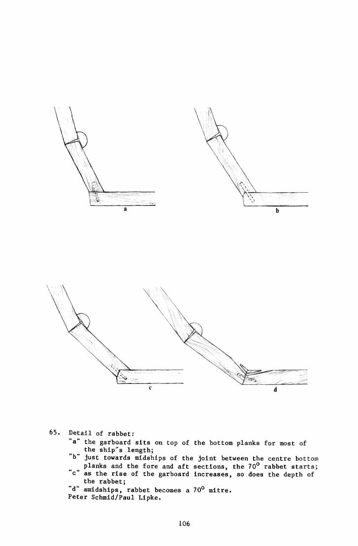
65. Detail of rabbet:
"a" the garboard sits on top of the bottom planks for most of the ship's length;
"b" just towards midships of the joint between the centre bottom planks and the fore and aft sections, the 70° rabbet starts;
"c" as the rise of the garboard increases, so does the depth of the rabbet;
"d" amidships, rabbet becomes a 70° mitre. Peter Schmid/Paul Lipke.
106
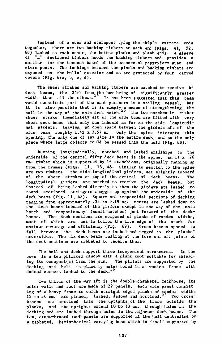
Instead of a stem and sternpost tying the ship's extreme ends together, there are two backing timbers at each end (Figs. 41, 52, 66) lashed to each other, the bottom planks and plank ends. A sleeve of "L" sectioned timbers hoods the backing timbers and provides a mortise for the tenoned based of the ornamental papyriform stem and stern posts. The lashings between the planks and backing timbers are exposed on the hulls' exterior and so are protected by four carved covers (Fig. 67a, b, c, d).
The sheer strakes and backing timbers are notched to receive 66 deck beams, the 24th from^^he bow being of significantly greater width than all the others. it has been suggested that this beam would constitute part of the mast partners in a sailing vessel, but it is also possible that is is simply^a means of strengthening the hull in the way of the main deck hatch. The two notches in either sheer strake immediately aft of the wide beam are fitted with very short deck beams that only run inboard as far as the side longitudinal girders, leaving an open space between the girders aft of the wide beam roughly 1.42 x 3.57 m. Only the spine interupts this opening, the only one of any size in the entire deck, and so the only place where large objects could be passed into the hold (Fig. 68).
Running longitudinally, notched and lashed amidships to the underside of the central fifty deck beams is the spine, an 11 x 26 cm. timber which is supported by 16 stanchions, originally running up from the frames (Figs. 11, 13, 48. Similar in section to the spine are two timbers, the side longitudinal girders, set slightly inboard of the sheer strakes on top of the central 49 deck beams. The longitudinal girders are notched to receive the deck beams, but instead of being lashed directly to them the girders are lashed to round sectioned stringers snugged up against the underside of the deck beams (Fig. 11, 48). Square and trapezoidal sections of decking ranging from approximately .32 to 9.19 sq. metres are lashed down to the deck beams inboard of the girders except in the way of the main hatch and "companionway" (small hatches) just forward of the deckhouse. The deck sections are composed of planks of random widths, most of which are cut to follow the live edge of the stock for maximum coverage and efficiency (Fig. 69). Cross braces spaced to fall between the deck beams are lashed and pegged to the planks' undersides. The six deck beams falling at the fore and aft joints of the deck sections are rabbeted to receive them.
The hull and deck support three independent structures. In the bows is a ten pillared canopy with a plank roof suitable for shielding its occupant(s) from the sun. The pillars are supported by the decking and held in place by ho^es bored in a wooden frame with dadoed corners lashed to the deck.
Two thirds of the way aft is the double chambered deckhouse, its outer walls and roof are made of 22 panels, each side panel consisting of a heavy frame to which straight edged planks of random widths 13 to 30 cm. are pinned, lashed, dadoed and mortised. Two cross-braces are mortised into the uprights of the frame outside the planks, and the uprights extend 10 to 13 cm. through holes in the decking and are lashed through holes in the adjacent deck beams. The ten, cross-braced roof panels are supported at the hull centreline by a rabbeted, hemispherical carrying beam which is itself supported by
107
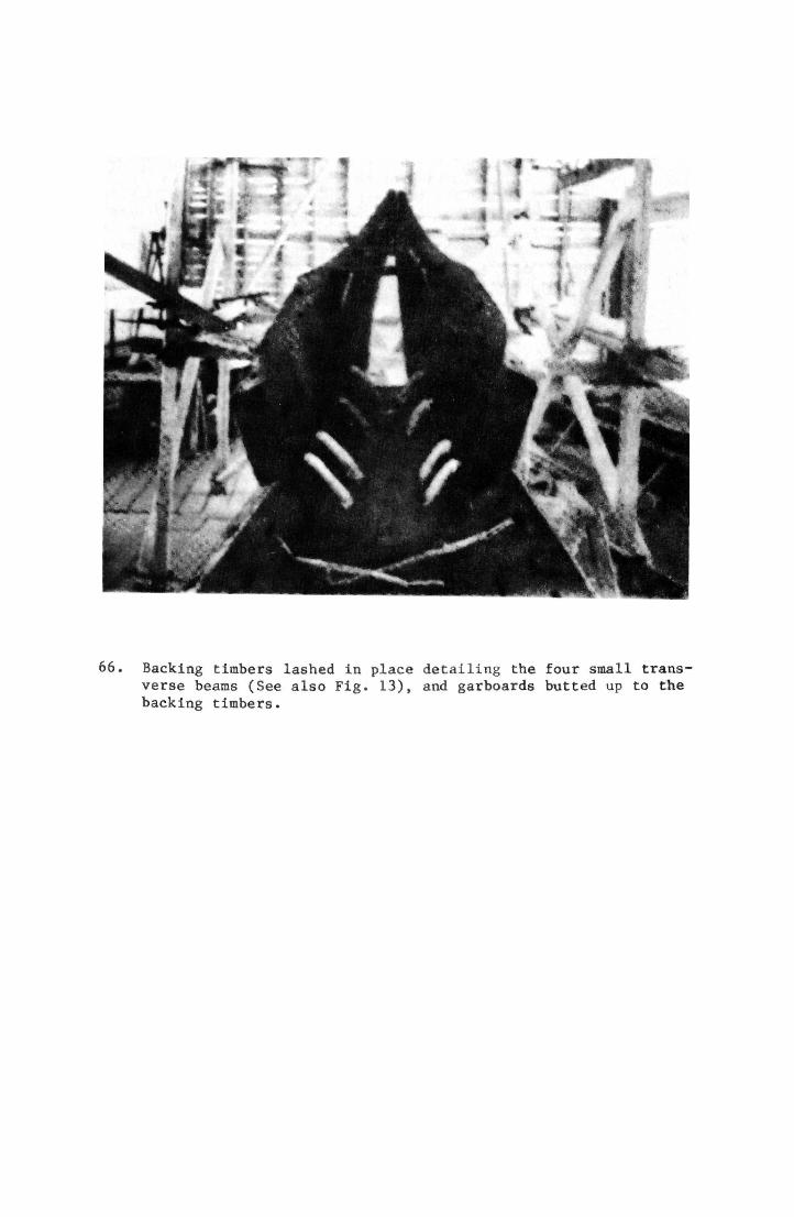
66. Backing timbers lashed in place detailing the four small transverse beams (See also Fig. 13), and garboards butted up to the backing timbers.
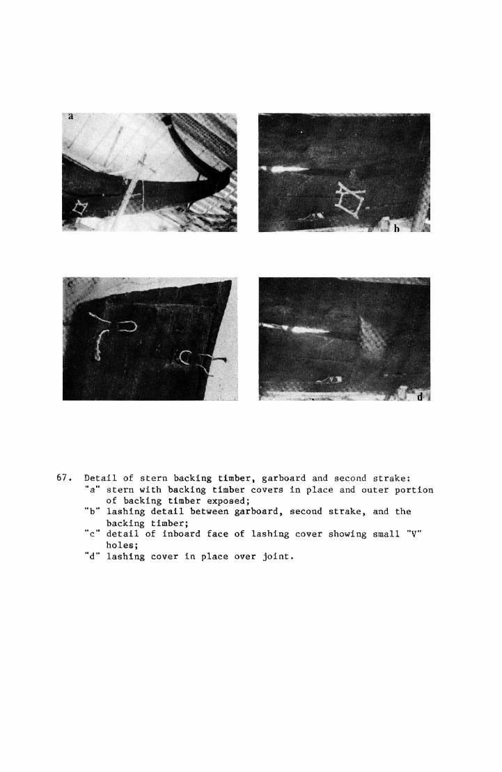
67. Detail of stern backing timber, garboard and second strake: "a" stern with backing timber covers in place and outer portion
of backing timber exposed; "b" lashing detail between garboard, second strake, and the
backing timber; "c" detail of inboard face of lashing cover showing small "V"
holes; "d" lashing cover in place over joint.
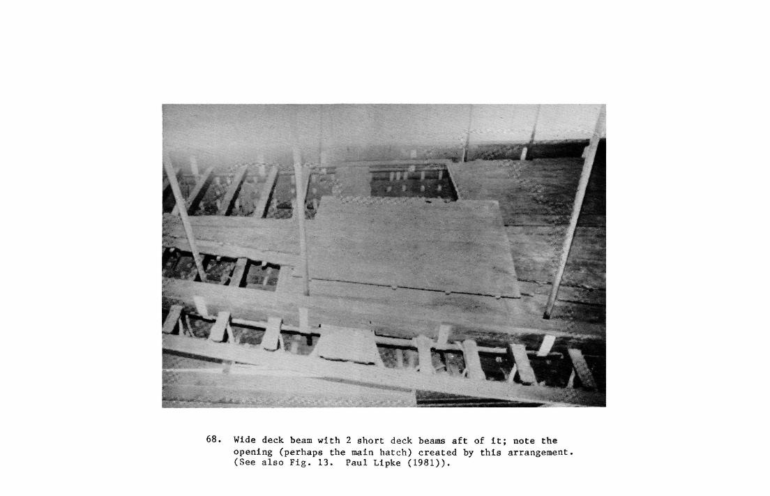
68. Wide deck beam with 2 short deck beams aft of it; note the opening (perhaps the main hatch) created by this arrangement, (See also Fig. 13. Paul Lipke (1981)).

69. Long, aft deck panel being raised from the pit detailing the live edges of the planks. Note workmen standing in pit on timbers.
71. Fifth "reconstruction"; Hag Ahmed looks on as workmen erect the bulkhead between the deckhouse's two chambers.
three palmette finished columns, the fore and aft ends of the deckhouse and the bulkhead separating the two chambers. The panels are supported athwart ships by this same bulkhead, the ends of the deckhouse and three more transverse hemispherical rabbeted beams let into the carrying beam. The ends of these beams are interlocked with the side panels with a distinctive notch (Figs. 7 0, 71). The roof panels are held in place by the rabbeted cross beams and wall panels and held down by longitudinal, rectangular sectioned beams (two beside and parallel to the centre line and one at each outboard edge). The five doors of the deckhouse (two double doors forward and a single one aft) are staggered athwartship, and can be latched (only from the Inside) with a wooden bolt; presumably to protect the privacy of the occupant(s) and/or the value of the cargo (Figs. 6, 47).
Built directly over and forward of the deckhouse but structually independent of it is the third superstructure; the framework for a canopy to be covered (theoretically) by the mats found in the pit's upper layer. This canopy Is supported by 48 pillars (36 over the cabin and 12 forward of it) divided into two rows, one just inside either side longitudinal girder. Over the deckhouse the pillars are spaced every half metre or so, and each pair athwart ships supports a cambered, hemispherical beam. In addition, each row is capped to hold the beams down. Forward of the deckhouse the cap and beams are rectangular in section and the pillar spacing is greater, averaging 2.1 metres. Along the sides of the deckhouse, either row of 18 pillars is supported by a single, half-round socketed stringer lashed to the underside of the deckbeams between the panels' legs and the side longitudinal girders (Fig. 48). Forward of the deckhouse, each of the 12 pillars is supported by a separate socketed stanchion lashed to the planking below decks (Figs. 11). Some of the pillars are additionally lashed to the side longitudinal girder through holes in Its upper and inboard surfaces (Fig. 48).
The positioning of the 12 oars is conjectural, as stated earlier.
Joints and Fastenings
The shipbuilders of the Fourth Dynasty used a wide variety of joints and fastenings in the Khufu ship: they are listed in Tables 3 and 4.
The 13 lashings found in layer 13 were not available to the author for close inspection. The Figures cited (60a, b) indicte that six of them; (a, b, c, f, g, and h) are of the same construction; two separate, parallel laid leads joined by a round seizing with trapping turns. The seizing appears to be done ingeniously with one length of rope, while we cannot know their precise application in the ship one clear possibility is that the leads ran athwart-ships from the upper strakes and were seized to one another in order to hold these strakes inward against the deck beams and frames.
Seizing "d" could be part of a lashing constructed identically to the six mentioned above, but the open loop also suggest a separate type that turns around a pillar before being lead off in opposite directions.
112
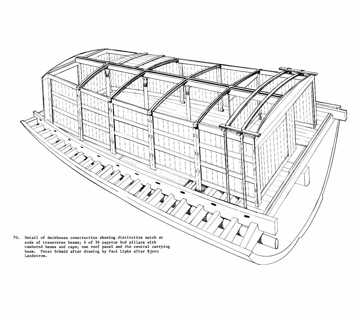
70. Detail of deckhouse construction showing distinctive notch at ends of transverse beams; 4 of 36 papyrus bud pillars with cambered beams and caps; one roof panel and the central carrying beam. Peter Schmid after drawing by Paul Lipke after Bjorn Landstrom.

pmanuelian
Typewritten Text
[This page is intentionally blank.]
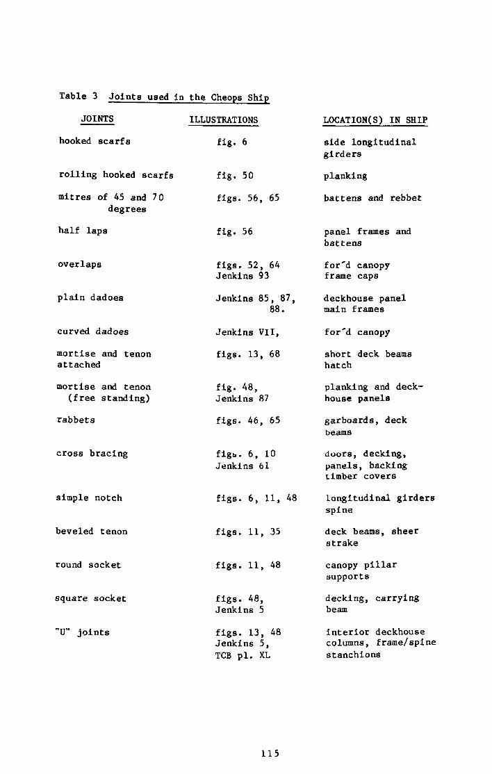
Table 3 Joints used In the Cheops Ship
JOINTS ILLUSTRATIONS
hooked scarfs
rolling hooked scarfs
mitres of 45 and 70 degrees
half laps
overlaps
plain dadoes
curved dadoes
mortise and tenon attached
mortise and tenon (free standing)
rabbets
cross bracing
simple notch
beveled tenon
round socket
square socket
"U" joints
fig. 6
fig. 50
figs. 56, 65
fig. 56
figs. 52, 64 Jenkins 93
Jenkins 85, 87, 88.
Jenkins VII,
figs. 13, 68
fig. 48, Jenkins 87
figs. 46, 65
figs. 6, 10 Jenkins 61
figs. 6, 11, 48
figs. 11, 35
figs. 11, 48
figs. 48, Jenkins 5
figs. 13, 48 Jenkins 5, TCB pi. XL
LOCATION(S) IN SHIP
side longitudinal girders
planking
battens and rebbet
panel frames and battens
for'd canopy frame caps
deckhouse panel main frames
for'd canopy
short deck beams hatch
planking and deckhouse panels
garboards, deck beams
doors, decking, panels, backing timber covers
longitudinal girders spine
deck beams, sheer strake
canopy pillar supports
decking, carrying beam
interior deckhouse columns, frame/spine stanchions
115
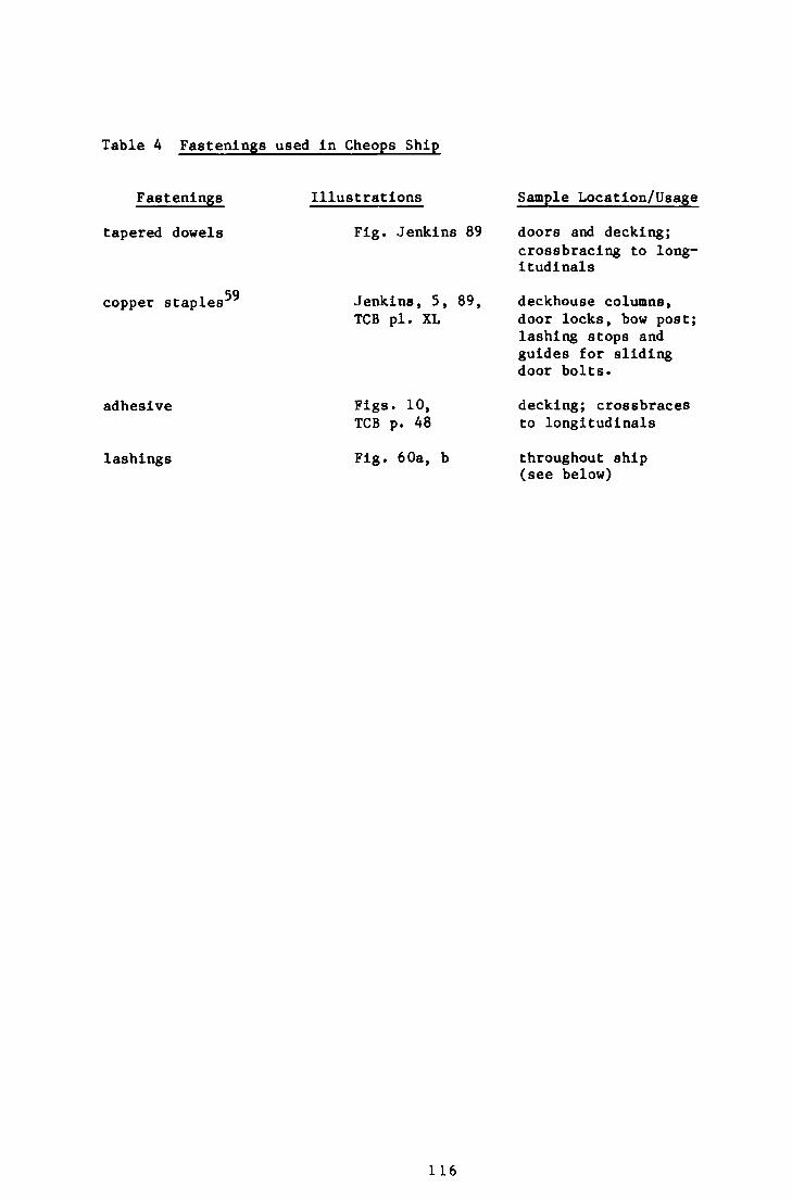
Table 4 Fastenings used In Cheops Ship
Fastenings
tapered dowels
copper staples
Illustrations
59
adhesive
lashings
Fig. Jenkins 89
Jenkins, 5, 89, TCB pi. XL
Figs. 10, TCB p. 48
Fig. 60a, b
Sample Location/Usage
doors and decking; crossbracing to longitudinals
deckhouse columns, door locks, bow post; lashing stops and guides for sliding door bolts.
decking; crossbraces to longitudinals
throughout ship (see below)
116
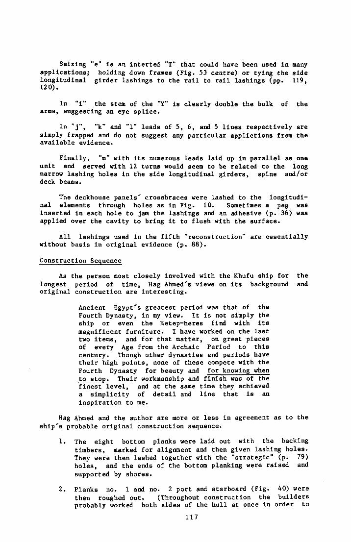
Seizing "e" is an interted "T" that could have been used in many applications; holding down frames (Fig. 53 centre) or tying the side longitudinal girder lashings to the rail to rail lashings (pp. 119, 120).
In "1" the stem of the "Y" is clearly double the bulk of the arms, suggesting an eye splice.
In " j " , "k" and "1" leads of 5, 6, and 5 lines respectively are simply trapped and do not suggest any particular applictions from the available evidence.
Finally, "m" with its numerous leads laid up in parallel as one unit and served with 12 turns would seem to be related to the long narrow lashing holes in the side longitudinal girders, spine and/or deck beams.
The deckhouse panels' crossbraces were lashed to the longitudinal elements through holes as In Fig. 10. Sometimes a peg was inserted in each hole to jam the lashings and an adhesive (p. 36) was applied over the cavity to bring it to flush with the surface.
All lashings used in the fifth "reconstruction" are essentially without basis in original evidence (p. 88).
Construction Sequence
As the person most closely involved with the Khufu ship for the longest period of time, Hag Ahmed's views on its background and original construction are interesting.
Ancient Egypt's greatest period was that of the Fourth Dynasty, in my view. It is not simply the ship or even the Hetep-heres find with its magnificent furniture. I have worked on the last two items, and for that matter, on great pieces of every Age from the Archaic Period to this century. Though other dynasties and periods have their high points, none of these compete with the Fourth Dynasty for beauty and for knowing when to stop. Their workmanship and finish was of the finest level, and at the same time they achieved a simplicity of detail and line that is an inspiration to me.
Hag Ahmed and the author are more or less in agreement as to the ship's probable original construction sequence.
1. The eight bottom planks were laid out with the backing timbers, marked for alignment and then given lashing holes. They were then lashed together with the "strategic" (p. 79) holes, and the ends of the bottom planking were raised and supported by shores.
2. Planks no. 1 and no. 2 port and starboard (Fig. 40) were then roughed out. (Throughout construction the builders probably worked both sides of the hull at once in order to
117
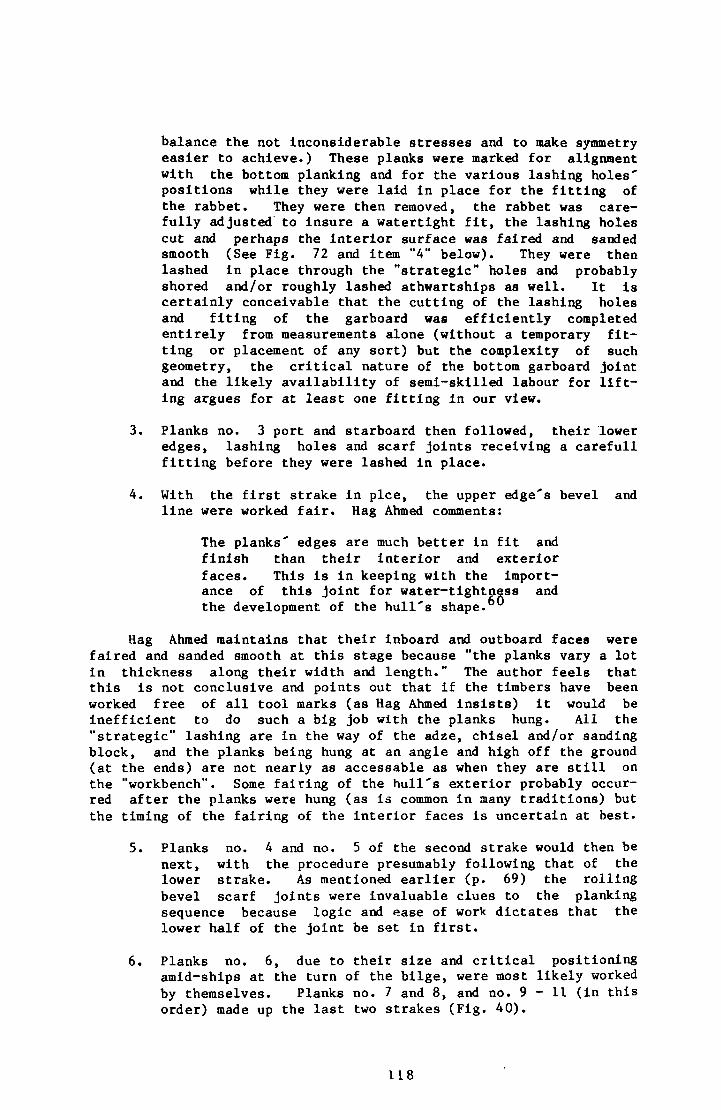
balance the not inconsiderable stresses and to make symmetry easier to achieve.) These planks were marked for alignment with the bottom planking and for the various lashing holes' positions while they were laid in place for the fitting of the rabbet. They were then removed, the rabbet was carefully adjusted to insure a watertight fit, the lashing holes cut and perhaps the interior surface was faired and sanded smooth (See Fig. 72 and item "4" below). They were then lashed in place through the "strategic" holes and probably shored and/or roughly lashed athwartships as well. It is certainly conceivable that the cutting of the lashing holes and fiting of the garboard was efficiently completed entirely from measurements alone (without a temporary fitting or placement of any sort) but the complexity of such geometry, the critical nature of the bottom garboard joint and the likely availability of semi-skilled labour for lifting argues for at least one fitting in our view.
3. Planks no. 3 port and starboard then followed, their lower edges, lashing holes and scarf joints receiving a carefull fitting before they were lashed in place.
4. With the first strake in pice, the upper edge's bevel and line were worked fair. Hag Ahmed comments:
The planks' edges are much better In fit and finish than their interior and exterior faces. This is in keeping with the importance of this joint for water-tightness and the development of the hull's shape.
Hag Ahmed maintains that their inboard and outboard faces were faired and sanded smooth at this stage because "the planks vary a lot in thickness along their width and length." The author feels that this is not conclusive and points out that if the timbers have been worked free of all tool marks (as Hag Ahmed insists) it would be inefficient to do such a big job with the planks hung. All the "strategic" lashing are in the way of the adze, chisel and/or sanding block, and the planks being hung at an angle and high off the ground (at the ends) are not nearly as accessable as when they are still on the "workbench". Some fairing of the hull's exterior probably occurred after the planks were hung (as is common in many traditions) but the timing of the fairing of the interior faces is uncertain at best.
5. Planks no. 4 and no. 5 of the second strake would then be next, with the procedure presumably following that of the lower strake. As mentioned earlier (p. 69) the rolling bevel scarf joints were invaluable clues to the planking sequence because logic and ease of work dictates that the lower half of the joint be set in first.
6. Planks no. 6, due to their size and critical positioning amid-ships at the turn of the bilge, were most likely worked by themselves. Planks no. 7 and 8, and no. 9 - 1 1 (in this order) made up the last two strakes (Fig. 40).
118
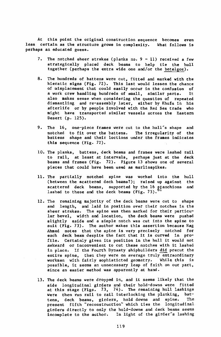
At this point the original construction sequence becomes even less certain as the structure grows in complexity. What follows is perhaps an educated guess.
7. The notched sheer strakes (planks no. 9 - 11) received a few strategically placed deck beams to help tie the hull together (perhaps the extra wide one and/or the betelgoz).
8. The hundreds of battens were cut, fitted and marked with the hieratic signs (Fig. 72). This last would lessen the chance of misplacement that could easily occur in the confusion of a work crew handling hundreds of small, similar parts. It also makes sense when considering the question of repeated dismantling and re-assembly later, either by Khufu in his afterlife or by people involved with the Red Sea trade who might have transported similar vessels across the Eastern Desert (p. 125).
9. The 16, one-piece frames were cut to the hull's shape and notched to fit over the battens. The irregularity of the battens shape and their loctions under the frames indicates this sequence (Fig. 72).
10. The planks, battens, deck beams and frames were lashed rail to rail, at least at intervals, perhaps just at the deck beams and frames (Fig. 72). Figure 13 shows one of several pieces that could have been used as marllnspikes.
11. The partially notched spine was worked into the hull (between the scattered deck beams?); raised up against the scattered deck beams, supported by the 16 stanchions and lashed to these and the deck beams (Fig. 73).
12. The remaining majority of the deck beams were cut to shape and length, and laid in position over their notches in the sheer strakes. The spine was then marked for their particular bevel, width and location, the deck beams were pushed slightly aside and a simple notch was cut into the spine to suit (Fig. 73). The author makes this assertion because Hag Ahmed notes that the spine is very precisely notched for each deck beam despite the fact that it is curved in profile. Certainly given its position in the hull it would not awkward or inconvenient to cut these notches with it lashed in place. If the Fourth Dynasty shipbuilders did precut the entire spine, then they were on average truly extraordinary workmen with fairly sophisticted geometry. While this is possible, it seems an unnecessary leap of faith on our part, since an easier method was apparently at hand.
13. The deck beams were dropped in, and it seems likely that the side longitudinal girders and their hold-downs were fitted at this stage (Figs. 73, 74). The remaining hull lashings were then run rail to rail interlocking the planking, battens, deck beams, girders, hold downs and spine. The present fifth "reconstruction" which ties the longitudinal girders directly to only the hold-downs and deck beams seems incomplete to the author. In light of the girder's lashing
119
holes being spaced between the deck, beams it would seem possible (and thinking structurally perhaps likely) that these slots held lines that lead not only to the hold-downs but also to some of the rail to rail lashings in some manner. In this way, the hull would be significantly stronger by virtue of being a complete, unified trapezoid (see also p. 112).
The decking and superstructure would appear to be more straightforward in their construction sequence.
14. The decking panels could now be laid out, cut out, assembled and lashed in place, leaving the main hatch and companionway open for easier access to the hull (Fig. 74).
15. The superstructures seem peculiarly well designed for frequent and fast assembly and removal. The forward canopy, and deckhouse canopy with its forward extention could all be removed without disturbing the deckhouse or each other in any significant way. All 58 papyrus-bud columns, their caps and arches could be removed without changing the various socketed parts that support them. All of these supports, excepting the forward canopy's, were out of the way below decks, and even the exception was unobtrusive and easily removed. The deckhouse's panels, being pre-assembled and lashed to the deck beams below, were similarly removable simply by cutting or untying a handful of lines. The half laps and mortise and tenons that lock the panels together presented no serious challenges to frequent handling, quite the contrary. There were no tapered dowels to remove as in the decking's door's and panel's Internal structures and the number of small independent parts was kept at an absolute minimum. Regardless of whether the Khufu ship had its superstructure removed frequently or not, there seems little doubt from its refinement that her builders had used this method for such purposes before. The construction seems apt for a timber-conscious river culture where relatively short distances make an easily modified carrying capacity of great value, one might almost say a necessity. In any case, only a more detailed study than was undertaken here would indicte which panels of the deckhouse were erected first. We can only assume tht the deckhouse as a whole was built before the canopy since it is underneath them.
There is little doubt to the author from the evidence that the Khufu ship is shell constructed; that is to say the builders sculpted the hull, adjusting the shape as they went and only added the internal structural members after the "shell" was complete. It makes a convincing case for those who believe that shell construction greatly predates the framing-then-planking skeletal technique commonly found in the West and elsewhere today. I mention this only to note that in discussing the whole question of shell vs. skeleton with Hag Ahmed he felt the distinction was an unimportant one. Furthermore, he is not fully convinced that the Khufu ship was necessarily built without benefit from moulds or frames. He is quite correct in saying that the notches in the frames for the battens (items 8 and 9) do not prove that the frames came after the battens. It would be
120
possible, he remarked, to cut the notches as the planking progressed if the frames had been lashed to the bottom planking at the outset. Awkward, but possible. The planks could then be hung directly on the frames over the precut and arranged and seized battens.
As to the tools used to build the ship originally, Hag Ahmed added:
Again we cannot be sure, but it seems fairly clear that the tools used were no more or less than those we have examples of in the Cairo National Museum and on tomb walls such as the relief showing boatbuilding in Ti's tomb at Sakkara; these are the adze, chisel, pull saw, mallett, flint knife, copper knife, stone pounder, sanding stones, bow drill, Spanish windlass and reamer.
121

pmanuelian
Typewritten Text
[This page is intentionally blank.]
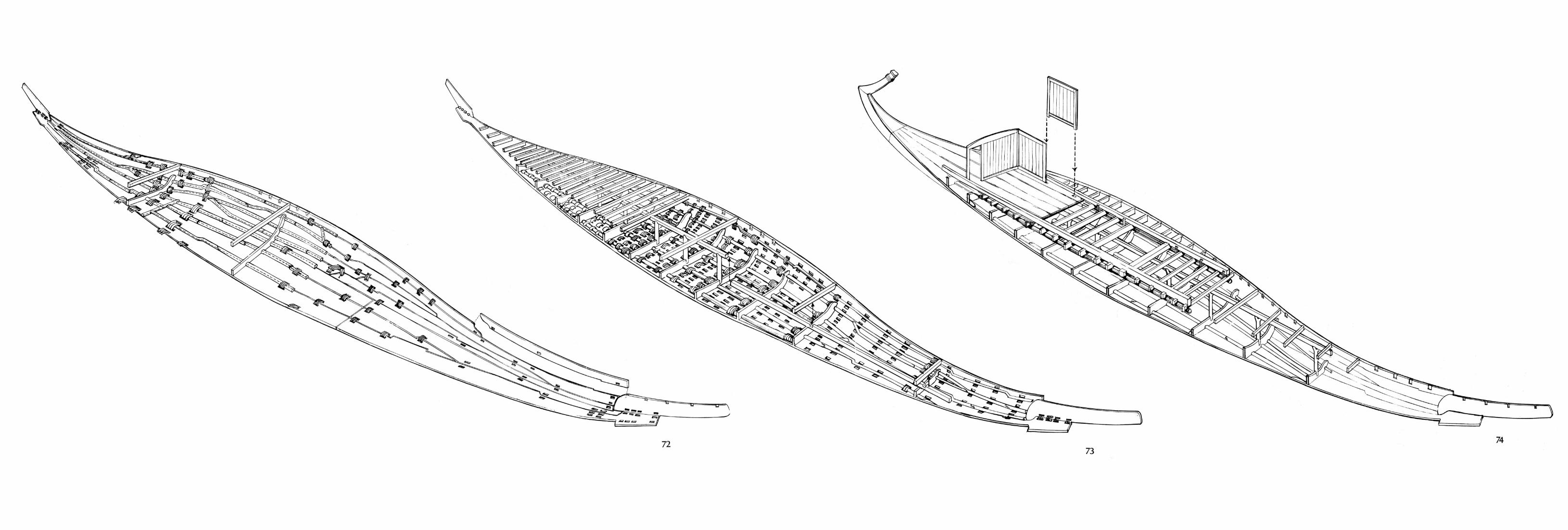
72 73
74

pmanuelian
Typewritten Text
[This page is intentionally blank.]
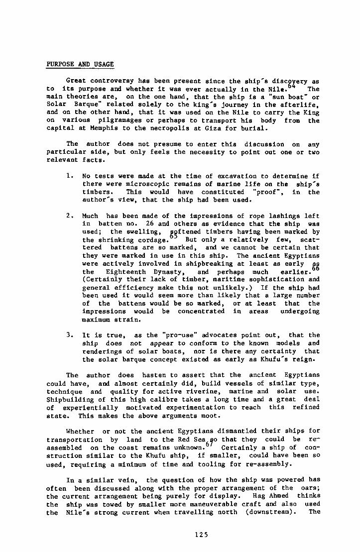
PURPOSE AND USAGE
Great controversy has been present since the ship's discovery as to its purpose and whether it was ever actually in the Nile. The main theories are, on the one hand, that the ship is a "sun boat" or Solar Barque" related solely to the king's journey in the afterlife, and on the other hand, that it was used on the Nile to carry the King on various pilgramages or perhaps to transport his body from the capital at Memphis to the necropolis at Giza for burial.
The author does not presume to enter this discussion on any particular side, but only feels the necessity to point out one or two relevant facts.
1. No tests were made at the time of excavation to determine if there were microscopic remains of marine life on the ship's timbers. This would have constituted "proof", in the author's view, that the ship had been used.
2. Much has been made of the impressions of rope lashings left in batten no. 26 and others as evidence that the ship was used; the swelling, softened timbers having been marked by the shrinking cordage. But only a relatively few, scattered battens are so marked, and we cannot be certain that they were marked in use in this ship. The ancient Egyptians were actively involved in shipbreaking at least as early as the Eighteenth Dynasty, and perhaps much earlier. (Certainly their lack of timber, maritime sophistication and general efficiency make this not unlikely.) If the ship had been used it would seem more than likely that a large number of the battens would be so marked, or at least that the impressions would be concentrated in areas undergoing maximum strain.
3. It is true, as the "pro-use" advocates point out, that the ship does not appear to conform to the known models and renderings of solar boats, nor is there any certainty that the solar barque concept existed as early as Khufu's reign.
The author does hasten to assert that the ancient Egyptians could have, and almost certainly did, build vessels of similar type, technique and quality for active riverine, marine and solar use. Shipbuilding of this high calibre takes a long time and a great deal of experientially motivated experimentation to reach this refined state. This makes the above arguments moot.
Whether or not the ancient Egyptians dismantled their ships for transportation by land to the Red Sea so that they could be reassembled on the coast remains unknown. Certainly a ship of construction similar to the Khufu ship, if smaller, could have been so used, requiring a minimum of time and tooling for re-assembly.
In a similar vein, the question of how the ship was powered has often been discussed along with the proper arrangement of the oars; the current arrangement being purely for display. Hag Ahmed thinks the ship was towed by smaller more maneuverable craft and also used the Nile's strong current when travelling north (downstream). The
125
oars (or rudders?) could then have been strictly for steering and perhaps additional maneuverability in docking. Certainly 12 oars seem inadequate as the sole source of long distance propulsion for a vessel with a waterline length of 32.3 m. (106.7 ft.). One other point is worth considering with regard to oar propulsion for the ship. If Dr. Phillips' identification of the oar blade as Ostrya Carpinifolia is correct, then there is a serious question regarding its practicality. The oars are all one piece, and calculating on the basis of Ostrya Carpinifolia's known weight and the scale drawings we find that oar no. 22 (p. 24) originally weighed in the vicinity of 57.15 kg. (127 lbs.)! Until such time as more detailed study makes proper calculations and/or experiments possible, we must wonder about the use of an oar over 7 m. In length made of one of the heaviest woods possible. The suggestion by Kamal Mallakh In conversations that the oars are ceremonial in purpose must be considered viable until their practicality is proven.
Author's Comment
The Khufu ship is a magnificent statement on the technical and aesthetic sophistication of the Fourth Dynasty Egyptians: proof that their works in wood were every bit as great as those in stone; proof that their river culture was already fully matured. Those who worked on this Project all recognized that with the original excavation team now either dead or retired, and the fields of nautical archeology and maritime preservation more firmly established than they were in 1954, now was the time to cut through the rumour, misinformation and mystery of the last 29 years. Certainly there is a great deal still to be learned from this extraordinary find, from both compiled but unpublished and as yet unresearched aspects. It is hoped that this report has helped to clarify what is_ known so that future work can be fully focused and effective.
126
NOTES
1. All quotations are to be attributed to Hag Ahmed Youssef unless noted otherwise.
2. Abubakr, A.M. (1971) The funerary Boat of Khufu, Beitrage zur Agyptischen Bauforschung und Altertumskunde, Heft 12, p. 2. (FBK)
3. Hag Ahmed added, "This study was far more productive than reading the books available at the time, though of course I pursued texts fanatically and still do."
4. Jenkins, N. (1980) The Boat Beneath the Pyramid, Thames and Hudson, illustrations 29 and 37. (Jenkins) Tskander, Nour, Moustafa and Osman The Cheops Boats, Antiquities Department of Egypt, 1960, plate XXIX. ^TCBl
5. Quarry marks of red ochre, carbon black and yellow ochre were found on many of the blocks, and these were recorded with tracings after layers of "crystalline common salt or common mortar" were removed from them" mechanically and then with a fine spray of water". They were then sprayed once with a 7% solution of polyvinyl acetate (TCB p. 39). While noting that the marks have never been fully studied, Abubakr points out (in FBK) that the measurements given in cubits and palms do not coincide with the mesurements of the blocks on which they are written. Secondly, ten triangular signs with hieratics found on the walls of the pit do not appear to relate to their locations on the pit wall. Clearly a more detailed study is in order to determine something of the quarrying system in use and/or the difference in measurements from the accepted 52.5 cm. to the cubit and 7.5 cm. to the palm. With time and exposure to the elements the quarry marks have almost disappeared. Any future study would have to rely heavily on the tracings, some samples of which were published in FBK pp. 9-11.
6. TCB pp. 20 - 24 and plates XIX - XXIII
7. TCB pp. 40 - 41, Jenkins pp. 64 - 65
8. TCB pp. 31 - 39
9. The 3 eastern boat pits (p. 2) are rather different, being more or less ellpses, without large flat ledges and much more roughly carved.
10. TCB pp. 31 - 34
11. TCB plate XXVIII
12. TCB plate L
13. Jenkins illustration 61.
127
14. The 1:10 model now on display in the museum was completed after the third reconstruction late in 1961, and Hag Ahmed's 1:20 model (Fig. 63) was finished after the fourth reconstruction in 1967.
15. For complete details of layer "A" see TCB pp. 42 - 45 and 56.
16. TCB p. 43, Zaki Iskander
17. TCB p. 45, Zaki Iskander
18. Dr. Frederick van Doorninck, correspondence with the author.
19. TCB p. 45, Zaki Iskander
20. Jenkins illustrations 47 and 48.
21. Jenkins illustrations 44 - 46
22. Jenkins illustration 50.
23. Jenkins illustrations 45 and 46.
24. TCB pp. 29 and 2 0, Jenkins p. 162
25. TCB Iskander quoting Phillips pp. 45 - 46
26. United States Naval Weather Service, Worldwide Airfield Summaries, Volume IX part I Africa (Northern Half) 1968.
27. It is interesting to compare the condition of the Khufu ship's timbers with that of the furniture in the Hetep-heres shaft. Reisner (1927) pp. 13 and 28 states the wood "had completely decayed" in the shaft, and was unrestorable. In contrast to the shallow but certainly airtight seal on the boat pit, the shaft was of courses of small squared blocks of limestone....the laying (of which) was particularly haphazard at a level between 10.6 and 11.6 m. while at 15 m. clean sand was met alternating with chips and blocks of stone." Well laid blocking commenced again at 24.8 m. In addition, the boats pit's floor is approximately 39.105 m. above the water table, where the shaft's floor is not more than 17.205 m. above it and perhaps as little as 3.9 m. (From unpublished research by Mark Lehner, Director, American Research Centre in Egypt's Sphinx Project, contained in personal correspondence with the author.)
28. Twelve of the notches In the sheer strakes towards the extreme ends of the ship (3 each side, each end) did not have deck beams that fit them, unlike all the others. Hag Ahmed thinks that these deck beams were either never put in the pit or were so damaged by their storage environment (compression, etc.) that in effect they had disintegrated and become the layer of wood dust and tiny fragments that littered the floor of the pit.
29. Administrative Reports to "Egyptology Centre," Service of Antiquities, Item 1. 12/27/54. Item 2. 3/31/62. Item 3. June to December 1964. (All unpublished)
128
30. Report to the Ministry of Culture, 1/3/78. (Unpublished)
31. Jenkins illustrations 73, and 74 which shows the gantry.
32. TCB p. 57
33. TCB p. 48
34. Lucas (1962) states on p. 9, "This material is one of the earliest, best known, and most reliable of adhesives, especially for wood. It is made by extracting certain animal products containing gelatine such as bones, skin cartilage and tendons with boiling water, concentrating the liquid by evaporation and then pouring it into moulds..."
35. Dr. Nabiel A.M. Saleh, Phytochemistry, Egyptian National Research Centre. Correspondence with the author detailing analysis of resin from Hag Ahmed's store room. He comments further "It contains chiefly resin acids, as well as smaller amounts of nonacid compounds...and varies in colour from pale yellow to dark red or darker, depending on source, method of collecting and processing." Hag Ahmed's material is amber in colour.
36. Jenkins illustrations 70
37. Jenkins illustration 71
38. Jenkins illustrations 58 - 60. The 10 pillars of the forward canopy had been placed in the pit together, separate from those of the deckhouse canopy and its forward extension. The planks and cross pieces of the forward canopy roof were also stacked together (unassembled). It was the matching numbers - ten holes in the planking of the roof and ten pillars that clued Hag Ahmed in on their relationship to one another.
39. TCB plate LXVI
40. Jenkins illustrations 76 - 77, note the spacers in figure 77.
41. Jenkins illustration 43
42. Jenkins illustration 61
43. Jenkins illustration 133
44. FBK plates 7b and 9 show scarfed battens, and the fourth reconstruction being dismantled with battens exposed.
45. Jenkins illustration 83. It was felt that the frames were too weak to support the spine via the new stanchions.
46. Helck (1973 - 4) indicates that the signs could be used In orienting any construction project, and are not nautical signs per se.
129
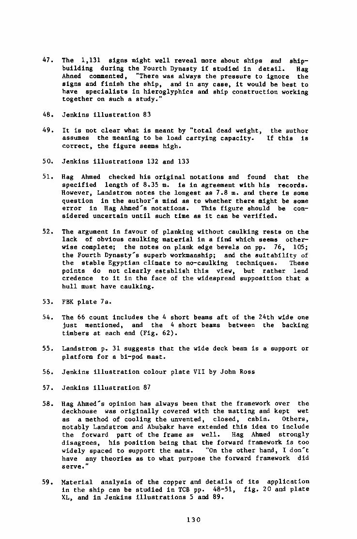
47. The 1,131 signs might well reveal more about ships and shipbuilding during the Fourth Dynasty if studied in detail. Hag Ahned commented, "There was always the pressure to ignore the signs and finish the ship, and in any case, it would be best to have specialists in hieroglyphics and ship construction working together on such a study."
48. Jenkins illustration 83
49. It is not clear what is meant by "total dead weight, the author assumes the meaning to be load carrying capacity. If this is correct, the figure seems high.
50. Jenkins illustrations 132 and 133
51. Hag Ahmed checked his original notations and found that the specified length of 8.35 m. is in agreement with his records. However, Landstrom notes the longest as 7.8 m. and there is some question in the author's mind as to whether there might be some error in Hag Ahmed's notations. This figure should be considered uncertain until such time as it can be verified.
52. The argument in favour of planking without caulking rests on the lack of obvious caulking material in a find which seems otherwise complete; the notes on plank edge bevels on pp. 76, 105; the Fourth Dynasty's superb workmanship; and the suitability of the stable Egyptian climate to no-caulking techniques. These points do not clearly establish this view, but rather lend credence to it in the face of the widespread supposition that a hull must have caulking.
53. FBK plate 7a.
54. The 66 count includes the 4 short beams aft of the 24th wide one just mentioned, and the 4 short beams between the backing timbers at each end (Fig. 62).
55. Landstrom p. 31 suggests that the wide deck beam is a support or platform for a bi-pod mast.
56. Jenkins illustration colour plate VII by John Ross
57. Jenkins illustration 87
58. Hag Ahmed's opinion has always been that the framework over the deckhouse was originally covered with the matting and kept wet as a method of cooling the unvented, closed, cabin. Others, notably Landstrom and Abubakr have extended this idea to include the forward part of the frame as well. Hag Ahmed strongly disagrees, his position being that the forward framework is too widely spaced to support the mats. "On the other hand, I don't have any theories as to what purpose the forward framework did serve."
59. Material analysis of the copper and details of its application in the ship can be studied in TCB pp. 48-51, fig. 20 and plate XL, and in Jenkins illustrations 5 and 89.
130
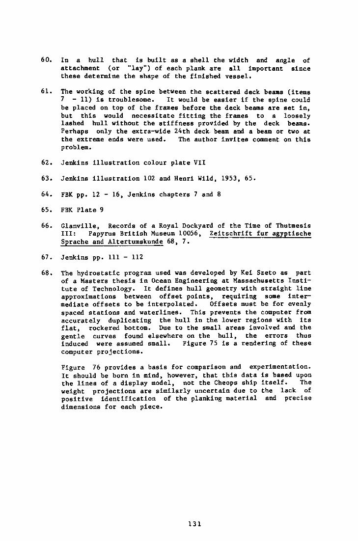
60. In a hull that is built as a shell the width and angle of attachment (or "lay") of each plank are all important since these determine the shape of the finished vessel.
61. The working of the spine between the scattered deck beams (items 7 - 11) is troublesome. It would be easier If the spine could be placed on top of the frames before the deck beams are set in, but this would necessitate fitting the frames to a loosely lashed hull without the stiffness provided by the deck beams* Perhaps only the extra-wide 24th deck beam and a beam or two at the extreme ends were used. The author invites comment on this problem.
62. Jenkins illustration colour plate VII
63. Jenkins illustration 102 and Henri Wild, 1953, 65.
64. FBK pp. 12 - 16, Jenkins chapters 7 and 8
65. FBK Plate 9
66. Glanville, Records of a Royal Dockyard of the Time of Thutmesis III: Papyrus British Museum 10056, Zeitschrift fur agyptische Sprache and Altertumskunde 68, 7.
67. Jenkins pp. Ill - 112
68. The hydrostatic program used was developed by Kei Szeto as part of a Masters thesis in Ocean Engineering at Massachusetts Institute of Technology. It defines hull geometry with straight line approximations between offset points, requiring some intermediate offsets to be interpolated. Offsets must be for evenly spaced stations and waterlines. This prevents the computer from accurately duplicating the hull In the lower regions with its flat, rockered bottom. Due to the small areas involved and the gentle curves found elsewhere on the hull, the errors thus induced were assumed small. Figure 75 is a rendering of these computer projections.
Figure 76 provides a basis for comparison and experimentation. It should be born in mind, however, that this data is based upon the lines of a display model, not the Cheops ship itself. The weight projections are similarly uncertain due to the lack of positive identification of the planking material and precise dimensions for each piece.
131
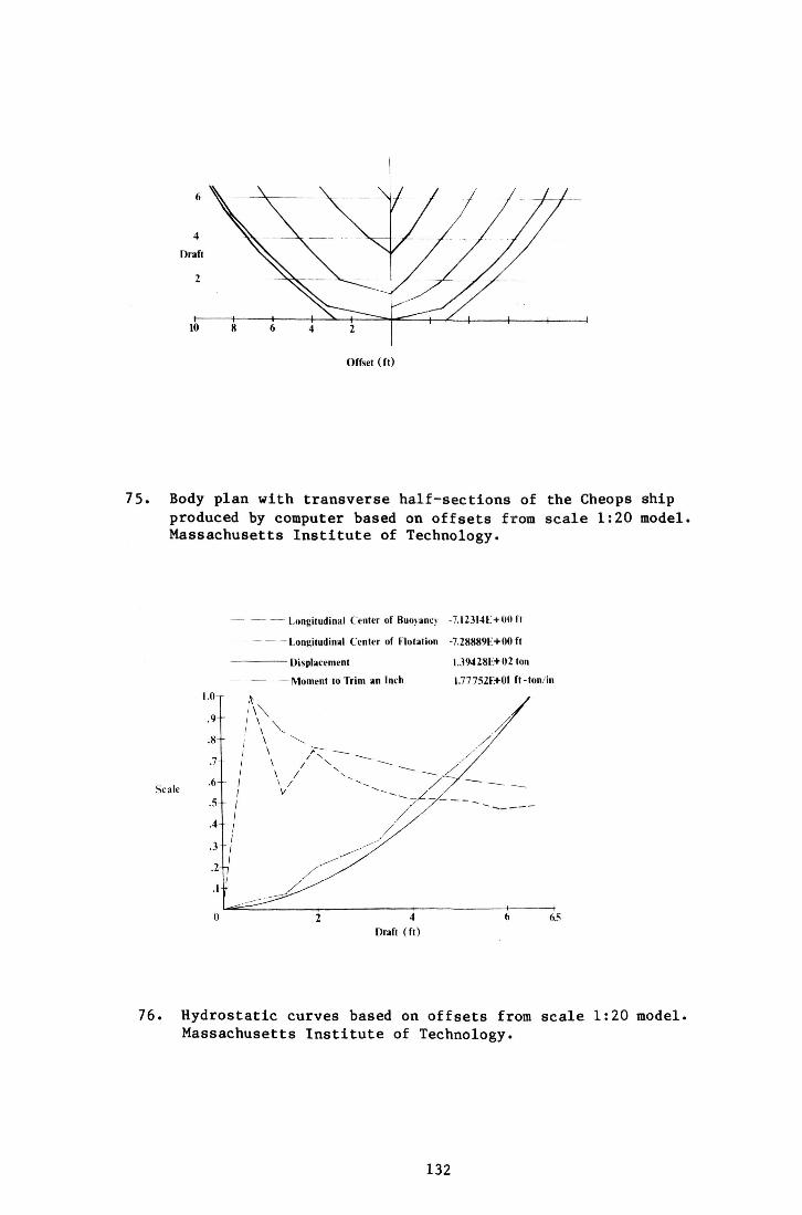
Offset (ft)
Body plan with transverse half-sections of the Cheops ship produced by computer based on offsets from scale 1:20 model. Massachusetts Institute of Technology.
Scale
Longitudinal Center of Buoyancy -7.12314K+00 ft
Longitudinal Center of Flotation -7.28889K+00 ft
Displacement 1.39428E+ 02 ton
— Moment to Trim an Inch 1.77752E+01 ft-ton/in
6. Hydrostatic curves based on offsets from scale 1:20 model. Massachusetts Institute of Technology.
132
REFERENCES:
The Four Works on the Khufu Ship
Abubakr, A.M., Mustafa, A.Y., 1971, The funerary Boat of Khufu, Beitrage zur Ägyptischen Bauforschung und Altertumskunde, Heft 12, pp. 1:16. (abbr. FBK) An excellent short article on the pit and its blocks; the ship's fifth "reconstruction" and its debatable original purpose. It is flawed by 10 inacurraces (corrected in this publication) and its occasionally unclear or misleading language. (The latter is likely the result of translation.) It is noteworthy as the first publication to deal with the ship itself in any detail, and for the mostly excellent photographs and plans accompanying the text.
Jenkins, N., 1980, The Boat Beneath the Pyramid, London. (abbr. Jenkins) The only comprehensive, popular work on the find; on balance the 149 illustrations make this a must see for all who have even a passing interest in the Khufu ship. Chapters 1-3 are excellent in their portrait of the milieu in which the discovery and excavation took place, their synopsis of Old Kingdom history, and the details of the discovery itself. Similarly, the last three chapters provide some valid analysis and commentary on solar boats, shipbuilding and shipping in ancient Egypt. The 2 central chapters, Excavation and Construction and Reconstruction contain numerous omissions and serious inaccuracies if judged by scholarly standards. This is admittedly inappropriate to a popular work, but as this is the only broad work available on the find it is often used as a reference by scholars.
Landstrom, B., 1970, Ships of the Pharoahs, Garden City and London, (abbr. Landstrom) The broad scope of this work limits the space given to the Khufu ship to 8 pages, much of these given over to somewhat fanciful illustrations. Landstrom's construction views were the first widely available, and as such were invaluable for years despite omissions and inaccuracies. The text is tight and to the point; touching on Herodotus' description of Egyptian boatbuilding, the pit's discovery, and the reconstructed ship's general dimensions.
Nour, M.Z., Osman, M.S., Iskander, Z., Moustafa, A.Y., 1960, The Cheops Boats, Part I, Cairo. (Abbr. TCB) The first (and last) of what was to be a series of scholarly reports on the two boat pits and their contents published by the Service. It varies from superficial to comprehensive in its coverage of the boundary wall, covering blocks, pit details and early excavation of the timbers. It stops just before restoration and reconstruction begin. The chapters by Osman (engineering) and Iskander (chemistry) are especially good for their clarity and attention to detail.
133
Abubakr, A., 1959, The funerary Boats of Khufu. Egypt Travel Magazine, Cairo.
Ballard, G., Jan. 1937, Egyptian Shipping of About 1500 B.C. Mariner's Mirror, 23:1:103
Bell, C , 1933, Ancient Egyptian Ship Design Based on a Critical Analysis of the Xllth Dynasty Barge. Ancient Egypt, 101.
Bell, C. 1934, Obelisk Barge of Hatshepsut. Ancient Egypt, 107.
Boreaux, C., 1924-5, Etudes de nautique egyptienne, Cairo.
Bowen, R., Jr. 1960, Raising Sail in the Third Millenium B.C., Egypt. Mariner's Mirror, 46: 1:1
Casson, L., 1971, Ships and Seamanship in the Ancient World. Princeton.
Cerney, J., Dec. 1955, A Note on the Recently Discovered Boat of Cheops. Journal of Egyptian Archeology, 41: 75.
Chaney, W., Basbus, M., 1978, Cedars of Lebanon; Witnesses of History. Economic Botany.
Clarke, S., 1920, Nile Boats and Other Matters. Ancient Egypt, Part II: 44-50.
de Kerchove, R., 1948, International Maritime Dictionary, New York.
Dimick, J., 1955, Lifting the Lid from the Cheops Boat Grave. Archeology, 8: 93-5.
Edgerton, W.F., 1922-3, Ancient Egyptian Ships and Shipping, American Journal of Semitic Languages and Literature, 39:109.
Faulkner, R., Feb. 1941, Egyptian Seagoing Ships. Journal of Egyptian Archeology, 26:3.
Feilden, B.M., 1982, The Royal Ship of Khufu; Mission for the World Ship Trust to Egypt, (unpublished).
Gamble, J., 1922, A Manual of Indian Timbers, s.l. : Sampson, Low and Marston, 710-715.
Glanville, S.R.K., 1932, Records of a Royal Dockyard of the Time of Tuthmosis III. Zeitschrift fur ägyptische Sprache und Alterumskunde, 68:7. " " " " " " " " " ~ " "
Greenhill, B., 1976, Archeology of the Boat. London and Middletown, ct . ~"~"~
Hall, J.W., 1952, Comparative Anatomy and Phylogeny of Betulaecae, Botanical Gazette, 113:235-270
Hadidi, M., Boulos, L., 1979, Street Trees in Egypt. Cairo.
134
Hasslof, 0., 1963, Wrecks, Archives and Living Tradition, Mariner's Mirror, 49: 162-177.
Hasslof, 0. (ed.), 1972, Ships and Shipyards, Sailors and Fishermen. Copenhagen.
Helck, W., 1973-4, Die Handwerker und Priesterphylen des Alten Retches in Agypten. Die Welt des Orients, VII: 1-8.
Hornell, J., Jan. 1937, Egyptian shipping of About 1500 B.C. Mariner's Mirror, 23:105.
Howard, A., 1920, The Timbers of the World. London, 56-58.
Lucas, A., 1962, Ancient Egyptian Materials and Industries. London, 9-10, 199-217, 429-441, 482-486.
Marks, L.S. ed., 1941, Mechanical Engineers Handbook, New York
Marx, E., 1947, Egyptian Shipping. Mariner's Mirror, 33:138.
Milan Kovac, 1980, Isolation Container for Preservation of the Royal Ship of Khufu within the Existing Museum at Giza, Cairo. Stockholm.
Moustafa, A., December 27, 1954, Report to Egyptology Centre, (unpublished).
Moustafa, A., March 31, 1962, Report to Egyptology Centre, (unpublished).
Moustafa, A., June-December 1964, Report to Egyptology Centre, (unpublished).
Moustafa, A., January 3, 1978, Report to Ministry of Culture, (unpublished).
Packard, E., 1970, consolidation of Decayed Wood Sculpture, IIC Conference on Conservtlon of Stone and Wood Objects.
Petrie, W.F., 1933, Egyptian Shipping. Ancient Egypt, 1:14. 65-75
Petrie, W.F., 1917, Tools and Weapons of the Ancient Egyptians. London.
Plenderleith, H.J., 1965, Report on the Cheops Ship. UNESCO, (unpublished).
[s.n.], 1956, Progress on the Funerary Boat of Cheops. Archeology, IX, 3 : 206-209.
Record, S.J., and Hess, R.W., 1943, Timbers of the New World New Haven
Reisner, G., 1913, Models of Ships and Boats. Cairo.
Reisner, G., 1955, A History of the Giza Necropolis, vol. II: The Tomb of Hetep-heres, the Mother of Cheops, Cambridge, Ma.
135
Samore, S., 1980, An Interview with Kamal el Mallakh Eggypt Then and Now, [s.l.].
Save-S8derbergh, T., 1946, The Navy of the Eighteenth Egyptian Dynasty, Uppsala.
Snow, C.H., 1903, Principal Species of Wood: Their Characteristic Properties. London.
Snyder, A., Snyder, P., 1968, Knots and Lines Illustrated. Tuckahoe.
Solver, C , 1961, Egyptian Seagoing Ships of about 2600 B.C. Mariner's Mirror, 47:24.
Solver, C , October 1936, Egyptian Shipping of about 1500 B.C., Mariner's Mirror, 22:430.
SSlver, C., October 1937, Egyptian Shipping of about 1500 B.C., Mariner's Mirror, 23:499.
Solver, C , January 1938, Egyptian Shipping of about 1500 B.C., Mariner's Mirror 24:110.
[s.n.], 1968, United States Naval Weather Service, Worldwide Airfield Summaries, IX:I Africa (Northern Half).
Werner, A., 1977-8, Consolidation of Deteriorated Wooden Artifacts. International Symposium on the Conservation and Restoration of Cultural Property, 11-21.
Wild, H. (illustr.), 1953, Le Tombeau de Ti, Part I. Cairo
Winclock, H., 1955, Models of Daily Life in Ancient Egypt. Cambridge, Ma.
136
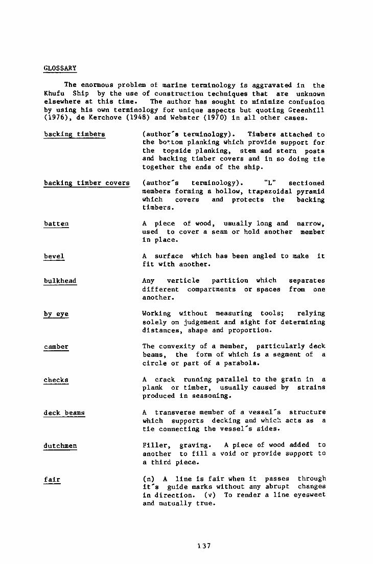
GLOSSARY
The enormous problem of marine terminology is aggravated in the Khufu Ship by the use of construction techniques that are unknown elsewhere at this time. The author has sought to minimize confusion by using his own terminology for unique aspects but quoting Greenhill (1976), de Kerchove (1948) and Webster (1970) in all other cases.
backing timbers (author's terminology). Timbers attached to the bottom planking which provide support for the topside planking, stem and stern posts and backing timber covers and in so doing tie together the ends of the ship.
backing timber covers (author's terminology). "L" sectioned members forming a hollow, trapezoidal pyramid which covers and protects the backing timbers.
batten A piece of wood, usually long and narrow, used to cover a seam or hold another member in place.
bevel A surface which has been angled to make it fit with another.
bulkhead Any verticle partition which separates different compartments or spaces from one another.
by eye
camber
checks
Working without measuring tools; relying solely on judgement and sight for determining distances, shape and proportion.
The convexity of a member, particularly deck beams, the form of which is a segment of a circle or part of a parabola.
A crack running parallel to the grain in a plank or timber, usually caused by strains produced in seasoning.
deck beams A transverse member of a vessel's structure which supports decking and which acts as a tie connecting the vessel's sides.
dutchmen Filler, graving. A piece of wood added to another to fill a void or provide support to a third piece.
fair (n) A line is fair when it passes through it's guide marks without any abrupt changes in direction, (v) To render a line eyesweet and mutually true.
137
fairing spline A narrow, clear of defects, straight member sprung to a curve in order to identify uneven sections of a line or timber.
frame
garboard
hold
keel batten
marline spike
mast partner
moulds
pillars
plank
rabbet
rocker
scarf
sheer
sheer strake
shell construction
A transverse member (usually made up of more than one piece of timber, but not in the Khufu Ship) extending from side to side and set against the planking.
The strake next to the keel or bottom edge plank.
The space(s) below deck designated for storage of cargo.
A member set longitudinally atop the keel timber to provide additional strength or backing surface.
A pointed tool used by seamen to separate strands of rope or as a lever when putting on seizings, marlings, etc.
Framing fitted in apertures of the deck for the support of masts.
Transverse wooden patterns taking their shape from the body plan or other calculations.
A long slender vertical member used to support another, horizontal member.
A component of a strake that is not all in one piece.
A groove or channel worked in a member to accept another, without a lip being formed.
The fore and aft curvature of the keel or bottom planks.
A tapered or wedge shaped joint between pieces of similar section at the joint.
The curve of the upper edge of the hull.
The top strake of planking.
A method of boatbuilding in which the shell (i.e. the watertight envelope of ends, bottom and planking) is built or partly built before the frames or other internal strengthening members are fitted.
138
skeleton construction A method of boatbuilding in which the framework of stems, keel and frames (or ribs) is first erected or partly erected. This skeleton is then clothed in a 'skin' of planking. Skeleton and shell construction merge into one another with the use of intermediate methods of uncertain age.
slash sawn A method of sawing up logs in which the longitudinal cuts are made parallel to one another through the entire diameter.
Spanish windlass A simple rope and rod device in which the rod twists the rope upon itself forcing two elements closer together and holding them there.
spine In the Khufu Ship, the central longitudinal girder running under the deck beams. The restorer referred to it as the "colonne vertebrae", and Landstrom surmises that the "spine" mentioned in The Book of the Dead and interpreted by Boreux (1924, p. 26) as a keel could likely be this central supporting member.
stagger Not placed in the same line or on the same grain, alternating in transverse position.
stanchion An upright post used as a support for another member, shorter and fatter usually than a pillar (which see).
stealer A tapered plank or plate worked into the entry or run of a vessel to preserve the general lie of the strakes without making the ends too thick or thin.
stem post In the Khufu Ship, the papyriform timber mortised and tenoned to the backing timber covers which forms the highest part of the bow.
stern post Same as "stem post" but at the extreme aft of the Khufu Ship.
stringer A fore and aft strengthening member, rectangular in section, often used at the turn of the bilge and sheer.