Leadership Crisis and the Emerging Resurgence of Military in African Politics
Upload
independentCategory
view
1download
0
The role of extensional structures on experimental calderasand resurgence
V. Acocella a;�, R. Funiciello a, E. Marotta b, G. Orsi b, S. de Vita b
a Dip. Scienze Geologiche Universita Roma TRE, Largo S.L. Murialdo, 1-00146 Roma, Italyb Osservatorio Vesuviano, Via Diocleziano, 328, 80124, Napoli, Italy
Received 1 July 2002; accepted 14 February 2003
Abstract
The structure and shape of collapses and resurgences is often controlled by pre-existing discontinuities, such asnormal faults in rift zones. In order to study the role of extensional structures on collapse and resurgence, we usedanalogue models. Dry sand simulated the brittle crust; silicone, located at the base of the sand-pack, simulatedmagma. In the experiments, regional extension pre-dated collapse or resurgence, forming normal faults in a graben-like structure; the graben was filled with additional sand, simulating post-rift deposits. A piston then moved thesilicone downward or upward, inducing collapse or resurgence within the previously deformed sand. The collapsesshowed an ellipticity (length of minor axis/length of major axis) between 0.8 and 0.9, with the major axis parallel tothe extension direction. The partial reactivation of the pre-existing normal faults was observed during thedevelopment of the caldera reverse faults, which, conversely to what was expected (from experiments without pre-existing extension), became partly inward dipping. Resurgence showed an elongation of the uplifted part, with themain axis perpendicular to the extension direction. At depth, pre-existing normal faults were partly reactivated by thereverse faults formed during resurgence; these locally became outward dipping normal faults. A total reactivation ofpre-existing faults was also observed during resurgence. The experiments suggest that the observed elongation ofcalderas and resurgences is the result of the reactivation of pre-existing structures during differential uplift. Such areactivation is mainly related to the loss in the coefficient of friction of the sand. The results suggest that ellipticcalderas and resurgences in nature may develop even from circular magma chambers.5 2003 Elsevier B.V. All rights reserved.
Keywords: extensional structures; caldera; resurgence; analogue models; reactivation
1. Introduction
Collapse calderas and resurgent domes are
common features in volcanic systems and havebeen classically interpreted in the light of an evo-lution characterised by regional tumescence, ma-jor eruption and caldera collapse and intra-caldera resurgent doming (Smith and Bailey,1968; Henry and Price, 1984; Newhall and Dzur-isin, 1988). Calderas and domes are commonlyrelated to in£ation^de£ation processes inside mag-ma chambers (Smith and Bailey, 1968; Lipman,
0377-0273 / 03 / $ ^ see front matter 5 2003 Elsevier B.V. All rights reserved.doi:10.1016/S0377-0273(03)00240-3
* Corresponding author. Fax: +39-06-54888201.E-mail addresses: [email protected] (V. Acocella),
[email protected] (R. Funiciello), [email protected](E. Marotta), [email protected] (G. Orsi), [email protected](S. de Vita).
VOLGEO 2677 20-11-03
Journal of Volcanology and Geothermal Research 129 (2004) 199^217
R
Available online at www.sciencedirect.com
www.elsevier.com/locate/jvolgeores

1984; Newhall and Dzurisin, 1988; Lipman,1997).
Calderas have been related to the removal ofmagma from the chamber (Williams, 1941; Smith,1979; Druitt and Sparks, 1984; Scandone, 1990;Lipman, 1997), to the excess of magma pressurein sill-like chambers (Komuro, 1987; Gudmunds-son, 1988; Gudmundsson et al., 1997; Gud-mundsson, 1998), or to the weight of underlyingintrusions (Walker, 1988). Resurgence consists ofthe uplift of part of a volcanic system, due to theascent of silicic magma (Smith and Bailey, 1968;Lipman, 1984; Marsh, 1984). Resurgence mayform resurgent blocks (Civetta et al., 1988; Orsiet al., 1991; Acocella and Funiciello, 1999) ordomes (Bailey et al., 1976; Lipman, 1984; Selfet al., 1986) depending upon the aspect ratio(width/thickness) of the crust overlying the mag-ma chamber; resurgent blocks form for aspectratios V1, whereas domes form for aspect ratiosV0.4 (Acocella et al., 2001a).
The structure of calderas and resurgences hasbeen recently investigated through analogue mod-els (Marti et al., 1994; Kennedy et al., 1999; Aco-cella et al., 2000; Roche et al., 2000; Acocella etal., 2001a; Acocella et al., 2001b; Walter andTroll, 2001; Troll et al., 2002). These experimentsshow similar structures : high angle reverse faultsborder calderas and resurgences, whereas normalfaults form subsequently. The reverse faults arethe structural boundaries of calderas and resur-gences, mechanically consistent with a di¡erentialuplift ; conversely, the normal faults are a result ofthe gravitational collapse induced by the reversefaults (e.g. Acocella et al., 2000, and referencestherein).
Despite the observed similar deformation pat-tern, these models were the result of a near-¢eldstress, induced by the intrusion, and did not takeinto account the role of far-¢eld (i.e. regional)stresses. These may, in fact, induce signi¢cant de-viations from the observed patterns in di¡erentways: through pre-existing regional structures (in-herited strain), which may in£uence the propaga-tion of the stresses or also be reactivated duringcollapse and resurgence; through the direct con-trol of the regional stresses (simultaneous stress)during collapse and resurgence. As most of the
resurgences and calderas are located in extension-al settings, extensional tectonics is the most rep-resentative far-¢eld stress to consider for any sim-ulation. Examples of calderas and resurgences indi¡erent (intraplate rift, oceanic ridge, continentalrift) extensional settings are reported in Fig. 1.
In order to evaluate the role of pre-existing ex-tensional structures on di¡erential uplifts in vol-canic areas, we performed analogue models. Herewe present the results of the experiments, wherewe consider the role of pre-existing regional exten-sional structures on collapse and resurgence. Thee¡ect of a simultaneous extensional stress on re-surgence was previously investigated (Withjackand Scheiner, 1982), showing fractures resultingfrom the superimposition of a regional and localstress ¢eld. Here we consider the e¡ect of an in-herited extensional strain on collapse and resur-gence, where extension is simulated only before,not during, collapse or resurgence. This fact issupported by the evidence that collapses and re-surgences (strain rates usually between 1035^10312 s31) are much faster than regional tectonics(strain rates usually V10315 s31). We ¢rst de-scribe the e¡ect on collapse, then on resurgenceand ¢nally on the superimposition of resurgenceover collapse. Our results simulate only large (ver-tical displacement from several tens of metres tothousands of metres) collapses or resurgences.However, a detailed comparison with nature isbeyond the scope of this paper and is only brie£yaddressed. The results highlight the reactivationof pre-existing regional normal faults on the de-formation pattern and its role on the ellipticity ofcalderas and resurgences.
2. Experimental procedure
2.1. Scaling
Models have to be geometrically, kinematicallyand dynamically scaled, following the principlesdiscussed by Hubbert (1937) and Ramberg(1981). We chose a length ratio between modeland nature z*= 1035 (1 cm in the model corre-sponds to 1 km in nature; Table 1). The densitiesof natural rocks (2000^2700 kg m33) and of the
VOLGEO 2677 20-11-03
V. Acocella et al. / Journal of Volcanology and Geothermal Research 129 (2004) 199^217200

experimental materials commercially available(900^1800 kg m33) impose a density ratio b*V0.5. Since the models were run at 1 g, the gravityratio g*= 1. These ratios imply that the stressratio between model and nature is b*g*z*V5U1036.
We assumed a Mohr^Coulomb failure criterionfor the rocks in the brittle crust, with an angle ofinternal friction P=30‡ and a mean cohesionc=107 Pa. Cohesion, having the dimensions of astress, must be scaled at approximately 5U1036 inthe experiments; this requires the use of material
with c=50 Pa to simulate the brittle crust. Forthis purpose, we used well sorted, round grain,dry quartzose sand, with P=37‡ and cohesion offew hundreds of Pa; its rheological properties anduse as analogue material are discussed in Krantz(1991) and Schellart (2000).
The simulation of magma has to take the vis-cosities, the related strain rates and timescalesinto account. Newtonian silicone putty, with vis-cosity V104 Pa s, simulated the ductile behaviourof magma (Weijermars et al., 1993; Merle andVendeville, 1995; Donnadieu and Merle, 1998;
Fig. 1. Examples of calderas and resurgences in extensional settings. (a) Sketch of the Long Valley caldera and resurgent dome,California, on the western side of the Basin and Range extensional Province (modi¢ed after Goldstein and Stein, 1988). (b) Struc-tural map of Pantelleria island, located along the Rift in the Straits of Sicily (Italy), showing a resurgent caldera (modi¢ed afterCivetta et al., 1988). (c) Structural map of the Kra£a caldera, within the oceanic rift of Iceland (modi¢ed after Opheim and Gud-mundsson, 1989).
VOLGEO 2677 20-11-03
V. Acocella et al. / Journal of Volcanology and Geothermal Research 129 (2004) 199^217 201

Hailermariam and Mulugeta, 1998; Merle, 1998).Magma viscosities vary widely, even within a verylimited range of temperatures (Talbot, 1999). Thecorresponding wide range of viscosity ratios be-tween model and nature are listed in Table 1; fora given viscosity and the imposed stress ratio, therelated strain rate, timescale and velocity ratiosare shown.
The extent to which the experimental results areapplicable is limited by current knowledge of suchnatural parameters as viscosities, timescales andstrain rates. Given the possible range of these val-ues in nature, a single experiment might be asso-ciated with di¡erent equivalents in nature, char-acterised by di¡erent viscosities, timescales andstrain rates (Table 1). The aim of the experimentsis thus not to simulate speci¢c cases; the goal israther to understand the overall mechanism ofdeformation, which might be valid for a widerange of natural cases.
2.2. Experimental apparatus
The experimental apparatus consists of threeparts: a cylinder with a piston inside, connectedto an engine; a table, with a hole in correspon-dence with the circular (diameter D=5 cm) nozzleof the underlying cylinder; a sliding plate abovethe table, attached to a vertical wall connected toa second engine (Fig. 2). Silicone, intended tosimulate a magmatic body at depth, ¢lls the cyl-
inder up to the level of the table. Horizontallayers of sand, intended to simulate the brittlecrust overlying a magma chamber, are placedpartly on the sliding plate, partly on the table.
Extension is ¢rst induced in the sand-pack.Pulling the plate with the engine outwards inducesin fact a velocity discontinuity (VD) at the edge ofthe sliding plate; this is responsible for the devel-opment of extensional structures within the sand-pack. The VD induced extension throughout thesand above the silicone. Additional horizontallayers of sand are placed at intervals (correspond-ing to 1 cm of extension) within the depressionformed by the migrating VD in order to simulatesyn-rift deposits and provide a horizontal topog-raphy before collapse or resurgence, in order tostudy the deformation process without topo-graphic controls.
After extending the sand-pack, the extensionengine is switched o¡ and collapse or resurgenceis simulated with the downward or upward move-ment of the piston within the cylinder. This in-duces the respective fall and rise of silicone andfurther deforms the overlying sand-pack. The pur-pose of the experiments is to study the deforma-tion pattern induced by the vertical movement ofthe silicone within a pre-fractured sand-packunder a previous regional extension.
We tested the role of the following ¢ve param-eters (Fig. 2) : (1) the thickness (T) of the sand-pack (between 3 and 7 cm), (2) the total amount
Table 1Scaling procedure adopted in the experimentsBrittle behaviour
Length ratio Gravity ratio Density ratio Stress ratio
L*=Lmod/Lnat = 1035 g*= 1 b*= 0.5 c*=b*g*L*= 5U1036
Ductile behaviour
Natural viscosity (W) Viscosity ratio (W*) Strain rate ratio Time ratio Velocity ratio Natural velocity(Pa s) Wmod = 104 Pa s e*=c*/W* t*= 1/e* v*= e*L* Vnat =m/h
104 1 5U1036 2U105 5U10311 1U108
107 1033 5U1033 2U102 5U1038 1U105
1011 1037 5U101 2U1032 5U1034 1U101
1015 10311 5U105 2U1036 5 1U1033
1018 10314 5U108 2U1039 5U103 1U1036
The scaling for the brittle crust imposes the use of cohesionless sand as analogue material. Newtonian silicone putty has beenused to simulate magma. The table provides the simulated viscosity, strain rate, timescale and velocity ratios between models andnature.
VOLGEO 2677 20-11-03
V. Acocella et al. / Journal of Volcanology and Geothermal Research 129 (2004) 199^217202

Fig. 2. Section view of the experimental apparatus. Silicone putty is placed inside the cylinder. Extension, controlled by the out-ward sliding of a mobile table above a plate, induces normal faults within the sand-pack. The extensional zone (graben) is ¢lledwith sand. The downward or upward movement of the piston generates collapse or resurgence in the sand-pack. Inset shows anoblique view of the sliding VD, responsible for the nucleation of normal faults: extension is measured in cm from the initial posi-tion of the VD with regard to the right rim of the nozzle.
Table 2Main imposed parameters and observed features for calderas and resurgences
Experiment Imposed parameters Observed features
Collapse T Extension Duration (min) Eccentricity Reactivated structures
(cm) (cm) test tcol
CALTEC 3 5 7 0 84 168 0.88M 0.04 1CALTEC 4 7 7 0 90 161 0.85M 0.06 1CALTEC 5 5 5.3 0 60 157 0.80M 0.04 2CALTEC 6 5 5.3 0 63 63 0.81M 0.02 2CALTEC 7 5 5.2 1.5 63 65 0.90M 0.05 1CALTEC 8 5 5.2 1.5 62 186 0.90M 0.07 1CALTEC 11 5 5 0 64 180 0.81M 0.06 2CALTEC 12 5 1.3 4 18 187 0.90M 0.06 1
Resurgence T Extension Duration (min) Eccentricity Reactivated structures
(cm) (cm) test tres
CALTEC 9 5 5 0 54 191 0.89M 0.04 1 (vertical fault)CALTEC 10 3 3 0 64 183 1M 0.06 0 (inward dipping fault)CALTEC 13 5 1.3 4 15 240 0.83M 0.05 1 (outward dipping fault)
In the ‘extension’ column, the left line refers to the total amount of extension and the right line to the distance of the VD fromthe right edge of the nozzle at the onset of extension.
VOLGEO 2677 20-11-03
V. Acocella et al. / Journal of Volcanology and Geothermal Research 129 (2004) 199^217 203

of regional extension (i.e. the amount of sliding ofthe mobile wall ; between 1.3 and 7 cm), (3) thelocation of the VD with regard to the circularnozzle at the base of the sand-pack (in cm, start-ing from the right rim of the nozzle, as in Fig. 2),(4) the time of collapse (tcol), and (5) the time ofresurgence (tres). Extension velocity was V50 mmh31. The sand-pack alone was extended and ex-tension did not a¡ect the underlying silicone. Col-lapse and resurgence velocities were V5 mm h31
and running times were between 60 and 250 min.Three sets of experiments were performed (Ta-
ble 2). In the ¢rst set, the downward movement ofthe piston simulated collapse in the upper crustafter regional extension. In the second, upwardmovement simulated resurgence after regional ex-tension. In the third, the superimposition of resur-gence over collapse after regional extension wasstudied. At the end of the experiments, additionalsand was placed onto the model surface and thenleveled, in order to preserve topography. Themodel was then saturated with water and cutinto cross sections.
3. Experimental results
3.1. Set 1: extension and collapse
The ¢rst set of (eight) experiments simulatescollapse calderas within a sand-pack with exten-sional structures ; here we describe two represen-tative experiments (CALTEC 3 and CALTEC 5).
Experiment CALTEC 3 has T=5 cm, total du-ration of extension (from the onset of the exten-sion to the o¡set of extension) text = 84P (min), foran extension of 7 cm, the initial position of theVD at the right rim of the 5-cm-wide nozzle andthe total duration of collapse (from the o¡set ofextension to the o¡set of collapse) tcol = 168P (Fig.3). The ¢rst stage of deformation was character-ised by extension. This, at textV15P, formed two-opposite verging normal faults nucleated alongthe VD; The normal fault nucleated from theVD above the sliding plate and dipping towardsthe table is called ‘synthetic’, whereas we term thenormal fault nucleated from the VD above thetable and dipping towards the sliding plane ‘anti-
thetic’ (Fig. 3a). These faults bordered a lineardepression, a graben-like structure, located abovethe VD. Increasing the extension induced the fur-ther development of the synthetic fault, attachedto the VD, while a new antithetic fault formed,along the migrating VD, at constant intervalsevery V1 cm of extension; as a consequence ofthe migration of the VD, the previous antitheticnormal fault became locked (Fig. 3b). Furtherextension increased the displacement on the syn-thetic fault and formed additional antithetic nor-mal faults, following the migration of the VD(Fig. 3c); the dip of these faults is 57‡ M 5‡.
This experiment was characterised by 7 cm ofextension; in this way, the area above the nozzle,which will subsequently be a¡ected by collapse,was completely pre-fractured. A section of this¢nal stage of extension in CALTEC 3 is shownin Fig. 3d. The resulting graben had the syntheticnormal fault accommodating all the deformationon one side and 6 antithetic normal faults accom-modating extension on the opposite side; thesenormal faults are here termed as ‘regional faults’.The graben is then ¢lled with sand.
Once the extending engine was stopped, thecollapse engine started. As a result of the down-ward movement of the piston, silicone sank withinthe cylinder. The map view of CALTEC 3 attcol = 40P shows a V4-cm-wide depression (Fig.3e), with an eccentricity E=Lmin/Lmax (whereLmin is the length of the minor axis of the ellipseand Lmax is the length of the major axis) = 0.88M0.04; the major axis of the ellipse is parallel to theextension direction. The further sink of the sili-cone forms an outer concentric depression start-ing at tcolV120P. The ¢nal stage of deformation(tcol = 170P), beyond which no signi¢cant variationof the deformation pattern is observed, shows afully developed outermost depression (Fig. 3f);although its right side partly follows a straightpath (arrow in Fig. 3f), this depression is subcir-cular.
The section of the experiment, parallel to theextension direction and in correspondence withthe diameter of the caldera, is shown in Fig. 3g.The correct evaluation of the deformation patternin Fig. 3g was made through the comparison withsections from analogue models of calderas with-
VOLGEO 2677 20-11-03
V. Acocella et al. / Journal of Volcanology and Geothermal Research 129 (2004) 199^217204

Fig. 3. Evolution of collapse experiment CALTEC 3. (a^d) Extension (section view) due to the outward migration of the VDgenerates an asymmetric graben, with 1 synthetic and several (the number depends upon the amount of extension) antithetic nor-mal faults. The graben is ¢lled with sand. (e^f) Collapse stages (map view): development of a ¢rst elliptic depression (e) and of asecond concentric circular depression (f); the arrow in (f) shows the straight path of a portion of the outer depression. (g) Sec-tion view of the ¢nal stage of deformation. (h) Line drawing of section in (g); the numbers refer to the order of development ofthe faults, the arrows to their kinematics. Inset shows the reactivation of pre-existing normal faults by the reverse fault borderingthe caldera.
VOLGEO 2677 20-11-03
V. Acocella et al. / Journal of Volcanology and Geothermal Research 129 (2004) 199^217 205

out pre-existing structures on a very similar appa-ratus (Acocella et al., 2000) and the graben sec-tion in Fig. 3d. The comparison permitted to con-sider all the information necessary for theunivocal interpretation of the cross sections ofthese experiments.
This procedure resulted in the line drawing inFig. 3h. Here the caldera faults (dashed) are dis-tinguished by the regional faults (solid lines). Thegraben, bordered by normal faults (numbers inFig. 3h refer to their order of development) isdissected by the collapse structures. These aretwo concentric ring faults; the inner (faults 7) isa reverse ring fault, associated with the ellipticdepression; the outer (faults 8) is a normal ringfault, associated with the circular depression. Pre-
vious caldera experiments showed that both thering faults nucleated at the VD at the rim of thenozzle and then propagated upwards; in particu-lar the reverse faults were outward dipping andthe normal faults subvertical to inward dipping(Acocella et al., 2000). The pair of faults 7a and8a (Fig. 3h) does not show any evident reactiva-tion of the pre-formed regional normal faults.Conversely, the pair of ring faults 7b and 8b, astangent in strike to fault 1, shows a partial reac-tivation (see inset in Fig. 3h) of the pre-existingnormal fault 1. The reactivation is shown by themoderate outward propagation (inward dip) ofthe reverse fault 7b (Fig. 3h), which follows (forV0.5 cm), in its bottom part, the path of theregional fault 1. Inward dipping normal fault 8b
Fig. 4. Collapse experiment CALTEC 5. (a) Map view of the ¢nal stage of deformation. (b) Section view parallel to the exten-sion direction. (c) Line drawing of the section, showing the reactivation of two normal faults during the development of the re-verse ring fault, which is partly inward dipping. Reactivation occurs where the reverse fault strikes tangent to the regional faults.(d) Section view perpendicular to the extension direction; reactivation does not occur where regional faults are transverse to thereverse ring fault, which is outward dipping.
VOLGEO 2677 20-11-03
V. Acocella et al. / Journal of Volcanology and Geothermal Research 129 (2004) 199^217206

also reactivates, during collapse, pre-existing nor-mal fault 3 at surface (Fig. 3h); this reactivationexplains the partial straight path of the right partof the outer depression (see arrow in Fig. 3f).
A better example of reactivation is shown in thesection view of CALTEC 5 (Fig. 4), with T=5cm, text = 60P, for a total extension of 5 cm, theinitial position of the VD at the left rim of the 5-cm-wide nozzle and tcol = 157P. The evolution ofthis experiment is similar to that of CALTEC 3.The ¢nal stage of deformation shows two concen-tric depressions (Fig. 4a); the innermost hasE=0.80M 0.04 (Fig. 4a), the outermost is circular.Fig. 4b shows the section along the diameter ofthe caldera, parallel to the extension direction; thecorresponding line drawing is shown in Fig. 4c:the reverse 6 and normal 7 ring faults dissect thegraben (normal faults 1 to 5). The VD was herestopped, after 5 cm of extension, at the left rim ofthe nozzle; as a result, the synthetic normal faultis located at the rim of the nozzle.
The reverse ring fault 6 reactivates for V1 cmthe regional faults 1 and 2 (Fig. 4c). This is shownby the outward propagation (inward dip) of thebottom of the reverse faults, following the pathsof the tangent (along strike) and pre-existing in-ward-dipping normal faults (Fig. 4c). No reacti-vation is observed along a section perpendicularto the extension direction (section CD in Fig. 4d);the reverse fault, perpendicular to the pre-existingregional normal faults, is here constantly outwarddipping.
Even though we tested di¡erent parameters, thecollapse experiments are consistent with a similarevolution, which is characterised by an inner el-liptic depression and an outer circular depression.The major axis of the elliptic depression is alwaysparallel to the extension direction. The ellipticityof the depressions varies as a function of the num-ber of reactivated faults (see Table 2); E is smaller(V0.8, as in CALTEC 5) when the reverse ringfault reactivates two tangent regional faults atopposite sides of the nozzle rim; E is larger(V0.9, as in CALTEC 3) when the ring faultreactivates 1 regional fault. The reactivation ofthe regional faults occurs only if these are veryclose (6 3 mm) to the rim of the nozzle, that iswhere the reverse faults propagate.
3.2. Set 2: extension and resurgence
The second set simulates resurgence throughthe rise of the silicone. Here we present the resultsof 3 signi¢cant experiments (CALTEC 9, CAL-TEC 13, CALTEC 10), having di¡erent T/D ra-tios (between the thickness of the sand and thediameter of the nozzle). The T/D ratio is in factconsidered a crucial parameter in controlling re-surgence modalities (Acocella et al., 2001a).
Experiment CALTEC 9 has T/D=1, text = 54P,total extension of 4.5 cm, the initial position ofthe VD at 0.5 cm to the left of the right rim of thenozzle and the total duration of resurgencetres = 191P (Fig. 5). The model extended for 4.5cm, until the VD reached the opposite rim ofthe nozzle; this resulted in the formation of anasymmetric graben, bordered by 1 synthetic and5 antithetic normal faults (Fig. 5a). After ¢llingthe graben with sand, the model underwent resur-gence. A broad uplift formed at tres = 60P (Fig.5b). This is better developed at tres = 120P (Fig.5c), where the uplifted area attains an ellipticshape, with E=0.89M 0.03. The major axis ofthe ellipse is perpendicular to the extension direc-tion (parallel to the regional faults), which is con-verse to what was observed in collapse experi-ments. Two regional faults (4 and 5 in Fig. 5a)on the right part of the resurgent block are reac-tivated during the uplift (arrows in Fig. 5c). In the¢nal stage (tres = 180P) of resurgence, the block isuplifted in portions bordered by three regionalfaults (see arrows in Fig. 5d).
The section view of the model through the di-ameter of the block and parallel to the extensiondirection is shown in Fig. 5e. The correspondingline drawing, obtained matching the section viewsof experimental resurgence without extension(Acocella et al., 2001a) and Fig. 5a, is shown inFig. 5f. Here the regional faults (solid lines) andresurgence faults (dashed lines) are displayed; thenumbers refer to their order of formation. Resur-gence formed a reverse fault (dashed line 6a) andreactivated the pre-existing regional faults. Faults4 and 5 were reactivated as normal faults ; faults3, 2 and (partly) 1 were reactivated as reversefaults (Fig. 5f). In particular, reverse fault 6b,which originated at the nozzle rim, propagated
VOLGEO 2677 20-11-03
V. Acocella et al. / Journal of Volcanology and Geothermal Research 129 (2004) 199^217 207

upwards and met the upper portion of fault 1,then reactivated as a reverse fault.
There is a marked di¡erence in the dip of thereverse faults in Fig. 5f : fault 6a is subvertical,possibly slightly outward dipping (dip V88‡),whereas fault 6b is inward dipping, (dip V65‡).During resurgence, reverse faults without previousextensional structures have a mean dip of 74‡;subvertical reverse faults have never been ob-served (Acocella et al., 2001a).
A more evident case of di¡erence in dip (and
plunge) of the two reverse faults is shown inCALTEC 13 (Fig. 6), with T/D=1, text = 15P, fora total extension of 1.3 cm, the initial position ofthe VD at 4 cm to the left of the right rim of thenozzle and tres = 240P (Fig. 6). Extension here in-duced two opposite verging normal faults (1 inFig. 6a). The synthetic normal fault 1 is locatedat 0.5 cm outside the nozzle rim; the antitheticnormal fault 1 is located in line with the nozzlerim.
The evolution of the resurgence is similar to
Fig. 5. Evolution of resurgence experiment CALTEC 9. (a) Section view after extension. (b) Map view of the early stage of resur-gence. (c) The block becomes elliptical with the axis, perpendicular to the extension direction; arrows point to reactivated region-al faults. (d) The ¢nal stage of deformation of the block shows an inner elliptic part and a subcircular outer uplifted area.(e) Section view of the experiment after resurgence. (f) Line drawing of the section; the numbers refer to the order of develop-ment of the faults, the arrows to their kinematics. The reverse fault bordering the block to the left is subvertical (dip V88‡).
VOLGEO 2677 20-11-03
V. Acocella et al. / Journal of Volcanology and Geothermal Research 129 (2004) 199^217208

CALTEC 9, with an elliptic block (E=0.83M0.05). The section of CALTEC 13 (Fig. 6b) showstwo regional faults (1) and three resurgence faults.Normal fault 2a is partly developed and is relatedto late resurgence, where gravity sliding occurs(Acocella et al., 2001a). The dip and plunge ofthe inward dipping fault 2b is consistent with dif-ferential uplift (Acocella et al., 2001a); however,fault 2c, supposed to be an inward dipping reversefault, is an outward dipping normal fault (dipV75‡).
We now consider experiment CALTEC 10 withT/D=0.6, text = 64P, for a total extension of 5 cm,the initial position of the VD at the right rim ofthe nozzle and tres = 183P (Fig. 7). The sectionview of the graben at the end of extension isshown in Fig. 7a. The VD (and fault 1) is locatedin correspondence with the nozzle rim; the nor-mal fault 6 is located at 0.7 cm from the rim.After resurgence, the ¢nal stage of deformationis shown in Fig. 7b. A dome is formed; two re-gional faults (indicated by arrows) were reacti-vated, bordering an elongated crestal depression,parallel to the VD. The resurgent dome is subcir-cular in map view.
Section view in Fig. 7c shows a similar defor-mation pattern as in CALTEC 9 (Fig. 5). Reversefault 7 has a di¡erent plunge from fault 2c in Fig.6b (slightly inward dipping, dip V80‡). Regionalfaults 6 and 5 were reactivated during resurgenceas reverse and normal faults, respectively, border-ing the crestal depression (Fig. 7c).
Not considering smaller scale perturbations dueto the activity of the faults, the overall shape ofthe rising silicone is domed, with the topmost part
Fig. 7. Evolution of resurgence experiment CALTEC 10.(a) Section view of the experiment after extension. (b) Mapview of the ¢nal stage of resurgence; arrows show the elon-gated crestal depression bordered by regional faults. (c) Sec-tion view of the experiment after resurgence; the overburdenshows a domed structure, as the overall topmost part of therising silicone. The fault bordering the block to the left (7) isreverse and inward dipping (dip V80‡).
Fig. 6. Section view (a) and related line drawing (b) of experiment CALTEC13 after extension and resurgence. The fault border-ing the block to the left (2c) is normal and outward dipping (dip V75‡).
VOLGEO 2677 20-11-03
V. Acocella et al. / Journal of Volcanology and Geothermal Research 129 (2004) 199^217 209
in the centre. The layers in the overburden arealso domed. This is di¡erent from what was ob-served in experiments CALTEC 9 and CALTEC13 (T/D=1), where the overall shape of siliconewas rising at the sides of the block or £at, respec-tively.
3.3. Set 3: extension, collapse and resurgence
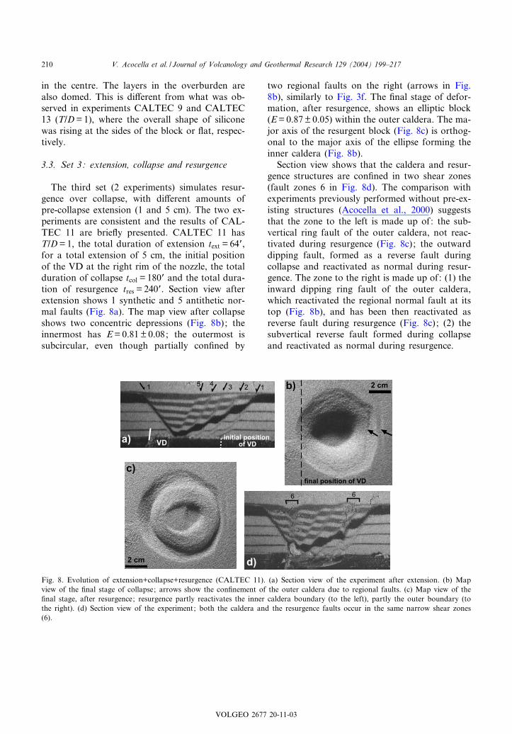
The third set (2 experiments) simulates resur-gence over collapse, with di¡erent amounts ofpre-collapse extension (1 and 5 cm). The two ex-periments are consistent and the results of CAL-TEC 11 are brie£y presented. CALTEC 11 hasT/D=1, the total duration of extension text = 64P,for a total extension of 5 cm, the initial positionof the VD at the right rim of the nozzle, the totalduration of collapse tcol = 180P and the total dura-tion of resurgence tres = 240P. Section view afterextension shows 1 synthetic and 5 antithetic nor-mal faults (Fig. 8a). The map view after collapseshows two concentric depressions (Fig. 8b); theinnermost has E=0.81M 0.08; the outermost issubcircular, even though partially con¢ned by
two regional faults on the right (arrows in Fig.8b), similarly to Fig. 3f. The ¢nal stage of defor-mation, after resurgence, shows an elliptic block(E=0.87M 0.05) within the outer caldera. The ma-jor axis of the resurgent block (Fig. 8c) is orthog-onal to the major axis of the ellipse forming theinner caldera (Fig. 8b).
Section view shows that the caldera and resur-gence structures are con¢ned in two shear zones(fault zones 6 in Fig. 8d). The comparison withexperiments previously performed without pre-ex-isting structures (Acocella et al., 2000) suggeststhat the zone to the left is made up of: the sub-vertical ring fault of the outer caldera, not reac-tivated during resurgence (Fig. 8c); the outwarddipping fault, formed as a reverse fault duringcollapse and reactivated as normal during resur-gence. The zone to the right is made up of: (1) theinward dipping ring fault of the outer caldera,which reactivated the regional normal fault at itstop (Fig. 8b), and has been then reactivated asreverse fault during resurgence (Fig. 8c); (2) thesubvertical reverse fault formed during collapseand reactivated as normal during resurgence.
Fig. 8. Evolution of extension+collapse+resurgence (CALTEC 11). (a) Section view of the experiment after extension. (b) Mapview of the ¢nal stage of collapse; arrows show the con¢nement of the outer caldera due to regional faults. (c) Map view of the¢nal stage, after resurgence; resurgence partly reactivates the inner caldera boundary (to the left), partly the outer boundary (tothe right). (d) Section view of the experiment; both the caldera and the resurgence faults occur in the same narrow shear zones(6).
VOLGEO 2677 20-11-03
V. Acocella et al. / Journal of Volcanology and Geothermal Research 129 (2004) 199^217210

4. Discussion
4.1. Interpretation of the experiments
Collapse over extension showed that, similarlyto collapses without pre-existing extensional struc-tures, a reverse and a normal ring fault formed;their overall evolution and mechanical interpreta-tion were previously discussed (i.e. Acocella et al.,2000). Here we focus on two main novelties re-lated to the regional extension: (1) the inner cal-dera is elliptic, with the major axis parallel to theextension direction (Figs. 3 and 4); (2) duringcollapse, the reverse faults bordering the depres-sion reactivate, becoming slightly inward dipping,the regional normal faults, if these are close(6 0.3 cm). Depending on such a distance, oneor two regional faults along the nozzle rim(Figs. 3h and 4c, respectively) may be reactivated.Experiments without reactivation have not beenobserved. The reactivated regional faults are tan-gent in strike to the reverse ring faults and noreactivation is observed on sections perpendicularto the extension direction (Fig. 4d). The smallereccentricities (EV0.8) are related to the calderaswhere both reverse faults reactivate the regionalnormal faults (Table 2). Conversely, higher eccen-tricities (EV0.9) are related to the reactivation ofonly 1 regional fault. Every reactivated regionalfault induces a decrease in the eccentricity ofV0.1.
We propose that the eccentricity of the innerring fault, which is the structural boundary ofthe collapses, is related to the partial reactivation(with a limited outward propagation of the re-verse faults) of the regional faults during collapse(Fig. 9). As a result, along this direction, the cal-dera gets wider than expected (Fig. 9b). No reac-tivation occurs where the reverse faults are trans-verse to the regional faults. Here the reverse faultsare outward dipping and the caldera is narrower(Fig. 9c). This results in an elliptic caldera at sur-face, parallel to the extension direction. The outercaldera is usually circular, even though it may bepartly shaped on pre-existing normal faults (Figs.3f and 8b).
Resurgence over pre-existing extensional struc-tures showed overall similarities with models
without the extensional structures. In fact, thesame architecture is observed as a function ofthe aspect ratio (height T/width D) of the over-burden. For T/DV1 a resurgent block forms; forT/DV0.6 a resurgent dome forms, similarly towhat was observed in Acocella et al. (2001a).We refer to this work for the interpretation ofthese deformation patterns. The overall shape ofuprising silicone is also partly dependent on the T/D ratio. For lower ratios, the silicone forms adome and its maximum uplift is located in thecentre (Fig. 7), whereas for higher ratios the sili-cone rises more at the sides (Figs. 5 and 6). Thesesimilarities show that pre-existing discontinuitiesdo not a¡ect the overall architecture of resurgentdomes.
The main novelties of the resurgence modelsare: (1) the uplifted parts are elliptic, with themajor axis orthogonal to the extension direction(Figs. 5 and 6); (2) the crestal depression (forexperiments with T/D6 0.6, as in Fig. 7b) is elon-gated (rather than circular) and bordered by re-gional faults ; (3) the faults bordering the upliftedpart, which should be inward dipping (Acocella etal., 2001a), with a reverse displacement, are heresubvertical (Figs. 5 and 6) or even outward dip-ping, with a normal displacement (Fig. 6).
The change in the plunge of the reverse faults(which thus become normal) occurs when theseare near (6 0.3 cm) to an outward dipping re-gional fault. This is, in fact, able to perturb thestress ¢eld of the newly formed reverse fault, in-ducing a change of plunge from inwards to out-wards, forming a normal fault (Fig. 6). On theright side of the uplifted block, resurgence occursforming a reverse fault (if no regional fault ispresent; Fig. 6) or (totally or in part) reactivatinga regional fault (if regional faults were alreadyformed; Fig. 5). Such a reactivation occurs ifthe regional fault is suitably oriented (sameplunge and similar dip) and tangent to the reversefault. Reactivation of the regional faults as nor-mal faults during resurgence has also been ob-served on the faults within the uplifted part(Fig. 5).
Thus, pre-existing regional structures can con-trol the development of the reverse faults border-ing the uplifted part in two ways: (1) if they are
VOLGEO 2677 20-11-03
V. Acocella et al. / Journal of Volcanology and Geothermal Research 129 (2004) 199^217 211

opposite verging, by inducing a change in theplunge of the expected reverse faults, forming nor-mal faults (fault 2c in Fig. 6); (2) if their plunge isconsistent, by the partial or total reactivation ofthe regional faults during the development of thereverse faults (fault 6 in Fig. 5f). Table 2 showsthat the more pronounced elliptic resurgences(smaller eccentricities) are due to the change inplunge of the reverse fault, which becomes a nor-mal fault. The di¡erent plunge of the fault shiftsthe structural boundary of the uplifted part in aninner position, resulting in an elliptic resurgence(Fig. 10). We interpret the ellipticity of the resur-gences as due to the change in the plunge of thereverse fault into a normal fault on one side of the
block. The reactivation of the regional fault as areverse fault (as fault 6b in Fig. 5f) during resur-gence does not signi¢cantly a¡ect the ellipticity ofthe uplifted part.
The experiments regarding resurgence over col-lapse under previous extension show the reactiva-tion of the former caldera faults during resur-gence. Even though the modalities of develop-ment of the caldera faults are partly controlledby the pre-existing regional structures, the modal-ities of reactivation of the caldera faults duringresurgence are identical to the ones observed with-out a regional extension (Acocella et al., 2000).
Both experimental collapse and resurgenceunder previous extension thus showed similar fea-
Fig. 9. (a) Proposed mechanism for the reactivation of regional faults during collapse and for the elongation of the caldera paral-lel to the extension direction. (b) The reverse faults, where tangent in strike to the regional faults, become partly inward dipping,inducing a wider depression on the corresponding parts at surface. (c) No reactivation is observed when the regional faults aretransverse to the reverse faults.
VOLGEO 2677 20-11-03
V. Acocella et al. / Journal of Volcanology and Geothermal Research 129 (2004) 199^217212
tures. Even though with di¡erent modalities, thereverse faults partly reactivated the regional faultsduring di¡erential uplift ; this resulted in ellipticcalderas and resurgences at surface. The normalfaults, which accommodated the deformation in-duced by the reverse faults, did not signi¢cantlya¡ect the shape of the collapses, domes andblocks at surface. This con¢rms that the reversefaults developed during di¡erential uplift are thestructural border of the depressions and upliftedpart (Acocella et al., 2000).
4.2. Modalities of reactivation
The modalities of reactivation of pre-existingnormal faults during collapse and resurgence areschematically shown, for consistent and oppositeplunges with regard to the regional faults, in Fig.11a. The solid line reports the dip in section viewof a regional fault, the dashed line the dip of theexpected normal and reverse faults in collapsesand resurgences without extension (Acocella etal., 2000) and the dotted line shows the dip ofthe observed normal and reverse faults after ex-tension. The mean dip of the regional normal
faults in the experiments is 57‡ M 5‡. The meandips of the reverse faults and normal faults duringcollapse and resurgence (without extension) are74‡ M 10‡ and 78‡ M 7‡, respectively. Regionalfaults thus have lower dips than the expected re-verse and normal faults.
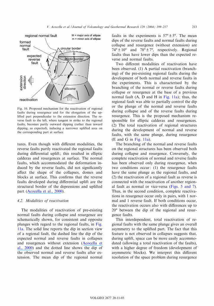
Two di¡erent modalities of reactivation havebeen observed. (1) A partial reactivation (branch-ing) of the pre-existing regional faults during thedevelopment of both normal and reverse faults inthe experiments. This is characterised by thebranching of the normal or reverse faults duringcollapse or resurgence at the base of a previousnormal fault (A, D and H in Fig. 11a); thus, theregional fault was able to partially control the dipor the plunge of the normal and reverse faultsduring collapse and of the reverse faults duringresurgence. This is the proposed mechanism re-sponsible for elliptic calderas and resurgences.(2) The total reactivation of regional structuresduring the development of normal and reversefaults, with the same plunge, during resurgence(E and G in Fig. 11a).
The branching of the normal and reverse faultson the regional structures has been observed bothduring collapse and resurgence. Conversely, thecomplete reactivation of normal and reverse faultshas been observed only during resurgence, whentwo conditions occur: (1) the resurgence faultshave the same plunge as the regional faults, and(2) the reactivation of a regional fault as reverse isconnected with the reactivation of another region-al fault as normal or vice-versa (Figs. 5 and 7).Thus, in the second condition, complete reactiva-tions in resurgence occur only in pairs, with 1 nor-mal and 1 reverse fault. If both conditions occur,the reactivation occurs also with di¡erences up to20‡ between the dip of the regional and resur-gence faults.
This interdependent, total reactivation of re-gional faults with the same plunge gives an overallasymmetry to the uplifted part. The fact that thisfeature is not observed in collapses suggests that,during uplift, space can be more easily accommo-dated (allowing a total reactivation of the faults),with a higher degree of freedom (development ofasymmetric blocks). We interpret this di¡erentresolution of the space problem during resurgence
Fig. 10. Proposed mechanism for the reactivation of regionalfaults during resurgence and for the elongation of the up-lifted part perpendicular to the extension direction. The re-verse fault to the left, where tangent in strike to the regionalfaults, becomes partly outward dipping (rather than inwarddipping, as expected), inducing a narrower uplifted area onthe corresponding part at surface.
VOLGEO 2677 20-11-03
V. Acocella et al. / Journal of Volcanology and Geothermal Research 129 (2004) 199^217 213

and collapse as responsible for the observed dif-ference in the occurrence of branching or totalreactivation modalities.
The observed, total reactivation of the regionalfaults during di¡erential uplift is the result of thelocal decrease in the shear strength d=cW+c,where c is the normal e¡ective stress, W is thestatic coe⁄cient of rock friction (W= tan P, whereP is the angle of internal friction) and c is thecohesion. The decrease in shear strength may be
related to the loss in cohesion c and a drop in thefriction coe⁄cient W. The loss of cohesion, giventhe low cohesion (few hundreds of Pa) of the drysand we used is assumed to be negligible. Thedrop in the friction coe⁄cient W is related to thedecrease of the angle of internal friction P withinthe dilatancy zone created by the fault. The dropin W has been previously observed experimentallyand has been estimated as V30% (Faccenna etal., 1995). Fig. 11b shows the qualitative relation-
Fig. 11. (a) Modalities of reactivation of the pre-existing normal faults during the development of the normal and reverse faultsin collapse and resurgence. Branching is characterised by a common path of the bottom of the regional faults and the calderaand resurgence faults. Conversely, a complete reactivation of the regional faults occurs only during resurgence. (b) SchematicMohr^Coulomb diagram showing the relationships between the intact failure envelope of the used sand and the (complete) reacti-vation envelope: values of the cohesion (cP), angle of internal friction (PP) and c3P vary accordingly.
VOLGEO 2677 20-11-03
V. Acocella et al. / Journal of Volcanology and Geothermal Research 129 (2004) 199^217214

ships between the intact (P=37‡) and the reacti-vated (PP=25‡) envelope in a Mohr^Coulomb di-agram. The di¡erence in shear strength is mostlyattributed to the loss (V30%) in the friction co-e⁄cient and, to a much lesser extent, to the dropin cohesion. In our experiments, the reactivatednormal faults had a dip of 57‡ M 5‡; theoreticalcalculations predict that pre-existing normal faultsdipping less than 50‡ become highly inhibited forreactivation (Sibson, 1985).
4.3. Comparison with nature
A detailed and speci¢c comparison with natureis beyond the purpose of this paper. Here webrie£y address some points of interest for a gen-eral application of our experiments.
As far as calderas are concerned, their ellipticityhas been related to the collapse of an elongatedunderlying magma chamber or post-caldera exten-sion. In the ¢rst case, the minimum regional stress¢eld orientation is responsible for a boreholebreakout mechanism for the elongation of magmachambers parallel to the extension direction (Ken-ya Rift ; Bosworth et al., 2000); alternatively, pre-existing transverse structures, reactivated duringextension, enhance the elongation of magmachambers and thus calderas at surface (EthiopianRift ; Acocella et al., 2002). In the second case, theellipticity of calderas has been explained as a con-sequence of the activity of post-caldera rift faultsand the magma chamber does not necessarilyhave to be elliptic (Fieale volcano, Afar; DeChabalier and Avouac, 1994).
Our experiments suggest a further explanationfor the ellipticity of calderas and show that, be-cause of the reactivation of pre-existing structures,elliptic calderas may develop from circular mag-ma chambers. These results can be applied to el-liptic calderas with moderate (up to few hundredsof metres) subsidence or, in the case of larger (upto thousands of metres) subsidence, only to theinner ring fault system. In fact, in the ¢rst case,only an elliptic ring fault forms (i.e. Fig. 3e). Inthe second case, two ring systems form, but onlythe inner is elliptic (i.e. Fig. 3f).
Even though the assessment of the shape of amagma chamber is essential for an accurate appli-
cation of our experiments, calderas elongated par-allel to the extension direction in narrow riftzones without pre-existing transverse structures(such as on newly-formed oceanic crust) may bethe best candidates for comparison. For example,the oceanic ridge of Iceland is formed on a non-fractured crust and is characterised by calderaswith a moderate subsidence; among these, Torfa-jokull, Kverkfjoll, Oskjuvatn (Askja) and Kra£acalderas are elliptic and elongated parallel to theextension direction (Newhall and Dzurisin, 1988,and references therein; Gudmundsson and Back-strom, 1991). In this framework, our experimentsmay be of interest to understand further the struc-ture of these Icelandic calderas and the role ofregional extension on their development.
As far as resurgence is concerned, analogouslyto what pointed out with calderas, the experi-ments permit to understand the structure of elon-gated resurgences with previous extensional struc-tures. Since resurgence is absent in calderas alongoceanic rift zones, comparison has to be madewith continental rifts, taking into account the pos-sible role of pre-existing transverse structures.Nevertheless, all the major resurgences in conti-nental extensional zones show a con¢nement orelongation of the uplifted area due to regionalstructures, such as at Ischia (Acocella and Funi-ciello, 1999), Campi Flegrei (Orsi et al., 1996), LaPacana (Lindsay et al., 2001) and Cerro Galan(Riller et al., 2001) or the elongation of the crestaldepression, in line with regional systems, such asValles (Nielson and Hulen, 1984; Self et al., 1986)and Long Valley (Bailey et al., 1976; Goldsteinand Stein, 1988).
Moreover, resurgence experiments show that,under regional extension, no continuous reversering fault is required, as this may partly be anormal fault. This means that the space requiredto accommodate the uplift during resurgence maybe created by the activity of a single ring struc-ture, partly reverse and partly normal. This mech-anism ¢nds close similarities with previous pro-posed resurgence mechanisms. In fact, a simpleshear mechanism for resurgence was proposedfor the resurgent blocks of Ischia, Pantelleria(Orsi et al., 1991) and Campi Flegrei (Orsi etal., 1996). According to this model, extension on
VOLGEO 2677 20-11-03
V. Acocella et al. / Journal of Volcanology and Geothermal Research 129 (2004) 199^217 215

one side of the block accommodated compressionon the opposite side. Even though our experi-ments are related to a pure-shear mechanismand do not simulate simple shear (without signi¢-cant internal block rotations), the overall geome-try and kinematics of this model is consistent withour results. Similar models, with subvertical nor-mal faults on one side of the block and normalfaults on the opposite, have also been proposedfor resurgence at Ischia (Tibaldi and Vezzoli,1998; Tibaldi and Vezzoli, 2000).
5. Conclusions
The collapse experiments under previous exten-sion showed inner elliptic depressions with themajor axis parallel to the extension direction.The partial reactivation of the pre-existing normalfaults was observed during the development of thecaldera reverse faults, which partly became in-ward dipping. Resurgence under previous exten-sion also showed a moderate elongation of theuplifted part, with the main axis perpendicularto the extension direction. At depth, pre-existingnormal faults were partly reactivated by the re-verse faults formed during resurgence; these be-came locally outward dipping, with a normalthrow. The experiments suggest that the observedelongation of calderas and resurgences is the re-sult of the reactivation of pre-existing structuresduring a di¡erential uplift. This reactivation re-sulted in elliptic calderas (major axis parallel tothe extension direction) and resurgences (majoraxis perpendicular to the extension direction) atsurface. The results suggest that elliptic calderasand resurgences may develop even with circularmagma chambers.
Acknowledgements
The authors wish to thank F. Cifelli for invalu-able assistance during the run of the experimentsand C. Faccenna for useful suggestions on reac-tivation. The reviewers H. Komuro, O. Rocheand the editor T. Koyaguchi provided useful com-ments and suggestions. The work was carried out
within the GNV framework program (project no.16).
References
Acocella, V., Funiciello, R., 1999. The interaction betweenregional and local tectonics during resurgent doming: Thecase of the island of Ischia, Italy. J. Volcanol. Geotherm.Res. 88, 109^123.
Acocella, V., Cifelli, F., Funiciello, R., 2000. Analogue modelsof collapse calderas and resurgent domes. J. Volcanol. Geo-therm. Res. 104, 81^96.
Acocella, V., Cifelli, F., Funiciello, R., 2001a. The control ofoverburden thickness on resurgent domes: Insights fromanalogue models. J. Volcanol. Geotherm. Res. 111, 137^153.
Acocella, V., Cifelli, F., Funiciello, R., 2001b. Formation andarchitecture of nested collapse calderas: Insights from ana-logue models. Terra Nova 13, 58^63.
Acocella, V., Korme, T., Salvini, F., Funiciello, R., 2002. Thecontrol of transverse tectonics on caldera development in theEthiopian Rift. J. Volcanol. Geotherm. Res. 119, 189^203.
Bailey, R.A., Dalrymple, G.B., Lanphere, M.A., 1976. Volca-nism, structure, and geochronology of Long Valley Caldera,Mono County, California. J. Geophys. Res. 81, 725^744.
Bosworth, W., Burke, K., Strecker, M., 2000. Magma chamberelongation as an indicator of intraplate stress ¢eld orienta-tion: ‘Borehole breakout mechanism’ and examples from theLate Pleistocene to Recent Kenya Rift Valley. In: Jessel,M.W., Urai, J.L. (Eds.), Stress, Strain and Structure, AVolume in Honour of W.D. Means. J. Virtual Explor. 2.
Civetta, L., Cornette, Y., Gillot, P.Y., Orsi, G., 1988. Theeruptive history of Pantelleria (Sicily Channel) in the last50 ka. Bull. Volcanol. 50, 47^57.
De Chabalier, J.B., Avouac, J.P., 1994. Kinematics of the AsalRift (Djibouti) determined from the deformation of FiealeVolcano. Science 265, 1677^1681.
Donnadieu, F., Merle, O., 1998. Experiments on the indenta-tion process during cryptodome intrusions: New insightsinto Mount St. Helens deformation. Geology 26, 79^82.
Druitt, T.H., Sparks, R.S., 1984. On the formation of calderasduring ignimbrite eruptions. Nature 310, 679^681.
Faccenna, C., Nalpas, T., Brun, J.P., Davy, P., Bosi, V., 1995.The in£uence of pre-existing thrust faults on normal faultgeometry in nature and in experiments. J. Struct. Geol. 17,1139^1149.
Goldstein, N.E., Stein, R.S., 1988. What’s new at Long Valley.J. Geophys. Res. 93, 13187^13190.
Gudmundsson, A., 1988. Formation of collapse calderas.Geology 16, 808^810.
Gudmundsson, A., 1998. Formation and development of nor-mal-fault calderas and the initiation of large explosive erup-tions. Bull. Volcanol. 60, 160^170.
Gudmundsson, A., Marti, J., Turon, E., 1997. Stress ¢eldsgenerating ring faults in volcanoes. Geophys. Res. Lett.24, 1559^1562.
VOLGEO 2677 20-11-03
V. Acocella et al. / Journal of Volcanology and Geothermal Research 129 (2004) 199^217216

Gudmundsson, A., Backstrom, K., 1991. Structure and devel-opment of the Sveinagja graben, northeast Iceland. Tecto-nophysics 200, 111^125.
Hailermariam, H., Mulugeta, G., 1998. Temperature-depen-dent rheology of bouncing putties used as rock analogs.Tectonophysics 294, 131^141.
Henry, C.H., Price, J.G., 1984. Variations in caldera develop-ment in the tertiary volcanic ¢eld of Trans-Pecos Texas.J. Geophys. Res. 89, 8765^8786.
Hubbert, M.K., 1937. Theory of scale models as applied to thestudy of geologic structures. Bull. Geol. Soc. Am. 48, 1459^1520.
Kennedy, B., Stix, J., Lavalle¤e, Y., Vallance, J., 1999. Controlson caldera structure and morphology: Results from exper-imental simulations. EOS Trans. Am. Geophys. Union 80,F1121.
Komuro, H., 1987. Experiments on cauldron formation: Apolygonal cauldron and ring fractures. J. Volcanol. Geo-therm. Res. 31, 139^149.
Krantz, R.W., 1991. Measurements of friction coe⁄cients andcohesion for faulting and fault reactivation in laboratorymodels using sand and sand mixtures. In: Cobbold, P.R.(Ed.), Experimental and Numerical Modelling of Continen-tal Deformation. Tectonophysics 188, pp. 203^207.
Lindsay, J.M., de Silva, S., Trumbull, R., Emmermann, R.,Wemmer, K., 2001. La Pacana caldera, N. Chile a re-eval-uation of the stratigraphy and volcanology of one of theworld’s largest resurgent calderas. J. Volcanol. Geotherm.Res. 106, 145^173.
Lipman, P.W., 1984. The roots of ash £ow calderas in WesternNorth America: Windows into the tops of granitic batho-liths. J. Geophys. Res. 89, 8801^8841.
Lipman, P.W., 1997. Subsidence of ash-£ow calderas: Relationto caldera size and magma-chamber geometry. Bull. Volca-nol. 59, 198^218.
Marsh, B.D., 1984. On the mechanics of caldera resurgence.J. Geophys. Res. 89, 8245^8251.
Marti, J., Ablay, G.J., Redshaw, L.T., Sparks, R.S.J., 1994.Experimental studies of collapse calderas. J. Geol. Soc.Lond. 151, 919^929.
Merle, O., 1998. Internal strain within lava £ows from ana-logue modelling. J. Volcanol. Geotherm. Res. 81, 189^206.
Merle, O., Vendeville, B., 1995. Experimental modelling ofthin-skinned shortening around magmatic intrusions. Bull.Volcanol. 57, 33^43.
Newhall, C.G., Dzurisin, D., 1988. Historical Unrest at LargeCalderas of the World. U.S. Geological Survey, 1109 pp.
Nielson, D.L., Hulen, J.B., 1984. Internal geology and evolu-tion of the Redondo Dome, Valles Caldera, New Mexico.J. Geophys. Res. 89, 9695^9711.
Opheim, J.A., Gudmundsson, A., 1989. Formation and geom-etry of fractures and related volcanism of the Kra£a ¢ssureswarm, Northeast Iceland. Geol. Soc. Am. Bull. 101, 1608^1622.
Orsi, G., De Vita, S., di Vito, M., 1996. The restless, resurgentCampi Flegrei nested caldera (Italy): Constrains on its evo-
lution and con¢guration. J. Volcanol. Geotherm. Res. 74,179^214.
Orsi, G., Gallo, G., Zanchi, A., 1991. Simple-shearing blockresurgence in caldera depressions. A model from Pantelleriaand Ischia. J. Volcanol. Geotherm. Res. 47, 1^11.
Ramberg, H., 1981. Gravity, Deformation and the Earth’sCrust, 2nd ed. Academic Press, London, 452 pp.
Riller, U., Petrinovic, I., Ramelow, J., Strecker, M., Oncken,O., 2001. Late Cenozoic tectonism, collapse caldera andplateau formation in the central Andes. Earth Planet. Sci.Lett. 188, 299^311.
Roche, O., Druitt, T.H., Merle, O., 2000. Experimental studyof caldera formation. J. Geophys. Res. 105, 395^416.
Scandone, R., 1990. Chaotic collapse of calderas. J. Volcanol.Geotherm. Res. 42, 285^302.
Schellart, W.P., 2000. Shear test results for cohesion and fric-tion coe⁄cients for di¡erent granular materials: Scaling im-plications for their usage in analogue modelling. Tectono-physics 324, 1^16.
Self, S., Go¡, F., Gardner, J.N., Wright, J.V., Kite, W.M.,1986. Explosive rhyolitic volcanism in the Jemez Mountains:Vent locations, caldera development and relation to regionalstructure. J. Geophys. Res. 91, 1779^1798.
Sibson, R.H., 1985. A note on fault reactivation. J. Struct.Geol. 7, 751^754.
Smith, R.L., 1979. Ash-£ow magmatism. Geol. Soc. Am. Spec.Pap. 180, 5^27.
Smith, R.L., Bailey, R.A., 1968. Resurgent cauldrons. Geol.Soc. Am. Mem. 116, 613^662.
Talbot, C.J., 1999. Can ¢eld data constrain rock viscosities?J. Struct. Geol. 21, 949^957.
Tibaldi, A., Vezzoli, L., 1998. The space problem of calderaresurgence: An example from Ischia Island, Italy. Geol.Rundsch. 87, 53^66.
Tibaldi, A., Vezzoli, L., 2000. Late Quaternary monoclinalfolding induced by caldera resurgence at Ischia, Italy. In:Cosgrove, J.W., Ameen, M.S. (Eds.), Forced Foldsand Fractures. Geol. Soc. Lond. Spec. Publ. 169, pp. 103^113.
Troll, V.R., Walter, T.R., Schmincke, H.U., 2002. Cyclic cal-dera collapse: Piston or piecemeal subsidence? Field andexperimental evidence. Geology 30, 135^138.
Walker, G.P.L., 1988. Three hawaiian calderas: An originthrough loading by shallow intrusions? J. Geophys. Res.93, 14773^14784.
Walter, T.R., Troll, V.R., 2001. Formation of caldera periph-ery faults: An experimental study. Bull. Volcanol. 63, 191^203.
Weijermars, R., Jackson, M.P.A., Vendeville, B., 1993. Rheo-logical and tectonic modeling of salt provinces. Tectonophy-sics 217, 143^174.
Williams, H., 1941. Calderas and their origin. Calif. Univ.Publ. Geol. Sci. Bull. 21, 239^346.
Withjack, M.O., Scheiner, C., 1982. Fault patterns associatedwith domes ^ An experimental and analytical study. AAPGBull. 66, 302^316.
VOLGEO 2677 20-11-03
V. Acocella et al. / Journal of Volcanology and Geothermal Research 129 (2004) 199^217 217
Copyright © 2022 FDOKUMEN