Vehicle Radiators' Performance Calculation and Improvement ...

The relativity of bandwidth – the pursuit of trulyultra wideband radiators for communication
applicationsIoan E. Lager, Leo P. Ligthart, Dani P. Tran, Fatma M. Tanyer-Tigrek, Massimiliano Simeoni, Piet van Genderen
IRCTR, Delft University of Technology Mekelweg 4, 2628 CD Delft, the Netherlands,{d.p.tran,f.m.tanyer-tigrek,m.simeoni,i.e.lager,l.p.ligthart,p.vangenderen}@tudelft.nl
Andrei SzilagyiMilitary Equipment & Technologies Research Agency, Aeroportului Street, No. 16, Bragadiru, 077025,
Jud. Ilfov, Romania, [email protected] I. Coman
NATO Consultation, Command and Control Agency (NC3A), Surveillance & Reconnaissance Resource Centre,2597 AK The Hague, the Netherlands, [email protected]
Abstract—An overview on the design of increasingly widerbandwidth radiators that are amenable to being integrated inarray configurations is presented. The initial step is representedby moderate bandwidth radiator of the cavity backed patchantennas. The bandwidth characteristics are then substantiallyincreased by combining coplanar waveguide (CPW) feedings andprofiled dipoles, the result being radiators with unprecedentedperformances. This type of radiators are further refined forimproving their time-domain adequacy or for ensuring intrinsicfiltering properties.
I. INTRODUCTION
Larger bandwidth is one of the most frequently invokedrequirements in present day radio applications: it is indispens-able for ensuring the needed resolution in radar applicationsand it is, together with increasingly sophisticated protocols, thedriving force behind enhancing the data rate in the communi-cation channels. With reference to the latter, it is worth notingthat the adoption of the First Report and Order by the FederalCommunication Commission (FCC) [1] that permitted thecommercial operation of Ultra Wide Band (UWB) technologyunleashed a research activity of considerable proportions fordeveloping the appropriate means for transforming the UWBtechnology from a high-end utility into a quotidian commodity.
Literally, the FCC defines an antenna as being UWB whenit has a fractional (relative) bandwidth of 20%, this valuebeing 25% in the case of the radar domain [2]. Nevertheless,this (apparently) simple estimator leaves room for severalside notes. Firstly, one must observe that, as resolution anddata rate are systems related features, so should bandwidth
The present article represents a revised version of the publication:D. P. Tran, C. I. Coman, F. M. Tanyer-Tigrek, A. Szilagyi, M. Simeoni,I. E. Lager, L. P. Ligthart and P. van Genderen, “The relativity of bandwidth –the pursuit of truly ultra wideband radiators”, Antennas for ubiquitous radioservices in a wireless information society. Proceedings of the Symposiumconcluding the Wide Band Sparse Element Array Antennas – WiSE project,pp. 55–74, Amsterdam: IOS Press, c© 2010. Reprinted with permission fromIOS Press.
be thought of in relation to the supported system. It thenfollows that, especially in the case of array antennas, aningenious system design may supplement for limitations of theelements constituting it, thus inducing some relativity in theinterpretation of the bandwidth. For example, by assemblingon the same aperture several moderate bandwidth radiatorshaving different, but contiguous, operational bandwidths, thecollective performance of the array will be (ultra) wide band.Furthermore, by restricting the assessment of the radiatorcapabilities to their impedance matching bandwidth (the onethat is accounted for in [2]), the UWB qualifier may turn outto be insufficiently substantiated. The impedance matchingover a certain bandwidth should be complemented over thesame bandwidth by a series of additional features, such asstable radiation characteristics, extremely low group delay,etc. Moreover, when the radiators are to be integrated inarray environments, avoiding the onset of grating lobes makesminiaturization an imperative factor when the arrays are to beoperated over an (ultra) wide bandwidth.
Addressing in a systematic and innovative manner thistype of aspects provided the grounds for the InternationalResearch Centre for Telecommunications and Radar (IRCTR)to initiate in 2004 the Wide Band Sparse Element ArrayAntennas (WiSE) project. One of its two directions of activitywas represented by compiling a catalogue of moderate to(ultra) wide band radiators amenable to being included in(planar) array antennas. This contribution summarizes someof the most notable achievements of this line of research. Tobenign with, Section II discusses a number of cavity backedpatch type radiators. Although they are characterized by amoderate bandwidth (in the range of 10%) these antennasare excellently adapted for being employed in planar arrays.The next step is represented by the presentation in Section IIIof a class of CPW-fed radiators having an omnidirectionalradiation followed, in Section IV, by the introduction of someextremely valuable variants that offer unidirectional radiation.
978-1-4244-6363-3/10/$26.00 c©2010 IEEE 7
The catalogue is completed in Section V by the discussion ofsome multi-frequency radiators. The account will be finalizedby drawing some conclusions.
II. CAVITY BACKED PATCH RADIATORS
The possibilities offered by the cavity backed patch topol-ogy were recognized already in the early stages of the WiSEproject. It should be observed that, although examples ofremarkably wide band radiators of this type are availablein the literature [3], [4], this configuration yields, in gen-eral, a moderate bandwidth. This is the more so the casewhen, in view of ensuring technological reproducibility andcompactness, a stratified, microwave laminate technology isused. Nevertheless, these radiators are extremely well suitedto array environments and posses some interesting features,such as a potentially high polarization purity. Moreover, thetopology lends itself to an accurate numerical modeling using,for example, the boundary-integral, resonant modes expansion(BI-RME) method [5], the application of which to the cavitybacked patch architectures being elaborately discussed in [6].This numerical tool can constitute the computational enginein complex and effective optimization schemes, as discussedin [6], as well.
These favorable properties provided the grounds for anumber of radiators of this type to be designed, manufacturedand physically validated within the WiSE project, both asindividual antennas and integrated in arrays. In the following,a selection of the most representative outcomes of this researchline will be discussed.
A. Cavity backed (stacked) patch antennas – initial experi-ments
The first type of antennas in this class that were devel-oped within the WiSE project concerned probe-fed, circularpatches, possibly with an additional parasitic patch, the genericconfiguration for the latter, more complex, variant being shownin Fig. 1. The geometrical parameters of the radiator weresubject to grid-search optimization strategies for enhancingthe operational bandwidth in the targeted X frequency band.This notoriously computation time consuming operation wasgreatly reduced by resorting to an accurate, semi-analyticapproach combining the BI-RME and mode-matching methodswith a Generalized Admittance description of the completechain consisting from the succession of the various waveguidesections that can be recognized in Fig. 1 (a) (see [6], [7]for a detailed description of this formalism). This procedureallowed designing a number of moderate band elementaryantennas. A particularly relevant design referred to a pair ofantennas having the operational bandwidths1 7.9 ÷ 8.4 GHzand 8.6÷9.3 GHz, respectively. These antennas were initially,tested as individual radiators and, subsequently, integrated in anon-periodic, shared aperture, planar array containing 31 and32 elements of the two kinds, respectively [7].
1All operational bandwidths quoted in this work are defined with respectto a VSWR � 2 condition, with VSWR denoting the Voltage Standing WaveRatio.
a
b
aWG
bWG
x
y
z
rin
rout
rp1
rp2
dyc
a
b
bWG
hc
rp1
rp2
dyc
h1
h2
h3
hm
hm
hm
x y
z
b
Fig. 1. The configuration concerning the double patch antenna. (a) Top view;(b) axial cross-section.
The array antenna experiments provided a clear evidenceof the high level of isolation between the elements ensuredby the cavity enclosure. In this sense, the measured reflectioncoefficient plots in Fig. 2 is characterized by a high degreeof uniformity of this parameter for elements embedded in ahighly non-uniform array environment. This behavior couldonly be obtained when the individual radiators were wellisolated from each other, an effect that can only be attributedto the employed cavities.
The experience gained in this phase of the project laid thebasis for developing a coplete family of such radiators, as willbe shown below. All hereafter discussed radiators share the twomain benefits already attested by the configuration shown inFig. 1: a superior inter-element separation and a remarkableease of manufacturing due to the use of vias for emulatingthe cavity enclosure. Additionally, some of the radiators willalso benefit from another advantage of the embedded patchconfiguration, namely from the fact that the aperture radiationensures a higher polarization purity.
B. High polarization purity cavity backed patch antennas
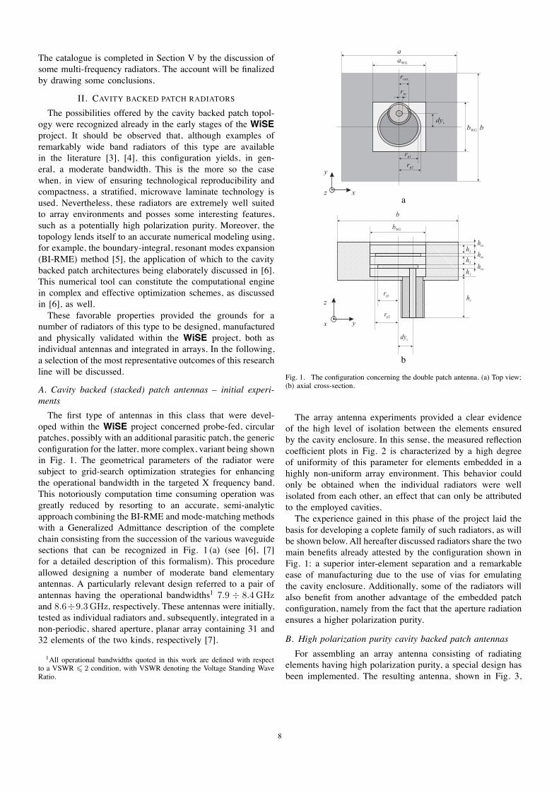
For assembling an array antenna consisting of radiatingelements having high polarization purity, a special design hasbeen implemented. The resulting antenna, shown in Fig. 3,
8
f (GHz)
elem
ent
index
(iL)
7 7.5 8 8.5 9 9.5 10 5
10
15
20
25
30
−20
−15 VSWR=1
VSWR=2
−5
0
a
f (GHz)
elem
ent
index
(iH)
7 7.5 8 8.5 9 9.5 10 5
10
15
20
25
30
−20
−15 VSWR=1
VSWR=2
−5
0
b
Fig. 2. The frequency dependence of the simulated active reflection coef-ficient for each elementary radiator in the two sub-arrays; the solid contoursindicate the levels corresponding to VSWR=2 and VSWR=1.5, respectively.(a) Performance of the sub-array SAL operating in the 7.9÷ 8.4GHz band-width; (b) performance of the sub-array SAH operating in the 8.6÷9.3GHzbandwidth.
consists of a cavity embedded microstrip patch which isradiating through a rectangular slot. This particular geometrywas selected in order to provide a good inter-element isolationbetween neighboring elements in the array environment, thisfeature being provided, as already indicated, by the cavityenclosure of the antenna. As before, the metallic walls areemulated by rows of equally-spaced metal plated throughholes. The antenna is fed from the rear so to enable compactarray arrangements. The elongated shape of the radiatingslot provides high polarization purity to the radiated field.The antenna is manufactured with standard multilayer printedcircuit board technology.
C. The cavity-backed slotted-patch antenna
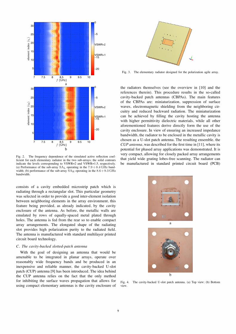
With the goal of designing an antenna that would beamenable to be integrated in planar arrays, operate overreasonably wide frequency bands and be produced in aninexpensive and reliable manner, the cavity-backed U-slotpatch (CUP) antenna [9] has been introduced. The idea behindthe CUP antenna relies on the fact that the only methodfor inhibiting the surface waves propagation that allows forusing compact elementary antennas is the cavity enclosure of
Fig. 3. The elementary radiator designed for the polarization agile array.
the radiators themselves (see the overview in [10] and thereferences therein). This procedure results in the so-calledcavity-backed patch antennas (CBPAs). The main featuresof the CBPAs are: miniaturization, suppression of surfacewaves, electromagnetic shielding from the neighboring cir-cuitry and reduced backward radiation. The miniaturizationcan be achieved by filling the cavity hosting the antennawith higher permittivity dielectric materials, while all otheraforementioned features derive directly form the use of thecavity enclosure. In view of ensuring an increased impedancebandwidth, the radiator to be enclosed in the metallic cavity ischosen as a U-slot patch antenna. The resulting ensemble, theCUP antenna, was described for the first time in [11], where itspotential for phased array applications was demonstrated. It isvery compact, allowing for closely packed array arrangementsthat yield wide grating lobes-free scanning. The radiator canbe manufactured in standard printed circuit board (PCB)
b
a
Fig. 4. The cavity-backed U-slot patch antenna. (a) Top view; (b) Bottomview.
9

8 8.5 9 9.5 10 10.5 11 11.5 12−25
−20
−15
−10
−5
0
frequency [GHz]
[dB
]
|Γ| measurements|Γ| simulations
Fig. 5. Simulated and measured return loss concerning the cavity-backedslotted-patch antenna.
technology from a single microwave laminate, this ensuringits economical and accurate production [12]. The experimentalprototype designed at IRCTR, displayed in Fig. 4, has bulkdimensions of about half a wavelength at the operationalfrequency of 10 GHz and exhibits a matching bandwidth ofabout 10% at the expense of a poor cross-polarization level(about -10 dB below the co-polar component) for observationangles away from the boresight direction (see Fig. 5).
III. CPW FED OMNIDIRECTIONAL UWB RADIATORS
The WiSE project set itself the task of developing antennasensuring a 50% system operational bandwidth. In this respect,the radiators described in Section II offer a bandwidth ofonly around 10%. While preliminary studies demonstrated thatsuch radiators may be assembled in arrays that meet the 50%bandwidth requirement, the resulting architecture turned outto be very complex and to have a relatively low gain andinsufficient aperture efficiency. Consequently, the explorationsturned towards developing truly UWB elements that coulddirectly yield the aimed at operational bandwidth.
A strategic choice for achieving this goal was opting for aCoplanar Waveguide (CPW) feeding. A first type of antennasin this category is characterized by an omnidirectional radia-tion pattern. In the following, this type will be exemplified bymeans of two representative radiators referred to as the ‘Eared’and the ‘Tulip’ loop antennas.
A. The ‘Eared’ antenna
A physical implementation of the ‘Eared’ antenna is shownin Fig. 6. The device is etched on a commercially availableRogers Rogers RT/duroid R© 5870 [13] high frequency laminatewith a relative permittivity εr = 2.33 at an operating frequencyof f0 = 9 GHz. The maximum linear dimension of thisdevice, denoted as Lmax in Fig. 6, amounts to 12 mm. Theradiator consists of several sections the effects of which onthe antenna performance being investigated in detail in [14],[15]. The feeding sections were extended in order to facilitatethe measurement of the device’s matching and radiation char-acteristics. The simulated and measured return loss frequencydependencies are presented in Fig. 7, with the simulated
Lmax
Fig. 6. The ‘Eared’ antenna.
results predicting an operational bandwidth of 150% stretchingbetween 6.5 GHz and 45 GHz. Note that the measurementswere limited by the operational bandwidth of the employedconnector. The antenna has omnidirectional radiation patternswith low cross-polar components (i.e. −25 dB at the desingfrequency) [14], [15].
5 7 9 11 13 15 17 19 21 23 25 27 29 31 33 35 37 39 41 43 45−40
−35
−30
−25
−20
−15
−10
−5
VSWR=2
VSWR=1.5
frequency [GHz]
retu
rn lo
ss [d
B]
simulationmeasurement
Fig. 7. Simulated and measured return loss frequency dependencies con-cerning ‘Eared’ antenna.
The initial ‘Eared’ antenna was re-engineered for making itsuitable to Impulse Radio applications, the targetted frequencyrange stretching, in that case, between 3.1 and 10.6 GHz.That variant was shown to have an impedance bandwidth of169%, between 2.7 and 33 GHz. The Impulse Radio variantwas also subject to a time domain performance assessment,
x
y
zO
Fig. 8. Linear array of 15 ‘Eared’ antennas.
10

the measured results evidencing remarkably low group delayvariations that were below 4 ns up to 10 GHz [16].
Fig. 9. Frequency and scanning angle dependencies of the (combined) arrayreflection coefficient magnitude.
Since, as mentioned in Section I, the aim of the WiSEproject was to assess the performance of the designed radiatorsin array environments, two linear arrays composed of 7and 15 ‘Eared’ antenna were manufactured, the latter devicebeing presented in Fig. 8. The frequency and scanning angledependences of the (combined) array reflection coefficientmagnitude which are presented in Fig. 9 attest that the lineararray has an operational bandwidth of 61%, between 8 GHzand 15 GHz. Furthermore, an excellent impedance matchingwas obtained for scanning angles between ϑ0 = 0◦ andϑ0 = 60◦ over the whole frequency band, with ϑ0 measuringthe tilting from the Oz axis in the {y = 0} − plane.
Lmax
Fig. 10. The ‘Tulip’ loop antenna.
B. The ‘Tulip’ loop antenna
The second CPW fed antenna developed within WiSEwas the so-called ‘Tulip’ loop antenna, a sample of which
4 5 6 7 8 9 10 11 12 13 14 15 16−40
−35
−30
−25
−20
−15
−10
−5
0
VSWR=2
VSWR=1.5
frequency [GHz]
retu
rn lo
ss [d
B]
simulationmeasurement
Fig. 11. Simulated and measured return loss frequency dependenciesconcerning the ‘Tulip’ loop antenna.
being shown in Fig. 10. The device is manufactured from thecommercially available Rogers Rogers RO/duroid R© 4003 highfrequency laminate [17], with a relative permittivity εr = 3.55at an operating frequency of f0 = 10 GHz. The radiation isensured by the loop and the tuning stub inside it controls theimpedance matching of the antenna. The maximum dimensionof the antenna, denoted by Lmax in Fig. 10, is 11 mm. Thefeed sections were again extended due to the reasons alreadydiscussed in Section III-A. The frequency characteristic ofthe magnitude of the reflection coefficient of the antennais presented in Fig. 11, the measured result indicating anoperational bandwidth of 70%, stretching between 7.2 GHzand 15 GHz. Similarly to the case of the ‘Eared’ antenna, the‘Tulip’ loop antenna has an omnidirectional radiation pattern(see [18]).
x
y
zO
Fig. 12. Linear array of CPW fed, printed, loop antennas.
For investigating the array performance of the ‘Tulip’ loopantenna, a linear array consisting of 4 such elements was man-ufactured, the device being illustrated in Fig. 12. The feedingsections of the individual radiators were separated by rows ofequi-spaced slots in order to mitigate the strong coupling that
11
was evidenced by the initial numerical experiments effectuatedon this type of arrays [19]. The frequency and scanning angledependencies of the (combined) array reflection coefficientmagnitude are presented in Fig. 13. Except for a small regioncorresponding to scanning angles ϑ0 � 60◦ (ϑ0 measuringthe tilting from the Oz axis in the {y = 0} − plane) andfrequencies f � 13.6 GHz, the array performance satisfiesthe VSWR � 2 condition by a large margin. An elaboratediscussion on the measured performance of this array antennais given in [20].
Fig. 13. Frequency and scanning angle dependencies of the (combined) arrayreflection coefficient magnitude for the array shown in Fig. 12.
IV. CPW-FED UNIDIRECTIONAL ANTENNAS
The CPW-fed antennas presented in Section III have clearlydemonstrated UWB capabilities. Nevertheless, these devicesare all characterized by omnidirectional radiation patterns, afeature that induces certain limitations for both incorporatingthem in (planar) arrays and for using them in hand-heldcommunication devices. An intense effort was then invested inobtaining CPW-fed radiators that maintain their UWB proper-ties even when a backing ground plane is added. The results ofthis research activity is illustrated by two remarkable devices,the so-called ‘diapason’ and ‘dispersion-free’ antennas that arehereafter analyzed.
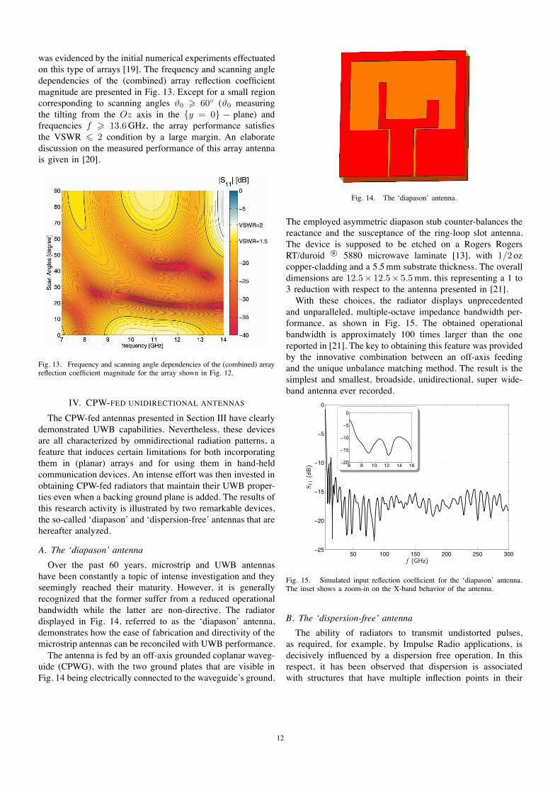
A. The ‘diapason’ antenna
Over the past 60 years, microstrip and UWB antennashave been constantly a topic of intense investigation and theyseemingly reached their maturity. However, it is generallyrecognized that the former suffer from a reduced operationalbandwidth while the latter are non-directive. The radiatordisplayed in Fig. 14, referred to as the ‘diapason’ antenna,demonstrates how the ease of fabrication and directivity of themicrostrip antennas can be reconciled with UWB performance.
The antenna is fed by an off-axis grounded coplanar waveg-uide (CPWG), with the two ground plates that are visible inFig. 14 being electrically connected to the waveguide’s ground.
Fig. 14. The ‘diapason’ antenna.
The employed asymmetric diapason stub counter-balances thereactance and the susceptance of the ring-loop slot antenna.The device is supposed to be etched on a Rogers RogersRT/duroid R© 5880 microwave laminate [13], with 1/2 ozcopper-cladding and a 5.5 mm substrate thickness. The overalldimensions are 12.5× 12.5× 5.5 mm, this representing a 1 to3 reduction with respect to the antenna presented in [21].
With these choices, the radiator displays unprecedentedand unparalleled, multiple-octave impedance bandwidth per-formance, as shown in Fig. 15. The obtained operationalbandwidth is approximately 100 times larger than the onereported in [21]. The key to obtaining this feature was providedby the innovative combination between an off-axis feedingand the unique unbalance matching method. The result is thesimplest and smallest, broadside, unidirectional, super wide-band antenna ever recorded.
50 100 150 200 250 300−25
−20
−15
−10
−5
0
f (GHz)
S11
(dB) 6 8 10 12 14 16
−20
−15
−10
−5
0
Fig. 15. Simulated input reflection coefficient for the ‘diapason’ antenna.The inset shows a zoom-in on the X-band behavior of the antenna.
B. The ‘dispersion-free’ antenna
The ability of radiators to transmit undistorted pulses,as required, for example, by Impulse Radio applications, isdecisively influenced by a dispersion free operation. In thisrespect, it has been observed that dispersion is associatedwith structures that have multiple inflection points in their
12

frequency characteristics. By succeeding to circumvent thisshortcoming, IRCTR managed to devise a radiator that ischaracterized by both extremely low dispersion and UWBimpedance matching characteristics. This device, termed asthe ‘dispersion-free’ antenna, is depicted in Fig. 16.
Fig. 16. The ‘dispersion-free’ antenna.
The radiator consists of a grounded substrate having apatch and a ring etched on its top side. As was the casewith the ‘diapason’ antenna, the patch is fed by a CPWG,with the ring being grounded. The structure is kept smallfor allowing for susceptance matching in the higher segmentof the operational frequency band. The notches in the patchphysically force the currents to flow along longer paths,making the patch (virtually) longer; this makes it possibleto neutralize the reactance in the lower end of the frequencybandwidth. The stubs at the upper-side of the grounded ringare extruded down to form capacitive gaps that provide pathsfor the flow of the displacement currents. In this manner, moredegrees of freedom are created for tuning the antenna at lowerfrequencies. To conclude with, the carves at the feeding point(the ‘neck’) of the patch allow a smooth CPWG to patchtransition. More details on the design and working principlesof this radiator can be found in [22], that article discussing afirst previous version of the ‘dispersion-free’ antenna.
The frequency characteristics of the ‘dispersion-free’ an-tenna are presented in Fig. 17. The plots demonstrate aremarkably wide and flat impedance bandwidth and, at thesame time, an extremely low group delay behavior. In bothrespects, the presently discussed device evidences clearlysuperior performances to those of the radiator reported in [22].
V. MULTI-FREQUENCY ANTENNAS
A particularly interesting feature to be implemented ina radiator is ensuring controllable filtering properties, theresult being sometimes referred to as a ‘filt-antenna’. Thistype of devices turned out to be extremely adequate forthe WiSE DEMO4
2 demonstrator, a concrete instantiationof the concept being represented by the UWB antenna fortactical radio-location and navigation (RAD-NAV) shown in
2DEMO4 demonstrator: a complex, wearable receive antenna system for aMETRA defined application.
6 7 8 9 10 11 12 13 141
1.25
1.5
1.75
2
f (GHz)
VSW
R
a
6 7 8 9 10 11 12 13 140.1
0.15
0.2
0.25
0.3
0.35
f (GHz)
Gro
up
delay
(ns)
b
Fig. 17. Frequency characteristics of the ‘dispersion-free’ antenna. (a) VSWRanalysis; (b) group delay analysis.
Fig. 18. Through its embedded filtering capabilities, this devicesafeguards the following frequency bands:
• the fixed and mobile satellite RAD-NAV bands L1
through L5;• the industrial, scientific and medical (ISM) ISM2.5G and
ISM5.8G radio bands as defined by the Radio commu-nication sector of the International TelecommunicationUnion (ITU-R);
• the complete FCC unlicensed UWB band (3.1 up to10.6 GHz).
a b
Fig. 18. The ‘RAD-NAV’ antenna. (a) Front side; (b) back side.
The antenna architecture consists of two identical, semi-elliptic patches that are anti-simetrically placed on the twosides of a dielectric slab. The lower patch acts as a groundplane while the upper one, fed by means of a microstripline, represents the radiating element. Several notched shapesare etched away from the radiator for matching and/or fil-tering purposes. The antenna is manufactured from a RogersRogers RT/duroid R© 5880 microwave laminate [13], with
13
1/2 oz copper-cladding and a 0.787 mm substrate thickness,the overall dimensions being 60 × 60 × 0.787 mm. Note thatthe design can be easily scaled up and down for accommo-dating the stringent requirements pertaining to the DEMO4
demonstrator.
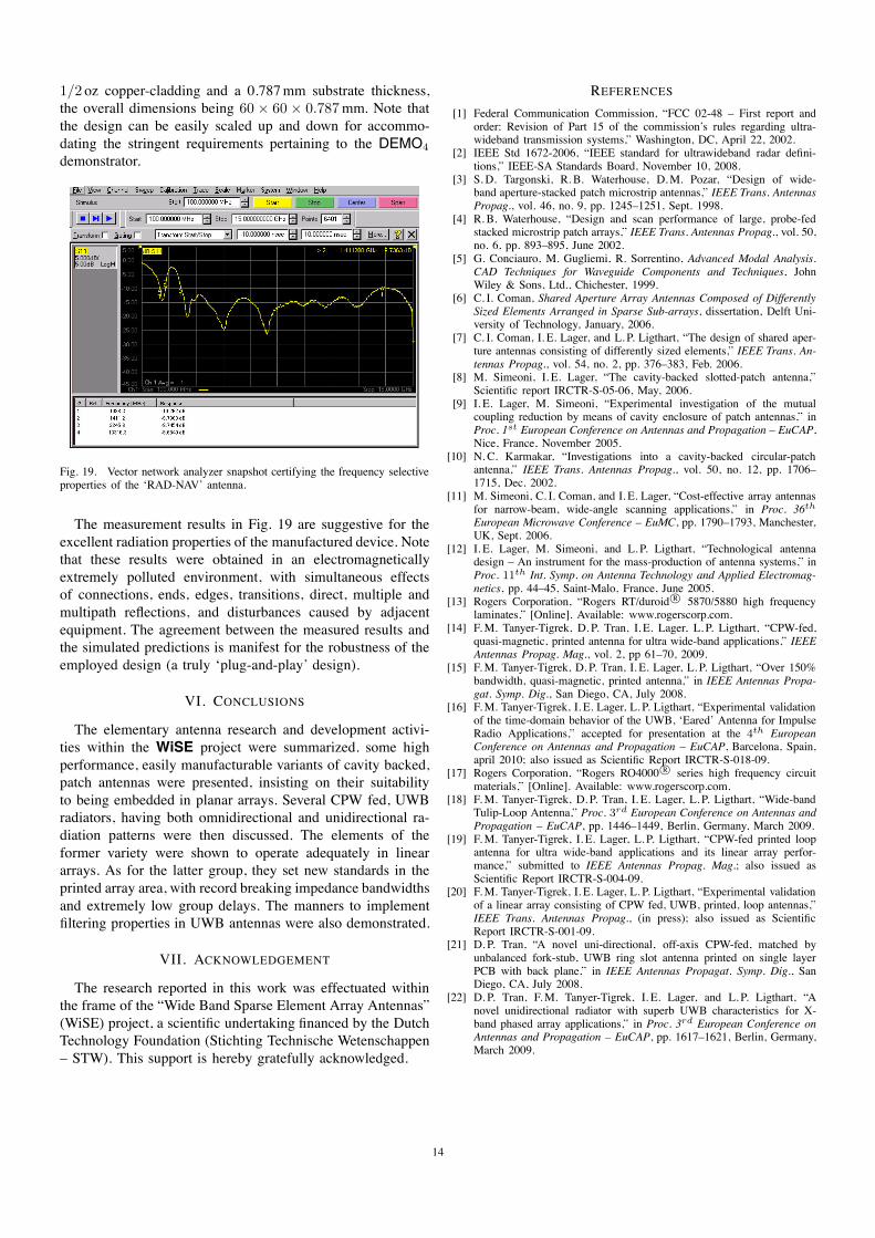
Fig. 19. Vector network analyzer snapshot certifying the frequency selectiveproperties of the ‘RAD-NAV’ antenna.
The measurement results in Fig. 19 are suggestive for theexcellent radiation properties of the manufactured device. Notethat these results were obtained in an electromagneticallyextremely polluted environment, with simultaneous effectsof connections, ends, edges, transitions, direct, multiple andmultipath reflections, and disturbances caused by adjacentequipment. The agreement between the measured results andthe simulated predictions is manifest for the robustness of theemployed design (a truly ‘plug-and-play’ design).
VI. CONCLUSIONS
The elementary antenna research and development activi-ties within the WiSE project were summarized. some highperformance, easily manufacturable variants of cavity backed,patch antennas were presented, insisting on their suitabilityto being embedded in planar arrays. Several CPW fed, UWBradiators, having both omnidirectional and unidirectional ra-diation patterns were then discussed. The elements of theformer variety were shown to operate adequately in lineararrays. As for the latter group, they set new standards in theprinted array area, with record breaking impedance bandwidthsand extremely low group delays. The manners to implementfiltering properties in UWB antennas were also demonstrated.
VII. ACKNOWLEDGEMENT
The research reported in this work was effectuated withinthe frame of the “Wide Band Sparse Element Array Antennas”(WiSE) project, a scientific undertaking financed by the DutchTechnology Foundation (Stichting Technische Wetenschappen– STW). This support is hereby gratefully acknowledged.
REFERENCES
[1] Federal Communication Commission, “FCC 02-48 – First report andorder: Revision of Part 15 of the commission’s rules regarding ultra-wideband transmission systems,” Washington, DC, April 22, 2002.
[2] IEEE Std 1672-2006, “IEEE standard for ultrawideband radar defini-tions,” IEEE-SA Standards Board, November 10, 2008.
[3] S. D. Targonski, R. B. Waterhouse, D. M. Pozar, “Design of wide-band aperture-stacked patch microstrip antennas,” IEEE Trans. AntennasPropag., vol. 46, no. 9, pp. 1245–1251, Sept. 1998.
[4] R. B. Waterhouse, “Design and scan performance of large, probe-fedstacked microstrip patch arrays,” IEEE Trans. Antennas Propag., vol. 50,no. 6, pp. 893–895, June 2002.
[5] G. Conciauro, M. Gugliemi, R. Sorrentino, Advanced Modal Analysis.CAD Techniques for Waveguide Components and Techniques, JohnWiley & Sons, Ltd., Chichester, 1999.
[6] C. I. Coman, Shared Aperture Array Antennas Composed of DifferentlySized Elements Arranged in Sparse Sub-arrays, dissertation, Delft Uni-versity of Technology, January, 2006.
[7] C. I. Coman, I. E. Lager, and L. P. Ligthart, “The design of shared aper-ture antennas consisting of differently sized elements,” IEEE Trans. An-tennas Propag., vol. 54, no. 2, pp. 376–383, Feb. 2006.
[8] M. Simeoni, I. E. Lager, “The cavity-backed slotted-patch antenna,”Scientific report IRCTR-S-05-06, May, 2006.
[9] I. E. Lager, M. Simeoni, “Experimental investigation of the mutualcoupling reduction by means of cavity enclosure of patch antennas,” inProc. 1st European Conference on Antennas and Propagation – EuCAP,Nice, France, November 2005.
[10] N. C. Karmakar, “Investigations into a cavity-backed circular-patchantenna,” IEEE Trans. Antennas Propag., vol. 50, no. 12, pp. 1706–1715, Dec. 2002.
[11] M. Simeoni, C. I. Coman, and I. E. Lager, “Cost-effective array antennasfor narrow-beam, wide-angle scanning applications,” in Proc. 36th
European Microwave Conference – EuMC, pp. 1790–1793, Manchester,UK, Sept. 2006.
[12] I. E. Lager, M. Simeoni, and L. P. Ligthart, “Technological antennadesign – An instrument for the mass-production of antenna systems,” inProc. 11th Int. Symp. on Antenna Technology and Applied Electromag-netics, pp. 44–45, Saint-Malo, France, June 2005.
[13] Rogers Corporation, “Rogers RT/duroid R© 5870/5880 high frequencylaminates,” [Online]. Available: www.rogerscorp.com.
[14] F. M. Tanyer-Tigrek, D. P. Tran, I. E. Lager, L. P. Ligthart, “CPW-fed,quasi-magnetic, printed antenna for ultra wide-band applications,” IEEEAntennas Propag. Mag., vol. 2, pp 61–70, 2009.
[15] F. M. Tanyer-Tigrek, D. P. Tran, I. E. Lager, L. P. Ligthart, “Over 150%bandwidth, quasi-magnetic, printed antenna,” in IEEE Antennas Propa-gat. Symp. Dig., San Diego, CA, July 2008.
[16] F. M. Tanyer-Tigrek, I. E. Lager, L. P. Ligthart, “Experimental validationof the time-domain behavior of the UWB, ‘Eared’ Antenna for ImpulseRadio Applications,” accepted for presentation at the 4th EuropeanConference on Antennas and Propagation – EuCAP, Barcelona, Spain,april 2010; also issued as Scientific Report IRCTR-S-018-09.
[17] Rogers Corporation, “Rogers RO4000 R© series high frequency circuitmaterials,” [Online]. Available: www.rogerscorp.com.
[18] F. M. Tanyer-Tigrek, D. P. Tran, I. E. Lager, L. P. Ligthart, “Wide-bandTulip-Loop Antenna,” Proc. 3rd European Conference on Antennas andPropagation – EuCAP, pp. 1446–1449, Berlin, Germany, March 2009.
[19] F. M. Tanyer-Tigrek, I. E. Lager, L. P. Ligthart, “CPW-fed printed loopantenna for ultra wide-band applications and its linear array perfor-mance,” submitted to IEEE Antennas Propag. Mag.; also issued asScientific Report IRCTR-S-004-09.
[20] F. M. Tanyer-Tigrek, I. E. Lager, L. P. Ligthart, “Experimental validationof a linear array consisting of CPW fed, UWB, printed, loop antennas,”IEEE Trans. Antennas Propag., (in press); also issued as ScientificReport IRCTR-S-001-09.
[21] D. P. Tran, “A novel uni-directional, off-axis CPW-fed, matched byunbalanced fork-stub, UWB ring slot antenna printed on single layerPCB with back plane,” in IEEE Antennas Propagat. Symp. Dig., SanDiego, CA, July 2008.
[22] D. P. Tran, F. M. Tanyer-Tigrek, I. E. Lager, and L. P. Ligthart, “Anovel unidirectional radiator with superb UWB characteristics for X-band phased array applications,” in Proc. 3rd European Conference onAntennas and Propagation – EuCAP, pp. 1617–1621, Berlin, Germany,March 2009.
14
Copyright © 2022 FDOKUMEN