
Russian amateur critics reviews: Case of the movie "Vysotsky"
Upload
khangminh22Category
view
0download
0
THE MOVIE | | US009839390B2
( 12 ) United States Patent Stein et al .
( 10 ) Patent No . : US 9 , 839 , 390 B2 ( 45 ) Date of Patent : Dec . 12 , 2017
( 54 ) PROSTHETIC COMPONENT HAVING A COMPLIANT SURFACE
( 71 ) Applicant : Orthosensor Inc , Dania Beach , FL ( US )
( 58 ) Field of Classification Search CPC . . . . . A61B 5 / 1036 ; A61B 5 / 686 ; A61B 5 / 6878 ;
A61B 5 / 6885 ; A61B 5 / 0031 ( Continued )
( 56 ) References Cited U . S . PATENT DOCUMENTS ( 72 ) Inventors : Marc Stein , Chandler , AZ ( US ) ;
Andrew Chase , Chandler , AZ ( US ) 3 , 727 , 616 A 4 , 066 , 082 A ( 73 ) Assignee : Orthosensor Inc . , Dania Beach , FL
( US )
4 / 1973 Lenzkes 1 / 1978 Arcan et al . ( Continued )
( * ) Notice : FOREIGN PATENT DOCUMENTS Subject to any disclaimer , the term of this patent is extended or adjusted under 35 U . S . C . 154 ( b ) by 150 days . WO W O 2007126917 A2 * 11 / 2007 . . . . . . . . . . A61F 2 / 4684
OTHER PUBLICATIONS ( 21 ) Appl . No . : 14 / 154 , 011
( 22 ) Filed : Jan . 13 , 2014
( 65 ) Prior Publication Data US 2014 / 0135655 A1 May 15 , 2014
( 63 ) Related U . S . Application Data
Continuation of application No . 13 / 406 , 512 , filed on Feb . 27 , 2012 , now Pat . No . 8 , 661 , 893 , which is a
( Continued )
International Search Report for PCT / US2012 / 056689 dated Feb . 25 , 2013 , 4 pages .
( Continued ) Primary Examiner — Lisa Caputo Assistant Examiner — Roger Hernandez - Prewitt ( 57 ) ABSTRACT A prosthetic component suitable for long - term implantation is provided . The prosthetic component measures a parameter of the muscular - skeletal system is disclosed . The prosthetic component comprises a first structure having at least one support surface , a second structure having at least one feature configured to couple to bone , and at least one sensor . The prosthetic component is a housing for the at least one sensor and electronic circuitry . The electronic circuitry is hermetically sealed from an external environment . The at least one sensor couples to the support surface of the first structure . The support surface of the first structure is com pliant . The first and second structure are coupled together housing the at least one sensor and electronic circuitry .
17 Claims , 26 Drawing Sheets
( 51 ) Int . CI . A61B 5 / 22 ( 2006 . 01 ) A63B 21 / 00 ( 2006 . 01 )
( Continued ) ( 52 ) U . S . CI .
CPC . . . . . . . . . . A61B 5 / 4528 ( 2013 . 01 ) ; A61B 5 / 0031 ( 2013 . 01 ) ; A61B 5 / 076 ( 2013 . 01 ) :
( Continued )
2712 - 2706
, 2710
2714 27202
27003
- 2722 2704 2708 s / 2704 2708 2716 Iloco
2718
2702 2702 M 2702 2724

US 9 , 839 , 390 B2 Page 2
Related U . S . Application Data continuation - in - part of application No . 12 / 825 , 852 , filed on Jun . 29 , 2010 , now Pat . No . 8 , 146 , 422 .
( 60 ) Provisional application No . 61 / 221 , 767 , filed on Jun . 30 , 2009 , provisional application No . 61 / 221 , 779 , filed on Jun . 30 , 2009 , provisional application No . 61 / 221 , 788 , filed on Jun . 30 , 2009 , provisional application No . 61 / 221 , 793 , filed on Jun . 30 , 2009 , provisional application No . 61 / 221 , 801 , filed on Jun . 30 , 2009 , provisional application No . 61 / 221 , 808 , filed on Jun . 30 , 2009 , provisional application No . 61 / 221 , 817 , filed on Jun . 30 , 2009 , provisional application No . 61 / 221 , 867 , filed on Jun . 30 , 2009 , provisional application No . 61 / 221 , 874 , filed on Jun . 30 , 2009 , provisional application No . 61 / 221 , 879 , filed on Jun . 30 , 2009 , provisional application No . 61 / 221 , 881 , filed on Jun . 30 , 2009 , provisional application No . 61 / 221 , 886 , filed on Jun . 30 , 2009 , provisional application No . 61 / 221 , 889 , filed on Jun . 30 , 2009 , provisional application No . 61 / 221 , 894 , filed on Jun . 30 , 2009 , provisional application No . 61 / 221 , 901 , filed on Jun . 30 , 2009 , provisional application No . 61 / 221 , 909 , filed on Jun . 30 , 2009 , provisional application No . 61 / 221 , 916 , filed on Jun . 30 , 2009 , provisional application No . 61 / 221 , 923 , filed on Jun . 30 , 2009 , provisional application No . 61 / 221 , 929 , filed on Jun . 30 , 2009 .
( 51 )
4 , 857 , 893 A 8 / 1989 Carrol 4 , 864 , 463 A 9 / 1989 Shkedi et al . 4 , 899 , 761 A 2 / 1990 Brown et al . 4 , 902 , 958 A 2 / 1990 Cook , II 4 , 920 , 279 A 4 / 1990 Charlet et al . 4 , 986 , 281 A 1 / 1991 Preves et al . 5 , 042 , 489 A 8 / 1991 Weiner et al . 5 , 119 , 676 A 6 / 1992 Bower et al . 5 , 197 , 488 A * 3 / 1993 Kovacevic . . . . . . . . . . . . . A61B 19 / 46
600 / 587 5 , 447 , 076 A * 9 / 1995 Ziegler . . . . . . . . . . . . . . . GOIL 1 / 142
73 / 862 . 625 5 , 470 , 354 A 11 / 1995 Hershberger et al . 5 , 650 , 571 A 7 / 1997 Freud et al . 5 , 683 , 396 A 11 / 1997 Tokish et al . 5 , 688 , 279 A 11 / 1997 McNulty et al . 5 , 733 , 292 A 3 / 1998 Gustilo et al . 5 , 871 , 018 A 2 / 1999 Delp et al . 5 , 900 , 592 A 5 / 1999 Sohns et al . 6 , 070 , 469 A 6 / 2000 Taniguchi et al . 6 , 072 , 784 A 6 / 2000 Agrawal et al . 6 , 165 , 142 A 12 / 2000 Bar 6 , 245 , 109 B1 6 / 2001 Mendes et al . 6 , 425 , 920 B1 7 / 2002 Hamada 6 , 429 , 585 B1 8 / 2002 Kitazume et al . 6 , 443 , 891 B1 9 / 2002 Grevious 6 , 447 , 448 B1 9 / 2002 Ishikawa et al . 6 , 583 , 630 B2 6 / 2003 Mendes et al . 6 , 621 , 278 B2 9 / 2003 Ariav 6 , 739 , 068 B1 5 / 2004 Rinner 6 , 796 , 988 B2 9 / 2004 Melkent et al . 6 , 856 , 141 B2 2 / 2005 Ariav 6 , 993 , 393 B2 1 / 2006 Von Arx et al . 7 , 035 , 077 B2 4 / 2006 Brendel 7 , 080 , 554 B2 7 / 2006 Ariav et al . 7 , 097 , 662 B2 8 / 2006 Evans , III et al . 7 , 153 , 281 B2 12 / 2006 Holmes 7 , 173 , 749 B2 2 / 2007 Maleki et al . 7 , 195 , 645 B2 3 / 2007 Disilvestro et al . 7 , 195 , 654 B2 3 / 2007 Jackson et al . 7 , 215 , 599 B2 5 / 2007 Nishimori et al . 7 , 283 , 867 B2 10 / 2007 Strother et al . 7 , 291 , 540 B2 * 11 / 2007 Mech . . . . . . . . . . . . . . . . HO1L 21 / 76251
257 / E21 . 567 7 , 347 , 817 B2 3 / 2008 Glukhovsky et al . 7 , 378 , 916 B2 5 / 2008 Oita et al . 7 , 384 , 403 B2 6 / 2008 Sherman 7 , 396 , 336 B2 7 / 2008 Orszulak et al . 7 , 412 , 897 B2 8 / 2008 Crottet et al . 7 , 442 , 196 B2 10 / 2008 Fisher et al . 7 , 454 , 972 B2 11 / 2008 Heyman et al . 7 , 477 , 926 B2 1 / 2009 McCombs 7 , 519 , 422 B2 4 / 2009 Lippert et al . 7 , 559 , 951 B2 7 / 2009 DiSilvestro et al . 7 , 575 , 602 B2 8 / 2009 Amirouche et al . 7 , 578 , 821 B2 8 / 2009 Fisher et al . 7 , 615 , 055 B2 11 / 2009 DiSilvestro 7 , 630 , 774 B2 12 / 2009 Karni et al . 7 , 632 , 283 B2 12 / 2009 Heldreth
B2 2 / 2010 Sharony et al . 7 , 725 , 288 B2 5 / 2010 Boillot 7 , 769 , 947 B2 8 / 2010 Ranganathan et al . 7 , 819 , 826 B2 10 / 2010 Diederich et al . 7 , 918 , 887 B2 4 / 2011 Roche 8 , 099 , 168 B2 1 / 2012 Roche 8 , 141 , 437 B2 3 / 2012 Amirouche et al . 8 , 169 , 185 B2 5 / 2012 Partovi et al . 8 , 197 , 549 B2 6 / 2012 Amirouche et al . 8 , 211 , 041 B2 7 / 2012 Fisher et al . 8 , 295 , 920 B2 10 / 2012 Bouton et al . 8 , 372 , 147 B2 2 / 2013 Roche 8 , 372 , 153 B2 2 / 2013 Roche 8 , 444 , 654 B2 5 / 2013 Roche 8 , 449 , 556 B2 5 / 2013 Roche 8 , 498 , 711 B2 7 / 2013 Roche
2002 / 0049394 A1 4 / 2002 Roy et al . 2003 / 0004518 A1 1 / 2003 Perren et al . 2003 / 0036713 A1 2 / 2003 Bouton et al . 2003 / 0036764 A1 2 / 2003 Hamada
Int . Cl . A63B 23 / 16 ( 2006 . 01 ) GOIL 3 / 24 ( 2006 . 01 ) GOIL 5 / 00 ( 2006 . 01 ) A61B 5 / 00 ( 2006 . 01 ) A61B 5 / 07 ( 2006 . 01 ) A61B 5 / 103 ( 2006 . 01 ) A61F 2 / 46 ( 2006 . 01 ) GOIL 1 / 25 ( 2006 . 01 ) A61F 2 / 38 ( 2006 . 01 ) A61B 5 / 01 ( 2006 . 01 ) U . S . CI . CPC . . . . . . . . . . A61B 5 / 1036 ( 2013 . 01 ) ; A61B 5 / 4571
( 2013 . 01 ) ; A61B 5 / 4585 ( 2013 . 01 ) ; A61B 5 / 4851 ( 2013 . 01 ) ; A61B 5 / 686 ( 2013 . 01 ) ;
A61B 5 / 6846 ( 2013 . 01 ) ; A61B 5 / 7225 ( 2013 . 01 ) ; A61F 2 / 4657 ( 2013 . 01 ) ; A61F 2 / 4684 ( 2013 . 01 ) ; GOIL 1 / 255 ( 2013 . 01 ) ;
A61B 5 / 01 ( 2013 . 01 ) ; A61B 5 / 1032 ( 2013 . 01 ) ; A61B 5 / 4509 ( 2013 . 01 ) ; A61B 2560 / 0209
( 2013 . 01 ) ; A61B 2562 / 0247 ( 2013 . 01 ) ; A61B 2562 / 0252 ( 2013 . 01 ) ; A61F 2 / 389 ( 2013 . 01 ) ;
A61F 2002 / 4666 ( 2013 . 01 ) Field of Classification Search USPC . . . . . . . 73 / 379 . 01 ; 600 / 587 ; 623 / 11 . 11 , 13 . 12 ;
D24 / 155 See application file for complete search history .
( 52 )
NNNNNNN ( 58 )
( 56 ) References Cited U . S . PATENT DOCUMENTS
4 , 092 , 597 A 4 , 127 , 110 A 4 , 277 , 758 A 4 , 480 , 485 A 4 , 731 , 762 A 4 , 764 , 804 A
5 / 1978 Place 11 / 1978 Bullara 7 / 1981 Mlshiro
11 / 1984 Bradshaw et al . 3 / 1988 Hanks 8 / 1988 Sahara et al .

US 9 , 839 , 390 B2 Page 3
( 56 ) References Cited 2008 / 0065225 A1 *
U . S . PATENT DOCUMENTS 2008 / 0082118 AL 2008 / 0097606 A1 * . . . . . . .
2008 / 0129486 A1 2008 / 0133016 A1 2008 / 0228195 A1 2008 / 0228231 A1 2009 / 0167719 Al 2010 / 0010494 Al 2010 / 0022874 Al 2010 / 0076505 AL 2010 / 0100130 A1 2010 / 0151946 AL 2010 / 0245114 A1 *
2003 / 0069644 A1 4 / 2003 Kovacevic et al . 2003 / 0114898 AL 6 / 2003 Von Arx et al . 2004 / 0011365 A11 / 2004 Govari et al . 2004 / 0019382 A1 * 1 / 2004 Amirouche . . . . . . . . . . A61B 5 / 0031
623 / 18 . 11 2004 / 0064073 A1 4 / 2004 Heldreth 2004 / 0131013 Al 7 / 2004 Ise et al . 2004 / 0152970 A1 8 / 2004 Hunter et al . 2004 / 0184351 A1 9 / 2004 Nishimori et al . 2004 / 0215079 Al 10 / 2004 Omura et al . 2005 / 0010299 Al 1 / 2005 Disilvestro 2005 / 0010302 Al 1 / 2005 Dietz et al . 2005 / 0020941 AL 1 / 2005 Tarabichi 2005 / 0252294 AL 11 / 2005 Ariav 2005 / 0267485 A112 / 2005 Cordes et al . 2005 / 0273170 A1 12 / 2005 Navarro et al . 2006 / 0058798 A1 3 / 2006 Roman et al . 2006 / 0069436 A1 3 / 2006 Sutton et al . 2006 / 0132120 A1 6 / 2006 Luber et al . 2006 / 0161051 AL 7 / 2006 Terrill - Grisoni et al . 2006 / 0206014 A1 9 / 2006 Ariav 2006 / 0241569 A1 10 / 2006 DiSilvestro 2006 / 0271112 A1 11 / 2006 Martinson et al . 2007 / 0129776 A1 6 / 2007 Robins et al . 2007 / 0219561 AL 9 / 2007 Lavallee et al . 2007 / 0233065 Al 10 / 2007 Donofrio et al . 2007 / 0234819 Al 10 / 2007 Amirouche et al . 2007 / 0242652 A1 10 / 2007 Dahlman et al . 2007 / 0272747 A1 11 / 2007 Woods et al . 2007 / 0285248 A1 * 12 / 2007 Hamel . . . . . . . . . . . G06K 19 / 0723
340 / 572 . 1
3 / 2008 Wasielewski . . . . . . . . . . A61B 5 / 03 623 / 18 . 11
4 / 2008 Edidin et al . 4 / 2008 Cragg A61F 2 / 3872
623 / 14 . 12 6 / 2008 Jeckelmann et al . 6 / 2008 Heinz 9 / 2008 Von Jako et al . 9 / 2008 Raphael et al . 7 / 2009 Woolley 1 / 2010 Quirno 1 / 2010 Wang et al . 3 / 2010 Borja 4 / 2010 Carl et al . 6 / 2010 Wilson et al . 9 / 2010 Celik - Butler . . . . . . . . GO1D 11 / 245
340 / 8 . 1 12 / 2010 Stein 12 / 2010 Stein et al . 12 / 2010 Stein et al . 6 / 2011 McIntosh et al . 6 / 2011 McIntosh et al .
2010 / 0331633 A1 2010 / 0331737 A1 2010 / 0331738 A1 2011 / 0160572 A1 2011 / 0160738 AL
OTHER PUBLICATIONS International Search Report for PCT / US2012 / 056743 dated Mar . 27 , 2013 , 4 pages . International Search Report for PCT / US2012 / 056702 dated Feb . 27 , 2013 , 7 pages . International Search Report for PCT / US2012 / 056748 dated Mar . 27 , 2013 , 4 pages . International Search Report for PCT / US2012 / 056740 dated Feb . 26 , 2013 , 4 pages .
* cited by examiner
U . S . Patent Dec . 12 , 2017 Sheet 1 of 26 US 9 , 839 , 390 B2
- 102
D A FEMORAL FEMORAL PROSTHETIC COMPONENT
104
DATA COMMUNICATION
1004 SENSOR SENSOR F le
TIBIAL PROSTHETIC COMPONENT
106 108
Fig . 1

U . S . Patent Dec . 12 , 2017 Sheet 2 of 26 US 9 , 839 , 390 B2
200
r - — - - - - - - — — — — — — — — —
OFFSET 7 -
DIGITAL I PRE - AMPLIFIER ADJUSTMENT COMPARATOR PULSE
206 206 L 210 212 214
2087 ! DRAH7H 20871 For 216 -
- í a JM - Hola 202
- + / - 1 - — — — — — -
NOISE REDUCTION 218 - - - 410
-
L - - - - - - -
Fig . 2 APPLIED FORCE 308 —
ENERGY PROPAGATING STRUCTURE
304
— SENSING ASSEMBLY 300
206 — — — — —
PRE - AMPLIFIER DIGITAL PULSE 214 —
202 216 | F ENERGY WAVE 310
- 1 -
=
=
CO TY = TRANSMITTER
TRANSDUCER TRANSIT TIME
— — - 7 - 302 RECEIVER
TRANSDUCER 306 Fig . 3

U . S . Patent Dec . 12 , 2017 Sheet 3 of 26 US 9 , 839 , 390 B2
- 400 4081 SENSING
ASSEMBLAGE 401 406
TRANSDUCER
WAVEGUIDE 403 7404
TRANSIT TIME PROPAGATION
TUNED OSCILLATOR 407
ENERGY WAVES 402
TRANSDUCER DIGITAL + 420 COUNTER 4052 - 422
DE DIGITAL TIMER AL RECASPER
- 424 DATA
REGISTER
DIGITAL F426 CLOCK
PULSE F410 GENERATOR Fig . 4 GENERATOR - 410 MODE
CONTROL F412
PHASE 414 ' | DETECTOR

U . S . Patent Dec . 12 , 2017 Sheet 4 of 26 US 9 , 839 , 390 B2
- 508 , 502 506 - - 508 , 510 NJ
MUX DRIVER
ANALOG MUX
2512 14
1520 EDGE - DETECT RECEIVER 516 ~ 0 .
ANALOG MUX 2007 un ro Home - 518
522 ZERO - CROSSING RECEIVER
Fig . 5 0
704 - 708 708 , 702 706 0
ANALOG DRIVER MUX
- 712 714
1720 7160 EDGE - DETECT RECEIVER
ANALOG MUX MUX Inn 200 ting OD
722 ) ZERO - CROSSING RECEIVER Fig . 7

DIGITAL
OSCILLATOR OUTPUT 624
AMPLIFIER DRIVER
PROPAGATING SINE
DIGITAL
STRUCTURE WAVES PRE - AMPLIFIER PULSES 638
642
626
EXTERNAL FORCES OR CONDITIONS 612 SINE WAVES 632
U . S . Patent
602
SCULPTOR > OSCILLATOR
634
622
AMPLIFIER DOETINEA fo r bb
620
WAVES U
Tonno 1
OSCILLATOR
ZERO - CROSSING
SWITCH1 SWITCH2 SWITCHI
AMPLETED RECEIVER
SWITCH2
MATCHING NETWORK 630 ANG
ENERGY WAVES 610
TRANSIT TIME 608 DETECTING TRANSDUCER 606
EMITTING TRANSDUCER
AMPLIFIER
TRANSDUCER
640
618
636
604
buo TRANSDUCER
Dec . 12 , 2017
644
-
—
—
—
—
- - - - - - - - - - - - - - - -
—
—
L
—
—
—
—
—
—
—
—
—
—
-
COUNTER REGISTER DATA OUT
1648
-
r646
-
FEEDBACK ( COUNT ) DATA IN
LOAD
COUNTER
START
-
1650 STOP
Sheet 5 of 26
|
-
START
-
FEEDBACK LOAD COUNT START STOP CONTROL CIRCUIT
CLOCK
-
-
-
000 CLOCK PULSES 656
-
START
TIMER DATA OUT
STOP
CLOCK
-
- 652 |
- -
LOAD DATA
r654
LOAD LOAD
DATA IN DATA REGISTER DATA OUT DATA REGISTER
-
854 | Fig . 6
US 9 , 839 , 390 B2
- L —
—
—
—
—
—
—
—
—
—
—
—
—
-
-
-
-
-
-
-
-
-
-
-
-
-
-
-

OSCILLATOR OUTPUT 624
AMPLIFIER 626
612
U . S . Patent
622
6202
n
OSCILLATOR
EXTERNAL FORCES PROPAGATING DIGITAL OR CONDITIONS .
???ITAL
W C
DRIVER
STRUCTURE ANALOG PRE
PRE - AMPLIFIER PULSES
602 PUI SES
ANALOGS
638 642
628
PULSES
834
832
. .
ENERGY WAVES
ZERO - CROSSING
610
MATCHING EMITTING TRANSIT TIME
RECEIVER AMPLIFIER
NETWORK TRANSDUCER 608 DETECTING
640
636
630
604
TRANSDUCER 606
SWITCH1 SWITCH2
618
Dec . 12 , 2017
644
—
—
-
—
—
—
—
—
-
-
—
—
—
—
—
—
—
—
—
—
—
—
—
—
—
—
—
—
L -
F648 |
COUNTER REGISTER DATA OUT
-
r646
—
FEEDBACK LOAD COUNT START —
FEEDBACK ( COUNT ) DATA IN
LOAD
COUNTER
START
Sheet 6 of 26
1650 |
STOP
—
STOP
CONTROL CIRCUIT CLOCK
0000 CLOCK PULSES 656
-
-
Lo STAR START CLOCK
TIMER TIMER DATA OUT
STOP Stopka
-
-
652
-
-
-
-
LOAD DATA
LOAD
654
LOAD
DATA IN DATA REGISTER DATA OUT DATA REGISTER
4 -
Fig . 8
US 9 , 839 , 390 B2
L
-
-
-
—
—
—
—
—
—
—
—
—
—
—
— -
— - -
-
-
-
-
-
-
-
-
-
-
1
U . S . Patent Dec . 12 , 2017 Sheet 7 of 26 US 9 , 839 , 390 B2
900
— — — — — — — — — —
PRE - AMPLIFIER 912
92071
DIFFERENTIATOR 914
DIGITAL PULSE 916 PULSE . 1916
- - - 7 DEBLANK 1 918 i DEBLANK 918
928
A1 ti 910 - L
dx / dt - - - - - — —
Fig . 9
APPLIED FORCE 1008
ENERGY PROPAGATING STRUCTURE
1004
- SENSING ASSEMBLY 1000
- - - PRE - AMPLIFIER
???ITAL PULSE
912 -
N PULSEL Ti 914 9281 ENERGY
WAVE 1010
- | -
-
-
- TRANSMITTER TRANSDUCER
1002 L - - - 1
TRANSIT TIME 1012
RECEIVER TRANSDUCER
1006 Fig . 10

U . S . Patent Dec . 12 , 2017 Sheet 8 of 26 US 9 , 839 , 390 B2
1104 TL 1108 1108 a 1102 1108 107 106 1 11 MUX 11207
DRIVER ANALOG MUX valbona u ????? na 1118
900
1114 1112 EDGE - DETECT RECEIVER i ANALOG ANALOGO za
MUX IN 1116 ZERO - CROSSING
RECEIVER
1100 Fig . 11
DIGITAL
ANAL
OSCILLATOR OUTPUT 1224 1220
AMPLIFIER 1226
ANALOG
U . S . Patent
DRIVER 1228
1222 ,
1202 1214 1
OSCILLATOR
EXTERNAL FORCES PROPAGATING OR CONDITIONS
DIGITAL
STRUCTURE 1212
PRE - AMPLIFIER PULSES 1238
1242
PULSES
ANALOG PULSES I
1234
1232
1232 JU . . .
ENERGY ENERGY WAVES tro . N 1210
EDGE - DETECT
EMITTING AND
RECEIVER AMPLIFIER
1208 REFLECTING "
1240
TRANSDUCER
| 1236
1204
SURFACE 1206
SWITCH1 SWITCH2
DETECTING TRANSIT TIME
MATCHING NETWORK 1230
1218
Dec . 12 , 2017
12444 —
—
—
—
—
-
-
—
—
—
—
—
—
—
—
—
—
—
—
—
—
–
–
–
–
7
-
+ 1248 |
COUNTER REGISTER DATA OUT
-
r1246 1250
FEEDBACK LOAD COUNT START
FEEDBACK ( COUNT ) DATA IN
LOAD
COUNTER
START
Sheet 9 of 26
STOP
STOP
CONTROL CIRCUIT CLOCK
CLOCK PULSES 1256 L
START START CLOCK
TIMER TIMER DATA OUT
STOP STOP
1252 | 1252 |
LOAD DATA
LOAD
r1254
DATA IN DATA REGISTER DATA OUT
51254
Fig . 12
US 9 , 839 , 390 B2
L
-
-
-
-
-
-
-
-
-
-
-
-
-
-
-
-
-
-
-
-
-
-
-
-
-
-
-
-

U . S . Patent Dec . 12 , 2017 Sheet 10 of 26 US 9 , 839 , 390 B2
BIASING SPRING 1332
TOP LOAD 1316
40826 KUHA - UPPER TRANSDUCER
406 PRINTED CIRCUIT BOARD 1336
HILAK PRINTED KAT ASIAKKAAT 401 Hii LL NAVEGUIDE 403
LOWER TRANSDUCER 405 lone the
1301 BOTTOM SUPPORT ANTENNA 1334
- ELECTRONICS 1310 Fig . 13
1414
1418 1416 1420 AX
T il + 1404 1402 - 1404
1408 1418
AY 1410
- 1412 V 1406 1412 Y ? Z
ex X 1400 1400
Fig . 14 fing

atent Dec . 12 , 2017 Sheet 11 of 26 US 9 , 839 , 390 B2
1502 . 1520 1510 1522 1504 1516
1508 - + 1508 + 1506 1506 1520 1518 1518
- - 1514 1504 1522
1516
1502
1508 - 7 1506 1500 1514 1514 4
1500 Fig . 15
1614 1604
1602 - 1608
1606 1612 1614 1610
mika 1600 1608 1602 1606 1604 Fig . 16

U . S . Patent Dec . 12 , 2017 Sheet 12 of 26 US 9 , 839 , 390 B2
INITIATE MEASUREMENT OPERATION F1702
RESET DIGITAL TIMER 422 AND DATA REGISTER 424 F 1704
PRESET COUNTER 420 TO NUMBER OF MEASUREMENT CYCLES TO TIME F1706
INITIATE MEASUREMENT CYCLES AND START DIGITAL TIMER 422 - 1708
DIGITAL COUNTER 420 STARTS + 1710 COUNTING DOWN
DIGITAL COUNTER 420 COUNTING DOWN 1712
1714 DIGITAL COUNT = 0 ? YES
CLOCK 426 INPUT TO DIGITAL TIMER 422 DISABLED SIGITAL 1716 1716
TIME COUNT TRANSFERRED TO DATA REGISTER 424 - 1718
1700 Fig . 17

U . S . Patent Dec . 12 , 2017 Sheet 13 of 26 US 9 , 839 , 390 B2
| COUNTER REGISTER
1812 18047 - 1816
1802 wa Mo . . . . . M SIGNAL GENERATOR ñ G ????TAL
COUNTER DOCHTA DECORACI 71806
DIGITAL CLOCK H 1808 ( 1810
DIGITAL TIMER
1800 1800 DATA REGISTER
1814
Fig . 18
SH I 1902
1816 - 1914
OOUL 1904 J 1802 VREF 1904 1906
VREF / 2T ! - - - - 1910 - 07
He SWITCH CONTROL 1912 . _ CONTROL 1912
1900 1900
Fig . 19

U . S . Patent Dec . 12 , 2017 Sheet 14 of 26 US 9 , 839 , 390 B2
APPLY A FORCE , PRESSURE , OR LOAD L 2002 TO A CAPACITOR
GENERATE A REPEATING SIGNAL CORRESPONDING TO THE
CAPACITANCE OF THE COPACITOR - 2004
2006 REPEATING THE SIGNAL A PREDETERMINED NUMBER OF TIMES
MEASURING AN ELAPSED TIME OF THE REPEATED SIGNAL - 2008
MAINTAINING THE FORCE , PRESSURE , OR LOAD DURING
A MEASUREMENT SEQUENCE + 2010
CORRELATING THE MEASURED ELAPSED TIME TO THE FORCE , PRESSURE ,
OR LOAD MEASUREMENT + 2012
2014 2000
RAISING THE PREDETERMINED NUMBER TO INCREASE MEASUREMENT ACCURACY
Fig . 20
72114 2122 2112 - 2104 ViTAZZA
2124 2104 PIZZA 210272108 - 2110 A 2120 2106 Zim ZZZZZ
2116?ta 2116 2118 2126 2100
Fig . 21 V

U . S . Patent Dec . 12 , 2017 Sheet 15 of 26 US 9 , 839 , 390 B2
2202
2206
22041 2206 2126 2124 2208 N2122N
2208 7 2202 Fig . 23 Fig . 22 Fig . 25
- - - - 72108 2124 Fig . 24 mrtv - - - 12122 - 2122 2 2
2112 om at
COMPRESSING MORE THAN ONE CAPACITOR IN SERIES 2602
MEASURING A CAPACITANCE OF MORE THAN ONE CAPACITOR IN PARALLEL 52604 2604
GENERATING A REPEATING SIGNAL HAVING A MEASUREMENT CYCLE CORRESPONDING
TO A CAPACITANCE OF THE MORE THAN ONE CAPACITOR IN PARALLEL
2606
MEASURING AN ELAPSED TIME OF THE REPEATING SIGNAL WHERE THE SIGNAL IS E2608
REPEATED A PREDETERMINED NUMBER OF TIMES 2600
CORRELATING THE ELAPSED TIME TO THE CAPACITANCE OF THE MORE
THAN ONE CAPACITOR IN PARALLEL E2610

U . S . Patent Dec . 12 , 2017 Sheet 16 of 26 US 9 , 839 , 390 B2
2712 - 2706
2710
2714 2720
2700
2722 < 2722
2704 2708 2716
2718 95 2722 2702 Fig . 27 2702 2702 - 2724
COMPRESSING A CAPACITOR WITH A FORCE , L 3002 PRESSURE , OR LOAD
SHIELDING AT LEAST ONE CONDUCTIVE REGION OF THE CAPACITOR TO REDUCE CAPACITIVE
COULPING 3004
3000 SHIELDING AN INTERCONNECT COUPLING TO
ELECTRONIC CIRCUITRY TO REDUCE CAPACITIVE COUPLING
3006

U . S . Patent Dec . 12 , 2017 Sheet 17 of 26 US 9 , 839 , 390 B2
2820
2818 UUUUUU
2814 2816272822 2806 P 2816 2816 - 10 28222808 ) 2850 Fig . 28
2814 ) 2812 2802 72804
H2908 - 2820
2818 2016 UUTUUD 2910
2906 2904
sky 29 DE Fig . 29 29027 2902 2906

U . S . Patent Dec . 12 , 2017 Sheet 18 of 26 US 9 , 839 , 390 B2
3120
3118
3114 - 3116
3122
- 3102
3108 3108 3108 25 / 3110 3110 3100 * 3106 3106 3108ten 310870 73108
3106 3128 oT3108
3130 3130 x 3126
3130
0
< 3104 3104
3124 3 2 4
Fig . 31

U . S . Patent Dec . 12 , 2017 Sheet 19 of 26 US 9 , 839 , 390 B2
Fig . 32 3122
3106 X3106
sse - 3106
3110
3120 Fig . 33 t 3118
3116
A 3102
IV 3 3302 3302 3104 3124
U . S . Patent Dec . 12 , 2017 Sheet 20 of 26 US 9 , 839 , 390 B2
- 3108 31087 31087 - 3106
- 3108 3106
3108
Fig . 34 ot3108 3108
3100
3102
3104 - 3302
3124
Fig . 35
U . S . Patent Dec . 12 , 2017 Sheet 21 of 26 US 9 , 839 , 390 B2
Fig . 36 3106 3114 2122
3108 3112 ZZIIIIIIIIIII ZZZZZZT2777353102 2104 2112 © 2124 2102
2108 TA2120 2100
777772124 24
3302
3104 3104 2106 2106 | 2116 3126 3126
2126 3128 3128
3114
3122 3117
3706
3704
v 3762 3702
3102 31107 3110 3108 gry Fig . 37
3710 37081 3106
3104

U . S . Patent Dec . 12 , 2017 Sheet 22 of 26 US 9 , 839 , 390 B2
- 3120 - 3102
3104
3302 Fig . 38
3708
37104 3110 3124 3122 3702 -
3118
3802

U . S . Patent Dec . 12 , 2017 Sheet 23 of 26 US 9 , 839 , 390 B2
3110
3128
3104 3902
3124
Fig . 39

U . S . Patent Dec . 12 , 2017 Sheet 24 of 26 US 9 , 839 , 390 B2
3114 3
- 3122 3112
3102
002 3100 3106 - 3110 - 3108
- - y - - - -
-
3104 3128 X
3126 - 31284 X 3108 3106 3108
3108 3126x 3124
Fig . 40

US . Patent Dec . 12 , 2017 Sheet 25 of 26 US 9 , 839 , 390 B2
g . 41 4100
- 4108
PROCESSOR 410241240
| INSTRUCTIONS VIDEO |
DISPLAY r4110
| MAIN MEMORY
4044124 INSTRUCTIONS
ALPHA - NUMERIC INPUT DEVICE
r4112
| CURSOR CONTROLr4114 DEVICE
4106 STATIC MEMORY 4124 INSTRUCTIONS |
DRIVE UNIT MACHINE - READABLE MEDIUM 4116 4120 4124 NETWORK
INTERFACE DEVICE INSTRUCTIONS
4122
SIGNAL GENERATION
DEVICE r4118
4126
NETWORK

U . S . Patent me to U . S . Patent Dec . 12 , 2017 Sheet 26 of 26 US 9 , 839 , 390 B2
4220 4250
APPLICATION INTERNET SERVICE 4200
x 4255 4255
MEASUREMENT 4230
SYSTEM SO 0 IMWWWWWW AR ???? NETWORK DATABASE 4201
4214 4240
- - - - www
- - - - - - - een bome
en aan e
comer 4204 care en bomen
common
4202 -
.
UTUU HUT -
comme
4205 are come some momente WLAN
- - - - - ne one or -

US 9 , 839 , 390 B2
PROSTHETIC COMPONENT HAVING A FIG . 1 illustrates a sensor placed in contact between a COMPLIANT SURFACE femur and a tibia for measuring a parameter in accordance
with an example embodiment ; CROSS - REFERENCE TO RELATED FIG . 2 illustrates a block diagram of an zero - crossing
APPLICATIONS 5 receiver in accordance with an example embodiment ; FIG . 3 illustrates a block diagram of the integrated
This application is a Continuation of U . S . application Ser . zero - crossing receiver coupled to a sensing assembly in No . 13 / 406 , 512 filed on Feb . 27 , 2012 claiming priority to accordance with an example embodiment ; Continuation - In - Part of U . S . application Ser . No . 12 / 825 , FIG . 4 illustrates a propagation tuned oscillator ( PTO ) 852 filed on Jun . 29 , 2010 claiming priority benefit of U . S . 10 incorporating a zero - crossing receiver or an edge detect Provisional Patent Application No . 61 / 221 , 881 filed on Jun . receiver to maintain positive closed - loop feedback in accor 30 , 2009 , the entire contents of which are hereby incorpo dance with an example embodiment ; rated by reference . This application further claims the pri FIG . 5 illustrates a sensor interface incorporating the ority benefit of non - provisional application Ser . No . 12 / 826 , zero - crossing receiver in a continuous wave multiplexing 349 filed on Jun . 29 , 2010 and non - provisional application 15 arrangement for maintaining positive closed - loop feedback Ser . Nos . 13 / 242 , 277 , and 13 / 242 , 662 filed on Sep . 23 , 2011 , the entire contents of which are hereby incorporated by in accordance with an example embodiment ;
FIG . 6 illustrates a block diagram of a propagation tuned reference . This application further claims the priority benefit oscillator ( PTO ) incorporating the integrated zero - crossing of U . S . provisional patent applications No . 61 / 221 , 761 , 61 / 221 . 767 . 61 / 221 . 779 . 61 / 221 . 788 . 61 / 221 . 793 . 61 / 221 . 20 receiver for operation in continuous wave mode ; 801 , 61 / 221 , 808 , 61 / 221 , 817 , 61 / 221 , 867 , 61 / 221 , 874 , FIG . 7 illustrates a sensor interface diagram incorporating 61 / 221 , 879 , 61 / 221 , 881 , 61 / 221 , 886 , 61 / 221 . 889 , 61 / 221 . the integrated zero - crossing receiver in a pulse multiplexing 894 , 61 / 221 , 901 , 61 / 221 , 909 , 61 / 221 , 916 , 61 / 221 , 923 , and arrangement for maintaining positive closed - loop feedback 61 / 221 , 929 all filed 30 Jun . 2009 which are hereby incor - in accordance with an example embodiment ; porated by reference . 25 FIG . 8 illustrates a block diagram of a propagation tuned
oscillator ( PTO ) incorporating the integrated zero - crossing FIELD receiver for operation in pulse mode in accordance with an
example embodiment ; The present invention pertains generally to measurement FIG . 9 illustrates a block diagram of an edge - detect
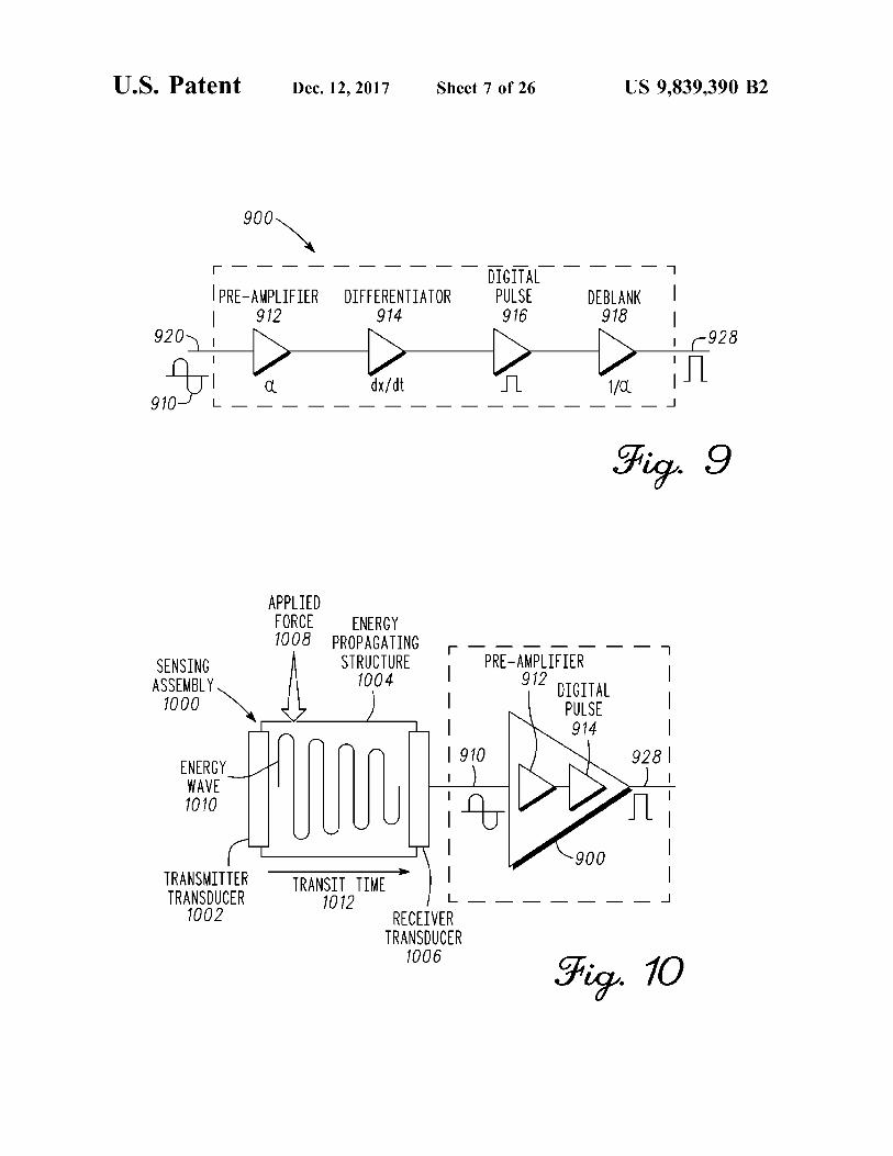
of physical parameters , and particularly to , but not exclu - 30 receiver circuit in accordance with an example embodiment ; sively , medical electronic devices for high precision sensing . FIG . 10 illustrates a block diagram of the edge - detect
BACKGROUND receiver circuit coupled to a sensing assembly ; FIG . 11 illustrates a sensor interface diagram incorporat
The skeletal system of a mammal is subject to variations 35 25 ing the edge - detect receiver circuit in a pulse - echo multi among species . Further changes can occur due to environ plexing arrangement for maintaining positive closed - loop
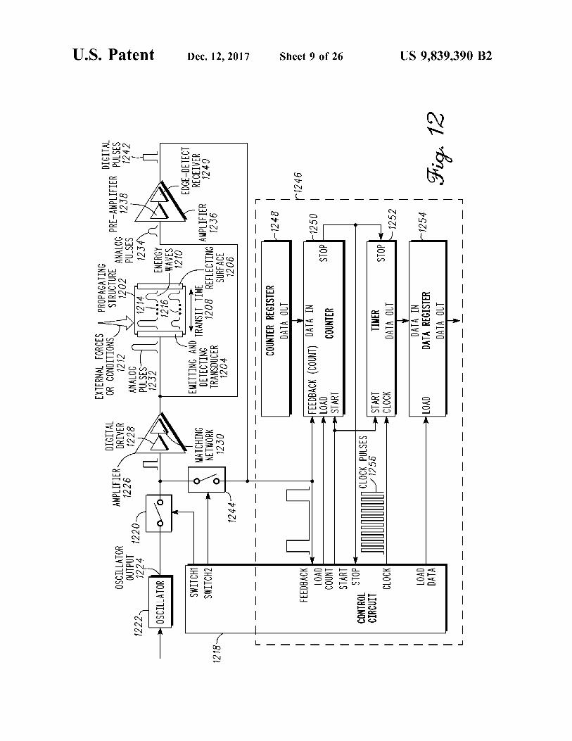
feedback in accordance with an example embodiment ; mental factors , degradation through use , and aging . An orthopedic joint of the skeletal system typically comprises FIG . 12 illustrates a block diagram of a propagation tuned
oscillator ( PTO ) incorporating the edge - detect receiver cir two or more bones that move in relation to one another . Movement is enabled by muscle tissue and tendons attached 40 cuit for operation in pulse echo mode ; to the skeletal system of the joint . Ligaments hold and FIG . 13 illustrates a simplified cross - sectional view of a stabilize the one or more joint bones positionally . Cartilage sensing module in accordance with an example embodi is a wear surface that prevents bone - to - bone contact , dis - ment ; tributes load , and lowers friction . FIG . 14 illustrates an assemblage for illustrating reflec
There has been substantial growth in the repair of the 45 tance and unidirectional modes of operation in accordance human skeletal system . In general , orthopedic joints have with an example embodiment ; evolved using information from simulations , mechanical FIG . 15 illustrates an assemblage that illustrates propa prototypes , and patient data that is collected and used to gation of ultrasound waves within a waveguide in the initiate improved designs . Similarly , the tools being used for bi - directional mode of operation of this assemblage ; orthopedic surgery have been refined over the years but have 50 FIG . 16 illustrates a cross - sectional view of a sensor not changed substantially . Thus , the basic procedure for element to illustrate changes in the propagation of ultra replacement of an orthopedic joint has been standardized to sound waves with changes in the length of a waveguide ; meet the general needs of a wide distribution of the popu - FIG . 17 illustrates a simplified flow chart of method steps lation . Although the tools , procedure , and artificial joint for high precision processing and measurement data in meet a general need , each replacement procedure is subject 55 accordance with an example embodiment ; to significant variation from patient to patient . The correc - FIG . 18 illustrates a block diagram of a medical sensing tion of these individual variations relies on the skill of the system in accordance with an example embodiment ; surgeon to adapt and fit the replacement joint using the FIG . 19 illustrates an oscillator configured to generate a available tools to the specific circumstance . measurement cycle corresponding to a capacitor in accor
60 dance with an example embodiment ; BRIEF DESCRIPTION OF THE DRAWINGS FIG . 20 illustrates a method of force , pressure , or load
sensing in accordance with an example embodiment ; Various features of the system are set forth with particu - FIG . 21 illustrates a cross - sectional view of a capacitor in
larity in the appended claims . The embodiments herein , can accordance with an example embodiment ; be understood by reference to the following description , 65 FIG . 22 illustrates the capacitor of FIG . 21 comprising taken in conjunction with the accompanying drawings , in more than one capacitor coupled mechanically in series in which : accordance with an example embodiment ;

US 9 , 839 , 390 B2
m
FIG . 23 illustrates the capacitor of FIG . 21 comprising where appropriate . For example specific computer code may more than one capacitor coupled electrically in parallel in not be listed for achieving each of the steps discussed , accordance with an example embodiment ; however one of ordinary skill would be able , without undo
FIG . 24 illustrates a top view of a conductive region of the experimentation , to write such code given the enabling capacitor of FIG . 21 and interconnect thereto in accordance 5 disclosure herein . Such code is intended to fall within the with an example embodiment ; scope of at least one exemplary embodiment .
FIG . 25 illustrates a cross - sectional view of the intercon In all of the examples illustrated and discussed herein , any nect coupled to the capacitor of FIG . 21 in accordance with specific materials , such as temperatures , times , energies , and an example embodiment ; material properties for process steps or specific structure
FIG . 26 illustrates a diagram of a method of measuring a 10 implementations should be interpreted to be illustrative only force , pressure , or load in accordance with an example and non - limiting . Processes , techniques , apparatus , and embodiment ; materials as known by one of ordinary skill in the art may
FIG . 27 illustrates a medical device having a plurality of not be discussed in detail but are intended to be part of an sensors in accordance with an example embodiment ; enabling description where appropriate . It should also be
FIG . 28 illustrates one or more prosthetic components 15 noted that the word “ coupled ” used herein implies that having sensors coupled to and conforming with non - planar elements may be directly coupled together or may be surfaces in accordance with an example embodiment ; coupled through one or more intervening elements .
FIG . 29 illustrates a tool having one or more shielded Additionally , the sizes of structures used in exemplary sensors coupled to a non - planar surface in accordance with embodiments are not limited by any discussion herein ( e . g . , an example embodiment ; 20 the sizes of structures can be macro ( centimeter , meter , and
FIG . 30 illustrates a diagram of a method of using a larger sizes ) , micro ( micrometer ) , and nanometer size and capacitor as a sensor to measure a parameter of the muscu smaller ) . lar - skeletal system in accordance with an example embodi Notice that similar reference numerals and letters refer to ment ; similar items in the following figures , and thus once an item
FIG . 31 illustrates a prosthetic component having a plu - 25 is defined in one figure , it may not be discussed or further rality of sensors in accordance with an example embodi s in accordance with an example embodi - defined in the following figures . ment ; In a first embodiment , an ultrasonic measurement system
FIG . 32 illustrates a cross - sectional view of a structure of comprises one or more ultrasonic transducers , an ultrasonic the prosthetic component in accordance with an example waveguide , and a propagation tuned oscillator ( PTO ) or embodiment ; 30 Phase Locked Loop ( PLL ) . The ultrasonic measurement
FIG . 33 illustrates the prosthetic component and an insert system in this embodiment employs a continuous mode in accordance with an example embodiment ; ( CM ) of operation to evaluate propagation characteristics of
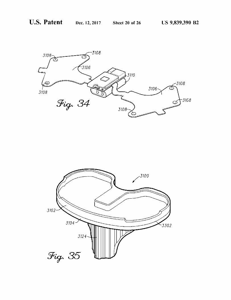
FIG . 34 illustrates electronic circuitry coupled to inter continuous ultrasonic waves in the waveguide by way of connect in accordance with an example embodiment ; closed - loop feedback to determine levels of applied forces
FIG . 35 illustrates an assembled the prosthetic component 35 on the waveguide . in accordance with an example embodiment ; In a second embodiment , an ultrasonic measurement
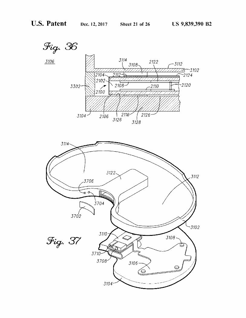
FIG . 36 illustrates a partial cross - sectional view of the system comprises one or more ultrasonic transducers , an prosthetic component in accordance with an example ultrasonic waveguide , and a propagation tuned oscillator embodiment ; ( PTO ) or Phase Locked Loop ( PLL ) . The ultrasonic mea
FIG . 37 illustrates the structure and electronic circuitry in 40 surement system in this embodiment employs a pulse mode accordance with an example embodiment ; ( PM ) of operation to evaluate propagation characteristics of
FIG . 38 illustrates the prosthetic component and a remote pulsed ultrasonic waves in the waveguide by way of closed system in accordance with an example embodiment ; loop feedback to determine levels of applied forces on the
FIG . 39 is an illustration of the electronic circuitry and the waveguide . structure in accordance with an example embodiment ; 45 In a third embodiment , an ultrasonic measurement system
FIG . 40 is an illustration of the electronic circuitry and the comprises one or more ultrasonic transducers , an ultrasonic structure in accordance with an example embodiment ; waveguide , and a propagation tuned oscillator ( PTO ) or
FIG . 41 depicts an exemplary diagrammatic representa - Phase Locked Loop ( PLL ) . The ultrasonic measurement tion of a machine in the form of a system within which a set system in this embodiment employs a pulse echo mode ( PE ) of instructions are executed in accordance with an example 50 of operation to evaluate propagation characteristics of ultra embodiment ; and sonic echo reflections in the waveguide by way of closed
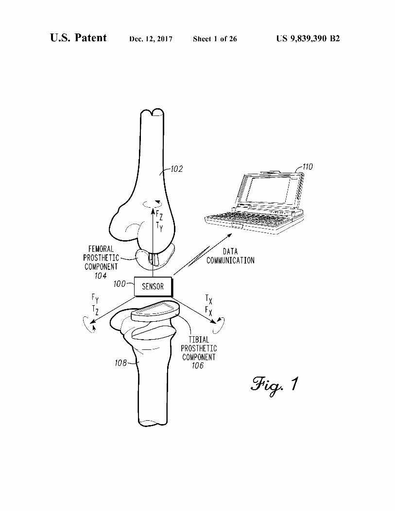
FIG . 42 is an illustration of a communication network for loop feedback to determine levels of applied forces on the measurement and reporting in accordance with an example waveguide . embodiment . FIG . 1 is an illustration of a sensor 100 placed in contact
55 between a femur 102 and a tibia 108 for measuring a DETAILED DESCRIPTION parameter in accordance with an exemplary embodiment . In
general , a sensor 100 is placed in contact with or in Embodiments of the invention are broadly directed to proximity to the muscular - skeletal system to measure a
measurement of physical parameters , and more particularly , parameter . In a non - limiting example , sensor 100 is used to to fast - response circuitry that supports accurate measure - 60 measure a parameter of a muscular - skeletal system during a ment of small sensor changes . procedure such as an installation of an artificial joint .
The following description of exemplary embodiment ( s ) is Embodiments of sensor 100 are broadly directed to mea merely illustrative in nature and is in no way intended to surement of physical parameters , and more particularly , to limit the invention , its application , or uses . evaluating changes in the transit time of a pulsed energy
Processes , techniques , apparatus , and materials as known 65 wave propagating through a medium . In - situ measurements by one of ordinary skill in the art may not be discussed in during orthopedic joint implant surgery would be of sub detail but are intended to be part of the enabling description stantial benefit to verify an implant is in balance and under

US 9 , 839 , 390 B2
appropriate loading or tension . In one embodiment , the to the planarized proximal end of the tibia 108 . Sensor 100 instrument is similar to and operates familiarly with other is placed between a condyle surface of femoral prosthetic instruments currently used by surgeons . This will increase component 104 and a major surface of tibial prosthetic acceptance and reduce the adoption cycle for a new tech component 106 . The condyle surface contacts a major nology . The measurements will allow the surgeon to ensure 5 surface of sensor 100 . The major surface of sensor 100 that the implanted components are installed within prede - approximates a surface of the insert . Tibial prosthetic com termined ranges that maximize the working life of the joint ponent 106 can include a cavity or tray on the major surface prosthesis and reduce costly revisions . Providing quantita - that receives and retains sensor 100 during a measurement tive measurement and assessment of the procedure using process . Tibial prosthetic component 106 and sensor 100 has real - time data will produce results that are more consistent . 10 a combined thickness that represents a combined thickness A further issue is that there is little or no implant data of tibial prosthetic component 106 and a final ( or chronic ) generated from the implant surgery , post - operatively , and insert of the knee joint . long term . Sensor 100 can provide implant status data to the In one embodiment , two sensors 100 are fitted into two orthopedic manufacturers and surgeons . Moreover , data separate cavities , the cavities are within a trial insert ( that generated by direct measurement of the implanted joint itself 15 may also be referred to as the tibial insert , rather than the would greatly improve the knowledge of implanted joint tibial component itself ) that is held in position by tibial operation and joint wear thereby leading to improved design component 106 . One or two sensors 100 may be inserted and materials . between femoral prosthetic component 104 and tibial pros
In at least one exemplary embodiment , an energy pulse is thetic component 106 . Each sensor is independent and each directed within one or more waveguides in sensor 100 by 20 measures a respective condyle of femur 102 . Separate sen way of pulse mode operations and pulse shaping . The sors also accommodate a situation where a single condyle is waveguide is a conduit that directs the energy pulse in a repaired and only a single sensor is used . Alternatively , the predetermined direction . The energy pulse is typically con - electronics can be shared between two sensors to lower cost fined within the waveguide . In one embodiment , the wave - and complexity of the system . The shared electronics can guide comprises a polymer material . For example , urethane 25 multiplex between each sensor module to take measure or polyethylene are polymers suitable for forming a wave - ments when appropriate . Measurements taken by sensor 100 guide . The polymer waveguide can be compressed and has aid the surgeon in modifying the absolute loading on each little or no hysteresis in the system . Alternatively , the energy condyle and the balance between condyles . Although shown pulse can be directed through the muscular - skeletal system . for a knee implant , sensor 100 can be used to measure other In one embodiment , the energy pulse is directed through 30 orthopedic joints such as the spine , hip , shoulder , elbow , bone of the muscular - skeletal system to measure bone ankle , wrist , interphalangeal joint , metatarsophalangeal density . A transit time of an energy pulse is related to the joint , metacarpophalangeal joints , and others . Alternatively , material properties of a medium through which it traverses . sensor 100 can also be adapted to orthopedic tools to provide This relationship is used to generate accurate measurements measurements . of parameters such as distance , weight , strain , pressure , 35 The prosthesis incorporating sensor 100 emulates the wear , vibration , viscosity , and density to name but a few . function of a natural knee joint . Sensor 100 can measure
Sensor 100 can be size constrained by form factor require - loads or other parameters at various points throughout the ments of fitting within a region the muscular - skeletal system range of motion . Data from sensor 100 is transmitted to a or a component such as a tool , equipment , or artificial joint . receiving station 110 via wired or wireless communications . In a non - limiting example , sensor 100 is used to measure 40 In a first embodiment , sensor 100 is a disposable system . load and balance of an installed artificial knee joint . A knee Sensor 100 can be disposed of after using sensor 100 to prosthesis comprises a femoral prosthetic component 104 , optimally fit the joint implant . Sensor 100 is a low cost an insert , and a tibial prosthetic component 106 . A distal end disposable system that reduces capital costs , operating costs , of femur 102 is prepared and receives femoral prosthetic facilitates rapid adoption of quantitative measurement , and component 104 . Femoral prosthetic component 104 typi - 45 initiates evidentiary based orthopedic medicine . In a second cally has two condyle surfaces that mimic a natural femur . embodiment , a methodology can be put in place to clean and As shown , femoral prosthetic component 104 has single sterilize sensor 100 for reuse . In a third embodiment , sensor condyle surface being coupled to femur 102 . Femoral pros - 100 can be incorporated in a tool instead of being a com thetic component 104 is typically made of a metal or metal ponent of the replacement joint . The tool can be disposable alloy . 50 or be cleaned and sterilized for reuse . In a fourth embodi
A proximal end of tibia 108 is prepared to receive tibialm ent , sensor 100 can be a permanent component of the prosthetic component 106 . Tibial prosthetic component 106 replacement joint . Sensor 100 can be used to provide both is a support structure that is fastened to the proximal end of short term and long term post - operative data on the the tibia and is usually made of a metal or metal alloy . The implanted joint . In a fifth embodiment , sensor 100 can be tibial prosthetic component 106 also retains the insert in a 55 coupled to the muscular - skeletal system . In all of the fixed position with respect to tibia 108 . The insert is fitted embodiments , receiving station 110 can include data pro between femoral prosthetic component 104 and tibial pros - cessing , storage , or display , or combination thereof and thetic component 106 . The insert has at least one bearing provide real time graphical representation of the level and surface that is in contact with at least condyle surface of distribution of the load . Receiving station 110 can record and femoral prosthetic component 104 . The condyle surface can 60 provide accounting information of sensor 100 to an appro move in relation to the bearing surface of the insert such that priate authority . the lower leg can rotate under load . The insert is typically In an intra - operative example , sensor 100 can measure made of a high wear plastic material that minimizes friction forces ( Fx , Fy , Fz ) with corresponding locations and torques
In a knee joint replacement process , the surgeon affixes ( e . g . Tx , Ty , and Tz ) on the femoral prosthetic component femoral prosthetic component 104 to the femur 102 and 65 104 and the tibial prosthetic component 106 . The measured tibial prosthetic component 106 to tibia 108 . The tibial force and torque data is transmitted to receiving station 110 prosthetic component 106 can include a tray or plate affixed to provide real - time visualization for assisting the surgeon in

US 9 , 839 , 390 B2
identifying any adjustments needed to achieve optimal joint In one embodiment , low power zero - crossing receiver pressure and balancing . The data has substantial value in 200 can be integrated with other circuitry of the propagation determining ranges of load and alignment tolerances tuned oscillator to further improve performance at low required to minimize rework and maximize patient function signal levels . The zero - crossing receiver 200 comprises a and longevity of the joint . 5 preamplifier 206 , a filter 208 , an offset adjustment circuitry
As mentioned previously , sensor 100 can be used for other 210 , a comparator 212 , and a digital pulse circuit 214 . The joint surgeries ; it is not limited to knee replacement implant filter 208 and offset adjustment circuitry 210 constitute a or implants . Moreover , sensor 100 is not limited to trial noise reduction section 218 as will be explained ahead . The measurements . Sensor 100 can be incorporated into the final zero - crossing receiver 200 can be implemented in discrete joint system to provide data post - operatively to determine if 10 analog components , digital components or combination the implanted joint is functioning correctly . Early determi - thereof . The integrated zero - crossing receiver 200 practices nation of a problem using sensor 100 can reduce cata - measurement methods that detect the midpoint of energy strophic failure of the joint by bringing awareness to a waves at specified locations , and under specified conditions , problem that the patient cannot detect . The problem can to enable capturing parameters including , but not limited to , often be rectified with a minimal invasive procedure at lower 15 transit time , phase , or frequency of energy waves . A brief cost and stress to the patient . Similarly , longer term moni - description of the method of operation is as follows . toring of the joint can determine wear or misalignment that An incoming energy wave 202 is coupled from an elec if detected early can be adjusted for optimal life or replace trical connection , antenna , or transducer to an input 204 of ment of a wear surface with minimal surgery thereby extend zero - crossing receiver 200 . Input 204 of zero - crossing ing the life of the implant . In general , sensor 100 can be 20 receiver 200 is coupled to pre - amplifier 206 to amplify the shaped such that it can be placed or engaged or affixed to or incoming energy wave 202 . The amplified signal is filtered within load bearing surfaces used in many orthopedic appli - by filter 208 . Filter 208 is coupled to an output of pre cations ( or used in any orthopedic application ) related to the amplifier 206 and an input of offset adjustment circuitry 210 . musculoskeletal system , joints , and tools associated there . In one configuration , filter 208 is a low - pass filter to remove with . Sensor 100 can provide information on a combination 25 high frequency components above the incoming energy of one or more performance parameters of interest such as wave 202 bandwidth . In another arrangement , the filter is a wear , stress , kinematics , kinetics , fixation strength , ligament band - pass filter with a pass - band corresponding to the balance , anatomical fit and balance . bandwidth of the incoming energy wave 202 . It is not
FIG . 2 is a block diagram of a zero - crossing receiver 200 however limited to either arrangement . The offset of the in accordance with one embodiment . In a first embodiment , 30 filtered amplified wave is adjusted by offset adjustment the zero - crossing receiver 200 is provided to detect transi circuitry 210 . An input of comparator 212 is coupled to an tion states of energy waves , such as the transition of each output of offset adjustment circuitry 210 . Comparator 212 energy wave through a mid - point of a symmetrical or monitors the amplified waveforms and triggers digital pulse cyclical waveform . This enables capturing of parameters circuitry 214 whenever the preset trigger level is detected . including , but not limited to , transit time , phase , or fre - 35 Digital pulse circuit 214 has an input coupled to the output quency of the energy waves . The receiver rapidly responds of comparator 212 and an output for providing digital pulse to a signal transition and outputs a digital pulse that is 216 . The digital pulse 216 can be further coupled to signal consistent with the energy wave transition characteristics processing circuitry , as will be explained ahead . and with minimal delay . The zero - crossing receiver 200 In a preferred embodiment , the electronic components are further discriminates between noise and the energy waves of 40 operatively coupled together as blocks of integrated circuits . interest , including very low level waves by way of adjust - As will be shown ahead , this integrated arrangement per able levels of noise reduction . A noise reduction section 218 forms its specific functions efficiently with a minimum comprises a filtering stage and an offset adjustment stage to number of components . This is because the circuit compo perform noise suppression accurately over a wide range of nents are partitioned between structures within an integrated amplitudes including low level waves . 45 circuit and discrete components , as well as innovative par
In a second embodiment , a zero - crossing receiver is titioning of analog and digital functions , to achieve the provided to convert an incoming symmetrical , cyclical , or required performance with a minimum number of compo sine wave to a square or rectangular digital pulse sequence nents and minimum power consumption . with superior performance for very low level input signals . FIG . 3 illustrates a block diagram of the integrated The digital pulse sequence represents pulse timing intervals 50 zero - crossing receiver 200 coupled to a sensing assembly that are consistent with the energy wave transition times . 300 in accordance with an exemplary embodiment . The The zero - crossing receiver is coupled with a sensing assem - pre - amplifier 206 and the digital pulse circuit 214 are shown bly to generate the digital pulse sequence responsive to for reference and discussion . In one embodiment , sensing evaluating transitions of the incoming sine wave . This assembly 300 comprises a transmitter transducer 302 , an digital pulse sequence conveys timing information related to 55 energy propagating structure ( or medium ) 304 , and a parameters of interest , such as applied forces , associated receiver transducer 306 . As will be explained further here with the physical changes in the sensing assembly . inbelow , the sensing assembly 300 in one embodiment is
In a third embodiment , the integrated zero - crossing part of a sensory device that measures a parameter such as receiver is incorporated within a propagation tuned oscilla force , pressure , or load . In a non - limiting example , an tor ( PTO ) to maintain positive closed - loop feedback when 60 external parameter such as an applied force 308 affects the operating in a continuous wave mode or pulse - loop mode . sensing assembly 200 . As shown , applied force 308 modifies The integrated edge zero - crossing receiver is electrically propagating structure 304 dimensionally . In general , the integrated with the PTO by multiplexing input and output sensing assembly 300 conveys one or more parameters of circuitry to achieve ultra low - power and small compact size . interest such as distance , force , weight , strain , pressure , Electrical components of the PTO are integrated with com - 65 wear , vibration , viscosity , density , direction , and displace ponents of the zero - crossing receiver to assure adequate m ent related to a change in energy propagating structure sensitivity to low - level signals . 304 . An example is measuring loading applied by a joint of

US 9 , 839 , 390 B2 10
the muscular - skeletal system as disclosed above using sens instruments , appliances , equipment , or accessories to these ing assembly 300 between the bones of the joint . devices , instruments , appliances , or equipment .
A transducer driver circuit ( not shown ) drives the trans FIG . 4 is an exemplary block diagram 400 of a propaga mitter transducer 302 of the sensing assembly 300 to pro - tion tuned oscillator ( PTO ) 404 to maintain positive closed duce energy waves 310 that are directed into the energy 5 loop feedback in accordance with an exemplary embodi propagating structure 304 . Changes in the energy propagat ment . The measurement system includes a sensing ing medium 304 due to an applied parameter such as applied assemblage 401 and propagation tuned oscillator ( PTO ) 404 forces 308 change the frequency , phase , and transit time of that detects energy waves 402 in one or more waveguides
403 of the sensing assemblage 401 . In one embodiment , energy waves 310 ( or pulses ) . In one embodiment , applied forces 308 affect the length of propagating structure 304 in 4 in 10 energy waves 402 are ultrasound waves . A pulse 411 is
generated in response to the detection of energy waves 402 a direction of a path of propagation of energy waves 310 . to initiate a propagation of a new energy wave in waveguide The zero - crossing receiver 200 is coupled to the receiver 403 . It should be noted that ultrasound energy pulses or transducer 306 to detect zero - crossings of the reproduced waves , the emission of ultrasound pulses or waves by energy wave 202 . Upon detecting a zero - crossing digital 15 ultrasound resonators or transducers , transmitted through pulse circuit 214 is triggered to output a pulse 216 . The ultrasound waveguides , and detected by ultrasound resona timing of the digital pulse 216 conveys the parameters of tors or transducers are used merely as examples of energy interest ( e . g . , distance , force weight , strain , pressure , wear , pulses , waves , and propagation structures and media . Other vibration , viscosity , density , direction , displacement , etc . ) . embodiments herein contemplated can utilize other wave Measurement methods that rely on such propagation of 20 forms , such as , light .
energy waves 310 or pulses of energy waves are required to The sensing assemblage 401 comprises transducer 405 , achieve highly accurate and controlled detection of energy transducer 406 , and a waveguide 403 ( or energy propagating waves or pulses . Moreover , pulses of energy waves may structure ) . In a non - limiting example , sensing assemblage contain multiple energy waves with complex waveforms 401 is affixed to load bearing or contacting surfaces 408 . therein leading to potential ambiguity of detection . In par - 25 External forces applied to the contacting surfaces 408 com ticular , directing energy waves 310 into the energy propa - press the waveguide 403 and change the length of the gating structure 304 can generate interference patterns waveguide 403 . Under compression , transducers 405 and caused by nulls and resonances of the waveguide , as well as 406 will also be move closer together . The change in characteristics of the generated energy waves 310 . These distance affects the transit time 407 of energy waves 402 interference patterns can multiply excited waveforms that 30 transmitted and received between transducers 405 and 406 . result in distortion of the edges of the original energy wave . The propagation tuned oscillator 404 in response to these
Briefly referring back to FIG . 2 , to reliably detect the physical changes will detect each energy wave sooner ( e . g . arrival of a pulse of energy waves , the zero - crossing receiver shorter transit time ) and initiate the propagation of new 200 leverages noise reduction section 218 that incorporates energy waves associated with the shorter transit time . As two forms of noise reduction . Frequencies above the oper - 35 will be explained below , this is accomplished by way of PTO ating frequencies for physical measurements of the param - 404 in conjunction with the pulse generator 410 , the mode eters of interest are attenuated with the filter 208 . In addition , control 412 , and the phase detector 414 . the offset level of the incoming waveform is adjusted by the Notably , changes in the waveguide 403 ( energy propa offset adjustment 210 to optimize the voltage level at which gating structure or structures ) alter the propagation proper the comparator 212 triggers an output pulse . This is more 40 ties of the medium of propagation ( e . g . transit time 407 ) . The reliable than amplifying the incoming waveform because it energy wave can be a continuous wave or a pulsed energy does not add additional amplification of noise present on the wave . A pulsed energy wave approach reduces power dis input . The combination of rapid response to the arrival of sipation allowing for a temporary power source such as a incoming symmetrical , cyclical , or sine waves with adjust - battery or capacitor to power the system during the course of able levels of noise reduction achieves reliable zero - crossing 45 Operation . In at least one exemplary embodiment , a continu detection by way of the ultra low power zero - crossing ous wave energy wave or a pulsed energy wave is provided receiver 200 with superior performance for very low level by transducer 405 to a first surface of waveguide 403 . signals . Transducer 405 generates energy waves 402 that are coupled
There are a wide range of applications for compact into waveguide 403 . In a non - limiting example , transducer measurement modules or devices having ultra low power 50 405 is a piezo - electric device capable of transmitting and circuitry that enables the design and construction of highly receiving acoustic signals in the ultrasonic frequency range . performing measurement modules or devices that can be Transducer 406 is coupled to a second surface of wave tailored to fit a wide range of nonmedical and medical guide 403 to receive the propagated pulsed signal and applications . Applications for highly compact measurement generates a corresponding electrical signal . The electrical modules or devices may include , but are not limited to , 55 signal output by transducer 406 is coupled to phase detector disposable modules or devices as well as reusable modules 414 . In general , phase detector 414 is a detection circuit that or devices and modules or devices for long term use . In compares the timing of a selected point on the waveform of addition to nonmedical applications , examples of a wide the detected energy wave with respect to the timing of the range of potential medical applications may include , but are same point on the waveform of other propagated energy not limited to , implantable devices , modules within implant - 60 waves . In a first embodiment , phase detector 414 can be a able devices , intra - operative implants or modules within zero - crossing receiver . In a second embodiment , phase intra - operative implants or trial inserts , modules within detector 414 can be an edge - detect receiver . In a third inserted or ingested devices , modules within wearable embodiment , phase detector 414 can be a phase locked loop . devices , modules within handheld devices , modules within In the example where sensing assemblage 401 is com instruments , appliances , equipment , or accessories of all of 65 pressed , the detection of the propagated energy waves 402 these , or disposables within implants , trial inserts , inserted occurs earlier ( due to the length / distance reduction of wave or ingested devices , wearable devices , handheld devices , guide 403 ) than a signal prior to external forces being

US 9 , 839 , 390 B2 12
applied to contacting surfaces . Pulse generator 410 gener measurements can be made in extension and in flexion . In ates a new pulse in response to detection of the propagated the example , assemblage 401 is used to measure the condyle energy waves 402 by phase detector 414 . The new pulse is loading to determine if it falls within a predetermined range provided to transducer 405 to initiate a new energy wave and location . Based on the measurement , the surgeon can sequence . Thus , each energy wave sequence is an individual 5 select the thickness of the insert such that the measured event of energy wave propagation , energy wave detection , loading and incidence with the final insert in place will fall and energy wave emission that maintains energy waves 402 within the predetermined range . Soft tissue tensioning can propagating in waveguide 403 . be used by a surgeon to further optimize the force or
The transit time 407 of a propagated energy wave is the pressure . Similarly , two assemblages 401 can be used to time it takes an energy wave to propagate from the first 10 measure both condyles simultaneously or multiplexed . The surface of waveguide 403 to the second surface . There is difference in loading ( e . g . balance ) between condyles can be delay associated with each circuit described above . Typi - measured . Soft tissue tensioning can be used to reduce the cally , the total delay of the circuitry is significantly less than force on the condyle having the higher measured loading to the propagation time of an energy wave through waveguide reduce the measured pressure difference between condyles . 403 . In addition , under equilibrium conditions variations in 15 One method of operation holds the number of energy circuit delay are minimal . Multiple pulse to pulse timings waves propagating through waveguide 403 as a constant can be used to generate an average time period when change integer number . A time period of an energy wave corre in external forces occur relatively slowly in relation to the sponds to energy wave periodicity . A stable time period is pulsed signal propagation time such as in a physiologic or one in which the time period changes very little over a mechanical system . The digital counter 420 in conjunction 20 number of energy waves . This occurs when conditions that with electronic components counts the number of propa - affect sensing assemblage 401 stay consistent or constant . gated energy waves to determine a corresponding change in Holding the number of energy waves propagating through the length of the waveguide 403 . These changes in length waveguide 403 to an integer number is a constraint that change in direct proportion to the external force thus forces a change in the time between pulses when the length enabling the conversion of changes in parameter or param - 25 of waveguide 403 changes . The resulting change in time eters of interest into electrical signals . period of each energy wave corresponds to a change in
The block diagram 400 further includes counting and aggregate energy wave time period that is captured using timing circuitry . More specifically , the timing , counting , and digital counter 420 as a measurement of changes in external clock circuitry comprises a digital timer 420 , a digital timer forces or conditions applied to contacting surfaces 408 . 422 , a digital clock 426 , and a data register 424 . The digital 30 A further method of operation according to one embodi clock 426 provides a clock signal to digital counter 420 and ment is described hereinbelow for energy waves 402 propa digital timer 422 during a measurement sequence . The gating from transducer 405 and received by transducer 406 . digital counter 420 is coupled to the propagation tuned In at least one exemplary embodiment , energy waves 402 oscillator 404 . Digital timer 422 is coupled to data register are an ultrasonic energy wave . Transducers 405 and 406 are 424 . Digital timer 420 , digital timer , 422 , digital clock 426 35 piezo - electric resonator transducers . Although not and data register 424 capture transit time 407 of energy described , wave propagation can occur in the opposite waves 402 emitted by ultrasound resonator or transducer direction being initiated by transducer 406 and received by 405 , propagated through waveguide 403 , and detected by or transducer 405 . Furthermore , detecting ultrasound resonator ultrasound resonator or transducer 405 or 406 depending on transducer 406 can be a separate ultrasound resonator as the mode of the measurement of the physical parameters of 40 shown or transducer 405 can be used solely depending on interest applied to surfaces 408 . The operation of the timing the selected mode of propagation ( e . g . reflective sensing ) . and counting circuitry is disclosed in more detail hereinbe - Changes in external forces or conditions applied to contact
ing surfaces 408 affect the propagation characteristics of The measurement data can be analyzed to achieve accu - waveguide 403 and alter transit time 407 . As mentioned
rate , repeatable , high precision and high resolution measure - 45 previously , propagation tuned oscillator 404 holds constant ments . This method enables the setting of the level of an integer number of energy waves 402 propagating through precision or resolution of captured data to optimize trade - waveguide 403 ( e . g . an integer number of pulsed energy offs between measurement resolution versus frequency wave time periods ) thereby controlling the repetition rate . including the bandwidth of the sensing and data processing As noted above , once PTO 404 stabilizes , the digital counter operations , thus enabling a sensing module or device to 50 420 digitizes the repetition rate of pulsed energy waves , for operate at its optimal operating point without compromising example , by way of edge - detection , as will be explained resolution of the measurements . This is achieved by the hereinbelow in more detail . accumulation of multiple cycles of excitation and transit In an alternate embodiment , the repetition rate of pulsed time instead of averaging transit time of multiple individual energy waves 402 emitted by transducer 405 can be con excitation and transit cycles . The result is accurate , repeat - 55 trolled by pulse generator 410 . The operation remains simi able , high precision and high resolution measurements of lar where the parameter to be measured corresponds to the parameters of interest in physical systems . measurement of the transit time 407 of pulsed energy waves
In at least one exemplary embodiment , propagation tuned 402 within waveguide 403 . It should be noted that an oscillator 404 in conjunction with one or more sensing individual ultrasonic pulse can comprise one or more energy assemblages 401 are used to take measurements on a mus - 60 waves with a damping wave shape . The energy wave shape cular - skeletal system . In a non - limiting example , sensing is determined by the electrical and mechanical parameters of assemblage 401 is placed between a femoral prosthetic pulse generator 410 , interface material or materials , where component and tibial prosthetic component to provide mea - required , and ultrasound resonator or transducer 405 . The sured load information that aids in the installation of an frequency of the energy waves within individual pulses is artificial knee joint . Sensing assemblage 401 can also be a 65 determined by the response of the emitting ultrasound permanent component or a muscular - skeletal joint or artifi - resonator 404 to excitation by an electrical pulse 411 . The cial muscular - skeletal joint to monitor joint function . The mode of the propagation of the pulsed energy waves 402
low .

US 9 , 839 , 390 B2 13 14
through waveguide 403 is controlled by mode control cir struction of , but is not limited to , compact ultra low power cuitry 412 ( e . g . , reflectance or uni - directional ) . The detect modules or devices for monitoring or measuring the param ing ultrasound resonator or transducer may either be a eters of interest . The flexibility to construct sensing modules separate ultrasound resonator or transducer 406 or the emit or devices over a wide range of sizes enables sensing ting resonator or transducer 405 depending on the selected 5 modules to be tailored to fit a wide range of applications mode of propagation ( reflectance or unidirectional ) . such that the sensing module or device may be engaged
In general , accurate measurement of physical parameters with , or placed , attached , or affixed to , on , or within a body , is achieved at an equilibrium point having the property that instrument , appliance , vehicle , equipment , or other physical an integer number of pulses are propagating through the system and monitor or collect data on physical parameters of energy propagating structure at any point in time . Measure - 10 interest without disturbing the operation of the body , instru ment of changes in the " time - of - flight ” or transit time of ment , appliance , vehicle , equipment , or physical system . ultrasound energy waves within a waveguide of known Referring to FIG . 17 , a simplified flow chart 1700 of length can be achieved by modulating the repetition rate of method steps for high precision processing and measure the ultrasound energy waves as a function of changes in ment data is shown in accordance with an exemplary distance or velocity through the medium of propagation , or 15 embodiment . The method 1700 can be practiced with more a combination of changes in distance and velocity , caused by or less than the steps shown , and is not limited to the order changes in the parameter or parameters of interest . of steps shown . The method steps correspond to FIG . 4 to be Measurement methods that rely on the propagation of practiced with the aforementioned components or any other
energy waves , or energy waves within energy pulses , may components suitable for such processing , for example , elec require the detection of a specific point of energy waves at 20 trical circuitry to control the emission of energy pulses or specified locations , or under specified conditions , to enable waves and to capture the repetition rate of the energy pulses capturing parameters including , but not limited to , transit o r frequency of the energy waves propagating through the time , phase , or frequency of the energy waves . Measurement elastic energy propagating structure or medium . of the changes in the physical length of individual ultra - In a step 1702 , the process initiates a measurement sound waveguides may be made in several modes . Each 25 operation . In a step 1704 , a known state is established by assemblage of one or two ultrasound resonators or trans - resetting digital timer 422 and data register 424 . In a step ducers combined with an ultrasound waveguide may be 1706 , digital counter 420 is preset to the number of mea controlled to operate in six different modes . This includes surement cycles over which measurements will be taken and two wave shape modes : continuous wave or pulsed waves , collected . In a step 1708 , the measurement cycle is initiated and three propagation modes : reflectance , unidirectional , 30 and a clock output of digital clock 426 is enabled . A clock and bi - directional propagation of the ultrasound wave . The signal from digital clock 426 is provided to both digital resolution of these measurements can be further enhanced counter 420 and digital timer 422 . An elapsed time is by advanced processing of the measurement data to enable counted by digital timer 420 based on the frequency of the optimization of the trade - offs between measurement resolu - clock signal output by digital clock 426 . In a step 1710 , tion versus length of the waveguide , frequency of the 35 digital timer 422 begins tracking the elapsed time . Simul ultrasound waves , and the bandwidth of the sensing and data taneously , digital counter 420 starts decrementing a count capture operations , thus achieving an optimal operating after each measurement sequence . In one embodiment , point for a sensing module or device . digital counter 420 is decremented as each energy wave Measurement by propagation tuned oscillator 404 and propagates through waveguide 403 and is detected by trans
sensing assemblage 401 enables high sensitivity and high 40 ducer 406 . Digital counter 420 counts down until the preset signal - to - noise ratio . The time - based measurements are number of measurement cycles has been completed . In a largely insensitive to most sources of error that may influ - step 1712 , energy wave propagation is sustained by propa ence voltage or current driven sensing methods and devices . gation tuned oscillator 404 , as digital counter 420 is decre The resulting changes in the transit time of operation cor mented by the detection of a propagated energy wave . In a respond to frequency , which can be measured rapidly , and 45 step 1714 , energy wave detection , emission , and propaga with high resolution . This achieves the required measure - tion continue while the count in digital counter 420 is greater ment accuracy and precision thus capturing changes in the than zero . In a step 1716 , the clock input of digital timer 422 physical parameters of interest and enabling analysis of their is disabled upon reaching a zero count on digital counter 420 dynamic and static behavior . thus preventing digital counter 420 and digital timer 422
These measurements may be implemented with an inte - 50 from being clocked . In one embodiment , the preset number grated wireless sensing module or device having an encap - of measurement cycles provided to digital counter 420 is sulating structure that supports sensors and load bearing or divided by the elapsed time measured by digital timer 422 to contacting surfaces and an electronic assemblage that inte calculate a frequency of propagated energy waves . Con grates a power supply , sensing elements , energy transducer versely , the number can be calculated as a transit time by or transducers and elastic energy propagating structure or 55 dividing the elapsed time from digital timer 422 by the structures , biasing spring or springs or other form of elastic preset number of measurement cycles . Finally , in a step members , an accelerometer , antennas and electronic cir - 1718 , the resulting value is transferred to register 424 . The cuitry that processes measurement data as well as controls number in data register 424 can be wirelessly transmitted to all operations of ultrasound generation , propagation , and a display and database . The data from data register 424 can detection and wireless communications . The electronics 60 be correlated to a parameter being measured . The parameter assemblage also supports testability and calibration features such as a force or load is applied to the propagation medium that assure the quality , accuracy , and reliability of the ( e . g . waveguide 403 ) such that parameter changes also completed wireless sensing module or device . change the frequency or transit time calculation of the
The level of accuracy and resolution achieved by the measurement . A relationship between the material charac integration of energy transducers and an energy propagating 65 teristics of the propagation medium and the parameter is structure or structures coupled with the electronic compo - used with the measurement value ( e . g . frequency , transit nents of the propagation tuned oscillator enables the con - time , phase ) to calculate a parameter value .

15 US 9 , 839 , 390 B2
16 The method 1700 practiced by the example assemblage of Initially , multiplexer ( mux ) 502 receives as input a clock
FIG . 4 , and by way of the digital counter 420 , digital timer signal 504 , which is passed to the transducer driver 506 to 422 , digital clock 426 and associated electronic circuitry produce the drive line signal 508 . Analog multiplexer ( mux ) analyzes the digitized measurement data according to oper - 510 receives drive line signal 508 , which is passed to the ating point conditions . In particular , these components accu - 5 transmitter transducer 512 to generate energy waves 514 . mulate multiple digitized data values to improve the level of Transducer 512 is located at a first location of an energy resolution of measurement of changes in length or other propagating medium . The emitted energy waves 514 propa aspect of an elastic energy propagating structure or medium gate through the energy propagating medium . Receiver that can alter the transit time of energy pulses or waves transducer 516 is located at a second location of the energy propagating within the elastic energy propagating structure 10 propagating medium . Receiver transducer 516 captures the or medium . The digitized data is summed by controlling the energy waves 514 , which are fed to analog mux 520 and digital counter 420 to run through multiple measurement passed to the zero - crossing receiver 200 . The captured cycles , each cycle having excitation and transit phases such energy waves by transducer 516 are indicated by electrical that there is not lag between successive measurement cycles , waves 518 provided to mux 520 . Zero - crossing receiver 200 and capturing the total elapsed time . The counter is sized to 15 outputs a pulse corresponding to each zero crossing detected count the total elapsed time of as many measurement cycles from captured electrical waves 518 . The zero crossings are as required to achieve the required resolution without over - counted and used to determine changes in the phase and flowing its accumulation capacity and without compromis - frequency of the energy waves propagating through the ing the resolution of the least significant bit of the counter . energy propagating medium . In a non - limiting example , a The digitized measurement of the total elapsed transit time 20 parameter such as applied force is measured by relating the is subsequently divided by the number of measurement measured phase and frequency to a known relationship cycles to estimate the time of the individual measurement between the parameter ( e . g . force ) and the material proper cycles and thus the transit time of individual cycles of ties of the energy propagating medium . In general , pulse excitation , propagation through the elastic energy propagat - sequence 522 corresponds to the detected signal frequency . ing structure or medium , and detection of energy pulses or 25 The zero - crossing receiver 200 is in a feedback path of the waves . Accurate estimates of changes in the transit time of propagation tuned oscillator . The pulse sequence 522 is the energy pulses or waves through the elastic energy coupled through mux 502 in a positive closed - loop feedback propagating structure or medium are captured as elapsed path . The pulse sequence 522 disables the clock signal 504 times for excitation and detection of the energy pulses or such that the path providing pulse sequence 522 is coupled waves are fixed . 30 to driver 506 to continue emission of energy waves into the Summing individual measurements before dividing to energy propagating medium and the path of clock signal 504
estimate the average measurement value data values pro - to driver 506 is disabled . duces superior results to averaging the same number of FIG . 6 is an exemplary block diagram of a propagation samples . The resolution of count data collected from a tuned oscillator ( PTO ) incorporating the zero - crossing digital counter is limited by the resolution of the least - 35 receiver 640 for operation in continuous wave mode . In significant - bit in the counter . Capturing a series of counts particular , with respect to FIG . 4 , it illustrates closed loop and averaging them does not produce greater precision than measurement of the transit time 412 of ultrasound waves this least - significant - bit , that is the precision of a single 414 within the waveguide 408 by the operation of the count . Averaging does reduce the randomness of the final propagation tuned oscillator 416 . This example is for opera estimate if there is random variation between individual 40 tion in continuous wave mode . The system can also be measurements . Summing the counts of a large number of operated in pulse mode and a pulse - echo mode . Pulse mode measurement cycles to obtain a cumulative count then and pulsed echo - mode use a pulsed energy wave . Pulse - echo calculating the average over the entire measurement period mode uses reflection to direct an energy wave within the improves the precision of the measurement by interpolating energy propagation medium . Briefly , the digital logic circuit the component of the measurement that is less than the least 45 646 digitizes the frequency of operation of the propagation significant bit of the counter . The precision gained by this tuned oscillator . procedure is on the order of the resolution of the least . In continuous wave mode of operation a sensor compris significant - bit of the counter divided by the number of ing transducer 604 , propagating structure 602 , and trans measurement cycles summed . ducer 606 is used to measure the parameter . In general , the
The size of the digital counter and the number of mea - 50 parameter to be measured affects the properties of the surement cycles accumulated may be greater than the propagating medium . For example , an external force or required level of resolution . This not only assures perfor - condition 612 is applied to propagating structure 602 that mance that achieves the level of resolution required , but also changes the length of the waveguide in a path of a propa averages random component within individual counts pro gating energy wave . A change in length corresponds to a ducing highly repeatable measurements that reliably meet 55 change in transit time 608 of the propagating wave . Simi the required level of resolution . larly , the length of propagating structure 602 corresponds to
The number of measurement cycles is greater than the the applied force 612 . A length reduction corresponds to a required level of resolution . This not only assures perfor higher force being applied to the propagating structure 602 . mance that achieves the level of resolution required , but also Conversely , a length increase corresponds to a lowering of averages any random component within individual counts 60 the applied force 612 to the propagating structure 602 . The producing highly repeatable measurements that reliably length of propagating structure 602 is measured and is meet the required level of resolution . converted to force by way of a known length to force
FIG . 5 is a sensor interface diagram incorporating the relationship . zero - crossing receiver 200 in a continuous wave multiplex - Transducer 604 is an emitting device in continuous wave ing arrangement for maintaining positive closed - loop feed - 65 mode . The sensor for measuring a parameter comprises back in accordance with one embodiment . The positive transducer 604 coupled to propagating structure 602 at a first closed - loop feedback is illustrated by the bold line path . location . A transducer 606 is coupled to propagating struc

US 9 , 839 , 390 B2 17 18
ture 602 at a second location . Transducer 606 is a receiving the operating frequency into digital binary numbers facili transducer for capturing propagating energy waves . In one tates communication , additional processing , storage , and embodiment , the captured propagated energy waves are display of information about the level and changes in electrical sine waves 634 that are output by transducer 606 . physical parameters of interest . Similarly , the frequency of
A measurement sequence is initiated when control cir - 5 energy waves 610 during the operation of the closed loop cuitry 618 closes switch 620 coupling oscillator output 624 circuit , and changes in this frequency , may be used to of oscillator 622 to the input of amplifier 626 . One or more measure movement or changes in physical attributes of pulses provided to amplifier 626 initiates an action to energy propagating structure or medium 602 . propagate energy waves 610 having simple or complex Prior to measurement of the frequency or operation of the waveforms through energy propagating structure or medium 10 propagation tuned oscillator , control logic 618 loads the loop 602 . Amplifier 626 comprises a digital driver 628 and count into digital counter 650 that is stored in count register matching network 630 . In one embodiment , amplifier 626 648 . The first digital pulses 642 initiates closed loop opera transforms the oscillator output of oscillator 622 into sine tion within the propagation tuned oscillator and signals waves of electrical waves 632 having the same repetition control circuit 618 to start measurement operations . At the rate as oscillator output 624 and sufficient amplitude to 15 start of closed loop operation , control logic 618 enables excite transducer 604 . digital counter 650 and digital timer 652 . In one embodi
Emitting transducer 604 converts the sine waves 632 into ment , digital counter 650 decrements its value on the rising energy waves 610 of the same frequency and emits them at edge of each digital pulse output by zero - crossing receiver the first location into energy propagating structure or 640 . Digital timer 652 increments its value on each rising medium 602 . The energy waves 610 propagate through 20 edge of clock pulses 656 . When the number of digital pulses energy propagating structure or medium 602 . Upon reaching 642 has decremented , the value within digital counter 650 to transducer 606 at the second location , energy waves 610 are zero a stop signal is output from digital counter 650 . The captured , sensed , or detected . The captured energy waves stop signal disables digital timer 652 and triggers control are converted by transducer 606 into sine waves 634 that are circuit 618 to output a load command to data register 654 . electrical waves having the same frequency . 25 Data register 654 loads a binary number from digital timer
Amplifier 636 comprises a pre - amplifier 634 and zero - 652 that is equal to the period of the energy waves or pulses cross receiver 640 . Amplifier 636 converts the sine waves times the value in counter 648 divided by clock period 656 . 634 into digital pulses 642 of sufficient duration to sustain With a constant clock period 656 , the value in data register the behavior of the closed loop circuit . Control circuitry 618 654 is directly proportional to the aggregate period of the responds to digital pulses 642 from amplifier 636 by opening 30 energy waves or pulses accumulated during the measure switch 620 and closing switch 644 . Opening switch 620 ment operation . Duration of the measurement operation and decouples oscillator output 624 from the input of amplifier the resolution of measurements may be adjusted by increas 626 . Closing switch 644 creates a closed loop circuit cou - ing or decreasing the value preset in the count register 648 . pling the output of amplifier 636 to the input of amplifier 626 FIG . 7 is a sensor interface diagram incorporating the and sustaining the emission , propagation , and detection of 35 integrated zero - crossing receiver 200 in a pulse multiplexing energy waves through energy propagating structure or arrangement for maintaining positive closed - loop feedback medium 602 . in accordance with one embodiment . In one embodiment ,
An equilibrium state is attained by maintaining unity gain the circuitry other than the sensor is integrated on an around this closed loop circuit wherein sine waves 632 input application specific integrated circuit ( ASIC ) . The positive into transducer 604 and sine waves 634 output by transducer 40 closed - loop feedback is illustrated by the bold line path . 606 are in phase with a small but constant offset . Transducer Initially , mux 702 is enabled to couple one or more digital 606 as disclosed above , outputs the sine waves 634 upon pulses 704 to the transducer driver 706 . Transducer driver detecting energy waves propagating to the second location . 706 generates a pulse sequence 708 corresponding to digital In the equilibrium state , an integer number of energy waves pulses 704 . Analog mux 710 is enabled to couple pulse 610 propagate through energy propagating structure or 45 sequence 708 to the transmitter transducer 712 . Transducer medium 602 . 712 is coupled to a medium at a first location . Transducer Movement or changes in the physical properties of energy 712 responds to pulse sequence 708 and generates corre
propagating structure or medium 602 change a transit time sponding energy pulses 714 that are emitted into the medium 608 of energy waves 610 . The transit time 608 comprises the at the first location . The energy pulses 714 propagate time for an energy wave to propagate from the first location 50 through the medium . A receiver transducer 716 is located at to the second location of propagating structure 602 . Thus , a second location on the medium . Receiver transducer 716 the change in the physical property of propagating structure captures the energy pulses 714 and generates a correspond 602 results in a corresponding time period change of the ing signal of electrical pulses 718 . Transducer 716 is coupled energy waves 610 within energy propagating structure or to a mux 720 . Mux 720 is enabled to couple to zero - cross medium 602 . These changes in the time period of the energy 55 receiver 200 . Electrical pulses 718 from transducer 716 are waves 610 alter the equilibrium point of the closed loop coupled to zero - cross receiver 200 . Zero - cross receiver 200 circuit and frequency of operation of the closed loop circuit . counts zero crossings of electrical pulses 718 to determine The closed loop circuit adjusts such that sine waves 632 and changes in phase and frequency of the energy pulses respon 634 correspond to the new equilibrium point . The frequency sive to an applied force , as previously explained . Zero - cross of energy waves 610 and changes to the frequency correlate 60 receiver 200 outputs a pulse sequence 722 corresponding to to changes in the physical attributes of energy propagating the detected signal frequency . Pulse sequence 722 is coupled structure or medium 602 . to mux 702 . Mux 702 is decoupled from coupling digital
The physical changes may be imposed on energy propa - pulses 704 to driver 706 upon detection of pulses 722 . gating structure 602 by external forces or conditions 612 Conversely , mux 702 is enabled to couple pulses 722 to thus translating the levels and changes of the parameter or 65 driver 706 upon detection of pulses 722 thereby creating a parameters of interest into signals that may be digitized for positive closed - loop feedback path . Thus , in pulse mode , subsequent processing , storage , and display . Translation of zero - cross receiver 200 is part of the closed - loop feedback

19 US 9 , 839 , 390 B2
20 path that continues emission of energy pulses into the and sustaining the emission , propagation , and detection of medium at the first location and detection at the second energy waves through energy propagating structure or location to measure a transit time and changes in transit time medium 602 . of pulses through the medium . An equilibrium state is attained by maintaining unity gain
FIG . 8 is an exemplary block diagram of a propagation 5 around this closed loop circuit wherein pulses 832 input into tuned oscillator ( PTO ) incorporating the zero - crossing transducer 604 and pulses 834 output by transducer 606 are receiver 640 for operation in pulse mode . In particular , with in phase with a small but constant offset . Transducer 606 as in phase w respect to FIG . 4 , it illustrates closed loop measurement of disclosed above , outputs the pulses 834 upon detecting
the transit time 412 of ultrasound waves 414 within the energy waves propagating to the second location . In the waveguide 408 by the operation of the propagation tuned ined 10 equilibrium state , an integer number of energy waves 610
propagate through energy propagating structure or medium oscillator 416 . This example is for operation in pulse mode . 602 . The system can also be operated in continuous wave mode Movement or changes in the physical properties of energy and a pulse - echo mode . Continuous wave mode uses a propagating structure or medium 602 change a transit time continuous wave signal . Pulse - echo mode uses reflection to to 15 608 of energy waves 610 . The transit time 608 comprises the direct an energy wave within the energy propagation time for an energy wave to propagate from the first location medium . Briefly , the digital logic circuit 646 digitizes the to the second location of propagating structure 602 . Thus , frequency of operation of the propagation tuned oscillator . the change in the physical property of propagating structure
In pulse mode of operation , a sensor comprising trans 602 results in a corresponding time period change of the ducer 604 , propagating structure 602 , and transducer 606 is 20 energy waves 610 within energy propagating structure or used to measure the parameter . In general , the parameter to medium 602 . These changes in the time period of the energy be measured affects the properties of the propagating waves 610 alter the equilibrium point of the closed loop medium . For example , an external force or condition 612 is circuit and frequency of operation of the closed loop circuit . applied to propagating structure 602 that changes the length The closed loop circuit adjusts such that pulses 832 and 834 of the waveguide in a path of a propagating energy wave . A 25 correspond to the new equilibrium point . The frequency of change in length corresponds to a change in transit time 608 energy waves 610 and changes to the frequency correlate to of the propagating wave . The length of propagating structure changes in the physical attributes of energy propagating 602 is measured and is converted to force by way of a known structure or medium 602 . length to force relationship . One benefit of pulse mode The physical changes may be imposed on energy propa operation is the use of a high magnitude pulsed energy wave . » e 30 gating structure 602 by external forces or conditions 612
thus translating the levels and changes of the parameter or In one embodiment , the magnitude of the energy wave parameters of interest into signals that may be digitized for decays as it propagates through the medium . The use of a subsequent processing , storage , and display . Translation of high magnitude pulse is a power efficient method to produce the operating frequency into digital binary numbers facili a detectable signal if the energy wave has to traverse a 36 taverse a 35 tates communication , additional processing , storage , and substantial distance or is subject to a reduction in magnitude display of information about the level and changes in as it propagated due to the medium . physical parameters of interest as disclosed in more detail A measurement sequence is initiated when control cir hereinabove . Similarly , the frequency of energy waves 610
cuitry 618 closes switch 620 coupling oscillator output 624 during the operation of the closed loop circuit , and changes of oscillator 622 to the input of amplifier 626 . One or more 40 in this frequency , may be used to measure movement or pulses provided to amplifier 626 initiates an action to changes in physical attributes of energy propagating struc propagate energy waves 610 having simple or complex ture or medium 602 . waveforms through energy propagating structure or medium FIG . 9 illustrates a block diagram of an edge - detect 602 . Amplifier 626 comprises a digital driver 628 and receiver circuit 900 in accordance with an exemplary matching network 630 . In one embodiment , amplifier 626 45 embodiment . In a first embodiment , edge - detect receiver transforms the oscillator output of oscillator 622 into analog 900 is provided to detect wave fronts of pulses of energy pulses of electrical waves 832 having the same repetition waves . This enables capturing of parameters including , but rate as oscillator output 624 and sufficient amplitude to not limited to , transit time , phase , or frequency of the energy excite transducer 604 . waves . Circuitry of the integrated edge - detect receiver 900
Emitting transducer 604 converts the analog pulses 832 50 provides rapid on - set detection and quickly responds to the into energy waves 610 of the same frequency and emits them arrival of an energy pulse . It reliably triggers thereafter a at a first location into energy propagating structure or digital output pulse at a same point on the initial wave front medium 602 . The energy waves 610 propagate through of each captured energy pulse or pulsed energy wave . The energy propagating structure or medium 602 . Upon reaching digital pulse can be optimally configured to output with transducer 606 at the second location , energy waves 610 are 55 minimal and constant delay . The edge - detect receiver 900 captured , sensed , or detected . The captured energy waves can isolate and precisely detect the specified point on the are converted by transducer 606 into analog pulses 834 that initial energy wave or the wave front in the presence of are electrical waves having the same frequency . interference and distortion signals thereby overcoming prob
Amplifier 636 comprises a pre - amplifier 638 and zero - lems commonly associated with detecting one of multiple cross receiver 640 . Amplifier 636 converts the analog pulses 60 generated complex signals in energy propagating mediums . 834 into digital pulses 642 of sufficient duration to sustain The edge - detect receiver 900 performs these functions accu the behavior of the closed loop circuit . Control circuitry 618 rately over a wide range of amplitudes including very responds to digital pulses 642 from amplifier 636 by opening low - level energy pulses . switch 620 and closing switch 644 . Opening switch 620 In a second embodiment , the edge - detect receiver 900 is decouples oscillator output 624 from the input of amplifier 65 incorporated within a propagation tuned oscillator ( PTO ) to 626 . Closing switch 644 creates a closed loop circuit cou - maintain positive closed - loop feedback when operating in a pling the output of amplifier 636 to the input of amplifier 626 pulse or pulse - echo mode . The edge - detect receiver 900 can

re
US 9 , 839 , 390 B2 21 22
be integrated with other circuitry of the PTO by multiplexing ing period . In this example , the digital output pulse 928 can input and output circuitry to achieve ultra low - power and then be coupled to signal processing circuitry as explained small compact size . Integration of the circuitry of the PTO hereinbelow . In one embodiment , the electronic components with the edge - detect receiver provides the benefit of increas are operatively coupled as blocks within an integrated ing sensitivity to low - level signals . 5 circuit . As will be shown ahead , this integration arrangement
The block diagram illustrates one embodiment of a low performs its specific functions efficiently with a minimum power edge - detect receiver circuit 900 with superior perfor number of components . This is because the circuit compo mance at low signal levels . The edge - detect receiver 900 nents are partitioned between structures within an integrated comprises a preamplifier 912 , a differentiator 914 , a digital circuit and discrete components , as well as innovative par pulse circuit 916 and a deblank circuit 918 . The edge - detect 10 titioning of analog and digital functions , to achieve the receiver circuit 900 can be implemented in discrete analog required performance with a minimum number of compo components , digital components or combination thereof . In nents and minimum power consumption . one embodiment , edge - detect receiver 900 is integrated into FIG . 10 illustrates a block diagram of the edge - detect an ASIC as part of a sensor system described hereinbelow . receiver circuit 900 coupled to a sensing assembly 1000 . The The edge - detect receiver circuit 900 practices measurement 15 pre - amplifier 912 and the digital pulse circuit 916 are shown methods that detect energy pulses or pulsed energy waves at for reference and discussion . The sensing assembly 1000 specified locations and under specified conditions to enable comprises a transmitter transducer 1002 , an energy propa capturing parameters including , but not limited to , transit gating medium 1004 , and a receiver transducer 1006 . The time , phase , frequency , or amplitude of energy pulses . A transmitter transducer 1002 is coupled to propagating brief description of the method of operation is as follows . In 20 medium 1004 at a first location . The receiver transducer a non - limiting example , a pre - amplifier triggers a compara - 1006 is coupled to energy propagating medium 1004 at a tor circuit responsive to small changes in the slope of an second location . Alternatively , a reflecting surface can input signal . The comparator and other edge - detect circuitry replace receiver transducer 1006 . The reflecting surface responds rapidly with minimum delay . Detection of small reflects an energy wave back towards the first location . changes in the input signal assures rapid detection of the 25 Transducer 1006 can be enabled to be a transmitting trans arrival of a pulse of energy waves . The minimum phase ducer and a receiving transducer thereby saving the cost of design reduces extraneous delay thereby introducing less a transducer . As will be explained ahead in further detail , the variation into the measurement of the transit time , phase , sensing assembly 1000 in one embodiment is part of a frequency , or amplitude of the incoming energy pulses . sensory device that assess loading , in particular , the exter An input 920 of edge - detect receiver 900 is coupled to 30 nally applied forces 1008 on the sensing assembly 1000 . A
pre - amplifier 912 . As an example , the incoming wave 910 to transducer driver circuit ( not shown ) drives the transmitter the edge - detect receiver circuit 900 can be received from an transducer 1002 of the sensing assembly 1000 to produce electrical connection , antenna , or transducer . The incoming energy waves 1010 that are directed into the energy propa wave 910 is amplified by pre - amplifier 912 , which assures gating medium 1004 . In the non - limiting example , changes adequate sensitivity to small signals . Differentiator circuitry 35 in the energy propagating medium 1004 due to the externally 914 monitors the output of pre - amplifier 912 and triggers applied forces 1008 change the frequency , phase , and transit digital pulse circuitry 916 whenever a signal change corre - time 1012 of energy waves 1010 propagating from the first sponding to a pulsed energy wave is detected . For example , location to the second location of energy propagating a signal change that identifies the pulsed energy wave is the medium 1004 . The integrated edge - detect receiver circuit initial wave front or the leading edge of the pulsed energy 40 900 is coupled to the receiver transducer 1006 to detect wave . In one arrangement , differentiator 914 detects current edges of the reproduced energy wave 910 and trigger the flow , and more specifically changes in the slope of the digital pulse 928 . In general , the timing of the digital pulse energy wave 910 by detecting small changes in current flow 928 conveys the parameters of interest ( e . g . , distance , force instead of measuring changes in voltage level to achieve weight , strain , pressure , wear , vibration , viscosity , density , rapid detection of slope . Alternatively , differentiator 914 can 45 direction , displacement , etc . ) related to the change in energy be implemented to trigger on changes in voltage . Together , propagating structure 1004 due to an external parameter . For preamplifier 912 and differentiator 916 monitor the quies - example , sensing assembly 1000 placed in a knee joint as cent input currents for the arrival of wave front of energy described hereinabove . wave ( s ) 910 . Preamplifier 912 and differentiator 916 detect M easurement methods that rely on the propagation of the arrival of low level pulses of energy waves as well as 50 energy pulses require the detection of energy pulses at larger pulses of energy waves . This detection methodology specified locations or under specified conditions to enable achieves superior performance for very low level signals . capturing parameters including , but not limited to , transit Differentiator circuitry 912 triggers digital pulse circuitry time , phase , frequency , or amplitude of the energy pulses . 916 whenever current flow driven by the initial signal ramp Measurement methods that rely on such propagation of of the incoming wave 910 is detected . The digital pulse is 55 energy waves 1010 or pulses of energy waves are required coupled to deblank circuit 918 that desensitizes pre - ampli - to achieve highly accurate and controlled detection of fier 912 . For example , the desensitization of pre - amplifier energy waves or pulses . Moreover , pulses of energy waves 912 can comprise a reduction in gain , decoupling of input may contain multiple energy waves with complex wave 920 from energy wave 910 , or changing the frequency forms therein leading to potential ambiguity of detection . In response . The deblank circuit 918 also disregards voltage or 60 particular , directing energy waves 1010 into the energy current levels for a specified or predetermined duration of propagating structure 1004 can generate interference pat time to effectively skip over the interference sections or terns caused by nulls and resonances of the waveguide , as distorted portions of the energy wave 910 . In general , energy well as characteristics of the generated energy wave 1010 . wave 910 can comprise more than one change in slope and These interference patterns can generate multiply excited is typically a damped wave form . Additional signals or 65 waveforms that result in distortion of the edges of the waves of the pulsed energy wave on the input 920 of original energy wave . To reliably detect the arrival of a pulse pre - amplifier 912 are not processed during the preset blank - of energy waves , the edge - detect receiver 900 only responds

23 ch
US 9 , 839 , 390 B2 24
to the leading edge of the first energy wave within each condition 1212 is applied to propagating structure 1202 that pulse . This is achieved in part by blanking the edge - detect changes the length of the waveguide in a path of a propa circuitry 900 for the duration of each energy pulse . As an gating energy wave . A change in length corresponds to a example , the deblank circuit 918 disregards voltage or change in transit time of the propagating wave . Similarly , the current levels for a specified duration of time to effectively 5 length of propagating structure 1202 corresponds to the skip over the interference sections or distorted portions of applied force 1212 . A length reduction corresponds to a the waveform . higher force being applied to the propagating structure 1202 .
FIG . 11 is a sensor interface diagram incorporating the Conversely , a length increase corresponds to a lowering of edge - detect receiver circuit 900 in a pulse - echo multiplexing the applied force 1212 to the propagating structure 1202 . arrangement for maintaining positive closed - loop feedback 10 The length of propagating structure 1202 is measured and is in accordance with one embodiment . The positive closed converted to force by way of a known length to force loop feedback is illustrated by the bold line path . Initially , relationship . multiplexer ( mux ) 1102 receives as input a digital pulse Transducer 1204 is both an emitting device and a receiv 1104 , which is passed to the transducer driver 1106 to ing device in pulse - echo mode . The sensor for measuring a produce the pulse sequence 1108 . Analog multiplexer ( mux ) 15 parameter comprises transducer 1204 coupled to propagat 1110 receives pulse sequence 1108 , which is passed to the ing structure 1202 at a first location . A reflecting surface is transducer 1112 to generate energy pulses 1114 . Energy coupled to propagating structure 1202 at a second location . pulses 1114 are emitted into a first location of a medium and Transducer 1204 has two modes of operation comprising an propagate through the medium . In the pulse - echo example , emitting mode and receiving mode . Transducer 1204 emits energy pulses 1114 are reflected off a surface 1116 at a 20 an energy wave into the propagating structure 1202 at the second location of the medium , for example , the end of a first location in the emitting mode . The energy wave propa waveguide or reflector , and echoed back to the transducer gates to a second location and is reflected by reflecting 1112 . The transducer 1112 proceeds to then capture the surface 1206 . The reflected energy wave is reflected towards reflected pulse echo . In pulsed echo mode , the transducer the first location and transducer 1204 subsequently generates 1112 performs as both a transmitter and a receiver . As 25 a signal in the receiving mode corresponding to the reflected disclosed above , transducer 1112 toggles back and forth energy wave . between emitting and receiving energy waves . Transducer A measurement sequence in pulse echo mode is initiated 1112 captures the reflected echo pulses , which are coupled when control circuitry 1218 closes switch 1220 coupling to analog mux 1110 and directed to the edge - detect receiver digital output 1224 of oscillator 1222 to the input of ampli 900 . The captured reflected echo pulses is indicated by 30 fier 1226 . One or more pulses provided to amplifier 1226 electrical waves 1120 . Edge - detect receiver 900 locks on starts a process to emit one or more energy waves 1210 pulse edges corresponding to the wave front of a propagated having simple or complex waveforms into energy propagat energy wave to determine changes in phase and frequency of ing structure or medium 1202 . Amplifier 1226 comprises a the energy pulses 1114 responsive to an applied force , as digital driver 1228 and matching network 1230 . In one previously explained . Among other parameters , it generates 35 embodiment , amplifier 1226 transforms the digital output of a pulse sequence 1118 corresponding to the detected signal oscillator 1222 into pulses of electrical waves 1232 having frequency . The pulse sequence 1118 is coupled to mux 1102 the same repetition rate as digital output 1224 and sufficient and directed to driver 1106 to initiate one or more energy amplitude to excite transducer 1204 . waves being emitted into the medium by transducer 1112 . Transducer 1204 converts the pulses of electrical waves Pulse 1104 is decoupled from being provided to driver 1106 . 40 1232 into pulses of energy waves 1210 of the same repeti Thus , a positive closed loop feedback is formed that repeat - tion rate and emits them into energy propagating structure or ably emits energy waves into the medium until mux 1102 medium 1202 . The pulses of energy waves 1210 propagate prevents a signal from being provided to driver 1106 . The through energy propagating structure or medium 1202 as edge - detect receiver 900 is coupled to a second location of shown by arrow 1214 towards reflecting surface 1206 . Upon the medium and is in the feedback path . The edge - detect 45 reaching reflecting surface 1206 , energy waves 1210 are receiver 900 initiates a pulsed energy wave being provided reflected by reflecting surface 1206 . Reflected energy waves at the first location of the medium upon detecting a wave propagate towards transducer 1204 as shown by arrow 1216 . front at the second location when the feedback path is The reflected energy waves are detected by transducer 1204 closed . and converted into pulses of electrical waves 1234 having
FIG . 12 is an exemplary block diagram of a propagation 50 the same repetition rate . tuned oscillator ( PTO ) incorporating the edge - detect Amplifier 1236 comprises a pre - amplifier 1234 and edge receiver circuit 900 for operation in pulse echo mode . In detect receiver 1240 . Amplifier 1236 converts the pulses of particular , with respect to FIG . 4 , it illustrates closed loop electrical waves 1234 into digital pulses 1242 of sufficient measurement of the transit time 412 of ultrasound waves duration to sustain the pulse behavior of the closed loop 414 within the waveguide 408 by the operation of the 55 circuit . Control circuitry 1218 responds to digital output propagation tuned oscillator 416 . This example is for opera - pulses 1242 from amplifier 1236 by opening switch 1220 tion in a pulse echo mode . The system can also be operated and closing switch 1244 . Opening switch 1220 decouples in pulse mode and a continuous wave mode . Pulse mode oscillator output 1224 from the input of amplifier 1226 . does not use a reflected signal . Continuous wave mode uses Closing switch 1244 creates a closed loop circuit coupling a continuous signal . Briefly , the digital logic circuit 1246 60 the output of amplifier 1236 to the input of amplifier 1226 digitizes the frequency of operation of the propagation tuned and sustaining the emission , propagation , and detection of oscillator . energy pulses through energy propagating structure or
In pulse - echo mode of operation a sensor comprising medium 1202 . transducer 1204 , propagating structure 1202 , and reflecting An equilibrium state is attained by maintaining unity gain surface 1206 is used to measure the parameter . In general , 65 around this closed loop circuit wherein electrical waves the parameter to be measured affects the properties of the 1232 input into transducer 1204 and electrical waves 1234 propagating medium . For example , an external force or output by transducer 1204 are in phase with a small but

25 US 9 , 839 , 390 B2
26 constant offset . Transducer 1204 as disclosed above , outputs cal assembly comprising electrical components and the electrical waves 1234 upon detecting reflected energy mechanical components that when configured and operated waves reflected from reflecting surface 1206 . In the equi - in accordance with a sensing mode performs as a positive librium state , an integer number of pulses of energy waves feedback closed - loop measurement system . The measure 1210 propagate through energy propagating structure or 5 ment system can precisely measure applied forces , such as medium 1202 . loading , on the electro - mechanical assembly . The sensing Movement or changes in the physical properties of energy mode can be a continuous mode , a pulse mode , or a pulse
propagating structure or medium 1202 change a transit time echo - mode . 1208 of energy waves 1210 . The transit time 1208 comprises In one embodiment , the electrical components can include the time for an energy wave to propagate from the first 10 ultrasound resonators or transducers 405 and 406 , ultra location to the second location of propagating structure 1202 sound waveguides 403 , and signal processing electronics and the time for the reflected energy wave to propagate from 1310 , but are not limited to these . The mechanical compo the second location to the first location of propagating nents can include biasing springs 1332 , spring retainers and structure 1202 . Thus , the change in the physical property of posts , and load platforms 1306 , but are not limited to these . propagating structure 1202 results in a corresponding time 15 The electrical components and mechanical components can period change of the energy waves 1210 within energy be inter - assembled ( or integrated ) onto a printed circuit propagating structure or medium 1202 . These changes in the board 1336 to operate as a coherent ultrasonic measurement time period of the repetition rate of the energy pulses 1210 system within sensing module 1301 and according to the alter the equilibrium point of the closed loop circuit and sensing mode . As will be explained ahead in more detail , the repetition rate of operation of the closed loop circuit . The 20 signal processing electronics incorporate a propagation closed loop circuit adjusts such that electrical waves 1232 tuned oscillator ( PTO ) or a phase locked loop ( PLL ) to and 1234 correspond to the new equilibrium point . The control the operating frequency of the ultrasound resonators repetition rate of energy waves 1210 and changes to the or transducers for providing high precision sensing . Further repetition rate correlate to changes in the physical attributes more , the signal processing electronics incorporate detect of energy propagating structure or medium 1202 . 25 circuitry that consistently detects an energy wave after it has
The physical changes may be imposed on energy propa - propagated through a medium . The detection initiates the gating structure 1202 by external forces or conditions 1212 generation of a new energy wave by an ultrasound resonator thus translating the levels and changes of the parameter or or transducer that is coupled to the medium for propagation parameters of interest into signals that may be digitized for therethrough . A change in transit time of an energy wave subsequent processing , storage , and display . Translation of 30 through the medium is measured and correlates to a change the operating frequency into digital binary numbers facili - in material property of the medium due to one or more tates communication , additional processing , storage , and parameters applied thereto . display of information about the level and changes in Sensing module 1301 comprises one or more assemblages physical parameters of interest . Similarly , the frequency of 401 each comprised one or more ultrasound resonators 405 energy waves 1210 during the operation of the closed loop 35 and 406 . As illustrated , waveguide 403 is coupled between circuit , and changes in this frequency , may be used to transducers ( 405 , 406 ) and affixed to load bearing or con measure movement or changes in physical attributes of tacting surfaces 408 . In one exemplary embodiment , an energy propagating structure or medium 1202 . ultrasound signal is coupled for propagation through wave
Prior to measurement of the frequency or operation of the guide 403 . The sensing module 1301 is placed , attached to , propagation tuned oscillator , control logic 1218 loads the 40 or affixed to , or within a body , instrument , or other physical loop count into digital counter 1250 that is stored in count system 1318 having a member or members 1316 in contact register 1248 . The first digital pulses 1242 initiates closed with the load bearing or contacting surfaces 408 of the loop operation within the propagation tuned oscillator and sensing module 401 . This arrangement facilitates translating signals control circuit 1218 to start measurement operations . the parameters of interest into changes in the length or At the start of closed loop operation , control logic 1218 45 compression or extension of the waveguide or waveguides enables digital counter 1250 and digital timer 1252 . In one 403 within the sensing module 1301 and converting these embodiment , digital counter 1250 decrements its value on changes in length into electrical signals . This facilitates the rising edge of each digital pulse output by edge - detect capturing data , measuring parameters of interest and digi receiver 1240 . Digital timer 1252 increments its value on tizing that data , and then subsequently communicating that each rising edge of clock pulses 1256 . When the number of 50 data through antenna 1334 to external equipment with digital pulses 1242 has decremented , the value within digital minimal disturbance to the operation of the body , instru counter 1250 to zero a stop signal is output from digital ment , appliance , vehicle , equipment , or physical system counter 1250 . The stop signal disables digital timer 1252 and 1318 for a wide range of applications . triggers control circuit 1218 to output a load command to The sensing module 401 supports three modes of opera data register 1254 . Data register 1254 loads a binary number 55 tion of energy wave propagation and measurement : reflec from digital timer 1252 that is equal to the period of the tance , unidirectional , and bi - directional . These modes can be energy waves or pulses times the value in counter 1248 used as appropriate for each individual application . In uni divided by clock period 1256 . With a constant clock period directional and bi - directional modes , a chosen ultrasound 1256 , the value in data register 1254 is directly proportional resonator or transducer is controlled to emit pulses of to the aggregate period of the energy waves or pulses 60 ultrasound waves into the ultrasound waveguide and one or accumulated during the measurement operation . Duration of more other ultrasound resonators or transducers are con the measurement operation and the resolution of measure - trolled to detect the propagation of the pulses of ultrasound ments may be adjusted by increasing or decreasing the value waves at a specified location or locations within the ultra preset in the count register 1248 . sound waveguide . In reflectance or pulse - echo mode , a
FIG . 13 is a simplified cross - sectional view of a sensing 65 single ultrasound or transducer emits pulses of ultrasound module 1301 in accordance with an exemplary embodiment . waves into waveguide 403 and subsequently detects pulses The sensing module ( or assemblage ) is an electro - mechani - of echo waves after reflection from a selected feature or

US 9 , 839 , 390 B2 28
termination of the waveguide . In pulse - echo mode , echoes operation in a combination of unidirectional and reflectance of the pulses can be detected by controlling the actions of the modes . In this mode of operation , one of the ultrasound emitting ultrasound resonator or transducer to alternate resonators , for example resonator 1402 is controlled to emit between emitting and detecting modes of operation . Pulse ultrasound waves 1418 into the waveguide 1414 . Another and pulse - echo modes of operation may require operation 5 ultrasound resonator or transducer 1406 is controlled to with more than one pulsed energy wave propagating within detect the ultrasound waves 1418 emitted by the emitting the waveguide at equilibrium . ultrasound resonator 1402 ( or transducer ) subsequent to Many parameters of interest within physical systems or their reflection by reflecting feature 1416 .
bodies can be measured by evaluating changes in the transit FIG . 15 is an exemplary assemblage 1500 that illustrates time of energy pulses . The frequency , as defined by the 10 propagation of ultrasound waves 1510 within the waveguide reciprocal of the average period of a continuous or discon - 1506 in the bi - directional mode of operation of this assem tinuous signal , and type of the energy pulse is determined by blage . In this mode , the selection of the roles of the two factors such as distance of measurement , medium in which individual ultrasound resonators ( 1502 , 1504 ) or transducers the signal travels , accuracy required by the measurement , affixed to interfacing material 1520 and 1522 , if required , are precision required by the measurement , form factor of that 15 periodically reversed . In the bi - directional mode the transit will function with the system , power constraints , and cost . time of ultrasound waves propagating in either direction The physical parameter or parameters of interest can within the waveguide 1506 can be measured . This can include , but are not limited to , measurement of load , force , enable adjustment for Doppler effects in applications where pressure , displacement , density , viscosity , localized tem - the sensing module 1508 is operating while in motion 1516 . perature . These parameters can be evaluated by measuring 20 Furthermore , this mode of operation helps assure accurate changes in the propagation time of energy pulses or waves measurement of the applied load , force , pressure , or dis relative to orientation , alignment , direction , or position as placement by capturing data for computing adjustments to well as movement , rotation , or acceleration along an axis or offset this external motion 1516 . An advantage is provided combination of axes by wireless sensing modules or devices in situations wherein the body , instrument , appliance , positioned on or within a body , instrument , appliance , 25 vehicle , equipment , or other physical system 1514 , is itself vehicle , equipment , or other physical system . operating or moving during sensing of load , pressure , or
In the non - limiting example , pulses of ultrasound energy displacement . Similarly , the capability can also correct in provide accurate markers for measuring transit time of the situation where the body , instrument , appliance , vehicle , pulses within waveguide 403 . In general , an ultrasonic equipment , or other physical system , is causing the portion signal is an acoustic signal having a frequency above the 30 1512 of the body , instrument , appliance , vehicle , equipment , human hearing range ( e . g . > 20 KHz ) including frequencies or other physical system being measured to be in motion well into the megahertz range . In one embodiment , a change 1516 during sensing of load , force , pressure , or displace in transit time of an ultrasonic energy pulse corresponds to ment . Other adjustments to the measurement for physical a difference in the physical dimension of the waveguide changes to system 1514 are contemplated and can be com from a previous state . For example , a force or pressure 35 pensated for in a similar fashion . For example , temperature applied across the knee joint compresses waveguide 403 to of system 1514 can be measured and a lookup table or a new length and changes the transit time of the energy pulse equation having a relationship of temperature versus transit When integrated as a sensing module and inserted or time can be used to normalize measurements . Differential coupled to a physical system or body , these changes are measurement techniques can also be used to cancel many directly correlated to the physical changes on the system or 40 types of common factors as is known in the art . body and can be readily measured as a pressure or a force . The use of waveguide 1506 enables the construction of
FIG . 14 is an exemplary assemblage 1400 for illustrating low cost sensing modules and devices over a wide range of reflectance and unidirectional modes of operation in accor - sizes , including highly compact sensing modules , disposable dance with an exemplary embodiment . It comprises one or modules for bio - medical applications , and devices , using more transducers 1402 , 1404 , and 1406 , one or more wave - 45 standard components and manufacturing processes . The guides 1414 , and one or more optional reflecting surfaces flexibility to construct sensing modules and devices with 1416 . The assemblage 1400 illustrates propagation of ultra - very high levels of measurement accuracy , repeatability , and sound waves 1418 within the waveguide 1414 in the reflec - resolution that can scale over a wide range of sizes enables tance and unidirectional modes of operation . Either ultra sensing modules and devices to the tailored to fit and collect sound resonator or transducer 1402 and 1404 in combination 50 data on the physical parameter or parameters of interest for with interfacing material or materials 1408 and 1410 , if a wide range of medical and non - medical applications . required , can be selected to emit ultrasound waves 1418 into For example , sensing modules or devices may be placed the waveguide 1414 . on or within , or attached or affixed to or within , a wide range
In unidirectional mode , either of the ultrasound resonators of physical systems including , but not limited to instru or transducers for example 1402 can be enabled to emit 55 ments , appliances , vehicles , equipments , or other physical ultrasound waves 1418 into the waveguide 1414 . The non - systems as well as animal and human bodies , for sensing the emitting ultrasound resonator or transducer 1404 is enabled parameter or parameters of interest in real time without to detect the ultrasound waves 1418 emitted by the ultra - disturbing the operation of the body , instrument , appliance , sound resonator or transducer 1402 . vehicle , equipment , or physical system .
In reflectance mode , the ultrasound waves 1418 are 60 In addition to non - medical applications , examples of a detected by the emitting ultrasound resonator or transducer wide range of potential medical applications may include , 1402 after reflecting from a surface , interface , or body at the but are not limited to , implantable devices , modules within opposite end of the waveguide 1414 . In this mode , either of implantable devices , modules or devices within intra - opera the ultrasound resonators or transducers 1402 or 1404 can be tive implants or trial inserts , modules within inserted or selected to emit and detect ultrasound waves . Additional 65 ingested devices , modules within wearable devices , modules reflection features 1416 can be added within the waveguide within handheld devices , modules within instruments , appli structure to reflect ultrasound waves . This can support ances , equipment , or accessories of all of these , or dispos

29 US 9 , 839 , 390 B2
30 ables within implants , trial inserts , inserted or ingested adjusts the frequency of ultrasonic waves 1614 in the devices , wearable devices , handheld devices , instruments , waveguide 1606 to maintain a same number or integer appliances , equipment , or accessories to these devices number of periods of ultrasonic waves in the waveguide instruments , appliances , or equipment . Many physiological 1606 . The CW operation persists as long as the rate of parameters within animal or human bodies may be measured 5 change of the length of the waveguide is not so rapid that including , but not limited to , loading within individual changes of more than a quarter wavelength occur before the joints , bone density , movement , various parameters of inter frequency of the Propagation Tuned Oscillator ( PTO ) can stitial fluids including , but not limited to , viscosity , pressure , respond . This restriction exemplifies one advantageous dif and localized temperature with applications throughout the ference between the performance of a PTO and a Phase vascular , lymph , respiratory , and digestive systems , as well 10 i Locked Loop ( PLL ) . Assuming the transducers are produc as within or affecting muscles , bones , joints , and soft tissue ing ultrasonic waves , for example , at 2 . 4 MHz , the wave areas . For example , orthopedic applications may include , length in air , assuming a velocity of 343 microns per but are not limited to , load bearing prosthetic components , or provisional or trial prosthetic components for , but not microsecond , is about 143u , although the wavelength within limited to , surgical procedures for knees , hips , shoulders . 15 a waveguide may be longer than in unrestricted air . elbows , wrists , ankles , and spines ; any other orthopedic or In a pulse mode of operation , the phase detector measures musculoskeletal implant , or any combination of these . a time of flight ( TOF ) between when an ultrasonic pulse is
FIG . 16 is an exemplary cross - sectional view of a sensor transmitted by transducer 1602 and received at transducer element 1600 to illustrate changes in the propagation of 1604 . The time of flight determines the length of the ultrasound waves 1614 with changes in the length of a 20 waveguide propagating path , and accordingly reveals the waveguide 1606 . In general , the measurement of a param - change in length of the waveguide 1606 . In another arrange eter is achieved by relating displacement to the parameter . In ment , differential time of flight measurements ( or phase one embodiment , the displacement required over the entire differences ) can be used to determine the change in length of measurement range is measured in microns . For example , an the waveguide 1606 . A pulse consists of a pulse of one or external force 1608 compresses waveguide 1606 thereby 25 more waves . The waves may have equal amplitude and changing the length of waveguide 1606 . Sensing circuitry frequency ( square wave pulse ) or they may have different ( not shown ) measures propagation characteristics of ultra - amplitudes , for example , decaying amplitude ( trapezoidal sonic signals in the waveguide 1606 to determine the change pulse ) or some other complex waveform . The PTO is in the length of the waveguide 1606 . These changes in length holding the phase of the leading edge of the pulses propa change in direct proportion to the parameters of interest thus 30 gating through the waveguide constant . In pulse mode enabling the conversion of changes in the parameter or operation the PTO detects the leading edge of the first wave parameters of interest into electrical signals . of each pulse with an edge - detect receiver rather than a As illustrated , external force 1608 compresses waveguide zero - crossing receiver circuitry as used in CW mode .
1606 and moves the transducers 1602 and 1604 closer to one FIG . 18 illustrates a block diagram of a medical sensing another by a distance 1610 . This changes the length of 35 system 1800 in accordance with an example embodiment . waveguide 1606 by distance 1612 of the waveguide propa - The medical sensing system operates similar to the systems gation path between transducers 1602 and 1604 . Depending described in FIG . 4 , FIG . 6 , FIG . 8 , and FIG . 12 to measure on the operating mode , the sensing circuitry measures the a medical parameter . The sensor of system 1800 is capacitor change in length of the waveguide 1606 by analyzing 1802 . Capacitor 1802 is a variable capacitor that varies with characteristics of the propagation of ultrasound waves 40 the medical parameter being measured . A capacitance value within the waveguide . of capacitor 1802 correlates to a value of the parameter . In
One interpretation of FIG . 16 illustrates waves emitting a first example , the parameter being measured is tempera from transducer 1602 at one end of waveguide 1606 and ture . The capacitance of capacitor 1802 is coupled to the propagating to transducer 1604 at the other end of the temperature to be measured . The capacitance of capacitor waveguide 1606 . The interpretation includes the effect of 45 1802 at “ temperature ” can be accurately measured by sys movement of waveguide 1606 and thus the velocity of tem 1800 and correlated back to a temperature value . waves propagating within waveguide 1606 ( without chang - Another example of a parameter is a force , pressure , or load . ing shape or width of individual waves ) and therefore the In one embodiment , the force , pressure , or load can be transit time between transducers 1602 and 1604 at each end applied to capacitor 1802 . The capacitance of capacitor 1802 of the waveguide . The interpretation further includes the 50 at the " force , pressure , or load ” is measured by system 1800 opposite effect on waves propagating in the opposite direc - and correlated back to a force , pressure , or load value . In tion and is evaluated to estimate the velocity of the wave either example , the capacitance will change by a known guide and remove it by averaging the transit time of waves manner over the parameter measurement range . In general , propagating in both directions . the change in capacitance over the parameter measurement
Changes in the parameter or parameters of interest are 55 range occurs in a regular manner . Irregularities in capaci measured by measuring changes in the transit time of energy tance change within the parameter System 1800 can be pulses or waves within the propagating medium . Closed calibrated over the parameter measurement range to account loop measurement of changes in the parameter or parameters for any irregularities in capacitance change or to further of interest is achieved by modulating the repetition rate of refine measurement accuracy . energy pulses or the frequency of energy waves as a function 60 System 1800 comprises a capacitor 1802 , a signal gen of the propagation characteristics of the elastic energy erator 1804 , a digital clock 1806 , a digital counter 1808 , a propagating structure . digital timer 1810 , a counter register 1812 , and a data
In a continuous wave mode of operation , a phase detector register 1814 . Signal generator 1804 is coupled to capacitor ( not shown ) evaluates the frequency and changes in the 1802 and has an output for providing a signal . Signal frequency of resonant ultrasonic waves in the waveguide 65 generator 1804 generates a signal 1816 or waveform that 1606 . As will be described below , positive feedback closed - corresponds to the capacitance of capacitor 1802 . The signal loop circuit operation in continuous wave ( CW ) mode 1816 changes as the capacitance of capacitor 1802 changes .

32 US 9 , 839 , 390 B2
31 For example , a time period of a measurement cycle of signal comparator 1906 transitions from a low state to a high state 1816 can relate to the capacitance of capacitor 1802 . when the voltage on capacitor 1802 is greater than or equal
In one embodiment , signal generator 1804 is an oscillator . to the reference voltage Vref . Switch control 1912 closes A digital clock 1806 is coupled to digital counter 1808 and switch 1910 and a reference voltage Vref / 2 is coupled to the digital timer 1810 . Digital clock 1806 provides a clock 5 negative input of comparator 1906 by switch 1908 when the signal to digital counter 1808 and digital timer 1810 during output of comparator 1906 transitions to the high state . The a measurement sequence . Digital counter 1808 couples to sink current of current source 1904 is 21 or twice as large as counter register 1812 and couples to the output of signal the current sourced by current source 1902 . Current source generator 1804 . Counter register 1812 provides a predeter - 1904 sinks a current I from capacitor 1802 and an equal mined count corresponding to the measurement sequence . In 10 current from current source 1902 . The voltage on capacitor general , measurement accuracy can be increased by raising 1802 falls as charge is removed . The output of comparator the predetermined count . Digital counter 1808 receives the changes from the high state to a low state when the voltage predetermined count from counter register 1812 . After ini - on the capacitor is less than or equal to the reference voltage tiating the measurement sequence the digital counter com Vref / 2 . In the example , voltage on capacitor 1802 will pares the number of measurement cycles at the output of 15 transition between the reference voltages Vref and Vref / 2 . signal generator 1804 to the predetermined count . The T he slew rate of the rising edge and falling edge of the measurement sequence ends when the count of measurement capacitor voltage is symmetrical . A repeating saw tooth cycles equals the predetermined count . In one embodiment , pattern is generated by oscillator 1900 until the sequence is each measurement cycle output by signal generator 1804 stopped . A measurement cycle corresponds to the time to decrements digital counter 1808 until a zero count is reached 20 generate a single triangle shaped waveform . The triangle which signifies an end of the measurement sequence . Digital shaped waveform constitutes the time to transition the timer 1810 measures a time period of the measurement voltage on capacitor 1802 from Vref / 2 to Vref and from Vref sequence . In other words , digital timer 1810 measures an to Vref / 2 . It should be noted that the measurement cycle elapsed time required for signal generator 1804 to output the relates to the capacitance of capacitor 1802 . Increasing the predetermined count of measurement cycles . Data register 25 capacitance of capacitor 1802 correspondingly increases the 1814 couples to digital timer 1810 and stores a value measurement cycle . Conversely , decreasing the capacitance corresponding to the time period or elapsed time of the of capacitor 1802 correspondingly decreases the measure measurement sequence . The elapsed time of the measure m ent cycle . The signal at the output of the comparator 1906 ment sequence corresponds to a statistically large number of also corresponds to signal 1816 . Thus , a relation is estab measurements of capacitor 1802 . The elapsed time corre - 30 lished by the signal output by oscillator 1900 to the capaci sponds to an aggregate of the predetermined count of tance of capacitor 1802 . measurement cycles or capacitance measurements . The Referring briefly to FIG . 1 , a sensor 100 is coupled to the value stored in data register 1814 can be a translation of the muscular - skeletal system . In the example , a prosthetic knee elapsed time to a force , pressure , or load value . The param - joint is illustrated and the sensor 100 is coupled to the knee eter being measured should produce a stable capacitance 35 region . Sensor 100 can be capacitor 1802 coupled to the value during the time period of the measurement sequence . muscular - skeletal system . Capacitor 1802 can be coupled to
FIG . 19 illustrates an oscillator 1900 generating a signal an articular surface of the prosthetic knee joint to measure a corresponding to a capacitor 1802 in accordance with an force , pressure , or load . In one embodiment , the force , example embodiment . Oscillator 1900 corresponds to signal pressure , or load applied to the articular surface is coupled generator 1804 of FIG . 18 . Oscillator 1900 is an example of 40 to capacitor 1802 whereby the capacitance varies with the a circuit used to generate signal 1816 of FIG . 18 . Oscillator force , pressure , or load applied thereto . Although a knee 1900 comprises a current source 1902 , a current source joint is shown , capacitor 1802 and system 1800 of FIG . 18 1904 , a comparator 1906 , a switch 1908 , a switch 1910 , and can be used in medical devices , tools , equipment , and a switch control 1912 . Capacitor 1802 is coupled to current prosthetic components to measure parameters that affect sources 1902 and 1904 . Current sources 1902 and 1904 45 capacitance of capacitor 1802 . Similarly , although a knee respectively source and sink current from capacitor 1802 . joint is described as an example , capacitor 1802 can be Current source 1902 sources a current I . Current source 1904 integrated into muscular - skeletal medical devices , tools , sinks a current 21 or twice the current provided by current equipment , and prosthetic components to measure an source 1902 . Switch 1910 enables current source 1904 to applied force , pressure , or load . Moreover , capacitor 1802 sink current when coupled to ground . Comparator 1906 50 and system 1800 of FIG . 18 is not limited to the knee but can includes a positive input coupled to capacitor 1802 , a be integrated into prosthetic components for parameter negative input coupled to switch 1908 , and an output . The measurement such as bone , tissue , shoulder , ankle , hip , output of comparator 1906 couples to switch control 1912 . knee , spine , elbow , hand , and foot . Switch control 1912 couples to switches 1908 and 1910 to Referring back to FIGS . 18 and 19 , signal generator 1804 control switch position . The output of comparator 1906 is a 55 outputs a repeating waveform that corresponds to the capaci control signal to switch control 1912 . tance of capacitor 1802 . Oscillator 1900 is an implementa
In general , current sources 1902 and 1904 respectively tion of signal generator 1804 that oscillates or generates a charge and discharge capacitor 1802 . Capacitor 1802 is repeating waveform . In the example , oscillator 1900 outputs charged by current source 1902 when the output of com - a repeating sawtooth waveform that has symmetrical rising parator 1906 is in a low state . Switch control 1912 opens 60 and falling edges . The measurement cycle of the waveform switch 1910 and a reference voltage Vref is coupled to the is the time required to transition from Vref / 2 to Vref and negative input of comparator 1906 by switch 1908 when the transition back to Vref / 2 . The time of the measurement cycle output of comparator 1906 transitions to the low state . The corresponds to the capacitance of the capacitor . The time of voltage on capacitor 1802 rises as the current I from current each measurement cycle will be substantially equal if the source 1902 charges the capacitance . The slew rate of the 65 capacitance of capacitor 1802 remains constant during the change in voltage on the capacitor is related to the capaci measurement sequence . In one embodiment , counter register tance of capacitor 1802 and the current I . The output of 1812 is loaded with a predetermined count . The measure

33 US 9 , 839 , 390 B2
34 ment sequence can be initiated at a predetermined point of ment range . The average capacitance of the capacitor can be the waveform . For example , a voltage Vref / 2 can be detected calculated using the measured elapsed time to generate the to start on the waveform to start the measurement sequence . predetermined number of waveforms during the measure Each subsequent time the voltage Vref / 2 is detected the ment sequence . The force , pressure , or load can then be digital counter 1808 is decremented . The measurement 5 determined from the previous characterization . Further sequence ends when digital counter decrements to zero . refinement can be achieved by using calibration techniques Digital timer 1810 measures the elapsed time of the mea during final testing of the capacitor . The calibration data on surement sequence corresponding to the predetermined the capacitor can be used in the calculation of the force , count of measurement cycles of the sawtooth waveform . pressure , or load to further reduce measurement error . At a Alternatively , the output of comparator 1906 can be used as 10 step 2014 , the predetermined number of waveforms can be the oscillating or repeating waveform . A rising or falling increased to raise measurement accuracy . The measurement edge of the output of comparator 1906 can be used to initiate resolution can be increased by this technique if the force , and decrement digital counter 1808 . The measurement pressure , or load is substantially constant over the increased sequence is configured to be initiated during a period when number of predetermined number waveforms . Moreover , the the parameter to be measured and by relation the capacitance 15 resolution supports measurement where the capacitance of capacitor 1802 is substantially constant . The process changes are relatively small over the force , pressure , or load measures the capacitance 1802 a number of times equal to measurement range . the predetermined count . Variations in the measurement can FIG . 21 illustrates a capacitor 2100 in accordance with an be averaged out by having a large predetermined count . The example embodiment . In general , a sensor for use in a process also allows for very small changes in capacitance to 20 medical environment is accurate , reliable , low cost , and have be measured very accurately . The accuracy of the measure - a form factor suitable for the application . Sensors that ment can be increased by raising the predetermined count of produce an electrical signal require a wired or wireless the measurement cycles . In one embodiment , the measured interconnect to electronic circuitry to receive , analyze , and capacitance is an average determined by the measured provide the measurement data . Capacitor 2100 meets the elapsed time and the predetermined count of measurement 25 above listed requirements . Capacitor 2100 can be used in cycles . The measured capacitance can be translated to the medical devices , tools , and equipment for measurement of parameter being measured such as a force , pressure , or load . different medical parameters . In the example , capacitor 2100 Data register 1814 can be configured to store the parameter can be integrated into devices , tools , equipment , and pros measurement or a number corresponding to the parameter thetic components for measuring parameters of the muscu measurement . 30 lar - skeletal system . Capacitor 2100 is suitable for intra
FIG . 20 discloses a method 2000 for measuring a force , operative and implantable prosthetic components that pressure , or load . The method description relates to and can support installation and long - term measurement of the reference FIGS . 1 , 4 , 6 , 8 , 12 , 13 , and 19 . The example installed structures . disclosed herein uses a prosthetic component implementa - Capacitor 2100 comprises a dielectric layer 2102 , a tion but method 2000 can be practiced in any other suitable 35 dielectric layer 2104 , and a dielectric layer 2106 . Capacitor system or device . The steps of method 2000 are not limited 2100 comprises more than two capacitors in series mechani to the order disclosed . Moreover , method 2000 can also have cally . In one embodiment , capacitor 2100 comprises 3 a greater number of steps or a fewer number of steps than capacitors in mechanical series . Referring briefly to FIG . 22 , shown . capacitor 2100 of FIG . 21 comprises capacitors 2206 , 2204 ,
At a step 2002 , a force , pressure , or load is applied to a 40 and 2208 . Capacitors 2206 , 2204 , and 2208 are coupled capacitor . Changes in the force , pressure , or load produce a mechanically in series . A compressive force , pressure , or corresponding change in a capacitance of the capacitor . At a load 2202 is applied to the series coupled capacitors 2206 , step 2004 , a repeating signal is generated . A time period of 2204 , and 2208 . Referring back to FIG . 21 , a first capacitor a single waveform of the repeating signal is a measurement comprises a conductive region 2108 , dielectric layer 2102 , cycle . The time period of the measurement cycle corre - 45 and conductive region 2110 . The first capacitor corresponds sponds to the capacitance of the capacitor . At a step 2006 , to capacitor 2204 of FIG . 22 . Conductive regions 2108 and the waveform or signal is repeated a predetermined number 2110 have a predetermined area such that the predetermined of times . A measurement sequence comprises the repeated area , dielectric constant of dielectric layer 2102 , and the waveform for the predetermined number of times . At a step thickness of dielectric layer 2102 determine the capacitance 2008 , an elapsed time of the measurement sequence is 50 of capacitor 2204 . In one embodiment , conductive layer measured . The elapsed time is the time required to generate 2108 overlies , has substantially equal area , and is aligned to the predetermined number of waveforms . At a step 2010 , the conductive layer 2110 . force , pressure , or load is maintained during the measure - A second capacitor comprises conductive region 2108 , ment sequence . In general , the force , pressure , or load dielectric layer 2104 , and a conductive region 2112 . The coupled to the capacitor should be constant during the 55 second capacitor corresponds to capacitor 2206 of FIG . 22 . measurement sequence . At a step 2012 , the measured In one embodiment , conductive region 2112 overlies , has elapsed time is correlated to the force , pressure , or load approximately equal area , and is aligned to conductive measurement . Typically , a measurement range is known for region 2108 . A load pad 2114 is formed overlying conduc the force , pressure , or load being applied to the capacitor . tive region 2112 . Load pad 2114 protects and prevents The capacitor or capacitor type being used can be charac - 60 damage to conductive layer 2112 due to a force , pressure or terized using known force , pressure , and loads throughout load applied to capacitor 2100 . the measurement range prior to use . Thus , a correlation A third capacitor comprises conductive region 2110 , between capacitance and force , pressure , or load is known . dielectric layer 2106 , and a conductive layer 2116 . The third For example , the relationship between capacitance and capacitor corresponds to capacitor 2208 of FIG . 22 . In one force , pressure , or load can be stored in a look up table or by 65 embodiment , conductive region 2116 overlies , has approxi a mathematical expression . In one embodiment , the capaci - mately equal area , and is aligned to conductive region 2110 . tor responds approximately linear throughout the measure A load pad 2118 is formed overlying conductive region

36 US 9 , 839 , 390 B2
35 2116 . Load pad 2118 protects and prevents damage to one embodiment , the dielectric of capacitor 2100 is com conductive layer 2116 due to a force , pressure or load pressed less than 10 % of the dielectric thickness over the applied to capacitor 2100 . In general , load pads 2114 and operating range . For example , the polyimide layer can be 2118 comprise a non - compressible material . Load pads 2114 approximately 0 . 0254 millimeters thick . Compression of the and 2218 can comprise metal , composite material , or a 5 polyimide can be less than 0 . 0022 millimeters over the entire polymer . load measurement range for a prosthetic knee application .
Capacitor 2100 couples to electronic circuitry as disclosed The interconnect can be flexible allowing placement on in FIG . 18 . Capacitor 2100 can comprise more than one non - planar regions . Moreover , capacitor 2100 can be con capacitor in parallel . In one embodiment , conductive regions formal to different surface shapes if required . Alternatively , 2108 and 2110 can be coupled in common . In the example , 10 capacitor 2100 can be formed as a compressible structure conductive regions 2108 and 2110 are coupled in common that does not flex or conform . by conductive via 2120 . Conductive regions 2112 and 2116 are also coupled in common or to a common voltage As mentioned previously , capacitor 2100 is coupled to potential . In one embodiment , conductive regions 2112 and electronic circuitry such as that disclosed in FIG . 18 . Using 2116 are coupled to ground forming a shield . Referring 15 interconnect to form capacitor 2100 provides the further briefly to FIG . 23 , capacitor 2100 comprises capacitors 2206 benefit of being able to integrate capacitor 2100 with the and 2208 . Capacitors 2206 and 2208 are coupled electrically interconnect that couples to the electronic circuitry . This in parallel having a terminal coupled to ground and a eliminates a connection between the sensor and the inter terminal comprising conductive regions 2108 and 2110 connect as they are formed as a single structure . The coupled in common . Capacitor 2204 is not shown in the 20 integrated capacitor and interconnect also increases sensor electrical equivalent circuit of capacitor 2100 because the reliability , lowers cost , and simplifies assembly . conductive regions of capacitor 2204 are shorted together . Referring briefly to FIG . 24 , a top view illustrates con Referring back to FIG . 21 , capacitor 2206 and capacitor ductive region 2112 formed overlying dielectric layer 2104 . 2208 can be formed having substantially equal capacitance . In general , the force , pressure , or load is applied uniformly Thus , capacitor 2100 comprises more than one capacitor that 25 on the conductive regions of the sensor capacitor . The load are mechanically in series and comprises more than one pad can support the distribution of the force , pressure , or capacitor that are coupled electrically in parallel . load across the entire conductive region . The area of the
In the example , capacitor 2100 can be used as a force , conductive region is of sufficient size to maintain elastic pressure , or load sensor for the muscular - skeletal system . compression of the dielectric material over the entire force , Capacitor 2100 can be integrated into a prosthetic compo - 30 pressure , or load range of the application . The area of the nent to measure the force , pressure , or load applied by the conductive regions can be increased to reduce the force , muscular - skeletal system . The measurement has supports pressure , or load per unit area thereby lowering dielectric the installation of prosthetic components and can be used for compression over the measurement range for improved long - term data collection on the implanted system . The size reliability . In the knee prosthetic component example , con and shape of capacitor 2100 is beneficial to biological 35 ductive region 2112 can have a circular shape . The area of sensing applications . The form factor of capacitor 2100 can conductive region 2112 is a function of the force , pressure , be made very small . Moreover , capacitor 2100 can be made or load range being measured . The diameter of conductive very thin which supports integration and placement in region 2112 is approximately 2 . 0 millimeters for a sensor for regions of the body that could not be achieved with con - a knee application . The dashed line indicates a periphery of ventional sensors . A thickness of less 2 . 5 millimeters and 40 conductive region 2108 that underlies conductive region typically less than 1 millimeter for capacitor 2100 can be 2112 . In the example , conductive region 2108 has a diameter manufactured of approximately 2 . 2 millimeters . More than one of the
In one embodiment , a multi - layered interconnect can be sensors can fit within a prosthetic component of the knee . An used to form capacitor 2100 . Multi - layer interconnect com - interconnect 2124 is coupled to conductive region 2112 . prises alternating conductive layers and dielectric layers . 45 Interconnect 2124 can be formed on the same layer as The conductive layers can be patterned to form conductive conductive region 2112 . Referring back to FIG . 21 , conduc regions and interconnect . Applying a force , pressure , or load tive region 2116 can have a similar circular shape as to multi - layer interconnect can deform the dielectric layers . conductive region 2112 . The diameter of conductive region It has been found that for small deformations the dielectric 2116 is approximately 2 . 0 millimeters for a sensor for a knee layers of interconnect will rebound elastically when the 50 application . The conductive region 2110 that overlies con stimulus is removed . Deformation of the dielectric layer ductive region 2112 is approximately 2 . 2 millimeters in changes the dielectric thickness of capacitor 2100 and the diameter . An interconnect 2126 can be formed overlying the capacitance value thereof . System 1800 of FIG . 18 supports polyimide layer 2106 and couple to conductive region 2116 . high resolution of small changes in capacitance that makes In the example , a force , pressure , or load is applied by the the use of capacitor 2100 viable . 55 muscular - skeletal system to load pads 2114 and 2118 . The
In general , the dielectric material for the interconnect can force , pressure , or load compresses capacitors 2206 , 2204 , comprise a polymer , polyester , an aramid , an adhesive , and 2208 silicon , glass , or composite material . Capacitor 2100 that are mechanically in series that comprise capacitor includes at least one dielectric layer comprising polyimide . 2100 . Dielectric layers 2202 , 2204 , and 2206 compress In one example , dielectric layers 2102 , 2104 , and 2106 60 under the force , pressure , or load . The plates of capacitor comprise polyimide . Alternatively , layer 2102 can be an 2204 are coupled in common and do not contribute to a adhesive layer that couples capacitors 2206 and 2208 capacitance of capacitor 2100 . The structure of capacitor together . Under testing , polyimide has been shown to com - 2100 minimizes the effect of parasitic capacitance . Conduc press elastically under load values typical for prosthetic tive regions 2112 and 2116 are coupled to ground . Conduc component load measurement . In general , capacitor 2100 65 tive regions 2112 and 2116 respectively overlie and underlie compresses less than 20 % of thickness of each capacitor to conductive regions 2108 and 2110 thereby acting as a maintain operation in an elastic region of the dielectric . In g round shield . The shield minimizes or blocks external

37 US 9 , 839 , 390 B2
38 capacitive interaction that could occur with conductive force , pressure , or load is substantially constant supports an regions 2112 and 2116 that can effect measurement accu - accurate correlation between capacitance and the force , racy . pressure , or load .
Referring briefly to FIG . 25 , a cross - sectional view of FIG . 27 illustrates a medical device having a plurality of interconnect 2122 , 2124 , and 2126 in an example embodi - 5 sensors in accordance with an example embodiment . In ment is provided . As described hereinabove , conductive general , embodiments of the invention are broadly directed regions 2108 and 2110 are coupled in common by via 2120 . to the measurement of physical parameters . The medical An interconnect 2122 couples to conductive regions 2108 device includes an electro - mechanical system that is con and 2110 . Interconnect 2122 , 2124 , and 2126 can couple figured to measure medical parameters and in the example capacitor 2100 to system 1800 of FIG . 18 . Interconnect 2124 " related to the measurement of the muscular - skeletal system . and 2126 are coupled to ground . Interconnect 2124 and 2126 Many physical parameters of interest within physical sys overlie and underlie interconnect 2122 thereby acting as a tems or bodies are currently not measured due to size , cost , shield . In one embodiment , interconnect 2122 has a width time , or measurement precision . For example , joint implants less than interconnects 2124 and 2126 . Interconnects 2124 16 such as knee , hip , spine , shoulder , and ankle implants would and 2126 shield and block potential capacitive interaction benefit substantially from in - situ measurements taken during with interconnect 2122 as it is routed and coupled to system surgery to aid the surgeon in the installation and fine - tuning 1800 of FIG . 18 . of a prosthetic system . Measurements can supplement the Referring back to FIG . 21 , parasitic capacitance related to subjective feedback of the surgeon to ensure optimal instal
capacitor 2100 remains substantially constant throughout 20 lation . Permanent sensors in the final prosthetic components the parameter measurement range . A first parasitic capaci can provide periodic data related to the status of the implant tance comprises interconnect 2124 , dielectric layer 2104 , in use . Data collected intra - operatively and long term can be and interconnect 2122 . A second parasitic capacitance com - used to determine parameter ranges for surgical installation prises interconnect 2126 , dielectric layer 2106 , and inter - and to improve future prosthetic components . connect 2122 . The first and second parasitic capacitances 25 The physical parameter or parameters of interest can add together to increase the capacitance of capacitor 2100 . include , but are not limited to , measurement of load , force , The force , pressure , or load is not applied to first and second pressure , position , displacement , density , viscosity , pH , spu parasitic capacitances thereby remaining constant during rious accelerations , and localized temperature . Often , a measurement . Thus , the change in capacitance of capacitor measured parameter is used in conjunction with another 2100 can be measured by system 1800 over the force , 30 measured parameter to make a qualitative assessment . In pressure , or load range using the method disclosed herein joint reconstruction , portions of the muscular - skeletal sys with secondary affects due to changes in parasitic capaci - tem are prepared to receive prosthetic components . Prepa tance being minimized . ration includes bone cuts or bone shaping to mate with one
FIG . 26 discloses a method 2600 for measuring a force , or more prosthesis . Parameters can be evaluated relative to pressure , or load . The method description relates to and can 35 orientation , alignment , direction , displacement , or position reference FIGS . 1 , 4 , 6 , 8 , 12 , 13 , 19 , and 21 - 25 . The steps as well as movement , rotation , or acceleration along an axis of method 2600 are not limited to the order disclosed . or combination of axes by wireless sensing modules or Moreover , method 2600 can also have a greater number of devices positioned on or within a body , instrument , appli steps or a fewer number of steps than shown . At a step 2602 , ance , vehicle , equipment , or other physical system . more than one capacitor in series is compressed . A sensor 40 In the present invention parameters are measured with an capacitor can comprise more than one capacitor coupled in integrated wireless sensing module or device comprising an series . The force , pressure , or load is applied across the i ) encapsulating structure that supports sensors and contact series coupled capacitors . At a step 2604 , a capacitance of ing surfaces and ii ) an electronic assemblage that integrates more than one capacitor in parallel is measured . The sensor a power supply , sensing elements , an accelerometer , anten capacitor can comprise more than one capacitor electrically 45 nas , electronic circuitry that controls and processes a mea coupled in parallel . surement sequence , and wireless communication circuitry . At a step 2606 , a repeating signal is generated having a The wireless sensing module or device can be positioned on
measurement cycle corresponding to capacitance of the or within , or engaged with , or attached or affixed to or more than one capacitor in parallel . In one embodiment , the within , a wide range of physical systems including , but not more than one capacitor in parallel is coupled to a signal 50 limited to instruments , equipment , devices , appliances , generator circuit . The signal generator circuit coupled to the vehicles , equipment , or other physical systems as well as more than one capacitor in parallel is configured to oscillate . animal and human bodies , for sensing and communicating The repeating signal comprises a repeating measurement parameters of interest in real time . cycle . A time period of each measurement cycle generated Sensors are disclosed that can indirectly measure the by the signal generator corresponds to the capacitance of the 55 parameter such as a capacitor having a capacitance that more than one capacitor in parallel . varies with the parameter . The capacitance or related factor
At a step 2608 , an elapsed time is measured of the ( e . g . time ) is measured and then converted to the parameter . repeating signal . In one embodiment , the repeating signal is The measurement system has a form factor , power usage , repeated a predetermined number of times . In other words , and material that is compatible with human body dynamics . the measurement cycle is repeated the predetermined num - 60 The physical parameter or parameters of interest can ber of times and the elapsed time of the predetermined include , but are not limited to , measurement of load , force , number of measurement cycles is measured . At a step 2610 , pressure , displacement , density , viscosity , pH , distance , vol the elapsed time is correlated to the capacitance of the more ume , pain , infection , spurious acceleration , and localized than one capacitor in parallel . As disclosed herein , the temperature to name a few . These parameters can be evalu capacitance of the more than one capacitor in parallel 65 ated by sensor measurement , alignment , direction , or posi corresponds to the applied force , pressure , or load . Measur tion as well as movement , rotation , or acceleration along an ing a large number of measurement cycles while the applied axis or combination of axes by wireless sensing modules or

39 US 9 , 839 , 390 B2
40 devices positioned on or within a body , instrument , appli general concepts and is not limited to this configuration . ance , vehicle , equipment , or other physical system . Support structure 2706 has an articular surface 2710 and an
In the example , an insert 2700 illustrates a device having articular surface 2712 . Condyles of a femoral prosthetic a medical sensor for measuring a parameter of the muscular component articulate with surfaces 2710 and 2712 . Loading skeletal system . Prosthetic insert 2700 is a component of a 5 on the prosthetic knee joint is distributed over a contact area joint replacement system that allows articulation of the of the articular surfaces 2710 and 2712 . Support structure muscular - skeletal system . The prosthetic insert 2700 is a 2708 has a load - bearing surface 2724 . The load - bearing wear component of the joint replacement system . The pros - surface 2724 couples to the tibial prosthetic component . The thetic insert 2700 has one or more articular surfaces that loading on load - bearing surface 2724 is much lower than allow joint articulation . In a joint replacement , a prosthetic 10 that applied to the articular surfaces due to the larger surface component has a surface that couples to the articular surface area for distributing a force , pressure , or load . of the insert 2700 . The articular surface is low friction and region 2714 of the support structure 2706 is unloaded can absorb loading that occurs naturally based on situation or is lightly loaded over the range of motion . Region 2714 or position . The contact area between surfaces of the articu - is located between the articular surfaces 2710 and 2712 . It lating joint can vary over the range of motion . The articular 15 should be noted that there is a minimum area of contact on surface of insert 2700 will wear over time due to friction articular surfaces 2710 and 2712 to minimize wear while produced by the prosthetic component surface contacting the maintaining joint performance . The contact location and articular surface during movement of the joint . Ligaments , contact area size can vary depending on the position of the muscle , and tendons hold the joint together and motivate the muscular - skeletal system . Problems may occur if the contact joint throughout the range of motion . 20 area falls outside a predetermined area range within articular
Insert 2700 is an active device having a power source surfaces 2710 and 2712 over the range of motion . In one 2702 , electronic circuitry 2704 , load pads 2722 , transmit embodiment , the location where the load is applied on capability , and sensors within the body of the prosthetic articular surfaces 2710 and 2712 can be determined by the component . Electronic circuitry 2704 includes the circuitry sensing system . This is beneficial because the surgeon now of FIG . 18 and FIG . 19 . In the example , sensors underlie 25 has quantitative information where the loading is applied . load pads 2722 . The sensors are capacitors formed in an The surgeon can then make adjustments that move the interconnect 2718 that couples to electronic circuitry 2704 . location of the applied load within the predetermined area Interconnect 2718 can be flexible and conformal to non using real - time feedback from the sensing system to track planar shapes . In one embodiment , insert 2700 is used the result of each correction . intra - operatively to measure parameters of the muscular - 30 The support structure 2708 can be formed to support the skeletal system to aid in the installation of one or more sensors and electronic circuitry 2704 that measure loading prosthetic components . As will be disclosed hereinbelow , on each articular surface of insert 2700 . A load plate 2716 operation of insert 2700 is shown as a knee insert to illustrate underlies articular surface 2710 . Similarly , a load plate 2720 operation and measurement of a parameter such as load and underlies articular surface 2712 . Interconnect 2718 underlies balance . Referring briefly to FIG . 1 , a typical knee joint 35 load plate 2720 . Capacitor sensors underlie load pads 2722 replacement system comprises an insert , femoral prosthetic in the vertices of the triangular shaped interconnect 2718 in component 104 , and tibial prosthetic component 106 . support structure 2708 . In one embodiment , the capacitor Although housed in the insert , sensor capacitors can also be sensors are formed in the interconnect 2718 . Interconnect housed within or coupled to femoral prosthetic component 2718 couples the sensors to electronic circuitry 2704 . A 104 or tibial prosthetic component 106 . Referring back to 40 shield is formed in interconnect 2718 that minimizes para FIG . 27 , insert 2700 can be adapted for use in other sitic capacitance and coupling to ensure accuracy over the prosthetic joints having articular surfaces such as the hip , measurement range . Load plate 2720 couples to the capaci spine , shoulder , ankle , and others . Alternatively , insert 2700 tor sensors through load pads 2722 . Load plate 2720 dis can be a permanent active device that can be used to take tributes the load applied to articular surface 2712 to the parameter measurements over the life of the implant . The 45 capacitor sensors at predetermined locations within insert sensing system is not limited to the prosthetic component 2700 . The measurements from the three sensors underlying example . The system can also be implemented in medical articular surface 2712 can be used to determine the location tools , devices , and equipment . of the applied load to insert 2700 . Load plate 2716 operates
Insert 2700 is substantially equal in dimensions to a similarly underlying articular surface 2710 . Although the passive final prosthetic insert . The substantially equal 50 surface of load plates 2716 and 2720 as illustrated are planar dimensions correspond to a size and shape that allow insert they can be non - planar with the sensors conforming to the 2700 to fit substantially equal to the passive final prosthetic non - planar surface . Similarly , the capacitor sensors can insert in a tibial prosthetic component . In the intra - operative formed having a non - planar shape . example , the measured load and balance using insert 2700 as A force , pressure , or load applied by the muscular - skeletal a trial insert would be substantially equal to the loading and 55 system is coupled to the articular surfaces 2710 and 2712 of balance seen by a final passive insert under equal conditions . prosthetic component insert 2700 , which respectively It should be noted that insert 2700 for intra - operative couples to plates 2716 and 2720 . In one embodiment , each measurement could be dissimilar in shape or have missing capacitor elastically compresses due to the force , pressure , features that do not benefit the trial during operation . Insert or load . Electronic circuitry 2704 is operatively coupled to 2700 should be positionally stable throughout the range of 60 the capacitor sensors underlying load plates 2716 and 2720 . motion equal to that of the final insert . A signal is generated that corresponds to the capacitance of
The exterior structure of insert 2700 comprises two com - the capacitor being measured . The signal is repeated a ponents . In the embodiment shown , insert 2700 comprises a predetermined number of times or for a predetermined support structure 2706 and a support structure 2708 . Support count . The elapsed time of the predetermined count is structures 2706 and 2708 have major support surfaces that 65 measured . The elapsed time corresponds to the capacitance are loaded by the muscular - skeletal system . As previously of the capacitor . The relationship between capacitance and mentioned , insert 2700 is shown as a knee insert to illustrate force , pressure , or load is known and used to determine the

US 9 , 839 , 390 B2 41
measurement value . Furthermore , the measurement data can part of the composite material that allows the sensing system be processed and transmitted to a receiver external to insert to be used both intra - operatively and as a final insert . 2700 for display and analysis . FIG . 28 illustrates one or more prosthetic components
In one embodiment , the physical location of the sensors having sensors coupled to and conforming with non - planar and electronic circuitry 2704 is housed in insert 2700 5 surfaces in accordance with an example embodiment . Hip thereby protecting the active components from an external joint prosthetic components are used as an example to environment . Electronic circuitry 2704 can be located illustrate non - planar sensors . The hip joint prosthesis com between articular surfaces 2710 and 2712 underlying region prises an acetabular cup 2806 , an insert 2808 , and a femoral 2714 of support structure 2700 . A cavity for housing the prosthetic component 2810 . The acetabular cup 2806 electronic circuitry 2704 can underlie region 2714 . Support + 10 couples to a pelvis . Cup 2806 can be cemented to pelvis
2802 thereby fastening the prosthetic component in a per structure 2708 has a surface within the cavity having retain manent spatial orientation for receiving femoral prosthetic ing features extending therefrom to locate and retain elec component 2810 . Insert 2808 is inserted into acetabular cup tronic circuitry 2704 within the cavity . Region 2714 is an 2806 having an exposed articular surface . A femoral head of unloaded or a lightly loaded region of insert 2700 thereby 16 DY 15 femoral prosthetic component 2810 can be placed into insert reducing the potential of damaging the electronic circuitry 2808 . Insert 2808 retains the femoral head . The articular 2704 due to a high compressive force during surgery or as surface of insert 2808 couples to the femoral head of femoral the joint is used by the patient . In one embodiment , a prosthetic component 2810 allowing rotation of the joint . temporary power source such as a battery , capacitor , induc The loading is distributed over an area of the articular tor , or other storage medium is located within insert 2700 to 20 surface of insert 2808 that varies depending on the leg power the sensors and electronic circuitry 2704 . position . A shaft of femoral prosthetic component 2810 is
Support structure 2706 attaches to support structure 2708 coupled to a femur 2804 . Cement can be used to fasten the to form an insert casing or housing . In one embodiment , shaft of femoral prosthetic component 2810 to femur 2804 . internal surfaces of support structures 2706 and 2708 mate Tissue such as tendons , ligaments , and muscle couple to together . Moreover , the internal surfaces of support struc - 25 pelvis 2802 and femur 2804 to retain and support movement tures 2706 and 2708 can have cavities or extrusions to house of the hip joint . The sensors and electronic circuitry dis and retain components of the sensing system . Externally , closed herein are not limited to prosthetic hip components support structures 2706 and 2708 provide load bearing and and can be applied similarly to other parts of the anatomy articular surfaces that interface to the other prosthetic com - including but not limited to the muscular - skeletal system , ponents of the joint . The load - bearing surface 2724 of 30 bone , organs , skull , knee , shoulder , spine , ankle , elbow , support structure 2708 couples to the tibial prosthetic com - hands , and feet . ponent . Load - bearing surface 2724 can have one or more In one embodiment , femoral prosthetic component 2810 features or a shape that supports coupling to the tibial can house electronic circuitry 2812 thereby protecting the prosthetic component . active components from an external environment . The elec
The support structures 2706 and 2708 can be temporarily 35 tronic circuitry 2812 can include the circuitry disclosed in or permanently coupled , attached , or fastened together . As FIG . 18 and FIG . 19 to measure capacitance of a capacitor shown , insert 2700 can be taken apart to separate support sensor . The electronic circuitry 2812 can further include a structures 2706 and 2708 . A seal can be located peripherally power source , power management circuitry , conversion cir on an interior surface of support structure 2708 . In one cuitry , digital logic , processors , multiple input / output cir embodiment , the seal can be an O - ring that comprises a 40 cuitry , and communication circuitry . The electronic circuitry compliant and compressible material . The O - ring com - 2812 can be a module having a form factor that can fit within presses and forms a seal against the interior surface of a prosthetic component . Similarly , electronic circuitry 2812 support structures 2706 and 2708 when attached together . can be integrated into a tool , device , or equipment . Alter Support structures 2706 and 2708 form a housing whereby natively , electronic circuitry 2812 can be a separate com the cavities or recesses within a boundary of the seal are 45 ponent that couples through a wired or wireless connection isolated from an external environment . In one embodiment to sensors . support structures 2706 and 2708 are coupled together when The femoral head of the prosthetic component 2810 is the O - ring is compressed sufficiently to interlock fastening spherical in shape . Capacitors 2814 are sensors that conform elements . Support structures 2706 and 2708 are held and couple to the curved surface of the femoral head . In first together by the fastening elements under force or pressure 50 embodiment , capacitors 2814 can underlie an external sur provided by the O - ring or other means such as a spring . face of the femoral head . A force , pressure , or load applied
In one embodiment , support structure 2700 comprises to the femoral head couples to and can elastically compress material commonly used for passive inserts . For example , capacitors 2814 . Capacitors 2814 and electronic circuitry ultra high molecular weight polyethylene can be used . The 2812 are protected from an external environment such that material can be molded , formed , or machined to provide the 55 the prosthetic component is suitable for long term monitor appropriate support and articular surface thickness for a final ing of the joint . In a second embodiment , capacitors 2814 insert . Alternatively , support structures 2706 and 2708 can can be exposed on portions of the surface conforming to a be made of metal , plastic , or polymer material of sufficient spherical shape of the femoral head . In a third embodiment , strength for a trial application . In an intra - operative capacitors 2814 can be formed having the non - planar shape . example , support structures 2706 and 2708 can be formed of 60 Capacitors 2814 can be in a trial prosthetic component that polycarbonate . It should be noted that the long - term wear of is disposed of after a single use . As disclosed herein , the articular surfaces is a lesser issue for the short duration capacitors 2814 can be formed in interconnect as disclosed of the joint installation . The joint moves similarly to a final in FIGS . 21 - 25 . The interconnect can be flexible and can insert when moved throughout the range of motion with a conform to non - planar surfaces . In the example , capacitors polycarbonate articular surface . Support structures 2706 and 65 2814 are formed in interconnect that couples to electronic 2708 can be a formed as a composite where a bearing circuitry 2812 to receive and process measurement data . The material such as ultra high molecular weight polyethylene is interconnect and more specifically capacitors 2814 are posi

US 9 , 839 , 390 B2 43 44
tioned within and coupled to the spherical femoral head pressure , or load is coupled from surface 2904 to the sensors . surface whereby force , pressure , or loads can be measured at The sensors provide quantitative data on the force , pressure , predetermined locations . Thus , the sensor system can be or load applied to the different locations of surface 2904 . The housed entirely within a prosthetic component . Similarly , quantitative data can be used as feedback to the material the sensors can be placed on , within or between acetabular 5 removal process for optimal fit of the acetabular cup . For cup 2806 and insert 2808 . As an example , capacitors 2816 example , placing too much force in one direction can result are shown placed between acetabular cup 2806 and insert in too much material being removed in a location thereby 2808 . Capacitors 2816 can also underlie or comprise a affecting the shape of the bone cut . portion of the articular surface of insert 2808 . Similarly , Capacitors 2906 are an example of sensors for measuring capacitors 2816 can underlie or comprise a portion of the 10 a force , pressure , or load . Capacitors 2906 are elastically curved surface of acetabular cup 2806 . Capacitors 2816 can compressible over the measurable range of reamer 2902 . be configured to measure force , pressure , or load applied to More specifically , the dielectric material comprising capaci different regions of the articular surface of insert 2808 . tors 2906 compresses under an applied force , pressure , or Electronic circuitry coupled to capacitors 2816 can be in load . The capacitance of a capacitor increases as the dielec proximity to or housed in acetabular cup 2806 , insert 2808 . 15 tric material decreases in thickness due to the force , pres Force , pressure , or load measurements on bone can be sure , or load . Conversely , the dielectric material increases in supported by the system . Capacitors 2822 can be embedded thickness as the force , pressure , or load applied to the in bone such as pelvis 2802 to measure forces applied capacitor is reduced thereby decreasing a capacitance value . thereto . Capacitors 2906 are coupled to different locations of surface
In the example , capacitors 2814 are located at predeter - 20 2904 of the cutting head of reamer 2902 . The capacitors mined locations of the femoral head of femoral prosthetic 2906 are distributed across surface 2904 to provide force , component 2810 . The capacitance of capacitors 2814 relate pressure , or load magnitudes and differential force , pressure , to the force , pressure , or load applied to the femoral head by or load magnitudes for different surface regions during a the muscular - skeletal system thereby providing measure - material removal process . The surface regions being mea ment data at the different locations of the femoral head . In 25 sured by capacitors 2906 will change with the trajectory of one embodiment , measurement data from capacitors 2814 reamer 2902 . The measurement data can be used to support can be wirelessly transmitted to a remote system 2818 in a bone reaming process for optimal prosthetic component fit . real - time . Remote system 2818 includes a display 2820 In one embodiment , capacitors 2906 are formed within an configured to display the measurement data . Remote system interconnect as disclosed in FIGS . 21 - 25 . The interconnect 2818 can be a computer that further processes the measure - 30 can include one or more dielectric layers or substrates ment data . The measurement data can be provided in an comprising polyimide . The polyimide layers are flexible , audible , visual , or haptic format that allows the user to can conform to a non - planar surface , or be formed having a rapidly assess the information . Rotating and moving the leg predetermined shape . Capacitors 2906 include one or more over the range of motion can provide quantitative data on shields to reduce capacitive coupling to the device . A shield how the loading varies over the range of motion of the hip 35 can be coupled to ground and be physically between a joint for the installation . The leg movement couples capaci - conductive region of capacitors 2906 and an external envi tors 2814 to different areas of the articular surface of insert ronment of the interconnect . The shield can be a conductive 2808 . Capacitors 2814 move in an arc when the leg is moved region of the capacitor . In one embodiment , a first shield is in a constant plane . The measurements data can indicate formed overlying a conductive region of a capacitor and a variations in loading that can require modification to the 40 second shield is formed underlying the conductive region of joint installation . The installation can be done in workflow the capacitor . The shield minimizes parasitic capacitances steps that are supported by remote system 2818 . Moreover , that can change a capacitance value of capacitors 2906 . clinical evidence from quantitative measurements over a Interconnect can be formed on the one or more polyimide statistically significant number of patients as target values or layers that couples to the conductive regions of capacitors ranges for an optimal fit . The surgeon can further fine - tune 45 2906 . The interconnect can couple capacitors 2906 to elec the installation based on the actual measured quantitative tronic circuitry ( not shown ) for generating a signal corre data and subjective feedback from the patient installation . sponding to a capacitance of each capacitor . Capacitors 2906
FIG . 29 illustrates a tool having one or more shielded couple to surface 2904 of the cutting head of reamer 2902 . sensors coupled to a non - planar surface in accordance with In the example , capacitors 2906 conform to a curved or an example embodiment . A reamer 2902 is used as an 50 non - planar surface corresponding to a shape of surface 2904 . example of a medical device , tool , equipment , or component In one embodiment , the interconnect and capacitors 2906 having one or more sensors . Reamer 2902 can be used in a are internal to the cutting head thereby isolated from an hip prosthetic joint replacement surgery for removing bone external environment . The interconnect couples to electronic in a pelvis 2908 to accept a prosthetic component such as an circuitry for measuring capacitance of capacitors 2906 . The acetabular cup . Reamer 2902 has spherical shaped surface 55 electronic circuitry can be housed in the cutting head or the 2904 having cutting blades or abrasives for removing bone handle of reamer 2902 . The electronic circuitry can include in an acetabular region 2910 to form a spherical shaped bone a power source such as a battery , inductive power source , region . The cutting head of reamer 2902 is sized to cut super capacitor , or other storage medium . As mentioned acetabular region 2910 region substantial equal in dimen - previously , the capacitance of capacitors 2906 can be related sions to the acetabular cup to be fitted therein . 60 to a force , pressure , or load applied thereto . In the example ,
In one embodiment , more than one sensor can be coupled the electronic circuitry generates a signal for each capacitor to the cutting head of reamer 2902 . In a non - limiting of capacitors 2906 that relates to a capacitance value . The example , the sensors can be used to measure a force , electronic circuitry can include transmit and receive cir pressure , or load . More specifically , the sensors can be cuitry for sending measurement data from capacitors 2906 . positioned corresponding to locations on surface 2904 of the 65 In one embodiment , the measured data is transmitted to a cutting head . The sensors are coupled to surface 2904 but are remote system 2818 . Remote system 2818 can include a internal to the cutting head of reamer 2902 . The force , display 2820 for presenting the measurement data . Data

46 US 9 , 839 , 390 B2
45 processing can be performed by remote system 2818 to when change in the parameter being measured occurs slowly convert the measurement data to a force , pressure , or load . in relation to physiological changes such as occurs in the Trajectory data and force , pressure , or load measurements muscular - skeletal system . The measurement data can be can be provided in a visual format that allows rapid assess analyzed to achieve accurate , repeatable , high precision and ment of the information . Audible feedback can be provided 5 high - resolution measurements . The system disclosed herein to supplement display 2820 when the user requires direct enables the setting of the level of precision or resolution of viewing of an operational area . Remote system 2818 can captured data to optimize trade - offs between measurement analyze the quantitative measurement data and transmit resolution versus frequency , including the bandwidth of the information to reamer 2902 that provides haptic or other sensing and data processing operations , thus enabling a types of feedback to the device that affects trajectory or 10 sensing module or device to operate at its optimal operating force , pressure , or load as directed by the user . Quantitative point without compromising resolution of the measure data provided by reamer 2902 is provided in real - time ments . This is achieved by the accumulation of multiple allowing the user to see how the changes affect bone cycles of excitation and transit time instead of averaging removal on pelvis 2908 on display 2820 . transit time of multiple individual excitation and transit
FIG . 30 discloses a method 3000 for measuring a force , 15 cycles . The result is accurate , repeatable , high precision and pressure , or load . The method description relates to and can high - resolution measurements of parameters of interest in reference FIGS . 1 , 4 , 6 , 8 , 12 , 13 , 19 , 21 - 25 , and 27 - 29 . The physical systems . steps of method 3000 are not limited to the order disclosed . Measurement using elastically compressible capacitors Moreover , method 3000 can also have a greater number of enables high sensitivity and high signal - to - noise ratio . The steps or a fewer number of steps than shown . At a step 3002 , 20 time - based measurements are largely insensitive to most a force , pressure , or load is applied to a capacitor . Changes sources of error that may influence voltage or current driven in the force , pressure , or load produce a corresponding sensing methods and devices . The resulting changes in the change in a capacitance of the capacitor . In one embodiment , transit time of operation correspond to frequency , which can the capacitor is formed on or in an interconnect . The be measured rapidly , and with high resolution . This achieves dielectric material of the capacitor can be elastically com - 25 the required measurement accuracy and precision thus cap pressible . In a step 3004 , at least one conductive region of turing changes in the physical parameters of interest and the capacitor is shielded to reduce capacitive coupling . In enabling analysis of their dynamic and static behavior . one embodiment , the shield can comprise a conductive Furthermore , summing individual capacitive measure region of the capacitor that is a plate of the capacitor . ments before dividing to estimate the average measurement Alternatively , the shield can be a separate structure . The 30 value data values produces superior results to averaging the shield can be grounded to minimize parasitic capacitance or same number of samples . The resolution of count data coupling to the capacitor . The shield can be between an collected from a digital counter is limited by the resolution external environment of the capacitor and the active con - of the least significant bit in the counter . Capturing a series ductive region or plate of the capacitor being shielded . of counts and averaging them does not produce greater Furthermore , the shield reduces variable parasitic capaci - 35 precision than this least significant bit that is the precision of tance that can affect measurement accuracy . The grounded a single count . Averaging does reduce the randomness of the conductive region can be between the active conductive final estimate if there is random variation between individual region and the external environment . In a step 3006 , inter - measurements . Summing the counts of a large number of connect coupling the capacitor to electronic circuitry is measurement cycles to obtain a cumulative count then shielded to further reduce capacitive coupling . The shield 40 calculating the average over the entire measurement period can be an interconnect of the capacitor . For example , a improves the precision of the measurement by interpolating grounded interconnect can be placed between the intercon - the component of the measurement that is less than the least nect carrying a signal and an external environment to significant bit of the counter . The precision gained by this prevent capacitive coupling from circuitry in the external procedure is on the order of the resolution of the least environment . Alternatively , the shield can be a separate 45 significant bit of the counter divided by the number of structure . Shielding for the capacitor and the interconnect measurement cycles summed . supports the measurement of very small capacitive values . FIG . 31 illustrates a prosthetic component 3100 having a The change in measured capacitance can be small in com - plurality of sensors in accordance with an example embodi parison to the total capacitance . Shielding prevents the total m ent . In general , there is need for short - term intra - operative capacitance from changing thereby allowing a capacitance 50 sensored prosthetic components that support the installation change of less than 10 picofarads to be measured . of a prosthetic joint and prosthetic components . Similarly ,
Thus , a system is provided herein for measuring small there is a need for the prosthetic joint to include sensors to capacitive values and small changes in capacitance . The monitor the joint long - term . Prosthetic component 3100 can system further supports a small form factor , high reliability , be used as a trial prosthetic component or as a permanent measurement accuracy , and low cost . Capacitors for force , 55 prosthetic component for long - term use in the body . Pros pressure , and load measurement can be formed in intercon - thetic component 3100 is illustrated as a tibial prosthetic nect used to couple the capacitors to electronic circuitry . The component in the example . Prosthetic component 3100 can capacitors are operated within a substantially elastically be adapted for use in hip , knee , shoulder , spine , ankle , compressible region of the dielectric material . Forming the elbow , toe , hand , or bone implants . Prosthetic component capacitors in the interconnect reduces system complexity , 60 3100 comprises a structure 3102 , a structure 3104 , intercon improves reliability , product consistency , and reduces nect 3106 , load pads 3108 , and electronic circuitry 3110 . assembly steps . Prosthetic component 3100 typically comprises a metal
A signal is generated corresponding to a capacitance of such as titanium , titanium alloy , cobalt , cobalt alloy , steel , or the capacitor under a force , pressure , or load . The signal is a steel alloy . The material is suitable for handling the loading repeated for a predetermined count . Measuring an elapsed 65 produced by the muscular - skeletal system on the joint . time of a large number of measurement cycles can be used Alternatively , the prosthetic component 3100 can be formed to generate an average time period of a measurement cycle of a polymer material . One such suitable material is PEEK

48 US 9 , 839 , 390 B2
47 ( polyether ether ketone ) . PEEK is a semi - crystalline ther - tive sensor . In the example , the form factor of prosthetic moplastic that has high tensile strength and is resistant to component 3100 limits the height of the sensor . In a passive thermal , aqueous , or biological degradation . PEEK can be prosthetic component ( e . g . having no sensors ) the structure molded to form the complex shapes required for a prosthetic is formed as a single device . The thickness of the support component . PEEK is light - weight and can be fastened to 5 surfaces is approximately 2 millimeters . In general , the bone by gluing . PEEK components can be welded together combined thickness of support surfaces 3112 and 3114 to form a hermetic seal . PEEK has a further benefit that it is coupled to support surfaces 3126 and 3128 can be main transmissive to signals used for communication or for sensor tained at 2 millimeters or less with the sensor therebetween . detection . Thus , the sensor requires a form factor that is substantially
Structure 3102 includes at least one support surface . As 10 less than 2 millimeters thick . In one embodiment , the sensor shown structure 3102 includes a support surface 3112 and a is an elastically compressible capacitive sensor . The area of support surface 3114 . The support surfaces 3112 and 3114 the sensor is determined by the load range to be measured receive an insert 3116 . Insert 3116 includes an articular and the compressible range where the sensor remains elastic . surface 3118 and an articular surface 3120 that support As disclosed hereinabove a measurement technique can be movement of the joint . Articular surfaces 3118 and 3120 15 applied that is sensitive to small changes in capacitance that respectively overlie support surfaces 3112 and 3114 . A force , allows measurement accuracy , precision , and repeatability . pressure , or load applied to articular surfaces 3118 and 3120 In one embodiment , the elastically compressible capacitors apply a corresponding force , pressure , or load to support are formed in the interconnect 3106 . surfaces 3112 and 3114 . A lightly loaded region resides Electronic circuitry 3110 can be fitted in the cavity formed between support surface 3112 and 3114 . In one embodiment , 20 by housing 3122 of structure 3102 . In one embodiment , the a housing 3122 is formed in structure 3102 in the lightly load cavity is formed in an unloaded or lightly loaded area of region . Housing 3122 includes a cavity for receiving elec - prosthetic component 3100 . The unloaded or lightly loaded tronic circuitry 3110 that controls measurement activity of region of housing 3122 is between the support surfaces 3112 prosthetic component 3100 . and 3114 . Thus , electronic circuitry 3110 is protected from
Structure 3104 includes at least one feature that couples to 25 impact forces and loading that occurs under normal opera bone . In the example , the proximal end of the tibia is tion of the joint . Interconnect 3106 and the sensors therein prepared to receive structure 3104 . A stem 3124 can be couple to electronic circuitry 3110 . Interconnect 3106 inserted into the medullary canal of the tibia . The stem 3124 include interconnect that couples the sensors to electronic aligns and supports structure 3104 to the tibia . Structure circuitry 3110 . Cavities 3130 are formed on a surface of 3104 can be glued to the tibia to securely fasten prosthetic 30 structure 3104 . Cavities 3130 support interconnect 3106 component 3100 in place . Alternatively , structure 3104 coupling from support surfaces 3126 and 3128 of structure comprising PEEK or a metallic structure can include points 3104 to electronic circuitry 3110 . Cavities 3130 provide a supporting bone growth . Structure 3104 would include pathway for interconnect 3106 into housing 3122 . features that anchor bone and provide bone growth hor - In general , structure 3102 couples to structure 3104 to mone . Bone can grow into and around the prosthetic com - 35 form prosthetic component 3100 . In one embodiment , struc ponent fusing structure 3104 to the tibia . Utilizing bone tures 3102 and 3104 are welded together around the periph growth for fastening can also be used in conjunction with ery to form a hermetic seal . Electronic circuitry 3110 , glue or other bonding agent . sensors , and interconnect 3106 are housed within prosthetic
In one embodiment , three sensors comprise a sensor array . component 3100 and hermetically sealed from an external There is a sensor array for each knee compartment . Each 40 environment . Alternatively , structure 3102 and 3104 can be sensor array is used to measure the load and position of load glued or mechanically fastened together to maintain herme of a knee compartment . An articular surface 3118 of insert ticity . The structure 3102 and 3104 can further include a seal 3116 corresponds to a first knee compartment of prosthetic or O - ring that prevents the ingress or egress of gas , liquids , component 3100 . Similarly , an articular surface 3120 of or solids . insert 3116 corresponds to a second knee compartment of 45 Interconnect 3106 respectively couple to support surface prosthetic component 3100 . A force , pressure , or load 3126 and surface 3128 of structure 3104 . As mentioned applied to articular surfaces 3118 and 3120 is respectively previously , load pads 3108 couple each sensor to a respec applied to a support surface 3112 and a support surface 3114 tive location on support surface 3112 and support surface of structure 3102 . The support surfaces 3112 and 3114 3114 . In the example , load pads 3108 bound an area in each transfer the force , pressure , or load to a corresponding 50 knee compartment that corresponds to articular surfaces sensor array . The load pads 3108 are at predetermined 3118 and 3120 of insert 3116 . The force , pressure , or load locations corresponding to articular surfaces 3118 and 3120 . applied to articular surface 3118 and 3120 is respectively Load pads 3108 transfer the force , pressure , or load at the transferred to surface 3112 and 3114 of structure 3102 . It predetermined location to the underlying sensors for mea - should be noted that surface 3112 and surface 3114 are surement . Thus , the force , pressure , or load magnitude and 55 compliant and not rigid . Each surface has sufficient compli the position of applied force , pressure , or load can be ance that allows the underlying sensors to compress . In one calculated from measurements by the three sensors in the embodiment , surface 3112 and surface 3114 is thinned or first and second knee compartments . The position of load made thin to achieve compliance . The combined thickness can be translated back to position on articular surfaces 3118 of surfaces 3112 or 3114 of structure 3102 and surfaces 3126 and 3120 . The sensors overlie a support surface 3126 and a 60 or 3128 of structure 3104 can be approximately 2 millime support surface 3128 of structure 3104 . Support surfaces ters . Surface 3112 and 3114 of structure 3102 can be less 3126 and 3128 respectively correspond to the first and than 1 millimeter thick to be made compliant . Alternatively , second knee compartments . In one embodiment support support structures 3112 and 3114 can comprise a material surfaces 3126 and 3128 are rigid under loading . that is compliant such as a polymer material .
Sensors for measuring load can be devices such as an 65 In the example , the load applied to each sensor can be ultrasonic waveguide , piezo - resistive sensor , mems sensor , calculated . The load magnitude corresponds to the combi strain gauge , polymer sensor , mechanical sensor , and capaci - nation of the three individual measurements . The position of
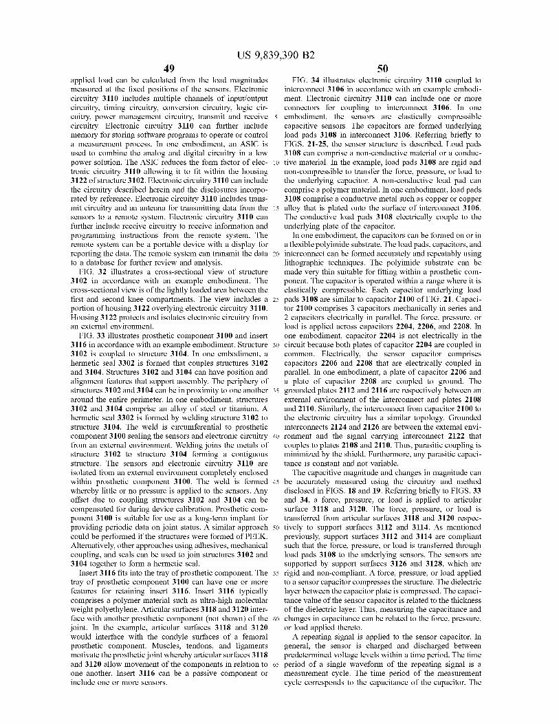
US 9 , 839 , 390 B2 49 50
applied load can be calculated from the load magnitudes FIG . 34 illustrates electronic circuitry 3110 coupled to measured at the fixed positions of the sensors . Electronic interconnect 3106 in accordance with an example embodi circuitry 3110 includes multiple channels of input / output ment . Electronic circuitry 3110 can include one or more circuitry , timing circuitry , conversion circuitry , logic cir connectors for coupling to interconnect 3106 . In one cuitry , power management circuitry , transmit and receive 5 embodiment , the sensors are elastically compressible circuitry . Electronic circuitry 3110 can further include capacitive sensors . The capacitors are formed underlying memory for storing software programs to operate or control load pads 3108 in interconnect 3106 . Referring briefly to a measurement process . In one embodiment , an ASIC is FIGS . 21 - 25 , the sensor structure is described . Load pads used to combine the analog and digital circuitry in a low 3108 can comprise a non - conductive material or a conduc power solution . The ASIC reduces the form factor of elec - 10 tive material . In the example , load pads 3108 are rigid and tronic circuitry 3110 allowing it to fit within the housing non - compressible to transfer the force , pressure , or load to 3122 of structure 3102 . Electronic circuitry 3110 can include the underlying capacitor . A non - conductive load pad can the circuitry described herein and the disclosures incorpo - comprise a polymer material . In one embodiment , load pads rated by reference . Electronic circuitry 3110 includes trans 3108 comprise a conductive metal such as copper or copper mit circuitry and an antenna for transmitting data from the 15 alloy that is plated onto the surface of interconnect 3106 . sensors to a remote system . Electronic circuitry 3110 can The conductive load pads 3108 electrically couple to the further include receive circuitry to receive information and underlying plate of the capacitor . programming instructions from the remote system . The In one embodiment , the capacitors can be formed on or in remote system can be a portable device with a display for a flexible polyimide substrate . The load pads , capacitors , and reporting the data . The remote system can transmit the data 20 interconnect can be formed accurately and repeatably using to a database for further review and analysis . lithographic techniques . The polyimide substrate can be
FIG . 32 illustrates a cross - sectional view of structure made very thin suitable for fitting within a prosthetic com 3102 in accordance with an example embodiment . The ponent . The capacitor is operated within a range where it is cross - sectional view is of the lightly loaded area between the elastically compressible . Each capacitor underlying load first and second knee compartments . The view includes a 25 pads 3108 are similar to capacitor 2100 of FIG . 21 . Capaci portion of housing 3122 overlying electronic circuitry 3110 . tor 2100 comprises 3 capacitors mechanically in series and Housing 3122 protects and isolates electronic circuitry from 2 capacitors electrically in parallel . The force , pressure , or an external environment . load is applied across capacitors 2204 , 2206 , and 2208 . In
FIG . 33 illustrates prosthetic component 3100 and insert one embodiment , capacitor 2204 is not electrically in the 3116 in accordance with an example embodiment . Structure 30 circuit because both plates of capacitor 2204 are coupled in 3102 is coupled to structure 3104 . In one embodiment , a common . Electrically , the sensor capacitor comprises hermetic seal 3302 is formed that couples structures 3102 capacitors 2206 and 2208 that are electrically coupled in and 3104 . Structures 3102 and 3104 can have position and parallel . In one embodiment , a plate of capacitor 2206 and alignment features that support assembly . The periphery of a plate of capacitor 2208 are coupled to ground . The structures 3102 and 3104 can be in proximity to one another 35 grounded plates 2112 and 2116 are respectively between an around the entire perimeter . In one embodiment , structures external environment of the interconnect and plates 2108 3102 and 3104 comprise an alloy of steel or titanium . A and 2110 . Similarly , the interconnect from capacitor 2100 to hermetic seal 3302 is formed by welding structure 3102 to the electronic circuitry has a similar topology . Grounded structure 3104 . The weld is circumferential to prosthetic interconnects 2124 and 2126 are between the external envi component 3100 sealing the sensors and electronic circuitry 40 ronment and the signal carrying interconnect 2122 that from an external environment . Welding joins the metals of couples to plates 2108 and 2110 . Thus , parasitic coupling is structure 3102 to structure 3104 forming a contiguous minimized by the shield . Furthermore , any parasitic capaci structure . The sensors and electronic circuitry 3110 are tance is constant and not variable . isolated from an external environment completely enclosed The capacitive magnitude and changes in magnitude can within prosthetic component 3100 . The weld is formed 45 be accurately measured using the circuitry and method whereby little or no pressure is applied to the sensors . Any disclosed in FIGS . 18 and 19 . Referring briefly to FIGS . 33 offset due to coupling structures 3102 and 3104 can be and 34 , a force , pressure , or load is applied to articular compensated for during device calibration . Prosthetic com - surface 3118 and 3120 . The force , pressure , or load is ponent 3100 is suitable for use as a long - term implant for transferred from articular surfaces 3118 and 3120 respec providing periodic data on joint status . A similar approach 50 tively to support surfaces 3112 and 3114 . As mentioned could be performed if the structures were formed of PEEK . previously , support surfaces 3112 and 3114 are compliant Alternatively , other approaches using adhesives , mechanical such that the force , pressure , or load is transferred through coupling , and seals can be used to join structures 3102 and load pads 3108 to the underlying sensors . The sensors are 3104 together to form a hermetic seal . supported by support surfaces 3126 and 3128 , which are
Insert 3116 fits into the tray of prosthetic component . The 55 rigid and non - compliant . A force , pressure , or load applied tray of prosthetic component 3100 can have one or more to a sensor capacitor compresses the structure . The dielectric features for retaining insert 3116 . Insert 3116 typically layer between the capacitor plate is compressed . The capaci comprises a polymer material such as ultra - high molecular tance value of the sensor capacitor is related to the thickness weight polyethylene . Articular surfaces 3118 and 3120 inter - of the dielectric layer . Thus , measuring the capacitance and face with another prosthetic component ( not shown ) of the 60 changes in capacitance can be related to the force , pressure , joint . In the example , articular surfaces 3118 and 3120 or load applied thereto . would interface with the condyle surfaces of a femoral repeating signal is applied to the sensor capacitor . In prosthetic component . Muscles , tendons , and ligaments general , the sensor is charged and discharged between motivate the prosthetic joint whereby articular surfaces 3118 predetermined voltage levels within a time period . The time and 3120 allow movement of the components in relation to 65 period of a single waveform of the repeating signal is a one another . Insert 3116 can be a passive component or measurement cycle . The time period of the measurement include one or more sensors . cycle corresponds to the capacitance of the capacitor . The

US 9 , 839 , 390 B2 52
waveform or signal is repeated a predetermined number of 2116 and interconnect 2126 . Structure 3104 acts as a shield times . A measurement sequence comprises the repeated for preventing signal or parasitic coupling to the capacitive waveform for the predetermined number of times . An sensors . elapsed time of the measurement sequence is measured . The Support surface 3114 of structure 3102 is supported by elapsed time is the time required to generate the predeter - 5 load pad 3108 and sensor 2100 . Load pad 3108 distributes mined number of waveforms . The force , pressure , or load is the load to sensor 2100 . Support surface 3114 is compliant maintained during the measurement sequence . The mea to loading placed thereon . In one embodiment , support sured elapsed time of the sensor capacitor is correlated to the surface 3114 made thin to allow flexing . In general , support
surface 3114 deflects a short distance over the entire load force , pressure , or load measurement . The relationship between capacitance and force , pressure , or load is known . 10 range . Sensor 2100 can elastically compress approximately
20 % of the total dielectric thickness . In one embodiment , In one embodiment , each capacitive sensor can be measured compression of sensor 2100 is limited to 10 % or less of the against known force , pressure , or load values after assembly total dielectric thickness . For example , a capacitor as dis of the prosthetic component . The measurements can be closed herein can compress approximately 0 . 00254 milli stored in memory that is part of the electronic circuitry onic circuitry 15 meters over the load range of a typical prosthetic component housed in the prosthetic component . Further refinement can load sensor . In one embodiment , a stack three capacitive be achieved by using calibration techniques or algorithms sensors in series , lamination material , and insulating mate during final testing of each capacitor that can take into rial would yield a total compression under maximum load account interpolation between measurements and non - linear ing of approximately 0 . 0076 millimeters . Thus , support compression of the dielectric . The measurement resolution 20 surfaces 3112 or 3114 do not flex significantly over the entire can be increased by this technique if the force , pressure , or load range . Load pad 3108 couples to a known location on load is substantially constant over the increased number of support surface 3114 . The known location also relates to a predetermined number waveforms . Moreover , the resolution point on the articular surface of the insert . The known supports measurement where the capacitance changes are location of each of the sensors is used to determine where relatively small over the force , pressure , or load measure - 25 the load is coupled to the articular surface by comparing the ment range . measured load magnitudes . Although a single sensor is
FIG . 35 illustrates an assembled prosthetic component shown , the other sensors formed in interconnect 3106 are 3100 in accordance with an example embodiment . Pros similarly coupled to structures 3102 and 3104 . Hermetic seal
3302 couples structures 3102 and 3104 together . Hermetic thetic component 3100 comprises structure 3102 coupled to structure 3104 . Prosthetic component 3100 houses elec - 30 30 seal 3302 can be a weld that melts and joins the material of tronic circuitry and sensors . A hermetic seal 3302 couples structures 3102 and 3104 .
Conductive region 2112 is a plate of the capacitor formed the structure 3102 to structure 3104 . In one embodiment , in interconnect 3106 . Interconnect 2124 couples conductive hermetic seal 3302 is a contiguous weld around the periph region 2112 to electronic circuitry 3110 . In the example , ery . As mentioned , weld does not load or lightly loads the 35 Toads me 35 conductive region 2112 and interconnect 2124 are coupled sensors underlying the support surfaces . In the example , to ground . Conductive region 2108 and conductive region prosthetic component 3100 is a tibial prosthetic component . 2110 are plates of the capacitor formed in the interconnect Structure 3102 includes a tray for receiving an insert having 3106 . Conductive regions 2108 and 2110 of sensor 2100 are at least one articular surface . The tibial prosthetic compo - coupled in common by via 2120 . Interconnect 2122 couples nent can be a single or dual compartment device . Structure 40 the conductive regions 2108 and 2110 to the electronic 3104 includes a stem 3124 for coupling to bone . In the circuitry . Interconnect 2122 carries a signal from the elec example , stem 3124 couples to the tibia . tronic circuitry to sensor 2100 to measure the capacitor .
FIG . 36 illustrates a partial cross - sectional view of pros - Conductive region 2112 is separated from conductive region thetic component 3100 in accordance with an example 2108 by dielectric layer 2104 . Similarly , conductive region embodiment . The cross - sectional view is in a region near the 45 2116 is separated from conductive region 2110 by dielectric periphery where hermetic seal 3302 couples structures 3102 layer 2106 . Conductive regions 2108 and 2110 are separated and 3104 together . In the example , a sensor 2100 is included by a dielectric layer 2102 but as mentioned previously are The sensor 2100 is formed in interconnect 3106 . A load pad coupled in common . In one embodiment , dielectric layers 3108 is formed on sensor 2100 . Interconnect 3106 further 2102 , 2104 , and 2106 comprise polyimide . Other dielectrics illustrates shielding of the sensor to minimize signal cou - 50 such as silicon dioxide , silicon nitride , mylar , and other pling and parasitic capacitance . polymers can be used . Interconnect 3106 and sensor 2100
The cross - section illustrates placement of sensor 2100 of can be formed by deposition , plating , and lithographic prosthetic component 3100 for load sensing . Support surface techniques on the substrate . 3128 of structure 3104 supports sensor 2100 . In the The capacitor of sensor 2100 comprises three capacitors example , support surface 3128 is rigid . Conductive region 55 mechanically in series . A force , pressure , or load applied to 2116 is a plate of the capacitor formed in interconnect 3106 . support surface 3114 compresses the three capacitors . A first Interconnect 2126 couples conductive region 2116 to the capacitor comprises conductive region 2112 , dielectric layer electronic circuitry 3110 . Conductive region 2116 and inter - 2104 , and conductive region 2108 . A second capacitor connect 2126 couples to support surface 3128 . In the comprises conductive region 2108 , dielectric layer 2102 , example , conductive region 2116 and interconnect 2126 are 60 and conductive region 2110 . A third capacitor comprises coupled to ground . Conductive region 2116 acts as a shield conductive region 2108 , dielectric layer 2106 , and conduc to prevent signal or parasitic coupling to conductive regions tive region 2116 . Electrically , the capacitor of sensor 2100 2110 and 2108 of sensor 2100 . Similarly , interconnect 2126 comprises the first and third capacitors coupled in parallel . acts as a shield for interconnect 2124 to prevent signal or The first and third capacitors have conductive regions 2108 parasitic coupling . In one embodiment , support surface 3128 65 and 2110 coupled in common . Similarly , conductive regions comprises a conductive material such as metal . Thus , struc - 2112 and 2116 of the first and third capacitors are coupled ture 3104 is coupled to ground by way of conductive region to ground . Conductive region 2112 and 2116 respectively

US 9 , 839 , 390 B2 53 54
shield conductive region 2108 and 2110 from coupling and In one embodiment , an ASIC combines many of the features parasitic capacitance external to interconnect 3106 . Simi - to minimize form factor and to lower power consumption . larly , interconnect 2124 and 2126 shield interconnect 2122 Sensors and communication circuitry are located on elec from signal coupling and parasitic capacitance external to tronic circuitry 3110 in proximity to transmissive region interconnect 3106 . 5 3122 allowing transmission and reception of signals . A
Structures 3102 and 3104 can comprise a conductive directional antenna can be placed in proximity to transmis material . For example , titanium , cobalt , and steel alloys are sive region 3702 to send and receive information to a remote conductive materials used to manufacture prosthetic com system . ponent 3100 . Placing interconnect 3106 on support surface In general , sensors can be used to monitor the synovial 3128 couples conductive region 2116 and interconnect 2126 10 fluid that is in proximity to the joint region . Synovial fluid to structure 3104 . Conductive region 2116 and support is a natural lubricant found in a muscular - skeletal joint . surface 3128 are coupled in common to ground . Similarly , Synovial fluid is found in joints such as the elbow , knee , load pad 3108 can comprise a conductive material . In one embodiment , a material such as copper or copper alloy can shoulder , hip and others . Synovial fluid comprises mucin , be deposited or plated to the surface of interconnect 3106 . 15 albu * 3106 15 albumin , fat , epthelium , and leukocytes . The lubricant also Load pad 3108 is coupled to conductive region 2112 and nourishes the avascular articular cartilage . Synovial fluid interconnect 2124 . Support surface 3114 is coupled to con - cushions joint impact and reduces friction as bone and ductive region 2112 and interconnect 2124 by load pad cartilage contact one another over the range of motion . 3108 . As mentioned previously , conductive region 2112 and Synovial fluid can also carry oxygen and other nutrients to interconnect 2124 are coupled to ground . Thus , structure 20 cartilage and other areas of the joint . Similarly , synovial 3102 and 3104 are coupled to ground . Alternatively , struc - fluid acts as transport to remove waste materials from the tures 3102 and 3104 can be coupled to ground via an joint region . The synovial fluid remains in and around the alternate path other than sensor 2100 . In one embodiment , joint . The synovial fluid can be retained by a synovial the electronic circuitry and sensor 2100 are housed in membrane that holds the lubricant in place . prosthetic component 3100 . Structures 3102 and 3104 form 25 There is a strong correlation between the health of a joint a shield that isolates electronic circuitry 3110 and sensor and the condition of the synovial fluid . Sensors that measure 2100 from parasitic coupling and parasitic capacitance in the temperature , pH , color , turbidity , viscosity , glucose , and external environment . The design further incorporates the proteins can be used to analyze synovial fluid . The sensors internal shields built into the capacitor that prevents or can be used individually or in concert with one another to minimizes parasitic coupling and parasitic capacitance 30 determine joint health . Prosthetic component 3100 includes external to interconnect 3106 . Although a capacitive sensor one or more of the sensors for monitoring the joint . In the is used in the example , the load sensor in prosthetic com example , the joint is monitored for infection . Infection in a ponent 3100 can comprises one of a strain gauge , mems newly implanted joint is a critical problem . It is often device , piezo - resistive sensor , mechanical sensor , polymer difficult for a patient with a joint implant to determine if he sensor , and ultrasonic sensor . 35 or she has an infection . The surgery itself and joint reha
FIG . 37 illustrates structure 3102 in accordance with an bilitation can mask early signs of an infection . The pros example embodiment . Structure 3102 of prosthetic compo - thetic joint is an ideal place for an infection to grow without nent 3100 when installed in a joint region of the patient abatement . There are areas in the prosthetic joint that are includes at least one region having exposure external to the isolated but have nutrients that can harbor bacteria and foster joint . The view shows housing 3122 of structure 3102 that 40 growth . Infection can lead to a substantial health risk , includes a transmissive region 3702 . In one embodiment , anti - biotic treatment , increased rehabilitation , long - term transmissive region 3702 comprises glass , PEEK , plastic , or hospitalization , and substantial cost . If the infection is polymer . Transmissive region 3702 can be bonded to an significant there is a scenario that requires the removal of the opening in a wall of housing 3122 that comprises a steel prosthetic joint . The patient is immobilized until the infec alloy , titanium , cobalt , an alloy , or metal . In one embodi - 45 tion subsides and then a new prosthetic joint is implanted . ment , housing 3122 houses electronic circuitry . Alterna - The patient trauma under such circumstances can be sig tively , part of or all of structure 3102 can comprise a nificant . Prosthetic joint 3100 can detect infection local to polymer such as PEEK , which is transmissive to some of the the joint , notify a doctor or healthcare provider , or take spectrum . In one embodiment , transmissive region 3702 is appropriate action in a timely manner . transmissive to sensor signals and communication signals . 50 In one embodiment , temperature can be monitored . A For example , signals can be blocked when structure 3102 temperature sensor 3704 can be mounted in proximity to comprises a conductive material and the conductive material transmissive region 3702 . Temperature sensor 3704 is is grounded . Prosthetic component 3100 can act as a shield coupled to electronic circuitry 3110 for receiving tempera to the electronic circuitry and sensors housed within the ture data . In one embodiment , electronic circuitry 3110 has device . Transmissive region 3702 can be transmissive to 55 multiple I / O channels for coupling to sensors . Temperature signals such as acoustic , ultrasonic , radio frequency , infra - sensor 3704 monitors the temperature of the joint . In one red , and light . Transmissive region 3702 has exposure to embodiment , temperature sensor 3704 measures the tem regions around and in proximity to the joint region . In one perature of the synovial fluid . Measurements of the synovial embodiment , window 3702 can be used to monitor the fluid can occur periodically . synovial fluid that resides in and around the joint . 60 A temperature difference can be detected between a
Sensors can also be located at or near transmissive region healthy knee and an infected knee . In the example , tempera 3702 . The sensors can be mounted with electronic circuitry ture sensor 3704 is calibrated to a normal temperature of the 3110 . Electronic circuitry 3110 can comprise one or more pc synovial fluid . The calibrations can occur periodically boards having interconnect and connectors . Integrated cir - because the normal temperature will change depending on cuits , ASIC devices , a power source , communication cir - 65 the patient condition . The absolute temperature and changes cuitry , digital logic , converters , power management , and in temperature are monitored . A change in temperature from other systems can be coupled together in a small form factor . the norm can be an indication of an infection . In the

55 US 9 , 839 , 390 B2
56 example , temperature sensor can be a MEMS sensor , a and blue components of white light . More than one trans thermocouple , thermistor or other temperature measuring missive region can be used to send and receive light . Also , device . one or more barriers or transmissive regions can be used to
In one embodiment , pH can be monitored . A pH sensor direct the light into the synovial fluid and prevent direct light 3706 can be mounted in proximity to transmissive region 5 from LED 3708 from radiating onto photo - diode array 3710 . 3702 and coupled to electronic circuitry 3110 for receiving Equations for the measurement can be as follows : pH data . Similar to temperature , pH sensor 3706 can be initially calibrated to the normal pH and recalibrated peri r = red , g = green , b = blue , c = calibration odically . A lower pH than the norm can indicate the presence of an infection . Measurement of absolute pH and differential 10 Color = [ rg , b ] / ( r + g + b ) pH over time can be used to detect an increase in bacteria . In general , a healthy knee has a pH of approximately 7 . 23 . An infected knee has a pH of approximately 7 . 06 . The Turbidity = ( r + g + b ) / 3c device can be calibrated for specifics of an individual The color measured by photo - diode array 3710 can be patient . The pH sensor can be a MEMS pH sensor , an 15 compared to known infection color data . Similarly , the implantable pH microsensor , electro - static pH sensor , or turbidity measurements by photo - diode array 3710 can be other pH measuring device . compared against known turbidity color data . Both color and
In one embodiment , turbidity and color can be monitored . turbidity measurements can be taken by prosthetic compo Turbidity is a measure of the cloudiness or haze due to the nent 3100 . Using both measurements in combination can suspension of particles within a fluid . For example , synovial 20 provide data that allows further refinement of the prognosis fluid becomes turbid as an infection grows . Bacteria , bac - thereby providing a better assessment and treatment meth terial waste products , and white blood cells are but a few of odology . Furthermore , taking periodic measurements and the particulates that can be suspended in the synovial fluid . comparing the color and turbidity measurements can yield a The turbidity increases as the infection worsens due to rate of change . The rate of change can be used to determine increased bacterial growth . Similarly , the color of the syn - 25 if the infection is increasing or declining . Comparing mea ovial fluid changes as an infection increases . For example , surements over time can be used to determine if the infection healthy synovial fluid is a relatively clear fluid . The synovial treatment is successful . Placing sensors in the prosthetic fluid changes color as the joint status changes from healthy component has substantial benefits in preventing infection . to non - inflammatory , non - inflammatory to inflammatory , Statistically most infections occur shortly after the joint and inflammatory to septic . A non - inflammatory synovial 30 implant or within the first few months after surgery . Infec fluid is a yellowish clear liquid that is indicative of joint tion is less likely to occur after the surgical wound has related problems such as osteoarthritis . The synovial fluid healed and rehabilitation of the joint has taken place . Pain will be viscous retaining its lubricating and damping prop - due to the surgery and during rehabilitation can also mask erties . An inflammatory synovial fluid is yellowish in color . infection symptoms . If an infection occurs , it will start as a The inflammatory synovial fluid is hazy and not clear . It will 35 local infection in proximity to the joint . A first benefit is that also have lost some of its viscous properties having a watery prosthetic component 3100 can identify an infection that is consistency . The inflammatory synovial fluid can indicate local to the joint before it has spread throughout the body . A problems such as rheumatoid arthritis or infection . Septic second benefit is that treatment of the infection can be local synovial fluid can be dark yellow to red in color . Moreover , to the joint region . A third benefit is that prosthetic compo septic synovial fluid is opaque . The synovial fluid can 40 nent 3100 can also include an antibiotic that could be contain high counts of bacteria , fungus , white , and red blood released in proximity to the joint . A fourth benefit is that cells . Measuring color , turbidity , or a combination of both prosthetic component 3100 can be in communication with a can be used to determine joint health . remote system and a database . The remote system can be
In the example , optical sensors such as a LED 3708 ( light provide notification to the patient to see a doctor . The remote emitting diode ) and photo - diode array 3710 can be used to 45 system can also provide data to the doctor for analysis and measure color and turbidity . In one embodiment , the LED treatment . 3708 and photo - diode array 3710 are positioned behind Amethod of long - term joint monitoring is disclosed using transmissive region 3702 . LED 3708 and photo - diode array prosthetic component 3100 . The method can be practiced 3710 are housed within prosthetic component 3100 and can with more or less than the steps shown , and is not limited to couple to or be part of electronic circuitry 3110 . As previ - 50 the order of steps shown . The method is not limited to the ously mentioned , transmissive region 3702 can be glass that example tibial prosthetic component example but can be is transmissive to light . LED 3708 can transmit white light used for hip , shoulder , ankle , elbow , spine , hand , foot , and directly to a photo - diode . The photo - diode can be part of bone . In a first step , electronic circuitry and one or more photo - diode array 3710 or a separate device . The photo sensors are housed in a prosthetic component . In a second diode can be used for calibration of LED 3708 and for 55 step , characteristics of synovial fluid are periodically mea detecting changes in the light or intensity output by the sured in proximity to the prosthetic component . The char device . LED 3708 also illuminates a sample of synovial acteristic can be used to determine the presence of an fluid . As shown , light emitted by LED 3708 is transmitted infection or other problem . Examples of measured charac through transmissive region 3702 into the synovial fluid in teristics are temperature , pH , color , turbidity , viscosity , proximity to prosthetic component 3100 . In one embodi - 60 glucose levels , and proteins . In a third step , measurements ment , three photo - diodes respectively having red , green , and are compared . In one embodiment , measurements compared blue optical filters detect light transmitted through the syn - against one another to determine if a change has occurred . ovial fluid . Each photo - diode measures the relative contri - Furthermore , multiple measurements made over time can bution of red , green , and blue . The contribution can be indicate a trend . In another embodiment , the measured ratiometrically compared with a calibration value corre - 65 characteristics can be compared against known or predeter sponding to a measurement by the calibration photo - diode . mined values that relate to infection or other problem being The calibration value corresponds to the sum of red , green , identified

US 9 , 839 , 390 B2 57 58
In a fourth step , a color of the synovial fluid is measured . photo - diode array . Each diode of the photo - diode array can In a fifth step , the color of the synovial fluid is compared have a filter for filtering the incoming light through the against a known color range . In a sixth step , it can be transmissive region of the prosthetic component . determined if an infection is present . In one embodiment , the FIG . 38 illustrates prosthetic component 3100 and a comparison yields a color similar to a known synovial fluid 5 remote system 3802 in accordance with an example embodi color . For example , clear synovial fluid is normal . A clear ment . Remote system 3802 can be equipment , a tool , a yellow synovial fluid can indicate inflammation and other computer , a note pad , a cell phone , a smartphone , or medical problems . A hazy yellow synovial fluid can indicate the device . Data transmitted from prosthetic component 3100 is presence of bacteria or other problems . A synovial fluid received by remote system 3802 . Similarly , remote system having a red tint can indicate sepsis and blood in the 10 3802 can transmit information to prosthetic component 3100 synovial fluid . that supports operation and sensor measurement . Remote
In a seventh step , the relative contributions of red , green , system 3802 can include logic circuitry , microprocessor , and blue colors are measured . In an eighth step , a contribu - microcontroller , or digital signal processor . In the example , tion of each color is ratiometrically compared to a sum of the remote system 3802 is a laptop computer with a display . relative contributions . A color of the synovial fluid can be 15 Remote system 3802 can include software for analyzing determined by assessing the contributions of red , green , and quantitative measurement data from prosthetic component blue colors . In a ninth step , a rate of change in color is 3100 and displaying the information for assessment . Remote determined . The rate of change in color can be used to system 3802 includes transmit circuitry , receive circuitry , or determine the status of an infection . For example , once an both for coupling to electronic circuitry 3110 of prosthetic infection is detected the rate of change corresponds to a 20 component 3100 . Similarly , electronic circuitry 3110 decrease or increase in the infection . It can also be used to includes transmit circuitry , receive circuitry , or both . In the determine the effectiveness of treatment . After treatment the example , electronic circuitry includes an ASIC having trans rate of change should indicate a decrease in the infection . mit and receive circuitry . In one embodiment , transmit and
A method of long - term joint monitoring is disclosed using receive circuitry transmits through transmissive region prosthetic component 3100 . The method can be practiced 25 3702 . Alternatively , other transmissive regions can be added with more or less than the steps shown , and is not limited to to prosthetic component 3100 for supporting antenna place the order of steps shown . The method is not limited to the ment . Also , prosthetic component 3100 can be made from a example tibial prosthetic component example but can be polymer such as PEEK that allows transmission and recep used for hip , shoulder , ankle , elbow , spine , hand , foot , and tion of signals . In one embodiment , transmission of data to bone . In a first step , electronic circuitry and one or more 30 remote system 3802 is short range . The transmission range sensors are housed in a prosthetic component . In a second is typically less than 10 meters . In an installed prosthetic step , a turbidity of synovial fluid is periodically measured in component , the RF transmission is made through tissue . The proximity to the prosthetic component . The turbidity can be short transmission distance reduces un - authorized reception used to determine the presence of an infection or other of data . In one embodiment , the data transmission is problem . Examples of other measured characteristics are 35 encrypted for security . The data can be decrypted by remote temperature , pH , color , turbidity , viscosity , glucose levels , system 3802 . and proteins . In a third step , the turbidity measurements are in the example , housing 3122 includes electronic circuitry compared to known turbidity measurements or a predeter - 3110 and a window 3702 . Window 3702 can be transmissive mined turbidity range . In one embodiment , comparing the to signals such as acoustic , ultrasonic , radio frequency , periodic measurements determine if a change has occurred . 40 infrared , and light . Window 3702 can comprise glass that is Furthermore , multiple turbidity measurements taken over bonded to the steel , titanium , cobalt , alloy , or metal of the time can indicate a trend . In another embodiment , the prosthetic component . Alternatively , part of or all of struc measured characteristics can be compared against known or ture 3102 can comprise a plastic or a polymer such as PEEK , predetermined turbidity values that relate to infection or which is transmissive to some of the spectrum . Window other problem being solved . In a fourth step , it can be 45 3702 is not blocked by other components of the prosthetic determined if an infection is present . Turbidity is a measure joint and has exposure to regions around and in proximity to of the cloudiness or haziness of a substance . For example , the joint region . In one embodiment , window 3702 can be healthy synovial fluid is clear . Conversely , infected synovial used to monitor a region in proximity to the prosthetic joint . fluid is hazy or cloudy due to the presence of bacteria . Similarly , sensors can be fastened to structure 3102 or 3104 Moreover , the severity of the infection can be related to the 50 and exposed to the region . Window 3702 can be used to number of particulates in the synovial fluid . The higher the measure one or more parameters that relate to the health of nu number of particulates the worse the infection can be synovial fluid . In the example , optical sensors are used to
In a fifth step , the turbidity is compared against previous measure color and turbidity . Electronic circuitry 3110 turbidity measurements . In a sixth step , a rate of change in couples to each of the sensors . In one embodiment , a channel turbidity is determined . In general , if the turbidity increases 55 is assigned to each sensor . The channels can be operated the infection or problem is worsening because healthy serially or in parallel . Logic circuitry in electronic circuitry synovial fluid is clear . Alternatively , if treatment has been 3110 controls when measurements are taken . The measure provided and the turbidity over time is decreasing than the ment data can be stored in memory on electronic circuitry patient health is improving . In a seventh step , data is 3110 until transmitted . The measurement data can be con wirelessly transmitted to a remote system . In one embodi - 60 verted to a digital format . The quantitative parameter mea ment , the remote system is in proximity to the prosthetic s urements can be used individually or in combination to component due to the limited range of transmission . The determine a health issue . remote system can include a processor and graphic proces - Amethod of long - term joint monitoring is disclosed using sor . In an eighth step , light is received through a transmissive prosthetic component 3100 . The method can be practiced region of the prosthetic component . Light is transmitted into 65 with more or less than the steps shown , and is not limited to the synovial fluid in proximity to the prosthetic component . the order of steps shown . The method is not limited to the The light illuminates the synovial fluid that is detected by a example tibial prosthetic component example but can be

59 US 9 , 839 , 390 B2
60 used for hip , shoulder , ankle , elbow , spine , hand , foot , and sensors for measuring in proximity to prosthetic component bone . In a first step , electronic circuitry and one or more 3100 . Interconnect 3106 overlies support surface 3126 and sensors are housed in a prosthetic component . In a second 3128 . Each interconnect 3106 includes a sensor array and step , synovial fluid in proximity to the prosthetic component corresponds to a compartment of the knee . Sensors underlie is monitored . In a third step , a characteristic of the synovial 5 load pad 3108 of interconnect 3106 for measuring a force , fluid is measured . Examples of characteristics being mea pressure , or load . Electronic circuitry 3110 can include sured are temperature , pH , color , turbidity , viscosity , glucose accelerometers for providing positioning information of the levels , and proteins . In a fourth step , data is sent to a remote joint . system . The data can be wirelessly transmitted from the FIG . 41 depicts an exemplary diagrammatic representa prosthetic component to the remote system . The remote 10 tion of a machine in the form of a system 4100 within which system can include digital logic , a processor , a digital signal a set of instructions , when executed , may cause the machine processor , a graphic processor , communication circuitry , or to perform any one or more of the methodologies discussed analog circuitry . In one embodiment , the transmission can be less than 10 meters due to power constraints of the signal above . In some embodiments , the machine operates as a and the medium in which it travels . For example , the 15 star 15 standalone device . In some embodiments , the machine may transmission has to be sent through the multiple layers of be connected ( e . g . , using a network ) to other machines . In a tissue between the prosthetic component and the external networked deployment , the machine may operate in the environment . capacity of a server or a client user machine in server - client
In a fourth step , the data sent by the prosthetic component user network environment , or as a peer machine in a can be analyzed . The data can be analyzed by the remote 20 peer - to - peer ( or distributed ) network environment . system . The data can also be sent to other equipment , The machine may comprise a server computer , a client devices , computers , or a database . The data can be combined user computer , a personal computer ( PC ) , a tablet PC , a with other information or data to create a clinical database laptop computer , a desktop computer , a control system , logic related to a study of the joint or prosthetic system . In a fifth circuitry , a sensor system , an ASIC , an integrated circuit , a step , a report is generated . The report is based on quantita - 25 network router , switch or bridge , or any machine capable of tive data provided by the sensors in the prosthetic compo - executing a set of instructions ( sequential or otherwise ) that nent . In a sixth step , the report is sent to at least one entity . specify actions to be taken by that machine . It will be In general , the report uses quantitative data generated by the understood that a device of the present disclosure includes sensors in the prosthetic component . In the example , the broadly any electronic device that provides voice , video or sensor data can be an analysis of the synovial fluid in 30 data communication . Further , while a single machine is proximity to the joint . The report can lead to an action being illustrated , the term “ machine ” shall also be taken to include taken . For example , detecting an infection or a condition any collection of machines that individually or jointly such as arthritis can lead to treatment . The sensors can be execute a set ( or multiple sets ) of instructions to perform any used to monitor progress of the treatment . In a seventh step , temperature of the synovial fluid can be measured . In an 35 one Synovial fluid can be measured in an 35 one or more of the methodologies discussed herein . eighth step , pH of the synovial fluid can be measured . In a System 4100 may include a processor 4102 ( e . g . , a central ninth step , the color or turbidity of the synovial fluid can be processing unit ( CPU ) , a graphics processing unit ( GPU , or measured . The report can be as simple as a status update on both ) , a main memory 4104 and a static memory 4106 , the sensor data to the patient or a detailed listing of all the which communicate with each other via a bus 4108 . System parameters measured , trends , and analysis of the data sent to 40 4100 may further include a video display unit 4110 ( e . g . , a a health care provider such as a doctor , surgeon , or hospital . liquid crystal display ( LCD ) , a flat panel , a solid state The entity can be broadly interpreted as anything or anybody display , or a cathode ray tube ( CRT ) ) . System 4100 may that has rights to use the information . The report can be include an input device 4112 ( e . g . , a keyboard ) , a cursor encrypted to maintain privacy of the information . Similarly , control device 4114 ( e . g . , a mouse ) , a disk drive unit 4116 , the sensor data can also include the load and position of load 45 a signal generation device 4118 ( e . g . , a speaker or remote data . This sensor data can be used to address kinematic control ) and a network interface device 4120 . issues regarding the joint and how the patient is adapting to The disk drive unit 4116 can be other types of memory the prosthesis . such as flash memory and may include a machine - readable
FIG . 39 is an illustration of electronic circuitry 3110 and medium 4122 on which is stored one or more sets of structure 3104 in accordance with an example embodiment . 50 instructions ( e . g . , software 4124 ) embodying any one or Structure 3104 is a component of prosthetic component more of the methodologies or functions described herein , 3100 disclosed herein . Structure 3104 can includes a cavity including those methods illustrated above . Instructions 4124 3902 for housing electronic circuitry 3110 . Electronic cir - may also reside , completely or at least partially , within the cuitry 3110 is placed vertically into cavity 3902 . Cavity main memory 4104 , the static memory 4106 , and / or within 3902 extends into stem 3124 of structure 3104 . In general , 55 the processor 4102 during execution thereof by the system the electronic circuitry can be housed within structure 3102 , 4100 . Main memory 4104 and the processor 4102 also may 3104 , or both . constitute machine - readable media .
FIG . 40 is an illustration of electronic circuitry 3110 and Dedicated hardware implementations including , but not structure 3104 in accordance with an example embodiment limited to , application specific integrated circuits , program Structure 3104 can include a cavity 4002 for housing 60 mable logic arrays and other hardware devices can likewise electronic circuitry 3110 . Electronic circuitry 3110 is placed be constructed to implement the methods described herein . horizontally into cavity 4002 . Cavity 4002 is centered Applications that may include the apparatus and systems of between interconnect 3106 in a lightly loaded region of various embodiments broadly include a variety of electronic prosthetic component 3100 . Sensors such as temperature , and computer systems . Some embodiments implement func pH , optical , glucose , and others can be mounted in housing 65 tions in two or more specific interconnected hardware mod 3122 and coupled to electronic circuitry 3110 . Cavity 4002 ules or devices with related control and data signals com underlies housing 3122 and provides room to accommodate municated between and through the modules , or as portions

US 9 , 839 , 390 B2 62
of an application - specific integrated circuit . Thus , the alignment , displacement , movement , rotation , and accelera example system is applicable to software , firmware , and tion ) with remote services or providers , for instance , to hardware implementations . analyze or report on surgical status or outcome . This data
In accordance with various embodiments of the present can be shared for example with a service provider to monitor disclosure , the methods described herein are intended for 5 progress or with plan administrators for surgical monitoring operation as software programs running on a computer purposes or efficacy studies . The communication network processor . Furthermore , software implementations can 4200 can further be tied to an Electronic Medical Records include , but not limited to , distributed processing or com - ( EMR ) system to implement health information technology ponent / object distributed processing , parallel processing , or practices . In other embodiments , the communication net virtual machine processing can also be constructed to imple - 10 work 4200 can be communicatively coupled to HIS Hospital ment the methods described herein . Information System , HIT Hospital Information Technology
The present disclosure contemplates a machine readable and HIM Hospital Information Management , EHR Elec medium containing instructions 4124 , or that which receives tronic Health Record , CPOE Computerized Physician Order and executes instructions 4124 from a propagated signal so Entry , and CDSS Computerized Decision Support Systems . that a device connected to a network environment 4126 can 15 This provides the ability of different information technology send or receive voice , video or data , and to communicate systems and software applications to communicate , to over the network 4126 using the instructions 4124 . The exchange data accurately , effectively , and consistently , and instructions 4124 may further be transmitted or received to use the exchanged data . over a network 4126 via the network interface device 4120 . The communications network 4200 can provide wired or
While the machine - readable medium 4122 is shown in an 20 wireless connectivity over a Local Area Network ( LAN ) example embodiment to be a single medium , the term 4201 , a Wireless Local Area Network ( WLAN ) 4205 , a “ machine - readable medium ” should be taken to include a Cellular Network 4214 , and / or other radio frequency ( RF ) single medium or multiple media ( e . g . , a centralized or system ( see FIG . 4 ) . The LAN 4201 and WLAN 4205 can distributed database , and / or associated caches and servers ) be communicatively coupled to the Internet 4220 , for that store the one or more sets of instructions . The term 25 example , through a central office . The central office can “ machine - readable medium ” shall also be taken to include house common network switching equipment for distribut any medium that is capable of storing , encoding or carrying ing telecommunication services . Telecommunication ser a set of instructions for execution by the machine and that vices can include traditional POTS ( Plain Old Telephone cause the machine to perform any one or more of the Service ) and broadband services such as cable , HDTV , DSL , methodologies of the present disclosure . 30 VOIP ( Voice over Internet Protocol ) , IPTV ( Internet Protocol
The term “ machine - readable medium ” shall accordingly Television ) , Internet services , and so on . be taken to include , but not be limited to : solid - state memo The communication network 4200 can utilize common ries such as a memory card or other package that houses one computing and communications technologies to support or more read - only ( non - volatile ) memories , random access circuit - switched and / or packet - switched communications . memories , or other re - writable ( volatile ) memories ; mag - 35 Each of the standards for Internet 4220 and other packet neto - optical or optical medium such as a disk or tape ; and switched network transmission ( e . g . , TCP / IP , UDP / IP , carrier wave signals such as a signal embodying computer HTML , HTTP , RTP , MMS , SMS ) represent examples of the instructions in a transmission medium ; and / or a digital file state of the art . Such standards are periodically superseded attachment to e - mail or other self - contained information by faster or more efficient equivalents having essentially the archive or set of archives is considered a distribution 40 same functions . Accordingly , replacement standards and medium equivalent to a tangible storage medium . Accord protocols having the same functions are considered equiva ingly , the disclosure is considered to include any one or lent . more of a machine - readable medium or a distribution The cellular network 4214 can support voice and data medium , as listed herein and including art - recognized services over a number of access technologies such as equivalents and successor media , in which the software 45 GSM - GPRS , EDGE , CDMA , UMTS , WiMAX , 2G , 3G , implementations herein are stored . WAP , software defined radio ( SDR ) , and other known tech
Although the present specification describes components nologies . The cellular network 4214 can be coupled to base and functions implemented in the embodiments with refer - receiver 4210 under a frequency - reuse plan for communi ence to particular standards and protocols , the disclosure is cating with mobile devices 4202 . not limited to such standards and protocols . Each of the 50 The base receiver 4210 , in turn , can connect the mobile standards for Internet and other packet switched network device 4202 to the Internet 4220 over a packet switched link . transmission ( e . g . , TCP / IP , UDP / IP , HTML , HTTP ) repre - The internet 4220 can support application services and sent examples of the state of the art . Such standards are service layers for distributing data from the measurement periodically superseded by faster or more efficient equiva - system 4255 to the mobile device 4202 . Mobile device 4202 lents having essentially the same functions . Accordingly , 55 can also connect to other communication devices through replacement standards and protocols having the same func - the Internet 4220 using a wireless communication channel . tions are considered equivalents . The mobile device 4202 can also connect to the Internet
FIG . 42 is an illustration of a communication network 4220 over the WLAN 4205 . Wireless Local Access Net 4200 for measurement and reporting in accordance with an works ( WLANs ) provide wireless access within a local exemplary embodiment . Briefly , the communication net - 60 geographical area . WLANs are typically composed of a work 4200 expands broad data connectivity to other devices cluster of Access Points ( APs ) 4204 also known as base or services . As illustrated , the measurement and reporting stations . The measurement system 4255 can communicate system 4255 can be communicatively coupled to the com with other WLAN stations such as laptop 4203 within the munications network 4200 and any associated systems or base station area . In typical WLAN implementations , the services . 65 physical layer uses a variety of technologies such as 802 . 11b As one example , measurement system 4255 can share its or 802 . 11g WLAN technologies . The physical layer may use
parameters of interest ( e . g . , angles , load , balance , distance , infrared , frequency hopping spread spectrum in the 2 . 4 GHz

64 US 9 , 839 , 390 B2
63 Band , direct sequence spread spectrum in the 2 . 4 GHz Band , and wherein the plurality of load sensors are configured or other access technologies , for example , in the 5 . 8 GHz to measure a load magnitude and position of load ISM band or higher ISM bands ( e . g . , 24 GHz , etcetera ) . applied to the prosthetic component ; and By way of the communication network 4200 , the mea a rigid load plate having a first surface and a second
surement system 4255 can establish connections with a 5 surface wherein the first surface of the rigid load plate remote server 4230 on the network and with other mobile is coupled to an interior surface of the second support devices for exchanging data . The remote server 4230 can structure , wherein the second surface of the rigid load have access to a database 4240 that is stored locally or plate couples to the plurality of load sensors , and remotely and which can contain application specific data . wherein a portion of the interconnect is between the The remote server 4230 can also host application services 10 second surface of the rigid load plate and a first surface directly , or over the internet 4220 .
It should be noted that very little data exists on implanted of the first support structure . 2 . The prosthetic component of claim 1 wherein the orthopedic devices . Most of the data is empirically obtained
by analyzing orthopedic devices that have been used in a interconnect comprises two or more dielectric layers and human subject or simulated use . Wear patterns , material 15 wo material 15 two or more patterned conductive layers . issues , and failure mechanisms are studied . Although , infor - 3 . The prosthetic component of claim 2 wherein at least mation can be garnered through this type of study it does one dielectric layer comprises polyimide . yield substantive data about the initial installation , post 4 . The prosthetic component of claim 1 wherein a shield operative use , and long term use from a measurement is formed in the interconnect to shield the plurality of load perspective . Just as each person is different , each device 20 sensors or the interconnect . installation is different having variations in initial loading , 5 . The prosthetic component of claim 1 wherein the balance , and alignment . Having measured data and using the plurality of load sensors are elastically compressible capaci data to install an orthopedic device will greatly increase the tors . consistency of the implant procedure thereby reducing 6 . The prosthetic component of claim 1 further including rework and maximizing the life of the device . In at least one 25 a load pad formed overlying each load sensor of the plurality exemplary embodiment , the measured data can be collected of load sensors wherein the load pad does not compress to a database where it can be stored and analyzed . For example , once a relevant sample of the measured data is 7 . The prosthetic component of claim 6 wherein the load collected , it can be used to define optimal initial measured pad is conductive . settings , geometries , and alignments for maximizing the life 30 8 . The prosthetic component of claim 6 wherein a surface and usability of an implanted orthopedic device . of each load pad is approximately co - planar and couple to The present invention is applicable to a wide range of the second support structure . medical and nonmedical applications including , but not limited to , frequency compensation ; control of , or alarms 9 . A prosthetic component for the muscular - skeletal sys for , physical systems ; or monitoring or measuring physical 35 € o or measuring physical 25 tem comprising : parameters of interest . The level of accuracy and repeatabil a first support structure ; ity attainable in a highly compact sensing module or device electronic circuitry wherein the electronic circuitry is may be applicable to many medical applications monitoring configured to control a measurement process and to or measuring physiological parameters throughout the transmit measurement data ; human body including , not limited to , bone density , move - 40 a plurality of sensors ; ment , viscosity , and pressure of various fluids , localized interconnect coupling the plurality of sensors to the temperature , etc . with applications in the vascular , lymph , electronic circuitry wherein the interconnect is flexible respiratory , digestive system , muscles , bones , and joints , and comprises at least one polyimide dielectric layer ; other soft tissue areas , and interstitial fluids . a second support structure coupled to the first support
While the present invention has been described with 45 structure to form a sealed housing to isolate the elec reference to particular embodiments , those skilled in the art tronic circuitry and the plurality of sensors from an will recognize that many changes may be made thereto external environment wherein the plurality of sensors without departing from the spirit and scope of the present are integrated with the interconnect , and wherein the invention . Each of these embodiments and obvious varia plurality of sensors are configured to measure a param tions thereof is contemplated as falling within the spirit and 50 eter ; and scope of the invention . a rigid load plate having a first surface and a second What is claimed is : surface wherein the first surface of the rigid load plate 1 . A prosthetic component configured to measure load and is coupled to an interior surface of the second support
position of load applied by the muscular - skeletal system structure , wherein the second surface of the rigid load comprising : plate couples to the plurality of load sensors , and
a first support structure ; wherein a portion of the interconnect is between the electronic circuitry wherein the electronic circuitry is second surface of the rigid load plate and a first surface
configured to control a measurement process and to of the first support structure . transmit measurement data ; 10 . The prosthetic component of claim 9 wherein the
a plurality of load sensors ; 60 interconnect comprises two or more dielectric layers and an interconnect coupling the plurality of sensors to the two or more patterned conductive layers .
electronic circuitry ; 11 . The prosthetic component of claim 9 wherein the a second support structure coupled to the first support interconnect comprises at least two dielectric layers of
structure to form a hermetically sealed housing to p olyimide . isolate the electronic circuitry and the plurality of load 65 12 . The prosthetic component of claim 9 wherein a shield sensors from an external environment wherein the is formed in the interconnect to shield the plurality of plurality of sensors are integrated with the interconnect , sensors or the interconnect .
55

US 9 , 839 , 390 B2 65 66
13 . The prosthetic component of claim 9 further including a load pad formed overlying each load sensor of the plurality of sensors wherein the load pad is non - compressible .
14 . A tibial prosthetic component a first support structure configured to couple to an insert ; 5 electronic circuitry wherein the electronic circuitry is
configured to control a measurement process and to transmit measurement data ;
a plurality of load sensors ; interconnect coupling the plurality of load sensors to the
electronic circuitry ; a second support structure configured to couple to a tibia wherein the second support structure is coupled to the first support structure to form a hermetically sealed 15 housing to isolate the electronic circuitry and the plu rality of load sensors from an external environment wherein the plurality of load sensors are integrated with with the interconnect , and wherein the plurality of load sensors are configured to measure a parameter ;
a rigid load plate having a first surface and a second surface wherein the first surface of the rigid load plate is coupled to an interior surface of the second support structure , wherein the second surface of the rigid load plate couples to the plurality of load sensors , and wherein a portion of the interconnect is between the second surface of the rigid load plate and a first surface of the first support structure ;
a load pad formed overlying each load sensor of the plurality of load sensors wherein the load pad is non compressible .
15 . The tibial prosthetic component of claim 14 wherein the interconnect comprises two or more dielectric layers and two or more patterned conductive layers .
16 . The tibial prosthetic component of claim 14 wherein at least one dielectric layer comprises polyimide .
17 . The tibial prosthetic component of claim 14 wherein a shield is formed in the interconnect to shield the plurality of load sensors or the interconnect .
the 10
* *
Copyright © 2022 FDOKUMEN