The Most Useful TV Schematics of 19.54
131
11!®lun 11 111 M 11111 III 11111 nu.n 111 IE j The Most Useful TV Schematics of 19.54 JUL.1, 1954s, TELEVISION SERVICING HIN FIDELITY MUGO GERNSBACK, Editor n this issue: Color TV Tubes Tape Recording Amplifier A. F. and R. F. Signal Generator VOLSCAN- Electronic Computer Controls Air Traffic (See age 4) www.americanradiohistory.com
-
Upload
khangminh22 -
Category
Documents
-
view
4 -
download
0
Transcript of The Most Useful TV Schematics of 19.54

11!®lun 11 I II 111 M 11111 III 11111 nu.n 111 IE j
The Most Useful TV Schematics of 19.54
JUL.1, 1954s,
TELEVISION SERVICING HIN FIDELITY
MUGO GERNSBACK, Editor
n this issue:
Color TV Tubes
Tape Recording
Amplifier
A. F. and R. F.
Signal
Generator
VOLSCAN- Electronic Computer Controls Air Traffic (See age 4)
www.americanradiohistory.com
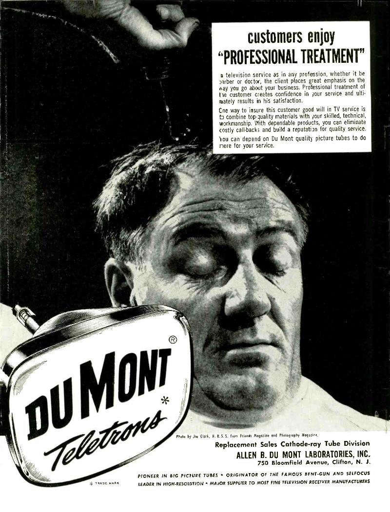
customers enjoy
"PROFESSIONAL TREATMENT"
television service as in any profession, whether it be
Brber or doctor, the client places great emphasis on the
gay you go about your business. Professional treatment of
he customer creates confidence in your service and ulti-
mately results in his satisfaction.
Cne way to insure this customer good will in TV service is
b combine top- duality materials with tour skilled, technical,
workmanship. With dependable products, you can eliminate
costly call -backs and build a reputatim for quality service.
lou can depend on Du Mont quality picture tubes to do
nore for your service.
v TRADE MARK
Photo by Joe Clark, Ni. R. S. S. from Friends Magazine and Photography Magazine.
Replacement Sales Cathode -ray Tube Division
ALLEN B. DU MONT LABORATORIES, INC. 750 Bloomfield Avenue, Clifton, N. J.
PIONEER IN BIG PICTURE TUBES ORIGINATOR OF THE FAMOUS BENT -GUN AND SELFOCUS
LEADER IN HIGH-RESOLUTION MAJOR SUPPLIER TO MOST FINE TELEVISION RECEIVER MANUFACTURERS
www.americanradiohistory.com
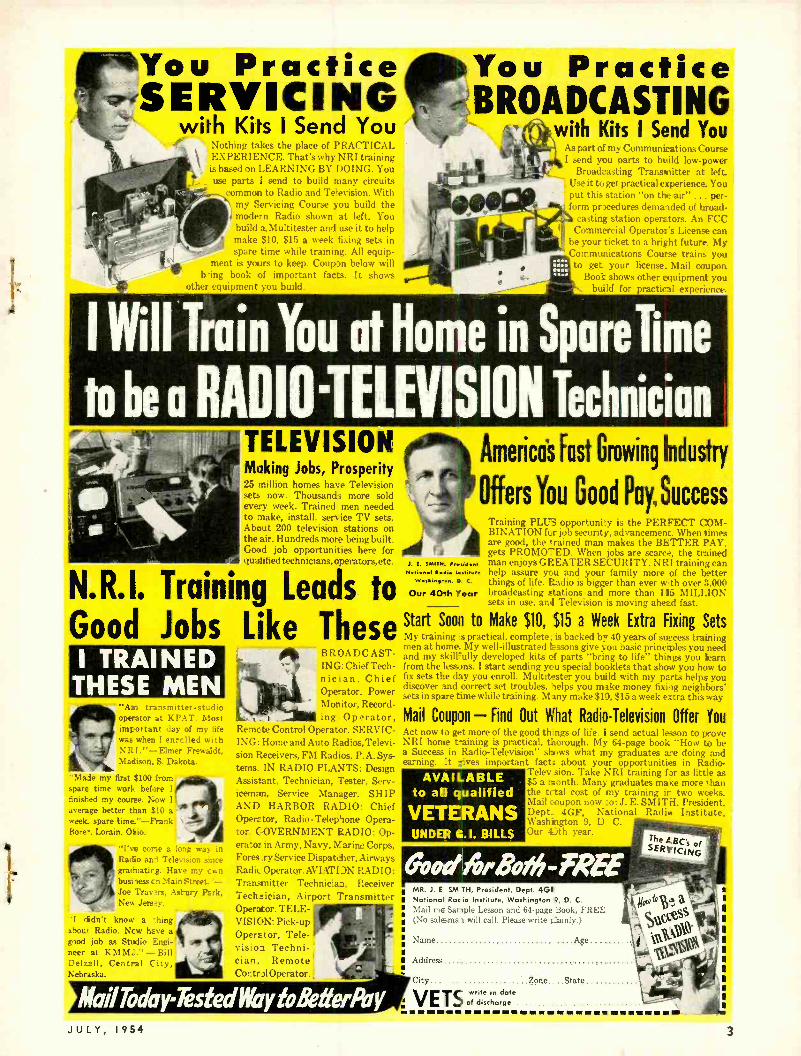
You Practice ''`SERVICING
with Kits I Send You Nt,thing takes the place of PRACTICAL
: EXPERIENCE. That's why NRI training is based on LEARNING BY DOING. You use parts I send to build many circuits
common to Radio and Television. With my Servicing Course you build the modern Radio shown at left. You build a Multitester and use it to help make $10. $15 a week fixing sets in spare time while training. All equip-
ment is yours to keep. Coupon below will being book of important facts. It shows
other equipment you build.
You Practice BROADCASTING
with Kits I Send You As part of my Communications Course I .,end you parts to build low -power
Broadcasting Transmitter at left. Use it to get practical experience. You put this station "on the air" . per-
' form procedures demanded of broad - casting station operators. An FCC
Commercial Operator's License can be your ticket to a bright future. My !`'mmunications Course trains you
mete to get your license. Mail coupon. 0.1 Book shows other equipment you
build for practical experience.
I Will Train You at Home in Sparelime
to be a RADIO'TELEViSION Technician TELEVISION Making Jobs, Prosperity 25 million homes have Television sets now. Thousands more sold every week. Trained men needed to make, install, service TV sets. About 200 television stations on the air. Hundreds more being built. Good job opportunities here for qualified technicians, operators, etc.
America's fast Growing Industry
Offers You Good Pay, Success
N.R.I. Training Leads to Good Jobs like These I TRAINED
THESE MEN .'Ant tray operator at i .TAT. Most important day of my life was when i enrclled with NRI." -Elmer Frewadt, Madison. S. Dakota.
"Made my first $100 from' spare time work before I
finished my course. Now 1
average better than S10 a week. spare time "- Franl: Bore-. Lorain, Ohio.
"I've come a long way in Ratio and Television since gradruatirg. Have my cwn busi less t n Main Street. '- Joe Traysrs, Astury Park. Nev. Jers*v.
"1 tidn't know a -thing about Radio. Ncw have a good job as Studio Engi- neer at KMM.. " -Bili Delzall, Central C ity. Nebraska.
BROADCAST- ING: Chief Tech- nician, Chief Operator. Power Monitor, Record- ing Operator,
Re.:. .:. ,mtrol Operator. SERVIC- ING: Home and Auto Radios,Televi- sion Receivers, FM Radios, P.A. Sys- tems. IN RADIO PLANTS: Design Assistant, Technician, Tester, Serv- iceman, Service Manager. SHIP AND HARBOR RADIO: Chief Operator, Radio - Telephone Opera- tor. C- OVERNMENT RADIO: Op- erator in Army, Navy, Marine Corps, Fores :ry Service Dispatcher, Airways Radie Operator. AVIATI )N RADIO: Transmitter Technician, Receiver Technician, Airport Transmitter Operator. TELE- VISION: Pick -up Operator, Tele- vis:oo Techni- cian, Remote Cortr h1 Operator.
J. S. SMITH. hsideM Notion, selle tattiDote
Weshigten, D. C.
Our 40th Year
Training PLUS opportunity is the PERFECT COM- BINATION for job security, advancement. When times are good, the *rained man makes the BETTER PAY. gets PROMOTED. When jobs are scarce, the trained man enjoys GREATER SECURITY. NRI training can help assure you and your family more of the better things of life. Radio is bigger than ever wth over 3,000 broadcasting stations and more than 115 MILLION sets in use, and Television is moving ahead fast.
Start Soon to Make $10, $15 a Week Extra Fixing Sets My training ',s practical, complete, is backed b =° 40 years of success training men at home. My well -illustrated lessons give you basic principles you need and my skillfully developed kits cf parts "bring to life' things you learn from the lessons. I start sending you special booklets that show you how to fix sets the day you enroll. Multitester you build with my parts helps you discover and correct set troubles. helps you make money fixing neighbors' sets in spare time while training. M any make $1), $15 a week extra this way
Mail Coupon - Find Out What Radio- Television Offer You Act now to get more of the good things of life. I send actual lesson to prove NRI home training is practical. thorough. My 64 -page book "How to be a Success in Radio- Television" shows what my graduates are doing and earning. _t lives important facts about your opportunities in Radio-
Telev sion. Take NRI training for as little as $5 a month. Many graduates make more than the total cost of my training in two weeks. Mail coupon now o: J. E. SMITH, President, Dept. 4GF, National Radio Institute, Washington 9, D C. Our 4 :th year.
AVAILABLE to ail qualified
VETERANS UNDER G.I. BILLS
Good ArRotYi-FREE MR. J. E SM TH, President, Dept. 4G1 National Racie Institute, Washington 9, D. C.
Mail me Sample Lesson and 64 -page Book, FREE No salamah will call. Please write plainly.)
Name Age.......,
Address
City Zone. ..State
VETS wr date of discite hin arge i ti
JULY, 1954 3
www.americanradiohistory.com

RIAl) I lELE i: i iiia:i
Formerly RADIO CRAFT Incorporating SHORT WAVE CRAFT TELEVISION NEWS RADIO & TELEVISION*
Hugo Gernsback Editor and Publisher
M. Harvey Gernsback Editorial Director
Fred Shunaman Managing Editor
Robert F. Scott W2PWG, Technical Editor
Jerome Kass Associate Editor
I. Queen Editorial Associate
Matthew Mandl Television Consultant
Charles A. Phelps Copy Editor
Angie Pascale Editorial Production
Wm. Lyon McLaughlin Tech. Illustration Director
Sol Ehrlich Art Director
Lee Robinson General Manager
John J. Lamson Sales Manager
G. Aliquo Circulation Manager
Adam .1. Smith Director, Newsstand Sales
Robert Fallath Promotion Manager
Seymour Schwartz Advertising Production
Giosie'
Member Magazine Publishers
Association
ON THE COVER (See article on page 75) The young lady on the cover, Miss Phyllis Barnes, is shown placing four gates on the PPI
scope. The Antrac continuously reports to the computer, the exact positions of the four targets.
(Color original by Avery Slack)
K(AB 0
ß Yl
CONTENTS JULY 1954
Editorial (Page 29)
Radioelectronics in 1980 by Hugo Gernsback 29
Television (Pages 30 -47) The Color CRT by Leonard Lieberman 30
Color TV Circuits, Part 2- Luminance and Bandpass Circuits by Ken Kleidon and Phil Steinberg
TV DX for July- September Television -it's a Cinch (Eleventh Conversation:
heterodyning in a television receiver) by E. Aisberg 36
TV Service Clinic Conducted by Matthew Mandl 38
Most Useful TV Circuits of 1954 40
Test Instruments (Pages 48 -55) Cross Dot Linearity Pattern Generator -...by Dan Lerner and Winston Starks
New Instruments for Better Servicing by Robert F. Scott Compact Wide -Range Oscillator by Richard Graham
Audio -High Fidelity (Pages 56 -74) A Versatile Tape Recording Amplifier by George L. Augspurger For Golden Ears Only by Monitor High Quality Audio, Part XI -Phase splitters; the centertapped trans-
former; the self balancing circuit; and the cathodyne (split -load) circuit by Richard H. Dorf
Servicing High -Fidelity Equipment by Joseph Marshall
Electronics (Pages 75 -85) Volscan Speeds Up Air Traffic (cover story) by Angie Pascale
Transistors from N to P by George Fletcher Cooper A Transistorized Geiger Counter -...by Nathan O. Sokel and Ira L. Resnick
Selenium Regulators by J. T. Cataldo
Radio (Pages 86 -95) Whistlers by Jack Darr 86
Card File by H. Johnson 90
Transistorized Commercial Killer by Harold Reed 93
New Design (Page 98) New Tubes and Transistors 98
33
35
48
51
54
56
59
62
69
75
77
82
84
Departments The Radio Month 14 New Devices Correspondence 18 New Patents
Tech notes 96 Question Box ._..
With the Radio -Electronic Technician 100 Circuits
Try This One
104 Business
108 Miscellany 110 People
Electronic Liter - 112 ature 114 Book Reviews - - -
MEMBER Audit Bureau of Circulations
Average Paid Circulation over 171,000
116
120
121
123
126
Vol. XXV, No. 7
RADIO -ELECTRONICS, July 1954, Vol. XXV, No, 7. Published monthly at Mt. Morris, Illinois by Gernsback Publications, Inc. Application pending for transfer of fie ̂ ond Class entry from the Post Office at Philadelphia, Pa., to the Post Office at Mt. Morris, 111. Copyright 1954 by Gernsback Publications. Inc. Text and Illustrations must not be reproduced without permission of copyright owners. EXECUTIVE, EDITORIAL and ADVERTISING OFFICES: Gernsback Publications, Inc., 25 West Broadway, New York 7, N. Y. Telephone REctor 2 -8630. Hugo Gernsback, President; \I. Harvey Gernsback, Vice -President; G. Aliquo, Secretary. SUBSCRIPTIONS: Address correspondence to Radio -Electronics, Subscription Dept. 404 N. Wesley Ave., Mt. Morris, Ill., or 25 West Broadway, New York 7, N. Y. When ordering a change please furnish an address stencil Impression from a recent wrapper. Allow one month for change of address.
SUBSCRIPTION RATES: In U. S. and Canada, and in U. S. possessions. $3.50 for one year; $6.00 for two years; $8.00 for three years; single copies 35e. All other foreign countrie, $4.:111 a year: $8.110 for two years; $11.00 for three years. BRANCH ADVERTISING OFFICES: Chicago: 7522 North Sheridan Road. Tel. Rogers Park 4 -8000. Los Angeles: Ralph W. Harker and Associates. 1127 Wilshire Blvd., Tel. MAdison e -1271. San Francisco: Ralph W. Harker and Associates, 582 Market St., Te1.GArfleld 1 -2481. FOREIGN AGENTS: Great Britain: Atlas Publishing and Distributing co., Ltd.. London EX, 4. Australia: McGill's Agency, Melbourne. France: Brentano's, Paris 2e. Belgium: Agence et Messageries de Is Presse, Brussels. Holland: Trilectron, Heemstede. Greece: International Book & News Agency, Athens. So. Africa: Central News Agency Ltd., Johannesburg: Capetown, Durban. Natal. Universal Book Agency, Johan- nesburg, Middle East: Steimatzky Middle East Agency, Jerusalem. India: Broadway News Centre, Dudar, Bombay #14. Pakistan: Paradise Book Stall. Karachi 3. POST- MASTER: If undeliverable send form 3578 to: RADIO -ELECTRONICS. 25 West Broadway, New York 7, N. Y. *Trademark registered U.S. Patent Office.
4 RADIO -ELECTRONICS
www.americanradiohistory.com

ADVANCE! Raise your earning power-learn RADIO-TELEVISION-ELECTRONICS by SHOP-METHOD HOME TRAINING
GOOD JOBS AWAIT THE TRAINED RADIO -TV TECHNICIAN
There is a place for you in the great Radio- Television- Electronics industry when you are trained as National Schools will train you at home!
Trained technicians are in growing demand at good pay -in manufacturing, broadcasting, television, communica- tions, radar, research laboratories, home Radio -TV service, and other branches of the field. National Schools Master Shop- Method Home Training, with newly added lessons and equipment, trains you in your spare time, right in your own home, for these fascinating opportunities. OUR METHOD IS PROVED BY THE SUCCESS OF NATIONAL SCHOOLS TRAINED MEN, ALL OVER THE WORLD, SINCE 1905.
EARN WHILE YOU LEARN Many National students pay for all or part of their train- ing with spare time earnings. We'll show you how you can do the same! Early in your training, you receive "Spare - time Work" Lessons which will enable you to earn extra money servicing neighbors' and friends' Radio and Tele- vision receivers, appliances, etc.
pNASE5: t ER Moster
Shop-Method from
Home Training
an EstRae iished
chool C11
t5 tLCOI
Ld n Trolr+Ln9
with its ov+
Shops, i ob O
ratoriesr Stud iT almost 50
Years of
Successful Experience in 'training
Ambitious Men .
We Bring Notional Schools
TO 'fool
You also receive this Multitester
T. R. F. Receiver
Signal Generator Audio Oscillator
National Schools Training is All- Embracing National Schools prepares you for your choice of many job opportunities. Thousands of home, portable, and auto radios are being sold daily -more than ever before. Tele- vision is sweeping the country, too. Co -axial cables are now bringing Television to more cities, towns, and farms every day! National Schools' complete training program qualifies you in all fields. Read this partial list of opportu- nities for trained technicians:
Business of Your Own Broadcasting Radio Manufacturing, Sales, Service Telecasting Television Manufacturing, Sales, Service Laboratories: Installation, Maintenance of Electronic Equipment Electrolysis, Call Systems Garages: Auto Radio Sales, Service Sound Systems and Telephone Companies, Engineering Firms Theatre Sound Systems, Police Radio And scores of other good jobs in many related fields.
TELEVISION TRAINING You get a complete series of up- to -the- minute lessons cov- ering all phases of re- pairing, servicing and construction. The same lesson texts used by resi- dent students in our modern and complete Television broadcast studios, lab- oratories and classrooms!
JULY, 1954
FREE! RADIO -TV BOOK AND SAMPLE LESSON! Send today .or National Schools' new, illustrated Book of Oppor-
tunity in Radio- Television- Electronics, and an actual
Sample Lesson. -No cost - no obligation. Use the
coupon now -we'll answer by return
airmail.
Superheterodyne Receiver
LEARN BY DOING You receive and keep all the modern equipment shown above, including tubes and valuable, professional qual- ity Multitester. No extra charges.
APPROVED FOR VETERANS
AND NON -VETERANS
Check coupon below
Both Resident and Home Study Courses Offered!
NATIONAL SCHOOLS LOS ANGELES 37, CALIFORNIA ESTABLISHED 1905 IN CANADA:E I I W. HASTI NGS STREET,VANCOUVER, B.C.
( mail in envelope or paste on postal card) NATIONAL SCHOOLS, Dept. RG -74
4000 S. Figueroa Street 323 West Palk Street Los Angeles 37. Calif. or Chicago 7. III.
Send FREE Radio -TV Electronics book and FREE sample lesson. No obligation, no salesman will call.
NAME BIRTHDAY 19
ADDRESS
C?TY ZONE STATE
Check here if interested in Resident School Training at Los Angeles. L VETERANS: Give Date of Discharge
5
www.americanradiohistory.com

no other rotor offers. SO MUCH
a Comb /efe /The
TR -2 the heavy duty rotor with compass control dial cabinet.
TR -4 the heavy duty rotor with meter dial cabinet.
TR -11 all purpose rotor with meter dial cabi- net.
TR -12 all purpose rotor for large TV antenna arrays with meter dial cabinet.
CORNELL-DUBILIER SOUTH PLAINFIELD, N. J.
6
videly promded on TV widely promoted to consumers on TV... ALL
CDR ROTORS are PRE -SOLD for you through on extensive campaign to millios every week exploiting the advantages of he CDR.
com,v/etey inerchandised completely merchandised...the easiest to sell ... in addition to the TV spot coverage ... there are newspaper mats, window streamers, envelope enclosures ... and an animated point of sale display, .. all the tools You need to sell the BEST SELLING ROTOR!
THE RADIART CORPORATION CLEVELAND 13, OHIO
RADIO -ELECTRONICS
www.americanradiohistory.com

All Electronic Pcrts
YOURS TO KEEP!
MULTIMIrIR
rft;40 ,11% $4101-irm
d-4/474 HELP ICU LEHR 016
LW[ISs[l tr RADIO- ELECTRONICS Now ... at home in spare time y.0 can get BOTH the very Irainirg and subsequent Empl.ymsnt Service you need to help you start earning real money in America's hrilling, multi -billion collar opportunity field of Television- Radio -Electronics. Now that -elevsion is corn ng to almost every community, here is o chance of a lifetime to prepare to cash in on one of Televis on's great expansions.
0.1.1.'s amazingly practical hone method enables you to set up your own HOME LABORA- TCRY. Lou get many Electronic parts which you mount on individual Eases with spring clip ccnnec ors. Tops for experimenting! Add or remove parts in a jiffy. No was ed hours of soldering and unsolderirg f.r each project. You spend minimum t me to get maximum knowledge of important circuits that really work. In fact, you get exactly the same type of basic training equipmert used in our Chicago training laboratory -one of the nation's fines'.
Build and KEEP This VALUABLE TEST EQUIPMENT Vow' home laboratory projects also include building and <eepirg a versatile 5 inch Os.:illoscope and precision Jewel Bearing Multi- Meter. These quality commercial test instruments help yo. EARN WHILE YOU LEARN and will prove mighty valuable, stould you later decide to start your own full time TV -Radio service bt.i.iness. You also build and kee' a quality 21 inch TV SET.
D.T.1. Provides EVERYTHING YOU NEED to master TELEVISION In adcitior to yo.ir home laboratory and easy -to -recd lessons, you even use HOME MOVIES -o wonderfully effective and exclusive D.T.I. training advantage. You woch hidden actions ... see electrons on the c
march. Importart fundamentals ... become "movie I4,e clear," helping ,ou learn foster . .. easier ...better. Full time Residerdial training in D.T.I.'s great Chicago laboratories also available. MAIL COU-
PON TODAY for all facts. (If subject to Military Service, you'll espe- cially welcome the information we hove for you.) D.T. l's Training is available Canada
Build and keep this BIG DTI
Engineered TV set- easily converted to U.H.F. (DTI offers
another home training, but without the TV set.)
"ONE OF AMERICA'S FORFMOS- TELEVISION TRAINING CENTERS'
DEVRY TECHNICAL INSTITUTE AFFILIATED WITH
DEFOREST'S TRAINING, INC. CHICAGO 41, ILLINOIS
JULY, 1954
- M0$' MAIL COUPON TODAY!
DEVR't TECHNICAL INSTITUTE 4141 BELMONT AVE., CHICAGO 41, ILL. DEPT RE -7 -K
I would like your valuable information- packed publication showing how I can get started toward c good job or my own businers in Television- Radio -Electronics.
Nome Ag-
Street _Ap
City _ Zone _Stote-
7
www.americanradiohistory.com

GET OFF THE SPOT
WITH THE
BONDED ELECTRONIC TECHNICIAN PROGRAM
Once you gain the confidence of customers, you're on your way to increased volume and profits. The Raytheon Bonded Electronic Technician program is designed to help you do just that. The Raytheon Registered Bond Certificate, the Raytheon Creed Display Decal and Identification Cards, featuring your bonded status and the fine Raytheon "Code of Ethics ", inspire customer confidence. And a recent survey proved that wherever Raytheon Bonded
skEY'RE 410
Technicians took full advantage of their Bonded status - used it to in- tif spire customer confidence - business improved by at least ten per cent.
Ask your Raytheon Tube Distributor if you can qualify for this im-
portant sales advantage. If you can, the bond is yours at no cost to you - it is Raytheon's investment in your future.
8
Receiving Tube Division New a., Chicago, III., Atlanta, Go., Los Ange es, Cal.
ARMING AND PICTURE TUBES IEIIRRU SIBMINIATURE ANU MINIATURE TUBES SEMICONDUCTOR DIODES A
dxixlleiace ira 4Vecenwics
NU
RADIO -ELECTRONICS
www.americanradiohistory.com
Let me send you FREE
the entire story
Just fill out the coupon and mail it. t will send you, free of charge, a copy of "How to Pass FCC License Exams," plus a sample FCC -type Exam. and the amazing new book- let. "Money- Making FCC License Information."
How Pass
CARL E. SMITH, E.E. President
I can train you to pass your FCC License Exams in a minimum of time if you've had any practical radio experience - amateur, Army. Navy, radio servicing, or other. My time- proved plan can help put you, too, on the road to success.
DOES NOT COYER
AMATEUR LICENSE
EXAMS
c.w.
FREE Tells where to apply and take FCC exami- nations, location of examining office, scope of knowled ge requ fired, approved way to pre- pare for FCC exami- nations, positive meth- od of checking your knowledge before tak- ing the examination.
0 FCC
COMMERCIAL
Radio Operator
License Exams
GET YOUR FCC TICKET IN A MINIMUM OF TIME
Get this Amazing Booklet FREE TELLS HOW
HERE IS YOUR
GUARANTEE If you fail to Pass
your
Commercial License exa
after completing our
to course, we guarantee
continue your training
without additional cost ucf
y kind, until you
cesansfully obtain y our
Commercial license, pro- r
vided you first sit fortis examination
within our days after completing o
course.
TELLS HOW
WE TO TRAIN AND COACH YOU AT HOME IN
SPARE TIME UNTIL YOU GET
If you have had any practical experience - Amateur, Army, Navy. radio repair, or
experimenting
Employers make
JOB OFFERS Like These to Our Graduates Every Month I..ir, r nom 'VA'c would two appreciate it you mould place Ih tollrwing addit iunal arlutt isrrnrnt iu ).our hoil'tin AA';mica- SuPor!r ncndent Of
I.mimunications Salllr }' }a6G.en per worth."
t-,r tram nationally -hnown airplane wanuCrcturrr. "We moll noon trim e6rt conic I raining ne experience in ra,lai maintenance to pet Mein opci ai ìonal check -nut ut radar mid other electronic, ,y.RVrs . . . starting salary . . Incoming In :,... ..,.: per month. "nr . These are just a few examples of the job offers that come to our office periodically. Some licensed radiomen filled each of these jobs . . . it might have been you!
HERE'S PROOF FCC LICENSES Are OFTEN SE- CURED IN A FEW HOURS OF STUDY WITH OUR COACHING at HOME in SPARE TIME
Name and Address Lee Worthy
2210, z Wilshire St., Bakersfield, Calif. Clifford E. Vogt
Box 1016. Dania, Fla. Francis X. Foerch
38 Beucler Pl.. Bergenfield, N. J. Sï Sgt. Ben H. Davis
317 North Roosevelt, Lebanon, III. Albert Schnell
110 West I Ith St., Escondido, Calif.
Litensr Lessons 2nd Phone I6
Ist Phone 20
1st Phone 38
Ist Phone 28
2nd Phone 23
Our Amazingly Effective
JOB-FINDING SERVICE
Helps CIRE Students Get Better Jobs
Here are a few recent examples of Job -Finding results GETS FIVE JOB- OFFERS FROM BROADCAST STATIONS
"Your 'Chief Engineer's Bulletin' is a grand way of obtaining employment for your graduates who have obtained their 1st class license. Since my name has been on the list I have received calls or letters from five stations in the southern states. and am now employed as Transmitting Engineer at WMMT."
Elmer Powell, Box 274, Sparta, Tenn. GETS CIVIL SERVICE JOB
"I have obtained a position at Wright -Patterson Air Force Base, Dayton, Ohio, as Junior Electronic Equipment Repairman. The Employment Application you pre- pared for me had a lot to do with my landing this desirable position."
Charles E. Loomis, 4516 Genessee Ave.. Dayton 6, Ohio.
OURS IS THE
STULDY COURSE WHICH SUP -
PLIES FCC -TYPE EXAMINATIONS WITH A LL LES- SONS AND FI- NAL TESTS.
GETS AIRLINES JOB "Due to your Job- Finding Service, I have been getting many offers from all over the country, and have taken a jab with Capital Airlines in Chicago, as Radio Me- chanic."
Harry Clare, 4537 S. Drexel Blvd., Chicago, Ill.
Your FCC ticket is required by most em- ployers as proof of your technical ability.
CLEVELAND INSTITUTE OF RADIO ELECTRONICS CARL E. SMITH, E. E., Consulting Engineer, President
Desk RE -66 - 4900 Euclid Bldg., Cleveland 3, Ohio
JULY, 1954
B
MAIL COUPON NOW CLEVELAND INSTITUTE
OF RADIO ELECTRONICS Desk RE -66
4900 Euclid Bldg., Cleveland 3, Ohio (Address to Desk No. to avoid delay)
T want to know how I can get my FCC ticket in a minimum of time. Send me your FREE booklet, "How to Pass FCC license Examinations" (does not cover exams for Amateur License). as well as a Sample F1'(' -type exam and the unlacing new booklet, "Money -Making FCC License Information." Tell me how I can get a TV Engineering Course without additional charge
NAME
ADDRESS
l CITY ZONE STATE Paste on 2 -cent post card or send air mail
9
www.americanradiohistory.com

HEAVY-DUTY
TOP- QUALITY I PLIER KIT with 10 CBS -Hytron Pliers Kit Stamps
LIMITED OFFER From July 1 through August 31 ... Your CBS -Hytron distributor will give you 1
Pliers Kit Stamp with your purchase of 25 CBS -Hytron receiving tubes.
PICK UP THESE FINE IMPORTED TOOLS. Examine the beautiful finish of their drop -forged tool steel. Try their comfortable handle grips. Feel the precise balance ... the powerful leverage. Go ahead ! Cut some eight -penny nails. Like cutting cheese, wasn't it? And not a trace of a nick in the tough, care- fully matched jaws. You will be proud to own these husky, quality pliers. Tested ... guaranteed
. they can take it. And did you notice that two are unique? Nothing else just like them ... they are "musts" for your tool kit. Yes sir, this free Pliers Kit (packed in an attractive, handy plastic case) is an offer you cannot afford to miss!
The 61/2-Inch Diagonals are husky, box- joint, fully polished side cutters with precisely matched jaws. Size is right: Compact, but big enough ... with comfortable, full -fashioned, full - polished handles ... to do repeated, tough cutting jobs with ease. The 8 -Inch Long -Nose is unique. Extra -long (2% inches), spring -tempered jaws combine with extra -long, knurled handles for powerful leverage. Hand -honed cutting knives. Beautifully chrome -plated. The 6 -Inch All- Purpose is also unique. Combines: Flat and round nose. Jaws shaped for positive gripping. Two wire strippers. Two side cutters. Finish of handles is gun -metal; jaws are fully polished. This tool has everything.
Manufacturers of Receiving Tubes Since 1921
RECEIVING
10
YTRO CBS -HYTRON Main Office: Danvers, Moss.,
TRANSMITTINC,
A Division of Columbia Broadcasting System, Inn,
A member of the CIS family: CBS Radio CBS Television Columbia Records, Inc. CBS Laboratories CBS -Columbia CBS International and CBS -Hytron
SPECIAL- PURPOSE TV PICTURE TUBES CRYSTAL DIODES AND TRANSISTORS
Get This Pliers Kit Stamp Book . . and stamps from your CBS -Hytron distribu- tor: One Pliers Kit Stamp for 25 CBS - Hytron receiving tubes. Each Stamp is im- printed with your CBS -Hytron distributor's code number. Redeem your Stamps with him.
This offer is valid only in areas where such offers are legal ... and it is limited: July 1
through August 31. Don't miss it. Be sure to get your free CBS -Hytron Pliers Kit. See it at your CBS -Hytron distributor's ... today!
RADIO -ELECTRONICS
www.americanradiohistory.com

Home Study Courses in
TELEVISION SERVICING offered by
RCA INSTITUTES r.
°oft :....`_.
me,
Study Television Servicing -from the very source of the latest, up -to- the- minute TV and Colo- TV developments. Train under the direction of men who are experts in this field. Take advantage of this oppor- tunity to place yourself on the road to success in television. RCA
In! titutes, Inc. (A Servi :e of Radio Corporation of America), thoroughly trains you it the "why" as well as the "how" of servicing television receivers.
FIRST HOME STUDY COURSE" IN COLOR TV SERVICING
Now you can train yourself to take advantage of the big future in Color TV. RCA Institutes Home Study Course covers all phases of Color TV Servicing. It is a practical down -to -earth course in basic color theory as well as how-to - do-it servicing techniques.
This color television course was planned and developed through the combined efforts of instructors of RCA Institutes, engineers of RCA Laboratories, and training specialists of RCA Service Company. You get the benefit of years of RCA research and development in color television.
Because of its highly specialized nature, this course is offered only to those already experienced in radio -television servicing. Color TV Servicing will open the door to the big opportunity you've always hoped for. Find out how easy it is to cash in on Color TV. Mail coupon today.
SEND FOR FREE BOOKLET
Mail coupon in envelope or paste on postal card. Check course you are inter- ested in. We will send you a booklet that gives you complete information. No sales- man will call.
HOME STUDY COURSE IN BLACK -AND -WHITE TV SERVICING
Thousands of men in the radio -electronics industry have successfully trained themselves as qualified specialists for a good job or a business of their own -servicing television receivers. You can do this too.
This RCA Institutes TV Servicing course gives you up -to- the- minute training and information on the very latest developments in black -and -white television.
As you study at home, in your spare time, you progress rapidly. Hundreds of pictures and diagrams, easy-to- under- stand lessons help you to quickly become a qualified TV serviceman.
There are ample opportunities in TV, for radio servicemen who have expert training. Mail coupon today. Start on the road to success in TV Servicing.
RCA INSTITUTES, INC. A SERVICE OF RADIO CORPORATION of AMERICA
350 WEST FOURTH STREET, NEW YORK14, N.K.
MAIL COUPON NOW
RCA INSTITUTES, INC. Home Study Dept. RE -75.1 350 West Fourth Street, New York 14, N. Y. Without obligation on my part, please send me copy of booklet on: _] Flome Study Course in TELEVISION SERVICING.
Home Study Course in Coi .os TV SERVICING.
Name
Address
City Zone State
(please print)
www.americanradiohistory.com

Exclusive! Electro -Lens Focusing*
New Winegard INTERCEPTOR Grabs and Boosts the Signal... Focuses It ...like a Lens
Completely new in appearance. Completely new in electrical design. Sensational in results! The new INTERCEPTOR antenna now combines the famous Winegard Multi- Resonant Dipole with the most sensational electronic design of the decade .. .
Electro -Lens Focusing.* This exclusive Winegard feature literally grabs the signal out of the air and focuses it on
the driven element the same as an ordinary lens focuses light. The result ... a picture gloriously brilliant ... sharp and clear. A picture up until now unobtainable!
Never before has one antenna incorporated so many outstanding and exclusive features. The INTERCEPTOR gives highest possible gain and still maintains rejection from the back and sides that really shuts out co- channel interference. Its Electro -Lens Focusing makes it an ideal fringe area antenna without the bulk required 5y present fringe antennas. Small, light- weight and compact, the INTERCEPTOR's neat appearance will be appreciated by owners of the finest homes.
Attention: Servicemen! You will notice we show no charts trying to
establish fabulous claims. We suggest you order a Winegard INTERCEPTOR today. If your regular jobber does not have it, please contact us. Test it for yourself. The INTERCEPTOR is its own best salesman!
A Winegard Exclusive ... Electro -Lens Focusing, All channels (2 -13).
Light, rigid, quick to assemble, easy to install. Low wind resistance. Designed for color reception.
For complete information on the Winegard INTERCEPTOR VHF antenna with exclusive Electro -Lens Focusing, send for Bulletin No. L -4.
3000 Scotten Boulevard, Burlington, Iowa
12
*Patent Pending
RADIO- ELECTRONICS
www.americanradiohistory.com

Get in on the TV boom... starting today!
CHECK THESE SEVEN
FAMOUS I. C. S. COURSES
-ONE FOR YOU!
PRACTICAL RADIO-TELEVISION ENGINEERING - Foundation course for radio -television career. Basic prin- ciples plus advanced training. Radio. Sound. TV.
TELEVISION TECHNICIAN -To qualify you for high -level technical posi- tions in television. Camera, studio, trans- mitter techniques. Manufacture, sale and installation of TV equipment
El TELEVISION RECEIVER SERVIC- ING- Installation, servicing, con- version. Dealership. For the man who knows about radio and wants TV training.
RADIO & TELEVISION SERVICING -Designed to start you repairing, in- stalling and servicing radio and tele- vision receivers soon after starting the course.
RADIO & TELEVISION SERVICING WITH TRAINING EQUIPMENT - Same as above but with addition of high -grade radio servicing equipment and tools.
RADIO OPERATING COURSE - Special course to help you pass the Government examination for operator's licenses. Code.TV. FM. Radio regulations.
INDUSTRIAL ELECTRONICS - Broad, solid background course devoted to the electron tube and to its many applications.
JULY, 1954
Prepare now for the new Radio -TV- Electronics boom. Get in on VHF and UHF ... aviation and mobile radio ... color TV ... binaural sound! The International Correspondence Schools can help you!
If you've ever thought about Radio or Television as a career .
if you have the interest, but not the training ... if you're waiting for a good time to start ... NOW'S THE TIME!
No matter what your previous background, I.C.S. can help you. If Radio -TV servicing is your hobby, I.C.S. can make it your own profitable business. If you're interested in the new developments in Electronics, I.C.S. can give you the basic courses of training you need. If you have the job but want faster progress, I.C.S. can qualify you for promotions and pay raises.
I.C.S. training is success -proved training. Hundreds of I.C.S. graduates hold top jobs with top firms like R.C.A., G.E., DU- MONT, I.T. &T. Hundreds of others have high ratings in military and civil service. Still others have successful businesses of their own.
With I.C.S., you get the rock -bottom basics and theory as well as the all- important bench practice and experimentation. You learn in your spare time -no interference with business or social life. You set your own pace -progress as rapidly as you wish.
Free career guidance: Send today for the two free success books, the 36 -page "How to Succeed" and the informative catalog on the course you check below. No obligation. Just mark and mail the coupon. With so much at stake, you owe it to yourself to act -and act fast!
I.C.S., Scranton 9, Penna.
INTERNATIONAL CORRESPONDENCE SCHOOLS
O Car Inspector
O Diesel Eng's and Power
Engineering
Woolen Mfg. Dyeing
D Throwing
BOX 2887 -L, SCRANTON Without cost or obligation, send me
ARCHITECTU RE and BUILDING CONSTRUCTION
O Air Conditioning- Refrig. O Architecture O Building Contractor O Building Maintenance O Carpenter and Mill Work O Estimating O Heating D Painting Contractor O Plumbing D Reading Arch. Blueprints O Steamfitting
ART O Cartooning O Commercial Art O Fashion Illustrating O Magazine Illustrating D Show Card and Sign Lettering D Sketching end Painting
AUTOMOTIVE O Auto Body Rebuilding O Auto Elec. Technician O Auto -Engine Tune Up O Automobile Mechanic
Name
9, PENNA. ( Partial list of 277 courses) "HOW to SUCCEED " and the opportunity booklet about Ne field BEFORE which I have marked X: AVIATION CI VIL, STRUCTURAL LEADERSHIP RAILROAD Aeronautical Engineering Jr. ENGINEERING O Foremanship O Air Brakes Aircraft & Engine Mechanic O Civil Engineering O Industrial Supervision O Diesel Locomotive BUSINESS O Construction Engineering O Leadership and Organization O Locomotive Engineer Advertising O Highway Engineering O Personnel -Labor Relations O Section Foreman Bookkeeping and Accounting O Reading Struct. Blueprints MECHANICAL STEAM AND Business Administration O Sanitary Engineering AND SHOP DI ESEL POWER Business Correspondence O Structural Engineering D Gas -Electric Welding O Combustion Engineering Certified Public Accounting D Surveying and Mapping O Heat Treatment O Metallurgy O Diesel -Elec. Creative Salesmanship DRAFTING O Industrial Engineering O Electric Light Federal Tax O Aircraft Drafting D Industrial Instrumentation O Stationary Fireman Letter- writing Improvement D Architectural Drafting O Industrial Supervision O Stationary Steam Managing Small Business O Electrical Drafting O Machine Design -Drafting TEXTI LE Office Management D Mechanical Drafting O Machine Shop Inspection O Carding and Spinning Retail Business Management O Mine Surveying and Mapping O Machine Shop Practice O Cotton, Rayon, Sales Management O Ship Drafting O Mechanical Engineering O Finishing and Stenographic -Secretarial O Structural Dialling O Quality Control O Loom Fixing Trafñc Management ELECTRICAL O Reading Shop Blueprints D Textile Designing CH EMISTRV O Electrical Engineering O Refrigeration O Textile Eng'r'g Analytical Chemistry O Electrical Maintenance O Sheet Metal Worker O Warping and Weaving Chemical Engineering O Electrician O Contracting O Tool Design O Toolmaking MISCELLANEOUS Chem. Lab. Technician O Lineman RADIO, TELEVISION O Domestic Refrigeration General Chemistry HIGH SCHOOL O Electronics O Marine Engineering Nate -al Gas Prod. & Trans. O Commercial O Practical Radio -TV Eng'r'ng O Ocean Navigation Petroleum Engineering O Good English O Radio and TV Servicing O Shipfitting Plastics O High School Subjects O Radio Operating D Short Story Writing Pulp and Paper Making O Mathematics O Television -Technician O Telephony
Ago Home Address
City Zone State Working Hour, A M to P
Occupation Canadian residents send
M
coupon to International Correspondence Schools, Canadian, Ltd., Special tuition rates to members of the U. S. Armed Forces. Montreal, Canada....
13
www.americanradiohistory.com

4yeara,ted
TUNG -SOL PICTURE TUBES
Gun made of best grade non -magnetic steel.
Glass bead type assembly is stronger both mechanically and electrically -gives greater protection against electrical leak- age.
Rolled edges in gun minimize corona.
Custom built stem with greater spacing between leads assures minimum leakage.
Low resistance of outside conductive coating minimizes radiation of horizontal oscillator sweep frequency.
Double cathode tab provides double protection against cathode circuit failure.
Selected screen composition resists burn- ing (X pattern).
Rigid control of internal conductive coat- ing provides utmostservice reliability.
Designed for use with single or double field ion trap designs.
One -piece construction of parts assures better alignment.
Maximum dispersion of screen coating assures uniform screen distribution.
Tung -Sol makes All -Glass Sealed Beam Lamps, Miniature Lamps, Signal Flashers, Picture Tubes, Radio, TV and Special Pur- pose Electron Tubes and Semiconductor Products.
TUNG -SOL ELECTRIC INC., Newark 4, N. 1, Sales Offices: Atlanta, Chicago, Columbus, Culver City (Los Angeles), Dallas, Denver, Detroit, Newark, Seattle.
TUNG-SOL RADIO AND TV TUBES
You (an Build A Reputation On Tung -Sol Quality
14
THE RADIO MONTH
ELECTRON MICROSCOPE twice as powerful as any now in use was dis- played by RCA in ceremonies at United Nations where it was presented to the Karolinska Institute of Stockholm, Sweden. The new microscope will permit study of particles smaller than one 10- millionth of an inch in diameter. Photo- graphs taken by an automatic camera contained in the instrument can be enlarged up to 200,000 times the size of the specimen.
The electron microscope directs a concentrated beam of electrons through the specimen, which is placed in a small aperture in the column about halfway between the viewing screen and the electron gun at the top of the column. As the electrons pass down through the specimen they are affected in varying degrees according to the density and composition of the various parts of the specimen. When the beam emerges from the far side, it bears the pattern or image of the specimen, which is then magnified by magnetic lenses and pro- jected on the viewing screen.
The instrument is the eighth RCA electron microscope in use in Sweden. Hundreds of the earlier types are in use throughout the world.
RETMA RADIATION LAB will be es- tablished as an independent certification unit for spurious radiation testing. Manufacturers will be able to send their TV and FM receivers to the laboratory for testing. Sets that pass the radiation tests will be permitted to carry a seal of approval.
ARRL AWARD has gone to A. Mack Seybold, RCA chemical engineer, for his important contributions to the elimination to television interference caused by amateur radio signals.
The award, presented annually by the American Radio Relay League, was based on an article dealing with sources and characteristics of unusual types of harmonic radiations from amateur radio signals, and outlining methods for their detection and elimination. It carries a $300 cash prize.
COPPER -LINED ROOM believed to be the largest in the world of its type has been built by G -E and will soon be a part of their test and research facili- ties.
A total of 20,900 pounds of copper sheeting was used to completely cover the floor, walls, and ceiling of this room. The principal purpose of the copper is to provide a shield for keeping electro- magnetic waves of external origin out of the room.
JACK POPPELE, veteran radio oper- ator, engineer, and executive, has been appointed director of the Voice of America, taking office in May. Poppele is one of the best -known figures on the American radio scene. He is most closely associated in the minds of radio- men with pioneer broadcast station WOR. He directed the construction of WOR's first transmitter at Bamberger's department store in Newark, N.J., and became the station's first chief engineer.
Later he was made vice- president in charge of engineering of the Mutual Broadcasting System, which included WOR. He resigned that position in late 1952 to establish his own business as a television consultant and engineer, re- maining, however, on the Board of Di- rectors of Mutual.
His prebroadcasting experience goes back to 1910, when as a boy he con- structed his own wireless station. Later he became a wireless operator at sea, at one time serving on the same ship with Allen B. Du Mont. During World War I he was an operator on an army transport.
TV TEETH has made its appearance as a physiological problem brought about by television. We have all heard about TV eyes- brought about by ex- cessive television viewing. Now we are advised by the British Dental Asso- ciation of a condition known as TV teeth.
An association report said that chil- dren have the habit of watching tele- vision with their heads held in their hands. When they get excited, they press harder and harder. This, the re- port says, may cause the teeth to go out of proper alignment.
RADIO -ELECTRONICS
www.americanradiohistory.com

big values
new releases
Popular Knight Portable Radio
Build- Your -Own Kit
, -...,....r r.-..--». * ;;;
Knight Super -Thin
Portable Radio
It's easy to build this powerful 3 -way superhet portable for AC, DC or battery operation. Tunes 535 -1650 kc broadcast band; has built -in antenna, printed -cir- cuit audio, large PM speaker, handsome carrying case. Easy to assemble from illustrated manual. High quality kit includes all parts, tubes and case (less batteries). Shpg. wt., 6 lbs. 83 S 730. Only ......... . .. $18.75 80 J 651. Battery Kit. Only $2.74
An ideal battery -operated personal portable, hardly thicker than a book. Advanced superhet circuit features low -drain tubes for 100 hours of bat- tery life. Includes built -in loopstick antenna, PM speaker, easy- tuning thumbwheel controls, automatic vol- ume control. Develops surprising power and wonderful tone quality. Housed in beautiful red plastic case, 6 x 9 x 2%" deep. With tubes (less batteries). Shpg. wt., 4 lbs. S 4K 717. Only . ... .. . $17.95 80.1651. Battery Kit. Only... $2.74
Say -A- Battery Rejuvenator -Plays Portables from A.C. Permits the operation of portable radios using single 1 % v. "A" and single 67% v. "B" batteries from AC outlet. Fits into battery compartment of set. Also serves as "B" bat- tery rejuvenator. Easy to install. 3% x 2% x 1 !; ". For 105- 125 v., 50 -60 cycles AC. Shpg. wt., 1) lbs. 80 P 190. Only .. . ... .. .. .
Speedway Heavy - Duty
Electric Drill
Exceptional value in a powerful, well - balanced drill. Has 14" gear -type chuck with key. Heavy -duty universal series - wound motor; self -aligning ball thrust bearings; trigger switch. No -load speed, 2400 rpm; full load, 1500 rpm. Capacity in steel, % "; in hardwood, 34 ". Overall length, 9 ". U.L. approved. For 110 -120 v., AC or DC. Shpg. wt., 4% lbs. 46 N 360. Only.... .. .. . $14.33
kt! - PE -101 -C Dynamotor Buy
Brand -new government surplus unit for mobile Hams, etc., at sensational low cost. Ruggedly built. For cars with 6 -volt or 12 -volt electrical systems. With 12 v. DC input, delivers 610 v. DC at 150 ma and 325 v. DC at 125 ma. With 6 v. input, delivers 300 v. DC at 90 ma and 160 v. DC at 110 ma. Complete with conversion instructions. Dia., 4"; length after conversion, 10 W. Shpg. wt., 12 lbs. 80 P 195. Only .... ......... ... $4.95
9
1
send for ALLIED'S Latest Free Supplement
Knight 25 -Watt 6V -110V P.A. System -A Top Value: Here it is -a terrific value in a Universal P.A. System -for election campaigns, for any application requiring powerful indoor or outdoor amplification. Covers up to 85,000 square feet. Operates anywhere - from 110 -130 v., 50 -60 cycles AC or from any 6 -volt auto storage battery. Features: 2 high impedance mike inputs; 1 phono input; optional record player; 25 watts usable output guaranteed; response 40- 15,000 cps, ± 2 db.; 2 speaker outlets -wide selection of imped- ances; tone control; separate volume controls for mikes and phono; built -in 6- volt -110 volt power supply; amplifier guaranteed uncondi- tionally for one full year; U.L. Approved. System includes: Knight 25 -Watt Universal amplifier with tubes; AC and 6 -volt cables; 2 University PH all -metal reflex trumpets complete with 25 -watt driver units; E -V mike, table stand, 20 -ft. cord and plug; 50 -ft. speaker cable. (Less phono top.) Shpg. wt., 140 lbs. 93 SX 632. Complete System. Only $182.50 WITH ELECTRO -VOICE PROJECTORS. As above, but with two E -V 848 compound diffraction projectors in place of University trumpets. Fea- tures extended frequency response. 93 SX 635. Only $182.50 3 -SPEED PHONO TOP. Plays 78, 333,6 and 45 rpm records. Highest quality; with turnover crystal cartridge. 93 SX 640. Only $17.45
Best Buy Knight Push- Button Tape Recorder
.:,, Top Recorder Value -NOW with Remote Control Provision
Latest model -acclaimed "best buy" by recording fans. Five push- buttons select all operating functions: fast forward, playback, stop, record and fast reverse. Now with provision for remote control. Fakes up to 7" reels. Two -speed dual - track for wide range of recording times. At 3.75" per second, 7" reel records for 1 hour -and additional hour on second half of tape; at 7.5" per second, records % hour continuously, 1 hour overall. 7" reel rewinds in 3 minutes. Response: ±
3 db from 75 -8500 cps at 7.5" speed; 80 -6000 cps at 3.75" speed. Efficient erase system; "lock" prevents accidental erase. Features: two neon recording level indicators, 2 -watt built -in amplifier; 5 x 7" oval speaker. Records from mike, radio, tuner or phono. Handsome 2 -tone portable case, 14 x 12 x 9 ". Complete with mike, take -up reel and 600 -ft. roll of tape. For 110 -120 v., 60 cycles AC. U.L. Approved. Shpg. wt., 29 lbs. 96RX675.Only....$104.50 REMOTE CONTROL. For remote starting and stopping of recorder. 18 -ft. cable and plug. 2 x 3 x 3 ". Shpg. wt., 3 lbs. 96 R 636. Only $6.64
Special Value Knight Recording Tape Top -quality, highly dependable y" recording tape at exceptionally low cost. Plastic base, smoothly coated with red oxide. Manufactured to meet rigid specifications. Features very low noise level, uniform output, and excellent response characteristics. Type "A ". 96 R 698. 600 feet. Net each, $1.37. 5 or more, each. . $1.24 96 R 699. 1200 feet. Net each, $2.10. 5 or more, each .... $1.89
New Centralab Compentrol- Improves Tone Quality
$5.85 4) Ward Economy Auto Aerials
Low -cost top cowl auto an- tenna. Fits any model car; easily and quickly installed completely from outside of car. Has 3 sections; telescopes to 56 ". Of sturdy, durable tubing; chrome -plated; with "8- ball" mounting insulator. Complete with 36" high -"Q" lead -in and coaxial -type connector. A value sensation; makes an ideal auto aerial replacement. Shpg. wt., 1 lb. 92 CX 000. Only... . $2.32 92 CX 001. As above, but with 54" lead -in. . . . . $ 2 . 5 4 2.54
Inter -Matic Time Switch
Ideal for control of room air con- ditioners, etc. SPST type; turns equipment on or off once in 24 hours; minimum time between settings, P hour. Manual operation won't interfere with settings. Handles 4000 watt load or 1 hp motor. Gray steel case with knockouts. 5 x 3 x 7 % ". U.L. approved. For 105 -125 v., 60 cycle A.C. Shpg. wt., 4 lbs. 78 8 322. Only $7.12 78 B 323. Adapter Kit to make above unit portable. Consists of 6 -ft. cord, plug. etc. Shpg. wt., 1 ffi. Only...980
New Fisher "50" Horn Speaker Enclosure Deluxe enclosure for use with any 12" or 15" speaker system, single, 2 -way, coaxial or tri -axial type. Compact, beautiful, flexible. Features: smooth response to below 30 cps; air loading of bass output reduces speaker distortion and in- creases power -handling capacity; substantially extends lower bass range; non -resonant design eliminates synthetic or "tuned" bass. Size: 37" h, 25" w, 203," d. 90 lbs. 81 DX710. Dark Mahogany. Net $129.50 81 DX 711. Korina Blonde. Net $134.50
r
ALLIED RADIO JULY, 1954
Dual shaft combination volume control and tone com- pensator- assures full range music, even at low volume levels. Accentuates bass and treble as volume is reduced. Level -set feature "customizes" control for individual room acoustics. For hi -fi amplifiers, radios, TV sets, etc. 30 M 436. Only $4.41
ALLIED RADIO CORP., Dept. 2 -G -4 100 N. Western Ave., Chicago 80, Ill.
Send FREE ALLIED Supplement No. 139.
Enter order for
$ enclosed.
Name
Address
City Zone....State J 15
www.americanradiohistory.com

SERVICE TECHNICIANS:
FOR YOUR SHOP! THE COMPLETE
PHOTOFACT SERVICE DATA LIBRARY
(world's best TV -Radio service data)
in this one handy file cabinet
YOURS FOR ONLY
1. If you now own some Sets
of PHOTOFACT Folders, you can COMPLETE your present library this EASY- PAY -WAY
2. If you've never used PHOTO - FACT, you've never realized your full earning power. Put
this file cabinet with its 220 Sets of PHOTOFACT Folders to work ... starting right NOW!
YES, ONLY $25 DOWN PUTS
THE COMPLETE PHOTOFACT
LIBRARY IN YOUR SHOP... COVERS OVER 17,000
TV, RADIO, RECORD
CHANGER, RECORDER
AND AMPLIFIER
MODELS
SEE YOUR PARTS DISTRIBUTOR
TODAY FOR FULL DETAILS
HOWARD W. SAMS & CO., INC. INDIANAPOLIS 5, INDIANA
6
THE RADIO MONTH EUROPEAN TELEVISION link con- sisting of eight nations went into operation June 6. On that date Belgium, Denmark, France, Germany, Holland, Italy, Switzerland and the United King- dom began exchanging television pro- grams, in a four -week experimental continental hookup.
by commercial and amateur operators.
COLOR MULTI -SCANNER for pro- ducing color television pictures directly from standard 16 -mm color films has been demonstrated by Du Mont Labora- tories. It was claimed that the pictures equal or excel live color television
?:i:;:::;i;?ï:_:'ïs''::'s::%:
Hy
1.. 1.5,.i1F.S
IMi 7 COMMA $1r1p.s 111Y SlMSMf
:., 411/
-...
Last year BBC pictures of the Cor- onation were seen in France, Belgium, Holland and Germany. This year the remaining countries will be joined by microwave links.
The network (see map) covered about 4,000 miles with 44 TV transmitters and 80 radio relay stations.
FCC ANNIVERSARY was celebrated June 19. On that date 20 years ago the creative Communications Act of 1934 was signed. As stated in that statute, the Commission was established "For the purpose of regulating inter- state and foreign commerce in com- munication by wire and radio ..."
The act coordinated in a single agency regulatory functions previously controlled by the Federal Radio Com- mission, certain supervision of tele- phone and telegraph operations for- merly vested .in the ICC; jurisdiction over Government telegraph rates which had been under the Post Office Depart- ment, and some Department of State powers with respect to submarine cable licenses.
At the time of inception there, were 51,000 authorized radio stations of all kinds, and fewer than 67,000 com- mercial and amateur radio operators. Today radio authorizations exceed 1; 100,000, and more than 860,000 different grades of licenses and permits are held
broadcasting in technical quality. Using transparent slides, the Color Multi - Scanner also produced still color pic- tures of quality identical with the films.
Basically the unit is composed of three parts: the flying spot scanner; the color Cinecon pickup, resembling a compact movie projector; and a color slide changer pickup.
The pictures shown were from 16 -mm Kodachrome originals, Kodachrome du- plicate prints, Technicolor, Eastman, and Ansco color film. Since these films constitute approximately 85% of all color motion pictures now in 16 -mm li- braries, television stations will be able to give viewing audiences a wide choice of quality film presentations.
FOUR NEW TV STATIONS have gone on the air since our last report. These are: WGAN -TV Portland, Me. 13 WKNY -TV Kingston, N. Y 66 KTEN Ada, Okla. 10 WSEE Erie, Pa 35
Seven stations have gone off the air: KDZA -TV, Pueblo, Colo., channel 3; WKLO -TV, Louisville, Ky., channel 21; KFAZ, Monroe, La., channel 43; WBKZ -TV, Battle Creek, Mich., channel 64; WTAC -TV, Flint, Mich., channel 16; KACY, Festus -St. Louis, Mo., channel 14; WFPG -TV, Atlantic City, N.J., channel 46. END
RADIO -ELECTRONICS
www.americanradiohistory.com

WANT MORE PAY? MORE SECURITY? A JOB WITH FUTURE UNLIMITED? VETERANS! CIVILIANS! NO EXPERIENCE NECESSARY!
I'll train you at home... in your spare time L. C. Lane, B.S., M.A. President: Radio -Television Training Association Executive Director: Pierce School of Radio & Television
LEARN MORE B give you ALL the practical training you need to qualify for the highest -paid tech- nician jobs in TV. RADIO -FM -TV TECHNICIAN TRAINING No experience necessary! You learn by practicing with equipment I send you. It's easy! I give you the same successful guid- ance that has helped hundreds of men to- wards a TV career. Many started with only grammar school training.
FM -TV TECHNICIAN TRAINING Saves you months if you have previous Armed Forces or civilian radio experience! Train at home. I give you kits, plus equipment to build BIG SCREEN TV RE- CEIVER. and FREE FCC COACHING COURSE! Everything AT NO EXTRA COST!
OPTIONAL: TWO WEEKS TRAINING IN NEW YORK CITY AT NO EXTRA COST!
ou get two wee s, t ours, of inten- sive Laboratory work on modern elec- tronic equipment at our associated school in New York City - Pierce School of Racio and Television. And I give you all this AT NO EXTRA COST whatsoever, after you finish your home study training in the Radio -FM- TV Technician course and FM -TV Technician Course.
FREE FCC COACHING COURSE! Important or :ETTER PAY JOBS re- quiring FCC License. You get this training AT HOME and AT NO EXTRA COST! Top TV jobs go to FCC licensed techni- cians.
for better -pay jobs in TV
Iv52 F152 TV sei, TV 5e1, 13'705000 19.125,000 SIO 724 Slo.on, lie
I9salest.) TV Sets 26,SOO,oMC Sloeon, 375
P R O O F ! TV NEEDS THOUSANDS
OF TECHNICIANS! TV is coming into practical! every community. More than 2,000 new TV stations .author- ized in this country alone! Thou sands of new studios being planned and built. All kinds of new equipment coming x1 the market. Millions of new TV -set owners will need servicing. It's the rich field of the future with money- making opportuities NOW ... if you get in on the ground floor. There just w.xt't be enough TV Technicians to go around. It's your chance of a lifetime for GOOD EARNINGS in a TOP JOB or YOUR OWN BUSI- NESS!
EARN MORE MORE MONEY AND A CAREER
ARE WAITING FOR YOU HERE!
WARNING! ALL VETERANS DISCHARGED BEFORE AUGUST 20, 1952 must be enrolled and IN TRAINING by August 20, 1954. Otherwise you lose your G.I. rights to a free education under NEW G.I. BILL! Don't put it off ... time is short! RUSH COUPON BELOW. Tell your ex -G.I. friends!
Publie
GET MORE Enough equip- ' ment to start
e your owe h o m e Labora-
tory! You learn by doing.) give
you ALL the equipment. You build and keep
a professions GIANT SCREEN
TV RECEIVER corn I'' rte,
é piece with mammoth
Add.-est System picture tube (takes any size up to 21 inch) ... also a Super -Het Radio Re- ceiver, RF Signal Generator, Combination Voltmeter - Ammeter - Ohmmeter, C-W Telephone Transmitter, Public Address System, AC -DC Power Supply, and more! 15 full Kits! All tubes supplied, too!
NEW! PRACTICAL TV CAMERAMAN & STUDIO COURSE!
(For men with previous radio and TV training) Ñ
M I train you at home for an exciting
M camera. W behind TV
ork with TV starss in TV M studios or "on location" at remote
pick -ups! A special one -week course of practical work on TV studio equipment" at Pierce School of Radio & TV, our as-
Ñ sociate resident school in New York City, M is offered upor your graduation. M
&MUM -M iiiiiiiiiiiz:NA
C -W Telephone Transmitter YOU GET ALL 4 FREE!
Jusr by mailing coupon. Try the Sample. Lesson. Read how and where you can make big money in TV ... easily!
VETERANS! MY SCHOOLS FULLY APPROVED TO TRAIN VETERANS UNDER NEW G.I. BILL! If discharged after June 27, 1950 - CHECK COUPON! Also ap- proved for RESIDENT TRAINING in New York City at Pierce School of Radio and Television ... qualifies you for full subsis *ente allowance up to $160 per monta. Write for details.
a
Super-Het Radio Receiver .
1rF Sianal Generator
RADIO- TELEVISION TRAINING ASSOCIATION 52 EAST 19th STREET, NEW YORK 3, N. Y.
Licensed by the State of New York Approved by the VA
JULY, 1954
II
MAIL THIS COUPON NOW! No Salesman Will Call!
N-. Leonard C. Lane. President RADIO -TELEVISION TRAINING ASSOCIATION 52 East 19th Street, New York 3, N. Y. Dept. R -?B Dear Mr. Lane: Mail me your NEW FREE BOOK. FF:F-E SAMPLE LESSON, and FREE aids that will chow me how I can make BIG MONEY IN TELE- VISION. I understand I am under no obligation and no salesman will call.
( PLEASE PRINT PLAINLY) NAME AGE ADDRESS
CIITV 70NE I AM INTERESTED
Radio -FM -TV Technician I Course
ND FM -TV Technician Course TV Cameraman & Studio
Course
STATE
IN: VETERANS! Check here for Training under NEW G.I. Bill
116 JIM MEN 11I 17
www.americanradiohistory.com

ASTATIC MODEL CAC -D -J CRYSTAL TURNOVER CARTRIDGE
THE MOST MASTERFUL performer among single needle, high fidelity crystal cartridges is Astatic's Model CAC -J, a result of collaboration between engineers of Astatic and Columbia Records Inc. How to project these some com- plete tonal values and absolute purity of reproduction into the design of a double needle, crystal turnover cartridge -without loss of perfection- seemed an insolvable en- gineering problem. But, pioneering in modern, high fidelity equipment proved as natural for Asiatic engineers as their work in developing the first commercially produced crystal cartridges and microphones. The revolutionary new de- sign of the Model CAC -D -J was the result. Combining two complete CAC -J Crystal Cartridge assemblies back to back, on a common plate, this unparalleled turnover unit elimi- nates interaction between needles and permits ideal out- put and response characteristics for each record type. Free of the limitations encountered in ordinary cartridge designs, the CAC -D -J has proved to be the most logical partner of the finest in high fidelity amplifiers, speakers
and related equipment. When you want the very best, be sure to check this master of crystal cartridges.
WRITE FOR
COMPLETE DETAILS
18
KNOWN THE WORLD OVER
FOR HIGHEST QUALITY
AT LOWEST POSSIBLE COST
EXPORT REPRESENTATIVE: 401 Broadway, New York, N. Y. Cable Address: ASTATIC, New York
CORPORATION CONNEAUT, OHIO
IN CANADA CANADIAN ASTA be UD ronoMO. oNrAHlo
CORRESPONDENCE
50 -CYCLE POWER Dear Editor:
In restudying my July, 1953, issue of RADIO- ELECTRONICS I ran into a com- ment you made with respect to the operation of radio, phonograph, and television equipment on 50 -cycle power such as is used in Mexico City. Perhaps this information may be useful.
I was called to Mexico City last year to help iron out some problems in con- nection with the operation of a radio and television factory. I ran into the same problems mentioned by your ques- tioner. The problem is not only one of difference in frequency. It is also a matter of voltage.
The power in the Federal District, which includes Mexico City and its suburbs, is not only 50 cycles, it is also 125 volts. The higher voltage, coupled with the lower frequency, plays havoc with electrical equipment designed to operate on 60 cycles. We found the only kind of phonograph, that would stand up under the beating it received in Mexico City was a Webster- Chicago model specially designed for that serv- ice. All other kinds we tried burned out after only a limited amount of use.
The 50 -cycle power also created seri- ous problems in television work. But the cause of the trouble was not so much the electrical effects as it was the mag- netic effects. The 50 -cycle magnetic fields created by the power transformer and other circuits affected the picture. In addition to the receivers built in that factory, experiments were conducted on numerous models built in the United States. All showed the same trouble.
It was found in most cases that the only satisfactory solution was to re- move the power supply from the main chassis. By removing the 50 -cycle mag- netic fields from the vicinity of the picture tube, performance was very much improved.
LEE WILCORON Des Plaines, Ill.
IONIC OSCILLATOR Dear Editor:
I would like to congratulate you for your interesting article, "The Ionic Os- cillator" (December, 1953). I am a student of Technical Physics at the Vienna University of Technology, my field of special interest being gas dis- charge circuits. It may be of interest to you that in trying this experiment I found under certain conditions neon tubes will also oscillate, the range being about 150 to 300 kc. At present I am searching for the oscillation frequen- cies of the various continental gas tubes available.
JOSEPH BRAUNBECK Vienna, Austria
DISTAFF DILEMMA Dear Editor:
I was disgusted with the hen -pecked tone of Joseph Marshall's otherwise commendable article, Milady's Golden
RADIO -ELECTRONICS
www.americanradiohistory.com

SYLVANIA
kitag gUre31 ,v./417igh
ARE PACKED
WITH PROFITS!
Make old sets like new... have more satisfied customers!
Interested in new sales records? You'll be heading in that direction when you replace old picture tubes with new Sylvania Aluminized Tubes.
Sylvania Aluminized Picture Tubes give terrific performance. They make old sets better and brighter than new by providing whiter whites- blacker blacks ... a 6 -times better picture contrast.
Sylvania Aluminized Picture Tubes are now available in most sizes for all popular TV sets. In other words, with Sylvania Aluminized Picture Tubes, you give your customers the best possible buy and the best possible service, including a full one -year warranty.
Remember, millions of set owners see and hear about Sylvania Picture Tubes on the nation -wide weekly television show "Beat The Clock." They know that they are famous for quality and dependability. For full details about aluminized tube replacement, write for Sylvania's "Aluminized Picture Tube Replacement Guide." Address: Dept. 4R -3807, Sylvania NOW!
JULY, 1954
YI VAN IA Sylvania Electric Products Inc. 1740 Broadway, New York 19, N. Y.
In Canada: Sylvania Electric (Canada) Ltd. University Tower Building, St. Catherine Street, Montreal, P. Q.
LIGHTING RADIO ELECTRONICS TELEVISION
19
www.americanradiohistory.com

CRYSTAL PICKUP CARTRIDGES
izçéee t.4i 92 cartridges you are most likely to
encounter in your service work!
TECHNICAL DATA AND
REPLACEMENT CHART
IS ENCLOSED.
MODEL RK -54 Replacement Kit List Price $22.55
Lists 192 Crystal Cartridges manu- factured by five leading cartridge
manufacturers.
Lowest investment for broadest coverage! The RK -54 is beyond all doubt the most practical Replacement Kit on the market! Proof? Simply this -you get the broadest coverage at the lowest investment - only $22.55 list! Think of it Crystal Car- tridges replace 192 of those specific Cartridges most likely to be in need of replacement! Two of the Cartridges consistently have been "best sellers" in the Shure line -as es- tablished by actual sales to Servicemen! The Cartridges are: Model W22AB, 3- Speed, 2- Needle Cartridge -Model W26B, All - Purpose, Single -Needle Cartridge -Model W78, 78 RPM, Dual -Volt, Dual- Weight Cartridge. Model W78 is the new, versatile Cartridge that replaces 149 other Cartridges. This Cartridge alone will become a sensation overnight! Order a Replacement Kit from your Distributor today -once you have worked with this practical kit you will find that these three Cartridges are dependable replacements -will make your service work faster, easier and more profitable!
20
TRANSPARENT PLASTIC BOX IS FREE!
This Handy Box is 5' long, 31/2' wide, 11/4' deep.
eitc2wil
Ear Amplifier, in your April issue. Is it not enough that we have thor-
oughly catered to the caprices and il- logical preferences of women in such fields as automobiles, architecture, and furnishings -to cite only a few -with- out also sacrificing the future of high - fidelity to these tin -eared tyrants?
The proven fact that the vast major- ity of audiophiles are men should serve to demonstrate that most women are intellectually, culturally, and scientif- ically unqualified to appreciate true high -fidelity, and consequently deserve no say in its acquisition or develop- ment.
VICTOR G. MAGRABI Brooklyn, N. Y.
PEACE OF MIND Dear Editor:
The other night, after coming home from work, I really enjoyed myself and I'd like to tell you about it. I baby - sat for a neighbor who had four chil- dren and one nonworking TV set, and I didn't see a single sign around the place indicating that her husband might have a hobby!
You see, my husband's hobby is hi- fi so we are amply equipped with three TV sets, umpteen radios, two record players, amplifiers, preamplifiers, pre - preamplifiers, and so on. He had been home with a cold and figured he could spend some time on his hobby.
Starting in a logical place, the bed- room, he set up the ironing board for table space, and opened up his parts box. In a few minutes the bed was covered with resistors, capacitors, coils, ohms, and everything else pertinent to the assembly of the whateveritis he was assembling.
He then expanded his operations to the living room where he unfolded a schematic the size of a bedsheet, to- gether with about 60 issues of RAmo- ELECTRONICS and began searching for "that darn article." He then ran to the back room and hauled out 10 paper bags of valuable used -only -once parts. They were placed on the kitchen table. The soldering iron was thoughtfully placed on the edge of the bathtub as a fire precaution.
It is in this stage of affairs that I arrived home from an 8 -hour grind over a hot typewriter. I found that in addition to my husband's activities, the junior miss was wrapped around the telephone, the younger ones were blast- ing away à la Hopalong Cassidy, and the FM set was overriding the din with noise -free music.
So when my desperate neighbor an- nounced her sitterless plight, I gladly went to her rescue. I returned home at midnight and went straight to bed except for a few minutes it took to bandage my toe when I accidently kicked a power transformer.
You know, I mentioned that the neighbor's TV set wasn't working - I'll bet anything it was the 1B3 acting up....
MRS. E. A. ARNESON
Rockville, Maryland
From America's
Most complete
WIRE LINE
ANACONDA FOAM
POLYETHYLENE TRANSMISSION
LINE
MULTI PAIRED INTERCOM
CABLES
COLUMBIA TELEVISION
TRANSMISSION LINES
MICROPHONE CABLE
ROTATOR CABLE
DELUXE TELEVISION SERVICE LITE
ALUMINUM GROUND WIRE
SPECIAL WIRE 8 CABLE TO
YOUR SPECIFICATIONS
SOLD THROUGH JOBBERS
ORDER TODAY! New! Catalog #104-Just of the Press.
Write for your copy TODAY.
WIRE & SUPPLY CO. 2850 Irving Park Road Chicago 18, III.
RADIO -ELECTRONICS
www.americanradiohistory.com

Keeps you up to date on Centralab's latest developments for faster, more profitable servicing New New New New New New New New
New New
New New
New
New
New
values in Adashaft* Radiohms Adashaft shafts Snap -Tite Controls Fastatch* Dual Concentric Controls Senior Compentrol* miniature rotary phenolic switches
Phenolic Switch Kit complete line of standard DD disc capacitors miniature disc capacitors 3000 -VDCW and 6000 -VDCW Hi -Vo- Disc* Capacitors arrangement of capacitor kits
Precision Attachable Terminal Hi- Vo -Kaps® Negative 330 and Negative 1500 TC
Tubular Capacitors easier -to -read listings on CRL Printed Electronic Circuits P. E. C.* Kits
*Trademark
JULY, 1954
Revised, 48 -page edition of handy reference book on America's most complete line of vol- ume controls, switches, capacitors, Printed Electronic Circuits *, steatite insulators
Centralab Catalog No. 29 pictures and describes hundreds of CRL components, with exact speci- fications and details.
Ask your Centralab distributor for your free copy. Or send the coupon to us today.
ti
7ec z acct curtipai,t czecd ma-C karicail
CENTRALAB, A Division of Globe -Union Inc. 922G E. Keefe Avente, Milwaukee 1, Wisconsin
Send me free copy of Centralab Catalog No. 29.
ti
Name -
Company
Address
City _._... -Zone. State G -3254
21
www.americanradiohistory.com

ASTRON capacitors for real , , .
. - . tQ .` Sf'
r .
t i ,. SJ.
' . ik tt
t.
3
t s c
1 t
t r; - 7r! `r
t "!' 1
: .4
o 1 e ` I ì 4 1 . 2 . k
. ~
Export Civision: Rocke International Corn. 13 E. 40 51., New York. N. Y.
In Canada:Charles W. Pointon 6 AI ina Ave., Toronto 10, Ontario
10 ì.: r' :r
.it j r
)Se '>.r
'stamina as in lstron capacitors)
TWO basic conditions must be filled by capacitors
to satisfy the need of service technicians:
Have they got GUTS? Yes- no one can look inside a capacitor and see how
long it will stand up; or how much of a beating it will take over a long period
of time. But you can put your trust in Astron for behind each Astron
capacitor is the meticulous quality control that insures staying power. No
call -back when you install an ASTRONI
Is there an ASTRON CAPACITOR for this job? Yes - there Is an Astron capacitor built especially to fill the specific. exacting replacement requirements of any job you tackle.
See your local jobber today and ask for ASTRON:
C O R P O R ___T2C aLl
A T I O N 225 GRANT AVENUE. E. NEWARK. NEW JERSEY
22 RADIO -ELECTRONICS
www.americanradiohistory.com

1.4
Train for a secure career not just another job!
Success ahead for trained men only in
Radio -T - Electronics Stop Dreaming! Start Planning!
Start Doing! Start Your
CREI CAREER TRAINING
AT HOME TO INSURE
MORE INCOME! WHAT YOU DO HOW- today, tomorrow, next week -will decide your success in the electronics field. Every day counts because the trained technicians are the ones who get the "plums" when promotions are handed out. How can you be sure to step ahead of competition, to earn more money, to get the position that carries more responsibility -and the pay that goes with it? The answer is contained in a CREI booklet called "Your Future in the New World of Electronics."
ERA OF COMMUNICATION
This is the era of Communication: aeronauti- cal, marine, police and fire, industrial, land transportation. This is the era of defense or- ders and a manufacturing industry which last year alone sold billions of dollars worth of electronic equipment, which will top ten billion dollars (without military) this year. This is the era of electronic development, research, design, production, testing, inspection, manu- facture, broadcasting, telecasting and servic- ing. This is the era of electronic careers - well-paid, interesting, and secure.
WHO WILL GET AHEAD?
COLLEGE DEGREE NOT ESSENTIAL -You don't have to be a college graduate to benefit from CREI's famed courses. You do have to be willing to study at home. You can do it while holding down a full time job. Thousands have. No matter what your level of electronics experience, CREI has a course for you.
CREI's professional guidance is recognized all over the world. Since 1927 CREI has trained technicians; you find them in radio and television stations; you find them in electronics planning and manufacture; you find them everywhere and, generally, near the top. During World War II CREI trained men for the Armed Services. Lead-
ing firms choose CREI courses for group train- ing in electronics ( among them are United Air Lines, Canadian Broadcasting Corp., Trans- Canada Airlines, Bendix Products Division, RCA Victor Division and Canadian Marconi).
CREI resident instruc- tion (day or night) is offered in Washing- ton, D.C. New classes start once a month.
VETERANS: If you were discharged after June 27, 1950 -check the coupon for full information about the new G. I. Bill of Rights.
There's a vacancy coming up. It means a boost in pay, prestige and responsibility. Can you fill it? The answer is NO if you postpone your self- training. The answer is YES if you're trained in elec- tronics.
CAPITOL RADIO ENGINEERING INSTITUTE
An Accredited Technical Institute 3224 16th St.. N.W., Washington 10, D. C.
JULY. 1954
PRACTICAL COURSES
CREI's practical courses are prepared by rec- ognized experts. You get up -to -date material. Your work is under the supervision of a regu- lar staff instructor who knows and teaches what industry needs. Training is accomplished on your own time, during hours chosen by you. KEY TO SUCCESS -As a graduate you'll find your CREI diploma the key to success in the entire field of electronics. At your service is the Placement Bureau which finds positions for advanced students and graduates. No short cuts are promised; no jobs are guaranteed - but requests for CREI- trained personnel far exceed current supply.
This can be your big year! Write today for complete details. Tuition is reasonable, terms are easy, information is free. Fill out the coupon and mail it at once.
MAIL COUPON FOR FREE BOOKLET
CAPITOL RADIO ENGINEERING INSTITUTE Dept.147- A,3224 16th St., N.W., Washington 10. D. C.
Send booklet "Your Future in the New World of Electronics" and course outline
CHECK TV, FM & Advanced AM Servicing Aeronautical Radio FIELD OF B Practical Television Engineering Engineering GREATEST Broadcast Radio Engineering (AM, FM, TV) INTEREST Practical Radio Engineering
Name
Street
City Zone State Check Residence School Veteran
J
23
www.americanradiohistory.com

,tiàTfO4/ W,Dt7 THE FIRST
CHOICE OF
SERVICEMEN Here's the antenna beyond all comparisons - the antenna that gives you exactly what you want in
packaging, ease of assembly, appearance, and
above all, customer satisfaction through
outstanding performance.
The Taco Trapper is the only high -gain,
broad band antenna that retains the appearance,
mechanical balance, and low wind
resistance of the accepted medium -gain,
streamlined yagi design.
Cat. No. 1880 Taco Trapper $19.15 ea.
Cat. No. 1882 Stacking Kit 1.15 ea.
Cat. No. 1884 4 -Stack Kit 5.90 ea.
COMPLETE DETAILS FROM YOUR DISTRIBUTOR ...
III A \ \CID TRAPPER...
Packed two antennas per carton ... No king - size cartons - fits in average auto!
24
Completely factory -assembled - no loose parts! Opens as easily as an umbrella. Ele-
ments automatically lock in position!
Exclusive Taco design permanently locks ele- ments - WITHOUT USE
OF TOOLS.
TECHNICAL APPLIANCE CORPORATON Sherburne, N. Y. In Canada: Hackbusch Electronics, Ltd., Toro -sto 4,, Ontario
RADIO-'ELECTRONICS
www.americanradiohistory.com

Now -the RCA ̀ VR -86A ...a UHF Swoop Generator
for research, production and
servicing for the price of a service instrument
only $ 2 7500 (Suggested User Price)
CHECK THESE FEATURES Wide frequency range -con-
tinuous from 300 to 950 Mc.
Wide sweep range- continu- ously adjustable up to 10% of in- dicated dial frequency for any frequency up to 750 Mc; up to 75 Mc for frequencies from 750 to 950 Mc.
Flat output- maximum voltage amplitude variation 0.1 db /Mc over swept range.
High output voltage -0.6 volt across 50 or 300 ohms.
Wide range attenuation-con - tinuously adjustable over a range of 60 db.
Electro- mechanical sweep of rugged, time -tested design.
Phased blanking circuit pro- vides essential zero -reference line.
Phased horizontal deflection voltage for oscilloscope.
50- and 300 -ohm outputs - balanced 300 -ohm output provided by shielded, padded 50- to 300 -ohm balun.
Specification Power Supply: 105 -125 volts,
60 CPS.
Dimensions: 13' long, 9%1 high, 7W deep.
Weight: 14 lbs.
Finish: Blue -grey hammeroid.
Now, for the first time, RCA offers a UHF Sweep Generator having the pre- cision and stability of laboratory types, for the price of a service instrument. Because of advancements in engineering design, the new WR -86A UHF Sweep Generator is suitable for both produc- tion -line testing and for general service applications on color and black -and- white UHF receivers, converters, tuners, filters, antennas, transmission lines, and other equipment operating in the range from 300 to 950 Mc.
The sweep oscillator uses an RCA - 6AF4 UHF triode in a specially de- signed circuit providing excellent sweep linearity and a maximum amplitude variation of 0.1 db /Mc combined with a large sweep width.
The oscillator compartment and its associated components are specially designed and sturdily constructed to assure maximum stability and
reliable performance over extended oper- ating periods. Critical parts are silver plated, and the entire oscillator section is enclosed in a silver -plated compart- ment to minimize leakage.
A blanking circuit is included to pro- vide a reference base line on an oscillo- scope. Horizontal sweep for the 'scope can be obtained from front -panel ter- minals.
The RCA WR -86A comes completely equipped with 4 -foot rf output cable, 50- to- 300 -ohm padded balun, and in- struction book.
fsoa N a a vor
iv ae of ciQ;:.,:;.; g6A
bt 4p, N ::. g
ogt° 3
e iri toc. ect,00
9era eet
RADIO CORPORATION of AMERICA TEST EQUIPMENT HARRISON. N. J.
JULY, 1954
iSg 5gee4
14aPe /fie/ 0aieyc/tt,b tot i9
Gtt9
Nocal
vg,?,
1JiY
25
www.americanradiohistory.com

The Bell Solar Battery. A square yard of the small silicon wafers turns sunshine into 50 watts of electricity. The battery's 6% efficiency
approaches that of gasoline and steam engines and will be increased. Theoretically the battery will never wear out. It is still in the early experimental stage.
Bell Solar Battery Bell Laboratories scientists have created the Bell Solar
Battery. It marks a big step forward in converting the sun's energy directly and efficiently into usable amounts of electricity. It is made of highly purified silicon, which comes from sand, one of the com- monest materials on earth.
The battery grew out of the same long -range research at Bell Laboratories that created the transistor -a pea -sized amplifier originally made of the semiconductor germanium. Research into semiconductors pointed to silicon as a solar energy converter. Trans- istor- inspired techniques developed a silicon wafer with unique properties.
The silicon wafers can turn sunlight into electricity to operate low -power mobile telephones, and charge storage batteries in remote places for rural telephone service. These are but two of the many applications foreseen for telephony.
Thus, again fundamental research at Bell Telephone Labo- ratories paves the way for still better low -cost telephone service.
26
BELL TELEPHONE LABORATORIES
Inventors of the Bell Solar Battery, left to right, G. L. Pearson, D. M. Chapin and C. S. Fuller - checking silicon wafers on which a layer of boron less than 1 /10,000 of an inch thick has been deposited. The boron forms a "p -n junction" in the silicon. Action of light on junction excites current flow.
IMPROVING TELEPHONE SERVICE FOR AMERICA PROVIDES CAREERS FOR CREATIVE MEN IN SCIENTIFIC AND TECHN "CAL FIELDS
RADIO -ELECTRONICS
www.americanradiohistory.com

The BACI(S'I'Op STOPS co- channel and adjacent - channel interference caused by rear signal pick -up!
Highest front -to -back ratio ever built into an antenna! No rear pick -up; eliminates "venetian blinds "! Largest screen area: 70 square feet! Very high all- channel gain. Incorporates basic Champion design, including Tri -Pole, with additional elements! Completely preassembled!
Table of Front -to -Bock Rotios
(Relative Volta o el
Channels Front- toBock
Ratios
2 9:1
3 10:1
4 11:1
5 20:1
6 18:1
Only low Band channel shown, since co- channel interference is not encoun tered on Hiçh Bond channels
Channel 5
eo
vo
00
IMPORTANT . . don't be misled by polar patterns representing relative POWER. Remem- ber, power is the square of voltage. All Channel Master paler patterns are presented in relative VOLTAGE
model no. 326 -2
VHF -UHF antenna
2 radical new antennas
by CHANNEL MASTER
$6390 list
The most beautiful antenna ever made! The only indoor antenna featuring powerful outdoor design principles - Bow -Tie and Screen.
DESIGNED FOR POWER! On UHF: For primary and secondary areas. In many
cases, performance is equal to actual outdoor installa- tions. Good directivity on all channels.
On VHF: Ideal in areas of strong VHF signals.
STYLED FOR BEAUTY !
Designed by a well -known industrial designer, the WONDER BOW is proof that indoor antennas con be beautiful as well as powerful. Wins customer approval on beauty alone!
The first gain figures ever to be published for an indoor antenna!
Gain bore Tuned erterenre Dipole
Gold and black orl.l no 416
Silver and black nod,/ no 417
CHANNEL MASTER CORP, I t l l t t l i l , r
...we'e The World's Largest Manufacturer of TV Antennas
Write for cornpletr technical literatura
Copyright 1954, Channel Master Corr- Pat. No. D-171560
www.americanradiohistory.com

NOW... 2 SENSATIONAL
EICO SCOPE VALUES! NEW AMAZING FEATURE PACKED
7" PUSH -PULL OSCILLOSCOPE
Only EICO Has All These Features VERTICAL FREQ. RESPONSE: flat ±2db10 cps -1mc VERTICAL SENS.:.01 volts rms /inch NOR. FREQ. RESP.: flat -!- 0 db 10 cps - 200 kc, -4 db at 500 kc HOR. SENS.: .3 volts rms /inch SWEEP RANGE: 15 cps -100 kc 3 -STEP FREQ. -COMPENSATED ATTENUATOR eliminates freq. distortion, overloading. CATHODE FOLLOWER inputs to both amplifiers PUSH -PULL outputs in both amplifiers RETURN TRACE BLANKING INT. VOLTAGE CALIBRATOR V & H TRACE EXPANSION L CENTERING: 1.5X full screen without distortion. DIRECT CONNECTION to vert. CRT plates. PHASING CONTROL of Internal 60 cps sine wave sweep. AT FRONT PANEL: intensity mod. input; 60 cps, sawtooth outputs.
221K VTVM KIT $25.95. WIRED AC & DC volts:
0.5, 10, 100, 500, 1000 V 3O KV with HVP -1 probe). 5 ohm ranges from .2 ohm to 1000 megs.
DC input Z 26 megs. 41/2" meter movement in can't - burn -out circuit.
1% mult. resis- tors.
HIGH VOLTAGE PROBE $6.95 Extends range of VTVMs
& voltmeters to 30 KV.
I
I360K SWEEP GEN. KIT $34.95.
-4061a°7
CATHODE RAY TUBE CHECKER
630K, WIRED $24.95 KIT $17.95
Checks all types of TV picture and C.R. tubes in the set or carton. Bridge measurement of peak beam current (proportion - al -to °screen brightness).
Detects shorted & open elements
625K TUBE TESTER KIT $34.95. WIRED $49.95.
MODEL 470K KIT $79.95. WIRED $129.50.
EICO EXCLUSIVE: 5" PUSH -PULL SCOPE, 425K, Amazing feature - packed economy - priced
Wired, $79.95. KIT, $44.95. PUSH -PULL V & H amplifiers. Sens: 0.5 -.1 rms v /in. Useful to 2.5 mc.
SWEEP. 15 cps -76 kc. Z -axis intensity modulation. Dual trace positioning controls.
SCOPE VOLTAGE CALIBRATOR KIT 495K KIT $12.95. WIRED $17.95.
Sq. wave output at power -line freq. with full -scale readings of
1, 1, 10 or 100 V. peak -to -peak Accuracy 5% of full -scale
on each range.
eV & 12V BATTERY ELIMINATOR KIT 1050K KIT $29.95. WIRED $38.93.
DC output: 0 -B V or 0.16 V.
Continuous current rating: l0Aat6V,6Aat 12 V.
Intermittent current rating: 20Aat6V,12Aat 12 V.
Separate Voltmeter & Am. meter.
Ilium. gear -driven "Speed Rollchart."
New lever -action ' switches for individ- ual testing of every element.
Tests all conven- tional & TV tubes.
PIX TUBE ADAPTER for Tube Testers $4.50. I Checks TV picture tubes while in set.
HWW! ONLY j,EIC - KITS
& WIRED INSTRUMENTS Gives You
LIFETIME SERVICE & CALIBRATION GUARANTEE*
tat less than our cost of handling (See EICO Guarantee Card enclosed with each Kit & Instrument).
ElCO SCOOPS! 232 K PEAK -to -PEAK VTVM n_pli¢
KIT 29.95 with DUAL -PURPOSE AC /DC
WI $49.95 Measures directly p -p voltage of complex and
sine waves: 0.4, 14, 42, 420, 1400, 4200 V p -p.
DC /RMS sine voltage range: 0 -1.5, 5, 15, 50,
150, 500, 1500 v. Ohms: 0 -1000 megs. 7 non -
skip ranges on every function. Calibration with-
out removing from cabinet. Zero center. Freq.
Resp. 30 cps -3mc. 1% precision ceramic multi-
pliers. Exceptional stability and accuracy. Com-
pact, portable (B1/2x5x5 "), smart, rugged.
NEW! UNI -PROBE! Terrific time -saver! Only 1 probe
for all functions -a half -turn of probe -tip selects DC
(Pat. Pend.) or AC -OHMS!
249 K PEAK -to -PEAK VTVM with 7'rí" MITER KIT $39.95 WIRED $59.95
944 K FLYBACK TRANSFORMER AND $Y3 YOKE ESTER
Kit
Tests all flybacks and yokes, in or out of TV set
-in just seconds! Detects even 1 shorted turn!
Exclusive separate calibration for air -and iron -
core flybacks assures utmost accuracy. Large
41/2" met smart, meter,
coledrucales Compact,
portable
1171K RES. DECADE BOX KIT $19.95 WIRED $24.95
DECADE CONDENSER BOX KIT 1180K KIT $14.95 WIRED $19.95
MA RESISTANCE SUBSTITUTION BOX 1100K WIRED $9.95 KIT $5.50
#
315K DELUXE SIG. GEN. KIT $39.95. WIRED
Continuous cover- age of all TV & FM frets. from 500 kc to 228 mc.
Sweep width var- iable 0.30 me.
Crystal marker oscillator, variable amplitude.
WIRED $49.95.
214K VTVM iKIT $34.95. WIRED $54.95.
249 K P -P KIT $39.95 WIRED $59.95 Large 71/2" meter,
can't -burn -out circuit. AC /DC volts: 0.5.
10, 100, 500, 1000 (30 KV with HV Probe).
5 ohms ranges from .7 ohm to 1000 megs.
DC input Z 26
Large 71" meter megs.
1% mutt. resistors.
950A -K R -C BRIDGE L R -C -L COMP. KIT $19.95. WIRED $29.95.
Measures & tests all resistors; .5 ohm to 500 megohms.
Every type conden ser, 10 remf to 5000 mfd.
0 -500 DC voltage source for capacitor leakage testing.
1
BAR GENERATOR 352K, WIRED 519.95 KIT, $14.95
Enables rapd adjustment of TV picture V &H linearity without hard -to -find station transmitted test pattern.
Produces 16 V or 12 H
bars. Operates on TV chan. nets 3. 4, or 5_
Prices 5% dlgher at West Coast. Specification* and prices sublet- to change without notice.
$59.95. I 565K MULTIMETER KIT $24.95 WIRED $29.95. 555K MULTIMETER KIT $29.95
WIRED $34.95. (1%, precision reslstoraa
Covers range of 75 kc to 150 mc.
7 calibrated scales: accuracy better than 1 %.
Bandspread vernier tuning.
4 -step RF shielded output multiplier: con- stant output Z.
377K SINE & SQUARE WAVE AUDIO GEN. KIT $31.95. WIRED $49.95.
Complete sine wave coverage, 20- 200,000 cps, in 4 directreading ranges.
Complete square wave coverage, 60- 50,000 cps.
Cathode follower output circuit.
536K MULTIMETER KIT 512.90.WIRED $14.90.
526K MULTIMETER KIT $13.90. WIRED 316.90. it% Precision resistors.
1000 /V; al ranges DC /AC volts: Zero to
1, 5, 10, 50, 100, 500, 5000.
DC /AC Current: 0.1, 10 ma; 0.1, 1 A.
Ohms: 0.500, 100 K, 1 meg.
Write NOW for FREE latest Catalog C -7 Ask your jobber for FREE EICO
20,000 í? /V; 31 ranges. DC /AC /Output volts:
0-2.5, 10, 50, 250, 1000, 5000.
DC Current: 0.100 us; 10, 100, 500 ma; 10 A.
Ohms: 0-2K, 200K, 20 meg.
145K SIG. TRACER KIT $19.95. WIRED $28.95.
Audibly signal traces ali IF, RF, Video & Audio circuits from ANT to SPKR or CRT to all TV, FM, AM, etc. withogt switching.
Germanium crystal diode probe responsive to over 200 mc.
Integral test speaker.
320K SIG. GEN. KIT $19.95. WIRED $29.95.
922K SIG. GEN. KIT $23.95. WIRED $34.95.
Fundamentals 150 ko to 34 mc, harmonics to 102 mc.
5 -step band switch -
gColpitts audio oscil- lator generates 400 cps pure sine wave voltage.
Permits pure RF, modulated RF, or pure AF.
business building decals.
Seperate Assembly 8 Operating Manuals supplied with each EICO KIT!
You build EICO Kits in one evening, but ... they last a Iiretime!
SAVE OV R 50 %! See the famous EICO line TO AY, of your local jobber.
Inc., 84 ' )i
.11, N. Y. www.americanradiohistory.com

ote' 44,/°*4 IrÀI,IO - u:u.i:i : utoN acs
Hugo Gernsback, Editor
Radioelectronics in 1980 . . . To read the Future aright, we must look back to the past . .
TWENTY -FIVE years ago this month saw the birth of this publication -then named RADIO- CRAFT. Conceived and founded by the present writer, he stated the future publication's platform in these words in the opening -
July 1929 -issue: " . RADIO -CRAFT will be a strictly -specialized class
publication, covering only a restricted field, namely: Radio set builders, radio constructors, short -wave fans, service men, amateurs (hams) and television enthusiasts."
Through the years, this broad policy has kept pace with the rapidly, ever -expanding radio -electronic field. Certain departments of the publication have been expanded -or contracted -to stay abreast of the changing times.
Let us now take a quick look at the radioelectronic age of the 1929 vintage, which, from this distance, in time - progress, may surprise us.
In 1929, many of our radio receivers then in use were still battery- operated. The house -current a.c. or d.c. sets were gradually coming into favor. In 1929 there were less than 11 million radio sets in use in the U. S. In 1953 there were over 118 million. Most of the present -day radio tubes were unknown -the screen -grid tube had just been brought out, coast -to -coast broadcasting hookups were entirely via land lines -the coaxial cable still was in the future, as was microwave relay cross -country transmission. Television still was in the rotating, Nipkow disc stage -the modern TV picture tube was in the blue -print, laboratory stage. In 1929, there were no transistors, no light portable radios with concealed aerials, no pocket radios, no hi- fidelity, no FM broadcasting, no beam -power tubes. Servicing instru- ments were few and crude. There were no signal tracers, no magnetic recording tape, no selenium rectifiers, no germanium rectifiers, no proximity fuse, no radar, no guided missiles, no electronic instrument landing for airplanes, no handy- talkies, no two -way taxi radio, no telemetering, no appliquéd (printed) circuits, no radio astronomy, no elec- tronic computers, no Ultra -High- Frequency transmitters, no intercoms, no atomic batteries, no solar batteries and several hundred other radioelectronic inventions common- place today, but unknown in 1929.
Since we developed these almost incredible marvels in a short twenty -five years, what -from this vantage point of accomplishment -can we expect at the end of the next twenty -five years, say by 1980?
We shall try here to describe only a few rather "safe" predictions, which appear reasonably certain -the too - fantastic ones unmentioned here will also sound common- place by 1980.
Semiconductor Boom. The semiconductors germanium and silicon, which now begin to rival the vacuum tube in the form of the transistor, the crystal diode, the photo transistor, as heavy current rectifiers and as a converter of solar power, will probably be responsible for major and far -reaching developments during the next quarter- century. We have but made a start in this direction, with the greatest elec- tronic inventions yet to come.
Germanium and silicon are only two semi -conductors now in this field -there will be many others, all with different functions and purposes. There will also be autopowered radio -active semiconductors that can generate their own current -a start of which was made in the atomic battery.
Atomic Power via Semiconductors. The writer has pointed out a number of times that atomic power today is grossly inefficient. To harness it now, you throttle down the atom and in the process obtain a large percentage of un-
JULY, 1954
wanted heat. Some of this heat then creates steam in a boiler which finally is used to run an electric generator. Most of the heat, however, is lost by "shielding ", to do away with harm- ful radiation. Yet this powerful radiation is electromagnetic in nature -but so far has never been used efficiently. It seems very likely that in the future we may use semi- conductors for a dual purpose -for shielding and absorbing gamma and other atomic radiation, while the shielding it- self simultaneously will generate useful electric current. When we do this, the atomic airplane and automobile will be the next logical and practical step.
Self- Powered Radios. The 1980 radio receiver will bear little resemblance to the present -day type. For the most part, radios will be much smaller than the ones we now know. For home and office use, they will be mostly functional and utilitarian. They will be combined with cigarette- boxes, book -ends, table lamps, ash -trays, desk clocks, fancy ink- stands, calendars, paper -weights -or in combination with these.
Large radios will be in the minority, except in combination with TV and high -fidelity phonograph sets. There will no longer be a reason for large radios, because the 1980 type has no tubes and all the components are minute, compared to those in use today.
Cordless Radios. You will no longer "plug in" a radio receiver twenty -five years hence, for it will be completely self- powered. The transistors (or a transistor combination) will generate all the necessary power atomically, hence the future radio will cost very little to operate for years. Yes, it will have to be serviced once in a while by a service technician, because even the radio set of the future may go out of order.
Battery -less, Auto -powered Pocket Radios will be made in profusion by 1980. They, too, will come in a variety of styles: Pen -radios, cigarette case -radios, compact vanity - case radios for milady, and many other types come to mind.
Smaller Television Receivers for black and white and multichrome reception will surely supplant our present day, cumbersome and bulky sets. Auto -powered and transistor - equipped, the size of our TV receivers will shrink in bulk from 50% to 75 %. The great depth of present -day sets, due to the long bottleneck of our picture tubes will not prevail in the future. The picture "tube" of 1980 will probably be less than 3 inches deep, against 15 to 28 inches of our present - day tubes. The scanning means (if we still scan in 1980) will probably be a sort of electronic pantograph which will operate from the top or side, parallel to the face of the tube rather than at right angles (perpendicular) to it, as the tube's electron gun does today.
This arrangement also will make it possible to produce light- weight compact TV portables weighing less than 8 lbs. With an interior built in antenna, such portables can readily be carried from room to room, for traveling purposes, for the office, for picnics or the beach.
Phoneview -TV over the telephone -proposed by the writer as early as 1910, will surely be commonplace by 1980. No longer will the telephone be "blind" in the future. Once we become accustomed to seeing each other during telephone conversations, we will marvel at how we ever lived without it.
Long an engineering project of the Bell Telephone Labora- tories and already partially realized, Phoneview seems assured once we shall have produced a simplified and com- pact picture tube that does not require high -voltage to oper- ate it. It probably will be a reality long before 1980. -H.G.
29
www.americanradiohistory.com

TELEVISION
By LEONARD LIEBERMAN
s in the early days of mono- chrome, color TV circuitry will show a wide variation from set
to set. An example of this situation can be seen in the color C -R tubes. Old - timers will remember a similar condi- tion in the early days of monochrome when high -voltage supplies used 60- cycle a.c., r.f. and fly -back systems.
Many variations of color C -R tubes have been patented. At present, there are only two types either at or ap- proaching the production level. These are the post- deflection focus type Law- rence Chromatron (Fig. 1) and the shadow -mask type represented by the CBS Colortron and the RCA 15GP22 (Fig. 2). Competition will probably re- sult in a single standard picture tube.
While the various combinations of electrostatic and electromagnetic sys- tems call for different circuits, the fundamental principles of monochrome C -R tube operation are the same. These are: the formation, focusing, and de- flection of the electron beam. In color TV, the picture tube not only must per- form these functions, but also must direct the beam to the exact color phosphor at the precise moment that color signal is at the signal input point.
The major difference in the various C -R tubes is in the method of directing the beam to the proper color phosphor. In the shadow -mask tube, a triangle consisting of the three color -phosphor dots (a triad) is located under a small hole (Fig. 3). An electron beam or beams are directed through the .hole to the proper color at the proper time.
In the post- deflection focusing tube (PDF) the screen consists of the three colors in stripes. Between the electron gun and screen are one or two grids located close to the screen (Fig. 4). By adjusting the voltage on the grids the beam can be directed to the proper color stripe. The proponents of the PDF tube claim a 50% greater light transfer efficiency as against a three - gun shadow -mask tube.
The shadow -mask tube A side view of the shadow -mask tube
is shown in Fig. 5. The phosphor screen
30
contains approximately 600,000 dots in groups of three. Each triad consists of a dot of green, red, and blue fluores- cent phosphor. Each dot is placed in its spot in a very precise manner. One of the differences between various shadow mask manufacturing processes lies in the manner that these dots are formed and located.
Between the phosphor screen and the electron gun is an opaque shadow - mask panel, which gives this type tube its name. This panel is a precision - machined piece of metal with approxi- mately 200,000 holes. These holes are accurately spaced and positioned so that when the mask is correctly located, each hole lies in proper relationship to a triad.
The electron gun structure can con- sist of either one or three individual guns. In the one -gun tube the beam is put through the screen aperture hole and, using external circuitry, is rotated so that it enters the aperture hole, striking each dot in the triad sequence. The current shadow -mask tubes are the three -gun type. Fig. 6 shows these guns located 120° apart and concentric with the axis of the tube.
In this tube, each color gun is com- plete, with an individual cathode, con- trol grid, and screen grid. The heater is common to all the guns. In addition, there is a common electro- static focus- ing electrode and a common convergence electrode.
In most color TV receivers the three cathodes are tied together to provide a common brightness control. The signal from each of the color channels is applied to its respective color -gun control grid (Fig. 7). In operation, each of the color signals is applied to its control grid simultaneously, and the three beams are formed, focused, and deflected to the proper aperture hole. By the construction of the guns, and by external circuits each color beam is made to strike the proper color dot in the triad on the screen (Fig. 8).
The mechanical problem of keeping the three beams focused and converged while scanning the entire screen is shown in Fig. 9. In position -A, the
Fig. 1 -Left, the Lawrence Chromatron. Fig. 2- Right, the tricolor 15GP22.
R
Fig. 3 -Color triad as seen through a screen aperture by electron gun.
three beams are directed to the center of the screen and are converged and focused properly. Because the screen and mask are flat while the beams are deflected in an arc, the three beams would not strike the aperture hole if no correction were applied as in position B. With corrections as shown at C, the beams are made to focus and converge at the hole.
With respect to convergence, there is a difference between the RCA 15GP22 and the CBS Colortron. This is in the shape of the shadow mask and of the glass plate on-which the phosphor dots are set. In the RCA tube the mask and plate is flat, and in the CBS tube they are spherical. The spherical shape makes the problems of dynamic focus- ing and convergence simpler because the correction distance at the ends of the sweep is not as great. However, some dynamic convergence and focusing is still required.
The convergence correction consists of applying a waveform to the d.c. potential on the focusing and converg- ence elements in the C -R tube. These waveforms are obtained from the cir- cuit shown in Fig. 10. Pulses are taken off the cathodes of the vertical and horizontal output tubes and coupled to the input of the convergence am- plifier. The potentiometer and adjust- able coil phase the horizontal and ver- tical waveforms with respect to each other and to the start of the sweep.
The output of the dynamic converg- ence amplifier is applied through two transformers to the convergence elec- trode. The taps insure that the voltage ratio between the dynamic convergence
RADIO -ELECTRONICS
www.americanradiohistory.com

PHOSPHOR SCREEN
DEFLECTING GRID
ELECTRON BEAM
GREEN
BLUE
RED
Fig. 4- Lawrence tube deflecting grid.
GRIDS 3 8 4 COMMON TO ALL GUNS
GUNS NI
N ̂ 2 N °3
Fig. 5 -Side view of shadow -mask tube.
GLASS SUPPORT BEADS
GLASS NECK OF C.R.T.
Fig. 6- Location of electron guns.
COLOR PIA TUBE
TO RED AMPL.
RED
BLUE
RED
BLUE
RED
BLUE
ELECTRON BEAMS
PHOSPHOR DOT SCREEN
APERTURE MASK
TELEVISION
Fig. 8- Shadow -mask beam convergence.
ments align the three beams in relation to each other and to the deflection axis of the neck.
One other operating requirement of this tube concerns the high voltage. Because the brightness signal is mixed directly with the chrominance signal and the cathodes are usually tied to- gether, separate d.c. restoration is re- quired for each color gun. Since bright- ness level is one of the elements of the picture, variations in beam current from any gun because of fluctuations in the high voltage will result in a dis- torted color picture. This makes a well -regulated high -voltage supply a very important requirement.
Post- deflection focusing The Chromatron is based on the tube
developed by Dr. Lawrence. In this, as in the shadow -mask tube, either a single- or three -gun system can be used.
TÓ GREEN AMPL.
TO BLUE AMPL.
7 ^l 7 RED GUN ANN GUN BLU GUN
Fig. 7- Partial diagram of a shadow - mask C -R tube input circuit.
and dynamic focusing electrodes is kept constant. The d.c. voltages for these electrodes are obtained from different sources. The convergence d.c. voltage is tapped off the high -voltage supply. The focus voltage comes from a rectifier in the horizontal output transformer circuit; a variable control in the cathode return circuit of the rectifier serves as the focus control.
Two other controls, external to the neck of the tube, are required for the operation of the three -gun shadow - mask Ç -R tube. They are the beam - position magnets (permanent magnets) and the purity coil. These two adjust-
JULY, 1954
1.2K MASTER BACKGROUND
SR
8.2K 28.2K
GREEN
BACKGROUND
IOK
BLUE BACKGROUND
PLATE BLUE
IOK DC RESTORER
PLATE GREEN DC RESTORER
PLATE RED DC RESTORER
The single -gun system is simpler to operate than the shadow -mask tube. Fig. 11 -a illustrates the relationship of the grid and the. screen. The screen consists of stripes of color phosphors. The beams are deflected as in the shadow -mask tube. A voltage (ap- proximately 4.5 kv) is applied to the grid wires, which focus and converge the beams as they pass the wires (Fig. 11 -b). The second anode voltage is 18 kv.
Present indications are that a single - gun type will become standard. Fig. 12 shows a cross- section view of one line in the one -gun tube. This tube has two
grids between the gun and the screen. This is done not only so that the beam can be focused past the grids, but also to control the beam, so that it strikes the color stripes in the correct sequence. The colors are arranged in the sequence RGBGRGB.
In the single -gun system, the voltages on the grids are set so that when the voltages are equal the beam will go straight through to the stripe directly ahead. By varying the voltage relation, the beam can be deflected in an action similar to that of electrostatic deflec- tion. In this case the electrostatic deflec- tion of the beam doesn't sweep the tube face, but is micro -deflected only across a three -stripe color section. The focus- ing action of the grids are the same as in the three -gun tube.
The voltage on the grids is varied at a sine -wave rate. The simplest rate to use for this purpose is the 3.58 -mc color subcarrier frequency. (The voltage of the sine wave is approximately 400 peak -to- peak.) This voltage is obtained by using the capacitance between the grids and connecting an external coil be- tween them. This L -C circuit can be designed to resonate at 3.58 mc. The circuit Q is high and the current re- quirement is low -close to 25 watts of r.f. power is required.
Fig. 13 shows the position of the beam in relation to the switching sine wave. As the sine wave goes through zero the beam is on the green stripe. Because of this one of the suggested systems for using the PDF tube is that the input grid be keyed by the 6th harmonic of 3.58 mc so that the color signal be at the input in the following rotation : GRRGBB.
Advantages and disadvantages The advantages of the single -gun
PDF tube lie in the simplicity of the color decoding which is inherent in a single -gun system, ease of C -R tube construction which makes it possible for the developers to talk of a 24 -inch- face tube by next year, and also a slightly higher light transfer efficiency from the glass face. It has several dis- advantages such as noticeable horizon- tal line structure in the current models
31
www.americanradiohistory.com

TELEVISION
DYNAMICALLY CORRECTED CONVERGENCE d FOCUSING C
ARC OF UNCORRECTED CONVERGENCE
G
I CYCLE OF 3.58MC
C.R.T. INPUT GATED BY 8TH HARMONIC OF 3.58MC
RGB Fig. 13 -Path of the electron beam Fig. 9- Shadow -mask tube convergence. when switched at a sine -wave rate.
iTO VERT OUT TUBE CATH.
10K .22
TO HORIZ OUT TUBE CVTH.
1.0
TOOK
.0047
I/2 6BL7 DYNAMIC CONVERG. AMPL.
220K VERT CONY. PHASE CONT. HORIZ CONV.TRANS
SMEG .0033
22MEG DC CONY.
.001 .0001 .001
.0033 3.3MEG
2
Fig. 10- Dynamic
10111 CONY. PHASE CONI.
convergence circuit. Output is fed to convergence electrode.
u VERT CONV.TRANS
CONY. ELECTRODE
10 FOCUS ELECTRODE
TO FOC S CON
EAU FROM BLUE GUN
BEAM FROM GREEN GUN
o
o
BEAM FROM RED GUN
o
o
G
R
G
G
B
a Fig. 11 -a- Convergence of the three beams. 11- b- Focusing field in PDF tube.
Q+O o IR IR
o
G G
G
B IB
G
6
Fig. 12 -a -Beam strikes green when voltage on both grids is equal. 12 -b- Beam action as one grid voltage be- comes more positive than the other.
when viewed from close up and the radiation resulting from the 25 watts of ri. from the switching circuit.
The shadow -mask tube also has a number of disadvantages as well as advantages. Its advantages are that only the desired dot is struck by the beam, no complex switching system is needed, and there is no problem of color registration. On the other hand, the
32
GRIDS
t ELECTROSTATIC FIELDS OF FORCE
-_- I
--- --_ R
I - =- G
/i G
G
B
R
6
shadow -mask tube has a number of serious drawbacks. The precision - machined parts, the extra convergence and focusing circuitry, the highly ac- curate high -voltage regulation required, and the small angle of deflection with its attendant small screen and long tube bell are among the disadvantages. The last -mentioned defect is one of the main reasons for the small (81/2 x 111/2 -inch) screens -whose reign was just being broken when this article was written, by Du Mont's demonstration of a 19- inch tube and RCA's announcement of the imminent introduction of a 19- inch type, with even bigger tubes promised for 1955.
Servicing color C -R tubes If, as it seems at present, the color
tube is shipped separately from the set, the service technician will have to know how to set up the tube. It is therefore worth while to study the adjustments of the tube which the service technician will most likely see first, the shadow - mask. After the tube is mounted in position in the set, the external units
are mounted on the tube neck. Turn the grid 2 (screen) voltage controls to minimum and the bias controls to maxi- mum bias. Connect the tube socket and the high -voltage anode. Apply voltage to the set. After the tube has warmed up, increase the voltage on grid 2 of the red gun. At the same time, reduce the bias voltage of that gun until the screen lights up.
Purity coil adjustment When the screen lights up, move the
deflection yoke approximately one - quarter inch from the bell of the tube. Increase the voltage adjustment control of the purity coil. Move the purity coil along the neck of the tube while simul- taneously rotating it in a manner simi- lar to the way the ion trap is adjusted on the present monochrome set, until a pure red can be seen in the center of the screen. Then slide the deflection yoke back toward the bell of the tube until a uniform red color is seen on the entire screen. The other guns are then adjusted in the same manner, by vary- ing the voltage control of the purity coil. Since the adjustments are inter- acting, it might be necessary to go back and touch the coils and the purity - coil voltage control until all the colors are uniform in turn.
In the purity coil are three beam - positioning magnets. To adjust these magnets as well as the convergence controls, a dot generator is required. With the generator output connected to the input of the video amplifier, the beam -positioning magnets are adjusted so that an equilateral triangle consist- ing of three adjoining color dots is produced in the center of the screen.
Convergence adjustments The d.c. convergence controls are ad-
justed so that the three colors form a white dot in the center of the screen. The dynamic convergence controls are used to make adjustments at the edge of the screen. The horizontal dynamic convergence control is used to cause the dots to merge into white in the horizontal direction at the sides of the screen. The vertical dynamic control does the same thing for the dots in the vertical direction.
Color balance The final adjustments are those con-
cerning color balance, done in the fol- lowing manner:
1. Adjust the voltage on the three screen grids (grid 2), to the same value.
2. Set the bias on each gun so that the screen has a grayish color.
3. Increase the brightness with the master brightness control and note which color seems to pre- dominate.
4. Reduce the grid 2 voltage on the gun which predominates.
5. Repeat steps 2 and 3 until no one color predominates when the mas- ter brightness control is advanced to maximum. END
RADIO -ELECTRONICS
www.americanradiohistory.com

r-
CLSR THERE are many circuits in' a color
TV receiver that are required re- gardless of the type picture tube used -whether it be the three -gun
dot type, the shadow -mask tube of RCA and CBS (Colortron), or the single -gun Lawrence (Chromatron) strip type tube.
The luminance channel in a color receiver consists of a number of video amplifiers identical to those found in a monochrome receiver, with the addi- tion of a delay line and a 3.58 -mc trap. The luminance channel has the same function as the video amplifier in a monochrome receiver in that it amplifies the luminance or monochrome portion of the color signal.
Fig. 1 shows the composite color video signal from the video detector coupled to the first video amplifier and then separated and fed to four different circuits: second video amplifier through a delay line, bandpass amplifier, burst amplifier, and sync separator for hori- zontal and vertical deflection synchro- nization. The sync separator and assorted circuits were covered in our previous article and the burst amplifier will be discussed in a future article.
A 4.5 -mc trap is shown (Fig. 2) in the luminance channel to prevent inter- ference patterns in the picture -the identical function of a 4.5 -me trap in a monochrome video amplifier. The two additional components not found in a monochrome video amplifier are the 3.58 -me trap and the delay line. The 3.58 -mc trap performs two functions: it keeps the color burst and subcarrier (color information) out of the lumi- nance channel to prevent an interfering dot pattern in the picture, and it acts as a pick -off coil for the signal coupled to the burst amplifier. The delay line slows up the luminance (monochrome) signal so that it arrives at the mixing (matrix) circuits at the same time as the chrominance (color) signal.
The delay line is necessary because, after the take -off from the first video amplifier, the chrominance signal must pass through the bandpass amplifier, demodulators and phase inverters, while the luminance signal usually passes through only one additional amplifier stage before being applied to the matrix circuits. The chrominance or color signal has a longer signal delay due to the greater number of stages (and also due to its narrower frequency band-
*Raytheon Manufacturing Company, Television and Radio Division.
JULY, 1954
TELEVISION
TV CIRCUITS
Part II -The luminance and bandpass circuits
By KEN KLEIDON AND PHIL STEINBERG*
VIDEO
DETECTOR
IST VIDEO
AMPLIFIER
TO 41 DEFLECTION SYNC SEP
TO BURST
AMPLIFIER
-C DELAY LINE
and TRAPS
BAND -PASS
AMPLIFIER
2ND VIDEO
AMPLIFIER
BAND - PASS
FILTER
FROM HOR Z. DEFLECTION TRANSFORMER FROM COLOR KILLER
TO DEFLECTION SYNC SEP
FROM VIDEO
DETECTOR
FROM COLOR
IST VIDEO AMPLIFIER
3 -SANG TRAP
CONTRAST ,CONTROL
_11± TO
DEMODILAT . RS
TO DEFLECTION
B+
LE ].SMC TRAP
mast AMP
FROM NOR DEFLECT ION TRANSFORMER
u FROM TRAP 01 00 DETECTER . OST
CON TRTROL
TO DELAY LINE BAO VIDEO
BRNO PASS AMP
Fig. 1 -Top, diagram shows signal path following the video detector. Fig. 2- Bottom, schematic shows circuits as indicated in Fig. 1.
width as compared to the luminance signal), and therefore the 1- microsecond delay line in the luminance channel synchronizes the two signals at the matrix circuits where the final color signals (red, green, and blue) are obtained.
To illustrate the need for a delay line in a color receiver, a comparison can be made to color printing. A famil- iar occurrence is the appearance of a
blurred color picture in a newspaper or magazine due to the fine -detail black - and -white printing being offset from the color printing. Similar results would occur if the delay line was not included in the luminance channel. Fig. 3 shows a typical delay line (actually one -half of a delay line -two identical lines are used in series). The delay line is simply a number of coils (22 for two lines in series) in series with terminating
s
33
www.americanradiohistory.com

TELEVISION
resistors at either end of the line. The second stage (some color re-
ceivers may employ three stages) in the luminance channel is a conventional video amplifier which builds up the luminance signal to the proper ampli- tude for application to the mixing cir- cuits. The frequency pass -band at the output of the luminance channel is shown in Fig. 4.
As in a monochrome receiver a con- trast control is included in the lumi- nance channel to vary the gain. Two contrast -control hookup arrangements may be found in a color receiver, depending on the design of the lumi- nance channel. In one case the contrast control is located in the first video amplifier's cathode circuit and the sig- nals to both the bandpass amplifier and second video amplifier are coupled to their respective circuits from the center arm of this control. The other arrange- ment uses a dual contrast control. One section is located in the first video amplifier's cathode circuit and is used as a take -off point for the chrominance signal applied to the bandpass am- plifier. The other control section is located in the plate circuit of the first video amplifier and varies the lumi- nance signal to the second video am- plifier. In either case a constant rela- tionship is maintained between the luminance and chrominance signals. The two contrast -control hookup arrange- ments are shown in Fig. 2.
The contrast control in a monochrome receiver is a handy tool for the service technician and will prove just as useful when servicing color receivers. Wher- ever a service condition of "no picture - no sound" (raster normal) occurs, vary- ing the contrast control will indicate which circuits are at fault. As a fast check to localize the possible cause of a "no picture -no sound" condition, observe the face of the picture tube at both maximum and minimum contrast - control settings. If no appreciable change is noticed between the two con - trol settings, the trouble is usually in the last two or three i.f.- amplifier stages up to the sound take -off point. If at the maximum control setting an in- crease in snow is noticed, the trouble is most likely in the tuner or first or second i.f. amplifiers, or the antenna may be disabled.
Since color receivers will probably be of the intercarrier type, both the sound and video information are amplified simultaneously by the tuner and major- ity of the i.f. amplifiers. Therefore, if the sound appears to be normal, it can be assumed that there are no defects in the tuner and i.f. amplifiers up to the
34
sound take -off point. A no- picture con- dition with normal sound (raster normal) would probably be caused by a defect between the sound take -off point and the picture tube. If such is the case, rapidly changing the contrast control setting should produce a flicker effect in the raster if the luminance channel between the contrast control and mixing circuit is functioning properly. This will further localize the cause of the trouble.
The luminance channel should be serviced carefully. Rearrangement of leads and components could possibly cause regeneration, especially in those receivers where the first and second video amplifiers are in the same glass envelope. Since the input and output of any two -stage amplifier has the same signal polarity, it is always a good practice to keep the output leads and components as far from the input as possible. Stray wiring capacitances have a much greater effect at higher frequencies and could easily cause a ringing effect in the picture, very similar in appearance to ghosts. The delay line can be checked with an ohm- meter. Checking continuity from input to output of the delay line will deter- mine whether it is open or of correct resistance, and measuring across either input or output terminals to chassis will determine whether it is shorted.
Bandpass amplifier As mentioned previously, the com-
posite color video signal from the video detector (Fig. 1) is coupled to the first video amplifier and then separated and fed to four different circuits, one being the bandpass amplifier. The bandpass amplifier selects the chrominance or color information (consisting of the color subcarrier and its upper and lower sidebands) from the composite color video signal and amplifies this color information sufficiently to feed the demodulators. The bandpass amplifier as shown in Fig. 2 is simply a tuned amplifier, similar to an i.f. amplifier except that it operates at video fre- quencies. The bandpass filter, which is the frequency determining factor of the amplifier, is placed in the plate circuit as in an i.f. amplifier. The bandpass characteristics will vary depending on the type of demodulators used and the i.f. amplifier response. Some manu- facturers may peak the high- frequency response of the bandpass amplifier to compensate for the deficiencies in the i.f. amplifiers due to narrow bandwidth. The frequency passband at the output of the bandpass amplifier is shown in Fig. 4 and represents the bandwidth
Fig. 3- Typical delay Line- a series of coils terminating in resistors at ends of line.
for the R -Y and B -Y demodulator sys- tem in dotted lines and the I -Q de- modulator system in a solid line. The only difference is that the bandwidth for the I -Q system extends lower in frequency than the R -Y, B -Y system. Demodulators will be discussed in a future issue.
The two signals, from the color killer and horizontal deflection transformer, applied to the bandpass amplifier (see Fig. 1) are necessary in a color receiver for the following reasons : The signal from the horizontal deflection trans- former is a negative pulse which is applied either to the control grid or screen grid of the bandpass amplifier, depending on the design of the receiver, to keep the color burst out of the chromi- nance channel. This pulse occurs dur- ing the horizontal blanking interval and prevents the bandpass amplifier from conducting for the duration of this pulse. If the color burst were allowed to pass through the bandpass amplifier, it would be demodulated and passed to
ww > a ._.i
Wa- ca
3.58MC 4.5MC TRAP TRAP
o I 2 3 4 5
LUMINANCE FREQUENCY RESPONSE
w C) >>
á- -
W CI-
ILI
CY<
f i
i
i i I/ 1 1 1 `' I
0 I 2 3 I 4 5
BAND -PASS FREQUENCY RESPONSE
Fig. 4- Luminance channel pass -band.
the blue grid of the picture tube as a pulse of about the same magnitude as the sync pulse. This would cause an undesirable change in blue background as the signal varies from channel to channel or from color to monochrome, due to the action of the d.c. restorer for the blue gun. The signal from the color killer is simply a negative bias voltage which holds the bandpass amplifier cut off during monochrome reception to prevent noise from passing through the chrominance channel and affecting the picture. Some receivers may not include the stage required for an auto- matic color killer but will provide a
RADIO -ELECTRONICS
www.americanradiohistory.com

switch which disables the B plus to the bandpass amplifier and accomplishes the same purpose.
Fig. 2 shows the chroma control at the output of the bandpass filter. This control varies the amplitude of the chrominance signal to the demodulators which in turn affects the saturation or intensity of the colors appearing on the face of the color picture tube. The chroma control will be provided on the front of the receiver as the only added customer's control necessary for color operation. For the customer the chroma control will affect the intensity or shad- ' ing of the various colors. As an example, increasing the chroma control setting will vary the red portion of the picture from a pink to a light red, to a deep red, or will vary the blue portion of the picture from a light blue to a medium blue, to a deep blue.
Servicing hints Servicing a color receiver will be,
approximately 75% of the time, iden- tical to servicing a monochrome re- ceiver. Since the N.T.S.C. system is compatible, a color receiver is capable of receiving a monochrome transmission in black- and -white. Because of this, the service technician can check reception on both color and monochrome signals as an aid to localizing troubles. If trouble is experienced when tuned to a color program, the first step should be to check the picture when tuned to a monochrome program. If the same trouble is noticed on both a color and a monochrome program, the mono- chrome circuits in the color receiver are at fault. However, if the trouble disappears when tuned to a monochrome program, the color circuits are at fault. It must be assumed that the picture -tube controls are correctly adjusted when making this check.
Whenever it is determined necessary to check the bandpass amplifier, this stage should be treated identically to an i.f. amplifier and serviced accordingly. Alignment of the bandpass amplifier, as any tuned circuit in a color receiver, should be performed according to the manufacturer's alignment instructions, and the specified procedure should be carefully followed. A typical alignment procedure specified by one manufacturer is simply to feed an unmodulated signal to the grid of the first video amplifier and connect an a.c. voltmeter across the chroma control. L3 -4 -5 are adjusted for maximum reading at the frequencies listed in the alignment procedure.
The bandpass amplifier, sometimes referred to as the chrominance am- plifier, selects and amplifies the color information; therefore any defects that occur in this stage may cause a loss of color on the face of the picture tube and result in a monochrome picture. The bandpass amplifier, color killer, and the color subcarrier oscillator and control circuits are the only stages that could cause a complete loss of color and result in a monochrome picture when tuned to a color program. (TO BE CONTINUED)
JULY, 1954
TELEVISION
IF reports received in the first few months of 1954 are any indication,
this year will break all TV dx records by a wide margin. The first four months of 1954 have already yielded about 150 sporadic -E reports, nearly twice last year's complete record for the same period, and May observations are piling in rapidly. From coast to coast, and from Yellowknife, Northwest Territory to Buenos Aires, Argentina, come indi- cations that 1954 is almost certain to be a banner year in TV dx circles.
The season opened ahead of previous years, with observers around the Gulf Coast reporting plenty of both sporadic - E and tropospheric dx as early as March. In fact, tropospheric dx seems to be an almost daily occurrence in that region, regardless of season. Sev- eral observers report that regular re- ception up to 300 miles or more is not at all uncommon, and when conditions really open up it's hard to identify one kind of dx from the other as the dis- tances for the two forms often overlap.
Atlantic seaboard observers got in some early licks, too. The fourth week in April saw tropospheric dx ranging from Halifax to Virginia. Canning in Halifax identified stations on every channel except 9 the night of April 20th, his list including WCBS, WPTZ, WBZ, WNBC, WNBW, WABD, WFIL, WNAC, WABC, WNHC, WGAR, WPIX and WATV. He suggests that dx -ers be on the lookout for CHSJ, St. John, New Brunswick, Channel 4, a re- cent arrival.
This same East Coast inversion en- abled Collier of Arlington, Va., to log 11 u.h.f. stations at distances of 150 miles or more. His best dx in this de- partment included WICC -43, Bridge- port, Conn., 290 miles; WKNB -30, New
JULY -SEPTEMBER
Britain, Conn., 330 miles; and WWOR- 14, Worcester, Mass., 385 miles. He was also seeing WNAC -7, Boston, 420 miles.
Our most northerly observer to date is Glick, of Yellowknife, NWT, who sees KOOK -2, Billings, Montana, oc- casionally, and has received signals from Seattle as well. The southern ex- treme of our reporting range is Amaro Detry, Buenos Aires, who reports re- ception of PRF -3, Sao Paulo, Brazil. This is a 1200 -mile hop, a common dis- tance for ES propagation.
We also have a few third -hand re- ports of reception of various South American stations in this country. Has anyone seen signals from the Argentine, Brazilian or Venezuelan stations suffi- ciently well to be positive of the iden- tification?
What can we expect for the balance of the summer and through September? Well, the sporadic -E season should be just hitting its early summer peak as you read this. The closing days of June, and the entire month of July should provide frequent and widespread sporadic -E dx, 600 to 1200 miles being the most common distances. Be on the watch for multiple -hop effects also, as this is the season when it should be possible to pull in trans -continental dx, up to 2500 miles, interference conditions permitting. Eastern observers will find this most likely after about 10 pm EDST.
Sporadic -E dx will probably continue through at least the first ten days of August, though it will be tapering off in both signal strength and duration after the latter part of July. August and September will be more notable for tropospheric dx, however. September, particularly, should provide some really fine examples of this type of propaga- tion. This is the season when the high channels go wild, and even u.h.f. may turn up some rather surprising stuff.
For best results in tropospheric dx work, watch for calm fair weather, pos- sibly with gradually increasing cloudi- ness. The barometer will be high, or beginning to fall, as a storm area ap- proaches after a protracted fair per- iod, Paths along large bodies of water will open most often, but stable inver- sions capable of providing highband dx of 700 miles or more are quite cap- able of building up over our great plains states as well, at this season. Early morning, the period around sun- down, and the hours after 10 pm or so are the favorable periods in the diurnal cycle. END
35
www.americanradiohistory.com

TELEVISION
From the original "La Television? . . Mais c'est tres simple!" Translated from the French by Fred Shun - aman. All North Amer- ican rights reserved. No extract may be printed without the permission of Radio - Electronics and the author.
Eleventh conversation: heterodyning in a television receiver
RF
RMP
36
TELEVISION - - It's a cinch By E. AISBERG
WILL -I'm glad to see you again, Ken; I've been walking around with an awful empty feeling . . .
KEN- Why -what's the trouble? WILL -Well, I feel something like a mother who abandons
her child to run off to a bridge party. You remember, we left our waves carrying the TV image, sync signals and all that, floating around somewhere between heaven and earth . . .
KEN -. . . and now you want to bring all this high - frequency energy back down to earth . . .
WILL -... and use it to operate a TV receiver. Wasn't I supposed to be going to build one, as part of the job of learning how TV works?
KEN -And have you given your receiver any thought? Is it going to be a superheterodyne? Will it have a u.h.f. range? Or are you sticking to the v.h.f. for the present? Will...
WILL -Hold on a moment! I haven't had time to decide about all these things! Now this circuit question, for instance. You give me the idea I could use a t.r.f., but all the diagrams I remember looking at are supers.
KEN -I was kidding a little. You could use t.r.f. They do in England, where most sets are fixed -tuned, and get only one station. But the superhet is the universal circuit for TV reception today.
The superheterodyne TV receiver WILL -I see you're making another one of those apple -
box diagrams. KEN -Will, you might as well learn to like these block
diagrams! They're the best way to get a general idea of how assemblies are hooked together. Suppose I had a visitor who wanted to get acquainted with New York. Would I start in by taking him through all the picturesque lanes of Greenwich Village? Not at all; I'd take him to the top of the Empire State Building and give him a general view of the whole island. It's the same way with a TV receiver. If I were to draw a complete and detailed schematic for you at the start, all you'd get out of it would be a frustrated feeling!
WILL -Oh, that's O.K.! Don't get me wrong -I don't object to apple boxes. But talking of frustration -I can't make anything out of this at all!
KEN -Get a grip on yourself and take a look at the sound part! How different is it from the radio receivers we studied together years ago?
WILL -The sound part looks normal. But look -it and the video i.f. both share the same oscillator and mixer. That ought to be very economical, but can you get it to work?
KEN -Very well indeed! First of all, the r.f. amplifier is wide enough to cover a whole channel -including both video and sound -without too much trouble.
WILL -But how do you separate video and sound after the converter stage?
KEN -Nothing magic about that, either! The oscillator beats with the different video and sound carrier frequencies and produces two intermediate frequencies that can be separated by tuned circuits without any trouble.
WILL -I still don't dig it. KEN -Let's suppose we're receiving channel 2, with the
picture carrier at 55.25 mc and the sound at 59.75. Now, if we tune our oscillator to 101 mc, what will the sound and pix i.f.'s be?
WILL -For the sound we'll have: 101- 59.75 =41.25
and for the video: 101- 55.25 =45.75
KEN -And if you tune your sound and pix i.f.'s to those frequencies, you shouldn't have any trouble. That is one reason the superhet is almost universally used. We need selectivity. The tuned circuits have to be wide enough to
RADIO -ELECTRONICS
www.americanradiohistory.com

admit the whole band without attenuation, but the pix circuits have to keep the sound carrier and its sidebands out. So your selectivity curve must be flat and broad, yet have very steep sides. If not, you get sound mixed up with the picture. Then you really have trouble.
WILL -How? Does the picture -tube screen go into vibra- tion?
KEN -Not quite as bad as that, Will! When you get sound in your picture, you have black and gray horizontal bars over your picture.
WILL, -That wouldn't be so good either. And you can keep the sound and picture apart without too much trouble?
KEN- We -e -11-not without trouble.... First, you must give your selectivity curve a shape that passes the whole video curve without letting the sound in. Since the i.f. circuits are tuned to fixed frequencies, they can be adjusted very accurately. So you can produce that broad, flat -topped curve by tuning one (for example) to a point near 43 mc, the next to 45.5 and the next one to a point between them. That is called stagger tuning. Or you can tune them all to a point near the center of the video i.f. band and couple them so close that the response at the center frequency drops and the curve spreads out, giving about the same effect. Second, you then use rejector circuits -called sound traps -to fur- ther reduce the sound signal.
WILL-So it does look as if the super is best? KEN- Except possibly where the set is fixed -tuned to one
station, as is usually the case in Europe, for example. But the super has one disadvantage. By its very nature, it produces interference that shows up ...
WILL -... as whistles! KEN -In an AM broadcast receiver, yes. But in TV, the
interference takes the form of stripes and bars, maire patterns and other visible figures instead of anything you can hear. But this disadvantage is balanced out by many other features of the super. It would be almost impossible to tune a multistage r.f. receiver to all the channels of the upper and lower v.h.f. bands, to say nothing of the u.h.f. And we've seen that the fixed- frequency tuning of the i.f. circuits makes it easier to get a curve broad enough for the pix signals, yet sharp enough to separate the sound from the image. But a stable oscillator is very important. If it drifts just a little, it may have no effect on the picture, but the sound suffers because of its narrower bandwidth.
WILL-Why should a narrow bandwidth be so disastrous? KEN -Well, suppose the oscillator changed from 101 to
101.1 mc, or 1 part in 1,000. You probably couldn't see the effect on the picture. The sound i.f. would move from 41.25 to 41.35 mc. Let's put it in kilocycles : The sound moves 100 kc, from 41,250 to 41,350. With a 25 -kc deviation each side of the carrier, or a sound bandwidth of 50 kc, you can see that the new sound i.f. is completely outside the sound i.f. channel's passband. You wouldn't hear any sound at all.
WILL--Considering some of the jokes and commercials, not to mention the sopranos -would that be bad?
KEN- Making jokes about a thing is often an excuse for having no positive ideas in your head. Couldn't you think of some way of remedying the condition instead?
WILL -Just stabilize the oscillator better. KEN- That's one way, and it works to a limited extent.
Another is to make the passband of the sound i.f. broader than the range of frequencies it has to amplify. Thus you have a safety margin if the oscillator varies a little. More popular is the intercarrier system. Both sound and pix signals are carried through the same composite i.f. amplifier to the detector or video amplifier. Then the sound is picked off on an intermediate frequency of 4.5 mc produced by the sound and picture carriers beating together. This sound signal is amplified through one or possibly two stages at 4.5 mc and demodulated with an ordinary discriminator. The sound and pix signals then always stay the same distance apart, no matter whether the receiver oscillator drifts or not.
WILLr- Sounds simple, but I can't figure it out at all! KEN- Probably your brain has taken too much of a beat-
ing already today. Maybe we'd better continue our studies another time! (To BE CONTINUED)
JULY, 1954
TELEVISION
CARRIER
oSC.
-1 1 '
414, 412 41.3 414
FIRST telDleO AMP.
_44
14 poss óoad
37
www.americanradiohistory.com

TELEVISION
IIIIIIIIIIIIIIIIIIIIIIIIIIIIIIIIIIIIIIIIIIIIIIIIIIIIIIIIIIIIIIIIIIIIIIIIIIIIIII
THERE is some disagreement among servicing technicians re- garding the afterglow which oc- curs in some receivers after the
receiver is shut off. Some contend that this is injurious to the tube and will eventually cause an ion burn. Others assert that the afterglow is no more . serious than any white picture area which would occur during reception.
I am inclined to agree with the lat- ter group, provided that the components on the neck of the picture tube have been properly adjusted. The vast ma- jority of picture tubes currently in use utilize either the slashed gun or bent gun ion -trapping principle. This means that initially both the electrons and ions are deflected downward toward the gun structure. A beam bender is then used to exert a magnetic force to lift the electrons up so they will travel to the tube face. Since the mass of an ion is greater than that of an electron, the ion is influenced only slightly by the magnetic field and thus is not lifted up and propelled toward the screen. The beam bender (ion trap magnet) must be properly adjusted, however, so that the ions go through the gun aperture and do not strike the edges of the aperture. If the brilliancy control is turned high and the ion trap is mis- adjusted, electrons strike the rim of the aperture and decompose the metal. This may generate additional ions which can reach the tube face and damage the screen; and the circular aperture hole will be distorted, resulting in poor focus.
With a properly adjusted trap mag- net, however, no ions will reach the tube face. When the receiver is shut off, the sweep fields collapse, causing the raster to shrink rapidly. Filter- capacitor charges maintain sufficient potential to cause electrons to reach the screen and produce the afterglow. Since the high voltage also is collapsing, the after- glow rarely has the intensity of a bril- liant white portion of a televised scene. For this reason, little screen damage occurs even over extended periods of time. There are a number of 10 -inch re- ceivers still in use with no ion burn *Author: Mandl's Television Servicing.
38
Fig. 1- Corner shadows on screen.
ion burns. Later I talked to one of the design engineers for this company and queried him about this statement. I also pointed out that I had seen a number of these receivers with pro- nounced ion burns in them. The engi- neer said, "Our tubes get ion burns as well as do other tubes if the trap is not adjusted properly. The statement in the service notes was the erroneous opinion of one of our technical writers."
Picture shimmer What causes the background shim-
mering sometimes present in our area during u.h.f. reception? I am not re- ferring to snow, weaving, jumping, or other types of interference. There is always some shimmering, but at times it is so decided, though it gets close to looking like snow and is very annoy- ing. l's there any remedy for it? F.O.W., Evansville, Indiana.
In weak -signal areas there is some "signal to masking" effect. Under such a condition general noise pulses which are received or which are generated within the tubes are not sufficiently strong to produce snow, but still affect the horizontal line trace to a slight ex- tent to produce the symptoms you de- scribe. It is difficult to entirely elim- inate the faint type of shimmering ef- fects in weak -signal areas. Improve- ments consist of a higher or better an- tenna, plus better antenna orientation. The r.f. tube in the v.h.f. tuner also may be a contributing cause, and sev- eral should be tried so that one can be found which has a minimum of gener- ated noise.
If the effects which you describe are not noticeable a few feet away from the receiver there would be little pur- pose in trying to correct the condition, since entire elimination of background effects is possible only in strong -signal areas.
which have been subjected to persistent afterglow for years.
Some technicians advise the set owner to turn the brilliancy on full prior to shutting off the set so that the after- glow is eliminated. This may cause more damage in a short time than any after- glow could over extended periods. With the brilliancy control on full, and with more than normal high voltage, the picture -tube cathode emission can be impaired. If the ion trap magnet is not adjusted properly, the excessive setting of the brilliancy control will aggravate ion burn conditions. In our opinion, therefore, the ion trap should be ad- justed properly and the receiver kept at normal brilliancy when turned off.
Proper adjustment of the ion trap magnet consists of rotating it with a forward and back movement until maxi- mum brilliancy is obtained. If corner shadows are present as shown in Fig. 1
they should be eliminated by adjustment of the focus ring or focus -coil assembly. A misadjusted ion trap magnet will contribute to some corner shadow condi- tions but if the magnet is set for maxi- mum brilliancy, any remaining corner shadows should be eliminated by the focus unit. Lately we have seen four receivers which have developed bad pic- ture tubes within a year. In each in- stance the tube emission had declined to the point where brilliancy was ex- tremely poor. In each instance, also, the owner had been told to turn the brilliancy up full before shutting the set off. It seems likely that the fore- going factors have contributed to the short -lived tubes, though of course the tubes may have developed defects for other reasons. We would be interested in hearing from readers regarding their experiences or opinions of the foregoing.
Sometimes statements appear in print which are in direct contradiction to design limitations. I once noticed a statement in the service notes of a well -known receiver which suggested misadjustment of the ion trap if diffi- culty is encountered in eliminating corner shadows. The service notes went on to say that the technician need not worry about ion burns because this manufacturer's brand did not develop
IIIIIIIIIIIIIIIIIIIIIIIilillllllllllllllll
Ringing coil Q In a Westinghouse H -620 receiver, I
have had trouble with poor horizontal synchronization. Normal adjustments did not help, nor did tube and part changes. I then modified the circuit ac- cording to the manufacturer's recom-
RADIO -ELECTRONICS
www.americanradiohistory.com

IIIIIIIIIIIIIIIIIIIIIIIIIIIIIIIIIIIIIIIIIIIIIIIIIIIIIIIIIIIIIIIIIIIIIIIIIpIIiIIIIIIIPIA
TO I.F. GRID TO I.F. GRID
ROM A.G.C. D
IIIIIIIIIIIIIIIIIIIIIIIIililllli111111111111111111111illll íl111111111111111111111111 ír
Fig. 2- Measuring the a.g.c. voltage.
mendations, but this did not cure the trouble entirely. The set would remain in good sync for a few days and then drift again. l then put a 22,000 -ohm re- sistor across the ringing coil and re- adjusted the receiver. This cured the trouble except in one instance when the line voltage dropped below normal. Are there any other suggestions you may have to improve this receiver? W. G., New York City.
Since you have changed tubes and parts and modified the horizontal cir- cuit according to the manufacturer's recommendation, the horizontal insta- bility should have been minimized. These particular sets have been giving trouble of this sort and your use of the 22,000 - ohm resistor across the ringing coil was a good idea. This broadens the Q of the coil and helps maintain stability. In this type of horizontal a.f.c. circuit, component parts and voltages are crit- ical to maintain good synchronization, and if the line voltage drops below 110, considerable instability often occurs. In areas where line voltage fluctuations persist, a voltage -regulating trans- former is necessary. In these receivers the horizontal output system also has considerable influence on horizontal sta- bility because of a change in loading. Excessive current in the horizontal output section or a change of parts will thus affect the stability of the hori- zontal oscillator. Since the receiver is now fairly stable, there is . little else that you could do except recheck align- ment and make sure sync tips are of proper amplitude by checking with a scope.
Synchroguide adjustments I am experiencing trouble with the
Synchroguide circuit of a Silvertone model 102 -A receiver. I have checked all parts and also replaced the hori- zontal oscillator transformer. I then aligned the circuit in accordance with the instructions given in the service notes for this receiver.
I found that now I cannot get synchro- nization except by placing a shorting jumper between C and D of the Merit replacement transformer. G. R. P., Brigantine, N. J.
The fact that you get good stability
JULY, 1954
when you short C and D of the trans- former indicates incorrect alignment of the horizontal a.f.c. system. If you align this with an oscilloscope having a shielded lead, you will be unable to get good results. Evidently the service notes did not emphasize that it is necessary to use unshielded leads or a low - capacitance oscilloscope input cable for observation of the waveform. If the system is adjusted with a high - capacitance lead, the shunting capac- itance in the cable will alter the char- acteristics of the horizontal a.f.c. circuit and thus produce false waveforms on the oscilloscope. Try realignment ac- cording to the step -by -step procedures given in the service notes, using a low - capacitance scope cable.
Loss of brightness I have converted an Admiral 20A1
for a 16DP4 tube. I have installed a Merit HVO -7 horizontal output trans-
' former, a MDF -70 yoke, and the ap- propriate focus coil and width control. Linearity is good and there is suf- ficient sweep but the set lacks bright- ness. My measurements indicate only 9,000 volts. If I leave in the capacitor which connects from the secondary of the transformer to the grid of the 6BG6 -G it upsets horizontal frequency. I have not changed the sweep circuits except to install the transformer and substitute new tubes. How can I get sufficient voltage? R. A., Brooklyn, N. Y.
The horizontal output transformer and yoke which you are using are in- tended for tubes having a deflection angle from 66 to 70 degrees. The 16DP4 tube has a deflection angle of only 60 degrees and should have had a trans- former and yoke suitable for the lower deflection angle.
The Merit HVO -7 transformer will deliver 14,000 volts when properly in- stalled. Such voltage, however, also depends on the proper function of the horizontal output tube circuit and the grid -drive signal. Adjust the drive just below the point where left -hand stretch or center compression of the picture occurs. This should be done with a sta- tion pattern or a cross -bar generator. Try various values in place of the original feedback capacitor to get the proper pulse amplitude for correct drive. You will also have to check the voltage -boost circuit because it may be applying excessive voltage to the origi- nal oscillator circuit via the 22,000 -ohm resistor connected to the linearity coil. You may have to increase the value of this resistor to establish the former voltages at the plate of the 6SN7 -GT oscillator to prevent loss of sync when the proper feedback pulse is applied. You will have some difficulty in cor- recting this if you continue to use 70- degree deflection components.
16GP4 to 21AP4 conversion The RCA TC -165 receiver uses a
16GP4 picture tube. I would like to replace this with a 21AP4. Can I do
TELEVISION
this without making circuit changes? H. S., Chula Vista, Calif.
The 16GP4 has a deflection angle of 70 degrees and operates with 11,700 volts on the high -voltage electrode in this receiver. The 21AP4 would give better definition and brightness at 16,000 volts, though direct substitution of the 21AP4 may work provided the original output system is operating at peak efficiency. If the high voltage is too low, some blooming and defocusing will result.
A.g.c. loss I have an Arvin model TE -315 -9
which develops trailing whites and turns partially negative when the con- trast is turned up more than three - quarters of the way. The trouble started a day or two after WTMJ -TV (Mil- waukee) changed to channel 4 and increased power. The antenna is a channel 3 Yagi, but since the set oper- ated all right for a while, I haven't blamed the trouble on the antenna. I found several leaky capacitors and re- placed them, and got peak performance again. This lasted only about two weeks, and on recheck, I found a num- ber of other capacitors defective, plus several off -value resistors and weak tubes. I replaced all defective units, but the a.g.c. on the video i.f. tubes is positive. I assume the a.g.c. is in- operative, but can't seem to localize the trouble. Do you think the a.g.c. trouble is caused by the additional pow- er of the station (which doesn't sound logical) or some trouble in the set? J. G. P., Waldo, Wis.
Since your initial replacement of de- fective components restored the re- reiver to peak performance for a couple of weeks, the trouble is not caused by an excessive signal from channel 4. An excessive signal normally creates a high negative a.g.c. bias. This in no way would cause repeated component breakdown or make tubes go defective. The fact that you found so many de- fective components and tubes when you rechecked the receiver simply indicates the results of normal aging of parts; or the troubles which occur if original parts and replacements are overloaded because of excessive line voltage; or some defective parts loading down others.
When a station is tuned in, a nega- tive bias should be present at the grids of the video i.f. amplifiers (Fig. 2). The positive voltage probably indicates either leaky coupling capacitors, gassy or otherwise defective tubes, or open series resistors in the a.g.c. bus. Thus, you will have to make a thorough check of tubes and parts in the a.g.c. system as well as the video i.f. stages con- trolled by the a.g.c. Any defective part in one of these stages can cause a positive a.g.c. voltage to appear at the grid of the other circuits. If the re- ceiver is tuned off a station, no nega- tive a.g.c. bias should be developed, but the grids of the tubes should still not be positive. END
39
www.americanradiohistory.com

TELEVISION
Most Useful TV Circuits of 1954
Westinghouse chassis V-2243-4 and V -2263
Models H- 830K21, H- 831K21, H- 830KU21 and H- 831KU21
ANT.
19
fLiR, 7 OR 681]7A AY.
SECTION I R - F
.33 .7B
2
FK = TINIIp
ID
39 7.5
The 830 model numbers indicate mahogany cabinets - the 831's blond cabinets. The
model numbers with a "U" indicate a
V -2273 chassis. This is identical with the V -2263 chassis shown, with an additional u.h.f. tuner for channels 14 through 83.
TOP
i4`ZV
EE C 300 - 005 6CB6
Isl. IF AP. 1059
300
R 328 303 66
9v
6 1 5.I
T300
11
310
ION
LOT TOM
CHANNEL vlEw 223
532 I3
ROTES: ALL DAMN AMENS VERO FROM THE EIOST ON
2. X FRONT OF LAYER -9 SEAR OF WEER. NIRIEI6 ON NOVAS SNOW C,MNNEL PCS TI1
d. . WALES OF ALL cAHOTOs3 YE pto IE
6.3 V.
12BM7 2NP4
KIR. WATT NOSE CAPPER C5.1
QAT 7
WPC CORIOL 5WEC APP.
ro CIIIKL 13.
6AU6 6805 s.NC P. WOO 0UTPLI 5 s 3 41.5 IL901 LSK 3
EC 86 1r IF
C505 ars
4 alt R . r . W. 9I
n L 304 3/1 'f 1uoó}lo.+ -
To3 ä3
63v
I. v A C
6C U6
6806G
68T 6AÚ6 N-áIE^IT.'6ITPIR RFRIIRC
' i
1000 L . TERM
co Tv, AP 601.
6C B6 6C BO
1 If n
If
)" 1A 6903 -_
C506 C8507
EArIOi T
MMF
AFC / \3 4445
HLAN, r LLY
T
12 AU7 IOR= .110173.
4MS
T 500 L.v.
POWER TRANS.
SW 500 OFF. ON
L500
BM
C36Á 30
R463 390
NOTES:
VOLTACAS v4.L VAR, 0179 ¿ANTP0. SET TNO. t OIE TIL COVT50., t . SCTME . t t. VERT. IU.3 COMTOL VERT LIN .CCNTR0.
2. FEN.TOPE 144F0H6 ISM WON TEE PK TINS FO FOL JET E S - At IGN AL OF 600. AT THE CAENCCE OF CAS. ALL OTTER WINCL5 SET FOR ICNIAL P[ SUE
0. PARTS 13ESANCE AHD REYON9E oF Tin COEPNOIT EAT CAIRE SAE WI6ATONS OF THE PEAK -TO - SEMI OQTAOE RE AOIEOS. L OL TOUPEES rEASUEO IRON °0ÁE93 wOMO L 20,000 OY /VOLT PETER YID NO SIGNAL NWT. IEADEOS 5NÁ0.Á
ME AS *Om _ 20 PER CDR. 6 ALL CAHOTANCE vLLIES r VO YO ALL IIESETANCE MLLES N ONIS LOLEE5 OTHERWISE SPECEED. 6. IN LATER PRODUCTION THERE 19 NO UHF INBOARD SOCK E T.
T. 113 EA66T PROWCTION 500 MI5 CAPACITOR SOL BC F0Á+0 AS 5HOWN (04301. WHEN 043015 REMOVED 5458 CHANGES TO 1000. 5. 16 LATER PRODUCTION A TAPPED RESISTOR i5 65E0 iN PLACE Of 554 ANO 5443 THIS SE5ISTOR'WILL BE IOENEIFIFO AS 5.54.
SECTION 5 POWER One FILAMENTS
EE NOTE 8
R%W
6AÚ6 ÉTEO AGO
6 136
12AT 7 SYNC. CONTROL
STK. AP.
52 5453 4.711
IR
.7R
6 A L 5 E0R12 . A E C
40 RADIO -ELECTRONICS
www.americanradiohistory.com
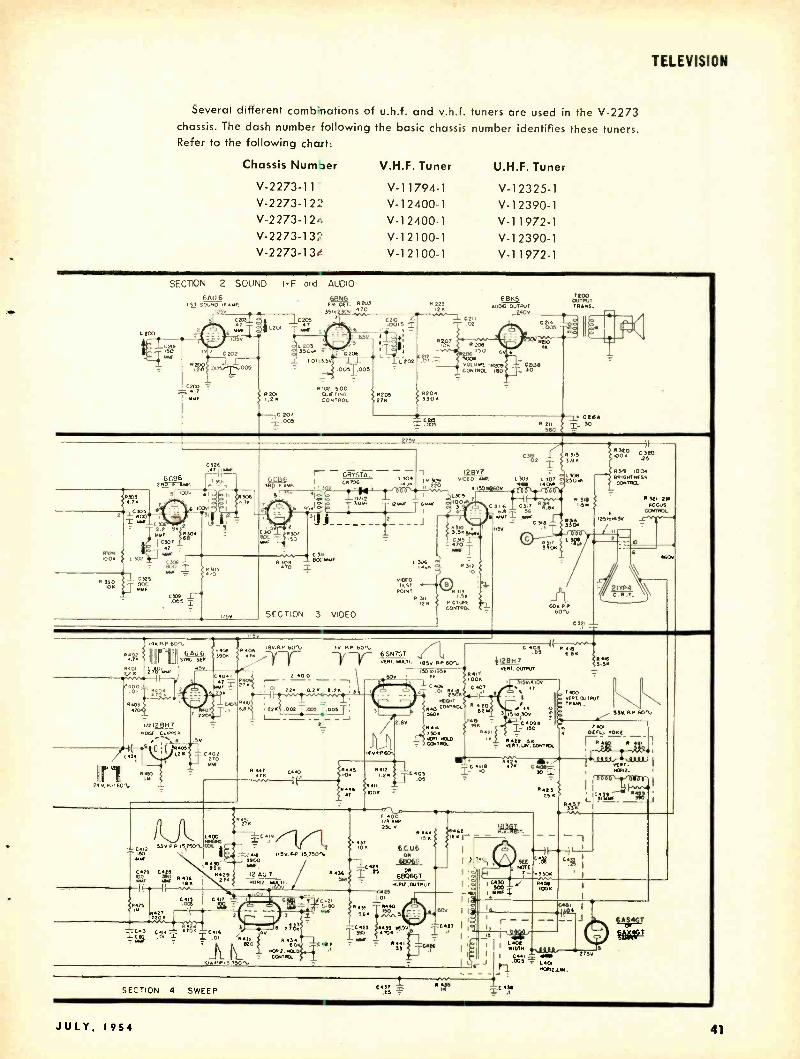
TELEVISION
Several different comb nations of u.h.f. and v.h.f. tuners are used in the V -2273 chassis. The dash number following the basic chassis number identifies these tuners. Refer to the following chart:
Chassis Number V.H.F. Tuner U.H.F. Tuner
V-2273-11 V-11794-1 V-12325-1 V-2273-122 V-12400-1 V-1 2390-1 V-2273-124 V-1 2400-1 V-1 1972-1 V-2273-132 V-12100-1 V-1 2390-1 V-2273-134 V-12100-1 V-11972-1
L 200
SECTION 2 SOUND I - F and AUDIO
20
MMF
6AU6 .sr SOUND IF ANN
105V
g3 c2 gq
IC 205
2 di 1201 1 6
IV
N?8
C200 = 4 7
616o-
C1202y q0 y/71005
R.
R 223 12N
C211 .02
6BN5 14010 OI1TPIIT
2406
C2M
T2oo OUTPUT TRANS.
R207
22 LoO
0--,Ç 207 .O05
P :02 500 LUI TING CONTROL
R 209 50
500a OIUME moo
CONTROL 180
ovo
C213B 30
R YII 560
CY! T- 3°
275
2
320 T .63
C301 47
F 100N 3 E 302
R 330 ION
' .288T L4s =
5325 SOG NNE
CO309 o5 I 305
I15Y
r- CRY5T0L, L 30 I cN706 pa 113 .Io . 0312
95,1 g. o
1 -i
= Cl11 ßl09
470 =
SECTION 3 VIDEO
COY
l 12657 Ipy 010E0 TAM L303 L307
2Y0 150
1.305
¡, R3314 }LG316 0317 6AN 6.e - 56
MMFT wF - C311 ISV .I
- 12MMF T6M1f I
I
2
6R1E0 TEST
POINT N313N. R
ZIN CONTROL
*OM 14
R 315 3.90
250 M
R 313 1.531
4ì"L2
RuO CIYO 100N 2S
R34 1002 BRIGMFIIESS GORTgpL
E
123roM3V
II
!Ryy 7 L74M !ON
R !12
2
G09. RP 601.
C321
R321 2M FOCUS
SECTION 4 SWEEP C637 .ee TC4.,3
JULY, 1954 41
www.americanradiohistory.com

TELEVISION
Stromberg -Carlson
Series 21T -22T
R
T.INMl:J OF Get? I 1
I 1 NAM
E
42
.9 - SJ L_---J
SEC
INPUT YN.F
\ T ,
TI T-. .T SSYC r---T
V It MTN.I .:AMI 6686
MINI.AW. 6BZ7
Mt,
7:7 -- I L-t
I
1
N10 il[
- I YLL -...
L-5
-2S
rr
UM T. TUN LIRCUI?
N t10 BOON
OISE
_ -' JJ - - - z.ov.
OC
NOTE CDR.. LINES FROM SOCKET cI NE CONNECTIONS USED ONLY
10ó M.V 0.OP. 'F TUNER IS PRESENT. :.s Ot1U 'FOMENTS
!.T- ...IMO I.F. COILS SMIiOHE° IN FOR HT. RECEPTION EIPONM RECEPTACLE VOX TO U.N.. CHASSIS
S4. OF COAX CONNECTION 4M.. INPUT E,I... COAX OUTPUT TO KN., [ CONNECTION
SO Y
O i0s TU MEN A6C
.c .óói,ll ¡T,001
r
CONT.
IF AOC
1( S.O Cf z
I NtbA 1 tYl. atlC 1 I I óos 2MOO! .om
a21AT CMS CaICT I ,
tt
NN OOR
HOC, 05C
R:s 6SN7GT C 201
8 oólw
CO,, caso
Mr
LMl
SYV.
110412.51U CONT OL
JYII L2n 0`Bi.`. CYIA
00 C t45 O!S
C2N S.YY. l50
11266 2A6 MM.
LS[
N 250 -t. .TM PNA E OTT
GALS
11232 net
:s COST
+15V
C OSI SSS
.oN 110510 H OLO
NTST 5..[
Ot3. N2SS
PTAS t.i.
Ab
1.ln S l.Tn. 11 5 Y..n1 1 te°ro/e}Oln.feénBOeinf
ORI x.OUTPU T
N
ANSIORMtII I tO
RADIO- ELECTRONICS
www.americanradiohistory.com

.11C. TRAP L -IT
I nDO1 Ixr
[ as
!R
IT
C -ISI
CRT
TELEVISION
21X P4A
Totocut GRET ITn11 ;w
MR r KL. I!
R-Iq Ln
1111 V
L-t3
V-211 r. IYGTIPIER
IB;SGT
1110
2.1 C=110
TSOOlORr wt
SIV.
JULY. 1954
LLLO
Sv. -lexf.°e rELLOw e
.11111r GOA ,6. -ST
1/-E11 I sto
RECTUMS woo
5U4G 6.3V . TARP Se SRN
YI
l.IeYP
B LUE
T- 21
l.Y.
050V.
00 ,-0 G- 2000 SI SSn
40YP
SLR
OxP
NST[ SOLTAOS x[A11U[[RExr[ AT xeO[ AT I
v Li. t sm.
rACYUx TUHYOITx[TER. ell vOLTAO[l e11.C.eRO ARE POSITIVE WITS RESPECT TO CNAf6111 OROUNO ERUPT Rxtu Ort11.
l.COYTReST RO [RI[xiYE0 00RttoL11 SET FOR MoIIYµ fICTYII[1{TRO i1YL RW
43
www.americanradiohistory.com

TELEVISION
RCA Models 21 -5 -348KÚ to 21 -5 -369KÚ
CHASSIS KCS88F and KCS88H.
TUNER UNIT
KRK -3I
518 LIT
LE1.j L16
L's
12
ANT. MATCHING UNIT i l5 1.4 LI
F -M 1 -F
I TRAP TRAP TRAP CZ
* N WHEN USING CONSIMAT,ON UAÇ.VMF ANT. CONNECT TRANSM.LIME T VHF TéRMINALS.
FOR SEPARATE UMF AMO PAF ANTENNS. DISCONNECT W105 . AND CONNECT TRANS... LINES TO RESPECTWE TERMINALS.
51 UWE VHF
C4 I 33 C L3 L2
TI
ANTI TRANI
1 51-C s 1-E
3 I REAR FRONT 1.
1 .2 2.
K 5 9 .
O.
JI-F REAR VIEW
PrM PIN VIEW
22K
LIO - LB
KRK -29D-I VHF SECTION I
r =7135
I 2 R54
4701
! 551
si VHF UHF
SI-D J2 _ REAR
P3R211T PUT K331
'2 '3., z Y " 3 ) 10 I ll 4
12
LIS L14
C6 SI-D 270 FRONT
15
F2 II , C1 10 9'=' 5 ;
Clo00c13 L20 270; 10 __- __ -" -
I ar
FA Ì ANTENNA 4.56
LI111 TERM. 8RD
W105 104
c e +e
3 7 9
RI 6800
é ; 'c
RF AGC
52 120 T I 9
7104 1ST. PIK
I.F TRANS
PC tot
CIO, SOUND TAKE OFF 3 IA TRANS. 30V
V IOI
6AU6 Sou.:
1-F AMPL
Hi 20V.
R103 1000
I 5
6CB6 1ST vIK, I F
C13 270
L27
51 -C SI -C REAR FRONT
RG 03
1000
526 17374 2.2
525
L2
52
2 3 11
q 5 95
L22 6 521
RIO
RN4 IODO
R 1161 r5 K C122
L28 0 470
023 .001
L29
_L 31
L32
C 34 470
L43 3!9
TZ CONV.TR.
-}TC,
R146 150 K
R 1000
117
TR2 L56 Tc19
1000 SI -8 REAR
á0K '?
041/4 II
S1 -8 FRONT
542 0 C36 1..3
CK 44 S'380
C21 536 i 0.5-3
3 W 13 549 C 22 n 0.8-3
LA
6X8 OSC FOUR
C120 4118 CI19- G.47T 33
1470
51 A C27 ROAR FINE IS I STI
3 LS6
5 567
LS6LS7
L60 SI-4
E C26 n 10
FRONT
C23 0.68T 105 MME
e i
LSO
LSI
L52 43
C51 T470
FT(-i7- UHF SECTION
C311 LLL
I
1000
C303 0.51 MME
--1 C301 D
2.6-70.2
C24I 512 10 T IOOK
CNANNEL SELECTOR SWITCN SI FRONT AND REAR SECTIONS VIEWED I
FROM FRONT AND SNOWN IN I
CHANNEL NO 2 POSITION._
TP.g
C301C 74-20.2
5-4 04
0.62MMF
1305
0308 S6 -I -4
5303 I500
)IO T V301
000 I
6AF4
i U303fl47¿I CR301
I 1311 1N82 I. C306 w-IS MIAER
I 7 u
C309 33T
?1
5304 L312 6600
R305 2200
1305 0.33
T301 C301Á ANT. 22.95 TR.
0115 120K
R145 47 K
8123 150 K
2 73 v.
[1T9 0.39
010913
12AU7 AOC OAM PL.
.0 V.
C136 5144
0.331 16 MEG.
273U.
C131 oz82T
1.310 0.15 MK
C 3 1000
12 i 3
T
3301 PI01
C2.2314 I
1,
O4ee S
44
All resistance values in ohms. K= 1000
Direction of arrows at controls indicates clockwise rotation.
LC139 r.047
12 ISO .33K
C137 470
é T
273V.
R147 471(
vK88 6X8 IST SYNC
C141 0.1 46V.
0139 R149 RIS[ ¿' 132K i SOOK
2 A.G.0 CONTI?
3 R151 330 180K
C160 0145 100 T 33K
2.2 MEG
C140
RISO 39K
RISS 1.2 MEG.
F-r C 142 .033
273K
R181 C163 T 330K O1 2'3VIC166 C162_ 0.47 65 T 5182 5184 C 16 0185 T 020. 82K T.022 3900
WIZ
65N7-GT HOR.SwEEP
OSC. ( CONTR.
-21
193v
0'60 180K
R183 150 K
N R186
OO K
L120 KENO/ FREO
9 LÓIR 7 t 3 W t wAVE
ñ47 Al
R 189TAF,
C167 FIN 330 ---II
C1613 .01
000 =1
R ISO M.8 EG
273V
All voltages measured with Volt- Ohmyst and with no signal input. Voltages should hold within - -2 =20 % with a 117 -volt a.c. supply.
RADIO- ELECTRONICS
.1f
www.americanradiohistory.com

TV r.f. range:
70 u.h.f. channels- 470 -890 mc.
12 v.h.f. channels -54 -88 mc,
174 -216 mc.
V102 T102 6A L5
RATIO MT. RATIO TRANS. 4.5 C. DETECTOR ----- ^ ZOv ;3.2 V
I* T 1
! ié/ 10 R106
29V IOK
v 1 A 0_'o.1 7 C106
l000
R105 10 I(
C04 .01
670'4 IC 107 39 K 1.0033
R 1N MODEL 215 3813 KU OMITTED: 5101, JIO1. WI01, «102 ANO 0117 CHANGED: C109 To ,0047, C112 To .001 CONNECTED:CIO, ro JOOCTION of R104, RI54 AND 0107
C112 BETWEEN V103.7 AND GOD. R154, C110 AND V116 -1 TO GND V116.10 ro JUNC T. of C 147, 8197 AND R165.2
ITO ql TEST
121 POINT
o I FRONT
9
an1
7
*S101 REAR
TELEVISION
Front and rear sections of switch SI01 viewed from front with switch shaft in ex- treme counter -clockwise postion No. 1.
Pos. 1 -TV Min. Highs 4- Phono. Min. Highs
2 -TV Normal 5- Phono. Normal
3 -TV Min. Lows 6- Phono. Min. Lows
RIO88 2 IMEG. v01.
CONTR E R109 44444. io
ñ MEG
RI07 3311
V103 6A V6 IST AUDIO AMPL
CIII .O -0.8V,
7E
C110 -.01 M w ;IDI J POI
NON IO NPUT
96V
3
2
R = C 117
Y ,0027
CI I2 270 I
0111 020 1(
V 104
6A55 7103 AUDIO AUDIO
OUTPUT OiJTPUTTR. RILL,
1C 113 , 240V. CIIS ,002=
E TOO
RED ISSN i 11
R 112
1 MEG
Rllo 330K
RI13 470
273 V.
124
VIO6 7 10 6C B6 'FDT':;:,,5 2N pPR I 45.5 MC.
)o
VI07 6C B6 31117 Pox IF
PL
T Io7 4TO. PIK
TRANS 44.5 MC
vlooa L 105
L103 6X8 LISO 250 RUN CR 101 36 MUN I ST O Ú7E0 47 ORO. DON
2100. DOT ORO. WNT . H _A,7._
V.
C131 0.1
R126 680
L 119
C126 C125
001
.001
273 V.
C125B .001
C133 470
R128 I
470
_ _OJ
3900
L104 250 MU N
GRN
142v
12130 120
4-H1-4 C1297 .0039
R157 33K
12AÚ 7 SYNC.
OUTPUT
62 v R160 C144 C146 10K 220 T-0082
R 162 C145 22K .0033
v110 B
12AU7 VERT 5WEEP 05C. ( DISCO
7.9v
390K :156 r
C184 470 I
CI7O O1
R158 T 200
R161 3900
C143 T 82
R163 IBK
-61V
CI46 .0039
RIBA 1 1.5 MEG
VERTICAL NOLO 2
CO =TR
61 0175V .
C147 0.1
273V1
R 166 4701(
12167 C152 C155 22K 015 .022
1-Jv1-11 I
.0022 33K 0153 1 .022 -28V.
if 9e
12AU7 VIDEO OUTPUT
O
R137 47011
RIODA 10 IS
PICTURE CONTRAST CONTROL
L108 180 MUM
WNT
200V.
6 6.0V.
RI42 39K
L107
500 U-N 0111.0117
R141 7500
273V.
C1348 R140 307".1.1 820
+ 273V
6K6 -6T VERTViEEP 0172 VERT SWEEP OUTPUT TR
221( Our.ur BLUT
0255v. I II11IIII
3 C156 Ile G1(ÿ ¡' 4 BRED
. L_J C151 RIGO .056 IBK
R165 C154 3.5MEG CM9 060
2 NEIGNT T.OI 12171 CONTR. 4.
4173 470K
RI69 390K
2
2
R 174 2.5 MEG VERT LINS CO=rR.
RI92 82oK
v13 6B116.6T
NOR SWEEP OUTPUT
C169 R194 680 47 -20v 150V
C173 0.1
R193 1 MEG
C 17 1 10 -I 160 r NOR. DRIVE _ COCO=TR
9191 39 K
11
Cn2 .0012
0.3 AMP
C174 R195 0.27 T 100
R198 56K
BI96
R197 270K
7110
N TRANS. IB3 -GT N V REGT
R176 R175 68oK 820K
15.400V
R177 2201(
R178 200K
6RKsNTNE1S 2
CONTKOL 3
C135 0.1
470 Ki
Y
RI79 ISOK
z
J
W 12K ; do
un. 1C7 IGrN CO=TR 82
17
C175 5
.047- 6AX4-6T DAMPER
273
iCr76 Lt12 270 1.5 MU N
9102 .M VF1N
OEPLECTION YOKE lew
I Y C160 vERT COILS I 34
J 91 LliS 1.04 4.1,A GRO _7 R203 '
ÿ 1000 8201 R202 1
560 560 I TEL
C IS? .022
P -M SPEAKER
21 RP4A 21ZP4B KINESCOPE
B
NO2
REM ROW
CNANNE L IND. LAMP
y © .Y
V 117
SU4-G ROOT. T 1
I *CDr l 3102
I
RID. D.
6RN. TEL
5v
Er. 13s023 . 0
JULY. 1954
LK RED
ELK
"L Y 3
BRN 4204 e¡ I 100',
1 R.
6 V
6RN_ J - iO3
L
111.R. 111.R.
113 LOON 273V suPP T
IISV.60+ SuMLV C132Á C134Á
80 MF 1100 MT
`Chassis KCS88H is identical to chassis 88F Picture i.f. carrier -45.75 mc.
except as noted on diagram. Sound i.f. carrier -41 -25 mc.
45
www.americanradiohistory.com
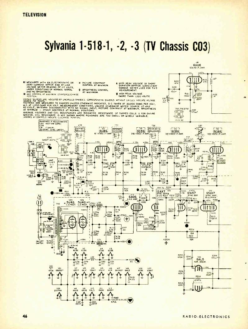
TELEVISION
Sylvania 1-518-1, -2, -3 (TV Chassis CO3)
MEASURED WITH AN ELECTROSTATIC OR W PICTURE CONTRAST ZERO CURRENT METER ANp AT LINE CONTROL AT MINIMUM. VOLTAGE METER READING OF Ill VOLTS, UNDER CONDITIONS OF NORMAL SIGNAL m BRIGHTNESS CONTROL AND NO BRIGHTNESS. AT MAXIMUM. ACC CONTROL AT MAXIMUM COUNTERCLOCKWISE POSITION.
A HIGI+ PEAK VOLTAGE OF SHORT DURATION (APPROX. 5,000V.) MAY DAMAGE METER USED FOR THIS MEASUREMENT.
40 HIGH PEAK VOLTAGE (MORE THAN 1,000 VOLTS)
VOLTAGE rURCES ARE INDICATED BY ENCIRCLED
S I , OAGES ARNMEASU ED TO CHA SI NLESS OTHERWISE INDICATED, D.C. TAKEN AT 20,000 OHMS PER VOLT, A.C. AT 1000 OHMS PER VOLT. MEASUREMENT CONDITIONS, UNLESS OTHERWISE NOTED: SOURCE 117 VOLT 60 CYCLE, ANTENNA DISCONNECTED WITH NO SIGNAL INPUT, PICTURE CONTRAST AT MAXIMUM, BRIGHTNESS AT MINIMUM - OTHER CONTROLS AT NORMAL POSITIONS. AVERAGE VOLTAGES AND COIL RESISTANCES ARE INDICATED. RESISTANCE OF TAPPED COILS IS FOR ENTIRE WINDING. COIL RESISTANCE IS NOT SHOWN WHERE READINGS ARE TOO SMALL OR WIDELY VARIABLE. ARROWS AT CONTROLS INDICATE CLOCKWISE ROTATION.
SM-t
BANDPASS IF ADJUSTMENTS L53 (BOTTOM CORE) L54 L8 (TUNER) 43.25 MC. IO MC. SWEEP,
10 MC
SWEEP WIDTH
TUNER 151S -t
IWITON ON VIM TUNER
I-5W -t
LS3
L54 Tor
L53
!`GDJ,5P111 Lll 1 1
T55
r v; r --+ .15 NC Go50un0 §SQ6.; 1 1
IQ VIDEO I.FAMPI
OS 1050 11
756 1-7,,T-1 x4,.25 MU
6C86 1 ADJ. SOUND :
2S VIDÉO I.F.AMR II II
05v. 103V
L62
45
V8
6AU6 SOUND I.F. AMP.
rvs L6Ç66:
Sae VIDEO F. AMP.
+0V
757 ---,
+.05.411 H 142 owl
L55
3
6061 4!N VIDEO I.F. AMP.
VHF TUNER
T. IV i.) L8
RIS 'C
I
I
336 +i 20i :1 +2600. USIS -P 41
ONLT1 0364_. I -SIN -163 - ANT
BOARD
3 c0L0 cor
caw o.
46
LINE PLUG
C
e01
120V'
6.3V.
R141
1.51(
.3V {11144
47n +100V
034
004 COS
.00Ss T B
,I ).t)C1N
íR146 R145 SIK 6,11S
R134 IK
RI40 IK IK
4142
1826 4.7K .,T
+320V.
R127 +120V
+390V p047Y R143 C139
4207 A047 360K .3
N
V.S TO NI 5
ON 011
C126 - 2.0,/
50V. .0047 18K
C127 0129 10047 R137
56K
LSMEG. 100K _--_ - - I V24 V2S 1
I 415U4G 5U4G 421+330V. L T50
I
L.V REGT. L.V. REGT ITTI,Aa 00 6
C 3V.AC +340V. I on 1 CI75A I I z40rT I A
4DOV. tlT
ON-OFF R175 SWITCH OOK
J Si AC
022 603 021
6V3Á 6306G7
1f411,
V26 2,01,44
y6.3V.AC
TO NOR.
a \i 0200
CI31 6AU6 221 A.G.C. AMP.
1758 80M/ 400V.
c
R176 2K
+320V
+330
V14 R204
I2AX7 IDK
SYNC. SEP a C203 ADC REGT. 0202,047
0047
11206 V141/2 10K I2AX7
SYNC. SEP.
+247V.
12AÚ7 SYNC. AMP, B CLIPPER
7V. +115+
-7.+250V CI13C 20 / 4oóv.
+SOY.
I 2 RI7 7 1 CI77
1 YC176A L1 7r7 .T.22
I D
4oDá
tE I
I
L51
sSISLIL, 4on. 1 BREEN V6 vS +V4 V3
6086 6C36 6086 6CB6
Alri . *i L52 i qi
/00
RI7B 4.7K
+120v.O
aCI78 C179 CI80 =C181 .001 .001 .001 .001
= T _
V7 V13 Ví4 VIS V)6 V17 12517 6406 124X7 12407 604 6AH4GT
V8 6AU6
-
270 245V. R
R201
P200 470K 33K I.OME
G
CONTRO
3411 R203 33K
C201 .0033
R205 6BOK
0204 R212 12K 680K
+410,
R213 330n
+120V
R209
6.3V.O AC
VIB V19 V20 GALS 6086 12B17
V9 VIO VII VI2 6AÚ6 6AL5
C182.- C163 .00471 1,0047
6AV6 6V6GT
- R180
4.711
9 i R179 4.3n
6.3 V. ACC)
+2150V,
T
R250 470K
R251 IOOK
R252 IOOK
33K
0250= vie .0047 6AL5
NOR. D1SCR.
-0V t -13V.
C252 IOOr..I
C251=
R253 .0047
M1 1.0MEG.
01 11 -It
RADIO -ELECTRONICS
www.americanradiohistory.com

C103 { 47/
Caution: The high -voltage lead to the picture tube has a potential of
17,000 volts. Observe precautions when the chassis is out of the cabinet
for servicing! Do not operate the receiver with the high -voltage cover removed!
Always use safety goggles and gloves when handling the picture tube.
V9
6ÁU6 SOUND I.F. LIM.
r .659 +5W.
552
vlo
6AL5 RATIO OET.
VII
6ÁV6 - I!T A.F. 8 TUNER AGG CLAMP
TO TuNER IV. CO2 GC DELAY I 4.34 I 01
R104 47K
0047 R2TÑ
R106 DE- EMPHASIS 27011 PLATE
I Ri07 C10í
T52
CHO
+120V.
IN105 VIDEO
DETECTOR
r 5i_7V L56
TH
+II an
0o II =0142 20143
2109 A
¡¡
VOM G, 15B LU E
CONTROL' V7 (
128Y7 VIDEO AMP.
70 L58 I
- - 2+nOv
, . .37v. +27v
ISMEG.
VIZ
6V6GT A.F. OUTPUT
+2234 RUS
RU3 470K
RI 12 4A 220K
CIII I00Vr/
413.5V +247V.
G138 C113A
210/ 4,1t- 400V. 0' 3,30n 25V
159 a.an 2
711
HALO LIGHT AND T30
CHANNEL INDICATOR LIGHT PLUG
CHANNEL INDICATOR
LIGHT
:7Ö61 +62V
22 6 K S 13ov. m
ELLO 3.9K
2.3n L57 2154 55o, 8.2K
T53
III
CN4_ 01
/:i2116 2K
+320V.
R47 249
TELEVISION
Aa[r
SPEAKER
3
Y
PICTURE RI
CONTRA CONTROL
R152 33K
0145 4.7N/
55. W2.OV. 11
L6100} é601 R159 +S90v 4.5no I .an R 3.9K `/
120v.X - R157 3 --M/9-411
6.8K
2158 RIGO
8162 39MEG.
331E
v26
2IEP4A PICTURE TUBE
+.6V. TO HOR. OUTPUT CATHODE CROAT
9+120K OV.
3604
+1204.
V17
6CVERTICAL 6C4
E
C VERT. OSC. 56 NOISE GATE, INT RER T PLATE +3004.
I) 4 2215 2216 -1 F209 -629.
22K 8.2K 8.2K C205 C206 C207,
.002.005T .005
.001
02081 .0033
8255
R za
6AH4GT VERT OUTPUT
C211 680-/
R220 - 220K -65V
R217 OMEG.
T. 'LO CONTROL
R218 1.8 MEG.
+590V.
919
6CCB6
JCJONTROL HOR MOLO 162
r m,
ont
I
JULY. 1954
Ion
C255 8.2K R257
1K
C257 IOOAA/
L
10011
R224 470K
R223
I.5MEG. HEIGHT CONTROL
C210 .I
0212 It
.047 R222 680K
R22S 120011
R226
scut TEST
G 76C
505 0214
rr .UÌ- I L66
C215
ISOOV
2227 12K
0213 T 1 or vNI /_v/ OR. YOKE
.0033 CONNECTOR SOCKET
(SEE NUMBERS IN HEXAGONS
ih T
YOKE
Tor vFt: 61 LiT gó
3201,
2164
1.0 MEG.
+590v
r I VERT. DEFLECTIO
COILS
HALO LIGHT
17,000V. ±1,000V.
r- -ass' K)
( a50v.I111
L65
!SA
HORIZONTAL DEFLECTION
COILS
2221
100K V201/2 V201/2 12BH7 128H7
C258 NOR. OSC.
C259 HOR. DISCI).
C262 2266 I 1 -239.1
+2501L -754 +575 I
.01 001 10o1T C261
680AA/ R262
8261 SS
150K7 1
82K R264
470K
bb O
01
R273
C264 (
IK
+320V.
-py (CO21
0 763
.22
C265 O' 565w/
V21
MOR. OUTPUT
L72 fA
0
0022 1209.
{ C254 .0152
Ia
foi on. 120V.
Cc
C253
.22 R254 non
2259 470K
R258 VIA 15K
C256 22
+.3V 2260 22K L69 T »n
C260 .0047
2505
4.7K
R263 250K
DRIVE ONTROL
2265
8267 15011
2266
+.68 TO BO/50550r CONTRAST CONTROL
L70
22 SV
CAP
HORIZONTAL SCANNING R
TRANSFORMER ASSEMBLY 15EE NuM8ER5 N CIRCLES
V23
IB3GT N.V. REGT
DO NOT ATTEMPT TO MEASURE VOLTAGES ON H. V. RECTIFIER
TUBE
liR6V3A +1755 !+3209_
I.an ® R270 L71
loon OC.
2269
8271
o 111I--------1II1 0
22K
4.313
C263 .047
C267 CO 320v
TOAGC AMVP.
3204.
0 25 A FUSE
0::ß4.4
0 TOP
V13 T
NC
02. SCAN AND M.V. PLUG CONNECTIONS
15EE NIMSERS IN SOUARESI
47
www.americanradiohistory.com

TEST INSTRUMENTS
:. ä... H
. ......;-:._..
PHIICO CRCSS-OOT LINEARITv GENERATOR
moue. Etaw
Fig. 1 -Front panel view of generator.
ACHOICE of dot or bar pat- terns for adjustment of color or black- and -white television sweep circuits is provided by
this instrument. The linearity pattern generator is
fast becoming one of the most useful pieces of test equipment in the tele- vision service shop. It permits accurate setting of the television sweep -circuit controls and may be used to preset the controls in the shop or make the final touch -up in the home. While not adver- tised as applicable to color TV work, the authors have successfully used this instrument for color convergence ad- justments of the tri -gun type color kinescope.
Linearity pattern generators come in various types and sizes. Some are called bar generators and produce only vertical and horizontal bars. Others are known as cross -hatch generators and produce vertical and horizontal bars simultaneously. This type of pat- tern is usually imperfect and unstable unless standard sync pedestals and pulses of 60 cycles and 15,750 kc are also provided. This would make the instrument too expensive for anything but laboratory use. If the cross -hatch pattern can be made stable it becomes the most useful pattern because it allows adjustment of both vertical and horizontal sweep- circuit controls with the same pattern.
A third type of linearity pattern is the cross -dot. The Philco model G8004, shown in Fig. 1, produces the cross -dot pattern illustrated in Fig. 2. This type of pattern provides all the advantages of the cross -hatch and permits better synchronization and stabilization with simple circuits. The pattern contains horizontal black lines or bars which permit the adjustment of vertical de- flection controls. It also includes verti-
Test Equipment Section, Philco Corp.
CROSS-DOT
LINEARITY PATTERN GENERATOR
By DAN LERNER and WINSTON STARKS*
cal rows of dots which take the place of vertical lines and permit the adjust- ment of horizontal deflection controls.
An additional advantage of the cross -dot pattern is that the dots are useful in checking special performance factors of the television receiver, in- cluding such items as focus, astig- matism, and high -voltage regulation effect on focus and blooming.
Circuit description The model G8004 cross -dot generator
produces an r.f. signal continuously tunable from channels 2 through 6. The r.f. signal can be modulated with a video pattern of any one of four types : (1) The cross -dot pattern shown in Fig. 2. (2) The horizontal bar pat- tern of Fig. 3. (3) The narrow, black vertical line pattern of Fig. 4. (4) The narrow white vertical line pattern of Fig. 5.
Fig. 6 shows the circuit diagram of the cross -dot generator. The heart of this circuit is a dual -triode 12AU7. The r.f. generator section uses one half of the 12AU7 (V1 -b) as an r.f. oscilla- tor, the frequency being controlled by C5 -T2 in the grid circuit. Cathode feedback is used, and the r.f. output is taken from the plate circuit.
The other half of the tube, V1 -a, operates as a pulse generator and modulator. With the function switch in either the left -hand or center posi- tion, this section of the tube operates as an L -C oscillator at about 189 kc when adjusted to produce 12 vertical lines on the television screen. The 189 kc figure was obtained by multiplying the 12 vertical lines by the horizontal sweep rate of 15,750 kc.
When the function switch is placed in the right -hand, or cross -dot position, the grid time -constant of the modulator is made very long. This fact, plus the unique design of the modulator trans- former T3, results in a modified block-
ing- oscillator action. The frequency of the blockage is adjusted by the hori- zontal line DOT CONTROL, a 5 -meg- ohm potentiometer used to control the grid time -constant. The blocking oscil- lator generates sharp pulses which, after clipping and shaping, are used to produce the horizontal bars in the pattern. When the horizontal line con- trol is adjusted to produce an 8 -line pattern, the frequency of the blocking oscillator is about 480 cycles. The 8- cycle figure is obtained by multiplying the number of horizontal bars on the TV screen by the vertical sweep rate (assumed to be adjusted to 60 cycles).
The unique feature of the circuit is the innovation by which the blocking action is made to produce rows of white dots superimposed upon the black bars.
The L -C circuit of the modulator, consisting of T3, C3, and C4, is shock - excited by the pulses produced by the blocking -oscillator action. Because the L -C circuit was pretuned to produce the vertical lines for the left -hand and center FUNCTION SWITCH positions, shock excitation of this circuit pro- duces a ringing or damped oscillations at the same frequency. The coil will not ring long enough to produce a vertical line but will produce a white dot at the point on the television raster where we would imagine the vertical line to cross the horizontal black line. (See Fig. 2)
The damped oscillations, produced in the grid L -C circuit, are shaped by damping, differentiation, and clipping. The phase and frequency of the pulses which form the dots is controlled by the VERTICAL LINES control C4. Since C4 adjusts the phase and frequency of the dots, it also controls their stability or synchronization on the TV screen. Al- though the same synchronization effect can be had by adjustment of the hori- zontal hold control of the TV receiver, this method would cause a change in
48 RADIO -ELECTRONICS
www.americanradiohistory.com

11 !I 11 1111 1
JULY, 1954
Fig. 2 -Cross -dot pattern. Function switch is in right - hand position.
Fig. 3-A horizontal bar pattern.
Fig. 4 -Black vertical lines pattern.
Fig. 5 -White vertical lines pattern.
TEST INSTRUMENTS
the sweep frequency of the receiver. An interesting feature of the cross -
dot circuit is that the production of the dot pattern by excitation from the hori- zontal line pattern makes it easier to lock the vertical dot rows in step with the horizontal lines.
The clipper crystal D1 and the asso- ciated R -C circuit elements shape the various modulation pulses to pro- vide sharper lines and dots. The modu- lation pulses and the r.f. signal are combined in the modulator crystal D2.
Since the generator does not produce standard vertical and horizontal sync pulses, it sometimes is difficult to obtain a stable pattern. The normal power - supply hum in a TV receiver is usually sufficient to cause pronounced weave in the pattern produced by any service linearity generator. The circuit has a built -in stabilization system designed to pick up sweep- frequency pulses radi- ated from the TV receiver into the power line. Capacitors Cl and C2 pass these pulses to the grid of the modula- tor to aid in stabilization. Whenever still better stabilization is needed, the EXT. SYNC jack may be connected to a wire which is simply wrapped one or two times around the yoke cable. (CAUTION: An actual connection to the yoke cable wires should never be made because of the very high pulse voltages on these wires.)
Vertical linearity To adjust the vertical linearity of a
television receiver, the r.f. output from the generator is fed into the antenna circuit, and the vertical hold control of the receiver is adjusted for the 60 -cycle sweep rate (normal setting). The pat- tern is then synchronized by the line controls on the generator. The horizon- tal -line control of the generator is ad- justed to give about 8 horizontal bars on the screen. Vertical linearity of the TV set is then adjusted by the height and vertical linearity controls. These two controls are adjusted to give a full raster with the horizontal bars equally spaced over the entire raster as shown in Fig. 2.
Picture height Using the same setup as in the pre-
ceding paragraph, both the height and vertical linearity controls of the TV receiver should be adjusted so that the vertical linearity is maintained as the total vertical deflection is varied. The vertical size of the pattern (vertical sweep) may be adjusted by simply set- ting the raster height so as to overscan approximately ifi to 1 bar space at both the top and bottom, assuming a total of 8 bars. The overscan is to allow for the blanking on the test pattern or program as transmitted by television stations. Maintain linearity in accord- ance with the procedure given in the preceding paragraph.
Horizontal linearity The function switch on the cross -dot
generator may be in any position for
49
www.americanradiohistory.com

TEST INSTRUMENTS
the adjustment of horizontal linearity. Horizontal linearity is judged by ob- serving the distance between the verti- cal bars (or the horizontal spacing of dots). If the bars or dots are equally spaced all the way across the raster (horizontally), the horizontal linearity may be considered satisfactory. How- ever, if they are not, the horizontal linearity control of the TV receiver should be adjusted to obtain the best spacing possible. Some sets do not have a horizontal linearity control. If linearity appears unusually poor, check for circuit or tube defects. It should be kept in mind that the horizontal grid drive control (some sets do not have one) also affects linearity. Usually this control is set for the most high voltage (brightest picture and most sweep width). If this adjustment produces excessive Barkhausen lines, the grid drive may have to be reduced, giving a slight loss of brightness.
Where a numerical figure for linear- ity (vertical or horizontal) is desired, it is common practice to calculate it as follows :
% nonlinearity = D1 - D2 100 D2
where D1 is the distance between two adjacent lines with greatest spac- ing, and D2 is the distance between two adjacent lines with closest spacing.
A figure of 20% is not at all uncom- mon, but 10% or better is desirable. It is not unusual to have a squeezing together at the edges of the raster. In most cases this is accepted as normal if it does not give a linearity figure of more than 20 %. Since it is common practice to make a raster overscan to take care of blanking and the effects of line voltage changes, the edge squeezing is at least partially hidden.
Horizontal width The reaction between the width and
horizontal linearity controls usually is not excessive. Therefore, with the gen- erator set up for about 12 vertical lines, it will normally be sufficient to adjust only the width control to give an over- scan of about one line or one dot space on each side of the raster.
Leveling and centering The picture can be leveled by rotating
the yoke to make the horizontal lines
50
level with respect to the edges of the picture -tube mask. This adjustment is best made when a large number of horizontal lines are in the pattern. The horizontal line control of the generator may be turned to give the maximum number of lines.
CAUTION: Avoid touching the yoke with the hands while the receiver is in operation, since very high voltage pulses are present on the yoke coils. To adjust yoke with the set in opera- tion, an insulated rod or similar tool should be used. When tightening the yoke after it has been adjusted, keep the yoke all the way forward with the insulated tool. This is to reduce the possibility of shadow at the corners and edges of the raster.
Picture centering is accomplished by adjusting the centering control until the overscan is the same at the top and bottom of the screen. Likewise, the overscan should be made the same on the right as it is on the left. If a shad- ow is now visible on the edge of the pattern, the setting of the beam bender should be checked. Yoke positioning also may be at fault. A defective horizontal circuit or defective yoke can also cause this trouble. A slight readjustment of centering can sometimes clear up shad- ow, but should not result in excessive decentering of the raster. If none of these adjustments help, the high voltage and circuit operation should be checked.
NOTE: Most television deflection and picture -tube assembly adjustments have some interaction. Where this effect is apparent when a particular adjust- ment is performed, a readjustment of the other controls affected should be made. In particular, it will be found that there is an interaction between yoke adjustments, centering, beam bender, and horizontal and high -voltage controls.
Beam bender and focus After making the above adjustments,
the beam bender will usually need re- adjustment. A misadjusted beam bender can result in serious damage to the picture -tube gun or screen.
The cross -dot pattern is ideally suited for making focus adjustments. With this pattern on the screen, the TV con- trast control should be set to a medium level and the brightness (or back-
=Io
22K DI CATH 22
-b; -_?_.;FUNCTION SW
02 q3
4.75
r H C3=100 C41100 I.51AEG
/VERT UNES ¡T3
100
5 AIEG
6
C211100
I 5K 1500
vl-b
12AU7
.75 D2CATH 820500/y ' 470 R.F.OUT
1 O
470 5 10 E%T.SYNC
-1 t +- i22 K
47 CHANNELS
i
156K CS 20 T2
HORIZ LINE COOT) CONT.
Fig. 6- Schematic of the Philco model G8004 cross -dot linearity generator.
"430-1 117VA0
CA
FUNCTION SW: I- BLACK BARS 2 -WHITE 3- DOTS
DI, 02= IN34
CAPS IN NPt
UNLESS NOTED
SEL. RECT.
eoPt saht 56K PILOT TRISOV
6.3V
ground) control is adjusted for normal brightness. The focus control is then adjusted for sharp lines and dots. It should be possible to see the sweep lines of the raster and the dots in sharp focus over the entire screen. If the television receiver does not have a cosine yoke it probably will not be possible to obtain sharp focus over the entire screen. In this case it will be necessary to compromise on the focus.
After the focus adjustments have been made, a check on defocusing and high -voltage regulation may be made by watching dots and sweep lines as the brightness and contrast controls on the television receiver are varied from minimum to maximum. Some defocus- ing is normal when both of these con- trols are set to maximum.
Circuit hum Excessive hum in the circuits of a
television receiver may cause poor sync or bending of parts of the picture. Also, on programs transmitted from rela- tively distant points, the residual hum in the receiver power supply may be out of step with the transmitted 60- cycle sweep, and the hum distortion will appear to drift through the picture. This effect is called picture weave. A horizontal shifting or weaving results from hum in the horizontal circuits. A shift in both directions simultaneously gives a circular motion to components of the picture. These effects are more apparent and more easily detected if a cross -dot pattern is viewed on the receiver screen. An extremely well - filtered power supply is used in the cross -dot linearity generator, so that any hum effects appearing on the TV receiver screen will be due to the hum originating in the receiver.
Generator alignment Alignment of the model G8004 is
simple and straightforward. The r.f. oscillator is aligned by first setting the channel dial pointer on the channel 2 mark and then adjusting the oscillator coil core to produce the strongest and clearest cross -dot pattern on a properly adjusted television receiver, also set to channel 2. Another method would be to use a grid -dip meter set at approxi- mately 58 me to peak the r.f. oscillator coil for channel 2 setting.
The modulator coil is usually ad- justed to produce 12 vertical lines when the vertical -line control is see midway in its range. If a different number of lines is desired, the adjustment can be made with a screwdriver inserted through the hole provided in the rear of the generator housing.
If the modulator coil is adjusted when the cross -dot pattern is being used, a change in adjustment not only will vary the spacing and number of vertical dot rows, but also will pull the number of horizontal lines along with the change, thereby tending to maintain the same proportion between the number of ver- tical dot rows and the number of hori- zontal lines. END
RADIO -ELECTRONICS
www.americanradiohistory.com

Fig. 1- Sweep -linearity patterns.
i
TEST INSTRUMENTS
Air MI Ur 1111 III Ilk,
Al II II II I I I 11111111111 411 I II lit
new instruments for Some recently developed test equipment for the radio and TV service technician
better servicing By Robert F. Scott TECHNICAL EDITOR
DURING the past several months a number of new and revolu- tionary radio and TV test in- struments have been developed
and many improvements have been made in basic test instruments such as multimeters, tube testers, v.t.v.m.'s, and signal generators. It is my belief that a technician's ability to do an effective job is determined directly by the efficiency of his test instruments and his knowledge of their applications and limitations. I have studied the features of some of the latest developments, and in this article I will review the circuits of new capacitor and flyback trans- former testers and the design features of a new v.h.f.- u.h.f. signal generator that uses an Inductuner as its tuning element.
Do -All TV signal generator The Radio City model 750 TV signal
generator combines the functions of AM signal, linearity pattern, and mark- er generators to justify its being called the Do -All generator. It is one of the most versatile instruments of its type currently available to service tech- nicians. It covers all FM and TV in- termediate frequencies and v.h.f. sig- nal frequencies in three fundamental ' ranges: 9 to 11, 21 to 47, and 54 to 200 megacycles. On the fourth and fifth ranges, used for u.h.f., the third and fourth harmonics of a band of fre- quencies between 155 and 230 mc are used to cover from 465 to 690 mc and 620 to 900 mc.
Internal modulation frequencies of 360 cycles and 141.75 kc may be applied separately to produce horizontal or vertical bars or used simultaneously to check sweep linearity. The linearity patterns obtainable with this instru-
JULY, !954
ment are shown in Fig. 1. The internal modulation frequencies are available at a separate output jack for testing audio and video amplifiers.
Performance Checking the dial calibrations of the
first three ranges against a BC -221 heterodyne frequency meter and an assortment of accurate crystals, I found the instrument unusually accur- ate for one of its type. In checking at least three points on each fundamental range, the calibration accuracy was found to be well within the 0.1 % limits specified by the manufacturer for the 9 -11 -mc band and less than the 0.5% tolerance specified for the remaining bands. These checks were made after a 30- minute warmup period. With a cold start, the instrument drifts for about 3 minutes and then settles down on frequency.
Circuit of the 750 The cotplete Do -All generator is
shown in Fig. 2. The r.f. tuning ele- ment is a 2- section Mallory spiral -type Inductuner. One section is connected across r.f. oscillator V2 -a for the 9 -11- and 21 -47 -mc bands; the other section is connected across V2 -b for the bands covering from 54 to 900 mc.
Either section of V2 may be modu- lated by 360 cycles and 141.75 kc. The modulation signals are applied across a 10,000 -ohm resistor (R9) common to the grid returns of V2 -a and V2 -b. The output of the r.f. oscillators is devel- oped across the 91 -ohm cathode re- sistor R8, common to both sections. The signal voltage is tapped off this resistor and applied to the 200 -ohm OUTPUT CONTROL.
The Fig. 3 diagrams show the basic
r.f. oscillator circuits for the various ranges. On band A (9 to 11 mc) coils L2 and L3 are connected in series with variable inductor L1, a part of the Inductuner, to limit the minimum in- ductance in the circuit of V2 -a when L1 is shorted out. The circuit capaci- tance consists of C3, C4, C5, C6, C7, and C8 connected as in Fig. 3 -a. The circuit tunes from 9 mc with Ll fully in the circuit to 11 mc with Ll shorted out.
On band B, the 21 -47 -mc range, L3 and capacitors C3, C4, and C5 are dis- connected so the circuit of V2 -b ap- pears as in Fig. 3 -b. On bands A and B, plate voltage is applied to V2 -a through 1,000- and 5,100 -ohm resistors to the center -tap on L2.
Band C, 54- 220 -mc, is covered by the basic range of the Inductuner sec- tion L4, connected between grid and plate of V2 -b. The tuned circuit con- sists of series coil L5 and variable in- ductor L4 in series and shunted by a 3 -12 -µµf trimmer C12. The inductance of L5 establishes the highest frequency, and the setting of the trimmer estab- lishes the low- frequency calibration point. B plus voltage is applied to the junction of L4 and L5 through a 10,- 000 -ohm series resistor. The circuit configuration is shown in Fig. 3 -c.
Bands D and D' are limited to a tun- able range of 155 to 230 mc by a band - spread arrangement obtained by con- necting shunt coil L7 across variable inductor L4 (see Fig. 3 -d). With L7 shunting L4, the effective inductance in series with L5 is reduced, thus rais- ing the low- frequency limit of the range. L5 and the trimmer capacitor determine the high- frequency end of the range with L4 shorted out. The third harmonic of this 155 -to- 230 -mc
51
www.americanradiohistory.com

TEST INSTRUMENTS
Versatile u.h.f.- v.h.f. signal
ON-OFF )00ppf TI SEL.RECT. 2.2K
R7VACC {{ L + ` CI
T26 I
Ry 0 TC2
6.3V
STANDBY ABC
53
generator.
range is used to cover from 465 to 690 mc, and the fourth harmonic is used between 620 and 900 mc.
Internal modulation is supplied by oscillator V1 (Fig. 2) . Section V 1 -a is tuned to approximately 360 cycles to produce six horizontal bars on the TV screen. V1 -b produces vertical bars. Its frequency is adjustable over a narrow range so it can be adjusted to precisely 141.75 kc. At this fre- quency, the TV set will sync with the pulses at the output of the generator. The frequency of Vl -b is varied by the VERTICAL LINE control.
The B plus lines to the plates of V1 -a and V1 -b are controlled by S2, the MODULATION switch. When set to OFF, the B supply is disconnected from both sections of Vl. If external modulation is desired, the modulating signal can then be applied to the r.f. oscillator through the AUDIO OUTPUT -EXT. MOD.
jack. The HOR. position of S2 applies B
plus voltage to V1 -a; the VERT. position
VI-a
17 .01 2
i(CI6
.001 CI9
VI-b C20
7
5pf
32
CI8
.05
RS
IK
R3 C7:4I301ipt
.001=C22 6.3V
V2
53-6,53 -b SECTIONS GANGED
IÓppr v2-a
T CH C9
C6 5-BOppf
SOppT
RI3 614
2MEG I20K
TUNING- R6
1\
LS \ --a 1 0-01
;4(...-C12 6
óIL6
1430
VERT LINE
#fC23
25pp` MAX
.C21
úpf
CIII .(001
ION
.F!fORIZ
VERT
CROSS NATCN
R9 .01 AUDIQOUT ( o
10K C24 EXT. MOD.
= 53-6 =RONT
r~
3-12ppf ` 2b Oppf
L7_
53 -b REAR
R8 9L CI4,,,.001
OUTCONT. 05 .F.OUT
R 0 .0
Fig. 2- Schematic of the Radio City model 750 Do -All signal generator.
LI
5.1K _ lL2
IK .001
r 21-47 MC
B+
52
V2a
MOD.IN S R8 91
6
Fig. 3 -The radio -frequency
TO RF. OUT
CONT.
10K
201
B+
54-260MC
Cl2 6
10p pt
10K
V2-b
IN R9 RB 91
C -
12
TO R.F.OUT CONT.
vi-6
155-230MC FUNDAMENTALS
465 -690 0 620-900MC
ON HARMONICS
TO R.F.OUT T
MOD.IN R9 R8 91
á
oscillator circuits for the various ranges.
applies plate voltage Co Vl -b; and the CROSSHATCH position turns on both sec- tions of VI to produce the checker- board test pattern on the TV screen. The outputs of V 1 -a and V 1 -b are taken from their respective plate cir- cuits and applied across the R9 in the grid circuits of the r.f. oscillators.
Flyback transformer tester The Kirby model 68 flyback tester
is one of the most recent test instru- ments developed to minimize second - guessing by the service technician. De- signed especially to test flyback trans- formers for shorts, open circuits, and intermittents, it can be used also for similar tests on audio, power, and ver- tical output transformers, and r.f. chokes with inductances above 10 -20 millihenries.
The tester in Fig. 4 is essentially a 1,500 -cycle triode oscillator. Raw a.c. on the plate keys the oscillations on and off at a 60 -cycle rate. The keying transients thus produced are useful in causing a permanent breakdown in in- termittent open or short circuits. The strength of oscillations is indicated by a 20,000- ohms -per -volt meter across the grid resistor. Meter sensitivity is controlled by the 2- megohm CALIBRATE
control. In most instances, flyback trans-
formers can be checked without being removed from the TV set. Continuity tests are made by connecting test leads across adjacent terminals on each winding of the transformer. If the cir- cuit is unbroken, it shorts out the oscillator grid voltage and the meter reads in the GOOD portion of the bottom scale.
Short tests are made by connecting the transformer primary directly across the primary of the tester oscillator coil. The test leads connect across the high - voltage section of the primary on 70° to 90° transformers and across the full primary (B plus and rectifier plate terminals) on transformers of less than 70 °. The inhérent inductance of direct -drive and air -core flyback trans- formers is too low for reliable tests, so the inductance is raised by removing the powdered -iron core from a defec- tive transformer, breaking it in half, and inserting it in the air core of the transformer being tested.
One or more shorted turns in the primary or secondary of the trans- former short -circuits the magnetic cir- cuit and places an unusually heavy load on the oscillator. This lowers the efficiency of the circuit so the grid voltage drops and the meter reading falls to REPLACE On the center scale.
Most linearity and width coils can be checked for short and open circuits in the same way as transformers.
The Sprague Kwik -Test The model KT -1 capacitor tester is
a new test instrument designed to sup- plement the standard capacitor analyzer or bridge by testing capacitors from 30 µµf to 2,000 1Lf for shorts, opens,
RADIO -ELECTRONICS
www.americanradiohistory.com

e
47NNf
I K
220},uí
47NNf
LI, L2,813
220 4444f 220 NN
N OPEN-SHORT
SWITCH
,444
PRESS-TO-TEST SWITCH
470k
TEST INSTRUMENTS
Instrument tests capacitors from 30 µµf to 2000 µf. Unit tests wide range of horizontal flyback transformers.
and intermittents without disconnect- ing them from their associated circuits. These tests can be made even when the capacitor is shunted by a resistance as low as 60 ohms. In the range of 0.1 to 2,000 µf, capacitors can be checked for shorts when shunted by a resistance as low as 2 ohms.
The circuit of the KT -1 Kwik -Test is shown in Fig. 5. Tests are made with the apparatus turned off and the test leads clipped to the capacitor under test. When the OPEN -SHORT switch is set to SHORT a 60 -cycle voltage is applied to the capacitor through a series circuit
6K6 .0056 -0075 66K
II7VAC
FIL 2MEG
CONTINUITY TEST
Fig. 4- Flyback transformer tester.
IKS 22
4-30ppf zl --- - -- -1 OPEN
consisting of a 30 -ohm resistor and a 470,000 -ohm resistor shunted by a 0.1- µf capacitor. When the TEST switch is pressed the capacitor is connected be- tween ground and the grid of the 1629 electron -ray indicator tube. A shorted capacitor grounds the grid of the 1629 and the eye remains open. If the capac- itor is not shorted, a part of the 60- cycle voltage biases the grid and causes the shadow angle to decrease. The amount of eye closure depends on the value of the capacitor and the circuit in parallel with it. A large capacitor shunted by a small resistance produces only a slight change in shadow angle. Intermittent shorts can be detected by tapping the capacitor.
Testing for open circuits A 20 -mc oscillator is used when
checking capacitors for open circuits. Coils Ll and L3 form the oscillator circuit. L2 feeds power simultaneously to the grid of the indicator tube through a 1N51 germanium diode and to the test clips through a pi- section impedance- matching network Z1 and
I La 7 CIt2.4.-P1-1\c r ` Q..""'
L 4zekf1 i
CATHLIN51
220ppt - bL2
1
JULY, 1954
70K
EG
PRESS TO TEST
oo o o-
1629
i470K
1626
T41ppt S;WK 220ppf
1E-7_
IIIVAC
Fig. 5- Sprague capacitor checker. FILS
30 /10A
I.5Kr
= ó - T 300v
a 48 -inch length of RG -54/U coaxial line, Ti.
The r.f. voltage applied to the diode is rectified to provide grid bias for the 1629 when the PRESS -TO -TEST switch is closed. The bias on the 1629 grid re- duces the shadow angle (closes the eye) in proportion to its d.c. value. With zero voltage the eye is wide open; a low voltage causes a slight closing, and a high voltage closes the eye.
The 30 -µµf trimmer (C1) on the in- put side of Z1 is adjusted at the fac- tory so the combination Z1 -T1 repre- sents a transmission line exactly one - quarter wavelength long (electrically) at 20 -mc. The transmission line and the diode rectifier are paralleled across L2. A capacitor to be checked is con- nected between the clips at the load end of the transmission line. If the capacitor is open the impedance- revers- ing characteristics of the quarter - wavelength line will make it appear as a short circuit across L2. Under this condition, L2 will not deliver voltage to the 1N51, so the eye remains open when the PRESS -TO -TEST switch is oper- ated.
The reactance of a good capacitor appears as an impedance between the clips. A small capacitor has a compar- atively high reactance, so L2 sees a partial short, and the voltage delivered to the diode is low. The eye will then show only a small closing. A large capacitor causes a greater closing be- cause its lower reactance appears as a higher impedance across L2 as it de- livers a larger voltage. Good capacitors of 200 µµf or larger close the eye com- pletely. Smaller capacitors close the eye in proportion to their capacitance.
When testing for opens or shorts, closing of the eye, no matter how slight, when the test switch is operated indicates that the capacitor has passed that particular test. END
53
www.americanradiohistory.com

TEST INSTRUMENTS
Front view of the compact wide -range oscillator
S electronic equipment gets smaller and more complex, min- iaturized test and service in- struments become important.
Increased circuit complexity means that more test equipment must be on the bench. The result is often bedlam and confusion, particularly with to- day's oversize test equipment.
Compact test equipment is often viewed with distrust for too often its small size has been obtained at the expense of performance. However, in the oscillator described, nothing is sac- rificed to achieve compactness. While the unit measures only 6 inches on each side, the frequency range extends from 20 cycles to 2 megacycles. The output is a constant 5 volts ± 0.5 db and has a distortion of only 0.25% through the audio range. Furthermore, to make duplication of the unit easy, no special selection or matching of resistors is necessary. Compactness is achieved mainly through the use of miniature tubes and careful placement of parts.
Circuit The oscillator is basically the popular
6AU6
2
COMPACT WIDE -RANGE OSCILLATOR By RICHARD GRAHAM
bridged -T with a cathode -follower out- put stage (Fig. 1). The 6AU6 (V1) serves as a high -gain broad -band am- plifier. The two 6AK6's following are both cathode -follower stages. Regen- eration at all frequencies is provided by the cathode -to- cathode coupling be- between V1 and V2 through the 3 -watt lamp. A degenerative path between the two stages is provided from the cathode of V2, through the bridged -T network to the grid of Vl. The amount of degeneration between the two stages will vary with frequency for a partic- ular set of R1 -5, R6 -10 and Cl values. This is illustrated in Fig. 2. The fre- quency of oscillation will then be at the frequency of minimum degenera- tion-i.e., the frequency at which the voltage fed back through the network is at a minimum.
By switching in five sets of resistors in the bridged -T network (RI through R10) and varying Cl over each range, continuous oscillations are produced from 20 cycles to 2 megacycles. (Band A- 20-300 cycles; Band B -250 -3,000 cycles; Band C -2.1 kc -25 kc; Band D -22 kc -250 kc; Band E -250 kc -2 mc).
Circuit adjustment and calibration is
15/350V
C2
100p pf
K 115V/3W
RII IK LM 10)0
50V
_ (13) IOMEG
A R I OMEG l 6AK6 (2)
OUT CONTROL
500K
I /400V
K
5K
4a B R 3MEG R6 6.BMEG
¡ C R3 300K 51-b o--V111r- o--MM
R
R
¡ DD Ry I E R 3K
CI RIO 680
15.467ppf 0-11/0r.
117VAC
MEG
V3
loo
, ISOEv our IK
SK
r-*
75MA SEL.REGT. VOLTAGE DOUBLER f5K /5W = .5A Ç3+
I00'150V + 125V/50MA=
+ + +
T60
20
T40 I00K
GALL 350V -!-
Fig. 1- Schematic of wide -range oscillator.
54
3 3
V2 >03 4 4 4
11_04T
47K
Bridged -T circuit is used.
greatly simplified by using regular 10% tolerance resistors in the bridged - T network. This makes it necessary to calibrate each frequency range indi- vidually to compensate for the resistor variations, but it eliminates tracking difficulties which would become evident on the higher frequency ranges. Need- less to say, 10% tolerance resistors are a lot cheaper too.
The 3 -watt lamp LM keeps the ampli- tude of the output constant by control- ling the regenerative feedback cur- rent. The lamp resistance increases with the current being fed back, thus stabilizing the output.
The 100 -µµf capacitor, C2, introduces some positive feedback peaking which boosts the output on the higher fre- quency range.
The output of the oscillator is taken from the cathode of V2 and fed into another cathode -follower stage, V3. This stage provides complete isolation between the oscillator and the output. The output is controlled by a log -taper potentiometer which permits an output adjustment down to the millivolt re- gion, easily and accurately.
The power supply is a compact transformer -operated half -wave voltage doubler using selenium rectifiers. This supply has an output of 180 volts under load at the output of the two- section R -C filter.
Construction The layout of the components both
above and below chassis is shown in Fig. 3 and Fig. 4. As might be expected in any circuit in which the grid is 30 megohms above ground (on band A) and which has a large unshielded me- tallic mass (Cl) connected to the grid, there can be a serious amount of hum pickup. The extent of this problem, if there is any at all, depends almost entirely on the parts layout. Since compactness necessitates arranging the components very close to each other, the possibility of hum pickup is greatly increased. A.c. pickup is not noticeable in this unit. However, in preliminary models the problem was severe. Thus the general layout shown is suggested.
If the constructor wants to change the layout to fit a cabinet and chassis
RADIO -ELECTRONICS
www.americanradiohistory.com

already on hand, keep the following in mind. The main difficulty will be ca- pacitance coupling between a.c.- carry- ing components and the grid circuit components of Vl. A shield fencing off the power transformer from the vari- able capacitor Cl is necessary. It need not be steel. Aluminum will do, since tl-e coupling is electrostatic rather than electromagnetic. Other components such as C3 and the selenium rectifier should be mounted below the chassis
RI-5
o
eour R5-10 err,
FREQUENCY OF OSCILLATION If0 f- Fig. 2- Bridged -T characteristics.
and as far away from V1 as is prac- ticable. R -C filtering in the power supply is preferable to using a choke, since the smaller area of the resistors reduces undesirable capaci- tance coupling. Shielding the heater wiring, particularly that of V1 is also helpful in reducing capacitive effects. Pacing the filaments at a positive voltage above ground also reduces hum due to heated cathode emission. Of
course, a cabinet or enclosure of some sort is absolutely essential for hum - free operation.
Cl has a % -inch shaft diameter which must be insulated and reduced to 1/4 -inch diameter to fit the dial mechanism. These two functions can be combined by modifying a National TX9 flexible coupling. This coupling has enough stock to drill the 1/4 -inch hole to % -inch. First disassemble the coupling, then drill out one collar to % inch. Solder the collar and flat flexible spring back together. A small piece of 1/4 -inch shafting (the excess cut from the shaft of the output con- trol) is used to couple the dial to the flexible coupling. Cl is insulated from the chassis by mounting it with three 3/4 -inch ceramic standoffs.
Adjustment and calibration After the unit is completed, let it
warm up, and observe the waveform on an oscilloscope. Adjust R11 until there is no noticeable distortion. Give R11 another slight twist to reduce dis- tortion to an even lower amount. Ac- tually, an oscilloscope can give only a rough indication. Distortion of 10% or less is not even observable on a scope. However, don't go overboard on this adjustment with the thought in mind of reducing the distortion to zero, because moving the arm of R11 down also reduces the available out- put voltage.
Loosen the trimmer capacitors on Cl to almost minimum capacitance. Leave
OUTPUT TERMINALS
FUSE POST 60X20X40pf
350 V
Fig. 3 -'hop view of the oscillator.
JULY, 1954
TEST INSTRUMENTS
Parts for wide -range oscillator. Resistors: 1-680, 3- 1,000, 1- 3,000, 2-- 5,000, 1-
6,800, 1- 30,000, 1- 47,000, 1- 68,000, 3- 100,000, 1- 300,000, I- 680,000 ohms, 3-I megohm, 1 -3 megohms, 1 -6.8 megohms, 3 -10 megohms, I/2 watt, 2 -5,000 ohms, 5 watts, I- 1,000, potentiometer; 1- 500,000 ohms, potentiometer (Centralab type B with C2 taper, with switch).
Capacitors: 1 -100 µtsf, ceramic; I--0.1 µf, 200 volts, paper; 2 -1.0 µf, 400 volts, paper; I -15 µf, I- 60 -20 -40 µf, 350 volts, electrolytic; 2 -100 µf, 50 volts, electrolytic; 1 -100 µf, 150 volts, electrolytic; I -2 -gang, 15 -467 µµf, variable (Allied Radio Co. No. 61-059).
Miscellaneous: 2 -6AK6, 1 -6AU6, tubes; I- selen- ium rectifier, 75 ma, voltage doubler (Sarkes -Tarz- ian 78D); I -3 -watt lamp, 117 volts; 1- transformer, 125 volts at 50 ma, 6.3 volts at 2 amps (Stancor PA8421); I -2 -pole, 6- position switch (Mallory 3126J); I -fuse with holder, 1/2 amp; 3- ceramic standoffs; 3 -tube sockets; I set- output terminals; I -pilot light and assembly; 1- cabinet, 6 x 6 x 6 inches; I- insulated coupling shaft; I-dial face.
some adjustment to realign the instru- ment if the calibration should ever go off. The instrument is now ready for calibration.
The lower frequencies can be cali- brated with Lissajous figures using the 60 -cycle power line as a standard. The higher frequencies can be calibrated with a broadcast receiver. For example, 100 -kc output from the oscillator when fed into the antenna of a calibrated broadcast receiver will produce harmon- ics every 100 kc. Thus, by subtracting two harmonic frequency readings on the receiver, the oscillator output frequency can be determined and a calibration point marked on the dial. The higher frequencies can be identi- fied in the receiver directly. END
l'-IRU R5 R6 TH RU RIO 5001í OUTPUT
CONTROL
.
Fig. 4 -The oscillator underchassis.
55
www.americanradiohistory.com

AUDIO -HIGH FIDELITY
Obtain wide range
and good quality with A VERSATILE TAPE RECORDING AMPLIFIER
USING tape for dubbing and play- ing back musical recordings has become so popular that today most custom audio systems con-
tain a tape recorder of some sort. Unless an experimenter has the money to buy a professional machine the alternative is usually to build -in a standard $200 home tape recorder and put up with second -best quality. The ridiculous per- formance claims of some of these low - cost machines, based usually on some small portion of the complete recording chain such as the input preamplifier, has trapped a great many unwitting audiophiles into this compromise. One of the few tape transport mechanisms
I ' f
- 3
3 r- , i
l 9
2
.
30 60 120 250 500 IK 2K 4K BK 16K
FRE0.-CPS
Fig. 1- Responsive curves. Solid line - authors circuit; dotted line- A.C.A.
5879 PLAYBACK AMPL.
By GEORGE L. AUGSPURGER
available to the home constructor which bridges the gap between the "Little Gem Pushbutton Wonder" and high - quality broadcast recorders is the Am- plifier Corporation of America "Twin - Trax" mechanism. Because of its mod- erate price, sturdy construction, and numerous quality design features, this unit has become popular with moderate - income experimenters.
My tape 'recording and playback am- plifier can be used with the Twin -Trax or any other high- impedance head trans- port chassis. When used with the Twin - Trax, the amplifier will record and play back music with a frequency range of 50 to 9,000 cycles within 3 db at a tape speed of 71/2 inches per second. The har- monic distortion at full recording modu- lation does not exceed 5% at any frequency within this range and the 5% figure is reached only at the lowest frequencies recorded. These figures in- clude the entire chain from the input to the recording amplifier, through the recording medium, and out the final stage of the playback amplifier.
An examination of the response curves (Fig. 1) will show that gain at 12,000 or 14,000 cycles is definitely
220K IMEG
IMEG 47K
3
270K 220K 47K 2
220K
70.480ppf 40K
.D01.¡.í5'/. 1.2K r25 .¡..I IMEG
11 1 I2AX7 --ot
RECORDING LEVEL CONT
IN
+ 3.3K 25
20'PPf
47K
.003
within the range of a little more equali- zation and there is a strong temptation to attempt it. In practice there is a very good reason why this is not a good idea. The plotted response of the recorder above 5,000 cycles is misleading be- cause in the upper high- frequency range, beat frequencies between the audio signal and the supersonic erase voltage are pronounced. This is a phe- nomenon which is strictly hush -hush among recorder manufacturers. While most literature on the art of tape re- cording states that a bias frequency of at least five times the highest audio frequency to be recorded must be used to avoid beat interference, the inter- ference in practice becomes noticeable at about one -tenth the bias frequency.
Therefore, the response curve above 6,000 cycles progressively indicates a much higher level than would be present if the beat interference didn't exist. Consequently a curve which begins to droop at about this frequency and has a gentle roll off to about 12 kc was aurally determined as the best compro- mise between flat high- frequency re- sponse and excessive beat -note distor- tion. This beat -note difficulty is not a
IBOV
20K IK I
1000/ 0MA 2W IOW IOW
± 20 T20 T220 ±¡,40 +40
OOK
10-IBOppf
RECORDING 3 AMPL.
22K
47K 8SN7 -GT
220K 6
1.2K Ii
-)I
270K
ol
47K
.25 41K
300ppfi100K IMEG
.01
3
2.2K I.I
RECORD-PLAYBACK HEAD y
ó 30MH
56
2W
5V
OK -NOISE BALANCE
-250
117VA6
275V
PLOT
rHsEATER BALANCE
TO HEATERS 100
5Y3
7000 C.T.
_25V 500
5W
75MA
Fig. 2- Schematic of the versatile tape recording and playback amplifier. Unit contains bias and erase controls.
RADIO -ELECTRONICS
www.americanradiohistory.com
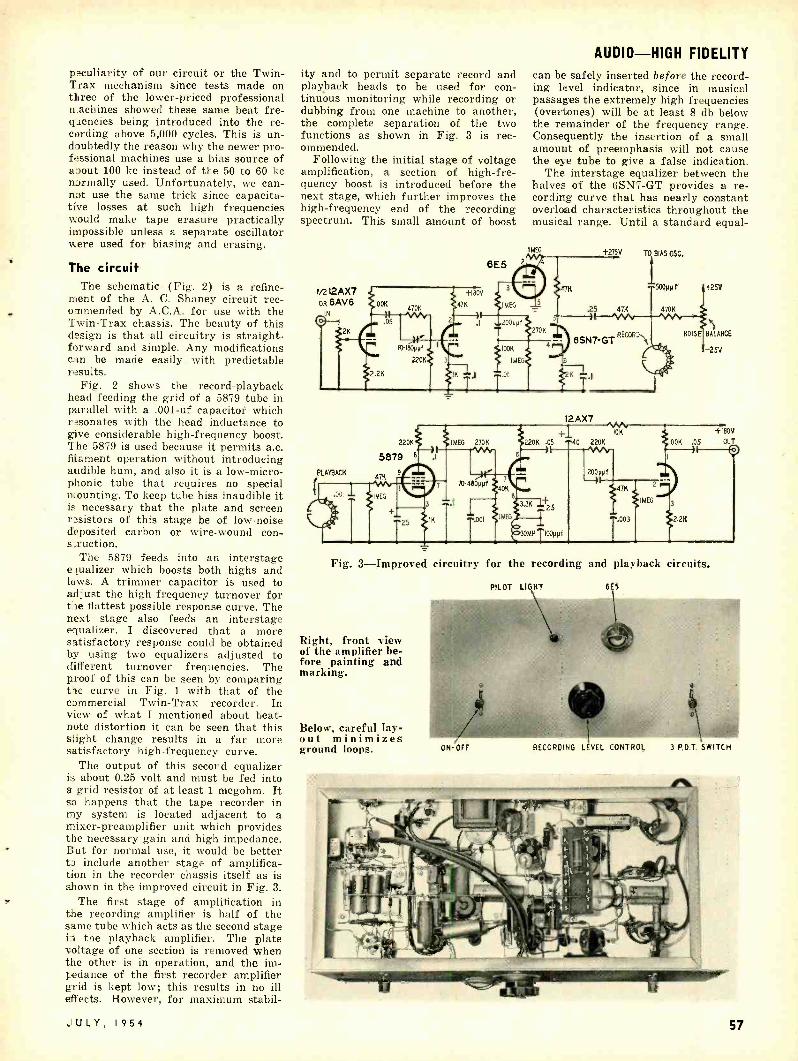
peculiarity of our circuit or the Twin - Trax mechanism since tests made on three of the lower -priced professional nachines showed these same beat fre- gzencies being introduced into the re- cording above 5,000 cycles. This is un- doubtedly the reason why the newer pro- fessional machines use a bias source of about 100 kc instead of the 50 to 60 kc normally used. Unfortunately, we can- not use the same trick since capacita- tive losses at such high frequencies would make tape erasure practically impossible unless a separate oscillator were used for biasing and erasing.
The circuit The schematic (Fig. 2) is a refine-
ment of the A. C. Shaney circuit rec- ommended by A.C.A. for use with the Twin -Trax chassis. The beauty of this design is that all circuitry is straight- forward and simple. Any modifications can be made easily with predictable results.
Fig. 2 shows the record -playback head feeding the grid of a 5879 tube in parallel with a .001 -uf capacitor which resonates with the head inductance to give considerable high- frequency boost. The 5879 is used because it permits a.c. filament operation without introducing audible hum, and also it is a low- micro- phonic tube that requires no special mounting. To keep tube hiss inaudible it is necessary that the plate and screen resistors of this stage be of low -noise deposited carbon or wire -wound con - sruction.
The 5879 feeds into an interstage equalizer which boosts both highs and laws. A trimmer capacitor is used to adjust the high- frequency turnover for t:le flattest possible response curve. The next stage also feeds an interstage equalizer. I discovered that a more satisfactory response could be obtained by using two equalizers adjusted to different turnover frequencies. The proof of this can be seen by comparing the curve in Fig. 1 with that of the commercial Twin -Trax recorder. In view of what I mentioned about beat - note distortion it can be seen that this slight change results in a far more satisfactory high- frequency curve.
The output of this second equalizer is about 0.25 volt and must be fed into a grid resistor of at least 1 megohm. It sa happens that the tape recorder in my system is located adjacent to a mixer- preamplifier unit which provides the necessary gain and high impedance. But for normal use, it would be better ti include another stage of amplifica- tion in the recorder chassis itself as is shown in the improved circuit in Fig. 3.
The first stage of amplification in the recording amplifier is half of the same tube which acts as the second stage in the playback amplifier. The plate voltage of one section is removed when the other is in operation, and the im- pedance of the first recorder amplifier grid is kept low; this results in no ill effects. However, for maximum stabil-
JULY, 1954
ity and to permit separate record and playback heads to be used for con- tinuous monitoring while recording or dubbing from one machine to another, the complete separation of the two functions as shown in Fig. 3 is rec- ommended.
Following the initial stage of voltage amplification, a section of high -fre- quency boost is introduced before the next stage, which further improves the high- frequency end of the recording spectrum. This small amount of boost
AUDIO -HIGH FIDELITY
can be safely inserted before the record- ing level indicator, since in musical passages the extremely high frequencies (overtones) will be at least 8 db below the remainder of the frequency range. Consequently the insertion of a small amount of preemphasis will not cause the eye tube to give a false indication.
The interstage equalizer between the halves of the 6SN7 -GT provides a re- cording curve that has nearly constant overload characteristics throughout the musical range. Until a standard equal-
IMEG +275V TO BIAS 05C.
I500Ppt +25V
.25 47K 470K
8SN7-GT REwROs
PLAYBACK
220!
5879 6
47K 5
I2AX7 10K
270K 220K .05 40 220K
6
10- 460ppf 40K
1
6
3.3K
MEG .001
25
30MH I00ppfi
200ppf -31
47K
.003
2
MEG
+1á0V
IOOK .05 OUT
I oO
3
2.2K
Fig. 3- Improved circuitry for the recording and playback circuits.
Right, front view of the amplifier be- fore painting and marking.
Below, careful lay- out minimizes ground loops.
PILOT LIGHT 6E5
ON-OPT RECORDING LÉVEL CONTROL 3 P.D.T. SWITCH
57
www.americanradiohistory.com

AUDIO -HIGH FIDELITY
ization is adopted for tape recorders this seems the most sensible approach since the recording -level indicator will give an accurate indication of proper modulation regardless of the frequency spectrum of the incoming signal. The cathode capacitors of both halves of the 6SN7 enter into the recording equaliza- tion as well as the interstage circuits.
The record -playback head is series fed from the second plate of the 6SN7, allowing a tiny amount of direct current to flow through the head, in the record position. This can be varied both as to potential and polarity so that by proper adjustment of the noise control the background noise of plastic -base tape can be made inaudible even at high listening levels.
The bias and erase oscillator circuit is more elaborate than that normally found outside professional -quality re- corders. However, the design is definite- ly worth while in providing optimum adjustment of both erase and bias volt- ages and in providing a pure sine -wave source for lowest possible distortion and tape noise. Except for the trimmers to peak the tuned circuits, the circuit is identical to that used in commercial A.C.A. machines. It is also the same circuit used in the original Brush BK- 400 series of tape recorders.
Construction Wiring the unit is not difficult, espe-
cially if a large chassis such as that shown in the photo is used. By allow- ing plenty of space, the three sections of the unit can be separated physically to avoid interaction. Ground loops in the playback amplifier must be avoided. The chassis has a separate ground bus with the chassis and playback amplifier grounded at one end and the power supply at the other. All other stages are grounded along the bus in the order of their signal level. If good ground- ing practice is followed and the filament balancing pot is properly adjusted, the hum level should be inaudible unless the playback head is located in the magnetic field of the power transformer. As a matter of fact, the only hum that
58
By sweeping the audio spectrum with an audio generator and recording this signal, then playing back the tape and monitoring the output, the various equalization controls can be adjusted by trial and error until an over -all response curve such as the one shown is achieved. With these adjustments completed, the recorder can be connected into your audio system and an aural check can
Rear view of the be made. tape recorder am- In both circuits a low value is shown plifier. for the recording level control. The
recorder should be driven from a fairly low- impedance source such as the cath- ode follower found on many pre- amplifiers. If a 500,000 -ohm or 1 -meg- ohm potentiometer is used to control the recording level, the input capac- itance of the first stage will seriously attenuate the upper audio frequencies at mid-range settings. If an excep- tionally low -noise power amplifier such as the Williamson or Ultra- Linear is used in your audio system, the recorder may be simply bridged across the voice coil output. Even with the varying impedance of a speaker load, the Ultra - Linear is so well regulated that no adverse effects are noted from the bridg- ing connection.
If the unit is to be bridged across a speaker, a wire -wound potentiometer of 10,000 to 20,000 ohms may be used for the recording volume control. Since such a potentiometer has a linear rather than a logarithmic taper, it tends to expand the range as the setting is advanced. This is ideal if the signal source is not much greater than the voltage required to fully modulate the recorder; such a condition exists when the voice -coil connection is used.
can be heard in the unit is that picked up by the playback head from the motor of the transport mechanism.
Adjustment Set the bias and erase voltage poten-
tiometers about one -quarter of full rota- tion. With an a.c. voltmeter or scope, adjust the peaking capacitors to give maximum output. The oscillator wave- form may be checked with a scope to make sure the signal is clean and the frequency is approximately 60 kc.
Now set both bias and erase voltages to zero and on a clean tape record a 1,000 -cycle tone at a level slightly more than that required to close the eye tube. With a scope or vacuum -tube voltmeter connected across the recording head, vary the bias voltage in definite steps so that when the tape is played back you can keep track of the bias voltage that was used. When the tape is played back and the output is monitored on the scope it will be found that as the bias voltage is increased the distortion of the sine wave will decrease and the signal level will rise. Eventually a point will be reached where the level remains constant and distortion is not detect- able. The proper adjustment of the bias voltage is just a little past this point where distortion disappears. The voltage will probably be about 150.
With the bias voltage properly set, again record an overmodulated tone on the tape. Rewind the tape and with no modulating voltage present adjust the erase voltage in definite steps just as the bias voltage was adjusted previous- ly. Now play the tape and monitor the output. A point will be found where the signal is completely erased and then another point where the tape noise level reaches a minimum. The proper adjust- ment is that point beyond complete tape erasure at which the background noise is the lowest. The noise -adjusting potentiometer can now be set to bring the noise level down to an absolute minimum which should be audible only at extremely high gain settings. The heater balancing potentiometer is like- wise adjusted.
Parts for recorder amplifier Resistors. 1- 250, 3- 1,200, 2- 2,200, 1- 3,300, 2-
22,000, 1- 40,000. 5- 47,000, 3- 100,000, 4- 220,000, 2- 270,000, 2 -470,000 ohms, 6-I megohm, /2 watt; 1- 20,000, 2-47,000, 2 watt; I -500, 5 watt, 2- 1,000, 10 watt; 1-100, 1- 2,000, 1- 10,000, 2 -100,- 000 ohms, potentiometers.
Capacitors: 1 -200 µµf, I -300 µµf, 1 -500 µtsf, mica, 400 volts; 5 -.001 µf, paper, 400 volts; II
001 µf, mica 5 %, 400 volts; 1 -.003 µf, 3-.01 µf, I -.02 µf, 2 -.05 µf, 6-0.1 µf, 1-0.25 µf, paper, 400 volts; 2 -25 µf, 25 volts, 1 -50 µf, 50 volts, 1- 20-20-20 µf, 1 -40-40 µf, 450 volts, electrolytic; 1- 10.180 µ f, 2- 70-480 µµf, 1- 25-280 µµf variable.
Miscellaneous: I- 5Y3 -GT, 1 -6E5, I- 6V6 -GT, I- I2AX7, 1 -5879, 2- 6SN7 -GT, tubes; 6 -tube sockets; 1-6E5 assembly; I -power transformer, 700 volts c.t. @ 75 ma, 5 volts @ 2 amps, 6.3 volts @ 3 amps; I- filter choke, 10 h, 40 ma; I -1 /4 -amp fuse and assembly; I -pilot lamp and assembly; 2 -30 -mh coils; I -60 -mh coil, c.t. (J. W. Miller 693 -T); I- s.p.s.t. switch; I- 3- p.d.t. switch, I- chassis; I -line cord; terminal strips.
For the audio enthusiast and experi- menter the design shown is a good one since it is not tricky, not difficult to build, and can be easily altered to fit individual circumstances. The amplifier may be used with any transport mech- anism which uses high- impedance re- cording and playback heads. If a unit other than the Twin -Trax is used, it may be necessary to alter the values of one or two of the equalizer components to obtain best results. Since the bias and erase voltages are completely adjustable, this section of the design can be used with any high -impedance erase and recording heads. END
RADIO-ELECTRONICS
www.americanradiohistory.com

FOR A I IR-.'.` PM RS A review of the latest in audio components and recordings of interest to the hi -fi enthusiast
By MONITOR
A unprecedented thing happened at our house a few days ago. We have often forgotten at night to shut off the sound sys-
tem from a radio program source after the station signed off, since the over -all hum level is inaudible as near as one foot to the speakers. It never happened w:_th a record because the hum and rum- ble picked up by a magnetic pickup, on our best turntable, let alone the changer, was always plainly audible. But this time it not only happened with a record, but with a microgroove record, arid moreover with the pickup in the final, run -out grooves. Our speakers are mounted in a wall which divides the house in two and distributes the sound all over it. Ordinarily the hum and rum - blc would be plainly audible even in our bedroom. But this time we went off to bed, completely unaware of the revolv- ing record.
The D & R turntable I can think of no more severe test of
a turntable, nor of a higher tribute to the D & R turntable which produced this incident. At a net price of just un- der $80 the D & R is not inexpensive; but that and the slight inconvenience of clanging speeds are the only draw- backs.
It is extremely difficult to measure the performance of a turntable with normal audio test equipment and thus obtain quantitative data on hum, rumble, flut- ter, and wow. D & R claims a total noise level of 60 lb, unmeasurable hum, negligible wow, and 60 db flutter. No matter how I measure it, I find no rea- son whatever to quarrel with these claims; they are certainly not exag- gerated.
By listening tests, the hum is inaud- ible even at "concert hall volume" with a G -E cartridge fully equalized for the NAB bass slope on the innermost grooves of a classical microgroove rec- ord. Magnetics with higher output, nor- mally less susceptible to hum, make no noticeable difference. The rumble and flutter are scarcely audible with speak- ers of very superior response below 40
JULY, 1954
cycles, such as corner horns, bass coup- lers and extremely large reflex enclos- ures. You can easily discern variations in the relative hum and rumble recorded on records. I have no means of measur- ing wow, but I do have records which are very sensitive to it, and I could not distinguish any, though I presume there must be a little.
I do not own one of those de luxe broadcast tables with remote drive, hys- teresis motors, etc; but my FM receiver, which uses a frequency- counting detec- tor is flat to far below 20 cycles, and I hear considerably more hum and rumble on the recorded output of all but one of the dozen FM stations we receive, and these include some of very high standards. It is not fair, of course, to compare a turntable with a changer, even the best changer. The additional complication of changing makes the noise problem infinitely more difficult to solve. With both the Cook and Clark - stan IM records I recorded the lowest IM figures I have ever achieved, and the IM with the D & R is greatly superior to that of a moderately good single - speed player, and that of an excellent though not the very latest changer. As
Precision D & R turntable. Runout tolerance on table periphery is .001
inch.
AUDIO -HIGH FIDELITY
ONLY
near z,; I can determine, the IM con- tributed by the turntable itself is com- pletely negligible. In short, here is a turntable which does its job of revolving the records without contributing any significant modification of the music on the record -and that is just about as high fidelity as you can expect from a turntable.
Rumble and flutter are produced by transmitting the vibrations, inescapable with any motor, to the turntable and thereby to the pickup. The isolation in this turntable is extremely admirable. The motor is mounted on airplane type vibration dampers, and the whole turn- table is mounted on a % -inch wood base, poorer in communicating vibration than a metal base. But these are elementary measures. The table is driven by an idler which contacts the outside rim of the table. The table, including the rim, is made of nonmagnetic nonmetallic ma- terial- masonite I would guess -which also reduces the passage of vibrations. The neoprene idler itself is 3 inches in diameter. The size and material both contribute to the dampening. Further- more, the idler floats completely on feet made of damping felt; no portion of the
59
www.americanradiohistory.com
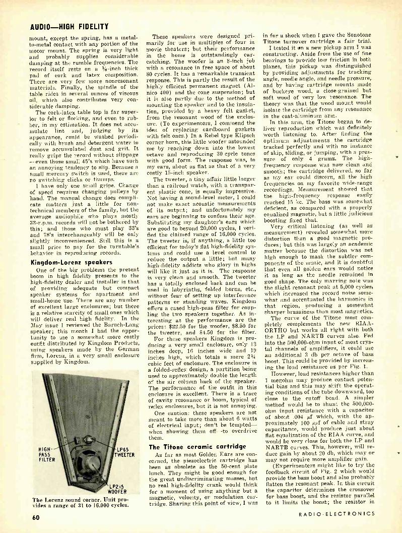
AUDIO -HIGH FIDELITY
mount, except the spring, has a metal - to-metal contact with any portion of the motor mount. The spring is very light and probably supplies considerable damping at the rumble frequencies. The record itself rests on a % -inch thick pad of cork and latex composition. There are very few more nonresonant materials. Finally, the spindle of the table rides in several ounces of viscous oil, which also contributes very con- siderable damping.
The cork -latex table top is far super- ior to felt or flocking, and even to rub- ber, in my estimation. It does not accu- mulate lint and, judging by its appearance, could be washed periodi- cally with brush and detergent water to remove accumulated dust and grit. It really grips the record without slippage -even those small 45's which have such an annoying tendency to slip. Because a small mercury switch is used, there are no switching clicks or thumps.
I have only one small gripe. Change of speed requires changing pulleys by hand. The manual change does compli- cate matters just a little for non- technical members of the family, but the average audiophile who plays mostly 33- r.p.m. records will not be bothered by this; and those who must play 33's and 78's interchangeably will be only slightly inconvenienced. Still this is a small price to pay for the turntable's behavior in reproducing records.
Kingdom- Lorenz speakers One of the big problems the present
boom in high fidelity presents to the high -fidelity dealer and installer is that of providing adequate but compact speaker systems for apartment and small -home use. There are any number of excellent large enclosures; but there is a relative scarcity of small ones which will deliver real high fidelity. In the May issue I reviewed the Baruch -Lang speaker; this month I had the oppor- tunity to use a somewhat more costly outfit distributed by Kingdom Products, using speakers made by the German firm, Lorenz, in a very small enclosure supplied by Kingdom.
HIGH PASS FILTER
LP65 TWEETER
LP2 15
WOOFER
The Lorenz sound corner. Unit pro- vides a range of 31 to 16,000 cycles.
60
These speakers were designed pri- marily for use in multiples of four in movie theaters; but their performance in the home is outstandingly ear - catching. The woofer is an 8 -inch job with a resonance in free space of about 80 cycles. It has a remarkable transient response. This is partly the result of the highly efficient permanent magnet (Al- nico 400) and the cone suspension; but it is also partly due to the method of mounting the speaker and to the insula- tion, provided by a heavy felt gasket, from the resonant wood of the enclos- ure. (To experimenters, I commend the idea of replacing cardboard gaskets with felt ones.) In a Rebel type Klipsch corner horn, this little woofer astounded me by reaching down into the lowest octave and reproducing 30 -cycle tones with good form. The response was, to my ears, about as flat as that of a very costly 15 -inch speaker.
The tweeter, a tiny affair little larger than a railroad watch, with a transpar- ent plastic cone, is equally impressive. Not having a sound -level meter, I could not make exact acoustic measurements of its output; and unfortunately my ears are beginning to confess their age. Substituting my daughter's ears which are good to beyond 20,000 cycles, I veri- fied the claimed range of 16,000 cycles. The tweeter is, if anything, a little too efficient for today's flat high -fidelity sys- tems and could use a level control to reduce the output a little; but many high- fidelity addicts who glory in highs will like it just as it is. The response is very clean and smooth. The tweeter has a totally enclosed back and can be used in labyrinths, folded horns, etc., without fear of setting up interference patterns or standing waves. Kingdom offers a cased high -pass filter for coup- ling the two speakers together. As in- teresting as the performance are the prices: $22.50 for the woofer, $8.50 for the tweeter, and $4.50 for the filter.
For these speakers Kingdom is pro- ducing a very small enclosure, only 13
inches deep, 16 inches wide and 19 inches high, which totals a mere 214 cubic feet of enclosure. The enclosure is a folded -reflex design, a partition being used to approximately double the length of the air column back of the speaker. The performance of the outfit in this enclosure is excellent. There is a trace of cavity resonance or boom, typical of reflex enclosures, but it is not annoying.
One caution: these speakers are not meant to take more than about 6 watts of electrical input; don't be tempted - when showing them off -to overdrive them.
The Tifone ceramic cartridge As far as most Golden Ears are con-
cerned, the piezoelectric cartridge has been as obsolete as the 50 -cent plate lunch. They might be good enough for the great undiscriminating masses, but no real high -fidelity crank would think for a moment of using anything but a magnetic, velocity, or modulation car- tridge. Sharing this point of view, I was
in for a shock when I gave the Sonotone Titone turnover cartridge a fair trial.
I tested it un a new pickup arm I was constructing. Aside from the use of fine bearings to provide low friction in both planes, this pickup was distinguished by providing adjustments for tracking angle, needle angle, and needle pressure, and by having cartridge mounts made of buckeye wood, a close- grained but soft wood of very low resonance. The theory was that the wood mount would isolate the cartridge from any resonance in the cast -aluminum arm.
In this arm, the Titone began to de- liver reproduction which was definitely worth listening to. After finding the optimum adjustments the cartridge tracked perfectly and with no instance of skip, sliding, or jumping, with a pres- sure of only 4 grams. The high - frequency response was now clean and smooth; the cartridge delivered, so far as my ear could discern, all the high frequencies on my favorite wide -range recordings. Measurement showed that the high- frequency response easily reached 15 kc. The bass was somewhat deficient, as compared with a properly equalized magnetic, but a little judicious boosting fixed that.
Very critical listening (as well as measurement) revealed somewhat more distortion than a good magnetic pro- duces; but this was largely an academic matter because the distortion was not high enough to mask the subtler com- ponents of the music, and it is doubtful that even all golden ears would notice it as long as the needle remained in good shape. The only marring note was the slight resonant peak at 5,000 cycles, which increased the record noise some- what and accentuated the harmonics in that region, producing a somewhat sharper brassiness than most magnetics.
The curve of the Titone most com- pletely complements the new RIAA- ORTHO but works all right with both the LP and NARTB curves also. Fed into the 500,000 -ohm input of most crys- tal channels of amplifiers, it could use an additional 3 db per octave of bass boost. This could be provided by increas- ing the load resistance as per Fig. 1.
However, load resistances higher than 1 megohm may produce contact poten- tial bias and this may shift the operat- ing conditions of the tube downward, too close to the cutoff bend. A simpler method would be to shunt the 500,000 - ohm input resistance with a capacitor of about .004 pf which, with the ap- proximately 100 µµf of cable and stray capacitance, would produce just about flat equalization of the RIAA curve, and would be very close for both the LP and NARTB curves. This, however, will re- duce gain by about 20 db, which may or may not require more amplifier gain.
(Experimenters might like to try the feedback circuit of Fig. 2 which would provide the bass boost and also probably flatten the resonant peak. In this circuit the capacitor determines the crossover for bass boost, and the resistor parallel to it limits the boost; the resistor in
RADIO -ELECTRONICS
www.americanradiohistory.com

series determines the amount of feed- back which should be adjusted to pro- duce the best leveling of the resonant peak. I used this circuit some years back with excellent results and though I haven't tried it with the Titone I be- lieve it would work all right. Those in- terested may like to look up the original paper of E. J. O'Brien in Electronics for March, 1949: "High Fidelity Response From Phonograph Pickups. ")
New records A Study in High Fidelity - Capitol SAL 9020
This recording was edited by Charles Fowler, editor of High Fidelity, and is accompanied by a printed commentary. I commend the lack of commentary on the record. Music can be tolerated after scores of repetitions, but a voice repeat- ing the same old song and dance in commentary, can become very irritating.
The most valuable sections of this record are the two bands of percussion instruments played by Hal Rees, chief percussionist for Twentieth Century - Fox. These two bands alone test almost any audio quality. They are especially valuable for simple tests of definition and naturalness, which is principally a function of very flat and distortion -free response. Comparisons of the very slight differences between some of the instru- ments yield an excellent measure of definition and naturalness.
Though I ordinarily lean to classical music, I found the popular side of this recording more interesting and reward- ing. This is partly because the music is less complex and more easy to apply to testing, but also because the classic side is not as well balanced -it has too many high and lows for my taste. However, the classical side does offer some inter- esting test material, particularly the very odd tone of the piano in the Shosta- kovitch concerto. I commend also the final band on the popular side, by Stan Kenton's orchestra, for distortion test- ing. Kenton -like Pearl White in early
movie days -has a cliff- hanging style in which the music is always teetering on the very edge of outrightly unpleasant dissonance. As recorded, this band of the record is very free of distortion and Kenton sounds good. Any system distor- tion will throw this section over the cliff into unpleasantness. Since this is the innermost band, it will produce large amounts of IM distortion with worn needles, improper needle align- ment or tracking, etc; hence it should prove very useful for testing all these possibilities.
Piectra and Percussion Dances, by Harry Partch. Played by Gate 5 En- semble. Available by mail for $8.00 (incl. postage) from: The Gate 5 En- semble, 3030 Bridgeway, RFD 67, Sausalito, Calif.
5
g+o
i 5 o 10
AUDIO -HICK FIDELITY
either in bass or treble, but I know of no record which can approach the con- catenation of percussive instruments of all sorts on this disc. If you're in the market for something really, but really, different in test and demonstration records, or an ice -breaking conversa- tion piece for a record -playing session, something that is practically guaran- teed to make your high -fidelity party or record concert the talk of the town, this is well worth the money. A note of warning: The music grows on you. After several hearings it has very con- siderable emotional appeal and musical interest. If you're afraid people may think you eccentric for liking it, you'd better stick to Tchaikovsky. I'm not sure of the recording curve, but it plays back very well with a wide -range pickup with NAB bass and a flat treble.
- 15
20
25
mill \ rn ,11 1.
I!rui/ W1II!:i% 11111
=iiiillllli 50 100 '500 IK SK IOK 15K
FREQ -CPS
Fig. 1- Loading effects on cartridge response for Titone turnover 9980 -S.
lol ¡ o
C, C +ISO f R LOAD ` TLOAD (CABLE) CAP. RES.
1 o ART RIDGE CAPACRANCE 450PM1
RI. 5Aa. G; R2 -2MEG;R3-IMEG ;R4- 500Kn;05-250Kn
ZERO DB ' 85V AT NORMAL LP RECORDING LEVEL
This is likely to make an impression of wondrous bewilderment when heard for the first time. It is written in a 43- tone -to- the -octave scale and is played on a set of absolutely unique instru- ments called, kitharas, harmonic canons, diamond and bass marimbas, cloud chamber bowls, eroica, adapted strings, etc. The result is entirely individual and, after the first bewilderment, most inter- esting. I'm not sure how seriously it is meant to be taken. But regardless of that, the high -fidelity brotherhood will find a collection of sounds they have probably never heard before and are likely never to hear again. The record- ing is not particularly outstanding
Titone turnover cartridge. At lower left is the replaceable arm and needle assembly.
Trio -Phonic Demonstration- Tempo DM -38
This is a special job produced by Tempo. for Hoffman to promote the sale of Hoffman's Trio -Phonic TV re- ceivers and distributed to its own dealers by Hoffman. It was carefully tailored for that job; and to satisfy the curiosity of those readers who may have heard of it and wondered about finag- ling one for high -fidelity testing or
10K-200K .05
f
+ 4.7K B+
6C4,6J5,v212AU7OR 6SN7-GT Fig. 2 -A Titone feedback circuit.
demonstration, I report that it is not one whit better for this purpose than any half -dozen popular records, of any speed and almost any age, you may pick up at random. The commentary verges on the ridiculous (sample : "re- produces down to 50 cycles -as low as the ear can hear "). Some of the selec- tions have no top nor bottom worth mentioning, and only "Sweet Georgia Brown" by Brother Bones and "Ju -Ju" by Thurston Knudson offer any material which would tax the capabilities of a moderately good table -model radio. Its function is to make the Hoffman sets sound good, and it will probably do a moderately good job of this with a good pickup. END
47K
JULY, 1954 61
www.americanradiohistory.com
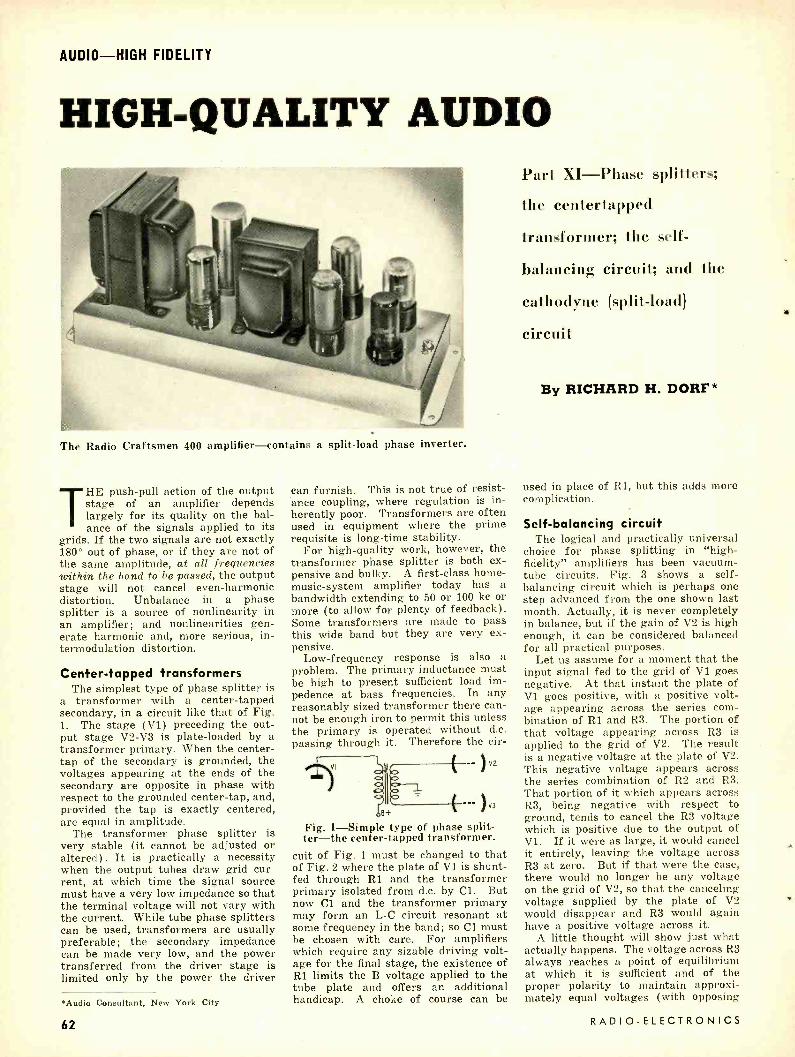
AUDIO -HIGH FIDELITY
HIGH -QUALITY AUDIO
The Radio Craftsmen 400 amplifier- contains a split -load phase inverter.
THE push -pull action of the output stage of an amplifier depends largely for its quality on the bal- ance of the signals applied to its
grids. If the two signals are not exactly 180° out of phase, or if they are not of the same amplitude, at all frequencies within the band to be passed, the output stage will not cancel even -harmonic distortion. Unbalance in a phase splitter is a source of nonlinearity in an amplifier; and nonlinearities gen- erate harmonic and, more serious, in- termodulation distortion.
Center -tapped transformers The simplest type of phase splitter is
a transformer with a center -tapped secondary, in a circuit like that of Fig. 1. The stage (VI) preceding the out- put stage V2 -V3 is plate -loaded by a transformer primary. When the center - tap of the secondary is grounded, the voltages appearing at the ends of the secondary are opposite in phase with respect to the grounded center -tap, and, provided the tap is exactly centered, are equal in amplitude.
The transformer phase splitter is very stable (it cannot be adjusted or altered). It is practically a necessity when the output tubes draw grid cur- rent, at which time the signal source must have a very low impedance so that the terminal voltage will not vary with the current. While tube phase splitters can be used, transformers are usually preferable; the secondary impedance can be made very low, and the power transferred from the driver stage is limited only by the power the driver
*Audio Consultant, New York City
can furnish. This is not true of resist- ance coupling, where regulation is in- herently poor. Transformers are often used in equipment where the prime requisite is long -time stability.
For high -quality work, however, the transformer phase splitter is both ex- pensive and bulky. A first -class home - music- system amplifier today has a bandwidth extending to 50 or 100 kc or more (to allow for plenty of feedback). Some transformers are made to pass this wide band but they are very ex- pensive.
Low -frequency response is also a problem. The primary inductance must be high to present sufficient load im- pedence at bass frequencies. In any reasonably sized transformer there can- not be enough iron to permit this unless the primary is operated without d.c. passing through it. Therefore the cir-
vz
I , V3
Fig. 1- Simple type of phase split - ter -the center- tapped transformer.
cuit of Fig. 1 must be changed to that of Fig. 2 where the plate of Vl is shunt - fed through R1 and the transformer primary isolated from d.c. by Cl. But now Cl and the transformer primary may form an L -C circuit resonant at some frequency in the band; so Cl must be chosen with care. For amplifiers which require any sizable driving volt- age for the final stage, the existence of Rl limits the B voltage applied to the tube plate and offers an additional handicap. A choke of course can be
VI
Part XI -Phase splitters;
the centertapped
transformer; the self -
balancing circuit; and the
cathodyne (split -load)
circuit
By RICHARD H. DORF*
used in place of R1, but this adds more complication.
Self- balancing circuit The logical and practically universal
choice for phase splitting in "high - fidelity" amplifiers has been vacuum - tube circuits. Fig. 3 shows a self - balancing circuit which is perhaps one step advanced from the one shown last month. Actually, it is never completely in balance, but if the gain of V2 is high enough, it can be considered balanced for all practical purposes.
Let us assume for a moment that the input signal fed to the grid of Vl goes negative. At that instant the plate of VI goes positive, with a positive volt- age appearing across the series com- bination of Rl and R3. The portion of that voltage appearing across R3 is applied to the grid of V2. The result is a negative voltage at the plate of V2. This negative voltage appears across the series combination of R2 and R3. That portion of it which appears across R3, being negative with respect to ground, tends to cancel the R3 voltage which is positive due to the output of V1. If it were as large, it would cancel it entirely, leaving the voltage across R3 at zero. But if that were the case, there would no longer be any voltage on the grid of V2, so that the canceling voltage supplied by the plate of V2 would disappear and R3 would again have a positive voltage across it.
A little thought will show just what actually happens. The voltage across R3 always reaches a point of equilibrium at which it is sufficient and of the proper polarity to maintain approxi- mately equal voltages (with opposing
62 RADIO -ELECTRONICS
www.americanradiohistory.com

Its NewI3 Years in Development -NOW READYfORYOU!
Mt Caµ v of Rs4s
r..ua«eTrr Vdt
These pa-os show envy a small part of the trari ig equipment I send my students.
ib the eew Terer ... 18 -:
-GhnMil amt. alines tus eetput
and res ester.
New Equipment! New Lessons! Enlarged Course! SPRAYBERRY PRACTICAL TRAINING IN
RADIO -TELEVISION 3 NO OBLIGATION TRAINING PLANS
You have NO MONTHLY PAYMENT CONTRACT to sign
... pay for this outstanding training as you learn! The complete facts are so big and so important to any man seeking training in Radio-Television that I urge you to mail the coupon be- low at once for my big all -new 56 page FREE CATALOG aid FREE Sample Lesson. Get the full story of this remarkable new
Frank L Sprayharry and up- to- the -second Training Plan. You'll read about ray 3 NO President, Spra -sexy OBLIGATION PLANS or "packaged unit" instruction for both Academy of Rao) beginners and the experienced man. You'll learn how I can now
prepare you in as little as 10 MONTHS to take your place in this fast moving b_g money industry as a Trained Radio -Television Technician. You'll see that you take no risk in enrolling for my Training because you DO NOT SIGN A BINDING TIME PAYMENT CONTRACT. I 1- ,ve peen training successful Radio -TV technicians for 22 years ... I can
prepare you, too, to get into your own profitable Service Shop or a good paying job, even if yo_ have no knowledge of Radio- Television. Mail the coupon ... I rush fall informatic a FREE and without obligation. (No salesman will call.)
PRACTICE AND TRAIN AT HOME WITH 25 NEW KITS OF EQUIPMENT
(NEWEST
DEVELOPMENTS
Your training coy.
ers J H F, Color Television, F M,
Oscilloscope Se'vicing, High Fidelity Sound and Transistors.
Yau w D brill this powerful short wave
You get valuable practical experience in construction, test- ing and shop practice. You build a powerful 2 band superLet radio, the all -new 18 range Sprayberry multitester, the new Sprayberry Training Television receiver, signal generator, signal tracer and many other projects. All equipment is yours to use and keep ... and you have practically every- thing needed to set up a Radio-Television Service Shop.
All your training Is IN YOUR HOME In spare hors. Keep on with your present Job and income while learning. I help you earn extra spare time money while ycu learn. If you expect to be in the armed forces later, there is no better preparation than practical Sprayberry Radio-Television training. Rush coupon below for all the facts -FREE!
SPRAYBERRY ACADEMY OF RADIO 111 NORTH CANAL STREET, DEPT. 2O -L, CHICAGO 6, ILLINOIS
Ti
R EECATALOG AND
SAMPLE LESSON Lush coupon for my catalog
'I-low to Make Money in ni dio- Tee- -ision ". PLUS an
actual sample Sprayberry Les-on without obligation -ALL
FREE. Mai: coupon NOW!
JULY, 19!54
SPRAYBERRY ACADEMY OF RADIO MAIL THIS COUPON FOR FREE
Dept. 20-L, 111 N. Canal St., Chicago 6, III. FACTS AND SAMPLE LESSON
Please rush all information on your ALL -NEW Radio -Television Train- ing Plan. I understand this does not obligate me and that ne sales- men will call upon me. Include New Catalog and Sample Lesson FREE.
Name Age
Address
City 7one State J 63
www.americanradiohistory.com

AUDIO -HIGH FIDELITY
phase) across both Rl and R2, which are of equal resistance. However the Rl and R2 voltages can never be pre- cisely equal; if they were, the voltages across R3 would cancel and no voltage would be . available to drive the V2 grid and create the necessary voltage across R2.
This is a simple and interesting ex- ample of a principle which is common to all self- correcting or self- compensat- ing systems. In each case an error is detected and the error itself is used to make the correction -the correction is proportional to the error. The prin- ciple is: Correction or compensation can never be perfect, because without any remaining error there is nothing to stimulate the correction mechanism. The degree of compensation achieved depends on the gain of the correcting system, since with higher gain less re- maining error is required to keep com- pensation in force.
`V2
V3
Fig. 2- Shunt -fed driver transformer. This principle can be applied very
easily to the circuit of Fig. 3. If V2 has high gain, a smaller grid voltage obtained from across R3 is sufficient to cause enough V2 output to bring about the equilibrium condition. Since the net voltage across R3 represents the unbalance between the output -stage grids, this means smaller unbalance. Obviously the whole situation is not affected in the least by the question of similarity between V1 and V2, which is untrue for most multitude phase split - ters. The quality of this circuit, from a balance standpoint, depends wholly on the gain of V2, if we assume Rl and R2 to be equal in value.
Bt
OUTPUT STAGE GRIDS
R3 R2
8+
Fig. 3 -Self- balancing phase splitter.
Unfortunately, this circuit is still not the ideal answer. Any triode operated with gain greater than 1 is subject to Miller effect, a multiplication in effec-
64
tive tube input capacitance proportional to the gain of the stage. The result is a decrease in high- frequency response. The signal in the Fig. 3 circuit goes through two such stages, so that the same objection applies as with the cir- cuit given last month. The signal reaching one output grid has gone through a single triode, while that reaching the other has gone through two. The self -balancing action is some help but does not cure the situation entirely.
Cathodyne circuit The phase splitter shown in Fig. 4 is
a very satisfactory circuit both in per- formance and simplicity. The actual circuit shown is that used in the Radio Craftsmen type 400 amplifier (see photo on page 62). Only a single tube (V1) is used, and changes in its char- acteristics do not affect the balance. Only two resistors, Rl and R2, need to be matched.
The cathodyne (split -load circuit) is a combination cathode -follower and plate -loaded amplifier. Ignoring for a moment the grid circuit of V1, note that the plate and cathode resistors R1 and R2 have equal values. Thus, the same d.c. and signal currents must flow through both Rl and R2. Since current flows in the same direction through both resistors, polarity is always the same at the top of both resistors with respect to the bottom (and vice versa). The bottom of R2 is grounded directly. The top of Rl is grounded through the power -supply filter capacitor. Output is taken from the lower end of Rl and the upper end of R2. Therefore, the output voltages are 180° out of phase. The output voltages are equal in amp- litude, since the same plate current creates identical voltage drops across the two identical resistors.
The last statement should be qualified. The impedance of the cathode output circuit is not actually equal to that of the plate output circuit. This is be- cause impedance is a complex value composed not only of d.c. resistance but also of reactance. As we discussed last month in relation to the cathode follow- er, the a.c. impedance of a cathode cir- cuit is almost never higher than about 500 to 600 ohms because of degenera- tive action. While the output voltage for the circuit of Fig. 4 can be computed simply by using Ohm's law to find the IR drop across R2, the impedance seen by the V3 grid is much lower than R2. As a result, the normal cathode -ground capacitance of the tube has little effect on the high- frequency response, being swamped by the effective low resist- ance.
The same is not true in the plate cir- cuit. The actual output impedance there is composed of Rl, the tube's plate resistance, and the tube's normal output capacitance. Both R1 and the plate resistance are relatively high (in relation to the cathode impedance), so the capacitance is not swamped so ef- fectively. Due to the capacitance, the
voltage appearing across Rl is not as large as that across R2 and is not quite 180° out of phase with it.
The degree of unbalance caused by this situation depends primarily on the value chosen for R1 and R2 (though a low- output- capacitance tube helps re- duce it). The lower the resistance values, the smaller the unbalancing effect of the complex plate impedance - but the lower, also, the undistorted out- put voltage capability. This drawback of the cathodyne circuit scared away many purists when high -fidelity began to blossom in a big way. However, it was found more recently that it is en- tirely possible to select values for Rl and R2 which would allow high enough output voltages, yet were small enough to swamp the capacitance to the point where high- frequency unbalance is not of any real importance. As a result there has been a swing back to the cathodyne.
One other problem with the cathodyne is the unusually large cathode resistor which causes a high d.c. voltage drop between cathode and ground. In the Craftsmen circuit of Fig. 4 this is 80 volts. If the grid resistor were grounded this would be a 80 -volt bias, far too high a value for correct tube operation. One simple answer, used by this manu- facturer (and in the original William- son amplifier) is to place a 75 -volt posi- tive potential on the grid by directly coupling the plate of the previous tube to the grid of Vl. Because of the 220,000 -ohm plate resistor of the pre- vious tube, its plate voltage is 75. R3 and Cl are used to provide a small amount of phase -shift compensation in the amplifier.
CIi390ppt R2 47N
6V6 (2) V3
Fig. 4 -Split -load phase splitter.
There are other methods of securing correct bias in common use. One is to ground the cathodyne grid as usual though a large -value resistor, then place another large -value resistor be- tween the B supply and grid. The two act as a voltage divider and are so proportioned that the correct positive voltage appears on the grid. Another approach is to place the bottom of the grid resistor at some point along the cathode resistor rather than at ground, choosing the point to maintain correct grid- cathode voltage. It is also pos- sible to insert a second cathode resistor between R2 (Fig. 4) and cathode, pro- portioned for correct bias. This new resistor is bypassed for a.c. and the lower end of the grid resistor is placed at the top of R2. (TO BE CONTINUED)
RADIO -ELECTRONICS
www.americanradiohistory.com

BUILD YOUR OWN
TEST INSTRUMENTS AMPLIFIERS RECEIVERS, etc.
Save by ordering direct from manufacturer.
All high quality standard brand components.
Increased knowledge through actual construction.
Sound engineering insures excellent performance.
Kit construction is fascinating and enjoyable.
MODEL O -9
OSCILLOSCOPE K I T
r ecteit4it VOLTAGE CALIBRATOR KIT The use of a Voltage Calibrator will greatly increase oscilloscope usefulness. Provides a convenient method of making peak to peak voltage measurements by establishing a rela- tionship between the unknown wave shape and the Voltage Calibrator. Voltage ranges .01-100 volts peak to peak. The Voltage Cali- brator features direct reading scales and a regulated power supply system.
$11so Shipping Wt. 4 lbs.
tTEtili-G4c:e VACUUM TUBE
VOLTMETER KIT
New features unheard of in a kit oscilloscope have been added to the already popular Heathkit series. All top quality components are used including a brand new RCA 5UP1 CRT. Ten other first line tubes complete the lineup. Voltage regulation provides a rock steady pattern regardless of normal line voltage variations. A built -in blanking amplifier eliminates the retrace line entirely. Other important advantages are a phasing control, Z axis input, direct connections to the deflection plates, 1 volt peak -to -peak calibration voltage and a calibrated grid screen.
Wiring is simplified by the use of the harness technique which also results in a neat professional appearance. Extremely wide vertical bandwidth allows accurate reproduction of even a 500 KC square wave. Excellent focusing characteristics are made possible by the use of the new RCA 5UP1 CRT and a spot shape control. One of the most versatile of test instruments, the Heathkit 0 -9 Oscilloscope will be invaluable in the radio and TV service shop, as a work project in schools and for all types of circuit investigation work in the laboratory. Its new features make Model O -9 comparable in every way to many commercially built oscilloscopes selling for as much as $400. Don't pass up this opportunity to add a really fine instrument to your service or experimental lab.
ELECTRONIC SWITCH KIT The Heathkit Electronic Switch Kit MODEL will further extend scope usefulness S -2 by permitting simultaneous observa- tion of two individually controlled 5235° traces. Continuously variable switch- e ing rates 10 cps to 2,000 cps in three ranges. Will also serve as a square wave generator over the range of switching frequencies.
Shipping Wt. 11 lbs.
The beautiful new 1953 Heathkit Model V -6 VTVM, the world's most popular kit 44. instrument, now offers many outstanding new features in addition to retaining all of the refinements developed and proven through the production of over 70,000 VTVM kits. The Heathkit VTVM now features extended voltage ranges with 50% greater coverage on the DC range. New 134 volt low scale provides well over 21/3 inches of scale length per volt permitting faster measurements with greater accu- racy. AC and DC ranges are 0- 1.5- 5- 15 -50- 150 -500 -1500 volts (1,000 volts maximum on AC). Ohmmeter ranges are Xl, X10, X100, X1,000, X1OK, X100K X1 meg. Measures .1 ohm to 1,000 megohms. Other features are db scale, center scale zero adjust and polarity reversal switch. High 11 megohm input resistance virtually eliminates circuit loading. The low anti -inflation price of this tremendously popular kit includes all tubes, necessary constructional material, test leads and the construction manual.
'eeta%t AC VACUUM TUBE
VOLTMETER KIT
MODEL AV -2
$2950 Shipping Wt. 5 lbs.
A new amplifier type AC VTVM that makes possible those sentitive measurements so essential in laboratory or audio work. Ten voltage ranges covering from 01 IIMS full scale to 300 volts RMS full scale. Inpput impedance 1 megohm with frequency response 20- 50,000 cycles. Ten DB ranges from -52 to +52 DB. Four diodes in meter bridge circuit for maxi- mum linearity.
1
MODEL V -6
Shipping Wt. 6 lbs.
7TeatGt4ct
HANDITESTER KIT
MODEL M -1
$145° Shipping Wt. 3 lbs,
The ever popular Handitester is now supplied with a Simpson 400 microampere meter movement. Provides AC and DC voltage ranges 0- 10-30- 300 -1,000 -5,000 volts. Ohmmeter ranges 0 -3,000 and 0- 300,000 ohms. DC current measurements 0-10 and 0 -100 milliamperes. A completely self contained portable instrument.
HEATH COMPANY Benton Harbor 20, Mich. JULY, 1954 65
www.americanradiohistory.com

HEATHKITS for the ENGINEER sfe4t!%. r VISUAL AURAL
SIGNAL TRACER KIT
MODEL T -3 $2350 Shipping
Wt. 10 lbs.
Designed especially for service applications in AM- SW -FM -7 V repair work. RF and audio two channel input. More than adequate sensitivity -new noise lo- cator circuit -calibrated wattmeter-substitution speaker- visual signal indication. Can be used with scope and VTVM, checks phono cartridges. phono mechanisms, micro- phones, tuners, etc. Let the Heathkit Visual Aural Sig- nal Tracer help you.
RESISTANCE SUBSTITUTION BOX KIT
Choice of 36 switch selected resistance values 15 ohms to 10 megohms. All stand- ard RTMA 1 watt 10% resistors. Buy several for those lab and service n pphcations.
Weetakr CONDENSER CHECKER KIT
An instrument designed solely for its particular job. Not a "sideline" or a multiple function instrument. Measures value and quality of unknown condensers and resistors. Capacity range .00001 mfd to 1,000 infd. Resist- ance range 100 ohms to 5 meg- ohms. Sensitive electron beam indicator -five polarizing test voltages- safety spring re- turn leakage test switch. An amazingly accurate in- strument at this low price.
MODEL C -3 ®0,10
$1950 Shipping Wt. 8 lbs.
rgfeat
SIGNAL GENERATOR KIT
MODEL SG -8
$1950 Ship. Wf. 8 lbs.
Q Ai lb. The standard
a7 G _ service instru- ment for align- ment work. .1
volts output from 160 KC to 1111 MC. Calibrated harmonics up to 220 MC. Internal (400 CPS) and external modulation. Pre- calibrat- ed coils for all 5 bands. Good sta- bility and accuracy. All test leads included.
ee taieeít GRID DIP METER KIT
One hand operation. 5 pre -wound coils cover 2 -250 MC. Controlled
sensitivity. Usable as an oscil- lator or an absorption
al wave meter. Extra low frequency coils avail- able.
MODEL GD -1 B
$1950 Ship. Wt. 4 lbs.
MODEL RS -1
Ship. Wt. $550 2lbs. 7
NEW Caer 2GZ`
20,000 OHMS PER VOLT
MULTIMETER KIT Here is the solution to all service problems requiring a portable meas- uring device of high accuracy. 20,000 ohms /volt sensitivity on DC and 5000 ohms /volt on AC. Full scale voltage ranges of 1.5, 5, 50, 150, 500, 1500 and 5000. DC current ranges of 150 microamperes; 15, 150 and 500 milliamperes; and 15 amperes. Re- sistances are measured from .2 ohms to 20 megohms in 3 ranges and deci- bela from -10 to +65 db. Model MM -1 uses standard
commercially available batteries and is not affected by strong RF fields as encountered in and near transmitting equipment. 1% pre- cision resistors on a very easily wired ring type range switch and a highly accurate Simpson 50 microampere meter fully qualifies the Heathkit Multi -
meter for close tolerance laboratory and service work. The meter movement is
placed in a recessed position for max- imum non -glare readability. The kit
includes the attractive black bake- lite cabinet, 2 color meter scales,
test leads, batteries and all other necessary components. Overall cabinet size is 5' "
wide x 4' deep x 7)i" high.
MODEL MM-1
$z65ó Ship. Wt. 6 lbs.
'4eeatitiz t TUBE CHECKER KIT
Checks overall tube quality, filament continuity, and in- dividual elements for shorts
and opens. Features chart illumination, harness type wiring, and large 3 -color meter scale.
Portable Model TC -2P at $34.50. Wt. 14 lbs. No. 91 -8 Cab- inet only at .$7.50. Wt. 7 lbs. No. 355 TV Picture Tube Adapt- er at $4.50. Wt. 1 ib. Yl",Rtil¢(L LABORATORY REGULATED
POWER SUPPLY KIT
rl
" `4
MODEL P5 -2
$335o Ship. Wt. 20Ibs.
A regulated variable 160- ,1.50 volt DC output power supply for the lab or serv- ice shop. Accurate voltage ,ind current measurements with large Simpson meter. AC supply 6.3 volts at 4 amperes -standby switch eliminates warmup time. Low hum content -5 tube circuit. AC and DC output voltages isolated from panel for maximum operational flexibility.
MODEL TC -2
$2950 Shipping Wt. 12 lbs,
AUDIO
4fezzelt t LABORATORY
GENERATOR KIT
WATTMETER KIT Measure output power levels di- rectly with the Heathkit Audio Wattmeter. Flat response to fre- quencies from 10 CPS to 250 KC. Full scale ranges of 5 MW, 50 MW, 500 MW, 5 W and 50 W. Db cali-
bration from -10 to +48. Uses non -inductive built -in load resistors pro -
Ship. Wt. viding impedances of 4,
50 8, 16 and 600 ohms. 6 lbs. Z / Q
Meter bridge uses 4 ger- manium diodes.
MODEL A W -1
Ship. Wt. 161bs. $3950
A professional laboratory instrument designed for extreme accuracy in fre- quency and output level. Colpitts oscillator operates in 5 ranges from 150 KC to :30 MC. Panel meter cali- brated in output voltage and percent of modulation. Output in excess of .1 volts. Features complete shield- ing of oscillator, buffer and attenuator sections; regu- lated power supply and 50 ohm output cable. Com- parable instruments priced many times higher t han the coat of this new hit.
HEATH COMPANY Benton Harbor 20, Mich. 66 RADIO -ELECTRONICS
www.americanradiohistory.com
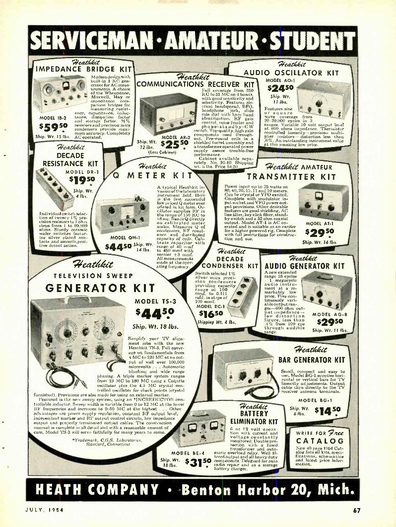
SERVICEMAN AMATEUR STUDENT Meat cteit
IMPEDANCE BRIDGE KIT Modern design with built -in 1 KC gen- erator for AC meas- urements. A choice of the Wheatstone,
M Maxwell, Hay or capacitance com- parison bridges for measuring resist-
ance, capacitance, induc- tance, dissipation factor and storage factor. S4% resistors and precision mica condensers provide maxi- mum accuracy. Completely AC operated.
MODEL IB -2
$5950 Ship. Wt. 15 lbs.
eat DECADE
RESISTANCE KIT MODEL DR -1
d,'N ,a $1 950
.
Ship. Wt. 4 lbs.
Individual switch selec- t ion of twenty 1% pre- cision resistors in 1 ohm steps from 1 to 99,999 ohms. Sturdy ceramic wafer switches featur- ing silver plated con- tacts and smooth,posi- tive detent action.
''eat`s4ít COMMUNICATIONS RECEIVER KIT
Full coverage from 550 KC to 35 MC on 4 bands, with good sensitivity and selectivity. Features ele- trical bandspread, BFO, headphone jack, slide rule dial with ham band identification, RF gain control, noise limiter and phone -standby -CW
switch. Top quality, high gain components used through- out. Pre -wound coils in a shielded turret assembly and a transformer operated power supply assure trouble -free performance.
Cabinet available sepa- rately. No 91 -10. Shipping wt. 5 lbs. Price $4.50.
eeeztifleee
AUDIO OSCILLATOR KIT MODEL AO -1
$2450 Ship. Wt.
11 lbs.
Ship. Wt. MODEL AR -2
12 bs. $2550 (Less Cabinet)
V, eatlsl¢it
Q M E T E R K I T
MODEL 0M-1
$4450 Ship. Wt. 14 lbs.
eeCL, 2l t TELEVISION SWEEP
GENERATOR KIT
l ^ì
Features sine ' or square wave coverage from 20- 20,000 cycles in 3 ranges. Variable 10 volt output level at 600 ohms impedance. Thermistor controlled linearity -precision multi- plier resistors - distortion less than .6 %. An outstanding instrument value at this amazing low price.
A typical Heathkit in- vasion of the laboratory instrument field. Here is the first successful low priced 6i meter ever offered in kit form. Os- cillator supplies RF in the range of 150 KC to 18 mc. Reads Q directly .
on calibrated meter scales. Measures Q of condensers, RF resist- ance and distributed capacity of coils. Cali- brate capacitor with range of 40 mmf to 450 mmf with vernier ±3 mmf. All measurements made at the oper- ating frequency.
1 MODEL TS -3
$445° Ship. Wt. 18 lbs.
Simplify your TV align- ment jobs with the new Heathkit TS -3. Full cover- age on fundamentals from 4 MC to 220 MC at an out- put of well over 100,000 microvolts ... Automatic blanking and wide range
phasing. A triple marker system ranges from 19 MC to 180 MC using a Colpitts oscillator plus the 4.5 MC crystal con- trolled oscillator for check points (crystal
furnished). Provisions are also made for using an external marker. Featured is the new sweep system, using an *INCREDUCTOR con-
trollable inductor. Sweep width is variable from 0 to 12 MC at the lower RF frequencies and increases to 0 -50 MC at the highest ... Other advantages are power supply regulation, constant RF output level, independent marker and RF output control circuits, low impedance output and properly terminated output cables. The construction manual is complete in all detail and with a reasonable amount of care, Model TS -3 will serve faithfully for many years to come
*Trademark, C.G.S. Laboratories, Stamford, Connecticut
'eAritielt AMATEUR
TRANSMITTER KIT Power input up to 35 watts on 80, 40, 20,15,11 and 10 meters. Can be crystal or VFO excited. Complete with modulator in- put socket and VFO power out - put provisions. Other desirable features are good shielding, AC line filter, key click filter, stand- by switch and a 52 ohm coaxial output. Model AT -1 is AC op- erated and is suitable as an exciter for a higher powered rig. Complete with full instructions for construc- tion and use.
eeatlt/eit DECADE
CONDENSER KIT Switch selected 1% silver mica preci- sion condensers providing capacity range of 100 mmf. to 0.111 mfd. in steps of 100 mmf. MODEL DC -1 .;
$1650 Shipping Wt. 4 lbs.
MODEL AT -1
$2950 Ship. Wt. 16 lbs.
Y>eQ>ütLt
AUDIO GENERATOR KIT A new extended range 18 cycles -1 megacycle audio instru- ment at a re- markably low price. Five con- tinuously vari- able output ran -. ges -600 ohm out- Put impedance - ow distortion
figure, less than .4% from 100 cps through audible range.
MODEL AG -8
$Z950 Ship. Wt. 11 lbs,
eatltkct BAR GENERATOR KIT
4. l;
MODEL BE -4 Ship. Wt.
18 lbs. $3150
' ceased BATTERY
ELIMINATOR KIT 6 or 12 volt opera- tion with current and voltage constantly monitored. Double pro- tection with a fused transformer and auto-
matic overload relay. Well fil- tered output and all heavy duty components. Designed for auto radio repair and as a storage battery charger.
Small, compact and easy to use, Model BG -1 supplies hori- zontal or vertical bars for TV linearity adjustments. Output cable clips directly to the TV receiver antenna terminals.
MODEL BG -1
Ship. Wt. $1450 6 lbs.
WRITE FOR glee CATALOG New 40 page 1954 Cat- alog lists all kits, speci- fications, schematics and latest price infor- mation.
HEATH COMPANY Benton Harbor 20, Mich. JULY, 1954 67
www.americanradiohistory.com

KIT TUNER St %fi /MODEL FM -2
J
b :' ' $22 50
"411' Shi in Wt. 9 tbs. PP g
Sensitive transformer operated 8 tube circuit. Frequency coy- erage 88 -108 Inc. Pre -assem - bled and tuned "front end." Vernier tuning with slide rule type dial.
NEW/ }e.a. er BROADCAST BAND
RECEIVER KIT
\, MODEL BR -2
50 1 e - I (Less Cabinet)
Shi Wt. P 11 lbs.
NEW HEATHKIT WILLIAMSON
AMPLIFIER The ideal amplifier for custom high fidelity Tops in performance, value and flexibility Altec Lansing Peerless or Acrosound available. Frequency response ±1. db negligible hum and noise levels and plenty of reserve power for complete listening pleasure. First Williamson Type Amplifier supplied with matching preamplifier.
E PRICES OF VARIOUS COMBINATIONS:
W -2 Amplifier Kit (Includes Main Amplifier with Peerless Output Transformer. Power Sup- ply and WA -P2 Preamplifier.) $f6 950 Shipping weight 38 lbs. Shipped v`n/ V4 express only
Amplifier Kit (Includes \tain Amplifier with Peerless Output Transformer and Power Supply.)
.)pp Shipping weight 3044915
W -3 Amplifier Kit only
Main Amplifier with Acrosound Output Transformer, Power Sup- ply and WA -P2 Preamplifier.) t` Shipping weight 38 lbs. Shipped i express only V V 5
t)
W -3M Amplifier Kit (Includes Main Amplifier with ACrosound Output Transformer and Power f StipplY.) Shipping weight 30 i 75
I w, snapped express only 49 -I +
output 10
t(
KIT audio installations.
of operation. transformers
CPS to
r
TYPE ECONOMY WATT
AMPLIFIER KIT MODEL A -7B
Either
100 Ií C. $15 SQ
t Ship. Wt. ID lbs. Dual inputs- separate bass and treble tone con-
1 trols- output impedances - "" of 4, 8, and 15 ohms. Perform -
ance far beyond that normally expected fer the price.
A -7C: Includes preamplifier for .,».. low level input ,devices.
Price $17.50
i i ¡u ¢ HIGH FIDELITY 20 WATT
Ir AMPLIFIER KIT ! MODEL A -98
( r
y. 35 sv
1. Shipping t Wt. 23 lbs. =
Gotnplete receiver with chassis -. mounted 5'''s ° PM Speaker and LOW P R I C E D .SC.tgIC U N I T new rod type antenna. Covers the full broadcast hand (550 WILLIAMSON T Y P E
KC -1600 KC) with excellent sensitivity and selectivity. ..-t- `-. AMPLIFIER KIT Operates as a receiver, tuner or a phono ampli- 1 MODEL W -4 M tier. High gain miniature tubes and IF trans- :_ ^- $3973 forers. Easy tuning I T formers. Easy with direct plane- tar drive. - + - Ship. Wt. 28 lbs.
Y Cabinet avail- The famous Heathkit Willisunon'l'ypeAmpli- a ble separately. fier is now available in a single chassis. Includes
Sh N power supply and power amplifier. Enjoy the Ship. 5 same high quality reproduction at less cost by Pico eliminating the second chassis, connecting $4.50. cables, etc. Size 15 Vs °wide -7° high-9° deep. Model W -4 includes W -4M and preamplifier WA-
P2. Shipping weight 35 lbs. Price $69.50.
HEATH COMPANY Benton ORDER ORDER YOUR C c- MAIL THE
TODAY TO
HEATHKIT HIGH FIDELITY p / Outstanding features of the
PREAMPLIFIER KIT Heathkit 20 Watt Amplifier include a frequency response
MODEL WA -P2 "° '° a of ±1 db from 20 CPS to 20 r,... -
s KC, leas than 1'7 harmonic $ 75 a distortion at rated output,
_ 0 `4 separate (boost and cut)
1 Ship. Wt. 7 lbs. - bass and treble tone
in- selected in- Complete compensa tionfar LP,NARTB, put jacks, hum balanc- AES and early 78 recording character- mg control and output istics. An ideal control unit for the custom impedances of 4, 8, 16 Hi -Fi system. 5 individually controlled and 500 ohms. Flex- inputs, 4 turnover and roll -off switch ibility is emphasiz- positions, 3 twin triode tubes, cathode ed in the input cir- follower output, monitored recorder output, cuits with built - shock mounted tube chassis and proper shield- in preamplifier ing. All condensers are of the molded plastic and proper type. Critical input circuits feature low noise equalization. deposited carbon resistors. Use it with any con- ventional high fidelity amplifier.
Harbor 20, Mich. BLANK
SHIP VIA MPpNY HE p1 H Parcel Post
"N"°11 70,
Express 14 i 890014 th1CNIGAN Freight
Best Way
PRINT) (PLEASE
QUANTITY ITEM MODEL NO. PRICE
Enclosed find ( ) check ( ) money order for On Express orders do not include transportation charges -they will be collected by
Please ship C.O.D. ( ) postage enclosed for pounds. the express agency at time of delivery.
ON PARCEL POST ORDERS insure postage for weight shown. ORDERS FROM CANADA and APO's must include full remittance.
68 RADIO -ELECTRONICS
www.americanradiohistory.com

AUDIO -HIGH FIDELITY
Servicing High -Fidelity Equipment
Courtesy Arrow Electronics Audio Center, New York Cify Measuring intermodulation on a well equipped bench for audio servicing.
MEASUREMENT and testing routines for the servicing of high -fidelity equipment differ from those used in develop-
ment and production work. Whereas the laboratory or production test bench is interested in how closely equipment meets ideal or desired speci- fications, the service technician is in- terested in discovering how and why the equipment departs from specifica- tions, and discovering this in the quick- est, most labor- saving way. His prob- lem is not actually measurement but diagnosis. This magazine and others have many times covered the various measurement methods applicable to audio systems, and I shall try not to
' go over the same ground, but instead to concentrate on describing ways in which these methods may be more effectively used and combined for rapid servicing.
We won't spend time discussing the problems presented by a hi -fi system when it simply stops completely and utters no sound at all. The real head- aches in high -fidelity servicing come from equipment with higher than nor- mal distortion; and it is here that ef-
JULY, 1954
fective routines are most often needed.
Procedure Let us suppose that you have visited
the installation and have decided that the high distortion is being produced in the main amplifier. You have re- moved the offending unit from its place in a clothes closet and have brought it to your shop. Now you're ready to find out what's ailing it and where. If you have no specialized instruments, you can use a signal provided by a record, a radio, or your test generator, and headphones or a v.t.v.m. for indication. But we will assume you are equipped with some or all of the following: IM analyzer, signal generator, scope, a.c. v.t.v.m.and wattmeter.
The first step is to find out how bad the situation is. This is most quickly and accurately determined with an IM analyzer. Provide a load for the ampli- fier. If you have a wattmeter it will provide the load as well as output in- dication. If you do not have one, use a 20 -watt resistor of 8 or 15 ohms. A 15 -ohm adjustable 20 -watt resistor with the slider set half -way, is very useful for this purpose. Measure the IM for levels of 0.1, 1.0 and 10 watts.
By JOSEPH MARSHALL
Part V -Using the IM
analyzer; checking feedback
loops; effectively
diagnosing audio
distortion measurements
If you have a wattmeter you can read the output on it. (Keep in mind that for two -frequency signals in a ratio of 4 to 1, the actual r.m.s. power out- put, equivalent to that of a single fre- quency, will be about 11/2 times the meter reading.) If you do not have a wattmeter, set the volume control un- til you obtain the following voltages as indicated on the IM analyzer meter when it is used as a voltmeter. These voltages apply to the composite 60- and 3000- (or '7000-) cycle signal in a ratio of 4 to 1.
Load Resistance Watts Volts 8 ohms 0.1 0.69 8 ohms 1.0 2.2 8 ohms 10.0 6.9
16 ohms 0.1 0.95 16 ohms 1.0 2.8 16 ohms 10.0 9.5
Compare the IM readings you get with those of the specifications for the amplifier in question. Most high -fidelity amplifiers specify 2% IM or less at 10 watts; and a fraction of 1% at 0.1 watt. Published distortion figures on commercial amplifiers are usually an averaged value, based on production sampling. Any given amplifier may de-
69
www.americanradiohistory.com

AUDIO -HIGH FIDELITY
part from the average figure and still be within the manufacturer's accep- table tolerance range. Few manufac- turers publish their tolerance figures. Your reading may be anything from these figures up to and exceeding 30 %. The higher the distortion level, in gen- eral, the easier it is going to be for you to find the trouble. If the figure is only slightly off, say only twice as high as specified, you are well advised to stop, think, and decide whether you ought to spend any more time at all on it.
In the latter case I would check the balance of the output tubes and adjust it if there is a balancing control, or try a new pair of tubes to find a better - balanced pair. If this does not bring the IM down close to specs, I would try changing the other tubes, especially the rectifier. If this tube has too high an internal voltage drop, it may be disturbing the operating curve of one or more tubes and causing abnormal distortion. If, after this, the IM is reasonably close to the specified value, I would ask myself if I didn't make a mistake in tracing trouble at the in- stallation. Unless your ears are very sharp and well accustomed to judging distortion, it is very unlikely that you could discern the difference between 2% or even 4% IM and less; and the same goes for your customer. If you heard distortion plainly in testing, but found not more than 5% IM on meas- uring, chances are very high that the trouble lies in the preamp, control unit, tuner, or even the turntable. And there is little point in doing much more work on the amplifier, since it is certainly
70
TITS
NO IM
10\6\1_11 111J_
L1-
A
going to be troublesome to reduce the remaining distortion any further; and indeed may not be possible at all with- out going to such extremes as changing plate and cathode resistors, etc. In any case, the audible difference, even with a speaker load, is going to be so small that the big bill you would have to present to your customer would prob- ably not seem justified to him. Further- more, unless you're a real expert, you may make matters worse.
Let us assume that you find more distortion than this, or that, in any case, you want to reduce it. The most effective procedure will be determined by the amount of distortion you find. If it is less than 10 % at maximum rated output, your best bet will be to continue with the IM analyzer. In most cases you will find that a scope gives no significant information when the IM is less than 10 or 12 %. IM distor- tion of course does not show up on sine waves; and amplitude or harmonic distortion does not show up clearly until it exceeds 3 %, which usually means an IM of 10 or 12% . So when the IM analyzer shows less than 10 or 12 %, the IM analyzer is by far the most effective diagnostic tool.
It may help, if the IM is less than 5%, to exaggerate the distortion. This can be done by adjusting the IM analyzer to deliver a mixed signal in a 1 -1 ratio instead of the normal 4 -1. In most cases this will at least double the indicated distortion.
Checking feedback loop Having determined that the tubes
are not the principal cause of the
11
B- SINGLE -ENDED STAGE
_l 1_ t1_ [t_ ,1_,
CURVATURE
C - PUSH-PULL STAGE
I1 1 T Titit-Ir1
ill , X11 J1111111 . UNBALANCED
D
fa'T11 -I Irr
l'611111111111i 1 lit
MOTOR BOATING
t
INGLE-ENDED DRIVER ALSO OVERDRIVEN
Fig. 1- Notches obtained as scope patterns enable rapid diagnosis.
trouble, and having obtained the best balance possible, the next step is to disconnect the feedback loop tempo- rarily and take another IM measure- ment. The distortion should increase by a factor of from 2 to 10 when the loop is disconnected. (You must, of course, reduce signal input to bring the output back down to normal.) If distortion does not increase markedly, check the feedback loop for a shorted or open resistor or capacitor, if the loop uses one. You can check the ca- pacitor easily with the, IM signal and meter.
Feed the signal to one end of the capacitor, and measure the voltage at both ends. Since the reactance at 60 cycles may be considerable, you may get a reduction in reading at the out- put; but with any likely value of capacitance, say up to .05 µf, the loss shouldn't be more than 3 db. If the loss is greater than this, the reactance is much too high -unless the feedback loop is meant to produce bass -boosting -and might be producing core satur- ation in the output transformer at a level much lower than normal. Produc- tion runs of capacitors may be off as much as plus 100 % and minus 50%; arid while it is very unlikely that a high -quality amplifier would have got by with so great a departure from specs, the capacitance might have changed through excess heat or hu- midity. The presence of a capacitor in the loop usually means that the loop starts at a point, like the plate of a tube, where d.c. voltages are present. Therefore, check the capacitor for leakage, which is likely to increase with age, overheating, etc. ; even a little d.c. leakage may throw the stage to which feedback is applied into the curved portion of its operating range. The feedback resistor can be checked with an ohmmeter. A difference from specified or marked value of plus or minus 20% will not be significant ordinarily; but a wider difference, especially on the low side, might well be, and in that case I would replace it with one which is as close as possible to the exact specified value.
If the feedback loop checks all right, the next step is to see if it produces instability. Check the current of the output tubes with and without the feedback loop; if the current rises significantly when the loop is con- nected, you've got either outright oscillation or regeneration. First check the parasitic suppressors. These are resistors of between 30 and 1,000 ohms in series with the grids or plates, or both. Usually, too, when a tetrode is used as a triode, there is a resistor of between 100 and 1,000 ohms between the screen and plate. Check all of these for opens or shorts; moderate depar- tures from specified values do not usually matter.
Further checks The next step is to check the de-
coupling network. This consists of one
RADIO -ELECTRONICS
www.americanradiohistory.com

or more resistors in series with the plates and the supply voltage, bypassed by electrolytics on one or both sides. This is also part of the hum -filtering network. Leakage may produce distor- tion by lowering the voltage, but does not harm the decoupling; so an open condition is what you want to look for. The simplest check is to take an elec- trolytic capacitor of around 20 to 40 pf, the larger the better, with a 400 - volt rating; place it in parallel with each of the filter or decoupling capaci- tors in turn. If this causes the plate current to drop to normal, replace the faulty capacitor with one of the same or greater capacitance.
If this still hasn't solved the prob- lem, and the output tubes are triodes or, as in the Williamson, tetrodes used as triodes, it will almost certainly do no harm to neutralize the output tubes. Most such tubes have plate to grid capacitances of between 10 and 20 ppf. Wire in a pair of 10- or 15 -µµf fixed capacitors from the plate of one tube to the grid of the other and the same on the other side. You are quite un- likely to make matters worse, and very likely to clear up the instability. The exception may occur with some output transformers whose high- frequency resonance peak is below 50 kc. Neutral- ization doubles the output capacitance, and it is possible, but only faintly possible with modern transformers, that this doubled capacitance might in- crease the resonant peak and therefore the parasitics. I repeat, however, that this is quite unlikely but I point it out just in case it should happen.
If all this has not resulted in sta- bility, your only remaining alternative is to reduce the feedback. Wire -in temporarily, in place of the feedback resistor, a potentiometer of 2 or 3 times greater value; adjust it until the plate current rises, then back it off until it falls to normal value. Sweep an audio generator from 20 cycles or less to 20 kc or more and check to see that the current does not rise at any frequency. If it does, back off the potentiometer some more until stability is once more obtained. Sweep again to make sure. This is now the maximum feedback the circuit will stand. You should get a considerable improvement of IM with the feedback loop con- nected. Now replace the potentiometer with a resistor equal in value to the used portion of the potentiometer, but in any case no greater resistance should be used.
Suppose the loop is stable but the IM continues high. Continue, with the loop disconnected, to make stage -by- stage analysis with the IM analyzer. If you equip the leads to the analyzer portion of the IM analyzer with in- sulated alligator clips, you can measure the IM in each stage and thus isolate the one in which the trouble is occur- ing. The analyzer does not permit balanced measurement of push -pull stages; you have to measure the IM on each side of a push -pull stage by moving the hot lead from one grid, or
JULY, 1954
plate, to the other. Keep in mind that measuring one side of a push -pull stage will give you a higher IM reading than actually exists at the output, because the cancellation due to push -pull oper- ation in not indicated. However, this is all to the good, since the distortion is magnified and is therefore easier to follow and locate.
You should find a point at which the distortion falls markedly (if you trace from output to input) or rises markedly (if you trace from input to output). You will also get an excellent indication of unbalance since an un- balanced stage will give you a higher reading on one side than on the other side.
Having found this stage, check the voltages, etc., as outlined in the first article of this series (February, 1954) and make the corrections recom- mended. It is difficult to set standards for IM distortion in individual stages. Modern amplifiers with 20 db or more of feedback can tolerate considerable distortion in individual stages at or near maximum output. However, I would say that an IM of 5% for a single -ended stage will usually be re- duced by feedback to less than 1%; and IM of 10% or even 15% per side in push -pull stages will be reduced by cancellation to less than 1 %; such values are tolerable. When you have reduced the IM in the faulty stage to this or lower values, take another over- all reading with the loop connected. Unless there is additional trouble, you should now get an acceptable IM level, and the remaining distortion can usual- ly be lowered some more by careful rebalancing.
The above method cannot be im- proved upon for diagnosis of today's first -class equipment when the distor- tion is low but still above the specified amount. It will continue to give very sharp indications of trouble, long after all other methods have indicated that the equipment is as clean as a pure sine wave. It has a couple of faults, however. First, it is a static method. That is to say, you cannot get a con- tinuous reading of the variation in IM; the readings are accurate only for a given fixed point. Second, although the indications of distortion are extremely sensitive, they give no clue as to the cause of the trouble, making diagnosis difficult.
Alternate method There is a modification which cor-
rects both faults, although at the ex- pense of some sensitivity. I recommend it highly, nevertheless, for it makes diagnosis extremely rapid. This method requires a scope in addition to the IM analyzer. Also, it is necessary to get into the analyzer and provide an out- put terminal at the point where the signal enters the demodulator or comes out of the high -pass filter. In the Heathkit IM -1 this is very easy. A 1,000 -µµf mica capacitor is connected to terminal 1 of the 12AX7. This is the plate of the second amplifier. The
AVENtrrON ád Sales
EKeNilve . 1
SHAV -PAK
Keep in Glove
Comportment
Specially Designed for Operating Standard A.C.
Electric Shavers in
Automobiles, Buses,
Trucks, Boats, and
Planes.
PLUGS INTO
CIGARETTE LIGHTER
RECEPTACLE
ON DASH
61295 LIST PRICE
TYPE
INPUT
O.C.
VOLTS
A.C.
OUTPUT
60 CYCLES
OUTPUT WATTAGE
LIST
PRICE
6 -SPY 6 115 volts 15 12.95
12 SP9 12 115 15 12.95
0p R OR S
aR 0.y Q0M
1`y%
oot or plane
ffice tt
INVERTERS
Plugs into Cigarette Lighter
Receptacle on Dash
$2250 AND UP
LIST PRICE
ATR INVERTERS . . .
especially designed for operating standard 110 volt A. C... .
TAPE RECORDER WIRE RECORDERS DICTATING MACHINES ELECTRIC RAZORS
for changing your storage battery current to A. C.
foudeliold ELECTRICITY
1ÆN" in your own Cad
-+tY
Set stows joó4 ea unite buret, tedaq aae eeHryblete ¿eaazstatLac
AMERICAN TELEVISION t RADIO CO. 2w/Kf Rrúo/. S. 1991,,
SAINT PAUL I, MINNESOTA -U. S. A. ,. .
71
www.americanradiohistory.com

Buy on our radically new
NO NO CARRYING
INTEREST!! Time Payment Pla n CHARGES!!
Superior's new
Model 670 -A SUPER METER A COMBINATION VOLT -OHM MILLIAMMETER PLUS
CAPACITY REACTANCE INDUCTANCE AND DECIBEL MEASUREMENTS
SPECIFICATIONS:
D.C. VOLTS: 0 to 7.5/15/75/150/750 /1,500/7,500 Volts
A.C. VOLTS: 0 to 15/30/150/300/1,500 /3,000 Volts
OUTPUT VOLTS: 0 to 15/30/150/300/1,500 /3,000 Volts
D.C. CURRENT: 0 to 1.5/15/150 Ma. 0 to 1.5/15 Amperes
RESISTANCE: 0 to 1,000 /100,000 Ohms 0 to 10 Megohms
CAPACITY: .001 to I Mfd. Ito 50 Mfd. (Quality test for elec- trolytics)
REACTANCE: 50 to 2,500 Ohms 2,500 Ohms to 2.5 Megohms
INDUCTANCE: .15 to 7 Henries 7 to 7,000 Henries
DECIBELS: -6 to +18 +14 to +38 +34 to +58
ADDED FEATURE: The Model 670 -A includes a special GOOD -BAD scale for checking the quality of electrolytic condensers at a test potential of 150 Volts.
The Model 670 -A comes housed, in a rugged crackle- finished steel cabinet complete with test leads and operating instructions.
40 NET
Model TV-11
new TUBE TESTER SPECIFICATIONS: * Tests all tubes including 4, 5, 6, 7, Octal, Lock- to damage a tube by inserting it in the wrong
in, Peanut, Bantam, Hearing Aid, Thyratron socket. Miniatures, Sub -miniatures, Novels, Sub- minars, Proximity fuse types, etc.
* Uses the new self -cleaning Lever Action Switches for individual element testing. Because all ele- ments are numbered according to pin- number in the RMA base numbering system, the user can instantly identify which element is under test. Tubes having tapped filaments and tubes with filaments terminating in more than one pin are truly tested with the Model TV -II as any of the pins may be placed in the neutral position when necessary.
* The Model TV -II does not use any combination type sockets. Instead individual sockets are used for each type of tube. Thus it is impossible
S uperior's
EXTRA SERVICE - The Model TV -I I may be used as an extremely sensitive Con- denser Leakage Checker. A relaxation
* Free -moving built -in roll chart provides com- plete data for all tubes. * Newly designed Line Voltage Control compen- sates for variation of any Line Voltage between 105 Volts and 130 Volts.
* NOISE TEST: Phono -jack on front panel for plugging in either phones or external amplifier will detect microphonic tubes or noise due to faulty elements and loose internal connections.
The model TV -11 oper- tes on 105 -130 Volt 60
Cycles A.C. Comes housed in beautiful hand- rubbed oak cabinet com- plete plete portable cover
type oscillator incorporated in this mode will detect leakages even when the fre quency is one per minute. $47so
Superior's New Model 660 -A AN AC OPERATED
SIGNAL GENERATOR PROVIDES COMPLETE COVERAGE for AM -FM & TV Alignment
SPECIFICATIONS: Generates Radio Frequencies from 100 Kilocycles
to 60 Megacycles on fundamentals and from 60 Megacycles to 220 Megacycles on powerful har- monics. Accuracy and Stabiilty are assured by the use of permeability trimmed Hi -Q coils. R.F. available separately or modulated by the internal audio oscillator. - Built in 400 cycle sine wave audio oscillator used to modulate the R.F. signal also available separately for audio testing of re- ceivers. amplifiers, hard of hearing aids. etc.
R.F. Oscillator Circuit: A high transconductance
TUBES USED: 1 -68E6 as R.F. Oscillator, mixer
and amplifier. I -6BE6 as Audio Oscillator. I -6H6 as Power Rectifier.
I MOSS ELEC -RONIC DISTRIBUTING CO., INC. I Dept. B- 101.5, 3849 Tenth Ave., New York 34, N. Y.
Please send the the units checked. I ans enclosing the down payment with outer and agree to pay the monthly balance as
shown. It is unf:erstood there udl be Bo carrying, interest or any other charges, provided I send my monthly payments alien due. It is ''nrt[ter Understood that should I tail to make payment when due, the full unpaid balance shall become im- mediately due and payable.
72
heptode is used as an R.F. oscillator, mixer and amplifier. Modulation is effected by electron coupling in the mixer section thus isolating the oscillator from load changes and affording high stability. A.F. Oscillator Circuit: A high trans - conductance heptode connected as a high -mu triode is used as an audio oscillator in a High -C Colpitts Circuit. The output (over I Volt) is nearly pure sine wave. Attenuator: A 5 step ladder type of attenuator is used.
The Model 660 -A comes complete with coaxial cable test lead and instruc- tions.
Name
Address
City 'lone State
$4295 MODEL 670 -A Total Price $28.40 57'
4[hI ó down payrn ot. Balance $3.50
MODEL TV11 mom
Total Price $47.50 11 511.50 down payment. Balance 56.0
monthly for 6 months. MODEL 660 -A Total Price $42.95 $ 12.05 down payment. Balance 55.011 monthly for 6 months. I enclose $ as down payment. Ship C.O.D. for the down payment.
--I
RADIO -ELECTRONICS
www.americanradiohistory.com

NO INTEREST!!
Buy on our radically new
Time Payment Plan NO yARGES /NG
Superior's New Model 770 -A The FIRST Pocket -Sized
VOLT-OHM MILLIAMMETER USING THE NEW "FULL- VIEW" METER 71% MORE SCALE
AREA!! Yes, although our new FULL -VIEW D'Arsonval type meter occupies ex-
actly the same space used by the older standard 21/1" Meters, it provides 71% more scale area. As a result, all cali- brations are printed in large easy -to- read type and for the first time it is
now possible to obtain measurements instead of approximations on a popu- lar priced pocket -sized V.O.M.
Features Specifications * Compact - measures 31/4" x
5' /s" s 21/4"
* Uses "Full View" 2% accu- rate, 850 Microampere D'Ar- sonval type meter
* Housed in round -cornered, molded case
* Beautiful black etched panel. Depressed letters filled with permanent white, insures long - life even with constant use.
6 A.C. VOLTAGE RANGES: 0- 15/30/- 150/300/1500/3000 Volts. 6 D.C. VOLTAGE RANGES: 0.7.5/15/75/150 /- 750/1500 Volts. 2 RESISTANCE RANGES: 0- 10,000 Ohms, 0.1 Megohm. 3 D.C. CURRENT RANGES: 0 -15 /150 Mo., 0-1.5 Amps. 3 DECIBEL RANGES: -6 db to +18 db, +14 db to +38 db, +34 db to +58 db.
THE MODEL 770 -A COMES COMPLETE WITH SELF -CONTAINED BATTERIES, TEST LEADS AND ALL OPERATING INSTRUCTIONS. ONLY
;15ss Superior's New Model 70 UTILITY TESTER
FOR REPAIRING ALL ELECTRICAL APPLIANCES MOTORS AUTOS As an electrical trouble shooter the Model 70:
Measures A.C. and D.C. Voltages, A.C. and D.C. Cur- rent, Resistances, Leakage, etc.
Will measure current consumption while the appli- ance under test is in operation.
Incorporates a sensitive direct- reading resistance range which will measure all resistances commonly used in electrical appliances, motors, etc. Leakage detecting circuit will indicate continuity from zero ohms to 5 megohms (5,000,000 ohms), Will test Toasters, Irons, Broilers, Heating Pads,
Clocks, Fans, Vacuum Cleaners, Refrigerators, Lamps, Fluorescents, Switches, Thermostats. etc.
SUPERIOR'S NEW MODEL TV -40
As an Automotive Tester the Model 70 will test: Both 6 Volt and 12 Volt Storage Batteries Genera-
tors Starters Distributors Ignition Coils Regula- tors Relays Circuit Breakers Cigarette Lighters
Stop Lights Condensers Directional Signal Systems All Lamps and Bulbs Fuses Heating Systems Horns Also will locate poor grounds, breaks in
wiring, poor connections, etc.
Handsome round-cornered mold- ed bakelite case. 3 5%s "x 21/4 ". Complete with all test leads. Also included is a 64 page book giving detailed in- structions for testing all elec- trical appliances, automotive equipment. etc. only
C.R.T. TUBE TESTER A complete picture tube tester * for little more than the price of a "make- shift" adapter!!
The Model TV -40 is absolutely cotn- plete! Self -contained, including built - in
power supply. it tests picture tubes tin the only practical way to efficiently
est such tubes; that is by the use of a separate exclusively
instrument which lsincrea to test the ever sing
number of picture tubes!
EASY TO USE:
Simply insert line cord into any 110 volt A.C. outlet, then attach tester socket to tube base (ION TRAP NEED NOT BE ON TUBE). Throw switch up for quality test . . read direct on Good -Bad scale. Throw switch down for all leakage tests.
MOSS ELECTRONIC DISTRIBUTING CO., INC. Dept. B -105, 3849 Tenth Ave.. New York 34, N. Y. l'h a.,. s,vui me the units checked. I am enclosing the downs
Tests all magnetically deflected * tubes . in the set . . . out of the set . . . in the carton!!
SPECIFICATIONS: Tests ALL magnetically deflected picture tubes from 7 inch to 30 inch types. Tests for quality by the well established emission method. All readings on "Good -Bad" scale. Tests for inter -element shorts and leakages up to S
megohms. Test for open elements.
Model TV-40 C.R.T. Tube Tester comes absolutely complete- nothing else to buy. Housed in round cor- nered, molded bakelite case. Only
paim,ut with order and agree to pay the monthly balance as Nance .: .uwn. It is understood there will be no carrying, interest or any other charges, provided I send my monthly payments when due. It is further understood that should I fall to make payment when dne, the full unpaid balance shall become im- mediately due and payable. City Zone State
Address
JULY, 1954
S 585 NET
Model 770 -A Total Price $15.85 $3.55 down payment. Balance $4.00 monthly for 3 months. Model 70 Total Price $15.85 $3.85 down payment. Balance $4.00 monthly for 3 months. Model TV -40 Total Price $15.85 $3.85 down payment. Balance $4.00 monthly for 3 months. I enclose $ as down payment. Ship C.O.D. for the down payment.
73
www.americanradiohistory.com
other end of this capacitor goes to a binding post added to the panel. The hot lead from the vertical input of the scope now goes to this post. The hori- zontal amplifier is in the internal sweep position.
The IM analyzer feeds the amplifier under test as usual; and the output of the amplifier goes to the analyzer input. The vertical channel of the scope goes to the new binding post and ground of the analyzer. The sweep is adjusted for 60 cycles (or if your analyzer has another low frequency, for that frequency). This will produce a pattern such as indicated at Fig. l -a. If there is no IM, the top and bottom of the trace will be flat. But, if there is any IM, the high frequency will be modulated by the low frequency and both the top and bottom will acquire some sort of curve or notches. The depth of the notches is proportional to the IM; the number of them is propor- tional to the aberrations causing the IM.*
The exact amount is not so impor- tant for servicing. What is significant is that the notches yield important clues to the causes of distortion. Most of the important ones are indicated in Fig. 1.
If the IM occurs in a single -ended stage, the pattern will have 2 or 4 notches, counting both those on top and bottom of the trace. Overdrive or underbias is indicated by sharp, rather narrow notches on one end; distortion due to curvature or overbias is indi- cated by wider, smoother notches on the other end. Which end the respective notches will occur on depends on the number of stages in the amplifier and the characteristics of the scope. In
*Le Bel. "New Method of Measuring and Analyz- ing Intermodulation." Audio Engineering, July,
1951.
most cases the overdrive notch will occur on the left. However, this is not too important, since the two types can be distinguished, if the scope trace is sharp and large enough, by the differ- ence in the shape of the notch.
If the single -ended stage is so badly overdriven that the positive peak is clipped and the negative peak rounded by curvature, four notches will ap- pear -two on top and two on the bot- tom. If these four appear simultane- ously or in quick succession as the signal input is increased, the stage is operating very close to the center of its operating curve. When there is something wrong, however, one form will appear long before the other. If the sharp overdrive notches appear first, the trouble is underbias; if the more gentle curvature notches appear first, the trouble is overbias. Some sort of notches will appear with any ampli- fier, even one in perfect shape, at or near maximum output. It is when they occur below maximum output that trouble is indicated.
When the IM is produced in a push - pull stage, four notches are normal. If the stage is well balanced, the notches on top and bottom will appear simultaneously or in rapid succession as the input signal is increased. If the stage is unbalanced, the notches will appear first on one side and then the other; the degree of unbalance is indicated by the difference in depth between the notches on top and those on the bottom.
Here too, the notches on one end are due to overdrive and the notches on the other end are due to curvature. Because in well -balanced push -pull stages one half of the circuit will be driven into positive bias and the other half into cutoff at about the same point, four notches of equal depth, top
"Yes- sir -eee!
74
The set sounds better than ever since we changed over to Hi -Fi!"
and bottom, indicate normal opera- tion. So an examination of the trace, as the input signal is varied around the point at which the notches begin to show up, will indicate the trouble.
If the distorting push -pull stage is driven by a single -ended stage which is also overdriven, one of the notches will be reduced or completely elimi- nated. When this happens at a point much below maximum rated output, it is a good sign of trouble in the power supply, since such simultaneous over- drive is almost always produced by unduly low plate voltages.
Finally, parasitic oscillation or re- generation, especially motorboating at frequencies below 40 cycles, is evi- denced by bumps and bulges instead of notches. Low- frequency parasitics will produce a rounding off of the whole pattern which will also grow vertically; high- frequency parasitics will put a lot of small bumps or spikes on the pattern.
You will note that most of the causes of distortion are indicated by these patterns. The significant thing is the point in the dynamic range of the equipment at which they appear. Therefore, a wattmeter makes this method extremely reliable. Thus, any amplifier can be overdriven; but this should not occur until near the maxi- mum rated power output; if an over- drive notch occurs at half- rated -power output or less, it is clearly a definite indication of underbias.
This method is not as sensitive an indicator of distortion as the IM ana- lyzer with the meter. Theoretically, if the trace were large enough, very low values of IM would be indicated. In practice, however, it is extremely diffi- cult to synchronize a trace with low distortion if (as in most IM analyzers) the high frequency is more than 20 times that of the low frequency. More- over, percentages of 2, 3, or 4 produce notch depths which are sometimes no deeper than the thickness of the scope trace; hence, unless very high acceler- ating potentials are used in the scope, the low percentages are obscured.
This is not critical for servicing; for the signal input to the amplifier can usually be increased until the dis- tortion is visible. The fine thing about this method is, first, that it does give definite clues as to the cause of the trouble, and, second, that the IM is indicated dynamically, and it can be observed to change as signal input is varied, or as circuit adjustments are made. If this procedure is used with the same sequence setup described earlier for the IM analyzer alone, diagnosis will be much more rapid.
It will take some experience to get onto it. Excellent training can be ob- tained by equipping a simple amplifier w_th variable resistors in the cathode and plate circuits. As these are varied, the variations in notches which follow overbiasing, underbiasing, too low a plate load, unbalance, etc., can be observed, and the effect of making corrections noted. (TO BE CONTINUED)
RADIO -ELECTRONICS
www.americanradiohistory.com

<;412104
RADAR
VO L SC A N _..-------`_.
..
CONTROL CONSOLES - ELECTRONICS
=~ SPEEDS UP DATA LiNK AIR TRAFFIC ORS
RELAYMEN
Progress of information through the Volscan system.
WHEN a large number of military aircraft return to a base within a short time, a terrific air traffic control
problem is set up. The problem becomes greater when we consider that more and more jets are being used. They have to be landed as quickly as possible because the lower they fly, the more fuel they use. Therefore, if the landing operation takes too long, the jets can very easily give out of fuel and crash. No human being can control more than 40 planes an hour. The problem was how to land 120 planes or more an hour. It was solved with the Volscan Air Traffic Control System, developed under Ben F. Green, Air Force Cambridge Research Center.
Volscan-closed-loop system To control 12U aircraft an hour
Volscan uses two identical Traffic
Operator Consoles and one Monitor Console. The Traffic Operators use a common radio channel to answer in- coming aircraft. Each console has a PPI scope, a panel controlling seven Antrac -Datac channels, and a Volscan Light Gun for assigning Antracs (Auto- matic tracking -while- scanning).
The Monitor's PPI permits him to watch the progress of all controlled aircraft. His time -situation panel shows the type and scheduled arrival time of each aircraft. Push -buttons permit him to change their automatically assigned schedules or to reserve time in the future for take -offs. The controls for setting in the wind direction and veloc- ity and entry gate locations are also on his panel.
Antrac An Antrac is assigned to the radar
target by pointing the Volscan Light
Rear -panel view of the equipment used in the Volscan system at Fort Dawes, Mass.
JULY, 1954
By ANGIE PASCALE
Gun at the corresponding blip on the PPI. When the light gun is pointed at a signal on the PPI, the light from that signal alone enters the barrel, thus effecting a time coincidence which moves the tracking gate to the position on the scope at which the gun is pointed. Once the Antrac is assigned, it isolates the target from all others by throwing a "gate" around it. Since this gate moves, following the blip, the Antrac retains the identity of the target.
An Antrac sorts out the data on a specific aircraft by generating two electronic time gates, one representing the predicted range of the aircraft plus and minus the gate width, and the other having the same function for azimuth. Since it is required that an incoming radar echo coincide with both these gates to enter an Antrac, each Antrac receives video signals from only aircraft that are within the area of space defined by the coincided range - azimuth gates. When a new echo from the aircraft does enter the Antrac, the error between the gate position and the echo is measured electronically and is utilized to correct the gate's position and velocity, which are then stored for use until the next echo is received.
As the Antrac, in a period of several scans, acquires the velocity of the tar- get, it smoothes the periodic video pulses that are the input into a gradually changing d.c. output. By holding the target velocity in its memory, the Antrac predicts where the target is during radar fades by continuing to move at the last rate it had memorized. The young lady on the cover has placed four gates on the PPI scope. The Antrac continuously reports to the computer the exact positions of the four targets.
Bailie A channel of the Volscan computer
called Datac, automatically selects a scheduled arrival time for the aircraft and calculates heading and altitude orders which will make good this schedule.
Datac calculates the aircraft's direct
75
www.americanradiohistory.com

BUY DIRECT . . . and SAVE!
'PRE -FAB' TUNERS
AUDIO PRODUCTS CO.
High Fidelity TUNERS and TUNER KITS introducing the LATEST DESIGN
COLLINS CHROMATIC TUNER
CHECK THESE OUTSTANDING FEATURES 41 tuning meter. Each tuner calibrated in microvolts for direct reading of signal strength. Not a kit. Completely wired, ready to use with FM antenna and amplifier. Sensitivity 3 microvolts with 20 DB of quieting. A.F.C. with disabling switch. New, compact, low design. Only 51/4" high. Matches latest bookshelf amplifiers. Voltage regulator tube for added stability. Newly designed front -end using 6BQ7 tube. Dual simultaneous audio output -high and
low impedance. Ultra wide range response, 20 to 25,000 cycles. Distortion less than 3/4 of 1 %. Hum 50 DB below program. Beautiful golden brown metal cabinet com- pletely enclosing tuner. 51/4 "x19" relay rack panel integral part of cabinet. Twelve tubes. Tone compensated volume control.
Plus many other smaller features which make this tuner the hottest item since high fidelity!
Overall size: 19" W. x 51/4" H. x 131/2" D. $9750 Shipping weight: 15 lbs.
COLLINS PRE -FAB KITS ALSO AVAILABLE
FM Tuner Kit
$55 Shipping weight: 14 lbs.
with AFC
$58.50
FM /AM Tuner Kit SWehipight ping $7750 with AFC
19 lbs. $81
IF -6 Amplifier 6 tubes 1975 Shipping Weight $ T 3 lbs.
flight time over the shortest possible path, which is the tangent path to the final turn circle. It reserves the earliest possible scheduled arrival time which the aircraft can make without conflict with other inbound traffic.
Throughout the run, Datac computes an error ratio which indicates the air- craft's performance in relation to its schedule. If the aircraft is on time, Datac orders a heading which directs it along the tangent path at present velocity. If the aircraft is late, Datac orders a heading which will hold it on the tangent path and increase velocity. If the aircraft is early, Datac orders an offset heading proportional to the magnitude of the error ratio so that the aircraft will be delayed sufficiently to meet its schedule.
Datac does not predict a fixed path for the aircraft, but is always calculat- ing to see what heading it should fly to make good its schedule. It controls the descent of the aircraft so that it will reach the entry gate at correct altitude.
The Datac control orders are relayed to the aircraft by voice or are sent automatically over the Data Link for display on the Zero Reader or for in- jection into the aircraft's autopilot.
As the plane responds to the control orders, the radar reports the change in its position, thus completing the loop.
The tracking and computing equip- ment making up the Volscan can be utilized in building -block fashion to meet the needs of any particular in- stallation. For instance, if the traffic rate at a base increases, one additional console and seven additional channels can be added.
One Volscan channel contains only 60 tubes. Since a Volscan airbase in- stallation consists principally of a number of such channels, it is not necessary to provide spares; each is a spare for the others.
Volscan can deliver aircraft satis- factorily to terminal points as far away as 20 miles, with some reduction in traffic rate, and as close as 2 miles, with no reduction in rate. END
FMF -3 Tuning Unit
$1525 Shipping weight:
2'2 lbs.
For Users of Collins Tuners:
Receive $5.00 credit toward the new FMF -3A front end! Mail us your old front end with $13.75 and we will send you the new, improved FMF -3A with AFC or, remit the full amount of $18.75 and when we receive your old unit in return a check will be mailed you for $5.00.
Collins Audio Products Co. is in no way affiliated with Collins Radio Co.
AM -4 Tuning Unit ssr '24" 18.75
To: Collins Audio Products Co. Inc. P.O. Box 368, Westfield, N. J. Dept. RE7 Tel. WEstfield 2 -4390
I Chromatic Tuner
IF -6 Amplifier
FM Tuner Kit with AFC
AM -4 Tuning Unit
Shipping weight: 21/2 lbs.
D FM /AM Tuner Kit with AFC
FMF -3 Tun. Unit with AFC
Name
Address
City _ - .- .. -..- State..._.__.- -_.... Amount for Kit $ See weights, add shipping cost $ -.... Total amount enclosed $ Check Money Order
WHEN YOU THINK OF TUNERS, THINK OF COLLINS AUDIO PRODUCTS
76
"Spend a fortune for an antenna and I get birds!"
RADIO -ELECTRONICS
www.americanradiohistory.com

transistors
DOROTHY PARKER once said of a "friend" that she covered the whole gamut of emotions from A to B. This article is the first
of a series -maybe regular, maybe not -which will try to provide some sort of background to those other articles on a transistorized television set, a semi- conductor moon rocket, and other de- vices, which are bound to appear in ever -increasing numbers. I shall not start at the beginning, because the be- ginning is too difficult and too remote; I shall not go on to the end, because no one man in one lifetime could attempt such a task; and I shall not try to be consecutive, because each article must be about something, and not merely a preparation for a beginning to an in- troduction. All I want to do in these articles is to make you feel that you know enough about transistors to build something yourself.
Transistors, as you can't help know- ing, are ... well, what are they? Semi- conducting amplifying . . . no, the current -amplification factor of a junc- tion transistor is less than unity. Per- haps I should search through the books to see what other people have said, but when I do I run slap into:
"Transistor electronics exists because of the controlled presence of imper- fections in otherwise nearly perfect crystals." 1
That isn't the sort of thing we can use at all. Let us just say that a transis- tor is a semiconductor device with at least three terminals, and that it will do the same kind of job as a vacuum tube.
Whatever the definition, there are two main kinds of transistors, the point type and the junction type. Roughly (and it is because this is really only very roughly correct that we need these articles) they behave like the triode and the pentode, respectively. The junc- tion type may be what is called an n -p -n transistor or it may be a p -n -p transistor. There is nothing in the vacuum -tube field which corresponds
'Shockley, Proc. I.R.E. Nov. 1952, p. 1289.
JULY, 1954
from N to
to this difference, which is one of polarity. We ground the negative term- inal of our battery in n -p -n circuits, but ground the positive terminal in p -n -p circuits. You see the difference is not altogether unimportant. The rather awkward names, n -p -n and p -n -p, refer to the constituents of the "sandwich," which looks something like Fig. 1: n -type and p -type refer to the german- ium, which, is as pure as possible, but doped to have about 1 part in 100 mil - lion of "controlled" impurity. The sort of impurity settles whether it is n- or p -type. In the point transistor, n -type germanium is used. Down inside the material the system is actually p -n -p, as you can see from Fig. 2: under the emitter and collector points the mate- rial has been converted to p -type.
For memory, the point transistor is a p -n -p: A ham sandwich has ham in the middle. An n -p -n transistor uses a positive main supply; a p-n -p transistor uses a negative main supply.
In the point transistor we put a fairly large negative voltage on the collector, and ground the base. The col- lector junction (in Fig. 2) is biased in the nonconducting direction, but there will be a small current, perhaps 0.5 ma at 20 volts. This is just the ordinary current through the back resistance of a diode. In Fig. 2 the electrons which leak through the junction are shown as solid dots moving toward the base in line ahead. Now we connect a battery with its positive pole at the emitter and its negative to base. The diode on the left conducts easily, of course, and only about 0.5 volt is needed to pass 1 ma into the emitter circuit. The effect of this emitter current, however, is not just a flow of electrons from base to emitter. Holes are also injected into the n -type material at the emitter junc- tion, and these drift over to the collec- tor junction, because they are attracted by the field of the collector voltage. These holes are very important, because the transistor action depends on them. What are they?
Suppose you consider your bank
ELECTRONICS
First of an intermittent series in a field where information is welcome
By GEORGE FLETCHER COOPER
account and your wife's. Your wife- like most engineer's wives - has no money: you are overdrawn by $150, like most engineers. She, a thoroughly good -hearted woman, draws a check for $150 and gives it to you to pay into your account. This delicate financial operation transfers your overdraft to her.
Holes are just overdrafts, but of electrons, not dollars. And when those holes drift over to where the electrons are plentiful, near the collector junc- tion, they behave just like the mort- gage in the old -time melodrama, and there is plenty of action. The arrival of a hole at the collector barrier (in a point -contact transistor) allows several electrons to slip through.
Notice this very carefully: You put in a hole current at E, and you get a change in electron current at C. With a tube the corresponding experiment is to apply a bias voltage to the grid and
EMITTER
BASE
GERMANIUM
L II
P-TYPE I I P-TYPE
N-TYPE
Fig. 1 -A p -n -p junction transistor.
E C
EMITTER JUNCTION \ / COLI,ECTOR JUNCTION
0 °° ° °° °°0, °G°
N-TYPE G!:RMANIUM Or
7/7
i
I
Fig. 2 -The point- contact p -n -p type.
77
www.americanradiohistory.com

Examine FREE
Prentice -Hall ELECTRONICS &
UHF LIBRARY Edited by W. L. EVERITT
5 VOLUMES 110.1 ILLUSTHATIONS
Pay Easy Installments If You Keep Set Punt to ttii, tiee, up -to -date Library otri complete con- fidence, for dependable facts on any phase of modern electronic theory and practice. These volumes. by out- standing authorities, give you thorough guidance-olearly written, logically arranged, profusely illustrated.
Electronic Fundamentals and Applications
By Prof. John D. Ryder, Univ. of Illinois
lbttiplete, logical, easy -to- follow treatment of (a) physical principles underlying electron tubes, (b) characteristics of vacuum tubes. (c) all basic tube circuits. Includes: Electron Ballistics, Cathode-Ray Tubes. Emission of Elec- trons. Space Charge in Vacuum Tubes. Diode Rectifiers. Triodes. Multi- Element Tubes. Small -Sigurd Amplifier Circuits. Audio -Frequency Amplifiers. Radio- Frequency Amplifiers. Oscillator Circuits. Modulation Systems. Wave-Shaping Circuits. Gaseous Conduction. Gas Diodes. Gas Control Tubes and Circuits. Photoelectric Cells. Solid -State Electronics.
Electromagnetic Waves and Radiating Systems
By Prof. Edward C. Jordan, Univ. of Illinois
Covers entire field of electromagnetic engineering. Includes propagation as well as radiation and transmission. Full treatment of UHF transmission lines, wave guides. an- tennas, slot antennas, radiation and diffraction, ground - wave and sky -wave propagation.
Ultra High Frequency Engineering
By Thomas L. Martin, Univ. of Arizona
Theory ami technique of ALL the new fields of electronic engineering: Radar. Telemetering. Electronic computing. Facsimile. Television, Blind landing systems, Pulse -time modulation, Ionosphere measurements ... and the others.
Networks, Lines and Fields
By Prof. John D. Ryder, Univ. of Illinois
Network tteut tormation and theorems. Resonance. Impe- dance transformation and coupled circuits. Filters. Gen- eral transmission line. High- frequency line. Equations of the electromagnetic field. Radiation. Transmission and reflection of plane waves at boundaries. Guided waves between parallel planes. Wave guides.
Elements of Television Systems
By George E. Anner, University of Illinois
Complete basic theory. plus current practice, covering: Closed TV Systems. Commercial Telecasting Systems, Color TV Systems. Gives clear exposition of all phases of picture transmission, including the new technique of dot interlace.
SEND NO MONEY - EXAMINE FREE
Just mail coupon below to get complete 5- Volume Set on 10 DAYS' FREE TRIAL. If not completely sat- isfactory, return in ten days and owe nothing. Or keep the set and pay only $5.35 down and $8 a month for five months until full price of $45.35 is paid. Decide for yourself- without risk or obligation -lust mail coupon to examine Library ten days free.
PRENTICE -HALL, Inc., Dept M -RE -754 Englewood Cliffs, New Jersey Send me the Prentice -Hall ELECTRONICS & UHF LIBRARY (5 Volumes) for ten days' free examina- tion. If fully satisfied in ten days I will send you $5.35 plus few cents postage and then $8 a month for five months until full price of $45.35 is paid. Or I will return the Library in ten days and owe nothing.
Name
Address
City and State
78
see how the plate voltage changes. The ratio of plate voltage change (at con- stant current) to grid voltage change is the amplification factor : in a transis- tor test the ratio of collector- current change (at constant voltage) to emitter current is called the current gain, and is written as a (alpha). For a point transistor, alpha may very easily be around 2.
PRIMARY EMITTER CONTROLLED CURRENT
EMITTER JUNCTIO COLLECTOR JUNCTION
SMALL RESIDUAL COLLECTOR
D REVERSE CURRENT
Fig. 3- Inside a junction transistor. The p -n -p unit is shown schematically.
Since the emitter circuit is of low impedance, we must take our input signal from a low- impedance source, but we then put a high impedance in the collector circuit. We might, for example, use 500 ohms for the emitter circuit and 10,000 ohms for the collec- tor. A change of 1 ma in 500 ohms corresponds to 0.5 volt, and the ampli- fied change, 2 ma in 10,000 ohms, gives us 20 volts, so that the voltage gain would be 40 times. The power gain, which is the thing that really matters, is 80 times, or 19 db.
When working with point transistors it is always advisable to think in terms of current, especially at the input side. If you find the idea of amplification factor in your mind, be sure it's the current gain, alpha. When the tube - minded engineer thinks of transconduc- tance, the transistor -minded engineer thinks of transimpedance, in volts/ milliamperes, for which a typical value might be 90.
Point transistors have some rather unpleasant characteristics. The circuits easily become unstable, and unless you take special precautions the result may be to destroy the transistor completely. You can do the same sort of thing with a tube, of course, but we know now that you must not disconnect the load on an output tetrode, or put positive bias on the grid, or do any of a number of other silly things. When you get used to transistors you know what you must avoid, and it just doesn't worry you any more. But it is easier to start off with the junction transistors, especially now that you can buy them: at one time, of course, when they were not readily available we just had to accept the prob-
IN
.15 MA
i
Fig. 4- Practical transistor hookup.
lems of the point type. This is no longer necessary.
The junction transistor is shown schematically in Fig. 3. This is a p -n -p transistor, with negative on the collec- tor. A small flow of current across the back resistance of the collector junction, perhaps 0.05 ma for 40 volts, is pro- duced if the emitter is not connected. The n -p junction provides, as you can see, a very good rectifier action. Now we apply a small positive bias to the emitter. "Holes" rush in from the emitter to the central region, wander across to the collector junction and find it easy to cross the barrier to the col- lector. Nearly every hole which leaves the emitter comes through to the col- lector; only a few get lost and provide a current in the base lead.
The current gain of a junction transistor is less than 1, and, depending on the type, may be 0.90, 0.95, or 0.99. All the amplification depends on the fact that you put in a signal at a low impedance and take it out at a high impedance, just as you do in the ground- ed grid triode amplifier.
For the beginner this approach to the junction transistor may still cause a little confusion, and there is quite a lot to be said for starting off with the grounded- emitter circuit. The simplest form of amplifier is shown in Fig. 4, which is for a transistor having an alpha of 0.93. The collector current of 2 ma and emitter current of 2.15 ma mean that the current in the base must be 0.15 ma, and this bias comes from the 1.5 -volt battery and 10,000 -ohm resistor on the left. Any change in base current will alter the conditions. Now
40
30
2
t
Ie=
;MA
\ -.5 -I. \\ -L5 l\
-2
\` -25 LOAD LINE
`/ \/ -3
-15 -4 -4.5
\ -5 \` 2 3
I -MA 4
Fig. 5- Characteristics of the Western Electric M1752 junction transistor.
in the simplest possible way of looking at things:
Ic = I - Ib = -Ib
Ib 11-a so Ie =
If we feed in a signal of i5 milli- amperes through the transformer, the collector current will carry a signal
component of 1 in ma. In our typi-
cal case, we have 1 1 1 = 14
1 -a 1 -0.93 0.07
so that the current gain of this arrange- ment is 14 times.
RADIO -ELECTRONICS
www.americanradiohistory.com
INTERNATIONAL RECTIFIER
C O R P O R RAI I O N
FL SEGUNDO CALIFORNIA
direct TV- RADIO replacement
WIDEST RANGE IN THE INDUSTRY
The type you need... when you need It
AVAILABLE FROM YOUR FAVORITE JOBBER
Available with universal mounting for universal replacement.
For mcre information write Dept. A for Bulletin JRP -2
INTERNAT Exec Chic New
Live Offic go Branc York Bra
JULY, 1554
ONAL RECTIFIER s: 1521 E. Grand Ave., El Segundo,Calif. P
h Office: 205 West Wacker Drive Pho nch Office: 501 Madison Avenue Ph
one: OReg e: Frankli one: Plaz
n 8-6281 2-3889 5-8665
79
www.americanradiohistory.com

Readq
NO r
completely NEW
STANCOR ITW TRANSFORMER REPLACEMENT
The new 1954 Stancor TV Replace- ment Guide and Catalog is a fully revised, up -to- the -minute listing of accurate transformer replacement data. Every recommendation has been rechecked against the latest information obtainable. This Stancor reference lists over 6800 TV models and chassis of 115 manufacturers, including hard -to- locate information on "private label" sets. To make your servicing easier, vir- tually all flybacks, yokes and power transformers listed are exact replace- ments. Where an exact replacement unit is not available, reference is made to the circuit or terminal changes required.
ht
'141111111111111111111111111,?
Stoncor transform- ers are listed in Photofact Folders and Counterfacts.
EXPORT
11111011111111111111011.
If you haven't received your copy, see your Stancor distributor, or write us directly.
STANCOR -WILLIAMSON
ULTRA -LINEAR HI -FI amplifier bulletin 479
Build your own ultra -linear hi -fi amplifier using Stancor high fidelity output trans- former A -8072 ($15.00 net). You can also use A -8072 to convert your present William- son amplifier to ultra- linear operation. Bulletin 479, avail- able FREE, contains perform- ance curves, schematics, parts lists, chassis layouts and other helpful construction and con- version information.
CHICAGO STANDARD TRANSFORMER CORPORATION 3592 Elston Avenue Chicago 18, Illinois
SALES: Roburn Agencies, Inc., 39 Warren Street, New York 7, N. Y.
TRAIN AT HOME FOR COLOR -TV and
Learn practical, pi type TV Servicing without lean- ing your present job. Included are money -making extras, such as set conversion, master antenna installation, 1711F-TV, NTSC Color System, field servicing short cuts. You can start earning Television money after first few lessons. You learn to test, trouble shoot and repair all types of TV sets.
HERE'S HOW YOU GET EXPERIENCE! You train on a large screen. modern TV receiver, tumishe,
kith the course and yours to keep! As an optional feature you i'sn get two weeks actual experience with Chicago's largest in dependent servicing organization. You learn by doing! Age i
no barrier. Many students are over 40! Beginner's Course avail hie. Send for FREE Catalog and SAMI'LE LESSON today
TV COMMUNICATIONS INST. 605 W. Washington Blvd.
Dept. RE -31, Chicago 6. Ill.
80
VETERANS! T.C.I. is approved for G.I. training. Under Public Law 550. Check coupon.
I MILTON S. KIVER, President
I TELEVISION COMMUNICATIONS INST. 605 W. Washington Blvd., Dept. RE -31, Chicago 6, III.
I Rush FREE Catalog and Sample Lesson. I I am not obligated. Salesman will not call.
I Name
I Address
I City Zonè State
Cheek here
L BEGINNERS check here for Basic TV Course. 1
You can't do better than start with this circuit, at audio, if you want to get used to transistors. But why 10,000 ohms in the collector circuit? What turns ratio does the transformer have? Take a look at Fig. 5, which shows the characteristics of the Western Electric M1752 junction transistor. The load
2
1.6
1.2
.6
.4
20 40 80 120
Ir yA
Fig. 6 -The M1752's low -level response.
I.= OyA
1
',
i -25 -50 -75 - 00 -125 -150 -175
IOOyW
.
'1
, I \ .
50pW NMI
JIPA WM
II !'w
- i= ES El EV =2211 -_
160 200
line shown allows a dissipation of 40 mw at the working point, 20 volts and 2 ma. You can draw in a safe load line on the corresponding characteristics of the transistor you use, just the same as you would do for a conventional vacuum tube.
To find the transformer ratio you need more of the transistor data. You will find the maker gives you two num- bers: rb the base resistance, and re the emitter resistance.
Roughly -we shall go into more de- tail later, perhaps -the input resist-
ance is 1 - a
From this, you can easily calculate the input resistance. For the M1752, Morton gives: re = 25; r6 = 250; and a =0.95 so that the input resistance is 250 +25 / (1 -0.95) = 250 +25 / 0.05 = 750 ohms. The value of a could be 0.99, in which case the input resistance would 2,750 ohms, with the two is left
rb + re
Fig. 7- Circuit for the experimenter.
unaltered. That should tell you the sort of input impedance that might possibly be expected.
The amplifier shown is designed for the maximum working level that the transistor will stand. It is not very high, and there is not much you can do with it. But there are many places where much lower levels are used -in ordinary broadcast receivers, for exam- ple. The characteristics shown in Fig. 6 show that the junction transistor will work well down to very low levels, with
RADIO -ELECTRONICS
www.americanradiohistory.com

corresponding economy in battery cur- rent. Fig. 7 shows how an r.f. or i.f. stage might be built, though the exact values of bias resistance will depend on the transistor you use. With an n -p -n transistor, just reverse the polarity of the battery.
The conscientious student who looks closely at Fig. 7 will already have noticed that although the battery pushes 100 pa into the transistor, it
Fig. 8-A separate bias can be used.
also pushes 75 pa through the bias net- work. In a way, this is the price you must pay for using a single transistor, but the extravagant use of power -75 pa wasted! -is necessary to make the circuit behave well.
One advantage of starting off with the circuit shown in Fig. 7 is that you can't do much damage anywhere in this circuit. All you need is a few ordinary i.f. transformers, with an extra tap, well down, to give you the right base connection - suppose you tap down at about one -tenth of the secondary turns; connect up one or more stages in tan- dem and then connect this i.f. amplifier between the first mixer and the detector in that old broadcast receiver. And there you have a transistor system working!
What if you want to use point transistors, though? The base input, grounded- emitter circuit is very tricky then, bécause, for reasons which I must pass for the moment, any impedance in the base tends to make this arrange-
10K IOOK 5 5MA IOOK
EMITTER SUPPLY- 50V
E
10K
COLLECTOR SUPPLY - 50V
Fig. 9 -"Tube tester" for transistors.
ment unstable. The input impedance will be rather lower, so that the tap must be moved down. More serious, however, is that fact that you will need to use a battery in the 10 -20 volt region instead of the 1.5 volts we have just discussed, and you must draw perhaps 4 ma in the collector circuit and 1 -2 ma in the emitter circuit. The use of a separate bias battery, is then worth while, and the circuit comes to look like Fig. 8. It is still cheaper to run than a tube amplifier, of course, but it is much more extravagant than the junction transistor circuit.
If you decide that you do want to try transistors, and that you want to do it my way, you will stick to these simple circuits. But having got hold of a transistor or two, how can you find out if they are any good or not? I myself have a nice machine that photographs
JULY, 1954
the set of characteristics so that I need not do anything except connect the transistor in the circuit, switch on, press the camera button, and then en- large the photograph. It took quite a time to build. A simple arrangement which is quite useful is shown in Fig. 9. The fixed 10,000 -ohm resistors are pro- vided to limit the current to 5 ma, which is safe for most transistors. In using the tester you set the emitter current to, say, 1 ma, and then vary the collector current with the series resistor, plotting voltage as a function of current. The high -voltage, high - resistance emitter feed circuit is very useful because it makes the emitter current independent of the collector cur- rent. This saves a great deal of time and trouble. This test set is particularly suitable for use with point transistors. Junction transistors are better tested, I think, by using the grounded -emitter connection, in which case the base sup- ply, on the left, need be only a 10 -volt battery, and the variable resistor should have a range up to 1 megohm. The ad- vantage of the grounded -emitter pres- entation is that the knee of the curve is less sharp, the slope of the nearly constant collector current region less flat, so that the deviations from the ideal are rather more easily seen. And also, of course, that is the way we like to use the junction transistor.
Just how much you need to know about what happens inside a transistor to be able to use one is anybody's guess. To date there are two main approaches; the network theory, and the electron - physics approach. I have used a little of each to show the fundamental con- cepts for properly understanding tran- sistors.
This article is meant to be only a beginning, a first step on the road of exploration of what we already can do with transistors. I do not aim to tell you how to build a television set using transistors only, nor do I intend to show you neat little boxes which you can copy. But I hope that these articles can help you to design your own circuits, and to understand other people's. END
"I think I just broke Ohm's Law."
Special Offer On This
Complete RADIO ENGINEERING
!LIBRARY The Famous Library that Brings High- powered Help on the Whole Field of Radio Engineering. Places Authoritative Facts, Standards, Data, Practice, and Theory At Your Fingertips.
Now offered at a special low price, the Radio Engineering Library brings you almost 4000 pages of tested methods, standards, data and accepted practice. This Library will help solve hundreds of problems for designers, researchers, engineers, and students in any field based on radio.
Written by leading radio engineers, these books cover circuit phenomena, networks, tube theory, vacuum tubes, amplification, measure- ments, etc. -give specialized treatment of all fields of practical design and application. They provide you with a complete and dependable encyclopedia of facts.
5 volumes, 3872 pages, 2770 illustrations
Eastman's FUNDAMENTALS OF VACUUM TUBES, 3rd Edition Termûn's RADIO ENGINEERING, 3rd Edi- tion Everitt's COMMUNICATION ENGINEERING, 2nd Edition Hund's HIGH FREQUENCY MEASUREMENTS, 2nd Edition Henny's RADIO ENGINEERING HANDBOOK, 4th Edition
SEND NO MONEY Special Low Price -Easy Terms
On this special offer you get this Library for $38, instead of $48. You save $10 and may pay on easy terms. Mail coupon below to examine the Library FREE for 10 days. No obligation. These books are recognized as standard works; you are bound to need them. So take advantage of this special money- saving offer. Mail coupon at once!
McGro e-Hill Book Co., Dept. RE -7 327 West 41st St., New York 36. N. Y.
Send for 10 days' FREE trial, the RADIO ENGINEERING LIBRARY. If not satisfied I will return books. Otherwise I will send $8 plus delivery charges then; and $6 a month for 5 months. (Reg. price $48, you save $10.)
Name
Home Address
City & State
Employed by We'll pay Delivery Charges if you en-
L.1 close $8 first payment WITH coupon. Same return privilege for full refund.
(Offer applies to U.S. only) RE -7
1
81
www.americanradiohistory.com

ELECTRONICS
A transistorized GEIGER COUNTER
By NATHAN O. SOKAL* and IRA L. RESNICK*
// OURIST gets $10,000 for Urani- um claim staked out with Geiger counter." Occasional headlines like this dramatize the fact that
many vacationers now carry Geiger counters with them wherever they go.
If you don't plan to go in for modern - style treasure -hunting, this Geiger - Mueller counter (see photo) will at least make a pleasant project good for an evening's education in ionizing radi- ation physics, Geiger -Mueller tubes, and transistors, all in one fell swoop. And you might discover uranium in your own back yard!
Geiger -Mueller tubes A Geiger -Mueller (G -M) tube' is a
metal cylinder with a wire running along its axis, as shown in Fig. 1. The tube is filled with gas, and a high -volt- age d.c. source, usually about 900 volts, is connected between the cylinder and the wire, the wire being positive. Ordi- narily, there is no current flow in the tube.
Ionizing radiation -alpha rays (he- lium nuclei), beta rays (fast- moving electrons), gamma rays (electromag- netic radiation similar to light, but of much shorter wavelength), or cosmic rays (very fast -moving nuclei of hydro- gen or other elements, or their by- products after passing through the atmosphere) - passing through the tube ionizes a gas molecule. The elec- tron knocked out of the gas molecule travels to the center wire, and the now positively charged gas molecule travels more slowly toward the negative cylin- der. The moving electron collides with gas molecules along its path, knocking electrons out of these molecules; these electrons in turn knock out others; within a few microseconds an electron "avalanche" has built up. The electrons and ions flowing inside the tube show up as a pulse of current drawn from the high -voltage source. The pulse for a typical G -M tube is shown in Fig. 2.
If an earphone is connected in series with the tube and the voltage source, as in Fig. 3, a faint click will be heard in the earphone each time a current pulse flows. The 1- megohm resistor in Fig. 3 is to limit the current drawn from the battery in case of an acci- dental short -circuit.
G -M tubes are made from about 1/a
inch to several feet in length, and with metal or metal- coated glass walls. De- pending on the diameter and the gas inside the tube, the operating voltage *Lincoln Laboratory, M.I.T.
82
The transistorized Geiger counter. Re- sistor appearing beneath transistor was for experimen- tal purposes and is not required for proper operation.
may be from about 300 to 1,200 volts d.c. The price ranges from about $3 to several hundred dollars, depending on many factors. A good choice out of all these possibilities is the Raytheon CK1026 (used by the authors) which operates at 900 volts and costs $3.15, or the Victoreen 1B88 which operates at 300 volts and costs $5.
Transistor amplifier A transistor amplifier can be added
to the basic circuit of Fig. 3; the clicks will then be louder, making for easier listening. A circuit using a grounded - emitter amplifier is shown in Fig. 4. In this circuit, the current pulse from the G -M tube is drawn out of the transistor base. A similar pulse, am- plified by the transistor, flows through the headphone in the collector circuit. The amount of amplification depends on the characteristics of the particular transistor, and on the pulse rise -time and duration. In the authors' equip- ment, the amplification was about seven times, using a CK721 transistor. A 2N34 or other good -quality p -n -p tran- sistor would also be suitable.
METAL CYLINDER
Fig. 1-Bask Gei- ger- Mueller tube. The cylinder has an airtight seal.
High -voltage sources The authors used batteries for their
high -voltage source. Three Burgess U200 or Eveready 493 300 -volt batteries in series give the 900 volts required for most G -M tubes.
A way to get the 900 volts without so
Parts for Geiger counter 1-CK721 or 2N34 p -n -p transistor; I- Raytheon CK1026 or Victoreen 1888 Geiger -Mueller tube; 1-chassis, 31/4 x 1% x 21/4 inches; I- magnetic head. phone set, 2,000 to 20,000 ohms; 3- Burgess U200 or Eveready 493 300 -volt batteries. Or, one such battery and two 0.5 -µf, 400 -volt capacitors plus a 4 -pole 2- position switch (Mallory 7242L). If the 1888 tube is used, only one 300 -volt battery is needed, without the capacitors and the switch; I-6 -volt battery; I- d.p.s.t. switch; I -7 -pin miniature tube socket with tall shield; I- high -voltage connector plug; 1- 1- megohm, 1/2-watt resistor; I -pin jack for phones.
TIME - Fig. 2- Typical GM current pulse.
CKI026 G M TUBE I MEG PHONES
900V II.}
Fig. 3 -The basic circuit. The ear- phones are in series with GM tube.
C,KI026 GM TUBE PNP CK721 (OR 2N34)
IMEG i PHONES
9-013/-
Fig. 4- Grounded -emitter amplifier.
0 CHARGE OPERATE o
j 300V * .5 It .5 i t *400w5 DC
Ó
Fig. 5 -A possible high -voltage source -using charged capacitors.
RADIO -ELECTRONICS
www.americanradiohistory.com

many batteries is to use a single bat- tery to charge two capacitors in paral- lel? If the capacitors are then con- nected in series with each other and with the battery, you have a high -volt- age source which decays slightly each time the G -M tube draws current. The larger the capacitance, the longer the unit operates between recharges. The capacitors and the battery can be con- nected to a 4 -pole, 2- throw, nonshorting switch as shown in Fig. 5, giving the equivalent of a 900 -volt battery from only a 300 -volt battery and two capaci- tors. One switch position is used for charging the capacitors, and the other is for operation. Of course, the switches must be capable of withstand- ing the voltages placed on them.
High voltage can be obtained from the low- voltage transistor battery by using a vibrator, a step -up transformer, and a rectifier. Victoreen makes vibra- tors and rectifiers suitable for this pur- pose. (Note that 900 volts -especially from batteries -can be dangerous. Be careful !- Editor)
A transistor oscillator can be used instead of the vibrator; full details on such a unit are given by G. W. Bryan' in an article in the Proceedings of the I.R.E., November, 1952. A high -voltage power supply of this type is manufac- tured by Technical Operations, Inc., Arlington, Mass.
The CK1026 tube can be mounted in a 7 -pin miniature tube socket by push- ing the center wire through the hole in the center of the socket. A tall tube
shield (such as for the 6AQ5) holds the G -M tube in the socket. (Drill holes in shield to pass radiation.) A strip of spring copper can be fitted inside the shield to connect the shield (and thus the chassis) to the outside of the tube envelope, the negative connection for the tube. The negative side of the high - voltage source is also connected to chassis, thus completing the high -volt- age circuit. Provide insulation be- tween chassis and the headphones and transistor adequate for 900 volts, or else connect the positive side of the high voltage to chassis and insulate the negative connection of the G -M tube from chassis.
When soldering the transistor into the circuit, hold the lead with pliers between the transistor and the solder- ing iron to prevent damaging the tran- sistor by excessive heat from the iron.
The headphones used in the authors' unit were 2,000 ohms impedance. Bet- ter results can probably be obtained with 20,000 -ohm headphones if they are available. If the utmost in portability is desired, a hearing -aid earphone can be used instead of the larger head- phones shown in the photograph. END
References 1Korff, Serge A., "Electron and Nuclear Counters -Theory and Use," D. Van Nostrand Co. Inc., New York, 1946.
'Blanchard, Thomas A., "Pocket -Size Uranium Detector," Radio -TV Experimenter, Vol. II, pp. 113 -115, Science and Mechanics Publishing Co.. 450 East Ohio St., Chicago 11, Illinois, 1952. 'Bryan, G. W., Jr., "Application of Transistors to High -Voltage Low- Current Supplies," Proc. I.R.E., pp. 1521 -1523. November. 1952.
A BETTER DRY CELL In the February, 1944, issue of this
magazine, Hugo Gernsback stated: "Many people, including technicians, do not !snow that in battery manufacture we can replace the zinc element with magnesium. When we do this some- thing extraordinary happens -the volt- age of the electric cell in which it is used appreciates considerably. Thus an ordinary dry cell, using zinc, which normally is rated at 1% volts, rises to almost 21/4 volts with magnesium . . .
I believe that by the time the war is over, this difficulty will also have been overcome."
It took technicians almost ten years to catch up with the above prediction. A magnesium cell has been developed. Its open- circuit voltage is about 2.05, a little lower than predicted. The original work was done by Drs. R. F. Kirk, P. F. George, and A. B. Fry, of the Dow Chemical Company, and in a letter to the Editor, they state as fol- lows: "You did indeed anticipate well in advance a development which is now a reality and which we feel is on the threshold of widespread acceptance. The cells are now manufactured for portable radio batteries for the mili- tary. The 2.25 -volt figure predicted by you was very close, our normal open circuit voltage being about 2.05. This varies with the alloy and cathode mix compositions and can be adjusted to give 2.25 volts." END
Type Each Type Each 0A2 $ .90 R4 .85 OB2 ..._ .88 R5 .62 0C3 .. .95 54 .67 A7GT .67 55 .2 AE4 .90 T4 .62 B3GT - .69 U4 .61 HSGT _.._ .51 U5 .51 J6 .93 V2 .45 L4 .63 X2A .......... .74 L6 .66 2X2 1.43 LA4 .82 3A5 .90 LA6 .80 3LF4 .76 LB4 .82 3 .66 LC5 .80 3 5GT .72 LC6 .80 3S4 .61 LD5 .80 3V4 .62 LE3 .80 5R4GY 1.00 LG5 .80 5U4G .44 LH4 .80 5V4G .83 LN5 .80 5Y3G .37 N34 .90 5Y3GT .32 N48 .50 5Y4G .43 N5GT .63 6A8GT ...._ .68 NM .75 6 A B4 ........ _ .51
WINDSOR "WONDER- BEAM" 3 -WAY TV ANTENNA
For Average Areas Fringe Areas and UHF, Adjustable arms, and new electronic wonder- switch for optimum performance with any TV set! SPECIAL PRICE, Lots of Six, Each $5.69
Singly, each $5.95
GUARANTEED ONE FULL YEAR
Thousands of Service Organizations and Dealers send us REPEAT orders month after month-they KNOW you can DEPEND on the WINDSOR prom - fse of PEAK PERFORMANCE! Every tube we ship is first carefully tested n our labs, right in a radio or TV set. under actual operating conditions.
Each WINDSOR tube is attractively packaged In the famous WINDSOR carton that has gained consumer acceptance throughout America.
BUY -and SELL -WINDSOR TUBES, with CONFIDENCE!
...FOR PEAK PERFORMANCE!
Type Each 6ACSGT .. .82 6AC7 6AF4 6AG5 6AH4 ..._ 6AH6 6AK5 6AL5 6AN8 6.495
6AQQ7 6AR5 6AS5 6AS7G 6AT6
.90 1.10 .59 .68 .89
1.05 .44 .95 .51 .47 .75 .42 .55
4.50 .42
6AUSGT .... .85 6AU6 .47 6AV5 .85 6AV6 .41 6AX4 ___ .72 6B8G ..._ .93 68A6 .50 68A7 .66 6BC5 .58 6BD5GT .98 66D6 .54 68E6 SI
Type Each 66F5 .66 68F6 .43 6BG6G _._ 1.47 68H6........_ .63 6BJ6 ___ .53 68K5 .._...» .76 68K7 -._ .97 68L7GT _.. .94 6BN6 __. .98 68Q6GT __ .98
.92 6BYSQ Gx
_ .85
6BZ7 1.09 6C4 ...._ .41 6G7 ...._ .60 6CB6 .58 6CD6G 2.04 6D6 .63 6E5 .72 6FSGT ...__ .54 6H6GT ...._ .55 6J5GT __._ .44 6J6 ..... 6J7 6K6GT _ 6K7 .._ _ .70
.68
.70
.45
6L6GA .88 .88
Type Each 697GT .55 6R7 .75 654 .51 658GT _ _ .75 6SA7GT _ .57 65C7 _ .63 65D7 .55 65F5GT .66 65G7...._ _ .55 6SH7GT .52 6SJ7GT _ .52 65K7GT _ .55 6SL7GT .68 65N7GT _ .59 65Q7GT _ .46 618 .85 6U4GT .60 6U5 .72 6U8 6V3 1.09 6V6GT .._... .51 6W4GT ..... .50 6W6GT .63 6X4 .37 6X5GT .36 6X8 6Y6G 6ZY5
.82
.64 60
Type Each 7A4 /XXL ..
7A5 .70 7A6 .57 7A7 .58 7A8 .56 7AD7 1.05 7AF7 .63 7AG7 .65 7AH7 .65 7AJ7 .70 784 ...... .54 785 .51 786 .52 7B7 .58 7C4 1.05 7C5 ....... .56 7C6 .50 7C7 :58 7E5 .85 7E6 .65 7E7 .85 7F7 .69 7F8 7G7 7H7 7.17 7K7 7L7
.97
.85
.61
.85
.85
FREE! WINDSOR TUBE CADDY Most practical service -aid ever designed for Radio Az TV repair- men! Now offered FREE with every purchase of $160.00 or accumulated purchases totalling $160.00 within 90 days. YOU
get Caddy credit memo with each purcvhase).
Carries approXimately125 tubes including meters and tools. 163/4" Long, 81/4" Wide. 133/n" High. Weighs only 9 lbs. Ruggedly constructed with heavy leatherette covering, strong
mepalsticcn handle. nickel plated hardware, and reinforced with
WINDSOR TUBE CADDY MAY ALSO BE PURCHASED OUTRIGHT FOR 514.95. Note to our Latin- American Friends: "Se Habla Es- panol ".
25% Deposit with Order. All merchandise F.O.B. NYC. For onlers less than $10. add SI handling cost. Deduct 2% if full remittance accompanies order. All merchand se subject to prior sale and price changes without notice.
iltiwiti ELECTRONI
.85
T e Each
7Q7 .62 7R7 .70 757 .90 7W .92 7W7 .99 7X6 ...... 62 7Y4 .45 7Z4 .50 2AG .60 2AL5 .44 2AT6 .53 2ÁT7 .75 2AÚ6 .47 2AÚ7 .58 2AV6 .41 2AV7 .87 2AX4 .72 2AX7 .67 2AY7 2.15 2B4 .66 2BA6 .50 2BA7 28D6 2BE6 2BH7
.66
.51
.52
.69
ype Each 2BY7 .77 2J5GT .48 25A7GT .57 2SH7GT _ .67 25K7GT .55 2SL7GT _ .67 2SN7GT _ ä9 25Q7GT -- .46 2V6 .51 4A7 .58 4AF7 -- --_ .68 4B6 .50 4C5 _- - .85 4C7 _ ...... _ .70 4E6 .70
4F7 - - -- .69
4F8 .99 4J7 4N7 4Q7 ._
4S7
.85
.75
.62
.85
.80 9BG6G .... 1.53 9T8 .87
/ Type Each 25AV5 ........ .85 25BQ6GT .. .98 25L6GT .... .53 25W4GT .... .53 25Z6GT .... .46 35A5 .55 3585 35C5 35L6GT 35W4 35Y4 35Z3
.53
.53
.52
.33
.48 .48
35Z5GT .... .33 50M .55 5085 _...... _ .52 5005 .52 SOL6GT .52
I I7Z3 .43 II7Z6GT .75
2612 -C NOSTRAND AVENUE. BROO TUBE CO.
LYN 10, N. Y.
WINDSOR "BROW- LITE" LEAVE BOTH
HANDS FREE
TO WORK!
World's most useful flashlighi Ideal for Radio ` J & TV Repairmen. Uses standard penlite batteries and bulb. Won't interfere with glasses, rides above them over the brow. Complete with $4.95 Batteries T
Write for Additional Tube Types and Prices. We also stock Special Purpose and Transmit- ting Tubes at Similar Savings! Dept. N -7.
JULY, 1954 83
www.americanradiohistory.com

ELECTRONICS
4 Fig. 1 -Types D -568 and D -1064 selenium regulators -ring indicates size.
selenium regulators I sillage stabilizing units with constant characteristics By J. T. CATALDO*
SELENIUM rectifiers have often been used as voltage regulators. But design engineers have had
trouble getting out production quantities of the units. The main diffi- culty has been to duplicate the charac- teristic curves of the rectifiers. As a solution, a series of three units have been developed, each having slightly different characteristics which can be readily met in production quantities.
Two of these selenium voltage regu- lators are shown in Fig. 1. They have been photographed with a man's ring for comparison purposes. Three gen- eral types of voltage regulators are available: D -568, D -923, and D -1064. Table I shows the nominal voltage they will regulate. A test circuit is shown in Fig. 2. This is a simple d.c. series circuit using a 6 -volt battery as the potential source. The forward charac- teristic of the unit can be plotted by setting the voltage values given in Table II for the particular unit and recording the forward current. The voltage regulation required is deter- mined by the forward characteristic curve plotted with the above data.
Types D -568, D -923, and D -1064 are recommended for the regulation of d.c. voltages in the order of 1.5, 2.0, and 3.0, respectively. These units are regular production items consisting of two or more specially processed selenium plates, connected in series on a mount- ing bracket, and make up the basic design of a series of selenium regula- tors for various voltages. It is possible, by the addition of more plates in series, to assemble selenium regulators for *As +t. Gen. Mgr., International Rectifier Cor- poration
84
regulation of higher voltages than those mentioned.
In operation, the selenium regulator is shunted across the load, with a voltage- dropping resistor in series with the source voltage and load as shown in Fig. 3. Regulation is obtained by using the forward characteristic shown in Fig. 4. When the regulator is con- nected in this manner, the voltage across the voltage- dropping resistor (R) varies inversely with changing load current, and the desired voltage is maintained.
Fig. 2- Circuit to determine forward characteristic of selenium regulators.
For example, when the voltage is 1.5, a current of approximately .125 milli- amperes flows through the regulator. If, in the operation of the equipment, the load current is decreased, the out- put voltage may rise to, say, 1.8. With this voltage across the regulator, the current flowing through it will be ap- proximately 220 ma. However, a cur -
Table II- Forward Characteristics
rent drain of 220 ma causes a larger voltage drop across R, and the output
o
VOLTAGE DROPPING I`
SELENIUMS..VOLTAGE REG. TOAD
Fig. 3- Circuit shows selenium regula- tor used with voltage- dropping resistor.
200
MA
lOo
111111111111111111il
111111111111211 111111111111211 11111PIWIMIN 1111111E2d1IMII
0 .2 .4 .6 .8 12 DC VOLTS
I4 16 18
Fig. 4 -The forward characteristic of type D -568 selenium regulator.
Table I- Selenium Regulators
Type Nominal Voltage
D-568 D-923 D-1064
1.5 y d.c. 2.0 y d.c. 3.0 y d.c.
Type D -568 Type D -923 Type D -1064
Test Voltage
Current in ma
Test Voltage
Current in ma
Test Voltage
Current in ma
1.2 1.5
1.2i
92 max. 125 -185 220 min.
1.5
2.0
160 -270 310 -600
2.4
3.0 3.6
90 max. 120 -185 220 min.
RADIO -ELECTRONICS
www.americanradiohistory.com

voltage drops to its normal value. On the other hand, if the load current is increased, the output voltage may drop to, say, 1.2. At this voltage, the regu- lator will draw approximately 80 ma, causing a lower voltage drop across R, thereby increasing the output voltage. R can be designed to drop the necessary voltage to maintain the 1.5 volts within certain tolerances.
These selenium regulators fill a much desired need for a component to regu- late low voltages in the order of 1.5 to 10. They are currently being suc- cessfully used in both military and commercial equipment. END
NOISE GENERATOR The junction type CK722 transistor
may be used as a noise generator to provide signals over a wide spectrum (see diagram).
The circuit, a Hartley type, uses a high base resistance and small capaci- tor. Evidently it superregenerates and sets up sidebands on either side of the carrier. This carrier is determined by the tank coils. In this case I have chosen 900 kc. The tank is slug -tuned and no shunt capacitor is added. On either side of 900 kc numerous sideband signals may be-heard. They are spaced approx- imately 10 kc, and extend to about 200 to 250 kc on either side of the carrier.
In the broadcast band, the individual sidebands may be distinguished from each other. As we tune, one sideband after another comes and goes. On the higher frequencies, the sidebands tend to merge or blend. For example, signals are heard at 1800 kc, 2700 kc, etc. On each side of these harmonic carriers, the sidebands generate a veritable bed-
TO RCVR ANT. POST
F.TRANS OR r SIMILAR R.F.COIL
lam. It is like a half -dozen air -raid sirens wailing at once, each with a dif- ferent pitch. Of course, these tones do not change unless the tuning is varied.
On the shortwave bands, the noise appears at every 900 kc. A tuning meter shows an increase in noise until a maxi- mum is reached at the harmonic of 900 kc, then there is a gradual decrease down to zero. At any point within this region, there are many simultaneous whistles, and the receiver may be tuned, adjusted, or aligned. No other modula- tion is needed from the generator.
With a more sluggish transistor, it may not be possible to use a carrier fre- quency as high as 900 kc. Then the cir- cuit should be set for some lower fre- quency. Some transistors may also re- quire a higher voltage, but I found that satisfactory results are obtained with as little as 3 volts.
The connection to the emitter seems to be necessary. It may be either a di- rect connection to the receiver antenna post or a long lead left floating near it. -I. Queen
JULY, 1954
COYNE trains you for
big pay jobs
in...
N E
Of LO
S shops n ..orrl / spare time at HOME
A fascinating field ! A great future ! A good job or independ- ence in a business of your own! TV is growing by leaps and bounds -1227 new communities, 1845 new stations given "go-ahead ". Trained men are worth their weight in gold!
COYNE HAS TRAINED MORE SUCCESSFUL MEN
Thousands of successful men trained at COYNE -the largest, oldest, best -equipped school of its kind (established 1899). A Coyne -trained man is a top- trained man. Coyne methods require no advanced education or previous experience.
TRAINING TAILORED TO MEET YOUR NEEDS
Resident Shop Training -You can learn on real equipment in the Great Shops of Coyne. Learn quickly- easily at Coyne. Practical Technical meth- od gives practical experience on massive outlay of full-size equipment plus necessary technical train- ing. Finance Plan whereby you can enroll now and pay most of tuition later. Also Monthly Payment Plan especially designed for K -Vets. If you need part-time work to help out with living expenses while at COYNE, we'll help you get it. Coupon brings FREE BOOK and details.
OR Coyne Tested Home Training -To those who cannot come to the Coyne shops here in Chicago, we offer modern, up- to-the -minute training de- signed to meet Coyne standards. Practical, down - to -earth, easy to follow, step-by -step instruction. So practical, you can quickly be earning money in . w. COOKE, President FOUNDED 1899
A TECHNICAL TRADE INSTITUT NOT FOR PROFIT
500 S. Pauline Street, Chicago e2, Dept. U4-TR4 9ECTRICITY RADIO TELEVISION REFRIGERATION ELECTRONICS
Television and Radio while learning -personal su. pervision by Coyne Staff -men who know TELE- VISION AND RADIO, AND KNOW HOW TO TEACH IT -and the cost is low -you pay only for training -no costly extras. Send coupon below for Picture Folder and full details. including easy Payment Plan.
MAIL COUPON FOR FREE INFORMATION Fill in and mail coupon, TODAY. Check the train- ing you're interested in. If you want information on both, check both.Com- plete details will come by return mail. No cost -No obligation -No salesman will call.
r B. W. COOKE, President COYNE ELECTRICAL SCHOOL 500 S. Paulina Street, Chicago 12 Dept. B4 -TR4
Send details of your offer on training checked below. This does not obligate me and no salesman will call. I am interested in:
D TELEVISION -RADIO HOME TRAINING D TELEVISION -RADIO IN COYNE SHOPS
Name
Address .
City State
RECEIVING
TUBES THREE TOP BRANDS ONLY AT TREMENDOUS SAVINGS OVER
REGULAR WHOLESALE OTHER TUBES AVAILABLE AT SAME LOW, LOW PRICES
Latest Code Dates Boxed Fully RIMA Guaranteed
OZ4 .62 BAKS 1.30 6BQ7 1.42 2AU7 .85 I83 .95 6AL5 .63 6BZ7 1.52 28A6 .73 IX2 1.06 6A95 .76 6CB6 .76 2BE6 .78 5U4 .63 6AU6 .67 6J6 .92 2SA7 .80 5Y3 .48 6AV6 .60 6K6 .65 2SK7 .77 6AB4 .80 6BA6 .71 6SN7 .85 25Q7 .67 6AC7 1.25 68G6 1.98 6V6G1 .75 35W4 .49 BAGS .83 6BK7 1.28 6W4 .70 35Z5 .51 6 A H 6 1.40 6 B Q 6 1.42 12.4T7 1.05 50L6 .75
Send for FREE catalog of add6tional Pubes and parts
Brand New Pie Tubes Full One Year Guarantee JULY SPECIAL! 16RP4
With Old Tube
4.95 WITH OLD TUBE With
Old Tube 1O8P4 .._.10.45 12LP4 ..._12.95
9.95 11.95
160P4 ....20.45 16RP4 ....17.95
16.95 14.95
12LP4A ..14.50 12QP4 ....12.95
11.95 11.95
17ßP4 ....20.95 17CP4 ....20.95
16.95 17.95
14CP4 ....14.95 1SAP4 ....15.95
13.95 14.95
19ÁP4 ....23.45 19AP4A ..23.95
19.95 19.95
16AP4 ....18.45 16CP4A ..19.45
16.95 15.95
20CP4 ....25.45 20HP4 ...26.95
19.95 20.95
I6DP4A ..17.45 I6EP4A ..20.45
15.95 16.95
21EP4 ....26.95 21AP4 ...26.95
20.95 21.95
16FP4 ....17.45 15.95 21FP4 ....27.95 21.95
STUART ELECTRONICS DISTRIBUTORS Dept. E -7 Minimum Order S10.00 TERMS: 25 °ó Check or Money Order, Balance C.O.D., F.O B. New York.
or money back in 10 deys.
149.09 Union Turnpike Flushing 67, N. Y.
OLympio 8-3553,4352 Satisfaction Guaranteed
85
www.americanradiohistory.com

RADIO
Let an old -timer tell you about
these here things called oscillations
By JACK DARR
/ / % \ / / ELL sir, I'll tell you ..." said the Old- Timer, lean- ing back from the bench and digging out a ciga-
rette. "There's lots of things in this business that'll puzzle you, and one of the best of 'em's oscillations. Whistlers, that is."
"Whistlers ?" asked the young Ham, his assistant. "You mean like this ?" and he gave a long piercing wolf - whistle.
"Nope, though I wouldn't be sur- prised if I find one some day that did. No, what I meant was oscillation."
"Oscillation, like in a transmitter, or in a superheterodyne? I thought all radios had to have. them."
"Oscillations, plural, not oscillator, singular, though some of 'em get plural oscillations, and they sound most sin- gular."
"Ugh!" groaned the young Ham. "If the trouble is as bad as your jokes, no wonder they're tough!"
"They're worse at times," said the Old- Timer. "Here. This one just came in. See if you can locate the trouble in it." He turned the switch on an old Philco sitting on the bench. As it warmed up, it began a loud, plopping sound, at about two cycles -per- second. "Now, then, what's that ?"
"Sounds like a motorboat," ventured the young Ham.
"Yep. That's the trade name for it. Now, little man, what is it, and what causes it ?"
"Well, it's- sounds like -Oh, I don't know."
"Good, glad to hear you admit it. One of the best things a radioman can do is admit to himself, once in a while, that there is a little something he ain't found out as yet! That's motor- boating, like you said. It's a slow audio oscilla- tion, resulting in a popping sound."
"But, I thought oscillations couldn't be heard, like r.f. and -"
"Whoa! Define me an oscillator. Just any old oscillator. What does it do ?"
"Well, it's a generator of alternating
86
--
current. That's what you always want me to say, ain't it ?"
"Correct! Now ain't that an alternat- ing current? It ain't d.c., is it ?" grinned the Old- Timer.
"Yes, but it's awful slow, and -" "Don't recollect saying anything about
how fast a.c. had to alternate, did I? As long as it's true a.c., it can be any- thing from one cycle up to umpteen megacycles, can't it ?"
"Yes, but-" "Now, remember, an oscillator can
generate any frequency in the book, as long as the proper conditions exist, and what are they ?"
"The feeding back of a signal from the output circuit into the input circuit in the proper phase to sustain oscilla- tions" recited the young Ham, all in one breath.
"Correct," smiled the Old- Timer. "Now, turn the page. Tell me what determines the frequency of an oscil- lator."
"Why, the size of the coil and capac- itor, isn't it ?"
"Well, let's say all the inductance and capacitance in the whole circuit, takin" 'em all together. In other words, the sizes of the capacitors and other stuff all .around this particular circuit will kinda tell you what frequency you're gonna get out of it. Now, let's get back to our old Philco. This is a slow oscillation, so we might kinda suspect that it is in the audio stages. Biggest components are there. Not like the r.f. and i.f. end, where the bypasses run smaller. In this set, and in all other similar a.c. sets, meanin' ones with a power transformer, not an a.c.- d.c., the output filter capacitor, right here, is the major cause of this kind of trouble." He turned the set over, and indicated a large can -type elec- trolytic. "Now, don't go and assume that it is the only cause of it; you're headin' for trouble if you do. You can have a similar trouble originatin' at any of three or four places in the cir- cuit. This is just the most likely, so that's the place you oughta check first.
Look here now." He picked up a large piece of scratch paper, and rapidly sketched a diagram (Fig. 1). "Here's a partial schematic showing the d.c. circuits of any radio receiver. Here's the filter. Let's mark it No. 1, and then see how many other places we can find that would give us trouble."
He stirred up a pile of stuff on the bench, coming up with a tubular capacitor. "Let's check this first. Here's a 16- mike, at 450 volts. Always use high -voltage capacitors on these. You're not working on an a.c. -d.c. now, with their 150 -volt capacitors. Let's try it." He shunted the new capacitor across the suspected one, and the motorboating stopped. "There. See now, if I take it out, the noise starts again." The pop- ping began again. "Now, let's fix it while we got 'er here. Hand me the dykes."
He clipped the wires leading to the old capacitor, and carefully installed the new one. As he was soldering the wires, the Young Ham asked, "Why can't you just stick that across the other one and leave it ?"
The Old -Timer looked at him re- proachfully. "Now, ain't I taught you better'n that? That's a sloppy way to do it, and besides, you're takin' a risk leaving the old one in the circuit. No tellin' what might happen to it. No, sir! Always cut the bad unit clear out of the circuit. If I catch you leavin' any in, I'll fan you. If this was a dual or even a triple unit, we'd cut the whole thing out, even if only one section was bad."
"But why ?" asked the young Ham. "Looks like you're taking out good parts. Why not leave 'em in there until they go out, too ?"
"That's just the point," replied the Old- Timer. "There's no tellin' how long they'll last, and you're eliminatin' one of the major causes of call backs if you remove 'em."
"But," puzzled the young Ham, "why did that capacitor cause the set to oscillate in the first place ?"
"Ain't you figured that out yet ?" asked the Old- Timer. "Look. What was
RADIO -ELECTRONICS
www.americanradiohistory.com

wrong with that capacitor? Was it shorted ?"
"No, if it had been shorted, it'd burn something up," replied the young Ham.
"Correct. Therefore, it musta been open, bein's as how there's only two things that can be wrong with a capacitor. If it's open, what effect will it have on the circuit ?"
"Well, it'll be the same as if you took it out entirely, won't it ?" said the young Ham.
"Right! Take it out of the circuit, and it'll have a mighty small filtering or bypassing effect, eh? Now, look here. (Fig. 1). See this last audio plate re- turn and this first audio return, and even all these r.f., mixer and i.f. plate returns? They all come back to the same place, don't they? If you have signal currents from all these stages comin' right back to here, what's to keep 'em from gettin' mixed up, and feedin' back into somewhere they ain't wanted? You gotta have something to run 'em off to ground, and that's where this capacitor comes in."
"Yes, but you told me that a capac- itor was always an open circuit," puzzled the young Ham.
"Junior. You just ain't been listenin'. I said it was an open circuit for d.c., not a.c. This big fat capacitor's a short circuit for any signal currents that get down here. Takes 'em right back to chassis, or ground, and they don't bother us. Now, without it, some of 'em feed back up into other stages, and then we've got oscillation. See? Now, there's other troubles comin' from that filter, too, besides motorboating. Let's see. I saw one come in this morning that sounded like it might be -here it is." And he picked up a small 1.4- volt battery set. Hooking it up to the bench power -pack, he connected a sig- nal generator to it, and began aligning the i.f. trimmers. "Now, listen. See if it'll do what I think it's gonna."
The alignment proceeded normally until he reached the last trimmer, when the little set burst into a loud squeal, changing in pitch as he turned the trimmer. He backed off the trimmer, and the squeal stopped. He cocked an eye at the young Ham.
"There you are, Buster. What's that, and what causes it"
"Don't tell me! Lemme guess! It's oscillation!"
"All right, smart -aleck, it's oscilla- tion. Now, where and why ?"
"Well, it's a high -pitched squeal, so it's probably in the i.f. or r.f. Is the
MIXER LF. AMPL.
output filter open there, too ?" "That was a guess, wasn't it ?" The
young Ham grinned but said nothing. "Well, it was a good one. That's what it is. Only thing, in this set, it's the only filter capacitor, because it's a battery set. Now, you get the same thing in the small a.c.-d.c.'s, because they use the output filter capacitor there to filter, and also to bypass the audio, i.f. and everything else. If it opens up, you'll get oscillations in the i.f. stage -sounds just like these. Reason she didn't show up here until I reached the last stage, the signal voltage that I was developin' across the returns didn't get high enough to feed back until I got almost all of 'em peaked; then it got big enough to feedback, and she spilled over." He disconnected one lead of the filter capacitor, and hooked it to the capacitor tester. "Yep, there she is. Reads about one mike, and look at the power factor. Clear over to 50, and the eye isn't open yet. Power factor in an electrolytic, is the ratio of the leakage current to the capacitance, roughly speakin', and the higher the power factor the lower the filtering efficiency, so there you are. If you want to be real sure, you can replace any capacitor that shows above 20 on the power - factor dial, but that's cuttin' 'em a mite close. Best clue is the way the set acts."
"But, how can you tell for sure when a capacitor needs replacing ?" asked the young Ham. "You're always telling me that I shouldn't ever replace any unnecessary parts in a customer's radio. How are you gonna tell ?"
"Son, the best judge of that is the set itself," replied the Old- Timer. "If it's squealin' loud enough for you to hear distinctly, there ain't a doubt about it. If you feel any doubt in your mind as to whether that squeal is actually there or not, or if the thing has a kinda `fringe -howl', tuning from station to station, try this. It'll set your mind at rest." He swiftly hooked up an oscillo- scope and signal generator to a little a.c. -d.c. next in line. While he waited for them to warm up, he continued. "Scope hooks across the volume control, signal generator to the mixer grid. Feedin' in an FM signal at the i.f. frequency, swept about 30 kc. That gives us what ?"
"The response curve of the i.f. stages ?"
"Correct! Didn't think you was lis- tenin'. Now, look here." And he pointed to the response curve appearing on the face of the scope. "See how this curve
A.F. OUT
RECr
ST 411
FEEDBACK LOOP
z 2T
Fig. 1- Schematic shows several sections of a typical a.c. receiver.
JULY, 1954
RADIO
is kinds ragged down here on the left side? (Fig. 2 -a). One side looks pretty good, but the other side breaks up at the baseline. That's oscillations. That set'd play pretty good, but you'd have a fairly loud hiss when you crossed each station. You can't tune that out, neither, not with an AM signal and an output meter. Only way to get it out is to use a scope and a FM signal, and round up the curve till it looks right. Now, could be that this is caused by a low filte ̂ capacitor, or something. You can shunt 'em with a good one, while you've still got the scope hooked up, and see, right fast. Also, that condi- tion might be caused by an open a.v.c. bypass, here, (Fig. 1, No. 2) or a B -plus bypass, here, (Fig. 1, No. 3) or a screen bypass, lere. (Fig. 1, No. 4) Best way
Fig. 2- Indications of oscillation.
to find out is to try shuntin' 'em with good capacitors. If none of these helps, tune the set for a good round curve, and you've got it. Now, a set that's oscillatin' worse than this one will look something like this," and he sketched a curve. (Fig. 2 -b.) "This one's in bad shape. Might be filters, or several things. 1f you try everything, and still got troubles, try changin' the i.f. ampli- fier tube. Sometimes that'll get it when all else fails. Don't pay no attention to what the tube -check says, either. A tube that tests perfectly good can os- cillate in the i.f. stage of some sets."
"Is any type of set worse than others on that ?" asked the Young Ham.
"Don't seem to be," opined the Old - Timer. "I've had 'em all do it, from battery sets to car radios, and they'll all take spells of it. If the set has an r.f. stage, chances are it has the same tube type in t, like 12BA6's in a.c.-d.c.'s, so just try swappin' 'em. That works, lots of times, See ? ?"
"I'm beginning to catch on -I think," said the young Ham, thoughtfully. "You mean that there are several causes of oscillation, and that you have to know all of them, and just keep on trying until you find out which one is actually causing the trouble ?"
"Hooray! You're gettin' better all the time," cheered the Old- Timer. "I'm beginnin' to have hopes for you. Locatin' trouble of any kind in a radio, amplifier or TV set, is just a matter of thinking of all the possible causes, and checking them out one at a time until you hit the right ore. Sometimes you'll get some dillies, too. Remember that TV set I had a few weeks back, with the video i.f.'s oscillating ?"
"I remember that one !" grinned the young Ham. "That was the day you just sat there at the bench, beating yourself
87
www.americanradiohistory.com

Save trouble- shooting time
- with this amazing continuity checker
and voltage indicator
This ingenious new pocket tester was de- signed especially for the service technician. Ideal for field- testing shorts, grounds and opens in power transformers, selenium rec- tifiers, vibrators, switches and pilot lights and for voltage on plates, screens and fila- ments. Slip it into your pocket for quick and accurate on- the -spot testing.
Used successfully by technicians at:
Beckman Instrs. General Electric Helipot Corp. I.B.M. Motorola Sandia Corp. Stromberg- Carlson and many others
ONLY $3.95 ppd. No C.O.D.'s. ORDER
YOURS TODAY Jobber inquiries invited Present Owners: Get more out of your Cireuttracer - write for new instruction book "Tracer Tips'
CHECK THESE UNIQUE FEATURES
For use up to 600 volts External or self -con- tained batteries Tests dead or live circuits Probe for low volt- age live circuits Compact, lightweight weight
IO oz.), rugged
AK GUARANTEE
DESCO MFG. CO. 603 E. WALNUT, PASADENA 1, CALIF.
Zeds 14s ryjtaJlruleactcurezá fit! lt may sound like bragging but, we've
made the most sensational Antenna buy of the
decade, ad we're f you Heren s an assortment of the
savings thef nest VEE.
- DX 4 and 8 element all aluminum atyagis s than
are priced in many
ectoncofrallscha nelseinoall ypesá so full
order
early and assure yourself of an adequate
supply of yagis at give-away D
4 Element 8 Element
All-Aluminum Yogis Vee -DX Long lohn
Channel 5
list $25.80
oo EACH
$7.95 EACH
Los of 3 Channel 9
Lots
10,13
$4.50 ea. $4.15 Lots of 3
Channel 7, 8 9
list S8.50
Vagis
Dept C7
CONCORD RADIO MINIMUM
20% deposit with C.O.D. ORDER 55.00
o Send new 1954 CONCORD CATALOG!
ZONE STATE
NAME
ADDRESS
CITY
CONCORD RADIO 54 VESEY ST.
NEW YORK 1, N. Y. DIghy 9 -1132
88
on the head and yelling, `But a stagger - tuned i.f. can't oscillate! It can't!' I thought you were going to flip, that day!"
"So did I!" admitted the. Old-Timer, with a rueful grin. "I'd checked every possible thing in that i.f. strip; every capacitor, tube, and coil in or around it, and still it oscillated. Couldn't get myself to admit that it was all right and the trouble was somewhere else. Finally found an open coil in a little 4.5 -mc trap, clear on past the video detector stage!"
"Why did that cause it to oscillate ?" asked the young Ham. "We just agreed that for oscillation to take place part of the output of an amplifier stage would have to be fed back in phase with the input -and an open 4.5 -mc trap wouldn:t do that!"
"Well, near as I can tell, the strong signal from the video i.f. was going on through the detector, striking the in- finite impedance of this open circuit, and `bouncing' back into the i.f. in just the right phase to cause it to spill over. If you remember, it acted just like that little a.c. -d.c., just now. It didn't spill over into oscillation until I got to the last adjustment. By then, the signal voltage was so big that it fed back and started the oscillation. Anyhow, we fixed the coil, and that fixed the set. I'm happy!"
He turned the a.c. -d.c. receiver off, and started to move the battery set aside, when it began a steady medium pitched howl.
"What's that ?" asked the young Ham. "That's oscillation, too, isn't it ?"
"Yep. That's an easy one. See here ?" and he pointed to the speaker leads ly- ing across the 1H5 tube. "This is the second detector and first audio, unshield- ed, and the speaker leads gettin' that closé to it makes enough feedback to cause that howl. Listen to it, now, so you'll remember it. You can get the same thing from gettin' the plate leads of the audio tubes dressed too close to a volume control, and so forth. Say, by the way, you can get one that sounds something like that from getting the leads mixed up on a replacement out- put transformer, if the set happens to have inverse feedback, and the feedback voltage is taken from the voice -coil winding of the output transformer. If you get one of them, and notice an extra wire running from the secondary winding back into the chassis, that's usually what it is, and you have to be careful. If it howls when you first turn it on, reverse the secondary leads; that'll usually stop it.
"Here's another funny one. Look here. (Fig. 1, No. 5) Here's a little capacitor that's put in there to improve the tone on lots of sets. Connected right across the primary winding of the output transformer. If that opens up, you may get a supersonic oscillation in the trans- former and the power tube, and that'll upset your apple cart as far as tone is concerned. You can't hear the oscilla- tion itself; seems to be up around 25 or 30 kc, but you can tell it's there, all right."
"How ?" asked the young Ham, in- terestedly.
"Well, first, you'll notice a heavy dis- tortion, like you had a heavy overload on some stage. If you measure the power tube grid voltage with a v.t.v.m., you'll get a whackin' big voltage, negative! Not positive, like a leaky coupling capacitor, but negative. This indicates that the tube is oscillating. If you hook a scope across it, you'll see it; it'll really put up a big pattern. Another cause can be a badly mismatched out- put transformer. Even if that's the one that was on it when the set came in, check it; somebody else mighta put on the wrong one by mistake. Of course, that sort of thing never happens around here."
"What, never ?" said the young Ham, slyly.
"Well, hardly ever," replied the Old - Timer. "I like Gilbert and Sullivan too.
"Here's a couple more for you. See this metal tube here ?" pointing to a 6K7 in the i.f. socket of the old Philco. "See that little metal strip there, sold- ered to the chassis? I had to put that on, last time it was in here. I replaced the 6K7 -G with a metal tube, and it oscillated. Ordinarily, a metal tube doesn't need shielding, but this par- ticular socket didn't have any connection to pin 1, which is where the shell of the metal tube is grounded. I slipped on this little grounding clip, and tacked it to the chassis, to ground the shell. Oscillated something like it did just now; kinda motorboated. In fact, I looked to see if that clip had come loose, first thing."
"If the tube has a shield, you don't need to do that, do you ?" asked the young Ham.
"Nope. I had to take the shield off this one, though, so I could get the new tube in the socket. The shield base was too small. Now here's one more, and we'll go git a cuppa cawfee. See this little set with the loop, this a.c: d.c.? Lots of 'em built like that. See that metal shield up the back of the chassis, about as high as the top of the tubes? Without that, most of 'em will have a tendency to burble and oscillate down around the low end of the dial, around 550 kc. If you catch one that does, try puttin' on this shield ; ground it to the chassis, and don't let it get too close to the loop. If you do, it'll detune it, and you ain't got any too much gain to throw away on these sets. Better still, take the dery loop off entirely and in- stall one of those little Loopsticks. Generally gives you more gain, and that always helps."
The Old -Timer stretched, and fumbled for another cigarette. "Well, that's about enough school for today. Let's go git that cawfee. I -where are you ?"
A voice from outside the door in- quired impatiently, "Well, are you comin' or ain't you ?" Grinning, the Old -Timer lit the cigarette, and ambled out the door. Up the block, he caught a glimpse of the young Ham as he rounded the corner, already halfway to the coffee shop. END
RADIO -ELECTRONICS
www.americanradiohistory.com

IT SAYS IT WANTS BETTER PROGRAMS AND SPRAGUE CAPACITORS.
Accept no substitutes. There is a Sprague Distributor in every sales area in the United States. Write for the name of yos.r
nearest source cf suF- ply today.
* Trademark
Don't Be Vague.. Insist on SPRAGUE
Insist on Sprague TWIST -LOK.: 'LYTICS
Sprague TVL's fill the top performance bill in the tough- est TV circuits. High tem- peratures, surge voltages, rip- ple currents won't faze them. Like all Sprague capacitors, Twist -Lok 'Lytics are your first line of defense against expensive call- backs.
Insist on Sprague TEL- OHMIKE
This capacitor- resistor ana- lyzer is the handiest instru- ment you can buy! Moderately priced for radio and TV re- pair shops, the Model TO -4 Tel -Ohmike offers top qual- ity and accuracy for every service need. Priced so you can afford it at $7330
PRAGUE JULY, 1954
Insist on Sprague N.
ATOMS
The smallest TV 'lytics made -ar d the only small ones for 85°C (185°F) up to 450 volts d -c. Guaranteed for low leaf:- age and long shelf life, they withstand high temperatures, high ripple currents, high surge voltages. From crowded TV chassis to jam -packed portables, Sprague Atoms fit 'em all.
Get your copy of Sprague's latest radio and TV
service catalog C -610. Write Sprague Products Company', 81 Marshall St., North Adams, Mass. 'Distributors' Division of Spragve Ele. fric Company
WORLD'S LARGEST CAPACITOR MANUFACTURER
89
www.americanradiohistory.com

N.J.R.T. TUBES 70% to 90% ITT
GUARANTEE ALL NJRT TUBES ARE BRAND NEW AND
FULLY GUARANTEED FOR ONE YEAR
Type Price Type Price IA7GT .45 6A F6 _ .75 IB3GT .67 6AG5 __..... .49 IH5GT .38 6A H4 .67 11_4 .. .50 6A K5 .59 IN5GT .62 6A L5 .39
I 11 .48 6AQ5 .39 1S5 .40 6AQ6 .36 1T4 .48 6AQ7 .68 11.14 .48 6A R5 .45 I U5 .40 6AS5 .50 IX2 .65 6AT6 .39 3A4 .45 6AU4GT _.. .70 3Q4 .48 6A U5 .82 3Q5GT .48 6A06 .45 3S4 .48 6A V6 .39 3V4 .50 6AX4GT .... .59 5Ú4G .55 6BA6 .40 5Y3GT .39 6BA7 .57 5Y4G .......... .39 6BC5 .49 6AB4 .42 6BD6 .45 6A F4 .92 6BE6 .39
Type Price Type Price Type Price Type Pric 6BF5 .55 6SA7GT .... .41, 2AT6 .35 25BQ6GT .. .7 6BG6G 1.20 6SB7Y .76 ' 2AT7 .. .65 25L6GT .4
6BH6 .45 6SC7 .59 2A U6 .38 25W4GT .... .4
6616 .41 6SD7GT .... .39 2A U7 .55 35A5 .4 6B K7 . .89 6SK7GT .... .39 2A V6 .50 35 B5 .38 6BL7GT .... .65 6SL7GT .49 2AV7 .60 35C5 .38 6BQ6GT .... .77 6SN7GT .... .55 2AX4GT .. .55 35L6GT ..._ .45 6BQ7A ...... .92 6SQ7GT .... .37 2AX7 .55 35W4 .45 6827 .95 6T8 .75 2BA6 .40 35Z5GT .45 6C4 .39 6U7 .56 2BA7 .57 45 .53 6CB6 .45 6U8 .59 2BE6 .41 50B5 .41
6CD6G 1.15 6V6GT .45 2BH7 .65 5005 .41
6F6 .45 6W4GT .45 2BY7 .65 50L6GT .59 6116 .53 6W6GT .45 2BZ7 .65 70L7GT ...... 1.07 615 .40 6X4 .39 2SL7GT .... .49 76 .42 616 .50 6X5GT ..._. .35 2SN7GT .... .50 81 1.25
6K6GT .39 7E6 .40 2SR7met... .55 I I7L7GT .... 1.19 6L6 .62 7X6 .58 2V6GT .50 I I7P7GT .... 1.39 6R7 .49 7L7 .77 2X4 .35 11723 .39 6S4 .39 I2A L5 .40 9BG6G .... 1.15 807 _..
_ 1.25
6S8GT .51 978 .75
T.V. PIX TUBES BRIGHTENER $1.39
HI -PO TV RECTIFIER TUBES
LAST LONGER
Makes Picture brighter, larger
HI -PO 567 HI -PO 6S78 TO 1RECPLACE (1.39 I T REPLACE$1.95
PEE -WEE "HIDE -A -WAY" ANTENNA -I9C no bigger than a half dollar
Free . Five 1L4 tubes individually cartoned list value $11.25 with every order of $25.00 or more.
Many 7 volt types not listed. All tubes individually boxed. Orders under $10 subject to $1 handling charge. Tubes offered subject to prior sale. Prices subject to change. All orders shipped F.O.B. 25% deposit required on c.o.d. shipments.
SEND FOR FREE TUBE LISTING
NJ RT \ TUBE CO. Sole Distributor of NJRT Tubes
906A WESTFIELD AVE., ELIZABETH, N. J. EL. 3 -6166
-FREE! ANY ONE OF THESE
HI- FIDELITY RECORDINGS 150 to 15.000 Cycles)
BEETHOVEN "Egmont" and r'Coriolanus" Overtures
,ong
- óR BIZET óR BACH ``Carmen" Suite
HERE is an amazing offer to lovers of fine music! Yours FREE -any one of these mag-
nificent recordings -brilliantly performed by the celebrated Netherlands Philharmonic Orchestra, under the baton of the distinguishehd British conductor Walter Goehr. These recordings, pressed from the purest "Vinylite" Plastic, repre- sent the last word in HIGH FIDELITY reproduc- tion. Each has remarkable beauty of tone and virtual absence of surface noise. Yet you may have any one of them FREE! OR -you may have ALL THREE records for ONLY $1.
We make this amazing offer to introduce you to the superb new Musical Masterpiece Society recordings. Each month you will receive notice of the two recordings selected by the Society. You may accept these records at our special price of LESS THAN ONE THIRD the usual retail price. Or you may reject any monthly selection either before or after you receive it.
There are no "strings" attached to this gener- ous offer, and you are not obliged to buy any records at all! So rush coupon to: The Musical
90
33,/3 R. P. M.
Long Play
"Brandenburg" Concerto No. 3
Masterpiece Society, Inc., Dept. 527, 250 W. 57th St, New York 19, N. Y.
The Musical Masterpiece Society. Inc.
I Dept. 527, 250 W. 57th St. New York 19, N. Y.
Please send me the high -fidelity L. P.
I
records checked. BEETHOVEN BIZET BACH
NOTE: If you have checked ONE record, it
I
is FREE- simply enclose 25c to help cover cost of special packing and shipping. If you have checked ALL THREE, enclose $1. (WE pay postage.)
I Please notify me each month of the So-
ciety's monthly selection of records which I may accept or reject, I am not obligated to
I
purchase ions records. And I may return any I do btty if not rompletely satisfied.
Name
Address
LCity Zone State
RADIO
CARD FILE By H. JOHNSON
EVER wonder what to do with your spare time? Set up a card file in-
dexing back issues of electronic period- icals on hand. You'll be able to locate diagrams and technical information easily and you will absorb plenty of technical information at the same time.
My card file uses 5 x 8 cards, listing some 12,000 items covering 4 periodi- cals over a period of approximately 6
years. It also includes several good text -books.
SCOTCH TAPE CESGN
SCOTCH
1 -Index tab shows subject head.
Setting up the card file in connection with Rider's manuals or some other in- dexed source of diagrams and technical data makes the job complete, since periodicals explain circuit operation and manuals supply circuit details. Cir- cuits are usually explained in articles when they are first introduced, but sev- eral years may pass before you meet a particular circuit in a defective chassis. With an index it takes only a moment to find information needed for the job.
My file is set up in boxes 814 x 6 x 12 inches. It usually takes me about three hours a month to keep the file up to date.
The file system is interesting to re- view, watching the development of various circuits. It also saves consider- able wear and tear on the library.
Set up subject heads on index tab cards. (Fig. 1.) Type the head on white paper and scotch -tape it to the index tab, using h -inch tape. The tape keeps the tabs clean so they can be read easily.
Some of my headings are Alarms, Amateur, Amplifiers, Antennas, Atten- uators, Coil Design, Converters, Elec- tronic Control, Electronic Counting,
SIGNAL GENERATOR COILS RADIO CRAFT AUG '40 PAGE 778
Fig. 2-File card contains references.
Mathematics, Microphone Circuits, Mi- crowaves, Oscilloscopes, Oscillators, Phase Inverters, Test Equipment, along with others through the alphabet, total- ing some 180 headings.
The general classification is listed on the tab card. The file card following is headed by the particular subject (E.g.
RADIO -ELECTRONICS
www.americanradiohistory.com

Right for You
and Your Customers
Because of excellent drift char- acteristics and extremely accurate taper curves, Mallory Midgetrols give your customers the set per- formance they want -long and trouble -free. Mallory Midgetrols are engineered for precision per- formance in both TV and radio sets despite variations in temperature and humidity.
Because of simplified de- sign and construction, Mallory Midgetrols are easy to install quickly. Round, tubular shafts can be cut fast, accurately ... are easily adapted for split -knurl, flatted, or set screw type knobs. And you can attach AC switches without con- trol disassembly.
Because from every angle- quality, price, performance- Mallory Midgetrols are right for you ... and your customers. Use them always.
Look at ALL 3 Features of this Mallory Control "Deal" (1) With the special Mallory Control Kit you get a selection of
controls and switches that give coverage of more than 50 radio and TV set models. (2) The Controls are selected on the
basis of set popularity in your area. (3) You get FREE a metal storage cabinet when you buy this deal.
Ask your Mallory Distributor or write P. O. Box 1558, Indianapolis, Indiana.
P.R. MALLORY aCO.I
A L L O IZ CAPACITORS CONTROLS VIBRATORS EWITCHES RESISTORS RECTIFIERS POWER SUFPLIES CONVERTER:; MERCURY BATTERIES
APPROVED PRECISION PRODUCTS P. R. MALLORY L CO. Inc., IN
www.americanradiohistory.com

3 RIDER BOOKS FOR JULY
TV FIELD SERVICE MANUAL VOL. 2
1. Edited by Harold Alsberg
The finest practical data for in- the -home serv-
icing. Tube layouts; picture tube adjustments; rear and front controls; tube compliment; tuner and horizontal oscillator adjustments; key voltages; tuner dial stringing; trouble symptoms; chart with tubes and parts to check; series filament wiring. Book lies flat, spiral binding. Covers 1947 through 1953. Volume 2
covers: Bendix, Capehart, CBS Columbia, Crosley, DuMont.
Approx. 160 (51 /2"4/2") pages, illus. Soft cover.
Volume I (Issued in May) Covers: Admiral, Affiliated Retailers (Artone), Aimcee (AMC), Air King, Air Marshall, Allied Purchasing, An- drea, Arvin and Automatic.
128 (51/2 x 81 /2") pages. Soft Volume I
2.
cover. only $2.10
HOW TO SERVICE
TAPE RECORDERS
Everything you need to know about what is
inside a tape recorder -operation of the recording head, types of electronic circuits, kinds of drive mechanisms used, trouble shoot- ing -and how to service, the many types of tape recorders with practical examples. Also discusses requirements for a tape recorder repair shop. Soft cover.
SPECIALIZED AUTO RADIO MANUALS
Cover 5 years production (1950 thru 1954) of factory installed car radios. Identical data from other sources is just not available! Con- tains: Parts list, Schematics, Tube layout, Volt- ages, Trimmer location, Chassis Views, Chassis Pictures, Dial stringing and complete installa- tion and removal information.
INDEPENDENT CAR 3. MANUFACTURERS
Covers- Kaiser -Fraser, Henry -J, Studebaker, Nash, Hudson, Packard, Willys
VOL. I -A (Released in May) Ford ... Lincoln ... Mercury
VOL. 2 -A (Release in June) Buick . . . Cadillac . . . Oldsmobile
VOL. 3 -A (Release in June) Chevrolet, Pontiac, GMC Trucks, Chevro-
let Trucks
Each Volume 81/2 x I I Soft Cover
WRITE FOR COMPLETE 32 PAGE
NEW RIDER CATALOG Buy these books now from your jobber, book - store -if not available from these sources, write to:
JOHN F /0ER PUBLISHER, INC. tEOC(..SVett.New Yak IJ,N.1.
..:" ;:..VV. ;r::;`..,
... ':: .
:,:on .,.,.
92
under coil design the file cards [Fig. 2] have headings such as R.F. Coils, Oscillator Coils, I.F. Coils, etc.) The magazine name, date, and page where the information appears are typed or printed clearly.
I find this a better plan than cutting out the diagrams and pasting them on file cards, since the complete article is always kept in good condition for further reference. END
CORRECTION A table of dimensions for parts in
Fig. 1 was inadvertently omitted from the article "R -J Type 12 -inch Speaker Enclosure" in the May, 1954 issue. Fig. 1 is reprinted here with the table of dimensions.
TABLE
Code Component I Dimensions (in inches)
A Spacer B Speaker hole
C Speaker baffle D Spacer E Ozite strips
% % x 20 101/2 inches Dia. in center of baffle 18X20zÿg % % X 20 (see article)
1kabío Tijittp=itribc DearfS Ztgo In Gernsback Publications
HUGO GERNSBACK Founder
Modern Electrics 1908 Wireless Association of Amr, lrn 1908 Electrical Experimenter 1913 Radio News _.. _ 1919 Science & Invention 1920 Television 1927 Radio -Craft 1929 Short -Wave Craft 1930 Television News 1931
Some of the larger libraries still have copies of ELEC- TRICAL EXPERIMENTER on file for interested readers.
In July, 1920, Electrical Experi- menter (Science and Invention) Do We "See" Electrically, by H. Win-
field Secor Listening for Signals from Mars, by
Dr. Frederick H. Millener A War -Time Radio Detective, by Pierre
H. Boucheron Marconi -The Master Radio Experi-
menter Using Morse Relay for Code Practice,
by Penuel E. Ballard Transformer Using Spark Coil Parts,
by E. W. Letper Three Types of Amateur Spark Gaps,
by Pierre H. Boucheron
LIGHTNING ARRESTOR FITS FLAT, OVAL, ROUND
AND OPEN CABLES!
ITS NEW! IT'S BETTER! The only Underwriters Listed UHF -VHF Lightning Arrestor selling at 90c list.
ORDER FROM YOUR NEAREST PARTS JOBBER
LIST PRICE
90C
Built -In Spotlight STEVE -EL "jumped the gun" by intro- ducing the "QUICK - HOTr before any- body else. We have never been so excited about a soldering gun development as we are about "QUICK - HOT ". It is without a doubt, the most efficient soldering gun of all 175 watt guns. * Extra long narrow tip for
easy reach. * Built -in spotlight. * Lifetime tip. * Soldering heat in V2 seconds.
S .30
Only lots of 3
S5.96 each
EXTRA SPECIAL 16 RP4
PICTURE TUBE $16.49
Brand new. Guaranteed 1 year
FREE,
Wr'te Dept. RE -7 for New BARGAIN BULLETIN
STEVE -EL Electronics Corp. 61 Reade St. Néw York 7, N. Y.
RADIO ELECTRONICS
www.americanradiohistory.com

Front view of the relay. The variable bias control is seen on the left side. RADIO
A novel approach for eliminating
the sponsor's message The killer in normal position under the TV set. Switch is on right side.
TRANSISTORIZED COMMERCIAL KILLER By HAROLD REED
EXPERIMENTERS often use tran- sistors in many applications, which although neither practical nor profitable on a commercial
basis, prove interesting and satisfying to the hobbyist. These experimental ap- plications contribute to familiarization and greater knowledge of transistor theory and circuitry. One such applica- tion is the transistorized commercial killer described in this article.
The unit is essentially a transistor- ized photoelectric relay that opens or short -circuits the voice -coil leads to the TV receiver's speaker. When the unit is connected and operating, I no longer have to get up and turn down the volume during commercials or when the phone rings. I simply turn on a small table lamp beside my favorite chair and the relay does the rest. I glance at the screen occasionally while the set is silenced to ascertain when the commercial is over.
The commercial killer can be used also with a radio receiver but the listener is at a disadvantage because he has no indication when the unde- sired part of the program has ended. In this application, however, the relay
. may be used to. connect a resistor across the speaker voice coil to reduce the volume to a level where the pro- gram is barely audible when the table lamp is on.
JULY, 1954
This photoelectric relay (see Fig. 1) is built around the Raytheon CK722 p -n -p junction transistor connected in a grounded- emitter circuit. Two self - generating photocells are wired in series and connected between the base and emitter of the CK722. A sensitive relay is connected in the output, or collector circuit, along with a 50,000 - ohm variable control for adjusting the negative voltage to the collèctor. All component parts are mounted in a 4 x 4 x 2 -inch metal box with room to spare. Construction
There is no critical arrangement in the mounting of the parts of the unit, except of course that the photocells be in proper position to allow light to strike the active surfaces. The relay, a surplus BK -7 -B, has an adjustable slider and scale for adjusting its sensi- tivity. With the sliding arm at zero on the scale, the relay operates with a current flow of 100 µa at 0.4 volt. The switch disconnects the battery and also prevents base -current flow which would occur when light strikes the active surface of the photocells.
The photocells are mounted on a strip of bakelite in which holes were cut, the exact diameter of the active portion of the cell surfaces. A larger cut, equivalent to the over -all diameter of the cell, is made halfway (counter-
sunk) through the back of the bakelite, allowing the cell to be recessed into the back of the strip. There is a small metallic ring deposit at the outer edge of the cell plate. I placed a strip of tinfoil under this ring and fastened it to a lug for the negative connection of the cell. Each plate and tinfoil is then held in place by the pressure from a spring leaf of a discarded phone jack or switch, which also provides contact with the back or positive connection of the cell, as shown in Fig. 2. Observe polarity and take care to prevent short- ing between the tinfoil and positive coating on the back and edges of the plate.
After wiring the unit as in Fig. 1, experiment to obtain positive relay action when the control light source strikes the photocells. Several variable factors must be considered: the setting of the relay slider arm, the battery voltage applied through the variable control, the ambient room illumination, and the distance between the photo - relay and the table lamp.
The following operating character- istics were obtained with the unit de- scribed here: With a 25 -watt lamp in the corner of the room 15 feet from the TV set (this lamp is normally turned on during a TV program), the collector voltage is adjusted to minus 12 and the relay sensitivity control
93
www.americanradiohistory.com
If you want professional sound quality
Sound engineers know that the selection of a fine
amplifier, pickup and speaker system is only part
of the story; that unless the turntable is of equal
quality, music reproduction must suffer. That is
/_>\ why they insist on such high standards for turn-
table performance.
do as the professionals do... Rek -O -Kut precision turntables are made to con-
form to the highest standards in the professional
field, and they certainly represent the finest you
can use in the home. A Rek -O -Kut turntable will
make all the difference in the world. The finer your
present system, the more apparent the improve-
ment will be. Whether you select the deluxe T -12H
or the standard LP -743, the entire performance of
your sound system will become a new and thrill-
ing experience.
jIl
/fr
cc
use a
REK -O -KUT precision turntable Rek -O -Kut Precision Turntables are priced from
$59.50. Write for specifications and descriptive
literature to Dept. J -13
The REK -O -KUT COMPANY Manufacturers of Professional Disc Recorders and Specialized Sound Systems.
38.01 Queens Boulevard, Long Island City 1, New York
Export Division 458 Broadway, New York, U.S.A. Cables: Morhanex
In Canada: Atlas Radio Corp., Ltd., 560 King Street, W., Toronto 28
11nmm OVER 50,000 TECHNICIANS
HAVE LEARNED
HOW TO GET
THE MOST OUT
OF BASIC TEST
EQUIPMENT for A.M. - F.M. - TV
94
ONLY 40 103 pages. Invaluable in- formation that will help you re- double the value of your basic test equipment.
`SERVICING BY
SIGNAL SUBSTITUTION' A BEST SELLER FOR OVER 12 YEARS!
(NEW, UP-TO-DATE, 12th EDITION)
The Modern, Simplified, Dynamic Approach to
Receiver Adjustment & Alignment Problems.
* Nothing complicated to learn * No extra equipment to purchase
* Universal. . .non-obsolescent * Employs only Basic Test Instruments Ask for "S.S.S." at your local Radio Parts Jobber or remit 40 in small stamps or coin directly to factory.
PRECISION APPARATUS COMPANY, INC. 92 -27 HORACE HARDING BLVD. ELMHURST 4 N. Y.
set to 13 on the scale. Collector current is 560 pa and the base current is 4 µa. The relay is not energized.
The controlling light source is a table lamp with a 100 -watt bulb, 10 feet from the TV set. When this lamp is on, the base current drops to 3µa and the collector current increases to 575 pa. This operates the relay and short- circuits or opens the speaker voice -coil leads. At 5 feet, thé device can be operated with just one photo- cell. Also, using the two cells, a 75-watt lamp gives satisfactory operation at 5 feet. With less illumination and for
CK122
C.) ±
PHOTOVOLTAIC CELLS
r -TO SPKRLVOICE CO
411 RY- SEE TEXT E
iI5V
50K
Fig. 1 -The transistorized photoelec- tric relay used in commercial killer.
greater distances, more than 2 of these inexpensive celle could be used in series. Sensitivity could also be in- creased by usin!o a larger photocell plate or Raytheon's CK721 transistor, which has a current amplification of
Fig. 2 -Rear view of photocells counter- sunk into the Bakelite mounting strip.
40. However, the cost will increase considerably.
A miniature radio tube could be made to function in this device, but the great advantage of the transistor in this application is its ability to operate without filament or plate voltages which would require a power supply
Parts for commercial killer Miscellaneous: I -CK722 transistor, I -IS -volt minia- ture battery (Eveready type 411 or equivalent), 1- 50,000 -ohm linear potentiometer, I- d.p.s.t. toggle switch, I- Cardwell BK -7 -B relay, 2- photovoltaic cells (see text).
I, / 1
Hiril DII
RV li RY
NO
a 6
Fig. 3- Connections for opening voice coil at a or shorting it out as at b.
RADIO -ELECTRONICS
www.americanradiohistory.com

Photo of all parts used in the relay. The transistor, used in other experi- ments, is cemented to a small plastic block which supports its fragile leads.
or a means of obtaining these voltages from the TV chassis. The unit is small and completely self- contained, with just two wires to be attached to the TV speaker. Fig. 3 shows connections between the relay contacts and the speaker voice coil leads. The life of the small 15 -volt battery in this circuit will probably be equivalent to its normal shelf life.
The cost of the unit is minimized by using surplus photocells and relay. I purchased the photocells for 29c each and the relay for $1.95, from Burstein - Applebee Co., in Kansas City, Missouri. Olson Radio Warehouse, of Akron,
Ohio, has rectangular- shaped selenium cells which give the same output as the round ones used in this instrument. Advance type 850 or Potter and Brum- field series LS -5, 2,500 -ohm relays can be used with a CK721 transistor. The components listed in the parts list are the least expensive.
While the immediate purpose of this unit is as a commercial killer, the basic circuit arrangement lends itself to many applications. Making use of the sensitive relay in the collector circuit, this unit can be used to energize or de- energize many types of electrical equip- ment. END
"His methods may seem a little crude, lady, but he often fixes them when I fail."
JULY, 1954
ELECTRICAL ENGINEERS
or
PHYSICS GRADUATES
with experience in
RADAR or
LECTRON ICS or those desiring to enter
these areas...
he time was never
nwre opportune that
now for becoming
associated with the field of advanced electronics.
Because of military
emphasis this is the most
rapidly growing and
promising sphere
of endeavor for the
young electrical
engineer or physicist.
Since 1948 Hughes Research and Develop- ment Laboratories have been engaged in an expanding program for design, development and manufacture of highly complex radar fire control systems for fighter and intercep- tor aircraft. This requires Hughes technical advisors in the field to serve companies and military agencies employing the equipment.
As one of these field engineers you will be- come familiar with the entire systems involved, including the most advanced electronic com- puters. With this advantage you will be ideally situated to broaden your experience and learning more quickly for future applica- tion to advanced electronics activity.
Positions are available in the continental United States for married and single men under 35 years of age. Overseas assignments are open to single men only.
Scientific and Engineering Staff
HUGHES
RESEARCH AND DEVELOPMENT LABORATORIES
Culver City, Los Angeles County, Calift)rnia
Assurance is required that relocation of the applicant will not cause disruption of an urgent military project.
95
www.americanradiohistory.com

Mr. Serviceman check these items for...
See your local Parts Jobber
A4"lea,F Model BE2
Eliminates TV Alignment Bias Batteries. Provides voltages recom- mended by all TV manufacturers. Quickly AGC troublenoses
Passes UHF, rejects VHF up to 50 DB without tuning. Eliminates FM, Airport, Taxi cab interference, etc.
ß w rt`;
i; Model LB2
Adds or subtracts 10 volts line volt- age with heavy, safe toggle switches for any TV set. Line restored to normal when turned off.
PEAK -TO -PEAK Comparison Meter
Add peak -to -peak measurements to $8.75 your scope for only
Handy for servicing gated AGC, gated sync separator, and essential for color.
Write or Additional In ormation
SERVICE INSTRUMENTS CO. 422 So. Dearborn - Chicago 5
I
96
TECHNOTES
EICO 950 -K R -C BRIDGE
Failure of the NE -51 neon lamp in the Eico 950 -K R -C bridge to glow with 120 volts or less across it does not nec- essarily mean that it is bad. Short out the test terminals and set the voltage to maximum. Allow the bridge to run this way for 48 hours or so. This ages the lamp so it will light with a mini- mum of 65 volts specified in the operat- ing instructions supplied with the bridge.
This aging process was used in the construction of two 950 kits. It saved the time and expense of purchasing a group of NE -51's and selecting a pair that worked properly. -G. P. Oberto
CROSLEY 88T FM -AM SET
The set played normally on AM but was muffled and distorted when switched to FM. While checking voltages, I noticed that a section of the FM -AM switch was connected to the cathode of the 25L6 -GT audio output tube. In- spection of the switch showed that when in the AM position the 20 -4 cathode bypass capacitor was discon- nected from across the 150 -ohm cathode resistor.
A check showed this capacitor to be partially shorted, thus causing dis- tortion when it was switched into the circuit for FM reception. A replace- ment cleared the trouble. -J. E. Ryan
AIRCASTLE RECORD PLAYER
A Model WRA1 -A Aircastle photo oscillator type record player had no output and its motor seemed to be burned out. When it was plugged into the line the motor would not run and the 6BA6 oscillator -modulator did not light.
Tackling the r.f. circuit first, I plugged in a new 6BA6. It lighted up and the motor began to run. This sudden starting of the motor stumped me until I checked the circuit and found that, in this model, the motor winding is connected in series with the heater of the 6BA6. Thus, the burned - out tube prevented the phono motor from running. -George R. Anglado
HALLICRAFTERS T -54, 505, 514
Poor horizontal and vertical sync on moderately strong stations may be caused by sync clipping due to insuf- ficient a.g.c. on the r.f. circuits.
To remedy this, disconnect the 2.2- megohm resistor (R28 on the manu- facturer's diagram, R12 in Photofacts) from ground. Wire the unused section (pins 3 and 4) of the 6H6 video detector
3RD PIX I.F. 100 pf
8AtJ8 8H6 VIDEO DET
k°11
6
2
- I
Bt
100 .001
TO AGC LINE
.8K }24MC B
R42 B 3
560K
145 47K
5
as a delayed a.g.c. rectifier as shown in the diagram. Disconnect the 560,000 - ohm a.g.c. filter resistor (Hallicrafters R42, Photofacts R29) from Point A on the video detector load and connect it to B in the a.g.c. rectifier circuit.
Additional parts required are one each : 1,500 -, 47,000 -, and 100,000 -ohm resistors and 330 -µ4 and .0015 -4 capacitors.
For further improvement, install 6BC5's or 6AG5's in the first and second video i.f. amplifiers. This in- creases the gain and results in less distortion of sync pulses. Do not change the last video i.f. stage because the circuit will oscillate. Realign the i.f. circuits after installing different tube types. -G. P. Oberto
ARVIN 9200 SERIES TV SETS
Complaints of sound distortion after warmup may be received on early pro- duction runs of the Arvin TE358 and TE363 receivers. This trouble is caused by a tendency for the quadrature coil L101 to drift off resonance.
This condition can be corrected by making minor alterations in the circuit to broaden the tuning of L101. Fig. 1
shows the physical arrangement of the components in early production sets and Fig. 2 shows the changes made in later runs to eliminate the trouble:
1. Remove C106 from terminal 4 of
C106
Fit.l
L101 and terminal T on the terminal strip.
2. Remove the end of R106 from terminal 4 on L101 and connect it to T on the terminal strip.
REAR VIE SI-c
Fit.2
3. Remove the center conductor of the yellow shielded wire from B on the PHONO -TV switch S1 -c.
4. Move the center conductor of the red shielded lead from A to B on Sl -c.
5. Add C106 from the center con- ductor of the yellow shielded lead to A on Sl -c. -Arvin Service Bulletin
ZlOppf 33K
RAG
4
IOOK 1.5K 330ppt
í110V
5.6K
A
TO VIDEO AMPL.
RADIO -ELECTRONICS
www.americanradiohistory.com

TELE-TONE MODEL 165
The complaint was distorted output with occasional intermittent operation.
The circuit of this set is rather un- usual, especially in the method of ob- taining bias for the audio output tube. The 50B5 output tube is biased by re- turning the ground end of its 330,000 - ohm grid resistor to the oscillator grid of the 12BE6 converter tube. The bias voltage is developed by oscillator grid current flowing through the 18,000 - ohm oscillator grid resistor. A check with a v.t.v.m. showed minus 7 volts on the oscillator grid and zero on the grid of the 50B5. The reason for the distor- tion was evident -no bias on the 50B5.
Although the .006 -µf audio coupling capacitor showed a d.c. resistance of well over 20 megohms, a normal bias appeared on the 50B5 grid when it was disconnected. This indicated that the capacitor was breaking down when a voltage was applied. The breakdown was intermittent and was sometimes severe enough to disable the oscillator and cause intermittent operation.
The trouble was eliminated by re- placing the capacitor. H. M. Layden
G -E 10T AND 12T SERIES TV SETS
Failure of the 4.5 -me i.f. trans- formers in humid areas has been traced to faulty lead dress which permits the secondary lead wires to touch the pri- mary winding inside the shield can. Although the leads and windings are insulated, electrolysis occurs when hu- midity is high. This eventually causes a breakdown between the primary and secondary. To correct this trouble, place a fiber washer next to the primary to prevent the secondary leads from touch- ing it. -W. S. Ross
PHILCO TYPE 91 R.F. CHASSIS When the set is turned on cold, the
screen of the picture tube is completely white without a sign of video modula- tion. The picture does not come in until after the set has been operating long enough to become completely warmed up. A check shows no video information on the grid of the first video amplifier tube. All resistors, capacitors, and peak- ing coils check O.K.
In several sets using the type 91 r.f. chassis this trouble was caused by an unsoldered connection on peaking coil L214. This was not noticeable because of the wax coating on the coil. The trouble can be cleared up by soldering the connection or replacing the coil.
When the set was cold, there was enough current through the unsoldered connection to check O.K. on the meter and to provide enough signal coupling to assure almost normal sound. After the set warmed up, the circuit was com- pleted and the video circuit operated normally.
The defective part, L214, is a 10 -µh peaking coil with a d.c. resistance of 8 ohms located in the video detector output circuit at the junction of the 1N64 diode and the 5 -i.rµf bypass ca- pacitor. Paul Trinkle END
JULY, 1954
there's an
extra profit incentive
when you
sell General
Instrument
GENERAL INSTRUMENT all channel UHF converter Veh exclusive features with sensational J- I improved tuning element GREATER PERFORMANCE, simpler construction, better design ... these features place the new Model 66 General Instrument converter far out front as the favored unit with dealers, jobbers, service ° technicians. In UHF converters, the tuning element makes the difference ... and General Instrument Corporation is a leader in the _Z. design and manufacture of UHF tuners! JOBBERS: -Some choice territories still remain open. Write for details about territories and extra profit
General instrument Ac Appliance CORPORATION
S.brhAarr o/ GENERAL INSTRUMENT CORPORATION 829 NrovarI Avon, Ebmbrrb S. N..
PHOTOGRAPHS RADIO -ELECTRONICS can use good photographs of service benches,
service shops, high -fidelity audio layouts, and any other interesting and
original radio -electronic devices.
We will pay $6.00 each for good professional photos or equivalent, suit- able for reproduction.
Full information on subject photographed will increase their acceptability.
The Editor, RADIO -ELECTRONICS 25 West Broadway, New York 7, N. Y.
97
www.americanradiohistory.com

E Viri2
UPTV ANTENNA UNCONDITIONALLY
GUARANTEED for
loo MILES ONYHF
()MILES oNUHF BOTH COI ORAND B LAC K &WHITE
IN ALL DIRECTIONS on ALL CHANNELS 2-83
WITHOUT A ROTOR MOTOR
ALL CHANNEL ANTENNA CORP. 47 -39 49th STREET, WOODSIDE 77, N. Y. EXETER 2 -1336
THIS MONTH'S HERSHEL SPECIALS RELAY BK -22K used with SCR 269F
Direction Finder $3.95 RELAY 200 ohm S.P.S.T. Telephone
type .95 RELAY 5000 ohm D.P.S.T. Plate sensi-
tive 1.95 RELAY 250 ohm Midget 4P.D.T. 24VDC 1.50 SWITCH High voltage IP. -6 position
from BC -375 Trans. .75 CHOKE 2.5 MH. 125 MA. .35 VARIABLE CONDENSER APC. type
200mmfd. with can shield 1/4" shaft .95 VARIABLE CONDENSER 150 mmfd.
doubled spaced .95 HEADSET HS -18 less head band .95 CHEST UNIT BE -74 Ideal for antenna
installation crews, uses two 11/2 volt flash lite cells 1.95
RHEOSTAT 30 ohm 50 watts Ohmite .95
RHEOSTAT 30 ohm to 145 ohm 25 wafts .49
RESISTOR I Meg I watt I percent Precion Shallcross .75
GLOW LAMP Argon 21/2 watt 105 -125 volt med. base .35
CORONA BALLS For tubes like VT-
127A tubes doz. 1.00 PADDER Dual ceramic 3 to 12mmfd.
Ideal for TV wave trap .25 TRANSFORMER Scope Pri IIOVAC
Sec. 4000V at 10Me 3.95 TRANSFORMER Modulation and
Driver -8I5 Class AB2 output 56 watts Driver 6SN7 to modulator BOTH UNITS ONLY 4.95
TRANSFORMER RCA Output Push -
Pull 6L6's 25 watts Pri. 5000 ohm
HERSHEL RADIO C0. Phone 5245 Grand River Ave.
DETROIT 8. MICHIGAN TYler
output Sec. # I -500 ohms, Sec. #2 -600 ohms sidetone 15 to 15,000 cy. flat HI -FI Special 1.95
DONUT ANTENNA Navy Type Ground Plane I44MC to 156MC 9.95
CHOKE Swinging 2 to 7 H 550MA 5.95 MIKE Lip WE Navy Type #CW51071 .95 TRANSFORMER Silver Sluged IF30MC .95 TRANSFORMER IF T104 35 -I 10MC --.- .95 TRANSFORMER IF T109 5MC Disc .95 TRANSFORMER 1st Lim T107 5MC .95
BUTTERFLY CONDENSERS: TYPE A 106 -330 MC Antenna Type $4.95 TYPE B 300 -1000 MC -can use 368As tube 4.95 TYPE C 300 -1000 MC -has clip for xtal Det. 4.95 TYPE D 135 -485 MC 4.95
250 500 500 1000 1000 2000 2000
CONDENSER M FD VOLT
12
10
200 3
IS 15
50
32 450 6 600
1000 of 2000 oi 3000 oi 3600 oi 5000 of
2 1000 of 3 660AC of
PHOTO FLASH CONDENSER 525 450
SPECIAL: PRICE S .39
.69 2.95
.79
.95 1 .29 2.95 1.29 1.75
.69 1.10 1 .89 2.45 4.95
.75 2.65
SPECIAL 9.00
ATTENTION HAMS! NO MORE TYI Conver- sion data for DRAKE FI5U low pass filter for 45MC cutoff frequency. ALL BANDS with conversion data $4.95
TERMS: Cash with order or 25 DOWN - BALANCE C.O.D. NET 10 DAYS RATED ACCOUNTS ALL PRICES NET F.O.B. DETROIT
Merchandise Subject to Prior Sale 8 -9400 MIN. ORDER $2.00
98
NEW DESIGN
new
tu
and Transistors AFTER months of rapid -fire new -
tube announcements, a lean month like this was bound to occur.
Refusing to be completely blacked out, RCA has announced the 6474/1854 image orthicon color TV camera tube. The 6474 is exceptionally sensitive and is capable of good resolution. Its spec- tral response approaches that of the eye. When using a suitably designed optical system and efficient color filters, the color camera can obtain com- mercially acceptable color pictures with about 350 foot -candles of incident in- candescent illumination on the scene and a lens stop of f :5.6.
The photocathode used in the 6474 has a relatively wide spectral response with high blue and high green sensitiv- ity, good red sensitivity, and practically no infrared sensitivity. The 6474 con- sists of an image section, a scanning section, and a multiplier section.
A medium -mu twin triode of the S- pin miniature type, the 5965, has been announced by RCA for use in fre- quency- divider circuits in electronic computers and other on -off control equipment involving long periods of operation under cutoff conditions.
The 5965 maintains its emission ca- pabilities even after long periods of cutoff, thereby providing plate- current consistency during its "on" cycles. Balance of cutoff bias between the two triodes is closely controlled during manufacture. The tube has a mid - tapped heater to permit operation from either a 6.3 -volt or a 12.6 -volt supply.
A rugged new hard -glass electron tube designed to withstand the high temperature and extreme stress condi- tions in military and commercial air- craft has been developed by Bendix Aviation Corp. The heat -resistant tube, with an envelope of Nonex glass, will operate at a bulb temperature of 572 °F. for a minimum of 1,000 hours.
The high temperatures required to mold Nonex glass melted conventional lead -in wires before they could be sealed into the base of the tube. This made it necessary to use tungsten, with its high - temperature malleability, for these wires. END
RADIO -ELECTRONICS
www.americanradiohistory.com
':..and all I did was install a
t0 antenna' It
Buyers are getting wiser. The quality of their TV reception is your responsibility ... and
hey'll hold you to it ! For your protection, sell and install
WALSCO, the finest antennas ever built for VHF and UHF.
WALSCO IMPERIAL CONICAL (all- channel VHF
Featuring the new, exclusive "Barrier Disc" Insulator to prevent
shorts and maintain lasting high gain performance anywhere. Designed for
color as well as black and white. Not affected by dirt, moisture, salt
... will not rust. Stainless steel hardware prevents corrosion losses
permanently. Pre -assembled ... guaranteed 3 years!
Single Bay .. . only $9.95 List. Also available in Dual and 4 Bay Stacks.
:'.,' ... 1...1 al ....' ..i ' ...h SSW MS ...a AWN .. 1115. 1.. '.W ..... -I a..1.. I ...\,....\I : : : ,
111101Mutt Io2poa21011
WALSCO CORNER REFLECTOI UIF)
No other UHF antenna so effectively combines all three... (1) extra high gain; (2) all- channel reception; (3) sharp vertical and horizontal directivity. Features the hollow, unbreakable X -77 Insulator .. .
silicone treated to shed dirt and moisture ... not affected by extreme heat, cold or wind. Single Bay ... $10.95 List. Also available in 2 and 4 Bay Stacks.
3602 Crenshaw Boulevard, Los. Angeles 36, California Branch: 315 West Walton, Chicago, Illinois Overseas Distributor: Ad Aurlema, Inc., 89 Broad St., New York 4, N.Y. Canadian Factory Distributor: Atlas Radio Corp., Ltd., 560 King St. West, Toronto 2 -B.
www.americanradiohistory.com

antennas & accessories Better Picture Quality -the acid test of every.,: antenna and installation accessory. That
why the complete AMPHENOL quality installation is the first choice of dealers, servicemen and the vie
public -for with AMPHENOL, BPQ is assured.
VHF
-fNIINE= *Reissue U.S. Pat. No. 23,273
VHF
conical
UHF
corner reflector UHF
bo -ty
UHF
rhombic UHF /VHF stacked -V
urtu TELE- COUPLER stand -off insulators
MR -CORE tubular Twin -Lead* *U. S. Pat. No 2,543,696
famed Flat Twin -Lead
new TRISONET
a;r
new LIGHTNING ARRESTOR
AMERICAN PHENOLIC CORPORATION citicago 50, ülinois
WITH THE TECHNICIAN
MARTS JOINS NATESA A special bulletin of the Milwaukee
Association of Radio and Television Services (MARTS) reported that the officers of that association, after an all - day session at the headquarters of NATESA in Chicago, had decided to join NATESA, subject to ratification by the membership at the next business meeting.
The rest of the bulletin was devoted to news briefs and an item about Frank Moch, president of NATESA, who was to address the next membership meet- ing. The item -which served to intro- duce NATESA as well as Frank Moch -was largely composed of selected quotations from his speeches and writings. The back page of the bulletin contained a convenient membership application.
ETHICAL FREE SERVICE The Television Installation Service
Association (TISA) of Chicago has offered free TV service to institu- tions open to orphans, cripples, and the aged, as well as to organizations which operate "off the street" centers for children and adolescents. The only stipulation is that the organization or institution be one which makes no charge to the recipient of its benefits. Organizations are asked to apply to TISA on their letterheads, giving make, model, and serial number of the set on which service is desired.
TISA has also formed a lecture bureau to supply speakers to meetings of nontechnical TV users who would like to hear about color, or are willing to be informed about the problems of TV reception and TV servicing. The lecturers are prepared to address civic, religious, fraternal, or PTA groups, giving the answers to such questions as : How often does a TV set need serv- icing? What can go wrong? How much should it cost? How long should a pic- ture tube last? What will it cost to maintain a color TV set?
ARTSD GETS TV ADS A recent report from the Associated
Radio -Television Service Dealers of Columbus, Ohio, indicates that the membership is enjoying the results of TV advertising. Fred Colton of the ARTSD Publicity Committee -the re- port states -explained to the members the fine co- operation the association was receiving from WTVN through spot announcements and displaying the ARTSD emblem. Members were asked to call customers' attention to the ex- cellent programs on channel 6 (where they might see the association pub- licity) .
NEVER UNDERESTIMATE . . .
Wives were the principal subject of discussion at. the San Antonio Radio and Television Association's April meeting. It was especially felt that the wives would benefit greatly from the
RADIO -ELECTRONICS
www.americanradiohistory.com

diving poils
a high
IQ... DELCO RADIO CAREFULLY CONTROLS THE PRODUCTION
OF ORIGINAL AND REPLACEMENT RF AND IF COILS
*INBUILT QUALITY. The "Q" of a coil affects its per- formance in the circuit, and is of vital importance to the radio engineer. The "I Q" of all RF and IF coils used for servicing is of equal importance to you, and can mean real customer satisfaction. To assure high I Q, Delco Radio care- fully controls the production of all RF and IF coils -both original equipment and replacement coils.
If you could visit the Delco Radio plant, you would see skilled operators sitting at expensive specially designed ma- chines winding high -quality coils. On the production line, these coils are assembled with their powdered iron cores and shield cans. By controlling all steps of the production, Delco Radio gives its coils not only the required Q, but also the highest possible I Q- Inbuilt Quality. Delco Radio parts are
mlp available through your UMS Delco Electronics Distributor. DELCO
Each RF and IF coil is wound under the super- vision of a skilled operator. and each is tested at several points alcng the production line. This painstaking care is what gives a high I Q to ,* Delco Radio Coils.
A GENERAL MOTORS PROOUCT( A UNITED MOTORS LINE
JULY, 1954
DISTRIBUTED BY ELECTRONICS WHOLESALERS EVERYWHERE
DELCO RADIO DIVISION OF GENERAL MOTORS CORPORATION, KOKOMO,INDIANA
101
www.americanradiohistory.com

NEW DEVICES
DOT GENERATORS Sylvania Electric Products, Inc., 1740 Broadway, New York 19, N. Y., an- nounced that they have developed and begun production of color television dot generators.
The color dot generator introduces on the color screen a large number of rectangles of light, which are large enough to show exactly the degree to which the electron beams are out of proper convergence. By observing these rectangles while the tube is being adjusted externally, the service technician is able to determine when the beams converge at the aperture.
The device is expected to have wide application in color television labora- tories and plants.
TRIAXIAL SPEAKERS Electro- Voice, Inc., Buchanan, Mich., has announced the new 12- and 15 -inch triaxial 3 -way speaker. The units com- bine the Super Sonax high- frequency driver with the Radon treble propa- gator and bass cone to cover a range of 30 to 15,000 cycles in E -V Regency or Aristocrat enclosures. The assem- blies include an X -36 m- derived cross- over network and an AT -37 brilliance control for adjusting the tweeter volume level.
The model I2TRX is 12i /2 inches in diameter and 8 inches deep, and has a 3.5 -pound magnet. The ISTRX is 151/4
inches in deep, with units have
diameter and 9% inches a 5.75 -pound magnet. Both 16 -ohm input impedances.
Radiart Corporation, 3455 Vega Ave., Cleveland, Ohio, has announced the development of an all- channel televi- sion antenna called the Ultamotic. It is perfectly synchronized for both monochromatic and color reception and has a gain response that does not vary more than 3 db on any channel across the band.
Other features of the U/tomatic in- clude a high front -to -back ratio, heavy -gauge. dipole and boom assem- bly and easily assembled reflector.
TUBE TESTER Electronic Measurements Corp., 280 Lafayette Street, New York 12, N. Y., has announced the production of a precision tube tester, model 208.
It checks all octal, loctal, miniature and nova) base tubes for tube quality as well as shorts, leakages, continuity, or opens between any two elements of the tube.
A flexible switching system assures complete tube testing of present and future tubes. A visual line voltage check is incorporated.
Individual sockets are furnished for each tube type to eliminate possible prong damage. To further lessen the chance of prong damage all elements are numbered according to pin num- ber in RETMA base numbering systems.
TRANSISTOR KIT Precise Development Corp., Ocean- side, L. I., N. Y., has announced the model TI transistor kit which includes all equipment (transistors, transform- ers, coils, etc.) necessary to permit one to acquire básic transistor knowl- edge through actual experimental and practical use of audio one -stage amplifiers through transformer -coupled amplifiers and special circuits.
A simple instruction book covers the physics of transistors and shows the application.
HIGH -VOLTAGE PROBE EICO (Electronic Instrument Co., Inc., 84 Withers Street, Brooklyn N. Y., has announced production of the new model HVP -2 high -voltage probe. De- signed for use with any v.t.v.m. or
M semensJnr-
20,000 -ohms per volt multimeters, it permits measurements up to 30,000 volts for TV servicing purposes.
A smooth body prevents dangerous accumulations of dirt or moisture; two large flash -guards lengthen the leak- age path; the multiplier resistor is completely encased within the probe body; the fully insulated grip prevents any metal touching the hand; the probe tip is of anticorona construc- tion, and a high- voltage cable is covered with special protective insu- lation. These six features add up to complete safety.
LIGHTNING ARRESTOR American Phenolic Corp., 1830 South 54 Avenue, Chicago, Ill., is now pro- ducing a new lightning arrestor for u.h.f. and v.h.f, reception. It pro- tects the TV set and dwelling from the hazards of lightning and also guards the signal from the antenna as well. It gives complete protection in both the u.h.f. and v.h.f. bands, plus the lowest possible measurable loss in signal strength. It handles flat, tubu- lar, or open -w rn transmission line.
IDEAS that will help you to MOVE AHEAD
and MAKE MORE MONEY in
11À1/11/- 1:1.1:1:?ILII N 11:S
-------
A FEW OF THE FEATURES you won't want to miss in next month's issue and the issues ahead:
HORIZONTAL INSTABILITY A discussion of this important subject in service technician's language. TV ANTENNA REPAIRS A report of the methods used by a successful service organiation. HOW TO MATCH SPEAKERS A discussion of the constant - voltage line for Audio and High Fidelity. TV COLOR CIRCUITS A new installment of this con- tinuing, important series every
s s technician nee.
HIGH- QUALITY AUDIO The 12th In the 'es covering this field. SERVICING HIGH. FIDELITY EQUIPMENT Another installment of this practical. down -to -earth LOW COST DOMESTIC AMPLI. FIER Good quality asaver y low cost. PRINTED RADIO CIRCUITS AND HIGH- FIDELITY FM TUNERS Interesting features of a new FM tuner.
TRANSISTOR COMMERCIAL CUTTER How to stop commercial. v Ills a flashlight. JUNCTION TRANSISTOR CHECKER An instrument svhieh provides a reliable method for learning the condition of your transistor. HIGH ACCURACY OHMMETER CIRCUITS Ways of reading your Ohmmeter Closer.
FREE! VALUABLE COLOR TV SERVICING GUIDE . . . yours as a gift with your subscription to RADIO- ELECTRONICS
if you send payment NOW!
YOUR NO RISK GUARANTEE If at any time you do not feel that RADIO -ELECTRONICS is a
real help to you, just tell us so and we will promptly refund The
unused portion of your subscription. You may keep the TV service guide as a gift. Fair enough? We want you to be the sole judge.
DON'T MISS A SINGLE ISSUE- subscribe today and SAVE MONEY. JUST GIVE THIS COUPON to your magasine agent or mail it direct fo us. ÿl
YES -I want to MOVE AHEAD AND MAKE MORE MONEY Please enter my subscription to RADIO -ELEC- TRONICS as checked below under your NO RISK offer and send me as a free gift the COLOR TV SERVICING GUIDE.
PLEASE CHECK:
One Year -12 big issues -$3.50 (SAVING ME 85c over the single copy price) Or you may prefer:
3 Years -36 big issues -$8.00 (SAVING ME $5.05 over the single copy price)
2 Years -24 big issues -$6.00 (SAVING ME $2.70 over the single copy price)
I enclose S Please bill me.
NAME (Please Print Clearly)
ADDRESS
CITY ZONE STATE 74
MAIL TODAY TO: RADIO -ELECTRONICS 25 West Broadway, New York 7, N.Y.
104 RADIO -ELECTRONICS
www.americanradiohistory.com

SPEAKER KITS Oxford Electric Corp., 3911 South Michigan Ave., Chicago, Ill., is intro- ducing to the trade a new line of rear -deck speaker kits. The model em- ploys the ever popular 6 x 9 -inch elliptical speaker, and the model RD -57 has a 5 x 7 -inch elliptical speak- er. The RD -57 unit was selected as the second model, since a number of late model cars are equipped with cutouts for this size unit. Both speakers have 2.15 -ounce Alnico V magnets and 3/4 -inch voice coils, which means there is sufficient power -handling capacity for the most powerful car radios.
The kits are complete with all neces- sary hardware and grille plates and are boxed in a display type carton.
CELLULINE LEAD -IN Belden Manufacturing Co., 4647 W. Van Buren Street, Chicago, Ill., has announced a new 300 -ohm u.h.f.-v.h.f. lead -in that employs a moistureproof cellular polyethylene core to eliminate moisture and maintain constant char- acteristics. It is water -, sun -, wind -, and abrasion- resistant. No end seal is required, and conductor spacing is constant at all times. It has a core made up of thousands of separately sealed tiny cells filled with inert gas.
The conductors are embedded in the heavy outer wall of brown virgin polyethylene. This wall protects the cable against mechanical abuse and damage from ultraviolet sunrays.
NEW HEADPHONE UNIT Telex, Inc., Telex Park, St. Paul, Minn., has developed a high -fidelity and lightweight headphone unit called the Dynaset.
The unit weighs only 1.25 ounces and is equipped with a high- fidelity speak- er which is .34 inch in diameter.
It can be used with transcription machines, for radio monitoring, and many other hearing applications. It is made of tough, sturdy Tenite and has exchangeable ear tips, anodized aluminum tone arms, and flexible tubing.
record compensation, and input se- lector. The model HF -I50 has a rated output of 12 watts and a frequency response of 20 to 40,000 cycles within /z db.
ACOUSTIC- GRILLE Walsco Electronics Corporation, 3602 Crenshaw Blvd., Los Angeles, Calif., has put out a new speaker grille calle the Acousto- Grille which has specially perforated fiber that needs no grille cloth backing. It has a gold finish and may be painted any color.
FILTER NETWORK Cornell -Dubilier Electric Corp., 333 Hamilton Blvd. South Plainfield, N. J., has announced a new filter network, the model UAK -4, for television an- tenna installations. It is designed with coils and capacitors, but contains no resistors. Therefore, it functions as a low -loss filter. Other features include: sealed polystyrene case with molded standoffs; maximum signal rejection ratio insuring minimum signal inter- action; easy installation; positive grip- ping to fit almost any mast; use in nominal 300 -ohm installations; no ghosts or images because there is minimum reflection loss. It is intended for segregating v.h.f. and u.h.f. at the set and is guaranteed to work with u.h.f.
The high -fidelity range covers both speech and music. Its under -the -chin styling makes it suitable for use by women, eliminating hair muss and head -band fatigue. Its sensitivity is 105 db above .000204 dynes per square centimeter for I milliwatt power in- put, and the frequency range is from 50 to 8,000 cycles or better.
HI -FI AUDIO AMPLIFIER Regency Division, I.D.E.A., 7900 Pen- dleton Pike, Indianapolis 26, Ind., has introduced a new high -fidelity audio amplifier, model HF -I50, with a pre- amplifier and power supply.
A wide range of reproduction is obtained through five controls: bass treble, loudness, level control and
JULY, 1954
SPEAKER ENCLOSURES Lowell Manufacturing Co., 3030 Lac - lade Station Road, St. Louis 17, Mo., has announced the introduction of its new 1954 speaker enclosures.
In the larger speaker enclosures reso- nance is prevented by heavy under - coatings. Many models are available with adjustable plaster flanges. Three - quarter -inch knockouts provide for PA and intercom wall and ceiling in- stallation. Speaker boxes are con- structed of I8 -gauge steel and speak- ers from 4 to 9 inches can be placed in them.
I-
Y
o AT HOME $ With the New Improved 1954
BUILD 15 RADIOS ONLY
Progressive Radio "EDU -KIT"
a NOW INCLUDES
SIGNAL TRACER and
CODE OSCILLATOR
x I-
W The Progressive Radio "Edu -Kit" s specifically prepared
who has a desire to learn Radio. The Kit has been used pared for any person
successfully by young and old in all parts of the world. It is not necessary that you have even the slightest background in science or radio.
in o The Progressive Radio Edo -Kit" is u d by any Radio Schools and Clubs
this country and abroad. It 's used for training and rehabilitation o1 Armed Forces Personnel and Veterans throughout the world.
The Progressive Radio individually
requires n instructor. br. All instructions are included. All parts are individually boxed, and identified by name, photograph
F, and diagram. Every step involved in building rthese sets is carefully explarned. You cannot make a mistake.
ATTRACTIVELY GIFT PACKED FREE SOLDERING IRON NO ADDITIONAL PARTS NEEDED EXCELLENT BACKGROUND FOR TV 10 DAY MONEY -BACK GUARANTEE SCHOOL INQUIRIES INVITED ABSOLUTELY NO KNOWLEDGE OF RADIO NECESSARY
WHAT THE PROGRESSIVE RADIO "EDU -KIT" OFFERS YOU
The Progressive Radio "Eau -Kit" offers you a home study course at a rock bottom price. Our Kit is designed to train Radio Technicians, with the basic facts of Radio Theory and Construction Practice expressed mply and clearly. You ill B a knowledge of basic Radio Principles involved l Radio Reception, Radio Transmission and Audio Amplification.
You will learn how to identify Radio Symbols and Diagrams; how to build radios, using regular radio circuit schematics; how to mount various radio parts; how tow a and solder in a professional manner. You will learn how to operate Receivers, rTransmitters, and Audio Amplifiers, You ill learn how to service and trouble -shoot radios. You will learn code. You will receive training for F.C.C. license.
In brief, you will receive a practical basic education in Radio, worth many times the small price you pay.
THE KIT FOR EVERYONE
a PROGRESSIVE TEACHING METHOD The Progressive Radio "Edu -Kit" comes complete with instructions. These
C instructions are arranged in a clear, imple and progressive manner. The theory of Radio Transmission, Radio Reception, Audio Amplification and servicing by Signal Tracing is clearly explained. Every part is identfied by photograph and
will You ill learn the function and theory of every part used. o The Progressive Radio "Edu-Kit" uses the principle of "Learn by Doing ". Therefore you will build radios, perform Jobs, a d conduct experiments to llus-
a [rate the principles high you learn. Th se radios are designed in a modern anner, according to the best principles of Present -day educational practice. You
begin by building a simple radio. The next set that you build is lihtly more advanced. Gradually. in progressive manner, you will find yourself constructing still re advanced ultl -tube radio
s ts, and doing work like a professional
Radio Technician- Altogether you will build fifteen radios, including Receivers, Z Transmitters, Amplifiers, Code Oscillator and Signal Tracer. These sets operate on 105.125 V. AC /DC. An Adaptor for 210450 V. AC /DC operation is available.
Y
W J
a ° o I-
THE PROGRESSIVE RADIO "EDU -KIT" IS COMPLETE You will receive every part necessary to build 15 different radio sets. Our
kits contain tubes tube sockets, r chassis, variable condensers, electrolytic con- densers, mica condensers, paper condensers, resistors, line cords, selenium recti- fiers, tie strips, coils, hardware, tubing, etc.
Every iron
that you d is included. These parts are individually packaged, so that you an easily identify every item. A soldering i is included, as well as an Electrical and Radio Tester. Complete, easy- to- follow instructions are provided.
In addition, the "Edu -Kit" now contains lessons for servicing with the Progressive Signal Tracer, F.C.C. instructions, quizzes. The "Edu -Kit" is a co plete radio course, down to the smallest detail.
TROUBLE -SHOOTING LESSONS Trouble- shooting nd s v ing a in luded. You will be taus ht to r e gnixe
and repair troubles. You ei 111 build fed learn to operate a professional Signal Tracer. You receive an Electrical and Radio Tester, and learn to use it for radio reppairs. While you are learning this practical way, you will be able to do many ob repair c for your ghbors and friends, and hargi fees which ill far crud the cost of the "Edu- Kit". Here is your opportunity to learn radio quickly and easily, and have others pay for it. Our Consultation Service will help you with any technical problems which you may have.
FREE EXTRAS a ELECTRICAL & RADIO TESTER ELECTRIC SOLDERING > X IRON TV BOOK RADIO TROUBLE -SHOOTING GUIDE -<
CONSULTATION SERVICE QUIZZES F.C.C. TRAINING Progressive "Edu- Kits" Inc., 497 Union Ave., Dept. RE -85, Brooklyn I I, N.Y.
I MAIL TODAY -Order shipped same day received. 10 -Day Money -Back Guarantee. Include ALL FREE EXTRAS
Send "Edu -Kit" Postpaid. I enclose full payment of $19.95 (U.S.A. only). Send "Edu -Kit" Postpaid. I enclose full payment of $20.95 (Outside U.S.A.).
I 210 -250 V. Adapter for "Edu- Kit " -$2.50. Send "Edu -Kit' C.O.D. I will pay $19.95 plus postage (U.S.A. only).
I I wish additional information describing "Edu- Kit ". No Obligation. I Send me FREE Radio -TV Servicing Literature. No Obligation.
Name Address I
PROGRESSIVE "EDU- KITS" INC. I I 497 UNION AVE., Dept. RE -85, Brooklyn 11, N. Y. I r tl
105
www.americanradiohistory.com

MATCHED DIODES Radio Receptor Co., Inc., Seletron and Germanium Div., 251 West 19 St., New York II, N. Y., is now supplying Type IN35, a matched pair of diodes, mounted in a single bracket. This im- provement supersedes the common type of double bracket mount which is more difficult and costly to handle, and at the same time apt to cause undue styli -- or the diodes.
Uses for the IN35 are in FM dis- criminators, ratio detectors, phase de- tectors, industrial control circuits, and other applications requiring matched pairs of diodes.
TUBULAR CERAMICONS Erie Resistor Corp., Distributor Div., Erie, Pa., has put on the market a complete new line of temperature compensating ceramicons covering a wide range of capacity values in three temperature coefficients: NPO, N330, and N750. Close tolerance capacitance and temperature coefficient units in non -insulated, molded insulated, and dipped phenolic insulated styles pro- vide commercial equivalents of many often used JAN types.
One purpose of the three tempera- ture coefficients is to provide the means of combining in parallel, vari- ous combinations of NPO and N330; and NPO and N750 to obtain inter- mediate temperature coefficients.
LAPEL MICROPHONE The Turner Co., 933 17 Street N. E., Cedar Rapids, Iowa, is now marketing the new improved lapel microphone L -100.
The new crystal microphone weighs only one ounce without the cable. An exclusive adjustable, rubber -padded clip permits the microphone to be clipped anywhere, and the cord is always straight down while the micro- phone is in the upright position.
The frequency response is 50 to 10,000 c.p.s.; the output level, 52 db
below I- volt /dyne /sq. cm; the pick- up pattern is essentially non- direc- tional. It is furnished with 20 -foot attached single- conductor shielded cable.
The microphone is sold without the clip as the Model 100. The specifica- tions are the same, with the exception of the cable which is a 7 -foot attached single- conductor shielded cable.
THE =630 TV RECEIVER remains unmatched for quality and performance RCA designed and developed this set quality -wise not price -
wise The original lo" set retailed at $375.00 Subsequent TV sets serve to prove the sacrifice of quality for price what
better proof can there be of its superiority than the fact that it is the choice of TV engineers and TV technicians! Herewith we offer you -YOUR BEST
BUYS IN TV! -All you pay is the price shown Excise taxes have already been paid by us.
Build Ay0444, Gaol
SUPER DELUXE
31 -TUBE
#630 TV CHASSIS
With -U. H. F.
With a #630 SUPER DELUXE 31 -TUBE TV KIT including your favorite U.H.F. Station. Engineered in strict adherence to the genuine RCA #630 plus added features .. OPERATES 16" to 24" PICTURE TUBES ... FULL 4 MC BANDWIDTH ... CASCODE TUNER ... COSINE DEFLECTION YOKE ... LARGER POWER TRANSFORMER ... KEYED AGC ... 12" SPEAKER ... UNI- VERSAL MOUNTING BRACKETS . . . CONDENSERS and RE- SISTORS at rated capacities and tolerances. You receive a COM- PLETE SET of PARTS and TUBES, everything needed is included (less wire & solder). All I.F. Coils and Transformers are factory pre - aligned and tuned. You will enjoy building it with "LIFESIZE easy to follow step -by -step ASSEMBLING INSTRUCTIONS" included with each KIT.
NOTHING BETTER AT ANY PRICE , only... $119 (less C.R.T.)
44
1I
DUMONT OR SHELDON PICTURE TUBES MOST desirable 4 sizes . . . BRAND NEW in Factory Sealed Cartons -With a Full Year Guarantee
17" #173P-1A $29.63 21 r tEP
Alu21m(nize4A d $44.68 24"A ;24CP4A $58.26 27 #27ÑP4A $82.57 luminized Aluminized
MANHATTAN CONSOLE TV CABINET, C.R.T. Size 17" te 21" $59.37
VOGUE TABLE MODEL TV CABINET
#630
Super DeLuxe TV Chassis with U.H.F. -Licensed under RCA patents
COMPLETE READY TO PLUG IN AND PLAY - Similar in characteristics and features to the TV KIT at left Manufactured especially for us by
Regal Electronics Corporation No efforts or
expense have been spared in workmanship or mate-
rials, to make this #630 SUPER DELUXE TV CHASSIS the Best obtainable for fringe areas, clarity and all- around -performance, regardless of price.
Customers report reception better than 200 miles
Each Set is factory aligned and air- tested All parts carry the RMA three month guarantee Our
mass volume of business on this CHASSIS (number- ing thousands of pleased customers) now makes it possible for us to reduce the price to 5 only 7 97
(less CRT))
#630
SPECIALS B
TECH - MASTER 27" GOLD MEDAL 2430 -9 TV CHASSIS
Including your assigned U.H.F. Station
90° deflection, operates all 24" or 27" rectangular and 30" round picture tubes. The last word in TV achievement Ideal for wall or custom- cabinet mounting Detailed technical data mailed on request, however with the knowledge that this CHASSIS is a 30 -tube #630 with both TECH - MASTER'S and OUR guarantee, you need not hesitate sending your order in now. Complete Ready to Plug in
and Play Special at $262.50LRT)
COMPLETE LINE OF =630 TECH -MASTERS
\ "HF entitles you to one UHF Station Free. UHF /VHF includes tuner covering all 82 channels.
MODEL 2430: For picture tubes up to 24 ". Audio con- nection for optional use of external amplifier. UHF /VHF $249.50 VHF $189.50 MODEL 2431: Same as 2430, but with True Fidelity Push -Pull audio amplifier. UHF /VHF 259.59 VHF 199.50
MODEL 2430-9: For new 90° kinescopes. (24" rectan- gular, 27" and 30 "). UHF /VHF 299.50 VHF 262.50 MODEL 1930: Similar to 2430 with slight modifications including area control switch at rear of chassis and cadmium plated finish instead of nickel. UHF /VHF 224.95 VHF 179.50
MODEL C -30: Designed for the utmost in Quality at an Economical price. UHF /VHF 209.95 VHF 149.50
C.R.T. size 17" to 21" $39.89 (All complete, ready to plug in. Prices NET. CRT not included) Either in genuine mahogany or ,walnut ii,l,nd 10''t extra) supplied ,with everything needed complete, drilled to fit #1330 Ch.i * -i_ or blank panel for any TV Chassis.
BROOKS RADIO & TV CORP., 84 Vesey St., Dept. A. New York 7, N.Y. TELEPHONE
COrtland 7 -2359
106 RADIO -ELECTRONICS
www.americanradiohistory.com

DO -ALL VOLTMETER Radio City Products, Inc., Ea ton, Fa., has introduced a new electronic Do -All voltmeter, model 657. It covers 62 individual electronic range measure- ments and combines a capacitance
meter, a high -range ohmrr.eter, s- well as conventional and low ranges, a v.t.v.m., a peak -to -peak v.t -v.m. and also an inductance meter with induct- ance measurements given by chart reference.
Capacitance measurements range from I µµf to 1,000 µf. -The ohmmeter has a 10 -ohm center seule or the low range and the highest ange is 10,000 megohms.
Both d.c. voltages and a.c. voltages are direct reading to 6,000 volts and do not require any ex-ernel multiplier probe. There is also a zero center d.c. v.t.v.m. permitting discriminator and other voltage measurements showing plus or minus from cer-er scale.
HI-FI CABINET G & H Wood Products Co., 75 North II Street, Brooklyn II, N. Y., has de- signed the Cabinort model 10 which
provides all the necesra ,-y space for a complete high -fidelity music system, plus a speaker baffle area of f ve cubic feet. The over -all dimension °: of the cabinet are 35 x 351/2 x 171/, inches. The record changer and radio com- partments are 141/2 e 161/4 x 15 inches deep. The speaker compar -ment is 16 x 34 x 16 inches deep.
TIME -SAVING POCKET KIT
Hunter Tools, Whittier, Calif., has an- nounced the development of the TV executive kit, which consis -s of a
1/4 -inch nut driver, a small regular screwdriver, and a No ì recess driver.
The tools come in a plastic kit which fits snugly in the technician's shirt pocket. The tools are easily accessible and always handy, yet completely out of the way when not in use.
One of the uses o' this kit is for
JULY, 1954
the removal of the back of all makes of TV sets without lugging out a com- plete tool box.
REDWOOD ANTENNAS JFD Manufacturing Co., Inc., 6101 16 Avenue, Brooklyn 4, N. Y., has put out the Redwood 2 -bay model UN102 and Redwood 4 -bay model UNI04
/ ,,',..n°-.-,
which offer complete reception on channels 2 through 83 without the necessity for couplers or double lines. The V -angle provides very directive reception on all three bands. The gain is aided by full -wave U- formed alumi- num dipoles that lie vertically, form- ing a stacked V -angle at their juncture.
NEW ROTATOR Brach Manufacturing Corp., 200 Cen- tral Avenue, Newark 4, N. J., has announced its new Sky Chief rotator.
The rotator has a built -in thrust bearing, replaceable motor unit, and
adjustments for -_,ss as large as I 11/16 inches. A gear mechanism in- tegrates high torque and positive anti - drift positioning into the rotator sys- tem. It has a unique flexible worm gear which is self- compensating and adjusts to the antenna load under rough weather conditions.
UHF SET COUPLER RMS, 2016 Bronxdale Ave., New York 60, N. Y., has developed a 2 -set u.h.f. coupler, model AC -2U. It is a printed - circuit unit, providing the necessary coupling without any interaction be- tween the two ultra -high frequency TV receivers.
The unit also provides the necessary 300 -ohm impedance required for the input and output circuits for maximum signal transfer. It is molded of ma- hogany- colored, nonbreakable styrene and mounts to any floor board or wall with the two wood screws that are provided. END
All specifications given on these pages are from manufacturer's dato.
a complete
TUBE TESTER s24' for only
} e2
Ittrna rfrlumur '0 r:a-nr
CaI
ltew EMC Model 208* CHECK THIS EXCLUSIVE COM3I lATION OF
Ist.Pemmm tests all popular fEATUFES:
tribe types quickly Lowest market price Completely portable
easily ... accurately Checis a:i popular octal,
... in the field or shop. local, miniature and noval bane tube=_
Flexible switching system The sensational new EMC assures complete testing
Model 208* ou Ive$ of al present and future g you tubes types
for the first time a Elements numbered accord -
complete precision tube Ing tc RTMA base system Individual sockets for each
taster for less tube type
tan $25.00. Checks completely for qual- ity as well as shorts, leak- ages, filament continuity
With it you can quickly or opens between any two tube
and accurately test Visuale1 irsenvoltage check all popular tube types with aid ustable control as-
for qua'ity as well sting accurate quality
as shorts, leakages, Matches and checks Hi -Fi tubes such as 1614, KT 66,
fillamert continuity and 58E1
and opens. Space saving, high impact case, 51/4 x 63/4 x 27/a"
MODEL 208 TUBE TESTER Cornes complete with de- (COMPLETELY WIRED AND TWEE) tailed instruction book and Only S24.90 tube listings MODEL CRA (PICTURE TUBE An invahoble tool for: Service. ADAPTOR OF MODEL 203) $4,,50 men, radio hams, HI -FI fans,
students, hobbyists.
Write to Dept. RE-7 hday for comp,.ett catolcg o precision test equipment.
E EXPORT DE^T.-
136 LICEfT :-. N. Y. 6, M. Y.
C iIELECTRONIC MERSFEMENT C7CF0lATION
2110 1frfYeZE STREET NEN YOWL IL Y. Y.
107
www.americanradiohistory.com

ATLAS RADIALS FOR CHURCHES
FOR FACTORIES
FOR TERMINALS
FOR CARNIVALS
With uniform 360° coverage, non -resonant con-
struction, and 100% storm -proofing, ATLAS Radial Driver Unit Projectors often solve the most
difficult sound problems -are excellent for repro- duction of speech, chimes and music. For com-
plete details on Radials and the famous ATLAS
line of Public Address and Microphone Stand Equipment ... WRITE NOW for FREE Catalog 553
ATLAS SOUND CORP. 1443 39th St., Brooklyn 18, N. Y. In Gonade, Atlas Radia Corp., Ltd. Toronto, ont.
9mme«4m
2 in 1 Tri -Linear -Triode AMPLIFIER
Wider Frequency Range Higher Power Lower Distortion
New Grommes 216 BA Basic Amplifier An improved version of two of the most popu- lar amplifier circuits. Triode or Tri -linear operation is obtained by a special switch. In the Triode position, it operates as an advanced Williamson circuit. In the Tri - Linear position. it becomes a super- powered tapped screen circuit. $99.50
Ideal Pre -Amplifiers for A bove Model 206 PA De -Luxe Pre -Amplifier
Campant, simplified 4 -knob control. Record compensator switch, other features. $55.00
Model 210 PA Custom Pre -Amplifier New custom equalizer. Step -type control, many more hi -fi features. $99.50 See Nearest Hi -Fi Jobber or Send Coupon!
° 9101 -Et King St., Franklin Park, Ill. Please rush Free Bulletin on new 216BA
PRECISION ELECTRONICS, INC.
Name
In Address City Zone State
108
NEW PATENTS
PULSE GENERATOR Patent No. 2,666,861
Richard D. Campbell, Brookmont, Md. (Assigned to Reed Research Inc.,
Washington, D. C.)
This circuit translates d.c. in to pulses. The number of pulses is proportional to the amplitude of the voltage. For example, if an input of 0.2 volt results in a single pulse, then a voltage of 0.8 would generate 4 pulses. The circuit is use- ful in computers and control devices.
A semiconductor is the heart of this invention. It may be of either P or N type conductivity. If it is P, it needs only one point -contact. The other contact is the crystal itself. If the semi- conductor is N type, it needs two point -contacts. Either diode provides snap action, illustrated in Fig. 1. As voltage is fed to the crystal, low cur- rent flows at first. Then at some critical point A, the semiconductor breaks down and consider- able flow occurs, as indicated at point B. If the voltage is lowered, the current is reduced to some
VOLTAGE
Fill
point C at which snap action again takes place. The current drops off sharply to the original point D.
Fig. 2 shows 'a pulse generator using an N type crystal. A positive signal is fed in through capacitor C. At first the current through the crystal is small. At the critical point the crys- tal breaks down and considerable flow occurs. The pulse is detected in a receiver. Since the crystal is now almost a short -circuit, C receives
E- C
TO SOURCE OF VARIABLE VOLTAGE
CA TH
D TO PULSE RCVR
Fit.2
practically the entire voltage and begins to charge. The semiconductor is left with almost no voltage so it returns to a state of low conduc- tivity. This marks the end of the pulse.
If the signal voltage continues to grow there is soon enough potential to break down the crystal again. This we have a second pulse, and so on.
When the signal ends, C can discharge through rectifier D. The diode also prevents application of reverse potential to the crystal which might cause damage to it.
MEASUREMENT OF COUNTER -E.M.F. OF A MOTOR
Patent No. 2,649,572
Oscar E. Carlson, Paterson, N. J.
Electromagnetic theory tells us that force is exerted on a current- carrying wire placed in a magnetic field. Conversely, when that wire moves through the field, induced current flows. These currents, the applied and the induced, flow in opposite directions. The induced flow is said to be caused by "counter- e.m.f." This invention permits measuring the counter- e.m.f.
Two tubes are used. V1 is a thyratron that rectifies the line voltage and delivers d.c. to the motor. Polarity signs are shown for the con- ducting half -cycle. VI conducts and passes cur- rent through a motor. Also, a negative bias is impressed upon the triode V2, causing it to block. Meter M does not deflect.
IIlV4C
LO AC VOLTAGE
119. t
u
During the next half -cycle, V1 blocks and no current is applied to the motor. Of course this machine continues to turn over because of its inertia. During this time, counter- e.m.f. exists without applied voltage. The counter- e.m.f., like the applied voltage, is positive. It is fed to the plate of V2. Since the polarity has reversed, we find the grid of V2 is also positive, and this triode conducts. The meter deflects and indicates the magnitude of the counter -e.m.f at the motor.
131 prevents conduction of V2 until the counter - e.m.f. is sufficiently high to control tube current. B2 in series with low- voltage a.c. provides the thyratron bias. This a.c. is in phase with the line voltage.
SQUARE -WAVE GENERATOR Patent No. 2,671,170
Augustus G. Douvas, Floral Park, N. Y.
(Assigned to Bell Telephone Labs., Inc.) A cold -cathode tube acts like a switch. When
ionized, it passes a steady current. At other times no current can flow. Therefore such a tube can make an efficient square -wave generator.
Fig.)
Fig. 1 shows a circuit using a triode gas tube. Input is applied between anode A and cathode K. A third element is shown at P, a probe which conducts the output current. The load is Z, a high impedance so that there will be negligible loading of the circuit. During nonconduction, P is at ground potential. When the tube is excited
OUTPUT
VOLTS
a small current flows through Z and the probe potential goes positive.
Fig. 2 shows typical waveforms. The sine wave is the input voltage across the tube. At some critical voltage, the tube ionizes. This is shown at A, which marks the beginning of the square wave. Ionization continues until the in- put drops below the critical value. At this time the tube blocks again and the square wave ends (B).
In this patent the inventor also describes the optimum mechanical design for a tube that would provide best results in this circuit.
TAPE RERECORDING Patent No. 2,666,813
Marvin Camras, Chicago, Ill. (Assigned to Armour Research Foundation
of Illinois Institute of Technology) Tape has many advantages over other sound -
recording methods, but it has one bad feature. It is difficult to record from a master tape to a
RADIO -ELECTRONICS
www.americanradiohistory.com

copy tape. While a disc can be used as a stamper to make many hundreds of copy discs, a tape cannot make copies so easily. This inventor, a pioneer in magnetic recording, has disclosed an improved method for recording on tape.
Master and copy tapes move past a sound head with two airgaps. (See diagram.) The master tape moves over the upper gap, generating an a.f. voltage through the head windings. This voltage energizes the second gap under which the copy tape is moving at the same speed as the master. The induced a.f, is mixed with a high -frequency biasing signal fed through leads A and B. Thus the copy tape is magnetized as required for a duplicate record.
To retain its original recording, the master should have a high coercive magnetic factor, at least twice that of the copy. The copy tape should have high permeability to pass the mag- netic field of the head. Also, it is preferable that the master be pre -aged by subjecting it to an a.f. field equal to that of the sound head. If these precautions are taken, the master can be used to make many duplications without loss of its own magnetism.
MASTER
COPY
A B MAGNETIC CORES
s 1 1 DRIVE ROLLER
r1 (14 // CO
BACKING PLATES GUIDE BLOCKS
FREQUENCY MULTIPLIER Patent No. 2,664,510
John S. Russo, Philadelphia, Pa. (Assigned to Radio Corp. of America)
This multiplier is especially effective in the low r.f. range. For example, it can multiply a 100 -kc fundamental signal to 500 to 600 kc.
The input feeds a 6AC7 or similar tube. Bias is provided by a grid leak, so only the signal peaks drive the tube into conduction. The plate network is tuned to the desired harmonic. Thus each pulse of excitation shocks the plate coil which oscillates at the harmonic frequency.
6AC7
,u
XMISSION LINE
iodT OR UNK
L3
I
LZ
J L_ CI^
L2 feeds the harmonic to a series -tuned com- bination L3, Cl, C2. The output voltage depends upon the Q of this output coil, so it should be as high as possible. Cl, C2, form a capacitive di- vider which feeds the harmonic to the next stage.
The transmission line impedance should equal that of the series network. When this is done, the line may be long. END
"It was bound to come."
JULY, 1954
An outstanding design for EVERY application
CORNELL-pVBIL1ER UHF AND VHF TV ANTENNAS
Model 10YG Model FIL -4 Model 93-FM
Model 4YG -45
Model VV Model K8.2 Model SL Model 92 -FM Model 5YG
Model UC -1 Model LZX -21 Model S -6
Model UBT -1 Model UW -1 -2 Model UW -4 Model V -8 Model VU -1
Here -in one brand name is the answer to ALL your antenna requirements! A full range of antennas - all precision manufactured... with highest quality materials ... each an outstanding value. Make sure of the best installa- tion possible ... SPECIFY C -D!
- ,
r---. --
Model CT-231 Model LDX-1
CONSISTENTLY DEPENDABLE
CORNELL- DUBILIER SOUTH PLAINFIELD, NEW JERSEY
ROTORS CAPACITORS VIBRATORS ANTENNAS CONVERTERS
SUBSCRIBERS If you're moving, please don't forget to send us your address as
it appears on the copy of the magazine, including the numbers
shown beside your name, as well as your new address.
If we receive this information before the 20th of the month, you
will continue getting the magazine without interruption.
Your cooperation will be most helpful and greatly appreciated.
109
www.americanradiohistory.com

VIDEO
TUBES AT WHOLESALE
100% GUARANTEED
Individually Boxed! Branded! Same Day Service
39c ea. 29c ea. Type Type 5Y3 117Z3 5Z3 1A4P 6X4 6X5 35W4 35Z5 49 80 75 76 77 35Z3
106 1C7 39 /44 35 =--,t
2A3 2A7 1F5G 37 36
49c Type 1A7 1H5 1L4 1N5 1R5 1T4 1U4 3Q4 3S4 3V4 6SD7 6SK7 6V6 12SA7 12SK7 50B5 5005 50L6 6AS5
ea. Type 5V4 5Y4 6AG5 6AQ5 6BA6 6ßC5 6BH6 6BJ6 6Cß6 6SA7 6SR7 7A6 7A7 7A8 7B4 7B5 7B6 7B7 7U5
69c ea. Type Type 6AK5 6SL7 6AJ5 6L6 6ßK7 6T8 6U8 19T8 12AT7 1T5GT 12AV7 6F7
6N6
1S5 e
1U5 51.14 6AB4 6AL5 6AT6 6AU6 6AV6 12AT6 12AU6 12AV6 12BA6 12BE6 12SQ7 25L6GT 25W4GT
Type 6BE6 6C4 6F6 6K6 654 6SQ7 6W4GT 12AL5 2526 35B5 35C5 1E7GT 1LA6 1LC6 1LC5 7A4 /XXL 7Z4
59c ea. Type 1B3GT 1L6 1X2
3Q5 6BA7 12AÚ7 12AX7 12BA7 12ßH7 12SL7
Type 6BD5 6J6 6S8 6SL7 6SN7 12SN7
6BY5G 7F7 7F8 7J7 7K7
79c ea. Type 6BQ6 6BQ7
6J8 7AK7
99c ea.
Type 6BZ7 25BQ6 14S7
6B7 1B4P
Type Type Type Type 6BG6 19BG6 6BN6 3A8GT 6CD6 11,7L7GT 6CU6GT
FREEIwith e
v eIy order of 320.00 or more_
famous 'Oxwall" magnetic screw driver kit. Includes ail sizes- Philips head. handles
get those pottLai oewdriv in al
1. May ;
rtight á spots, etc.
only,
$1.99 each 3 for $5.50
MINIMUM ORDER $7.00 257y deposit with der. Balance C.O.D. If full remittance is sent. please include postage. Excess money will be refunded. We have more than 250 types in stock at all times. Order your other needs nt similar savings or write for quotations. Quantity Users -write for special discounts!
VIDEO ELECTRIC COMPANY
P. 0. BOX 911 NEWARK, N. J.
110
QUESTION BOX
AM WITH POLIC -ALARM SETS Please print a diagram showing the
changes necessary to receive AM signals on a Polic -Alarm PR -31A 30 -50 -mc FM receiver. I would like to add an AM -FM switch and cover the same band of frequencies. S. J. P., Utica, N. Y.
The diagram shows how a simple AM detector circuit can be installed and switched into action at will. The diode plate connected to pin 6 in the 19T8 is unused in the original circuit. Use it as the AM detector.
Break the original wiring (shown in solid lines) at the points indicated and add the leads and components shown in dashed lines. Keep all leads short. The AM -FM switch S1 -S2 may be a rotary type mounted close to the 19T8 and second i.f. amplifier sockets. Its control shaft should be long enough to extend through the chassis skirt at a convenient point.
6B J6 2NDFM LEAMPL
o
SI
10yyf RATIO DET 19T8
z ¡ 47K 2
.0051
I f----- I
2-70-K
!--Wl7 I 1 i
T4784f ---
I SI-S2 GANGED
L__
70
100881
B+ = 47K
.001
.01 AM ó 52 -.BREAK
I MEG VOL.
10
.01 8
IST A.F. AMPL.
9
BREAK - HARD -TO -FIND INDUCTORS
The tout- nrod,llated radio -control re- ceiver and transmitter circuits in Figs. 808 and 904 of "Model Control by Radio" require 2.82 -, 6.55 -, and 9.4 -henry chokes. I cannot find these values listed in my catalogs. Is it possible that these inductance values should be in micro - henries or in millihenries? Where can I obtain miniature lightweight chokes in the specified values for use in a model airplane ? -J. S. H., Albertson, N. Y.
The values of the inductors are specified correctly in henries. They are used with .001 -, .002 -, and .003 -0 capacitors to tune to frequencies of approximately 3,000, 1,380, and 955 cycles, respectively. UTC (United Transformer Co.) has a line of minia- ture, lightweight, toroid type inductors with the required inductance range. The MQE -15 has an inductance of 2.8 henries and weighs only 1.5 ounces. The MQA -16 and MQA -17 have inductances of 6 and 10 henries, respectively. You can use these with minor changes in the values of the tuning capacitors.
If you have an inductance bridge, you can remove laminations from small a.c. -d.c. type filter chokes until you get
the required inductance. Knowing the desired resonant frequency, you can determine the required values of induc- tance or capacitance from the formulas:
25,330 L-=
Fa X C and
25,330 C F= X L
where L is in microhenries, C is in microfarads, and F is in kilocycles. If the capacitance needed for resonance at a given frequency is not available, use the closest commercial value smaller than that desired and shunt it with a variable that can be adjusted to tune the circuit to resonance.
49'ER FOR OLD TIMER Please print the diagram of a set
called the 49'er, described about 15 years ago in RADIO- CRAFT. It used two type 49 tubes powered by a pair of 1.5- volt flashlight cells. -W. R. O., Leeds, N. Dak.
The diagram shows the most popular version of the 49'er. The low B plus voltages on the plate and grid 1 im- prove sensitivity and volume. The tuned circuit consists of a 365 -µµf tun- ing capacitor and a broadcast antenna transformer designed for . a high - impedance antenna. The primary is
A+B- +1.5W A-3V +15V
used as the tickler for the space- charge regenerative detector.
We would like to be able to recom- mend a more modern tube for this cir- cuit but there is no equivalent or near - equivalent for the old 49.
STRING MUSIC PICKUP Several years ago I constructed a
pickup for a steel guitar from an article in your magazine. I have since lost the pickup and the magazine containing the article. Please reprint details on the construction of this instrument. - S. C., New York, N. Y.
Different types of magnetic pickups for steel- stringed instruments were de- scribed in articles in the September, 1939, October, 1943, December, 1947, and March, 1948, issues. The earliest issue is out of print and no longer available from this office. You may find a copy in a back -number magazine
RADIO -ELECTRONICS
www.americanradiohistory.com

r
4
store or on file at a library. The Decem- ber, 1947, and March, 1948, issues are currently available from this office for 50c per copy.
The diagrams of the first two pickups are too extensive to be reprinted in this column, so we are reprinting details on the one in the March, 1948, issue.
The pickup is built around an Alnico V bar magnet 3/16 x 5/16 x 2% inches. The Alnico slug is polished on one narrow face and is magnetized longi- tudinally. If such a magnet is not avail- able, a reasonably good substitute can be made from high -grade steel cut to shape and magnetized, preferably on a
SUCTIQN CUP 'BOTTOM VIEW
t WINDING
i
ALNICO MAGNET t-3/16-
3/32 "BAKE1JTE
5" 1 4
2-5/6" CLAMP TO HOLD 5/16 MIKE CABLE
WINDING e o o
MAGNET FIBER FORM
POSITION OF INSTRUMENT STRINGS SUCTION CUP
heavy -duty magnetizer at a local garage or machine shop.
The thin fiber coil form is shaped as shown, slotted to fit the magnet, and then glued with coil cement. When it is dry, remove the magnet and replace it with a piece of wood drilled in the center to pass a 1 -inch 6 -32 screw. Chuck this assembly in a hand drill or slow -speed lathe and scramble -wind the form full of No. 32 or smaller wire. (Wire smaller than No. 32 is harder to handle but gives greater output.) Solder two flexible leads to the coil ends for connections to the external circuit.
Cement the coil and magnet assem- bly to a 3/32 -inch bakelite or fiberboard mounting plate and then solder the flexible leads to a length of microphone cable. The outside end of the coil wind- ing goes to the shield of the cable. Add suction cups to hold the pickup in place over the strings. Adjust the mounting assembly so the pickup is as close as possible to the strings without touching.
The impedance of the pickup is high enough to permit its use directly in the grid circuit of a tube without a match- ing transformer. END
eus "You called, sir ?"
JULY, 1954
()
LOOK TO THE LITTLE I NDIAN k FOR
THE B1 IRTVALUE IN
MOLDED PAPER TUBULAR CAPACITORS
the Sangamo
140'
The Telechief will outlive all
othertubulars! Major manu-
facturers' test and stamp of approval prove that
Telechiefs have longer life. They
have a final insulation resist-
ance value 10 to 15 times greater than any other paper tubular- because
they're molded in HUMIDITITE!
The Telechief out-
performs all other molded paper tubulars
in moisture resistance ... in high temperature opera-
tion ...in holding its rated capacity under all conditions.
Sc s4-i 1
Ike EXTRA VALUE AT NO EXTRA COST! This amaz-
ing new capacitor - that meets specifications so
tough that no previously existing paper tubular
could approach them -is a premium tubular at the
price of an ordinary one. See your Sangamo Distributor
today!
/go,l dome s D ̀ 110
SANGAMO ELECTRIC COMPANY MARION, ILLINOIS
111
www.americanradiohistory.com
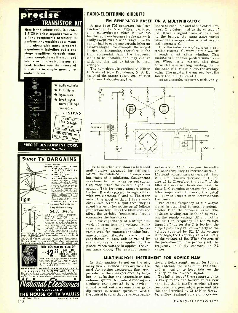
Here is the unique PRECISE TRAN- SISTOR KIT that supplies you with all the components necessary to perform innumerable experiments
. . along with many prepared experiments including audio one stage amplifiers through trans- former- coupled amplifiers ... and into special circuits. Instruction book teaches you the theory of transistors in simple non- mathe- matical terms.
* Audio oscillator
* RF oscillator
* Signal tracer
* Tuned signal
tracer (TRF type
receiver), etc.
TI ...Kit $17.95 WRITE FOR
1954 CATALOG
INCLUDING NEW HIGH
FIDELITY INSTRUMENTS
IN KIT WIRED FORM
PRECISE DEVELOPMENT CORP. Oceanside, New York
Super TV BARGAINS
`
Fringe Master MOTORLESS DIRECTRONIC
No GHOSTS
BEAMEDONICALLY '' / / __
NO MOTORS NEEDED \ NO INTERFERENCE
Model AX -599. 18-ele- ment, army stacked ary provides sparkling re- ception In city or fringe -all channels in all di- rections. Serviceman's
$16-95
kit provides 18 hi- tensil aluminum elements. 6- position Directronic Beam Selector. 1 set matched stacking bars, 7
Complete Kit ....$16.95 5' TRI -X Coble, unl-
versal U- Clamp.
Tremendous Conical Bargain
2 -Bay 16Element Array
$4.99 LOOT SS of 3 With Hi -Band Adapters. Sturdy %" Elements. SINGLE LOTS EACH $5.30 This conical 2 -bay 16- element array provides ultra-fine fringe reception. Includes sixteen a/s inch airplane type aluminum elements. Including hi -band adapters for greater gain on the high channels and is com-
with one pair of stacking
- plete
bars to each array. These are packed in cartons of hree 16- element arrays per carton, with tie rods, at
$14.95 per carton. Single 16- element arrays, separately boxed -your cost $5.30 each. 3 Two -Bay Arrays per carton with- out Tie Rods, $13.50 carton. 4 Bay Ultra- Fringe Stacking A.asemhly for Above -Model 411. $1.95 set.
ry UHF CORNER REFLECTOR IN $2.99 EACH H
OF ONLY LOTS OF 6 SINGLE
EEACHS ° _ . iii i s.- i .1,
f<I
This hi -gain UHF Corner Reflector can only he offered you at this
price for a short time. 8 to 11 db gain across UHF band. Order Model F -6.
NEW SPRING- SUMMER CATALOG AVAILABLE ALL PRICES F.O.B. CLEVELAND. OHIO
Don t a n 't more than complete purchase price. Pay shippin charges on receipt of goods. 25% deposit on all C.O.D. orders. please. Money -hark guarantee.
,/ t OF CLEVELAND
THE HOUSE OF TV VALUES 207 Delco Bldg.
112 Cleveland 3, Ohio
RADIO -ELECTRONIC CIRCUITS
FM GENERATOR BASED A new type FM generator has been
disclosed by the Patent Office. It is based on a multivibrator which is excellent for this purpose because its frequency is easily swept over a wide range. The in- ventor had to overcome certain inherent disadvantages. For example, the output is rich in harmonics, therefore is far from sinusoidal. Also, the frequency tends to be unstable and may change with the slightest variation in plate voltage.
The new circuit is credited to Milton E. Mohr of New Providence, N. J. He assigned the patent (2,577,795) to Bell Telephone Laboratories, Inc.
ON A MULTIVIBRATOR tance of each unit and of the entire net- work C is determined by the voltage of B1. When a signal from A2 is added to the bridge, the capacitance varies about the average value. A positive sig- nal decreases C.
L is the inductance of coils on a sat- urable reactor. Current flows from B2 through a saturating winding. This maintains L at some predetermined val- ue. When signal current also flows through the saturating winding, the in- ductance of L varies about the average value. The greater the current flow, the lower the inductance of L.
As an example, suppose a positive sig-
TO SIG SOURCE
-4 .
á
+ L_=
I /i- 1
o
OUT
o
I
I i The basic schematic shows a balanced
multivibrator, arranged for self- oscil- lation. The balanced circuit keeps even harmonics at a minimum. Components are chosen to provide the desired center frequency when no control signal is present. This frequency appears across the load R and is passed through a filter with two elements, C and L. The filter network is novel in that it has a vari- able cutoff. As the output frequency is swept higher or lower, the cutoff follows proportionately. Thus the filter does not affect the variable fundamental but it eliminates the harmonics.
C is the capacitance of a bridge net- work of capacitors and voltage- divider resistors. Each capacitor is of the ce- ramic type, for example one using bari- um- strontium titanate dielectric. The capacitance of each unit is varied by changing the voltage applied to the plates. When voltage is applied, the ca- pacitance drops. The average capaci-
MULTIPURPOSE INSTRUM In their anxiety to get on the air,
many newly licensed hams overlook the need for station accessories that corn - pensate for their inexperience, by help- ing in adjusting the transmitter and antenna system. No ham station -par- ticularly one operated by a novice - should be without a wavemeter or grid - dip meter to assure operation within the desired band without spurious radia-
nal exists at Al. This causes the multi - vibrator frequency to increase as usual. If circuit adjustments are correct, there is a simultaneous decrease of C and also of L. Therefore, the cutoff of the filter is also raised. In an ideal case, the ratio L/C remains constant for a fixed filter impedance. However, the cutoff will vary in proportion to instantaneous frequency.
The center frequency of the output signal is stabilized by setting potenti- ometer P to the optimum value. The optimum setting can be found by vary- ing the supply voltage B2 and noting the shift in frequency. If the voltage tapped off the resistor P is too low, the output frequency varies inversely as the voltage supplied by B2. If the voltage is too high, the frequency varies directly as the voltage at B2. When the arm of the potentiometer P is properly set, the frequency is fairly constant as B2 varies.
ENT FOR NOVICE HAM tions, a field- strength meter for tuning the antenna for maximum radiation, and a monitor to keep tabs on the quality of the emitted signal.
The initial cost of these separate units is likely to tax the budget of the new ham, but this is hardly so when all are combined in a general -purpose unit like this one described by ZL4AH in Break- In, a New Zealand amateur magazine.
RADIO -ELECTRONICS
www.americanradiohistory.com

The circuit shown is a combination wavemeter, neutralization indicator, field -strength meter, and phone modu- lation monitor. For coverage from 2.6 to 75 mc, wind 4 plug -in coils as follows :
11100yyi
modulate the transmitter with a steady tone and increase the audio gain for 100% modulation on a scope or bor- rowed modulation meter. Tune the wavemeter to resonance, switch the meter to A.F. and reduce the coupling
INSTRUMENT RECT
2.50 .5
MOW COIL (SEE TEXT) 100y0 AF
25K 0-I MA
2.5 to 6.5 mc-31 turns No. 20 en- ameled wire close -wound on 1%-inch form. Tap 8th turn from bottom.
5.5 to 12.5 me -15 turns No. 20 en- ameled wire spaced to 34 inch on 1%- inch form. Tap 5th turn from bottom.
12 to 32 me -51/4 turns No. 20 wire spaced to % inch on 1% -inch form. Tap 2nd turn from bottom.
25 to 75 mc-6 turns No. 12 wire spaced % inch on 1/2-inch form. Tap 2nd turn from bottom.
You need a rigid antenna about 10 inches long when calibrating and using the instrument as a wavemeter. Use an accurately calibrated signal gener- ator or variable oscillator to calibrate the vernier dial for the various bands. Place the instrument close to the cir- cuit being checked or used for calibra- tion and tune the variable capacitor for maximum swing on the meter. Re- duce the sensitivity of the 25,000 -ohm control for high accuracy.
To calibrate the modulation meter,
SIGNAL TRACER FOR AUDIO A 4 -tube r.f. -a.f. signal tracer was
described on page 74 of the August, 1952, issue. It uses separate 6SK7 r.f. amplifiers for the 175- and 456 -kc cir- cuits. I have simplified it by eliminat- ing one of the 6SK7's and the associ- ated components. The modifications are shown in the diagram. Miniature tubes were substituted for the ones used in the original unit.
The input circuits to the 6SK7 r.f. amplifiers were not tuned, so I was able to eliminate one stage by moving the
6SK7,6BJ6 REIN .01
° 3OI75KC
I
°AF IN
175AC
O
SENSITIVITY
to the transmitter, until the meter reads 0.8. Switch back to R.F. and set the sensitivity control so the meter gain reads 0 -8. Note the setting of the sen- sitivity control so it can be reset to this point whenever the modulation meter is used. When the modulation monitor is calibrated, adjust the sensitivity con- trol to the preset point, and then, with the meter set to R.F., adjust the coupling so the meter reads 0.8. The meter now indicates 100% modulation on negative peaks when the needle swings to 0.8 with the switch at A.F. Plug in head- phones for aural monitoring.
As a field- strength meter, use a longer antenna if needed and tune for resonance. As a neutralization indicator, it operates as a wavemeter coupled closely to the plate tank of the stage being neutralized. Remove plate volt- age from the stage and apply normal grid drive. Set the neutralizing capaci- tor for minimum indication on the meter.
AND RADIO FREQUENCIES to ground through a 250 -0I4 capacitor. The power amplifier remained the same except for the substitution of a minia- ture tube.
The adjustment of this circuit fol- lows pretty much along conventional lines. The signal- tracer's 175 -kc and 456 -kc intermediate frequency trans- formers should be carefully aligned with an accurate signal generator.
The tracer can be used on sigr.als from the mixer or converter plate to the second detector stage in radio re-
455KC 455KC
IOOK
Bt
VOL CONT
180yyt 2OI
T VAF IN
selector switch from the detector input to the plate of the single r.f. amplifier. I saved one switch section by connect- ing the transformer secondaries in series as shown. The changes in the audio circuit consisted of adding a .01 -uf capacitor between the a.f. input jack and the volume control and by- passing the first a.f. amplifier plate
JULY, 1954
TO 6E6 OR KARS GRID
220K
2'"
01
t125V
ceivers using an intermediate frequency of 175 kc or 456 kc. For tracing audio signals, be sure to use shielded leads. The output does not necessarily have to feed another amplifier ; in many cases better indication can be obtained by using an audio frequency vacuum-tube voltmeter or an electron -ray indicator tube. Francis R. Miles E NI)
TrTh"- TEST
INSTRUMENTS (in KIT and WIRED FORM)
With professional and amateur alike, PRECISE is the foremost choice. PRECISE insures the use of the finest components in the finest precision- engineered equipment. Fully guaranteed, PRECISE instruments and kits use NO SURPLUS. What's more, kits contain easy -to- follow 3 -colof step -by -step instruction books.
Send for complete PRECISE 1954 Catalog 1M which includes the amazing #111 Emission and Mutual Conductance TUBE TESTER.
PRECISE DEVELOPMENT CORP. Oceanside, New York
"I believe all your troubles would vanish, Mrs. Kosgriff,
if you'd simply get a JENSEN NEEDLE!"
a
113
www.americanradiohistory.com

(Patent Pending)
TiPtaile UHF CONVERTER
. breathtakingly beautiful ... unsurpassed performance
The new Fen -tone creation is
indeed o masterpiece of engineering and styling. Small wonder it
created a sensation in the 1954 Radio
Parts Show. Use the Fen -tone UHF CONVERTER as a lamp, an
illuminated aquarium, an illuminated plant vase. You don't "hide" this
decorator's dream piece)
List Price $29.95
Fen -tone VHF Booster of similar
design, list price $29.95
Created by craftsmen whose love for music inspired
the finest phonograph instrument ever.
See Your Jobber
Literature on request.
FENTON Company 15 Moore Street, New York 4, N. Y.
114
TRY THIS ONE
A.C. VOLTAGE STANDARD Most v.t.v.m. kit manufacturers sug-
gest calibrating the a.c. scale by using the power line for accuracy of 5 to 10 %, or, for greater accuracy, by using a known standard voltage.
The average tube tester provides a series of standard voltages suitable for calibration purposes when the line con- trol switch or rheostat is set correctly. Set the filament selector to the desired test voltage and plug the test prods into socket pins 2 and 7 and set up the tester for any tube with the heater con- nected to these pins. Pins 2 and 7 have ample separation to prevent a short between the prods. -G. P. Oberto
(A tube -tester transformer supplies the rated voltages under load so it is advisable to use a tube or similar load for increased accuracy. Many testers have all the heater pins on different sockets connected in parallel so it is easy to plug a tube into one and test prods into another. Editor)
IMPROVISED FUSE CLIPS Spring clips for the plates of hori-
zontal output and high -voltage rectifier tubes make handy holders for fuses in TV circuits. If the fuse is in the hori- zontal output circuit, solder one clip directly to a lug on the transformer to hold the fuse firmly in place. The other end of the fuse is held in a clip on the end of a flexible lead. This scheme per- mits you to use fuses of different lengths and diameters that will not fit into a standard holder. -Hyman Herman
MATCHING ANTENNA TO BC -348
Many owners of BC -348 receivers complain that they cannot match the high input impedance of the set to a low- impedance coaxial or ribbon line. If your model is one of those with a panel- mounted antenna trimmer, it is easy to convert it to a pi- network an- tenna input circuit which provides a good match to low- impedance lines.
Simply connect a 365 -µµf variable capacitor between the antenna and ground posts on the set and adjust the set's antenna padders for minimum ca- pacitance. (You may have to disconnect the padders on the higher frequency ranges.)
A 365 -µµf capacitor will suffice in most cases, but a 2 -gang broadcast variable with a switch or clip between its sections will give a more flexible setup for various types of antenna feeders. Once you find the proper set- ting for the variable capacitor, you won't have to alter it until you change antennas. All you have to do is peak the incoming signal with the panel - mounted trimmer. -Samuel H. Bever- age, W1MGP
INCREASING MIKE PICKUP Acoustic feedback in PA installations
often can be eliminated by increasing the microphone pickup from the front and decreasing it from the sides. One
WATCH for the
AUGUST Issue of
RADIO- ELECTRONICS
At Your Dealers
JULY 23rd
EASY TO LEARN CODE It is easy to learn or increase speed with an instructograph lode Teach- er. Affords the Quickest and most practical method yet developed. For beginners or advanced students. Available tapes for beginner's alpha- bet to typical messages on all sub- jects. Speed ranges 5 to 40 WPM. Always ready -no QRM.
ENDORSED BY THOUSANDS!
The Inatru.tov rapii Code Teacher literally takes the place of an oper- ator- instructor and enahles anyone to learn and master Code without fur- ther assistance. Thousands of successful operators have "acquired the code' with the Instructograph System. Write today for convenient rental and purchase plans.
INSTRUCTOGRAPH COMPANY 4701 Sheridan Rd.. Dept. RC, Chicago -10, III.
GET MORE WORK OUT OF YOUR
OSCILLOSCOPE
MODERN OSCILLOSCOPES
AND THEIR USES
The most widely used book of its
kind! 326 pages
370 pictures Price $6.00
Here, written so you can easily understand it, is a complete guide to the handiest, most wide- ly used test instrument of them all -the cathode ray oscilloscope!
This big book, MODERN OS- SCILLOSCOPES AND THEIR USES by Jacob H. Ruiler, Jr. of Allen B. DuMont Labs gets right down to brass tasks. It shows where and hole to use 'scopes on all types of AM, FM and TV service work . . . and on other electronic jobs as well. No fancy theory. You quickly learn how 'scopes work and how to use them for fast, accurate servicing from troubleshooting to set realigning and everything in between. You learn bow to make connections; bow to adjust circuit components; how to set the controls, and how to ANA- LYZE PATTERNS fast and right! Practice from it 10 days . . . at our risk!
Dept. RE -74, RHINEHART & CO., Inc. 232 Madison Ave., New York 16, N. Y.
L
Send MODERN OSCILLOSCOPES AND THEIR USES for IO -day FREE EXAMINATION. If I
decide to keep book, I will then send you $6.00 plus a few cents postage In full payment. It not, I will return book postpaid and owe you nothing.
Name
Address .. City. Zone, State OUTSIDE U.S.A. -Cash with order only. Price $6.50. Money back If book is returned In 10
days.
RADIO -ELECTRONICS
www.americanradiohistory.com

way of doing this is to make a funnel from a hollow rubber ball and slip it over the front of the mike. By increas- ing pickup from the front of the mike, you can back down on the amplifier gain control and thus reduce the tend- ency for feedback to develop.
Obtain a 4- or 5 -inch rubber ball and puncture it with the corner of a razor blade to release the gas and the small amount of liquid that is inside. Now, cut the ball in half and then cut the opening for the mike. Make the opening slightly smaller than the diameter of the mike case.
A plastic or aluminum funnel can be used instead of the rubber ball, but the ball makes a more snug fit because of its elasticity, and it can be compressed, wrapped with a rubber band, and car- ried in the pocket easily. -Arthur Trauffer
MOBILE ANTENNAS When installing antennas on police
radio cars, we eliminate drilling mount- ing holes in the body by making up a special bumper bracket for the antenna base. We took a 4 x 12 -inch piece of % -inch metal and formed it to fit the curve of the rear bumper. Then we made a right -angle bend in the top to provide a flat horizontal surface for mounting the antenna base. Next, we removed a bumper guard and drilled a hole in our bracket so it could be bolted securely between the bumper bolt and the guard. Stanley Clark
ELIMINATING KEYING CHIRP I have had a new v.f.o. here at
W2OUX for some time, and it has been performing very well in every respect. One day recently I noted a keying chirp. Naturally I investigated the oscillator first, then the power supply, shielding, and all connections. Every- thing was in proper order. Finally I looked over the semi -automatic key very carefully.
Tests showed that at any speed the dots gave one tone while the dashes gave another. The tones differed by about 100 cycles. An ohmmeter indicated almost a short across the dash con- tacts, but the dot contacts had nearly 3 ohms resistance! Evidently this resis- tance interfered with normal oscillator operation. Pressure with a pair of pliers tightened the dot contact which is fixed to a spring arm. The chirp completely disappeared.
If you suspect this trouble in your own rig, the quickest test is as follows: Tune the receiver to the transmitter frequency and adjust the tuning or b.f.o. for a beat of about 500 cycles. Hold the dot contacts closed with one hand, while the other hand sends inter- mittent dashes. There should be no change in the note when the dashes are made. To test the dash contacts, hold these closed while closing the dot con- tacts intermittently. -W2OUX
SIMPLE MIKE STAND It's easy to mount the new small
crystal mikes, such as the Turner model 81 or Shure model 777 Slim -Ex, onto
JULY, 1954
an economical photolamp stand. An added feature is the ball- and -socket joint which allows the mike to be tilted to an angle.
Since most photolamp stands have a % -inch outside diameter top draw -tube, it is necessary only to thread the top of the tube with a %-27 pipe die so the ball- and -socket joint can be screwed on. File off the % -27 male threads on the neck of the swivel so it can be pushed into the opening of an Am- phenol 75 -MC1F or 75 -MC1M (depend- ing on the mike) cable connector, as shown. Spread a few drops of solder around the edges to hold the swivel and connector together securely; or saw a little off the end of the connector so its setscrew will contact the neck of the swivel. Pass the mike cable all the way through the tubes of the stand, and through the swivel to the connector. Solder the shield on the cable to the inside edge of the neck on the swivel before final assembly. The photo shows the Turner model 81 microphone. - Arthur Trauffer
ASBESTOS SHIELDS I always carry a few small strips of
sheet asbestos in my tool kit and use it whenever I'm soldering in or above a radio or TV chassis. A few pieces placed under tie lugs, resistors, or capacitors catch stray drops of solder and chute them out into the open where they cannot cause any damage. In tight spots, I use it to protect delicate components and leads from the heat of the iron. The material is soft and can be torn or cut when necessary to fit around leads. Above the chassis, I use it to prevent solder drops from falling into socket holes and plugging them. The asbestos strips also provide excel- lent insulation against soldering -iron, heat when working close to components susceptible to high temperatures. This is especially true in the case of com- ponents such as peaking coils and waxed capacitors.
I use the thin sheet material sold by plumbing supply stores for wrapping heating pipes. Fifteen or twenty cents will purchase enough to last a long time. Considering the price of the as- bestos it is a remarkably good invest- ment, and as you carry it around you will find a great many more uses for it. -Frank W. Dresser. END
is here!
for Quick TV Set Adjustment and
Alignment! !
* For adjustment of vertical linearity and height controls
* Accurate positioning of focus coil o- magnet
* Precise setting of yoke
* Complete with instructions
Dealer Vet
$195
*HORIZONT LA BAR GENERATOR-
Your Jobber Today!
Menula<1urers el [Poahomt rqeiFmem rin,e 1912
Export Scheel International 4237 N. Lincoln, Chicago 13, 111.
115
www.americanradiohistory.com

The new Gernsback Library helps you learn more earn more!
SERVICE TECHNICIANS -EXPERIMENTERS! The more you know about electronics, the more money you can make! GERNSBACK LIBRARY Books offer one of the best ways of keeping up with the new and important in TV, radio and high fidelity. Just one tip from any of these low -cost books may be worth the price of the entire series to you! Check this list of titles and order the books you need today.
TV Repair Techniques - No. 50.
Top technician- writers tell how to recognize, find and correct quickly, the tricky TV servicing problems which stump even the ex- perts. A few minutes read- ing this book can save you hours of servicing time. 128 Pages. Over 100 Illus- trations. $1.50
H i gh- Fideli ty- Design, Construction, Measurements - No. 48.
An audio man's audio book. How to get top per- formance from a high - fidelity system. New 3 -way approach. 21 top audio men wrote this book. 128 Pages. Over 100 Illustra- tions. $1.50
high -fidelity
L.r
Television Technotes- No. 46.
Cut routine trouble shoot- ing to the bone in TV servicing. Here are the symptoms, causes and cures of over 600 troubles which occur in scores of sets made by leading manufac- turers. 128 Pages. $1.50
5 CLASSICS ON RADIO AND AUDIO
Radio Tube Fundamentals -No. 45 Tubes for the technician. $1.00
Model Control By Radio -No. 43
Theory and construction. $1.00
High -Fidelity Techniques -No. 42 Best at any price. $1.00
Public- Address Guide -No. 41
Earn money with P.A. 75c
Practical Disc Recording -No. 39
A complete guide. 75c
116
Transistors- theory and practice -No. 51
Tran5'Sfa1s Rufus P. Turner talks ,,.. -ir, ,'"" transistors from the view-
; point of the practical man. Transistor applications in well -known circuits! Com- plete guide to the charac- teristics of commercial
+tg transistors. 144 pages. Il- lustrated. $2.00
,nd '' Radio & TV Test Instruments radio -No. 49.
.ST
i
umNIS How o b ild
ust about
ti to ab
for every
TV-radio serv- icing. Plus chapters on
$ 45 constructing a practical servicing bench and carry-
É . ,,. ing case. 128 Pages. Over 100 Illustrations. $1.50
r <- Radio & TV Hints -No. 47.
t QlP Offers over 300 sure -fire ti, hints, gimmicks, and short
RA > cuts on radio, TV and audio. Gathered from the hard- earned experience of experts. Grouped in seven
)k- "^' ß sections. 112 Pages. 132 Illustrations. $1.00
Basic Radio Course - No. 44.
BASIC John T. Frye's classic on ç 1 fundamentals! For the t»
"RA4iO practical man who wants
' - L °f)t to learn theory. Covers
J everything from Ohm's Law to advanced servicing
, in a style which makes learning fun. 176 Pages. Cloth cover. $2.25
From the publishers of RADIO -ELECTRON ICS
See your distributor -or mail this coupon
GERNSBACK PUBLICATIONS, INC., Dept. 74
25 West Broadway New York 7, N.Y.
Enclosed is my remittance of $
Please send me the following books postpaid.
39 41 42 43 44 45
46 47 48 49 50 SI
Name (Please print clearly)
Street.....- __.__..._.. -.._ __... -.._
City __......_. Zone State- .-- .._....___
BUSINESS
Merchandising and Promotion Technical Appliance Corp., Sher-
burne, N. Y., manufacturer of Taco an- tennas, recently completed a successful series of technical forums throughout Wisconsin, Iowa, Nebraska, and the up- per Mississippi River Valley. The series was given by Ken Lippitt, the com- pany's vice -president in charge of en- gineering.
Walsco Electronics Corp., Los An- geles, has designed a new double- decker tool display for its complete line of alignment and specialty tools. The corn-
pact unit provides space for all the com- pany's alignment and specialty tools in less than two square feet of counter space.
The RCA Tube Division, Harrison, N. J., is under way on a promotion cam- paign to alert home TV set owners to the need of installing lightning arrest- ers and of periodically checking antenna electrical connections on receivers. The program, "Operation Checkup," centers around a four -point installation check- up offered by TV service technicians. Window posters and direct -mail litera- ture are being used to back up the cam- paign.
Raytheon Manufacturing Co., Receiv- ing Tube Division, Newton, Mass., re- ports continued success with its "Serv- ice Saver" technical forums. Over 850 service technicians attended the recent Chicago meeting which was co -spon- sored by Allied Radio Corp., and 1,500 attended the meetings held throughout the Northwest with the cooperation of local Raytheon tube distributors.
Mueller Electric Co., Cleveland, Ohio, is offering a new display board which mounts 18 of its most popular small clips and insulators. The 7 x 9 -inch blue Formica board permits an effective display in a minimum space.
Channel Master Corp., Ellenville, N. Y., produced an interesting motion picture about TV antennas for the gen- eral public. The 13- minute sound movie, "The Vital Link," is now available for television and club promotion from As- sociation Films, New York City.
Simpson Electric Co., Chicago, is con- tinuing its TV servicing lecture and demonstration tour throughout the Mid- west under the sponsorship of local electronic parts jobbers.
Alpha Wire Corp., New York City, has introduced standardization into the retailing of small quantities of wire for
RADIO -ELECTRONICS
www.americanradiohistory.com

service technicians, with the develop- ment of its new Service Spool assort- ment. The assortment consists of five types of wire commonly needed in gen- eral electronics work.
New Plants and Expansions Orradio Industries, Opelika, Ala.,
manufacturer of Irish Brand sound re- cording tape, recently opened a new southern California warehouse in Los Angeles. J. Herbert Orr, president of the company, said that the expansion, which quadruples the floor space for- merly occupied in Los Angeles, was nec- essitated by the upswing in the demand for Irish tape.
r Raytheon Manufacturing Co., Walt- ham, Mass., officially opened its new $2,000,000 electronics laboratory in Bed- ford, Mass., overlooking Hanscom Air Force Base. The company also an- nounced plans to erect a new wing to its present administration building in Waltham to house advanced develop- ment and production facilities for ce- ramics.
Jensen Manufacturing Co., has ac- quired an additional plant in Gutten- berg, Iowa, for the production of small speakers. The new plant makes space available in the company's Chicago Laramie Ave. plant which will be de- voted to expanded production of high - fidelity speakers.
Precise Development Corp., Ocean- side, N. Y., moved to a new specially built factory to provide for its expand- ing manufacturing facilities. A month- long Open House will be held some time this summer.
Radio City Products moved its Engi- neering Department and Development Laboratories and General and Adminis- trative Offices from New York City to Easton, Pa. The Purchasing Division and the New York City district sales office are now located at 101 West 31st St. The company has begun construc- tion on an additional new building in Easton which will add about 5,000 square feet to the company's present facilities.
Tung -Sol Sales Corp. moved its At- lanta headquarters to new and larger quarters at 1859 Cheshire Bridge Rd., N.E.
Show Notes The 1954 Western Electronic Show
and Convention management has made arrangements for the addition of an 11,000- square -foot tent annex to the Los Angeles Pan -Pacific Auditorium to meet the demand for extra exhibit space at the show, August 25-27.
The 1954 High- Fidelity Show, which will be held in the Palmer House in Chi- cago September 30 through October 2, is already ahead of last year both in number of participating companies and in rooms under contract.
Production and Sales RETMA reported factory production
of 1,447,110 TV sets and 2,581,565 ra- dios for the first quarter of 1954, as against 2,259,943 TV sets and 3,834,784
JULY, 1954
TELTRON TUBES GUARANTEED! ., .. LOWEST PRICES EVER! All tubes individually boxed ... unconditional y guaranteed for one year.
TYPE PRICE TYPE PRICE TYPE PRICE TYPE PRICE TYPE PRICE 0Z4 1A7GT
.45
.53 6K7 6Q7
.40
.40 6BK5 61387
.75
.78 678 6U8
.71
.76 121327 12K7
.63 1B3GT 1 H5GT
.62
.51 6ÁB4 6AC7 ........
.43
.65 6BL7GT 6BN6
.78
.90 6V3 6V6GT ..
.80
.48 125A7GT 125K7GT
.40 .. .45
1L4 1L6
.51
.51 GAGS 6AH4GT
.52
.65 69066T .... 66Q7
.83
.85 6W4GT 6W6ß7
.43 .53
125L70T 125N7GT
.. .45
.. .60 1 LC6 1NSGT
.49
.51 6AK5 .96 6BY5G 6627
.60
.95 _
6X4 6X5GT
.37
.38 125Q7GT 19806G
_. .56 .. .38
1.48 IRS 155
.51
.43 GALS 6AQ5
.43 6C4
.48 6C66 .41 .51
6X8 7F8
.80
.49 ....
1978 25130667
.71 1T4 1U4
.51
.51 6AR5 6ÁT6
.48
.37 6C1360 6CÚ6
1.63 .95
7N5 12AL5
.49
.43 25L6GT ... 25W4GT
._ .82 .41
lus 1X2
.43 .65
6AUSGT 6AU6
.. .60 .43
6F6 6FSGT
.42 .44
12AT6 12AT7
.37
.71 25Z5 252667
.. .43 .55 .36 243
247 .35 .35
6AV5GT ._.. 6ÁV6
.60
.37 6H8 6AF4
.50 1.02
12AU6 12AÚ7
.43
.58 ....
35135 35C5
.48
.48 304 30567
.53 6AX4GT .. 6AX5GT ..._
.60
.60 615ßT 6J6
.49 .61
12AV6 12AV7
.42
.73 35L6GT 35W4
.41 .33
354 3V4 SUM] 5V40
.61 .48 .48 .43 .49
6BA6 6887 68C5 6BE6 6BF5
.56
.58
.48
.46
.48
6860T 654 658GT 65Á76T
39
.41 .65
. .45
12AX4GT 128X7 12AZ7 1284 12BÁ6
.. .60 .61 .65 .72 .46
351,4 352507 50A5 50B5 SOCS
.42 __ .33
.49
.48 5Y3GT 5Y40
.30
.40 66E6 6BG6G
.48 1.18
65K7GT 65L7GT
.45
.60 12BA7 128E6
.58
.46 SOyLL660T ..
0
.48 .50
5Z3 688
.42
.40 6BN6 66.16
.51 .51
65N7GT 65137G7 ....
.60 .38
120Y7 12BH7
.65
.61 117X3 117L7GT
.33 .. 1.20
117Z60T .. .65
FREE 57.10 Ilst value Bonus Box of three 133147 tubes and 25 as. sorted orderof $25 or r more.
h each
We now have a complete line of special purpose and trans- mitting tubes in stock.
Write for quotations on your requirements -Dept. T.
We guarantee your orders to be shipped the same day they are received!
Minimum order $10.00. 25% deposit on C.O.D. orders - save parcel post charges. Orders accompanied with full remittance will be shipped prepaid anywhere in continental U.S.A. All orders subject to prior sale.
Send for Free complete tube listing
e 6BG6G tube will be FREE GIFT EOFFER er
accompanying this ad.
SPECIAL! while 29 each
They last la Type Type Type Type 1A4P 1E767 19 34 106 1F4 1629 35
1C7G 1N40 22 35/51 1D5GP 2117 33 36 107G
These pecials are new, famous dividuaily boxed. Order now.
10 for $2.50
Type 37
39/44 46 49 I FSG
make in-
TELTRON ELECTRIC COMPANY 428 Harrison Ave., Dept. RE7, Harrison, N. J. Phone Humboldt 4 -9848
74 MAGNEMITE Icg rictiosjc 4%ousui de ZUonld!
Dag- HERE IS LATE INFORMATION IN A HANDY FORM FOR RADIO AND TELEVISION REPAIRMEN, SERVICEMEN AND STUDENTS
-w 2 VOLS.S6 C PAY ONLY I Mo. , AUDELS T.V. -RADIO
SERVICE LIBRARY- Highly Endorsed -1001 Facts -Over 1552 Pages - 625 Illustrations, Diagrams of Parts. Presents Impor- tant Subjects of Modern Radio, Television, Indus- trial Electronics, F.M., Pub - lic Address Systems, Auto, Marine & Aircraft Radio, Phonograph Pick -Ups, etc.
IT PAYS TO KNOWS The Basic Principles - Construction- Installation - Operation - Repairs - Trouble Shooting. Shows How to get Sharp, Clear T.V. Pictures. Install Aeri- als -How to Test. Explains Color Systems, Methods of Conversion, Terms, etc. In- cludes Ultra High Fre-
ablenfor Quick Ready Ref- erence & Home Study. Tells How to Solve T.V. 85 Radio Troubles- Answers Your Questions.
Get this Information for Yourself. 7 DAY TEST -ASK TO SEE IT!
ow- MAIL ORDER- ---' AUDEL, Publishers, 49 W. 23 St., N.Y. IO, N.Y. Mail AUDELS T. V. RADIO SERVICE LIBRARY 2 Vols. 56 on 7 days free trial. If O. K. I will remit $1 in 7 days and $1 monthly until $6 is paid. Otherwise I will return them.
Name
Address
Occupation
Employed by RE
Dawson recording deep In Africa's Gold Coast. American Museum expedition In ranges of New Guinea. Dwight Cooke Interviews for CBS all over Asia. Wherever you go, whether it be to the North Pole or the bottom of an African dia- mond mine, its not too far for the Magnemite, truly portable tape recorder, whose versatility and unfailing de- pendability has gained global popularity for itself. You'll never grow tired carrying a Magnemite, since these units weigh as little as lk lbs. com- plete with batteries. Letterhead size, this mighty little handful meets NARTB standards and will easily satisfy your most critical recording needs. For the whole MAGNEMITE story write to Dept. RE:
AMPLIFIER CORP. of AMERICA 398 Broadway, N. Y. 13, N. Y.
117
www.americanradiohistory.com

THANK YOU, Mr. Serviceman for naming
yourpreferred brand! In a recent nationwide survey *, radio and TV servicemen were asked this question: "What brand of replacement speakers do you prefer? Why ?" QUAM was first in number on mentions - almost 30% more than the next most preferred brand.
WHY' hure are same
typical comments
about QUMM
speakers by
these servic.eraell
* Conducted by Brand Name Surveys of Chicago, Illinois, May 1954.
"Adjust -a -Cone feature- ruggedness" "Complete range of sizes and types" "Stand up best in service" "Include hardware for easier installation"
"Good construction" "Listed in Sams' Photofacts" "Heavier magnets" "Good quality at a reasonable price" "Always satisfactory"
ask for QUAM the quality line, for ALI. your speaker needs
QUAM- NICHOLS COMPANY 236 EAST MARQUETTE ROAD CHICAGO 37, ILLINOIS
CHROME -PLATED 2 CELL PRE -FOCUSED FLASHLIGHTS
Individual cartons; 12 to box, $3.72 doz.;
gross lots $3.60 doz.; case lots -50 doz., $3.30 doz. Samples 50c each. Excellent
promotional item. Distributors & jobbers only.
Free Catalog on Request
METALACE CORP. 2101 Grand Concourse, Dept. R, N.Y. N.Y.
i
ÀIPIc:A4 ¡ K RADIOS PHONOGRAPHS TV
TEST EQUIPMENT HI -F1
Write for FREE Brochure
RADIO KITS, INC. 120 Cedar St., N. Y. 6
118
RADIO -ELECTRONICS is paying
good rates on acceptance for origi-
nal and unusual articles on audio,
television, FM and AM servicing, as
well as articles on industrial elec-
tronic equipment and applications.
Send for a copy of our Authors'
Guide. Address:
THE EDITOR RADIO -ELECTRONICS
25 West Broadway New York 7, N. Y.
radios for the 1953 quarter. 1954 pro- duction is at approximately the same level as for the 1952 period.
It also reported the retail sale of 1,780,795 TV sets for the first quarter of 1954. This almost exactly equals the figure for the 1953 period. Radio sales for the first three months of 1954 to- taled 1,059,336 (exclusive of automo- bile sets), as against 1,438,866 for the 1953 period.
RETMA announced that manufactur- ers had sold 1,962,864 cathode -ray tubes valued at $41,995,088 for the first quar- ter of this year, compared to 2,798,921 worth $67,696,464 in the 1953 period. 76,385,978 receiving tubes were sold this year, as against 122,058,756 for the 1953 quarter.
Business Briefs ... Tung -Sol Electric Co., Newark, N. J., celebrated its 50th anniversary with a dinner at the Military Park Ho- tel, Newark, N. J. Harvey W. Harper, chairman and founder of the company, and Louis Rieben, president, were hon- ored by more than 400 leaders in the automotive, electrical, and electronics fields. Donald A. Quarles, assistant Sec- retary of Defense for Research and De- velopment, was a guest speaker at the event.
. Raytheon Manufacturing Co., Re- ceiving Tube Division, Newton, Mass., delivered its first 15GP22 color picture tube to American Television, Inc., New Haven, Conn., distributor.
Dage Electric Co., Beech Grove, Ind., states that the company should not be confused with Dage Electronics Corp. which was recently purchased by Thompson Products. Dage Electric, which manufactures a complete line of special and standard r.f. connectors and cable assemblies, recently expanded its manufacturing facilities. ... RETMA recently took steps to in- crease its revenue by voluntary contri- butions, to implement its program for industry self- regulation of TV interfer- ence, and to set up policy committees to direct RETMA activities on the radio - TV excise tax and u.h.f. television. The association also voted to present special certificates to all members and alter- nates of the recently disbanded NTSC.
. Radar -Radio Industries of Chicago, Inc., a nonprofit trade association of electronics manufacturers, which served Government agencies in a liaison ca- pacity during World War II and the Korean War, has gone on a stand -by basis. Headquarters will be maintained at No. 1 N. La Salle St., Chicago, with present directors serving as an emer- gency committee.
Westinghouse Electric Corp. will close its radio and TV assembly plant in Sunbury, Pa., on August 27, consolidat- ing all production operations at the di- vision's headquarters plant in Me- tuchen, N. J. Westinghouse has offered to sublease the Sunbury plant rent -free until February, 1956, to any employer willing and able to provide 1,000 or more jobs for Sunbury people.
RADIO -ELECTRONICS
www.americanradiohistory.com

. The Conference Co- ordinating Committee comprising membership from six trade associations in the elec- tronics industry, recently adopted a set of governing policies which the com- mittee agrees to follow in co- ordinating regional conferences run by sales rep- resentatives. The committee will sup- port a maximum of four regional con- ferences in any one calendar year. For the balance of 1954 it has lent its sup- port to conferences to be held by the Paul Bunyan Representatives in Breezy Point, Minn., July 8-11; the Rocky Mountain Chapter of The Representa- tives, August 29 - September 1; and the Heart of America Chapter at Lake Taneycomo, Mo., September 19- Septem- a ber 22. ... RETMA celebrated its 30th Anni- versary this year during its annual con -
4 vention, June 15-17, in Chicago. Sylvania Electric Products, New
York City, was awarded the annual "NATESA Friends of Service Manage- ment" plaque for 1953.
RETMA membership reached a new high of 383 when the following 17 new members were admitted to the as- sociation:
ACF Electronics, Alexandria, Va. ; Boeing Airplane Co., Seattle, Wash. ; Calvideo Tube Corp., Los Angeles, Calif. : Cargo Packers, Inc., Broklyn, N. Y. ; Collins Radio Co., Cedar Rapids, Iowa ; Condenser Manufacturers, Inc., Nashville, Tenn. ; Connector Corp., Chicago, Ill. ; Consoli- dated Vultee Aircraft Corp. ; Pomona Division, Pomona, Calif. ; Elcon Electronics, Inc., Brook- lyn, N. Y. ; Elgin Metalformers Corp., Elgin, Ill.; Hy -Gain Television Products, Lincoln, Neb. ; In- ternational Telemeter Corp., Los Angeles, Calif.; Maurice I. Parisier & Co., New York, N. Y.; Southern Electronics Co., Greeneville, Tenn.; TRESCO (Transformer and Electronic Special- ties Co.), Philadelphia, Pa. ; Viking Electric, Los Angeles ; Wire Company of America, Santa Barbara, Calif.
Sarkes Tarzian, Rectifier Division, Bloomington, Ind., published an open letter to service technicians allowing them credit for replaced selenium rec- tifiers when returned to distributors. Distributors in turn are allowed credit against purchases. G. Eannarino, di- rector of the division, says the offer is being made to alleviate the critical selenium supply situation. END
"I got so mad fishing around for good programs, I converted it into an aquar- ium."
JULY, 1954
Now! HANDLE TELEVISION SERVICE
THIS NEW "SHORT CUT" WAY! Locate TV troubles at a glance ... Fix 'em twice as fast!
No. 1
*o-F1%
No. 2
PI1N°0°1FIM TV TROUBLE
FINDING GUIDES by Ghirardi & Middleton
The looks of the picture on a bad TV receiver can tell you at a glance what is wrong. PIX -O. FIX not only make this easy -but also show how and where to make repairs.
PIX -O -FIX No. 1- Identifies 24 com- mon troubles by actual TV screen photos. Gives 192 causes and 253 remedies for these troubles. Price separately, $1.25.
PIX -O -FIX No. 2 (New)- Covers 23 additional troubles not included in No. 1. Together, the 2 volumes are a comprehensive guide to easy "picture analysis" servicing of any TV set. Price separately, $1.25.
SPECIAL! Get both PIX -O -FIX No. I and No. 2 for only $2. Use coupon.
NEW! PIX -O -FIX No. 2 JUST OUT! Users of PIX -O -FIX No. 1 were so enthusiastic about it that No. 2 has now been issued to include 23 TV receiver troubles not previously covered. Get both at bargain price of only $2 ... a saving of SO' !
HANDLE 90% OF TV TROUBLES BY EASY PICTURE ANALYSIS!
Cut TV testing time to minutes! Make repairs fast and right!
Just turn the dial of the Ghir- ardi PIX -O -FIX. When the TV screen image in the PIX -O -FIX "window" matches the image on the set you're repairing you've got your clue as to what is wrong! PIX -O -FIX then gives you all causes of this particular trouble plus the section of the receiver in which it has prob- ably happened. Next you get step by step repair instructions.
Usually, the component likely to be faulty is specified. Quick tests to apply to it are explained -or parts substitution recom- mended where this is the best procedure.
The two PIX -O -FIX units cover 47 different kinds of TV trouble - just about anything you're ever likely to be called on to fix. Operation is simple and easy. Our money -back guarantee pro- tects you fully.
Dept. RE -74, Rinehart & Co., Inc. IN 232 Madison Ave., New York 16, N. Y.
Enclosed find $ for which please rush the following. E PIX -O -FIX No. I ($1.25) PIX -O -FIX No. 2 ($1.25)
BOTH PIX -O -FIX No. I and No. 2 at the spe- dial price of only $2.00 for two plus postage
Ir not satisfactory. I will return PIX -O -FIX postpaid ii 1" o lays and you guarantee to refund the purchase price.
In Street
City, Zone. State OUTSIDE U.S.A. .? 1.50 each. .2.50 jar both.
Same return privilege with money refunded.
*Pat. Pend.
ONLY
$495 * Ppd.
or COD + Chgs.
NEW TV DYNATRACER TRACES TV SIGNALS AND VOLTAGES LOCATES DEFECTIVE COMPONENTS REQUIRES NO ADDITIONAL EQUIPMENT
Ideal for trouble -shooting televi- sion sets in home or shop Out- performs more expensive testera and pays for itself on first repair.
A "MUST" FOR EVERY TV TECHNICIAN
The "DYNATRACER" is a self - powered quality test instrument that traces TV signals through any Video. Sound, Sync, AFC, Horizon- tal or Vertical Sweep Circuit -iso- lates trouble to a stage or compo- nent. Traces voltages (50/500 V. AC/ Oct. Also locates open, shorted. in- termittent or leaky (up to 20 MEG-
OHMS) condensers, resistors. coils, XFormers. etc. Complete with Instruction Manual and Repair Guide
FREE 10 DAY MONEY -BACK GUARANTEE With each new order 'll include
unique "TV High Voltage Indi- catr" useful in your testing work.
cat Hn advertisement . attach n me and address Bill. check or m..ney order and mail to
211 -04 99th Ave., Dept. 115 Queens Village, N. Y.
TELEVISION Big demand for graduates
B.S. DEGREE IN 27 MONTHS in radio including TV engineering -VHF, UHF, AM and FM. Students use over $100,000 worth of equipment including 2 large commercial type transmitters in new TV lab. Intense specialized course includes strong basis in mathematics, science and advanced design in radio and TV. Hundreds of young men each year are earning engi- neering degrees in this recognized institution. Start any quarter. Many earn a major part of expense in this industrial center. Low tuition. Competent in- struction. Thorough, intense, practical program. Also B.S. DEGREE IN 27 MO. in Aeronautical, Chemical, Civil, Electrical and Mechanical Engi- neering. G.I. Gov't approved. Enter Sept., Dec., March, June. Free catalog. ENROLL NOW.
INDIANA TECHNICAL COLLEGE 1774 E. Washington Blvd., Fort Wayne 2, Indiana
New EICO PROBES
SCOPE PROBES SCOPE DEMODULATOR PROBE
KIT $3.75 WIRED $5.75
LOW CAPACITY PROBE
KIT $3.75 WIRED $5.75
DIRECT PROBE
KIT $2.75 WIRED $3.95
VTVM PROBES VTVM RF PROBES
KIT $3.75 WIRED $4.95
PEAK -TO -PEAK PROBES
KIT $4.95 WIRED $6.95
SENSATIONAL NAL HIGH VOLTAGE
PROBE Model HVP -2 `'- °My $4,95
See these amazing probe values at your jobber today. Write now for FREE catalog CP -7. Read EICO's other ads in this issue -turn to Adver- tisers Index!
ELECTRONIC INSTRUMENT CO.,Inc. 84 WITHERS STREET, BROOKLYN, NEW YORK
119
www.americanradiohistory.com

IN CONSTRUCTION Rohn Towers are built of heavy duty tubular steel electrically welded throughout by skilled workmen exact- ly to specifications. Proof of Rohn con- struction lies in the fact that thousands of towers have been sold in the past several years and have successfully withstood the rigors of time in all climates and under the severest of conditions!
IN PERFORMANCE Rohn Towers assure you of trouble. free performance and once installed give unquestioned satisfaction year in and year out! You are free of com- plaints because over the years Rohn Towers have proved themselves from the serviceman, dealer and customer point of view!
IN SALES Sales acre prance has been phenomenal - thousands have been sold coast-to- coast - and the design has been one which has withstood every test known! Why "experiment" with an unproved tower design when you can sell Rohn! So we ask you. "Why take chances with an untried tower. Be sure - sell Rohn -the only tower of its kind to withstand every test!
Rohn Fold -Over Tower only one of its kind esclusive with Rohn - patent pending. Rohn Telescoping
Mast - complete line in a proven structural design in 20' -30' -40'- 50' models.
3 Self Supporting Rohn Towers To Fit Your Every Need The No. 5 - The self-supporting tower for use up to 40', or guyed to 80'. An economical, yet sturdy, permanent tower! The No. 10 -The standard it design that is self -supporting to S0' and can be installed to 120' when guyed! The No. 20 - The heavy duty Rohn Tower, ideal for communication and where great height is required - self-supporting to 60', or guyed to 1501 Ml Rohn Towers are in 10' sections - easily erected, transported and stored!
A COMPLETE LINE OF TOWER ACCESSORIES AND HARDWARE A full line of Superior Design Tower ac-
cessories is available including guying brackets. house brackets, wall mounts for towers and masts, special tower bases such
as peak and flat roof mounts, etc.
Contact your Rohn authorized represen tatire or your distributor for FREE CATALOG or write . . .
MANUFACTURING CO. DEPT. RE 116 LIMESTONE BELLEVUE
PEORIA. ILL.
RADIO TELEVISION SERVICEMEN !
HERE IS YOUR 1954 OPPORTUNITY TO DEVELOP A PROFITABLE
SMALL APPLIANCE REPAIR SERVICE
WITH PRESENT SHOP EQUIPMENT
We supply a complete program designed to maintain you in the highly profitable traffic appliance repair field.
ELECTRIC SWEEPER SERVICE CO.
"The House of CES SC 100,000 Parts"
2034 EUCLID AVE. CLEVELAND 15, OHIO
120
Get More Service Coils with
EICO DECALS For Store Windows &Cars.
Write EICO
Brooklyn II. N.Y. Dept. DC -7
ENJOY 3 COLOR TELEVISION FILTER SCREEN NOW
Chan tY f dull e ye -straining black and while pictures into beautiful color tones. Seconds to attach. No tools used. Helps eliminate glare and snow in fringe Order direct. Send 51 for screen size up to 10'. 51.25 size 17". 61.50 size
available sire 21 "i 52.50 side 24".
S3 sin blue. green. or amber.)fePrices anfsolid color
screens are 1004, less. We pay postage except on C.O.D. orders. Satisfaction guaranteed. Inquiries from dealers lso welcomed. Zingo Products, Johnstown 13, New York
MISCELLANY
ELECTRONIC DICTIONARY AMPLIFIER- Device for taking
noise and making it louder. D.B. -Part of the sentence, "Abie,
see de bee ?" DIPOLE -What Stroganoff said as
he shot Czernizowski. ENGINEER -Locomotive driver who
owns a TV set. GRID -Football field. HAM -Trailing edge of an uncouth
animal. KILOCYCLE -Dangerous two- wheel-
ed vehicle. MICROMICROFARAD -One of the
Rofarad brothers -the one who stutters. MULTIVIBRATOR -Bump and grind
artiste. OHM -A H'englishman's castle. PENTODE -Convict frog. POLYDOPE- Unintelligent parrot. 6D6 -Main highway between Chicago
and Los Angeles. 6N7- Thirteen. SQUARE WAVE -Unsophisticated
female Navy personnel. SYNC -What is done to a ship to get
rid of the rats. TECHNICIAN -Resident of Texas. TRANSISTOR -Female having no
fixed home, wandering from place to place.
TOROID -Sign of the Zodiac under which most electronics engineers are born.
YAGI -Hindu holy man. -Charles Hendrix
"What do you mean, Miss Loring's set was in bad shape! ?"
RADIO -ELECTRONICS
www.americanradiohistory.com

PEOPLE
Norman C. Owen was elected president of Webster- Chicago Corp., Chicago, at the annual stock- holders' meeting. He was formerly vice - president in charge of sales. Peter Jensen, pres- ident of Jensen In- dustries, Chicago, was elected to the Board of Directors of Webcor.
Norman C. Owen
C. Chandler Cole joined Ward Prod- ucts Division of The Gabriel Co., Cleveland, Ohio, as general manager. He was formerly a top executive with several industrial firms in the Chica- go area.
C. Chandler Cole
Ray L. Triplett, president of Triplett Electrical Instrument Co., Bluffton, Ohio, is celebrating his 50th anniver- sary in the electronics industry. He was
W. L. Nylen, Sr., presents Ray L. Trip- lett with the Oriental "God of Good
Fortune." honored recently while on a trip to Hawaii with the presentation of the Oriental "God of Good Fortune" by W. L. Nylen, Sr., president of a Hono- lulu distributor firm.
Robert L. Klabin was promoted to vice - president and general manager of the newly created Elizabeth Division of General Instru- ment Corp., Eliza- beth, N. J. He was formerly controller and general man- ager of the F. W. Sickles Division plant in Danielson, Conn.
Ralph C. Seiler joined Triad Trans- former Corp., Ven- ice, Calif., as as- sistant sales man- ager. He was for- merly plant man- ager of West Coast Electronic Co.
JULY, 1954
Robert L. Klabin
Ralph C. Seiler
Obituary Maurice S. Despres, a member of the Board of Directors of Admiral Corp., and founder and president of Dale Dis- tributing Co., New York and New Haven, died in New York City after a long illness.
Personnel Notes . Jerome J. Kahn, widely known
electronics executive, has been retained by John H. Chatz, principal trustee of Crescent Industries, Inc., Chicago, to spearhead reorganization of the com- pany and establish profitable produc- tion, sales, and promotion policies.
Robert C. Sprague, chairman of the RETMA Board of Directors and chairman of the Board of Sprague Elec- tric Co., North Adams, Mass., was awarded the association's Medal of Honor at its annual convention in Chi- cago, June 15 -17. Robert S. Gates, ex- ecutive vice -president of Collins Radio Co., was elected a director -at -large of RETMA. This was the first such elec- tion since a change in the by -laws last year permitting the board to name up to 10 directors -at- large.
... V. H. Lawrence was named vice - president of Industrial Relations of Jones & Laughlin Steel Corp., Pitts- burgh, Pa., succeeding W. R. Elliott who is retiring. Elliot will remain with the company temporarily as a con- sultant to the president.
... Ted Martin, Jr., pioneer field sales representative, was promoted to a spe- cial assignment sales post by the RCA Tube Division, Harrison, N. J. He will operate out of the division's home office.
. David D. Coffin, manager of Ray- theon Manufacturing Company's Mis- sile and Radar Division, was named as- sistant vice -president of the Waltham, Mass., firm.
William (Bill) Edwards joined Ox- ford Electric Corp., Chicago, as sales engineer. He has had 25 years of ex- perience in the speaker field with such companies as Utah Radio Products and Crescent Industries.
... Carlos L. Bailiff, George McAlis- ter, and Hugh L. Overbey, Jr., were ap- pointed district sales managers in a re- alignment of sales territories by Chan- nel Master Corp., Ellenville, N. Y. Bail- iff now covers Alabama, Columbus, Ga., and Pensacola, Fla.; McAlister covers Florida; Overbey covers South Carolina, Georgia, and Chattanooga, Tenn.
. Richard O. Kennedy, Jr., joined Allen D. Cardwell Electronics Produc- tions Corp., Plainville, Conn., as as- sistant to the president. He was for- merly a management consultant to manufacturing concerns. The Cardwell Company is a subsidiary of Chesapeake Industries, New York City.
Raymond B. George, vice- presi- dent of merchandising for Philco Corp., Philadelphia, has expanded his responsi-
ON
and
NEW. th 5vonderfut 50 (except sounding Also plete assembling glossed and hasten Includes
EDLIE "SAVE says 3 -WAY Portable KITS" other KITS and WIRED UNITS
3 -Way Portable
` RADIO R: KIT
y `
AC!DC y ,am ` . X Batteries
:111/.1,t. lightweight t,..rtal,le ratio kit c latest supersensitive .tiperhet. circuit. reception from either batteries. or 115 V..
-60 cycle AC or DC. Includes all complete parts wire & solder) necessary to build a great radio.
includes circuit diagrams and simplified. t -
step -by -step Instruction folder which n easy. Housed in beautifully 1.;. -
Catalia cabinet in two delightful distinctive colors: maroon or ala- $13 95 (ivory). Size: 9./2" x 57/s" x 43% ".
tubes!
TERRIFIC VALUE! as b
;$ BERM. 'frO 41 - anninmin n auunnmwmp
tnnmmp,- - ..,...-
5 TUBE AC /DC Superhet Kit Rit 1: 5 tube superhet kit. AC DC includes all
construct this latest quality components quired to te
design. highly sensitive superhet broadcast receiver, complete with black, glistening Bakelite cabinet es- eludes wire & solder). Kit of 5 tubes. I2AT6. 2/12- BAG. 12BE6. 35W4, 50B5.
Price, Leas Tubes S7.e[ 95
Extra for Tubes $3.25
Great Saving`' 6 -TUBE RADIO KIT Kit /2: Low priced 6 -tube kit designed for extra high sensitivity, excellent selectivity and good, rich tone quality. Uses 25L6, 25Z6. 6SQ7, 6SA7. 2/6007 in an easily constructed circuit. Includes all ptn'i..: punched chassis, resistors, condensers, coils, socket.. PM speaker, hardware, etc. Special closeout prise. (Less tubes & SI" cabinet)
Matched set of 6 tubes for kit 53.25
3 -i t
TUBE " ~
PHONO AMPLIFIER
NOT A KIT An assembled unit ready
main/ for n tallation trol tone and volume con
and 8 ft. rubber á2-l5 cord, (less tubes).. Lowest Price!
With complete set 5445 of tubes
Phono Oscillator
NEW SAVINGS! I
NOT A KIT!
Wireless p!,,,,, .t ilia- tor transmits recording for crystal p!cknpa or voice from carbon mike through radio without wires. Can also be used
m as an Interco by using PM speaker as mike (less tubes) 52.85
With complete set of tubes
PRECISION RESISTOR KIT Consists of 50 -1nr Wtlkor ñrbobltn resistors of 50 different hmages, housed a transparent plastic box. May be combined in series of parallel to pro- duce almost any desired ohmage. Each resistor re- tails for about 85c.
Terrific Cash Sayer!
$9.45 Kif of SO only 2
TERMS: All mdse shipped FOB New York City. prices subject to change without notice. Include 20% deposit for COD's. WRITE TODAY FOR NEW FREE CATALOG!
EDLIE Electronics 154 Greenwich Street New York 6, New York
DI 9 -3143 N
121
www.americanradiohistory.com

Make your Math
r-
EASY! You'll find those time- saving equations easy to use, easy to solve with the aid of
Elements of Mathematics for
Radio, TV & Electronics By Bernhard Fischer & Herbert Jacobs If you've ever hesitated to use a time -saving equa- tion because you were not quite sure how to set it up; or had moments of doubt about decimals or
or wanted a percentages; quick IS THE BOOK FOR YOU.
your t makfig- uring-THIS n
crystal clear each step in the reasoning and each procedure in the arithmetic, geometry, and alge- bra needed by radio and TV technicians. You'll find it EASY to work out frequency resolutions voltage drops, inductive reactances, decibels and the many other radio and TV problems in which accurate use of math is essential. Hundreds of sample problems, with answers, give you thorough practice.
Radio & TV
Mathematics by Bernhard Fischer
A handbook of step-by -step solutions for 409 problems in radio, TV, and industrial electronics. Whatever YOUR problem- whether it is to cor- rect the power factor of a motor, find the impe- dance and length of a matching stub between an- tenna and transmission line, or any of hundreds of other problems -here is the clear, exact solu- tion.
Have you got your copy of "The most helpful" service guide?
Mandl's TV Servicing The book thai is eagerly bought by servicemen throughout the country as the most practical and helpful guide to quick, accurate trouble- shooting on today s receivers.
Mandl's TV Service Course Laboratory Manual 46 experiments, with exact what -to -do and what - to -look -for directions, show how each part of a typical receiver operates and what causes trouble.
SEE THEM ON APPROVAL The Macmillan Ca., 60 Fifth Ave., Now York 11 G2
Please send me the books checked below. I will remit full price plus small delivery charge, or return books in 10 days. ( Save: Send check or money order and we pay delivery charge)
Elem. of Math, $7.20 TV Servicing, $5.75
Radio IL TV Math. $6.75 TV Serv. Lab. Man. $3.90
Signed
Address
This offer good only within continental limita of U.S.A.
J'
122
bilities to include over -all direction of the advertising activities of all con- sumer product divisions. Morgan Green- wood, newly appointed general adver- tising manager, will continue to direct all Philco advertising.
. Harold J. Krollman joined Brook Electronics, Inc., Elizabeth, N. J., as production manager of the Linden, N. J., plant. He was previously with Automatic Manufacturing Co. and Fed- eral Telephone & Radio Co.
... Saul Kotchever joined the sales staff of Parkside Wire Co., Chicago.
Edward Flaxman was appointed sales manager of Waldom Electronics, Chicago. He has been identified with the speaker cone industry for many years.
... Richard McQueen joined National Co., Malden, Mass., as advertising and promotion manager. He was formerly with Magnecord. Elliott H. Ruttenberg, formerly with the Special Products Di- vision of Raytheon, Chicago, joined Na- tional as price administrator. John S. Boyers, ex- Magnecord, is now chief en- gineer of National's Magnetic Memory Devices Division.
... Joseph A. Hatchwell, Mid -Atlantic regional sales manager for Allen B. Du Mont Laboratories' Television Receiver Division, Clifton, N. J., was promoted to director of service.
... Bob Stephens, of Stephens Manu- facturing Co., was elected chairman of the Advisory Committee for the 1955 West Coast Audio Fair, to be held at a date and location not yet determined. Membership on the Advisory Commit- tee was increased by the addition of the following members: Gramer Yarbrough, American Microphone Co.; Bert Ber- lant, Berlant Associates; Bill Thomas, James B. Lansing Sound Co.; Bob New- comb, Newcomb Audio Products.
Ralph H. G. Mathews, veteran ra- dio and electronics engineer, joined Magnavox Co., Fort Wayne, Ind., as sales counsel for the High -Fidelity Di- vision. END
STAN-BURN
* CATHODE RAY TUBE SPECIALS * * 100P4A
10FP4A * 12KP4A 12LP4A 12QP4A/81014
Dumont 12UP4B 14CPA * 15DP4 /81014
Dumont 23.75 16AP4A 30.95 * 16DP4A (N.U.) 25.25 16GP4 or B 31.25 16KP4 /16RP4 24.20 * 16KP4A
(Aluminum) 28.35 16JP4A (N.U.) 25.25 * 16LP4A 28.50 16WP4A 16GP40 * 17BP4A 17BP4B 17CP4 * 17CP48
(Aluminum) 29.00 19AP4A 41.50 * 20CP4 30.00 20LP4 37.50 21AP4 42.00 21EP4 31.80 21EP4A 36.35
*. 24AP4 78.50 QUANTITY CRT USERS
* toes Prepaid. 10 COT'sam in irnums shjpment.,WRITE FOR DETAILS.
ONE YEAR GUARANTEE G.E. STAN-BURN
514.95 100P4 510.20 21.10 12LP4 24.45 12LP4A 18.75 12QP4
12JP4 21.00 12UP4A 28.75 14CP4 24.50 1SDP4
16141.4 16DP4 or A 16JP4 or A 16CP4 or A 16FP4 16WP4 16AP4 16AP4A I6EP4 16EP4A 16GP4 or A 176P4 17CP4A 17GP4B 19FP4 19FP4A 19AP4 19AP4A 20CP4 21EP4 21AP4 24AP4
13.95 * 11.90 11.90 14 50 * 15 60 17.50 17 s9 * y. 17.50 17.50 17.59 17 50 17 50 17.50 23.00 19.00 23.50 21.00 16.30 21.60 22.60 23.00 24.00 23.90 24.90 23.95 25.50 26.50 49.00
26.50 31.25 24.25 30.30 23.90
* * ANTENNAE SPECIALS
1 -5 6 or more RED DOUBLE "V" Anteno 2.19 1.98 10 EMENT CONICAL
Downed Inserts ... Folded Hi- Straight Low Quick Rig
1/2 loments * WINDOW C
* NEPCO MASTS 42 Mil. * TV WIRE 55 Mil. 300 OHM 72 OHM COAXIAL
2.98 2.79 4.25 3.25
ONICALS 4.95 3.75 * 5 FOOT SWEDG {D .79 .69
MASTS 10 FOOT PLAIN 1.69 1.29 *
$191.ás M Ft. 35.00 M Ft. *
*
*
* *
* *
*
CHASSIS 630 TECHMASTER $149.G * Model 1930 with Cascode Tuner 17
OPEN FACE CABINET $42.00
TAPE RECORDERS IN STOCK PENTRON -Model 973C-2-speed Tape Re-
corder Write for Prlee. RADIO CRAFTSMAN
Model C400 -Hi Fi Amplifier Net $42.90 * Model CIO -AM -FM Tuner Net 131.50 Model C500- Williamson Amplifier Net 99.50
We also carry MASCO -BOGEN- PILOT, etc. Ampli- * fiers- Pre -Amps, FM Tuners and WEBSTER Tape Recorders. * 6 "a9" PM SPEAKER S 3.98 7" PM SPEAKER 3.96 70° Yoke 1.98 * 630 Vert. Output Upright 1.98 630 Vert. Output Potted .29
9 630 Vert. Blocking Ose. Xform 1,6
. * CASCODE TUNERS 14.96 DU MONT 21.25 14.95 Famous INPUTNER 10.00 TV Permanent Magnet Focus Assembly 1.90
Three Speed Automatic VM Record Player in portable carrying case. Special $39.95 20CP4 Progressive Special $23.95
AUTHORIZED DISTRIBUTORS for: General Electric
* Automatic ic andS General Motors. De Wald, Regal
rs
* *
* * *
* *
* *
AUTOMATIC CUSTOM -BUILT RADIOS for Plymouth, * Ford, Chevrolet and many others, always in tock. We carry a complete stock of HI- FIDELITY and SOUND EQUIPMENT. Send us your requests. We * also carry a complete line of popular makes of Radio tubes at 50 /10 °/p discount. Also many other special purpose nd transmitting types, and all electronic * parts and equipment at lowest prices. Send as a list of your requirements for prompt quotations. Terms: 20% with order. Balance COD. All prices .R. FOB. NEW YORK Warehouse. Minimum order $5.00. Write for our latest price list and Hi -Fi Catalog to Dept. RE -7. *
STAN -BURN ELECTRONICS CO.
1697 BROADWAY NEW YORK 19, N.Y.
$3.00 FOR CARTOON IDEAS
RADIO -ELECTRONICS prints sev- eral radio cartoons every month. Readers are invited to contribute humorous radio ideas which can be used in cartoon form. It is not neces- sary that you draw a sketch, unless you wish.
Address
RADIO- CARTOONS, RADIO -ELECTRONICS
25 West Broadway, New York 7, N.Y.
RADIO -ELECTRONICS
www.americanradiohistory.com

BLAK -RAY SELF -FILTERING ULTRA -VIOLET LAMP
BLAK -RAY 4 -watt lamp, model X -4, complete with UN tube. This lamp gives long -wave ultra- violet radiation having a wave -length of 3654 fo 4000 angstrom units. Some of the substances made to fluoresce visibly when illuminated by U -V light are certain woods, oils, minerals, milkstone, cloth, paints, plastics, yarn, drugs, crayons, etc. This lamp is self -filtering and the invisible U -V rays are harmless to the eyes and skin. Equipped with spectral -finish aluminum reflector. Consumes only 4 watts and can be plugged into any 110 volt 50 -60 cycle A.C. outlet. Will give 2000 to 3000 hours of service. It weighs but I% lbs. Approved by the Underwriters Laboratories and has a built - in transformer so that it may be safely used for long periods when necessary. Extra U -V lobes are available. Shin wt. 4 lbs.
$16.75 ITEM NO. 125 J UNUSUAL BUY (Shp Chris. 70v)
POWERFUL ALL PURPOSE MOTOR Sturdy shaded pole A.C. induc- tion motor. 15 watts, 3000 rpm. 3 "x2 "x144 "; 4 mounting studs; 7/11" shaft, 3/16" diameter; 110- 120 volts, 50 -60 cycles. A.C. only. When geared down, this unit can operate an 18" turn- table with a 200 Ib. dead weight. Use it for fans, dis- plays, timers and other pur- poses. ITEM NO. 147
2 lbs. $2.45
UNUSUAL BUY (Shp.Chgs.330
WATTHOUR METER Leading makes- recon- ditioned. Ideal for trailer parks. 100 -110 volts, 60 cycles, 2 -wire A.C. 5 amp. Heavy met- al case 81 /1" x 61/4" x 5 ". Easy to install. Ship. wt. 14 lbs. ITEM N0. 33 $4.50 NOW ONLY (Shp. Chas. $1.25)
WESTERN ELECTRIC BREAST MIKE Lightweight I lb. carbon micro- phone. Aircraft type. Breastplate mountings adjustable 2 -gray swivel. Easily fastened straps. For home broadcasts, communica- tions etc. Complete with 6 foot cord, hard rubber plug. Shera- dived plate, non -rusting finish. Ship. wt. 2 lbs. $1.98 ITEM NO. 152 NEW LOW PRICE (Shp. Chas, 32c)
AMAZING BLACK LIGHT 250 -watt ultra- violet light source. Makes fluorescent articles glow in the dark. Fits any lamp socket. For experimenting, entertaining, unusual lighting effects.
IT Ship.
NO. 287ós. $2e45 A SAVING AT (Shp. Chgs. 35v)
250 POWER TELESCOPE LENS KIT Make your own high powered 6 ft. telescope! Kit contains 2" diam., 75" focal length, ground
and polished objective lens and necessary eye pieces. Magnifies 50x to 250x. Full instructions. Ship. wt. I lb. $2.95 ITEM NO. 123
YOU SAVE AT Ishp. Chg..loc)
HUDSON SPECIALTIES CO. 25 West Broadway, Dept. RE-7-54 New York 7, N. Y. ] am enclosing full remittance for Items circled below. Be wire to Include shipping charges.) OR, my deposit of $ Ship balance C.O.D. MINIMUM C.O.D. ORDER 55.00. C.O.D. ORDERS ACCEPTED ONLY WITH 20% DEPOSIT INCLUDE SHIPPING CHARGES. circle Item. Wanted
87 147 33 152 128 121
Name
Add[ees
Please Print dearly
City zone.... State
JULY, 1954
J
ELECTRONIC LITERATURE
Any or all of these catalogs, bulletins, or periodicals are available to you on re- quest direct to the manufacturers, whose addresses are listed at the end of each item. Use your letterhead -do not use postcards. To facilitate identification, mention the issue and page of RADIO - ELECTRONICS on which the item appears. All literature offers void after six months.
CAPACITOR INFORMATION A comprehensive 48 -page catalog
issued by Astron Corporation contains -beside complete listings and prices of Astron electrolytic, paper, metal- lized and special- purpose capacitors - a wealth of technical information on capacitors.
Of the 48 pages, three are devoted to a section of the selection and applica- tion of electrolytic capacitors, and an additional page to their performance and test specifications. Engineering and design information on impregnated paper -foil capacitors covers four pages -including characteristics and test specifications on standard and 150 °C capacitors. There is also a four -page section of information on metallized paper capacitors, with an additional page of performance characteristics and test specs.
Gratis to service personnel and other interested parties from Astron Corpor- ation, 255 Grant Ave., E. Newark, N.J.
SOUND EQUIPMENT Leonard Radio Inc., has put out a
16 -page catalog on high -fidelity sound equipment. Photos of the equipment appear along with their specifications, description, dimensions, weight, and price.
Available from Leonard Radio Inc., 69 Cortlandt Street, New York 7, N.Y.
SELENIUM RECTIFIER HANDBOOK Sarkes Tarzian has issued of 3 -color
74 -page catalog, No. 666. The catalog is divided into seven
sections. Center -sealed power rectifiers, high -voltage selenium rectifiers, em- bedded selenium rectifiers, and center - cooled radio and television rectifiers are described in detail in the first four sec-
. tions, along with photographs, sche- matics, and charts. Many suggestions for applications are given in one sec- tion, and a wealth of engineering data in another. The last section contains a revised selenium rectifier replacement guide.
Available from Sarkes Tarzian Inc., Rectifier Division, 415 College Avenue, Bloomington, Ind. Price $1.00.
COLOR BROADCAST CATALOG Radio Corporation of America has
released a 16 -page standard color broadcast equipment catalog, present- ing in package form all items required for transmitting network color.
The list includes RCA's color stabiliz- ing amplifier, color monitor, color sig- nal analyzer, linearity checker, color
! ! HEARING AID PARTS ! !
2'x3'x/AID AMPLIFIER yred. CHASSIS (2 REAL) VEST POCKET RADIO OR AMPLIFIER adding only simple tuner & phone. WITH SCHEMATICS FOR A 2 or 3 TUBE SET. Less tubes & case $2.49 SET OF 2 SUB -MINI. TUBES for above $2.98 HEARING AID BONE CONDUCTION RECEIVER 11 /2 "x
si "xl) Makes sensitive MUSICAL CONTACT MSKE, PICK-UP
PHONF.. ETC. Lo- Impedance. 53.98 CRYSTAL PICK -U MIKE ilk "x1 /a ") hi -impe- dance. Rubber al,OCk-mtd. 1.29 MIDGET OUTPUT XFMR ( a/4 "sq.xl /2 "). Matches reg. Glee coil. bone seer, or lo- imped, phone.... ea. 49e MIDGET AUDIO CHOKE 4500 ohms OC-ea. 49e 12/55.00
HEARING AID CORD . . . Extremely flexible: black silk over rubber . . . 2 wire (1/16" O.D.) -Se ft. 100 ft. $3.75; 3 wire -7° ft.. 100 ft $5.75 ! ! SCOPE PARTS ! !
3" CR TUBE SHIELD, 3ßP1. etc ea. $1.29 " CR TUBE FRONT BE7.FI 88 5" CR TUBE SPONGE RUBBER FRONT GASKET 88 5" SCOPE VISOR moulded vinyl 98 51/4" CLEAR CONVEX LENS round ea. 390 6/1 98
! ! XMAS IN JULY ! !
y. WheniiTTMM7yB051
RADIO ELEC- TRONICS PARTS KIT" . LOAD- ED with new & surplus . inventory odds WORTH & SEVER- AL TIMES THE
. . . 17 lbs. of: SWITCH- ES. . SOCKETS. CONTROLS. WIRE. COILS. TV PARTS & DIA- GRAMS. PHOTO - FACTS. RESIS- TORS. CONDENS- ERS. ETC. (SUPS. wt. 20 lbs.)
$3.95 SPECIAL WOOD CABINET I CHASSIS KIT Beautiful it. walnut veneer. Inside: 111/2"x7,
-.1," 1/4 H.x 6"D. 4" sq. dial png. on right. $,./5 PLUS 6 tube punched chassis, perfectly
matched -set. ATTENTION: SCHOOLS & MFRS. . . WRITE FOR SPECIAL PRICE ON QUANTITIES.
ASTATIC ALL- CHROME CRYSTAL MIKE Bullet type, swivel head. 30-10.000 cycle $7.95 18 FT. WHIP ANTENNA . . . 6 steel tapered screw sections 53.75. Extra extension sects. ea. 75e RADIO HARDWARE. TREASURE . . . FULL LE. CAN of: Nuts, Screws, Washers, Lugs, etc. -ea. 89e
3 lbs. 52.49 ECLIPSE REVERSIBLE MOTOR (Type Y -150. 2BJ -8143) Approx. 16 H.P. 3800 RPM, 24VDC.
56 95 Splined 1/2'T haft.6 "L.x4" O.D. Shpg. wt. 11 lbs. BRAND NEW -WHILE THEY LAST!
"DIRECT FACTORY SPEAKER REPAIRS SINCE 1927 "-I Min. Order $3.00. 2i , deposit req. on all C.O.D.'s.
please add sufliel nt postage- cxeess refunded
Lto DNS RADIO New
Dey Street New Yorrk
CORP.
C N. Y, J
URGENT! URGENT!
ELECTRONIC TUBES We Pay Spot Cash for:
RADIO, TV -all types State types, condition
of merchandise, quantities and price.
COLUMBIA ELECTRONICS CORP. 115 Liberty Street, N. Y.C.
RADIO -ELECTRONICS is paying
good rates on acceptance for
original and unusual articles on
audio, television, FM and AM
servicing, as well as articles on in-
dustrial electronic equipment and
applications. Send for a copy of
our Authors' Guide. Address:
THE EDITOR RADIO- ELECTRONICS
25 West Broadway, New York 7, N. Y.
123
www.americanradiohistory.com

We specialize in TUBES -Receiving, transmitting and special purpose, etc. -serving the industry for years. More than 3000 different types in stock for IMMEDIATE DELIVERY -including hard- topet and discontinued numbers. All tubes exhaustively tested in our fully equipped laboratories, and re- tested at time of shipment. FULL ONE-YEAR GUARANTEE. All tubes individually boxed and codedated. Type Price
0A2 .89 0A3/VR75 .99 0A40 .65 OB2 .74 0B3 7a90 .95 0C3 VR105.98 003 VR15O.89 024 .54 1A5G7 . .43 1A7 .49 IA B5 .39
I AX2 . ..55 1B3 .69 10807 .77 1G6GT I .54 1HSGT .43 1JBG .59 1L4 .45 1LA .59 1LA6 .79 1L84 .79 1LC5 .59 1LC6 .79 11.05 .52 1LE3 .78 1LG5 .77 1LH4 . .78 1LN5 .S7 185 .61 1P5G7 .... .56 1Q5G7 .... .57 1R5 .49 154 .58 155 .43 15116 .48 174 .48 1U4 .49
'11.15 .48
1X2A .55 2A3 .95 2A6 .49 2A7 64 2B7 .62 2X2 .39 2X2A 1.15 3A4 .44 3A5 .93
FREE OFFER!
Seven As- sorted 12 7, 6, I and 2 - volt type tubes. List Value ap- prox. $23. FREE with every order for $25 or more!
Type Price 3A8 .60 3B7 .39 306 .39
3044 .79
3Q5GT .55 354 .50 3V4 .52 574 1.28 5Ú4G .53 57367 .38 523 ....33 646 .47 6A7 .82 6A8 .69 6684 .49 6AB7 .75 6AC5GT _ .99
6AC7 ..69 6A F4 .89 6A F6 .75 GAGS .52 6ÁG7 .95 6ANe .89 66.15 .89 6AK5 ..49 6ALS ..30 BAQS .41 BATE .37 6AÚ6 .43 6AV5 .79 6AV6 .37 6AX4GT .57 667 .95
6B8G ..29 6BA6 .42 6BA7 .56 6BC5 .52 6B06 .44 611E6 .39 6666 .... 1.24 613116 .48 613.16 .44 861(7 .95 6BL7 .85 6BNe .79
fiBQ7A .88
6827 r .79 64 .39 6C5 .39 11060 .57 6C80 .85 6C86 .45 6CD6 1.10 606 .69 8013G .98 6F6 .45 6F7 .93
Type Price
6F8G , .69 666G .65 flue .49 Gis .40
.53 6J7 .49 6.186
T .45 .95
6K7G 61(7 .39
6L7G , .39 6N7 .98 6Q7 .49 687 .49 654 .42 65713 .59 65A7 .40 65C7 .79 13S1/7GT .38 65F5 .45 65F7 .59 6SG7GT .40 65íH7 .60 6511707 .50
6SJ7 ...39 651(7 . .40 65L7GT" .52 65N7GT .52 6507 .41 6587 .45 6577 .49 678 .59 6UG7 .45 6U8 .59 6V6GT .43
6W4GT .39 6W6 .48 6X4 .36 6X5GT .37
7A5 .59 7A6 .69 767 .69 7AD7 .95 7AG7 .55 7AH7 .56
TOP QUALITY FULLY GUARANTEED TUBES
BELOW MFRS' PRICES /fA
HIS MONTH'S SPE em 1 new policy brings you greater tube
sings than you thought possihie! Ash month, a un- GOODWILL offering, are giving, e
her Ot popular tube types (listed below trt extra bold AT PRICES BEL fiW OffURs OW at COST,
t Look
for h mnnl .
!n industry -wide publications!
Type Price 784 .44 765 .59 7B6 .59 7C4 .58
7C5 ...49 7C7
7F7 7147 7J7
.65
.59
.65 59
.75
.59 7N7 .... .62 707 .61 7R7 .65 757 .85 777 .91 7V7 .91 7W7 .85
7Z4 .49 727 .85 lOY .69 12A6 . .59 12A H7 .89 12AT8 .39
12AT7 .68 12AU6 .39
12AU7 .49 12AV6 .44 12AV7 .69 12AX4GT ...59 126X7 .59 12AY7 .79 12BA6 .47 128A7 .59 12606 .49 126E6 .49 126H7 .65 12877 . .65 12827 .63 12C8 .34 12F5GT .35
Type Price 12146 .45 12J SGT .39 12176T .58 121(7 .55 121(8 .58 120767 .59 125807 .61 125A7GT .64 125C7 .69 125F5 .49 125F7GT .69 12567 .75 125147 .75 125.17 .59
12SK7GT .44 12517GT .49 12SN7GT .58 1250707 .56 125117 .49 12Z3 .39 1464 .69 14A5 .59 14AF7 .59 1488 .65 14C7 .69 14E7 .83 14F7 .67 14F8 .95 14H7 14N7 .69 14Y4 .69 19 .49 19BG6 1.26 19T8 .79 22 .44 25AV40T .84 258Q6OT .79 25L6GT .41 25Z5 .64 252607 .44 26 .44 27 .38 32L7G7 _ .98 35C5 35W4 .37
.37
STANDARD BOOSTER, lots of 3, each $8.58 Single lots, each 56.98
TRACTOR RADIO, List $99.75, net each 529.77 HEADSETS, PAIR, lots of 3, each 52.56
Single lots, each $2.89 See June Issues of Radio News and Radio -Elec- ironies for complete descriptions.
Minimum Order $10. Please i nel ude 25% deposit with order. Prices subject to change without notice. All prices F.O.B. our warehouse. N.Y.C.
WRITE FOR TYPES NOT LISTED
Type Price 35Y4 .45 35Z3 .43 3525GT .48 42 .41 43 .55 45Z3 .42 46 .49 47 .89 49 .44 SOBS .44
5005 ..40 5OL6GT .62 50X6 .64 SOY6GT .59 56 .49
.55 58 .58 7OL7GT 1.00 71A .54 76 .43
.5S 78 77
.45 81 1.11 82 .69 83 .79 84 .54 85 .59
89Y ....29 11723 .38 11724GT .75 807 1.39 2031 .95 9001 1. 9002 9003 1
9004 9006
CATHODE RAY
Type Price 3EP1 5.50
5BP1 3.55 SBP4 5.95 SCP1 5.95 7BP7 7.45 12DP7 19.50 16HP4A 18.95 16DP4 18.95
INDUSTRIAL Type Price
1822 1.80 1B24 8.89 1832 1.90 1N23 1.95 2C26A .59
ELECTRONIUBE WHOLESALERS. INC. 140 DUANE STREET NEW YORK 13, N. Y. Phone, BArday 7 -7616
Type Price 2C40 8.95 2C44 .89 2D21 1.09 2J26 ....26.95 3C24 1.75 211 2.21 304TL 7.50 307A 4.80 316A 2.50 446A 3.46 705A 1.50 715B 6.50 717A .58 721A -2.50 726A 9.50 801A ... .39 803 2.90 815 3.90 826 .89 836 3.95 837 ..._ 841 842 860 864 874 954
1.30 .60
6.85 .85
1.30 .34 .54
CK1005 .60 1616 1.95 1619 .35 1624 1.70 1625 .29 1626 .49 1629 .44 1630 1.10 1831 1.40 1632 .65 1633 .89 1634 1.10 7193 .55 8012 . . -2.50 8013A 3.30 8020 2.90
NEW LISTING !
Just out - all popular tube types, at lowest wholesale prices! Send today for your FREE Copy!
OPPORTUNITY ADLETS Rates -45e per word (including name, address and initials). Minimum ad 10 words. Cash must accompany all ads except those placed by accredited agencies. Discount, 10% for 12
consecutive issues. Misleading or objectionable ads not accepted. Copy for Sept. issue must reach us before June 16, 1954.
Radio Electronics, 25 W. Broadway, New York 7, N. Y.
SPEAKER REPAIRS ON ALL MAKES. Jobbers wanted. BUILD YOUR OWN ELECTRONIC ORGAN, OR MINIA-
Amprite Speaker Service, 70 Vesey St., New York 7, N. Y. TITRE electronic brain. Jim Kirk, WBJKX, 1552 Church Street. San Francisco 14, California.
REPAIR ON ALL MAKES of test equipment, and kit construction. starting September First. Write now for free information. Bigelow Electronics, Pioneer Road, Beulah, Michigan.
DIAGRAMS FOR REPAIRING RADIOS $1.00. Record Changers $1.50. Television $2.00. Give Make, Model. Diagram Service, 672 -RE, Hartford I. Conn.
TEST EQUIPMENT Repaired and Calibrated by Factory staff. All makes. Superior, Simpson, Triplett, Heath. etc. Immediate service. Douglas Instrument Laboratory, 176a Norfolk Avenue, Boston 19, Mass.
TUBES -TV, RADIO, TRANSMITTING, AND SPECIAL PURPOSE TYPES BOUGHT, SOLD AND EX- CHANGED. Send details to B. N. Gensler W2LNI, 136
Liberty, N. Y. 6, N. Y.
ALL MAKES OF ELECTRICAL INSTRUMENTS AND TESTING equipment repaired. Write for free catalogue on new and used instruments at a savings. Hazelton In- strument Co., 128 Liberty Street. New York, N. Y.
124
24 -PAGE PLANS "1 -Tube Receiver" (Record 12.000 miles) with 6 issues "Radiobuilder" $1.00. Laboratories. 328 -B Fuller. Redwood City, California.
WANTED: AN /APR -4, other "APR. ", "TS- ", "IE- ", ARC -1, ARC -3, ART -13, BC -348, etc. Microwave Equip- ment. Everything Surplus. Special tubes. Tec Manuals. Lab Quality Equipment, Meters. Fast Action, Fair Treat- ment. Top Dollar! Littell, Fairhills Box 26, Dayton 9, Ohio.
ALUMINUM TUBING, Angle and Channel. Plain and Perforated Sheet, Willard Radcliff, Fostoria, Ohio.
TELEVISION RECEIVERS $30 UP. W4API. 1420 South Randolph, Arlington 4. Virginia.
BASS -REFLEX ENCLOSURES $19.95 up. Buy Direct. Send for Literature. Velvet -Voice Enclosures, Box 472, Fontana. California.
TV FM ANTENNAS. ALL TYPES INCLUDING UHF. Mounts. accessories. Lowest prices. Wholesale Supply Co., Lunenburg 2. Maas.
monitor analyzer, burst -controlled os- cillator, color frequency standard, burst flag generator, color bar generator, and color plexer.
Available to interested parties from Radio Corporation of America, Broad- cast Equipment Section, Engineering Products Department, Camden, N.J.
WIRE AND CABLE FOR SOUND Alpha Wire's wire and cable for
sound catalog 153 -S comprises eight pages. It features a new way in which to illustrate each type of wire and cable so that the reader can clearly understand its construction and appli- cation. Each wire and cable is "strip- ped back" and its constituent con- ductors and insulation clearly marked. Integrated with these "anatomic" pho- tos are construction specifications ar- ranged in easy -to -read tables and in brief, clear textual descriptions. The general purpose of each type is also carefully detailed.
To help the reader find the wire or cable he needs as quickly as possible, three fast -reference charts are included in the catalog. These are: descriptive index, numerical index, and the Alpha E -Z identification chart (which cross - references construction data with Alpha catalog numbers).
Gratis from Alpha Wire, 430 Broad- way, New York 13, N.Y.
VOLTAMMETER Charles Engelhard, Inc., has issued
a 4 -page booklet introducing the new Hermach -Engelhard transfer voltam- meter, an instrument with an accuracy of 0.05% from 20 to 20,000 cycles. It lists all the features that the a.c. volt- meter offers.
Available upon request to Charles Engelhard, Inc., 850 Passaic Avenue, East Newark, N.J.
TIME DELAY GENERATOR Rutherford Electronics Co. has pre-
pared a 2 -page brochure on the Model A -5 time -delay generator. It describes in detail all the electrical and physical characteristics of the unit. In addition, it outlines some of the possible uses of the instrument as well as its special features.
Available free from Rutherford Elec- tronics, 3707 South Robertson Blvd., Culver City, Calif. END
"Well, either super circus has pink elephants or my chrome's on the bum!"
RADIO -ELECTRONICS
www.americanradiohistory.com

RADIO SCHOOL DIRECTORY TELEVISION
PREPARE FOR A GOOD JOB! BROADCAST ENGINEER ELECTRONICS
RADIO SERVICING
Television Servicing (Approved for Veterans)
SEND FOR FREE LITERATURE BALTIMORE TECHNICAL INSTITUTE
1425 EUTAW PLACE. BALTIMORE 17, MD.
Get Your F C C LICENSE Quickly!
Correspondence or residence preparation for F.C.C. examinations. Results guaranteed. An FCC commercial operator license means greater opportunities and higher pay. We are specialists in preparing you, in a MINIMUM OF TIME, to pass FCC examinations for all classes of licenses. Beginners get 2nd class license in 5 weeks and 1st class in 3 additional weeks. Write for free booklet.
GRANTHAM School of Electronics Dept. 101, 6064 Hollywood Blvd., Hollywood 28,Calif.
Be a " 5ev" man. Learn how to send and receive messages In code by telegraph and radio. Commerce need, thousands of men for lobs. Good pay, adventure. in- teresting work. Learn at bona quickly through famous Candler System. Qual- ity for Amateur or Commercial Li- cense. Write for FREE HOOK. CANDLER SYSTEM CO.
Dept. 3 -H. Box 928, Denver 1, Co lo., U.S.A.
RCA INSTITUTES, INC. A service of Radio Corporation of America
350 West 4th St., New York 14, N. Y.
OFFERS COURSES IN ALL TECHNICAL PHASES OF
RADIO, TELEVISION, ELECTRONICS Approved for Veterans
Write Dept. RC -54 for Catalog
ADIVD4EÓREÉRTCIIONTI1S Intensive, specialized course including strong basis in mathematics and electrical engineering, advanced radio theory and design, television. Modern lab. Lac tuition. Self -help opportunities. Also B.S. degree in 27 months in Aeronautical. Chemical, Civil. Electrical, and Mechanical Engineering. G.I. Gov't approved. Enter September. December. March, June. Catalog.
INDIANA TECHNICAL COLLEGE 1574 E. Washington Blvd., Fort Wayne 2, Indiana
MORE JOBS than graduates
Demand for our engineering graduates exceeds supply. Effective place- ment. Study in this world -famed college estab- lished 1884. Quarters start June, Sept., Jan., March. Approved for Korean Vets. Bach. Sc. degree in 27 months
Complete Radio Eng. courses . . TV, UHF and FM. Also Mech., Civil, Elec., Chem., Aero. and Adm. Eng. ; Bus. Adm., Acct. Small classes. Well - equipped labs. Modest costs. Prep. courses. Write
Jean McCarthy, Director of Admissions, for Catalog and Campus View Book.
Eel
ele ct r enic Engine
uoneat o.;'k°ntunify forts esn an¿ adry r
99
tY
TRI -STATE COLLEGE 2474 College Avenue, Angola, Indiana
GET INTO
ELECTRONICS You can enter this uncrowded, inter- esting field. Defense expansion, new developments demand trained special- ists. Study all phases radio & elec- tronics theory and practice: TV: FM; broadcasting; servicing; aviation. ma- rine, police radio. 18 -month course. Graduates in demand by major com- panies. H.S. or equivalent required. Begin Jan., March, June, Sept. Cam- pus life. Write for catalog.
VALPARAISO TECHNICAL INSTITUTE Dept. C Valparaiso, Ind.
TV REPAIRMEN MAKE TOP MONEY
In just 39 weeks, you can get complete TV service training! Streamlined course gives you all
essentials for a good job as service technician. Graduates in great demand; jobs are plentiful in this growing field. Other courses, in electronics, radio operation and maintenance. Day or evening classes; modern equipment. Opportunity for em- ployment in local industry.
Write for Catalog 111 Today
INDIANAPOLIS ELECTRONIC SCHOOL 312 E. Washington, Indianapolis 4, Ind.
LEARN TV SERVICING Send for free 24 -page illustrated booklet which tells you how to become a successful TV technician. America's leading TV servicing school offers you a
tia lcimathd &tdesign theory. program
concentrate on radin & TV servicing only. You get professional training & experience right in our fully -equipped shops & laboratories. Write Dept. E-74.
Approved for Veterans WESTERN TELEVISION INSTITUTE
341 W. 18th st. Los Angeles 15. Calif.
SUBSCRIBERS If you're moving, please don't forget to send us your address as it appears on the copy of the magazine, including the num- bers shown beside your name, as well as your new address. If we receive this information before the 20th of the month, you will continue getting the magazine without interruption. Your cooperation will be most helpful and greatly appreci- ated.
JULY, 1954
You Can Become an
ELECTRICAL ENGINEER with a Bachelor of Science Degree
IN 36 MONTHS
2 Major in Electronics or Power at
Milwaukee School of Engineering
Everyone knows the tre- mendous opportunities
ahead in electrical engineering. The expanding field of color television alone is one example. In addition to the demand for engineers, thousands of engineering technicians are need- ed. The Milwaukee School of Engi- neering can prepare you to become an engineer in 36 months or an en- gineering technician in 12 to 18 months. It'll pay you to look into it today. No obligation. Technician and Service Courses - 12 to 18 months In 12 months you can be a radio technician. An additional 6 -month course qualifies you as a radio -tele- vision technician with an Associate in Applied Science degree. Or you can earn an industrial electronic technician certificate in 12 months.
These technician courses form the first third of the program lead- ing to a B.S. Degree in Electrical Engineering. Twenty -one subjects in electronics, electronic engineer- ing, and electronic design in this course.
Also offered are: radio -television service course (12 mos.) ; electrical service course (6 mos.); general preparatory and refresher course (3 mos.).
Terms open July, September, January and April Faculty of specialists - 50,000 former students - Annual enrollment from 48 states and 23 foreign countries -Non- profit institution - 51st year of service - Course approved for veterans - Residence courses only.
MILWAUKEE SCHOOL OF ENGINEERING
TEAR OUT AND MAIL TODAY MILWAUKEE SCHOOL OF ENGINEERING Dept. RE -754. 1025 N. Milwaukee Street Milwaukee I. Wisconsin Send me fl Free illustrated booklet on oppor- tunities in Electrical Engineering or Free illus- trated booklet on careers in Radio-TV.
I am interested in (name of course)
Name Age
Address
City Zone__ _State
If veteran, indicate date of discharge
125
www.americanradiohistory.com

first -flight
Without trust in Daddy's strong arms, fear would blot out the fun of first flight. But because Daddy's smiling, loving face is below, life adds a thrilling new dimension, founded in love and trust.
All our adventures begin in and come home to the security we cannot do without.
To give and to get security is the main business of living. It is a privilege and a responsibility. It provides us life's finest rewards.
Have you ever thought that this security is possible only in a democracy? We continue to grow stronger as a nation when more and more secure homes are bulwarked together. The security of your country depends on your security.
Saving for security is easy! Here's a savings system that really works -the Payroll Savings Plan for investing in United States Savings Bonds.
Go to your company's pay office,
choose the amount you want to save. That money will be set aside for you before you even draw your pay. And invested in Bonds which are turned over to you.
If you can save only $3.75 a week on the Plan, in 9 years and 8 months you will have $2,137.30.
U.S. Series "E" Savings Bonds earn interest at an average of 3% per year, compounded semiannually, when held to maturity! And they can go on earning interest for as long as 19 years and 8 months if you wish, giving you back 80% more than you put in!
For your sake, and your family's, too, how about signing up today? Or join the Bond -A -Month Plan where you bank.
The U. S. Government does not pay fo, this advertisement. It is donated by this publication in cooperation with the Advertising Council of America,
Magazine
126
BOOK REVIEWS
SPECIALIZED HOME AND PORT- ABLE RADIO MANUAL, Volume 8 (RCA). Published by John F. Rider Publisher, Inc., 480 Canal Street, New York 13, N. Y. 81/2 x 11 inches, 96 pages. Price $1.65.
This is the eighth in a series of 11
volumes of diagrams and servicing information covering 49 different home and portable radio manufacturers. The manufacturers are grouped alphabet- ically through the 11 volumes.
Volume 8 covers RCA home and port- able receivers released between June, 1951, and December, 1953. Thirty -four of the 96 pages contain schematic dia- grams; the remaining pages carry tube - socket voltage and alignment tables, dial- stringing and service- adjustment diagrams, parts lists, and other perti- nent servicing data.
This book presents in a compact, convenient, and inexpensive form, all the material found on pages 1 through 96 of the RCA section of Volume 23 of Rider's Perpetual Troubleshooter's Manual.-RFS
AUTOMATIC RECORD CHANGER SERVICE MANUAL, Volume 5 (1952- 1953) including Multispeed Changers and Tape Recorders. Compiled and published by Howard W. Sams & Co., 2205 E. 46th Street, Indianapolis 5, Ind. 81/2 x 11 inches, pages not numbered. Price $3.00.
Like the previous volumes of this series, this is a compilation of Photo - fact folders covering the various makes and models of record changers and tape recorders. A comparison of this volume with the preceding one points up very dramatically the growth and acceptance of tape recorders.
Of the 22 folders in this volume, only six are needed to cover 17 different changer models produced by 5 manu- facturers, and 16 cover approximately 57 tape recorder models of 11 different makes. (The previous volume of 26 folders covered 16 changer models, 14 tape and 6 wire recorders, and one combination disc and tape recorder.)
A two -part 14 -page index is included in the book. The first section lists all makes and models of record changers and recorders covered in Volumes 1
through 5. The second section is a cross -index showing the make and model number of the record changer used in various radio and TV receiver combina- tions produced since 1947.-RFS
Color TV
By Jeanne DeGood
The jobs and pay in this TV Are better than the duller
kind, And quite an opportunity -
Unless a man is color -blind.
SERVICING TV VERTICAL and HOR- IZONTAL OUTPUT SYSTEMS, by Harry E. Thomas. Published by John F. Rider Publisher, Inc., 480 Canal Street, New York 13, N. Y. 5% x 8% -
inches, 172 pages. Price $2.40. Displaying painstaking attention to
details, the author has given a complete analysis of the television "workhorse" circuits, the vertical and horizontal out- put systems.
Using easily understood, straight - from- the -shoulder theory, he treats ex- haustively the development of the verti- cal and horizontal waveshapes as they are formed in their respective output circuits and appear in the deflection yokes. The horizontal output circuit being the more complex and of the greater interest to the service techni- cian, is treated at great length. The author discusses the output tube, out- put transformer, linearity and width coils, damper diode, deflection yokes, and high -voltage circuit individually and collectively.
Separate chapters are devoted to variations in horizontal and vertical sweep output systems, the deflection yoke, and mechanical features of sweep - circuit components.
As a conclusion to the book, the final chapter consolidates the previously cov- ered theory in a thorough discussion of waveforms and picture -tube patterns caused by defective output circuits.
For fulfilling a designated purpose, the author has scored a bull's -eye. -JK THE PRESENT STATE OF PHYSICS, arranged by Frederick S. Brackett. Published by the American Association for the Advancement of Science, 1515 Massachusetts Ave., N.W., Washington 5, D. C. 61/2 x 9 inches, 265 pages. Price $6.75.
This is a collection of papers on nuc- leonics, solid -state electronics, chemical physics, and biophysics. The book is in- tended for scientists, and the language of much of it is at the scientist's level. However, electronic technicians will be particularly interested in three of the papers: "The New Electronics" (Lark - Horowitz), "Flow of Electrons in Holes and Semiconductors" (Gardeen), and "Barium Titanate Ferroelectrics" (von Hippel). They will find all three both understandable and informative. FS COLOR TV CIRCUITS and SERVIC- ING, by Charles C. Beste and Frederick J. Beste, Jr. Published by Beste Elec- tronic Engineering Co., Baltimore, Md. 6 x 9 inches, 104 pages. Price $2.95.
This book is suitable for those who wish to get a quick smattering of color TV, or for those who have heard of color TV and have a mild, not insati- able, urge to learn more about it. Within its six chapters the authors dis- cuss fundamentals of color television, reproduction of color TV images, NTSC color system, color receiver circuits, color TV servicing, and a glossary of color terms.
While this book is by no means com- plete, it can act as an introduction to a more comprehensive text. MC END
RADIO -ELECTRONICS
www.americanradiohistory.com

Here's a NEW Wau to Reath
the Top in
TV SERVICING
All practice method techniques,
skills, knowledge of circuits, etc.
Includes 17" picture tube, all other tubes, components for a TV Receiver, Scope, Signal Generator, HF Probe. Low Introductory price under $200, on easy terms. Mail Coupon today.
IF YOU HAVE some Radio or Television experience, or if you know basic Radio -Television principles but lack experience-
NRI's new Professional Television Servicing course can train you to go places in TV servicing. This advertisement is your personal invitation to get a free copy of our booklet which describes this training in detail.
LEARN- I1Y- I1l1ING eeALL THE WAY" This is 100% learn -by- doing, practical training. We supply all the components, all tubes, including a 17 -inch picture tube, and com- prehensive manuals covering a thoroughly planned program of practice. You learn how experts diagnose TV receiver defects quickly. You see how various defects affect the performance of a TV receiver -picture and sound; learn to know the causes of defects, accurately, easily, and how to fix them. You do more than just build circuits. You get practice recognizing, isolating, and fixing innumerable TV receiver troubles.
You get actual experience aligning TV receivers, diagnosing the causes of complaints from scope patterns, eliminating inter- ference, using germanium crystals to rectify the TV picture signal, obtaining maximum brightness and definition by properly adjusting the ion trap and centering magnets, etc. There isn't room on this or even several pages of this magazine to list all the servicing experience you get.
JULY, 1954
SERV CE MANAGER
UHF AND COLOR TV MAKING NEW DOOM Installing front -end channel selector strips in modern UHF -VHF Television receivers and learning UHF servicing problems and their solution is part of the practice you get if you live in a UHF area. To cash in on the coming color TV boom you'll need the kind of knowledge and experience which this training gives.
GET DETAILS OF NEW COURSE FREE Once again -if you want to ge places in TV servicing, we invite you to find out what you get, what you practice, what you learn from NRI's new course in Professional Television Servicing. See pictures of equipment supplied, read what you practice. Judge for yourself whether this training will further your am- bition to reach the top in TV serv- icing. We believe it will. We be- lieve many of tomorrow's top TV servicemen will be graduates of this training. Mailing the coupon in- volves no obligation. r
National Radio Institute, Dept. 4GFT 16th and U Sts., N.W., Washington 9, D. C. Please send my FREE copy of "How to Reach the Top in TV Servicing." I understa.d no salesman will call.
Name AgP
Address
City Zone State_ L
i
J 127
www.americanradiohistory.com

I DIAMONDS OR RHINESTONES?
How many tunes have you been fooled b chap, imitation Jewelry (or tubes) that looked like the "real" thing? . . .
Too often cheap prices and extravagant claims have fooled the buyer into purchasing these imita- tions, instead of the genuine article.
Barry Electronics sells first quality, fully guar- anteed, individually boxed, STANDARD- B1tAND Tubes. Our Tubes do not have to be "set or meter checked" . They are from original. sealed car- tons from the five leading Tube manufacturers.
Cheap imitations such as seconds, rewashed bar- gains, and off -brands result in unnecessary call- backs. expenses, and loss of customer good- will... .
You can place your confidence in our new, first qualify, fully- guaranteed STAND- ARD -BRAND Tubes.
Ask for FREE News Bulletin and Handy Order Form
Tube Orders Over 525.00, with full remittance, PREPAID to you in U.S.A.
RECEIVING TUBES Type Net 0A2 .95 062 .85 0133 /1.1R90 .82 0C3 VR1OS . 91 OD3 VR150.89 OZ4 OZ4A .55 1A7GT .77 163GT .90 1827 _..11.50 IH5GT .77 1L4 .60
1LA6 1.10 1L84 1.10 1105 1.10 1N5GT .95 104 .65 IRS 155 1T4 1 U4 1 U5
.75
.75
.70
.75
.70 1.03 .90 .90
3.25 .59 .39 .89
. .90 .75 .90 .75
1.50 1.50 .59 .97
5X40 .75 5Y3GT .48 5Z3 .75 GA8GT ._ 1.10 6AB
... . .95 6ÁC7 1.14 6AD7G -1.85 GAF4 1.39 GAGS .78 GAG7 1.10 GAHSGT .89 GARB .93 6AJ5 1.30 6ÁK5 .80 6ÁK5 -W 1.50 6AK6 .98 GALS .60 GAN4 1.60 6ÁN5 3.65 6AQ6 .73 6A55 . .75 6AS6 2.65 6Á57G 3.75 6AT6 .58 6AU4GT -1.00 6AU5GT 1.15 6AU6 .65 6AVSGT 1.10 GAV6 .57 6AX4GT .84
IV2 1X28 122 2X2 3A4 3Q4 3Q5GT 354 3L4 3V4 5AW4 5040V 5U4G
Type Net 6AX5GT ..1.25 6B8 .75 6BA6 .70 68C5 .74 66E6 .72 68F5 .94 6BG6G 1.89 60H6 .85 61316 .85 61365 .. .95 68K7Á 1.15 6BL7GT 1.20 6BN6 1.20 60060T 1.27 6007A 1.23 66X707 1.25 6BV5G 1.75 6027 1.28 6C4 .56 6C6 .50 6CB6 .75 6CD6G 1.80 6CL6 1.10 6CÚ6 2.10 6D6 .75 6F4 3.50 6F5 .68 6F5GT .68 6F6 .70 6F8G .85 6G60 .85 6H6 .52 6J4(RCA) 4.95 13.15 .55 8.16 .80 637 .75 6K6GT 6K7 .60 6L6G 1.10 6L6GA __.1.10 6L6M 1.45 6L7 .80 607M .70 6Q7GT .80 654 .63 657M .98 6SA7 .69 65C7 .88 650707 .80 6507 .66 65147 .98 Bail .65 65x7 .69 65L7GT .65
79 651.17 . .63
6T4 1.35 6T8 .99 6U8 1.05 6V3A 1.30 6V6GT .67 6W4GT .65 6W6GT .82 6X5GT .52 6X8 1.00 7A7 .75 7A8 .69 766 .75 7137 .76
Type Net 788 .78 7C4 .29 7C5 .69 7E5 .39 7F7 .85 7F811 1.55 7H7 .70 7N7 .95 7Q7 .98 7X7 .90 12AT6 12AT7 1.05 12AUG .65 12AÚ7 .84 12AV6 _ . .55 12ÁV7 1.00 12AW6 .88 12AX4 .90 12AX7 12AY7 1.75 12AZ7 .92 1284 .98 12BA6 12606 128E6 12BV7 ....1.05 12627 ....1.10 125A7 .... .69 125F5 ... .70
125J7 .... .55 125147 .. .69 125L70T.. .65 125N7GT. . .85 125Q7GT.. .63 125R7 _ .69 125X7GT 1.10 14F7 .75 19006G.. 2.05 1978 1.10 2513060T 1.35 25L6GT .- .70 25W4GT .- .70 2525 .75 25Z6GT .64 26A6 1.75 26A7ß7.. 4.50 26C6 1.25 2606 1.75 28D7 1.55 35A5 .. .72 3505 .70 35C5 .72 3SL6GT .70 35W4 .45
5 3 .70 35Z5GT .50 SOAS .75 SOBS .70 SOCS .72 50L6GT .70
.66
.75
84' 6Z4 1.61 117Z3 .75 11706 1.00 1620 4.50 5642 1.00
80 81 83V
SPECIAL -PURPOSE TUBES Write for our complete listing of XMTG, Industrial, Special- Purpose and Crystal Diodes. We stock over 2,000 types at excellent prices.
Above is only a partial listing of our huge stock. Types not listed may be ordered at approx. the same savings. Many new special purpose types In stock.
AUTHORIZED DISTRIBUTORS CBS -HYTRON EIMAC WESTINGHOUSE
ORIGINAL JOBBERS' BOXED TUBES IN STOCK -LATE DATES, at
WHOLESALE PRICE LEVELS!
TWO- COLORED TUBE CARTONS, kith nett Safety Partitions. Prevents Tube Breakage. Thi. Super -Gloss Red and Black Carton is the Most Distinctive Box Available Today! Minimum: loo any one size. Quantity prices on request.
Miniature (6AU6, BALS, etc.) S 01CH GT (6SN7, 6W4. etc.) .0125 LARGE GT (183. 6006GT. etc.) .015 LARGE G (5U4G. 6006G. etc.) .02
Terms: 25% with order, balance C.O D. All merchandise guaranteed. F.O.B.. N Y.C.
PHONE: REctor 2 -2562
BARRYELE
CORP.ICS
136 -B LIBERTY ST. N. Y. 6, N.Y.
DRIVER UNITS & TRUMPETS
Higher Conversion Efficiency
1 , Hig Amplifier
Costs
lowers AmP Eliminates
2. Highest Quality Expense
Maintenance
RUGGEDIZED TRUMPETS
"Less Driver Unit
UNIVERSITY trump ets are built to the highest standards In the industry-by the pioneers of the reflex trumpet. They are completely weather proof, super candi boned for any locale or climate. Achieve ment of highest at tainable conversion efficiencies reduce amplifier require merits. Get the facts.
MODEL
Low Frequency Cutoff
Sound Distribution Air Column Length
Bell Diameter *Horn Length
Shipping Weight
OH LH PH SMH
BS cps. 120 cps.1 SO cps.200 cps.
65° 750 e5° 95°
61/2 ft. 41/1 ft. 31/2 N. 21/2 ft. 30 Vs" 253/4" 201/4" 161/4" 277/4" 19" 151/4" 12"
25 lbs. 20 lbs. 11 lbs. 9 lbs.
HIGH EFFICIENCY DRIVER UNITS
MODEL SA -HF - Workhorse of the sound Industry for general PA and Industrial use. Very high efficiency delivers extra punch to cut through heavy noise. Response to 10,000 cps. -ideal for both speech and music. Tropically and hermetically sealed for trouble -free service anywhere.
MODEL MA -25 - A low cost unit for use where response to 6000 cps. meets requirements. No compromise in quality - incorporates all the famous UNIVERSITY quality fea- tures - high efficiency magnet structure, tropicallized full size 2" voice coil, rim -centered break -down proof bakelite diaphragm, etc.
MODEL PA -30 -A "de -luxe" unit incorporating every advance design feature including famous University W Alnico 5 Magnetand built- intrans. former with terminals available thru housing base. For all amplifiers in. cluding 70 volt systems. Response 80- 10,000 cps. with 30 watt cont. power.
MODEL SA -30 - Similar to the SA -HF in response and efficiency but includes a multi- impedance line matching transformer with taps ac- cessible through water -tight cover. Taps designated in impedance val- ues and watts for "constant voltage" lines. Die -cast aluminum housing affords lasting protection.
Write for catalog describing the complete line of University Hi -Fi and PA
reproducer equipment, including Radial Type Projectors. Address Desk 16 -G
LOUDSPEAKERS V INC 80 SO. KENSICO AVE WHITE PLAINS. N Y
128
ADVERTISING INDEX
Radio -Electronics does not assume responsibility for any errors appearing in the index below.
All Channel Antenna Corp 98 Allied Radio Corp. 15 American Phenolic Corp. 100 American Television and Radio CO 71 Amplifier Corporation of America 117 Arkay Radio Kits, Inc 118 Astatic Corp. 18 Astron Corp. 22 Atlas Sound Corp. 108 Audel Publishers 117
B arry Electronics Corp. 128 B ell Telephone Labs. 26 Brooks Radio A TV Corp 106
CBS Hytron (Div. of Columbia Broadcasting System) Capitol Radio Engineering Institute Centralab- Division of Globe Union Century Electronics Co. Channel Master Corp. Chicago Standard Transformer Corp Cleveland Institute of Radio Electronics Collins Audio Products Co.. Inc Columbia Electronics Corp. Columbia Wire A Supply Co. Concord Radio Cornell- Dubilier Electric Corp. Coyne Electrical 6 TV Radio School
10 23 21
119 27 80
9 76
123 20 88
109 85
Delco Radio (Division of General Motors Corp.) 101 Deseo Mfg. Co. 88 DeVry Technical Institute 7 Dumont Labs., Allen B Inside Front Cover
Edlie Electronics 121 E lectric Sweeper Service Co 120 Electro- Voice, Inc. Inside Back Cover Electron Tube Wholesalers, Inc 124 Electronic Instrument Co., Inc. (EICO) 28, 119. 120 Electronic Measurements Corp. 107
Fenton Co. 114
General Cement Mfg. Co. 103 General Instrument A Appliance Corp 97 General Test Equipment 102
Heath Co. 65-68 Hershel Radio Co. - 98 Hudson Specialties Co 123 Hughes Research A Development Labs 95
Indiana Technical College 119 Instructograph Co. 114 International Correspondence Schools 13 International Rectifier Corp 79
Jensen Industries 113
Leotone Radio Corp. 123
Mallory A Co., Inc., P. R. 91 McGraw -Hill Book Co. 81 Macmillan Co., The 122 Metalace Corp. 118 Moss Electronic Distributing Co 72, 73 Mosley Electronics 102 Musical Masterpiece Society 90
National Electronics of Cleveland 112 National Radio Institute 3...127 National Schools 5 New Jersey Television Supply Co 90 Perme -Power Co. 115 Precise Development Corp. 112, 113 Precision Apparatus Co., Inc 94 Precision Electronics 108 Prentice -Hall, Inc. 78 Progressive "Edu- Kits ", Inc. 105 Quam Nichols, Inc. 118
RCA Institutes, Inc. 11 RCA Victor Div. (Radio Corp. of America) 25. Back Cover Rad -Tel Tube Co 129 Radelco Manufacturing Co 92 Radiart Corp. 6 Radio City Products 102
RADIO SCHOOL DIRECTORY
PAGE 125
Baltimore Technical Institute Candler System Co. Grantham School of Electronics Indiana Technical College Indianapolis Electronic School Milwaukee School of Engineering RCA Institutes. Inc. Tri-State College Valparaiso Technical Institute Western Television Institute
Radio- Television Training Association Raytheon Manufacturing Co. Rek -O -Kut Co. Rider. Inc., John F Rinehart A Co., Inc Rohn Manufacturing Co
Sams A Co.. lee., Howard W. Sangamo Electric Co. Service Instruments Co. Shure Brothers, Inc Sprague Products Co. Sprayberry Academy of Radio Stan -Burn Radio A Electronics Steve -El Electronics Corp Stuart Electronic Distributing Co
Sylvania Electric Products
17
94 92
114. 119 120 18
111 96 20 89 63
122 92 85 19
Tab 130 Technical Appliance Corp. 24 Television Communications Institute 80 Teltron Electric Co. 117 Tung -Sol Electric Co. 14
University Loud Speakers 128
Video Electric Co. 110
Walsco Electronics Corp. Windsor Electronic Tube Co Winegard Co.
Zingo Products
99 83 12
120
RADIO -ELECTRONICS
www.americanradiohistory.com

70% to 90% OFF 9n TUBES IND UOIDEDALLY
FULL YEAR GUARANTEE! SAME DAY SERVICE ... OVER 300 TYPES IN STOCK AT ALL TIMES!
Compare! Save!. on RAD -TEL TUBES and PARTS! No. 6 70' YOKE Manufactured by Todd, Sickle and other leading mfrs. Very good value, makes conversion profitable and s mple. Get 'ern
while they're still around! List price - $7.50
$1.95 Lots of 5
51.80 ea.
No. 7
55 YOKE
99C Lots of3 89c ea.
Granco "Star" UHF CONVERTER Brand I ! Latest model! Unit is highly engineered. receives all UHF channels. Coaxial tuned cavity elements complete with 6ÁF4 oscillator, 6CB6 I -F and crys- tal mixer. Shipped ready to install and operate. List Priie $29.95.
$22.45 Deluxe d- el Five Star UHF Con - verter. Pre - 1N82 -6BQ7 rasende and 64F4 oscilla- tor. List price539.95.
529.97
Philco TV BOOSTER Completely self -contained. including 2 6.16 tubes . 1 for high chsel is and 1 for low han- Si 11 cabinet. Lots of 3 cabinet. In factory-sealed
rectifier. cartons, with instructions No. 125 9.95 ea,
I STANDARD BOOSTER COMPLETE $5.95
VARIABLE CONDENSERS Manufactured by Philco, Radio Condenser, etc. 2 Gang AM and FM No. 9 Each Lotsof3 Contains 2 separate sections for AM and 2 for FM ith
c padeer condensera. With at- tached slug tuned high fre- quency coil whose plunger geared to condenser shafts Pulley type drive wheel. 2 Gang AM 3 Gang FM No.10 Equipped with drum pulley 89c and padders. 2 Gang Superhet No. 11
79e Complete with padders and drum pulley drive. 3 Gang AM Superhet No. 12
89c Complete with padders and OV pulley type drive heel.
79c
69c
79c
No. 96 Famous Standard Coil
CASCODE TUNER Famous standard tuner TV front end. Double the gain With a great reduction in noise. A MUST for fringe area
tubes 65K7 or 6BQ7 replacement. Includes óent.
$14.95 List price $34.50
ANODE CAPS 19c ea. `,ee °L1O
No. 132 CATHODE RAY TUBE REJUVENATOR Fits all makes of picture tubes. Completely automatic. Easy to install, no tools needed. For A.C. parallel circuits. Your Old Picture Tubes Are Still Useful. List price -$5.95.
Lots of 10
1.09 1.39 Each
each
All New Parts At Old Fashioned SAVINGS! No. 82 HI-Watt RESISTOR KIT Consisting of 5, 10, 15
and 20 Watt vitreous type resistors by Ward, I.R.C., etc. A top- flight buy! ASSORTED KIT OF 20
$1.95 $1.853e7 No. 47
WEN SOLDERING GUN
3 onda n 120 Volt AC readies it for any solder- ing requirement. 250 Watt size. Also cuts plastic tile with special tip/. Multi-
useful! UL Approved. Euil
in spot light. 9.71 List price -$12.95
Lots of 3, 8.64 Each TIPS
Forclos' Long Life 35c ea. Standard Tip Ile ea.
WEN POLISHER 10 46 ea. Lots of 9.30 ea.
CERAMICON KIT 1 kit of 50 assorted ceramic discs, $i 699 biplafes, tubular condensers. All con- densers popular sizes, used in T.V. and
Lota r 5 F.M. sets. A MUST kit. List price 9 ea.
ARMY -NAVY No. 46 HI- VOLTAGE No. 75
HEAD SETS Individually box. ed. Very sensi. Live. Meets both Army and Navy specifications. List Price-616.00.
$2.95 Lots of 3
each per set $2.83 ea.
No. 44 10 inch
SPEAKER 2.15 oz.
$3.95 $á:6ó éá.
4500 VOLTS RF TRANSFORMER
Ideal for T.V. and Oscilloscope power Supplies. using 5" to 7" tubes. This buy is
BIG to be beaten! List price $7.50.
79C 69c ëa3 DOUBLE FLYBACK
TTR -172 Up to 13.5KV output. RCA Type Horizon- tal deflection transformer, with two filament windings
for voltage doubler Aera- tion. First time at this low price. $1.89 ea. $1.79ea3
RAD -TEL TUBE CO.
Type 0A2 0A4 0B2 0C3 OD3 024M IA5 1A7GT 1AX2 1 B3GT IC5 I E7 IG6 1 H 1 H5GT 1L4 I LA4 1 LA6
I LC5 ILC6 I LD5 ILE3 I LGS
1 LH4 1 LN5 1 N5GT
1 PSGT IQ5GT iR5 154
1S5 1T4 1 U4 1 U5 V
1X2A 2A3 2W3 2X2 3A4 3 E5
3 LF4 394 395GT 354 3 V4 5U4G 5W4GT 5Y3GT 5Z3 6A6 6A7 6AB4 6AC5 6AC7M 6A F4 6AG5 6AG7M 6AH4 6A H6 6AJ5 6AK5 6A K6 6A I.5 6AM8 6A95 6A96 6A97 6AR5 6AS5 6AS6 6AT6 6AU4GT 6A U5GT
Price 74
.68
.81
.72
.70 .55 .49 .47 .62 .73
43
.29 .24 30
.49 .46 .59 .69 .59 .79 .59 .59 69
.69
.59
.67 .57 .58 .62 .59 .51 .58 .57 .50 .43 .63 .30 .38 .49 .45 .46 69
.48
.49
.58
.58
.55 .50 .37 .45 .51
.69 .44 .69
.86
.90
.56
.99
.57
.73 65
.55 .59 .42 .78 .50 .37 .70 .45 50
.69
.41
.68 82
Type Price 6AU6 .46 6AV5GT .83 6AV6 .40 6AX4GT .65 6B4 .54 6BA6 .49 6BA7 .57 6BC5 .54 6BD5 .59 6BD6 .45 6BE6 .51 6BF5 .41
6BF6 .37 6BG6G 1.25 6BH6 .53 6BJ6 .49 6BK5 .80 6BK7 .80 6BL7GT .83 6BN6 .59 6BQ6GT .98 6697 .90 6BZ7 .90 6C4 .40 6C5 .39 6C6 .58 6CB6 .54 6CD6 1.11 6CF6 .64 6D6 .59 6E5 .48 6F5GT .39 6F6 .59 6G6 .42 6H6GT .41 6J5GT .43 6J6 .52 6J7 .43 6K5 .47 6K6GT .45 6K7 .44 6L6 .64 6L 7M .68 6N 7M .63 6Q7 .45 6R7 .69 6S4 .48 657M .79 6S8GT .53 6SA7GT .55 6SD7GT .41
6SF5GT .46 6SG7GT .41
6SH7GT .49 6SJ7GT .41
6SK7GT .53 6SL7GT .48 6SN7GT .59 6SQ7GT .46 6SR7GT .45 6SS7GT .42 61-4
6T8 6U5 6U6 6U8 6V6GT 6W4GT 6W6GT 6X4 6X5GT 6X8 6Y6G 7A4
.99 .80 .57 .59 .78 .50 .47 .57 .37 .37 .75 .48 .47
115 Coit St..
Irvington 11, N. J.
Type 7A5 7A6 7A7 7A8 7AD7 7AF7 7B4 785 7B6 7B7 7C4 7C5 7C6 7E5 7E6 7E7 7F7 7G7 7H7 7J 7 7K7 7L7 7N7 797 7R7 7S7 7V7 7X6 7X7 7Y4 7Z4 12A4 I 2A6 I2A8GT 12AL5 12AQ5 12AT6 12AT7 12AU6 12AU7 12AV6 12AV7 12AX4 12AX7 12AY7 I2AZ7 1284 12BA6 12BA7 12BD6 128E6 12BF6 128117 12BY7
2 BZ7
Price .59 .69 .69 .68 .79 .53 .44 .45 .69 .49 .59 .69 .59 .59 .30 .59 .79 .89 .59 .79 .69 .59 .69 .66 .89 .79 .89 .54 .70 .69 .59 .60 .54 .61
.37 .52 .41 .72 .46 .60 .39 .73 .67 .63 .99 .59 .60 .49 .60 .45 .51 .39 .63 .65 .65
2C8M .34 2H6 .56 2SC7M .63 2J5 .42 2J7 .49 2K8 .59 2Q7 .59 2S8GT .62
12SA7GT .65 12SF5 .50 12567 .51
12SJ7M .67 12SK7GT .63 12SL7GT .57 125N7GT .52 12S97GT .56 12SR7M .49 12V6GT .46 12X4 .38
Type I4A4 I 4A5 14A7 14AF7 1486 14B8 I 4C 7
14E6 14E7 14F7 I 4H 7
14J 7
I4N7 14R7 1457 14W7 I 4X7 I 4Y7 19666 19T8 I9V8
Price 69
.59 .63 .59 .63 .63 .79 .75 .88 .65 .59 .30 .84 .79 .89 .30 .69 .62
1.39 .69 .79
24A .39 25AV5GT .83 25B96GT .98 25L6GT .51 25W4GT .59 2525 .66 25Z6 .49 26 .45 27 .39 32 L7 .89 35 .58 35B5 .52 35C5 .51 35L6GT .51 35W4 .47 35Y4 .54 35Z3 .59 35Z4 .47 35Z5GT .47 36 .39 41 .42 42 .42 43 .55 45 .55 45Z3 .44 45Z5 .49 50A5 .55 5065 .52 5005 .51 5oL6GT .61 50Y6 .49 50Y7 .50 55 .49 56 .49 57 .58 58 .60 70L7 .97 75 .49 76 .44 77 .57 78 .47 80 .43 83V .68 84/6Z4 .46 85 .59 117L7 .99 I17P7 .99 117Z3 .37 117Z6 .69 807 .99 866A 1.39 Hi-Po
#567 1.39
Integrity Is Our Chief Asset"
TERMS: rtl rehodepo sit
Ac '
0al F.O.B. Irvington warehouse. ORDERS UNDER
$5- 1.00 HANDLIN G Subject to prior
s ale.
PLEASE. Send fell r mttance alto' ch
for all pos
unused save
charges! We refund sed money! ey!
Send
CATALOGUE
FREE
I Essexte 5 -2947 "b9740" B
f d Dema dover
JULY, 1954 129
www.americanradiohistory.com

'j 11 li'
Curr. 18/14 36.28 54/40 130/100 Volts Volts Volts Volts
ÌAMP 1.40 2.40 3.80 8.50 2AMP 2.10 3.00 5.40 10.50 4AMP 3.75 7.50 11.50 25.25 6AMP 4.50 9.00 13.00 33.00
1OAMP 6.60 12.75 20.00 42.50 12AMP 8.20 16.25 22.50 48.00 20A5 P 13.25 25.50 38.00 79.50 24AMP 16.25 32.50 45.00 86.50
Rectifier 6 Transformer 115V/60 cy inputs.
up to 14VDC at 12 Amps S 19.98 up to 28VDC at 4 amps 14.98 up to 28VDC at 12 amps 29.98 up to 28V1í(' at 24 amps 63.98 up to 28VDC at ,U amps 127.00 WRITE FOR POWER RECTIFIER CATALOG
HIGH CURRENT PWR SUPPLIES
Variable 0-28VDC. Cotn- pletely Built, Ready to Go. Full Wave Selenium Rectifier, Transformer, Variar, Volt & Amp
Meters, Switch Terminals & Fuse. In Hvy Dty Steel Cabinet. Standard 115V 60 Cy Input. 220V To Order. Write!
Stock Continuous With Number Rating Meters T28V5A 0-28VDC at 5 Amp. ....$47.75 T28V12A 0 -28VDC at 12 Amp 89.00 T28V24A 0-28VDC at 24 Amp 129.50 T28V50A 0 -28VDC at 50 Amp 239.50 T816 -0 -8. 0 -16V. Variable 0.10
Amps rated 6 12VDC continuous, metered 35.00
RECTIFIER XFMRS Primary 115V 60 Cyc
Secondary 0- 9- 12- 18- 24.36V 4 Amp $ 8.75; 2'$15.75
12 Amp $16.75; 2 $29.95 24 Amp $35.75: 269.95 18 Volt. 2 Amps $2.25; 2 $4. 2x12.6V/2A or 2.'.!V, 2A or 12.6V/4.1
$3.59; 3/510; 12/936. RECTIFIER CHOKES
4 Amp .07 Hy .6 Ohm $7.95 12 Amp .01 He .1 Ohm 14.95 24 Amp .004 Hy .025 Ohm 29.95
SELENIUM RECTIFIERS
We specialize in Rec. tirera, Power supplies to specifications. Im- mediate delivery.
":TABS THAT'S A BUY
BATTERY CHARGER RECTIFIER 13 -0.13V (CT) 100 Amp., fan cooled. Re- place your old inefficient sulfide rectifier with new selenium type $11.98
EXPORTERS WRITE FOR QTY PRICE
CONDENSER SPECIAL 2 MFD
1000 VDC 330 YAC
"CD" MFGR each a of 10
Smaller Quantities each..49e; 3 for $1.25
250
VARIABLE DC POWER SUPPLY Full Wave rectification, 6000Mfd filter Condens- er. fused. 6.3V or 12.6V at 2 amp. operates 115V/ 60cy. Model 2DCF
$12.98 As above except 4 amp. Model 4DCF $20.98
TOGGLE SWITCHES SPOT 15A /125V Center Off - AN3022-1B 69e;5/$2.50 SPST 5A/125V used LN 4/51 SPDT 15A/125V Center Off Mom. 79c; 3/92; 20/510 SPOT 15A/125V AN3022 -3B
.. 59e; 3/51.25; 30/510.00 DPST 20A/125V AN3027 -2B d
69e: 5/52.50; 25/510.00 DPST 5A /125V BKLT CSD....49c- 3/$1.20 3PDT 22A/ 125V C'Hammer $1.49; 2 /$1.98 4PDT 10A /125V $1.98; 3/55; 20/$30
OIL CONDENSER SPECIAL
2MFD 600VDC Aerovox Type Po9 Steatite Insulators. Adjustable Mounting Clamp, Case 2" dia. x 23/4" high. BRAND NEW 69c; 3 for $1.50
TV & COAX CABLE 300 Ohm Twine". Heals' duty 65 mil copper TV lead in. 61.39 per ft. 2e; 100 ft 1000 Ft. $11.95; 5000 Ft. $50.00 300 Ohm Twinex. 100 Mil Extra
heavy duty 100 ft $3.29 1000 Ft. $24.00
ROBU 52 Ohm 100 ft. $11; 1000 ft. $98 RGI1U 75 Ohm 100 ft. $11: 1000 ft. 598 RG59U 73 Ohm 100 ft. 5 S; 500 ft. 522 HiVOlts 15KV Anode Wire 50 ft. $1.50
TELEVISION ANTENNA VEE CONICAL e r Broad d re- sponse, all channel, power- ful for fringe areas....$8.95 FOLDED DIPOLE Hi & low antennas. all channel, sturdy construction $4.95
TV LAN 8 elements s barf& clamp $3.95
Sturdy 39
DOUBLE -V Ant. All Channel Sturdy Cons. w/Mtg Clamps & 100 ft. Twinex $4.49
5 WINDOW
FOOTS Interlocking MaChannel t r' Sections$ Hvvy Duty. rustproof 2 for $1.49; 10 for $7
YOU PICK
THEM C WHILE THEY LAST
LOTS OF 10 Your selection of 10 at 59e each or smaller quantity at indicated prices.
ELECTROLYTIC CONDENSER 2X 20MFD /450VDC....69e; 3 for 51.95 3X 15MFD /450VDC....98s1 3 for 2.50 3X 20MFD /400VDC....79e; 2 for 1.29 25MFD /450VDC 69a; 3 for 1.95 20MF/450V &20MF/25V ....3 for 1.95 50 mf /350vdc FP S for 1.00 30.15 -10 mf /250vdc 5 for 1.00 16MFD /450V 55e; 3 for 1.20 Dual 8MFD /450V 755; afar 1.50 Dual 16MFD /450V....85c; 3 for 2.00
WAREHOUSE CLEARANCE CRYSTALS FT243 Holder 4190, 4780. 5030, 5235. 5485. 5880. 6335KC each 49e; 3/51.00. Assorted values. 10/52 Special FT243/3525, 3735, 3980KC, each 89c; 4 for $3.00' 30 for 50. Vender Root Counter 3 dig et 85e; 3 for 52 Veeder Root 4 Diget 985; 3 for 52.49 RF Choke 20M11/200MA 39a; 10 for $2 Band Pass Filters 60. 90. 150 eye: 2 for $3
TUB 062 .88 OA '31/R75 1.04 OB2 1.37 0113/VR90 .96 OC3/VR1O5 .92 0163 8Ó16°..:: .8Ó
1L6 1.35 1L05 .98 1LN5 .78 1P5 .78 174 .79 íR4 1.29 1R5 .59 1U4 .52 1US .54 2Á4G 1.18 2X2 .42 5R4GY 1.20 5R4GYW 1.75 5T4 1.48 5U40 .55 5X40 .79 6AC7 .80 6AG5 .71 61937 1.14 6AR6 1.21 6AJ5 1.40 6655 .87 6AK6 .92 6AL5 .48 6AL7GT .98 66N5 3.27
*From This Special List We Ship $10.00 and Up Tube Orders At Our Expense (Post- paid) Within Continental Limits of U.S.A.
90 Day Gtd. When ordering mention 7RE 6605 .52 6N6 .60 6Y6G .88 6606 .81 6J4 6.66 768 .68 6AQ7GT ... 1.29 BJS .54 7C7 .76 6AR6 3.27 6.16 .58 7F7 .82 6655 ..... .79 6.17 .72 7F8 1.24 6656 2.22 696 .54 7H7 .72 61157G ... 3.48 697 .58 7N7 .92 611T6 .54 6K4A 3.68 7517 1.06 6AU5GT __ 1.10 BKBGT 1.08 7Y4 .68 6606 .56 6L6 1.48 12A6 .48 6AV5GT .98 6L6G 1.08 12611707 . 1.45 8AV6 .. .49 6L6GA 1.08 12AL5 .54 6AX4 6U4 _ .74 6L6GAY 1.98 12AT6 .54 684G 1.18 65A7GT .66 12AT7 .89 60A6 .54 65C7 .90 12AU6 .72 66A7 1.09 6SF5 .78 12AU7 .69 6005 .63 65F7 .73 12AV6 .52 6BC7 1.23 6507 .64 126V7 .98 6006 .83 6597 .61 12AW6 1.18 68E6 .54 65J7 .58 12AX7 .98 6BF5 .98 651(70T .56 12AY7 1.69 6BG6G 1.58 65L7GT .64 12BÁ8 .59 6B56 .63 65X]07 .68 12BÁ7 .94 6816 .69 6507GT .62 120D6 .59 6BK7 1.58 65137 .62 1213E6 .59 6BL7GT 1.19 6557 .88 120F6 .85 6897 2.69 678 .96 12057 1.29 6BQ6GT 1.20 6U4 .74 12C8 .62 6807 1.65 6U8 .99 1296 .64 6C4 .52 6V6 1.39 12 ./5 .52 6C5 .68 6V6GT .59 1298 .68 6C316 .59 6W4GT .52 12Q7GT .55 604 2.70 6X4 .49 12SA7GT .68 6F6GT .. .79 6X5 .54 125C7 1.08
12SF7GT ...... .84 12507 .80 12597 .83 12SJ7GT . .54 1251(7 .66 125L7GT .62 12SN7GT .68 125Q7GT .54 19aG6 1.98 19V8 1.98 25BQ6GT .98 25L6GT .67 25Z5 .78 25Z6GT .58 2807 1.94 3505 .52 35L6 .67 35Z5GT .54 35Y4 .68 4523 .88 SOA5 .76 5085 .54 SOCS .54 5OL6GT .62 RK61/XFG1 2.65 80 .58 81 1.38 83 1.12 83V 1.22 84/6Z4 .62 117L' M7GT 1.98 117Z60T .96 CK502AX 1.49 CK503AX 1.49 CKSOSAX 1.79 CK512AX 1.45 CKS3IDX 1.89 CK532DX 1.89 CK533AX 1.29
CK536AX .... .99 CKS38DX . .98 CK539DX .... 2.19 CK543DX ... .99 CK544DX -.. .99 CK546DX .... 1.99 CKS7IAX .... 2.49 CK1005 .68 2050 1.48 CK5672 1.20 CKS678 1.28 5687 3.74 CK5702 2.90 CK5703 1.29
Xtal Diodes 1N21A 1N21B 1822 1823 1N23A 1142311 1N25 1828 IN27 11434 1N34A 1N35 lN38A 11541 IN42 11445 1N46 1N47 11448 11451 1N54 1E60 1N63/K63 1869
1.55 2.10 1.22 1.35 1.89 2.10 4.98 8.75 1.55 .64 .88
1.65 1.29 8.95
16.95 1.45
.69 4.00
.47
.45
.78
.60 2.49
.98
106 WATT SEC PHOTOFLASH KIT - AC
Includes transf condensers two /525MFD /450V /Total 103W /Seeds. Resistors. capaci- tors, rectifier. flash tube in in- dicating flash gun, guide f 40 on Kodachrome. Special $39.98
BATTERY 106 WATT /SCDS PHOTOFLASH KIT
Same specs, only 5 batteries @ 90V/450V total. 2000 to 3000 flashes $42.98 525MFD /450V /53w'sed5 condensers, co nd ensers low
2/517.00 6kD /12.MÁ 2.8V
e/c 80$WS
00 c dsr....55.95
CK5517 mini (no -fill) gas rectifier $2.88.
Electronic 800VD0
FlashrrHandbook rectifier $2.98
data 50c. 9
"TAB" PHOTOFLASH LAMPS "Tab"
No. Replaces Max. Each TLW FA104 /U5W.... 150 $5.98 THI AMGLO 5804X 100 10.98 23ST GE FT 210 200 9.98 THVA SYLV. 4330 200 9.98 TLW GE FT 118 150 5.98 V4X4 X400. 200 10.98 TLX FA100 /DX 150 9.00 353GTQ FT 503 2000 49.98 FT1O5 FT 105 150 4.29
TRIGGER COIL FOR GE 86G41 1.48 WRITE FOR "TAB" FLASH TUBE DATA SOC
866A KIT and XFORMER
(2) 866A Tubes & Sockets. Transformer Rated.PRI 115V/ 60cy Sec 2.5VCT /10A Hi- Volt Insulation $4.98
../\ "LENK" 180 WATT PERFECT BALANCE
SOLDERING GUN No other soldering gun offers .all these features at any price. 115VAC 180 Watt, lightweight 28 ozs.. melts solder 31/2 seeds., swivel
180° tip. special alloy korodless tip. Heavy duty transformer
MOU $7
S MAKE GUNS TAS -4 soldering gun 135w 7.89 TAS -5 soldering gun 250W 8.77 TAD -4 dual heat 100.150W 9.85 TAD -5 dual heat 200 -275W 10.53 TA -32 soldering iron 115V /60watt 1.20 TA -250 oldering gun 2 tipa 115VAC/
250W focus light, built for comfort.1O.29
130
HI -Fl SPEAKERS All 8 ohm. V.C.. Alnico V Magnets, Inbuilt Network, 2 wires needed for HF & LF Response Famous Hi -FI Speakers Mfgrs. 15" Coaxial Pm & 5" Tweet -
25 watt /20 -17500 cy. Model P2SCO 523.75 12" Coaxial PM & 31/2" Tweeter. 12 watt /45 -15KC Spec. $12.75; 3 for $35
8" Coaxial PM & 21/2" Tweeter, 8 watt /70- 15000 cy Model P8C0 54.98; 2/515
12" HI -FI PM 10 watt/35 -14kc $9.95 8" HI -FI PM 7 watt 45 -14kc $7.25
AUDIO COMPONENTS Electrovoice triplay cart. $1.98 GE RPX040/78 Goldstone $5.25 GE RPXO41 /MG Goldtone $5.25 GE RPX050 /GE Boxed $5.98 GE RPX052 /Dual (D &S) $17.75 GE RPXO53 /.001 & .003 diamonds 525.98
"TAB" GM Phono Needle Replacements
RRPJ012 Dual .OÓ11& .003 diamonds RPJ001 /78 or RPJ005 .001 sapphire 51.35 RPJ003/78 or RPJ004 /LP diamond 510.89 RPJ013 Dual diamond Be sapphire....512.89 MGor78 single osmi1um._.59c; 12 for $5.98 MGor78 Dual esappplhirree51 98; 4 for $7.50
TUBE SOCKETS CINCH- JOHNSON -AMPH r.'
Octal (low -loss mica) ring mtg. each 12e: 10 for 51.00 Octal (mica) ring mtg.. -12/51 Octal (steatite) ring mtg 12 for 2.00 Octal (bakelite) saddle mtg 15 for 1.00 Octal (bakelite)saddle mtg 15 for 1.00 Octal mica) saddle mtg 12 for 1.00 Octal (steatite) saddle mtg 12 for 2.00 Loktal (steatite) ring mtg 10 for 2.00 Laktal (mica) saddle mtg 12 for 1.00 7 pin min (mica) base shld 20e; 12 for 2.00 7 pin min (mica) bottom mtg 12e; 10/51 7 pin min (bklt) rubber shock mtg. 12/52 7 pin min wafer 9e; 15 for 1.00 9 pin min (mica) bottom mtg....20e; 12/$2 9 pin min (51110 bottom mtg 185; 7/51 9 pin min (bklt) base shld 28e 5 for 1.00 WRITE 4 /QTY PRICE 6 XMITTING TYPES
OIL CONDENSERS NEW WAREHOUSE LIST
.00025MFD /25KV 54.00: 2 for $7.00
.00I6MFD / 15KV $7.00; 2 for $12.00
2X.1 MFD /2000V $1.39; 2 for $2.00 .5MFD /600V 25a; 6 for $1.00 5MFD /1SOOV SSC; 3 far $2.00
1MFD /500V 33c 4for 51.00 IMFD /600V 39c 3 for 51.00 IMFD /1000V 39c 3for $1.00 2MFD /600V 59e 5 for 52.00 4MFD /3000V $7.98 2 for 514.00 4MFD /5000V $19.95 2 for $35.00 5MFD /BOON 51.50 3 for $4.00 16MFD /600VAC /1800VDC....55.95. 2/510 1OMFD/600V(2.5 -2.5 -5MFD) oil 12 for $18
OIL CONDENSER SPECIAL
30 MFD $1.75 ea. 800 VDC lots of 3
Case dimensions, not including insulators 414,H x 35/4w x 11/4 "D Smaller Quantities, special $1.98
"TAB" SPECIALS NUMECHRON color TV -Clock 6 Lite $7.98 TROUBLE -LITE hvy dty 25 ft. $1.49; EXTENSION CORD 3 -way reept. 6 ft. 24e; PORTABLE Personal #5300 Radio 516.88 HI -FI Portable Automatic 29051 Phono $89.95 LP; TAB" Special 566.00 PORTABLE Phono 3 -speed }f 7055 539.95 CUSTOM Clock Radio íf5170 $24.97 ACOUSTONE HI -FI Plastic Speaker Cloth 3 ft. eq.$2.65. CLOCK Motor 10 Vgc -'4RPM Swítch..98e
CIRCUIT BREAKERS Heinman Magn. Bkrs. Amps: .220, 3. 7, 9.
12, 15. 20. 30. 35. 40. 80. 180 Ea. $1.98; 12 for 520.00: 50/575
Sq. 100 15, C20
Toggle 25 985; 10/58.98; 50/539
CIRCUIT Ea. 27er5/53 00;
Amps Asst. 100 /515.
CRKT Brk Fuse W /MTG Clips 3/51.
THAT'S A T A A BUY
// THAT'S A BUY
Dept. 7RE 111 LIBERTY STREET. NEW YORK 6, N. Y., U.S.A.
SPEEDWAY ELECTRIC DRILL 1/4" MODEL 200J
Hi- Torque (powerful) UL appod. 2400 RPM 115V AC /DC motor. Jacobs geared a
h aligning illess
key. Self thrust bearing. Light weight and easy to handle. l)lcluding 9 drill bits. "TAB" Special $14.75 Model 400J 1/2^ electric drill. 425 RPM and 9 drill bits in case $29.95 Model 79.1 3/a^ /600RPM /9drill bits 20.95
CHROME VANADIUM SPEED DRILLS 29 Pcs Set 1/16^ to 1/2 by 64tha $7.98 60 Pes Set 61 to 60 CV. 5.95 13 Pcs Set 1/16, to 1/4" with index....1.98 12 Pcs Set 1/16^ to Vs" 2.98 Drill Index Huot for 29 Pcs Set 1.98 Drill Index Hunt for 60 Peg Set 1.49
NEW RHEOSTAT LIST 20 ohm 50W Model J 1.98; 10 for 14.00 80 ohm 50W w /knob 1.98; 10 for 14.00
100 ohm 50W w /knob 1.50; lO for 9.00 125 ohm 25W Model H 1.10; 10 for 7.00 225 ohm 50W 1.98; 10 for 15.00 300 ohm 225W Model P 2.98 500 ohm 25W Model H 1.10 800 ohm 50W Model J 1.98
2500 ohm 25W 1.10 5000 ohm 25W Model H 1.25
TRANSFORMERS All 115 V 60 Cyc Input TV. 6 CR pwr Xmfr up to 20" tubes. Hi VOLTS to 20KV (w /quad- ru ler kt.) ALL tubes- PL & FIL wndgs. 300 VDC /275 Ma Full -Wave; 6.4V/10.36,5,4V / 8A,2.5V/ 3A Hyperail Core, 011 Fill $4.98; 2 for $8.50; 6 for $22.00 2500V /20MA, 6.3V /.6A, 2.5V/1.75A for BC412 Scope Repimt. $7.98 1600VCT /5MA, 6.3VCT /3A, 6.3VCT /1OA, 2.5VCT /5A SPECIAL $7.93; 2 for $14.00 950VCT /1OOMA, 5V /5A, 5V /2.5A, 45V /1A. 10V/1.5A, Western Elect 54.98 900V /35MA 2X2.5V,/2A, XCLENT 1800V DRIER TWO 2X2 FIL WNDGS $2.25 850VCT 148MA, 5V /3A, 6.3V/5A, 6.3V/3A $4.98; 2 for $9.00 778VCT /200MA, 5V /3A, 8.3VCT /5A 54.98 770V /2.SMA, 2.5V/3A, HVINS HMSLD in- cludes FILTER PARTS. 4 /scope 53.69 700VCT /70MA, SVCT /3A,6.3VCT /2.5A. $4 55OVCT /250MA, 5V /2A, 6.3VCT /2.5A. 12.6V/3.5A. CSD RCA 54.50; 2/58.00 500VCT /6OMA. 6.3V /4A Hmsld. $2.98 420VCT /90MA, ,.3V /1.9A, W /INPUTS 6, 12, 24 11 5 )5)' 115 & 230 VAC @ 51.49 2X330VCT 10MA, EACH WNDG 53.49
230 TO 115V AUTOFORMERS For 220 -250V, 50.60cy Input. To 110 -125V or Step -up, with Cord Plug & Receptacle. Model TPA100 100 Watts $4.00 Model TPA300 300 Watts 50.75 Model TPA500 500 Watts $7.65 Model TPAI000 1000 Watts 518.75
FILTER CHOKES 6HY /175MA $1.49; 2/52.49 10HY/ 125MA /UTC(CASED/
H's1d /11(vins $1.98 5OHy /125ma. CSD. H'sld $2.89 20Hy /300ma or 15Hy /400ma
12Kvins $8.95 13.5Hy 1 aril 17C Kv in6s
9 R a eo n....535.00
98e 0/4m500Hmo
Q Swingine; $8.98; 2/513
Dual 2Hy /300ma Cased 95c r 1211y /85ma HMSLD $1.25; 2.$2.00
TRANSFORMER SPECIAL 6.3 VOLT 33/4 AMP
CONTINUOUS DTY, 115VAC Input
SIZE 2 5/16H/2L/11/s "W. MTO CNTR 25 /o. MFGRS,
Jobbers, DLRS ORDER NOW THIS $1.98 VALUE
Special $1.00; 12 for $10; 100 for $75
10 for 7.50 10 for 15.00 10 for 7.00 10 for 9.00
FILAMENT TRANS. 2.SVCT '106 12.5KVINS....55.50; 3 for $14 2.5VCT'1OA SKVINS 53.59 7.5VCT 12A 15 24V '1.25A CSD
VINS $$1.98; 2 for 53.49
0 $3.49
425V, 2A Sel Rect Xfmr $2.95 64v lAmp HMSLD $3.49; 2 for $5.00 2512.6V/26 25.2V/2Á or 12.6V/4A CSI, $3.59::1 /510.OÓ; 12'538.00
PRECISION RESISTORS FOUR MILLION IN STOCK
All 1% Accuracy Gtd ORDER ANY VALUE WE HAVE IT:
REGULARLY SOLD FOR 69c AND UP "TAB" SPECIAL 35e EACH;
10 OF ONE VALUE 25c ea. 100 OF ONE VALUE 520.00 10 ASSORTED VALUES (U- SELECT)...53.00 INDICATE SECOND RANGE, NO MFGRS CHOICE, WE SHIP TYPES IN STOCK NOTE: 1 MEG 6 UP ADD 25c EA RESISTOR
SPECIAL SALE TEST EQUIPMENT
NEW & LIKE NEW (LN) ALL TESTED -MONEY
BACK GUARANTEE WE BUY, SELL & TRADE
TEST EQUIP. EICO No. Description 944 Flybacker (New) $34.95 221 VTVM (LN) $ 49.95 Reg. S 42.00 425 Scope 5" (LN) 79.95 Reg. 69.00 470 Scope 7^ (LN) 129.50 Reg. 112 SO 320 Sig Gen (LN) 29.95 Reg. 26.95 377 Sine/ Sq /Aud /Gen)LN) 49.95 reg. 44 95 380 TV -FM Swp Gen 49.95 Reg. 44.95 511 3 "TS& VOM (LN) 17.95 Reg. 15 95 1171 Decade ResEox)LN)24.95 Reg. 22.45 352 Bar Generator (New) 19 95 Simpson 260 VOM (LN) 38.95 Reg 35 O Prec )se308WSCOpe8 "(LN)229.50Reg. 198 00 Precise 907W VTM(LN)$57.98 Reg. $49.00 Precise 630W RF /AF /TVMarker(LN) 545 00 Precise 111W Mu -Coud Tube Chkr(N) 139 95 GE-574A TV Sweep Gen (New) 275.00 GE -ST4A TV Marker Gen (New) 300.00 GE -ST2A 5" Lab Oscilloscope (New) 275 00 EMC -206P Mutual conductance tube
tNecker & adaptors for picture tube esting. Tests all tubes mu -eond,
chkrs. shorts. Equal $200 tube Wired (ew) 81.83
EMC 102 VOM Ready to go )LN) 13.40 EMC 104 VOM Ready to go (LN) 24.25 Money Back Guarantee (Cost of Mdse. Only) SS Min. Order F.O.B. N.Y.C. Add Shpg. Charges or 25% Dep. Tubes Gtd. via R -Exp. only. Prices subject to Change Without Notice. Phone Rector 2.6245.
CABLE: "TABPARTS"
RADIO -ELECTRONICS
www.americanradiohistory.com

NOW - Better choice than ever! -in CRYSTAL MICROPHONES
NEW MODEL 924 Unique crystal Lavalier for chest or hand use. Supplied with neck Cord, support clips and 18' cable. Output -60 db. Response 70 -8,000 cps. For home recording, paging, PA and amateur radio. Pressure cast case in lustrous satin chrome finish. Wire -mesh head acoustically treated for wind and moisture protection. HiZ. Size 3-5/32" x 1- 7/32 ". Net wt. 8 oz. List Price $18.00
NEW "926"
E-V QUALITY, AT LOW COST
-IN NEW SLIM DESIGN
The "926" crystal microphone combines handsome new styl- ing with E -V quality features! Designed for public address, tape recording and communica- tions. Frequency response is smooth, peak -free 70 -8000 cps. Output level -60 db. Omnidirec- tional. Hi -Z. Moisture -sealed crystal. / " -27 thread stand cou- pler. Die cast case, finished in Satin Chromium. Size 1°Ac x 6Y," including swivel mount. 18 ft. cable. Net wt. 11 oz.
Model 926. List Price $24.50
Model 915 CENTURY Most popular microphone ever produced! Stands by it- self. Fits in hand cr on stand. Smooth response 60- 7000 cps. Output -50 db. AC-DC insulated. Moisture- sealed crystal. Satin Chro- mium finish. Hi -Z.
Model 915. List Price $11.25 Model 915.5. With switch.
List $13.00
With two brand new models, E -V again sets the pace in crystal micro- phones! This 1954 line makes selec-
tion easier, more complete...assures top per - formance...provides maximum value. Each has the advantage of E -V research -engineering, pre- cision manufacturing and quality control. Each is styled to suit individual taste and purpose. Each offers smooth, clear reproduction of voice and music -and high output -for public address and paging, for amateur communications, for improved home tape recording. Write for full information.
gieeZroka ELECTRO -VOICE, INC. BUCHANAN, MICH.
Export: 13 E. 40th St., N.Y. 16, U.S.A. Cables: Ariab
Licensed under Patents of the Brush Development Co. E -V Pat. Pend.
Model 920 SPFEREX All -direction picL -up for round -table conferences, home recording and public address. Response 60.700) cps. Output level -50 db. Omnidirectional. Acoustic fil- ter protects against wind and breath blasts. Moisture - sealeu crystal. Hi-Z. Satin Chromium finish. Model 920. List $22.58
Model 9H MERCURY Smartly designed for general - purpose use. Response 50- 8000 cps. Output -50 db. Omnidirectional. Metal Seal crystal. Hi -Z. Tiltable head. "On -Off" switch. Built-in ca- ble connector. 5/s " -27 thread. Satin Chromium finish. 6 ft. and 18 ft. cable. Model 511.8. List $25.50 Model 911-20. List $27.50
Model 950 CARDAX World's favorite high level crystal cardioid' with dual frequency response for high fidelity sound pick -up or 'or extra crispness of speech. Reduces feedback and back- ground noise. Metal Seal Crystal. Hi -Z. "On -Off" switch. % " -27 thread. T +It- able head. Satin Chromium finish. 18 ft. cable. Model 950. List $42.50
E -'s Pat. 2,627.558
www.americanradiohistory.com

BRO MgTiS 3--56
20 NCTTSS , for
coion T V Now at no extra cost to you the famous RCA INSTITUTES
HOME STUDY COURSE IN COLOR TV with your purchase of RCA Tubes
U VIEITviD 5D @H HOME STUDY COURSE
Infla 7DOD @VJ HOME STUDY COURSE
¡MON Owl
?L6W7r5J@ YC
@ C.7Û ,M© STUD
@dr.oD
4[11,NWKID@ 1
TUDY
Q[C,(LyQxrjvj NOME STUDY reu---
Here is an outstanding offer which can put your service business out front in your neighbor- hood. Here is an opportunity to learn more about color TV ... quickly ... thoroughly from the famous RCA Institutes. When you buy RCA Tubes, you can earn a complete, 9 -step Home Study Course on Color TV at no extra cost. This is your chance to improve your outlook for COLOR TV profits now before this big business gets into full swing.
Remember -the RCA Institutes Home Study
LOOK WHAT YOU GET... GROUP I -COLOR TV THEORY
1. Introduction to Color Television
2. Principles of Two -Phase Modulation and Colorimetry
3. Principles of Color TV Receivers
GROUP II -COLOR TV RECEIVERS
4. Color Kinescopes
S. The Color Television System
6. Color TV Receiver Circuits
GROUP Ill -COLOR TV SERVICING 7. Set -up and Adjustment of Color TV Receivers
8. Servicing and Alignment of Color TV Receivers
9. Test Equipment for Color TV Servicing
Course in Color Television is an advanced course, written expressly for experienced television tech- nicians who want to be prepared for the special- ized business of Color TV servicing. Remember also that RCA pioneered and developed com- patible Color Television.
Act today on this progressive offer. Ask your RCA Distributor Salesman for complete details as to how you can earn the RCA Institutes Color TV Home Study Course FREE with your purchases of RCA Tubes.
ACT NOW:- Offer expires November 15, 1954.
RADIO CORPORATION of AMERICA ELECTRON TUBES HARRISON, N. J.
www.americanradiohistory.com

The entire contents of this CD/DVD are copyright 2014 by ADV Plans, LLC. All Rights Reserved. Reproduction or distribution of this disk, either free or for a fee is strictly prohibited. We actively monitor and remove listings on eBay thru Vero. You are free to copy or use individual images in your own projects, magazines, brochures or other school projects. Only the sellers listed here are authorized distributors of this collection: www.theclassicarchives.com/authorizedsuppliers Please view our other products at www.theclassicarchives.com, or our ebay stores: TheClassicArchives ADVPlans SuperShedPlans
ADV Plans, LLC Copyright Notice: