
The introduction of a CO2 laser cutting and engraving device ...
143
The introduction of a CO2 laser cutting and engraving device into engineering education Mayer Markus Bachelor Thesis Lapland University of Applied Sciences Mechanical Engineering Bachelor of Engineering 2021
-
Upload
khangminh22 -
Category
Documents
-
view
3 -
download
0
Transcript of The introduction of a CO2 laser cutting and engraving device ...

The introduction of a CO2 laser cutting and engraving device into engineering education
Mayer Markus
Bachelor Thesis Lapland University of Applied Sciences
Mechanical Engineering Bachelor of Engineering
2021

Mechanical Engineering Bachelor of Engineering
Abstract of Thesis
Author Markus Mayer Year 2021 Supervisor Ari Pikkarainen, M.Sc. (tech.) Commissioned by Ari Pikkarainen, M.Sc. (tech.) Title of Thesis The introduction of a CO2 laser cutting and
engraving device into engineering education Number of pages 88 + 12
The engineering education at Lapland University of Applied Sciences is apparently already very diverse. The practical part of the education is supported by a number of laboratories and practical work. This Bachelor’s thesis deals with the integration of a new device into this environment. The device under investigation is a compact tabletop laser cutting and engraving device that expands the possibilities of the students in terms of their projects and knowledge growth. It is manufactured by Flux and the product name is BEAMO. The work is roughly divided into three major parts consisting of theoretical basics, the testing phase and the development of projects. Work began with a comprehensive research on the topic of laser technology. This was important to understand the possibilities of the own device and the theory behind the obstacles, limitations and problems encountered. During an extensive test phase, 11 different materials were examined using a standardised test scheme and other limiting factors such as resolution and influence of the focal point were analysed. The results of the cutting operation were digitised for better clarity and all obtained test samples are available for inspection at the 3D printing laboratory of Lapland University of Applied Sciences in Kemi. The results of the test phase were then used to draft recommendations for later users, which are recorded in the guidebook. Since all the materials used could be processed under the conditions recommended by the manufacturer, there were many possibilities for independent projects. Due to the ease of use of the device and the short processing times compared to additive manufacturing processes, this device will now be able to make a valuable contribution to the training of young engineers in the future. Key words engineering education, CO2-laser, material testing Other information The thesis includes a separate Guidebook.

CONTENTS
1 INTRODUCTION ............................................................................................ 8
1.1 Motivation .............................................................................................. 8
1.2 Objectives .............................................................................................. 8
1.3 Non-objectives ....................................................................................... 9
1.4 Scope..................................................................................................... 9
1.5 Methodology .......................................................................................... 9
2 THEORETICAL BACKGROUND .................................................................. 11
2.1 Physical basics of laser beam generation ............................................ 11
2.2 Laser beam characteristics and handling............................................. 13
2.2.1 Wavelength ................................................................................... 14
2.2.2 Coherence ..................................................................................... 15
2.2.3 Mode and beam diameter ............................................................. 15
2.2.4 Polarisation ................................................................................... 16
2.2.5 Laser optics ................................................................................... 17
2.3 Applied laser technologies ................................................................... 18
2.3.1 Semiconductor laser ...................................................................... 18
2.3.2 Dye laser ....................................................................................... 19
2.3.3 Solid state laser ............................................................................. 20
2.3.4 Chemical laser............................................................................... 20
2.3.5 Free-electron laser ........................................................................ 21
2.3.6 Gas laser ....................................................................................... 21
2.3.7 Applications ................................................................................... 24
2.3.8 Safety classes, genreal issues ...................................................... 25
2.4 Advantages / Disadvantages of lasers ................................................. 27
3 FLUX BEAMO LASER DEVICE .................................................................... 29
3.1 Setup ................................................................................................... 29
3.1.1 The equipment .............................................................................. 29
3.1.2 Peripheral factors, workspace layout ............................................. 32
3.1.3 Problems during installation and start up ...................................... 33
3.2 Testing ................................................................................................. 34
3.2.1 Beam Studio .................................................................................. 34
3.2.2 Other Software .............................................................................. 36
3.2.3 Testing strategy ............................................................................. 37

3.2.4 Safety issues ................................................................................. 40
3.2.5 Materials for testing ....................................................................... 40
3.2.6 Test 1: Plywood ............................................................................. 41
3.2.7 Test 2: Acrylic glass ...................................................................... 46
3.2.8 Test 3: Leather .............................................................................. 49
3.2.9 Test 4: Rubber............................................................................... 51
3.2.10 Test 5: Corrugated cardboard .................................................... 53
3.2.11 Test 6: Wood, natural ................................................................. 56
3.2.12 Test 7: Fabric ............................................................................. 57
3.2.13 Test 8: PLA ................................................................................ 58
3.2.14 Additional Materials .................................................................... 59
3.2.15 DPI test ...................................................................................... 61
3.2.16 Focus test .................................................................................. 64
3.3 Problems during testing ....................................................................... 66
3.3.1 Failed attempts .............................................................................. 67
3.3.2 Physical limitations of the device ................................................... 69
3.3.3 X-axis wobble ................................................................................ 70
3.3.4 Unknown materials and dangers ................................................... 71
3.3.5 Carbon build-up with plywood cutting ............................................ 72
3.4 Conclusion of the testing phase ........................................................... 72
3.5 Maintenance ........................................................................................ 74
4 DESIGN OF MATCHING PROJECTS FOR LAPLAND UAS STUDENTS ... 76
4.1 Description, Scope ............................................................................... 76
4.2 Safety sheet and handling instructions ................................................ 77
4.3 Theoretical basics of CO2 laser technology ......................................... 77
4.4 Description of purposed student projects ............................................. 77
4.4.1 Cutting projects ............................................................................. 78
4.4.2 Engraving projects ......................................................................... 79
4.4.3 Production and documentation ...................................................... 79
5 CONCLUSION AND DISCUSSION .............................................................. 80
5.1 Summary ............................................................................................. 80
5.2 Practical work ...................................................................................... 81
5.3 Outlook ................................................................................................ 82
BIBLIOGRAPHY ............................................................................................... 83

LIST OF FIGURES ........................................................................................... 85
LIST OF TABLES .............................................................................................. 87
APPENDICES ................................................................................................... 88
Appendix 1 ...................................................................................................... II
Appendix 2 .................................................................................................... IX
Appendix 3 .................................................................................................... XI
Appendix 4 ................................................................................................... XII

6
FOREWORD Finally.
After years of procrastination and meaningless actions I am very blessed to be
upon the first double degree students of UAS Technikum Wien and Lapland UAS
in Kemi. This would not have been possible without Mr. Peter Franz, who
introduced me and my fellow colleagues to the program and his work and efforts
to get us to this fascinating country. Johanna in Vienna and Sanna in Kemi did
their best in supporting us with all the minor issues due to our guinea pig status.
I would like to express a very special Thank You to Mr. Ari Pikkarainen, a powerful
man, mentor and supervisor who guided us along this journey and helped
everywhere he could in his busy life. Thank you further to Mrs. Susan Wojcicki
and their contractors for supplying me with endless material and distractions for
over 20 h/week.
Without the financial support from my parents and Franzi’s cooking skills, my life
here would not have been that enjoyable and successful.
Thanks to Nicole for baking every Sunday, just like my awesome mother back in
Maria Enzersdorf.
All the staff of Lapland UAS, the lunch ladies and the ravintola team have created
the best working environment I ever studied in but watermelons and onions
should not be mixed into a salad, just saying.

7
SYMBOLS AND ABBREVIATIONS
AM Additive Manufacturing
Ar Argon
CAD Computer Aided Design
CNC Computer Numerical Control
CO Carbon monoxide
CO2 Carbon dioxide
DF Fluorodeuterium
DPI Dots Per Inch
FEL Free electron laser
HAZ Heat affected zone
HBr Bromine-hydrogen
HCl Hydrogen-chlorine, Hydrochloric acid
He-Ne Helium-Neon
HF Flourine-hydrogen
Lapland UAS Lapland University of Applied Sciences
LFS Low Force Stereolithography
MPE Maximum permissible exposure
N Nitrogen
PC Poly Carbonate
PLA Polylactic Acid
PMMA Polymethylmethacrylate
PVC Polyvinylchloride
RF Radio (wave) frequency
TEM Transverse electromagnetic mode
UI User Interface
YAG Yttrium aluminium garnet
8
1 INTRODUCTION
This chapter deals with the introduction of the Bachelor thesis, the motivation and
justification behind the thesis and the aims and non-goals. It should attract the
reader's interest and provide a good transition to the theoretical foundations. The
framework of the thesis is set out in the course of this chapter. Practice-oriented
learning characterises the Mechanical Engineering degree programme at
Lapland University of Applied Sciences (Lapland UAS). Through hands-on
successes and setbacks, learned theoretical knowledge can be practically
applied in the university's laboratories, thus consolidating the knowledge. In
addition to a laboratory for 3D printing technology, the range of instruments has
been expanded with the acquisition of a laser device. In the future, the device will
be available to students for learning and creating.
1.1 Motivation
The continuous development and improvement of study programmes to meet the
needs of the industry motivates to contribute to the appropriate implementation
of a new technology at Lapland UAS. The acquired device promises a good
insight into the topic of laser technology and should help to support the interest
and understanding of the students. This thesis deals with the clever integration
of this new device into the study programme of the future mechanical engineers.
During this bachelor thesis, theoretical basics are collected, the device is put into
operation and tests are carried out. Finally, projects with all necessary additional
materials are developed, described and made available.
1.2 Objectives
One of the main objectives of this work is to set up the new laser device in the
laboratory area and perform tests with different materials. Furthermore, one of
the main goals is to prepare documents for the Finnish students to be able to
carry out their own projects safely. In addition, the carbon dioxide (CO2)
technology used is to be compared with other commercially available
technologies in order to be able to recommend possible further expenditures.

9
Advantages and disadvantages of different technologies are to be worked out
and described.
1.3 Non-objectives
This paper aims to simplify the introduction of laser cutting and engraving into the
student learning process and to anticipate most of the problems that happen in
the first attempts. However, no claim is made for actual successful projects, as
experience and skill in topics such as woodworking and finishing lie with each
individual imitator. In general, the safety guide and the instructions for use are
intended to facilitate smooth and safe operations for both the machine and the
user. However, the documents provided can only be recommendations; injuries
and damages are the responsibility of the user.
1.4 Scope
In the course of this Bachelor project, in addition to the thesis itself, a guidebook
for Finnish mechanical engineering students will be created, which will contain all
the necessary documents for operating the new laser device as well as some
safety instructions. These instructions will be adapted to the actual use of the
students and other operators and will be a simplification of the already existing
operating instructions. In order to prepare the laboratory exercises properly, tests
will be carried out after the machine has been set up and commissioned. Different
materials are tested using a uniform method to describe the capabilities of the
laser. The paper and all materials produced will be written in English and made
available to Lapland UAS and provided in online databases.
1.5 Methodology
The general method used in this work is the scientific method of trial and error.
Based on a literature research and the study of the documentation of the device,
tests are carried out and as many settings and applications of the device as
possible are worked out through the try and error principle. Figure 40 shows a
schematic sequence of the work in semi-chronological order. Due to the
necessary size of the figure, it has been moved to Appendix 1. In Figure 40 you

10
can see a flow chart of the work steps, sorted by order and approximate
integration. The red ellipses always mark the beginning or end of an important
milestone. The yellow rhomboids represent inputs or outputs of the supervisor
during the work. The bevelled rectangles symbolise stand-alone documents that
have been created and will be part of the final submission. All rectangles between
the arrows are process steps or rough chapter divisions and are meant to clarify
the elements of the flow of the work. The five rough divisions of all events on the
left side serve the purpose of classifiability and merge smoothly into each other.

11
2 THEORETICAL BACKGROUND
The word laser is defined as „...a device that produces a powerful narrow beam
of light that can be used as a tool, for example to cut metal, to perform medical
operations, etc. The beam of light is also known as a laser“ (Cambridge University
Press 2014). When the word laser is used in this work, it can refer either to the
device that generates the laser beam or to the beam itself, since per definition
both things can be meant. It will always be clear from the context which term is
being used. This first content chapter deals with basic fundamental knowledge
about laser technology. In a coherent sequence, this technology is explained and
techniques are compared. Starting with the production of a laser beam by emitting
photons through orbital jumps, through the bundling and handling of laser beams
to the areas of application and some examples, this chapter will be structured like
this.
2.1 Physical basics of laser beam generation
The word laser comes from the abbreviation Light Amplification by Stimulated
Emission of Radiation. This abbreviation essentially describes the function of a
laser. Namely, the artificially induced emission of photons by amplifying the
absorption transition during the orbital jump of an excited medium. (Demtröder
2010, 271) Figure 1 shows three electron transmissions in an atom using the
orbital model. It serves as a detailed explanation for the formation of light through
orbital jumps.
Figure 1. Electron transition in an atom (Kwok-san & Shiu-sing 2000)

12
As can be seen in Figure 1, a distinction is made between three possible changes
of state with corresponding effects. Electrons can be lifted to higher energy levels
by external influences such as radiation, which is called absorption (a).
Absorption can happen spontaneous and is driven e.g. by the sun’s radiation and
can be felt as heat on a absorbing surface. However, since this new state does
not happen without external forces, it is unstable but of higher energy. Therefore,
energy is released in the form of photons when the electron returns to its original
position on its own (b). The higher orbits are reached here, the more photons are
also released. In the case of several spontaneous emissions, however, neither
the alignment, phase nor polarisation of the photons match. It can therefore be
practically ruled out that a directed light beam will form naturally. In the third case,
the emission of photons is stimulated (c). The frequency and phase of the emitted
photon match those of the added photon. This means that the polarisation and
direction of the resulting light wave is also uniform. This process now enables the
creation of a directional coherent laser beam. (Steen & Mazumder 2010, 14–16)
A simple laser is made up of three components. Firstly, an active medium is
needed from which light is generated and amplified. This medium usually gives
the process its name, for example CO2 laser. The active medium can be solid,
liquid, gaseous or in the state of a plasma. For example, rubies in solid lasers,
dyes dissolved in alcohol or water, or gases such as helium-neon (He-Ne), CO2,
argon (Ar) and nitrogen (N) are used as active media. As a further component, a
laser device needs a so-called pumping source or mechanism. Any form of
energy can be used as a source. Common pumps consist of flash lamps, other
lasers, electrons, chemical reactions, ion beams and X-rays. The third
component of a simple laser are the resonators, which cause optical feedback.
The two resonators reflect the generated light between the parallel surfaces and
thus induce an oscillation. If the distance between the reflectors matches the gain,
the light is amplified with each pass. One of the two reflectors is not 100 %
reflective and allows a certain amount of light to escape from the reaction
chamber with each pass, resulting in the shaping of a laser beam. The resonator
is also responsible for the monochromaticity and unidirectionality of the beam.
(Steen & Mazumder 2010, 12–13) Figure 2 shows the basic structure of a laser
and the three components described above.

13
Figure 2. Basic working mechanism of a laser (Kale, Garde, Garde & Gupta 2017)
The basic structure of a laser with any active medium is shown in Figure 2. The
area of the active medium and the indicated radiation directions of the excited
photons can be seen in blue. Furthermore, the pump source can be seen in
yellow. It serves to excite the active medium by introducing energy. The two
different reflectors can be seen to the left and right of the active medium. As
described above and visible in the illustration, they return part of the induced
radiation to the active medium and thus form a light oscillator. The distance
between the two optical resonators plays a decisive role in the amplification factor
of the laser generator. (Demtröder 2010, 23–24; Steen & Mazumder 2010, 271–
272)
2.2 Laser beam characteristics and handling
This chapter is intended to explain some of the most important terms related to
laser light in order to understand the influence, the meaning and the effects of
various changes in the later chapters. First, more fundamental terms such as
wavelength and coherence are explained, followed by the significance and
influence of the diameter of laser light. The chapter is concluded by the topics of
polarisation and the role and effect of optics in manipulating light.

14
2.2.1 Wavelength
As is well known, light can be seen as a particle and as a wave. This assumption
is changed depending on which view is better suited to an investigation. This is
called wave-particle dualism. Photons can be absorbed by matter and their
energy can also be emitted again in the form of light. However, the concept of
quantisation can only be explained with the particle model. In this case, the light
of a given wavelength can no longer be distinguished, since this energy contains
that of a single photon. Each individual photon can therefore have its own
wavelength. In the model, the electromagnetic wave describes the range of
visible and invisible light. This light propagates in waves in a space. These waves
are decisively characterised by their wavelength, whereby one also speaks of
reciprocal frequency. For humans, the wavelength range from 380 nm to 780 nm
is visible. At wavelengths shorter than 380 nm, the so-called ultraviolet range
begins and above 780 nm the term infrared range is used. (Beyerer, León & Frese
2016, 27) Figure 3 below shows the electromagnetic spectrum. It is intended to
help visualise the wavelengths of different laser beams and also to support safety
and visibility assessments.
Figure 3. The electromagnetic spectrum (Frank 2006)
Figure 3 above shows a wide spectrum of the wavelength that electromagnetic
waves can have. It is easy to see that the visible range of radiation is quite small
relative to the spectrum shown here. One usually speaks of light only within this
spectrum, although this name for electromagnetic waves is also used for laser
light outside this range. Generally speaking, the light emitted by lasers is one of

15
the purest spectra there is. This means that within a concentrated beam, a certain
wavelength predominates, which makes lasers so effective. (Steen & Mazumder
2010, 98)
2.2.2 Coherence
Laser light is further exciting because of the coherence of the individual light
waves. Unlike natural incoherent wave clusters, the uniform beams of artificially
generated laser light can serve different purposes. This property can be used for
distance measurement, Doppler velocity measurements and spectral
interferometry. In materials processing, however, the measure of coherence has
no practical applications yet, nor is it given any special attention. (Steen &
Mazumder 2010, 98)
2.2.3 Mode and beam diameter
As discussed in chapter 2.1, laser light is generated in a specific cavity. The
generated wave is standing, coherent and its shape depends directly on the
shape of the cavity. However, not only are identical waves generated in a plane
and on an axis, but these waves can also lie at a certain angle along the axis.
How the light image looks when it is emitted from the cavity is described by the
so-called mode. The shape of these wave images is called transverse
electromagnetic mode (TEM). In addition, there is the specification TEMplq where:
p is the number of radial zero fields, l is the number of angular zero fields and q
is the number of longitudinal zero fields. (Steen & Mazumder 2010, 100)The most
common modes are shown in Figure 4. It is intended to show the different forms
in which laser beams occur or are generated.

16
Figure 4. Various mode patterns (Steen & Mazumder 2010, 101)
Most slow-flow lasers have near-perfect TEM00 or TEM01* modes. Transverse
lasers usually have a large number of different modes due to the temperature
differences along the glass cylinder in gas lasers. As the mode height increases,
so does the effort required to focus the beam, because the light no longer comes
from a single source. Another point to consider when processing materials is the
beam diameter. Depending on the application, a smaller spot size is desirable in
order not to heat the surrounding material too much. (Steen & Mazumder 2010,
101)
2.2.4 Polarisation
The next term describes the polarisation of the emitted light bundles. The product
of stimulated emissions is characterised not only by the resulting long chains of
waves but also by the fact that their electric vectors are uniformly aligned. This is
referred to as a polarised beam. However, this is only possible on its own in the
two-dimensional theory. To generate a polarised beam with real laser devices,
filtering is required. Non-polarised laser light can influence the quality of material

17
processing, as the degree of reflection at the cutting edge significantly changes
the cutting pattern. The polarised light can be aligned with the help of a circular
polariser. (Steen & Mazumder 2010, 101–102)
2.2.5 Laser optics
A laser device without some kind of optical element is hardly possible. Almost
every technology and application requires the manipulation and controllable
modification of many properties of the laser beam. The most important type of
optical element, apart from numerous filters, are the lenses. For the purpose of
better representation of their effect, stigmatised representation is used. It
transforms all possible object points into ordered image points. (Meschede 2008,
26) Figure 5 shows the functional principle of simple stigmatised lenses.
Figure 5. Stigmatic display of lenses (Meschede 2008, 27)
An optical element is one that reunites or focuses all rays from a point source
back into one point. This basic operation is shown in Figure 5 above. Let the point
source of light be labelled P and P' show the point of convergence equidistant
from the optical element. In the case of very distant point sources, one can speak
of quasi-parallel beams. This also applies to the parallel unbundled radiation of a
laser tube. In this case, a lens can be used to bundle the beams. Since the energy
density is highest at the bundling point, this is also referred to as the focal point.
The distance from the lens to the focal point is called the focal length which is
shown as f in Figure 5. (Meschede 2008, 26–27) Since most laser applications

18
require very small spot sizes, there are also a variety of optics to focus the beams,
some of which are several mm wide, to less than 0.01 mm in some cases. For
CO2 lasers, lenses with resulting focal point sizes as small as 0.03 mm are
available. (Universal Laser Systems, Inc. 2021)
Lets look at the beam pattern in Figure 5 and consider that the cloud of beams
around the focal point could be above or inside the material to be machined. You
can already see the first problem with machining three-dimensional objects with
tools that can only be relocated in two dimensions.
2.3 Applied laser technologies
The following subchapter deals with the brief introduction of some known laser
technologies. Some of them differ significantly due to their active medium. After
the short introductions, the application areas of selected technologies are
presented and discussed. After that, another subsection will deal with the topic of
safety and classification into safety classes. After a brief introduction to the history
and development of laser technology over time, general advantages and
disadvantages of the technologies in certain applications will be presented.
As already described in the introduction, lasers are not only used in material
processing. In addition to medical applications, they are also used for surveying
and entertainment purposes. However, since this paper deals with material
processing, the other possible applications will not be considered further. Only in
the comparisons will other areas of application be mentioned as examples. The
laser technologies that are mainly used in material processing are CO2 lasers,
various forms of yttrium aluminium garnet lasers (YAG, Nd:YAG, Yb:YAG,
Er:YAG) and diode lasers. (Steen & Mazumder 2010, 12)
2.3.1 Semiconductor laser
Semiconductor lasers or diode lasers are the most widely used lasers today. The
first lasers were operated at low temperatures, but in the 1970s operation at room
temperature was developed. In semiconductor lasers, electric current is
converted directly into laser light and the small dimensions of the laser crystals

19
make them particularly interesting. Normally, the dimensions of the crystals are
around 300 µm x 100 µm x 100 µm. Furthermore, the differential laser efficiency
reaches comparatively high values of up to 50 %. This means that up to 50 % of
the pump current can be converted into coherent light output. Of the three ways
in which a diode laser can generate a beam, the injection type is important
because it is more widespread. With the help of specially doped semiconductor
layers, light with a wavelength of 370 nm to 32 µm is generated. Gallium, indium,
aluminium and arsenite are mainly used for doping. The output power can range
from 1 mW to over 300 W and is in part strongly temperature-dependent. (Sigrist
2018, 307, 311, 345)
2.3.2 Dye laser
Another type of laser is the dye laser. As the name suggests, the laser light is
generated with the help of dyes. For a long time, they were the most common
technology in the visible light range, but in recent years they have been
increasingly ousted from the market by the more advanced diode lasers. The dye
used is usually dissolved in a liquid such as methanol or water, although
experiments have also been carried out with solid-state matrices. Dye lasers are
optically pumped lasers, as the dye molecules are irradiated with visible or
ultraviolet light and show broadband fluorescence. Due to this broad tuning
range, modern spectroscopy mainly uses dye lasers. In addition, there are broad
areas of application in dermatology and for the therapy and destruction of
tumours. Either flash lamps or pulsed respectively continuous lasers can be used
as pumps. Nowadays, mainly excimer lasers are used as pumps. With different
dyes, the tuning range of excimer laser pumped dye lasers ranges between 320
nm and 985 nm. These lasers have average powers of 0.1 to 10 W and have
pulse repetition frequencies between 20 and 200 Hz. (Sigrist 2018, 283, 289,
299–301, 304)

20
2.3.3 Solid state laser
Another laser technology is the solid-state laser. They consist of glass-like
crystals and, with dimensions of several centimetres, are much larger than
semiconductor lasers. The crystalline structures are doped by optically active ions
and thus transformed into the active medium of the solid-state laser. Ions of
transition metals such as Cr3+, or of rare earths such as Ho3+ and Nd3+ are mostly
used for this. The density of the laser-active ions is in the order of 1019 cm-3, which
is much higher than, for example, in gas lasers. Therefore, despite the relatively
low efficiency of around 0.1 %, high powered light outputs can still be achieved.
Solid-state lasers are usually excited by pumps from flash lamps or diode lasers.
The most important solid-state laser today is the neodymium laser. In the past,
glass and today mainly host crystals of cubic yttrium-aluminium garnets are
doped with neodynium. Nd:YAG lasers built in this way can have outputs between
a few watts and several kilowatts when excited with diode lasers. (Sigrist 2018,
351, 356–357)
2.3.4 Chemical laser
With chemical lasers, the laser radiation is generated directly by chemical
reactions. In this process, the chemical energy is converted into coherent
radiation energy without any significant input of, for example, electrical energy.
However, the laser systems used are usually not purely chemical lasers, because
here the atoms are treated by photolysis, electrical discharges and electron beam
excitation. Since chemical compounds and reactions contain large amounts of
energy, large light outputs can be assumed. One of the most studied chemical
lasers is the fluorine-hydrogen (HF) laser. Through the reaction of fluorine and
hydrogen, the resulting molecules can be set into vibration and through further
chain reactions, a beam with wavelengths between 2.7 µm and 3.3 µm can be
generated. Some laser transitions are similar to those of carbon monoxid (CO)
gas lasers and when electrical discharges are used, the pulsed HF lasers
resemble CO2 lasers with pre-ionisation. The continuous light output ranges up
to 10 kW, with the most important applications being in the military sector. Other
important representatives of chemical lasers include the fluorodeuterium (DF)

21
laser, hydrogen-chlorine (HCl) laser, bromine-hydrogen (HBr) laser and finally the
iodine laser. The latter technology achieves pulse peaks of several TW of power
due to the atomic iodine produced during photodissociation of CH3I, which is why
it was of interest for laser fusion research. (Sigrist 2018, 399, 401–402)
2.3.5 Free-electron laser
The next laser technology discussed is the Free Electron Laser (FEL). Here, a
relativistic electron beam is sent through a strong periodically alternating
magnetic field. This field of force induces the electron beam to move in a wave-
like motion. This motion causes the electrons to emit electromagnetic waves,
which are called synchrotron radiation. Since this type of laser beam generation
does not use an active medium in the classical sense, the question arises
whether FELs should be called lasers or purely electronic radiation sources. The
development of FELs was already promoted in the 1980s. FELs are interesting
because of their wide tuning range and high peak and average powers. However,
such facilities are very expensive and complicated, which is why they are used in
the more unconventional areas of the THz range and the vacuum UV and X-ray
range. The emitted radiation also has a high transversal coherence, which means
that the radiation can always be focused to a diffraction-limited spot size and can
thus be transported over very large distances. Another typical application is in
molecular and atomic physics, where the lasers are used in material
investigations, isotropic separations, lithography and biological studies on ultra-
short time scales. The further development of this technology will simplify
procedures in X-ray spectroscopy in the future. (Sigrist 2018, 403–404, 407, 409)
2.3.6 Gas laser
In this laser category, the active medium is present in a gaseous or vapour phase.
Most gases, especially noble gases, are suitable as laser medium. Each of them
provides several laser transitions. The output ranges span from the UV range to
the submillimetre wave range. The gas lasers include neutral atom (e.g. He-Ne,
metal vapour), ion (e.g. Ar+), molecular (e.g. CO2) and excimer (e.g. KrF) lasers.
Gas lasers have a number of properties that make them particularly suitable for

22
applications in industry and research. The excitation of the active medium in a
gas laser usually occurs through an electrical discharge. However, there are also
gas lasers in which the excitation takes place by optical pumping with another
laser, by a gas-dynamic expansion or by chemical pumping. In an electrical gas
discharge, free electrons and ions are produced. These charge carriers gain
kinetic energy through acceleration in the electric field of the gas discharge. In
this process, the movement of the ions is generally unimportant, since only the
free electrons contribute to the excitation of the gas atoms, ions or molecules.
Continuous gas lasers are normally operated with a low-pressure discharge
because a continuous discharge cannot be maintained at higher pressure.
Since the laser used in this work is a CO2 gas laser, this type is discussed in
detail here. The CO2 laser belongs to the group of vibrating rotating lasers and is
one of the most important molecular lasers. It was first realised by Patel in 1964
and is today one of the most powerful lasers in the world. In contrast to other gas
lasers, it is still very strongly represented on the market today. Continuous
outputs of around 80 kW are achieved and, together with the high efficiency of 15
- 20 %, there are a number of possible uses, especially in industrial applications.
The construction of CO2 lasers can be roughly divided into eight categories. The
gas laser used in the course of this work belongs to the designs with longitutinal
slow gas flows. Therefore, only this design will be presented in more detail in the
following. For the sake of completeness, however, the other types will be
mentioned. In addition to the construction type already mentioned, there are also
closed lasers, waveguide lasers and so-called slab lasers. Furthermore, there are
CO2 lasers with fast gas flow, transversely excited atmospheric pressure lasers,
gas-dynamic lasers and continuously tunable high-pressure CO lasers. The first
CO2 laser ever built, in 1964, was of the same design as the laser used in this
work. The characteristic slow longitutinal gas flow takes place in a glass tube with
an internal diameter of about 1 to 3 cm, which is usually water-cooled from the
outside. The active medium is formed by a CO2-He-N2 mixture which is excited
by means of a direct current discharge in the axial direction. The reflector mirrors
can be positioned either in contact with the gas mixture in the tube or outside.
The composition of the gas mixture at the usual 20 mbar depends, among other

23
things, on the gas flow, the tube diameter and the degree of decoupling. The
discharge current is primarily used for light output control and the maximum
output is directly influenced by the length of the discharge tube. With an ultimate
efficiency of around 10 %, typical laser powers of between 50 and 80 W per metre
of tube can be achieved. (Sigrist 2018, 223, 248–249, 256–257) Figure 6 below
shows the typical structure of a slow-flow transverse gas laser. Since this
configuration is similar to that of the laser tube used and presented later, a closer
look at this technology is quite reasonable.
Figure 6. Basic construction of a slow flow gas laser (Steen & Mazumder 2010,
36)
Figure 6 above shows the schematic structure of a low-flow gas laser. Most of
these laser tubes are cylindrical, but there are also square and triangular
shapes.(Steen & Mazumder 2010, 36) The flow direction of both media can be
clearly seen in the figure. The cooling water is cooled elsewhere in the system by
heat exchangers in form of radiators and should be as bubble-free as possible to
obtain good cooling performance. The energy supply can come either from a
direct- or alternating current power source and can also be provided by means of
a radio wave (RF) discharge. Such CO2 gas lasers have a light output of between
3 and 100 W at an initial wavelength of 10.6 µm and are exclusively operated
continuously. (Steen & Mazumder 2010, 33)

24
2.3.7 Applications
Lasers have been used for many different purposes since their development. In
some fields, they can replace proven technologies and are now among the
workhorses of material processing. In addition to this field of application, there
are many others such as entertainment, medicine, research and surveying. Since
this thesis revolves around a material-processing laser cutter, the following
chapter will focus more on the different uses of lasers in this field as well as their
properties, advantages and disadvantages.
Cutting material is one of the main tasks of industrial laser equipment. The
advantage over conventional technologies such as oxy flame, NC milling and
abbrasive fluid jetting lies in higher processing speeds and better edge qualities.
Of course, this only applies to flat workpieces, which already brings the first
disadvantage of laser technology. Furthermore, there is no need to clamp the
workpiece before machining and the tool does not experience any wear except
for the ageing of possible laser tubes and the cleaning of the focus lenses. When
it comes to cutting material, cheaper and faster manufacturing processes such
as cutting dies are only available for very large quantities of 10,000 or more.
(Steen & Mazumder 2010, 131–133, 183)
Focused laser beams have the highest energy densities available to industry and
are comparable to electron beams. These high power densities cause the
material to vaporise when the energy is absorbed. The resulting slit is filled by
the surrounding liquid material during welding and is called keyhole welding.
Since these slots are very narrow and the processing speed is relatively high due
to the high power, the zone around the weld seam that is affected by the heat
(HAZ) is also relatively small. Another characteristic of lasers used for welding is,
that compared to other conventional methods such as tungsten inert gas (TIG)
welding, there is hardly any contamination in the surrounding area. Unlike
electron beams, which are also very powerful, welding with lasers can also be
carried out at atmospheric pressure. The areas of application in which lasers are
used for cutting and welding work are constantly increasing. Today, for example,
many steps in car production are already done by lasers. These include the

25
precise cutting of airbag parts, welding of car body parts, welding of gear wheels
in transmissions and marking work on all parts and materials. Lasers are also
used to weld fibres, plastics, marine components and bimetal saw blades. (Steen
& Mazumder 2010, 199–201, 241–242)
2.3.8 Safety classes, genreal issues
Any kind of energy can be dangerous or deadly. Lasers are no exception,
although general reputation and caution have led to relatively safe handling. The
main dangers posed by a laser beam include injury to the eyes and skin, the risk
of electrocution and injuries due to fire and toxic fumes. The human organ most
at risk from laser radiation is the eye. In order to correctly assess the danger of a
laser to the eye, it is first necessary to understand what happens in the eye with
radiation or what kind of radiation triggers what. A distinction is made between
transmission into the eye and absorption of radiation from the retina. This is
because not all radiation that enters the eye also has an effect on the retina. The
wavelength of the laser light is decisive for this. (Sigrist 2018g, 411; Steen &
Mazumder 2010, 519) Figure 7 shows two graphs that can be used to explain the
hazard potential for the eye of different laser technologies.
Figure 7. Spectral transmissivity of the ocular fluid and the absorptivity of the
retina (Steen & Mazumder 2010, 521)

26
Figure 7 above shows the range of wavelengths absorbed or transmitted by the
vitreous body in the eye and the retina. From this, one can directly conclude the
possible damage caused by laser light in the eye. In addition to the wavelength,
the x-axis also shows the ranges in which different laser technologies are found.
For example, one can see that the emitted beam of gas lasers with a helium-neon
mixture penetrates the vitreous body very well and is absorbed by the retina by
more than 50 %. This is of course due to the fact that ruby lasers are in the visible
range of light and can therefore easily cause damage to the eye. However, it
should be mentioned here that the duration of exposure has a very large influence
on the damage caused. Many dangers are reduced by the natural blink reflex;
after all, you cannot look directly into the sun for very long either. This is not to
say that lasers that are outside the wavelength ranges presented above cannot
be harmful to the eyes. Another danger posed by lasers is damage to the skin
and eyes caused by thermal effects, among other things. There are different
permissible exposure times which are divided into so-called maximum
permissible exposure (MPE) levels. Wounds caused by lasers on the skin that do
not cut directly through the body are usually relatively harmless because the
interfaces are clean and can grow over well. However, thermal damage to the
eye usually leads to permanent loss of vision. So the rule of thumb is never to
hold parts of the body within the range of laser beams or to cross them.
(Steen & Mazumder 2010, 520–523)
According to EN 60825-1:2001, laser devices are divided into 7 safety classes
depending on their relative hazard potential. For example, all lasers that can be
used to process material are classified as class 4 lasers. Exceptions are made
for laser devices that are completely enclosed and thus inaccessible to humans,
or are equipped with certain safety and shutdown devices. The laser classes are
as follows: 1, 1M, 2, 2M, 3R, 3B, 4. Class 1 lasers are either so harmless that you
can look into them continuously or are designated as such if more powerful lasers
are built into a fixed housing. These include industrial laser material processing
equipment, CD players and laser printers, for example. From class 1M, protective
goggles are mandatory and the rays are dangerous to the eyes. There is still no
danger to the skin. Class 2 and above must be marked with a special warning

27
symbol. From class 3R there is little danger to the skin and from class 3B the
natural blink reflex is no longer sufficient to prevent serious eye damage. Class 4
lasers are capable of burning or vaporising material and are subject to further
regulated safety precautions in addition to enclosures.
Since electrically excited gas lasers are sometimes operated at very high
voltages, there is also a real risk of electric shock and death from electrification.
CO2 lasers, for example, are operated at up to 30,000 volts and smoothing
capacitors can still have a lot of energy stored even after the device is switched
off. Another source of danger comes from the fumes and smoke produced during
material processing. Especially organic materials such as wood and leather can
emit very toxic substances such as cyanides and other carcinogenic substances
during irradiation. Benzene, toluene, nitrogen dioxide and acetylenes make up a
small part of the large group of toxic substances, which is why good ventilation
and exhaust air treatment are very important in material processing with lasers.
(Steen & Mazumder 2010, 523–526)
2.4 Advantages / Disadvantages of lasers
This chapter is dedicated to some advantages and disadvantages various laser
technologies have over the traditional technology of computer numerical
controlled (CNC) milling machines and the relatively new additive manufacturing
(AM) technology, which is sometimes reffered to as 3D printing technology. As
all those technologies are constantly developed and very specific usecases
always need special tools, some of those points may seem irrelevant in the near
future.
One of the biggest advantage laser machines have compared to other
technologies is speed of operation. When laser machines are set up, they can
quickly perform desired work and produce multiple identical parts in a short time
through precise repetition. Furthermore, there is no physical connection or
contact points between the tool and the workpiece when using lasers. Unlike CNC
machines or with AM processes, there are no wear parts due to abrasion on the
material, etc. Of course, optics and lasers have to be maintained themselves, but

28
in terms of wear, they still have great advantages over the aforementioned
technologies.
One disadvantage of the current laser technologies is the two-dimensional
working plane. While the focal point can sometimes be adjusted to work on
uneven surfaces, most machines are limited to machining relatively flat
workpieces. Nowadays, multi-axis CNC machines can work on a workpiece at
many different angles and the workpieces themselves are sometimes mounted
on multiple moving axes. Of course, it only makes limited sense to compare
subtractive and additive manufacturing processes.
Another positive point of lasers is the variety of materials that can be processed.
While classic CNC machines specialise in metal and plastic parts and AM
processes can only process fusible plastics, a laser device can be used on a wide
variety of materials. Organic or non-organic, in the end the active medium and
the light output determine the limitations with regard to material. A disadvantage
that goes hand in hand with increasing quality demands is the need for expertise.
Setting up and operating large laser systems economically requires specialised
personnel and training. Furthermore, high acquisition costs are a negative point.
Compared to conventional plasma cutters and waterjets, laser machines with
comparable capabilities can cost more than twice as much to purchase. On the
other hand, the moderate operating costs are limited to the electricity bill and the
possible need to replace the laser emitter. (Velling 2020)

29
3 FLUX BEAMO LASER DEVICE
This chapter deals with the introduction of the new laser cutting and engraving
device into the laboratory environment at Lapland UAS. The setup process and
the testing phase are described here and the chapter ends with a conclusion of
the testing phase which leads into the next big part of this work, the design of
projects for students and other users. The laser device will be named just BEAMO
at some points, which is the product name and is to be seen as equivalent to its
function. Which software to use and what file types are supported with the main
user interface is described in the beginning of chapter 3.2.
3.1 Setup
As the BEAMO is a new device that has never been operated let alone been
installed in the laboratory environment of Lapland UAS, this chapter deals with
the setup and installation process of the device. First, a quick introduction to the
topic is given by the showing of some product photos and looking at the
equipment and tools that were shipped along with the main device. After this the
BEAMO is set into position and the mandatory exhaust air hose is connected to
the main ventilation system of the laboratory. This process and accompanying
problems are described in Chapter 3.1.3. The final setup process leads directly
into the initial testing phase. This phase has a dedicated chapter due to the large
extent and it is described in detail.
3.1.1 The equipment
The device came shipped in a cardboard box and was securely held in place by
foam parts. Its dimensions are 615 x 445 x 177 mm and it weights about 22 kg.
In addition to the device itself the manufacturer has provided a number of
important parts. Those include a basic maintenance set with a funnel and some
lubrication oil as well as a plastic vent hose and a dedicated hose clamp. The
vent hose proved itself to be of rather unpleasing quality and was too short for
being hooked up to the main ventilation system so it has not been used at all. A
power cord and a Wifi dongle could be found in the package as well as a small

30
sample of thin plywood for initial testing and double sided tape for securing the
work piece. Figure 8 shows a product shot of the device which gives first
impressions and tells the arrangement of all the parts and features. The main
chamber is accessed via a transparent lid and the power button is located to the
right side, which is the only physical button on the machine. The laser device
stands on four rubber feet to dampen the vibrations but the fast movement of the
laser head causes the whole table to resonate and this issue is dealt with in
Chapter 3.1.2.
Figure 8. Flux BEAMO product image (Flux Europe 2021b)
Figure 9 gives a view on the back side of the device where all the ports and the
exhaust fan opening are positioned. The laser tube is also located in the backside
of the device and can be accessed via an own lid which is held down with six hex
key screws.
Figure 9. View of the back side

31
Figure 10 shows a top view of the device with the laser tube cover removed. The
laser tube and the water hoses for cooling the gas chamber are visible under the
back cover. In addition to that the BEAMO is equipped with an air pump. The
generated pressured air is fed through the laser head onto the surface of the
workpiece to help with the removal of burned material and to extinguishe embers.
Problems with this function will be described in chapter 3.3
Figure 10. Top view of the device with laser tube cover removed
The laser tube is filled with the active medium CO2 gas and the glas vile is
surrounded with another tube for liquid cooling purposes. Because this gas laser
is excited via a hich voltage DC pumping unit, anode and kathode of the pumping
mechanism can be made out through the red insulation caps in Figure 10. The
three mirrors which guide the unfocused laser beam to the focusing lens in the
laser head can be seen on the upper left corner of the figure. Two of those mirrors
are inside the operating chamber and are separately moved along the x- and y-
axis with the help of stepper motors. The x-axis holds the third mirror together
with the laser head and slides on a linear rail. The y-axis supports the x-axis and
the second mirror together with the stepper motor for actuating the x-axis. It is
guided via two metal rods and associated gliding parts.

32
3.1.2 Peripheral factors, workspace layout
This subchapter is dedicated to the setup process of the BEAMO itself and the
surrounding precautions. The installation of Beam Studio, which is the main
desktop User Interface (UI) is described in chapter 3.2.1. Figure 41 shows the
laser device installed on one of the laboratory tables with the attached exhaust
air hose leading to the overhead ventilation system. The figure was moved to
Appendix 1 because of its size and to remain a good flow of reading. A fire blanket
was installed directly next to the laser device for safety purposes. General safety
issues are described in chapter 3.2.4. If the negative pressure of the main
ventilation system is enough to suck out all of the fumes or if adjustments have
to be made were examined next. Figure 11 shows the connection between two
enclosures.
Figure 11. Connection of the air hoses to the main ventilation system
To increase the suction of the ventilation system all the unused air connections
in the laboratory would be sealed off with the help of endcaps. Figure 11 shows
how the two hoses are connected together and that the airflow can be cut off with
the help of a electronically actuated flow regulator. To ensure a propper function
of the vantilation system, this regulator has to stay in an open position.

33
3.1.3 Problems during installation and start up
The first problems came shortly after the first startup of the machine. The initial
approach was to try out the designated phone application for controlling the
decive and sending pictures for engraving purposes. The connection to the printer
via the wireless network worked good but the phone app was very unreliable. The
installed version was 1.0.5 which was last updated in the Google Play Store on
the 28th of August 2020. After multiple crashes and only one successful
engravement of a picture the attempt of using the laser device was adjourned.
The next problems arose when the latest version of the desktop app Beam Studio
was not able to connect to the BEAMO neighter via Lan nor a wireless
connection. This problem was fixed by manually updating the firmware to the
latest stable Version 3.2.6 with a thumbdrive. To have the latest firmware installed
on the device out of the factory would have been pleasant.
One of the biggest issues during the startup phase after the installation of the air
hose to the designated iris valve was that the smoke generated while cutting
plywood sheets was pushed out into the Low Force Stereolithography (LFS)
enclosure. The connection of the two air hoses and the irises can be seen in
Figure 11. This caused an unwanted smell and would subsequently lead to
harmful fumes entering the laboratory, which has to be prevented. The exhaust
hose from the laser device is connected on the right side which is indicated by
the change in color due to the fumes and particles from operation. As can be
seen in Figure 9 the BEAMO has its own exhaust fan, which proved itself to be
more powerful when it came to pushing the exhaust out into the air duct than the
ventilation system being able to pull in the gases. This resulted in an unwanted
positive pressure in the exhaust air system which led to the shortcut of the
airstream into the LFS enclosure. This problem could be fixed by changing the
fan speed of the BEAMO in increments of 10 % steps until, at 30 % fan speed,
the main ventilation system generated enough suction to prevent a shortcut into
the laboratory. In addition to the now fixed air flow, no fumes escaped the
enclosure during the next tests even though the fan speed was seemingly low.

34
3.2 Testing
One objective of the practical work of this Bachelor thesis is the testing of different
materials and how to get the wanted results with the BEAMO. Cutting and
engraving different patterns and pictures on different materials is the main goal
of this task. The following subchapters describe the process in detail and should
help users to produce successful parts later right away. Although materials such
as acrylic sheets are very homogen in their composition, wooden materials can
lead to very differing results due to the natural grain and thus changes in
hardness for example. Some of the figures and tables showing the results were
moved to Appendix 1 and Appendix 2 respectively because of the large number
and different expressions.
3.2.1 Beam Studio
Beam Studio is the main desktop UI when it comes to preparing files for cutting
or engraving processes. The software is supplied by the manufacturer and the
link can be found in Appendix 3. The used version was 1.4.6 and has proven to
be quite stable. Figure 12 shows the layout of the user interface from which files
can be imported, resized and prepared for operation. Further the connection with
the laser device can be established from here and also debugging and live video
of the current camera feed is supported from here.
Figure 12. Main window of Beam Studio
35
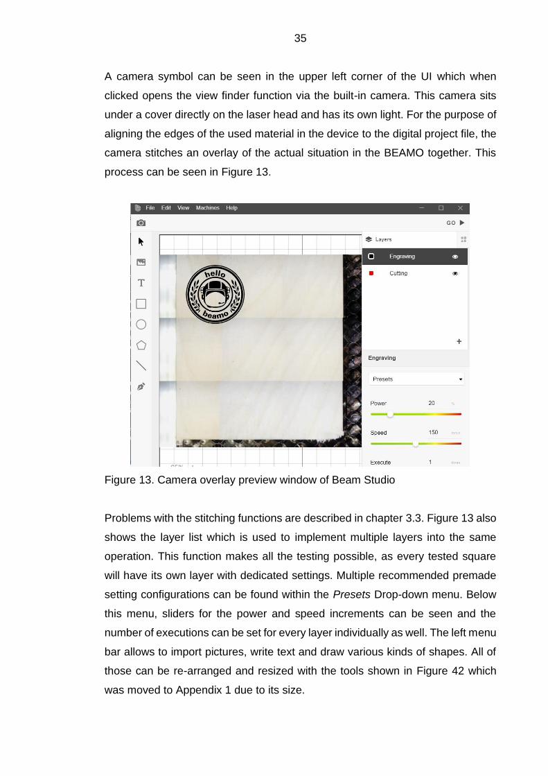
A camera symbol can be seen in the upper left corner of the UI which when
clicked opens the view finder function via the built-in camera. This camera sits
under a cover directly on the laser head and has its own light. For the purpose of
aligning the edges of the used material in the device to the digital project file, the
camera stitches an overlay of the actual situation in the BEAMO together. This
process can be seen in Figure 13.
Figure 13. Camera overlay preview window of Beam Studio
Problems with the stitching functions are described in chapter 3.3. Figure 13 also
shows the layer list which is used to implement multiple layers into the same
operation. This function makes all the testing possible, as every tested square
will have its own layer with dedicated settings. Multiple recommended premade
setting configurations can be found within the Presets Drop-down menu. Below
this menu, sliders for the power and speed increments can be seen and the
number of executions can be set for every layer individually as well. The left menu
bar allows to import pictures, write text and draw various kinds of shapes. All of
those can be re-arranged and resized with the tools shown in Figure 42 which
was moved to Appendix 1 due to its size.

36
3.2.2 Other Software
The Beam Studio software is able to handle a number of different file formats that
can be imported through File -> Open. Supported filetypes are listed in
Table 1. Every program which can export vector files with one of the supported
filetypes can be used within Beam Studio. For engraving, pictures with mostly
used filetypes can also be imported and prepared with the onboard tool set.
Table 1. Supported file types of Beam Studio
Filetype Description
.svg Vectorfile
.bvg Savefile, Flux
.jpg Bitmap, picture
.png Bitmap, picture
.dxf Vector, AutoCAD
.js Text, Java Script
.beam G-code, Flux
.ai Logos, Adobe
.pdf Documents
The real potential of the laser device in this specific laboratory environment lies
in the production of parts created from computer aided design (CAD) drawings
when it comes to cutting operations. There are multiple CAD programs which can
export vector files in the .dxf format but only two examples are desceibed here
as they were already used for other projects with the BEAMO. The first program
is AutoDesk Inventor which is often used during the engineering education at
Lapland UAS. Vectors can be exported from 2D drawings when the drawing
borders are removed so that only the parts for the export are left. Vectors are
exported as follows: File -> Safe As -> Safe Copy As -> .dxf. The created files
can be imported into Beam Studio and further processed for operation. The
dimensions of the parts are the same in Beam Studio although the user is asked
to enter the unit of the file while importing. This demanded unit seems to be a
multiplication factor and can be set to 1 if no changes in size are needed in this
first step. The transfer from a simple sketch in Inventor into Beam Studio can take
up to four steps, which needs some time to get used to.

37
Another versatile way to export vector files of drawings is by using AutoCAD from
AutoDesk. The basic scale settings of AutoCAD can lead to the creation of
vectors which do not fit within the work area boundaries. They are usually way
too big and therefore not even visible in the UI of Beam Studio. Drawing templates
are recommended to make the size of the vectors fit into the work area.
3.2.3 Testing strategy
This chapter describes how the testing of the chosen materials was planned and
then executed. The two processes of cutting and engraving was investigated
separately. Not every material was tested with both applications. For example
with the polylactic acid (PLA) sheet only the engravement test was carried out.
This is because it is not very useful to cut a premade sheet of AM filament with a
laser as the shape could also have been created with the AM process. Further,
the materials paper and fabric also only were tested with the engraving pattern.
First the stragety for the cutting tests will be described here. In order to make this
procedures more organized, a standardised test grid from the manufacturer was
used. The basic idea is to test different laser head speeds over the gradients of
light power output. Another variable of testing the capabilities of the device is the
amount of passes over the same spot. Multiple passes usually result in deeper
cuts but the limits of that will be described during the commenting of the individual
samples. The resulting matrix of the cutting test can be seen in Figure 14.
Figure 14. Test matrix for cutting

38
This matrix was aligned with the different materials and the focus point was set
to the top surface with the help of the focus bar. The focus was lowered beneath
the top surface with materials thicker than 5 mm. The focus test in Chapter 3.2.16
will give the explanation to this modification. The power during this test hits the
upper limit of 60 %. The manufacturer recommends to stay below 70 % to prolong
the lifespan of the laser tube. Later tests show the effects of 60 % power output
and for most of the applications no higher power is needed and the laser tube
should be preserved. The results of the cutting tests will be transferred into digital
tables for commenting and a three color scheme will be applied to distinguish the
different results in the separate areas. This method was chosen to keep the focus
of the reader on the results and to maintain a standardised environment. Further
the reader shall not be distracted by the real pictures and fot the sake of
investigating the results, digital tables are well suited. The color scheme uses
green, yellow and red to differentiate between clean holes, almost holes and no
holes. Figure 15 shows how the color scheme was applied to the real test
samples.
Figure 15. Test example for explaining color scheme
Figure 15 shows how the color scheme for the digitalisation of the real test
samples was applied. It should be clear to see which settings resulted in holes
ad which ones have not. The yellow color is used, when the outlines of the laser
beam are visible on the bottom side of the sample but the cube is not entirely free
yet. As some test samples consist of natural materials with changing densities,
this color marks an edge case. Here it could simply be enough to swap out the
sample and get a successful result. That is why those seemingly unsuccessful
results were mentioned here as well. All test samples for cutting got a unique
number engraved onto the top right corner of the part. Those numbers are found
on the digital test sheets. As the real samples could potentially provide additional
information to the user, they are stored near the device in the laboratory.
39
Next, the testing method for engraving the chosen materials is explained. The
engraving patterns used are made by Flux and can be accessed the same way
as the cutting pattern via the UI of Beam Studio. Engraving on even surfaces
uses repeated head movement with constant laser feed over the area chosen.
The engraving process works like a conventional plotter, where the picture or the
pattern is sliced into fine lines on the x-axis. The laser head then moves from left
to right in a set speed and steps down on the y-axis to form the two dimensional
workpiece. The distance between the lines and the distance between the dots on
the x-axis depends on the speed, power output and the set resolution of the
BEAMO. Those values can be changed in the UI of Beam Studio. All the following
tests have been carried out using the Medium resolution of 250 dots per inch
(DPI). A later done DPI test shows the differences and effects of changing DPI
values in chapter 3.2.15. The results of the engraving tests are not converted into
digital tables as has been done with the cutting tests. This is because there are
too many different results and the rating of the squares is very subjective. For this
reason, real images are used to comment the results and point out the problems
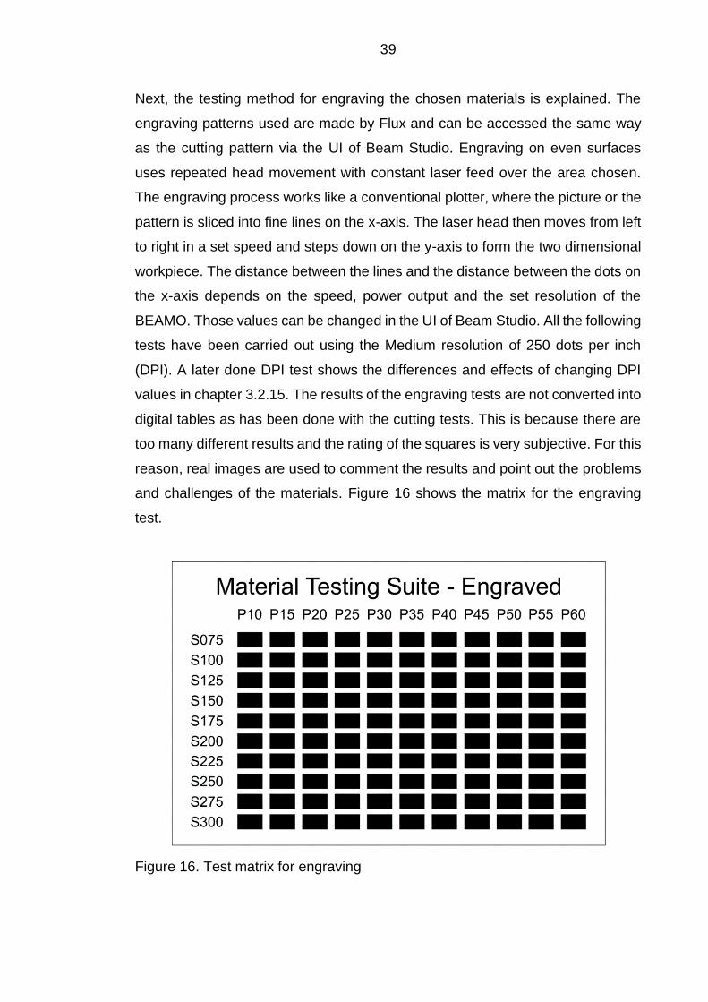
and challenges of the materials. Figure 16 shows the matrix for the engraving
test.
Figure 16. Test matrix for engraving

40
As the maximum speed of the laser head is limited to 300 mm/s and the maximum
recommended power output is just under 70 %, this test grid covers almost the
entire range of settings. Because the opinions on the results of the engraving
tests are highly subjective, all samples are stored near the BEAMO in the
laboratory like the cutting samples.
3.2.4 Safety issues
Most of the materials that are tested are known and their behaviour during the
laser treatment is predictable. The same applies to the fumes and particles that
are emitted caused by the laser impact. A possible source of danger comes from
unknown or undefinable materials. Those materials are transparent and opaque
plastics for example. While polymethylmethacrylate (PMMA) or acrylic glass is
safe to use with the laser device, materials such as polycarbonate (PC) and
polyvinylchloride (PVC) emit harmful gases such as dioxin or hydrochloric acid
(HCl). Those gases will harm the lungs and can corrode machine parts.
(Flux Europe 2021c, 47) That is why special attention has to be paid to those
unknown materials. Especially with thicker wooden materials there exists a
potential fire hazard. The embers produced could be further excited by the
pressured air which is fed through the laser head. It is therefore really important
to stay in close circumference of the machine during cutting operations.
3.2.5 Materials for testing
This chapter containes all the materials tested with and without the standardized
test grids. Not all of the materials which should be workable with the BEAMO
were tested during this phase of the work. Some additional materials such as
cement slabs, stone and EVA foam will not be covered. The used materials are
listed in Table 2.

41
Table 2. List of tested materials
Material Thickness [mm]
Plywood 4, 6.5
Acrylic glas 3, 8
Leather ~2
Rubber 1.5
Corrugated cardboard 2, 4
Wood, natural 18
Paper, fabric -
PLA -
Glass -
Anodized aluminium -
Table 2 lists all the different materials that were tested. The thickness of the
materials is provided when cutting operations have been done. The thickness of
the paper and fabric tested is negligible and has therefore not been mentioned.
A slab of natural wood got tested as well, to confirm potential limitations during
cutting operations with plywood caused by the glue and changing densities.
3.2.6 Test 1: Plywood
The first material tested were sheets of birch plywood in two different thicknesses.
The material was tested with the cutting and the engraving test grids and the
results can be seen in the digitalized tables down below. As the plywood was
precut out of large sheets and due to the natural deformation of those thin sheets,
most of the resulting test sheets were warped slightly. This could be prevented
by storing the sheets in a big pile with flat surfaces pressing them together and
straighten them over time. During both tests, no problems were caused by this
warping effects but some larger faces of parts during the project production
experienced tight fits due to this issue. Table 3 marks the first test on the machine
after the setup and its result are described below.

42
Table 3. Material test sheet; plywood, 4 mm, 1 pass, cut
Material Testing: Cut Material: Plywood Thickness: 4 mm
Passes: 1 DPI: 250
1.1 P10 P15 P20 P25 P30 P35 P40 P45 P50 P55 P60
S003
S004
S005
S006
S007
S008
S009
S010
S012
S014
As the caption of Table 3 tells, the thinner plywood sheet was tested first. With
4 mm the sheet expierienced the most amount of warping but the effects on the
test sheets are minor. As the digital version of the test implies only four settings
led to successful holes being cut through the entire sheet. Slight burn marks can
be seen on all of the top edges of the successful holes, due to the slow speed
and high laser power output. As the table tells, this first test configuration was
applied only once. The next test was repeated two times with the same material
sheet and the results can be seen in Table 4.
Table 4. Material test sheet; plywood, 4 mm, 2 passes, cut
Material Testing: Cut
Material: Plywood Thickness: 4 mm
Passes: 2 DPI: 250
1.2 P10 P15 P20 P25 P30 P35 P40 P45 P50 P55 P60
S003
S004
S005
S006
S007
S008
S009
S010
S012
S014

43
Table 4 shows the digitized results of the second test. Compared to the first
operation, many more holes could be created by treating the sheet for a second
pass. This implies that many of those now successful cuts were rather close on
the first pass already. A slight anomalie can be made out near the bottom right
corner of the test sheet. One could question why the areas with 40 % power and
12 mm/s speed resulted in the creation of a hole but not with higher power at the
same speed. As wood is a natural material with varying densities, those test rigs
cannot be taken serious obviously. It is furthermore possible that the glue bonding
the layers of wood together plays an important role when it comes to cutting
through those sheets. The next test configuration treated the same material three
times and the digitized results can be seen in Table 5.
Table 5. Material test sheet; Plywood, 4 mm, 3 passes, cut
Material Testing: Cut
Material: Plywood Thickness: 4 mm
Passes: 3 DPI: 250
1.3 P10 P15 P20 P25 P30 P35 P40 P45 P50 P55 P60
S003
S004
S005
S006
S007
S008
S009
S010
S012
S014
In this next test, the seemingly logical arrangement of successful holes is visible.
This test resulted in the most number of holes, although the increase of holes
compared to the second test is not as significant as from the first to the second
operation. The later described problem of a reflective carbon layer which forms
within plywood sheet at multiple treatment passes could be the reason for this
only slight increase the number of successfully cut holes. The next tests that were
carried out treat the thicker plywood sheets. With those sheets being 6.5 mm thick
they exceed the limits that the manufactorer gives the machine over 200 %. Flux
claims the BEAMO is able to successfully cut through 3 mm of wood
(Flux Europe 2021d).
44
The next table was moved into Appendix 2 as the number of tables require
separation. Table 12 clearly shows the limits of the machine and contains the
results of the third test with the 6.5 mm thick plywood sheets. The test grid got
passed over the sheet three times, but other than some marks on a few of the
areas on the backside, no holes were successful. The two prior digitized test
sheets are not in this list because the results are not meaningful. The limits of the
machine as far as the cutting of thick plywood sheets were reached during this
test. The problems with the test sheets catching fire during the runs are described
in chapter 3.3. Due to the unsuccessful treatment of the thicker 6.5 mm plywood
sheets, this material is not suited for projects, as the holes that were successful
had extensive burn marks on the cut edges. Another test revealed an interesting
phenomenon of plywood. Some kind of charred carbon layer seems to build up
during multiple passes wich hinderes further treatments. This will be discussedd
in more detail in chapter 3.3.5.
The next text was carried out to see the capabilities of the BEAMO for engraving
plywood sheets. As plywood sheets aim to have a rather uniform surface, the
results presented here might not be useful for natural wooden surfaces which
contain differing densities and grain structures. Changes in color and penetration
depth might occur with natural wood. The results for engraving on plywood can
be seen in Figure 17.

45
Figure 17. Material test sheet; plywood, engrave
In this first standardized engraving test, plywood was treated with the test grid
provided by the manufacturer FLUX. The results in Figure 17 promise a wide
variety of applications as every test square shows color changes varying from
settle to rather dark charred surfaces. This is advantageous when picking the
settings for engraving projects, as the color tone can be chosen out of a wide
range of settings. As all standardized engraving tests are done with a resolution
of 250 dpi and later separate testings (see chapter 3.2.15) show the significant
changes in penetration depth when changing the resolution, the use cases for
this machines seem plentiful. Upon closer inspection, faster speeds seem to lead
to a wobbling motion on the x-axis. It is yet to be assessed if this issue is only
present with plywood or other materials are also affected which would make this
a material-independent and hence a machine problem. The interpretation of the
resulting colors is quite subjective and is therefore not commented further. The
real samples are stored near the machine in the laboratory at Lapland UAS and
can be used as reference and in teaching in the future.

46
3.2.7 Test 2: Acrylic glass
The second material that was used to test the limits and capabilities of the
BEAMO was polymethylmethacrylate (PMMA) also known as acrylic glass.
PMMA is a polymer and synthetically produced so the density and inner structure
can be assumed to be very homogenous. This would result in a good repeatability
of the cuts with given settings. The material usually comes with two protective
polymer films on each side. The upper film gets removed right before the tests,
to ensure a clean test sample piece and not to disturb the result through a
potentially resistive plastic film. As one of the layers has some kind of colouring,
the bottom one is kept in place to make the alignment through the onboard
camera easier, as the otherwise transparent material leads to visibility issues.
The manufacturer only claims that the sheets with a thickness of 3 mm could be
cut successfully but the later tests almost expands this range three times.
Additionally, two different thicknesses were tested and Table 6 shows the
digitalized results of the first PMMA test at 3 mm thickness.
Table 6. Material test sheet; acrylic glass, 3 mm, 1 pass, cut
Material Testing: Cut
Material: Acrylic glass Thickness: 3 mm
Passes: 1 DPI: 250 250
3.1 P10 P15 P20 P25 P30 P35 P40 P45 P50 P55 P60
S003
S004
S005
S006
S007
S008
S009
S010
S012
S014
The first test with the thin PMMA sheet resulted in 31 clean holes and is shown
in Table 6. This already makes the material quite workable and promises good
results. The holes follow the same step pattern as with cutting plywood, where
the increase in power and derease of laser head speed similarly result in
successful cuts. The last increasing steps of the power increments do not seem

47
to have any further influence, which leads to multiple interpretations. Either, the
reduction of the laser power does not really follow the said increments of 5 % or
the material develops a kind or resistance to the higher output powers. Changes
in density could also be possible in theory but the PMMA sheets seem to have
quite a uniform density distribution. The test grid was applied a second time and
the result can be seen in Table 7.
Table 7. Material test sheet; acrylic glass, 3 mm, 2 passes, cut
Material Testing: Cut
Material: Acrylic glass Thickness: 3 mm
Passes: 2 DPI: 250 250
3.2 P10 P15 P20 P25 P30 P35 P40 P45 P50 P55 P60
S003
S004
S005
S006
S007
S008
S009
S010
S012
S014
79 holes and one test square almost successfully cut is the result of the second
iteration with the thin PMMA sheet which is visualized in Table 7. As the first test
was already very successful, this is only a bonus but it shows the capabilities of
the machine quite well. Edge quality seems to be linked to the speed setting. At
slower speeds, the surface stays melted for longer and therefore has time to even
out, which leaves an almost polished finish. This test shows that the operation
time of projects which do not require a perfect surface quality of the cutting edges
can be done much quicker than with the recommended settings.
The next two tests deal with the thicker PMMA sheets with a thickness of 8 mm.
The two digitised tables of results have been moved to Appendix 2, as the overall
result is not the best and due to the space some selected results are only
presented here in written form. As can be seen after the first process in Table 13,
there were no continuous holes. As this material is more than twice as thick as
specified by the manufacturer, this result was not expected, but was not

48
particularly surprising either. What was noticeable, however, were the non-
vertical cut edges, visible from the side. These seem to be more pronounced at
higher cutting speeds than in the lower speed range. This will be discussed again
later. The second test resulted in at least 14 successful holes, although one spot
was almost successful and due to the crooked edges most of the cubes had to
be pushed out with force. This already indicates a limited range of application if
straight edges are required in this rigid material. The resulting pattern can be
found in its digitised form in Table 14. The material was tested a third time due to
the moderately successful number of holes, applying the same pattern three
times. The result can be seen in Table 8.
Table 8. Material test sheet; acrylic glass, 8 mm, 3 passes, cut
Material Testing: Cut
Material: Acrylic glass Thickness: 8 mm
Passes: 3 DPI: 250
4.3 P10 P15 P20 P25 P30 P35 P40 P45 P50 P55 P60
S003
S004
S005
S006
S007
S008
S009
S010
S012
S014
Compared to previous tests, the number of successful holes has not increased
significantly by 11. 25 successful holes have the same tilted vertical edge as in
the two tests before. It can be assumed that either the light output of the laser is
simply not sufficient, or that some kind of hardening of the material is taking place,
which makes further processing more difficult. Since it is still possible to cut
through the material and the crooked edges do not allow any interlocking
applications anyways, it is left with the three tests.
The next test was conducted to show the BEAMOs capability of engraving PMMA
material. The upper layer of protective film was removed to ensure propper

49
results and to eliminate disturbances by the films own properties. Figure 18
shows the resulting pattern on the material.
Figure 18. Material test sheet; acrylic glass, engrave
As it is visible in Figure 18 the sheet was engraved successfully and various
applications seem to be possible with this. The gradients show an interesting
pattern because the step from 15 % power to 20 % gave an interesting result.
The two columns suddenly change and the usual steady course does not occur.
This leads to the assumption that the gradation of the light output does not
correspond to the indicated 5 % steps. If this phenomenon repeats with other
materials, is yet to be found out. The texture is not commented further, as varying
expectations make an objective assessment tricky.
3.2.8 Test 3: Leather
The next material to be assessed is leather. A roughly 2 mm thick piece of leather
was prepared for the test by using some painters tape for fixing the rough and
warped material to the workarea. This material was tested with both premade test
grids and it has to be noted here that the leather used is a genuine natural
material. This means that according to the manufacturer, harmful fumes can be
emitted during the operation containing nitrogen oxides and aromatic

50
compounds. (Flux Europe 2021c, 44) The aromatic part of the fumes is
characterised by a very strong odour similar to burned hair. The results of the
cutting test can be seen in Table 9.
Table 9. Material test sheet; leather, ~2 mm, 1 pass, cut
Material Testing: Cut
Material: Leather Thickness: 2 mm
Passes: 1 DPI: 250
5.1 P10 P15 P20 P25 P30 P35 P40 P45 P50 P55 P60
S003
S004
S005
S006
S007
S008
S009
S010
S012
S014
This table shows the rather successful cutting operations after the test. The test
piece was kept inside of the ventilated chamber for two minutes to get rid of the
smell. And again this material shows a deviation from the usual pattern after the
cutting process in that there is no gradual arrangement of the holes but an abrupt
difference between 30 and 35 % power. This may be due to poor power control
or a change in density within the material. A black layer of burned material got
stuck around the right part of the test grid and around the parts of text. Due to the
airflow inside of the chamber, most of the sheet was covered in this residue which
got removed with a pressured air hose. The odour remains after the cleaning,
further washing can help to minimise this issue. Due to this material being made
out of natural fibres, some strands of fibres have not been cut through all the way
which is attributable to a change in density. The next test was done to examine
the capability of the machine for engraving this rather rough material. The result
of the engraving test grid can be seen in Figure 19.

51
Figure 19. Material test sheet; leather, engrave
Compared to other materials tested, leather showed less color change overall in
the higher affected areas near the top right corner as for example wood. Figure
19 shows, that with the test in leather, the step from 15 to 20 % in power increase
also seems to mark a barrier for the laser beam regarding the color change of the
material. The assumption, that there is a faulty power controlling present gets
increasingly settle with this additional material behaving in a similar way. Further,
a wave pattern can be located near the bottom left corner of the test grid, which
also indicates problems with beam regulation or a problem with the axis
movements leading to changes in operation speeds and therefore changes in the
exposure time. Those wave patterns are also visible within the test squares of the
engraved plywood shown in Figure 17.
3.2.9 Test 4: Rubber
Rubber was one of the materials that only got tested with the standardized
engraving test grid. Initial testing without the cutting grid revealed the build-up of
some sort of protective oxide layer during the cutting process and the clearly
noticeable scent. As the manufacturer also does not provide premade settings
for the cutting of rubber, this test was set aside. The results of the engraving test
on rubber can be seen in Figure 20.

52
Figure 20. Material test sheet; rubber, engrave
Figure 20 shows that even the weakest settings leave markings on the surface,
which indicates a good workability. As there are verious kinds of rubbers, the
safety factor when it comes to hazardous fumes shall not be neglected. A slight
odor could be sensed after the operation but the built-in housing fan removed
most of the exhaust gases. Due to the resolution set to 250 dpi in all of the
engraving tests and the fire retardant properties of the type of rubber used, single
lines which were not exposed to the laser beam remained standing and left a
rough surface on some of the embossed faces. Figure 21 shows a detailed
section of the bottom right corner on the test sheet where the uneven surface and
some distortions along the x-axis are visible.
Figure 21. Detail of engraved rubber test sheet

53
The uneven surfaces at the bottom of the embossed faces and the curvy
appearance of the edges on the x-axis are cearly visible in Figure 21. As those
lines appear to be formed in other materials during engraving as well, the topic
will be discussed in chapter 3.3.3 in more detail. What is noticeable is, that the
rubber does not change color through the treatment. This means fast processing
times for basically the same results on the one hand but no clear visible markings
compared to plywood when the surfaces are kept clean. Staining the engraved
surfaces might work well due to the remaining fine lines holding colorings.
3.2.10 Test 5: Corrugated cardboard
Corrugated cardboard sheets were tested next with both test grids. Two different
sheets were chosen but they only differ in overall thickness to one another
measuring in at four mm and two mm. They both consist of three layers, one top
and bottom, and one corrugated layer in between This is type of cardboard is
called single wall board. The sheet between the surfaces which also have the
names liners or linerboard, is called flute. There are different types of cardboard
with differing numbers of walls/liners and flutes with varying shapes as well.
(Hanchett Paper Company 2021) Giving this basic layouts of the two used sheets,
it can be estimated that the results from the cutting test will be quite similar as
basically the same amount of material has to be passed, only with different gap
sizes. The first test results can be seen within Table 10.

54
Table 10. Material test sheet; cardboard, 4 mm, 1 pass, cut
Material Testing: Cut
Material: Cardboard Thickness: 4 mm
Passes: 1 DPI: 250
6.1 P10 P15 P20 P25 P30 P35 P40 P45 P50 P55 P60
S003
S004
S005
S006
S007
S008
S009
S010
S012
S014
The first result of the cardboard cutting operation again shows the rapid change
between the 15 % and 20 % column. As those two test sheets basically only
consist of three layers of glued paper and therefore do not pose a very great
obstacle to the laser beam, the assumption of some sort of power regulation
problem solidifies gradually. All the holes are clean when inspected from the top
but the ones in the upper right corner got the bottom edge completely burned
away due to the high power settings and the slow cutting speed. The airstream
which should help the laser beam with cutting could have excited the removal of
the paper layer as well. The second result table has been moved to Appendix 2
as it shows quite similar results apart from two spots, where no holes were
successful. The results can be found in Table 15.
Next the thin sheet was used to apply the engraving test grid. As the material is
so thin and fragile, the results were awaited with great interest. The resulting
patterns are provided in Figure 22.

55
Figure 22. Material test sheet; cardboard, engrave
The results of the cardboard engraving test provide some interesting insights into
what the BEAMO is capable of. Figure 22 shows the very differing results caused
by the test grid settings. As with some materials prior, the two most left columns
have different results than the rest of the squares and distinguish themselfs
greatly from the third column. All squares in those two columns are the only ones
that did not penetrate through the first layer of paper at all. Only the different
gradings in color are what separate them from each other. From the third column
on, every square penetrates through the first layer of paper at least with the top
right ones cutting all the way through the third layer as well. Here again the wavy
course in the squares with faster speeds can be seen. Another finding of this test
is, that it takes only very little power to successfully engrave paper, which can
also be achieved with the highest speed settings. This could be used when
creating custom paper or cardboard shapes with the addditional engraving of text
or symbols on top. Apart from the burned bottom edges, this test is considered a
success and provides important details regarding the capabilities of the BEAMO.

56
3.2.11 Test 6: Wood, natural
This next test will be carried out to show how natural wood reacts to the laser
treatment and how the results can differ compared to those from plywood and
why. For this purpose, a 18 mm thick piece of natural fur wood slab was cut to
size with a jigsaw. As this test is meant to compare the cutting behaviour of the
two materials only the cutting test grid were applied to it. The grid was repeated
three times right away as the thickness is way beyond the recommended
dimensions and capability of the machine according to the manufacturer. For this,
the slab got layed onto the metal mesh and the focus mechanism had to be
pushed as high as it got. After the second pass, the focus point got lowered due
to the thickness of the part. The focus point could only be lowered by approx.
4 mm due to the height limitations on the laser head. Figure 35 shows how this
step hit one dimensional barrier of the laser device. Table 11 shows the results
of the cutting test.
Table 11. Material test sheet; natural wood, 18 mm, 3 passes, cut
Material Testing: Cut
Material: Wood, natural Thickness: 18 mm
Passes: 3 DPI: 250
8.1 P10 P15 P20 P25 P30 P35 P40 P45 P50 P55 P60
S003
S004
S005
S006
S007
S008
S009
S010
S012
S014
Although no holes were successful, multiple things can be assumed based on the
results visualised in Table 11. Firstly, the exact same test resulted in an almost
identical pattern on the back side with the 6.5 mm thick plywood sheet. Both tests
with three repetitions each revealed no successful holes but the natural wood
slab has almost three times the thickness. Differences in density between birch

57
wood (510-770 kg/m³) and fir wood (530 kg/m³) can be neglected
(Engineering ToolBox 2004). It can therefore be assumed, that either the layer
configuration of the plywood and/or the additional laser resistance from the glue
itself between the plywood layers increase the overall laser resistance in such a
way that the natural wood is much easier to work with. This additional resistance
could arise because the reflectivity or the density of the glue is higher and/or the
insulating carbon layer is more prominent which would also lead to a decreased
workability.
3.2.12 Test 7: Fabric
This test was created to show the low end capabilities of the BEAMO. The low
end describes the minimal power settings of the machine, which turned out to be
not very sensitive based on prior tests. The significant jump between the 15 %
and the 20 % power rating is of particular interest here. The material that was
chosen to examine those goals is a thin industrial fabric. It can be found in the
form of cleaning cloths in various laboratories throughout the campus. Here, only
the engraving test grid was applied due to the weak material which is assumed
not to withstand any of the cutting settings and therefore give no useful
information about this very property. The result of the engraving test was moved
to Appendix 1 as it does not contribute as much useful information as other test
results in this testing phase. Figure 43 shows the results and the clear border
between the two critical power settings can be seen again. All of the test squares
with 25 % power or higher got removed completely and the bottom section
starting at a speed of 150 mm/s shows uneven edges in the horizontal direction
due to the x-axis wobble again. The overall results of the remaining 20 test
squares in the 10 % and 15 % power columns show a good range of color. This
material is therefore usable for engraving text and symbols with very light settings
and with the highest speeds the BEAMO can achieve.

58
3.2.13 Test 8: PLA
Another material that was tested is PLA which is widely used in AM processes. It
seems not very useful to cut parts from the AM process as the designs are often
not limited to two dimensions and can be designed and produced in the desired
way through the AM process in the first place. It can be useful, however, to
engrave details onto flat surfaces, as the implementation of text or symbols into
printed parts can be difficult to achieve, especially with small sizes. For this
reason a flat sheet of PLA was printed and then tested with the engraving test
grid. The result of this test can be seen in Figure 23.
Figure 23. Material test sheet; PLA, engrave
The engraving test on PLA was successful and is provided in Figure 23. Every
square got affected by the treatment and the individual results reach from some
slight visual appearances near the bottom left corner to major indentations around
the top right corner. The quality of the results are not commented for the reason
of the quality being too subjective to be rated here. It is however important to
mention that the white material has not changed color caused by the laser
treatment and is therefore comparable to the engraving results of PMMA which
are provided in Figure 18. The wobble on the x-axis is visible in the lower section

59
of squares again. Further, the jump in texture from the 15 % to the 20 % power
increment column is noticable with this material as well.
3.2.14 Additional Materials
More materials got tested, all of which got engraved. Those materials get
mentoined separately because the standardized cutting and engraving grid has
not been applied due to either the lack of space on the piece or the inconvenient
way the operation was carried out. The first material than got engraved with a
custom pattern was a glass mirror. Text was engraved onto the surface with the
settings premade by the manufactorer. The result of the operation can be seen
in Figure 24.
Figure 24. Material test; glass, engrave
Figure 24 shows the engraved text on the mirror. Due to the mirroring effect, the
text appears twice and is rather hard to read. This would not happen with a
ordinary piece of glass of course, but the size and the font of the text add up to
the inconvinient reading experience. As the tested mirror was small enough to fit
into the operation chamber of BEAMO, the testing procedure was straight
forward. However, due to the limited space in the chamber it is not possible to
engrave larger pieces and the number of useable products seems rather limited.
Some of the letters were not immediately visible, but could be made to appear by
pressing firmly on them. This probably has to do with the fact that the glass
shatters into very small pieces in the treated area, which does not seem to work

60
reliably due to changing densities and strengths. This problem could be improved
by adjusting the operating settings.
The next material that was tested without the test grids and with no particular
testing strategy was anodized aluminum. The housing of an ANKER PowerCore
battery pack was chosen, as it acts as a sacrificial test piece for the next planned
aluminum test, where the backside of a laptop case will be engraved. The
operation was conducted with the suggested power rating but with double the
speed as the resolution was cranked all the way up to 1000 dpi. The differences
that occur when changing the resolution are examined and discussed in chapter
3.2.15. One of the two results can be seen in Figure 25.
Figure 25. Material test; anodized aluminum, engrave
Figure 25 shows the resulting picture which was engraved onto the aluminium
surface of a ANKER powerbank. Since there are no particularly small details, the
resolution was set to 250 dpi. The lines are the result of the paint being removed
by the laser which reveales the bare metal underneath. Due to the lasers inability
to penetrate aluminuim and the high reflection of the beam, the insides of the
case were safe and the surface stayed cool to the touch. The second .png-picture
that was engraved on the backside of the same powerbank is provided in
Appendix 1 due to its size. Figure 44 shows a complex wiring diagram of an

61
unknown circuit and convinces with a very high level of detail. For this operation,
the resolution was switched to 1000 dpi and the speed of the provided settings
was increased to reduce overtreatment due to the very small step width with this
high resolution setting. Due to the large area covered, the operation took about
50 minutes to finish and the powerbank stayed cool to the touch the entire time.
Figure 45 is also provided in Appendix 1 and shows a detailed view of the
engraved circuit. It can be seen that some lines appear stronger than others. This
could be the result of the grading and sharpening process during the preparation
of the source picture in Beam Studio. The smallest sized text samples are not
readable anymore, which shows the limit of the BEAMO, at least on this not
100 % smooth surface.
3.2.15 DPI test
This next test does not focus on the capabilities of the BEAMO regarding to one
specific material but rather examines the effects of one of the more basic settings
which affect engraving operations. As the title of this chapter indicates, the next
tests deal with the influence of the resolution setting. There are four different dpi
settings available with the BEAMO which can be set via Beam Studio. The setting
can be found under Edit -> Document Settings in the main window, which leads
to a small settings window. In addition to the resolution, the work area of all the
available machines can be set here. Under those two options, several add-ons to
the machine such as the rotary tool, autofocus mechanism and the additional
diode laser can be activated. As the used machine has none of those features at
the time of testing they will not be discussed further. The four dpi settings range
from Low (100 dpi) and Medium (250 dpi) to High (500 dpi) and Ultra High (1000
dpi). The testing was carried out using the slightly smaller classic engraving test
grid provided by the manufactorer and was applied to PMMA sheets. This
material was chosen, because the effects and depth of penetration can be
observed from the side due to the transparent matter. The scope of the next tests
is to examine the resulting engravment patterns caused by the decreasing step
distances on the y-axis in order to reach higher resolutions. The same pattern will
be applied to four different PMMA sheets to make the results comparable. Figure
26 shows the classic engraving test sheet from above at 100 dpi.

62
Figure 26. DPI testing; example view on test grids
The basic arrangement and settings for each test square is visible here and the
the following detailed visualisations will focus on the bottom left corner of all four
sheets. Figure 27 shows the first DPI test with the minimum resolution of 100 DPI.
Figure 27. DPI test, 100 DPI
The result of the first test took 3 minutes and 4 seconds to complete and is
visualized in Figure 27. The operation time is important in this test as it gradually
increases with higher resolution settings. It can be seen here, that the laser beam
hardly penetrates the surface, as the sheet is 3 mm thick for comparison. Further,
the rather rough y-axis steps are clearly visible. This also affects the look of text
as is shown in a collage of all four test sheets which concentrates on the heading
text in Figure 47 provided in Appendix 1. Here, the line width of the different
resolutions is really visible. In addition, the BEAMO seems to have a problem with
straight lines at the middle two resolutions. This issue is most visible in the bottom
right letter ”E”. Interestingly, at the highest setting with 1000 DPI, this issue seems
to be no longer the case and straight lines are engraved correctly. The next test

63
was carried out using a resolution of 250 DPI. The resulting cross section can be
seen in Figure 28.
Figure 28. DPI test, 250 DPI
The detailed result of the classic engravement test grid with a resolution of 250
DPI can be seen in Figure 28. No single lines can be made out in comparison to
the last test anymore. While only two squares are visible from the side with the
lowest resolution, here four squares got engraved deep enough to see them. Due
to the laser beams being closer together but with the same speed and power
settings, the resulting faces are embossed down into the PMMA deeper. Although
the resolution is more than double the value, the operation time only increased
by about one minute and 35 seconds to 4 minutes and 41 seconds. Depending
on the desired result, this setting can therefore be convincing compared to the
previous one, as the processing time does not increase proportionally. How much
deeper the embossment of the face becomes, cannot be commented on yet. This
connection can be better interpreted with the help of the next result, shown in
Figure 29.
Figure 29. DPI test, 500 DPI
The test grid was applied on a third sheet of 3 mm thick PMMA and the results
can be seen in Figure 29. This operation, with double the resolution took about
1.8 times longer than the previous one. After eight minutes and 15 seconds, the
faces were embossed about twice as deep into the material when compared with
the previous side view. The bottom of the created impressions starts to become

64
a little rougher here, which is noticable in the right most ditch. Based on the image
material above, it can be said that it was possible to penetrate approximately 1.5
mm deep into the material. The edges of the indentations are still comparatively
vertical, which seems to change drastically in the last test with the highest
resolution. The results of this last application are visible in Figure 30.
Figure 30. DPI test, 1000 DPI
The final interpretations based on the effects of resolution are developed in this
test and are visualized in Figure 30. This test took more than twice as long as the
last one at double resolution. While the most left impression looks almost similar
as the most right in the previous test, the other edges expierienced quite a bit of
distortion. As every spot of all of the test faces got treated only once, the
interpretation of those crooked edges seems a little difficult and exceptional. A
possible explaination could be some sort of optical effect which bends the laser
beam alongside the y-axis. As this effect is only visible in the bottom half of the
edges, the previous resolutions can not be taken to confirm this assumption. The
problem of warped edges was already described during the interpretation of the
results of the thicker PMMA sheet during cutting.
3.2.16 Focus test
As discussed in section 2.2.5, laser devices work with optics to focus the light
beam into powerful tools. Due to the nature of those optics, only focus points can
be created which limits a fixed lens installation like the BEAMO has, in its
standard configuration in theory. Figure 5 was used to describe the shape of the
generated laser beams and how the angle of attack could affect the cutting
capabilities. To link this theoretical aknowledgements to real world findings, this
next test is designed to make the beam visible as it gradually gets unfocussed
and therefore should lose cutting power and lead to non vertical cutting edges. A

65
simpe test rig was built for this purpose. To max out the range of treatment, the
metal grid mesh got removed out of the operation chamber. The material of
choice is plywood as it easily changes color and is handy to work with. The result
on the test rig is shown in Figure 31.
Figure 31. Focus test
For the test, a simple text was projected in a 45° angle to the edges and four
different lines for cutting were placed on the test sheet. This test specimen can
be observed in the laboratory near the BEAMO. Due to the limits of the machine
being approached, the focus point laid slightly below the top edge of the test
piece. As expected the beams patterns gradually widened towards the bottom
edge and the power being used range from 70 % and 60 % to 30 % while keeping
a constant speed of 3 mm/s. A fourth vertical line was cut using 70 % of power
and a speed of 10 mm/s to examine the effect of quicker cuts. The resulting cone
is slightly less wide compared to the most left one, which is caused by the shorter
exposure time. Although the focus point was more than 4 cm above the bottom
of the chamber, the cardboard piece which holds the plywood in place was
removed by the laser beam which shows the power of the machine and/or the
workability of cardboard in that sense. The results of this test show that the
focuspoint is quite stretched out in reality, giving the operator the ability to cut
materials with several milimeters in thickness with only minor changes of the
cutting edge angle. Further, the beam seems to bend outwards after the first

66
centimeter cutted. It then expands in a very narrow cone and gets about 4 mm
wide by the time it hits the bottom of the operation chamber.
3.3 Problems during testing
This chapter is dedicated to minor and major flaws and difficulties which occured
during the testing phase. Some of them could easily be fixed through software
patches, others may require further investigation and proper training before using
the machine. Of course, some of the problems were created while using the
machine outside of the recommended boundries which was one of the goals for
this initial testing phase. The first issue came up on one of the first cutting tests
for plywood. The first test pieces were aligned with the help of the onboard
camera. Some of the resulting images turned out to be very misaligned and
unusable. Figure 32 shows a case of a heavily distorted picture, the result of poor
digital stitching.
Figure 32. Distorted camera stitching
This issue was not a big problem during the test phase as the raw material was
usually big enough and the test sheets were either treated only once or have not
been moved during multiple passes. It could, however, become more severe
when there is only a limited amount of space available and precise engraving is
mandatory. This is one of the problems that could easily be fixed by software
enhancements. Figure 32 represents the worst result of the stitching process and
it is not visible everytime. User errors could be causing this artefacts too, for
example through bumping into the table during the stitching process or dirty axial
rails and therefore imprecise movements.

67
3.3.1 Failed attempts
With extensive initial testing operations, failed parts and issues due to user error
or limitations of the BEAMO or the material are always present. During the very
first tests with the thick plywood sheets, the material started to burn on the inside.
This problem is provided for visual inspection in Figure 33.
Figure 33. Glowing embers inside of test sample
The incident occured in the top right corner of the test grid which contains the
most powerful settings combined with the slowest movement steps possible.
This, together with the pressured assistant airflow resulted in embers being
pushed past the cutting edges into the untouched material. Due to the relatively
high laser settings being applied on such a small surface, the squares burned
away almost completely and did this with a clearly visible smoke development.
The test was paused multiple times because the embers grew to an
uncomfortable size and were extinguished with a moistened cloth. The damaged
test sheet can be seen in Figure 34.
Figure 34. Failed Material test

68
The failed test sheet is stored near the BEAMO in the laboratory for closer
inspection. This test proved that the machine must no be unattended for longer
periods of time whilst cutting operations. All of this happened in under two
minutes and without the immediate actions, greater damage could have been
caused to the test sample and the machine. As during the time of this particular
test the ventilator speed was just being adjusted down, the laboratory
environment was filled with fragrant scents. Multiple steps got developed to
prevent this from happening in the future. First, some of the thicker plywood
sheets were damped in water just before treatment to extinguish embers right
away. This turned out to be quite successful, the cutting edge quality was
increased at the same time. In a second step, whenever multiple passes of the
same path had to be done, the whole pattern was finished first and then repeated
so the intividual squares had no chance of developing embers that got excited
due to multiple powerful passes within a short amount of time. Lastly, as the
thicker plywood sheets turned out to be quite hard to work with and no projects
will be developed in the course of this thesis with it, not using it in the first place
prevents any cases of damages.
Another incident happened during the preparation of the projects for the students.
Two-layer cardboard was chosen because of its higher stability compared to
single-layer cardboard for cutting shapes. Since the single-layer cardboard
proved to be easy to work with and safe in the previous tests (see chapter 3.2.10),
this material was also chosen because of its very good availability. Since the
chosen material consists of five paper layers instead of three, slightly higher
operating settings were selected to ensure a successful cut. A strong smoke
development obstructed the view of the workpiece during the process, which
meant that the formation of severe glowing spots within the structure was
overlooked. Additional air came through the two fluted channels, eventually
forming an open flame. This flame was quickly extinguished with a wet cloth and
the process stopped immediately, but parts of the laser head and cover were still
affected by the fire for a few seconds. The burned piece of cardboard is provided
in Appendix 1 as Figure 50 for inspection. While the laser head and the control
panel showed no visible damage, the transparent cover of the operating room
was slightly bent by the heat. Although the operation of the laser device could be

69
continued without any problems, this incident clearly shows that even a seemingly
harmless material can lead to severe damage and danger if it is not under
supervision.
3.3.2 Physical limitations of the device
This chapter describes the limited operating space in the machine. Since the
workpieces affected by these limitations are usually not cut, they tend to limit the
engraving of thick or bulky objects. The machine is shipped with an approximately
20 mm thick cutting pad as shown in Figure 10. From the top of this base on,
there is a working volume with a maximum height of 16 mm. This height is
achieved by moving the laser head upwards as far as it will go. For larger objects,
the cutting base can be removed, which opens up to roughly 36 mm of vertical
space. Even though cutting operations are hardly practical without this work
surface and at these thicknesses, they should not be carried out because the
gases produced have to escape downwards and can thus cause discolouration
around the exit points. Such cutting operations are also not really practical
because of the non-variable focal point. The focus issue was described in chapter
3.2.16, where almost all the available space was also used for testing. The
extreme case was also investigated during the tests and the very close distance
created from laser head to workpiece can be seen in Figure 35.
Figure 35. Height limitation of the laser head

70
The work piece visble in Figure 35 is the thick piece of natural wood that was
treated in chapter 3.2.11. With such close distances, care must be taken that no
contact points are possible and that the workpiece lies flat and stable on the base.
In the case of the test with the thick piece of natural wood, the focal point lay well
below the top surface, which was a known constraint from the beginning.
3.3.3 X-axis wobble
Another issue that came up during the testing phase was the problem with
straight lines on the x-axis on several occasions and settings. This problem has
already been discussed in chapter 3.2.15 with the help of Figure 47. This
phenomenon seems to occur the strongest at high laser head speeds and with
medium resolution settings. A possible explaination could be an issue with the
gear belt that moves the laser head and is driven by the x-axis stepper motor.
Vibrations in the belt and its own flexibility could result in a hopping motion along
the x-axis. This problem is also known with AM processes. Here, artefacts near
sharp corners where the print head has to slow down or accelerate can cause
distortions and uneven surfaces. (Simplify3D 2021) An example picture is
provided in Appendix 1 as Figure 49 to make this analogy clearer. The issue is
again clearly visible in Figure 22. For further tests and projects, slower speeds
and resolution settings while engraving would prevent this problem with a
simultaneous increase of operation time. This problem seems to appear
regardless of the material used, as shown in Figure 17, Figure 18, Figure 19,
Figure 20 and Figure 22. When looking at printed parts, it can be assumed that
this wobbling or ringing effect usually only occures near sharp corners. Those
corners would convert to the y-axis limits of the test squares within the engraving
tests. It is yet to be examined if this effect is still visible when the laser head
moves over a longer distance along the x-axis. This would then lead to the
assumption, that the quick changes in movement is causing this artefacts. The
origin of this problem could lie in a mechanical problem such as a loose belt or a
software problem when it comes to deceleration.

71
3.3.4 Unknown materials and dangers
This chapter focuses on unknown materials and associated hazards. As already
announced in chapter 3.2.4, there are many different categories, ingredients and
potentially hazardous emitted substances, especially in the case of plastics. The
danger when it comes to direct use in the machine is that a harmless piece of
PMMA can hardly be distinguished visually from a dangerous piece of PC.
Therefore, it is important to use known material sources and not to laser process
certain leftovers from old projects, for example. While many materials can be
used in the workshop without any problems, they can develop carcinogenic
substances when processed with the laser. It so happened that among the
transparent plastics selected for testing was also a piece of alleged PC and the
result can be seen in Figure 36.
Figure 36. Dangers with unknown materials
The difference to the harmless PMMA becomes visible at the latest when working
with it. The material is not only very hard and cannot be cut with the usual settings,
but it also develops a yellowish-brown smoke which even settles on the
workpiece. Since these fumes are not only very harmful to health but can also
damage machine parts, no further tests were carried out with this material.
In addition to the dangers linked to unknown materials, potential damages and
contaminations of the machine are unwanted too. As seen in Figure 48, provided
in Appendix 1, the equipment can also get covered with debris and could suffer
in terms of accuracy and performance. Here the dangerous fumes that were

72
emitted from the PC sheet shown in Figure 36 led to a deposit of charred debris
around the nozzle center. This was a clear visualisation of the dangers, as
nobody should inhale those black particles. Those debris could be cleaned off
with ease but other unknown materials may cause greater permanent damage.
3.3.5 Carbon build-up with plywood cutting
To create a hole in the thicker plywood sheet with operation time ignored, multiple
passes of the same settings got applied. Those revealed an upper limit of how
often a piece of plywood is even workable. After 15 passes with settings that
should be able to cut through a 30 mm sheet with ease in theory, the attempt was
aborted. Upon closer inspection the maximum penetration depth was about 5
mm, with no visible stains on the other side. The 6.5 mm thick plywood sheet was
basically uncuttable. The settings that were applied to the board were P40/S006
with 15 passes. The lower power was chosen to get a cleaner cut edge and to
preserve the lifetime of the lasertube. A possible explaination for this failure is the
creation of a heat resistant and insulating charred carbon layer, generated by the
laser beam. This accumulation probably occurred during the first repetitions,
which made the later repetitions useless. It can be assumed that the lower power
had a sgnificant share in the creation of this phenomenon. The problem of burning
wood when using higher power settings and lower speeds has already been
described in chapter 3.3.1. On the basis of those findings, the limits of the
machine had been found in terms of the ability of cutting plywood. In addition to
that it can be stated that using more power and slower speeds with fewer
repetitions is more effective than using less power with significantly more passes
although edge quality has to be sacrificed here.
3.4 Conclusion of the testing phase
This chapter serves as a summary and general evaluation of the entire test
phase. Furthermore, some indications for a successful cutting or engraving
process are presented here. Apart from a few incidents and unexpected results,
this test phase can be considered a success. The failed workpieces and incidents
contribute as much valuable insight into the machine's capabilities as the many

73
successful tests. While there were predictably good results with some materials,
such as PMMA, the thicker versions of the test pieces gave far-reaching insights
into the function, malfunction and capabilities of the machine under investigation.
The machine environment proved to be well set up and tests could be carried out
efficiently and neatly. By building a register, the resulting pieces could also be
stored neatly. They are an important source of information for future projects that
do not have the time and material to test the limits first. As described, natural
materials such as wood and leather can vary due to changing density, so testing
with the same material before production is advisable for larger projects.
Requirements for safety and attention of the operator were made clear and
justified by the failed tests, which sometimes included the development of fire.
Especially with PMMA, a recommendation for achieving smooth surfaces can be
given after this test phase based on the normal material tests and the resolution
tests. Figure 37 shows the result of fast laser head movements.
Figure 37. Effects on edge face quality with high cutting speeds
Here you can see how the fast movements can significantly reduce the working
time but only with a reduced surface quality. With faster movements you notice
that the material has less time to melt smoothly, resulting in a rougher surface.
With round shapes, this can also lead to cut edges not being square and parts
getting caught in each other. There are several solutions that lead to beautiful
surfaces and do not require any finishing. Firstly, the surface quality of cut PMMA
is influenced by the number of repetitions. Even though lasers are very precise
tools, minimal deviations from the previous path can lead to clouding and

74
contamination of the previously smooth surface. Further, Figure 38 shows how
much more appealing surfaces become when the processing speed is reduced.
Figure 38. Effects on edge face quality with low cutting speeds
With slower speeds, of course, the working time also increases, but if the surface
quality is in the foreground, this compromise should be made. Even if the setting
with faster movements and less power and more repetitions is equal to a single
slow powerful repetition in terms of a successful cut, the slower one is advisable.
The tolerances created by the necessary removal of material are also worsened
by repeating more often at best.
3.5 Maintenance
As the manufacturer suggests, the laser device needs frequent maintenance
which includes cleaning and checking the water level in the reservoir. All the
moving parts should be wiped and lubricated at weekly or two-weeks intervals
and the water should be changed every three month. For the purpose of taking
care of the machine, a maintenance schedule was created. In the course of this
work, several lubrications and one water change were done which provided
material for the guidelines and showed how it is done and what to look out for.
The UI of the BEAMO includes a counter which shows the operating hours of the
laser tube. A replacement tube was purchased together with a replacement grid
bed during the ordering of the main device. The new and unused laser tube can
be seen in Figure 39.

75
Figure 39. Replacement gas laser tube
The laser tube has a limited lifespan of about six months to a year. The
manufactorer limits the general warranty of the device to 12 months excluding the
laser tube which gets only three months of a claim period. As the mirrors and
lenses also have a limited lifespan of about one year and are consumables,
maintenance is required here to ensure a long lasting service. (Flux Europe
2021a)

76
4 DESIGN OF MATCHING PROJECTS FOR LAPLAND UAS STUDENTS
This chapter now combines the theoretical knowledge from the elaborated basis
and the acquired knowledge from the practical tests with the machine. It is roughly
divided into the general description, the scope of the projects, safety notes and
the description of own projects. Throughout this chapter there are frequent
references to the extra Guide, which will be included in the appendix of the final
version of the thesis. It will contain detailed instructions and provide suggestions
in case of e.g. failures.
4.1 Description, Scope
The aim of this part of the thesis is to develop a system to familiarise the Lapland
UAS students with laser processing. This includes practical examples and
explanations of how to complete successful projects of one's own. In the course
of this development, an online platform for sharing the results and a guidebook
will be developed to provide detailed knowledge about working with the BEAMO
to save the students problems, material and time. The manual will contain safety
instructions as well as precise settings for processing the most common
materials. Furthermore, there will be tips and tricks in case there is a problem
with the process. The guidebook is intended as a supplement to the existing
manual provided by the manufacturer. Besides the basics, it already contains
very good instructions on maintenance and cleaning. Therefore, the self-created
guide will refer to these instructions at most, but will not give any instructions of
its own regarding maintenance and repair. The guide is provided in printed and
bound form in DIN A5 format in the laboratory. Schematics and plans for some
projects are provided in electronic form. As detailed instructions for each project
cannot be provided due to time constraints, links to two websites that allow the
creation of simple yet interesting projects are provided in the guide and in
Appendix 3.

77
4.2 Safety sheet and handling instructions
As this manual and the machine are used by students, rules for use must be
defined. This is not only to protect the projects from the next user from damage
due to heavy contamination of the last user etc. but has simple safety reasons.
As already experienced during the testing, some materials pose a very real fire
hazard. Therefore, the machine must never be left unattended during processes
that involve cutting, for example. These rules will be integrated into the guide in
simple language and without ambiguity. A Finnish translation could clarify the
importance of this matter. These rules are also important because at the time of
writing only one unit of the BEAMO is available in the laboratory.
4.3 Theoretical basics of CO2 laser technology
In order to give the students a general overview of the laser technology and also
to support them with regard to their own learning curve, the guide will additionally
include basic general knowledge about lasers and compare different lasers with
the BEAMO and other process technologies such as AM or CNC by means of a
simple pro and con list. This should ensure that the students can also work on
reasonable projects with the laser device and evaluate firstly what the limits are
and secondly when it might be better to use a different technology. All possible
upgrades of the machine would have to be elaborated in a further work, so that
the creative horizon of the students can be adequately adapted and even more
diverse projects can be created in the future. The diode laser module deserves
special mention here, as it would immediately expand the BEAMO's range of
applications and, for example, make metal a new material that can be processed.
4.4 Description of purposed student projects
The proposed projects for the students are described in this chapter. The detailed
elaboration will be found in the final Guidebook. The projects are designed in
such a way that mainly the laser device can be used for production. Some of
these projects are also possible without this technology, which gives the
opportunity to describe advantages and disadvantages of this process. The

78
projects are chosen so that they can be completed either alone in a few days or
in pairs in one day. They are also meant to serve as inspiration for own project
work, which may lead to variations of the proposed projects and completely own
projects in the future. Since the aim of these projects is to be integrated into
engineering education and to transfer knowledge, the projects try to come up with
different materials and levels of difficulty. In addition, the online platform offers
the possibility to share projects and get inspiration. Details can be found in the
guidebook. In the following, the individual projects are briefly presented to give
an overview. The projects can be roughly divided into cutting and engraving
projects, whereby the other method can also be integrated in each case.
4.4.1 Cutting projects
This type of project describes those whose main part falls on cutting operations.
Decorations and inscriptions can also be made with engravings. This type of
project requires much shorter production times on average than projects with a
lot of engraving. This is due to the fast processing speeds, which are sufficient
for a successful result with most materials. Plywood boxes with a simple plug-in
system are presented as the first project. For this, 4 mm thick plywood sheets are
used to cut out the designed shapes. The shapes for the complicated geometries
are defined with the help of an online tool, whereby a very high degree of
individual ideas can be achieved. The only limitation here is the size of the
operating space and the availability of the material. This project deals with wood
as a material and the associated details in terms of tolerances. The laser beam
always burns a little more material than specified, which requires fine adjustments
in terms of fit.
The next project is leading to self-designed and produced puzzles. The required
shapes are again made with an online tool and the materials range from paper
and cardboard to wood and acrylic. Examples can be found in the guide and the
entire process is also described there. It is possible to engrave the image of the
puzzle on the material with the laser device. Jigsaw puzzles are a relatively
simple project, but aligning and designing a meaningful jigsaw puzzle takes time
and creativity.

79
4.4.2 Engraving projects
This type of project consists mainly of engravings. Since each engraving is unique
and not only virgin material can be processed for engravings, the projects will be
differentiated by material. While shapes, writing and ornaments can be engraved
on the surface when producing wooden boxes from new material, own objects
can also be decorated. This includes objects made of wood, metal and plastics.
For this purpose, all objects and materials that appear interesting are tested,
presented and documented in the guidebook. Plastics engravings are embedded
on mobile phone covers, charging adapters and in acrylic glass, among other
things. With a little creativity, thick paper can be made into business cards, for
example, and monochrome paper engravings generally make for vivid projects.
Apart from the boxes, wooden engravings are also incorporated into barbecue
forks, for example. With anodised aluminium, battery packs and a laptop cover
form the final stage of engravings for own objects. The purpose of these
engravings is to show what is possible through the examples given and to
promote one's own creativity. Of course, the concept of the ethnic engineering
also comes into play here. Defacing and destroying other people's property or
depicting reprehensible images does not belong in this environment and should
not be made possible through this project. A link to the Code of Ethics in
Engineering can be found in Appendix 3.
4.4.3 Production and documentation
The handbook will include the fundamental operating mode of the laser machine
and some general tips and tricks in case of problems. Detailed instructions with
important checkpoints and hints for the production of the student projects will also
be provided. These will be explained step by step and each project will be
assessed on the basis of feasibility and risks and prerequisites. Whether prior
knowledge of topics such as soldering, woodwork or steady hands might be
required is also assessed. The approximate time each project will take may also
be of interest in planning the work. Therefore, in addition to the pure active
machine time, the approximate finishing and/or pre-processing time is also
estimated.

80
5 CONCLUSION AND DISCUSSION
This chapter deals with the summary of the whole thesis by explaining the links
from the practical part to the theoretical part. The work is evaluated here
according to whether the set goals were achieved and how this happened.
Finally, an outlook on possible future work is given.
5.1 Summary
In the course of this Bachelor thesis, the new laser device from Flux called
BEAMO was set up in the 3D printing laboratory at Lapland UAS in Kemi. Based
on theoretical knowledge, the capabilities and limits of the machine were tested
with the help of prefabricated test grids. Part of the method consisted of a long
and extensive testing phase to try out most of the scenarios on the most common
materials to enable reasonable and feasible projects. This testing phase got
described in chapter 3.2.3. In addition to the materials, basic physical and other
limits of the machine were also investigated. This included the influence of a
changing focus point, the effects of different resolution settings and the spatial
limits of the operating chamber.The problems with glow nests due to too much
light output and with non-straight edges were recorded and evaluated. The test
grid proved to be very practical as it covered the main part of the application range
and was applicable to most materials due to its relatively compact size. 11
different materials were tested in this way and with the suggested project ideas
and detailed descriptions, students can work with them in the future.
It can be said that all the goals were achieved and that the timetable was realistic.
Some points were more complex than expected but this was compensated by
less complex points. During this work, the machine was also used for some other
tasks and small projects, but the author reserved the right not to release the
machine to the rest of the community yet. Of course, with the completion of this
work, this is a given.

81
5.2 Practical work
The practical work can be divided into two parts. The test phase and the project
description phase. In the test phase it was found that under the recommended
conditions all materials can be successfully processed as indicated. In addition,
the maximum possible thickness of some materials such as wood and acrylic
glass was exceeded by more than double in some cases. The dangers posed by
artificial materials such as PC were clearly experienced and described as is
describd in chapter 3.3.4. Furthermore, it was found out that an acceptable focus
line with a length of about 10 mm is available, taking into account slightly slanted
cutting edges. The effects on texture and penetration depth of different resolution
settings were also investigated. It was found that acceptable textures can be
achieved at 250 dpi with a relatively low process time as is described in chapter
3.2.15. Depending on personal taste in engraved textures, a comprehensive
collection of engraving samples is now available in digital form in this thesis and
in real in the laboratory. All patterns are also available in the lab and can be
assigned thanks to the individual numbering.
The second part of the practical work consisted of working out useful and
interesting projects for the Finnish students. It is described as Development
phase in chapter 1.5 and the rough process can be seen in Figure 40 in Appendix
1. It included production and documentation of the individual parts as well as the
eventual finalisation of the workpieces. In addition, a guidebook with all the
descriptions, instructions and safety informations was produced in the course of
this section. The most important points before working with the device and the
start-up process are described here. QR codes make it easy to download
software and lead to the mould generators, among other things. A set of rules
has been developed to ensure safe and efficient operation for all involved.
Additionally, detailed suggestions for settings to process certain materials are
given. The project descriptions conclude the guidebook and it is now available in
printed form in the laboratory.

82
5.3 Outlook
Only time will tell whether the online tool for sharing one's own projects will prove
its worth. Meanwhile, future work can take care of expanding the knowledge base
around laser technologies in the laboratory setting. Expanding the machine with
the add-ons or expanding the test results can help to give students even more
opportunities to make their education at Lapland UAS more diverse. For example,
all engraving tests could be carried out again with the three remaining resolution
settings in order to actually exhaust all available settings with regard to engraving
with this device. In addition, the machine could be supplemented with the three
extensions currently available to increase the range of applications. The diode
laser module could allow metal as an additional material and further work can be
done to evaluate the usefulness of this acquisition first. Furthermore, the rotary
add-on could also enable round materials to be processed and the autofocus
module could make the BEAMO fit for uneven surfaces and automatic focus
direction for changing materials.

83
BIBLIOGRAPHY
Beyerer, J., León, F.P. & Frese, C. 2016. Licht. Automatische Sichtprüfung, 23–120.
Cambridge University Press 2014. Definition of Laser. Accessed 20 February 2021 https://dictionary.cambridge.org/de/worterbuch/englisch/laser.
Demtröder, W. 2010. Laser. Experimentalphysik 3, 271–296.
Engineering ToolBox 2004. Density of Various Wood Species. Density of Various Wood Species Accessed 26 April 2021 https://www.engineeringtoolbox.com/wood-density-d_40.html.
Flux Europe 2021a. beamo. FLUX | Craft Your Imagination Accessed 21 March 2021 https://flux3dp.com/beamo/.
Flux Europe 2021b. Beamo - Flux Europe. Accessed 19 March 2021 https://www.fluxlasers.com/beamo.html.
Flux Europe 2021c. beamo-user-manual-20191203.pdf. Accessed 19 March 2021 https://cdn.webshopapp.com/shops/290919/files/316242658/beamo-user-manual-20191203.pdf.
Flux Europe 2021d. FLUX Beamo. Flux Europe Accessed 30 March 2021 https://www.fluxlasers.com/products/beamo/?source=facebook.
Frank, H. 2006. Electromagnetic Spectrum. Accessed 25 February 2021 https://www.e-education.psu.edu/geog160/sites/www.e-education.psu.edu.geog160/files/file/spectrum.html.
Hanchett Paper Company 2021. The Ultimate Guide to Corrugated Boxes | Shorr Packaging Corporation. Accessed 23 April 2021 https://www.shorr.com/packaging-news/2019-07/ultimate-guide-corrugated-boxes.
Kale, L.N., Garde, J.B., Garde, S.S. & Gupta, P. 2017. Figure 1: Basic mechanism of the working of a laser (Reproduced from... ResearchGate Accessed 20 February 2021 https://www.researchgate.net/figure/Basic-mechanism-of-the-working-of-a-laser-Reproduced-from-Robert-A-Convissar_fig1_316625757.
Kwok-san, L. & Shiu-sing, T. 2000. Further physics - What is laser? Accessed 20 February 2021 http://www.hk-phy.org/articles/laser/laser_e.html.
Meschede, D. 2008. Optik, Licht und Laser. Wiesbaden: Vieweg+Teubner.
Prusa Research a.s. 2021. Ghosting. Prusa Knowledgebase Accessed 27 April 2021 https://help.prusa3d.com/en/article/ghosting_1801#_ga=2.90850393.296515191.1590136653-718336605.1583915167.

84
Sigrist, M.W. 2018. Laser: Theorie, Typen und Anwendungen. Berlin, Heidelberg: Springer Berlin Heidelberg.
Simplify3D 2021. Vibrations and Ringing. Accessed 27 April 2021 /support/print-quality-troubleshooting/vibrations-and-ringing/.
Steen, W.M. & Mazumder, J. 2010. Laser Material Processing. London: Springer London.
Universal Laser Systems, Inc. 2021. Erhältliche Linsen. Accessed 26 February 2021 https://www.ulsinc.com/de/available-lenses.
Velling, A. 2020. What Are the Advantages & Disadvantages of Laser Cutting? Fractory Accessed 30 March 2021 https://fractory.com/laser-cutting-advantages-disadvantages/.

85
LIST OF FIGURES
Figure 1. Electron transition in an atom (Kwok-san & Shiu-sing 2000) ............. 11
Figure 2. Basic working mechanism of a laser (Kale, Garde, Garde & Gupta 2017)
.......................................................................................................................... 13
Figure 3. The electromagnetic spectrum (Frank 2006) ..................................... 14
Figure 4. Various mode patterns (Steen & Mazumder 2010, 101) .................... 16
Figure 5. Stigmatic display of lenses (Meschede 2008, 27) .............................. 17
Figure 6. Basic construction of a slow flow gas laser (Steen & Mazumder 2010,
36) ..................................................................................................................... 23
Figure 7. Spectral transmissivity of the ocular fluid and the absorptivity of the
retina (Steen & Mazumder 2010, 521) .............................................................. 25
Figure 8. Flux BEAMO product image (Flux Europe 2021b) ............................. 30
Figure 9. View of the back side ......................................................................... 30
Figure 10. Top view of the device with laser tube cover removed ..................... 31
Figure 11. Connection of the air hoses to the main ventilation system ............. 32
Figure 12. Main window of Beam Studio ........................................................... 34
Figure 13. Camera overlay preview window of Beam Studio ............................ 35
Figure 14. Test matrix for cutting ...................................................................... 37
Figure 15. Test example for explaining color scheme ....................................... 38
Figure 16. Test matrix for engraving ................................................................. 39
Figure 17. Material test sheet; plywood, engrave.............................................. 45
Figure 18. Material test sheet; acrylic glass, engrave ....................................... 49
Figure 19. Material test sheet; leather, engrave ................................................ 51
Figure 20. Material test sheet; rubber, engrave ................................................ 52
Figure 21. Detail of engraved rubber test sheet ................................................ 52
Figure 22. Material test sheet; cardboard, engrave........................................... 55
Figure 23. Material test sheet; PLA, engrave .................................................... 58
Figure 24. Material test; glass, engrave ............................................................ 59
Figure 25. Material test; anodized aluminum, engrave ..................................... 60
Figure 26. DPI testing; example view on test grids ........................................... 62
Figure 27. DPI test, 100 DPI ............................................................................. 62
Figure 28. DPI test, 250 DPI ............................................................................. 63
Figure 29. DPI test, 500 DPI ............................................................................. 63
86
Figure 30. DPI test, 1000 DPI ........................................................................... 64
Figure 31. Focus test ........................................................................................ 65
Figure 32. Distorted camera stitching ............................................................... 66
Figure 33. Glowing embers inside of test sample ............................................. 67
Figure 34. Failed Material test........................................................................... 67
Figure 35. Height limitation of the laser head .................................................... 69
Figure 36. Dangers with unknown materials ..................................................... 71
Figure 37. Effects on edge face quality with high cutting speeds ...................... 73
Figure 38. Effects on edge face quality with low cutting speeds ....................... 74
Figure 39. Replacement gas laser tube ............................................................ 75
Figure 40. Methodolical flow chart of the thesis process ..................................... II
Figure 41. Space around the device and safety precautions ............................. III
Figure 42. Menu for editing selected elements ................................................. IV
Figure 43. Material test sheet; fabric, engrave ................................................... V
Figure 44. Engraved Circuit on anodized aluminum .......................................... V
Figure 45. Detailed view of the engraved circuit ............................................... VI
Figure 46. Detail of engraved PLA test sheet ................................................... VI
Figure 47. DPI test; detail of texts .................................................................... VII
Figure 48. Filthy nozzle after PC cutting .......................................................... VII
Figure 49. Analogy of ringing in AM parts (Prusa Research a.s. 2021) .......... VIII
Figure 50. Burned two-layer cardboard after failed cutting operation .............. VIII

87
LIST OF TABLES
Table 1. Supported file types of Beam Studio ................................................... 36
Table 2. List of tested materials ........................................................................ 41
Table 3. Material test sheet; plywood, 4 mm, 1 pass, cut ................................. 42
Table 4. Material test sheet; plywood, 4 mm, 2 passes, cut .............................. 42
Table 5. Material test sheet; Plywood, 4 mm, 3 passes, cut ............................. 43
Table 6. Material test sheet; acrylic glass, 3 mm, 1 pass, cut ........................... 46
Table 7. Material test sheet; acrylic glass, 3 mm, 2 passes, cut ....................... 47
Table 8. Material test sheet; acrylic glass, 8 mm, 3 passes, cut ....................... 48
Table 9. Material test sheet; leather, ~2 mm, 1 pass, cut ................................. 50
Table 10. Material test sheet; cardboard, 4 mm, 1 pass, cut ............................ 54
Table 11. Material test sheet; natural wood, 18 mm, 3 passes, cut .................. 56
Table 12. Material test sheet; plywood, 6.5 mm, 3 passes, cut ......................... IX
Table 13. Material test sheet; acrylic glass, 8 mm, 1 pass, cut ......................... IX
Table 14. Material test sheet; acrylic glass, 8 mm, 2 passes, cut ...................... X
Table 15. Material test sheet; cardboard, 2 mm, 1 pass, cut ............................. X

88
APPENDICES
Appendix 1. Pictures and Schematics
Appendix 2. Tables
Appendix 3. Useful Websites
Appendix 4. BEAMO Guidebook

I
Appendices present information that you feel is important but does not fit entirely
in the text, such as manuscripts, photos, paintings, interview questions, drawings,
programme lists, multipage tables and figures and odd-sized graphical
presentations. Appendices must always be commented on in the text. Do not use
any appendices that are not referred to in the text. The appendices themselves
must contain all the information needed to interpret them: a heading and an
explanation of the photo or table. It is not necessary to use the thesis layout in
the appendices.
If an appendix consists of more than one page, mark the page of the appendix
and the total number of pages as follows: Appendix 1 1(3); mark the next page:
Appendix 1 2(3); etc.
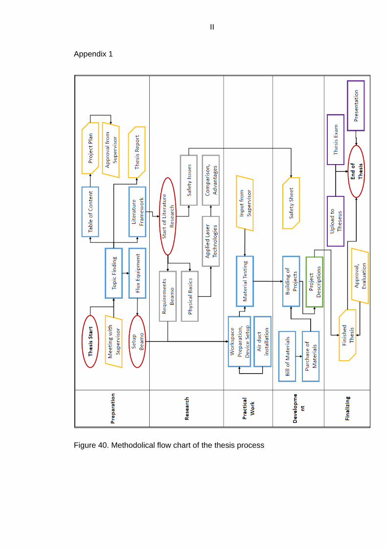
II
Appendix 1
Figure 40. Methodolical flow chart of the thesis process

III
Figure 41. Space around the device and safety precautions

IV
Figure 42. Menu for editing selected elements

V
Figure 43. Material test sheet; fabric, engrave
Figure 44. Engraved Circuit on anodized aluminum

VI
Figure 45. Detailed view of the engraved circuit
Figure 46. Detail of engraved PLA test sheet

VII
Figure 47. DPI test; detail of texts
Figure 48. Filthy nozzle after PC cutting

VIII
Figure 49. Analogy of ringing in AM parts (Prusa Research a.s. 2021)
Figure 50. Burned two-layer cardboard after failed cutting operation

IX
Appendix 2
Table 12. Material test sheet; plywood, 6.5 mm, 3 passes, cut
Material Testing: Cut
Material: Plywood Thickness: 6.5 mm
Passes: 3 DPI: 250
2.3 P10 P15 P20 P25 P30 P35 P40 P45 P50 P55 P60
S003
S004
S005
S006
S007
S008
S009
S010
S012
S014
Table 13. Material test sheet; acrylic glass, 8 mm, 1 pass, cut
Material Testing: Cut
Material: Acrylic glass Thickness: 8 mm
Passes: 1 DPI: 250 250
4.1 P10 P15 P20 P25 P30 P35 P40 P45 P50 P55 P60
S003
S004
S005
S006
S007
S008
S009
S010
S012
S014

X
Table 14. Material test sheet; acrylic glass, 8 mm, 2 passes, cut
Material Testing: Cut
Material: Acrylic glass Thickness: 8 mm
Passes: 2 DPI: 250
4.2 P10 P15 P20 P25 P30 P35 P40 P45 P50 P55 P60
S003
S004
S005
S006
S007
S008
S009
S010
S012
S014
Table 15. Material test sheet; cardboard, 2 mm, 1 pass, cut
Material Testing: Cut
Material: Cardboard Thickness: 2 mm
Passes: 1 DPI: 250
7.1 P10 P15 P20 P25 P30 P35 P40 P45 P50 P55 P60
S003
S004
S005
S006
S007
S008
S009
S010
S012
S014

XI
Appendix 3
− Beam Studio and firmware download:
https://www.fluxlasers.com/downloads/
− Add-Ons:
https://www.fluxlasers.com/beamo-rotary-extend.html
https://www.fluxlasers.com/hybrid-diode-laser.html
https://www.fluxlasers.com/autofocus-module-beamo.html
− DWG to SVG file conversion:
https://cloudconvert.com/dwg-to-svg
https://anyconv.com/de/dwg-in-svg-konverter/
https://www.microsoft.com/en-us/p/dwg-to-svg-
converter/9pffgw6mtpcb?activetab=pivot:overviewtab
− Plywood box generation:
https://festi.info/boxes.py/?language=en
− Puzzle shape generation:
https://cdn.rawgit.com/Draradech/35d36347312ca6d0887aa7d55f366e30
/raw/b04cf9cd63a59571910cb226226ce2b3ed46af46/jigsaw.html
− Code of Ethics:
https://www.ieee.org/about/corporate/governance/p7-8.html

XII
Appendix 4
This section will be added later and will contain the whole guidebook.
euda

Flux BEAMO laser cutting and engraving device
GUIDELINES
Author: Markus Mayer

Contents
STARTUP OF THE DEVICE / USER INTERFACE ......... 4
SOFTWARE .............................................................. 7
SAFETY PRECAUTIONS AND RULES OF USE ......... 14
LIMITATIONS......................................................... 17
CUTTING ............................................................... 20
ENGRAVING ........................................................ 21
ODD SHAPES ........................................................ 24
TIPS AND TRICKS .................................................. 25
PROJECTS ............................................................. 28
ADDITIONAL INSPIRATIONS ................................ 37
USEFUL WEB-LINKS ............................................... 42
QUICK START GUIDE ............................................ 43

Flux BEAMO Guidelines Markus Mayer 2021
3
Introduction
This document shall help first users and students with starting and
completing products and projects with the Flux BEAMO laser device
successfully. It is intented to be used exclusively in the working
environment of the 3D printing laboratory at the Lapland University of
Applied Sciences in the Kosmos Campus in Kemi. In the course of my
Bachelor’s thesis I set up the new laser cutting and engraving device
from Flux named BEAMO. It is a 30 W CO2 laser plotter in a compact
desktop design. Part of my work was to test the abilities of BEAMO with
different materials of different thicknesses. I applied a premade test grid
to look for the best resulting settings and developed a number of small
projects for recreational use. This guide is structured in a way that the
startup process and the selection of the material and possible problems
with quality etc. are described in a cronological order. If a work piece
hasn’t worked out the way it should have, don’t touch the part yet and
look for the ‘Tips and Tricks’ to maybe turn the tide and end up with one
piece less for the trash can.
If you like your part and want to share your project with the BEAMO
family of Lapland UAS, use the hashtag #beamedatlapin to share and
see other previous parts and projects, click here to get to the collection.
Disclaimer: Any harm or damage that is caused by the laser device during operation is the absolute fault of the operator. This guide is full of recommendations on the basis of personal experiences. Careful handling, logical thinking and acting with common sense are expected. The author is not responsible if the rules of the game are not observed or careless work is done.
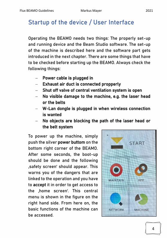
Flux BEAMO Guidelines Markus Mayer 2021
4
Startup of the device / User Interface
Operating the BEAMO needs two things: The properly set-up
and running device and the Beam Studio software. The set-up
of the machine is described here and the software part gets
introduced in the next chapter. There are some things that have
to be checked before starting up the BEAMO. Always check the
following things:
− Power cable is plugged in
− Exhaust air duct is connected propperly
− Shut off valve of central ventilation system is open
− No visible damage to the machine, e.g. the laser head
or the belts
− W-Lan dongle is plugged in when wireless connection
is wanted
− No objects are blocking the path of the laser head or
the belt system
To power up the machine, simply
push the silver power buttom on the
bottom right corner of the BEAMO.
After some seconds, the boot-up
should be done and the following
‚safety screen‘ should appear. This
warns you of the dangers that are
linked to the operation and you have
to accept it in order to get access to
the ‚home screen‘. This central
menu is shown in the figure on the
right hand side. From here on, the
basic functions of the machine can
be accessed.

Flux BEAMO Guidelines Markus Mayer 2021
5
This is the MAINTAIN menu. Here,
the laser head can be controlled
and moved with the help of the
arrows. The home position moves
the laser head to the top left
corner of the chamber. The
movements come in handy during
cleaning operations, because the
four corners (marked A-D) can
quickly be reached and thus the
rails and rods of the axis cleaned
and lubricated. This menu is
further of interest to quickly test
new materials through very short
laser pulses, activated via the big
red button in the bottom of the
screen.
This is one of the more important
menus, the network settings. The
BEAMO comes with a W-Lan
Dongle which allows it to connect
to wireless networks. The set-up
process and the connection can be
established either through an own
hotspot from an own device or the
machine can be accessed through
the wireless ‚3D Lab‘ network.
Note: It is important that the
BEAMO is in the same network as
your laptop or computer!

Flux BEAMO Guidelines Markus Mayer 2021
6
Note: Sometimes the BEAMO does not immeadiatly react to the
touchscreen inputs. This is normal and just needs some times
and multiple tries. The brain of the machine is a Raspberry Mini
Computer, so it has limited processing capabilities!
This is the MACHINE menu that
contains general information and
settings options. The only things
that might be interesting here are
the firmware version, the
ventilator rotation speed and the
laser tube usage. The ventilator
speed was set to this low setting
based on the suction capabilities
of the central ventilation system
where the BEAMO is connected to.
It shall not be changed, the suction
of the fan is enough for not letting
fumes escape. If you have to
update the firmware, you can find
the latest version following this
link.
For more detailed information regarding the set-up
process look in the manual provided by the
manufacturer. You will find the digital version by
following this link.

Flux BEAMO Guidelines Markus Mayer 2021
7
Software
The second vital part of the operation is the Beam Studio
software. It can be downloaded using this link and is
available for Windows, MacOC 10.13+ and Ubuntu. The
used stable version is the latest Version 1.4.6 and was
used on a Windows laptop. The mobile phone application
was not very stable at the point of testing (April 2021) and
is therefore not mentioned and
described further. After the
installation of the software, open
it to get started.
On the right side, the main
window of Beam Studio is
shown. The main elements are
visible and are grouped together
in colored squares. Within the
orange square you find the ‚File‘
header. It is used to import files,
open projects, export g-code
and set preferences. The
standard preferences should not
be changes, although the
language can be set there for
example. There are some initial
settings, that have to be changed
in order to ensure a proper
function. The ‚Edit‘ header is
used to undo, copy/paste objects
and change the Document
Settings.

Flux BEAMO Guidelines Markus Mayer 2021
8
The blue square contains the ‚work area‘ of the BEAMO
and its size has to be changed using the Document
Settings. On the right the Work Area can be changed to
‚beamo‘ and also the resolution of the engraving process
can be altered. This setting does not affect the cutting
performance of the machine.
All future add-ons to the machine can also be enabled in
the Document Settings. To apply the settings just press
‚Save‘. The next important thing is the setup of the
connection to the BEAMO.
For this click ‚Machines‘,
found in the orange square. A
drop-down menu appears.
When no machine is
connected, only two options
are available, ‚Machine
Setup‘ and ‚Test Network
Settings‘. When you want to
connect the Machine click
the first one and this window
should appear. The wireless
connection can be set by
entering the IP-adress of the
BEAMO which can be found
in the Network menu after a
successful connection to a
wireless network. The
BEAMO also recieves a IP-
adress from the accesspoint
when connected via an
Ethernet cable. The BEAMO
can be connected wireless

Flux BEAMO Guidelines Markus Mayer 2021
9
and via wire at the same time. The connection wizard
guides you through a problem and when you want to test
the networks speed and connectivity.
The green square includes all the tools you need for basic
operations like the drawing of simple shapes and the
importing of picture files. The supported file formats for
pictures can be found on the last page of this guidebook.
Vectors can also be imported by clicking on the Image
symbol under the arrow in the green square. The red
square contains all the settingsss for layer management
and the power and speed settings for the operation.
Multiple layers can be created to combine different
settings within the same operation. The order of layers
from top to bottom is also the order of execution.
Note: Keep the order of the layers in mind before you
start the operation! If you cut out small pieces that you
also want to engrave, it is always better to engrave them
first, so move the layers with the mouse.

Flux BEAMO Guidelines Markus Mayer 2021
10
There are already a lot of presets
provided by the manufacturer. They
can be accessed through clicking
on the ‚Presets‘ drop-down menu
found in the red marked square on
the previous page. Those contain
most of the materials that can be
processed but some additional
ones like thick paper have been
tested during this project. Most of
the times, the provided settings are
enough to get successful parts. But
for some materials, more efficient
settings can be applied to cut the
production time. The engraving
settings provided here work best at
250 dpi, an adaptation for higher
resolution settings has to be made
to prevent ‚over-treatment‘. It is
possible to add own presets with
the option near the bottom vsible in
the screenshot on the right.

Flux BEAMO Guidelines Markus Mayer 2021
11
For setting up the workpiece in the operation chamber
and aligning the drawings, vectors and images with the
workpiece, there is a built-in CMOS camera on the laser
head with a stitching feature. To get to this preview
function, click on the ‚camera‘ symbol found
in the top left corner of the Beam Studio homescreen.
This function is only
available if the BEAMO is
connected, of course. To
start scanning the work
area, simply draw a square
with yout computer mouse
and the laser head will
move along a path to gain
all the necessary picture
parts. As you can see in the
screenshot on the right, a
blind spot is left on the top
edge of the work area. This
is the result of the camera being located beneath the
laser nozzle and it cannot ‚see‘ the upper part, otherwise
the laser head would smash into the wall of the operation
chamber. It is of course possible to place the workpiece
there.
Note: The stitching can sometimes be distorted and
missaligned. Always scan your whole workpiece if
spacing is important! If you see any unwanted glitches,
do the whole process again. You can delete the stitched
image with the ‚bin‘ symbol found in the left
toolbar.

Flux BEAMO Guidelines Markus Mayer 2021
12
Inventor
One of the most versatile ways to use the
BEAMO is by laser-cutting forms and shapes
from CAD drawings. Wether this may be
parts for your project like gears or folding
shapes, Inventor can export the right files
and here is a short description. To export
vector files from Inventor, a drawing has to
be created with ‚File‘ > ‚New‘ > ‚Drawing.idw‘.
The template of the drawing does not matter,
any will work. Import your drawing into the
plan layout by clicking on ‘Base’ in the top left
corner and select the right scale. After that
you have to remove everything except the
drawing itself, so all borders and plan heads
etc. have to go as shown in the right
screenshot. Next, to export the vectors of
your work, go to ‘File’ > ‘Safe as’ > ‘Safe Copy
as’ and then select the .dxf format. This is the
vector format which can be processed by Beam Studio.

Flux BEAMO Guidelines Markus Mayer 2021
13
AutoCAD
Another CAD program which easily can export vector
files is AutoCAD from AutoDesk. Here the process is
almost the same as with Inventor, although the
scale of the drawings can deviate strongly
depending on the version of the program and
the template. To export your drawing from
AutoCAD, simply click on the AutoCAD Icon in
the top left corner as shown in the screenshot
on the right. Then navigate to ‘Safe
as’ > ‘other Formats’ and choose
the .dxf format in the AutoCAD 2013
version as shown on the right. The
newer version of 2018 works too
but Beam Studio likes the 2013 one
for some reason. AutoCAD is a
very good tool to create shapes
that are a little more complex than
just rectangles, which of course
can also be drawn with the built-in
feature in Beam Studio.
Note: It can happen, that the .dxf file does not show up
after importing it into Beam Studio! It is most likely that
the scale is way off and you either can not see the file
because it is too small or because it is so big, that it does
not fit onto the work area at all. Keep that in mind before
exporting and measure your parts. Beam studio works in
Milimeters.

Flux BEAMO Guidelines Markus Mayer 2021
14
Safety precautions and rules of use
Lasers are dangerous even if they are properly enclosed.
A certain risk always remains, espacially when the
machine is used by many people at once and some are
just learning how to use it. As this document shall help
users to get their projects done safe and with ease
certain rules and guidelines have to be made up. Those
rules aim to procets the user as well as the machine to
ensure a long lasting lifetime. The following safety rules
have to be understood and applied:
− Never leave the machine alone during cutting
operations!
− When pricessing flamable maerials, always have
a wet cloth besides the machine!
− Do not use the machine if you see any visible
damage to the laser head or the belts!
− Do not open the lid during operation! (There is a
safety switch but it is not super fast)
− Make sure the material you have is safe to use!
(see dangerous materials on page 15 for info)
Note: There is a fire extinguisher in the hallway just out
of the lab door. Just saying!

Flux BEAMO Guidelines Markus Mayer 2021
15
Dangerous Materials
There are a number of hazardous materials which are
divided into two different categories. The first category
includes all materials that release toxic substances and
particles when exposed to the laser. Despite the use of
an exhaust system, these particles can stick to the
workpiece and some substances can even damage parts
of the machine through corrosion. These substances
include the materials PVC, PC and ABS. They release
carcinogenic substances when
processed by laser light and certain acids
can attack machine parts. In general,
materials with aromatic benzene rings in
their chemical structure are not suitable
for processing. The problem with
polycarbonate, for example, is that it is
very difficult to distinguish visually from
the safe PMMA, which is another name for acrylic glass.
The second category includes substances
that do not emit any hazardous
substances in principle, but which pose a
safety risk in terms of fire hazard due to
their composition. This includes wood that
is thicker than 5 mm and multi-fluted
cardboard. An example of multi-fluted
cardboard is shown on the right. These
materials can catch fire especially when
high light power is combined with slow
laser head movements. Processing the

Flux BEAMO Guidelines Markus Mayer 2021
16
same areas several times in short intervals can also
promote pockets of embers. Sufficient time must
therefore be allowed when planning the operation to
avoid igniting possible small pockets of embers by
repeating the operation too
quickly. Since the laser head
and the electronics attached to
it are very close to the
workpiece, even a small open
flame can cause serious
damage. The lens in the laser
head can soot and possibly
even break under the heat. On
the right you can see an
example of an incident with double-walled cardboard.
This result was very surprising and educational. Only by
following the safety rules could the open flame be
extinguished quickly and damage to the machine
prevented.

Flux BEAMO Guidelines Markus Mayer 2021
17
Limitations
Of course the machine has some limits due to its compact
size and the maximum laser light output of 30 W. This
results in a set of restrictions which are listed and
described below. A distinction is made between physical
limits and limitations ragarding some materials. The
specifications of the BEAMO can be found by following
this link.
Physical Limits
The area which can be processed
with the laser is approximately 300
mm wide and 210 mm tall and is
therefore a little more than on a
standardised DIN A4 sheet. The
maximum thickness of parts that fit
beneath the laser nozzle is approx.
16 mm with the cutting pad installed
and roughly 36 mm without it. Keep
in mind that the focus point lies
slightly below the metal guard which can be seen on the
right. Such short distances should be avoided for safety
reasons. If the laser head gets caught in the workpiece,
the belt system and the laser head may be damaged. The
larger the workpieces, the greater the risk that an
unevenness in the material will lead to contact with the
laser head. Especially with materials that warp or are
already bent under the influence of the laser, it must be
checked whether there is enough clearance at all points.

Flux BEAMO Guidelines Markus Mayer 2021
18
Secure those materials with painters tape to avoid
collisions and misalignment.
Note: If it is possible, it is always better to cut the raw
material into smaller pieces already to avoid collision.
With stiff materials this is less important.
Another limitation exists in regards of the work area. The
work area in Beam Studio and the real world work area
do not overlap exactly, which can lead to parts being cut
outside of the material. Two things have to be kept in
mind before starting to align the part. Firstly, it seems
that the real work area is shifted a
little bit down and about double
the amount to the right. On the
right you can see the approximate
top left corner of the real work
area in orange, which is also the
home position of the laser head.
The second thing to keep in mind
is, that the first rule is only
applicable if the meshed real work
area is pushed all the way to the bottom end stops! If you
remove the mesh for cleaning, make sure to slide it down
all the way to not have another person misalign their
work.
Note: Use the camera preview feature to make sure, your
drawing fits onto the material well. But also do not place
your parts in the middle of a big sheet to safe some of it.
Common sense!

Flux BEAMO Guidelines Markus Mayer 2021
19
Material Limits
Of course, there are certain materials
that simply cannot be processed with
the normal gas laser. These include all
types of metal and generally very thick
materials. The respective maximum
tested thicknesses are listed in the
Cutting chapter from page 20.
Stainless steel can be processed with
the help of the diode laser module,
which is available separately. On the
right you can see a piece of plywood
with a thickness of 6.5 mm, which can
no longer be cut with the BEAMO. Since
wood can ignite with slow movements
and high light output, this poor result
even poses a fire hazard.
You can find all the minimum capabilities regarding the
workability of materials on the website of FLUX by
following this link.
Note: During the testing period of this thesis, not all the
available materials got tested with all the possible
combinations of power settings. It is very likely that there
are settings, which can ultimately result in successful
parts even though they are here presented as not
workable.

Flux BEAMO Guidelines Markus Mayer 2021
20
Cutting
In order to enable the user to carry out
successful projects and to save the
lengthy test phase, this chapter contains
recommendations for the cutting
operation with the laser device. These
recommendations may not be effective
with organic, natural materials, as even slight
differences in density can influence the result. This is
especially noticeable with plywood. The following table
contains several recommendations for several
materials:
Material Thickness Power Speed Executions
Plywood 4 mm P50-P70 S003-S006* 3x
PMMA 3-4 mm P40-P55 S003-S006** 1x
PMMA 8 mm P50-P60 S003-S005 3x
Leather ~2 mm P40-P60 S003-S014 1x
Cardboard 1 flute P20-P60 S003-S014 1x
Paper 1 mm P20-P35 S014-S025 1x
Paper 2.5 mm P45-P55 S012-S015 2x
*Keep in mind, that too fast repetitions can excite embers. See
the picture in the top rigt corner!
**The surface finish gets better when using slower speeds.
To achieve the best desired result, some experience is
always necessary. The test pieces from the test phase
are always available for viewing near the machine. It is
advisable to take a look at the test pieces before the
operation. If surface quality is not of great importance,
acrylic glass, for example, can also be cut much faster,
which can greatly reduce the operation time.

Flux BEAMO Guidelines Markus Mayer 2021
21
Engraving
Getting good engravings can be
difficult. Especially with real
photos, the results can be
unattractive. Especially on acrylic glass, it is not
recommended to engrave faces, for example. Other
objects such as landscapes can look good on acrylic
glass with a little practice. The results of the tests are
available in the laboratory and are very subjective. One
important setting can have a
decisive influence on the quality
of the engraving. The resolution
can be set in four steps and
controls the spacing of the lines
on the x-axis. This setting is
comparable to the layer height
in 3D printing. Finer lines or
higher resolutions multiply the
operation time. To change the
resolution, go to ‚Edit‘ in the main window of Beam Studio
and then to ‚Document Settings‘. For most engraving
operations, 250 dpi are well suitable but for really fine
details choosing 1000 dpi will result
in the best quality. As already said,
the quality changes with higher
resolutions and the engraving depth
does the same. Here you can see he
same power settings with 100 dpi and
1000 dpi. Note, how the upper sample
barely got scratched and the bottom
one is cut all the way through.

Flux BEAMO Guidelines Markus Mayer 2021
22
To import pictures and vectors for engraving simply
either click on ‚File‘ > ‚Open‘ or choose the picture symbol
in the toolbar on the left edge of Beam Studio.
Text: Found in the toolbar, text can easily be placed within
Beam Studio. There are many options to edit the written
text within the settings menu on the
right side. You can align the textbox in
reference to the work area and
change its position with the tools
found in the red square. Within the
orange square you will find menus to
change the font, size and style of the
text. Further, spacings and vertical
text can be set. The ‚Infill‘ setting is
important. When disabled, the text is
converted into paths and get cut out. It
is important to check this setting if you
don’t want to cut right through your
phone case or laptop back! When
enabled, the text gets sliced for the
engraving operation. The options in
the green square allow you to make
automated arrays of the textbox or to
convert the letters into paths for
disassembly.

Flux BEAMO Guidelines Markus Mayer 2021
23
Pictures: Every picture that is
imported into Beam Studio is
automatically recolored using a
greyscale. Because the laser can
only produce one* „color“ this is
mandatory and using colored
pictures requires some editing to get
a good result. When the chosen
image is selected, this editing menu
appears on the right side of Beam
Studio. Some tips for choosing pictures before the editing
steps are described:
− Best case: Take monochrome pictures if possible
− High contrast is important for the grey scaling
− All surfaces that should be visible have to be lit
approx. The same amount
− No big shaddows are possible, only with loss in
details
− Eye sections have to be properly lit to avoid a
racoon effect.
The gradient can be edited by clicking
on the ‚Gradient‘-button. You can
disable the gradient and then choose
a threshhold gradient uppon which
the pixel gets added to a pure black/white picture. All the
white spots are removed and are seen as transparent.
Keep that in mind, it can look awkward if you engrave a
face and just the cheeks and the forehead have blank
spots! With the gradient disabled, you can ‚Trace‘ the
outlines of your picture to get vectors for cutting if you
disable the ‚Infill‘ in addition.
*other laser technologies can produce different colors on metals for example by varying their frequency and intensity.

Flux BEAMO Guidelines Markus Mayer 2021
24
Odd shapes
It is possible to cut and engrave materials and faces that
are not perfectly flat. This is due to the focus point acting
more as a focus line with an approx. 8 mm length.
Further, due to the always bigger gaps appearing
resulting from the burning away of surrounding material,
slight changes in focus do not matter that much anyways.
This enables a whole new set of objects that can be
treated with precious laser light.
Round objects
Grill forks for example! Due to their round
face and relatively small diameter, the
edges get rather steep quickly when
viewed from the top. For this very reason,
when engraving round objects, always
leave some free space to the sides, the
resulting engravements or cutting edges
would only look good exactly from the top.
More on the topic of engraving grill forks
on page 36.
Uneven faces
Due to the same reason of the focus point acting more as
a line, even quite rough surfaces can be engraved. This is
shown with the leather engravings found from page 37
on. The limits of the maximum roughness lies within the
~8 mm focus line.

Flux BEAMO Guidelines Markus Mayer 2021
25
Tips and Tricks
This chapter can help you if something did not go as
planned.
-) The piece caught fire during the run!
Be careful when processing multiflute cardboard or
thicker plywood! Always have something next to the
BEAMO to extinguish the flames!
The excitement of embers or even flames can happen
uppon multiple reasons. It is firstly possible that the
chosen material was soaked in a flamable liquid like IPA
or Acetone, either from cleaning beforehand or oily
remains. Secondly, treating multiflute cardboard and
plywood with high power settings at low movement
speeds can result in the excitement of embers.
Especially with the thicker cardboard, air that reaches
through the flutes from the side can perfectly support the
generation of this unwanted incident. It was found that
making flammable surfaces wet before treating them
with an intense laser beam can help to delay the heating
up and ignition a bit.
Remember tho: It should be common sense that the
operation chamber should not be flooded with water!

Flux BEAMO Guidelines Markus Mayer 2021
26
-) The result is not satisfying!
If the work piece is not what it should be after the
process is finished and it is still laying exactly as it was
before, there are a number of things that can be done
now.
With plywood there seems to be a limited amount of
passes that can still remove material. Some kind of work
hardening or another form of resistance to laser light
develops during multiple lower power passes. With
plywood it is always advisable to crank the power all the
way up (the machine limits the maximum increment to
70 % to preserve the lifetime of the laser tube) and find a
slow enough speed, where the parts just does not catch
on fire immediately.
Thicker acrylic glass tends to distort the laser beam
when the speed is too high, so slow speeds result in
straighter and cleaner edges. Multiple passes are also
possible with acrylic glass but the surface finish will
degrade with more executions.
-) No connection between Beam Studio and
BEAMO!
There is the autmatic Connection Wizard for
troubleshooting in Beam Studio. Check if your computer
and the BEAMO are actually in the same network! If so
then check if the BEAMO has got a valid IP-address from
the router. You can also ‚Test the Network Settings‘, the
User Interface where to find this option is shown on
page 8.

Flux BEAMO Guidelines Markus Mayer 2021
27
-) It smells bad or like barbeque in the lab!
Multiple reasons could lead to a smoky lab situation.
Check if the shut off valve is in an open position. There is
a switch on the wall near the workplace of the BEAMO. It
should light up when the valve is open. Next, check if the
built-in ventilator is set to 30 % speed. If it is set to a
lower speed, fumes can not get sucked out properly and
could escape through the gaps of the device.
If the speed is set higher, initial testing showed that the
fumes then got pushed out of the SLA printer enclosure
and entered the lab room in that way. Either way is bad
and depending on the material, harmful fumes could lead
to longterm respiratory damage.
Note: For more tips and tricks, look in the BEAMO manual
provided by the manufacturer. The printed version should
be near this guidebook and the digital version can be
accessed through this link.

Flux BEAMO Guidelines Markus Mayer 2021
28
Projects
Here, five projects are described for recreational use.
The settings with which most of them got done are
supplied, although for the first one having plywood as
material changes in density etc. could lead to
unsuccessful attempts of recreation. More treated
objects and little projects are present on display in the
lab near the BEAMO. There are also more pictures of
additional projects from page 37 on.
Skill in craftmanship and creativity are required with the
post-processing of some parts of the projects, but I am
no artist myself either so everything is doable of course.
Again, if you like your project and want to share it and
see other previous works, use the hashtag
#beamedatlapin to contribute to the collection. You can
reach the official collection via this link.

Flux BEAMO Guidelines Markus Mayer 2021
29
Plywood boxes
The first projects are the
plywood boxes. They can either
be designed as poker card
boxes or act as storage bins
with multiple compartments
inside. All the shapes for the
various boxes are created
using the boxes.py web-tool.
It can be accessed by following this link and is free of use.
Down below you can see the main page.
The boxes are usually made out of plywood, but
cardboard and thick paper like watercoloring sheets
could also work.

Flux BEAMO Guidelines Markus Mayer 2021
30
After typing in all the required specifications into the
web-tool simply generate all the shapes of the parts by
pressing ‚Enter‘ on the keyboard or click the ‚Generate‘
button. On the right you can see the most
important text boxes which have to get
filled. All the text boxes have descriptions
besides them but don’t forget to set the
thickness of the material and you can set
the ‚reference‘ box to ‚0‘ to not generate
one piece of trash more. The burn factor
can be set to 0.2 to tighten the fit a little
bit but this changes from material to
material of course.
When the shapes are generates and
saved, import them into Beam Studio. Choose ‚Layers‘
when importing to get one layer
per shape. This is important to
be able to move them around
and fit them onto the work area
afterwards. As shown on the
left, additional symbols and text
can be added to the work area
but keep in mind to add a
separate engraving layer! After
you are done with arranging the
shapes with the help of the
camera preview function you
can group all the shapes
together by selecting them all
and choosing ‚group‘ with the
right mouse button clicked.

Flux BEAMO Guidelines Markus Mayer 2021
31
After you are finished you can slice
your operation and start the process.
Due to the plywood being a little
harder to cut and the very real chance
of it to start a fire, stay next to the
machine and have a wet cloth ready!
After the successful cut, remove the
parts and clean them off with the help
of pressured air. You can also wipe the
edges off to remove the charred ash.
After that, you can start with the
assembly using woodglue. You can
then sand the faces and edges to get a
clean look and sharp edges. Look at
page 29 for an example of clean edges.
For additional reinforcement, try using
little nails that can be found in the
workshop. Be careful not to split the
thin sheets.
Used Settings:
E: 500 dpi, P25 S175
C: P65 S007 3x

Flux BEAMO Guidelines Markus Mayer 2021
32
Business cards
The next project was created
using PowerPoint. Business
cards can give the opportunity to
get creative using the tools in the
workshop. For this piece, the
standard pocket card size of
85 mm x 54 mm. You will find
different common dimensions for
other cards online. The different
parts of the card are achieved by
exporting the vetors for cutting
separately to the ones for
engraving. Export your shapes
out of PowerPoint by going to
‚File‘ > ‚Safe as‘ and select the .svg
filetype. It is again advisable to
engrave first and then cut out the
shapes and outline.
Thick paper with 300 g/m² was used for this project for
higher rigidity which can be found in the arts and crafts
aisle in Tex (of course).
Note: As engraving anything can take a long time, try by
printing your business card or any other card with a
regular toner printer and just cut out the shapes
precisely later. This will speed up yout production time
significantly, especially if you want to produce more than
two cards.

Flux BEAMO Guidelines Markus Mayer 2021
33
Phone case engraving
Engraving phone cases is a
good way to decore personal
objects permanently. For this
reason, think in advance what
exactly you want to engrave
onto the surface. There are
cases with a leathery look,
they require a little stonger
settings but this material is
easily burned through, so be
gentle in ramping them up. If
you do not like the result of the
texture, just apply it again. On
the right you can see multiple
images and shapes engraved
onto a phone case. Fine lines
are as well possible as bigger
faces. Some cases will end up
with a glossy look and the
material should not curl up
during the process, that means
a too deep cut.
As cheap cases are often made out of nasty plastics, don’t
exaggerate it with the engraving.
Settings used:
E: 250 dpi, P13-P15 S140

Flux BEAMO Guidelines Markus Mayer 2021
34
Puzzles
Another possible project is the creation
of self designed and produced puzzles.
Two different kinds of puzzles can be
made. The first one is the easiest one
and only requires the raw material on
which the picture or pattern is engraved
and the puzzle shape is cut at the same
time. You can see the manufacturing
process of a simple nine piece puzzle
on the right hand side.
The raw image got edited to get the
best result possible. Then the
generated puzzle shape is overlayed in
a separate layer for cutting! To make
the transparent spots more visible, the
camera preview feature is used to get
the real color of the cardboard in
contrast to the black engraving spots.
The last picture shows the finished
puzzle. Due to the weak properties of
the cardboard, the fit of the pieces is
quite loose because alot of material got
removed. With other and thicker
materials, this effect is not as strong.
Settings used:
E: 250 dpi, P15 S095
C: P25 S006

Flux BEAMO Guidelines Markus Mayer 2021
35
The puzzle shapes for cutting get generated using a free
web-tool, which can be accessed using this link. Here
you can set the sliders and export the neccessary .svg
files via the ‚Download SVG‘ button.
Note: You can also just glue normal pictures to a piece of
cardboard or thick paper to get a nice colorful puzzle.
For this you have to adjust the settings a bit because you
have to cut through the image paper in addition, also if
you are using thick watercoloring sheets.
Here, a picture was engraved
directly on ~2 mm thick
watercoloring paper and cut
with the settings mentioned
above. The watercoloring
sheet is perfect for this, as it is
rigit, white for better contrast
and burns cleanly and leaves
just a very thin edge on the
back side.
Settings used: for cutting thick
paper + picture paper: P45 S015 2x

Flux BEAMO Guidelines Markus Mayer 2021
36
Grill Forks
As already mentioned, grill forks are
another project possible. Here the meshed
work platform has to be removed to get
more clearance and using the previewing
camera feature is vital to the success. Due
to the steep angles on the sides, leave gaps
of about 3 – 4 mm to either side to prevent
visible distortions.
The premade settings for engraving wood
are applied here and the focus is set to the
top edge closest to the laser nozzle. As
those forks are round, they have to be fixed
in place using painters tape to prevent them
from rolling away during the operaton.
On the right, you can see the preview of two
forks with some stitching distortion in the
top part. Here, the premade settings were
applied but with 500 dpi, which resulted in
very deep embossments. They are approx.
1 mm deep and help to keep the texture on
the surface for a long time.
Note: You can rotate your object between
engraving sessions to get more surfaces
covered. The rotating add-on for the BEAMO
would speed up this process!

Flux BEAMO Guidelines Markus Mayer 2021
37
Additional Inspirations
This last chapter is dedicated to all the other projects and
materials I worked on during the testing phase. Some of
the same images and projects can also be found under
the already mentioned hashtag #beamedatlapin and on
the official BEAMO Instagram project page by following
this link.

Flux BEAMO Guidelines Markus Mayer 2021
38

Flux BEAMO Guidelines Markus Mayer 2021
39

Flux BEAMO Guidelines Markus Mayer 2021
40

Flux BEAMO Guidelines Markus Mayer 2021
41

Flux BEAMO Guidelines Markus Mayer 2021
42
Useful Web-Links
Here, useful links are provided in clear text. Enjoy!
Flux Europe Download (for Firmware, Beam Studio,
BEAMO user manual):
https://www.fluxlasers.com/downloads/
Flux Europe BEAMO specs:
https://www.fluxlasers.com/products/beamo/
Box vectors for projects:
https://festi.info/boxes.py/?language=en
Puzzle shape vector generator:
https://cdn.rawgit.com/Draradech/35d36347312ca6d088
7aa7d55f366e30/raw/b04cf9cd63a59571910cb226226ce2
b3ed46af46/jigsaw.html
Instagram page of Lapin UAS projects:
https://www.instagram.com/uastw_goes_laplanduas/
Free Vectors for Laser Cutting:
https://3axis.co/
DXF Projects page:
https://dxfprojects.com/
Icons and Photos:
https://thenounproject.com/

Flux BEAMO Guidelines Markus Mayer 2021
43
Quick Start Guide
This quick start guide contains only the most important
steps without any descriptions. Simply follow this steps
to get started right away.
1. Power on the machine
2. During boot-up, clean out the work area, lies it flat?
3. Put the raw material into the operation chamber
4. Set the focus with the help of the little transparent guide piece
5. Connect the BEAMO with your laptop/ Beam Studio
6. Align your image/vector with the help of the camera feature
7. (Correct the image in regards of gradients and sharpness)
8. Set the power and speed settings and bring the layers in order
9. Slice the operation
10. Get started!
Important Notes:
Do not forget about setting the focus!
Never leave the machine alone during cutting operations!
Always have something to extinguish fire next to the machine!