The future of Ca looping – A review of developments
26
A paper in the proceedings of a conference on fluidization 9 19–20 November 2014, Johannesburg, South Africa IFSA 2014, Industrial Fluidization South Africa: 9–33. Edited by A. Luckos & B.C. North Johannesburg: Southern African Institute of Mining and Metallurgy, 2014 The future of Ca looping – A review of developments D. Hanak, V. Manovic, E.J. Anthony Combustion and CCS Center, Cranfield University, Bedford, United Kingdom Keywords: Ca looping, CO 2 capture, pilot plant research Abstract—CCS technology is essential if we are to meet goals of keeping CO 2 levels at or below 450 ppm. Unfortunately, while current solutions in particular amine scrubbing offer are evidently technically feasible, there is a major need to reduce the cost and energy losses associated with CCS. One possible option is a second generation technology called Ca looping. This paper analyses current pilot plant research in order to provide an overview of where research is currently going and what yet remains to be done. INTRODUCTION Novel CCS technologies, which avoid the expense and efficiency reductions associated with amine scrubbing, are urgently needed. A promising alternative to both oxy-combustion and solvent absorption is a second generation CO 2 capture technology called calcium looping (CaL) that uses a calcium-based solid sorbent. Here, the main aim of this paper is to review recent developments in calcium looping technology for CO 2 capture. THE CALCIUM LOOPING PROCESS Use of calcium-based sorbent for CO 2 absorption was patented in 1933. 1,2 However, the calcium looping (CaL) process for post-combustion CO 2 capture technology was first proposed by Shimizu et al. 3 in 1999 (see Figure 1). In the CaL process the flue gas from the air-blown boiler is fed directly to the carbonator and CO 2 is removed from the flue gas stream in the form of solid CaCO 3 particles. 3 This process proceeds at a reasonably fast conversion rate for practical application 2,4,5 , but CO 2 removal efficiency decreases rapidly with increasing temperature and ceases at ~775°C as the equilibrium partial pressure of CO 2 exceeds the partial pressure in the flue gas above ~775°C. 6 The optimal carbonator operating temperature ranges between 580°C and 700°C due to the trade-off between the reaction kinetics and the equilibrium driving forces. 7,8 The CaCO 3 is sent to another fluidised-bed reactor, the so-called calciner, in which it is calcined and CO 2 is released. 2 Calcination is conducted above 900°C to achieve rapid reaction without excessive sintering. 9 As calcination is an endothermic, additional fuel must be burned in the calciner using O 2 . 3,10,11 The calcination step consumes approximately 35% to 50% of the overall heat input to the system. 12 Technology status There are numerous demonstrations of the technology worldwide: IFK (University of Stuttgart, 10 kW th ), CanmetENERGY (75 kW th ), La Pereda (CaOling project, 1.7 MW th ), and Industrial Technology Research Institute Hsinchu (1.9 MW th ) among others. 13,14
Transcript of The future of Ca looping – A review of developments

A paper in the proceedings of a conference on fluidization 9 19–20 November 2014, Johannesburg, South Africa
IFSA 2014, Industrial Fluidization South Africa: 9–33. Edited by A. Luckos & B.C. North Johannesburg: Southern African Institute of Mining and Metallurgy, 2014
The future of Ca looping – A review of developments
D. Hanak, V. Manovic, E.J. Anthony Combustion and CCS Center, Cranfield University, Bedford, United Kingdom
Keywords: Ca looping, CO2 capture, pilot plant research
Abstract—CCS technology is essential if we are to meet goals of keeping CO2 levels at or below 450 ppm. Unfortunately, while current solutions in particular amine scrubbing offer are evidently technically feasible, there is a major need to reduce the cost and energy losses associated with CCS. One possible option is a second generation technology called Ca looping. This paper analyses current pilot plant research in order to provide an overview of where research is currently going and what yet remains to be done.
INTRODUCTION Novel CCS technologies, which avoid the expense and efficiency reductions associated with amine scrubbing, are urgently needed. A promising alternative to both oxy-combustion and solvent absorption is a second generation CO2 capture technology called calcium looping (CaL) that uses a calcium-based solid sorbent. Here, the main aim of this paper is to review recent developments in calcium looping technology for CO2 capture.
THE CALCIUM LOOPING PROCESS Use of calcium-based sorbent for CO2 absorption was patented in 1933.1,2 However, the calcium looping (CaL) process for post-combustion CO2 capture technology was first proposed by Shimizu et al.3 in 1999 (see Figure 1).
In the CaL process the flue gas from the air-blown boiler is fed directly to the carbonator and CO2 is removed from the flue gas stream in the form of solid CaCO3 particles.3 This process proceeds at a reasonably fast conversion rate for practical application2,4,5, but CO2 removal efficiency decreases rapidly with increasing temperature and ceases at ~775°C as the equilibrium partial pressure of CO2 exceeds the partial pressure in the flue gas above ~775°C.6 The optimal carbonator operating temperature ranges between 580°C and 700°C due to the trade-off between the reaction kinetics and the equilibrium driving forces.7,8
The CaCO3 is sent to another fluidised-bed reactor, the so-called calciner, in which it is calcined and CO2 is released.2 Calcination is conducted above 900°C to achieve rapid reaction without excessive sintering.9 As calcination is an endothermic, additional fuel must be burned in the calciner using O2.3,10,11 The calcination step consumes approximately 35% to 50% of the overall heat input to the system.12
Technology status There are numerous demonstrations of the technology worldwide: IFK (University of Stuttgart, 10 kWth), CanmetENERGY (75 kWth), La Pereda (CaOling project, 1.7 MWth), and Industrial Technology Research Institute Hsinchu (1.9 MWth) among others.13,14

10
Figure 1. Conceptual design of CaL process system for CO2 capture
Romano15 describes this process as similar to oxy-combustion technology but where only
some portion of coal is burned in pure oxygen environment. The main advantages of the CaL system over the solvent-based CO2 capture technologies are:
• Availability of a large amount of recoverable high-grade heat able to generate an additional high-pressure steam to produce surplus power output.10
• An efficiency penalty of 7% to 8%15, with the CO2 capture stage accounting for 2 to 3%, mainly due to the reduced oxygen requirement.16 This is comparable to the energy penalty of flue gas desulphurisation units (0.5-4%).17
• Application of the fluidised bed reactors, has been commercially proven for coal combustion systems.
• Natural limestone or dolomite as the CO2 absorber which is cheap5, environmentally benign18, and has a high CO2 absorption capacity.
Nevertheless, reduction in the sorbent CO2 carrying capacity19 on cycling operation, due to sintering, attrition and sulfation, appears to be the major challenge of this technology, and require a considerable amount of spent sorbent to be replaced, although reuse of this material reused in the cement production industry, might provide benefits in terms of reducing the CO2 production from both the power and cement industries.18
REVIEW OF CALCIUM LOOPING LABORATORY AND PILOT-SCALE EXPERIMENTS
A number of the more important pilot plant units are described in (Table 1).
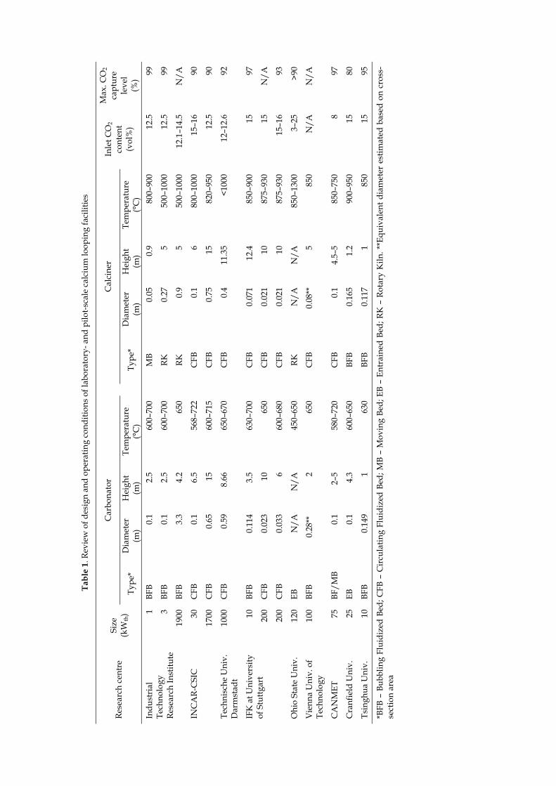
Industrial Technology Research Institute The Industrial Technology Research Institute (ITRI) in Taiwan has developed a bench-scale 1 kWth pilot plant, which can be operated in either a batch or continuous mode (Table 2).20
The pilot plant developed at the ITRI was then modified by substituting the MB calciner with an air-fired rotary kiln calciner (RK) (Figure 1). This increased the pilot plant capacity to 3 kWth. The calciner has a length-to-diameter ratio of 18.5 and an inclination angle of 5°, based on the operating experience from the cement industry (Table 3). Such design corresponds to a residence time of approximately 30 minutes at a rotation speed of 1 rpm. Furthermore, liquefied petroleum gas is directly fired in the calciner using a 58 kWth burner. The gas enters the BFB carbonator through a perforated plate distributor composed of 96 holes of 1.5 mm in diameter. Although the carbonation reaction is exothermic, the carbonator was heated using an external heating system to balance the heat losses to the environment.14
Tabl
e 1.
Rev
iew
of d
esig
n an
d op
erat
ing
cond
ition
s of l
abor
ator
y- a
nd p
ilot-s
cale
cal
cium
loop
ing
faci
litie
s
Rese
arch
cen
tre
Size
(k
Wth
)
Car
bona
tor
C
alci
ner
Inle
t CO
2 co
nten
t (v
ol%
)
Max
. CO
2 ca
ptur
e le
vel
(%)
Type
* D
iam
eter
(m
) H
eigh
t (m
) Te
mpe
ratu
re
(°C
)
Type
* D
iam
eter
(m
) H
eigh
t (m
) Te
mpe
ratu
re
(°C
) In
dust
rial
Te
chno
logy
Re
sear
ch In
stitu
te
1 BF
B 0.
1 2.
560
0–70
0
MB
0.05
0.9
800–
900
12.5
99
3 BF
B 0.
1 2.
560
0–70
0
RK
0.27
550
0–10
0012
.599
1900
BF
B 3.
3 4.
265
0
RK
0.9
550
0–10
0012
.1–1
4.5
N/A
INC
AR-
CSI
C
30
CFB
0.
1 6.
556
8–72
2
CFB
0.
16
800–
1000
15–1
690
17
00
CFB
0.
65
1560
0–71
5
CFB
0.
7515
820–
950
12.5
90
Tech
nisc
he U
niv.
D
arm
stad
t 10
00
CFB
0.
59
8.66
650–
670
C
FB
0.4
11.3
5<1
000
12–1
2.6
92
IFK
at U
nive
rsity
of
Stu
ttgar
t 10
BF
B 0.
114
3.5
630–
700
C
FB
0.07
112
.485
0–90
015
97
200
CFB
0.
023
1065
0
CFB
0.
021
1087
5–93
015
N/A
200
CFB
0.
033
660
0–68
0
CFB
0.
021
1087
5–93
015
–16
93
Ohi
o St
ate
Uni
v.
120
EB
N/A
N
/A45
0–65
0
RK
N/A
N/A
850–
1300
3–25
>90
Vie
nna
Uni
v. o
f Te
chno
logy
10
0 BF
B
0.28
**
265
0
CFB
0.
08**
585
0N
/AN
/A
CA
NM
ET
75
BF/M
B 0.
1 2–
558
0–72
0
CFB
0.
14.
5–5
850–
750
897
Cra
nfie
ld U
niv.
25
EB
0.
1 4.
360
0–65
0
BFB
0.16
51.
290
0–95
015
80
Tsin
ghua
Uni
v.
10
BFB
0.14
9 1
630
BF
B 0.
117
185
015
95
*BFB
– B
ubbl
ing
Flui
dize
d Be
d; C
FB –
Cir
cula
ting
Flui
dize
d Be
d; M
B –
Mov
ing
Bed;
EB
– En
trai
ned
Bed;
RK
– R
otar
y K
iln. *
*Equ
ival
ent d
iam
eter
est
imat
ed b
ased
on
cros
s-se
ctio
n ar
ea
12
PHInGO
Pilot-Desigcemeunit. higheholesheighsystem80–95diese
Tab
Parameter Height or lengnternal diame
Gas velocity (mOperating tem
Figure 1. 3 k
Tab
ParametBFB carbHeight (Internal Gas veloOperatinInventorRotary kLength (Internal RotationSolid resInclinati
-scale test fagn of the 1.9ent plant flue
Using data fer attainable s and an opeht were suspm is designe5%. Furthermel oil in the R
ble 1. Dimensi
gth (m) eter (m) m/s)
mperature (°C)
kWth experime
ble 2. Dimensi
ter bonator (m) diameter (m)
ocity (m/s) ng temperaturry (kg) kiln calciner (m) diameter (m)
nal speed (rpmsidence time (mion angle (°)
acility 9 MWth pilot e gas contaifrom cold mvelocities. T
en-area ratiopended at thed to operatemore, energy
RK calciner w
ons and opera
Car
ental facility at
ons and opera
3
re (°C)
m) min)
plant, whichning 20–25%
model tests, thThe design coo of 1.56%. Mhe top of thee with the avy for calcina
which require
ating conditio
rbonator 2.50.1
0.2–0.4600–700
t Industrial Te
ating conditio
3 kWth bench
060
h removes a% of CO221, whe perforatedonsists of a dMoreover, 36e carbonator
verage conveation is proes flue gas re
ns of the 1 kW
Calc
80
echnology Res
ns of the 3 kW
scale
2.50.1
0.2–0.400–700
8–15
50.271–3
15–355
a tonne of COwas based od plate gas d
double-layere6 water-cooler as a meansersion of 20–4ovided throuecirculation f
Wth ITRI pilot p
iner Cir0.9
0.05n/a
0–900
search Institut
Wth ITRI pilot p
1.9 MWth pi
10 000
O2 per hour on the 3 kWt
distributor wed perforateded double sts of tempera40% and CO
ugh direct ofor temperatu
plant
rculation pipe0
0.0025n/n/
te in Taiwan14
plant
ilot scale
4.2 3.3
0.2–0.4 650
0–17 000
5 0.9
1–5 10–15
5
from the Huth laboratory
was selected dd plate with teel jackets oature contro
O2 capture levoxy-combustiture control.
e 0.5 54 /a /a
ualien y-scale due to 6 mm
of 2 m l. The
vels of ion of A key
benefthus,
Test cTests85%vperfo
A to theover config
Test cAs inCO2, to thelimes
Thoperaof 6 correwas oregiocombunsuihighe
Th
whichbetweachiemakeinven
fit of such a increased us
campaign us were perfo
vol. air and 1orming the ex
57-h campaie calciner, wthe entire tiguration, the
campaign usn the previou
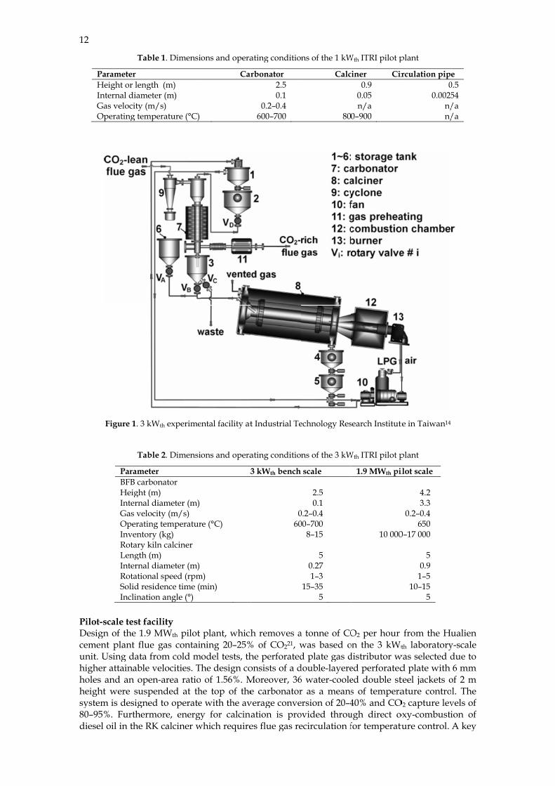
typical of coe carbonatorstone is fed tohe first test ation of the R
kg/h, the sponds to soobserved at
on (Figure 2)bustion chamitable for ener than 96%,
Figu
he 3 kWth pih was to keeen fresh so
eve the desire-up rate wntory in the
configuratiosable length
sing 1 kWth bormed to as5%vol. CO2,xperiments, iign of contin
was conducteime. Althoue MB carbon
sing 3 kWth bus case, the floal-fired powr at a controo the calcineperformed
RK calciner. usable lengorbent resid1 m from th. On the oth
mber causinndothermic cwhile the ca
ure 2. Temper
ilot plant waeep the CO2
rbent make-red CO2 cap
was lower the system wa
on is a more for calcinatio
bench-scale sess the COwhich is use
industrial grnuous operated and achie
ugh the preliator was clai
bench-scale lue gas enter
wer plants. Tolled rate of r, while inacusing the mIt showed thth for the cence time of
he combustioher hand, theng the operacalcination rrbonation co
rature distribu
as also used2 capture lev-up rate and
pture level, bhan the puras reduced
e uniform temon. The desir
facility O2 capture eed as the flu
rade limestontion, in whicheved CO2 caiminary resuimed to be d
facility ring the carb
The flue gas 47 L/min. T
ctive sorbent modified 3 khat if the calccalcination f 9 minutes.
on chamber ae temperaturating conditreaction. Neonversion wa
ution in the rot
d to run a 10vel above 85
d spent sorbebut maintainrge rate, two
and excessi
mperature dred calcinatio
efficiency froidising medine was calcinh 0.1 kg/h ofapture level ults indicateifficult to op
bonator contawas first preTo account fis purged fro
kWth facility ciner is fed wreaction is This is beca
and thus excre of 720°C wtions downs
evertheless, tas only 64%.1
tary kiln calcin
00-h long ca5%. Selectioent purge ratn appropriato effects weive degrada
istribution inon efficiency
om the mixtium in the caned at 850°C.f fresh limestin the carbo
d the practierate.14
ains approxieheated to 23for sorbent dom the systewas a batch
with fresh limapproximateause a tempcessive sinterwas observedstream of ththe calcinatio14
ner in the first
mpaign the n of the apte was showe process peere observed
ation of sorb
n the calciney is 80–95%.
ture composarbonator. Pr.20 tone was suponator aboveicability of s
imately 15%v30°C and thedeactivation,em. h test to ev
mestone at thely 1.5 m, w
perature of 1ring occurs id at 2 m frohe calciner on efficiency
t test
main objectppropriate bawn to be critierformance. d: the total bent activity
13
er and
sed of rior to
pplied e 99%
such a
vol. of en fed , fresh
aluate he rate which 000°C in this
om the to be
y was
tive of alance ical to If the solid
y was
14
obserthe soaboveas thbecaucalcin
Wlevel solidsand amainphen
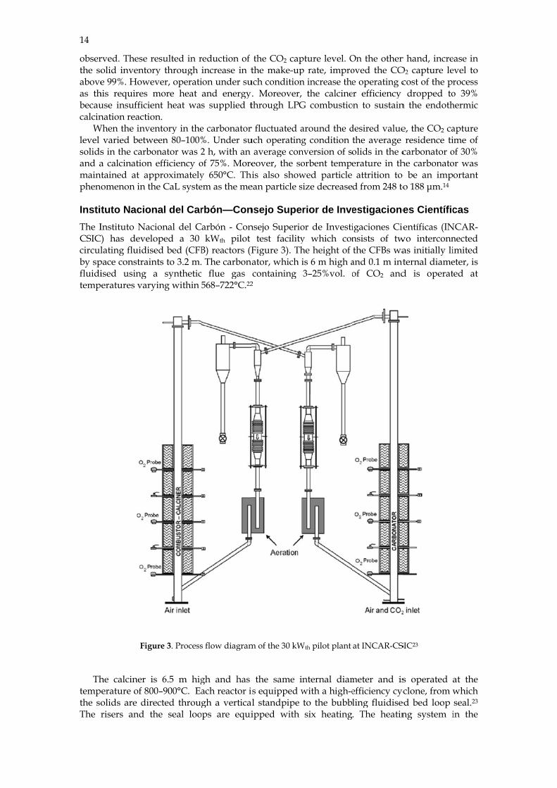
InstiThe ICSICcirculby spfluiditemp
Th
tempthe soThe
rved. These rolid inventoe 99%. Howe
his requires use insufficienation reactio
When the invevaried betw
s in the carba calcination
ntained at apnomenon in th
tuto NacioInstituto Nac
C) has devellating fluidis
pace constraiised using
peratures vary
Fig
he calciner iperature of 80
olids are dirrisers and t
resulted in rory through ever, operatimore heat
ent heat waon. entory in the
ween 80–100%bonator was 2n efficiency opproximatelyhe CaL syste
nal del Carcional del Cloped a 30 sed bed (CFBints to 3.2 m.a syntheticying within
gure 3. Process
is 6.5 m hig00–900°C. Earected throuthe seal loo
reduction of increase in tion under suand energys supplied t
e carbonator %. Under su2 h, with an of 75%. Morey 650°C. Thiem as the me
rbón—Conarbón - ConkWth pilot
B) reactors (F The carbona
c flue gas 568–722°C.22
s flow diagram
gh and has ach reactor igh a vertical
ops are equi
the CO2 capthe make-up
uch condition. Moreover, through LPG
r fluctuated auch operating
average coneover, the sois also show
ean particle s
nsejo Supensejo Superio
test facilityFigure 3). Thator, which icontaining
2
m of the 30 kW
the same is equipped wl standpipe ipped with
pture level. Op rate, impron increase the
the calcineG combustio
around the dg condition
nversion of soorbent tempewed particle size decrease
rior de Inveor de Investiy which conhe height of is 6 m high a3–25%vol. o
Wth pilot plant
nternal diamwith a high-eto the bubbsix heating
On the other oved the COe operating c
er efficiency on to sustain
desired valuethe average olids in the cerature in th
attrition to d from 248 to
estigacioneigaciones Ciensists of twthe CFBs wa
and 0.1 m intof CO2 and
at INCAR-CS
meter and isefficiency cycling fluidise. The heatin
r hand, increO2 capture lecost of the pr
dropped ton the endoth
e, the CO2 caresidence ti
carbonator ohe carbonatoo be an impo 188 μm.14
es Científicientíficas (INwo interconnas initially liternal diamed is operat
SIC23
s operated ayclone, from wed bed loop ng system i
ease in evel to rocess o 39% hermic
apture ime of of 30% or was ortant
cas NCAR-nected imited eter, is ted at
at the which seal.23 in the
carboexces
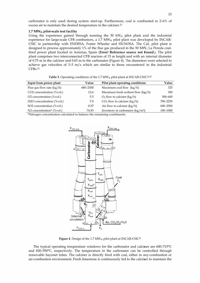
1.7 MUsingexperCSICdesigfired plantof 0.7achieCFBs
Input Flue gaCO2 coO2 conH2O cSO2 coN2 con*Nitro
Thand 8remoair-co
onator is onlss air to main
MWth pilot-scg the experrience for lar
C in partnersgned to proce
power plant comprises t75 m in the ceve gas velos.24
Tabl
from power pas flow rate (koncentration (ncentration (%concentration oncentration (ncentration* (%gen concentra
he typical op820–950°C, r
ovable bayonombustion en
ly used durintain the desi
cale test facilience gainedrge-scale CFship with ENess approxim
nt located intwo interconalciner and 0
ocities of 3–5
le 3. Operatin
plant kg/h) (%vol.)
%vol.) (%vol.) %vol.) %vol.) ation calculate
Figure 4. D
perating temrespectively.
net tubes. Thnvironment.
ing system sired tempera
lity d through r
FB combustorNDESA, Fos
mately 1% ofAsturias, Sp
nnected CFB 0.65 m in the5 m/s which
ng conditions o
Valu680–23
1257
0.74.
ed to balance t
Design of the 1
mperature wi. The tempe
he calciner isFresh limest
start-up. Fuature in the c
running the rs, a 1.7 MWster Wheelerf the flue gaspain (Error! reactors of 1
e carbonator h are simila
of the 1.7 MW
ue Pilot 300 Maxi2.6 Maxi5.5 O2 flo7.0 CO2 f07 Air fl83 Inven
the remaining
1.7 MWth pilo
indows for terature in ths directly firetone is contin
rthermore, ccalciner.22
30 kWth pWth pilot planr and HUNs produced i
Reference 15 m height (Figure 4). T
ar to those e
th pilot plant a
plant operatiimum coal flowimum fresh soow to calciner flow to calcinelow to calcinerntory in carbonconstituents.
t plant at INC
the carbonatohe carbonatoed with coalnuously fed
coal is comb
ilot plant annt was devel
NOSA. The Cn the 50 MWsource not fand with an
The diameterencountered
at INCAR-CSI
ng conditionsw (kg/h)
orbent flow (kg(kg/h)
er (kg/h) r (kg/h) nator (kg/m2)
CAR-CSIC25
or and calcinor can be col, either in oto the calcin
busted in 2–
and the indueloped by INCaL pilot plWe La Peredafound.). The
n internal diars were selec
d in the indu
IC24,25
s
g/h) 3
7060
) 10
ner are 600–ontrolled th
oxy-combustiner to mainta
15
6% of
ustrial NCAR-lant is a coal-e pilot ameter cted to ustrial
Value325300
300–60000–225000–250000–1000
–715°C rough ion or
ain the
16
desirefoundthe hloop loopi
Test cThe separresultcouldcarbocaptuthat t
Onsystem70–902.1 mparticlevels
MreporCO2. tempof 3 mshowkg/m
Test cArias380 hcomb
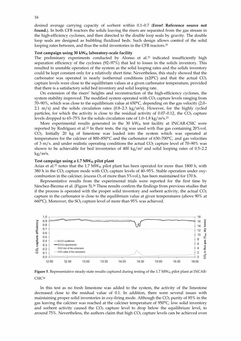
ReSánchif thecaptu660°C
Figure
CSIC2
Indecremaingas leand saroun
ed average d.). In both C
high-efficiencseals are de
ing rates betw
campaign uspreliminary
ration efficieted in unstab
d be kept cononator was ure levels wethere is a satin extension m stability im0%, which wm/s) and thcles, for whis dropped to
More experimrted by Rodr
Initially 20peratures for m/s. and un
wn to be achm2s.
campaign uss et al.25 noteh in the CO2 bustion in theepresentativehez-Biezma ee process is oure in the carC). Moreover
e 5. Represent26
n this test aseased close
ntaining propeaving the csorbent activnd 75%. Nev
carrying caCFB reactorscy cyclones, aesigned as bween, and th
sing 30 kWth
experimenency of the cble operationnstant only fooperated in
ere close to thisfactory soliof the risers
mproved. Thwas close to th
e solids circich the activ
o 65–75% for mental resultríguez et al.20 kg of limthe calciner
nder realistichievable for
sing a 1.7 MWes that the 1.capture mode calciner, (exe results froet al. (Figureoperated witrbonator is cr, the SO2 cap
tative steady-s
s no fresh lito the resid
per solid invealciner was vity caused
vertheless, th
apacity of sos the solids land then dir
bubbling fluihus the solid
h laboratory-ts conductecyclones (92–n of the systor a relativel
nearly isothe equilibriuid bed invents’ heights an
he modified she equilibriuculation ratevity is close
the solids cirts generated22 In their tes
mestone wasof 800–850°operating c
bed invento
Wth pilot pla.7 MWth pilode with CO2
xcess O2 of mom the expee 5).26 These rth the propeclose to the epture level of
state results ca
mestone wadual value oentories in oxreached at ththe CO2 ca
he authors cla
orbent witheaving the rrected to theidized beds.inventories i
-scale facilityed by Alon–97%) that ltem as the soly short timethermal condum values at tory and solind reconstrusystem opera
um value at 6es (0.8–2.3 kto the residurculation rat
d in the 30 sts, the rig ws loaded inC and the caonditions th
ories of 400
ant ot plant has b
capture levemore than 5%erimental trresults confirer solid invenequilibrium vf more than 9
aptured durin
as added to of 0.1. In axy-firing mohe calciner t
apture level aim that high
hin 0.1–0.7 (isers are sep
e double loop. Such desigin the CFB re
y so et al.23
led to lossesolid looping e. Nevertheleditions (±20a given carb
id looping rauction of theated with CO650°C, depenkg/m2s). Houal activity
te of 1.0–1.8 kkWth test f
was used witnto the systarbonator of
he actual COkg/m2 and
been operateels of 40–95%
%vol.), has beials were rerm the findinntory and sovalue at give95% was ach
ng testing of th
the system, addition, theode. Althougtemperature to drop bel
h CO2 captur
(Error! Referparated from p seals by grgn allows coeactors.25
indicated in in the solidrates and th
ess, this stud°C) and tha
bonator tempate. e high-efficieO2 capture lending on thewever, for tof 0.07–0.12,
kg/m2s.23 facility at INth flue gas cotem which
630–700°C, 2 capture levsolid loopin
ed for more %. Stable opeeen maintaineported for ngs from preorbent activiten temperatuhieved.
he 1.7 MWth pi
the activityere were sevh the CO2 puof 950°C, lo
low the equre levels can
rence sourcm the gas stre
ravity. The dontrol of the
nsufficiently ds inventory
he solids invedy showed that the actuaperature, pro
ency cycloneevels ranginge gas velocitythe highly c
2, the CO2 ca
NCAR-CSIC ontaining 20was operatand gas velo
vel of 70–90%ng rates of 0
than 1800 heration undened for 170 h
the first timevious studieity, the actuaures (above 9
ilot plant at IN
y of the limeveral issuesurity of 85%
ow solid inveuilibrium levn be achieved
ce not eam in double e solid
high y. This entory hat the l CO2
ovided
es, the g from y (2.0–cycled apture
were 0%vol. ted at ocities % was 0.5–2.2
h, with r oxy-.
me by es that al CO2 90% at
NCAR-
estone s with
in the entory vel, to d even
if higsystem
Arplantto higoperaafter conclbe re(95%)usingactivi
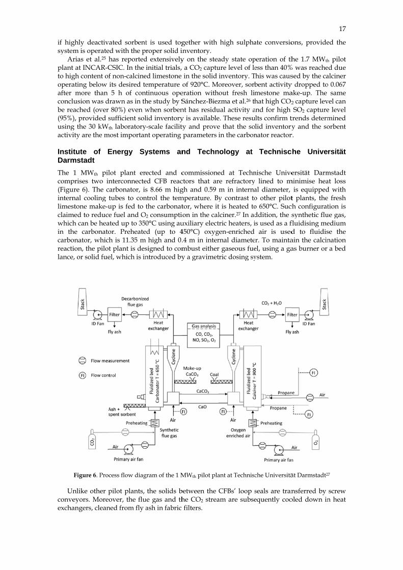
InstiDarmThe comp(Figuinternlimesclaimwhichin thcarboreactilance
Unconveexcha
ghly deactivam is operaterias et al.25 ht at INCAR-Cgh content ofating below
more than lusion was dached (over ), provided s
g the 30 kWt
ity are the m
tute of Emstadt 1 MWth pil
prises two inure 6). The cnal cooling tstone make-u
med to reduceh can be hea
he carbonatoonator, whichion, the pilot
e, or solid fue
Figure 6. Proc
nlike other peyors. Moreoangers, clean
ated sorbentd with the phas reportedCSIC. In the f non-calcineits desired te5 h of con
rawn as in th80%) even w
sufficient solth laboratory
most importan
Energy Sy
lot plant ernterconnectearbonator, istubes to conup is fed to e fuel and O
ated up to 35or. Preheateh is 11.35 mt plant is desel, which is in
cess flow diag
pilot plants, over, the flu
ned from fly a
t is used togroper solid i
d extensivelyinitial trials,
ed limestone emperature tinuous opehe study by Swhen sorbenlid inventory
y-scale facilitnt operating
ystems an
ected and ced CFB reacs 8.66 m hig
ntrol the temthe carbonat
O2 consumpti0°C using au
ed (up to 4m high and 0.
signed to comntroduced by
gram of the 1 M
the solids bue gas and thash in fabric
gether withinventory. y on the stea a CO2 captuin the solid of 920°C. Mo
eration withSánchez-Bieznt has residuy is availablety and proveparameters
nd Techn
commissionectors that argh and 0.59 mperature. Bytor, where ition in the caluxiliary elect450°C) oxyg.4 m in intermbust eithery a gravimet
MWth pilot pla
between the he CO2 streafilters.
high sulpha
ady state opure level of leinventory. Toreover, sorbout fresh limzma et al.26 thual activity ae. These resue that the soin the carbon
nology at
ed at Technre refractorym in internay contrast tot is heated tolciner.27 In adtric heaters, igen-enriched rnal diameter gaseous fuetric dosing sy
ant at Technisc
CFBs’ loop sam are subse
ate conversio
peration of thess than 40%
This was causbent activitymestone mahat high CO2
and for high ults confirm t
lid inventorynator reactor
Technisc
nische Unive lined to mal diameter, o other piloto 650°C. Sucddition, the sis used as a f
air is usedr. To mainta
el, using a gaystem.
che Universitä
seals are tranequently coo
ons, provide
he 1.7 MWth
% was reachesed by the ca
y dropped toake-up. The 2 capture levSO2 capture
trends determy and the so
r.
che Unive
ersität Darmminimise hea
is equippedt plants, the
ch configuratsynthetic flufluidising med to fluidisain the calcinas burner or
ät Darmstadt2
nsferred by oled down in
17
ed the
h pilot ed due alciner o 0.067
same vel can e level mined orbent
rsität
mstadt at loss d with e fresh tion is
ue gas, edium se the nation a bed
27
screw n heat
18
Test campaign The first tests performed using the 1 MWth pilot plant was conducted in July 2011. Since then, the facility has been operated for around 400 h to analyse CO2 capture using the CaL process. In the first campaign, lasting 72 h, continuous separation of CO2 from the 1300 Nm3/h synthetic gas comprising 10–12 vol% of CO2 was analysed.28 Throughout the campaign, the make-up flow was kept between 70–150 kg/h and the solid looping rate between 1500 and 3000 kg/h. The study revealed that lower CO2 capture levels are obtained if sintered CaO, which has been calcined at 1000°C before the test, is fed to the carbonator rather than fresh limestone. An increase of the CO2 capture level was observed when fresh limestone was fed to the carbonator. Despite poor performance of the calciner cyclone and low CO2 concentration in the flue gas caused by limited firing power in the calciner, the total CO2 capture level was more than 90%.
On increasing the power of the burners and the lances, as well as improving the cyclone performance, a second test campaign using propane firing in the calciner was carried out. These changes led to a significant reduction of the make-up rate. Moreover, the fluidisation air was enriched with 50% O2 to maintain desirable gas velocity in the calciner and to ensure nearly complete combustion of propane. Again, the carbonator was operated at 660°C and was supplied with the synthetic flue gas containing 12%vol. of CO2. To maintain a desired average CO2 capture level in the carbonator, the solid looping rate was kept at 2000 kg/h which corresponds to average Ca/C ratio of 11.6. The maximum CO2 capture level in the carbonator was found to be 85%, which is equivalent to 92% when oxy-combustion of propane in the calciner is considered.
In the third campaign, the calciner was fired with the pulverised coal and the fluidisation air enriched by 45–50% O2. The temperature in the carbonator reached 670°C. The same amount of synthetic flue gas was used as in second campaign. It was found that to reach the same CO2 capture level in the carbonator (85%), the solid looping ratio needed to be increased to approximately 2800 kg/h (Ca/C=17.2). Moreover, it was found that the CO2 concentration in the clean gas was close to the equilibrium CO2 concentration at the current operating temperature. The CO2 capture level dropped to approximately 60% when the temperature in the carbonator dropped to 610°C.27
Institute of Combustion and Power Plant Technology at University of Stuttgart The Institute of Combustion and Power Plant Technology (Institut für Feuerungs-und Kraftwerkstechnik, IKF) at University of Stuttgart has developed a calcium looping pilot plant based on 10 kWth dual fluidised beds (DFB) that can be operated in continuous mode.29 The practicability and stability of the DFB system, which is composed of a CFB riser and a bubbling fluidised bed (BFB) (Table 5), was first analysed using a down-scaled cold model.57,59
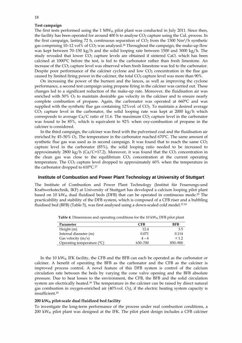
Table 4. Dimensions and operating conditions for the 10 kWth DFB pilot plant
Parameter CFB BFB Height (m) 12.4 3.5 Internal diameter (m) 0.071 0.114 Gas velocity (m/s) 4 – 6 < 1.2 Operating temperature (°C) 630–700 850–900
In the 10 kWth IFK facility, the CFB and the BFB can each be operated as the carbonator or calciner. A benefit of operating the BFB as the carbonator and the CFB as the calciner is improved process control. A novel feature of this DFB system is control of the calcium circulation rate between the beds by varying the cone valve opening and the BFB absolute pressure. Due to heat losses to the environment, the CFB, the BFB and the solid circulation system are electrically heated.30 The temperature in the calciner can be raised by direct natural gas combustion in oxygen-enriched air (40%vol. O2), if the electric heating system capacity is insufficient.29
200 kWth pilot-scale dual fluidized bed facility To investigate the long-term performance of the process under real combustion conditions, a 200 kWth pilot plant was designed at the IFK. The pilot plant design includes a CFB calciner

operaeitherFigurregimvalveconfigcontr
Thequipwoodenergcondiin intdesigresidediamremolean bup thwith
Test cThe tused condistate carbomaxim
Thanalygiven
Test cDietebeen
ating in the fr under a turre 7).31,32 A
me, required es for controguration wit
rolled throug
Fig
he fast fluidipped with a d chips). Althgy demand itions in the ternal diamegned to operence time.31
meter28, is fluioved via a wabed region. T
he system duinsulating co
campaign ustests were co
to clean theitions. The eoperation w
onator was omum of 97%he effect of ysed and comn temperatur
campaign user et al.31 repo
recorded an
fast fluidisatrbulent or fasdesign invoa redesign o
olling the loth the carbongh the L-valv
gure 7. Comp
ised CFB calcstaged oxid
hough the firin the calcincalciner. In
eter), the heatrate under lThe fast flui
idised with tater-cooled hThe facility h
uring start-uponcrete and r
sing a 10 kWnducted usine synthetic fexperiments with a minooperated at
%. the carbona
mpared withre were achie
sing a 200 kWort that more
nd the facilit
tion regime ast fluidised flving two s
of the solid ciooping ratiosnator operative which is d
arison of 200 k
ciner, whichdant supply ring system ner, flue gasthe turbulent is removedlower fluidisidised CFB che flue gas a
heat exchanghas a 400 kWp. To minimrefractory m
Wth DFB facilng the Germflue gas havrevealed tha
or make-up 660°C, the
ator operatinh the equilibreved by Ca/C
Wth DFB facie than 600 h ty was found
and a reconffluidisation rsymmetric Circulation sys in both CFing in the tur
directly fed fr
kWth DFB pilo
h is 10 m in hfor oxy-comis designed s recirculati
nt fluidised bd only using sation velocicarbonator, wand the heat ger in the denWth gas burn
mise the heat material resist
lity man limestone
ving 15%volat it was relof fresh sorachievable C
ng temperaturium data (FC ratio highe
ility of successfu
d to be hydr
figurable CFregime ( CFBs, which ystem througFBs indepenrbulent regimrom the CFB
ot plant config
height and 0mbustion of s
to handle upon is used
bed carbonatthe fluidisedities than th
which is 10 mreleased du
nse bed regioner that is us
loss in the sant to abrasi
e originating. CO2 to simlatively strairbent to accCO2 capture
ure and the igure 8). Theer than 14.30
ul operation orodynamicall
FB carbonato
operate in h implement
ndently.32 Come, the solidcalciner.31
gurations at IF
.021 m in intsolid fuel (cop to 70%vol.to achieve rtor (6 m in hd bed heat exhe CFB carbom high and 0e to the exoton and a bayed to genera
system the reion.32
g from Swabimulate coal-fghtforward
count for atte level excee
CO2 capture best CO2 ca
of the 200 kWly stable. Th
or that can op
the fast fluntation of twoonversely, fo
d circulation
FK33
ternal diameoal, wood p. of O2 to merealistic ope
height and 0.xchanger. It ionator and
0.023 m in inthermic reactyonet cooler ate hot gas toeactors were
ian Alb whicfired power to achieve strition. Wheeded 90%, w
re level werapture levels
Wth pilot planhe tests perfo
19
perate
idised o cone or the rate is
eter, is pellets, eet the rating 033 m is also lower
nternal tion is in the o heat
e lined
ch was plant
steady en the with a
e also s for a
nt has ormed
20
mainsynth
Figure
HturbuNevereactitempstudydesuldeter(Figulevel,
Figure
IFK33
nly aimed ahetic flue gas
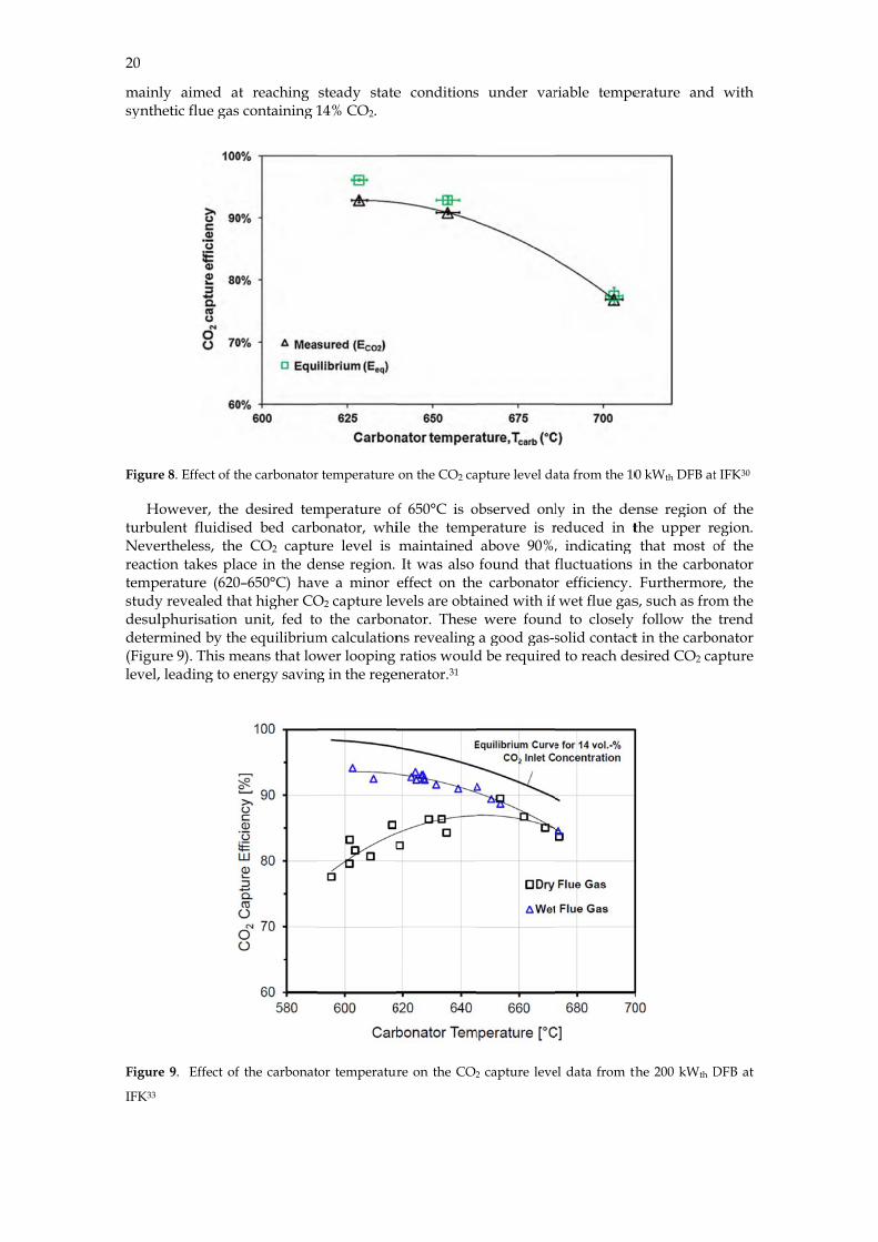
e 8. Effect of th
owever, theulent fluidiseertheless, theion takes pla
perature (620y revealed thlphurisation rmined by thure 9). This m, leading to e
e 9. Effect of
at reaching s containing 1
he carbonator
e desired temed bed carbe CO2 captuace in the de0–650°C) havhat higher CO
unit, fed tohe equilibriummeans that lowenergy saving
f the carbonat
steady state14% CO2.
r temperature
mperature ofbonator, whiure level is ense region. ve a minor eO2 capture leo the carbonm calculationwer looping g in the rege
tor temperatur
e conditions
on the CO2 ca
f 650°C is oile the tempmaintained It was also
effect on theevels are obtanator. Thesens revealing ratios would
enerator.31
re on the CO2
s under var
apture level da
observed onlperature is r
above 90%,found that f
e carbonatorained with ife were found
a good gas-sd be required
2 capture leve
riable tempe
ata from the 10
ly in the dereduced in t, indicating fluctuations r efficiency. wet flue gas
d to closely solid contactd to reach de
el data from th
erature and
0 kWth DFB at
ense region othe upper rthat most oin the carboFurthermor
s, such as fro follow the t in the carboesired CO2 ca
the 200 kWth D
with
t IFK30
of the egion. of the onator re, the om the
trend onator apture
DFB at
OhioOhio Carbothe OReactby th
InFi
reactooccur980°Cmultisorbe
Test cThe Cnaturwas u
Innot acarboamou
Thlevel perfoachiesuch challe
VienReseareform
o State UnivState Univer
onation – CaOhio State Ction Separati
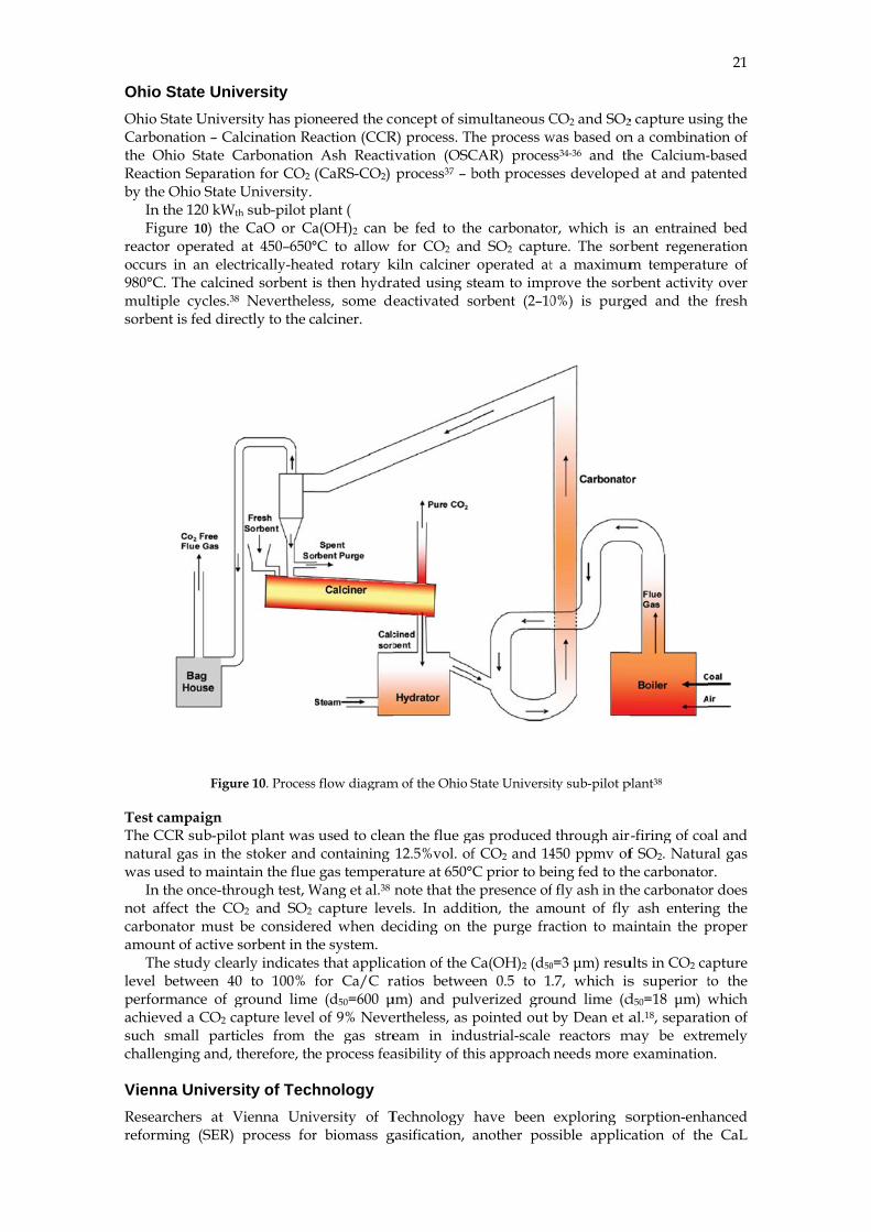
he Ohio State n the 120 kWt
igure 10) theor operated rs in an elecC. The calciniple cycles.38
ent is fed dire
Figu
campaign CCR sub-piloral gas in theused to main
n the once-thraffect the COonator must unt of active he study clea
between 40ormance of geved a CO2 c
small partienging and,
nna Universarchers at Vming (SER)
versity rsity has pioalcination ReCarbonation ion for CO2 University.
th sub-pilot pe CaO or Ca
at 450–650°ctrically-heat
ned sorbent i8 Nevertheleectly to the c
ure 10. Process
ot plant was e stoker and
ntain the fluerough test, WO2 and SO2 be considersorbent in th
arly indicates0 to 100% ground lime
capture level icles from ttherefore, th
sity of TechVienna Univ
process for
neered the coeaction (CCR
Ash Reacti(CaRS-CO2)
plant ( a(OH)2 can b°C to allow ted rotary kis then hydraess, some dealciner.
s flow diagram
used to clead containing e gas temperaWang et al.38
capture levred when dehe system. s that applicafor Ca/C r
e (d50=600 μof 9% Neve
the gas strehe process fea
hnology versity of Tr biomass g
oncept of simR) process. Thivation (OSCprocess37 – b
be fed to thfor CO2 an
kiln calciner ated using seactivated s
m of the Ohio S
an the flue ga12.5%vol. of
ature at 650°note that the
vels. In addieciding on th
ation of the Catios betweμm) and pulertheless, as peam in indasibility of th
Technology gasification,
multaneous Che process w
CAR) procesboth process
he carbonatod SO2 captuoperated at
team to impsorbent (2–10
State Universi
as producedf CO2 and 14C prior to bee presence oftion, the amhe purge fra
Ca(OH)2 (d50
en 0.5 to 1lverized gropointed out ustrial-scale
his approach
have been another pos
CO2 and SO2
was based onss34-36 and thses develope
or, which is ure. The sorbt a maximum
prove the sor0%) is purg
ity sub-pilot p
through air-450 ppmv ofeing fed to thf fly ash in th
mount of fly action to ma
0=3 μm) resu.7, which isund lime (dby Dean et areactors m
needs more
exploring sssible applic
2 capture usinn a combinathe Calcium-
ed at and pat
an entrainerbent regenem temperaturbent activityged and the
plant38
r-firing of coaf SO2. Naturhe carbonatorhe carbonatory ash enterinaintain the p
ults in CO2 cas superior td50=18 μm) wal.18, separat
may be extrexamination
sorption-enhcation of the
21
ng the tion of -based tented
d bed ration ure of y over
fresh
al and ral gas r. r does
ng the proper
apture to the which tion of emely n.
hanced e CaL
22
procewhichhigh Figuroperatakesmaterare trconceheat heat t
FigureTechn
Test cThe condifor th700°C
ThproceachieCO2 rg/Nm
ThKoppgasifiTherecombsolid mater
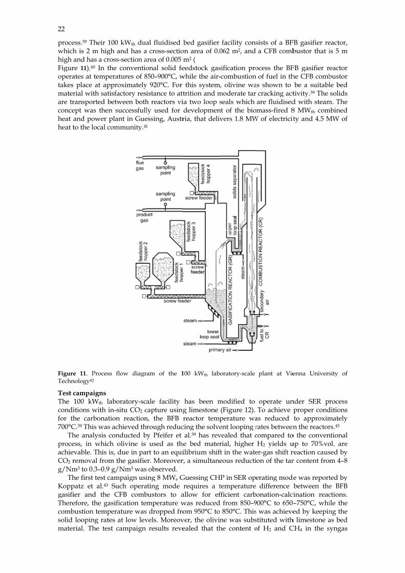
ess.39 Their 1h is 2 m higand has a cro
re 11).40 In thates at tempes place at aprial with satiransported bept was thenand power pto the local c
e 11. Processnology42
campaigns 100 kWth laitions with ihe carbonat
C.39 This washe analysis cess, in whichevable. This iremoval fromm3 to 0.3–0.9 he first test cpatz et al.43 ier and theefore, the gabustion temp
looping raterial. The tes
100 kWth duagh and has aoss-section ahe conventioeratures of 8
pproximatelyisfactory res
between bothn successfullplant in Gue
community.41
s flow diagr
aboratory-scin-situ CO2 ction reactions achieved thconducted bh olivine is is, due in pam the gasifieg/Nm3 was
campaign usiSuch opera
CFB combasification teperature wases at low levst campaign
al fluidised a cross-sectioarea of 0.005 onal solid fe850–900°C, wy 920°C. For istance to atth reactors vily used for essing, Austr1
am of the 1
ale facility capture usingn, the BFB rhrough reducby Pfeifer et
used as thert to an equi
er. Moreover observed. ing 8 MWe G
ating mode bustors to amperature w
s dropped frovels. Moreov
results reve
bed gasifier on area of 0.0m2 ( eedstock gas
while the air-this system
trition and mia two loop sdevelopmenria, that deli
100 kWth lab
has been mg limestone reactor temp
cing the solveal.39 has rev
he bed materilibrium shifr, a simultane
Guessing CHrequires a t
allow for efwas reducedom 950°C to
ver, the oliviealed that th
facility cons062 m2, and
sification pro-combustion
m, olivine wamoderate tar seals which
nt of the biovers 1.8 MW
boratory-scale
modified to (Figure 12). perature waent looping rvealed that crial, higher ft in the wateeous reducti
HP in SER opetemperature fficient carb
d from 850–9o 850°C. Thisne was subshe content o
sists of a BFa CFB comb
ocess the BFof fuel in th
as shown to cracking actare fluidisedmass-fired 8
W of electricit
plant at Vie
operate unTo achieve
as reduced rates betweencompared toH2 yields u
er-gas shift ron of the tar
erating moddifference
onation-calc900°C to 650s was achievestituted withof H2 and C
FB gasifier rebustor that i
FB gasifier rhe CFB combbe a suitabl
tivity.39 The d with steam8 MWth comity and 4.5 M
enna Univers
nder SER prproper condto approximn the reactor
o the convenup to 70%voreaction causr content fro
de was reportbetween the
cination reac0–750°C, whied by keepin
h limestone aCH4 in the s
eactor, is 5 m
eactor bustor le bed solids
m. The mbined MW of
sity of
rocess ditions mately rs.43 ntional ol. are sed by m 4–8
ted by e BFB ctions. ile the ng the as bed syngas
decredrivinwith be im
Fi
Figureusing
Figuretypica
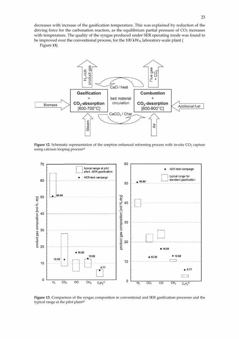
eases with inng force for temperature
mproved overigure 13).
e 12. Schematcalcium loopi
e 13. Comparal range at the
ncrease of thethe carbona
e. The qualityr the conven
tic representating process43
ison of the sy pilot plant43
e gasificationtion reactiony of the syngtional proces
tion of the sor
ngas composi
n temperaturn, as the equgas producedss, for the 10
rption enhanc
ition in conve
re. This was uilibrium pard under SER 0 kWth labor
ced reforming
ntional and S
explained byrtial pressureoperating matory-scale p
process with
ER gasificatio
by reduction e of CO2 incr
mode was fouplant (
in-situ CO2 c
on processes a
23
of the reases und to
capture
and the
24
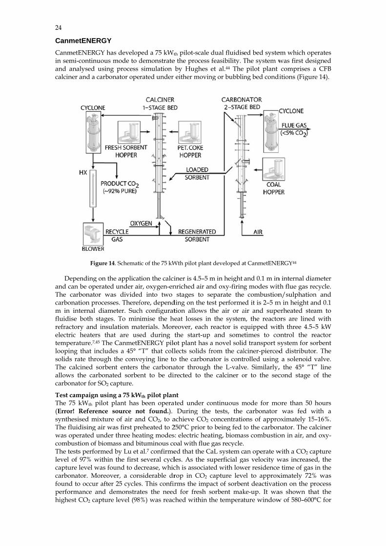
CanmCanmin semand acalcin
Deand cThe carbom in fluidirefracelectrtemploopisolidsThe callowcarbo
Test cThe 7(ErrosynthThe fwas ocombThe tlevel captucarbofoundperfohighe
metENERGmetENERGYmi-continuouanalysed usiner and a car
Figure
epending oncan be operacarbonator
onation proce internal diaise both stagctory and inric heaters t
perature.7,45 Ting that inclus rate througcalcined sor
ws the carboonator for SO
campaign us75 kWth pilo
or! Referenchesised mixtufluidising airoperated undbustion of biotests perform
of 97% withure level wasonator. Mored to occur af
ormance andest CO2 captu
GY has developus mode to ding process
rbonator ope
e 14. Schemat
n the applicatted under aiwas dividedesses. Therefameter. Suchges. To min
nsulation mathat are us
The CanmetEudes a 45° “gh the convebent enters
onated sorbeO2 capture.
sing a 75 kWot plant has e source nure of air an
r was first prder three heaomass and bi
med by Lu et hin the first s found to deeover, a confter 25 cycles
d demonstraure level (98
ped a 75 kWt
demonstratesimulation rated under
ic of the 75 kW
tion the calciir, oxygen-end into two fore, dependh configurat
nimise the heaterials. Mored during t
ENERGY pilo“T” that colleying line tothe carbona
ent to be dir
Wth pilot planbeen operat
ot found.). nd CO2, to areheated to 2ating modesituminous coal.7 confirmeseveral cycl
ecrease, whicnsiderable drs. This confirtes the need
8%) was reac
th pilot-scale e the processby Hughes either movin
Wth pilot plan
iner is 4.5–5 nriched air an
stages to sding on the tetion allows eat losses in
reover, each the start-upot plant has lects solids fo the carbonator throughrected to th
nt ted under cDuring the
achieve CO2
250°C prior ts: electric heaoal with flueed that the Cles. As the sch is associatrop in CO2
rms the impd for fresh sched within t
dual fluidise feasibility. Tet al.44 The
ng or bubblin
nt developed a
m in height nd oxy-firing
separate the est performethe air or a
n the systemreactor is eq
p and somea novel solidfrom the cal
nator is contrh the L-valvhe calciner o
ontinuous me tests, the concentratioo being fed t
ating, biomase gas recycle. CaL system csuperficial gated with lowcapture leve
pact of sorbensorbent makthe temperat
ed bed systeThe system w
pilot plant ng bed condi
t CanmetENE
and 0.1 m ing modes wit
combustioned it is 2–5 mair and supem, the reacto
quipped wittimes to cod transport slciner-piercedrolled using e. Similarly,
or to the sec
mode for mocarbonator
ons of approto the carbonss combustio
an operate was velocity w
wer residenceel to approxnt deactivatike-up. It wature window
em which opwas first descomprises a
itions (Figur
ERGY44
n internal diath flue gas ren/sulphation
m in height anerheated steaors are linedth three 4.5–ontrol the rsystem for sod distributora solenoid
, the 45° “Tcond stage o
ore than 50 was fed w
oximately 15nator. The caon in air, and
with a CO2 cawas increasee time of gas ximately 72%ion on the pras shown thw of 580–600
perates signed a CFB re 14).
ameter ecycle. n and nd 0.1 am to
d with –5 kW eactor orbent r. The valve.
T” line of the
hours with a 5–16%. alciner d oxy-
apture ed, the
in the % was rocess at the °C for
25
fresh sorbent and approximately 700°C after 20 cycles. When the temperature dropped below 500°C, the reaction rate slowed down significantly. This was reflected in the off-gas CO2 concentration of approximately 9–10%vol. of CO2, which reflects a drop of CO2 capture level.
Table 5. Operating conditions of the 75 kWth CanmetENERGY pilot plant
Parameter Minimum Maximum CFB Calciner Bed temperature (°C) 850 950 Initial sorbent inventory (kg) 4.5 5.0 Sorbent make-up batch (kg) 0.3 0.5 Biomass consumption rate (kg/h) 4.0 7.6 Coal consumption rate (kg/h) 2.6 5.8 Air flow rate (air-firing mode) (kg/h) 8.0 14.4 Oxygen flow rate (oxy-firing mode) (kg/h) 5.2 7.7 Moving or bubbling FB carbonator Bed temperature (°C) 580 720 Air flow rate (slpm) 40 100 CO2 flow rate (slpm) 7.5 19.0 CO2 concentration at inlet (%vol.) 15.0 16.5 Air flow for solid conveying (slpm) 35 55
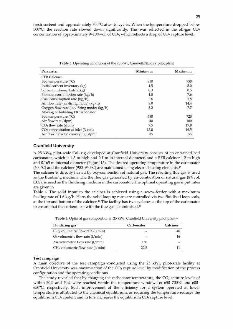
Cranfield University A 25 kWth pilot-scale CaL rig developed at Cranfield University consists of an entrained bed carbonator, which is 4.3 m high and 0.1 m in internal diameter, and a BFB calciner 1.2 m high and 0.165 m internal diameter (Figure 15). The desired operating temperature in the carbonator (600°C) and the calciner (900–950°C) are maintained using electric heating elements.46 The calciner is directly heated by oxy-combustion of natural gas. The resulting flue gas is used as the fluidising medium. The the flue gas generated by air-combustion of natural gas (8%vol. CO2), is used as the fluidising medium in the carbonator. The optimal operating gas input rates are given in Table 6. The solid input to the calciner is achieved using a screw-feeder with a maximum feeding rate of 1.6 kg/h. Here, the solid looping rates are controlled via two fluidised loop seals, at the top and bottom of the calciner.47 The facility has two cyclones at the top of the carbonator to ensure that the sorbent lost with the flue gas is minimised.46
Table 6. Optimal gas composition in 25 kWth Cranfield University pilot plant46
Fluidizing gas Carbonator Calciner CO2 volumetric flow rate (l/min) – 40 O2 volumetric flow rate (l/min) – 16 Air volumetric flow rate (l/min) 150 – CH4 volumetric flow rate (l/min) 22.5 11
Test campaign A main objective of the test campaign conducted using the 25 kWth pilot-scale facility at Cranfield University was maximisation of the CO2 capture level by modification of the process configuration and the operating conditions.
The study revealed that by changing the carbonator temperature, the CO2 capture levels of within 50% and 70% were reached within the temperature windows of 650–700°C and 600– 650°C, respectively. Such improvement of the efficiency for a system operated at lower temperature is attributed to the chemical equilibrium, as reducing the temperature reduces the equilibrium CO2 content and in turn increases the equilibrium CO2 capture level.
26
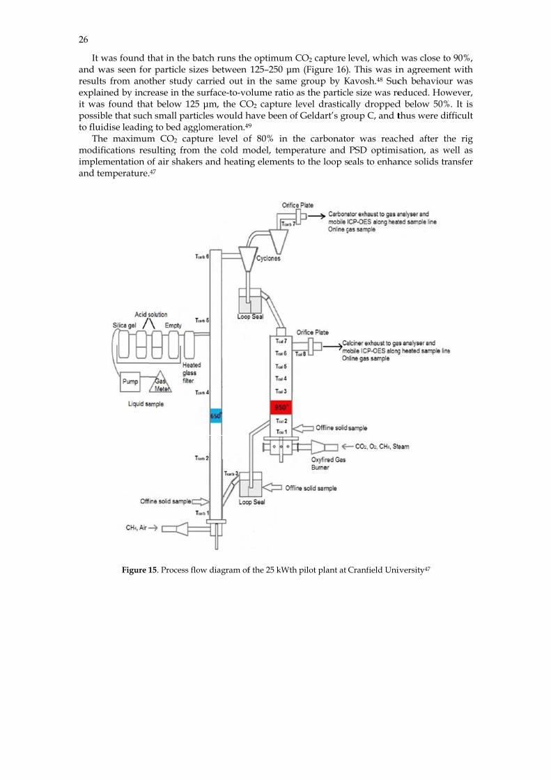
It and wresultexplait wapossito flu
Thmodiimpleand t
was found twas seen forts from anot
ained by incras found thaible that suchuidise leadinghe maximumifications resementation otemperature.
Figure 1
that in the bar particle sizther study crease in the sat below 125h small particg to bed agglm CO2 captsulting fromof air shaker47
15. Process flo
atch runs thezes between carried out isurface-to-vo μm, the COcles would hlomeration.49
ture level ofm the cold m
s and heatin
ow diagram of
e optimum C125–250 μm
in the same olume ratio aO2 capture lehave been of 9 f 80% in th
model, tempeng elements t
f the 25 kWth
CO2 capture lm (Figure 16)
group by Kas the particlevel drasticaGeldart’s gr
he carbonatoerature and to the loop s
pilot plant at
level, which . This was in
Kavosh.48 Sucle size was really droppedoup C, and t
or was reachPSD optimieals to enhan
Cranfield Uni
was close ton agreementch behavioueduced. How
d below 50%thus were di
hed after thisation, as wnce solids tra
iversity47
o 90%, t with
ur was wever,
%. It is ifficult
he rig well as
ansfer

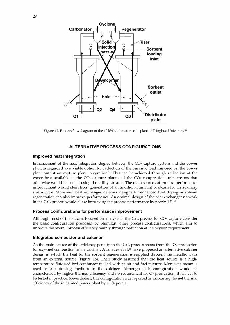
TsinThe interc0.149transfinjectcompcalcinheate
Test cIn thsorbewas kBFBs(850°level the C
Th0.7%vaveraleavinmeancarbo
ghua Univedual fluidis
connected BF m and 0.117ferred betwetion nozzles pensate for hner, each reaers are used f
campaign e test campa
ent to clean kept betwee. When the dC), the CO2 of 89% in th
CO2 fraction ihe carbonatovol., which cage conversing the carbo
n size of theonator, respe
Figure 1
ersity sed bed syFBs (Figure 7, respectiveeen the bedare used to
heat losses aactor was equfor heating th
aign performthe syntheti
en 30–36 kg/desired temp
fraction in he carbonatorincreased to aor was operacorresponds ton in the ca
onator was 16e particles w
ectively.
16. Effect of pa
ystem develo17). The intely, and the h
ds through tho transport tand to mainuipped with he flue gas, t
med, dolomiic flue gas co/h which coperatures wethe clean gar. Increasing approximateated at 640°to a CO2 caparbonator rea6.2%. Feng ewas reduced
article size on t
oped at theernal diametheight of eache cyclones the solids frntain desired
four 2.5 kWthe risers, the
ite (d50=0.5 montaining 12
orresponded ere achieved as was 1.2%vg the operatinely 10%vol d°C and the rpture level of
ached 70.4%et al.50 noted d to 0.16 mm
the CO2 captu
e Tsinghua ters of the cach bed is 1 m
and the dorom the bedd temperatu
Wth electric hee cyclones an
mm) was us2.1–14.5%volto the invenin the carbo
vol., which cng temperatu
due to chemicresulting CO95%. Under
% and the avthat after 7 h
m and 0.42
ure level47
University arbonator an
m. In this systowncomers.
to the riserre in the ca
eaters. Also, nd the downc
sed as a sourl. CO2. The sntory heightnator (630°Ccorresponds ure of the carcal equilibriu
O2 fraction insuch operat
verage conveh of continuomm in the
consists ofnd the calcintem, the soliIn addition,r in each BFarbonator anadditional ecomers.50
urce of the nsolid loopint of 0.3 m inC) and the ca
to a CO2 carbonator to 6um limitationn the clean gting conditioersion of paous operatio
e calciner an
27
f two ner are ds are solid
FB. To nd the lectric
natural g rate
n both alciner apture 680°C, ns. gas to ns the rticles
on, the nd the
28
ImprEnhaplantplantwasteotherimprosteamregenin the
ProcAlthothe bimpro
IntegAs thfor oxdesigfrom tempused charabe tesefficie
Figure 17. Pr
roved heat ancement of t is regardedt output on e heat availrwise would ovement wo
m cycle. Morneration can e CaL proces
cess configough most obasic configuove the over
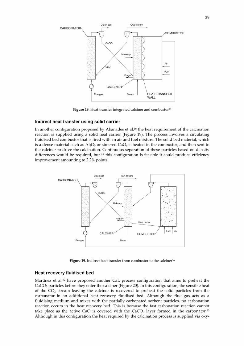
grated comhe main sourxy-fuel comb
gn in which an external
perature fluidas a fluid
acterised by sted in practency of the in
rocess flow di
ALTER
integrationthe heat int
d as a viable capture plaable in the be cooled u
ould stem froreover, heat also improv
ss would allo
gurations fof the studiesuration propall process e
mbustor andrce of the effbustion in ththe heat forl source (Figdised bed codising medihigher thermice. Neverthentegrated po
iagram of the 1
RNATIVE PR
n egration degoption for r
nt integratioCO2 capture
using the utilom generatioexchanger n
ve performanow improvin
or performs focused onposed by Shfficiency ma
d calcinerficiency pena
he calciner, Ar the sorbentgure 18). Thmbustor fueum in the
mal efficiencyeless, this co
ower plant by
10 kWth labora
ROCESS C
gree betweenreduction of on.21 This cae plant andlity streams. on of an addnetwork desnce. An optim
ng the proces
mance impron analysis of himizu3, othainly through
alty in the CAbanades et t regeneratioheir study aelled with an
calciner. Ay and no req
onfiguration wy 1.6% point
ator-scale plan
CONFIGURA
n the CO2 cathe parasiti
an be achievd the CO2 co
The main soditional amosigns for enhmal design os performan
ovement the CaL pro
her process ch reduction o
CaL process sal.16 have pron is supplieassumed than air and fueAlthough suquirement fowas reported
ts.
nt at Tsinghua
ATIONS
apture systec load impo
ved through ompression ources of proount of steamhanced fuel of the heat exce by nearly
ocess for CO2
configurationof the oxygen
stems from toposed an aed through tat the heat el mixture. Much configuror O2 producd as increasin
a University50
em and the posed on the p
utilisation unit stream
ocess performm for an auxdrying or soxchanger ne1%.51
2 capture conns, which a
n requiremen
the O2 produalternative cathe metallic source is a
Moreover, steuration wouction, it has ng the net th
power power of the
ms that mance xiliary olvent twork
nsider aim to nt.
uction alciner
walls high-
eam is ld be yet to
hermal
29
Figure 18. Heat transfer integrated calciner and combustor16
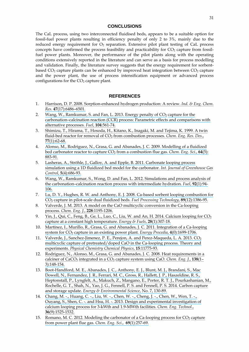
Indirect heat transfer using solid carrier In another configuration proposed by Abanades et al.16 the heat requirement of the calcination reaction is supplied using a solid heat carrier (Figure 19). The process involves a circulating fluidised bed combustor that is fired with an air and fuel mixture. The solid bed material, which is a dense material such as Al2O3 or sintered CaO, is heated in the combustor, and then sent to the calciner to drive the calcination. Continuous separation of these particles based on density differences would be required, but if this configuration is feasible it could produce efficiency improvement amounting to 2.2% points.
Figure 19. Indirect heat transfer from combustor to the calciner16
Heat recovery fluidised bed Martínez et al.52 have proposed another CaL process configuration that aims to preheat the CaCO3 particles before they enter the calciner (Figure 20). In this configuration, the sensible heat of the CO2 stream leaving the calciner is recovered to preheat the solid particles from the carbonator in an additional heat recovery fluidised bed. Although the flue gas acts as a fluidising medium and mixes with the partially carbonated sorbent particles, no carbonation reaction occurs in the heat recovery bed. This is because the fast carbonation reaction cannot take place as the active CaO is covered with the CaCO3 layer formed in the carbonator.53 Although in this configuration the heat required by the calcination process is supplied via oxy-

30
fuel cpoint
CalcAn exloopi( Figurreactogaseoand ccapabrequiconsi
combustion, ts with a sub
Fig
cium and chxperimental ing with the
re 21) proposor. In this coous fuel on ccopper (II) oble of improired. Althougidered as in t
Fig
it is expectebsequent redu
gure 20. Three
hemical loostudy conduchemical loo
sed by the aunfiguration,
contact with oxide, the fo
oving the ovegh several prthe early stag
gure 21. Conce
ed to increauction in the
e-bed configur
oping integucted by Maoping cycles
uthors compthe heat for the metal ox
ormer beingerall system rocess configges of develo
eptual design o
se the therm fuel consum
ration with an
grated cyclanovic and Afor the pulv
rises, in addsorbent regexide. The so
g the oxygenperformanc
gurations weopment.
of CaO/CuO-
mal efficiencymption of 9%
additional he
le Anthony54 exerised coal c
dition to the ceneration is polid sorbent cn carrier. Thce as cryogenere proposed
-looping cycle
y of the CaLpoints.
eat recovery be
xplored integcombustion p
carbonator aprovided by consists of bherefore, thisnic air separ
within such
for CO2 captu
L process by
ed52
gration of caplants. The s
and calciner, combustion
both calcium s configurat
ration is no lh concepts m
ure54
y 1.4%
alcium ystem
an air of the oxide
tion is longer
must be
31
CONCLUSIONS The CaL process, using two interconnected fluidised beds, appears to be a suitable option for fossil-fuel power plants resulting in efficiency penalty of only 2 to 3%, mainly due to the reduced energy requirement for O2 separation. Extensive pilot plant testing of CaL process concepts have confirmed the process feasibility and practicability for CO2 capture from fossil-fuel power plants. Moreover, the performance of the pilot plants along with the operating conditions extensively reported in the literature and can serve as a basis for process modelling and validation. Finally, the literature survey suggests that the energy requirement for sorbent-based CO2 capture plants can be enhanced by improved heat integration between CO2 capture and the power plant, the use of process intensification equipment or advanced process configurations for the CO2 capture plant.
REFERENCES 1. Harrison, D. P. 2008. Sorption-enhanced hydrogen production: A review. Ind. & Eng. Chem.
Res. 47(17):6486–6501. 2. Wang, W., Ramkumar, S. and Fan, L. 2013. Energy penalty of CO2 capture for the
carbonation–calcination reaction (CCR) process: Parametric effects and comparisons with alternative processes. Fuel, 104:561-74.
3. Shimizu, T., Hirama, T., Hosoda, H., Kitano, K., Inagaki, M. and Tejima, K. 1999. A twin fluid-bed reactor for removal of CO2 from combustion processes. Chem. Eng. Res. Des., 77(1):62-68.
4. Alonso, M., Rodríguez, N., Grasa, G. and Abanades, J. C. 2009. Modelling of a fluidized bed carbonator reactor to capture CO2 from a combustion flue gas. Chem. Eng. Sci., 64(5): 883-91.
5. Lasheras, A., Ströhle, J., Galloy, A. and Epple, B. 2011. Carbonate looping process simulation using a 1D fluidized bed model for the carbonator. Int. Journal of Greenhouse Gas Control, 5(4):686-93.
6. Wang, W., Ramkumar, S., Wong, D. and Fan, L. 2012. Simulations and process analysis of the carbonation–calcination reaction process with intermediate hydration. Fuel, 92(1):94-106.
7. Lu, D. Y., Hughes, R. W. and Anthony, E. J. 2008. Ca-based sorbent looping combustion for CO2 capture in pilot-scale dual fluidized beds. Fuel Processing Technology, 89(12):1386-95.
8. Valverde, J. M. 2013. A model on the CaO multicyclic conversion in the Ca-looping process. Chem. Eng. J., 228:1195-1206.
9. Yin, J., Qui, C., Feng, B., Ge, L., Luo, C., Liu, W. and An, H. 2014. Calcium looping for CO2 capture at a constant high temperature. Energy & Fuels, 28(1):307-18.
10. Martínez, I., Murillo, R., Grasa, G. and Abanades, J. C. 2011. Integration of a Ca-looping system for CO2 capture in an existing power plant. Energy Procedia, 4(0):1699-1706.
11. Valverde, J., Sanchez-Jimenez, P. E., Perejon, A. and Perez-Maqueda, L. A. 2013. CO2 multicyclic capture of pretreated/doped CaO in the Ca-looping process. Theory and experiments. Physical Chemistry Chemical Physics, 15:11775-93.
12. Rodriguez, N., Alonso, M., Grasa, G. and Abanades, J. C. 2008. Heat requirements in a calciner of CaCO3 integrated in a CO2 capture system using CaO. Chem. Eng. J., 138(1–3):148-154.
13. Boot-Handford, M. E., Abanades, J. C., Anthony, E. J., Blunt, M. J., Brandani, S., Mac Dowell, N., Fernandez, J. R., Ferrari, M. C., Gross, R., Hallett, J. P., Haszeldine, R. S., Heptonstall, P., Lyngfelt, A., Makuch, Z., Mangano, E., Porter, R. T. J., Pourkashanian, M., Rochelle, G. T., Shah, N., Yao, J. G., Fennell, P. S. and Fennell, P. S. 2014. Carbon capture and storage update. Energy & Environmental Science, No. 7, 130-89.
14. Chang, M. -., Huang, C. -., Liu, W. -., Chen, W. -., Cheng, J. -., Chen, W., Wen, T. -., Ouyang, S., Shen, C. -. and Hsu, H. -. 2013. Design and experimental investigation of calcium looping process for 3-kWth and 1.9-MWth facilities. Chem. Eng. Technol., 36(9):1525-1532.
15. Romano, M. C. 2012. Modeling the carbonator of a Ca-looping process for CO2 capture from power plant flue gas. Chem. Eng. Sci., 69(1):257-69.
32
16. Abanades, J. C., Anthony, E. J., Wang, J. and Oakey, J. E. 2005.Fluidized bed combustion systems integrating CO2 capture with CaO. Environmental Science and Technology, 39(8):2861–66.
17. Markusson, N. 2012. The politics of FGD deployment in the UK (1980s-2009). Case study for the project CCS: Realising the potential, University of Edinburgh, Edinburgh, Scotland.
18. Dean, C. C., Blamey, J., Florin, N. H., Al-Jeboori, M. J. and Fennell, P. S. 2011. The calcium looping cycle for CO2 capture from power generation, cement manufacture and hydrogen production. Chem. Eng. Res. Des., 89:836-55.
19. Abanades, C. J. and Alvarez, D. 2003. Conversion limits in the reaction of CO2 with lime. Energy & Fuels, 17:308-15.
20. Huang, C., Hsu, H., Liu, W., Cheng, J., Chen, W., Wen, T. and Chen, W. 2011. Development of post-combustion CO2 capture with CaO/CaCO3 looping in a bench scale plant. Energy Procedia, 4(0):1268-75.
21. CCSA. 2013. Taiwan inaugurates advanced carbon capture plant. CCSA Weekly Newsletter, 212(2):4.
22. Rodríguez, N., Alonso, M. and Abanades, J. C. 2011. Experimental investigation of a circulating fluidized-bed reactor to capture CO2 with CaO. AIChE J., 57(5):1356-66.
23. Alonso, M., Rodríguez, N., González, B., Grasa, G., Murillo, R. and Abanades, J. C. 2010. Carbon dioxide capture from combustion flue gases with a calcium oxide chemical loop. Experimental results and process development. Int. Journal of Greenhouse Gas Control, 4(2):167-73.
24. Sánchez-Biezma, A., Ballesteros, J. C., Diaz, L., de Zárraga, E., Álvarez, F. J., López, J., Arias, B., Grasa, G. and Abanades, J. C. 2011). Postcombustion CO2 capture with CaO. Status of the technology and next steps towards large scale demonstration. Energy Procedia, 4(0):852-59.
25. Arias, B., Diego, M. E., Abanades, J. C., Lorenzo, M., Diaz, L., Martínez, D., Alvarez, J. and Sánchez-Biezma, A. 2013. Demonstration of steady state CO2 capture in a 1.7MWth calcium looping pilot. Int. Journal of Greenhouse Gas Control, 18:237-45.
26. Sánchez-Biezma, A., Paniagua, J., Diaz, L., Lorenzo, M., Alvarez, J., Martínez, D., Arias, B., Diego, M. E. and Abanades, J. C. 2013. Testing postcombustion CO2 capture with CaO in a 1.7 MWt pilot facility. Energy Procedia, 37(0):1-8.
27. Ströhle, J., Junk, M., Kremer, J., Galloy, A. and Epple, B. 2014. Carbonate looping experiments in a 1 MWth pilot plant and model validation. Fuel, 127:13-22.
28. Dieter, H., Bidwe, A. R., Varela-Duelli, G., Charitos, A., Hawthorne, C. and Scheffknecht, G. 2014. Development of the calcium looping CO2 capture technology from lab to pilot scale at IFK, University of Stuttgart. Fuel, 127:23-37.
29. Rodríguez, N., Alonso, M., Abanades, J. C., Charitos, A., Hawthorne, C., Scheffknecht, G., Lu, D. Y. and Anthony, E. J. 2011. Comparison of experimental results from three dual fluidized bed test facilities capturing CO2 with CaO. Energy Procedia, 4(0):393-401.
30. Charitos, A., Hawthorne, C., Bidwe, A. R., Sivalingam, S., Schuster, A., Spliethoff, H. and Scheffknecht, G. 2010. Parametric investigation of the calcium looping process for CO2 capture in a 10 kWth dual fluidized bed. Int. Journal of Greenhouse Gas Control, 4(5):776-84.
31. Dieter, H., Hawthorne, C., Zieba, M. and Scheffknecht, G. 2013. Progress in calcium looping post combustion CO2 capture: Successful pilot scale demonstration. Energy Procedia, 37(0):48-56.
32. Hawthorne, C., Dieter, H., Bidwe, A., Schuster, A., Scheffknecht, G., Unterberger, S. and Käß, M. 2011. CO2 capture with CaO in a 200 kWth dual fluidized bed pilot plant. Energy Procedia, 4(0):441-8.
33. 33. Dieter, H. 2012. Design concepts, operating experiences and experimental results of the 200 kWth calcium-looping pilot plant. 2nd Int. Workshop on Oxy-FBC Technology, 28-29 June, Stuttgart.
34. Ghosh-Dastidar, A. and Mahuli, S. 1998. Calcium carbonate sorbent and methods of making and using same. U.S. Patent 5779464.
35. Mahuli, S. and Agnihotri, R. 2001. Suspension carbonation process fo reaction of partially utilized sorbent, U.S. Patent 6309996 B1.
36. Gupta, H., Thomas, T. J., Park, A. -. A., Iyer, M. V., Gupta, P., Agnihotri, R., Jadhav, R. A., Walker, H. W., Weavers, L. K., Butalia, T. and Fan, L. -. 2007. Pilot-scale demonstration of
33
the OSCAR process for high-temperature multipollutant control of coal combustion flue gas, using carbonated fly ash and mesoporous calcium carbonate. Ind. Eng. Chem. Res., 46(14):5051-60.
37. Fan, L., Gupta, H. and Iyer, M. V. 2008. Separation of carbon dioxide (CO2) from gas mixtures by calcium based reaction reparation (Cars-CO2) process. U.S. patent application no. 0233029.
38. Wang, W., Ramkumar, S., Li, S., Wong, D., Iyer, M., Sakadjian, B. B., Statnick, R. M. and Fan, L. 2010. Subpilot demonstration of the carbonation-Calcination reaction (CCR) process: High-temperature CO2 and sulfur capture from coal-fired power plants. Ind. Eng. Chem. Res., 49(11):5094-5101.
39. Pfeifer, C., Schmid, J. C., Pröll, T. and Hofbauer, H. 2010. Next generation biomass gasifier. Proc. 19th European Biomass Conference and Exhibition, vol. June 6-10, no. 2010, Berlin, Germany.
40. Aigner, I., Pfeifer, C. and Hofbauer, H. 2011. Co-gasification of coal and wood in a dual fluidized bed gasifier, Fuel, 90(7):2404-12.
41. Hofbauer, H., Rauch, R., Bosch, K., Koch, R. and Aichernig, C. 2003. Biomass CHP plant Güssing – A success story. In Bridgwater, A. V. (ed.), Pyrolysis and Gasification of Biomass and Waste, Newsbury, UK, CPL Press, pp. 371-383.
42. Kirnbauer, F., Wilk, V. and Hofbauer, H. 2013. Performance improvement of dual fluidized bed gasifiers by temperature reduction: The behavior of tar species in the product gas. Fuel, 108:534-42.
43. Koppatz, S., Pfeifer, C., Rauch, R., Hofbauer, H., Marquard-Moellenstedt, T. and Specht, M. 2009. H2 rich product gas by steam gasification of biomass with in situ CO2 absorption in a dual fluidized bed system of 8 MW fuel input. Fuel Processing Technology, 90(7–8):914-21.
44. Hughes, R. W., Lu, D. Y., Anthony, E. J. and Macchi, A. 2005. Design, process simulation and construction of an atmospheric dual fluidized bed combustion system for in situ CO2 capture using high-temperature sorbents. Fuel Processing Technology, 86(14–15):1523-31.
45. Symonds, R. T., Lu, D. Y., Hughes, R. W., Anthony, E. J. and Macchi, A. 2009. CO2 capture from simulated syngas via cyclic carbonation/calcination for a naturally occurring limestone: Pilot-plant testing. Ind. Eng. Chem. Res., 48(18):8431-40.
46. Cotton, A., Finney, K. N., Patchigolla, K., Eatwell-Hall, R. E. A., Oakey, J. E., Swithenbank, J. and Sharifi, V. 2014. Quantification of trace element emissions from low-carbon emission energy sources: (I) Ca-looping cycle for post-combustion CO2 capture and (II) fixed bed, air blown down-draft gasifier. Chem. Eng. Sci., 107:13-29.
47. Cotton, A. M. 2013. Engineering scale-up and environmental effects of the calcium looping cycle for post-combustion CO2 capture (PhD thesis), Cranfield University, Cranfield, UK.
48. Kavosh, M. 2011. Process engineering and development of post-combustion CO2 separation from fuels using limestone in CaO-looping cycle (PhD thesis), Cranfield University, Cranfield.
49. Geldart, D. 1973. Types of gas fluidization. Powder Technology, 7(5):285–92. 50. Fang, F., Li, Z. -. and Cai, N. -. 2009. Continuous CO2 capture from flue gases using a dual
fluidized bed reactor with calcium-based sorbent. Ind. Eng. Chem. Res., 48(24):11140-47. 51. Lara, Y., Lisbona, P., Martínez, A. and Romeo, L. M. 2013. Design and analysis of heat
exchanger networks for integrated Ca-looping systems. Applied Energy, 111:690-700. 52. Martínez, A., Lara, Y., Lisbona, P. and Romeo, L. M. 2012. Energy penalty reduction in the
calcium looping cycle. Int. Journal of Greenhouse Gas Control, 7:74-81. 53. Arias, B., Abanades, J. C. and Grasa, G. S. 2011. An analysis of the effect of carbonation
conditions on CaO deactivation curves. Chem. Eng. J., 167(1):255-61. 54. Manovic, V. and Anthony, E. J. 2011. Integration of calcium and chemical looping
combustion using composite CaO/CuO-based materials. Environmental Science and Technology, 45(24):10750-6.

34