The Free High School Science Texts: A Textbook for High School Students Studying Physics
396
The Free High School Science Texts: A Textbook for High School Students Studying Physics. FHSST Authors 1 August 5, 2005 1 See http://savannah.nongnu.org/projects/fhsst
-
Upload
independent -
Category
Documents
-
view
3 -
download
0
Transcript of The Free High School Science Texts: A Textbook for High School Students Studying Physics

The Free High School Science Texts: A Textbook for High
School Students Studying Physics.
FHSST Authors1
August 5, 2005
1See http://savannah.nongnu.org/projects/fhsst

Copyright c© 2003 “Free High School Science Texts”Permission is granted to copy, distribute and/or modify this document under theterms of the GNU Free Documentation License, Version 1.2 or any later versionpublished by the Free Software Foundation; with no Invariant Sections, no Front-Cover Texts, and no Back-Cover Texts. A copy of the license is included in thesection entitled “GNU Free Documentation License”.
i

Contents
I Physics 1
1 Units 31.1 PGCE Comments . . . . . . . . . . . . . . . . . . . . . . . . . . . . . . . . . . . . 31.2 ‘TO DO’ LIST . . . . . . . . . . . . . . . . . . . . . . . . . . . . . . . . . . . . . 31.3 Introduction . . . . . . . . . . . . . . . . . . . . . . . . . . . . . . . . . . . . . . . 31.4 Unit Systems . . . . . . . . . . . . . . . . . . . . . . . . . . . . . . . . . . . . . . 4
1.4.1 SI Units (Systeme International d’Unites) . . . . . . . . . . . . . . . . . . 41.4.2 The Other Systems of Units . . . . . . . . . . . . . . . . . . . . . . . . . . 5
1.5 The Importance of Units . . . . . . . . . . . . . . . . . . . . . . . . . . . . . . . . 61.6 Choice of Units . . . . . . . . . . . . . . . . . . . . . . . . . . . . . . . . . . . . . 71.7 How to Change Units— the “Multiply by 1” Technique . . . . . . . . . . . . . . 71.8 How Units Can Help You . . . . . . . . . . . . . . . . . . . . . . . . . . . . . . . 8
1.8.1 What is a ‘sanity test’? . . . . . . . . . . . . . . . . . . . . . . . . . . . . 81.9 Temperature . . . . . . . . . . . . . . . . . . . . . . . . . . . . . . . . . . . . . . 81.10 Scientific Notation, Significant Figures and Rounding . . . . . . . . . . . . . . . . 91.11 Conclusion . . . . . . . . . . . . . . . . . . . . . . . . . . . . . . . . . . . . . . . 10
2 Waves and Wavelike Motion 112.1 What are waves? . . . . . . . . . . . . . . . . . . . . . . . . . . . . . . . . . . . . 11
2.1.1 Characteristics of Waves : Amplitude . . . . . . . . . . . . . . . . . . . . 112.1.2 Characteristics of Waves : Wavelength . . . . . . . . . . . . . . . . . . . . 122.1.3 Characteristics of Waves : Period . . . . . . . . . . . . . . . . . . . . . . . 122.1.4 Characteristics of Waves : Frequency . . . . . . . . . . . . . . . . . . . . . 132.1.5 Characteristics of Waves : Speed . . . . . . . . . . . . . . . . . . . . . . . 13
2.2 Two Types of Waves . . . . . . . . . . . . . . . . . . . . . . . . . . . . . . . . . . 142.3 Properties of Waves . . . . . . . . . . . . . . . . . . . . . . . . . . . . . . . . . . 15
2.3.1 Properties of Waves : Reflection . . . . . . . . . . . . . . . . . . . . . . . 152.3.2 Properties of Waves : Refraction . . . . . . . . . . . . . . . . . . . . . . . 172.3.3 Properties of Waves : Interference . . . . . . . . . . . . . . . . . . . . . . 192.3.4 Properties of Waves : Standing Waves . . . . . . . . . . . . . . . . . . . . 202.3.5 Beats . . . . . . . . . . . . . . . . . . . . . . . . . . . . . . . . . . . . . . 262.3.6 Properties of Waves : Diffraction . . . . . . . . . . . . . . . . . . . . . . . 282.3.7 Properties of Waves : Dispersion . . . . . . . . . . . . . . . . . . . . . . . 30
2.4 Practical Applications of Waves: Sound Waves . . . . . . . . . . . . . . . . . . . 302.4.1 Doppler Shift . . . . . . . . . . . . . . . . . . . . . . . . . . . . . . . . . . 302.4.2 Mach Cone . . . . . . . . . . . . . . . . . . . . . . . . . . . . . . . . . . . 322.4.3 Ultra-Sound . . . . . . . . . . . . . . . . . . . . . . . . . . . . . . . . . . . 33
ii

2.5 Important Equations and Quantities . . . . . . . . . . . . . . . . . . . . . . . . . 35
3 Geometrical Optics 373.1 Refraction re-looked . . . . . . . . . . . . . . . . . . . . . . . . . . . . . . . . . . 37
3.1.1 Apparent and Real Depth: . . . . . . . . . . . . . . . . . . . . . . . . . . 383.1.2 Splitting of White Light . . . . . . . . . . . . . . . . . . . . . . . . . . . . 393.1.3 Total Internal Reflection . . . . . . . . . . . . . . . . . . . . . . . . . . . . 40
3.2 Lenses . . . . . . . . . . . . . . . . . . . . . . . . . . . . . . . . . . . . . . . . . . 403.2.1 Convex lenses . . . . . . . . . . . . . . . . . . . . . . . . . . . . . . . . . . 413.2.2 Concave Lenses . . . . . . . . . . . . . . . . . . . . . . . . . . . . . . . . . 413.2.3 Magnification . . . . . . . . . . . . . . . . . . . . . . . . . . . . . . . . . . 423.2.4 Compound Microscope . . . . . . . . . . . . . . . . . . . . . . . . . . . . . 433.2.5 The Human Eye . . . . . . . . . . . . . . . . . . . . . . . . . . . . . . . . 43
3.3 Introduction . . . . . . . . . . . . . . . . . . . . . . . . . . . . . . . . . . . . . . . 443.4 Reflection . . . . . . . . . . . . . . . . . . . . . . . . . . . . . . . . . . . . . . . . 44
3.4.1 Diffuse reflection . . . . . . . . . . . . . . . . . . . . . . . . . . . . . . . . 443.4.2 Regular reflection . . . . . . . . . . . . . . . . . . . . . . . . . . . . . . . . 443.4.3 Laws of reflection . . . . . . . . . . . . . . . . . . . . . . . . . . . . . . . . 443.4.4 Lateral inversion . . . . . . . . . . . . . . . . . . . . . . . . . . . . . . . . 45
3.5 Curved Mirrors . . . . . . . . . . . . . . . . . . . . . . . . . . . . . . . . . . . . . 453.5.1 Concave Mirrors (Converging Mirrors) . . . . . . . . . . . . . . . . . . . . 453.5.2 Convex Mirrors . . . . . . . . . . . . . . . . . . . . . . . . . . . . . . . . . 463.5.3 Refraction . . . . . . . . . . . . . . . . . . . . . . . . . . . . . . . . . . . . 463.5.4 Laws of Refraction . . . . . . . . . . . . . . . . . . . . . . . . . . . . . . . 473.5.5 Total Internal Reflection . . . . . . . . . . . . . . . . . . . . . . . . . . . . 483.5.6 Mirage . . . . . . . . . . . . . . . . . . . . . . . . . . . . . . . . . . . . . . 49
3.6 The Electromagnetic Spectrum . . . . . . . . . . . . . . . . . . . . . . . . . . . . 493.7 Important Equations and Quantities . . . . . . . . . . . . . . . . . . . . . . . . . 50
4 Vectors 514.1 PGCE Comments . . . . . . . . . . . . . . . . . . . . . . . . . . . . . . . . . . . . 514.2 ‘TO DO’ LIST . . . . . . . . . . . . . . . . . . . . . . . . . . . . . . . . . . . . . 514.3 Introduction . . . . . . . . . . . . . . . . . . . . . . . . . . . . . . . . . . . . . . . 52
4.3.1 Mathematical representation . . . . . . . . . . . . . . . . . . . . . . . . . 524.3.2 Graphical representation . . . . . . . . . . . . . . . . . . . . . . . . . . . . 53
4.4 Some Examples of Vectors . . . . . . . . . . . . . . . . . . . . . . . . . . . . . . . 534.4.1 Displacement . . . . . . . . . . . . . . . . . . . . . . . . . . . . . . . . . . 534.4.2 Velocity . . . . . . . . . . . . . . . . . . . . . . . . . . . . . . . . . . . . . 544.4.3 Acceleration . . . . . . . . . . . . . . . . . . . . . . . . . . . . . . . . . . . 57
4.5 Mathematical Properties of Vectors . . . . . . . . . . . . . . . . . . . . . . . . . . 584.5.1 Addition of Vectors . . . . . . . . . . . . . . . . . . . . . . . . . . . . . . 584.5.2 Subtraction of Vectors . . . . . . . . . . . . . . . . . . . . . . . . . . . . . 604.5.3 Scalar Multiplication . . . . . . . . . . . . . . . . . . . . . . . . . . . . . . 61
4.6 Techniques of Vector Addition . . . . . . . . . . . . . . . . . . . . . . . . . . . . 614.6.1 Graphical Techniques . . . . . . . . . . . . . . . . . . . . . . . . . . . . . 614.6.2 Algebraic Addition and Subtraction of Vectors . . . . . . . . . . . . . . . 71
4.7 Components of Vectors . . . . . . . . . . . . . . . . . . . . . . . . . . . . . . . . . 764.7.1 Block on an incline . . . . . . . . . . . . . . . . . . . . . . . . . . . . . . . 784.7.2 Vector addition using components . . . . . . . . . . . . . . . . . . . . . . 79
iii

4.8 Do I really need to learn about vectors? Are they really useful? . . . . . . . . . . 834.9 Summary of Important Quantities, Equations and Concepts . . . . . . . . . . . . 83
5 Forces 855.1 ‘TO DO’ LIST . . . . . . . . . . . . . . . . . . . . . . . . . . . . . . . . . . . . . 855.2 What is a force? . . . . . . . . . . . . . . . . . . . . . . . . . . . . . . . . . . . . 855.3 Force diagrams . . . . . . . . . . . . . . . . . . . . . . . . . . . . . . . . . . . . . 855.4 Equilibrium of Forces . . . . . . . . . . . . . . . . . . . . . . . . . . . . . . . . . 875.5 Newton’s Laws of Motion . . . . . . . . . . . . . . . . . . . . . . . . . . . . . . . 91
5.5.1 First Law . . . . . . . . . . . . . . . . . . . . . . . . . . . . . . . . . . . . 925.5.2 Second Law . . . . . . . . . . . . . . . . . . . . . . . . . . . . . . . . . . . 935.5.3 Third Law . . . . . . . . . . . . . . . . . . . . . . . . . . . . . . . . . . . . 97
5.6 Examples of Forces Studied Later . . . . . . . . . . . . . . . . . . . . . . . . . . . 1015.6.1 Newtonian Gravity . . . . . . . . . . . . . . . . . . . . . . . . . . . . . . . 1015.6.2 Electromagnetic Forces . . . . . . . . . . . . . . . . . . . . . . . . . . . . 101
5.7 Summary of Important Quantities, Equations and Concepts . . . . . . . . . . . . 102
6 Rectilinear Motion 1046.1 What is rectilinear motion? . . . . . . . . . . . . . . . . . . . . . . . . . . . . . . 1046.2 Speed and Velocity . . . . . . . . . . . . . . . . . . . . . . . . . . . . . . . . . . . 1046.3 Graphs . . . . . . . . . . . . . . . . . . . . . . . . . . . . . . . . . . . . . . . . . . 106
6.3.1 Displacement-Time Graphs . . . . . . . . . . . . . . . . . . . . . . . . . . 1066.3.2 Velocity-Time Graphs . . . . . . . . . . . . . . . . . . . . . . . . . . . . . 1086.3.3 Acceleration-Time Graphs . . . . . . . . . . . . . . . . . . . . . . . . . . . 1096.3.4 Worked Examples . . . . . . . . . . . . . . . . . . . . . . . . . . . . . . . 111
6.4 Equations of Motion . . . . . . . . . . . . . . . . . . . . . . . . . . . . . . . . . . 1176.5 Important Equations and Quantities . . . . . . . . . . . . . . . . . . . . . . . . . 125
7 Momentum 1267.1 What is Momentum? . . . . . . . . . . . . . . . . . . . . . . . . . . . . . . . . . . 1267.2 The Momentum of a System . . . . . . . . . . . . . . . . . . . . . . . . . . . . . . 1307.3 Change in Momentum . . . . . . . . . . . . . . . . . . . . . . . . . . . . . . . . . 1317.4 What properties does momentum have? . . . . . . . . . . . . . . . . . . . . . . . 1337.5 Impulse . . . . . . . . . . . . . . . . . . . . . . . . . . . . . . . . . . . . . . . . . 1347.6 Summary of Important Quantities, Equations and Concepts . . . . . . . . . . . . 139
8 Work and Energy 1408.1 What are Work and Energy? . . . . . . . . . . . . . . . . . . . . . . . . . . . . . 1408.2 Work . . . . . . . . . . . . . . . . . . . . . . . . . . . . . . . . . . . . . . . . . . . 1408.3 Energy . . . . . . . . . . . . . . . . . . . . . . . . . . . . . . . . . . . . . . . . . . 144
8.3.1 Types of Energy . . . . . . . . . . . . . . . . . . . . . . . . . . . . . . . . 1448.4 Mechanical Energy and Energy Conservation . . . . . . . . . . . . . . . . . . . . 1498.5 Summary of Important Quantities, Equations and Concepts . . . . . . . . . . . . 151
Essay 1 : Energy 152
Essay 2 : Tiny, Violent Collisions 158
iv

9 Collisions and Explosions 1599.1 Types of Collisions . . . . . . . . . . . . . . . . . . . . . . . . . . . . . . . . . . . 159
9.1.1 Elastic Collisions . . . . . . . . . . . . . . . . . . . . . . . . . . . . . . . . 1599.1.2 Inelastic Collisions . . . . . . . . . . . . . . . . . . . . . . . . . . . . . . . 165
9.2 Explosions . . . . . . . . . . . . . . . . . . . . . . . . . . . . . . . . . . . . . . . . 1679.3 Explosions: Energy and Heat . . . . . . . . . . . . . . . . . . . . . . . . . . . . . 1729.4 Important Equations and Quantities . . . . . . . . . . . . . . . . . . . . . . . . . 175
10 Newtonian Gravitation 17610.1 Properties . . . . . . . . . . . . . . . . . . . . . . . . . . . . . . . . . . . . . . . . 17610.2 Mass and Weight . . . . . . . . . . . . . . . . . . . . . . . . . . . . . . . . . . . . 177
10.2.1 Examples . . . . . . . . . . . . . . . . . . . . . . . . . . . . . . . . . . . . 17710.3 Normal Forces . . . . . . . . . . . . . . . . . . . . . . . . . . . . . . . . . . . . . 17810.4 Comparative problems . . . . . . . . . . . . . . . . . . . . . . . . . . . . . . . . . 182
10.4.1 Principles . . . . . . . . . . . . . . . . . . . . . . . . . . . . . . . . . . . . 18310.5 Falling bodies . . . . . . . . . . . . . . . . . . . . . . . . . . . . . . . . . . . . . . 18510.6 Terminal velocity . . . . . . . . . . . . . . . . . . . . . . . . . . . . . . . . . . . . 18510.7 Drag force . . . . . . . . . . . . . . . . . . . . . . . . . . . . . . . . . . . . . . . . 18510.8 Important Equations and Quantities . . . . . . . . . . . . . . . . . . . . . . . . . 186
11 Pressure 18711.1 Important Equations and Quantities . . . . . . . . . . . . . . . . . . . . . . . . . 187
Essay 3 : Pressure and Forces 188
12 Heat and Properties of Matter 19012.1 Phases of matter . . . . . . . . . . . . . . . . . . . . . . . . . . . . . . . . . . . . 190
12.1.1 Density . . . . . . . . . . . . . . . . . . . . . . . . . . . . . . . . . . . . . 19012.2 Phases of matter . . . . . . . . . . . . . . . . . . . . . . . . . . . . . . . . . . . . 192
12.2.1 Solids, liquids, gasses . . . . . . . . . . . . . . . . . . . . . . . . . . . . . . 19412.2.2 Pressure in fluids . . . . . . . . . . . . . . . . . . . . . . . . . . . . . . . . 19412.2.3 change of phase . . . . . . . . . . . . . . . . . . . . . . . . . . . . . . . . . 194
12.3 Deformation of solids . . . . . . . . . . . . . . . . . . . . . . . . . . . . . . . . . . 19412.3.1 strain, stress . . . . . . . . . . . . . . . . . . . . . . . . . . . . . . . . . . 19412.3.2 Elastic and plastic behavior . . . . . . . . . . . . . . . . . . . . . . . . . . 194
12.4 Ideal gasses . . . . . . . . . . . . . . . . . . . . . . . . . . . . . . . . . . . . . . . 19612.4.1 Equation of state . . . . . . . . . . . . . . . . . . . . . . . . . . . . . . . . 19712.4.2 Kinetic theory of gasses . . . . . . . . . . . . . . . . . . . . . . . . . . . . 20312.4.3 Pressure of a gas . . . . . . . . . . . . . . . . . . . . . . . . . . . . . . . . 20712.4.4 Kinetic energy of molecules . . . . . . . . . . . . . . . . . . . . . . . . . . 208
12.5 Temperature . . . . . . . . . . . . . . . . . . . . . . . . . . . . . . . . . . . . . . 21012.5.1 Thermal equilibrium . . . . . . . . . . . . . . . . . . . . . . . . . . . . . . 21112.5.2 Temperature scales . . . . . . . . . . . . . . . . . . . . . . . . . . . . . . . 21212.5.3 Practical thermometers . . . . . . . . . . . . . . . . . . . . . . . . . . . . 21312.5.4 Specific heat capacity . . . . . . . . . . . . . . . . . . . . . . . . . . . . . 21412.5.5 Specific latent heat . . . . . . . . . . . . . . . . . . . . . . . . . . . . . . . 21412.5.6 Internal energy . . . . . . . . . . . . . . . . . . . . . . . . . . . . . . . . . 21412.5.7 First law of thermodynamics . . . . . . . . . . . . . . . . . . . . . . . . . 215
12.6 Important Equations and Quantities . . . . . . . . . . . . . . . . . . . . . . . . . 215
v

13 Electrostatics 21613.1 What is Electrostatics? . . . . . . . . . . . . . . . . . . . . . . . . . . . . . . . . 21613.2 Charge . . . . . . . . . . . . . . . . . . . . . . . . . . . . . . . . . . . . . . . . . . 21613.3 Electrostatic Force . . . . . . . . . . . . . . . . . . . . . . . . . . . . . . . . . . . 218
13.3.1 Coulomb’s Law . . . . . . . . . . . . . . . . . . . . . . . . . . . . . . . . . 21813.4 Electric Fields . . . . . . . . . . . . . . . . . . . . . . . . . . . . . . . . . . . . . . 223
13.4.1 Test Charge . . . . . . . . . . . . . . . . . . . . . . . . . . . . . . . . . . . 22313.4.2 What do field maps look like? . . . . . . . . . . . . . . . . . . . . . . . . . 22313.4.3 Combined Charge Distributions . . . . . . . . . . . . . . . . . . . . . . . . 22513.4.4 Parallel plates . . . . . . . . . . . . . . . . . . . . . . . . . . . . . . . . . . 22813.4.5 What about the Strength of the Electric Field? . . . . . . . . . . . . . . . 229
13.5 Electrical Potential . . . . . . . . . . . . . . . . . . . . . . . . . . . . . . . . . . . 23013.5.1 Work Done and Energy Transfer in a Field . . . . . . . . . . . . . . . . . 23013.5.2 Electrical Potential Difference . . . . . . . . . . . . . . . . . . . . . . . . . 23313.5.3 Millikan’s Oil-drop Experiment . . . . . . . . . . . . . . . . . . . . . . . . 236
13.6 Important Equations and Quantities . . . . . . . . . . . . . . . . . . . . . . . . . 239
14 Electricity 24014.1 Flow of Charge . . . . . . . . . . . . . . . . . . . . . . . . . . . . . . . . . . . . . 24014.2 Circuits . . . . . . . . . . . . . . . . . . . . . . . . . . . . . . . . . . . . . . . . . 24214.3 Voltage and current . . . . . . . . . . . . . . . . . . . . . . . . . . . . . . . . . . 24414.4 Resistance . . . . . . . . . . . . . . . . . . . . . . . . . . . . . . . . . . . . . . . . 25214.5 Voltage and current in a practical circuit . . . . . . . . . . . . . . . . . . . . . . . 25414.6 How voltage, current, and resistance relate . . . . . . . . . . . . . . . . . . . . . . 25614.7 An analogy for Ohm’s Law . . . . . . . . . . . . . . . . . . . . . . . . . . . . . . 26114.8 Power in electric circuits . . . . . . . . . . . . . . . . . . . . . . . . . . . . . . . . 26214.9 Calculating electric power . . . . . . . . . . . . . . . . . . . . . . . . . . . . . . . 26214.10Resistors . . . . . . . . . . . . . . . . . . . . . . . . . . . . . . . . . . . . . . . . . 26414.11Nonlinear conduction . . . . . . . . . . . . . . . . . . . . . . . . . . . . . . . . . . 26514.12Circuit wiring . . . . . . . . . . . . . . . . . . . . . . . . . . . . . . . . . . . . . . 26714.13Polarity of voltage drops . . . . . . . . . . . . . . . . . . . . . . . . . . . . . . . . 27014.14What are ”series” and ”parallel” circuits? . . . . . . . . . . . . . . . . . . . . . . 27114.15Simple series circuits . . . . . . . . . . . . . . . . . . . . . . . . . . . . . . . . . . 27314.16Simple parallel circuits . . . . . . . . . . . . . . . . . . . . . . . . . . . . . . . . . 27814.17Power calculations . . . . . . . . . . . . . . . . . . . . . . . . . . . . . . . . . . . 28014.18Correct use of Ohm’s Law . . . . . . . . . . . . . . . . . . . . . . . . . . . . . . . 28114.19Conductor size . . . . . . . . . . . . . . . . . . . . . . . . . . . . . . . . . . . . . 28314.20Fuses . . . . . . . . . . . . . . . . . . . . . . . . . . . . . . . . . . . . . . . . . . . 28414.21Important Equations and Quantities . . . . . . . . . . . . . . . . . . . . . . . . . 284
15 Magnets and Electromagnetism 28715.1 Permanent magnets . . . . . . . . . . . . . . . . . . . . . . . . . . . . . . . . . . 28715.2 Electromagnetism . . . . . . . . . . . . . . . . . . . . . . . . . . . . . . . . . . . . 29115.3 Magnetic units of measurement . . . . . . . . . . . . . . . . . . . . . . . . . . . . 29315.4 Electromagnetic induction . . . . . . . . . . . . . . . . . . . . . . . . . . . . . . . 29515.5 AC . . . . . . . . . . . . . . . . . . . . . . . . . . . . . . . . . . . . . . . . . . . . 29715.6 Measurements of AC magnitude . . . . . . . . . . . . . . . . . . . . . . . . . . . 306
vi

16 Electronics 31416.1 capacitive and inductive circuits . . . . . . . . . . . . . . . . . . . . . . . . . . . 314
16.1.1 A capacitor . . . . . . . . . . . . . . . . . . . . . . . . . . . . . . . . . . . 31416.1.2 An inductor . . . . . . . . . . . . . . . . . . . . . . . . . . . . . . . . . . . 314
16.2 filters and signal tuning . . . . . . . . . . . . . . . . . . . . . . . . . . . . . . . . 31516.3 active circuit elements, diode, LED and field effect transistor, operational amplifier 315
16.3.1 Diode . . . . . . . . . . . . . . . . . . . . . . . . . . . . . . . . . . . . . . 31516.3.2 LED . . . . . . . . . . . . . . . . . . . . . . . . . . . . . . . . . . . . . . . 31816.3.3 Transistor . . . . . . . . . . . . . . . . . . . . . . . . . . . . . . . . . . . . 32416.3.4 The transistor as a switch . . . . . . . . . . . . . . . . . . . . . . . . . . . 326
16.4 principles of digital electronics logical gates, counting circuits . . . . . . . . . . . 33116.4.1 Electronic logic gates . . . . . . . . . . . . . . . . . . . . . . . . . . . . . . 331
16.5 Counting circuits . . . . . . . . . . . . . . . . . . . . . . . . . . . . . . . . . . . . 33216.5.1 Half Adder . . . . . . . . . . . . . . . . . . . . . . . . . . . . . . . . . . . 33216.5.2 Full adder . . . . . . . . . . . . . . . . . . . . . . . . . . . . . . . . . . . . 332
17 The Atom 33417.1 Models of the Atom . . . . . . . . . . . . . . . . . . . . . . . . . . . . . . . . . . 33417.2 Structure of the Atom . . . . . . . . . . . . . . . . . . . . . . . . . . . . . . . . . 33417.3 Isotopes . . . . . . . . . . . . . . . . . . . . . . . . . . . . . . . . . . . . . . . . . 33517.4 Energy quantization and electron configuration . . . . . . . . . . . . . . . . . . . 33517.5 Periodicity of ionization energy to support atom arrangement in Periodic Table . 33517.6 Successive ionisation energies to provide evidence for arrangement of electrons into
core and valence . . . . . . . . . . . . . . . . . . . . . . . . . . . . . . . . . . . . 33517.7 Bohr orbits . . . . . . . . . . . . . . . . . . . . . . . . . . . . . . . . . . . . . . . 33817.8 Heisenberg uncertainty Principle . . . . . . . . . . . . . . . . . . . . . . . . . . . 33817.9 Pauli exclusion principle . . . . . . . . . . . . . . . . . . . . . . . . . . . . . . . . 33817.10Ionization Energy . . . . . . . . . . . . . . . . . . . . . . . . . . . . . . . . . . . . 33917.11Electron configuration . . . . . . . . . . . . . . . . . . . . . . . . . . . . . . . . . 33917.12Valency . . . . . . . . . . . . . . . . . . . . . . . . . . . . . . . . . . . . . . . . . 33917.13 . . . . . . . . . . . . . . . . . . . . . . . . . . . . . . . . . . . . . . . . . . . . . . 340
18 Modern Physics 34118.1 Introduction to the idea of a quantum . . . . . . . . . . . . . . . . . . . . . . . . 34118.2 The wave-particle duality . . . . . . . . . . . . . . . . . . . . . . . . . . . . . . . 34118.3 Practical Applications of Waves: Electromagnetic Waves . . . . . . . . . . . . . . 342
19 Inside atomic nucleus 34419.1 What the atom is made of . . . . . . . . . . . . . . . . . . . . . . . . . . . . . . . 34419.2 Nucleus . . . . . . . . . . . . . . . . . . . . . . . . . . . . . . . . . . . . . . . . . 346
19.2.1 Proton . . . . . . . . . . . . . . . . . . . . . . . . . . . . . . . . . . . . . . 34619.2.2 Neutron . . . . . . . . . . . . . . . . . . . . . . . . . . . . . . . . . . . . . 34619.2.3 Isotopes . . . . . . . . . . . . . . . . . . . . . . . . . . . . . . . . . . . . . 346
19.3 Nuclear force . . . . . . . . . . . . . . . . . . . . . . . . . . . . . . . . . . . . . . 34819.4 Binding energy and nuclear masses . . . . . . . . . . . . . . . . . . . . . . . . . . 348
19.4.1 Binding energy . . . . . . . . . . . . . . . . . . . . . . . . . . . . . . . . . 34819.4.2 Nuclear energy units . . . . . . . . . . . . . . . . . . . . . . . . . . . . . . 34819.4.3 Mass defect . . . . . . . . . . . . . . . . . . . . . . . . . . . . . . . . . . . 34919.4.4 Nuclear masses . . . . . . . . . . . . . . . . . . . . . . . . . . . . . . . . . 350
vii

19.5 Radioactivity . . . . . . . . . . . . . . . . . . . . . . . . . . . . . . . . . . . . . . 35219.5.1 Discovery of radioactivity . . . . . . . . . . . . . . . . . . . . . . . . . . . 35219.5.2 Nuclear α, β, and γ rays . . . . . . . . . . . . . . . . . . . . . . . . . . . . 35219.5.3 Danger of the ionizing radiation . . . . . . . . . . . . . . . . . . . . . . . 35319.5.4 Decay law . . . . . . . . . . . . . . . . . . . . . . . . . . . . . . . . . . . . 35419.5.5 Radioactive dating . . . . . . . . . . . . . . . . . . . . . . . . . . . . . . . 354
19.6 Nuclear reactions . . . . . . . . . . . . . . . . . . . . . . . . . . . . . . . . . . . . 35619.7 Detectors . . . . . . . . . . . . . . . . . . . . . . . . . . . . . . . . . . . . . . . . 357
19.7.1 Geiger counter . . . . . . . . . . . . . . . . . . . . . . . . . . . . . . . . . 35719.7.2 Fluorescent screen . . . . . . . . . . . . . . . . . . . . . . . . . . . . . . . 35719.7.3 Photo-emulsion . . . . . . . . . . . . . . . . . . . . . . . . . . . . . . . . . 35719.7.4 Wilson’s chamber . . . . . . . . . . . . . . . . . . . . . . . . . . . . . . . 35719.7.5 Bubble chamber . . . . . . . . . . . . . . . . . . . . . . . . . . . . . . . . 35819.7.6 Spark chamber . . . . . . . . . . . . . . . . . . . . . . . . . . . . . . . . . 358
19.8 Nuclear energy . . . . . . . . . . . . . . . . . . . . . . . . . . . . . . . . . . . . . 35819.8.1 Nuclear reactors . . . . . . . . . . . . . . . . . . . . . . . . . . . . . . . . 35919.8.2 Fusion energy . . . . . . . . . . . . . . . . . . . . . . . . . . . . . . . . . . 362
19.9 Elementary particles . . . . . . . . . . . . . . . . . . . . . . . . . . . . . . . . . . 36619.9.1 β decay . . . . . . . . . . . . . . . . . . . . . . . . . . . . . . . . . . . . . 36719.9.2 Particle physics . . . . . . . . . . . . . . . . . . . . . . . . . . . . . . . . . 36719.9.3 Quarks and leptons . . . . . . . . . . . . . . . . . . . . . . . . . . . . . . . 37019.9.4 Forces of nature . . . . . . . . . . . . . . . . . . . . . . . . . . . . . . . . 374
19.10Origin of the universe . . . . . . . . . . . . . . . . . . . . . . . . . . . . . . . . . 376
A GNU Free Documentation License 381
viii

Part I
Physics
1

Physics is the study of the world around us. In a sense we are more qualified to do physicsthan any other science. From the day we are born we study the things around us in an effort tounderstand how they work and relate to each other. Learning how to catch or throw a ball is aphysics undertaking for example.
In the field of study we refer to as physics we just try to make the things everyone hasbeen studying more clear. We attempt to describe them through simple rules and mathematics.Mathematics is merely the language we use.
The best approach to physics is to relate everything you learn to things you have alreadynoticed in your everyday life. Sometimes when you look at things closely you discover things youhad overlooked intially.
It is the continued scrutiny of everything we know about the world around us that leadspeople to the lifelong study of physics. You can start with asking a simple question like ”Whyis the sky blue?” which could lead you to electromagnetic waves which in turn could lead youwave particle duality and to energy levels of atoms and before long you are studying quantummechanics or the structure of the universe.
In the sections that follow notice that we will try to describe how we will communicate thethings we are dealing with. This is our langauge. Once this is done we can begin the adventureof looking more closely at the world we live in.
2

Chapter 1
Units
1.1 PGCE Comments
• Explain what is meant by ‘physical quantity’.
• Chapter is too full of tables and words; need figures to make it more interesting.
• Make researching history of SI units a small project.
• Multiply by one technique: not positive! Suggest using exponents instead (i.e. use thetable of prefixes). This also works better for changing complicated units (km/h−1 tom.s−1 etc....). Opinion that this technique is limited in its application.
• Edit NASA story.
• The Temperature section should be cut-down. SW: I have edited the original section butperhaps a more aggressive edit is justified with the details deffered until the section ongases.
1.2 ‘TO DO’ LIST
• Write section on scientific notation, significant figures and rounding.
• Add to sanity test table of sensible values for things.
• Graph Celsius/Kelvin ladder.
• Address PGCE comments above.
1.3 Introduction
Imagine you had to make curtains and needed to buy material. The shop assistant would needto know how much material was required. Telling her you need material 2 wide and 6 long wouldbe insufficient— you have to specify the unit (i.e. 2 metres wide and 6 metres long). Withoutthe unit the information is incomplete and the shop assistant would have to guess. If you weremaking curtains for a doll’s house the dimensions might be 2 centimetres wide and 6 centimetreslong!
3

Base quantity Name Symbol
length metre mmass kilogram kgtime second s
electric current ampere Athermodynamic temperature kelvin K
amount of substance mole molluminous intensity candela cd
Table 1.1: SI Base Units
It is not just lengths that have units, all physical quantities have units (e.g. time and tem-perature).
1.4 Unit Systems
There are many unit systems in use today. Physicists, for example, use 4 main sets of units: SIunits, c.g.s units, imperial units and natural units.
Depending on where you are in the world or what area of physics you work in, the units willbe different. For example, in South Africa road distances are measured in kilometres (SI units),while in England they are measured in miles (imperial units). You could even make up your ownsystem of units if you wished, but you would then have to teach people how to use it!
1.4.1 SI Units (Systeme International d’Unites)
These are the internationally agreed upon units and the ones we will use. Historically theseunits are based on the metric system which was developed in France at the time of the FrenchRevolution.
All physical quantities have units which can be built from the 7 base units listed in Table 1.1(incidentally the choice of these seven was arbitrary). They are called base units because none ofthem can be expressed as combinations of the other six. This is similar to breaking a languagedown into a set of sounds from which all words are made. Another way of viewing the base unitsis like the three primary colours. All other colours can be made from the primary colours butno primary colour can be made by combining the other two primaries.
Unit names are always written with lowercase initials (e.g. the metre). The symbols (orabbreviations) of units are also written with lowercase initials except if they are named afterscientists (e.g. the kelvin (K) and the ampere (A)).
To make life convenient, particular combinations of the base units are given special names.This makes working with them easier, but it is always correct to reduce everything to the baseunits. Table 1.2 lists some examples of combinations of SI base units assigned special names. Donot be concerned if the formulae look unfamiliar at this stage– we will deal with each in detailin the chapters ahead (as well as many others)!
It is very important that you are able to say the units correctly. For instance, the newton isanother name for the kilogram metre per second squared (kg.m.s−2), while the kilogrammetre squared per second squared (kg.m2.s−2) is called the joule.
Another important aspect of dealing with units is the prefixes that they sometimes have(prefixes are words or letters written in front that change the meaning). The kilogram (kg) is asimple example. 1kg is 1000g or 1× 10³g. Grouping the 103 and the g together we can replace
4

Quantity Formula Unit Expressed in Name ofBase Units Combination
Force ma kg.m.s−2 N (newton)Frequency 1
T s−1 Hz (hertz)Work & Energy F.s kg.m2.s−2 J (joule)
Table 1.2: Some Examples of Combinations of SI Base Units Assigned Special Names
the 103 with the prefix k (kilo). Therefore the k takes the place of the 103. Incidentally thekilogram is unique in that it is the only SI base unit containing a prefix
There are prefixes for many powers of 10 (Table 1.3 lists a large set of these prefixes). Thisis a larger set than you will need but it serves as a good reference. The case of the prefix symbolis very important. Where a letter features twice in the table, it is written in uppercase forexponents bigger than one and in lowercase for exponents less than one. Those prefixes listedin boldface should be learnt.
Prefix Symbol Exponent Prefix Symbol Exponent
yotta Y 1024 yocto y 10−24
zetta Z 1021 zepto z 10−21
exa E 1018 atto a 10−18
peta P 1015 femto f 10−15
tera T 1012 pico p 10−12
giga G 109 nano n 10−9
mega M 106 micro µ 10−6
kilo k 103 milli m 10−3
hecto h 102 centi c 10−2
deca da 101 deci d 10−1
Table 1.3: Unit Prefixes
As another example of the use of prefixes, 1× 10⁻³g can be written as 1mg (1 milligram).
1.4.2 The Other Systems of Units
The remaining sets of units, although not used by us, are also internationally recognised and stillin use by others. We will mention them briefly for interest only.
c.g.s Units
In this system the metre is replaced by the centimetre and the kilogram is replaced by thegram. This is a simple change but it means that all units derived from these two are changed.For example, the units of force and work are different. These units are used most often inastrophysics and atomic physics.
Imperial Units
These units (as their name suggests) stem from the days when monarchs decided measures. Hereall the base units are different, except the measure of time. This is the unit system you aremost likely to encounter if SI units are not used. These units are used by the Americans and
5

British. As you can imagine, having different units in use from place to place makes scientificcommunication very difficult. This was the motivation for adopting a set of internationally agreedupon units.
Natural Units
This is the most sophisticated choice of units. Here the most fundamental discovered quantities(such as the speed of light) are set equal to 1. The argument for this choice is that all otherquantities should be built from these fundamental units. This system of units is used in highenergy physics and quantum mechanics.
1.5 The Importance of Units
Without units much of our work as scientists would be meaningless. We need to express ourthoughts clearly and units give meaning to the numbers we calculate. Depending on which unitswe use, the numbers are different (e.g. 3.8 m and 3800 mm actually represent the same length).Units are an essential part of the language we use. Units must be specified when expressingphysical quantities. In the case of the curtain example at the beginning of the chapter, the resultof a misunderstanding would simply have been an incorrect amount of material cut. However,sometimes such misunderstandings have catastrophic results. Here is an extract from a story onCNN’s website:
(NOTE TO SELF: This quote may need to be removed as the licence we are using allows forall parts of the document to be copied and I am not sure if this being copied is legit in all ways?)
NASA: Human error caused loss of Mars orbiter November 10, 1999
WASHINGTON (AP) — Failure to convert English measures to metric values causedthe loss of the Mars Climate Orbiter, a spacecraft that smashed into the planet insteadof reaching a safe orbit, a NASA investigation concluded Wednesday.
The Mars Climate Orbiter, a key craft in the space agency’s exploration of the redplanet, vanished after a rocket firing September 23 that was supposed to put thespacecraft on orbit around Mars.
An investigation board concluded that NASA engineers failed to convert Englishmeasures of rocket thrusts to newton, a metric system measuring rocket force. OneEnglish pound of force equals 4.45 newtons. A small difference between the twovalues caused the spacecraft to approach Mars at too low an altitude and the craftis thought to have smashed into the planet’s atmosphere and was destroyed.
The spacecraft was to be a key part of the exploration of the planet. From its stationabout the red planet, the Mars Climate Orbiter was to relay signals from the MarsPolar Lander, which is scheduled to touch down on Mars next month.
“The root cause of the loss of the spacecraft was a failed translation of Englishunits into metric units and a segment of ground-based, navigation-related missionsoftware,” said Arthus Stephenson, chairman of the investigation board.
This story illustrates the importance of being aware that different systems of units exist.Furthermore, we must be able to convert between systems of units!
6

1.6 Choice of Units
There are no wrong units to use, but a clever choice of units can make a problem look simpler.The vast range of problems makes it impossible to use a single set of units for everything withoutmaking some problems look much more complicated than they should. We can’t easily comparethe mass of the sun and the mass of an electron, for instance. This is why astrophysicists andatomic physicists use different systems of units.
We won’t ask you to choose between different unit systems. For your present purposes the SIsystem is perfectly sufficient. In some cases you may come across quantities expressed in unitsother than the standard SI units. You will then need to convert these quantities into the correctSI units. This is explained in the next section.
1.7 How to Change Units— the “Multiply by 1” Technique
Firstly you obviously need some relationship between the two units that you wish to convertbetween. Let us demonstrate with a simple example. We will consider the case of convertingmillimetres (mm) to metres (m)— the SI unit of length. We know that there are 1000mm in1m which we can write as
1000mm = 1m.
Now multiplying both sides by 11000mm we get
1
1000mm1000mm =
1
1000mm1m,
which simply gives us
1 =1m
1000mm.
This is the conversion ratio from millimetres to metres. You can derive any conversion ratio inthis way from a known relationship between two units. Let’s use the conversion ratio we havejust derived in an example:
Question: Express 3800mm in metres.
Answer:
3800mm = 3800mm× 1
= 3800mm× 1m
1000mm= 3.8m
Note that we wrote every unit in each step of the calculation. By writing them in andcancelling them properly, we can check that we have the right units when we are finished. Westarted with ‘mm’ and multiplied by ‘ m
mm ’. This cancelled the ‘mm’ leaving us with just ‘m’—the SI unit we wanted to end up with! If we wished to do the reverse and convert metres tomillimetres, then we would need a conversion ratio with millimetres on the top and metres onthe bottom.
7

1.8 How Units Can Help You
We conclude each section of this book with a discussion of the units most relevant to thatparticular section. It is important to try to understand what the units mean. That is whythinking about the examples and explanations of the units is essential.
If we are careful with our units then the numbers we get in our calculations can be checkedin a ‘sanity test’.
1.8.1 What is a ‘sanity test’?
This isn’t a special or secret test. All we do is stop, take a deep breath, and look at our answer.Sure we always look at our answers— or do we? This time we mean stop and really look— doesour answer make sense?
Imagine you were calculating the number of people in a classroom. If the answer you got was1 000 000 people you would know it was wrong— that’s just an insane number of people to havein a classroom. That’s all a sanity check is— is your answer insane or not? But what units werewe using? We were using people as our unit. This helped us to make sense of the answer. If wehad used some other unit (or no unit) the number would have lacked meaning and a sanity testwould have been much harder (or even impossible).
It is useful to have an idea of some numbers before we start. For example, let’s considermasses. An average person has mass 70kg, while the heaviest person in medical history had amass of 635kg. If you ever have to calculate a person’s mass and you get 7000kg, this shouldfail your sanity check— your answer is insane and you must have made a mistake somewhere.In the same way an answer of 0.00001kg should fail your sanity test.
The only problem with a sanity check is that you must know what typical values for thingsare. In the example of people in a classroom you need to know that there are usually 20–50people in a classroom. Only then do you know that your answer of 1 000 000 must be wrong.Here is a table of typical values of various things (big and small, fast and slow, light and heavy—you get the idea):
Category Quantity Minimum Maximum
PeopleMass
Height
Table 1.4: Everyday examples to help with sanity checks
(NOTE TO SELF: Add to this table as we go along with examples from each section.)Now you don’t have to memorise this table but you should read it. The best thing to do is
to refer to it every time you do a calculation.
1.9 Temperature
We need to make a special mention of the units used to describe temperature. The unit oftemperature listed in Table 1.1 is not the everyday unit we see and use.
Normally the Celsius scale is used to describe temperature. As we all know, Celsius temper-atures can be negative. This might suggest that any number is a valid temperature. In fact, thetemperature of a gas is a measure of the average kinetic energy of the particles that make up thegas. As we lower the temperature so the motion of the particles is reduced until a point is reached
8

where all motion ceases. The temperature at which this occurs is called absolute zero. There isno physically possible temperature colder than this. In Celsius, absolute zero is at −273oC.
Physicists have defined a new temperature scale called the Kelvin scale. According to thisscale absolute zero is at 0K and negative temperatures are not allowed. The size of one unitkelvin is exactly the same as that of one unit Celsius. This means that a change in temperatureof 1 degree kelvin is equal to a change in temperature of 1 degree Celsius— the scales just startin different places. Think of two ladders with steps that are the same size but the bottom moststep on the Celsius ladder is labelled -273, while the first step on the Kelvin ladder is labelled 0.There are still 100 steps between the points where water freezes and boils.
|----| 102 Celsius |----| 375 Kelvin
|----| 101 Celsius |----| 374 Kelvin
water boils ---> |----| 100 Celsius |----| 373 Kelvin
|----| 99 Celsius |----| 372 Kelvin
|----| 98 Celsius |----| 371 Kelvin
.
.
.
|----| 2 Celsius |----| 275 Kelvin
|----| 1 Celsius |----| 274 Kelvin
ice melts ---> |----| 0 Celsius |----| 273 Kelvin
|----| -1 Celsius |----| 272 Kelvin
|----| -2 Celsius |----| 271 Kelvin
.
.
.
|----| -269 Celsius |----| 4 Kelvin
|----| -270 Celsius |----| 3 Kelvin
|----| -271 Celsius |----| 2 Kelvin
|----| -272 Celsius |----| 1 Kelvin
absolute zero ---> |----| -273 Celsius |----| 0 Kelvin
(NOTE TO SELF: Come up with a decent picture of two ladders with the labels —waterboiling and freezing—in the same place but with different labelling on the steps!)
This makes the conversion from kelvin to Celsius and back very easy. To convert from Cel-sius to kelvin add 273. To convert from kelvin to Celsius subtract 273. Representing the Kelvintemperature by TK and the Celsius temperature by ToC ,
TK = ToC + 273. (1.1)
It is because this conversion is additive that a difference in temperature of 1 degree Celsiusis equal to a difference of 1 kelvin. The majority of conversions between units are multiplicative.For example, to convert from metres to millimetres we multiply by 1000. Therefore a changeof 1m is equal to a change of 1000mm.
1.10 Scientific Notation, Significant Figures and Rounding
(NOTE TO SELF: still to be written)
9

1.11 Conclusion
In this chapter we have discussed the importance of units. We have discovered that there aremany different units to describe the same thing, although you should stick to SI units in yourcalculations. We have also discussed how to convert between different units. This is a skill youmust acquire.
10

Chapter 2
Waves and Wavelike Motion
Waves occur frequently in nature. The most obvious examples are waves in water, on a dam, inthe ocean, or in a bucket. We are most interested in the properties that waves have. All waveshave the same properties so if we study waves in water then we can transfer our knowledge topredict how other examples of waves will behave.
2.1 What are waves?
Waves are disturbances which propagate (move) through a medium 1. Waves can be viewed asa transfer energy rather than the movement of a particle. Particles form the medium throughwhich waves propagate but they are not the wave. This will become clearer later.
Lets consider one case of waves: water waves. Waves in water consist of moving peaks andtroughs. A peak is a place where the water rises higher than when the water is still and a troughis a place where the water sinks lower than when the water is still. A single peak or trough wecall a pulse. A wave consists of a train of pulses.
So waves have peaks and troughs. This could be our first property for waves. The followingdiagram shows the peaks and troughs on a wave.
Peaks
Troughs
In physics we try to be as quantitative as possible. If we look very carefully we notice thatthe height of the peaks above the level of the still water is the same as the depth of the troughsbelow the level of the still water. The size of the peaks and troughs is the same.
2.1.1 Characteristics of Waves : Amplitude
The characteristic height of a peak and depth of a trough is called the amplitude of the wave.The vertical distance between the bottom of the trough and the top of the peak is twice theamplitude. We use symbols agreed upon by convention to label the characteristic quantities of
1Light is a special case, it exhibits wave-like properties but does not require a medium through which to
propagate.
11

the waves. Normally the letter A is used for the amplitude of a wave. The units of amplitudeare metres (m).
Amplitude
Amplitude
2 x Amplitude
Worked Example 1
Question: (NOTE TO SELF: Make this a more exciting question) If the peak of awave measures 2m above the still water mark in the harbour what is the amplitudeof the wave?Answer: The definition of the amplitude is the height that the water rises to abovewhen it is still. This is exactly what we were told, so the answer is that the amplitudeis 2m.
2.1.2 Characteristics of Waves : Wavelength
Look a little closer at the peaks and the troughs. The distance between two adjacent (next toeach other) peaks is the same no matter which two adjacent peaks you choose. So there is afixed distance between the peaks.
Looking closer you’ll notice that the distance between two adjacent troughs is the same nomatter which two troughs you look at. But, more importantly, its is the same as the distancebetween the peaks. This distance which is a characteristic of the wave is called the wavelength.
Waves have a characteristic wavelength. The symbol for the wavelength is λ. The units aremetres (m).
λ
λ
λ
The wavelength is the distance between any two adjacent points which are in phase. Twopoints in phase are separate by an integer (0,1,2,3,...) number of complete wave cycles. Theydon’t have to be peaks or trough but they must be separated by a complete number of waves.
2.1.3 Characteristics of Waves : Period
Now imagine you are sitting next to a pond and you watch the waves going past you. First onepeak, then a trough and then another peak. If you measure the time between two adjacent peaksyou’ll find that it is the same. Now if you measure the time between two adjacent troughs you’ll
12

find that its always the same, no matter which two adjacent troughs you pick. The time youhave been measuring is the time for one wavelength to pass by. We call this time the period andit is a characteristic of the wave.
Waves have a characteristic time interval which we call the period of the wave and denotewith the symbol T. It is the time it takes for any two adjacent points which are in phase to passa fixed point. The units are seconds (s).
2.1.4 Characteristics of Waves : Frequency
There is another way of characterising the time interval of a wave. We timed how long it takesfor one wavelength to pass a fixed point to get the period. We could also turn this around andsay how many waves go by in 1 second.
We can easily determine this number, which we call the frequency and denote f. To determinethe frequency, how many waves go by in 1s, we work out what fraction of a waves goes by in 1second by dividing 1 second by the time it takes T. If a wave takes 1
2a second to go by then in
1 second two waves must go by. 11
2
= 2. The unit of frequency is the Hz or s−1.
Waves have a characteristic frequency.
f = 1T
f : frequency (Hz or s−1)T : period (s)
2.1.5 Characteristics of Waves : Speed
Now if you are watching a wave go by you will notice that they move at a constant velocity. Thespeed is the distance you travel divided by the time you take to travel that distance. This isexcellent because we know that the waves travel a distance λ in a time T. This means that wecan determine the speed.
v = λT
v : speed (m.s−1)λ : wavelength (m)T : period (s)
There are a number of relationships involving the various characteristic quantities of waves.A simple example of how this would be useful is how to determine the velocity when you have thefrequency and the wavelength. We can take the above equation and substitute the relationshipbetween frequency and period to produce an equation for speed of the form
v = fλ
v : speed (m.s−1)λ : wavelength (m)f : frequency (Hz or s−1)
Is this correct? Remember a simple first check is to check the units! On the right handside we have velocity which has units ms−1. On the left hand side we have frequency which is
13

measured in s−1 multiplied by wavelength which is measure in m. On the left hand side we havems−1 which is exactly what we want.
2.2 Two Types of Waves
We agreed that a wave was a moving set of peaks and troughs and we used water as an example.Moving peaks and troughs, with all the characteristics we described, in any medium constitute awave. It is possible to have waves where the peaks and troughs are perpendicular to the directionof motion, like in the case of water waves. These waves are called transverse waves.
There is another type of wave. Called a longitudinal wave and it has the peaks and troughsin the same direction as the wave is moving. The question is how do we construct such a wave?
An example of a longitudinal wave is a pressure wave moving through a gas. The peaks inthis wave are places where the pressure reaches a peak and the troughs are places where thepressure is a minimum.
In the picture below we show the random placement of the gas molecules in a tube. Thepiston at the end moves into the tube with a repetitive motion. Before the first piston strokethe pressure is the same throughout the tube.
!
"# $%
&
'(
)
*
+,-
./ 01
2
3
4
5
6
7
8
9
:;
<=
>
?
@A
B
C
D
E
FGH
I
JLK
M
N
O
P
Q
RS T
U
V
WX YZ
[
\]^
_` abcd
e fg
h
i
jk
l
m
n
o
p
q
rs
t u
v w
x
yz
|
~
When the piston moves in it compresses the gas molecules together at the end of the tube.If the piston stopped moving the gas molecules would all bang into each other and the pressurewould increase in the tube but if it moves out again fast enough then pressure waves can be setup.
¡ ¢£¤
¥ ¦
§
¨
©
ª
«
¬
®¯°
±²³
´µ¶
·¸
¹
º
»¼
½
¾
¿À
Á
 ÃÄ
Å
Æ
Ç
ÈÉ
Ê
Ë
ÌÍ
Î
ÏÐ
Ñ
ÒÓ
Ô
Õ
Ö
×
Ø
Ù
Ú
ÛÜÝ
Þ
ß
à
á
âã
äå
æ
çè
é ê
ë
ìí
î
ï
ðñ
ò
ó
ô
õ
ö
÷
ø
ù
ú û
üý
þ
ÿ
! "#
$
%& '
(
)
*
+
,
-
. /
0
1
2
3465798
:
;
<
=
>
?@
A
B
CDEF
G
H
I
J
K L
M
NO
P
Q
R
S
T UVXW
When the piston moves out again before the molecules have time to bang around then theincrease in pressure moves down the tube like a pulse (single peak). The piston moves out sofast that a pressure trough is created behind the peak.
Y
Z[
\] ^
_`
a
b
c d e
f
g
h i j
k
l
mno
p
q
r
st
uv
wx y
z
|~
¡
¢ £¤¥
¦
§
¨©
ª
«¬
®
¯° ±
²³
´µ
¶
·
¸
¹
º»
¼½
¾¿
À
Á
ÂÃ
Ä
ÅÆ
ÇÈÉ
Ê
Ë
ÌÍÎ Ï
Ð
ÑÒ
Ó
ÔÕÖ ×
Ø
Ù
ÚÛ
ÜÝ
Þàß
áãâ
ä
å
æçèêé
ë
ìíîï
ð
ñ
òôóõö
÷ø
ù
úû
ü
ýþ
ÿ
As this repeats we get waves of increased and decreased pressure moving down the tubes. Wecan describe these pulses of increased pressure (peaks in the pressure) and decreased pressure(troughs of pressure) by a sine or cosine graph.
!"
#$
% &'
(
)*
+ ,-.
/0
12
3
4
5 6
7
8
9
:
; <=
>?
@A
B
C
D
E
F
G
HI
J
KL
M
N
O
P
Q
R
ST
U V
W
X
YZ
[
\
]
^ _`
abc
d
efgh ijk
lm
no
p q r
s
t
uv
w
x y
z
|
~
¡ ¢¤£
¥§¦¨ª©«
¬
®
¯°±
²
³´
µ¶
·
¸¹º
»¼
½¾
¿À
Á
Â
Ã
ÄÆÅÇ
È
É
ÊË
Ì
Í
Î
ÏÐ ÑÓÒÔ
Õ
Ö×
ØÙ
ÚÛ
ÜÝ
Þßà
áâ
ãäåæç
èé
ê
ë
ì
í
î
ï
ðñò
óôõ ö
÷
ø
ù
ú
û
ü
ý
þÿ
14

There are a number of examples of each type of wave. Not all can be seen with the nakedeye but all can be detected.
2.3 Properties of Waves
We have discussed some of the simple characteristics of waves that we need to know. Now wecan progress onto some more interesting and, perhaps, less intuitive properties of waves.
2.3.1 Properties of Waves : Reflection
When waves strike a barrier they are reflected. This means that waves bounce off things. Soundwaves bounce off walls, light waves bounce off mirrors, radar waves bounce off planes and it canexplain how bats can fly at night and avoid things as small as telephone wires. The property ofreflection is a very important and useful one.
(NOTE TO SELF: Get an essay by an air traffic controller on radar) (NOTE TO SELF: Getan essay by on sonar usage for fishing or for submarines)
When waves are reflected, the process of reflection has certain properties. If a wave hits anobstacle at a right angle to the surface (NOTE TO SELF: diagrams needed) then the wave isreflected directly backwards.
Incident ray
If the wave strikes the obstacle at some other angle then it is not reflected directly backwards.The angle that the waves arrives at is the same as the angle that the reflected waves leaves at.The angle that waves arrives at or is incident at equals the angle the waves leaves at or is reflectedat. Angle of incidence equals angle of reflection
θi = θr (2.1)
15

θi = θr
θi : angle of incidenceθr : angle of reflection
Incident ray
θi θr
In the optics chapter you will learn that light is a wave. This means that all the properties wehave just learnt apply to light as well. Its very easy to demonstrate reflection of light with amirror. You can also easily show that angle of incidence equals angle of reflection.
If you look directly into a mirror your see yourself reflected directly back but if you tilt themirror slightly you can experiment with different incident angles.
Phase shift of reflected wave
When a wave is reflected from a more dense medium it undergoes a phase shift. That meansthat the peaks and troughs are swapped around.
The easiest way to demonstrate this is to tie a piece of string to something. Stretch the stringout flat and then flick the string once so a pulse moves down the string. When the pulse (a singlepeak in a wave) hits the barrier that the string is tide to it will be reflected. The reflected wavewill look like a trough instead of a peak. This is because the pulse had undergone a phase change.The fixed end acts like an extremely dense medium.
If the end of the string was not fixed, i.e. it could move up and down then the wave wouldstill be reflected but it would not undergo a phase shift. To draw a free end we draw it as aring around a line. This signifies that the end is free to move.
16

2.3.2 Properties of Waves : Refraction
Sometimes waves move from one medium to another. The medium is the substance that iscarrying the waves. In our first example this was the water. When the medium propertieschange it can affect the wave.
Let us start with the simple case of a water wave moving from one depth to another. Thespeed of the wave depends on the depth 2. If the wave moves directly from the one medium tothe other then we should look closely at the boundary. When a peak arrives at the boundaryand moves across it must remain a peak on the other side of the boundary. This means thatthe peaks pass by at the same time intervals on either side of the boundary. The period andfrequency remain the same! But we said the speed of the wave changes, which means that thedistance it travels in one time interval is different i.e. the wavelength has changed.
Going from one medium to another the period or frequency does not change only the wave-length can change.
Now if we consider a water wave moving at an angle of incidence not 90 degrees towards achange in medium then we immediately know that not the whole wavefront will arrive at once.So if a part of the wave arrives and slows down while the rest is still moving faster before itarrives the angle of the wavefront is going to change. This is known as refraction. When a wavebends or changes its direction when it goes from one medium to the next.
If it slows down it turns towards the perpendicular.
2
17

AirWater
If the wave speeds up in the new medium it turns away from the perpendicular to the mediumsurface.
AirWater
When you look at a stick that emerges from water it looks like it is bent. This is because thelight from below the surface of the water bends when it leaves the water. Your eyes project thelight back in a straight line and so the object looks like it is a different place.
18

AirWater
2.3.3 Properties of Waves : Interference
If two waves meet interesting things can happen. Waves are basically collective motion of parti-cles. So when two waves meet they both try to impose their collective motion on the particles.This can have quite different results.
If two identical (same wavelength, amplitude and frequency) waves are both trying to forma peak then they are able to achieve the sum of their efforts. The resulting motion will be apeak which has a height which is the sum of the heights of the two waves. If two waves are bothtrying to form a trough in the same place then a deeper trough is formed, the depth of which isthe sum of the depths of the two waves. Now in this case the two waves have been trying to dothe same thing and so add together constructively. This is called constructive interference.
A=0.5
B=1
A+B=1.5
If one wave is trying to form a peak and the other is trying to form a trough then they arecompeting to do different things. In this case they can cancel out. The amplitude of the resulting
19

wave will depend on the amplitudes of the two waves that are interfering. If the depth of thetrough is the same as the height of the peak nothing will happen. If the height of the peak isbigger than the depth of the trough a smaller peak will appear and if the trough is deeper thena less deep trough will appear. This is destructive interference.
A=0.5
B=1
B-A=0.5
2.3.4 Properties of Waves : Standing Waves
When two waves move in opposite directions, through each other, interference takes place. Ifthe two waves have the same frequency and wavelength then a specific type of constructiveinterference can occur: standing waves can form.
Standing waves are disturbances which don’t appear to move, they look like they stay in thesame place even though the waves that from them are moving. Lets demonstrate exactly howthis comes about. Imagine a long string with waves being sent down it from either end. Thewaves from both ends have the same amplitude, wavelength and frequency as you can see in thepicture below:
-5 -4 -3 -2 -1 0 1 2 3 4 5-1
0
1
To stop from getting confused between the two waves we’ll draw the wave from the left witha dashed line and the one from the right with a solid line. As the waves move closer togetherwhen they touch both waves have an amplitude of zero:
20

-5 -4 -3 -2 -1 0 1 2 3 4 5-1
0
1
If we wait for a short time the ends of the two waves move past each other and the wavesoverlap. Now we know what happens when two waves overlap, we add them together to get theresulting wave.
-5 -4 -3 -2 -1 0 1 2 3 4 5-1
0
1
Now we know what happens when two waves overlap, we add them together to get theresulting wave. In this picture we show the two waves as dotted lines and the sum of the two inthe overlap region is shown as a solid line:
-5 -4 -3 -2 -1 0 1 2 3 4 5-1
0
1
The important thing to note in this case is that there are some points where the two wavesalways destructively interfere to zero. If we let the two waves move a little further we get thepicture below:
-5 -4 -3 -2 -1 0 1 2 3 4 5-1
0
1
Again we have to add the two waves together in the overlap region to see what the sum ofthe waves looks like.
-5 -4 -3 -2 -1 0 1 2 3 4 5-1
0
1
In this case the two waves have moved half a cycle past each other but because they are outof phase they cancel out completely. The point at 0 will always be zero as the two waves movepast each other.
21

When the waves have moved past each other so that they are overlapping for a large regionthe situation looks like a wave oscillating in place. If we focus on the range -4, 4 once the waveshave moved over the whole region. To make it clearer the arrows at the top of the pictureshow peaks where maximum positive constructive interference is taking place. The arrows at thebottom of the picture show places where maximum negative interference is taking place.
-4 -3 -2 -1 0 1 2 3 4-1
0
1
As time goes by the peaks become smaller and the troughs become shallower but they do notmove.
-4 -3 -2 -1 0 1 2 3 4-1
0
1
For an instant the entire region will look completely flat.
-4 -3 -2 -1 0 1 2 3 4-1
0
1
The various points continue their motion in the same manner.
-4 -3 -2 -1 0 1 2 3 4-1
0
1
Eventually the picture looks like the complete reflection through the x-axis of what we startedwith:
-4 -3 -2 -1 0 1 2 3 4-1
0
1
Then all the points begin to move back. Each point on the line is oscillating up and downwith a different amplitude.
22

-4 -3 -2 -1 0 1 2 3 4-1
0
1
If we superimpose the two cases where the peaks were at a maximum and the case where thesame waves were at a minimum we can see the lines that the points oscillate between. We callthis the envelope of the standing wave as it contains all the oscillations of the individual points.A node is a place where the two waves cancel out completely as two waves destructively interferein the same place. An anti-node is a place where the two waves constructively interfere.
Important: The distance between two anti-nodes is only 12λ because it is the distance from
a peak to a trough in one of the waves forming the standing wave. It is the same as the distancebetween two adjacent nodes. This will be important when we workout the allowed wavelengthsin tubes later. We can take this further because half-way between any two anti-nodes is a node.Then the distance from the node to the anti-node is half the distance between two anti-nodes.This is half of half a wavelength which is one quarter of a wavelength, 1
4λ.
Anti-nodes
Nodes
To make the concept of the envelope clearer let us draw arrows describing the motion ofpoints along the line.
Every point in the medium containing a standing wave oscillates up and down and theamplitude of the oscillations depends on the location of the point. It is convenient to draw theenvelope for the oscillations to describe the motion. We cannot draw the up and down arrowsfor every single point!
Reflection from a fixed end
If waves are reflected from a fixed end, for example tieing the end of a rope to a pole and thensending waves down it. The fixed end will always be a node. Remember: Waves reflected froma fixed end undergo a phase shift.
The wavelength, amplitude and speed of the wave cannot affect this, the fixed end is alwaysa node.
Reflection from an open end
If waves are reflected from end, which is free to move, it is an anti-node. For example tieing theend of a rope to a ring, which can move up and down, around the pole. Remember: The wavessent down the string are reflected but do not suffer a phase shift.
23

Wavelengths of standing waves with fixed and open ends
There are many applications which make use of the properties of waves and the use of fixed andfree ends. Most musical instruments rely on the basic picture that we have presented to createspecific sounds, either through standing pressure waves or standing vibratory waves in strings.
The key is to understand that a standing wave must be created in the medium that isoscillating. There are constraints as to what wavelengths can form standing waves in a medium.
For example, if we consider a tube of gas it can have
• both ends open (Case 1)
• one end open and one end closed (Case 2)
• both ends closed (Case 3).
Each of these cases is slightly different because the open or closed end determines whether anode or anti-node will form when a standing wave is created in the tube. These are the primaryconstraints when we determine the wavelengths of potential standing waves. These constraintsmust be met.
In the diagram below you can see the three cases different cases. It is possible to createstanding wave with different frequencies and wavelengths as long as the end criteria are met.
Case 1
L
Case 2
L
Case 3
L
The longer the wavelength the less the number of anti-nodes in the standing waves. Wecannot have a standing wave with 0 no anti-nodes because then there would be no oscillations.We use n to number to anti-nodes. If all of the tubes have a length L and we know the endconstraints we can workout the wavelenth, λ, for a specific number of anti-nodes.
Lets workout the longest wavelength we can have in each tube, i.e. the case for n = 1.
n = 1
λ = 2L λ = 4L
Case 1: In the first tube both ends must be nodes so we can place one anti-node in themiddle of the tube. We know the distance from one node to another is 1
2λ and we also know this
distance is L. So we can equate the two and solve for the wavelength:
1
2λ = L
λ = 2L
Case 2: In the second tube one ends must be a node and the other must be an anti-node.We are looking at the case with one anti-node we we are forced to have it at the end. We knowthe distance from one node to another is 1
2λ but we only have half this distance contained in the
tube. So :
1
2(1
2λ) = L
λ = 4L
24

Case 3: Here both ends are closed and so we must have two nodes so it is impossible toconstruct a case with only one node.
Next we determine which wavelengths could be formed if we had two nodes. Remember thatwe are dividing the tube up into smaller and smaller segments by having more nodes so we expectthe wavelengths to get shorter.
NB: If you ever calculatea longer wavelengthfor more nodes you
have made a mistake.Remember to check if
your answers make sense!
n = 2
λ = L λ = 43L λ = 2L
Case 1: Both ends are open and so they must be anti-nodes. We can have two nodes insidethe tube only if we have one anti-node contained inside the tube and one on each end. Thismeans we have 3 anti-nodes in the tube. The distance between any two anti-nodes is half awavelength. This means there is half wavelength between the left side and the middle andanother half wavelength between the middle and the right side so there must be one wavelengthinside the tube. The safest thing to do is workout how many half wavelengths there are andequate this to the length of the tube L and then solve for λ.
Even though its very simple in this case we should practice our technique:
2(1
2λ) = L
λ = L
Case 2: We want to have two nodes inside the tube. The left end must be a node and theright end must be an anti-node. We can have one node inside the tube as drawn above. Againwe can count the number of distances between adjacent nodes or anti-nodes. If we start from theleft end we have one half wavelength between the end and the node inside the tube. The distancefrom the node inside the tube to the right end which is an anti-node is half of the distance toanother node. So it is half of half a wavelength. Together these add up to the length of the tube:
1
2λ +
1
2(1
2λ) = L
2
4λ +
1
4λ = L
3
4λ = L
λ =4
3L
Case 3: In this case both ends have to be nodes. This means that the length of the tube isone half wavelength: So we can equate the two and solve for the wavelength:
1
2λ = L
λ = 2L
To see the complete pattern for all cases we need to check what the next step for case 3 iswhen we have an additional node. Below is the diagram for the case where n=3.
n = 3
λ = 23L λ = 4
5L λ = L
25

Case 1: Both ends are open and so they must be anti-nodes. We can have three nodesinside the tube only if we have two anti-node contained inside the tube and one on each end.This means we have 4 anti-nodes in the tube. The distance between any two anti-nodes is halfa wavelength. This means there is half wavelength between every adjacent pair of anti-nodes.We count how many gaps there are between adjacent anti-nodes to determine how many halfwavelengths there are and equate this to the length of the tube L and then solve for λ.
3(1
2λ) = L
λ =2
3L
Case 2: We want to have three nodes inside the tube. The left end must be a node and theright end must be an anti-node, so there will be two nodes between the ends of the tube. Againwe can count the number of distances between adjacent nodes or anti-nodes, together these addup to the length of the tube. Remember that the distance between the node and an adjacentanti-node is only half the distance between adjacent nodes. So starting from the left end we 3nodes so 2 half wavelength intervals and then only a node to anti-node distance:
2(1
2λ) +
1
2(1
2λ) = L
λ +1
4λ = L
5
4λ = L
λ =4
5L
Case 3: In this case both ends have to be nodes. With one node in between there are twosets of adjacent nodes. This means that the length of the tube consists of two half wavelengthsections:
2(1
2λ) = L
λ = L
2.3.5 Beats
If the waves that are interfering are not identical then the waves form a modulated pattern witha changing amplitude. The peaks in amplitude are called beats. If you consider two sound wavesinterfering then you hear sudden beats in loudness or intensity of the sound.
The simplest illustration is two draw two different waves and then add them together. Youcan do this mathematically and draw them yourself to see the pattern that occurs.
Here is wave 1:
26

Now we add this to another wave, wave 2:
When the two waves are added (drawn in coloured dashed lines) you can see the resulting wavepattern:
To make things clearer the resulting wave without the dashed lines is drawn below. Notice thatthe peaks are the same distance apart but the amplitude changes. If you look at the peaks theyare modulated i.e. the peak amplitudes seem to oscillate with another wave pattern. This iswhat we mean by modulation.
2Amin2Amax
The maximum amplitude that the new wave gets to is the sum of the two waves just like forconstructive interference. Where the waves reach a maximum it is constructive interference.
The smallest amplitude is just the difference between the amplitudes of the two waves, exactlylike in destructive interference.
The beats have a frequency which is the difference between the frequency of the two wavesthat were added. This means that the beat frequency is given by
fB = |f1 − f2| (2.2)
fB = |f1 − f2|
fB : beat frequency (Hz or s−1)f1 : frequency of wave 1 (Hz or s−1)f2 : frequency of wave 2 (Hz or s−1)
27

2.3.6 Properties of Waves : Diffraction
One of the most interesting, and also very useful, properties of waves is diffraction. When awave strikes a barrier with a hole only part of the wave can move through the hole. If the hole issimilar in size to the wavelength of the wave diffractions occurs. The waves that comes throughthe hole no longer looks like a straight wave front. It bends around the edges of the hole. If thehole is small enough it acts like a point source of circular waves.
This bending around the edges of the hole is called diffraction. To illustrate this behaviourwe start by with Huygen’s principle.
Huygen’s Principle
Huygen’s principle states that each point on a wavefront acts like a point source or circularwaves. The waves emitted from each point interfere to form another wavefront on which eachpoint forms a point source. A long straight line of points emitting waves of the same frequencyleads to a straight wave front moving away.
To understand what this means lets think about a whole lot of peaks moving in the samedirection. Each line represents a peak of a wave.
If we choose three points on the next wave front in the direction of motion and make each ofthem emit waves isotropically (i.e. the same in all directions) we will get the sketch below:
What we have drawn is the situation if those three points on the wave front were to emit wavesof the same frequency as the moving wave fronts. Huygens principle says that every point on thewave front emits waves isotropically and that these waves interfere to form the next wave front.
To see if this is possible we make more points emit waves isotropically to get the sketch below:
28

You can see that the lines from the circles (the peaks) start to overlap in straight lines. To makethis clear we redraw the sketch with dashed lines showing the wavefronts which would form. Ourwavefronts are not perfectly straight lines because we didn’t draw circles from every point. If wehad it would be hard to see clearly what is going on.
Huygen’s principle is a method of analysis applied to problems of wave propagation. Itrecognizes that each point of an advancing wave front is in fact the center of a fresh disturbanceand the source of a new train of waves; and that the advancing wave as a whole may be regardedas the sum of all the secondary waves arising from points in the medium already traversed.This view of wave propagation helps better understand a variety of wave phenomena, such asdiffraction.
Wavefronts Moving Through an Opening
Now if allow the wavefront to impinge on a barrier with a hole in it, then only the points on thewavefront that move into the hole can continue emitting forward moving waves - but because alot of the wavefront have been removed the points on the edges of the hole emit waves that bendround the edges.
29

The wave front that impinges (strikes) the wall cannot continue moving forward. Only thepoints moving into the gap can. If you employ Huygens’ principle you can see the effect is thatthe wavefronts are no longer straight lines.
For example, if two rooms are connected by an open doorway and a sound is produced in aremote corner of one of them, a person in the other room will hear the sound as if it originatedat the doorway. As far as the second room is concerned, the vibrating air in the doorway is thesource of the sound. The same is true of light passing the edge of an obstacle, but this is not aseasily observed because of the short wavelength of visible light.
This means that when waves move through small holes they appear to bend around the sidesbecause there aren’t enough points on the wavefront to form another straight wavefront. This isbending round the sides we call diffraction.
2.3.7 Properties of Waves : Dispersion
Dispersion is a property of waves where the speed of the wave through a medium depends onthe frequency. So if two waves enter the same dispersive medium and have different frequenciesthey will have different speeds in that medium even if they both entered with the same speed.
We will come back to this topic in optics.
2.4 Practical Applications of Waves: Sound Waves
2.4.1 Doppler Shift
The Doppler shift is an effect which becomes apparent when the source of sound waves or theperson hearing the sound waves is moving. In this case the frequency of the sounds waves can
30

be different.This might seem strange but you have probably experienced the doppler effect in every day
life. When would you notice it. The effect depends on whether the source of the sound is movingaway from the listener or if it is moving towards the listener. If you stand at the side fo the roador train tracks then a car or train driving by will at first be moving towards you and then away.This would mean that we would experience the biggest change in the effect.
We said that it effects the frequency of the sound so the sounds from the car or train wouldsound different, have a different frequency, when the car is coming towards you and when it ismoving away from you.
Why does the frequency of the sound change when the car is moving towards or away fromyou? Lets convince ourselves that it must change!
Imagine a source of sound waves with constant frequency and amplitude. Just like each ofthe points on the wave front from the Huygen’s principle section.
Remember the sound waves are disturbances moving through the medium so if the sourcemoves or stops after the sound has been emitted it can’t affect the waves that have been emittedalready.
The Doppler shift happens when the source moves while emitting waves. So lets imagine wehave the same source as above but now its moving to the right. It is emitting sound at a constantfrequency and so the time between peaks of the sound waves will be constant but the positionwill have moved to the right.
In the picture below we see that our sound source (the black circle) has emitted a peak whichmoves away at the same speed in all directions. The source is moving to the right so it catchesup a little bit with the peak that is moving away to the right.
31

When the second peak is emitted it is from a point that has moved to the right. This meansthat the new or second peak is closer to the first peak on the right but further away from thefirst peak on the left.
If the source continues moving at the same speed in the same direction (i.e. with the samevelocity which you will learn more about later). then the distance between peaks on the right ofthe source is the constant. The distance between peaks on the left is also constant but they aredifferent on the left and right.
This means that the time between peaks on the right is less so the frequency is higher. It ishigher than on the left and higher than if the source were not moving at all.
On the left hand side the peaks are further apart than on the right and further apart than ifthe source were at rest - this means the frequency is lower.
So what happens when a car drives by on the freeway is that when it approaches you hearhigher frequency sounds and then when it goes past you it is moving away so you hear a lowerfrequency.
2.4.2 Mach Cone
Now we know that the waves move away from the source at the speed of sound. What happensif the source moves at the speed of sound?
This means that the wave peaks on the right never get away from the source so each wave isemitted on top of the previous on on the right hand side like in the picture below.
32

If the source moves faster than the speed of sound a cone of wave fronts is created. This iscalled a Mach cone. Sometimes we use the speed of sound as a reference to describe the speedof the object. So if the object moves at exactly the speed of sound we can say that it moves at1 times the speed of sound. If it moves at double the speed of sound then we can say that itmoves at 2 times the speed of sound. A convention for this is to use Mach numbers, so movingat the speed of sound is Mach one (one times the speed of sound) and moving at twice the speedof sound is called Mach two (twice the speed of sound).
2.4.3 Ultra-Sound
Ultrasound is sound with a frequency greater than the upper limit of human hearing, approxi-mately 20 kilohertz. Some animals, such as dogs, dolphins, and bats, have an upper limit thatis greater than that of the human ear and can hear ultrasound.
Ultrasound has industrial and medical applications. Medical ultrasonography can visualisemuscle and soft tissue, making them useful for scanning the organs, and obstetric ultrasonographyis commonly used during pregnancy. Typical diagnostic ultrasound scanners operate in thefrequency range of 2 to 13 megahertz. More powerful ultrasound sources may be used to generatelocal heating in biological tissue, with applications in physical therapy and cancer treatment.Focused ultrasound sources may be used to break up kidney stones.
Ultrasonic cleaners, sometimes called supersonic cleaners, are used at frequencies from 20-40kHz for jewellery, lenses and other optical parts, watches, dental instruments, surgical instrumentsand industrial parts.
These cleaners consist of containers with a fluid in which the object to be cleaned is placed.Ultrasonic waves are then sent into the fluid. The main mechanism for cleaning action in anultrasonic cleaner is actually the energy released from the collapse of millions of microscopiccavitation events occurring in the liquid of the cleaner.
33

Interesting
Fact:Ultrasound generator/speaker systems are sold with claims that they frighten away rodentsand insects, but there is no scientific evidence that the devices work; controlled tests haveshown that rodents quickly learn that the speakers are harmless.
Medical Ultrasonography
Medical ultrasonography makes uses the fact that waves are partially reflected when the mediumin which they are moving changes density.
If the density increases then the reflected waves undergoes a phase shift exactly like the casewhere the waves in a string were reflected from a fixed end. If the density decreases then thereflected waves has the same phase exactly like the case where the waves in a string were reflectedfrom a free end.
Combining these properties of waves with modern computing technology has allowed medicalprofessionals to develop an imaging technology to help with many aspects of diagnosis. Typicalultrasound units have a hand-held probe (often called a scan head) that is placed directly on andmoved over the patient: a water-based gel ensures good contact between the patient and scanhead.
Ultrasonic waves are emitted from the scan head and sent into the body of the patient.The scan head also acts a receiver for reflected waves. From detailed knowledge of interferenceand reflection an image of the internal organs can be constructed on a screen by a computerprogrammed to process the reflected signals.
Interesting
Fact:Medical ultrasonography was invented in 1953 at Lund University by cardiologist Inge
Edler and Carl Hellmuth Hertz, the son of Gustav Ludwig Hertz, who was a graduatestudent at the department for nuclear physics.
UsesUltrasonography is widely utilized in medicine, primarily in gastroenterology, cardiology,
gynaecology and obstetrics, urology and endocrinology. It is possible to perform diagnosis ortherapeutic procedures with the guidance of ultrasonography (for instance biopsies or drainageof fluid collections).
Strengths of ultrasound imaging
• It images muscle and soft tissue very well and is particularly useful for finding the interfacesbetween solid and fluid-filled spaces.
• It renders ”live” images, where the operator can dynamically select the most useful sectionfor diagnosing and documenting changes, often enabling rapid diagnoses.
• It shows the structure as well as some aspects of the function of organs.
34

• It has no known long-term side effects and rarely causes any discomfort to the patient.
• Equipment is widely available and comparatively flexible; examinations can be performedat the bedside.
• Small, easily carried scanners are available.
• Much cheaper than many other medical imaging technology.
Weaknesses of ultrasound imaging
• Ultrasound has trouble penetrating bone and performs very poorly when there is air be-tween the scan head and the organ of interest. For example, overlying gas in the gastroin-testinal tract often makes ultrasound scanning of the pancreas difficult.
• Even in the absence of bone or air, the depth penetration of ultrasound is limited, makingit difficult to image structures that are far removed from the body surface, especially inobese patients.
• The method is operator-dependent. A high level of skill and experience is needed to acquiregood-quality images and make accurate diagnoses.
Doppler ultrasonographyUltrasonography can be enhanced with Doppler measurements, which employ the Doppler
effect to assess whether structures (usually blood) are moving towards or away from the probe.By calculating the frequency shift of a particular sample volume, e.g. within a jet of blood flowover a heart valve, its speed and direction can be determined and visualised. This is particularilyuseful in cardiovascular studies (ultrasonography of the vasculature and heart) and essential inmany areas such as determining reverse blood flow in the liver vasculature in portal hypertension.The Doppler information is displayed graphically using spectral Doppler, or as an image usingcolour Doppler or power Doppler. It is often presented audibly using stereo speakers: thisproduces a very distinctive, despite synthetic, sound.
2.5 Important Equations and Quantities
Frequency:
f =1
T. (2.3)
Quantity Symbol S.I. Units DirectionAmplitude A m —
Period T s —Wavelength λ m —Frequency f Hz or s−1 —
Speed v m.s−1 —
Table 2.1: Units used in Waves
35

Speed:
v = fλ
=λ
T
36

Chapter 3
Geometrical Optics
In this chapter we will study geometrical optics. Optics is the branch of physics that describesthe behavior and properties of light and the interaction of light with matter. By geometricaloptics we mean that we will study all the optics that we can treat using geometrical analysis(geometry), i.e. lines, angles and circles.
As we have seen in the previous chapters, light propagates as a wave. The waves travel instraight lines from the source. So we will consider light as a set of rays. The wavelike nature willbecome apparent when the waves go from one medium to another. Using rays and Snell’s law todescribe what happens when the light ray moves from one medium to another we can solve allthe geometrical optics problems in this chapter.
3.1 Refraction re-looked
We have seen that waves refract as they move from shallower to deeper water or vise versa, thuslight also refracts as it moves between two mediums of different densities.
We may consider the parallel beams of light in Fig 1(a) as a set of wheels connected bya straight rod placed through their centres as in Fig1(b). As the wheels roll onto the grass(representing higher density), they begin to slow down, while those still on the tarmac move ata relatively faster speed. This shifts the direction of movtion towards the normal of the grass-tarmac barrier. Likewise light moving from a medium of low density to a medium of high density(Fig 2) moves towards the normal, hence the angle of incidence (i) is greater than the angle ofRefraction (r): i ¿ r for d1 ¡ d2
(NOTE TO SELF: Diagram of ray moving into more dense medium) (NOTE TO SELF:Discussion of Snell’s Law) (NOTE TO SELF: Follow by discussion of how we can reverse rays)(NOTE TO SELF: Show its all the same)
37

where both angles are measured from the normal to the ray. I is the incident ray and R isthe refracted ray.
Rays are reversible
3.1.1 Apparent and Real Depth:
If you submerge a straight stick in water and look at the stick where it passes through the surfaceof the water you will notice that it looks like the stick bends. If you remove you will see that thestick did not bend. The bending of the stick is a very common example of refraction.
How can we explain this? We can start with a simple object under water. We can see thingsbecause light travels from the object into our eyes where it is absorbed and sent to the brainfor processing. The human brain interprets the information it receives using the fact that lighttravels in straight lines. This is why the stick looks bent. The light did not travel in a straightline from the stick underwater to your eye. It was refracted at the surface. Your brain assumesthe light travelled in a straight line and so it intrepets the information so that it thinks the stickis in a different place.
This phenomenon is easily explained using ray diagrams as in Fig??. The real light raysare represented with a solid line while dashed lines depict the virtual rays. The real light raysundergo refraction at the surface of the water hence move away from the normal. However theeye assumes that light rays travel in straight lines, thus we extend the refracted rays until theyconverge to a point. These are virtual rays as in reality the light was refracted and did notoriginate from that point.
38

water
air
(NOTE TO SELF: Insert an example with water - can be worked example!)We note that the image of is seen slightly higher and ahead of the object. Where would we
see the object if it was submerged in a fluid denser than water?(NOTE TO SELF: Insert an example with denser medium show change - can be worked
example!)
3.1.2 Splitting of White Light
How is a rainbow formed? White is a combination of all other colours of light. Each colour hasa different wavelength and is thus diffracted through different angles.
blueyellowred
The splitting of white light into its component colours may be demonstrated using a triangularprism (Fig4). White light is incident on the prism. As the white light enters the glass itscomponent colours are diffracted through different angles. This separation is further expandedas the light rays leave the prism. Why? What colour is diffracted the most? If red has the longestwavelength and violet the shortest, what is the relation between refraction and wavelength?
As the sun appears after a rainstorm, droplets of water still remain in the atmosphere. Theseact as tiny prisms that split the suns light up into its component colours forming a rainbow.
39

white light
blue
yellow
red
3.1.3 Total Internal Reflection
Another useful application of refraction is the periscope. We know that as light move from higherto lower density mediums, light rays tend to be diffracted towards the normal. We also knowthat the angle of refraction is greater than the angle of incidence and increases as we increase theangle of incidence (Fig 5(a),(b)). At a certain angle of incidence, c, the refracted angle equals90o (Fig 5(c)), this angle is called the critical angle. For any angle of incidence greater than cthe light will be refracted back into the incident medium, such refraction is called Total Internalreflection (Fig 5(d)).
A periscope uses two 90o triangular prisms as total internal reflectors. Light enters theperiscope and is reflected by the first prism down the chamber, where again the light is reflectedto the observer. This may be illustrated using a ray diagram as in (Fig 6).
3.2 Lenses
Lenses are used in many aspects of technology ranging from contact lenses to projectors.We shall again use light rays to explain the properties on lenses. There are two types of
lenses, namely: Converging: Lenses that cause parallel light rays to converge to a point (Fig 7).Diverging: Lenses that cause parallel light rays to diverge (Fig 8). Such deviation of light raysare caused by refraction.
It is now a good time to introduce a few new definitions: Optical Centre: The centre ofthe lens Principal Axis: The line joining two centres of curvature of the surfaces of the lens.Focal Point: The point at which light rays, parallel to the principal axis, converge, or appear toconverge, after passing through the lens. Focal Length: The distance between the optical centreand the focal point.
40

As seen in Fig 7 and 8, the focal point of a converging lens is real, while the focal point of adiverging lens is vitual.
3.2.1 Convex lenses
Convex lenses are in general converging lenses. Hence they possess real focal points (with oneexception, discussed later). Such focal points allow for real images to be formed.
One may verify the above by placing an illuminated object on one side of a convex lens,ensuring that the distance between them is greater than the focal length (explained later). Byplacing a screen on the other side of the lens and varing the distance, one will acquire a sharpimage of the object on the screen.
The ray diagrams below illustrate the images formed when an object is placed a distance dfrom the optical centre of a convex lens with focal length F.
d Image type Magnification Orientation Image Position (I) Figure ¿2F Real ¡1 Inverted F¡I¡2F9(a) 2F Real 1 Inverted 2F 9(b) F¡d¡2F Real ¿1 Inverted ¿2F 9(c) F No Image - - - 9(d) ¡F Virtual¿1 Original ¿d 9(e)
3.2.2 Concave Lenses
Concave lenses disperse parallel rays of light and are hence diverging lenses. All images formedby concave lenses are virtual and placed between the lens and the object. Furthermore, theimage retains its original orientation while it is smaller in size (Fig 10).
A
B
A′
B′
41

A
B
A′
B′
3.2.3 Magnification
By Definition the magnification, m, is:m = (Height of Image) / (Height of Object)however, using similar triangles, we may prove that:m = (Distance of Image) / (Distance of Object)where both distances are measured from the optical centre.The above method allows us to accurately estimate the magnification of an image. This is
commonly used in a compound microscope as discussed in the next section.
Worked Example 2
A
n object is placed 0.5m in front of a convex a lens.
• At what distance should a screen be placed in order to create an image with amagnification of 1.5?
• If the height of the image and object are equal, what is the focal length of thelens?
Solutions: a)m = (Distance of Image) / (Distance of Object)therefore Distance of Image = (Distance of Object) x mDistance of Image = 0.5m x 1.5 = 0.75mb)This implies that the magnification m = 1. Therefore from the above table it isseen that d = I = 2F Therefore F = d/2 = 0.25m
42

3.2.4 Compound Microscope
This type of microscope uses two convex lenses. The first creates a real magnified image of theobject that is in turn used by the second lens to create the final image. This image is virtualand again enlarged. The final image, as seen in Fig 11, is virtual, enlarged and inverted.
The lens, L1 that forms the real image is called the objective lens, while L2 is referred to asthe eyepiece.
A
B
B1
A1
3.2.5 The Human Eye
The eye also contains a biconvex lens that is used to focus objects onto the retina of the eye.However, in some cases the lens maybe abnormal and cause defects in ones vision.
Hyperopia (Long-Sightedness)
This occurs when the image is focussed beyond the retina. Hyperopia is due to the eyeball beingtoo short or the lens not being convex enough. A convex lens is used to correct this defect(Fig12).
Miopia (Short-Sightedness)
Images are focussed before the retina. The lens being too convex or the eyeball being too longcauses this. A concave lens corrects this defect (Fig 13).
Astigmatism
When this occurs, one is able to focus in one plane (e.g. vertical) but not another. This again isdue to a distortion in the lens and may be cured by using relevant lenses.
43

3.3 Introduction
Light is at first, something we feel incredibly familiar with. It can make us feel warm, it allowsus to see, allows mirrors and lenses to ‘work’, allows for ...
Under more careful study light exhibits many fascinating and wonderful properties. Thestudy of light has led to many important and amazing scientific discoveries and much progress.For example fibre optics, lasers and CCD’s play a huge role in modern technology.
• Light is a form of energy. This is demonstrated by Crookes Radiometer or Solar Cells
• Light travels in straight lines. This is demonstrated by an experiment involving a card withan hole looking at light source e.g. candle. Also the simple camera: candle black box oneside pin hole other side grease proof paper. We see the candle upside down on the paper
• Light travels at a constant speed. The speed depends on the medium it is in. (substancelike air or water)1.
• Nothing travels faster than the speed of light in a vacuum c = 2.99790 × 10⁸. This is oneof the fundamental constants in physics.
Probably the most important use of light by the majority of living things on earth is thatit allows them to see. If the light from an object enters our optical detectors/sensors i.e. oureyes!, we can see that object. In some cases the light originates at the object itself. Objectswhich give out light are said to be luminous objects e.g. a lighted candle/torch/bulb, the Sun,stars. The moon is not a luminous object! Why?
Most objects however are not luminous, objects which do not give out their own light. Wecan see them because they reflect light into our eyes.
3.4 Reflection
3.4.1 Diffuse reflection
(NOTE TO SELF: diag of light rays hitting a rough surface) (NOTE TO SELF: diag of lightrays hitting a polished surface)
Most objects do not have perfectly smooth surfaces. Because of this different parts of thesurface reflect light rays in different directions (angles).
3.4.2 Regular reflection
Mirrors and highly polished surfaces give regular reflection. A mirror is a piece of glass with athin layer of silver (aluminium is commonly used) on the rear surface
Light is reflected according to the laws of reflection.
3.4.3 Laws of reflection
(NOTE TO SELF: diag of i N r rays striking a mirror define i r N)
Laws of reflection:The angle of incidence is always equal to the angle of reflection
The incident ray, the normal and the reflected ray are all in the same plane
1There are some substances where light moves so slowly you can walk faster than it moves - more on this later!
44

Note that the angle of incidence i is between the incident ray and the normal2 to the surface,not between the incident ray and the surface of the mirror.
There are two forms of an image formed by reflection: real and virtual.A real image is formed by the actual intersection of light rays. It is always inverted (upside
down) and can be formed on a screenA virtual image is formed by the apparent intersection of light rays. It is always erect and
cannot be formed on a screen.Images formed in plane mirrors are virtual images. Real images are formed by lenses (e.g. the
image on a cinema screen) or by curved mirrors.
3.4.4 Lateral inversion
Where some thing is back to front e.g. AMBULANCE(NOTE TO SELF: How a periscope works, why images are right!)
3.5 Curved Mirrors
3.5.1 Concave Mirrors (Converging Mirrors)
(NOTE TO SELF: how to remember a con cave from a convex mirror)(NOTE TO SELF: diag of light rays striking a concave mirror base ray diag! define things)P = pole of mirror F = focal point (focus) C = centre of curvature —CP— = radius of
curvature (r) —FP— = focal length (f)r = 2f
Rules for ray tracing:Rays of light that arrive parallel to principal axis leave the surface of the mirror through the focal pointRays of light that arrive through the focal point leave the surface of the mirror parallel to principal axis
Rays of light that arrive through the centre of curvature leave the surface back through the centre of curvature
(NOTE TO SELF: Maybe diag for each of these above!)In order to obtain the position, nature (real or virtual) and size of the image we need just
apply the rules above. The details depend on the distance of the object from the mirror surface..Object outside CdiagImage - located between c and f - inverted (upside down) - diminished (reduced in size,
smaller) - realObject at CdiagImage - located at c - inverted (upside down) - same size - realObject between C and fdiagImage - located outside c - inverted (upside down) - magnified (increased in size, larger) -
realObject at fdiag
2The normal is a line that is perpendicular to the surface i.e. the angle between the line and the surface is 90o
45

Image - located at infinityObject between f and PdiagImage - located behind the mirror - erect (right side up) - magnified (increased in size, larger)
- virtual
3.5.2 Convex Mirrors
diag base ray diag! define thingsImage - located behind the mirror - erect (right side up) - diminished (reduced in size, smaller)
- virtualWe can also arrive at the position and nature of the image by calculation, using the following
formula1/u + 1/v = 1/fANDMagnification (=M)m = v/u(We will deal with the ‘proff’ for these later)N.B.distance between f and P = f (focal length negative for convex mirror) distance between o
and P = u (object distance) distance between i and P = v (image distance negative for virtualimage)
concave mirror f is positive convex mirror f is negative real image v is positive virtual imagev is negative
Lots of examples with numberse.g. u = 10cm v = 20cm m=2things are bigger if m ¿ 1 (and -1) things are smaller if 0 ¿ m ¿ 1 (and -1)Uses of Convex mirrors
• image is always erect
• wide range of view
They often used in shops, double decker busses, dangerous bends in roads, wing mirrors of carsDisadvantage False sense of distance (objects seem closer than they actually are)uses of concave mirrorsThey are usually used as make-up mirrors or shaving mirrors and in reflecting telescopesAdvantages
• if object is inside f the image is magnified
MAYBE MENTION ‘Virtual object’ in convex mirror for completeness
3.5.3 Refraction
When light travels from one medium to another it changes direction, except when it is incidentnormally on the separating surface. The change of direction is caused by the change in thevelocity of the light as it passes from one medium to the other.
46

-5 -4 -3 -2 -1 0 1 2 3 4 5-4
-3
-2
-1
0
1
2
3
4
A B
CD
diag defining angles i, r and NLight is refracted according to the laws of refraction:
3.5.4 Laws of Refraction
Laws of Refraction:sin i /sin r is a constant for two given media (Snell’s Law)
The incident ray, the normal and the refracted ray are all in the same plane
Sin i /sin r is known as the refractive index (n)EXP verify Snell’s lawEXP coin in an empty cup, move head till it disappears. Then fill with water. Can you see
it?diag real apparent depthDue to refraction a body which is at O beneath the water appears to be at I when seen from
above. As a result of refraction the pool appears to be 1.5m instead of 2m. The relationshipbetween the real depth and the apparent depth is determined by the refractive index of water,which is 4/3
diag of water depth in pooln = sin i /sin r =—AP—/—PI— / —AP—/—PO— —PO—/—PI—However the above diagram is greatly exaggerated in size. In practise—PO— —AO— and —PI— —AI—So n =—AO—/—AI— == real/apparent depth!More than two media1 n 3 = 1 n 2× 2 n 3e.g. air glass waterThe refractive index of glass is 3/2 and the refractive index of water is 4/3. The refractive
index from water to glassa n w= 4/3 =¿ w n a =3/4w n g = w n a× a n g = 3/4× 3/2 = 9/8
47

3.5.5 Total Internal Reflection
This can only happen when light is travelling into a less dense mediumRefrectionnumbers are n1 = 2 and n2 = 1:
-8 -7 -6 -5 -4 -3 -2 -1 0 1 2 3 4 5 6 7 8-3
-2
-1
0
1
2
3
4
5
6
A B
diag air glass critical angle i rWhen light travels from glass to air it is refracted away from the normal as in a above. As
the angle of incidence is increased the angle of refraction eventually reaches 90o as in b If theangle of incidence is increased further beyond this value total internal reflection occurs as in c
The critical angle c is the angle of incidence corresponding to the angle of refraction of 90o
From the above the refractive index from from air to glassn=sin90/sin c = 1/sin cAlso sin c = 1 / n = 2/3 in the case of glass.Sin c = 0.6667 =¿ critical angle for glass is 41o49′
Total internal reflection has some very useful properties egdiag prism for turning light 180o
daig prism for turning light 90o
The size of the final image in a pair of binoculars depends on the distance travelled by the lightwithin the binoculars. By using two prisms this distance can be increased without increasingthe length of the binoculars.
Fibre Optics
Water can be directed from one place to another by confining it within a pipe. In the sameway light can be directed from one place to another by confining it within a single glass fibre.The light is kept within the fibre by total internal reflection. The amount of light which can becarried by a single fibre is very small so it is usual to form a light tube tapping a few thousandfibres together. On great advantage of such a light tube is flexibility; it can be ties in knots
48

and still function. However since total internal reflection only occurs when light is going from amedium to a less dense medium, it is necessary ti coat each fibre with glass of a lower refractiveindex. Otherwise light would leak from one fibre at their points of contact.
Light tube can be used to bring light from a lamp to an object, thus illuminating the object.A second light tube can then used to carry light from the illuminated object to an observer, thusenabling the object to be seen and photographed. The procedure has been used to photographthe digestive system the reproductive system and many other parts of the human body. In thecase of the light tube carrying light from the object to the observer, it is vital that the individualfibres in the tube do not cross each other, otherwise the image will become garbled. Like radiowaves, light waves are electromagnetic. (cf section em) However, their shorter wavelength andhigher frequency means that a single light beam can carry far more telephone conservations atone time compared with a radio wave.
In the case of long fibre cables it would be necessary to incorporate a device to boost theintensity of the light to make up for losses due to absorption. Nevertheless the system has greatpotential for the communication industry, including the possibility of transmitting pictures overlong distances.
As we said earlier, the reason why light bends when going from one medium to another isbecause of the change of velocity. This will be dealt with in more detail later. For the momentwe consider only the implication for the refractive index.
1 n 2 = velocity medium 1 / velocity medium 2
3.5.6 Mirage
Yet another effect of refraction is the mirage. The most common mirage occurs in warm weatherwhen motorists see what appears to be a pool of water on the road close to the horizon. Theexplanation is this: when air is heated it expands and becomes less dense and when it cools itcontracts and becomes more dense. In summer the ground is hot and the layer of air nearestthe ground is hot. The layer above that is cooler, etc etc. A of light coming from the blue skypasses down through the layers of air which are getting progressively less dense. As it does so itis progressively bent, as shown in the diagram. As a result an image of the blue sky is seen onthe road and is taken to be a pool of water!
3.6 The Electromagnetic Spectrum
They are transverse waves. They can travel through empty space. They travel at the speed oflight.
Short wavelength Long wavelengthDangersMicrowaves kill living cells Ultraviolet light causes skin cancer and can kill living cellsUsesRadio waves are used in TV’s and radios Microwaves are used to heat foods, they are also
used to transmit signals to satellites and back to earth. Infrared light is used to asses heat lossfrom buildings, weather forecasting, locating survivors in earthquakes and in TV remote controls.Visible light is used in fibre optics. Ultraviolet light produces vitamins in the skin if it is in smalldoses. Suntan. X-Rays are used to look at bones inside your body, my body and everybody’sbody. g-rays are used to treat cancer.
49

3.7 Important Equations and Quantities
UnitsQuantity Symbol Unit S.I. Units Direction
or
Table 3.1: Units used in Optics
50

Chapter 4
Vectors
(NOTE TO SELF: SW: initially this chapter had a very mathematical approach. I have tonedthis down and tried to present in a logical way the techniques of vector manipulation afterfirst exploring the mathematical properties of vectors. Most of the PGCE comments revolvedaround the ommision of the graphical techniques of vector addition (i.e. scale diagrams), inclinequestions and equilibrium of forces. I have addressed the first two; equilibrium of forces and thetriangle law of three forces in equilibrium I think would be better off in the Forces Chapter. Alsothe Forces chapter should include some examples of incline planes. Inclines are introduced heremerely as an example of components in action!)
4.1 PGCE Comments
• Use a+b = c to illustrate that a = c-b under subtraction.
• Summarise properties of vectors at end.
• Mention that vector multiplication exists in two forms- neither introduced at school, butused implicitly in work and motor rules.
4.2 ‘TO DO’ LIST
• Mention that the direction of a vector is measured from its tail.
• Also include explanations of the ways in which to specify direction (e.g. bearing, compasspoints, angle from vertical, etc.)
• Include exam-type questions involving flowing rivers or aeroplanes in wind. These questionslink displacement, velocity and time and also test the learners understanding of vectorscombining to give a combined result (i.e. resultant).
• Mention that displacement at a point is the directed line from the start to that point.
• Rewrite section on velocity to make clear the distinction between average and instantaneousrates of change (velocity and speed). The ∆’s in the equations imply we are calculatingaverage quantities. Mention that we take the limit of a small time interval to give instanta-neous quantities. Perhaps the example of a parabola with average gradient and gradient of
51

tangent can be used as an illustration. Else defer until chapter on Graphs and Equations ofMotion. Instantaneous velocity: reading on the speedometer in a direction tangent to thepath. Instantaneous speed is magnitude of instantaneous velocity but average speed is notequal to magnitude of average velocity. Average speed and average velocity are the totaldistance and resultant displacement over the time interval related to that part of the path.The example of the circular track uses these definitions and is an important illustrationof the differences. Instantaneous calculated at a certain instant in time while average iscalculated over an interval.
• Include relative velocity.
• Address PGCE comments above and comments in the text.
4.3 Introduction
“A vector is ‘something’ that has both magnitude and direction.” “‘Things’? What sorts of‘things’?” Any piece of information which contains a magnitude and a related direction can bea vector. A vector should tell you how much and which way.
Consider a man driving his car east along a highway at 100 km/h. What we have given hereis a vector– the car’s velocity. The car is moving at 100 km/h (this is the magnitude) and weknow where it is going– east (this is the direction). Thus, we know the speed and direction ofthe car. These two quantities, a magnitude and a direction, form a vector we call velocity.
Definition: A vector is a measurementwhich has both magnitude and direction.
In physics magnitudes often have directions associated with them. If you push somethingit is not very useful knowing just how hard you pushed. A direction is needed too. Directionsare extremely important, especially when dealing with situations more complicated than simplepushes and pulls.
Different people like to write vectors in different ways. Anyway of writing a vector so that ithas both magnitude and direction is valid.
Are vectors physics? No, vectors themselves are not physics. Physics is just a descriptionof the world around us. To describe something we need to use a language. The most commonlanguage used to describe physics is mathematics. Vectors form a very important part of themathematical description of physics, so much so that it is absolutely essential to master the useof vectors.
4.3.1 Mathematical representation
Numerous notations are commonly used to denote vectors. In this text, vectors will be denoted
by symbols capped with an arrow. As an example, −→s , −→v and−→F are all vectors (they have both
magnitude and direction). Sometimes just the magnitude of a vector is required. In this case,
the arrow is ommitted. In other words, F denotes the magnitude of vector−→F . |−→F | is another
way of representing the size of a vector.
52

4.3.2 Graphical representation
Graphically vectors are drawn as arrows. An arrow has both a magnitude (how long it is) anda direction (the direction in which it points). For this reason, arrows are vectors.
In order to draw a vector accurately we must specify a scale and include a reference directionin the diagram. A scale allows us to translate the length of the arrow into the vector’s magnitude.For instance if one chose a scale of 1cm = 2N (1cm represents 2N), a force of magnitude 20Nwould be represented as an arrow 10cm long. A reference direction may be a line representing ahorizontal surface or the points of a compass.
Worked Example 3
Drawing vectors
Question: Using a scale of 1cm = 2m.s−1 represent the following velocities:a) 6m.s−1 northb) 16m.s−1 east
Answer:scale 1cm = 2m.s−1
N
S
EW
a)
3cm
b)8cm
4.4 Some Examples of Vectors
4.4.1 Displacement
Imagine you walked from your house to the shops along a winding path through the veld. Yourroute is shown in blue in Figure 12.3. Your sister also walked from the house to the shops, butshe decided to walk along the pavements. Her path is shown in red and consisted of two straightstretches, one after the other. Although you took very different routes, both you and your sisterwalked from the house to the shops. The overall effect was the same! Clearly the shortest pathfrom your house to the shops is along the straight line between these two points. The length ofthis line and the direction from the start point (the house) to the end point (the shops) forms avery special vector known as displacement. Displacement is assigned the symbol −→s .
Definition: Displacement is defined as the magnitude and directionof the straight line joining one’s starting point to one’s final
point.
53

Start(House)
Finish(Shop)
Disp
lace
men
t
Figure 4.1: Illustration of Displacement
OR
Definition: Displacement is a vector with directionpointing from some initial (starting) point to some final (end) point and
whose magnitude is the straight-line distance from the starting pointto the end point.
(NOTE TO SELF: choose one of the above)In this example both you and your sister had the same displacement. This is shown as the
black arrow in Figure 12.3. Remember displacement is not concerned with the actual path taken.It is only concerned with your start and end points. It tells you the length of the straight-line pathbetween your start and end points and the direction from start to finish. The distance travelledis the length of the path followed and is a scalar (just a number). Note that the magnitude ofthe displacement need not be the same as the distance travelled. In this case the magnitude ofyour displacement would be considerably less than the actual length of the path you followedthrough the veld!
4.4.2 Velocity
Definition: Velocity is the rate of change ofdisplacement with respect to time.
The terms rate of change and with respect to are ones we will use often and it is importantthat you understand what they mean. Velocity describes how much displacement changes for acertain change in time.
We usually denote a change in something with the symbol ∆ (the Greek letter Delta). Youhave probably seen this before in maths– the gradient of a straight line is ∆y
∆x . The gradient isjust how much y changes for a certain change in x. In other words it is just the rate of changeof y with respect to x. This means that velocity must be
−→v =∆−→s∆t
=−→s final −−→s initial
tfinal − tinitial. (4.1)
54

(NOTE TO SELF: This is actually average velocity. For instantaneous ∆’s change to dif-ferentials. Explain that if ∆ is large then we have average velocity else for infinitesimal timeinterval instantaneous!)
What then is speed? Speed is how quickly something is moving. How is it different fromvelocity? Speed is not a vector. It does not tell you which direction something is moving, onlyhow fast. Speed is the magnitude of the velocity vector (NOTE TO SELF: instantaneous speedis the magnitude of the instantaneous velocity.... not true of averages!).
Consider the following example to test your understanding of the differences between velocityand speed.
Worked Example 4
Speed and Velocity
Question: A man runs around a circular track of radius 100m. It takes him 120s tocomplete a revolution of the track. If he runs at constant speed calculate:
1. his speed,
2. his instantaneous velocity at point A,
3. his instantaneous velocity at point B,
4. his average velocity between points A and B,
5. his average velocity during a revolution.
N
S
EW
100mDirection the man runs
A
B
Answer:
1. To determine the man’s speed we need to know the distance he travels and howlong it takes. We know it takes 120s to complete one revolution of the track.
Step 1 : First we find the distance the man travels
What distance is one revolution of the track? We know the track is a circle andwe know its radius, so we can determine the perimeter or distance around thecircle. We start with the equation for the circumference of a circle
C = 2πr
= 2π(100m)
= 628.3 m.
So we know the distance the man covers in one revolution is 628.3 m.
55

Step 2 : Now we determine speed from the distance and time.
We know that speed is distance covered per unit time. So if we divide thedistance covered by the time it took we will know how much distance was coveredfor every unit of time.
v =Distance travelled
time taken
=628.3m
120s
= 5.23 m.s−1
2. Step 3 : Determine his instantaneous velocity at A
Consider the point A in the diagram.
Direction the man runs
A
We know which way the man is running around the track and we know his speed.His velocity at point A will be his speed (the magnitude of the velocity) plus hisdirection of motion (the direction of his velocity). The instant that he arrivesat A he is moving as indicated in the diagram below.
A
So his velocity vector will be 5.23 m.s−1 West.
3. Step 4 : Determine his instantaneous velocity at B
Consider the point B in the diagram.
Direction the man runsB
56

We know which way the man is running around the track and we know his speed.His velocity at point B will be his speed (the magnitude of the velocity) plus hisdirection of motion (the direction of his velocity). The instant that he arrivesat B he is moving as indicated in the diagram below.
B
So his velocity vector will be 5.23 m.s−1 South.
4. Step 5 : Now we determine his average velocity between A and B
(NOTE TO SELF: add this here to further stress the difference between averageand instantaneous velocities, as well as the difference between magnitude ofaverage velocity and average speed!)
5. Step 6 : Now we calculate his average velocity over a complete revolution.
The definition of average velocity is given earlier and requires that you know thetotal displacement and the total time. The total displacement for a revolutionis given by the vector from the initial point to the final point. If the man runs Remember -
displacementcan be zeroeven whendistance isnot!
in a circle then he ends where he started. This means the vector from his initialpoint to his final point has zero length.
So a calculation of his average velocity follows:
−→v =∆−→s∆t
=0m
120s
= 0 m.s−1
4.4.3 Acceleration
Definition: Acceleration is the rate of change ofvelocity with respect to time.
Acceleration is also a vector. Remember that velocity was the rate of change of displacementwith respect to time so we expect the velocity and acceleration equations to look very similar. Infact,
−→a =∆−→v∆t
=−→v final −−→v initial
tfinal − tinitial(4.2)
(NOTE TO SELF: average and instantaneous distiction again! expand further- what does itmean.)
Acceleration will become very important later when we consider forces.
57

4.5 Mathematical Properties of Vectors
Vectors are mathematical objects and we will use them to describe physics in the language ofmathematics. However, first we need to understand the mathematical properties of vectors (e.g.how they add and subtract).
We will now use arrows representing displacements to illustrate the properties of vectors.Remember that displacement is just one example of a vector. We could just as well have decidedto use forces to illustrate the properties of vectors.
Using vectors isan important
skill you MUSTmaster!
4.5.1 Addition of Vectors
If we define a displacement vector as 2 steps in the forward direction and another as 3 stepsin the forward direction then adding them together would mean moving a total of 5 steps inthe forward direction. Graphically this can be seen by first following the first vector two stepsforward and then following the second one three steps forward:
2 steps+
3 steps=
=5 steps
We add the second vector at the end of the first vector, since this is where we now are after thefirst vector has acted. The vector from the tail of the first vector (the starting point) to the headof the last (the end point) is then the sum of the vectors. This is the tail-to-head method ofvector addition.
As you can convince yourself, the order in which you add vectors does not matter. In theexample above, if you decided to first go 3 steps forward and then another 2 steps forward, theend result would still be 5 steps forward.
The final answer when adding vectors is called the resultant.
Definition: The resultant of a number of vectorsis the single vector whose effect is the same as
the individual vectors acting together.
In other words, the individual vectors can be replaced by the resultant– the overall effect is the
same. If vectors −→a and−→b have a resultant
−→R , this can be represented mathematically as,
−→R = −→a +
−→b .
Let us consider some more examples of vector addition using displacements. The arrows tellyou how far to move and in what direction. Arrows to the right correspond to steps forward,while arrows to the left correspond to steps backward. Look at all of the examples below andcheck them.
1 step+
1 step=
2 steps=
2 steps
1 step+
1 step=
2 steps=
2 steps
58

Let us test the first one. It says one step forward and then another step forward is the sameas an arrow twice as long– two steps forward.
It is possible that you end up back where you started. In this case the net result of what youhave done is that you have gone nowhere (your start and end points are at the same place). In
this case, your resultant displacement is a vector with length zero units. We use the symbol−→0
to denote such a vector:
1 step+
1 step=
1 step
1 step=−→0
1 step+
1 step=
1 step
1 step=−→0
Check the following examples in the same way. Arrows up the page can be seen as steps leftand arrows down the page as steps right.
Try a couple to convince yourself!
+ = = + = =
+ = = −→0 + = = −→0
It is important to realise that the directions aren’t special– ‘forward and backwards’ or ‘leftand right’ are treated in the same way. The same is true of any set of parallel directions:
+ = = + = =
+ = = −→0 + = = −→0
In the above examples the separate displacements were parallel to one another. However thesame ‘tail-to-head’ technique of vector addition can be applied to vectors in any direction.
+ = = + = =
59

+ = =
Now you have discovered one use for vectors; describing resultant displacement– how far andin what direction you have travelled after a series of movements.
Although vector addition here has been demonstrated with displacements, all vectors behavein exactly the same way. Thus, if given a number of forces acting on a body you can use the samemethod to determine the resultant force acting on the body. We will return to vector additionin more detail later.
4.5.2 Subtraction of Vectors
What does it mean to subtract a vector? Well this is really simple; if we have 5 apples and wesubtract 3 apples, we have only 2 apples left. Now lets work in steps; if we take 5 steps forwardand then subtract 3 steps forward we are left with only two steps forward:
5 steps-
3 steps=
2 steps
What have we done? You originally took 5 steps forward but then you took 3 steps back.That backward displacement would be represented by an arrow pointing to the left (backwards)with length 3. The net result of adding these two vectors is 2 steps forward:
5 steps+
3 steps=
2 steps
Thus, subtracting a vector from another is the same as adding a vector in theopposite direction (i.e. subtracting 3 steps forwards is the same as adding 3 steps backwards).
This suggests that in this problem arrows to the right are positive and arrows to the leftare negative. More generally, vectors in opposite directions differ in sign (i.e. if we define upas positive, then vectors acting down are negative). Thus, changing the sign of a vector simplyreverses its direction:
- = - =
- = - =
- = - =
60

In mathematical form, subtracting −→a from−→b gives a new vector −→c :
−→c =−→b −−→a
=−→b + (−−→a )
This clearly shows that subtracting vector −→a from−→b is the same as adding (−−→a ) to
−→b .
Look at the following examples of vector subtraction.
- = + = −→0
- = + =
4.5.3 Scalar Multiplication
What happens when you multiply a vector by a scalar (an ordinary number)?Going back to normal multiplication we know that 2× 2 is just 2 groups of 2 added together
to give 4. We can adopt a similar approach to understand how vector multiplication works.
2 x = + =
4.6 Techniques of Vector Addition
Now that you have been acquainted with the mathematical properties of vectors, we return tovector addition in more detail. There are a number of techniques of vector addition. Thesetechniques fall into two main categories- graphical and algebraic techniques.
4.6.1 Graphical Techniques
Graphical techniques involve drawing accurate scale diagrams to denote individual vectors andtheir resultants. We next discuss the two primary graphical techniques, the tail-to-head tech-nique and the paralelogram method.
The Tail-to-head Method
In describing the mathematical properties of vectors we used displacements and the tail-to-head graphical method of vector addition as an illustration. In the tail-to-head method of vectoraddition the following strategy is followed:
• Choose a scale and include a reference direction.
• Choose any of the vectors to be summed and draw it as an arrow in the correct directionand of the correct length– remember to put an arrowhead on the end to denote its direction.
61

• Take the next vector and draw it as an arrow starting from the arrowhead of the first vectorin the correct direction and of the correct length.
• Continue until you have drawn each vector– each time starting from the head of the previousvector. In this way, the vectors to be added are drawn one after the other tail-to-head.
• The resultant is then the vector drawn from the tail of the first vector to the head of thelast. Its magnitude can be determined from the length of its arrow using the scale. Itsdirection too can be determined from the scale diagram.
Worked Example 5
Tail-to-Head Graphical Addition I
Question: A ship leaves harbour H and sails 6km north to port A. From here theship travels 12km east to port B, before sailing 5.5km south-west to port C. De-termine the ship’s resultant displacement using the tail-to-head technique of vectoraddition.
Answer:
Now, we are faced with a practical issue: in this problem the displacements are toolarge to draw them their actual length! Drawing a 2km long arrow would require avery big book. Just like cartographers (people who draw maps), we have to choosea scale. The choice of scale depends on the actual question– you should choose ascale such that your vector diagram fits the page. Before choosing a scale one shouldalways draw a rough sketch of the problem. In a rough sketch one is interested in theapproximate shape of the vector diagram.
Step 1 : Draw a rough sketch of the situationIts easy to understand the problem if we first draw a quick sketch.
N
S
EW
H
6km
A12km
B
5.5km
C
45o
62

In a rough sketch one should include all of the information given in the problem. Allof the magnitudes of the displacements are shown and a compass has been includedas a reference direction.Step 2 : Next we choose a scale for our vector diagramIt is clear from the rough sketch that choosing a scale where 1cm represents 1km(scale: 1cm = 1km) would be a good choice in this problem )– the diagram will thentake up a good fraction of an A4 page. We now start the accurate construction.Step 3 : Now we construct our scaled vector diagramContruction Step 1: Starting at the harbour H we draw the first vector 6cm longin the direction north (remember in the diagram 1cm represents 1km):
N
S
EW
1cm = 1km
6cm
H
A
Construction Step 2: Since the ship is now at port A we draw the second vector12cm long starting from this point in the direction east:
63

N
S
EW
1cm = 1km
6cm
H
A 12cmB
64

Construction Step 3: Since the ship is now at port B we draw the third vector5.5cm long starting from this point in the direction south-west. A protractor is re-quired to measure the angle of 45o.
N
S
EW
1cm = 1km
6cm
H
A 12cmB
5.5c
m
C
45o
Construction Step 4: As a final step we draw the resultant displacement from thestarting point (the harbour H) to the end point (port C). We use a ruler to measurethe length of this arrow and a protractor to determine its direction
N
S
EW
1cm = 1km
6cm
H
A 12cmB
5.5c
m
C
45o
8.38cm
75.4o
65

Step 4 : Apply the scale conversionWe now use the scale to convert the length of the resultant in the scale diagram tothe actual displacement in the problem. Since we have chosen a scale of 1cm = 1kmin this problem the resultant has a magnitude of 8.38 km. The direction can bespecified in terms of the angle measured either as 75.4o east of north or on a bearingof 75.4o.Step 5 : Quote the final answerThe resultant displacement of the ship is 8.38 km on a bearing of 75.4o!
Worked Example 6
Tail-to-Head Graphical Addition II
Question: A man walks 40 m East, then 30 m North.a) What was the total distance he walked?b) What is his resultant displacement?
N
S
EW
40m
30m
Answer:Step 1 : a) Determine the distance that the man traveledIn the first part of his journey he traveled 40 m and in the second part he traveled30 m. This gives us a total distance traveled of 40 + 30 = 70 m.Step 2 : b) Determine his resultant displacement - start by drawing a rough sketchThe man’s resultant displacement is the vector from where he started to where heended. It is the sum of his two separate displacements. We will use the tail-to-headmethod of accurate construction to find this vector. Here is our rough sketch:
66

N
S
EW
Result
ant
40m
30m
Step 3 : Choose a suitable scaleA scale of 1cm represents 5m (1cm = 5m) is a good choice here. Now we can beginthe process of construction.Step 4 : Draw the first vector according to scaleWe draw the first displacement as an arrow 8cm long (according to the scale 8cm =8× 5m = 40m) in the direction east:
N
S
EW
1cm = 5m
8cm
Step 5 : Draw the second vector according to scaleStarting from the head of the first vector we draw the second displacement as anarrow 6cm long (according to the scale 6cm = 6× 5m = 30m) in the direction north:
67

N
S
EW
1cm = 5m
8cm
6cm
Step 6 : Determine the resultant vectorNow we connect the starting point to the end point and measure the length anddirection of this arrow (the resultant)
N
S
EW
1cm = 5m
8cm
6cm10
cm
36.9o
Step 7 : Apply the scale conversionFinally we use the scale to convert the length of the resultant in the scale diagram tothe actual magnitude of the resultant displacement. According to the chosen scale1cm = 5m. Therefore 10cm represents 50m. The resultant displacement is then 50m36.9o north of east.
68

The Parallelogram Method
When needing to find the resultant of two vectors another graphical technique can be applied-the parallelogram method. The following strategy is employed:
• Choose a scale and a reference direction.
• Choose either of the vectors to be added and draw it as an arrow of the correct length inthe correct direction.
• Draw the second vector as an arrow of the correct length in the correct direction from thetail of the first vector.
• Complete the parallelogram formed by these two vectors.
• The resultant is then the diagonal of the parallelogram. Its magnitude can be determinedfrom the length of its arrow using the scale. Its direction too can be determined from thescale diagram.
Worked Example 7
Parallelogram Method of Graphical Addition I
Question: A force of F1 = 5N is applied to a block in a horizontal direction. Asecond force F2 = 4N is applied to the object at an angle of 30o above the horizontal.
F1 = 5N
F2=
4N
30o
Determine the resultant force acting on the block using the parallelogram method ofaccurate construction.
Answer:Step 1 : Firstly make a rough sketch of the vector diagram
5N
4N
30o
69

Step 2 : Choose a suitable scaleIn this problem a scale of 1cm = 0.5N would be appropriate, since then the vectordiagram would take up a reasonable fraction of the page. We can now begin theaccurate scale diagram.
Step 3 : Draw the first scaled vectorLet us draw F1 first. According to the scale it has length 10cm:
10cm1cm = 0.5N
Step 4 : Draw the second scaled vectorNext we draw F2. According to the scale it has length 8cm. We make use of aprotractor to draw this vector at 30o to the horizontal:
10cm
8cm
30o
1cm = 0.5N
Step 5 : Determine the resultant vectorNext we complete the parallelogram and draw the diagonal:
10cm
8cm 17.4cm
13.3o
1cm = 0.5N
Step 6 : Apply the scale conversionFinally we use the scale to convert the measured length into the actual magnitude.Since 1cm = 0.5N , 17.4cm represents 8.7N . Therefore the resultant force is 8.7N at13.3o above the horizontal.
70

The parallelogram method is restricted to the addition of just two vectors. However, it isarguably the most intuitive way of adding two forces acting at a point.
4.6.2 Algebraic Addition and Subtraction of Vectors
Vectors in a Straight Line
Whenever you are faced with adding vectors acting in a straight line (i.e. some directedleft and some right, or some acting up and others down) you can use a very simple algebraictechnique:
• Choose a positive direction. As an example, for situations involving displacements in thedirections west and east, you might choose west as your positive direction. In that case,displacements east are negative.
• Next simply add (or subtract) the vectors with the appropriate signs.
• As a final step the direction of the resultant should be included in words (positive answersare in the positive direction, while negative resultants are in the negative direction).
Let us consider a couple of examples.
Worked Example 8
Adding vectors algebraically I
Question: A tennis ball is rolled towards a wall which is 10m away to the right.If after striking the wall the ball rolls a further 2.5m along the ground to the left,calculate algebraically the ball’s resultant displacement.(NOTE TO SELF: PGCE suggest a ‘more real looking’ diagram, followed by a di-agram one would draw to solve the problem (like our existing one with the positivedirection shown as an arrow)) Answer:Step 1 : Draw a rough sketch of the situation
10 m
2.5 mWall
Start
Step 2 : Decide which method to use to calculate the resultantWe know that the resultant displacement of the ball (−→s resultant) is equal to the sumof the ball’s separate displacements (−→s 1 and −→s 2):
−→s resultant = −→s 1 +−→s 2
Since the motion of the ball is in a straight line (i.e. the ball moves left and right),we can use the method of algebraic addition just explained.
71

Step 3 : Choose a positive directionLet’s make to the right the positive direction. This means that to the left becomesthe negative direction.Step 4 : Now define our vectors algebraicallyWith right positive:
−→s 1 = +10.0m
and−→s 2 = −2.5m
Step 5 : Add the vectorsNext we simply add the two displacements to give the resultant:
−→s resultant = (+10m) + (−2.5m)
= (+7.5)m
Step 6 : Quote the resultantFinally, in this case right means positive so:
−→s resultant = 7.5m to the right
Let us consider an example of vector subtraction.
Worked Example 9
Subtracting vectors algebraically I
Question: Suppose that a tennis ball is thrown horizontally towards a wall at 3m.s−1
to the right. After striking the wall, the ball returns to the thrower at 2m.s−1.Determine the change in velocity of the ball.Answer:Step 1 : Draw a sketchA quick sketch will help us understand the problem (NOTE TO SELF: Maybe asketch here?)Step 2 : Decide which method to use to calculate the resultantRemember that velocity is a vector. The change in the velocity of the ball is equalto the difference between the ball’s initial and final velocities:
∆−→v = −→v final −−→v initial
Since the ball moves along a straight line (i.e. left and right), we can use the algebraictechnique of vector subtraction just discussed.Step 3 : Choose a positive directionLet’s make to the right the positive direction. This means that to the left becomesthe negative direction.
72

Step 4 : Now define our vectors algebraicallyWith right positive:
−→v initial = +3m.s−1
and−→v final = −2m.s−1
Step 5 : Subtract the vectorsThus, the change in velocity of the ball is:
∆−→v = (−2m.s−1)− (+3m.s−1)
= (−5)m.s−1
Step 6 : Quote the resultantRemember that in this case right means positive so:
∆−→v = 5m.s−1 to the left
Remember that the technique of addition and subtraction just discussed can only be appliedto vectors acting along a straight line.
A More General Algebraic technique
In worked example 3 the tail to head method of accurate construction was used to determinethe resultant displacement of a man who travelled first east and then north. However, theman’s resultant can be calculated without drawing an accurate scale diagram. Let us revisit thisexample.
Worked Example 10
An Algebraic solution to Worked Example 3
Question: A man walks 40 m East, then 30 m North.Calculate the man’s resultant displacement.
Answer:
Step 1 : Draw a rough sketchAs before, the rough sketch looks as follows:
73

N
S
EW
Result
ant
40m
30m
α
Step 2 : Determine the length of the resultantNote that the triangle formed by his separate displacement vectors and his resultantdisplacement vector is a right-angle triangle. We can thus use Pythogoras’ theoremto determine the length of the resultant. If the length of the resultant vector is calleds then:
s2 = (40m)2 + (30m)2
s2 = 2500m2
s = 50m
Step 3 : Determine the direction of the resultantNow we have the length of the resultant displacement vector but not yet its direction.To determine its direction we calculate the angle α between the resultant displacementvector and East.We can do this using simple trigonometry:
tan α =opposite
adjacent
tan α =30
40α = arctan(0.75)
α = 36.9o
Step 4 : Quote the resultantOur final answer is then:
Resultant Displacement: 50 m at 36.9o North of East
This is exactly the same answer we arrived at after drawing a scale diagram!
In the previous example we were able to use simple trigonometry to calculate a man’s resultantdisplacement. This was possible since the man’s directions of motion were perpendicular (north
74

and east). Algebraic techniques, however, are not limited to cases where the vectors to becombined are along the same straight line or at right angles to one another. The followingexample illustrates this.
Worked Example 11
Further example of vector addition by calculation
Question: A man walks from point A to point B which is 12km away on a bearingof 45o. From point B the man walks a further 8km east to point C. Calculate theman’s resultant displacement.Answer:Step 1 : Draw a rough sketch of the situation
A
B
F
C
Gθ
12km
8km
45o
45o
BAF = 45o since the man walks initially on a bearing of 45o. Then, ABG = BAF =45o (alternate angles parallel lines). Both of these angles are included in the roughsketch.
Step 2 : Calculate the length of the resultantThe resultant is the vector AC. Since we know both the lengths of AB and BC andthe included angle ABC, we can use the cosine rule:
AC2 = AB2 + BC2 − 2 ·AB ·BC cos(ABC)
= (12)2 + (8)2 − 2 · (12)(8) cos(135o)
= 343.8
AC = 18.5 km
Step 3 : Determine the direction of the resultantNext we use the sine rule to determine the angle θ:
75

sin θ
8=
sin 1350
18.5
sin θ =8× sin 135o
18.5θ = arcsin(0.3058)
θ = 17.8o
Thus, FAC = 62.8o.Step 4 : Quote the resultantOur final answer is then:
Resultant Displacement: 18.5km on a bearing of 62.8o
4.7 Components of Vectors
In the discussion of vector addition we saw that a number of vectors acting together can becombined to give a single vector (the resultant). In much the same way a single vector can bebroken down into a number of vectors which when added give that original vector. These vectorswhich sum to the original are called components of the original vector. The process of breakinga vector into its components is called resolving into components.
While summing a given set of vectors gives just one answer (the resultant), a single vector canbe resolved into infinitely many sets of components. In the diagrams below the same black vectoris resolved into different pairs of components. These components are shown in red. When addedtogether the red vectors give the original black vector (i.e. the original vector is the resultant ofits components).
In practice it is most useful to resolve a vector into components which are at right angles toone another.
Worked Example 12
Resolving a vector into components
76

Question: A motorist undergoes a displacement of 250km in a direction 30o northof east. Resolve this displacement into components in the directions north (−→s N ) andeast (−→s E).Answer:Step 1 : Draw a rough sketch of the original vector
N
S
EW
250km
30o
Step 2 : Determine the vector componentNext we resolve the displacement into its components north and east. Since thesedirections are orthogonal to one another, the components form a right-angled trianglewith the original displacement as its hypotenuse:
N
S
EW
250km
30o−→s E
−→ sN
Notice how the two components acting together give the orginal vector as their re-sultant.Step 3 : Determine the lengths of the component vectorsNow we can use trigonometry to calculate the magnitudes of the components of theoriginal displacement:
sN = 250 sin 30o
= 125 km
77

and
sE = 250 cos 30o
= 216.5 km
Remember sN and sE are the magnitudes of the components– they are in the direc-tions north and east respectively.(NOTE TO SELF: SW: alternatively these results can be arrived at by construction.Include?)
4.7.1 Block on an incline
As a further example of components let us consider a block of mass m placed on a frictionlesssurface inclined at some angle θ to the horizontal. The block will obviously slide down the incline,but what causes this motion?
The forces acting on the block are its weight mg and the normal force N exerted by thesurface on the object. These two forces are shown in the diagram below.
θ
θ
mg
N
W‖
W⊥
Now the object’s weight can be resolved into components parallel and perpendicular to theinclined surface. These components are shown as red arrows in the diagram above and areat right angles to each other. The components have been drawn acting from the same point.Applying the parallelogram method, the two components of the block’s weight sum to the weightvector.
To find the components in terms of the weight we can use trigonometry:
W‖ = mg sin θ
W⊥ = mg cos θ
The component of the weight perpendicular to the slope W⊥ exactly balances the normalforce N exerted by the surface. The parallel component, however, W‖ is unbalanced and causesthe block to slide down the slope.
78

Figure 4.2: An example of two vectors being added to give a resultant
4.7.2 Vector addition using components
In Fig 4.3 two vectors are added in a slightly different way to the methods discussed so far. Itmight look a little like we are making more work for ourselves, but in the long run things will beeasier and we will be less likely to go wrong.
In Fig 4.3 the primary vectors we are adding are represented by solid lines and are the samevectors as those added in Fig 4.2 using the less complicated looking method.
Each vector can be broken down into a component in the x-direction and one in the y-direction. These components are two vectors which when added give you the original vector asthe resultant. Look at the red vector in figure 4.3. If you add up the two red dotted ones in thex-direction and y-direction you get the same vector. For all three vectors we have shown theirrespective components as dotted lines in the same colour.
But if we look carefully, addition of the x components of the two original vectors gives thex component of the resultant. The same applies to the y components. So if we just added allthe components together we would get the same answer! This is another important property ofvectors.
Worked Example 13
Adding Vectors Using Components
Question: Lets work through the example shown in Fig. 4.3 to determine the resul-tant.Answer:Step 1 : Decide how to tackle the problemThe first thing we must realise is that the order that we add the vectors does notmatter. Therefore, we can work through the vectors to be added in any order.
79

Figure 4.3: Components of vectors can be added as well as the vectors themselves
Step 2 : Resolve the red vector into componentsLet us start with the bottom vector. If you are told that this vector has a length of5.385 units and an angle of 21.8o to the horizontal then we can find its components.We do this by using known trigonometric ratios. First we find the vertical or ycomponent:
sin θ =y
hypotenuse
sin(21.8) =y
5.385y = 5.385 sin(21.8)
y = 2
5.385
5
2
Secondly we find the horizontal or x component:
cos θ =x
hypotenuse
cos(21.8) =x
5.385x = 5.385 cos(21.8)
x = 5
80

We now know the lengths of the sides of the triangle for which our vector is thehypotenuse. If you look at these sides we can assign them directions given by thedotted arrows. Then our original red vector is just the sum of the two dotted vectors(its components). When we try to find the final answer we can just add all the dottedvectors because they would add up to the two vectors we want to add.Step 3 : Now resolve the second vector into components. The green vector has a length of 5 units and a direction of 53.13 degrees to thehorizontal so we can find its components.
sin θ =y
hypotenuse
sin(53.13) =y
5y = 5 sin(53.13)
y = 45
3
4
cos θ =x
hypotenuse
cos(53.13) =x
5x = 5 cos(53.13)
x = 3
Step 4 : Determine the components of the resultant vectorNow we have all the components. If we add all the x-components then we will havethe x-component of the resultant vector. Similarly if we add all the y-componentsthen we will have the y-component of the resultant vector.The x-components of the two vectors are 5 units right and then 3 units right. Thisgives us a final x-component of 8 units right.The y-components of the two vectors are 2 units up and then 4 units up. This givesus a final y-component of 6 units up.Step 5 : Determine the magnitude and direction of the resultant vectorNow that we have the components of the resultant, we can use Pythagoras’ theoremto determine the length of the resultant. Let us call the length of the hypotenuse land we can calculate its value;
81

l2 = (6)2 + (8)2
l2 = 100
l = 10.6
8
10
The resultant has length of 10 units so all we have to do is calculate its direction. Wecan specify the direction as the angle the vectors makes with a known direction. Todo this you only need to visualise the vector as starting at the origin of a coordinatesystem. We have drawn this explicity below and the angle we will calculate is labeledα.
82

0 1 2 3 4 5 6 7 80
1
2
3
4
5
66
8
α
Using our known trigonometric ratios we can calculate the value of α;
tan α =6
8
α = arctan6
8α = 36.8o.
Step 6 : Quote the final answerOur final answer is a resultant of 10 units at 36.8o to the positive x-axis.
4.8 Do I really need to learn about vectors? Are theyreally useful?
Vectors are essential to do physics. Absolutely essential. This is an important warning. Ifsomething is essential we had better stop for a moment and make sure we understand it properly.
4.9 Summary of Important Quantities, Equations and Con-cepts
Vector A vector is a measurement which has both magnitude and direction.
Displacement Displacement is a vector with direction pointing from some initial (starting)point to some final (end) point and whose magnitude is the straight-line distance from thestarting point to the final point.
83

Distance The distance travelled is the length of your actual path.
Velocity Velocity is the rate of change of displacement with respect to time.
Acceleration Acceleration is the rate of change of velocity with respect to time.
Resultant The resultant of a number of vectors is the single vector whose effect is the same asthe individual vectors acting together.
Quantity Symbol S.I. Units DirectionDisplacement −→s m X
Velocity −→u ,−→v m.s−1 X
Distance d m –Speed v m.s−1 –
Acceleration −→a m.s−2 X
Table 4.1: Summary of the symbols and units of the quantities used in Vectors
84

Chapter 5
Forces
5.1 ‘TO DO’ LIST
• introduce concept of a system for use in momentum- in NIII for instance, also concept ofisolated system and external forces
• add incline plane examples
• generally ‘bulk-up’ the Newton’s Laws sections
5.2 What is a force?
The simplest answer is to say a ‘push’ or a ‘pull’. If the force is great enough to overcomefriction the object being pushed or pulled will move. We could say a force is something thatmakes objects move. Actually forces give rise to accelerations!
In fact, the acceleration of a body is directly proportional to the net force acting on it. Theword net is important– forces are vectors and what matters in any situation is the vector sum ofall the forces acting on an object.
The unit of force is the newton (symbol N ). It is named after Sir Isaac Newton, whose threelaws you will learn about shortly.
Interesting
Fact:Force was first described by Archimedes. Archimedes of Syracuse (circa 287 BC - 212
BC), was a Greek mathematician, astronomer, philosopher, physicist and engineer. Hewas killed by a Roman soldier during the sack of the city, despite orders from the Romangeneral, Marcellus, that he was not to be harmed.
5.3 Force diagrams
The resultant force acting on an object is the vector sum of the set of forces acting on that oneobject. It is very important to remember that all the forces must be acting on the same object.
85

The easiest way to determine this resultant force is to construct what we call a force diagram.In a force diagram we represent the object by a point and draw all the force vectors connectedto that point as arrows. Remember from Chapter ?? that we use the length of the arrow toindicate the vector’s magnitude and the direction of the arrow to show which direction it acts in.
The second step is to rearrange the force vectors so that it is easy to add them together andfind the resultant force.
Let us consider an example to get started:Two people push on a box from opposite sides with a force of 5N .
5N 5N
When we draw the force diagram we represent the box by a dot. The two forces are representedby arrows, with their tails on the dot.
Force Diagram:
5N 5N
See how the arrows point in opposite directions and have the same magnitude (length). Thismeans that they cancel out and there is no net force acting on the object.
This result can be obtained algebraically too, since the two forces act along the same line.Firstly we choose a positive direction and then add the two vectors taking their directions intoaccount.
Consider to the right as the positive direction
Fres = (+5N) + (−5N)
= 0N
As you work with more complex force diagrams, in which the forces do not exactly balance,you may notice that sometimes you get a negative answer (e.g. −2N). What does this mean?Does it mean that we have something the opposite of force? No, all it means is that the force acts
Always rememberto check your
signsin the opposite direction to the one that you chose to be positive. You can choose the positivedirection to be any way you want, but once you have chosen it you must keep it.
Once a force diagram has been drawn the techniques of vector addition introduced in theprevious chapter can be implemented. Depending on the situation you might choose to use agraphical technique such as the tail-to-head method or the parallelogram method, or else analgebraic approach to determine the resultant. Since force is a vector all of these methods apply!
Worked Example 14
Single Force on a block
Question: A block on a frictionless flat surface weighs 100N . A 75N force is appliedto the block towards the right. What is the net force (or resultant force) on the block?Answer:
86

Step 1 : Firstly, draw a force diagram for the block
Fnormal = 100N
Fapplied = 75N
Fweight = 100N
Be careful not to forget the two forces perpendicular to the surface. Every objectwith mass is attracted to the centre of the earth with a force (the object’s weight).However, if this were the only force acting on the block in the vertical directionthen the block would fall through the table to the ground. This does not happenbecause the table exerts an upward force (the normal force) which exactly balancesthe object’s weight.Step 2 : AnswerThus, the only unbalanced force is the applied force. This applied force is then theresultant force acting on the block.
5.4 Equilibrium of Forces
At the beginning of this chapter it was mentioned that resultant forces cause objects to acceler-ate. If an object is stationary or moving at constant velocity then either,
• no forces are acting on the object, or
• the forces acting on that object are exactly balanced.
A resultant force would cause a stationary object to start moving or an object moving atconstant velocity to speed up or slow down.
In other words, for stationary objects or objects moving with constant velocity, the resultantforce acting on the object is zero. The object is said to be in equilibrium.
Objects at restor moving with
constant velocityare in equilibrium
and have a zeroresultant force
If a resultant force acts on an object then that object can be brought into equilibrium byapplying an additional force that exactly balances this resultant. Such a force is called theequilibrant and is equal in magnitude but opposite in direction to the original resultant forceacting on the object.
Definition: The equilibrant of any number of forces is the single forcerequired to produce equilibrium.
87

−→F1
−→F2
Resultant of−→F1 and
−→F2
−→F3
Equilibrant of−→F1 and
−→F2
In the figure the resultant of−→F1 and
−→F2 is shown in red. The equilibrant of
−→F1 and
−→F2 is then
the vector opposite in direction to this resultant with the same magnitude (i.e.−→F3).
• −→F1,−→F2 and
−→F3 are in equilibrium
• −→F3 is the equilibrant of−→F1 and
−→F2
• −→F1 and−→F2 are kept in equilibrium by
−→F3
As an example of an object in equilibrium, consider an object held stationary by two ropesin the arrangement below:
50o 40o
Rope 1 Rope 2
Let us draw a force diagram for the object. In the force diagram the object is drawn as a dotand all forces acting on the object are drawn in the correct directions starting from that dot. Inthis case, three forces are acting on the object.
88

50o
40o
−→W
−→T1 −→
T2
Each rope exerts a force on the object in the direction of the rope away from the object.
These tension forces are represented by−→T1 and
−→T2. Since the object has mass, it is attracted
towards the centre of the earth. This weight is represented in the force diagram as−→W .
Since the object is stationary, the resultant force acting on the object is zero. In other wordsthe three force vectors drawn tail-to-head form a closed triangle:
50o
40o
−→W
−→T1
−→T2
In general, when drawn tail-to-head the forces acting on an object in equilibrium form aclosed figure with the head of the last vector joining up with the tail of the first vector. Whenonly three forces act on an object this closed figure is a triangle. This leads to the triangle lawfor three forces in equilibrium:
Triangle Law for Three Forces in Equilibrium:Three forces in equilibrium can be represented in magnitude and
direction by the three sides of a triangle taken in order.
Worked Example 15
89

Equilibrium
Question: A car engine of weight 2000N is lifted by means of a chain and pulleysystem. In sketch A below, the engine is suspended by the chain, hanging station-ary. In sketch B, the engine is pulled sideways by a mechanic, using a rope. Theengine is held in such a position that the chain makes an angle of 30o with the verti-cal. In the questions that follow, the masses of the chain and the rope can be ignored.
CHAIN
ENGINE
Sketch A
30o
CHAIN
ROPEENGINE
Sketch B
i) Draw a force diagram representing the forces acting on the engine in sketch A.ii) Determine the tension in the chain in sketch A.iii) Draw a force diagram representing the forces acting on the engine in sketch B.ii) In sketch B determine the magnitude of the applied force and the tension in thechain.
Answer:
Step 1 : Force diagram for sketch Ai) Just two forces are acting on the engine in sketch A:
−→T chain
−→W
90

Step 2 : Determine the tension in the chainii) Since the engine in sketch A is stationary, the resultant force on the engine is zero.Thus the tension in the chain exactly balances the weight of the engine,
Tchain = W
= 2000N
Step 3 : Force diagram for sketch Biii) Three forces are acting on the engine in sketch B:
−→F applied
−→T chain
−→W
30o
30o
Since the engine is at equilibrium (it is held stationary) the three forces drawn tail-to-head form a closed triangle.Step 4 : Calculate the magnitude of the forces in sketch Biv) Since no method was specified let us calculate the magnitudes algebraically. Sincethe triangle formed by the three forces is a right-angle triangle this is easily done:
Fapplied
W= tan 30o
Fapplied = (2000) tan 30o
= 1155 N
and
Tchain
W=
1
cos 30o
Tchain =2000
cos 30o
= 2309 N
5.5 Newton’s Laws of Motion
Our current laws of motion were discovered by Sir Isaac Newton. It is said that Sir Isaac Newtonstarted to think about the nature of motion and gravitation after being struck on the head by afalling apple.
Newton discovered 3 laws describing motion:
91

5.5.1 First Law
Definition: Every object will remain at rest or inuniform motion in a straight line unless it is made
to change its state by the action of an external force.
For example, a cement block isn’t going to move unless you push it. A rocket in space is notgoing to speed up, slow down nor change direction unless the engines are switched on.
Newton’s First Law may seem rather surprising to you when you first meet it. If you rolla ball along a surface it always stops, but Newton’s First Law says that an item will remainin uniform motion in a straight line unless a force acts upon it. It doesn’t seem like there isany force acting on the ball once you let it go, but there is! In real life (unlike many physicsproblems) there is usually friction acting. Friction is the external force acting on the ball causingit to stop.
Notice that Newton’s First Law says that the force must be external. For example, you can’tgrab your belt and pull yourself up to the ceiling. Of course, you could get someone else to pullyou up, but then that person would be applying an external force.
Worked Example 16
Newton’s First Law in action
Question: Why do passengers get thrown to the side when the car they are drivingin goes around a corner?Answer: Newton’s First LawStep 1 : What happens before the car turnsBefore the car starts turning both you and the car are travelling at the same velocity.(picture A)Step 2 : What happens while the car turnsThe driver turns the wheels of the car, which then exert a force on the car and thecar turns. This force acts on the car but not you, hence (by Newton’s First Law) youcontinue moving with the same velocity. (picture B)Step 3 : Why passengers get thrown to the sideIf the passenger is wearing a seatbelt it will exert a force on the passenger until thepassenger’s velocity is the same as that of the car (picture C). Without a seatbelt thepassenger may hit the side of the car or even the windscreen!
92

A: Both the car andthe person travelling atthe same velocity
B: The cars turns butnot the person
C: Both the car andthe person are travel-ling at the same veloc-ity again
5.5.2 Second Law
Definition: The resultant force acting on a body results inan acceleration which is in the same direction as the resultant force
and is directly proportional to the magnitude of this force andinversely proportional to the mass of the object.
In mathematical form this law states,
−→F Res = m−→a (5.1)
So if a resultant force−→F Res acts on an object with mass m it will result in an acceleration −→a .
It makes sense that the direction of the acceleration is in the direction of the resultant force. Ifyou push something away from you it doesn’t move toward you unless of course there is anotherforce acting on the object towards you!
Worked Example 17
Newton’s Second Law
Question: A block of mass 10kg is accelerating at 2m.s−2. What is the magnitudeof the resultant force acting on the block?Answer:Step 1 : Decide what information has been suppliedWe are given
• the block’s mass
• the block’s acceleration
all in the correct units.
93

Step 2 : Determine the force on the blockWe are asked to find the magnitude of the force applied to the block. Newton’s SecondLaw tells us the relationship between acceleration and force for an object. Since weare only asked for the magnitude we do not need to worry about the directions of thevectors:
FRes = ma
= 10kg × 2m.s−2
= 20N
Thus, there must be a resultant force of 20N acting on the box.
Worked Example 18
Newton’s Second Law 2
Question: A 12N force is applied in the positive x-direction to a block of mass100mg resting on a frictionless flat surface. What is the resulting acceleration of theblock?Answer:Step 1 : Decide what information has been suppliedWe are given
• the block’s mass
• the applied force
but the mass is not in the correct units.Step 2 : Convert the mass into the correct units
100mg = 100× 10−3g = 0.1g
1000g = 1kg
1 = 1kg × 1
1000g
=1kg
1000g0.1g = 0.1g × 1
= 0.1g × 1kg
1000g
= 0.0001 kg
Step 3 : Determine the direction of the accelerationWe know that net force results in acceleration. Since there is no friction the appliedforce is the resultant or net force on the block (refer to the earlier example of the blockpushed on the surface of the table). The block will then accelerate in the directionof this force according to Newton’s Second Law.
94

Step 4 : Determine the magnitude of the acceleration
FRes = ma
12N = (0.0001kg)a
a =12N
0.0001kg
= 120000N
kg
= 120000kg.m
s2.kg
= 120000m
s2
= 1.2× 10⁵ m.s−2
From Newton’s Second Law the direction of the acceleration is the same as that of theresultant force. The final result is then that the block accelerates at 1.2× 10⁵ m.s−2
in the positive x-direction.
Weight and Mass
You must have heard people saying “My weight is 60kg”. This is actually incorrect because it ismass that is measured in kilograms. Weight is the force of gravity exerted by the earth on anobject with mass:
Fweight = mg (5.2)
As such, weight is measured in newtons.If you compare this equation to Newton’s Second Law you will see that it looks exactly the
same with the a replaced by g. Thus, when weight is the only force acting on an object (i.e.when Fweight is the resultant force acting on the object) the object has an acceleration g. Suchan object is said to be in free fall. The value for g is the same for all objects (i.e. it is independentof the objects mass):
g = 9.8ms−2 ≈ 10ms−2 (5.3)
You will learn how to calculate this value from the mass and radius of the earth in Chapter??. Actually the value of g varies slightly from place to place on the earth’s surface.
The reason that we often get confused between weight and mass, is that scales measure yourweight (in newtons) and then display your mass using the equation above.
(NOTE TO SELF: include example of skydiver- calculate the acceleration before and afteropening parachute– free-fall and then negative acceleration)
Worked Example 19
Calculating the resultant and then the acceleration
95

Question: A block (mass 20kg) on a frictionless flat surface has a 45N force appliedto it in the positive x-direction. In addition a 25N force is applied in the negativex-direction. What is the resultant force acting on the block and the acceleration ofthe block?Answer:Step 1 : Decide what information has been suppliedWe are given
• the block’s mass
• Force F1 = 45N in the positive x-direction
• Force F2 = 25N in the negative x-direction
all in the correct units.Step 2 : Figure out how to tackle the problemWe are asked to determine what happens to the block. We know that net force resultsin an acceleration. We need to determine the net force acting on the block.Step 3 : Determine the magnitude and direction of the resultant forceSince F1 and F2 act along the same straight line, we can apply the algebraic techniqueof vector addition discussed in the Vectors chapter to determine the resultant force.Choosing the positive x-direction as our positive direction:
Positive x-direction is the positive direction:
FRes = (+45N) + (−25N)
= +20N
= 20N in the positive x− direction
where we remembered in the last step to include the direction of the resultant forcein words. By Newton’s Second Law the block will accelerate in the direction of thisresultant force.Step 4 : Determine the magnitude of the acceleration
FRes = ma
20N = (20kg)a
a =20N
20kg
= 1N
kg
= 1kg.m
s2.kg
= 1 m.s−2
The final result is then that the block accelerates at 1 m.s−2 in the positive x-direction(the same direction as the resultant force).
96

Worked Example 20
Block on incline
Question: insert question here maybe with friction!
θ
θ
mg
N
W‖
W⊥
5.5.3 Third Law
Definition: For every force or action there is an equalbut opposite force or reaction.
Newton’s Third Law is easy to understand but it can get quite difficult to apply it. Animportant thing to realise is that the action and reaction forces can never act on the same objectand hence cannot contribute to the same resultant.
Worked Example 21
Identifying action-reaction pairs
Question: Consider pushing a box on the surface of a rough table.
1. Draw a force diagram indicating all of the forces acting on the box.
2. Identify the reaction force for each of the forces acting on the box.
Answer:
1. The following force diagram shows all of the forces acting on the box
97

Remember to drawthe object in yourforce diagram as a
dot
Fpush
Fnormal
Ffriction
Fweight
2. The following table lists each of forces acting on the box (the actions) togetherwith their corresponding reactions:
Action ReactionFpush : Person pushing Box pushing
on the box on the personFweight : The earth attracting The box attracting
the box (the weight) the earthFnormal : The box pushing on The table pushing
the table on the boxFfriction : The table acting on The box acting on
the box the table
Notice that to find the reaction force you need to switch around the objectsupplying the force and the object receiving the force. Be careful not to thinkthat the normal force is the reaction partner to the weight of the box. Thenormal force balances the weight force but they are both forces acting on thebox so they cannot possibly form an action-reaction pair.
There is an important thing to realise which is related to Newton’s Third Law. Think aboutdropping a stone off a cliff. It falls because the earth exerts a force on it (see Chapter ??) and itdoesn’t seem like there are any other forces acting. So is Newton’s Third Law wrong? No, thereactionary force to the weight of the stone is the force exerted by the stone on the earth. Thisis illustrated in detail in the next worked example.
Worked Example 22
Newton’s Third Law
Question: A stone of mass 0.5kg is accelerating at 10 m.s−2 towards the earth.
98

1. What is the force exerted by the earth on the stone?
2. What is the force exerted by the stone on the earth?
3. What is the acceleration of the earth, given that its mass is 5.97× 1027kg?
Answer:
1. Step 1 : Decide what information has been supplied
We are given
• the stone’s mass
• the stone’s acceleration (g)
all in the correct units.
Step 2 : The force applied by the earth on the stone
This force is simply the weight of the stone.
Step 3 : The magnitude of the force of the earth on the stone
Applying Newton’s Second Law, we can find the magnitude of this force,
FRes = ma
= 0.5kg × 10 m.s−2
= 5N
Therefore the earth applies a force of 5N towards the earth on the stone.
2. By Newton’s Third Law the stone must exert an equal but opposite force on theearth. Hence the stone exerts a force of 5N towards the stone on the earth.
3. We have
• the force acting on the earth
• the earth’s mass
in the correct units
Step 4 : To find the earth’s acceleration we must apply Newton’s Second Law tofind the magnitude
FRes = ma
5N = (5.97× 1027kg)a
a =5N
5.97× 1027kg
= 8.37521× 10⁻²⁸ m.s−2
The earth’s acceleration is directed towards the stone (i.e. in the same directionas the force on the earth). The earth’s acceleration is really tiny. This is whyyou don’t notice the earth moving towards the stone, even though it does.
99

Interesting
Fact:Newton first published these laws in Philosophiae Naturalis Principia Mathematica (1687)and used them to prove many results concerning the motion of physical objects. Only in1916 were Newton’s Laws superceded by Einstein’s theory of relativity.
The next two worked examples are quite long and involved but it is very important that youunderstand the discussion as they illustrate the importance of Newton’s Laws.
Worked Example 23
Rockets
Question: How do rockets accelerate in space?
Answer:
• Gas explodes inside the rocket.
• This exploding gas exerts a force on each side of the rocket (as shown in thepicture below of the explosion chamber inside the rocket).
Note that the forces shown in this picture arerepresentative. With an explosion there willbe forces in all directions.
• Due to the symmetry of the situation, all the forces exerted on the rocket arebalanced by forces on the opposite side, except for the force opposite the openside. This force on the upper surface is unbalanced.
• This is therefore the resultant force acting on the rocket and it makes the rocketaccelerate forwards.
Systems and External Forces
The concepts of a system and an external forces are very important in physics. A system is anycollection of objects. If one draws an imaginary box around such a system then an external forceis one that is applied by an object or person outside the box. Imagine for example a car pullinga trailer.
100

5.6 Examples of Forces Studied Later
Most of physics revolves around forces. Although there are many different forces we deal withthem all in the same way. The methods to find resultants and acceleration do not depend on thetype of force we are considering.
At first glance, the number of different forces may seem overwhelming - gravity, drag, electricalforces, friction and many others. However, physicists have found that all these forces can beclassified into four groups. These are gravitational forces, electromagnetic forces, strong nuclearforce and weak nuclear force. Even better, all the forces that you will come across at school areeither gravitational or electromagnetic. Doesn’t that make life easy?
5.6.1 Newtonian Gravity
Gravity is the attractive force between two objects due to the mass of the objects. When youthrow a ball in the air, its mass and the earth’s mass attract each other, which leads to a forcebetween them. The ball falls back towards the earth, and the earth accelerates towards theball. The movement of the earth toward the ball is, however, so small that you couldn’t possiblymeasure it.
5.6.2 Electromagnetic Forces
Almost all of the forces that we experience in everyday life are electromagnetic in origin. Theyhave this unusual name because long ago people thought that electric forces and magnetic forceswere different things. After much work and experimentation, it has been realised that they areactually different manifestations of the same underlying theory.
The Electric Force
If we have objects carrying electrical charge, which are not moving, then we are dealing withelectrostatic forces (Coulomb’s Law). This force is actually much stronger than gravity. This mayseem strange, since gravity is obviously very powerful, and holding a balloon to the wall seemsto be the most impressive thing electrostatic forces have done, but think about it: for gravityto be detectable, we need to have a very large mass nearby. But a balloon rubbed in someone’shair can stick to a wall with a force so strong that it overcomes the force of gravity—with justthe charges in the balloon and the wall!
Magnetic force
The magnetic force is a different manifestation of the electromagnetic force. It stems from theinteraction between moving charges as opposed to the fixed charges involved in Coulomb’s Law.
Examples of the magnetic force in action include magnets, compasses, car engines, computerdata storage and your hair standing on end. Magnets are also used in the wrecking industry topick up cars and move them around sites.
101

Friction
We all know that Newton’s First Law states that an object moving without a force acting on itwill keep moving. Then why does a box sliding on a table stop? The answer is friction. Frictionarises from the interaction between the molecules on the bottom of a box with the molecules ona table. This interaction is electromagnetic in origin, hence friction is just another view of theelectromagnetic force. The great part about school physics is that most of the time we are toldto neglect friction but it is good to be aware that there is friction in the real world.
Friction is also useful sometimes. If there was no friction and you tried to prop a ladder upagainst a wall, it would simply slide to the ground. Rock climbers use friction to maintain theirgrip on cliffs.
Drag Force
This is the force an object experiences while travelling through a medium. When somethingtravels through the air it needs to displace air as it travels and because of this the air exerts aforce on the object. This becomes an important force when you move fast and a lot of thoughtis taken to try and reduce the amount of drag force a sports car experiences.
The drag force is very useful for parachutists. They jump from high altitudes and if therewas no drag force, then they would continue accelerating all the way to the ground. Parachutesare wide because the more surface area you show, the greater the drag force and hence the sloweryou hit the ground.
5.7 Summary of Important Quantities, Equations and Con-cepts
Equilibrium Objects at rest or moving with constant velocity are in equilibrium and have azero resultant force.
Equilibrant The equilibrant of any number of forces is the single force required to produceequilibrium.
Triangle Law for Forces in Equilibrium Three forces in equilibrium can be represented inmagnitude and direction by the three sides of a triangle taken in order.
Newton’s First Law Every object will remain at rest or in uniform motion in a straight lineunless it is made to change its state by the action of an external force.
Newton’s Second Law The resultant force acting on a body results in an acceleration whichis in the same direction as the resultant force and is directly proportional to the magnitudeof this force and inversely proportional to the mass of the object.
Quantity Symbol S.I. Units DirectionMass m kg —
Acceleration −→a m.s−2 X
Force−→F kg.m.s−2 or N X
Table 5.1: Summary of the symbols and units of the quantities used in Force
102

Newton’s Third Law For every force or action there is an equal but opposite force or reaction.
103

Chapter 6
Rectilinear Motion
6.1 What is rectilinear motion?
Rectilinear motion means motion along a straight line. This is a useful topic to study for learninghow to describe the movement of cars along a straight road or of trains along straight railwaytracks. In this section you have only 2 directions to worry about: (1) along the direction ofmotion, and (2) opposite to the direction of motion.
To illustrate this imagine a train heading east.
Train
N
S
EW
P
If it is accelerating away from the station platform (P), the direction of acceleration is thesame as the direction of the train’s velocity - east. If it is braking the direction of acceleration isopposite to the direction of its motion, i.e. west.
6.2 Speed and Velocity
Let’s take a moment to review our definitions of velocity and speed by looking at the workedexample below:
104

Worked Example 24
Speed and Velocity
30mA B
C
40m
Question: A cyclist moves from A through B to C in 10 seconds. Calculate bothhis speed and his velocity.Answer:Step 1 : Decide what information has been suppliedThe question explicitly gives
• the distance between A and B
• the distance between B and C
• the total time for the cyclist to go from A through B to C
all in the correct units! Rememberto check theunits!
Step 2 : Determine the cyclist’s speedHis speed - a scalar - will be
v =s
t
=30m + 40m
10s
= 7m
s
Step 3 : First determine the cyclist’s resultant displacementSince velocity is a vector we will first need to find the resultant displacement of thecyclist. His velocity will be
−→v =−→st
The total displacement is the vector from A to C, and this is just the resultant of thetwo displacement vectors, ie.
−→s =−→AC =
−−→AB +
−−→BC
105

Using the rule of Pythagoras:
−→s =
√
(30m)2
+ (40m)2
= 50m in the direction from A to C
Step 4 : Now we can determine the average velocity from the displacement and thetime
∴−→v =
50m
10s
= 5m
sin the direction from A to C
For this cyclist, his velocity is not the same as his speed because there has been a change inthe direction of his motion. If the cyclist traveled directly from A to C without passing throughB his speed would be
v =50m
10s
= 5m
s
and his velocity would be
−→v =50m
10s
= 5m
sin the direction from A to C
In this case where the cyclist is not undergoing any change of direction (ie. he is traveling ina straight line) the magnitudes of the speed and the velocity are the same. This is the definingprinciple of rectilinear motion.
Important: For motion along a straight line the magnitudes of speed andvelocity are the same, and the magnitudes of the distance and displacement are the same.
6.3 Graphs
In physics we often use graphs as important tools for picturing certain concepts. Below are somegraphs that help us picture the concepts of displacement, velocity and acceleration.
6.3.1 Displacement-Time Graphs
Below is a graph showing the displacement of the cyclist from A to C:
106

∆t
∆−→s
A
C
10
50
dis
pla
cem
ent
(m)
time (s)
This graphs shows us how, in 10 seconds time, the cyclist has moved from A to C. We knowthe gradient (slope) of a graph is defined as the change in y divided by the change in x, i.e ∆y
∆x .
In this graph the gradient of the graph is just ∆−→s∆t - and this is just the expression for velocity.
Important: The slope of a displacement-time graph gives the velocity.
The slope is the same all the way from A to C, so the cyclist’s velocity is constant over the entiredisplacement he travels.
In figure 6.1 are examples of the displacement-time graphs you will encounter.
dis
pla
cem
ent
timea)
dis
pla
cem
ent
timeb)
dis
pla
cem
ent
timec)
Figure 6.1: Some common displacement-time graphs:
a) shows the graph for an object stationary over a period of time. The gradient is zero, sothe object has zero velocity.
b) shows the graph for an object moving at a constant velocity. You can see that the displace-ment is increasing as time goes on. The gradient, however, stays constant (remember: itsthe slope of a straight line), so the velocity is constant. Here the gradient is positive, sothe object is moving in the direction we have defined as positive.
c) shows the graph for an object moving at a constant acceleration. You can see that both thedisplacement and the velocity (gradient of the graph) increase with time. The gradient isincreasing with time, thus the velocity is increasing with time and the object is accelerating.
107

6.3.2 Velocity-Time Graphs
Look at the velocity-time graph below:
∆t
∆−→v
A
B
velo
city
time
This is the velocity-time graph of a cyclist traveling from A to B at a constant acceleration,i.e. with steadily increasing velocity. The gradient of this graph is just ∆−→v
∆t - and this is justthe expression for acceleration. Because the slope is the same at all points on this graph, theacceleration of the cyclist is constant.
Important: The slope of a velocity-time graph gives the acceleration.
Not only can we get the acceleration of an object from its velocity-time graph, but we canalso get some idea of the displacement traveled. Look at the graph below:
10
5
velo
city
(m/s)
time (s)
This graph shows an object moving at a constant velocity of 10m/s for a duration of 5s. Thearea between the graph and the time axis (the (NOTE TO SELF: SHADED) area) of the aboveplot will give us the displacement of the object during this time. In this case we just need tocalculate the area of a rectangle with width 5s and height 10m/s
area of rectangle = height× width
= −→v × t
= 10m
s× 5s
= 50m
= −→s = displacement
108

So, here we’ve shown that an object traveling at 10m/s for 5s has undergone a displacementof 50m.
Important: The area between a velocity-time graph and the ‘time’axis gives the displacement of the object.
Here are a couple more velocity-time graphs to get used to:
velo
city
timea)
velo
city
timeb)
Figure 6.2: Some common velocity-time graphs:
In figure 6.2 are examples of the displacement-time graphs you may encounter.
a) shows the graph for an object moving at a constant velocity over a period of time. Thegradient is zero, so the object is not accelerating.
b) shows the graph for an object which is decelerating. You can see that the velocity isdecreasing with time. The gradient, however, stays constant (remember: its the slope of astraight line), so the acceleration is constant. Here the gradient is negative, so the objectis accelerating in the opposite direction to its motion, hence it is decelerating.
6.3.3 Acceleration-Time Graphs
In this chapter on rectilinear motion we will only deal with objects moving at a constant accel-eration, thus all acceleration-time graphs will look like these two:
acce
lera
tion
timea)
acce
lera
tion
timeb)
Here is a description of the graphs below:
a) shows the graph for an object which is either stationary or traveling at a constant velocity.Either way, the acceleration is zero over time.
109

b) shows the graph for an object moving at a constant acceleration. In this case the acceler-ation is positive - remember that it can also be negative.
We can obtain the velocity of a particle at some given time from an acceleration time graph -it is just given by the area between the graph and the time-axis. In the graph below, showing anobject at a constant positive acceleration, the increase in velocity of the object after 2 secondscorresponds to the (NOTE TO SELF: shaded) portion.
5
2
acce
lera
tion
(m/s
2)
time (s)
area of rectangle = −→a × t
= 5m
s2× 2s
= 10m
s= −→v
Its useful to remember the set of graphs below when working on problems. Figure 6.3 showshow displacement, velocity and time relate to each other. Given a displacement-time graph likethe one on the left, we can plot the corresponding velocity-time graph by remembering that theslope of a displacement-time graph gives the velocity. Similarly, we can plot an acceleration-timegraph from the gradient of the velocity-time graph.
110

Displacement Velocity Acceleration
Figure 6.3: A Relationship Between Displacement, Velocity and Acceleration
6.3.4 Worked Examples
Worked Example 25
Relating displacement-, velocity-, and acceleration-time graphs
Question: Given the displacement-time graph below, draw the corresponding velocity-time and acceleration-time graphs, and then describe the motion of the object.
dis
pla
cem
ent
(m)
time (s)0 2 4 6
Answer:Step 1 : Decide what information is suppliedThe question explicitly gives a displacement-time graph.Step 2 : Decide what is asked?3 things are required:
1. Draw a velocity-time graph
2. Draw an acceleration-time graph
111

3. Describe the behaviour of the object
Step 3 : Velocity-time graph - 0-2 secondsFor the first 2 seconds we can see that the displacement remains constant - so theobject is not moving, thus it has zero velocity during this time. We can reach thisconclusion by another path too: remember that the gradient of a displacement-timegraph is the velocity. For the first 2 seconds we can see that the displacement-timegraph is a horizontal line, ie. it has a gradient of zero. Thus the velocity during thistime is zero and the object is stationary.Step 4 : Velocity-time graph - 2-4 secondsFor the next 2 seconds, displacement is increasing with time so the object is moving.Looking at the gradient of the displacement graph we can see that it is not constant.In fact, the slope is getting steeper (the gradient is increasing) as time goes on.Thus, remembering that the gradient of a displacement-time graph is the velocity,the velocity must be increasing with time during this phase.Step 5 : Velocity-time graph - 4-6 secondsFor the final 2 seconds we see that displacement is still increasing with time, butthis time the gradient is constant, so we know that the object is now travelling at aconstant velocity, thus the velocity-time graph will be a horizontal line during thisstage.So our velocity-time graph looks like this one below. Because we haven’t been givenany values on the vertical axis of the displacement-time graph, we cannot figureout what the exact gradients are and hence what the values of the velocity are. Inthis type of question it is just important to show whether velocities are positive ornegative, increasing, decreasing or constant.
velo
city
(m/s)
time (s)0 2 4 6
Once we have the velocity-time graph its much easier to get the acceleration-timegraph as we know that the gradient of a velocity-time graph is the just the accelera-tion.Step 6 : Acceleration-time graph - 0-2 secondsFor the first 2 seconds the velocity-time graph is horizontal at zero, thus it has agradient of zero and there is no acceleration during this time. (This makes sensebecause we know from the displacement time graph that the object is stationaryduring this time, so it can’t be accelerating).Step 7 : Acceleration-time graph - 2-4 secondsFor the next 2 seconds the velocity-time graph has a positive gradient. This gradientis not changing (i.e. its constant) throughout these 2 seconds so there must be a
112

constant positive acceleration.Step 8 : Accleration-time graph - 4-6 secondsFor the final 2 seconds the object is traveling with a constant velocity. During thistime the gradient of the velocity-time graph is once again zero, and thus the objectis not accelerating.The acceleration-time graph looks like this:
acce
lera
tion
(m/s
2)
time (s)0 2 4 6
Step 9 : A description of the object’s motionA brief description of the motion of the object could read something like this: Att = 0s and object is stationary at some position and remains stationary until t = 2swhen it begins accelerating. It accelerates in a positive direction for 2 seconds untilt = 4s and then travels at a constant velocity for a further 2 seconds.
Worked Example 26
Calculating distance from a velocity-time graph
Question: The velocity-time graph of a car is plotted below. Calculate the displace-ment of the car has after 15 seconds.
113

velo
city
(m/s)
time (s)
4
-2
5 12
15
Answer:Step 1 : Decide how to tackle the problemWe are asked to calculate the displacement of the car. All we need to rememberhere is that the area between the velocity-time graph and the time axis gives us thedisplacement.Step 2 : Determine the area under the velocity-time graphFor t = 0s to t = 5s this is the triangle on the left:
Area4 =1
2b× h
=1
25s× 4m/s
= 10m
For t = 5s to t = 12s the displacement is equal to the area of the rectangle
Area¤ = w × h
= 7s× 4m/s
= 28m
For t = 12s to t = 14s the displacement is equal to the area of the triangle above thetime axis on the right
Area4 =1
2b× h
=1
22s× 4m/s
= 4m
For t = 14s to t = 15s the displacement is equal to the area of the triangle below the
114

time axis
Area4 =1
2b× h
=1
21s× 2m/s
= 1m
Step 3 : Determine the total displacement of the carNow the total displacement of the car is just the sum of all of these areas. HOW-EVER, because in the last second (from t = 14s to t = 15s) the velocity of the car isnegative, it means that the car was going in the opposite direction, i.e. back whereit came from! So, to get the total displacement, we have to add the first 3 areas(those with positive displacements) and subtract the last one (because it signifies adisplacement in the opposite direction).
−→s = 10 + 28 + 4− 1
= 41m in the positive direction
Worked Example 27
Velocity from a displacement-time graph
Question: Given the diplacement-time graph below,
1. what is the velocity of the object during the first 4 seconds?
2. what is the velocity of the object from t = 4s to t = 7s?
s(m
)
t (s)
2
4 7
Answer:Step 1 : The velocity during the first 4 secondsThe velocity is given by the slope of a displacement-time graph. During the first 4seconds, this is
−→v =∆s
∆t
=2m
4s= 0.5m/s
115

Step 2 : The velocity during the last 3 secondsFor the last 3 seconds we can see that the displacement stays constant, and that thegradient is zero. Thus −→v = 0m/s
Worked Example 28
From an acceleration-time graph to a velocity-time graph
Question: Given the acceleration-time graph below, assume that the object startsfrom rest and draw its velocity-time graph.
a(m
/s2)
t (s)
2
-2
2
4
6
Answer: Once again attempt to draw the graph in time sections, i.e. first drawthe velocity-time graph for the first 2 seconds, then for the next 2 seconds and so on.
v(m
/s)
t (s)
4
2 4 6
116

6.4 Equations of Motion
This section is about solving problems relating to uniformly accelerated motion. We’ll firstintroduce the variables and the equations, then we’ll show you how to derive them, and afterthat we’ll do a couple of examples.
u = starting velocity (m/s) at t = 0
v = final velocity (m/s) at time t
s = displacement (m)
t = time (s)
a = acceleration (m/s2)
v = u + at (6.1)
s =(u + v)
2t (6.2)
s = ut +1
2at2 (6.3)
v2 = u2 + 2as (6.4)
Make sure you can rhyme these off, they are very important! There are so many differenttypes of questions for these equations. Basically when you are answering a question like this:
1. Find out what values you have and write them down.
2. Figure out which equation you need.
3. Write it down!!!
4. Fill in all the values you have and get the answer.
Interesting
Fact:Galileo Galilei of Pisa, Italy, was the first to determined the correct mathematical lawfor acceleration: the total distance covered, starting from rest, is proportional to thesquare of the time. He also concluded that objects retain their velocity unless a force– often friction – acts upon them, refuting the accepted Aristotelian hypothesis thatobjects ”naturally” slow down and stop unless a force acts upon them. This principle wasincorporated into Newton’s laws of motion (1st law).
Equation 6.1By the definition of acceleration
a =∆v
t
117

where ∆v is the change in velocity, i.e. ∆v = v − u. Thus we have
a =v − u
tv = u + at
Equation 6.2In the previous section we saw that displacement can be calculated from the area between avelocity-time graph and the time-axis. For uniformly accelerated motion the most complicatedvelocity-time graph we can have is a straight line. Look at the graph below - it represents anobject with a starting velocity of u, accelerating to a final velocity v over a total time t.
velo
city
(m/s
)
time (s)
u
v
t
To calculate the final displacement we must calculate the area under the graph - this is justthe area of the rectangle added to the area of the triangle. (NOTE TO SELF: SHADING)
Area4 =1
2b× h
=1
2t× (v − u)
=1
2vt− 1
2ut
Area¤ = w × h
= t× u
= ut
Displacement = Area¤+ Area4
s = ut +1
2vt− 1
2ut
=(u + v)
2t
Equation 6.3This equation is simply derived by eliminating the final velocity v in equation 6.2. Rememberingfrom equation 6.1 that
v = u + at
118

then equation 6.2 becomes
s =u + u + at
2t
=2ut + at2
2
= ut +1
2at2
Equation 6.4This equation is just derived by eliminating the time variable in the above equation. FromEquation 6.1 we know
t =v − u
a
Substituting this into Equation 6.3 gives
s = u(v − u
a) +
1
2a(
v − u
a)2
=uv
a− u2
a+
1
2a(
v2 − 2uv + u2
a2)
=uv
a− u2
a+
v2
2a− uv
a+
u2
2a
2as = −2u2 + v2 + u2
v2 = u2 + 2as (6.5)
This gives us the final velocity in terms of the initial velocity, acceleration and displacementand is independent of the time variable.
Worked Example 29
Question: A racing car has an initial velocity of 100m/s and it covers a displacementof 725m in 10s. Find its acceleration.Answer:Step 1 : Decide what information has been suppliedWe are given the quantities u, s and t - all in the correct units. We need to find a.Step 2 : Find an equation of motion relating the given information to the accelerationWe can use equation 6.3
s = ut +1
2at2
Step 3 : Rearrange the equation if neededWe want to determine the acceleration so we rearrane equation 6.3 to put accelerationon the left of the equals sign:
a =2(s− ut)
t2
119

Step 4 : Do the calculationSubstituting in the values of the known quantities this becomes
a =2(725m− 100m
s · 10s)102s2
=2(−275m)
100s2
= −5.5m
s2
Step 5 : Quote the final answerThe racing car is accelerating at -5.5 m
s2 , or we could say it is decelerating at 5.5 ms2 .
Worked Example 30
Question: An object starts from rest, moves in a straight line with a constantacceleration and covers a distance of 64m in 4s. Calculate
• its acceleration
• its final velocity
• at what time the object had covered half the total distance
• what distance the object had covered in half the total time.
Answer:Step 1 : Decide what information is suppliedWe are given the quantities u, s and t in the correct units.Step 2 : Acceleration: Find an equation to calculate the acceleration and rearrangeTo calculate the acceleration we can use equation 6.3.Step 3 : Rearrange to make a subject of the formula
a =2(s− ut)
t2
Step 4 : Do the calculationSubstituting in the values of the known quantities this becomes
a =2(64m− 0m
s 4s
42s2
=128m
16s2
= 8m
s2
Step 5 : Final velocity: Find an equation to calculate the final velocityWe can use equation 6.1 - remember we now also know the acceleration of the object.
v = u + at
120

Step 6 : Do the calculation
v = 0m
s+ (8
m
s2)(4s)
= 32m
s
Step 7 : Time at half the distance: Find an equation to relate the unknown and knownquantitiesHere we have the quantities s, u and a so we do this in 2 parts, first using equation6.4 to calculate the velocity at half the distance, i.e. 32m:
v2 = u2 + 2as
= (0m)2 + 2(8m/s2)(32m)
= 512m2/s2
v = 22.6m/s
Now we can use equation 6.2 to calculate the time at this distance:
t =2s
u + v
=(2)(32m)
0m/s + 22.6m/s
= 2.8s
Step 8 : Distance at half the time: Find an equation to relate the distance and timeTo calculate the distance the object has covered in half the time. Half the time is 2s.Thus we have u, a and t - all in the correct units. We can use equation 6.3 to get thedistance:
s = ut +1
2at2
= (0m/s)(2s) +1
2(8
m
s2)(2s)2
= 16m
Worked Example 31
Question: A ball is thrown vertically upwards with a velocity of 10m/s from thebalcony of a tall building. The balcony is 15m above the ground and gravitationalaccleration is 10m/s2. Find a) the time required for the ball to hit the ground, andb) the velocity with which it hits the ground.Answer:Step 1 : Draw a rough sketch of the problemIn most cases helps to make the problem easier to understand if we draw ourselves apicture like the one below:
121

s1
v1
u1balcony
ground
s2
v2
u2
a1, a2
where the subscript 1 refers to the upward part of the ball’s motion and the subscript2 refers to the downward part of the ball’s motion.Step 2 : Decide how to tackle the problemFirst the ball goes upwards with gravitational acceleration slowing it until it reachesits highest point - here its speed is 0m/s - then it begins descending with gravitationalacceleration causing it to increase its speed on the way down. We can separate themotion into 2 stages:Stage 1 - the upward motion of the ballStage 2 - the downward motion of the ball.We’ll choose the upward direction as positive - this means that gravitation acceleratonis negative. We have used this and we’ll begin by solving for all the variables of Stage1.Step 3 : For Stage 1, decide what information is givenWe have these quantities:
u1 = 10m/s
v1 = 0m/s
a1 = −10m/s2
t1 = ?
s1 = ?
Step 4 : Find the time for stage 1Using equation 6.1 to find t1:
v1 = u1 + a1t1
t1 =v1 − u1
a1
=0m/s− 10m/s
−10m/s2
= 1s
Step 5 : Find the distance travelled during stage 1
122

We can find s1 by using equation 6.4
v21 = u2
1 + 2a1s1
s1 =v21 − u2
1
2a
=(0m/s)2 − (10m/s)2
2(−10m/s2)
= 5m
Step 6 : For Stage 2, decide what information is suppliedFor Stage 2 we have the following quantities:
u2 = 0m/s
v2 = ?
a2 = −10m/s2
t2 = ?
s2 = −15m− 5m = 20m
Step 7 : Determine the velocity at the end of stage 2We can determine the final velocity v2 using equation 6.4:
v22 = u2
2 + 2a2s2
= (0m/s)2 + 2(−10m/s2)(−20m)
= 400(m/s)2
v2 = 20m/s downwards
Step 8 : Determind the time for stage 2Now we can determine the time for Stage 2, t2, from equation 6.1:
v2 = u2 + a2t2
t2 =v2 − u2
a2
=−20m/s− 0m/s
−10m/s2
= 2s
Step 9 : Quote the answers to the problemFinally,a) the time required for the stone to hit the ground is t = t1 + t2 = 1s + 2s = 3sb) the velocity with which it hits the ground is just v2 = −20m/s
These questions do not have the working out in them, but they are all done in the mannerdescribed on the previous page.
Question: A car starts off at 10 m/s and accelerates at 1 m/s2 for 10 seconds. What is it’s finalvelocity?Answer: 20 m/s
123

Question: A car starts from rest, and accelerates at 1 m/s2 for 10 seconds. How far does itmove?Answer: 50 m
Question: A car is going 30 m/s and stops in 2 seconds. What is it’s stopping distance for thisspeed?Answer: 30 m
Question: A car going at 20 m/s stops in a distance of 20 m/s.
1. What is it’s deceleration?
2. If the car is 1 Tonne (1000 Kg, or 1 Mg) how much force do the brakes exert?
124

6.5 Important Equations and Quantities
UnitsQuantity Symbol Unit Base S.I. Units
Displacement −→s - m + directionVelocity −→u ,−→v - m.s−1 + directionDistance s - mSpeed v - m.s−1
Acceleration −→a - m.s−1 + direction
Table 6.1: Units used in Rectilinear Motion
125

Chapter 7
Momentum
7.1 What is Momentum?
Momentum is a physical quantity which is closely related to forces. We will learn about thisconnection a little later. Remarkably momentum is a conserved quantity. This makes momentumextremely useful in solving a great variety of real-world problems. Firstly we must consider thedefinition of momentum.
Definition: The momentum of an object is defined as its mass multipliedby its velocity.
Mathematically,
−→p = m−→v
−→p : momentum (kg.m.s−1 + direction)m : mass (kg)−→v : velocity (m.s−1 + direction)
Thus, momentum is a property of a moving object and is determined by its velocity and mass.A large truck travelling slowly can have the same momentum as a much smaller car travellingrelatively fast.
Note the arrows in the equation defining momentum– momentum is a vector with the samedirection as the velocity of the object.
Momentum is avector with thesame directionas the velocity.
Since the direction of an object’s momentum is given by the direction of its motion, one cancalculate an object’s momentum in two steps:
• calculate the magnitude of the object’s momentum using,
p = mv
p : magnitude of momentum (kg.m.s−1)m : mass (kg)v : magnitude of velocity (m.s−1)
126

• include in the final answer the direction of the object’s motion
Worked Example 32
Calculating Momentum 1
Question: A ball of mass 3kg moves at 2m.s−1 to the right. Calculate the ball’smomentum.Answer:Step 1 : Decide what information has been suppliedThe question explicitly gives
• the ball’s mass, and
• the ball’s velocity
in the correct units!Rememberto checkthe units!Step 2 : Decide how to tackle the problem
What is being asked? We are asked to calculate the ball’s momentum. From thedefinition of momentum,
−→p = m−→v ,
we see that we need the mass and velocity of the ball, which we are given.Step 3 : Do the calculationWe calculate the magnitude of the ball’s momentum,
p = mv
= (3kg)(2m.s−1) = 6 kg.m.s−1.
Step 4 : Quote the final answerWe quote the answer with the direction of the ball’s motion included,
−→p = 6 kg.m.s−1 to the right
Worked Example 33
Calculating Momentum 2
Question: A ball of mass 500g is thrown at 2m.s−1. Calculate the ball’s momentum.Answer:Step 1 : Decide what information is suppliedThe question explicitly gives
• the ball’s mass, and
• the magnitude of the ball’s velocity
but with the ball’s mass in the incorrect units!Rememberto checkthe units!
127

Step 2 : Decide how to tackle the problemWhat is being asked? We are asked to calculate the momentum which is defined as
−→p = m−→v .
Thus, we need the mass and velocity of the ball but we have only its mass and themagnitude of its velocity. In order to determine the velocity of the ball we need thedirection of the ball’s motion. If the problem does not give an explicit direction weare forced to be general. In a case like this we could say that the direction of thevelocity is in the direction of motion of the ball. This might sound silly but the lackof information in the question has forced us to be, and we are certainly not wrong!The ball’s velocity is then 2m.s−1 in the direction of motion.Step 3 : Convert the mass to the correct units
1000g = 1kg
1 =1kg
1000g
500g × 1 = 500g × 1kg
1000g
= 0.500kg
Step 4 : Do the calculationNow, let us find the magnitude of the ball’s momentum,
p = mv
= (0.500kg)(2m.s−1) = 1 kg.m.s−1
Step 5 : Quote the final answerRemember to include the direction of the momentum:
−→p = 1 kg.m.s−1 in the direction of motion of the ball
Worked Example 34
Calculating the Momentum of the Moon
Question: The moon is 384 400km away from the earth and orbits the earth in27.3 days. If the moon has a mass of 7.35 × 10²²kg1 what is the magnitude of itsmomentum if we assume a circular orbit?Answer:Step 1 : Decide what information has been suppliedThe question explicitly gives
1This is 1
81of the mass of the earth
128

• the moon’s mass,
• the distance to the moon, and
• the time for one orbit of the moon
with mass in the correct units but all other quantities in the incorrect units. TheRememberto checkthe units!units we require are
• seconds (s) for time, and
• metres (m) for distance
Step 2 : Decide how to tackle the problemWhat is being asked? We are asked to calculate only the magnitude of the moon’smomentum (i.e. we do not need to specify a direction). In order to do this we requirethe moon’s mass and the magnitude of its velocity, since
p = mv.
Step 3 : Find the speed or magnitude of the moon’s velocitySpeed is defined as,
speed =Distance
time
We are given the time the moon takes for one orbit but not how far it travels in thattime. However, we can work this out from the distance to the moon and the factthat the moon’s orbit is circular. Firstly let us convert the distance to the moon tothe correct units,
1km = 1000m
1 =1000m
1km
384 400km× 1 = 384 400km× 1000m
1km= 384 400 000m
= 3.844× 10⁸ m
Using the equation for the circumference, C, of a circle in terms of its radius, we candetermine the distance travelled by the moon in one orbit:
C = 2πr
= 2π(3.844× 10⁸ m)
= 2.42× 10⁹ m.
Next we must convert the orbit time, T , into the correct units. Using the fact thata day contains 24 hours, an hour consists of 60 minutes, and a minute is 60 secondslong,
1day = (24)(60)(60)seconds
1 =(24)(60)(60)s
1day
27.3days× 1 = 27.3days(24)(60)(60)s
1day
= 2.36× 10⁶s
129

Therefore,T = 2.36× 10⁶s.
Combining the distance travelled by the moon in an orbit and the time taken by themoon to complete one orbit, we can determine the magnitude of the moon’s velocityor speed,
v =Distance
time
=C
T
= 1.02× 10³ m.s−1.
Step 4 : Finally calculate the momentum and quote the answerThe magnitude of the moon’s momentum is:
p = mv
= (7.35× 10²²kg)(1.02× 10³ m.s−1)
= 7.50× 1025 kg.m.s−1.
7.2 The Momentum of a System
In Chapter ?? the concept of a system was introduced. The bodies that make up a system canhave different masses and can be moving with different velocities. In other words they can havedifferent momenta.
Definition: The total momentum of a system is thesum of the momenta of each of the objects in the system.
Since momentum is a vector, the techniques of vector addition discussed in Chapter ?? mustbe used to calculate the total momentum of a system. Let us consider an example.
Worked Example 35
Calculating the Total Momentum of a System
Question: Two billiard balls roll towards each other. They each have a mass of0.3kg. Ball 1 is moving at v1 = 1 m.s−1 to the right, while ball 2 is moving atv2 = 0.8 m.s−1 to the left. Calculate the total momentum of the system.
Answer:Step 1 : Decide what information is suppliedThe question explicitly gives
• the mass of each ball,
• the velocity of ball 1, −→v1 , and
130

• the velocity of ball 2, −→v2 ,
all in the correct units!Rememberto checkthe units!Step 2 : Decide how to tackle the problem
What is being asked? We are asked to calculate the total momentum of the sys-tem. In this example our system consists of two balls. To find the total momentumwe must sum the momenta of the balls,
−→p total = −→p1 +−→p2
Since ball 1 is moving to the right, its momentum is in this direction, while the secondball’s momentum is directed towards the left.
−→p 1
m1 −→p 2
m2
System
Thus, we are required to find the sum of two vectors acting along the same straightline. The algebraic method of vector addition introduced in Chapter ?? can thus beused.Step 3 : Choose a positive directionLet us choose right as the positive direction, then obviously left is negative.Step 4 : Calculate the momentumThe total momentum of the system is then the sum of the two momenta taking thedirections of the velocities into account. Ball 1 is travelling at 1 m.s−1 to the rightor +1 m.s−1. Ball 2 is travelling at 0.8 m.s−1 to the left or −0.8 m.s−1. Thus,
Right is the positive direction
−→p total = m1−→v1 + m2
−→v2
= (0.3kg)(+1 m.s−1) + (0.3kg)(−0.8 m.s−1)
= (+0.3 kg.m.s−1) + (−0.24 kg.m.s−1)
= +0.06 kg.m.s−1
= 0.06 kg.m.s−1 to the right
In the last step the direction was added in words. Since the result in the second lastline is positive, the total momentum of the system is in the positive direction (i.e. tothe right).
7.3 Change in Momentum
If either an object’s mass or velocity changes then its momentum too will change. If an objecthas an initial velocity −→u and a final velocity −→v , then its change in momentum, ∆−→p , is
131

∆−→p = −→p final −−→p initial = m−→v −m−→u
Worked Example 36
Change in Momemtum
Question: A rubber ball of mass 0.8kg is dropped and strikes the floor at a velocityof 6 m.s−1. It bounces back with an initial velocity of 4 m.s−1. Calculate the changein momentum of the rubber ball caused by the floor.Answer:Step 1 : Decide what information has been suppliedThe question explicitly gives
• the ball’s mass,
• the ball’s initial velocity, and
• the ball’s final velocity
all in the correct units.Rememberto checkthe units!Do not be confused by the question referring to the ball bouncing back with an “initial
velocity of 4 m.s−1”. The word “initial” is included here since the ball will obviouslyslow down with time and 4 m.s−1 is the speed immediately after bouncing from thefloor.Step 2 : Decide how to tackle the problemWhat is being asked? We are asked to calculate the change in momentum of the ball,
∆−→p = m−→v −m−→u .
We have everything we need to find ∆−→p . Since the initial momentum is directeddownwards and the final momentum is in the upward direction, we can use the alge-braic method of subtraction discussed in the vectors chapter.Step 3 : Choose a positive directionLet us choose down as the positive direction. Then substituting,
Down is the positive directionStep 4 : Do the calculation and quote the answer
∆−→p = m−→v −m−→u= (0.8kg)(−4 m.s−1)− (0.8kg)(+6 m.s−1)
= (0.8kg)(−10 m.s−1)
= −8 kg.m.s−1
= 8 kg.m.s−1 up
where we remembered in the last step to include the direction of the change inmomentum in words.
132

−→u 1m1
−→u 2 m2
Figure 7.1: Before the collision.
7.4 What properties does momentum have?
You may at this stage be wondering why there is a need for introducing momentum. Remarkablymomentum is a conserved quantity. Within an isolated system the total momentum is constant.No matter what happens to the individual bodies within an isolated system, the total momentumof the system never changes! Since momentum is a vector, its conservation implies that both itsmagnitude and its direction remains the same.
Momentum isconserved in
isolated systems!This Principle of Conservation of Linear Momentum is one of the most fundamentalprinciples of physics and it alone justifies the definition of momentum. Since momentum is relatedto the motion of objects, we can use its conservation to make predictions about what happensin collisions and explosions. If we bang two objects together, by conservation of momentum, thetotal momentum of the objects before the collision is equal to their total momentum after thecollision.
Principle of Conservation of Linear Momentum:The total linear momentum of an isolated system is constant.
orIn an isolated system the total momentum before a collision
(or explosion) is equal to the total momentum after thecollision (or explosion).
Let us consider a simple collision of two pool or billiard balls. Consider the first ball (massm1) to have an initial velocity (−→u1). The second ball (mass m2) moves towards the first ball withan initial velocity −→u2. This situation is shown in Figure 7.1. If we add the momenta of each ballwe get a total momentum for the system. This total momentum is then
−→p total before = m1−→u1 + m2
−→u2,
After the two balls collide and move away they each have a different momentum. If we callthe final velocity of ball 1 −→v1 and the final velocity of ball 2 −→v2 (see Figure 7.2), then the totalmomentum of the system after the collision is
−→p total after = m1−→v1 + m2
−→v2 ,
This system of two balls is isolated since there are no external forces acting on the balls.Therefore, by the principle of conservation of linear momentum, the total momentum beforethe collision is equal to the total momentum after the collision. This gives the equation for theconservation of momentum in a collision of two objects,
133

−→v 1 m1
−→v 2m2
Figure 7.2: After the collision.
−→p total before = −→p total after
m1−→u1 + m2
−→u2 = m1−→v1 + m2
−→v2
m1 : mass of object 1 (kg)m2 : mass of object 2 (kg)
−→u1 : initial velocity of object 1 (m.s−1 + direction)−→u2 : initial velocity of object 2 (m.s−1 + direction)
−→v1 : final velocity of object 1 (m.s−1 + direction)−→v2 : final velocity of object 2 (m.s−1 + direction)
This equation is always true- momentum is always conserved in collisions.
Momentum isalways conserved
incollisions!
The chapter ‘Collisions and Explosions’ (Chapter ??) deals with applications of momentumconservation.
7.5 Impulse
At the beginning of this chapter it was mentioned that momentum is closely related to force.We will now explain the nature of this connection.
Consider an object of mass m moving with constant acceleration −→a . During a time ∆t theobject’s velocity changes from an initial velocity −→u to a final velocity −→v (refer to Figure 7.3). We
know from Newton’s First Law that there must be a resultant force−→F Res acting on the object.
Starting from Newton’s Second Law,
−→F Res = m−→a
= m(−→v −−→u
∆t) since −→a =
−→v −−→u∆t
=m−→v −m−→u
∆t
=−→p final −−→p initial
∆t
=∆−→p∆t
This alternative form of Newton’s Second Law is called the Law of Momentum.
134

−→F Res
−→um
t = 0
−→F Res
−→vm
t = ∆t
Figure 7.3: An object under the action of a resultant force.
Law of Momentum: The applied resultant force actingon an object is equal to the rate of changeof the object’s momentum and this force
is in the direction of the change in momentum.
Mathematically,
−→F Res = ∆−→p
∆t
−→F Res : resultant force (N + direction)∆−→p : change in momentum (kg.m.s−1 + direction)
∆t : time over which−→F Res acts (s)
Rearranging the Law of Momentum,
−→F Res∆t = ∆−→p .
The product−→F Res∆t is called impulse,
Impulse ≡ −→F Res∆t = ∆−→p
From this equation we see, that for a given change in momentum,−→F Res∆t is fixed. Thus,
if FRes is reduced, ∆t must be increased (i.e. the resultant force must be applied for longer).Alternatively if ∆t is reduced (i.e. the resultant force is applied for a shorter period) then theresultant force must be increased to bring about the same change in momentum.
Worked Example 37
Impulse and Change in momentum
135

Question: A 150 N resultant force acts on a 300 kg object. Calculate how longit takes this force to change the object’s velocity from 2 m.s−1 to the right to6 m.s−1 to the right.Answer:Step 1 : Decide what information is suppliedThe question explicitly gives
• the object’s mass,
• the object’s initial velocity,
• the object’s final velocity, and
• the resultant force acting on the object
all in the correct units!Rememberto checkthe units!Step 2 : Decide how to tackle the problem
What is being asked? We are asked to calculate the time taken ∆t to accelerate theobject from the given initial velocity to final velocity. From the Law of Momentum,
−→F Res∆t = ∆−→p
= m−→v −m−→u= m(−→v −−→u ).
Thus we have everything we need to find ∆t!Step 3 : Choose a positive directionAlthough not explicitly stated, the resultant force acts to the right. This follows fromthe fact that the object’s velocity increases in this direction. Let us then choose rightas the positive direction.
Step 4 : Do the calculation and quote the final answerRight is the positive direction
−→F Res∆t = m(−→v −−→u )
(+150N)∆t = (300kg)((+6m
s)− (+2
m
s))
(+150N)∆t = (300kg)(+4m
s)
∆t =(300kg)(+4m
s )
+150N∆t = 8s
Worked Example 38
Calculating Impulse
Question: A cricket ball weighing 156g is moving at 54 km.hr−1 towards a batsman.It is hit by the batsman back towards the bowler at 36 km.hr−1. Calculate i) the
136

ball’s impulse, and ii) the average force exerted by the bat if the ball is in contactwith the bat for 0.13s.Answer:Step 1 : Decide what information is suppliedThe question explicitly gives
• the ball’s mass,
• the ball’s initial velocity,
• the ball’s final velocity, and
• the time of contact between bat and ball
all except the time in the wrong units!Rememberto checkthe units!Answer to (i):
Step 2 : Decide how to tackle the problemWhat is being asked? We are asked to calculate the impulse
Impulse = ∆−→p =−→F Res∆t.
Since we do not have the force exerted by the bat on the ball (−→F Res), we have to
calculate the impulse from the change in momentum of the ball. Now, since
∆−→p = −→p final −−→p initial
= m−→v −m−→u ,
we need the ball’s mass, initial velocity and final velocity, which we are given.Step 3 : Convert to S.I. unitsFirstly let us change units for the mass
1000g = 1kg
1 =1kg
1000g
156g × 1 = 156g × 1kg
1000g
= 0.156kg
Next we change units for the velocity
1km = 1000m
1 =1000m
1km
3600s = 1hr
1 =1hr
3600s
54km
hr× 1× 1 = 54
km
hr× 1000m
1km× 1hr
3600s
= 15m
s
137

36km
hr× 1× 1 = 36
km
hr× 1000m
1km× 1hr
3600s
= 10m
s
Step 4 : Choose your conventionNext we must choose a positive direction. Let us choose the direction from thebatsman to the bowler as the postive direction. Then the initial velocity of the ballis −→u = −15 m.s−1, while the final velocity of the ball is −→v = +10 m.s−1
Step 5 : Calculate the momentumNow we calculate the change in momentum,
Direction from batsman to bowler is the positive direction
∆−→p = −→p final −−→p initial
= m−→v −m−→u= m(−→v −−→u )
= (0.156kg)((+10 m.s−1)− (−15 m.s−1))
= +3.9 kg.m.s−1
= 3.9 kg.m.s−1 in the direction from batsman to bowler
where we remembered in the last step to include the direction of the change inmomentum in words.Step 6 : Determine the impulseFinally since impulse is just the change in momentum of the ball,
Impulse = ∆−→p= 3.9 kg.m.s−1 in the direction from batsman to bowler
Answer to (ii):Step 7 : Determine what is being askedWhat is being asked? We are asked to calculate the average force exerted by the bat
on the ball,−→F Res. Now,
Impulse =−→F Res∆t = ∆−→p .
We are given ∆t and we have calculated the change in momentum or impulse of theball in part (i)!Step 8 : Choose a conventionNext we choose a positive direction. Let us choose the direction from the batsmanto the bowler as the postive direction.Step 9 : Calculate the forceThen substituting,
Direction from batsman to bowler is the positive direction
138

−→F Res∆t = Impulse
−→F Res(0.13s) = +3.9
kg.m
s
−→F Res =
+3.9kg.ms
0.13s
= +30kg.m
s2
= 30N in the direction from batsman to bowler
where we remembered in the final step to include the direction of the force in words.
7.6 Summary of Important Quantities, Equations and Con-cepts
UnitsQuantity Symbol Unit S.I. Units Direction
Momentum −→p - kg.m.s−1 X
Mass m - kg —Velocity −→u ,−→v - m.s−1 X
Change in momentum ∆−→p - kg.m.s−1 X
Force−→F N kg.m.s−2 X
Impulse J - kg.m.s−1 X
Table 7.1: Summary of the symbols and units of the quantities used in Momentum
Momentum The momentum of an object is defined as its mass multiplied by its velocity.
Momentum of a System The total momentum of a system is the sum of the momenta of eachof the objects in the system.
Principle of Conservation of Linear Momentum: ‘The total linear momentum of an iso-lated system is constant’ or ‘In an isolated system the total momentum before a collision(or explosion) is equal to the total momentum after the collision (or explosion)’.
Law of Momentum: The applied resultant force acting on an object is equal to the rate ofchange of the object’s momentum and this force is in the direction of the change in mo-mentum.
139

Chapter 8
Work and Energy
8.1 What are Work and Energy?
During this chapter you will discover that work and energy are very closely related: We considerthe energy of an object as its capacity to do work and doing work as the process of transferringenergy from one object or form to another. In other words,
• an object with lots of energy can do lots of work.
• when work is done, energy is lost by the object doing work and gained by the object onwhich the work is done.
Lifting objects or throwing them requires that you do work on them. Even making electricityflow requires that something do work. Something must have energy and transfer it through doingwork to make things happen.
8.2 Work
To do work on an object, one must move the object by applying a force with at least a componentin the direction of motion. The work done is given by
W = F‖s
W : work done (N.m or J)F‖ : component of applied force parallel to motion (N)s : displacement of the object (m)
It is very important to note that for work to be done there must be a component of the ap-plied force in the direction of motion. Forces perpendicular to the direction of motion do no work.
As with all physical quantities, work must have units. As follows from the definition, work ismeasured in N.m. The name given to this combination of S.I. units is the joule (J).
Definition: 1 joule is the work done when an object is moved 1m underthe application of a force of 1N in the direction of motion.
140

The work done by an object can be positive or negative. Since force (F‖) and displacement(s) are both vectors, the result of the above equation depends on their directions:
• If F‖ acts in the same direction as the motion then positive work is being done. In thiscase the object on which the force is applied gains energy.
• If the direction of motion and F‖ are opposite, then negative work is being done. Thismeans that energy is transferred in the opposite direction. For example, if you try to pusha car uphill by applying a force up the slope and instead the car rolls down the hill youare doing negative work on the car. Alternatively, the car is doing positive work on you!
Worked Example 39
Calculating Work Done I
Question: If you push a box 20m forward by applying a force of 15N in the forwarddirection, what is the work you have done on the box?Answer:Step 1 : Analyse the question to determine what information is provided
• The force applied is F = 15N .
• The distance moved is s = 20m.
• The applied force and distance moved are in the same direction. Therefore,F‖ = 15N .
These quantities are all in the correct units, so no unit conversions are required.
Step 2 : Analyse the question to determine what is being asked
• We are asked to find the work done on the box. We know from the definitionthat work done is W = F‖s
Step 3 : Next we substitute the values and calculate the work done
W = F‖s
= (15N)(20m)
= 300 N ·m= 300 J
Remember that the answer must be positive as the applied force and the motion arein the same direction (forwards). In this case, you (the pusher) lose energy, while thebox gains energy.
141

Worked Example 40
Calculating Work Done II
Question: What is the work done by you on a car, if you try to push the car up ahill by applying a force of 40N directed up the slope, but it slides downhill 30cm?Answer:Step 1 : Analyse the question to determine what information is provided
• The force applied is F = 40N
• The distance moved is s = 30cm. This is expressed in the wrong units so wemust convert to the proper S.I. units (meters):
s = 30cm = 30cm · 1m
100cm= 0.3m
• The applied force and distance moved are in opposite directions. Therefore, ifwe take s = 0.3m, then F‖ = −40N .
Step 2 : Analyse the question to determine what is being asked
• We are asked to find the work done on the car by you. We know that work doneis W = F‖s
Step 3 : Substitute the values and calculate the work doneAgain we have the applied force and the distance moved so we can proceed withcalculating the work done:
W = F‖s
= (−40N)(0.3m)
= −12N ·m= −12 J
Note that the answer must be negative as the applied force and the motion are inopposite directions. In this case the car does work on the person trying to push.
What happens when the applied force and the motion are not parallel? If there is an anglebetween the direction of motion and the applied force then to determine the work done we haveto calculate the component of the applied force parallel to the direction of motion. Note that thismeans a force perpendicular to the direction of motion can do no work.
Worked Example 41
Calculating Work Done III
Question: Calculate the work done on a box, if it is pulled 5m along the ground byapplying a force of F = 10N at an angle of 60o to the horizontal.
142

60o
F
Answer:Step 1 : Analyse the question to determine what information is provided
• The force applied is F = 10N
• The distance moved is s = 5m along the ground
• The angle between the applied force and the motion is 60o
These quantities are in the correct units so we do not need to perform any unit con-versions.
Step 2 : Analyse the question to determine what is being asked
• We are asked to find the work done on the box.
Step 3 : Calculate the component of the applied force in the direction of motionSince the force and the motion are not in the same direction, we must first calculatethe component of the force in the direction of the motion.
60o
F
F||
F‖
From the force diagram we see that the component of the applied force parallel tothe ground is
F|| = F · cos(60o)
= 10N · cos(60o)
= 5 N
Step 4 : Substitute and calculate the work doneNow we can calculate the work done on the box:
W = F‖s
= (5N)(5m)
= 25 J
Note that the answer is positive as the component of the force F‖ is in the samedirection as the motion.
We will now discuss energy in greater detail.
143

8.3 Energy
As we mentioned earlier, energy is the capacity to do work. When positive work is done onan object, the system doing the work loses energy. In fact, the energy lost by a system isexactly equal to the work done by the system.
Like work (W ) the unit of energy (E) is the joule (J). This follows as work is just the transferof energy.
A very important property of our universe which was discovered around 1890 is that energyis conserved.
Energy is never created nor destroyed, but merelytransformed from one form to another.
Energy isconserved!Energy conservation and the conservation of matter are the principles on which classical me-
chanics is built.
IN THE ABSENCE OF FRICTION
When work is done on an object by a system:
-the object gains energy equal to the work done by the system
Work Done = Energy Transferred
IN THE PRESENCE OF FRICTION
When work is done by a system:
-only some of the energy lost by the system istransferred into useful energy
-the rest of the energy transferred is lost to friction
Total Work Done = Useful Work Done + Work Done Against Friction
8.3.1 Types of Energy
So what different types of energy exist? Kinetic, mechanical, thermal, chemical, electrical, radi-ant, and atomic energy are just some of the types that exist. By the principle of conservationof energy, when work is done energy is merely transferred from one object to another and fromone type of energy to another.
144

Kinetic Energy
Kinetic energy is the energy of motion that an object has. Objects moving in straight linespossess translational kinetic energy, which we often abbreviate as Ek.
The translational kinetic energy of an object is given by
Ek = 12mv2
Ek : kinetic energy (J)m : mass of object (kg)v : speed of the object (m.s−1)
Note the dependence of the kinetic energy on the speed of the object– kinetic energy is relatedto motion. The faster an object is moving the greater its kinetic energy.
Worked Example 42
Calculation of Kinetic Energy
Question: If a rock has a mass of 1kg and is thrown at 5m/s, what is its kineticenergy?Answer:Step 1 : Analyse the question to determine what information is provided
• The mass of the rock m = 1kg
• The speed of the rock v = 5m/s
These are both in the correct units so we do not have to worry about unit conversions.
Step 2 : Analyse the question to determine what is being asked
• We are asked to find the kinetic energy. From the definition we know that towork out Ek, we need to know the mass and the velocity of the object and weare given both of these values.
Step 3 : Substitute and calculate the kinetic energy
Ek =1
2mv2
=1
2(1kg)(5
m
s)2
= 12.5kg ·m2
s2
= 12.5 J
145

To check that the units in the above example are in fact correct:
kg ·m2
s2=
(kg ·m
s2
)
·m = N ·m
= J
The units are indeed correct!
Study hint: Checking units is an important cross-check andyou should get into a habit of doing this. If you, for example,
finish an exam early then checking the units in your calculationsis a very good idea.
Worked Example 43
Mixing Units and Kinetic Energy Calculations 1
Question: If a car has a mass of 900kg and is driving at 60km/hr, what is its kineticenergy?Answer:Step 1 : Analyse the question to determine what information is provided
• The mass of the car m = 900kg
• The speed of the car v = 60km/hr. These are not the units we want so beforewe continue we must convert to m/s. We do this by multiplying by one:
60km
hr× 1 = 60
km
hr× 1000m
1km
= 60000m
hr
Now we need to change from hours to seconds so we repeat our procedure:
60000m
hr× 1 = 60000
m
hr× 1hr
3600s
= 16.67m
s
and so the speed in the units we want is v = 16.67m/s.
Step 2 : Analyse the question to determine what is being asked
• We are asked to find the kinetic energy.
Step 3 : Substitute and calculate
146

We know we need the mass and the speed to work out Ek and we are given both ofthese quantities. We thus simply substitute them into the equation for Ek:
Ek =1
2mv2
=1
2(900kg)(16.67
m
s)2
= 125 000kgm2
s2
= 125 000 J
Worked Example 44
Mixing Units and Kinetic Energy Calculations 2
Question: If a bullet has a mass of 150g and is shot at a muzzle velocity of 960m/s,what is its kinetic energy?Answer:Step 1 : Analyse the question to determine what information is provided
• We are given the mass of the bullet m = 150g. This is not the unit we wantmass to be in. We need to convert to kg. Again, we multiply by one:
150g · 1 = 150g · 1kg
1000g
= 0.15kg
• We are given the muzzle velocity which is just how fast the bullet leaves thebarrel and it is v = 960m/s.
Step 2 : Analyse the question to determine what is being asked
• We are asked to find the kinetic energy.
Step 3 : Substitute and calculateWe just substitute the mass and velocity (which are known) into the equation for Ek:
Ek =1
2mv2
=1
2(150kg)(960
m
s)2
= 69 120kgm2
s2
= 69 120 J
147

Potential Energy
If you lift an object you have to do work on it. This means that energy is transferred tothe object. But where is this energy? This energy is stored in the object and is called potentialenergy. The reason it is called potential energy is because if we let go of the object it would move.
Definition: Potential energy is the energy an object has due to itsposition or state.
As an object raised above the ground falls, its potential energy is released and transformedinto kinetic energy. The further it falls the faster it moves as more of the stored potential energyis transferred into kinetic energy. Remember, energy is never created nor destroyed, but merelytransformed from one type to another. In this case potential energy is lost but an equal amountof kinetic energy is gained.
In the example of a falling mass the potential energy is known as gravitational potential energyas it is the gravitational force exerted by the earth which causes the mass to accelerate towardsthe ground. The gravitational field of the earth is what does the work in this case.
Another example is a rubber-band. In order to stretch a rubber-band we have to do workon it. This means we transfer energy to the rubber-band and it gains potential energy. Thispotential energy is called elastic potential energy. Once released, the rubber-band begins to moveand elastic potential energy is transferred into kinetic energy.
Gravitational Potential Energy
As we have mentioned, when lifting an object it gains gravitational potential energy. One is freeto define any level as corresponding to zero gravitational potential energy. Objects above thislevel then possess positive potential energy, while those below it have negative potential energy.To avoid negative numbers in a problem, always choose the lowest level as the zero potentialmark. The change in gravitational potential energy of an object is given by:
∆EP = mg∆h
∆EP : Change in gravitational potential energy (J)m : mass of object (kg)g : acceleration due to gravity (m.s−2)
∆h : change in height (m)
When an object is lifted it gains gravitational potential energy, while it loses gravitationalpotential energy as it falls.
Worked Example 45
Gravitational potential energy
148

Question: How much potential energy does a brick with a mass of 1kg gain if it islifted 4m.Answer:Step 1 : Analyse the question to determine what information is provided
• The mass of the brick is m = 1kg
• The height lifted is ∆h = 4m
These are in the correct units so we do not have to worry about unit conversions.Step 2 : Analyse the question to determine what is being asked
• We are asked to find the gain in potential energy of the object.
Step 3 : Identify the type of potential energy involvedSince the block is being lifted we are dealing with gravitational potential energy. Towork out ∆EP , we need to know the mass of the object and the height lifted. Asboth of these are given, we just substitute them into the equation for ∆EP .Step 4 : Substitute and calculate
∆EP = mg∆h
= (1kg)(
10m
s2
)
(4m)
= 40kg ·m2
s2
= 40 J
8.4 Mechanical Energy and Energy Conservation
Kinetic energy and potential energy are together referred to as mechanical energy.The total mechanical energy (U) of an object is then the sum of its kinetic and potential energies:
U = EP + EK
U = mgh +1
2mv2 (8.1)
Now,
IN THE ABSENCE OF FRICTION
Mechanical energy is conserved
Ubefore = Uafter
This principle of conservation of mechanical energy can be a very powerful tool for solvingphysics problems. However, in the presence of friction some of the mechanical energy is lost:
149

IN THE PRESENCE OF FRICTION
Mechanical energy is not conserved(The mechanical energy lost is equalto the work done against friction)
∆U = Ubefore − Uafter = Work Done Against Friction
Worked Example 46
Using Mechanical Energy Conservation
Question: A 2kg metal ball is suspended from a rope. If it is released from point Aand swings down to the point B (the bottom of its arc) what is its velocity at pointB?
A
B
0.5m
Answer:Step 1 : Analyse the question to determine what information is provided
• The mass of the metal ball is m = 2kg
• The change in height going from point A to point B is h = 0.5m
• The ball is released from point A so the velocity at point A is zero (vA = 0m/s).
These are in the correct units so we do not have to worry about unit conversions.
Step 2 : Analyse the question to determine what is being asked
• Find the velocity of the metal ball at point B.
Step 3 : Determine the Mechanical Energy at A and BTo solve this problem we use conservation of mechanical energy as there is no friction.Since mechanical energy is conserved,
UA = UB
Therefore we need to know the mechanical energy of the ball at point A (UA) and atpoint B (UB). The mechanical energy at point A is
UA = mghA +1
2m(vA)2
150

We already know m, g and vA, but what is hA? Note that if we let hB = 0 thenhA = 0.5m as A is 0.5m above B. In problems you are always free to choose a linecorresponding to h = 0. In this example the most obvious choice is to make point Bcorrespond to h = 0.
Now we have,
UA = (2kg)(
10m
s2
)
(0.5m) +1
2(2kg)(0)2
= 10 J
As already stated UB = UA. Therefore UB = 10J , but using the definition ofmechanical energy
UB = mghB +1
2m(vB)2
=1
2m(vB)2
because hB = 0. This means that
10J =1
2(2kg)(vB)2
(vB)2 = 10J
kg
vB =√
10m
s
8.5 Summary of Important Quantities, Equations and Con-cepts
UnitsQuantity Symbol Unit S.I. Units Direction
Work W J N.m or kg.m2.s−2 —Kinetic Energy EK J N.m or kg.m2.s−2 —
Potential Energy EP J N.m or kg.m2.s−2 —Mechanical Energy U J N.m or kg.m2.s−2 —
Table 8.1: Summary of the symbols and units of the quantities used in Energy
Principle of Conservation of Energy: Energy is never created nor destroyed, but merelytransformed from one form to another.
Conservation of Mechanical Energy: In the absence of friction, the total mechanical energyof an object is conserved.
151

Essay 1 : Energy
Author: Asogan Moodaly
Asogan Moodaly received his Bachelor of Science degree (with honours) in Mechanical Engineeringfrom the University of Natal, Durban in South Africa. For his final year design project he worked ona 3-axis filament winding machine for composite (Glass re-enforced plastic in this case) piping. Heworked in Vereeniging, Gauteng at Mine Support Products (a subsidiary of Dorbyl Heavy Engineering)as the design engineer once he graduated. He currently lives in the Vaal Triangle area and is workingfor Sasol Technology Engineering as a mechanical engineer, ensuring the safety and integrity ofequipment installed during projects.
Energy and electricity. Why the fuss?
Disclaimer: The details furnished below are very basic and for illustration purposes only.Why do we need energy? Note that I use the word energy and not electricity. On a broad scale
it stimulates economic growth, etc, etc but on a personal level it allows us to lead a comfortablelifestyle.
e.g. Flick a switch and Heat for cooking Entertainment such as television and radio Heatfor water and interior of house Ironing Electronic and electrical devices such as alarms, garagedoors, etc.
In a modern household this energy is provided in the form of electricity which is powered viafossil fuels or nuclear.
How is electricity made? In a nutshell: By moving a magnet through or near a set ofconducting coils.
Conducting wire typically copper
Light bulb
Iron core incoil increaseselectricity
Linear Rotational
Magnet
Magnet
Most power stations produce steam through heat (nuclear reaction or burning fossil fuels),the steam drives a turbine which moves a magnet relative to a coil (the generator like the abovebut on a much larger scale i.e. bigger magnets, bigger coils, etc), which produces electricity thatis transmitted via a power network to our homes. Gas fired plants burn gas directly in a gasturbine to produce the same desired relative motion between permanent magnet and coil.
152

Water
Steam
Coal
Heat
Generator
Boiler
Magnet attachedto shaft
CoilsTurbine blades
Shaft
Steam rushes throughTurbine, causing theblades to spin (attached tothe shaft so shaft spins)
Electricity transmittedthrough power cable
Power Station
Pylons supportcables transformers
houses
transmission cables
Coal, oil and gas are fossil fuels. Fossil fuels were created by decomposing organic (plant andanimal) matter a long, long time ago and are typically found underground. Different tempera-tures and pressures resulted in the organic matter transforming into coal, oil or gas.
Why the fuss about fossil fuels?
1. Fossil fuel power is bad news in the long run. It pollutes and contributes to the greenhouseeffect (global warming resulting in melting polar ice caps, floods, droughts, disease, etc).
2. Its not going to last forever.
3. Nuclear power is cleaner in terms of emissions but theres no proven way of disposing of thenuclear waste. Oh, and it wont last forever either!
Renewable Energy As the name suggests renewable energy lasts forever. Solar (sun), wind,geothermal, wave, hydro and biomass (organic) are all sources of energy that will last until thesun eventually explodes many millions of years from now. Hopefully the human race will havemoved from the earth by then! Generally the principal of renewable electricity generation issimilar to fossil fuel electricity generation in that electricity is generated by moving a magnetrelative to a conducting coil. What is different is the way energy is supplied to cause that motion.
The below are a few different types of available renewable energy technologies.
Solar
There are different types of solar electricity technologies, the main ones being solar thermal andphotovoltaic.
153

Mirrored troughreflector, reflectssunlight onto blackpipes
Black pipes carrying oil
SteamTurbine
Transmissioncables &pylon
Heated oil storedin insulated tankfor night use
GeneratorSteampipes
Water pipes
Sun
Heat exchanger transfersheat from hot oil to waterWater becomes steam
Solar thermal uses the heat of the sun to produce electricity. Sun is concentrated usingmirrors. This heat either creates steam which drives a turbine which in turn drives a generator(as per fossil fuel generation), or drives an air engine (engine that uses expanding air to obtainmotion) that drives a generator.
Photovoltaic panels convert sunlight directly into electricity. The benefit of photovoltaicpanels is that there are no moving parts, and is therefore relatively maintenance free. Thedownside is that its very expensive at this stage (17/06/2004).
Water (in
black) is heatedby sunlight. Coldwater sinks. Hotwater rises intothe geyser.
copperpipes painted
Solar Water Heaters could save up to 30% of the total electricity used in a house.
Wooden box with glass topprovides insulation. Silicongel should be used to make thebox airtight. If air escapes, sodoes heat.
Insulated geyserto store water
HotWaterout Cold
waterin
Heater on roof
Wind
Wind turbines catch wind that spins the blades. The blades are connected to a shaft that spinsbecause of the wind. This spinning shaft spins another shaft that turns a permanent magnetrelative to conducting coils.
Note that gears are used to convert the slow spinning of the 1st shaft to a faster spin on the2nd shaft. The generator shaft needs to spin at the correct speed to produce the right amountand quality of electricity. Some generators are now being modified to run at slower speeds. Thissaves money as gears are not needed.
154

‘Nacelle’ -containing allmoving parts
Vessel
Blades
Shaft 1 (slow spin)
Shaft 2 (Fast spin)
GeneratorGears
to blades
Detail of Nacelle Vessel (top view)
Biomass
Biomass is anything organic i.e. plant or animal matter. It can be used in the place of coal asper a normal coal fired plant and is renewable as long as the biomass e.g. wood; is handled in asustainable manner. By sustainable I mean that suitable farming practices are used so that theland is not over farmed which will result in the soil becoming barren and nothing growing thereagain.
Input biomass
Upside downfloatingcontainer tocatch biogas
Processed biomass -fertilizer
Pipe carrying biogas for heat or power
Input biomass being digestedWater forms aseal to keepair out
Biogasbubbles
Biomass can also be processed using anaerobic digestion to produce a gas that can be burnedfor heat or electricity. This biogas is made up of a number of other gases that are similar tothose found in fossil fuel natural gas Except the amount of the gases are different. E.g. Naturalgas has about 94
Anaerobic digestion: Anaerobic means No air. Therefore anaerobic digestion means to digestin the absence of air. Bacteria that naturally exist in organic matter will convert organic matterto biogas and fertilizer when all the air is removed.
Thousands of anaerobic digesters have been installed in rural India, Nepal and China in ruralareas where cow dung, human waste and chicken litter (faeces) are all processed using anaerobicdigestion to produce gas that can be burned in the home for cooking and heating. The leftoveris used as fertilizer.
Geothermal Energy
In some places on earth, the earths crust is thinner than others. As a result the heat from theearths core escapes. The heat can be captured by converting water to steam, and using the
155

steam to drive a steam generator as discussed above.Hydroelectric power Water from a river is diverted to turn a water turbine to create electricity
similar to the principles of steam generation. The water is returned to the river after driving theturbine.
Pipe divertingwater
Generator house
River
Transmissioncables
Wave Energy
Some wave energy generators work similarly to wind turbines except that underwater oceancurrents turns the blades instead of wind; and of course most of the structure is under water!
Ocean floor
Ocean current blades
Underwater pipe to shorecarrying transmission cable
Another concept uses the rising and falling of the tides to suck air in using a one way valve.As a result air becomes compressed in a chamber and the compressed air is let out to drive aturbine which in turn drives a generator
One way valve allows airto be sucked in then shutswhen air tries to get out.
Generator house withturbine and generator
Cliff face
Chamber withcompressed air
As the water level fallsand rises, air is suckedin and compressedOcean floor
156

These are relatively new technologies.Liquid Fuels Liquid fuels are used mainly for transportation. Petrol and diesel are the most
common liquid fuels and are obtained from oil.Sasol is the only company in the world that makes liquid fuels from coal; and will be one of the
leading companies in the world to make liquid fuels from natural gas! The Sasol petro-chemicalplants are based in Sasolburg on the border of the Free State and in Secunda in Mpumalanga.
However, as discussed above coal, gas and oil are fossil fuels and are not renewable. Petroland diesel are obtained from fossil fuels and therefore pollute and contribute to the green houseeffect (global warming).
Alternatives
Biodiesel
Oil can be extracted from plants such as the soya bean, sunflower and rapeseed by pressing itthrough a filter. This oil if mixed correctly with either methanol or dry ethanol and SodiumHydroxide will separate the plant oil into biodiesel, glycerol and fertilizer.
The biodiesel can be used as produced in a conventional diesel engine with little or no mod-ifications required.
The glycerol can be refined a bit further for pharmaceutical companies to use, or can be usedto make soap.
Ethanol
Corn, maize and sugar cane can be used to make ethanol as a fuel substitute for petrol. Its madeby the same fermentation process used to make alcohol. Enzymes are often used to speed up theprocess.
In ethanol from sugar cane production, the leftover bagasse (the fibre part of the sugar cane)can be burned in a biomass power station to produce electricity.
Hydrogen
Through the process of electrolysis electricity (hopefully clean, renewable electricity!) can splitwater into hydrogen and oxygen. The stored hydrogen can be used in a fuel cell to createelectricity in a process that is opposite to electrolysis; to drive electric motors in a car.
The hydrogen can also be burned directly in a modified internal combustion engine.In both cases the waste product is water.
157

Essay 2 : Tiny, Violent Collisions
Author: Thomas D. Gutierrez
Tom Gutierrez received his Bachelor of Science and Master degrees in physics from San JoseState University in his home town of San Jose, California. As a Master’s student he helped work on alaser spectrometer at NASA Ames Research Centre. The instrument measured the ratio of differentisotopes of carbon in CO2 gas and could be used for such diverse applications as medical diagnosticsand space exploration. Later, he received his Ph.D. in physics from the University of California, Daviswhere he performed calculations for various reactions in high energy physics collisions. He currentlylives in Berkeley, California where he studies proton-proton collisions seen at the STAR experimentat Brookhaven National Laboratory on Long Island, New York.
High Energy Collisions
Take an orange and expanded it to the size of the earth. The atoms of the earth-sized orangewould themselves be about the size of regular oranges and would fill the entire “earth-orange”.Now, take an atom and expand it to the size of a football field. The nucleus of that atom wouldbe about the size of a tiny seed in the middle of the field. From this analogy, you can see thatatomic nuclei are very small objects by human standards. They are roughly 10−15 meters indiameter – one-hundred thousand times smaller than a typical atom. These nuclei cannot beseen or studied via any conventional means such as the naked eye or microscopes. So how doscientists study the structure of very small objects like atomic nuclei?
The simplest nucleus, that of hydrogen, is called the proton. Faced with the inability toisolate a single proton, open it up, and directly examine what is inside, scientists must resort toa brute-force and somewhat indirect means of exploration: high energy collisions. By collidingprotons with other particles (such as other protons or electrons) at very high energies, one hopesto learn about what they are made of and how they work. The American physicist RichardFeynman once compared this process to slamming delecate watches together and figuring outhow they work by only examining the broken debris. While this analogy may seem pessimistic,with sufficent mathematical models and experimental precision, considerable information can beextracted from the debris of such high energy subatomic collisions. One can learn about boththe nature of the forces at work and also about the sub-structure of such systems.
The experiments are in the category of “high energy physics” (also known as “subatomic”physics). The primary tool of scientific exploration in these experiments is an extremely violentcollision between two very, very small subatomic objects such as nuclei. As a general rule, thehigher the energy of the collisions, the more detail of the original system you are able to resolve.These experiments are operated at laboratories such as CERN, SLAC, BNL, and Fermilab, justto name a few. The giant machines that perform the collisions are roughly the size of towns.For example, the RHIC collider at BNL is a ring about 1 km in diameter and can be seen fromspace. The newest machine currently being built, the LHC at CERN, is a ring 9 km in diameter!
Let’s examine the kinematics of such a collisions in some detail...
158

Chapter 9
Collisions and Explosions
In most physics courses questions about collisions and explosions occur and to solve these wemust use the ideas of momentum and energy; with a bit of mathematics of course! This sectionallows you to pull the momentum and energy ideas together easily with some specific problems.
9.1 Types of Collisions
We will consider two types of collisions in this section
• Elastic collisions
• Inelastic collisions
In both types of collision, total energy and total momentum is always conserved. Kinetic energyis conserved for elastic collisions, but not for inelastic collisions.
9.1.1 Elastic Collisions
Definition: An elastic collision is a collision where total momentumand total kinetic energy are both conserved.
(NOTE TO SELF: this should be in an environment for definitions!!)
This means that the total momentum and the total kinetic energy before an elastic collision isthe same as after the collision. For these kinds of collisions, the kinetic energy is not changedinto another type of energy.
Before the Collision
In the following diagram, two balls are rolling toward each other, about to collide
−→p 1, K1−→p 2, K2
159

Before the balls collide, the total momentum of the system is equal to all the individual momentaadded together. The ball on the left has a momentum which we call −→p 1 and the ball on theright has a momentum which we call −→p 2, it means the total momentum before the collision is
−→p Before = −→p 1 +−→p 2 (9.1)
We calculate the total kinetic energy of the system in the same way. The ball on the left has akinetic energy which we call K1 and the ball on the right has a kinetic energy which we call K2,it means that the total kinetic energy before the collision is
KBefore = K1 + K2 (9.2)
After the Collision
The following diagram shows the balls after they collide
−→p 3, K3−→p 4, K4
After the balls collide and bounce off each other, they have new momenta and new kineticenergies. Like before, the total momentum of the system is equal to all the individual momentaadded together. The ball on the left now has a momentum which we call −→p 3 and the ball on theright now has a momentum which we call −→p 4, it means the total momentum after the collisionis
−→p After = −→p 3 +−→p 4 (9.3)
The ball on the left now has a kinetic energy which we call K3 and the ball on the right now hasa kinetic energy which we call K4, it means that the total kinetic energy after the collision is
KAfter = K3 + K4 (9.4)
Since this is an elastic collision, the total momentum before the collision equals the total momen-tum after the collision and the total kinetic energy before the collision equals the total kineticenergy after the collision
Before After−→p Before = −→p After (9.5)−→p 1 +−→p 2 = −→p 3 +−→p 4
and
KBefore = KAfter (9.6)
K1 + K2 = K3 + K4
Worked Example 47
An Elastic Collision
160

We will have a look at the collision between two pool balls. Ball 1 is at rest and ball2 is moving towards it with a speed of 2 [m.s−1]. The mass of each ball is 0.3 [Kg].After the balls collide elastically, ball 2 comes to a stop and ball 1 moves off. Whatis the final velocity of ball 1?Step 1 : Draw the “before” diagramBefore the collision, ball 2 is moving; we will call it’s momentum P2 and it’s kineticenergy K2. Ball 1 is at rest, so it has zero kinetic energy and momentum.
2 −→p 2, K2
1 −→p 1 = 0, K1 = 0
Step 2 : Draw the “after” diagramAfter the collision, ball 2 is at rest but ball 1 has a momentum which we call P3 anda kinetic energy which we call K3.
2−→p 4 = 0, K4 = 01 −→p 3, K3
Because the collision is elastic, we can solve the problem using momentum conserva-tion or kinetic energy conservation. We will do it both ways to show that the answeris the same, whichever method you use.Step 3 : Show the conservation of momentumWe start by writing down that the momentum before the collision −→p Before is equalto the momentum after the collision −→p After
Before After (9.7)−→p Before = −→p After
−→p 1 +−→p 2 = −→p 3 +−→p 4
0 +−→p 2 = −→p 3 + 0−→p 2 = −→p 3
We know that momentum is just P = mv, and we know the masses of the balls, sowe can rewrite the conservation of momentum in terms of the velocities of the balls
−→p 2 = −→p 3 (9.8)
m2v2 = m3v3
0.3v2 = 0.3v3
v2 = v3
So ball 1 exits with the velocity that ball 2 started with!
v3 = 2[m.s−1] (9.9)
161

Step 4 : Show the conservation of kinetic energyWe start by writing down that the kinetic energy before the collision KBefore is equalto the kinetic energy after the collision KAfter
Before After (9.10)
KBefore = KAfter
K1 + K2 = K3 + K4
0 + K2 = K3 + 0
K2 = K3
We know that kinetic energy is just K = mv2
2, and we know the masses of the balls,
so we can rewrite the conservation of kinetic energy in terms of the velocities of theballs
K2 = K3 (9.11)
m2v22
2=
m3v23
2
0.15v22 = 0.15v2
3
v22 = v2
3
v2 = v3
So ball 1 exits with the velocity that ball 2 started with, which agrees with the answerwe got when we used the conservation of momentum.
v3 = 2[m.s−1] (9.12)
Worked Example 48
Elastic Collision 2
Question: Now for a slightly more difficult example. We have 2 marbles. Marble 1has mass 50 g and marble 2 has mass 100 g. I roll marble 2 along the ground towardsmarble 1 in the positive x-direction. Marble 1 is initially at rest and marble 2 hasa velocity of 3 m.s−1 in the positive x-direction. After they collide elastically, bothmarbles are moving. What is the final velocity of each marble?Answer:Step 1 : Put all the quantities into S.I. unitsSo:
m1 = 0.05kg and m2 = 0.1kg
Step 2 : Draw a rough sketch of the situationBefore the collision:
2 −→p2, Ek2
1 −→p1 = 0, Ek1 = 0
162

After the collision:
2−→p3, Ek3
1 −→p4, Ek4
Step 3 : Decide which equations to use in the problemSince the collision is elastic, both momentum and kinetic energy are conserved in thecollision. So:
EkBefore = EkAfter
and−−−−→pBefore = −−−−→pAfter
There are two unknowns (−→v1 and −→v2) so we will need two equations to solve for them.We need to use both kinetic energy conservation and momentum conservationin this problem.Step 4 : Solve the first equationLet’s start with energy conservation. Then:
EkBefore = EkAfter
1
2m1−→u1
2+
1
2m2−→u2
2=
1
2m1−→v1
2+
1
2m2−→v2
2
m1−→u1
2+ m2
−→u22
= m1−→v1
2+ m2
−→v22
But −→u1=0, and solving for −→v22:
−→v22
= −→u22 − m1
m2−→v1
2
−→v22
= (3)2 − (0.05)
(0.10)−→v1
2
−→v22
= 9− 1
2−→v1
2(A)
Step 5 : Solve the second equationNow we have simplified as far as we can, we move onto momentum conservation:
−−−−→pBefore = −−−−→pAfter
m1−→u1 + m2
−→u2 = m1−→v1 + m2
−→v2
But −→u1=0, and solving for −→v1 :
m2−→u2 = m1
−→v1 + m2−→v2
m1−→v1 = m2
−→u2 −m2−→v2
−→v1 =m2
m1
−→u2 −m2
m1
−→v2
−→v1 = 2(3)− 2−→v2
−→v1 = 6− 2−→v2 (B)
163

Step 6 : Substitute one equation into the otherNow we can substitute (B) into (A) to solve for −→v2 :
−→v22
= 9− 1
2−→v1
2
−→v22
= 9− 1
2(6− 2−→v2)
2
−→v22
= 9− 1
2(36− 24−→v2 + 4−→v2
2)
−→v22
= 9− 18 + 12−→v2 − 2−→v22
3−→v22
= −9 + 12−→v2
−→v22
= 4−→v2 − 3−→v2
2 − 4−→v2 + 3 = 0
(−→v2 − 3)(−→v2 − 1) = 0−→v2 = 3 or −→v2 = 1
We were lucky in this question because we could factorise. If you can’t factorise, thenyou can always solve using the formula for solving quadratic equations. Remember:
x =−b±
√b2 − 4ac
2a
So, just to check:
−→v2 =4±
√
42 − 4(1)(3)
2(1)
−→v2 =4±√
16− 12
2
−→v2 =4±√
4
2−→v2 = 2± 1
−→v2 = 3 or −→v2 = 1 same as before
Step 7 : Solve for and quote the final answersSo finally, substituting into equation (B) to get −→v1 :
−→v1 = 6− 2−→v2
If −→v2 = 3 m.s−1 then
−→v1 = 6− 2(3) = 0 m.s−1
But, according to the question, marble 1 is moving after the collision. So −→v1 6= 0 and−→v2 6= 3. Therefore:
−→v2 = 1 m.s−1 in the positive x− direction
and−→v1 = 4 m.s−1 in the positive x− direction
164

9.1.2 Inelastic Collisions
Definition: An inelastic collision is a collision in which total momentumis conserved but total kinetic energy is not conserved;
the kinetic energy is transformed into other kinds of energy.
So the total momentum before an inelastic collisions is the same as after the collision. But thetotal kinetic energy before and after the inelastic collision is different. Of course this does notmean that total energy has not been conserved, rather the energy has been transformed intoanother type of energy.
As a rule of thumb, inelastic collisions happen when the colliding objects are distorted insome way. Usually they change their shape. To modify the shape of an object requires energyand this is where the “missing” kinetic energy goes. A classic example of an inelastic collision isa car crash. The cars change shape and there is a noticeable change in the kinetic energy of thecars before and after the collision. This energy was used to bend the metal and deform the cars.Another example of an inelastic collision is shown in the following picture.
Here an asteroid (the small circle) is moving through space towards the moon (big circle).Before the moon and the asteroid collide, the total momentum of the system is:
−−−−→pBefore = −→pm +−→pa
(−→pm stands for −−−→pmoon and −→pa stands for −−−−−→pasteroid) and the total kinetic energy of the system is:
EBefore = Ekm + Eka
−→pm, Ekm−→pa, Eka
When the asteroid collides inelastically with the moon, its kinetic energy is transformedmostly into heat energy. If this heat energy is large enough, it can cause the asteroid and thearea of the moon’s surface that it hit, to melt into liquid rock! From the force of impact of theasteroid, the molten rock flows outwards to form a moon crater.
After the collision, the total momentum of the system will be the same as before. But sincethis collision is inelastic, (and you can see that a change in the shape of objects has taken place!),
165

total kinetic energy is not the same as before the collision.
−−−−→pAfter, EkAfter
So:
−−−−→pBefore = −−−−→pAfter
−→pm +−→pa = −−−−→pAfter
but
EkBefore 6= EkAfter
Ekm + Eka 6= EkAfter
Worked Example 49
Inelastic Collision
Question: Let’s consider the collision of two cars. Car 1 is at rest and Car 2 ismoving at a speed of 2m.s−1 in the negative x-direction. Both cars each have a massof 500kg. The cars collide inelastically and stick together. What is the resultingvelocity of the resulting mass of metal?Answer:Step 1 : Draw a rough sketch of the situationBefore the collision:
Car 1
−→p1 = 0
Car 2
−→p2
After the collision:
−−−−→pAfter
166

Step 2 : Decide which equations to use in the problemWe know the collision is inelastic and there was a definite change in shape of theobjects involved in the collision - there were two objects to start and after the collisionthere was one big mass of metal! Therefore, we know that kinetic energy is notconserved in the collision but total momentum is conserved. So:
EkBefore 6= EkAfter
but−−−−−−→pTBefore = −−−−→pAfter
Step 3 : Solve for and quote the final velocitySo we must use conservation of momentum to solve this problem. Take the negativex-direction to have a negative sign:
−−−−−−→pTBefore = −−−−→pAfter
−→p1 +−→p2 = −−−−→pAfter
m1−→u1 + m2
−→u2 = (m1 + m2)−→v
0 + 500(−2) = (500 + 500)−→v−1000 = 1000−→v−→v = −1 m.s−1
Therefore,
−→v = 1 m.s−1 in the negative x− direction.
9.2 Explosions
When an object explodes, it breaks up into more than one piece and it therefore changes its shape.Explosions occur when energy is transformed from one kind e.g. chemical potential energy toanother e.g. heat energy or kinetic energy extremely quickly. So, like in inelastic collisions, totalkinetic energy is not conserved in explosions. But total momentum is always conserved.Thus if the momenta of some of the parts of the exploding object are measured, we can usemomentum conservation to solve the problem!
Interesting
Fact:The Tunguska event was an aerial explosion that occurred near the Podkamennaya
(Stony) Tunguska River in what is now Evenkia, Siberia, at 7:17 AM on June 30, 1908.The size of the blast was later estimated to be equivalent to between 10 and 15 milliontons of regular explosive. It felled an estimated 60 million trees over 2,150 square kilo-meters.
At around 7:15 AM, Tungus natives and Russian settlers in the hills northwest of LakeBaikal observed a huge fireball moving across the sky, nearly as bright as the Sun. A fewminutes later, there was a flash that lit up half of the sky, followed by a shock wave that
167

knocked people off their feet and broke windows up to 650 km away (the same as thedistance from Bloemfontein to Durban!). The explosion registered on seismic stationsacross Europe and Asia, and produced fluctuations in atmospheric pressure strong enoughto be detected in Britain. Over the next few weeks, night skies over Europe and westernRussia glowed brightly enough for people to read by.
Had the object responsible for the explosion hit the Earth a few hours later, it wouldhave exploded over Europe instead of the sparsely-populated Tunguska region, producingmassive loss of human life.
In the following picture, a closed can of baked beans is put on a stove or fire:
BAKEDBEANS
−−→pcan, Ekcan
Before the can heats up and explodes, the total momentum of the system is:
−−−−→pBefore = −−→pcan
= 0
and the total kinetic energy of the system is:
EkBefore = Ekcan
= 0
since the can isn’t moving. Once the mixture of beans, juice and air inside the can reach a certaintemperature, the pressure inside the can becomes so great that the can explodes! Beans andsharp pieces of metal can fly out in all directions. Energy in the system has been transformedfrom heat energy into kinetic energy.
−→p3, Ek3
−→p4, Ek4
−→p2, Ek2
−→p1, Ek1
168

After the explosion, the can is completely destroyed. But momentum is always conserved, so:
−−−−→pBefore = −−−−→pAfter
−−−−→pBefore = −→p1 +−→p2 +−→p3 +−→p4
0 = −→p1 +−→p2 +−→p3 +−→p4
However, the kinetic energy of the system is not conserved. The can’s shape was changed in theexplosion. Before the explosion the can was not moving, but after the explosion, the pieces ofmetal and baked beans were moving when they were flying out in all directions! So:
EkB 6= EkA
Safety tip: Never heat a closed can on a stove or fire! Always openthe can or make a hole in the lid to allow the pressure inside and outside
the can to remain equal. This will prevent the can from exploding!
Worked Example 50
Explosions 1
Question: An object with mass mTot = 10 kg is sitting at rest. Suddenly it explodesinto two pieces. One piece has a mass of m1 = 5 kg and moves off in the negativex-direction at −→v1 = 3ms−1. What is the velocity of the other piece?Answer:Step 1 : Draw a rough sketch of the situationBefore the explosion, the object is at rest:
−−→pTot = 0, EkTot = 0
After the explosion, the two pieces move off:
1 2−→p1, Ek1
−→p2, Ek2
Step 2 : Decide which equations to use in the problemNow we know that in an explosion, total kinetic energy is not conserved. There is adefinite change in shape of the exploding object! But we can always use momentumconservation to solve the problem. So:
−−−−→pBefore = −−−−→pAfter
−−−−→pBefore = −→p1 +−→p2
169

But the object was initially at rest so:
0 = −→p1 +−→p2
0 = m1−→v1 + m2
−→v2 (A)
Step 3 : Find the mass of the second pieceNow we know that m1= 5 kg but we do not know what the mass of m2 is. However,we do know that:
mTot = m1 + m2
m2 = mTot −m1
= 10 kg − 5 kg
= 5 kg
Step 4 : Solve for and quote the velocity of the other pieceNow we can substitute all the values we know into equation (A) and solve for −→v2 . Let’schoose the positive x-direction to have a postive sign and the negative x-direction tohave a negative sign:
0 = m1−→v1 + m2
−→v2 (A)
0 = 5(−3) + 5−→v2
0 = −15 + 5−→v2
5−→v2 = 15−→v2 = +3 m.s−1
Therefore,
−→v2 = 3 m.s−1 in the positive x− direction.
Worked Example 51
Explosions 2
Question: An object with mass mTot =15 kg is sitting at rest. Suddenly it explodesinto two pieces. One piece has a mass of m1 = 5000 g and moves off in the positivex-direction at v1 = 7ms−1. What is the final velocity of the other piece?Answer:Step 1 : Draw a rough sketch of the situationBefore the collision:
−−→pTot = 0, EkTot = 0
170

After the collision:
1−→p1, Ek1
2−→p2, Ek2
Step 2 : Convert all units into S.I. units
m1 = 5000 g
m1 = 5 kg
Step 3 : Decide which equations to use in the problemNow we know that in an explosion, total kinetic energy is not conserved. There is adefinite change in shape of the exploding object! But we can always use momentumconservation to solve the problem. So:
−−−−→pBefore = −−−−→pAfter
−−−−→pBefore = −→p1 +−→p2
But the object was initially at rest so:
0 = −→p1 +−→p2
0 = m1−→v1 + m2
−→v2 (A)
Step 4 : Determine the mass of the other pieceNow we know that m1= 5 kg but we do not know what the mass of m2 is. However,we do know that:
mTot = m1 + m2
m2 = mTot −m1
= 15 kg − 5 kg
= 10 kg
Step 5 : Solve for and quote the final velocity of the other pieceNow we can substitute all the values we know into equation (A) and solve for −→v2 . Let’schoose the positive x-direction to have a postive sign and the negative x-direction tohave a negative sign:
0 = m1−→v1 + m2
−→v2 (A)
0 = 5(7) + 10(−→v2)
0 = 35 + 10(−→v2)
10(−→v2) = −35−→v2 = −3.5 m.s−1
Therefore,
−→v2 = 3.5 m.s−1 in the negative x− direction.
171

9.3 Explosions: Energy and Heat
In explosions, you have seen that kinetic energy is not conserved. But remember that totalenergy is always conserved. Let’s look at what happens to the energy in some more detail. Ifa given amount of energy is released in an explosion it is not necessarily all transformed intokinetic energy. Due to the deformation of the exploding object, often a large amount of theenergy is used to break chemical bonds and heat up the pieces.
Energy is conserved but some of it is transferred through non-conservative processes likeheating. This just means that we cannot get the energy back. It will be radiated into theenvironment as heat energy but it is all still accounted for.
Now we can start to mix the ideas of momentum conservation with energy transfer to makelonger problems. These problems are not more complicated just longer. We will start off short
Long problemsshould be treatedlike a number ofsmaller problems.Focus on them one
at a time.
and them combine the different ideas later on.
Worked Example 52
Energy Accounting 1
Question: An object with a mass of mt = 17 kg explodes into two pieces of massm1 = 7 kg and m2 = 10 kg. m1 has a velocity of 9ms−1 in the negative x-directionand m2 has a velocity of 6.3ms−1 in the positive x-direction. If the explosion releaseda total energy of 2000 J, how much was used in a non-conservative way?Answer:Step 1 : Draw a rough sketch of the situationBefore the collision:
−−→pTot = 0, EkTot = 0
After the collision:
1−→p1, Ek1
2−→p2, Ek2
E = 2000 J
Step 2 : (NOTE TO SELF: step is deprecated, use westep instead.)Determine what is being asked We are asked how much energy was used in a non-conservative fashion. This is the difference between how much energy was used ina conservative fashion and how much was used in total. We are lucky because wehave everything we need to determine the kinetic energy of both pieces. The kineticenergy of the pieces is energy that was used in a conservative way.
172

Step 3 : Determine the total kinetic energyThe sum of the kinetic energy for the two blocks is the total kinetic energy of thepieces. So:
EkTot = Ek1 + Ek2
=1
2m1−→v1
2 +1
2m2−→v2
2
=1
2(7)(9)2 +
1
2(10)(6.3)2
= 283.5 + 198.45
EkTot = 481.95 J
Step 4 : Solve for and quote the final answerThe total energy that was transformed into kinetic energy is 481.95 J. We know that2000 J of energy were released in total. the question makes no statements about othertypes of energy so we can assume that the difference was lost in a non-conservativeway. Thus the total energy lost in non-conservative work is:
E − EkTot = 2000− 481.95
= 1518.05 J
Worked Example 53
Energy Accounting 2
Question: An object at rest, with mass mTot = 4 kg, explodes into two pieces (m1,m2) with m1 = 2.3 kg. m1 has a velocity of 17ms−1 in the negative x-direction. Ifthe explosion released a total energy of 800 J,
1. What is the velocity of m2?
2. How much energy does it carry?
3. And how much energy was used in a non-conservative way?
Answer:Step 1 : Draw a rough sketch of the situationBefore the collision:
−−→pTot = 0, EkTot = 0
After the collision:
173

1−→p1, Ek1
2−→p2, Ek2
E = 800 J
Step 2 : Now we know that in an explosion, total kinetic energy is not conserved. There is adefinite change in shape of the exploding object! But we can always use momentumconservation to solve the problem. So:
−−−−→pBefore = −−−−→pAfter
−−−−→pBefore = −→p1 +−→p2
But the object was initially at rest so:
0 = −→p1 +−→p2
0 = m1−→v1 + m2
−→v2 (A)
Step 3 : (NOTE TO SELF: step is deprecated, use westep instead.)Now we know that m1= 2.3 kg but we do not know what the mass of m2 is. However,we do know that:
mTot = m1 + m2
m2 = mTot −m1
= 4 kg − 2.3 kg
= 1.7 kg
Step 4 : (NOTE TO SELF: step is deprecated, use westep instead.)Now we can substitute all the values we know into equation (A) and solve for −→v2 . Let’schoose the positive x-direction to have a postive sign and the negative x-direction tohave a negative sign:
0 = m1−→v1 + m2
−→v2 (A)
0 = (2.3)(−17) + 1.7−→v2
0 = −39.1 + 1.7−→v2
1.7−→v2 = 39.1−→v2 = 23 m.s−1
• −→v2 = 23 m.s−1 in the positive x -direction
Step 5 : (NOTE TO SELF: step is deprecated, use westep instead.)Now we need to calculate the energy that the second piece carries:
Ek2 =1
2m2−→v2
2
=1
2(1.7)(23)2
= 449.65 J
174

• The kinetic energy of the second piece is Ek2 = 449.65 J
Step 6 : (NOTE TO SELF: step is deprecated, use westep instead.)Now the amount of energy used in a non-conservative way in the explosion, is thedifference between the amount of energy released in the explosion and the total kineticenergy of the exploded pieces:
E − EkTot = 800− EkTot
We know that:
EkTot = Ek1 + Ek2
=1
2m1−→v1
2 + 449.65
=1
2(2.3)(17)2 + 449.65
= 332.35 + 449.65
= 782 J
Step 7 : (NOTE TO SELF: step is deprecated, use westep instead.)So going back to:
E − EkTot = 800− EkTot
= 800− 782
= 18 J
• 18 J of energy was used in a non-conservative way in the explosion
9.4 Important Equations and Quantities
UnitsQuantity Symbol Unit S.I. Units Directionvelocity −→v — m
s or m.s−1 X
momentum −→p — kg.ms or kg.m.s−1 X
energy E J kg.m2
s2 or kg.m2s−2 —
Table 9.1: Units commonly used in Collisions and Explosions
Momentum:−→p = m−→v (9.13)
Kinetic energy:
Ek =1
2m−→v 2 (9.14)
175

Chapter 10
Newtonian Gravitation
10.1 Properties
Gravity is a force and therefore must be described by a vector - so remember magnitude anddirection. Gravity is a force that acts between any two objects with mass. To determine themagnitude of the force we use the following equation:
F =Gm1m2
r2(10.1)
This equation describes the force between two bodies, one of mass m1, the other of mass m2
(both have units of Kilogrammes, or Kg for short). The G is Newton’s ‘Gravitational Constant’(6.673× 10⁻¹¹ [Nm2kg−2]) and r is the straight line distance between the two bodies in meters.
This means the bigger the masses, the greater the force between them. Simply put, bigthings matter big with gravity. The 1/r2 factor (or you may prefer to say r−2) tells us that thedistance between the two bodies plays a role as well. The closer two bodies are, the strongerthe gravitational force between them is. We feel the gravitational attraction of the Earth mostat the surface since that is the closest we can get to it, but if we were in outer-space, we wouldbarely even know the Earth’s gravity existed!
Remember thatF = ma (10.2)
which means that every object on the earth feels the same gravitational acceleration! That meanswhether you drop a pen or a book (from the same height), they will both take the same lengthof time to hit the ground... in fact they will be head to head for the entire fall if you drop themat the same time. We can show this easily by using the two equations above (10.1 and 10.2).The force between the Earth (which has the mass me) and an object of mass mo is
F =Gmome
r2(10.3)
and the acceleration of an object of mass mo (in terms of the force acting on it) is
ao =F
mo(10.4)
So we substitute equation (10.3) into equation (10.4), and we find that
ao =Gme
r2(10.5)
176

Since it doesn’t matter what mo is, this tells us that the acceleration on a body (due to the Earth’sgravity) does not depend on the mass of the body. Thus all objects feel the same gravitationalacceleration. The force on different bodies will be different but the acceleration will be the same.Due to the fact that this acceleration caused by gravity is the same on all objects we label itdifferently, instead of using a we use g which we call the gravitational acceleration.
10.2 Mass and Weight
Weight is a force which is measured in Newtons, it is the force of gravity on an object. People arealways asking other people “What is your weight?” when in fact they should be asking “Whatis your mass?”.
Mass is measured in Kilograms (Kg) and is the amount of matter in an object, it doesn’tchange unless you add or remove matter from the object (if you continue to study physics throughto university level, you will find that Einstein’s theory of relativity means that mass can changewhen you travel as fast as light does, but you don’t need to worry about that right now). Thereare 1000g in 1Kg and 1000Kg in a Tonne.
To change mass into weight we use Newton’s 2nd Law which is F = Ma. The weight is theforce and gravity the acceleration, it can be rewritten as:
W = mg (10.6)
W is the Weight, measured in Newtons. M is the Mass, measured in Kg and g is the accelerationdue to gravity, measured in m/s2 it is equal to 10 on the Earth.
10.2.1 Examples
1. A bag of sugar has a mass of 1Kg, what is it’s weight? (Acceleration due to gravity =10m/s2)
- Step 1: Always write out the equation, it helps you to understand the question, andyou will get marks as well.
W = Mg (10.7)
- Step 2: Fill in all the values you know. (remember to make sure the mass is in Kgand NOT in grams or Tonnes!)
W = 1× 10
W = 10 (10.8)
- Step 3: Write out the answer remembering to include the units! You will lose marksif you don’t
W = 10Newtons (10.9)
2. A space-man has a mass of 90Kg, what is his weight (a) on the earth? (b) on the moon?(c) in outer space? (The acceleration due to gravity on the earth is 10m/s2, on the moongravity is 1/6 of the gravity on earth).
(a)
W = Mg
W = 90× 10 = 900
W = 900Newtons (10.10)
177

(b)
W = Mg
W = 90× 10× 1/6 = 150
W = 150Newtons (10.11)
(c) Weightless in outer space because g = 0.
So now when somebody asks you your weight, you know to reply “Anything!! But my massis a different matter!”
10.3 Normal Forces
If you put a book on a table it does not accelerate it just lies on the table. We know that gravityis acting on it with a force
F = GmEmbook
r2(10.12)
but if there is a net force there MUST be an acceleration and there isn’t. This means that thegravitational force is being balanced by another force1.
This force we call the normal force. It is the reaction force between the book and the table. Itis equal to the force of gravity on the book. This is also the force we measure when we measurethe weight of something.
The most interesting and illustrative normal force question, that is often asked, has to dowith a scale in a lift. Using Newton’s third law we can solve these problems quite easily.
When you stand on a scale to measure your weight you are pulled down by gravity. Thereis no acceleration downwards because there is a reaction force we call the normal force actingupwards on you. This is the force that the scale would measure. If the gravitational force wereless then the reading on the scale would be less.
Worked Example 54
Normal Forces 1
Question: A man weighing 100kg stands on a scale (measuring newtons). What isthe reading on the scale?Answer:Step 1 : Decide what information is suppliedWe are given the mass of the man. We know the gravitational acceleration that actson him - g = 10m/s2.Step 2 : Decide what equation to use to solve the problemThe scale measures the normal force on the man. This is the force that balancesgravity. We can use Newton’s laws to solve the problem:
Fr = Fg + FN (10.13)
where Fr is the resultant force on the man.
1Newton’s third law!
178

Step 3 : Firstly we determine the net force acting downwards on the man due togravity
Fg = mg
= 100kg × 9.8m
s2
= 980kgm
s2
= 980N downwards
Step 4 : Now determine the normal force acting upwards on the manWe now know the gravitational force downwards. We know that the sum of all theforces must equal the resultant acceleration times the mass. The overall resultantacceleration of the man on the scale is 0 - so Fr = 0.
Fr = Fg + FN
0 = −980N + FN
FN = 980N upwards
Step 5 : Quote the final answerThe normal force is then 980N upwards. It exactly balances the gravitational forcedownwards so there is no net force and no acceleration on the man.
Now we are going to add things to exactly the same problem to show how things changeslightly. We will now move to a lift moving at constant velocity. Remember if velocity isconstant then acceleration is zero.
Worked Example 55
Normal Forces 2
Question: A man weighing 100kg stands on a scale (measuring newtons) inside alift moving downwards at 2m
s . What is the reading on the scale?Answer:Step 1 : Decide what information is suppliedWe are given the mass of the man and the acceleration of the lift. We know thegravitational acceleration that acts on him.Step 2 : Decide which equation to use to solve the problemOnce again we can use Newton’s laws. We know that the sum of all the forces mustequal the resultant acceleration times the mass (This is the resultant force, Fr).
Fr = Fg + FN (10.14)
179
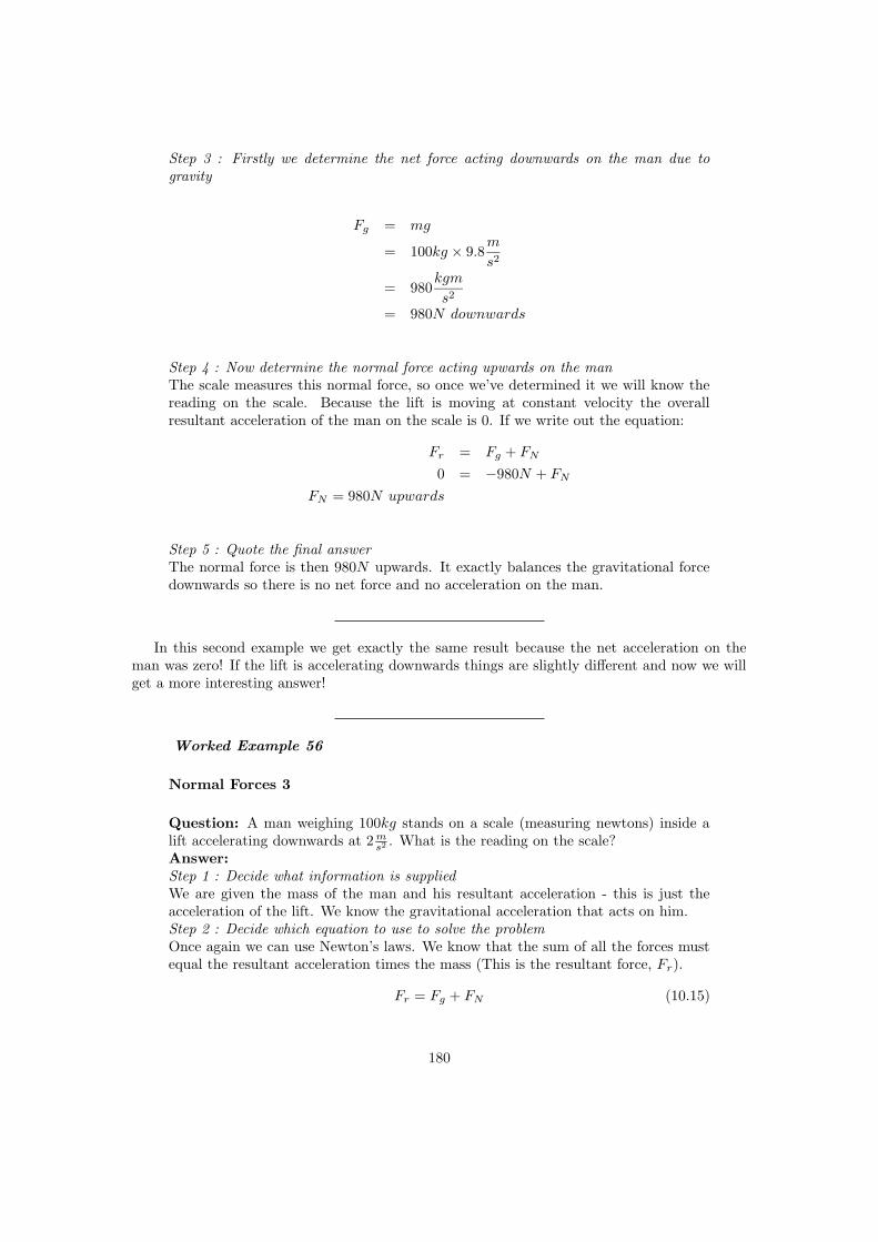
Step 3 : Firstly we determine the net force acting downwards on the man due togravity
Fg = mg
= 100kg × 9.8m
s2
= 980kgm
s2
= 980N downwards
Step 4 : Now determine the normal force acting upwards on the manThe scale measures this normal force, so once we’ve determined it we will know thereading on the scale. Because the lift is moving at constant velocity the overallresultant acceleration of the man on the scale is 0. If we write out the equation:
Fr = Fg + FN
0 = −980N + FN
FN = 980N upwards
Step 5 : Quote the final answerThe normal force is then 980N upwards. It exactly balances the gravitational forcedownwards so there is no net force and no acceleration on the man.
In this second example we get exactly the same result because the net acceleration on theman was zero! If the lift is accelerating downwards things are slightly different and now we willget a more interesting answer!
Worked Example 56
Normal Forces 3
Question: A man weighing 100kg stands on a scale (measuring newtons) inside alift accelerating downwards at 2 m
s2 . What is the reading on the scale?Answer:Step 1 : Decide what information is suppliedWe are given the mass of the man and his resultant acceleration - this is just theacceleration of the lift. We know the gravitational acceleration that acts on him.Step 2 : Decide which equation to use to solve the problemOnce again we can use Newton’s laws. We know that the sum of all the forces mustequal the resultant acceleration times the mass (This is the resultant force, Fr).
Fr = Fg + FN (10.15)
180

Step 3 : Firstly we determine the net force acting downwards on the man due togravity, Fg
Fg = mg
= 100kg × 9.8m
s2
= 980kgm
s2
= 980N downwards
Step 4 : Now determine the normal force acting upwards on the man, FN
We know that the sum of all the forces must equal the resultant acceleration times themass. The overall resultant acceleration of the man on the scale is 2 m
s2 downwards.If we write out the equation:
Fr = Fg + FN
100kg × (−2)m
s2= −980N + FN
−200kgm
s2= −980N + FN
−200N = −980N + FN
FN = 780N upwards
Step 5 : Quote the final answerThe normal force is then 780N upwards. It balances the gravitational force down-wards just enough so that the man only accelerates downwards at 2 m
s2 .
Worked Example 57
Normal Forces 4
Question: A man weighing 100kg stands on a scale (measuring newtons) inside alift accelerating upwards at 4 m
s2 . What is the reading on the scale?Answer:Step 1 : Decide what information is suppliedWe are given the mass of the man and his resultant acceleration - this is just theacceleration of the lift. We know the gravitational acceleration that acts on him.Step 2 : Decide which equation to use to solve the problemOnce again we can use Newton’s laws. We know that the sum of all the forces mustequal the resultant acceleration times the mass (This is the resultant force, Fr).
Fr = Fg + FN (10.16)
181

Step 3 : Firstly we determine the net force acting downwards on the man due togravity, Fg
Fg = mg
= 100kg × 9.8m
s2
= 980kgm
s2
= 980N downwards
Step 4 : Now determine the normal force upwards, FN
We know that the sum of all the forces must equal the resultant acceleration times themass. The overall resultant acceleration of the man on the scale is 2 m
s2 downwards.if we write out the equation:
Fr = Fg + FN
100kg × (4)m
s2= −980N + FN
400kgm
s2= −980N + FN
400N = −980N + FN
FN = 1380N upwards
Step 5 : Quote the final answerThe normal force is then 1380N upwards. It balances the gravitational force andthen in addition applies sufficient force to accelerate the man upwards at 4 m
s2 .
10.4 Comparative problems
Here always work with multiplicative factors to find something new in terms of something old.
Worked Example 58
Comparative Problem 1
Question:On Earth a man weighs 70kg. Now if the same man was instantaneouslybeamed to the planet Zirgon, which has the same size as the Earth but twice themass, what would he weigh? (NOTE TO SELF: Vanessa: isn’t this confusing weightand mass?)Answer:
182

Step 1 : We start with the situation on Earth
W = mg = GmEm
r2(10.17)
Step 2 : Now we consider the situation on Zirgon
WZ = mgZ = GmZm
r2Z
(10.18)
Step 3 : Relation between conditions on Earth and Zirgonbut we know that mZ = 2mE and we know that rZ = r so we could write the equationagain and substitute these relationships in:Step 4 : Substitute
WZ = mgZ = G(2mE)m
(r)2(10.19)
WZ = 2(G(mE)m
(r)2) (10.20)
Step 5 : Relation between weight on Zirgon and Earth
WZ = 2(W ) (10.21)
Step 6 : Quote the final answerso on Zirgon he weighs 140kg.
10.4.1 Principles
• Write out first case
• Write out all relationships between variable from first and second case
• Write out second case
• Substitute all first case variables into second case
• Write second case in terms of first case
Interesting
Fact:The acceleration due to gravity at the Earth’s surface is, by convention, equal to 9.80665ms−2. (The actual value varies slightly over the surface of the Earth). This quantity isknown as g. The following is a list of the gravitational accelerations (in multiples of g)at the surfaces of each of the planets in our solar system:Mercury 0.376Venus 0.903Earth 1Mars 0.38
Jupiter 2.34Saturn 1.16Uranus 1.15Neptune 1.19Pluto 0.066
183

Note:The ”surface” is taken to mean the cloud tops of the gas giants (Jupiter, Saturn, Uranusand Neptune) in the above table.
Worked Example 59
Comparative Problem 2
Question: On Earth a man weighs 70kg. On the planet Beeble how much will heweigh if Beeble has mass half of that of the Earth and a radius one quarter that ofthe earth.Answer:Step 1 : Start with the situation on Earth
W = mg = GmEm
r2(10.22)
Step 2 : Now consider the situation on Beeble
WB = mgB = GmBm
r2B
(10.23)
Step 3 : Relation between conditions on Earth and on BeebleWe know that mB = 1
2mE and we know that rB = 1
4r so we could write the equation
again and substitute these relationships in:Step 4 : Substitute
WB = mgB = G(mB)m
(rB)2
= mgB = G( 12mE)m
( 14r)2
= 8(G(mE)m
(r)2)
Step 5 : Relation between weight on Earth and weight on Beeble
WB = 8(W ) (10.24)
Step 6 : Quote the final answerSo the man weighs 560kg on Beeble!
184

Interesting
Fact:Did you know that the largest telescope in the Southern Hemisphere is the South AfricanLarge Telescope (SALT) which came online in 2005 outside Sutherland in the Karoo.
10.5 Falling bodies
Objects on the earth fall because there is a gravitation force between them and the earth - whichresults in an acceleration - as we saw above. So if you hold something in front of you and let itgo - it will fall.
It falls because of an acceleration toward the centre of the earth which results from thegravitational force between the two.
These bodies move in a straight line from the point where they start to the centre for theearth. This means we can reuse everything we learnt in rectilinear motion. the only thing thatneeds thinking about is the directions we are talking about.
We need to choose either up or down as positive just like we had to choose a positive directionin standard rectilinear motion problems. this is the hardest part. If you can do rectilinear motionyou can do falling body problems. Just remember the acceleration they feel is constant andbecause of gravity - but once you have chosen your directions you can forget that gravity hasanything to do with the problem - all you have is a rectilinear motion problem with a constantacceleration!!
10.6 Terminal velocity
Physics is all about being simple - all we do is look at the world around us and notice how itreally works. It is the one thing everyone is qualified to do - we spend most of our time when weare really young experimenting to find out how things work.
Take a book - wave it in the air - change the angle and direction. what happens of coursethere is resistance. different angles make it greater - the faster the book moves the greater it is.The bigger the area of the book moving in the direction of motion the greater the force.
So we know that air resistance exists! it is a force. So what happens when an object falls? ofcourse there is air resistance - or drag as it is normally called. There is an approximate formulafor the drag force as well.
The important thing to realise is that when the drag force and the gravitational force areequal for a falling body there is no net force acting on it - which means no net acceleration. Thatdoes not mean it does not move - but it means that its speed does not change.
It falls at a constant velocity! This velocity is called terminal velocity.
10.7 Drag force
The actual force of air resistance is quite complicated. Experiment by moving a book throughthe air with the face of the book and then the side of the book forward, you will agree that thearea of the book makes a difference as to how much you must work in order to move the book atthe same speed in both cases. This is why racing cars are slim-lined in design, and not shapedlike a big box!
185

Get a plastic container lid (or anything waterproof) swing it around in air and then try toswing it around under water. The density of the water is much larger than the air, making youhave to work harder at swinging the lid in water. This is why boats and submarines are a lotslower than aeroplanes!
So we know that density, area and speed all play a role in the drag force. The expression weuse for drag force is
D =1
2CρAv2 (10.25)
where C is a constant which depends on the object and fluid interactions, ρ is the density, A isthe area and v is the velocity.
10.8 Important Equations and Quantities
UnitsQuantity Symbol Unit S.I. Units Direction
mass m — kg or — —velocity −→v — m
s or m.s−1 X
force−→F N kg.m
s2 or kg.m.s−2 X
energy E J kg.m2
s2 or kg.m2.s−2 —
Table 10.1: Units used in Newtonian Gravitation
186

Chapter 11
Pressure
11.1 Important Equations and Quantities
UnitsQuantity Symbol Unit S.I. Units Direction
or
Table 11.1: Units used in Pressure
187

Essay 3 : Pressure and Forces
Author: Asogan Moodaly
Asogan Moodaly received his Bachelor of Science degree (with honours) in Mechanical Engineeringfrom the University of Natal, Durban in South Africa. For his final year design project he worked ona 3-axis filament winding machine for composite (Glass re-enforced plastic in this case) piping. Heworked in Vereeniging, Gauteng at Mine Support Products (a subsidiary of Dorbyl Heavy Engineering)as the design engineer once he graduated. He currently lives in the Vaal Triangle area and is workingfor Sasol Technology Engineering as a mechanical engineer, ensuring the safety and integrity ofequipment installed during projects.
Pressure and Forces
In the mining industry, the roof (hangingwall) tends to drop as the face of the tunnel (stope)is excavated for rock containing gold.
As one can imagine, a roof falling on one’s head is not a nice prospect! Therefore the roofneeds to be supported.
RoofFace
The roof is not one big uniform chunk of rock. Rather it is broken up into smaller chunks.It is assumed that the biggest chunk of rock in the roof has a mass of less than 20 000 kgstherefore each support has to be designed to resist a force related to that mass. The strength ofthe material (either wood or steel) making up the support is taken into account when workingout the minimum required size and thickness of the parts to withstand the force of the roof.
FaceRoof
Supports
188

Sometimes the design of the support is such that the support needs to withstand the rockmass without the force breaking the roof..
Therefore hydraulic supports (hydro = water) use the principles of force and pressure suchthat as a force is exerted on the support, the water pressure increases. A pressure relief valvethen squirts out water when the pressure (and thus the force) gets too large. Imagine a verylarge, modified doctor’s syringe.
Pressure
Force
Pressure relief
valve
Seal to trap
water in tube
Water filled
tube
Force
Rubber seal to
trap medicine
in syringe
Doctor’s syringeHydraulic support
Pressure
In the petrochemical industry, there are many vessels and pipes that are under high pressures.A vessel is a containment unit (Imagine a pot without handles, that has the lid welded to the potthat would be a small vessel) where chemicals mix and react to form other chemicals, amongstother uses.
End Product
Chemical
The end product chemicals are sold to companies that use these chemicals to make shampoo,dishwashing liquid, plastic containers, fertilizer, etc. Anyway, some of these chemical reactionsrequire high temperatures and pressures in order to work. These pressures result in forces beingapplied to the insides of the vessels and pipes. Therefore the minimum thickness of the pipe andvessels walls must be determined using calculations, to withstand these forces. These calculationstake into account the strength of the material (typically steel, plastic or composite), the diameterand of course the pressure inside the equipment. Let examine the concepts of force and pressurein further detail.
189

Chapter 12
Heat and Properties of Matter
12.1 Phases of matter
12.1.1 Density
Matter is a substance which has mass and occupies space. The density of matter refers to howmuch mass is in a given volume. Said differently, you can imagine the density to be the amountof mass packed into a given volume.
density =Mass
V olume
If we consider a bar of soap and a bar of steel with the same volume, the steel will have moremass because it has a greater density. The density is greater in steal because more atoms areclosely packed in comparison to the soap. Although they are both the same size, the bar of steelwill be ”heavier” because it has more mass.
Worked Example 60
Density of objects
A bar of aluminum (Al) has dimensions 2cm x 3cm x 5cm with a mass of 81g. A barof lead (Pb) has dimensions 3cm x 3cm x 5cm and a mass of 510.3g. Calculate thedensity of the aluminum and lead.Solution:
First we calculate the volume of Al and Pb:
volume = Length ∗Width ∗Height
For Aluminum: volume = 2cm ∗ 3cm ∗ 5cm = 30cm3
For Lead: volume = 3cm ∗ 3cm ∗ 5cm = 45cm3
We can now calculate the densities using the mass and volume of each material.
For Aluminum: density = 81g30cm3 = 2.7g/cm3
For Lead: density = 510.3g45cm3 = 11.34g/cm3
190

3cm
2cm5cm
3cm
3cm5cm
Now that you know the density of aluminum and lead, which object would be bigger(larger volume): 1kg of Lead or 1kg of Aluminum.
Solution:
1kg of aluminum will be much larger in volume than 1kg of lead. Aluminum has asmaller density so it will take a lot more of it to have a weight of 1kg. Lead is muchmore dense, so it will take less for it to weigh 1kg.
The density of liquids and gases can be calculated the same way as in solids. If the mass andvolume of a liquid is known, the density can be calculated. We can often determine which liquidhas a greater density by mixing two liquids and seeing how they settle. The more dense liquidwill fall towards the bottom, or ’sink’. If you have ever added olive oil to water, you have seenit sits on the surface, or ’floats’. This is because olive oil is less dense than water. Fog occurswhen water vapor becomes more dense than air(”a cloud that sinks in air”).
This principle can be used with solids and liquids. In fact, it is the density of an object thatdetermines if it will float or sink in water. Objects with densities greater than water will sink.
Worked Example 61
Objects floating in water
Ivory soap is famous for ”soap that floats”. If a 5cm x 3cm x 10cm bar of ivory soapweighs 1.35 Newtons, show that its density is less than water.
Solution:
First calculate the bars volume: volume = 3cm ∗ 5cm ∗ 10cm = 150cm3
Now we must determine the mass of the bar based on its weight. We will use Newton’sSecond law (F = ma):
Weight = mass ∗ gravity =⇒ Weight = 9.8m/s2 ∗Mass
191

Mass =1.35N
9.8m/s2= .138kg
Using the mass and the volume we determine the density of the soap:
density =138g
150cm3= .92g/cm3
Water has a density of 1g/cm3, therefore the soap is less dense than water, allowingit to float.
12.2 Phases of matter
Although phases are conceptually simple, they are hard to define precisely. A good definition ofa phase of a system is a region in the parameter space of the system’s thermodynamic variablesin which the free energy is analytic. Equivalently, two states of a system are in the same phase ifthey can be transformed into each other without abrupt changes in any of their thermodynamicproperties.
All the thermodynamic properties of a system – the entropy, heat capacity, magnetization,compressibility, and so forth – may be expressed in terms of the free energy and its derivatives.For example, the entropy is simply the first derivative of the free energy with temperature. Aslong as the free energy remains analytic, all the thermodynamic properties will be well-behaved.
When a system goes from one phase to another, there will generally be a stage where thefree energy is non-analytic. This is known as a phase transition. Familiar examples of phasetransitions are melting (solid to liquid), freezing (liquid to solid), boiling (liquid to gas), andcondensation (gas to liquid). Due to this non-analyticity, the free energies on either side of thetransition are two different functions, so one or more thermodynamic properties will behave verydifferently after the transition. The property most commonly examined in this context is theheat capacity. During a transition, the heat capacity may become infinite, jump abruptly to adifferent value, or exhibit a ”kink” or discontinuity in its derivative.
In practice, each type of phase is distinguished by a handful of relevant thermodynamicproperties. For example, the distinguishing feature of a solid is its rigidity; unlike a liquid or agas, a solid does not easily change its shape. Liquids are distinct from gases because they havemuch lower compressibility: a gas in a large container fills the container, whereas a liquid formsa puddle in the bottom. Many of the properties of solids, liquids, and gases are not distinct;for instance, it is not useful to compare their magnetic properties. On the other hand, theferromagnetic phase of a magnetic material is distinguished from the paramagnetic phase by thepresence of bulk magnetization without an applied magnetic field.
To take another example, many substances can exist in a variety of solid phases each corre-sponding to a unique crystal structure. These varying crystal phases of the same substance arecalled polymorphs. Diamond and graphite are examples of polymorphs of carbon. Graphite iscomposed of layers of hexagonally arranged carbon atoms, in which each carbon atom is stronglybound to three neighboring atoms in the same layer and is weakly bound to atoms in the neigh-boring layers. By contrast in diamond each carbon atom is strongly bound to four neighboringcarbon atoms in a cubic array. The unique crystal structures of graphite and diamond areresponsible for the vastly different properties of these two materials.
Metastable phases
192

Metastable states may sometimes be considered as phases, although strictly speaking theyaren’t because they are unstable. For example, each polymorph of a given substance is usuallyonly stable over a specific range of conditions. For example, diamond is only stable at extremelyhigh pressures. Graphite is the stable form of carbon at normal atmospheric pressures. Althoughdiamond is not stable at atmospheric pressures and should transform to graphite, we know thatdiamonds exist at these pressures. This is because at normal temperatures the transformationfrom diamond to graphite is extremely slow. If we were to heat the diamond, the rate oftransformation would increase and the diamond would become graphite. However, at normaltemperatures the diamond can persist for a very long time.
Another important example of metastable polymorphs occurs in the processing of steel. Steelsare often subjected to a variety of thermal treatments designed to produce various combinationsof stable and metastable iron phases. In this way the steel properties, such as hardness andstrength can be adjusted by controlling the relative amounts and crystal sizes of the variousphases that form.
Phase diagramsThe different phases of a system may be represented using a phase diagram. The axes of
the diagrams are the relevant thermodynamic variables. For simple mechanical systems, wegenerally use the pressure and temperature. The following figure shows a phase diagram for atypical material exhibiting solid, liquid and gaseous phases.
The markings on the phase diagram show the points where the free energy is non-analytic.The open spaces, where the free energy is analytic, correspond to the phases. The phases areseparated by lines of non-analyticity, where phase transitions occur, which are called phaseboundaries.
In the above diagram, the phase boundary between liquid and gas does not continue indef-initely. Instead, it terminates at a point on the phase diagram called the critical point. Thisreflects the fact that, at extremely high temperatures and pressures, the liquid and gaseousphases become indistinguishable. In water, the critical point occurs at around 647 K (374 C or705 F) and 22.064 MPa.
The existence of the liquid-gas critical point reveals a slight ambiguity in our above definitions.When going from the liquid to the gaseous phase, one usually crosses the phase boundary, butit is possible to choose a path that never crosses the boundary by going to the right of thecritical point. Thus, phases can sometimes blend continuously into each other. We should note,however, that this does not always happen. For example, it is impossible for the solid-liquidphase boundary to end in a critical point in the same way as the liquid-gas boundary, becausethe solid and liquid phases have different symmetry.
An interesting thing to note is that the solid-liquid phase boundary in the phase diagramof most substances, such as the one shown above, has a positive slope. This is due to thesolid phase having a higher density than the liquid, so that increasing the pressure increases themelting temperature. However, in the phase diagram for water the solid-liquid phase boundaryhas a negative slope. This reflects the fact that ice has a lower density than water, which is anunusual property for a material.
193

12.2.1 Solids, liquids, gasses
12.2.2 Pressure in fluids
12.2.3 change of phase
12.3 Deformation of solids
12.3.1 strain, stress
Stress (σ) and strain (ε) is one of the most fundamental concepts used in the mechanics ofmaterials. The concept can be easily illustrated by considering a solid, straight bar with aconstant cross section throughout its length where a force is distributed evenly at the ends of thebar. This force puts a stress upon the bar. Like pressure, the stress is the force per unit area.In this case the area is the cross sectional area of the bar.
stress =Force
Areacrosssection=⇒ σ =
F
A
(A) Bar under compression (B) Bar under tension
Figure 12.1: Illustration of Bar
The bar in figure 1a is said to be under compression. If the direction of the force (−→F ), were
reversed, stretching the bar, it would be under tension (fig. 1b). Using intuition, you can imaginehow the bar might change in shape under compression and tension. Under a compressive load,the bar will shorten and thicken. In contrast, a tensile load will lengthen the bar and make itthinner.
Figure 12.2: Bar changes length under tensile stress
For a bar with an original length L, the addition of a stress will result in change of length4L. With 4L and L we can now define strain as the ratio between the two. That is, strain isdefined as the fractional change in length of the bar:
Strain ≡ 4L
L
12.3.2 Elastic and plastic behavior
Material properties are often characterized by a stress versus strain graph (figure x.xx). Oneway in which these graphs can be determined is by tensile testing. In this process, a machine
194

L 4L
Figure 12.3: Left end of bar is fixed as length changes
||
+
Figure 12.4: dashed line represents plastic recovery **incomplete**
stretches a the material by constant amounts and the corresponding stress is measured andplotted. Typical solid metal bars will show a result like that of figure x.xx. This is called a TypeII response. Other materials may exibit different responses. We will only concern ourself withType II materials.
The linear region of the graph is called the elastic region. By obtaining the slope of the linearregion, it is easy to find the strain for a given stress, or vice-versa. This slope shows itself tobe very useful in characterizing materials, so it is called the Modulus of Elasticity, or Young’sModulus:
E =stress
strain=
F/A
∆L/L
The elastic region has the unique property that allows the material to return to its originalshape when the stress is removed. As the stress is removed it will follow line back to zero. Onemay think of stretching a spring and then letting it return to its original length. When a stressis applied in the linear region, the material is said to undergo elastic deformation.
When a stress is applied that is in the non-linear region, the material will no longer return toits original shape. This is referred to as plastic deformation. If you have overstretched a springyou have seen that it no longer returns to its initial length; it has been plastically deformed. Thestress where plastic behavior begins is called the yield strength (point A, fig x).
When a material has plastically deformed it will still recover some of its shape (like anoverstretched spring). When a stress in the non-linear region is removed, the stress strain graphwill follow a line with a slope equal to the modulus of elasticity (see the dashed line in figurex.xx). The plastically deformed material will now have a linear region that follows the dashedline.
Greater stresses in the plastic region will eventually lead to fracture (the material breaks).The maximum stress the material can undergo before fracture is the ultimate strength.
195

||
+
Figure 12.5: dashed line represents plastic recovery **incomplete**
12.4 Ideal gasses
Author: Gerald Wigger
Gerald Wigger started his Physics studies at ETH in Zuerich, Switzerland. He moved to CapeTown, South Africa, for his Bachelor of Science degree (with honours) in Physics from the Universityof Cape Town in 1998. Returned to Switzerland, he finished his Diploma at ETH in 2000 and followedup with a PhD in the Solid State Physics group of Prof. Hans-Ruedi Ott at ETH. He graduatedin the year 2004. Being awarded a Swiss fellowship, he moved to Stanford University where he iscurrently continuing his Physics research in the field of Materials with novel electronic properties.
Any liquid or solid material, heated up above its boiling point, undergoes a transition intoa gaseous state. For some materials such as aluminium, one has to heat up to three thousanddegrees Celsius (C), whereas Helium is a gas already at -269 C. For more examples see Table12.1. As we find very strong bonding between the atoms in a solid material, a gas consists ofmolecules which do interact very poorly. If one forgets about any electrostatic or intermolecularattractive forces between the molecules, one can assume that all collisions are perfectly elastic.One can visualize the gas as a collection of perfectly hard spheres which collide but whichotherwise do not interact with each other. In such a gas, all the internal energy is in the formof kinetic energy and any change in internal energy is accompanied by a change in temperature.Such a gas is called an ideal gas.
In order for a gas to be described as an ideal gas, the temperature should be raised farenough above the melting point. A few examples of ideal gases at room temperature are Helium,Argon and hydrogen. Despite the fact that there are only a few gases which can be accuratelydescribed as an ideal gas, the underlying theory is widely used in Physics because of its beautyand simplicity.
A thermodynamic system may have a certain substance or material whose quantity can beexpressed in mass or mols in an overall volume. These are extensive properties of the system.In the following we will be considering often intensive versus extensive quantities. A material’sintensive property, is a quantity which does not depend on the size of the material, such astemperature, pressure or density. Extensive properties like volume, mass or number of atoms on
196

Material Temperature in Celsius Temperature in KelvinAluminium 2467 C 2740 K
Water 100 C 373.15 KEthyl alcohol 78.5 C 351.6 KMethyl ether -25 C 248 K
Nitrogen -195.8 C 77.3 KHelium -268.9 C 4.2 K
Table 12.1: Boiling points for various materials in degrees Celsius and in Kelvin
quantity unit intensive or extensivepressure p Pa intensivevolume V m3 extensive
molar volume vmol m3/mol intensivetemperature T K intensive
mass M kg extensivedensity ρ kg/m3 intensive
internal energy E J extensive
Table 12.2: Intensive versus extensive properties of matter
the other hand gets bigger the bigger the material is (see Table 12.2 for various intensive/extensiveproperties). If the substance is evenly distributed throughout the volume in question, then avalue of volume per amount of substance may be used as an intensive property. For an example,for an amount called a mol, volume per mol is typically called molar volume. Also, a volumeper mass for a specific substance may be called specific volume. In the case of an ideas gas, asimple equation of state relates the three intensive properties, temperature, pressure, and molaror specific volume. Hence, for a closed system containing an ideal gas, the state can be specifiedby giving the values of any two of pressure, temperature, and molar volume.
12.4.1 Equation of state
The ideal gas can be described with a single equation. However, in order to arrive there, wewill be introducing three different equations of state, which lead to the ideal gas law. Thecombination of these three laws leads to a complete picture of the ideal gas.
1661 - Robert Boyle used a U-tube and Mercury to develop a mathematical relationshipbetween pressure and volume. To a good approximation, the pressure and volume of a fixedamount of gas at a constant temperature were related by
p · V = constant
p : pressure (Pa)V : Volume (m3)
In other words, if we compress a given quantity of gas, the pressure will increase. And if weput it under pressure, the volume of the gas will decrease proportionally.
197

Figure 12.6: Pressure-Volume diagram for the ideal gas at constant temperature.
Worked Example 62
compressed Helium gas
A sample of Helium gas at 25C is compressed from 200 cm3 to 0.240 cm3. Itspressure is now 3.00 cm Hg. What was the original pressure of the Helium?Solution:
It’s always a good idea to write down the values of all known variables, indicatingwhether the values are for initial or final states. Boyle’s Law problems are essentiallyspecial cases of the Ideal Gas Law:Initial: p1 = ?; V1 = 200 cm3;Final: p2 = 3.00 cm Hg; V2 = 0.240 cm3;Since the number of molecules stays constant and the temperature is not changedalong the process, so
p1 · V1 = p2 · V2
hence
p1 = p2 · V2/V1 = 3.00cmHg · 0.240cm3/200cm3
Setting in the values yields p1 = 3.60 · 10−3 cm Hg.Did you notice that the units for the pressure are in cm Hg? You may wish to convertthis to a more common unit, such as millimeters of mercury, atmospheres, or pascals.3.60 · 10−3 Hg · 10mm/1 cm = 3.60 · 10−2 mm Hg
198

3.60 · 10−3 Hg · 1 atm/76.0 cm Hg = 4.74 · 10−5 atm
One way to experience this is to dive under water. There is air in your middle ear, whichis normally at one atmosphere of pressure to balance the air outside your ear drum. The waterwill put pressure on the ear drum, thereby compressing the air in your middle ear. Divers mustpush air into the ear through their Eustacean tubes to equalize this pressure.
Worked Example 63
pressure in the ear of a diver
How deep would you have to dive before the air in your middle ear would be com-pressed to 75% of its initial volume? Assume for the beginning that the temperatureof the sea is constant as you dive.Solution:
First we write down the pressure as a function of height h:
p = p0 + ρ · g · h
where we take for p0 the atmospheric pressure at height h = 0, ρ is the density ofwater at 20 degrees Celsius 998.23 kg/m3, g = 9.81 ms−2.
As the temperature is constant, it holds for both heights h
p0 · V0 = (p0 + ρgh) · Ve
Now solving for h using the fact that
Ve/V0 = 0.75
yieldsh = (0.75 ∗ p0 − p0)/(ρg)
Now, how far can the diver dive down before the membranes of his ear brake.
Solution:
As the result is negative, h determines the way he can dive down. h is given asroughly 2.6 m.
In 1809, the French chemist Joseph-Louis Gay-Lussac investigated the relationship betweenthe Pressure of a gas and its temperature. Keeping a constant volume, the pressure of a gassample is directly proportional to the temperature. Attention, the temperature is measured inKelvin! The mathematical statement is as follows:
199

p1/T1 = p2/T2 = constant
p1,2 : pressures (Pa)T1,2 : Temperatures (K)
That means, that pressure divided by temperature is a constant. On the other hand, if weplot pressure versus temperature, the graph crosses 0 pressure for T = 0 K = -273.15 C as shownin the following figure. That point is called the absolute Zero. That is where any motion ofmolecules, electrons or other particles stops.
Figure 12.7: Pressure-temperature diagram for the ideal gas at constant volume.
Worked Example 64
Gay-Lussac
Suppose we have the following problem:A gas cylinder containing explosive hydrogen gas has a pressure of 50 atm at atemperature of 300 K. The cylinder can withstand a pressure of 500 atm before itbursts, causing a building-flattening explosion. What is the maximum temperaturethe cylinder can withstand before bursting?Solution: Let’s rewrite this, identifying the variables:A gas cylinder containing explosive hydrogen gas has a pressure of 50 atm (p1) ata temperature of 300 K (T1). The cylinder can withstand a pressure of 500 atm
200

(p2) before it bursts, causing a building-flattening explosion. What is the maximumtemperature the cylinder can withstand before bursting?Plugging in the known variables into the expression for the Gay-Lussac law yields
T2 = p2/p1 ∗ T1 = 500atm/50atm ∗ 300K = 3000K
we find the answer to be 3000 K.
The law of combining volumes was interpreted by the Italian chemist Amedeo Avogadro in1811, using what was then known as the Avogadro hypothesis. We would now properly refer toit as Avogadro’s law:
Equal volumes of gases under the same conditions of temperature and pressurecontain equal numbers of molecules.
This can be understood in the following. As in an ideal gas, all molecules are consideredto be tiny particles with no spatial extension which collide elastically with each other. So, thekind of gas is irrelevant. Avogadro found that at room temperature, in atmospheric pressure thevolume of a mol of a substance, i.e. 6.022·1023 molecules or atoms, occupies the volume of 22.4l.
Figure 12.8: Two different gases occupying the same volume under the same circumstances.
Combination of the three empirical gas laws, described in the preceding three sections leadsto the Ideal Gas Law which is usually written as:
p · V = n ·R · T
p : pressure (Pa)V : Volume (m3)n : number of mols (mol)R : gas konstant (J/molK)T : temperature (K)
201
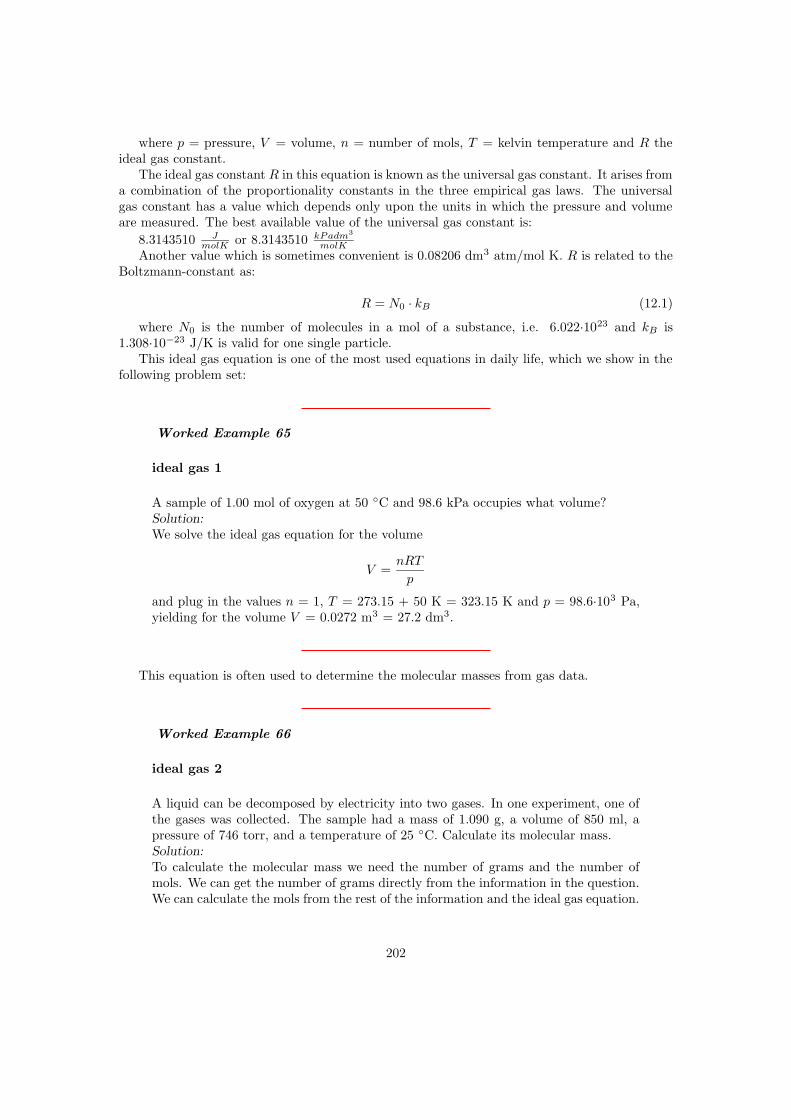
where p = pressure, V = volume, n = number of mols, T = kelvin temperature and R theideal gas constant.
The ideal gas constant R in this equation is known as the universal gas constant. It arises froma combination of the proportionality constants in the three empirical gas laws. The universalgas constant has a value which depends only upon the units in which the pressure and volumeare measured. The best available value of the universal gas constant is:
8.3143510 JmolK or 8.3143510 kPadm3
molKAnother value which is sometimes convenient is 0.08206 dm3 atm/mol K. R is related to the
Boltzmann-constant as:
R = N0 · kB (12.1)
where N0 is the number of molecules in a mol of a substance, i.e. 6.022·1023 and kB is1.308·10−23 J/K is valid for one single particle.
This ideal gas equation is one of the most used equations in daily life, which we show in thefollowing problem set:
Worked Example 65
ideal gas 1
A sample of 1.00 mol of oxygen at 50 C and 98.6 kPa occupies what volume?Solution:
We solve the ideal gas equation for the volume
V =nRT
p
and plug in the values n = 1, T = 273.15 + 50 K = 323.15 K and p = 98.6·103 Pa,yielding for the volume V = 0.0272 m3 = 27.2 dm3.
This equation is often used to determine the molecular masses from gas data.
Worked Example 66
ideal gas 2
A liquid can be decomposed by electricity into two gases. In one experiment, one ofthe gases was collected. The sample had a mass of 1.090 g, a volume of 850 ml, apressure of 746 torr, and a temperature of 25 C. Calculate its molecular mass.Solution:
To calculate the molecular mass we need the number of grams and the number ofmols. We can get the number of grams directly from the information in the question.We can calculate the mols from the rest of the information and the ideal gas equation.
202

V = 850mL = 0.850L = 0.850dm3
P = 746torr/760torr = 0.982atm
T = 25.0C + 273.15 = 298.15K
pV = nRT
(0.982atm)(0.850L) = (n)(0.0821Latmmol − 1K − 1)(298.15K)
n = 0.0341mol
molecular mass = g/mol = 1.090 g/ 0.0341 mol = 31.96 g/mol. The gas is oxygen.
Or the equation can be comfortably used to design a gas temperature controller:
Worked Example 67
ideal gas 3
In a gas thermometer, the pressure needed to fix the volume of 0.20 g of Helium at0.50 L is 113.3 kPa. What is the temperature?Solution:
We transform first need to find the number of mols for Helium. Helium consists of 2protons and 2 neutrons in the core (see later) and therefore has a molar volume of 4g/mol. Therefore, we find
n = 0.20g/4g/mol = 0.05mol
plugging this into the ideal gas equation and solving for the temperature T we find:
T =pV
nR=
113.3 · 103Pa · 0.5 · 10−3m3
0.05mol · 8.314J/molK= 136.3K
The temperature is 136 Kelvin.
12.4.2 Kinetic theory of gasses
The results of several experiments can lead to a scientific law, which describes then all experi-ments performed. This is an empirical, that is based on experience only, approach to Physics.A law, however, only describes results; it does not explain why they have been obtained. Signif-icantly stronger, a theory is a formulation which explains the results of experiments. A theoryusually bases on postulates, that is a proposition that is accepted as true in order to provide abasis for logical reasoning. The most famous postulate in Physics is probably the one formulatedby Walter Nernst which states that if one could reach absolute zero, all bodies would have thesame entropy.
203

The kinetic-molecular theory of gases is a theory of great explanatory power. We shall seehow it explains the ideal gas law, which includes the laws of Boyle and of Charles; Dalton’s lawof partial pressures; and the law of combining volumes.
The kinetic-molecular theory of gases can be stated as four postulates:
• A gas consists of particles (atoms or molecules) in continuous, random motion.
• Gas molecules influence each other only by collision; they exert no other forces on eachother.
• All collisions between gas molecules are perfectly elastic; all kinetic energy is conserved.
• The average energy of translational motion of a gas particle is directly proportional totemperature.
In addition to the postulates above, it is assumed that the volumes of the particles arenegligible as compared to container volume.
These postulates, which correspond to a physical model of a gas much like a group of billiardballs moving around on a billiard table, describe the behavior of an ideal gas. At room temper-atures and pressures at or below normal atmospheric pressure, real gases seem to be accuratelydescribed by these postulates, and the consequences of this model correspond to the empiricalgas laws in a quantitative way.
We define the average kinetic energy of translation Et of a particle in a gas as
Et = 1/2 ·mv2 (12.2)
where m is the mass of the particle with average velocity v. The forth postulate states thatthe average kinetic energy is a constant defining the temperature, i.e. we can formulate
Et = 1/2 ·mv2 = c · T (12.3)
where the temperature T is given in Kelvin and c is a constant, which has the same value forall gases. As we have 3 different directions of motion and each possible movement gives kBT , wefind for the energy of a particle in a gas as
Et = 1/2 ·mv2 = 3/2kBT = 3/2R
NAT (12.4)
Hence, we can find an individual gas particle’s speed rms = root mean square, which is theaverage square root of the speed of the individual particles (find u)
vrms =
√
3RT
Mmol(12.5)
where Mmol is the molar mass, i.e. the mass of the particle m times the Avogadro numberNA.
Worked Example 68
kinetic theory 1
204

Calculate the root-mean-square velocity of oxygen molecules at room temperature,25 C.Solution:
Using
vrms =√
3RT/Mmol ,
the molar mass of molecular oxygen is 31.9998 g/mol; the molar gas constant hasthe value 8.3143 J/mol K, and the temperature is 298.15 K. Since the joule is thekg·m2·s−2, the molar mass must be expressed as 0.0319998 kg/mol. The root-mean-square velocity is then given by:
vrms =√
3(8.3143)(298.15)/(0.0319998) = 482.1m/s
A speed of 482.1 m/s is 1726 km/h, much faster than a jetliner can fly and fasterthan most rifle bullets.
The very high speed of gas molecules under normal room conditions would indicate that agas molecule would travel across a room almost instantly. In fact, gas molecules do not do so.If a small sample of the very odorous (and poisonous!) gas hydrogen sulfide is released in onecorner of a room, our noses will not detect it in another corner of the room for several minutesunless the air is vigorously stirred by a mechanical fan. The slow diffusion of gas molecules whichare moving very quickly occurs because the gas molecules travel only short distances in straightlines before they are deflected in a new direction by collision with other gas molecules.
The distance any single molecule travels between collisions will vary from very short to verylong distances, but the average distance that a molecule travels between collisions in a gas canbe calculated. This distance is called the mean free path l of the gas molecules. If the root-mean-square velocity is divided by the mean free path of the gas molecules, the result will bethe number of collisions one molecule undergoes per second. This number is called the collisionfrequency Z1 of the gas molecules.
The postulates of the kinetic-molecular theory of gases permit the calculation of the meanfree path of gas molecules. The gas molecules are visualized as small hard spheres. A sphereof diameter d sweeps through a cylinder of cross-sectional area π · (d/2)2 and length vrms eachsecond, colliding with all molecules in the cylinder.
The radius of the end of the cylinder is d because two molecules will collide if their diametersoverlap at all. This description of collisions with stationary gas molecules is not quite accurate,however, because the gas molecules are all moving relative to each other. Those relative velocitiesrange between zero for two molecules moving in the same direction and 2vrms for a head-oncollision. The average relative velocity is that of a collision at right angles, which is
√2vrms.
The total number of collisions per second per unit volume, Z1, is
Z1 = πd2√
2vrms (12.6)
This total number of collisions must now be divided by the number of molecules which arepresent per unit volume. The number of gas molecules present per unit volume is found byrearrangement of the ideal gas law to n/V = p/RT and use of Avogadro’s number, n = N/NA;thus N/V = pNA/RT . This gives the mean free path of the gas molecules, l, as
(urms/Z1)/(N/V ) = l = RT/πd2pNA
√2 (12.7)
205

According to this expression, the mean free path of the molecules should get longer as thetemperature increases; as the pressure decreases; and as the size of the molecules decreases.
Worked Example 69
mean free path
Calculate the length of the mean free path of oxygen molecules at room temperature,25 C, taking the molecular diameter of an oxygen molecule as 370 pm.Solution:
Using the formula for mean free path given above and the value of the root-mean-square velocity urms,
l =(8.3143kgm2s−2/Kmol)(298.15K)
π(370 · 10−12m)2(101325kg/ms2)(6.0225 · 1023mol−1)√
2,
so l = 6.7·10−8 m = 67 nm.
The apparently slow diffusion of gas molecules takes place because the molecules travel onlya very short distance before colliding. At room temperature and atmospheric pressure, oxygenmolecules travel only (6.7·10−8 m)/(370·10−12 m) = 180 molecular diameters between collisions.The same thing can be pointed out using the collision frequency for a single molecule Z1, whichis the root-mean-square velocity divided by the mean free path:
Z1 =πd2pNA
√2
/RT= vrms/l (12.8)
For oxygen at room temperature, each gas molecule collides with another every 0.13 nanosec-onds (one nanosecond is 1.0·10−9 s), since the collision frequency is 7.2·10+9 collisions per secondper molecule.
For an ideal gas, the number of molecules per unit volume is given using pV = nRT and n= N/NA as
N/V = NAp/RT (12.9)
which for oxygen at 25 C would be (6.022·1023 mol−1)(101325 kg/m s2) / (8.3143 kg m2/s2
K mol)(298.15 K) or 2.46·1025 molecules/m3. The number of collisions between two moleculesin a volume, Z11, would then be the product of the number of collisions each molecule makestimes the number of molecules there are, Z1N/V , except that this would count each collisiontwice (since two molecules are involved in each one collision). The correct equation must be
Z11 =πd2p2N2
A
√2vrms
2R2T 2(12.10)
If the molecules present in the gas had different masses they would also have different speeds,so an average value of vrms would be using a weighted average of the molar masses; the partialpressures of the different gases in the mixture would also be required. Although such calculationsinvolve no new principles, they are beyond our scope.
206

12.4.3 Pressure of a gas
In the kinetic-molecular theory of gases, pressure is the force exerted against the wall of acontainer by the continual collision of molecules against it. From Newton’s second law of motion,the force exerted on a wall by a single gas molecule of mass m and velocity v colliding with it is:
F = m · a = m∆v
∆t(12.11)
In the above equation, the change in a quantity is indicated by the symbol ∆, that means bychanging the time t by a fraction, we change the velocity v by some other minimal amount. It isassumed that the molecule rebounds elastically and no kinetic energy is lost in a perpendicularcollision, so ∆v = v - (-v) = 2v (see figure below). If the molecule is moving perpendicular tothe wall it will strike the opposite parallel wall, rebound, and return to strike the original wallagain. If the length of the container or distance between the two walls is the path length l, thenthe time between two successive collisions on the same wall is ∆t = 2l/v. The continuous forcewhich the molecule moving perpendicular to the wall exerts is therefore
Figure 12.9: Change in momentum as a particle hits a wall.
F = m2v
2l/v=
mv2
l(12.12)
The molecules in a sample of gas are not, of course, all moving perpendicularly to a wall,but the components of their actual movement can be considered to be along the three mutuallyperpendicular x, y, and z axes. If the number of molecules moving randomly, N, is large, then onthe average one-third of them can be considered as exerting their force along each of the threeperpendicular axes. The square of the average velocity along each axis, v2(x), v2(y), or v2(z),will be one-third of the square of the average total velocity v2:
v2(x) = v2(y) = v2(z) = v2/3 (12.13)
The average or mean of the square of the total velocity can replace the square of the perpen-dicular velocity, and so for a large number of molecules N ,
F = (N/3)mv2
l(12.14)
Since pressure is force per unit area, and the area of one side of a cubic container must be l2,the pressure p will be given by F/l2 as:
207

p = (N/3)mv2
l3(12.15)
This equation rearranges to
pV = N ·mv2/3 (12.16)
because volume V is the cube of the length l. The form of the ideal gas law given aboveshows the pressure-volume product is directly proportional to the mean-square velocity of thegas molecules. If the velocity of the molecules is a function only of the temperature, and weshall see in the next section that this is so, the kinetic-molecular theory gives a quantitativeexplanation of Boyle’s law.
Worked Example 70
gas pressure
A square box contains He (Helium) at 25 C. If the atoms are colliding with the wallsperpendicularly (at 90) at the rate of 4.0 · 1022 times per second, calculate the force(in Newtons) and the pressure exerted on the wall per mol of He given that the areaof the wall is 100 cm2 and the speed of the atoms is 600 ms−1.Solution:
We use the equation 12.14 to calculate the force.
F = (N/3)mv2
l= (N/3)mv
v
l
The fraction v/l is the collision frequency Z1 = 0.6679 s−1. The product of N · Z1
is the number of molecules impinging on the wall per second. This induces for theforce:
F = (N/3)mvτ = 6.022 · 1023/3 · 0.004g/mol
6.022 · 1023· 600m/s · 0.6679s−1
yielding for the force F = 0.534 N. The pressure is the force per area:
p = F/A = 0.534N/0.01m2 = 53.4Pa.
The calculated force is 0.534 N and the resulting pressure is 53.4 Pa.
12.4.4 Kinetic energy of molecules
In the following, we will make the connection between the kinetic theory and the ideal gas laws.We will find that the temperature is an important quantity which is the only intrinsic parameterentering in the kinetic energy of a gas.
We will consider an ensemble of molecules in a gas, where the molecules will be regarded asrigid large particles. We therefore neglect any vibrations or rotations in the molecule. Hence,making this assumption, Physics for a molecular gas is the same as for a single atom gas.
208

The square of the velocity is sometimes difficult to conceive, but an alternative statementcan be given in terms of kinetic energy. The kinetic energy Ek of a single particle of mass mmoving at velocity v is mv2/2. For a large number of molecules N , the total kinetic energy Ek
will depend on the mean-square velocity in the same way:
Ek = N ·mv2/2 = n ·Mv2/2 (12.17)
The second form is on a molar basis, since n = N/NA and the molar mass M= mNA whereNA is Avogadro’s number 6.022·1023. The ideal gas law then appears in the form:
pV = 2Ek/3 (12.18)
Compare pV = nMv2/2. This statement that the pressure-volume product of an ideal gasis directly proportional to the total kinetic energy of the gas is also a statement of Boyle’s law,since the total kinetic energy of an ideal gas depends only upon the temperature.
Comparison of the ideal gas law, pV = nRT , with the kinetic-molecular theory expressionpV = 2Ek/3 derived in the previous section shows that the total kinetic energy of a collection ofgas molecules is directly proportional to the absolute temperature of the gas. Equating the pVterm of both equations gives
Ek = 3/2nRT , (12.19)
which rearranges to an explicit expression for temperature,
T =2
3R
Ek
n=
Mv2
3R(12.20)
We see that temperature is a function only of the mean kinetic energy Ek, the mean molecularvelocity v, and the mean molar mass M .
Worked Example 71
mean velocity 1
Calculate the kinetic energy of 1 mol of nitrogen molecules at 300 K?Solution:
Assume nitrogen behaves as an ideal gas, then
Ek = 3/2 ·RT = (3/2)8.3145J/(molK) · 300K = 3742J/mol(or3.74kJ/mol)
At 300 K, any gas that behaves like an ideal gas has the same energy per mol.
As the absolute temperature decreases, the kinetic energy must decrease and thus the meanvelocity of the molecules must decrease also. At T = 0, the absolute zero of temperature, allmotion of gas molecules would cease and the pressure would then also be zero. No moleculeswould be moving. Experimentally, the absolute zero of temperature has never been attained,although modern experiments have extended to temperatures as low as 1 µK.
However, at low temperatures, the interactions between the particles becomes important andwe enter a new regime of Quantum Mechanics, which considers molecules, single atoms or protonsand electrons simultaneously as waves and as rigid particles. However, this would go too far.
209

Worked Example 72
mean velocity 2
If the translational rms. speed of the water vapor molecules (H2O) in air is 648 m/s,what is the translational rms speed of the carbon dioxide molecules (CO2) in thesame air? Both gases are at the same temperature. And what is the temperature wemeasure?Solution:
The molar mass of H2O is
MH2O = 2 · 1g/mol + 1 · 16g/mol = 18g/mol
As the temperature is constant we can write
T =Mv2
3R=
0.018kg/mol · (648m/s)2
3 · 8.314J/mol ·K = 303.0K = 29.9C
Now we calculate the molar mass of CO2
MCO2= 2 · 16g/mol + 1 · 12g/mol = 44g/mol
The rms velocity is again calculated with eq. 12.20
vCO2=
√
3R · TMCO2
=
√
3 · 8.314J/molK · 303.0K0.044kg/mol
= 414.5m/s
The experiment was performed at 29.9 C and the speed of the CO2-molecules is414.5 m/s, that is much slower than the water molecules as they are much heavier.
12.5 Temperature
Let us look back to the equation for the temperature of an ideal gas,
T =2
3R
Ek
n(12.21)
We can see that temperature is proportional to the average kinetic energy of a molecule in thegas. In other words temperature is a measure of how much energy is contained in an object –in hot things the atoms have a lot of kinetic energy, in cold things they have less. It may besurprising that ‘hot’ and ‘cold’ are really just words for how fast molecules or atoms are movingaround, but it is true.
Definition: Temperature is a measure of the average kinetic energy of the particlesin a body.
It should now be clear that heat is nothing more than energy on the move. It can be carried
210

ice
water
Figure 12.10: A heat flow diagram showing the heat flowing from the warmer water into thecooler ice cube.
by atoms, molecules or electromagnetic radiation but it is always just transport of energy. Thisis very important when we describe movement of heat as we will do in the following sections.‘Cold’ is not a physical thing. It does not move from place to place, it is just the word for a lackof heat, just like dark is the word for an absence of light.
12.5.1 Thermal equilibrium
Now that we have defined the temperature of an isolated object (usually referred to as a body)we need to consider how heat will move between bodies at different temperatures. Let us taketwo bodies; A which has a fixed temperature and B whose temperature is allowed to change. Ifwe allow heat to move between the two bodies we say they are in thermal contact.
First let us consider what happens if B is cooler than A. Remember – we have fixed thetemperture of A so we need only worry about the temperature of B changing. An example ofsuch a situation is an ice cube being dropped into a large pan of boiling water on a fire. Thewater temperature is fixed i.e. does not change, because the fire keeps it constant. It should beobvious that the ice cube will heat up and melt. In physical terms we say that the heat is flowingout of the (warmer) boiling water, into the (cooler) ice cube. This flow of heat into the ice cubecauses it to warm up and melt. In fact the temperature of any cooler object in thermal contactwith a warmer one will increase as heat from the warmer object flows into it.
The reverse would be true if B were warmer than A. We can now picture putting a smallamount of warm water in to a freezer. If we come back in an hour or so the water will havecooled down and possibly frozen. In physical terms we say that the heat is flowing out of the(warmer) water, into the (cooler) air in the freezer. This flow of heat out of the ice cube in tothe aircauses it to cool down and (eventually) freeze. Again, any warm object in thermal contactwith a cooler one will cool down due to heat flowing out of it.There is one special case which we have not yet discussed – what happens if A and B are at thesame temperature? In this case B will neither warm up nor cool down, in fact, its temperaturewill remain constant. When two bodies are at the same temperature we say that they are inthermal equilibrium. Another way to express this is to say that two bodies are in thermal equi-librium if the particles within those bodies have the same average kinetic energies.
211
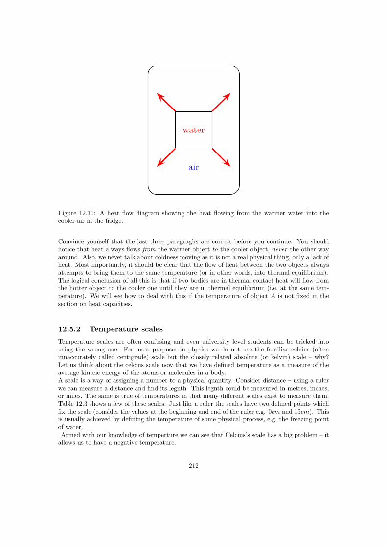
water
air
Figure 12.11: A heat flow diagram showing the heat flowing from the warmer water into thecooler air in the fridge.
Convince yourself that the last three paragraghs are correct before you continue. You shouldnotice that heat always flows from the warmer object to the cooler object, never the other wayaround. Also, we never talk about coldness moving as it is not a real physical thing, only a lack ofheat. Most importantly, it should be clear that the flow of heat between the two objects alwaysattempts to bring them to the same temperature (or in other words, into thermal equilibrium).The logical conclusion of all this is that if two bodies are in thermal contact heat will flow fromthe hotter object to the cooler one until they are in thermal equilibrium (i.e. at the same tem-perature). We will see how to deal with this if the temperature of object A is not fixed in thesection on heat capacities.
12.5.2 Temperature scales
Temperature scales are often confusing and even university level students can be tricked intousing the wrong one. For most purposes in physics we do not use the familiar celcius (ofteninnaccurately called centigrade) scale but the closely related absolute (or kelvin) scale – why?Let us think about the celcius scale now that we have defined temperature as a measure of theaverage kinteic energy of the atoms or molecules in a body.A scale is a way of assigning a number to a physical quantity. Consider distance – using a rulerwe can measure a distance and find its legnth. This legnth could be measured in metres, inches,or miles. The same is true of temperatures in that many different scales exist to measure them.Table 12.3 shows a few of these scales. Just like a ruler the scales have two defined points whichfix the scale (consider the values at the beginning and end of the ruler e.g. 0cm and 15cm). Thisis usually achieved by defining the temperature of some physical process, e.g. the freezing pointof water.Armed with our knowledge of temperture we can see that Celcius’s scale has a big problem – it
allows us to have a negative temperature.
212

Scale Symbol DefinitionFahrenheit F Temperature at which an equal mixture of ice and salt melts = 0F
Temperature of blood = 96F
Celcius C Temperature at which water freezes = 0CTemperature at which water boils = 100C
Kelvin K Absolute zero is 0 KTriple point of water is 273.16 K
Table 12.3: The most important temperature scales.
We found that temperature is a measure of the average kinetic energy of the particles in a body.Therefore, a negative temperature suggests that that the particles have negative kinetic energy.This can not be true as kinetic energy can only be positive. Kelvin addressed this problemby redefining the zero of the scale. He realised that the coldest temperature you could achievewould be when the particles in a body were not moving at all. There is no way to cool somethingfurther than this as there is no more kinetic energy to remove from the body. This temperatureis called absolute zero. Kelvin chose his scale so that 0K was the same as absolute zero and chosethe size of his degree to be the same as one degree in the celcius scale.
Interesting
Fact:Rankine did a similar thing to Kelvin but set his degree to be the same size as one degreefahrenheit. Unfortunately for him, almost everyone preferred Kelvin’s absolute scale andthe rankine scale is now hardly ever used!
It turns out that the freezing point of water, 0C, is equal to 273.15 K. So, in order to convertfrom celcius to kelvin need to subtact 273.15.
Definition: T (K) = T (C)− 273.15
12.5.3 Practical thermometers
It is often important to be able to determine an object’s temperature precisely. This can bea challenge at very high or low tempertures or in inaccesible places. Consider a scientist whowishes to know how hot the magma in a volcano is. They are not going to be able to just lowera thermometer in to the magma as it will just melt as it reaches the superheated rock.We will now look at some less extreme situations and show how a variety of thermometry tech-niques can be developed. Consider first the gas cylinder which we tried to explode in workedexample 7 by heating it while sealed. We decided that we would need to heat it to around 3000Kbefore it explodes. How can we check this experimentally? In a sealed gas cylinder the volume ofthe gas and the number of moles of gas remain constant as we heat, this is why we could use theGay-Lussac law in example 7. The Gay-Lussac law tells us that pressure is directly proportional
213

to temperature for fixed volume and amount of gas. Therefore by mesuring the pressure in thecylinder (which can be done by fitting a pressure gauge to the top of it) we can indirectly workout the temperature.This is similar to familiar alcohol or mercury thermometers. In these we use the fact that ex-pansion of a liquid as it is heated is approximately proportional to temperature so we can usethis expansion to as a measure of temperature. In fact, any thermometer you can imagine usessome physical property which varies with temperature to measure it indirectly.
12.5.4 Specific heat capacity
Conversion of macroscopic energy to microscopic kinetic energy thus tends to raise the temper-ature, while the reverse conversion lowers it. It is easy to show experimentally that the amountof heating needed to change the temperature of a body by some amount is proportional to theamount of matter in the body. Thus, it is natural to write
∆Q = MC∆T
(23.4)where M is the mass of material, ∆Q is the amount of energy transferred to the material,
and ∆T is the change of the material’s temperature. The quantity C is called the specific heatof the material in question and is the amount of energy needed to raise the temperature of aunit mass of material one degree in temperature. C varies with the type of material. Values forcommon materials are given in table 22.2.
Table 22.2: Specific heats of common materials. Material C (J kg−1 K−1) brass 385 glass669 ice 2092 steel 448 methyl alcohol 2510 glycerine 2427 water 4184
12.5.5 Specific latent heat
It can be seen that the specific heat as defined above will be infinitely large for a phase change,where heat is transferred without any change in temperature. Thus, it is much more useful todefine a quantity called latent heat, which is the amount of energy required to change the phaseof a unit mass of a substance at the phase change temperature.
12.5.6 Internal energy
In thermodynamics, the internal energy is the energy of a system due to its temperature. Thestatement of first law refers to thermodynamic cycles. Using the concept of internal energy itis possible to state the first law for a non-cyclic process. Since the first law is another way ofstating the conservation of energy, the energy of the system is the sum of the heat and workinput, i.e., E = Q + W. Here E represents the heat energy of the system along with the kineticenergy and the potential energy (E = U + K.E. + P.E.) and is called the total internal energyof the system. This is the statement of the first law for non-cyclic processes.
For gases, the value of K.E. and P.E. is quite small, so the important internal energy functionis U. In particular, since for an ideal gas the state can be specified using two variables, thestate variable u is given by , where v is the specific volume and t is the temperature. Thus, bydefinition, , where cv is the specific heat at constant volume.
214

Internal energy of an Ideal gas
In the previous section, the internal energy of an ideal gas was shown to be a function of boththe volume and temperature. Joule performed an experiment where a gas at high pressure insidea bath at the same temperature was allowed to expand into a larger volume.
picture requiredIn the above image, two vessels, labeled A and B, are immersed in an insulated tank containing
water. A thermometer is used to measure the temperature of the water in the tank. The twovessels A and B are connected by a tube, the flow through which is controlled by a stop. Initially,A contains gas at high pressure, while B is nearly empty. The stop is removed so that the vesselsare connected and the final temperature of the bath is noted.
The temperature of the bath was unchanged at the and of the process, showing that theinternal energy of an ideal gas was the function of temperature alone. Thus Joule’s law is statedas = 0.
12.5.7 First law of thermodynamics
We now address some questions of terminology. The use of the terms “heat” and “quantity ofheat” to indicate the amount of microscopic kinetic energy inhabiting a body has long been outof favor due to their association with the discredited “caloric” theory of heat. Instead, we use theterm internal energy to describe the amount of microscopic energy in a body. The word heat ismost correctly used only as a verb, e. g., “to heat the house”. Heat thus represents the transfer ofinternal energy from one body to another or conversion of some other form of energy to internalenergy. Taking into account these definitions, we can express the idea of energy conservation insome material body by the equation
∆E = ∆Q−∆W (first law of thermodynamics)
where ∆E is the change in internal energy resulting from the addition of heat ∆Q to thebody and the work ∆W done by the body on the outside world. This equation expresses the firstlaw of thermodynamics. Note that the sign conventions are inconsistent as to the direction ofenergy flow. However, these conventions result from thinking about heat engines, i. e., machineswhich take in heat and put out macroscopic work. Examples of heat engines are steam engines,coal and nuclear power plants, the engine in your automobile, and the engines on jet aircraft.
12.6 Important Equations and Quantities
UnitsQuantity Symbol Unit S.I. Units Direction
or
Table 12.4: Units used in Electricity and Magnetism
215

Chapter 13
Electrostatics
13.1 What is Electrostatics?
Electrostatics is the study of electric charge which is not moving i.e. is static.
13.2 Charge
All objects surrounding us (including people!) contain large amounts of electric charge. Chargecan be negative or positive and is measured in units called coulombs (C). Usually, objectscontain the same amount of positive and negative charge so its effect is not noticeable and theobject is called electrically neutral. However, if a small imbalance is created (i.e. there is alittle bit more of one type of charge than the other on the object) then the object is said to beelectrically charged.
Some rather amusing examples of what happens when a person becomes charged are forexample when you charge your hair by combing it with a plastic comb and it stands right upon end! Another example is when you walk fast over a nylon carpet and then touch a metaldoorknob and give yourself a small shock (alternatively you can touch your friend and shockthem!)
Charge has 3 further important properties:
• Charge is always conserved. Charge, just like energy, cannot be created or destroyed.
• Charge comes in discrete packets. The smallest unit of charge is that carried by oneelectron called the elementary charge, e, and by convention, it has a negative sign(e = −1.6× 10⁻¹⁹C).
• Charged objects exert electrostatic forces on each other. Like charges repel and unlikecharges attract each other.
Interesting
Fact:The word ‘electron’ comes from the Greek word for amber! The ancient Greeks observedthat if you rubbed a piece of amber, you could use it to pick up bits of straw. (Attractiveelectrostatic force!)
216

You can easily test the fact that like charges repel and unlike charges attract by doing a verysimple experiment. Take a glass rod and rub it with a piece of silk, then hang it from its middlewith a piece string so that it is free to move. If you then bring another glass rod which you havealso charged in the same way next to it, you will see the rod on the string turn away from therod in your hand i.e. it is repelled. If, however, you take a plastic rod, rub it with a piece of furand then bring it close to the rod on the string, you will see the rod on the string turn towardsthe rod in your hand i.e. it is attracted!
//////////
F
F
+
++
+
++
+
++
++
+
//////////
F
F
+
++
+
++
-
--
--
--
What actually happens is that when you rub the glass with silk, tiny amounts of negativecharge are transferred from the glass onto the silk, which causes the glass to have less negativecharge than positive charge, making it positively charged. When you rub the plastic rod withthe fur, you transfer tiny amounts of negative charge onto the rod and so it has more negativecharge than positive charge on it, making it negatively charged.
Conductors and Insulators
Some materials allow charge carriers to move relatively freely through them (e.g. most metals,tap water, the human body) and these materials are called conductors. Other materials, whichdo not allow the charge carriers to move through them (e.g. plastic, glass), are called non-conductors or insulators.
Aside: As mentioned above, the basic unit of charge, namely the elementarycharge, e, is carried by the electron. In a conducting material (e.g. copper),when the atoms bond to form the material, some of the outermost, loosely boundelectrons become detached from the individual atoms and so become free to movearound. The charge carried by these electrons can move around in the material!In insulators, there are very few, if any, free electrons and so the charge cannotmove around in the material.
217

If an excess of charge is put onto an insulator, it will stay where it is put and there will be aconcentration of charge in that area on the object. However, if an excess of charge is put onto aconductor, the charges of like sign will repel each other and spread out over the surface of theobject. When two conductors are made to touch, the total charge on them is shared between thetwo. If the two conductors are identical, then each conductor will be left with half of the totalcharge.
13.3 Electrostatic Force
As we now know, charged objects exert a force on one another. If the charges are at rest thenthis force between them is known as the electrostatic force. An interesting characteristic ofthe electrostatic force is that it can be either attractive or repulsive, unlike the gravitationalforce which is only ever attractive. The relative charges on the two objects is what determineswhether the force between the charged objects is attractive or repulsive. If the objects haveopposite charges they attract each other, while if their charges are similar they repel each other(e.g. two metal balls which are negatively charged will repel each other, while a positively chargedball and negatively charged ball will attract one another).
F
F
F
F
-
-
+
-
It is this force that determines the arrangement of charge on the surface of conductors. Whenwe place a charge on a spherical conductor the repulsive forces between the individual like chargescause them to spread uniformly over the surface of the sphere. However, for conductors withnon-regular shape there is a concentration of charge near the point or points of the object.
++++++
++++++++
++ --
---
------
-- -
----
This collection of charge can actually allow charge to leak off the conductor if the point is sharpenough. It is for this reason that buildings often have a lightning rod on the roof to remove anycharge the building has collected. This minimises the possibility of the building being struck bylightning.
This “spreading out” of charge would not occur if we were to place the charge on an insulatorsince charge cannot move in insulators.
13.3.1 Coulomb’s Law
The behaviour of the electrostatic force was studied in detail by Charles Coulomb around 1784.Through his observations he was able to show that the electrostatic force between two point-like
218

charges is inversely proportional to the square of the distance between the objects. He alsodiscovered that the force is proportional to the product of the charges on the two objects.
F ∝ Q1Q2
r2,
where Q1 is the charge on the one point-like object, Q2 is the charge on the second, and r is thedistance between the two.
The magnitude of the electrostatic force between two point-like charges is given by Coulomb’sLaw:
F = kQ1Q2
r2(13.1)
and the proportionality constant k is called the electrostatic constant. We will use the value
k = 8.99× 10⁹N ·m2/C2.
The value of the electrostatic constant is known to a very high precision (9 decimal places). Notmany physical constants are known to as high a degree of accuracy as k.
Aside: Notice how similar Coulomb’s Law is to the form of Newton’s UniversalLaw of Gravitation between two point-like particles:
FG = Gm1m2
r2,
where m1 and m2 are the masses of the two particles, r is the distance betweenthem, and G is the gravitational constant. It is very interesting that Coulomb’sLaw has been shown to be correct no matter how small the distance, nor how largethe charge: for example it still applies inside the atom (over distances smaller than10−10m).
Let’s run through a simple example of electrostatic forces.
Worked Example 73
Coulomb’s Law I
Question: Two point-like charges carrying charges of +3× 10⁻⁹C and −5× 10⁻⁹Care 2m apart. Determine the magnitude of the force between them and state whetherit is attractive or repulsive. Answer:Step 1 : (NOTE TO SELF: step is deprecated, use westep instead.)First draw the situation:
+3× 10⁻⁹C −5× 10⁻⁹C· ·
2m
Step 2 : (NOTE TO SELF: step is deprecated, use westep instead.)Is everything in the correct units? Yes, charges are in coulombs [C] and distances inmeters [m].
219

Step 3 : (NOTE TO SELF: step is deprecated, use westep instead.)Determine the magnitude of the force: Using Coulomb’s Law we have
F = kQ1Q2
r2
= (8.99× 10⁹N ·m2/C2)(+3× 10−9C)(−5× 10⁻⁹C)
(2m)2
= −3.37× 10⁻⁸N
Thus the magnitude of the force is 3.37 × 10⁻⁸N. The minus sign is a result of thetwo point charges having opposite signs.Step 4 : (NOTE TO SELF: step is deprecated, use westep instead.)Is the force attractive or repulsive? Well, since the two charges are oppositely charged,the force is attractive. We can also conclude this from the fact that Coulomb’s Lawgives a negative value for the force.
Next is another example that demonstrates the difference in magnitude between the gravita-tional force and the electrostatic force.
Worked Example 74
Coulomb’s Law II
Question: Determine the electrostatic force and gravitational force between twoelectrons 1Aapart (i.e. the forces felt inside an atom)Answer:Step 1 : (NOTE TO SELF: step is deprecated, use westep instead.)First draw the situation: e e
−1.60× 10⁻¹⁹C −1.60× 10⁻¹⁹C
1A
Step 2 : (NOTE TO SELF: step is deprecated, use westep instead.)Get everything into S.I. units: The charge on an electron is −1.60×10⁻¹⁹C, the massof an electron is 9.11× 10⁻³¹kg, and 1A=1× 10⁻¹⁰mStep 3 : (NOTE TO SELF: step is deprecated, use westep instead.)Calculate the electrostatic force using Coulomb’s Law:
FE = kQ1Q2
r2= k
e · e1A2
= (8.99× 10⁹N ·m2/C2)(−1.60× 10−19C)(−1.60× 10⁻¹⁹C)
(10−10m)2
= 2.30× 10⁻⁸N
Hence the magnitude of the electrostatic force between the electrons is 2.30× 10⁻⁸N.(Note that the electrons carry like charge and from this we know the force must berepulsive. Another way to see this is that the force is positive and thus repulsive.)
220

Step 4 : (NOTE TO SELF: step is deprecated, use westep instead.)Calculate the gravitational force:
FE = Gm1m2
r2= G
me ·me
(1A)2
= (6.67× 10⁻¹¹N ·m2/kg2)(9.11× 10−31C)(9.11× 10⁻³¹kg)
(10−10m)2
= 5.54× 10−51N
The magnitude of the gravitational force between the electrons is 5.54× 10−51N
Notice that the gravitational force between the electrons is much smaller than the electrostaticforce. For this reason, the gravitational force is usually neglected when determining the forcebetween two charged objects.
We mentioned above that charge placed on a spherical conductor spreads evenly along thesurface. As a result, if we are far enough from the charged sphere, electrostatically, it behavesas a point-like charge. Thus we can treat spherical conductors (e.g. metallic balls) as point-likecharges, with all the charge acting at the centre.
Worked Example 75
Coulomb’s Law: Challenge Question
Question: In the picture below, X is a small negatively charged sphere with a massof 10kg. It is suspended from the roof by an insulating rope which makes an angleof 60o with the roof. Y is a small positively charged sphere which has the samemagnitude of charge as X. Y is fixed to the wall by means of an insulating bracket.Assuming the system is in equilibrium, what is the magnitude of the charge on X?
– +10kg
50cm
60o
X
Y
///////////
\\\\\
Answer:How are we going to determine the charge on X? Well, if we know the force between Xand Y we can use Coulomb’s Law to determine their charges as we know the distancebetween them. So, firstly, we need to determine the magnitude of the electrostaticforce between X and Y.Step 1 : (NOTE TO SELF: step is deprecated, use westep instead.)Is everything in S.I. units? The distance between X and Y is 50cm = 0.5m, and themass of X is 10kg.
221

Step 2 : (NOTE TO SELF: step is deprecated, use westep instead.)Draw the forces on X (with directions) and label.
T : tension from the thread
FE : electrostatic force
Fg: gravitational force
60o
X
Step 3 : (NOTE TO SELF: step is deprecated, use westep instead.)Determine the magnitude of the electrostatic force (FE). Since nothing is moving(system is in equlibrium) the vertical and horizonal components of the forces mustcancel. Thus
FE = T sin(60o); Fg = T sin(60o).
The only force we know is the gravitational force Fg = mg. Now we can calculatethe magnitude of T from above:
T =Fg
sin(60o)=
(10kg)(10m/s2)
sin(60o)= 1155N.
Which means that FE is:
FE = T cos(60o) = 1154N · cos(60o) = 577.5N
Step 4 : (NOTE TO SELF: step is deprecated, use westep instead.)Now that we know the magnitude of the electrostatic force between X and Y, we cancalculate their charges using Coulomb’s Law. Don’t forget that the magnitudes of thecharges on X and Y are the same: |QX| = |QY|. The magnitude of the electrostaticforce is
FE = k|QXQY|
r2= k
Q2X
r2
|QX| =
√
FEr2
k
=
√
(577.5N)(0.5m)2
8.99× 10⁹N ·m2/C2
= 1.27× 10⁻⁴C
Thus the charge on X is −1.27× 10⁻⁴C
222

13.4 Electric Fields
We have learnt that objects that carry charge feel forces from all other charged objects. It isuseful to determine what the effect of a charge would be at every point surrounding it. To dothis we need some sort of reference.
We know that the force that one charge feels due to another depends on both charges (Q1
and Q2). How then can we talk about forces if we only have one charge? The solution to thisdilemna is to introduce a test charge. We then determine the force that would be exerted on itif we placed it at a certain location. If we do this for every point surrounding a charge we knowwhat would happen if we put a test charge at any location.
This map of what would happen at any point we call a field map. It is a map of the electricfield due to a charge. It tells us how large the force on a test charge would be and in whatdirection the force would be.
Our map consists of the lines that tell us how the test charge would move if it were placedthere.
13.4.1 Test Charge
This is the key to mapping out an electric field. The equation for the force between two electriccharges has been shown earlier and is:
F = kQ1Q2
r2. (13.2)
If we want to map the field for Q1 then we need to know exactly what would happen if we put Q2
at every point around Q1. But this obviously depends on the value of Q2. This is a time whenwe need to agree on a convention. What should Q2 be when we make the map? By conventionwe choose Q2 = +1C.
This means that if we want to work out the effects on any other charge we only have tomultiply the result for the test charge by the magnitude of the new charge.
The electric field strength is then just the force per unit of charge and has the same magnitudeand direction as the force on our test charge but has different units:
E = kQ1
r2(13.3)
The electric field is the force per unit of charge and hence has units of newtons per coulomb[N/C].
So to get the force the electric field exerts we use:
F = EQ (13.4)
Notice we are just multiplying the electric field magnitude by the magnitude of the charge it isacting on.
13.4.2 What do field maps look like?
The maps depend very much on the charge or charges that the map is being made for. We willstart off with the simplest possible case. Take a single positive charge with no other chargesaround it. First, we will look at what effects it would have on a test charge at a number ofpoints.
223

Positive Charge Acting on Test Charge
At each point we calculate the force on a test charge, q, and represent this force by a vector.
+Q
We can see that at every point the positive test charge, q, would experience a force pushing itaway from the charge, Q. This is because both charges are positive and so they repel. Alsonotice that at points further away the vectors are shorter. That is because the force is smaller ifyou are further away.
If the charge were negative we would have the following result.
Negative Charge Acting on Test Charge
-Q
Notice that it is almost identical to the positive charge case. This is important – the arrows arethe same length because the magnitude of the charge is the same and so is the magnitude of thetest charge. Thus the magnitude of the force is the same. The arrows point in the oppositedirection because the charges now have opposite sign and so the test charge is attracted to thecharge.
Now, to make things simpler, we draw continuous lines showing the path that the test chargewould travel. This means we don’t have to work out the magnitude of the force at many differentpoints.
224

Electric Field Map due to a Positive Charge
+Q
Some important points to remember about electric fields:
• There is an electric field at every point in space surrounding a charge.
• Field lines are merely a representation – they are not real. When we draw them, we justpick convenient places to indicate the field in space.
• Field lines always start at a right-angle (90o) to the charged object causing the field.
• Field lines never cross!
13.4.3 Combined Charge Distributions
We look at the field of a positive charge and a negative charge placed next to each other. Thenet resulting field would be the addition of the fields from each of the charges. To start off withlet us sketch the field maps for each of the charges as though it were in isolation.
Electric Field of Negative and Positive Charge in Isolation
+Q -Q
225

Notice that a test charge starting off directly between the two would be pushed away fromthe positive charge and pulled towards the negative charge in a straight line. The path it wouldfollow would be a straight line between the charges.
+Q -Q
Now let’s consider a test charge starting off a bit higher than directly between the charges.If it starts closer to the positive charge the force it feels from the positive charge is greater, butthe negative charge does attract it, so it would move away from the positive charge with a tinyforce attracting it towards the negative charge. As it gets further from the positive charge theforce from the negative and positive charges change and they are equal in magnitude at equaldistances from the charges. After that point the negative charge starts to exert a stronger forceon the test charge. This means that the test charge moves towards the negative charge with onlya small force away from the positive charge.
+Q -Q
Now we can fill in the other lines quite easily using the same ideas. The resulting field mapis:
+Q -Q
Two Like Charges I: The Positive Case
For the case of two positive charges things look a little different. We can’t just turn the arrowsaround the way we did before. In this case the test charge is repelled by both charges. This tellsus that a test charge will never cross half way because the force of repulsion from both chargeswill be equal in magnitude.
226

+Q +Q
The field directly between the charges cancels out in the middle. The force has equal magnitudeand opposite direction. Interesting things happen when we look at test charges that are not ona line directly between the two.
+Q +Q
We know that a charge the same distance below the middle will experience a force along areflected line, because the problem is symmetric (i.e. if we flipped vertically it would look thesame). This is also true in the horizontal direction. So we use this fact to easily draw in the nextfour lines.
+Q +Q
227

Working through a number of possible starting points for the test charge we can show theelectric field map to be:
+Q +Q
Two Like Charges II: The Negative Case
We can use the fact that the direction of the force is reversed for a test charge if you change thesign of the charge that is influencing it. If we change to the case where both charges are negativewe get the following result:
-Q -Q
13.4.4 Parallel plates
One very important example of electric fields which is used extensively is the electric field betweentwo charged parallel plates. In this situation the electric field is constant. This is used for manypractical purposes and later we will explain how Millikan used it to measure the charge on theelectron.
228
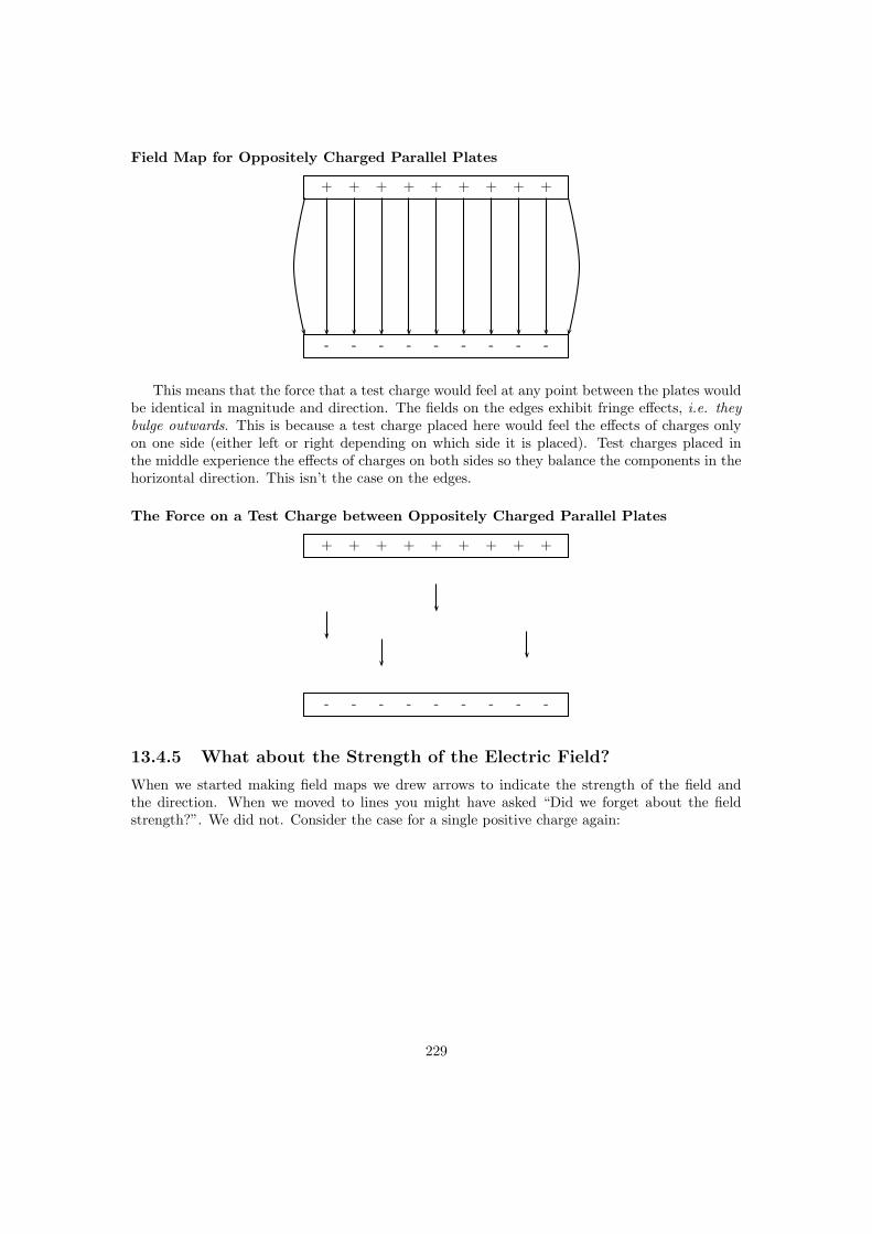
Field Map for Oppositely Charged Parallel Plates
+ + + + + + + + +
- - - - - - - - -
This means that the force that a test charge would feel at any point between the plates wouldbe identical in magnitude and direction. The fields on the edges exhibit fringe effects, i.e. theybulge outwards. This is because a test charge placed here would feel the effects of charges onlyon one side (either left or right depending on which side it is placed). Test charges placed inthe middle experience the effects of charges on both sides so they balance the components in thehorizontal direction. This isn’t the case on the edges.
The Force on a Test Charge between Oppositely Charged Parallel Plates
+ + + + + + + + +
- - - - - - - - -
13.4.5 What about the Strength of the Electric Field?
When we started making field maps we drew arrows to indicate the strength of the field andthe direction. When we moved to lines you might have asked “Did we forget about the fieldstrength?”. We did not. Consider the case for a single positive charge again:
229

A
B
mg
m
h
Figure 13.1: A mass under the influence of a gravitational field.
+Q
Notice that as you move further away from the charge the field lines become more spread out.In field map diagrams the closer field lines are together the stronger the field. This brings us toan interesting case. What is the electric field like if the object that is charged has an irregularshape.
13.5 Electrical Potential
13.5.1 Work Done and Energy Transfer in a Field
When a charged particle moves in an electric field work is done and energy transfers take place.This is exactly analogous to the case when a mass moves in a gravitational field such as that setup by any massive object.
Work done by a field
Gravitational CaseA mass held at a height h above the ground has gravitational potential energy since, ifreleased, it will fall under the action of the gravitational field. Once released, in the absence offriction, only the force of gravity acts on the mass and the mass accelerates in the direction ofthe force (towards the earth’s centre). In this way, work is done by the field. When the mass
230

+ + + + + + +
- - - - - - -
QE
A
B
+Q
s
Figure 13.2: A charged particle under the influence of an electric field.
falls a distance h (from point A to B), the work done is,
W = Fs
= mgh
In falling, the mass loses gravitational potential energy and gains kinetic energy. The work doneEnergy is
conserved!by the field is equal to the energy transferred,
W = Gain in Ek = Loss in Ep (a falling mass)
Electrical CaseA charge in an electric field has electrical potential energy since, if released, it will moveunder the action of the electric field. When released, in the absence of friction, only the electricforce acts on the charge and the charge accelerates in the direction of the force (for positivecharges the force and acceleration are in the direction of the electric field, while negative chargesexperience a force and acceleration in the opposite direction to the electric field.) Consider apositive charge +Q placed in the uniform electric field between oppositely charged parallel plates.The positive charge will be repelled by the positive plate and attracted by the negative plate (i.e.it will move in the direction of the electric field lines). In this way, work is done by the field. Inmoving the charge a distance s in the electric field, the work done is,
W = Fs
= QEs since E =F
Q.
In the process of moving, the charge loses electrical potential energy and gains kinetic energy.The work done by the field is equal to the energy transferred,
W = Gain in Ek = Loss in Ep (charge moving under the influence of an electric field)
Work done by us
Gravitational CaseIn order to return the mass m in Fig.13.1 to its original position (i.e. lift it a distance h from Bback to A) we have to apply a force mg to balance the force of gravity. An amount of work mghis done by the lifter. In the process, the mass gains gravitational potential energy,
mgh = Gain in Ep (lifting a mass)
231

Electrical CaseIn order to return the charge in Fig.13.2 to its original position (i.e. from B back to A) we haveto exert a force QE on the charge to balance the force exerted on it by the electric field. Anamount of work QEs is done by us. In the process, the charge gains electrical potential energy,
Energy isconserved!
QEs = Gain in Ep (charge moved against an electric field)
In summary, when an object moves under the influence of a field, the field does workand potential energy is transferred into kinetic energy. Potential energy is lost,while kinetic energy is gained. When an object is moved against a field we have todo work and the object gains potential energy.
Worked Example 76
Work done and energy transfers in a field
Question: A charge of +5nC is moved a distance of 4 cm against a uniform electricfield of magnitude 2× 10¹²N.C−1 from A to B.
+ + + + + + +
- - - - - - -
B
A+5nC
4cm
(a) Calculate the work done in moving the charge from A to B.(b) The charge is now released and returns to A. Calculate the kinetic energy of thecharge at A.
Answer:(a)Step 1 : (NOTE TO SELF: step is deprecated, use westep instead.)We are given the values of the charge, the field and the distance the charge mustmove. All are in the correct units.Step 2 : (NOTE TO SELF: step is deprecated, use westep instead.)Since the charge is positive we have to do work to move it from A to B (since this isagainst the field). This work is given by,
W = QEs
= (5× 10⁻⁹)(2× 10¹²)(0.04)
= 400 J
(b)
232

Step 3 : (NOTE TO SELF: step is deprecated, use westep instead.)When released the charge moves under the influence of the electric field and returnsto A. Work is now done by the field and the work done is equal to the kinetic energygained,
Gain in Ek = QEs
= (5× 10⁻⁹)(2× 10¹²)(0.04)
= 400 J
Since the charge started at rest, the gain in kinetic energy is the final kinetic energy,
Eat Ak = 400 J
13.5.2 Electrical Potential Difference
Consider a positive test charge +Q placed at A in the electric field of another positive pointcharge.
++Q
A B
The test charge moves towards B under the influence of the electric field of the other charge.In the process the test charge loses electrical potential energy and gains kinetic energy. Thus, atA, the test charge has more potential energy than at B – A is said to have a higher electricalpotential than B. The potential energy of a charge at a point in a field is defined as the workrequired to move that charge from infinity to that point.
The potential difference between two points in an electric field is defined as the workrequired to move a unit positive test charge from the point of lower potential tothat of higher potential. If an amount of work W is required to move a charge Q from onepoint to another, then the potential difference between the two points is given by,
V =W
Qunit : J.C−1 or V (the volt)
233

From this equation it follows that one volt is the potential difference between two points in anelectric field if one joule of work is done in moving one coulomb of charge from the one point tothe other.
Worked Example 77
Potential difference
Question:A positively charged object Q is placed as shown in the sketch. The potential differ-ence between two points A and B is 4× 10⁻⁴ V.
+QA B
(a) Calculate the change in electrical potential energy of a +2nC charge when itmoves from A to B.(b) Which point, A or B, is at the higher electrical potential? Explain.(c) If this charge were replaced with another of charge -2nC, in what way would itschange in energy be affected?
Answer:(a) The electrical potential energy of the positive charge decreases as it moves fromA to B since it is moving in the direction of the electric field produced by the objectQ. This loss in potential energy is equal to the work done by the field,
Loss in Electrical Potential Energy = W
= V Q (Since V =W
Q)
= (4× 10⁻⁴)(2× 10⁻⁹)
= 8× 10⁻¹³ J
(b) Point A is at the higher electrical potential since work is required by us to movea positive test charge from B to A.(c) If the charge is replaced by one of negative charge, the electrical potential energyof the charge will increase in moving from A to B (in this case we would have to dowork on the charge).
As an example consider the electric field between two oppositely charged parallel plates adistance d apart maintained at a potential difference V .
234

+ + + + + + +
- - - - - - -
P
O +Q
d
This electric field is uniform so that a charge placed anywhere between the plates will experiencethe same force. Consider a positive test charge Q placed at point O just off the surface of thenegative plate. In order to move it towards the positive plate we have to apply a force QE. Thework done in moving the charge from the negative to the positive plate is,
W = Fs
= QEd,
but from the definition of electrical potential,
W = V Q.
Equating these two expressions for the work done,
QEd = V Q,
and so, rearranging,
E =V
d.
Worked Example 78
Parallel plates
Question:Two charged parallel plates are at a distance of 180 mm from each other. The po-tential difference between them is 3600 V as shown in the diagram.
+ + + + + + +
- - - - - - -
X
Y
d = 180mm V = 3 600V
235

+ + + + + + +
- - - - - - -
-QFup=QE
Fdown=mgd
Figure 13.3: An oil drop suspended between oppositely charged parallel plates.
(a) If a small oil drop of negligible mass, carrying a charge of +6.8 × 10⁻⁹ C, isplaced between the plates at point X, calculate the magnitude and direction of theelectrostatic force exerted on the droplet.(b) If the droplet is now moved to point Y, would the force exerted on it be bigger,smaller or the same as in (a)?Answer:(a)Step 1 : (NOTE TO SELF: step is deprecated, use westep instead.)First find the electric field strength between the plates,
E =V
d
=3600
0.180
= 20000 N.C−1 from the positive to the negative plate
Step 2 : (NOTE TO SELF: step is deprecated, use westep instead.)Now the force exerted on the charge at X is,
F = QE
= (6.8× 10⁻⁹)(20000)
= 1.36× 10⁻⁴ down
(b)Step 3 : (NOTE TO SELF: step is deprecated, use westep instead.)The same. Since the electric field strength is uniform, the force exerted on a chargeis the same at all points between the plates.
13.5.3 Millikan’s Oil-drop Experiment
Robert Millikan measured the charge on an electron by studying the motion of charged oil dropsbetween oppositely charged parallel plates. Consider one such negative drop between the platesin Fig.13.3. Since this drop is negative, the electric field exerts an upward force on the drop. Inaddition to this upward force, gravity exerts a downward force on the drop. Millikan adjusted
236

the electric field strength between the plates by varying the potential difference applied acrossthe plates. In this way, Millikan was able to bring the drops to rest. At equlibrum,
Fup = Fdown
QE = mg
Since E = Vd ,
QV
d= mg,
and, therefore,
Q =mgd
V
Millikan found that all drops had charges which were multiples of 1.6 × 10⁻¹⁹ C. Since objectsbecome charged by gaining or losing electrons, the charge on an electron must be −1.6×10⁻¹⁹ C.The magnitude of the electron’s charge is denoted by e,
e = 1.6× 10⁻¹⁹ C
Worked Example 79
Charge
Question:A metal sphere carries a charge of +3.2 × 10⁻⁸ C. How many electrons did it haveto lose to attain its charge?Answer:Since the sphere is positive it lost electrons in the process of charging (when an objectloses negative charges it is left positive). In fact, it lost,
3.2× 10⁻⁸
1.6× 10−19= 2× 10¹¹ electrons
Worked Example 80
Millikan oil-drop experiment
Question:In a Millikan-type experiment a positively charged oil drop is placed between twohorizontal plates, 20 mm apart, as shown.
237

- - - - - - -
+ + + + + + +
The potential difference across the plates is 4000V. The drop has a mass of 1.2 ×10⁻¹⁴kg and a charge of 8× 10⁻¹⁹C.(a) Draw the electric field pattern between the two plates.(b) Calculate:
1. the electric field intensity between the two plates.
2. the magnitude of the gravitational force acting on the drop.
3. the magnitude of the Coulomb force acting on the drop.
(c) The drop is observed through a microscope. What will the drop be seen to do?Explain.(d) Without any further calculations, give two methods that could be used to makethe drop remain in a fixed position.Answer:(a)
- - - - - - -
+ + + + + + +
(b) 1.
E =V
d
=4000
0.02
= 2× 10⁵ V.m−1 up
2.
Fgrav = mg
= (1.2× 10⁻¹⁴)(10)
= 1.2× 10⁻¹³N
238

3.
FCoulomb = QE
= (8× 10⁻¹⁹)(s× 105)
= 1.6× 10⁻¹³N
(c) Since Fup > Fdown, the drop accelerates upwards.(d) The Coulomb force can be decreased by decreasing the electric field strength be-tween the plates. Since E = V
d , this can be done either by increasing d or decreasingV .
13.6 Important Equations and Quantities
UnitsQuantity Symbol Unit S.I. Units Directioncharge q or Q C (Coulomb) A.s or — —
force−→F N (Newton) kg.m
s2 or kg.m.s−2 X
mass m — kg or — —acceleration −→a — m
s2 or m.s−2 X
radial distance r — m or — —
electric field−→E N/C or V/m kg.m
A.s3 or kg.m.A−1.s−3 X
work W J kg.m2
s2 or kg.m2.s−2 —
potential difference V V (Volt) kg.m2
A.s3 or kg.m2.A−1.s−3 —
Table 13.1: Units used in Electrostatics
239

Chapter 14
Electricity
Warning: We believe in experimenting and learningabout physics at every opportunity, BUT playing withelectricity can be EXTREMELY DANGEROUS!Do not try to build home made circuits without someone who knowsif what you are doing is safe. Normal electrical outletsare dangerous. Treat electricity with respect in your everyday life.You will encounter electricity everyday for the rest of your life and to make sure you are able to make wise decisions we have included an entire chapter on electrical safety. Please read it - not only will it make you safer but it will show the applications of many of the ideas you will learn in this chapter.
14.1 Flow of Charge
While the normal motion of ”free” electrons in a conductor is random, with no particular directionor speed, electrons can be influenced to move in a coordinated fashion through a conductivematerial. This motion of electrons is what we call electricity, or electric current. This is incontrast to static electricity, which is an unmoving accumulation of electric charge. Just likewater flowing through the emptiness of a pipe, electrons are able to move between the atoms ofa conductor. The conductor may appear to be solid to our eyes, but any material composed ofatoms is mostly empty space! The liquid-flow analogy is so fitting that the motion of electronsthrough a conductor is often referred to as a ”flow.”
As each electron moves uniformly through a conductor, it pushes on the one ahead of it,such that all the electrons move together as a group. The starting and stopping of electron flowthrough the length of a conductor is virtually instantaneous from one end of a conductor to theother, even though the motion of each electron may be very slow. As an analogy consider a tubefilled end-to-end with marbles:
Tube
Marble Marble
The tube is full of marbles, just as a conductor is full of free electrons. If a single marbleis suddenly inserted into this full tube on the left-hand side, another marble will immediatelytry to exit the tube on the right. Even though each marble only traveled a short distance, thetransfer of motion through the tube is virtually instantaneous from the left end to the right end,
240

no matter how long the tube is. With electricity, the overall effect from one end of a conductorto the other effectively instantaneous. Each individual electron, though, travels through theconductor at a much slower pace.
If we want electrons to flow in a certain direction to a certain place, we must provide theproper path for them to move, just as a plumber must install piping to get water to flow wherehe or she wants it to flow. Wires made of highly conductive metals such as copper or aluminumare used to from this path.
This means that there can be electric current only where there exists a continuous path ofconductive material (wire) providing a path for electrons. In the marble analogy, marbles canflow into the left-hand side of the tube (and, consequently, through the tube) only if the tubeis open on the right-hand side for marbles to flow out. If the tube is blocked on the right-handside, the marbles will just ”pile up” inside the tube, and marble ”flow” will not occur. The sameholds true for electric current: the continuous flow of electrons requires there be an unbrokenpath. Let’s look at a diagram to illustrate how this works:
A thin, solid line (as shown above) is the conventional symbol for a continuous piece of wire.Since the wire is made of a conductive material, such as copper, its constituent atoms have manyfree electrons which can easily move through the wire. However, there will never be a continuousor uniform flow of electrons within this wire unless they have a place to come from and a placeto go. Let’s add an hypothetical electron ”Source” and ”Destination:”
Electron ElectronSource Destination
Now, with the Electron Source pushing new electrons into the wire on the left-hand side,electron flow through the wire can occur (as indicated by the arrows pointing from left to right).However, the flow will be interrupted if the conductive path formed by the wire is broken:
Electron ElectronSource Destination
no flow! no flow!
(break)
Air is an insulator, and an air gap separates the two pieces of wire, the path has now beenbroken, and electrons cannot flow from Source to Destination. This is like cutting a water pipein two and capping off the broken ends of the pipe: water can’t flow if there’s no exit out of thepipe.
If we were to take another piece of wire leading to the Destination and simply make physicalcontact with the wire leading to the Source, we would once again have a continuous path forelectrons to flow. The two dots in the diagram indicate physical (metal-to-metal) contact betweenthe wire pieces:
Electron ElectronSource Destination
no flow!
(break)
Now, we have continuity from the Source, to the newly-made connection, down, to the right,and up to the Destination. Please take note that the broken segment of wire on the right handside has no electrons flowing through it, because it is no longer part of a complete path fromSource to Destination.
It is interesting to note that no ”wear” occurs within wires due to this electric current, unlikewater-carrying pipes which are eventually corroded and worn by prolonged flows. Electrons do
241

encounter some degree of friction as they move and this friction can generate heat in a conductor.This is a topic we’ll discuss later.
14.2 Circuits
In order for the Source-and-Destination scheme to work, both would have to have a huge reservoirof electrons in order to sustain a continuous flow! Using the marble-and-tube analogy, the marblesource and marble destination buckets would have to be large reservoirs to contain enough marblecapacity for a ”flow” of marbles to be sustained.
The answer to this paradox is found in the concept of a circuit : a never-ending loopedpathway for electrons. If we take a wire, or many wires joined end-to-end, and loop it around sothat it forms a continuous pathway ( a circle), we have the means to support a uniform flow ofelectrons without having to resort to huge reservoirs.
electrons can flow
in a path without
beginning or end,
continuing forever!
A marble-and-hula-hoop "circuit"
Each electron advancing clockwise in this circuit pushes on the one in front of it, which pusheson the one in front of it, and so on, and so on, just like a hula-hoop filled with marbles. Now,we have the capability of supporting a continuous flow of electrons indefinitely without the needfor reservoirs. All we need to maintain this flow is a continuous means of motivation for thoseelectrons, which we’ll address in the next section of this chapter.
It must be realized that continuity is just as important in a circuit as it is in a straight pieceof wire. Just as in the example with the straight piece of wire between the electron Source andDestination, any break in this circuit will prevent electrons from flowing through it:
242

(break)
electron flow cannot
in a "broken" circuit!
no flow!
no flow!
no flow!
occur anywhere
continuous
An important principle to realize here is that it doesn’t matter where the break occurs. Anydiscontinuity in the circuit will prevent electron flow throughout the entire circuit.
electron flow cannot
in a "broken" circuit!
no flow!
no flow!
no flow! (break)
occur anywhere
continuous
A combination of batteries and conductors with other components is called an electric circuitor circuit. The word circuit implies that you return to your starting point and this is an importantproperty of electric circuits. They must contain a closed loop before charge can flow.
The simplest possible circuit is a battery with a single conductor. Now how do we form aclosed loop with these two components? The battery has two terminals (connection points).One is called the positive terminal and one the negative. When we describe charge flowing weconsider charges moving from the positive terminal of the battery around the conductor andback into the battery at the negative terminal. As much charge flows out of the positive terminalas flows into the negative terminal so there is no build up of charge in the battery. The batterydoes work on the charges causing them to move round the circuit.
Now I keep talking about batteries and circuits but we need to draw these things to helpkeep the ideas clear in our minds. To do this we need to agree on how to draw things so thatother people can understand what we are doing. We need a convention.
243

14.3 Voltage and current
As was previously mentioned, we need more than just a continuous path (circuit) before acontinuous flow of electrons will occur: we also need some means to push these electrons aroundthe circuit. Just like marbles in a tube or water in a pipe, it takes some kind of influencing forceto initiate flow. With electrons, this force is the same force at work in static electricity: the forceproduced by an imbalance of electric charge.
The electric charge difference serves to store a certain amount of energy. This energy is notunlike the energy stored in a high reservoir of water that has been pumped from a lower-levelpond:
Pump
Pond
Reservoir Energy stored
Water flow
The influence of gravity on the water in the reservoir creates a force that attempts to movethe water down to the lower level again. If a suitable pipe is run from the reservoir back to thepond, water will flow under the influence of gravity down from the reservoir, through the pipe:
244

Pond
Reservoir
Energy released
It takes energy to pump that water from the low-level pond to the high-level reservoir, andthe movement of water through the piping back down to its original level constitutes a releasingof energy stored from previous pumping.
If the water is pumped to an even higher level, it will take even more energy to do so, thusmore energy will be stored, and more energy released if the water is allowed to flow through apipe back down again:
245

Reservoir
Pump
Pond
Energy stored
More energy releasedMore energy stored
Energy released
Reservoir
Pond
Pump
Electrons are not much different. If we ”pump” electrons away from their normal ”levels,”creating a condition where a force exists as the electrons seek to re-establish their former positions.The force attracting electrons back to their original positions is analogous to the force gravityexerts on water in the reservoir, trying to draw it down to its former level.
Just as the pumping of water to a higher level results in energy being stored, ”pumping”electrons to create an electric charge imbalance results in a certain amount of energy beingstored in that imbalance. And, just as providing a way for water to flow back down from theheights of the reservoir results in a release of that stored energy, providing a way for electrons
246

to flow back to their original ”levels” results in a release of stored energy.When the electrons are poised in that static condition (just like water sitting still, high in
a reservoir), the energy stored there is called potential energy, because it has the possibility(potential) of release that has not been fully realized yet.
This potential energy, stored in the form of an electric charge imbalance and capable ofprovoking electrons to flow through a conductor, can be expressed as a term called voltage,which technically is a measure of potential energy per unit charge of electrons, or something aphysicist would call specific potential energy. Defined in the context of static electricity, voltageis the measure of work required to move a unit charge from one location to another, against theforce which tries to keep electric charges balanced. In the context of electrical power sources,voltage is the amount of potential energy available (work to be done) per unit charge, to moveelectrons through a conductor.
Because voltage is an expression of potential energy, representing the possibility or potentialfor energy release as the electrons move from one ”level” to another, it is always referencedbetween two points. Consider the water reservoir analogy:
Reservoir
Location #1
Location #2
Drop
Drop
Because of the difference in the height of the drop, there’s potential for much more energy tobe released from the reservoir through the piping to location 2 than to location 1. The principlecan be intuitively understood in dropping a rock: which results in a more violent impact, a rockdropped from a height of one foot, or the same rock dropped from a height of one kilometre?Obviously, the drop of greater height results in greater energy released (a more violent impact).We cannot assess the amount of stored energy in a water reservoir simply by measuring thevolume of water any more than we can predict the severity of a falling rock’s impact simplyfrom knowing the weight of the rock: in both cases we must also consider how far these masseswill drop from their initial height. The amount of energy released by allowing a mass to dropis relative to the distance between its starting and ending points. Likewise, the potential energyavailable for moving electrons from one point to another is relative to those two points. Therefore,voltage is always expressed as a quantity between two points. Interestingly enough, the analogyof a mass potentially ”dropping” from one height to another is such an apt model that voltagebetween two points is sometimes called a voltage drop.
Voltage can be generated by means other than rubbing certain types of materials against
247

each other. Chemical reactions, radiant energy, and the influence of magnetism on conductorsare a few ways in which voltage may be produced. Respective examples of these three sources ofvoltage are batteries, solar cells, and generators (such as the ”alternator” unit under the hood ofyour automobile). For now, we won’t go into detail as to how each of these voltage sources works– more important is that we understand how voltage sources can be applied to create electronflow in a circuit.
Let’s take the symbol for a chemical battery and build a circuit step by step:
Battery
-
+
1
2Any source of voltage, including batteries, have two points for electrical contact. In this
case, we have point 1 and point 2 in the above diagram. The horizontal lines of varying lengthindicate that this is a battery, and they further indicate the direction which this battery’s voltagewill try to push electrons through a circuit. The fact that the horizontal lines in the batterysymbol appear separated (and thus unable to serve as a path for electrons to move) is no causefor concern: in real life, those horizontal lines represent metallic plates immersed in a liquid orsemi-solid material that not only conducts electrons, but also generates the voltage to push themalong by interacting with the plates.
Notice the little ”+” and ”-” signs to the immediate left of the battery symbol. The negative(-) end of the battery is always the end with the shortest dash, and the positive (+) end ofthe battery is always the end with the longest dash. Since we have decided to call electrons”negatively” charged (thanks, Ben!), the negative end of a battery is that end which tries topush electrons out of it. Likewise, the positive end is that end which tries to attract electrons.
With the ”+” and ”-” ends of the battery not connected to anything, there will be voltagebetween those two points, but there will be no flow of electrons through the battery, becausethere is no continuous path for the electrons to move.
248

Battery
-
+
1
2
No flowPump
Pond
Reservoir
No flow (once thereservoir has beencompletely filled)
Electric Battery
Water analogy
The same principle holds true for the water reservoir and pump analogy: without a returnpipe back to the pond, stored energy in the reservoir cannot be released in the form of waterflow. Once the reservoir is completely filled up, no flow can occur, no matter how much pressurethe pump may generate. There needs to be a complete path (circuit) for water to flow from thepond, to the reservoir, and back to the pond in order for continuous flow to occur.
We can provide such a path for the battery by connecting a piece of wire from one end of thebattery to the other. Forming a circuit with a loop of wire, we will initiate a continuous flow ofelectrons in a clockwise direction:
249

Battery
-
+
1
2
Pump
Pond
Reservoir
Water analogy
water flow!
electron flow!
water flow!
Electric Circuit
So long as the battery continues to produce voltage and the continuity of the electrical pathisn’t broken, electrons will continue to flow in the circuit. Following the metaphor of watermoving through a pipe, this continuous, uniform flow of electrons through the circuit is called acurrent. So long as the voltage source keeps ”pushing” in the same direction, the electron flowwill continue to move in the same direction in the circuit. This single-direction flow of electronsis called a Direct Current, or DC.
Because electric current is composed of individual electrons flowing in unison through aconductor by moving along and pushing on the electrons ahead, just like marbles through a tubeor water through a pipe, the amount of flow throughout a single circuit will be the same at anypoint. If we were to monitor a cross-section of the wire in a single circuit, counting the electronsflowing by, we would notice the exact same quantity per unit of time as in any other part of thecircuit, regardless of conductor length or conductor diameter.
250

If we break the circuit’s continuity at any point, the electric current will cease in the entireloop, and the full voltage produced by the battery will be manifested across the break, betweenthe wire ends that used to be connected:
Battery
-
+
1
2
(break)
no flow!
no flow!
-
+
voltagedrop
Notice the ”+” and ”-” signs drawn at the ends of the break in the circuit, and how theycorrespond to the ”+” and ”-” signs next to the battery’s terminals. These markers indicatethe direction that the voltage attempts to push electron flow. Remember that voltage is alwaysrelative between two points. Whether a point in a circuit gets labeled with a ”+” or a ”-”depends on the other point to which it is referenced. Take a look at the following circuit, whereeach corner of the loop is marked with a number for reference:
Battery
-
+
1 2
(break)
no flow!
no flow!
-
+
34
With the circuit’s continuity broken between points 2 and 3, voltage dropped between points2 and 3 is ”-” for point 2 and ”+” for point 3.
Now let’s see what happens if we connect points 2 and 3 back together again, but place abreak in the circuit between points 3 and 4:
Battery
-
+
1 2
(break)
no flow!
no flow!
34-+
251

With the break between 3 and 4, the voltage drop between those two points is ”+” for 4and ”-” for 3. Take special note of the fact that point 3’s ”sign” is opposite of that in the firstexample, where the break was between points 2 and 3 (where point 3 was labeled ”+”). It isimpossible for us to say that point 3 in this circuit will always be either ”+” or ”-”, because thesign is not specific to a single point, but is always relative between two points!
14.4 Resistance
The circuit in the previous section is not a very practical one. In fact, it can be quite dangerousto build (directly connecting the poles of a voltage source together with a single piece of wire).The reason it is dangerous is because the magnitude of electric current may be very large in sucha short circuit, and the release of energy very dramatic (usually in the form of heat). Usually,electric circuits are constructed in such a way as to make practical use of that released energy,in as safe a manner as possible.
One practical and popular use of electric current is for the operation of electric lighting. Thesimplest form of electric lamp is a tiny metal ”filament” inside of a clear glass bulb, which glowswhite-hot (”incandesces”) with heat energy when sufficient electric current passes through it.Like the battery, it has two conductive connection points, one for electrons to enter and theother for electrons to exit.
Connected to a source of voltage, an electric lamp circuit looks something like this:
Battery
-
+
electron flow
electron flow
Electric lamp (glowing)
As the electrons work their way through the thin metal filament of the lamp, they encountermore opposition to motion than they typically would in a thick piece of wire. This opposition toelectric current depends on the type of material, its cross-sectional area, and its temperature. It istechnically known as resistance. (It can be said that conductors have low resistance and insulatorshave very high resistance.) This resistance serves to limit the amount of current through thecircuit with a given amount of voltage supplied by the battery, as compared with the ”shortcircuit” where we had nothing but a wire joining one end of the voltage source (battery) to theother.
When electrons move against the opposition of resistance, ”friction” is generated. Just likemechanical friction, the friction produced by electrons flowing against a resistance manifestsitself in the form of heat. The concentrated resistance of a lamp’s filament results in a relativelylarge amount of heat energy dissipated at that filament. This heat energy is enough to causethe filament to glow white-hot, producing light, whereas the wires connecting the lamp to thebattery (which have much lower resistance) hardly even get warm while conducting the same
252
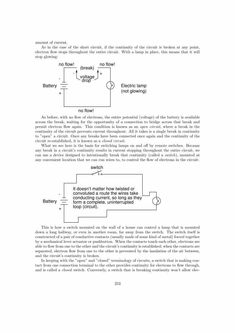
amount of current.As in the case of the short circuit, if the continuity of the circuit is broken at any point,
electron flow stops throughout the entire circuit. With a lamp in place, this means that it willstop glowing:
Battery
-
+
(break)
no flow!
no flow! no flow!
- +voltagedrop
Electric lamp(not glowing)
As before, with no flow of electrons, the entire potential (voltage) of the battery is availableacross the break, waiting for the opportunity of a connection to bridge across that break andpermit electron flow again. This condition is known as an open circuit, where a break in thecontinuity of the circuit prevents current throughout. All it takes is a single break in continuityto ”open” a circuit. Once any breaks have been connected once again and the continuity of thecircuit re-established, it is known as a closed circuit.
What we see here is the basis for switching lamps on and off by remote switches. Becauseany break in a circuit’s continuity results in current stopping throughout the entire circuit, wecan use a device designed to intentionally break that continuity (called a switch), mounted atany convenient location that we can run wires to, to control the flow of electrons in the circuit:
Battery
-
+
switch
It doesn’t matter how twisted orconvoluted a route the wires takeconducting current, so long as theyform a complete, uninterrupted loop (circuit).
This is how a switch mounted on the wall of a house can control a lamp that is mounteddown a long hallway, or even in another room, far away from the switch. The switch itself isconstructed of a pair of conductive contacts (usually made of some kind of metal) forced togetherby a mechanical lever actuator or pushbutton. When the contacts touch each other, electrons areable to flow from one to the other and the circuit’s continuity is established; when the contacts areseparated, electron flow from one to the other is prevented by the insulation of the air between,and the circuit’s continuity is broken.
In keeping with the ”open” and ”closed” terminology of circuits, a switch that is making con-tact from one connection terminal to the other provides continuity for electrons to flow through,and is called a closed switch. Conversely, a switch that is breaking continuity won’t allow elec-
253

trons to pass through and is called an open switch. This terminology is often confusing to thenew student of electronics, because the words ”open” and ”closed” are commonly understoodin the context of a door, where ”open” is equated with free passage and ”closed” with block-age. With electrical switches, these terms have opposite meaning: ”open” means no flow while”closed” means free passage of electrons.
14.5 Voltage and current in a practical circuit
Because it takes energy to force electrons to flow against the opposition of a resistance, there willbe voltage manifested (or ”dropped”) between any points in a circuit with resistance betweenthem. It is important to note that although the amount of current (the quantity of electronsmoving past a given point every second) is uniform in a simple circuit, the amount of voltage(potential energy per unit charge) between different sets of points in a single circuit may varyconsiderably:
Battery
-
+
1 2
34
same rate of current . . .
. . . at all points in this circuitTake this circuit as an example. If we label four points in this circuit with the numbers 1, 2,
3, and 4, we will find that the amount of current conducted through the wire between points 1and 2 is exactly the same as the amount of current conducted through the lamp (between points2 and 3). This same quantity of current passes through the wire between points 3 and 4, andthrough the battery (between points 1 and 4).
However, we will find the voltage appearing between any two of these points to be directlyproportional to the resistance within the conductive path between those two points, given thatthe amount of current along any part of the circuit’s path is the same (which, for this simplecircuit, it is). In a normal lamp circuit, the resistance of a lamp will be much greater than theresistance of the connecting wires, so we should expect to see a substantial amount of voltagebetween points 2 and 3, with very little between points 1 and 2, or between 3 and 4. The voltagebetween points 1 and 4, of course, will be the full amount of ”force” offered by the battery, whichwill be only slightly greater than the voltage across the lamp (between points 2 and 3).
This, again, is analogous to the water reservoir system:
254

Pump
Pond
Reservoir
Waterwheel
(energy released)
(energy stored)
12
3
4
Between points 2 and 3, where the falling water is releasing energy at the water-wheel, thereis a difference of pressure between the two points, reflecting the opposition to the flow of waterthrough the water-wheel. From point 1 to point 2, or from point 3 to point 4, where water isflowing freely through reservoirs with little opposition, there is little or no difference of pressure(no potential energy). However, the rate of water flow in this continuous system is the sameeverywhere (assuming the water levels in both pond and reservoir are unchanging): through thepump, through the water-wheel, and through all the pipes. So it is with simple electric circuits:the rate of electron flow is the same at every point in the circuit, although voltages may differbetween different sets of points.
When Benjamin Franklin made his conjecture regarding the direction of charge flow (fromthe smooth wax to the rough wool), he set a precedent for electrical notation that exists to thisday, despite the fact that we know electrons are the constituent units of charge, and that they aredisplaced from the wool to the wax – not from the wax to the wool – when those two substancesare rubbed together. This is why electrons are said to have a negative charge: because Franklinassumed electric charge moved in the opposite direction that it actually does, and so objects hecalled ”negative” (representing a deficiency of charge) actually have a surplus of electrons.
By the time the true direction of electron flow was discovered, the nomenclature of ”positive”and ”negative” had already been so well established in the scientific community that no effortwas made to change it, although calling electrons ”positive” would make more sense in referringto ”excess” charge. You see, the terms ”positive” and ”negative” are human inventions, and assuch have no absolute meaning beyond our own conventions of language and scientific description.Franklin could have just as easily referred to a surplus of charge as ”black” and a deficiency as”white,” in which case scientists would speak of electrons having a ”white” charge (assuming thesame incorrect conjecture of charge position between wax and wool).
However, because we tend to associate the word ”positive” with ”surplus” and ”negative” with”deficiency,” the standard label for electron charge does seem backward. Because of this, manyengineers decided to retain the old concept of electricity with ”positive” referring to a surplusof charge, and label charge flow (current) accordingly. This became known as conventional flownotation:
255

+
-
Conventional flow notation
Electric charge moves from the positive (surplus)side of the battery to thenegative (deficiency) side.
Others chose to designate charge flow according to the actual motion of electrons in a circuit.This form of symbology became known as electron flow notation:
+
-
Electric charge moves
side of the battery to the
Electron flow notation
from the negative (surplus)
positive (deficiency) side.
In conventional flow notation, we show the motion of charge according to the (technicallyincorrect) labels of + and -. This way the labels make sense, but the direction of charge flowis incorrect. Does it matter, really, how we designate charge flow in a circuit? Not really,so long as we’re consistent in the use of our symbols. You may follow an imagined directionof current (conventional flow) or the actual (electron flow) with equal success insofar as circuitanalysis is concerned. Concepts of voltage, current, resistance, continuity, and even mathematicaltreatments such as Ohm’s Law (chapter 2) and Kirchhoff’s Laws (chapter 6) remain just as validwith either style of notation.
14.6 How voltage, current, and resistance relate
First lets recap some of the ideas we have learnt so far. We will need these to understand howvoltage, current and resistance relate.
An electric circuit is formed when a conductive path is created to allow free electrons tocontinuously move. This continuous movement of free electrons through the conductors of acircuit is called a current, and it is often referred to in terms of ”flow,” just like the flow of aliquid through a hollow pipe.
The force motivating electrons to ”flow” in a circuit is called voltage. Voltage is a specificmeasure of potential energy that is always relative between two points. When we speak of acertain amount of voltage being present in a circuit, we are referring to the measurement ofhow much potential energy exists to move electrons from one particular point in that circuit toanother particular point. Without reference to two particular points, the term ”voltage” has nomeaning.
Free electrons tend to move through conductors with some degree of friction, or opposition
256

to motion. This opposition to motion is more properly called resistance. The amount of currentin a circuit depends on the amount of voltage available to motivate the electrons, and also theamount of resistance in the circuit to oppose electron flow. Just like voltage, resistance is aquantity relative between two points. For this reason, the quantities of voltage and resistanceare often stated as being ”between” or ”across” two points in a circuit.
To be able to make meaningful statements about these quantities in circuits, we need to beable to describe their quantities in the same way that we might quantify mass, temperature,volume, length, or any other kind of physical quantity. For mass we might use the units of”pound” or ”gram.” For temperature we might use degrees Fahrenheit or degrees Celsius. Hereare the standard units of measurement for electrical current, voltage, and resistance:
Quantity Symbol MeasurementUnit of
AbbreviationUnit
Current
Voltage
Resistance
I
E Vor
R
Ampere ("Amp")
VoltOhm
A
V
Ω
The ”symbol” given for each quantity is the standard alphabetical letter used to represent thatquantity in an algebraic equation. Standardized letters like these are common in the disciplinesof physics and engineering, and are internationally recognized. The ”unit abbreviation” for eachquantity represents the alphabetical symbol used as a shorthand notation for its particular unitof measurement. And, yes, that strange-looking ”horseshoe” symbol is the capital Greek letterΩ, just a character in a foreign alphabet (apologies to any Greek readers here).
Each unit of measurement is named after a famous experimenter in electricity: The amp afterthe Frenchman Andre M. Ampere, the volt after the Italian Alessandro Volta, and the ohm afterthe German Georg Simon Ohm.
The mathematical symbol for each quantity is meaningful as well. The ”R” for resistanceand the ”V” for voltage are both self-explanatory, whereas ”I” for current seems a bit weird.The ”I” is thought to have been meant to represent ”Intensity” (of electron flow), and the othersymbol for voltage, ”E,” stands for ”Electromotive force.” From what research I’ve been ableto do, there seems to be some dispute over the meaning of ”I.” The symbols ”E” and ”V” areinterchangeable for the most part, although some texts reserve ”E” to represent voltage acrossa source (such as a battery or generator) and ”V” to represent voltage across anything else.
One foundational unit of electrical measurement, often taught in the beginnings of electronicscourses but used infrequently afterwards, is the unit of the coulomb, which is a measure of electriccharge proportional to the number of electrons in an imbalanced state. One coulomb of chargeis equal to 6,250,000,000,000,000,000 electrons. The symbol for electric charge quantity is thecapital letter ”Q,” with the unit of coulombs abbreviated by the capital letter ”C.” It so happensthat the unit for electron flow, the amp, is equal to 1 coulomb of electrons passing by a givenpoint in a circuit in 1 second of time. Cast in these terms, current is the rate of electric chargemotion through a conductor.
As stated before, voltage is the measure of potential energy per unit charge available tomotivate electrons from one point to another. Before we can precisely define what a ”volt” is,we must understand how to measure this quantity we call ”potential energy.” The general metricunit for energy of any kind is the joule, equal to the amount of work performed by a force of 1newton exerted through a motion of 1 meter (in the same direction).Defined in these scientificterms, 1 volt is equal to 1 joule of electric potential energy per (divided by) 1 coulomb of charge.Thus, a 9 volt battery releases 9 joules of energy for every coulomb of electrons moved through
257

a circuit.These units and symbols for electrical quantities will become very important to know as we
begin to explore the relationships between them in circuits. The first, and perhaps most impor-tant, relationship between current, voltage, and resistance is called Ohm’s Law, discovered byGeorg Simon Ohm and published in his 1827 paper, The Galvanic Circuit Investigated Mathe-matically. Ohm’s principal discovery was that the amount of electric current through a metalconductor in a circuit is directly proportional to the voltage impressed across it, for any giventemperature. Ohm expressed his discovery in the form of a simple equation, describing howvoltage, current, and resistance interrelate:
E = I RIn this algebraic expression, voltage (E) is equal to current (I) multiplied by resistance (R).
Using algebra techniques, we can manipulate this equation into two variations, solving for I andfor R, respectively:
I = ER
R = EI
Let’s see how these equations might work to help us analyze simple circuits:
Battery-
+
electron flow
electron flow
Electric lamp (glowing)
In the above circuit, there is only one source of voltage (the battery, on the left) and only onesource of resistance to current (the lamp, on the right). This makes it very easy to apply Ohm’sLaw. If we know the values of any two of the three quantities (voltage, current, and resistance)in this circuit, we can use Ohm’s Law to determine the third.
In this first example, we will calculate the amount of current (I) in a circuit, given values ofvoltage (E) and resistance (R):
258

Battery
-
+Lamp
E = 12 V
I = ???
I = ???
R = 3 Ω
What is the amount of current (I) in this circuit?
I = ER
= =12 V3 Ω
4 A
In this second example, we will calculate the amount of resistance (R) in a circuit, givenvalues of voltage (E) and current (I):
Battery
-
+Lamp
E = 36 V
I = 4 A
I = 4 A
R = ???
What is the amount of resistance (R) offered by the lamp?
ER = ==I
36 V4 A
9 Ω
In the last example, we will calculate the amount of voltage supplied by a battery, givenvalues of current (I) and resistance (R):
259

Battery
-
+Lamp
E = ???
I = 2 A
I = 2 A
R = 7 Ω
What is the amount of voltage provided by the battery?
R =IE = (2 A)(7 Ω) = 14 VOhm’s Law is a very simple and useful tool for analyzing electric circuits. It is used so often
in the study of electricity and electronics that it needs to be committed to memory by the seriousstudent. For those who are not yet comfortable with algebra, there’s a trick to remembering howto solve for any one quantity, given the other two. First, arrange the letters E, I, and R in atriangle like this:
E
I R
If you know E and I, and wish to determine R, just eliminate R from the picture and seewhat’s left:
E
I R
EI
R =
If you know E and R, and wish to determine I, eliminate I and see what’s left:
E
I R
EI =R
Lastly, if you know I and R, and wish to determine E, eliminate E and see what’s left:
E
I R
E = I R
260

Eventually, you’ll have to be familiar with algebra to seriously study electricity and elec-tronics, but this tip can make your first calculations a little easier to remember. If you arecomfortable with algebra, all you need to do is commit E=IR to memory and derive the othertwo formulae from that when you need them!
14.7 An analogy for Ohm’s Law
Ohm’s Law also make intuitive sense if you apply if to the water-and-pipe analogy. If we havea water pump that exerts pressure (voltage) to push water around a ”circuit” (current) througha restriction (resistance), we can model how the three variables interrelate. If the resistance towater flow stays the same and the pump pressure increases, the flow rate must also increase.
PressureFlow rate
Resistance
=
=
=
VoltageCurrent
Resistance
=
=
=
increase
same
increase increase
increase
same
E = I RIf the pressure stays the same and the resistance increases (making it more difficult for the
water to flow), then the flow rate must decrease:
PressureFlow rate
Resistance
=
=
=
VoltageCurrent
Resistance
=
=
=
same
increase increase
same
E = I R
decreasedecrease
If the flow rate were to stay the same while the resistance to flow decreased, the requiredpressure from the pump would necessarily decrease:
PressureFlow rate
Resistance
=
=
=
VoltageCurrent
Resistance
=
=
=
same same
E = I R
decrease
decrease
decrease
decreasedecrease
As odd as it may seem, the actual mathematical relationship between pressure, flow, andresistance is actually more complex for fluids like water than it is for electrons. If you pursue
261
further studies in physics, you will discover this for yourself. Thankfully for the electronicsstudent, the mathematics of Ohm’s Law is very straightforward and simple.
14.8 Power in electric circuits
In addition to voltage and current, there is another measure of free electron activity in a circuit:power. First, we need to understand just what power is before we analyze it in any circuits.
Power is a measure of how much work can be performed in a given amount of time. Work isgenerally defined in terms of the lifting of a weight against the pull of gravity. The heavier theweight and/or the higher it is lifted, the more work has been done. Power is a measure of howrapidly a standard amount of work is done.
In electric circuits, power is a function of both voltage and current.
P = I EIn this case, however, power (P) is exactly equal to current (I) multiplied by voltage (E),
rather than merely being proportional to IE. When using this formula, the unit of measurementfor power is the watt, abbreviated with the letter ”W.”
It must be understood that neither voltage nor current by themselves constitute power.Rather, power is the combination of both voltage and current in a circuit. Remember thatvoltage is the specific work (or potential energy) per unit charge, while current is the rate atwhich electric charges move through a conductor. Voltage (specific work) is analogous to thework done in lifting a weight against the pull of gravity. Current (rate) is analogous to the speedat which that weight is lifted. Together as a product (multiplication), voltage (work) and current(rate) constitute power.
A circuit with high voltage and low current may be dissipating the same amount of power asa circuit with low voltage and high current. Neither the amount of voltage alone nor the amountof current alone indicates the amount of power in an electric circuit.
In an open circuit, where voltage is present between the terminals of the source and thereis zero current, there is zero power dissipated, no matter how great that voltage may be. SinceP=IE and I=0 and anything multiplied by zero is zero, the power dissipated in any open circuitmust be zero.
14.9 Calculating electric power
We’ve seen the formula for determining the power in an electric circuit: by multiplying thevoltage in ”volts” by the current in ”amps” we arrive at an answer in ”watts.” Let’s apply thisto a circuit example:
262

Battery
-
+Lamp
E = 18 V
I = ???
I = ???
R = 3 Ω
In the above circuit, we know we have a battery voltage of 18 volts and a lamp resistance of3 Ω. Using Ohm’s Law to determine current, we get:
I =ER = =
18 V3 Ω 6 A
Now that we know the current, we can take that value and multiply it by the voltage todetermine power:
P = I E = (6 A)(18 V) = 108 WAnswer: the lamp is dissipating (releasing) 108 watts of power, most likely in the form of
both light and heat.Let’s try taking that same circuit and increasing the battery voltage to see what happens.
Intuition should tell us that the circuit current will increase as the voltage increases and thelamp resistance stays the same. Likewise, the power will increase as well:
Battery
-
+Lamp
E = 36 V
I = ???
I = ???
R = 3 Ω
Now, the battery voltage is 36 volts instead of 18 volts. The lamp is still providing 3 Ω ofelectrical resistance to the flow of electrons. The current is now:
I =ER = =
36 V3 Ω 12 A
This stands to reason: if I = E/R, and we double E while R stays the same, the currentshould double. Indeed, it has: we now have 12 amps of current instead of 6. Now, what aboutpower?
263

P = I E = (12 A)(36 V) = 432 WNotice that the power has increased just as we might have suspected, but it increased quite
a bit more than the current. Why is this? Because power is a function of voltage multiplied bycurrent, and both voltage and current doubled from their previous values, the power will increaseby a factor of 2 x 2, or 4. You can check this by dividing 432 watts by 108 watts and seeing thatthe ratio between them is indeed 4.
Using algebra again to manipulate the formulae, we can take our original power formula andmodify it for applications where we don’t know both voltage and resistance:
If we only know voltage (E) and resistance (R):
If, I = ER
and P = I E
Then, P = ER
E or P = ER
2
If we only know current (I) and resistance (R):
If,
I
=E R and P = I E
Then, P = or P = R2
I
I R( ) IAn historical note: It was James Prescott Joule, not Georg Simon Ohm,
who first discovered the mathematical relationship between powerdissipation and current through a resistance. This discovery,
published in 1841, followed the form of the last equation (P =I2R), and is properly known as Joule’s Law. However, these power
equations are so commonly associated with the Ohm’s Law equationsrelating voltage, current, and resistance (E=IR ; I=E/R ; and R=E/I)
that they are frequently credited to Ohm.
14.10 Resistors
Because the relationship between voltage, current, and resistance in any circuit is so regular,we can reliably control any variable in a circuit simply by controlling the other two. Perhapsthe easiest variable in any circuit to control is its resistance. This can be done by changing thematerial, size, and shape of its conductive components (remember how the thin metal filamentof a lamp created more electrical resistance than a thick wire?).
Special components called resistors are made for the express purpose of creating a precisequantity of resistance for insertion into a circuit. They are typically constructed of metal wire orcarbon, and engineered to maintain a stable resistance value over a wide range of environmentalconditions. Unlike lamps, they do not produce light, but they do produce heat as electric poweris dissipated by them in a working circuit. Typically, though, the purpose of a resistor is not toproduce usable heat, but simply to provide a precise quantity of electrical resistance.
The most common schematic symbol for a resistor is a zig-zag line:
264

Resistor values in ohms are usually shown as an adjacent number, and if several resistors arepresent in a circuit, they will be labeled with a unique identifier number such as R1, R2, R3, etc.As you can see, resistor symbols can be shown either horizontally or vertically:
with a resistance valueof 150 ohms.
with a resistance valueof 25 ohms.
R1
R2
150
25
This is resistor "R1"
This is resistor "R2"
In keeping more with their physical appearance, an alternative schematic symbol for a resistorlooks like a small, rectangular box:
Resistors can also be shown to have varying rather than fixed resistances. This might befor the purpose of describing an actual physical device designed for the purpose of providingan adjustable resistance, or it could be to show some component that just happens to have anunstable resistance:
variableresistance
. . . or . . .
In fact, any time you see a component symbol drawn with a diagonal arrow through it, thatcomponent has a variable rather than a fixed value. This symbol ”modifier” (the diagonal arrow)is standard electronic symbol convention.
Because resistors dissipate heat energy as the electric currents through them overcome the”friction” of their resistance, resistors are also rated in terms of how much heat energy they candissipate without overheating and sustaining damage. Naturally, this power rating is specifiedin the physical unit of ”watts.” Most resistors found in small electronic devices such as portableradios are rated at 1/4 (0.25) watt or less. The power rating of any resistor is roughly proportionalto its physical size. Also note how resistances (in ohms) have nothing to do with size!
14.11 Nonlinear conduction
”Advances are made by answering questions. Discoveries are made by questioninganswers.”
Bernhard Haisch, Astrophysicist
Ohm’s Law is a simple and powerful mathematical tool for helping us analyze electric circuits,but it has limitations, and we must understand these limitations in order to properly apply it toreal circuits. For most conductors, resistance is a rather stable property, largely unaffected by
265

voltage or current. For this reason, we can regard the resistance of most circuit components asa constant, with voltage and current being inversely related to each other.
For instance, our previous circuit example with the 3 Ω lamp, we calculated current throughthe circuit by dividing voltage by resistance (I=E/R). With an 18 volt battery, our circuit currentwas 6 amps. Doubling the battery voltage to 36 volts resulted in a doubled current of 12 amps.All of this makes sense, of course, so long as the lamp continues to provide exactly the sameamount of friction (resistance) to the flow of electrons through it: 3 Ω.
Battery
-
+Lamp
Battery+
-
Lamp
18 V
36 V
I = 6 A
I = 12 A
R = 3 Ω
R = 3 Ω
However, reality is not always this simple. One of the phenomena we need to mention is ofconductor resistance changing with temperature. In an incandescent lamp (the kind employ-ing the principle of electric current heating a thin filament of wire to the point that it glowswhite-hot), the resistance of the filament wire will increase dramatically as it warms from roomtemperature to operating temperature. If we were to increase the supply voltage in a real lampcircuit, the resulting increase in current would cause the filament to increase temperature, whichwould in turn increase its resistance, thus preventing further increases in current without furtherincreases in battery voltage. Consequently, voltage and current do not follow the simple equa-tion ”I=E/R” (with R assumed to be equal to 3 Ω) because an incandescent lamp’s filamentresistance does not remain stable for different currents.
The phenomenon of resistance changing with variations in temperature is one shared by al-most all metals, of which most wires are made. For most applications, these changes in resistanceare small enough to be ignored. In the application of metal lamp filaments, the change happensto be quite large.
A more realistic analysis of a lamp circuit, however, over several different values of batteryvoltage would generate a plot of this shape:
266

I(current)
E(voltage)
The plot is no longer a straight line. It rises sharply on the left, as voltage increases from zeroto a low level. As it progresses to the right we see the line flattening out, the circuit requiringgreater and greater increases in voltage to achieve equal increases in current.
If we try to apply Ohm’s Law to find the resistance of this lamp circuit with the voltageand current values plotted above, we arrive at several different values. We could say that theresistance here is nonlinear, increasing with increasing current and voltage. The nonlinearity iscaused by the effects of high temperature on the metal wire of the lamp filament.
14.12 Circuit wiring
So far, we’ve been analyzing single-battery, single-resistor circuits with no regard for the connect-ing wires between the components, so long as a complete circuit is formed. Does the wire lengthor circuit ”shape” matter to our calculations? Let’s look at a couple of circuit configurationsand find out:
Battery Resistor
1 2
34
Battery Resistor
2
34
1
10 V
10 V
5 Ω
5 Ω
267

When we draw wires connecting points in a circuit, we usually assume those wires havenegligible resistance. As such, they contribute no appreciable effect to the overall resistance of thecircuit, and so the only resistance we have to contend with is the resistance in the components.In the above circuits, the only resistance comes from the 5 Ω resistors, so that is all we willconsider in our calculations. In real life, metal wires actually do have resistance (and so dopower sources!), but those resistances are generally so much smaller than the resistance presentin the other circuit components that they can be safely ignored.
If connecting wire resistance is very little or none, we can regard the connected points ina circuit as being electrically common. That is, points 1 and 2 in the above circuits may bephysically joined close together or far apart, and it doesn’t matter for any voltage or resistancemeasurements relative to those points. The same goes for points 3 and 4. It is as if the endsof the resistor were attached directly across the terminals of the battery, so far as our Ohm’sLaw calculations and voltage measurements are concerned. This is useful to know, because itmeans you can re-draw a circuit diagram or re-wire a circuit, shortening or lengthening the wiresas desired without appreciably impacting the circuit’s function. All that matters is that thecomponents attach to each other in the same sequence.
It also means that voltage measurements between sets of ”electrically common” points willbe the same. That is, the voltage between points 1 and 4 (directly across the battery) will bethe same as the voltage between points 2 and 3 (directly across the resistor). Take a close lookat the following circuit, and try to determine which points are common to each other:
Battery
Resistor
1 2
34
56
10 V
5 Ω
Here, we only have 2 components excluding the wires: the battery and the resistor. Thoughthe connecting wires take a convoluted path in forming a complete circuit, there are severalelectrically common points in the electrons’ path. Points 1, 2, and 3 are all common to eachother, because they’re directly connected together by wire. The same goes for points 4, 5, and 6.
The voltage between points 1 and 6 is 10 volts, coming straight from the battery. However,since points 5 and 4 are common to 6, and points 2 and 3 common to 1, that same 10 volts alsoexists between these other pairs of points:
Between points 1 and 4 = 10 volts
Between points 2 and 4 = 10 volts
Between points 3 and 4 = 10 volts (directly across the resistor)
Between points 1 and 5 = 10 volts
Between points 2 and 5 = 10 volts
Between points 3 and 5 = 10 volts
Between points 1 and 6 = 10 volts (directly across the battery)
Between points 2 and 6 = 10 volts
Between points 3 and 6 = 10 volts
Since electrically common points are connected together by (zero resistance) wire, there is nosignificant voltage drop between them regardless of the amount of current conducted from one
268

to the next through that connecting wire. Thus, if we were to read voltages between commonpoints, we should show (practically) zero:
Between points 1 and 2 = 0 volts Points 1, 2, and 3 are
Between points 2 and 3 = 0 volts electrically common
Between points 1 and 3 = 0 volts
Between points 4 and 5 = 0 volts Points 4, 5, and 6 are
Between points 5 and 6 = 0 volts electrically common
Between points 4 and 6 = 0 volts
This makes sense mathematically, too. With a 10 volt battery and a 5 Ω resistor, the circuitcurrent will be 2 amps. With wire resistance being zero, the voltage drop across any continuousstretch of wire can be determined through Ohm’s Law as such:
E = I R
E = (2 A)(0 Ω)
E = 0 VIt should be obvious that the calculated voltage drop across any uninterrupted length of wire
in a circuit where wire is assumed to have zero resistance will always be zero, no matter whatthe magnitude of current, since zero multiplied by anything equals zero.
Because common points in a circuit will exhibit the same relative voltage and resistancemeasurements, wires connecting common points are often labeled with the same designation.This is not to say that the terminal connection points are labeled the same, just the connectingwires. Take this circuit as an example:
Battery
Resistor
1 2
34
56
wire #2
wire #2
wire #1
wire #1
wire #1
10 V
5 Ω
Points 1, 2, and 3 are all common to each other, so the wire connecting point 1 to 2 is labeledthe same (wire 2) as the wire connecting point 2 to 3 (wire 2). In a real circuit, the wire stretchingfrom point 1 to 2 may not even be the same color or size as the wire connecting point 2 to 3,but they should bear the exact same label. The same goes for the wires connecting points 6, 5,and 4.
Knowing that electrically common points have zero voltage drop between them is a valuabletroubleshooting principle. If I measure for voltage between points in a circuit that are supposedto be common to each other, I should read zero. If, however, I read substantial voltage betweenthose two points, then I know with certainty that they cannot be directly connected together.
269

If those points are supposed to be electrically common but they register otherwise, then I knowthat there is an ”open failure” between those points.
One final note: for most practical purposes, wire conductors can be assumed to possess zeroresistance from end to end. In reality, however, there will always be some small amount ofresistance encountered along the length of a wire, unless it’s a superconducting wire. Knowingthis, we need to bear in mind that the principles learned here about electrically common pointsare all valid to a large degree, but not to an absolute degree. That is, the rule that electricallycommon points are guaranteed to have zero voltage between them is more accurately statedas such: electrically common points will have very little voltage dropped between them. Thatsmall, virtually unavoidable trace of resistance found in any piece of connecting wire is boundto create a small voltage across the length of it as current is conducted through. So long as youunderstand that these rules are based upon ideal conditions, you won’t be perplexed when youcome across some condition appearing to be an exception to the rule.
14.13 Polarity of voltage drops
We can trace the direction that electrons will flow in the same circuit by starting at the negative(-) terminal and following through to the positive (+) terminal of the battery, the only sourceof voltage in the circuit. From this we can see that the electrons are moving counter-clockwise,from point 6 to 5 to 4 to 3 to 2 to 1 and back to 6 again.
As the current encounters the 5 Ω resistance, voltage is dropped across the resistor’s ends.The signs of this voltage drop is negative (-) at point 4 with respect to positive (+) at point 3.We can mark the polarity of the resistor’s voltage drop with these negative and positive symbols,in accordance with the direction of current (whichever end of the resistor the current is enteringis negative with respect to the end of the resistor it is exiting :
Battery
Resistor
1 2
34
56
- +
+
-
current
current
10 V
5 Ω
We could make our table of voltages a little more complete by marking the polarity of thevoltage for each pair of points in this circuit:
Between points 1 (+) and 4 (-) = 10 volts
Between points 2 (+) and 4 (-) = 10 volts
Between points 3 (+) and 4 (-) = 10 volts
Between points 1 (+) and 5 (-) = 10 volts
Between points 2 (+) and 5 (-) = 10 volts
Between points 3 (+) and 5 (-) = 10 volts
Between points 1 (+) and 6 (-) = 10 volts
Between points 2 (+) and 6 (-) = 10 volts
Between points 3 (+) and 6 (-) = 10 volts
270

While it might seem a little silly to document polarity of voltage drop in this circuit, it isan important concept to master. It will be critically important in the analysis of more complexcircuits involving multiple resistors and/or batteries.
It should be understood that polarity has nothing to do with Ohm’s Law: there will neverbe negative voltages, currents, or resistance entered into any Ohm’s Law equations! There areother mathematical principles of electricity that do take polarity into account through the useof signs (+ or -), but not Ohm’s Law.
14.14 What are ”series” and ”parallel” circuits?
Circuits consisting of just one battery and one load resistance are very simple to analyze, butthey are not often found in practical applications. Usually, we find circuits where more than twocomponents are connected together.
There are two basic ways in which to connect more than two circuit components: series andparallel. First, an example of a series circuit:
1 2
34
+
-
R1
R2
R3
Series
Here, we have three resistors (labeled R1, R2, and R3), connected in a long chain from oneterminal of the battery to the other. (It should be noted that the subscript labeling – thoselittle numbers to the lower-right of the letter ”R” – are unrelated to the resistor values in ohms.They serve only to identify one resistor from another.) The defining characteristic of a seriescircuit is that there is only one path for electrons to flow. In this circuit the electrons flow in acounter-clockwise direction, from point 4 to point 3 to point 2 to point 1 and back around to 4.
Now, let’s look at the other type of circuit, a parallel configuration:
1
+
-
2 3 4
5678
R1 R2 R3
Parallel
Again, we have three resistors, but this time they form more than one continuous path forelectrons to flow. There’s one path from 8 to 7 to 2 to 1 and back to 8 again. There’s anotherfrom 8 to 7 to 6 to 3 to 2 to 1 and back to 8 again. And then there’s a third path from 8 to 7 to
271

6 to 5 to 4 to 3 to 2 to 1 and back to 8 again. Each individual path (through R1, R2, and R3)is called a branch.
The defining characteristic of a parallel circuit is that all components are connected betweenthe same set of electrically common points. Looking at the schematic diagram, we see that points1, 2, 3, and 4 are all electrically common. So are points 8, 7, 6, and 5. Note that all resistors aswell as the battery are connected between these two sets of points.
And, of course, the complexity doesn’t stop at simple series and parallel either! We can havecircuits that are a combination of series and parallel, too:
1
+
-
2 3
456
R1
R2 R3
Series-parallel
In this circuit, we have two loops for electrons to flow through: one from 6 to 5 to 2 to 1 andback to 6 again, and another from 6 to 5 to 4 to 3 to 2 to 1 and back to 6 again. Notice howboth current paths go through R1 (from point 2 to point 1). In this configuration, we’d say thatR2 and R3 are in parallel with each other, while R1 is in series with the parallel combination ofR2 and R3.
This is just a preview of things to come. Don’t worry! We’ll explore all these circuit config-urations in detail, one at a time!
The basic idea of a ”series” connection is that components are connected end-to-end in a lineto form a single path for electrons to flow:
only one path for electrons to flow!
R1 R2 R3 R4
Series connection
The basic idea of a ”parallel” connection, on the other hand, is that all components areconnected across each other’s leads. In a purely parallel circuit, there are never more than twosets of electrically common points, no matter how many components are connected. There aremany paths for electrons to flow, but only one voltage across all components:
272

These points are electrically common
These points are electrically common
R1 R2 R3 R4
Parallel connection
Series and parallel resistor configurations have very different electrical properties. We’ll ex-plore the properties of each configuration in the sections to come.
14.15 Simple series circuits
Let’s start with a series circuit consisting of three resistors and a single battery:
1 2
34
+
-9 V
R1
R2
R3
3 kΩ
10 kΩ
5 kΩ
The first principle to understand about series circuits is that the amount of current is thesame through any component in the circuit. This is because there is only one path for electronsto flow in a series circuit, and because free electrons flow through conductors like marbles in atube, the rate of flow (marble speed) at any point in the circuit (tube) at any specific point intime must be equal.
From the way that the 9 volt battery is arranged, we can tell that the electrons in this circuitwill flow in a counter-clockwise direction, from point 4 to 3 to 2 to 1 and back to 4. However,we have one source of voltage and three resistances. How do we use Ohm’s Law here?
An important caveat to Ohm’s Law is that all quantities (voltage, current, resistance, andpower) must relate to each other in terms of the same two points in a circuit. For instance, witha single-battery, single-resistor circuit, we could easily calculate any quantity because they allapplied to the same two points in the circuit:
273

1 2
34
+
-9 V 3 kΩ
I = ER
=I 9 volts3 kΩ
= 3 mA
Since points 1 and 2 are connected together with wire of negligible resistance, as are points 3and 4, we can say that point 1 is electrically common to point 2, and that point 3 is electricallycommon to point 4. Since we know we have 9 volts of electromotive force between points 1 and4 (directly across the battery), and since point 2 is common to point 1 and point 3 common topoint 4, we must also have 9 volts between points 2 and 3 (directly across the resistor). Therefore,we can apply Ohm’s Law (I = E/R) to the current through the resistor, because we know thevoltage (E) across the resistor and the resistance (R) of that resistor. All terms (E, I, R) applyto the same two points in the circuit, to that same resistor, so we can use the Ohm’s Law formulawith no reservation.
However, in circuits containing more than one resistor, we must be careful in how we applyOhm’s Law. In the three-resistor example circuit below, we know that we have 9 volts betweenpoints 1 and 4, which is the amount of electromotive force trying to push electrons through theseries combination of R1, R2, and R3. However, we cannot take the value of 9 volts and divideit by 3k, 10k or 5k Ω to try to find a current value, because we don’t know how much voltage isacross any one of those resistors, individually.
1 2
34
+
-9 V
R1
R2
R3
3 kΩ
10 kΩ
5 kΩ
The figure of 9 volts is a total quantity for the whole circuit, whereas the figures of 3k, 10k,and 5k Ω are individual quantities for individual resistors. If we were to plug a figure for totalvoltage into an Ohm’s Law equation with a figure for individual resistance, the result would notrelate accurately to any quantity in the real circuit.
For R1, Ohm’s Law will relate the amount of voltage across R1 with the current through R1,given R1’s resistance, 3kΩ:
274

IR1 =ER1
3 kΩER1 = IR1(3 kΩ)
But, since we don’t know the voltage across R1 (only the total voltage supplied by the batteryacross the three-resistor series combination) and we don’t know the current through R1, we can’tdo any calculations with either formula. The same goes for R2 and R3: we can apply the Ohm’sLaw equations if and only if all terms are representative of their respective quantities betweenthe same two points in the circuit.
So what can we do? We know the voltage of the source (9 volts) applied across the seriescombination of R1, R2, and R3, and we know the resistances of each resistor, but since thosequantities aren’t in the same context, we can’t use Ohm’s Law to determine the circuit current. Ifonly we knew what the total resistance was for the circuit: then we could calculate total currentwith our figure for total voltage (I=E/R).
This brings us to the second principle of series circuits: the total resistance of any seriescircuit is equal to the sum of the individual resistances. This should make intuitive sense: themore resistors in series that the electrons must flow through, the more difficult it will be for thoseelectrons to flow. In the example problem, we had a 3 kΩ, 10 kΩ, and 5 kΩ resistor in series,giving us a total resistance of 18 kΩ:
Rtotal = R1 R2 R3+ +
Rtotal = 3 kΩ 10 kΩ 5 kΩ+ +
Rtotal = 18 kΩIn essence, we’ve calculated the equivalent resistance of R1, R2, and R3 combined. Know-
ing this, we could re-draw the circuit with a single equivalent resistor representing the seriescombination of R1, R2, and R3:
1
4
+
-
R1 + R2 + R3 =18 kΩ9 V
Now we have all the necessary information to calculate circuit current, because we have thevoltage between points 1 and 4 (9 volts) and the resistance between points 1 and 4 (18 kΩ):
= 9 volts =18 kΩ
500 µAItotal
Itotal=Etotal
Rtotal
Knowing that current is equal through all components of a series circuit (and we just deter-mined the current through the battery), we can go back to our original circuit schematic andnote the current through each component:
275

1 2
34
+
-9 V
R1
R2
R3
I = 500 µA
I = 500 µA
3 kΩ
10 kΩ
5 kΩNow that we know the amount of current through each resistor, we can use Ohm’s Law to
determine the voltage drop across each one (applying Ohm’s Law in its proper context):
ER1 = IR1 R1 ER2 = IR2 R2 ER3 = IR3 R3
ER1 = (500 µA)(3 kΩ) = 1.5 V
ER2 = (500 µA)(10 kΩ) = 5 V
ER3 = (500 µA)(5 kΩ) = 2.5 VNotice the voltage drops across each resistor, and how the sum of the voltage drops (1.5 +
5 + 2.5) is equal to the battery (supply) voltage: 9 volts. This is the third principle of seriescircuits: that the supply voltage is equal to the sum of the individual voltage drops.
However, the method we just used to analyze this simple series circuit can be streamlinedfor better understanding. By using a table to list all voltages, currents, and resistances in thecircuit, it becomes very easy to see which of those quantities can be properly related in anyOhm’s Law equation:
E
I
R
Volts
Amps
Ohms
R1 R2 R3 Total
Ohm’s Law
Ohm’s Law
Ohm’s Law
Ohm’s Law
The rule with such a table is to apply Ohm’s Law only to the values within each verticalcolumn. For instance, ER1 only with IR1 and R1; ER2 only with IR2 and R2; etc. You beginyour analysis by filling in those elements of the table that are given to you from the beginning:
E
I
R
Volts
Amps
Ohms
R1 R2 R3 Total
9
3k 10k 5k
As you can see from the arrangement of the data, we can’t apply the 9 volts of ET (total
276

voltage) to any of the resistances (R1, R2, or R3) in any Ohm’s Law formula because they’re indifferent columns. The 9 volts of battery voltage is not applied directly across R1, R2, or R3.However, we can use our ”rules” of series circuits to fill in blank spots on a horizontal row. Inthis case, we can use the series rule of resistances to determine a total resistance from the sumof individual resistances:
E
I
R
Volts
Amps
Ohms
R1 R2 R3 Total
9
3k 10k 5k 18k
Rule of seriescircuits
RT = R1 + R2 + R3
Now, with a value for total resistance inserted into the rightmost (”Total”) column, we canapply Ohm’s Law of I=E/R to total voltage and total resistance to arrive at a total current of500 µA:
E
I
R
Volts
Amps
Ohms
R1 R2 R3 Total
Ohm’s Law
3k 10k 5k 18k
9
500µ
Then, knowing that the current is shared equally by all components of a series circuit (another”rule” of series circuits), we can fill in the currents for each resistor from the current figure justcalculated:
E
I
R
Volts
Amps
Ohms
R1 R2 R3 Total
3k 10k 5k 18k
9
500µ500µ500µ500µ
Rule of seriescircuits
IT = I1 = I2 = I3
Finally, we can use Ohm’s Law to determine the voltage drop across each resistor, one columnat a time:
277

E
I
R
Volts
Amps
Ohms
R1 R2 R3 Total
3k 10k 5k 18k
9
500µ500µ500µ500µ
Ohm’sLaw
Ohm’sLaw
Ohm’sLaw
1.5 5 2.5
14.16 Simple parallel circuits
Let’s start with a parallel circuit consisting of three resistors and a single battery:
1
+
-
2 3 4
5678
R1 R2 R3
10 kΩ 2 kΩ 1 kΩ9 V
The first principle to understand about parallel circuits is that the voltage is equal across allcomponents in the circuit. This is because there are only two sets of electrically common pointsin a parallel circuit, and voltage measured between sets of common points must always be thesame at any given time. Therefore, in the above circuit, the voltage across R1 is equal to thevoltage across R2 which is equal to the voltage across R3 which is equal to the voltage across thebattery. This equality of voltages can be represented in another table for our starting values:
E
I
R
Volts
Amps
Ohms
R1 R2 R3 Total
9 9 9 9
10k 2k 1k
Just as in the case of series circuits, the same caveat for Ohm’s Law applies: values forvoltage, current, and resistance must be in the same context in order for the calculations to workcorrectly. However, in the above example circuit, we can immediately apply Ohm’s Law to eachresistor to find its current because we know the voltage across each resistor (9 volts) and theresistance of each resistor:
278

IR1 =ER1
R1
IR2 =ER2
R2
IR3 =ER3
R3
IR1 =9 V
10 kΩ= 0.9 mA
IR2 =9 V =
2 kΩ4.5 mA
IR3 =9 V =1 kΩ
9 mA
E
I
R
Volts
Amps
Ohms
R1 R2 R3 Total
9 9 9 9
10k 2k 1k
0.9m 4.5m 9m
Ohm’sLaw
Ohm’sLaw
Ohm’sLaw
At this point we still don’t know what the total current or total resistance for this parallelcircuit is, so we can’t apply Ohm’s Law to the rightmost (”Total”) column. However, if we thinkcarefully about what is happening it should become apparent that the total current must equalthe sum of all individual resistor (”branch”) currents:
1
+
-
2 3 4
5678
IT
IT
R1 R2 R3
10 kΩ 2 kΩ 1 kΩ9 V
IR1 IR2 IR3
As the total current exits the negative (-) battery terminal at point 8 and travels throughthe circuit, some of the flow splits off at point 7 to go up through R1, some more splits off atpoint 6 to go up through R2, and the remainder goes up through R3. Like a river branching intoseveral smaller streams, the combined flow rates of all streams must equal the flow rate of thewhole river. The same thing is encountered where the currents through R1, R2, and R3 join toflow back to the positive terminal of the battery (+) toward point 1: the flow of electrons frompoint 2 to point 1 must equal the sum of the (branch) currents through R1, R2, and R3.
This is the second principle of parallel circuits: the total circuit current is equal to the sumof the individual branch currents. Using this principle, we can fill in the IT spot on our tablewith the sum of IR1, IR2, and IR3:
279

E
I
R
Volts
Amps
Ohms
R1 R2 R3 Total
9 9 9 9
10k 2k 1k
0.9m 4.5m 9m
Rule of parallelcircuits
Itotal = I1 + I2 + I3
14.4m
Finally, applying Ohm’s Law to the rightmost (”Total”) column, we can calculate the totalcircuit resistance:
E
I
R
Volts
Amps
Ohms
R1 R2 R3 Total
9 9 9 9
10k 2k 1k
0.9m 4.5m 9m 14.4m
625
Ohm’sLawRtotal =
Etotal
Itotal
= 9 V14.4 mA
= 625 Ω
Please note something very important here. The total circuit resistance is only 625 Ω: lessthan any one of the individual resistors. In the series circuit, where the total resistance wasthe sum of the individual resistances, the total was bound to be greater than any one of theresistors individually. Here in the parallel circuit, however, the opposite is true: we say thatthe individual resistances diminish rather than add to make the total. This principle completesour triad of ”rules” for parallel circuits, just as series circuits were found to have three rules forvoltage, current, and resistance. Mathematically, the relationship between total resistance andindividual resistances in a parallel circuit looks like this:
Rtotal =
R1 R2 R3
1 1 1+ +
1
The same basic form of equation works for any number of resistors connected together in par-allel, just add as many 1/R terms on the denominator of the fraction as needed to accommodateall parallel resistors in the circuit.
14.17 Power calculations
When calculating the power dissipation of resistive components, use any one of the three powerequations to derive and answer from values of voltage, current, and/or resistance pertaining toeach component:
280

P = IE P =P = ERE2
I2R
Power equations
This is easily managed by adding another row to our familiar table of voltages, currents, andresistances:
E
I
R
Volts
Amps
Ohms
R1 R2 R3 Total
P Watts
Power for any particular table column can be found by the appropriate Ohm’s Law equation(appropriate based on what figures are present for E, I, and R in that column).
An interesting rule for total power versus individual power is that it is additive for anyconfiguration of circuit: series, parallel, series/parallel, or otherwise. Power is a measure of rateof work, and since power dissipated must equal the total power applied by the source(s) (asper the Law of Conservation of Energy in physics), circuit configuration has no effect on themathematics.
14.18 Correct use of Ohm’s Law
One of the most common mistakes made by beginning electronics students in their applicationof Ohm’s Laws is mixing the contexts of voltage, current, and resistance. In other words, astudent might mistakenly use a value for I through one resistor and the value for E across a setof interconnected resistors, thinking that they’ll arrive at the resistance of that one resistor. Notso! Remember this important rule: The variables used in Ohm’s Law equations must be commonto the same two points in the circuit under consideration. I cannot overemphasize this rule. Thisis especially important in series-parallel combination circuits where nearby components may havedifferent values for both voltage drop and current.
When using Ohm’s Law to calculate a variable pertaining to a single component, be sure thevoltage you’re referencing is solely across that single component and the current you’re referencingis solely through that single component and the resistance you’re referencing is solely for thatsingle component. Likewise, when calculating a variable pertaining to a set of components in acircuit, be sure that the voltage, current, and resistance values are specific to that complete setof components only! A good way to remember this is to pay close attention to the two pointsterminating the component or set of components being analyzed, making sure that the voltagein question is across those two points, that the current in question is the electron flow from oneof those points all the way to the other point, that the resistance in question is the equivalentof a single resistor between those two points, and that the power in question is the total powerdissipated by all components between those two points.
The ”table” method presented for both series and parallel circuits in this chapter is a goodway to keep the context of Ohm’s Law correct for any kind of circuit configuration. In a tablelike the one shown below, you are only allowed to apply an Ohm’s Law equation for the valuesof a single vertical column at a time:
281

E
I
R
Volts
Amps
Ohms
R1 R2 R3 Total
P Watts
Ohm’sLaw
Ohm’sLaw
Ohm’sLaw
Ohm’sLaw
Deriving values horizontally across columns is allowable as per the principles of series andparallel circuits:
E
I
R
Volts
Amps
Ohms
R1 R2 R3 Total
P Watts
For series circuits:
Add
Equal
Add
Add
Etotal = E1 + E2 + E3
Rtotal = R1 + R2 + R3
Ptotal = P1 + P2 + P3
Itotal = I1 = I2 = I3
282

E
I
R
Volts
Amps
Ohms
R1 R2 R3 Total
P Watts
Equal
Add
Add
Ptotal = P1 + P2 + P3
For parallel circuits:
Diminish
Etotal = E1 = E2 = E3
Itotal = I1 + I2 + I3
Rtotal =
R1 R2 R3
1 1 1+ +
1
Not only does the ”table” method simplify the management of all relevant quantities, it alsofacilitates cross-checking of answers by making it easy to solve for the original unknown variablesthrough other methods, or by working backwards to solve for the initially given values from yoursolutions. For example, if you have just solved for all unknown voltages, currents, and resistancesin a circuit, you can check your work by adding a row at the bottom for power calculations oneach resistor, seeing whether or not all the individual power values add up to the total power. Ifnot, then you must have made a mistake somewhere! While this technique of ”cross-checking”your work is nothing new, using the table to arrange all the data for the cross-check(s) resultsin a minimum of confusion.
14.19 Conductor size
It should be common-sense knowledge that liquids flow through large-diameter pipes easier thanthey do through small-diameter pipes (if you would like a practical illustration, try drinking aliquid through straws of different diameters). The same general principle holds for the flow ofelectrons through conductors: the broader the cross-sectional area (thickness) of the conductor,the more room for electrons to flow, and consequently, the easier it is for flow to occur (lessresistance).
Electrical wire is usually round in cross-section (although there are some unique exceptionsto this rule), and comes in two basic varieties: solid and stranded. Solid copper wire is just as itsounds: a single, solid strand of copper the whole length of the wire. Stranded wire is composedof smaller strands of solid copper wire twisted together to form a single, larger conductor. Thegreatest benefit of stranded wire is its mechanical flexibility, being able to withstand repeatedbending and twisting much better than solid copper (which tends to fatigue and break aftertime).
283

14.20 Fuses
Normally, the ampacity rating of a conductor is a circuit design limit never to be intentionallyexceeded, but there is an application where ampacity exceedence is expected: in the case of fuses.
A fuse is nothing more than a short length of wire designed to melt and separate in the eventof excessive current. Fuses are always connected in series with the component(s) to be protectedfrom overcurrent, so that when the fuse blows (opens) it will open the entire circuit and stopcurrent through the component(s). A fuse connected in one branch of a parallel circuit, of course,would not affect current through any of the other branches.
Normally, the thin piece of fuse wire is contained within a safety sheath to minimize hazardsof arc blast if the wire burns open with violent force, as can happen in the case of severeovercurrents. In the case of small automotive fuses, the sheath is transparent so that the fusibleelement can be visually inspected. Residential wiring used to commonly employ screw-in fuseswith glass bodies and a thin, narrow metal foil strip in the middle.
14.21 Important Equations and Quantities
UnitsQuantity Symbol Unit S.I. Units Direction
or
Table 14.1: Units used in Electricity and Magnetism
• REVIEW:
• A circuit is an unbroken loop of conductive material that allows electrons to flow throughcontinuously without beginning or end.
• If a circuit is ”broken,” that means it’s conductive elements no longer form a completepath, and continuous electron flow cannot occur in it.
• The location of a break in a circuit is irrelevant to its inability to sustain continuous electronflow. Any break, anywhere in a circuit prevents electron flow throughout the circuit.
• REVIEW:
• Electrons can be motivated to flow through a conductor by a the same force manifested instatic electricity.
• Voltage is the measure of specific potential energy (potential energy per unit charge) be-tween two locations. In layman’s terms, it is the measure of ”push” available to motivateelectrons.
• Voltage, as an expression of potential energy, is always relative between two locations, orpoints. Sometimes it is called a voltage ”drop.”
• When a voltage source is connected to a circuit, the voltage will cause a uniform flow ofelectrons through that circuit called a current.
284

• In a single (one loop) circuit, the amount current of current at any point is the same asthe amount of current at any other point.
• If a circuit containing a voltage source is broken, the full voltage of that source will appearacross the points of the break.
• The +/- orientation a voltage drop is called the polarity. It is also relative between twopoints.
• REVIEW:
• Resistance is the measure of opposition to electric current.
• A short circuit is an electric circuit offering little or no resistance to the flow of electrons.Short circuits are dangerous with high voltage power sources because the high currentsencountered can cause large amounts of heat energy to be released.
• An open circuit is one where the continuity has been broken by an interruption in the pathfor electrons to flow.
• A closed circuit is one that is complete, with good continuity throughout.
• A device designed to open or close a circuit under controlled conditions is called a switch.
• The terms ”open” and ”closed” refer to switches as well as entire circuits. An open switchis one without continuity: electrons cannot flow through it. A closed switch is one thatprovides a direct (low resistance) path for electrons to flow through.
• REVIEW:
• Connecting wires in a circuit are assumed to have zero resistance unless otherwise stated.
• Wires in a circuit can be shortened or lengthened without impacting the circuit’s function– all that matters is that the components are attached to one another in the same sequence.
• Points directly connected together in a circuit by zero resistance (wire) are considered tobe electrically common.
• Electrically common points, with zero resistance between them, will have zero voltagedropped between them, regardless of the magnitude of current (ideally).
• The voltage or resistance readings referenced between sets of electrically common pointswill be the same.
• These rules apply to ideal conditions, where connecting wires are assumed to possess ab-solutely zero resistance. In real life this will probably not be the case, but wire resistancesshould be low enough so that the general principles stated here still hold.
• REVIEW:
• Power is additive in any configuration of resistive circuit: PTotal = P1 + P2 + . . . Pn
• REVIEW:
• When electrons flow through a conductor, a magnetic field will be produced around thatconductor.
285

• The left-hand rule states that the magnetic flux lines produced by a current-carrying wirewill be oriented the same direction as the curled fingers of a person’s left hand (in the”hitchhiking” position), with the thumb pointing in the direction of electron flow.
• The magnetic field force produced by a current-carrying wire can be greatly increased byshaping the wire into a coil instead of a straight line. If wound in a coil shape, the magneticfield will be oriented along the axis of the coil’s length.
• The magnetic field force produced by an electromagnet (called the magnetomotive force,or mmf), is proportional to the product (multiplication) of the current through the elec-tromagnet and the number of complete coil ”turns” formed by the wire.
286

Chapter 15
Magnets and Electromagnetism
15.1 Permanent magnets
Magnetism has been known to mankind for many thousands of years. Lodestone, a magnetizedform of the iron oxide mineral magnetite which has the property of attracting iron objects, isreferred to in old European and Asian historical records, around 800 BC in Europe and earlierin the East, around 2600 BC. The root of the English word magnet is the Greek word magnes,thought to be derived from Magnesia in Asia Minor, once an important source of lodestone.
Lodestone was used as a navigational compass as it was found to orient itself in a north-southdirection if left free to rotate by suspension on a string or on a float in water.
A compass is a navigational instrument for finding directions.It consists of a magnetised pointer free to align itself
accurately with Earth’s magnetic field. A compass provides aknown reference direction which is of great assistance in
navigation. The cardinal points are north, south, east and west.A compass can be used in conjunction with a clock and a sextant
to provide a very accurate navigation capability. This devicegreatly improved maritime trade by making travel safer and more
efficient.A compass can be any magnetic device using a needle to indicatethe direction of the magnetic north of a planet’s magnetosphere.Any instrument with a magnetized bar or needle turning freely
upon a pivot and pointing in a northerly and southerly directioncan be considered a compass.
In 1269, Frenchmen Peter Peregrinus and Pierre de Maricourt, using a compass and a lode-stone, found that the magnetic force of the lodestone at the opposite ends, which they definedto be the poles of the magnet. They found that like poles repel one another whilst unlike polesattract. It was also discovered that poles always occur in pairs, it is impossible to isolate a singlepole, a monopole. Breaking a piece of lodestone in half would result in two pieces, each with it’sown pair of poles.
287

N Smagnet
N N SSmagnet magnet
. . . after breaking in half . . .
In 1600 the English physician William Gilbert concluded that the Earth itself is a magnetand that the Earth’s magnetic poles are approximately aligned along the Earth’s axis of rotation.
The British scientist, John Michell, discovered in 1750 that the magnitude of forces betweenthe poles of magnets follows an inverse square law; i.e. it varies inversely as the square of thedistance of separation.
Magnetic forces are a result of magnetic fields. The magnetic field is an entity produced bymoving electric charges that exerts a force on other moving charges. In permanent ferromagnetsthe magnetic field is produced by the spin of electrons within the material being in the samedirection.
By placing a magnet underneath a piece of paper and sprinkling iron filings on top onecan map the magnetic field. The filings align themselves parallel to the field. Magnetic fieldscan be represented by magnetic field lines which are parallel to the magnetic field and whosespacing represents the relative strength of the magnetic field. The strength of the magnetic fieldis referred to as the magnetic flux. Magnetic field lines form closed loops. In a bar magnetmagnetic field lines emerge at one pole and then curve around to the other pole with the rest ofthe loop being inside the magnet.
N Smagnet
magnetic field
288

Opposite poles of a magnet attract each other and bringing them together results in theirmagnetic field lines converging.
Like poles of a magnet repel each other and bringing them together results in their magneticfield lines diverging.
Ferromagnetism is a phenomenon exhibited by materials like iron, nickel or cobalt. Theybecome magnetized in an external magnetic field by aligning their electron spins with the ex-ternal field. Ferromagnetic materials retain their magnetism even when the field is removedas the electron spins retain their orientation. At high enough temperatures ferromagnets losetheir orientation as the heat causes the orientations of electron orbits within iron to becomerandomized.
Iron always magnetizes so as to be attracted to a magnet, regardless of which magnetic poleis brought toward the unmagnetized iron:
N SmagnetironN S
attraction
The ability of a ferromagnetic material tends to retain its magnetization after an externalfield is removed is called it’s retentivity.
Paramagnetic materials are materials like aluminum or platinum which become magnetizedin an external magnetic field in a similar way to ferromagnetic materials but lose their magnetismwhen the external magnetic field is removed.
Diamagnetism is exhibited by materials like copper or bismuth which become magnetized ina magnetic field with a polarity opposite to the external magnetic field. Unlike iron, they areslightly repelled by a magnet
289

N Smagnetdiamagneticmaterial NS
repulsion
The cause of Earth’s magnetic field is not known for certain, but is possibly explained by thedynamo theory. The magnetic field extends several tens of thousands of kilometers into space.The field is approximately a magnetic dipole, with one pole near the geographic north pole andthe other near the geographic south pole. An imaginary line joining the magnetic poles would beinclined by approximately 11.3 from the planet’s axis of rotation. The location of the magneticpoles is not static but wanders as much as several kilometers a year. The two poles wanderindependently of each other and are not at exact opposite positions on the globe. Currently thesouth magnetic pole is further from the geographic south pole than than north magnetic pole isfrom the north geographic pole.
The strength of the field at the Earth’s surface at this time ranges from less than 30 microtesla(0.3 gauss) in an area including most of South America and South Africa to over 60 microtesla(0.6 gauss) around the magnetic poles in northern Canada and south of Australia, and in partof Siberia. The field is similar to that of a bar magnet, but this similarity is superficial. Themagnetic field of a bar magnet, or any other type of permanent magnet, is created by thecoordinated motions of electrons (negatively charged particles) within iron atoms. The Earth’score, however, is hotter than 1043 K, the temperature at which the orientations of electronorbits within iron become randomized. Therefore the Earth’s magnetic field is not caused bymagnetised iron deposits, but mostly by electric currents (known as telluric currents). Anotherfeature that distinguishes the Earth magnetically from a bar magnet is its magnetosphere.
A magnetosphere is the region around an astronomical object, in which phenomena aredominated by its magnetic field. Earth is surrounded by a magnetosphere, as are the magnetizedplanets Jupiter, Saturn, Uranus and Neptune. Mercury is magnetized, but too weakly to trapplasma. Mars has patchy surface magnetization.
The distant field of Earth is greatly modified by the solar wind, a hot outflow from the sun,consisting of solar ions (mainly hydrogen) moving at about 400 km/s . Earth’s magnetic fieldforms an obstacle to the solar wind.
The Earth’s magnetic field reverses at intervals, ranging from tens of thousands to manymillions of years, with an average interval of 250,000 years. It is believed that this last oc-curred some 780,000 years ago. The mechanism responsible for geomagnetic reversals is notwell understood. When the North reappears in the opposite direction, we would interpret thisas a reversal, whereas turning off and returning in the same direction is called a geomagneticexcursion. At present, the overall geomagnetic field is becoming weaker at a rate which would,if it continues, cause the field to disappear, albeit temporarily, by about around 3000-4000 AD.The deterioration began roughly 150 years ago and has accelerated in the past several years. So
290

far the strength of the earth’s field has decreased by 10 to 15 percent.
15.2 Electromagnetism
The discovery of the relationship between magnetism and electricitywas, like so many other scientific discoveries, stumbled upon almost
by accident. The Danish physicist Hans Christian Oersted waslecturing one day in 1820 on the possibility of electricity
and magnetism being related to one another, and in the processdemonstrated it conclusively by experiment in front of his whole
class! By passing an electric current through a metal wire suspendedabove a magnetic compass, Oersted was able to produce a definite
motion of the compass needle in response to the current. What beganas conjecture at the start of the class session was confirmed as factat the end. Needless to say, Oersted had to revise his lecture notesfor future classes! His serendipitous discovery paved the way for a
whole new branch of science: electromagnetics.
Detailed experiments showed that the magnetic field produced by an electric current is alwaysoriented perpendicular to the direction of flow. A simple method of showing this relationshipis called the left-hand rule. Simply stated, the left-hand rule says that the magnetic flux linesproduced by a current-carrying wire will be oriented the same direction as the curled fingers ofa person’s left hand (in the ”hitchhiking” position), with the thumb pointing in the direction ofelectron flow:
I I
I I
The "left-hand" rule
The magnetic field encircles this straight piece of current-carrying wire, the magnetic fluxlines having no definite ”north” or ”south’ poles.
(NOTE TO SELF: Need to add wires attracting or wires repelling)While the magnetic field surrounding a current-carrying wire is indeed interesting, it is quite
weak for common amounts of current, able to deflect a compass needle and not much more. Tocreate a stronger magnetic field force (and consequently, more field flux) with the same amount ofelectric current, we can wrap the wire into a coil shape, where the circling magnetic fields aroundthe wire will join to create a larger field with a definite magnetic (north and south) polarity:
291

magnetic field
NS
The amount of magnetic field force generated by a coiled wire is proportional to the currentthrough the wire multiplied by the number of ”turns” or ”wraps” of wire in the coil. This fieldforce is called magnetomotive force (mmf), and is very much analogous to electromotive force(E) in an electric circuit.
An electromagnet is a piece of wire intended to generate a magnetic field with the passage ofelectric current through it. Though all current-carrying conductors produce magnetic fields, anelectromagnet is usually constructed in such a way as to maximize the strength of the magneticfield it produces for a special purpose. Electromagnets find frequent application in research,industry, medical, and consumer products.
As an electrically-controllable magnet, electromagnets find application in a wide variety of”electromechanical” devices: machines that effect mechanical force or motion through electricalpower. Perhaps the most obvious example of such a machine is the electric motor.
Relay
Applying current through the coilcauses the switch to close.
Relays can be constructed to actuate multiple switch contacts, or operate them in ”reverse”(energizing the coil will open the switch contact, and unpowering the coil will allow it to springclosed again).
292

Multiple-contact relay
Relay with "normally-closed" contact
15.3 Magnetic units of measurement
If the burden of two systems of measurement for common quantities (English vs. metric) throwsyour mind into confusion, this is not the place for you! Due to an early lack of standardizationin the science of magnetism, we have been plagued with no less than three complete systems ofmeasurement for magnetic quantities.
First, we need to become acquainted with the various quantities associated with magnetism.There are quite a few more quantities to be dealt with in magnetic systems than for electricalsystems. With electricity, the basic quantities are Voltage (E), Current (I), Resistance (R), andPower (P). The first three are related to one another by Ohm’s Law (E=IR ; I=E/R ; R=E/I),while Power is related to voltage, current, and resistance by Joule’s Law (P=IE ; P=I2R ;P=E2/R).
With magnetism, we have the following quantities to deal with:
Magnetomotive Force – The quantity of magnetic field force, or ”push.” Analogous toelectric voltage (electromotive force).
Field Flux – The quantity of total field effect, or ”substance” of the field. Analogous toelectric current.
Field Intensity – The amount of field force (mmf) distributed over the length of the elec-tromagnet. Sometimes referred to as Magnetizing Force.
Flux Density – The amount of magnetic field flux concentrated in a given area.
Reluctance – The opposition to magnetic field flux through a given volume of space ormaterial. Analogous to electrical resistance.
Permeability – The specific measure of a material’s acceptance of magnetic flux, analogousto the specific resistance of a conductive material (ρ), except inverse (greater permeability meanseasier passage of magnetic flux, whereas greater specific resistance means more difficult passageof electric current).
But wait . . . the fun is just beginning! Not only do we have more quantities to keeptrack of with magnetism than with electricity, but we have several different systems of unitmeasurement for each of these quantities. As with common quantities of length, weight, volume,and temperature, we have both English and metric systems. However, there is actually more than
293

one metric system of units, and multiple metric systems are used in magnetic field measurements!One is called the cgs, which stands for Centimeter-Gram-Second, denoting the root measuresupon which the whole system is based. The other was originally known as the mks system,which stood for Meter-Kilogram-Second, which was later revised into another system, calledrmks, standing for Rationalized Meter-Kilogram-Second. This ended up being adopted as aninternational standard and renamed SI (Systeme International).
Quantity Symbol
MeasurementUnit ofand abbreviation
Field Force
Field Flux
FieldIntensity
FluxDensity
CGS SI English
Reluctance
Permeability
mmf
Φ
H
B
µ
Gilbert (Gb) Amp-turn Amp-turn
Oersted (Oe)
Maxwell (Mx) Weber (Wb) Line
Gauss (G) Tesla (T)
per meter per inch
Lines persquare inch
Gilberts perMaxwell
Amp-turnsper Weber
Amp-turns Amp-turns
Amp-turnsper line
Gauss perOersted
Lines perinch-Amp-Tesla-meters
per Amp-turn turn
ℜ
And yes, the µ symbol is really the same as the metric prefix ”micro.” I find this especiallyconfusing, using the exact same alphabetical character to symbolize both a specific quantity anda general metric prefix!
As you might have guessed already, the relationship between field force, field flux, and re-luctance is much the same as that between the electrical quantities of electromotive force (E),current (I), and resistance (R). This provides something akin to an Ohm’s Law for magneticcircuits:
Electrical Magnetic
E = IR mmf = Φℜ
A comparison of "Ohm’s Law" forelectric and magnetic circuits:
And, given that permeability is inversely analogous to specific resistance, the equation forfinding the reluctance of a magnetic material is very similar to that for finding the resistance ofa conductor:
Electrical Magnetic
R = ρ lA
lµA
ℜ =
A comparison of electricaland magnetic opposition:
294

In either case, a longer piece of material provides a greater opposition, all other factors beingequal. Also, a larger cross-sectional area makes for less opposition, all other factors being equal.
15.4 Electromagnetic induction
While Oersted’s surprising discovery of electromagnetism paved the way for more practical ap-plications of electricity, it was Michael Faraday who gave us the key to the practical generationof electricity: electromagnetic induction. Faraday discovered that a voltage would be generatedacross a length of wire if that wire was exposed to a perpendicular magnetic field flux of changingintensity.
An easy way to create a magnetic field of changing intensity is to move a permanent magnetnext to a wire or coil of wire. Remember: the magnetic field must increase or decrease in intensityperpendicular to the wire (so that the lines of flux ”cut across” the conductor), or else no voltagewill be induced:
+V
-
magnet movedback and forth
N
S
-
+
voltage changes polaritywith change in magnet motion
with change in magnet motioncurrent changes direction
Electromagnetic induction
Faraday was able to mathematically relate the rate of change of the magnetic field flux withinduced voltage (note the use of a lower-case letter ”e” for voltage. This refers to instantaneousvoltage, or voltage at a specific point in time, rather than a steady, stable voltage.):
dΦdt
Where,
N
N =Φ =t =
Number of turns in wire coil (straight wire = 1)Magnetic flux in WebersTime in seconds
e =
e = (Instantaneous) induced voltage in volts
The ”d” terms are standard calculus notation, representing rate-of-change of flux over time.
295

”N” stands for the number of turns, or wraps, in the wire coil (assuming that the wire is formedin the shape of a coil for maximum electromagnetic efficiency).
This phenomenon is put into obvious practical use in the construction of electrical generators,which use mechanical power to move a magnetic field past coils of wire to generate voltage.However, this is by no means the only practical use for this principle.
If we recall that the magnetic field produced by a current-carrying wire was always perpen-dicular to that wire, and that the flux intensity of that magnetic field varied with the amount ofcurrent through it, we can see that a wire is capable of inducing a voltage along its own lengthsimply due to a change in current through it. This effect is called self-induction: a changingmagnetic field produced by changes in current through a wire inducing voltage along the lengthof that same wire. If the magnetic field flux is enhanced by bending the wire into the shape of acoil, and/or wrapping that coil around a material of high permeability, this effect of self-inducedvoltage will be more intense. A device constructed to take advantage of this effect is called aninductor, and will be discussed in greater detail in the next chapter.
A device specifically designed to produce the effect of mutual inductance between two ormore coils is called a transformer.
Because magnetically-induced voltage only happens when the magnetic field flux is changingin strength relative to the wire, mutual inductance between two coils can only happen withalternating (changing – AC) voltage, and not with direct (steady – DC) voltage. The onlyapplications for mutual inductance in a DC system is where some means is available to switchpower on and off to the coil (thus creating a pulsing DC voltage), the induced voltage peakingat every pulse.
A very useful property of transformers is the ability to transform voltage and current levelsaccording to a simple ratio, determined by the ratio of input and output coil turns. If theenergized coil of a transformer is energized by an AC voltage, the amount of AC voltage inducedin the unpowered coil will be equal to the input voltage multiplied by the ratio of output toinput wire turns in the coils. Conversely, the current through the windings of the output coilcompared to the input coil will follow the opposite ratio: if the voltage is increased from inputcoil to output coil, the current will be decreased by the same proportion. This action of thetransformer is analogous to that of mechanical gear, belt sheave, or chain sprocket ratios:
296

+ +
Large gear
Small gear(many teeth)
(few teeth)
high torque, low speed
low torque, high speed
AC voltagesource Load
high voltage
low current
low voltage
high current
manyturns few turns
Torque-reducing geartrain
"Step-down" transformer
A transformer designed to output more voltage than it takes in across the input coil is called a”step-up” transformer, while one designed to do the opposite is called a ”step-down,” in referenceto the transformation of voltage that takes place. The current through each respective coil, ofcourse, follows the exact opposite proportion.
15.5 AC
Most students of electricity begin their study with what is known as direct current (DC), whichis electricity flowing in a constant direction, and/or possessing a voltage with constant polarity.DC is the kind of electricity made by a battery (with definite positive and negative terminals),or the kind of charge generated by rubbing certain types of materials against each other.
As useful and as easy to understand as DC is, it is not the only ”kind” of electricity inuse. Certain sources of electricity (most notably, rotary electro-mechanical generators) naturallyproduce voltages alternating in polarity, reversing positive and negative over time. Either asa voltage switching polarity or as a current switching direction back and forth, this ”kind” ofelectricity is known as Alternating Current (AC):
297

I
I
DIRECT CURRENT(DC)
ALTERNATING CURRENT(AC)
I
I
Whereas the familiar battery symbol is used as a generic symbol for any DC voltage source,the circle with the wavy line inside is the generic symbol for any AC voltage source.
One might wonder why anyone would bother with such a thing as AC. It is true that insome cases AC holds no practical advantage over DC. In applications where electricity is used todissipate energy in the form of heat, the polarity or direction of current is irrelevant, so long asthere is enough voltage and current to the load to produce the desired heat (power dissipation).However, with AC it is possible to build electric generators, motors and power distributionsystems that are far more efficient than DC, and so we find AC used predominately across theworld in high power applications. To explain the details of why this is so, a bit of backgroundknowledge about AC is necessary.
If a machine is constructed to rotate a magnetic field around a set of stationary wire coilswith the turning of a shaft, AC voltage will be produced across the wire coils as that shaftis rotated, in accordance with Faraday’s Law of electromagnetic induction. This is the basicoperating principle of an AC generator, also known as an alternator :
N S
+ -
Load
II
N
S
Load
no current!
no current!
Load
N
S
N
Load
S
- +I I
Step #1 Step #2
Step #3 Step #4
Alternator operation
Notice how the polarity of the voltage across the wire coils reverses as the opposite poles of
298

the rotating magnet pass by. Connected to a load, this reversing voltage polarity will create areversing current direction in the circuit. The faster the alternator’s shaft is turned, the fasterthe magnet will spin, resulting in an alternating voltage and current that switches directionsmore often in a given amount of time.
While DC generators work on the same general principle of electromagnetic induction, theirconstruction is not as simple as their AC counterparts. With a DC generator, the coil of wireis mounted in the shaft where the magnet is on the AC alternator, and electrical connectionsare made to this spinning coil via stationary carbon ”brushes” contacting copper strips on therotating shaft. All this is necessary to switch the coil’s changing output polarity to the externalcircuit so the external circuit sees a constant polarity:
Load
N S N S
- +
+-
I
N S SN
Load
Step #1 Step #2
N S SN
Load
N S
Load
SN
-
-
I
+
+
Step #3 Step #4
(DC) Generator operation
The generator shown above will produce two pulses of voltage per revolution of the shaft,both pulses in the same direction (polarity). In order for a DC generator to produce constantvoltage, rather than brief pulses of voltage once every 1/2 revolution, there are multiple setsof coils making intermittent contact with the brushes. The diagram shown above is a bit moresimplified than what you would see in real life.
The problems involved with making and breaking electrical contact with a moving coil shouldbe obvious (sparking and heat), especially if the shaft of the generator is revolving at high speed.If the atmosphere surrounding the machine contains flammable or explosive vapors, the practicalproblems of spark-producing brush contacts are even greater. An AC generator (alternator) doesnot require brushes and commutators to work, and so is immune to these problems experiencedby DC generators.
The benefits of AC over DC with regard to generator design is also reflected in electricmotors. While DC motors require the use of brushes to make electrical contact with movingcoils of wire, AC motors do not. In fact, AC and DC motor designs are very similar to their
299

generator counterparts (identical for the sake of this tutorial), the AC motor being dependentupon the reversing magnetic field produced by alternating current through its stationary coils ofwire to rotate the rotating magnet around on its shaft, and the DC motor being dependent onthe brush contacts making and breaking connections to reverse current through the rotating coilevery 1/2 rotation (180 degrees).
So we know that AC generators and AC motors tend to be simpler than DC generatorsand DC motors. This relative simplicity translates into greater reliability and lower cost ofmanufacture. But what else is AC good for? Surely there must be more to it than design detailsof generators and motors! Indeed there is. There is an effect of electromagnetism known asmutual induction, whereby two or more coils of wire placed so that the changing magnetic fieldcreated by one induces a voltage in the other. If we have two mutually inductive coils and weenergize one coil with AC, we will create an AC voltage in the other coil. When used as such,this device is known as a transformer :
Transformer
ACvoltagesource
Induced ACvoltage
The fundamental significance of a transformer is its ability to step voltage up or down fromthe powered coil to the unpowered coil. The AC voltage induced in the unpowered (”secondary”)coil is equal to the AC voltage across the powered (”primary”) coil multiplied by the ratio ofsecondary coil turns to primary coil turns. If the secondary coil is powering a load, the currentthrough the secondary coil is just the opposite: primary coil current multiplied by the ratio ofprimary to secondary turns. This relationship has a very close mechanical analogy, using torqueand speed to represent voltage and current, respectively:
300

+ +
Large gear
Small gear(many teeth)
(few teeth)
AC voltagesource Load
high voltage
low current
low voltage
high current
manyturns few turns
Speed multiplication geartrain
"Step-down" transformer
high torquelow speed
low torquehigh speed
If the winding ratio is reversed so that the primary coil has less turns than the secondarycoil, the transformer ”steps up” the voltage from the source level to a higher level at the load:
++
Large gear
Small gear(many teeth)
(few teeth)
AC voltagesource Load
low voltage
high current
high voltage
low current
few turns many turns
Speed reduction geartrain
"Step-up" transformer
low torquehigh speed
high torquelow speed
The transformer’s ability to step AC voltage up or down with ease gives AC an advantageunmatched by DC in the realm of power distribution. When transmitting electrical power overlong distances, it is far more efficient to do so with stepped-up voltages and stepped-down currents
301

(smaller-diameter wire with less resistive power losses), then step the voltage back down and thecurrent back up for industry, business, or consumer use use.
Step-up
Step-down
Power Plant
low voltage
high voltage
low voltage
. . . to other customers
Home orBusiness
Transformer technology has made long-range electric power distribution practical. Withoutthe ability to efficiently step voltage up and down, it would be cost-prohibitive to construct powersystems for anything but close-range (within a few miles at most) use.
As useful as transformers are, they only work with AC, not DC. Because the phenomenon ofmutual inductance relies on changing magnetic fields, and direct current (DC) can only producesteady magnetic fields, transformers simply will not work with direct current. Of course, directcurrent may be interrupted (pulsed) through the primary winding of a transformer to createa changing magnetic field (as is done in automotive ignition systems to produce high-voltagespark plug power from a low-voltage DC battery), but pulsed DC is not that different from AC.Perhaps more than any other reason, this is why AC finds such widespread application in powersystems.
If we were to follow the changing voltage produced by a coil in an alternator from any pointon the sine wave graph to that point when the wave shape begins to repeat itself, we wouldhave marked exactly one cycle of that wave. This is most easily shown by spanning the distancebetween identical peaks, but may be measured between any corresponding points on the graph.The degree marks on the horizontal axis of the graph represent the domain of the trigonometricsine function, and also the angular position of our simple two-pole alternator shaft as it rotates:
one wave cycle
Alternator shaftposition (degrees)
0 90 180 270 360(0)
90 180 270 360(0)
one wave cycle
Since the horizontal axis of this graph can mark the passage of time as well as shaft positionin degrees, the dimension marked for one cycle is often measured in a unit of time, most oftenseconds or fractions of a second. When expressed as a measurement, this is often called theperiod of a wave. The period of a wave in degrees is always 360, but the amount of time oneperiod occupies depends on the rate voltage oscillates back and forth.
A more popular measure for describing the alternating rate of an AC voltage or current wavethan period is the rate of that back-and-forth oscillation. This is called frequency. The modern
302

unit for frequency is the Hertz (abbreviated Hz), which represents the number of wave cyclescompleted during one second of time. In the United States of America, the standard power-linefrequency is 60 Hz, meaning that the AC voltage oscillates at a rate of 60 complete back-and-forth cycles every second. In Europe, where the power system frequency is 50 Hz, the AC voltageonly completes 50 cycles every second. A radio station transmitter broadcasting at a frequencyof 100 MHz generates an AC voltage oscillating at a rate of 100 million cycles every second.
Prior to the canonization of the Hertz unit, frequency was simply expressed as ”cycles persecond.” Older meters and electronic equipment often bore frequency units of ”CPS” (CyclesPer Second) instead of Hz. Many people believe the change from self-explanatory units likeCPS to Hertz constitutes a step backward in clarity. A similar change occurred when the unitof ”Celsius” replaced that of ”Centigrade” for metric temperature measurement. The nameCentigrade was based on a 100-count (”Centi-”) scale (”-grade”) representing the melting andboiling points of H2O, respectively. The name Celsius, on the other hand, gives no hint as tothe unit’s origin or meaning.
Period and frequency are mathematical reciprocals of one another. That is to say, if a wavehas a period of 10 seconds, its frequency will be 0.1 Hz, or 1/10 of a cycle per second:
Frequency in Hertz = 1Period in seconds
An instrument called an oscilloscope is used to display a changing voltage over time on agraphical screen. You may be familiar with the appearance of an ECG or EKG (electrocar-diograph) machine, used by physicians to graph the oscillations of a patient’s heart over time.The ECG is a special-purpose oscilloscope expressly designed for medical use. General-purposeoscilloscopes have the ability to display voltage from virtually any voltage source, plotted as agraph with time as the independent variable. The relationship between period and frequencyis very useful to know when displaying an AC voltage or current waveform on an oscilloscopescreen. By measuring the period of the wave on the horizontal axis of the oscilloscope screenand reciprocating that time value (in seconds), you can determine the frequency in Hertz.
trigger
timebase
s/divDC GND AC
X
GNDDCV/div
vertical
OSCILLOSCOPE
Y
AC
1m
16 divisions@ 1ms/div =
a period of 16 ms
Frequency = period
1 116 ms
= = 62.5 Hz
Voltage and current are by no means the only physical variables subject to variation overtime. Much more common to our everyday experience is sound, which is nothing more than
303

the alternating compression and decompression (pressure waves) of air molecules, interpreted byour ears as a physical sensation. Because alternating current is a wave phenomenon, it sharesmany of the properties of other wave phenomena, like sound. For this reason, sound (especiallystructured music) provides an excellent analogy for relating AC concepts.
In musical terms, frequency is equivalent to pitch. Low-pitch notes such as those producedby a tuba or bassoon consist of air molecule vibrations that are relatively slow (low frequency).High-pitch notes such as those produced by a flute or whistle consist of the same type of vibrationsin the air, only vibrating at a much faster rate (higher frequency). Here is a table showing theactual frequencies for a range of common musical notes:
C (middle)
Note Musical designation
C
C sharp (or D flat) C# or Db
D D
D sharp (or E flat) D# or Eb
E E
F F
F sharp (or G flat) F# or Gb
G G
G sharp (or A flat) G# or Ab
A A
A sharp (or B flat) A# or Bb
B B
C
B
A sharp (or B flat) A# or Bb
A A1 220.00
440.00
261.63
Frequency (in hertz)
B1
C1
293.66
233.08
246.94
277.18
311.13
329.63
349.23
369.99
392.00
415.30
466.16
493.88
523.25
Astute observers will notice that all notes on the table bearing the same letter designationare related by a frequency ratio of 2:1. For example, the first frequency shown (designated withthe letter ”A”) is 220 Hz. The next highest ”A” note has a frequency of 440 Hz – exactly twice asmany sound wave cycles per second. The same 2:1 ratio holds true for the first A sharp (233.08Hz) and the next A sharp (466.16 Hz), and for all note pairs found in the table.
Audibly, two notes whose frequencies are exactly double each other sound remarkably similar.This similarity in sound is musically recognized, the shortest span on a musical scale separatingsuch note pairs being called an octave. Following this rule, the next highest ”A” note (one octaveabove 440 Hz) will be 880 Hz, the next lowest ”A” (one octave below 220 Hz) will be 110 Hz. Aview of a piano keyboard helps to put this scale into perspective:
304

C D E F G A B C D E F G A BC D E F G A B
C#
DbD#
EbF#
GbG#
AbA#
BbC#
DbD#
EbF#
GbG#
AbA#
BbC#
DbD#
EbF#
GbG#
AbA#
Bb
one octave
As you can see, one octave is equal to eight white keys’ worth of distance on a piano key-board. The familiar musical mnemonic (doe-ray-mee-fah-so-lah-tee-doe) – yes, the same patternimmortalized in the whimsical Rodgers and Hammerstein song sung in The Sound of Music –covers one octave from C to C.
While electromechanical alternators and many other physical phenomena naturally producesine waves, this is not the only kind of alternating wave in existence. Other ”waveforms” of ACare commonly produced within electronic circuitry. Here are but a few sample waveforms andtheir common designations:
Square wave Triangle wave
Sawtooth wave
one wave cycle one wave cycle
These waveforms are by no means the only kinds of waveforms in existence. They’re simplya few that are common enough to have been given distinct names. Even in circuits that aresupposed to manifest ”pure” sine, square, triangle, or sawtooth voltage/current waveforms, thereal-life result is often a distorted version of the intended waveshape. Some waveforms are socomplex that they defy classification as a particular ”type” (including waveforms associatedwith many kinds of musical instruments). Generally speaking, any waveshape bearing closeresemblance to a perfect sine wave is termed sinusoidal, anything different being labeled as non-sinusoidal. Being that the waveform of an AC voltage or current is crucial to its impact in acircuit, we need to be aware of the fact that AC waves come in a variety of shapes.
305

15.6 Measurements of AC magnitude
So far we know that AC voltage alternates in polarity and AC current alternates in direction.We also know that AC can alternate in a variety of different ways, and by tracing the alternationover time we can plot it as a ”waveform.” We can measure the rate of alternation by measuringthe time it takes for a wave to evolve before it repeats itself (the ”period”), and express thisas cycles per unit time, or ”frequency.” In music, frequency is the same as pitch, which is theessential property distinguishing one note from another.
However, we encounter a measurement problem if we try to express how large or small anAC quantity is. With DC, where quantities of voltage and current are generally stable, we havelittle trouble expressing how much voltage or current we have in any part of a circuit. But howdo you grant a single measurement of magnitude to something that is constantly changing?
One way to express the intensity, or magnitude (also called the amplitude), of an AC quantityis to measure its peak height on a waveform graph. This is known as the peak or crest value ofan AC waveform:
Time
Peak
Another way is to measure the total height between opposite peaks. This is known as thepeak-to-peak (P-P) value of an AC waveform:
Time
Peak-to-Peak
Unfortunately, either one of these expressions of waveform amplitude can be misleading whencomparing two different types of waves. For example, a square wave peaking at 10 volts isobviously a greater amount of voltage for a greater amount of time than a triangle wave peakingat 10 volts. The effects of these two AC voltages powering a load would be quite different:
306

Time
10 V
10 V(peak)
10 V(peak)
more heat energydissipated
dissipatedless heat energy
(same load resistance)
One way of expressing the amplitude of different waveshapes in a more equivalent fashion is tomathematically average the values of all the points on a waveform’s graph to a single, aggregatenumber. This amplitude measure is known simply as the average value of the waveform. Ifwe average all the points on the waveform algebraically (that is, to consider their sign, eitherpositive or negative), the average value for most waveforms is technically zero, because all thepositive points cancel out all the negative points over a full cycle:
++
++ + +
++
+
---
- -
---
-True average value of all points(considering their signs) is zero!
This, of course, will be true for any waveform having equal-area portions above and below the”zero” line of a plot. However, as a practical measure of a waveform’s aggregate value, ”average”is usually defined as the mathematical mean of all the points’ absolute values over a cycle. Inother words, we calculate the practical average value of the waveform by considering all pointson the wave as positive quantities, as if the waveform looked like this:
307

+++
+ + ++
+++++
+ + ++
++
Practical average of points, allvalues assumed to be positive.
Polarity-insensitive mechanical meter movements (meters designed to respond equally to thepositive and negative half-cycles of an alternating voltage or current) register in proportion tothe waveform’s (practical) average value, because the inertia of the pointer against the tensionof the spring naturally averages the force produced by the varying voltage/current values overtime. Conversely, polarity-sensitive meter movements vibrate uselessly if exposed to AC voltageor current, their needles oscillating rapidly about the zero mark, indicating the true (algebraic)average value of zero for a symmetrical waveform. When the ”average” value of a waveform isreferenced in this text, it will be assumed that the ”practical” definition of average is intendedunless otherwise specified.
Another method of deriving an aggregate value for waveform amplitude is based on thewaveform’s ability to do useful work when applied to a load resistance. Unfortunately, an ACmeasurement based on work performed by a waveform is not the same as that waveform’s ”av-erage” value, because the power dissipated by a given load (work performed per unit time) isnot directly proportional to the magnitude of either the voltage or current impressed upon it.Rather, power is proportional to the square of the voltage or current applied to a resistance (P= E2/R, and P = I2R). Although the mathematics of such an amplitude measurement mightnot be straightforward, the utility of it is.
Consider a bandsaw and a jigsaw, two pieces of modern woodworking equipment. Bothtypes of saws cut with a thin, toothed, motor-powered metal blade to cut wood. But whilethe bandsaw uses a continuous motion of the blade to cut, the jigsaw uses a back-and-forthmotion. The comparison of alternating current (AC) to direct current (DC) may be likened tothe comparison of these two saw types:
blademotion
(analogous to DC)
blademotion
(analogous to AC)
Bandsaw
Jigsaw
wood
wood
The problem of trying to describe the changing quantities of AC voltage or current in a single,aggregate measurement is also present in this saw analogy: how might we express the speed ofa jigsaw blade? A bandsaw blade moves with a constant speed, similar to the way DC voltagepushes or DC current moves with a constant magnitude. A jigsaw blade, on the other hand,moves back and forth, its blade speed constantly changing. What is more, the back-and-forthmotion of any two jigsaws may not be of the same type, depending on the mechanical design
308

of the saws. One jigsaw might move its blade with a sine-wave motion, while another with atriangle-wave motion. To rate a jigsaw based on its peak blade speed would be quite misleadingwhen comparing one jigsaw to another (or a jigsaw with a bandsaw!). Despite the fact that thesedifferent saws move their blades in different manners, they are equal in one respect: they all cutwood, and a quantitative comparison of this common function can serve as a common basis forwhich to rate blade speed.
Picture a jigsaw and bandsaw side-by-side, equipped with identical blades (same tooth pitch,angle, etc.), equally capable of cutting the same thickness of the same type of wood at thesame rate. We might say that the two saws were equivalent or equal in their cutting capacity.Might this comparison be used to assign a ”bandsaw equivalent” blade speed to the jigsaw’sback-and-forth blade motion; to relate the wood-cutting effectiveness of one to the other? Thisis the general idea used to assign a ”DC equivalent” measurement to any AC voltage or current:whatever magnitude of DC voltage or current would produce the same amount of heat energydissipation through an equal resistance:
RMS
powerdissipated
powerdissipated10 V
10 V
2 Ω
2 Ω
50 W
50 W
5 A RMS
5 A RMS
5 A
5 A
Equal power dissipated throughequal resistance loads
Suppose we were to wrap a coil of insulated wire around a loop of ferromagnetic material andenergize this coil with an AC voltage source:
wirecoil
iron core
As an inductor, we would expect this iron-core coil to oppose the applied voltage with itsinductive reactance, limiting current through the coil as predicted by the equations XL = 2πfLand I=E/X (or I=E/Z). For the purposes of this example, though, we need to take a more
309

detailed look at the interactions of voltage, current, and magnetic flux in the device.Kirchhoff’s voltage law describes how the algebraic sum of all voltages in a loop must equal
zero. In this example, we could apply this fundamental law of electricity to describe the respectivevoltages of the source and of the inductor coil. Here, as in any one-source, one-load circuit, thevoltage dropped across the load must equal the voltage supplied by the source, assuming zerovoltage dropped along the resistance of any connecting wires. In other words, the load (inductorcoil) must produce an opposing voltage equal in magnitude to the source, in order that it maybalance against the source voltage and produce an algebraic loop voltage sum of zero. Fromwhere does this opposing voltage arise? If the load were a resistor, the opposing voltage wouldoriginate from the ”friction” of electrons flowing through the resistance of the resistor. Witha perfect inductor (no resistance in the coil wire), the opposing voltage comes from anothermechanism: the reaction to a changing magnetic flux in the iron core.
Michael Faraday discovered the mathematical relationship between magnetic flux (Φ) andinduced voltage with this equation:
dΦdt
Where,
N
N =Φ =t =
Number of turns in wire coil (straight wire = 1)Magnetic flux in WebersTime in seconds
e =
e = (Instantaneous) induced voltage in volts
The instantaneous voltage (voltage dropped at any instant in time) across a wire coil is equalto the number of turns of that coil around the core (N) multiplied by the instantaneous rate-of-change in magnetic flux (dΦ/dt) linking with the coil. Graphed, this shows itself as a set of sinewaves (assuming a sinusoidal voltage source), the flux wave 90o lagging behind the voltage wave:
e = voltageΦ = magnetic flux
e Φ
Magnetic flux through a ferromagnetic material is analogous to current through a conductor:it must be motivated by some force in order to occur. In electric circuits, this motivating forceis voltage (a.k.a. electromotive force, or EMF). In magnetic ”circuits,” this motivating force ismagnetomotive force, or mmf. Magnetomotive force (mmf) and magnetic flux (Φ) are relatedto each other by a property of magnetic materials known as reluctance (the latter quantitysymbolized by a strange-looking letter ”R”):
310

Electrical Magnetic
E = IR mmf = Φℜ
A comparison of "Ohm’s Law" forelectric and magnetic circuits:
In our example, the mmf required to produce this changing magnetic flux (Φ) must be suppliedby a changing current through the coil. Magnetomotive force generated by an electromagnet coilis equal to the amount of current through that coil (in amps) multiplied by the number of turnsof that coil around the core (the SI unit for mmf is the amp-turn). Because the mathematicalrelationship between magnetic flux and mmf is directly proportional, and because the mathe-matical relationship between mmf and current is also directly proportional (no rates-of-changepresent in either equation), the current through the coil will be in-phase with the flux wave:
e = voltageΦ = magnetic flux
i = coil current
e Φi
This is why alternating current through an inductor lags the applied voltage waveform by90o: because that is what is required to produce a changing magnetic flux whose rate-of-changeproduces an opposing voltage in-phase with the applied voltage. Due to its function in providingmagnetizing force (mmf) for the core, this current is sometimes referred to as the magnetizingcurrent.
It should be mentioned that the current through an iron-core inductor is not perfectly sinu-soidal (sine-wave shaped), due to the nonlinear B/H magnetization curve of iron. In fact, if theinductor is cheaply built, using as little iron as possible, the magnetic flux density might reachhigh levels (approaching saturation), resulting in a magnetizing current waveform that lookssomething like this:
e = voltageΦ = magnetic flux
i = coil current
e Φi
When a ferromagnetic material approaches magnetic flux saturation, disproportionately greaterlevels of magnetic field force (mmf) are required to deliver equal increases in magnetic field flux(Φ). Because mmf is proportional to current through the magnetizing coil (mmf = NI, where ”N”
311

is the number of turns of wire in the coil and ”I” is the current through it), the large increasesof mmf required to supply the needed increases in flux results in large increases in coil current.Thus, coil current increases dramatically at the peaks in order to maintain a flux waveform thatisn’t distorted, accounting for the bell-shaped half-cycles of the current waveform in the aboveplot.
The situation is further complicated by energy losses within the iron core. The effects ofhysteresis and eddy currents conspire to further distort and complicate the current waveform,making it even less sinusoidal and altering its phase to be lagging slightly less than 90o behindthe applied voltage waveform. This coil current resulting from the sum total of all magneticeffects in the core (dΦ/dt magnetization plus hysteresis losses, eddy current losses, etc.) is calledthe exciting current. The distortion of an iron-core inductor’s exciting current may be minimizedif it is designed for and operated at very low flux densities. Generally speaking, this requires acore with large cross-sectional area, which tends to make the inductor bulky and expensive. Forthe sake of simplicity, though, we’ll assume that our example core is far from saturation and freefrom all losses, resulting in a perfectly sinusoidal exciting current.
As we’ve seen already in the inductors chapter, having a current waveform 90o out of phasewith the voltage waveform creates a condition where power is alternately absorbed and returnedto the circuit by the inductor. If the inductor is perfect (no wire resistance, no magnetic corelosses, etc.), it will dissipate zero power.
Let us now consider the same inductor device, except this time with a second coil wrappedaround the same iron core. The first coil will be labeled the primary coil, while the second willbe labeled the secondary :
wirecoil
iron core
wirecoil
If this secondary coil experiences the same magnetic flux change as the primary (which itshould, assuming perfect containment of the magnetic flux through the common core), and hasthe same number of turns around the core, a voltage of equal magnitude and phase to the appliedvoltage will be induced along its length. In the following graph, the induced voltage waveformis drawn slightly smaller than the source voltage waveform simply to distinguish one from theother:
312

Φ = magnetic flux
Φ
ep = primary coil voltagees = secondary coil voltage
ep
es
ip = primary coil current
ip
313

Chapter 16
Electronics
(NOTE TO SELF: Mark: I have very little idea of how to make this flow, fit in or even howbest to explain any of it. All the content in here is just trawled from other GFDL projects:www.wikipedia.com www.wikibooks.com The syllabus document has NO meaningful informationon this stuff.)
Electronics:
16.1 capacitive and inductive circuits
16.1.1 A capacitor
(NOTE TO SELF: If we are going to talk of capacitive circuits we need a definition of capacitor.)A capacitor (historically known as a ”condenser”) is a device that stores energy in an electric
field, by accumulating an internal imbalance of electric charge. It is made of two conductorsseparated by a dielectric (insulator). The problem of two parallel plates with a uniform electricfield between them is a capacitor.
When voltage exists one end of the capacitor is getting drained and the other end is gettingfilled with charge. This is known as charging. Charging creates a charge imbalance between thetwo plates and creates a reverse voltage that stops the capacitor from charging. This is whywhen capacitors are first connected to voltage charge flows only to stop as the capacitor becomescharged. When a capacitor is charged current stops flowing and it becomes an open circuit. Itis as if the capacitor gained infinite resistance.
Just as the capacitor charges it can be discharged.
16.1.2 An inductor
(NOTE TO SELF: If we are going to talk of inductive circuits we need a definition of a inductor)An inductor is a device which stores energy in a magnetic field. Inductors are formed of a coil
of conductive material. When current flows through the wire it creates a magnetic field whichexists inside the coil. When the current stops the magnetic field gets less, but we have learntthat a changing magnetic field induces a current in a wire. So when the current turns off themagnetic field decreases inducing another current in the wire. As the field decreases in strengthso does the induced magnetic field.
Normally they are made of copper wire, but not always (Example: aluminum wire, or spiralpattern etched on circuit board). The material around and within the coil affects its properties;
314

common types are air-core (only a coil of wire), iron-core, and ferrite core. Iron and ferrite typesare more efficient because they conduct the magnetic field much better than air; of the two,ferrite is more efficient because stray electricity cannot flow through it.
Interesting
Fact:Some inductors have more than a core, which is just a rod the coil is formed about.
Some are formed like transformers, using two E-shaped pieces facing each other, thewires wound about the central leg of the E’s. The E’s are made of laminated iron/steelor ferrite.
Important qualities of an inductorThere are several important properties for an inductor.* Current carrying capacity is determined by wire thickness. * Q, or quality, is determined
by the uniformity of the windings, as well as the core material and how thoroughly it surroundsthe coil. * Last but not least, the inductance of the coil.
The inductance is determined by several factors.* coil shape: short and squat is best * core material * windings: winding in opposite directions
will cancel out the inductance effect, and you will have only a resistor.
16.2 filters and signal tuning
(NOTE TO SELF: I think this relies on an understanding of second order ODEs and thatsbeyond the scope of the maths syllabus - we can put something high level but there is no waythey’ll understand it properly - surely we should teach as little phenomonology as possible - thewaves chapter has a ton of it already)
16.3 active circuit elements, diode, LED and field effecttransistor, operational amplifier
16.3.1 Diode
A diode functions as the electronic version of a one-way valve. By restricting the direction ofmovement of charge carriers, it allows an electric current to flow in one direction, but blocks itin the opposite direction. It is a one-way street for current.
315

Diode behavior is analogous to the behavior of a hydraulic device called a check valve. Acheck valve allows fluid flow through it in one direction only:
Check valves are essentially pressure-operated devices: they open and allow flow if the pres-sure across them is of the correct ”polarity” to open the gate (in the analogy shown, greater fluidpressure on the right than on the left). If the pressure is of the opposite ”polarity,” the pressuredifference across the check valve will close and hold the gate so that no flow occurs.
Like check valves, diodes are essentially ”pressure-” operated (voltage-operated) devices. Theessential difference between forward-bias and reverse-bias is the polarity of the voltage droppedacross the diode. Let’s take a closer look at the simple battery-diode-lamp circuit shown earlier,this time investigating voltage drops across the various components:
316

When the diode is forward-biased and conducting current, there is a small voltage droppedacross it, leaving most of the battery voltage dropped across the lamp. When the battery’spolarity is reversed and the diode becomes reverse-biased, it drops all of the battery’s voltageand leaves none for the lamp. If we consider the diode to be a sort of self-actuating switch (closedin the forward-bias mode and open in the reverse-bias mode), this behavior makes sense. Themost substantial difference here is that the diode drops a lot more voltage when conducting thanthe average mechanical switch (0.7 volts versus tens of millivolts).
This forward-bias voltage drop exhibited by the diode is due to the action of the depletionregion formed by the P-N junction under the influence of an applied voltage. When there is novoltage applied across a semiconductor diode, a thin depletion region exists around the regionof the P-N junction, preventing current through it. The depletion region is for the most partdevoid of available charge carriers and so acts as an insulator:
317

16.3.2 LED
A light-emitting diode (LED) is a semiconductor device that emits light when charge flows inthe correct direction through it. If you apply a voltage to force current to flow in the directionthe LED allows it will light up.
This notation of having two small arrows pointing away from the device is common to theschematic symbols of all light-emitting semiconductor devices. Conversely, if a device is light-activated (meaning that incoming light stimulates it), then the symbol will have two small arrowspointing toward it. It is interesting to note, though, that LEDs are capable of acting as light-sensing devices: they will generate a small voltage when exposed to light, much like a solar cellon a small scale. This property can be gainfully applied in a variety of light-sensing circuits.
The color depends on the semiconducting material used to construct the LED, and can be inthe near-ultraviolet, visible or infrared part of the electromagnetic spectrum.
Interesting
Fact:Nick Holonyak Jr. (1928 ) of the University of Illinois at Urbana-Champaign developedthe first practical visible-spectrum LED in 1962.
318

Physical function
Because LEDs are made of different chemical substances than normal rectifying diodes, theirforward voltage drops will be different. Typically, LEDs have much larger forward voltage dropsthan rectifying diodes, anywhere from about 1.6 volts to over 3 volts, depending on the color.Typical operating current for a standard-sized LED is around 20 mA. When operating an LEDfrom a DC voltage source greater than the LED’s forward voltage, a series-connected ”dropping”resistor must be included to prevent full source voltage from damaging the LED. Consider thisexample circuit:
With the LED dropping 1.6 volts, there will be 4.4 volts dropped across the resistor. Sizingthe resistor for an LED current of 20 mA is as simple as taking its voltage drop (4.4 volts)and dividing by circuit current (20 mA), in accordance with Ohm’s Law (R=E/I). This givesus a figure of 220 ?. Calculating power dissipation for this resistor, we take its voltage dropand multiply by its current (P=IE), and end up with 88 mW, well within the rating of a 1/8watt resistor. Higher battery voltages will require larger-value dropping resistors, and possiblyhigher-power rating resistors as well. Consider this example for a supply voltage of 24 volts:
Here, the dropping resistor must be increased to a size of 1.12 k? in order to drop 22.4 voltsat 20 mA so that the LED still receives only 1.6 volts. This also makes for a higher resistorpower dissipation: 448 mW, nearly one-half a watt of power! Obviously, a resistor rated for 1/8watt power dissipation or even 1/4 watt dissipation will overheat if used here.
Dropping resistor values need not be precise for LED circuits. Suppose we were to use a 1 k?resistor instead of a 1.12 k? resistor in the circuit shown above. The result would be a slightlygreater circuit current and LED voltage drop, resulting in a brighter light from the LED andslightly reduced service life. A dropping resistor with too much resistance (say, 1.5 k? insteadof 1.12 k?) will result in less circuit current, less LED voltage, and a dimmer light. LEDs arequite tolerant of variation in applied power, so you need not strive for perfection in sizing thedropping resistor.
Also because of their unique chemical makeup, LEDs have much, much lower peak-inversevoltage (PIV) ratings than ordinary rectifying diodes. A typical LED might only be rated at5 volts in reverse-bias mode. Therefore, when using alternating current to power an LED, youshould connect a protective rectifying diode in series with the LED to prevent reverse breakdownevery other half-cycle:
319

Light emission
The wavelength of the light emitted, and therefore its color, depends on the materials forming thepn junction. A normal diode, typically made of silicon or germanium, emits invisible far-infraredlight (so it can’t be seen), but the materials used for an LED have emit light corresponding tonear-infrared, visible or near-ultraviolet frequencies.
Considerations in use
Unlike incandescent light bulbs, which can operate with either AC or DC, LEDs require a DCsupply of the correct electrical polarity. When the voltage across the pn junction is in the correctdirection, a significant current flows and the device is said to be forward biased. The voltageacross the LED in this case is fixed for a given LED and is proportional to the energy of theemitted photons. If the voltage is of the wrong polarity, the device is said to be reverse biased,very little current flows, and no light is emitted.
Because the voltage versus current characteristics of an LED are much like any diode, theycan be destroyed by connecting them to a voltage source much higher than their turn on voltage.
The voltage drop across a forward biased LED increases as the amount of light emittedincreases because of the optical power being radiated. One consequence is that LEDs of thesame type can be readily operated in parallel. The turn-on voltage of an LED is a function ofthe color, a higher forward drop is associated with emitting higher energy (bluer) photons. Thereverse voltage that most LEDs can sustain without damage is usually only a few volts. SomeLED units contain two diodes, one in each direction and each a different color (typically red andgreen), allowing two-color operation or a range of colors to be created by altering the percentageof time the voltage is in each polarity.
LED materials
LED development began with infrared and red devices made with gallium arsenide. Advancesin materials science have made possible the production of devices with ever shorter wavelengths,producing light in a variety of colors.
Conventional LEDs are made from a variety of inorganic minerals, producing the followingcolors:
• aluminium gallium arsenide (AlGaAs): red and infrared
• gallium arsenide/phosphide (GaAsP): red, orange-red, orange, and yellow
• gallium nitride (GaN): green, pure green (or emerald green), and blue
• gallium phosphide (GaP): red, yellow and green
• zinc selenide (ZnSe): blue
320

• indium gallium nitride (InGaN): bluish-green and blue
• silicon carbide (SiC): blue
• diamond (C): ultraviolet
• silicon (Si) - under development
(NOTE TO SELF: The above list is taken from public sources, but at least one LED givenas blue does not produce blue light. (There is a good chance that almost none do, because ofthe higher frequency of blue.) This is a common problem in daily life due to the majority ofmankind being ignorant of colour theory and conflating blue with light blue with cyan, the latteroften called ”sky blue”. A cyan LED may be distinguished from a blue LED in that adding ayellow phosphor to the output makes green, rather than white light. And often aqua is calledblue-green when in actuality the latter is cyan, and light cyan-green would be aqua. What addsto the confusion is that cyan LEDs are enclosed in blue plastic. A great amount of work isneeded to dispel these intuitive myths of colour mixing before accurate descriptions of physicalphenomena and their production can happen. - This needs to be sorted out)
Blue and white LEDs and Other colors
Commercially viable blue LEDs based invented by Shuji Nakamura while working in Japan atNichia Corporation in 1993 and became widely available in the late 1990s. They can be addedto existing red and green LEDs to produce white light.
Most ”white” LEDs in production today use a 450nm 470nm blue GaN (gallium nitride)LED covered by a yellowish phosphor coating usually made of cerium doped yttrium aluminiumgarnet (YAG:Ce) crystals which have been powdered and bound in a type of viscous adhesive.The LED chip emits blue light, part of which is converted to yellow by the YAG:Ce. The singlecrystal form of YAG:Ce is actually considered a scintillator rather than a phosphor. Since yellowlight stimulates the red and green receptors of the eye, the resulting mix of blue and yellow lightgives the appearance of white.
The newest method used to produce white light LEDs uses no phosphors at all and is basedon homoepitaxially grown zinc selenide (ZnSe) on a ZnSe substrate which simultaneously emitsblue light from its active region and yellow light from the substrate.
Other colors
Recent color developments include pink and purple. They consist of one or two phosphor layersover a blue LED chip. The first phosphor layer of a pink LED is a yellow glowing one, andthe second phosphor layer is either red or orange glowing. Purple LEDs are blue LEDs withan orange glowing phosphor over the chip. Some pink LEDs have run into issues. For example,some are blue LEDs painted with fluorescent paint or fingernail polish that can wear off, andsome are white LEDs with a pink phosphor or dye that unfortunately fades after a short tme.
Ultraviolet, blue, pure green, white, pink and purple LEDs are relatively expensive comparedto the more common reds, oranges, greens, yellows and infrareds and are thus less commonlyused in commercial applications.
The semiconducting chip is encased in a solid plastic lens, which is much tougher than theglass envelope of a traditional light bulb or tube. The plastic may be colored, but this is onlyfor cosmetic reasons and does not affect the color of the light emitted.
321

Operational parameters and efficiency
Most typical LEDs are designed to operate with no more than 30-60 milliwatts of electricalpower. It is projected that by 2005, 10-watt units will be available. These devices will produceabout as much light as a common 50-watt incandescent bulb, and will facilitate use of LEDs forgeneral illumination needs.
Interesting
Fact:In September 2003 a new type of blue LED was demonstrated by the company Cree, Inc.to have 35% efficiency at 20 mA. This produced a commercially packaged white lighthaving 65 lumens per watt at 20 mA, becoming the brightest white LED commerciallyavailable at the time.
Organic light-emitting diodes (OLEDs)
If the emissive layer material of an LED is an organic compound, it is known as an Organic LightEmitting Diode (OLED). To function as a semiconductor, the organic emissive material musthave conjugated pi bonds. The emissive material can be a small organic molecule in a crystallinephase, or a polymer. Polymer materials can be flexible; such LEDs are known as PLEDs orFLEDs.
Compared with regular LEDs, OLEDs are lighter and polymer LEDs can have the addedbenefit of being flexible. Some possible future applications of OLEDs could be:
• Light sources
• Wall decorations
• Luminous cloth
LED applications
Here is a list of known applications for LEDs, some of which are further elaborated upon in thefollowing text:
• in general, commonly used as information indicators in various types of embedded systems(many of which are listed below)
• thin, lightweight message displays, e.g. in public information signs (at airports and railwaystations, among other places)
• status indicators, e.g. on/off lights on professional instruments and consumers audio/videoequipment
• infrared LEDs in remote controls (for TVs, VCRs, etc)
• clusters in traffic signals, replacing ordinary bulbs behind colored glass
• car indicator lights and bicycle lighting; also for pedestrians to be seen by car traffic
322

• calculator and measurement instrument displays (seven segment displays), although nowmostly replaced by LCDs
• red or yellow LEDs are used in indicator and [alpha]numeric displays in environments wherenight vision must be retained: aircraft cockpits, submarine and ship bridges, astronomyobservatories, and in the field, e.g. night time animal watching and military field use
• red or yellow LEDs are also used in photographic darkrooms, for providing lighting whichdoes not lead to unwanted exposure of the film
• illumination, e.g. flashlights (a.k.a. torches, UK), and backlights for LCD screens
• signaling/emergency beacons and strobes
• movement sensors, e.g. in mechanical and optical computer mice and trackballs
• in LED printers, e.g. high-end color printers
LEDs offer benefits in terms of maintenance and safety.
• The typical working lifetime of a device, including the bulb, is ten years, which is muchlonger than the lifetimes of most other light sources.
• LEDs fail by dimming over time, rather than the abrupt burn-out of incandescent bulbs.
• LEDs give off less heat than incandescent light bulbs and are less fragile than fluorescentlamps.
• Since an individual device is smaller than a centimetre in length, LED-based light sourcesused for illumination and outdoor signals are built using clusters of tens of devices.
Because they are monochromatic, LED lights have great power advantages over white lightswhere a specific color is required. Unlike the white lights, the LED does not need a filter thatabsorbs most of the emitted white light. Colored fluorescent lights are made, but they are notwidely available. LED lights are inherently colored, and are available in a wide range of colors.One of the most recently introduced colors is the emerald green (bluish green, about 500 nm)that meets the legal requirements for traffic signals and navigation lights.
Interesting
Fact:The largest LED display in the world is 36 metres high (118 feet), at Times Square, NewYork, U.S.A.
There are applications that specifically require light that does not contain any blue compo-nent. Examples are photographic darkroom safe lights, illumination in laboratories where certainphoto-sensitive chemicals are used, and situations where dark adaptation (night vision) must bepreserved, such as cockpit and bridge illumination, observatories, etc. Yellow LED lights are agood choice to meet these special requirements because the human eye is more sensitive to yellowlight.
323

16.3.3 Transistor
The transistor is a solid state semiconductor device used for amplification and switching, andhas three terminals. The transistor itself does not amplify current though, which is a commonmisconception, but a small current or voltage applied to one terminal controls the current throughthe other two, hence the term transistor; a voltage- or current-controlled resistor. It is the keycomponent in all modern electronics. In digital circuits, transistors are used as very fast electricalswitches, and arrangements of transistors can function as logic gates, RAM-type memory andother devices. In analog circuits, transistors are essentially used as amplifiers.
Transistor was also the common name in the sixties for a transistor radio, a pocket-sizedportable radio that utilized transistors (rather than vacuum tubes) as its active electronics. Thisis still one of the dictionary definitions of transistor.
The only functional difference between a PNP transistor and an NPN transistor is the properbiasing (polarity) of the junctions when operating. For any given state of operation, the currentdirections and voltage polarities for each type of transistor are exactly opposite each other.
Bipolar transistors work as current-controlled current regulators. In other words, they restrictthe amount of current that can go through them according to a smaller, controlling current. Themain current that is controlled goes from collector to emitter, or from emitter to collector,depending on the type of transistor it is (PNP or NPN, respectively). The small current thatcontrols the main current goes from base to emitter, or from emitter to base, once again dependingon the type of transistor it is (PNP or NPN, respectively). According to the confusing standardsof semiconductor symbology, the arrow always points against the direction of electron flow:
324

Bipolar transistors are called bipolar because the main flow of electrons through them takesplace in two types of semiconductor material: P and N, as the main current goes from emitterto collector (or visa-versa). In other words, two types of charge carriers – electrons and holes –comprise this main current through the transistor.
As you can see, the controlling current and the controlled current always mesh togetherthrough the emitter wire, and their electrons always flow against the direction of the transistor’sarrow. This is the first and foremost rule in the use of transistors: all currents must be goingin the proper directions for the device to work as a current regulator. The small, controllingcurrent is usually referred to simply as the base current because it is the only current that goesthrough the base wire of the transistor. Conversely, the large, controlled current is referred toas the collector current because it is the only current that goes through the collector wire. Theemitter current is the sum of the base and collector currents, in compliance with Kirchhoff’sCurrent Law.
If there is no current through the base of the transistor, it shuts off like an open switch andprevents current through the collector. If there is a base current, then the transistor turns onlike a closed switch and allows a proportional amount of current through the collector. Collectorcurrent is primarily limited by the base current, regardless of the amount of voltage available topush it. The next section will explore in more detail the use of bipolar transistors as switchingelements.
Importance
The transistor is considered by many to be one of the greatest discoveries or inventions in modernhistory, ranking with banking and the printing press. Key to the importance of the transistor inmodern society is its ability to be produced in huge numbers using simple techniques, resultingin vanishingly small prices. Computer ”chips” consist of millions of transistors and sell for rands,with per-transistor costs in the thousandths-of-cents.
The low cost has meant that the transistor has become an almost universal tool for non-mechanical tasks. Whereas a common device, say a refrigerator, would have used a mechanicaldevice for control, today it is often less expensive to simply use a few million transistors andthe appropriate computer program to carry out the same task through ”brute force”. Today
325

transistors have replaced almost all electromechanical devices, most simple feedback systems,and appear in huge numbers in everything from computers to cars.
Hand-in-hand with low cost has been the increasing move to ”digitizing” all information.With transistorized computers offering the ability to quickly find (and sort) digital information,more and more effort was put into making all information digital. Today almost all media inmodern society is delivered in digital form, converted and presented by computers. Common”analog” forms of information such as television or newspapers spend the vast majority of theirtime as digital information, being converted to analog only for a small portion of the time.
Interesting
Fact:The transistor was invented at Bell Laboratories in December 1947 (first demonstrated onDecember 23) by John Bardeen, Walter Houser Brattain, and William Bradford Shockley,who were awarded the Nobel Prize in physics in 1956.
16.3.4 The transistor as a switch
Because a transistor’s collector current is proportionally limited by its base current, it can beused as a sort of current-controlled switch. A relatively small flow of electrons sent through thebase of the transistor has the ability to exert control over a much larger flow of electrons throughthe collector.
Suppose we had a lamp that we wanted to turn on and off by means of a switch. Such acircuit would be extremely simple:
For the sake of illustration, let’s insert a transistor in place of the switch to show how it cancontrol the flow of electrons through the lamp. Remember that the controlled current througha transistor must go between collector and emitter. Since it’s the current through the lampthat we want to control, we must position the collector and emitter of our transistor where thetwo contacts of the switch are now. We must also make sure that the lamp’s current will moveagainst the direction of the emitter arrow symbol to ensure that the transistor’s junction biaswill be correct:
326

In this example I happened to choose an NPN transistor. A PNP transistor could also havebeen chosen for the job, and its application would look like this:
The choice between NPN and PNP is really arbitrary. All that matters is that the propercurrent directions are maintained for the sake of correct junction biasing (electron flow goingagainst the transistor symbol’s arrow).
Going back to the NPN transistor in our example circuit, we are faced with the need to addsomething more so that we can have base current. Without a connection to the base wire of thetransistor, base current will be zero, and the transistor cannot turn on, resulting in a lamp that isalways off. Remember that for an NPN transistor, base current must consist of electrons flowingfrom emitter to base (against the emitter arrow symbol, just like the lamp current). Perhaps thesimplest thing to do would be to connect a switch between the base and collector wires of thetransistor like this:
If the switch is open, the base wire of the transistor will be left ”floating” (not connectedto anything) and there will be no current through it. In this state, the transistor is said to becutoff. If the switch is closed, however, electrons will be able to flow from the emitter throughto the base of the transistor, through the switch and up to the left side of the lamp, back to thepositive side of the battery. This base current will enable a much larger flow of electrons fromthe emitter through to the collector, thus lighting up the lamp. In this state of maximum circuitcurrent, the transistor is said to be saturated.
327

Of course, it may seem pointless to use a transistor in this capacity to control the lamp. Afterall, we’re still using a switch in the circuit, aren’t we? If we’re still using a switch to control thelamp – if only indirectly – then what’s the point of having a transistor to control the current?Why not just go back to our original circuit and use the switch directly to control the lampcurrent?
There are a couple of points to be made here, actually. First is the fact that when used inthis manner, the switch contacts need only handle what little base current is necessary to turnthe transistor on, while the transistor itself handles the majority of the lamp’s current. Thismay be an important advantage if the switch has a low current rating: a small switch may beused to control a relatively high-current load. Perhaps more importantly, though, is the factthat the current-controlling behavior of the transistor enables us to use something completelydifferent to turn the lamp on or off. Consider this example, where a solar cell is used to controlthe transistor, which in turn controls the lamp:
Or, we could use a thermocouple to provide the necessary base current to turn the transistoron:
328

Even a microphone of sufficient voltage and current output could be used to turn the transistoron, provided its output is rectified from AC to DC so that the emitter-base PN junction withinthe transistor will always be forward-biased:
The point should be quite apparent by now: any sufficient source of DC current may be usedto turn the transistor on, and that source of current need only be a fraction of the amount ofcurrent needed to energize the lamp. Here we see the transistor functioning not only as a switch,but as a true amplifier: using a relatively low-power signal to control a relatively large amountof power. Please note that the actual power for lighting up the lamp comes from the batteryto the right of the schematic. It is not as though the small signal current from the solar cell,thermocouple, or microphone is being magically transformed into a greater amount of power.Rather, those small power sources are simply controlling the battery’s power to light up thelamp.
Field-Effect Transistor (FET)
(NOTE TO SELF: Schematic can be found under GFDL on wikipedia)The schematic symbols for p- and n-channel MOSFETs. The symbols to the right include
an extra terminal for the transistor body (allowing for a seldom-used channel bias) whereas inthose to the left the body is implicitly connected to the source.
The most common variety of field-effect transistors, the enhancement-mode MOSFET (metal-oxide semiconductor field-effect transistor) consists of a unipolar conduction channel and a metalgate separated from the main conduction channel by a thin layer of (SiO2) glass. This is why analternative name for the FET is ’unipolar transistor.’ When a potential difference (of the properpolarity) is impressed across gate and source, charge carriers are introduced to the channel,making it conductive. The amount of this current can be modulated, or (nearly) completelyturned off, by varying the gate potential.
Because the gate is insulated, no DC current flows to or from the gate electrode. Thislack of a gate current and the ability of the MOSFET to act like a switch, allows particularlyefficient digital circuits to be created, with very low power consumption at low frequencies. Thepower consumption increases markedly with frequency, because the capacitive loading of theFET control terminal takes more energy to slew at higher frequencies, in direct proportion to thefrequency. Hence, MOSFETs have become the dominant technology used in computing hardwaresuch as microprocessors and memory devices such as RAM. Bipolar transistors are more ruggedand hence more useful for low-impedance loads and inductively reactive (e.g. motor) loads.
Power MOSFETs become less conductive with increasing temperature and can therefore beapplied in shunt, to increase current capacity, unlike the bipolar transistor, which has a negative
329

temperature coefficient of resistance, and is therefore prone to thermal runaway. The downsideof this is that, while the power FET can protect itself from overheating by diminishing thecurrent through it, high temperatures need to be avoided by using a larger heat sink than for anequivalent bipolar device. Macroscopic FET power transistors are actually composed of manylittle transistors. They are stacked (on-chip) to increase breakdown potential and paralleled toreduce Ron, i.e. allowing for more current, bussing the gates to provide a single control (gate)terminal.
The depletion mode FET is a little different. It uses a back-biased diode for the controlterminal, which presents a capacitive load to the driving circuit in normal operation. With thegate tied to the source, a DFET is fully on. Changing the potential of a DFET (pulling an N-channel gate downward, for example) will turn it off, i.e. ’deplete’ the channel (drain-source) ofcharge carriers. MOSFETs, formerly called IGFETs (for Insulated Gate Field-Effect Transistor)can be depletion-mode, enhancement-mode, or mixed-mode, but are almost always enhancementmode in modern commercial practice. This means that, with the source and gate tied together(thus equipotential) the channel will be off (high impedance or non-conducting). The n-channeldevice (reverse for P-channel), like in the DFET, is turned on by raising the potential of thegate. Typically, the gate on a MOSFET will withstand +-20V, relative to the source terminal. Ifone were to raise the gate potential of an n-channel device without limiting the current to a fewmilliamps, one would destroy the gate diode, like any other small diode. Why do we typicallythink of n-channel devices as the default? In silicon devices, the ones that use majority carriersthat are electrons, rather than holes, are slightly faster and can carry more current than theirP-type counterparts. The same is true in GaAs devices.
The FET is simpler in concept than the bipolar transistor and can be constructed from awide range of materials.
The most common use of MOSFET transistors today is the CMOS (complementary metallicoxide semiconductor) integrated circuit which is the basis for most digital electronic devices.These use a totem-pole arrangement where one transistor (either the pull-up or the pull-down)is on while the other is off. Hence, there is no DC drain, except during the transition from onestate to the other, which is very short. As mentioned, the gates are capacitive, and the chargingand discharging of the gates each time a transistor switches states is the primary cause of powerdrain.
The C in CMOS stands for ’complementary.’ The pull-up is a P-channel device (using holesfor the mobile carrier of charge) and the pull-down is N-channel (electron carriers). This allowsbusing of the control terminals, but limits the speed of the circuit to that of the slower P device(in silicon devices). The bipolar solutions to push-pull include ’cascode’ using a current sourcefor the load. Circuits that utilize both unipolar and bipolar transistors are called Bi-Fet. Arecent development is called ’vertical P.’ Formerly, BiFet chip users had to settle for relativelypoor (horizontal) P-type FET devices. This is no longer the case and allows for quieter andfaster analog circuits.
A clever variant of the FET is the dual-gate device. This allows for two opportunities to turnthe device off, as opposed to the dual-base (bipolar) transistor which presents two opportunitiesto turn the device on.
FETs can switch signals of either polarity, if their amplitude is significantly less than thegate swing, as the devices (especially the parasitic diode-free DFET) are basically symmetrical.This means that FETs are the most suitable type for analog multiplexing. With this concept,one can construct a solid-state mixing board, for example.
The power MOSFET has a ’parasitic diode’ (back-biased) normally shunting the conductionchannel that has half the current capacity of the conduction channel. Sometimes this is useful indriving dual-coil magnetic circuits (for spike protection), but in other cases it causes problems.
330

The high impedance of the FET gate makes it rather vulnerable to electrostatic damage,though this is not usually a problem after the device has been installed.
A more recent device for power control is the insulated-gate bipolar transistor, or IGBT. Thishas a control structure akin to a MOSFET coupled with a bipolar-like main conduction channel.These have become quite popular.
16.4 principles of digital electronics logical gates, countingcircuits
16.4.1 Electronic logic gates
The simplest form of electronic logic is diode logic (DL). This allows AND and OR gates to bebuilt, but not inverters, and so is an incomplete form of logic. To built a complete logic system,valves or transistors can be used. The simplest family of logic gates using bipolar transistorsis called resistor-transistor logic, or RTL. Unlike diode logic gates, RTL gates can be cascadedindefinitely to produce more complex logic functions. These gates were used in early integratedcircuits. For higher speed, the resistors used in RTL were replaced by diodes, leading to diode-transistor logic, or DTL. It was then discovered that one transistor could do the job of twodiodes in the space of one diode, so transistor-transistor logic, or TTL, was created. In sometypes of chip, to reduce size and power consumption still further, the bipolar transistors werereplaced with complementary field-effect transistors (MOSFETs), resulting in complementarymetal-oxide-semiconductor (CMOS) logic.
For small-scale logic, designers now use prefabricated logic gates from families of devices suchas the TTL 7400 series invented by Texas Instruments and the CMOS 4000 series invented byRCA, and their more recent descendants. These devices usually contain transistors with multipleemitters, used to implement the AND function, which are not available as separate components.Increasingly, these fixed-function logic gates are being replaced by programmable logic devices,which allow designers to pack a huge number of mixed logic gates into a single integrated circuit.
Electronic logic gates differ significantly from their relay-and-switch equivalents. They aremuch faster, consume much less power, and are much smaller (all by a factor of a million or morein most cases). Also, there is a fundamental structural difference. The switch circuit creates acontinuous metallic path for current to flow (in either direction) between its input and its output.The semiconductor logic gate, on the other hand, acts as a high-gain voltage amplifier, whichsinks a tiny current at its input and produces a low-impedance voltage at its output. It is notpossible for current to flow between the output and the input of a semiconductor logic gate.
Another important advantage of standardised semiconductor logic gates, such as the 7400 and4000 families, is that they are cascadable. This means that the output of one gate can be wiredto the inputs of one or several other gates, and so on ad infinitum, enabling the constructionof circuits of arbitrary complexity without requiring the designer to understand the internalworkings of the gates.
In practice, the output of one gate can only drive a finite number of inputs to other gates,a number called the ’fanout limit’, but this limit is rarely reached in the newer CMOS logiccircuits, as compared to TTL circuits. Also, there is always a delay, called the ’propagationdelay’, from a change an input of a gate to the corresponding change in its output. When gatesare cascaded, the total propagation delay is approximately the sum of the individual delays, aneffect which can become a problem in high-speed circuits.
The US symbol for an AND gate is: AND symbol and the IEC symbol is AND symbol.The US circuit symbol for an OR gate is: OR symbol and the IEC symbol is: OR symbol.
331

The US circuit symbol for a NOT gate is: NOT symbol and the IEC symbol is: NOT symbol.In electronics a NOT gate is more commonly called an inverter. The circle on the symbol is
called a bubble, and is generally used in circuit diagrams to indicate an inverted input or output.The US circuit symbol for a NAND gate is: NAND symbol and the IEC symbol is: NAND
symbol.The US circuit symbol for a NOR gate is: NOR symbol and the IEC symbol is: NOR symbol.In practice, the cheapest gate to manufacture is usually the NAND gate. Additionally, Charles
Peirce showed that NAND gates alone (as well as NOR gates alone) can be used to reproduceall the other logic gates.
Two more gates are the exclusive-OR or XOR function and its inverse, exclusive-NOR orXNOR. Exclusive-OR is true only when exactly one of its inputs is true. In practice, these gatesare built from combinations of simpler logic gates.
The US circuit symbol for an XOR gate is: XOR symbol and the IEC symbol is: XORsymbol.
16.5 Counting circuits
An arithmetic and logical unit (ALU) adder provides the basic functionality of arithmetic op-erations within a computer, and is a significant component of the arithmetic and logical unit.Adders are composed of half adders and full adders, which add two-bit binary pairs, and ripplecarry adders and carry look ahead adders which do addition operations to a series of binarynumbers.
(NOTE TO SELF: Pictures on wikipedia under GFDL)
16.5.1 Half Adder
A half adder is a logical circuit that performs an addition operation on two binary digits. Thehalf adder produces a sum and a carry value which are both binary digits.
Sum(s) = A xor B Cot(c) = A and BHalf adder circuit diagram Half adder circuit diagramFollowing is the logic table for a half adder:A B Sum Cot0 0 0 00 1 1 01 0 1 01 1 0 1
16.5.2 Full adder
A full adder is a logical circuit that performs an addition operation on three binary digits. Thefull adder produces a sum and carry value, which are both binary digits.
Sum = (A xor B) xor Cin Cot = (A nand B) nand (Cin nand (A xor B))Full adder circuit diagram Full adder circuit diagram
332

A B Cin Sum Cot0 0 0 0 00 0 1 1 00 1 0 1 00 1 1 0 11 0 0 1 01 0 1 0 11 1 0 0 11 1 1 1 1
UnitsQuantity Symbol Unit S.I. Units Direction
or
Table 16.1: Units used in Electronics
333

Chapter 17
The Atom
Atoms are the building blocks of matter. They are the basis of all the structures and organismsin the universe. The planets, the sun, grass and trees, the air we breathe, and people are allmade up of atoms.
17.1 Models of the Atom
17.2 Structure of the Atom
Atoms are very small and cannot be seen with the naked eye. They consist of two main parts: thepositively charged nucleus at the centre and the negatively charged elementary particles calledelectrons which surround the nucleus in their orbitals. (Elementary particle means that theelectron cannot be broken down to anything smaller and can be thought of as a point particle.)The nucleus of an atom is made up of a collection of positively charged protons and neutralparticles called neutrons.
interesting fact: the neutrons and protons are not elementary particles. They are actuallymade up of even smaller particles called quarks. Both protons and neutrons are made of threequarks each. There are all sorts of other particles composed of quarks which nuclear physicistsstudy using huge detectors - you can find out more about this by reading the essay in Chapter??.
(NOTE TO SELF: Insert diagram of atomic structure - see lab posters)Atoms are electrically neutral which means that they have the same number of negative
electrons as positive protons. The number of protons in an atom is called the atomic numberwhich is sometimes also called Z. (NOTE TO SELF: check A and Z) The atomic number is whatdistinguishes the different chemical elements in the Periodic table from each other. In fact, theelements are listed on the Periodic table in order of their atomic numbers. For example, the firstelement, hydrogen (H), has one proton whereas the sixth element, carbon (C) has 6 protons.Atoms with the same number of protons (atomic number) share physical properties and showsimilar chemical behaviour. The number of neutrons plus protons in the nucleus is called theatomic mass of the atom.
334

17.3 Isotopes
Two atoms are considered to be the same element if they have the same number of protons(atomic number). However, they do not have to have the same number of neutrons or overallatomic mass. Atoms which have the same number of protons but different numbers of neutronsare called isotopes. For example, the hydrogen atom has one proton and no neutrons. Thereforeits atomic number is Z=1 and atomic mass is A=1. If a neutron is added to the hydrogen nucleus,then a new atom is formed with atomic mass A=2 but atomic number is still Z=1. This atomis called deuterium and is an isotope of hydrogen.
17.4 Energy quantization and electron configuration
17.5 Periodicity of ionization energy to support atom ar-rangement in Periodic Table
17.6 Successive ionisation energies to provide evidence forarrangement of electrons into core and valence
[Brink and Jones sections: de Broglie - matter shows particle and wave characteristics, provedby Davisson and Germer. Shroedinger and Heisenberg developed this model into quantum me-chanics]
The nucleus (atomic nucleus) is the center of an atom. It is composed of one or moreprotons and usually some neutrons as well. The number of protons in an atom’s nucleus is calledthe atomic number, and determines which element the atom is (for example hydrogen, carbon,oxygen, etc.).
Though the positively charged protons exert a repulsive electromagnetic force on each other,the distances between nuclear particles are small enough that the strong interaction (which isstronger than the electromagnetic force but decreases more rapidly with distance) predominates.(The gravitational attraction is negligible, being a factor 1036 weaker than this electromagneticrepulsion.)
The discovery of the electron was the first indication that the atom had internal structure.This structure was initially imagined according to the ”raisin cookie” or ”plum pudding” model,in which the small, negatively charged electrons were embedded in a large sphere containing allthe positive charge. Ernest Rutherford and Marsden, however, discovered in 1911 that alphaparticles from a radium source were sometimes scattered backwards from a gold foil, which ledto the acceptance of a planetary model, in which the electrons orbited a tiny nucleus in the sameway that the planets orbit the sun.
Interesting Fact: The word atom is derived from the Greek atomos, indivisible, from a-, not,and tomos, a cut.
An atom is the smallest portion into which a chemical element can be divided while stillretaining its properties. Atoms are the basic constituents of molecules and ordinary matter.Atoms are composed of subatomic particles.
Atoms are composed mostly of empty space, but also of smaller subatomic particles. At thecenter of the atom is a tiny positive nucleus composed of nucleons (protons and neutrons). Therest of the atom contains only the fairly flexible electron shells. Usually atoms are electricallyneutral with as many electrons as protons.
335

Atoms are generally classified by their atomic number, which corresponds to the number ofprotons in the atom. For example, carbon atoms are those atoms containing 6 protons. Allatoms with the same atomic number share a wide variety of physical properties and exhibit thesame chemical behavior. The various kinds of atoms are listed in the Periodic table. Atomshaving the same atomic number, but different atomic masses (due to their different numbers ofneutrons), are called isotopes.
The simplest atom is the hydrogen atom, having atomic number 1 and consisting of oneproton and one electron. It has been the subject of much interest in science, particularly in theearly development of quantum theory.
The chemical behavior of atoms is largely due to interactions between the electrons. Inparticular the electrons in the outermost shell, called the valence electrons, have the greatestinfluence on chemical behavior. Core electrons (those not in the outer shell) play a role, but itis usually in terms of a secondary effect due to screening of the positive charge in the atomicnucleus.
There is a strong tendency for atoms to completely fill (or empty) the outer electron shell,which in hydrogen and helium has space for two electrons, and in all other atoms has spacefor eight. This is achieved either by sharing electrons with neighboring atoms or by completelyremoving electrons from other atoms. When electrons are shared a covalent bond is formedbetween the two atoms. Covalent bonds are the strongest type of atomic bond.
When one or more electrons are completely removed from one atom by another, ions areformed. Ions are atoms that possess a net charge due to an imbalance in the number of protonsand electrons. The ion that stole the electron(s) is called an anion and is negatively charged. Theatom that lost the electron(s) is called a cation and is positively charged. Cations and anionsare attracted to each other due to coulombic forces between the positive and negative charges.This attraction is called ionic bonding and is weaker than covalent bonding.
As mentioned above covalent bonding implies a state in which electrons are shared equallybetween atoms, while ionic bonding implies that the electrons are completely confined to theanion. Except for a limited number of extreme cases, neither of these pictures is completelyaccurate. In most cases of covalent bonding, the electron is unequally shared, spending moretime around the more electronegative atom, resulting in the covalent bond having some ioniccharacter. Similarly, in ionic bonding the electrons often spend a small fraction of time aroundthe more electropositive atom, resulting in some covalent character for the ionic bond. [edit]
Models of the atom* Democritus’ shaped-atom model (for want of a better name) * The plum pudding model *
Cubical atom * The Bohr model * The quantum mechanical modelThe Plum pudding model of the atom was made after the discovery of the electron but before
the discovery of the proton or neutron. In it, the atom is envisioned as electrons surrounded bya soup of positive charge, like plums surrounded by pudding. This model was disproved by anexperiment by Ernest Rutherford when he discovered the nucleus of the atom.
The Bohr Model is a physical model that depicts the atom as a small positively chargednucleus with electrons in orbit at different levels, similar in structure to the solar system. Becauseof its simplicity, the Bohr model is still commonly used and taught today.
In the early part of the 20th century, experiments by Ernest Rutherford and others hadestablished that atoms consisted of a small dense positively charged nucleus surrounded byorbiting negatively charged electrons. However classical physics at that time was unable toexplain why the orbiting electrons did not spiral into the nucleus.
The simplest possible atom is hydrogen, which consists of a nucleus and one orbiting electron.Since the nucleus is positive and the electron are oppositely charged they will attract one anotherby coulomb force, in much the same way that the sun attracts the earth by gravitational force.
336

However, if the electron orbits the nucleus in a classical orbit, it ought to emit electromagneticradiation (light) according to well established theories of electromagnetism.
If the orbiting electron emits light, it must lose energy and spiral into the nucleus, so why doatoms even exist? What’s more, the spectra of atoms show that the orbiting electrons can emitlight but only at certain frequencies. This made no sense at all to the scientists of the time.
These difficulties were resolved in 1913 by Niels Bohr who proposed that:* (1) The orbiting electrons existed in orbits that had discrete quantized energies. That
is, not every orbit is possible but only certain specific ones. The exact energies of the allowedorbits depends on the atom in question. * (2) The laws of classical mechanics do not applywhen electrons make the jump from one allowed orbit to another. * (3) When an electron makesa jump from one orbit to another the energy difference is carried off (or supplied) by a singlequantum of light (called a photon) which has a frequency that directly depends on the energydifference between the two orbitals.
f = E / hwhere f is the frequency of the photon, E the energy difference, and h is a constant of
proportionality known as Planck’s constant. Defining we can writewhere ? is the angular frequency of the photon.* (4) The allowed orbits depend on quantized (discrete) values of orbital angular momentum,
L according to the equationWhere n = 1,2,3, and is called the angular momentum quantum number.These assumptions explained many of the observations seen at the time, such as why spectra
consist of discrete lines. Assumption 4) states that the lowest value of n is 1. This correspondsto a smallest possible radius (for the mathematics see Ohanian-principles of physics or any of thelarge, usually American, college introductory physics textbooks) of 0.0529 nm. This is known asthe Bohr radius, and explains why atoms are stable. Once an electron is in the lowest orbit, itcan go no further. It cannot emit any more light because it would need to go into a lower orbit,but it can’t do that if it is already in the lowest allowed orbit.
The Bohr model is sometimes known as the semiclassical model because although it doesinclude some ideas of quantum mechanics it is not a full quantum mechanical description of theatom. Assumption 2) states that the laws of classical mechanics don’t apply during a quantumjump but doesn’t state what laws should replace classical mechanics. Assumption 4) states thatangular momentum is quantised but does not explain why.
In order to fully describe an atom we need to use the full theory of quantum mechanics,which was worked out by a number of people in the years following the Bohr model. This theorytreats the electrons as waves, which create 3D standing wave patterns in the atom. (This iswhy quantum mechanics is sometimes called wave mechanics.) This theory considers that ideaof electrons as being little billiard ball like particles that travel round in orbits as absurdlywrong; instead electrons form probability clouds. You might find the electron here with a certainprobability; you might find it over there with a different probability. However it is interestingto note that if you work out the average radius of an electron in the lowest possible energystate it turns out to be exactly equal to the Bohr radius (although it takes many more pages ofmathematics to work it out).
The full quantum mechanics theory is a beautiful theory that has been experimentally testedand found to be incredibly accurate, however it is mathematically much more advanced, andoften using the much simpler Bohr model will get you the results with much less hassle. Thething to remember is that it is only a model, an aid to understanding. Atoms are not really littlesolar systems.
* See also: Hydrogen atom, quantum mechanics, Schrdinger equation, Niels Bohr. * An in-teractive demonstration (http://webphysics.davidson.edu/faculty/dmb/hydrogen/) of the prob-
337

ability clouds of electron in Hydrogen atorm according to the full QM solution.
17.7 Bohr orbits
Brink and Jones sections: Standing waves (quantisation). Atom seen as positive nucleus withvibrating electron waves surrounding it. Shrodinger’s equation calucaltes the energy of thesewaves and their shape and position– most probable region of movement of electrons called orbitals(talk about n=1,2 energy levels and spdf orbitals).
17.8 Heisenberg uncertainty Principle
Quantum mechanics is a physical theory that describes the behavior of physical systems at shortdistances. Quantum mechanics provides a mathematical framework derived from a small set ofbasic principles capable of producing experimental predictions for three types of phenomena thatclassical mechanics and classical electrodynamics cannot account for: quantization, wave-particleduality, and quantum entanglement. The related terms quantum physics and quantum theoryare sometimes used as synonyms of quantum mechanics, but also to denote a superset of theories,including pre-quantum mechanics old quantum theory, or, when the term quantum mechanics isused in a more restricted sense, to include theories like quantum field theory.
Quantum mechanics is the underlying theory of many fields of physics and chemistry, includ-ing condensed matter physics, quantum chemistry, and particle physics.
17.9 Pauli exclusion principle
The Pauli exclusion principle is a quantum mechanical principle which states that no two identicalfermions may occupy the same quantum state. Formulated by Wolfgang Pauli in 1925, it is alsoreferred to as the ”exclusion principle” or ”Pauli principle.”
The Pauli principle only applies to fermions, particles which form antisymmetric quantumstates and have half-integer spin. Fermions include protons, neutrons, and electrons, the threetypes of elementary particles which constitute ordinary matter. The Pauli exclusion principlegoverns many of the distinctive characteristics of matter. Particles like the photon and gravitondo not obey the Pauli exclusion principle, because they are bosons (i.e. they form symmetricquantum states and have integer spin) rather than fermions.
The Pauli exclusion principle plays a role in a huge number of physical phenomena. Oneof the most important, and the one for which it was originally formulated, is the electron shellstructure of atoms. An electrically neutral atom contains bound electrons equal in number tothe protons in the nucleus. Since electrons are fermions, the Pauli exclusion principle forbidsthem from occupying the same quantum state.
For example, consider a neutral helium atom, which has two bound electrons. Both of theseelectrons can occupy the lowest-energy (1s) states by acquiring opposite spin. This does notviolate the Pauli principle because spin is part of the quantum state of the electron, so the twoelectrons are occupying different quantum states. However, the spin can take only two differentvalues (or eigenvalues.) In a lithium atom, which contains three bound electrons, the thirdelectron cannot fit into a 1s state, and has to occupy one of the higher-energy 2s states instead.Similarly, successive elements produce successively higher-energy shells. The chemical propertiesof an element largely depends on the number of electrons in the outermost shell, which gives riseto the periodic table of the elements.
338

The Pauli principle is also responsible for the large-scale stability of matter. Molecules cannotbe pushed arbitrarily close together, because the bound electrons in each molecule are forbiddenfrom entering the same state as the electrons in the other molecules - this is the reason for therepulsive r-12 term in the Lennard-Jones potential. The Pauli principle is the reason you do notfall through the floor.
Astronomy provides the most spectacular demonstrations of this effect, in the form of whitedwarf stars and neutron stars. In both types of objects, the usual atomic structures are disruptedby large gravitational forces, leaving the constituents supported only by a ”degeneracy pressure”produced by the Pauli exclusion principle. This exotic form of matter is known as degeneratematter. In white dwarfs, the atoms are held apart by the degeneracy pressure of the electrons.In neutron stars, which exhibit even larger gravitational forces, the electrons have merged withthe protons to form neutrons, which produce a larger degeneracy pressure.
Another physical phenomenon for which the Pauli principle is responsible is ferromagnetism,in which the exclusion effect implies an exchange energy that induces neigboring electron spinsto align (whereas classically they would anti-align).
17.10 Ionization Energy
(first, second etc.)
17.11 Electron configuration
i.e. filling the orbitals starting from 1s..... Aufbau principle unpaired and paired electrons Hund’srule: 1 e- in each orbital before pairing in p orbitals shorthand: 1s22s22p1 etc
17.12 Valency
Capacity for bondingCovalent bonding is a form of chemical bonding characterized by the sharing of one or more
pairs of electrons, by two atoms, in order to produce a mutual attraction; atoms tend to shareelectrons, so as to fill their outer electron shells. Such bonds are always stronger than theintermolecular hydrogen bond and similar in strength or stronger than the ionic bond. Commonlycovalent bond implies the sharing of just a single pair of electrons. The sharing of two pairs iscalled a double bond and three pairs is called a triple bond. Aromatic rings of atoms and otherresonant structures are held together by covalent bonds that are intermediate between single anddouble. The triple bond is relatively rare in nature, and two atoms are not observed to bondmore than triply.
Covalent bonding most frequently occurs between atoms with similar electronegativities,where neither atom can provide sufficient energy to completely remove an electron from theother atom. Covalent bonds are more common between non-metals, whereas ionic bonding ismore common between two metal atoms or a metal and a non-metal atom.
Covalent bonding tends to be stronger than other types of bonding, such as ionic bonding.In addition unlike ionic bonding, where ions are held together by a non-directional coulombicattraction, covalent bonds are highly directional. As a result, covalently bonded molecules tendto form in a relatively small number of characteristic shapes, exhibiting specific bonding angles.
339

17.13
340

Chapter 18
Modern Physics
18.1 Introduction to the idea of a quantum
Imagine that a beam of light is actually made up of little ”packets” or ”bundles” of energy, calledquanta.
It’s like looking at a crowd of people from above. At first, it seems as though they are onehuge patch, without any spaces between them. You would never suspect that they were people.But as you move closer, you slowly begin to see that they are individuals, and when you get evencloser, you may even recognize a few. Light seems like a continuous wave at first, but when wezoom in at the subatomic level, we notice that a beam of light actually consists of little ”packets”of energy, or quanta.
This idea introduces the concept of the quantum (particle) nature of light, which is demon-strated by the photoelectric effect. When a metal surface is illuminated with light, electrons canbe emitted from the surface. This is known as the photoelectric effect.
18.2 The wave-particle duality
The wave nature of light is demonstrated by diffraction, interference, and polarization of light;and the particle nature of light is demonstrated by the photoelectric effect. So light has bothwave-like and particle-like properties, but only shows one or the other, depending on the kindof experiment we perform. A wave-type experiment shows the wave nature, and a particle-typeexperiment shows particle nature.
When you’re watching a cricketer on the field, you see only that side of his personality. Soto you, he is just a good cricketer. You do not see his golfing side, for example. Only when heis playing golf, will that side be revealed to you. The same applies to light.
Now, we consider light to behave not as a wave, but as particles. But what do we call a’particle’ of light?
Photon : A photon is a quantum (energy packet) of light.Imagine a sheet of metal. On the surface, there are electrons that are waiting to be set free.
If a photon comes along and strikes the surface of the metal, then it will give its entire energypacket to one electron. This means that the electron now has some energy, and it may escape(leave the surface) if this energy Ek is greater than the minimum energy required to free anelectron Emin.
Now, suppose the electron needs 5eV of kinetic energy to escape. And suppose this little
341

photon has just 2eV of energy in its energy packet. Then the electron will not leave the surfaceof the metal. But suppose the photon has 8eV of energy. This means that the electron willemerge with 3eV of kinetic energy.
Note that this does not mean the photon can give 5eV of energy to one electron and 3eV toanother. A photon will give all of its energy to just one electron.
The minimum amount of energy needed for an electron to escape (electrons do not normallyleave a metal whenever they please), is called the work function of the metal. In our example,the work function is 5eV. The work function has a different value for each metal: 4.70eV forcopper and 2.28eV for sodium. It is worth mentioning that the best conductors are those withthe smallest work functions.
The frequency of the radiation is very important, because if it is below a certain thresholdvalue, no electrons will be emitted. Even if the intensity of the light is increased, and the light isallowed to fall on the surface for a long period of time, if the frequency of the radiation is belowthe threshold frequency, electrons will not be emitted.
We therefore reason that E = h? Where E is the energy of the photon, h = 6.57X10⁻³⁴Jsis Plancks constant, and ? is the frequency of the radiation.
This means that the kinetic energy acquired by the electron is equal to the energy of thephoton minus the work function, ?, i.e. Ek = h? - ? The electrons emerge with a rangeof velocities from zero up to a maximum vmax. The maximum kinetic energy, (1/2)mvmax2,depends (linearly) on the frequency of the radiation, and is independent of its intensity.
For incident radiation of a given frequency, the number of electrons emitted per unit time isproportional to the intensity of the radiation.
Electron emission takes place from the instant the light shines on the surface, i.e. there is nodetectable time delay.
What are the uses of the photoelectric effect?For this work, Einstein received the Nobel prize in 1905.
18.3 Practical Applications of Waves: Electromagnetic Waves
In physics, wave-particle duality holds that light and matter simultaneously exhibit propertiesof waves and of particles. This concept is a consequence of quantum mechanics.
In 1905, Einstein reconciled Huygens’ view with that of Newton; he explained the photoelec-tric effect (an effect in which light did not seem to act as a wave) by postulating the existence ofphotons, quanta of energy with particulate qualities. Einstein postulated that light’s frequency,?, is related to the energy, E, of its photons:
E = hf (18.1)
where h is Planck’s constant (6.626× 10⁻³⁴Js).In 1924, De Broglie claimed that all matter has a wave-like nature; he related wavelength, ?,
and momentum, p:
λ =h
p(18.2)
This is a generalization of Einstein’s equation above since the momentum of a photon is givenby,
p =E
c, (18.3)
where c is the speed of light in vacuum, and ? = c / ?.
342

De Broglie’s formula was confirmed three years later by guiding a beam of electrons (whichhave rest mass) through a crystalline grid and observing the predicted interference patterns.Similar experiments have since been conducted with neutrons and protons. Authors of similarrecent experiments with atoms and molecules claim that these larger particles also act like waves.This is still a contoversial subject because these experimenters have assumed arguments of wave-particle duality and have assumed the validity of deBroglie’s equation in their argument.
The Planck constant h is extremely small and that explains why we don’t perceive a wave-likequality of everyday objects: their wavelengths are exceedingly small. The fact that matter canhave very short wavelengths is exploited in electron microscopy.
In quantum mechanics, the wave-particle duality is explained as follows: every system andparticle is described by state functions which encode the probability distributions of all measur-able variables. The position of the particle is one such variable. Before an observation is madethe position of the particle is described in terms of probability waves which can interfere witheach other.
343

Chapter 19
Inside atomic nucleus
Amazingly enough, human mind that is kind of contained inside a couple of liters of human’sbrain, is able to deal with extremely large as well as extremely small objects such as the wholeuniverse and its smallest building blocks. So, what are these building blocks? As we alreadyknow, the universe consists of galaxies, which consist of stars with planets moving around. Theplanets are made of molecules, which are bound groups (chemical compounds) of atoms.
There are more than 1020 stars in the universe. Currently, scientists know over 12 millionchemical compounds i.e. 12 million different molecules. All this variety of molecules is madeof only a hundred of different atoms. For those who believe in beauty and harmony of nature,this number is still too large. They would expect to have just few different things from whichall other substances are made. In this chapter, we are going to find out what these elementarythings are.
19.1 What the atom is made of
The Greek word ατoµoν (atom) means indivisible. The discovery of the fact that an atom isactually a complex system and can be broken in pieces was the most important step and pivotingpoint in the development of modern physics.
It was discovered (by Rutherford in 1911) that an atom consists of a positively charged nu-cleus and negative electrons moving around it. At first, people tried to visualize an atom as amicroscopic analog of our solar system where planets move around the sun. This naive planetarymodel assumes that in the world of very small objects the Newton laws of classical mechanicsare valid. This, however, is not the case.
The microscopic world is governed by quantum mechanics which does not have such notionas trajectory. Instead, it describes the dynamics of particles in terms of quantum states that arecharacterized by probability distributions of various observable quantities.
For example, an electron in the atom is not moving along a certain trajectory but rather alongall imaginable trajectories with different probabilities. If we were trying to catch this electron,after many such attempts we would discover that the electron can be found anywere around thenucleus, even very close to and very far from it. However, the probabilities of finding the electron
344

P (r)
rRBohr
Figure 19.1: Probability density P (r) for finding the electron at a distance r from the proton in theground state of hydrogen atom.
at different distances from the nucleus would be different. What is amazing: the most probabledistance corresponds to the classical trajectory!
You can visualize the electron inside an atom as moving around the nucleus chaotically andextremely fast so that for our “mental eyes” it forms a cloud. In some places this cloud is moredense while in other places more thin. The density of the cloud corresponds to the probabilityof finding the electron in a particular place. Space distribution of this density (probability) iswhat we can calculate using quantum mechanics. Results of such calculation for hydrogen atomare shown in Fig. 19.1. As was mentioned above, the most probable distance (maximum of thecurve) coincides with the Bohr radius.
Quantum mechanical equation for any bound system (like an atom) can have solutions onlyat a discrete set of energies E1, E2, E3 . . . , etc. There are simply no solutions for the energiesE in between these values, such as, for instance, E1 < E < E2. This is why a bound system ofmicroscopic particles cannot have an arbitrary energy and can only be in one of the quantumstates. Each of such states has certain energy and certain space configuration, i.e. distributionof the probability.
A bound quantum system can make transitions from one quantum state to another eitherspontaneously or as a result of interaction with other systems. The energy conservation law isone of the most fundamental and is valid in quantum world as well as in classical world. Thismeans that any transition between the states with energies Ei and Ej is accompanied with eitheremission or absorption of the energy ∆E = |Ei − Ej |. This is how an atom emits light.
Electron is a very light particle. Its mass is negligible as compared to the total mass of theatom. For example, in the lightest of all atoms, hydrogen, the electron constitutes only 0.054%of the atomic mass. In the silicon atoms that are the main component of the rocks around us, all14 electrons make up only 0.027% of the mass. Thus, when holding a heavy rock in your hand,you actually feel the collective weight of all the nuclei that are inside it.
345

19.2 Nucleus
Is the nucleus a solid body? Is it an elementary building block of nature? No and no! Althoughit is very small, a nucleus consists of something even smaller.
19.2.1 Proton
The only way to do experiments with such small objects as atoms and nuclei, is to collide themwith each other and watch what happens. Perhaps you think that this is a barbaric way, likecolliding a “Mercedes” and “Toyota” in order to learn what is under their bonnets. But withmicroscopic particles nothing else can be done.
In the early 1920’s Rutherford and other physicists made many experiments, changing oneelement into another by striking them with energetic helium nuclei. They noticed that all thetime hydrogen nuclei were emitted in the process. It was apparent that the hydrogen nucleusplayed a fundamental role in nuclear structure and was a constituent part of all other nuclei.By the late 1920’s physicists were regularly referring to hydrogen nucleus as proton. The term“proton” seems to have been coined by Rutherford, and first appears in print in 1920.
19.2.2 Neutron
Thus it was established that atomic nuclei consist of protons. Number of protons in a nucleusis such that makes up its positive charge. This number, therefore, coincides with the atomicnumber of the element in the Mendeleev’s Periodic table.
This sounded nice and logical, but serious questions remained. Indeed, how can positivelycharged protons stay together in a nucleus? Repelling each other by electric force, they shouldfly away in different directions. Who keeps them together?
Furthermore, the proton mass is not enough to account for the nuclear masses. For example,if the protons were the only particles in the nucleus, then a helium nucleus (atomic number 2)would have two protons and therefore only twice the mass of hydrogen. However, it actually isfour times heavier than hydrogen. This suggests that it must be something else inside nuclei inaddition to protons.
These additional particles that kind of “glue” the protons and make up the nuclear mass,apparently, are electrically neutral. They were therefore called neutrons. Rutherford predictedthe existence of the neutron in 1920. Twelve years later, in 1932, his assistant James Chadwickfound it and measured its mass, which turned out to be almost the same but slightly larger thanthat of the proton.
19.2.3 Isotopes
Thus, in the early 1930’s it was finally proved that atomic nucleus consists of two types of par-ticles, the protons and neutrons. The protons are positively charged while the neutrons areelectrically neutral. The proton charge is exactly equal but opposite to that of the electron.The masses of proton and neutron are almost the same, approximately 1836 and 1839 electronmasses, respectively.
346

Apart from the electric charge, the proton and neutron have almost the same properties. Thisis why there is a common name for them: nucleon. Both the proton and neutron are nucleons,like a man and a woman are both humans. In physics literature, the proton is denoted by letterp and the neutron by n. Sometimes, when the difference between them is unimportant, it is usedthe letter N meaning nucleon (in the same sense as using the word “person” instead of man orwoman).
Chemical properties of an element are determined by the charge of its atomic nucleus, i.e.by the number of protons. This number is called the atomic number and is denoted by letterZ. The mass of an atom depends on how many nucleons its nucleus contains. The number ofnucleons, i.e. total number of protons and neutrons, is called the atomic mass number and isdenoted by letter A.
Standard nuclear notation shows the chemical symbol, the mass number and the atomicnumber of the isotope.
AZX
number of nucleons
number of protons
chemical symbol
For example, the iron nucleus (26-th place in the Mendeleev’s periodic table of the elements)with 26 protons and 30 neutrons is denoted as
5626Fe ,
where the total nuclear charge is Z = 26 and the mass number A = 56. The number of neutronsis simply the difference N = A − Z (here, it is used the same letter N , as for nucleon, but thisshould not cause any confusion). Chemical symbol is inseparably linked with Z. This is why thelower index is sometimes omitted and you may encounter the simplified notation like 56Fe.
If we add or remove a few neutrons from a nucleus, the chemical properties of the atomremain the same because its charge is the same. This means that such atom should remain inthe same place of the Periodic table. In Greek, “same place” reads ισoς τ oπoς (isos topos). Thenuclei, having the same number of protons, but different number of neutrons, are called thereforeisotopes.
Different isotopes of a given element have the same atomic number Z, but different massnumbers A since they have different numbers of neutrons N . Chemical properties of differentisotopes of an element are identical, but they will often have great differences in nuclear stability.For stable isotopes of the light elements, the number of neutrons will be almost equal to thenumber of protons, but for heavier elements, the number of neutrons is always greater than Zand the neutron excess tends to grow when Z increases. This is because neutrons are kind ofglue that keeps repelling protons together. The greater the repelling charge, the more glue youneed.
347

19.3 Nuclear force
Since atomic nuclei are very stable, the protons and neutrons must be kept inside them by someforce and this force must be rather strong. What is this force? All of modern particle physicswas discovered in the effort to understand this force!
Trying to answer this question, at the beginning of the XX-th century, physicists found thatall they knew before, was inadequate. Actually, by that time they knew only gravitational andelectromagnetic forces. It was clear that the forces holding nucleons were not electromagnetic.Indeed, the protons, being positively charged, repel each other and all nuclei would decay in asplit of a second if some other forces would not hold them together. On the other hand, it wasalso clear that they were not gravitational, which would be too weak for the task.
The simple conclusion was that nucleons are able to attract each other by yet unknown nu-clear forces, which are stronger than the electromagnetic ones. Further studies proved that thishypothesis was correct.
Nuclear force has rather unusual properties. Firstly, it is charge independent. This meansthat in all pairs nn, pp, and np nuclear forces are the same. Secondly, at distances ∼ 10−13 cm,the nuclear force is attractive and very strong, ∼ 100 times stronger than the electromagneticrepulsion. Thirdly, the nuclear force is of a very short range. If the nucleons move away fromeach other for more than few fermi (1 fm=10−13 cm) the nuclear attraction practically disappears.Therefore the nuclear force looks like a “strong man with very short hands”.
19.4 Binding energy and nuclear masses
19.4.1 Binding energy
When a system of particles is bound, you have to spend certain energy to disintegrate it, i.e. toseparate the particles. The easiest way to do it is to strike the system with a moving particle thatcarries kinetic energy, like we can destroy a glass bottle with a bullet or a stone. If our bullet-particle moves too slow (i.e. does not have enough kinetic energy) it cannot disintegrate thesystem. On the other hand, if its kinetic energy is too high, the system is not only disintegratedbut the separated particles acquire some kinetic energy, i.e. move away with some speed. Thereis an intermediate value of the energy which is just enough to destroy the system without givingits fragments any speed. This minimal energy needed to break up a bound system is calledbinding energy of this system. It is usually denoted by letter B.
19.4.2 Nuclear energy units
The standart unit of energy, Joule, is too large to measure the energies associated with individualnuclei. This is why in nuclear physics it is more convenient to use a much smaller unit calledMega-electron-Volt (MeV). This is the amount of energy that an electron acquires after passingbetween two charged plates with the potential difference (voltage) of one million Volts. Soundsvery huge, isn’t it? But look at this relation
1MeV = 1.602× 10⁻¹³ J
and think again. In the units of MeV, most of the energies in nuclear world can be expressed byvalues with only few digits before decimal point and without ten to the power of something. For
348

example, the binding energy of proton and neutron (which is the simplest nuclear system and iscalled deuteron) is
Bpn = 2.225MeV .
The simplicity of the numbers is not the only advantage of using the unit MeV. Another, moreimportant advantage, comes from the fact that most of experiments in nuclear physics are collisionexperiments, where particles are accelerated by electric field and collide with other particles.From the above value of Bpn, for instance, we immediately know that in order to break updeuterons, we need to bombard them with a flux of electrons accelerated through a voltage notless than 2.225 million Volts. No calculation is needed! On the other hand, if we know thata charged particle (with a unit charge) passes through a voltage, say, 5 million Volts, we can,without any calculation, say that it acqures the energy of 5 MeV. It is very convenient. Isn’t it?
19.4.3 Mass defect
Comparing the masses of atomic nuclei with the masses of the nucleons that constitute them,we encounter a surprising fact: Total mass of the nucleons is greater than mass of the nucleus!For example, for the deuteron we have
md < mp + mn ,
where md, mp, and mn are the masses of deuteron, proton, and neutron, respectively. Thedifference is rather small,
(mp + mn)−md = 3.968× 10⁻³⁰ kg ,
but on the nuclear scale is noticeable since the mass of proton, for example,
mp = 1672.623× 10−30 kg
is also very small. This phenomenon is called “mass defect”. Where the mass disappears to,when nucleons are bound?
To answer this question, we notice that the energy of a bound state is lower than the energyof free particles. Indeed, to liberate them from a bound complex, we have to give them someenergy. Thinking in the opposite direction, we conclude that, when forming a bound state, theparticles have to get rid of the energy excess, which is exactly equal to the binding energy. Thisis observed experimentally: When a proton captures a neutron to form a deuteron, the excessenergy of 2.225 MeV is emitted via electromagnetic radiation.
A logical conclusion from the above comes by itself: When proton and neutron are bounding,some part of their mass disappears together with the energy that is carried away by the radiation.And in the opposite process, when we break up the deutron, we give it the energy, some part ofwhich makes up the lost mass.
Albert Einstein came to the idea of the equivalence between the mass and energy long beforeany experimental evidences were found. In his theory of relativity, he showed that total energyE of a moving body with mass m is
E =mc2
√
1− v2
c2
, (19.1)
349

where v is its velocity and c the speed of light. Applying this equation to a non-moving body(v = 0), we conclude that it possesses the rest energy
E0 = mc2 (19.2)
simply because it has mass. As you will see, this very formula is the basis for making nuclearbombs and nuclear power stations!
All the development of physics and chemistry, preceding the theory of relativity, was basedon the assumption that the mass and energy of a closed system are conserving in all possibleprocesses and they are conserved separately. In reality, it turned out that the conserving quantityis the mass-energy,
Ekin + Epot + Erad + mc2 = const ,
i.e. the sum of kinetic energy, potential energy, the energy of radiation, and the mass of thesystem.
In chemical reactions the fraction of the mass that is transformed into other forms of energy(and vise versa), is so small that it is not detectable even in most precise measurements. Innuclear processes, however, the energy release is very often millions times higher and thereforeis observable.
You should not think that mutual transformations of mass and energy are the features of onlynuclear and atomic processes. If you break up a piece of rubber or chewing gum, for example,in two parts, then the sum of masses of these parts will be slightly larger than the mass of thewhole piece. Of course we will not be able to detect this “mass defect” with our scales. But wecan calculate it, using the Einstein formula (19.2). For this, we would need to measure somehowthe mechanical work A used to break up the whole piece (i.e. the amount of energy supplied toit). This can be done by measuring the force and displacement in the breaking process. Then,according to Eq. (19.2), the mass defect is
∆m =A
c2.
To estimate possible effect, let us assume that we need to stretch a piece of rubber in 10 cmbefore it breaks, and the average force needed for this is 10 N (approximately 1 kg). Then
A = 10N× 0.1m = 1J ,
and hence
∆m =1J
(299792458m/s)2≈ 1.1× 10⁻¹⁷ kg.
This is very small value for measuring with a scale, but huge as compared to typical masses ofatoms and nuclei.
19.4.4 Nuclear masses
Apparently, an individual nucleus cannot be put on a scale to measure its mass. Then how cannuclear masses be measured?
This is done with the help of the devices called mass spectrometers. In them, a flux of identi-cal nuclei, accelerated to a certain energy, is directed to a screen where it makes a visible mark.
350

Before striking the screen, this flux passes through magnetic field, which is perpendicular tovelocity of the nuclei. As a result, the flux is deflected to certain angle. The greater the mass,the smaller is the angle (because of inertia). Thus, measuring the displacement of the mark fromthe center of the screen, we can find the deflection angle and then calculate the mass.
Since mass and energy are equivalent, in nuclear physics it is customary to measure massesof all particles in the units of energy, namely, in MeV. Examples of masses of subatomic particlesare given in Table 19.1. The values given in this table, are the energies to which the nuclear
particle number of protons number of neutrons mass (MeV)
e 0 0 0.511
p 1 0 938.272
n 0 1 939.566
21H 1 1 1875.613
31H 1 2 2808.920
32He 2 1 2808.391
42He 2 2 3727.378
73Li 3 4 6533.832
94Be 4 5 8392.748
126C 6 6 11174.860
168O 8 6 14895.077
23892U 92 146 221695.831
Table 19.1: Masses of electron, nucleons, and some nuclei.
masses are equivalent via the Einstein formula (19.2).
There are several advantages of using the units of MeV to measure particle masses. Firstof all, like with nuclear energies, we avoid handling very small numbers that involve ten to thepower of something. For example, if we were measuring masses in kg, the electron mass wouldbe me = 9.1093897× 10⁻³¹ kg. When masses are given in the equivalent energy units, it is veryeasy to calculate the mass defect. Indeed, adding the masses of proton and neutron, given inthe second and third rows of Table 19.1, and subtracting the mass of 2
1H, we obtain the bindingenergy 2.225 MeV of the deuteron without further ado. One more advantage comes from particlephysics. In collisions of very fast moving particles new particles (like electrons) can be createdfrom vacuum, i.e. kinetic energy is directly transformed into mass. If the mass is expressed inthe energy units, we know how much energy is needed to create this or that particle, withoutcalculations.
351

19.5 Radioactivity
As was said before, the nucleus experiences the intense struggle between the electric repulsionof protons and nuclear attraction of the nucleons to each other. It therefore should not be sur-prising that there are many nuclei that are unstable. They can spontaneously (i.e. without anexternal push) break in pieces. When the fragments reach the distances where the short rangenuclear attraction disappears, they fiercely push each other away by the electric forces. Thusaccelerated, they move in different directions like small bullets making destruction on their way.This is an example of nuclear radioactivity but there are several other varieties of radioactivedecay.
19.5.1 Discovery of radioactivity
Nuclear radioactivity was discovered by Antoine Henri Becquerel in 1896. Following WilhelmRoentgen who discovered the X-rays, Becquerel pursued his own investigations of these mysteri-ous rays.
The material Becquerel chose to work with contained uranium. He found that the crystalscontaining uranium and exposed to sunlight, made images on photographic plates even wrappedin black paper. He mistakingly concluded that the sun’s energy was being absorbed by the ura-nium which then emitted X-rays. The truth was revealed thanks to bad weather.
On the 26th and 27th of February 1896 the skies over Paris were overcast and the uraniumcrystals Becquerel intended to expose to the sun were returned to a drawer and put over (bychance) the photographic plates. On the first of March, Becquerel developed the plates and to hissurprise, found that the images on them were clear and strong. Therefore the uranium emittedradiation without an external source of energy such as the sun. This was the first observation ofthe nuclear radioactivity.
Later, Becquerel demonstrated that the uranium radiation was similar to the X-rays but,unlike them, could be deflected by a magnetic field and therefore must consist of charged particles.For his discovery of radioactivity, Becquerel was awarded the 1903 Nobel Prize for physics.
19.5.2 Nuclear α, β, and γ rays
Classical experiment that revealed complex content of the nuclear radiation, was done as follows.The radium crystals (another radioactive element) were put at the bottom of a narrow straightchannel made in a thick piece of lead and open at one side. The lead absorbed everything exceptthe particles moving along the channel. This device therefore produced a flux of particles movingin one direction like bullets from a machine gun. In front of the channel was a photoplate thatcould register the particles.
Without the magnetic field, the image on the plate was in the form of one single dot. Whenthe device was immersed into a perpendicular magnetic field, the flux of particles was split inthree fluxes, which was reflected by three dots on the photographic plate.
One of the three fluxes was stright, while two others were deflected in opposite directions.This showed that the initial flux contained positive, negative, and neutral particles. They were
352

named respectively the α, β, and γ particles.
The α-rays were found to be the 4He nuclei, two protons and two neutrons bound together.They have weak penetrating ability, a few centimeters of air or a few sheets of paper can effectivelyblock them. The β-rays proved to be electrons. They have a greater penetrating power than theα-particles and can penetrate 3 mm of aluminum. The γ-rays are not deflected because they arehigh energy photons. They have the same nature as the radio waves, visible light, and the X-rays,but have much shorter wavelength and therefore are much more energetic. Among the three,the γ-rays have the greatest penetrating power being able to pass through several centimeters oflead and still be detected on the other side.
19.5.3 Danger of the ionizing radiation
The α, β, and γ particles moving through matter, collide with atoms and knock out electronsfrom them, i.e. make positive ions out of the atoms. This is why these rays are called ionizingradiation.
Apart from ionizing the atoms, this radiation destroys molecules. For humans and all otherorganisms, this is the most dangerous feature of the radiation. Imagine thousands of tiny tinybullets passing through your body and making destruction on their way. Although people donot feel any pain when exposed to nuclear radiation, it harms the cells of the body and thus canmake people sick or even kill them. Illness can strike people years after their exposure to nu-clear radiation. For example, the ionizing particles can randomly modify the DNA (long organicmolecules that store all the information on how a particular cell should function in the body).As a result, some cells with wrong DNA may become cancer cells.
Fortunately, our body is able to repair some damages caused by radiation. Indeed, we areconstantly bombarded by the radiation coming from the outer space as well as from the innerparts of our own planet and still survive. However, if the number of damages becomes too large,the body will not cope with them anymore.
There are established norms and acceptable limits for the radiation that are considered safefor human body. If you are going to work in contact with radioactive materials or near them,make sure that the exposure dose is monitored and the limits are adhered to.
You should understand that no costume can protect you from γ-rays! Only a thick wall ofconcrete or metal can stop them. The special costumes and masks that people wear when han-dling radioactive materials, protect them not from the rays but from contamination with thatmaterials. Imagine if few specks of radioactive dirt stain your everyday clothes or if you inhaleradioactive atoms. They will remain with you all the time and will shoot the “bullets” at youeven when you are sleeping.
In many cases, a very effective way of protecting yourself from the radiation is to keep certaindistance. Radiation from nuclear sources is distributed equally in all directions. Therefore thenumber n of dangerous particles passing every second through a unit area (say 1 cm2) is thetotal number N of particles emitted during 1 second, divided by the surface of a sphere
n =N
4πr2,
353

where r is the distance at which we make the observation. From this simple formula, it is seenthat the radiation intensity falls down with incresing distance quadratically. In other words, ifyou increase the distance by a factor of 2, your exposure to the radiation will be decreased by afactor of 4.
19.5.4 Decay law
Unstable nuclei decay spontaneously. A given nucleus can decay next moment, next day or evennext century. Nobody can predict when it is going to happen. Despite this seemingly chaoticand “unscientific” situation, there is a strict order in all this.
Atomic nuclei, being microscopic objects, are ruled by quantum probabilistic laws. Althoughwe cannot predict the exact moment of its decay, we can calculate the probability that a nucleuswill decay within this or that time interval. Nuclei decay because of their internal dynamics andnot because they become “old” or somehow “rotten”.
To illustrate this, let us imagine that yesterday morning we found that a certain nucleus wasgoing to decay within 24 hours with the probability of 50%. However, this morning we foundthat it is still “alive”. This fact does not mean that the decay probability for another 24 hoursincreased. Not at all! It remains the same, 50%, because the nucleus remains the same, nothingwrong happened to it. This can go on and on for centuries.
Actually, we never deal with individual nuclei but rather with huge numbers of identicalnuclei. For such collections (ensembles) of quantum objects, the probabilistic laws become stat-ictical laws. Let us assume that in the above example we had 1 million identical nuclei insteadof only one. Then by this morning only half of these nuclei would survive because the decayprobability for 24 hours was 50%. Among the remaining 500000 nuclei, 250000 will decay bytomorrow morning, then after another 24 hours only 125000 will remain and so on.
The number of unstable nuclei that are still “alive” continuously decreases with time accordingto the curve shown in Fig. 19.2. If initially, at time t = 0, their number is N0, then after certaintime interval T1/2 only half of these nuclei will remain, namely, 1
2N0. Another one half of the
remaining half will decay during another such interval. So, after the time 2T1/2, we will haveonly one quarter of the initial amount, and so on. The time interval T1/2, during which one halfof unstable nuclei decay, is called their half-life time. It is specific for each unstable nucleus andvary from a fraction of a second to thousands and millions of years. A few examples of suchlifetimes are given in Table 19.2
19.5.5 Radioactive dating
Examining the amounts of the decay products makes possible radioactive dating. The mostfamous is the Carbon dating, a variety of radioactive dating which is applicable only to matterwhich was once living and presumed to be in equilibrium with the atmosphere, taking in carbondioxide from the air for photosynthesis.
Cosmic ray protons blast nuclei in the upper atmosphere, producing neutrons which in turnbombard nitrogen, the major constituent of the atmosphere. This neutron bombardment pro-duces the radioactive isotope 14
6C. The radioactive carbon-14 combines with oxygen to form
354

0 T1/2 2T1/2 3T1/2 4T1/2
N0
12N0
14N0
18N0
t
N(t)
Figure 19.2: The time T1/2 during which one half of the initial amount of unstable particles decay,is called their half-life time.
isotope T1/2 decay mode
21484Po 1.64× 10⁻⁴ s α, γ
8936Kr 3.16 min β−, γ
22286Rn 3.83 days α, γ
9038Sr 28.5 years β−
22688Ra 1.6× 10³ years α, γ
146C 5.73× 10³ years β−
23892U 4.47× 10⁹ years α, γ
11549In 4.41× 10¹⁴ years β−
Table 19.2: Half-life times of several unstable isotopes.
carbon dioxide and is incorporated into the cycle of living things.
The isotope 146C decays (see Table 19.2) inside living bodies but is replenished from the air
355

and food. Therefore, while an organism is alive, the concentration of this isotope in the body re-mains constant. After death, the replenishment from the breath and food stops, but the isotopesthat are in the dead body continue to decay. As a result the concentration of 14
6C in it graduallydecreases according to the curve shown in Fig. 19.2. The time t = 0 on this Figure correspondsto the moment of death, and N0 is the equilibrium concentration of 14
6C in living organisms.
Therefore, by measuring the radioactive emissions from once-living matter and comparing itsactivity with the equilibrium level of emissions from things living today, an estimation of thetime elapsed can be made. For example, if the rate of the radioactive emissions from a piece ofwood, caused by the decay of 14
6C, is one-half lower than from living trees, then we can concludethat we are at the point t = T1/2 on the curve 19.2, i.e. it is elapsed exactly one half-life-timeperiod. According to the Table 19.2), this means that the tree, from which this piece of woodwas made, was cut approximately 5730 years ago. This is how physicists help archaeologists toassign dates to various organic materials.
19.6 Nuclear reactions
Those of you who studied chemistry, are familiar with the notion of chemical reaction, which,in essence, is just regrouping of atoms that constitute molecules. As a result, reagent chemicalcompounds are transformed into product compounds.
In the world of nuclear particles, similar processes are possible. When nuclei are close to eachother, nucleons from one nucleus can “jump” into another one. This happens because there areattractive and repulsive forces between the nucleons. The complicated interplay of these forcesmay cause their regrouping. As a result, the reagent particles are transformed into productparticles. Such processes are called nuclear reactions.
For example, when two isotopes 32He collide, the six nucleons constituting them, can rearrange
in such a way that the isotope 42He is formed and two protons are liberated. Similarly to chemical
reactions, this process is denoted as
32He + 3
2He −→ 42He + p + p + 12.86MeV . (19.3)
The same as in chemical reactions, nuclear reactions can also be either exothermic (i.e. releasingenergy) or endothermic (i.e. requiring an energy input). The above reaction releases 12.86 MeVof energy. This is because the total mass on the left hand side of Eq. (19.3) is in 12.86 MeVgreater than the total mass of the products on the right hand side (you can check this usingTable 19.1).
Thus, when considering a particular nuclear reaction, we can always learn if it releases orabsorbs energy. For this, we only need to compare total masses on the left and right hand sidesof the equation. Now, you can understand why it is very convenient to express masses in theunits of energy.
Composing equations like (19.3), we should always check the superscripts and subscripts ofthe nuclei in order to have the same number of nucleons and the same charge on both sides of theequation. In the above example, we have six nucleons and the charge +4 in both the initial andfinal states of the reaction. To make the checking of nucleon number and charge conservationeasier, sometimes the proton and neutron are denoted with superscripts and subscripts as well,
356

namely, 11p and 1
0n. In this case, all we need is to check that sum of superscripts and sum ofsubscripts are the same on both sides of the equation.
19.7 Detectors
How can we observe such tiny tiny things as protons and α-particles? There is no microscopethat would be able to discern them. From the very beginning of the sub-atomic era, scientistshave been working on the development of special instruments that are called particle detectors.These devices enable us either to register the mere fact that certain particle has passed throughcertain point in space or to observe the trace of its path (the trajectory). Actually, this is as goodas watching the particle. Although the particle sizes are awfully small, when passing throughsome substances, they leave behind visible traces of tens of centimeters in length. By measuringthe curvature of the trajectory of a particle deflected in electric or magnetic field, a physicist candetermine the charge and mass of the particle and thus can identify it.
19.7.1 Geiger counter
The most familiar device for registering charged particles is the Geiger counter. It cannot tellyou anything about the particle except the fact that it has passed through the counter. Thecounter consists of a thin metal cylinder filled with gas. A wire electrode runs along the centerof the tube and is kept at a high voltage (∼ 2000 V) relative to the cylinder. When a particlepasses through the tube, it causes ionization of the gas atoms and thus an electric dischargebetween the cylinder and the wire. The electric pulse can be counted by a computer or made toproduce a “click” in a loudspeaker. The number of counts per second tells us about intensity ofthe radiation.
19.7.2 Fluorescent screen
The very first detector was the fluorescent screen. When a charged particle hits the screen, ahuman eye can discern a flash of light at the point of impact. In fact, we all use this kind ofdetectors every day when watching TV of looking at a computer (if it does not have an LCDscreen of course). Indeed, the images on the screens of their electron-ray tubes are formed bythe accelerated electrons.
19.7.3 Photo-emulsion
Another type of particle detector, dating back to Becquerel, is the nuclear photographic emulsion.Passage of charged particles is recorded in the emulsion in the same way that ordinary black andwhite photographic film records a picture. The only difference is that nuclear photoemulsion ismade rather thick in order to catch a significant part of the particle path. After the developing,a permanent record of the charged particle trajectory is available.
19.7.4 Wilson’s chamber
In the fields of sub-atomic physics and nuclear physics, Wilson’s cloud chamber is the most fun-damental device to observe the trajectories of particles. Its basic principle was discovered by C.T. R. Wilson in 1897, and it was put to the practical use in 1911.
357

The top and the side of the chamber are covered with round glasses of several centimetersin diameter. At the bottom of the chamber, a piston is placed. The air filled in the chamberis saturated with vapor of water. When pulling down the piston quickly, the volume of thechamber would be expanded and the temperature goes down. As a result, the air inside wouldbe supersaturated with the vapor. If a fast moving charged particle enters the chamber whenit is in such a supersaturated state, the vapor of water would condense along the line of theions generated by the particle, which is the path of the particle. Thus we can observe the trace,and also take a photograph. To make clear the trace, a light is sometimes illuminated from theside. When placing the cloud chamber in a magnetic field, we can obtain various informationsabout the charged particle by measuring the curvature of the trace and other data. The bubblechamber and the spark chamber have taken place of the cloud chamber which is nowadays usedonly for the educational purposes. Wilson’s cloud chamber has however played a very importantrole in the history of physics.
19.7.5 Bubble chamber
Bubble chamber is a particle detector of major importance during the initial years of high-energyphysics. The bubble chamber has produced a wealth of physics from about 1955 well into the1970s. It is based on the principle of bubble formation in a liquid heated above its boiling point,which is then suddenly expanded, starting boiling where passing charged particles have ionizedthe atoms of the liquid. The technique was honoured by the Nobel prize award to D. Glaserin 1960. Even today, bubble chamber photographs provide the aesthetically most appealingvisualization of subnuclear collisions.
19.7.6 Spark chamber
Spark chamber is a historic device using electric discharges over a gap between two electrodeswith large potential difference, to render passing particles visible. Sparks occurred where the gashad been ionized. Most often, multiple short gaps were used, but wide-gap chambers with gapsup to 40 cm were also built. The spark chamber is still of great scientific value in that it remainsrelatively simple and cheap to build as well as enabling an observer to view the paths of chargedparticles.
19.8 Nuclear energy
Nuclei can produce energy via two different types of reactions, namely, fission and fusion reac-tions. Fission is a break up of a nucleus in two or more pieces (smaller nuclei). Fusion is theopposite process: Formation of a bigger nucleus from two small nuclei.
A question may arise: How two opposite processes can both produce energy? Can we makean inexhaustible souce of energy by breaking up and then fusing the same nuclei? Of cousre not!The energy conservation law cannot be circumvented in no way. When speaking about fusionand fission, we speak about different ranges of nuclei. Energy can only be released when eitherlight nuclei fuse or heavy nuclei fission.
To understand why this is so, let us recollect that for releasing energy the mass of initialnuclei must be greater than the mass of the products of a nuclear reaction. The mass differenceis transformed into the released energy. And why the product nuclei can loose some mass ascompared to the initial nuclei? Because they are more tightly bound, i.e. their binding energies
358

are lager.
Fig. 19.3 shows the dependence of the binding energy B per nucleon on the number A ofnucleons constituting a nucleus. As you see, the curve reaches the maximum value of ∼ 9 MeVper nucleon at around A ∼ 50. The nuclei with such number of nucleons cannot produce energyneither through fusion nor through fission. They are kind of “ashes” and cannot serve as a fuel.In contrast to them, very light nuclei, when fused with each other, make more tightly boundproducts as well as very heavy nuclei do when split up in lighter fragments.
︸ ︷︷ ︸
︸︷︷︸︸︷︷︸
↑fusion
← fission ←
10
8
6
4
2
0
10
8
6
4
2
0
0 50 100 150 200 250
number of nucleons, A
B/A, (MeV)
Figure 19.3: Binding energy per nucleon.
In fission processes, which were discovered and used first, a heavy nucleus like, for example,uranium or plutonium, splits up in two fragments which are both positively charged. Thesefragments repel each other by an electric force and move apart at a high speed, distributing theirkinetic energy in the surrounding material.
In fusion reactions everything goes in the opposite direction. Very light nuclei, like hydrogenor helium isotopes, when approaching each other to a distance of a few fm (1 fm = 10−13 cm),experience strong attraction which overpowers their Coulomb (that is electric) repulsion. As aresult the two nuclei fuse into a single nucleus. They collapse with extremely high speeds towardseach other. To form a stable nucleus they must get rid of the excessive energy. This energy isemitted by ejecting a neutron or a photon.
19.8.1 Nuclear reactors
Since the discovery of radioactivity it was known that heavy nuclei release energy in the processesof spontaneous decay. This process, however, is rather slow and cannot be influenced (speed upor slow down) by humans and therefore could not be effectively used for large-scale energy pro-duction. Nonetheless, it is ideal for feeding the devices that must work autonomously in remote
359

places for a long time and do not require much energy. For this, heat from the spontaneous-decays can be converted into electric power in a radioisotope thermoelectric generator. Thesegenerators have been used to power space probes and some lighthouses built by Russian engi-neers. Much more effective way of using nuclear energy is based on another type of nuclear decaywhich is considered next.
Chain reaction
The discovery that opened up the era of nuclear energy was made in 1939 by German physicistsO. Hahn, L. Meitner, F Strassmann, and O. Frisch. They found that a uranium nucleus, afterabsorbing a neutron, splits into two fragments. This was not a spontaneous but induced fission
n + 23592U −→ 140
54Xe + 9438Sr + n + n + 185MeV (19.4)
that released ∼ 185 MeV of energy as well as two neutrons which could cause similar reactionson surrounding nuclei. The fact that instead of one initial neutron, in the reaction (19.4) weobtain two neutrons, is crucial. This gives us the possibility to make the so-called chain reactionschematically shown in Fig. 19.4.
ntnUt t
nUt tnUt t
nUt t
nUt tnUt t
nUt t
Figure 19.4: Chain reaction on uranium nuclei.
In such process, one neutron breaks one heavy nucleus, the two released neutrons break twomore heavy nuclei and produce four neutrons which, in turn, can break another four nuclei andso on. This process develops extremely fast. In a split of a second a huge amount of energy canbe released, which means explosion. In fact, this is how the so-called atomic bomb works.
Can we control the development of the chain reaction? Yes we can! This is done in nuclearreactors that produce energy for our use. How can it be done?
Critical mass
First of all, if the piece of material containing fissile nuclei is too small, some neutrons may reachits surface and escape without causing further fissions. For each type of fissile material thereis therefore a minimal mass of a sample that can support explosive chain reaction. It is calledthe critical mass. For example, the critical mass of 235
92U is approximately 50 kg. If the mass is
360

below the critical value, nuclear explosion is not possible, but the energy is still released and thesample becomes hot. The closer mass is to its critical value, the more energy is released andmore intensive is the neutron radiation from the sample.
The criticality of a sample (i.e. its closeness to the critical state) can be reduced by changingits geometry (making its surface bigger) or by putting inside it some other material (boron orcadmium) that is able to absorb neutrons. On the other hand, the criticality can be increased byputting neutron reflectors around the sample. These reflectors work like mirrors from which theescaped neutrons bounce back into the sample. Thus, moving in and out the absorbing materialand reflectors, we can keep the sample close to the critical state.
How a nuclear reactor works
In a typical nuclear reactor, the fuel is not in one piece, but in the form of several hundredvertical rods, like a brush. Another system of rods that contain a neutron absorbing material(control rods) can move up and down in between the fuel rods. When totally in, the control rodsabsorb so many neutrons, that the reactor is shut down. To start the reactor, operator grad-ually moves the control rods up. In an emergency situation they are dropped down automatically.
To collect the energy, water flows through the reactor core. It becomes extremely hot andgoes to a steam generator. There, the heat passes to water in a secondary circuit that becomessteam for use outside the reactor enclosure for rotating turbines that generate electricity.
Nuclear power in South Africa
By 2004 South Africa had only one commercial nuclear reactor supplying power into the nationalgrid. It works in Koeberg located 30 km north of Cape Town. A small research reactor was alsooperated at Pelindaba as part of the nuclear weapons program, but was dismantled.
Koeberg Nuclear Power station is a uranium Pressurized Water Reactor (PWR). In such areactor, the primary coolant loop is pressurised so the water does not boil, and heat exchangers,called steam generators, are used to transmit heat to a secondary coolant which is allowed to boilto produce steam. To remove as much heat as possible, the water temperature in the primaryloop is allowed to rise up to about 300 C which requires the pressure of 150 atmospheres (tokeep water from boiling).
The Koeberg power station has the largest turbine generators in the southern hemisphereand produces ∼10000 MWh of electric energy. Construction of Koeberg began in 1976 and twoof its Units were commissioned in 1984-1985. Since then, the plant has been in more or lesscontinuous operation and there have been no serious incidents.
Eskom that operates this power station, may be the current technology leader. It is de-veloping a new type of nuclear reactor, a modular pebble-bed reactor (PBMR). In contrast totraditional nuclear reactors, in this new type of reactors the fuel is not assembled in the form ofrods. The uranium, thorium or plutonium fuels are in oxides (ceramic form) contained withinspherical pebbles made of pyrolitic graphite. The pebbles, having a size of a tennis ball, are ina bin or can. An inert gas, helium, nitrogen or carbon dioxide, circulates through the spacesbetween the fuel pebbles. This carries heat away from the reactor.
361

Ideally, the heated gas is run directly through a turbine. However since the gas from theprimary coolant can be made radioactive by the neutrons in the reactor, usually it is brought toa heat exchanger, where it heats another gas, or steam.
The primary advantage of pebble-bed reactors is that they can be designed to be inherentlysafe. When a pebble-bed reactor gets hotter, the more rapid motion of the atoms in the fuelincreases the probability of neutron capture by 238
92U isotopes through an effect known as Dopplerbroadening. This isotope does not split up after capturing a neutron. This reduces the number ofneutrons available to cause 235
92U fission, reducing the power output by the reactor. This naturalnegative feedback places an inherent upper limit on the temperature of the fuel without anyoperator intervention.
The reactor is cooled by an inert, fireproof gas, so it cannot have a steam explosion as a waterreactor can.
A pebble-bed reactor thus can have all of its supporting machinery fail, and the reactor willnot crack, melt, explode or spew hazardous wastes. It simply goes up to a designed ”idle” tem-perature, and stays there. In that state, the reactor vessel radiates heat, but the vessel and fuelspheres remain intact and undamaged. The machinery can be repaired or the fuel can be removed.
A large advantage of the pebble bed reactor over a conventional water reactor is that they op-erate at higher temperatures. The reactor can directly heat fluids for low pressure gas turbines.The high temperatures permit systems to get more mechanical energy from the same amount ofthermal energy.
Another advantage is that fuel pebbles for different fuels might be used in the same basicdesign of reactor (though perhaps not at the same time). Proponents claim that some kinds ofpebble-bed reactors should be able to use thorium, plutonium and natural unenriched Uranium,as well as the customary enriched uranium. One of the projects in progress is to develop pebblesand reactors that use the plutonium from surplus or expired nuclear explosives.
On June 25, 2003, the South African Republic’s Department of Environmental Affairs andTourism approved ESKOM’s prototype 110 MW pebble-bed modular reactor for Koeberg. Eskomalso has approval for a pebble-bed fuel production plant in Pelindaba. The uranium for this fuelis to be imported from Russia. If the trial is successful, Eskom says it will build up to ten localPBMR plants on South Africa’s seacoast. Eskom also wants to export up to 20 PBMR plantsper year. The estimated export revenue is 8 billion rand a year, and could employ about 57000people.
19.8.2 Fusion energy
For a given mass of fuel, a fusion reaction like
21H + 3
1H −→ 42He + n + 17.59MeV . (19.5)
yield several times more energy than a fission reaction. This is clear from the curve given inFig. 19.3. Indeed, a change of the binding energy (per nucleon) is much more significant for afusion reaction than for a fission reaction. Fusion is, therefore, a much more powerful sourceof energy. For example, 10 g of Deuterium which can be extracted from 500 litres of water and15 g of Tritium produced from 30 g of Lithium would give enough fuel for the lifetime electricity
362

needs of an average person in an industrialised country.
But this is not the only reason why fusion attracted so much attention from physicists. An-other, more fundamental, reason is that the fusion reactions were responsible for the synthesisof the initial amount of light elements at primordial times when the universe was created. Fur-thermore, the synthesis of nuclei continues inside the stars where the fusion reactions produceall the energy which reaches us in the form of light.
Thermonuclear reactions
If fusion is so advantageous, why is it not used instead of fission reactors? The problem is in theelectric repulsion of the nuclei. Before the nuclei on the left hand side of Eq. (19.5) can fuse,we have to bring them somehow close to each other to a distance of ∼ 10−13 cm. This is not aneasy task! They both are positively charged and “refuse” to approach each other.
What we can do is to make a mixture of the atoms containing such nuclei and heat it up.At high temperatures the atoms move very fast. They fiercely collide and loose all the electrons.The mixture becomes plasma, i.e. a mixture of bare nuclei and free moving electrons. If thetemperature is high enough, the colliding nuclei can overcome the electric repulsion and approacheach other to a fusion distance.
When the nuclei fuse, they release much more energy than was spent to heat up the plasma.Thus the initial energy “investment” pays off. The typical temperature needed to ignite thereaction of the type (19.5) is extremely high. In fact, it is the same temperature that our sunhas in its center, namely, ∼15 million degrees. This is why the reactions (19.3), (19.5), and thelike are called thermonuclear reactions.
Human-made thermonuclear reactions
The same as with fission reactions, the first application of thermonuclear reactions was inweapons, namely, in the hydrogen bomb, where fusion is ignited by the explosion of an ordi-nary (fission) plutonium bomb which heats up the fuel to solar temperatures.
In an attempt to make a controllable fusion, people encounter the problem of holding theplasma. It is relatively easy to achieve a high temperature (with laser pulses, for example). Butas soon as plasma touches the walls of the container, it immediately cools down. To keep itfrom touching the walls, various ingenious methods are tried, such as strong magnetic field andlaser beams directed to plasma from all sides. In spite of all efforts and ingenious tricks, all suchattempts till now have failed. Most probably this straightforward approach to controllable fusionis doomed because one has to hold in hands a “piece of burning sun”.
Cold fusion
To visualize the struggle of the nuclei approaching each other, imagine yourself pushing a metallicball towards the top of a slope shown in Fig. 19.5. The more kinetic energy you give to the ball,the higher it can climb. Your purpose is to make it fall into the narrow well that is behind thebarrier.
363

Veff
R
¡¡ª
¾
Coulombbarrier
projectile
x
Figure 19.5: Effective nucleus–nucleus potential as a function of the separation between the nuclei.
In fact, the curve in Fig. 19.5 shows the dependence of relative potential energy Veff betweentwo nuclei on the distance R separating them. The deep narrow well corresponds to the strongshort-range attraction, and the ∼ 1/R barrier represents the Coulomb (electric) repulsion. Thenuclei need to overcome this barrier in order to “touch” each other and fuse, i.e. to fall into thenarrow and deep potential well. One way to achieve this is to give them enough kinetic energy,which means to rise the temperature. However, there is another way based on the quantum laws.
As you remember, when discussing the motion of the electron inside an atom (see Sec. 19.1),we said that it formed a “cloud” of probability around the nucleus. The density of this clouddiminishes at very short and very long distances but never disappears completely. This meansthat we can find the electron even inside the nucleus though with a rather small probability.
The nuclei moving towards each other, being microscopic objects, obey the quantum laws aswell. The probability density for finding one nucleus at a distance R from another one also formsa cloud. This density is non-zero even under the barrier and on the other side of the barrier.This means that, in contrast to classical objects, quantum particles, like nuclei, can penetratethrough potential barriers even if they do not have enough energy to go over it! This is calledthe tunneling effect.
The tunneling probability strongly depends on thickness of the barrier. Therefore, instead oflifting the nuclei against the barrier (which means rising the temperature), we can try to makethe barrier itself thinner or to keep them close to the barrier for such a long time that even alow penetration probability would be realized.
How can this be done? The idea is to put the nuclei we want to fuse, inside a molecule wherethey can stay close to each other for a long time. Furthermore, in a molecule, the Coulombbarrier becomes thinner because of electron screening. In this way fusion may proceed even at
364

room temperature.
This idea of cold fusion was originally (in 1947) discussed by F. C. Frank and (in 1948) putforward by A. D. Sakharov, the “father” of Russian hydrogen bomb, who at the latest stagesof his career was worldwide known as a prominent human rights activist and a winner of theNobel Prize for Peace. When working on the bomb project, he initiated research into peacefulapplications of nuclear energy and suggested the fusion of two hydrogen isotopes via the reaction(19.5) by forming a molecule of them where one of the electrons is replaced by a muon.
The muon is an elementary particle (see Sec. 19.9), which has the same characteristics asan electron. The only difference between them is that the muon is 200 times heavier than theelectron. In other words, a muon is a heavy electron. What will happen if we make a muonicatom of hydrogen, that is a bound state of a proton and a muon? Due to its large mass themuon would be very close to the proton and the size of such atom would be 200 times smallerthan that of an ordinary atom. This is clearly seen from the formula for the atomic Bohr radius
RBohr =~
2
me2,
where the mass is in the denominator.
Now, what happens if we make a muonic molecule? It will also be 200 times smaller than anordinary molecule. The Coulomb barrier will be 200 times thinner and the nuclei 200 times closerto each other. This is just what we need! Speaking in terms of the effective nucleus–nucleuspotential shown in Fig. 19.5, we can say that the muon modifies this potential in such a waythat a second minimum appears. Such a modified potential is (schematically) shown in Fig. 19.6.
¡¡ª
probability density
Veff
Rx
Figure 19.6: Effective nucleus–nucleus potential (thick curve) for nuclei confined in a molecule. Thincurve shows the corresponding distribution of the probability for finding the nuclei at a given distancefrom each other.
The molecule is a bound state in the shallow but wide minimum of this potential. Most of
365

the time, the nuclei are at the distance corresponding to the maximum of the probability densitydistribution (shown by the thin curve). Observe that this density is not zero under the barrier(though is rather small) and even at R = 0. This means that the system can (with a small proba-bility) jump from the shallow well into the deep well through the barrier, i.e. can tunnel and fuse.
Unfortunately, the muon is not a stable particle. Its lifetime is only ∼ 10−6 sec. This meansthat a muonic molecule cannot exist longer than 1 microsecond. As a matter of fact, from aquantum mechanical point of view, this is quite a long interval.
The quantum mechanical wave function (that describes the probability density) oscillateswith a frequency which is proportional to the energy of the system. With a typical bindingenergy of a muonic molecule of 300 eV this frequency is ∼ 1017 s−1. This means that the particlehits the barrier with this frequency and during 1 microsecond it makes 1011 attempts to jumpthrough it. The calculations show that the penetration probability is ∼ 10−7. Therefore, during1 microsecond nuclei can penetrate through the barrier 10000 times and fusion can happen muchfaster than the decay rate of the muon.
Cold fusion via the formation of muonic molecules was done in many laboratories, but un-fortunately, it cannot solve the problem of energy production for our needs. The obstacle isthe negative efficiency, i.e. to make muonic cold fusion we have to spend more energy than itproduces. The reason is that muons do not exist like protons or electrons. We have to producethem in accelerators. This takes a lot of energy.
Actually, the muon serves as a catalyst for the fusion reaction. After helping one pair ofnuclei to fuse, the muon is liberated from the molecule and can form another molecule, andso on. It was estimated that the efficiency of the energy production would be positive only ifeach muon ignited at least 1000 fusion events. Experimentalists tried their best, but by now therecord number is only 150 fusion events per muon. This is too few. The main reason why themuon does not catalyze more reactions is that it is eventually trapped by a 4He nucleus whichis a by-product of fusion. Helium captures the muon into an atomic orbit with large bindingenergy, and it cannot escape.
Nonetheless, the research in the field of cold fusion continues. There are some other ideas ofhow to keep nuclei close to each other. One of them is to put the nuclei inside a crystal. Anotherway out is to increase the penetration probability by using molecules with special properties,namely, those that have quantum states with almost the same energies as the excited states onthe compound nucleus. Scientists try all possibilities since the energy demands of mankind growcontinuously and therefore the stakes in this quest are high.
19.9 Elementary particles
In our quest for the elementary building blocks of the universe, we delved inside atomic nucleusand found that it is composed of protons and neutrons. Are the three particles, e, p, and n,the blocks we are looking for? The answer is “no”. Even before the structure of the atomwas understood, Becquerel discovered the redioactivity (see Sec. 19.5.1) that afterwards puzzledphysicists and forced them to look deeper, i.e. inside protons and neutrons.
366

19.9.1 β decay
Among the three types of radioactivity, the α and γ rays were easily explained. The emission of αparticle is kind of fission reaction, when an initial nucleus spontaneously decays in two fragmentsone of which is the nucleus 4
2He (i.e. α particle). The γ rays are just electromagnetic quantaemitted by a nuclear system when it transits from one quantum state to another (the same likean atom emits light).
The β rays posed the puzzle. On the one hand, they are just electrons and you may thinkthat it looks simple. But on the other hand, they are not the electrons from the atomic shell. Itwas found that they come from inside the nucleus! After the β-decay, the charge of the nucleusincreases in one unit,
AZ (parent nucleus) −→ A
Z+1 (daughter nucleus) + e ,
which is in accordance with the charge conservation law.
There was another puzzle associated with the β decay: The emitted electrons did not havea certain energy. Measuring their kinetic energies, you could find very fast and very slow elec-trons as well as the electrons with all intermediate speeds. How could identical parent nuclei,after loosing different amount of energy, become identical daughter nuclei. May be energy is notconserving in the quantum world? The fact was so astonishing that even Niels Bohr put forwardthe idea of statistical nature of the energy conservation law.
To explain the first puzzle, it was naively suggested that neutron is a bound state of protonand electron. At that time, physicists believed that if something is emitted from an object, thissomething must be present inside that object before the emission. They could not imagine thata particle could be created from vacuum.
The naive (pe) model of the neutron contradicted the facts. Indeed, it was known already thatthe pe bound state is the hydrogen atom. Neutron is much smaller than the atom. Therefore, itwould be unusually tight binding, and perhaps with something elese involved that keeps the sizesmall. By the way, this “something elese” could also save the energy conservation law. In 1930,Wolfgang Pauli suggested that in addition to the electron, the β decay involves another particle,ν, that is emitted along with the electron and carries away part of the energy. For example,
23490Th −→ 234
91Pa + e− + ν . (19.6)
This additional particle was called neutrino (in Italian the word “neutrino” means small neutron).The neutrino is electrically neutral, has extremely small mass (maybe even zero, which is stilla question in 2004) and very weakly interacts with matter. This is why it was not detectedexperimentally till 1956. The “bar” over ν in Eq. (19.6) means that in this reaction actually theanti-neutrino is emitted (see the discussion on anti-particles further down in Sec. 19.9.2).
19.9.2 Particle physics
In an attempt to explain the β decay and to understand internal structure of the neutron a newbranch of physics was born, the particle physics. The only way to explore the structure of sub-atomic particles is to strike them with other particles in order to knock out their “constituent”parts. The simple logic says: The more powerful the impact, the smaller parts can be knocked
367

out.
At the beginning the only source of energetic particles to strike other particles were thecosmic rays. Earth is constantly bombarded by all sort of particles coming from the outer space.Atmosphere protects us from most of them, but many still reach the ground.
Antiparticles
In 1932, studying the cosmic rays with a bubble chamber, Carl Anderson made a photograph oftwo symmetrical tracks of charged particles. The measurements of the track curvatures showedthat one track belonged to an electron and the other was made by a particle having the samemass and equal but positive charge. These particles were created when a cosmic γ quantum ofa high energy collided with a nucleus.
The discovered particle was called positron and denoted as e+ to distinguish it from the elec-tron, which sometimes is denoted as e−. It was the first antiparticle discovered. Later, it wasfound that every particle has its “mirror reflection”, the antiparticle. To denote an antiparticle,it is used “bar” over a particle symbol. For example, p is the anti-proton, which has the samemass as an ordinary proton but a negative charge.
When a particle collides with its “mirror reflection”, they annihilate, i.e. they burn outcompletely. In this collision, all their mass is transformed into electromagnetic energy in theform of γ quanta. For example, if an electron collides with a positron, the following reactionmay take place
e− + e+ −→ γ + γ , (19.7)
where two photons are needed to conserve the total momentum of the system.
In principle, stable antimatter can exist. For example, the pair of p and e+ can form an atomof anti-hydrogen with exactly the same energy states as the ordinary hydrogen. Experimentally,atoms of anti-helium were obtained. The problem with them is that, surrounded by ordinarymatter, they cannot live long. Colliding with ordinary atoms, they annihilate very fast.
There are speculations that our universe should be symmetric with respect to particles andantiparticles. Indeed, why should preference be given to matter and not to anti-matter? Thisimplies that somewhere very far, there must be equal amount of anti-matter, i.e. anti-universe.Can you imagine what happens if they meet?
Muon, mesons, and the others
In yet another cosmic-ray experiment a particle having the same properties as the electron but∼207 times heavier, was discovered in 1935. It was given the name muon and the symbol µ. Fora long time it remained “unnecessary” particle in the picture of the world. Only the moderntheories harmonically included the muon as a constituent part of matter (see Sec 19.9.3).
The same inexhaustible cosmic rays revealed the π and K mesons in 1947. The π mesons(or simply pions) were theoretically predicted twelve years before by Yukawa, as the mediatorsof the strong forces between nucleons. The K mesons, however, were unexpected. Furthermore,they showed very strange behaviour. They were easily created only in pairs. The probability
368

of the inverse process (i.e. their decay) was 1013 times lower than the probability of their creation.
It was suggested that these particles possess a new type of charge, the strangeness, which isconserving in the strong interactions. When a pair of such particles is created, one of them hasstrangeness +1 and the other −1, so the total strangeness remains zero. When decaying, they actindividually and therefore the strangeness is not conserving. According to the suggestion, this isonly possible through the weak interactions that are much weaker than the strong interactions(see Sec. 19.9.4) and thus the decay probability is much lower.
The golden age of particle physics began in 1950-s with the advent of particle accelerators,the machines that produced beams of electrons or protons with high kinetic energy. Havingsuch beams available, experimentalists can plan the experiment and repeat it, while with thecosmic rays they were at the mercy of chance. When the accelerators became the main tool ofexploration, the particle physics acquired its second name, the high energy physics.
During the last half a century, experimentalists discovered so many new particles (few ofthem are listed in Table 19.3) that it became obvious that they cannot all be elementary. Whencolliding with each other, they produce some other particles. Mutual transformations of theparticles is their main property.
family particle symbol mass (MeV) Lifetime T1/2 (s)photon photon γ 0 stable
electron e−, e+ 0.511 stablemuon µ−, µ+ 105.7 2.2× 10⁻⁶
leptons tau τ−, τ+ 1777 10−13
electron neutrino νe ∼ 0 stablemuon neutrino νµ ∼ 0 stabletau neutrino ντ ∼ 0 stable
pion π+, π− 139.6 2.6× 10⁻⁸
pion π0 135.0 0.8× 10⁻¹⁶
kaon K+, K− 493.7 1.2× 10⁻⁸
kaon K0S 497.7 0.9× 10⁻¹⁰
hadrons kaon K0L 497.7 5.2× 10⁻⁸
eta meson η0 548.8 10−18
proton p 938.3 stableneutron n 939.6 900lambda Λ0 1116 2.6× 10⁻¹⁰
sigma Σ+ 1189 0.8× 10⁻¹⁰
sigma Σ0 1192 6× 10⁻²⁰
sigma Σ− 1197 1.5× 10⁻¹⁰
omega Ω−, Ω+ 1672 0.8× 10⁻¹⁰
Table 19.3: Few representatives of different particle families.
Physicists faced the problem of particle classification similar to the problems of classificationof animals, plants, and chemical elements. The first approach was very simple. The particles weredivided in four groups according to their mass: leptons (light particles, like electron), mesons(intermediate mass, like pion), baryons (heavy particles, like proton or neutron), and hyperons
369

(very heavy particles).
Then it was realized that it would be more logical to divide the particles in three familiesaccording to their ability to interact via weak, electromagnetic, and strong forces (in addition tothat, all particles experience gravitational attraction towards each other). Except for the grav-itational interaction, the photon (γ quantum) participates only in electromagnetic interactions,the leptons take part in both weak and electromagnetic interactions, and hadrons are able tointeract via all forces of nature (see Sec. 19.9.4).
In addition to conservation of the strangeness, several other conservation laws were discov-ered. For example, number of leptons is conserving. This is why in the reaction (19.6) we have anelectron (lepton number +1) and anti-neutrino (lepton number −1) in the final state. Similarly,the number of baryons is conserving in all reactions.
The quest for the constituent parts of the neutron has led us to something unexpected. Wefound that there are several hundreds of different particles that can be “knocked out” of theneutron but none of them are its parts. Actually, the neutron itself can be knocked out of someof them! What a mess! Further efforts of experimentalists could not find an order, which wasfinally discovered by theoreticians who introduced the notion of quarks.
19.9.3 Quarks and leptons
While experimentalists seemed to be lost in the maze, the theoreticians groped for the way out.Using an extremely complicated mathematical technique, they managed to group the hadronsin such families which implied that all known (and yet unknown) hadrons are build of only sixtypes of particles with fractional charges. The main credit for this (in the form of Nobel Prize)was given to M. Gell-Mann and G. Zweig.
At first, they considered a subset of the hadrons and developed a theory with only three typesof such truly elementary particles. When Murray Gell-Mann thought of the name for them, hecame across the book ”Finnegan’s Wake” by James Joyce. The line ”Three quarks for MisterMark...” appeared in that fanciful book (in German, the word “quark” means cottage cheese).He needed a name for three particles and this was the answer. Thus the term quark was coined.
Later, the theory was generalized to include all known particles, which required six types ofquarks. Modern theories require also that the number of different leptons should be the sameas the number of different quark types. According to these theories, the quarks and leptons aretruly elementary, i.e. they do not have any internal structure and therefore are of a zero size(pointlike). Thus, the world is constructed of just twelve types of elementary building blocksthat are given in Table 19.4. Amazingly enough, the electron that was discovered before all otherparticles, more than a century ago, turned out to be one of them!
After Gell-Mann, who used a funny name (quark) for an elementary particle, the fundamentalphysics was flooded with such names. For example, the six quark types are called flavors (forcottage cheese, this is appropriate indeed), the three different states in which each quark can be,are called colors (red, green, blue), etc. Modern physics is so complicated and mathematical,that people working in it, need such kind of jokes to “spice unsavoury dish with flavors”. Thefunny names should not confuse anybody. Elementary particles do not have any smell, taste,or colour. These terms simply denote certain properties (similar to electric charge) that do not
370

family elementary particle symbol chargeleptonnumber
baryonnumber mass (MeV)
electron e− −1 1 0 0.511
muon µ− −1 1 0 105.7
leptons tau τ− −1 1 0 1777
electron neutrino νe 0 1 0 ∼ 0
muon neutrino νµ 0 1 0 ∼ 0
tau neutrino ντ 0 1 0 ∼ 0
up u +2/3 0 1/3 360
down d −1/3 0 1/3 360
quarks strange s −1/3 0 1/3 1500
charmed c +2/3 0 1/3 540
top (truth) t +2/3 0 1/3 174000
bottom (beauty) b −1/3 0 1/3 5000
Table 19.4: Elementary building blocks of the universe.
exist in human world.
Hadrons
There are particles that are able to interact with each other by the so-called strong forces. An-other name for these forces is nuclear forces. They are very strong at short distances (∼ 10−15 m),and very quickly vanish when the distance between the particles increases. All these particlesare called hadrons. The protons and neutrons are examples of hadrons.
As you remember, we learned about the existence of huge variety of particles when trying tolook inside a nucleon, more particularly, the neutron. So, what the neutron is made of? Can weget the answer at last, after learning about the quarks? Yes, we can.
According to modern theories, all hadrons are composed of quarks. The quarks can be com-bined in groups of two or three. The bound states of two quarks are called mesons, and the boundcomplexes of three quarks are called baryons. No other numbers of quarks can form observableparticles1.
Nucleons are baryons and therefore consist of three quarks while the pion is a meson con-taining only two quarks, as schematically shown in Fig. 19.7. Comparing this figure with Table19.4, you can see why quarks have fractional charges. Counting the total charge of a hadron,you should not forget that anti-quarks have the opposite charges. The baryon number for ananti-quark also has the opposite sign (negative). This is why mesons actually consist of a quarkand anti-quark in order to have total baryon number zero.
1Recently, experimentalists and theoreticians started to actively discuss the possibility of the existence of
pentaquarks, exotic particles that are bound complexes of five quarks.
371

proton
¹¸º·u ¹¸º·u
¹¸º·d
neutron
¹¸º·d ¹¸º·d
¹¸º·u
π+ meson
¹¸º·u ¹¸º·
d
Figure 19.7: Quark content of the proton, neutron, and π+-meson.
Particle reactions
At the early stages of the particle physics development, in order to find the constituent parts ofvarious particles, experimentalists simply collided them and watched the “fragments”. However,this straightforward approach led to confusion. For example, the reaction between the π− mesonand proton,
π− + p −→ K0 + Λ0 , (19.8)
would suggest (if naively interpreted) that either K0 or Λ0 is a constituent part of the nucleonwhile the pion is incorporated into the other “fragment”. On the other hand, the same collisioncan knock out different “fragments” from the same proton. For example,
π− + p −→ π0 + n , (19.9)
which leads to an absurd suggestion that neutron is a constituent part of proton.
The quark model explains all such “puzzles” nicely and logically. Similarly to chemical reac-tions that are just rearrangements of atoms, the particle reactions of the type (19.8) and (19.9)are just rearrangements of the quarks. The only difference is that, in contrast to chemistry wherethe number of atoms is not changing, the number of quarks before the collision is not necessarilyequal to their number after the collision. This is because a quark from one colliding particle canannihilate with the corresponding antiquark from another particle. Moreover, if the collision issufficiently powerful, the quark-antiquark pairs can be created from vacuum.
It is convenient to depict the particle transformations in the form of the so-called quark flowdiagrams. On such diagrams, the quarks are represented by lines that may be visualized as thetrajectories showing their movement from the left to the right.
For example, the diagram given in Fig. (19.8), shows the quark rearrangement for the reac-tion (19.8). As you can see, when the pion collides with proton, its u quark annihilates with theu quark from the proton. At the same time, the ss pair is created from the vacuum. Then, thes quark binds with the d quark to form the strange meson K0, while the s quark goes togetherwith the ud pair as the strange baryon Λ0.
The charge-exchange reaction (19.9) is a more simple rearrangement process shown in Fig.19.9. You may wonder why the quark and antiquark of the same flavor in the π0 meson do notannihilate. Yes they do, but not immediately. And due to this annihilation, the lifetime of π0 is100 million times shorter than the lifetime of π± (see Table 19.3).
372

d
u
u
u
d
d
s
s
u
d
π−
p
K0
Λ0
Figure 19.8: Quark-flow diagram for the reaction π− + p −→ K0 + Λ0 .
u
d
u
u
d
u
u
d
u
d
π−
p
π0
n
Figure 19.9: Quark-flow diagram for the reaction π− + p −→ π0 + n .
Despite its simplicity, the quark-flow diagram technique is very powerful method not onlyfor explaining the observed reactions but also for predicting new reactions that have not yetbeen seen in experiments. Knowing the quark content of particles (which is available in modernPhysics Handbooks), you can draw plenty of such diagrams that will describe possible particletransformations. The only rule is to keep the lines continuous. They can disappear or emergeonly for a quark-antiquark pair of the same flavor.
However, the continuity of the quark lines is valid only for the processes caused by the stronginteraction. Indeed, the β-decay of a free neutron (caused by the weak forces),
n −→ p + e− + νe , (19.10)
as well as the β-decay of the nuclei, indicate that quarks can change flavor. In particular, theβ-decay (19.10) or (19.6) happens because the d quark transformes into the u quark,
d −→ u + e− + νe , (19.11)
due to the weak interaction, as shown in Fig. 19.10
Quark confinement
At this point, it is very logical to ask if anybody observed an isolated quark. The answer is“no”. Why? And how can one be so confident of the quark model when no one has ever seen an
373

x
e−
νe
d
u
d
u
u
d
n
p
Figure 19.10: Quark-flow diagram for the β decay of neutron.
isolated quark?
Basically, you can’t see an isolated quark because the quark-quark attractive force does notlet them go. In contrast to all other systems, the attraction between quarks grows with thedistance separating them. It is like a rubber cord connecting two balls. When the balls are closeto each other, the cord is not stretched and the balls do not feel any force. If, however, you tryto separate the balls, the cord pulls them back. The more you stretch the cord, the stronger theforce becomes (according to the Hook’s law of elasticity). Of course, a real rubber cord wouldeventually break. This does not happen with the quark-quark force. It can grow to infinity. Thisphenomenon is called the confinement of quarks.
Nonetheless, we are sure that the nucleon consists of three quarks having fractional charges.A hundred years ago Rutherford, by observing the scattering of charged particles from an atom,proved that its positive charge is concentrated in a small nucleus. Nowadays, similar experimentsprove the existence of fractional point-like charges inside the nucleon.
The quark model actually is much more complicated than the quark-flow diagrams. It is aconsistent mathematical theory that explains a vast variety of experimental data. This is whynobody doubts that it reflects the reality.
19.9.4 Forces of nature
If asked how many types of forces exist, many people start counting on their fingers, and whenthe count exceeds ten, they answer “plenty of”. Indeed, there are gravitational forces , electrical,magnetic, elastic, frictional forces, and also forces of wind, of expanding steam, of contractingmuscles, etc.
If, however, we analyze the root causes of all these forces, we can reduce their number to justa few fundamental forces (or fundamental interactions, as physicists say).
For example, the elastic force of a stretched rubber cord is due to the attraction between themolecules that the rubber is made of. Looking deeper, we find that the molecules attract eachother because of the electromagnetic attraction between the electrons of one molecule and nucleiof the other. Similarly, if we depress a piece of rubber, it resists because the molecules refuse toapproach each other too close due to the electric repulsion of the nuclei. Therefore the elasticity
374

of rubber has the electromagnetic origin.
Any other force in the human world can be analyzed in the same manner. After doing this,we will find that all forces that we see around us (in the macroworld), are either of gravitationalor electromagnetic nature. As we also know, in the microworld there are two other types offorces: The strong (nuclear) forces that act between all hadrons, and the weak forces that areresponsible for changing the quark flavors.
Therefore, all interactions in the Universe are governed by only four fundamental forces:Strong, electromagnetic, weak and gravitational. These forces are very different in strength andrange. Their relative strengths are given in Table 19.5. The most strong is the nuclear interac-tion. The strength of the electromagnetic forces is one hundred times lower. The weak forcesare nine orders of magnitude weaker than the nuclear forces, and the gravity is 38 orders ofmagnitude weaker! It is amazing that this subtle interaction governs the cosmic processes. Thereason is that the gravitational forces are of long range and always attractive. There is no suchthing as negative mass that would screen the gravitational field, like negative electrons screenthe field of positive nuclei.
Force Relative Strength Range
Strong 1 Short
Electromagnetic 0.0073 Long
Weak 10−9 Very Short
Gravitational 10−38 Long
Table 19.5: Four fundamental forces and their relative strengths.
Towards the unified force
Physicists always try to simplify things. Since there are only four fundamental forces, it is tempt-ing to ask ”If only four, then why not only one?”. Can it be that all interactions are just differentfaces of one master force?
The first who started the quest for unification of forces was Einstein. After completing hisgeneral theory of relativity, he spent 30 years in unsuccessful attempts to unify the electromag-netic and gravity forces. At that time, it seemed logical because both of them were infinite inrange and obeyed the same inverse square law. Einstein failed because the unification should bedone on the basis of quantum laws, but he tried to do it using the classical concepts.
Electro-weak unification
Now it is known that despite the similarities in form of the gravity and electromagnetic forces,the gravity will be the last to yield to unification. The more implausible unification of the electro-
375

magnetic and weak forces turned out to be the first successful step towards the unified interaction.
In 1979, the Nobel prize was awarded to Weinberg, Salam, and Glashow, who developed aunified theory of electromagnetic and weak interactions. According to that theory, the electro-magnetic and weak forces converge to one electro-weak interaction at very high collision energies.The theory also predicted the existence of heavy particles, the W and Z, with masses around80000 MeV and 90000 MeV, respectively. These particles were discovered in 1983, which broughtexperimental verification to the new theory.
Grand unification
The next step was to try to combine the electro-weak theory with the theory of the strong interac-tions (i.e. quark theory) in a single theory. This work was called the grand unification. Currently,physicists discuss versions of such theory that predicts the convergence of the three forces at aw-fully high energies ∼ 1017 MeV. The quarks and leptons in this theory, are the unified leptoquarks.
The grand unification is not that successful as the electro-weak theory. It has the problemof mathematical consistency and contradicts to at least one experiment. The matter is that itpredicts the proton decay,
p −→ e+ + π0 ,
that does not conserve both the baryon and lepton numbers, with the lifetime of ∼ 1029 years.The measurements show, however, that the lifetime of the proton is at least 1032 years.
Theory of everything
Some people believe that the grand unification has an inherent principal flaw. According tothem, one cannot unify the forces step by step (leaving the gravity out), and the correct way isto combine all four forces in the so-called theory of everything.
There are few different approaches to unifying everything. One of them suggests that allfundamental particles (quarks and leptons) are just vibrating modes of string loops in multidi-mensional space. The electron is a string vibrating one way, the up-quark is a string vibratinganother way, and so on. The other approach introduces a new level of fundamental particles, thepreons, that could be constituent parts of quarks and leptons. The quest goes on.
Everyone agrees that constructing the theory of everything would in no way mean that biology,geology, chemistry, or even physics had been solved. The universe is so rich and complex that thediscovery of the fundamental theory would not mean the end of science. The ultimate theory ofeverything would provide an unshakable pillar of coherence forever assuring us that the universeis a comprehensible place.
19.10 Origin of the universe
Looking deep inside microscopic particles, physicists need to collide them with high kinetic en-ergies. The smaller parts of matter they want to observe, the higher energy they need. This iswhy they build more and more powerful accelerators. However, the accelerators have naturallimitations. Indeed, an accelerator cannot be bigger than the size of our planet. And even if wemanage to build a circular accelerator around the whole earth (along the equator, for example),
376

it would not be able to reach the energy of ∼ 1017 MeV at which the grand unification of funda-mental interactions takes place.
So, what are we to do? How can we test the theory of everything? Is it possible at all?Yes, it is! The astronomically high values, like ∼ 1017 MeV, should be looked for in the cosmos,of course. Our journey towards extremely small objects eventually leads us to extremely largeobjects, like whole universe.
Equations of Einstein’s theory of relativity can describe the evolution of the universe. Physi-cists solved these equations back in time and found that the universe had its beginning. Approx-imately 15 billion years ago, it started from a zero size point that exploded and rapidly expandedto the present tremendous scale. At the first instants after the explosion, the matter was at suchincredibly high density and temperature that all particles had kinetic energies even higher thanthe unification energy ∼ 1017 MeV. This means that at the very beginning there was only onesigle force and no difference among fundamental particles. Everything was unified and “simple”.
You may ask “So what? How can so distant past help us?”. In many ways! The develop-ment of the universe was governed by the fundamental forces. If our theories about them arecorrect, we should be able to reproduce (with calculations) how that development proceededstep by step. During the expansion, all the nuclei and atoms in the cosmos were created. Theamounts of different nuclei are not the same. Why? Their relative abundances were determinedby the processes in the first moments after the explosion. Thus, comparing what follows from thetheories with the observed abundances of chemical elements, we can judge validity of our theories.
Nowadays, the most popular theory, describing the history of the universe, is the so–calledBig-Bang model. The diagram given in Fig. 19.11, shows the sequence of events which led to thecreation of matter in its present form.
Nobody knows what was before the Big Bang and why it happened, but it is assumed thatjust after this enigmatic cataclysm, the universe was so dense and hot that all four forces ofnature (strong, electromagnetic, weak, and gravitational) were indistinguishable and thereforegravity was governed by quantum laws, like the other three types of interactions. A completetheory of quantum gravity has not been constructed yet, and this very first “epoch” of our his-tory remains as enigmatic as the Big Bang itself.
The ideal “democracy” (equality) among the forces lasted only a small fraction of a second.By the time t ∼ 10−43 sec the universe cooled down to ∼ 1032 K and the gravity separated.The other three forces, however, remained unified into one universal interaction mediated by anextremely heavy particle, the so-called X boson, which could transform leptons into quarks andvice versa.
When at t ∼ 10−35 sec most of the X bosons decayed, the quarks combined in trios and pairsto form nucleons, mesons, and other hadrons. The only symmetry which lasted up to ∼ 10−10 sec,was between the electromagnetic and weak forces mediated by the Z and W particles. Fromthe moment when this last symmetry was broken (∼ 10−10 sec) until the universe was about onesecond old, neutrinos played the most significant role by mediating the neutron-proton transmu-tations and therefore fixing their balance (neutron to proton ratio).
Already in a few seconds after the Big Bang nuclear reactions started to occur. The protons
377

BIG BANG? ?
? ?
?
??
?
?
??
∼ ∼
? ?
today
timetemperature
0
10−43sec
10−35sec
10−10sec
1 sec
10 sec
500 sec
15 × 109years2.9 K
107 K
109 K
1010 K
1015 K
1028 K
1032 Ksingle unified force
gravitational force separated
strong force separated
weak force separated
n+ν→p+e−, p+ν→n+e
+
p+n→2H+γ, 2H+2H→
4He+γ
pp–chain
Figure 19.11: Schematic “history” of the universe.
and neutrons combined very rapidly to form deuterium and then helium. During the very firstseconds there were too many very energetic photons around which destroyed these nuclei im-mediately after their formation. Very soon, however, the continuing expansion of the universechanged the conditions in favour of these newly born nuclei. The density decreased and thephotons could not destroy them that fast anymore.
During a short period of cosmic history, between about 10 and 500 seconds, the entire universebehaved as a giant nuclear fusion reactor burning hydrogen. This burning took place via a chainof nuclear reactions, which is called the pp-chain because the first reaction in this sequence is theproton-proton collision leading to the formation of a deuteron. Nowadays, the same pp-chain isthe main source of energy in our sun and other stars.
But how do we know that the scenario was like this? In other words, how can we check theBig–Bang theory? Is it possible to prove something which happened 15 billion years ago and insuch a short time? Yes, it is! The pp-chain fusion,
pp-chain:
p + p → 2H + e+ + νe
e−+p + p → 2H + νe
p + 2H → 3He + γ3He + 3He → 4He + p + p3He + 4He → 7Be + γ
378

e−+7Be → 7Li + νe
p + 7Li → 8Be + γ8Be → 4He + 4He
p + 7Be → 8B + γ8B → 8Be∗ + e++νe
8Be∗ → 4He + 4He
is the key for such a proof.
-
6
10−12
10−10
10−8
10−6
10−4
10−2
1
ρ/ρp
10 102 103 104 t (sec)
deuterium
helium
Figure 19.12: Mass fractions ρ (relative to hydrogen ρp) of primordial deuterium and 4He versus thetime elapsed since the Big Bang.
As soon as the nucleosynthesis started, the amount of deuterons, helium isotopes, and otherlight nuclei started to increase. This is shown in Fig. 19.12 for 2H and 4He. The temperature andthe density, however, continued to decrease. After a few minutes the temperature dropped tosuch a level that the fusion practically stopped because the kinetic energy of the nuclei was notsufficient to overcome the electric repulsion between nuclei anymore. Therefore the abundancesof light elements in the cosmos were fixed (we call them the primordial abundances). Since then,they practically remain unchanged, like a photograph of the past events, and astronomers canmeasure them. Comparing the measurements with the predictions of the theory, we can checkwhether our assumptions about the first seconds of the universe are correct or not.
Astronomy and the physics of microworld come to the same point from different directions.The Big Bang theory is only one example of their common interest. Another example is relatedto the mass of neutrino. When Pauli suggested this tiny particle to explain the nuclear β-decay,it was considered as massless, like the photon. However, the experiments conducted recently,indicate that neutrinos may have small non-zero masses of just a few eV.
In the world of elementary particles, this is extremely small mass, but it makes a huge dif-ference in the cosmos. The universe continues to expand despite the fact that the gravitationalforces pull everything back to each other. The estimates show, that the visible mass of all galax-ies is not sufficient to stop and reverse the expansion. The universe is filled with a tremendousnumber of neutrinos. Even with few eV per neutrino, this amounts to a huge total mass of them,which is invisible but could reverse the expansion.
Thus, the cooperation of astronomers and particle physicists has led to significant advancesin our understanding of the universe and its evolution. The quest goes on. A famous German
379

philosopher Friedrich Nietzsche once said that “The most incomprehensible thing about thisUniverse is that it is comprehensible.”
380

Appendix A
GNU Free DocumentationLicense
Version 1.2, November 2002Copyright c© 2000,2001,2002 Free Software Foundation, Inc.59 Temple Place, Suite 330, Boston, MA 02111-1307 USAEveryone is permitted to copy and distribute verbatim copies of this license document, butchanging it is not allowed.
PREAMBLE
The purpose of this License is to make a manual, textbook, or other functional and useful doc-ument “free” in the sense of freedom: to assure everyone the effective freedom to copy andredistribute it, with or without modifying it, either commercially or non-commercially. Secon-darily, this License preserves for the author and publisher a way to get credit for their work,while not being considered responsible for modifications made by others.
This License is a kind of “copyleft”, which means that derivative works of the document mustthemselves be free in the same sense. It complements the GNU General Public License, whichis a copyleft license designed for free software.
We have designed this License in order to use it for manuals for free software, because freesoftware needs free documentation: a free program should come with manuals providing thesame freedoms that the software does. But this License is not limited to software manuals; itcan be used for any textual work, regardless of subject matter or whether it is published as aprinted book. We recommend this License principally for works whose purpose is instruction orreference.
APPLICABILITY AND DEFINITIONS
This License applies to any manual or other work, in any medium, that contains a notice placedby the copyright holder saying it can be distributed under the terms of this License. Such anotice grants a world-wide, royalty-free license, unlimited in duration, to use that work underthe conditions stated herein. The “Document”, below, refers to any such manual or work. Anymember of the public is a licensee, and is addressed as “you”. You accept the license if you copy,modify or distribute the work in a way requiring permission under copyright law.
381

A “Modified Version” of the Document means any work containing the Document or a portionof it, either copied verbatim, or with modifications and/or translated into another language.
A “Secondary Section” is a named appendix or a front-matter section of the Document thatdeals exclusively with the relationship of the publishers or authors of the Document to the Docu-ment’s overall subject (or to related matters) and contains nothing that could fall directly withinthat overall subject. (Thus, if the Document is in part a textbook of mathematics, a SecondarySection may not explain any mathematics.) The relationship could be a matter of historical con-nection with the subject or with related matters, or of legal, commercial, philosophical, ethicalor political position regarding them.
The “Invariant Sections” are certain Secondary Sections whose titles are designated, as beingthose of Invariant Sections, in the notice that says that the Document is released under thisLicense. If a section does not fit the above definition of Secondary then it is not allowed to bedesignated as Invariant. The Document may contain zero Invariant Sections. If the Documentdoes not identify any Invariant Sections then there are none.
The “Cover Texts” are certain short passages of text that are listed, as Front-Cover Texts orBack-Cover Texts, in the notice that says that the Document is released under this License. AFront-Cover Text may be at most 5 words, and a Back-Cover Text may be at most 25 words.
A “Transparent” copy of the Document means a machine-readable copy, represented in aformat whose specification is available to the general public, that is suitable for revising thedocument straightforwardly with generic text editors or (for images composed of pixels) genericpaint programs or (for drawings) some widely available drawing editor, and that is suitable forinput to text formatters or for automatic translation to a variety of formats suitable for input totext formatters. A copy made in an otherwise Transparent file format whose markup, or absenceof markup, has been arranged to thwart or discourage subsequent modification by readers is notTransparent. An image format is not Transparent if used for any substantial amount of text. Acopy that is not “Transparent” is called “Opaque”.
Examples of suitable formats for Transparent copies include plain ASCII without markup,Texinfo input format, LATEX input format, SGML or XML using a publicly available DTD andstandard-conforming simple HTML, PostScript or PDF designed for human modification. Ex-amples of transparent image formats include PNG, XCF and JPG. Opaque formats includeproprietary formats that can be read and edited only by proprietary word processors, SGML orXML for which the DTD and/or processing tools are not generally available, and the machine-generated HTML, PostScript or PDF produced by some word processors for output purposesonly.
The “Title Page” means, for a printed book, the title page itself, plus such following pagesas are needed to hold, legibly, the material this License requires to appear in the title page. Forworks in formats which do not have any title page as such, “Title Page” means the text near themost prominent appearance of the work’s title, preceding the beginning of the body of the text.
A section “Entitled XYZ” means a named subunit of the Document whose title either isprecisely XYZ or contains XYZ in parentheses following text that translates XYZ in anotherlanguage. (Here XYZ stands for a specific section name mentioned below, such as “Acknowl-edgements”, “Dedications”, “Endorsements”, or “History”.) To “Preserve the Title” of such asection when you modify the Document means that it remains a section “Entitled XYZ” accord-ing to this definition.
The Document may include Warranty Disclaimers next to the notice which states that thisLicense applies to the Document. These Warranty Disclaimers are considered to be included byreference in this License, but only as regards disclaiming warranties: any other implication thatthese Warranty Disclaimers may have is void and has no effect on the meaning of this License.
382

VERBATIM COPYING
You may copy and distribute the Document in any medium, either commercially or non-commercially,provided that this License, the copyright notices, and the license notice saying this License appliesto the Document are reproduced in all copies, and that you add no other conditions whatsoeverto those of this License. You may not use technical measures to obstruct or control the readingor further copying of the copies you make or distribute. However, you may accept compensationin exchange for copies. If you distribute a large enough number of copies you must also followthe conditions in section A.
You may also lend copies, under the same conditions stated above, and you may publiclydisplay copies.
COPYING IN QUANTITY
If you publish printed copies (or copies in media that commonly have printed covers) of theDocument, numbering more than 100, and the Document’s license notice requires Cover Texts,you must enclose the copies in covers that carry, clearly and legibly, all these Cover Texts: Front-Cover Texts on the front cover, and Back-Cover Texts on the back cover. Both covers must alsoclearly and legibly identify you as the publisher of these copies. The front cover must present thefull title with all words of the title equally prominent and visible. You may add other materialon the covers in addition. Copying with changes limited to the covers, as long as they preservethe title of the Document and satisfy these conditions, can be treated as verbatim copying inother respects.
If the required texts for either cover are too voluminous to fit legibly, you should put the firstones listed (as many as fit reasonably) on the actual cover, and continue the rest onto adjacentpages.
If you publish or distribute Opaque copies of the Document numbering more than 100, youmust either include a machine-readable Transparent copy along with each Opaque copy, or statein or with each Opaque copy a computer-network location from which the general network-usingpublic has access to download using public-standard network protocols a complete Transparentcopy of the Document, free of added material. If you use the latter option, you must takereasonably prudent steps, when you begin distribution of Opaque copies in quantity, to ensurethat this Transparent copy will remain thus accessible at the stated location until at least one yearafter the last time you distribute an Opaque copy (directly or through your agents or retailers)of that edition to the public.
It is requested, but not required, that you contact the authors of the Document well beforeredistributing any large number of copies, to give them a chance to provide you with an updatedversion of the Document.
MODIFICATIONS
You may copy and distribute a Modified Version of the Document under the conditions of sec-tions A and A above, provided that you release the Modified Version under precisely this License,with the Modified Version filling the role of the Document, thus licensing distribution and mod-ification of the Modified Version to whoever possesses a copy of it. In addition, you must dothese things in the Modified Version:
1. Use in the Title Page (and on the covers, if any) a title distinct from that of the Document,and from those of previous versions (which should, if there were any, be listed in the History
383

section of the Document). You may use the same title as a previous version if the originalpublisher of that version gives permission.
2. List on the Title Page, as authors, one or more persons or entities responsible for authorshipof the modifications in the Modified Version, together with at least five of the principalauthors of the Document (all of its principal authors, if it has fewer than five), unless theyrelease you from this requirement.
3. State on the Title page the name of the publisher of the Modified Version, as the publisher.
4. Preserve all the copyright notices of the Document.
5. Add an appropriate copyright notice for your modifications adjacent to the other copyrightnotices.
6. Include, immediately after the copyright notices, a license notice giving the public permis-sion to use the Modified Version under the terms of this License, in the form shown in theAddendum below.
7. Preserve in that license notice the full lists of Invariant Sections and required Cover Textsgiven in the Document’s license notice.
8. Include an unaltered copy of this License.
9. Preserve the section Entitled “History”, Preserve its Title, and add to it an item statingat least the title, year, new authors, and publisher of the Modified Version as given on theTitle Page. If there is no section Entitled “History” in the Document, create one statingthe title, year, authors, and publisher of the Document as given on its Title Page, then addan item describing the Modified Version as stated in the previous sentence.
10. Preserve the network location, if any, given in the Document for public access to a Trans-parent copy of the Document, and likewise the network locations given in the Documentfor previous versions it was based on. These may be placed in the “History” section. Youmay omit a network location for a work that was published at least four years before theDocument itself, or if the original publisher of the version it refers to gives permission.
11. For any section Entitled “Acknowledgements” or “Dedications”, Preserve the Title of thesection, and preserve in the section all the substance and tone of each of the contributoracknowledgements and/or dedications given therein.
12. Preserve all the Invariant Sections of the Document, unaltered in their text and in theirtitles. Section numbers or the equivalent are not considered part of the section titles.
13. Delete any section Entitled “Endorsements”. Such a section may not be included in theModified Version.
14. Do not re-title any existing section to be Entitled “Endorsements” or to conflict in titlewith any Invariant Section.
15. Preserve any Warranty Disclaimers.
If the Modified Version includes new front-matter sections or appendices that qualify asSecondary Sections and contain no material copied from the Document, you may at your optiondesignate some or all of these sections as invariant. To do this, add their titles to the list of
384

Invariant Sections in the Modified Version’s license notice. These titles must be distinct fromany other section titles.
You may add a section Entitled “Endorsements”, provided it contains nothing but endorse-ments of your Modified Version by various parties–for example, statements of peer review or thatthe text has been approved by an organisation as the authoritative definition of a standard.
You may add a passage of up to five words as a Front-Cover Text, and a passage of up to25 words as a Back-Cover Text, to the end of the list of Cover Texts in the Modified Version.Only one passage of Front-Cover Text and one of Back-Cover Text may be added by (or througharrangements made by) any one entity. If the Document already includes a cover text for thesame cover, previously added by you or by arrangement made by the same entity you are actingon behalf of, you may not add another; but you may replace the old one, on explicit permissionfrom the previous publisher that added the old one.
The author(s) and publisher(s) of the Document do not by this License give permission touse their names for publicity for or to assert or imply endorsement of any Modified Version.
COMBINING DOCUMENTS
You may combine the Document with other documents released under this License, under theterms defined in section A above for modified versions, provided that you include in the combi-nation all of the Invariant Sections of all of the original documents, unmodified, and list themall as Invariant Sections of your combined work in its license notice, and that you preserve alltheir Warranty Disclaimers.
The combined work need only contain one copy of this License, and multiple identical Invari-ant Sections may be replaced with a single copy. If there are multiple Invariant Sections with thesame name but different contents, make the title of each such section unique by adding at theend of it, in parentheses, the name of the original author or publisher of that section if known,or else a unique number. Make the same adjustment to the section titles in the list of InvariantSections in the license notice of the combined work.
In the combination, you must combine any sections Entitled “History” in the various originaldocuments, forming one section Entitled “History”; likewise combine any sections Entitled “Ac-knowledgements”, and any sections Entitled “Dedications”. You must delete all sections Entitled“Endorsements”.
COLLECTIONS OF DOCUMENTS
You may make a collection consisting of the Document and other documents released under thisLicense, and replace the individual copies of this License in the various documents with a singlecopy that is included in the collection, provided that you follow the rules of this License forverbatim copying of each of the documents in all other respects.
You may extract a single document from such a collection, and distribute it individuallyunder this License, provided you insert a copy of this License into the extracted document, andfollow this License in all other respects regarding verbatim copying of that document.
AGGREGATION WITH INDEPENDENT WORKS
A compilation of the Document or its derivatives with other separate and independent documentsor works, in or on a volume of a storage or distribution medium, is called an “aggregate” if the
385

copyright resulting from the compilation is not used to limit the legal rights of the compilation’susers beyond what the individual works permit. When the Document is included an aggre-gate, this License does not apply to the other works in the aggregate which are not themselvesderivative works of the Document.
If the Cover Text requirement of section A is applicable to these copies of the Document, thenif the Document is less than one half of the entire aggregate, the Document’s Cover Texts maybe placed on covers that bracket the Document within the aggregate, or the electronic equivalentof covers if the Document is in electronic form. Otherwise they must appear on printed coversthat bracket the whole aggregate.
TRANSLATION
Translation is considered a kind of modification, so you may distribute translations of the Doc-ument under the terms of section A. Replacing Invariant Sections with translations requiresspecial permission from their copyright holders, but you may include translations of some orall Invariant Sections in addition to the original versions of these Invariant Sections. You mayinclude a translation of this License, and all the license notices in the Document, and any War-ranty Disclaimers, provided that you also include the original English version of this License andthe original versions of those notices and disclaimers. In case of a disagreement between thetranslation and the original version of this License or a notice or disclaimer, the original versionwill prevail.
If a section in the Document is Entitled “Acknowledgements”, “Dedications”, or “History”,the requirement (section A) to Preserve its Title (section A) will typically require changing theactual title.
TERMINATION
You may not copy, modify, sub-license, or distribute the Document except as expressly providedfor under this License. Any other attempt to copy, modify, sub-license or distribute the Documentis void, and will automatically terminate your rights under this License. However, parties whohave received copies, or rights, from you under this License will not have their licenses terminatedso long as such parties remain in full compliance.
FUTURE REVISIONS OF THIS LICENSE
The Free Software Foundation may publish new, revised versions of the GNU Free DocumentationLicense from time to time. Such new versions will be similar in spirit to the present version, butmay differ in detail to address new problems or concerns. See http://www.gnu.org/copyleft/.
Each version of the License is given a distinguishing version number. If the Document specifiesthat a particular numbered version of this License “or any later version” applies to it, you have theoption of following the terms and conditions either of that specified version or of any later versionthat has been published (not as a draft) by the Free Software Foundation. If the Document doesnot specify a version number of this License, you may choose any version ever published (not asa draft) by the Free Software Foundation.
386

ADDENDUM: How to use this License for your documents
To use this License in a document you have written, include a copy of the License in the documentand put the following copyright and license notices just after the title page:
Copyright c© YEAR YOUR NAME. Permission is granted to copy, distribute and/ormodify this document under the terms of the GNU Free Documentation License,Version 1.2 or any later version published by the Free Software Foundation; with noInvariant Sections, no Front-Cover Texts, and no Back-Cover Texts. A copy of thelicense is included in the section entitled “GNU Free Documentation License”.
If you have Invariant Sections, Front-Cover Texts and Back-Cover Texts, replace the “with...Texts.”line with this:
with the Invariant Sections being LIST THEIR TITLES, with the Front-Cover Texts beingLIST, and with the Back-Cover Texts being LIST.
If you have Invariant Sections without Cover Texts, or some other combination of the three,merge those two alternatives to suit the situation.
If your document contains nontrivial examples of program code, we recommend releasingthese examples in parallel under your choice of free software license, such as the GNU GeneralPublic License, to permit their use in free software.
387