The Effect of Humeral Short Stem Positioning, Humeral Head ...
136
Western University Western University Scholarship@Western Scholarship@Western Electronic Thesis and Dissertation Repository 12-2-2020 4:30 PM The Effect of Humeral Short Stem Positioning, Humeral Head The Effect of Humeral Short Stem Positioning, Humeral Head Contact, and Head Positioning on Bone Stress following Total Contact, and Head Positioning on Bone Stress following Total Shoulder Arthroplasty Shoulder Arthroplasty Amir Tavakoli, The University of Western Ontario Supervisor: Langohr, Daniel G., The University of Western Ontario A thesis submitted in partial fulfillment of the requirements for the Master of Engineering Science degree in Mechanical and Materials Engineering © Amir Tavakoli 2020 Follow this and additional works at: https://ir.lib.uwo.ca/etd Part of the Biomechanical Engineering Commons Recommended Citation Recommended Citation Tavakoli, Amir, "The Effect of Humeral Short Stem Positioning, Humeral Head Contact, and Head Positioning on Bone Stress following Total Shoulder Arthroplasty" (2020). Electronic Thesis and Dissertation Repository. 7546. https://ir.lib.uwo.ca/etd/7546 This Dissertation/Thesis is brought to you for free and open access by Scholarship@Western. It has been accepted for inclusion in Electronic Thesis and Dissertation Repository by an authorized administrator of Scholarship@Western. For more information, please contact [email protected].
-
Upload
khangminh22 -
Category
Documents
-
view
3 -
download
0
Transcript of The Effect of Humeral Short Stem Positioning, Humeral Head ...

Western University Western University
Scholarship@Western Scholarship@Western
Electronic Thesis and Dissertation Repository
12-2-2020 4:30 PM
The Effect of Humeral Short Stem Positioning, Humeral Head The Effect of Humeral Short Stem Positioning, Humeral Head
Contact, and Head Positioning on Bone Stress following Total Contact, and Head Positioning on Bone Stress following Total
Shoulder Arthroplasty Shoulder Arthroplasty
Amir Tavakoli, The University of Western Ontario
Supervisor: Langohr, Daniel G., The University of Western Ontario
A thesis submitted in partial fulfillment of the requirements for the Master of Engineering
Science degree in Mechanical and Materials Engineering
© Amir Tavakoli 2020
Follow this and additional works at: https://ir.lib.uwo.ca/etd
Part of the Biomechanical Engineering Commons
Recommended Citation Recommended Citation Tavakoli, Amir, "The Effect of Humeral Short Stem Positioning, Humeral Head Contact, and Head Positioning on Bone Stress following Total Shoulder Arthroplasty" (2020). Electronic Thesis and Dissertation Repository. 7546. https://ir.lib.uwo.ca/etd/7546
This Dissertation/Thesis is brought to you for free and open access by Scholarship@Western. It has been accepted for inclusion in Electronic Thesis and Dissertation Repository by an authorized administrator of Scholarship@Western. For more information, please contact [email protected].
ii
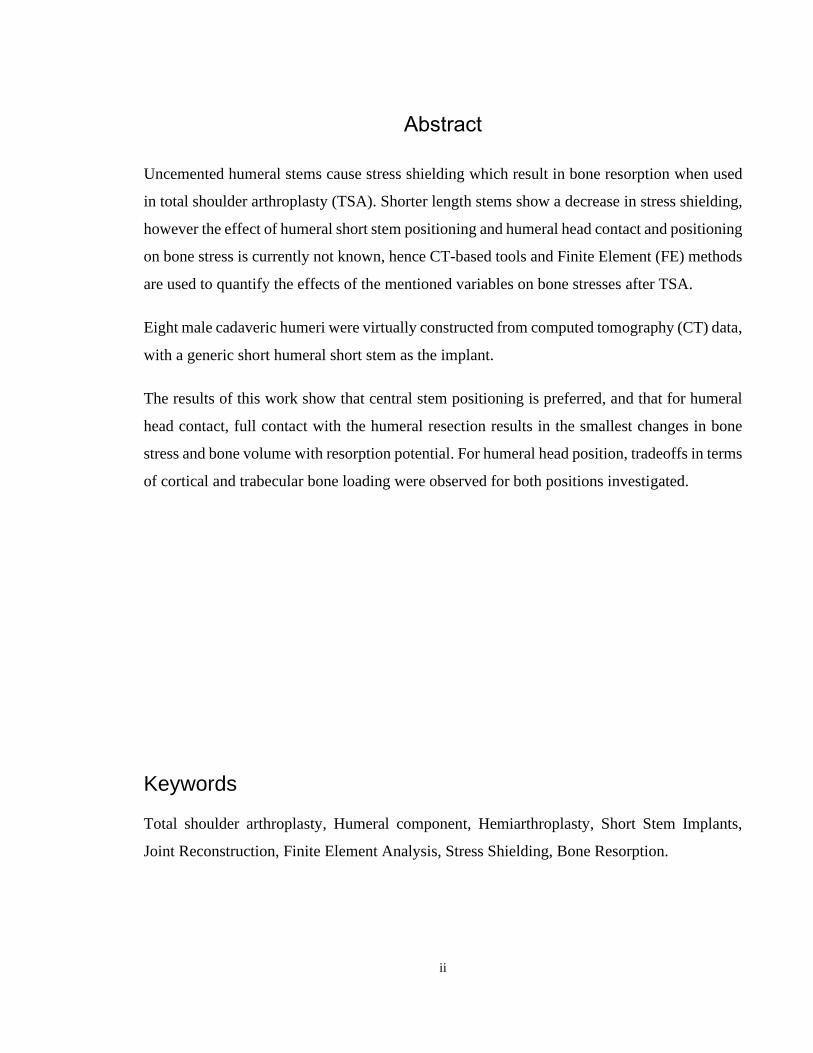
Abstract
Uncemented humeral stems cause stress shielding which result in bone resorption when used
in total shoulder arthroplasty (TSA). Shorter length stems show a decrease in stress shielding,
however the effect of humeral short stem positioning and humeral head contact and positioning
on bone stress is currently not known, hence CT-based tools and Finite Element (FE) methods
are used to quantify the effects of the mentioned variables on bone stresses after TSA.
Eight male cadaveric humeri were virtually constructed from computed tomography (CT) data,
with a generic short humeral short stem as the implant.
The results of this work show that central stem positioning is preferred, and that for humeral
head contact, full contact with the humeral resection results in the smallest changes in bone
stress and bone volume with resorption potential. For humeral head position, tradeoffs in terms
of cortical and trabecular bone loading were observed for both positions investigated.
Keywords
Total shoulder arthroplasty, Humeral component, Hemiarthroplasty, Short Stem Implants,
Joint Reconstruction, Finite Element Analysis, Stress Shielding, Bone Resorption.

iii
Summary for Lay Audience
Osteoarthritis of the shoulder joint can lead to severe pain, discomfort and a reduced range of
motion. Total shoulder arthroplasty (TSA) is an effective treatment to alleviate pain and restore
shoulder function in the case of shoulder arthritis. Number of cases patients who go through
TSA has significantly increased in the recent years. In the TSA surgery, the surface known as
the “articular surface” is removed. This surface is the in-between surface in the shoulder joint,
which is a ball-and-socket type of joint. After the removal of the articular surface, the canal of
the humerus bone, the long bone of the upper arm, is prepared to accept the stem of the implant.
Bone is a dynamic structure, meaning that it is adapts itself according to loads exerted on it.
After TSA, when bone is replaced by a metallic implant, the stress distribution changes at the
upper end of the humerus (proximal humerus). This means that some parts of the proximal
humerus are shielded from stress, and hence do not experience the same loads as before the
TSA. As time goes by these locations are prone to bone loss, a phenomenon known as bone
resorption, which can lead to implant loosening, which requires revision surgery.
Humeral implants consist of two parts, the head and the stem. Since both components are
responsible to transfer the load from the head to the rest of the bone; therefore, their positioning
and contact with the resection plane are important factors.
For the position of the stem and the head, we looked for locations where the stress pattern of
the implanted shoulder and healthy shoulder are as similar as possible, and bone loss is
minimized. We fo1und that for stem position, the optimal positioning is the it is when its axis
is aligned with the axis of the bone shaft and head contact is best when there is full contact
between the resected plane and the backside of the head. We also studied the optimal position
for the head and found no significance difference for when head is situated closer to the body
or away.
iv
Co-Authorship Statement
Chapter 1
Amir Tavakoli - Conducted literature review, set project objectives and wrote the manuscript.
Daniel Langohr - Edited the manuscript.
Chapter 2
Amir Tavakoli – FE model development, study design, data collection, statistical analysis,
wrote the manuscript.
Jake Reeves – Study implementation tools design, reviewed and edited manuscript.
Ken Faber – Study design, resection plane selection, reviewed and edited manuscript.
Daniel Langohr – Study design, reviewed and edited manuscript, data collection and data
analysis.
Chapter 3
Amir Tavakoli – FE model development, study design, data collection, statistical analysis,
wrote the manuscript.
Ken Faber – Study design, resection plane selection, reviewed and edited manuscript.
Daniel Langohr – Study design, reviewed and edited manuscript, data collection and data
analysis.
Chapter 4
Amir Tavakoli – FE model development, study design, data collection, statistical analysis,
wrote the manuscript.
Gregory Spangenberg – FE model development, data collection.
Ken Faber – Study design, resection plane selection, reviewed and edited manuscript.
Daniel Langohr – Study design, reviewed and edited manuscript, data collection and data
analysis.
Chapter 5
Amir Tavakoli - Wrote the manuscript.
Daniel Langohr – Edited the manuscript.

v
Acknowledgments
I would like to thank my supervisor Dr. Daniel Langohr, for without his brilliant guidance and
enlightening vision this research project was not possible. Also, I would like to take this
opportunity to sincerely thank my clinical supervisor Dr. Faber, for his amazing expertise and
excellent constructive advice that were critical to this work.
Great thanks to my advisory committee member, Dr. Willing, for his helpful insights and
instructions. I also truly appreciate the very helpful assistance I received from Dr. Reeves.
This dissertation was also made possible by the help of my fellow lab mates at Roth McFarlane
Hand and Upper Limb Center: Jason Lockhart, Jakub Szmit, Carolyn Berkmortel and Nicholas
Van Osch. I would also like to thank my friends Pendar and Meisam for their help.
Lastly, I would like to thank my family for supporting me non conditionally.
vi
Table of Contents
Abstract ............................................................................................................................... ii
Summary for Lay Audience ............................................................................................... iii
Co-Authorship Statement................................................................................................... iv
Acknowledgments............................................................................................................... v
Table of Contents ............................................................................................................... vi
List of Figures ..................................................................................................................... x
List of Appendices ........................................................................................................... xiv
Chapter 1 ............................................................................................................................. 1
1 Introduction .................................................................................................................... 1
1.1 Shoulder Anatomy .................................................................................................. 1
1.1.1 Osseous Constructs ..................................................................................... 3
1.1.2 Soft Tissue ................................................................................................ 10
1.2 Shoulder Arthroplasty ........................................................................................... 11
1.2.1 Glenohumeral Arthropathies leading to Shoulder Arthroplasty ............... 11
1.2.2 Different types of Shoulder Arthroplasty ................................................. 12
1.3 Structure and Material Properties of Glenohumeral Bones .................................. 17
1.3.1 Structure of Bone ...................................................................................... 17
1.3.2 Elastic Properties of Bone ......................................................................... 19
1.4 Stress Shielding and Wolff’s Law ........................................................................ 20
1.5 Humeral Implant Stem Positioning ....................................................................... 22
1.6 Finite Element Modelling of Shoulder Arthroplasty ............................................ 25
1.6.1 Finite Element Mesh Modelling ............................................................... 25
1.6.2 Volume-Weighted Scalar Average Change in Bone Stress ...................... 27
1.6.3 Time-Zero Potential Bone Response ........................................................ 28
vii
1.7 Thesis Rationale .................................................................................................... 29
1.8 Objectives and Hypotheses ................................................................................... 29
1.9 Thesis Overview ................................................................................................... 31
1.10 References ............................................................................................................. 33
Chapter 2 ........................................................................................................................... 42
2 Valgus Short Stem Humeral Malalignment Increases Stress Shielding in Total Shoulder
Arthroplasty ................................................................................................................. 42
2.1 Introduction ........................................................................................................... 42
2.2 Methods................................................................................................................. 43
2.2.1 Finite Element Simulation and Model Development................................ 43
2.2.2 Outcome Variables and Statistical Analysis ............................................. 46
2.3 Results ................................................................................................................... 47
2.3.1 Changes in Bone Stress ............................................................................. 47
2.3.2 Time-Zero Estimated Bone Response ...................................................... 50
2.4 Discussion ............................................................................................................. 53
2.4.1 Changes in Bone Stress ............................................................................. 53
2.4.2 Time-Zero Expected Bone Response........................................................ 54
2.5 Conclusions ........................................................................................................... 58
2.6 References ............................................................................................................. 59
Chapter 3 ........................................................................................................................... 62
3 The Effect of Humeral Head Backside Contact on Humeral Bone Stress following Total
Shoulder Arthroplasty with a Short Humeral Stem ..................................................... 62
3.1 Introduction ........................................................................................................... 62
3.2 Methods................................................................................................................. 64
3.2.1 Finite Element Simulation and Model Development................................ 64
3.2.2 Outcome Variables and Statistical Analysis ............................................. 66
3.3 Results ................................................................................................................... 67
viii
3.3.1 Changes in Bone Stress ............................................................................. 67
3.3.2 Time-Zero Bone Response ....................................................................... 73
3.4 Discussion ............................................................................................................. 77
3.4.1 Variations in Bone Stress .......................................................................... 77
3.4.2 Time-Zero Expected Bone Response........................................................ 79
3.5 Conclusions ........................................................................................................... 84
References .................................................................................................................... 85
Chapter 4 ........................................................................................................................... 88
4 The Effect of Humeral Head Positioning on Humeral Bone Stress following Total
Shoulder Arthroplasty with a Short Humeral Stem ..................................................... 88
4.1 Introduction ........................................................................................................... 88
4.2 Methods................................................................................................................. 89
4.2.1 Finite Element Simulation and Model Development................................ 89
4.2.2 Outcome Variables and Statistical Analysis ............................................. 91
4.3 Results ................................................................................................................... 93
4.3.1 Change in Bone Stress .............................................................................. 93
4.3.2 Time-Zero Estimated Bone Response ...................................................... 97
4.4 Discussion ........................................................................................................... 100
4.4.1 Variations in Bone Stress ........................................................................ 100
4.4.2 Time-Zero Expected Bone Response...................................................... 101
4.5 Conclusions ......................................................................................................... 105
4.6 References ........................................................................................................... 106
Chapter 5 ......................................................................................................................... 109
5 Thesis Conclusion and Concluding Thoughts ........................................................... 109
5.1 Summary ............................................................................................................. 109
5.2 Strengths and Limitations ................................................................................... 112
ix
5.3 Future Directions ................................................................................................ 114
5.4 Significance......................................................................................................... 115
References .................................................................................................................. 116
Appendices ...................................................................................................................... 118
Appendix A - BioDigital Permission Request ........................................................... 118
Appendix B - Principles of Anatomy and Physiology 8th Edition- Gerard J. Tortora
Permission Request ............................................................................................. 119
Curriculum Vitae ............................................................................................................ 121
x
List of Figures
Figure 1-1: Joints of the Shoulder (Adapted from BioDigital, New York, United States)....... 2
Figure 1-2: Osseous Anatomy of a Right Humerus (Adapted from BioDigital, New York,
United States) ............................................................................................................................ 4
Figure 1-3: Rotator Cuff Muscle Attachment Sites on the Greater Tuberosity (Adapted from
Dr. Jana’s opensource38) ........................................................................................................... 5
Figure 1-4: Anterior View of a Right Scapula and Clavicle74 .................................................. 7
Figure 1-5: Glenoid Labrum65 .................................................................................................. 9
Figure 1-6: Types of Shoulder Reconstruction( Adapted with permission from Tortora, 2011)74
................................................................................................................................................. 14
Figure 1-7: Short- Stemmed Implant Models (Equinoxe, 2017; Zimmer Biomet, 2013; Arthrex,
2018; Tornier, 2013)74 ............................................................................................................ 15
Figure 1-8: Trabecular and Cortical Bone .............................................................................. 18
Figure 1-9: Medial Cortical Narrowing (MCN) due to Stem Fixation60 ................................ 23
Figure 1-10:Medial Metaphyseal Thinning (MMT), and Lateral Metaphyseal Thinning
(LMT)60 ................................................................................................................................... 23
Figure 1-11: Stem Axis Deviation60 ....................................................................................... 24
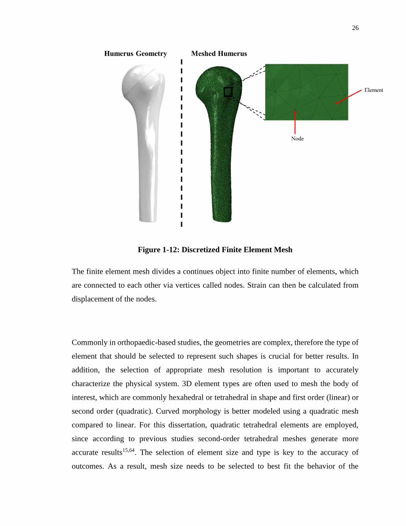
Figure 1-12: Discretized Finite Element Mesh ....................................................................... 26
Figure 2-1: (A) Valgus (left), Standard (middle), and Varus (right) Stem Positions Investigated,
and (B) Stem and Head Frictional Contact Interface Conditions8,10,19 ................................... 44
Figure 2-2: Mean (±1 STD) von Mises of the Change in Cortical Bone (left) and Trabecular
Bone Stress (right) for Valgus (left), Standard (middle), and Varus (right) Implant Positions
................................................................................................................................................. 47

xi
Figure 2-3: Mean (±1 STD) von Mises of the Change in Cortical Bone Stress (top) and
Trabecular Bone Stress (bottom) for the Varus (inset top), Standard (inset middle), and Valgus
(inset bottom) Implant Positions by Anatomic Quadrant (inset left to right) and Slice ......... 48
Figure 2-4: Estimated Time-Zero Bone Response of Cortical (top) and Trabecular Bone
(bottom) for the Varus (inset top), Standard (inset middle), and Valgus (inset bottom) Implant
Positions by Anatomic Quadrant (inset left to right) and Slice Depth (inset top to bottom) .. 51
Figure 2-5: Points of contact for load transfer for the Valgus (left) and Varus (right) implant
positions (forces responding to implant-bone load transfer represented by arrows) under the
applied joint reaction force (shown in red) ............................................................................. 56
Figure 3-1: (A) Humeral Head Backside Contact Conditions Investigated Including Superior
(SUP, left), Full (FULL, middle), and Inferior (INF, right), and (B) Stem and Head Friction
Interface Conditions Simulated 10,12,13 .................................................................................... 65
Figure 3-2: Mean (±1 STD) von Mises of the Change in Stress Compared to the Intact State
for Cortical (left) and Trabecular (right) Bone for all Humeral Head Backside Contact
Conditions Investigated (SUP, FULL, INF; from left to right) .............................................. 68
Figure 3-3: Mean (±1 STD) von Mises of the Change in Cortical Bone Stress (top) and
Trabecular Bone Stress (bottom) for all Humeral Head Backside Contact Conditions SUP
(inset top), FULL (inset middle), and INF (inset bottom) , Anatomical Quadrants (Posterior,
Lateral, Medial, Anterior; from left to right), and Humeral Slice Depths Investigated ......... 70
Figure 3-4: Estimated Time-Zero Bone Response of Cortical (top) and Trabecular Bone
(bottom) for the Superior (inset top), Full (inset middle), and Inferior (inset bottom) Humeral
Head Backside Contact Conditions by Anatomic Quadrant (inset left to right) and Slice Depth
(inset top to bottom) ................................................................................................................ 74
Figure 3-5: Representative Bone Stresses for the Superior (left), Full (middle), and Inferior
(right) Humeral Head Backside Contact Conditions .............................................................. 78
xii
Figure 3-6: Areas of Contact for Load Transfer for the Superior (left) and Inferior (right)
Humeral Head Backside Contact Conditions (forces responding to implant-bone load transfer
represented by arrows) under the Applied Joint Reaction Force (shown in red) .................... 79
Figure 3-7: Representative Contact Stress Distribution at the Humeral Resection Plane for the
Superior (left), Full (middle), and Inferior (right) Humeral Head Backside Contact Conditions
................................................................................................................................................. 80
Figure 3-8: Representative Deformation of the Humeral Resection Plane (magnified 75x for
clarity) for the Superior (left), Full (middle), and Inferior (right) Humeral Head Backside
Contact Conditions.................................................................................................................. 81
Figure 3-9: Representative Medial Gapping (magnified 200x for clarity) for the Superior (left),
Full (middle), and Inferior (right) Humeral Head Backside Contact Conditions ................... 81
Figure 4-1: Humeral Head Positions Investigated including Superior-Lateral (S-L, left), and
Inferior-Medial (I-M, right), and (B) Stem and Head frictional Contact Interface
Conditions7,8,9,14 ...................................................................................................................... 90
Figure 4-2: von Mises of the Change in Stress Compared to the Intact State for Cortical (left)
and Trabecular (right) Bone for all Humeral Head Positions Investigated (S-L, I-M ; from left
to right).................................................................................................................................... 93
Figure 4-3: : Mean (±1 STD) von Mises of the Change in Cortical Bone Stress (top) and
Trabecular Bone Stress (bottom) for all Humeral Head Positions S-L (inset top), and I-M (inset
bottom) , Anatomical Quadrants (Posterior, Lateral, Medial, Anterior; from left to right), and
Humeral Slice Depths Investigated ......................................................................................... 94
Figure 4-4: Estimated Time-Zero Bone Response of Cortical (top) and Trabecular Bone
(bottom) for the Superior-Lateral (inset top), and Inferior-Medial (inset bottom) Humeral Head
Positions by Anatomic Quadrant (inset left to right) and Slice Depth (inset top to bottom) .. 97
Figure 4-5: Representative Bone Stresses for the Superior-Lateral (left), and Inferior-Medial
(right) Humeral Head Positions ............................................................................................ 100

xiii
Figure 4-6: Areas of Contact for Load Transfer for the Superior-Lateral (left) and Inferior-
Medial (right) Humeral Head Position (forces responding to implant-bone load transfer
represented by arrows) under the Applied Joint Reaction Force .......................................... 101
Figure 4-7: Representative Contact Stress Distribution at the Humeral Resection Plane for the
Superior-Lateral (left), and Inferior-Medial (right) Humeral Head Positions ...................... 102
Figure 4-8: Representative Medial Gapping (magnified 200x for clarity) for the Superior-
Lateral (left), and (the lack of) Lateral Gapping for the Inferior-Medial (right) Humeral Head
Positions ................................................................................................................................ 103
Figure 4-9: Representative Deformation of the Humeral Resection Plane (magnified 75x for
clarity) for the Superior-Lateral (left), and Inferior-Medial (right) Humeral Head Positions
............................................................................................................................................... 104

xiv
List of Appendices
Appendix A - BioDigital Permission Request ...................................................................... 118
Appendix B - Principles of Anatomy and Physiology 8th Edition- Gerard J. Tortora Permission
Request .................................................................................................................................. 119
1
Chapter 1
1 Introduction
Total Shoulder Arthroplasty (TSA) is an effective treatment for end-stage glenohumeral
arthritis to alleviate pain and restore the normal function of the glenohumeral joint48. An
increasing number of total shoulder arthroplasties are being performed each year, thus
highlighting the necessity to evaluate the performance of different implant designs. With
increasing computational power, the utilization of various computational tools has become
more popular within the field of orthopaedic implant design and assessment. The humeral
stem is an important feature of the TSA implant, and while stem size has been the topic of
several recent research studies, the effect of the position of the stem inside the humeral
canal, the state of humeral head backside contact with the humeral resection plane, and the
position of the humeral head on the resection plane on humeral bone stresses have not yet
been fully explored. Geriatric patients going through TSA, might be also suffering from
osteoporosis, which makes the osseous tissue less rigid compared to a healthy tissue. This
significant difference between the implant’s stiffness and osteoporotic bone’s stiffness is a
risk factor25,28,53,61. Within this dissertation, finite element analysis has been used to assess
the impact of varus-valgus angulation, humeral head contact condition with the resection
plane, and humeral head position on humeral bone stress and expected bone response
following TSA.
1.1 Shoulder Anatomy
The shoulder joint, also known as glenohumeral joint, is comprised of several components.
It consists of three bones, three joints, four articulations, as well as numerous muscles,
tendons, and ligaments (Figure 1-1). The synergy of these components allows the shoulder
joint to have the greatest range of motion compared to the other joints in the body, which
enable the shoulder to move in the sagittal, coronal, and transverse planes. This joint is
primarily a synovial ball-and-socket joint, and since the humerus articulates with the
relatively shallow glenoid cavity, it can be an unstable joint. This instability facilitates the

2
joint to be more mobile, and allows movements such as flexion, extension, abduction,
adduction, medial or internal rotation, and external rotation19,59,83.
Figure 1-1: Joints of the Shoulder (Adapted from BioDigital, New York, United
States)
Anatomical view of the Glenohumeral joint, which consists of five main articulations.
3
1.1.1 Osseous Constructs
Motions within the glenohumeral joint are accomplished with five articulations: the
glenohumeral joint, sternoclavicular joint, acromioclavicular joint, subacromial joint, and
the scapulothoracic joint39 (Figure 1-1). The purpose of each articulation is to guide and
facilitate motion necessary for the activities of daily living39. The three main bones of the
shoulder are the clavicle, humerus, scapula. The location where these three bones come
together with the ribs and sternum creates the four articulations previously mentioned24.
The glenohumeral joint, located between the humeral head and the glenoid cavity is the
main interest of this study.
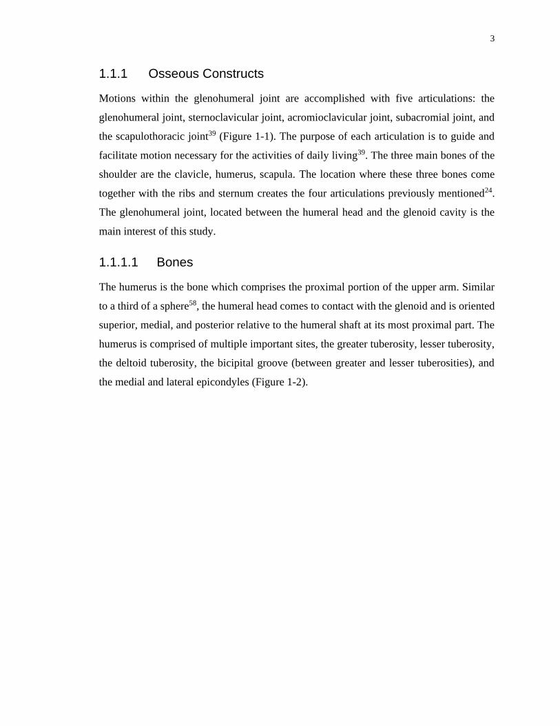
1.1.1.1 Bones
The humerus is the bone which comprises the proximal portion of the upper arm. Similar
to a third of a sphere58, the humeral head comes to contact with the glenoid and is oriented
superior, medial, and posterior relative to the humeral shaft at its most proximal part. The
humerus is comprised of multiple important sites, the greater tuberosity, lesser tuberosity,
the deltoid tuberosity, the bicipital groove (between greater and lesser tuberosities), and
the medial and lateral epicondyles (Figure 1-2).

4
Figure 1-2: Osseous Anatomy of a Right Humerus (Adapted from BioDigital, New
York, United States)
Major landmarks of the humerus, which are critical points for several muscles and
articulations that give rise to the shoulder’s ability to have its mobility and range of motion.

5
The deltoid tuberosity can be found at the midshaft of the humerus on the lateral side and
is the distal insertion point of the deltoid muscle. The greater tuberosity acts as the
attachment site of the rotator cuff muscles (supraspinatus, infraspinatus, and teres minor)
and the wrapping point between the deltoid insertion and origin, which are located on the
humerus and the acromion, respectively (Figure 1-3). The location of the greater tuberosity
and the function it serves allows the deltoid to operate when the arm is placed below 45°
of glenohumeral abduction39. The lesser tuberosity is the insertion site for subscapularis
muscle.
Figure 1-3: Rotator Cuff Muscle Attachment Sites on the Greater Tuberosity
(Adapted from Dr. Jana’s opensource38)
Attachment sites for the four muscles that make up the rotator cuff muscle bundle.
6
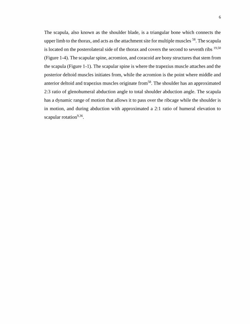
The scapula, also known as the shoulder blade, is a triangular bone which connects the
upper limb to the thorax, and acts as the attachment site for multiple muscles 58. The scapula
is located on the posterolateral side of the thorax and covers the second to seventh ribs 19,50
(Figure 1-4). The scapular spine, acromion, and coracoid are bony structures that stem from
the scapula (Figure 1-1). The scapular spine is where the trapezius muscle attaches and the
posterior deltoid muscles initiates from, while the acromion is the point where middle and
anterior deltoid and trapezius muscles originate from58. The shoulder has an approximated
2:3 ratio of glenohumeral abduction angle to total shoulder abduction angle. The scapula
has a dynamic range of motion that allows it to pass over the ribcage while the shoulder is
in motion, and during abduction with approximated a 2:1 ratio of humeral elevation to
scapular rotation9,36.

7
Figure 1-4: Anterior View of a Right Scapula and Clavicle74
Important landmarks of the clavicle and the scapula, where tendons and muscles are
attached to.

8
1.1.1.2 Articulations
The glenohumeral joint, which is also commonly referred to simply as the shoulder joint,
significantly contributes to the range of motion of the shoulder. It is a ball-in-socket type
of articulation that is made up of osseous constructs (i.e., bones), soft tissues (i.e.,
musculotendinous parts, ligaments), and a synovial joint enclosure. This articulation is
made up of the humeral head, which is a hemispherical convex which is located medially,
posteriorly, and superiorly, and its contact with glenoid cavity which is covered in articular
cartilage as well as surrounded by hyaline cartilage called the labrum (Figure 1-5), which
is a shallow, pyriform articular surface located on the lateral angle of scapula4,24,50. To
conduct studies on this joint regarding joint replacements, a comprehension with regards
to the motion and reaction forces within this joint is essential. Due to the complex nature
of the glenohumeral joint, and the multiple muscles that take part in mobilizing the joint,
discrepancies are prevalent when measuring joint reaction forces. It is worthy to note that
several studies have explored glenohumeral contact forces both in-vitro2,18,32 and in-vivo
scenarios30,76.
9
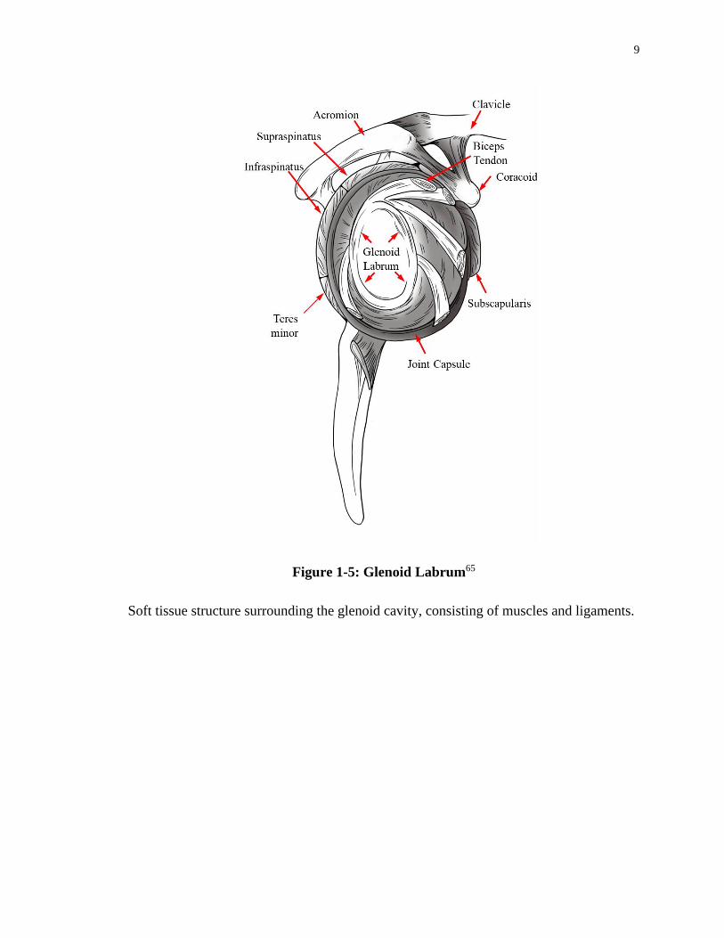
Figure 1-5: Glenoid Labrum65
Soft tissue structure surrounding the glenoid cavity, consisting of muscles and ligaments.
10
Among the studies available, Bergmann et al6 who used a telemetrized shoulder implant to
directly measure the in-vivo loads post-operatively, is one of the most reliable in the
literature available. The magnitude and orientation of the contact forces reported for
glenohumeral joint reaction forces infer that shoulder can withstand loads that surpass
patient bodyweight, despite not being a weight bearing articulation. The novel in-vivo joint
load measurement allows for better estimation of the realistic data for motion and
movement such as abduction, flexion, and extension. Data derived from Bergmann et al6
including shoulder joint reaction forces for 75° and 45° abduction are used in this work.
1.1.2 Soft Tissue
1.1.2.1 Passive Soft Tissues
The joint capsule, ligaments, and glenoid labrum act as the stabilizer of the glenohumeral
joint. The geometric layout of the bony anatomy of the shoulder results in forces and
relative motion that the osseous construct of the glenohumeral joint cannot accommodate.
Hence the soft tissues of the shoulder augment these bony structures and restrict mobility
and contribute to the stability of the joint10,16,19,31,41.
The glenohumeral joint capsule is sufficiently loose that it enables the movement of the
humerus with sufficient range of motion, however at the limits of motion the tension rises
to prevent damages and possible dislocation of the humeral head59.
1.1.2.2 Active Musculature
Several muscles act as the stabilizers and actuators of motion at the glenohumeral joint.
These muscles are classified into three groups; the axioscapular muscles, the axiohumeral
muscles, and the scapulohumeral muscles.
The axioscapular muscles initiate on the thoracic cage and insert into scapula, and consist
of the rhomboids minor and major, the trapezius, the pectoralis major, the levator scapulaei,
and the serratus anterior. The axioscapular muscles act to make the movement and
stabilization of the scapula.

11
The axiohumeral muscles start at the thoracic cage and their attachment site is on the
humerus, located laterally to the humerus and medially with respect to the axial skeleton.
Axiohumeral muscles are comprised of the latissimus dorsi, and major pectoralis muscles.
Pectoralis major muscle has an anteromedial insertion point on the clavicle. Even though
the latissimus dorsi and pectoralis major muscles are located on the opposite sides of the
coronal plane, they create the same movements which are to medially rotate the humerus,
and adduction50.
The scapulohumeral muscles originate on the scapula and attach onto the humerus, and are
comprised of the deltoid, teres minor, teres major, coracobrachialis, supraspinatus,
subscapularis, and infraspinatus. The main purpose of the deltoid muscle is to produce
approximately 50% of the moment required for glenohumeral abduction. The deltoid
muscle is sectioned into of three parts: anterior, middle, and posterior31. The anterior and
middle sections are the major contributors to the moment creating the elevation of the joint
during abduction39. The posterior part of the deltoid acts upon the humerus for external
rotation and extension, while the anterior part supports with internal rotation and flexion
of the humerus1.
The rotator cuff consists of the following muscles: the teres minor, subscapularis,
supraspinatus, and infraspinatus. This bundle of muscles surrounds the glenohumeral joint
in a way that it encapsulates the ligaments, the muscles, the tendons, and the joint capsule
that make up the glenohumeral joint; however, it does not include the inferior aspect of the
joint. During shoulder motion, it plays a key stabilizer role by applying moments in
abduction-adduction and internal-external rotation movements, hence keeping the humeral
head in the glenoid cavity during arm elevation19,55.
1.2 Shoulder Arthroplasty
1.2.1 Glenohumeral Arthropathies leading to Shoulder Arthroplasty
With the aim to reconstruct the fractures to the humeral head 56, shoulder arthroplasty has
emerged as a therapy for various disorders of the shoulder such as: avascular necrosis,
osteoarthritis, rheumatoid arthritis, rotator cuff tear, and additional (complications of
bursae and tendons and etc.) arthropathies of the shoulder 43,54,68. Avascular necrosis, also
12
known as osteonecrosis, is the death of bone tissues due lack of blood supply mainly caused
by broken bone or dislocation of the joint, which eventually causes the bone’s structure to
collapse. Glenohumeral osteoarthritis is the gradual degradation of the articular cartilage,
leading to swelling, pain and hinderance in mobility. Rheumatoid arthritis of the shoulder,
is an autoimmune disease, initiating when the body itself invades the healthy cells at the
joint. Inflammation at the joint is the major symptom for this disorder, which can be
observed simultaneously in both shoulders. RA causes pain, swelling and stiffness in the
shoulder. Rotator cuff is a group of muscles and tendons that hold the shoulder joint in
place and allow the movement of arm and shoulder. A tear in the rotator cuff tendons leads
to pain, reduced range of motion and weakness.
1.2.2 Different types of Shoulder Arthroplasty
While degenerative osteoarthritis is known to affect load-bearing joints (e.g. the knee and
hip), problems also arise when glenohumeral joint is also affected by osteoarthritis, which
often occurs in the geriatric population. Total shoulder arthroplasty restores the normal
anatomical functions of the shoulder, lessening pain and discomfort and consequently
increasing the quality of life48.
Modern day arthroplasty for proximal humerus was initially developed by Neer using a
vitallium implant for the treatment of humeral fractures47. TSA can also be used to relieve
pain and restore shoulder functions that are disrupted by disorders such as rheumatoid
arthritis, traumatic arthritis, and osteoarthritis47,78,80. In general, there are three parts in a
shoulder replacement prosthesis: the humeral head, the humeral stem, and the glenoid
component. Positioning of the humeral stem will be one focus of this work.
Total shoulder arthroplasty (TSA), reverse shoulder arthroplasty (RSA), hemi-arthroplasty,
and partial surface reconstruction are all techniques commonly used for replacement of
shoulder (Figure 1-6).
In TSA, both sides of the joint (i.e. the humeral head and glenoid cavity) are replaced with
implants; while in hemi-arthroplasty only one side of the joint (either the glenoid or the
humeral head) is reconstructed by an implant and the other side remains in the native state.

13
RSA reverses the native geometry of joint, by replacing the concave glenoid with a convex
hemisphere and replacing what used to be the convex humeral head with a concave dish8,
thereby creating a more favorable moment arm enabling deltoid muscle to function better
during abduction. In partial resurfacing, one of articular surfaces is reconstructed and
leaving the innate bone intact8.
There have been several improvements achieved in TSA, including novel implant designs,
enhanced methods of stabilization and sterilization of the implants, advancements in
materials alongside innovations in surgical procedures since the first reported shoulder
replacement22,27. Recent implant designs are employing smaller overall geometries. This
size reduction is most observable in stem length, as new designs are moving towards
shorter stems or eliminating the stem entirely.
Utilization of shorter stem lengths allows for less reaming of the humeral canal, thus
preserving the native bone of the humerus. Preservation of native bone reduces the cortical
bone stress and reduces the likelihood of perioperative periprosthetic fractures. Shorter
stem length has also been linked to reduced stress shielding, the prevention of which has
been shown to reduce stem loosening in the long term21,27,40,42. Some of the implant
manufacturers who have developed short and stemless implant models include Exactech,
Biomet, Arthrex, and Tornier (Figure 1-7). Throughout this dissertation Exactech’s
Equinoxe Preserve will be used.

14
Figure 1-6: Types of Shoulder Reconstruction( Adapted with permission from
Tortora, 2011)74
Four treatment options for shoulder arthroplasty, in which there exists a humeral, glenoid,
or humeral and glenoid components. In partial resurfacing technique, a humeral cap is used.

15
Figure 1-7: Short- Stemmed Implant Models (Equinoxe, 2017; Zimmer Biomet, 2013;
Arthrex, 2018; Tornier, 2013)74
Exactech, Biomet, Arthrex, and Tornier are manufactures are short stem humeral implants.

16
In terms of implant fixation, cemented and uncemented/press-fit are the two main methods
to secure the implant to the host bone and prevent loosening. Depending on the fixation
type, different surface textures will be featured on the implant. Some of these surface
textures are plasma spray, grit blast, smooth polished, and trabecular metal, all of which
can be used to enhance the bond quality between the implant and peri-prosthetic bone73.
Recently, the uncemented method has gained popularity, since more of the original native
bone is conserved in this method, allowing for better long-term stabilization, and allowing
for better revision surgery outcomes45,70.
While numerous advancements have been made in TSA, concerns remain. Implant
loosening, intra-operative fracture, periprosthetic fracture, and proximal bone loss as a
result of stress-shielding and osteolysis are still common issues experienced by humeral
implants17,21,42. According to Denard et al21, while short stem humeral implants result in
less osteolysis; cortical thinning of lateral proximal metaphysis still occurs in
approximately 20%, and close to 50% exhibited cortical thinning of medial metaphysis.
The same study noted that calcar bone was partially resorbed in an additional 23% of short
stem models and posits that upon implantation of short stem models only 86% were
anatomically aligned compared to 98% of standard-length stems. As a result of this
malalignment the patient can suffer potentially from pain, joint stiffness, and reduced range
of motion23.
In a finite element study by Razfar et al65, short stem implants reduced the average stress
in cortical bone; however trabecular bone stress rose increased with respect to the standard-
length stems.
Casagrande et al14 and Morwood et al52 reported an 8% revision rate due to humeral
component loosening in patient with short stem implants, and a minimum of one humeral
radiolucency in 71% of the implants with 21% of implants showing radiolucencies, and
partial or complete osteolysis on the medial calcar in 18% of patients.
With over 66,000 shoulder replacements performed annually in the United States alone,
the long-term stability and durability of humeral implants is a vital factor. To enable the
glenohumeral joint to function normal and without pain, while minimizing the likelihood

17
of humeral revision is the goal. It is crucial to prevent humeral revision as it can lead to
periprosthetic fractures, metaphyseal bone loss as well as other potential complications42.
1.3 Structure and Material Properties of Glenohumeral Bones
1.3.1 Structure of Bone
Bone is a finely organized composite material that offers vital structural support for the
body and organs. Bone is comprised of organic and inorganic phases, that enable this
compact connective tissue to have regulatory characteristics. The organic phase of the bone
is type I collagen fiber which allows the bone to bear tensile stresses, and the inorganic
phase is made up of calcium phosphate hydroxyapatite which gives rise to compressive
stress bearing characteristics of the bone. The resulting bone is the combination of organic
and inorganic phases that create a strong resilient structure, each having one-third and two-
third ratios, respectively4,20,63.
The humerus is part of the appendicular skeleton (i.e., long bones such as the arm, legs,
etc.). Long bones are aggregate structures, the composition of which can be categorized
into two components: trabecular and cortical bone (Figure 1-8). At the local scale, long
bones are divided into three sub-parts: the epiphysis (the end part of the bone where the
articulation is located), the diaphysis (middle section, shaft), and the metaphysis (the
transitional region between diaphysis and epiphysis) (Figure 1-8). The epiphysis is
composed of a cortical shell with a cancellous bone center. The diaphysis is a comprised
of a cortical shell with a hollow canal called the medullary canal in which the bone marrow
is found. The metaphysis consists of both cortical and trabecular constructs that act as
transition zone of bone from diaphysis to epiphysis.

18
Figure 1-8: Trabecular and Cortical Bone
Long bones consist of two different osseous tissues: cortical and trabecular bone. Cortical
bone is an isotropic hard mineralized exterior shell, and trabecular bone is an anisotropic
porous interior structure (Adapted with permission from Tortora, 2011).
19
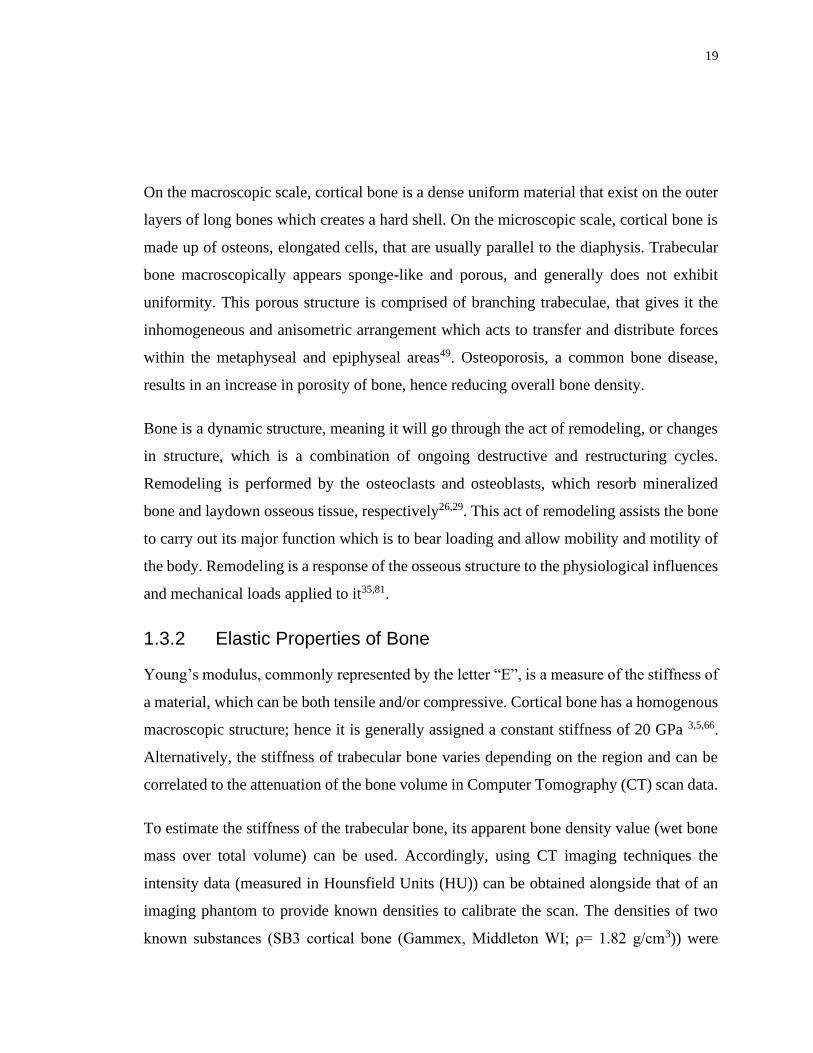
On the macroscopic scale, cortical bone is a dense uniform material that exist on the outer
layers of long bones which creates a hard shell. On the microscopic scale, cortical bone is
made up of osteons, elongated cells, that are usually parallel to the diaphysis. Trabecular
bone macroscopically appears sponge-like and porous, and generally does not exhibit
uniformity. This porous structure is comprised of branching trabeculae, that gives it the
inhomogeneous and anisometric arrangement which acts to transfer and distribute forces
within the metaphyseal and epiphyseal areas49. Osteoporosis, a common bone disease,
results in an increase in porosity of bone, hence reducing overall bone density.
Bone is a dynamic structure, meaning it will go through the act of remodeling, or changes
in structure, which is a combination of ongoing destructive and restructuring cycles.
Remodeling is performed by the osteoclasts and osteoblasts, which resorb mineralized
bone and laydown osseous tissue, respectively26,29. This act of remodeling assists the bone
to carry out its major function which is to bear loading and allow mobility and motility of
the body. Remodeling is a response of the osseous structure to the physiological influences
and mechanical loads applied to it35,81.
1.3.2 Elastic Properties of Bone
Young’s modulus, commonly represented by the letter “E”, is a measure of the stiffness of
a material, which can be both tensile and/or compressive. Cortical bone has a homogenous
macroscopic structure; hence it is generally assigned a constant stiffness of 20 GPa 3,5,66.
Alternatively, the stiffness of trabecular bone varies depending on the region and can be
correlated to the attenuation of the bone volume in Computer Tomography (CT) scan data.
To estimate the stiffness of the trabecular bone, its apparent bone density value (wet bone
mass over total volume) can be used. Accordingly, using CT imaging techniques the
intensity data (measured in Hounsfield Units (HU)) can be obtained alongside that of an
imaging phantom to provide known densities to calibrate the scan. The densities of two
known substances (SB3 cortical bone (Gammex, Middleton WI; ρ= 1.82 g/cm3)) were

20
located within the initial CT scan and were used to create a linear relationship, to derive
the apparent bone density of trabecular bone. Using the intensity information and
calibration data, the apparent bone density of each voxel (trabecular bone in small volumes)
to be determined82. Young’s modulus is then obtained from the resulting apparent bone
density using the density-modulus equations available in several studies3,12,44,69,75.
The equations within these studies mainly focus on both cortical and trabecular bone;
however, Morgan et al51 proposed a formula which yields Young’s modulus for only
cancellous bone at different sites throughout the body yielding the mechanical properties
of trabecular bone at several anatomical sites. Following this, in computational FE models,
individual elements of a mesh can be assigned the resulting nonuniform Young’s modulus
values to model the inhomogeneous attributes of trabecular bone82.
1.4 Stress Shielding and Wolff’s Law
Wolff’s law describes the behavior of bone subjected to mechanical stimulus, and states
that bone resorbs and remodels partially due to the applied mechanical loading that it
withstands. Wolff’s law suggests that when the loads that act on a section of bone exceed,
or diminish past certain threshold, bone’s reaction is to remodel or resorb, which leads to
an optimized osseous structure able to respond to alterations in loading. The resulting
differing architecture, strength, and composition observed in the cortical diaphysis and
trabecular epiphysis, is thought to be due in part to Wolff’s law which relates structure to
loading environment13,81.
Following total shoulder arthroplasty, intact bone previously responsible for bearing
mechanical load due to the applied joint reaction force is replaced with a stiff metallic
humeral implant, which causes a change in the distribution of loading that leads to
remodeling in the form of resorption of bone in the affected regions. Stiffness and rigidity
are directly proportional to one another, thus a metallic implant having higher stiffness has
also a higher rigidity value. Within the bone-implant construct, the load distribution is set
by the magnitude of rigidity values (both bending and axial rigidity). Subsequently, when
an implant is positioned inside the bone, since it is significantly more rigid than the intact
osseous structure that it replaced, it will carry a greater proportion of humeral loading, and
21
the surrounding remaining osseous tissues will therefore be subjected to less mechanical
stimulus than it was in the intact state. This is known as stress shielding, and can result in
bone reduction after arthroplasties leading to implant loosening and failure. According to
a radiographic study by Nagels et al53 regarding total shoulder arthroplasty, stress shielding
was observed in 9% of their cases (n=70) around the humeral implants within the cortical
bone, suggesting higher values could exist if changes in other osseous constructs are
assessed as well. Several other studies have also noted bone resorption in the vicinity of
humeral implant stems37,72,77.
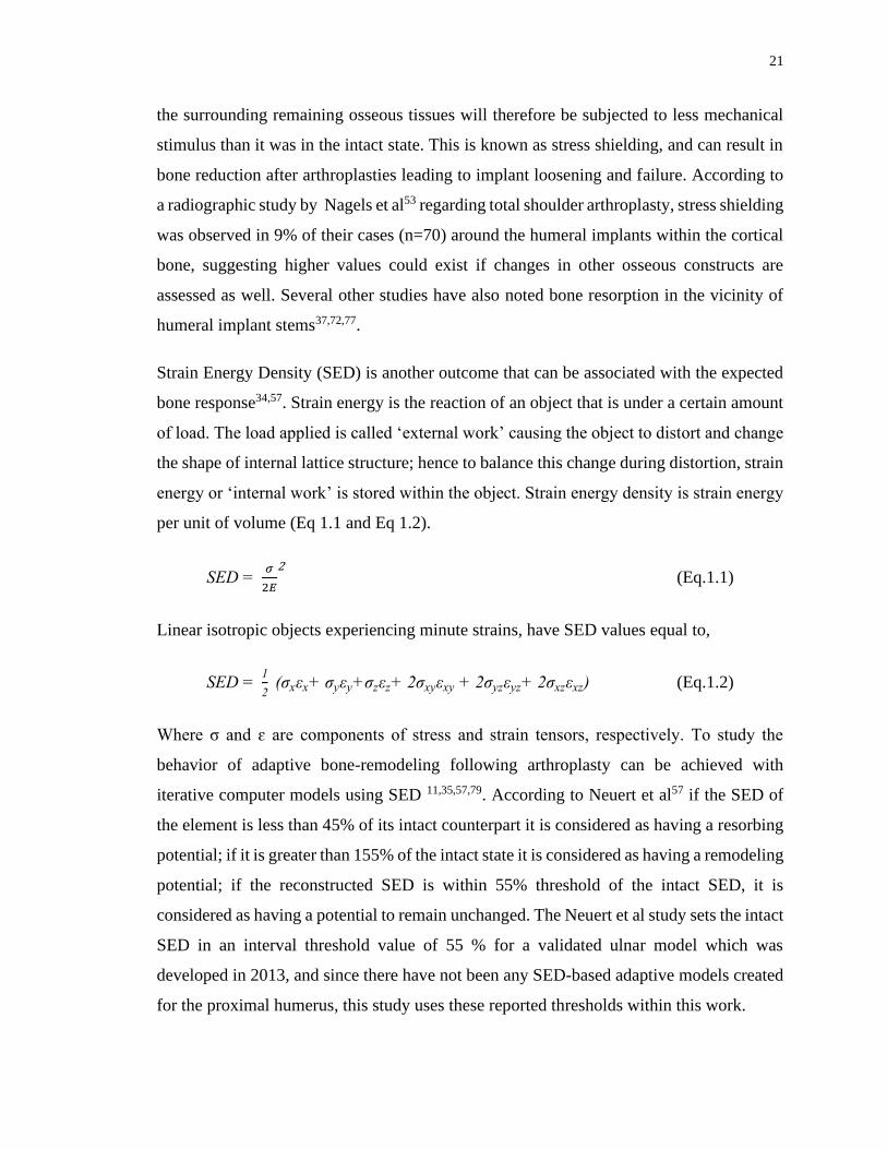
Strain Energy Density (SED) is another outcome that can be associated with the expected
bone response34,57. Strain energy is the reaction of an object that is under a certain amount
of load. The load applied is called ‘external work’ causing the object to distort and change
the shape of internal lattice structure; hence to balance this change during distortion, strain
energy or ‘internal work’ is stored within the object. Strain energy density is strain energy
per unit of volume (Eq 1.1 and Eq 1.2).
SED = 𝜎
2𝐸
2 (Eq.1.1)
Linear isotropic objects experiencing minute strains, have SED values equal to,
SED = 1
2 (σxεx+ σyεy+σzεz+ 2σxyεxy + 2σyzεyz+ 2σxzεxz) (Eq.1.2)
Where σ and ɛ are components of stress and strain tensors, respectively. To study the
behavior of adaptive bone-remodeling following arthroplasty can be achieved with
iterative computer models using SED 11,35,57,79. According to Neuert et al57 if the SED of
the element is less than 45% of its intact counterpart it is considered as having a resorbing
potential; if it is greater than 155% of the intact state it is considered as having a remodeling
potential; if the reconstructed SED is within 55% threshold of the intact SED, it is
considered as having a potential to remain unchanged. The Neuert et al study sets the intact
SED in an interval threshold value of 55 % for a validated ulnar model which was
developed in 2013, and since there have not been any SED-based adaptive models created
for the proximal humerus, this study uses these reported thresholds within this work.

22
1.5 Humeral Implant Stem Positioning
In recent years much research has revolved around stem design, mainly due to the persistent
issues with stress-shielding and bone remodeling following TSA. Stem length and material
are two major points of interest regarding stem design, since both are play key roles in load
transfer within the humerus7.
As previously mentioned, smaller geometries are associated with less proximal stress
shielding and more closely approximate the intact state21,65. Peduzzi et al60 studied bony
ingrowth in 183 patients following shoulder replacement surgery and reported good mid-
term outcomes with no complications associated to the stem, yet 80.3% of the patients did
have proximal bony adaptations.
According to Peduzzi et al60, one of the main contributors to ‘under the baseplate
osteolysis’, was stem axis deviation, more specifically deviation in valgus. Medial cortical
narrowing evaluates the ratio between proximal cortical thickness measured on the latest
follow-up radiograph and just after the operation. Peduzzi et al posited that this is caused
by stress shielding due to distal fixation of the stem (Figure 1-9). Medial metaphysis
thinning and lateral metaphysis thinning also occur due to anomalous distribution of
metaphyseal stresses that arise when the stem is not aligned with the humeral shaft axis
(Figure 1-10). The study concludes that stem axis deviation from the humeral shaft axis
increases the risk of bony adaptations, suggesting implant positioning plays a major role
with regards to stress shielding in humeral short stem components and proximal peri-
prosthetic bone resorption60.

23
Figure 1-9: Medial Cortical Narrowing (MCN) due to Stem Fixation60
Figure 1-10:Medial Metaphyseal Thinning (MMT), and Lateral Metaphyseal
Thinning (LMT)60

24
Figure 1-11: Stem Axis Deviation60
(A) Stem axis aligned with humeral shaft axis. Neck has adequate width. Medial cortex
and stem not in contact, thickness of medial cortex conserved. (B) Stem axis not aligned
with humeral shaft axis. Neck length is long, medial cortex and stem are in contact. Medial
cortex has reduced in thickness.

25
1.6 Finite Element Modelling of Shoulder Arthroplasty
1.6.1 Finite Element Mesh Modelling
Finite element analysis (FEA) is a contemporary method of computational modeling that
is used in many engineering fields. In orthopaedics, FEA is employed allowing an in-silico
approach to simulate the loading of both bone and joint replacement implants. FEA permits
the investigation and estimation of the stress and strain experienced by the joint in-vivo.
FE also allows for the non-invasive means of studying internal bony stress states, which
are difficult (or impossible) to obtain using in-vitro manners. Consequently, cost- and time-
effectiveness is another plus side of using FE compared to in-vitro methods.
The computational model is divided into a finite number of elements, which connect to one
another via nodes, which connect to form the finite element mesh (Figure 1-12). By
applying this process of discretization of the solid continuum into elements, the local
behavior of each element can be used to study overall performance of the system. For
instance, the changes in position of each individual node can be calculated using boundary
conditions, applied loading, and the material properties of elements connected to the node.
To expand the research focus, different loading conditions, materials, and geometry can be
investigated efficiently.
26
Figure 1-12: Discretized Finite Element Mesh
The finite element mesh divides a continues object into finite number of elements, which
are connected to each other via vertices called nodes. Strain can then be calculated from
displacement of the nodes.
Commonly in orthopaedic-based studies, the geometries are complex, therefore the type of
element that should be selected to represent such shapes is crucial for better results. In
addition, the selection of appropriate mesh resolution is important to accurately
characterize the physical system. 3D element types are often used to mesh the body of
interest, which are commonly hexahedral or tetrahedral in shape and first order (linear) or
second order (quadratic). Curved morphology is better modeled using a quadratic mesh
compared to linear. For this dissertation, quadratic tetrahedral elements are employed,
since according to previous studies second-order tetrahedral meshes generate more
accurate results15,64. The selection of element size and type is key to the accuracy of
outcomes. As a result, mesh size needs to be selected to best fit the behavior of the

27
geometry of interest, while considering efficient modelling of the study by optimizing
computational resources46. To determine the smallest appropriate mesh size while not
compromising the accuracy and exceeding computational resources, convergence tests are
used on FE models. A mesh convergence analysis assesses how sensitive each FE outcome
is to the mesh size. To accomplish this, the model is run multiple times using different
mesh sizes to determine the element size at which further refinement does not vary the
results appreciably.
Creating the finite element mesh, often called discretization, is the initial step to the FE
analysis. Applying loads, boundary conditions, sectioning, material properties, and element
properties are steps that follow. The strain of each element is calculated by the software, in
the case of this thesis, ABAQUS FEA software is used (Dassault Systèmes, Johnston, RI,
USA). The resulting output of this analysis includes stresses, strains, and other desired
outcomes. Advancements in FEA software has enabled researchers to explore numerous
factors, such as implant designs, different load setups, different material properties and
bone geometries33,62.
1.6.2 Volume-Weighted Scalar Average Change in Bone Stress
The volume-weighted average change in bone stress is measured in absolute terms, so the
value indicates a change in magnitude of bone stress in the region-of-interest compared to
the intact state. The method for calculating the change in bone stress of the region of
interest is as follows: six stress components are calculated in each element using FE
software (𝜎11, 𝜎12, 𝜎13, 𝜎21, 𝜎22, 𝜎23). ∆𝜎𝑥𝑦 is the change in each of the stress components
and is calculated using Equation 1.3, and shows the change in stress magnitude and the
direction. ∆𝜎𝑉𝑀 is the von Mises of change in stress and is calculated using Equation 1.4.
The change in stress is then normalized to the intact state values using a volume-weighted
average to make sure each element has the appropriate contribution value to the total stress
change (Eq 1.5). It is important to note that the resulting values are indicative of the
magnitude of change in stress of the reconstructed bone from the intact state, and do not
reflect whether the overall stress state was lower or higher. In an ideal scenario implant
would mimic the stress state of the intact bone, hence larger deviations from the intact state
is deemed as less favorable.
28
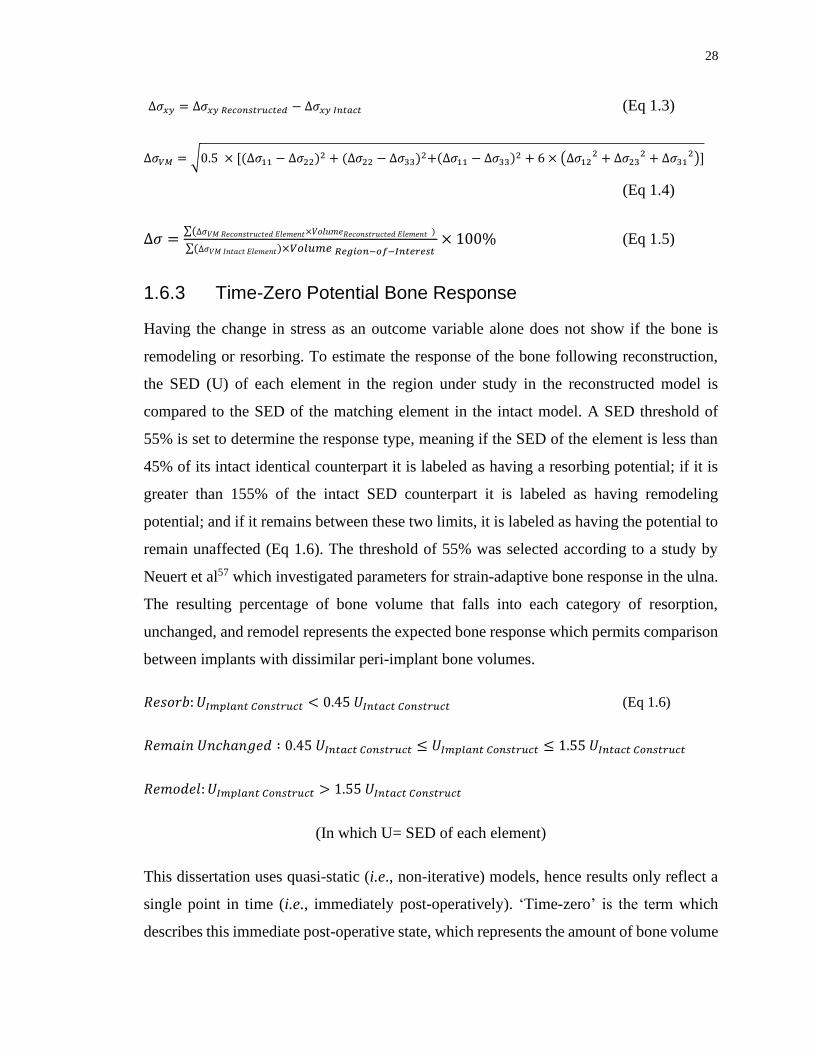
∆𝜎𝑥𝑦 = ∆𝜎𝑥𝑦 𝑅𝑒𝑐𝑜𝑛𝑠𝑡𝑟𝑢𝑐𝑡𝑒𝑑 − ∆𝜎𝑥𝑦 𝐼𝑛𝑡𝑎𝑐𝑡 (Eq 1.3)
∆𝜎𝑉𝑀 = √0.5 × [(∆𝜎11 − ∆𝜎22)2 + (∆𝜎22 − ∆𝜎33)2+(∆𝜎11 − ∆𝜎33)2 + 6 × (∆𝜎122 + ∆𝜎23
2 + ∆𝜎312)]
(Eq 1.4)
∆𝜎 =∑(∆𝜎𝑉𝑀 𝑅𝑒𝑐𝑜𝑛𝑠𝑡𝑟𝑢𝑐𝑡𝑒𝑑 𝐸𝑙𝑒𝑚𝑒𝑛𝑡×𝑉𝑜𝑙𝑢𝑚𝑒𝑅𝑒𝑐𝑜𝑛𝑠𝑡𝑟𝑢𝑐𝑡𝑒𝑑 𝐸𝑙𝑒𝑚𝑒𝑛𝑡 )
∑(∆𝜎𝑉𝑀 𝐼𝑛𝑡𝑎𝑐𝑡 𝐸𝑙𝑒𝑚𝑒𝑛𝑡)×𝑉𝑜𝑙𝑢𝑚𝑒 𝑅𝑒𝑔𝑖𝑜𝑛−𝑜𝑓−𝐼𝑛𝑡𝑒𝑟𝑒𝑠𝑡× 100% (Eq 1.5)
1.6.3 Time-Zero Potential Bone Response
Having the change in stress as an outcome variable alone does not show if the bone is
remodeling or resorbing. To estimate the response of the bone following reconstruction,
the SED (U) of each element in the region under study in the reconstructed model is
compared to the SED of the matching element in the intact model. A SED threshold of
55% is set to determine the response type, meaning if the SED of the element is less than
45% of its intact identical counterpart it is labeled as having a resorbing potential; if it is
greater than 155% of the intact SED counterpart it is labeled as having remodeling
potential; and if it remains between these two limits, it is labeled as having the potential to
remain unaffected (Eq 1.6). The threshold of 55% was selected according to a study by
Neuert et al57 which investigated parameters for strain-adaptive bone response in the ulna.
The resulting percentage of bone volume that falls into each category of resorption,
unchanged, and remodel represents the expected bone response which permits comparison
between implants with dissimilar peri-implant bone volumes.
𝑅𝑒𝑠𝑜𝑟𝑏: 𝑈𝐼𝑚𝑝𝑙𝑎𝑛𝑡 𝐶𝑜𝑛𝑠𝑡𝑟𝑢𝑐𝑡 < 0.45 𝑈𝐼𝑛𝑡𝑎𝑐𝑡 𝐶𝑜𝑛𝑠𝑡𝑟𝑢𝑐𝑡 (Eq 1.6)
𝑅𝑒𝑚𝑎𝑖𝑛 𝑈𝑛𝑐ℎ𝑎𝑛𝑔𝑒𝑑 ∶ 0.45 𝑈𝐼𝑛𝑡𝑎𝑐𝑡 𝐶𝑜𝑛𝑠𝑡𝑟𝑢𝑐𝑡 ≤ 𝑈𝐼𝑚𝑝𝑙𝑎𝑛𝑡 𝐶𝑜𝑛𝑠𝑡𝑟𝑢𝑐𝑡 ≤ 1.55 𝑈𝐼𝑛𝑡𝑎𝑐𝑡 𝐶𝑜𝑛𝑠𝑡𝑟𝑢𝑐𝑡
𝑅𝑒𝑚𝑜𝑑𝑒𝑙: 𝑈𝐼𝑚𝑝𝑙𝑎𝑛𝑡 𝐶𝑜𝑛𝑠𝑡𝑟𝑢𝑐𝑡 > 1.55 𝑈𝐼𝑛𝑡𝑎𝑐𝑡 𝐶𝑜𝑛𝑠𝑡𝑟𝑢𝑐𝑡
(In which U= SED of each element)
This dissertation uses quasi-static (i.e., non-iterative) models, hence results only reflect a
single point in time (i.e., immediately post-operatively). ‘Time-zero’ is the term which
describes this immediate post-operative state, which represents the amount of bone volume

29
that has the potential to react according to the SED sorting. Iterative modelling is required
to detect changes in bone density but was not included in this study due to high
computational expense and quantity of implant models.
1.7 Thesis Rationale
While the use of TSA is increasing at a high rate, the effect of changes in implant
positioning on implant load transfer, post-operative bone stress, and expected bone
remodeling patterns have yet to be fully explored. Different studies have focused on effects
of various implant stem designs, such as stem length, surface texture, implant porosity, and
material selection to optimize the functionality of the stem, and to ultimately better mimic
the intact state of the bone22,27,40,42,65,67,71.
The effect of stem angulation and its effect on bone stress distribution and bone response
has not been investigated. Additionally, the effect of humeral head backside contact with
the humeral resection plane, as well as the effect of humeral head position on the humeral
resection plan has not been fully explored. To the Author’s knowledge only a single study
has investigated bone response due to stem axis deviation in the shoulder60; no studies have
investigated impact of varus-valgus angulation of the stem on bone stress, and bone
remodeling for both cortical and trabecular bone. Additionally, only one study has
investigated the effect of humeral head backside contact with the resection plane74, and
none have looked at the position of the humeral head on the resection plane.
Evaluation of the effects of changes in these variables will assist in optimizing surgical
technique and implant design to maximize implant life span and minimize the potential of
peri-prosthetic bone volume reduction, thus improving patient outcomes and TSA
effectiveness.
1.8 Objectives and Hypotheses
The goal of this dissertation is to enhance the current understanding of the performance of
TSA implants by firstly investigating the effect of stem axis deviation from the humeral
shaft axis and evaluating bone stresses and bone response at an immediate post-operation
time. Secondly, we will examine the effect of humeral head backside contact with the

30
humeral cut plane, comparing contact in only the inferior or superior aspect versus full
contact with the resection plane. Finally, we will investigate the effect of humeral head
position on the resection plane.
Objectives:
1. To develop three-dimensional FE models of the proximal humerus from patient-
specific CT scans, positioning the implant inside the virtually reamed osseous tissue
and position the stem in standard-varus-valgus angulations.
2. Assess the impact of changes in stem angulation comparing the standard position
where the stem axis is aligned with the humeral shaft axis to varus angulation where
the distal stem is in contact with the lateral endosteum, and valgus angulation where
the distal stem come to contact with the medial endosteum.
3. Employing the newly constructed models to investigate the effects of changes in
humeral head backside contact on peri-prosthetic bone volume in terms of bone
stress and bone response. The backside of the head component will be divided into
inferior and superior areas, and the scenarios investigated will be full contact versus
inferior or superior contact.
4. Employing the newly constructed models to investigate the effects of changes in
humeral head position on peri-prosthetic bone volume in terms of bone stress and
bone response. The humeral head component will be positioned in two different
positions, inferior-medial and superior-lateral locations, and the scenarios
investigated will have full contact with the resection plane.
Hypotheses:
1. The standard stem position will result in less bone stress change and expected bone
resorption compared to the varus-valgus angulations and shows the closest behavior
to the intact state relative to varus-valgus angulations.
2. Full head contact result in less bone stress change and expected bone resorption
compared to inferior or superior contact.

31
3. Superior-lateral and inferior-medial humeral head positions will show different
bone stress patterns as a result of varying contact with the cortex at the resection
plane.
1.9 Thesis Overview
Chapter 2 describes a study conducted to measure the change in bone stress within regions
of interest of the proximal humerus bone as the stem was positioned in standard, varus, and
valgus angulations. Bone response pattern were also investigated when changing the
angulation of the stem as mentioned in Objective 2.
Chapter 3 describes the investigation to assess the change in bone stress within regions of
interest of the proximal humerus as the humeral head backside contact conditions were
altered in three different scenarios of inferior, full, and superior contact. The outcomes of
this identical mesh-based study show the variation of cortical and trabecular bone stresses
and response in the proximal humerus, as mentioned in Objective 3.
Chapter 4 describes a study to determine the change in bone stress when the humeral head
is positioned in 2 different aspects of the resection plane, namely the inferior-medial
position and superior-lateral positions. This FE analysis featured an identical mesh-based
outcomes, to assess the variation in cortical and trabecular bone stresses and expected bone
remodeling response in the proximal humerus, as mentioned in Objective 4.
Chapter 5 provides a brief summary of the work completed in this dissertation and
discusses the potential implications that can be drawn from the results of the work, as well
as considers the future directions regarding this research.

32

33
1.10 References
1. Ackland DC, Pandy MG. Moment arms of the shoulder muscles during axial
rotation. J. Orthop. Res. 2011;doi:10.1002/jor.21269
2. Anglin C, Wyss UP, Pichora DR. Glenohumeral contact forces. Proc. Inst. Mech.
Eng. Part H J. Eng. Med. 2000;doi:10.1243/0954411001535660
3. Austman RL, Milner JS, Holdsworth DW, Dunning CE. Development of a
customized density-modulus relationship for use in subject-specific finite element models
of the ulna. Proc. Inst. Mech. Eng. Part H J. Eng. Med.
2009;doi:10.1243/09544119JEIM553
4. Bannister, LH Collins, P Dyson, M Dussek J. Gray’s anatomy. The anatomical
basis of medicine and surgery. 38th ed. New York: Churchill Livingstone; 1995.
5. Bayraktar HH, Morgan EF, Niebur GL, Morris GE, Wong EK, Keaveny TM.
Comparison of the elastic and yield properties of human femoral trabecular and cortical
bone tissue. J. Biomech. 2004;doi:10.1016/S0021-9290(03)00257-4
6. Bergmann G, Graichen F, Bender A, Kääb M, Rohlmann A, Westerhoff P. In vivo
glenohumeral contact forces-Measurements in the first patient 7 months postoperatively.
J. Biomech. 2007;40(10):2139–2149. doi:10.1016/j.jbiomech.2006.10.037
7. Bobyn JD, Mortimer ES, Glassman AH, Engh CA, Miller JE, Brooks CE.
Producing and avoiding stress shielding: Laboratory and clinical observations of
noncemented total hip arthroplasty. In: Clinical Orthopaedics and Related Research. 1992.
doi:10.1097/00003086-199201000-00010
8. Boileau P, Sinnerton RJ, Chuinard C, Walch G. Arthroplasty of the shoulder. J.
Bone Jt. Surg. - Ser. B. 2006;doi:10.1302/0301-620X.88B5.16466
9. Bolsterlee B, Veeger DHEJ, Chadwick EK. Clinical applications of
musculoskeletal modelling for the shoulder and upper limb. Med. Biol. Eng. Comput.
2013;doi:10.1007/s11517-013-1099-5
34
10. Burkart AC, Debski RE. Anatomy and function of the glenohumeral ligaments in
anterior shoulder instability. In: Clinical Orthopaedics and Related Research. 2002.
doi:10.1097/00003086-200207000-00005
11. Carter DR, Fyhrie DP, Whalen RT. Trabecular bone density and loading history:
Regulation of connective tissue biology by mechanical energy. J. Biomech.
1987;doi:10.1016/0021-9290(87)90058-3
12. Carter DR, Hayes WC. The Compressive Behavior Porous of Bone Structure as a
Two-Phase. J. bone Jt. Surg. 1977;59(7):954–962. doi:10.1007/978-1-4471-5451-8_116
13. Carter DR, Orr TE, Fyhrie DP. Relationships between loading history and femoral
cancellous bone architecture. J. Biomech. 1989;doi:10.1016/0021-9290(89)90091-2
14. Casagrande DJ, Parks DL, Torngren T, Schrumpf MA, Harmsen SM, Norris TR, et
al. Radiographic evaluation of short-stem press-fit total shoulder arthroplasty: Short-term
follow-up. J. Shoulder Elb. Surg. [Internet]. 2016;25(7):1163–1169. Available from:
http://dx.doi.org/10.1016/j.jse.2015.11.067doi:10.1016/j.jse.2015.11.067
15. Cifuentes AO, Kalbag A. A performance study of tetrahedral and hexahedral
elements in 3-D finite element structural analysis. Finite Elem. Anal. Des.
1992;doi:10.1016/0168-874X(92)90040-J
16. Clark JM, Harryman DT. Tendons, ligaments, and capsule of the rotator cuff. Gross
and microscopic anatomy. J. Bone Jt. Surg. - Ser. A. 1992;doi:10.2106/00004623-
199274050-00010
17. Collin P, Matsukawa T, Boileau P, Brunner U, Walch G. Is the humeral stem useful
in anatomic total shoulder arthroplasty? Int. Orthop. 2017;doi:10.1007/s00264-016-3371-
4
18. Conzen A, Eckstein F. Quantitative determination of articular pressure in the
human shoulder joint. J. Shoulder Elb. Surg. 2000;doi:10.1067/mse.2000.105137

35
19. Culham E, Peat M. Functional Anatomy of the Shoulder Complex Resting Position
of the Scapula. J. Orthop. Sport. Phys. Ther. 1993;18(1):342–350.
20. Dalla Pria Bankoff A. Biomechanical Characteristics of the Bone. Hum.
Musculoskelet. Biomech. 2012;doi:10.1016/S1067-2516(02)80064-3
21. Denard PJ, Noyes MP, Walker JB, Shishani Y, Gobezie R, Romeo AA, et al.
Proximal stress shielding is decreased with a short stem compared with a traditional-length
stem in total shoulder arthroplasty. J. Shoulder Elb. Surg.
2018;doi:10.1016/j.jse.2017.06.042
22. Derar H, Shahinpoor M. Recent Patents and Designs on Hip Replacement
Prostheses. Open Biomed. Eng. J. 2015;doi:10.2174/1874120701509010092
23. Duparc F. Malunion of the proximal humerus. Orthop. Traumatol. Surg. Res.
2013;doi:10.1016/j.otsr.2012.11.006
24. Dutton M. Dutton’s Orthopaedic Examination, Evaluation and Intervention. 2012.
doi:10.1192/bjp.111.479.1009-a
25. Glowacki J. Osteoporosis and Osteopenia in Patients with Osteoarthritis. Orthop.
Rheumatol. Open Access J. 2016;doi:10.19080/oroaj.2016.02.555590
26. Hadjidakis DJ, Androulakis II. Bone remodeling. In: Annals of the New York
Academy of Sciences. 2006. doi:10.1196/annals.1365.035
27. Harmer L, Throckmorton T, Sperling JW. Total shoulder arthroplasty: are the
humeral components getting shorter? Curr. Rev. Musculoskelet. Med.
2016;doi:10.1007/s12178-016-9313-3
28. Healey JH, Vigorita VJ, Lane JM. The coexistence and characteristics of
osteoarthritis and osteoporosis. J. Bone Jt. Surg. - Ser. A. 1985;doi:10.2106/00004623-
198567040-00013
36
29. Hegedus DH, Cowin SC. Bone remodeling II: small strain adaptive elasticity. J.
Elast. 1976;doi:10.1007/BF00040896
30. van der Helm FCT. A finite element musculoskeletal model of the shoulder
mechanism. J. Biomech. 1994;doi:10.1016/0021-9290(94)90065-5
31. Hess SA. Functional stability of the glenohumeral joint. Man. Ther.
2000;doi:10.1054/math.2000.0241
32. Hopkins AR, Hansen UN, Amis AA, Taylor M, Emery RJ. Glenohumeral
kinemtics following total shoulder arthroplasty: A finite element investigation. J. Orthop.
Res. 2007;doi:10.1002/jor.20290
33. Huiskes R, Chao EYS. A survey of finite element analysis in orthopedic
biomechanics: The first decade. J. Biomech. 1983;doi:10.1016/0021-9290(83)90072-6
34. Huiskes R, Rulmerman R, Van Lenthe GH, Janssen JD. Effects of mechanical
forces on maintenance and adaptation of form in trabecular bone. Nature.
2000;doi:10.1038/35015116
35. Huiskes R, Weinans H, Grootenboer HJ, Dalstra M, Fudala B, Slooff TJ. Adaptive
bone-remodeling theory applied to prosthetic-design analysis. J. Biomech.
1987;doi:10.1016/0021-9290(87)90030-3
36. Inman VT, Saunders JB, Abbott LC. Observations of the function of the shoulder
joint. 1944. Clin. Orthop. Relat. Res. 1996;doi:10.1097/00003086-199609000-00002
37. Inoue K, Suenaga N, Oizumi N, Yamaguchi H, Miyoshi N, Taniguchi N, et al.
Humeral bone resorption after anatomic shoulder arthroplasty using an uncemented stem.
J. Shoulder Elb. Surg. 2017;doi:10.1016/j.jse.2017.04.012
38. Jana. Opensource images from Dr.Jana. Available from:
https://commons.wikimedia.org/wiki/User:DrJanaOfficial
37
39. Jobe CM, Phipatanakul WP, Coen MJ. Gross Anatomy of the Shoulder. In:
Rockwood and Matsen’s The Shoulder. 2009. doi:10.1016/b978-1-4160-3427-8.50008-8
40. Jost PW, Dines JS, Griffith MH, Angel M, Altchek DW, Dines DM. Total Shoulder
Arthroplasty Utilizing Mini-Stem Humeral Components: Technique and Short-Term
Results. HSS J. 2011;doi:10.1007/s11420-011-9221-4
41. Kask K, Põldoja E, Lont T, Norit R, Merila M, Busch LC, et al. Anatomy of the
superior glenohumeral ligament. J. Shoulder Elb. Surg.
2010;doi:10.1016/j.jse.2010.01.019
42. Keener JD, Chalmers PN, Yamaguchi K. The humeral implant in shoulder
arthroplasty. J. Am. Acad. Orthop. Surg. 2017;doi:10.5435/JAAOS-D-15-00682
43. Kim SH, Wise BL, Zhang Y, Szabo RM. Increasing incidence of shoulder
arthroplasty in the United States. J. Bone Jt. Surg. - Ser. A. 2011;doi:10.2106/JBJS.J.01994
44. Leung ASO, Gordon LM, Skrinskas T, Szwedowski T, Whyne CM. Effects of bone
density alterations on strain patterns in the pelvis: Application of a finite element model.
Proc. Inst. Mech. Eng. Part H J. Eng. Med. 2009;doi:10.1243/09544119JEIM618
45. Litchfield RB, McKee MD, Balyk R, Mandel S, Holtby R, Hollinshead R, et al.
Cemented versus uncemented fixation of humeral components in total shoulder
arthroplasty for osteoarthritis of the shoulder: A prospective, randomized, double-blind
clinical trial-A JOINTs Canada Project. J. Shoulder Elb. Surg.
2011;doi:10.1016/j.jse.2011.01.041
46. Logan DL. A First Course in Finite Element Method. 2004. doi:10.1088/1751-
8113/44/8/085201
47. Mariotti U, Motta P, Stucchi A, Ponti di Sant’Angelo F. Stemmed versus stemless
total shoulder arthroplasty: a preliminary report and short-term results. Musculoskelet.
Surg. 2014;doi:10.1007/s12306-014-0312-5
38
48. Massimini DF, Li G, Warner JP. Glenohumeral contact kinematics in patients after
total shoulder arthroplasty. J. Bone Jt. Surg. - Ser. A. 2010;doi:10.2106/JBJS.H.01610
49. McKinley MP, O’Loughlin VD, Bidle TS. Skeletal System: Bone Structure and
Function. In: Anatomy & Physiology: An Integrative Approach. 2016.
50. Moore KL, Agur AMR, Dalley AF. Essential clinical anatomy: Fourth edition.
2012.
51. Morgan EF, Bayraktar HH, Keaveny TM. Trabecular bone modulus-density
relationships depend on anatomic site. J. Biomech. 2003;doi:10.1016/S0021-
9290(03)00071-X
52. Morwood MP, Johnston PS, Garrigues GE. Proximal ingrowth coating decreases
risk of loosening following uncemented shoulder arthroplasty using mini-stem humeral
components and lesser tuberosity osteotomy. J. Shoulder Elb. Surg. [Internet].
2017;26(7):1246–1252. Available from:
http://dx.doi.org/10.1016/j.jse.2016.11.041doi:10.1016/j.jse.2016.11.041
53. Nagels J, Stokdijk M, Rozing PM. Stress shielding and bone resorption in shoulder
arthroplasty. J. Shoulder Elb. Surg. 2003;12(1):35–39. doi:10.1067/mse.2003.22
54. Neer CS. Replacement arthroplasty for glenohumeral osteoarthritis. J. Bone Jt.
Surg. - Ser. A. 1974;doi:10.2106/00004623-197456010-00001
55. Neer CS. Shoulder reconstruction / Charles S. Neer II ; illustrated by Robert J.
Demarest. Philadelphia ; Saunders; 1990.
56. NEER CS. Articular replacement for the humeral head. J. Bone Joint Surg. Am.
1955;doi:10.2106/00004623-195537020-00001
57. Neuert MAC, Dunning CE. Determination of remodeling parameters for a strain-
adaptive finite element model of the distal ulna. Proc. Inst. Mech. Eng. Part H J. Eng. Med.
2013 Sep;227(9):994–1001. doi:10.1177/0954411913487841
39
58. O’Brien SJ, Voos JE, Neviaser AS, Drakos MC. Developmental Anatomy of the
Shoulder and Anatomy of the Glenohumeral Joint. In: Rockwood and Matsen’s The
Shoulder. 2009. doi:10.1016/b978-1-4160-3427-8.50007-6
59. Peat M. Functional anatomy of the shoulder complex. Phys. Ther.
1986;66(12):1855–1865. doi:10.1093/ptj/66.12.1855
60. Peduzzi L, Goetzmann T, Wein F, Roche O, Sirveaux F, Mole D, et al. Proximal
humeral bony adaptations with a short uncemented stem for shoulder arthroplasty: a
quantitative analysis. JSES Open Access [Internet]. 2019;3(4):278–286. Available from:
https://doi.org/10.1016/j.jses.2019.09.011doi:10.1016/j.jses.2019.09.011
61. Pervaiz K, Cabezas A, Downes K, Santoni BG, Frankle MA. Osteoporosis and
shoulder osteoarthritis: Incidence, risk factors, and surgical implications. J. Shoulder Elb.
Surg. 2013;doi:10.1016/j.jse.2012.05.029
62. Prendergast PJ. Finite element models in tissue mechanics and orthopaedic implant
design. Clin. Biomech. 1997;doi:10.1016/S0268-0033(97)00018-1
63. Ralston SH. Bone structure and metabolism. Med. (United Kingdom).
2017;doi:10.1016/j.mpmed.2017.06.008
64. Ramos A, Simões JA. Tetrahedral versus hexahedral finite elements in numerical
modelling of the proximal femur. Med. Eng. Phys.
2006;doi:10.1016/j.medengphy.2005.12.006
65. Razfar N, Reeves JM, Langohr DG, Willing R, Athwal GS, Johnson JA.
Comparison of proximal humeral bone stresses between stemless, short stem, and standard
stem length: A finite element analysis. J. Shoulder Elb. Surg.
2016;doi:10.1016/j.jse.2015.11.011
66. Rho JY, Ashman RB, Turner CH. Young’s modulus of trabecular and cortical bone
material: Ultrasonic and microtensile measurements. J. Biomech. 1993;doi:10.1016/0021-
9290(93)90042-D
40
67. Romeo AA, Thorsness RJ, Sumner SA, Gobezie R, Lederman ES, Denard PJ.
Short-term clinical outcome of an anatomic short-stem humeral component in total
shoulder arthroplasty. J. Shoulder Elb. Surg. 2018;doi:10.1016/j.jse.2017.05.026
68. Schairer WW, Nwachukwu BU, Lyman S, Craig E V., Gulotta L V. National
utilization of reverse total shoulder arthroplasty in the United States. J. Shoulder Elb. Surg.
2015;doi:10.1016/j.jse.2014.08.026
69. Schileo E, Taddei F, Malandrino A, Cristofolini L, Viceconti M. Subject-specific
finite element models can accurately predict strain levels in long bones. J. Biomech.
2007;doi:10.1016/j.jbiomech.2007.02.010
70. Schmidutz F, Agarwal Y, Müller PE, Gueorguiev B, Richards RG, Sprecher CM.
Stress-shielding induced bone remodeling in cementless shoulder resurfacing arthroplasty:
A finite element analysis and in vivo results. J. Biomech.
2014;doi:10.1016/j.jbiomech.2014.08.029
71. Soltanmohammadi P. Finite Element Analysis of Hollow-stemmed Shoulder
Implants in Different Bone Qualities Derived from a Statistical Shape and Density Model.
Univ. West. Ontario - Electron. Thesis Diss. Repos. 2019;6631:1–103.
72. Spormann C, Durchholz H, Audigé L, Flury M, Schwyzer HK, Simmen BR, et al.
Patterns of proximal humeral bone resorption after total shoulder arthroplasty with an
uncemented rectangular stem. J. Shoulder Elb. Surg. 2014;doi:10.1016/j.jse.2014.02.024
73. Sumner DR. Long-term implant fixation and stress-shielding in total hip
replacement. J. Biomech. 2015;doi:10.1016/j.jbiomech.2014.12.021
74. Synnott S. The Effect of Implant Girth and Implant Collar on the Degree of Bone
to Implant Contact and Bone Stresses in the Proximal Humerus. 2018;(July).
75. Taddei F, Cristofolini L, Martelli S, Gill HS, Viceconti M. Subject-specific finite
element models of long bones: An in vitro evaluation of the overall accuracy. J. Biomech.
2006;doi:10.1016/j.jbiomech.2005.07.018
41
76. Terrier A, Ramondetti S, Merlini F, Pioletti DD, Farron A. Biomechanical
consequences of humeral component malpositioning after anatomical total shoulder
arthroplasty. J. Shoulder Elb. Surg. 2010;doi:10.1016/j.jse.2010.06.006
77. Verborgt O, El-Abiad R, Gazielly DF. Long-term results of uncemented humeral
components in shoulder arthroplasty. J. Shoulder Elb. Surg.
2007;doi:10.1016/j.jse.2006.02.003
78. Walch G, Boileau P, Noël E. Shoulder arthroplasty: Evolving techniques and
indications. Jt. Bone Spine. 2010;doi:10.1016/j.jbspin.2010.09.004
79. Weinans H, Huiskes R, Grootenboer HJ. The behavior of adaptive bone-
remodeling simulation models. J. Biomech. 1992;doi:10.1016/0021-9290(92)90056-7
80. Wiater JM, Fabing MH. Shoulder arthroplasty: Prosthetic options and indications.
J. Am. Acad. Orthop. Surg. 2009;doi:10.5435/00124635-200907000-00002
81. Wolff J. The Law of Bone Remodelling. 1986. doi:10.1007/978-3-642-71031-5
82. Zannoni C, Mantovani R, Viceconti M. Material properties assignment to finite
element models of bone structures: A new method. Med. Eng. Phys.
1999;doi:10.1016/S1350-4533(98)00081-2
83. Zarins B. Book Review Shoulder Reconstruction By Charles S. Neer II. 551 pp.,
illustrated. Philadelphia, W.B. Saunders, 1990. $125. N. Engl. J. Med. 1990;323(8).
doi:10.1056/nejm199008233230822
42
Chapter 2
2 Valgus Short Stem Humeral Malalignment Increases Stress Shielding in Total Shoulder Arthroplasty
The use of uncemented humeral stems in total shoulder arthroplasty (TSA) is known to
cause stress shielding and result in bone resorption. Shorter length stems with smaller
overall dimensions have been shown to decrease stress shielding, however the effect of
humeral short stem varus-valgus positioning on bone stress is currently not known. The
purpose of this study was to quantify the effect of humeral short stem varus-valgus
angulation on bone stresses after TSA.
2.1 Introduction
Total shoulder arthroplasty (TSA) is an effective treatment to restore shoulder function and
alleviate pain in patients with glenohumeral arthritis. On the humeral side, the articular
surface of the humeral head is removed, and the proximal humerus is reamed to allow the
humeral stem to be inserted into the canal. Stress shielding induced bone resorption
following TSA may be due to the replacement of bone with a stiffer metallic implant 7,9,15
.Raiss et al18 found stress-shielding occurred in 63% of a cohort of 103 patients who
received a TSA with a uncemented standard length humeral stem with a mean follow up
time of 5 years. To help reduce the risk of stress shielding, alterations to humeral stem
design including reduced stem length, changes to the implant surface characteristics in
regions of bony contact, and modifications to stem geometry.
Recent reports of clinical outcomes of short stem humeral stem components have been
favorable and stress shielding was less frequently observed with some implants when
compared to standard length stems. In a study by Casagrande et al5, 11% of patients had
humeral loosening, and close to 9% were considered at risk of loosening with stress
shielding mentioned as a probable cause. According to Schnetzke et al22, a series of patients
that underwent TSA had good clinical outcomes when a short stem prosthesis was used,
and no evidence of loosening was observed.

43
Clinical studies have also investigated differences in various short stem humeral designs.
Radiographic changes of patients following TSA with two different short stem humeral
implants were compared in a study by Denard et al6. They reported no differences in
functional outcomes between the two stem designs employed. In another study by
Morwood et al14, patients treated with coated mini-stem humeral components were less
likely to have radiographic features of loosening when compared to patients treated with
uncoated stems.
Peduzzi et al17 reported good mid-term results with no stem-related complications even
though proximal bony adaptations were observed in more than 80% of the cases.
Additionally, both Peduzzi et al17 and Langohr et al11 showed that smaller-sized implants
reduce the risk for bony adaptations and result in humeral bone stresses that more closely
approximate the intact state when compared to larger-sized implants. Peduzzi et al17 also
suggested that stem axis deviation can increase the risk of stress shielding.
While clinical data seems to suggest that error in the placement of humeral short stems
could have negative consequences in terms of humeral stress shielding, the actual effects
of varus-valgus mal positioning on bone stress and expected bone response immediately
following surgery are not well understood. The purpose of this study was to quantify the
effect of humeral short stem varus-valgus positioning on humeral cortical and trabecular
bone stresses after TSA. We hypothesized that central positioning of the humeral stem
within the canal would be better than varus or valgus stem positioning.
2.2 Methods
2.2.1 Finite Element Simulation and Model Development
Eight male cadaveric humeri (average age: 68±6 yrs, 8L) were modelled in three
dimensions using computed tomography (CT) data. These geometries were imported into
MIMICS (Materialise, Leuven, Belgium) for model generation and material designation.
To separate the cortical and trabecular sections of the humerus, the incorporation of both
automatic threshold-based and manual segmentation methods was necessary. These 3D

44
models were then virtually reconstructed three times by an orthopaedic surgeon (KJF)
using a short stem humeral implant (Exactech Equinoxe® Preserve) that was placed
directly in the center of the humeral canal (STD), in valgus alignment (VAL) or varus
alignment (VAR) (Figure 2-1). Valgus alignment of the humerus resulted in contact of the
distal tip of the humeral stem with the medial cortex endosteum, whereas varus alignment
resulted in contact with the lateral cortex endosteum. The humeral head was intentionally
sized and positioned such that contact was achieved on the medial cortex, and no contact
was present on the lateral cortex.
Figure 2-1: (A) Valgus (left), Standard (middle), and Varus (right) Stem Positions
Investigated, and (B) Stem and Head Frictional Contact Interface Conditions8,10,19
Three positions of the stem which were studied in this chapter. Varus and Valgus
angulations were positioned such that stem contacts the cortex and yielding two potential
extreme positions.

45
Bone was meshed with quadratic tetrahedral elements with a 2 mm maximum edge length,
based on a mesh convergence study done by Langohr et al11. In order to generate identical
bone meshes to permit direct element-to-element comparison of bone stresses, a custom
technique19 was used. This method generated identical meshes on both the cortical and
trabecular sections of the pre- and post-reconstructed humeral bone for all specimens; for
all of the three implant positions investigated. This was accomplished through the
generation of a “piece-wise” assembly of partitions in the trabecular bone of each
specimen, which when appropriate partitions were removed, produced the required reamed
trabecular geometry to accept all three humeral implant positions independently, without
requiring the re-meshing of the trabecular bone. This allowed the direct comparison of each
element in the reamed bone geometry to the corresponding element in the intact bone
model.
Cortical bone was given a constant modulus of elasticity of E = 20 GPa and Poisson’s ratio
of = 0.32,20. Trabecular bone elements were assigned material properties based on CT
attenuation, that varied spatially using a density-modulus relationship of 𝐸 = 8920𝜌𝑎𝑝𝑝1.83 in
which E is the elastic modulus and 𝜌𝑎𝑝𝑝 is the apparent bone density1,4,12,13,21,23 with a
Poisson’s ratio of = 0.3. The implant was meshed using quadratic tetrahedral elements,
also with a maximum edge length of 2 mm, and assigned titanium material properties with
a modulus of elasticity of E = 110 GPa and a Poisson’s ratio of = 0.3. To represent the
three different surface characteristics used, the stem was divided into 3 sections based on
their application and each were given appropriate frictional characteristics: plasma spray
(most proximal section, µ = 0.88), grit blast (middle section, µ = 0.63), and polished (most
distal section, µ = 0.40). The backside of the humeral head was assigned polished frictional
characteristics (µ = 0.40)8,10,19 (Figure 2-1).
The humerus was resected at the mid-diaphysis, and a fixed boundary condition was
applied at the resected distal end. A joint reaction force was applied directed towards the
center of the humeral head at the articular surface, representing 45˚ and 75˚ of abduction,
with a magnitude of 440 N for 45˚ and 740 N for 75˚ 3. Joint reaction forces were based on

46
in-vivo data reported by Bergmann et al who studied shoulder loading using a telemetrized
shoulder implant, and a 50th-percentile male body weight of 88.3 kg was assumed3.
2.2.2 Outcome Variables and Statistical Analysis
Four anatomical quadrants (medial, lateral, anterior, posterior) and eight slices, each 5 mm
thick, were used to analyze the outcome variables for this study. Slices were parallel to the
humeral resection plane for both cortical and cancellous bone.
To assess the volume-weighted percentage change in bone stress for each reconstructed
state versus intact, the resulting difference for each of the six stress components (σ11, σ22,
σ33, σ12, σ13, σ 23) was calculated. Next, the differential values were input into the von Mises
equation, which yielded a scalar representation of the change in bone stress from pre- to
post-reconstruction. This scalar value serves as an indication of overall change in bone
stress accounting for both tensile and compressive stresses encompassing all six stress
components but does not indicate the directional change of the resulting stress vector.
The changes in strain energy density (ΔSED) for every element from intact state to the
reconstructed state was also calculated. The expected time-zero bone response (resorb, no
change, or remodel) for each element of bone in each slice and quadrant was then estimated
using a threshold value of 55% change in strain energy density (ΔSED), where an decrease
in SED of more than 55% would result in an element being classified as having bone
resorption potential, and an increase of more than 55% would result in bone remodeling
potential16. The resulting elemental response was volume weighted based on the volume
of each individual element.
A four-way (implant position, abduction angle, slice depth, quadrant) repeated measure
analysis of variance (RM-ANOVA) with a significance level of α = 0.05 was conducted to
assess the change in bone stress and the expected bone response for each implant position
investigated. A post-hoc power analysis showed that a power of 0.8 or greater was achieved
for all outcome variables.

47
2.3 Results
2.3.1 Changes in Bone Stress
Pooling all quadrants, slice depths, and abduction angles, both the valgus and varus
positions resulted in larger changes in bone stress from the intact state than the standard
central position, for both cortical and trabecular bone. For cortical bone, the standard
position (STD) altered bone stress by 28.9±5.5%, whereas the valgus (VAL) and varus
(VAR) positions altered bone stress by 36.4±8.8% (P = 0.03) and 33.1±8.4% (P = 0.17),
respectively (Figure 2-2). Similar trends were observed for trabecular bone stress changes
relative to the intact state, where the standard position (STD) altered bone stress by
86.3±27.9%, and the valgus (VAL) and varus (VAR) positions altered bone stress by
88.1±48.3% (P = 0.9) and 90.2±51.1% (P = 0.81), respectively (Figure 2-2).
Figure 2-2: Mean (±1 STD) von Mises of the Change in Cortical Bone (left) and
Trabecular Bone Stress (right) for Valgus (left), Standard (middle), and Varus
(right) Implant Positions
Results of mean± standard deviation for von Mises of change in stress obtained for both
cortical and trabecular bone for the three positions studied.

48
Significant changes in cortical bone stress compared to intact were observed in all
quadrants at depths of 5 mm or greater beneath the resection plane (Figure 2-3).
Figure 2-3: Mean (±1 STD) von Mises of the Change in Cortical Bone Stress (top)
and Trabecular Bone Stress (bottom) for the Varus (inset top), Standard (inset
middle), and Valgus (inset bottom) Implant Positions by Anatomic Quadrant (inset
left to right) and Slice
von Mises of the change in stress for both cortical and trabecular bone shown in each
individual slice and anatomic quadrant, for each of stem positions.

49
2.3.1.1 Change in Cortical Bone Stress
For cortical bone, in the posterior quadrant at depths greater than 5 mm, the valgus position
altered bone stress more than the standard position (5-10 mm: 45° P=0.033, 75° P=0.019;
10-15 mm: 45° P=0.014, 75° P=0.01; 15-20 mm: 45° P=0.016, 75° P=0.012; 20-25 mm:
45° P=0.005, 75° P=0.005; 25-30 mm: 45° P=0.005, 75° P=0.004; 30-35 mm: 45°
P=0.008, 75° P=0.006; 35-40 mm: 45° P=0.002, 75° P=0.003) (Figure 2-3).
Likewise, within the lateral quadrant, at slice depths between 5-40 mm, the valgus position
altered cortical bone stress more than the standard position (5-10 mm: 45° P=0.029, 75°
P=0.027; 10-15 mm: 45° P=0.007, 75° P=0.007; 15-20 mm: 45° P=0.003, 75° P=0.005;
20-25 mm: 45° P=0.009, 75° P=0.011; 25-30 mm: 45° P=0.035, 75° P=0.025; 30-35 mm:
45° P=0.008, 75° P=0.002; 35-40 mm: 45° P=0.017, 75° P=0.004).
In the medial quadrant at slice depths between 20-40 mm the valgus position altered
cortical bone stresses more than standard position (20-25 mm: 75° P=0.045; 25-30 mm:
45° P=0.032, 75° P=0.044; 30-35 mm: 45° P=0.021, 75° P=0.023; 35-40 mm: 45°
P=0.003, 75° P=0.003).
In the anterior quadrant at slice depths of 25-40mm beneath the resection plane, the valgus
position changed cortical bone stress more than standard position (25-30 mm: 45°
P=0.021, 75° P=0.013; 30-35 mm: 45° P=0.02, 75° P=0.006; 35-40 mm: 45° P=0.018, 75°
P=0.007).
2.3.1.2 Change in Trabecular Bone Stress
In the posterior quadrant at the 20-25 mm slice depth, the valgus position altered bone
stress more than the standard position (20-25 mm: 75° P=0.047) (Figure 2-3).
Within the lateral quadrant at the slice depth of 0-5 mm, the valgus position altered
trabecular bone stress less than the standard position (0-5 mm: 45° P=0.007, 75° P=0.009),
however this trend changed for the slice depths from 10-40 mm with no statistical
significance between the two alignments.

50
In the medial quadrant, the slice depths between 30-40 mm beneath the resection plane
were the only locations where the valgus position altered trabecular bone stress
significantly less than the standard position (30-35 mm: 45° P=0.038, 75° P=0.021; 35-40
mm: 45° P=0.022, 75° P=0.017).
In the anterior quadrant, at the slice of 0-5 mm, the varus position changed trabecular bone
stress more than the standard position (0-5 mm: 75° P=0.012).
2.3.2 Time-Zero Estimated Bone Response
Following reconstruction, for both cortical and trabecular bone in all quadrants, there
existed volumes of bone that exhibited resorbing potential for all three positions
investigated. Overall, the valgus position produced the largest volume of bone with
resorbing potential compared to the standard and varus positions in all quadrants and slice
depths except in the medial quadrant within the most proximal slice (Figure 2-4).

51
Figure 2-4: Estimated Time-Zero Bone Response of Cortical (top) and Trabecular
Bone (bottom) for the Varus (inset top), Standard (inset middle), and Valgus (inset
bottom) Implant Positions by Anatomic Quadrant (inset left to right) and Slice
Depth (inset top to bottom)
Expected bone response for both cortical and trabecular bone shown in each individual
slice and anatomic quadrant, for each of stem positions.
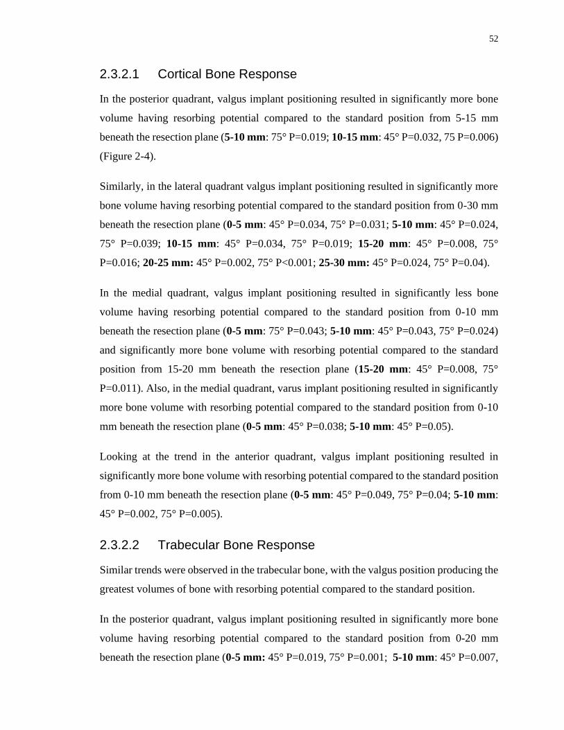
52
2.3.2.1 Cortical Bone Response
In the posterior quadrant, valgus implant positioning resulted in significantly more bone
volume having resorbing potential compared to the standard position from 5-15 mm
beneath the resection plane (5-10 mm: 75° P=0.019; 10-15 mm: 45° P=0.032, 75 P=0.006)
(Figure 2-4).
Similarly, in the lateral quadrant valgus implant positioning resulted in significantly more
bone volume having resorbing potential compared to the standard position from 0-30 mm
beneath the resection plane (0-5 mm: 45° P=0.034, 75° P=0.031; 5-10 mm: 45° P=0.024,
75° P=0.039; 10-15 mm: 45° P=0.034, 75° P=0.019; 15-20 mm: 45° P=0.008, 75°
P=0.016; 20-25 mm: 45° P=0.002, 75° P<0.001; 25-30 mm: 45° P=0.024, 75° P=0.04).
In the medial quadrant, valgus implant positioning resulted in significantly less bone
volume having resorbing potential compared to the standard position from 0-10 mm
beneath the resection plane (0-5 mm: 75° P=0.043; 5-10 mm: 45° P=0.043, 75° P=0.024)
and significantly more bone volume with resorbing potential compared to the standard
position from 15-20 mm beneath the resection plane (15-20 mm: 45° P=0.008, 75°
P=0.011). Also, in the medial quadrant, varus implant positioning resulted in significantly
more bone volume with resorbing potential compared to the standard position from 0-10
mm beneath the resection plane (0-5 mm: 45° P=0.038; 5-10 mm: 45° P=0.05).
Looking at the trend in the anterior quadrant, valgus implant positioning resulted in
significantly more bone volume with resorbing potential compared to the standard position
from 0-10 mm beneath the resection plane (0-5 mm: 45° P=0.049, 75° P=0.04; 5-10 mm:
45° P=0.002, 75° P=0.005).
2.3.2.2 Trabecular Bone Response
Similar trends were observed in the trabecular bone, with the valgus position producing the
greatest volumes of bone with resorbing potential compared to the standard position.
In the posterior quadrant, valgus implant positioning resulted in significantly more bone
volume having resorbing potential compared to the standard position from 0-20 mm
beneath the resection plane (0-5 mm: 45° P=0.019, 75° P=0.001; 5-10 mm: 45° P=0.007,

53
75° P=0.004; 10-15 mm: 45° P=0.009, 75° P=0.001; 15-20 mm: 45° P=0.018, 75°
P=0.042) (Figure 2-4).
Likewise, in the lateral quadrant, valgus positioned implants resulted in significantly more
bone volume with resorbing potential when compared to the standard position at slice
depths from 0-25 mm beneath the resection plane (0-5 mm: 45° P=0.005, 75° P=0.011; 5-
10 mm: 45° P=0.01, 75° P=0.004; 10-15 mm: 45° P=0.014, 75° P=0.012; 15-20 mm: 45°
P=0.026, 75° P=0.026; 20-25 mm: 45° P=0.042). Additionally, in the lateral quadrant,
varus positioning of the implant resulted in significantly more bone volume with resorbing
potential compared to the standard position from 25-30 mm beneath the resection plane
(25-30 mm: 75° P=0.005).
Similarly, in the medial quadrant, valgus implant positioning resulted in significantly more
bone volume having resorbing potential compared to the standard position from 10-20 mm
and 30-40 mm beneath the resection plane (10-15 mm: 75° P=0.037; 15-20 mm: 75°
P=0.044; 30-35 mm: 45° P=0.015, 75° P=0.013; 35-40 mm: 45° P=0.008, 75° P=0.009 ).
In the anterior quadrant, valgus implant positioning produced significantly more bone
volume with resorbing potential compared to the standard position from 0-5 mm beneath
the resection plane (0-5 mm: 75° P=0.045), which was also the same trend for varus
implant positioning resulting in significantly more of its bone volume with resorbing
potential compared to the standard position from 20-25 mm and 30-35mm below the
resection plane (20-25 mm: 45° P=0.018, 75° P=0.023; 30-35 mm: 75° P=0.048 ).
2.4 Discussion
2.4.1 Changes in Bone Stress
The volume-weighted absolute average change in bone stress, Δσ, delivers an estimate for
the magnitude of bone stress that was altered within the volume-of-interest relative to the
intact state. Since the outcome measure is an absolute differential, it does not provide
information on whether the stress value was overall higher or lower within the
reconstructed bone; it simply reflects the total magnitude of change from the intact state.

54
An ideal scenario is one in which the reconstructed state mimics the stress of the intact
state and any alteration in the bone stress outcome measure is likely less favorable.
Changes in cortical bone stress generally decreased moving distally for all three implant
positions, likely due to the increasing load transfer from the implant to the surrounding
cortical bone; returning the stress state of the bone to its natural form. Varus and valgus
implant alignment seemed to have the largest impact on changes in cortical bone stress in
the posterior and lateral quadrants. Valgus alignment produced significantly larger changes
in bone stress compared to the standard and varus implant alignment at depths greater than
5 mm below the humeral cut plane. There were also many slice depths in these quadrants,
particularly in the range of 5-25 mm beneath the humeral cut plane where the valgus
aligned implant altered cortical bone stress more than the varus aligned implant. In the
medial quadrant, valgus alignment had the greatest impact on cortical bone stress in the
most distal slices, likely a direct result of distal contact of the humeral stem with the medial
cortex endosteum.
Similar trends were observed within trabecular bone where valgus implant alignment
produced larger departures in bone stress from the intact state compared to the standard
position, with the exception of the most distal slices in the medial quadrant, where
interestingly the standard position produced significantly larger changes in bone stress
compared to the varus position. It is also interesting to note that although the varus aligned
implant produced larger departures in bone stress than the standard implant position,
significant differences between these two implant positions were only detected in
trabecular bone at 75º of abduction in the most proximal slice.
2.4.2 Time-Zero Expected Bone Response
Valgus implant alignment produced more potential for cortical bone resorption than the
standard position in the lateral quadrant from 0-30 mm, and in the anterior quadrant from
0-10 mm beneath the humeral cut plane at time-zero. This was also found in the posterior
and medial quadrants from 10-20 mm beneath the humeral cut plane. This may be due to
distal contact of the valgus aligned stems with the medial cortex causing direct load transfer
distally that unloads the proximal aspect of the humerus. Similar results were observed in

55
trabecular bone, where the valgus implant alignment produced more expected bone
resorption than the standard position in most of the slices between 0-25 mm beneath the
humeral cut plane in the posterior and lateral quadrants, and a variety of slices in the medial
and anterior quadrants.
The only locations where valgus alignment produced less expected bone resorption than
the standard and varus positions were in the two most proximal slices of the medial
quadrant. This trend reversal could be a result of the interaction of the points of load
transfer of the valgus and varus aligned stems (Figure 2-5). The distal aspect of the valgus
positioned stem is stabilized by contact with the medial cortex endosteum which prevented
movement of the stem in the direction of adduction forming a ‘bottle opener’ effect. This
may be exacerbated by the absence of humeral head contact with the lateral cortex,
resulting in the implant being supported by the less stiff trabecular bone, thereby reducing
load transfer laterally. Medial contact forces between the backside of the humeral head and
the resection plane may have been elevated to counteract the moment produced by the
distal stem contact resulting in less medial bone resorption directly beneath the humeral
resection plane.
The varus aligned stem is initially stabilized by contact with the lateral cortex and, in
contrast to valgus stem positioning, the distal stem can move freely in the medial direction.
The lateral contact between the resection plane and the backside of the humeral head would
normally counteract the applied joint reaction force. Since there was no lateral cortical
contact, the humeral head subsided slightly into the trabecular bone and resulted in
displacement of the distal stem away from the lateral cortex endosteum medially. This may
explain why significant differences between the varus and standard positions were not
typically observed.

56
Figure 2-5: Points of contact for load transfer for the Valgus (left) and Varus (right)
implant positions (forces responding to implant-bone load transfer represented by
arrows) under the applied joint reaction force (shown in red)
Joint reaction force (shown in red) passing through the humeral head center. The position
of joint reaction force is dictated by the intersection of articular surface and the force
passing through the humeral head center.
57
The results of this work agree with the findings of Peduzzi et al17, who investigated stress
shielding in 183 patients following TSA with Aequalis Ascend Flex short stems at 2 year
follow up. Although they reported good mid-term results with no complications related to
the stem, proximal bony adaptations were observed in 80.3% of patients. They also found
that varus and valgus stem axis deviations increased the risk of bony adaptation, suggesting
that implant positioning may also contribute to stress shielding in humeral short stem
components. It is important to note that the stem design in their study included a different
metaphyseal geometry, which may have affected the implant-bone load transfer patterns.
The presence of bone resorption potential in all implant positions investigated also agrees
with clinical studies that have reported stress shielding in a large proportion of patients. In
a study of 73 patients who had received uncemented short stem humeral components with
a minimum 2 year follow up, Casagrande et al5 found that 71% of shoulders had signs of
radiolucency and 8.7% were “at risk” of loosening before a minimum 3-year mark for
follow up. The causes for humeral loosening and bone resorption were not clear in this
study; however, lack of bony on-growth and stress shielding are mentioned as possible
causes. Although Schnetzke et al22 reported good clinical outcomes and implant fixation in
82 patients that underwent TSA, they also reported that 13.6% of shoulders had stress
shielding and resorption taking place at the medial cortex of the humeral calcar.
The present study has several strengths. Our analysis allowed for direct element-to-element
comparison of bone stress and changes in strain energy density between the intact and the
reconstructed states, enabling us to detect alterations in the distinct anatomical segments
of the humerus bone. Joint loads were applied representing two distinct abduction angles,
in which telemetrized shoulder implant data representative of certain daily tasks was
utilized to represent clinically relevant cases3. Eight humeri were virtually repeatedly
reconstructed with three different stem positions, allowing for the comparison of bone
stress between each implant position, something which would have not been achievable
using in-vitro cadaveric testing due to the destructive nature of implantation. This allowed

58
for repeated statistical assessments over the population of humeri investigated, which
would not have been possible if a single bone model was employed.
This study also has several limitations. Assumptions made in assigning bone material
properties, model boundary conditions, and expected bone response are necessary for
computational modelling; and while they may induce error, it is important to note this error
is constant throughout all models, and hence the comparison of results following the
alteration of implant position are likely to be a direct result of this change in modelling
parameter alone. Furthermore, the estimates obtained for expected bone response
according to change in strain energy density alterations, are obtained immediately
following humeral reconstruction, and therefore may not be indicative of long-term bone
remodeling since the model is not iterative and does not account for the long-term bone
remodeling process. Lastly, the incomplete coverage between the back side of the head and
the resection plane might have altered bone-implant load transfer and amplified the
differences measured between the three stem positions. Future investigations should
consider varying degrees of humeral head backside contact to assess its impact on humeral
bone stress following shoulder arthroplasty.
2.5 Conclusions
The results of this study show that the preferred positioning for a short stem humeral
implant is a centered, standard implant position without any distal cortical contact.
However, if distal contact must occur, valgus malposition may be worse than varus
malposition in terms of changes in bone stress from the intact state, the expected time-zero
bone response and subsequent stress-shielding. The three different stem positions were
selected according to the implant design constraints, essentially creating a “worst case
scenario” for when the stem was in contact with the cortex.

59
2.6 References
1. Austman RL, Milner JS, Holdsworth DW, Dunning CE. Development of a
customized density-modulus relationship for use in subject-specific finite element models
of the ulna. Proc. Inst. Mech. Eng. Part H J. Eng. Med.
2009;doi:10.1243/09544119JEIM553
2. Bayraktar HH, Morgan EF, Niebur GL, Morris GE, Wong EK, Keaveny TM.
Comparison of the elastic and yield properties of human femoral trabecular and cortical
bone tissue. J. Biomech. 2004;doi:10.1016/S0021-9290(03)00257-4
3. Bergmann G, Graichen F, Bender A, Kääb M, Rohlmann A, Westerhoff P. In vivo
glenohumeral contact forces-Measurements in the first patient 7 months postoperatively.
J. Biomech. 2007;40(10):2139–2149. doi:10.1016/j.jbiomech.2006.10.037
4. Carter DR, Hayes WC. The Compressive Behavior Porous of Bone Structure as a
Two-Phase. J. bone Jt. Surg. 1977;59(7):954–962. doi:10.1007/978-1-4471-5451-8_116
5. Casagrande DJ, Parks DL, Torngren T, Schrumpf MA, Harmsen SM, Norris TR, et
al. Radiographic evaluation of short-stem press-fit total shoulder arthroplasty: Short-term
follow-up. J. Shoulder Elb. Surg. [Internet]. 2016;25(7):1163–1169. Available from:
http://dx.doi.org/10.1016/j.jse.2015.11.067doi:10.1016/j.jse.2015.11.067
6. Denard PJ, Noyes MP, Walker JB, Shishani Y, Gobezie R, Romeo AA, et al.
Radiographic changes differ between two different short press-fit humeral stem designs in
total shoulder arthroplasty. J. Shoulder Elb. Surg. 2018;27(2):217–223.
doi:10.1016/j.jse.2017.08.010
7. Denard PJ, Raiss P, Gobezie R, Edwards TB, Lederman E. Stress shielding of the
humerus in press-fit anatomic shoulder arthroplasty: review and recommendations for
evaluation. J. Shoulder Elb. Surg. [Internet]. 2018;27(6):1139–1147. Available from:
https://doi.org/10.1016/j.jse.2017.12.020doi:10.1016/j.jse.2017.12.020
60
8. Grant JA, Bishop NE, Götzen N, Sprecher C, Honl M, Morlock MM. Artificial
composite bone as a model of human trabecular bone: The implant-bone interface. J.
Biomech. 2007;40(5):1158–1164. doi:10.1016/j.jbiomech.2006.04.007
9. Inoue K, Suenaga N, Oizumi N, Yamaguchi H, Miyoshi N, Taniguchi N, et al.
Humeral bone resorption after anatomic shoulder arthroplasty using an uncemented stem.
J. Shoulder Elb. Surg. 2017;doi:10.1016/j.jse.2017.04.012
10. Kuiper JH, Huiskes R. Friction and stem stiffness affect dynamic interface motion
in total hip replacement. J. Orthop. Res. 1996;14(1):36–43. doi:10.1002/jor.1100140108
11. Langohr GDG, Reeves J, Roche CP, Faber KJ, Johnson JA. The effect of short-
stem humeral component sizing on humeral bone stress. J. Shoulder Elb. Surg. [Internet].
2020;29(4):761–767. Available from:
https://doi.org/10.1016/j.jse.2019.08.018doi:10.1016/j.jse.2019.08.018
12. Leung ASO, Gordon LM, Skrinskas T, Szwedowski T, Whyne CM. Effects of bone
density alterations on strain patterns in the pelvis: Application of a finite element model.
Proc. Inst. Mech. Eng. Part H J. Eng. Med. 2009;doi:10.1243/09544119JEIM618
13. Morgan EF, Bayraktar HH, Keaveny TM. Trabecular bone modulus-density
relationships depend on anatomic site. J. Biomech. 2003;doi:10.1016/S0021-
9290(03)00071-X
14. Morwood MP, Johnston PS, Garrigues GE. Proximal ingrowth coating decreases
risk of loosening following uncemented shoulder arthroplasty using mini-stem humeral
components and lesser tuberosity osteotomy. J. Shoulder Elb. Surg. [Internet].
2017;26(7):1246–1252. Available from:
http://dx.doi.org/10.1016/j.jse.2016.11.041doi:10.1016/j.jse.2016.11.041
15. Nagels J, Valstar ER, Stokdijk M, Rozing PM. Patterns of loosening of the glenoid
component. J. Bone Jt. Surg. - Ser. B. 2002;84(1):83–87. doi:10.1302/0301-
620X.84B1.11951

61
16. Neuert MAC, Dunning CE. Determination of remodeling parameters for a strain-
adaptive finite element model of the distal ulna. Proc. Inst. Mech. Eng. Part H J. Eng. Med.
2013 Sep;227(9):994–1001. doi:10.1177/0954411913487841
17. Peduzzi L, Goetzmann T, Wein F, Roche O, Sirveaux F, Mole D, et al. Proximal
humeral bony adaptations with a short uncemented stem for shoulder arthroplasty: a
quantitative analysis. JSES Open Access [Internet]. 2019;3(4):278–286. Available from:
https://doi.org/10.1016/j.jses.2019.09.011doi:10.1016/j.jses.2019.09.011
18. Raiss P, Edwards TB, Deutsch A, Shah A, Bruckner T, Loew M, et al. Components
in Shoulder Arthroplasty. 2014;54:1–9. doi:10.2106/JBJS.M.00378
19. Razfar N, Reeves JM, Langohr DG, Willing R, Athwal GS, Johnson JA.
Comparison of proximal humeral bone stresses between stemless, short stem, and standard
stem length: A finite element analysis. J. Shoulder Elb. Surg.
2016;doi:10.1016/j.jse.2015.11.011
20. Rho JY, Ashman RB, Turner CH. Young’s modulus of trabecular and cortical bone
material: Ultrasonic and microtensile measurements. J. Biomech. 1993;doi:10.1016/0021-
9290(93)90042-D
21. Schileo E, Taddei F, Malandrino A, Cristofolini L, Viceconti M. Subject-specific
finite element models can accurately predict strain levels in long bones. J. Biomech.
2007;doi:10.1016/j.jbiomech.2007.02.010
22. Schnetzke M, Coda S, Walch G, Loew M. Clinical and radiological results of a
cementless short stem shoulder prosthesis at minimum follow-up of two years. Int. Orthop.
2015;39(7):1351–1357. doi:10.1007/s00264-015-2770-2
23. Taddei F, Cristofolini L, Martelli S, Gill HS, Viceconti M. Subject-specific finite
element models of long bones: An in vitro evaluation of the overall accuracy. J. Biomech.
2006;doi:10.1016/j.jbiomech.2005.07.018
62
Chapter 3
3 The Effect of Humeral Head Backside Contact on Humeral Bone Stress following Total Shoulder Arthroplasty with a Short Humeral Stem
The use of uncemented humeral stems in total shoulder arthroplasty (TSA) is known to
cause stress shielding and result in bone resorption. Shorter length stems with smaller
overall dimensions have been shown to decrease stress shielding, however the effect of
humeral head backside contact with the resection plane has not yet been fully investigated.
The purpose of this study was to simulate three different humeral head backside contact
conditions and compare their effects on humeral bone stress and expected bone response.
3.1 Introduction
Total shoulder arthroplasty (TSA) is a successful procedure used to restore shoulder
function and alleviate pain in patients with glenohumeral arthritis. The procedure involves
humeral head resection and canal preparation with reaming and broaching to create a void
that approximates the geometry of the desired prosthesis. The humeral stem is implanted
into the canal and the replacement humeral head component is sized and positioned on the
humeral resection plane.
Humeral stress shielding following TSA is common and is clinically concerning. Several
studies have reported proximal stress shielding in 29 to 80% of recipients9,20,23 at mean
follow up ranging from 2 to 3 years. Furthermore, early stem loosening, a problem mostly
unique to uncemented implants, has been reported in up to 11% of patients, with another
9% at risk of loosening with stress shielding listed as probable cause at 33 month average
follow up8.
Strategies to mitigate proximal humeral stress shielding include modifications in humeral
short stem design such as changing the implant surface characteristics and altering stem
geometry, using smaller implants that do not fill the proximal humerus and ensuring that
the stem is accurately positioned within the humeral canal. In a comparison of coated and

63
uncoated short stem humeral components, the coated patient cohort reported 21% having
some stress shielding no implant loosening with, compared to the uncoated group that had
3% exhibiting implant loosening, with another 21% at risk of loosening, and 44% with
stress shielding18. Both clinical and in-vitro computational studies have shown that smaller
sized implants can reduce the risk of stress shielding and result in humeral bone stresses
that more closely approximate the intact state when compared to larger-sized implants13,20.
Surgical technique may also affect stress shielding. For example, implants that are
positioned in varus or valgus within the canal are at higher risk of proximal stress shielding
than centrally positioned implants20. Computational work presented in Chapter 2 confirms
that central stem positioning is advantageous compared to varus or valgus stem angulation
that results in distal stem contact with the medial or lateral cortex.
While the current literature seems to suggest that proximal stress shielding following TSA
with a humeral short stem can be affected by short stem design, sizing, and surgical
technique, the effect of humeral head backside contact with the humeral resection plane on
humeral bone stresses and expected bone response is not currently fully understood.
In an in-vitro computational model, Synnott et al24 using a generic humeral short stem
compared full backside contact of a humeral head sized to cover the full humeral resection
plane to one which was left proud with no backside contact. They reported that full
backside contact resulted in less changes in humeral bone stress compared to intact, and
that the non-contact condition resulted in significantly more expected proximal cortical
bone resorption due to the lack of load transfer to the cortex at the resection plane.
While previous work suggests that humeral head backside contact with the resection plane
may play an important role in cortical humeral stress shielding, the effect of humeral head
backside contact when using a size of implant that does not fully cover the humeral
resection plane and the impact of uneven backside contact is currently not known. This is
important since coverage of the entire resection plane is not always possible clinically, and
often a smaller humeral head is positioned in the inferior-medial position on the resection
due to anatomy and the preservation of soft tissue. Furthermore, sometimes humeral head

64
backside contact is only achieved either medially or laterally as a result of resection plane
inconsistencies or humeral head misalignment.
The purpose of this study was to quantify the effect of humeral head backside contact on
humeral cortical and trabecular bone stresses after TSA with a short stem humeral
component and an inferior-medial positioned humeral head. We hypothesized that full
backside contact would produce humeral stresses closest to that of the intact bone due to
load transfer occurring over the entire backside surface. We also hypothesized that when
full backside contact could not be achieved, medial contact would be preferable when
compared to lateral contact because of medial load transfer to the medial cortex.
3.2 Methods
3.2.1 Finite Element Simulation and Model Development
Three dimensional models of eight male left cadaveric humeri (68±6 years average age)
were generated from computed tomography (CT) data using MIMICS (Materialise,
Leuven, Belgium) software. A combination of automatic threshold-based and manual
segmentation methods was used to separate cortical and trabecular bone.
The resulting humeral bone models were then virtually prepared for reconstruction by an
orthopaedic surgeon to accept a short stem humeral implant (Exactech Equinoxe®
Preserve) that was sized based on previous investigations and placed directly in the center
of the humeral canal. The humeral head was purposely positioned in the inferior-medial
position such that contact was achieved on the medial cortex, and no contact existed on the
lateral cortex.
Three different humeral head backside contact conditions were implemented for each
specimen (Figure 3-1); full backside contact with the entire humeral resection plane
(FULL), semi-circular backside contact with only the inferior-medial half of the humeral
resection plane (INF), and semi-circular backside contact with only the superior-lateral half
of the humeral resection plane (SUP).

65
Figure 3-1: (A) Humeral Head Backside Contact Conditions Investigated Including
Superior (SUP, left), Full (FULL, middle), and Inferior (INF, right), and (B) Stem
and Head Friction Interface Conditions Simulated 10,12,13
Three backside contact conditions of the humeral head which were studied in this chapter.
Superior and Inferior contacts were interfaced such that head lacks contacts with the
resection plane at a designated area.

66
Both cortical and trabecular bone was meshed with quadratic tetrahedral elements having
a 2 mm maximum edge length, as deemed appropriate by a mesh convergence analysis13.
Cortical bone was given a modulus of elasticity of E = 20 GPa and Poisson’s ratio of =
0.34,21. Trabecular bone was given a spatially varying modulus of elasticity using a density-
modulus relationship of 𝐸 = 8920𝜌𝑎𝑝𝑝1.83 where E is the elastic modulus and 𝜌𝑎𝑝𝑝 is the
apparent bone density3,7,14,17,22,25 and a Poisson’s ratio of = 0.3. The implant was also
meshed with quadratic tetrahedral elements with a maximum edge length of 2 mm and was
given material properties of titanium having a modulus of elasticity of E = 110 GPa and a
Poisson’s ratio of = 0.3. The stem surface was assigned three friction characteristics:
plasma spray (most proximal, µ = 0.88), grit blast (middle, µ = 0.63), and polished (most
distal, µ = 0.40), and the humeral head backside surface was given polished frictional
characteristics (µ = 0.40)10,12,13 (Figure 3-1).
A fixed boundary condition was applied at the distal end of the humerus which was
sectioned at the mid-diaphysis and joint reaction forces representing 45˚ and 75˚ of
abduction were applied towards the center of the humeral head on the articular surface,
with a magnitude of 440 N for 45˚ and 740 N for 75˚ based on in-vivo telemetrized TSA
data assuming a 50th-percentile male with a body weight of 88.3 kg5.
3.2.2 Outcome Variables and Statistical Analysis
To permit statistical analysis, the humerus was divided into four anatomical quadrants
(medial, lateral, anterior, posterior) and eight slices of 5 mm thick each, which were parallel
to the humeral resection plane for both cortical and trabecular bone.
The volume-weighted percent change in bone stress for each humeral head position versus
the intact was calculated using the resulting difference for each of the six stress components
(σ11, σ22, σ33, σ12, σ13, σ 23). The resulting values were then inserted into the von Mises
equation, yielding a scalar representation of the change in bone stress from pre- to post-
reconstruction to serve as an indication of the overall change in bone stress as a result of
both tensile and compressive stresses although does not include the direction (positive or
negative) of the change.
67
The volume-weighted change in strain energy density (ΔSED) for each element from the
intact to the reconstructed state was also determined, and the expected time-zero bone
response (resorb, no change, or remodel) for each element was then estimated using a
threshold value of 55% change in strain energy density (ΔSED). A decrease in SED of
more than 55% would result in an element being classified as having bone resorption
potential and an increase of more than 55% would result in bone remodeling potential19.
A four-way (humeral head backside contact, abduction angle, slice depth, quadrant)
repeated measure analysis of variance (RM-ANOVA) with a significance level of α = 0.05
was conducted to assess the change in bone stress and the expected bone response for each
implant position investigated. A post-hoc power analysis showed that a power of 0.8 or
greater was achieved for all outcome variables.
3.3 Results
3.3.1 Changes in Bone Stress
Considering all quadrants, slice depths, and abduction angles, the full humeral head
backside contact condition resulted in the smallest departure in cortical and trabecular bone
stress relative to the intact state compared to the superior and inferior backside contacts.
For cortical bone, the full backside contact altered bone stress by 28.9±5.5% compared to
intact, which was significantly less than the superior (37.0±3.9%, P = 0.022) and inferior
(53.4±3.9%, P < 0.001) backside contact conditions (Figure 3-2). Similar trends were
observed for changes in trabecular bone stress relative to the intact state, where the full
backside contact altered bone stress by 86.3±27.9% compared to intact bone. Also, the
superior and inferior contact conditions, altered bone stress by 115.2±45.0% (P = 0.309)
and 197.4±80.2% (P = 0.024), respectively.

68
Figure 3-2: Mean (±1 STD) von Mises of the Change in Stress Compared to the
Intact State for Cortical (left) and Trabecular (right) Bone for all Humeral Head
Backside Contact Conditions Investigated (SUP, FULL, INF; from left to right)
Results of mean± standard deviation for von Mises of change in stress obtained for both
cortical and trabecular bone for the three contact conditions studied.
69
3.3.1.1 Change in Cortical Bone Stress
For cortical bone, in the posterior quadrant the inferior contact altered bone stress more
than the full contact at all depths beneath the resection plane (0-5 mm: 45° P<0.001, 75°
P<0.001;5-10 mm: 45° P<0.001, 75° P<0.001; 10-15 mm: 45° P<0.001, 75° P<0.001; 15-
20 mm: 45° P<0.001, 75° P<0.001; 20-25 mm: 45° P<0.001, 75° P<0.001; 25-30 mm:
45° P<0.001, 75° P<0.001; 30-35 mm: 45° P<0.001, 75° P<0.001; 35-40 mm: 45°
P=0.002, 75° P<0.001) (Figure 3-3).
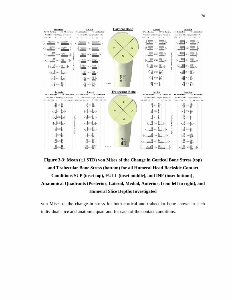
70
Figure 3-3: Mean (±1 STD) von Mises of the Change in Cortical Bone Stress (top)
and Trabecular Bone Stress (bottom) for all Humeral Head Backside Contact
Conditions SUP (inset top), FULL (inset middle), and INF (inset bottom) ,
Anatomical Quadrants (Posterior, Lateral, Medial, Anterior; from left to right), and
Humeral Slice Depths Investigated
von Mises of the change in stress for both cortical and trabecular bone shown in each
individual slice and anatomic quadrant, for each of the contact conditions.
71
Similarly, within the lateral quadrant the inferior contact altered cortical bone stress more
than the full contact at all slice depths (0-5 mm: 45° P=0.021, 75° P=0.015; 5-10 mm: 45°
P=0.001, 75° P=0.001; 10-15 mm: 45° P=0.001, 75° P=0.001; 15-20 mm: 45° P=0.001,
75° P<0.001; 20-25 mm: 45° P<0.001, 75° P<0.001; 25-30 mm: 45° P<0.001, 75°
P<0.001; 30-35 mm: 45° P<0.001, 75° P<0.001; 35-40 mm: 45° P<0.001, 75° P<0.001).
Superior contact within the lateral quadrant showed a similar trend, altering cortical bone
stress more than the full contact at slice depths between 5-25mm and 30-40mm (5-10 mm:
45° P=0.014, 75° P=0.018; 10-15 mm: 45° P=0.024, 75° P=0.027; 15-20 mm: 45°
P=0.033, 75° P=0.035; 20-25 mm: 45° P=0.047, 75° P=0.045; 30-35 mm: 45° P=0.038,
75° P=0.027; 35-40 mm: 45° P=0.011, 75° P=0.013).
In the medial quadrant the inferior contact altered cortical bone stresses more than the full
contact at all slice depths (0-5 mm: 45° P<0.001, 75° P<0.001; 5-10 mm: 45° P=0.001,
75° P<0.001; 10-15 mm: 45° P=0.001, 75° P=0.001; 15-20 mm: 45° P=0.001, 75°
P=0.001; 20-25 mm: 45° P=0.001, 75° P<0.001; 25-30 mm: 45° P=0.001, 75° P<0.001;
30-35 mm: 45° P=0.001, 75° P<0.001; 35-40 mm: 75° P<0.001). Similarly, superior
contact within the medial quadrant changed cortical bone stress more than the full contact
at slice depths between 0-15mm (0-5 mm: 45° P=0.005, 75° P=0.001; 5-10 mm: 45°
P=0.001, 75° P<0.001; 10-15 mm: 45° P=0.007, 75° P=0.011) .
In the anterior quadrant the inferior contact changed cortical bone stress more than the full
contact at all slice depths (0-5 mm: 45° P<0.001, 75° P<0.001; 5-10 mm: 45° P<0.001,
75° P<0.001; 10-15 mm: 45° P<0.001, 75° P<0.001; 15-20 mm: 45° P<0.001, 75°
P<0.001; 20-25 mm: 45° P<0.001, 75° P<0.001; 25-30 mm: 45° P<0.001, 75° P<0.001;
30-35 mm: 45° P=0.001, 75° P<0.001; 35-40 mm: 45° P=0.011, 75° P=0.002). Likewise,
superior contact within the anterior quadrant altered cortical bone stress more than the full
contact from 0-15mm and 35-40mm beneath the resection plane (0-5 mm: 45° P=0.036,
75° P=0.032; 5-10 mm: 45° P=0.015, 75° P=0.014; 10-15 mm: 45° P=0.004, 75° P=0.004;
35-40 mm: 75° P=0.046).
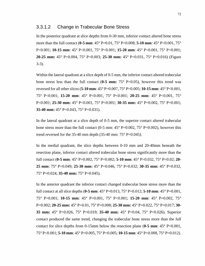
72
3.3.1.2 Change in Trabecular Bone Stress
In the posterior quadrant at slice depths from 0-30 mm, inferior contact altered bone stress
more than the full contact (0-5 mm: 45° P=0.01, 75° P=0.008; 5-10 mm: 45° P<0.001, 75°
P<0.001; 10-15 mm: 45° P<0.001, 75° P<0.001; 15-20 mm: 45° P<0.001, 75° P<0.001;
20-25 mm: 45° P=0.004, 75° P=0.003; 25-30 mm: 45° P=0.031, 75° P=0.016) (Figure
3-3).
Within the lateral quadrant at a slice depth of 0-5 mm, the inferior contact altered trabecular
bone stress less than the full contact (0-5 mm: 75° P=0.05), however this trend was
reversed for all other slices (5-10 mm: 45° P=0.007, 75° P=0.005; 10-15 mm: 45° P<0.001,
75° P<0.001; 15-20 mm: 45° P<0.001, 75° P<0.001; 20-25 mm: 45° P<0.001, 75°
P<0.001; 25-30 mm: 45° P<0.001, 75° P<0.001; 30-35 mm: 45° P=0.002, 75° P=0.001;
35-40 mm: 45° P=0.043, 75° P=0.031).
In the lateral quadrant at a slice depth of 0-5 mm, the superior contact altered trabecular
bone stress more than the full contact (0-5 mm: 45° P=0.002, 75° P=0.002), however this
trend reversed for the 35-40 mm depth (35-40 mm: 75° P=0.045).
In the medial quadrant, the slice depths between 0-10 mm and 20-40mm beneath the
resection plane, inferior contact altered trabecular bone stress significantly more than the
full contact (0-5 mm: 45° P=0.002, 75° P=0.002; 5-10 mm: 45° P=0.032, 75° P=0.02; 20-
25 mm: 75° P=0.049; 25-30 mm: 45° P=0.046, 75° P=0.032; 30-35 mm: 45° P=0.032,
75° P=0.024; 35-40 mm: 75° P=0.045).
In the anterior quadrant the inferior contact changed trabecular bone stress more than the
full contact at all slice depths (0-5 mm: 45° P=0.013, 75° P=0.012; 5-10 mm: 45° P=0.001,
75° P=0.001; 10-15 mm: 45° P=0.001, 75° P<0.001; 15-20 mm: 45° P=0.002, 75°
P=0.002; 20-25 mm: 45° P=0.01, 75° P=0.008; 25-30 mm: 45° P=0.022, 75° P=0.017; 30-
35 mm: 45° P=0.026, 75° P=0.019; 35-40 mm: 45° P=0.04, 75° P=0.026). Superior
contact produced the same trend, changing the trabecular bone stress more than the full
contact for slice depths from 0-15mm below the resection plane (0-5 mm: 45° P=0.001,
75° P<0.001; 5-10 mm: 45° P=0.005, 75° P=0.005; 10-15 mm: 45° P=0.008, 75° P=0.012).
73
3.3.2 Time-Zero Bone Response
Following reconstruction, in all quadrants for both cortical and trabecular bone there
existed volumes of bone that exhibited resorbing potential for all three contact conditions
investigated. In general, the inferior contact resulted the largest volume of bone with
resorbing potential compared to the full and superior contact conditions in all quadrants
and slice depths except in the medial quadrant within the most proximal slice (Figure 3-4).

74
Figure 3-4: Estimated Time-Zero Bone Response of Cortical (top) and Trabecular
Bone (bottom) for the Superior (inset top), Full (inset middle), and Inferior (inset
bottom) Humeral Head Backside Contact Conditions by Anatomic Quadrant (inset
left to right) and Slice Depth (inset top to bottom)
Expected bone response for both cortical and trabecular bone shown in each individual
slice and anatomic quadrant, for each of the contact conditions.
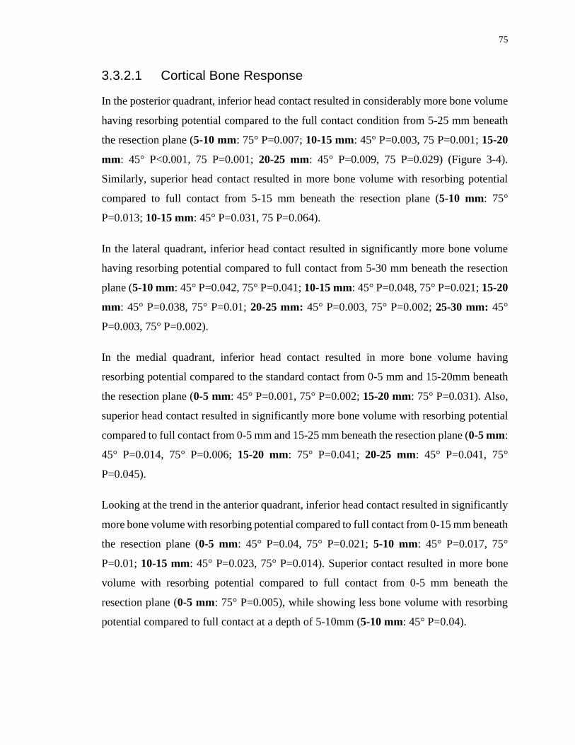
75
3.3.2.1 Cortical Bone Response
In the posterior quadrant, inferior head contact resulted in considerably more bone volume
having resorbing potential compared to the full contact condition from 5-25 mm beneath
the resection plane (5-10 mm: 75° P=0.007; 10-15 mm: 45° P=0.003, 75 P=0.001; 15-20
mm: 45° P<0.001, 75 P=0.001; 20-25 mm: 45° P=0.009, 75 P=0.029) (Figure 3-4).
Similarly, superior head contact resulted in more bone volume with resorbing potential
compared to full contact from 5-15 mm beneath the resection plane (5-10 mm: 75°
P=0.013; 10-15 mm: 45° P=0.031, 75 P=0.064).
In the lateral quadrant, inferior head contact resulted in significantly more bone volume
having resorbing potential compared to full contact from 5-30 mm beneath the resection
plane (5-10 mm: 45° P=0.042, 75° P=0.041; 10-15 mm: 45° P=0.048, 75° P=0.021; 15-20
mm: 45° P=0.038, 75° P=0.01; 20-25 mm: 45° P=0.003, 75° P=0.002; 25-30 mm: 45°
P=0.003, 75° P=0.002).
In the medial quadrant, inferior head contact resulted in more bone volume having
resorbing potential compared to the standard contact from 0-5 mm and 15-20mm beneath
the resection plane (0-5 mm: 45° P=0.001, 75° P=0.002; 15-20 mm: 75° P=0.031). Also,
superior head contact resulted in significantly more bone volume with resorbing potential
compared to full contact from 0-5 mm and 15-25 mm beneath the resection plane (0-5 mm:
45° P=0.014, 75° P=0.006; 15-20 mm: 75° P=0.041; 20-25 mm: 45° P=0.041, 75°
P=0.045).
Looking at the trend in the anterior quadrant, inferior head contact resulted in significantly
more bone volume with resorbing potential compared to full contact from 0-15 mm beneath
the resection plane (0-5 mm: 45° P=0.04, 75° P=0.021; 5-10 mm: 45° P=0.017, 75°
P=0.01; 10-15 mm: 45° P=0.023, 75° P=0.014). Superior contact resulted in more bone
volume with resorbing potential compared to full contact from 0-5 mm beneath the
resection plane (0-5 mm: 75° P=0.005), while showing less bone volume with resorbing
potential compared to full contact at a depth of 5-10mm (5-10 mm: 45° P=0.04).

76
3.3.2.2 Trabecular Bone Response
In the posterior quadrant, inferior head contact resulted in significantly more bone volume
having resorbing potential compared to full contact from 0-20 mm beneath the resection
plane (0-5 mm: 75° P=0.038; 5-10 mm: 45° P=0.006, 75° P=0.001; 10-15 mm: 45°
P=0.001, 75° P=0.001; 15-20 mm: 45° P=0.035, 75° P=0.034) (Figure 3-4); however this
trend was reversed for a single slice at the 25-30mm depth ( 25-30 mm: 45° P=0.021, 75°
P=0.027). Additionally, superior contact resulted in less bone volume having resorbing
potential compared to full contact in a single slice from the 0-5mm depth (0-5 mm: 75°
P=0.025).
Likewise, in the lateral quadrant, inferior head contact resulted in significantly more bone
volume with resorbing potential when compared to full contact at slice depths from 0-25
mm beneath the resection plane (0-5 mm: 45° P<0.001, 75° P<0.001; 5-10 mm: 45°
P<0.001, 75° P<0.001; 10-15 mm: 45° P<0.001, 75° P<0.001; 15-20 mm: 45° P<0.001,
75° P<0.001; 20-25 mm: 45° P=0.003, 75° P=0.002). Additionally, superior contact of the
head of the implant resulted in less bone volume with resorbing potential compared to full
contact in one slice from 30-35 mm beneath the resection plane (30-35 mm: 45° P=0.009).
In the medial quadrant, inferior head contact resulted in less bone volume having resorbing
potential compared to full contact from 10-30 mm beneath the resection plane (10-15 mm:
45° P=0.029, 75° P=0.034; 15-20 mm: 45° P=0.023, 75° P=0.02; 20-25 mm: 45° P=0.018,
75° P=0.042; 25-30 mm: 45° P=0.044), while resulting in more bone volume having
resorbing potential compared to the full head contact only at the most proximal slice of 0-
5mm below the resection plane (0-5 mm: 45° P=0.008). Superior contact produced less
bone volume having resorbing potential compared to full contact from 5-15 mm (5-10 mm:
45° P=0.006, 75° P=0.026; 10-15 mm: 45° P=0.014, 75° P=0.037), although this trend was
reversed distally at slice depths from 25-40 mm ( 25-30 mm: 45° P=0.031, 75° P=0.031;
30-35 mm: 45° P=0.027, 75° P=0.035; 35-40 mm: 45° P=0.037).
In the anterior quadrant, inferior head contact produced considerably more bone volume
with resorbing potential compared to full contact from 0-15 mm below the surgical plane
(0-5 mm: 45° P=0.032, 75° P=0.032; 5-10 mm: 45° P=0.002, 75° P=0.001; 10-15 mm:
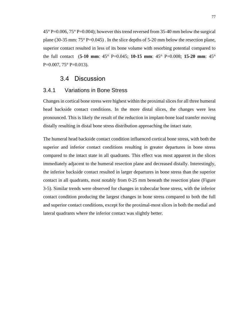
77
45° P=0.006, 75° P=0.004); however this trend reversed from 35-40 mm below the surgical
plane (30-35 mm: 75° P=0.045) . In the slice depths of 5-20 mm below the resection plane,
superior contact resulted in less of its bone volume with resorbing potential compared to
the full contact (5-10 mm: 45° P=0.045; 10-15 mm: 45° P=0.008; 15-20 mm: 45°
P=0.007, 75° P=0.013).
3.4 Discussion
3.4.1 Variations in Bone Stress
Changes in cortical bone stress were highest within the proximal slices for all three humeral
head backside contact conditions. In the more distal slices, the changes were less
pronounced. This is likely the result of the reduction in implant-bone load transfer moving
distally resulting in distal bone stress distribution approaching the intact state.
The humeral head backside contact condition influenced cortical bone stress, with both the
superior and inferior contact conditions resulting in greater departures in bone stress
compared to the intact state in all quadrants. This effect was most apparent in the slices
immediately adjacent to the humeral resection plane and decreased distally. Interestingly,
the inferior backside contact resulted in larger departures in bone stress than the superior
contact in all quadrants, most notably from 0-25 mm beneath the resection plane (Figure
3-5). Similar trends were observed for changes in trabecular bone stress, with the inferior
contact condition producing the largest changes in bone stress compared to both the full
and superior contact conditions, except for the proximal-most slices in both the medial and
lateral quadrants where the inferior contact was slightly better.

78
Figure 3-5: Representative Bone Stresses for the Superior (left), Full (middle), and
Inferior (right) Humeral Head Backside Contact Conditions
The largest changes in trabecular bone stress were noted distally within the medial quadrant
(Figure 3-5), where the inferior contact produced significantly larger departures in bone
stress compared to both the full and superior contact conditions. This could be due to
medial support provided by the trabecular bone required to stabilize the humeral stem under
the applied joint reaction force combined with the lack of superior support at the resection
plane (Figure 3-6). A similar phenomenon was observed for the distal-most lateral
trabecular bone for the superior humeral backside contact, albeit at a much lower
magnitude.

79
Figure 3-6: Areas of Contact for Load Transfer for the Superior (left) and Inferior
(right) Humeral Head Backside Contact Conditions (forces responding to implant-
bone load transfer represented by arrows) under the Applied Joint Reaction Force
(shown in red)
3.4.2 Time-Zero Expected Bone Response
The expected time-zero bone response yielded further insight into the direction of changes
in bone stress. In cortical bone, the inferior humeral head backside contact condition
produced more potential for bone resorption than both the full and superior contact
condition in the lateral quadrant from 5-30 mm, likely a direct result of the lack of load
transfer on the superior half of the humeral head. Similar trends were observed in the
posterior and anterior quadrants from 10-25 mm and 0-15 mm beneath the resection plane,
respectively.
Interestingly within the medial quadrant, both the inferior and superior contact conditions
produced more expected cortical bone resorption than the full contact in the most proximal
slice. This was expected for the superior contact condition due to the complete lack of
medial contact, but the inferior contact should have transferred loading to the medial

80
cortex. Analysis of the contact stress distribution on the resection plane for all three contact
conditions showed that indeed the inferior head position had little to no load transfer at the
most medial aspect of the resection (Figure 3-7). This was likely a result of subsidence of
the unsupported lateral aspect of the humeral head resulting in the implant rotating in the
direction of adduction relative to the humerus as shown in Figure 3-6. The full contact
condition exhibits a more even distribution of load transfer across the resection plane,
including all but the most medial aspect of the cortex, and the superior contact loaded only
the lateral trabecular bone, as expected.
Figure 3-7: Representative Contact Stress Distribution at the Humeral Resection
Plane for the Superior (left), Full (middle), and Inferior (right) Humeral Head
Backside Contact Conditions
Analysis of the deformation of the humeral bone at the resection plane and the micromotion
of the implant confirm these postulations, with the inferior contact condition showing
implant subsidence focused at the lateral edge of the medial contact (Figure 3-8) as well
as the presence of medial gapping (Figure 3-9) confirming that the implant rotated in the
direction of adduction relative to the humerus resulting in a lack of medial cortical contact.
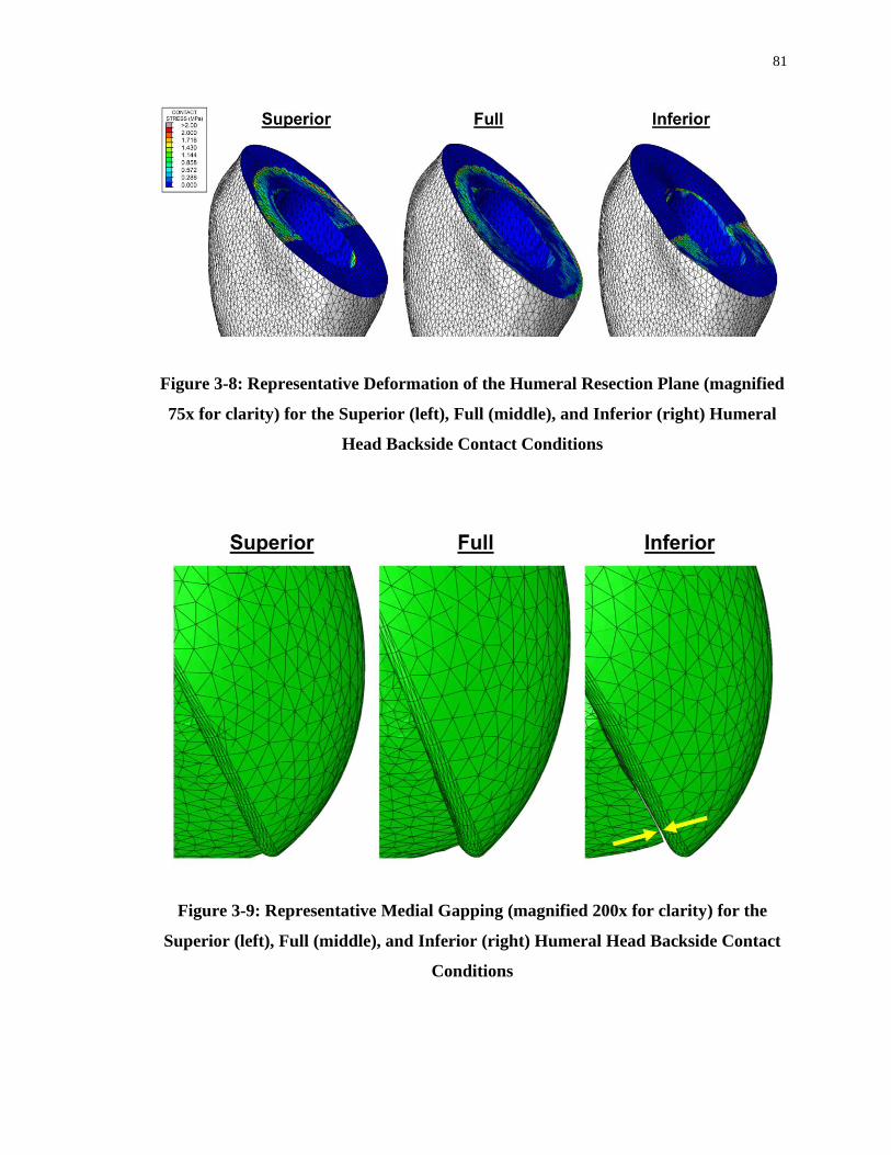
81
Figure 3-8: Representative Deformation of the Humeral Resection Plane (magnified
75x for clarity) for the Superior (left), Full (middle), and Inferior (right) Humeral
Head Backside Contact Conditions
Figure 3-9: Representative Medial Gapping (magnified 200x for clarity) for the
Superior (left), Full (middle), and Inferior (right) Humeral Head Backside Contact
Conditions

82
Similar patterns were detected in the trabecular bone, where inferior contact produced more
expected bone resorption than the full contact in most slices between 0-20 mm beneath the
humeral cut plane in the posterior and lateral quadrants, and three most proximal slices
within the anterior quadrant. This trend was reversed in the medial quadrant, where the
inferior contact condition resulted in less expected bone resorption than both the full and
superior contact conditions at slice depths from 10-30 mm. This was again likely a result
of the loading of the more distal medial trabecular bone as a result of the need for medial
support of the stem in the absence of superior humeral head contact (Figure 3-6).
It is also important to note that for the inferior-medial humeral head position tested, there
is an absence of available contact between the backside of the lateral head and the lateral
cortex, and therefore for the superior contact condition the humeral head backside is only
interacting with the lateral trabecular bone of the resection plane, which may predispose
the implant to subside laterally under the applied joint reaction force.
To the best of the current authors’ knowledge, other than the work by Synnott et al 24, there
is no published work regarding the effect of humeral head backside contact conditions on
bone stress. However, this concept has been studied in femoral hip implants, in which both
collared and collarless implants are used1,6. In the hip, the main purpose of the collar is to
prevent subsidence of the femoral stem, which increases the chances of primary
osteointegration and also increases axial load transfer to the calcar, hence reducing
resorption11,16. According to Meding et al.16, achieving full contact between the collar and
the calcar occurs in less than 40% of cases. However, a study by Ji et al.11 suggests even
with a perfect contact for collared implants, there is no significant difference in bone loss
between the collared and collarless stems. Interestingly, Allen et al.2 suggested that femoral
bone surface strain is same for both collared and collarless implants 5 mm below the collar,
but at depths of 25 mm the collared implants showed greater surface strains which better
mimicked the intact state. According to Mansour et al.15 collarless implants resulted in
greater bone loss compared to collared implants.
The results of this study agree with the findings of Mansour et al and Allen et al2,15; bone
stress alterations and bone resorption was lowest with the full contact condition, which is
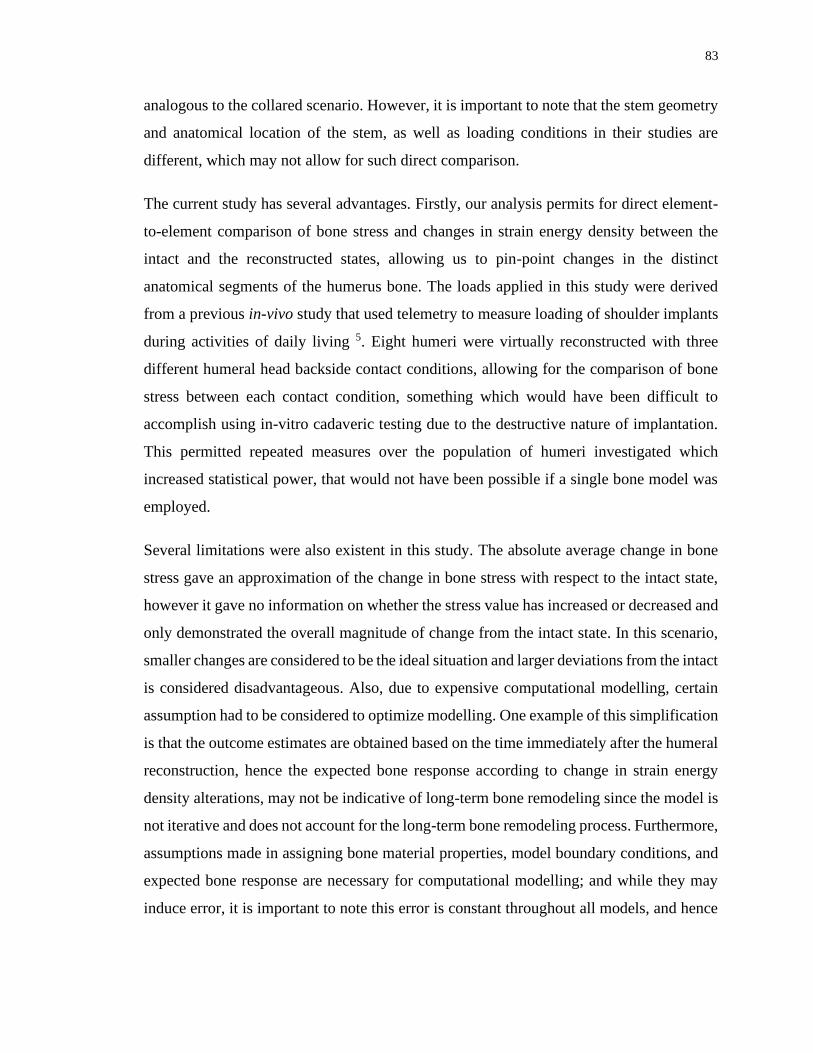
83
analogous to the collared scenario. However, it is important to note that the stem geometry
and anatomical location of the stem, as well as loading conditions in their studies are
different, which may not allow for such direct comparison.
The current study has several advantages. Firstly, our analysis permits for direct element-
to-element comparison of bone stress and changes in strain energy density between the
intact and the reconstructed states, allowing us to pin-point changes in the distinct
anatomical segments of the humerus bone. The loads applied in this study were derived
from a previous in-vivo study that used telemetry to measure loading of shoulder implants
during activities of daily living 5. Eight humeri were virtually reconstructed with three
different humeral head backside contact conditions, allowing for the comparison of bone
stress between each contact condition, something which would have been difficult to
accomplish using in-vitro cadaveric testing due to the destructive nature of implantation.
This permitted repeated measures over the population of humeri investigated which
increased statistical power, that would not have been possible if a single bone model was
employed.
Several limitations were also existent in this study. The absolute average change in bone
stress gave an approximation of the change in bone stress with respect to the intact state,
however it gave no information on whether the stress value has increased or decreased and
only demonstrated the overall magnitude of change from the intact state. In this scenario,
smaller changes are considered to be the ideal situation and larger deviations from the intact
is considered disadvantageous. Also, due to expensive computational modelling, certain
assumption had to be considered to optimize modelling. One example of this simplification
is that the outcome estimates are obtained based on the time immediately after the humeral
reconstruction, hence the expected bone response according to change in strain energy
density alterations, may not be indicative of long-term bone remodeling since the model is
not iterative and does not account for the long-term bone remodeling process. Furthermore,
assumptions made in assigning bone material properties, model boundary conditions, and
expected bone response are necessary for computational modelling; and while they may
induce error, it is important to note this error is constant throughout all models, and hence
84
the comparison of results following the alteration of implant position are likely to be a
direct result of this change in modelling parameter alone.
Future investigations should consider full coverage of humeral cut plane with the humeral
head backside to assess its impact on humeral bone stress following shoulder arthroplasty.
Also, future works require investigating heads of different geometry that better mimics the
oval-shaped face of the resection plane
3.5 Conclusions
The results of this study show that full humeral head backside contact with the humeral
resection plane is preferable for short stem humeral TSA implants with the humeral head
in the inferior-medial position. However, if separation of contact must occur for this
humeral head position, having contact only inferiorly may be worse than superior contact
in terms of changes in bone stress from the intact state and the expected time-zero bone
response and subsequent stress-shielding.

85
References
1. Al-Dirini RMA, Huff D, Zhang J, Besier T, Clement JG, Taylor M. Influence of
collars on the primary stability of cementless femoral stems: A finite element study using
a diverse patient cohort. J. Orthop. Res. 2018;36(4):1185–1195. doi:10.1002/jor.23744
2. Allen, W. ., Beaupré, G. ., Carter, D. ., Giddings, V., Goodman, S. ., D.J, S. & van
der, Meulen MC. Femoral Collar Effect on bone strains after cemented hip replacement.
1996;(Standford,CA).
3. Austman RL, Milner JS, Holdsworth DW, Dunning CE. Development of a
customized density-modulus relationship for use in subject-specific finite element models
of the ulna. Proc. Inst. Mech. Eng. Part H J. Eng. Med.
2009;doi:10.1243/09544119JEIM553
4. Bayraktar HH, Morgan EF, Niebur GL, Morris GE, Wong EK, Keaveny TM.
Comparison of the elastic and yield properties of human femoral trabecular and cortical
bone tissue. J. Biomech. 2004;doi:10.1016/S0021-9290(03)00257-4
5. Bergmann G, Graichen F, Bender A, Kääb M, Rohlmann A, Westerhoff P. In vivo
glenohumeral contact forces-Measurements in the first patient 7 months postoperatively.
J. Biomech. 2007;40(10):2139–2149. doi:10.1016/j.jbiomech.2006.10.037
6. Camine VM, Rudiger HA, Pioletti DP, Terrier A. Subsidence and local
micromotion around collared and collarless cementless femoral stems. J. Orthop. Res.
2017;
7. Carter DR, Hayes WC. The Compressive Behavior Porous of Bone Structure as a
Two-Phase. J. bone Jt. Surg. 1977;59(7):954–962. doi:10.1007/978-1-4471-5451-8_116
8. Casagrande DJ, Parks DL, Torngren T, Schrumpf MA, Harmsen SM, Norris TR, et
al. Radiographic evaluation of short-stem press-fit total shoulder arthroplasty: Short-term
follow-up. J. Shoulder Elb. Surg. [Internet]. 2016;25(7):1163–1169. Available from:
http://dx.doi.org/10.1016/j.jse.2015.11.067doi:10.1016/j.jse.2015.11.067
86
9. Denard PJ, Noyes MP, Walker JB, Shishani Y, Gobezie R, Romeo AA, et al.
Radiographic changes differ between two different short press-fit humeral stem designs in
total shoulder arthroplasty. J. Shoulder Elb. Surg. 2018;27(2):217–223.
doi:10.1016/j.jse.2017.08.010
10. Grant JA, Bishop NE, Götzen N, Sprecher C, Honl M, Morlock MM. Artificial
composite bone as a model of human trabecular bone: The implant-bone interface. J.
Biomech. 2007;40(5):1158–1164. doi:10.1016/j.jbiomech.2006.04.007
11. Jeon I, Bae JY, Park JH, Yoon TR, Todo M, Mawatari M, et al. The biomechanical
effect of the collar of a femoral stem on total hip arthroplasty. Comput. Methods Biomech.
Biomed. Engin. 2011;doi:10.1080/10255842.2010.493513
12. Kuiper JH, Huiskes R. Friction and stem stiffness affect dynamic interface motion
in total hip replacement. J. Orthop. Res. 1996;14(1):36–43. doi:10.1002/jor.1100140108
13. Langohr GDG, Reeves J, Roche CP, Faber KJ, Johnson JA. The effect of short-
stem humeral component sizing on humeral bone stress. J. Shoulder Elb. Surg. [Internet].
2020;29(4):761–767. Available from:
https://doi.org/10.1016/j.jse.2019.08.018doi:10.1016/j.jse.2019.08.018
14. Leung ASO, Gordon LM, Skrinskas T, Szwedowski T, Whyne CM. Effects of bone
density alterations on strain patterns in the pelvis: Application of a finite element model.
Proc. Inst. Mech. Eng. Part H J. Eng. Med. 2009;doi:10.1243/09544119JEIM618
15. Mansour HA, Ray D, Mukherjee DP. Stress Shielding. Proc. IEEE Fourteenth
South. Biomed. Eng. Conf. 1995;53–54.
16. Meding JB, Ritter MA, Keating EM, Faris PM. A comparison of collared and
collarless femoral components in primary cemented total hip arthroplasty. J. Arthroplasty.
1998;doi:10.1016/s0883-5403(98)90118-8
17. Morgan EF, Bayraktar HH, Keaveny TM. Trabecular bone modulus-density
relationships depend on anatomic site. J. Biomech. 2003;doi:10.1016/S0021-
9290(03)00071-X
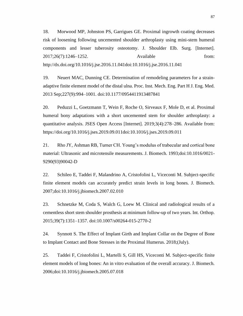
87
18. Morwood MP, Johnston PS, Garrigues GE. Proximal ingrowth coating decreases
risk of loosening following uncemented shoulder arthroplasty using mini-stem humeral
components and lesser tuberosity osteotomy. J. Shoulder Elb. Surg. [Internet].
2017;26(7):1246–1252. Available from:
http://dx.doi.org/10.1016/j.jse.2016.11.041doi:10.1016/j.jse.2016.11.041
19. Neuert MAC, Dunning CE. Determination of remodeling parameters for a strain-
adaptive finite element model of the distal ulna. Proc. Inst. Mech. Eng. Part H J. Eng. Med.
2013 Sep;227(9):994–1001. doi:10.1177/0954411913487841
20. Peduzzi L, Goetzmann T, Wein F, Roche O, Sirveaux F, Mole D, et al. Proximal
humeral bony adaptations with a short uncemented stem for shoulder arthroplasty: a
quantitative analysis. JSES Open Access [Internet]. 2019;3(4):278–286. Available from:
https://doi.org/10.1016/j.jses.2019.09.011doi:10.1016/j.jses.2019.09.011
21. Rho JY, Ashman RB, Turner CH. Young’s modulus of trabecular and cortical bone
material: Ultrasonic and microtensile measurements. J. Biomech. 1993;doi:10.1016/0021-
9290(93)90042-D
22. Schileo E, Taddei F, Malandrino A, Cristofolini L, Viceconti M. Subject-specific
finite element models can accurately predict strain levels in long bones. J. Biomech.
2007;doi:10.1016/j.jbiomech.2007.02.010
23. Schnetzke M, Coda S, Walch G, Loew M. Clinical and radiological results of a
cementless short stem shoulder prosthesis at minimum follow-up of two years. Int. Orthop.
2015;39(7):1351–1357. doi:10.1007/s00264-015-2770-2
24. Synnott S. The Effect of Implant Girth and Implant Collar on the Degree of Bone
to Implant Contact and Bone Stresses in the Proximal Humerus. 2018;(July).
25. Taddei F, Cristofolini L, Martelli S, Gill HS, Viceconti M. Subject-specific finite
element models of long bones: An in vitro evaluation of the overall accuracy. J. Biomech.
2006;doi:10.1016/j.jbiomech.2005.07.018

88
Chapter 4
4 The Effect of Humeral Head Positioning on Humeral Bone Stress following Total Shoulder Arthroplasty with a Short Humeral Stem
The use of uncemented humeral stems in total shoulder arthroplasty (TSA) is known to
cause stress shielding and result in bone resorption. The use of stems with shorter lengths
and smaller overall dimensions, as well as optimal surgical positioning have been shown
to decrease stress shielding, however the effect of humeral head positioning on the
resection plane has not yet been investigated. The purpose of this study was to investigate
two different humeral head positioning on the resection plane and their effect on humeral
bone stress and expected bone response.
4.1 Introduction
Total shoulder arthroplasty (TSA) is used to restore shoulder function and reduce pain in
patients with glenohumeral arthritis. During surgical implantation, the articular surface of
the humeral head is removed and the proximal humerus is reamed to allow a stem to be
inserted. Following this, the humeral head component is sized and positioned on the
humeral resection plane. Either due to surgeon preferences or humeral anatomy, sometimes
it is not possible for the replacement humeral head to be sized such that it covers the entire
resection plane. In these cases, the head is often placed either on the superior-lateral or the
inferior-medial aspect of the humeral resection.
The occurrence of humeral stress shielding following TSA remains a concern. Clinical
studies have reported proximal stress shielding in 29 to 80% of recipients6,13,17 at a 2 to 3
year follow-up. Stem loosening has an incidence up to 11% of patients, with another 9%
of patients being identified as at risk of loosening at average two and a half year follow-
up5.
Synnott et al18 compared the effect of having either a full or no humeral backside contact
with the humeral resection plane using finite element modelling and a generic short stem

89
humeral implant with a humeral head that covered the entire resection plane. They reported
that the full backside contact condition resulted in humeral bone stress that were closer to
that of the intact state, and that no backside contact resulted in more proximal cortical bone
expected to resorb due to the elimination of load transfer to the cortex at the periphery of
the resection plane. Chapter 3 investigated the effect of humeral head backside contact
using an in-silico method, which confirmed full backside contact is beneficial relative to
only inferior or superior contact conditions.
While previous work suggests that humeral head backside contact with the resection plane
may play an important role in cortical humeral stress shielding, the effect of humeral head
positioning when using a size of implant that does not fully cover the humeral resection
plane is currently not known. This is important since coverage of the entire resection plane
is not always possible clinically, and often contact between the cortex and the backside of
the humeral head is only possible medially due to humeral anatomy. Furthermore, due to
variations in anatomical humeral head geometry, the head can be positioned with slight
flexibility by the surgeon and hence the head can be moved only medially or laterally.
Therefore, the purpose of this study was to quantify the effect of humeral head positioning,
either inferior-medial or superior-lateral, on humeral cortical and trabecular bone stresses
after TSA with a short stem humeral component. We hypothesized that the inferior-medial
humeral head position would produce bone stresses closest to the intact state and result in
less expected bone resorption in the medial quadrant, and that the superior-lateral position
would produce similar results but in the lateral quadrant, directly as a result of their contact
with the cortex at these respective locations.
4.2 Methods
4.2.1 Finite Element Simulation and Model Development
Three dimensional models of eight male left cadaveric humeri (68±6 years average age)
were generated from computed tomography (CT) data using MIMICS (Materialise,
Leuven, Belgium) software. A combination of automatic threshold-based and manual
segmentation methods were used to separate cortical and trabecular bone.

90
These resulting humeral bone models were then virtually prepared for reconstruction by an
orthopaedic surgeon to accept a short stem humeral implant (Exactech Equinoxe®
Preserve) that was optimally sized and placed directly in the center of the humeral canal.
Two different humeral head positions were implemented for each specimen (Figure 4-1);
the superior-lateral position on the humeral resection plane (S-L), and the inferior-medial
position of the head on the humeral resection plane (I-M).
Figure 4-1: Humeral Head Positions Investigated including Superior-Lateral (S-L,
left), and Inferior-Medial (I-M, right), and (B) Stem and Head frictional Contact
Interface Conditions7,8,9,14
Two humeral head positions which were studied in this chapter. Superior-Lateral and
Inferior-Medial positions were placed such that head lacks contacts with the cortical shell
at medial and lateral sides respectively.

91
Both cortical and trabecular bone was meshed with quadratic tetrahedral elements having
a 2 mm maximum edge length, as deemed sufficient by a mesh convergence analysis9,14.
Cortical bone was given a modulus of elasticity of E = 20 GPa and Poisson’s ratio of =
0.32,15. Trabecular bone was given a spatially varying modulus of elasticity using a density-
modulus relationship of 𝐸 = 8920𝜌𝑎𝑝𝑝1.83 where E is the elastic modulus and 𝜌𝑎𝑝𝑝 is the
apparent bone density1,4,10,11,16,19 and a Poisson’s ratio of = 0.3. The implant was also
meshed with quadratic tetrahedral elements with a maximum edge length of 2 mm and was
given material properties of titanium having a modulus of elasticity of E = 110 GPa and a
Poisson’s ratio of = 0.3. The three surface characteristics of the stem were assigned
appropriately: plasma spray (most proximal, µ = 0.88), grit blast (middle, µ = 0.63), and
polished (most distal, µ = 0.40), and the humeral head backside surface was given polished
frictional characteristics (µ = 0.40)7,8,9,14 (Figure 4-1).
A fixed boundary condition was applied at the distal end of the humerus which was
sectioned at the mid-diaphysis and joint reaction forces representing 45˚ and 75˚ of
abduction were applied towards the center of the humeral head on the articular surface,
with a magnitude of 440 N for 45˚ and 740 N for 75˚ based on in-vivo telemetrized TSA
data assuming a 50th-percentile male with a body weight of 88.3 kg3.
4.2.2 Outcome Variables and Statistical Analysis
To permit statistical analysis, the humerus was divided into four anatomical quadrants
(medial, lateral, anterior, posterior) and eight slices of 5 mm thick each, which were parallel
to the humeral resection plane for both cortical and trabecular bone.
The volume-weighted percent change in bone stress for each humeral head position versus
intact was calculated using the resulting difference for each of the six stress components
(σ11, σ22, σ33, σ12, σ13, σ 23). The resulting values were then inserted into the von Mises
equation, yielding a scalar representation of the change in bone stress from pre- to post-
reconstruction to serve as an indication of the overall change in bone stress as a result of
both tensile and compressive stresses although does not include the direction (positive or
negative) of the change.

92
The volume-weighted change in strain energy density (ΔSED) for each element from the
intact to the reconstructed state was also determined, and the expected time-zero bone
response (resorb, no change, or remodel) for each element was then estimated using a
threshold value of 55% change in strain energy density (ΔSED). A decrease in SED of
more than 55% would result in an element being classified as having bone resorption
potential and an increase of more than 55% would result in bone remodeling potential12.
A four-way (humeral head position, abduction angle, slice depth, quadrant) repeated
measure analysis of variance (RM-ANOVA) with a significance level of α = 0.05 was
conducted to assess the change in bone stress and the expected bone response for each
implant position investigated. A post-hoc power analysis showed that a power of 0.8 or
greater was achieved for all outcome variables.
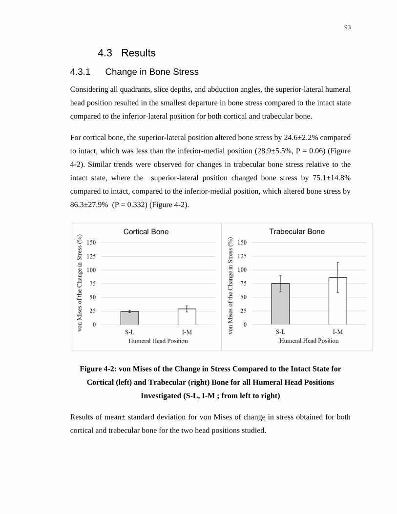
93
4.3 Results
4.3.1 Change in Bone Stress
Considering all quadrants, slice depths, and abduction angles, the superior-lateral humeral
head position resulted in the smallest departure in bone stress compared to the intact state
compared to the inferior-lateral position for both cortical and trabecular bone.
For cortical bone, the superior-lateral position altered bone stress by 24.6±2.2% compared
to intact, which was less than the inferior-medial position (28.9±5.5%, P = 0.06) (Figure
4-2). Similar trends were observed for changes in trabecular bone stress relative to the
intact state, where the superior-lateral position changed bone stress by 75.1±14.8%
compared to intact, compared to the inferior-medial position, which altered bone stress by
86.3±27.9% (P = 0.332) (Figure 4-2).
Figure 4-2: von Mises of the Change in Stress Compared to the Intact State for
Cortical (left) and Trabecular (right) Bone for all Humeral Head Positions
Investigated (S-L, I-M ; from left to right)
Results of mean± standard deviation for von Mises of change in stress obtained for both
cortical and trabecular bone for the two head positions studied.

94
Figure 4-3: : Mean (±1 STD) von Mises of the Change in Cortical Bone Stress (top)
and Trabecular Bone Stress (bottom) for all Humeral Head Positions S-L (inset
top), and I-M (inset bottom) , Anatomical Quadrants (Posterior, Lateral, Medial,
Anterior; from left to right), and Humeral Slice Depths Investigated
von Mises of the change in stress for both cortical and trabecular bone shown in each
individual slice and anatomic quadrant, for each of the head positions.

95
4.3.1.1 Change in Cortical Bone Stress
For cortical bone, in the posterior quadrant the inferior-medial head position changed bone
stress more than the superior-lateral position at slice depths 0-10 mm beneath the resection
plane (0-5 mm: 45° P=0.046, 75° P=0.046; 5-10 mm: 75° P=0.04) (Figure 4-3).
Similarly, within the lateral quadrant the inferior-medial position altered cortical bone
stress more than the superior-lateral position at slice depths 0-30 mm below the surgical
plane (0-5 mm: 45° P=0.029, 75° P=0.049; 5-10 mm: 45° P=0.016, 75° P=0.005; 10-15
mm: 45° P=0.008, 75° P=0.005; 15-20 mm: 45° P=0.012, 75° P=0.009; 20-25 mm: 45°
P=0.007, 75° P=0.011; 25-30 mm: 45° P=0.017).
In the medial quadrant the inferior-medial position showed similar alterations in cortical
bone stresses compared to the superior-lateral position, and no significant changes were
observed between the two humeral head positions.
Likewise, in the anterior quadrant, the inferior-medial position and the superior-lateral
positions resulted in same stress changes, and no considerable difference between the two
positions is detected.
4.3.1.2 Change in Trabecular Bone Stress
In the posterior quadrant at slice depths from 25-35 mm, the inferior-medial position
altered bone stress less than the superior-lateral position (25-30 mm: 45° P=0.023; 30-35
mm: 45° P=0.032) (Figure 4-3).
Within the lateral quadrant at slice depths of 0-5 mm and 10-20 mm, the inferior-medial
position altered trabecular bone stress more than the superior-lateral (0-5 mm: 45°
P=0.013, 75° P=0.043; 10-15 mm: 45° P=0.009, 75° P=0.025; 15-20 mm: 45° P=0.003,
75° P=0.012 ), however this trend was reversed at slice depths from 30-40 mm (30-35 mm:
75° P=0.034; 35-40 mm: 45° P=0.042, 75° P=0.023).
In the medial quadrant at slice depths between 0-10 mm beneath the resection plane, the
inferior-medial position altered trabecular bone stress significantly less than the superior-
lateral position (0-5 mm: 45° P=0.003, 75° P=0.005; 5-10 mm: 75° P=0.045).

96
Interestingly, within slice depths of 25-40 mm, this trend was reversed, with the inferior-
medial position changing bone stress significantly more than the superior-lateral position
(25-30 mm: 45° P=0.04, 75° P=0.037; 30-35 mm: 45° P=0.028, 75° P=0.033; 35-40 mm:
45° P=0.028).
In the anterior quadrant the superior-lateral and inferior-medial head positions showed
similar changes in trabecular bone stress at all slice depths.
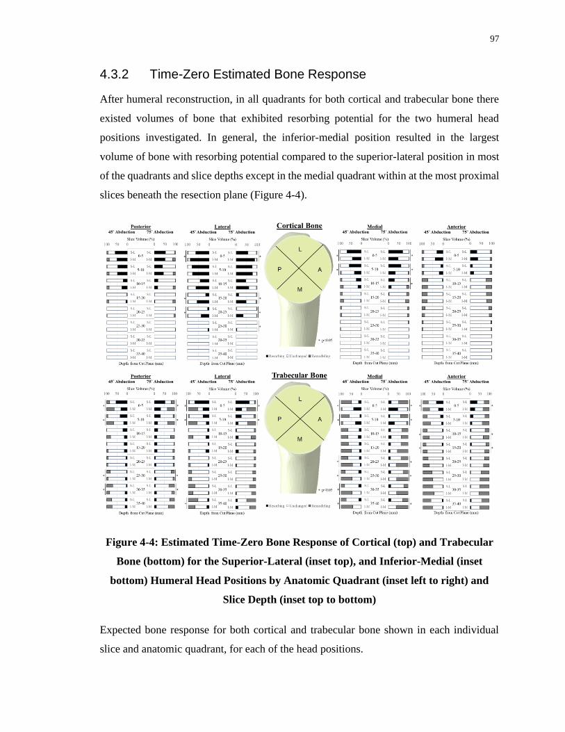
97
4.3.2 Time-Zero Estimated Bone Response
After humeral reconstruction, in all quadrants for both cortical and trabecular bone there
existed volumes of bone that exhibited resorbing potential for the two humeral head
positions investigated. In general, the inferior-medial position resulted in the largest
volume of bone with resorbing potential compared to the superior-lateral position in most
of the quadrants and slice depths except in the medial quadrant within at the most proximal
slices beneath the resection plane (Figure 4-4).
Figure 4-4: Estimated Time-Zero Bone Response of Cortical (top) and Trabecular
Bone (bottom) for the Superior-Lateral (inset top), and Inferior-Medial (inset
bottom) Humeral Head Positions by Anatomic Quadrant (inset left to right) and
Slice Depth (inset top to bottom)
Expected bone response for both cortical and trabecular bone shown in each individual
slice and anatomic quadrant, for each of the head positions.

98
4.3.2.1 Cortical Bone Response
In the posterior quadrant, the inferior-medial humeral head position resulted in the same
levels of bone volume having resorbing potential compared superior-lateral head position
in nearly all slices beneath the resection plane.
In the lateral quadrant, the inferior-medial head position resulted in significantly more bone
volume having resorbing potential compared to the superior-lateral head position from 0-
5 mm and 15-30 mm beneath the resection plane (0-5 mm: 45° P=0.001, 75° P<0.001; 15-
20 mm: 45° P=0.009, 75° P=0.005; 20-25 mm: 45° P=0.01, 75° P=0.014; 25-30 mm: 75°
P=0.047) (Figure 4-4).
In the medial quadrant, the inferior-medial head position resulted in less bone volume
having resorbing potential compared to the superior-lateral head position from 0-15 mm
beneath the resection plane (0-5 mm: 45° P=0.015, 75° P=0.003; 5-10 mm: 45° P=0.012,
75° P=0.002; 10-15 mm: 75° P=0.006).
Looking at the trend in the anterior quadrant, the inferior-medial head position resulted in
the same level of bone volume with resorbing potential compared to superior-lateral
position in most of the slices beneath the resection plane.
4.3.2.2 Trabecular Bone Response
In the posterior quadrant, the inferior-medial head position resulted in significantly less
bone volume having resorbing potential compared to the superior-lateral head position
from 0-10 mm beneath the resection plane (0-5 mm: 45° P=0.005, 75° P=0.013; 5-10 mm:
45° P=0.001, 75° P=0.011); however this trend was reversed for the slices at the 25-35mm
depth (25-30 mm: 45° P=0.042, 75° P=0.042; 30-35 mm: 45° P=0.006, 75° P=0.009)
(Figure 4-4).
Similarly, in the lateral quadrant, the inferior-medial head position resulted in significantly
less bone volume with resorbing potential compared to the superior-lateral position at slice
depths from 0-10 mm beneath the resection plane (0-5 mm: 45° P<0.001, 75° P<0.001; 5-
10 mm: 45° P=0.003, 75° P=0.002). This pattern reversed in the most distal slice, with the

99
inferior-medial head position resulting in more bone volume with resorbing potential (35-
40 mm: 45° P=0.024).
In the medial quadrant, the inferior-medial head position resulted in more bone volume
having resorbing potential from 0-10 mm beneath the resection plane (0-5 mm: 45°
P=0.002, 75° P<0.001; 5-10 mm: 45° P<0.001, 75° P=0.001), although this trend was again
reversed distally at slice depths from 20-40 mm below the resection plane (20-25 mm: 45°
P=0.04, 75° P=0.028; 25-30 mm: 45° P=0.023, 75° P=0.024; 30-35 mm: 45° P=0.033; 35-
40 mm: 45° P=0.031, 75° P=0.045).
In the anterior quadrant, the inferior-medial head position showed noticeably less bone
volume with resorbing potential compared to the superior-lateral head position from 0-5
mm and 10-20 mm below the surgical plane (0-5 mm: 45° P=0.005, 75° P=0.019; 10-15
mm: 45° P<0.001, 75° P=0.001; 15-20 mm: 45° P=0.032, 75° P=0.023).

100
4.4 Discussion
4.4.1 Variations in Bone Stress
Interestingly, significant differences in cortical bone stress between the two implant
positions investigated only occurred in the lateral quadrant. Analysis of the bone stress
patterns for both positions in the medial quadrant showed similar results (Figure 4-5).
Figure 4-5: Representative Bone Stresses for the Superior-Lateral (left), and
Inferior-Medial (right) Humeral Head Positions
Trabecular bone showed similar trends, although significant differences were detected in
either the proximal-most or distal-most slices in the medial and lateral quadrants. It is
interesting to note that when cortical contact occurred, the adjacent trabecular bone was
largely unloaded; this is apparent laterally for the superior-lateral position and medially for
the inferior-medial position (Figure 4-5). This was likely a result of the stiffer cortical bone
carrying more load than the adjacent less-stiff trabecular bone (Figure 4-6).

101
Figure 4-6: Areas of Contact for Load Transfer for the Superior-Lateral (left) and
Inferior-Medial (right) Humeral Head Position (forces responding to implant-bone
load transfer represented by arrows) under the Applied Joint Reaction Force
4.4.2 Time-Zero Expected Bone Response
The time-zero expected bone response yielded further insight into the direction of the
changes in both stress for both positions investigated. In the cortical bone, the inferior-
medial head position produced more bone volume with the potential to resorb compared to
the superior-lateral position within the lateral quadrant at slices 0-25 mm below the
resection plane. This was expected since the inferior-medial position lacks direct contact
in the lateral cortex and hence it will be subjected to less loading which will lead to more
expected volume of bone with resorption. Similarly, the opposite was true for the superior-
lateral position, which produced more bone volume with expected resorption potential
within the medial quadrant due to the lack of medial cortical contact. This was visually
apparent in the contact stress distribution on the resection plane for the two positions
investigated (Figure 4-7).

102
Figure 4-7: Representative Contact Stress Distribution at the Humeral Resection
Plane for the Superior-Lateral (left), and Inferior-Medial (right) Humeral Head
Positions
Interestingly, for the inferior-medial humeral head position the medial-most cortical bone
did become unloaded. Analysis of the micromotion of the implant showed that under the
applied loading the inferior-medial positioned humeral head lifted off the resection plane
slightly, which resulted in the lack of load transfer at the medial-most cortex (Figure 4-8).
It is important to note that the same did not happen laterally for the superior-lateral head
position.
103
Figure 4-8: Representative Medial Gapping (magnified 200x for clarity) for the
Superior-Lateral (left), and (the lack of) Lateral Gapping for the Inferior-Medial
(right) Humeral Head Positions
Analysis of the deformation of the humeral head resection plane verified these
observations, with the inferior-medial position showing implant subsidence on the lateral
aspect of the resection plane confirming that the that implant rotated in the direction of the
adduction with respect to the humerus (Figure 4-9). For the superior-lateral position, the
subsidence of the implant into the medial aspect of the resection plane appeared slightly
less, which may have been a contributing factor to why lateral gapping did not occur for
this head position (Figure 4-9).

104
Figure 4-9: Representative Deformation of the Humeral Resection Plane (magnified
75x for clarity) for the Superior-Lateral (left), and Inferior-Medial (right) Humeral
Head Positions
To the best of current authors knowledge, other than the study by Synnott et al 18 and the
results reported in Chapter 3, no other literature has investigated the effect of humeral head
backside contact conditions on humeral bone stress. Similar trends were observed in the
present study compared to Chapter 3, whereby medial head back contact produced similar
results as the inferior-medial humeral head positioning mainly due to the medial cortical
contact present in both cases. Lateral head back contact was similar to the superior-lateral
head positioning, although cortical contact was not present in the prior as the effect of head
back contact was only studied for the inferior-medial humeral head position. Interestingly,
for both the medial head back contact condition and the inferior-medial head position,
implant liftoff was observed for both at the medial-most cortex, due to implant
micromotion in the direction of adduction relative to the humerus.
Strengths of this study include the direct element-to-element comparison performed for
both bone stress and changes in strain energy density between the intact and the
reconstructed states. The loads applied within this study represent two distinct abduction
105
angles, in which telemetrized shoulder implant data representative of specific daily
activities was utilized to represent clinically applicable cases3. The study also included
eight humeri which were virtually repeatedly reconstructed with two different humeral
head positions, which permitted a repeated measures study design that increased statistical
power.
There were also several limitations. The absolute average change in bone stress gave no
information on whether the stress value has increased or decreased and only demonstrated
the overall magnitude of change from the intact state, and smaller changes were considered
to be better than larger deviations. Also, the expected bone response is estimated based on
the time immediately after the humeral reconstruction, hence the expected bone response
according to change in strain energy density alterations, may not be indicative of long-term
bone remodeling. Furthermore, assumptions made in assigning bone material properties,
model boundary conditions, and expected bone response are necessary for computational
modelling; and while they may induce error, it is important to note this error is constant
throughout all models, and hence the comparison of results following the alteration of
implant position are likely to be a direct result of this change in modelling parameter alone.
4.5 Conclusions
The results of this study show that inferior-medial humeral head positioning loads the
medial cortex at the cost of unloading the medial trabecular bone, and that the opposite
occurs for the superior-lateral position where the lateral cortex is loaded at the cost of
unloading the lateral trabecular bone. Also, the lift off of the humeral head from resection
plane at the medial-most cortex for the inferior-medial head position add to the risk of
medial humeral stress shielding.

106
4.6 References
1. Austman RL, Milner JS, Holdsworth DW, Dunning CE. Development of a
customized density-modulus relationship for use in subject-specific finite element models
of the ulna. Proc. Inst. Mech. Eng. Part H J. Eng. Med.
2009;doi:10.1243/09544119JEIM553
2. Bayraktar HH, Morgan EF, Niebur GL, Morris GE, Wong EK, Keaveny TM.
Comparison of the elastic and yield properties of human femoral trabecular and cortical
bone tissue. J. Biomech. 2004;doi:10.1016/S0021-9290(03)00257-4
3. Bergmann G, Graichen F, Bender A, Kääb M, Rohlmann A, Westerhoff P. In vivo
glenohumeral contact forces-Measurements in the first patient 7 months postoperatively.
J. Biomech. 2007;40(10):2139–2149. doi:10.1016/j.jbiomech.2006.10.037
4. Carter DR, Hayes WC. The Compressive Behavior Porous of Bone Structure as a
Two-Phase. J. bone Jt. Surg. 1977;59(7):954–962. doi:10.1007/978-1-4471-5451-8_116
5. Casagrande DJ, Parks DL, Torngren T, Schrumpf MA, Harmsen SM, Norris TR, et
al. Radiographic evaluation of short-stem press-fit total shoulder arthroplasty: Short-term
follow-up. J. Shoulder Elb. Surg. [Internet]. 2016;25(7):1163–1169. Available from:
http://dx.doi.org/10.1016/j.jse.2015.11.067doi:10.1016/j.jse.2015.11.067
6. Denard PJ, Noyes MP, Walker JB, Shishani Y, Gobezie R, Romeo AA, et al.
Radiographic changes differ between two different short press-fit humeral stem designs in
total shoulder arthroplasty. J. Shoulder Elb. Surg. 2018;27(2):217–223.
doi:10.1016/j.jse.2017.08.010
7. Grant JA, Bishop NE, Götzen N, Sprecher C, Honl M, Morlock MM. Artificial
composite bone as a model of human trabecular bone: The implant-bone interface. J.
Biomech. 2007;40(5):1158–1164. doi:10.1016/j.jbiomech.2006.04.007
8. Kuiper JH, Huiskes R. Friction and stem stiffness affect dynamic interface motion
in total hip replacement. J. Orthop. Res. 1996;14(1):36–43. doi:10.1002/jor.1100140108

107
9. Langohr GDG, Reeves J, Roche CP, Faber KJ, Johnson JA. The effect of short-
stem humeral component sizing on humeral bone stress. J. Shoulder Elb. Surg. [Internet].
2020;29(4):761–767. Available from:
https://doi.org/10.1016/j.jse.2019.08.018doi:10.1016/j.jse.2019.08.018
10. Leung ASO, Gordon LM, Skrinskas T, Szwedowski T, Whyne CM. Effects of bone
density alterations on strain patterns in the pelvis: Application of a finite element model.
Proc. Inst. Mech. Eng. Part H J. Eng. Med. 2009;doi:10.1243/09544119JEIM618
11. Morgan EF, Bayraktar HH, Keaveny TM. Trabecular bone modulus-density
relationships depend on anatomic site. J. Biomech. 2003;doi:10.1016/S0021-
9290(03)00071-X
12. Neuert MAC, Dunning CE. Determination of remodeling parameters for a strain-
adaptive finite element model of the distal ulna. Proc. Inst. Mech. Eng. Part H J. Eng. Med.
2013 Sep;227(9):994–1001. doi:10.1177/0954411913487841
13. Peduzzi L, Goetzmann T, Wein F, Roche O, Sirveaux F, Mole D, et al. Proximal
humeral bony adaptations with a short uncemented stem for shoulder arthroplasty: a
quantitative analysis. JSES Open Access [Internet]. 2019;3(4):278–286. Available from:
https://doi.org/10.1016/j.jses.2019.09.011doi:10.1016/j.jses.2019.09.011
14. Razfar N, Reeves JM, Langohr DG, Willing R, Athwal GS, Johnson JA.
Comparison of proximal humeral bone stresses between stemless, short stem, and standard
stem length: A finite element analysis. J. Shoulder Elb. Surg.
2016;doi:10.1016/j.jse.2015.11.011
15. Rho JY, Ashman RB, Turner CH. Young’s modulus of trabecular and cortical bone
material: Ultrasonic and microtensile measurements. J. Biomech. 1993;doi:10.1016/0021-
9290(93)90042-D
16. Schileo E, Taddei F, Malandrino A, Cristofolini L, Viceconti M. Subject-specific
finite element models can accurately predict strain levels in long bones. J. Biomech.
2007;doi:10.1016/j.jbiomech.2007.02.010

108
17. Schnetzke M, Coda S, Walch G, Loew M. Clinical and radiological results of a
cementless short stem shoulder prosthesis at minimum follow-up of two years. Int. Orthop.
2015;39(7):1351–1357. doi:10.1007/s00264-015-2770-2
18. Synnott S. The Effect of Implant Girth and Implant Collar on the Degree of Bone
to Implant Contact and Bone Stresses in the Proximal Humerus. 2018;(July).
19. Taddei F, Cristofolini L, Martelli S, Gill HS, Viceconti M. Subject-specific finite
element models of long bones: An in vitro evaluation of the overall accuracy. J. Biomech.
2006;doi:10.1016/j.jbiomech.2005.07.018
109
Chapter 5
5 Thesis Conclusion and Concluding Thoughts
This chapter recaps the objectives, methods utilized to achieve the objectives, and
elaborates on the hypotheses of this thesis. Strengths and limitations will be discussed,
followed by future work and the significance of this work to allow for better patient
outcomes after total shoulder arthroplasty.
5.1 Summary
As advancements take place in the field of medical treatment, the need to understand the
consequences of these new procedures is critical. The interdisciplinary field of
Biomechanical Engineering and the collaborative tools it provides can help in the
elucidation of such knowledge. Recent advancements in total shoulder arthroplasty has led
to a new generation of humeral implants, hence, recent studies have focused on the effects
of stemless prosthesis geometry on bone stresses and bone morphology mainly beneath the
surgical plane3,4,10,13. These studies suggest that compared to their standard-length
counterparts, shorter length mimic the intact state better which is considered a promising
outcome, while reducing blood loss and surgery time2,8. Considering the high cost of in-
vitro and in-silico studies, there have been limitations in investigation of various aspects of
these shorter implants6,7,13. Finite element analysis (FEA) enables the assessment of any
structure, pre and post modification, hence FEA is also a strong tool to investigate joints
following reconstruction. Using FEA, a direct comparison can be made between different
implants within the same bone; thereby raising statistical power of the study.
While the literature by Razfar et al, Favre et al, and Langohr et al, investigates the effects
of stems length7,10,13, no study to the knowledge of the author investigates the effects of
stem and head positioning, as well as the head backside contact, other than the work by
Synnott et al.15 who looked at head back contact for full resection plane coverage.

110
In the first phase of this research (Chapter 2), eight (8) male cadaveric humeri were
modelled in their intact condition using a combination of automatic and manual
segmentation methods. Cortical bone was assigned uniform properties, while trabecular
bone was given non-uniform properties based on a density modulus equation12 using CT
data. Models could then be made in FEA software and realistic joint loads applied.
For Chapter 2, three reconstructed states were compared (Figure 2-1). The purpose of this
study was to develop a greater understanding of the effect of stem positioning of short stem
humeral implants (Objective 2). Our criteria for choosing the optimal positioning included
that which caused the smallest magnitude of change in bone stress, and the least bone
volume with the potential to resorb, both of which could help to minimize the occurrence
of stress-shielding. It was found that the stem position which best mimics the intact state
is where the centered, standard implant position. In this position the stem axis is aligned
with the humeral shaft axis, and there is no distal cortical contact. Valgus and varus
malposition were cases where the distal aspect of the stem is in contact with medial and
lateral endosteum respectively. In the case where distal contact is inevitable during the
surgery, valgus malposition was found to be worse than the varus malposition in terms of
time-zero expected bone response and changes in bone stress. For the case of varus
malposition, it was found that the distal aspect of the stem lifted off from the lateral
endosteum, hence not contributing to distal load transfer.
The second phase of this thesis (Chapter 3), investigated three humeral head backside
contact conditions, namely superior (SUP), full (FULL), and inferior (INF). Models
generated from Chapter 2 were modified to allow for the simulation of the different
backside contact conditions. The backside of the humeral head was split into two equal
semi circles. The head was positioned at the medial edge of the resection plane, so there
was no head contact with the lateral cortex. For the superior contact condition, the lateral
semi-circle was in contact with the resection plane, and for the inferior contact condition
the medial semi-circle interacted with the resection plane. Finally, for the full contact the
entire head backside was in contact with the resection plane (Figure 3-1). Eight (8) male
cadaveric humeri were examined with the three (3) contact conditions, to find which
contact conditions would result in least amount of change in bone stress from the intact
111
state and lowest volume of bone with the potential to resorb (Objective 3). It was found
that the full contact condition (FULL), produced stress pattern that are closer to the intact
state, and the least amount of bone volume with resorbing potential according to the change
in strain energy density. However, if the gap between the head and resection plane is
unavoidable, having an inferior contact might be worse than superior contact as medial
liftoff was observed resulting in an unloading of the medial-most cortex.
In the third and final phase of this work (Chapter 4), an investigation on humeral head
positioning of the short stem humeral implant was conducted. Models from Chapter 2 were
modified to enable for the investigation of two different humeral head positions; a case
where the humeral head is located at the superior-lateral position (S-L), and the inferior-
medial position (I-M) (Figure 4-1). For the superior-lateral position the humeral head
contacted the lateral cortex, and for the inferior-medial position the head contacted the
medial cortex. Three dimensional models of eight male left cadaveric humeri were
examined with the two (2) humeral head positions, to find which of the positions result in
least change in bone stress from the intact state and produce lower volume of bone with
the potential to resorb (Objective 4). The results showed that the superior-lateral head
position produced cortical and trabecular bone stresses that were closer to the intact state
compared to the inferior-medial head position. Also, time-zero expected bone response
results showed both head positions exhibited resorbing potential; however mainly, the
inferior-medial position resulted in the largest volume of bone with resorbing potential
(Figure 4-4). Interestingly, the inferior-medial head position also caused the head to liftoff
from the medial cortex of the humeral resection plane, which could raise the potential for
stress shielding particularly in the medial-most location.
This research aimed to develop a greater understanding of the relatively new style of total
shoulder arthroplasty implants that use a short length stem, particularly the effect of
positioning of both the short stem and the humeral head components on the stress and the
response of the proximal humerus bone. It is important to realize that the deviations from
the central position and full head back contact conditions caused departures from the ideal
scenario, but this tradeoff can be worse in one situation (varus vs. valgus, medial vs. lateral
contact) versus the other. It is interesting to note that some of our hypotheses were

112
incorrect. We initially proposed that central stem positioning would be optimal, but in the
case of varus stem angulation, stem lift off from the distal lateral cortex under loading
resulted in the negative effects of the distal stem contact being largely eliminated for many
quadrants and slice depths which seemed to show that varus error is ‘safer’ than valgus
error. Also interestingly, we found that the inferior-medial head contact condition resulted
in medial head liftoff and the unloading of the medial-most cortex, something that we did
not foresee, also this did agree with our hypothesis that full head back contact would be
optimal. It is worth mentioning that the results of this dissertation may also be applicable to
Reverse Total Shoulder Arthroplasty (RTSA), as several newer implants of this type being
introduced also employ short stem humeral implants.
5.2 Strengths and Limitations
Employment of telemetrized shoulder implant data into the finite element analysis of this
study to represent joint loading allowed us to use in-vivo data1 in our in-silico simulation;
hence allowing us to merge real-world observations with computational studies. Since joint
loading was directly measured by a modified implant after TSA, the data used was well
demonstrative of what could reasonably be expected to be exerted on the implant in-vivo.
Also, the loads applied are representative of daily activities that an individual could be
expected to perform. However, only 45˚ and 75˚ abduction angles were used to apply the
joint reaction forces, which were only specific to 50th male with body weight of 85 kg and
does not account for other angles of abduction1,11. In an ideal case, the value of the reaction
forces need to be specimen-specific according to individual’s bodyweight; however, to
reduce variations in loading amongst the specimens, the method used in this study was
thought to be sufficient for the research objectives. Also, in Chapter 4 the position of the
head was displaced, which resulted in the alteration of the line of action for the joint
reaction forces passing through the humeral head center. Due to this, the loading scenario
was altered slightly, which might yield different result in terms of direction of the load as
well as the contact between the implant and the bone. However, it is important to note that
this alteration also takes place clinically, and as such it is important to include in the
modelling process. A prospect that was also missing in this dissertation was the use of CT
113
scans of patients with Osteoarthritis, since only cadaveric CT scans of normal humeri were
used here.
The investigation of short stem TSA implant component positioning using a finite element
model enabled a direct element-to-element comparison of bone stress and alterations in
strain energy density between the intact and the reconstructed states. This allowed us to
find changes in exact anatomical regions of the humerus bone. By applying identical
meshing techniques, the outcomes were normalized to the intact bone on an element-to-
element basis for every positioning change between the implant’s components. However,
since the computational FE analysis required long processing times and the number of FE
models created were high, we were not able to test other system parameters of interest such
as the frictional coefficients at the bone-implant contact (Chapter 2 :96 FE models [1
implant x 2 models: intact and reconstructed x 2 abduction angles x 8 specimen x 3 stem
positions]; Chapter 3: 96 FE models [1 implant x 2 models: intact and reconstructed x 2
abduction angles x 8 specimen x 3 head contact conditions]; Chapter 4 :64 FE models [1
implant x 2 models: intact and reconstructed x 2 abduction angles x 8 specimen x 2 head
positions]). The only friction values that were investigated were the ones shown in Figure
2-1, and the implant bone-interface may be subject to different values or might alter during
time. It would also be interesting to investigate the effect of this parameter.
Each specimen included in these studies (n=8) were virtually repeatedly reconstructed for
different implant conditions, which enabled the paired comparison of bone stress between
each condition. This would have been hard (or impossible) to achieve using in-vitro
cadaveric testing since implantation is inherently a deconstructive process requiring
irreversible material removal. It also allowed for a repeated measure statistical analysis,
which enhanced statistical power and would not have been possible if just a single bone
was modeled. Although the sample size of eight (8) could be generally considered as small,
most FE models of joint arthroplasty often report results of a single-specimen models,
which disallows them from drawing statistically supported conclusions.
The application of an inhomogeneous trabecular material property distribution based on
modulus-density equation by Morgan et al12, allowed for a more realistic bone response
114
model. Even though, the equations were not specific to the trabecular bone of proximal
humerus, it was based on the average obtained from a pool of several trabecular bone sites
within the body (i.e. vertebra, proximal tibia, and proximal femur).
Finally, computational power and time restriction were two factor that resulted in certain
limitations within this study. Due to high number of elements in each model, computational
time was on average 14 hours for each sample, which lead to making certain compromises,
one which was outcome estimates were obtained based on the time immediately following
the TSA, hence the expected bone response based on changes in strain energy density, may
not be well indicative for a long term bone remodeling process. It is important to realize,
while some of the assumptions made during the material application and the boundary
condition selected process, may induce error; however, all of these possible errors are
consistent throughout all models. Hence, it is reasonable to assume the comparison of
results following the alterations of each condition (stem position, head contact, head
position) are likely a direct result of changing these parameters.
5.3 Future Directions
The current implant component positioning study has achieved the objectives outlined at
the beginning of this thesis, yet, there are areas to explore in the future investigations
regarding peri-implant bone loss following joint reconstruction.
Firstly, the head size used within this study was a single size humeral head of the
Exactech’s Equinoxe Preserve implant. This head did not cover the head at the resection
plane completely in any of the studies, and there were areas of cortical shell and trabecular
bone exposed at least in a quadrant of the resection plane. There still exists the need to
conduct a FE modeling with full coverage of the humeral cut plane with the humeral
backside to examine the humeral bone stress after the TSA. This can easily be performed
in the future by using a larger size humeral head component.
Second, the absolute average change in bone stress gave an approximation of the change
in bone stress relative to the intact state; however, it gave no insight on whether the stress
value has increased or decreased, and solely demonstrated a scalar magnitude of change

115
from the intact state. Inclusion of such parameter to determine, change in direction and rise
or decline of stress has occurred would be helpful for future investigations to add another
indicator (positive or negative) in addition to expected bone response.
Finally, since the implant incorporated within this dissertation was a commercially
available short stem humeral implant it was not specific to each anatomy. With the current
advancements in the field of machine learning, specifically generative design, designers
can fine tune from a certain number of outputs, which allows for implant that are patient-
specific and can be designed to better mimic the individual’s anatomy. Obtaining those
models virtually and comparing their effects on bone stresses compared to the generic ones
may also an area worth exploring to determine if the extra effort to produce patient specific
implants is justified.
5.4 Significance
Since the number of total shoulder arthroplasties have increased in recent years, and is
forecasted to increase significantly over the next decade5. The number of TSA and
hemiarthroplasty performed in the United States in the year 2000 was 19000, which
increased to 66000 in the year 20119,14; hence a better understanding of the effects of
implant design and component positioning are vital to improve patient’s short term and
long-term outcomes. This works shows the importance of short stem humeral implant
component positioning and head backside contact condition on proximal humeral bone
stresses and expected bone response. The stem component of the humeral implant plays a
major key in stress distribution and load transfer to the distal aspects of the humerus bone,
and the head is responsible for load distribution at the articular surface and the surrounding
base bone. The results of this study not only provide an insight on which position of the
stem and head delivers optimal results, it can result in an overall enhancement of TSA
implant procedure clinically within the operating room.

116
References
1. Bergmann G, Graichen F, Bender A, Kääb M, Rohlmann A, Westerhoff P. In vivo
glenohumeral contact forces-Measurements in the first patient 7 months postoperatively.
J. Biomech. 2007;40(10):2139–2149. doi:10.1016/j.jbiomech.2006.10.037
2. Berth A, Pap G. Stemless shoulder prosthesis versus conventional anatomic
shoulder prosthesis in patients with osteoarthritis: A comparison of the functional outcome
after a minimum of two years follow-up. J. Orthop. Traumatol. 2013;doi:10.1007/s10195-
012-0216-9
3. Denard PJ, Noyes MP, Walker JB, Shishani Y, Gobezie R, Romeo AA, et al.
Proximal stress shielding is decreased with a short stem compared with a traditional-length
stem in total shoulder arthroplasty. J. Shoulder Elb. Surg.
2018;doi:10.1016/j.jse.2017.06.042
4. Denard PJ, Noyes MP, Walker JB, Shishani Y, Gobezie R, Romeo AA, et al.
Radiographic changes differ between two different short press-fit humeral stem designs in
total shoulder arthroplasty. J. Shoulder Elb. Surg. 2018;27(2):217–223.
doi:10.1016/j.jse.2017.08.010
5. Deore VT, Griffiths E, Monga P. Shoulder arthroplasty—Past, present and future.
J. Arthrosc. Jt. Surg. 2018;doi:10.1016/j.jajs.2017.12.001
6. Favre P, Henderson AD. Prediction of stemless humeral implant micromotion
during upper limb activities. Clin. Biomech. 2016;doi:10.1016/j.clinbiomech.2016.05.003
7. Favre P, Seebeck J, Thistlethwaite PAE, Obrist M, Steffens JG, Hopkins AR, et al.
In vitro initial stability of a stemless humeral implant. Clin. Biomech.
2016;doi:10.1016/j.clinbiomech.2015.12.004
8. Heuberer PR, Brandl G, Pauzenberger L, Laky B, Kriegleder B, Anderl W.
Radiological changes do not influence clinical mid-term outcome in stemless humeral head
replacements with hollow screw fixation: A prospective radiological and clinical
evaluation. BMC Musculoskelet. Disord. 2018;doi:10.1186/s12891-018-1945-6
117
9. Kim SH, Wise BL, Zhang Y, Szabo RM. Increasing incidence of shoulder
arthroplasty in the United States. J. Bone Jt. Surg. - Ser. A. 2011;doi:10.2106/JBJS.J.01994
10. Langohr GDG, Reeves J, Roche CP, Faber KJ, Johnson JA. The effect of short-
stem humeral component sizing on humeral bone stress. J. Shoulder Elb. Surg. [Internet].
2020;29(4):761–767. Available from:
https://doi.org/10.1016/j.jse.2019.08.018doi:10.1016/j.jse.2019.08.018
11. McDowell MA, Fryar CD, Ogden CL, Flegal KM. Anthropometric reference data
for children and adults: United States, 2003-2006. Natl. Health Stat. Report. 2008;
12. Morgan EF, Bayraktar HH, Keaveny TM. Trabecular bone modulus-density
relationships depend on anatomic site. J. Biomech. 2003;doi:10.1016/S0021-
9290(03)00071-X
13. Razfar N, Reeves JM, Langohr DG, Willing R, Athwal GS, Johnson JA.
Comparison of proximal humeral bone stresses between stemless, short stem, and standard
stem length: A finite element analysis. J. Shoulder Elb. Surg.
2016;doi:10.1016/j.jse.2015.11.011
14. Schairer WW, Nwachukwu BU, Lyman S, Craig E V., Gulotta L V. National
utilization of reverse total shoulder arthroplasty in the United States. J. Shoulder Elb. Surg.
2015;doi:10.1016/j.jse.2014.08.026
15. Synnott S. The Effect of Implant Girth and Implant Collar on the Degree of Bone
to Implant Contact and Bone Stresses in the Proximal Humerus. 2018;(July).

118
Appendices
Appendix A - BioDigital Permission Request

119
Appendix B - Principles of Anatomy and Physiology 8th Edition- Gerard J. Tortora Permission Request

120
121
Curriculum Vitae
Name: Amir Tavakoli
Post-secondary University of Waterloo
Education and Waterloo, Ontario, Canada
Degrees: 2012-2017 B.A.Sc
The University of Western Ontario
London, Ontario, Canada
2018-2020 M.E.Sc
Honours and Province of Ontario Graduate Scholarship
Awards: 2019-2020,
Canadian Bone and Joint Conference Top Master’s Student Award
2020
Related Work Graduate Teaching Assistant
Experience The University of Western Ontario
2018-2020
Publications:
A.Tavakoli, K.J.Faber, D.Langohr (2020) Valgus Short Stem Humeral Malalignment
Increases Stress Shielding in Total Shoulder Arthroplasty, The Orthopaedic Research
Society (ORS), Phoenix, Ariz, USA (Poster, February 2020).
A.Tavakoli, K.J.Faber, D.Langohr (2020) The Effect of Angulation on Stress Shielding in
Total Shoulder Arthroplasty, Canadian Bone and Joint Conference, London, ON, Canada
(Podium, June 2020).
A.Tavakoli, K.J.Faber, D.Langohr (2020) The Effect of Short Stem Humeral Implant
Varus-Valgus Position on Bone Stress following Total Shoulder Arthroplasty, Canadian
Orthopaedic Association Conference, Halifax, NS, Canada (Podium, June 2020).
A.Tavakoli, K.J.Faber and D.Langohr (2020) Humeral Short Stem Varus-Valgus
Angulation Affects Bone Stress in Total Shoulder Arthroplasty, International Society for
Technology in Arthroplasty Conference, Toronto, ON, Canada (Podium, October 2019).
A.Tavakoli, J.Reeves, K.J.Faber and D.Langohr (2020) Valgus Short Stem Humeral
Malalignment Increases Stress Shielding in Total Shoulder Arthroplasty. Submitted to The
Journal of Shoulder and Elbow Arthroplasty.

122