APPLICATION OF SUSTAINABLE CONSTRUCTION PRINCIPLES IN CONSTRUCTION INDUSTRY
Upload
khangminh22Category
view
1download
0
Saimaa University of Applied Sciences Department of Mechanical Engineering and Production Technology Lappeenranta, Finland Nikita Guliaev The Design, Construction and Implementation of an Autonomous Outdoor Quadcopter using an RPi microcomputer and a MultiWii flight control-ler Thesis 2017
2
Abstract Nikita Guliaev The Design, Construction and Implementation of an Autonomous Outdoor Quadcopter using an RPi microcomputer and a MultiWii flight controller, 50 pages, 2 appendices Saimaa University of Applied Sciences, Department of Mechanical Engineering and Production Technology Thesis 2017 Instructor: Lecturer Timo Eloranta, Saimaa University of Applied Sciences The purpose of the present study was to design and construct an outdoor aerial vehicle, called a quadcopter, with autonomous flight functions, and to install within the vehicle a video streaming system. The thesis also includes a re-search study on a number of practical applications of such a working model. Throughout the project, the principal method of study relied upon has been in-dependent research.
Pertinent data were collected in the Lappeenranta Academic Library and from sources on the Internet. The study was carried out at the Saimaa University of Applied Sciences in the Department of Mechanical Engineering and Production Technology. Additional practical data for the thesis were gathered from tech-nical literature and Internet sources, with advice and recommendations from Saimaa University lecturers.
The construction phase of the study resulted in the creation of an operational quadcopter which achieved autonomous flight. Further research led to an exam-ination of some of the ways in which such a low-budget quadcopter could be put to use.
An additional study will be required to increase the quadcopter’s flying time and range. Eventually, such a model-sized, working aerial vehicle could be utilized by individuals, organisations and governmental agencies.
Keywords: quadcopter, quadrotor, UAV (Unmanned Aerial Vehicle), drone, MAV (Micro Air Vehicle), autonomous flight, RPi (Raspberry Pi) microcomputer, MultiWii flight controller.
3
Table of contents
TERMINOLOGY .................................................................................................. 41 INTRODUCTION .......................................................................................... 5
1.1 Research Motivation ............................................................................. 51.2 Research Objective ............................................................................... 81.3 Research Scope and Approach ............................................................ 8
2 BACKGROUND ............................................................................................ 92.1 Available Quadcopter Technology ........................................................ 92.2 Current Advances in Quadcopter Performance .................................... 9
3 MECHANICAL DESIGN AND COMPONENTS .......................................... 103.1 Initial Concepts and Design Process .................................................. 133.2 Frame Design...................................................................................... 143.3 Motor Designs ..................................................................................... 16
3.3.1 Theoretical Performance ............................................................. 173.4 ESC ..................................................................................................... 183.5 Battery ................................................................................................. 193.6 The Propellers ..................................................................................... 21
4 SYSTEM ARCHITECTURE ....................................................................... 244.1 Multiwii ................................................................................................ 24
4.1.1 Sensors ........................................................................................ 254.1.2 Camera Gimbal ............................................................................ 27
4.2 Raspberry Pi ....................................................................................... 294.2.1 Camera Server and Camera Software ........................................ 29
5 CONTROL .................................................................................................. 325.1 Radio RX ............................................................................................. 335.2 3DR Telemetry .................................................................................... 345.3 MultiWii PID ......................................................................................... 355.4 MultiWii Conf ....................................................................................... 37
6 EVALUATION............................................................................................. 386.1 Mechanical Performance .................................................................... 386.2 Control Performance ........................................................................... 40
7 CONCLUSION ........................................................................................... 418 Appendices ................................................................................................ 459 References ................................................................................................. 48
4
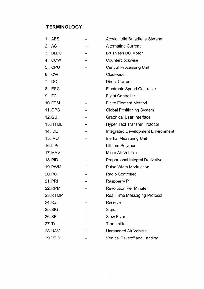
TERMINOLOGY
1. ABS – Acrylonitrile Butadiene Styrene
2. AC – Alternating Current
3. BLDC – Brushless DC Motor
4. CCW – Counterclockwise
5. CPU – Central Processing Unit
6. CW – Clockwise
7. DC – Direct Current
8. ESC – Electronic Speed Controller
9. FC – Flight Controller
10. FEM – Finite Element Method
11. GPS – Global Positioning System
12. GUI – Graphical User Interface
13. HTML – Hyper Text Transfer Protocol
14. IDE – Integrated Development Environment
15. IMU – Inertial Measuring Unit
16. LiPo – Lithium Polymer
17. MAV – Micro Air Vehicle
18. PID – Proportional Integral Derivative
19. PWM – Pulse Width Modulation
20. RC – Radio Controlled
21. PRI – Raspberry Pi
22. RPM – Revolution Per Minute
23. RTMP – Real-Time Messaging Protocol
24. Rx – Receiver
25. SIG – Signal
26. SF – Slow Flyer
27. Tx – Transmitter
28. UAV – Unmanned Air Vehicle
29. VTOL – Vertical Takeoff and Landing
5
1 INTRODUCTION
1.1 Research Motivation
Quadcopters of the hand-held size used for this study are currently available on
the market and their use has piqued the interest of the general public. Continual
advances in miniaturization and the rapid development of the electronics have
allowed drones of every type and size to evolve at an accelerated pace. Interest
in the field of UAVs is increasing, as their current relevance has now become a
subject of significant research by governments and much speculation in the
media.
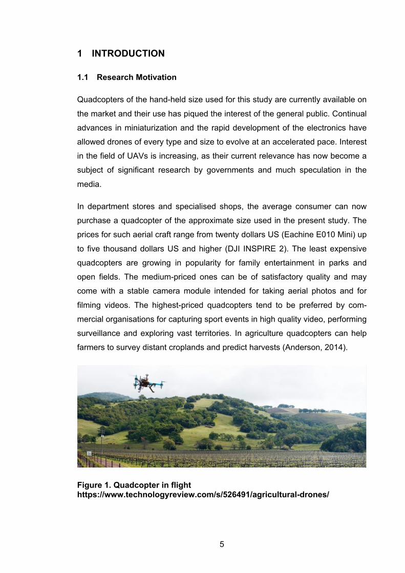
In department stores and specialised shops, the average consumer can now
purchase a quadcopter of the approximate size used in the present study. The
prices for such aerial craft range from twenty dollars US (Eachine E010 Mini) up
to five thousand dollars US and higher (DJI INSPIRE 2). The least expensive
quadcopters are growing in popularity for family entertainment in parks and
open fields. The medium-priced ones can be of satisfactory quality and may
come with a stable camera module intended for taking aerial photos and for
filming videos. The highest-priced quadcopters tend to be preferred by com-
mercial organisations for capturing sport events in high quality video, performing
surveillance and exploring vast territories. In agriculture quadcopters can help
farmers to survey distant croplands and predict harvests (Anderson, 2014).
Figure 1. Quadcopter in flight https://www.technologyreview.com/s/526491/agricultural-drones/
6
In short, quadcopters can find wide application in a range of activities, mainly
those associated with aerial photography. In recent years, commercial use has
extended to such enterprises as Amazon for the delivery of goods in mountain-
ous regions.
Currently, an especially relevant topic is the utilization of quadcopters in viewing
and photographing forestlands and observing wildlife in their natural habitat.
This topic is a subject of research for the present study and is discussed further.
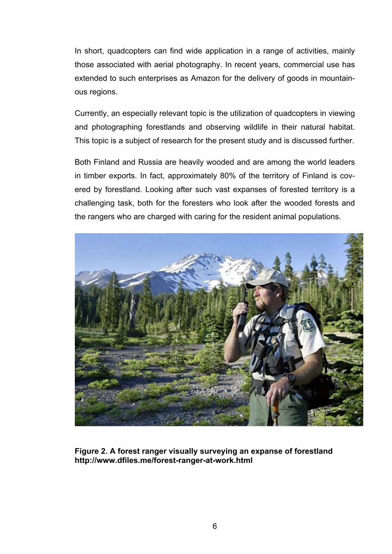
Both Finland and Russia are heavily wooded and are among the world leaders
in timber exports. In fact, approximately 80% of the territory of Finland is cov-
ered by forestland. Looking after such vast expanses of forested territory is a
challenging task, both for the foresters who look after the wooded forests and
the rangers who are charged with caring for the resident animal populations.
Figure 2. A forest ranger visually surveying an expanse of forestland http://www.dfiles.me/forest-ranger-at-work.html
7
Both Russia and Finland allocate significant financial sums in their annual
budgets in an effort to control such vast forested territories. In addition, statistics
show that the forestry budgets of both countries are, as a rule, inflated by the
need to pay extra compensation to foresters and rangers who are often com-
pelled to work in long overtime shifts.
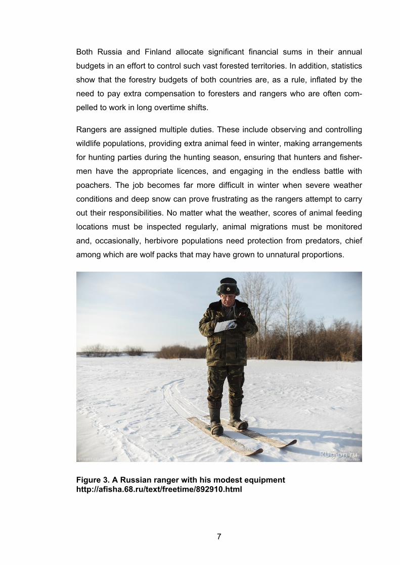
Rangers are assigned multiple duties. These include observing and controlling
wildlife populations, providing extra animal feed in winter, making arrangements
for hunting parties during the hunting season, ensuring that hunters and fisher-
men have the appropriate licences, and engaging in the endless battle with
poachers. The job becomes far more difficult in winter when severe weather
conditions and deep snow can prove frustrating as the rangers attempt to carry
out their responsibilities. No matter what the weather, scores of animal feeding
locations must be inspected regularly, animal migrations must be monitored
and, occasionally, herbivore populations need protection from predators, chief
among which are wolf packs that may have grown to unnatural proportions.
Figure 3. A Russian ranger with his modest equipment http://afisha.68.ru/text/freetime/892910.html
8
Due to the constrains of limited forestry budgets, foresters and rangers must
perform their tasks with little more than a snowmobile and a navigator, through
far too often their scant equipment may be limited to no more than a compass
and a pair of skis. (Polyakov, 2015.)
1.2 Research Objective
The present thesis focuses on creating a quadcopter based on an RPi (Rasp-
berryPi) microcomputer and MultiWii microcontrollers. The chief objective of the
project is to design, construct and demonstrate the viability of a quadcopter-
drone that could perform a variety of tasks in the fields of forestry and wildlife
conservation.
Introducing a drone for the purposes described could dramatically increase the
efficiency of foresters and rangers. Provided that the quadcopter is capable of
performing autonomous monitoring of forested regions and wildlife, the use of
such an aerial vehicle could also prove economical.
1.3 Research Scope and Approach
The present research proposes two main goals and a third potential goal:
1. Identifying principal targets and objectives
2. Design and fabricate a full-sized quadcopter prototype
3. Drafting plans for developing the quadcopter and initiating full-scale pro-
duction
The first two goals have been achieved, the thesis now focuses on the result of
their completion. While the third goal extends beyond the scope of the present
study, it offers a pathway to proceed with future work.
9
2 BACKGROUND
2.1 Available Quadcopter Technology
The quadcopter (or quadrotor) represents one example of an emerging class of
vehicles called MAVs (Micro Air Vehicles), which are a subclass of the vehicles
called UAVs (Unmanned Aerial Vehicles). Like other MAVs, the quadcopter has
already demonstrated myriad applications. First designed a century ago, mod-
ern quadcopters have evolved into small, easily maneuverable vehicles. Having
proved their usefulness in aerial photography, current experimentation is allow-
ing quadcopters to communicate intelligently with other intelligent machines, to
investigate unexplored environments, and to maneuver in dense surroundings
with speed and precision. These recent advances will allow quadcopters to be
adapted to long-term surveillance and serve invaluably in search-and-rescue
missions. Furthermore, if innovative developing technologies are combined into
the quadcopter, it will be capable of advanced autonomous missions that are
not currently possible with any other vehicle. (Johnson, 1994.)
Any type of UAV is popularly called a drone, though the term actually refers to
any type of robot-controlled vehicle – in the case of a UAV, one that flies, but
drones may also refer to other types of robot-controlled vehicles which operate
on land or under water.
The quadcopter is a subclass of UAVs, which are divided according to their type
of flight. In the copter-type vehicles, the propellers are arranged vertically and
thus flight is due to the thrust of the propellers, whereas fixed-wing UAVs fly like
a conventional airplane with the lifting force caused by the shape of the wing.
The quadcopter has four motors mounted on the four arms of the frame, with
each arm positioned at a 90-degree angle to the others. There are two sets of
CW and CCW propellers mounted on the motors to create opposite force and
thus avoid unwanted rotation during horizontal flight.
2.2 Current Advances in Quadcopter Performance
According to the author’s research, the quadcopter’s control elements had to be
altered for autonomous flight to be achieved.
10
Among the most positive features of the proposed quadcopter are the low cost
of its components and the relative ease of fabrication, factors which do not in
any way detract from the quadcopter’s performance.
A major improvement in the quadcopter for this study is the implementation of
autonomous flight combined with a built-in RPi video unit. The program for vid-
eo transmission and changes to the flight controller represent the author’s origi-
nal work.
These low-cost additions and alterations make the finished product unique
among quadcopters.
3 MECHANICAL DESIGN AND COMPONENTS
The quadcopter’s most visible component is its frame, which must be strong
enough to withstand the varying degrees of stress exerted on it during flight. At
the same time, the frame must be lightweight in order to reduce the load on the
motors and to increase flight time.
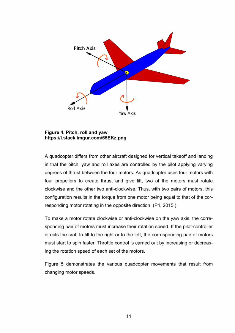
There are three main axes of movement, for which the standard aerodynamic
terms are pitch, roll and yaw. The following figure illustrates these axes as they
apply to a fixed-wing airplane.
11
Figure 4. Pitch, roll and yaw https://i.stack.imgur.com/65EKz.png
A quadcopter differs from other aircraft designed for vertical takeoff and landing
in that the pitch, yaw and roll axes are controlled by the pilot applying varying
degrees of thrust between the four motors. As quadcopter uses four motors with
four propellers to create thrust and give lift, two of the motors must rotate
clockwise and the other two anti-clockwise. Thus, with two pairs of motors, this
configuration results in the torque from one motor being equal to that of the cor-
responding motor rotating in the opposite direction. (Pri, 2015.)
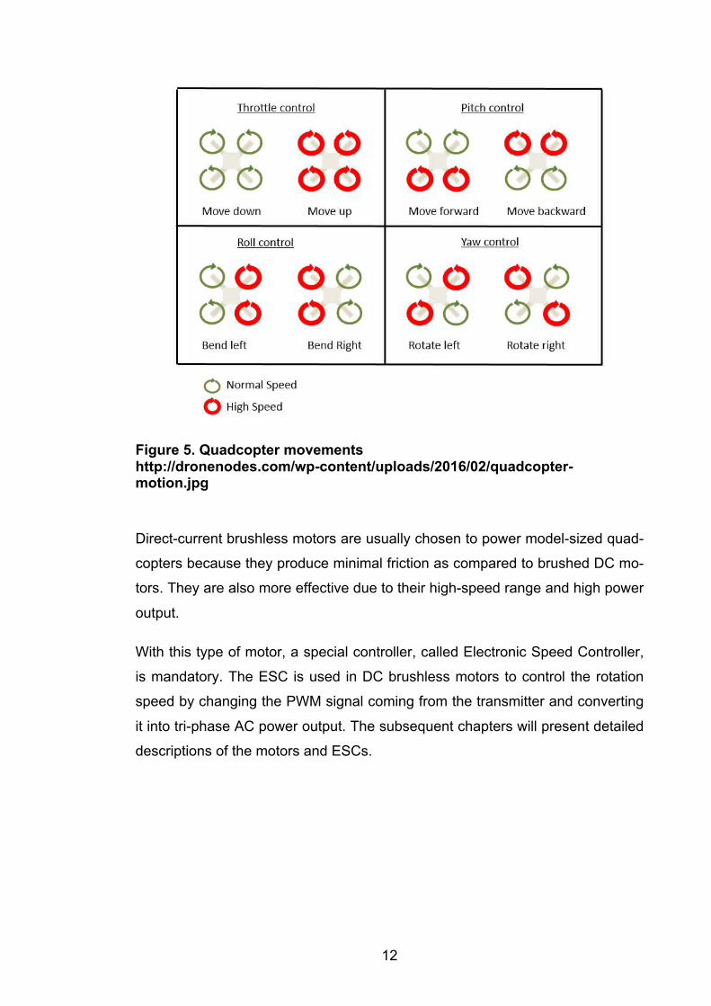
To make a motor rotate clockwise or anti-clockwise on the yaw axis, the corre-
sponding pair of motors must increase their rotation speed. If the pilot-controller
directs the craft to tilt to the right or to the left, the corresponding pair of motors
must start to spin faster. Throttle control is carried out by increasing or decreas-
ing the rotation speed of each set of the motors.
Figure 5 demonstrates the various quadcopter movements that result from
changing motor speeds.
12
Figure 5. Quadcopter movements http://dronenodes.com/wp-content/uploads/2016/02/quadcopter-motion.jpg
Direct-current brushless motors are usually chosen to power model-sized quad-
copters because they produce minimal friction as compared to brushed DC mo-
tors. They are also more effective due to their high-speed range and high power
output.
With this type of motor, a special controller, called Electronic Speed Controller,
is mandatory. The ESC is used in DC brushless motors to control the rotation
speed by changing the PWM signal coming from the transmitter and converting
it into tri-phase AC power output. The subsequent chapters will present detailed
descriptions of the motors and ESCs.
13
3.1 Initial Concepts and Design Process
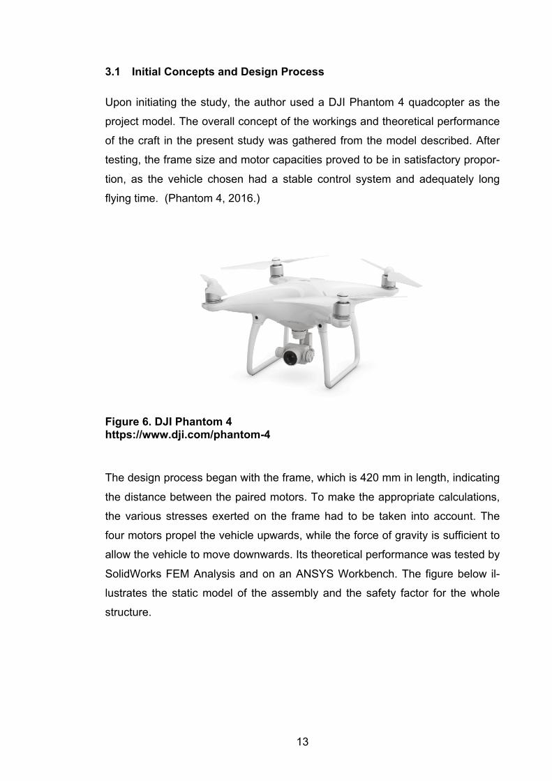
Upon initiating the study, the author used a DJI Phantom 4 quadcopter as the
project model. The overall concept of the workings and theoretical performance
of the craft in the present study was gathered from the model described. After
testing, the frame size and motor capacities proved to be in satisfactory propor-
tion, as the vehicle chosen had a stable control system and adequately long
flying time. (Phantom 4, 2016.)
Figure 6. DJI Phantom 4 https://www.dji.com/phantom-4
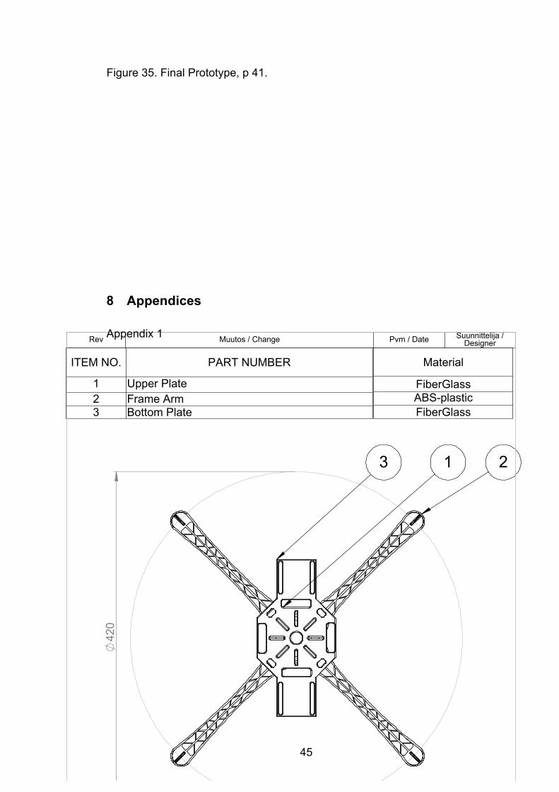
The design process began with the frame, which is 420 mm in length, indicating
the distance between the paired motors. To make the appropriate calculations,
the various stresses exerted on the frame had to be taken into account. The
four motors propel the vehicle upwards, while the force of gravity is sufficient to
allow the vehicle to move downwards. Its theoretical performance was tested by
SolidWorks FEM Analysis and on an ANSYS Workbench. The figure below il-
lustrates the static model of the assembly and the safety factor for the whole
structure.
14
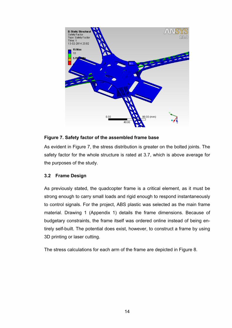
Figure 7. Safety factor of the assembled frame base
As evident in Figure 7, the stress distribution is greater on the bolted joints. The
safety factor for the whole structure is rated at 3.7, which is above average for
the purposes of the study.
3.2 Frame Design
As previously stated, the quadcopter frame is a critical element, as it must be
strong enough to carry small loads and rigid enough to respond instantaneously
to control signals. For the project, ABS plastic was selected as the main frame
material. Drawing 1 (Appendix 1) details the frame dimensions. Because of
budgetary constraints, the frame itself was ordered online instead of being en-
tirely self-built. The potential does exist, however, to construct a frame by using
3D printing or laser cutting.
The stress calculations for each arm of the frame are depicted in Figure 8.
15
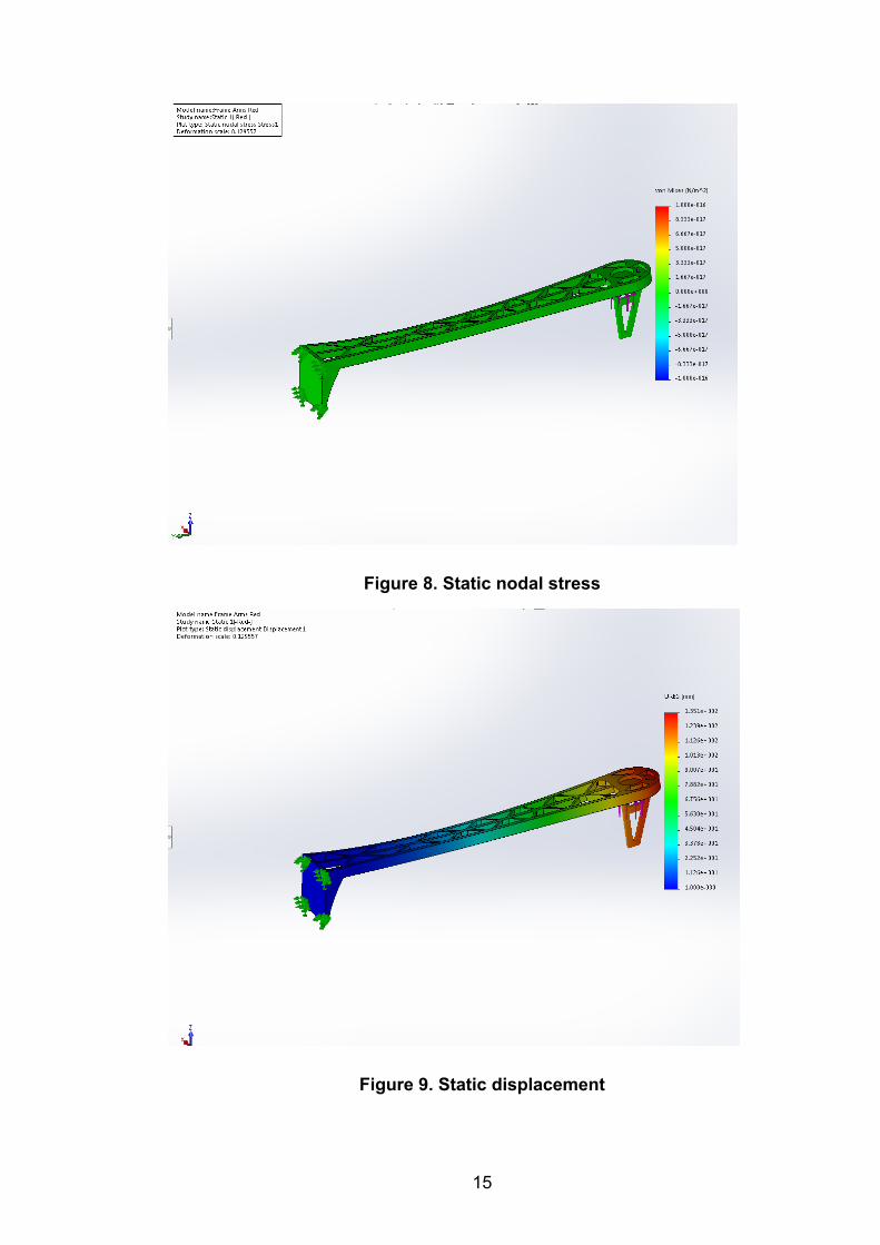
Figure 8. Static nodal stress
Figure 9. Static displacement
16
Figure 8 shows that the average stress of an arm is 1.7 N/mm2, which is suffi-
cient for a total load of approximately 10.0 N, and demonstrates that the load on
each arm is 2.5 N.
Figure 9 illustrates the static displacement of an arm. The result of the dis-
placement is only slightly above the satisfactory level, as the load on each arm
is 2.5 N.
However, the overall estimation of static stresses with FEM demonstrates that
the frame will be adequate strength for the load and will thus prove to be suffi-
ciently reliable for the purposes of the present study.
3.3 Motor Designs
The motors chosen are Brushless DC motors. BLDC motors are often used in
quadcopters of the size required for the project. This type of a motor is easy to
control and is suitable for mounting on the frame.
Each motor consists of a permanent magnet which rotates around a fixed arma-
ture. BLDC motors offer several advantages over brushed DC motors. Among
the advantages are more torque per weight, reduced noise, greater reliability,
longer lifetime and increased efficiency. (Prof. A. V. Javir, 2015.)
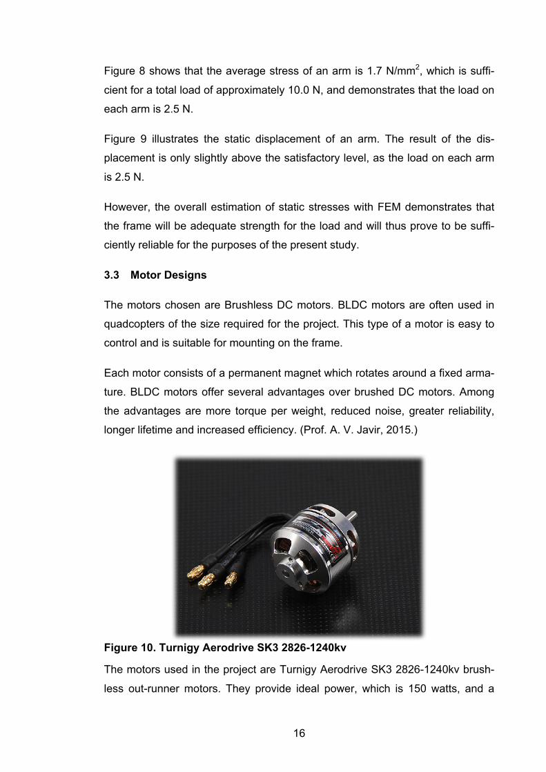
Figure 10. Turnigy Aerodrive SK3 2826-1240kv
The motors used in the project are Turnigy Aerodrive SK3 2826-1240kv brush-
less out-runner motors. They provide ideal power, which is 150 watts, and a
17
medium 𝐾" rate of 1240 rpm/volts. Such a degree of 𝐾" is appropriate, as it pro-
vides the required rotational speed as well as high torque.
3.3.1 Theoretical Performance
The performance of a brushless DC-motor is nearly identical to a brushed DC-
motor. The major difference lies in the BLDC’s commutator being integrated into
the speed controller, while a brushed DC motor’s commutators are located di-
rectly inside the motor. 𝐾𝑣 rating is the relationship between the RPM and the
voltage.
For the motor chosen in the present project:
𝐾𝑣 = 1280[𝑟𝑝𝑚𝑣𝑜𝑙𝑡𝑠]
By measuring the electro-mechanical relationship, the torque constant 𝐾3 can
be determined as follows:
𝐸𝑙𝑒𝑐𝑡𝑟𝑖𝑐𝑎𝑙𝑝𝑜𝑤𝑒𝑟 ∗ 𝑒𝑓𝑓𝑖𝑐𝑖𝑒𝑛𝑐𝑦 = 𝑀𝑒𝑐ℎ𝑎𝑛𝑖𝑐𝑎𝑙𝑝𝑜𝑤𝑒𝑟
𝐸 ∗ 𝐼 ∗ 3 = 𝑁 ∗2𝜋60 ∗ 𝑇
𝐸𝑁 = 0.0604599788 ∗
𝑇𝐼
where
• E = motor voltage rms [V]
• I = motor current [A]
• N = angular velocity of the motor [rpm]
• T = motor torque [Nm] 𝐸𝑁 =
1𝐾"
𝑇𝐼 = 𝐾3
thus, the constant relationship between 𝐾3 and 𝐾" is obtained.
18
𝐾3 = 1
0.06046 ∗1𝐾"
𝐾3 = 0.01794 * 𝐾"
The torque can be calculated as
𝑇 = 𝐼 ∗ 𝐾3
The next step is to measure the current with ammeter and write down the val-
ues of 𝑇 to the table.
3.4 ESC
An Electronic Speed Controller (ESC) is used for controlling a brushless motor.
The ESC operates at 100Hz frequency with a standard RC-signal which yields a
high pulse of 1-2 milliseconds. The ESC has an internal regulator that controls
the speed of the motor.
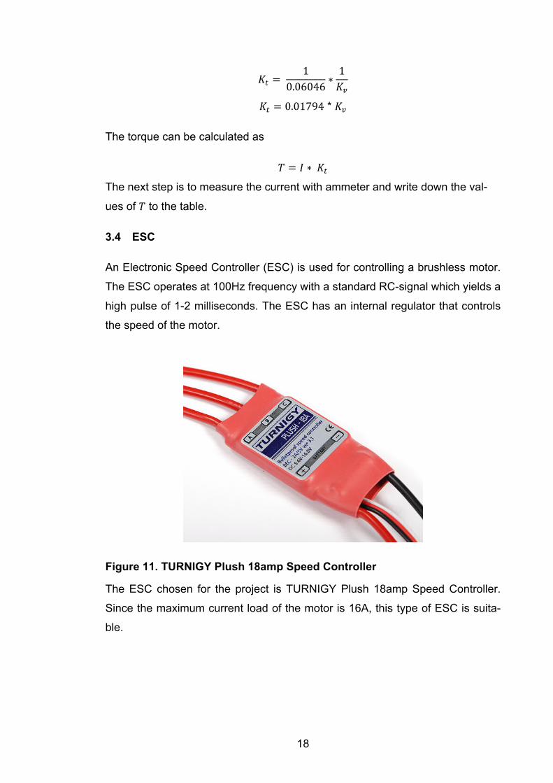
Figure 11. TURNIGY Plush 18amp Speed Controller
The ESC chosen for the project is TURNIGY Plush 18amp Speed Controller.
Since the maximum current load of the motor is 16A, this type of ESC is suita-
ble.
19
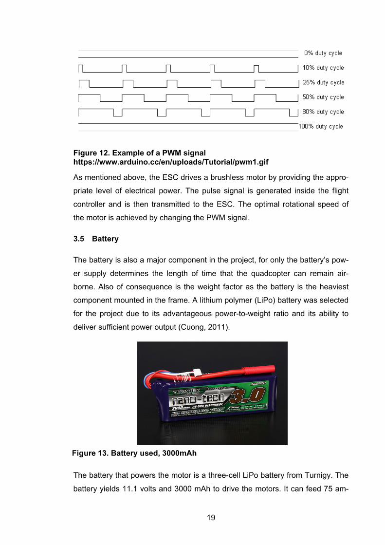
Figure 12. Example of a PWM signal https://www.arduino.cc/en/uploads/Tutorial/pwm1.gif
As mentioned above, the ESC drives a brushless motor by providing the appro-
priate level of electrical power. The pulse signal is generated inside the flight
controller and is then transmitted to the ESC. The optimal rotational speed of
the motor is achieved by changing the PWM signal.
3.5 Battery
The battery is also a major component in the project, for only the battery’s pow-
er supply determines the length of time that the quadcopter can remain air-
borne. Also of consequence is the weight factor as the battery is the heaviest
component mounted in the frame. A lithium polymer (LiPo) battery was selected
for the project due to its advantageous power-to-weight ratio and its ability to
deliver sufficient power output (Cuong, 2011).
The battery that powers the motor is a three-cell LiPo battery from Turnigy. The
battery yields 11.1 volts and 3000 mAh to drive the motors. It can feed 75 am-
Figure 13. Battery used, 3000mAh
20
peres continually and peak at 125 amperes. It has three LiPo cells in serial con-
nection. Each cell is 3.7 volts, producing a total of 11.1 volts. This particular bat-
tery discharges with a 25C rating, which designates the amount of continuous
current that can be drawn: 3000mAh * 25C = 75A. For the present study, there
is a 15A average current draw, by means of which the quadcopter’s approxi-
mate flying time can be calculated as
3.0𝐴ℎ ÷ 15.0𝐴 = 0.2ℎ
An approximate estimation of flying time is 12 minutes at medium power con-
sumption. In such a period of time and at an average speed of 40 km/h, the
quadcopter can fly a distance of 5.0 km and then return to its launch site. (Fly-
ing Tech, 2014)
A power-distribution board is an equally important part of the project, as the RPi
and MultiWii also need power. They both requite 4.5 - 5.5 volts, which is well
within the capacity of a regular three-cell LiPo battery. To achieve the lower
voltage, a customized battery pack of four alkaline 1.2-volts (AA) batteries was
assembled.
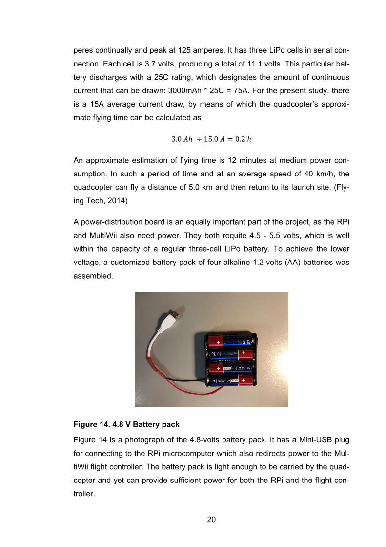
Figure 14. 4.8 V Battery pack
Figure 14 is a photograph of the 4.8-volts battery pack. It has a Mini-USB plug
for connecting to the RPi microcomputer which also redirects power to the Mul-
tiWii flight controller. The battery pack is light enough to be carried by the quad-
copter and yet can provide sufficient power for both the RPi and the flight con-
troller.
21
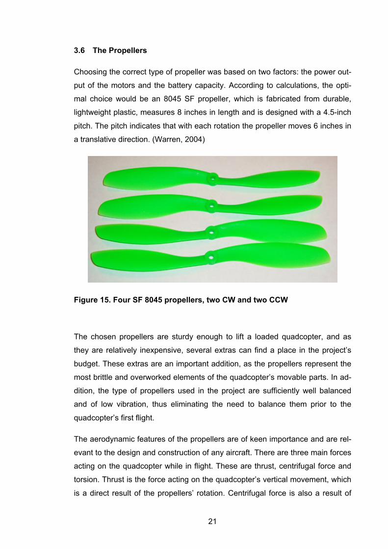
3.6 The Propellers
Choosing the correct type of propeller was based on two factors: the power out-
put of the motors and the battery capacity. According to calculations, the opti-
mal choice would be an 8045 SF propeller, which is fabricated from durable,
lightweight plastic, measures 8 inches in length and is designed with a 4.5-inch
pitch. The pitch indicates that with each rotation the propeller moves 6 inches in
a translative direction. (Warren, 2004)
Figure 15. Four SF 8045 propellers, two CW and two CCW
The chosen propellers are sturdy enough to lift a loaded quadcopter, and as
they are relatively inexpensive, several extras can find a place in the project’s
budget. These extras are an important addition, as the propellers represent the
most brittle and overworked elements of the quadcopter’s movable parts. In ad-
dition, the type of propellers used in the project are sufficiently well balanced
and of low vibration, thus eliminating the need to balance them prior to the
quadcopter’s first flight.
The aerodynamic features of the propellers are of keen importance and are rel-
evant to the design and construction of any aircraft. There are three main forces
acting on the quadcopter while in flight. These are thrust, centrifugal force and
torsion. Thrust is the force acting on the quadcopter’s vertical movement, which
is a direct result of the propellers’ rotation. Centrifugal force is also a result of
22
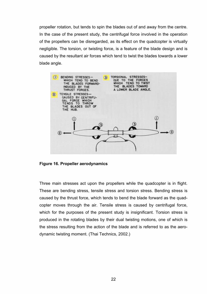
propeller rotation, but tends to spin the blades out of and away from the centre.
In the case of the present study, the centrifugal force involved in the operation
of the propellers can be disregarded, as its effect on the quadcopter is virtually
negligible. The torsion, or twisting force, is a feature of the blade design and is
caused by the resultant air forces which tend to twist the blades towards a lower
blade angle.
Figure 16. Propeller aerodynamics
Three main stresses act upon the propellers while the quadcopter is in flight.
These are bending stress, tensile stress and torsion stress. Bending stress is
caused by the thrust force, which tends to bend the blade forward as the quad-
copter moves through the air. Tensile stress is caused by centrifugal force,
which for the purposes of the present study is insignificant. Torsion stress is
produced in the rotating blades by their dual twisting motions, one of which is
the stress resulting from the action of the blade and is referred to as the aero-
dynamic twisting moment. (Thai Technics, 2002.)
23
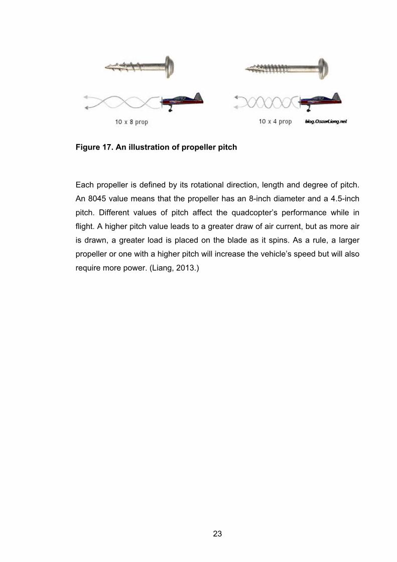
Figure 17. An illustration of propeller pitch
Each propeller is defined by its rotational direction, length and degree of pitch.
An 8045 value means that the propeller has an 8-inch diameter and a 4.5-inch
pitch. Different values of pitch affect the quadcopter’s performance while in
flight. A higher pitch value leads to a greater draw of air current, but as more air
is drawn, a greater load is placed on the blade as it spins. As a rule, a larger
propeller or one with a higher pitch will increase the vehicle’s speed but will also
require more power. (Liang, 2013.)
24
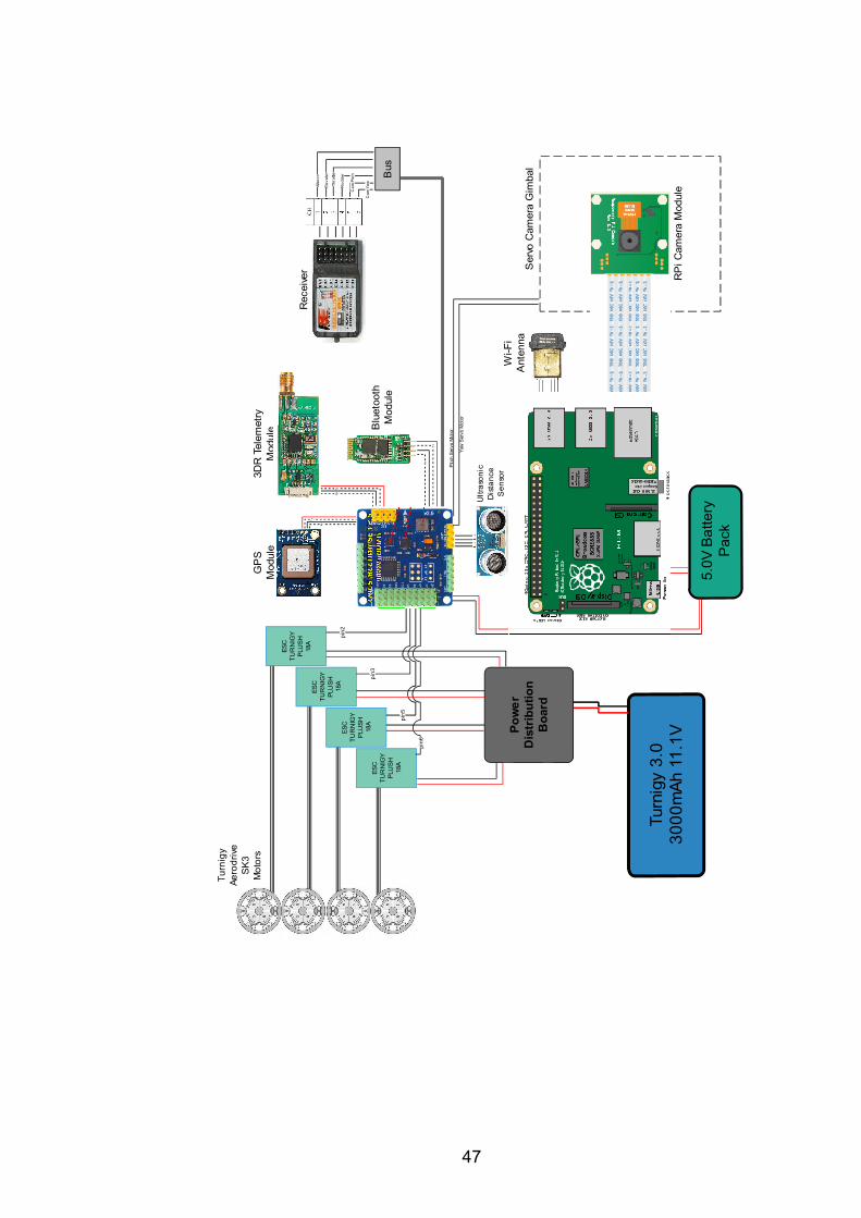
4 SYSTEM ARCHITECTURE
As designed and constructed, the author’s quadcopter is based on a MultiWii
flight controller and an RPi microcomputer, the second of which is used for
onboard video reception and transmission. In future quadcopter designs, it may
be more expedient to eliminate the MultiWii flight controller altogether and utilise
only the RPi microcomputer, as the craft also has different sensors, a radio re-
ceiver, 3DR telemetry and a gimbal-system camera.
4.1 Multiwii
The flight controller (FC) is the controlling brain centre of any UAV. Inside the
FC there are numerous essential components, such as an IMU, a PID control-
ler, the PWM signal output, a processor and many others. The present study
uses a MultiWii flight controller because it operates reliably, does not present a
major expenditure and supports all of the required features, including GPS nav-
igation. (MultiWii, 2015.)
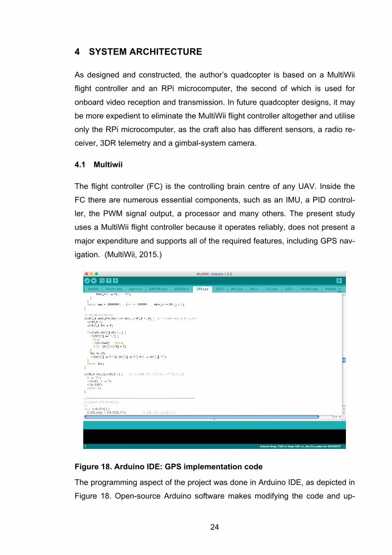
Figure 18. Arduino IDE: GPS implementation code
The programming aspect of the project was done in Arduino IDE, as depicted in
Figure 18. Open-source Arduino software makes modifying the code and up-
25
loading it to the flight controller simple procedures. This software works excep-
tionally well with a MultiWii boards as both are based on Arduino open-source
software.
MultiWii software contains an important file, which is called Config.h. Both basic
and advanced setups can be accomplished in this file. Tuning, calibrating and
using optional features must be done in advance of the quadcopter’s initial
flight.
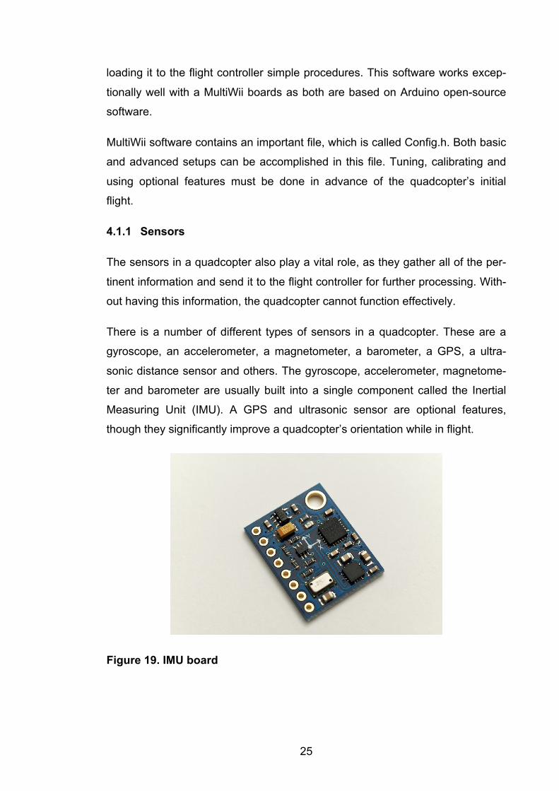
4.1.1 Sensors
The sensors in a quadcopter also play a vital role, as they gather all of the per-
tinent information and send it to the flight controller for further processing. With-
out having this information, the quadcopter cannot function effectively.
There is a number of different types of sensors in a quadcopter. These are a
gyroscope, an accelerometer, a magnetometer, a barometer, a GPS, a ultra-
sonic distance sensor and others. The gyroscope, accelerometer, magnetome-
ter and barometer are usually built into a single component called the Inertial
Measuring Unit (IMU). A GPS and ultrasonic sensor are optional features,
though they significantly improve a quadcopter’s orientation while in flight.
Figure 19. IMU board
26
For this project, the sensor board is an internal feature of the flight controller.
The board helps to translate information directly from the IMU to the processor,
which significantly increases processing speed.
With the help of an IMU, the quadcopter can instantly obtain information on its
flight orientation. The gyroscope helps the quadcopter to maintain an absolute
angular reference, while the accelerometer measures the degree of the vehi-
cle’s rotation in space. These various sensors are most often combined with the
GPS system through a digital filtering system. The accelerometer and gyro pro-
vide short-term data, while the GPS corrects any of the accumulated errors of
the IMU. Also, a barometer sensor is used outdoors to maintain a particular alti-
tude. (Benriplay, 2014.)
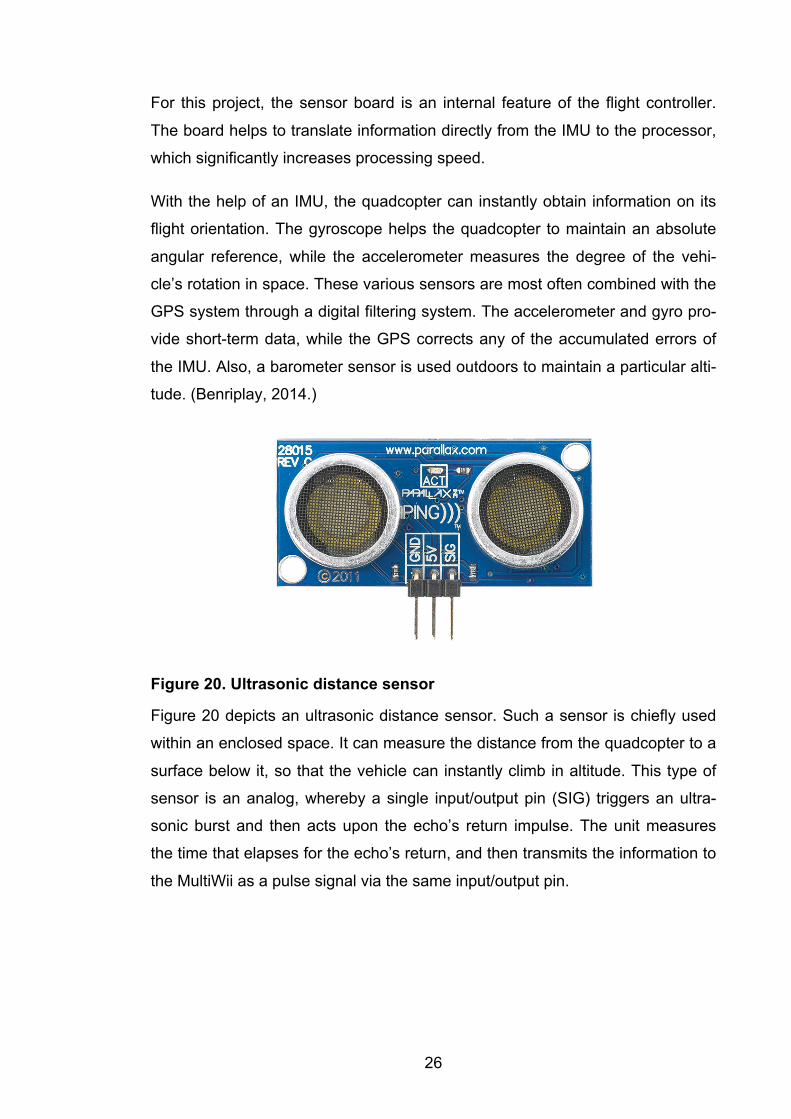
Figure 20. Ultrasonic distance sensor
Figure 20 depicts an ultrasonic distance sensor. Such a sensor is chiefly used
within an enclosed space. It can measure the distance from the quadcopter to a
surface below it, so that the vehicle can instantly climb in altitude. This type of
sensor is an analog, whereby a single input/output pin (SIG) triggers an ultra-
sonic burst and then acts upon the echo’s return impulse. The unit measures
the time that elapses for the echo’s return, and then transmits the information to
the MultiWii as a pulse signal via the same input/output pin.
27
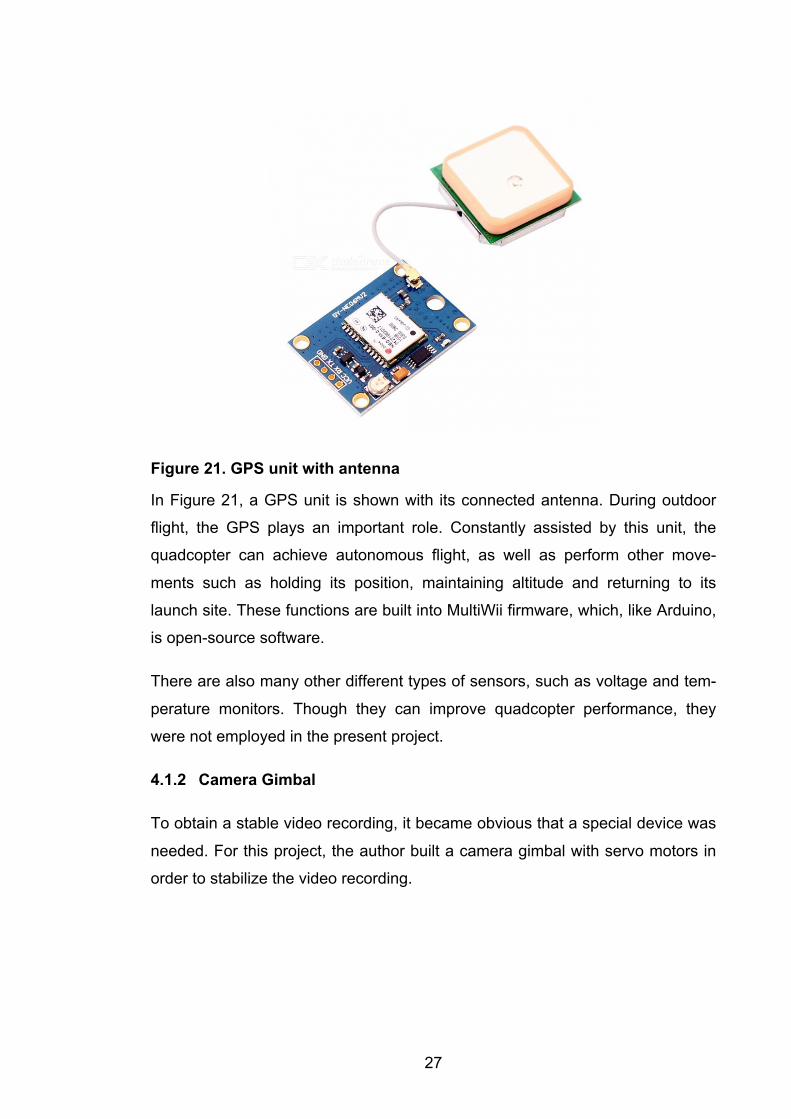
Figure 21. GPS unit with antenna
In Figure 21, a GPS unit is shown with its connected antenna. During outdoor
flight, the GPS plays an important role. Constantly assisted by this unit, the
quadcopter can achieve autonomous flight, as well as perform other move-
ments such as holding its position, maintaining altitude and returning to its
launch site. These functions are built into MultiWii firmware, which, like Arduino,
is open-source software.
There are also many other different types of sensors, such as voltage and tem-
perature monitors. Though they can improve quadcopter performance, they
were not employed in the present project.
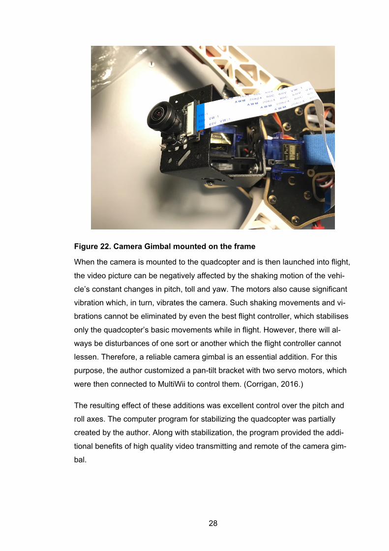
4.1.2 Camera Gimbal
To obtain a stable video recording, it became obvious that a special device was
needed. For this project, the author built a camera gimbal with servo motors in
order to stabilize the video recording.
28
Figure 22. Camera Gimbal mounted on the frame
When the camera is mounted to the quadcopter and is then launched into flight,
the video picture can be negatively affected by the shaking motion of the vehi-
cle’s constant changes in pitch, toll and yaw. The motors also cause significant
vibration which, in turn, vibrates the camera. Such shaking movements and vi-
brations cannot be eliminated by even the best flight controller, which stabilises
only the quadcopter’s basic movements while in flight. However, there will al-
ways be disturbances of one sort or another which the flight controller cannot
lessen. Therefore, a reliable camera gimbal is an essential addition. For this
purpose, the author customized a pan-tilt bracket with two servo motors, which
were then connected to MultiWii to control them. (Corrigan, 2016.)
The resulting effect of these additions was excellent control over the pitch and
roll axes. The computer program for stabilizing the quadcopter was partially
created by the author. Along with stabilization, the program provided the addi-
tional benefits of high quality video transmitting and remote of the camera gim-
bal.
29
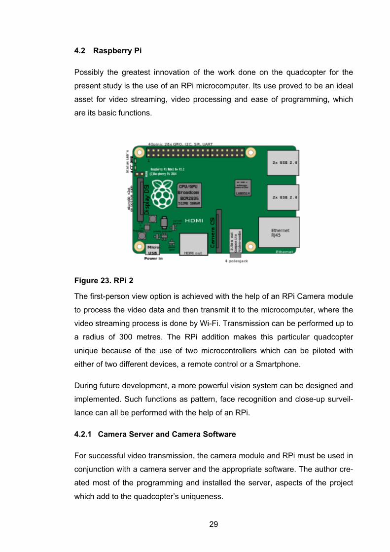
4.2 Raspberry Pi
Possibly the greatest innovation of the work done on the quadcopter for the
present study is the use of an RPi microcomputer. Its use proved to be an ideal
asset for video streaming, video processing and ease of programming, which
are its basic functions.
Figure 23. RPi 2
The first-person view option is achieved with the help of an RPi Camera module
to process the video data and then transmit it to the microcomputer, where the
video streaming process is done by Wi-Fi. Transmission can be performed up to
a radius of 300 metres. The RPi addition makes this particular quadcopter
unique because of the use of two microcontrollers which can be piloted with
either of two different devices, a remote control or a Smartphone.
During future development, a more powerful vision system can be designed and
implemented. Such functions as pattern, face recognition and close-up surveil-
lance can all be performed with the help of an RPi.
4.2.1 Camera Server and Camera Software
For successful video transmission, the camera module and RPi must be used in
conjunction with a camera server and the appropriate software. The author cre-
ated most of the programming and installed the server, aspects of the project
which add to the quadcopter’s uniqueness.
30
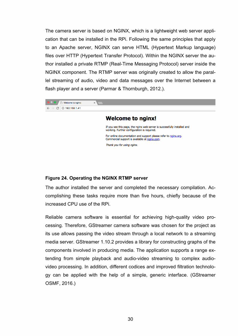
The camera server is based on NGINX, which is a lightweight web server appli-
cation that can be installed in the RPi. Following the same principles that apply
to an Apache server, NGINX can serve HTML (Hypertext Markup language)
files over HTTP (Hypertext Transfer Protocol). Within the NGINX server the au-
thor installed a private RTMP (Real-Time Messaging Protocol) server inside the
NGINX component. The RTMP server was originally created to allow the paral-
lel streaming of audio, video and data messages over the Internet between a
flash player and a server (Parmar & Thornburgh, 2012.).
Figure 24. Operating the NGINX RTMP server
The author installed the server and completed the necessary compilation. Ac-
complishing these tasks require more than five hours, chiefly because of the
increased CPU use of the RPi.
Reliable camera software is essential for achieving high-quality video pro-
cessing. Therefore, GStreamer camera software was chosen for the project as
its use allows passing the video stream through a local network to a streaming
media server. GStreamer 1.10.2 provides a library for constructing graphs of the
components involved in producing media. The application supports a range ex-
tending from simple playback and audio-video streaming to complex audio-
video processing. In addition, different codices and improved filtration technolo-
gy can be applied with the help of a simple, generic interface. (GStreamer
OSMF, 2016.)
31
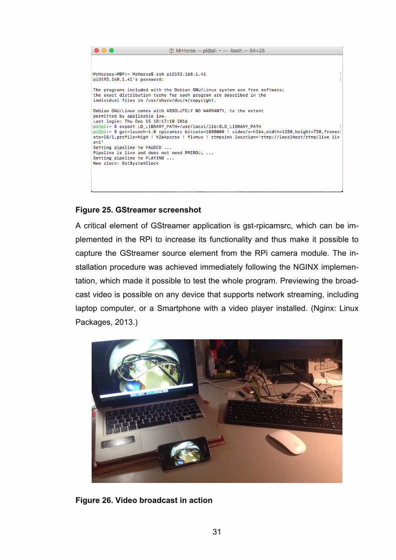
Figure 25. GStreamer screenshot
A critical element of GStreamer application is gst-rpicamsrc, which can be im-
plemented in the RPi to increase its functionality and thus make it possible to
capture the GStreamer source element from the RPi camera module. The in-
stallation procedure was achieved immediately following the NGINX implemen-
tation, which made it possible to test the whole program. Previewing the broad-
cast video is possible on any device that supports network streaming, including
laptop computer, or a Smartphone with a video player installed. (Nginx: Linux
Packages, 2013.)
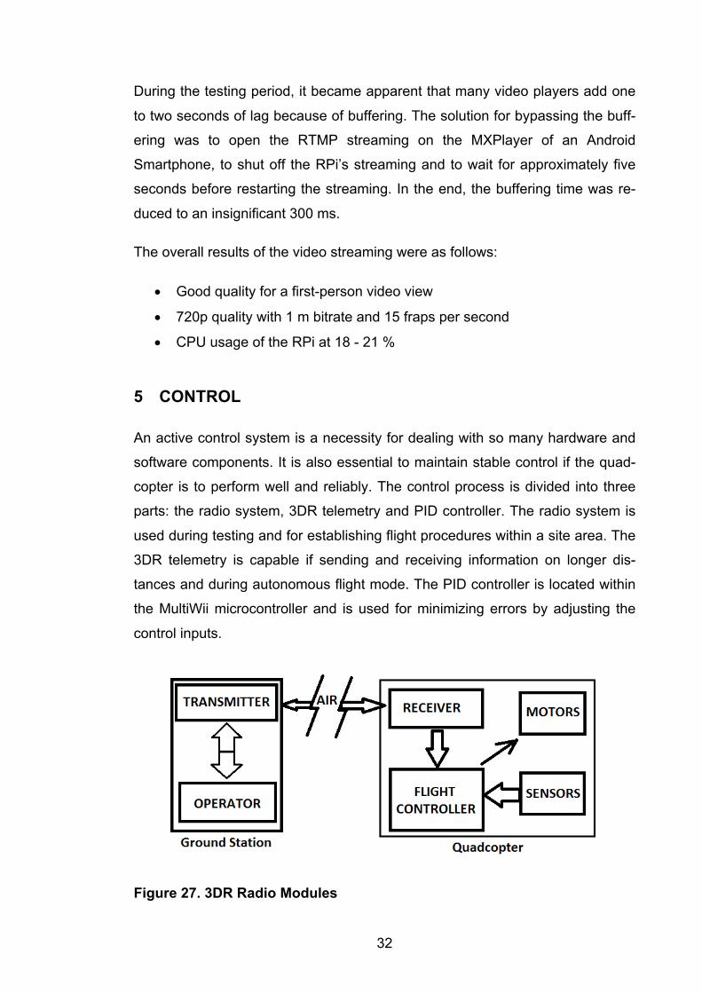
Figure 26. Video broadcast in action
32
During the testing period, it became apparent that many video players add one
to two seconds of lag because of buffering. The solution for bypassing the buff-
ering was to open the RTMP streaming on the MXPlayer of an Android
Smartphone, to shut off the RPi’s streaming and to wait for approximately five
seconds before restarting the streaming. In the end, the buffering time was re-
duced to an insignificant 300 ms.
The overall results of the video streaming were as follows:
• Good quality for a first-person video view
• 720p quality with 1 m bitrate and 15 fraps per second
• CPU usage of the RPi at 18 - 21 %
5 CONTROL
An active control system is a necessity for dealing with so many hardware and
software components. It is also essential to maintain stable control if the quad-
copter is to perform well and reliably. The control process is divided into three
parts: the radio system, 3DR telemetry and PID controller. The radio system is
used during testing and for establishing flight procedures within a site area. The
3DR telemetry is capable if sending and receiving information on longer dis-
tances and during autonomous flight mode. The PID controller is located within
the MultiWii microcontroller and is used for minimizing errors by adjusting the
control inputs.
Figure 27. 3DR Radio Modules
33
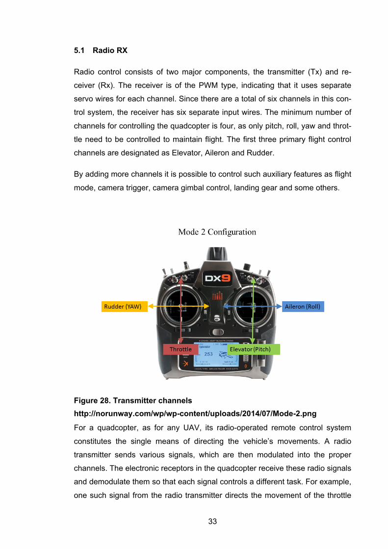
5.1 Radio RX
Radio control consists of two major components, the transmitter (Tx) and re-
ceiver (Rx). The receiver is of the PWM type, indicating that it uses separate
servo wires for each channel. Since there are a total of six channels in this con-
trol system, the receiver has six separate input wires. The minimum number of
channels for controlling the quadcopter is four, as only pitch, roll, yaw and throt-
tle need to be controlled to maintain flight. The first three primary flight control
channels are designated as Elevator, Aileron and Rudder.
By adding more channels it is possible to control such auxiliary features as flight
mode, camera trigger, camera gimbal control, landing gear and some others.
Figure 28. Transmitter channels http://norunway.com/wp/wp-content/uploads/2014/07/Mode-2.png
For a quadcopter, as for any UAV, its radio-operated remote control system
constitutes the single means of directing the vehicle’s movements. A radio
transmitter sends various signals, which are then modulated into the proper
channels. The electronic receptors in the quadcopter receive these radio signals
and demodulate them so that each signal controls a different task. For example,
one such signal from the radio transmitter directs the movement of the throttle
34
analog stick. The more pressure applied to this lever, the greater is the value of
throttle being modulated and transmitted directly to the quadcopter. When the
vehicle receives the signal, all values are demodulated and the channels gov-
erning the throttle increase the motor speed to an appropriated degree. (Gul-
zaar, 2016.)
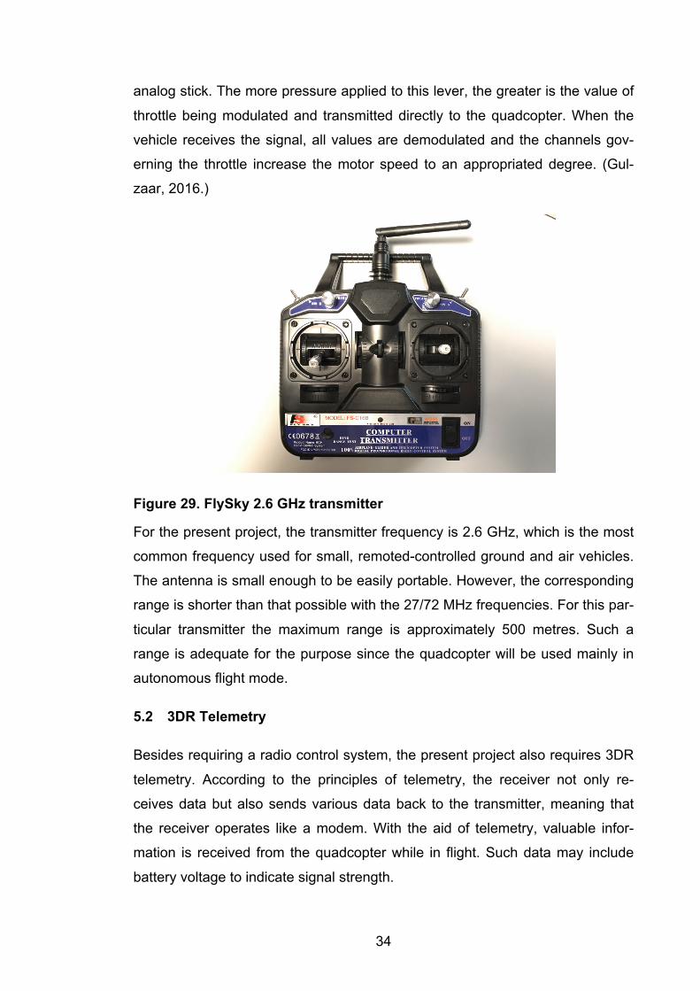
Figure 29. FlySky 2.6 GHz transmitter
For the present project, the transmitter frequency is 2.6 GHz, which is the most
common frequency used for small, remoted-controlled ground and air vehicles.
The antenna is small enough to be easily portable. However, the corresponding
range is shorter than that possible with the 27/72 MHz frequencies. For this par-
ticular transmitter the maximum range is approximately 500 metres. Such a
range is adequate for the purpose since the quadcopter will be used mainly in
autonomous flight mode.
5.2 3DR Telemetry
Besides requiring a radio control system, the present project also requires 3DR
telemetry. According to the principles of telemetry, the receiver not only re-
ceives data but also sends various data back to the transmitter, meaning that
the receiver operates like a modem. With the aid of telemetry, valuable infor-
mation is received from the quadcopter while in flight. Such data may include
battery voltage to indicate signal strength.
35
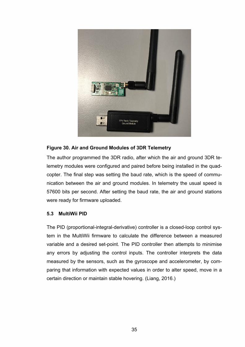
Figure 30. Air and Ground Modules of 3DR Telemetry
The author programmed the 3DR radio, after which the air and ground 3DR te-
lemetry modules were configured and paired before being installed in the quad-
copter. The final step was setting the baud rate, which is the speed of commu-
nication between the air and ground modules. In telemetry the usual speed is
57600 bits per second. After setting the baud rate, the air and ground stations
were ready for firmware uploaded.
5.3 MultiWii PID
The PID (proportional-integral-derivative) controller is a closed-loop control sys-
tem in the MultiWii firmware to calculate the difference between a measured
variable and a desired set-point. The PID controller then attempts to minimise
any errors by adjusting the control inputs. The controller interprets the data
measured by the sensors, such as the gyroscope and accelerometer, by com-
paring that information with expected values in order to alter speed, move in a
certain direction or maintain stable hovering. (Liang, 2016.)
36
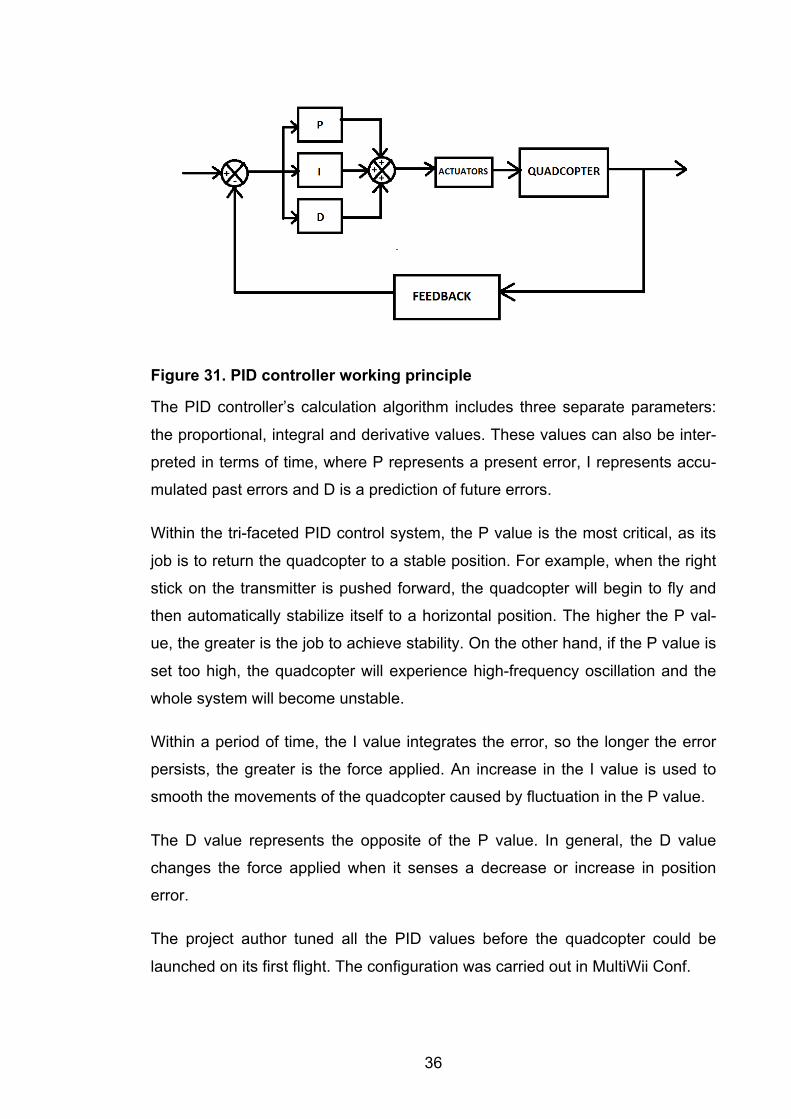
Figure 31. PID controller working principle
The PID controller’s calculation algorithm includes three separate parameters:
the proportional, integral and derivative values. These values can also be inter-
preted in terms of time, where P represents a present error, I represents accu-
mulated past errors and D is a prediction of future errors.
Within the tri-faceted PID control system, the P value is the most critical, as its
job is to return the quadcopter to a stable position. For example, when the right
stick on the transmitter is pushed forward, the quadcopter will begin to fly and
then automatically stabilize itself to a horizontal position. The higher the P val-
ue, the greater is the job to achieve stability. On the other hand, if the P value is
set too high, the quadcopter will experience high-frequency oscillation and the
whole system will become unstable.
Within a period of time, the I value integrates the error, so the longer the error
persists, the greater is the force applied. An increase in the I value is used to
smooth the movements of the quadcopter caused by fluctuation in the P value.
The D value represents the opposite of the P value. In general, the D value
changes the force applied when it senses a decrease or increase in position
error.
The project author tuned all the PID values before the quadcopter could be
launched on its first flight. The configuration was carried out in MultiWii Conf.
37
Although the PID settings profoundly affect the quadcopter’s performance, elim-
inating the vibration of the propellers and motors must be done even before
configuring the PID. Similarly, the weight distribution on the frame plays a vital
role in the quadcopter’s stability.
5.4 MultiWii Conf
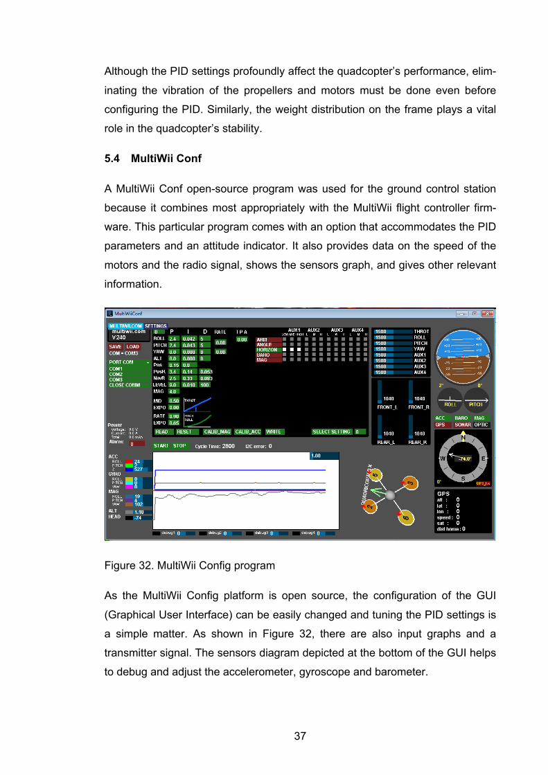
A MultiWii Conf open-source program was used for the ground control station
because it combines most appropriately with the MultiWii flight controller firm-
ware. This particular program comes with an option that accommodates the PID
parameters and an attitude indicator. It also provides data on the speed of the
motors and the radio signal, shows the sensors graph, and gives other relevant
information.
Figure 32. MultiWii Config program
As the MultiWii Config platform is open source, the configuration of the GUI
(Graphical User Interface) can be easily changed and tuning the PID settings is
a simple matter. As shown in Figure 32, there are also input graphs and a
transmitter signal. The sensors diagram depicted at the bottom of the GUI helps
to debug and adjust the accelerometer, gyroscope and barometer.
38
On the right side of the GUI, a visualization menu displays the quadcopter’s cur-
rent position and location. The GPS navigation system allows the MultiWii to
navigate autonomously through multiple Way Points. (EOSBandi, 2013.)
Another significant advantage of the MultiWii Cong is the program’s capacity to
switch between flight modes. This particular GUI supports ACRO, ANGLE and
HORIZON flight modes:
• ACRO stands for Acrobatic Flight Mode for maneuverability and fast con-
trol. Only the gyroscope is used in this mode.
• The ANGLE mode provides stability and shows whether the Pitch, Roll,
Yaw and PID level values have been set correctly. This flight mode is
regulated by the gyroscope and accelerometer.
• HORIZON is a combination of the ACRO and ANGLE modes. This mode
ideally pairs the ‘Calm’ and ‘Aerobatic’ RC sticks.
6 EVALUATION
The performance of the quadcopter prototype was tested manually more than
fifty times under both outdoor and indoor conditions. The frame’s strength and
durability were tested with FEM simulations. The balance of the propellers was
tested using the reflected laser beam method. The Vibration Sensor was used
to balance the motors.
The performance of the quadcopter’s onboard sensors was achieved in the Mul-
tiWii Config by comparing the results with the values considered most highly
desirable.
6.1 Mechanical Performance
The result of the frame’s overall performance was judged by the author to be
‘very good’. The bolt connections between the components are so stable that
the frame can be depended on for many years of use. The motor mountings
have also proved to be reliably durable.
39
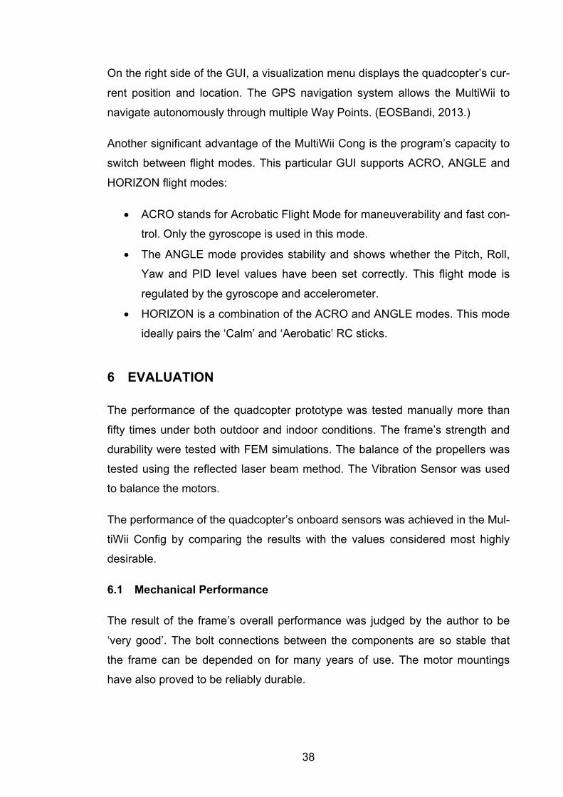
Even before the project started, it was assumed that some of the quadcopter’s
working parts would heat up while operating. The components which emit vary-
ing degree of heat are the motors, ESCs and battery. After just a few tests,
however, it became apparent that their location relative to the craft’s exterior
frame allowed them to be cooled by the air rushing past them. The possibility of
the working and moving parts being negatively affected by overheating thus
became a minor concern.
Figure 33. Motor's mount
During numerous test flights the quadcopter’s frame proved to be ruggedly du-
rable and its connections stable. When it was noted that some of the sensors
were not mounted securely enough for the load, they had to be reinforced with
extra clamps and strong elastic tape.
The main flight controller is attached to the frame by four bolts. There is also a
length of 3 mm compressed foam tape stretched underneath the controller to
help eliminate vibration which might otherwise negatively affect the sensor data.
The propellers also cause strong vibration if not properly balanced with a spe-
cial calibration tool. Such a procedure is mandatory whenever the propellers
need to be replaced.
40
6.2 Control Performance
One of the essential setup procedures for the whole system is the precise cali-
bration of the Electronic Speed Controllers. These ESCs are basically responsi-
ble for the motors rotating at the rate of speed determined by the flight control-
ler. The correct calibration procedure ensures that the ESCs exhibit the mini-
mum and maximum pulse-width modulation (PWM) values received from the
flight controller. For the quadcopter, the minimum PWM values is set at 1150, a
value which is so low that the motors do not turn at all. When a value of 50 is
added to the PWM variable, the motors start turning at minimum speed. The
maximum PWM value is 1800, at which setting the motors rotate at their highest
speed.
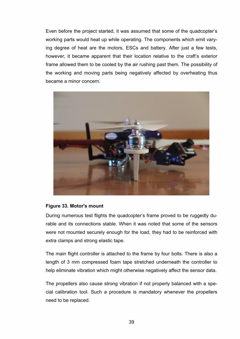
The PID settings are similarly relevant to maintain stable flight. The setup pro-
cess was done in the MultiWii configuration program. A PID loop setup was thus
chosen as the most appropriate tuning method. The first step was positioning
the quadcopter’s main load in the very middle of the craft in order to create a
balanced centre of gravity. The P value was set at 0.0060, which is in the mid-
dle of the P range for this particular system and results in the drone’s move-
ments being smooth and stable.
Figure 34. PID settings
During testing it was determined that the drone’s maximum range was approxi-
mately 4.5 kilometres, which is considered sufficient for such a craft. This over-
all performance is in complete accord with the quadcopter’s maximum theoreti-
cal distance of 5.0 km.
41
Taking everything into account, the option of autonomous flight was achieved:
the quadcopter demonstrated that it was able to fly between multiple waypoints,
to hover when so instructed and to perform reliably in making video recordings.
During these various testing periods, the RPi server also proved to be more
than adequately stable.
During the final test flight, the main controller experienced a failure, which led to
the temporary collapse of the whole system and resulted in the quadcopter fall-
ing to earth. The vehicle’s most important components were not damaged and
only one propeller had to be replaced. Accordingly, a post-crash forensic analy-
sis was conducted. The analysis showed that one element of the flight controller
was defective and had caused the accident. Before resuming future flights, the
flight controller will be completely replaced and the quadcopter’s electronic sys-
tem will again become stable.
7 CONCLUSION
On the whole, the quadcopter prototype of the present study has demonstrated
its merits. In particular, the MultiWii flight controller, despite its small size, has
proved to be unexpectedly powerful in controlling the quadcopter’s complicated
system. The RPi microcontroller has also confirmed that it is an essential factor
in video processing and broadcasting. Both the MultiWii and the RPi worked
harmoniously in tandem, a successful interdependence which has demonstrat-
ed that their implementation in the project was the correct choice.
42
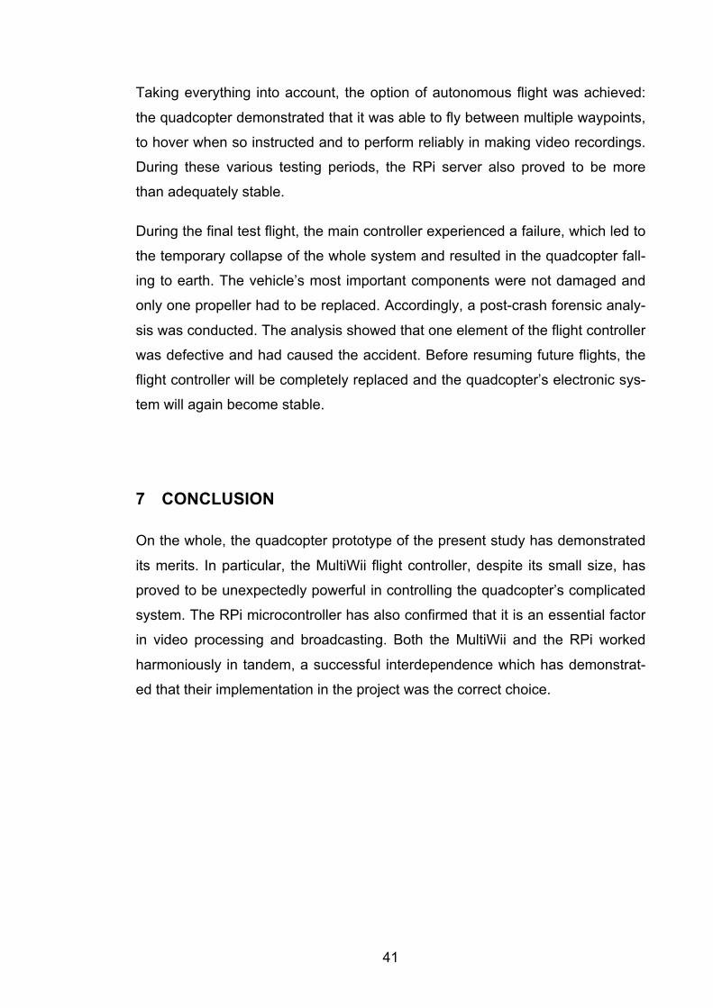
Figure 35. Final Prototype
The overall performance of the sensors was also positive, even though at the
start of the project the magnetometer displayed a number of obvious errors.
Afterwards, it was discovered that the problem was one of magnetic interfer-
ence due to the magnetometer’s close proximity to the power wires. When the
magnetometer was repositioned, it began functioning correctly and the errors
ceased to appear.
The control system generally displayed stability and reliability. In the early stag-
es of the project, the control system’s periodic instability was found to be the
result of inexact calibration. Following the first outdoor tests, mistakes in the
control system were discovered and resolved.
43
Figures
Figure 1. Quadcopter in the sky, p. 6.
Figure 2. Forest ranger at work, p. 7.
Figure 3. Russian ranger’s equipment, p. 8.
Figure 4. Pitch, Roll and Yaw axes, p. 11.
Figure 5. Quadcopter motions, p. 12.
Figure 6. DJI Phantom 4, p. 13.
Figure 7. Factor of safety of the assembly, p. 14.
Figure 8. Static nodal stress, p. 15.
Figure 9. Static displacement, p. 15.
Figure 10. Turnigy Aerodrive SK3 2826-1240kv, p. 16.
Figure 11. Turnigy Plush 18amp Speed Controller, p. 18.
Figure 12. Example of PWM signal, p. 19.
Figure 13. LiPo Battery, p. 19.
44
Figure 14. 4.8 V Battery pack, p. 20.
Figure 15. SF 8045 propeller, p. 22.
Figure 16. Dynamics of propeller, p. 22.
Figure 17. Propeller’s pitch illustration, p. 23.
Figure 18. Arduino IDE. GPS implementation code, p. 25.
Figure 19. IMU board, p. 26.
Figure 20. Ultrasonic distance sensor, p. 27.
Figure 21. GPS unit with antenna, p. 27.
Figure 22. Camera Gimbal mounted on the frame, p. 28.
Figure 23. Raspberry Pi 2, p. 29.
Figure 24. Running NGINX RTMP server, p, 30.
Figure 25. Gstreamer screenshot, p. 31.
Figure 26. Live video broadcast, p. 31.
Figure 27. 3DR Radio Modules, p. 32.
Figure 28. Transmitter channels, p. 33.
Figure 29. FlySky 2.6 GHz transmitter, p. 34.
Figure 30. Air and Ground Modules of 3DR Telemetry
Figure 31. PID controller working principle, p. 36.
Figure 32. MultiWii Config program, p. 37.
Figure 33. Motor’s mount, p. 39.
Figure 34. PID settings, p. 40.
45
42
0
3 1 2 3
5
Rev Muutos / Change Pvm / Date Suunnittelija / Designer
ITEM NO. PART NUMBER
1 Upper Plate2 Frame Arm3 Bottom Plate
Material
FiberGlassABS-plasticFiberGlass
YleistoleranssitGeneral tolerances
Machining: ISO 2768-mKWelded constructions: EN ISO 13920-BFWelding quality level: CFlame cutting: ISO 9013-331Casting: ISO 8062-CT 11Stamping: SFS 5803-m
Projekti / opintojaksoProject / course
www.saimia.fi
A4
SuunnittelijaDesigner
PvmDate
PvmDate
HyväksyjäAccepted by
AsiakasCustomer
kgMassaWeightMittakaava
Scale 1:5PiirustusnumeroItem
RevisioRevision
NimitysDescription
Guliaev N.
Frame Assembly
Figure 35. Final Prototype, p 41.
8 Appendices
Appendix 1

46
Appendix 2
47
ESC
TUR
NIG
YPL
USH
18A
ESC
TUR
NIG
YPL
USH
18A
ESC
TUR
NIG
YPL
USH
18A
ESC
TUR
NIG
YPL
USH
18A
Turn
igy
Aero
driv
eS
K3
Mot
ors
pin2
pin3
pin6
pin5
Turn
igy
3.0
3000
mAh
11.
1V
Power
Distribution
Board
5.0V
Bat
tery
Pac
k
Rx
Tx
Tx
Rx
3DR
Tel
emet
ryM
odul
eG
PS
Mod
ule
Rx
Tx
Blu
etoo
thM
odul
e
Wi-F
iA
nten
na
RP
i Cam
era
Mod
ule
Ser
vo C
amer
a G
imba
l
Pitc
h S
ervo
Mot
or
Yaw
Ser
vo M
otor
Rec
eive
rAi
lero
n
Elev
ator
Thro
ttle
Rud
der
Cam
Pitc
h
Cam
Yaw
Bus
Ultr
ason
icD
ista
nce
Sen
sor
48
9 References
Anderson, С. 2014. MIT Technology Review.
https://www.technologyreview.com/s/526491/agricultural-drones/. Accessed on
10 October 2016.
Benriplay, 2014. Benriplay Software Development and DIY Arduino. Implement-
ing a Quadcopter IMU. http://www.benripley.com/diy/arduino/implementing-a-
quadcopter-imu/. Accessed on 13 November 2016.
Corrigan, F. 2016. DroneZon: Drone Technology, Knowledge, News & Reviews.
Drone Gimbal Design and Parts for Quality Aerial Filming.
https://www.dronezon.com/learn-about-drones-quadcopters/drone-gimbal-
design-components-parts-technology-overview/. Accessed on 15 November
2016.
Cuong C. Quach, Edward F. Hogge, Thomas H. Strom, Boyd L. Hill, Sixto L.
Vazquez, Kai Goebel, Bhaskar Saha, Edwin Koshimoto. Battery health man-
agement system for electric UAVs. Aerospace Conference, 2011 IEEE, 2011.
DJI INSPIRE 2. DJI Store. http://store.dji.com/product/inspire-
2?vid=20481#/bundles?_k=llpnsp. Accessed on 10 October 2016.
Eachine E010 Mini. Banggood Internet Shop.
http://www.banggood.com/Eachine-E010-Mini-2_4G-4CH-6-Axis-Headless-
Mode-RC-Quadcopter-RTF-p-1066972.html?rmmds=search. Accessed on 10
October 2016.
EOSBandi, 2013. MutliWii Official Webpage, Documentation. GPS NAV.
http://www.multiwii.com/forum/viewtopic.php?viewtopic.php?f=8&t=3989. Ac-
cessed on 3 December 2016.
Flying Tech, 2014. Efficiency vs. performance. Multirotor Beginner’s Guide.
http://www.flyingtech.co.uk/blog/efficiency-vs-performance-how-build-drone-
long-flight-time. Accessed on 1 November 2016.
Gibiansky, A. n.d. Quadcopter Dynamics, Simulation and Control. Simulation.
49
GStreamer OSMF, 2016. Gstreamer Documentation. Application Development
Manual. https://gstreamer.freedesktop.org/documentation/. Accessed on 21 No-
vember 2016.
Gulzaar, 2016. FPV Frenzy. RC Transmitter for an FPV Quadcopter.
http://fpvfrenzy.com/rc-transmitter-fpv-quadcopter/. Accessed on 24 November
2016.
Prof. Javir, A. V. 2015. JIAATS. Design, Analysis and Fabrication of Quadcop-
ter.
Johnson, W. 1994. Helicopter Theory. New York: Dover Publications, pp. 13.
Liang, O. 2013. Oscar Liang: Quadcopter Motor & Propellers.
https://oscarliang.com/quadcopter-motor-propeller/. Accessed on 6 November
2016.
Liang, O. 2016. Oscar Liang: PID for Quadcopter RC Flight Behaviour.
https://oscarliang.com/understanding-pid-for-quadcopter-rc-flight/. Accessed on
1 December 2016.
MultiWii, 2015. MultiWii Official Website. Main Page.
http://www.multiwii.com/wiki/?title=Main_Page. Accessed on 10 November
2016.
Nginx: Linux Packages, 2013. Nginx Official Website.
https://nginx.org/en/linux_packages.html. Accessed on 20 November 2016
Parmar, H. & Thornburgh, M. 2012. Adobe System Incorporated. Adobe’s Real
Time Messaging Protocol & Em Pleh.
Phantom 4, 2016. DJI Official Web page. Phantom 4.
https://www.dji.com/phantom-4. Accessed on 20 October 2016.
Polyakov, A. 2015. One day from ranger’s life, Afisha 86.
http://afisha.68.ru/text/freetime/892910.html. Accessed on 12 October 2016.
50
Pri, A. 2015. Quadcopter Flyers. Quadcopter Yaw, Roll and Pitch defined.
http://www.quadcopterflyers.com/2015/02/quadcopters-yaw-roll-and-pitch-
defined.html. Accessed on 15 October 2016.
Thai Technics, 2002. Thai Technics. Aircraft Propellers Information.
http://www.thaitechnics.com/propeller/prop_intro.html. Accessed on 3 Novem-
ber 2016.
Warren, F. Phillips. Mechanics of flight. John Wileys & Sons, inc., 2004.
Copyright © 2022 FDOKUMEN