The crimping concept - Gogatec
33
CRIMPING TOOLS 704 The crimp connection is an irreversible, non-reusable connection between one or two conductors and a crimp contact. It is obtained by compression deformation (cold forming) and consequent reshaping of the contact crimping stem, or crimp barrel. A good crimp connection is provided by a suitable combination between the crimping dies, the contact crimp barrel (hence the crimp contact), and the cross-section of the conductor. These considerations refer to crimped connections made with flexible copper conductors of class 5 (flexible) or 6 (more flexible than class 5) according to EN IEC 60228 standard. Solid copper conductors (class 1) or conductors made by other materials (aluminium, iron, etc.) often require special precautions for both crimp contacts and crimping tools, to be agreed upon with the manufacturer. The main technical advantages provided by crimped connections over soldered connections are: - Independence from temperature, being this a “cold” process, performed without using heat and not requiring further materials. - Elimination of the contact uncertainties due to cold solders. - No degradation of the elastic characteristics of the female contacts (a problem that arises with soldering temperatures). - No health risks connected with the use of heavy metals or fumes generated from the soldering process. - Preservation of the conductor’s flexibility immediately beyond connection. - No conductors with burned, discoloured or overheated insulating material. - Excellent reproducibility of the performances of the electrical and mechanical connections. - Easier production controls. Other advantages obtained by crimping connections over screw-type connections are: - Lower voltage drop across the connection. - High stability in time even in the presence of vibrations. - High durability in presence of corrosion (gas-tightness). - Individual insertion of the contacts in the connector (it is possible to eliminate unnecessary contacts). - Less time required for connection. - Possibility of pre-production of the terminated conductors with crimp contacts. - Easy replacement of individual contacts during maintenance. - Possibility of selectively isolating the circuits during maintenance via the extraction of the contacts from the connector. The crimped connections for wire sections up to 10 mm 2 are covered by the EN 60352-2:2006 European standard equivalent to the IEC 60352-2 Issue 2 (2006-02) international standard. The EN 60352-2 standard also includes a practical guidance, which lists the following main points. The quality of a crimped connection is mainly affected by the quality of the materials used and by the condition of the surfaces both of the crimp contact (in particular the crimp barrel) and of the conductor. To ensure a good quality crimped connection, an essential parameter is the mechanical retention of the conductor in the contact. The standard makes a distinction between the closed crimp barrel, inherently stronger, and the open crimp barrel. ILME crimp contacts are closed crimp barrel contacts, with inspection hole which ensure a higher mechanical performance compared to the open barrel crimp contacts, such as better mechanical robustness and stability during operation. They have been high speed precision-machined, thus ensuring a better electrical performance (better conductivity). In 2002 the Amendment 2 of the previous IEC standard had controversially unified the minimum tensile strength for open crimp barrel contacts (curve B of former Figure 5) and closed crimp barrel contacts (curve A of former Figure 5) making them both equal to the lower values (those of curve B), which can be achieved by open barrel crimp contacts. This change has determined an arguable relaxation of the suitability requirements both for closed crimp barrel, typically larger, machine turned and for crimp tools specially made for these contacts. Several industries continue to prefer the higher performance ensured by closed crimp barrel contacts, the only ones able to ensure the higher resistance to tensile stress values believed to be essential for the most demanding industrial applications. Therefore, ILME continues to refer to curve A of Figure 5 illustrated in the EN 60352-2:1994 standard: ILME closed crimp barrel contacts, used with flexible copper wires, featuring a cross-sectional area included in the ranges shown and correctly crimped with the recommended tools, ensure tensile breaking resistant connections at least equal to the values shown in the table below (for reference, the corresponding R t /S unified tensile stress load value is also shown [N/mm 2 ]). See Table 1. Crimping tools The crimping concept
-
Upload
khangminh22 -
Category
Documents
-
view
0 -
download
0
Transcript of The crimping concept - Gogatec
CRIM
PING
TOO
LS
704
The crimp connection is an irreversible, non-reusable connection between one or two conductors and a crimp contact. It is obtained by compression deformation (cold forming) and consequent reshaping of the contact crimping stem, or crimp barrel. A good crimp connection is provided by a suitable combination between the crimping dies, the contact crimp barrel (hence the crimp contact), and the cross-section of the conductor.
These considerations refer to crimped connections made with flexible copper conductors of class 5 (flexible) or 6 (more flexible than class 5) according to EN IEC 60228 standard.
Solid copper conductors (class 1) or conductors made by other materials (aluminium, iron, etc.) often require special precautions for both crimp contacts and crimping tools, to be agreed upon with the manufacturer.
The main technical advantages provided by crimped connections over soldered connections are:- Independence from temperature, being this a “cold” process, performed
without using heat and not requiring further materials.- Elimination of the contact uncertainties due to cold solders.- No degradation of the elastic characteristics of the female contacts (a
problem that arises with soldering temperatures).- No health risks connected with the use of heavy metals or fumes
generated from the soldering process.- Preservation of the conductor’s flexibility immediately beyond
connection.- No conductors with burned, discoloured or overheated insulating
material.- Excellent reproducibility of the performances of the electrical and
mechanical connections.- Easier production controls.Other advantages obtained by crimping connections over screw-type connections are:- Lower voltage drop across the connection.- High stability in time even in the presence of vibrations.- High durability in presence of corrosion (gas-tightness).- Individual insertion of the contacts in the connector (it is possible to
eliminate unnecessary contacts).- Less time required for connection.- Possibility of pre-production of the terminated conductors with crimp
contacts.- Easy replacement of individual contacts during maintenance.
- Possibility of selectively isolating the circuits during maintenance via the extraction of the contacts from the connector.
The crimped connections for wire sections up to 10 mm2 are covered by the EN 60352-2:2006 European standard equivalent to the IEC 60352-2 Issue 2 (2006-02) international standard.
The EN 60352-2 standard also includes a practical guidance, which lists the following main points.
The quality of a crimped connection is mainly affected by the quality of the materials used and by the condition of the surfaces both of the crimp contact (in particular the crimp barrel) and of the conductor.
To ensure a good quality crimped connection, an essential parameter is the mechanical retention of the conductor in the contact. The standard makes a distinction between the closed crimp barrel, inherently stronger, and the open crimp barrel. ILME crimp contacts are closed crimp barrel contacts, with inspection hole which ensure a higher mechanical performance compared to the open barrel crimp contacts, such as better mechanical robustness and stability during operation. They have been high speed precision-machined, thus ensuring a better electrical performance (better conductivity).
In 2002 the Amendment 2 of the previous IEC standard had controversially unified the minimum tensile strength for open crimp barrel contacts (curve B of former Figure 5) and closed crimp barrel contacts (curve A of former Figure 5) making them both equal to the lower values (those of curve B), which can be achieved by open barrel crimp contacts. This change has determined an arguable relaxation of the suitability requirements both for closed crimp barrel, typically larger, machine turned and for crimp tools specially made for these contacts. Several industries continue to prefer the higher performance ensured by closed crimp barrel contacts, the only ones able to ensure the higher resistance to tensile stress values believed to be essential for the most demanding industrial applications.
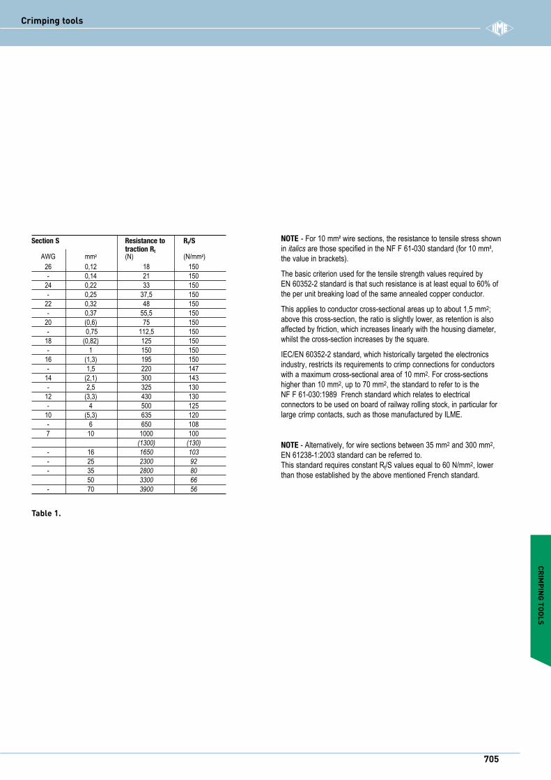
Therefore, ILME continues to refer to curve A of Figure 5 illustrated in the EN 60352-2:1994 standard: ILME closed crimp barrel contacts, used with flexible copper wires, featuring a cross-sectional area included in the ranges shown and correctly crimped with the recommended tools, ensure tensile breaking resistant connections at least equal to the values shown in the table below (for reference, the corresponding Rt/S unified tensile stress load value is also shown [N/mm2]). See Table 1.
Crimping tools
The crimping concept
CRIMPING TOOLS
705
i
Table 1.
NOTE - For 10 mm2 wire sections, the resistance to tensile stress shown in italics are those specified in the NF F 61-030 standard (for 10 mm2, the value in brackets).
The basic criterion used for the tensile strength values required by EN 60352-2 standard is that such resistance is at least equal to 60% of the per unit breaking load of the same annealed copper conductor.
This applies to conductor cross-sectional areas up to about 1,5 mm2; above this cross-section, the ratio is slightly lower, as retention is also affected by friction, which increases linearly with the housing diameter, whilst the cross-section increases by the square.
IEC/EN 60352-2 standard, which historically targeted the electronics industry, restricts its requirements to crimp connections for conductors with a maximum cross-sectional area of 10 mm2. For cross-sections higher than 10 mm2, up to 70 mm2, the standard to refer to is the NF F 61-030:1989 French standard which relates to electrical connectors to be used on board of railway rolling stock, in particular for large crimp contacts, such as those manufactured by ILME.
NOTE - Alternatively, for wire sections between 35 mm2 and 300 mm2, EN 61238-1:2003 standard can be referred to. This standard requires constant Rt/S values equal to 60 N/mm2, lower than those established by the above mentioned French standard.
Section S Resistance to Rt/S traction Rt AWG mm2 (N) (N/mm2) 26 0,12 18 150 - 0,14 21 150 24 0,22 33 150 - 0,25 37,5 150 22 0,32 48 150 - 0,37 55,5 150 20 (0,6) 75 150 - 0,75 112,5 150 18 (0,82) 125 150 - 1 150 150 16 (1,3) 195 150 - 1,5 220 147 14 (2,1) 300 143 - 2,5 325 130 12 (3,3) 430 130 - 4 500 125 10 (5,3) 635 120 - 6 650 108 7 10 1000 100 (1300) (130) - 16 1650 103 - 25 2300 92 - 35 2800 80 50 3300 66 - 70 3900 56
Crimping tools
When you have selected quality crimp contacts and conductors, the next and most important step is to select the correct crimp tool. The practical guidance of standard EN 60352-2 provides the following recommendations on the subject, listing some of the ideal requirements for crimping tools, some optional characteristics, but, above all, it provides a preview of the indispensable controls:
a) The crimping tools and the contacts used shall be supplied by the same manufacturer, otherwise the user shall assume all responsibility for the quality and reliability of the crimp connections.
b) The crimping tools must function correctly and provide a correct crimp without damage to the pin or the component to crimp.
c) In order to obtain a reliable crimp connection, a crimping device with a mechanism that controls the entire crimping cycle shall be used. At the end of the crimping cycle the handles and the ratchet must return to the open position.
d) In all cases the crimping operation shall be made in one single phase, with no further interventions.
e) The removable parts of the tool such as the crimping dies and the locators must be designed in such a way as to make it possible to be inserted within the tool only in the correct manner.
f) The tools must be supplied with the appropriate means for a correct positioning of the pins to be crimped and of the conductors during crimping.
g) The tools must be designed in such a way so that only the necessary adjustments may be made.
h) The action of the tool must be such that both the pin to be crimped and the fixture of the isolation (when present) are respectively crimped or compressed with a single action.
i) The design of the tool must ensure that the dies for a particular tool may be interchangeable within tools of the same type. If they are not interchangeable, the identification of tools for which they are suitable must be marked on the dies.
j) The tools may be designed so as to produce a marking or coding of the die on the pin to be crimped so that the crimping may be checked for verification of the correct die.
k) The design of the tool must allow the verification of the dies with gauges to measure wear. The gauge verification method must be that specified by the manufacturer of the tools.
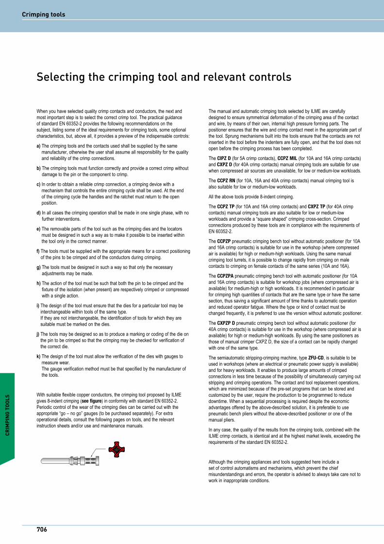
With suitable flexible copper conductors, the crimping tool proposed by ILME gives 8-indent crimping (see figure) in conformity with standard EN 60352-2. Periodic control of the wear of the crimping dies can be carried out with the appropriate “go – no go” gauges (to be purchased separately). For extra operational details, consult the following pages on tools, and the relevant instruction sheets and/or use and maintenance manuals.
The manual and automatic crimping tools selected by ILME are carefully designed to ensure symmetrical deformation of the crimping area of the contact and wire, by means of their own, internal high pressure forming parts. The positioner ensures that the wire and crimp contact meet in the appropriate part of the tool. Sprung mechanisms built into the tools ensure that the contacts are not inserted in the tool before the indenters are fully open, and that the tool does not open before the crimping process has been completed.
The CIPZ D (for 5A crimp contacts), CCPZ MIL (for 10A and 16A crimp contacts) and CXPZ D (for 40A crimp contacts) manual crimping tools are suitable for use when compressed air sources are unavailable, for low or medium-low workloads.
The CCPZ RN (for 10A, 16A and 40A crimp contacts) manual crimping tool is also suitable for low or medium-low workloads.
All the above tools provide 8-indent crimping.
The CCPZ TP (for 10A and 16A crimp contacts) and CXPZ TP (for 40A crimp contacts) manual crimping tools are also suitable for low or medium-low workloads and provide a “square shaped” crimping cross-section. Crimped connections produced by these tools are in compliance with the requirements of EN 60352-2.
The CCPZP pneumatic crimping bench tool without automatic positioner (for 10A and 16A crimp contacts) is suitable for use in the workshop (where compressed air is available) for high or medium-high workloads. Using the same manual crimping tool turrets, it is possible to change rapidly from crimping on male contacts to crimping on female contacts of the same series (10A and 16A).
The CCPZPA pneumatic crimping bench tool with automatic positioner (for 10A and 16A crimp contacts) is suitable for workshop jobs (where compressed air is available) for medium-high or high workloads. It is recommended in particular for crimping high quantities of contacts that are the same type or have the same section, thus saving a significant amount of time thanks to automatic operation and reduced operator fatigue. Where the type or kind of contact must be changed frequently, it is preferred to use the version without automatic positioner.
The CXPZP D pneumatic crimping bench tool without automatic positioner (for 40A crimp contacts) is suitable for use in the workshop (where compressed air is available) for high or medium-high workloads. By using the same positioners as those of manual crimper CXPZ D, the size of a contact can be rapidly changed with one of the same type.
The semiautomatic stripping-crimping machine, type ZFU-CD, is suitable to be used in workshops (where an electrical or pneumatic power supply is available) and for heavy workloads. It enables to produce large amounts of crimped connections in less time because of the possibility of simultaneously carrying out stripping and crimping operations. The contact and tool replacement operations, which are minimized because of the pre-set programs that can be stored and customized by the user, require the production to be programmed to reduce downtime. When a sequential processing is required despite the economic advantages offered by the above-described solution, it is preferable to use pneumatic bench pliers without the above-described positioner or one of the manual pliers.
In any case, the quality of the results from the crimping tools, combined with the ILME crimp contacts, is identical and at the highest market levels, exceeding the requirements of the standard EN 60352-2.
Although the crimping appliances and tools suggested here include a set of control automatisms and mechanisms, which prevent the chief misunderstandings and errors, the operator is advised to always take care not to work in inappropriate conditions.
CRIM
PING
TOO
LS
706
Crimping tools
Selecting the crimping tool and relevant controls

CRIMPING TOOLS
d inspection hole
Multipolar cable Conductor cables
The practical guide in standard EN 60352-2 supplies further general information regarding crimp contacts for multipole connectors.
1. Insertion of the conductor in the crimp contactsThe conductor must be correctly positioned in the pin to be crimped.The crimping indentations must be correctly positioned on the foot to be crimped. There must be sufficient space, in conformity with the manufacturer’s instructions, between the end of the insulating material of the conductor and the pin to be crimped (“d”).As a general rule, the stripping length is equal to the pin insertion depth + 1 mm (for sections up to 1 mm2) and + 2 mm (for sections from 1 to 10 mm2) *. When using closed crimp pins with an inspection hole, the crimp conductor must be visible through the inspection holes.
* Keeping the conductor strands visible above the contact collar enables you to check correct, i.e. make sure no strands have been cut. This also ensures a certain flexibility for the connection, by not transmitting to the contact any flexure stresses caused by installation. However, in practice, some operators give priority to insulation, by reducing to zero the gap between cable insulation and the contact collar.
2. Insertion of crimped contacts in the connector insertIt is recommended that the crimped contacts be perfectly straight and inserted within the contact slots in a single operation and without excessive force until a clicking sound is heard. The correct retention of the contact should be verified with a light pulling of the wire. Non alignment of the crimped contacts must be avoided because this could cause possible loosening of the retention springs and consequently jeopardise the retention of the contact in the insert.For small section conductors (≤ 0,35 mm2) or for specific application, the use of the insertion tool specified by the manufacturer is recommended.
3. Removal of inserted contactsIn the case of incorrect insertion or wiring substitution, inserted contacts may only be removed using the removal tools specified by the manufacturer.
4. Mounting and flexure of multi-wired bundles or multipolar cables with crimp contactsBundles of conductors or multipolar cables with crimp contacts for multipole connectors must not cause stress to the inserted contacts with their weight as this would cause the contacts to bend over to the coupling area of the connectors and consequently damage them. The connectors must therefore be provided with cable clamps or the conductor bundles or multipolar cables must be mounted as described in the figures below.
If the conductor bundles or the multipolar cables have to be immediately folded over on the back of the connector insert, it is recommended not to use any mechanical force in the axial direction with respect to the coupled contacts. The figure shows a correct bending and clamping of the multiwire bundles using the crimp contacts.
To keep the play within this limit, especially during the uncoupling phase, guide pins CRM and CRF may be used. The use of ILME pliers (code number CPES) is recommended for the uncoupling operations for CD inserts (64 poles) and CDD inserts (108 poles).The pliers work on the fulcrum and lever principle and perform the following main tasks:I - Reduce effort and coupling times to the minimum, even when working in the
most impractical and inaccessible points.II- Perform the uncoupling of multipolar connectors in full conformity of standard
DIN 43652 (now EN 175301-801).The pliers allow the extraction of the inserts to be made perfectly axially with respect to the contacts, evenly distributing the pressure on four points (housing pins).
Correct Incorrect
5. Coupling and uncoupling of multipolar connectors with crimp contactsIn order to prevent stress on the crimp contacts, the connectors must be coupled and uncoupled in the axial direction with respect to the contacts, without touching the conductor bundles or cables.Standard DIN 43652 (incorporated into specification EN 175301-801) that applies to the ILME inserts of the CD series (this recommendation is also valid for the CDD series) prescribes a maximum deflection from the axis of ± 5° on the greater side and ± 2° on the smaller side.
707
iCrimping tools
The crimping operation
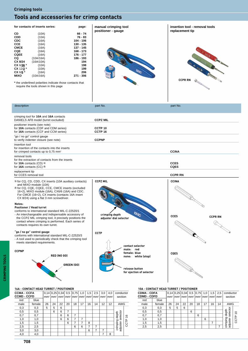
description part No. part No.
crimping tool for 10A and 16A contacts DANIELS AF8 model (turret excluded) CCPZ MIL
positioner inserts (see note) for 10A contacts (CDF and CDM series) CCTP 10 for 16A contacts (CCF and CCM series) CCTP 16
“go / no go” control gauge to verify indenter closure (see note) CCPNP
insertion tool for insertion of the contacts into the inserts for crimped contacts up to 0,75 mm2 CCINA
removal tools for the extraction of contacts from the inserts for 10A contacts (CD) 1) CCES for 16A contacts (CC) 2) CQES
replacement tip for CCES removal tool CCPR RN
manual crimping tool insertion tool - removal toolspositioner - gauge replacement tip
1) for CQ, CD, CDD, CX inserts (10A auxiliary contacts) and MIXO module (10A)
2) for CQ, CQE, CQEE, CCE, CMCE inserts (excluded 16+2), MIXO module (16A), CX6/6 (16A) and CDC.For CMCE (16+2), CX inserts (contacts 16A insert CX 8/24) using a flat 3 mm screwdriver.
Notes:Positioner / Head turretconforms to international standard MIL-C-22520/1- An interchangeable and indispensable accessory of
the CCPZ MIL crimping tool, it precisely positions the contact where crimping is performed. Each series of contacts requires its own turret.
“go / no go” control gaugeconforms with international standard MIL-C-22520/3- A tool used to periodically check that the crimping tool
meets standard requirements.
RED (NO GO)
GREEN (GO)
CCPNP
CCTP
contact selectormale: red female: blue none: white (stop)
release buttonfor ejection of selector
CCINA
CCES CCPR RN
CQES
CRIM
PING
TOO
LS
crim
ping
dep
thad
just
er s
elec
tor
CC
TP
16
CCMA - CCFA 0,14 0,25 0,34 0,5 0,75 1,0 1,5 2,5 3,0 4,0 conductor CCMD - CCFD mm2 mm2 mm2 mm2 mm2 mm2 mm2 mm2 mm2 mm2
section
red blue male female 26 24 22 20 18 17 16 14 12 12 AWG 0,3 0,3 5 5 6 0,5 0,5 6 6 7 0,7 0,7 6 6 7 1,0 1,0 6 6 7 7 1,5 1,5 6 7 7 8 2,5 2,5 6 6 7 7 3,0 3,0 6 7 7 4,0 4,0 7 8
16A - CONTACT HEAD TURRET / POSITIONER
crim
ping
dep
thad
just
er s
elec
tor
CC
TP
10
CDMA - CDFA 0,14 0,25 0,34 0,5 0,75 1,0 1,5 2,5 conductor CDMD - CDFD mm2 mm2 mm2 mm2 mm2 mm2 mm2 mm2 section red blue male female 26 24 22 20 18 17 16 14 AWG 0,3 0,3 5 5 6 0,5 0,5 6 0,7 0,7 6 1,0 1,0 6 1,5 1,5 7 2,5 2,5 7
10A - CONTACT HEAD TURRET / POSITIONER
CCPZ MIL
crimping depth adjuster dial selector
CCPR RN
708
for contacts of inserts series: page:
CD (10A) 66 - 74CDD (10A) 76 - 83CDC (16A) 104 - 106CCE (16A) 130 - 135CMCE (16A) 137 - 145CQE (16A) 168 - 173CQEE (16A) 176 - 177CQ (10A/16A) 186 - 193CX 8/24 (16A/10A) 194CX 6/36 * (10A) 198 CX 12/2 * (10A) 199CX 6/6 * (16A) 206MIXO (10A/16A) 271 - 306
* the underlined polarities indicate those contacts that require the tools shown in this page
Crimping tools
Tools and accessories for crimp contacts
CRIMPING TOOLS
Gauge tool selector Ø A ± 0,00254 mm Ø B ± 0,00254 mm pos. No. (GO) green (NO GO) redCCPNP 4 0,991 (mm) 1,118 (mm) 0,0390 (in) 0,0440 (in)
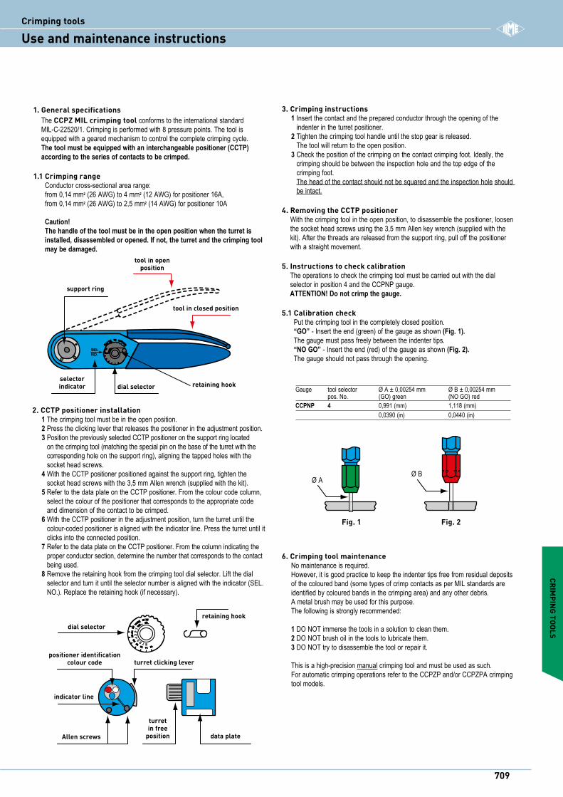
1. General specifications The CCPZ MIL crimping tool conforms to the international standard MIL-C-22520/1. Crimping is performed with 8 pressure points. The tool is equipped with a geared mechanism to control the complete crimping cycle. The tool must be equipped with an interchangeable positioner (CCTP) according to the series of contacts to be crimped.
1.1 Crimping range Conductor cross-sectional area range: from 0,14 mm2 (26 AWG) to 4 mm2 (12 AWG) for positioner 16A, from 0,14 mm2 (26 AWG) to 2,5 mm2 (14 AWG) for positioner 10A Caution! The handle of the tool must be in the open position when the turret is installed, disassembled or opened. If not, the turret and the crimping tool may be damaged.
3. Crimping instructions1 Insert the contact and the prepared conductor through the opening of the
indenter in the turret positioner.2 Tighten the crimping tool handle until the stop gear is released.
The tool will return to the open position.3 Check the position of the crimping on the contact crimping foot. Ideally, the
crimping should be between the inspection hole and the top edge of the crimping foot. The head of the contact should not be squared and the inspection hole should be intact.
4. Removing the CCTP positioner With the crimping tool in the open position, to disassemble the positioner, loosen the socket head screws using the 3,5 mm Allen key wrench (supplied with the kit). After the threads are released from the support ring, pull off the positioner with a straight movement.
5. Instructions to check calibration The operations to check the crimping tool must be carried out with the dial selector in position 4 and the CCPNP gauge. ATTENTION! Do not crimp the gauge.
5.1 Calibration check Put the crimping tool in the completely closed position. “GO” - Insert the end (green) of the gauge as shown (Fig. 1). The gauge must pass freely between the indenter tips. “NO GO” - Insert the end (red) of the gauge as shown (Fig. 2). The gauge should not pass through the opening.
87654
32
1
retaining hookdial selector
turret clicking lever
turretin free
position
indicator line
data plate
positioner identificationcolour code
Allen screws
Fig. 1
Ø AØ B
Fig. 2
2. CCTP positioner installation1 The crimping tool must be in the open position.2 Press the clicking lever that releases the positioner in the adjustment position.3 Position the previously selected CCTP positioner on the support ring located
on the crimping tool (matching the special pin on the base of the turret with the corresponding hole on the support ring), aligning the tapped holes with the socket head screws.
4 With the CCTP positioner positioned against the support ring, tighten the socket head screws with the 3,5 mm Allen wrench (supplied with the kit).
5 Refer to the data plate on the CCTP positioner. From the colour code column, select the colour of the positioner that corresponds to the appropriate code and dimension of the contact to be crimped.
6 With the CCTP positioner in the adjustment position, turn the turret until the colour-coded positioner is aligned with the indicator line. Press the turret until it clicks into the connected position.
7 Refer to the data plate on the CCTP positioner. From the column indicating the proper conductor section, determine the number that corresponds to the contact being used.
8 Remove the retaining hook from the crimping tool dial selector. Lift the dial selector and turn it until the selector number is aligned with the indicator (SEL.NO.). Replace the retaining hook (if necessary).
6. Crimping tool maintenanceNo maintenance is required.However, it is good practice to keep the indenter tips free from residual deposits of the coloured band (some types of crimp contacts as per MIL standards are identified by coloured bands in the crimping area) and any other debris.A metal brush may be used for this purpose.The following is strongly recommended:
1 DO NOT immerse the tools in a solution to clean them.2 DO NOT brush oil in the tools to lubricate them.3 DO NOT try to disassemble the tool or repair it.
This is a high-precision manual crimping tool and must be used as such.For automatic crimping operations refer to the CCPZP and/or CCPZPA crimping tool models.
CDMA - CDFA 0,14 0,25 0,34 0,5 0,75 1,0 1,5 2,5 conductor CDMD - CDFD mm2 mm2 mm2 mm2 mm2 mm2 mm2 mm2 section red blue male female 26 24 22 20 18 17 16 14 AWG 0,3 0,3 5 5 6 0,5 0,5 6 0,7 0,7 6 1,0 1,0 6 1,5 1,5 7 2,5 2,5 7
SELNO.
tool in openposition
support ring
tool in closed position
selectorindicator dial selector retaining hook
709
iCrimping tools
Use and maintenance instructions
description part No. part No.
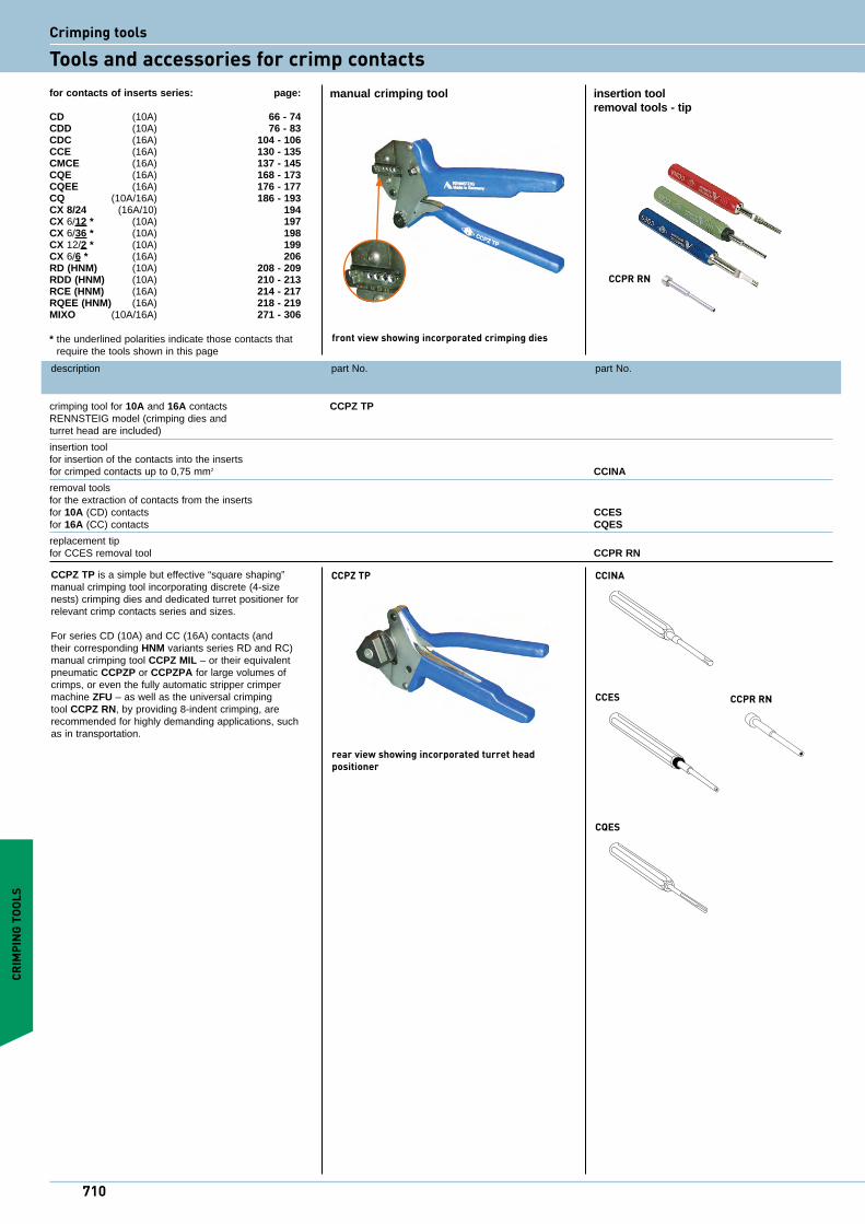
crimping tool for 10A and 16A contacts CCPZ TP RENNSTEIG model (crimping dies and turret head are included)
insertion tool for insertion of the contacts into the inserts for crimped contacts up to 0,75 mm2 CCINA
removal tools for the extraction of contacts from the inserts for 10A (CD) contacts CCES for 16A (CC) contacts CQES
replacement tip for CCES removal tool CCPR RN
manual crimping tool insertion tool removal tools - tip
CCPZ TP is a simple but effective “square shaping” manual crimping tool incorporating discrete (4-size nests) crimping dies and dedicated turret positioner for relevant crimp contacts series and sizes.
For series CD (10A) and CC (16A) contacts (and their corresponding HNM variants series RD and RC) manual crimping tool CCPZ MIL – or their equivalent pneumatic CCPZP or CCPZPA for large volumes of crimps, or even the fully automatic stripper crimper machine ZFU – as well as the universal crimping tool CCPZ RN, by providing 8-indent crimping, are recommended for highly demanding applications, such as in transportation.
CCPZ TP CCINA
CCES CCPR RN
CQES
CRIM
PING
TOO
LS
for contacts of inserts series: page:
CD (10A) 66 - 74CDD (10A) 76 - 83CDC (16A) 104 - 106CCE (16A) 130 - 135CMCE (16A) 137 - 145CQE (16A) 168 - 173CQEE (16A) 176 - 177CQ (10A/16A) 186 - 193CX 8/24 (16A/10) 194CX 6/12 * (10A) 197CX 6/36 * (10A) 198CX 12/2 * (10A) 199CX 6/6 * (16A) 206RD (HNM) (10A) 208 - 209RDD (HNM) (10A) 210 - 213RCE (HNM) (16A) 214 - 217RQEE (HNM) (16A) 218 - 219MIXO (10A/16A) 271 - 306
* the underlined polarities indicate those contacts that require the tools shown in this page
front view showing incorporated crimping dies
rear view showing incorporated turret head positioner
CCPR RN
710
Crimping tools
Tools and accessories for crimp contacts
CRIMPING TOOLS
description part No. part No.
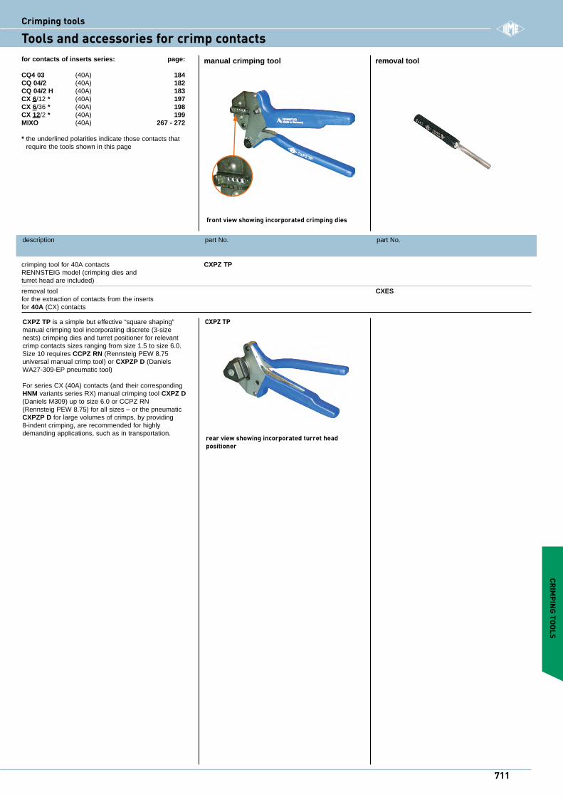
crimping tool for 40A contacts CXPZ TP RENNSTEIG model (crimping dies and turret head are included)
removal tool CXES for the extraction of contacts from the inserts for 40A (CX) contacts
manual crimping tool removal tool
CXPZ TP is a simple but effective “square shaping” manual crimping tool incorporating discrete (3-size nests) crimping dies and turret positioner for relevant crimp contacts sizes ranging from size 1.5 to size 6.0. Size 10 requires CCPZ RN (Rennsteig PEW 8.75 universal manual crimp tool) or CXPZP D (Daniels WA27-309-EP pneumatic tool)
For series CX (40A) contacts (and their corresponding HNM variants series RX) manual crimping tool CXPZ D (Daniels M309) up to size 6.0 or CCPZ RN (Rennsteig PEW 8.75) for all sizes – or the pneumatic CXPZP D for large volumes of crimps, by providing 8-indent crimping, are recommended for highly demanding applications, such as in transportation.
CXPZ TP
for contacts of inserts series: page:
CQ4 03 (40A) 184CQ 04/2 (40A) 182CQ 04/2 H (40A) 183CX 6/12 * (40A) 197CX 6/36 * (40A) 198 CX 12/2 * (40A) 199MIXO (40A) 267 - 272
* the underlined polarities indicate those contacts that require the tools shown in this page
front view showing incorporated crimping dies
rear view showing incorporated turret head positioner
711
iCrimping tools
Tools and accessories for crimp contacts
description part No. part No.
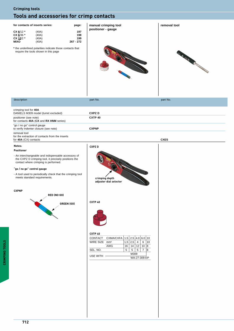
crimping tool for 40A DANIELS M309 model (turret excluded) CXPZ D
positioner (see note) CXTP 40 for contacts 40A (CX and RX HNM series)
“go / no go” control gauge to verify indenter closure (see note) CXPNP
removal tool for the extraction of contacts from the inserts for 40A (CX) contacts CXES
manual crimping tool removal toolpositioner - gauge
RED (NO GO)
GREEN (GO)
CXPNP
for contacts of inserts series: page:
CX 6/12 * (40A) 197CX 6/36 * (40A) 198 CX 12/2 * (40A) 199MIXO (40A) 267 - 272
* the underlined polarities indicate those contacts that require the tools shown in this page
Notes:Positioner
- An interchangeable and indispensable accessory of the CXPZ D crimping tool, it precisely positions the contact where crimping is performed.
“go / no go” control gauge
- A tool used to periodically check that the crimping tool meets standard requirements.
CXTP 40
CRIM
PING
TOO
LS
CXTP 40CONTACT CXMA/CXFA 1.5 2.5 4.0 6.0 10WIRE SIZE mm2 1,5 2,5 4 6 10 AWG 16 14 12 10 8SEL. NO. 5 5 5 7 8
USE WITH M309
WA-27-309-EP
CXPZ D
crimping depth adjuster dial selector
712
Crimping tools
Tools and accessories for crimp contacts
87654
32
1
retaining hookdial selector
Allen screws data plate
CRIMPING TOOLS
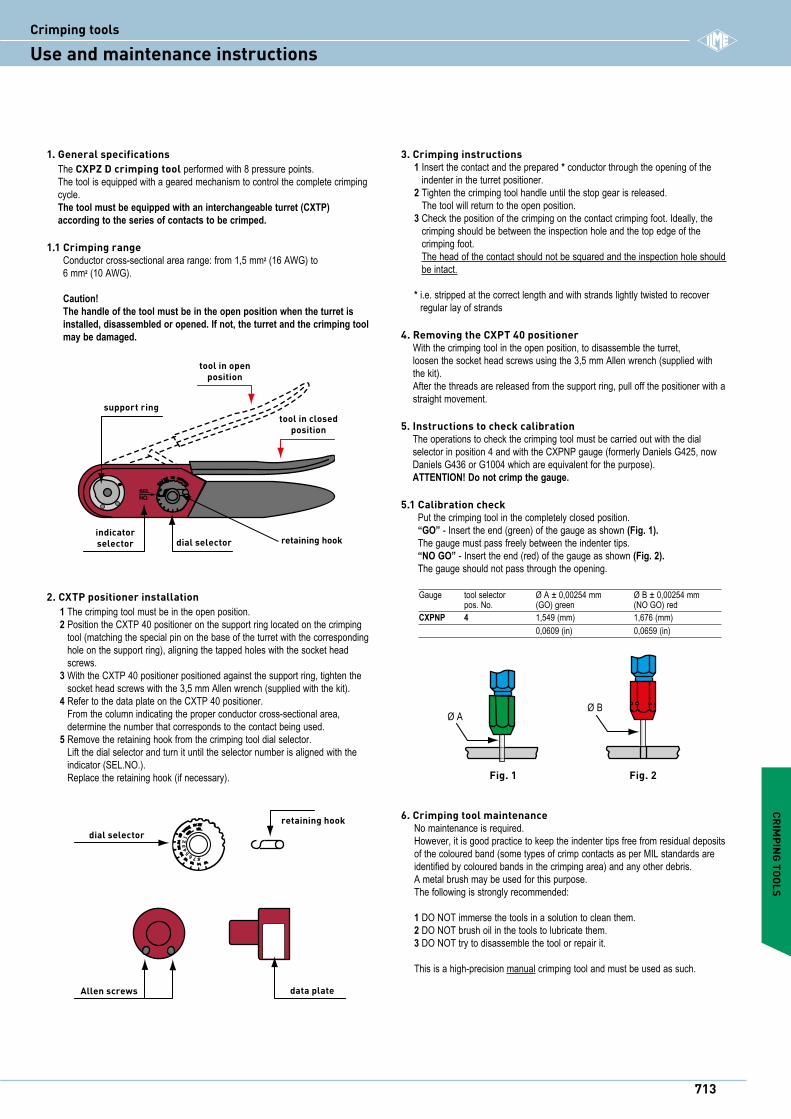
Gauge tool selector Ø A ± 0,00254 mm Ø B ± 0,00254 mm pos. No. (GO) green (NO GO) redCXPNP 4 1,549 (mm) 1,676 (mm) 0,0609 (in) 0,0659 (in)
1. General specifications The CXPZ D crimping tool performed with 8 pressure points. The tool is equipped with a geared mechanism to control the complete crimping cycle. The tool must be equipped with an interchangeable turret (CXTP) according to the series of contacts to be crimped.
1.1 Crimping range Conductor cross-sectional area range: from 1,5 mm2 (16 AWG) to 6 mm2 (10 AWG). Caution! The handle of the tool must be in the open position when the turret is installed, disassembled or opened. If not, the turret and the crimping tool may be damaged.
3. Crimping instructions1 Insert the contact and the prepared * conductor through the opening of the
indenter in the turret positioner.2 Tighten the crimping tool handle until the stop gear is released.
The tool will return to the open position.3 Check the position of the crimping on the contact crimping foot. Ideally, the
crimping should be between the inspection hole and the top edge of the crimping foot. The head of the contact should not be squared and the inspection hole should be intact.
* i.e. stripped at the correct length and with strands lightly twisted to recover regular lay of strands
4. Removing the CXPT 40 positioner With the crimping tool in the open position, to disassemble the turret, loosen the socket head screws using the 3,5 mm Allen wrench (supplied with the kit). After the threads are released from the support ring, pull off the positioner with a straight movement.
5. Instructions to check calibration The operations to check the crimping tool must be carried out with the dial selector in position 4 and with the CXPNP gauge (formerly Daniels G425, now Daniels G436 or G1004 which are equivalent for the purpose). ATTENTION! Do not crimp the gauge.
5.1 Calibration check Put the crimping tool in the completely closed position. “GO” - Insert the end (green) of the gauge as shown (Fig. 1). The gauge must pass freely between the indenter tips. “NO GO” - Insert the end (red) of the gauge as shown (Fig. 2). The gauge should not pass through the opening.
Fig. 1
Ø AØ B
Fig. 2
2. CXTP positioner installation1 The crimping tool must be in the open position.2 Position the CXTP 40 positioner on the support ring located on the crimping
tool (matching the special pin on the base of the turret with the corresponding hole on the support ring), aligning the tapped holes with the socket head screws.
3 With the CXTP 40 positioner positioned against the support ring, tighten the socket head screws with the 3,5 mm Allen wrench (supplied with the kit).
4 Refer to the data plate on the CXTP 40 positioner. From the column indicating the proper conductor cross-sectional area, determine the number that corresponds to the contact being used.
5 Remove the retaining hook from the crimping tool dial selector. Lift the dial selector and turn it until the selector number is aligned with the indicator (SEL.NO.). Replace the retaining hook (if necessary).
6. Crimping tool maintenanceNo maintenance is required.However, it is good practice to keep the indenter tips free from residual deposits of the coloured band (some types of crimp contacts as per MIL standards are identified by coloured bands in the crimping area) and any other debris.A metal brush may be used for this purpose.The following is strongly recommended:
1 DO NOT immerse the tools in a solution to clean them.2 DO NOT brush oil in the tools to lubricate them.3 DO NOT try to disassemble the tool or repair it.
This is a high-precision manual crimping tool and must be used as such.
SELNO.
tool in openposition
support ringtool in closed
position
indicatorselector dial selector retaining hook
713
iCrimping tools
Use and maintenance instructions
description part No. part No.
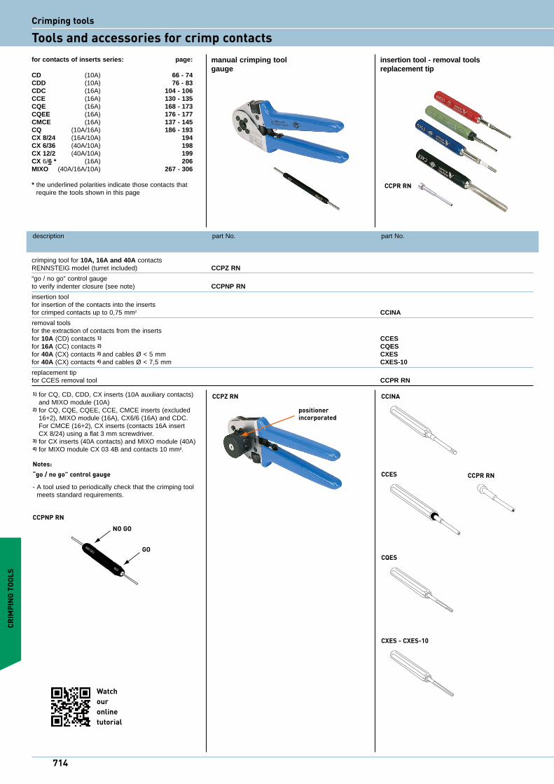
crimping tool for 10A, 16A and 40A contacts RENNSTEIG model (turret included) CCPZ RN
“go / no go” control gauge to verify indenter closure (see note) CCPNP RN
insertion tool for insertion of the contacts into the inserts for crimped contacts up to 0,75 mm2 CCINA
removal tools for the extraction of contacts from the inserts for 10A (CD) contacts 1) CCES for 16A (CC) contacts 2) CQES for 40A (CX) contacts 3) and cables Ø < 5 mm CXES for 40A (CX) contacts 4) and cables Ø < 7,5 mm CXES-10
replacement tip for CCES removal tool CCPR RN
manual crimping tool insertion tool - removal toolsgauge replacement tip
for contacts of inserts series: page:
CD (10A) 66 - 74CDD (10A) 76 - 83CDC (16A) 104 - 106CCE (16A) 130 - 135CQE (16A) 168 - 173CQEE (16A) 176 - 177CMCE (16A) 137 - 145CQ (10A/16A) 186 - 193CX 8/24 (16A/10A) 194CX 6/36 (40A/10A) 198 CX 12/2 (40A/10A) 199CX 6/6 * (16A) 206MIXO (40A/16A/10A) 267 - 306
* the underlined polarities indicate those contacts that require the tools shown in this page
1) for CQ, CD, CDD, CX inserts (10A auxiliary contacts) and MIXO module (10A)
2) for CQ, CQE, CQEE, CCE, CMCE inserts (excluded 16+2), MIXO module (16A), CX6/6 (16A) and CDC.For CMCE (16+2), CX inserts (contacts 16A insert CX 8/24) using a flat 3 mm screwdriver.
3) for CX inserts (40A contacts) and MIXO module (40A)4) for MIXO module CX 03 4B and contacts 10 mm2.
Notes:“go / no go” control gauge
- A tool used to periodically check that the crimping tool meets standard requirements.
CCPNP RNNO GO
GO
CCPZ RN
positioner incorporated
CCINA
CCES CCPR RN
CQES
CXES - CXES-10
CRIM
PING
TOO
LS
CCPR RN
714
Watch ouronline tutorial
Crimping tools
Tools and accessories for crimp contacts
indenters
movable handle
fixed handleclosure
stop
adjustment knob with 1/100 mm units for fine adjustment
metric scale with 2/10 mm units for approximate adjustments
12-seat positioner
scale in mm, with 2/10 mm units
crimp depth -
adjustment knob with1/100 mm units for fine adjustment
crimp depth +
Fig. 1 Fig. 2
Ø A Ø B
CRIMPING TOOLS
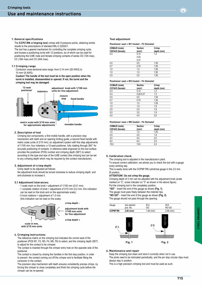
1. General specifications The CCPZ RN crimping tool crimps with 8 pressure points, obtaining similar results to the prescriptions of standard MIL-C-22520/1. The tool has a geared mechanism for controlling the complete crimping cycle, and houses a positioning turret with 12 positions, six of which can be used for positioning the ILME male and female crimping contacts of series CD (10A max), CC (16A max) and CX (40A max).
1.1 Crimping range Conductor cross-sectional area range: from 0,14 mm2 (26 AWG) to 10 mm2 (8 AWG). Caution! The handle of the tool must be in the open position when the turret is installed, disassembled or opened. If not, the turret and the crimping tool may be damaged.
Positioner seat = M1 (male) - F2 (female)CDMA/D (male) Section CrimpCDFA/D (female) (mm2) depth (mm)0,3 0,14 1,3 0,25 0,370,5 0,5 1,550,7 0,75 1,551,0 1,0 1,551,5 1,5 1,552,5 2,5 1,55
Positioner seat = M3 (male) - F4 (female)CCMA/D (male) Section CrimpCCFA/D (female) (mm2) depth (mm)0,3 0,14 1,20,3 0,25-0,37 1,30,5 0,5 1,550,7 0,75 1,551,0 1,0 1,551,5 1,5 1,82,5 2,5 1,83,0 3,0 1,94,0 4,0 2,0
Positioner seat = M5 (male) - F6 (female)CXMA/D (male) Section CrimpCXFA/D (female) (mm2) depth (mm)1,5 1,5 1,552,5 2,5 1,84,0 4,0 2,06,0 6,0 2,510,0 10,0 2,3
Tool adjustment
Gauge tool selector Ø A Ø B pos. No. GO NO GOCCPNP RN 2,00 (mm) 1,94 (mm) 2,06 (mm)
5. Calibration check The crimping tool is adjusted in the manufacturer’s plant. To ensure correct calibration, we advise you to check the tool with a gauge every working day. This is easily done with the CCPNP RN cylindrical gauge in the 2,0 mm Ø position. ATTENTION!: Do not crimp the gauge. Crimping depth of 2 mm can be adjusted with the adjustment knob (scale marked on “2”, screw indicator on “0” as shown in the above figure). Put the crimping tool in the completely position. “GO” - Insert the end of the gauge as shown (Fig. 1). The gauge must pass freely between the indenter tips. “NO GO” - Insert the end of the gauge as shown (Fig. 2). The gauge should not pass through the opening.
2. Description of tool Crimping tool components: a first mobile handle, with a precision stop mechanism with teeth and an opening limiting guide; a second fixed handle with metric scale (units of 2/10 mm); an adjustment system with fine step adjustments of 1/100 mm; four indenters; a 12-seat positioner, fully rotating through 360° for accurate positioning of contacts. A reference table engraved on the tool surface provides the positioner (POS) number and crimping depth (SET) to select according to the type and size of the ILME contact (the crimping tool can be set to any crimping depth which may be required by the contact manufacturer).
3. Adjustment of crimp depth Crimp depth to be adjusted ad follows: the adjustment knob should be turned clockwise to reduce crimping depth, and anti-clockwise to increase it.
3.1 Adjustment tolerances: - 1 scale mark on the knob = adjustment of 1/100 mm (0,01 mm); - 1 complete rotation of knob = adjustment of 2/10 mm (0,2 mm, this indication
can be read on the knob and on the approximate scale); - 5 knob rotations = adjustment of 1,0 mm
(this indication can be read on the scale).
6. Maintenance and repair Keep the crimping tool clean and store it correctly when not in use. The joints need to be lubricated periodically, and the pin stop circular clips must always stay in position. This is a high precision crimping tool and must be used as such.
4. Crimping instructions The reference matrix on the crimping tool indicates the correct seat of the positioner (POS M1, F2, M3, F4, M5, F6) to select, and the crimping depth (SET) to adjust for the contact to be crimped. The contact is inserted through the crimper entry hole on the opposite side of the positioner. The contact is closed by closing the handles in the first stop position, in order to prevent the contact coming out off the crimper and to facilitate fitting the conductor in the contact. The precision stop mechanism with teeth ensures consistently precise crimps, by forcing the crimper to close completely and finish the crimping cycle before the crimper can be re-opened.
715
iCrimping tools
Use and maintenance instructions
description part No. part No.
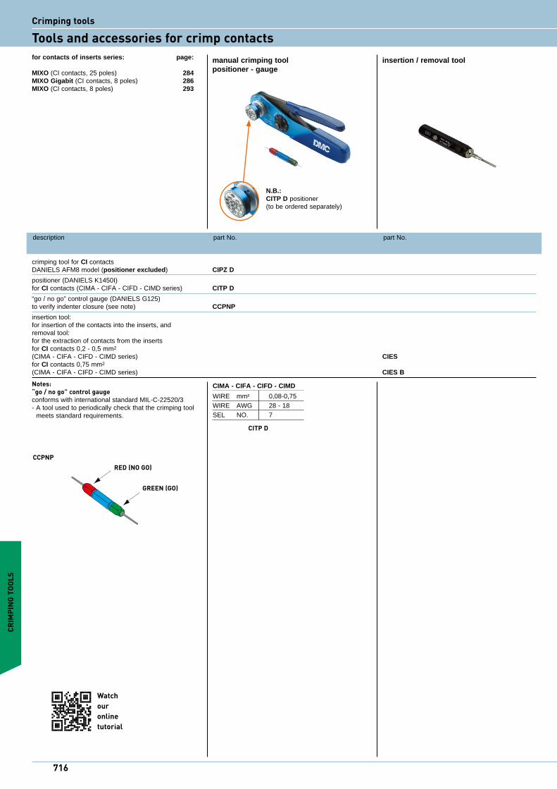
crimping tool for CI contacts DANIELS AFM8 model (positioner excluded) CIPZ D
positioner (DANIELS K1450I) for CI contacts (CIMA - CIFA - CIFD - CIMD series) CITP D
“go / no go” control gauge (DANIELS G125) to verify indenter closure (see note) CCPNP
insertion tool: for insertion of the contacts into the inserts, and removal tool: for the extraction of contacts from the inserts for CI contacts 0,2 - 0,5 mm2 (CIMA - CIFA - CIFD - CIMD series) CIES for CI contacts 0,75 mm2 (CIMA - CIFA - CIFD - CIMD series) CIES B
manual crimping tool insertion / removal toolpositioner - gauge
for contacts of inserts series: page:
MIXO (CI contacts, 25 poles) 284MIXO Gigabit (CI contacts, 8 poles) 286MIXO (CI contacts, 8 poles) 293
Notes:“go / no go” control gaugeconforms with international standard MIL-C-22520/3- A tool used to periodically check that the crimping tool
meets standard requirements.
RED (NO GO)
GREEN (GO)
CCPNP
CRIM
PING
TOO
LS
CIMA - CIFA - CIFD - CIMD
WIRE mm2 0,08-0,75WIRE AWG 28 - 18SEL NO. 7
CITP D
N.B.:CITP D positioner(to be ordered separately)
716
Watch ouronline tutorial
Crimping tools
Tools and accessories for crimp contacts
description part No. part No.
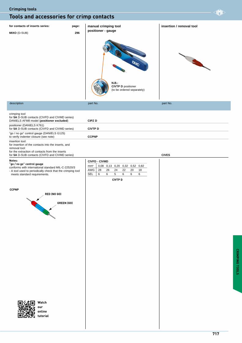
crimping tool for 5A D-SUB contacts (CIVFD and CIVMD series) DANIELS AFM8 model (positioner excluded) CIPZ D
positioner (DANIELS K761) for 5A D-SUB contacts (CIVFD and CIVMD series) CIVTP D
“go / no go” control gauge (DANIELS G125) to verify indenter closure (see note) CCPNP
insertion tool: for insertion of the contacts into the inserts, and removal tool: for the extraction of contacts from the inserts for 5A D-SUB contacts (CIVFD and CIVMD series) CIVES
manual crimping tool insertion / removal toolpositioner - gauge
for contacts of inserts series: page:
MIXO (D-SUB) 296
Notes: “go / no go” control gaugeconforms with international standard MIL-C-22520/3- A tool used to periodically check that the crimping tool
meets standard requirements.
RED (NO GO)
GREEN (GO)
CCPNP
CRIMPING TOOLS
CIVFD - CIVMD
mm2 0,08 0,13 0,20 0,32 0,52 0,82AWG 28 26 24 22 20 18SEL 6 6 5 6 6 6
CIVTP D
N.B.:CIVTP D positioner(to be ordered separately)
717
i
Watch ouronline tutorial
Crimping tools
Tools and accessories for crimp contacts
tool in closedposition
spring clip
selector knob
positioner guide
tool in openposition
bayonet pin
dataplate
positioner “K” series
safety clip
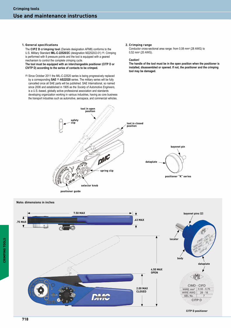
2. Crimping range Conductor cross-sectional area range: from 0,08 mm2 (28 AWG) to 0,52 mm2 (20 AWG). Caution! The handle of the tool must be in the open position when the positioner is installed, disassembled or opened. If not, the positioner and the crimping tool may be damaged.
.75 MAX
7.50 MAX
.63 MAX
2.00 MAXCLOSED
4.50 MAXOPEN
bayonet pins (2)
locator
dataplate
body
CITP D positioner
CRIM
PING
TOO
LS
1. General specifications The CIPZ D crimping tool (Daniels designation AFM8) conforms to the U.S. Military Standard MIL-C-22520/2C (designation M22520/2-01) (1). Crimping is performed with 8 pressure points and the tool is equipped with a geared mechanism to control the complete crimping cycle. The tool must be equipped with an interchangeable positioner (CITP D or CIVTP D) according to the series of contacts to be crimped. (1) Since October 2011 the MIL-C-22520 series is being progressively replaced
by a corresponding SAE (1) AS22520 series. The military series will be fully cancelled once all SAE parts will be published. SAE International, so named since 2006 and established in 1905 as the Society of Automotive Engineers, is a U.S.-based, globally active professional association and standards developing organization working in various industries, having as core business the transport industries such as automotive, aerospace, and commercial vehicles.
Note: dimensions in inches
718
Crimping tools
Use and maintenance instructions

3. CITP D or CIVTP D positioner installation1 The crimping tool must be in the open position.2 Remove the safety clip from the positioner guide.3 Insert the previously selected CITP D or CIVTP D positioner into the
positioner guide on the head of the tool. Push down and rotate 90 degrees until bayonet pins lock.
4 Refer to the data plate on the CITP D or CIVTP D positioner for the setup of the selector number that determines crimp height, based on the contact size and conductor size.
5 With the tool in open position, remove the spring clip then raise and rotate selector knob until number indicated on data plate for conductor size to be crimped is in line with SEL. NO. arrow. Reinstall spring clip to avoid unintended change of setup
4. Crimping instructions1 Insert the contact and the prepared (correctly stripped) conductor through the
indenter opening in the positioner.2 Squeeze the crimping tool handles together until ratchet releases. Handles
will return to open position.3 Check the position of the crimping on the contact crimp barrel. Ideally, the
crimping should be between the inspection hole and the top edge of the crimp barrel.
The edge of the contact barrel should not result squared and the inspection hole should remain intact.
5. Removing the CITP D or CIVTP D positioner With the crimping tool in the open position, to disassemble the positioner, push down on the positioner to release the bayonet pins from the positioner guide. Turn 90 degrees anticlockwise and remove the positioner from the tool.
6. Instructions to check calibration The operations to check the crimping tool must be carried out with the dial selector in position 8 and the CCPNP gauge. CAUTION! Do not crimp gauge!
6.1 Calibration check Put the crimping tool in the completely closed position. “GO” - Insert the end (green) of the gauge as shown (Fig. 1). The gauge must pass freely between the indenter tips. “NO GO” - Insert the end (red) of the gauge as shown (Fig. 2). The gauge should not pass through the opening.
7. Crimping tool maintenanceNo maintenance is required. However, it is good practice to keep the indenter tips free from residual deposits of the coloured band (some types of crimp contacts as per SAE (MIL) standards are identified by coloured bands in the crimping area) and any other debris. A small wire brush may be used for this purpose.
The following is strongly recommended:1 DO NOT immerse the tools in a solution to clean them.2 DO NOT brush oil in the tools to lubricate them.3 DO NOT try to disassemble the tool or repair it.
This is a high-precision manual crimping tool and must be used as such.
Fig. 1
Ø AØ B
Fig. 2
Gauge tool selector Ø A ± 0,00254 mm Ø B ± 0,00254 mm pos. No. (GO) green (NO GO) redCCPNP 8 0,991 (mm) 1,118 (mm) 0,0390 (in) 0,0440 (in)
CRIMPING TOOLS
719
i
description part No. part No.
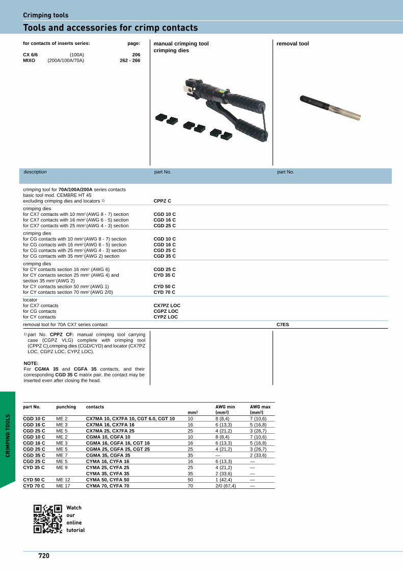
crimping tool for 70A/100A/200A series contacts basic tool mod. CEMBRE HT 45 excluding crimping dies and locators 1) CPPZ C
crimping dies for CX7 contacts with 10 mm2 (AWG 8 - 7) section CGD 10 C for CX7 contacts with 16 mm2 (AWG 6 - 5) section CGD 16 C for CX7 contacts with 25 mm2 (AWG 4 - 3) section CGD 25 C
crimping dies for CG contacts with 10 mm2 (AWG 8 - 7) section CGD 10 C for CG contacts with 16 mm2 (AWG 6 - 5) section CGD 16 C for CG contacts with 25 mm2 (AWG 4 - 3) section CGD 25 C for CG contacts with 35 mm2 (AWG 2) section CGD 35 C
crimping dies for CY contacts section 16 mm2 (AWG 6) CGD 25 C for CY contacts section 25 mm2 (AWG 4) and CYD 35 C section 35 mm2 (AWG 2) for CY contacts section 50 mm2 (AWG 1) CYD 50 C for CY contacts section 70 mm2 (AWG 2/0) CYD 70 C
locator for CX7 contacts CX7PZ LOC for CG contacts CGPZ LOC for CY contacts CYPZ LOC
removal tool for 70A CX7 series contact C7ES
manual crimping tool removal toolcrimping dies
for contacts of inserts series: page:
CX 6/6 (100A) 206MIXO (200A/100A/70A) 262 - 266
NOTE:For CGMA 35 and CGFA 35 contacts, and their corresponding CGD 35 C matrix pair, the contact may be inserted even after closing the head.
part No. punching contacts AWG min AWG max mm2 (mm2) (mm2)CGD 10 C ME 2 CX7MA 10, CX7FA 10, CGT 6.0, CGT 10 10 8 (8,4) 7 (10,6)CGD 16 C ME 3 CX7MA 16, CX7FA 16 16 6 (13,3) 5 (16,8) CGD 25 C ME 5 CX7MA 25, CX7FA 25 25 4 (21,2) 3 (26,7) CGD 10 C ME 2 CGMA 10, CGFA 10 10 8 (8,4) 7 (10,6) CGD 16 C ME 3 CGMA 16, CGFA 16, CGT 16 16 6 (13,3) 5 (16,8)CGD 25 C ME 5 CGMA 25, CGFA 25, CGT 25 25 4 (21,2) 3 (26,7)CGD 35 C ME 7 CGMA 35, CGFA 35 35 — 2 (33,6)CGD 25 C ME 5 CYMA 16, CYFA 16 16 6 (13,3) —CYD 35 C ME 9 CYMA 25, CYFA 25 25 4 (21,2) — CYMA 35, CYFA 35 35 2 (33,6) —CYD 50 C ME 12 CYMA 50, CYFA 50 50 1 (42,4) —CYD 70 C ME 17 CYMA 70, CYFA 70 70 2/0 (67,4) —
1) part No. CPPZ CF: manual crimping tool carrying case (CGPZ VLG) complete with crimping tool (CPPZ C),crimping dies (CGD/CYD) and locator (CX7PZ LOC, CGPZ LOC, CYPZ LOC).
CRIM
PING
TOO
LS
720
Watch ouronline tutorial
Crimping tools
Tools and accessories for crimp contacts
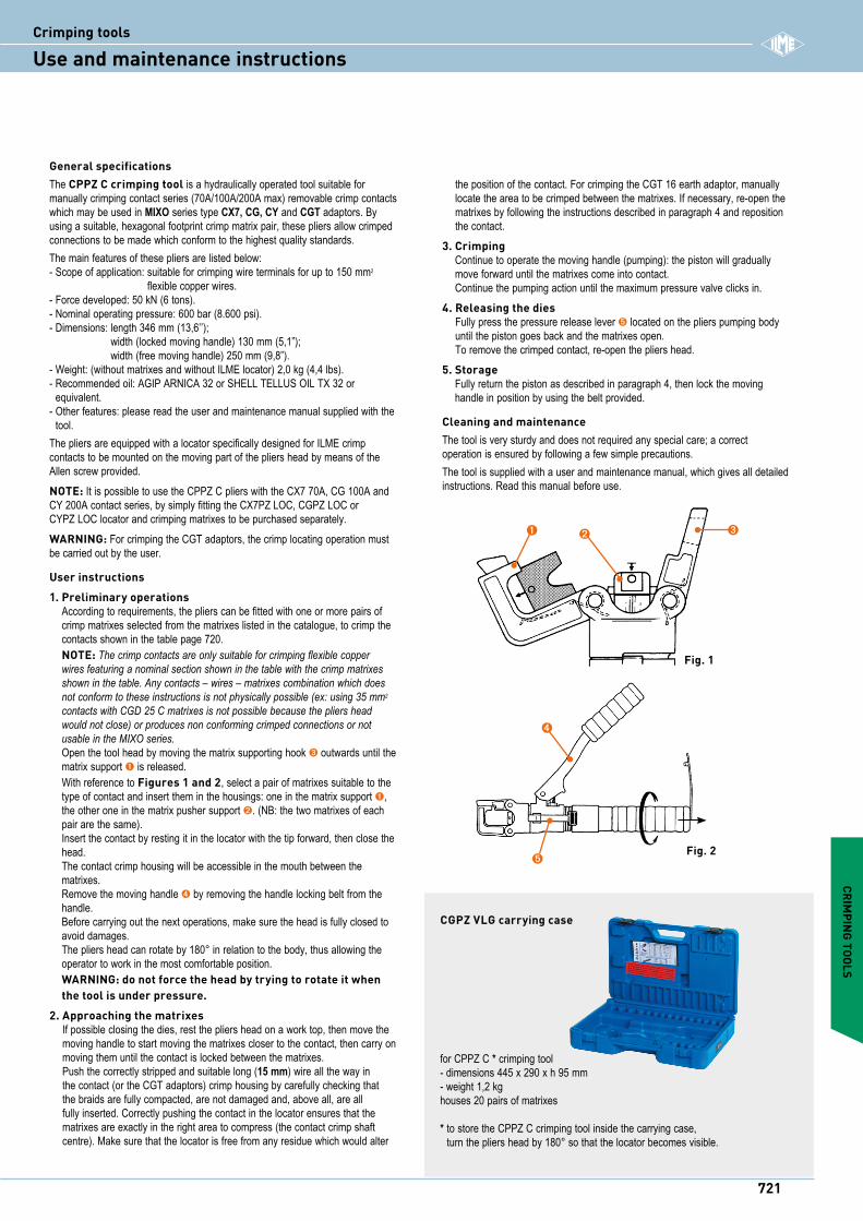
General specificationsThe CPPZ C crimping tool is a hydraulically operated tool suitable for manually crimping contact series (70A/100A/200A max) removable crimp contacts which may be used in MIXO series type CX7, CG, CY and CGT adaptors. By using a suitable, hexagonal footprint crimp matrix pair, these pliers allow crimped connections to be made which conform to the highest quality standards.The main features of these pliers are listed below:- Scope of application: suitable for crimping wire terminals for up to 150 mm2
flexible copper wires.- Force developed: 50 kN (6 tons).- Nominal operating pressure: 600 bar (8.600 psi).- Dimensions: length 346 mm (13,6’’);
width (locked moving handle) 130 mm (5,1”); width (free moving handle) 250 mm (9,8”).
- Weight: (without matrixes and without ILME locator) 2,0 kg (4,4 lbs).- Recommended oil: AGIP ARNICA 32 or SHELL TELLUS OIL TX 32 or
equivalent.- Other features: please read the user and maintenance manual supplied with the
tool.The pliers are equipped with a locator specifically designed for ILME crimp contacts to be mounted on the moving part of the pliers head by means of the Allen screw provided.NOTE: It is possible to use the CPPZ C pliers with the CX7 70A, CG 100A and CY 200A contact series, by simply fitting the CX7PZ LOC, CGPZ LOC or CYPZ LOC locator and crimping matrixes to be purchased separately.WARNING: For crimping the CGT adaptors, the crimp locating operation must be carried out by the user.
User instructions1. Preliminary operations
According to requirements, the pliers can be fitted with one or more pairs of crimp matrixes selected from the matrixes listed in the catalogue, to crimp the contacts shown in the table page 720. NOTE: The crimp contacts are only suitable for crimping flexible copper wires featuring a nominal section shown in the table with the crimp matrixes shown in the table. Any contacts – wires – matrixes combination which does not conform to these instructions is not physically possible (ex: using 35 mm2 contacts with CGD 25 C matrixes is not possible because the pliers head would not close) or produces non conforming crimped connections or not usable in the MIXO series. Open the tool head by moving the matrix supporting hook ➌ outwards until the matrix support ➊ is released. With reference to Figures 1 and 2, select a pair of matrixes suitable to the type of contact and insert them in the housings: one in the matrix support ➊, the other one in the matrix pusher support ➋. (NB: the two matrixes of each pair are the same). Insert the contact by resting it in the locator with the tip forward, then close the head. The contact crimp housing will be accessible in the mouth between the matrixes. Remove the moving handle ➍ by removing the handle locking belt from the handle. Before carrying out the next operations, make sure the head is fully closed to avoid damages. The pliers head can rotate by 180° in relation to the body, thus allowing the operator to work in the most comfortable position. WARNING: do not force the head by trying to rotate it when the tool is under pressure.
2. Approaching the matrixes If possible closing the dies, rest the pliers head on a work top, then move the moving handle to start moving the matrixes closer to the contact, then carry on moving them until the contact is locked between the matrixes. Push the correctly stripped and suitable long (15 mm) wire all the way in the contact (or the CGT adaptors) crimp housing by carefully checking that the braids are fully compacted, are not damaged and, above all, are all fully inserted. Correctly pushing the contact in the locator ensures that the matrixes are exactly in the right area to compress (the contact crimp shaft centre). Make sure that the locator is free from any residue which would alter
the position of the contact. For crimping the CGT 16 earth adaptor, manually locate the area to be crimped between the matrixes. If necessary, re-open the matrixes by following the instructions described in paragraph 4 and reposition the contact.
3. Crimping Continue to operate the moving handle (pumping): the piston will gradually move forward until the matrixes come into contact. Continue the pumping action until the maximum pressure valve clicks in.
4. Releasing the dies Fully press the pressure release lever ➎ located on the pliers pumping body until the piston goes back and the matrixes open. To remove the crimped contact, re-open the pliers head.
5. Storage Fully return the piston as described in paragraph 4, then lock the moving handle in position by using the belt provided.
Cleaning and maintenance The tool is very sturdy and does not required any special care; a correct operation is ensured by following a few simple precautions. The tool is supplied with a user and maintenance manual, which gives all detailed instructions. Read this manual before use.
Fig. 2
Fig. 1
CRIMPING TOOLS
for CPPZ C * crimping tool- dimensions 445 x 290 x h 95 mm- weight 1,2 kghouses 20 pairs of matrixes
* to store the CPPZ C crimping tool inside the carrying case, turn the pliers head by 180° so that the locator becomes visible.
CGPZ VLG carrying case
➌➋➊
➍
➎
721
iCrimping tools
Use and maintenance instructions
description part No. part No.
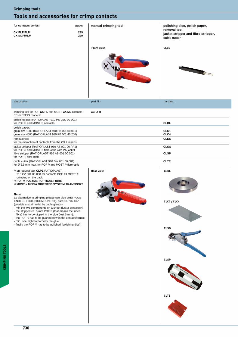
crimping tool for POF CX PL and MOST CX ML contacts CLPZ R RENNSTEIG model 1)
polishing disc (RATIOPLAST 910 PS 0SC 00 001) for POF 2) and MOST 3) contacts CLDL
polish paper: grain size 1000 (RATIOPLAST 910 PB 001 00 001) CLC1 grain size 4000 (RATIOPLAST 910 PB 001 40 250) CLC4
removal tool CLES for the extraction of contacts from the CX L inserts
jacket stripper (RATIOPLAST 910 AZ 001 00 PA1) CLSG for POF 2) and MOST 3) fibre optic with PA jacket fibre stripper (RATIOPLAST 910 AB 001 00 001) CLSP for POF 2) fibre optic
cable cutter (RATIOPLAST 910 SW 001 00 001) CLTE for Ø 2,3 mm max, for POF 2) and MOST 3) fibre optic
manual crimping tool polishing disc, polish paper, removal tool, jacket stripper and fibre stripper, cable cutter
1) on request tool CLPZ RATIOPLAST 910 CZ 001 00 008 for contacts POF 2) / MOST 3) crimping on the back
2) POF = POLYMER OPTICAL FIBRE3) MOST = MEDIA ORIENTED SYSTEM TRANSPORT
Note:as alternative to crimping please use glue UHU PLUS ENDFEST 300 (BICOMPONENT), part No. “CL GL” (provide a strain relief by cable glands):- mix the two components on a sheet (just a drop/each)- the stripped ca. 5 mm POF 2) (that means the inner
fibre) has to be dipped in the glue (just 5 mm);- the POF 2) has to be pushed now in the contact/ferrule;- min. one night to hard/dry the glue; - finally the POF 2) has to be polished (polishing disc).
Rear view
for contacts series: page:
CX PLF/PLM 299CX MLF/MLM 299
CLC1 / CLC4
CLSG
CLSP
CLTE
Front view CLES
CRIM
PING
TOO
LS
CLDL
730
Crimping tools
Tools and accessories for crimp contacts
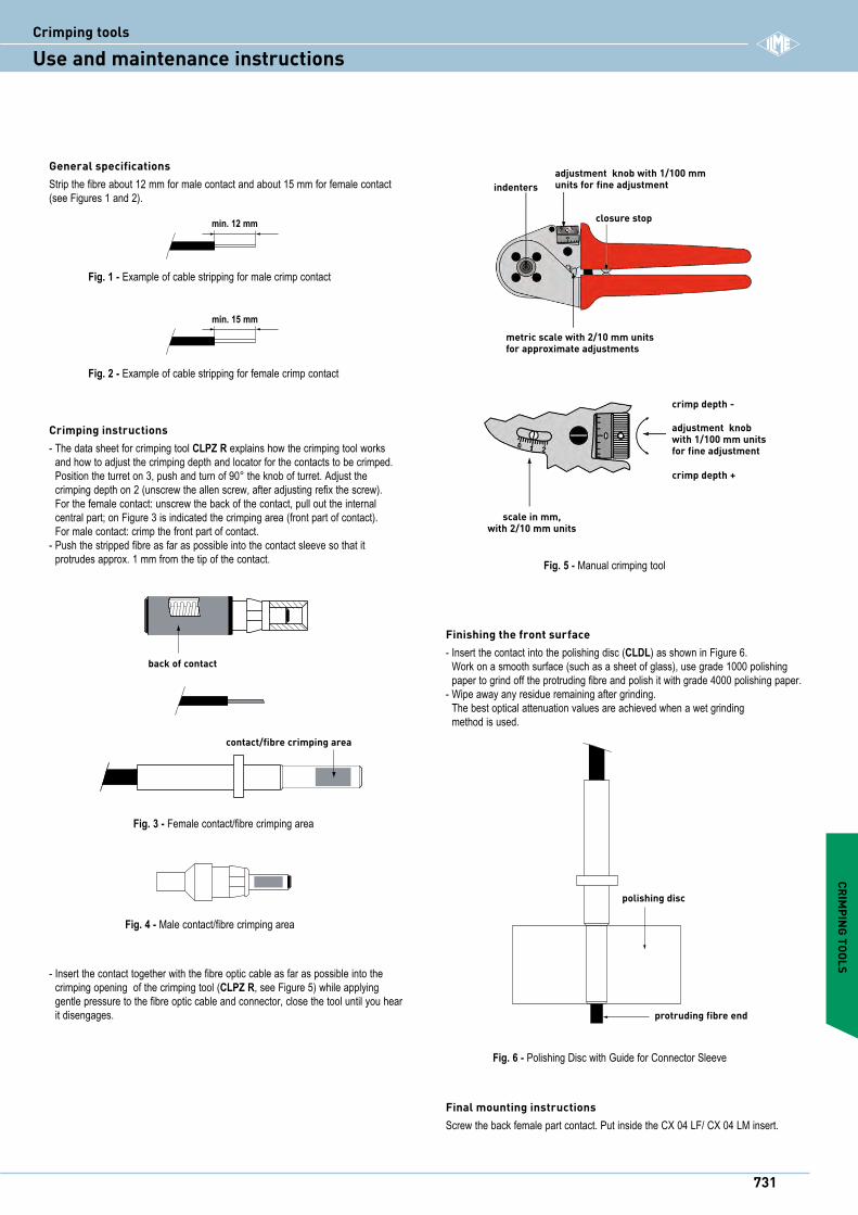
Crimping instructions- The data sheet for crimping tool CLPZ R explains how the crimping tool works
and how to adjust the crimping depth and locator for the contacts to be crimped.Position the turret on 3, push and turn of 90° the knob of turret. Adjust the crimping depth on 2 (unscrew the allen screw, after adjusting refix the screw). For the female contact: unscrew the back of the contact, pull out the internal central part; on Figure 3 is indicated the crimping area (front part of contact). For male contact: crimp the front part of contact.
- Push the stripped fibre as far as possible into the contact sleeve so that it protrudes approx. 1 mm from the tip of the contact.
Finishing the front surface- Insert the contact into the polishing disc (CLDL) as shown in Figure 6.
Work on a smooth surface (such as a sheet of glass), use grade 1000 polishing paper to grind off the protruding fibre and polish it with grade 4000 polishing paper.
- Wipe away any residue remaining after grinding. The best optical attenuation values are achieved when a wet grinding method is used.
General specificationsStrip the fibre about 12 mm for male contact and about 15 mm for female contact (see Figures 1 and 2).
min. 12 mm
Fig. 1 - Example of cable stripping for male crimp contact
min. 15 mm
Fig. 2 - Example of cable stripping for female crimp contact
back of contact
contact/fibre crimping area
Fig. 3 - Female contact/fibre crimping area
Fig. 4 - Male contact/fibre crimping area
indenters
closure stop
adjustment knob with 1/100 mm units for fine adjustment
metric scale with 2/10 mm units for approximate adjustments
scale in mm, with 2/10 mm units
crimp depth -
adjustment knob with 1/100 mm units for fine adjustment
crimp depth +
Fig. 5 - Manual crimping tool
polishing disc
protruding fibre end
Fig. 6 - Polishing Disc with Guide for Connector Sleeve
- Insert the contact together with the fibre optic cable as far as possible into the crimping opening of the crimping tool (CLPZ R, see Figure 5) while applying gentle pressure to the fibre optic cable and connector, close the tool until you hear it disengages.
Final mounting instructionsScrew the back female part contact. Put inside the CX 04 LF/ CX 04 LM insert.
CRIMPING TOOLS
731
iCrimping tools
Use and maintenance instructions
description part No. part No.
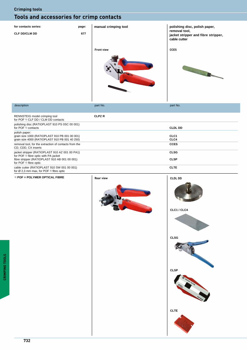
RENNSTEIG model crimping tool CLPZ R for POF 1) CLF DD / CLM DD contacts
polishing disc (RATIOPLAST 910 PS 0SC 00 001) for POF 1) contacts CLDL DD
polish paper: grain size 1000 (RATIOPLAST 910 PB 001 00 001) CLC1 grain size 4000 (RATIOPLAST 910 PB 001 40 250) CLC4
removal tool, for the extraction of contacts from the CCES CD, CDD, CX inserts
jacket stripper (RATIOPLAST 910 AZ 001 00 PA1) CLSG for POF 1) fibre optic with PA jacket fibre stripper (RATIOPLAST 910 AB 001 00 001) CLSP for POF 1) fibre optic
cable cutter (RATIOPLAST 910 SW 001 00 001) CLTE for Ø 2,3 mm max, for POF 1) fibre optic
manual crimping tool polishing disc, polish paper, removal tool, jacket stripper and fibre stripper, cable cutter
1) POF = POLYMER OPTICAL FIBRE Rear view
for contacts series: page:
CLF DD/CLM DD 677
CLDL DD
CLC1 / CLC4
CLSG
CLSP
CLTE
Front view CCES
CRIM
PING
TOO
LS
732
Crimping tools
Tools and accessories for crimp contacts
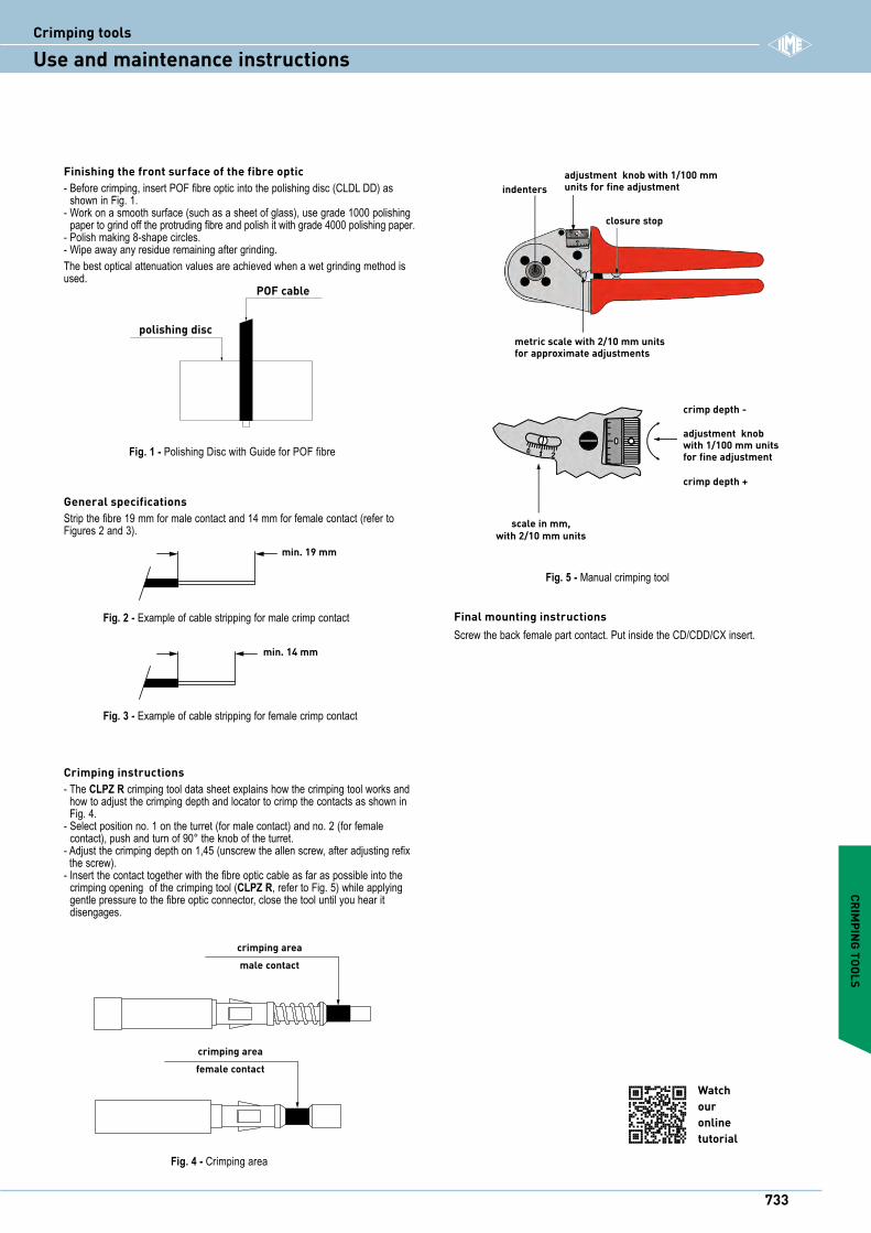
indenters
closure stop
adjustment knob with 1/100 mm units for fine adjustment
metric scale with 2/10 mm units for approximate adjustments
scale in mm, with 2/10 mm units
crimp depth -
adjustment knob with 1/100 mm units for fine adjustment
crimp depth +
Fig. 5 - Manual crimping tool
Final mounting instructionsScrew the back female part contact. Put inside the CD/CDD/CX insert.
Fig. 4 - Crimping area
crimping area male contact
crimping areafemale contact
Crimping instructions- The CLPZ R crimping tool data sheet explains how the crimping tool works and
how to adjust the crimping depth and locator to crimp the contacts as shown in Fig. 4.
- Select position no. 1 on the turret (for male contact) and no. 2 (for female contact), push and turn of 90° the knob of the turret.
- Adjust the crimping depth on 1,45 (unscrew the allen screw, after adjusting refix the screw).
- Insert the contact together with the fibre optic cable as far as possible into the crimping opening of the crimping tool (CLPZ R, refer to Fig. 5) while applying gentle pressure to the fibre optic connector, close the tool until you hear it disengages.
Watch ouronline tutorial
CRIMPING TOOLS
Finishing the front surface of the fibre optic- Before crimping, insert POF fibre optic into the polishing disc (CLDL DD) as
shown in Fig. 1.- Work on a smooth surface (such as a sheet of glass), use grade 1000 polishing
paper to grind off the protruding fibre and polish it with grade 4000 polishing paper.- Polish making 8-shape circles.- Wipe away any residue remaining after grinding.The best optical attenuation values are achieved when a wet grinding method is used.
Fig. 1 - Polishing Disc with Guide for POF fibre
POF cable
polishing disc
General specificationsStrip the fibre 19 mm for male contact and 14 mm for female contact (refer to Figures 2 and 3).
Fig. 2 - Example of cable stripping for male crimp contact
Fig. 3 - Example of cable stripping for female crimp contact
min. 19 mm
min. 14 mm
733
iCrimping tools
Use and maintenance instructions
description part No. part No.
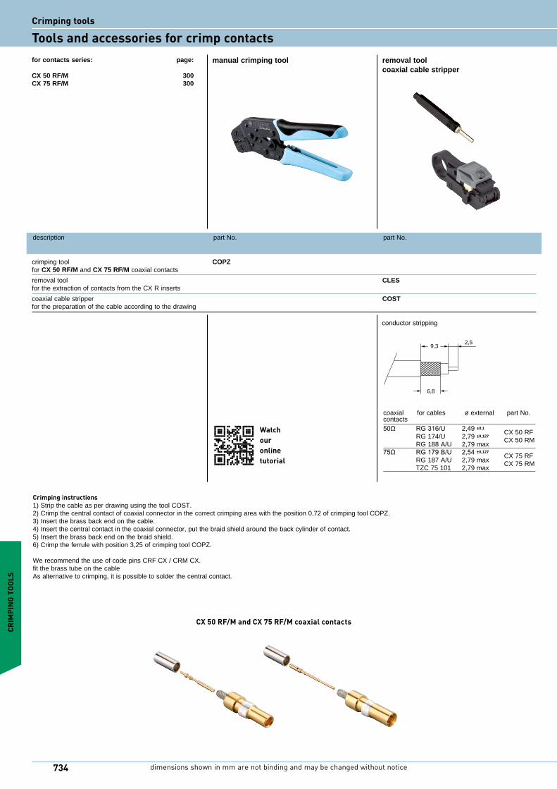
crimping tool COPZ for CX 50 RF/M and CX 75 RF/M coaxial contacts
removal tool CLES for the extraction of contacts from the CX R inserts
coaxial cable stripper COST for the preparation of the cable according to the drawing
manual crimping tool removal tool coaxial cable stripper
for contacts series: page:
CX 50 RF/M 300CX 75 RF/M 300
Crimping instructions1) Strip the cable as per drawing using the tool COST.2) Crimp the central contact of coaxial connector in the correct crimping area with the position 0,72 of crimping tool COPZ.3) Insert the brass back end on the cable.4) Insert the central contact in the coaxial connector, put the braid shield around the back cylinder of contact.5) Insert the brass back end on the braid shield. 6) Crimp the ferrule with position 3,25 of crimping tool COPZ.
We recommend the use of code pins CRF CX / CRM CX. fit the brass tube on the cableAs alternative to crimping, it is possible to solder the central contact.
CRIM
PING
TOO
LS
coaxial for cables ø external part No. contacts 50Ω RG316/U 2,49±0,1 CX 50 RF RG 174/U 2,79 ±0,127
CX 50 RM RG 188 A/U 2,79 max75Ω RG179B/U 2,54±0,127
CX 75 RF RG 187 A/U 2,79 max CX 75 RM TZC 75 101 2,79 max
conductor stripping
9,32,5
6,8
CX 50 RF/M and CX 75 RF/M coaxial contacts
Watch ouronline tutorial
734 dimensions shown in mm are not binding and may be changed without notice
Crimping tools
Tools and accessories for crimp contacts
description part No. part No.
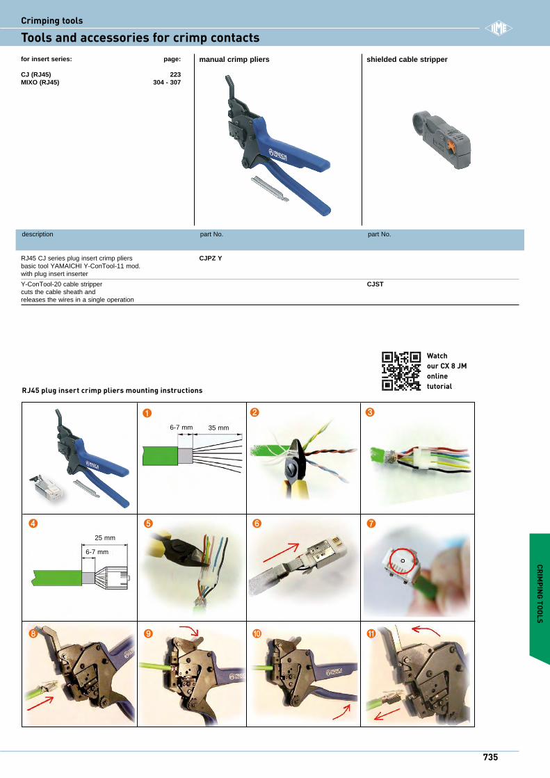
RJ45 CJ series plug insert crimp pliers CJPZ Y basic tool YAMAICHI Y-ConTool-11 mod. with plug insert inserter
Y-ConTool-20 cable stripper CJST cuts the cable sheath and releases the wires in a single operation
manual crimp pliers shielded cable stripperfor insert series: page:
CJ (RJ45) 223MIXO (RJ45) 304 - 307
CRIMPING TOOLS
RJ45 plug insert crimp pliers mounting instructions
❶
6-7 mm
6-7 mm
35 mm
25 mm
❷ ❸
❹ ❺ ❻ ❼
❽ ❾ ❿ ⓫
Watch our CX 8 JMonline tutorial
735
iCrimping tools
Tools and accessories for crimp contacts
description part No. part No.
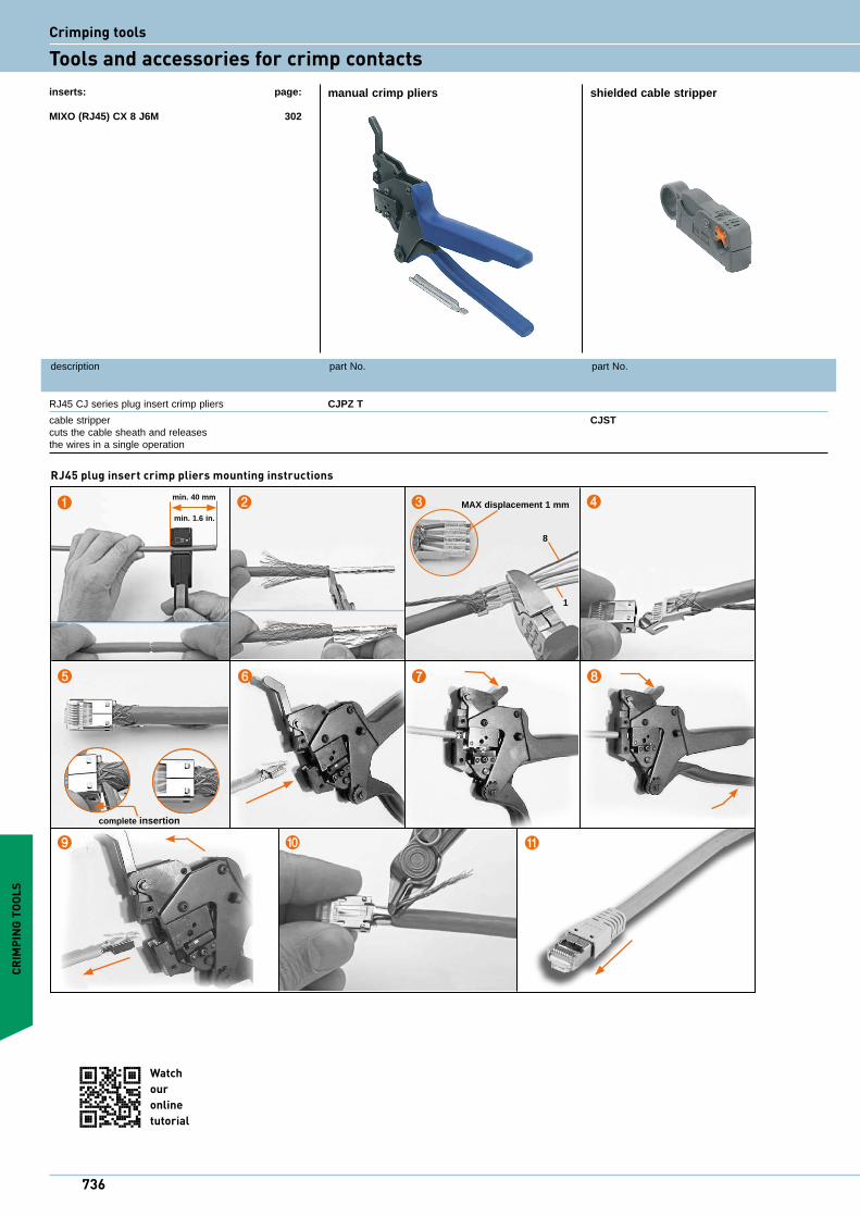
RJ45 CJ series plug insert crimp pliers CJPZ T
cable stripper CJST cuts the cable sheath and releases the wires in a single operation
manual crimp pliers shielded cable stripperinserts: page:
MIXO (RJ45) CX 8 J6M 302
CRIM
PING
TOO
LS
❶ ❷ ❸
❻
complete insertion
❹
❺ ❽
⓫❿❾
min. 40 mm
min. 1.6 in.
1
8
MAX displacement 1 mm
❼
RJ45 plug insert crimp pliers mounting instructions
Watch ouronline tutorial
736
Crimping tools
Tools and accessories for crimp contacts
CRIMPING TOOLS
manual IDC pliers
description part No.
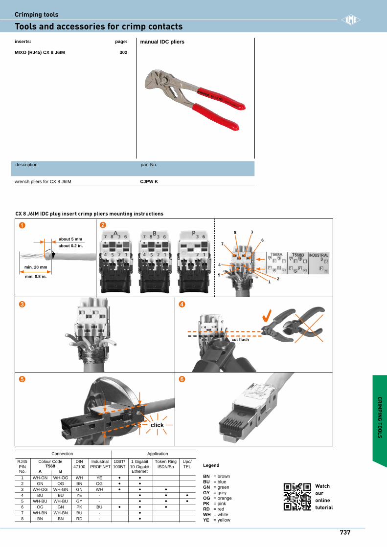
wrench pliers for CX 8 J6IM CJPW K
inserts: page:
MIXO (RJ45) CX 8 J6IM 302
❶ ❷
❸
cut flush
❹
❺ ❻
click
4
4
52
1
6
38
7
8 6
4 2
8 6
4 2 2
6min. 20 mm
min. 0.8 in.
about 5 mm
about 0.2 in.
Connection Application
RJ45 Colour Code DIN Industrial 10BT/ 1 Gigabit Token Ring Upo/ PIN T568 47100 PROFINET 100BT 10 Gigabit ISDN/So TEL No. A B Ethernet
1 WH-GN WH-OG WH YE • • 2 GN OG BN OG • • 3 WH-OG WH-GN GN WH • • • 4 BU BU YE - • • • 5 WH-BU WH-BU GY - • • • 6 OG GN PK BU • • • 7 WH-BN WH-BN BU - • 8 BN BN RD - •
Legend
BN = brownBU = blueGN = greenGY = greyOG = orangePK = pinkRD = redWH = whiteYE = yellow
Watch ouronline tutorial
CX 8 J6IM IDC plug insert crimp pliers mounting instructions
737
iCrimping tools
Tools and accessories for crimp contacts
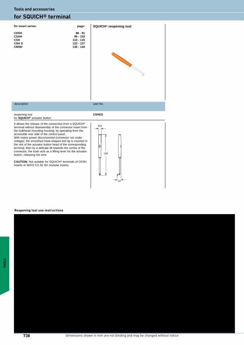
SQUICH® reopening tool
description part No.
reopening tool CSHES for SQUICH® actuator button
for insert series: page:
CDSH 86 - 91CSAH 99 - 103CSH 110 - 115 CSH S 122 - 127CMSH 136 - 144
139
9,5
13
TOOL
S
It allows the release of the connection from a SQUICH® terminal without disassembly of the connector insert from the bulkhead mounting housing, by operating from the accessible rear side of the control panel.With mains power disconnected (connector not under voltage), the smoothed hook-shaped tool tip is inserted in the slot of the actuator button head of the corresponding terminal, then by a delicate tilt towards the centre of the connector, the tools acts as a lifting lever for the actuator button, releasing the wire.
CAUTION: Not suitable for SQUICH® terminals of CKSH inserts or MIXO CX 05 SH modular inserts.
Reopening tool use instructions
dimensions shown in mm are not binding and may be changed without notice738
Tools and accessories
for SQUICH® terminal
140
Crimping tools
141
i
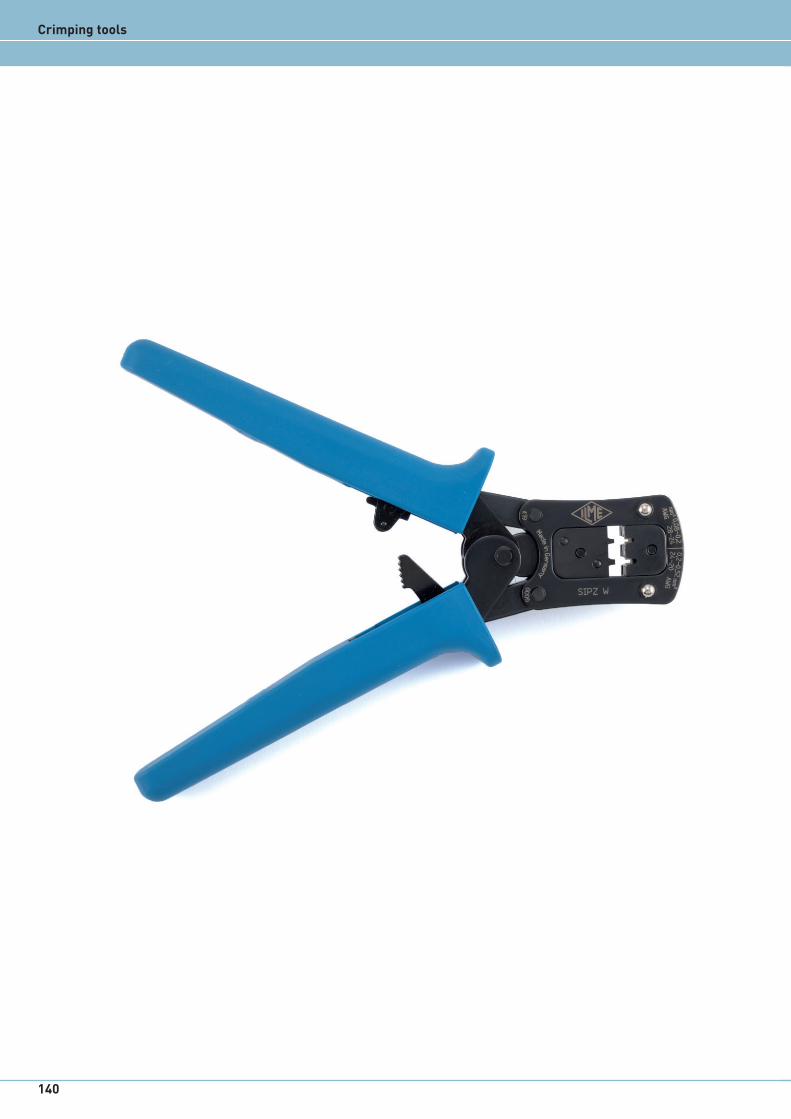
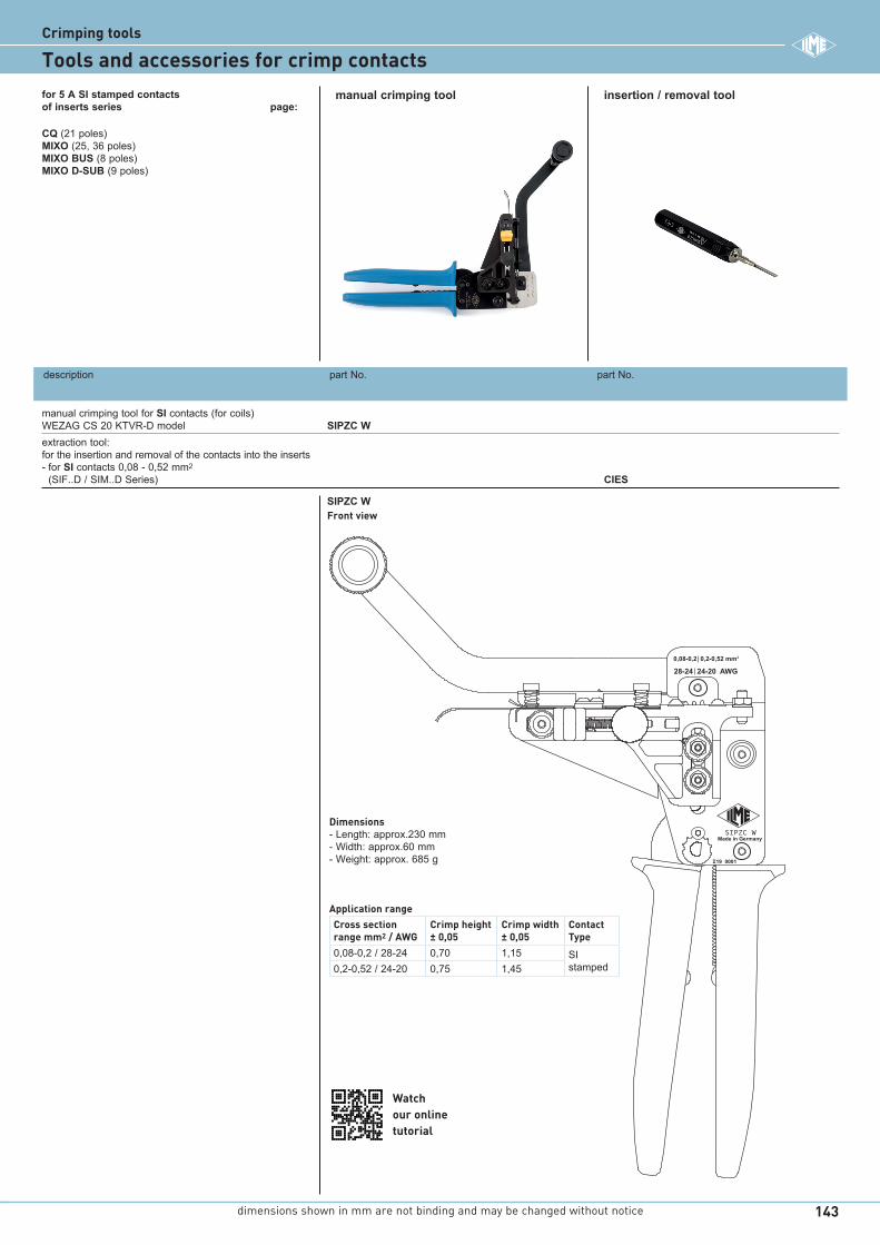
Professional crimping hand tool SIPZ W, SIPZC W for SI stamped contact SeriesEasy handling tools designed both for loose and coils version of 5 A stamped crimp contacts. Application range from 0,08 mm2 to 0,52 mm2 (AWG 28-20). Contacts positioning with insulation stop.
CIPZP D Pneumatic crimping toolPneumatic version of the CIPZ D tool for 5 A turned contacts. Crimping range from 0,08 mm2 to 0,75 mm2 (AWG 28-18) with CITP D locator for CI and RI contacts Series.
CCPZP RN Pneumatic crimping machine4/8 indent crimping unit with locator and digital readout display for CD, CC and CX contact Series. The machine is operated by a pneumatic foot valve according to the same crimping adjustment of CCPZ RN manual tool (crimping depth and positioner seat).
Find more information on our products at www.ilme.com
CRIMPINGTOOLS
dimensions shown in mm are not binding and may be changed without notice142
Crimping tools
Tools and accessories for crimp contacts
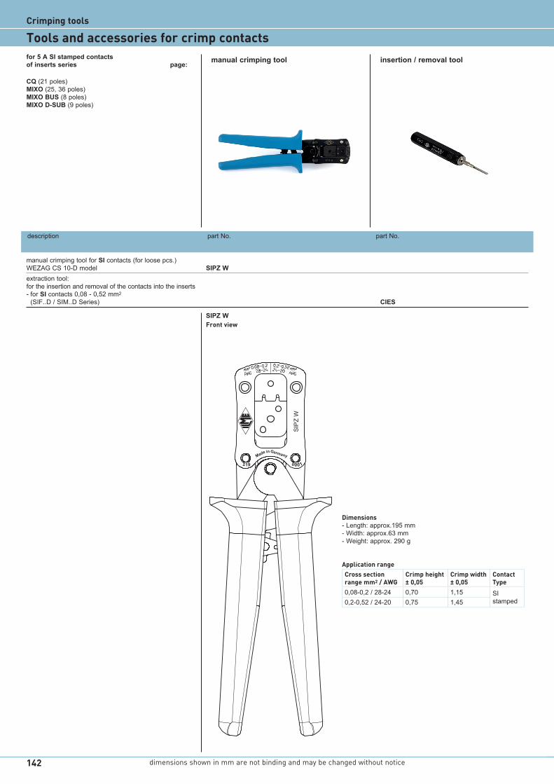
description part No. part No.
manual crimping tool for SI contacts (for loose pcs.) WEZAG CS 10-D model SIPZ Wextraction tool: for the insertion and removal of the contacts into the inserts - for SI contacts 0,08 - 0,52 mm2
(SIF..D / SIM..D Series) CIES
manual crimping tool insertion / removal toolfor 5 A SI stamped contacts of inserts series page:
CQ (21 poles) MIXO (25, 36 poles)MIXO BUS (8 poles)MIXO D-SUB (9 poles)
Dimensions- Length: approx.195 mm- Width: approx.63 mm- Weight: approx. 290 g
Application rangeCross section range mm2 / AWG
Crimp height ± 0,05
Crimp width ± 0,05
Contact Type
0,08-0,2 / 28-24 0,70 1,15 SI stamped0,2-0,52 / 24-20 0,75 1,45
SIPZ WFront view
SIP
Z W
i
Made inGermany
I19 0001
dimensions shown in mm are not binding and may be changed without notice 143
i
description part No. part No.
manual crimping tool for SI contacts (for coils) WEZAG CS 20 KTVR-D model SIPZC Wextraction tool: for the insertion and removal of the contacts into the inserts - for SI contacts 0,08 - 0,52 mm2
(SIF..D / SIM..D Series) CIES
manual crimping tool insertion / removal toolfor 5 A SI stamped contacts of inserts series page:
CQ (21 poles) MIXO (25, 36 poles)MIXO BUS (8 poles)MIXO D-SUB (9 poles)
SIPZC WiMade in Germany
I19 0001
28-24 24-20 AWG0,08-0,2 0,2-0,52 mm2
Watchour onlinetutorial
Dimensions- Length: approx.230 mm- Width: approx.60 mm- Weight: approx. 685 g
Application rangeCross section range mm2 / AWG
Crimp height ± 0,05
Crimp width ± 0,05
Contact Type
0,08-0,2 / 28-24 0,70 1,15 SI stamped0,2-0,52 / 24-20 0,75 1,45
SIPZC WFront view
Crimping tools
Tools and accessories for crimp contacts

dimensions shown in mm are not binding and may be changed without notice144
CCVPPCCSPZP
bayonet pins (2)
locator
RED (NO GO)
GREEN (GO)
CCPNP
dataplate
body
CITP D positioner
Crimping tools
Tools and accessories for crimp contacts
description part No. part No.
pneumatic crimping tool for turned 5 A contacts model DANIELS WA22 equivalent to CIPZ D (turret excluded) CIPZP Dpositioner (DANIELS K1450I) for 5 A contacts (CIMA - CIFA - CIFD - CIMD Series) CITP Dbench support for CIPZP D pneumatic crimping tool CCSPZP (DANIELS BM-2A)pneumatic foot valve (DANIELS WA10A) CCVPP“go / no go” control gauge to verify indenter closure (See notes below) CCPNPinsertion and extraction tool: for the insertion and removal of the contacts into the inserts - for CI and RI contacts 0,2 - 0,5 mm2
(CIMA - CIFA - CIFD - CIMD Series) CIES- for CI and RI contacts 0,75 mm2
(CIMA - CIFA - CIFD - CIMD Series) CIES B
pneumatic crimping tool insertion tool - removal toolspositioner - gauge
Notes:
Positioner conforms to international standard MIL-C-22520/1- An interchangeable and indispensable accessory of
the CIPZP D crimping tool, it precisely positions the contact where crimping is performed.
“go / no go” control gaugeconforms with international standard MIL-C-22520/3- A tool used to periodically check that the crimping tool
meets standard requirements.
for 5 A CI and RI turned contacts of inserts series page:
CQ (21 poles) MIXO (25, 36 poles)MIXO BUS (8 poles)MIXO D-SUB (9 poles)GIGABIT (8 poles)SHIELDED (20 poles)
Gauge tool selector Ø A ± 0,00254 mm Ø B ± 0,00254 mm pos. No. (GO) green (NO GO) redCCPNP 8 0,991 (mm) 1,118 (mm) 0,0390 (in) 0,0440 (in)
dimensions shown in mm are not binding and may be changed without notice 17
i
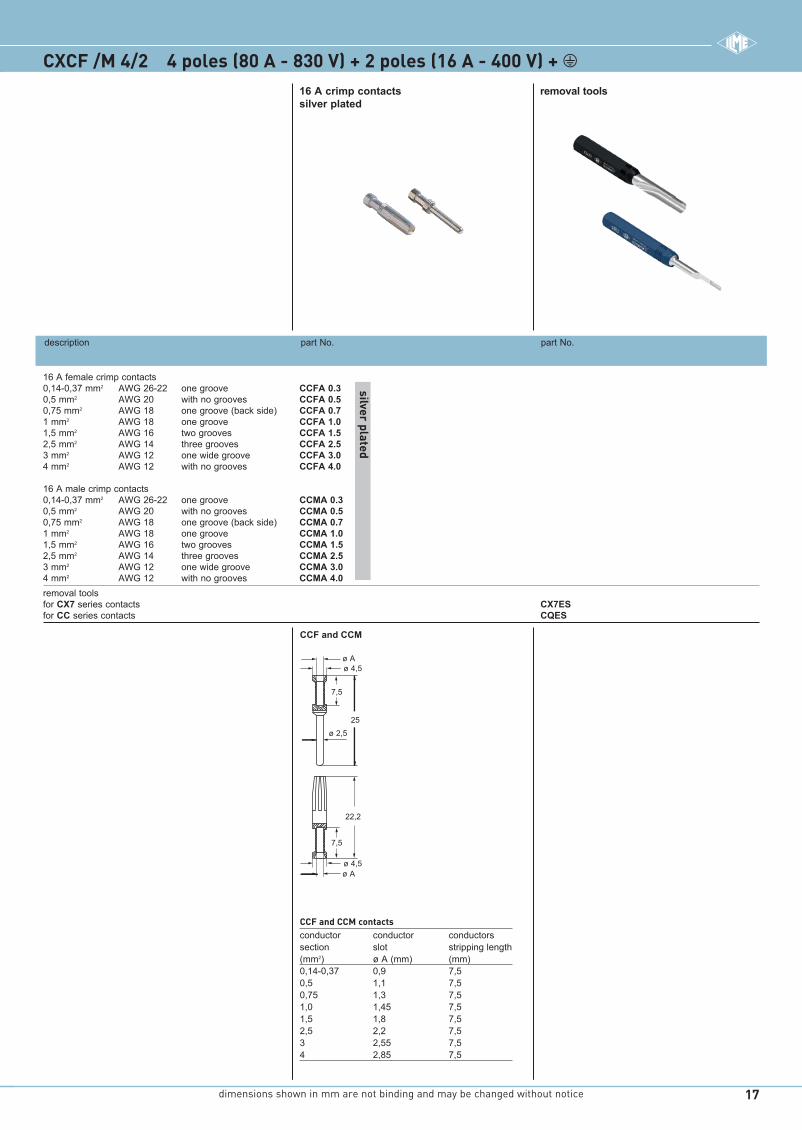
CCF and CCM
22,2
25
7,5
ø 2,5
ø Aø 4,5
ø Aø 4,5
7,5
CCF and CCM contactsconductor conductor conductors section slot stripping length(mm2) ø A (mm) (mm)0,14-0,37 0,9 7,50,5 1,1 7,50,75 1,3 7,51,0 1,45 7,51,5 1,8 7,52,5 2,2 7,53 2,55 7,54 2,85 7,5
16 A crimp contacts removal tools silver plated
16 A female crimp contacts 0,14-0,37 mm2 AWG 26-22 one groove CCFA 0.3 0,5 mm2 AWG 20 with no grooves CCFA 0.5 0,75 mm2 AWG 18 one groove (back side) CCFA 0.7 1 mm2 AWG 18 one groove CCFA 1.0 1,5 mm2 AWG 16 two grooves CCFA 1.5 2,5 mm2 AWG 14 three grooves CCFA 2.5 3 mm2 AWG 12 one wide groove CCFA 3.0 4 mm2 AWG 12 with no grooves CCFA 4.0
16 A male crimp contacts 0,14-0,37 mm2 AWG 26-22 one groove CCMA 0.3 0,5 mm2 AWG 20 with no grooves CCMA 0.5 0,75 mm2 AWG 18 one groove (back side) CCMA 0.7 1 mm2 AWG 18 one groove CCMA 1.0 1,5 mm2 AWG 16 two grooves CCMA 1.5 2,5 mm2 AWG 14 three grooves CCMA 2.5 3 mm2 AWG 12 one wide groove CCMA 3.0 4 mm2 AWG 12 with no grooves CCMA 4.0removal tools for CX7 series contacts CX7ES for CC series contacts CQES
silver plated
description part No. part No.
CXCF /M 4/2 4 poles (80 A - 830 V) + 2 poles (16 A - 400 V) + m
XDGPDT21 121 014 089 16.03.36.indd 17XDGPDT21 121 014 089 16.03.36.indd 17 03/06/21 14:1303/06/21 14:13