CONNECTOR CONCEPT STUDIES
87
ZERO LEAKAGE DESIGN FOR DUCTS AND TUBE CONNECTIONS FOR DEEP SPACE TRAVEL CONNECTOR CONCEPT STUDIES Volume I1 of Final Report Prepared under Contract No. NAS 8- 11523 23 August 1967 Prepared for PROPULSION AND VEHICLE ENGINEERING DIVISION NATIONAL AERONAUTICS AND SPACE ADMINISTRATION HUNTSVILLE, ALABAMA GEORGE C. MARSHALL SPACE FLIGHT CENTER Prepared by Mechanic a1 Equipment Branch Mechanic a1 Technology Laboratory Research and Development Center Schenectady, New York L . G e Gitz end anner General Electric Company 1 \ Sponsored by Missile and Space Division General Electric Company --. Philadelphi a, Pennsylvania ’ ‘ , General Electric Company Project Engineer: J. A. Bain NASA Technical Manager: H. Fuhrmann, (R-P&VE- PM)
-
Upload
khangminh22 -
Category
Documents
-
view
0 -
download
0
Transcript of CONNECTOR CONCEPT STUDIES

ZERO LEAKAGE DESIGN FOR DUCTS AND TUBE CONNECTIONS FOR D E E P SPACE TRAVEL
CONNECTOR CONCEPT STUDIES
Volume I1 of
Final Report Prepared under Contract No. NAS 8- 11523
23 August 1967
Prepared for
PROPULSION AND VEHICLE ENGINEERING DIVISION
NATIONAL AERONAUTICS AND SPACE ADMINISTRATION HUNTSVILLE, ALABAMA
GEORGE C. MARSHALL SPACE FLIGHT CENTER
Prepared by
Mechanic a1 Equipment Branch Mechanic a1 Technology Laboratory Research and Development Center
Schenectady, New York
L . G e Gitz end anner
General Electric Company 1
\
Sponsored by
Missile and Space Division General Electric Company --. Philadelphi a, Pennsylvania
’ ‘,
General Electric Company Project Engineer: J. A. Bain NASA Technical Manager: H. Fuhrmann, (R-P&VE- PM)

FOREWORD
This is volume I1 of a six volume final report covering work accomplished by the Research and Development Center of the General Electr ic Company, Schenectady, New York from 5 July 1963 to 30 June 1967. This program was sponsored by the Missi le and Space Division of Lhe General Electric Company, Philadelphia, Pennsylvania, under National Aeronautics and Space Administration Contract NAS 8 - 11 523,
Z e r o Leakage Design for Ducts and Tube Connectors for Deep Space Travel. I '
I '
The six volumes contained in this final repor t a r e :
Volume I - - "Fundamental Investigations"
Volume I1 - - Connector Concept Studies"
Volume 111 - - "Guide in Selecting Duct, Tubing and Gasketing Mater ia ls for Space Vehicles and Missiles"
Volume I V - - "New Connector Designs and Testing"
Volume V - - "Tube Connector Design Principles and Evaluation''
Volume VI - - "X - Connector Feasibility Studies"
1 1
i

TABLEOFCONTENTS
Sect ion Page
FOREWORD . . . . . . . . . . . . . . . . i
INTRODUCTION 1 1
1 Scope of Work . . . . . . . . . . .
CONCLUSION . . . . . . . . . . . . . . 2
Ultrasonic Welding . . . . . . . . . . . Magnetic Forming . . . . . . . . . .
Lined Tubing and Ducts . . . . . . . .
Explosive Forming . . . . . . . . . .
Adhesive Bonding Techniques . . . . . . Fusion Welding Studies . . . . . . . . .
7 3 RECOMMENDATIONS . . . . . . . . . . . Ultrasonic Welding . . . . . . . . . . Explosive Forming . . . . . . . . . . Magnetic Forming . . . . . . . . . . Adhesive Bonding Tecnniques . . . . . . Fusion Welding Studies . . . . . . . . . Lined Tubing and Ducts . . . . . . . .
9
9
ULTRASONIC WELDING . . . . . . . . . . Description of the P rocess . . . . . . .
Ultrasonic Welding . . . . . . . . Advantages and Disadvantages of
Field Application . . . . . . . . . . .
4
9 10
13
13 13
5 EXPLOSIVE FORMING . . . . . . . . . . Introduction . . . . . . . . . . . . . . Technical Discussion . . . . . . . . . .
6 3 1
3 1 3 2
MAGNETIC FORMING . . . . . . . . . . . Introduction . . . . . . . . . . . . . Magnetic Forming Test Summary . . . .
ADHESIVEBONDING TECHNIQUES . . . . . 55 7 55 55 59
Introduction . . . . . . . . . . . . . . De sign Consider ations . . . . . . . . . Testing Procedure and Results . . . . .
ii

TABLE O F CONTENTS (Cont'd)
Section
8 FUSION WELDING STUDIES . . . . . . . . . Introduction . . . . . . . . . . . . . . . Description of Tes ts . . . . . . . . . . Test Results . . . . . . . . . . . . . .
9 LINED TUBING AND DUCTS . . . . . . . . . Introduction . . . . . . . . . . . . . . Description and Discussion of Teflon
Lined Pipe . . . . . . . . . . . . . Sealing the Liner . . . . . . . . . . . .
10 REFERENCES . . . . . . . . . . . . .
Page
63
63 63 68
77
77
77 8 0
83
iii

Figure
1
4
8
9
10
11
12
13
14
15
16
17
LIST O F ILLUSTRATIONS
Two-inch Sample Joint-prepared with Two Wraps of ,073 inch MDF A-5, Ready fo r Fir ing
Joint After Fir ing Showing Excellent Draw Depth and Uniformity (End Effect not Visible in Photo)
Cross-section of Joint Constructed with Explo- sive W i r e . . . . . . . . . . . . . . . . . lOOX Magnification Cross Section View of an Ex- plosive Formed Permanent Connector. (Shown is 2024-T3 Aluminum Insert (Bottom) and 6061-T6 Tubing (Top), this is the Same System a s Shown in Figure 3.) . . . . . . . . . . . . Explosive Forming Flange Connection . . . . . Explosive Forming Sleeve Type Connection . . Flange-type Connection Before Forming Together with Disassembled Cover . . . . . . . . . .
. . . .
.
Flange-type Connection Ready to Shoot with Pro- tective Cover i n Place . . . . . . . . . . . Flange-type Connection Mounted Between Buffer Plates . Explosive Sheet is Detonated on Top of One of the Plates . . . . . . . . . . . . . Sample of Explosive Welding Performed with a Straight Sleeve Joint by Detonating a Laye r of Bulk Material . . . . . . . . . . . . . . . Straight Sleeve Joint Mounted i n Protective Cover (Note that the Mandrel Keeps the Tubes in Place and Prevents Collapsing) . . . . . . . . . . Ignition Point of the Continuous Explosive Sheet Ring . . . . . . . . . . . . . . . . . . Indentation Where the Two Shock Waves Meet
Location of Points where Microphotographs Were Taken. (The Section to the Right of Position IV Shows the Ignition Point in the Same Horizontal Plane) . . . . . . . . . . . . . . . . . . Start of Weld at Low Impact Velocity
End of Weld at Highest Impact Velocity
. . . . . Middle of Weld Showing Waviness of Weld Line .
. . .
Page
14
14
1 6
17
18
18
20
20
21
22
2 3
24
24
26
27
28
29
iv

LIST O F ILLUSTRATIONS (Cont'd)
Figure
18
19
20
2 1
22
23
24
25
26
27
28
29
30
Indentation Where Shock Waves Meet
Lower Portion Shows Elements of Magnetically Swaged Connector. Upper Portion I l lustrates Completed Connection (3 /8 inch Outside Dia- meter Tubing, 3003-H- 14 Aluminum; 2024-T4 Union) . . . . . . . . . . . . . . . . . . Elements of 2 inch Connector for Magnetic Swaging (Tubing - 3003-H- 14 Aluminum; Union
Uneven Depth of Draw Due to Width of Split in Shaper . . . . . . . . . . . . . . . . . Uniform Depth of Draw; Plane of Photo 90" f rom Plane of Shaper Split . . . . . . . . . X-ray of Magnetic Formed Permanent Connector. Note Variation in Tube Deformation.
. . . . .
2024-T4) . . . . . . . . . . . . . . . . .
This Con- nector has been Successfully Leak Tested . . . X-ray of Same Connector as in Figure 23, Rotated 90" . . . . . . . . . . . . . . . . 6061-T6 Aluminum Tube Deformation as a Func- tion of Gap Length for Constant Magnetic Field Strength. Inser t is 2024-T3 Aluminum. Gaps Range f rom 2x, 4x, 6x, and 8x of the Tube Wall Thickness. inch . . . . . . . . . . . . . . . . . . . 3003-H14 Aluminum Tube Deformation with Vary- ing Gap Depth. 2024-T3 Aluminum Inser ts . Mag- netic Field Strength not Varied. Gap Length is 3x Tube W a l l Thickness. Tube W a l l Thickness is 0.035 inch Depth of Gap - Ox, lx, 1. 5x, 2x, 2 . 5 ~ Tube W a l l Thickness . . . . . . . . . 606 1-T6 Aluminum Tube Deformation with Vary- ing Gap Depth. 2024-T3 Aluminum Inser ts . Mag- netic Field Strength not Varied. Tube W a l l Thickness. Tube W a l l Thickness is 0.035 inch Depth of Gap - Ox, lx, 1. 5x, 2x, 2 . 5 ~ Tube W a l l Thickness . . . . . . . . . . . . . . SB Series Inser t . . . . . . . . . . . . . . Knife Edge Series Inser t . . . . . . . . . . Free End Ser ies Inser t . . . . . . . . . . .
Tube W a l l Thickness is 0. 035
Gap Length is 3x
Page
30
33
33
35
35
37
37
39
40
40
41
42
43
V

LIST O F ILLUSTRATIONS (Cont'd)
Figure
31 SS Ser ies Inser t Geometry . . . . . . . . . . 32 F i n d Connector Shape . . . . . . . . . . . 33 SP Ser ies Inser t Geometry . . . . . . . . . . 34 SH Ser ies Inser t Geometry . .. . . . . . . . . 35 SC Ser ies Inser t Geometry . . . . . . . . . . 36 SJ Series Inser t . . . . . . . . . . . . . . 37 R Series Insert . . . . . . . . . . . . . . . 38
39
40
41
42
43
44
45
46
47
48
49
50
Tube to Tube Configurations . . . . . . . . Plate to Plate Joint . . . . . . . . . . . . . Top View of Magneform Assembly Shown in
Side View of the Magneform Assembly Shown i n F i g u r e 39 . . . . . . . . . . . . . . . . Typical Bonding Geometry . . . . . . . . . . Cryogenic Tensile Testing Fixture . . . . . .
Figure 39 . . . . . . . . . . . . . . . .
Welding Setup Schematic . . . . . . . . . . Welding Tes t Setup for Purging the Inside and Out- side of the Tube With Argon . . . . . . . . . Welding Fixture Mounted on a Lathe for Centering
Test Setup a s Diagrammatically Illustrated in Figure 44 . . . . . . . . . . . . . . . . . Fi l te r Used in the Prel iminary T e s t (Bottom)
and Driving . . . . . . . . . . . . . . . .
and Weldment Tes t (Top) . . . . . . . . . .
Teflon Lined Pipe . , . . . . . . . . . . . Fi l te rs Used in Fusion Welding Part ic le Counts .
Page
45
46
47
48
49
51
51
52
53
54
54
56
61
65
66
66
67
71
74
78
vi

LIST OF TABLES
Table
1
2
3
4
5
6
7
8
9
10
11
Ser ies T Test Results . . . . . . . . . . . . . Tensile Test Results . . . . . . . . . . . . Thermocycling Test Sequence . . . . . . . . .
Tensile Test Results After Thermocycling . . . Tensile Test Results at Two Different Temperatures . . . . . . . . . . . . . . . . Results of Tensile Tests Following Vibration . . . . . . . . . . . . . . . . Vibrational Test Results . . . . . . . . . . . Preliminary Background Test Results . . . . .
Welding Test Results . . . . . . . . . . . . . Stainless Steel Aluminum Tube Welding Test Results . . . . . . . . . . . . .
Results of the Analysis of the Filters Shown in Figure 49, . . . . . . . . . . . . .
vii
Page
57
58
58
60
60
62
62
68
70
72
75

Section 1
INTRODUCTION
This is volume I1 of a s ix volume report covering work accomplished during the period 5 July 1963 to 30 June 1967 under National Aeronautics and Space Administration Contract No. 8- 11523, "Zero Leakage Design for Ducts and Tube Connections for Deep-space Travel. I t
I t The work resu l t s discussed in Section 2, "Conclusions, and much of
A s the t e rm is used in th i s report , a "permanent the textual mater ia l of this report apply to both permanent and semi- permanent connectors. connector" is one which possesses the following features:
0 Requires special equipment for construction and assembly
Requires special tools for disassembly.
Is totally destroyed upon opening
The "semi-permanent" connector also requi res special tools f o r construction, assembly, and disassembly: i t is, however, not destroyed until it has been disconnected several t imes. The t tseparablel t connector is one which can be made up and disconnected with only common hand tools such a s standard wrenches, screwdrivers , etc.
Permanent connectors a r e by definition inapplicable to final closure of Final enclosures and al l connections that may need to be opened systems.
f o r test , inspection, o r replacement of defective components, presently utilize separable connectors. The bas ic purpose of this program is through the exploration of various joining techniques and concepts, to develop semi-permanent connectors with which to replace separable connectors in all but the most frequently opened joints.
Separable connectors, however, often leak.
The scope of the work to date is summarized below.
SCOPE O F WORK
The work accomplished in t h i s period involved a welding technique which is at present used in only permanent connectors, to determine whether limitations of the process in connector design a r e inherent o r avoidable. Joining concepts presently used in applications other than connectors and other novel joining concepts were also considered. For instance, it was assumed that exotic and composite materials might best satisfy the total requirements f o r fluid systems. nector problems and thus Connectors for lined tubes came to be considered.
These, however, resulted in new con-
The following specific joining methods were analyzed:
0 Ultrasonic welding
1

0 Explosive forming
0 Magnetic forming
0 Adhesive bonding techniques
Fusion welding studies
0 Lined tubing and ducts
The experimental data obtained was analyzed to determine the suitability of each method to the present program.
2

Section 2
CONCLUSIONS
Specific conclusions derived from these connector concept studies are divided by subject and listed below. It might be noted that cold pressure welding and diffusion bonding have been investigated and these procedures are written up in Vol. IV of this final report .
ULTRASONIC WELDING
Ultrasonic equipment is not currently available for making the seal for zero leakage fluid connectors within the range- of the National Aeronautics and Space Administration requirements.
EXPLOSIVE FORMING
Several Tube joints were made using aluminum tubing and a solid metall ic mandrel to keep the tube from collapsing. p re s su re tight when tested up to the yield point of the tube mater ia l and metallographic photographs showed welding had occurred in the joint area.
These joints were
T w o problems arose in making joints using the explosive technique. The first resulted from the means used to detonate the main sheet of ex- plosive wrapped around the tube. lead-in length of explosive located outside the joint fixturing was detonated and a s the explosion advanced along the lead-in into the joint fixture, ex- plosive amplification resul ts f rom a more concentrated charge where the lead-in joined the main sheet charge. Because of this, tube deformation in this a rea was excessive, and in some test resulted in the rupture of the w all.
A high charge detonation cap joined to a
A second problem area appeared in the form of explosive reinforcement produced by the interaction of two travelling explosive waves. of explosive wrapped about the tube joint's periphery was detonated at one point, two separate explosive waves were created and travelled circumferentially away from the point of detonation. 180° f rom the point of detonation, wave amplification resulted, causing, in some cases, a rupturing of the tube wall.
Since the sheet
At a point on the joint 's periphery, located
Neither of these problems however, present themselves a s major ones. F rom the results of th i s preliminary feasibility study, i t can be said that this technique contains much promise for application to the fabrication of connec- t o r s . practical in-place permanent connectors.
Should light-weight fixturing be developed, it would lend itself well to
3

MAGNETIC FORMING
The magnetic forming process, in general, was successful in fabricating a number of good leak-tight joints with sound mechanical strength. However, because of a problem inherent in the split shape r s allowing a non-uniform force field, the resul ts of the tes t s w e r e not of high enough degree of success to warrant the adoption of this process a s a means of making a permanent connector. A segment of the tes t program dealing with the making of good joints repeatably showed that the percentage of acceptable joints made w a s unsatisfactory. workability, cleanliness, and ease of handling. other than a machined coil shaper piece was required.
Nevertheless, the process is one which allowed fo r easy Also, no expensive fixturing
ADHESIVE BONDING TECHNIQUES
Epoxy bonding has long been used in the aircraf t industry and elsewhere. However, special potential problems have ar isen when this form of bonding has been employed as the joining and sealing mechanism in a connector. Tes t s were made to isolate and solve these problems. only one formulation of adhesive was used, looked very promising. only a l o o tapered joint was used in these tests, it is anticipated that the strength of these joints can be almost doubled by employing 5 O tapers . Besides strength, it was also proved that adhesives can be very easily used to form zero leakage connections. could be employed a s the sealing par t of such connectors and in fact us'ed to replace the gasket.
The results, where Since
Therefore, in integrated connectors, they
Since the resul ts of the thermocycling tests looked very promising, the difference i n the expansion of the various mater ia l s tested does not appear to be a critical factor. chosen f o r these tests and to the extent that this is o r is not feasible, the resul ts may be optimistic.
However, a non-brittle mater ia l was especially
FUSION WELDING STUDIES
From the point of cleanliness, fusion welding is well suited to the making of permanent duct joints.
LINED TUBING AND DUCTS -
Metal components, notably aluminum and stainless steel, have been used for most fluid systems to date. During this contract period, lined tubes which could handle fluids not compatible with meta ls were considered fo r future use. It appears that joints in such systems can be satisfactorily made. because of the relative lack of definition of the problem and the range of variability that could be visualized, no attempt was made to design, build, and demonstrate such a connector.
However,
4

It h s been demonstrat d that teflon lined pipe can be used over a temp- 0 0
era ture range of -10O0F. to -+ 500 F. and possibly down to -420 F. a s high as 900 ps i have been contained for short periods of rime, P rope r flange designs could resul t in containment of high p r e s s u r e f o r unlimited t ime periods if leakage by permeation is not a problem.
P r e s s u r e s
Teflon lined pipe, a s opposed to other conventional mater ia ls , has the following advantages:
1.
2.
3.
It i s compatible wi th all propellants except fluorides.
It is a thermoplastic that may be heat-sealed.
It is a tough material , having the ability of withstanding flexing, impact, and elongation.
It is thermally and electrically resistant, and thus provides a thermal insulation fo r cryogenic f l u i d s and electr ic isolation to sparks or static electricity.
4.
Teflon, like other plastics and rubbers, has the disadvantage of being
t imes grea te r than through .metals. poffus. 10 the fluid is reactive wi th the pipe and that the l iner must protect the pipe and form a seal at any joint , i t is important to consider whether these presumptions a r e likely to present seriou's problems.
Leakage by permeation of gas through the plastic is approximately Therefore, since it is presumed that
5

Section 3
RECOMMENDATIONS
Based on the test resul ts obtained during this program, the following recommendations are made.
ULTRASONIC WELDING
The utilization of ultrasonic equipment to obtain zero leak connections iinder field applications is not a t t h e present time a possibility. o r severa l of the advantages of the ultrasonic process over other techniques is required, it is recommended that an investigation be made to determine whether the required development of the ultrasonic equipment is justified.
If one
EXPLOSIVE FORMING
In regard to explosive forming, i t is felt that the concentration of ex-
Additionally, plosive in the sheet was too high and that a lower concentration sheet would have to b e sought in o rde r to make the process acceptable. m o r e effort will h a v e to be placed on finding a suitable support for the tube's inner wall and for protection of the tube's surface during detonation. lirriinary tes t s indicated the practicality of being able to accomplish both these aspects. development.
F r e -
However, each is lar from iinalized and requi res m o r e
MAGNETIC FORMING
It is recommended that some effort in the magnetic forming process be made to overcome the problem of the "split" coil shaper. idea of a one shot throw-away coil would be applicable. successfully produced it would be adaptable to field use and thereby eliminate the obstacle of making the process field operable.
k'ee*haps the If this could be
ADHESIVE BONDING TECHNIQUES
Adhesive bonded joints have proven to be high in strength and possess an adequate degree of leak-tightness. fidence in many present day applications. between the adhesive and the operation fluids is established added consideration should be given to their use. epoxy and s imilar mater ia l s ) should be seriously considered where permanent joints a re needed and welding cannot be used. suitability a r e recommended.
Therefore, they can be used with con- Furthermore, when compatibility
In addition, the u s e of cemented joints (i. e.
Fur ther tes t s to prove
PRECEDiNG PAGE BLANK NOT FILMED.
7
FUSION WELDING STUDIES
The tes t s conducted on sound fusion welds have shown that these can be made without contaminating the duct system. process , when viewed from this aspecto should not be ruled out a s ,a joining means, and i t is recommended that t h i s approach remain a possibility in duct joining applications. Also, fur ther consideration should be given to the development of techniques for making and inspecting final c losures by fusion welding. Chances for success a r e judged to be high and could lead to weight reduction and improved reliability, particularly in l a r g e r systems.
As a result, the fusion weld
LINED TUBING AND DUCTS
It is recommended that specific application parameters be reviewed in light of the advantages of a lined duct system. should be given further consideration whenever the application permits .
It is felt that this system
8

Section 4
ULTRASONIC WELDING
DESCRIPTION O F THE PROCESS
The ultrasonic welding process was investigated in o rde r to determine its feasibility in the making of leak-tight sea ls for fluid connectors. is a method widely employed for the joining of s imi la r and diss imilar metals by the introduction of high frequency vibratory energy into overlapping meta ls in the a rea to be joined. produced without a r c o r spark, without melting the pieces to be joined, without the formation of a cast structure, and with negligible loss of thickness.
This
It h a s been found that a good bond can be
In this process the weld occurs when a tip, clamped against a workpiece, This produces is made to oscillate in a plane parallel to the weld interface.
dynamic s t r e s s e s in the metal resulting in elastoplastic deformations which produce a moderate temperature r i se in the weld zone. In no instance in- volving monometallic welds made under normal conditions, has there been any evidence of melting of the metal in the weld zone (See Ref. 1)
ADVANTAGES AND DISADVANTAGES O F ULTRASONIC WELDING
AdvantaQes
A listing bf the various advantages of ultrasonic welding a r e a s follows:
1. Dissimilar meta ls can be joined (Stainless 321 to Aluminum 6061 - T6 have been welded together,), (See Ref. 2).
Normally, surface preparation is not highly cri t ical since vibratory displacements disrupt normal oxides. moved by mechanical abrasion or chemical etching. complished, the elapsed t ime before welding is not important. (See Ref. 3).
Thin foils of 0. 00017 inches can b e welded (See Ref. 3).
No inert atmosphere is required.
Hermetic sea ls have been obtained by ultrasonic welding and tested. welding technique in the production of silicon rect i f iers (See Ref. 3).
2. Heavy scale should be r e -
If this is ac-
7.
4.
5. The General Electric Company has adopted the ultrasonic
6. Since no melting takes place, the parent mater ia l is relatively un- disturbed. percent of the parent material was achieved (See Ref. 3) .
In some investigations a weld strength equal to 80
7. No contamination of the weld a rea occurs (See Ref . 3 ) .
9

I r . T e m p e r a t u r e i n c r e a s e s of only a few d e g r e e s F a h r e n h e i t r e s u l t f r o m welding.
T h e r e is no indicat ion tha t w e l d s a r e suscep t ib l e to c o r r o s i o n .
The power s o u r c e and welding head c a n b e loca ted 100 feet o r more apa r t .
dependabili ty of t h e welding p r o c e s s is v e r y high.
Although th ick m a t e r i a l s cannot b e welded , t he l imi t ing f a c t o r is the th inner of t h e p i e c e s t o hc j o i n e d : i . e . , a thin s h e e t wi th in the l imi t ing s i z e c a n b e joined t o m e t a l of any th i ckness .
9 .
10..
11. With p r o p e r s e tup and ma in tenance of t he weld ing uni t , t h e
12.
Disadvantages
T h e m a j o r diff icul t ies a s soc ia t ed wi th u l t r a s o n i c weld ing are a s fol lows:
1. The m a x i m u m t h i c k n e s s e s tha t c a n b e welded a r e 0 . 1 inch f o r a luminum and 0. 02 t o 0. 05 inch f o r h a r d e r m a t e r i a l s .
2. Depending on the m a t e r i a l t o b e welded , equipment can b e c o m e v e r y l a r g e .
Low power eff ic iency is obtained. 3 .
F I E L D AP P L I C A TI0 N
T h e welding equipment u l t ima te ly dec ided upon f o r u s e m u s t b e capab le of pe r fo rming the weld unde r f ie ld condi t ions. u l t r a son ic welding equipment is tha t it could b e c o m e v e r y l a r g e . p r o b l e m w a s f u r t h e r inves t iga ted and it w a s found tha t c o m m e r c i a l l y ava i l - able u l t r a son ic w e l d e r s r a n g e f r o m 20 t o 4000 w a t t un i t s . power r e q u i r e m e n t s t he l a r g e r the phys ica l s i z e of the uni t . At the p r e s e n t time u l t r a son ic spot w e l d e r s a r e ava i lab le wi th a weld ing head weighing only 1 2 pounds and having the capabi l i ty of welding a luminum w i r e f r o m 0. 0005 to 0. 020 inch in d i a m e t e r ,
T h e m a j o r fa l lacy wi th T h i s
T h e l a r g e r t he
Ring w e l d e r s which m a k e w e l d s or? d i a m e t e r s f r o m 1 / 8 inch to 2 1 / 2 i n c h e s a r e ava i lab le f r o m t h e Sonobond C o r p o r a t i o n in Pennsy lvan ia . c o m m e r c i a l l y ava i lab le r i n g w e l d e r s cannot b e adapted t o p e r m a n e n t type connec to r s s ince they a r e not po r t ab le . develop a por tab le , cont inuous s e a m w e l d e r w h e r e t h e power r e q u i r e m e n t s would be much smaller when a p r o g r e s s i v e weld is m a d e in s t ead of wt.lding an en t i r e r ing at once. weld i o r c e s needed f o r bonding would be small , . Sea l ing m a t e r i a l s of approximate ly 0. 005 inch thick c a n b e used . f o r connec tors would then have s o m e of t h e c h a r a c t e r i s t i c s of a l ight , For tab le spot w e l d e r and s o m e of a cont inuous seam weld ing mach ine .
T h e s e
However , it a p p e a r s p o s s i b l e t o
T h e tube could be des igned so t ha t t h e u l t r a s o n i c
A p r a c t i c a l u l t r a s o n i c w e l d e r
10

One manufacturer of ultrasonic equipment was consulted, and it was estimated that a 300 watt seam welder would adequately form the hermet r ic sea l for fluid connectors. welder are:
The basic character is t ics of th i s 300 watt seam
1.
2.
The ultrasonic head is 3 inches in diameter and 14 inches long.
The maximum thickness of 1100 se r i e s aluminum that could be welded is 0.010 to 0.012 'inch thick. .
A clamping force of 80 to 100 pounds is required ac ross work pieces and the ultrasonic head.
3.
AS a clearance about the periphery of the tube flange of only three inches is obtainableathe use of ultrasonic welding is restr ic ted in making field welds. Present techniques require the 14 inch dimension to be perpendicular to the duct center line thereby requiring a dimension much greater than the three inches allowed.
11

PRECEDING PAGE BLANK NOT h ~ ~ v r c ~ .
Section 5
EXPLOSIVE FORMING
INTRODUCTION
The technique of explosive forming o r joining was analyzed a s par t of this program of investigation and evaluation of the p rocesses by which permanent tube connections may be made. joining permanent tube connectors could be developed which would offer little disadvantage and could be successfully adapted to a number of different situations.
It was hoped that a method for
It w a s initially realized that some problems such a s the danger of the However, with proper fixturing it explosives would have to be overcome.
was felt that this aspect could be minimized.
Overall, explosive forming has a marked economic advantage. Explosives a r e relatively cheap and even though necessary fixturing would be somewhat expensive when all costs and t ime involved a r e considered, the method should prove to be quite inexpensive. It was visualized that the greatest portion of t ime would be consumed in assembling the joint and fixturing. Once th i s is done, the charge can be ignited and the joint formed instantaneously.
Concurrent with th i s investigation of explosive forming, an analysis of magnetic forming was conducted, the la t ter being reported in Section 6 of this volume of the final report. So that adequate comparison between the two methods could be made, two s izes of tube ( 3 / 8 inch and 2 inch) were selected a s representative of the range over which these processes would be applicable.
TECHNICAL DISCUSSION
When explosives a r e mentioned a s a means of effecting a joint, the con- tainment of the explosive charge immediately comes to mind. While this poses some drawbacks in the way of handling and fixturing the mass ive con- tainment, it was felt that these disadvantages could be overcome.
A number of joints w e r e made by assembling two tubes, an insert, and an explosive wire wrapped around the tubes, over the a r e a to b e formed. The appearance of a 2 h c h tube assembly before fir ing and of the joint after firing a r e shown in Figures 1 and 2, respectively. and in se r t s used for this first series of tests a r e the same a s those shown in F igures 1 9 and 20.
The details of the tubes
A DuPont modified detonation fuse (MDF) with A-5 explosive core wire
Here, the energy w a s used. quate energy distribution except at the ends of the wrap.
The detonation produced an excellent depth of draw with ade-
13

Figure 1. Two-inch Sample Joint-prepared with Two Wraps of 073 inch MDF A-5, Ready for Firing.
Figure 2. Joint After Firing Showing Excellent Draw Depth and Uniformity (End Effect not Visible in Photo).
14

distribution was non-uniform due to the end effect. controlled by surrounding the ends with containment. sectioned to determine whether cold welding was achieved. pr ime importance to assure that a structurally sound joint with EO leakage is formed. resul ts of the sectioning a r e shown in Figure 3.
This, however, can be The sample used was
I This is of
In these tests no evidence of leakage was found and the end
L In o rde r t o cross-section the connector, the assembly was first
potted in an epoxy and then cut and etched. could be noticed. First, on the right side of the connector, the explosive charge was placed in an eccentric manner with respect to the inser t depression and knife edge. is not that which was intended and hence a good mating with the knife edge was not formed. junction has been satisfactorily placed and the resultant metal deform ation appears symmetric. the explosive charge with respect to the center of the inser t depression on the right hand end nas caused the tubing to b e pushed longitudinally into the inser t centering r i se . High magnification inspection of the end of the tubing and the insert centering rise showed extremely close contact between the two metals. While this was unintentional in this particular experiment, a possible sea l there was investigated. collapse in the knife edge region indicated absence of a seal, a leak check with a vacuum inside the fitting was run and also showed the absence of a seal a t the tube ends.
Several important phenomena These a r e illustrated in Figure 3.
The resultant tube deformation
Conversely, the explosive charge forming the left hand
It can also be noted in Figure 3 that the eccentricity of
Since the non-uniformity of the tube
Figure 4 shows a high magnification photo of the knife edge of the inser t and the opposing portion of the tubing. The aluminum components pictured a r e 6061-T6 tubing and 2024-T3 inser t . It can be noticed in t h i s f igure that, while the explosive charge caused definite plastic defor- mation in the tubing, the elastic springback was sufficient to cause separation between the tubing and the knife edge. Hence, if the seal intended w a s to occur in this location, the junction would not be satisfactory.
Upon completion of this initial test phase, an effort was undertaken to m o e effectively apply the high forces generated by containing them through proper containment fixtures. utilize the forces generated. More directly, it was felt that the new fix- turing and tube joints would provide basic information regarding the cold welding process and whether it could be applied to the task at hand.
Other connector joints were designed to better
Two different kinds of connections were tr ied, namely a flange type connector, Figure 5, and a straight sleeve joint, Figure 6.
Tile flange type connector was tried in two different ways:
0 1. An explosive sheet was detonated on top of a 6 flared flange. The 6O angle is critical, according to the available l i terature on this
15

I
Figure 3. Cross-section of Joint Constructed with Explosive Wire.
16

Figure 4. lOOX Magnification Cross Section View of an Explosive Formed Permanent Connector. (Shown is 2024-T3 Aluminum Insert (Bottom) and 6061 Tubing (Top), this is the Same System a s Shown in Figure 3 ) .

Figure 5. Explosive Forming Flange Connection.
'-I - - - I I I I I I
I
Figure 6 . Explosive Farming Sleeve Type Connection. * .
18

process (Ref. 4 ) because it is necessary in o rde r to obtain relative velocities between the two mater ia ls to be joined. In this case good welds were not achieved. charge of PETN (Pentaerythritetetranitrate ) explosive which was too large. plosive also arose. tests, a s well a s the fixturing required to contain the charges employed.
However, these first t e s t s emr,!oved a
A problem of protecting the tube from damage by the ex- Figures 7 and 8 show the setup used f o r these
2. In the seconu t r i a l the tube samples were folded together and held in two buffer plates connected by a hinge. This setup is shown in Figure 9. An explosive charge was detonated on top of one of these plates and it was observed that no welding took place a t any of the pre-set angles used.
A straight sleeve joint was t r ied and appears more promisin than the flange type joint. Instead of the PETN explosive sheet (3g pe r in5, which was too high a charge) a plastic bulk explosive mater ia l in the form of a collar was placed around the flared tube and detonated. hanging loose and did not stick to the tube, welding took place a s shown in the photomicrograph, Figure 10. with the inside mandrel and the outside cover. A solid s teel mandrel was used fo r the tube t e s t s to prevent the tube from collapsing. plication, the mandrel would be replaced by a hollow inser t capable of with- standing explosive forces. inser t made of 2024-T4 aluminum was sufficient.
Although this mater ia l was
Figure 11 shows the setup of this tes t
In actual ap-
La ter tes t s showed that a 1 / 4 inch wall thickness
Since the bulk mater ia l is hard to properly distribute and keep in place, attempts were made to find a substitute. and p r imer cord a r e locally strong. available on the market was DuPont EL-506C wi th 1 g / inA charge density; Tes ts w i t h the mater ia l were conducted on the straight sleeve joint. tes ts , good welds were achieved in most cases . to be no longer a ser ious problem since tape wrapped around the tube pr ior to applying the explosive adequately protects the tube surface.
I t was decided that l iner charges The lowest energy yxplosive sheet
In these Tube protection appeared
A basic problem encountered was the presence of i r regular i t ies of the A continuous ring of
From this, an i r regular i ty of the weld
weld both a t the beginning and end of the shock wave. explosive sheet around the tube has to be ignited, resulting in a somewhat higher charge at the ignition point. is evident a s shown in Figure 12.
0 After ignition, two shock waves travel around the tube and meet 180 opposite the ignition point. There the waves cause an indentation which fo rms the second i r regular i ty of the weld (See Figure 13) . In some cases this indentation allowed a leak.
The generation of a weld is dependent on the velocity of contacting, which in turn, depends on the geometry, mass , and accelerating force.
19

Figure 7. Flange -type Connection Before Forming Together with Disassembled Cover.
Figure 8. Flange-type Connection Ready to Shoot With Protective Cover in Place.
20

Figure E I . Flange-type Connection Mounted Between Buffer Plates. Explosive Sheet is Detonated on Top of One of the Plates.
21

Figure 10. Sample of Explosive Welding Performed wi th a Straight Sleeve Joint by Detonating a Layer of Bulk Material.
22

Figure 11. Straight Sleeve Joint Mounted in Protective Cover (Note that the Mandrel Keeps the Tubes in Place and Prevents Collapsing).
23

Figure 12. Ignition Point of the Continuous Explosive Sheet Ring.
Figure 13. Indentation where the Two Shock Waves Meet.
24

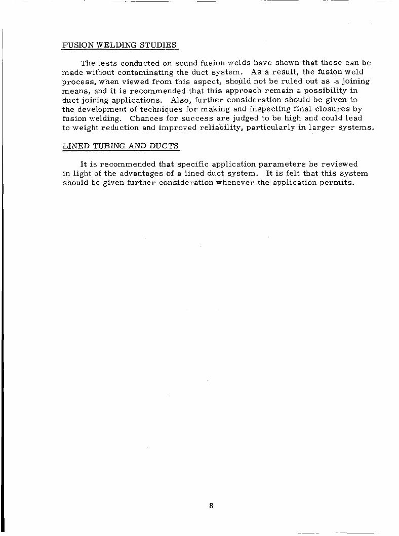
Three different photographs taken from a weld of a tube joint show the effects. Figure 15 was taken at the tip of the angle (Position 111 Figure 141, Figure 16 at the middle of the weld (Position I1 of Figure 14); and Figure 1 7 shows the end where the acceleration was highest (Position 1,Figure 14). Where the welding s ta r t s , a t the tip of the angle, the mater ia l s make ver.y good contact, but some increase in impact velocity is needed until the surface jetting process begins and welding is promoted. The beginning of the waviness in the weld line can be seen at the bottom of Figure 15. In the middle of the weld this surface jetting is very eleborate as seen in Figure 16. A t the end of the weld where the impact velocity is very high the waviness tends to vanish. diffusion occurs a s seen in Figure 17. The darker shades on one side of the weld indicate the metal working that has taken place. increase from the s t a r t of t h e weld a t the tip of the angle, Figure 15, to the end in Figure 17, where the most deformation and bending occurs .
The locations a r e indicated in Figure 14.
Here a kind of
The shades
Position IV in Figure 14 indicates the point where the two shock waves F igure 18
No actual welding took place
met. An indentation can be seen but the mater ia l did not break. i l lustrates a photomicrograph of this location. The indentation in the shadowy work hardened mater ia l can be seen. in this plane, again due to the fact that the location is too close to the tip of the angle where the impact velocity was s t i l l small. In other planes the welding occurred as shown in Figure 15, 16, and 17 .
25

Figure 14. Location of Points where Microphotographs w e r e Taken. Position IV Shows the Ignition Point in the Same Horizontal Plane).
(The Section to the Right
26

~
Figure 15. Start of Weld at Low Impact Velocity.
27

Figure 16. Middle of Weld Showing Waviness of Weld Line.
28
i
.i
Figure 17. End of Weld at Highest Impact Velocity.
29


Section 6
MAGNETIC FORMING
INTRODUCTION
Magnetic forming, while not new, has recently been applied in industry for applications s imilar to that of forming permanent connections and joints in tubes fo r leak-tightness. The process involves the application of a rapidly created magnetic field around the work piece with the piece itself the e lec t r ic conductor.
The rapid creation of this magnetic field produces eddy currents in the work piece which react with the field and produce a significant magnitude of Iorce which repel ls the work piece from the field producing coil. The fo rces so produced a r e generally of very short duration, but can be suf- ficient to produce permanent deformation at a very high rate . In a sense, one can consider that the eddy currents in the work piece constrict the flux l ines f rom the main coil, and that in their des i re to not be SO constricted the flux produces a "pressure" on the work piece. of flux may be 300,000 gauss, producing a "pressbre" of about 50,000 pounds p e r square inch (Ref. 5). would normally produce, metal inser ts known a s "field shapers" can be used to vary flux density and produce a desired pattern of "pressure. I'
A typical level
Rather than accept that pattern which the coil
Magneform, a machine designed and marketed by General Dynamics
By the use of this device, p re s su re and vacuum Corporation, employs the magnetic forming principle,, and w aS used throughout this study. tight joints in both s imilar and dissimilar mater ia l s we le produced. Relative to the overall requirements of a permanent connector, preliminary information indicated that the process was unique in that it provided a solution to virtually all major problems. F o r example:
1,
2.
3.
4.
5.
The process in no way affected the cleanliness of the end product.
The process introduced an increase in joint strength through cold working. Although this may vary with material,, the strength factor is essentially always a plus value, allowing an optimum in strength-weight ratio in the joint.
The forming p res su res and forces tended to be comparable to those of the explosive welding processes, thus they introduce the possibility of effecting a cold weld a s well a s pressure-deformation relationships (swaging) fo r sealing.
The process can be applied to joining s imi la r and diss imilar metals.
While the process depends on the formed mater ia l being a conductor, and the efficiency is a function of the resis tance of the formed.materia1,
3 i

the process can be applied to non-conducting o r poor conducting mater ia ls provided a good conducting "driver" can be used.
The process is capable of being made portable, and requi res a minimum of operator training o r skill a s compared to typical welding processes. With proper dimensional setup and predetermined coil- power setting, the process is essentially independent of any other variables, human o r otherwise.
6.
With the foregoing considerations in mind, the program described in the remainder of this section was instituted in an effor t to determine whether the magnetic forming process could be applied to the task of permanent con- nector fabrication of in-place assemblies.
In addition to the tes t s performed on tube connections, severa l tests were made in an attempt to improve the character is t ics of the magnetic forming machine.
MAGNETIC FORMING TEST SUMMARY
The primary aim of all t e s t s performed was LO effect a p re s su re seal between a tube and an insert . When two such connections can be suc- cessfully made, a tube-to-tube junction is formed. Much like in the ex- plosive forming operation, the inser t pe r fo rms the function of supporting the high s t r e s ses required to make the joint and acts a s one of the seal elements.
A typical joint configuration is shown in Figure 19 and 20. I t is r e c - ognized that this joint presents a line restriction. However, this r e - striction must not be construed a s par t of the final joint design because the joint configuration tested.w a s merely a convenient mechanism to evaluate the sealing capability of the magnetic forming process and to e s - tablish procedures and parameters .
Aluminum mater ia l s were the pr imary mater ia l s used in all tes ts . Both 6061--T6 (hard) and 3003-H14 (soft) were used a s tube elements to provide a comparison between the hardness of tube mater ia ls . were made from 2024 variety aluminum; while a limited number employed the softer 1100 se r i e s aluminum. Two inch and three-eights inch outside diameter tubing were chosen a s the t e s t s i ze s so that comparison could be made. Early in the program, however, tests were concentrated on use of the three-eights size. maximum power output was able to c rea te enough deformation to make satisfactory joints approximately that size.
Most inser t8
This was prompted by the fact that the 6000 joule
One test s e r i e s used b r a s s for its tube mater ia l and an aluminum sleeve a s the "driver". following tes t summaries.
Reasons for this choice wi l l become apparent in the
32

Figure 19. Lower Portion Shows Elements of Magnetically Swaged Connector. Upper Portion Illustrates Completed Con- nection (3/ 8 inch Outside Diameter Tubing, 3003-H-14 Aluminum; 2024-T4 Union).
Figure 20. Elements of 2 inch Connector for Magnetic Swaging (Tubing - 3003-H-14 Aluminum; Union 2024-T4).
33

For the finished joint shown in Figure 2 1 and 22, a m a s s spectrometer check with internal vacuum was made and no evidence of a leakage'was found. To tes t the joints sensitivity to vibration, the sample was mounted and vibrated at its natural frequency at a 200 g ' s acceleration level for ap- proximately 15 minutes. leak-tight. and at one of the tube convolutions adjacent to the seal section. were attributed to fatigue failure at these points. t he same inser t configuration was made and subjected to the following tests:
A second leak check showed the joint to be still .
However, leakage did occur in the tube at the point of mounting Both leaks
A second connector with
1. A one atmosphere leak tes t (atmospheric p re s su re to a vacuum); no measurable leak was in evidence.
Tne system was pressurized at 2000 ps i with helium for a period of 20 hours. Again, no measurable leak ( l e s s than
The connector was vibrated for 20 minutes in a manner such that 200 g ' s loading existed on the connector.
Successive vacuum and p res su re leak checks were performed, again yielding no measurable leaks.
2. atm c c / s e c )
3. 1
4.
Encouraged by these successes , the tes t program was now directed toward the collection of design information concerning this technique. soon, however, two ser ious problems arose. informity of the tubes' deformation in the joint ht the completion of the formfng process was found (See F igures 2 1 and 22). covered that this forming technique allowed a certain degree of elastic springback in the deformed mater ia l . The elastic springback, in turn, caused separation of the mated pa r t s so that a seal was not effected. This phenomenon has been previously discussed in Section 5 "Explosive Forming' ' of this volume and is i l lustrated in Figure 4 which shows the cross-sect ion of an explosively formed joint.
Very First, a lack of circumferential
Secondly, it was dis-
Several different experiments throughout the program were conducted wi th the magnetic forming machine and specially fabricated tube and inser t p rocess in order to overcome the above shortcomings.
In order for the force field LO be concentrated over a smal l length (measured longitudinally), a shaper is fitted into a work coil. made from beryllium copper, has the function of concentrating the force over an extremely small length. contain a single loop coil, a slit is radially cut ac ross its thickness. At this slit, however, the force field is not the same a s elsewhere about the periphery. This problem is inherent when a shaper is used and thus the question arose a s to whether this problem could be sufficiently reduced by proper sizing of the shaper. to reduce the effects of this phenomenon. the s l i t was tr ied. is limited to a smaller par t of the periphery.
The shaper,
However, i-n. orde r that this shaper w i l l not
Three different techniques had been considered
As the slit becomes narrower the diminution in the force First, a reduction in the width of
The f i rs t shaper coil had a
34

Figure 21. Uneven Depth of Draw Due to Width of Split in Shaper.
0 Figure 22. Uniform Depth of Draw; Plane of Photo 90 Plane of Shaper Split.
from
35

0. 065 inch s l i t while the following shaper coil was machined with a slit of only 0.011 inch. not show a significant amount of improvement in the circumferential uniformity of tube collapse. inch aluminum tubing.
Initial t e s t s conducted with the second shaper did
These t e s t s were conducted on three-eights The resu l t s of this experiment were not encouraging.
A second means of reducing the singularity effect was to increase the clearance between the outside diameter of the tube and the inside diameter of the shaper. While this technique inherently reduces the force experienced by the tubing, i t tends to wash out any deviations in the force field. Initial t e s t s were made with the clearance between the outside diameter of the tube and the inside diameter of the shaper being equal to the slit width in the shaper. Additional tes t s were conducted wi th ra t ios of the tube-shaper clearance to shaper sl i t being 1 to 1, 2 to 1, 3 .to 1, and 3. 5 to 11. t e s t s gave no significant increase in quality of the joint.
These
The technique of employing the magnetic forming process twice on the same connector was also tr ied in several samples. technique showed some tendency to separate surfaces already mated, l a t e r t e s t s illustrated that some reduction in leakage ra te is possible. The first forming operation usually resulted in non-uniform collapse of the tube into the inser t groove. The tubes were leak tested at one atmosphere p re s su re differential and then re-swaged by the magnetic forming process with the tubes rotated 180 with respect to the shaper slit irom the f i r s t forming operation. A second one atmosphere p re s su re differential leak test pe r - formed showed a definite improvement in leakage r a t e s in the case where 6061-T6 aluminum tubes were used. 3003-H14 aluminurn tubes were used proved inconclusive. spection of the difference in the amount of deformation caused by the second magnetic forming process yielded s imi la r results. that the 3003-H14 tubes were not a s highly affected a s those of 6061-T6 aluminum
Whi le initial t es t of this
0
Second leak t e s t s in cases where Visual in-
Overall, it was noted
Further testing in the program embodied a concerted effort directed toward the design and testing of various inser t and connector configurations. This appeared necessary in light of the success (derived from the initial connections made and the apparent lack of knowledge of this process a s applied to connectors in general. Since many samples can be magnetically formed within an hour 's machine time, several samples of different var - ie t ies of inser t configurations can be economically made and much valauble design data derived. certain element of understanding of the process while others were devel- oped in order to take advantage of the knowledge gained.
Many configurations were designed to increase a
Initial Connector Inser t Design
The configuration (Figures 19, 21, and 22) was successful. Subsequent X-rays (Figures 23 and 24) indicated lack of deformation uniformity and
36

1
I -
Figure 23. X-Ray of Magnetic Formed Permanent Connector. Note Variation in Tube Deformation. This Con- nector has been Successfully Leak Tested.
~~ ~ ~~
Figure 24. X-Ray of Same Connector as in Figure 23 , Rotated 90'.
37

lack of sealing at the knife edges. the s t a r t of the trough adjacent to the knife edge. were already discussed.
Any seal that occurred must exist at Results of these tests
Gap Depth and Width Ser ies
This se r ies was designed to obtain knowledge concerning the depth of deformation of the tube into various widths of grooves. tests were made with constant width gaps but wi th varying depth. lengths were incrementally varied from two to eight t imes the 0. 035 inch tube wall thickness. Both 6061-T6 and 3003-H14 tube mater ia l s were used (Sees X-ray Figures 25, 26, and 27). These t e s t s were designed to provide information relative to design of upcoming knife edge and springback inser t configuration tests. As expected, the width of the groove increased, a s did the depth to which the tube deformed.
In addition, several Gap
SB Series
This test s e r i e s was designed to overcome the tube's springback tendency. Inser t s were made with varying wall thicknesses to determine which ones reacted best. Inser t thicknesses were 20, 30, 60, and 90 thousandths of an inch. Of the eight samples tested, vacuum leak tes t s showed that the best seals were made with thinner walled inser ts .
Both 6061-T6 and 3003-H14 tubes were used (See Figure 28).
KE Series
This knife edge se r i e s was performed with inser t s using various heights of annular knife edges designed to "bite" into the deformed tube. though non-uniform tube deformation was shown to be a problem, it was felt that successful connections could be derived with inser t s designed from data gained in the varying gap tests. 6061-T6 tubes.
tue% 10
Even
Eight samples were tested with Three knife edges were too short to make contact with the
However, two of the highest ones resulted in sea ls of the order of atm c c / s e c (See Figure 29)-
F r e e End F E Series
This se r ies of tes t s used an inser t designed so that the end of the tube Eight samples (four each with both Leaks ranged from 10-2 atm c c l s e c
was deformed into the inser t groove. tube materials) w e r e vacuum tested. to The two best (both wi th 6061-T6 tubes) were pressued tested. One showed no leakage at 2000 psi or 24 hours. The other leaked at the 1800 ps i level (See Figure 30 insert) .
atm cc /sec .
Repeatability and Surface Finish ( S S ) Ser ies
At this point in the program, it was decided to test the repeatability of the magnetic forming process. The same basic configuration as that used f o r
38

Figure 25. 6061-T6 Aluminum Tube Deformation as a Function of Gap Length for Constant Magnetic Field Strength. Insert is 2024-T3 Aluminum. 2x, 4x, 6x, and 8x of the Tube Wall Thickness. Tube Wal l Thickness is 0.035 inch.
Gaps Range f rom

Figure 26. 3003-HI4 Aluminum Tube Deformation with Varying Gap Depth. 2024-T3 Aluminum Inserts. Magnetic Field Strength not Varied. W a l l Thickness. Depth of Gap - Ox, lx , 1. 5x, 2x, 2. 5x Tube W a l l Thickness.
Gap Length is 3x Tube Tube W a l l Thickness is 0.035 inch
Figure 27. 6061-T6 Aluminum Tube Deformation with Varying Gap Depth. 2024-T3 Aluminum Inserts. Magnetic Field Strength not Varied. Wall Thickness. Depth of Gap - Ox, lx , 1. 5x, 2x, 2. 5x Tube W a l l Thickness .
Gap Length is 3x Tube Tube Wall Thickness is 0.035 inch
40

, 1 2 5 2 . minimum
3- ,03125
.375"
,060" *+
L
T'
Figure 28, SB Series Insert
125- .030

0.305" Dia .
1 / (Not t o Scale)
+,, 0.305" Dia. 1 0 . i 7 5 " Dia.
0.02
Sample D E
1 0 . 197I.l 0 . 2 3 7 " 2 0. 207" 0. 247" 3 0 . 217" 0 . 2 5 7 " 4 0. 227" 0 . 2 6 7 " 5 0 . 2 3 7 " 0 . 2 7 7 " 6 0 . 2 4 7 " 0. 257" 7 0 . 257" 0 . 2 9 7 " 8 0 . 2 6 5 " 0.305"
Figure 29. Knife Edge Series Insert
42

"A" DIA. Snug Fit Inside
&'IO. D. Tube 8
Figure 30. Free End Ser ies Inser t
43

the very f i r s t successful inser t s was employed but without the knife edges since X-rays showed them not to be beneficial (SeeFigure 31) . of the eleven in se r t s were lightly sand blasted to tes t the effect of the dif- ferent surface finishes. p re s su re levels at which leakage occurred after successful vacuum te s t s showed the inconsistency of the technique. at levels ranging from 0 to 2000 psi. not to effect the results.
Also, four out
Random The finished joint is shown in Figure 32.
Excessive leakage occurred The different surface finished seemed
SS Series Tensile Tes t s
Two of the SS series tes t connectors were tensile tested and showed strengths in excess of the strength of tube material . 45,000 psi).
(Approximately
The following three inser t configurations were designed to improve sealability at the point where the tube mater ia l begins to deform into the groove. w h e r e sealability occurred
X-rays of pr ior successful connections showed this a r ea to be
S P Series
T h i s insert configuration (See Figure 3 3 ) was designed with a knife edge at the s t a r t of t h e groove. caused by the tubes' deformation. would cause a "biting-in" action. both kinds of tubing, all showed excellent sealability in the vacuum tes t ( leaks beyond the range of the equipment), but all three of those p re s su re tested leaked at low internal pressures , ranging from 5 to 150 psi.
The idea was to take advantage of t h e shear action Relative motion between tube and inser t
Of the three samples made, each with
SH Series
This insert (See Figure 34) was designed to act a s an annular centilever to overcome the tubes ' spring-back tendency. The high degree of flexibility at the tube and inser t junction coupled with i t s bite-in" character is t ic was tested in s ix samples, three each with the soft and hard tubing. All showed good sealability (leaks between vacuum check, but the one sample that w a s p r e s s u r e tested leaked at 5 psi.
1 1
atm c c l s e c to undetectable) in the
SC Series
Like the SH ser ies , this inser t (See Figure 35) was supposed to provide a spring action but with increased stiffness. Again, s ix samples were made and showed excellent vacuum sealability beyond the range of detection. On pressurizing them, however, all leaked at low p r e s s u r e s ranging f rom 5 to 400 psi. t h e magnetic process and its character is t ics and LO check the various ideas formulated from the foregoing tests.
The remaining tes t s e r i e s involved efforts to l e a r n more about
4 4

- 1" S l i d e f i t 8 i n
tubing I . D .
T I
Figure 3 1 . S S Series Insert Geometry
45

magneform h i t locat ion /-
L inser t
Figure 3 2 . Final Corinectol. Shape
4 6

O . D . S l i d e f i t in tubing I .D. 1 8
Figure 33. SP Series Insert Geometry
47

Material 2024-T4
Slide Fit in A
Tube I . D .
LToo1 Radius Permissible on Inside Corners
Figure 34. SH Series Insert Geometry
48

Material 2024-24
S l i d e Fit i n A
Tube I.D.
0.
t Tool Radius Perminsible on Inside Corners
Figure 35. SC Series Insert Geometry
49

SJ Series
I
Tube-to-tube Confimration Ser ies
Several samples w e r e made to test the sealability offered by the use of solft f i l ler mater ia ls in the seal grooites. Five samples were made with b r a s s mater ia ls for tubes and inser t (See Figure 36). The inboard grooves were filled with solder and shaped. The outboard grooves were used a s positioners with the first tube deformations made at those locations. b r a s s tubes were machined down to allow 0.003 inches of solder coating of their inside diameter and placement of aluminum required for the process. this kind of forming operation, creating more force at the inser t . made showed low leakage in a vacuum test, the highest
The
1 1 driver" s leeves It was found that aluminum reac ts bet ter to
A l l samples atm cc / sec .
R Series
The inser t s shown in Figure 37 were designed with ramped s ides of the The deformation of the ends of the tubes down the ramp inboard grooves.
was to instigate sealing due to the relative motions involved. Springback was to be obviated by the inability of the tube to t ravel back up the ramp. The outboard groove, like the SJ ser ies , was for positioning only. Tubes were of 6061-T6 tubing and in se r t s were 1100-F aluminum mater ia l . A cold weld was sought between the hard and soft mater ia ls . made showed excellent vacuum sealability (ranging from and lower) but low pressure sealing. was 30 psi; however, most samplesbegan to leak in the neighborhood of 0 psi .
All Five samples atm cc / sec :
The highest p re s su re level attained
The final attempt at making a tube joint was done with the configuration shown in Figure 38. tube sections while they were deformed into the groove. were aluminum. aluminum, and the inser t 2024-T4. very high vacuum test leakages in the neighborhood of 10-1 a tm-cc /sec . Deformations at the maximum (6000 joule)-power setting of the magnetic forming machine were disappointingly low.
The idea was to create relative motions between the All of the mater ia l s
The outer tube was 3003-H14, the inner tube 1100-F Of the three samples made, all showed
A departure from the tube inser t configuration was that shown in Figure 39. I t represents a flange joint designed to take advantage of high deformation resulting from flat coil magnetic forces. and groove type of annular rings. plates were also t r ied with no surface deviations. resul ts . The f i r s t cracked at the base due to excessive deformation; the second showed no connection at all, a manual pull resulting in separation of the plates. (See Figures 40 and 41).
Sealing was to occur at the tongue In addition to this configuration, flat
Both showed disappointing
5 0

DIA.
Figure 36. SJ Ser ies Insert
1
t i +
f Figure 37 . R
3 8 DIA.
Series Inser t
I-
51

b
0.670 b
Outer Tube - 6" Long
Base
Figure 38. Tube to Tube Configurations
52

I
i
0.070 r 0 m
0 0 In
0.070
Figure 39. Plate to Plate Joint
5 3

Figure 40. Top View of Magneform Assembly Shown in Figure 39.
Figure 41. Side View of the Mangeform Assembly Shown in Figure 39.
54

Section 7
ADHESIVE BONDING TECHNIQUES
INTRODUCTION
The technique of using adhesives to bond tubes and ducts h a s many nresent day applications in aircraft, missi les , and spacecraft. To date, adhesive joints with tensile strengths a s high as 15,000 ps i have been obtained with aluminum and adhesives like epoxy resins ( fo r instance, Araldite AN- 100 and Epon VI). a r e a s a r e available, tapered joints can be employed to increase the strength efficiency of the bond. should be within 5 to 10 degrees. Thus, with these facts in mind, this tech- nique was explored a s a possible method of making duct joints.
Therefore, for duct joint applications, where no la rge bonding
The typical tube angles which should be expected
DE SIGN CONSIDE RATIONS
If the angle of the taper is called a (See Figure 4 2 ) the ratio of the cross-sectional a r e a of the tube to the surface a r e a of the taper is:
A adhesive = 1 A tube sin a
The angle a itself can be determined by the simple assumption that the joint should have the same strength a s the pipe and then also:
0 tube = 1 (for small a ) adhesive s i n a
For different angles t h i s factor becomes:
a atube/ adhesive
50 7 O
8 O
1 oo
11.47 8 . 2 0 6 7. 185 5.759
This is only a theoretical factor based on the geometry and neglects the facts that the edges are not perfectly sharp and that the adhesive line has a certain thickness. with strength a s low a s 10 percent that of t h e pipe mater ia l could produce adequale joints.
However, this calculation does show that an adhesi:7c
Adhesive joints which might not be strong enough for some structut.al purposes could very easily be supported mechanically with some lightweight equipment and still take advantage of the leak-tightness of adhesive bonds.
55

t L D
Figure 42. Typical Bonding Geometry
5 6

In all ca ses the adhesive was cured at room temperature overnight and then fo r two hours a t 176'F.
Se r i e s "T" was made f rom different tube ends with plain tapered joints but different angles of taper. only four of them could be p re s su re checked because of the dimensions of the vacuum chamber .
All samples proved to be leak-tight; however,
During. the test the tubes w e r e pressed between two sealing end caps in order to pressurize them. of the series T tests.
Table 1 gives the
Table 1
SERIES T TEST RESULTS
Character is t ics Vacuum Test Inside Pres s u r e
1000 psi T -1 1' ' 0. D. x. 065"; 5 taper No leak
1000 psi T-2 1" 0.D.x. 065"; 8 taper No leak
T-3 1" 0 . D . x . 065";10° taper No leak 375 psi
1000 psi T-4 3/4" O . . D . x . 065"; & taper N o leak
0
0
0
resul ts
I, eakage (a tm c c / s e c )
ZxlG-'
N o leak
1 x l G - 8
No leak
Ser ies "J" was made of 3 / 4 inch outside diameter x 0. 095 inch tubing. I I
I Instead of plain tapered joints, the male pieces had a machined-in shoulder to adjust different film thicknesses of the adhesive ( 1 / 6 4 , 1/32, and 3/64). Samples of this s e r i e s were run in a rotating beam fatigue testing machine. The eccentricity of the pieces made it impossible to adequately tes t most of them. and run for 100,000 cycles without failure. were vacuum tested, they both proved to be leak-tight.
However, two samples were loaded with 40 and 60 in-lbs respectively, Further, when these joints
As al l the plain tapered joints gave better results, a third s e r i e s "R" w a s made having a 10 degree angle and using the sample epoxy resin but with different filler ratios. Talc w a s used a s f i l ler material . Samples w e r e made with straight tapers from 3/4 inch outside diameter x 0. 095 inch tubing.
Out of the 25 samples, all w e r e leak-tight except one which showed a smal l leak ( l x 10'' atm cc l sec ) a f t e r 1 / 2 hour. jected to an extended t ime leakage tes t of less than one hour.
All samples w e r e then sub- No other leaks
5 7

w e r e found. t o t h e following t e s t s :
A f t e r t h i s p r e l i m i n a r y check, 21 of t h e s a m p l e s w e r e sub jec t ed
Five s a m p l e s pu l l - t e s t ed f o r t h e i r t e n s i l e s t r eng th . 0
4 Eight s a m p l e s t h e r m o c y c l e t e s t e d be tween -67 and +185 F.
T h r e e of the eight s a m p l e s pul led f o r t e n s i l e s t r e n g t h at r o o m t e m p e r a t u r e .
F i v e of t he eight s a m p l e s t h e r m o c y c l e d be tween -295 and +185 F.
Two of t h e f i v e s a m p l e s pul led f o r t e n s i l e s t r e n g t h a t r o o m t e m p e r a t u r e . a t - 295OF.
0
The f inal t h r e e s a m p l e s pulled f o r t e n s i l e s t r e n g t h
Eight s a m p l e s v ibra ted .
T h e r e s u l t s of t he f i v e t ens i l e tests a r e l i s t ed in T a b l e 2 . F o r s a m p l e F o r N u m b e r s 1, 3, 4, and 5, an a v e r a g e a r e a of the s a m p l e s w e r e u s e d .
s a m p l e Number 2 the a r e a fo r the spec i f ic s a m p l e w a s employed .
T a b l e 2 TENSILE T E S T RESULTS
2 N o . Load ( l b s . ) Average A r e a ( in ) T e n s i l e S t r eng th ( p s i )
3,300
4,000
3,670
3,210
3,740
0 . 8 2 0
0 .775
0 . 8 2 0
0 . 8 2 0
0 . 8 2 0
4,020
5,150
4,470
3 ,920
4,560
Tne the rmocyc l ing t e s t s w e r e run acco rd ing to spec i f i ca t ion MII, -STD- 202A Method 102A, t e s t condition D , f ive cyc le s . s t e p s and t h e r e s u l t s are l i s t ed i n gable 3 .
E a c h cyc le had f o u r
Tab le 3
THERMOCYCLING T E S T SEQUENCE
Step
1
2
3
4
0 Minu tes a t F.
30 +10 - 1
-67
15
15
+18 +77- g
+18 +77- 9
58

Geometries with two o r m o r e bonding a r e a s to increase the strength o f such joints a r e also possible. the joints semi-permanent so t h a t they cozlc! be r e a s s c ~ i b l e d af ter cleaning. An illustration of the typical bonding geometry is shown in Figure 4 2 .
Finally, the u s e of heat o r even solvents could make
It is t rue that it may not be practical to use adhesive joints on liquid oxygen sys tems because of its incompatibility, and in any event development would be needed to a s su re that a system is liquid oxygen compatible. the lack of liquid oxygen compatibility should not prevent use of this method f o r fuel and inert gas systems.
However,
A problem which a r i s e s in the use of adhesives is that of the difference in the coefficients of expansion for the adhesive and the s t ruc tura l mater ia ls . Typical coefficients a r e approximately:
-6 a 40 x I O in/in/OF - f o r epoxy, value given is approximate for
formulation used in tes t s ; may vary ap- preciably for other iormulations.
-6 0
-6 0 1 3 x 10 in / in / F - f o r aluminum
9..5 x 10 in / in / F - for stainless s tee l
There is, nowever, a possibility of lowering the thermal coefficient of the adhesive by adding filler material .
Liquid oxygen c-ompatible 1-esins d o exist. necessarily nave the best mechanical strength. ambient temperatures may become brittle on being exposed to cryogenic conditions while others with good ,,roperties at very low temperatures show poor resu l t s at ambient temperatures . However, there is the possibility o f having the adhesives tailor-made f o r any application.
However, such res ins d o not High strength adhesives at
TESTING PROCEDURE AND RESULTS
In t h e t e s t s made an epoxy rormulation was chosen to avoid br i t t leness a t low temperatures . adhesive. used. The formulation was:
This, of course, resulted in a lower strength of the For the first two se r i e s "TI' and "J," unfilled xaesin has been
100p t s /w - Epon 828 0 100 ptS/w - Veramid 125
The t h i r d , o r "R" se r ies , was bonded with a filled resin of the formulation:
. 7 0 pts/w - Epon 820 Q 70Pt s /w - Veramid 125 e 50 Pts/w - Talc
5 9

The results of the tensile tes t of th ree samples a f t e r thermocycling is indicated in Table 4. pared with the figures in Table This could be due to the fact that the samples were cured fur ther by the thermocycling procedure. To prove this, however, more pull t es t s would have to be run.
There seems to be a slight increase of strength com- 2.
Table 4
TENSILE TEST RESULTS AFTER THERMOCYCLING 2 Load (lbs. ) Area (in ) Tensile Strength (ps i ) No.
1 3,900 0 . 7 7 5 5,030
2 3,700 0. 710 5,200
3 3,150 0. 790 4,000
After the f i rs t thermocycling tes t at d r y ice temperature , which did not appear to influence the bond, the same procedure was repeated at liquid nitrogen temperature. The cycles were a s shown in Table 3 except for a temperature change in Step 1 from -67 F . to -295 F. A l l five samples subjected to this test showed no leakage in a vacuum test .
0 0
0 The tensile tes t s of the samples which were thermocycled between -295 0 and +185 F. were run a t two different temperatures. The resul ts of these
tes t s a r e given in Table 5 . Two of the samples were pulled at room tem- perature for comparison with previous tensile tes t s (Tables 2 and 4 ). Three other samples were tested at liquid nitrogen temperature. This was done in a fixture a s shown in Figure 4 3 and liquid nitrogen was poured into the Styrofoam mold to cool the joint. s t i l l about 1 / 2 filled with liquid nitrogen. Therefore, it can be assumed that the ioint was kept at this temperature during the tes t .
At the end of the tes t the mold w a s
Table 5
TENSILE TEST RESULTS AT TWO DIFFERENT TEMPERATTJRES
Strength (ps i ) 2 Temperature Load (lbs. ) Area ( in ) ~ _..- No. -
1 Room Temperature 3,610 0 . 7 7 5 4,650
2 Room Temperature 3,750 0 . 8 7 1 4,300
3 Liquid Nitrogen 5,750 0 . 8 7 1 6,600
4 Liquid Nitrogen 5,050 0. 711
5 Liquid Nitrogen 5,&50 0 .871
7,100
6,720
There is an’increase in strength at lower temperatures of about 50 percent, although the method of cooling the samples means another temperature shock p r io r r o loading.
60

Figure 43. Cryogenic Tensile Testing Fixture
6 1

The vibration t e s t s were f i r s t performed in a rotating beam machine. Because of the eccentricity of the samples, the resul ts were not useful. After new fixtures had been made for vibration on a shaker, Tab1 were vibrated at 200 g's with'a momentum load of 150 i n - b for 10 cycles with no failure. while the shear stress in the adhesive joint w a s calculated a t 1225 ps i because of the extended a r e a of the taper. pulled in tension and no decrease in strength could be observed, a s seen in Table 6.
6 samples 8 The load represented a fiber s t r e s s of 5320 ps i
Three of the= samples w e r e
Table 6
RESULTS OF TENSILE TESTS FOLLOWJNG VIBRATION
Sample Strength (ps i ) 2 Load (lbs. ) Area (in )
1 3,340 . 7 4 3 4,630
2 3,700 , 7 7 5 4,780
3 3,420 . 9 3 4 3,660
Tile remaining five samples were vibrated further while che load was increased. Having a fixed 1 n th of tes t equipment, the g-level was raised. The samples withstood 4x10 cycles at 150, 200, 250, and 300 in-lbs moment load and g-levels of 200, 300, and 485 g ' s . The s t r e s s e s of the tube and the adhesive a r e indicated in Table
% g
7.
Table 7
VIBRATIONAL TEST RESULTS
Moment Load Tube S t r e s s Shear S t r e s s (in-lb) g-level Cycles ( p s i ) Of the Adhesive (ps i )
150 200 10 5,300 1,125
200 300 1 0 7,090 1,640
6
6
6
6 250 38 0 1 0 8,860 2,020
300 48 5 1 0 10,630 2,450
A l l samples were leak checked in a vacuum test af ter each s tep and were still leak-tight. in-lbs and 485 g ' s since the driving force needed was more than 10 t imes higher than f o r the other four and exceeded the maximum driving force of the machine. hesive used, the fatigue strength is at least half the normal s t r eng th , while calculations a r e usually made with 1 / 3 of the normal strength.
One of these five samples could not be vibrated at 300
The vibration tes t s indicate that fo r the formulation of ad-
62

Section 8
FUSION WELDING STUDIES
INTRODUCTION
The bes t possible tube o r duct permanent conneztor is one which adds no weight to the system a d thus weighs the same a s an equal length of the original pipe o r tube. a joint but has several inherent disadvantages. The major problem is that of insuring a high level of cleanliness of the system; that is, of assuring that the welding p rocess will not generate dirt . Therefore, welding studies have been made with respect to cleanliness attainable. Specifications MSFC-SPEC- 164 and 10419906B were taken a s a guide for these tes ts .
Fusion welding represents a techniques for making such
DESCRIPTION O F TESTS
Two approaches were used to detect dir t generated by the welding pro- cess. The approaches were:
1. To clean the samples to be welded and check the cleanliness of these samples after the welding.
To investigate the generation of par t ic les by the welding pro- cess.
2.
Samples suitable fo r butt welding were made from 2 inch outer diameter aluminum and stainless s teel tubes. pickled and cleaned in the following way:
P r i o r to welding, the pieces w e r e
(OAKITE No. 23, 8 0 Cleaned in alkaline cleanser at 180°F. ounces p e r gallon)
0 Rinsed
0 Pickled in a 130 F solution consisting of one gallon forty ounces of No. 90 actane (Fluoride sa l t ) and two and one half gallons of water.
of nitr ic acid,
R.insed in cold water
0 R.insed in deionized water
0 Dried in oven at 190°F
Tubes were joined using a tungsten a r c inert gas welding system mount- ed on a special set up which insured an argon atmosphere inside and outside the tube. were flushed with argon fo r five minutes. No special seam preparation was given to the samples welded. made so that were found leak-tight in a mass spectrometer leak test.
To provide an oxygen f r e e atmosphere the tube pieces (in place)
A butt joint with no f i l ler mater ia l added w a s undercutting of the weld w a s inevitable. A l l samples tested
63

A commercial grade aluminum tube and a conventional grade of argon were used for these tests. N o special welding equipment was employed, no splatter due to impurities of the mater ia l occurred during welding and the resul ts can very easily be repeated and have been repeated a s reported.
A s mentioned ear l ier , it is of major interest to learn about the genera- tion of particles from the welding process itself, since this knowledge is imp0 r tan t in determining the suitability of fusion welding for permanent connectors. par t ic les on a tube grea te r than 20 microns before and after the welding, but this was inconclusive because of contamination from sources not r e - lated to the welding process, such a s f rom the air.
An attempt w a s made to determine and compare the number of
-4 second technique for determining whether the welding process gener- ated dirt was devised and is pictured in Figures 45, 46, and 47, and is shoivn schematically in Figure 44. Referring to Figure 44 one finds that argon is taken from the bottle (1) and r u n through a glass wool filter (4). By using Fi l ter I ( 5 ) the argon can be checked for par t ic les beforc it is utilized to flush the inside of the tube samples to be nelded (8). of the tube is shielded by the argon supply of the torch (11 ). After passing the welding zone the argon s t ream, at the inside of the tube, is sucked through a Sinclair Phoenix" photometer (10) and a "Millipore" fi l ter (5) i n o rde r to check fo r generated particles. The "Sinclair Phoenix" photo- me te r (10) gives an instant reading and once taken the s ize and number of par t ic les generated can be determined by examining the "Millipore" f i l t e r under a microscope.
The outside
1 1
F o r the welding process, it is necessary to prevent any inside pressure. Therefore, again referr ing to Figure 44, a monometer (2) is kept at a constant setting of one half inches of water. the measured particle s ize ra ther than the capacity of the photometer. Therefore, it is necessary to have a bypass (9) in o r d e r to use a variable flow rate, while the instruments u.ork at a constant one. Flow me te r s ( 3 ) located at each side measure the actual flow through Fi l te rs I and I1 and the photometer. the whole system, the geometry of the tube samples (2 inches outer diam- eter , 0. 049 inch wall and 2 inches long) demands that the flow velocity of the argon g a s at least equal the falling velocity of the particles. velocity of particles is a function of par t ic le size. flow rate of 50 ft / h r all par t ic les smal le r than 6 0 microns in dinmc.tc.r a r e transported.
The flow r a t e s a r e dictated by
A s the tubes to be welded have the biggest cross-sect ion in
Falling Thus, by choosing a
3
This size particle is visible to the naked eye.
The f inding of par t ic les onthe filter does not give the exact number, a s the portion of the fi l ter on which par t ic les were counted has to be related to the whole fi l ter area, and the flow r a t e through the f i l ter has to be fur ther related to the overall flow- r a t e through the welded tube. get a correct count of how many par t ic les in the cr i t ical s ize range have been generated, both the total gas flow through the tube and the flow through
Therefore, to
64

a 7 a tn c,
a k s M E
65

Figure 45. Welding Test Set-up for Purging the Inside and Outside of the Tube with Argon.
Figure 46. Welding Fixture Mounted on a Lathe for Centering and Driving.
66

Figure 47. Test Setup a s Diagrammatically Illustrated in Figure 44.

Filters I and I1 were measured. The whole t e s t set-up was cleaned before being assembled. Every piece was finally washed with acetone. Flushing with argon did not show any par t ic les left by the cleaning procedure. Thus, only par t ic les generated during the welding were transported . . to the instru- rnents and filters.
TEST RESULTS
Preliminary t e s t s were run to check the system and obtain background readings wi th Millipore filters. Results of these t e s t s a r e shown in Table 8.
Table 8
PRELIMINARY BACKGROUND TEST RESULTS
' Par t i c l e Total Count Number of Kind of Test TotalCountP20p F o r 3 cm2 20p
Fi l te r Run Flow R.ate Time Flow On 1 5 2 mm Whole Pa r t i c l e s No. Argon Stream ( c c / s e c ) (min) (cc) F i l t e r Area F i l t e r A r e a P e r cc
A
B
C
D
E
F
Directly off tank through regulator
Directly off tank through regulator & glass wool fi l ter
Through tes t set up with specially cleaned g lass tube
Through aluminum tube (a i r leak) no heat
Through
48 1 2880 1 4 82. 9 0. 03
100
100
100 aluminum tube (no heat)
Through 100 aluminum tube heated for 2 minut e s but not welded
1 1 5 88. 8
1 6000 1 2
1 6000 17
71
100.08
2 6000 1 7 100.08
2 12000 1 4 82. 9
0. 0118
0. 0168
0. 0168
0. 007
68

The different f i l t e rs show an almost constant par t ic le reading no matter which parameter was changed. Looking at unused Millipore filters, taken right f rom the box in which they were shipped, par t ic les of 20por l a r g e r w e r e found in just the same numbers a s in the preliminary tests. Therefore, it is necessary to count the f i l ters before and after each t e s t ' i n o rde r to ob- tain an accurate evaluation.
The welding t e s t s reported below were run fo r two and one-half minutes. However, the tubes were flushed with argon fo r a longer t ime to make s u r e that no oxygen was in the system before start ing the tes t and to protect the hot weld f rom oxidation af ter welding. At the beginning of the tes t the argon flush w a s switched over to the "Sinclair Phoenix" Photometer and the Mil l i - pore f i l t e r (Fi l ter 11). After one-half minute of flushing, welding was started. This took just about one minute, during which t ime the Millipore f i l t e r before the welding fixture (Fi l ter I) w a s also taking samples. minute l a t e r the argon w a s shut off from the photometer and the Millipore fi l ters, but not the tube. and the pa r t s removed. See Table 9 fo r results.
One
After cooling w a s completed the argon w a s stopped
Here again tes t samples were run to give background readings for the
Heating up a straight piece of stainless steel tube without doing designed system. particles. any welding did not show any increase in particles, a s w a s found in the preliminary t e s t s in which an aluminum tube was heated. of 3 2 1 stainless steel weldments which showed good penetration and leak- tightness were made. c les of the 20p s ize range, it showed a coloration, as shown in Figure 48. A s this stain could not be resolved under a 400 power microscope and w a s still a homogeneous coloration, it seemed to be a deposited metal vapor. Thus, the par t ic les generated by the welding process a r e very small, much smal le r than the cri t ical s ize of 20 microns. par t ic le count before and after the tes t can be neglected, a s they a r e due to human e r ro r .
The revolution of the welding fixture did not generate
Then five samples
Although Fi l te r I1 did not show any increase in parti-
The small deviations in the
The f i l t e rs of these five samples had been analyzed and all contained manganese. showed t r a c e s of silicon. vapor p re s su re of the elements likely to be present.
Two of them also contained s i lver and one of the la t ter two Manganese was expected a s it has the lowest
These t e s t s were repeated for both 321 stainless s teel and 6061-T6 aluminum tubes. The same tes t set-up w a s used, but some changes were made. Specifically, r ings of filler material cut from the same tubes and pr.essed flat were added to the joint in order to get a built up weld instead of an undercutting. It worked very well and placed more strength into the welded area. instead of 20 microns, and the resul ts were much the same a s before, (See Table 10.).
The f i l ters were counted f o r particles of 5 microns o r l a r g e r
69

0
m - m .. 0 0
e Lo
0
0
n N
Lo
N
El
N
Lo ..
2
0
0
W
0 El
d
CI - . d
0 .. Lo
N
0 0 .. N
Lo . U . C
$2 a g m u zi d
/ ~
N N I +
Z m
2 -
0 0 0 0 L o -
c e L o - . .
0 0 0 0 0 0
o m N N . .
- - - -
~n N N
0 0
n
n
0
0
W
0 2
4
W +
N
2
c 4
0 :: c
0
0
m
v N
d +
c
W
0
0
-.e
0 El
..
9
- 0 -
z o o N N
0 0 0 8 8 : : . . . e ' P e L o L o L o
0 0 0
8 8 X . . . m m n N N N
N N N m w c
0 7 0
0 0 0 0 0 0
0 0 0
w w w . . .
0 0 0 0 0 0
m o - " N N
m d
Lo
N'
c .
.
m n w n n d d d d d
L o L o L o L o L o
N N & & & . .
0 0 0 0 0 O L o O O O
N . ( . I . m N N N N N
N. O. 9 *. 9
c - 0 . L o L o : z
- 4 N C I . Y )
d d d d d z z z z z
L o w c m m

Figure 48. Filter Used in the Preliminary Test (Bottom) and Weldment Test (Top).
71

t. w t. cn
I4 w w t. cn
72

Another slight change w a s made in that the g l a s s wool f i l ter t rap w a s left out of the system, since previously it had no influence on the particle count when argon w a s taken right f rom the tank. in the number of par t ic les in a few tes ts on Filter I p r io r to welding. par t ic les only can come from the tank o r the regulator. equipment of the welding shop w a s used, t he g l a s s wool filter would have trapped these particles. whole system was left for several hours due to a short circuit in the labora- tory. However, increase in count on Fi l ter I, column 14, c lear ly indicates that the increase in count on Filter 11, column 22, is due to par t ic les in the argon, and is not generated by the welding.
There was now an increase These
A s just the regular
The highest increase occurred in tes t 3 when the
Looking at the results, there is no increase in par t ic les (five microns o r larger) due to welding. The stain o n the f i l t e r showed a somewhat higher intensity and m o r e coloration but there was no difference in the appearance of the stain generated by the two different mater ia l s - stainless steel and aluminum (Figure 49). ated although welding t ime and alternation of the welding cur ren t seemed to have some effect. (Test No. 7, Filter No. B14). The amount of heat generated, o r the s i ze of the welding zone at the inside could have an effect on the stain but with the two samples made it is not proven (F i l te rs 18, 17, 16 show li t t le in- c r e a s e in darkness - welding t ime 60, 40, 20 seconds). of the weld is not achieved the re is no stain on the f i l ter at all.
The higher intensity of the stain could not be elimin -
Welding without filter mater ia l also made no difference
If full penetration
The welding of the aluminum w a s done with direct current instead of alternating current (which is common). The difference between alternating current and direct cur ren t welding could not be shown since the alternating current welds were not satisfactory due to interaction with the driving system. Compared with aluminum welds, previously done in the s a m e welding fixture, the heat affected zone seemed to be smal le r with alternating current .
Fi l te r B13 showed a normal coloration with no difference from .those used during s ta inless steel weldings. that t he re was not full penetration of the weld. fore, the cur ren t w a s raised and t h e stain on Filter B11 looked very dark.
Almost no stain on filter B12 indicated F o r the next sample, there-
Welding with alternating current produced poor resul ts in tes t No. 11. The speed up of the driving motor w a s compensated during welding by higher current but penetration was not achieved. After a bet ter insulation of the driving system, and careful grounding and shielding, this sample w a s re- done. But as soon as the a r c w a s made, t he motor speeded up again and slowed down afterwards. A s a result a hole was burned through the wall. F i l t e r No. B10 shows no stain although the re w a s penetration pr ior to burning. Also surprising was that there were no par t ic les found on the filter. Even the time delay o r a l i t t le blow-by cannot have affected the reading, since the gas is sucked through the filter by a vacuum pump. Particles if generated, should have been transported.
7 3

0
0 1
Figure 49. Filters Used in Fusion Welding Part ic le Counts.
74

To make su re that par t ic les were transported within the system, a hole was drilled into the weld region of one sample and 30 microns Lycopodium spores were injected. the par t ic les were transported through all l ines of the photometer to the fi l ter . The fi l ter itself was ruptured because of the amount of par t ic les and no actual count could be made. examination of small sections showed that they were transported through the system.
The same flow rate and p res su re were applied and
But the coloration of the pieces and an
Spectrographic analysis of the filter, Table 11, showed just about the The stains on the fi l ter used fo r s ta inless steel
The f i l t e rs used Other elements
s ame resu l t s a s before . welds consisted of Si, Fe, Mg, Cu, Ag, and Mn, all of the same intensity. Other elements with lower intensities were Pb, Cr , Zn. for aluminum welds showed Si, Fe (out of 5), Mg and Al. such a s Cu, Ag, and Zn were only found in single samples.
Table 11
RESULTS OF THE ANALYSIS O F THE FILTERS SHOWN IN FIGURE 49.
B20 1 1 1 1 1 B19 1 1 1 1
Fi l ter blanks without stain
B18 2 2 2 2 2 2 1 1 1 B17 2 2 2 2 2 2 1 1 1 F i l t e r s used B16 2 2 2 2 2 2 1 1 1 for s ta inless B 1 5 1 2 1 2 1 2 2 1 1 1 steel weldings B 1 4 1 2 1 2 1 2 2 1 1 1
B13 1 2 3 1 1 B 1 2 2 1 2 1 1 B11 2 2 3 1 1 B10 1 1 1 1 B 9 2 2 2 2 1 1
1 F i l t e r s used for aluminum w el dings
These tests have been made with ordinary purchased mater ia l s and con- ventional welding equipment. applications, were used to prevent oxidation. start ing with clean par t s and an inside and outside gas shield, good welds can be made without any evidence of contamination by par t ic les five microns o r la rger . a s par t ic les so fine in texture that they a re not resolvable under a 400 power microscope.
Gas shields, which a r e also possible in field These t e s t s prove that,
The welding process does generate metal vapors which deposit
7 5

Section 9
LINED TUBING AND DUCTS
1NTR.ODUCTION
An ideal tube mater ia l is one having high ultimate strength, corrosion res i s tance to all fluids, and the capability of forming structurally sound and leak-proof connections. A logical approach is the use of a composite mater ia l consisting of a l iner for optimum corrosion resistance, a casing fo r strength, and a connector fastened to the tube designed to give a leak- tight joint. It would be desirable if the corrosion resis t ing mater ia l could also be easily sealed, forming a permanent o r semi-permanent leak-tight c o nn e c t ion.
Metals which fulfill the structural requirements fo r a tube may react with the fluid contained, In some cases the oxide, fluoride, o r other com- pound generated has physical properties which cause it to become a "pro- tective layer". Thus, upon exposure to ordinary atmosphere, a thin aluminum oxide film fo rms on aluminum very rapidly and. protects the aluminum under it from oxidation. Similarly, chromium oxide protects stainless steel f rom oxidation o r "rusting", and other compounds protect other metals in other environments. Such a protective film, however, may not form, o r may be susceptible to cracking and flaking under shock, vibra- tion, o r thermal cycling.
form a suitable self-protective film. Plastics, rubber, ceramics, and unalloyed metals a r e possible l iner materials.
A l iner of suitable mater ia l could serve a s the I protective film for material combinations which a r e reactive and do not
The most promising non-metallic duct mater ia ls a r e plastics. plastic mater ia ls a r e m o r e compatible with oxidizing agents and hydro- carbon fuels than thermosetting plastics and can also easily produce a leak- tight connection. solvent o r adhesive. mater ia l where the strength requirements a r e low o r as l ine r s of ducts where their good compatibility and sealing capabilities wi l l be utilized. promising thermoplastic is Teflon since it is resis tant to a l l fuels, oxidizers, and monopropellants, except fluorides.
Thermo-
Connections can be made by heat sealing o r the use of a Thermoplastic mater ia ls may be used as a duct
The most
DESCRIPTION AND DISCUSSION O F TEFLON LINED P I P E
A sketch of a Teflon lined pipe is shown in Figure 5Q. It consists of a Teflon l iner inside a metallic pipe having a right angle f l a r e at the ends of each section. Behind the line at each 90 degree flared end is a resilient backing cushion designed to keep the Teflon l iner away from the pipe flange and to provide a cushion f o r the Teflon to Teflon seal between two joined pipes. The R,esistoflex Corporation, the manufacturer of this material , has found it necessary to include the resilient backing and a generous radius
PRECEDING PAGE 6LANK_BOOT,F!WEP,

a rd E
a, a ii:

of curvature of the l iner around the 90 degree bend to eliminate problems associated with cold flow of Teflon and differences in thermal expansion between Teflon and the casing metal. to form the leak-tight joint and a clamp is drawn over the weld to pull the two pipe sections together forming a Teflon to Teflon s'eal 'in addition to the Teflon weld. under pressure. 50 is a concept of a connector that is not presently available.
A fusion weld is made with the Teflon
The clamp also prevents the Teflon l iner from extruding when The fusion weld and clamp arrangement shown in Figure
The Resistoflex Corporation presently manufactures a T F E Teflon lined pipe with bolted flanges having either schedule 40 ductile o r stainless steel pipe a s a case. than T F E Teflon, is presently being introduced. The TFE lined pipe, de- signed f o r the c'hemical industry, is limited to a temperature range from -100" F to +500° F and p res su res below 300 psi. Both limitations a r e due to the behavior of the TFE Teflon liner. e ra ture of 500°F and may be used at cryogenic temperatures although it has reduced ductility a t these temperatures. manufacturing process and the limited demand fo r Teflon lined pipe for cryogenic service, the lower limit has been set at - 100°F, The Teflon lined flexible hose used in a i rcraf t has been successfully used to t ransfer liquid oxygen. No major problem areas a r e foreseen by Resistoflex in designing a pipe to operate at -420" F. The recommended p res su re of 300 ps i is based on the manufacturing tes t currently given to the l iner (and limited by the flange connection between sectionsl, tes ted under hydrostatic p re s su re of 225 ps i using dyed water. is then assembled into the pipe casing and given a spark tes t to uncover any flaws in the liner. short t ime periods. is the extrusion of the Teflon out of the gap between the two flanges. flange design could eliminate this problem becomes a major problem at high pressures.
F E P Teflon, which is eas ie r to join by fusion welding
Teflon has an upper service temp-
Because of R.esistoflex's
Liners a r e first The l iner
P r e s s u r e s as high a s 900 ps i have been contained for The biggest problem associated with high p res su res
Leakage by permeation also P r o p e r
The following problem a r e a s a r e associated with the use of Teflon lined pipe:
1. Differential in expansion of the l iner and casing due to temperature change.
Cold flow of the Teflon l iner.
Heat sealing of the l iner of two pipe sections to form a tight joint.
Leakage of a fluid by permeation through the liner.
2.
3.
4.
The hoop s t r e s s e s in radial displacements f rom temperature changes a r e not considered a ser ious problem because of the Teflon's ductility. In the axial direction, however, the l iner has a tendency to move relative to the case if not con- strained at the ends of the pipe. two sections, any differential changes in axial length of the l iner relative
developed in the l iner and casing due to the differentials
By proper design of the joint between

to the case can b e accommodated. and the backing cushion a r e required to accommodate the change in relative displacements. Resistoflex claims to have eliminated prnbl ems associat cd with cold flow by incorporating a radius at the 90 degree f l a r e and using ; backing cushion, and a sizeable f lare at the joint.
The small radius at the 90 degree bend
SEALING THE LINER
Teflon lined pipe sections can be joined and bonded by:
Adhesives o r solvents
Hot g a s welding
0 High frequency welding
0 Heated tool welding
Friction welding
Ultrasonic welding
Various procedures have been developed for preparing special surfaces on TFE and F E P Teflon pa r t s to which conventional adhesives -will bond. As a result, a good bonding strength is achieved with adhesives in bonding Teflon to steel, aluminum, copper, and plastics.
Hot gas welding is s imi la r to gas welding of metals except hot gas is used instead of an open flame. plastics because of the intense heat and oxidization.
An open flame cannot be used with thermo-
High frequency welding is based on the creation of local heat. If a plastic with a high power factor is held between two electrodes of a high frequency generator, local heating between the two plastic sheets wi l l occur. may be welded by this procedure.
TFE is difficult to weld by high frequency welding, but FEP Teflon
Heated tool welding uses a hot plate o r knife which is placed between the two sheets to be welded. the tool is removed, the two sheets pressed together and bonded. carbons a r e very difficult i f not impossible to weld by this method.
When the surfaces of the two sheets have rqelted, Fluoro-
In friction welding, heat generated by friction in the interface par t s to be welded is used to make the weld. heat that is generated by the rotational rubbing of two contacting surfaces. F E P Teflon has been spin welded, but it is a difficult procedure. be possible to spin weld a FEP ring because the flanges themselves apply a squeezing force. is stopped and welding to t h e flanges may result .
Spin welding employs the frictional
It may
When the face of t h e r ing mel t s o r softens, the spinning
Ultrasonic welding is a new process requiring fur ther developments. The principle of operation is that ultrasonic pulsations, created by an
80

ultrasonic generator and transmitted to the mater ia l to be welded by way of a transducer, cause controllable local melting and welding of the material .
The recommended method of welding F E P Teflon is by a heated tool, hot gas, o r solvent. m ethods.
TFE is difficult to heat seal by any of the welding
Teflon l ike other organic mater ia ls is porous resulting in the leakage
The permeation rate of oxygen through Teflon wi th a one
15 of gases at a permeation r a t e of approximately 10 through metals. atmospheric p r e s s u r e differential has been reported to be between 0. 3 9 and 1. 2 g r a m s / 100 ina/dzy/mil. A permeation r a t e of 1 g ram/ 100 in'/day/mil is equal to 1. 8 x 10- As a comparison, hydrogen
3 a has a permeation r a t e through aluminum of 3 x lo-= c m - m m / , c m -sec-atm.
t imes great-er than
3 a crn -mm/ cm -sec-atm.
The expression for flow ra t e through a solid is given by
where D is the permeation rate, A the surface a r e a normal to flow, L the length d leakage path, and A P the pressure differential.
Using this expression, a flow ra te of 28 x 10- pounds of gaseous 6
oxygen per day wi l l be lost through a one foot section of two inch diameter 6 2 mil w a l l Teflon l iner, where the p re s su re differential is one atmosphere. However, the permeation ra te may be decreased by treating the surfaces o r adding f i l lers to the Telfon. must be compatible with the fluid to be used.
Obviously, the surface treatment o r f i l ler

Section 10
REFERENCES
I I 1 . Ultrasonic Welding,'' Welding Handbook, Chapter 52, Section 3, American Welding Society, 1960.
2. Koziarski, J . , and Dick, P., "Ultrasonic Welding Joins Stainless to Aluminum in Nuclear Power Plant,", Materials in Design Engineering, Vol. 53, May 1961, p p 146-147.
I 1 3. Peterson, J . M . ; M c Kaig, H.L.; and De Pr i sco , C. F., Ultrasonic Welding in Electronic Devices," IRE International Convention Record, P a r t 6, 1962, pp. 3-12.
4 . Rinehart, J. S., and Pearson, J . , Explosive Working of Metals, Pergamon P r e s s (distributed in Western Hemisphere by Macmillan), 1963.
I I 5 . Carson, R. W . , P E Special Report on High-energy-rate Forming," High-energy-rate Forming, McGraw-Hill Publishing Company, New York, 1962. p. 86)
(Reprinted from Product Engineering, October 15, 1962,
83