
The Creation Phase in Network Slicing: From a Service ... - arXiv
6
This article has been accepted for publication in the European Conference on Networks and Communications (EuCNC), 2018. The Creation Phase in Network Slicing: From a Service Order to an Operative Network Slice Jose Ordonez-Lucena *† , Oscar Adamuz-Hinojosa *† , Pablo Ameigeiras *† , Pablo Mu˜ noz *† , Juan J. Ramos-Mu˜ noz *† , Jes´ us Folgueira Chavarria ‡ , Diego Lopez ‡ * Research Center on Information and Communication Technologies, University of Granada. † Department of Signal Theory, Telematics and Communications, University of Granada. ‡ Telefonica I+D-Global CTO. Email: {jordonez, oadamuz, pameigeiras, pabloml, jjramos}@ugr.es *† {jesus.folgueira, diego.r.lopez}@telefonica.com ‡ Abstract—Network slicing is considered a key mechanism to serve the multitude of tenants (e.g. vertical industries) targeted by forthcoming 5G systems in a flexible and cost-efficient manner. In this paper, we present a SDN/NFV architecture with multi- tenancy support. This architecture enables a network slice provider to deploy network slice instances for multiple tenants on-the-fly, and simultaneously provision them with isolation guarantees. Following the Network Slice as-a-Service delivery model, a tenant may access a Service Catalog, selecting the slice that best fits its needs and ordering its deployment. This work provides a detailed view on the stages that a network slice provider must follow to deploy the ordered network slice instance, accommodating it into a multi-domain infrastructure, and putting it operative for tenant’s consumption. These stages address critical issues identified in the literature, including (i) the mapping from high-level service requirements to network func- tions and infrastructure requirements, (ii) the admission control, and (iii) the specific information a network slice descriptor should have. With the proposed architecture and the recommended set of stages, network slice providers can deploy (and later operate) slice instances with great agility, flexibility, and full automation. Index Terms—Network Slicing, SDN, NFV, Service Catalog, Slice Instance Creation. I. I NTRODUCTION The ongoing digital transformation is geared towards the in- tegration of vertical industries into an ecosystem boosting tech- nical and business innovation. This may bring a multitude of new vertical-driven use cases and application scenarios, with very distinct requirements. Current research efforts focus on finding ways to accommodate them on the same infrastructure in a flexible, agile, and cost-efficient manner. Network slicing will be key for this end. Leveraging network softwarization technologies such as Software Defined Networking (SDN) and Network Functions Virtualization (NFV), network slicing aims to logically split an infrastructure into a set of self-contained programmable network instances, each customized to only serve the particular needs of a given use case. The shared and multi-domain nature of the infrastructure on top of which these Network Slice (NSL) instances run makes isolation a capital requirement for network slicing. Network slicing has brought the attention of the research community. Many standardization bodies and Fora have ad- dressed this concept, including NGMN, IETF, ONF, and 3GPP. In [1], ETSI NFV provides an insight into the different views that some of these organizations have about slicing, analyzing how their visions match with the NFV constructs. Network slicing is claimed to unlock new business oppor- tunities, with flexible service delivery models. One of them is Network Slicing as-a-Service [2]. This service delivery model enables an NSL provider (e.g. network operator) to deploy customized NSL instances for their clients (e.g. verticals) on request, and deliver them as a service. These clients, taking the role of NSL tenants, may in turn use the purchased NSL in- stances to deploy their business services for their own clients. This empowers recursive business models (e.g. Business-to- Business-to-X models), with multiple actors providing services at different positions in the value chain. In our previous work [3], we proposed an SDN/NFV-based architecture enabling operation of NSL instances with recur- siveness, multi-tenancy and multi-domain support. Although these issues have been addressed in architectural solutions proposed in different 5G-PPP projects (e.g. 5G-Crosshaul, 5GNORMA, 5GEx, etc.), none of them consider the isolation as the first criteria for architecture design. This have lead to so- lutions that do not address all the isolation properties necessary in slicing: performance, security, privacy, and management isolation. Unlike those proposals, our solution satisfies each of these isolation properties while being compliant with ETSI NFV information model. For this end, two architectural en- hancements are considered with respect to the NFV framework [4]: the decomposition of the NFV Orchestrator (NFVO) into resource and network service orchestration blocks, and the inclusion of a Tenant SDN Controller. The results derived from this work have contributed in ongoing standardization efforts, including those conducted by ETSI NFV [1] and IETF [5]. The vision given in [3] focused on the run-time phase, considering the NSL instances were operative and leased out to their tenants. However, the creation phase was omitted. In this phase, a tenant requests a NSL from a catalog, and orders its instantiation. The creation phase brings new challenges, in- cluding the translation of tenant-specific service requirements c 2018 IEEE. Personal use of this material is permitted. Permission from IEEE must be obtained for all other uses, in any current or future media, including reprinting/republishing this material for advertising or promotional purposes, creating new collective works, for resale or redistribution to servers or lists, or reuse of any copyrighted component of this work in other works. arXiv:1804.09642v1 [cs.NI] 25 Apr 2018
-
Upload
khangminh22 -
Category
Documents
-
view
2 -
download
0
Transcript of The Creation Phase in Network Slicing: From a Service ... - arXiv

This article has been accepted for publication in the European Conference on Networks and Communications (EuCNC), 2018.
The Creation Phase in Network Slicing: From aService Order to an Operative Network Slice
Jose Ordonez-Lucena∗†, Oscar Adamuz-Hinojosa∗†, Pablo Ameigeiras∗†, Pablo Munoz∗†, Juan J. Ramos-Munoz∗†,Jesus Folgueira Chavarria‡, Diego Lopez‡
∗Research Center on Information and Communication Technologies, University of Granada.†Department of Signal Theory, Telematics and Communications, University of Granada.
‡ Telefonica I+D-Global CTO.Email: {jordonez, oadamuz, pameigeiras, pabloml, jjramos}@ugr.es∗† {jesus.folgueira, diego.r.lopez}@telefonica.com‡
Abstract—Network slicing is considered a key mechanism toserve the multitude of tenants (e.g. vertical industries) targetedby forthcoming 5G systems in a flexible and cost-efficient manner.In this paper, we present a SDN/NFV architecture with multi-tenancy support. This architecture enables a network sliceprovider to deploy network slice instances for multiple tenantson-the-fly, and simultaneously provision them with isolationguarantees. Following the Network Slice as-a-Service deliverymodel, a tenant may access a Service Catalog, selecting theslice that best fits its needs and ordering its deployment. Thiswork provides a detailed view on the stages that a networkslice provider must follow to deploy the ordered network sliceinstance, accommodating it into a multi-domain infrastructure,and putting it operative for tenant’s consumption. These stagesaddress critical issues identified in the literature, including (i) themapping from high-level service requirements to network func-tions and infrastructure requirements, (ii) the admission control,and (iii) the specific information a network slice descriptor shouldhave. With the proposed architecture and the recommended setof stages, network slice providers can deploy (and later operate)slice instances with great agility, flexibility, and full automation.
Index Terms—Network Slicing, SDN, NFV, Service Catalog,Slice Instance Creation.
I. INTRODUCTION
The ongoing digital transformation is geared towards the in-tegration of vertical industries into an ecosystem boosting tech-nical and business innovation. This may bring a multitude ofnew vertical-driven use cases and application scenarios, withvery distinct requirements. Current research efforts focus onfinding ways to accommodate them on the same infrastructurein a flexible, agile, and cost-efficient manner. Network slicingwill be key for this end. Leveraging network softwarizationtechnologies such as Software Defined Networking (SDN) andNetwork Functions Virtualization (NFV), network slicing aimsto logically split an infrastructure into a set of self-containedprogrammable network instances, each customized to onlyserve the particular needs of a given use case. The sharedand multi-domain nature of the infrastructure on top of whichthese Network Slice (NSL) instances run makes isolation acapital requirement for network slicing.
Network slicing has brought the attention of the researchcommunity. Many standardization bodies and Fora have ad-
dressed this concept, including NGMN, IETF, ONF, and 3GPP.In [1], ETSI NFV provides an insight into the different viewsthat some of these organizations have about slicing, analyzinghow their visions match with the NFV constructs.
Network slicing is claimed to unlock new business oppor-tunities, with flexible service delivery models. One of them isNetwork Slicing as-a-Service [2]. This service delivery modelenables an NSL provider (e.g. network operator) to deploycustomized NSL instances for their clients (e.g. verticals) onrequest, and deliver them as a service. These clients, taking therole of NSL tenants, may in turn use the purchased NSL in-stances to deploy their business services for their own clients.This empowers recursive business models (e.g. Business-to-Business-to-X models), with multiple actors providing servicesat different positions in the value chain.
In our previous work [3], we proposed an SDN/NFV-basedarchitecture enabling operation of NSL instances with recur-siveness, multi-tenancy and multi-domain support. Althoughthese issues have been addressed in architectural solutionsproposed in different 5G-PPP projects (e.g. 5G-Crosshaul,5GNORMA, 5GEx, etc.), none of them consider the isolationas the first criteria for architecture design. This have lead to so-lutions that do not address all the isolation properties necessaryin slicing: performance, security, privacy, and managementisolation. Unlike those proposals, our solution satisfies eachof these isolation properties while being compliant with ETSINFV information model. For this end, two architectural en-hancements are considered with respect to the NFV framework[4]: the decomposition of the NFV Orchestrator (NFVO) intoresource and network service orchestration blocks, and theinclusion of a Tenant SDN Controller. The results derived fromthis work have contributed in ongoing standardization efforts,including those conducted by ETSI NFV [1] and IETF [5].
The vision given in [3] focused on the run-time phase,considering the NSL instances were operative and leased outto their tenants. However, the creation phase was omitted. Inthis phase, a tenant requests a NSL from a catalog, and ordersits instantiation. The creation phase brings new challenges, in-cluding the translation of tenant-specific service requirements
c© 2018 IEEE. Personal use of this material is permitted. Permission from IEEE must be obtained for all other uses, in any current or future media,including reprinting/republishing this material for advertising or promotional purposes, creating new collective works, for resale
or redistribution to servers or lists, or reuse of any copyrighted component of this work in other works.
arX
iv:1
804.
0964
2v1
[cs
.NI]
25
Apr
201
8

This article has been accepted for publication in the European Conference on Networks and Communications (EuCNC), 2018.
into network functions and infrastructure requirements, thespecification of an NSL descriptor, and the admission control.These and other aspects have been identified in [6] as still openissues in the context of network slicing. Addressing them isthus essential to make a complete network slicing solution.
In this paper, we concentrate on the creation phase of net-work slicing, complementing the run-time phase addressed inour previous work. The main objective is to provide an insightinto the procedures and mechanisms required to make thedeployment of NSLs more flexible, agile, and automated fromthe perspective of both the NSL provider and the tenant. Toincorporate these mechanisms and procedures, we extend ourSDN/NFV-based architecture with two new functional blocks:the NSL Manager and the NSL Orchestrator. In the context ofthis architecture, we identify the stages the NSL provider shallfollow for completing a catalog-driven NSL deployment. Ineach stage, we specify the input/output information, the stepsinvolved, and the role that each functional block plays.
The remainder of this article is as follows. Section IIshows how the concept of ETSI NFV network service iskey to provide a resource-centric view of an NSL. SectionIII describes the slicing architecture, with focus on the newfunctional blocks. Section IV provides a detailed view on thecreation phase, on a step-by-step basis. Finally, Section Vsummarizes the main conclusions of this work.
II. NFV NETWORK SERVICES AND NETWORK SLICES
The concept of Network Service (NS) introduced by ETSINFV is key for network slicing. NSLs leverage the capabilitiesoffered by NSs to satisfy the network requirements of the usecases they accommodate. From a resource-centric viewpoint,an NSL instance may be composed of one or more NSinstances. Particularly, three scenarios can be considered:(a) The NSL instance consists of an instance of a simple NS.(b) The NSL instance consists of an instance of a composite
NS.(c) The NSL instance consists of a concatenation of simple
and/or composite NS instances.
VNF
Composite NS
Nested NS
VNF VNF
VNFVNF
Fig. 1. An example of a composite NS. This NS consists of two VNFs andone simple NS.
A simple NS includes one or more Virtualized NetworkFunctions (VNFs), and virtual links providing connectivitybetween them. In search of modularity and recursiveness, theNFV framework provides the ability to include in the designof an NS one or more nested NSs. The result is a compositeNS (see Fig. 1).
According to ETSI NFV, an NS instance is deployed froman NS descriptor. An NS descriptor is a deployment templateused for creating and operating instances of an NS. The NS de-scriptor provides a list of pointers to the VNF descriptors of theconstituent VNFs, and additional information on connectivitybetween them. In case of a composite NS, the correspondingNS descriptor also references the NS descriptor(s) of thenested NS(s).
A key mechanism in the NS descriptor is NS flavoring.NS flavoring enables customizing the deployment of an NSinstance, in terms of functionality and performance. As statedin [7], an NS descriptor consists of one or more NS flavors,each specifying a different deployment configuration for theNS. Selecting an NS flavor within the NS descriptor enablesselecting the VNFs and virtual links to be deployed as part ofthe NS, and hence the features to be activated for that NS.
A given NS flavor includes one or more NS InstantiationLevels (NS-ILs), each specifying a possible option of instanti-ating the NS using this flavor. An NS instance resulting froma NS-IL can only include instances of those VNFs and virtuallinks that have been declared in the flavor. The goal of a NS-ILis to describe how to deploy each constituent VNF and virtuallink. To that end, an NSL-IL contains the following:
• For each VNF to be used for the NS instance, the NS-ILspecifies the number of instances to be deployed, theirresource levels (i.e. the level of resources to be allo-cated for each instance), and their applicable affinity/anti-affinity rules. Currently, the reliability requirements of aVNF (e.g. the subset of instances to serve as backup,if high availability hardware/software is required for anyinstance, etc.) are not part of the NS-IL, although theirinclusion is expected for the NFV Release 3 [1].
• For each virtual link to be used for the NS instance,the NS-IL specifies transport reliability and the bitraterequirements.
According to the mentioned ideas, a triplet (NS descriptorID, NS Flavor ID, NS-IL ID) provides a complete resource-centric description of an NS instance. The second term indi-cates the subset of VNFs and virtual links to be deployed forthe NS, and hence the functionality selected for the NS. Thethird term specifies how instantiating each of those VNFs andlinks, thus setting the level of performance of the NS.
As seen, NS flavoring is key for slicing, as it enablesselecting only the needed capabilities within an NS for a givenNSL. To provide a complete resource-centric description of anNSL instance, it is required to specify which triplet is used toinstantiate each constituent NS. For this end, we introduce theconcept of NSL Instantiation Level (NSL-IL). The NSL-IL isan information element that provides a (list of) pointer(s) tothe triplet(s) of the constituent NS instance(s). This means thatif an NSL instance have M NS instances - see (c) -, then theNSL-IL will refer to the M triplets used for their instantiation.
III. NETWORK SLICING ARCHITECTURE
In this section, we describe a SDN/NFV based architecturefor network slicing that extends our previous proposal [3].

This article has been accepted for publication in the European Conference on Networks and Communications (EuCNC), 2018.
Note that this architecture focuses on the transport and corenetwork domains, omitting the RAN domain for simplicity.
As Fig. 2 shows, this architecture enables an NSL providerto simultaneously operate multiple NSL instances. These in-stances run on top of a common infrastructure that spans acrossmultiple administrative domains, each belonging to a differentinfrastructure provider. This infrastructure, consisting of ge-ographically distributed Points of Presence (PoPs) and WideArea Networks (WANs) connecting them, enables multi-sitedeployments. To manage the resources of the PoP(s) and/orWAN(s) within its administrative domain, an infrastructureprovider leverages the capabilities of a Virtual InfrastructureManager (VIM) and/or WAN Infrastructure Manager (WIM),respectively.
The NSL provider, taking the role of an infrastructure ten-ant, rents the infrastructure resources owned by the underlyinginfrastructure providers, and uses them to provision the NSLinstances. For this end, the NSL provider has a resourceorchestration functional block. The Resource Orchestrator usesthe finite set of resources that are at its disposal (the resourcessupplied by the underlying VIMs/WIMs), and dispatches themto the NSL instances in an optimal way. This optimizationmeans that all the NSL instances are simultaneously pro-vided with the resources needed to satisfy their (potentiallydiverging) requirements, while preserving their performanceisolation. The resource requirements of each NSL instance arestated by its NSL-IL (see Section II).
An NSL instance uses its assigned resources to run instancesof VNFs. These VNF instances are stitched together to buildup the required NS instance(s), following the specificitiesgiven in the NSL-IL. At infrastructure level, note that VNFinstances are executed on virtualization containers (e.g., virtualmachines [VM], docker containers, unikernels, etc.). Thesevirtualization containers are deployed inside one or more PoPs,according to the geolocation requirements of the VNFs.
Infrastructure Provider #1 Domain
Infrastructure Provider #3 Domain
Infrastructure Provider #2 Domain
NSL Provider Domain
WIM
VNF
vRouter
VNF
VNF
VNF
Tenant SDN Controller
VNF
NSL Instance #M
VNFMVNFMVNFM
vRouter
VNF
VNF
VNF
Tenant SDN Controller
NSL Manager
NS OrchestratorNSL Instance #1
Tenant SDN Controller
NSL Manager
NS Orchestrator
NSL Orchestrator
Resource Orchestrator
VM
PoP #2
VM
VM
VM
VM
VM
VM
PoP #1
VM VM
VM
VM
VIMVIM
NSL Tenant #N Domain
WAN #1
. . .
NSL Tenant #1 Domain
Catalogs
NS Catalog
VNF Catalog
VM
NSL Catalog
VNFVNF
VNF VNF VNFMVNFMVNFM
VNF life cycle management
VNF chaining andconfiguration
Fig. 2. SDN/NFV-based Network Slicing Architecture.
To preserve management isolation across NSL instances,each instance has its own management plane. This plane
consists of four functional blocks: VNF Manager (VNFM),NS Orchestrator, Tenant SDN Controller, and NSL Manager.
The VNFM(s) and the NS Orchestrator perform the requiredlife cycle operations (e.g. instantiation, scaling, termination,etc.) over the instances of the VNFs and NS(s), respec-tively. Since these operations involve modifying the amountof resources to be allocated for those instances, an interplaybetween these functional blocks and the Resource Orchestratoris required. The Tenant SDN Controller performs VNF con-figuration and chaining in a programmatic manner. On onehand, this SDN Controller configures the VNF instances atapplication level, taking the role of an Element Manager (EM)[4]. On the other hand, it chains the VNF instances for NSconstruction, leveraging the forwarding capabilities providedby the data plane. Finally, the NSL Manager coordinates theoperations and management data from both the Tenant SDNController and the NS Orchestrator, performing the fault, con-figuration, accounting, performance, and security managementwithin the NSL instance. Additionally, it provides visibilityand management capability exposure to external blocks. Inthis respect, note that the NSL Manager is of key importancefor a NSL tenant. Each tenant consumes its NSL instance,and operates it at its convenience (within the limits agreedwith the NSL provider) through the NSL Manager. By way ofexample, the tenant could use an SDN application in the NSLmanager to programmatically modify the VNF chaining ruleson-the-fly, according to its needs.
Beyond the domain of an NSL instance, the NSL providerdefines an NSL Orchestrator. This functional block plays akey role in the creation phase and the run-time phase. Inthe creation phase, it receives the order to deploy a NSLinstance for a tenant, checks the feasibility of the order, andif feasible, triggers the instantiation of the NSL. For this end,it interacts with the Resource Orchestrator, and accesses theVNF and NS Catalogs. These catalogs contain VNF and NSdescriptors, exposing the capabilities of all the VNFs and NSsthat an NSL provider can select for the NSLs. At run-time, theNSL Orchestrator performs policy-based inter-slice operations.Particularly, it analyses the performance and fault managementdata received from the operative NSL instances to managetheir Service Level Agreements. In case of Service LevelAgreement violations, then the NSL Orchestrator decideswhich NSL instances need to be modified, and sends correctivemanagement actions (e.g. scaling, healing, etc) to their NSLManagers.
The interplay among the functional blocks described so farenables slicing. Abstraction is a key architectural principle forthis end. Having different abstraction levels across functionalblocks logically placed at different layers leads to a looselycoupled architecture. Each functional block is only responsiblefor a specific set of tasks, being they limited by the level ofinformation the functional block understands.
In our architecture, the VIM/WIM, the Resource Orchestra-tor, and the NSL/NS Orchestrator operate at different layers,and hence provide different abstraction levels. The ResourceOrchestrator maintains a PoP resource map derived from
This article has been accepted for publication in the European Conference on Networks and Communications (EuCNC), 2018.
the information provided by VIM(s) and WIM(s), includ-ing data on geolocation, capabilities1, and resource state.The Resource Orchestrator abstracts this information to theNSL/NS Orchestrator, providing a resource-agnostic view ofthe set of reachable PoPs. This view only includes high-levelinformation on the locations and capabilities of those PoPs,without any information on their resources, nor the VIM(s)responsible for their management.
IV. NETWORK SLICE CREATION PHASE
Section III focuses on the run-time phase of the networkslicing concept, considering that the NSL instances are oper-ative and being consumed by their tenants. However, prior tothis phase, the creation phase occurs. This section concentrateson the creation phase, providing a detailed view on the stepsthe NSL provider must follow to instantiate a NSL accordingto the specificities gathered in a catalog-driven service order.For better understandability, these steps have been groupedinto five well-defined stages. These stages are described below.
A. Service ordering
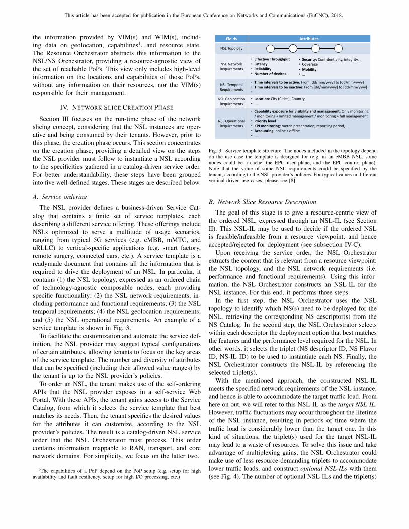
The NSL provider defines a business-driven Service Cat-alog that contains a finite set of service templates, eachdescribing a different service offering. These offerings includeNSLs optimized to serve a multitude of usage scenarios,ranging from typical 5G services (e.g. eMBB, mMTC, anduRLLC) to vertical-specific applications (e.g. smart factory,remote surgery, connected cars, etc.). A service template is areadymade document that contains all the information that isrequired to drive the deployment of an NSL. In particular, itcontains (1) the NSL topology, expressed as an ordered chainof technology-agnostic composable nodes, each providingspecific functionality; (2) the NSL network requirements, in-cluding performance and functional requirements; (3) the NSLtemporal requirements; (4) the NSL geolocation requirements;and (5) the NSL operational requirements. An example of aservice template is shown in Fig. 3.
To facilitate the customization and automate the service def-inition, the NSL provider may suggest typical configurationsof certain attributes, allowing tenants to focus on the key areasof the service template. The number and diversity of attributesthat can be specified (including their allowed value ranges) bythe tenant is up to the NSL provider’s policies.
To order an NSL, the tenant makes use of the self-orderingAPIs that the NSL provider exposes in a self-service WebPortal. With these APIs, the tenant gains access to the ServiceCatalog, from which it selects the service template that bestmatches its needs. Then, the tenant specifies the desired valuesfor the attributes it can customize, according to the NSLprovider’s policies. The result is a catalog-driven NSL serviceorder that the NSL Orchestrator must process. This ordercontains information mappable to RAN, transport, and corenetwork domains. For simplicity, we focus on the latter two.
1The capabilities of a PoP depend on the PoP setup (e.g. setup for highavailability and fault resiliency, setup for high I/O processing, etc.)
Fields Attributes
NSL Topology
NSL Network Requirements
• Effective Throughput• Latency• Reliability• Number of devices
NSL Temporal Requirements
• Time intervals to be active: From [dd/mm/yyyy] to [dd/mm/yyyy]• Time intervals to be inactive: From [dd/mm/yyyy] to [dd/mm/yyyy]• ….
NSL GeolocationRequirements
• Location: City (Cities), Country• ….
NSL OperationalRequirements
• Capability exposure for visibility and management: Only monitoring / monitoring + limited management / monitoring + full management
• Priority level• KPI monitoring: metric presentation, reporting period, …• Accounting: online / offline• ….
• Security: Confidentiality, integrity, …• Coverage
• Mobility• …
Fig. 3. Service template structure. The nodes included in the topology dependon the use case the template is designed for (e.g. in an eMBB NSL, somenodes could be a cache, the EPC user plane, and the EPC control plane).Note that the value of some NSL requirements could be specified by thetenant, according to the NSL provider’s policies. For typical values in differentvertical-driven use cases, please see [8].
B. Network Slice Resource Description
The goal of this stage is to give a resource-centric view ofthe ordered NSL, expressed through an NSL-IL (see SectionII). This NSL-IL may be used to decide if the ordered NSLis feasible/infeasible from a resource viewpoint, and henceaccepted/rejected for deployment (see subsection IV-C).
Upon receiving the service order, the NSL Orchestratorextracts the content that is relevant from a resource viewpoint:the NSL topology, and the NSL network requirements (i.e.performance and functional requirements). Using this infor-mation, the NSL Orchestrator constructs an NSL-IL for theNSL instance. For this end, it performs three steps.
In the first step, the NSL Orchestrator uses the NSLtopology to identify which NS(s) need to be deployed for theNSL, retrieving the corresponding NS descriptor(s) from theNS Catalog. In the second step, the NSL Orchestrator selectswithin each descriptor the deployment option that best matchesthe features and the performance level required for the NSL. Inother words, it selects the triplet (NS descriptor ID, NS FlavorID, NS-IL ID) to be used to instantiate each NS. Finally, theNSL Orchestrator constructs the NSL-IL by referencing theselected triplet(s).
With the mentioned approach, the constructed NSL-ILmeets the specified network requirements of the NSL instance,and hence is able to accommodate the target traffic load. Fromhere on out, we will refer to this NSL-IL as the target NSL-IL.However, traffic fluctuations may occur throughout the lifetimeof the NSL instance, resulting in periods of time where thetraffic load is considerably lower than the target one. In thiskind of situations, the triplet(s) used for the target NSL-ILmay lead to a waste of resources. To solve this issue and takeadvantage of multiplexing gains, the NSL Orchestrator couldmake use of less resource-demanding triplets to accommodatelower traffic loads, and construct optional NSL-ILs with them(see Fig. 4). The number of optional NSL-ILs and the triplet(s)

This article has been accepted for publication in the European Conference on Networks and Communications (EuCNC), 2018.
selected for each of them depend on the traffic fluctuationsexpected for the NSL instance. To estimate these fluctuations,the NSL Orchestrator may rely on traffic models that the NSLprovider has inferred from historical data.
0 3
NSL-IL #1
NSL-IL #2
NSL-IL #3
NSL-IL #4
Traf
fic
load
Targettraffic load
6 9 12 15 18 21 Time(h)
Fig. 4. Example of the traffic load expected for a given NSL instance duringa typical day. NSL-IL #4 is the target NSL-IL, and the rest are the optionalNSL-ILs. The entire set of NSL-ILs enables the NSL provider to adjust thelevel of resources within the NSL instance at run-time, in such a way itsatisfies the desired performance, while making an efficient resource usage.
The target NSL-IL, along with the optional NSL-ILs, definethe complete set of NSL-ILs among which the NSL instancecan scale up/down during its entire life cycle.
C. Admission ControlThe target NSL-IL specifies the resource requirements fit-
ting the tenant’s demands. Once derived, the NSL providercan perform the admission control. The admission controlaims to check if the NSL provider can satisfy the resource,geolocation, and temporal requirements of the ordered NSL.For this end, the following information is needed:(1) The resource requirements of the NSL instance. This
includes(a) the resources to be allocated for each VNFinstance and virtual link, (b) the affinity/anti-affinity rulesapplicable between VNF instances, and (c) the reliabilityrequirements for each VNF instance and virtual link.
(2) The geographical region(s) where each VNF is needed.(3) The time intervals when the NSL instance needs to be
active (operative).(4) Information of the PoPs (and the WAN network(s) con-
necting them) to which the NSL provider is subscribed.The information shown in (1)-(3) is available to the NSL
Orchestrator; indeed, (1) is part of the target NSL-IL, while(2)-(3) are derived from the geolocation and temporal re-quirements specified in the service order. The informationspecified in (4) is available to the Resource Orchestrator, andprovided by the underlying VIM(s)/WIM(s). The fact that theNSL Orchestrator and the Resource Orchestrator operate atdifferent abstraction levels means that they deal with differentlevel of information, and hence none of them is able toperform the admission control at its own. The interplay of bothfunctional blocks is needed. Following this idea, the admissioncontrol can be splitted into three steps. The NSL Orchestratorperforms the first two steps, being the latter carried out by theResource Orchestrator.
In the first step, the NSL Orchestrator calculates whichPoP(s) is (are) candidate to host each VNF instance. A PoP is
candidate for a VNF instance if the location and capabilities ofthe PoP satisfy the geolocation and reliability requirements ofthat instance. For this step, the NSL Orchestrator takes as in-puts the information specified in (1c) and (2), and the resource-agnostic view provided by the Resource Orchestrator. As seenin Section III, this view consists of high-level information ofthe location and capabilities of the reachable PoPs.
In the second step, the NSL Orchestrator sends two kindof data to the Resource Orchestrator. On one hand, data con-cerning the NSL lifetime. For this end, the NSL Orchestratortakes the information shown in (3), and passes it down to theResource Orchestrator. On the other hand, data concerningthe target NSL-IL to be accommodated. For that, the NSLOrchestrator takes the resource requirements specified in (1),along with the candidate PoPs calculated in the first step, andpasses then down to the Resource Orchestrator at VNF/virtuallink level. For each VNF instance, the NSL Orchestrator com-municates the candidate PoP(s), and the requirements shownin (1a) and (1b). For each virtual link, the NSL Orchestratorcommunicates the requirements specified in (1a) and (1c).
In the third step, the Resource Orchestrator seeks feasiblesolutions to deploy the target NSL-IL. A solution is feasible aslong as each VNF instance can be allocated in a candidate PoPduring the time interval(s) in which the NSL instance needs tobe active, while satisfying the VNF affinity/anti-affinity rulesand connectivity needs. For this step, the Resource Orches-trator takes the data received from the NSL Orchestrator, andcompares it against the information specified in (4).
If there exists one feasible solution, the admission control issuccessful. In this case, the Service Level Agreement betweenthe NSL provider and the tenant can be formalized; otherwise,these two parties shall re-negotiate the content of the serviceorder.
D. Optimization and Resource Reservation
A successful admission control may derive multiple feasi-ble solutions for the target NSL-IL (e.g. multiple PoPs canaccommodate a given VNF instance). However, only one ofthem must be eventually selected for deployment. To solvethis issue, the Resource Orchestrator may run an algorithmthat calculates the optimal solution. Examples of optimalitycriteria that could be used for this algorithm include minimizeresource usage, minimize energy consumption, etc.
Once the optimal solution is found, the Resource Orches-trator may proceed with resource reservation. The ResourceOrchestrator sends resource reservation requests towards theunderlying VIM(s)/WIM(s). The hard and soft nature of thisreservation depends on the NSL provider’s policies, as well asthe nature of the use case the NSL instance will accommodate.
E. Network Slice Preparation
The NSL preparation is the last stage prior to put theNSL operative. It consists of setting up all that is requiredto manage the NSL instance throughout its entire life cycle,from commissioning (instantiation, configuration, and activa-tion) to decommissioning (de-activation and termination) [9].

This article has been accepted for publication in the European Conference on Networks and Communications (EuCNC), 2018.
This includes (1) preparing the network environment, and (2)designing and on-boarding the NSL descriptor.
In the network environment preparation, the NSL Orches-trator performs the following tasks:
• It negotiates with the Resource Orchestrator a prioritylevel for the NSL instance. Having different priority lev-els allows the Resource Orchestrator to define a priorityorder between the NSL instances in case they competefor the same resources, or in case of resource scarcity.
• It prepares the management plane of the NSL in-stance. First, the NSL Orchestrator instantiates the NSLManager, the Tenant SDN Controller, the NS Orchestra-tor, and the VNFM(s). Then, it configures these functionalblocks in an appropriate manner, making them readyfor the run-time phase. By means of example, the NSLOrchestrator configures the NSL Manager in such a wayit provides the tenant only with the visibility and themanagement capabilities specified in the service order.
In parallel to the network environment preparation, the NSLOrchestrator builds up the NSL descriptor. The NSL descriptoris a deployment template used by the NSL Manager to operatethe NSL instance during its life cycle in an agile, automatedfashion. This descriptor includes the following parts:
• A set of policy-based workflows. These workflows en-ables the NSL Manager to enforce the expected behaviorof the NSL instance during its life cycle, in a timelymanner. The NSL Manager translates the content of theseworkflows into appropriate NS and VNF managementactions, and forwards them to the NS Orchestrator and tothe tenant SDN controller for their enforcement.
• The set of NSL-ILs available for use, constructedin the Network Slice Resource Description phase (seesubsection IV-B). The NS Orchestrator use the tripletsreferenced by these NSL-ILs to scale the NS instance(s)at run-time, according to time-varying traffic demands.
• VNF configuration primitives at application level,and VNF chaining management instructions. Both areused by the Tenant SDN Controller to programmaticallyconfigure and chain the VNF instance(s).
• Information about management data, used for perfor-mance management (e.g. metrics to be monitored, metricpresentation, reporting period) and fault management(e.g. alarms to be subscribed). Derived from the NSLoperational requirements specified in the service order,the management data may be collected from the NSOrchestrator and the Tenant SDN Controller, and usedfor visibility/manageability purposes.
Note that the policy-based workflows contained in the NSLdescriptor enables the NSL manager to automate all the lifecycle operations that are manually triggered from the OSSin the ETSI NFV framework [10], making the NSL instancea self-contained entity. The remaining content of the NSLdescriptor is used to feed these workflows (e.g. performancemetrics may be taken as inputs for the workflows targeted atthe NSL scaling operation).
V. CONCLUSIONS
An SDN/NFV-based network slicing architecture has beenpresented in this work. This architecture addresses the twophases considered for network slicing: the creation phase andthe run-time phase. This work focuses on the former.
We have provided detailed insight into the steps neededto successfully complete catalog-driven NSL deployments.These steps have been arranged into five stages: ServiceOrdering, Network Slice Resource Description, AdmissionControl, Optimization & Resource Reservation, and NetworkSlice Preparation. In each of these stages, the input/outputinformation required, the steps involved, and the role of theparticipant functional block(s) have been specified.
With the architecture and the ordered set of stages proposedin this work, NSL providers are able to perform cost-efficientdeployments, in an agile, flexible, and automated manner.The presence of a Service Catalog, with customizable serviceofferings that brings flexibility in service definition, and theinterplay between the NSL Orchestrator and Resource Or-chestrator are crucial for that end. Additionally, the correctdesign of a NSL descriptor in the creation phase is key fora successful operation in the run-time phase. This descriptormakes the NSL instance a self-contained entity, enabling theslice-specific management plane to operate the NSL instancein a customized way, with great agility, and full automation.
ACKNOWLEDGMENT
This work is partially supported by the Spanish Ministryof Economy and Competitiveness and the European Re-gional Development Fund (Project TEC2016-76795-C6-4-R),the Spanish Ministry of Education, Culture and Sport (FPUGrant 16/03354), and the University of Granada, AndalusianRegional Government and European Social Fund under YouthEmployment Program.
REFERENCES
[1] ETSI GS NFV-EVE 012, “Network Functions Virtualization (NFV);Evolution and Ecosystem; Report on Network Slicing Support with ETSINFV Architecture Framework,” Dec. 2017.
[2] X. Zhou et al., “Network slicing as a service: enabling enterprises’ ownsoftware-defined cellular networks,” IEEE Commun. Mag., vol. 54, no. 7,pp. 146–153, 2016.
[3] J. Ordonez-Lucena et al., “Network Slicing for 5G with SDN/NFV:Concepts, Architectures, and Challenges,” IEEE Commun. Mag., vol. 55,no. 5, pp. 80–87, 2017.
[4] ETSI GS NFV-MAN 001, “Network Functions Virtualization (NFV);Management and Orchestration,” Dec. 2014.
[5] L. Geng et al., “Common Operation and Management on network Slices(COMS) Architecture,” in Internet Engineering Task Force (IETF),March 2018.
[6] X. Foukas et al., “Network Slicing in 5G: Survey and Challenges,” IEEECommun. Mag., vol. 55, no. 5, pp. 94–100, 2017.
[7] ETSI GS NFV-IFA 014, “Network Functions Virtualization (NFV);Management and Orchestration; Network Service Templates Specifica-tion,” Aug. 2017.
[8] Next Generation Mobile Networks (NGMN) Alliance, “Perspectives onVertical Industries and Implications for 5G,” Sept. 2016.
[9] 3GPP TS 28.801 V.15.1.0, “Telecommunication management; Study onmanagement and orchestration of network slicing for next generationnetwork,” Jan. 2018.
[10] ETSI GS NFV-IFA 013, “Network Functions Virtualization (NFV)Release 2; Management and Orchestration; Os-Ma-Nfvo reference point- Interface and Information Model Specification,” Aug. 2017.