The application of shallow shells in structural floor systems.
125
RICE UNIVERSITY The Application of Shallow Shells in Structural Floor Systems by John Malcolm McRae A THESIS SUBMITTED IN PARTIAL FULFILLMENT OF THE REQUIREMENTS FOR THE DEGREE OF Master in Architecture Thesis Director's Signature: Nat Krahl Houston, Texas May, 1967
-
Upload
khangminh22 -
Category
Documents
-
view
0 -
download
0
Transcript of The application of shallow shells in structural floor systems.

RICE UNIVERSITY
The Application of Shallow Shells in Structural Floor Systems
by
John Malcolm McRae
A THESIS SUBMITTED
IN PARTIAL FULFILLMENT OF THE
REQUIREMENTS FOR THE DEGREE OF
Master in Architecture
Thesis Director's Signature:
Nat Krahl
Houston, Texas
May, 1967

TABLE OF CONTENTS
Chapter 1 - Historical Review and Preliminary Analysis 1
Chapter 2 - Simplest Application of Cast-In-Place 23
Chapter 3 - Integration of More Complex Variables - Precasting, Mechanical, Lighting Interior Partitions 42
Chapter 4 - Consideration of Architectural Aesthetics 68
Chapter 5 - Limiting Factors and Considerations for Future Investigation 77
Chapter 6 - Review and Synthesis 79
Chapter 7 - Demonstration 82
Table of Footnotes 109
Bibliography Ill

ABSTRACT
The Application of Shallow Shells in Structural Floor Systems
by
. John Malcolm McRae
The purpose of this thesis is to demonstrate the application
of shallow concrete shells for structural floor systems. The
shell is first placed in its historical context. The writer then
proposes the application of shells for floors through rationale
based on three points:
(1) historical precedent;
(2) structural capability;
(3) aesthetic qualities.
The application having been proposed, the writer then proceeds
to an analysis of the problem - from the simplest stages to the
more complex applications. The specific criteria which are the
basis of the application of shallow shells for floors follow the
analysis. The last part is a demonstration of several prototype
systems of shells for floors.

CHAPTER 1
Historical Review and Preliminary Analysis.
Thin shells have, in recent years, come into wide use as a
means of architectural and structural expression. Their first
application in construction, however, dates back to the turn of
the twentieth century, and many of the principles of shell struc¬
tures were recognized and developed by the Romans as early as
100 B.C. through arch and vault construction.
The arch, or in its more complex form, the vault, is one of
two structural forms that has been primarily used by man in en¬
closing space - the other being the beam. While the beam is a
prehistoric form, the archetype being Stonehenge, more than 3,000
years of recorded history passed before the arch form was evolved]
. It was the Romans, then, who first exploited the arch to its
fullest significance. Their development of arch and vault con¬
struction in cut stone, brick, and concrete was perhaps Rome's 2
greatest contribution to the evolution of the building art.
One thing which made this possible was the discovery of the
pozzuolana earths (after the town Pozzuoli), which form a hydrau¬
lic cement when mixed with slaked lime. This gave the Romans a 3
material almost as strong as modern concrete.
The geometric forms of shell concrete frequently bear an
architectural resemblance in silhouette to these earlier struc¬
tures, particularly in the spaces they create in internal volume.
An examination of the use of reinforced concrete as a plastic
material for the enclosure of space, however, will show the difference
of these outwardly similar forms. The architecture of mass is essen-

tially the architecture of equilibrium - an equilibrium of com¬
pression, with such varying expressions as the massive Roman arch
and the soaring Gothic vault. The introduction of materials in
which their sense of their tensile quality is allowed to be fully
expressed has created a new aesthetic. Reinforced concrete has
given this new aesthetic a new dimension.^
A comparison of some structures of similar span, of old and
new origin, is of value in contrasting the structural capabilities
of reinforced concrete and the concrete and stone of previous
generations.
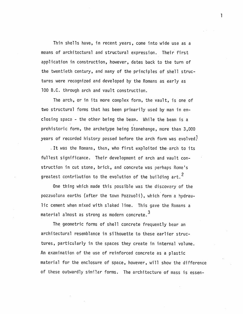
The pantheon of Rome, built in various stages and completed
in A.D. 124, has an internal span of 142 feet. The dome is of
travertine, tufa, brick and pumice and is 4 feet thick at the
thinnest point.^ By contrast, the auditorium at the Massachusetts
Institute of Technology by Eero Saarinen spans 155 feet, with a
maximum thickness of 20 inches near the edge to a minimum of 3.5
inches at the crest.6 (See illustrations, p.3 )
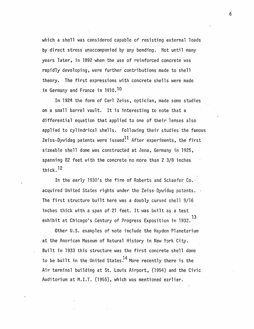
Another and perhaps more striking example is a comparison of
the sixteen century dome of St. Peter's Cathedral in Rome with a
modern dome in Jena, Germany. Both domes have a span of 132 feet.
The modern dome, however, is considerably flatter; its rise-of-arch
to-span proportion is shallower than that of the dome of St. Peter'
The latter, which is partially constructed as a double shell, has
an average thickness of about 10 feet and a total dead weight of
about 11,000 short tons compared to the reinforced concrete dome

3
PANTHEON, ROHE
;
KRESGE AUDITORIUM, M.I.T.

with a shell thickness of only 2.36 inches and a total dead weight
of 364 short tons.^ (See illustrations, p.5 ).
Following the time of Rome and the medieval and Renaissance
periods there was little development of the vault and dome as a
structural system and only in the 20th century has the curved form
returned as an architectural expression.
Today, working chiefly in reinforced concrete, architects
are moving toward more open and flexible designs. Having pur¬
posely abandoned the simple beam, they are forced back to methods
devised by earlier builders for spanning large open areas. The
striking shell structures that are now appearing all over the
world bear a fundamental relation to the cathedrals of the Middle
Ages. Vaulted roofs, after an almost total eclipse, are back in 8 the mainstream of architecture.
So it seems that the history of architecture, as also ex¬
pressed in the opinion of Mr. Serge Chermayeff of Harvard Uni¬
versity, begins to take on a "cyclic" form - the primitive post
and beam to the daring domes of the Renaissance and the impos¬
ing stone vaults of the Gothic; back to the rectilinear forms,
and finally to the present portion of history which concludes
the second cycle, a period in which curvature once again emerges
as an architectural form.^
Historically, the mathematics involved in designing con¬
crete shells had origin in 1828 when the work of G. Lame and
E. Clapeyron was published containing the 'membrane analogy1 by

5
ST. PETER'S CATHEDRAL, ROME
SCHOTT WORKSHOP, JENA, GERMANY
which a shell was considered capable of resisting external loads
by direct stress unaccompanied by any bending. Not until many
years later, in 1892 when the use of reinforced concrete was
rapidly developing, were further contributions made to shell
theory. The first expressions with concrete shells were made
in Germany and France in 191oJ°
In 1924 the form of Carl Zeiss, optician, made some studies
on a small barrel vault. It is interesting to note that a
differential equation that applied to one of their lenses also
applied to cylindrical shells. Following their studies the famous
Zeiss-Dywidag patents were issued!^ After experiments, the first
sizeable shell dome was constructed at Jena, Germany in 1925,
spanning 82 feet with the concrete no more than 2 3/8 inches
thick. ^
In the early 1930's the firm of Roberts and Schaefer Co.
acquired United States rights under the Zeiss-Dywidag patents.
The first structure built here was a doubly curved shell 9/16
inches thick with a span of 21 feet. It was built as a test 13
exhibit at Chicago's Century of Progress Exposition in 1932.
Other U.S. examples of note include the Hayden Planetarium
at the American Museum of Natural History in New York City.
Built in 1933 this structure was the first concrete shell dome
to be built in the United States.^ More recently there is the
Air terminal building at St. Louis Airport, (1954) and the Civic
Auditorium at M.I.T. (1955), which was mentioned earlier.
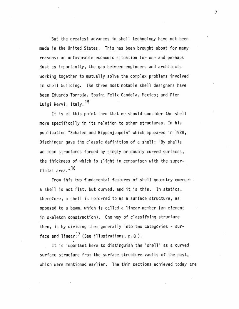
But the greatest advances in shell technology have not been
made in the United States. This has been brought about for many
reasons: an unfavorable economic situation for one and perhaps
just as importantly, the gap between engineers and architects
working together to mutually solve the complex problems involved
in shell building. The three most notable shell designers have
been Eduardo Torroja, Spain; Felix Candela, Mexico; and Pier 15 Luigi Nervi, Italy.
It is at this point then that we should consider the shell
more specifically in its relation to other structures. In his
publication "Schalen und Rippenjuppeln" which appeared in 1928,
Dischinger gave the classic definition of a shell: "By shells
we mean structures formed by singly or doubly curved surfaces,
the thickness of which is slight in comparison with the super¬
ficial area."^
From this two fundamental features of shell geometry emerge:
a shell is not flat, but curved, and it is thin. In statics,
therefore, a shell is referred to as a surface structure, as
opposed to a beam, which is called a linear member (an element
in skeleton construction). One way of classifying structure
then, is by dividing them generally into two categories - sur¬
face and linear.^ (See illustrations, p.8 ).
It is important here to distinguish the 'shell' as a curved
surface structure from the surface structure vaults of the past,
which were mentioned earlier. The thin sections achieved today are

8
LINEAR STRUCTURE EXAMPLE: Skeleton Steel High Rise
Two Dimensions Small In Relation To Third.
SURFACE STRUCTURE EXAMPLE: Shell
Two Dimensions Large In Relation To Third.

not only the result of new systems of calculation, which in con¬
trast to the empirical methods of the past offer a relatively
exact reflection of the pattern of stresses, but of the use of
appropriate materials. As previously pointed out, only when the
construction consists of a material which withstands compression
and tension can it work like a shell. Medieval vaults are made 18 of stone and can, therefore only resist compression. The link¬
age of several vaulted shells allows the same classic solutions
that were built in stone in antiquity, yet with more freedom
and possibilities than stone affords.^'
A surface structure must exemplify four characteristics in
order to work like a shell:
(a) a singly or doubly curved form;
(b) a thickness which is small in relation to its super¬
ficial area;
(c) a material resistant to compression and tension;
(d) proper support; it will thus develop, at most, a
small amount of bending in a limited portion of
the shell
The material most commonly used in shell construction is
reinforced concrete but shells can also be built in timber, steel,
aluminum, etc.
There are many other ways of classifying structures and a look
at some of these might help to clarify the nature of various struc¬
tural systems and particularly the shell in relation to other systems.

One of these is a division of structures into categories of
very flexible and stiff. (See illustrations, p. 11). A very flexible
structure is incapable of resisting compressive forces acting upon
it (e.g. cable, membrane). A stiff structure is required to with¬
stand a certain amount of compressive forces in addition to ten¬
sile and shearing stresses (e.g. column, beam, shell, arch).
Another more general classification than the previous two
would be according to how many different sources of structural
strength are present. (See illustrations, p.12). These include:
(1) tensile and compressive strength in x - direction
(2) tensile and compressive strength in y - direction
(3) in-surface shearing resistance in x - direction
(4) in-surface shearing resistance in y - direction
(5) transverse shearing strength iri x - direction
(6) transverse shearing strength in y - direction
(7) bending resistance in x - direction
(8) bending resistance in y - direction
(9) torsion resistance around x - axis
(10) torsion resistance around y - axis
From these general classifications of structures v/e can pro¬
ceed to a breakdown of categories within the family of shells.
There are many ways to classify shells but to the architect a
classification based on outward form would be most pertinent. From
this standpoint, every possible shell form falls into two groups:
doubly curved shells and singly curved shells. Doubly curved shells

-H-
VERY FLEXIBLE SYSTEM
VERY STIFF SYSTEM

12
Tensile and Compressive Strength and In-Surface Shearing Resistance
Transverse Shearing Strength
Bending and Torsion Resistance
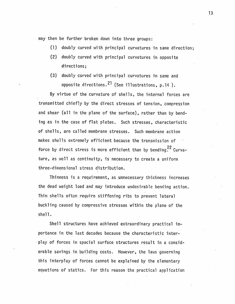
may then be further broken down into three groups:
(1) doubly curved with principal curvatures in same direction
(2) doubly curved with principal curvatures in opposite
directions;
(3) doubly curved with principal curvatures in same and
opposite directions.^ (See illustrations, p.14 ).
By virtue of the curvature of shells, the internal forces are
transmitted chiefly by the direct stresses of tension, compression
and shear (all in the plane of the surface), rather than by bend¬
ing as in the case of flat plates. Such stresses, characteristic
of shells, are called membrane stresses. Such membrane action
makes shells extremely efficient because the transmission of 22 force by direct stress is more efficient than by bending. Curva¬
ture, as well as continuity, is necessary to create a uniform
three-dimensional stress distribution.
Thinness is a requirement, as unnecessary thickness increases
the dead weight load and may introduce undesirable bending action.
Thin shells often require stiffening ribs to prevent lateral
buckling caused by compressive stresses within the plane of the
shell.
Shell structures have achieved extraordinary practical im¬
portance in the last decades because the characteristic inter¬
play of forces in spacial surface structures result in a consid¬
erable savings in building costs. However, the laws governing
this interplay of forces cannot be explained by the elementary
equations of statics. For this reason the practical application

FOUR TYPES OF SHELLS
DOUBLY CURVED, PRINCIPAL CURVES IN SAME DIRECTION
DOUBLY CURVED, PRINCIPAL CURVES IN OPPOSITE DIREC¬ TIONS
DOUBLY CURVED. PRINCIPAL CURVES IN SAME AND OPPO¬ SITE DIRECTIONS

of shells became possible only afer their special theory had 23 been developed. However, the various aspects of shell design
and analysis will not be covered in this thesis. Two excellent
resource books for those further interested in this aspect of
shells are Elementary Statics of Shells by Alf Pfluger and Thin
Concrete Shells by A. M. Haas.
The structural solutions with shells have, to date, been
limited primarily to roofs. So much effort has been put into
refining the shell as a roof-structure that the possibilities of
shells applied to flooring systems have gone virtually unexplored.
There are several reasons to account for this:.
(1) Historically, because of its obvious efficiency for long
spans, man has employed the dome and vault as a solution
to the problem of spanning large areas.
(2) Shells are still in an early stage of development and
are not fully understood. Naturally then, architects
and engineers are hesitant to explore areas of poten¬
tial other than roof construction.
(3) Shells, to be efficient in long spans, need a signifi¬
cantly large rise in relation to the span. It is not
immediately apparent that when the span is short, as
in floors, the ratio of rise to span can be markedly
reduced and still maintain low stresses,
(4) A shell of only 2 or 3 inches thick will span a hun¬
dred feet. A span to thickness ratio of this magni¬
tude cannot be maintained in an application to floors,

for a minimum thickness of at least 1 1/2 inches is
required in some cases just to cover the reinforcing.
(However, this does not necessarily mean such struc¬
tures are uneconomical.)
(5) There are obvious problems apparent in the applica¬
tion of shells for floors and people fail to look
beyond these to inherent advantages.
Consideration of shallow shells for floors may be correlated
with an existing floor system - the flat slab. Just as there
is a membrane action that develops in the shell, there is also a
membrane action that develops in flat slabs. (See illustrations,
p. 17). This action is described extensively in the book Plastic
and Elastic Design of Slabs and Plates by R. H. Wood.
With this understanding, it becomes apparent that shallow
shells are at least feasible as a structural system for floors,
assuming they will meet requirements of vertical and wind loads.
At a later point in this paper it will be shown that shells are
not only feasible as a flooring system but have certain structural
advantages over other systems.
The importance of the shallowness of the shell should be
reemphasized here. The shell must be shallow in order to main¬
tain a minimum overall thickness of floor construction (includ¬
ing fill and wearing surface). This in turn affects the floor
to floor height. If, because the shells are not shallow enough,
the floor to floor height must be increased unwarrentedly, then

COMPRESSIVE MEMBRANE STRESSES
TENSILE MEMBRANE STRESSES

18
the economic feasibility of using them will be reduced.
Certain types of shells are more capable of withstanding
floor loads than others. Of these, doubly curved shells are
best since they have more sources of structural strength than
singly curved shells such as barrel vaults.
Hyperbolic paraboloids are one type of doubly curved shell
which warrant study in their possible application to floors.
However, this writer has decided to approach the problem from a
different direction for several reasons:
(1) Hypars have a tendency to develop bending moments and
often develop large bending moments if boundary stiff-
ners are not rigidly supported;
(2) Colin Faber, in his book, Candela: The Shell Builder,
suggests that umbrella type hypars must have a large
rise in order to act effectively.^^ Further research
indicates this statement cannot be fully confirmed,
but this illustration does at least cast doubt on the
economic feasibility of umbrella hypars for floors
because of the problem with rise-of-arch-to-span ratio.
This would be a good area for investigation at some
future time.
Here we should point out some differences between synclastic
(all principal curves up or down) shells and saddle shells (prin¬
cipal curves alternate - both positive and negative). An example
of a saddle shell is the hyperbolic paraboloid, which was just dis-

cussed. Synclastic shells are supported by shear stresses on
boundary arches. Saddle shells, on the other hand, are supported
by shear stresses in end stiffeners. Uneven stresses will develop
in hyperbolic paraboloids if the boundary stiffeners are not
rigidly supported. In this case some of the stiffeners' weight
hangs from the shell, and the two halves of the paraboloid be¬
have very much like cantilevered beams2®
Among the types of shells which do show definite promise
are paraboloids of revolution and elliptical domes. Both are
synclastic shells with thickened edges and the bending distur¬
bances at the boundaries penetrate only a short distance into
such shells. The rigidity is exceptionally high, even with very
shallow shells. Preliminary analysis by this writer and Dr.
Nat Krahl of PJce University indicates that paraboloids up to a
40 feet span with as little as 5% rise will easily stand conven¬
tional office floor loads. Also indications are that with a
span of less than 10 feet the rise can be reduced to 4% or less.
The application of concrete shells for floors has an
ancient as well as a modern forerunner in the State of Jalisco
and its principal City, Guadalajara, in Mexico.
This construction system, known in Guadalajara as "techo
de boveda," is essentially a structural system whereby a roof
or floor is constructed of brick multiple barrel vaults, almost
flat (3.6% rise), which are supported on a framework of steel,
or sometimes concrete. The system is apparently unique to this
portion of Central Mexico. 27 (See illustrations, p. 20).

20
Ancient techo de bdveda construction system

This system will be described and illustrated in more detail
in Chapter 2 of this thesis. Let us suffice to say here that if
floors can be built of brick vaults as strong as these are known
to be then the same system could be built much stronger and with
a thinner section 'in reinforced concrete.
Felix Candela of Mexico built two schools in 1953-54 which
were multi-story structures employing prismatic or folded slabs
for floors. (See illustration, p.22). In the book Candela:
The Shell Builder the author suggests that this may have been the
first time that shells were used for floors. The author goes on
to say that Candela considers shells for floors a "hopeless path" pO
of investigation. This writer does not consider folded slabs or
plates as true shells because they react in a different manner
structurally. In this light, however, other structures have since
been built using folded plates for floors, among them is the Arts
and Architecture Library at Washington University in St. Louis,
Missouri.
To further illustrate the potential of shells for floors -
when the structural capabilities of the ancient "techo de bbveda"
system became known through load tests and experimental models,
it was decided that this system would be used as a structural
design determinant in all the buildings on the new campus of the po
Universidad Autonoma de Guadalajara. This project, under the
guidance of Mr. Harry Ransom, architectural professor at Rice
University, will be detailed and illustrated in Chapter 2.

Built 1953, Primatic Slab Construction

CHAPTER 2
Simplest Application of Cast-In-Place

The simplest application of concrete floors is a cast-in¬
place method with no consideration for mechanical systems, plumb¬
ing, or interior partitions. These considerations would be
applicable primarily to building types such as warehouses and
parking garages. The extension of the system into precasting
and other building types involves problems that will be dis¬
cussed in Chapter 3.
There are many methods of structuring a floor system.
Four obvious methods will be illustrated. They are:
(1) barrel shells and a one-way beam system (this is simply
an application in reinforced concrete of the "techo de
boveda" system used in Guadalajara);
(2) double curvature shells and a one-v/ay beam system;
(3) double curvature shells and a two-way beam system
(this is an application in concrete of the system
employed by Mr. Harry Ransom for the Uni versidad
Autonoma de Guadalajara);
(4) double curvature (parabolic) shells resting directly
on columns.
An understanding of the "techo de boveda" system is impor¬
tant for the problems encountered here are similar to any appli¬
cation with concrete shells.
This system is a combination of two separate structures;

first the brick vaults, which support the floor and the loads
imposed on the floor, and which carry these loads to the support¬
ing structure; and second, the supporting framework of steel or
concrete beams, girders, and columns which directly support the
vaults.30
The illustrations on the following page show the various
stages of development of vaulted construction in Central Mexico
culminating with the "techo de boveda" system.
The supporting beams are placed 32 - 51 inches center-to-
center, and this distance becomes the span of the barrel vault.
The bricks comprising the barrel vaults are laid without frame¬
work, each successive row of bricks in itself becoming an arch
rib spanning between steel beams. The vaults themselves are 31 almost flat, the rise being only 1.5-3 inches (3-8 cm.).
A level surface above the vault is achieved by filling with
a light-weight concrete made from hydrated lime and "Jal", which
is a local pumice sand and gravel. This fill acts to distribute
evenly over the vaults the concentrated floor loads. The floor o
live load used locally for design of dwelings is 30.8 lbs/ft.
(150 Kg/m^) and 71.8 lb/ft^ (350 kg/m^) for office buildings.^
A wearing surface of burnt clay brick or tile is usually placed
on top of the concrete fill.
The allowable loads and practices used by the local people
are based primarily on accumulated experiences. However, load
tests on experimental vaults similar to those of local construc¬
tion demonstrated a capability of sustaining a superimposed uni-

(0 f WOOD BEAM
EA/ZTff E/LL
Primitive Terrado Construction by Indians
Modification of Terrado Construction by Spaniards
l
"Techo deb6veda"

formly distributed load of 388 lb/ft. Based on maximum live loads OO
in current use this is a safety factor of greater than 5.4.
These examples illustrate the necessity for at least 4 basic
elements in shell floor construction:
(1) shell;
(2) secondary system of columns, or columns and beams;
(3) fill to distribute loads;
(4) wearing surface.

27
Test Barrel Vaults, Guadalajara
It is important here to understand the need for containing
the horizontal thrust of the vault coming into the beam. As
shown in the illustration above, tie rods have been added to
counteract the force of the vault and thus equilize the forces
acting at the beam. This will be discussed further at a a later
point in the thesis.

;24
-<
Type 1: Barrel Shells One-Way Beam System
I I c. lie
-zfegjgUz.
I i II
!! _J L.
'1 r I I I I
l i i i
_J L.
"if" I
-M G/EDEJ2. I I
! r
I | 24 £> e>
_T
M tii
A
3
. u_ P<I —rr i I i l 1 I 1 i Pr—
O I I I Q I II Ql I!
,8 i i i i« ii i „ u £ 4-
-COLUW
-BEAM
Plan 1/8" =1' 0"
H ■T WEARING GUFFAGB -F/LL
Section A 1/8" = 11 0"

29
Type 1
Section B 1" = 1' 0"
Section C 1"=1'0"

BARREL SHELLS AND ONE-WAY BEAM SYSTEM:
Barrell Shell, 6" Rise in 8' - O" Span
Span: 8' - 0"
Total:
Live Load 100 psf Dead Loads: 1" Wearing Surface 13 Foam Concrete, 4" avg.
at 60 pcf (l"-7") 20 2 1/2" Cone. Shell 31
164 psf
Horizontal Thrust = 8h 164 x 8.002 x 12
8x6 2,620 lbs./ft.
H 2,620 Compressive Stress = A = 12 x 2.5 = 87 psi
Barrel Shell, 3" Rise in 8' - 0" Span
Span: 8‘ - 0" Live Load 100 psf Dead Loads: 1" Wearing Surface 13
Foam Cone..2 1/2" avg. at 60 Dcf (1" -4") 12
2 1/2" Cone. Shell 31 Total: 156 psf
156 x 8.002 x 12 Horizontal Thrust = 8x3 = 4,990 lbs./ft.
4,990 Compressive Stress = 12 x 2.5 = 166 psi
Barrel Shell, 6" Rise in 24' - 0" Span
Span: 24' - 0" Live Load 100 psf Dead Loads: 1" Wearing Surface 13
Foam Cone., 5" avg. at 60 pcf (2" - 8") 25
2 1/2" Cone. Shell JH Total: 169 psf
169 x 24,002 x 12 Horizontal Thrust = 8x6 = 24,300 lbs./ft.
24,300 Compressive Stress = 12 x 2.5 = 810 psi

31
It is apparent from the calculations on the previous page
that for barrel vaults the span may be much greater than 8 ft.
(166 psi compressive stress with 3" rise) and still be within the
allowable limit for compressive stresses (810 psi with 6" within
24').
A comparison with flat concrete slab construction under the
same conditions will be advantageous in clarifying the advantages
and disadvantages of barrel vault structures.
THE CRSI DESIGN HANDBOOK (Revised 1959) gives comparative
information in the table: "Solid Concrete Slabs - End Spans
(approximately 2/3% Reinf.)."
An 8'-0" span with 156 psf floor load requires a 4" slab
thickness. A 4" slab may be used with an 8' span with up to
192 psf (total live and dead load). For the same span the barrel
shell as presented in the calculations has a 3 1/2" structural
thickness.*
A 24' 0" span with 169 psf floor load requires a 9 1/2"
slab. The live load is 100 psf and a 9 1/2" slab will safely
support a 106 psf live load. The same span with a barrel shell
requires only a 3 1/2" thickness.
*3 1/2" thickness - 1" cone, wearing surface + 2 1/2" shell thick¬
ness: minimum - 2" to 2 1/2" required for cast-in-place shells
including cone, cover over reinf. (3/4" min.), ACI BUILDING CODE
(318 - 63).

We may deduce from this that barrel shells have relatively no
economic structural advantages over flat slabs with short spans
but have definite advantages with longer spans. For shorter spans
there would be some advantage with precasting. It would be more
economical because it makes unnecessary the use of formwork and shor¬
ing, which is very expensive.

24
-0
33
Type 2: Double Curvature Shells - One-Way Beam System
Plan 1/8" = 1' 0"
r WEARING SURFACE. | FILL
W u u. . —DOU&LE-C.UKVATURE SHELL., 1 —SEAM
. /ZJSB.
Section A 1/8" = T 0"

Type 2
{“'COAte. WEA/Z/N& £>U£FACE-\ r-POAM tZOA/C. P/LL.
Section B 1" = V 0"
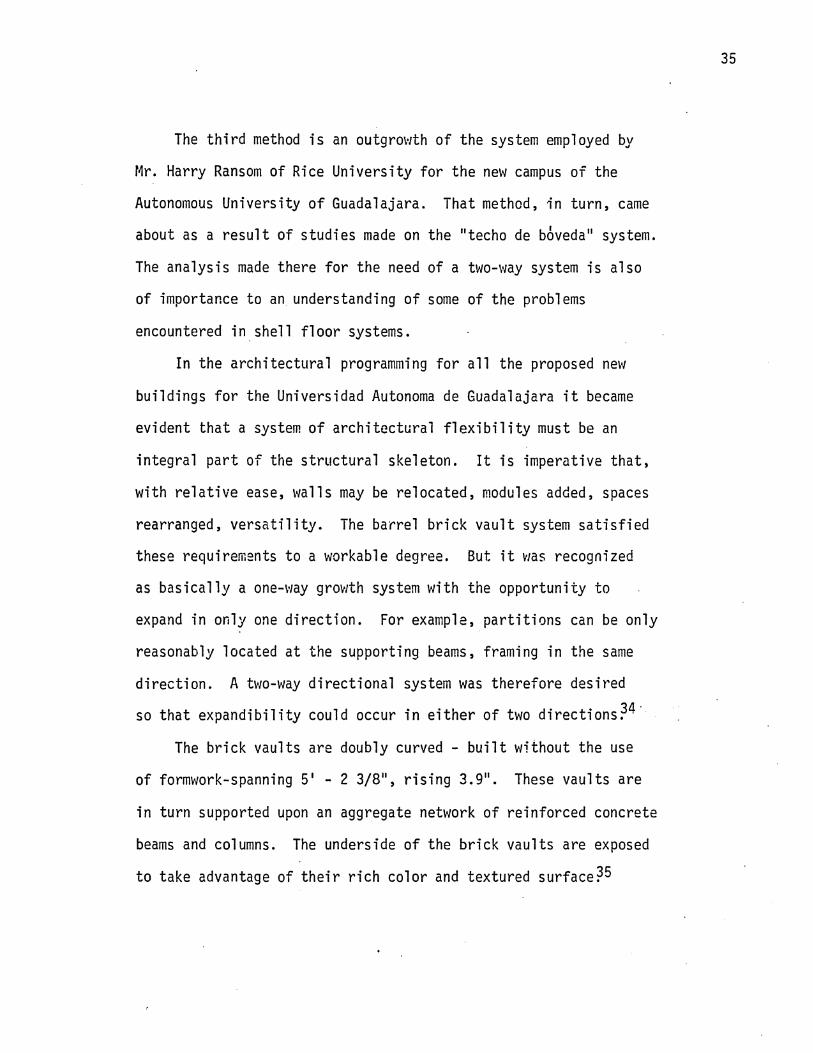
The third method is an outgrowth of the system employed by
Mr. Harry Ransom of Rice University for the new campus of the
Autonomous University of Guadalajara. That method, in turn, came
about as a result of studies made on the "techo de boveda" system.
The analysis made there for the need of a two-way system is also
of importance to an understanding of some of the problems
encountered in shell floor systems.
In the architectural programming for all the proposed new
buildings for the Universidad Autonoma de Guadalajara it became
evident that a system of architectural flexibility must be an
integral part of the structural skeleton. It is imperative that,
with relative ease, walls may be relocated, modules added, spaces
rearranged, versatility. The barrel brick vault system satisfied
these requirements to a workable degree. But it v/as recognized
as basically a one-way grov/th system with the opportunity to
expand in only one direction. For example, partitions can be only
reasonably located at the supporting beams, framing in the same
direction. A two-way directional system was therefore desired OA ■
so that expandibility could occur in either of two directions.
The brick vaults are doubly curved - built without the use
of formwork-spanning 5' - 2 3/8", rising 3.9". These vaults are
in turn supported upon an aggregate network of reinforced concrete
beams and columns. The underside of the brick vaults are exposed
to take advantage of their rich color and textured surface

Construction of test vaults two-way grid system, to be
employed in the buildings for the new campus
of the Universidad Autonomos de Guadalajara.

37
Test vault construction, bottom photograph indicates
quality of underside of finished vaults.

38
Type 3: Double Curvature Shells - Two-Way Beam System
Plan 1/8" = T 0"
.... r— WEARING SURFACE -FILL.
GR/DWORK OF SEAMS I DOUBLE-CURVATURE. SHELL, 4-" R/SE
Section A 1/8" =W 0"

39
Type 3
Section B 1" = V 0"
Section C 1" V 0"

40
Type 4: Double Curvature Shells - resting directly on Columns
A :
tl
23 K
c c
1—m—f
COLUMN
— OOU3LE- CURVATURE SHELL
& ±_
JS>
t
24- o"
Plan 1/8" = 1' 0"
a
-WEARING SURFACE
- - -
—FILL
Y \ ? f. !' * ■ •*■' • LLL-L2-i=^ss=
• 1-0OU8LE-CURVATURE SHELL ^4" R/SE
pL ( COLUMN
Section A 1/8" =1' 0"

Type 4 41
Section C 1" = V 0"

CHAPTER 3
Integration of More Complex Variables-Precasting, Mechanical, Lighting Interior Partitions

An extension of the application of shells for floors
to include more complicated building types (i.e., addition
of mechanical systems, interior walls, and the possibility
of precasting)involves a number of problems. It is impossible
to consider all the problems but the writer will illustrate
some of the more important ones and include some alternative
solutions to these.
There are three methods of construction with reinforced
concrete: cast-in-place, precasting, and a combination of both.
Cast-in-place has been considered in Chapter 2 and the more
complex problem of precasting will be reviewed here. There
have been considerable advances in precast shell technology
in Eastern Europe in recent years but Pier Luigi Nervi of
Italy is probably the notable designer of precast concrete
shells. In Structures by Nervi, he states, "besides its
technical advantages, prefabrication possesses interesting
aesthetic-architectural characteristics deriving from the
inherent lightness of prefabricated structures and from the
speed of construction typical of mass-produced elements.
Moreover, prefabrication allows the use of elements of com¬
plicated shape without construction difficulties or expensive
formwork, since each form is used to pour a large number of
elements."36
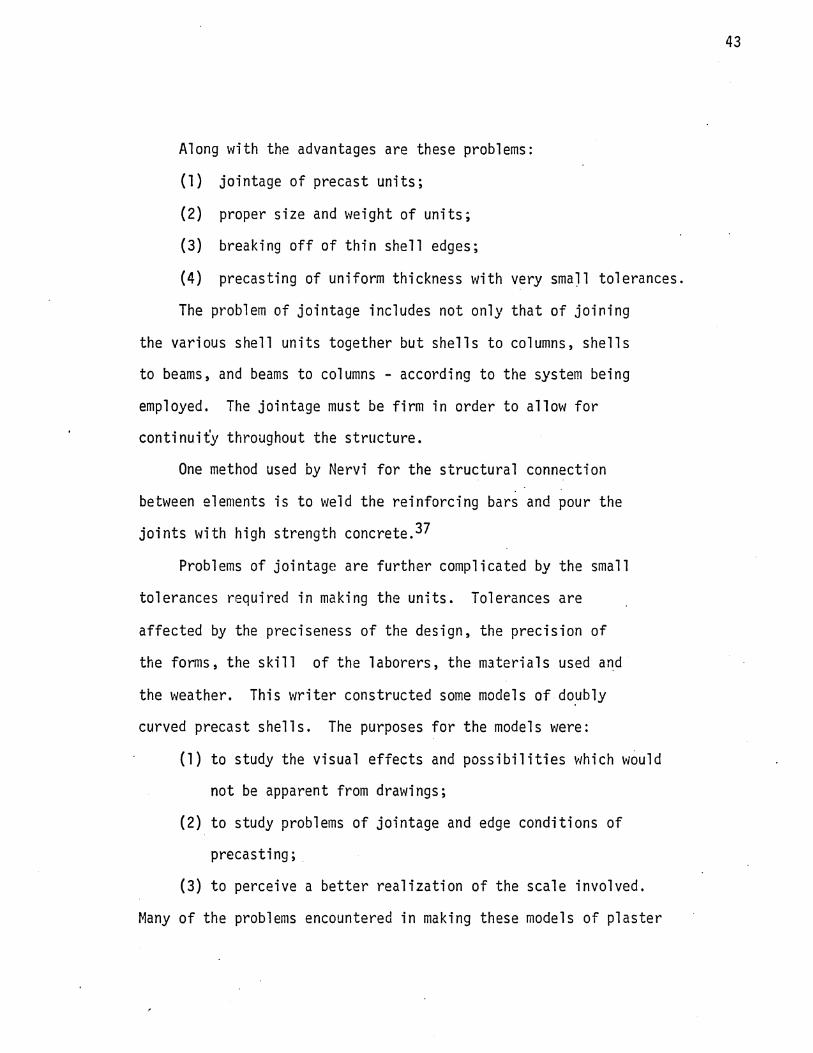
Along with the advantages are these problems:
(1) jointage of precast units;
(2) proper size and weight of units;
(3) breaking off of thin shell edges;
(4) precasting of uniform thickness with very small tolerances
The problem of jointage includes not only that of joining
the various shell units together but shells to columns, shells
to beams, and beams to columns - according to the system being
employed. The jointage must be firm in order to allow for
continuity throughout the structure.
One method used by Nervi for the structural connection
between elements is to weld the reinforcing bars and pour the
joints with high strength concrete.^
Problems of jointage are further complicated by the small
tolerances required in making the units. Tolerances are
affected by the preciseness of the design, the precision of
the forms, the skill of the laborers, the materials used and
the weather. This writer constructed some models of doubly
curved precast shells. The purposes for the models were:
(1) to study the visual effects and possibilities which would
not be apparent from drawings;
(2) to study problems of jointage and edge conditions of
precasting;
(3) to perceive a better realization of the scale involved.
Many of the problems encountered in making these models of plaster

will also be encountered in construction of full size concrete
units.
Unlike the hyperbolic paraboloid which can be generated
with straight line forms, the paraboloid of revolution which
was used for the models presented problems in proper control
of the curvature with small tolerances. This problem, however,
could be overcome with proper equipment in a laboratory or a
manufacturing plant.
The material first used for the form was potters clay.
However, unless a properly controlled humidity was maintained,
the clay mould would shrink. The form was then cast permanently
in plaster at 1/4" =1' 0" and shell units were in turn cast
from this. At this point the following problems arose:
(1) what reinforcing material to use to maintain strength
and yet be flexible enough to assume the contours of
the form;
(2) how to maintain uniform thickness-at a small scale;
(3) how to assure uniform, slow drying of plaster to pre¬
vent shrinkage and warpage;
(4) breaking of edges.
Several reinforcing materials were tried. The most reliabl
proved to be nylon mesh, which maintained reinforcing strength
yet easily assumed the curvature of the shell. The other three
problems mentioned above were never completely solved.

Another consideration is that of size and weight. The
weight and dimensions must be carefully considered in relation
to the mechanical equipment available to lift them into position.
Usually a complete scaffolding must be designed and horizontal
and vertical transportation equipment provided for. The effi¬
ciency of this handling system may be responsible for the 38 success or failure of the project.
The next few pages are photographs of a model illustrating
prefabricated umbrellas 40 feet square and 2 inches thick ex¬
cept at the valleys where the thickness is increased to 4 inches.
The total weight of such a unit is 46,000 lbs. Conventional
equipment could easily move and lift such a shell. The main
problem would be to prevent breaking of the edges in handling.
Some other examples of precast units and their weights are:
(1) post-tensioned bridge girder (940 Ib/ft x 95' = 89,400 lbs.);
(2) pretensioned roof beam (520 Ib/ft. x 66' = 34,400 lbs.).^

46

47

48

49
I

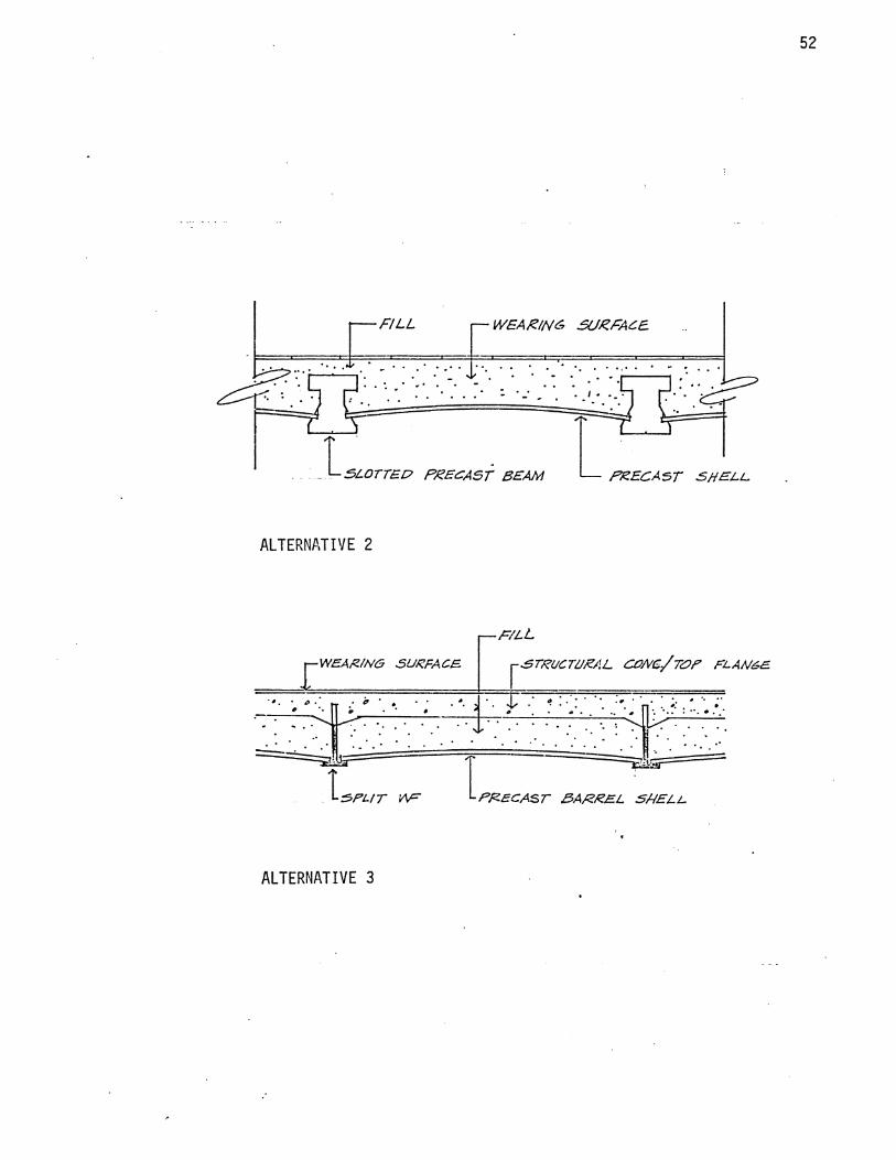
The following five pages present alternative solutions to the
problems of precasting.

51
ALTERNATIVE 1
I i
SECTION
t—i- X GHZDEZ.
H-
f- ONE-WAY BEAM SYSTEM
■C.OLUMH
•H
I I
PLAN
52
ALTERNATIVE 2
■—F/LL
WEAR/NS SURFACE r STRUCTURAL COA/C-/TSF RLAMCE
ALTERNATIVE 3

53
ALTERNATIVE 4
SECTION
PLAN

54
ALTERNATIVE 5
SECTION
PLAN

55
ALTERNATIVE 6
SECTION

A second major problem is how to integrate the mechanical
system into the shell flooring system. Some aspects of this
problem are:
(1) Whether to expose the duct system below the shell or
place it in the fill above (basic assumption - shell
is to be exposed from below and not covered with
suspended ceiling!);
(2) if the answer to question (1) is to expose the ducts,
the question is how can this be done properly from
both an architectural and mechanical standpoint;
(3) if the answer to question (1) is to put the ductwork
in the fill, there are several needs to be met:
(a) how to keep the size of the ductwork small enough
to make putting it in the fill feasible,
(b) how to allow for concentrated loads which are
directly above ducts,
(c) where to place ducts (at valleys or at peak),
(d) how to distribute air out into the room.
A good example of the first aspect, exposing the ducts,
is the Skidmore, Owing's & Merrill - Great Southern Life Building,
Houston, Texas. Here the ducts run between girders of a one¬
way beam system.
A similar solution would prove interesting for shell floors.
The idea of expressing both the structure and mechanical as a pure

expression seems justified. Care would have to be taken not to
"clutter" the ceiling and destroy the appearance of the shell
forms.
Ductwork should be placed at low point of shell because:
(1) this allows for greatest flexibility in duct size;
(2) decreases risk with concentrated loads above ducts;
(3) easiest to dissipate air into room from this point.
(See illustration, p. 58).

MECHANICAL CONSIDERATIONS
SPACE REQUIRED FOR DUCTS
METHOD OF DISTRIBUTION OF AIR

How much space do the mechanical ducts require? The answer
to this question is dependent on several things:
(1) the amount of air needed in the room;
(2) the distance from central unit;
(3) the type of system, conventional or high-speed.
The amount of space required for ducts is critical to the design,
for a matter of inches saved in depth could mean great savings
in overall cost of materials. (See illustration, p.58).
How is the air dissipated into a room? The question involves
not how is it to be distributed down into a room but whether down
through the ceiling or up through the floor.
One possibility is a 'mushroom' type rising up out of the
floor diffusing cool air into the upper portion of the space.
(See illustration, p.60). They should be placed where they do
not interfere with room functions. They might also serve as an
ordering device for the rooms and might be integrated with the ,. ... 40 lighting.
If the air is dissipated out through the ceiling there are
several ways in which this could be done. Page 60 illustrates
the use of paraboloids of revolution resting on a one or two-
way grid work of beams. Return could be carried out through
the corridor to a return air plenum.

r SUELL
"MUSHROOM" DIFFUSION'
DIFFUSION THROUGH CEILING
Lighting
A third major area of consideration is artificial lighting.
The governing light source for past structures was of course
daylight and, in a sense, this has continued to present day. Since
"structure" has developed using natural lighting as its criterion
of form, when new structures (i.e. shells) have been developed,
the models and perspectives have been illustrated as for use in
natural light. The artificial lighting is only afterward added
to the structure.4^
This procedure is illustrated by the early development of
shell constructing where the basic simplicity of the structure so
appealed to architects that the needs of other services were
neglected; the result was shell structure designed for natural
daylighting in which the artificial lighting and other services
were hung below the shell, often producing a confusing and untidy
appearance.4^
This trend is changing along with the development of shells
and architects are realizing the possibilities with artificial
lighting of shells. The aesthetic possibilities of artificial
lighting are more limited in thin shell application than in con¬
ventional structure, but, at the same time, the possibilities
that are present suggest some exciting solutions. The matter
of daylighting will be considered in Chapter 4.
Some of the problems involved are:
(1) how to best accentuate and express the exposed structure

while giving proper light to the room;
(2) how to integrate the lighting fixtures so that they do not
interfere visually with the structure. The more techni¬
cal problems involved with illumination level; lighting
materials, etc. will not be considered in this thesis.
The six methods of distributing light are illustrated graphi- AO
cally on page 63 .
The ones that can probably be most usefully employed in shell
lighting are upward and downward diffused and upward concentrating.'
Light reflected from the curved surface of the shell can serve to
accentuate the strong form of the structure.

SIX METHODS OF LIGHTING
mmmmm DOWNWARD CONCENTRATING
DOWNWARD DIFFUSING
UPWARD CONCENTRATING
UPWARD DIFFUSING
T MULTI-DIRECTIONAL CONCENTRATING
MULTI-DIRECTIONAL
DIFFUSING

The type of lighting shown at the top of page 65 is known as
cove lighting. If possible it is best to use the entire shell as
a reflector for cove lighting. This preserves and emphasizes the
purity, and simplicity of the structure.^ Boyd Anderson says
"treating the shell as a reflector is better appreciated with each
application."^
In the bottom figure the lighting units are simply suspended
from the ceiling. To achieve the proper lighting quality the
rules of thumb shown in figures should be followed with regard to
distance of light source from shell.
Rotterdam, Holland's train stations, illustrate a successful
relationship between the artificial sources and the structural
shell. While a high proportion of light is directed downward
toward the platform edge, some light is permitted upward to give
a gentle light over the whole curve of the roof. This both
emphasizes the character of the roof form and adds a sense of
protection from the canopy to travelers at night.^
There are many psychological effects that the quality of
light may have upon a space. Light can give the shell a 'hardness'
or 'softness' depending upon how it is used and as well has an
effect upon the sense of scale of the space. Scale will be dis¬
cussed further in Chapter 4. The effects of natural light will
not be considered here.

65
COVE LIGHTING
TOP LIGHTING
SUSPENDED LIGHTING.

Another problem of significance but which will not be considered
here is the method of handling plumbing. Consideration must be
given to incorporating hot and cold water supply lines, waste and
vent stacks into a service core.
A fourth major area of consideration is integration of interior
partitioning with the shell flooring system.
The problems involved are:
(1) how to solve aesthetic problem of connection of rectili¬
near wall plane with curved surface of shells;
(2) the technical problem of coordinating walls with a
gridwork of beams, if such are used;
(3) retaining sense of curved ceiling while incorporating
wall planes.
The solid wall should be detached from the shell surface if
at all possible. This will allow the shell to float in space
in its own articulate form, free from any superficial support.
The void between the top of the wall can be filled with glass or
clear plastic panel. Page 67 will illustrate this situation.
It is not always known exactly where interior walls will need
to be placed in a building, particularly a speculative structure.
For this reason a grid system on a small module has advantages
over larger modules in some cases.

67
WALLS CARRIED SOLID TO CEILING
SOLID WALL BROKEN - SPACE FLOWS THROUGH

CHAPTER 4
Consideration of Architectural Aesthetics

Chapter 4 deals with some of the considerations of architectural
expression involved. The problems are:
(1) how to best express the structural system of shells on
both interior and exterior;
(2) how to exploit the shells for sun control;
(3) how to express the light, airy quality of shells;
(4) how to terminate the shell at ground and roof;
(5) scale.
Robert Mai11 art achieved with his bridge designs a distinctly
graceful quality peculiar to the forms he used. The bridges purely
express the manner in which the forces act upon the structures.
(See illustration, p. 69).
Similarly it is important that shell designs convey a sense
of lightness and airiness expressive of their true nature. Felix
Candela has achieved this with many of his shell structures, illu¬
strated on page 70.
Pages 71 and 72 illustrate the manner in which the shell
might be handled at the exterior, both in expressing the structural
system and exploiting the shell for sun control.
Another major problem is how to express the termination of
the shell at ground and roof. For purposes of drainage and insula¬
tion the roof should probably be flat although it would have a
pleasing effect to express the shells on the roof.
The fifth major concern is scale. The module or size of the
shells bears a distinct relationship to the scale of the building.

69
Salginatobel bridge, designed by Robert Maillart.
Mai Hart's bridges purely expresses the manner
in which the forces act upon the structures.

70
Church of our Miraculous Lady, Felix Candela, 1953
Indicative of light-lacy quality of much of Candela's work.

The rhythm set up in a shell flooring system should carry
through to the exterior . It should be readily apparent that shells
form a significant portion of the structural system.
■ 1 1
' 1
Ji 1 f
HORIZONTAL AND VERTICAL ACCENTUATION

RELATIONSHIP OF SHELL AT EXTERIOR WALL
Cantilevered Shell and Fill
Cantilevered Shell
Cantilevered Beam and Shell
From Architectural Scale we read "...when there is a structural
skeleton on columns and beams, it supplies a large module running
throughout the design. Where the structural units are shells, vaults,
or folded concrete planes, they may easily provide a unit that is
an eighth or a quarter of a small building. And where a single
shell or vault embraces the whole building, all of its divisions
will necessarily be related to the structural span. Can there
be any doubt that structural behavior and systems of construction
determine orders of physical dimensions that are, as a rule, the
natural bases for a building's visual scale?" ^
The discipline of planning is as exacting as that of con¬
struction. For instance, where a work space is custom - fitted,
as in the modern kitchen or bathroom, the accommodations of
'people's bodies and bodily movements fills the room with dimen¬
sions that - within an inch or two - are determined by use.
The more intimately and carefully a building is designed for the
activities of its occupants, the more these measurements deter¬
mine its minimum. ^
The kitchen and bath are one example. On a building scale,
the function of an auditorium would, of course, require a larger
minimum dimension than that of a school room. The auditorium space
would also dictate a larger shell module (perhaps even a single
shell spanning the entire area) than the school - not only because
of reasons of structural efficiency but because the size of the
space would visually warrant a larger scale module.

74
SHELL AS SMALL BASIC UNIT
SHELL AS LARGE BASIC UNIT

This is related to unit size. The synthesis of physical
dimensions often finds its expression in a bay unit. In a
medieval hall, for instance, the synthesizing bay unit may
coordinate a useful plan area, a handsome visual division, and
a convenient structural unit for stone vaulting and large
window openings. In a modern office building, the bay may be
even more comprehensive. It may provide a suitable unit of
steel skeleton construction (or shell construction) and a
useful area of rental space; and it may also allow the space
to be divided in many ways by a modular partition system and
furnish an elaborate system of lighting and air-conditioning.^
The bay unit might be much larger for a warehouse or a
garage, than for an office building. There are two readily
apparent reasons for this; one is functional, the other is
related to human scale. The office building has a smaller
module to which man may more readily relate.

LARGE MODULE-LARGE SCALE
(Warehouse, Department Store Prototype)
SMALL MODULE-SMALL SCALE
(Office, Apartment, Hotel Prototype)

CHAPTER 5
Limiting Factors and Considerations for Future
Investigation

This thesis has been primarily an architectural approach
to the application of shells for floors. There are two basic
aspects of the problem which have been mentioned but should
here be stressed as an area for additional research:
(1) the effects of concentrated loads upon the fill
and, consequently the shell;
(2) the appropriate materials and proper design of the
fill and wearing surface.
The intent here is only to define the problems, not to
solve them. Solving these problems is a matter for further
engineering research. It can be assumed, however, from the
experience of "techo de biveda? that some combination of
shell, fill and wearing surface will withstand conventional
floor loads. The fill material used in Guadalajara is a lightweight
concrete made from hydrated lime and "jal”, which is a local
pumice sand and gravel.^® From test results its compressive
strength against cracking was 50 lb/in^ and 61.9 lb/in^ 3 Ri
against rupture. Its volumetric weight at 10 days was 58.5 Ib/ft .
Its average thickness was 2.8 inches. The wearing surface of
burnt clay brick was .4 inches in thickness.^ These details are
obviously good for ordinary office floor loads where severe con¬
centrations are not present, and hence these strengths, unit
weights, and thicknesses become a starting point for design or
additional research. Studies aimed at optimum combinations of
materials could proceed from this point.

The strength of the concrete and the depth are not arrived
at analytically but are based primarily on accumulated experience.
This fill is only structural in that it sustains the load from
the floor above and distributes it across the vault. The vaults,
just as shells, will not withstand large concentrated loads
because of their thinness. The "jal" is used not only for its
strength but because of its light weight. This writer has
suggested throughout this text the use of foam concrete, an
aerated concrete which has a range of strength and unit weight.
Other materials which might be considered for this fill are
inert earth materials and synthetics such as foamed plastic.
The material must be stable enough to support evenly the wearing
surface above or else cracking will occur if, for instance,
concrete is used for the wearing surface. This is the extent
to which these problems will be considered here.

CHAPTER 6
Review and Synthesis

The shell was described in Chapter 1 in its historical con¬
text and in relation to other structural systems. The pro¬
position was then posed that shallow shells are applicable for
flooring systems in multi-story buildings with a preliminary
basis presented for this proposition.
Chapters 2-4 were an analysis of the proposition. In
Chapter 2 was demonstrated the simplest application - cast-in¬
place shells of several types with structural analysis. In
Chapter 3 were enumerated the several problems and alternatives
involved with extending the proposition to additional building
types and precasting. In Chapter 4 were presented the problems
and alternatives of architectural expression involved.
From the investigation and analysis on the previous chapters
we may draw several general conclusions:
(1) shells are structurally feasible for floor systems
and, in fact, have some advantages over other systems;
(2) precasting and integration of mechanical systems pre¬
sent problems not ordinarily experienced with other
systems but, conversely, potential with mechanical
and lighting not available with other systems;
(3) shells for floors have unique potential for architectural
and structural expression from both interior and exter¬
ior.
There are, however, some limiting factors which must be pointed
out in regard to this study:
(1) only simple guideline structural analyses have been made.

A complete structural analysis would have to be made
on a system before detailed dimensions and reinforce¬
ment could be determined;
(2) There are, as has been said, some particular structural
problems which should be investigated further - i.e.
the effects of concentrated loads upon the fill and
shell, the optimum design of fill and wearing sur¬
face;
(3) The important consideration of economy has not been
dealt with by this writer. A complete cost analysis
of a system will naturally follow as a sequel in any
further investigation of shells for floors. Systems
used are not always the most inexpensive but, if they
are not, there must be other advantages.
The general conclusions above have basis in specific criteria
which reinforce the thesis that shallow shells are applicable in
flooring systems:
I. Historical precedent
A. Singly curved, "flat" vaults were used in Mexico for
many centuries. This has evolved into the "Techo de I
boveda" system.
B. Doubly curved "flat" vaults are being used in con¬
struction for new campus of Autonomous University of
Guadalajara.
C. Use of folded plates in multi-story construction by
Candela and others is analogous in its similarity.

II. Structural properties
A. Structural analysts have shown that it is possible
for membrane action to develop even within the
shallow depth of flat slab construction, and hence
very shallow shells, carrying load entirely through
membrane action, should be possible.
B. Shallow shells of very thin sections and relatively
long span are capable of carrying normal and above
normal floor loads.
C. Thinness of shell is an economical factor with cer¬
tain spans.
D. Shells are the most efficient type of structure
available and hence should be efficient used as
shallow shells for floors.
III. Architectural and mechanical potential
A. There are a variety of ways in which to handle
mechanical, lighting and interior walls.
B. There is a unique aesthetic quality of shell forms.
There will, in Chapter 7 be demonstrated three prototype shell
flooring systems, based upon the above criteria and their relation¬
ship to the material presented in the previous chapters. I again
point out that this thesis, as an investigation into this area,
covers only limited aspects of the possibilities of shells for
floors and further investigation along these avenues of thought
is encouraged.

CHAPTER 7
Demonstration

Prototype I is the result of an initial three week investi¬
gation of shells for floors in the fall of 1966. An evaluation
follows the demonstration of this prototype.

A speculative office building for
Houston, Texas

r
>
<
*
U
ttl
ft
\L
0.
0
0
J
h
0)
JU
srm
^LAKI

84
t
» Ni
PLA
N

85
i
! ! j
i
I i
I I' \1
a nl a
2 ^ (Q Mi
Pit
A M
)N6
PL
AN
'/?*•
-1V
*

86
WA
UL
6B
£T
t0N

87
ttC
'UO
H A
4
&C
T1
0H
g> 5/s-iV

88
i I
I
w
£H
£L
L -
BB
AM
£0A
tAJ£.6
T/i>
/J
1 "

89

90
1
Mtf
RT
H
I5L
&V
AT
U>
M

91
£
l
L
feLg
yA-n
sN
oeru
u
HO
tt'T
U'N
tbT
CO
tLn
eJtt
.

92
tNT
££
£t<
gg
.

93
In an evaluation of the design several points were brought
out:
(1) The distribution ofthe mechanical through the'cap' as
shown in the isometric, presents problems related to
combining the mechanical outlet and point of structural
bearing into one unit.
(2) It has been suggested that there is a certain aesthetic
and perhaps structural impurity in employing doubly-
curved shells with a one-way beam system.
(3) Round ducts are better suited" for these circumstances
than rectangular ducts.
(4) The sun-screen solution at the exterior walls on the
east and west is not well resolved.

94
Prototype II.
—~
I I i I
~fxh
1 1 1 1 1 1 1 1 1 1 l 1 1 % 1
J 1 J 1 L—f—L
i u “"Tr
ljl 11
P r lil 111
\ i S i -_l ; U_.
----i7r\" ii \
r: V"
~P\r ' Ml
I IP \\\p \« _ll _l L 11
JL
6. _ JL_
■1-tv
1;1 JM =*7
! i ' I
iir-
✓■'iii'-./ Xijl/'N i L J;L _J!L _i i
n;r -n ii 7 i i;i ; i 1!
> ....
71 r — W 11 j?
>J—-I t,<
,Tjf\ Mi
i
“1 jF* \ / j i*: /\ nr
=T= i
\ Mi / \ i i / \i;i /• \ U l_ _J l_ II ; I
2
""i.r- ' in
\ II 1-T
“iir' / I I -
'71
\J .71 ir
i!i
f TWO-WAY GR/D-WORK OF BEAMS
I I
\ i L J !,n .J
n r n
i:r in
Ml ITT
-PRECAST SHELL.
r-=* • COLUMN
A k £>-Om
A * A A v *
a
•i ..... (j
24-' K
Plan 1/8" = T 0"
■WEAR/A/6 SURFACE T—FILL
J— AFR/DWORK OF BEAMS 1— PRECAST SHELL, 4" RISE
Section A 1/8" = V 0"

Prototype II
Section B. T‘ = 1' 0"
Section C 1" 1' 0"

96
Scale Model, Prototype II.

97
Scale Model, Prototype II.

Prototype III
98
c A
Sv/
- I
A ✓ \ V
t i I _L. 'o „»
*
O 'COLUMN
O
Plan 1/8" = T 0"
DOU&LB- CUE M TUR.E. SHELL
Section A 1/8" =1' 0"

DOUBLY CURVED SHELL SUPPORTED DIRECTLY BY COLUMNS
Paraboloid of Revolution, 18" Rise in 24' - 0" Square Bay
Live Load 100 psf Dead Loads: 1" Wearing Surface 13
Foam Concrete,"2" - 20", avg. 11" at 60 pcf 55
2 1/2" Cone. Shell 31 Total: 199 psf
Total Load in one panel = 199 x 24 x 24 = 114,700 lbs.
114,700 Vertical Component of Thrust = 4 = 28,700 lbs. = 28.7^
o
y = Kx2
9 = K x 144 x 144 K = T44~
y = 4.34 x 10"4 x2
dh/ = 8.68 x 10⁻⁴ x dx .
dy; = 8.68 x 10‘4 x dx x = 144
F _Fy _ 28,700 x 0.1250. 0.1250
9 = 0.000434 = 4.34 x 10 x 144 "
144 = 0.1250 = F X
229,000 lbs. = 229k
F = + 28.72 231k
231,000 48 x 4 = Compressive Stress = 1 ,202 psi

DOUBLY CURVED SHELL SUPPORTED DIRECTLY BY COLUMNS (cont'd.)
Paraboloid of Revolution, 24" Rise in 24' - 0" Square Bay
Live Load 100 psf Dead Loads: 1" Wearing Surface 13
Foam Concrete, 2" - 26", avg. 14" at 60 pcf 70
2 1/2" Cone. Shell JH
Total: 214 psf
Total Load in One Panel = 214 x 24 x 24 = 123,200 lbs. = 123.2^
123,200 Fy = 4 = 30,800 lbs. = 30.8K
y = K x2 12 = K x 144 x 144 K= 0.000579 = 5.79 x 10~4
y = 5.79 x 10“4 x2
& = 11.58 x 10'4 x dx
. = 11.58 x 10"4 x 144 = 0.1668 = Fv dx x = 144. *
- irfit - 184.700 1bs- = i84-7k
- ”\ 184. 72 + 30.82 = 187.4k
187,400 Compressive Stress = x 4 ” PS1
At exterior column (not corner column) 7^=*- /BSA
- z&s-jc /S4fc
/S.4K,
O
/<£<?.•£/£
t
SHEAfS ms.
/S.fAZ MoM- £>/A<B.
If we arbitrarily limit the working shearing stress to about 200 psi, we shall then require
Effective Column Area = bd = ^ = ^^’ gdlT = in.2
E.6., b=30", d = 30", bd = 30 x 30" = 900 in.2

101
Tie Size
Reg'd. A = T fall
185k o 20 j = 9.25 in. 6 - #11 bars
(int. grade billet steel)
Alternatively
185k , CQ . 2 Reg'd. A - T[g- . - ’-68 in.
ksi 16-3/8" high-strength
bars (ult. strength = 200 ksi )
A1ternatively
Reg'd. A = = 2.13 in.2
87 ksi 2-T 1/2" Regular Stress
Steel bars (ult. strength = 145 ksi)
2-1 1/2" Regular Stressteel bars selected - fewer bars,
easier to handle for erection, maneuvering of A/c ducts.

102
Prototype III.
Section B. 1" = V 0"
COLUMN

103
Prototype III.
Section C 1" = T 0"

Prototype III. 104
/RECAST
PRECAST
PRECAST
•Cutaway Exploded Isometric Column-Shell Connection
.1" = V 0"
COLUMN
SHELL
COLUMN

Prototype III
Precast Shell Connection 3" = 11 0"

Prototype III.
Mechanical Detail 1" = T 0"
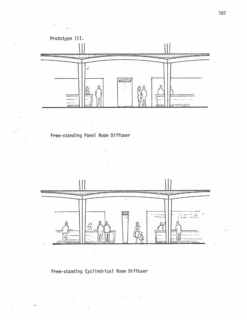
Prototype III.
Free-standing Panel Room Diffuser
Free-standing Cyclindrical Room Diffuser

108
Inte
rior
Vie
w

TABLE OF FOOTNOTES

L. De Syllas, "Domes, Vaults, and the Development of Shell Roof¬ ing," Proceedings of a_ Symposium on Concrete Shell Roof Con¬ struction, 1954, p.3.
^Talbot Hamlin, Architecture Throuqh the Aqes, (New York, 1953, p. 148.)
^"Architectural Vaulting," Scientific American, Vol. 205, p.144.
De Syllas, op. cit., p. 6.
^Bannister Fletcher, A History of Architecture on the Comparative Method, (New York, 1961, p. 1997)
^James W. Buckley, "Thin Concrete Shells," Rice University Insti¬ tute, 1958, p.9.
^Alf Pfizer, Elementary Statics of Shells, (New York, 1961,) p. 2.
^"Architectural Vaulting," Scientific American, Vol. 205, p.144.
^Buckley, op. cit., p. 7.
^Willard B. Robinson, "Concrete Shell Structures," Rice Insti¬ tute, 1959, p. 5.
1]Ibid, p. 6.
1 ? Fletcher, op. cit., p. 1068.
13 Robinson, op. cit., p. 6.
^Buckley, op. cit., p.8.
15 Robinson, op. cit., p. 6.
^Jtfrgen Joedicke, Shell Architecture, (New York, 1963), p.19.
17Ibid., p. 19.
18 Ibid., p. 19.

19 Eduardo Torroja, Philosophy of Structure, (University of Californi Berkeley) p. 175.
20 Mario Salvadori and Robert Heller, Structures in Architecture,
(Englewood Cliffs, New Jersey), p. 329.
21 Joedicke, op. cit., p. 20.
22Wi11 iam Zuk, Concepts of Structures, (Reinhold Corp., N.Y., 1963), p. 52.
23Pflliger, op. cit., p. 2.
24 R. H. Wood, Plastic and Elastic Design of Slabs and Plates,
(New York, 1961), p. 4.
^Colin Faber, Candela: The Shell Builder, (New York, 1963), p. 62.
Salvadori and Keller, op. cit., p. 342 - 344.
27»vaulted Brick Construction in Guadalajara," Nat Rrahl and Harry Ransom, Architecture at Rice, no. 18, 1966, p.17.
28 - » . . Faber, op. cit., p. 43.
^Rrahl, Ransom, op. cit., p. 51.
30Ibid., p. 19.
3^Ibid., p. 20.
32Ibid., p. 20.
33Ibid., p. 23.
34Ibid., p. 51
33Ibid., p. 20.
36 Pier Luigi Nervi, Structures, (New York, 1956), p. 63.

Ibid., p. 64. 37
38Ibid., p. 65.
39 T. Y. Lin, Design of Prestressed Concrete Structures, 2nd. Ed. (Wiley & Sons, N.Y.), Chapter 16.
40 Buckley, op. cit., p. 22.
^Derek Phillips, Lighting in Architectural Design, (New York, 1954), p. 195.
42Ibid., p. 199.
43 John E. Flynn and Samuel Mills, Architectural Lighting Graphics, (New York, 1962), p. 16.
^Robinson, op. cit., p. 25.
45 Ibid.
46 Phillips, op. cit., p. 20.
^Heath Licklider, Architectural Scale, (London, 1965), p'.19.
48Ibid., p. 20.
49Ibid., p. 27.
88Krahl and Ransom, op. cit., p. 20.
Ibid., p. 41.
52 Ibid., p. 39.

BIBLIOGRAPHY
"Architectural Vaulting," Scientific American, Vol. 205.
Buckley, William, "Thin Concrete Shells," Rice Institute, 1958, A paper submitted to the Department of Architecture in partial fulfillment of the requirements for the degree of Master in Architecture.
De Syllas, "Domes, Vaults, and the Development of Shell Roofing," Proceedings of a_ Symposium on Concrete Shell Roof Con¬ struction, 1954.
Faber, Candela; The Shell Builder, (Reinhold Corp., N.Y.) 1963.
Flynn and Mills, Architecture Liqhtinq Graphics, (Reinhold Corp. N.Y.) 1962.
Fletcher, A History of Architecture on the Comparative Method, (Charles Scribner's Sons, N.Y.), 1961.
Hamlin, Architecture Through the Aoes, (G. P. Putnam's Sons, N. Y7TT1953.
Joedicke, Shell Architecture, (Reinhold Corp. N.Y.), 1963.
Krahl and Ransom, "Vaulted Brick Construction in Guadalajara,1:' Architecture at Rice, no. 18, 1966.
Licklider, Architectural Scale, (The Architectural Press, Lon¬ don), 1965.
Lin, Design of Prestressed Concrete Structures, 2nd. Ed., (Wiley and Sons, N.Y.)
Nervi, Structures, (F. W. Dodge Corp. N. Y.), 1956.
Pfluqer, Elementary Statics of Shells, (F. W. Dodge Corp. N.Y.), 1961.
Phillips, Liqhtinq in Architectural Design, (McGraw-Hill, N.Y.), 1964.
Robinson, James, "Concrete Shell Structures," Rice Institute, 1959, A paper submitted to the Department of Architecture in partial fulfillment of the requirements for the degree of Master in Architecture.
Salvadori and Heller, Structures in Architecture (Englewood Cliffs, N.J.).
Torroja, Philosophy of Structures (University of California, press, Berkeley), 1958.
Zuk, Concepts of Structures, (Reinhold Corp., N.Y.), 1963.