CONSTRUCTION METHOD TO BUILD ICE SHELLS WITH ...
79
MASTER’S THESIS Diplomarbeit CONSTRUCTION METHOD TO BUILD ICE SHELLS WITH PNEUMATIC FORMWORK executed for the purpose of obtaining the academic degree of Master Graduate Engineer under the direction of o.Univ.Prof.Dipl.Ing.Dr.Ing. Johann Kollegger, M.Eng and Dipl.Ing. Sonja Dallinger E212 - Institute for Structural Engineering Karlsplatz 13/212 A-1040 Wien submitted at the Vienna University of Technology Faculty of Civil Engineering by Juan Ignacio Pérez Latorre 0928134 E-28039 Madrid SPAIN Valle de Bergantiños, 5, 6ºB Vienna, February 2010
-
Upload
khangminh22 -
Category
Documents
-
view
1 -
download
0
Transcript of CONSTRUCTION METHOD TO BUILD ICE SHELLS WITH ...

MASTER’S THESIS Diplomarbeit
CONSTRUCTION METHOD TO BUILD ICE SHELLS WITH PNEUMATIC FORMWORK
executed for the purpose of obtaining the academic degree of
Master Graduate Engineer under the direction of
o.Univ.Prof.Dipl.Ing.Dr.Ing. Johann Kollegger, M.Eng and
Dipl.Ing. Sonja Dallinger
E212 - Institute for Structural Engineering Karlsplatz 13/212
A-1040 Wien
submitted at the Vienna University of Technology
Faculty of Civil Engineering
by
Juan Ignacio Pérez Latorre 0928134
E-28039 Madrid SPAIN Valle de Bergantiños, 5, 6ºB
Vienna, February 2010
COSTRUCTION METHOD TO BUILD ICE SHELLS WITH PNEUMATIC FORMORK Juan Ignacio Pérez Latorre
2
ACKNOWLEDGEMENTS This final thesis constitutes the colophon to my master degree in Industrial Engineering majoring in mechanics and structures. Now I would like to thank to all persons involved during this learning period. First I would like to express my profound gratitude to my family and my girlfriend, who have continuously supported and gave me encouragement during my whole studies, without them I could not get it. I am very grateful to the Institute for Structural Engineering of the Vienna University of Technology for providing me the opportunity to work with them in this exciting work. This allowed me to be part in a real investigation project and increase my knowledge and abilities in the matter working with an excellent team.
I would like to give my heartfelt thanks to O.Univ.Prof. Dipl.-Ing. Dr.-Ing. Johann Kollegger Head of the Institute for Structural Engineering for his help and unfailing support; and to my supervisor Dipl.-Ing. Sonja Dallinger, for her enthusiastic approach, continuous inspiration and enlightening guidance. My sincere thanks also to my friends that had supported me unconditionally in the hard moments, and my colleagues and professors in the Carlos III University of Madrid who contributed to my work in some manner.

COSTRUCTION METHOD TO BUILD ICE SHELLS WITH PNEUMATIC FORMORK Juan Ignacio Pérez Latorre
3
INDEX 1. INTRODUCTION…………………………………………………………………….4
1.1 Shells general………………………………………………………………...5 1.2 Ice as construction material………………………………………………...10 1.3 Shells built at Institute for Structural Engineering…………………………11 1.3.1. Wooden Shell…………………………………………………….14 1.3.2. Concrete Shell……………………………………………………16 1.3.3. Ice Shell…………………………………………………………..18 2. PRELIMINARY EXPERIMENTS………………………………………………….23 2.1. Experiment Set Up………………….……………………………………...24
2.2. Results……………………………………………………………………...35 3. NEW SHELL CONSTRUCTION METHOD……………………………………….38
3.1. General Idea………………………………………………………………..39 3.2. Design of Ice Shell…………………………………………………………41
3.3. Construction………………………………………………………………..51 3.4. Creeping……………………………………………………………………56 3.5. Results of the Measurements………………………………………………59 3.6. Problems and suggestion for further experiments…………………………62 4. SUMMARY………………………………………………………………………….65 References……………………………………………………………………………...67
List of Figures…………………………………………………………………………..69
List of Tables…………………………………………………………………………...71
List of Graphics………………………………………………………………………...71
ANNEXES……………………………………………………………………………...72
ANNEX I. DEAD LOAD IN THE ICE SHELL……………………………….73 ANNEX II. PRELIMINARY EXPERIMENTS………………………………..74 ANNEX III. COMPARISON OBERGURGL-CONTAINER…………………76 ANNEX IV. CREEPING……………………………………………………….77

COSTRUCTION METHOD TO BUILD ICE SHELLS WITH PNEUMATIC FORMORK Juan Ignacio Pérez Latorre
4
1. INTRODUCTION

COSTRUCTION METHOD TO BUILD ICE SHELLS WITH PNEUMATIC FORMORK Juan Ignacio Pérez Latorre
5
1.1. SHELLS GENERAL
The dictionary says that shell is “the hard outer covering of something, speciality nuts, eggs and some animals”. In structures the concept is the same, enclose and protect. We use the word to describe a hard covering, specially curved structure which supports external applied loads. Shells are natural, logical and functional load carrying systems. If a space has to be surrounded by a minimal area of surface, the shell is the logical optimum. Additionally, for the load transfer of a uniformly distributed load, the shell structure is the perfect choice because mainly normal forces appear in the cross section [1]. Shell structures have been built by man since the most ancient times. In architecture, we say dome like a curved roof or vault, usually hemispherical in section and circular or oblong on plan, without angles or corners, which allows huge spaces in buildings, as well as the possibility of a powerful lighting. Despite they can be thin; domes are a stronger architectural element, thanks to compressive forces they create. Until the 19th century, domes were constructed of masonry, of wood, or of combinations of the two, frequently reinforced with iron chains around the base to contain the outward thrust of the structure. Since then, as industrial technology developed, domes have been constructed of cast iron, reinforced concrete, steel, aluminium, laminated wood, or plastic [2] [3]. Although shell structures possess excellent load carrying system and make a great visual impact, only few shells have been built in the last decades. The main problem is the difficult, time-consuming and expensive production. Traditionally, shells are produced by means of complex formwork. Creating such formwork increases the construction time and affords additional material which cannot be reused after the shell has been completed. HISTORY OF DOMES The dome seems to have developed as roofing for circular mud-brick huts in ancient Mesopotamia about 6,000 years ago. In the 14th century BC the Mycenaean Greeks built tombs roofed with steep corbelled domes in the shape of pointed beehives.
After about 1600 BC the Mycenaeans, ancient inhabitants of the south-eastern Greek mainland, buried their dead in tholos tombs, stone chambers with beehive-shaped domes. This tholos tomb, (c. 1300 - c. 1250 BC), mistakenly named as the Treasury of Atreus, by its discoverer, consists of stone blocks arranged in superimposed concentric circles. The vault reaches a height of about 12 m, Figure 1, [3].

COSTRUCTION METHOD TO BUILD ICE SHELLS WITH PNEUMATIC FORMORK Juan Ignacio Pérez Latorre
6
Figure 1. Treasury of Atreus, Mycenae, Greece. (Source: greatbuildings.com)
The Romans developed the masonry dome in its purest form, culminating in the Pantheon of Hadrianus, Figure 2. The Pantheon in Rome is one of the most famous buildings in the world. It was commissioned by Hadrian in 118 and completed in 128 AD. Set on a massive circular drum 6 m thick that conceals eight interlocked masonry piers, the coffered dome rises 43 m to form a perfect hemisphere on the interior, with a large oculus (roundel) in the centre. The oculus (a round opening) at the top is 8.5 m in diameter and provides the only source of light for the interior [3].
The massive size of the Pantheon is accompanied by a tremendous weight. Roman architects used ingenious design to create a stable structure without the use of internal supports. The tremendous weight of the stone on top of the entryways, windows, and passages would cause them to collapse. The architects solved this problem with the use of arches. Arches take the tremendous force of the stone above it and redirect this force through its sides to the Pantheon’s support walls and piers. These support walls and pillars provide a horizontal normal force to counteract the force of the stone above the arches. The structure’s weight is channelled through the piers to its foundation [4].
Figure 2. Pantheon of Hadrianus, Rome. (Source: greatbuildings.com and myself)

COSTRUCTION METHOD TO BUILD ICE SHELLS WITH PNEUMATIC FORMORK Juan Ignacio Pérez Latorre
7
The use of domes was continued in the Early Christian period for relatively small circular structures such as mausoleums and baptisteries. Byzantine architects were far more inventive in their use of domes. In the Byzantine capital of Constantinople, a succession of large domed churches reached its apogee in Hagia Sophia, the church built (532-537) for the Emperor Justinian I. Its shallow dome, 31 m (100 ft) wide and ringed with windows at its base, is supported on four spherical triangles backed by immense exterior piers and by a series of semi-domes [3].
After Constantinople fell to the Seljuk Turks in 1453, Hagia Sophia was
converted into a mosque and became the model for a number of vast domed mosques built throughout the Ottoman Empire in subsequent centuries, Figure 3. Even before that, however, there was a long tradition of Islamic domed buildings (palaces, mosques, tombs, and baths); the Dome of the Rock (691) in Jerusalem is one of the earliest examples. Set on a pillared arcade, its double dome is of timber construction. Perhaps the most famous Islamic structure is the Taj Mahal in Agra, India, built (1631-1648) by the Mughal ruler Shah Jahan as a mausoleum for his favourite wife. Its slightly bulbous white marble dome rises on a tall drum over a spacious equilateral building.
Figure 3. Hagia Sophia, Istambul. (Source: greatbuildings.com and myself)
It was also Byzantine engineers who designed the Mosque of the Rock (691) in
Jerusalem and the Great Mosque of Damascus (715). Soon the Islamic style adopted the so-called onion dome, which later passed to Russia in the XIII century [5].
Meanwhile, in Western Europe, domes disappeared from architecture after the
fall of the Roman Empire. There were several good attempts, such as half domes (apses), rib vaults or troncoconic domes such as the one in the Baptistry of Pisa, finished in 1363 (the current one is more recent, though), but the technique of the semispheric dome had disappeared [5].
The first great Italian Renaissance dome was the majestic octagonal dome built (1420-1436) by the architect Filippo Brunelleschi for Florence Cathedral, Figure 4. The immense structure, 39 m (130 ft) in diameter and 91 m (300 ft) tall, is topped with a lantern 16 m (52 ft) high, and consists of an outer roof shielding and an inner masonry shell.

COSTRUCTION METHOD TO BUILD ICE SHELLS WITH PNEUMATIC FORMORK Juan Ignacio Pérez Latorre
8
Figure 4. Florence Cathedral (Source: myself)
The 8 primary ribs and 16 secondary ribs form a tightly interlocked masonry
cage. He took inspiration from the circular dome in the Rome Pantheon, and designed his with double shell and octagonal shape. The dome lied on a drum, instead of directly on the roof, thus avoiding scaffolds from the ground level [3].
In this manner he built the highest dome at the time, and a true architectonic model, since it was copied in Saint Peter of Rome by Giacomo della Porta (not Michelangelo) in 1593. The later domes of Saint Paul in London (1708) and the Capitol in Washington (1850) used the same technique [5].
In northern Europe, the most notable domes in Baroque style were built. The resplendent Church of St Louis des Invalides in Paris, built (1676-1706) by Jules Hardouin-Mansart has a dome (28 m/92 ft wide) set on two unusually tall drums pierced with large windows that flood the interior with light. Sir Christopher Wren's noble dome for St Paul's Cathedral (1675-1711), London, incorporates a shallow inner dome, a conical masonry shell supporting the high lantern, and an outer lead-sheathed dome of timber.
The U.S. Capitol dome, built in 1793, gets its height from this engineering sleight of hand. The large outer dome is a thin shell, held up by a ring of curved iron ribs, Figure 5. Underneath it all is a smaller, self-supporting dome, visible only from the inside. The U.S. Capitol dome is also one of the earliest domes made of pre-fabricated cast-iron ribs. The switch from heavy masonry to lightweight metal ribs in the late 18th century greatly reduced the weight of domes being built around the world [6].
Figure 5. United States Capitol, Washington. (Source: greatbuildings.com)

COSTRUCTION METHOD TO BUILD ICE SHELLS WITH PNEUMATIC FORMORK Juan Ignacio Pérez Latorre
9
Still parallel, in Persia, the dome of the Oljeitu Mausoleum (Soltaniyeh, 1312) was built. This was, in fact, the first double-shell dome, and was additionaly reinforced with arches between both shells, which were an architectural revolution in the Muslim world, comparable to that of Brunelleschi. It started an architectural trend that designed domes as big as the Mausoleum of Khoja Ahmed Yasavi (Kazakhstan, 1405) and the Taj Mahal (India, 1653) [5].
The marble dome of the Taj Mahal has a height of about the same size as the base of the building, about 35 meters, and is accentuated as it sits on a cylindrical "drum" of about 7 metres high. This dome is a clear example of the so called onion-dome, Figure 6.
Figure 6. Taj Mahal, Agra, India. (Source: greatbuildings.com)
One of the most characteristic elements of the Baroc architecture was the oval dome, invented by Giacomo da Vignola (chapel of Saint Andreas, Rome, 1553) and especially developed in the churches of Bernini and Borromini. This kind of dome gave a dramatic dynamism to Baroc churches. The biggest of this kind was built by Francesco Gallo in the Basilica of Vicoforte (Italia, 1773).
Through the XIX century some domes made out of glass and iron have been built. Walter Benjamin was the first who wrote about iron and glass construction in his work “Paris, capital of the 19th century”. Then Günther Bantmann has designed the Galleria Vittorio Emanuele and since then several projects and constructions have been carried out by using this materials.
The technological developments of the 20th century have radically changed the concept and construction of the dome. New techniques and construction procedures of domes have been developed, as well as new materials have been introduced.
Modern thin concrete shells, which began to appear in the 1920s, are made from thin steel reinforced concrete, and in many cases lack any ribs or additional reinforcing structures, relying wholly on the shell structure itself. Shells may be cast in place, or pre-cast off site and moved into place and assembled. The strongest form of shell is the monolithic shell, which is cast as a single unit. The most common monolithic form is the dome, but ellipsoids and cylinders are also possible using similar construction methods.

COSTRUCTION METHOD TO BUILD ICE SHELLS WITH PNEUMATIC FORMORK Juan Ignacio Pérez Latorre
10
1.2. ICE AS CONSTRUCTION MATERIAL Ice is a beautiful material present in nature associated mainly to winter and cold
temperatures. Most people will associate ice with pictures of frozen lakes and water falls, ice crystals and icicles. However, considering the strength properties, ice is a rather weak material compared to conventional construction materials like concrete or wood [7].
Pure liquid water is transformed to its solid state, ice, at a temperature of 0°C
when the pressure is at one atmosphere. Interestingly, the density of liquid water at the freezing point is 0.99984 g/cm3 but decreases to 0.9168 g/cm3 when that water organizes itself into crystalline ice at 0°C. This density difference is due to the large open spaces within the crystal lattice of ice. The increased volume of the solid lattice causes pure water to expand by approximately 9 % upon freezing, resulting in ruptured pipes or damaged engines when the process occurs in a closed vessel. Ice is one of a very few solid substances that is lower in density than the corresponding liquid state.
Therefore, ice as a construction material is either used as a decorative material
on a supporting structure or it is applied in structures with very low stress states due to self weight and wind forces.
Ice is a translucent material. A variety of possibilities exists to enhance the
appearance and attractiveness of an ice shell. For instance the interior of the shell could be illuminated during the night with the effect that the light will be reflected at the cracks and the glow coming through the walls of the shell will gently illuminate the surrounding area. Installing bright lights inside will make the ice shell a very visible and striking structure at night.
One example for the use of ice on a supporting structure is the Scandinavian
hotel in Jukkasjärvi [8] where ice blocks from the Torneälv River are placed on an arch of corrugated steel sheaths. Only double curved shell structures qualify for the second option to use ice as a construction material for very low permissible stresses.
To enable the freezing of water a constant temperature below -2ºC is a
requirement to build the ice shells. In the northern hemisphere this temperature requirement will only be met during the winter months November to March and it will strongly depend on altitude and location. Warmer short periods will not harm the ice shell due to the long winter nights and also due to the possibility to increase the thickness of the ice during cold periods.
Igloos and Japanese structures were used for the storage of vegetables and stake
during the winter. Small ice shells were also built by Isler [9] by hanging textile membranes from supports, spraying the membranes with fresh water and removing the supporting struts after the freezing of water.
Larger ice shells with spans up to 30 m were constructed by Kokawa. Kokawa’s
ice domes were built on air inflated membrane which was covered by snow with the aid of snow ploughs and then sprayed with water, Figure 7 [10].

COSTRUCTION METHOD TO BUILD ICE SHELLS WITH PNEUMATIC FORMORK Juan Ignacio Pérez Latorre
11
Figure 7. Kokawa’s ice dome. (Source: [10])
1.3. SHELLS BUILT AT INSTITUTE FOR STRUCTURAL ENGINEERING
In order to achieve a more economic production of shell structures many new
production methods have been developed. Beside the possibility of using formwork structures for more than one concrete step [11] or using precast concrete elements, pneumatic formworks (air-houses) can be used [12]. One possibility to build thin concrete shells is to spray-coat an inflated rubber-like membrane with a layer of concrete. Another procedure consists in inflating a membrane covered with freshly mixed concrete.
According to another construction method [7, 13], it is possible to built a doubly
curved shell from a plate. The key element of this method is building a flat circular plate made of concrete and soft Styrofoam components. These soft Styrofoam components are placed between concrete segments and therefore enable the plate to be deformed.
A steel tendon is placed along the edge of the plate and a pneumatic formwork is
situated under the concrete plate. After the complete hardening of the concrete, the erecting becomes possible by stressing the tendon and simultaneously inflating the pneumatic formwork. The pneumatic formwork triggers the desired vertical impulse. Moreover it outweighs the dead load of the concrete. During this lifting process the wedges made of Styrofoam are compressed and it is therefore possible to transform a plane plate into a doubly curved shell.
The pictures in Figure 8 demonstrate the shaping process of a reinforced
concrete shell with a diameter of 13 m built by the Institute for Structural Engineering at Vienna University at Technology, in June 2005.
Figure 8. Transforming a plate into a shell (Source: [14])

COSTRUCTION METHOD TO BUILD ICE SHELLS WITH PNEUMATIC FORMORK Juan Ignacio Pérez Latorre
12
For applications on a large scale this previous building method was modified introducing the precast elements that need to be assembled on site. Normally concrete elements are connected by a grouting of overlapping steel reinforcement. If precast elements and sloped surfaces are used, this technology may entail structural problems. Therefore a new assembly method for precast elements was developed.
At the Institute for Structural Engineering at Vienna University of Technology a
new construction method for building shells is currently under development both concrete and ice. The method consists of transforming a plate into a shell by means of a pneumatic formwork.
One characteristic of doubly shells is that the surface is not developable which
means that the surface can not be flattened into a plane without distortion. If one tries flattening the hemispherical half of an orange peel into a plane surface, wedge-shaped gaps will open (see Figure 9). Referring to the example of the orange peel, a shortening of the circumference of 36 % is necessary to transform a circular disc into a hemisphere. This new construction method makes use of this very concept. Therefore the shape of the plane plate, which is going to be transformed into a shell, has to be chosen according to the final shape of the shell.
Figure 9. Shell structure inspired by nature. (Source: [14])
Moreover, for this construction method the shell is divided into matching plane elements approximating the real shape of the shell. Strictly speaking, the shell structure is fragmented into a polyhedron.
This construction method is shown with an example of a hemispherical cupola.
The plan view in Figure 10 shows the plane elements placed on the working surface. These elements are precast concrete parts which can easily be produced at the factory and subsequently be transported to the site. Using precast concrete offers a variety of advantages, like e.g. high concrete quality and a fast assembly on site. These precast concrete elements are kept together by steel tendons and therefore have to be equipped with ducts during their production process. There are tendons in radial direction holding the elements together as well as tendons in circumference direction.

COSTRUCTION METHOD TO BUILD ICE SHELLS WITH PNEUMATIC FORMORK Juan Ignacio Pérez Latorre
13
Figure 10. Plan View. (Source: [14])
During the erection process these tendons in circumference direction are
instrumental for the assembly of the elements. Therefore winches are needed to tighten these tendons ensuring that the elements are joining properly. Moreover after the erection process and after deflating the pneumatic formwork, the tendons in circumference direction at the bottom of the dome may be used to carry the horizontal force.
In order to transform the plate into a shell a pneumatic formwork is used. While
air is inflating the pneumatic formwork the elements lift and therefore the plane plate is transformed into a shell. After the transformation process the interfaces are filled with grouting material and post-tensioning can be applied.
The innovative main points of this construction method are the combined usage
of precast elements, pneumatic formworks and post tensioning.
Building shells with precast elements is an already known procedure, but in the past large doubly curved elements were produced. Therefore the transportation and the fittings were very difficult. With this new method the positioning of the elements is carried out by the pneumatic formwork. Moreover, the production of the precast elements is simple compared to other shells consisting of precast concrete, because all elements are plane and relatively small and there are only a limited number of different elements.
Pneumatic formworks have also been already used for shell structures. But with this method the complex process of covering an inflated pneumatic formwork with freshly mixed concrete is not necessary. Moreover the pneumatic formwork replaces a complicated doubly curved wooden or steel formwork.
The post tensioning is also remarkable. It holds the elements in place during the construction and, the post-tensioning cables can be used to improve the structural behaviour of the shell structure after the construction [14].
To demonstrate this new construction method, timber models were created to
find the most suitable process to achieve a successful transformation operation of the flat plate into a shell.

COSTRUCTION METHOD TO BUILD ICE SHELLS WITH PNEUMATIC FORMORK Juan Ignacio Pérez Latorre
14
1.3.1. WOODEN SHELL The first model consisted of 96 elements. In radial direction each elements contains 2 steel tendons. Moreover there are steel tendons in circumference direction. The diameter of the initial plate was 2 m, and the final shell formed had 1,28 m of diameter and 0,64 m of height [15].
The central ring had an anchorage system holding the meridian cables as shown in the Figure 11.
Figure 11. First wooden model. Anchorage system in the central ring. (Source: [15])
A pneumatic formwork is placed under the elements. Weights are placed on the edge of the circular plate. In this model the weights are steel elements. The pneumatic formwork then is filled with air. Therefore the elements lifted and formed a shell, Figure 12.
Figure 12. First wooden model. Raising process of the shell. (Source: [15])
Moreover a second wooden model was created. This model also consists of 96
elements, but the diameter of the plate, which is to be transformed into a shell, amounts to 4m, which is twice the diameter of the other wooden model [15].
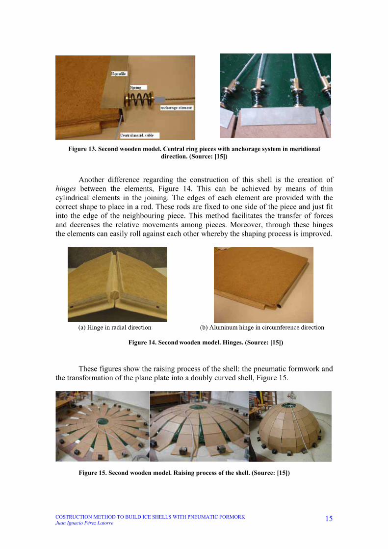
One difference to the small wooden model, are springs which are placed at the
ends of the tendons in the central ring, Figure 13. During the transformation process the interfaces between the elements open. In order to allow the elongation of the cables caused by the increase of the angle between the pieces, springs are placed on top of the central pieces. If the tendons need to increase their length to adopt the final semi spherical shape, the springs will shorten. Through these springs controlled stresses can be generated in the tendons.
COSTRUCTION METHOD TO BUILD ICE SHELLS WITH PNEUMATIC FORMORK Juan Ignacio Pérez Latorre
15
Figure 13. Second wooden model. Central ring pieces with anchorage system in meridional direction. (Source: [15])
Another difference regarding the construction of this shell is the creation of hinges between the elements, Figure 14. This can be achieved by means of thin cylindrical elements in the joining. The edges of each element are provided with the correct shape to place in a rod. These rods are fixed to one side of the piece and just fit into the edge of the neighbouring piece. This method facilitates the transfer of forces and decreases the relative movements among pieces. Moreover, through these hinges the elements can easily roll against each other whereby the shaping process is improved.
(a) Hinge in radial direction (b) Aluminum hinge in circumference direction
Figure 14. Second wooden model. Hinges. (Source: [15]) These figures show the raising process of the shell: the pneumatic formwork and
the transformation of the plane plate into a doubly curved shell, Figure 15.
Figure 15. Second wooden model. Raising process of the shell. (Source: [15])

COSTRUCTION METHOD TO BUILD ICE SHELLS WITH PNEUMATIC FORMORK Juan Ignacio Pérez Latorre
16
1.3.2. CONCRETE SHELL In one field experiment a hemispherical concrete shell with a diameter of 8,4 m was created. This concrete shell consisted of 96 precast concrete parts with a thickness of 5mm. Sixteen of these 96 elements have the same dimension whereby only six different formworks for the production of the elements are required (see Figure 16). Each of these precast elements contains ducts, so that the tendons can be pulled through afterwards. On site, the precast parts are positioned on the not yet inflated formwork and assembled with tendons (see Figure 16). Hence a concrete plate with a diameter of 13m is created.
Figure 16. Precast Concrete Elements. (Source : [14])
Figure 17 shows the pneumatic formwork which was used for the experiment. It is made of glued PVC membranes forming a hemisphere. To find the optimal shape of the pneumatic formwork the used PVC membrane was tested. Through experiments the modulus of elasticity as well as the poison’s ratio was determined. With this knowledge the stretching of the fabric under load could be taken into account and the shape of the hemisphere adjusted accordingly.
Figure 17. Pneumatic formwork. (Source: [14])

COSTRUCTION METHOD TO BUILD ICE SHELLS WITH PNEUMATIC FORMORK Juan Ignacio Pérez Latorre
17
The pictures in figure 18 show how the pneumatic formwork was only inflated with air, therefore the elements lifted and the plane plate was transformed into a hemispherical shell. The maximum required internal air pressure amounted to 37mbar.
Figure 18. Erection Process of the Concrete Shell. (Source: [14])

COSTRUCTION METHOD TO BUILD ICE SHELLS WITH PNEUMATIC FORMORK Juan Ignacio Pérez Latorre
18
1.3.3. ICE SHELL First an ice shell in the laboratory of the Institute for Structural Engineering was built. A room was isolated and equipped with a cooling unit. The final shell had a diameter of 4,8 m and 0,9 m height, Figure 19. In this case a previous method was used, Styrofoam segments where placed between the ice segments. All the shell was surrounded with an unbounded tendon marked in red [7].
A flat ice plate with 32 Styrofoam segments was produced, Figure 19a. The circle in the plan was approximated by a polygonal line with 31 straight parts and a concrete anchor block for the post tensioning tendons. Along the circumference scaffolding had to be provided in order to form the boundary of the ice shell with a thickness of 40 mm, Figure 19b. Along the edge of the ice plate an unbounded tendon was placed and two stressing anchorages were provided at the anchor block. Figure 19c shows a section through the ice shell which was obtained by stressing the tendon. During the transformation from the flat plane to shell the diameter was reduced from 5,2 m to 4,8 m.
Figure 19. (a) Plan view of the ice plate, (b) Section of the ice plate, (c) Section of the ice shell,
(d) Detail D. (Source: [7]) This construction method is only applicable if large strains in the ring direction can occur during the forming process. The detail of Figure 19d (showing a part of the flat plate), indicates the different properties in the ring and meridian directions. In the meridian direction struts consisted of ice, while in the ring direction the stiffness properties are governed by the elastic-plastic behaviour of the Styrofoam segments.

COSTRUCTION METHOD TO BUILD ICE SHELLS WITH PNEUMATIC FORMORK Juan Ignacio Pérez Latorre
19
During the shaping process the Styrofoam segments were compressed from 57 mm to 17mm at the circumference. The shape of the Styrofoam segments was determined by hand calculations in such a way that during the forming process a reduction of the segment width to 30 % of the original width would produce the intended shape of a dome with 0,9m sag. During the transformation of the plate into the shell the radius of curvature was decreasing from an infinite radius for the plate to a radius of 3,75 m for the final shape. This radius of curvature had to be equivalent to the thickness of the shell divided by the sum of the absolute values of the strains at the top and bottom surface. For a given thickness of 40 mm and a radius of 3,75 m the sum of these strains had to be around 1 %. Since the ultimate tensile strength of ice is smaller than the compressive strength, cracking occurred during the shaping process. The cracks in the ice can be seen as well as the fibre glass mesh which was used a reinforcement in order to obtain many distributed cracks with small crack widths, Figure 20.
Figure 20. Completed ice shell in laboratory. (Source: [7]) In the laboratory experiment the centre of the plate was lifted by about 15 mm with the aid of an air jack placed underneath the plate. Then the tendon was stressed simultaneously at both anchorages up to a force of 50 kN. At this force level a buckling of the plate into a neighbouring stable equilibrium position occurred. During the buckling of the plate the in-plane stresses of the plate were reduced from 0,5 N/mm2 to much smaller values and the tendon force dropped to 15 kN. The centre rise after buckling was about 0,25 m. Further stressing of the tendon resulted in a reduction of the circumference and a rise of the centre of the shell. When the final sag of 0,9 m was reached in the tendon was locked at the anchorages.

COSTRUCTION METHOD TO BUILD ICE SHELLS WITH PNEUMATIC FORMORK Juan Ignacio Pérez Latorre
20
Stresses in the shell during the shaping process remain small. Meridian stresses can be readily calculated from equilibrium equations and hoop stresses in the ring direction are governed by the yield level of the Styrofoam material. The largest stresses occur during the buckling process. After the completion of the shaping process the meridian stresses are only in the range of 0,1 N/mm2. The shaping process can therefore be considered as a proof loading of the shell [7].
Figure 21. Raising process of the ice shell. (Source: [7])
With this method in December 2005 the Institute for Structural Engineering at
Vienna University of Technology, constructed an ice dome with a diameter of 13m originating from one flat plate, Figure 22.
Figure 22. Ice dome built in December 2005.
In winter 2008/2009 this new ice shell construction method was tested in field experiments which took place in Obergurgl, a village in the Alps in Tyrol, Austria, situated almost 2000 meter above sea level.
Figure 23. Austria map, Obergurgl location. (Source: azerb.com)

COSTRUCTION METHOD TO BUILD ICE SHELLS WITH PNEUMATIC FORMORK Juan Ignacio Pérez Latorre
21
Two experiments, a large ice shell and a small ice shell, were carried out. In both cases the process was the same. First the pneumatic formwork was placed on the plane working surface. Then a frame was situated alongside the circumference of the circular plate. Afterwards water, which froze to ice, was sprayed inside the frame. So a circular plate of ice was generated.
After the hardening of the ice, those parts of the ice which were superfluous for the transformation into a shell were removed, Figure 24. Through the removal of the superfluous material, interfaces in radial direction were created. Also the ducts were created cutting the paths, placing the ducts and filling the gaps, to ensure the ducts, with water again.
The interfaces in circumference direction were produced by cutting into the ice. These cuttings were predetermined breaking points. Therefore the ice broke along these cuts during the transformation process.
Then the cable winches were anchored in the right place and direction in the special elements.
Figure 24. Circular plate of ice formation, cutting the elements. (Source: [16])
The pneumatic formwork raised the elements to form the shell, Figure 25. When
the final shape was obtained the tendons were tight and the cable winches were removed. Also a door was built removing three elements near the base, Figure 26.
Figure 25. Raising process in the small ice shell. (Source: [16])

COSTRUCTION METHOD TO BUILD ICE SHELLS WITH PNEUMATIC FORMORK Juan Ignacio Pérez Latorre
22
Figure 26. Door built in the small ice shell. (Source: [16])
In the big ice shell, the last ring of the structure did not rise properly due to the fracture in the wood frame in the central ring. This was probably caused because the frame was formed in December 2008 but there was not enough cold to continue with the experiment, so the rest of the process was made in January 2009. In this long period the wood frame got damage with the humidity from the snow falls during Christmas time.
Other way for creating the ducts, where the cables are placed, can be tested in the future. The frame is situated alongside the circumference of the circular plate. First a layer of water is sprayed inside the frame. When it freezes into ice the conducts are placed in the right position over the ice layer previously created. Then a second layer of water is sprayed inside the frame. After the hardening of the ice, those parts of the ice which are superfluous for the transformation into a shell will be removed [16].
Figure 27. Circular plate formation in the big ice shell. (Source: [16])
Figure 28. Raising process in the big ice shell. (Source: [16])

COSTRUCTION METHOD TO BUILD ICE SHELLS WITH PNEUMATIC FORMORK Juan Ignacio Pérez Latorre
23
2. PRELIMINARY EXPERIMENTS
COSTRUCTION METHOD TO BUILD ICE SHELLS WITH PNEUMATIC FORMORK Juan Ignacio Pérez Latorre
24
2.1. EXPERIMENT SET UP In order to study the ice behaviour, three experiments were developed at the
Institute for Structural Engineering between October and December 2009. The object of study was to study the deformation of ice when it transforms from a plane into a curved element using a pneumatic formwork.
In the experiments we built ice beams supported in two points in order to study
the deformation caused by its own weight. Moreover we used tendons to increase the tensile strength. All of these parameters were changes in the experiments.
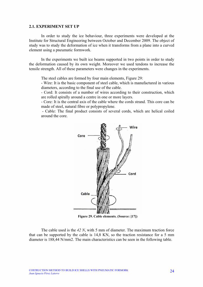
The steel cables are formed by four main elements, Figure 29: - Wire: It is the basic component of steel cable, which is manufactured in various diameters, according to the final use of the cable. - Cord: It consists of a number of wires according to their construction, which are rolled spirally around a centre in one or more layers. - Core: It is the central axis of the cable where the cords strand. This core can be made of steel, natural fibre or polypropylene. - Cable: The final product consists of several cords, which are helical coiled around the core.
Figure 29. Cable elements. (Source: [17])
The cable used is the 42 N, with 5 mm of diameter. The maximum traction force
that can be supported by the cable is 14,8 KN, so the traction resistance for a 5 mm diameter is 188,44 N/mm2. The main characteristics can be seen in the following table.

COSTRUCTION METHOD TO BUILD ICE SHELLS WITH PNEUMATIC FORMORK Juan Ignacio Pérez Latorre
25
Table 1. Cable selection. Teufelberger, Catalogue Stahl- und Faserseile. (Source: [17])
Anchorage elements, cable closure and rope clip, were used in order to ensure that the maximum traction force fulfils the requirements needed. The elements chosen from Seilerei Wüstner catalogue, company specialized in cables anchorage systems [18], Figure 30.
Figure 30. Anchorage element: cable closure. Seilerei Wüstner. (Source: [18])
As can be seen in Table 2, the maximum axial force supported by the element is 70% of the force supported by the steel cable. As can be seen in Table 1, the maximum traction force that can support the cable is of 14,8KN. So the maximum axial force supported by the element is 13,16KN.

COSTRUCTION METHOD TO BUILD ICE SHELLS WITH PNEUMATIC FORMORK Juan Ignacio Pérez Latorre
26
Table 2. Cable closure geometrical parameters. (Source: [18])
The chosen pneumatic formwork supports 3 tons and normally is used to lift vehicles with the exhaust pipe but we entrusted it to a compressor.
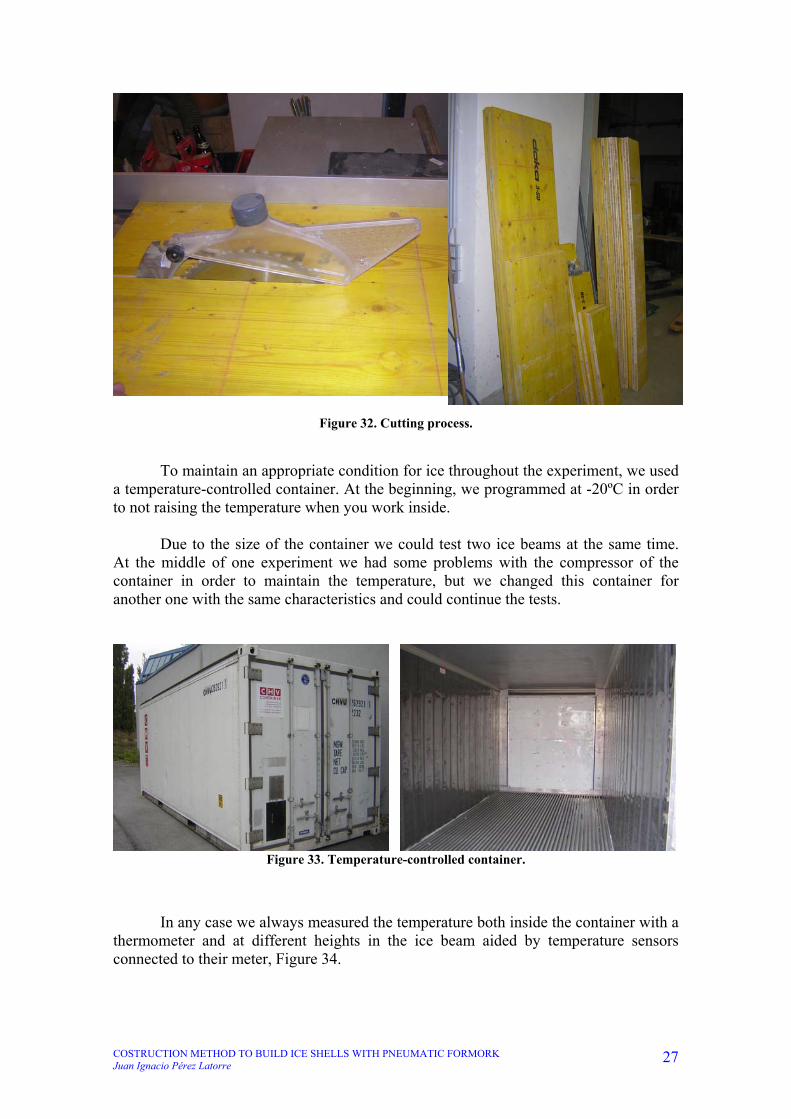
Figure 31. Compressor and pneumatic formwork used. In order to make ice beams without loosing the water, we built an external wooden box with a plastic inside. The wood chosen was an excellent sandwich plate of the company Doka, Figure 32. We prepared all in the laboratory of the Institute for Structural Engineering before move to the site with all means and tools we needed.
COSTRUCTION METHOD TO BUILD ICE SHELLS WITH PNEUMATIC FORMORK Juan Ignacio Pérez Latorre
27
Figure 32. Cutting process.
To maintain an appropriate condition for ice throughout the experiment, we used a temperature-controlled container. At the beginning, we programmed at -20ºC in order to not raising the temperature when you work inside. Due to the size of the container we could test two ice beams at the same time. At the middle of one experiment we had some problems with the compressor of the container in order to maintain the temperature, but we changed this container for another one with the same characteristics and could continue the tests.
Figure 33. Temperature-controlled container.
In any case we always measured the temperature both inside the container with a thermometer and at different heights in the ice beam aided by temperature sensors connected to their meter, Figure 34.

COSTRUCTION METHOD TO BUILD ICE SHELLS WITH PNEUMATIC FORMORK Juan Ignacio Pérez Latorre
28
Figure 34. Thermometer and temperature sensors with their meter.
The first experiment consisted in two ice beams with one and three tendons respectively. We built a wooden box and put three bags of pneumatic formwork in the middle before making the ice. In the rest of the bottom we put a Styrofoam plate in order to create a uniform base of the ice beam, Figure 35.
Figure 35. First wooden box built. Before making ice we put some screws at the end of the beams to join the ice and the extreme wooden plate. Besides in all experiments we made the ice step by step, placing thin layers of water each time to obtain excellent ice properties, Figure 36.

COSTRUCTION METHOD TO BUILD ICE SHELLS WITH PNEUMATIC FORMORK Juan Ignacio Pérez Latorre
29
Figure 36. Screws at the end and the first thin layer of water.
In order to increase the maximum bearable bending moment we put the tendons
almost at the top. Later we found out that better results could be achieved by pulling the tendons in the middle of the cross-section to ensure better interaction between ice and steel and to decrease the statically effective cross-section in order to increase the deformation.
We marked eleven points at the top with a green spray and put a blue rope as
height reference. This rope helped us to measure the distance between the reference and each point in order to calculate the deformation, Figure 37.
Figure 37. Detail of the tendons at the top and reference rope. All was ready to lift both beams but something catastrophic happened. At the beginning we saw a lot of cracks but we thought that all was good and then the tendons were separated from the ice beam so traction force was supported only by the ice. Moreover we saw that lift only in the middle of the beam was not a good idea because the one steel tendon beam broke in this point about the high tension supported, Figure 38. All our mistakes helped us to learn for the next experiment. So in this first experiment could not take any measures of deformation.

COSTRUCTION METHOD TO BUILD ICE SHELLS WITH PNEUMATIC FORMORK Juan Ignacio Pérez Latorre
30
Figure 38. First lift process.
In the second experiment we built two ice beams with the same dimensions but with two and four tendons respectively. The construction method was the same; we put again the screws at the end of the beams and made ice step by step in thin plates of ice. In this case we put the pneumatic formwork in pairs not in the middle of the beams, Figure 39.
Figure 39. Second disposition of experiment.
We put the tendons in the middle height of the beams and marked the points at the top in order to measure the deformation. Again we could take the temperature of ice at the bottom and top of each beam thanks to temperature sensors, Figure 40.

COSTRUCTION METHOD TO BUILD ICE SHELLS WITH PNEUMATIC FORMORK Juan Ignacio Pérez Latorre
31
Figure 40. Ice beams ready to lift.
In lifting process we controlled slowly the air compressor and put wooden supports under the ice beams, Figure 40. Moreover we removed the wooden box to work the ice alone in his deformation. The measures taken following days helped us to obtain results.
Figure 41. Wooden supports. As time passed and deformation increased, the voids and cracks grew larger. The pictures show the large amount of ice cracks in its changes of curvature. The most important and the distances between supports are shown in the following figures. Moreover in the last picture you can see a detail of the thin ice plate that we get in the process, Figure 44.

COSTRUCTION METHOD TO BUILD ICE SHELLS WITH PNEUMATIC FORMORK Juan Ignacio Pérez Latorre
32
Figure 42. Representation of the four tendons beam.
Figure 43. Representation of the two tendons beam.
Figure 44. Some cracks and detail of ice beams.
Figure 45. Final curvature in second experiment.

COSTRUCTION METHOD TO BUILD ICE SHELLS WITH PNEUMATIC FORMORK Juan Ignacio Pérez Latorre
33
In the third experiment we built two ice beams with three tendons both because the results at last experiment tell that was the best way. The construction process was the same but we put a different disposition of the pneumatic formwork. We placed one in the middle of each beam and a pair besides their leaving enough space to hold the wooden supports, Figure 46.
Figure 46. Disposition in last experiment.
At the top of each ice beam we cut 15 slices with a chainsaw. The depth of this
cracks were between 5 and 7 cm. That was the main reason of the huge curvature experienced by the ice in comparison with other experiments. This last experiment was most similar to the ice shell which would be built days later in Obergurgl.
Figure 47. Ice beams after put the tendons in the middle height.

COSTRUCTION METHOD TO BUILD ICE SHELLS WITH PNEUMATIC FORMORK Juan Ignacio Pérez Latorre
34
When we lift the beams we had a big problem with one of them because it broke into two pieces. The problem was due to poor control of air pressure when the ice beam was lifted but it was not resting on its wooden supports.
Figure 48. Curvature in the last experiment.

COSTRUCTION METHOD TO BUILD ICE SHELLS WITH PNEUMATIC FORMORK Juan Ignacio Pérez Latorre
35
2.2. RESULTS The procedure for measuring to obtain results was always the same. We put a blue rope at a certain height in order to have a reference and subtract the distances between each point that was falling and the reference. The following graphic reflects the final increased length suffered by each of the eleven points marked on the ice beams along its length, Graphic 1.
-2
0
2
4
6
8
10
12
14
1 2 3 4 5 6 7 8 9 10 11
Marked points
ΔL
(cm
)
4 tendons
2 tendons
3 tendons
Graphic 1. Final increased length.
As we can see the deformation suffered by the 3 tendons ice beam is much greater than others thanks to the cuts made with the chainsaw.
Another graph of interest is the increased length over time suffered by ice beams
at the ends, Point 1 (graphic 2) and Point 11 (graphic 11) in each case.
0
24
6
8
1012
14
16
0 2000 4000 6000 8000 10000
Time (min)
ΔL
(cm
)
4 tendons
2 tendons
3 tendons
Graphic 2. Increased length of point 1.

COSTRUCTION METHOD TO BUILD ICE SHELLS WITH PNEUMATIC FORMORK Juan Ignacio Pérez Latorre
36
0
24
6
8
1012
14
16
0 2000 4000 6000 8000 10000
Time (min)
ΔL
(cm
)
4 tendons
2 tendons
3 tendons
Graphic 3. Increased length of point 11.
In the initial stage, or primary creep, the strain rate is relatively high, but slows with increasing strain. This is due to work hardening. The strain rate eventually reaches a minimum and becomes near constant. This is due to the balance between work hardening and annealing (thermal softening). This stage is known as secondary or steady-state creep. This stage is the most understood. The characterized “creep strain rate” typically refers to the rate in this secondary stage. Stress dependence of this rate depends on the creep mechanism. In tertiary creep, the strain rate exponentially increases with strain because of necking phenomena, Figure 49.
Figure 49. Stages of creep. (Source: www.lessig.org)
In two and four tendons ice beams, we stopped the measures in the secondary
stage, but in the three tendons ice beams we can see the beginning of the tertiary stage because we take measures along more time.
Point 11 started the primary creep later due at the beginning the ice beam was
supported by ice in the bottom. When we saw that, we broke the ice bottom and the ice beam started its deformation in that point. Moreover we could not take more measures in the last experiments because the end of ice beam was on the ground.

COSTRUCTION METHOD TO BUILD ICE SHELLS WITH PNEUMATIC FORMORK Juan Ignacio Pérez Latorre
37
Depending on the supports position, the moment diagram is different for each case, Graphic 4.
0
500
1000
1500
2000
2500
0 1 2 3 4 5 6
x (m)
Mo
me
nt
(N*m
)
4 tendons
2 tendons
3 tendons
Graphic 4. Moment diagram.
The maximum moment value is from the 4 tendons ice beam because it had the largest length between the support and the end of the beam. Moreover the 2 tendons ice beam has a different maximum moment values because one support was near one end of the ice beam (130 cm) and the other further away than the other end (200 cm). The best moment distribution belongs to 3 tendons ice beam due to the distance between supports and the distance between each support and the end of the beam. This gives us an idea of how important it would be the support and interaction between the pneumatic formwork and ice few days later in Obergurgl (Austria).
COSTRUCTION METHOD TO BUILD ICE SHELLS WITH PNEUMATIC FORMORK Juan Ignacio Pérez Latorre
38
3. NEW SHELL METHOD CONSTRUCTION METHOD

COSTRUCTION METHOD TO BUILD ICE SHELLS WITH PNEUMATIC FORMORK Juan Ignacio Pérez Latorre
39
3.1. GENERAL IDEA In the winter season 2009/2010 we wanted to build an ice cupola, which was intended to be used as an ice bar in Obergurgl, Tyrol (Austria). The ice cupola would be assembled by means of a newly developed construction method that had never been used before. The key element of this method was distorting individual ice segments of the shell which were subsequently lifted into their final position. In the first step, plane elements made of ice were produced, as illustrated in figure 50. In order to obtain such elements, an ice plate was made by spraying water on a previously levelled and sealed working surface. Afterwards superfluous parts of the ice, which were unnecessary for the development of the shell, were removed.
Figure 50. Plane Ice Elements.
In the next step, the elements were distorted uniaxially – this curvature was being produced both by elastic deformation and creep deformation. These deformations generated tensile forces; therefore steel ropes had been placed inside the ice elements during their production. In order to distort the ice elements the middle part of the segments was lifted with the help of a pneumatic formwork that had to be under the ice elements before making the ice plate. Through the pneumatic formwork the end parts of every element were bent down. By maintaining this condition creep deformations were added to these instant deformations caused by dead load. Eventually, this distorted state was fastened with temporary tension chains. After the distortion the elements would be lifted and assembled to form a shell. In order to carry out the lifting process a timber tower with a lifting device was built. In figure 51 the distorted ice elements as well as the mounting tower can be seen.

COSTRUCTION METHOD TO BUILD ICE SHELLS WITH PNEUMATIC FORMORK Juan Ignacio Pérez Latorre
40
Figure 51. Distorted Ice Elements.
After placing the timber tower the ice elements would be lifted individually. Figure 52 shows the elements in their final position. In the next step the gaps between the elements would be filled with snow and water. Additionally, a tension cable carrying the horizontal forces was attached. Thus, these individual elements would constitute a shell structure and at this stage the mounting tower and the temporary tension chains could be removed. The finished ice shell would have a diameter of about 10 m and a height of 3,8 m. After creating an entrance for the ice cupola, the ice bar would be ready to be opened.
Figure 52. Lifted Ice Elements.

COSTRUCTION METHOD TO BUILD ICE SHELLS WITH PNEUMATIC FORMORK Juan Ignacio Pérez Latorre
41
3.2. DESIGN OF ICE SHELL Unlike other lift methods developed by Institute for Structural Engineering explained above, we designed a new pneumatic formwork. In order to not need a high air pressure, we wanted to decrease the radius of the pneumatic formwork as much as possible, Figure 53.
Figure 53. Real cross-section of the pneumatic formwork (Measures in cm).
We designed 16 PVC pieces in order to build the pneumatic formwork. At the end of each piece we put 10 cm in order to join the pieces. We can see the design of PVC pieces in figure 54.
Figure 54. PVC piece of the pneumatic formwork.
In order to design the 16 ice pieces we made a 3-Dimension model (Figure 55) and then we calculated the measures of each plane ice piece (Figure 56).

COSTRUCTION METHOD TO BUILD ICE SHELLS WITH PNEUMATIC FORMORK Juan Ignacio Pérez Latorre
42
Figure 55. 3-Dimension ice piece model.
Figure 56. Plane ice piece. We designed a wooden tower with a sliding platform at the top to lift each ice curved pieces, Figure 58. In the platform would be a chain pull system to lift two faced ice pieces every step. Figure 57 shows a complete view of the pull system, the wooden tower and two ice curved pieces.

COSTRUCTION METHOD TO BUILD ICE SHELLS WITH PNEUMATIC FORMORK Juan Ignacio Pérez Latorre
43
Figure 57. General view.

COSTRUCTION METHOD TO BUILD ICE SHELLS WITH PNEUMATIC FORMORK Juan Ignacio Pérez Latorre
44
Figure 58. First wooden tower design.
Moreover we compared the design of ice elements with the ice beams built at the container. The elements of the ice shell did not have a constant width so we put 8 steel tendons at the wide end of each element, 6 tendons at the middle and 4 tendons at the other end.
0,00
0,20
0,40
0,60
0,80
1,00
1,20
1,40
1,60
0,0 1,0 2,0 3,0 4,0 5,0 6,0
Length (m)
Rei
nfo
rcem
ent/
Wid
th (
cm²/
m)
Ice Shell in Obergurgl 2 Tendons/55cm 4 Tendons/55cm 3 Tendons/55cm
Graphic 5. Reinforcement/Width.

COSTRUCTION METHOD TO BUILD ICE SHELLS WITH PNEUMATIC FORMORK Juan Ignacio Pérez Latorre
45
As we can see in the previous graphic the behaviour of the ice elements in Obergurgl would be between the two tendons ice beam and the 3 tendons ice beam in most parts of the ice elements. The high reinforcement near the centre until the first meter is due to the thin width of the ice elements. These reinforcements would help us to lift the elements by the chains safely as well as carrying the tensile forces during the creeping process. The finite elements analysis program RFEM 4 was used to manage numerical calculations. RFEM 4 represents the program using 3D Finite Element Analysis (FEA) that meets the requirements of modern civil engineering. It is used as the basic program to determine internal forces, deformations, support reactions and stresses of plates, shells, solids, frameworks or composite structures.
RFEM is especially suitable for concrete, timber and steel structures, but can be applied for ice due is similar like concrete about their properties. For the design of different structural elements, adequate add-on modules are available. There, specific features of the materials and codes are considered. Also dimensioning and other special analyses (stability, dynamics, etc.) are carried out in the modules.
It is only necessary to study the points which belong to one meridian due to all points situated in the same ring shell will have the same properties, forces, stresses and displacements. The main points taken into account in our study are the edges of the planar elements. In these points the resultant forces and the stresses are calculated analytically and with finite element analysis. The main physical properties of the ice shell are exposed in the following Table 3.
Properties Ice Density [Kg/m3] 916,7 Poisson's ratio 0,33
Young's modulus [N/mm2] 400 Shell Thickness [m] 0,2
Radius [m] 4,2 Table 3. Physical properties.
For the analytical analysis some symbols are used in this section [19]. Dimensional parameters θ [ ] Meridional angle φ [ ] Perimetrical angle r [L] Radius s [L] Ordinate length of the meridians t [L] Shell thickness

COSTRUCTION METHOD TO BUILD ICE SHELLS WITH PNEUMATIC FORMORK Juan Ignacio Pérez Latorre
46
Figure 59. Dimensional parameters [19].
Deformations u [L] Translational displacement in x-direction w [L] Translational displacement in z-direction w [L] Translational displacement perpendicular to shell axis χ [ ] Elongation of the meridian tangent E [K/L2] Modulus of elasticity μ [ ] Poisson´s ratio
42
2213
t
rx Dimensionless shell parameter
Figure 60. Deformations [19].

COSTRUCTION METHOD TO BUILD ICE SHELLS WITH PNEUMATIC FORMORK Juan Ignacio Pérez Latorre
47
Load types, load components and stresses resultants pE [K/L2] Self-weight of the shell per unit of middle surface pS [K/L2] Snow pressure per unit of middle surface px [K/L2] py [K/L2] Surface load components pz [K/L2] Nθ [K/L] Normal forces Nφ [K/L] T [L/L] Tangential force Mθ [KL/L] Moments Mφ [KL/L] Q [K/L] Shear force
Figure 61. Load components and resultant forces [19].
To calculate the stresses in all load cases the following formulas are used:
I
zM
A
N
I
zM
A
N
In our load cases the structure won’t suffer moments and the stress calculated is
per unit length (being t the shell thickness), so the formulas are reduced to the following:
t
N [N/m2]
t
N [N/m2]
Figure 62. Shell element with local axis.

COSTRUCTION METHOD TO BUILD ICE SHELLS WITH PNEUMATIC FORMORK Juan Ignacio Pérez Latorre
48
In self weight case, the normal forces can be obtained with the following formulas:
20
sin
coscos rpN E [N/m]
cossin
coscos2
0rpN E [N/m]
T = 0
mtkg
Ng
m
kgpE
3 [N/m2]
ρ [kg/m3] Material density g = 9.8 m/s2 Gravity px = pE sinθ pz = pE cosθ
Figure 63. Forces caused by a distributed load over the shell [19].
Using the formulas in five shell points we obtain the following results for forces and stresses, Table 2. Shell point θ [º] θ [rad] Nθ [N/m] Nφ [N/m] σθ [N/m2] σφ [N/m2]
1 6,95 0,12 0,00 -6741,71 0,00 -37453,94 2 22,50 0,39 -3189,19 -3085,47 -17717,73 -17141,50 3 45,00 0,79 -3878,58 -923,83 -21547,68 -5132,38 4 67,50 1,18 -4853,44 2254,40 -26963,53 12524,46
5 90,00 1,57 -6741,73 6741,76 -37454,08 37454,22 Table 4. Dead load analytical results.

COSTRUCTION METHOD TO BUILD ICE SHELLS WITH PNEUMATIC FORMORK Juan Ignacio Pérez Latorre
49
In RFEM4 the results at the beginning were not really similar as we see in the followings figures.
Figure 64. Shell meridional forces (Nθ, [N/m]). (Mesh 1).
Figure 65. Shell hoop forces (Nφ, [N/m]). (Mesh 1).
The difference between results was due to the mesh. In a second time we made a smaller mesh and the results would be similar like the analytical results as we can see.

COSTRUCTION METHOD TO BUILD ICE SHELLS WITH PNEUMATIC FORMORK Juan Ignacio Pérez Latorre
50
Figure 66. Shell meridional forces (Nθ, [N/m]). (Mesh 2).
Figure 67. Shell hoop forces (Nφ, [N/m]). (Mesh 2).
Nθ [KN/m]
Analytical Solution RFEM4 Solution. Mesh 1 RFEM4 Solution. Mesh 2
Max 0 -0,56 -0,02
Min -6,74 -6,28 -6,52 Table 5. Shell meridional forces.
Nφ [KN/m]
Analytical Solution RFEM4 Solution. Mesh 1 RFEM4 Solution. Mesh 2
Max 6,74 8,78 6,5
Min -6,74 -6,54 -6,73 Table 6. Shell hoop forces.

COSTRUCTION METHOD TO BUILD ICE SHELLS WITH PNEUMATIC FORMORK Juan Ignacio Pérez Latorre
51
3.3. CONSTRUCTION Before going to Obergurgl, we made the pneumatic formwork in the laboratory of the Institute in Vienna. We cut 16 PVC pieces designed previously and we joined all of them helped with glue cleaning with acetone before. This step was critical because the pneumatic formwork would support heigh weight later and small holes would be catastrophic days after.
Figure 68. Cutting process.
Figure 69. Gluing process.
In Obergurgl the first step was to make a level ice surface. The place provided by Hotel Alpina had a lot of snow at the beginning and we needed a tractor in order to take away the snow. When the surface was clean, we began to measure helped by a theodolite and we put water and snow where it was necessary as we can see in the following pictures.

COSTRUCTION METHOD TO BUILD ICE SHELLS WITH PNEUMATIC FORMORK Juan Ignacio Pérez Latorre
52
Figure 70. Making level surface.
The next step was marking the centre of the shell. That point would be our reference for every measure. Then we made the foundation of the wooden tower around the centre reference. The end of ice plate was marked by paint sprays and we started to make the ice base plate spraying water.
Figure 71. Surface of the tower and ice base plate.
Afterwards we put the pneumatic formwork protected by a plastic at the bottom surrounded by ropes that would be guides for the future chains. We put up a plastic with wood at the end in order to not let out the water and we joined the air pressure tubes with the pneumatic formwork.
Figure 72. Pneumatic formwork over ice base plate.

COSTRUCTION METHOD TO BUILD ICE SHELLS WITH PNEUMATIC FORMORK Juan Ignacio Pérez Latorre
53
Figure 73. Plastic at the bottom and air pressure tubes joined.
In the gaps between the future ice pieces, we put Styrofoam pieces in order to protect the pneumatic formwork. Afterwards we started to spray water bit by bit as in the Container experiments to obtain ice with good mechanic properties.
Figure 74. Styrofoam pieces.
The next step was to put the tendons at the middle of the ice plate designed previously. At the end of the ice plate we put the steel elements. Moreover we started to build the wooden tower. We continued spraying water until the final ice plate size.
Figure 75. Tendons at the middle of the ice plate.

COSTRUCTION METHOD TO BUILD ICE SHELLS WITH PNEUMATIC FORMORK Juan Ignacio Pérez Latorre
54
Figure 76. Detail at the end of the tendons.
Figure 77. Ice plate before Christmas.
After Christmas we started to cut the ice plate into the 16 designed ice pieces. We used a chainsaw carefully above the pneumatic formwork. We spent some days in that work because we needed to cut small ice pieces to take away between the ice elements about the height weigh. Moreover we continued the work at the top of the tower putting the supports chains.
Figure 78. Cutting ice plate process and detail of chains at the top of the tower.

COSTRUCTION METHOD TO BUILD ICE SHELLS WITH PNEUMATIC FORMORK Juan Ignacio Pérez Latorre
55
Afterwards we cut each ice piece in hoop direction with 5 cm of thickness as the last experiment at the Container, Figure 79. Moreover we ended the pull system at the top of the tower and we put the chains at the centre of ice pieces. The last step was made a stairs in the tower and a wooden bridge in order to take the deformation measures in creeping and to access to the tower. Then we were prepared to lift the ice elements with the pneumatic formwork.
Figure 79. Cuts in hoop direction.
Figure 80. Ending work in wooden tower and bridge.
Figure 81. Ice elements prepared to lift.

COSTRUCTION METHOD TO BUILD ICE SHELLS WITH PNEUMATIC FORMORK Juan Ignacio Pérez Latorre
56
3.4. CREEPING The air pressure system had two working ways. On the one hand we could select the air pressure in the display. On the other hand the compressor could work alone if the pneumatic formwork pressure decreased to atmospheric pressure helped by the Figure 82 system.
Figure 82. Air pressure system and compressors.
When we started to lift the ice elements we saw the first problem, the air
pressure tube did not work correctly in the connexion between the tube and the pneumatic formwork due to ice. We repaired that and we continued with the lift process.
Figure 83. Repairing connexion between tube and pneumatic formwork.
Then we had a catastrophic error, in lifting process ice elements were not properly supported by the pneumatic formwork. There was a large distance from the central end to the support surface therefore the moment was so high that some elements broke, Figure 84. We removed the air inside the pneumatic formwork and we repaired the broken elements mixing water and snow.

COSTRUCTION METHOD TO BUILD ICE SHELLS WITH PNEUMATIC FORMORK Juan Ignacio Pérez Latorre
57
Figure 84. Broken elements.
Figure 85. Repairing broken elements.
Figure 86. Repaired elements.
In the second time we increased the cuts of the ice until thickness around 10 cm in order to improve the interface between ice elements and pneumatic formwork and to decrease the moment in the central end. Moreover we increased the air pressure slowly. The procedure on subsequent days was always the same; we did 24-hour shifts per day to control the pressure inside the pneumatic formwork and to test the ice elements. We increased the air pressure step by step to bend the ice elements as we

COSTRUCTION METHOD TO BUILD ICE SHELLS WITH PNEUMATIC FORMORK Juan Ignacio Pérez Latorre
58
wanted. We were also taking deformation measures in the elements located near the bridge helped by the theodolite that we will study in the next section.
Figure 87. Creeping process.
Before lifting the ice elements, we joined the ends of each elements with chains helped by the ropes under the pneumatic formwork. We tightened the chains as much as possible and we filled the cuts with water. All was prepared to lift the ice elements and to create the ice shell.

COSTRUCTION METHOD TO BUILD ICE SHELLS WITH PNEUMATIC FORMORK Juan Ignacio Pérez Latorre
59
3.5. RESULTS OF THE MEASUREMENTS To take measurements of the height reached by each ice elements, we used a large wooden stick in order to measure the height of both ends. Then we calculate the mean, we can see the results in the following graphic.
Figure 88. Taking height measures.
Graphic 6. Height of the ice elements before lifting.
0
10
20
30
40
50
60
70
0 500 1000 1500 2000 2500 3000 3500 4000
Acumulate time (min)
Ave
rag
e h
eig
ht
(cm
)
Element 1 Element 2 Element 3 Element 4
Element 5 Element 6 Element 7 Element 8
Element 9 Element 10 Element 11 Element 12
Element 13 Element 14 Element 15 Element 16

COSTRUCTION METHOD TO BUILD ICE SHELLS WITH PNEUMATIC FORMORK Juan Ignacio Pérez Latorre
60
We take the measures the last days before lifting so at the beginning of the graphic, the height of each element was stable. The last increase of height is due to the day before lifting, we increased the air pressure inside the pneumatic formwork. Moreover we take height measures at different points along the two elements located near the bridge helped by the theodolite, the Element 1 was between Hotel Alpina and the bridge and the Element 16 between the bridge and the street. In this case we take the measures along few days more before lifting. In the following graphics we can see the rise of each element along the time.
0,0
5,0
10,0
15,0
20,0
25,0
30,0
35,0
40,0
45,0
50,0
0 10 20 30 40 50 60 70
Time (h)
Ris
e (c
m)
Graphic 7. Rise vs. Time of Element 1.
0,0
5,0
10,0
15,0
20,0
25,0
30,0
35,0
40,0
45,0
0 10 20 30 40 50 60 70
Time (h)
Ris
e (c
m)
Graphic 8. Rise vs. Time of Element 16.

COSTRUCTION METHOD TO BUILD ICE SHELLS WITH PNEUMATIC FORMORK Juan Ignacio Pérez Latorre
61
We can also study the rise of each element along its length from the centre of the ice shell until the outer end. After these results we decided it was time to start lifting.
0
10
20
30
40
50
60
0 100 200 300 400 500 600
Element 1 (cm)
Ris
e (
cm
)
Measure 1 Measure 2 Measure 3 Measure 4 Measure 5 Measure 6
Measure 7 Measure 8 Measure 9 Measure 10 Measure 11 Measure 12
Graphic 9. Rise vs. Length of Element 1.
-20
-10
0
10
20
30
40
50
0 100 200 300 400 500 600
Element 16 (cm)
Ris
e (
cm
)
Measure 1 Measure 2 Measure 3 Measure 4 Measure 5
Measure 6 Measure 7 Measure 8 Measure 9 Measure 10
Measure 11 Measure 12 Measure 13
Graphic 10. Rise vs. Length of Element 16.

COSTRUCTION METHOD TO BUILD ICE SHELLS WITH PNEUMATIC FORMORK Juan Ignacio Pérez Latorre
62
3.6. PROBLEMS AND SUGGESTION FOR FURTHER EXPERIMENTS The night before lifting a terrible accident happened, 12 of 16 elements were broken. It happened quickly and we had no time to react. Somewhere in the pneumatic formwork an air leak developed and the compressor had not enough power to support the ice elements. We can see the disaster in the following pictures.
Figure 89. Ice elements destroyed.
But the problem was not the air leak in the pneumatic formwork neither the inability of the power compressor. The problem was that the chains under the pneumatic formwork did not work rightly. The height of the ice elements and the pneumatic formwork upper the chains were so great that the chains were curved and were not enough strained. Therefore part of the problem was also the design. Besides the tensor system was not enough to strain the chains with our hands in this design, the tensor system was in a difficult and dangerous access under the ice elements as we can see in the following pictures.

COSTRUCTION METHOD TO BUILD ICE SHELLS WITH PNEUMATIC FORMORK Juan Ignacio Pérez Latorre
63
Figure 90. Tensor-chain system under the ice elements.
Figure 91. Chains under the pneumatic formwork.
For further experiments we would change the design with the pneumatic formwork and the chains due to it is not a good solution. Anyway in Obergurgl we should let down the air of the pneumatic formwork slowly and step by step in order that the chains working rightly. After the disaster we obtained good results to further experiments too. We lifted the whole elements helped by a crane-truck and we saw that the experiment will be possible hereafter.

COSTRUCTION METHOD TO BUILD ICE SHELLS WITH PNEUMATIC FORMORK Juan Ignacio Pérez Latorre
64
Figure 92. Lifting process.
Figure 93. Details at the ends of the ice elements.
Figure 94. Work team in Obergurgl.

COSTRUCTION METHOD TO BUILD ICE SHELLS WITH PNEUMATIC FORMORK Juan Ignacio Pérez Latorre
65
4. SUMMARY

COSTRUCTION METHOD TO BUILD ICE SHELLS WITH PNEUMATIC FORMORK Juan Ignacio Pérez Latorre
66
This thesis has presented a study into the new construction method to build ice shells with pneumatic formwork, developed at the Institute for Structural Engineering of the Vienna University of Technology.
Shells are natural, logical and functional load carrying systems. Additionally, for the load transfer of a uniformly distributed load, the shell structure is the perfect choice because mainly normal forces appear in the cross section.
Although shell structures possess excellent load carrying system and make a
great visual impact, only few shells have been built in the last decades. The main problem is the difficult, time-consuming and expensive production. Traditionally, shells are produced by means of complex formwork. Creating such formwork increases the construction time and affords additional material which cannot be reused after the shell has been completed.
Ice as a construction material is either used as a decorative material on a
supporting structure or it is applied in structures with very low stress states due to self weight and wind forces. Ice shells can be used in temporary architecture, as roof structures for sport and music events, or presentations and promotions of sale products. Moreover the translucent nature of ice, allows several possibilities to make attractive this structure. For instance the internal illumination of the ice shell during the night creates a luminous atmosphere in the surroundings.
The new construction method consists of transforming an ice plate into an ice
shell by means of a pneumatic formwork. The ice elements, with steel tendons inside, are cut form an initial ice plate. While air is inflating the pneumatic formwork the elements creep. When the pneumatic formwork is removed chains support the stress of each element. Afterwards a pull-chain system is used to lift the elements from the top of a wooden tower built at the centre. The elements are linked and we retire the tower and the chains, the ice shell is finished.
Before building the ice shell in Obergurgl, Tyrol (Austria) we tested different
experiments making ice beams in a temperature-controlled container in Vienna. Moreover we used finite element software, RFEM4, to study and to compare the load configuration with the analytical solution.
In Obergurgl the ice elements were creeping but we could not lift the elements
into an ice shell. The night before lifting the pneumatic formwork had an air leak and the most of the elements were broken. But the problem was that the chains under the pneumatic formwork did not work rightly so the chains did not support the stress of the ice elements.
Therefore the problem was the design. For further experiments we would change
the design with the pneumatic formwork and the chains due to it is not a good solution. As many engineering experiments at this time did not end well but these construction method is in development and it has real possibilities nowadays in the market. Moreover with the work team at the Institute for Structural Engineering of the Vienna University of Technology they can get substantial progress in the construction field.

COSTRUCTION METHOD TO BUILD ICE SHELLS WITH PNEUMATIC FORMORK Juan Ignacio Pérez Latorre
67
REFERENCES [1] Billington DP. Thin Shell Concrete Structures. McGraw-Hill Book Company,
1965. [2] Lite Strabo Blog. Domes. January 2009.
http://litestraboen.blogspot.com/2007/01/domes.html
[3] Encyclopaedia Encarta UK. January 2009. Article. Domes: Introduction; Origins; Renaissance, Baroque, and Neo-Classical Domes; 20th-Century Domes. http://uk.encarta.msn.com/encyclopedia_761555109/Dome.html
[4] Building the roman Pantheon. January 2009. http://www.angelfire.com/super/tyvernon
[5] Lite Strabo Blog. Domes. January 2009.
http://litestraboen.blogspot.com/2007/01/domes.html [6] Building Big Bridges, Domes, Skyscrapers, Dams, and Tunnels. January 2009.
http://www.pbs.org/wgbh/buildingbig/dome/index.html [7] Ice Shells for Temporary Event Architecture. Johann Kollegger, Prof., Clemens
Preisinger, Eng., Michael Kaulfus, Eng., Vienna University of Technology, Vienna, Austria. April 2004.
[8] Schwarz, C., Drexler, T. Temporäre Eventarchitektur mit vorgespannten
Schalen aus Eis – Glasfasergewebeverbund. Master Thesis, Vienna University of Technology, 2004.
[9] Ramm, E., Schunk, E. Heinz Isler Schalen. Karl Krärner Verlag, Stuttgart, 1986. [10] Goto Kokawa Ice domes. www.htokai.ac.jp/DA/kkw/indexe.html. February
2009. [11] E. Ramm and E. Schunck, editors, Heinz Isler: Schalen. Vdf Hochschulverlag
AG an der ETH Zürich, 2002. [12] F. Otto, Pneu and bone, Institute for Lightweight Structures, University of
Stuttgart, 1995. [13] S. Krispel and J. Kollegger, Bau einer Stahlbetonschale ohne Schalung. Beton –
Zement 2006, 2:24-29. [14] Thin Post-Tensioned Concrete Shell Structures: Connection and Construction
Technology. Sonja Dallinger. 7th fib International PhD Symposium in Civil Engineering in Stuttgart, Germany. Institute for Structural Engineering, Vienna University of Technology, Vienna, Austria. September 2008.

COSTRUCTION METHOD TO BUILD ICE SHELLS WITH PNEUMATIC FORMORK Juan Ignacio Pérez Latorre
68
[15] Joining of spatially curved surfaces from thin-walled prefabricated elements. Master´s Thesis Diplomarbeit. Patricia Fernández Alloza. Institute for Structural Engineering, Vienna University of Technology, Vienna, Austria. July 2008.
[16] Technology to build double curved shells from plane elements. Master´s Thesis
Diplomarbeit. Rocio Martin-Oar Luca de Tena. Institute for Structural Engineering, Vienna University of Technology, Vienna, Austria. March 2009.
[17] Teufelberger. Catalogue Stahl- und Faserseile. January 2009.
www.teufelberger.com. [18] Seilerei Wüstner. Catalogue anchorage elements. January 2009. www.seil.at. [19] Elementare Schalenstatik. Alf Pflüger. Berlin, Heidelberg, New York: Springer
1981.

COSTRUCTION METHOD TO BUILD ICE SHELLS WITH PNEUMATIC FORMORK Juan Ignacio Pérez Latorre
69
LIST OF FIGURES Figure 1. Treasury of Atreus, Mycenae, Greece. (Source: greatbuildings.com)………...6 Figure 2. Pantheon of Hadrianus, Rome. (Source: greatbuildings.com and myself)……6 Figure 3. Hagia Sophia, Istambul. (Source: greatbuildings.com and myself)…………...7 Figure 4. Florence Cathedral (Source: myself)………………………………………….8 Figure 5. United States Capitol, Washington. (Source: greatbuildings.com)…………....8 Figure 6. Taj Mahal, Agra, India. (Source: greatbuildings.com)…………………..……9 Figure 7. Kokawa’s ice dome. (Source: [10])………………………………………….11 Figure 8. Transforming a plate into a shell (Source: [14])……………………………..11 Figure 9. Shell structure inspired by nature. (Source: [14])……………………………12 Figure 10. Plan View. (Source: [14])…………………………………………………..13 Figure 11. First wooden model. Anchorage system in the central ring. (Source: [15])..14 Figure 12. First wooden model. Raising process of the shell. (Source: [15])………….14 Figure 13. Second wooden model. Central ring pieces with anchorage system in meridional direction. (Source:[15])………………………………………… 15 Figure 14. Second wooden model. Hinges. (Source: [15])…………………………….15 Figure 15. Second wooden model. Raising process of the shell. (Source: [15])……….15 Figure 16. Precast Concrete Elements. (Source : [14])………………………………...16 Figure 17. Pneumatic formwork. (Source: [14])……………………………………….16 Figure 18. Erection Process of the Concrete Shell. (Source: [14])……………………..17 Figure 19. (a) Plan view of the ice plate, (b) Section of the ice plate, (c) Section of the ice shell, (d) Detail D. (Source: [7])………………………………...18 Figure 20. Completed ice shell in laboratory. (Source: [7])……………………………19 Figure 21. Raising process of the ice shell. (Source: [7])………………………………20 Figure 22. Ice dome built in December 2005…………………………………………..20 Figure 23. Austria map, Obergurgl location. (Source: azerb.com)…………………….20 Figure 24. Circular plate of ice formation, cutting the elements. (Source: [16])………21 Figure 25. Raising process in the small ice shell. (Source: [16])………………………21 Figure 26. Door built in the small ice shell. (Source: [16])…………………………….22 Figure 27. Circular plate formation in the big ice shell. (Source: [16])………………..22 Figure 28. Raising process in the big ice shell. (Source: [16])…………………………22 Figure 29. Cable elements. (Source: [17])……………………………………………...24 Figure 30. Anchorage element: cable closure. Seilerei Wüstner. (Source: [18])………25 Figure 31. Compressor and pneumatic formwork used………………………………...26 Figure 32. Cutting process……………………………………………………………...27 Figure 33. Temperature-controlled container…………………………………………..27 Figure 34. Thermometer and temperature sensors with their meter……………………28 Figure 35. First wooden box built……………………………………………………...28 Figure 36. Screws at the end and the first thin layer of water………………………….29 Figure 37. Detail of the tendons at the top and reference rope………………………....29 Figure 38. First lift process……………………………………………………………..30 Figure 39. Second disposition of experiment…………………………………………..30 Figure 40. Ice beams ready to lift……………………………………………………....31 Figure 41. Wooden supports…………………………………………………………....31 Figure 42. Representation of the four tendons beam…………………………………...32 Figure 43. Representation of the two tendons beam…………………………………...32 Figure 44. Some cracks and detail of ice beams………………………………………..32 Figure 45. Final curvature in second experiment………………………………………32 Figure 46. Disposition in last experiment……………………………………………....33

COSTRUCTION METHOD TO BUILD ICE SHELLS WITH PNEUMATIC FORMORK Juan Ignacio Pérez Latorre
70
Figure 47. Ice beams after put the tendons in the middle height……………………….33 Figure 48. Curvature in the last experiment…………………………………………....34 Figure 49. Stages of creep. (Source: www.lessig.org)....................................................36 Figure 50. Plane Ice Elements………………………………………………………….39 Figure 51. Distorted Ice Elements……………………………………………………...40 Figure 52. Lifted Ice Elements…………………………………………………………40 Figure 53. Real cross-section of the pneumatic formwork (Measures in cm)………….41 Figure 54. PVC piece of the pneumatic formwork……………………………………..41 Figure 55. 3-Dimension ice piece model……………………………………………….42 Figure 56. Plane ice piece………………………………………………………………42 Figure 57. General view………………………………………………………………..43 Figure 58. First wooden tower design………………………………………………….44 Figure 59. Dimensional parameters [19]……………………………………………….46 Figure 60. Deformations [19]…………………………………………………………..46 Figure 61. Load components and resultant forces [19]………………………………...47 Figure 62. Shell element with local axis………………………………………………..47 Figure 63. Forces caused by a distributed load over the shell [19]…………………….48 Figure 64. Shell meridional forces (Nθ, [N/m]). (Mesh 1)……………………………..49 Figure 65. Shell hoop forces (Nφ, [N/m]). (Mesh 1)…………………………………...40 Figure 66. Shell meridional forces (Nθ, [N/m]). (Mesh 2)……………………………..50 Figure 67. Shell hoop forces (Nφ, [N/m]). (Mesh 2)…………………………………...50 Figure 68. Cutting process……………………………………………………………...51 Figure 69. Gluing process………………………………………………………………51 Figure 70. Making level surface………………………………………………………..52 Figure 71. Surface of the tower and ice base plate……………………………………..52 Figure 72. Pneumatic formwork over ice base plate…………………………………...52 Figure 73. Plastic at the bottom and air pressure tubes joined…………………………53 Figure 74. Styrofoam pieces……………………………………………………………53 Figure 75. Tendons at the middle of the ice plate……………………………………...53 Figure 76. Detail at the end of the tendons……………………………………………..54 Figure 77. Ice plate before Christmas…………………………………………………..54 Figure 78. Cutting ice plate process and detail of chains at the top of the tower………54 Figure 79. Cuts in hoop direction………………………………………………………55 Figure 80. Ending work in wooden tower and bridge………………………………….55 Figure 81. Ice elements prepared to lift………………………………………………...55 Figure 82. Air pressure system and compressors………………………………………56 Figure 83. Repairing connexion between tube and pneumatic formwork……………...56 Figure 84. Broken elements…………………………………………………………….57 Figure 85. Repairing broken elements………………………………………………….57 Figure 86. Repaired elements…………………………………………………………..57 Figure 87. Creeping process……………………………………………………………58 Figure 88. Taking height measures……………………………………………………..59 Figure 89. Ice elements destroyed……………………………………………………...62 Figure 90. Tensor-chain system under the ice elements………………………………..63 Figure 91. Chains under the pneumatic formwork……………………………………..63 Figure 92. Lifting process……………………………………………………………....64 Figure 93. Details at the ends of the ice elements……………………………………...64 Figure 94. Work team in Obergurgl…………………………………………………....64

COSTRUCTION METHOD TO BUILD ICE SHELLS WITH PNEUMATIC FORMORK Juan Ignacio Pérez Latorre
71
LIST OF TABLES Table 1. Cable selection. Catalogue Stahl-und Faserseile. (Source: [17])……….……25 Table 2. Cable closure geometrical parameters. (Source: [18])………………………..26 Table 3. Physical properties…………………………………………………………….45 Table 4. Dead load analytical results…………………………………………………...48 Table 5. Shell meridional forces………………………………………………………..50 Table 6. Shell hoop forces……………………………………………………………...50 LIST OF GRAPHICS Graphic 1. Final increased length………………………………………………………35 Graphic 2. Increased length of point 1…………………………………………………35 Graphic 3. Increased length of point 11………………………………………………..36 Graphic 4. Moment diagram……………………………………………………………37 Graphic 5. Reinforcement/Width………………………………………………………44 Graphic 6. Height of the ice elements before lifting…………………………………...59 Graphic 7. Rise vs. Time of Element 1…………………………………………………60 Graphic 8. Rise vs. Time of Element 16………………………………………………..60 Graphic 9. Rise vs. Length of Element 1……………………………………………….61 Graphic 10. Rise vs. Length of Element 16…………………………………………….61

COSTRUCTION METHOD TO BUILD ICE SHELLS WITH PNEUMATIC FORMORK Juan Ignacio Pérez Latorre
72
ANNEXES

COSTRUCTION METHOD TO BUILD ICE SHELLS WITH PNEUMATIC FORMORK Juan Ignacio Pérez Latorre
73
ANNEX I. DEAD LOAD IN THE ICE SHELL Shell Parameters r [m] 4,2 θ0 [º] 6,9523
θ0 [rad] 0,1213
Ice Properties Density [Kg/m3] 916,7 Poisson's ratio 0,33 Shell Thickness [m] 0,2
mtkg
Ng
m
kgpE
3 [N/m2]
20
sin
coscos rpN E
cossin
coscos2
0rpN E
t
N
t
N
Shell point θ [º] θ [rad] Nθ [N/m] Nφ [N/m] σθ [N/m2] σφ [N/m2]
1 6,95 0,12 0,00 -6741,71 0,00 -37453,94 2 22,50 0,39 -3189,19 -3085,47 -17717,73 -17141,50 3 45,00 0,79 -3878,58 -923,83 -21547,68 -5132,38 4 67,50 1,18 -4853,44 2254,40 -26963,53 12524,46 5 90,00 1,57 -6741,73 6741,76 -37454,08 37454,22

COSTRUCTION METHOD TO BUILD ICE SHELLS WITH PNEUMATIC FORMORK Juan Ignacio Pérez Latorre
74
ANNEX II. PRELIMINARY EXPERIMENTS 4 ROPES ICE BEAM
Acumulate time ΔL [min] 1 2 3 4 5 6 7 8 9 10 11
0 0 0 0 0 0 0 0 0 0 0 0 180 1,5 1 0,5 0 0 0 0 0 0,5 1,5 1,5 321 2 1 0,5 0 -0,5 0 0 0 1 1 1,5 522 2 1,5 1 0,5 0 0 0 0,5 1 1,5 2 1225 3,5 2,5 2 1 0,5 0,5 1 1 1,5 2,5 2,5 1520 3 2,5 2 0,5 0 0 0,5 1 1 2,5 2,5 1815 3,5 3 1,5 0,5 0 0 0,5 1 1,5 2,5 3 3075 5 5 2,5 1,5 1 0,5 1 1 2,5 4 4,5 4095 5,5 4,5 3 1,5 0,5 0 0,5 1 2,5 4 5 5895 6,5 5 3,5 1,5 0,5 0 0,5 1,5 2,5 4,5 6
2 ROPES ICE BEAM
Acumulate time ΔL [min] 1 2 3 4 5 6 7 8 9 10 11
0 0 0 0 0 0 0 0 0 0 0 0 180 3 3 2 1 0 1 1 2 2 3,5 4 321 3,5 2,5 1,5 0,5 -0,5 0,5 0 2 2 4 4 522 4 4 2 1,5 0 0,5 0,5 1,5 2 3 3,5 1225 6 4,5 3 1,5 0 1 1 2 2 4,5 5 1520 5 4,5 2,5 1 0 0,5 0,5 2 2 4 4 1815 5,5 4,5 2,5 1 0 0,5 0 1,5 2 4 4 3075 6 4,5 2,5 1 0 1 1 2 2,5 4,5 5 4095 6 4,5 2,5 1 0 0,5 0,5 2 2 4,5 5,5 5895 6 4,5 2,5 1 0 0,5 0,5 2 2,5 5 6
3 ROPES ICE BEAM
Acumulate time ΔL [min] 1 2 3 4 5 6 7 8 9 10 11
0 0 0 0 0 0 0 0 0 0 0 0 225 3,5 2,5 1 0,5 0 0,5 0 1 0,5 0,5 0,5 330 4,5 3,5 1,5 0,5 0 0,5 0,5 1,5 0,5 0,5 0,5 1155 7 5 2 0,5 0 0,5 0 1,5 0,5 1 1 1380 7 5 2,5 0,5 0 0,5 0,5 1,5 0,5 1 0,5 1695 7 5 2,5 0,5 0 0,5 0,5 2 0,5 1 1 2805 9 6,5 3 0,5 0 0,5 0,5 1,5 2 4 5 4480 11,5 8 4 0,5 -0,5 0 0 2,5 4,5 8 10 7545 13,5 9,5 5 1 -0,5 0 0,5 2 5 9 11 8910 15 10 5 0,5 -0,5 0 0 2,5 6,5 12 15
p [N/m3] thickness (cm) wide (cm) g (N/m)
4 tendons 8983,66 22,25 58 1159,34132 2 tendons 8983,66 21 58 1094,20979 3 tendons 8983,66 21,55 58 1122,63082

COSTRUCTION METHOD TO BUILD ICE SHELLS WITH PNEUMATIC FORMORK Juan Ignacio Pérez Latorre
75
M (N*m) x (m) 4 tendons 2 tendons 3 tendons
0 0 0 00,1 5,7967 5,47105 5,613150,2 23,1868 21,8842 22,45260,3 52,1703 49,23945 50,518350,4 92,7472 87,5368 89,81040,5 144,9175 136,77625 140,328750,6 208,6812 196,9578 202,07340,7 284,0383 268,08145 275,044350,8 370,9888 350,1472 359,24160,9 469,5327 443,15505 454,66515
1 579,67 547,105 561,3151,1 701,4007 661,99705 679,191151,2 834,7248 787,8312 808,29361,3 979,6423 924,60745 948,622351,4 1136,1532 1174,933442 1100,17741,5 1304,2575 1172,680742 1262,958751,6 1483,9552 1181,370142 1556,246551,7 1675,2463 1201,001642 1472,04931,8 1878,1308 1231,575242 1399,078351,9 2092,6087 1273,090942 1337,3337
2 2353,87433 1325,548742 1286,815352,1 2297,64634 1388,948642 1247,52332,2 2253,01175 1463,290642 1219,457552,3 2219,97056 1548,574742 1202,61812,4 2198,52277 1644,800942 1197,004952,5 2188,66838 1751,969242 1202,61812,6 2190,40739 1870,079642 1219,457552,7 2203,7398 1999,132142 1247,52332,8 2228,66561 2139,126742 1286,815352,9 2265,18482 2290,063442 1337,3337
3 2313,29743 2188,42 1399,078353,1 2092,6087 1975,04905 1472,04933,2 1878,1308 1772,6202 1556,246553,3 1675,2463 1581,13345 1622,200353,4 1483,9552 1400,5888 1436,96643,5 1304,2575 1230,98625 1262,958753,6 1136,1532 1072,3258 1100,17743,7 979,6423 924,60745 948,622353,8 834,7248 787,8312 808,29363,9 701,4007 661,99705 679,19115
4 579,67 547,105 561,3154,1 469,5327 443,15505 454,665154,2 370,9888 350,1472 359,24164,3 284,0383 268,08145 275,044354,4 208,6812 196,9578 202,07344,5 144,9175 136,77625 140,328754,6 92,7472 87,5368 89,81044,7 52,1703 49,23945 50,518354,8 23,1868 21,8842 22,45264,9 5,7967 5,47105 5,61315
5 0 0 0
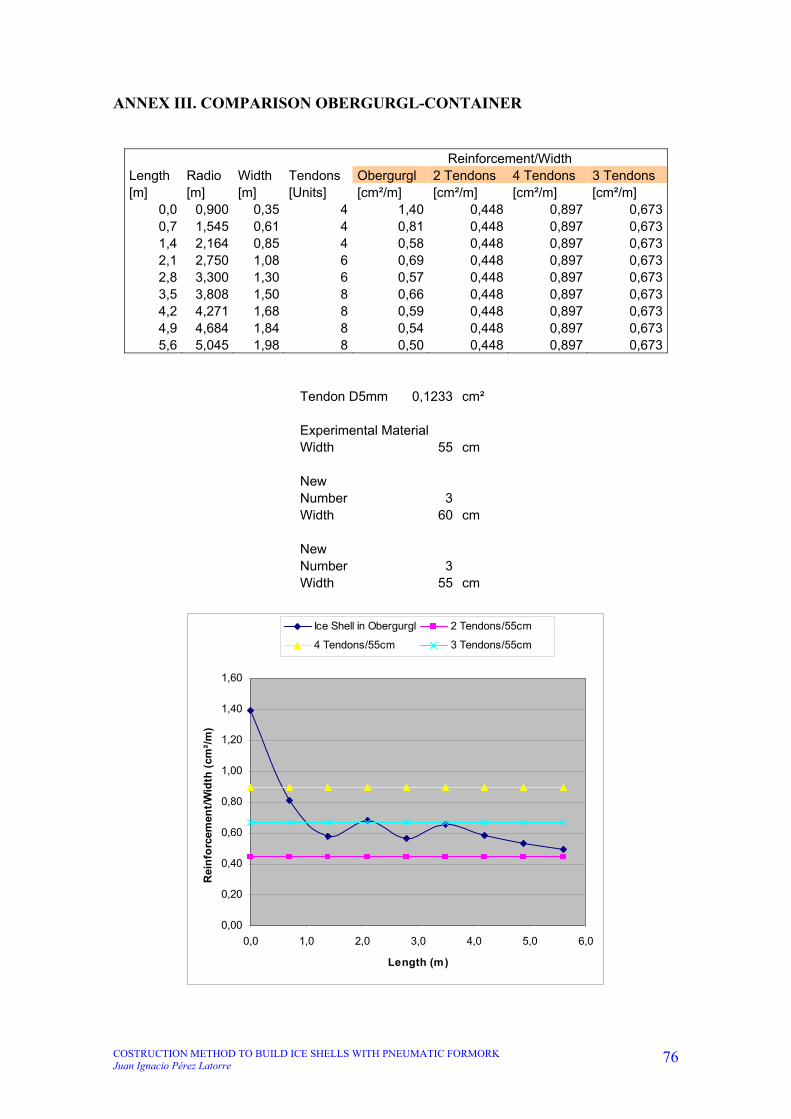
COSTRUCTION METHOD TO BUILD ICE SHELLS WITH PNEUMATIC FORMORK Juan Ignacio Pérez Latorre
76
ANNEX III. COMPARISON OBERGURGL-CONTAINER
Reinforcement/Width Length Radio Width Tendons Obergurgl 2 Tendons 4 Tendons 3 Tendons [m] [m] [m] [Units] [cm²/m] [cm²/m] [cm²/m] [cm²/m]
0,0 0,900 0,35 4 1,40 0,448 0,897 0,6730,7 1,545 0,61 4 0,81 0,448 0,897 0,6731,4 2,164 0,85 4 0,58 0,448 0,897 0,6732,1 2,750 1,08 6 0,69 0,448 0,897 0,6732,8 3,300 1,30 6 0,57 0,448 0,897 0,6733,5 3,808 1,50 8 0,66 0,448 0,897 0,6734,2 4,271 1,68 8 0,59 0,448 0,897 0,6734,9 4,684 1,84 8 0,54 0,448 0,897 0,6735,6 5,045 1,98 8 0,50 0,448 0,897 0,673
Tendon D5mm 0,1233 cm² Experimental Material Width 55 cm New Number 3 Width 60 cm New Number 3 Width 55 cm
0,00
0,20
0,40
0,60
0,80
1,00
1,20
1,40
1,60
0,0 1,0 2,0 3,0 4,0 5,0 6,0
Length (m)
Rei
nfo
rcem
ent/
Wid
th (
cm²/
m)
Ice Shell in Obergurgl 2 Tendons/55cm
4 Tendons/55cm 3 Tendons/55cm

COSTRUCTION METHOD TO BUILD ICE SHELLS WITH PNEUMATIC FORMORK Juan Ignacio Pérez Latorre
77
ANNEX IV. CREEPING Height (cm): Acumulate time Element
(min) 1 2 3 4 5 6 7 8 9 10 11 12 13 14 15 16
0 42,4 48,2 37,6 35,5 45,5 37,2 44,5 43,6 34 35,3 36,7 34,6 43,4 45,7 32 35,7
384 43,5 48 36,7 36,6 46 37,1 44,5 43,1 34 37 37,5 37,2 43,2 46,4 40 34,2
1374 47,5 51,3 43,8 41,7 48,75 43 48,2 47,2 39 41,2 41 41,2 47,7 51,7 43 40,5
3024 42 47,2 40 38,7 40,7 35,7 44 46 36 37 33,5 34 39 44,5 37 38
3114 43 49 42 39 42 39 46 47,2 38 39 35,5 37 42 45 39 39
3224 48 55 46 42 50 42 49 51 43 41 41,2 41,5 52,5 53,7 49,5 46,5
3284 52,5 58 46 46 52 45,5 51 54,5 44,5 43,5 43,5 43,5 54,5 56,5 52 49
3494 51,5 58,5 47 44,5 52 45 51 55 44,5 44 43,5 42,5 53 54 46,5 46
Element 1: Ref. Height Height [cm] Rise Time
[cm] 1 2 3 4 5 6 7 8 9 10 11 12 [cm] [h]
348,7 317,2 321,3 326,4 331,7 336,5 339,6 340,8 338,5 334,7 329,4 324 318,3 23,1 0
348,7 317,3 322,3 327,9 333,4 338,7 341,2 342,8 340,4 336,4 330,5 324,4 318,2 25,1 3,5
349 317,3 321,7 328,4 334,5 340,2 344,1 344,9 341,8 336,9 330,4 324,2 318,2 27,2 13
349 318 323,4 330,2 337 343,1 347,4 348,1 344,7 340,2 332,8 326,2 320,1 29,1 15,5
349 317 322,5 329,4 336,4 342,8 347,3 348,2 344,9 340,1 333,1 326,4 320,4 29,5 18,3
349 316,7 322,7 329,9 336,9 343,3 347,8 348,7 345,6 340,7 333,6 326,9 320,5 30,1 19,6
349 315,2 323,4 331,3 338,7 345,5 349,8 350,5 347 342,2 334,3 327,2 320,2 32,8 21,2
350,7 316,9 326 335 343,8 351,3 354,2 357,7 353,9 347,8 338,9 329,9 321,9 38,3 29
349,5 316,6 326,3 336,5 345,9 354,9 360 361 357,2 350,7 340,8 331,1 322,7 41,35 38
348,8 317 324,8 335,4 345 353 359,1 360 356 348,4 338,5 329 319,2 41,9 43,3
346,2 312,5 322,9 333,6 343,8 352,8 359 360,3 355,5 348,3 337,6 327 317,4 45,35 49
349 314,8 325,9 336,9 347,5 356,5 363 364,4 359,2 351,6 340,6 329,8 319,8 47,1 62
Element 16:
Ref. Height Rise Time
Height 1 2 3 4 5 6 7 8 9 10 11 12 [cm] [h]
348,7 322,8 323 325,7 328,4 331 333,5 334,4 333,5 330,5 325,5 322,7 318 14,0 0
348,7 323,9 324,2 327,5 330,6 333,5 336 336 335,4 332 326,5 322,2 318,8 14,7 3,5
349 327,3 327,8 331,2 334,5 337,9 340,5 340,2 339,8 335,2 328,8 324,4 319,6 17,1 13
349 323,3 325,4 330,8 336,2 341,1 344,5 344 343,7 338,2 331,4 325,2 319,8 23,0 15,5
349 321,2 323,6 329,5 335,4 340,8 344,6 344,1 343,9 338,3 331,4 325,2 320,2 23,9 18,3
349 320,6 323,5 329,5 335,5 341,3 345 344,6 344,4 337,6 330,8 327,4 317,9 25,8 19,6
349 319,5 322,8 329,8 336,4 342,3 346 345,9 345,4 338,5 331,3 325,8 317,7 27,4 21,1
349 323,8 327,2 334,3 341,1 347,4 351,2 351,4 350,3 344 337 330,5 322,2 28,4 21,4
350,7 324,6 329,1 336,9 344,2 350,9 355,5 355 354,3 347,9 339,2 330,9 322,7 31,85 28,7
349,5 326,5 330,4 337 347 354,3 359 359 358,1 350 341 333,1 323,2 34,15 38,7
348,8 324 328,5 337,9 345,9 353,4 358,1 357,9 356,9 350 339,4 330,9 321,3 35,45 43
346,2 320,5 325,9 335,7 344,6 352,8 358,2 357,9 356,5 349,3 339 330 318,8 38,55 49,7
349 321,8 327,9 338,1 347,8 356,3 362 361,9 360,6 352 341,9 329,2 320,4 40,9 62,7

COSTRUCTION METHOD TO BUILD ICE SHELLS WITH PNEUMATIC FORMORK Juan Ignacio Pérez Latorre
78
Element 1: Point 1 2 3 5 6 7 8 9 10 11 12Lenght [cm] 0 48 98 200 252 301 352 403 453 503 553
1. 31,5 27,4 22,3 12,2 9,1 7,9 10,2 14 19,3 24,7 30,4
x 0 47,8 97,6 199,1 251,0 300,0 350,9 401,8 451,5 501,2 550,9
y 0 4,1 9,2 19,3 22,4 23,6 21,3 17,5 12,2 6,8 1,1
2. 31,4 26,4 20,8 10 7,5 5,9 8,3 12,3 18,2 24,3 30,5
x 0 47,7 97,4 198,9 250,8 299,8 350,7 401,6 451,2 500,8 550,4
y 0 5 10,6 21,4 23,9 25,5 23,1 19,1 13,2 7,1 0,9
3. 31,7 27,3 20,6 8,8 4,9 4,1 7,2 12,1 18,6 24,8 30,8
x 0 47,8 97,3 198,7 250,5 299,5 350,4 401,2 450,8 500,4 550,0
y 0 4,4 11,1 22,9 26,8 27,6 24,5 19,6 13,1 6,9 0,9
4. 31 25,6 18,8 5,9 1,6 0,9 4,3 8,8 16,2 22,8 28,9
x 0 47,7 97,2 198,4 250,2 299,2 350,1 400,9 450,4 499,9 549,6
y 0 5,4 12,2 25,1 29,4 30,1 26,7 22,2 14,8 8,2 2,1
5. 32 26,5 19,6 6,2 1,7 0,8 4,1 8,9 15,9 22,6 28,6
x 0 47,7 97,2 198,3 250,1 299,1 350,0 400,8 450,3 499,8 549,5
y 0 5,5 12,4 25,8 30,3 31,2 27,9 23,1 16,1 9,4 3,4
6. 32,3 26,3 19,1 5,7 1,2 0,3 3,4 8,3 15,4 22,1 28,5
x 0 47,6 97,1 198,2 250,0 299,0 349,9 400,7 450,2 499,7 549,3
y 0 6 13,2 26,6 31,1 32 28,9 24 16,9 10,2 3,8
7. 33,8 25,6 17,7 3,5 -0,8 -1,5 2 6,8 14,7 21,8 28,8
x 0 47,3 96,7 197,7 249,5 298,5 349,4 400,1 449,5 499,0 548,5
y 0 8,2 16,1 30,3 34,6 35,3 31,8 27 19,1 12 5
8. 33,8 24,7 15,7 -0,6 -3,5 -7 -3,2 2,9 11,8 20,8 28,8
x 0 47,1 96,3 197,0 248,9 297,8 348,6 399,3 448,5 497,7 547,0
y 0 9,1 18,1 34,4 37,3 40,8 37 30,9 22 13 5
9. 32,9 23,2 13 -5,4 -10,5 -11,5 -7,7 -1,2 8,7 18,4 26,8
x 0 47 95,96 196,28 248 297 347,87 398,46 447,47 496,52 545,81
y 0 9,7 19,9 38,3 43,4 44,4 40,6 34,1 24,2 14,5 6,1
10. 31,8 24 13,4 -4,2 -10,3 -11,2 -7,2 0,4 10,3 19,8 29,6
x 0 47,36 96,22 196,67 248,31 297,3 348,15 398,58 447,59 496,68 545,71
y 0 7,8 18,4 36 42,1 43 39 31,4 21,5 12 2,2
11. 33,7 23,3 12,6 -6,6 -12,8 -14,1 -9,3 -2,1 8,6 19,2 28,8
x 0 46,85 95,7 195,86 247,49 296,47 347,25 397,73 446,58 495,44 544,51
y 0 10,4 21,1 40,3 46,5 47,8 43 35,8 25,1 14,5 4,9
12. 34,2 23,1 12,1 -7,5 -14 -15,4 -10,2 -2,6 8,4 19,2 29,2
x 0 46,69 95,47 195,55 247,14 296,12 346,85 397,28 446,06 494,88 543,87
y 0 11,1 22,1 41,7 48,2 49,6 44,4 36,8 25,8 15 5

COSTRUCTION METHOD TO BUILD ICE SHELLS WITH PNEUMATIC FORMORK Juan Ignacio Pérez Latorre
79
Element 16: Point 1,00 2,00 3,00 5,00 6,00 7,00 8,00 9,00 10,00 11,00 12,00
Lenght [cm] 0,00 38,00 88,00 191,00 240,00 292,00 343,00 396,00 445,00 496,00 546,00
1. 25,90 25,70 23,00 17,70 15,20 14,30 15,20 18,20 23,20 26,00 30,70
x 0,00 38,00 87,93 190,79 239,73 291,72 342,71 395,63 444,37 495,29 545,07
y 0,00 0,20 2,90 8,20 10,70 11,60 10,70 7,70 2,70 -0,10 -4,80
2. 24,80 24,50 21,20 15,20 12,70 12,70 13,30 16,70 22,20 26,50 29,90
x 0,00 38,00 87,89 190,71 239,65 291,65 342,65 395,54 444,23 495,05 544,93
y 0,00 0,30 3,60 9,60 12,10 12,10 11,50 8,10 2,60 -1,70 -5,10
3. 21,70 21,20 17,80 11,10 8,50 8,80 9,20 13,80 20,20 24,60 29,40
x 0,00 38,00 87,88 190,66 239,59 291,59 342,59 395,39 443,97 494,78 544,55
y 0,00 0,50 3,90 10,60 13,20 12,90 12,50 7,90 1,50 -2,90 -7,70
4. 25,70 23,60 18,20 7,90 4,50 5,00 5,30 10,80 17,60 23,80 29,20
x 0,00 37,94 87,65 190,13 239,01 291,01 342,01 394,72 443,25 493,87 543,58
y 0,00 2,10 7,50 17,80 21,20 20,70 20,40 14,90 8,10 1,90 -3,50
5. 27,80 25,40 19,50 8,20 4,40 4,90 5,10 10,70 17,60 23,80 28,80
x 0,00 37,92 87,57 189,95 238,80 290,80 341,80 394,50 443,02 493,64 543,39
y 0,00 2,40 8,30 19,60 23,40 22,90 22,70 17,10 10,20 4,00 -1,00
6. 28,40 25,50 19,50 7,70 4,00 4,40 4,60 11,40 18,20 21,60 31,10
x 0,00 37,89 87,53 189,85 238,71 290,71 341,71 394,27 442,80 493,68 542,77
y 0,00 2,90 8,90 20,70 24,40 24,00 23,80 17,00 10,20 6,80 -2,70
7. 29,50 26,20 19,20 6,70 3,00 3,10 3,60 10,50 17,70 23,20 31,30
x 0,00 37,86 87,36 189,60 238,46 290,46 341,46 394,01 442,47 493,18 542,52
y 0,00 3,30 10,30 22,80 26,50 26,40 25,90 19,00 11,80 6,30 -1,80
8. 25,20 21,80 14,70 1,60 -2,20 -2,40 -1,30 5,00 12,00 18,50 26,80
x 0,00 37,85 87,34 189,50 238,35 290,35 341,34 393,97 442,46 493,05 542,35
y 0,00 3,40 10,50 23,60 27,40 27,60 26,50 20,20 13,20 6,70 -1,60
9. 26,10 21,60 13,80 -0,20 -4,80 -4,30 -3,60 2,80 11,50 19,80 28,00
x 0,00 37,73 87,12 189,16 237,95 289,94 340,94 393,55 441,77 492,09 541,41
y 0,00 4,50 12,30 26,30 30,90 30,40 29,70 23,30 14,60 6,30 -1,90
10. 23,00 19,10 12,50 -4,80 -9,50 -9,50 -8,60 -0,50 8,50 16,40 26,30
x 0,00 37,80 87,36 188,86 237,63 289,63 340,62 393,00 441,17 491,55 540,56
y 0,00 3,90 10,50 27,80 32,50 32,50 31,60 23,50 14,50 6,60 -3,30
11. 24,80 20,30 10,90 -4,60 -9,30 -9,10 -8,10 -1,20 9,40 17,90 27,50
x 0,00 37,73 86,84 188,67 237,44 289,44 340,43 392,98 440,82 491,11 540,17
y 0,00 4,50 13,90 29,40 34,10 33,90 32,90 26,00 15,40 6,90 -2,70
12. 25,70 20,30 10,50 -6,60 -12,00 -11,70 -10,30 -3,10 7,20 16,20 27,40
x 0,00 37,61 86,64 188,21 236,91 288,91 339,89 392,40 440,31 490,51 539,24
y 0,00 5,40 15,20 32,30 37,70 37,40 36,00 28,80 18,50 9,50 -1,70
13. 27,20 21,10 10,90 -7,30 -13,00 -12,90 -11,60 -3,00 7,10 19,80 28,60
x 0,00 37,51 86,46 187,83 236,49 288,49 339,48 391,77 439,72 489,11 538,33
y 0,00 6,10 16,30 34,50 40,20 40,10 38,80 30,20 20,10 7,40 -1,40