
The Application of Digital Computers to Guidance and Control .
308
AGAR D-C P-68-70 AGARD CONFERENCE PROCEEDINGS No. 68 on The Application of Digital Computers to Guidance and Control . DlSTRlBUTlO N A N D AVAlLABl LlTY ON BACK COVER
-
Upload
khangminh22 -
Category
Documents
-
view
3 -
download
0
Transcript of The Application of Digital Computers to Guidance and Control .
AGAR D-C P-68-70
AGARD C O N F E R E N C E PROCEEDINGS No. 68
on
The Application of Digital Computers to Guidance and Control .
DlSTRlBUTlO N A N D AVAlLABl LlTY ON BACK COVER

AGARD Conference Proceedings No. 68
NORTH ATLANTIC TREATY ORGANIZATION
ADVISORY GROUP FOR AEROSPACE RESEARCH AND DEVELOPMENT
(ORGANISATION D U TRAITE DE L'ATLANTIQUE NORD) '
THE APPLICATION OF DIGITAL COMPUTERS
TO GUIDANCE AND CONTROL
Papers presented at the 10th Meeting of the Guidance and Control Panel of AGARD, held in London, England. 2 - 4 June 1970
Panel Chairman : Professor C. T. Leondes (US)
Panel Executive : Major C.D,Mount, USAF
Program Chairman : Dr G.E.Roberts (UK)
Program Co-chairman : Dr G. E. Knausenberger (US)
Local Conference Coordinator : Mr D.B.Smith (UK)
i v
C 0 N T E N T S
Page
FOREWORD i ii
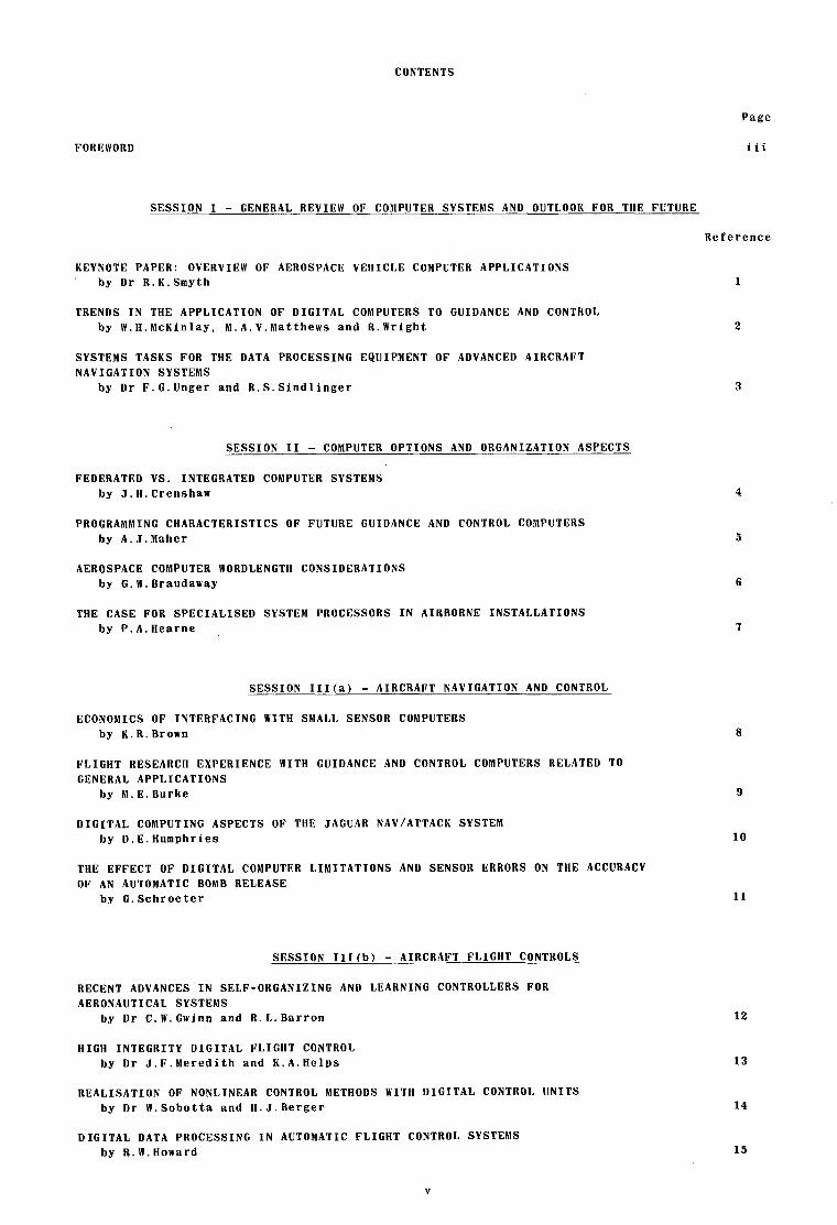
SESSION I - GENERAL REVIEW OF COMPUTER SYSTEMS AND OUTLOOK FOR TllE FUTURE
Reference
KEYNOTE PAPER: OVERVIEW OF AEROSPACE VEHICLE COMPUTER APPLICATIONS . by Dr R.K.Smyth
TRENDS IN THE APPLICATION OF DIGITAL COMPUTERS TO GUIDANCE AND CONTROL by W.H.McKinlay, M.A.V.Matthews and R.Wright
SYSTEMS TASKS FOR THE DATA PROCESSING EQUIPMENT OF ADVANCED AIRCRAFT NAVIGATION SYSTEMS
by Dr F. G. Unger and R. S . Sindlinger
SESSION I1 - COMPUTER OPTIONS AND ORGANIZATION ASPECTS
FEDERATED VS. INTEGRATED COMPUTER SYSTEMS by J. H. Crenshaw
PROGRAMMING CHARACTERISTICS OF FUTURE GUIDANCE AND CONTROL COMPUTERS by A.J.Maher
AEROSPACE COMPUTER WORDLENGTH CONSIDERATIONS by G. W. Braudaway
THE CASE FOR SPECIALISED SYSTEM PROCESSORS IN AIRBORNE INSTALLATIONS by P.A. Hearne
SESSION III(a) - AIRCRAFT NAVIGATION AND CONTROL
ECONOMICS OF INTERFACING WITH SMALL SENSOR COMPUTERS by K.R.Brown
FLIGHT RESEARCH EXPERIENCE WITH GUIDANCE AND CONTROL COMPUTERS RELATED TO GENERAL APPLICATIONS
by M.E.Burke
DIGITAL COMPUTING ASPECTS OF THE JAGUAR NAV/ATTACI( SYSTEM by D. E. Humphries
THE EFFECT OF DIGITAL COMPUTER LIMITATIONS AND SENSOR ERRORS ON THE ACCURACY OF AN AUTOMATIC BOMB RELEASE
by 0. Schroeter
SESSION III(b) - AIRCRAFT FLIGHT CONTROLS
RECENT ADVANCES IN SELF-ORGANIZING AND LEARNING CONTROLLERS FOR AERONAUTICAL SYSTEMS
by Dr C.W.Gwinn and R.L.Barron
HIGH INTEGRITY DIGITAL FLIGHT CONTROL by Dr J.F.Meredith and K.A.Helps
REALISATION OF NONLINEAR CONTROL METHODS WITH DIGITAL CONTROL UNITS by Dr W. Sobotta and H. J. Berger
DIGITAL DATA PROCESSING IN AUTOMATIC FLIGHT CONTROL SYSTEMS by R. W. Howard
1
2
3
8
9
10
11
12
13
1 4
15
V
SESSION III(c) - SPACE AND MISSILE APPLICATIONS
THE USE OF A DIGITAL COMPUTER FOR TllE ELDO INERTIAL GUIDANCE SYSTEM by M. J . W. Gage
THE STAR COMPUTER: A SELF-TESTING AND REPAIRING COMPUTER FOR SPACECRAFT GUIDANCE, CONTROL AND AUTOMATIC MAINTENANCE
by A. Avizienis
SENSITIVITY ANALYSIS OF APPROXIMATE OPTIMUM GUIDANCE PROCEDURES FOR ON-LINE OPERATION
by E.Gottzein and H.Bittner
REAL-TIME DATA PROCESSING AND ORBIT DETERMINATION ON THE APOLLO INSTRUMENTATION SllIPS
by Dr F.C.Johnson
SESSION IV - OVERALL GUIDANCE ASPECTS
DISPLAY AND INTERFACE IMPLICATIONS IN THE USE OF DIGITAL COMPUTERS by J . G. Carr
THE TESTING OF COMPUTER-EQUIPPED GUIDANCE AND NAVIGATION SYSTEMS by M . G . Jaenke
FAULT ISOLATION IN A DIGITAL GUIDANCE AND CONTROL COMPUTER by D.H.Blauvelt
SPACEBORNE COMPUTER FOR ATTITUDE CONTROL AND DATA HANDLING by P. van Otterloo
Ref erence
16
17
18
19
2 0
2 1
2 2
23
vi

OVERVIEW OF AEROSPACE VEHICLE COMPUTER APPLICATIONS
bY
D r . R i c h a r d K . S m y t h , P r e s i d e n t , R a l p h E . Manns Co. (USA)
G o r d o n H. Smith , Chief Sc ient i s t , A u t o n e t i c s (USA)
1

1
SUMMARY
During the 1 9 5 0 ' ~ ~ many debates arose among the system designers of avionics for aerospace vehicles on the topic: "should this function be mechanized with analog or digital techniques?" The proponents of the digital mechanization side of the debate won a few of the arguments and airborne digital computers were introduced. These early applications of aerospace digital computers occurred only where accuracy of computation was an overriding factor in the system design criteria. In all other instances, analog mechanizations won hands down. Specifically, digital mechanizations first proved desirable and feasible for performing the computations associated with inertial nav.;gation and guidance and for weapon delivery of free-fall ballistic weapons. In the case of the third generation ballistic missiles developed in the late 1 9 5 0 ' ~ ~ the flight control function rode along on the coattails of the inertial guidance system and, thus, digital flight control systems were born.
During the 1960's, dramatic things happened to the technology of digital computers. Microelectronic Integrated Circuits (MIC's) and microminiaturized magnetic core memories were introduced. This new silicon technology gave birth to a new generation of airborne digital computers which is characterized by low cost per bit, small volume per bit, and small weight per bit o f memory, and high speed. Typical parameters of these computers are for a total machine cost of $0.20 per bit of programmable memory, 200 bits/in3, and 400 bits/oz or some 340,000 bits of memory in a one cubic foot volume, weighing about 50 pounds. The tremendous computational capability of these airborne machines made the many debates of analog versus digital computation obsolete. In systems with complex mission computation functions, digital computation was much cheaper than analog computation and that settled the debates.
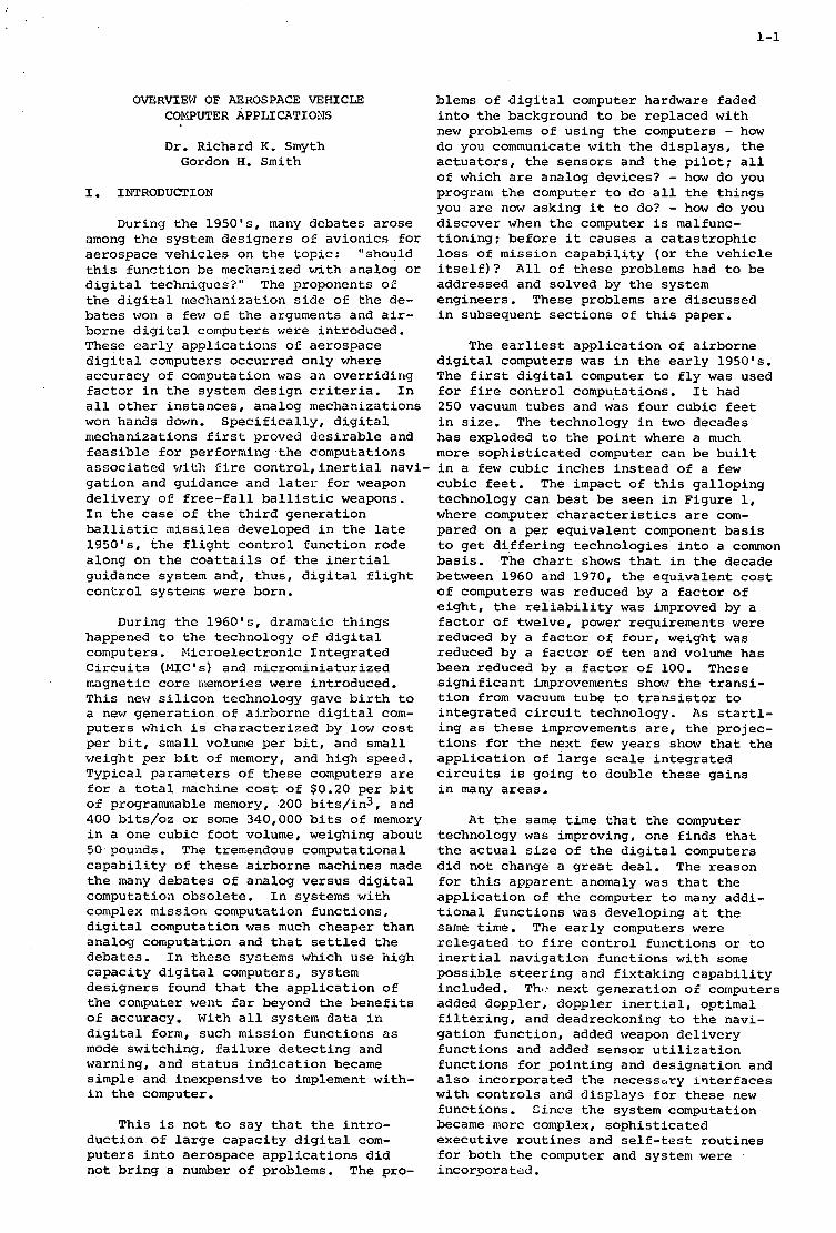
This is not to say that the introduction of large capacity digital computers into aerospace applications did not bring a number of problems. The problems of digital computer hardware faded into the background to be replaced with new problems of using the computers - how do you communicate with the displays, the actuators, the sensors and the pilot; all of which are analog devices? - how do you program the computer to do all the things you are now asked it to do? - how do you discover when the computer is malfunctioning; before it causes a catastrophic loss of mission capability (or the vehicle itself)? engineers.
All o f these problems had to be addressed and solved by the system
The powerful vehicle-borne digital computers, coupled with the ingenuity of a new generation of engineers raised on modern control theory, have made feasible the wide- spread use of Kalman filtering applications to guidance and control. When Dr. Rudy Kalman first introduced his optimum filtering concepts in the mid-19501s, the computers required to implement the concept were almost too large to get in a room - much less into an airplane or missile. Advanced computer technology has changed all of this. The current MIC computers use only a small fraction of their capacity of Kalman filtering and perform many other important mission functions as well.
The new generation of solid state technology promises to introduce another round of revolutionary digital hardware that will have as great-if not greater-impact on systems mechanization as did the MSC computer. The metal oxide semiconductor (MOS) devices are now being produced in production quantities. The MOS circuits will give rise to a new round of debates for the 1970's - should we use general purpose com- puters or special purpose computers? The answer shall be most probably that we should use both. The MOS technology will make special purpose digital computers and devices feasible that were not otherwise. For example, consider the impact on the system designers thinking if 1024 bit MOS shift registers could be mass-produced at $1.00 per device. This would make the cost of memory 0.1 cents per bit! The application of this type of memory to such functions as display scan converters and radar doppler processing would result in many system breakthroughs in the area of target acquisition systems.
The new computer technologies allow the system engineer to implement almost any mission functions which he can conceive of limited only by the capabilities of the sensors, displays, and human operators.
I . .
1-1
OVERVIEW OF AEROSPACE VEHICLE COYGUTER APPLI CAT1 ObJS
D r . Richard K. Smyth Gordon H. Smith
I. INTRODUCTION
During t h e 1 9 5 0 ' ~ ~ many deba te s a r o s e among t h e system des igne r s of a v i o n i c s f o r aerospace v e h i c l e s on t h e t o p i c : "should t h i s f u n c t i o n be mechanized wi th analog o r d i g i t a l techniques?" The proponents of t h e d i g i t a l mechanization s i d e of the de- b a t e s won a few of t h e arguments and a i r - borne d i g i t a l computers w e r e introduced. These e a r l y a p p l i c a t i o n s of aerospace d i g i t a l computers occurred on ly where accuracy of computation was a n o v e r r i d i n g f a c t o r i n t h e system des ign c r i t e r i a . I n a l l o t h e r i n s t a n c e s , analog mechanizations won hands down. S p e c i f i c a l l y , d i g i t a l mechanizations f i r s t proved d e s i r a b l e and f e a s i b l e f o r performing the computations
blems o f d i g i t a l computer hardware faded i n t o the background t o be rep laced w i t h new problems o f u s ing t h e computers - how do you communicate w i t h t h e d i s p l a y s , t h e a c t u a t o r s , the s e n s o r s and the p i l o t : a l l of which a r e analog dev ices? - how do you program t h e computer t o do a l l the t h i n g s you a r e now ask ing it t o do? - how do you d i scove r when t h e computer is malfunc- t i o n i n g : be fo re it causes a c a t a s t r o p h i c loss of mission c a p a b i l i t y ( o r t h e v e h i c l e i t s e l f ) ? A l l of t h e s e problems had t o be addressed and solved by the system eng inee r s . These problems a r e d i scussed i n subsequent s e c t i o n s o f t h i s paper.
The e a r l i e s t a p p l i c a t i o n of a i r b o r n e d i g i t a l computers was i n the e a r l y 1950's . The f i r s t d i g i t a l computer t o f l y was used f o r f i r e c o n t r o l computations. It had 250 vacuum tubes and was f o u r cubic f e e t i n s i z e . The technology i n two decades has exploded t o t h e p o i n t where a much more s o p h i s t i c a t e d computer can be b u i l t
a s s o c i a t e d w i t h f i r e c o n t r o 1 , i n e r t i a l navi- i n a few cubic inches i n s t e a d of a f e w g a t i o n and guidance and l a t e r f o r weapon d e l i v e r y o f f r e e - f a l l b a l l i s t i c weapons. I n the c a s e of t h e t h i r d g e n e r a t i o n b a l l i s t i c missiles developed i n t h e l a t e 1950's , t h e f l i g h t c o n t r o l f u n c t i o n rode along on the c o a t t a i l s o f the i n e r t i a l guidance system and, t h u s , d i g i t a l f l i g h t c o n t r o l systems w e r e born.
During the 1 9 6 0 ' ~ ~ dramatic t h i n g s happened t o t h e technology o f d i g i t a l computers. Mic roe lec t ron ic I n t e g r a t e d C i r c u i t s ( M I C I S ) and microminiatur ized magnetic c o r e memories w e r e introduced. Th i s new s i l i c o n technology gave b i r t h t o a new g e n e r a t i o n o f a i r b o r n e d i g i t a l com- p u t e r s which i s c h a r a c t e r i z e d by low cost p e r b i t , sma l l volume per b i t , and small weight per b i t of memory, and h igh speed. Typ ica l parameters of t h e s e computers a r e f o r a t o t a l machine c o s t of $0.20 p e r b i t of programmable memory, 200 b i t s / i n 3 , and 400 b i t s / o z o r some 340,000 b i t s of memory i n a one cub ic f o o t volume, weighing about 50 pounds. The tremendous computat ional c a p a b i l i t y of these a i r b o r n e machines made t h e many deba te s o f analog ve r sus d i g i t a l computation obso le t e . I n systems wi th complex mission computation func t ions , d i g i t a l computation was much cheaper t h a n analog computation and t h a t s e t t l e d t h e debates . I n t h e s e systems which use h igh c a p a c i t y d i g i t a l Computers, system d e s i g n e r s found t h a t the a p p l i c a t i o n o f t h e computer went f a r beyond the b e n e f i t s o f accuracy. With a l l system d a t a i n d i g i t a l form, such mission func t ions a s mode switching, f a i l u r e d e t e c t i n g and warning, and s t a t u s i n d i c a t i o n became simple and inexpensive t o implement w i t h - i n t h e computer.
Th i s is n o t t o say t h a t the i n t r o - d u c t i o n o f l a r g e c a p a c i t y d i g i t a l com- p u t e r s i n t o aerospace a p p l i c a t i o n s d i d no t b r i n g a number o f problems. The pro-
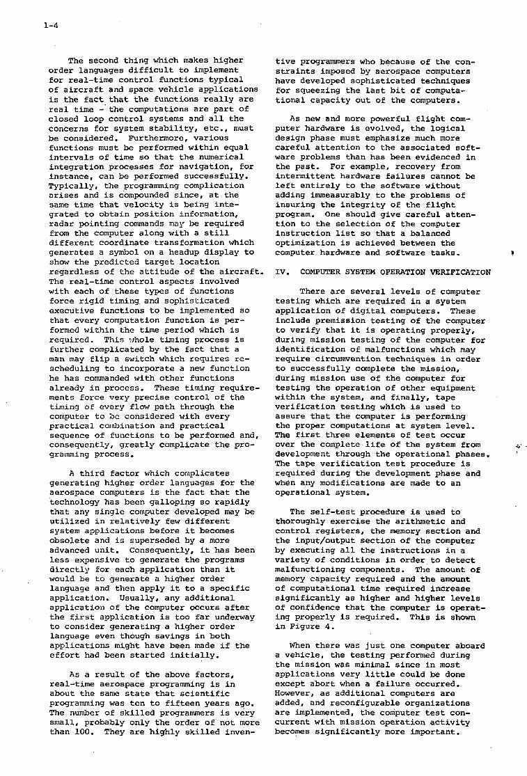
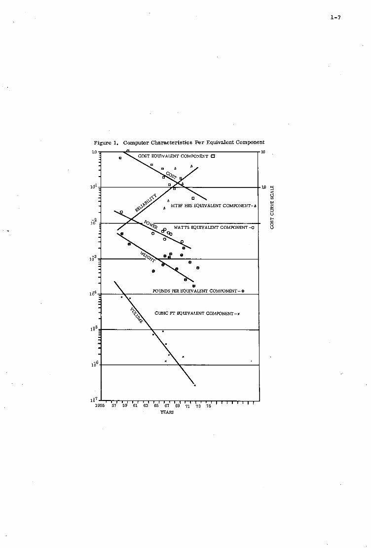
c u b i c f e e t . The impact o f t h i s g a l l o p i n g technology can b e s t be seen i n Figure 1, where computer c h a r a c t e r i s t i c s a r e com- pared on a p e r e q u i v a l e n t component b a s i s t o g e t d i f f e r i n g t echno log ie s i n t o a common b a s i s . The c h a r t shows t h a t i n t h e decade between 1960 and 1970, t h e e q u i v a l e n t c o s t o f computers was reduced by a f a c t o r of e i g h t , the r e l i a b i l i t y was improved by a f a c t o r o f twelve, power requirements w e r e reduced by a f a c t o r of fou r , weight was reduced by a f a c t o r of t e n and volume has been reduced by a f a c t o r of 100. These s i g n i f i c a n t improvements show t h e t r a n s i - t i o n from vacuum tube t o t r a n s i s t o r t o i n t e g r a t e d c i r c u i t technology. A s s t a r t l - i n g a s t h e s e improvements a r e , t h e p ro jec - t i o n s f o r t h e next few y e a r s show t h a t t h e a p p l i c a t i o n of i a r g e s c a l e i n t e g r a t e d c i r c u i t s is going t o double t h e s e g a i n s i n many a reas .
A t t h e same t i m e t h a t t h e computer technology was improving, one f i n d s t h a t t h e a c t u a l s i z e o f t h e d i g i t a l computers d i d no t change a g r e a t dea l . The reason f o r t h i s apparent anomaly was t h a t t h e a p p l i c a t i o n of t h e computer t o many addi- t i o n a l func t ions was developing a t t h e same t i m e . The e a r l y computers w e r e r e l e g a t e d t o f i r e c o n t r o l func t ions o r t o i n e r t i a l nav iga t ion f u n c t i o n s wi th some p o s s i b l e s t e e r i n g and f i x t a k i n g c a p a b i l i t y included. Ths. nex t g e n e r a t i o n of computers added doppler , doppler i n e r t i a l , opt imal f i l t e r i n g , and deadreckoning t o t h e navi- g a t i o n func t ion , added weapon d e l i v e r y f u n c t i o n s and added senso r u t i l i z a t i o n f u n c t i o n s f o r p o i n t i n g and d e s i g n a t i o n and a l s o incorporated t h e necessary i r l t e r f a c e s w i t h c o n t r o l s and d i s p l a y s f o r t h e s e new func t ions . S ince t h e system computation became more complex, s o p h i s t i c a t e d execu t ive r o u t i n e s and s e l f - t e s t r o u t i n e s f o r bo th t h e computer and system w e r e '
i nco rpora t ed .
1-2
The fol lowing gene ra t ion of computers w i l l add r a d i o naviga t ion and more sophis - t i c a t e d opt imal f i l t e r i n g concepts i n o rde r t o opt imal ly combine the informat ion from a l l naviga t ion sensors . T h i s next genera- t i o n of computers w i l l also be concerned wi th t h e countermeasures func t ion both f o r t h r e a t i d e n t i f i c a t i o n func t ions and a l s o f o r s e l e c t i n g t h e most appropr i a t e counter - measures f o r t h e p a r t i c u l a r t h r e a t s en- countered. The i n t e g r a t i o n of computer technology w i l l go much deeper i n t o a l l t h e f a c e t s of the system t o inc lude com- munication, in-depth system t e s t i n g , damage assessment, premission planning and postmission eva lua t ion func t ions and w i l l provide s o p h i s t i c a t e d f a i l u r e cir- cumvention procedures. During the same per iod of t i m e a s t h i s t h i r d gene ra t ion of computer a p p l i c a t i o n s , special-purpose c a p a b i l i t i e s a r e being expanded t o inc lude mul t ip lex ing , d i g i t a l f i l t e r i n g , and l e a r n i n g and se l f -o rgan iz ing func t ions .
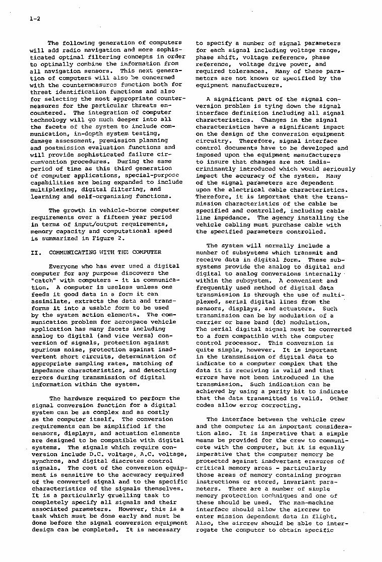
The growth i n vehicle-borne computer requirements over a f i f t e e n year per iod i n terms of input /output requirements , memory capac i ty and computat ional speed is summarized i n F igure 2.
11. COMMUNICATING WITH T I E COMPUTER
Everyone who has ever used a d i g i t a l computer f o r any purpose d i scove r s the "ca tch" w i t h computers - it is communica- t i o n . A computer is u s e l e s s un le s s one feeds i t good da ta i n a form it can a s s i m i l a t e , e x t r a c t s t h e d a t a and t r a n s - forms it i n t o a usable form t o be used by t h e system a c t i o n elements. The com- munication problem f o r aerospace v e h i c l e a p p l i c a t i o n has many f a c e t s i nc lud ing analog t o d i g i t a l (and v i c e versa) con- ve r s ion of s i g n a l s , p r o t e c t i o n a g a i n s t spur ious noise , p r o t e c t i o n a g a i n s t inad- v e r t e n t s h o r t c i r c u i t s , de te rmina t ion of appropr i a t e sampling r a t e s , matching of impedance c h a r a c t e r i s t i c s , and d e t e c t i n g e r r o r s dur ing t ransmiss ion of d i g i t a l in format ion w i t h i n t h e system.
The hardware requi red t o perform the s i g n a l conversion func t ion f o r a d i g i t a l system can be a s complex and a s c o s t l y a s t h e computer i t s e l f . The conversion requirements can be s impl i f i ed i f t h e senso r s , d i s p l a y s , and a c t u a t i o n elements a r e designed t o be compatible wi th d i g i t a l systems. The s i g n a l s which r e q u i r e con- ve r s ion inc lude D.C. vo l t age , A.C. vo l t age , synchros, and d i g i t a l discretes c o n t r o l s i g n a l s . The c o s t of t h e conversion equip- ment i s s e n s i t i v e t o t h e accuracy requi red of t h e converted s i g n a l and t o t h e s p e c i f i c c h a r a c t e r i s t i c s of the s i g n a l s themselves. It i s a p a r t i c u l a r l y g r u e l l i n g t a s k t o completely spec i fy a l l s i g n a l s and t h e i r a s soc ia t ed parameters. However, t h i s is a t a s k which must be done e a r l y and must be done be fo re t h e s i g n a l conversion equipment des ign can be completed. It i s necessary
t o spec i fy a number of s i g n a l parameters f o r each s i g n a l i nc lud ing vo l t age range, phase s h i f t , vo l t age r e fe rence , phase r e fe rence , vo l t age d r i v e power, and requi red to l e rances . Many of t h e s e para- meters a r e not known o r s p e c i f i e d by the equipment manufacturers.
A s i g n i f i c a n t p a r t of t h e s i g n a l con- ve r s ion problem i s t y i n g down t h e s i g n a l i n t e r f a c e d e f i n i t i o n inc lud ing a l l s i g n a l c h a r a c t e r i s t i c s . Changes i n the s i g n a l c h a r a c t e r i s t i c s have a s i g n i f i c a n t impact on t h e des ign of t h e conversion equipment c i r c u i t r y . Therefore , s i g n a l i n t e r f a c e c o n t r o l documents have t o be developed and imposed upon t h e equipment manufacturers t o i n s u r e t h a t changes a r e not i n d i s - c r iminan t ly introduced which would s e r i o u s l y impact the accuracy of the system. Many of t h e s i g n a l parameters a r e dependent upon t h e e l e c t r i c a l c a b l e c h a r a c t e r i s t i c s . Therefore , it i s important t h a t the t r a n s - mission c h a r a c t e r i s t i c s of t h e cab le be s p e c i f i e d and c o n t r o l l e d , i nc lud ing c a b l e l i n e impedance. v e h i c l e cab l ing must purchase cab le w i t h the s p e c i f i e d parameters c o n t r o l l e d .
The agency i n s t a l l i n g t h e
The system w i l l normally inc lude a number of subsystems which t r ansmi t and r ece ive d a t a i n d i g i t a l form. These sub- systems provide t h e analog t o d i g i t a l and d i g i t a l t o analog conversions i n t e r n a l l y wi th in t h e subsystem. A convenient and f r equen t ly used method of d i g i t a l d a t a t ransmiss ion is through t h e u s e of mul t i - plexed, s e r i a l d i g i t a l l i n e s from t h e senso r s , d i s p l a y s , and ac tua to r s . Such t ransmiss ion can be by modulation of a c a r r i e r o r base band (dc) modulation. The s e r i a l d i g i t a l s i g n a l inust be converted t o a form compatible wi th t h e computer c o n t r o l processor . This conversion is q u i t e simple, however. It i s important i n the t ransmiss ion of d i g i t a l da ta t o i n d i c a t e t o a computer complex t h a t the da ta i t is rece iv ing is v a l i d and t h a t e r r o r s have not been introduced i n t h e t ransmiss ion . Such i n d i c a t i o n can be achieved by using a p a r i t y b i t t o i n d i c a t e t h a t t h e d a t a t r ansmi t t ed i s v a l i d . O t h e r codes a l low e r r o r c o r r e c t i n g .
The i n t e r f a c e between t h e v e h i c l e c r e w and t h e computer i s an important cons idera- t i o n a l s o . It i s imperat ive t h a t a simple means be provided f o r the c r e w t o c o m u n i - c a t e wi th the computer, bu t it i s equa l ly imperat ive t h a t t h e computer memory be p ro tec t ed a g a i n s t i nadve r t an t e r a s u r e s of c r i t i c a l memory a r e a s - p a r t i c u l a r l y those a r e a s of memory con ta in ing program i n s t r u c t i o n s o r s t o r e d , i n v a r i a n t para- meters. There a r e a number of simple memory p r o t e c t i o n tcciiniques and one of these should be used. The man-machine i n t e r f a c e should allow t h e a i r c rew t o e n t e r mission dependent da t a i n f l i g h t . Also, t he a i rc rew should be a b l e t o i n t e r - roga te the computer t o o b t a i n s p e c i f i c
1-3
information. P rov i s ion should be made f o r t h e ground crew t o e n t e r s p e c i f i c mission d a t a through a ground prepared tape. Typ ica l d a t a f o r a t a c t i c a l a v i o n i c system may inc lude d a t a such a s t h e type of munit ions being c a r r i e d f o r weapon d e l i v e r y computations, and the r o u t e p o i n t s , d e s t i n a t i o n s , and t a r g e t s f o r the nav iga t ion computations. Normally, such mission dependent d a t a i s so e x t e n s i v e t h a t it would be t o o t i m e consuming t o e n t e r the d a t a manually. The implica- t i o n s f o r the equipment needed t o p repa re t h e mission d a t a t a p e s a r e apparent .
Fu tu re v e h i c l e systems and subsystems should be designed such t h a t the r e q u i r e - ment f o r s i g n a l conversion by t h e computer complex i s minimized. Conversion of synchro s i g n a l s i s p a r t i c u l a r l y c o s t l y i n terms o f c i r c u i t complexity. The des ign requirement for t h e f u t u r e i s c l e a r - e l i m i n a t e syncliros t o t h e e x t e n t p o s s i b l e and des ign the v e h i c l e subsystems such t h a t a l l parameters a r e converted t o d i g i t a l 201-m and t r a n s m i t t e d t o the computer complex i n s e r i a l d i g i t a l form.
111. PROGRAMMING THE COPWUTER
A s t h e role of t h e vehicle-borne computer expands, the t a s k o f producing a s s o c i a t e d so f tware i n a manner responsive t o c o n s t a n t l y changing f l i g h t requirements i n c r e a s e s i n d i f f i c u l t y . Software pro- d u c t i o n on a t i g h t schedule i s p o s s i b l e today on ly by employing l a r g e numbers o f people w i t h no s i n g l e person having a d e t a i l e d f a m i l i a r i t y wi th t h e e n t i r e program. Therefore , f u t u r e r e s e a r c h i n f l i g h t sof tware development w i l l be d i r e c t e d a t s o l v i n g the enormous i n f o r - mation and communication problem which n e c e s s a r i l y a r i s e s from such circum- s t ances .
Considerable emphasis i s being placed on t h e development o f Higher o rde r languages t o s i m p l i f y the t a s k of pre- pa r ing o p e r a t i o n a l f l i g h t programs. Although t h i s should help s o l v e an i m - p o r t a n t a s p e c t o f t h e problem, no amount of programming elegance can a l l e v i a t e t h e systems eng inee r ing t a s k o f a s s u r i n g t h a t t h e sof tware s p e c i f i c a t i o n i s complete and a c c u r a t e o r t h a t t h e documentation is adequate, uniform, and r e a d i l y under- s t andab le .
I t i s g e n e r a l l y agreed t h a t gene ra t ing the code f o r a f l i g h t program r e p r e s e n t s on ly a sma l l p o r t i o n o f t h e t o t a l develop- ment cyc le . The r e a l l y d i f f i c u l t ancl time-consuming j o b i s program v a l i d a t i o n . S ince much of t h e v a l i d a t i o n tas?c is c l e r i c a l i n na tu re , high-speed d i g i t a l d a t a p rocess ing can and should be more e f f e c t i v e l y employed. Future requirements w i l l demand, f o r example, the development of such ingenious t o o l s a s automatic pro- gram ana lyze r s t o supplement t h e use of
d i g i t a l and hybr id f l i g h t s imula to r s .
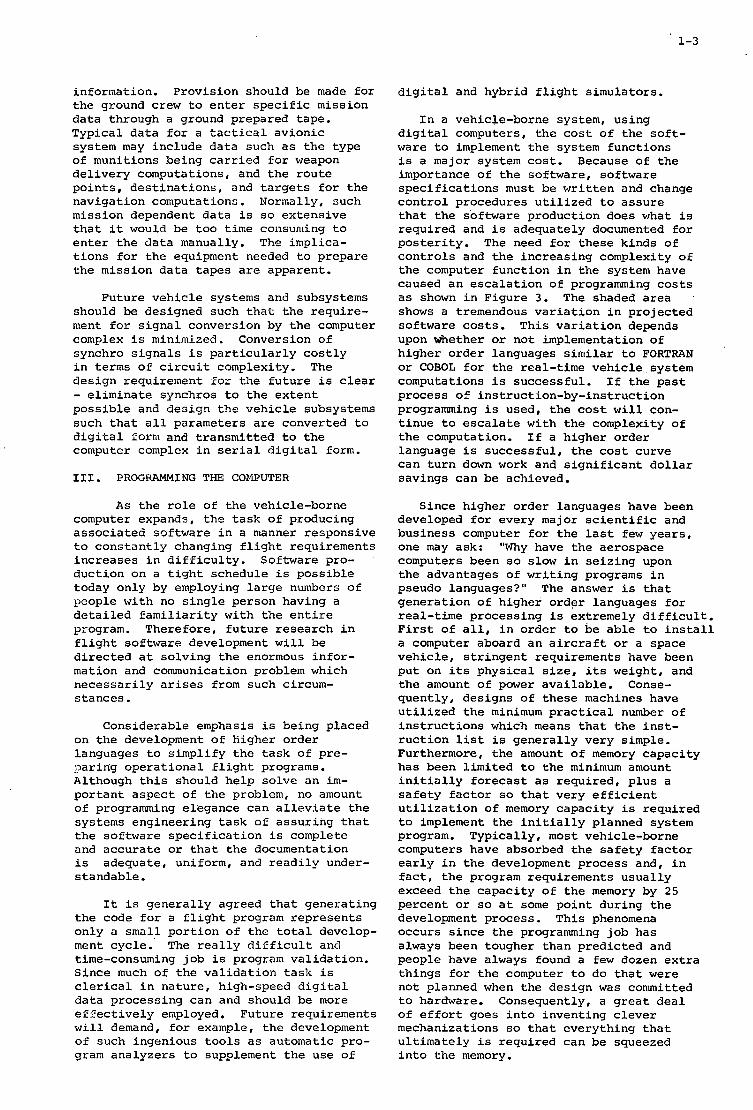
I n a vehicle-borne system, us ing d i g i t a l computers, t h e c o s t of the s o f t - ware t o implement the system func t ions i s a major system c o s t . Because of t h e importance o f the sof tware, sof tware s p e c i f i c a t i o n s must be w r i t t e n and change c o n t r o l procedures u t i l i z e d t o a s s u r e t h a t the sof tware product ion does what is requ i r ed and i s adequately documented f o r p o s t e r i t y . The need f o r these k inds o f c o n t r o l s and t h e i n c r e a s i n g complexity o f t h e computer f u n c t i o n i n t h e system have caused a n e s c a l a t i o n of programming c o s t s a s shown i n F igu re 3 . The shaded a r e a shows a tremendous v a r i a t i o n i n p r o j e c t e d sof tware c o s t s . T h i s v a r i a t i o n depends upon whether o r no t implementation o f h ighe r o r d e r languages s i m i l a r t o FORTRAN or COBOL f o r the rea l - t ime v e h i c l e system computations i s success fu l . I f t h e p a s t process 0: i n s t r u c t i o n - b y - i n s t r u c t i o n programming i s used, t h e c o s t w i l l con- t i n u e t o e s c a l a t e w i t h the complexity of t h e computation. I f a h ighe r o r d e r language i s s u c c e s s f u l , the c o s t curve can t u r n down work and s i g n i f i c a n t d o l l a r s av ings can be achieved.
S ince h ighe r o rde r languages have been developed f o r every major s c i e n t i f i c and bus iness computer f o r t h e l a s t few y e a r s , one may ask: "Why have t h e aerospace computers been so s low i n s e i z i n g upon t h e advantages of w r i t i n g programs i n pseudo languages?" The answer is t h a t g e n e r a t i o n of h ighe r ordgr languages f o r r ea l - t ime p rocess ing i s extremely d i f f i c u l t . F i r s t o f a l l , i n o r d e r t o be a b l e t o i n s t a l l a computer aboard a n a i r c r a f t o r a space v e h i c l e , s t r i n g e n t requirements have been p u t on i t s p h y s i c a l s i z e , i t s weight, and t h e amount o f power a v a i l a b l e . Conse- quen t ly , des igns of these machines have u t i l i z e d t h e minimum p r a c t i c a l number of i n s t r u c t i o n s which means t h a t t h e i n s t - r u c t i o n l i s t i s g e n e r a l l y ve ry simple. Furthermore, the amount o f memory c a p a c i t y has been l i m i t e d t o the minimum amount i n i t i a l l y f o r e c a s t a s r equ i r ed , p l u s a s a f e t y f a c t o r so t h a t ve ry e f f i c i e n t u t i l i z a t i o n o f memory c a p a c i t y i s requ i r ed t o implement the i n i t i a l l y planned system program. Typ ica l ly , most vehicle-borne computers have absorbed t h e s a f e t y f a c t o r e a r l y i n t h e development process and, i n f a c t , t h e program requirements u s u a l l y exceed t h e c a p a c i t y o f t h e memory by 2 5 p e r c e n t o r so a t some p o i n t du r ing t h e development process. Th i s phenomena occurs s i n c e the programming j o b has always been tougher t h a n p r e d i c t e d and people have always found a few dozen e x t r a t h i n g s f o r t h e computer t o do t h a t w e r e no t planned when t h e des ign was committed t o hardware. Consequently, a g r e a t d e a l o f e f f o r t goes i n t o inven t ing c l e v e r mechanizations so t h a t eve ry th ing t h a t u l t i m a t e l y i s requ i r ed can be squeezed i n t o t h e memory.
1-4
The second thing which makes higher order languages difficult to implement for real-time control functions typical of aircraft and space vehicle applications is the fact that the functions really are real time - the computations are part of closed loop control systems and all the concerns for system stability, etc., must be considered. Furthermore, various functions must be performed within equal intervals of time so that the numerical integration processes for navigation, for instance, can be performed successfully. Typically, the programming complication arises and is compounded since, at the same time that velocity is being inte- grated to obtain position information, radar pointing commands may be required from the computer along with a still different coordinate transformation which generates a symbol on a headup display to show the predicted target location regardless of the attitude of the aircraft. The real-time control aspects involved with each of these types of functions force rigid timing and Sophisticated executive functions to be implemented so that every computation function is per- formed within the time period which is required. This whole timing process is further complicated by the fact that a man may flip a switch which requires re- scheduling to incorporate a new function he has commanded with other functions already in process. These tirninq require- ments force very precise control of the timing of every flow path through the computer to be considered with every practical cornbination and practical sequence of functions to be performed and, consequently, greatly complicate the pro- gramming process.
A third factor which complicates generating higher order languages for the aerospace computers is the fact that the technology has been galloping so rapidly that any single computer developed may be utilized in relatively few different system applications before it becomes obsolete and is superseded by a more advanced unit. Consequently, it has been less expensive to generate the programs directly for each application than it would be to generate a higher order language and then apply it to a specific application. Usually, any additional application of the computer occurs after the first application is too far underway to consider generating a higher order language even though savings in both applications might have been made if the effort had been started initially.
A s a result of the above factors, real-time aerospace programming is in about the same state that scientific programming was ten to fifteen years ago. The number of skilled programmers is very small, probably only the order of not more than 100. They are highly skilled inven-
tive programmers who because of the con- straints imposed by aerospace computers have developed sophisticated techniques for squeezing the last bit of computa- tional capacity out of the computers.
As new and more powerful flight com- puter hardware is evolved, the logical design phase must emphasize much more careful attention to the associated soft- ware problems than has been evidenced in the past. For example, recovery from intermittent hardware failures cannot be left entirely to the software without adding immeasurably to the problems of insuring the integrity of the flight program. One should give careful atten- tion to the selection of the computer instruction list s o that a balanced optimization is achieved between the computer hardware and software tasks. b
IV. COMPUTER SYSTEM OPERATION VERIFICATION
There are several levels of computer testing which are required in a system application of digital computers. These include premission testing of the computer to verify that it is operating properly, during mission testing of the computer for identification of malfunctions which may require circumvention techniques in order to successfully complete the mission, during mission use of the computer for testing the operation of other equipment within the system, and finally, tape verification testing which is used to assure that the computer is performing the proper computations at system level. The first three elements of test occur over the complete life of the system from c . development through the operational phases. The tape verification test procedure is required during the development phase and when any modifications are made to an operational system.
1
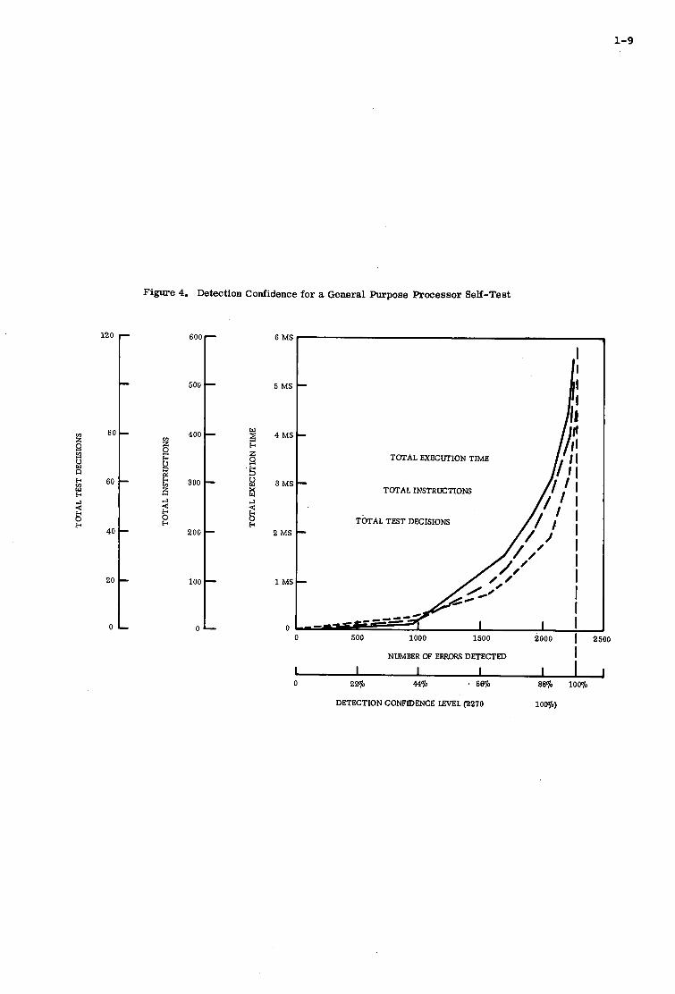
The self-test procedure is used to thoroughly exercise the arithmetic and control registers, the memory section and the input/output section of the computer by executing all the instructions in a variety of conditions in order to detect malfunctioning components. The amount of memory capacity required and the amount of computational time required increase significantly as higher and higher levels of confidence that the computer i s operat- ing properly is required. This is shown in Figure 4.
When there was just one computer aboard a vehicle, the testing performed during the mission was minimal since in most applications very little could be done except abort when a failure occurred. However, as additional computers are added, and reconfigurable organizations are implemented, the computer test con- current with mission operation activity becomes significantly more important.
1-5
The p r e r e q u i s i t e f o r swi tch ing t o a backup mode o r a l t e r n a t e computation path is the es tab l i shment t h a t t h e r e is some d i f f i - . c u l t y w i t h one of t h e computat ional black boxes i n t h e primary o r c u r r e n t computa- t i o n a l organiza t ion . This same p re requ i - s i t e is requi red a t t h e system l e v e l t o select appropr i a t e da t a from a l t e r n a t e sensors which may provide s i m i l a r inEor- mation. This system l e v e l func t ion a l s o complicates t h e t e s t i n g procedure. Current a p p l i c a t i o n s may r e q u i r e 20 pe rcen t of t h e computing capac i ty t o be u t i l i z e d f o r mission o r i en ted t e s t i n g . Because t h e g r e a t advances which a r e expected i n self- hea l ing o r s e l f - r econf igu r ing system o rgan iza t ions w i l l f u r t h e r complicate t e s t i n g procedures , more s i g n i f i c a n t e f f o r t is t o be expected i n developing mixtures of hardware and sof tware approaches t o f a c i l i t a t e t e s t i n g dur ing mission execut ion.
I n t h e e a r l y days of aerospace v e h i c l e computer a p p l i c a t i o n s , t h e t ape v e r i f i c a - t i o n t e s t i n g was a d i f f i c u l t chore and methodology was developed t o i n s u r e the computer would ope ra t e i n i t s a n t i c i p a t e d environment. It has become necessary t o s imula te t h e dynamic da ta t o be expected i n an ope ra t iona l v e h i c l e w i th a s t a t i c computer system and v e r i f y t h a t a l l of t h e sof tware pa ths operated i n t h e s t a t i c environment a s i f they were ope ra t ing i n a v e h i c l e performing i t s va r ious mission phases. I t has become necessary t o use a u x i l i a r y computers - sometimes analog, sometimes d i g i t a l , and sometimes both - t o s imula te the dynamic environment and it i s necessary t o s imula te i n t e r f a c e s and equipments which w e r e no t immediately a v a i l a b l e t o t h e computer i n t e g r a t i o n job.
V. SYNERGISTIC COMPUTER APPLICATIONS
The powerful vehicle-borne d i g i t a l computers, coupled with the ingenui ty of a new gene ra t ion of engineers r a i s e d on modern CoiItrOl theory , have made f e a s i b l e t h e widespread u s e of Kalman f i l t e r i n g a p p l i c a t i o n s t o guidance and c o n t r o l . When D r . Rudy Kalman f i r s t introduced his optimum f i l t e r i n g concepts i n t h e m i d - 1950 ' s , t h e computers requi red t o imple- ment t h e concept w e r e almost t oo l a r g e t o g e t i n a room - much less i n t o an a i r - p lane o r missile. Advanced computer technology has changed a l l of th is . The c u r r e n t MIC computers u s e only a small f r a c t i o n of t h e i r capac i ty f o r Kalman f i l t e r i n g and perform many o t h e r important mission func t ions a s wel l .
A Kalman f i l t e r implements two d i f f e r e n t func t ions . The f i r s t i s a s t a t i s t i c a l e r r o r a n a l y s i s of t h e system using a l l a v a i l a b l e a p r i o r i Imowledge of system e r r o r dynamics and e r r o r source s t a t i s t i c s . The second func t ion is t h e e s t ima t ion of the system e r r o r s included i n the model us ing weighted observa t ions
of some of t h e e r r o r s . The weight ing mat r ices requi r6d f o r the e s t ima t ion func t ion a r e obtained from the e r r o r covar iance mat r ix computed by t h e e r r o r a n a l y s i s p o r t i o n of t h e f i l t e r . I n most a p p l i c a t i o n s , p a r t o r a l l of t h e e r r o r e s t ima tes a r e then used t o c o r r e c t t h e system v a r i a b l e s .
Kalman f i l t e r i n g has been used exten- s i v e l y i n a i r c r a f t naviga t ion systems which use a v a r i e t y of naviga tor sensors and f i x t a k i n g means. A Kalman f i l t e r i s simply a sys temat ic way of mechanizing i n a computer the good judgment of a good human naviga tor . The Kalman f i l t e r uses measurements from independent sources of r e fe rence information, e s t ima tes t h e pro- bable e r r o r s from these sources , and then weights t h e p o s i t i o n from the r e fe rences i n v e r s e l y t o the magnitude of the probable e r r o r s , and f i n a l l y makes t h e best esti- mate of t h e p o s i t i o n f i x .
High powered a i rbo rne computers have g iven a tremendous impetus t o strapdown i n e r t i a l systems. The coord ina te a x i s t ransformat ions which a r e so e a s i l y accomplished i n the d i g i t a l computer w i l l a l low t h e e l imina t ion of t h e heavy, c o s t l y , and, sometimes, , u n r e l i a b l e e l e c t r o - '
mechanical gimbals of i n e r t i a l systems. With some a d d i t i o n a l advances i n s t r a p - down senso r s , t h e new gene ra t ion computers should make strapdown systems compet i t ive even i n h igh accuracy a p p l i c a t i o n s .
S e l f - t e s t and r e p a i r of computers i s an important func t ion both f o r long space probe missions and manned a i r c r a f t . The s p e c i f i c s of such computer func t ions a r e d iscussed i n d e t a i l i n subsequent con- fe rence papers . The self-test and r e p a i r func t ion is performed a t t h e computer hardware l e v e l a s w e l l a s a t t h e system mode l e v e l . Such mechanizations involve f u n c t i o n a l redundancy which inc ludes both sof tware redundancy a s w e l l a s hardware redundancy. I n a d d i t i o n t o s e l f - t e s t and r e p a i r a p p l i c a t i o n s f o r i n - f l i g h t opera- t i o n , s e l f - d i a g n o s t i c a lgor i thms have ' been developed which provide f o r i s o l a t i o n of f a i l u r e s t o a r ep laceab le module f o r ground maintenance opera t ions .
The conference papers d i s c u s s a number of o t h e r imagina t ive a p p l i c a t i o n s of com- p u t e r s t o aerospace v e h i c l e s , i nc lud ing nonl inear c o n t r o l a lgori thms, a t t i t u d e c o n t r o l a lgor i thms, v e r t i c a l v e l o c i t y obtained from Kalman f i l t e r i n g of baro- m e t r i c and i n e r t i a l r a t e s of descent , automatic f l i g h t c o n t r o l system computa- t i o n , ach iev ing a h igh degree of system i n t e g r i t y through mul t ip l e subchannels w i th switch-over i n event of f a i l u r e s , i n t e r f a c i n g with smal l sensor computers, se l f -organiz ing and l ea rn ing a lgor i thms, i n t e r f a c e w i t h small sensor o r i en ted com- p u t e r s , and i n t e r f a c e wi th CRT d i sp lays .
1-6
A most important synergistic effect of computer systems in aerospace vehicle applications is the availability within the computer in digital form virtually all system parameters and variables such as position, velocity, attitude, time-to-go, angles and ranges from the vehicle to targets as determined by sensors, and mode status informations. The availability of all this mission critical information allows the synthesis of new mission modes and functions to be developed after the hardware is all delivered by changes to software. The new computer technologies allow the system engineer to implement almost any mission function which he can conceive - limited only by his imagina- tion and the capabilities of the sensors, displays , and human operators.
VI. OUTLOOK FOR 1970's
In looking forward to the application of digital computing techniques, during the next decade, we can see that the growth of applications will be even more startling and more exciting than it was in the last decade. The capability inherent in the large scale integrated circuit which allows thousands of active devices comprising hundreds of logic gates to be combined in a single circuit device provides computational functions at a cost ridiculously low when compared with the last decade. Computers com- parable in capacity with anything flying today can be built in a size approximating a large matchbox. Such computers will require less than 10 watts of power and be priced in the range of the cost of an automobile. Whether that cost is that of a Rolls Royce or a Volkswagen is yet to be determined but, nevertheless, the cost for computing capacity will be significantly reduced. Furthermore, the small size, the l ow power and the low cost of this next generation of computers will allow com- puter organizations to be implemented which formerly were impractical but highly desirable. Computer organizations are now practical which will allow each functional area, such as navigation, or weapon delivery, or countermeasures, or sensor processing to have its own dedicated computation capability, and, consequently, allow a digital black box approach to system integration much i i l the same way that analog black box systems were for- merly integrated. This provides the software flexibility and precision of the digital approaches to be combined with the independency and simplicity of the . analog approach. Furthermore, the sophis- ticated processing which can be done with computers dedicated to specific functions may allow simplification in the sensor hardware and may extract more useful in- formation than was formerly possible.
In the early aerospace application of digital computers, many kinds 'of computa-
tions were processed through a single arithmetic center because that was the most economical way to do the job. A s the systems became more complex, the software problem associated with running everything through one funnel was diffi- cult. This, combined with the concern that if a single computer failed, that all capability in the system was lost, led people into a multicomputer or multi- processor organization so that some back- up capability would still be available. With the advent of the ability to use many computers without exorbitant penal- ties in cost, weight, power, or volume, organizations with many processing paths and ability to self-heal or reconfigure around malfunctions will be not only very attractive, but also very practical. These kinds of organizations are essential for the long term, deep space probe type of missions requiring successful opera- tions for years without interruption.
The application of large scale inte- grated circuit devices will also provide another direction to aerospace computing in the next decade and that will be the use of special-purpose computers coupled into the sensing or display subsystems. In fact, many of the old tradeoffs which were made in deciding to go from analog computing to digital computing techniques will have to be re-examined to decide if the function should be implemented in a general purpose computer or if a few special-purpose digital devices should be used. Several companies have commercially available circuits which provide a digital differential analyzer integrator function. These integrators can be interconnected to provide coordinate transformations, multiplication, division, and square root functions, as well a s the ability to be interconnected to directly and continu- ously solve differential equations. Another approach to special-purpose com- putations provides circuit chips which perform multiplication, addition, and delay functions which can be intercon- nected in such a manner to perform digital filtering for either bandpass or notch filtering, spectral analysis, difference equation solution, match filters, radar filters, digital flight control, and other similar functions. Tradeoffs will need to be made comparing the cost, flexi- bility, computer rates, etc., for each potential application before a final decision can be made. In any event, the next decade will see applications of digital computers and digital computing techniques into areas that were impossible to even contemplate in the last decade.
1-7
Figure 1. Computer Characteristics Per Equivalent Component
\ POUNDS PER EQUIVALENT COMPONENT-e
1 \ CUBIC FT EQUIVALENT COMPONENT-x
1 6 7 ' , , I , , , , I I , 1955 57 59 '61 63 65 67 '6d '71' :$ 75
1 , ~ [ 1 [ [ 1 1 ~
YEARS

1-8
Figure 2. Computer Requirements x108
0 /
I
BITS/SECOND 1 , , , i, ~~~~~1 , , , I , lB1:: , , I I I , X SPEED (COMPUTER) SHORT OPERATIONS/SEC 0 SPEED (COMPUTER SYSTEMS) SHORT OPERATIONS/SEC
1955 56 57 58 59 60 61 62 63 64 65 66 67 68 69 70 71 72 73 7475 76 ~ 1 0 3
YEARS
Figure 3. Dollar Programing Costs
l o 7 m
1 104J
1 1 1 1 1 1 1 1 . . . , ,
YEARS 60 61 62 63 64 65 66 67 68 69 70 71 72 13
1 10
.1
1-9
120
80 2 s 8
8 60
w c
H 40
20
0 -
-
-
-
-
-
-
Figure 4. Detection Confidence for a General Purpose Processor Self-Test
6 MS b
5 MS
4 MI
3 MI
2 MS
1 M6
TOTAL EXECUTION TIME
TOTAL INSTRUCTIONS
T&AL TEST DECISIONS
0 500 1000 ' 1500 2000 I 2500
NUMBER OF ERRORS DETECTED I 1 I I I I 1 0 2241, 44% * 6Wo 86qo l O C q 0
DETECTION CONFIDENCE LEVEL (2270 low4

1

2
TKENDS I N THE A P P L I C A T I O N OF D I G I T A L COMPUTERS TO GUIDANCE AND CONTROL
W.H. McKinlay, M.A.V. Matthews and R. Wright
Ferranti Limited
2
SUMMARY
This paper looks h i s t o r i c a l l y at the growth of the t o t a l guidance and cont ro l system requirement, primarily i n manned a i r c r a f t . machine in t e r f ace and the growth of navigation from a human operated t a sk t o one demanding processing and automatic computation.
It touches on Fl ight Control, t he s ign i f icance of d i sp lays as a man-
Having dea l t b r i e f l y with spec i f i c aspec ts of these requirements which ind ica t e advantages i n mechanising them using airborne d i g i t a l computers it touches on the e f f ec t of progressing from analogue t o d i g i t a l techniques.
Some of t he system options ava i l ab le i n designing a d i g i t a l system f o r an a i r c r a f t a r e summarised and machines which have been used i n experimental work o r as the bas i s f o r s tud ie s a r e described. dea ls with the problems of input and output cont ro l and describes the Fer ran t i "S" i n t e r f ace developed f o r use with the FM 1200 computer. opposed t o c e n t r a l computing.
The paper
Reference i s made t o the use of sensor processing techniques as
2-1
TMNDS I N THE APPLICATI@N OF DIGITAL COWPUTERS TO GUIDAWCE NIT) CONTROL
by
W.H. McKinlay, M.A.V. Matthews and i?. !IriEht, Fer ran t i Limited
Introduct ion
I n a l l areas of advanced technology there are two processcs of evolut ion which can be viewed separa te ly but which i n t e r a c t t o product w h a t is sometimes ca l led "the s ta te of the art". of operat ional needs which present problems requir ing technical solut ions. o f t h e technologies ava i lab le t o meet t h e needs. rates of progress do not match. whenever a major pro jec t r e s u l t s i n t h e i r implementation as hardware.
The f i r s t is t h e growth The second is the evolution
To some extent they proceed independently, becoming locked together Neither of these two processes is continuous and t h e i r
I f they are mismatched, f o r example i f a n operat ional requirement more exact ing than the ava i lab le technologies is tackled o r i f the technologies are appl ied without due regard t o the operat ional require- ments the r e s u l t is an unsa t i s fac tory equipment o r system. Clear ly the problem becomes even more i n t e r e s t i n g i f there i s a sudden s p u r t i n t h e Operational o r technological areas. It is f o r t h i s reason t h a t the present increasing appl ica t ion of d i g i t a l computing techniques t o guidance and cont ro l is of p a r t i c u l a r i n t e r e s t . There has been a massive spur t forward i n technology and whereas many operat ional problems were unsolved 20 years ago because adequate technologies d id not e x i s t t h e problem now is of ten t h e reverse. operat ional problems i f systems are not t o become too complex and too expensive. To some extent the quest ion is not "how much should w e do" but Ithow l i t t l e must we do''.
The advent of d i g i t a l technology has been accompanied by a rapid development of microminiaturisation
This fea ture , together with the t rend t o approach problems of sa fe ty
The a i m of t h i s paper is p a r t l y t o look at some
It is necessary t o decide very precisely how t o use powerful d i g i t a l techniques t o solve
and in tegra ted c i r c u i t techniques which have t h e poten t ia l t o lead t o much higher s tandards of r e l i a b i l i t y than were ava i lab le a decade ago. or mission accomplishment i n s t a t i s t i c a l terms, is leading t o a much more sophis t ica ted approach t o the problems of redundancy and reversion i n system design. of these general t rends and p a r t l y t o i l l u s t r a t e them by reference t o techniques and equipments which are ava i lab le today and which can serve as examples around which t o i l l u s t r a t e some of the points made.
Growth of Operational Requirements
The a i r c r a f t i s t h e f i r s t vehicle ava i lab le t o man which is capable of freedom of movement i n three dimensions anywhere over the surface of the ear th . because i t was a t t h e centre of the dominant problem of achieving adequate manual control. The e a r l y European pioneers favoured an inherent ly s t a b l e a i r c r a f t which tended t o f l y s t r a i g h t i n l e v e l without human in te rvent ion but w a s r e l a t i v e l y unmanoeuvreable, and a l l t h e i r e f f o r t s were aimed a t imparting increased manoeuvreability. I n cont ras t t h e Wright Brothers had r e a l i s e d from t h e start than an a i r c r a f t which w a s bas ica l ly unstable had much greater poten t ia l freedom of mnoeuvre provided t h a t adequate f l y i n g cont ro ls could be developed and f u l l use made of the poten t ia l skill of t h e human p i l o t . That the Wright Brothers had made a cor rec t judgement was apparent when t h e i r aircraft was f i r s t demonstrated i n Europe and i t was r e a l i s c d t h a t they had succeeded by so lv ing a bas ic problem which is still at the hear t o f a l l new developments i n aviat ion:
I n the e a r l y days of f ly ing t h i s fact was appreciated
the man/machine interface.
The bas ic information required f o r cont ro l w a s pr imari ly v isua l , f u l l use being made of the human beings a b i l i t y t o de tec t both pos i t ion and rate of displacement r e l a t i v e t o a v isua l horizon. f l i g h t instruments were developed t o provide longer term references and eventual ly these advanced t o t h e s tage a t which s u f f i c i e n t redundant instrumental information was ava i lab le fo r manual f l i g h t without an ex terna l v i sua l reference. A t t h e same time a i r c r a f t designers concentrated on producing adequate cont ro l c h a r a c t e r i s t i c s by t a i l o r i n g the design of t h e i r a i r c r a f t t o meet handling requirements which were based pr imari ly on h i s t o r i c a l knowledge of p i l o t skill.
Gradually
The idea of using instrumental and cont ro l engineering techniques t o increase t h e s t a b i l i t y of an a i r c r a f t while preserving its manoeuvreability appeared qui te e a r l y i n t h e h is tory of av ia t ion and there i s i n our company archives some i n t e r e s t i n e correspondence between our founder, D r S.Z. de Fer ran t i , and some of the e a r l y European a v i a t i o n pioneers. f a i l e d t o catch on and a common response from t h e a i r c r a f t constructors was t h a t they were too busy making aeroplanes t o consider such developments.
I n general t h e idea of using gyroscopes and o ther devices
Ultimately as the range and endurance of a i r c r a f t increased t h e problem of p i l o t fa t igue and the necess i ty t o reduce workload emerged, with the r e s u l t t h a t t h e Automatic P i l o t was cieveloped. The technologies were not very advanced but they had had t o await the appearance of an operat ional need created by increased a i r c r a f t performance.
I n those e a r l y days navigation was ak in t o the marine ar t of pi lotage. It was concerned la rge ly with map reading and the use of l o c a l knowledge. Trans-Oceanic f l i g h t s were attempted the t r a d i t i o n a l techniques of marine navigation were adapted t o aer ia l use. Long range navigation was as much an art as n science and was based on a combination of dead reckon- i n g with discontinuous pos i t ion f ix ing provided by astronomical and o ther means. guidance was provided by bas ic f l i g h t instruments and shor t term ccnt ro l c h a r a c t e r i s t i c s were a function of the a i r c r a f t ' s charac te r i s t ics . by the human operator.
A s a i r c r a f t flew longer d is tances and i n p a r t i c u l a r as
Navigation w a s t r a d i t i o n a l
There was very l i t t l e in tegra t ion between these areas except as provided
Clear ly any successful i n t e g r a t i o n of navigation a i d s and automatic f l i g h t control depended on the transmission of information round the a i r c r a f t and had t o await the appl ica t ion of e lectronics . The f i r s t e l e c t r i c a l a u t o p i l o t s capable of accept ing guidance inputs became ava i lab le during the Second World War and subsequently, and had been preceded by the f i r s t navigation a i d s t o produce e l e c t r i c a l outputs def ining
2-2
t h e deviation from a planned track. The ILS system was one of the e a r l i e s t examples.
With the appearance of e l e c t r i c a l technology and primitive analo,,ue computers i t became possible t o tack le some of t he more d i f f i c u l t operatjonal problems which had h i the r to been unsolved. Thesc include:-
Precise all-weather navigation fo r c i v i l a i r c r a f t i n a defined air t r a f f i c cont ro l system.
All-weather long range navigation and target-finding c a p a b i l i t i e s i n mi l i ta ry a i r c r a f t .
Accurate automatic f l i g h t cont ro l capdble of f ly ing the a i r c r a f t a long defined paths i n space without frequent p i l o t intervention.
Operations i n increas ingly lower weather minima.
I n the 1950s the need t o solve these problems more e f f ec t ive ly and the advent of much f a s t e r a i r c r a f t with much more sophis t ica ted operdtional ro l e s l ed t o a fur ther important landmark i n the development of oper<Ltional requirements. Up t o t h a t time navigation, guidance and cont ro l systems had been required t o carry out tasks which would normally be within the capabi l i ty of the human p i l o t g i v m s u f f i c i e n t information. A s confidence i n the new technologies developed operational requirements emerged which were beyond the a b i l i t y of the human operator but capable of so lu t ion by e l ec t ron ic means, t he most notable of these being automatic landing i n conditions of extremely low v i s i b i l i t y . This led t o a new concept i n the use of redundancy i n a i r c r a f t systems. Whereas redundancy had previously been provided f o r use a t the p i l o t ' s d i sc re t ion i t now became necessary t o develop systems which would'themselves handle f a i l u r e modes and reversionary procedures following f a i l u r e s and t h i s is exemplified i n the various conffgurations of f a i l u r e surv iva l au topi lo ts .
I n the mi l i ta ry f i e l d a p a r a l l e l s i t u a t i o n e x i s t s i n the use of t e r r a i n following radars f o r low l e v e l f l i g h t , where equipment f a i l u r e s can c rea t e hazards which cannot be contained by the human p i lo t .
It is i n t e r e s t i n g to note t h a t nearly 50 years elapsed from the ea r ly days o f av ia t ion t o the wide-
It took the advent of spread acceptance tha t instrumental and cont ro l engineering techniques could be used as an e s s e n t i a l part of the basic airframe i n order t o impart the required handling cha rac t e r i s t i c s . t he swept wing high subsonic o r supersonic a i r c r a f t t o gain f u l l acceptance of au tos t ab i l i s a t ion as a means of c r ea t ing acceptable handling cha rac t e r i s t i c s , and even now the use of e l e c t r i c a l cont ro l s igna l l i ng i n conjunction with au tos t ab i l i s a t ion is only j u s t beine recognised as a va l id so lu t ion t o handling problems which would otherwise involve unacceptable pena l t ies i n s t r u c t u r a l weight o r mechnical complexity and r e l i a b i l i t y .
A t t he same time the appearance of systems carrying out t a sks c l ea r ly beyond the capab i l i t y of the human operator has refocused a t t e n t i o n on the man-machine in t e r f ace , the s ign i f icance of which was o r ig ina l ly recognised by the Wright Brothers. The cont ras t is that the in t e r f ace is becoming much more complex as e lec t ron ic s a r e deployed t o permit a i r c r a f t t o car ry out more complex missions o r operate i n more complicated environments such as t he A X systems which we expect t o see i n the 1970s and t h e 19800.
Evolution of Technology
From the days of t h e f i r s t e l ec t ron ic and e l e c t r i c a l au top i lo t s the gains achieved by improving technology were primarily i n terms of increased performance and lower weight and volume. time before the operational requirements and the complexity of t he systems reached a l e v e l at which. technological def ic ienc ies became a major source of embarrassment. of recur r ing problems had appeared, including among others:-
It w a s some
However by the l a t e 1950s a number
The d i f f i c u l t y of f i l t e r i n g noisy rad io guidance information without introducing system l ags having comparatively severe operational pena l t ies .
A tendency f o r complex systems t o impose a heavy workload on the crew because much of the log ic i n mode se l ec t fon between one f l i g h t phase and another had t o be supplied by the human p i lo t .
An i n a b i l i t y t o solve the navigation problem s a t i s f a c t o r i l y because the nature of t he computations involved made any ava i lab le computers complex and unreliable.
An increase i n complexity i n automatic p i l o t s due t o the need t o employ such techniques as gain scheduling or disturbance compensation i n order t o achieve prec ise performance.
The d i f f i c u l t i e s of mechanising multiple redundant f a i l u r e surv iva l automatic f l i g h t cont ro l systems i n t h e presence of the high d r i f t and tolerance l eve l s generated by analogue compon- en t s i n an airborne environment.
The heavy maintenance load imposed i n complex analogue systems because of these d r i f t tend- encies and t h e i r inherent un re l i ab i l i t y .
The excessive cable weight associated with in t eg ra t ing analogue equipment6 which were fundamentally incapable of employing multiplexing or wire sharing techniques without undue complexity and un re l i ab i l i t y .
The need f o r excessive amounts of f l i g h t t e s t time t o optimise analogue f l i g h t cont ro l systems and the d i f f i c u l t y of incorporating modifications t o cont ro l laws found necessary during development.
2-3
The appearance of the d i g i t a l computer i n a form su i t ab le fo r airborne use occurred at a time when these technica l problems and growing opera t iona l requirements threatened t o produce a plateau i n the development of p i d a n c e and cont ro l systems. 'dith hindsight i t is possible t o see t h a t the po ten t i a l of t he d i g i t a l computer w a s oversold i n its ear ly days . For example its r e l i a b i l i t y was not as grea t as had been predicted i n some quar te rs and some of the ea r ly systems proposed were much more expensive than t h e i r analogue counterparts, although at t h e i r i n i t i a t i o n the reverse claims had been made.
The claim tha t problems of system optimisation and modification could e a s i l y be d e a l t with because of the f l e x i b i l i t y of software w a s not as well founded as it a t f i r s t appeared t o be, and evidence t o t h i s e f f e c t e x i s t s i n a l l the systems which ran out of computer capacity o r suffered severe development delays because of the need t o compress, optimise and modify computer programmes.
The imposition of d i g i t a l techniques i n systems having analogue sensors and d isp lays resu l ted i n a mul t ip l i c i ty of input-output functions and severe complexity i n an equipment a rea which was st i l l fundamentally analogue. the accumulation of experience i n t h e i r development problems the f u l l benef i t s of t he change of technique a r e now from time t o time r ea l i s ed , pa r t i cu la r ly i f operational requirements a r e sc ru t in i sed and adjusted t o match the technology. proper appl ica t ion of d i g i t a l techniques: r e l i a b i l i t y problems have been a l lev ia ted .
Computers f o r Navigation Guidance and System In tegra t ion
However with the appearance of 2nd, 3rd and 4 th generation d i g i t a l systems and
Certainly one pa r t i cu la r problem a rea has benefited immediately from the a i r c r a f t wiring has been g rea t ly reduced and maintenance and
It i s i n t e r e s t i n g t o compare the developments i n airborne computing t o the evolution of d i g i t a l techniques i n o ther a reas such as business da t a processing, weapon cont ro l systems and air t r a f f i c cont ro l systems. Here the general purpose computer has become the main t o o l fo r computation, da ta manipulation and decision making and its v e r s a t i l i t y and f l e x i b i l i t y has allowed the development of systems t h a t would not otherwise have been prac t ica l . i n i t i a l application. themselves be in tegra ted , v i a d i g i t a l communications systems, with ground based d i g i t a l a i r t r a f f i c cont ro l and a i r l i n e management systems.
The d i g i t a l technology has extended t o a reas outside that of the The trend is now c l e a r l y towards in tegra ted a i r c r a f t d i g i t a l systems which w i l l
I n designing a d i g i t a l system i n an a i r c r a f t many choices a r e open including extreme a l t e rna t ives and intermediate so lu t ions . These choices include:-
Spec ia l Purpose Computers Dis t r ibu ted Computation Sub-system i s o l a t i o n No reversionary f a c i l i t i e s Analogue da ta transmission Individual s igna l paths
Variable program s torage Short word length Fault de tec t ion by hardware Machine code programming
General Furpose Computers
Central Computation System in tegra t ion Full reversionary f a c i l i t i e s D i g i t a l da ta transmission Signals multi-plexed
Fixed program storage Long word length Fault de tec t ion by software High l e v e l language programming
k number of these choices w i l l be t r ea t ed i n depth i n l a t e r papers. Within the Fer ran t i Company th ree computers have been developed f o r use i n airborne systems. a r i s e n mainly as the r e s u l t of h i s t o r i c a l events and marketing necess i ty i n d i f f e ren t Departments of the Company, they do offer'complementary cha rac t e r i s t i c s and ranges of po ten t i a l appl ica t ions , and serve t o i l l u s t r a t e d i f f e ren t choices between the parameters l i s t e d before.
Although each of these machines has
A l l of t he computers use in tegra ted c i r c u i t s . The f i r s t t o be developed was the ARGUS 400, and w e be l ieve i t t o be t h e f i r s t micro-miniature airborne computer t o be designed and developed i n Europe. It is bas i ca l ly a re-engineered version of the e a r l i e r ARGUS general purpose computers, i n i t i a l l y developed f o r the cont ro l of the BLOODHOUND miss i le . s e r i a l a r i thmet ic un i t and a fe r r i te -core memory operating i n the p a r a l l e l mode. is not f u l l y used by the computer, and the r e su l t an t waiting time is u t i l i s e d by allowing d i r e c t access t o the s t o r e f o r input and output without l o s s of computing speed. The computer a l s o has f a c i l i t i e s f o r d i r e c t l y addressing input-output by program. Some appl icn t ions of t h i s computer w i l l be described l a t e r , but it is of i n t e r e s t t o note thn t its main airborne appl ica t ion has been i n experimental navigation systems. This confirms our view tha t a &-bit da ta word i s s u f f i c i e n t fo r most navigational fiystems, and i l l u s t r a t e s the f l e x i b i l i t y of using a var iab le program s tore . s torage appears t o have been sa t i s f ac to ry .
It is a 24-bit, "one and a ha l f" address machine using a The speed of the s t o r e
I n these appl ica t ions protected v o l a t i l e program
A more recent development is t h e 9 4 1200 computer. This machine is pa r t i cu la r ly i n t e r e s t i n g because i ts desi@ or ig ina ted from a proposal t o meet the X.S.R.O. requirement f o r a da ta handling system f o r the Large Astronomical S a t e l l i t e (L.A.S.),(see Ref.1). should have an operational l i f e t ime of about one year. r e l i a b i l i t y by introducing redundancy a t the log ic element and also by using e r r o r cor rec t ing codes. w a s eventually decided thn t the most appropriate arrangement consisted of dupl ica t ion a t the sub-system l e v e l , so t h a t i n - f l i gh t r epa i r could be e f fec ted by reconfib-ring the system under t h e cont ro l of a ground s t a t ion . proposed system containing two computers, two input-output sub-systems, two power supply un i t s , e igh t blocks of core-store and an unduplicated, but i n t e rna l ly redundant, switching un i t cont ro l led by a redundant tone d i g i t a l command system. With t h i s arrangement i t w a s predicted that f a u l t s could occur which would degrade
One of the requirements of the system was t h a t it Consideration was given t o achieving the required
It
The switching elements used t o s e l e c t sub-systems f o r se rv ice used quadded-logic. The
2-4
the system, but t h a t there was a reasonable probabi l i ty (0.89) of having a minimal useable system a f t e r one year ' s l i f e .
The computer proposed was a small G.P., s ing le address machine, operat ing i n a s e r i a l - p a r a l l e l mode. It had a word length of 13 b i t s . appeared t h a t a t least 12-bi ts were required t o specify an e f f i c i e n t i n s t r u c t i o n code. The d a t a word length used i n associated s c i e n t i f i c experiments length was adopted f o r both ins t ruc t ions and data. standard word formats f o r ground-to-air d a t a l i n k s might have a similar e f f e c t on the choice of word length f o r fu ture a i rborne computerfi. The design was based on low-power T.T.L. logic . The c e n t r a l processor design used some 280 in tegra ted c i r c u i t flat-packs, and w a s estimated t o weigh 3 Kgms and have a power consumption of 5 watts. second s t o r e cycle time, was about 36 micro-seconds. computing load of 20,000 simple orders a second.
A shor t word length was des i rab le i n order t o minimise hardware, and it
was t o be 13-bits, including par i ty , and so t h i s word It i s worth commenting here t h a t the adoption of
The speed of a bas ic ins t ruc t ion , using a 1 micro-second beat and an 8 micro- This w a s adequate t o dea l with the estimated
I n t h e L.A.S. study t h e achievement of r e l i a b i l i t y and power consumpt.ion t a r g e t s presentet1 the grea tes t d i f f i c u l t y ; the achievement of acceptable weights, cos t s and computational speed did not appear t o be d i f f i c u l t .
Although t h e L.A.S. pro jec t was not funded, the study of a number of new aerospace and control pro jec ts , including jet-engine control and the ARINC 561 I n e r t i a l Navigator, indicated that there was a need fo r a small cheap and r e l i a b l e computer with similar f a c i l i t i e s t o those of the L.A.S. machine, but with a higher computing power.
A minimum hardware so lu t ion and shor t word length were st i l l acceptable and were des i rab le , not only t o achieve high r e l i a b i l i t y , but a l s o low cost.
The word length was reduced t o the more conventional length of l2 -b i t s , but the design included fea tures t o f a c i l i t a t e multi-length working. T.T.L. log ic (Fer ran t i Micronor 51, an ex is t ing f a s t (1 microsecond) core-store, a more powerful function code ( including hardware d iv is ion) and a parallel ar i thmetic un i t . 4 microseconds and mul t ip l ica t ion i n 14 microseconds. in- l ine elements and occupies 10 cms length of a JATR box.
The required increased computing power w a s achieved by adopting f a s t
Simple orders are executed i n about The c e n t r a l processor u n i t comprises some 360 dual-
The FM 1200 computer has been used as t h e bas i s of a number of s t u d i e s of a i r c r a f t systems, including I n general engine cont ro l i n multi-engined a i r c r a f t and advanced mi l i ta ry navigation and a t t a c k systems.
i n these fiystems, where the computing capacity of t h e machine has been approached, i t has been advantageous t o use mult iple computer systems i n order t o provide reversion. 24-bit Computations are adequate f o r navicat ion, and t h a t there is not s i g n i f i c a n t reduction i n the proportion of double-length working should the machine word length be increased t o &bits.
These s t u d i e s have a l s o indicated t h a t
For a number of appl ica t ions the FM 1200 is now heing offered with semi-conductor memories, both f o r f ixed and v o l a t i l e storage. d i f f i c u l t i e s of operat ing a f a s t fe r r i te -core s t o r e over a wide temperature range. The use of fixed- s torage fo r program allows t h e G.P. computer t o be dedicated t o a p a r t i c u l a r appl ica t ion , and makes i t less vulnerable t o catastrophic f a i l u r e as t h e r e s u l t of t rans ien t noise.
This gives a common technology with t h e c e n t r a l processor, and avoids the
However, ava i lab le fixed s torage elements require the contents of the memory t o be determined during the manufacturing process, so t h a t re-programming of a fixed semi-conductor s t o r e can be expensive and time consuming.
The t h i r d Fer ran t i Computer is the DISC machine (DIgi ta l Sensor Computer), which belongs t o t h e c l a s s
The machine w a s d e s i p e d i n i t i a l l y as a spec in l processor f o r use i n of small processors associated with a single sensor and i s the bas i s of a paper by Mr K.R. Brown which w i l l be presented la ter i n the session. I.N. systems, and with a view t o explo i t ing an ava i lab le hybrid thin-film technology. For the appl ica t ion a small fixed-program s t o r e and a moderate computing speed were acceptable. was considered essent ia l . computations. has s ince been made more f lex ib le , and i n p a r t i c u l a r now includes jump orders. machine t o be more general ly appl ied t o sensor and sub-system appl icat ions. computer has a r e s t r i c t e d capacity f o r o ther tasks.
However precis ion ar i thmetic The machine uses an 8-bit ins t ruc t ion word and can perform 16-bit and 32-bit
It was o r i g i n a l l y designed t o operate with a f ixed sequence of orders , but the order code This has enabled t h e
Uhen used i n I .N. systems the
I n addi t ion to the development of these computers Fer ran t i has acquired experience of the in tegra t ion of d i g i t a l computers i n t o systems through two experimental f l i g h t programmes. the use of ARGUS 400 as what has s ince come t o be ca l led an area navigation computer. designed t o receive inputs from Doppler, heading, i n e r t i a l , a i r da ta , VOlI/DME and hyperbolic sensors and t o provide present pos i t ions , s t e e r i n g and data l i n k outputs. panel having numerical readouts with switches and keys f o r mode s e l e c t i o n 'and da ta input. was flown on an evaluat ion bas is i n a B.O.A.C. VC 10 a i r c r a f t i n regular service.
The f i r s t of these involved The system w a s
The p i l o t i n t e r f a c e was a small cont ro l The equipment
The second programme involved f ly ing a version of the Automatic Chart Display o r i g i n a l l y developed f o r t h e Concorde prototype i n a Comet operated by the A. & A.E.E., Boscombe Down. The computer i n t h i s system w a s o r i g i n a l l y intended t o i n t e r f a c e t h e A.C.D. with the comprehensive da ta system i n the Comet and i ts t a s k was conceived as being mainly co-ordinate conversion from l a t i t u d e and longi tude t o film co-ordinates. Since the computing t a s k was considered t o be too ins igni f icant t o j u s t i f y use of an ABGUS 400, and s ince t h e l31 1200 was not developed a t t h a t time, it was decided t o use a s m a l l American computer, the Bosch A r m a Micro-D. This machine is p a r t i c u l a r l y compactly constructed and its use enabled a l l the e lec t ronics - computer, 1/0 and power supply t o be packed i n t o a l A T R un i t (7" x 12" x gtl approx.). Eventually, because of problems i n in te r fac ing with the a i r c r a f t da ta bus, and because of the d e s i r e t o demonstrate and evaluate a la rge number of operat ional modes, i t w a s decided to i n t e r f a c e the computer d i r e c t l y with a i r da ta compass, I . N . , and Tacan, and to expand the computer programme u n t i l i t , t o o , performed many of the functions

2-5
of an a rea navigation system. occasions i n the U.K., hhrope, the U.S.A. and Canada.
This system was a l so flown successfu l ly and demonstrated on a number of
Input-Output Control
The demands of present systems on the input-output speeds and organisation a r e not usually c r i t i c a l , but requirements a r e bound t o be increased, for example by the use of e l ec t ron ic d isp lays and on-line s i g n a l processing.
I n some simple systems d i r e c t programme cont ro l of input and output is acceptable, t he main programme e f fec t ive ly stopping while t h e f u l l input or output sequence is completed, t h i s sequence bein8 intimately connected with the timing of the processor nnd its programmes. processor can be requested by a peripheral device, the normal programmes being in te r rupted t o serv ice the programmes required by the peripheral (Programme In te r rup t ) . This system requi res a met,hod of a l loca t ing p r i o r i t i e s i f more than one peripheral can bid f o r the computer a t the same time. These approaches were generally adopted i n ea r ly system appl ica t ions , i n which designers, impressed by the power and f l e x i b i l i t y of the new d i g i t a l computer and by the economics of s ca l e obtainable by maximum use of i t tended t o put as many functions as poqsible i n t o the programme, which as a r e s u l t becarre deeply involved i n the physical functioning of the peripheral sensors. For example, the computer w a s used t o complete the display servo loops i n the experimental. char t display system previously re fer red to. While systems designed on t h i s p r inc ip l e can be and have been made t o operate successfu l ly , grave disadvantages have been met with. I n t he typ ica l instance where development of computer software and peripheral hardware proceed i n p a r a l l e l , the problems thrown up i n one area w i l l r e ac t on the other. The same appl ies t o any changes i n tiie operational requirement. The e f f ec t on software development can be pa r t i cu la r ly bad. As successive modifications become necessary, programmes a r e a l t e r e d , rearranged and patched. Under pressure of time, each modification is made not i n the most e f f i c i e n t way, but i n the way which'can be made t o work i n the sho r t e s t time. Soon the ava i l ab le s torage becomes f u l l and fu r the r modifications a r e needed t o make more space. These may well reac t i n unpredicted ways on o ther previously s a t i s f a c t o r y parts of the programme. Multiple programme in t e r rup t s f o r input/output can be a frequent source of trouble, leading t o in te rac t ions which a r e o f t en d i f f i c u l t t o recognise and put r igh t .
Alternatively serv ice by the cen t r a l
.
As a r e s u l t of these experiences severa l t rends have emerged, a l l tending t o divide the ove ra l l system i n t o a number of simple c l ea r ly understood sub-systems each having a well-defined in t e r f ace with the r e s t of t he system. These in t e r f aces a r e also designed not t o require t i g h t synchronisation. Thus there i s a tendency t o i s o l a t e development problems t o a pa r t i cu la r sub-system. these trends:
The following a r e typ ica l of
Sensors a r e becoming more self-contained and l e s s dependent on a cen t r a l processor for control (e.g. ther new Fer ran t i char t display has self-closed loops).
Standardised in t e r f ace formats a r e being adopted (e.g. the ARINC 561 and 575 s e r i a l formats).
I n some cases small d i g i t a l processors a re dedicated t o one or a small group of sensors.
A fu r the r type of input (Data In t e r rup t ) allows a per iphera l t o cause the computer t o h e s i t a t e i n its normal sequence while the per iphera l has d i r e c t access t o the computer s tore . Where more than one block of s torage is f i t t e d , i t is possible t o arrange a system whereby the peripheral can access a s t o r e block, locking out t h e computer from t h a t pa r t i cu la r block (Forted Storage).
An example of an advanced input/output system is the Fe r ran t i ' S f In te r face , which has been developed f o r use with the 3 4 1200. This enables the computer o r the peripheral t o i n i t i a t e the t r ans fe r of s ing le words or blocks of words from the computer s to re . The t r ans fe r takes p l x e s e r i a l l y between the buf fer r e g i s t e r i n the computer C.I.E. and the per iphera ls , the buffer r e g i s t e r being loaded o r unloaded from the s t o r e by a pa ra l l e l - t r ans fe r Data In te r rupt . A t the termination of a sequence of t r ans fe r s a Programme In te r rup t can be i n i t i a t e d f o r the da t a t o be serviced, but u n t i l t h i s happens the t r ans fe r proceeds e f f ec t - i ve ly independently of the computer. d i c t a t ed by the peripheral and can be at a peak r a t e of up t o 8 megabits a second.
The r a t e of s e r i a l t r ans fe r over t he peripheral-computer highway is
Programming and Higher Level Languages
The programming of computers f o r dedicated airborne appl ica t ions involving small amounts of storage (e.g. 4000 words) can be adequately performed using e f f i c i e n t assembler languages, although it i s of ten more convenient t o simulate the a i rborne computer on a l a rge r ground-based computer system, which need not have the same machine code. input/output enivronment. use of higher-level real-time languages can probably be ju s t i f i ed .
By t h i s means the computer programmes can be developed using a simulated For l a rge systems, such as that fo r a maritime reconnaissance a i r c r a f t , the
Future System Configurations
The range of machines and per iphera ls now ava i lab le f o r airborne systems has g rea t ly multiplied the number of options ava i lab le i n determining a system configuration. The following a r e some of the var iab les t o be considered:-
The complexity of the most s ign i f i can t operational tasks t o be undertaken, the processor power required and the number of da t a sources t o which the computer must have access.
The cycle time requirements, r e l a t ed t o the bandwidth requirements of t he ove ra l l loop i n which the computer appears.
2-6
The operational requirement i n the event of f a i lu re : f a i l u r e surv iva l , performance degredation acceptable, reversionary operational mode acceptable, increased crew workload to le rab le .
The extent t o which the operational tasks can be car r ied out automatically without human in te rvent ion as opposed t o those which involve a high degree of d i sc re t ion of decision making, and hence more powerful d i sp lays and means of manual access.
The extent t o which l i b ra ry da ta must be s tored , whether i t requires t o be updated frequently and whether i t must be accessed rapidly. The requirement or otherwise fo r it t o be accessed by tile crew before being used by the computer.
The extent t o which l i b r a r y da ta must be s tored , whether i t requi res t o be updated frequently and whether i t must be accessed rapidly. The requirement or otherwise f o r it t o be accessed by the crew before being used by the computer.
Two extreme examples w i l l serve t o ind ica t e how these fac tors can influence the choice of a system configuration.
A commercial a i r c r a f t navigating i n a complex controlled a i r space i n the 1970s and 1980s w i l l ca r ry an a rea navigation system which w i l l be duplicated i n the i n t e r e s t s of safety. i n the outer navigation loop is such t h a t a comparatively low computation speed is acceptable provided t h a t any comparatively simple guidance Computations imposed on the computer can be ca r r i ed out rap id ly enough.. i n s t ruc t ions and clearances which can involve choices between a l a rge number of ava i lab le options over a complete route network. For example up t o 20 standard a r r i v a l or departure procedures could be associated with each major terminal a i rpo r t . ?he workload associated with terminal a r ea navigation is at i ts highest immediately a f t e r takeoff and during the descent and f i n a l approach when o ther sources of workload i n the cockpit a l s o reach a peak. pa r t i cu la r areas: the s torage of l a rge amounts of da ta i n a cheap back-up s torage medium and the provision of d i sp lays permitt ing the crew t o access and inspect t h e data before using it f o r f l i g h t cont ro l purposes. It is probable t h a t t h i s requirement for t h e crew t o monitor the computer's operation f u l l y w i l l p e r s i s t when t h e A.T.C. system i t s e l f is l a rge ly automated and clearances a r e transmitted t o the a i r c r a f t through da ta l ink .
The bandwidth required
For the crew the operational problem w i l l be t o comply rap id ly with a i r t r a f f i c cont ro l
Such a system w i l l therefore impose heavy demands i n two
Such a system is therefore l i k e l y t o cons is t of two moderately powerful general purpose computers with l a rge capacity back up s t o r e s and e l ec t ron ic displays. capable of conveying pos i t ion and o r i en ta t ion da ta unambigiously a r e a l s o a requirement and i t is probable t h a t the projected moving map using microfilm storage w i l l become a standard f l i g h t instrument f o r t h i s purpose, s ince the da t a s tored i n it is independent of t h a t s tored i n the computer system and can be used t o c ross check it.
I n cont ras t there w i l l be a continuous requirement fo r high performance mi l i t a ry a i r c r a f t having low cos t e a s i l y maintained systems capable of continued operation following unserv iceabi l i ty o r b a t t l e damage. These a i r c r a f t w i l l carry comparatively complex sensors such as i n e r t i a l platforms, air da ta sensors and multi-mode radars , each of which has a prpcessing requirement. These requirements wi l l probably be best met by small rugged fixed programmes dispersed computers such as DISC or its successors. Whether o r not a more complex general processor or processors are ca r r i ed w i l l depend la rge ly on t h e operational ro l e , the weapons used and the ex ten t t o which the crew requi re ass i s tance i n t h e i r deployment and operation.
For p i l o t o r i en ta t ion purposes separa te d isp lays
F ina l ly a l a rge complex mi l i t a ry a i r c r a f t employed on maritime reconnaissance o r as an airborne command post may requi re c e n t r a l computers much more powerful than any a t present i n service.
Reference 1: J.E. Remmington, R.A. W i l l i a m s , R.E. Wright "The out l ine of the Fe r ran t i da t a handling system proposed by the Sub-Aviation Group f o r pro jec t L.A.S.". In te rna t iona l Colloquium on Aerospace Computers i n Rockets and Spacecraft , published by the Centre National D'Etudes Spa t i a l e s , Paris.
Proceedings of t he 1968
SYSTEMS TASKS FOR T H E DATA PROCESSING EQUIPMENT
OF ADVANCED AIRCRAFT NAVIGATION SYSTEMS
F . G . Unger and R.S. Sindlinger
TELDIX G. M. B. H.
Heidelberg, G e r m a n y
3

3
SUMMARY
The t a s k s of t he data process ing equipment in advanced navigation s y s t e m s for a i r c r a f t a r e vast ly i n c r e a s e d as c o m p a r e d t o conventional s y s t e m s in u s e today. Ma jo r t a s k s are p rocess ing of different s e n s o r informat ion , solution of navigation equations, op t imal u s e of redundant data by f i l t e r ing and e s t ima t ion , au tomat ic mode con t ro l , m a l - function de tec t ion and isolation. T h e s e t a s k s a r e desc r ibed to s o m e de ta i l and poss ib le h a r d w a r e solut ions a r e d i scussed .
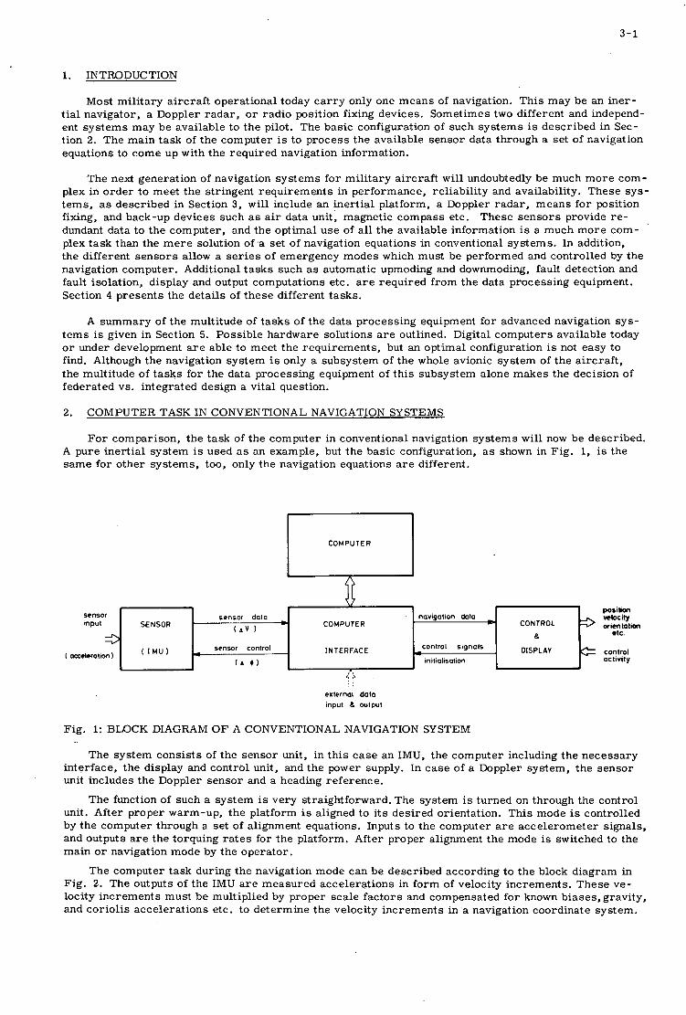
3-1
sensor sensor data navigation &la input SENSOR COMPUTER
3 ( A V )
0 ~ 0 ~
sensor control I N TE RFAC E control signcls
initialisation ( aaeleration ) ( I Mu ( A
1. INTRODUCTION
poslbm nbc i ly
etc CONTROL 3 Orimtatim
DISPLAY e control
a
actlvlty
Most mi l i t a ry a i r c r a f t ope ra t iona l today c a r r y only one m e a n s of navigation. Th i s may be an i n e r - t i a l naviga tor , a Doppler r a d a r , o r r a d i o posit ion fixing devices . Somet imes two different and independ- ent s y s t e m s m a y be avai lable to t h e pilot. The bas i c configuration of such s y s t e m s is desc r ibed in Sec- t ion 2. T h e ma in t a s k of t h e c o m p u t e r is to p r o c e s s the avai lable s e n s o r da ta through a se t of cavigation equat ions to c o m e up with t h e r equ i r ed navigation information.
T h e next genera t ion of navigation s y s t e m s f o r m i l i t a r y a i r c r a f t wil l undoubtedly be much m o r e c o m - plex in o r d e r t o m e e t t h e s t r ingent r e q u i r e m e n t s in pe r fo rmance , re l iab i l i ty and avai labi l i ty . T h e s e s y s - t e m s , as desc r ibed in Section 3, wil l include an i n e r t i a l p la t form, a Doppler r a d a r , m e a n s f o r position fixing, and back-up dev ices such as air data unit , magnet ic c o m p a s s e tc . T h e s e s e n s o r s provide r e - dundant da ta t o t h e compute r , and t h e opt imal u s e of all t h e avai lable informat ion is a much m o r e c o m - plex t a s k than the m e r e solution 0f .a s e t of navigation equat ions in conventional s y s t e m s . In addition, t h e different s e n s o r s allow a s e r i e s of emergency m o d e s which must be p e r f o r m e d and cont ro l led by the navigation computer . Additional t a s k s such as automat ic upmoding and downmoding, fault detection and fault isolat ion, d i sp lay and output computa t ions e tc . are requ i r ed f r o m t h e da ta p rocess ing equipment . Section 4 p r e s e n t s t he d e t a i l s of t h e s e d i f fe ren t t a s k s .
A s u m m a r y of t h e multi tude of t a s k s of t h e da ta p rocess ing equipment f o r advanced navigation s y s - t e m s is given in Section 5. Poss ib l e h a r d w a r e solut ions a r e outlined. Digital c o m p u t e r s avai lable today or under development a r e ab le to m e e t t h e r equ i r emen t s , but an opt imal configuration is not easy to find. Although t h e navigation s y s t e m is only a s u b s y s t e m of the whole avionic s y s t e m of t h e a i r c r a f t , t h e mul t i tude of t a s k s for t h e da ta p rocess ing equipment of t h i s s u b s y s t e m alone m a k e s the dec is ion of federa ted vs . in tegra ted des ign a v i ta l question.
2. COMPUTER TASK IN CONVENTIONAL NAVIGATION SYSTEMS
F o r compar ison , t h e t a s k of t h e computer in conventional navigation s y s t e m s will now be desc r ibed . A pure i n e r t i a l s y s t e m is used as an example, but t h e bas i c configuration, a s shown in F ig . 1, is the s a m e f o r o t h e r s y s t e m s , too, only t h e navigation equat ions are different .
Fig. 1: BLOCK DIAGRAM O F A CONVENTIONAL NAVIGATION SYSTEM
The s y s t e m c o n s i s t s of t h e s e n s o r unit , in t h i s c a s e an IMU, t h e c o m p u t e r including t h e n e c e s s a r y in t e r f ace , t h e display and con t ro l unit , and t h e power supply. In c a s e of a Doppler sys t em, t h e s e n s o r unit inc ludes the Doppler s e n s o r and a heading r e f e r e n c e .
The function of such a s y s t e m is ve ry s t ra ight forward . The s y s t e m is tu rned on through the con t ro l unit. Af te r p rope r warm-up , t h e p la t form is aligned to i t s d e s i r e d or ientat ion. Th i s mode is cont ro l led by t h e computer th rough a set of a l ignment equations. Inputs to t h e computer a r e a c c e l e r o m e t e r s ignals , and outputs a r e t h e torquing r a t e s f o r t h e p la t form. Af te r p rope r a l ignment t h e mode is switched to t h e ma in o r navigation mode by t h e o p e r a t o r .
The computer t a s k dur ing t h e navigation mode can be desc r ibed accord ing to t h e block d iagram in F ig . 2. T h e outputs of t he IMU a r e m e a s u r e d acce le ra t ions in f o r m of velocity inc remen t s . T h e s e ve - locity i n c r e m e n t s mus t b e multiplied by p rope r s c a l e f a c t o r s and compensa ted f o r known b i a s e s , gravi ty , and Coriolis acce le ra t ions etc . t o de t e rmine t h e velocity i n c r e m e n t s in a navigation coord ina te sys t em.

3-2
T h e s e i n c r e m e n t s a r e then in tegra ted for velocity and a second in t eg ra to r provides posit ion informa- t ion. Additional compensa t ion may c o r r e c t for t he el l ipt ic i ty of t he e a r t h , if n e c e s s a r y . Torquing r a t e s f o r t h e p la t form including compensat ion s igna l s f o r fixed gy ro dr i f t and e a r t h rotat ion a r e ca lcu la ted f r o m posit ion and velocity information.
Fig. 2: SCHULER-TUNED INERTIAL NAVIGATION SYSTEM
A s indicated in Fig. 2, inputs t o t h e computer dur ing t h e m a i n o r navigation mode a r e s e n s o r da ta in f o r m of velocity inc remen t s , and t h e outputs a r e posit ion and velocity informat ion to t h e con t ro l &nd d isp lay panel, and r a t e commands to t h e platform. The computer t a s k s as desc r ibed above can be ex- p r e s s e d in a se t of navigation equations which mus t be p rocessed a t a re l a t ive ly high rate (5 to 30 t i m e s pe r second) . T h e s e equations can be expres sed by l i n e a r d i f fe ren t ia l o r a lgeb ra i c equations and a r e sui t - able f o r analog and digi ta l computing techniques .
The computer h a r d w a r e avai lable f o r t h e s e t a s k s today can be put into four ca t egor i e s :
Analog C o m p u t e r s 0 Digital Different ia l Ana lyze r s (DDA) 0 Special P u r p o s e Who1 e Number C o m p u t e r s
Genera l P u r p o s e C o m p u t e r s
Analog c o m p u t e r s gradual ly d i sappea r and do not need t o be cons ide red f u r t h e r . Al l t h r e e digi ta l c o m - puter t ypes have t h e i r spec ia l advantages and d isadvantages and t h e bes t solution depends on t h e re- qu i r emen t s of a pa r t i cu la r application.
The DDA i s best sui ted f o r solving t h e navigation equat ions espec ia l ly f o r a pure i n e r t i a l sys t em, because it computes inc remen ta l changes to quant i t ies r a t h e r than whole va lues of quant i t ies t hemse lves . New LSI c i r c u i t s a r e espec ia l ly sui ted for DDA's and allow new des igns . The biggest disadvantage of a DDA is i t s poor flexibil i ty, espec ia l ly if additional t a s k s are requ i r ed .
Special purpose c o m p u t e r s a r e of i nc reas ing impor t ance through t h e u s e of r e a d - o n l y - m e m o r i e s . They p resen t a good solution f r o m a cos t - e f f ec t iveness point of view in c a s e s w h e r e the computat ional

3-3
problem is c l e a r l y defined at t h e beginning.
Gene ra l purpose c o m p u t e r s w e r e reduced in s i z e , cost, weight and volume dur ing t h e past few y e a r s th rough t h e u s e of mic roe lec t ron ic s , and so-ca l led s ingle t a s k G P c o m p u t e r s a r e coming into use. The i r p r i m e advantage is t h e i r f lexibil i ty when t h e computat ional r e q u i r e m e n t s are changed.
3. CONFIGURATION OF ADVANCED NAVIGATION SYSTEMS
Next genera t ion navigation s y s t e m s f o r a i r c r a f t wil l ce r t a in ly combine a multi tude of s e n s o r s t o m e e t i n c r e a s e d r e q u i r e m e n t s in accu racy , re l iab i l i ty and availabilfty. A typical configuration of such s y s t e m s is shown in t h e block d i a g r a m of Fig. 3. The c e n t r a l unit of t h e s y s t e m is t h e da ta p r o c e s s o r o r navigation computer whose inputs a r e supplied by a s e r i e s of s e n s o r s shown on t h e left hand s ide of t he block d i ag ram. T h e navigation informat ion is m a d e avai lable through output and d isp lay uni ts as indicated on t h e r ight hand s i d e of t he block d i ag ram. Only t h e flow of navigation informat ion is shown in F ig . 3, while con t ro l s igna l s are not detai led f o r r e a s o n s of c l a r i t y . The p rocess ing of con t ro l s ig- n a l s such as se l f - tes t in format ion is a l s o pa r t of t h e c o m p u t e r t a sk .
SENSOR SENSOR ELECTRONIC
EOUIPLDENT DATA PROCESSING
EWIPMENT INPUT AND OUTPUT
EOUIPMENT
I I CONTROL AN0 system status gyro torquing signals
cantrat and BITE signals
heading and attitude angels + I
I M U ELECTRONICS - W,O,
I M U
P L Velocity Vo, V b , V c
Iandheo availability DOPPLER RAOAR DOPPLER RAOAR
ANTENNA ELECTRONICS conlrol and BITE singnats
hcadin an le HEAOING AND PLATFORM
ATTITUDE roll and pitch angle REFERENCE PLATFORM
distance and bearing
RADIO NAVIGATION RADIO NAVIGATION dillerences
static pressure ps
dynamic pressure pd 'IR OATA AIR DATA
*mp.mtur. I I I ELECTRONICS
I I I I AUXILIARY SENSOR AND BACK-UP SENSOR INPUTS 4
NAVIGATION
COMPUTER
(Central unit
memory and
interlace unit )
MAP DISPLAY
OTHER
AVIONIC
SVSTEWS I ' I
F i g . 3: ADVANCED NAVIGATION SYSTEM ( MULTISENSOR SYSTEM)
Any pa r t i cu la r s y s t e m may not n e c e s s a r i l y contain all of t h e uni ts shown in Fig. 3, but t h i s wil l not change the computer t a s k significantly, a s long as redundant s e n s o r informat ion is avai lable and must be p rocessed in an opt imal s e n s e .
The different s e n s o r s , t h e i r m e a s u r e d quant i t ies and t h e i r poss ib le outputs and inputs a r e now desc r ibed .
I n e r t i a l Measurement ' Unit (IMU)
The inertial p la t form is stabi l ized in a known coord ina te f r a m e and m e a s u r e s acce le ra t ion along p la t form axes . Partial integrat ion is accompl ished in t h e platform e l ec t ron ic s .
Avai lable outputs: velocity i n c r e m e n t s
or ientat ion ang le s (usual ly analog)
A V in pla t form coord ina te s x, y, z

3-4
Requi red inputs: gy ro torquing rates w f o r p la t form orientat ion.(usual ly i n digi ta l f o r m as angular i n c r e m e n t s A 6 g
I
Cont ro l s igna l s to t h e computer :
r eady s igna l s - -depending on t e m p e r a t u r e , gy ro wheel supply, se l f - tes t outputs e tc . - and IMU mode indication s igna ls .
Cont ro l s igna l s f rom t h e computer : con t ro l
tu rn-on and turn-off s igna l s f o r mode
0 Back-up Heading and Atti tude Refe rence Unit
T h i s unit p rovides or ientat ion ang le s in c a s e of a malfunct ion of t h e i n e r t i a l p la t form.
0 Doppler Radar :
The Doppler r a d a r s e n s o r c o n s i s t s of a body-fixed or a stabi l ized antenna and t h e r equ i r ed e l ec - t ron ic s . Or ien ta t ion ang le s f o r s tabi l izat ion can be provided by t h e i n e r t i a l p la t form o r a v e r t i c a l gy ro . T h e Doppler r a d a r m e a s u r e s ground speed of t h e a i r c r a f t .
Available outputs: d i s t ance i n c r e m e n t s or velocity components in body-fixed a x e s o r : velocity and d r i f t angle; l and - sea c r i t e r i o n
Required inputs:
Cont ro l s ignals :
or ientat ion ang le s 6 in c a s e of a s tabi l ized antenna.
avai labi l i ty and se l f - tes t s igna l s , mode con t ro l s ignals .
0 Radio Rece ive r Unit:
Radio position-fixing s e n s o r s under cons idera t ion a r e L o r a n C and D, Decca, Tacan and Omega. T h e s e s e n s o r s give position informat ion with r e s p e c t t o known posi t ions of t h e t r a n s m i t t e r s ta t ions.
Available outputs: d i s tance d i f f e rences t o t h r e e s t a t ions in f o r m of t i m e d i f fe rence pulses ( in c a s e of Loran , Decca and Omega) o r : r ange and bea r ing to one o r m o r e s t a t ions (Tacan)
Requi red inputs:
Cont ro l s ignals :
s ta t ion select ion s igna ls , phase r a t e commands ( L o r a n ) .
avai labi l i ty and se l f - tes t s igna l s , s ta t ion identification s ignals ; mode con t ro l s ignals .
0 A i r Data Sensor:
The air da ta s e n s o r m e a s u r e s s ta t ic 8nd dynamic air p r e s s u r e and air t e m p e r a t u r e . F r o m t h e s e da ta can be de r ived vehic le t r u e a i r s p e e d and b a r o m e t r i c alt i tude.
Available outputs: s ta t ic and dynamic a i r p r e s s u r e , air t e m p e r a t u r e ( t h e s e outputs a r e usually analog)
Requi red inputs: none
Cont ro l s ignals :
Additional back-up s e n s o r s f o r emergency modes :
avai labi l i ty and se l f - tes t s igna ls .
Magnet ic c o m p a s s , v e r t i c a l and d i r ec t iona l gy ro etc .
The different output and d isp lay uni ts and t h e i r cor responding input and output s igna l s are as follows:
0 Contro l and Display Unit:
Th i s unit is t h e in t e r f ace between the pilot and t h e navigation sys t em. It p rovides d isp lay of naviga- t ion informat ion as wel l as s y s t e m s ta tus , such as mode of opera t ion , availabil i ty of subsys t ems , malfunct ion o c c u r r e n c e e tc .
Inputs f r o m t h e computer : posit ion, velocity, heading, a t t i tude; t i m e of flight, bea r ing and d i s t ance to t a r g e t s .
Outputs t o t h e computer : ini t ia l posit ion, flight plan data .


3-6
DOPPLER
) - - - - - --I A t , , A t ? 1 NAVIGATION 1-w
- AIR DATA I Fig . 4: PROCESSING OF SENSOR DATA
-+ - b +
V N - f ( V , , t o , l a n d / c s a )
4 3 + + R = f ( R , , R ? , R , , ~ t , , ~ t ~ )
( Decca, Loran , Omega
4 4 ' V - f ( TAS , V
N 'A wind
4
The n e c e s s a r y gy ro torquing r a t e s w mus t be de r ive w'. and the platform or ien ta t ion TI: g
P
f rom the d e s i r e d platform ro ta t ion r a . 3
The platform g imba l angles a r e not d i r ec t ly r e q u i r e d a s navigation information, but they a r e used to d e t e r m i n e Doppler and a i r da ta s e n s o r or ien ta t ion .
Doppler Sensor :
The Doppler s e n s o r m e a s u r e s ground veloci ty V d
along ~ r c r a f t o r Doppler beam a x e s a , b, c . The m e a s u r e d da ta mus t be t r a n s f o r m e d into a $%%@hector V along navigat ional coord ina tes by using Doppler or ien ta t ion angles' TD. Changes of t he Doppler s c a l e q a c t o r mus t be included by using land/sea c r i t e r i a .
Radio Navigation Sensor:
The r e q u i r e d s a n s f o r m a t i o n s depend on t h e type of s y s t e m used. In c a s e of a Tacan r e c e i v e r , po- si t ion information R mus t be computed fr-h the m e a s u r e d d i s t ances s t o a Tacan s ta t ion and t h e known position R of t h i s s ta t ion. Simultaneous o r eequent ia l m e a s u r e m e % to two o r m o r e s t a t ions may cons iderably r e d u c e the position e r r o r because the e r r o r contr ibut ion of t he bear ing angle uncer ta in ty is re la t ive ly high, if only one s ta t ion is used.
and the bear ing angle I3 TC 0
In c a s e of hyperbol ic s y s t e m s (Loran , Decca, Omega 4
t he position R of t he a i r c r a f t is comput-
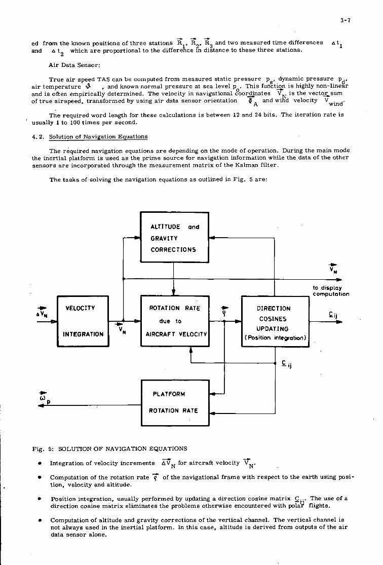
3-7
- VELOC I T Y AV,
4 - 4
A t l ed f r o m the known posi t ions of t h r e e s t a t ions R1, R2, R3 and two m e a s u r e d t i m e d i f fe rences and
A t 2 which a r e proport ional t o the d i f fe rence in d is tance to t h e s e t h r e e s ta t ions .
A i r Data Sensor :
b b
to display 7
I computation
+ 01 REC T I O N Cij
1 - C O S I N E S 9
ROTATION RATE
d' T h i s functuxn is highly non- l inear
T r u e a i r speed TAS can be computed f r o m m e a s u r e d s t a t i c p r e s s u r e p,, ,dynamic p r e s s u r e p
VN is the v e c t o x s u m a i r t e m p e r a t u r e 6 , and known n o r m a l p r e s s u r e a t s e a leve l p and is often empir ica l ly de te rmined . The veloci ty in navigat ional coord ina tes of t r u e a i r speed , t r a n s f o r m e d by using a i r data s e n s o r or ien ta t ion
0'
6 , and wind veloci ty V . wind'
The r e q u i r e d word length fo r t h e s e ca lcu la t ions is between 1 2 and 24 bits . The i t e r a t ion r a t e is ' usual ly 1 t o 100 t i m e s p e r second.
+ * INTEGRATION vN
4. 2. Solution of Navigation Equat ions
The r e q u i r e d navigation equat ions a r e depending on the mode of operat ion. During the ma in mode the i n e r t i a l platform is used as the p r i m e s o u r c e for navigation information while the da t a of t he o the r s e n s o r s a r e incorpora ted through the m e a s u r e m e n t m a t r i x of t he Kalman f i l t e r .
The t a s k s of solving the navigation equat ions a s outlined in Fig . 5 a r e :
due to - m U P D A T I N G
( Position intcgation) AIRCRAFT VELOCITY
* b
ALTITUDE and
G R A V I T Y
C O R R E C T I O N S 'I t
PLATFORM
ROTATION RATE
J C - ij
Fig . 5: SOLUTION O F NAVIGATION EQUATIONS
d -L
N' 0 In tegra t ion of veloci ty i n c r e m e n t s AVN fo r a i r c r a f t veloci ty v
Computation of t he ro ta t ion r a t e 7 of the navigat ional f r a m e with r e s p e c t t o t h e e a r t h using posi- t ion, veloci ty and alt i tude.
0 Posi t ion in tegra t ion , usual ly pe r fo rmed by updating a d i rec t ion cos ine m a t r i x si.. The u s e of a d i rec t ion cos ine m a t r i x e l imina te s the p rob lems o therwise encountered with polad fl ights.
Computation of alt i tude and gravi ty c o r r e c t i o n s of t he v e r t i c a l channel . The v e r t i c a l channel is not a lways used in the i n e r t i a l platform. In t h i s c a s e , alt i tude is der ived f rom outputs ,of t he a i r da ta s e n s o r a lone.
0
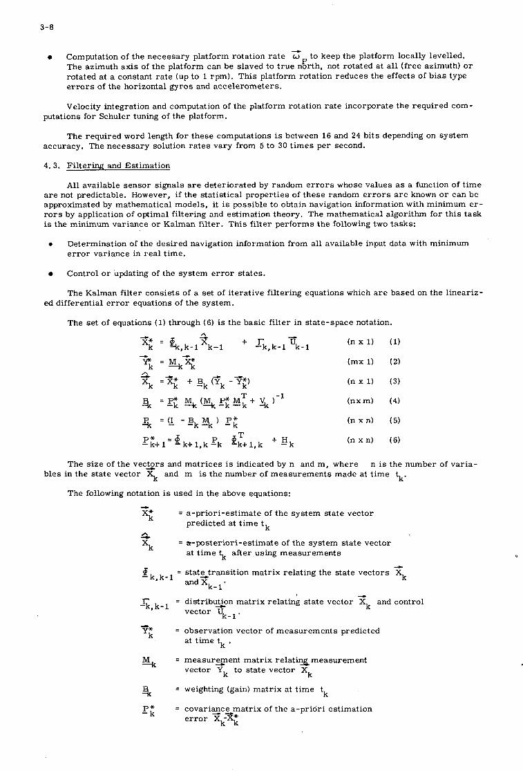
3-8
4
0 Computation of t h e n e c e s s a r y platform rotat ion r a t e o t o keep the platform locally levelled. The az imuth a x i s of t h e platform can be s laved to t r u e north, not ro t a t ed a t all ( f r e e az imuth) o r rotated a t a constant r a t e (up to 1 r p m ) . Th i s platform rotat ion r e d u c e s t h e e f fec ts of b i a s type e r r o r s of t he hor izonta l g y r o s and a c c e l e r o m e t e r s .
P
Velocity integrat ion and computat ion of t he p la t form rotat ion r a t e i nco rpora t e t h e r equ i r ed c o m - putations f o r Schuler tuning of t h e p la t form.
The r equ i r ed word length f o r t h e s e computat ions is between 16 and 24 b i t s depending on s y s t e m accuracy . T h e n e c e s s a r y solution r a t e s va ry f rom 5 to 30 t i m e s p e r second.
4. 3. F i l t e r i n g and Es t ima t ion
Al l avai lable s e n s o r s igna l s a r e de t e r io ra t ed by random e r r o r s whose va lues as a function of t i m e a r e not predictable . However, if t he s t a t i s t i ca l p r o p e r t i e s of t h e s e r andom e r r o r s a r e known or c a n be approximated by ma themat i ca l models , it is poss ib le t o obtain navigation informat ion with min imum e r - rors by application of op t imal f i l t e r ing and es t imat ion theory. The ma themat i ca l a lgor i thm f o r t h i s t a s k is t h e min imum va r i ance o r Kalman f i l t e r . T h i s f i l t e r p e r f o r m s t h e following two t a sks :
0 Determina t ion of t h e des i r ed navigation informat ion f r o m all avai lable input da ta with minimum e r r o r va r i ance in r e a l t ime .
Cont ro l or updating of t he s y s t e m e r r o r s t a t e s .
The Kalman f i l t e r c o n s i s t s of a se t of i t e r a t i v e f i l t e r ing equat ions which a r e based on t h e l i n e a r i z - ed different ia l e r r o r equations of t h e sys t em.
The set of equations (1) through (6) is t h e bas i c f i l t e r in s t a t e - s p a c e notation.
T h e s i z e of t h e v e c t o r s and m a t r i c e s is indicated by n and m , w h e r e n is t h e number of v a r i a -
k' b l e s in t h e s t a t e vec to r 3 and m is t h e number of m e a s u r e m e n t s made at t i m e t
The following notation is used in the above equations: - 5 s xk
= a - p r i o r i - e s t i m a t e of t h e s y s t e m s t a t e vec to r pred ic ted at t i m e t k
= a - p o s t e r i o r i - e s t i m a t e of t h e s y s t e m s t a t e vec to r a t t i m e 5 after using m e a s u r e m e n t s
--L
xk = state-transition m a t r i x r e l a t ing the s t a t e ' v e c t o r s ' k , k - 1 and Xk-
r -k*k-l vec to r u ~ - ~ .
= d i s t r ibuzon m a t r i x r e l a t ing s t a t e vec to r zk and con t ro l
= observa t ion vec to r of m e a s u r e m e n t s pred ic ted at t i m e t k . Yt
% = m e a s u r e m e n t m a t r i x r e l a t i n 2 m e a s u r e m e n t
5 vec to r Yk to s t a t e vec to r
k 3 = weighting (gain) m a t r i x a t t i m e t
J?f = c o v a r i a z c 5 m a t r i x of t h e a - p r i o r i e s t ima t ion e r r o r x -X* k k
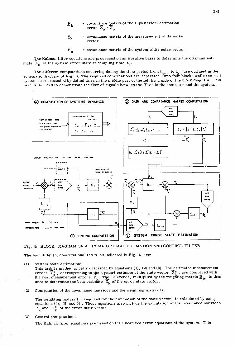
3 -9
= covariazce g a t r i x of the a-posteriori estimation
k - xk e r ro r X
= covariance matrix of the measurement white noise vector
-pk
-vk
= covariance matrix of the system white noise vector. -Hk
ghe Kalman filter equations a r e processed on an iterative basis to determine the optimum esti- mate \ of the system e r r o r state at sampling t ime tk.
The different computations occurring during the t ime period from t to tk a r e outlined in the k: schematic diagram of Fig. 6. The required computations a r e separated Inio four blocks while the real
system is represented by dotted lines in the middle part of the left hand side of the block diagram. This part is included to demonstrate the flow of signals between the filter in the computer and the system.
-1 -- @ COMPUTATION OF SYSTEMS DVNAMICS
compulolion 01 Ihe liom sensor dam i i malrices
!b,b-O , c b , b . t , ! b ;
! b , ! b , E b
proccrsmg and norigohon equononr computation - I
ERROR PROPAGATION OF T H E REAL SYSTEM
r - - - - i
-1 @ GAIN AND COVARIANCE MATRIX COMPUTATION
I I
I
1 I I r--L-
- - !b,-l
I 'be , , b I L-- -1 f-
u b L - - - - - -
- 4
- r -
ERROR STATE ESTIMATION
-b,b. l delay
~- .----
r0.d k q l h l b 32 blls
1l8mMn mu 1 I O p.r mm
Fig. 6: BLOCK DIAGRAM OF A LINEAR OPTIMAL ESTIMATION AND CONTROL FILTER
The four different computational tasks a s indicated in Fig. 6 are:
(1) System state estimation: This t a s k is mathematically described by equations (l), (2) and ( 3 ) . The-estimated measurement e r r o r s Yf , corresponding toLhe a priori estimate of the state vector X* a r e compared with the real measurement e r ro r s Y k' used to determine the best estimate 'iT, of the e r r o r state vector.
Computation of the covariance matrices and the weighting matrix E:
The weighting matrix E , required for the estimation of the state vector, is calculated by using equations (4), (5) and (6). These equations also include the calculation of the covariance matrices Pk and _P* of the e r r o r stat,e vector.
TQe difference, multiplied by the weighing matrix gk, is then
( 2 )
k -
(3) Control computations:
The Kalman filter equations a r e based on the linearized e r ro r equations of the system. This
linear e r ro r model is only valid a s long as the components of the e r ro r state vector a r e small. This requirement can only be achieved by controlling the state vector in a closed loop operation. This mean2 that computed values of the state vector, af ter proper transformations into the control vec- tor U a r e fed back to the system and used to correct system e r ro r parameters (i. e. gyro drift, biases, scale factors etc. ). k’
(4) Computation of systems dynamics:
The matrices representing the systems dynamics a r e required for the filter equations and must be consecutively computed.
describes the e r ro r propagation in the system from time given by the system e r r o r 1 The state transition matrix 2
tk - l . k *. equations and valid e r ro r models. to t ime t It is derived<’%om the coefficient matrix A(t)
The measurement matrix M
The distribution matrix r
The covariance matrices of system noise- and measurement noise V a r e also determined from noise e r ro r models and systems dynamics.
is determined by the systems configuration. -k
is determined by system control equations. -k, k-1
Hk -k
The processing of the Kalman filter equation represents a very heavy burden on the navigation com- puter, because many matrix transformations and multiplications with large matrices are involved. It is therefore very important to keep the order of the e r ro r state vector, and accordingly the order of the matrices, as low a s possible and still make maximal use of the redundant data. Very extensive stud- ies and simulations a r e required to optimize the Kalman filter for a particular system with regard to size of the state vector, required word length, and iteration rate. Usually, adequate word length l ies between 24 and 32 bits and the required iteration rate for the complete filter is between 1 and 10 t imes per minute. But a small part of the computations must be performed at higher rates.
4 .4 . Submodes and Emergency Modes
The navigation computer must be programmed to perform certain tasks associated with the different possible modes of operation. The submodes are used during normal operation while emergency modes a r e only used in case of equipment malfunction. During these modes, it is possible to use parts of the navigation program or the optimal filtering program in combination with additional equations. Logic de- cisions a r e required to combine these program parts.
The different modes that must be considered are:
Stand -by:
Alignment:
This mode is used to warm up the inertial platform and to keep it on operational temperature. No computer functions a r e performed and usually power is switched off from the computer.
This mode includes coarse and fine alignment of the inertial platform. A set of alignment equations must be processed to achieve gyrocompass- ing. The platform may be slewed to t rue north, not rotated at all, or rotated at a constant rate. The Kalman filter can be incorporated into this mode.
Navigation Emergency Modes:
In case of a malfunction of the inertial platform, navigation is performed by dead reckoning using velocity and heading information. Several dif- ferent back-up modes a r e available using Doppler radar or air data as velocity information and the back-up heading and attitude reference, a directional gyro, or the magnetic compass a s heading reference.
The navigation equati.ons that must be available in the computer a r e al- most independent of the type of sensor used. A simplified Kalman filter can also be implemented if redundant position information is sti l l avail- able.
Calibration: Calibration of certain system parameters is performed during the normal navigation mode with the Kalman filter. Additional calibration can be done during alignment, also with the aid of the Kalman filter. It may be neces- sary, however, to add a special calibration mode, where calibration is performed to a higher degree of accuracy under favorable environmental conditions.
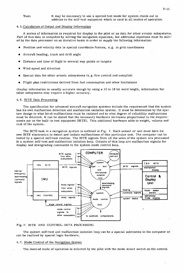
3-11
-
inter no1 emergency downmoding
signols command
-
Test:
I M U B I T E
I M U
I M U CONTROL
It may be necessary to use a special test mode for system check-out in addition to the self-test equipment which is used in all modes of operation.
4. 5. Calculation of Output and Display Information
A ser ies of information i s required for display to the pilot o r a s data for other avionic subsystems.. Part of this data is computed by solving the navigation equations, but additional equations must be solv- ed by the data processor on an iterative basis in order to supply the following information:
Position and velocity data in special coordinate frames, e. g. in grid coordinates
Aircraft heading, track and drift angle
Distance and time of flight to several way points or targets
Wind speed and direction
e Special data for other avionic subsystems (e. g. fire control and autopilot)
0 Flight plan restrictions derived from fuel consumption and other limitations
Display information is usually accurate enough by using a 1 2 to 16 bit word length, information for other subsystems may require a higher accuracy.
4.6. BITE Data Processing
The specification for advanced aircraft navigation systems include the requirement that the system has i ts own malfunction detection and malfunction isolation system. It must be determined by the sys- tem design to what level malfunctions must be isolated and to what degree of reliability malfunctions must be detected. It can be stated that the necessary hardware increases proportional to the require- ments put on the built-in test equipment (BITE). This additional hardware adds to weight, volume and cost of the system.
The BITE task in a navigation system is outlined in Fig. 7. Each sensor o r unit must have i ts own BITE electronics to detect and isolate malfunctions of this particular unit. The computer can be tested by a special self-test routine. The BITE signals from all the units of the system a r e processed in a system self-test and malfunction isolation loop. Outputs of this loop a r e malfunction signals for display and downgrading commands to the system mode control loop.
1
lrom other
B I T E signols
down moding reody from other signals [ % command
subsystems
reody signals mode conlrol
signals lo
olher subsystems to submode computations
BITE signals
moding command signal!
system shlus
C 8 D BITE
malt unction dimlav
Control 8, Display
Unit
mode wlecl switch
operational mode display
Fig. 7: BITE AND CONTROL DATA PROCESSING
The system self-test and malfunction isolation loop can be a special subroutine in the computer o r can be realized by special logic hardware.
4. 7. Mode Control of the Navigation System
The desired mode of operation is selected by the pilot with the mode select switch on the control
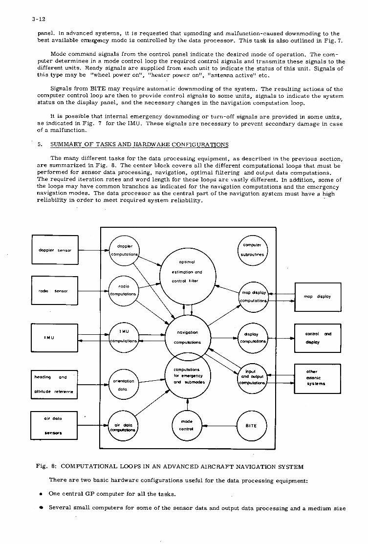
3-12
panel. In advanced systems, it is requested that upmoding and malfunction-caused downmoding to the best available e m r g a c y mode is controlled by the data processor. This task is also outlined in Fig. 7.
Mode command signals from the control panel indicate the desired mode of operation. The com- puter determines in a mode control loop the required control signals and transmits these signals to the different units. Ready signals a r e supplied from each unit to indicate the status of this unit. Signals of. this type may be "wheel power on", "heater power on", "antenna active" etc.
Signals from BITE may require automatic downmoding of the system. The resulting actions of the computer control loop a r e then to provide control signals to some units, signals to indicate the system status on the display panel, and the necessary changes in the navigation computation loop.
It is possible that internal emergency downmoding or turn-off signals a r e provided in some units, a s indicated in Fig. 7 for the IMU. These signals a r e necessary to prevent secondary damage in case of a malfunction.
5. SUMMARY OF TASKS AND HARDWARE CONFIGURATIONS
The many different tasks for the data processing equipment, a s described in the previous section, a r e summarized in Fig. 8. The center block covers all the different computational loops that must be performed for sensor data processing, navigation, optimal filtering and output data computations. The required iteration rates and word length for these loops a r e vastly different. In addition, some of the loops may have common branches as indicated for the navigation computations and the emergency navigation modes. The data processor a s the central part of the navigation system must have a high reliability in order to meet required system reliability.
I
C o m p u t e r
subroutines
doppler doppler sensor
optimal
I \ f estimation and \
avionic sy s tc ms
Fig. 8: COMPUTATIONAL LOOPS IN AN ADVANCED AIRCRAFT NAVIGATION SYSTEM
There a r e two basic hardware configurations useful for the data processing equipment:
One central GP computer for all the tasks.
Several small computers for some of the sensor data and output data processing and a medium size
0
3-13
computer for navigation, optimal filtering and mode control.
The use of a single G P computer results in the minimum hardware, and the advanced computers available today a r e able to meet all the requirements. But the programming of all the different loops with iteration rates ranging from 10 to 30 t imes per second to 1 every few minutes is a very tedious task. The accuracy requirements will probably best be met by a 16 to 24 bit word length using double precision for the filtering and part of the navigation computations. The difficult task of scaling all pa- rameters may be alleviated in the future by using floating point machines. In order to meet the required reliability it may be necessary to use a second computer a s back-up o r to have double o r triple redun- dancy inside the computer.
The use of several small computers has the advantages of simpler programming and higher relia- bility. These computers may be DDA's o r small G P machines. The following tasks a r e suitable for separate processing:
0 IMU sensor processing.
Often a small inertial platform computer is used for position integration including Schuler tuning of the platform. This computer must be available if "hot insertion" is required.
0 A i r data computations.
A special a i r data computer is advantageous because of the very special computational requirement.
0 Radio navigation data processing.
Solution of hyperbolic position information into earth-fixed coordinates can be performed by a small computer a s part of the radio navigation unit.
0 Display computations.
Some of the display computations may be performed in the map display o r the control and display panel.
0 BITE data processing.
The processing of all BITE information may be performed by a separate malfunction detecting and recording computer for the navigation system o r for the complete avionic system.
These peripheral computers a r e usually matched with a central computer for optimal filtering, navigation and mode control. But emergency modes must be available, in case the central computer fails.
The broad spectrum of tasks of the data processing equipment for advanced aircraft navigation systems has been outlined. The basic specification that must be used by the system designer to detail the tasks for a particular system is that maximum use is made of all available sensor information and that the obtainable systems performance is not significantly degraded by the processing of data.

4
FEDERATED VS. INTEGRATED COMPUTER SYSTEMS
J a m e s H. Crenshaw
IBM Corporat ion, F e d e r a l Sys t ems Division,
E lec t ron ic s S y s t e m s Center , Owego, New York 13827, USA.

4
SUMMARY
A s it becomes possible through microminiaturization techniques to provide more digital computing capability in smaller, lighter packages, the Aerospace industry is finding it desirable to utilize the advantages of digital computers in more complex and varied applications.
The problem of computer subsystem organization must be solved in such a way as to best accommodate the sys- tem requirements and also provide flexibility, expandability and reliability. Solutions of this problem can vary between the two extremes represented by (1) the completely dedicated loosely-federated, system made up of a s many CPU's as there a re tasks and (2) the completely integrated, simplex o r multi-processor, system capable of performing all of the required tasks.
This paper reviews the system organizations utilized in such operational systems as the F111-MKII, the A-7D/E, MASS and ILASS. It also reviews the design considerations for various other developmental systems.
The advantages and disadvantages of the Federated and Integrated approaches a r e reviewed from an abstract point of view and then the system dependent variables which must be considered by the designer a re discussed to em- phasize the real world situation. Such features a s vulnerability to the %ingle bulletqt and graceful degradation are considered along with the queuing theory, "waiting time", and loading factor trade offs. The important factor of rela- tive cost of the two approaches is also discussed.
In conclusion, the final selection may be determined by system dependent factors although customer preference is a major consideration. In general the comparisons presented in this paper favor the integrated system with problem size determining whether a single processor o r a multiple processor configuration is required.
4- 1
FEDERATED VS. INTEGRATED COMPUTER SYSTEMS
James H. Crenshaw IBM Electronics Systems Center
Owego, New York 13827
INTRODUCTION
Each advance in computer technology generates more complex and varied applications for digital computers in the aerospace industry. These advances include faster circuit and memory speed, microminiaturization, and drama- tic cost reductions. The selection of computer organization is a dynamic process, continuously taking advantage of the latest technology to meet an expanding number of applications. Historically, computer organization has varied between the two extremes represented by:
0 The completely dedicated, loosely-federated, system made up of as many computers as there a re tasks. (This approach predates the advent of general purpose digital computation for aerospace applications and has been retained in modified form for some digital applications. )
The completely integrated system capable of performing all the required computations within a single computer complex. (Capabilities of a single processor may be expanded by employement of multiprocessors if requirements exceed those which can be met with a simplex computer. )
0
In practice, computer organization may be a combination of both, as will be illustrated by examples such as the Gemini, MAS, ILAAS, Saturn, Mark II, A-'ID/E, and VS A-NEW. The advantages and disadvantages of the two or- ganizational concepts a re examined considering such factors as: size, weight, cost, storage requirements, vulner- ability to battle damage, queuing problems, waiting time, and loading factor. From examination of past system organizations, technological development, and the comparison of federated vs. integrated systems, conclusions a re drawn relative to future trends for aerospace applications.
This'paper i s primarily limited to general-purpose digital computers. Definitions of terms used in the paper a s they apply to general-purpose computers a re as follows:
Federated Computer System
A federated system consists of several computers, each dedicated to a particular task. The computers com- municate through their 1/0 channels for normal functions. Redundancy may be provided, as in the case of the dual federated system, where each computer can perform backup functions in addition to i ts normal functions in the event of malfunction of the other computer.
Integrated Computer System
An integrated system is defined as one which performs unrelated tasks in a multiprogrammed mode of opera- tion. The system may contain one CPU (the simplex system), o r two CPU's sharing common main storage operating in a multiprocessing mode. The number of job queues distinguishes a federated system from an integrated system. A federated system requires a job queue and executive program in each computer, while an integrated system has only one job queue and executive program residing in the common storage.
Multiprogrammed System
Independent of the hardware configuration, a system may or may not be multiprogrammed. Multiprogramming is the concurrent, interleaved execution of multiple programs which a r e implemented by timed or externally con- trolled interrupts.
Applications
Table I is a partial listing of aerospace applications for general-purpose digital computers.
Many factors, some technical and others arbitrary,affect the final partitioning o r assignment of functions. At the present time, special-purpose processors are generally employed for high-speed functions such as radar data processing, character generation, image enhancement, and terrain following. Other functions such a s landing con- trol , air data, and engine control a r e generally separated due to tradition, reliability considerations, and the desire for independent operation.
Analog and special-purpose digital processors will continue to be applied to such functions, but the rationale for each function should be re-examined for each new system in the light of advancing technology. However, this paper will be limited to the organizational forms of the general-purpose digital computer which encompasses the major por- tion of the computational functions.
4- 2
Table I
AVIONIC SYSTEM FUNCTIONAL APPLICATIONS
Navigation Inertial Platform Management Guidance Weapon Delivery Operator Control and Display Character Generation Sensor Control Sensor Data Storage Statistical Processing Filtering Image Enhancement Ai r Data Terrain Following Flight Parameter Recording Countermeasures Detection and Control Threat Analysis Auto Pilot Landing Control Engine Control Self Test System Diagnostics (AIDS)
SURVEY OF EXISTING SYSTEMS
A survey of existing systems reveals that there is no single satisfactory approach. Both integrated and feder- ated systems have been developed and successfully utilized. Each application is somewhat unique, but some insight into trends can be obtained and conclusions drawn by examination of the information generally available in the liter- ature regarding the existing systems selected for review. All of the following computer systems described a r e pro- ducts of IBM Owego, with the exception of MAS and ILAAS, which were included because of their unique structure.
Gemini
The Gemini system utilizes a simplex-multiprogrammed digital computer which performs rendezvous and re- entry functions and also backup ascent guidance. See Figure 1. This computer is classed as an integrated system for the functions which i t performs. However, there a r e many other elements of the system which do not interface with the computer. Figure 2 is a functional diagram of the Gemini System.
Integrated Helicopter Avionics System (IHM)
The IHAS computer centralcomplexconsists of a Signal Transfer Unit (STU) , a Digital Interface Unit (DIU), and a Central Processor Unit (CPU). See Figure 3. Triple redundancy is employed to enhance reliability; modularity per- mits growth for adding functions or sensors. The computer central complex is an integrated system since i t handles both the navigation and sensing functions. However, the individual elements are a hybrid consisting of a general- purpose STU and special-purpose (federated) Digital Differential Analyzer (DDA) . Integrated Light Attack Avionics System (ILAAS)
ILAAS employs a federated computer system containing two independent, dedicated-multiprogrammed digital computers: one performs navigation and weapon delivery, and the other performs inertial and radar data computa- tions. See Figure 4. Two additional redundant computers are optional if additional reliability is desired. A core of functionally independent units is employed to reduce the impact resulting from the loss of a function. Each core unit is independent ana does not depend on other elements. Full system operation is achieved with the core units and other integrated units. Graceful degradation is achieved in the event of equipment failure, since the core-functions alone provide the final backup capability.
Saturn
The Saturn Guidance and Control System, shown in Figure 5, employs a federated system in which each compo- nent performs its own particular function. The digital computer is concerned only with the guidance task. Within this task, the computer is integrated with a triple modular redundant CPU and duplex memory to achieve the reliability required for the Apollo mission. Figure 6 is a photograph of the Saturn Computer used in the Apollo mission.
4- 3
Mark II
The Mark II digital computer is shown in Figure 7. The Mark I1 System uses two identical digital computers and a three-section signal converter. Each computer is dedicated to a specific function, i . e . , weapon-delivery or navigation. However, each computer contains backup routines for the other wit!! independent sections of the signal converter to provide graceful degradation. In addition, a third smaller computer is completely dedicated to inertial navigation computations. Figure 8 is a fUnCti0Ml diagram of the computer complex.
The total system may be considered to be federated; however, the individual elements function in many ways similar to an integrated system. In fact, the backup weapon-delivery functions a r e normally computed simultaneously in the navigation computer because of the transient which would otherwise occur during a transfer of control.
A-7D/E
The A-7D/E Avionics Computer, Figure 9, is a multiprogrammed-simplex-integrated system which handles functions such as navigation, weapon delivery, and self-test in interleaved manner.
The emphasis in the computer is on simplicity and minimum computational hardware necessary to perform a relatively large number of system functions. The A-?D/E began a s a replacement for an existing analog computer in the A-i'A/B. During the proposal stage, as the flexibility, accuracy, and added modes which a r e possible with digital computation became apparent, numerous functions were added resulting in a true integrated system. Extensive signal conversion equipment is supplied and i s characteristic of an integrated computer system. However, no redundancy is provided, either in hardware o r in communication channels. See Figure 10.
The A-7 system provides, at a fraction of the cost, functional capabilities comparable to larger, more com- plex systems. However, there is no graceful degradation in the event of a computer failure.
VS A-NEW
There is a growing trend in systems currently under development to utilize multiprocessor techniques. The '
tasks to be performed a re so complex that a single computer cannot accomplish the job. VS A-NEW is an example of this trend. Figure 11 is a simplified diagram of the system.
The VS A-NEW system is a multiprogrammed-multiprocessor-integrated system which has considerably greater capabilities than most previous avionics computers. In this system, each CPU has access to all storage and 1/0 Fits and the operation is controlled by a single executive routine and job queue. In the supervisor program, the system uses concepts and techniques similar to the dual IBM System 360 Model 65 shared&orage multiprocessing system.
The VS A-NEW, A-'ID/E, and Mark II are all members of the IBM System/4 Pi family.
In all of the previous systems, even where the central computer is integrated, there a r e other dedicated pro- cessors assigned to specific functions which provide inputs to the central computer or utilize outputs. For example, . the pilot's displays may contain various forms of general-purpose processors for generating symbols and buffering information received from the computer. Another processor may exist in the radar to operate on raw radar data, to provide filtering or weighting, and to convert information to digital format for transmittal to the central computer. A i r data computations and auto-pilot functions a r e almost always performed independently. Therefore, in the stric- test sense, all the systems selected are to a greater or lesser degree federated. These systems contain a general- purpose computer, integrated in the context of the functions which it performs, but which is federated with other special-purpose or dedicated processors.
FEDERATED vs. INTEGRATED COMPUTER SYSTEMS
The consideration of federated vs. integrated computer systems is most interesting when there is a require- ment for multiple processors, whatever the reason, i.e., computational complexity exceeds the capabilities of a simplex computer, o r other considerations such as redundancy, graceful degradation, or independence for flight safety. Obviously, an integrated system may use a single simplex computer.
Integrated systems a r e put to best advantage in situations where task queues tend to be long or unpredictable, and where processing power and flexibility a r e at a premium. Graceful degradation can be provided with multiple processors with either system. Federated systems may be less vulnerable to battle damage if the processors can operate independently.
Table II summarizes some of the relative advantages and disadvantages of the two configurations.
Multiprocessing in an integrated system, provides an advantage over a federated processor system, since a federated system would require multiple executive programs and program queues. An integrated multiprocessing system, on the other hand, has only one program queue and one executive. Both CPU's a r e controlled by the one exe- cutive, and both receive program priorities from the same queue. The benefit of this approach is examined in the next paragraph.
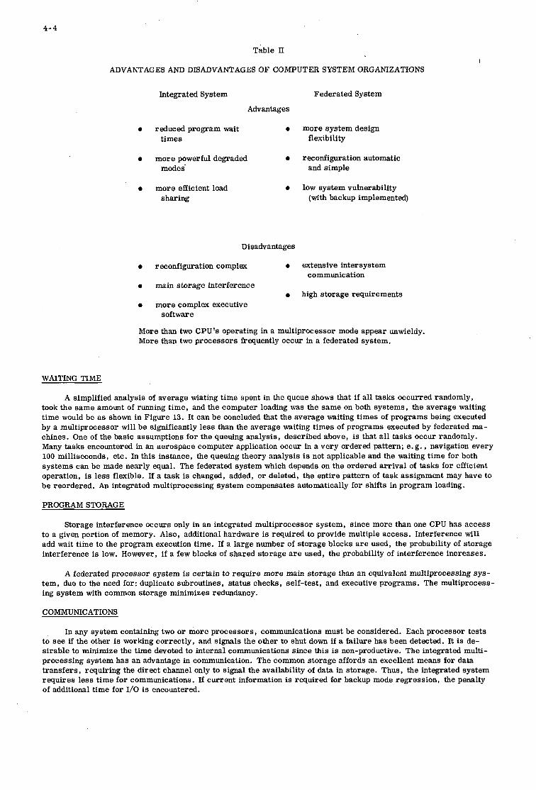
4-4
Table 11
ADVANTAGES AND DISADVANTAGES OF COMPUTER SYSTEM ORGANIZATIONS
Integrated System Federated System
Advantages
0 reduced program wait 0 more system design times flexibility
0 more powerful degraded 0 reconfiguration automatic modes and simple
0 more efficient load 0 low system vulnerability sharing (with backup implemented)
Disadvantages
0 reconfiguration complex 0 extensive intersystem
0 main storage interference
0 more complex executive
communication
0 high storage requirements
software
More than two CPU's operating in a multiprocessor mode appear unwieldy. More than two processors frequently occur in a federated system.
WAITING TIME
A simplified analysis of average wiating time spent in the queue shows that if all tasks occurred randomly, took the same amount of running time, and the computer loading was the same on both systems, the average waiting time would be as shown in Figure 13. It can be concluded that the average waiting times of programs being executed by a multiprocessor will be significantly less than the average waiting times of programs executed by federated ma- chines. One of the basic assumptions for the queuing analysis, described above, is that all tasks occur randomly. Many tasks encountered in an aerospace computer application occur in a very ordered pattern; e. g. , navigation every 100 milliseconds, etc. In this instance, the queuing theory analysis is not applicable and the waiting time for both systems can be made nearly equal. The federated system which depends on the ordered arrival of tasks for efficient operation, is less flexible. If a task is changed, added, or deleted, the entire pattern of task assignment may have to be reordered. An integrated multiprocessing system compensates automatically for shifts in program loading.
PROGRAM STORAGE
Storage interference occurs only in an integrated multiprocessor system, since more than one CPU has access to a given portion of memory. Also, additional hardware is required to provide multiple access. Interference will add wait time to the program execution time. If a large number of storage blocks a r e used, the probability of storage interference is low. However, if a few blocks of shared storage are used, the probability of interference increases.
A federated processor system is certain to require more main storage than an equivalent multiprocessing sys- tem, due to the need for: duplicate subroutines, status checks, self-test, and executive programs. The multiprocess- ing system with common storage minimizes redundancy.
COMMUNICATIONS
In any system containing two o r more processors, communications must be considered. Each processor tests to see if the other is working correctly, and signals the other to shut down if a failure has been detected. It is de- sirable to minimize the time devoted to internal communications since this is non-productive. The integrated multi- processing system has an advantage in communication. The common storage affords an excellent means for data transfers, requiring the direct channel only to signal the availability of data in storage. Thus, the integrated system requires less time for communications. If current information is required for backup mode regression, the penalty of additional time for 1/0 is encountered.
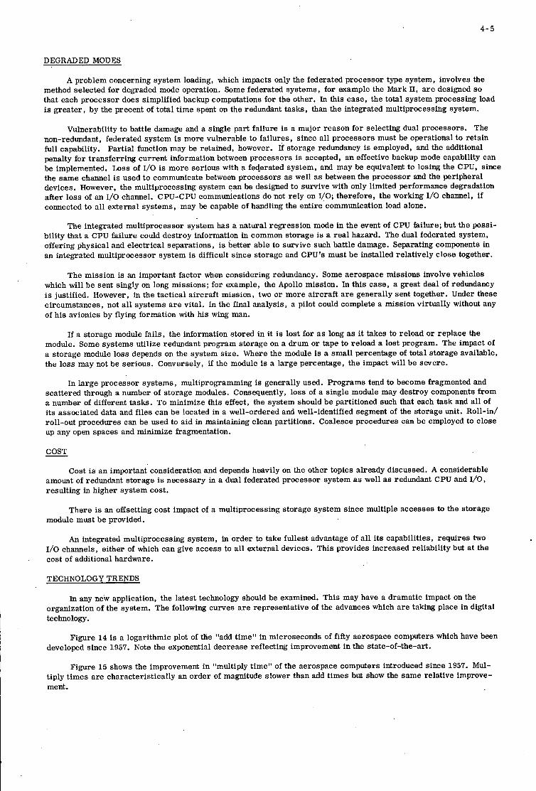
4- 5
DEGRADED MODES
A problem concerning system loading, which impacts only the federated processor type system, involves the method selected for degraded mode operation. Some federated systems, for example the Mark 11, a r e designed so that each processor does simplified backup computations for the other. In this case, the total system processing load is greater, by the precent of total time spent on the redundant tasks, than the integrated multiprocessing system.
Vulnerability to battle damage and a single part failure is a major reason for selecting dual processors. The non-redundant, federated system is more vulnerable to failures, since all processors must be operational to retain full capability. penalty for transferring current information between processors is accepted, an effective backup mode capability can be implemented. Loss of 1/0 is more serious with a federated system, and may be equivalent to losing the CPU, since the same channel is used to communicate between processors as well as between the processor and the peripheral devices. However, the multiprocessing system can be designed to survive with only limited performance degradation after loss of an I/O channel. CPU-CPU communications do not rely on I/O; therefore, the working 1/0 channel, lf connected to all external systems, may be capable of handling the entire communication load alone.
Partial function may be retained, however. If storage redundancy is employed, and the additional
The integrated multiprocessor system has a natural regression mode in the event of CPU failure; but the possi- bility that a CPU failure could destroy information in common storage is a rea l hazard. The dual federated system, offering physical and electrical separations, is better able to survive such battle damage. Separating components in an integrated multiprocessor system is difficult since storage and CPU's must be installed relatively close together.
The mission is an important factor when considering redundancy. Some aerospace missions involve vehicles which will be sent singly on long missions; for example, the Apollo mission. In this case, a great deal of redundancy is justified. However, in the tactical aircraft mission, two or more aircraft a r e generally sent together. Under these circumstances, not all systems a r e vital. In the final analysis, a pilot could complete a mission virtually without any of his avionics by flying formation with his wing man.
If a storage module fails, the information stored in it is lost for as long as it takes to reload or replace the module. Some systems utilize redundant program storage on a drum or tape to reload a lost program. The impact of a storage module loss depends on the system size. Where the module is a small percentage of total storage available, the loss may not be serious. Conversely, if the module is a large percentage, the impact will be severe.
In large processor systems, multiprogramming is generally used. Programs tend to become fragmented and scattered through a number of storage modules. Consequently, loss of a single module may destroy components from a number of different tasks. To minimize this effect, the system should be partitioned such that each task and all of its associated data and files can be located in a well-ordered and well-identified segment of the storage unit. Roll-in/ roll-out procedures can be used to aid in maintaining clean partitions. Coalesce procedures can be employed to close up any open spaces and minimize kagmentation.
COST
Cost i s an important consideration and depends heavily on the other topics already discussed. A considerable amount of redundant storage is necessary in a dual federated processor system a s well as redundant CPU and I/O, resulting in higher system cost.
There is an offsetting cost impact of a multiprocessing storage system since multiple accesses to the storage module must be provided.
An integrated multiprocessing system, in order to take fullest advantage of all its capabilities, requires two 1/0 channels, either of which can give access to all external devices. This provides increased reliability but a t the cost of additional hardware.
TECHNOLOGY TRENDS
In any new application, the latest technology should be examined. This may have a dramatic impact on the organization of the system. The following curves a re representative of the advances which a re taking place in digital technology.
Figure 14 is a logarithmic plot of the "add time" in microseconds of fifty aerospace computers which have been developed since 1957. Note the exponential decrease reflecting improvement in the state-of-the-art.
Figure 15 shows the improvement in "multiply time" of the aerospace computers introduced since 1957. Mul- tiply times are characteristically an order of magnitude slower than add times but show the same relative improve- ment.

4- 6
CONCLUSIONS
System selection is strongly influenced by part experience and customer preferences. Problems in digital com- puters of the past include; loss of information from drums, low computer reliability, hang-up in program loops, e r ro r s in reading analog-to-digital converter, noise, EMI, and programming errors . Past experience can lead to selection of system approaches not based on evaluation of current state-of-the-art. Technological gains in compo- nent size reduction, cost reduction, increased performance, and improved reliability make system organizational concepts previously restricted to ground installations, feasible for aerospace applications. As technology advances, applications will grow and the demand for complex systems will increase.
Table III summarizes the characteristics of state-of-the-art systems from the preceding examples. It is the writer's opinion, based on this comparison, that the system design should begin with a single computer simplex in- tegrated system. Multiprocessors may be required if the computational requirements exceed the capabilities of a simplex system, or for graceful degradation in the event of malfunction; but it is important to separate capacity con- siderations from reliability. The first approach to improving operational effectiveness should be to emphasize com- ponent reliability and simplicity of design. In most airborne systems today, digital computers a r e more reliable than the peripheral sensors. The dramatic, two orders of magnitude, improvement in reliability over the past ten years, can be predicted to continue in the future. It i s feasible to expect that digital computer mean-time-between-failures may soon be equal to the expected system life. Most of the more elaborate organizations which have been discussed in this paper can be categorized a s a form of redundancy. Over the years, IBM has successfully employed duplex computers, quad-circuit redundancy, and triple modular redundancy to effect improved reliability. However, re- dundancy in any form should be undertaken only a s a last resor t , since all parameters except mission effectiveness a r e adversely affected. Cost, weight, volume, power, and the total number of maintenance actions a r e increased. As has been pointed out in the paper, the mission application also affects the selection of the computer organization. In many applications, the simplex computer may be the place to stop. Redundancy should be considered only for those areas of the system demanding such attention, rather than indiscriminately duplicating equipment.
Table III
SUMMARY OF CH-RACTERISTICS
Confivuration Size Weight MTBF Storage cos t
Simplex 1 45 3000 16K 1.0
Integrated Multiprocessor 1.7 75 1400 21K 1.5
Federated 2.1 95 1000 24K 2.0
Dual Federated 2.4 100 4000* 3 2K 2.4
*based on backup modes
Programming simplicity is becoming increasingly important. Except in those applications where extremely large production quantities warrant customized design, it may be justifiable to accept inefficiencies. For example, standardization of software programs may become desirable. Once the pregram is developed and checked out, it could be employed in future programs desiring this capability even though some minor penalties might be incurred. The present duplication of effort and occurrence of costly e r ro r s could be avoided. In this respect, the federated system offers some advantage. There is a prevalent opinion that the programming, particularly of independent o r nearly independent functions, is easier to manage with a federated system. I do not agree that this is necessarily true. The software interface can be defined and controlled with strict adherence to application ground rules with the same thoroughness which is required for the hardware interface between two computers.
The conclusion of federated vs. integrated for future applications is by no means obvious. A case can be made for either approach and, in fact, almost every system which was examined during the preparation of the paper proved to be neither entirely integrated nor federated, but rather a combination of both. This can be expected to continue. However, considering the growth in applications and the continuing reduction in cost and physical size, it is predicted that the integrated, multiprogrammed, multiprocessor will gain increasing acceptance in future applications, follow- ing the pattern of ground-based computational centers. The simplex integrated system will remain the most efficient organization and will find continuing usage in many applications. The federated system is expected to decline due to its more limited flexibility and equipment penalties.
,
ACKNOWLEDGEMENTS
The author acknowledges inputs from a number of internal study reports with particular insight gained from those by Mr. C.H. Simmons, Mr. P.H. Giroux, Mr. H.G. Jud, Mr. C.H. Powers and Mr. A.S . Buchman. Mr. S. B. Balden contributed to the assembling of data, analyzing trends, and organizing the paper.

4-7
BIBLIOGRAPHY
Baechler, Donald 0. STATE OF THE ART OF AEROSPACE DIGITAL COMPUTERS, 1962-1967. Computer Group News. January 1968.
Daggert, D.H. ; Lee, R.Q. The F-111D COMPUTER COMPLEX. American Institute of Aeronautics and Astronautics. 1968.
Harold, Glen M. TRENDS IN AVIONICS SYSTEMS. Control Data Corporation.
Miller, Barry. ADVANCED F-111 SYSTEM NEARS PRODUCTION. Aviation Week & Space Technology. Septemher 9 , 1968.
Miller, Barry. IHAS PROTOTYPE FLIGHT TESTS UNDER WAY. Aviation Week & Space Technology. Decemher 4, 1967.
h i c e , Richard C. INTEGRATION PLUS FEDERATION. Sperry Rand.
Seidel, Paul E. , and others. ILAAS -- INTEGRATED LIGHT ATTACK AVIONIC SYSTEM. Sjmrry Rand Engineerlng Review. 1968.
Hylton, Harvey I. THE F-111 MARK II COMPUTER COMPLEX BASELINE HOW IT WAS DERIVED. NAECON Proceedings. l967.
REFERENCES
1.
2.
3.
Gemini Electronics S p t e m a , SPACE/AERONAUTICS, October, 1963, pg. 83.
MA6 Simplified Block Diagram, AVIATION WEEK, June 21, 1965, pg. 50.
1- Block Diagram. NAECON PROCEEDINGS. R. C. Price, Sperry Rand Corp., 1969, pg. 6.
4. Saturn Guidance & Control System, ASTRONAUTICS &AERONAUTICS, (a publication of the American Institute of Aeronautics & Astronautice, Inc.), E.D. Geissler and W. Haeussermarm. NASA, Huntsville, Ala., February 1962, pg. 45.
The MARK II Digital Computer Complex, NAECON PROCEDINGS, A.I. Hylton, Wright-Patterson Air Force Base, Ohio, 1967, pg. 224.
5.

4-8
f ,'
f
Figure 1. Gemini Computer
Aggena Target Vehicle r----- -- 1
Transponder Command
L - - - - - - - \ /
Radar Ih lnertiol Horizon Plotform
MDlU
Molter Time Reference
Attitude Control
Doto TrCl"Smiui0" To Ground Station
Acquisition Beocon
Band Beacons Communications
Figure 2 . GEMINI Electronics System

svbrystem
.
Doppler Radar
Attitude 8 Heading Reference
Ai r Data
Magnetic
computer Cenlrol Complex
- - Signal Tronrfer Unit (STU)
Centml Pmcesor Unit (CPU1
Digital Interface Unit
4
Environment Sensing
Automatic Flight Control Suk.lystem
Stability Augurnntotion
Aircraft Actuators n 8 senron
(DIU) Display Subsystem
I Flight Mode Control I
Subptem
1 Communication 6
I
In,trument.tion Smptam (GFE)
. Terrain Following Rodor
Cockpit lnrtr~menri
TACAN, ARN-52
UHF, ARC-51
VHF, ARC-44
HF, ARC-94
LF DF, ARN-59
IFF, APX-46
VHF DF. ARA-25
Vertical S i twt ion
Horizontol Tmctical
contmll a ~~~i~ ~ i ~ p ~ o p
t Station Keeping Radm
Ro&r Altimeter 4 . Figme 3. Simplified Block Diagram of IHAS System
Air Data Set
Forward Looking Radar
Lomn
I"PTti.1
- - Horir. Situation lndisotor
Command Doto Applique Engine
- - lnrtrumentr
Flight
Stondby Gyro Head-up Plotfarm Computerr Display
Navigation Wewan Vert. S i tuat iw Doppler Delivery Computer Rmdor
r Mcde Ewluotor Unit
Radio Hariz. Situation Altimeter Inertiol/Rador Dirploy
Computer
lnth"me"I3
EW senran
C N I T a t
4-'1
k4 Control Set
Figure 4. ILAAS Block Diagram
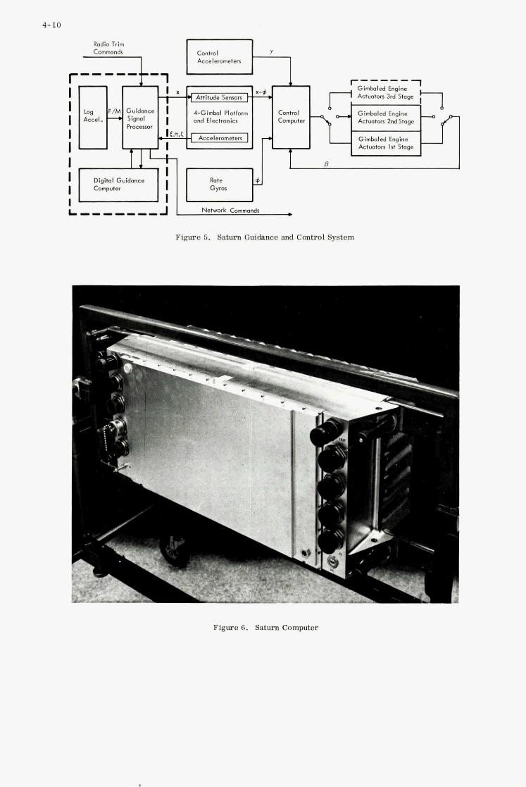
4-10
Figure 5. Saturn Guidance and Control System
,

4-11
I
.--.- i A .:
J .
Figure 7 . Mark II Digital Computer
0 " 0
F 0 5 T J To and From Sensors m d Display Devices
Figure 8. The Mark II Digital Computer Complex

4-12
- Figure 9. A-TD/E Avionics Computer
Releare Controls
Pl.tf0rm
Latitude, Mmg. Ver
Mag. Hdg
Torque Pvlres
Pitch, I Roll Ground Speed Drift Angle Doppler
Altitude, Mach,
Angle of
AttDck Sen-,
, leading Flight Commands
Range, Beoring, Ground Tresk
Symbol Position
Aiming Reticle Control
t t Equipment
Slot". Advisory P o d
Coordinates
Al t imetr
II
Integrated
Panel
Present Position Wind,
Forward Locking Rodor
II Figure 10. A-I Avionics System Functional Diagram

- 0
Processor A Processor B
I - J
l T 1 I' . 1 Console I/O I/O
Channel 1 Channel 2
Figure 11. VS A-NEW Simplified Block Diagram
4-13
Figure 12. VS A NEW System
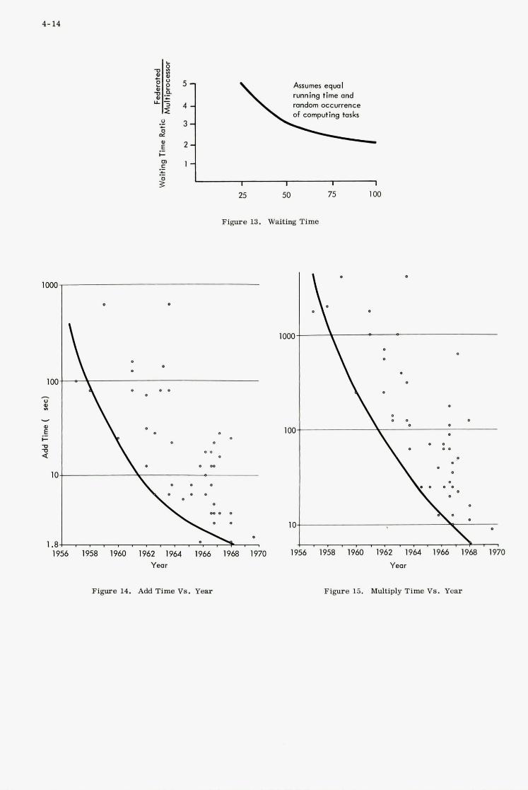
4- 14
1000
1 oc
IC
1 .a l!
Arrumer eqwl running time and random occurrence of computing tasks
25 50
Figure 13. Waiting Time
1000
-\
10
l!
75 100
1958 1960 1962 1964 1966 1968 1970 Year
Figure 14. Add Time VS. Year
Yeor
Figure 15. Multiply Time Vs. Year
PROGRAMMING CHARACTERISTICS OF FUTURE G 81 C COMPUTERS
5
by
A u s t i n J . M a h e r
K e a r f o t t D i v i s i o n S i n g e r - G e n e r a l P r e c i s i o n , I n c .
5
SUMMARY
The d i f f i c u l t i e s o f t e n encountered i n programming d i g i t a l computers have become legendary. Airborne computer programs, i nc lud ing those f o r Guidance and Con t ro l , have remained s i n g u l a r l y d i f f i c u l t t o develop d e s p i t e t h e s i g n i f i c a n t advances i n t h e techniques f o r developing o t h e r computer programs. This i s due i n l a r g e measure t o t h e a u s t e r e i n s t r u c - t i o n s e t provided i n m o s t a i r b o r n e computers. The r a t i o n a l e f o r employing a minimum i n s t r u c t i o n se t i s based on t h e assumption t h a t it i s more impor tan t t o avoid s i z e ana weight i n c r e a s e s a t t h e expense of programming ease ( e s p e c i a l l y when t h i s i s a one t i m e cost f o r product ion sys tem) . However, i n K e a r f o t t ' s exper ience on a wide v a r i e t y of a i r - borne computation problems, t h e impact of programming i n f l e x i b i l i t y can have s e r i o u s i m - p a c t s on t h e development and maintenance of an e f f e c t i v e , f l e x i b l e guidance and c o n t r o l system. Furthermore, i t can l i m i t t h e a d d i t i o n a l f l e x i b i l i t y of growth through so f tware and des ign improvements throuqh sof tware .
This paper f i r s t reviews t h e types of d i f f i c u l t i e s encountered i n deve loping and main- t a i n i n g a i rbo rne computer programs. These inc lude problems encountered i n t h e i n i t i a l development of t h e system program and t h e s i g n i f i c a n t changes t o t h e o r i g i n a l program based on l abora to ry and f l i g h t tests of t h e o v e r a l l system. During t h i s development phase, many system problem s o l u t i o n s r e s u l t i n a hardware/software t r a d e o f f which u s u a l l y f o r c e s a sof tware change s i n c e sof tware i s more f l e x i b l e than hardware. However, t r u e sof tware f l e x i b i l i t y was s a c r i f i c e d e a r l i e r when it w a s deemed t o be less impor tan t t han t h e v i r t u e s of a minimum CPU. I n t h e s e f i n a l s t a g e s of system development, i s is usua l ly agreed t h a t t h e choice of a more f l e x i b l e CPU would now be advantageous.
A s advances i n MSI and LSI c i r c u i t r y cont inue , t h e CPU becomes a less and less s i g n i f i c a n t component i n t h e o v e r a l l computer s i z e , weight , power, and cos t . Consequently, i t seems an appropr i a t e t i m e t o ask whether f o r many a p p l i c a t i o n s i t may be more e f f e c t i v e t o i n c r e a s e t h e complexity of t h e CPU t o f a c i l i t a t e program development whi le u s ing t h e advanced c i r c u i t r y t o main ta in a s u f f i c i e n t l y sma l l a i r b o r n e computer. A t t e n t i o n i s a l s o d i r e c t e d a t t h e inc reased computat ional requirements ( e .g . , s enso r mixing v i a Kalman F i l t e r i n g ) which a r e being imposed on a i rbo rne Guidance and Cont ro l computers and t h e techniques of computer o rgan iza t ion which would f a c i l i t a t e t h e i r implementation. Many of t h e s e techniques w e r e o r i g i n a l l y developed f o r h igh performance ground-based computers b u t have n o t y e t been accepted by a i r b o r n e computer des igne r s f o r reasons of economy, or apparent economy.
By a s s i m i l a t i n g r e s u l t s of prev ious system development exper ience and p r e d i c t i n g t h e t r e n d s i n a i r b o r n e computer hardware development, c h a r a c t e r i s t i c s are proposed f o r f u t u r e a i rbo rne Guidance and Cont ro l computers. The proposed computer c h a r a c t e r i s t i c s would minimize s i g n i f i c a n t programming d i f f i c u l t i e s whi le r e t a i n i n g d e s i r e a b l e hardware f e a t u r e s ( e .g . , p r o t e c t e d memory, smal l s i z e , e t c . ) . The f e a t u r e s covered inc lude word l eng th t r a d e o f f s , type of a r i t h m e t i c , add res s ing techniques , subprogram l inkages , e t c . , and i n summary r e p r e s e n t a f u n c t i o n a l s p e c i f i c a t i o n f o r a class of f u t u r e a i rbo rne com- p u t e r s us ing MSI o r LSI techniques .
F i n a l l y , t h e s p e c i f i c c h a r a c t e r i s t i c s a r e p re sen ted of an a i rbo rne computer designed t o meet t h e s e f u n c t i o n a l s p e c i f i c a t i o n s . Although, t h i s implementation does n o t uniquely s a t i s f y t h e above f u n c t i o n a l s p e c i f i c a t i o n ( i . e . , o t h e r des igns might provide equa l sof tware f a c i l i t i e s ) , it does provide a l l t h e d e s i r e d programming c h a r a c t e r i s t i c s . Consequently, i t is a u s e f u l v e h i c l e f o r i l l u s t r a t i n g t h e d e s i r e a b i l i t y and p r a c t i c a b i l i t y of t h e proposed computer o rgan iza t ion . The s impl i fy ing e f f e c t of t h e expanded CPU cap- a b i l i t y on t h e sof tware development cyc le is then covered i n some d e t a i l . Of p a r t i c u l a r i n t e r e s t i s t h e f a c t t h a t h igh l e v e l languages (FORTRAN, J O V I A L , e t c . ) are n a t u r a l l y e f f i c i e n t i n t h e s p e c i f i e d machine whi le a t t empt s a t an e f f i c i e n t compiler language us ing a less s o p h i s t i c a t e d CPU are probably doomed t o f a i l u r e . This dependence of compiler e f f i c i e n c y on t h e o rgan iza t ion of t h e a i rbo rne computer i s a f a c t o r which i s usua l ly overlooked i n recommendations f o r t h e use of problem o r i e n t e d language t o "so lve" t h e a i rbo rne computer programming problem. The computer a r c h i t e c t u r e must be c a r e f u l l y chosen t o permi t a compiler t o gene ra t e e f f i c i e n t o b j e c t programs, a s K e a r f o t t l ea rned as e a r l y a s 1962 when w e developed a NELIAC compiler f o r t h e L90 a i r b o r n e computer.
Hopeful ly , t h e vo ice of t h e sof tware system d e s i g n e r s , a s a r t i c u l a t e d i n t h i s paper w i l l n o t cont inue t o go unheeded b u t w i l l r e s u l t i n a series of a i r b o r n e computers i n t h e 1 9 7 0 ' s which provide t r u e programming f l e x i b i l i t y , and t h e enumerated advantages t o t h e t o t a l system.
5 - 1
I n o r d e r t o d i s c u s s f u t u r e Guidance and Cont ro l computers, i t i s necessary t o c o n j e c t u r e what s i g n i f i c a n t hardware changes w i l l be experienced i n a i r b o r n e computers i n t h e per iod of i n t e r e s t . This i s necessary s i n c e m o s t changes i n computer a r c h i t e c t u r e ar ise i n response t o a change i n t h e c a p a b i l i t y of t h e b a s i c hardware components. Although t h e t i m e scale might be s u b j e c t t o some debate , t h e r e i s g e n e r a l agreement among a i r b o r n e computer d e s i g n e r s t h a t t h e next major hardware change w i l l be p r e c i p i t a t e d by advances i n MSI and LSI c i r c u i t r y . This w i l l pe rmi t t h e r e a l i z a t i o n of complex l o g i c w i t h i n p r o g r e s s i v e l y less s i z e and weight. This i n c r e a s e i n l o g i c d e n s i t y can be e x p l o i t e d i n two r a t h e r d i s t i n c t f a s h i o n s . F i r s t i t can be envis ioned as t h e accomplishment of t h e same l o g i c f u n c t i o n s w i t h i n less s i z e , weight and power. With t h e p o s s i b l e except ion of an i n c r e a s e of execut ion speed, t h e r e is no i n c r e a s e i n o r g a n i z a t i o n a l performance. This i s t h e more customary u t i l i z a t i o n of improved c i r c u i t r y . A l t e r n a t i v e l y however, t h e s e technology advances could be e q u a l l y e f f e c t i v e i n provid ing a s i g n i f i c a n t i n c r e a s e i n t h e c a p a b i l i t y of t h e CPU whi le r e t a i n i n g t h e same s i z e and weight. For example, new, more powerful i n s t r u c t i o n s might be added t o t h e computer 's r e p e r t o i r e t o provide improved performance.
I t i s t h e purpose of t h i s paper t o advocate a pa th somewhere between t h e s e t w o extremes wherein t h e convent iona l austere i n s t r u c t i o n s e t of t h e a i r b o r n e computer i s s t rengthened by t h e a d d i t i o n of some powerful new c a p a b i l i t i e s b u t t h e s e are c a r e f u l l y s t r u c t u r e d and l i m i t e d t o a l s o permi t t h e s i z e of t h e processor u n i t t o be decreased.
S ince my personal background l i e s i n t h e area of sof tware development r a t h e r than l o g i c des ign or c i r c u i t des ign , t h e p r i n c i p a l mot iva t ion f o r suggested o r g a n i z a t i o n a l changes w i l l be t o f a c i l i t a t e t h e r a p i d development of a c c u r a t e , o p e r a t i o n a l sof tware and t o enhance t h e f l e x i b i l i t y of t h a t sof tware once i t is developed. The opin ions expressed on t h e hardware i m p l i c a t i o n s of t h e suQgested computer s t r u c t u r e w e r e reached through c o n s u l t a t i o n wi th s e v e r a l a i r b o r n e computer d e s i g n engineers and r e f l e c t a r a t h e r non- c o n t r o v e r s i a l concensus of op in ion on t h e expected d i r e c t i o n of a i r b o r n e computer hard- ware development.
2 . AIRBORNE COMPUTER PROGRAMMING
The primary reasons f o r us ing d i g i t a l a i r b o r n e computers i n G&C a p p l i c a t i o n s a r e t h e i r accuracy and t h e i r f l e x i b i l i t y . The l a t t e r i s o s t e n s i b l y accomplished through modifica- t i o n of t h e computer program. However, making changes t o a i r b o r n e computer programs has proven t o be s i g n i f i c a n t l y more d i f f i c u l t i n p r a c t i c e t h a n it i s i n concept. Conse- q u e n t l y , much of t h e in tended f l e x i b i l i t y i s e i t h e r l o s t o r achieved a t a h igh p r i c e . L e t us review t h e p r i n c i p a l c o n t r i b u t o r s t o t h i s " p r a c t i c a l " problem as a pre lude t o searching f o r p o t e n t i a l s o l u t i o n s .
S ince v i r t u a l l y a l l a i r b o r n e computers perform pure ly i n t e g e r (or f r a c t i o n a l ) a r i t h m e t i c , t h e va lue of t h e LSB (or MSB) must be chosen by t h e programmer for every d a t a word i n c l u d i n g i n t e r m e d i a t e r e s u l t s . This process i s commonly r e f e r r e d t o as s c a l i n g . Proper s c a l i n g f u r t h e r r e q u i r e s t h a t a l l a r i t h m e t i c o p e r a t i o n s conform t o t h e s c a l i n g r u l e s a p p r o p r i a t e t o t h e o p e r a t i o n . For example, i f t w o numbers are t o be added, t h e i r scale v a l u e s must be t h e same. I f two numbers are t o be d iv ided , t h e numerator i n t e g e r must be l a r g e r than t h e denominator; o therwise , a d i v i d e overflow condi t ion w i l l be encountered. F i n a l l y , s i n c e t h e choice of scale f a c t o r s and t h e i r manipulat ion can have s e r i o u s iinpli- c a t i o n s on t h e numerical accuracy of t h e r e s u l t , g r e a t c a r e must be taken t o a d j u s t t h e s c a l i n g and/or t h e a lgor i thm t o minimize t h e numerical errors so induced. I n s h o r t , s c a l i n g i s a t e d i o u s , e x a c t i n g j o b which i s accomplished manually and is probably t h e g r e a t e s t s i n g l e c o n t r i b u t o r t o aerospace programming problems.
Most assemblers f o r a i r b o r n e computers g e n e r a t e a b s o l u t e coding r a t h e r than r e l o c a t a b l e coding. This aga in p u t s a burden on t h e programmer which might be a l l e v i a t e d . Upon closer i n s p e c t i o n , it i s u s u a l l y found t h a t t h e absence of r e l o c a t a b l e coding i n t h e assembler can be t r a c e d t o c h a r a c t e r i s t i c s i n t h e a i r b o r n e computer which make automatic r e l o c a t i o n d i f f i c u l t o r impossible t o achieve. The most prominent of t h e s e is t h e presence of f i x e d memory pages i n t h e computer organiza t ion .
The documentation problems a s s o c i a t e d wi th an assenbly language ( o r machine language) program are u s u a l l y more s e v e r e than i f a h i g h e r l e v e l language were used. This i s e s p e c i a l l y t r u e f o r a i r b o r n e computer a p p l i c a t i o n s which f r e q u e n t l y imply t i m e c o n s t r a i n t s , accuracy l i m i t s , e tc . which are d i f f i c u l t t o document even i n a problem o r i e n t e d language.
F i n a l l y , t h e compiler f o r a high l e v e l language (FORTRAN, ALGOL, JOVIAL, PL/I, NELIAC, SPL, e t c . ) is n o t a v a i l a b l e due t o i t s almost unavoidable i n e f f i c i e n c y , an i n e f f i c i e n c y which is rooted as much i n t h e a r c h i t e c t u r e of t h e a i r b o r n e computer as it is i n any o t h e r source .
I n s h o r t i t would appear t h a t t h e a i r b o r n e computer sof tware f i e l d i s s t a l l e d a t t h e tech- nology l e v e l achieved by ground based machines i n 1957. Hopefully, t h e expected advances i n hardware technology, coupled wi th r e f l e c t i o n on t h e problems noted h e r e i n , w i l l r e s u l t i n a q e n e r a t i o n of a i r b o r n e computers and s u p p o r t sof tware v a s t l y s u p e r i o r t o t h a t pre-
I

5 - 2
3 . HARDWARE CONSIDERATIONS
I n o rde r t o develop a meaningful model f o r f u t u r e G&C computers, it i s necessary t o review t h e hardware technology and t o p r e d i c t t h e g e n e r a l d i r e c t i o n of i t s development i f n o t i t s s p e c i f i c c h a r a c t e r . Toward t h a t end, t h e most dominant f a c t o r i s t h e continued r a p i d development of l o g i c c i r c u i t r y . I n both t h e commercial and m i l i t a r y f i e l d , l o g i c cir- c u i t r y con t inues t o i n c r e a s e i n speed and dec rease i n s i z e .
Improvements have been much slower i n memory technology, p a r t i c u l a r l y f o r t h e m i l i t a r y a i r b o r n e environment. Although p rogres s is being made toward memories based on LSI c i r c u i t r y , t h e s e a r e g e n e r a l l y l i m i t e d t o read-only memories (ROM) o r v o l a t i l e r ead /wr i t e memories. Since t h e most common a i r b o r n e a p p l i c a t i o n c a l l s f o r a non-vo la t i l e b u t e l e c t r i c a l l y a l t e r a b l e memory, co re memories w i l l probably dominate i n t h i s a r e a f o r many yea r s t o come. Advances i n core memory technology f o r a i r b o r n e environments has been g radua l i n t h e r e c e n t p a s t and t h e f u t u r e holds l i t t l e promise f o r a dramatic improve- ment.
Consequently, s i n c e t h e c o s t of t h e memory and i t s e l e c t r o n i c s is a l r eady g r e a t e r t han t h a t of t h e a r i t h m e t i c u n i t , t h i s d i s p a r i t y i s almost c e r t a i n t o i n c r e a s e . This e f f e c t is compounded by t h e f a c t t h a t t h e a p p l i c a t i o n s f o r a i r b o r n e d i g i t a l computers cont inue t o i n c r e a s e i n s i z e ( i . e . , memory r equ i r emen t s ) .
I t fo l lows , t hen , t h a t a t t empt s t o minimize t h e c o s t of an a i r b o r n e computer f o r v i r t u a l l y any a p p l i c a t i o n should concen t r a t e on minimizing t h e memory requirements . I n f a c t , it is l i k e l y t h a t a c e r t a i n amount of i nc reased complexity i n t h e l o g i c u n i t could reduce t h e c o s t of t h e computer i f i t promoted more e f f i c i e n t use of t h e memory. This f a c t o r s e r v e s a s one of t h e bases f o r t h e recommendations made below on f u t u r e computer a r c h i - t e c t u r e .
4 . RECOMMENDED COMPUTER CHARACTERISTICS
Based on t h e above c o n s i d e r a t i o n s some s p e c i f i c c h a r a c t e r i s t i c s a r e now recommended f o r f u t u r e a i r b o r n e d i g i t a l computers. W e do n o t i n t e n d t o d i s c u s s t h e minimum s i z e machine used f o r s p e c i a l s enso r p rocess ing o r sma l l m i s s i l e guidance s i n c e these tend t o have very s p e c i a l o r g a n i z a t i o n s which depend l a r g e l y on t h e s p e c i f i c a p p l i c a t i o n . Rather w e s h a l l d i s c u s s t h e medium t o l a r g e s c a l e machines wi th correspondingly more s e v e r e s o f t - ware problems. Any s y n t h e s i s of a machine o r g a n i z a t i o n must n e c e s s a r i l y be an i t e r a t i v e process s i n c e des ign g o a l s a r e u s u a l l y ( a s i n t h i s c a s e ) somewhat i n c o n f l i c t with each o t h e r . For example, a powerful i n s t r u c t i o n set i s d e s i r a b l e and a long i n s t r u c t i o n word i s i t s s i m p l e s t embodiment. Y e t , a long i n s t r u c t i o n word i s a t va r i ance wi th t h e goa l of minimum memory. A f u l l t r ea tmen t of t h e i t e r a t i v e s y n t h e s i s p rocess i s beyond t h e scope of t h i s paper . However, w e s h a l l devote t h e fol lowing f e w paragraphs t o a presen- t a t i o n of t h e computer c h a r a c t e r i s t i c s which a r e f e l t t o be of g r e a t e s t va lue i n aggre- g a t e . I n a d d i t i o n , a b r i e f i n d i c a t i o n of major i n t e r r e l a t i o n s between t h e s e cha rac t e r - i s t ics and t h e des ign g o a l s i s p resen ted t o a t l e a s t i n p a r t s u b s t a n t i a t e t h e e f f i c i e n c y of t h e r e s u l t i n g o r g a n i z a t i o n .
For most Guidance and Control a p p l i c a t i o n s , a long b a s i c d a t a word is advocated (say 2 4 t o 32 b i t s ) . This a s s u r e s s u f f i c i e n t accuracy f o r most of t h e c r i t i c a l G&C computations. Although it s i g n i f i c a n t l y i n c r e a s e s t h e d a t a a r e a memory, t h i s u s u a l l y r e p r e s e n t s less than 1 0 % of t h e computer 's f u l l memory and thus t h e o v e r a l l impact is s l i g h t . Moreover machines wi th s h o r t d a t a word l eng th ( 1 4 t o 18 b i t s ) r e q u i r e t h a t two words be used t o r e p r e s e n t c r i t i c a l v a r i a b l e s . I n f a c t , f o r most c a s e s , t h e apparent i n c r e a s e i n memory caused by implementing a long d a t a word w i l l be more than o f f s e t by sav ings i n t h e s t o r a g e of c r i t i c a l v a r i a b l e s and by economies i n t h e i n s t r u c t i o n memory due to :
a ) e l i m i n a t i o n of extended p r e c i s i o n requirement and i t s a s s o c i a t e d i n s t r u c t i o n i n c r e a s e .
b ) s i m p l i f i c a t i o n of complex algori thms employed t o avoid e r r o r propagat ion due t o s h o r t d a t a word l eng th .
Since some d a t a can be r ep resen ted i n s h o r t d a t a words, i t i s tempting t o sugges t t h a t both long and s h o r t op t ions be a v a i l a b l e . However, t h i s would then r e q u i r e t h e a b i l i t y t o address h a l f words which would r e q u i r e a longer address f i e l d i n each i n s t r u c t i o n . Consequently, pu re ly long d a t a words a r e recommended wi th t h e r e a l i z a t i o n t h a t any sub- s t a n t i a l q u a n t i t y of s h o r t d a t a words ( e . g . , b a l l i s t i c d a t a t a b l e s ) can be accommodated by a p p r o p r i a t e packing and/or unpacking of d a t a through subrou t ines o r macro ope ra t ions .
Two major i nnova t ions i n ground-based s c i e n t i f i c computers were introduced i n 1957 which r evo lu t ion ized t h e a r t of so f tware development: t h e FORTRAN compiler and f l o a t i n g p o i n t a r i t h m e t i c hardware. The f l o a t i n g p o i n t hardware provided t h e s o l u t i o n t o many numerical a n a l y s i s problems b u t more important ly it assu red a s u b s t a n t i a l i n c r e a s e i n t h e e f f i c i e n c y of FORTRAN programs. This same r e v o l u t i o n i s long overdue i n a i r b o r n e computers. Con- sequen t ly , t h e inco rpora t ion of f l o a t i n g p o i n t a r i t h m e t i c hardware i s s t r o n g l y recommended based i n p a r t on t h e r e a l i z a t i o n t h a t compilers f o r a i r b o r n e computers w i l l be s e v e r e l y l i m i t e d without f a - t f l o a t i n g p o i n t ope ra t ions . Even be fo re compilers a r e a v a i l a b l e , however, t h e requirement t o s c a l e a l l a r i t h m e t i - opera t ions w i l l be e l imina ted . This w i l l n o t only f a c i l i t a t e t h e development of a i r b o r n e computer programs b u t w i l l g r e a t l y s i m - p l i f y t h e i r documentation thereby f a c i l i t a t i n g t h e exped i t ious p r e p a r a t i o n of program changes. The r e c e n t advances i n mathematical techniques f o r optimum senso r d a t a mixing

5-3
f o r guidance and nav iga t ion ( i . e . , Kalman F i l t e r i n g ) have placed even g r e a t e r demands on t h e programmer's a b i l i t y t o s c a l e f i x e d p o i n t ope ra t ions without l o s i n g acruracy. These o p e r a t i o n s become s t r a i g h t f o r w a r d wi th t h e a v a i l a b i l i t y of f a s t f l o a t i n g p o i n t a r i t h m e t i c .
Furthermore, t h e c o s t of t h i s a d d i t i o n a l c a p a b i l i t y should be minimal i f proper advantage i s taken of new MSI and L S I c i r c u i t r y . I t should a l s o prove convenient i n t h i s imple- mentation t h a t a long b a s i c d a t a word l eng th was chosen. For example, based on a 32 b i t d a t a word, t h e f l o a t i n g p o i n t word could c o n s i s t of an 8 b i t exponent f i e l d and a 2 4 b i t mant issa o r magnitude f i e l d .
Although w e have s p e c i f i e d long d a t a words f o r our computer, it i s almost impera t ive t h a t s h o r t i n s t r u c t i o n words be used. This i s based on t h e d e s i r e t o minimize t h e amount of expensive memory t h a t is requ i r ed and t h e knowledge t h a t 80 o r 9 0 % of t h e memory c o n s i s t s of i n s t r u c t i o n s . For example, i f a 32 b i t d a t a word was chosen, a 1 6 b i t i n s t r u c t i o n word would be d e s i r a b l e wi th e i t h e r 1 6 b i t o r 32 b i t p a r a l l e l access t o a memory word. However, l a t e r c o n s i d e r a t i o n s w i l l i n d i c a t e a requirement f o r i n s t r u c t i o n s longer than 1 6 b i t s . A s u i t a b l e compromise would be t h e a v a i l a b i l i t y of both s h o r t ( 1 6 b i t ) and long (32 b i t ) i n s t r u c t i o n s where t h e o p e r a t i o n code would determine t h e l eng th of t h e i n s t r u c t i o n . Note t h a t our e a r l i e r d e c i s i o n t o l i m i t t h e machine t o long (32 b i t ) d a t a words now re- s u l t s i n t h e a v a i l a b i l i t y of an a d d i t i o n a l b i t i n t h e address f i e l d of s h o r t i n s t r u c t i o n s which access d a t a , t hus doubling i t s range of a p p l i c a b i l i t y . One des ign goa l f o r t h e machine should be a s u f f i c i e n t l y powerful set of s h o r t i n s t r u c t i o n s t o reduce t h e need f o r long i n s t r u c t i o n s t o a minimum.
A s i m i l a r design g o a l o b t a i n s i n t h e a r c h i t e c t u r e of t h i r d gene ra t ion ground-based com- p u t e r s . Whereas second gene ra t ion computers ( I B M 7 0 9 4 , Univac 1107 , e t c . ) pe rmi t t ed t h e address f i e l d of each i n s t r u c t i o n t o d e s i g n a t e any word i n t h e computer 's memory (32 o r 65K words ) , t h i s luxury could n o t be a f fo rded i n t h i r d gene ra t ion machines whose memory might c o n s i s t of s e v e r a l m i l l i o n words, r e q u i r i n g an address f i e l d of 2 1 b i t s o r more. Consequently, des igns were developed which make e x t e n s i v e use of p o i n t e r r e g i s t e r s t o permit s h o r t i n s t r u c t i o n s wi th l i m i t e d address f i e l d s t o access t h e e n t i r e memory. These techniques a r e d i r e c t l y a p p l i c a b l e t o a i r b o r n e computer design.
While t h e use of p o i n t e r r e g i s t e r s pe rmi t s a s h o r t i n s t r u c t i o n t o o b t a i n operands from any r eg ion of memory, a s i m i l a r problem must be solved f o r a l l jump o r branch i n s t r u c - t i o n s . The a b i l i t y t o jump t o any l o c a t i o n i n memory is most convenient ly provided v i a t h e use of an o p t i o n a l long i n s t r u c t i o n format. A s h o r t jump i n s t r u c t i o n (with an m b i t address f i e l d ) may be implemented i n one of two common ways:
1) Add o r s u b t r a c t t h e m b i t address f i e l d t o t h e i n s t r u c t i o n counter . Th i s pro- v i d e s a jump range of f 2m around t h e p r e s e n t va lue of t h e i n s t r u c t i o n counter .
2 ) Replace t h e m l e a s t s i g n i f i c a n t b i t s of t h e i n s t r u c t i o n coun te r w i th t h e m b i t address f i e l d of t h e i n s t r u c t i o n . This pe rmi t s a jump t o any l o c a t i o n w i t h i n t h e block of 2m i n s t r u c t i o n s con ta in ing t h e jump i n s t r u c t i o n .
The second approach is more common i n p r e s e n t a i r b o r n e computers s i n c e t h e replacement o p e r a t i o n is simpler t o implement than t h e a d d i t i o n o r s u b t r a c t i o n c a l l e d f o r i n t h e f i r s t approach. However, t h e f i r s t approach i s recommended he re ; aga in hoping t h a t t h e use of advanced c i r c u i t r y w i l l v i r t u a l l y e l i m i n a t e t h e p o t e n t i a l hardware pena l ty . This re- commendation is based on s t i l l another sof tware des ign goal : t h a t it be p o s s i b l e t o assemble r e l o c a t a b l e sub rou t ines without c o n s t r a i n t . A r e l o c a t a b l e sub rou t ine is a sequence of i n s t r u c t i o n s which can be loaded i n t o any p o r t i o n of t h e computer 's memory e i t h e r without change o r w i th t h e a d d i t i o n of an address displacement t o t h e address f i e l d of c e r t a i n i n s t r u c t i o n s . However, no s t r u c t u r a l changes a r e pe rmi t t ed i n t h e i n - s t r u c t i o n sequence. i t impossible t o determine whether a s h o r t jump i n s t r u c t i o n can be used un le s s it can be guaranteed t h a t both t h e jump i n s t r u c t i o n and i t s t a r g e t l o c a t i o n l i e i n t h e same block of 2m i n s t r u c t i o n s . Note t h a t t h e boundaries of t h i s block a r e f i x e d memory l o c a t i o n s a t add res ses which form a m u l t i p l e of 2m. Consequently, t h e cond i t ion f o r using s h o r t jump i n s t r u c t i o n s cannot be guaranteed independent of t h e r e l o c a t i o n address . This method should t h e r e f o r e be d i sca rded i n f avor of t h e f i r s t approach.
S t i l l another c o n s t r a i n t on t h e des ign of our advanced G&C computer is t h e d e s i r e t h a t t h e program c o n s i s t e n t i r e l y of "pure code". I n o t h e r words, t h e i n s t r u c t i o n p o r t i o n of memory i s c o n s t a n t and cannot be a l t e r e d du r ing t h e execut ion of t h e program (except i n d i r e c t l y v i a t h e use of index r e g i s t e r s ) . There a r e s e v e r a l mo t iva t ions f o r t h i s con- s t r a i n t , namely:
The second technique f o r implementing a s h o r t jump i n s t r u c t i o n makes
1) To permit t h e use of a ROM (read-only memory) t o a s s u r e t h e i n t e g r i t y of t h e program..
2 ) To permit v e r i f i c a t i o n of t h e i n t e g r i t y of t h e program i n a r ead /wr i t e memory v i a check-sum tes ts , etc.
To avoid t h e c a t a s t r o p h i c e r r o r s which can a r i s e through i n s t r u c t i o n modifica- t i o n and t o avoid t h e o v e r l y complex program s t r u c t u r e s which it f o s t e r s .
3 )
4 ) To provide t h e necessary b a s i s f o r t h e development of r e e n t r a n t sub rou t ines which can be "s imultaneously" used by s e v e r a l p rocesso r s or on s e v e r a l i n t e r r u p t l e v e l s .
5 - 4
Some common i n s t r u c t i o n s i n h e r e n t l y v i o l a t e t h e concept of a cons t an t i n s t r u c t i o n memory and t h e r e f o r e must be avoided. The most common of t h e s e is t h e sub rou t ine jump which s t o r e s t h e r e t u r n address a t t h e f i r s t l o c a t i o n i n t h e sub rou t ine . Other i n s t r u c t i o n s which f a c i l i t a t e v i o l a t i o n s of pure code (depending upon how they a r e u t i l i z e d ) should e i t h e r be avoided o r t h e i r usage c a r e f u l l y c o n t r o l l e d . memory increment i n s t r u c t i o n which provides a tempting a l t e r n a t e t o t h e use of an index r e g i s t e r o r p o i n t e r f o r address mod i f i ca t ion . However, i t can be s a f e l y used t o i n c r e - ment coun te r s and o t h e r v a r i a b l e s i n t h e d a t a a r e a .
One such i n s t r u c t i o n is t h e
Once p r o v i s i o n s have been made f o r t h e c r e a t i o n of pure code, r e e n t r a n t sub rou t ines can be developed simply by c a r e f u l a l l o c a t i o n of t h e v a r i a b l e d a t a a r e a s . Reentrant r o u t i n e s have an obvious advantage when a program invo lves s e v e r a l i n t e r r u p t l e v e l s o r m u l t i p l e p rocesso r s . They permit t h e va r ious independent programs t o s h a r e common subrou t ines r a t h e r than r e q u i r i n g m u l t i p l e cop ie s of t h e same subrou t ine f o r each independent program. I n a d d i t i o n t o t h i s obvious memory economy, K e a r f o t t uncovered a more obscure b u t more g e n e r a l l y u s e f u l f e a t u r e du r ing a s tudy of r e e n t r a n t sub rou t ine s t r u c t u r e s . One memory economy which i s introduced manually i n t o a i r b o r n e computer programs i s t h e s h a r i n g of temporary ( s c r a t c h ) d a t a s t o r a g e between subrou t ines on t h e same l e v e l . This s h a r i n g i s accomplished au tomat i ca l ly v i a t h e memory a l l o c a t i o n process when r e e n t r a n t r o u t i n e s a r e used. I n f a c t , more e x t e n s i v e s h a r i n g i s p o s s i b l e under t h e automatic p rocess s i n c e no o p p o r t u n i t i e s f o r s h a r i n g a r e overlooked by t h e memory a l l o c a t i o n algori thm. When t h e s h a r i n g i s accomplished manually ( o r more p r e c i s e l y , men ta l ly ,v i a t h e thought p rocesses of t h e programmer), f u l l sha r ing is r a r e l y accomplished. Note t h a t t h i s advantage is ob ta ined even though t h e " r e e n t r a n t " r o u t i n e s a r e never i n f a c t r e e n t e r e d , s i n c e it is a c h a r a c t e r i s t i c of t h e memory a l l o c a t i o n process i t s e l f .
To summarize t h e c h a r a c t e r i s t i c s of t h e recommended f u t u r e a i r b o r n e G&C computer w e r e c a l l t h a t i t s h a l l :
1) Employ a long (32 b i t ) d a t a word
2) Provide f a s t f l o a t i n g p o i n t a r i t h m e t i c i n hardware
3 ) P e r m i t both s h o r t (16 b i t ) and long (32 b i t ) i n s t r u c t i o n s
4 ) Inc lude many index r e g i s t e r s o r p o i n t e r s
5) El iminate f i x e d i n s t r u c t i o n block boundaries
6 ) Employ s t r i c t l y pure code and r e e n t r a n t r o u t i n e s i f p o s s i b l e
where c e r t a i n s p e c i f i c parameters were chosen f o r s i m p l i c i t y . I t is urged t h a t t h e ad- vances i n modern c i r c u i t r y be used t o develop a family of f u t u r e computers w i th t h e recommended performance r a t h e r than t o cont inue t o pursue t h e unimaginative course o f . simply s h r i n k i n g t h e CPU ( C e n t r a l Processor Unit) beyond t h e p o i n t of s i g n i f i c a n t pay- back.
5. THE ROLE OF COMPILER LANGUAGES
Seve ra l o r g a n i z a t i o n s have r e c e n t l y been s tudy ing t h e use of one o r more high l e v e l (compiler) languages f o r t h e development of a i r b o r n e computer programs. These s t u d i e s have been motivated by t h e w e l l known d i f f i c u l t i e s encountered i n developing and con- t r o l l i n g a i r b o r n e computer programs i n machine language ( o r assembly l anguage ) , coupled wi th t h e knowledge t h a t much less d i f f i c u l t y i s encountered i n developing r a t h e r complex programs f o r land based machines using compiler languages. Many of t h e s e e f f o r t s have narrowed t h e i r scope t o a s ea rch f o r t h e optimum language ( e .g . , t h e s p e c i f i c a t i o n of SPL by S D C ) . Although t h e s e e f f o r t s a r e m e r i t o r i o u s , it i s erroneous t o assume t h a t t h e i d e n t i f i c a t i o n of an appropr i a t e language w i l l a lone improve t h e development c y c l e f o r a i r b o r n e computer programs. The more s e r i o u s problem is t h e f a c t t h a t t h e o b j e c t code c r e a t e d i n t h e compilat ion process i s i n v a r i a b l y i n e f f i c i e n t and an improvement i n t h e language w i l l n o t s u b s t a n t i a l l y a l t e r t h i s process .
I n 1962, K e a r f o t t developed a NELIAC compiler f o r i t s L90 a i r b o r n e computer. The language was then used t o develop an i n e r t i a l nav iga t ion program and i t s use uncovered t h e two problems which con t inue t o l i m i t t h e use of compilers f o r a i r b o r n e computers, namely:
1) The continued dependence on t h e programmer t o s c a l e t h e f ixed -po in t a r i t h m e t i c o p e r a t i o n s r equ i r ed . This p rocess i s e r r o r prone, d i f f i c u l t t o document, and i s t h e dominant problem i n p rocess ing r e q u e s t s f o r program r e v i s i o n s .
s t r u c t u r e of t h e compiler program, it i s p r i m a r i l y dependent upon t h e a r c h i - t e c t u r e of t h e a i r b o r n e computer.
2 ) The i n e f f i c i e n c y of t h e o b j e c t code. Although t h i s depends somewhat on t h e
The r ecogn i t ion of t h e s e important c o n s i d e r a t i o n s had a s i g n i f i c a n t e f f e c t on t h e choice of computer c h a r a c t e r i s t i c s recommended e a r l i e r i n t h i s paper . For example, t h e i n c l u s i o n of f l o a t i n g p o i n t a r i t h m e t i c hardware is imperat ive f o r t h e e f f e c t i v e implementation of FORTRAN o r any o t h e r a l g e b r a i c language. Attempts t o implement an a l g e b r a i c language without t h i s hardware can only be accomplished i n one of two ways:
5 - 5
1) U s e sub rou t ines t o accomplish t h e b a s i c f l o a t i n g p o i n t a r i t h m e t i c o p e r a t i o n s . The speed of t h e s e sub rou t ines w i l l be approximately t e n t i m e s slower than t h e same o p e r a t i o n accomplished v i a hardware. Although t h i s speed pena l ty may be accep tab le f o r a f e w a p p l i c a t i o n s , i t g e n e r a l l y cannot be t o l e r a t e d .
2 ) Eliminate f l o a t i n g p o i n t o p e r a t i o n s from t h e a l g e b r a i c language. Since s c a l i n g f o r i n t e g e r ( o r f ixed -po in t ) a r i t h m e t i c i s t h e major problem i n G&C app l i ca - t i o n s , t h e r e s u l t i n g language w i l l n o t provide a s u i t a b l e s o l u t i o n t o t h i s problem.
Other a s p e c t s of machine a r c h i t e c t u r e should a l s o r e c e i v e c a r e f u l a t t e n t i o n i f e f f i c i e n t compiled o b j e c t code is a des ign goa l . For example, r e l o c a t i o n of program segments should be r e a d i l y accomplished without r e g u l a r l y r e s o r t i n g t o long i n s t r u c t i o n s . The e l i m i n a t i o n of f i x e d memory blocks o r pages f o r s h o r t jump i n s t r u c t i o n s i s one s t e p i n t h i s d i r e c t i o n . A l s o , t h e hardware/software convention f o r c a l l i n g subrou t ines should be c a r e f u l l y chosen, i n p a r t i c u l a r t h e technique f o r t r a n s m i t t i n g arguments ( e i t h e r by name o r by address o r by v a l u e ) .
The p r o v i s i o n s f o r pure code, which permits t h e development of r e e n t r a n t s u b r o u t i n e s , can c o n t r i b u t e t o e f f i c i e n t o b j e c t code. I n f a c t , i f r e e n t r a n t sub rou t ines a r e widely used, s u b s t a n t i a l economies w i l l be r e a l i z e d i n temporary ( s c r a t c h ) d a t a a l l o c a t i o n . This f e a t u r e might w e l l be copied by t h e a l g e b r a i c compilers on l a r g e ground-based machines which l a r g e l y ignore t h i s p o s s i b i l i t y (one except ion appears t o be t h e FORTRAN compiler f o r t h e XDS Sigma 7 computer).
Even i f a l l t h e s e p recau t ions a r e taken, machine ( o r assembly) language programming w i l l s t i l l have i t s advocates , j u s t a s it d i d i n 1957 when FORTRAN was f i r s t introduced. They w i l l c la im t h a t any compiler is somewhat i n e f f i c i e n t and t h a t t h i s i n e f f i c i e n c y cannot be t o l e r a t e d i n t h e i r a p p l i c a t i o n . This o b j e c t i o n , which w i l l f r e q u e n t l y be emotional b u t j u s t a s f r e q u e n t l y be v a l i d , can e a s i l y be circumvented by des ign ing t h e compiler program t o accep t i n - l i n e machine code i n symbolic assembly language. Consequently, should a c r i t i c a l computation be compiled " i n e f f i c i e n t l y " , it can be r ep laced by hand w r i t t e n " e f f i c i e n t " coding. I ' m s u r e many of you w i l l r e c a l l t h a t t h i s technique was widely used i n e a r l y FORTRAN compilers f o r p r e c i s e l y t h e same reason. I t should n o t be necessary, t h e n , t o implement automatic op t imiza t ion algori thms such a s those used i n t h e 360 FORTRAN H compiler. However, t h e s e could a l s o be developed whenever it i s j u s t i - f i e d economically.
I n b r i e f , t hen , a l g e b r a i c compilers should see widespread a p p l i c a t i o n t o G&C systems once t h e a p p r o p r i a t e a i r b o r n e computers a r e developed. I f f u t u r e a i r b o r n e computer des igne r s do n o t provide t h e f a c i l i t i e s necessary f o r e f f i c i e n t compiled o b j e c t code, a l g e b r a i c compilers w i l l cont inue t o see l i m i t e d s e r v i c e i n t h e G&C f i e l d .
6. CONCLUSION
Although t i m e d i d n o t pe rmi t e x p l i c i t c o n s i d e r a t i o n of many a l t e r n a t i v e s i n a i r b o r n e computer a r c h i t e c t u r e (microprogramming, p a r a l l e l p rocesso r s , s t a c k o p e r a t i o n s , mult i - p rocess ing , e t c . ) , t h e conclusions of t h i s paper should n o t be considered t e n t a t i v e o r l i m i t e d . The p r i n c i p a l message l ies i n t h e cons ide ra t ions upon which t h e recommended computer s t r u c t u r e is based. This had l a r g e l y t o do wi th t h e f l e x i b i l i t y of t h e computer from t h e so f tware viewpoint and t h e a t t empt s t o conserve memory v i a a p p r o p r i a t e s t r u c t u r - i n g of t h e c e n t r a l p rocesso r u n i t (CPU). The s p e c i f i c s t r u c t u r e d i scussed i n paragraph f i v e should be considered more an example than a s a s p e c i f i c a t i o n . Any a l t e r n a t i v e c o n f i g u r a t i o n t h a t s a t i s f i e s t h e same goa l s would be equa l ly accep tab le .
I n t h i s s p i r i t , t hen , it i s a p p r o p r i a t e t o conclude by summarizing t h e p r i n c i p a l design g o a l s proposed, and t o recommend t h e i r c a r e f u l c o n s i d e r a t i o n i n t h e s y n t h e s i s of any new computer des ign . The p r i n c i p a l des ign goa l s include:
a ) e l i m i n a t i o n of t h e s c a l i n g problem ( v i a f l o a t i n g p o i n t hardware)
b ) e f f i c i e n t u se of memory ( v i a s h o r t i n s t r u c t i o n s and r e e n t r a n t r o u t i n e s which s h a r e s c r a t c h a r e a )
c) use of p r o t e c t e d memory ( v i a pure code which a l s o f a c i l i t a t e s r een t r ancy)
d ) sub rou t ine r e l o c a t i o n f a c i l i t i e s ( v i a p o i n t e r . r e g i s t e r s and r e l a t i v e jump i n s t r u c t i o n s )
e) f a c i l i t a t e e f f i c i e n t compilat ion ( v i a e f f i c i e n t sub rou t ine c a l l i n g sequence, f l o a t i n g p o i n t hardware, r een t r ancy f a c i l i t i e s ) .
Based on t h e hope t h a t t h e s e f a c t o r s r e c e i v e due c o n s i d e r a t i o n , t h e computers developed i n t h e 1970's w i l l s i g n i f i c a n t l y improve t h e problems h e r e t o f o r e encountered i n developing sof tware f o r a i r b o r n e G&C computers. A l i k e l y bonus i s t h e p r o l i f e r a t i o n of e f f i c i e n t compilers f o r high l e v e l languages and t h e i r subsequent widespread use i n developing a i r - borne computer programs.


6
AEROSPACE COMPUTER WORD LENGTH CONSIDERATIONS
G. W. Braudaway
IBM Corpora t ion , F e d e r a l Sys t ems Division,
E lec t ron ic s Sys t ems Cen te r , Owego, New York 13827, USA.

6
SUMMARY
This paper describes a number of data-word and instruction-format factors that must be considered in selecting a common word length in which both a re stored. Examples drawn from avionic navigation computations a re used to illustrate the premise that variable word length arithmetic can be used to produce numeric results equivalent to those produced by uniform word length arithmetic while reducing storage requirements substantially. Additional storage sav- ings can result from use of variable length instruction formats. It is urged that additional emphasis be placed on de- veloping techniques to use variable word length arithmetic and instruction formats efficiently.
6- 1
AEROSPACE COMPUTER WORD LENGTH CONSIDERATIONS
G. W. Braudaway IBM Electronics Systems Center
Owego, New York 13827
INTRODUCTION
One of the objectives of aerospace mission analysis is to identify and quantify the required onboard computer per- formance characteristics. Typical characteristics include instruction execution times, data-word lengths, and storage capacity. Such characteristics have a fundamental influence on hardware design. All too often, however, these charac- teristics a re determined by oversimplified and extremely subjective analyses. This has been true especially in the determination of data-word length, where results of simulation studies have been tabulated as a "word-length" require- ment for various mission functions. (1) Such simplified studies, usually based on a single inviolable numerical imple- mentation, imply that a uniform data-word length is required throughout all calculation. * This is not true. Also, pro- gram storage estimates generally do not use the fact that many current generation aerospace computers employ instruc- tions that a re not of uniform length, and thus can store two o r more instructions in the space required for one operand. (2) A s a result, little emphasis has been placed on developing techniques that exploit variable precision arithmetic and multiple length instruction formats to increase storage and execution efficiency. efficiency potentially reduces hardware requirements, improves reliability, reduces power dissipation, or provides growth for new functions, adequate word length and instruction format selection techniques must be developed.
Because improvement in storage
DATA-WORD LENGTH
In the conceptual phase of design, the systems analyst must decide the degree of preciseness required of the various measured or computed parameters so that overall system effecriveness is not compromised. Parameter e r ro r s are attributable to two sources, (1) environment measuring devices and (2) numerical computation required to process raw measurement data into useful results. The source over which control can most easily be exerted is the numerical processing of measurement data. The software implementor's principal objective is , then, to implement the required computational procedures so that the preciseness of computed parameters is not degraded. Generally, the e r ro r con- tribution from numerical processing should be of the order of one percent of the e r ro r budgeted to any specific parameter.
All too frequently, statements such as the one which follows are heard: "To do inertial navigation, a numerical Just how mis- word length of 24 bits is required.
leading they are becomes apparent when one recalls that a Turing machine with a data word length of one bit is capable of computing any quantity which is computable. What the statement should say is: "The way in which the numerical process for inertial navigation has been implemented requires a data word length of 24 bits to insure a negligible e r r o r contribution from compuation. 'I The key word in this statement is "implemented. Any method of implementation (and there generally are many) which meets precision requirements can claim no more than to have established an upper limit on the number of instructions and data-word length required. It is extremely risky to claim that any method of imple- mentation has established a lower limit on either the number of instructions o r data-word length.
Such statements a re inaccurate and misleading, to say the least.
One fact which is usually overlooked when "word-length requirements" a re specified is that, in general, the numerical precision which can be obtained by almost any programmable digital computer is unlimited, regardless of what basic data-word length is used. This can be demonstrated easily by merely appending successive data words to- gether, with the understanding that the magnitude of the first bit of the second word is half that of the last bit of the first word, and that the magnitude of the first bit of the third word is half that of the last bit of the second word, and so on.
Representing a value by two and three data-words is commonly referred to as double-precision and triple-precision respectively. All that is needed to complete the unlimited precision argument is the formulation of algorithms for ad- dition, subtraction, multiplication, and division of multiple-precision operands in terms of single-precision operations. This can be done in a straight forward manner, but the algorithms for multiple and especially divide become quite cum- bersome for owrands of more than two basic word-lengths.
Another facet of implementing a numerical process is the effective use which can be made of varying the precision of arithmetic computation within the process. Nearly all precision analyses made to date have required the data-word length to be uniform. However, it will be shown in a subsequent example of inertial navigation implementation that a basic word length of 15 to 16 bits (including sign), when coupled with a very insignificant amount of double precision arithmetic used exclusively in the accumulation of velocity and position integrals, produces results which a re as precise as those produced by an implementation which uses a uniform data-word length of 28 to 30 bits (including sign). , There- fore, since the implementation using the shorter operands and very limited double precision has established an upper
I wish to acknowledge the useful comments concerning variable format instructions made by William Patzer, Senior Engineer, IBM Corporation, Federal Systems Division, Owego, New York.
*The discussion given here is based on the use of fixed-point arithmetic typical of nearly all present day aerospace computers rather than on hardware-implemented floating-point arithmetic.

6- 2
bound on required complexity, any implementation which requires a longer data-word length is wasteful of the computing resource.
A digression is in order to demonstrate the variable precision arithmetic technique. In the evaluation of expressions which define variables whose resultion must exceed that of the basic word length being used, the use of multiple pre- cision is required. However, in most cases all terms in the expressions defining these variables need not be computed with multiple precision arithmetic. Consider, for example, the expression for the approximate radius of the geoid as a function of latitude. This expression can be written in series form, and ignoring terms of order e3 and greater is:
2 2 2 1- (e-5e /2) sin #J - (5e /2)
where R is the equatorial radius and e is the ellipticity of the geoid, and $ is latitude. The maximum e r ro r in the truncate8 series is about 0.428 feet at a latitude of 59". The equatorial radius of the geoid is about 2.09 x lo7 feet , so if an overall resolution of h2 feet is specified, a numerical word length of at least 24 bits is needed. However, the maxi- muin magnitude of the te rm containing e is about 69,600 feet and the term containing only e2 is about 588 feet. Hence, a word length of only 16 bits is required to contain the term containing e, and a word length of 9 bits is required to con- tain the term containing only e2. If the computer has a basic data-word length of 16 bits, it would be necessary to repre- sent the radius of the geoid in double precision; that is , using 32 bits. It is evident, however, that each of the variable terms can be computed in single precision and added to a constant term, stored in double precision, after an appropriate right shift to align their binary points. The only double precision instruction required is "Addft.
To show the effectiveness of variable precision arithmetic, a typical north-slaved, altitude-damped aircraft inertial navigator was implemented using fixed-point binary arithmetic. Double precision arithmetic was used only for the accu- mulation of the velocity and position integrals. Data-word lengths of 15 and 16 bits (including sign) were used. The results of this analysis are shown in subsequent graphs for the various word lengths on a typical 90-minute great circle flight at constant speed and altitude. See Figures 1 and 2. The e r ro r s shown a re due solely to computation; the inertial platform was carefully simulated so that i ts e r ro r contribution was negligible.
To contrast these, a second implementation of the same navigator was made in which all calculations were per- formed with a uniform data-word length. Results for word lengths of 28 and 30 bits a re shown in Figures 3 and 4. It can be seen that the preciseness of the 16 bit implementation with double precision accumulation is equivalent to the pre- ciseness of the 30 bit solution with no double precision. (The rapid variations in speed and velocity-heading a re due to the resolution of platform velocity-meter inputs, which was 0.03 feet per second. ) It is obvious that significant storage savings can be made using the 16 bit word length with limited double precision. An even more important result is that only 16 bit arithmetic need be implemented in hardware.
Results of this nature a re typical for nearly all aircraft and spacecraft problems including navigation, platform alignment, calibration, etc. Even for Loran navigation, where the quality of raw measurement data would require a data-word length of about 24 bits, extensive d4 bit arithmetic is still not generally required, but is used in critical calculations only. It is estimated that betwe& 80 and 90 percent of all aircraft and spacecraft data processing computa- tion can be performed with data-word lengths no longer than 15-16 bits. Shorter word length would require much more extensive use of double or multiple precision arithmetic; longer word lengths would squander computing hardware.
/
INSTRUCTION WORD LENGTH
When selecting wordlengths one must also consider instruction formats and the possibility of using variable length formats, since instructions must generally be stored in the same length words as data. However, instruction format selection is not without its pitfalls. If the instruction format is too short, operand addressing limitations a re imposed. To circumvent those limitations increased use must be made of indexed addressing, which is usually accompanied by a performance loss. A format that provides little used addressing capability is a poor choice because it is wasteful of instruction storage space. With the number of logic circuits held constant, a trade-off exists between variable instruc- tion format lengths with improved storage efficiency or uniform instruction length with higher performance. A small investment in additional circuits can often maximize improvement in storage efficiency and minimize degradation of performance.
A word length too short to permit storage of two o r more instructions per word, yet longer than that required for a single instruction, would also be a poor choice. The word length must be selected to minimize total storage require- ments, instruction and data, without unduly sacrificing necessary processing speed.
STORAGE EFFICIENCY
Figures 5 and 6 represent the storage and execution "efficiencyff of a fixed-point computer as a function of basic data-word length when applied to a typical aerospace data processing job. It is assumed that the magnitude of the data processing job is invariant. It is also assumed that each implementation produces results of sufficient or more than sufficient preciseness to meet system requirements. It is assumed that the same basic instruction set is used through- out; only the data-word length changes. It is also assumed that more instruction executions a re required to perform double-precision operations than single-precision, but that the instruction storage required to invoke each double-pre- cision arithmetic subroutine is, at worst, no more than twice that required for a single-precision arithmetic operation. The rather modest amount of instruction storage required for the reusable multiple-precision arithmetic subroutines is assumed to be small compared with total program storage.

6-3
Figure 5 shows the number of instruction executions required a s a function of the hasic data-word length. when the data-word length I6 1 hit, the implementation is that of the Turing machine. This lmplementatlon Is least efficient in terms of the number of instruction executions required to do a spacific job. AS a word length increases from 1 bit, the number of instructton executions requlred decreases. This decrease continues until the data word length la large enough so that no double precision operations are necessary and the number of precision-motivated scaling shifts has decreased to zero. For most aerospace applications the number of double precision owrations required will have dropped to z e m with a data-word length of 30 bits or greater. The number of precision-motivated scaling shlfts may decrease slightly b e y d that point but not significantly.
Figure 6 represents the data storage required a s a function of the basic data-word length. For basic data-word lengths greater than 30 bits, storage size increases linearly with the word lex@ to accommodate the longer data words. The significant upward increment in storage capacity near the 30-bit word length represents the necessity of including more double-precision operanls to maintain the required degree of preciseness. From 30 bits. the curve varies roughly linearly as the word length decreases to approximately 15 or 16 bits. Below 15 bits, the curve expands upward due to the use of multiple precislon arithmetic. A s the data-word length decreases to one hit, the storage requlred for data approaches the theoretical minimum typical of the Turing machine. But a s the word length approach this limit, emcu- tion efficiency greatly decreases because of the excessive number of storage references and data-word manipulations required, as mentioned above.
CONCLUSIONS
In selecting a data-word length for a particular computer, one must study the application to determine the relative importance of computing speed versus storage efficiency. long data-word lengths can be a poor choice since their manipulation requires excessive computer logic circuitry; also they can produce numerical results of superfluous pre- ciseness and hence use storage inefficiently. Shorter data-word lengths may require use of double-precision arithmetic algorithms thereby reducing computing s p e d . Too short a word length can require extensive use of double-or multiple- precision arithmetic with an excessive panalfy In compu€icg speed. The optimal data-word length must consider all of the factors mentioned and include consideration of the efficient storage of computer instruchons within the same memory.
Double- or half-precision arlthmetic operations must he considered in determlnlng a nearly optlmal data-word length. Highly subjective "precision-analyses" employing a slngle numerical Implementation of the problem in question and utilizing a miform data-word length wffl always result in an excessive specification for the required data-word length, and should therefore be regarded as nothing more tban a means of establishing an upper limit on requirements.
To insure efficient utilization of non-uniform data-word lengths and instruction formats, programming aids must be developed to optimize format selection for o p r a t b a l programs.
REFERENCES
1. "Horizons in Guldance Computer Cornpment Technology". Maurer. Harold E. and Ricci, Robert C., E Transactlone on ComDuters, Vol. C-17, No. 7. July 1968, pp. 621-634.
2. "Structure of An Aerospace Computer Family". Patzer, William J., Airborne and Spaceborne Comrruter Computer Lecture Series, published in 1969 under the sponsorship of the Advisory Group for Aerospace Research and Development - NATO.
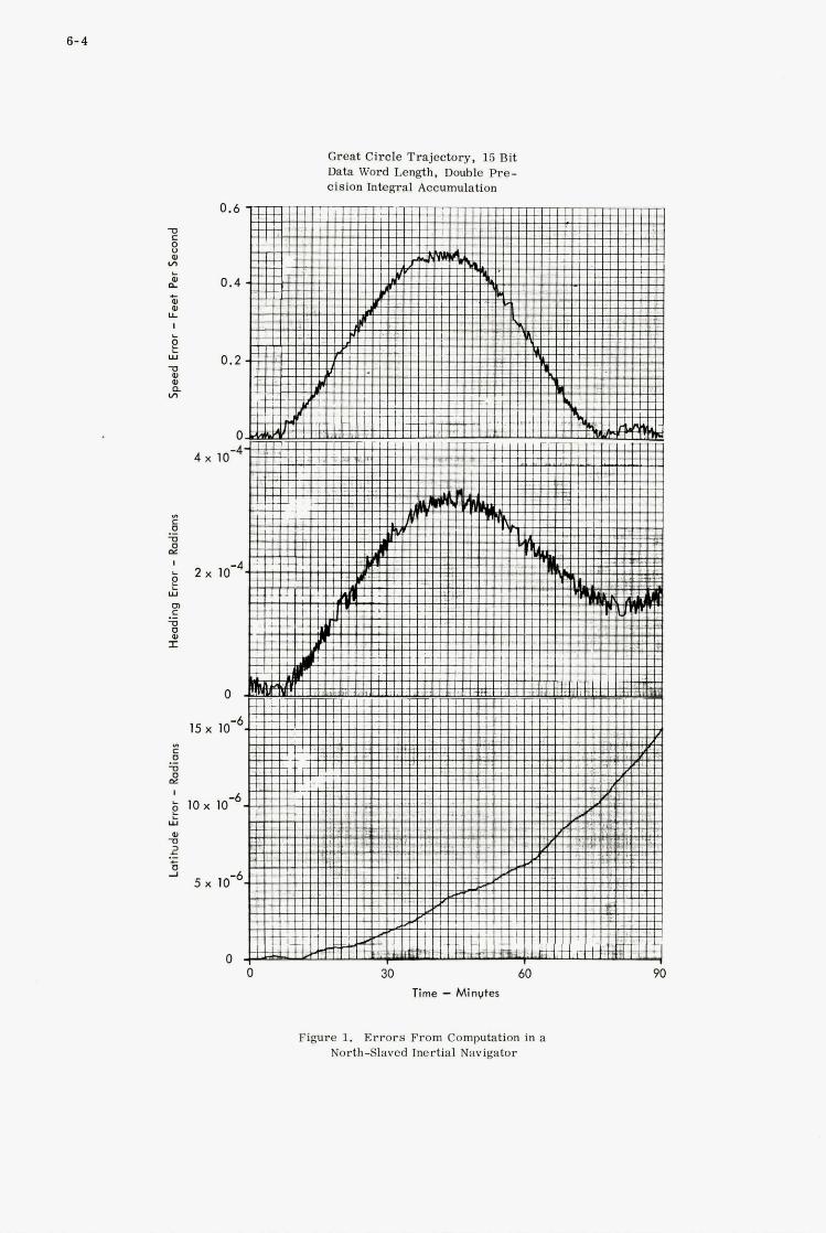
6-4
Great Circle Trajectory, 15 Bit Data Word Length, Double h e - cision Integral Accumulation
4 x
L
2 r;
2 x
15 x
I
E Y
10 x
4 2 .- L
2 5 x
30 60 Time - Minvtes
Figure 1. Errors From Computation in a NorthSlaved Inertial Navigator

6-5
* c 0 s 2 L e
Lii
s rn c
0 0 I
Great Circle Trajectory, 16 Bit Data Word Length, Double Pre- cision Integral Accumulation
-4 x
- a x
Time - Minutes
Figure 2. Errors From Computation in a NorthSlaved Inertial Navigator
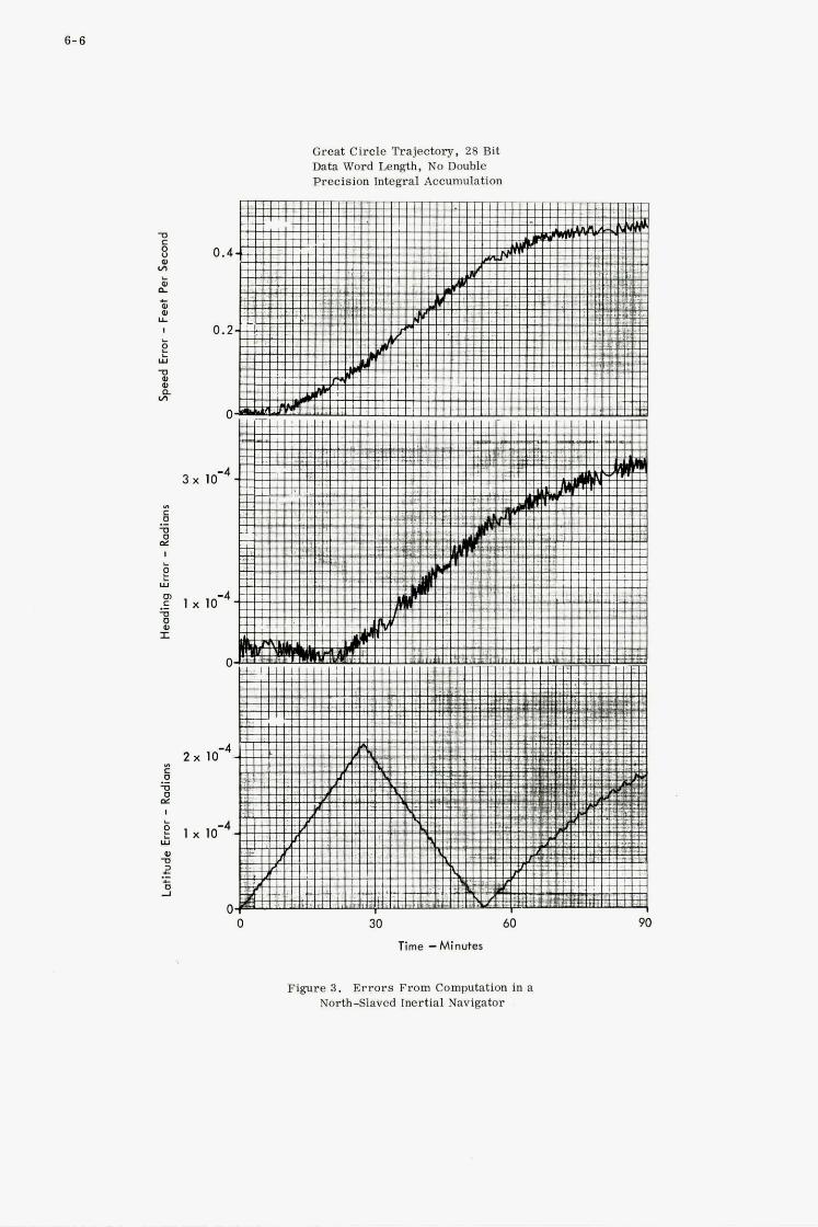
6- 6
Great Circle Trajectory, 28 Bit Data Word Length, No Double Recision Integral Accumulation
I
3 x
lx
2 x
l x U
V I! .- c s
0 30 60 Time -Minutes
90
Figure 3 . Errors From Computation in a NorthSlaved Inertial Navigator

IO )I
I - w
F .- -U 0 U I:
5m
4 r
" I
0
Great Circle Trajectory, 30 Bit Data Word Length, No Double Precision €ntegral Accumulation
30 60
Time - Minuter
Figure 4. Errors From Computation in a North-Slaved Inertial Navigator

6-8
a 0 0
1 10 20 Boric Word Length (Bits)
30
Figure 5. Number of 6IStNCtiOII Executions Required as a hmction of Data Word Length (Aerospace Data Processing)
0 0 0
0 a
1 IO 20 30 Baric Word Length (Bits)
Figure 6. Storage Required for Data as a Function of Data Word length (Aerospace Data Processing)
THE CASE FOR SPECIALISED SYSTEM
PROCESSORS IN AIRBORNE INSTALLATIONS
P. A. Hea rne
ELLIOTT FLIGHT AUTOMATION, Ai rpor t Works ,
Roches t e r , Kent.

7
SUMMARY
This paper examines the favourable changes made possible in avionic systems by the ready
availability in the 1970's of low-cost, single o r limited task processors. However, such availability
has certain dangers and the need to optimise the avionics with regard to the functional requirements
of particular systems, e. g. flight control, navigation, etc. , rather than attempting to t reat the
avionics primarily as a computing system, is emphasised.
A l s o examined are the system requirements of airborne data processors in the a reas
of navigation. weapon delivery, flight control, engine control, a i r data and displays. F rom this
examination, three different generic types of processor a re derived.
One of these generic types, a small control processor, is examined in detail and the
various analyses and trade-off studies carried out to determine i ts structure a re summarised.
The hardware implementation of this machine is then discussed.
Finally, a comparison between a 'distributed computer' avionics system using a number of
these machines on a large,centralised multiprocessor system is made. From this comparison i t
is shown that the distributed system has a number of important advantages and is a more flexibie
and cost-effective solution for avionics systems.

7.1
THE CASE FOR, SPECIALISED SYSTEM PROCESSORS IN
AIRBORNE INSTALLATIONS
SECTION 1 - GENERAL.
T h e high rate of technological advance in digital techniques makes it unwise t o be too dogmat ic about absolu tes in choice of s y s t e m mechanisat ion, technology, o r d e r code and EO on. Many of t h e s e a r e a m a t t e r of n e a r re l igious conviction although i t mus t be admi t ted that the rel igious fashion changes often abruptly. In the belief that we are now in a pe rmis s ive era I would l ike to get down to s o m e plain bas i c fac ts which relate the p r o c e s s o r s c h a r a c t e r i s t i c s t o the specif ic r equ i r emen t s of a i r b o r n e s y s t e m s and which r e l ega te the computer f r o m the r o l e of an all demanding all worshipped god to an o r d e r l y well behaved moronic hand-servant t o the a i r c r a f t des igner .
Histor ical ly , a i rbo rne digital computers have been a s soc ia t ed with the concept of a cen t r a l i s ed instal la t ion in which a l a r g e number i f not the en t i r e ty of the m a j o r computat ional p r o c e s s o r s r equ i r ed i n the a i r c r a f t w e r e p e r f o r m e d in one coniputer o r one computing complex.
In the e a r l y days of a i r b o r n e computers s o m e 1 2 - 14 y e a r s prev ious ly , the r eason f o r t h i s addiction towards a cen t r a l i s ed complex was p r i m a r i l y a n economic one. E a r l y a i r b o r n e computers using d i s c r e t e semi-conductors o r even vacuum tubes, ref lected the then high cost of scient i f ic and indus t r i a l machines . Consequently, if one pa r t i cu la r problem f o r example iner t ia l navigation, r equ i r ed the application of digi ta l techniques and the use of a pro ,cessor t h e r e was inevitably a tendency to apply the p r o c e s s o r t o as many different t a s k s as poss ib le in o r d e r t o get as much economic benefit as poss ib le f r o m what was undoubtedly a v e r y expensive p iece of equipment .
However, the concept of the cen t r a l i s ed computer per forming a multi-task r o l e offended both p rac t i ca l ly and theo re t i ca l ly against the well t r i e d concepts of ensu r ing a i r c r a f t safety and in t eg r i ty by m e a n s of e i t h e r s i m i l a r o r d i s s i m i l a r redundancy. Many a i r c r a f t des igne r s faced with the proposa l f o r a s ingle cen t r a l i s ed p r o c e s s o r f o r all m a j o r aircraft t a s k s quite r ight ly r e j ec t ed it on fl ight s a fe ty grounds.
T h e proponents of the cen t r a l i s ed l a r g e computer approach countered th i s re ject ion by the proposa l f o r a multiplexed cen t r a l i s ed computer complex in which the computer is still used in a multi- t a sk ro le , but i n t eg r i ty is a l legedly ensu red by u s e of a mult iplexed redundant computer and in t e r f ace complex.
Such approaches s e e m to u s at El l iot t t o fail to recognise that the purpose of t h e av ionics in the a i r c r a f t is to s e r v e the needs of the a i r c r a f t and its s y s t e m s r a t h e r than in the case of the Cent ra l i sed computer complex to b i a s the a i r c r a f t and s y s t e m requ i r emen t s i n favour of a data process- ing philosophy. It is imposs ib le to o v e r - e m p h a s i s e th i s point. Many people nowadays, pa r t i cu la r ly the spec ia l i s ed s y s t e m engineer ing groups r e f e r t o the concept of computing s y s t e m s o r the computer network as though the p r i m e r equ i r emen t was to obtain a completely rat ional ised and ideal ised data p rocess ing sys t em.
I would stress a s s t rongly as poss ib le that t he p r i m e r equ i r emen t is to achieve the mos t cos t effective a i r c r a f t and its as soc ia t ed navigation, flight control , air data, d isp lay and o ther sub- s y s t e m s . T h e data p rocess ing capabili ty of t he digital computer is m e r e l y a tool by which the spec ia l i s t s y s t e m des igne r be i t f o r navigation, flight control o r whatever achieves the computat ional r equ i r emen t s of h i s pa r t i cu la r s y s t e m s .
Th i s necessa ry e m p h a s i s upon the r equ i r emen t s of the s y s t e m negates many of t he a r g u m e n t s f o r the cen t r a l i s ed computer complex. A s shown in Section 2 different s y s t e m s have v e r y different computat ional r equ i r emen t s s o m e such as navigation requi r ing r e l axed high p rec i s ion working w h e r e a s o t h e r s such as displays r e q u i r e r e l a t ive ly low p rec i s ion a t a high work r a t e . A cen t r a l i s ed computer which would have to meet t he most demanding accu racy as well as the mos t demanding speed requi re - ments would in many ins t ances over-kill the computat ional r equ i r emen t f o r pa r t i cu la r individual sys t ems . Th i s fact and o t h e r s such a s differ ing in tegr i ty r equ i r emen t s f o r different s y s t e m s which are examined in m o r e detai l l a t e r , indicates the dange r s of approaching the mechanisat ion of a i r c r a f t computat ional r equ i r emen t s f r o m a data p rocess ing s y s t e m viewpoint r a t h e r than f r o m the viewpoint of t he s y s t e m requ i r emen t s themselves .
Unfortunately, in t he e a r l y s t a g e s at l e a s t a i r b o r n e computer des ign groups tended to sp r ing f r o m engineer ing groups who had previous ly been a s soc ia t ed with the design of sc ien t i f ic o r o the r ground-borne machines r a t h e r than f r o m des igne r s of a i r b o r n e equipment. Th i s ground equipment a n c e s t r y has in some ins t ances led to the apostol ic att i tude in r e l a t ion to the data p rocess ing s y s t e m a s an end in i tself r a t h e r than as one facet of the s e v e r a l means to that end. F u r t h e r m o r e , t he ini t ia l s c a r c i t y of aeronaut ica l equipment des igne r s in the e a r l y a i r b o r n e computer groups led t o a n e m p h a s i s on the design of t he a i r b o r n e computer a s a computer with a l a r g e 'C' r a t h e r than as a s y s t e m e lement which e m p h a s i s has i n s o m e ins t ances continued until f a i r l y r ecen t t imes .
7.2
Fortunately, today the widespread availability at low cost of digital components has enabled a much more realistic view to be taken of the design of airborne processors. First and foremost it has proved possible to build individual digital single task' processor units which a r e directly cost and weight compatible with their individual analogue counterparts. Thus there is no longer the necessity to inject multi-tasks into a computer to justify its cost which is now directly comparable with the analogue computation element which it replaces.
Furthermore, the increasingly widespread availability of such techniques a s computer aided design and simulation of integrated circuits, logic and stores has enabled a lot of mystique to be removed from the design of digital processors. It is now quite feasible to consider the design of specialised processors in accordance with the particular requirements of individual systems rather than the steam age approach to trying to fit one processor to many different applications. Of course, in a situation in which a number of individual single task computers replace the single o r multiplexed central computer, the smaller computers, whilst not identical would have many familiar similarities in terms of the type of micro-circuit and constructional standards employed. There will also be some form of resemblance, though not necessarily compatibility in their order code. A s shown later airborne computers which may be produced in large numbers for one single defined task differ greatly in the hardware and software trade-off from ground-borne computers which must be capable of being readily programmed for a wide variety of different applications for which they are usually supplied in relatively small numbers.
This note, therefore, examines firstly the requirements of the various avionic systems and secondly one of the generic type of these new specialised digital processors which tend to meet these requirements. Some indication is also given of the relative cost and system effectiveness of the specialised system processor approach. Note though that the specialised system processor will probably still be a general performance machine rather than the centralised computer approach.
SECTION 2 - AVIONICS SUB-SYSTEM REQUIREMENTS
Considering first of all the general requirements for any avionic system we have in general to specify requirements of accuracy and resolution, speed o r bandwidth, reliability and integrity and in addition we must decide upon the most economical way in which these requirements can be met. In addition, to these basic requirements, with a digital system in particular, we must examine carefully the interfacing requirements and the programming task involved in establishing the software for the computer.
Considering the main system blocks, in an advanced military aircraft we find the following.
2.1 Navigation
Navigation sub-system requirements for single task processors a r e usually related to the provision of individual special processors for individual sensors requiring extensive computation. The best known example is, of course, the inertial navigation requirement where the accuracy of digital computing is required to maintain the accuracy of open loop integration and the various processor terms.
Two choices of processor a r e available. When the processor is intimately involved with the inner platform control loops including the actual torquing pulses for gyro and accelerometers there is a high premium on speed coupled with an 18 to 24 bit word length requirement for accuracy. Storage requirements a r e also increased somewhat. On the credit side there is a reduction in the intimate platform electronicsandan overall simplification of the system. The other choice is to have a separate and relatively self-contained intimate platform electronic unit which will probably also house the analogue digital convertor and the appreciably slower computer which has the same word length accuracy requirements and a slightly lower storage requirement. Although this gives a slightly higher system cost it has the advantage of allowing independent operation of the platform a s an attitude reference in the event of computer failure and it also can offer simplification of the navigation processor. In each case this processor calculates present position from accelerometer and heading inputs, provides the necessary p1atfor.m precession terms, carr ies out the necessary system mode management and switching sequences, executes the gyro compassing phase and provides overall sub-system self-check. Additional modes which may often be included are waypoint and target storage and associated steering calculations and sometimes Kalman Filtering mechanisation. Generally it seems cost effective to put steering and waypoint storage in the special navigation processor but to reserve Kalman Filtering for the overall main system integration computer.
The inertial navigation processor with the desirable characteristics would have an 18 to 24 bit word length and would have between 4,000 and 6,000 words of storage depending upon the elaborations o r modes and outputs over and beyond the basic present position and steering modes which can usually be contained in a basic 4096 word block.
Note, however, that read only memories rather dilute the importance of binary power intervals of store capacity.
7.3
Speed requirements vary according to the system mechanisation chosen. If a parallel computer is used including the intimate platform functions a one micro-second store access time with better than three micro-second add time seems necessary.
The less demanding speed requirement can in fact be met by a ser ia l computer with much slower speeds. If, however, a parallel computer were used in the interests of commonality the store access time would be in the six to ten micro-second region since reduction below this figure would not give any further cost advantages at 1970 technology.
A processor of this type is very suitable for such complex radio navigation aids as Omega involving timing and hyperbolic transformations. The lower level of complexity processor, probably serial, is also directly applicable to Doppler VOR area nav. TACAN and similar radio navigation aids.
The correlation, compounding, filtering etc, of the various individual navigation sensors is carried out by the main systems integration computer referred to below which receives processed data from the processors of the various sensors. This computer also acts as a central storehouse and data distribution centre for all of the processed data from the various sensors. However, i f the main computer should fail the crew still have directly available to them the individual processed data from individual sensors albeit in an uncombined o r unfiltered form,
Because of this variety of navigational information normally available in a modern aircraft failure of a part of the navigation sub-system does not, in general, have any immediate effect of the safety of the aeroplane so that it is not necessary to have complete redundancy in the sensor/processors subsys tems for navigation. Such redundancy as is required is given by the alternative navigation sensors available and by increasing the crew workload in the event of a failure in the main computer system.
2.2 Weapon Delivery
Turning now to weapon delivery for military aircraft this sub-system requires solution of the ballistic equations for a wide variety of different weapons and computation of the release point based upon the range information from such sensors as radar, laser etc.
The accuracy requirements in general a r e not as great as navigation due to the more limited range involved in the weapon delivery computations so that satisfactory accuracy can be achieved with shorter word length. In general weapon delivery accuracy can be achieved with 1 2 - 16 bit word lengths albeit with some double length working.
The speed requirements, however, a r e very much greater and whereas with navigation an iteration rate of about five times per second is generally adequate, the iteration rate for weapon delivery increases to about 40 - 50 times per second.
The integrity requirements on the overall weapon delivery system are, of course, stringent since the possibility of accidental weapon release must be minimised. This integrity is normally achieved by having safety interlocks so that the system is only operational when armed by positive crew action immediately prior to an attack.
2.3 Flight Control
The requirements of flight control systems a r e covered in detail in another paper. In general, however, the accuracy required is limited to approximately 1 2 bits. For the outer loop control functions the speed requirements a r e moderate (approximately 20 - 30 iterations per second is the highest rate required) whilst for inner loop control, extremely high iteration rates a r e required (possibly even up to several hundred iterations per second). The integrity requirements vary depending upon the part of the flight control system concerned. It may be satisfactory to have a single lane for some of the outer loop control functions whilst the stability auggmeritation and any terrain following systems require multi-lane fail safe o r fail operative redundant solutions. The Flight Control system requirements a r e thus complex, and must be considered in detail. This is done in M r . R.W. Howard’s paper given at this meeting to which I refer you.
2.4 Engine Control
Engine Control has broadly the same problems as flight control with similar accuracies and similar integrity requirements. When used in an outer loop mode o r organisational control the computer tends to require lower speed but larger s tore capacity and when used in an inner loop control such a s for re-heat or acceleration control the speed requirement is increased and storage requirement reduced somewhat.
2.5 A i r Data
Air Data computation calls for the solution of complex functions at reasonably high iteration rates at between 20 and 50 per second. The accuracy requirements again a r e of the order of 1 2 bits since
7.4
once again this is the accuracy with which we are able to extract the basic sensor information and it is obviously not worthwhile computing to any higher degree of accuracy than that sensor information.
The integrity requirements of air data are again complex. For display purposes the integrity is usually provided by having standby instruments and having, within the basic flight instruments normally driven by the air data computer, alternative means of driving that instrument. Redundancy may, however, be required to satisfy stability augmentation requirements.
2.6 Electronic Displays
The computing requirements for displays again usually require high-speed computation, for example on a Head-Up Display 50 iterations per second a r e required to avoid flicker on the cathode ray tube, and as such displays are more and more becoming the primary flying instruments in the aircraft the amount of data required is increasing. Accuracy again is equivalent to a 1 2 bit word length, the accuracy being dictated in this case by the accuracy with which the data can be positioned on the face of a cathode ray tube. Integrity once again is usually satisfied by having alternative display configur- ations rather than by redundancy of the basic display,
2.7 Main Computer
Finally, I must consider the computer for the function which is generally known in today's circles as the main computer, formerly known as the central computer, when the computer tasks envisaged did not extend into flight control and other areas. This computer generally performs what is known as the Nav. Attack function and its main purpose is to integrate the outputs of the other subsys tems such as navigation and displays in such a way that large amounts of data can be transferred, correlated, compared etc. between the various subsys tems within the aircraft. The function of this Nav. Attack computer, whether in an aircraft with primarily analogue o r primarily digital computation for the sensors and control functions, is to provide the centralised source of the best possible information derived from these different subsys tems to be used in the navigation and attack functions. Thus, for example, the Nav. Attack computer would produce the ground stabilisation and pointing signals for the Low Light Television and Laser Ranger which i t would in turn derive from the inertial navigation and possible .. tracking radar subsys tems. Similarly, the Nav. Attack computer would probably organise the display format mode change which must necessarily take place when moving from the en route phase to the attack phase of the mission and would also generate much of the data in te rms of navigation, position, weapon state etc, which would be passed to the display processors for generation as display formats on the different surfaces.
This type of integration and management task requires computer word lengths of the order of 18 - 24 bits with a fairly large s tore and, because of the timing requirements associated with a multi- task type function in this instance, the speed of the computer is more comparable with that of the control processor than the navigation computer previously considered.
It is important to note that although this larger main computer is carrying out an integration task, failure of the computer does not affect the integrity of the aeroplane since all of the information which it uses is still available in a semi-processed form from the other subsys t ems - navigation, air data etc, in the aircraft. The crew are , therefore, still able to use this semi-processed information, albeit with a higher degree of crew workload even though the integration and correlation function on the main computer may be lost due to computer failure. This gives a welcome form of dissimilar redund- ancy which may be further improved in later systems by a degree of task sharing between the different processors using the ser ia l data transmission systems which nowadays is a common feature of advanced military aircraft.
W e have so far considered relatively slow, high-precision computers for navigation purposes, high-speed and lower precision computers for weapon delivery, flight control and air data, and displays where the accuracy in a computation is necessarily limited by the requisite accuracy of the inputs and outputs and the larger main computer for overall system integration and management where both high accuracy'and high-speed working is necessary to cater for its multi-task role. The problem of attempting to meet all these requirements in an efficient manner in one o r more large centralised computers is obviously an extreme one. Instead, rationalising these needs to basic aircraft functional requirements leads to three major types of data processor which could be used in future aircraft systems as shown in Figure 1. These are characterised as Management, Control and Sensor processors.
The Management processor is essentially a large, fast, powerful computer useful for carrying out combined navigation/attack/ management computing, o r a s a tactical processor.
The Control processors are smaller, less accurate machines and include as examples small inertial navigation processors, display processors, flight and engine control processors and weapon delivery processors.
Sensor processors include air data processors, fuel measurement system processors etc.
I would now like to concentrate upon the control processor application to indicate the
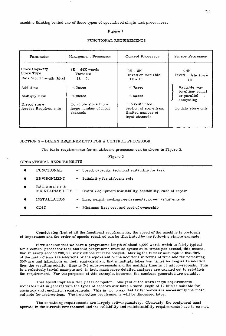
7.5
machine thinking behind one of these types of specialised single task processors.
Para met e r
Store Capacity Store Type Data Word Length (bits)
Add time
Multiply time
Direct store Access Requirements
Figure 1
FUNCTIONAL REQUIRENIENTS
Management Processor
8K - 64K words Variable 18 - 24
< Spsec
< Spsec
To whole store from large number of input channels
Control Processor
2K - 8K Fixed or Variable
12 - 18
< 3usec
< Susec
To restricted. Section of store from limited number of input channels
Sensor Process or
<4K '
1 2
Variable may be either serial or parallel computing
Fixed + data store
To data store only
SECTION 3 - DESIGN REQUIREMENTS FOR A CONTROL PROCESSOR
The basic requirements for an airborne processor can be shown in Figure 2.
Figure 2 OPERATIONAL REQUIREMENTS
0 FUNCTIONAL - Speed, capacity, technical suitability for task
0 ENVIRONMENT - Suitability for airborne role
0 RELIABILITY & MAINTAINABILITY - Overall equipment availability, testability, ease of repair
0 INSTALLATION - Size, weight, cooling requirements, power requirements
e COST - Minimum first cost and cost of ownership
Considering first of all the functional requirements, the speed of the machine is obviously of importance and the order of speeds required can be illustrated by the following simple example.
If we assume that we have a programme length of about 4,000 words which is fairly typical for a control processor task and this programme must be cycled at 50 times per second, this means that in every second 200,000 instructions must be obeyed. Making the further assumption that 7070 of the instructions are additions o r the equivalent to the additions in terms of time and the remaining 30% a r e multiplications o r their equivalent and that a multiply takes four times a s long a s an addition then the resulting addition time is 2.6 micro-seconds and the multiply time is 11 micro-seconds. This is a relatively trivial example and, in fact, much more detailed analyses a r e carried out to establish the requirement, For the purposes of this example, however, the numbers generated a r e suitable.
This speed implies a fairly fast computer. Analysis of the word length requirements indicates that in general with the types of sensors available a word length of 1 2 bits is suitable for accuracy and resolution requirements. This is not to say that 1 2 bit words are necessarily the most suitable for instructions. The instruction requirements will be discussed later.
The remaining requirements are largely self-explanatory. Obviously, the equipment must operate in the aircraft environment and the reliability and maintainability requirements have to be met.
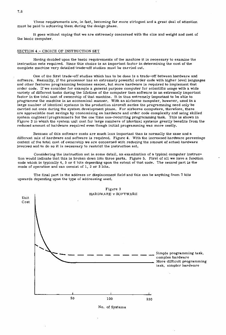
7.6
These requirements a re , in fact, becoming far more stringent and a great deal of attention must be paid to achieving them during the design phase.
It goes without saying that we a r e extremely concerned with the size and weight and cost of the basic computer.
SECTION 4 - CHOICE OF INSTRUCTION SET
Having decided upon the basic requirements of the machine i t is necessary to examine the instruction sets required. Since this choice is an important factor in determining the cost of the complete machine very detailed trade-off studies must be carried out.
One of the first trade-off studies which has to be done is a trade-off between hardware and software. Basically, if the processor has an extremely powerful order code with higher level languages and other features programming becomes easier, but more hardware is required to implement that order code. If we consider for example a general purpose computer for scientific usage with a wide variety of different tasks during the lifetime of the computer then software is an extremely important factor in the total cost of ownership of that machine. It is thus extremely important to be able to programme the machine in an economical manner. With an airborne computer, however, used in a large number of identical systems in the production aircraft series the programming need only'be carried out once during the system development phase. For airborne computers, therefore, there a r e appreciable cost savings by economising on hardware and order code complexity and using skilled system engineerIprogrammers for the one time non-recurring programming task, This is shown in Figure 3 in which the system unit cost for large numbers of identical systerns greatly benefits from the reduced amount of hardware required even though initial programming was more costly.
Because of this software costs a r e much less important than is normally the case and a different mix of hardware and software is required. Figure 4. With the increased hardware percentage content of the total cost of ownership we a r e concerned with reducing the amount of actual hardware involved and to do so i t is necessary to restrict the instruction set.
Considering the instruction set in some detail, an examination of a typical computer instruc- tion would indicate that this is broken down into three parts. Figure 5. First of all we have a function code which is typically 4, 5 o r 6 bits depending upon the extent of that code. The second part is the mode of operation and can consist of 1, 2 o r 3 bits.
The final part is the address o r displacement field and this can be anything from 7 bits upwards depending upon the type of addressing used.
Unit cos t
Figure 3 HARDWARE v SOFTWARE
Simple programming task, complex hardware More difficult programming task, simpler hardware
---------
I I I
50 100 150
No. of Systems
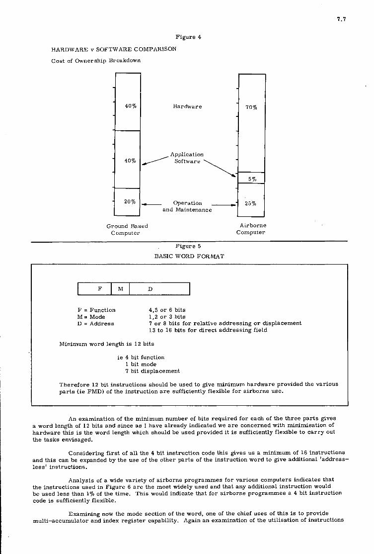
7.7
F
Figure 4
HARDWARE v SOFTWARE COMPARISON
Cost of Ownership Breakdown
M D
Hardware
Application
\ / Software
- Operation I
and Maintenance
-
70%
5 70 -
25%
Ground Based Computer
Airborne Computer
Figure 5
BASIC WOXD FORMAT
n
F = Function M = Mode D = Address
4.5 or 6 bits 1 ,2 o r 3 bits 7 or 8 bits for relative addressing o r displacement 13 to 16 bits for direct addressing field
inimum word length is 12 bits
ie 4 bit function 1 bit mode 7 bit displacement
Therefore 12 bit instructions should be used to give minimum hardware provided the various parts (ie FMD) of the instruction a r e sufficiently flexible for airborne use.
An examination of the minimum number of bits required for each of the three parts gives a word length of 12 bits and since as I have already indicated we are concerned with minimisation of hardware this is the word length which should be used provided it is sufficiently flexible to car ry out the tasks envisaged.
Considering first of all the 4 bit instruction code this gives us a minimum of 16 instructions and this can be expanded by the use of the other parts of the instruction word to give additional 'address- less' instructions.
Analysis of a wide variety of airborne programmes for various computers indicates that the instructions used in Figure 6 a r e the most widely used and that any additional instruction would be used less than 1% of the time. This would indicate that for airborne programmes a 4 bit instruction code is sufficiently flexible.
Examining now the mode section of the word, one of the chief uses of this is to provide multi-accumulator and index register capability. Again an examination of the utilisation of instructions

7.8
Figure 6
CHOICE OF ORDER CODE - 4
Utilization
0 .
10
20 I
30
40
Percentages
50
60
70
8C
9(
100
Write
Read
Mult ,
Jump
ump if Ne
Add
Subtract
Divide count
VERDAN
0
10
20
30
4c
5(
40-50 1c Other instructions
Write
Read
Mult .
Add
Shift
Negate and Add
Jump
Divide
JumD if Negl Subroutine Entry
1 Collate Jump i f Zero
--I- Count -1- Store E. Reg
MCS 920
in airborne programmes indicates that a large proportion of the time is taken up by load and store instructions. This is, in fact, typical of single accumulator machines and the method of reducing it is to go to multiaccumulator operation.
However, a detailed analysis of the control processor tasks for this type of computer indicates that only approximately 15% of storage locations a r e saved by having multiaccumulator operation. Since multiaccumulator operation would require the word length and hence the storage cost to be increased by more than 150/, it does not seem worthwhile for these special purpose applic- ations and a single accumulator system is, therefore, chosen.
The f inal part of the instruction word is the address field and with a seven bit field a page of 128 words can be addressed. Using a mode bit enables two separate 128 word field to be addressed.
Each additional bit added enables the size,of the address page to be doubled so that for example,with a 13 bit address 8,192 words a r e available on the page.
To utilise the complete storage capability of the machine a pointer register indicating the page address must be used and this must be set to a new value every time the page changes.
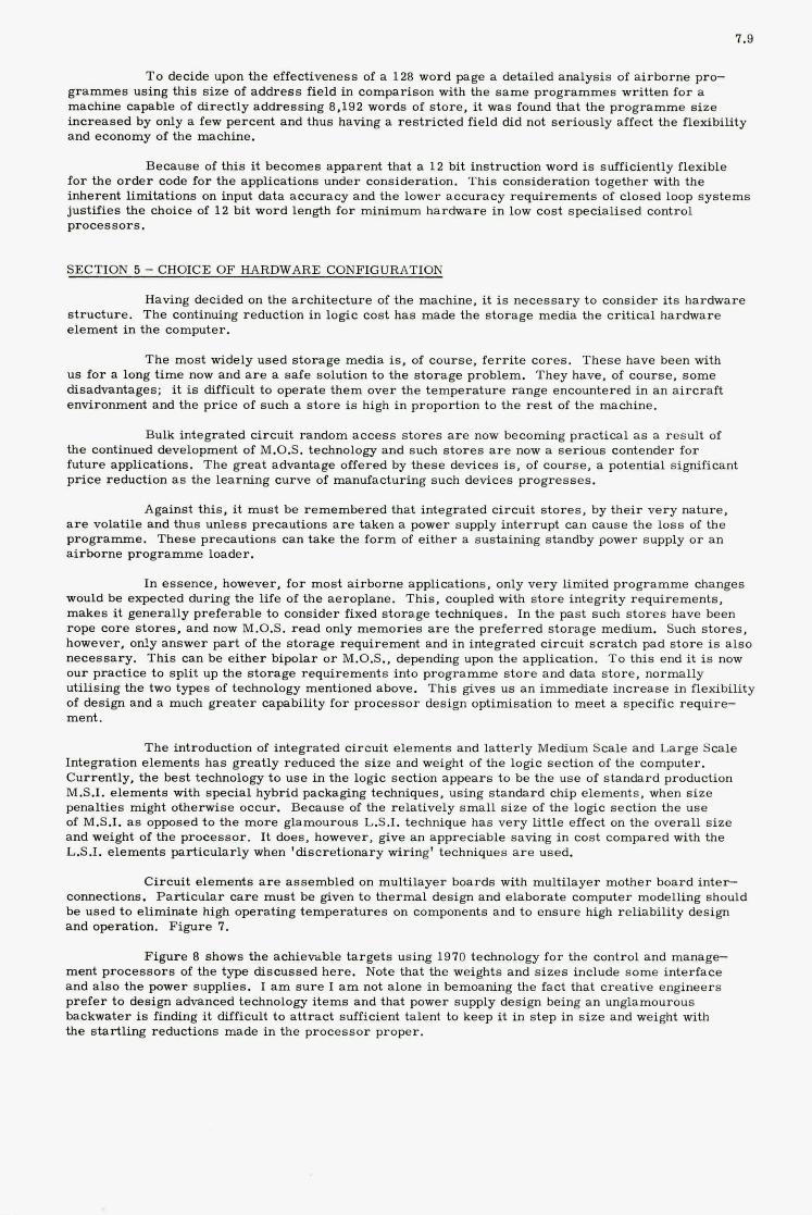
7.9
T o decide upon the effect iveness of a 128 word page a detai led ana lys i s of a i r b o r n e pro- g r a m m e s us ing th i s s i z e of a d d r e s s field in compar i son with the s a m e p r o g r a m m e s wr i t ten f o r a machine capable of d i r ec t ly addres s ing 8,192 words of s to re , it was found that the p r o g r a m m e s i z e i n c r e a s e d by only a few pe rcen t and thus having a r e s t r i c t e d f i e ld did not s e r i o u s l y a f fec t the flexibil i ty and economy of the machine.
Becauee of t h i s it becomes apparent tha t a 1 2 bit ins t ruc t ion word is sufficiently flexible f o r t he o r d e r code f o r t he appl icat ions under considerat ion. T h i s considerat ion together with the inherent l imi ta t ions on input data a c c u r a c y and the lower a c c u r a c y r equ i r emen t s of c losed loop s y s t e m s just i f ies the choice of 1 2 bit word length f o r minimum ha rdware in low cos t s p e c i a l i s e d control p r o c e s s o r s .
SECTION 5 - CHOICE OF HARDWARE CONFIGURATION
Having decided on the a r c h i t e c t u r e of the machine, it is n e c e s s a r y to cons ide r its ha rdware s t ruc tu re . T h e continuing reduct ion in log ic cos t bas made the s t o r a g e media the c r i t i ca l ha rdware e lement in the computer .
T h e most widely used s t o r a g e media is, of course , f e r r i t e cores . T h e s e have been with u s f o r a long t i m e now and a r e a sa fe solution to the s t o r a g e problem. They have, of course . s o m e disadvantages: it is difficult t o ope ra t e t h e m ove r the t e m p e r a t u r e range encountered i n a n a i r c r a f t environment and the p r i c e of such a s t o r e is high i n proport ion to the r e s t of t he machine.
Bulk in tegra ted c i rcu i t r andom a c c e s s s t o r e s a r e now becoming p rac t i ca l a s a r e su l t of the continued development of M.O.S. technology and such s t o r e s a r e now a s e r i o u s contender f o r fu ture appl icat ions. The g r e a t advantage of fe red by t h e s e devices is, of course , a potent ia l significant p r i c e reduct ion as the learn ing cu rve of manufactur ing such devices p r o g r e s s e s .
Against this. it m u s t be r e m e m b e r e d tha t in tegra ted c i rcu i t s t o r e s , by the i r v e r y nature , a r e volati le and thus un le s s precaut ions a r e taken a power supply in te r rupt can cause the l o s s of the p r o g r a m m e . T h e s e precaut ions can take the f o r m of e i the r a sustaining s tandby power supply o r a n a i r b o r n e p r o g r a m m e loader .
In e s sence , however, f o r most a i r b o r n e appl icat ions, only v e r y l imited p r o g r a m m e changes would be expec ted during the l i fe of t he aeroplane. This , coupled with s t o r e in tegr i ty r equ i r emen t s , m a k e s it gene ra l ly preferab le to cons ide r f ixed s t o r a g e techniques. In the pas t such s t o r e s have been rope c o r e s t o r e s , and now M.O.S. r e a d only m e m o r i e s a r e the p r e f e r r e d s t o r a g e medium. Such s t o r e s . however , only a n s w e r part of t he s t o r a g e r equ i r emen t and in in tegra ted c i rcu i t s c r a t c h pad s t o r e is a l s o necessa ry . Th i s can be e i the r bipolar o r M.O.S.. depending upon the application. To this end it is now our p r a c t i c e to sp l i t up the s t o r a g e r e q u i r e m e n t s into p r o g r a m m e s t o r e and data s to re . no rma l ly u t i l i s ing the two types of technology mentioned above. T h i s gives u s a n immedia te i n c r e a s e in flexibil i ty of design and a much g r e a t e r capabi l i ty f o r p r o c e s s o r design opt imisat ion to meet a spec i f ic r e q u i r e ment .
The introduct ion of in tegra ted c i r cu i t e l emen t s and l a t t e r ly Medium Scale and La rge Scale Integrat ion e l emen t s h a s g rea t ly reduced the s i z e and weight of the logic sec t ion of the computer . Current ly , the bes t tecbnology t o u s e in the log ic sec t ion a p p e a r s t o be the use of s t a n d a r d production M.S.I. e l emen t s with spec ia l hybr id packaging techniques, using s t a n d a r d chip e l emen t s , when s i z e penal t ies might otherwise occur. Because of the re la t ive ly s m a l l s i z e of the logic sec t ion the u s e of M.S.I. as opposed to the m o r e glamourous L.S.I. technique bas v e r y l i t t l e effect on the ove ra l l s i z e and weight of the p r o c e s s o r . I t does. however , give a n apprec i ab le saving i n cost compared with the L.S.I. e l emen t s pa r t i cu la r ly when 'd i scre t ionary wiring' techniques a r e used.
C i rcu i t e l emen t s a r e a s s e m b l e d on mul t i l aye r boa rds with mult i layer mother board inter- connections. P a r t i c u l a r c a r e m u s t be given to t h e r m a l design and e labora te computer modelling should be u s e d t o e l iminate high operat ing t e m p e r a t u r e s on components and t o e n s u r e high re l iab i l i ty design and operat ion. F i g u r e 7.
Figure 8 shows the achievable t a rge t s using 1970 technology f o r the control and m a n a g e ment p r o c e s s o r s of the type d i scussed h e r e . Note tha t the weights and s i z e s include some in te r face and a l s o the power suppl ies . I a m s u r e I a m not a lone i n bemoaning the f ac t that c r ea t ive eng inee r s p r e f e r t o design advanced technology i t e m s and tha t power supply design being a n unglamourous backwater is finding it difficult t o a t t r a c t sufficient talent to keep it in s t e p in s i z e and weight with the s t a r t l i ng reduct ions made in the p r o c e s s o r proper .
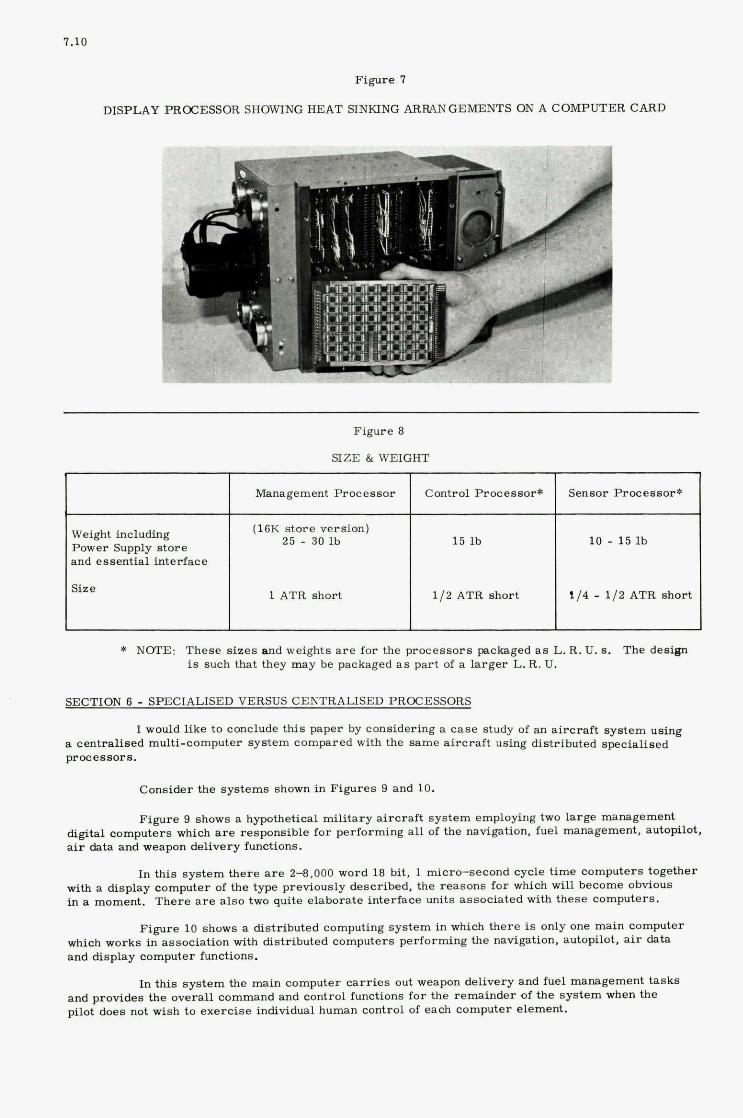
1.10
Management Processor Control Processor*
(16K store version) 25 - 90 1b 15 lb
and essential interPace
Size 1 ATR short 112 ATR short
Figure 7
DISPLAY PROCESSOR SHOWING HEAT SINKING ARRANGEMENTS ON A COMPUTER CARD
Sensor pToce8sor*
10 - 15 lb
114 - 112 ATR short
Figure 8
SIZE &WEIGHT
* NOTE: These sizes and weights are for the processors packaged as L. R. U. S. The design 18 Such that they =ay be packaged as part of a larger L. R. U.
SECTION 6 - SPECIALISED VERSUS CENTRALISED PROCESSORS
lude this paper by considering a case study of an aircraft system us@ stem compared with the same aircraft using distributed specialised
processors.
Consider the systems shown in Figares 9 and 10.
Figure 9 sbovfs a bypothetid military aircraft system employing two large management digital computers which are responsible for performing all ef the navigation, fuel management, ardopblOt, air data and weapon delivery functions.
In this system there are 2f),oOO word 18 bit, 1 micra-second cycle time computers together with a display computer of the type previously described. the reasons for which w i l l become obvious in a moment. There are also two quite elaborate interface units associated with these Computers.
Figure 10 shows a distributed computing system in which there is only one main computer which works in associatiod with distributed eomputers performing the mvigkation, autopilot. air data and display computer bct ions.
In this system the main computer oarries out weapon and providea the overall command and control functions for the r pilot does not wish to exercise individual human control of each computer element.
and fuel management tasks of the system when the
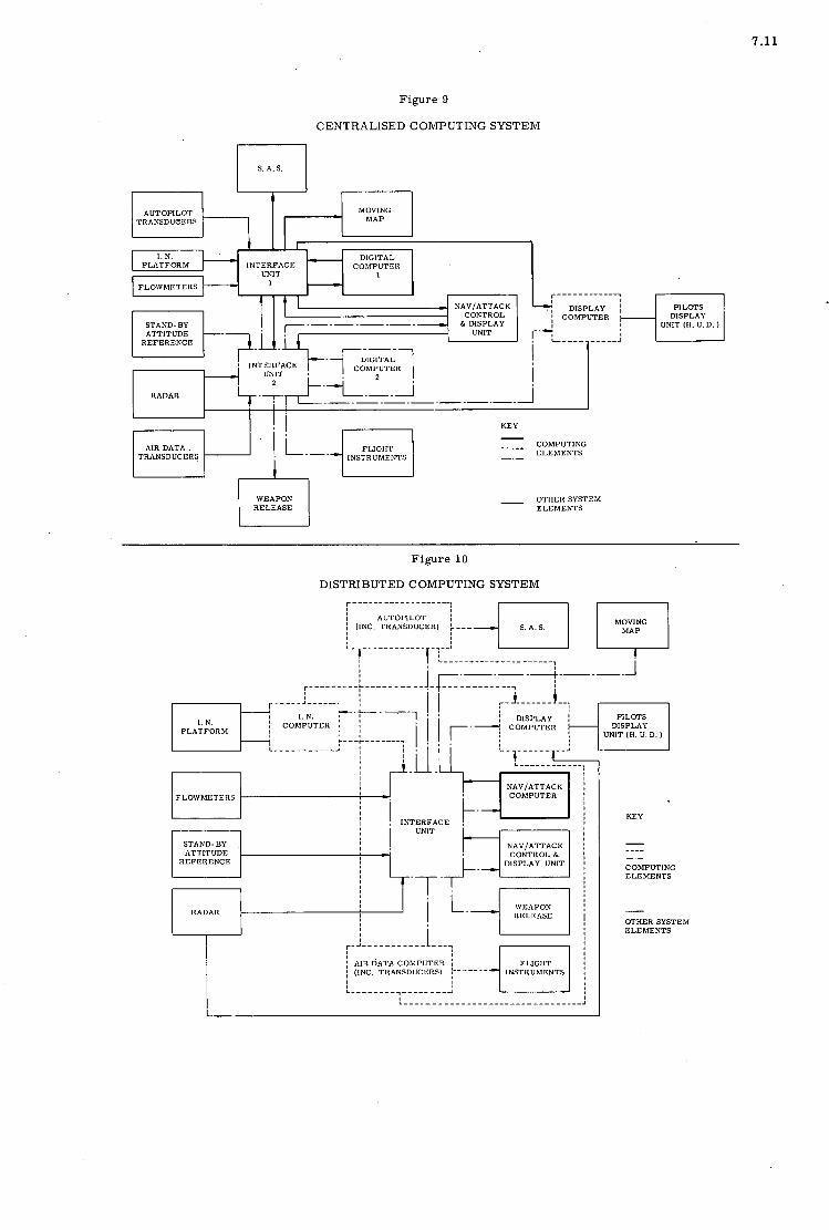
7.11
Figure 9
CENTRALISED COMPUTING SYSTEM
I
h I
MOVING MAP I - AUTOPILOT
TRANSDUCERS
I. N. DIGITAL INTERFACE COMPUTER -
- UNIT 1 PLATFORM
FLOWMETERS - 1
STAND-BY ATTITUDE
REFERENCE
* INTERFACE UNIT I
RADAR
I I / KEY -
COMPUTING ELEMENTS
----- TRANSDUCERS INSTRUMENTS -. -
WEAPON I RELEASE I - OTHER SYSTEM ELEMENTS
Figure 10
DISTRIBUTED COMPUTING SYSTEM
m m - - -. - - - - -. . - __. . _ _ ! i 4 S.A.S . I I 1 I AUTOPILOT
i (INC. TRANSDUCER) :---
r - : - - I
I.-----------
NAVIATTACK FLO\VMETERS COMPUTER
INTERFACE
NAVIATTACK CONTROL &
DISPLAY UNIT -+- ATTITUDE
REFERENCE
-7-
INSTRUMENTS i AIR DATA COMPUTER I 1 (INC. TRANSDUCERS) :------ !
KEY
COMPUTING ELEMENTS
- I T H E R SYSTEM ELEMENTS
7.12
i)
Comparison between the two systems evokes the following points:
Programming
Anybody who has been concerned with the commissioning and operation of advanced digital systems will appreciate the problems involved when a large number of tasks a r e combined in a single digital computer programme. Changes in individual tasks often demand a complete re-packing of the programme and when changes are introduced sometime after the original programme has been written, the original personnel may not always be available and a considerable hiatus may occur. One o r two air defence systems have shown evidence of this.
On the other hand, if the programming toad can be distributed between individual computers, the programme is both easier to write and understand since it relates to one task only and it becomes a much simpler matter to car ry out the initial programming and maintain adequate software control throughout the life of the project.
Although this may seem a small matter the success of many digital systems is dependent upon the intelligence and understanding of the associated software and anything which can be done to simplify this brings considerable benefits in both the development and operational phases.
ii) Iteration Rate
Although the larger computers can store considerably larger amounts of information in terms of data and tasks to be performed it remains a fact of life o r computer engineering that the speed at which they can perform these individual tasks is no faster than the speed of the smaller computers.
Therefore, if the large central computer is performing four tasks say, and a smaller computer performing one, the larger computer can only produce an iteration rate o r frequency of solution, 1 / 4 that of the smaller computer.
Since many of the tasks which we a r e now considering suitable for digital control such a s the Automatic Flight Control System, are dependent upon a high solution rate for stability, e.g.in the terrain following mode, it follows that the central computer can only be used for these high band-width tasks provided it is relieved of its other task functions.
In the dual central computer system illustrated it is obvious that the computing require- ments of the aircraft demand the full time usage of both computers and i t is not generally possible to consider a condition where one computer is unloaded merely because it has to concentrate on a high band-width task.
On the other hand, i f individual small computers a r e performing the different high band-wj.dth tasks they can allocate the whole of their computing cycle time to t h e i r particular function and this very real limitation is removed. The most demanding areas for computing time are the display generation and the autopilot control tasks, and it is noteworthy that in the system considered even the multiplex central computer was unable to perform display calculations at an adequate rate for the system under consideration, and the use of a special additional computer was necessary even though the storage capacity of the central computer was adequate.
In the systems considered on a purely cycle time basis, the dual central computer system was unable to perform anything other than simple heading and height holding autopilot functions and very limited air data information capability, as opposed to the distributed system in which full autopilot functions including terrain following the full air data capability were achieved.
It is interesting to note that recent simulation and analytical work on digital control systems has shown the need for far higher iteration rates for inner and outer loop stability than were at f irst envisaged and indicate the importance of computing speeds in this particular application.
iii) Weight and Volume
The weight of the computer and interface elements of the centralised computer system a r e 183 lb. compared with 174 1b.for the distributed system and the volume of the centralised system is 4.6 cu.ft. as opposed to 3.9 cu.ft. in the distributed system.
On this basis neither system has any clear advantage over the other.
iv) System Integrity
The function failure rate, i.e. the mean time between complete failure of a particular function is approximately twice a s good on the distributed computing system because the individual distributed computers being less complex have an appreciably higher mean time between failure.

7.13
There is, therefore, a significant gain in both the operational capability and the maintenance requirements in favour of the distributed computing system.
V) cos t
The first cost of the computer and interface elements of the centralised computing system is f63.000 compared with the f49.000 of the distributed computing system. There is, therefore, a 30% cost advantage in favour of the distributed computing system and this is also reflected when account is taken of the spares and operational maintenance cost of the system in service. This is probably the single greatest advantage of the distributed system.
Figure 11 summarises the aavantages of the distributed as opposed to the centralised computing system. Although the absolute ratios of one system over the other may be queried, I believe there is sufficient indication from the studies carried out to date, which I have not time to produce in detail here, to indicate that at this moment of time in development of airborne digital systems, distributed computing systems offer much’ more advantageous methods of applying digital control in aircraft than the hitherto favoured centralised system.
Figure 11
CENTRALISED v DISTRIBUTED CONlPUTING SYSTEMS
Centralised Distributed
Programming Demanding Relaxed
Restricted Satisfactory Iteration Rate
Weight 183 lb 174 lb
Volume 4. 6 cu.ft. 3 . 9 cu.ft.
Integrity 1.0 2.0
cos t 1 .0 0. 7
SECTION 7 - ACKNOWLEDGEMENTS
The author wishes to aclmowledge the help of the many member8 ef EFA staff who have over a number of years produced the concept discussed in this paper.


ECONOMIES OF INTERFACING WITH SMALL SENSOR COMPUTERS
K. R. Brown
I n e r t i a l Systems Department Fer ran t i Limited Edinburgh, UK
8
8
SUMMARY
With t h e newer generation of d i g i t a l processors, it is increasingly obvious tha t t h e in t e r f ace between computer and sensor i s t h e major par t of t he complete system. This is pa r t i cu la r ly t r u e i n the a i r c r a f t navigation f i e l d where the t rend i s t o self-contained systems which include a small d i s t a l -processor - t he sensor computer. This must i n t e r f ace with the input sensors and feed outputs t o t h e other a i r c r a f t systems by d i g i t a l da t a links and by various analogue transmissions.
To make such self-contained systems economical, i t i s necessary t o r e s t r i c t t h e s i z e and cos t of the in t e r f ace coupling the computer t o the sensors and t o t h e remaining systems. case of avionics equipment h economical so lu t ion i s the one which leads t o a reduction i n the material content and the overa l l s i z e of t h e equipment. Certain techniques which reduce the cos t of storage within the in t e r f ace and permit the sharing of expensive high accuracy p a r t s of t he c i r c u i t r y a re described. These a l so reduce t h e bulk of the equipment.
Both output and input of d a t a t o the computer must be considered; t h e da t a can be of m a n y forms. computers is frequently par t of a closed loop cont ro l system, i n which case very ca re fu l a t t en t ion t o t h e method of s igna l flow is required t o reduce t h e e f f e c t s of t he cont ro l system dynamics on the computer load.
Certain bas ic design pr inc ip les and ru l e s a r e s t a t e d i n the paper, and the use of these ru l e s is i l l u s t r a t e d by two examples - t he in t e r f ace with an i n e r t i a l platform and a synchro/resolver i n t e r f ace un i t .
,
Certainly i n the
The d a t a i n and out of sensor
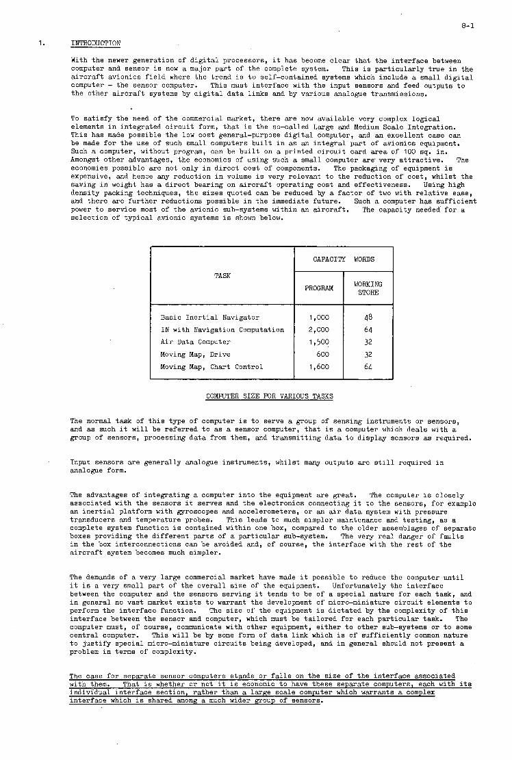
1.
8- 1
INTRODUCTION
With the newer generation of d i g i t a l processors, i t has become c l e a r t h a t t he in t e r f ace between computer and sensor i s now a major par t of t he complete system. This i s pa r t i cu la r ly t rue i n the a i r c r a f t avionics f i e l d where the t rend is t o self-contained systems which include a small d i g i t a l computer - the sensor computer. This must in te r face with t h e input sensors and feed outputs t o the o ther a i r c r a f t systems by d i g i t a l da t a l i nks and by various analogue transmissions.
To s a t i s f y the need of the commercial market, there a re now ava i lab le very complex log ica l elements i n in tegra ted c i r c u i t form, tha t i s the so-called Large and Medium Scale Integration. This has made possible the l o w cost general-purpose d i g i t a l computer, and an ,exce l len t case can be made f o r the use o f such small computers b u i l t i n as an in t eg ra l par t of avionics equipment. Such a computer, without program, can be b u i l t on a pr in ted c i r c u i t card a rea of 100 sq. in. Amongst o ther advantages, t he economics of us ing such a small computer a r e very a t t r ac t ive . economies possible a r e not only i n d i r e c t cos t of components. expensive, and hence any reduction i n volume is very relevant t o t he reduction of cos t , whilst the saving i n weight has a d i r ec t bearing on a i r c r a f t operating cos t and effectiveness. dens i ty packing techniques, t h e s i z e s quoted can be reduced by a f ac to r of two with r e l a t i v e ease, and the re a re fu r the r reductions possible i n the immediate future. Such a computer has su f f i c i en t power t o serv ice most o f t he avionic sub-systems within an a i r c r a f t . s e l ec t ion o f t yp ica l avionic systems i s shown below.
The The packaging of equipment i s
U s i n g high
The capacity needed f o r a
TASK
Basic I n e r t i a l Navigator I N with Navigation Computation A i r Data Computer Moving Map, Drive Moving Map, Chart Control
I CAPACITY WORDS
PROGRAM
1,000
2,000
1,500
600 1,600
I WORKING
STORF: I 1
48 64 32 32
64
COMPUTER SIZE FOR VARIOUS TASKS
The normal t a sk of t h i s type of computer i s t o serve a group of sensing instruments o r sensors, and as such it w i l l be r e fe r r ed t o as a sensor computer, t h a t i s a computer which dea ls with a group of sensors, processing da ta from them, and t ransmi t t ing da ta t o d isp lay sensors as required.
Input sensors a re generally analogue instruments, whilst many outputs a re s t i l l required i n analogue form.
The advantages of i n t eg ra t ing a computer i n t o the equipment a re great. assoc ia ted with the sensors i t serves and t h e e l ec t ron ic s connecting it t o t he sensors, f o r example an i n e r t i a l platform with gyroscopes and accelerometers, o r an air d a t a system with pressure transducers and temperature probes. complete system function i s contained within one box, compared t o the o lder assemblages of separate boxes providing the d i f f e ren t p a r t s of a pa r t i cu la r sub-system. i n the box interconnections can be avoided and, of course, t he in t e r f ace with the r e s t of the a i r c r a f t system becomes much simpler.
The computer i s c lose ly
This leads t o much simpler maintenance and t e s t ing , as a
The very r e a l danger o f f a u l t s
The demands of a very la rge commercial market have made it possible t o reduce the computer u n t i l i t is a very small par t of t he overa l l s i z e o f the equipment. Unfortunately the in t e r f ace between the computer and the sensors serving it tends t o be of a spec ia l nature f o r each task , and i n general no vas t market e x i s t s t o warrant t h e development of micro-miniature c i r c u i t elements t o perform the in t e r f ace function. The s i z e of the equipment i s d i c t a t ed by the complexity of t h i s i n t e r f ace between the sensor and computer, which must be t a i lo red f o r each pa r t i cu la r task. The computer must, of course, communicate with o ther equipment, e i t h e r t o o ther sub-systems o r t o some c e n t r a l computer. This w i l l be by some f o r m of d a t a l i n k which i s of s u f f i c i e n t l y common nature t o j u s t i f y spec ia l micro-miniature c i r c u i t s being developed, and i n general should not present a problem i n terms of complexity.
The case f o r separate sensor computers stands o r f a l l s on the s i z e of the in t e r f ace associated with them. That i s whether o r not i t i s economic t o have these separate computers, each with i t s individual i n t e r f ace sec t ion , r a the r than a la rge sca le computer which warrants a complex in t e r f ace which is shared among a much wider group of sensors.

8-2
By ca re fu l organisation of the in te r face t o share the accurate analogue c i r c u i t s which are es sen t i a l t o i t and which c rea te most o f t he bulk, i t i s possible t o hold the s i z e within economic l i m i t s . of t h e in te r face . computer and the in t e r f ace - t h i s must be of both small s i z e and low cost. This buf fer need only s to re d a t a between successive computer cyc les - a time ranging between 30 milliseconds and perhaps 300 milliseconds. c i r c u i t s explo i t ing t h i s method of buf fer ing can lead t o grea t economies. t o buf fer a frequently updated DC voltage is , of course, a very obvious example of t h i s technique', and i s ce r t a in ly too obvious t o dwell on. However, i n combination with o ther c i r c u i t elements, t h i s technique can be enlarged t o include the storage and modulation o f AC voltages and t o buf fer d i r ec t current pulses. It is i n these two areas t h a t t he g rea t e s t economies have been rea l i sed .
This paper describes some techniques which have proved successful i n reducing the s i z e The key t o the problem i s the requirement f o r buf fer s torage between the
For t h i s purpose a capacitor proves t o have a l l t h e necessary proper t ies , and The use of capac i tors
2. THE INTERFACE PROBLEM
The problems which must be considered i n studying the economics of t he in t e r f ace between sensors and computers fall under the following headings.
(a) It i s necessary t o share the accurate and bulky analogue-digital conversion c i r c u i t s as widely as possible i n a pa r t i cu la r equipment. Every attempt should be made t o have only one such conversion uni t .
The buf fer storage between the computer and the in t e r f ace can.be bulky.
Does the da t a from o r t o the sensor change rap id ly? If so, can the conversion c i r c u i t r y and the buf fer storage be arranged t o dea l with rap id ly changing s igna ls?
The in t e r f ace and the computer may form par t of a closed loop cont ro l system, i n which case the computing speed and proper t ies of t h e in t e r f ace a f f ec t t he s t a b i l i t y of t he cont ro l system.
(b) The s i z e and complexity of t h i s must be c lose ly controlled.
( c )
(d)
Although the in t e r f ace problems of d i f f e ren t systems a re d i f f e r e n t , both i n t h e accuracy required and i n the format of t he d a t a dea l t with, t he design techniques used t o reduce t h e material content of t he in t e r f ace u n i t appear t o follow s i m i l a r ru les .
The quan t i t i e s t o be d e a l t with i n t h e , i n t e r f a c e between the analogue sensors and t h e computer i n t h e system mentioned i n the Table on Page 8-1 can be grouped under the following headings.
Accurate d i r ec t current pulses - both input and output
Synchros - both cont ro l t r ansmi t t e r s and cont ro l transformers, including four-wire devices such as reso lvers
AC and DC voltages - input and output t o and from sensors and aircraft
Self-balancing bridge
The problem of encoding the DC voltage through a multiplex analogue t o d i g i t a l convertor i s commonplace, and requi res no fu r the r comment. LSI packages already e x i s t f o r t h i s function. Methods of dea l ing with AC voltages and the self-balancing bridge can be considered as var i a t ions of t he technique used t o provide the more complex synchro angular transmission. The problems of producing a small in t e r f ace u n i t can be concentrated i n the two remaining areas , t ha t i s
(a) The quantizing of d i r e c t current. This i s required t o an accuracy o f b e t t e r than one par t i n 104, both i n magnitude and i n time; and
Simulating both the functions of a synchro angular transmission, t ha t i s the synchro t ransmi t te r and the cont ro l transformer
(b)
These widely separate .functions a re e n t i r e l y d i f f e ren t and ye t t he methods t o reduce the material content prove t o follow very s i m i l a r rules.
(a) Share the accurate generation of analogue quan t i t i e s as widely as possible
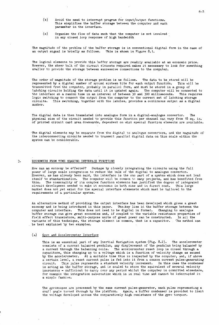
8-3
(b) Avoid the need t o in t e r rup t program f o r input/output functions. This s impl i f ies the buf fer storage between t h e computer and each parameter i n the in te r face .
Organise t h e flow of da t a such t h a t t he computer i s not involved i n any closed loop response of high bandwidth
( c )
The magnitude of t he problem i f the buf fer storage i s i n conventional d i g i t a l form i n the case of an output s igna l i s b r i e f l y as follows. This is shown i n Figure 8.1.
The log ica l elements t o provide thifi buf fer storage a re r ead i ly ava i lab le at an economic price. However, the sheer bulk of t he c i r c u i t elements required makes it necessary t o look f o r something smaller t o provide t h e storage between successive connections t o the computer.
The order of magnitude of t he storage problem i s as follows. represented by a d i g i t a l number o f around s ix teen b i t s f o r each output func t i in . transmitted from'the computer, probably i n p a r a l l e l form, and must be stored i n a group o f l a tch ing c i r c u i t s holding the da t a u n t i l i t i s updated again. The computer w i l l be connected t o t he in t e r f ace at a random time i n an in t e rva l of between 30 and 300 milliseconds. This requi res log ic switching t o connect t he output from the computer t o the cor rec t s e t of la tch ing storage c i r c u i t s . This switching, together with the la tches , provides a continuous output as a d i g i t a l number.
The d a t a t o be s tored w i l l be This w i l l be
The d i g i t a l da t a i s then t r ans l a t ed in to analogue form i n a digital-analogue convertor. The physical s i z e of t he c i r c u i t needed t o provide t h i s function per channel can vary from 18 sq. in. of pr in ted c i r c u i t card a rea downwards, dependent on what spec ia l function elements a re available.
.The d i g i t a l elements mw be separate from the d i g i t a l t o analogue convertors, and the magnitude of t he interconnecting c i r c u i t s needed t o transmit p a r a l l e l d i g i t a l da t a on t h i s sca le within the system can be considerable.
3. ECONOMIES FROM TIME SHARING INTERFACE FUNCTIONS
How can an economy be e f fec ted? Perhaps by c lose ly in t eg ra t ing the c i r c u i t s using the f u l l power of la rge sca l e in t eg ra t ion t o reduce the bulk of t he d i g i t a l t o analogue convertor. However, as has already been sa id , t he in t e r f ace i s the one par t of a system which does not lend i t s e l f t o standardisation. The computer w i l l be common t o many pro jec ts , and has benefited from t h i s . The commonality of its complex function elements has j u s t i f i e d the degree of in tegra ted c i r c u i t development needed t o make it economic i n both s i z e and i n d i r ec t cost . This la rge market does not ye t e x i s t f o r the spec ia l i n t e r f ace elemenets which must be t a i l o r e d t o the requirements of a pa r t i cu la r system.
An a l t e rna t ive method of providing the output i n t e r f ace has been developed which gives a grea t economy and is being introduced i n t h i s paper. computer and in te r face . This does not need t o be d i g i t a l i n f o r m a t . Changing t o analogue buf fer storage can give grea t economies and, i f coupled t o t he var iab le res i s tance proper t ies of f i e l d e f f ec t t r a n s i s t o r s , multi-purpose u n i t s of grea t power can be constructed. I n a l l the va r i an t s of t h i s technique, t he storage element i s common, t h a t is a capacitor. The method can be bes t explained by two examples.
The-key l i e s i n the buf fer storage between the
(a) Gyro and Accelerometer In te r face
This i s an e s sen t i a l pa r t of any I n e r t i a l Navigation system (Fig. 8.2). The accelerometer cons i s t s of a current balanced pendulum, any displacement of t he pendulum being balanced by a current through the balancing co i l s . The accelerometer r e s e t loop i s closed through a capac i tors , t h i s charging up t o a voltage which i s a function of ve loc i ty change as sensed by the accelerometer. A t a su i t ab le time t h i s i s inspected by t h e computer, and, i f above a c e r t a i n l eve l , a r e s e t current pulse i s fed i n t o it f r o m a common current pulse-generating c i r c u i t . This pulse represents a standard ve loc i ty increment. I n t h i s case the condenser i s ac t ing as the buf fer storage, and is scaled t o s to re the equivalent of several ve loc i ty increments - su f f i c i en t t o car ry over any period whilst t he computer i s committed elsewhere, f o r example the in t eg ra t ion sub-routine which i s i n r e a l time and cannot be in te r rupted i n a simple fashion.
The gyroscopes a re precessed by the same current pulse-generator, each pulse representing a s m a l l angle turned through by the platform. the voltage developed across the comparatively high res i s tance of the gyro torquer.
Again, a buf fer condenser i s provided t o l i m i t
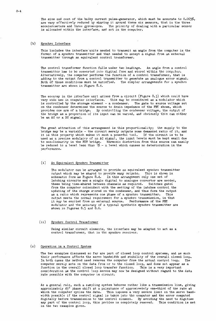
8-4
The s i z e and cos t of t he bulky current pulse-generator, which must be accurate t o O.OO5%, a r e very e f f ec t ive ly reduced by sharing it around these s i x sensors, t h a t is the th ree accelerometers and th ree gyroscopes. i s a l loca ted within the in t e r f ace , and not i n the computer.
The p r i o r i t y of dea l ing with a pa r t i cu la r sensor
(b) Synchro In te r face
This includes the in t e r f ace u n i t s needed t o transmit an angle f r o m the computer i n the format of a synchro t ransmi t te r and tha t needed t o accept a s igna l from an externa l t ransmi t te r through an equivalent cont ro l transformer.
The cont ro l transformer function falls under two headings. An angle from a cont ro l t ransmi t te r has t o be converted i n t o d i g i t a l form and s tored within the computer. Al te rna t ive ly , t he computer performs the function of a cont ro l transformer, t h a t i s adding t o the output from a cont ro l t ransmi t te r t o generate an analogue e r r o r signal. Both OY these conditions must be sa t i s f i ed . The simpler arrangements f o r a synchro t r ansmi t t e r a r e shown i n Figure 8.4.
The economy i n the in t e r f ace u n i t a r i s e s from a c i r c u i t (Figure 8.3) which could have very wide use i n computer in te r faces . i s cont ro l led by the storage element - a condenser. The gate t o source voltage s e t on t h e condenser determines the source t o d ra in impedance of t he FET shown, which provides one a r m of a bridge. By con t ro l l i ng the condenser voltage, t he output of t h e bridge as a proportion of i ts input can be varied, and obviously t h i s can e i t h e r be an AC o r a DC signal.
This may be considered as a modulator which
The grea t a t t r a c t i o n of t h i s arrangement i s t h i s propor t iona l i ty ; t he supply t o t he bridge may be a var iab le - the c i r c u i t merely outputs some demanded r a t i o of i t , and it is t h i s property which makes it such a powerful tool. I f t h e c i r c u i t i s t o be used as a prec ise modulator o f an AC s igna l , t he input l eve l s must be kept small due t o non-linearity i n the FET bridge. be reduced t o a leve l l e s s than 1% - a l eve l which causes no de te r io ra t ion i n the performance.
Harmonic d i s t o r t i o n from t h i s source can e a s i l y
(i) An Equivalent Synchro Transmitter
The modulator can be arranged t o provide an equivalent synchro t ransmi t te r output which may be shared t o provide many outputs. This i s shown i n schematic form as Figure 8.4. la tch ing c i r c u i t s and a s ing le d i g i t a l t o analogue convertor a r e needed, these being time-shared between channels as required. from the computer coincident with the s e t t i n g of the la tches cont ro l the updating of t h e charge s tored on the condenser, and thus form t h e output as a r a t i o which represents one phase of a synchro t ransmi t te r . This output meets t he normal requirement f o r a synchro transmission, i n t h a t i t m a y be excited from an externa l source. modulator and the accuracy of a typ ica l synthe t ic synchro t ransmi t te r a r e shown i n Figures 8.5 and 8.6.
I n t h i s arrangement only one s e t o f
Switches gated
Performance of t h e FET
(ii) Synchro Control Transformer
Using s i m i l a r c i r c u i t elements, t he in t e r f ace m a y be adapted t o act as a cont ro l transformer, t h a t i s the synchro receiver.
( c ) Operation i n a Control System
The two examples discussed s o f a r a r e par t o f closed loop cont ro l systems, and as such t h e i r performance a f f e c t s t h e servo bandwidth and s t a b i l i t y of t he ,overa l l closed loop. I n both cases the method used removes the computer from the ac tua l cont ro l loop. The computer merely a c t s on the da t a f r o m o r t o the closed loop, and does not appear as a function i n the ove ra l l closed loop t r ans fe r function. consideration as t he cont ro l loop servos may now be designed without regard t o the da t a r a t e possible with the computer i n c i r c u i t .
This i s a very important
A s a general r u l e , such a sampling system behaves r a the r l i k e a transmission l i n e , g iv ing approximately 45' phase s h i f t at a pulsatance o f approximately one-third of t he r a t e at which the computer cyc les the data. This imposes a very severe l i m i t on the servo band- width possible i f t h e control s igna l i s taken i n t o the computer and the e r r o r computed d i g i t a l l y before transmission t o t he cont ro l element. By avoiding the need t o d i g i t i s e any par t of t h e cont ro l loop, t h i s problem is completely removed. This condition i s met i n the t w o examples given.

8- 5
To give p r a c t i c a l examples, the accelerometer capture loop i s closed with a bandwidth exceeding 600 c/s and synchro follow-up servos have been operated at bandwidths of around 20 c/s us ing a 400 c/s c a r r i e r . operated without modification i n these cases.
Servo elements designed f o r normal analogue use have
41 CONCLUSIONS
The in t e r f ace of a sensor computer can be s o bulky compared t o the small computers possible at present t ha t i t can dominate the s i z e of t he equipment. cos t implications of i t s bulk prove t o be a r e a l l i m i t as t o whether such self-contained systems a r e feas ib le .
The cos t of such an in t e r f ace aqd t he
By ca re fu l choice of c i r c u i t elements, one o r two standard c i r c u i t s which may be time-shared can be arranged t o dea l with the complete analogue-digital i n t e r f ace of t he system associated with such a small sensor computer. t o a leve l compatible with t h a t of t h e computer without development of spec ia l in tegra ted c i r c u i t s . The combination of t h i n f i lm techniques i n conjunction with standard c i r c u i t elements on pr in ted c i r c u i t boards proves t o be an adequate form of constmction. The methods chosen t o reduce the s i z e of t he in t e r f ace a l so prove t o have the cor rec t p roper t ies required f o r i n t e r f ac ing with the cont ro l elements of ac t ive sensors and save a vast amount o f high speed d i g i t a l processing if the cont ro l loop of t he ac t ive sensor i s t o be converted d ig i t a l ly .
This sharing of common functions reduces t h e s i z e of t he in t e r f ace
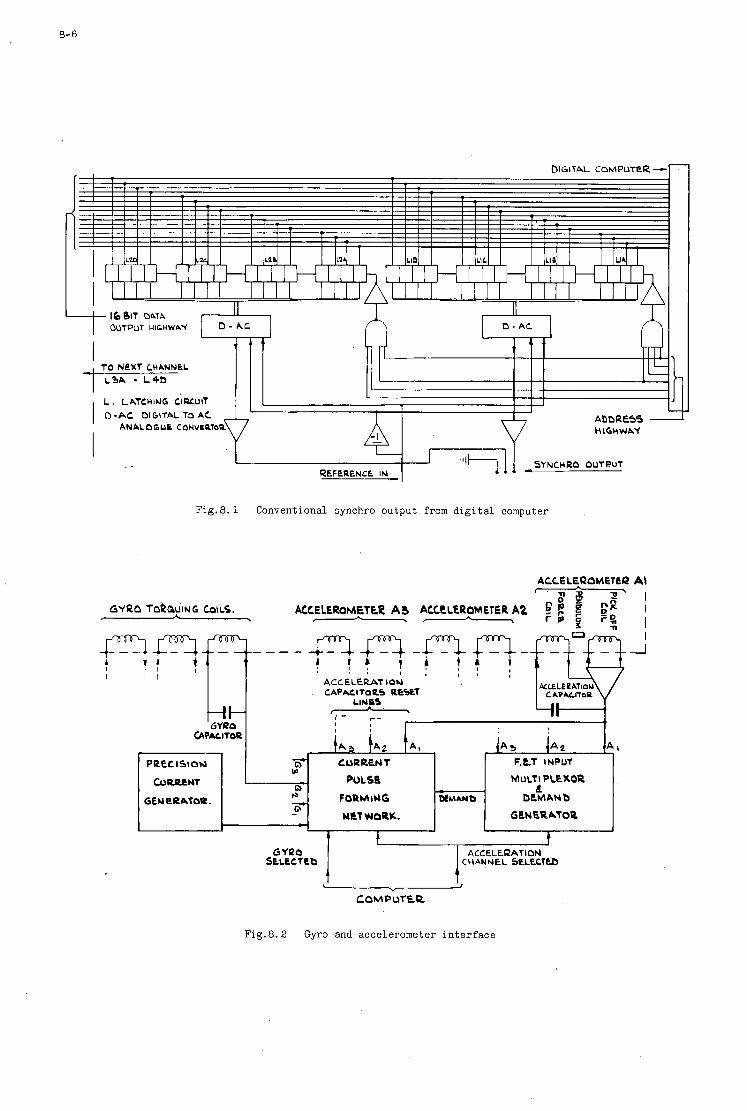
8- 6
ANALOGUE CONVERT0
SYNCHRO OUTPUT
Fig .8 .1 Conventional synchro output from d i g i t a l computer
I I - -L SLLCCTEb
GYIZa 1 1 I
ACCELEl2ATION CHANNEL SELtCTEb
t L "
COMPUTER
Fig.8.2 Gyro and accelerometer i n t e r f ace
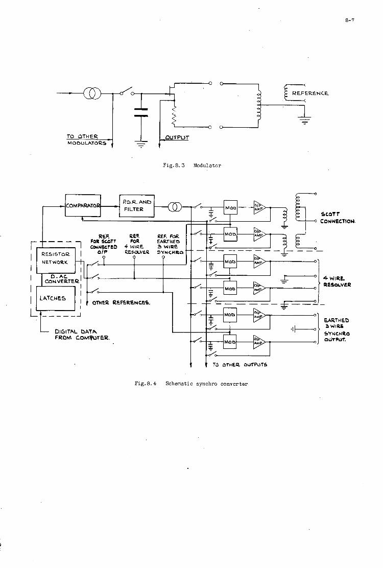
8- 7
TO OTHER MODULATORS
COUNECTlOM.
RESOLVEP SYNCHRO
I- - - - --I L DIGITAL DATA
FROM COMToT€R.
Fig. 8.4
Fig. 8.3 Modulator
Schematic synchro converter
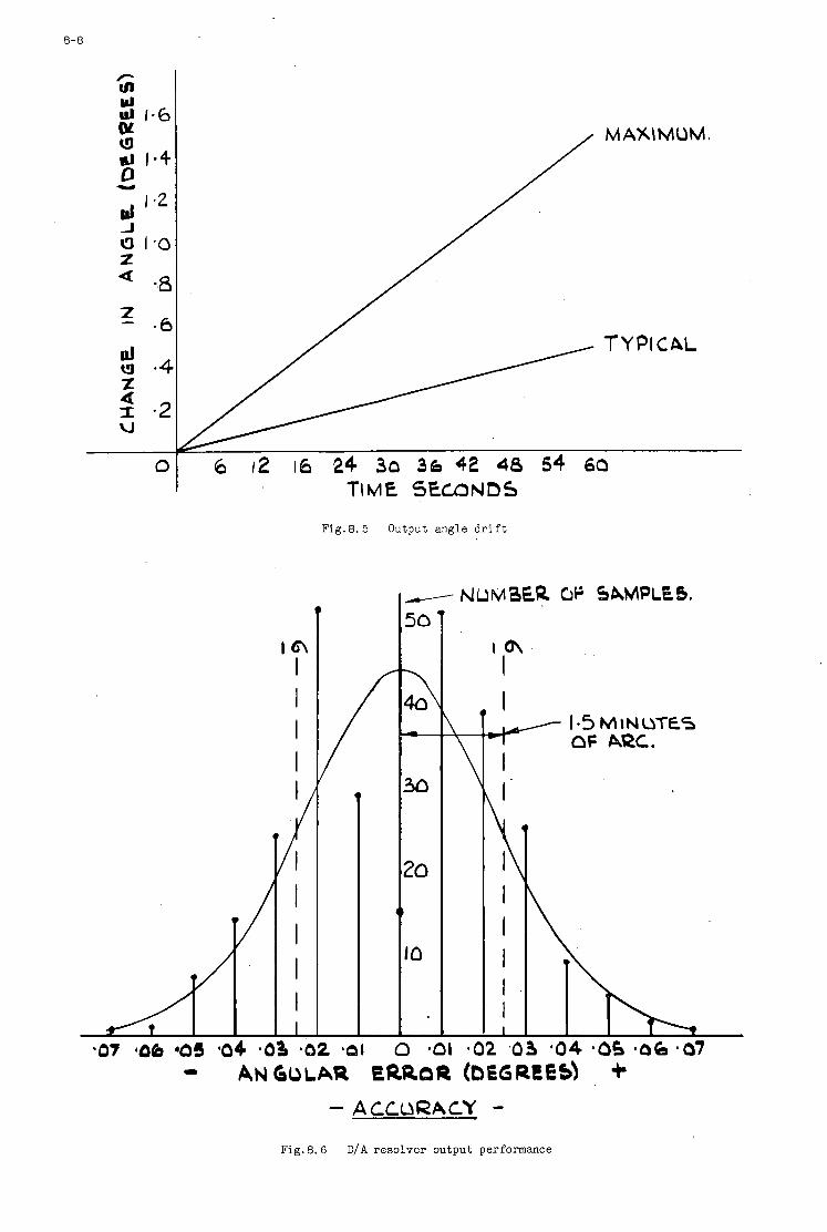
8-8
I T \M€ '3EU3ND5
Fig.8.5 Output angle d r i f t
I I I I
l 1
I I I I
/ t In
I
1.5 MINUTES I F
I
k I
I I I I I
OF ARC.
- ANGULAR ERROR (DEGREES\ + -ACCURACY -
Fig. 8 .6 D/A resolver output performance
9
\
FLIGHT RESEARCH EXPERIENCE WITH GUIDANCE AND CONTROL COMPUTERS RELATED
TO GENERAL APPLICATIONS
Melvin E. Burke NASA Flight Research Center
Edwards, California, USA
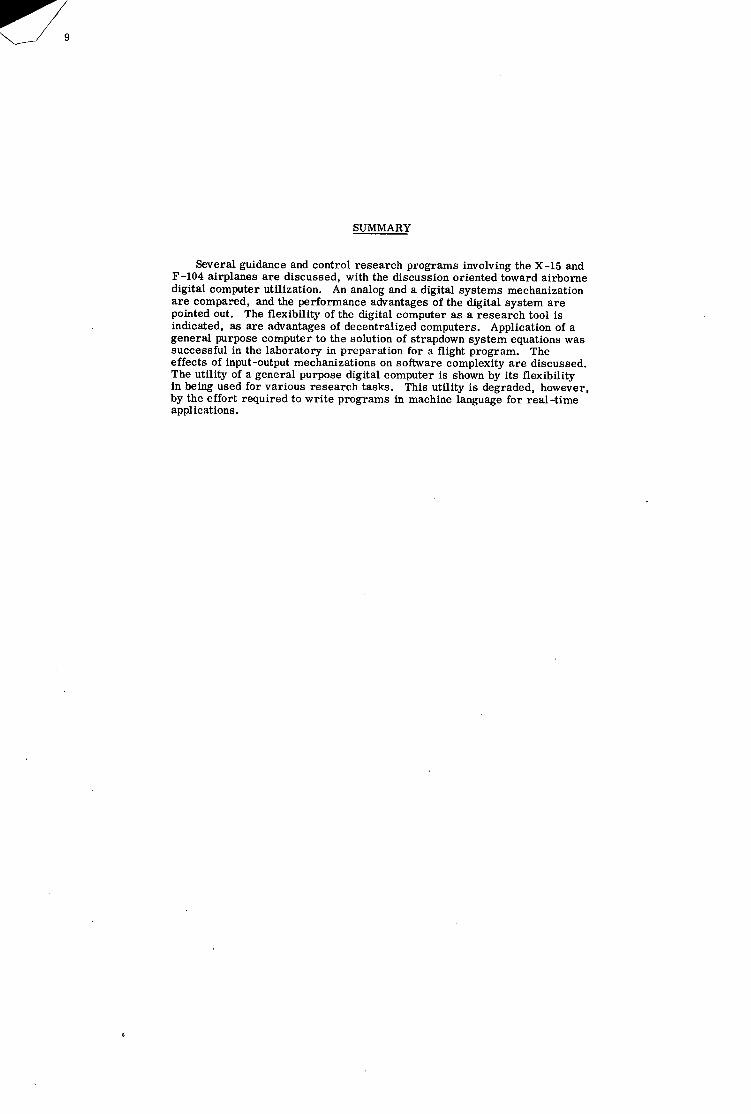
SUMMARY
Several guidance and control research programs involving the X-15 and F -104 airplanes a re discussed, with the discussion oriented toward airborne digital computer utilization. An analog and a digital systems mechanization a r e compared, and the performance advantages of the digital system a re pointed out. The flexibility of the digital computer as a research tool is indicated, as a re advantages of decentralized computers. Application of a general purpose computer to the solution of strapdown system equations was successful in the laboratory in preparation for a flight program. The effects of input-output mechanizations on software complexity a r e discussed. The utility of a general purpose digital computer is shown by its flexibility in being used for various research tasks. This utility is degraded, however, by the effort required to write programs in machine language for real-time applications.

INTRODUCTION
Flight research activities at the NASA Flight Research Center have provided systems engineers with the oppor- tunity to investigate airborne computer utilization in control anci/or guidance systems in both conventional and re - search aircraft. The computers used have included both analog and digital mechanizations, as indicated in the brief compilation of table 1. Generally, the applications have followed the trends seen in operational vehicles; that is,
TABLE 1. - CONTROL/GUIDANCE COMPUTER USE
Aircraft
X-15
JetStar
Lifting bodies
F-104
PA -30
(M2-F3, X-24)
F-8A
~ - Computer
Comments Control Guidance Type
Research Analog Analog/digital 2 airplanes with stability augmentation system
1 airplane with adaptive flight control system
Production (config- Analog ------------ Computer for model-following ured for research) airborne simulation
(variable stability) Analog _ _ _ _ _ _ _ _ _ _ _ _ _ -_________________________ Research
Production Analog Digital Special configuration for guidance research
Production Analog _ _ _ _ _ _ _ _ _ _ _ _ Special configuration for general aviation control systems research
Research Analog ------------ Special configuration for supercritical wing evaluation
DISC U SSION
X-15 PROGRAM
The X-15 was a rocket-powered research airplane designed to be air-launched from a B-52 ca r r i e r aircraft at about 45,000 feet (13,604 meters) altitude and Mach 0.80 (1). The X-15 had a flight envelope extending to speeds above Mach 6 and altitudes above 350,000 feet (106,680 meters). A typical time history of velocity and altitude for a high-altitude mission is shown in figure 1. Because of these extreme ranges in velocity and altitude, an inertial flight-data system (IFDS) was required to provide the pilot with displays of aircraft velocity, altitude, and three- axis Euler angle attitude information. Initially, all three of the X-15 airplanes had analog inertial flight-data systems. In two of the airplanes, the systems were later converted to digital systems because of the poor reliability of the analog system (2). The third airplane retained a redesigned version of the analog system. One of the airplanes that was converted to the use of a digital system was equipped with the self-adaptive flight control system and was later also configured with a high-speed digital computer to provide the computer capability required to conduct guidance investigations.
Analog Versus Digital Mechanization. The conversion of two X-15 airplanes from analog to digital inertial flight-data systems provided a unique opportunity to compare the relative merits of the two system mechanizations operating in the same environment and performing essentially the same functions.
The analog system was mechanized a s shown in the simplified flow $agram of figure 2 to provide pitch (e), roll (q), and heading ($) attitudes, total velocity (Vt), rate of climb (h), and geometric height above the surface of the earth (h). In this mechanization within the computer, a wide range of electromechanical components was used. These components included choppers, servomotors, tachometers, amplifiers, and potentiometers. They were grouped in three major packages --an erection integrator, a velocity integrator, and a position integrator--with each package processing data for all three axes--vertical, range, and cross range. This mechanization was simplified somewhat because of the bounded range within which the X-15 airplane was designed to operate.
The solution of the guidance equations in the digital system was mechanized as shown in figure 3. This mechan- ization, while basically quite different from the analog, provided essentially the same information to the pilot. The
mechanization was a combined digital differential analyzer (DDA) and general purpose (GP) computer. The DDA section was used for continuous summing of the accelerometer outputs because of its inherent speed in accomplishing this type of operation, and the GP section was used for the solution of equations which required more precision but less speed. The memory of this computer was a rotating disk with a capacity of 1664 24-bit words. This system was mechanized to provide the reference axis in the north, east, andvertical directions. Gyrocompassing tech- niques were used for initial alignment of the system.
The vertical loop in an inertial system is normally not mechanized to provide altitude information. When the loop is mechanized, it must be damped from an external source to prevent divergence. When it is switched from damped to undamped as it was in the X-15 during its free flight, the rate of divergence is an early indication of the overall system performance. This was particularly true in the X-15, where pure inertial operation was limited to the relatively short duration (approximately 10 minutes) of the free flight. The analog system was continually erected through interface with systems carried on the B-52 airplane until the X-15 was launched. The digital sys- tem, however, operated in the navigational mode with only the vertical loop slaved until launch. Thus, it would be expected that the analog system would outperform the digital system. Data from 10 flights for each system presented in figure 4 indicate that this was not the case. These data a re the mean inertial altitude e r ro r and its standard deviation as a function of time from launch of the X-15. The data were obtained by comparing the recorded output of the system with a reference curve obtained by smoothing data from ground based radar systems, pressure altitude systems, and independent acceleration measurements. The noteworthy points in these data a r e the standard devia- tions. These deviations a re high for the analog system and consistently lower for the digital system, which indicates a more consistent performance of the digital system.
The analog system was marginally adequate for the X-15 program when aspects such as reliability and perform- ance a re considered. The factors that made the digital system stand out were more simplified operating procedures, consistent performance, and flexibility. The flexibility aspect of the digital system was especially significant when the airplane carried experiments which required computer-supplied information and processed forms of this infor- mation. On the basis of the experiences with these two system mechanizations in this program, the digital system would be the clear choice for use in similar applications.
Guidance Experiments. Two experiments were included in the later phases of the X-15 program that were specifically oriented toward the investigation of guidance concepts. The first , a manual boost guidance study (3). generated fly-to-null pitch attitude commands a s a function of altitude, altitude rate, and total velocity. These com- mands were updated at the rate of 10 times each second and provided the pilot with guidance commands which placed him successfully on a preplanned trajectory at burnout. The second, an energy management (EM) study, did not reach flight status but was extensively evaluated on ground based computers and simulators (4). Since energy management required f a r more computing capability than did boost guidance, it will be described further to illustrate the complex program that a digital computer is capable of handling. Additional computing capacity was required on the X-15 airplane to conduct these studies.
System Description: The basic aircraft systems configuration for the X-15 airplane used in these experiments is shown in the simplified block diagram of figure 5. This configuration is analogous to a decentralized computer concept; that is, each system operated independently, so that a failure in one system had little effect on the per- formance of any other system. This philosophy was followed throughout the X-15 program partially because of pilot insistence on system independence. No experiment was added to the X-15 which, if a failure occurred in that ex- periment, would affect the Operation of the basic system. The addition of the digital computer to perform the nec- essary computations for the guidance experiments resulted in the systems configuration shown in figure 6. This was a prototype computer that used a 4096 24-bit word, random access, non-destructive read out, micro-biax memory. In this application, the computer interfaced with the air-data system analog computer, the IFDS digital computer, and the pilot's displays. Also, through the IFDS digital computer, it was interfaced with the adaptive flight control sys- tem.
Each system retained its operational independence except the computer added for guidance experiments. This computer was dependent on the other computers for i ts input data. In the limited operational experience with this computer, no failures occurred in other systems that affected its operation. program, several system failures did occur, and the pilot was able to recover the vehicle and often complete the mission successfully because the systems were sufficiently isolated that he received guidance information from either the air-data system o r the IFDS. The integration of the additional computer with the other systems on the X-15 airplane presented no significant problems.
However, during the overall X-15
One problem which did occur was not directly related to the centralized o r decentralized computer concept but is directly related to the application of digital computers in aircraft. This problem concerns the susceptibility of digital computers to power transients. On most aircraft, there is usually a rather large amount of noise on the power buss, and spike transients occur when systems a r e turned off. Computers a re equipped with transient pro- tection circuitry so the contents of the working registers can be stored for later recall when the transients are no longer present. The sensory circuits in the computers work well, the data are stored, and, when the power source is quiet, processing is restarted. The problem is especially apparent when this occurs under dypamic conditions and valuable sensor data a re lost. If this happens often,, the solutbns a re no longer valid. This problem occurred on the X-15 airplane from time to time and was sufficiently severe to justify a major effort to rectify it by rewiring the airplane and isolating the noise-generating systems to a separate buss.
Energy Management Study: The energy management study planned for the X-15 airplane was the flight evaluation of a concept developed by Bell Aerospace Systems, Buffalo, New York, for maneuvering lifting reentry vehicles. This concept was npecifically tailored to the X-15 for evaluation. It utilized a predictor concept designed to compute the extreme dimensions of the physical a rea within reach of the X-15 airplane, which determined the ground area attainable (GAA). In addition, from these predictions, the anticipated maximum values for temperature, dynamic pressure, and normal acceleration were obtained. This was accomplished by repeated integrations of the differential equations of motion for a "model" vehicle and by the use of various energy-distance relationships. Aerodynamic coefficients and flight criticalities for the model were stored within the computer.
As shown in figure 7, when the vehicle approached the re,entry phase, the energy management computations were initiated. Starting with the initial conditions of the "real" vehicle, the model was rapidly "flown" through a maximum range, a minimum range, and a maximum cross range flight, using the flight techniques and vehicle constraints

9 -3
- - -- j:aEdt = '11 c12 '13
j t a N d t 0
jOsdt = '31 c32 '33
= c21 c22 c23
t
- &---
applicable to each. During any given prediction flight, the stepwise integrations could be discontinued once the model reached equilibrium conditions, after which simplified ene rgyas t ance relations were sufficient.
The energy management system also generated commands for both display and flight control. By selecting one of several pre-stored landing sites, the energy management program would determine the location of the site within the ground area attainable, and, based on this location, would generate both pitch and roll commands necessary to direct the ''real" vehicle to the high-key point for the si te selected. In addition, the commands necessary for phugoid damping were superimposed on the guidance commands so that any trajectory oscillations were eliminated. Vehicle constraints were fully respected during the generation of all commands.
This concept was evaluated on the X-15 ground based simulator by using a hybrid analog and digital computer facility. The simulation was later interfaced with the ALERT computer so that the ALERT program could be dynamically checked out prior to flight.
Utilization of a high-speed digital computer interfaced with the X-15 systems proved to be a feasible method of conducting research investigations when the added computing capacity was required. These two programs. manual boost guidance and energy management, illustrate the great degree of flexibility that a digital computer provides, particularly in a research application.
GUIDANCE RESEARCH PROGRAM . An F-104 airplane is being used at the NASA Flight Research Center as a test vehicle t o conduct research studies
on strapdown guidance and real-time flight-path optimization. A general purpose digital computer is being used in both of these studies. This has provided an opportunity to investigate the use of this type of computer in an appli- cation normally handled by a special purpose (SP) computer and to investigate the trade off between hardware and software complexity. These investigations were conducted as required during the strapdown system study. The flight-path optimization study represents an investigation into the use of a general purpose computer for real-time applications. Although flight results are not yet available, much of the information gained in the laboratory is pertinent to airborne computer utilization and is further described.
Strapdown Guidance System. Briefly, the basic difference between a strapdown and a gimbaled inertial guidance system is the mechanization to establish a reference coordinate system within which acceleration measurements may be integrated for navigation purposes. In a gimbaled system this is accomplished through the gimbals and gyro feed- back to position the gimbals, whereas in a strapdown system it is accomplished within the computer, as indicated in the following equation:
jot%&
It$" 0
t joazd t
In the gimbaled local vertical system the coordinate transformation matrix C(T) is unity or some preselected value for convenience of mechanization. In the strapdown system C(T) must be continually updated from a measured se t of initial conditions. Strapdown systems to date have utilized computers specifically designed for them, often with the coordinate transformation matrix hardwired for speed of solution. Little has been reported on the use of a purely general purpose type of computer in this application.
The system assembled for this investigathn is shown in a simplified block diagram in figure 8. This system. as indicated, consists of the inertial measurement unit ( M U ) , an input-output unit, control panel, a power supply, a pilot's display, and the ALERT digital computer. The design of the system was not optimized; that is, major components such as the IMU and the computer were obtained from other programs. This meant that certain hard- ware and software conditions were set. These conditions included allowable interconnect cable length, maximum allowable angular rates, the format of the IMU data word, and the IMU sample interval. .
The IMU consisted of three pulse-torqued gyros, three pulse-rebalance accelerometers, and the necessary electronics for closing the loop about each of these sensors. The maximum allowable angular rate that the gyro torquers were capable of maintaining was 20.8 deg/sec (0.363 r a d i d s e c ) . The computer used had a 2 -microsecond access core memory of 16,384 24-bit words. The central processor used fixed-point arithmetic.
Normally, complete data acquisition systems a re installed in each airplane for flight research programs. How- ever, because of manpower limitations, it has been necessary to proceed on this program with a limited data acquisition system. To supplement this system, some 8,192 words of the computer's 16,384 words of memory were reserved for the storage of important parameters generated in the computer that would normally have been recorded on the data acquisition system. Data will be stored a s 12-bit words, giving a total capability of some 16,000 words.
Strapdown Syskm Coordinate Transformation Solution With a General Purpose Computer: Two tasks were re - quired to accomplish the solution of the strapdown system coordinate transformation problem. First. provisions had to be made to transfer data from the IMU to the computer. Six channels of digital data, with each channel representing a velocity change (AV) along a reference axis or an angular change (AO) about a reference axis, had to be input to the computer. Second, an algorithm had to be selected to perform the transformation. This algorithm had to provide a sufficiently accurate solution and yet not be so cumbersome as to consume too much of the com- puter's computational cycle.
The computer has two modes of inputing data: a direct memory access (DMA) under peripheral control, and a direct i n p u t a t p u t (DIO) under program control. The DIO mode was selected to retain program control. All data
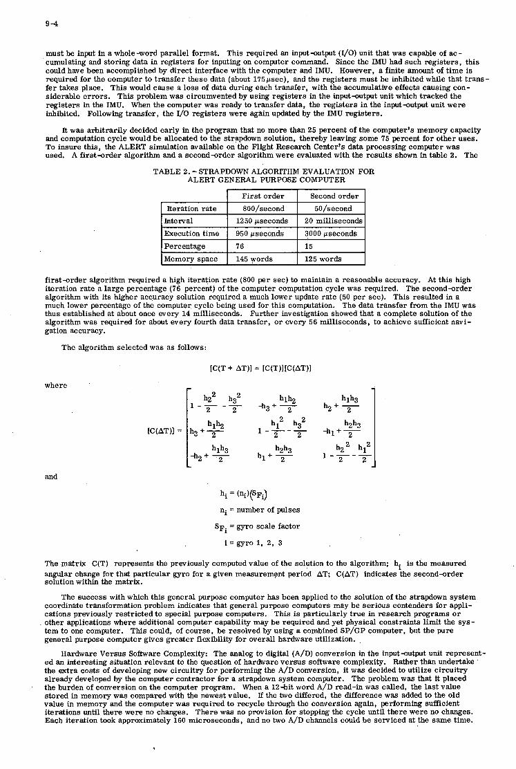
9-4
First order
must be input in a whole-word parallel format. This required an input-output (I/O) unit that was capable of ac- cumulating and storing data in registers for inputing on computer command. Since the IMU had such registers, this could have been accomplished by direct interface with the computer and IMU. However, a finite amount of t ime is required for the computer to transfer these data (about 175psec), and the registers must be inhibited while that trans- fer takes place. This would cause a loss of data during each transfer, with the accumulative effects causing con- siderable errors . This problem was circumvented by using registers in the input-output unit which tracked the registers in the IMU. When the computer was ready to transfer data, the registers in the input-output unit were inhibited. Following transfer, the 1/0 registers were again updated by the IMU registers.
It was arbitrarily decided early in the program that no more than 25 percent of the computer's memory capacity and computation cycle would be allocated to the strapdown solution, thereby leaving some 75 percent for other uses. To insure this, the ALERT simulation available on the Flight Research Center's data processing computer was used. A first-order algorithm and a second-order algorithm were evaluated with the results shown in table 2. The
TABLE 2. - STRAPDOWN ALGORITHM EVALUATION FOR ALERT GENERAL PURPOSE COMPUTER
Second order
Interval Execution time
Percentage Memory space
1250 pseconds 20 milliseconds
950 pseconds 3000 pseconds
76 15 145 words 125 words
gation accuracy.
The algorithm selected was as follows:
[C(T + AT)] = [C(T)][C(AT)]
where
haha h i + - 2
hlh3 -ha + '2
and
hi = (ni)(sFi)
ni = number of pulses
SF^ = gyro scale factor
i =gyro 1, 2, 3
hlh3 h2+ 2
h2h3 2
hz2 h t I----
2 2
-hi + -
The matrix C(T) represents the previously computed value of the solution to the algorithm; hi is the measured angular change for that particular gyro for a given measurement period AT; C(AT) indicates the second-order solution within the matrix.
The success with which this general purpose computer has been applied to the solution of the strapdown system coordinate transformation problem indicates that general purpose computers may be serious contenders for appli- cations previously restricted to special purpose computers. This is particularly true in research programs o r other applications where additional computer capability may be required and yet physical constraints limit the sys- tem to one computer. This could, of course, be resolved by using a combined SP/GP computer, but the pure general purpose computer gives greater flexibility for overall hardware utilization. ,
ed an interesting situation relevant to the question of hardware versus software complexity. Rather than undertake the extra costs of developing new circuitry for performing the A/D conversion, it was decided to utilize circuitry already developed by the computer contractor for a strapdown system computer. The problem was that it placed the burden of conversion on the computer program. When a 12-bit word A/D read-in was called, the last value stored in memory was compared with the newest value. If the two differed, the difference was added to the old value in memory and the computer was required to recycle through the conversion again, performing sufficient iterations until there were no changes. There was no provision for stopping the cycle until there were no changes. Each iteration took approximately 160 microseconds, and no two A/D channels could be serviced at the same time.
Hardware Versus Software Complexity: The analog to digital (A/D) conversion in the input-output unit represent-
9 -5
It was soon apparent that valuable computer time was being used servicing the A/D conversion in the input-utput unit. This was no problem in the previous application of this mechanization because the computer was used only for the solution of the navigation equations and thus had ample idle time for servicing the I/O unit. In this application, however, the coordinate transformation and navigation solutions were but small portions of the computer use. Most of the computer cycle was to be used for the solution of the flight-path optimization problem, and, if this were to be accomplished in real time, servicing of the I/O unit had to be minimized.
A second I/O unit w a ~ ordered with adequate A/D conversion capabilities. In order to utilize the previously de- scribed unit, a change in programing was initiated which eliminated some of the iterations previously required. i4 test was applied which required agreement only to the fifth least significant bit before proceeding to other functions.
This experience with the I/O unit clearly demonstrates how the unwary may seriously compromise the software effort and indeed the overall computer capability through attempts to simplify the hardware. Fortunately, a solution was readily available through software manipulation that was not overly complex. The question of software com- plexity is still a serious problem to the general purpose computer user. The problems involved with machine language programing a re significant when the computer is used in applications involving real-time solutions. At- tempts to use more simplified programing techniques, such as Fortran, have proved to be too costly in machine efficiency to be practical.
Flight-Path Optimization. Techniques for optimizing the flight path of a vehicle that would provide savings in either time or fuel in maneuvering from one flight condition to another have been under investigation by researchers for some time. A flight evaluation of the gradient method, with the pilot using a placard of various cross-referenced Mach number and angle-f-attack commands, demonstrated a considerable savings in time required to get to cruise conditions (5). The major drawback of the techniques proposed to date has been that the computational requirements have been too great for real-time solutions on an airborne computer.
Real -time solutions for flight-path optimization offer considerable advantages when variables such as atmos - pheric temperature, excess thrust, and fuel flow a r e measured and the measurements a re used in the optimization solution. In view of these advantages, optimization techniques, which include dynamic programing and Balakrish- nan's epsilon method, for possible real-time solutions are being investigated and have shown considerable promise (6)(7). Figure 9 shows three Mach/altitude curves for an F-104 airplane to climb and accelerate to the end condi- tions of 40,000 feet (12,192 meters) altitude and Mach 1.9. Curve A represents the profile obtained by using the manufacturer's handbook procedures. Curve B was obtained by using the gradient optimization method. Curve C was obtained from Balakrishnan's epsilon method (7). Previous studies have shown a possible savings of 22 percent in time with the gradient method over the manufacturer's handbook procedures. The differences between curves B and C appear significant; however, the net time to reach the end conditions differs by only a fraction of a percent (6).
The dynamic programing technique has been programed for the ALERT computer and will be the first tech- nique to be evaluated in flight. This technique, however, has significant limitations in the number of variables that can be handled. Analytical and simulation investigations of other techniques a re continuing, and it is planned to phase these techniques into the flight program.
CONCLUDING REMARKS
A comparison of a digital and an analog inertial flight data system operating in essentially the same environment and performing the same function was made during the X-15 research airplane program. The advantages of the digital system were significantly greater than those of the analog system. On the basis of the experience with these two systems, it would be inconceivable to undertake another research airplane program similar to the X-15 program without requiring a digital inertial flight data system a s one of the basic airplane systems.
The question of which concept to use, centralized o r decentralized computer systems, is difficult to answer. Interfacing of computer with computer presented no significant problem. However, decentralized computers will probably be used on future research airplanes as a result of pilot objections to the routing of all display parameters through a single electronic component. This objection may be overcome with proper redundancy and demonstrated reliability.
Use of a true general purpose computer in applications normally handled by a special purpose computer can present some significant problems. These problems can be solved, however, and, from the standpoint of having extra computer capacity available for other problem solutions, it is often advantageous to use a general purpose computer. This is particularly true when the computer is being used in research programs.
The investigation of hardware versus software complexity was limited in this paper to the computer input-output unit. It was shown that attempts to simplify hardware mechanizations resulted not only in more complex software but also in consumption of the computer computation cycle. This, of course, was unsatisfactory when the computer was being applied to real-time solutions that required high utilization of the computation cycle.
The various research programs conducted with the same general purpose digital computer point out the high degree of flexibility of this computer. The biggest drawback to the use of digital computers in research programs is the high cost both in manpower and programing time. This is particularly true when near-real-time solutions and the most efficient machine language programing are required. This would not be nearly as great a consideration in operational use where the effort could be amortized over a number of aircraft and a period of time.
The digital computer has been widely used in guidance but has had only limited use in flight control systems for aircraft. It is expected that more digital logic circuits will be used in flight control systems as new sensors, such as the laser gyro, gain acceptance. Also, the acceptance of fly-by-wire controls will provide easier applications of digital mechanization. Certainly solutions of equations in statistical and nonlinear control theory a re more suited for digital computers. It is anticipated that digitally mechanized flight control systems will evolve during the next decade. However, the takeover of flight control systems will probably not be as thorough as the takeover of guidance systems has been in the past decade.
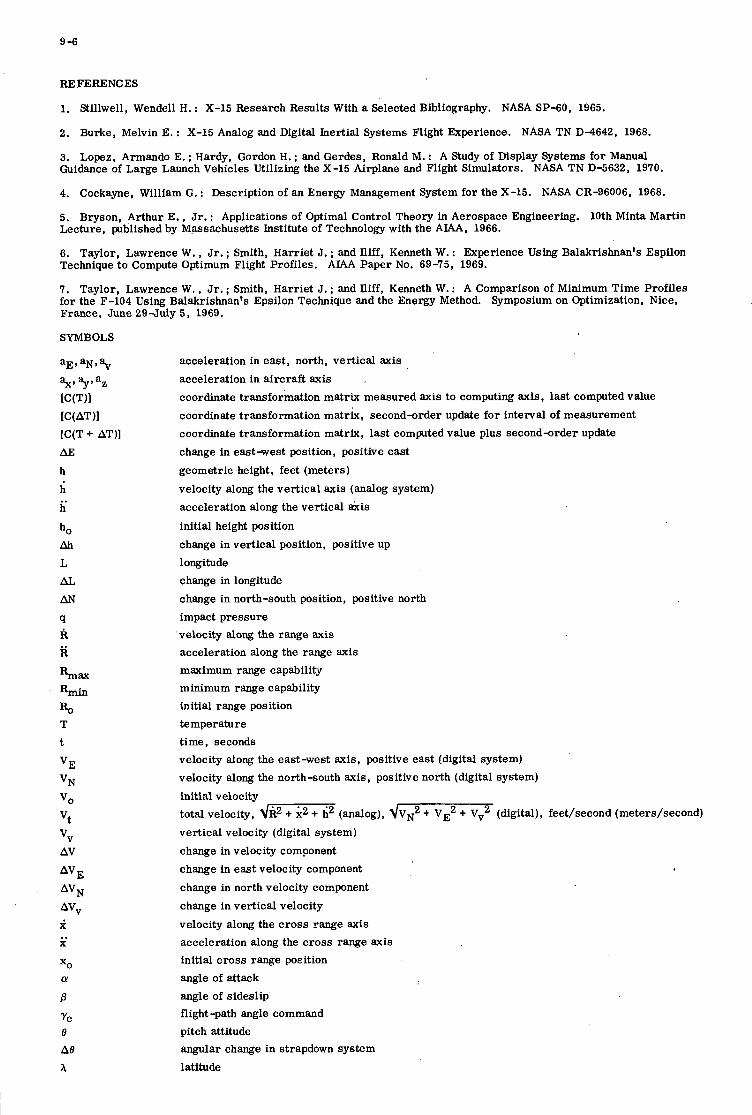
9-6
RE FERENC ES
1. Stillwell, Wendell H. : X-15 Research Results With a Selected Bibliography. NASA SP-60, 1965.
2. Burke, Melvin E. : X-15 Analog and Digital Inertial Systems Flight Experience. NASA TN D-4642, 1968.
3. Lopez, Armando E. ; Hardy, Gordon H. ; and Gerdes, Ronald M. : A Study of Display Systems for Manual Guidance of Large Launch Vehicles Utilizing the X-15 Airplane and Flight Simulators. NASA TN D-5632, 1970.
4. Cockayne, William G. : Description of an Energy Management System for the X-15. NASA CR-96006, 1968.
5. Bryson, Arthur E. , Jr. : Applications of Optimal Control Theory in Aerospace Engineering. 10th Minta Martin Lecture, plblished by M,assachusetts Institute of Technology with the A M , 1966.
6. Taylor, Lawrence W. , Jr. ; Smith, Harriet J. ; and Iliff, Kenneth W. : Experience Using Balakrishnan's Espilon Technique to Compute Optimum Flight Profiles. A M Paper No. 69-75, 1969.
7. Taylor, Lawrence W. , Jr. ; Smith, Harriet J. ; and Iliff, Kenneth W. : A Comparison of Minimum Time Profiles for the F-104 Using Balakrishnan's Epsilon Technique and the Energy Method. Symposium on Optimization, Nice, France, June 29-July 5, 1969.
acceleration in east, north, vertical axis acceleration in aircraft axis coordinate transformation matrix measured axis to computing axis, last computed value coordinate transformation matrix, second-rder update for interval of measurement coordinate transformation matrix, last computed value plus second-rder update
change in eastwest position, positive east
geometric height, feet (meters)
velocity along the vertical axis (analog system) acceleration along the vertical &is initial height position change in vertical position, positive up longitude change in longitude change in north-south position, positive north impact pressure velocity along the range axis acceleration along the range axis maximum range capability minimum range capability initial range position temperature t ime, seconds velocity along the east-west axis, positive east (digital system)
velocity along the north-south axis, positive north (digital system)
initial velocity total velocity, dR2 + K2 + i2 (analog), ~ V N ~ + V E ~ + Vv2 (digital), feet/second (meters/second) vertical velocity (digital system)
change in velocity component change in east velocity component
change in north velocity component change in vertical velocity
velocity along the c ros s range axis acceleration along the cross range axis initial cross range position angle of attack angle of sideslip flight -path angle command pitch attitude angular change in strapdown system latitude
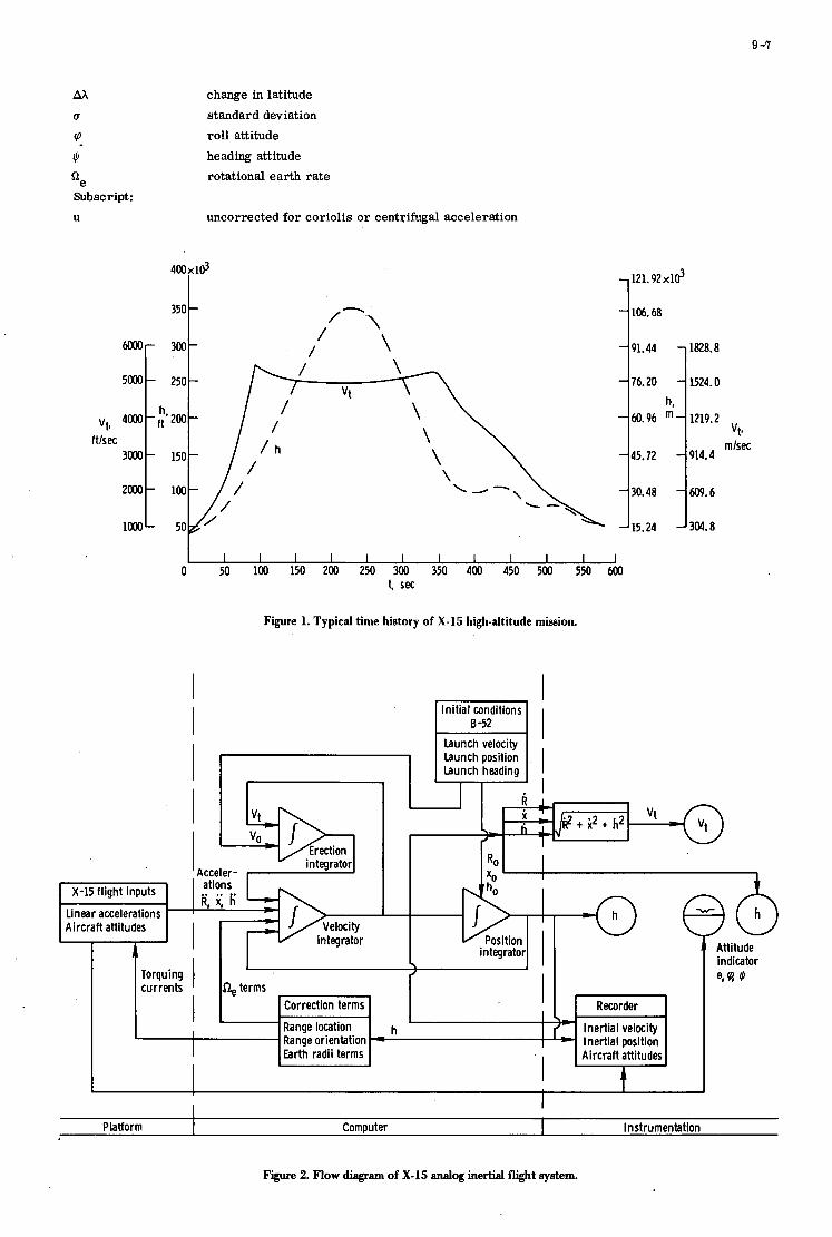
9 -7
- -
h, m-
-
-
-
M
U
cp
II,
'e Subscript : U
1828.8
1524.0
1219.2
914.4
609.6
304.8
vt* ftlsec
Platform
change in latitude
standard deviation roll attitude
heading attitude rotational earth ra te
Computer Instrumentation
uncorrected for Coriolis o r centrifugal acceleration
4000 t r.zmr
350 -
m- 300-
5000 - 250-
\ / /
/
3000 - 150-
2ooo- 100-
121.92xld
106.68
I I I I I I I 1 1 I I I J 0 50 100 150 200 250 300 350 400 450 500 550 600
t, sec
Figure 1. Typical time history of X-15 high-altitude mission.
- 91.44
- 76.20
- 60.96
- 45.72
30.48
15.24
-
-
I Initial conditions
I
integrator Acceler-
vt* mlsec
I I b u n c h velocity Launch position b u n c h heading
I I R I i vt -
k 2 t i 2 t h 2 I
RO
Attitude indicator
@
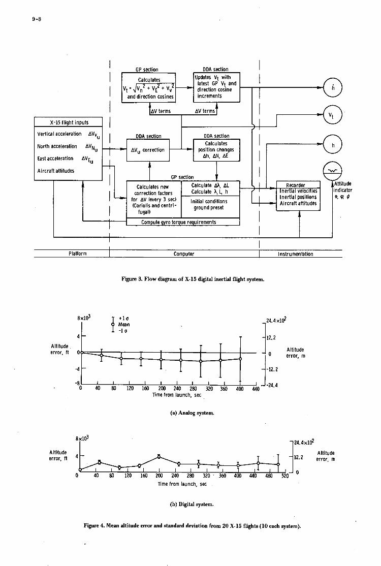
9 -8
Platform
I I I I
Vertical acceleration AVvU
Computer I Ins t rumenht ion
GP section DDA section
Altitude
Updates Vt wi th latest GP Vt and direction cosine
Ca Icu lates
12.2
-
I and direction cosines I I increments I
z
I 1 L
1 I I I I 1 I
error, ft Ot
-4
-8
-
DDA section n I t Calculates I ODA section
Altitude 0 error, m
-12.2
AVu correction position changes Ah, AN, AE
North acceleration AVN,
East acceleration AVE,
Aircraf t attitudes GP section
correction factors
fugall
Compute gyro torque requirements
,-- I I I t ner la veoci ies
Inert ia l positions Aircraf t attitudes
I I
Attitude ndicator e, (rl *
(a) Analog system.
1 2 4 . 4 xl$ 8 x l d I
Altitude 12.2 error, m I I. XF
I I I I I 1 I 1 0 40 80 120 160 200 240 280 320 ' 360 400 440 480 520
Time from launch, sec
(b) Digital system.
Figure 4. Mean altitude error and standard deviation from 20 X-15 flights (10 each system).
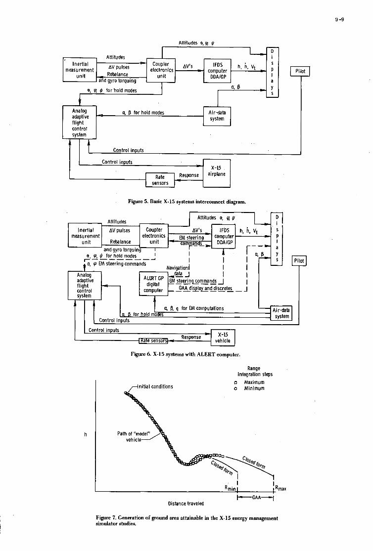
9 -9
Coupler Avts
measurement electronics - computer - AV pulses unit -= Reba lance
Inert ia l
I - unit DDAlGP
Attitudes e, 0 JI
- lFDS
I and gyro torquing
1. , Attitudes h, k, Vt 1
a
e, 0 JI for hold modes + Analog a, B for hold modes Air-data adaptive system f l ight control system
Control inputs I l l Control inputs - X-15
Figure 5. Basic X-15 systems interconnect diagram.
- r, Attitun Inert ia l AV pulses Coupler
and gyro torquing 1 A::js r!: 'p
measu rement electronics EM steering computer Reba lance a m m a n s DDAlGP r -
I e, (p, cl. for hold modes --------A
m I
MLLK I .. .
I system I I I I
h, -
r I I I I
J
1 S
T 1 -
I ' a, 8, q for EM computations
Control inputs
I "-IC I Control inputs
A-12
vehicle
Figure 6. X-15 systems with ALERT computer.
h
ni t ia l conditions
Range integration steps
n Maximum o Min imum
CRmax I I
Rmin I + G A A ~
Distance traveled
Figure 7. Generation of ground area attainable in the X-15 energy management simulator studies.
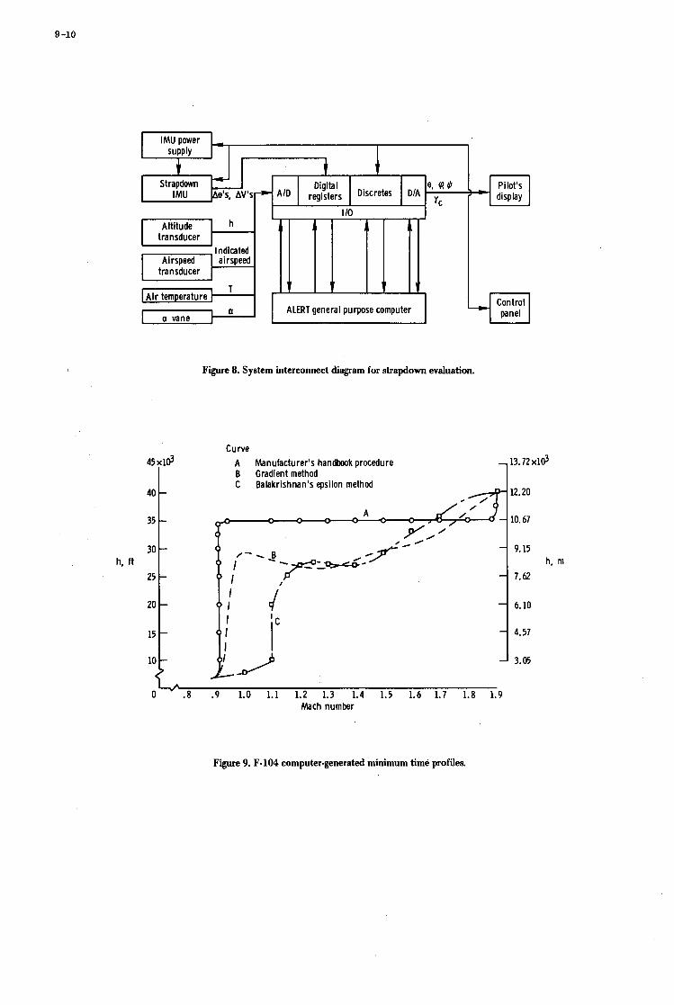
Figure 8. System interconnect diagram for strapdown evaluation.
40
35
30
25
20
h, ft
15
10
-
-
-
-
-
-
-
Curve A Manufacturer's handbook procedure - 13.72 xld B Gradient method C Balakrishnan's epsilon method
- 9.15
- 1.62 h, m
6.10
4.57
3.05
O L . 8 .9 1.0 1.1 1.2 1.3 1.4 1.5 1.6 1.7 1.8 1.9 Mach number
A
Figure 9. F-104 computer-generated minimum time profiles.
10
DIGITAL COMPUTING ASPECTS OF THE JAGUAR NAVIATTACK SYSTEM
BY
D E HUMPHRIES
AVIONICS DEPARTMENT
ROYAL AIRCRAFT ESTABLISHMENT
British Crown Copyright, reproduced with the permission of the Controller, Her Brittanic Majesty '8 Stationery Office.
SUMMARY
!be Jaguar nav/attack system performs approximately the same t a sk a s that i n the Harr ie r a i r c r a f t , which i s wholly analogue, bu t does the job using a d i g i t a l computer f o r roughly the same cost. the s imi l a r i t y of Harr ie r system requirements, everJr endeavour has been made t o prevent t h e system from becoming simply a d i g i t a l oopy of analogue ideas, but t o approach each requirement from a d i g i t a l viewpoint. evolved during its development up t o i t s present stage of 'Hack' a i r c r a f t f l i g h t trials. A b r i e f descr ip t ion of the u n i t s which comprise the system end t he f a c i l i t i e s which i t provides i s given, l a t h p a r t i c u l a r emphasis on those areas where the change t o a digital computer has allowed muoh g rea t e r design freedom and operational f l e x i b i l i t y .
Despite
T h i s paper describes the lessons t h a t have been learned and the techniques t h a t have been
10-1
1 IN!CRODUCTION
The nnvigation and a t t a o k mstem whioh is being mamfaotured by E l l i o t t Automation for the B r i t i s h vers ion of the Anglo-Frenoh Jaguar a i r o r a f t , represents a p a r t i c u l a r l y important milestone in the appl ioat ion of d i g i t a l oomputers the Jaguar p e r f o m approximately the same t ask a s t h a t i n the Harr ier a i r o r a f t , which is wholly analogue but uses a d i g i t a l computer and y e t costs roughly the same amount. the requirements however every endeavour has been made t o avoid making simply a digital copy of analogue teohniques but t o approach each requirement f r o m a d i g i t a l viewpoint.
4.4 System Desoription
i n t o the avionios systems for UK mil i ta ry aimraft. The system for
Despite the s i m i l a r i t y of
Fig 1 shorn a funotional block diagram of the system. In te r fac ing with the r eminde r of the
The E3(Ft) i n e r t i a l system is predominantly analogue, via the i n t e f l a c e u n i t , mainly due t o the f a o t that at t h i s stage of aystem development, the majority of peripheral sub-ayetens are st i l l analogue. platfonm is d u s t e r ro ta ted and the major p a r t of the neoessarg oaloulationa are canled out i n the digital oomputer. i n fomat ion from the platform e lec t ronics u n i t i n t o the d i g i t a l oomputer in p a r a l l e l binary form. in te r fao ing requirements, in p a r t i c u l a r the signal forma have been d ic ta ted la rge ly by the oharactex- i s t i o s of the per ipheral equipment, but where possible the preferred form is analogue VOltageS whioh lend themselves par t iou lar ly well t o simple and accurate digi ta l conversion espeoial ly when the ~ o l t a g e oomes from a potentiometer energised by the InterPaoe uni t . areas where the ohange t o a digital oomputer has allowed a considerable improvement in both f a c i l i t i e s and operational f l e x i b i l i t y over t h a t a t ta inable by analogue meana and it is proposed t o describe three areas in whioh these advantages have been apparent.
2 mDBsELBcTIoIQ
Om of the few digital l i n k s in the system is in the transmission of veloc i ty The
There are however a number of
I n an analogue aystem oomplioated m l e y l o g i c is required t o convert a l imi ted number of mode se lec t ions avai lable t o the p i l o t , i n t o the neoessaly switching aotiona t o oonneot the c i r o u i t elements appropriate t o the node. However, oonsideration of the problem from a d i g i t a l viewpoint ind ica tes that a f resh approach might well y i e l d dividends. By the use of push buttons representing yes/no a m e r s t o a l imi ted number of qUeStiOM, simple s e l e c t i o n of a wide range of oombinationa is possible. push but ton oontrol system i s i i i u a t r a t e a i n pig 2.
hdng the development. of this programme it became c l e a r that a flow diagram for the weapon aiming prognmm oould be oonstxucted whose deoision s t ruoture was largely oontrol led by the s e t t i n g s of the push buttons, resu l t ing i n a simple y e t e f f e c t i v e s teer ing progranme with s t r a i g h t f o m a n i loglo.
determine the r e l a t i v e pos i t ion of the target t o high precision, and b a l l i s t i c s t o c a l c u l a t e the f l i g h t of the weapon. b a l l i s t i o f l i g h t i n t o coinoidenoe with the ta rge t , and i n i t i a t i n g a release. There is l i t t l e var ia t ion in the sub-routinns neoessary for the b a l l i s t i o oalculation, other than t o s e l e c t the necessaly b a l l i s t i c parameters in response t o the ac tua l weapons selected, but it i s in the ohoioe of method of d e t e d n i n g the t a r g e t pos i t ion that a great deal of f l e x i b i l i t y is possible, and it is l a rge ly over the mioro navigation p a r t of the weapon aiming programme t h a t the push but ton panel exercises control. The process of se lec t ion m y be summarised under the following headings.
2.1 B e Initial S t a r t i n g Conditians
can e i t h e r have a s t h e i r s t a r t i n g oonditiona the values given by the navigation system, ( a planned t a r g e t ) , o r an a r b i t r a r y s e t of values, baaed on the most l i k e l y r e l a t i v e pos i t ion for an unerpeoted t a r g e t t o be sighted. Opportunity), for example a few miles ahead and t h e radio a l t i m e t e r height below. by Buttons A and B.
Such a
The Weapon Aiming problem oan be e f f e c t i v e l y divided i n t o two main blooka, mioronavigation t o
The weapon aiming problem then reduoea t o one of bringing the end point of the
The three r e l a t i v e pos i t ion ooo&ates of the t a r g e t pos i t ion
(Target of This ohoioe is made
Alternat ively, the s t a r t i n g conditions can be derived by adding a preoisely known o f f s e t in each oooFdinate, f o l l d n g a preli.UdnaSg micro-navigation M against an eas i ly v i s i b l e f ix ing point, this choice is made by Button C.
2.2 Response t o Updating Inputs
Onoe the p i l o t i d e n t i f i e s the ta rge t , he oan begin t o oorrect the r e l a t i v e coodina tea using the display s ight , and in addi t ion inputs from the radio al t imeter , o r barometric height u n i t are avai lable if required. The main a l t e r n a t i v e options open are:
a. Acoept the depression angle of the t a r g e t from the p i l o t v i a his display, and sca le the t r i a n g l e using e i t h e r Barometric or radio height.
Alternat ively, start using this method but once the marker has been l a i d over the ac tua l tarmt, ref ine the slant range by oomparing the s igh t l i n e sp in ra te calculated using oomputed range, with the a c t u a l sp in rate , and then modifying the range u n t i l the spin r a t e s match. A process termed Kinematic Ranging which is se lec ted by Button F.
Of oourse the whole of the micro-navigation prooess can be ignored, and the results of the
. This s e l e c t i o n is made by Button E.
b.
b a l l i s t i c s oalculat ions displayed on the s i g h t giving an impact point predict ing mode, allowing the p i l o t t o Judge coincidence w i t h the t a r e t and M t i a t e release. This mode is seleotad by Button D.
0
10-2
It is clear even f r o m this b r i e f descr ip t ion the way in whioh computing rout ines c a n b e directly oontrolled by the push buttons, t o give a very wide range of options through a simple set of controls.
3 VERTICAL VFZOCIW COMmPpATION
Although Barometric height ra te , and v e r t i c a l ac id l e ra t ion from a n i n e r t i a l platform, provide complementary da t a which can be mixed t o provide accurate v e r t i c a l ve loc i ty information, t he p r a c t i c a l r ea l i s a t ion of an e f f ec t ive mix by analogue means has proved d i f f i cu l t .
I n l e v e l f l ight accurate height rate can ba obtained *om barometric data, and t h i s can be used t o back off any accelerometer b i a s and nul the accelerometer output.
I n order t o take Ail1 advantage of the acoelerometera a b i l i t y t o d e t e c t rap id changes i n velocity, t h i s loop must have a long time constant, so t ha t shor t t e r m information is derived from i n e r t i a l data, and long term f r o m Baro data. A t yp ica l analogue loop f o r t h i s purpose is shown i n F ig 3. scheme works e f f ec t ive ly i n l e v e l f l i g h t and for shor t rap id climbs and dives, s ince over sho r t i n t e r v a l s e r r o r s i n b a r o m e t r i c height rate r e su l t i ng f r o m d iv ing o r climbing through a non-standard atmosphere have l i t t l e e f f e c t on the accelerometer b ias , and the accelerometer information is believed. I n long slow olimbs o r desoenta, however, even the long loop time constant is unable t o prevent erroneous b i a s correction tenus being appl ied t o the accelerometer output with the r e s u l t t h a t a t the end of a long slow change of height through a non-standard atmosphere a l a r g e height rate e r r o r a n accumulate. is required t o recover t h e cor rec t value.
This
Worse still, because of the long tilde constant of the loop, a long period of l e v e l flight
A simple expedient i s t o use the v e r t i c a l accelerometers i a s n open loop configuration during height changes bu t since i n this arrangement e r r o r s are not only unbounded but divergent, Over long periods i n open loop, l a r g e e r r o m st i l l bui ld up, r e su l t i ng i n t r ans i en t s when the loop is closed again, and Once again a slow re cove^.
techniques f o r t h i s mixing, s ince it was clear that a var iab le gain system was required (Referenca I).
Develcping the model, however, l e d t o a muoh clearer i n s i g h t i n t o the nature of t h e problem, a d
Studies were the re fom undertaken a t RAE t o inves t iga te the p o s s i b i l i t y of us ing Kalman F i l t e r i n g
the gain behaviour of t he f i l t e r indicated c l ea r ly the ways i n which a simpler system could st i l l be made much more e f f ec t ive than e a r l i e r ones. The important po in t is t ha t s ince there are two sources of er ror , accelerometer e r ro r , and deviations of the atmosphere from ICBN, this should be recognised i n aqy mixer design, and r a t h e r than feed the error signal always t o cor rec t the same parameter, t o use i t t o co r rec t the mom l i k e l y error source, which w i l l raw according t o the state of the f l ight, pa r t i cu la r ly the aircrafts v e r t i o a l velocity.
If one considers an airoraft i n love1 flight, clearly the ga in of the p r i g i n a l systems are of the
However, immediately upon en te r ing a dive, any r i g h t order s ince any steady divargence i n v e r t i c a l velooity must be due t o inco r rec t accelerometer b i a s , o r backing off of the ea r ths *g" components. immediate deviation between the two cources, is l i k e l y t o be due t o Barometric e r r o r and the cor rec t ion should be applied therefore t o the Baro input, and the loop providing cor rec t ions t o the accelerometer open c i rcu i ted . This system s t i l l does not prevent e r ro r s due t o the i n e r t i a l ve loc i ty divergence from bui ld ing up, bu t if a high gain is used t o force t h e inertid ra te t o agree with the barometric v e r t i c a l rate as soon as l e v e l f l i g h t is regained, a t l e a s t the recovery is more rapid, and the magnitude of the r e su l t i ng t r ans i en t grea t ly reduced. represents a considerable improvement over previous analogue loops bu t i t i s perhaps worth poin t ing out the addi t iona l advantages which the true Kalman Fil ter can sohieve.
A s y s t e m l i k e this which is shown i n F ig 4
There are two main improvements, firstly it makes use of the baro-corrections estimated in the early stages of the dive, t o caloulate the percentage devia t ion of t he atmosphere f r o m standard, whiob it uses l a t e r i n the descent when othenrise both baro and i n e r t i a l information are unre l iab le . Secondly, because of statistical co r re l a t ion estimates which have been b u i l t up about aqy height errom a r i s i n g as a result of i nco r rec t ve loc i ty information, once l e v e l f l i g h t is regained, cor rec t ions are not only applied t o the velocity, bu t a l s o t o the height e r ro r , so t h a t an extremely accurate estimate of t rue height is a l s o ava i lab le from this ayatem . The expeated performance of suoh a K a l m a n Filter Baro/inertial loop, derived from the mathematical models, is shown i n Figs 5 and 6, which am ext rac ted f r o m Reference 1. It i s expected t h a t the sub-optimal system will approaoh this performance i n the computation o f v e r t i c a l velocity, although i t w i l l not be ab le t o provide the remarkable height error recovery which i s exhibited by the true f i l ter . i n t o the system the facility for height f i x i n g while passing Over l e v e l ground of known height above sea l eve l . i n the oomputer i s subt rac ted from the Barometric height, and the r e s u l t compared with the value received f r o m the rad io a l t imeter , and when the p i l o t operates the "Height Fix" button the baro-datum is r e s e t t o b r i n g the two i n t o agreement. i n the computer, t he d i f fe rence between computed aircraft height and t a r g e t height can be used t o set the in i t ia l value of t he v e r t i c a l r e l a t ive pos i t ion coordinate t o a n acceptable accuracy as described i n sec t ion 2.
G IN KIGET DATA INSERTION
This, however, can be compensated for by bui ld ing
I n this process the height of t h e ground which has been s to red along with o the r mission data
Thus if t he he ight of t a r g e t above sea level i s a l s o stored
I n the pas t , t he nature of analogue oomputing i n aircraft system has meant t h a t the main method of a l t e r i n g a p a r t i c u l a r perameter was by means of "slewing". was provided for the operator, by which he could cont ro l t he rate of increase or decrease of the quant i ty u n t i l i t s value as ind ica ted on a d i a l o r counter ind ica ted the desimd value.
I n t h i s mathod a va r i ab le rate cont ro l
Since in geneml
ohanging parameters involves the physioal movement of a s h a f t i t is unlilmly that there is aw p o s s i b i l i t y of instantaneous ohange t o a new value. no longer appl ies and the p o s s i b i l i t y of i n s t a n t ohange is avai lable . I n the Jaguar system in i t ia l thoughts tended towards a d i g i t a l version of the "slewingn system. was added t o or subtracted f r o m the e lda t ing s tored number a t a f lxed rate whenever the slew control was operated. The d i g i t a t which this increment was added depended on the amount of r o t a t i o n of the slew oontrol, small movements causing the inorements t o the l e a s t s ign i f icant b i t of the number, and inoreasing ro ta t ion causing the increments t o be added f u r t h e r up the number towards the most signifi- cant end. This resu l ted i n a logarithmic "slew" control which i t was thought would be easy t o operate. I n praotioe, however, a number of s ign i f icant disadvantages became apparent, mainly due t o the f a o t t h a t the conversion t o decimal took plaoe "downstream" of the slewing operation, so that the slewing prooess was i n binary, while t h e d i s p l w was i n deoimal, and s ince the conversion t o decimal was done a t a r e l a t i v e l y slow r e p e t i t i o n rate , deoimal d i g i t s which were ohanging very rapidly appeared as random numbers whioh were c l e a r l y readable and which made assessment of the value reaahed very d i f f i c u l t . It w a s obviously possible by the use of software t o make the behaviour represent more olosely the oharaoter i s t ios of analogue "slewing", but r a t e "slewing" is not an i d e a l method for data i n s e r t i o n and therefore advantage was taken of a re-appraisal t o look a t some a l t e r n a t i v e schemes whioh might prove both e a s i e r t o implement and operat ional ly m o m effect ive. The n o d method f o r real time data i n s e r t i o n t o a d i g i t a l computer i s by means of a keyboard, and there is no doubt t h a t f o r rapid t r a n s f e r of information when the operator can concentrate wholly on the t a s k the keyboani is ideal. I n a s ing le s e a t otrilce aircraft, however, this is by no means the s i tua t ion . l e v e l , f lying, the p i l o t cannot affo2d t o d i v e r t his a t t e n t i o n i n t o the cookpit for more than one o r two seconds at a t h e , so that the keyboard, with i ts demand for visua l i d e n t i f i c a t i o n of the keys, for e f f e c t i v e operation, becomes l e s s a t t r a c t i v e . conditions of considerable buf fe t i s l i k e l y t o prove d i f f i c u l t unless some form of hand o r w r i s t support is provided. only the last two d i g i t s need t o be ohanged. a i r c r a f t , was t h a t as i n any s ingle s e a t aircraft, oookpit space within easy view and reach of the p i l o t was at a premium and t o provide space for a keyboard with s u f f i c i e n t key spacing for easy operation would have been extremely diff ' icul t and would have needed qui te a radioal re-design of the oookpit, p a r t i c u l a r l y if t h e hand support f o r buf fe t oonditions was a l s o provided.
The scheme which has been devised requires one ext ra push but ton t o be provided on a hand oont ro l le r which is already present f o r operating the weapon aiming system. A sketch of the modified hand cont ro l le r is shown i n Flg 7, the important controls for this purpose being the "d ig i t advanoe" push button, operated by the thumb, and the "Phase change t r igger" operated by squeesing with the first finger. and the c o n t r o l l e r is plaoed a t the p i l o t s l e f t hand, j u s t t o the rear of the thro t t lea . for revis ing q y number is the same but for convenienae t h i s descr ip t ion w i l l deal with ohanging the s t o m d l a t i t u d e and longitude of a t a r g e t or navigation rw-point.
With d i g i t a l computing, however, this l i m i t a t i o n
I n this system a binary d i g i t
During high speed, low
I n addition, i t s operation by a gloved hand, in
If an e r r o r is made, the whole number has t o be reinser ted, aa it has even if One f i r t h e r oonstraint whioh was prodded by the Jaguar
The hand grasps the b a r r e l of the o o n t r o l l e r so that i t i s Ailly supported in all dimct iona , The aequenoe
i
ii
iii
i v
V
v i
The present s tored value of l a t i t u d e and longitude are displayed in the two s e t s of optioal ind ica tors by operating the look up oontrol and nay-point aeleotor.
If i t is desired t o ohange e i t h e r or both of the s tored values then a push but ton under the appropriate window is pressed and the most significant d i g i t of that number begins t o f l a s h a t a slow r a t e ind ica t ing that the d i g i t advanoe oontrol is operative on that digit.
The first press of the ' d i g i t advanoe' oontrol seta the digit t o 1, the second t o 2 e t a so that n presses s e t s the d i g i t t o read ta.
The phase change t r i g g e r is then squeesed and control passes t o the next most s ign i f loant d i g i t which then begins t o f lash , and the pmoeas repeated, u n t i l the whole number is reset . If i t is wished t o leave a d i g i t unal tered then a seoond prees of this phase ohange t r i g g e r without operation of the 'digit advanoe' w i l l paas oontrol t o the next digit leaving the previous one unaltered.
The number is then oheoked t o see that it i s oorreot and if i t is, an ' i n a e r t ' but ton is pressed and the new value i s stored in the computer.
This prooess oan then be repeated for the other s tored value.
Although when described fully as it is above t h i s prooesa sound^ very laborious, p r a c t i c a l experiments have indioated t h a t i t is very easy t o learn, and speedy operation oomes natural ly , so that the time taken t o i n s e r t oomplete da ta about each way-point is about 20 seconds, b u t more important i t is possible t o feed in a oomplete l a t i t u d e , longitude, and t a r g e t height i n the dr, with the only time spent head down being the checking time neoeasary t o ensure t h a t the r i g h t number has been set up befom inser t ing .
It is o l e a r from the above t h a t the mquirements for rapid data i m e r t i o n i n t o the system p r i o r t o the mission, are not compatible with the mquirements for r o d i f l o a t i o n of the data during the fliat which csan r e s u l t from changes i n the t a o t i a a l s i t u a t i o n during the mission. whioh were imposed by the Jaguar requirements it is possible t h a t a more e f feo t ive system than t h a t described above could be devised, but even so suoh a system would have t o be or ien ta ted towards minimum 'head-down' time, and i t i s unl ikely t h a t this would be oompatible with the speed required for mission data inser t ion. It s e e m therefore t h a t i n fu ture d i g i t a l systems w i l l need t o have an addi t ional means of rapid data inser t ion. i n t o which a oard whioh had been pmpared a t t h e pre-f l ight b r i e f i n g could be i n s e r t e d whioh would rapidly enable a l l the mission data t o be inser ted i n the shor tes t possible timeo
Removed from the cons t ra in ts
Suoh a f a o i l i t y muld be provided by a simple c a d mader
10-4
5 CONCLUSION
The three examples quoted above, a r e by no means the only areas i n whioh the change t o a d i g i t a l system have allowed much g m a t e r freedom and f l e x i b i l i t y than t h a t a t ta inable with an analogue system and y e t a t no grea te r cost for the whole system. But they have been chosen as examples beoause they represent the' dividends that oan be reaped by adopting a fresh approaoh t o old pmblems and s t a r t i n g the design of a d i g i t a l system from a olean sheet of paper ra ther than from the stand-point of an e x i s t i n g analogue system even though the system is mquired t o fulfil the same functioas. It is hope4 t h a t i n the same view, when i t comes t o the next genemition of d i g i t a l avionio system we w i l l not allow sohenee devised within the oonstraints of the Jaguar or other e a r l i e r d i g i t a l systems t o influenoe the design, but t o taka as muoh advantage as possible of the ex t ra freedoms t h a t recent advances w i l l allow.
Ref 1 Application of Kalman F i l t e r i n g t o Baro/InertIal Height System. Royal Airoraft Establishment T e c M c a l Report No 691 21. P M Barham and P Manvllle.
The work desoribed i n this paper was oarr ied out i n olose ool laborat ion with E l l i o t t Automation ( I n e r t i a l Navigation Division) whose assis tanoe is gmtefu l ly acknowledged.
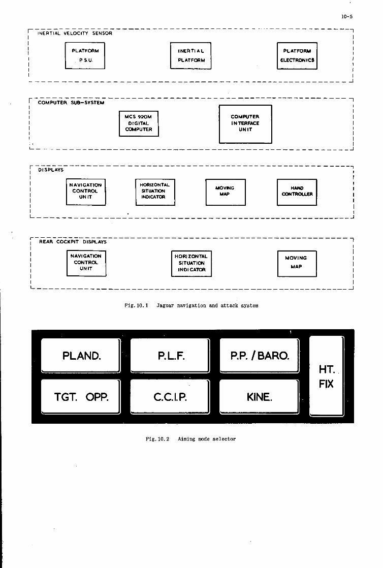
10- 5
MCS 92OM I DIGITAL I COMPUTER
COMPUTER I N TERFACE
UN IT
NAVIGATION I co:;:"p" 1 HOW ZONTAL SITUATION
MOVING p-l Fig. 10.1 Jaguar navigation and attack system
Fig. 10.2 Aiming mode selector
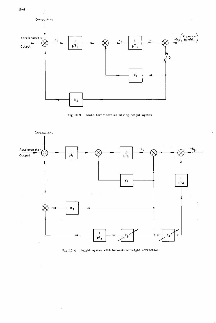
10-6
Correct ions
I
A e1
Fig. 10 .3 Basic baro/ inert ial mixing height system
Corrucrions
output
c
Fig. 10.4 Height system with barometric height correction

10-7
+I
Vel error f t JQC- '
-I
500
250
Height error
($9
-250
- 500
Fig. 10.5 Vertical velocity error during 50 ft/sec climb/descent
.evelat Climb ot 5 0 f t sec-' Levelat ea level 60000 ft
Descend to sea I Level Flight I eve I
/i /
/ /
/ /
0
3500 --
Fig. 10.6 Height error during 50 ft/sec climb/descent

Fig. 10.7 Hand controller for data insertion
11
The Effect of Digital Computer Limitations and Sensor E r r o r s on the Accuracy of an Automatic Bomb Release
Gerhard Schroeter
Industrieanlagen-Betriebsgesellschaft mbH Ottobrunn, Germany
Summary
Onboard computer and attitude/air data sensor errors - among others - cause delivery errors of automatically released bombs.
For a retarded bomb it is shown by numerical evaluation that with a uniform distribution of release conditions the computing error (= difference between true value and the estimate, which is won from a polynomial) is approximately normally distributed with mean value zero and standard deviation a,a being dependent on the degree of the polynomial and the width of the admissible interval of release conditions.
Besides, formulas are derived for the estimation of the influence of the inaccuracy of weapon computer input data on the impact point. These formulas can be applied to derive the requirements which attitude/air data sensors should satisfy to provide for sufficiently accurate bombing. An example is given.

I 11-1
1. Introduction
If a bomb is to be automatically released, the pilot initiates a command that starts the weapon release computations at the instant when the target symbol on his head-up display matches the target.
Instantaneously, the position of the aircraft relative to the target is determined by means of sensors providing data on slant range and sight angle (angle between line of sight and horizontal). Simultaneously the momentary bomb range x, is calculated from the height, velocity and dive angle, and the difference a between the bomb range x, and the horizontal distance to the target x2, i.e.
1 - a = x x2
is determined. By means of the navigation system, the position of the aircraft is continuously monitored and'Butomatically brought up to date, thus the value a also can be determined continuously. If a equals zero, the bomb is released automatically. A prerequisite that has to be met is that the pilot flies the aircraft in a vertical plane which contains the target.
There are two principal sources of error associated with the nature of the automatic bombing method. These are
- computational errors resulting from an approximated solution of the differential equation of the bomb range because of limited onboard computer storage capacity, and
- sensor errors which cause ISt inaccurate estimates of the release conditions, thus causing differences between actual and calculated bomb range, and 2nd a wrong determination of the horizontal distance between aircraft and target.
The influence of those errors onto the delivery error w i l l be outlined in the next paragraph.
2. Error Analysis
2.1 Computer Limitations
It can be shown that the bomb trajectory in a homogeneous environment (no wind) satisfies a differential equation with release height h, release velocity v and release angleJI(i. e. the angle between flight direction and a horizontal at release) as initial conditions. The differential equation has to be solved numerically by the onboard computer in sufficiently short time . Methods to solve this equation in an adequate manner are not to be described here, but it is assumed that the bomb range x, can be found by evaluating a polynomial of limited degree with the release conditions as independent variables:
x1 = a. + al*h + a2.v + a3*$ + + a4.h2 + a5-v 2 + as- J 1 2 + a7-h.v + ...
11-2
The average accuracy should be the better the more terms are included in the polynomial. If a series of points of solution has been calculated previously by some standard routine of numerical analysis, the coefficients ai can be obtained e.g. by the method of the least sum of squares. Once the coefficients ai are calculated they can be stored in the onboard computer, and the bomb range can be determined according to Eq.. ( 2 ) .
If we consider e.g. a hypothetical retarded bomb with drag coefficient cw = 2 and cross section/mass ratio F/m = 0 , 0 0 2 m /kg we get different polynomials depending on the number n of terms in the sum and the interval of validity of the approximate solution. If e.g. the interval of admissible release conditions is given by
2
100 m< hG 500 m, 100 m/sec*; v G 300 m/sec, O o < 4J < 30°,
which provides high flexibility in the selection of attack modes we get for n = 20 a polynomial of third degree in h, v,$ with a standard deviation0 of error of about 8 rn, if we assume that the release conditions are at random uniformly distributed over that interval. It can be shown, that the error then fits approximately a normal distribution with zero mean and standard deviation, U.
If we only admit release conditions which are confined by
100 mdh< 300 m, 150 m/sec< VS 250 m/Aec, O o < 4J < 15O,
the standard deviation of error is only about 2 m, if the polynomial has . 2 0 terms. On the other hand a standard deviation of error of approximately 8 m is reached with n = 5 if only the smaller interval of release conditions is admitted, These figures show clearly how reduction of military flexibility reduces either the error at a given storage capacity of an onboard computer or the requirelnents as to the storage capacity.
2.2 Sensor Errors
A s to the sensor errors, their influence can be evaluated separately for the bomb range and for the distance to the target. If Ah, AV, and& signify the errors of h, v, and$, respectively, we can determine the deviation of the calculated range from the true range approximately according to Eq.(3):
In the same manner we get the error Ax2 from the horizontal distance x2 between target and aircraft which is given by
x2 = 1 cos9
11-3
where 1 is the slant range, andcpthe angle between the line of sight and the horizontal:
Ax2 = Al,-cos'p - Ag .losin g. Her e
All = A 1 +A12,
A 1 being the error of the sensor for slant range, and A12 being an error due to a wrong point of reference resulting from inaccurate determination of the sight angle g.
If we introduce into Eq. ( 3 )
h = - 1 sing
where v = ground speed, and regard that for the total delivery error because of Eq. 71)
Aa =Axl -Ax2
holds, we finally get
ha = b, A V + b2 .A$ + b3 A c p , + b4 A 1 + E g
with
E = computational error
ax, ax , a@ a v
b2 = - + - v tang
b4 = -
Here aircraft and the line of sight.
A V , is the error of the angle g, between the longitudinal axis of the
If the distribution of the release conditions (h, v,g ) is known,
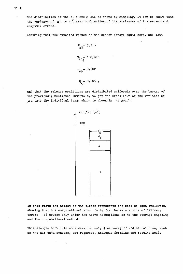
11-4
the distribution of the bits and E can be found by sampling. It can be shown that the variance of Aa is a linear combination of the variances of the sensor and computer errors.
Assuming that the expected values of the sensor errors equal zero, and that
0 = 7,5 m A 1
0 = 0,002 AJ,
= 0,005 , 9 and that the release conditions are distributed uniformly over the larger of the previously mentioned intervals, we get the break down of the variance of Aa into the individual terms which is shown in the graph.
100
In this graph the height of the blocks represents the size of each influence, ehowing that the computational error is by far the main source of delivery errors - of course only under the above assumptions as to the storage capacity and the computational method.
This example took into consideration only 4 sensors; if additional ones, such as the air data sensors, are regarded, analogue formulas and results hold.

11-5
Symbols and Abbreviations
x2 1
a
h
cp
91
@; V
E
“i d
n
U A 1
U
horizontal bomb range
horizontal distance aircraft-target
slant range aircraft-target
-x2 release height
longitudinal velocity at release
dive angle at release
angle between line of sight and a horizontal at release
cp -J)
ground speed
computational error
coefficients of the polynomial for x1
standard deviation of E
number of terms in the polynomial for x1
standard deviation of the error of the sensor for slant range
standard deviation of the error of the sensor for ground speed
standard deviation of the error of the sensor for dive angle
standard deviation of the error of the angle between line of sight and
longitudinal axis of the aircraft


12
R E C E N T A D V A N C E S I N S E L F - O R G A N I Z I N G A N D L E A R N I N G
C O N T R O L L E R S F O R A E R O N A U T I C A L S Y S T E M S
Cecil W. Gwinn' and Roger L. Barren'
*Physicist, Avionics Laboratory
Wright-Patterson Air Force Base. Ohio, USA
tpresident, Adaptronics, Inc. McLean, Virginia, USA
Air Force Systems Command, United States Air Force

12

12- I
RECENT ADVANCES I N SELF-ORGANIZING A N D LEARNING CONTROLLERS FOR AERONAUTICAL SYSTEMS
Cecil W.Gwinn and Roger L.Barron
1. BACKGROUND I N CYBERNETICS
What kind of control system, if hooked up backward, having no a priori knowledge of t h i s fac t , can discover t h a t it is, rewire i t s e l f , and work properly? if put together more or less at random, can reorganize i t s e l f t o be s tab le t o some given s e t of environmental conditions? A system which displays t h i s property has been called variously a self-organizing or learning system.
This is par t of the more general question: What kind of a system,
Such systems and some of t he i r aeronautical applications are the subject of t h i s paper.
The only systems we know at present t ha t display t h i s reorganization property t o a marked degree are l iving systems. The study of self-organization and learning, among other aspects of l iving systems, for the purpose of building non-living machines displaying similar characterist ics, is included in a branch of Cybernetics called Bionics. The philosophical background of the science of Bionics is discussed by one of t he authors i n Reference 1.
The exploration of these ideas properly began with the paper “Behaviour, Purpose, and Teleology” by N. Wiener, W.Rosenbleuth, and J.Bigelow i n 1943 (Reference 2). cal notions as, “goal”, “purpose”, “evolution”, e tc . , i n a quantitative manner. Philosophers had been debating these terms for centur ies , and it was qui te s t a r t l i ng in the context of the times t o be shown tha t a quantitative treatment w a s indeed possible. A s an outgrowth of t h i s way of thinking, Wiener i n 1948 founded the science of Cybernetics (Reference 3) , meaning, i n h is words, “the study of control and communication i n animal and machine”.
Therein was shown the poss ib i l i ty of t rea t ing such teleologi-
Wiener’s development of t h i s theme w a s couched i n a highly abstract form for t he times and not eas i ly accessible t o the engineer. H i s ideas were put at the disposal of the engineer by the Br i t i sh psychiatrist , W i l l i a m Ross Ashby. i n 1952 by the publication of the book Design for a Brain (Reference 4) and i n 1956 with the t r ea t i s e Introduction t o Cybernetics (Reference 5 ) . Ashby demonstrated i n these books, par t icu lar ly the f i r s t , tha t it is possible, working from purely cybernetic ideas, t o develop machines t h a t would show such peculiar animal-like charac te r i s t ics as purpose, goal, and survival potential i n an a priori unknown environment. It is important t o note t h a t a brain was not being constriicted, but rather a machine which exhibited behaviour which is presumed t o be caused, i n animals, by a nervous system.
Ashby amplified the definit ion of Cybernetics as follows: “Many a book has borne the t i t l e ‘Theory of Machines; but it usually contains information about things, about levers and cogs. Cybernetics, too, is a ‘theory of machines’ but it t r e a t s not things but ways of behaving. I t does not ask. ‘What is t h i s thing?’ but, ‘What does it do?’ I t is thus functional and behavioristic!” In the authors’ opinion there has been no end of confusion caused by misunderstanding t h i s point of view. To c i t e an example, there did not ex is t at the time Ashby wrote and not t o any great degree today an accepted explanation, at the physiological level, of such operationally observed and defined (by experimental psychologists) behavioral parameters RS learning, recognition, etc. This is not t o say t h a t such knowledge would not be desirable, but t he Cyberneticist is forced today t o define, t o paraphrase Eddington (Reference 6). h i s “neuron or nerve c e l l as a conceptual car r ie r of a set of psychological variates”. The point of Cybernetics, then, is the expl ic i t poss ib i l i ty of quantitatively t rea t ing such behavioral parameters independently of t h e mechanisms presumed t o give r i s e t o them.
A number of s c i en t i f i c people, including the present authors, were caught up i n the ferment of these ideas. The US Department of Defense became interested, and i n the period 1958-60, through one of its elements, the US Air Force, i n i t i a t ed the Bionics (another word for applied Cybernetics) program. We w i l l not go in to de t a i l on the various types of learning and self-organizing machines studied since t h i s period. One type, known as a probabili ty s t a t e variable (PSV) machine, was ultimately selected for intensive development. In June 1960 one of the present authors suggested t o the Air Force the use of t h i s particular machine i n control applications. I t was suggested t h a t a period of f ive t o ten years of theoretical and development work would rea l ize t h i s spec i f ic application. Theoretical work was in i t i a t ed i n 1961 and a laboratory prototype of the controller was f i r s t constructed i n 1964. This paper w i l l deal with the self-organizing control ler , some of the r e su l t s of f l i g h t tes t ing of an elementary version of t h i s controller during 1969, and cer ta in aspects of the design for a self-organizing control system for on-line optimization of th rus t specific fuel consumption i n turbopropulsion systems.
We s h a l l f i r s t define some terms as they are now coming in to use in Bionics.
12-2
To Control:
To force and/or s t ee r toward accomplishment of required actuator outputs. I t is implied t h a t there is a set of c r i t e r i a t o be improved or optimized i n some sense for e f f ic ien t control. poration of learning or self-organizing system functions and/or by a p r i o r i design. may involve input and feedback channels t ha t embrace adaptively-trained models for prediction and other functions.
This optimization m a y be by incor- A complete control system
To Adapt:
There are two uses of t h i s word which should be, but are often not, careful ly distinguished. Consider a system f ( t ) with output c ( t ) . and input r ( t ) . Suppose, however t h a t output c ‘ ( t ) is preferred, given input r( t) . There are only two ways tha t t h i s can be accomplished. (1) I t is known t h a t t h e system f ( t ) would produce out- put c ’ ( t ) i f supplied with some input r ’ ( t ) # r ( t ) . Therefore the desired output can be obtained by a l ter ing the input r ( t ) f ( t ) . the system toward the desired response. I t is the only case t h a t can occur i n l inear systems containing feedback loops. (2) I t is known tha t there e x i s t s a system g ( t ) that , given input r ( t ) , w i l l produce the desired out- put c ’ ( t ) . Therefore the system f ( t ) is i t s e l f operated upon, causing a change i n its t ransfer function i n a way t h a t produces the preferred output c ‘ ( t ) i n the presence of input r ( t ) . A l l systems t o be discussed as adaptive i n t h i s paper w i l l , unless otherwise indicated, f a l l under case (2). On the face of it, t h i s defini- t i o n seems a rather dras t ic choice, as it inevitably makes the adaptive system nonlinear. of t h i s dis t inct ion and its imClications see Reference 7.
un t i l it becomes ident ical t o r ’ ( t ) , using t h i s changed variable as the input t o the system This changing of the input is usually brought about by a feedback loop generating an e r ror signal s teer ing
For a f u l l discussion
Learning:
Given a specified operational s i tua t ion and specified c r i t e r i a re la ted t o performance i n t h i s s i tuat ion, learning is defined as statist ical improvement of performance according t o the criteria. t h i s character is t ic can have the additional a b i l i t y of spontaneously i n i t i a t i n g t ransfer functions. Because memory is an inferred part of t h i s def ini t ion, the dis t inct ion has arisen between learning systems with very short term memory, cal led hereafter, self-organizing systems, and those with long term memory. Long term memory can be up-dated with experience t o improve system “models” of controlled-process dynamics, optimum operating points, and boundaries. The dis t inct ion between terms of memory a r i se s only as a function of the properties, real or inferred, of t h e specified environmental si tuation. The bulk of t h i s paper w i l l be i n the discussion of applications i n which the environmental s i tua t ion can be approached with short term, or self-organizing, learning systems.
A system which exhibi ts
However the technique is not limited t o only t h i s s i tuat ion.
Random Generator:
This is a term, while not of the same nature a s t h e preceding terms, which w i l l be so much a part of the following tha t it is advisable t o define it at t h i s point. A random generator is taken t o mean a subsystem which generates interrelat ions i n the rest of the system, such tha t these interrelat ions cannot be predicted based on information derived solely from parameters of t h a t par t of the system which excludes t h i s subsystem.
There are two main areas t o be considered in the design of any control system. One of these re la tes t o the character is t ics of the environmental s i tuat ion, called the “plant” i n control l i t e r a tu re . The other relates t o necessary properties of the control ler given the environmental si tuation.
The character is t ics of the environmental s i tua t ion or plant might be summed up i n a number of questions:
0 Is it l inear or nonlinear?
0 Is it of low order or high order?
0 Is it stationary, quasi-stationary, or non-stationary?
0 Does it contain s ignif icant transport delays?
o Is there interact ion or cross-coupling between the actuators t ha t drive multiple response variables?
0 Does the coordinate system of the sensors undergo rotat ion with respect t o the coordinate system of the actuators?.
We must careful ly distinguish i n a l l these questions between our verbal and/or analytical description of the environmental s i tuat ion and the “real” environmental si tuation. t o s i tua t ions known t o be nonlinear. one attempts t o extrapolate them t o another regime he finds them t o t a l l y inadeguate. s ta t ionar i ty when at most quasi-stationarity exis ts . The g i s t of t h i s is t h a t too often the environmental s i tua t ion is a construct ref lect ing limited analyt ical a b i l i t i e s ra ther than the more unconstrained actual si tuation.
Engineers qui te often make l inear approximations Such approximations may be useful i n one regime of the s i tuat ion, but when
Again one often assumes
“Rotation” h a s evident physical interpretation i n control of vehicles. bu t t h e mathematics of rotation are eauallg appl i - cable t o treatment of other multivariable processes.
12-3
Presuming however t h a t an environmental s i tua t ion is given, a r t i f i c i a l l y constrained or not, what character- ist ics are commonly sought fo r i n the controller? A list of some, by no means complete, would be:
0 rapid real time convergence t o solutions,
0 minimum amount of hardware consistent with environmental s i tua t ion complexity,
0 minimum amount of information processing consistent with environment s i tuat ion complexity,
0 r e l i ab i l i t y .
Other desirable but generally not sought fo r character is t ics would be:
0 minimization of the needed amount of analyt ical description of t h e environment s i tuat ion,
0 insens i t iv i ty t o sensor noise,
0 a b i l i t y t o deal with a p r i o r i unplanned for eventuali t ies,
0 search of t ransfer function space rather than input function space t o give desired control response.
With self-organizing and learning control systems, except for the elementary self-organizing control ler des- cribed i n Section 3;the approach is t o use an automatic search fo r the system parameter values tha t give best performance. This search i n parameter space is directed by a means for performance assessment. The performance goal generally is t o achieve and maintain the minimum levels of system response e r ror t h a t are consistent with available control resources. Subsidiary goals may relate t o observance of operating boundaries (such as the surge boundary i n a turbojet compressor).
As discussed inReferences 9 and 10, the two basic types of parameter search are the unguided searches, both systematic and purely random, and the guided searches, which use performance trend information t o quicken t h e i r convergence. The most familiar of t h e guided searches is the classical steepest descent method. With t h i s method, the gradient of the system performance surface is computed from systematic explorations about the exis t ing operating point and the next s tep is conducted i n t h i s gradient direction. The past decade has seen increasing at tent ion given t o guided random searches. Here, information acquired during the search is used t o control the probability dis t r ibut ion of future steps. Two versions of the guided random method are employed. The simpler of these uses constant s tep magnitudes, the direct ions of the s teps being s t a t i s t i c a l l y governed by performance trend data. This method is applicable t o self-organizing (short-term memory) systems. In some cases, the s tep magnitudes are varied as a deterministic function of error levels.
The other, more general, version of the guided random search is a stochastic process i n which the parameter vector, g , at time t is taken i n the form
a( t ) = a*(t) + gt,&t, I (1)
where _a* represents the mean of a , usually the “best t o date” value from prior experiments i n t h e search, i . e . , - a* a ; E is a transformation matrix t h a t is usually modified as informa- t i o n is gained and system performance changes; and 5 is a normal random vector, often defined for convenience as having a unit covariance matrix. being continually adjusted so as t o guide fur ther exploration, is a powerful too l i n multidemensional, multi- modal surface search problems. This search appearstobe particularly well suited t o off- l ine and on-line learning of prediction models i n control systems.
is the current estimate of the best
The algorithm ciaracterized generally by Equation ( l ) , with _a* and
2 . S E L F - O R G A N I Z I N G CONTROL
Parameter search and performance assessment processes fo r control systems were discussed by one of t h e present authors i n an ear l ie r AGARD paper (Reference 10). Design of correlation logic uni t s was t reated extensively, and it was shown how modular performance assessment and correlation uni t s are combined i n self-organizing controller (SOC) networks. The simpler guided random search method is used i n these correlat ion uni ts , t h a t is, search act ions per ta in only t o t h e question of step directions.
References 10-12 develop the theory of self-organizing control fo r plants t ha t can be correct ly characterized by t h e vector-matrix re la t ionship
i n which g is the gain matrix t h a t transforms a control vector change (nu) i n to an increment a t the Nth (highest non-singular) derivative level of the system response vector, t reated, it is shown how t h e goal of minimum
5 . Although more general cases are
12-4
where e, f o r performance assessment (provided N = 2 and e is a one-dimensional control error):
e + T ; and 7 i s a posi t ive prediction constant, leads one t o the following binary value function
v = - sgn e, sgn e, . (3)
Consider, now, an i l l u s t r a t i v e application of the SOC. Figure 1 shows a hypothetical two-degree-of-freedom plant. The goal of the SOC is t o position a mass, q , i n x-y space. Two coplanar, mutually-orthogonal forces, F, and F, , act on the mass. and K, , respectively. Thus:
These forces are produced by the SOC working through fixed actuator gains, K ,
F, = K,u, , F, = K,u, . (4)
The most important feature of the plant is t h a t the angle, ‘p , between F, and the x axis is arbi t rary and unknown; furthermore, it is assumed t h a t cp cannot be measured by any direct means.
I f t h e mass moves without f r ic t ion or spring r e s t r a in t , one has the d i f fe ren t ia l equations
m i = F, cos ‘p - F, s i n ‘p
mj; = F, s i n ‘p f F, cos cp ,
or
where
and
COS ‘p -sin ‘p
G E m ) ,
s i n ‘p COS ‘p
the latter being the undetermined gain matrix of the plant.
The task of the SOC is t o manipulate U, and U, i n such a w a y t ha t the predicted errors
- - - x, - x + T ( i c - i )
Y, - Y + ~ ( j l , - j l ) , eRy
(5)
where T is a positive constant, are driven t o zero regardless of the value of ‘p . Alternative SOC configurations for t h i s application are shown in Figure 2. “Configuration A” uses one Perfor-
mance Assessment (PA) unit and two Correlation Logic (CL) units. The value signal, v , fo r t h i s controller i s
which can a l so be written i n the form
v = - sgn (spx sgn epx f I,, sgn ep,) . (11)
Configuration A o f fe rs simplicity, but it requires t h a t IPx and 8,, be computed at frequencies as high as 1/2 At , where A t is the correlat ion sampling rate. (Typical At values are times l/f,, i n which f, is the 3 dB freqliency of the closed-loop system). To relax the bandwidth requirement on PA c i r cu i t s , it is helpful t o subdivide v in to separate value s ignals for ex and e, . Doing th i s , it i s a lso possible t o use feedforward of epx and e,, t o Actuation-Correlation Logic (ACL) uni ts , as indicated i n Figure 2 under the heading “Configuration B”. These uni t s are a lso described i n References 10-12. I t has been found t h a t Con- f igurat ion B provides successful SOC operation even i f eRx and e, are computable up t o only 3f, . Thus, despite its greater component count. Configuration B is a t t rac t ive wten t h e process has high natural frequencies.
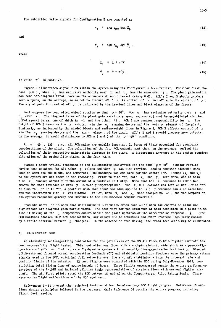
12-5
The subdivided value signals for Configuration B are computed as
vx = sgn epx sgn f p
and
v = sgn epy sgn Yp Y
where
i n which 7’ is positive.
15)
Figure 3 i l l u s t r a t e s signal flow within the system using the Configuration B controller. Consider f i r s t the case cp = 0 , when u I has exclusive authority over x and u p has the same over y . The plant gain matrix has zero off-diagonal terms, because the actuators do not interact ( s in cp = 0) . zero outputs, on the average, so as not t o d is turb ACL 1 i n its control of x and ACL 4 i n its control of y . The signal path for control of y is indicated by the heaviest l i nes and black elements of t he figure.
ACL’s 2 and 3 should produce
Next suppose the controlled object ro ta tes so t h a t cp = 90’. Now u 1 has exclusive authority over y and u p over x . The diagonal terms of t he plant gain matrix are zero, and control must be established v i a the off-diagonal terms, one of which is -1 and the other +1 . ACL 2 now assumes responsibil i ty for x , the output of ACL 2 reaching the x subplant v i a the U:, summing device and the -sin cp element of t he plant. Similarly, as indicated by the shaded blocks and medium-weight l i n e s in Figure 3. ACL 3 e f fec ts control of y v i a t h e u1 summing device and the s i n cp element of the plant. ACL’s 1 and 4 should produce zero outputs, on the average, t o avoid disturbance t o ACL’s 3 and 2 at the ‘p = 90’ condition.
A t cp = 45’ , 135’, e tc . , a l l ACL paths are equally important i n terms of t he i r potential for producing The po la r i t i e s of t he four ACL outputs must then, on the average, re f lec t t he accelerations of t he plant.
po la r i t i e s of t he i r respective gain-matrix elements in the plant. A disturbance anywhere i n t h e system requires a l te ra t ion of the probabili ty s t a t e s i n the four ACL’ s.
Figure 4 shows typical responses of t he i l l u s t r a t ive SOC system for t he case ‘p = 30’ , similar r e su l t s having been obtained for a l l other cp values and when cp w a s time varying. Analog computer elements were used t o simulate the plant , and commercial SOC hardware was employed for the controller. t o the system are not shown i n the recording. Pr ior t o time “a”, both xc and yc were zero, and at t h i s time xc changed abruptly by the amount of a posit ive unit step. Note tha t t he x response is rapid but smooth and t h a t interaction with y is nearly imperceptible. The x, = 1 command w a s l e f t on un t i l time “c”. A t time ‘b”, pr ior t o “c”, a posit ive uni t s tep input w a s a lso applied t o y ; y response was also excellent and the interaction with x was minimal. A t “c”, both x, and y, were changed t o -1 , and the outputs of the system responded quickly and smoothly t o the simultaneous command reversals.
Inputs (x, and y,)
From the above, it is seen t h a t Configuration B requires cross-feed ACL’s when the controlled plant has significant off-diagonal gain-matrix terms. The best test for t he existence of t h i s condition i n a plant is t o f ind i f mixing of the SOC monitors changes i n plant acceleration, any delays due t o actuators and other upstream lags being masked by a f i n i t e in te rva l between I! changes). In the absence of such mixing, the cross-feed ACL’s may be eliminated.
components occurs within the plant upstream of i ts acceleration response, f . (The
3 . ELEMENTARY SOC
An elementary self-organizing controller for the pitch ax is of the US Air Force F-1O1B f ighter a i r c ra f t has been successfully f l i g h t tested. This controller w a s flown with a cockpit e l ec t r i c s ide s t i ck in a pseudo-fly- by-wire configuration, t ha t is. as a fly-by-wire system with a normally disengaged mechanical backup. Blended pitch-rate and forward normal acceleration feedback (C*) and s tab i la tor position feedback were the primary return signals used by the SOC. which had f u l l authority over the a i r c ra f t s tab i la tor within the inherent ra te and posit ion limits of i ts actuator. 32 t e s t f l i g h t s were conducted with the SOC during July-November 1969, con- s t i t u t ing t o t a l f lying time of approximately 40 hours. These f l i g h t s encompassed nearly the en t i re performance envelope of the F-lO1B and included p i lo t ing tasks representative of missions flown with current f ighter air- c ra f t . The Air Force p i lo t s rated the SOC between A 1 and A2 on the Cooper-Harper P i lo t Rating Scale. There were no in- f l igh t malfunctions of the SOC equipment.
References 9-11 present the technical background for the elementary SOC f l i g h t program. Reference 13 out- l i nes design principles followed i n the hardware, while Reference 14 de ta i l s the en t i r e program, including f l i g h t t e s t resul ts .
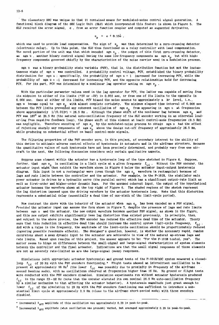
12-6
The elementary SOC was unique i n tha t it contained means for modulated-noise control signal generation. A functional block diagram of the SOC Logic Unit (SLU) which incorporated t h i s feature is shown i n Figure 5. The SLU received the e r ror signal, e , from an er ror function coupler and computed an augmented derivative.
e = e + 0.15; , P
which w a s used t o provide lead compensation. was then determined by a zero-crossing detector (electronic relay). Up t o t h i s point, the S L U thus functioned as a re lay controller with lead compensation. The novel portion of the uni t was t h a t which encoded sgn ep , t he output of t h i s f i r s t zero-crossing detector, as sgn U , another binary control signal having the same low-frequency components as frequency components governed chiefly by the charac te r i s t ics of the noise carrier used i n a modulation process.
The sign of ep
sgn ep but with high-
sgn U was a binary probabili ty state variable (PSV), t h a t is, the d is t r ibu t ion function but not t he instan- taneous s t a t e of sgn U was controlled. A probabili ty control voltage, PCV, established the binary probabili ty d is t r ibu t ion for sgn U ; specifically, the probabili ty of sgn U = 1 increased for increasing PCV, while the probabili ty of PCV.
sgn U = -1 decreased for increasing PCV, and the opposite relationships held for decreasing For its par t , PCV was determined by a nonlinear lag operator acting on sgn ep .
With the par t icu lar parameter values used i n the lag operator for PCV, the l a t t e r w a s capable of moving from its midpoint t o e i the r of i ts limits (+3V or -3V) i n 0.003 sec, o r from one of its limits t o the opposite i n 0.006 sec. Once at e i ther of its l imi t s , PCV biased t h e noise source t o approximately a W level , i .e. , sgn U became equal t o sgn e with almost complete cer ta inty. The minimum elapsed time interval of 0.006 sec between the PCV limits preveneed any coherent osc i l la t ion of sgn ep from appearing i n sgn U at frequencies above approximately l/(O.Olm) = 26.5 Hz . Although the phase s h i f t of t he nonlinear lag between sgn ep and PCV was 180’ at 26.5 Hz (the natural auto-oscillation frequency of t he SLU encoder working i n an otherwise lead- or-lag f r e e negative feedback loop), t he phase s h i f t of t h i s element at basic control-mode frequencies (0.5 Hz) was negligible. Therefore encoding of sgn ep by the modulated-noise process t o obtain sgn U had the e f fec t of rejecting sharply any components of while producing no substantial e f fec t on basic control-mode signals.
sgn ep above the design cut-off frequency of approximately 26.5 Hz.
The f i l t e r i n g properties of the PSV encoder were, i n t h i s project , of secondary in te res t t o the a b i l i t y of t h i s device t o mitigate adverse control e f fec ts of hysteresis i n actuators and i n the airframe structure. Because the quantitative values of such hysteresis have not been precisely determined, and probably vary from one air- c r a f t t o the next, the following discussion considers only cer ta in quali tative aspects.
Suppose some element within the actuator has a hysteresis loop o f the type sketched i n Figure 6. Suppose, fur ther , t h a t Without t he PSV encoder, t he actuator input might then exhibit t h e waveform shown i n Figure 6 below the actuator input-output hysteresis diagram. lags and rate l i m i t s between the controller and the actuator. power actuator is driven by a hydraulic servo (the pa ra l l e l servo) which has a significant output-rate l i m i t as well as f i r s t -order and higher-order dynamic lags. actuator becomes the waveform shown at the top r igh t of Figure 6. The shaded regions of t he sketch represent t he lag d is tor t ion imposed upon the driving waveform by the actuator hysteresis loop. represents a substantial delay (essentially a dead time of one-sixth of the limit-cycle period).
sgn ep is osc i l la t ing i n a l i m i t cycle at a given frequency f,, . This input is not a rectangular wave (even though the sgn ep waveform is rectangular) because of
For example, i n the F-1OlB. the s t ab i l a to r main
For the assumed coherent input, the output of t he hypothetical
Note tha t t h i s d i s tor t ion
Now contrast the above with the behavior of the actuator when sgn ep has been encoded as a PSV signal. Provided the actuator input can assume the form shown i n Figure 7 , despite t he presence of lags and r a t e limits between sgn U and the actuator, t he new output waveform becomes another PSV signal , as shown i n the figure, and t h i s new output exhibits s ign i f icant ly less lag d is tor t ion than existed previously. In principle, then, and subject t o the above proviso, the PSV encoder has reduced t h e effective dead time of the actuator. says t h a t t h i s reduction in e f fec t ive dead time should increase the control system limit-cycle frequency, f,, . And with a raise i n t h e frequency, the amplitude of the limit-cycle osc i l la t ion should be proportionately reduced (ignoring possible resonance effects) . The designer! s question, however, is whether the necessary rapid, random excursions about a mean dynamic input t o the actuator are achievable i n view of the natural up-stream lags and r a t e limits. Based upon r e su l t s of t h i s project , the answer appears t o be: “For the F-1O1B tes ted , yes”. The matter seems t o hinge on differences between the small-signal and large-signal charac te r i s t ics of system elements between the controller and the f i n a l actuator. Indications a r e tha t the small signal responses of these elements are not as severely rate-limited as are the large-signal (mean) responses.
Theory
Simulations (with appropriate actuator hysteresis) and ground t e s t s of t he F-lOlB/SOC system measured a closed- Flight tests showed an intermittent osc i l la t ion t o be loop
present at approximately 16 Hzt ( the lower second bending mode), with no osc i l la t ions observed at frequencies higher than 16 Hz. were conducted with the PSV encoders disabled. Simulation experiments run without actuator hysteresis produced f,, by a similar mechanism t o tha t affecting the actuator behavior). lower s t an t i a l l i m i t cycle at approximately 2.9 Hz (close t o the airframe short-period mode) with these encoders disabled.
f,, of 20 Hz with the PSV encoders functioning.* f,, was possibly due t o proximity i n frequency of the airframe
No ground o r f l i g h t tests
i n the range 33-60 Hz (note t h a t the encoder elevated i ts own nominal 26.5 Hz auto-oscil lation frequency A hysteresis magnitude j u s t great enough t o
f,, of the simulation t o 20 Hz with t h e PSV encoders functioning was sufficient t o introduce a sub-
~~ ~~
* Incremental SSpT amplitude of t h i s oscillation was approximately 0.20 in peak-to-peak. ’ Incremental GSPT amplitude (when oscillation was present) varied, bu t averaged approximately 0.25 i n peak-to-peak.
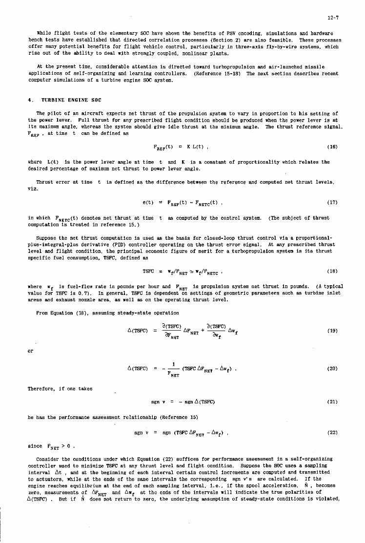
12-7
While f l i g h t t e s t s of the elementary SOC have shown the benefits of PSV encoding, simulations and hardware bench tests have established tha t directed correlation processes (Section 2) are a l so feasible. offer many potent ia l benefits fo r f l i g h t vehicle control, par t icular ly i n three-axis fly-by-wire systems, which rise out of the a b i l i t y t o deal with strongly coupled, nonlinear plants.
These processes
A t the present time, considerable a t tent ion is directed toward turbopropulsion and air-launched missile applications of self-organizing and learning controllers. computer simulations of a turbine engine SOC system.
(Reference 15-18) The next section describes recent
4 . T U R B I N E E N G I N E SOC
The p i l o t of an aircraft expects net thrust of the propulsion system t o vary i n proportion t o h i s se t t ing of the power lever, Ful l th rus t for any prescribed f l i gh t condition should be produced when the power lever is at i ts maximum angle, whereas t h e system should give i d l e thrust at the minimum angle. FREF , at time t can be defined as
The thrust reference signal,
F,,,(t) 3 K L ( t ) I (16)
where L(t) is the power lever angle a t time t and K is a constant of proportionality which re la tes the desired percentage of maximum net thrust t o power lever angle.
Thrust e r ror at time t is defined as the difference between the reference and computed net thrust levels , viz.
i n which FNETC(t) denotes net th rus t at time t as computed by the control system. (The subject of thrust computation is t reated i n reference 15.)
Suppose the net thrust computation is used as the basis for closed-loop thrust control v i a a proportional- plus-integral-plus derivative (PID) control ler operating on the thrust e r ror signal. A t any prescribed thrust level and f l i g h t condition, the pr incipal economic f igure of merit fo r a turbopropulsion system is its thrust spec i f ic fue l consumption, TSFC, defined as
where wf is fuel-flow rate i n pounds per hour and F,,, is propulsion system net thrust i n pounds. ( A typical value for TSFC is 0.7). areas and exhaust nozzle area, as well as on the operating thrust level.
In general, TSFC is dependent on se t t ings of geometric parameters such as turbine i n l e t
From Equation ( l a ) , assuming steady-state operation
or
1 A(TSFC) = - - (TSFCAF,,, -Awf) .
F~~~
Therefore, i f one takes
sgn v = - sgn A(TSFC)
he has t h e performance assessment re la t ionship (Reference 15)
sgn v = sgn (TSFC AF,,, - Aw,) , (22)
s ince F,,, > 0 . Consider the conditions under which Equation (22) suff ices for performance assessment i n a self-organizing
control ler used t o minimize TSFC at any thrust level and f l i g h t condition. interval At , and at the beginning of each interval cer ta in control increments are computed and transmitted t o actuators, while at the ends of the same intervals the corresponding sgn v ' s are calculated. I f the engine reaches equilibrium at t h e end of each sampling interval , i . e . , i f the spool acceleration, N , becomes zero, measurements Of mNET at the ends of t h e intervals w i l l indicate t h e t rue polar i t ies of
A(TSFC) . But i f N does not re turn t o zero, the underlying assumption of steady-state conditions is violated,
Suppose the SOC uses a smpl ing
and Awf
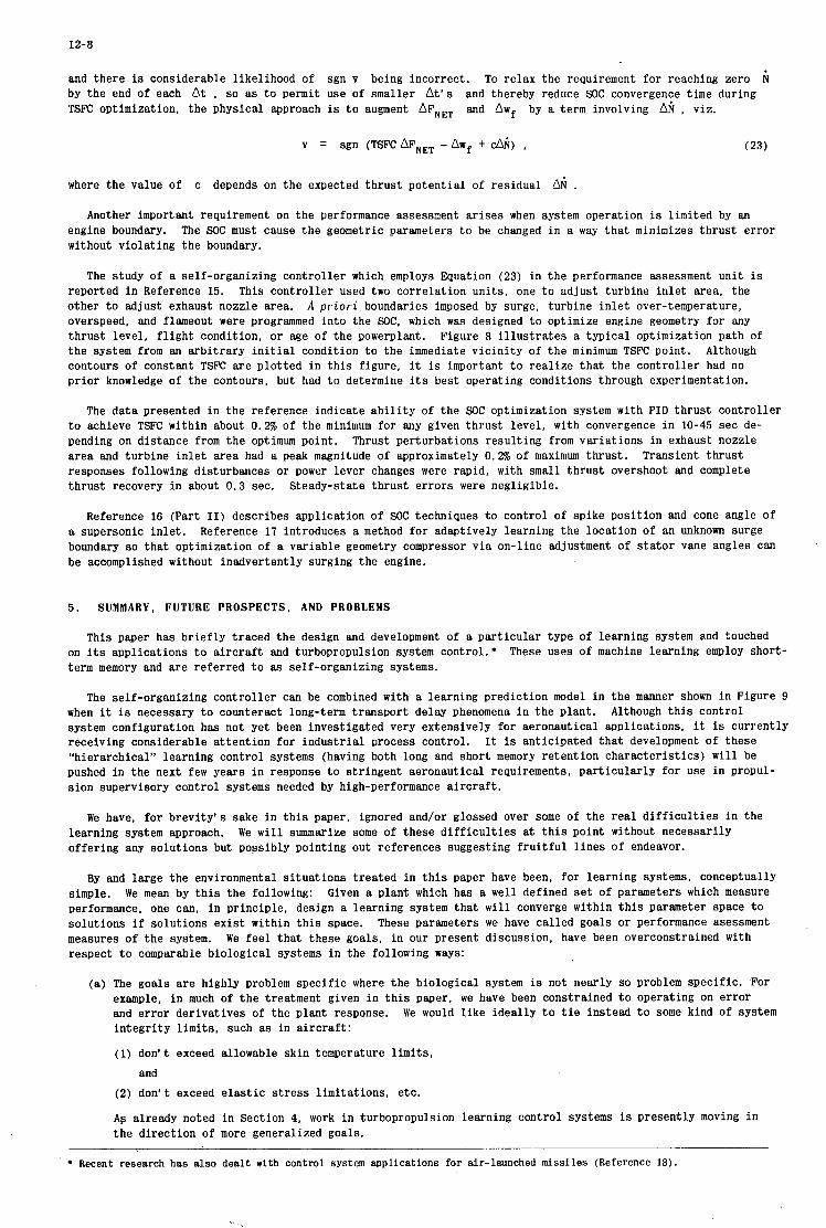
12-8
and there is considerable likelihood of sgn v being incorrect. To relax the requirement fo r reaching zero by the end of each A t , so as t o permit use of smaller At’s and thereby reduce SOC convergence time during TSFC optimization, the physical approach is t o augment A F ~ , , and ow, by a term involving AN , viz.
v = sgn (TSFCAF,,, -Awf + &) , (23)
where the value of c depends on the expected thrus t potent ia l of residual A i .
Another important requirement on the performance assessment a r i ses when system operation is limited by an engine boundary. without violating the boundary.
The SOC must cause t h e geometric parameters t o be changed in a w a y t h a t minimizes thrust error
The study of a self-organizing control ler which employs Equation (23) in the performance assessment uni t is
A p r i o r i boundaries imposed by surge, turbine i n l e t over-temperature, reported i n Reference 15. This control ler used two correlation uni ts , one t o zdjust turbine in l e t area, the other t o adjust exhaust nozzle area. overspeed, and flameout were programmed into the SOC, which w s s designed t o optimize engine geometry for any thrust level, f l i g h t condition, or age of the powerplant. the system from an arbi t rary i n i t i a l condition t o the immediate v ic in i ty of the minimum TSFC point. Although contours of constant TSFC are plot ted in t h i s f igure, it is important t o real ize that the control ler had no pr ior knowledge of the contours, but had t o determine its best operating conditions through experimentation.
Figure 8 illustrates a typical optimization path of
The data presented i n the reference indicate a b i l i t y of the SOC optimization system with PID thrust control ler t o achieve TSFC within about 0.2% of the minimum for any given thrust level, w i t h convergence i n 10-45 sec de- pending on distance from the optimum point. Thrust perturbations resulting from variat ions i n exhaust nozzle area and turbine i n l e t area had a peak magnitude of approximately 0.2% of maximum thrust . responses following disturbances o r power lever changes were rapid, with small thrust overshoot and complete thrust recovery i n about 0.3 sec.
Transient thrust
Steady-state thrust errors were negligible.
Reference 16 (Part 11) describes application of SOC techniques t o control of spike position and cone angle of a supersonic in l e t . boundary so tha t optimization of a variable geometry compressor v ia on-line adjustment of s t a t o r vane angles can be accomplished without inadvertently surging the engine.
Reference 17 introduces a method fo r adaptively learning the location of an unknown surge
5 . SUMMARY, FUTURE PROSPECTS, A N D PROBLEMS
This paper has br ief ly traced the design and development of a par t icular type of learning system and touched on its applications t o a i r c r a f t and turbopropulsion system control: term memory and are referred t o as self-organizing systems.
These uses of machine learning employ short-
The self-organizing control ler can be combined with a learning prediction model i n the manner shown i n Figure 9 when it is necessary t o counteract long-term transport delay phenomena i n the plant. system configuration has not yet been investigated very extensively for aeronautical applications, it is currently receiving considerable a t tent ion fo r industr ia l process control. I t is anticipated t h a t development of these “hierarchical” learning control systems (having both long and short memory retent ion character is t ics) w i l l be pushed in the next few years i n response t o s t r ingent aeronautical requirements, par t icular ly fo r use in propul- sion supervisory control systems needed by high-performance aircraf t .
Although t h i s control
We have, fo r brevi ty’s sake i n t h i s paper, ignored and/or glossed over some of the r ea l d i f f i c u l t i e s i n the learning system approach. offering any solutions but possibly pointing out references suggesting f r u i t f u l l i n e s of endeavor.
We w i l l summarize some of these d i f f i c u l t i e s at t h i s point without necessarily
By and large the environmental s i tuat ions t reated i n t h i s paper have been, for learning systems, conceptually simple. performance, one can, i n principle, design a learning system that w i l l converge within t h i s parameter space t o solutions i f solutions ex i s t within t h i s space. measures of t h e system. respect t o comparable biological systems i n the following ways:
We mean by t h i s the following: Given a plant which has a well defined s e t of parameters which measure
These parameters we have cal led goals or performance asessment We f e e l that these goals, i n our present discussion, have been overconstrained with
(a) The goals are highly problem specif ic where the biological system is not nearly so problem specific. For example, i n much of t h e treatment given i n t h i s paper, we have been constrained t o operating on e r ror and error derivatives of the plant response. in tegr i ty l imits , such as i n a i r c ra f t :
(1) don‘t exceed allowable skin temperature limits,
We would l i k e ideal ly t o t i e instead t o some kind of system
and (2) don’t exceed elastic stress limitations, etc.
Ag already noted in Section 4, work i n turbopropulsion learning control systems is presently moving i n the direct ion of more generalized goals.
Recent research has also dealt with control system applications for air-launched missiles (Reference 18).
12-7
I he has the performance assessment re la t ionship (Reference 15)
While f l i gh t t e s t s of the elementary SOC have shown the benefits of PSV encoding, simulations and hardware bench t e s t s have established t h a t directed correlation processes (Section 2) are a l so feasible. o f fe r many potent ia l benefi ts fo r f l i g h t vehicle control, pa r t i cu la r ly i n three-axis fly-by-wire systems, which r i s e out of t h e a b i l i t y t o deal w i t h strongly coupled, nonlinear plants.
These processes
~
sgn v = sgn (TSFCAF,,, -Aw,) , (22) I
since FNET > 0 . Consider the conditions under which Equation (22) suff ices for performance assessment i n a self-organizing
control ler used t o minimize TSFC at any thrust level and f l i g h t condition. interval At , and at the beginning of each interval cer ta in control increments are computed and transmitted t o actuators, while at t h e ends of the same intervals t h e corresponding sgn v ' s are calculated. If t h e engine reaches equilibrium at the end of each sampling interval , i .e . , i f the spool acceleration, zero, measurements of MNET and Awf at t h e ends of the intervals w i l l indicate the t rue polar i t ies of A(TSFC) . But i f does not re turn t o zero, the underlying assumption of steady-state conditions is violated,
Suppose the SOC uses a sampling
N , becomes
A t the present time, considerable a t tent ion is directed toward turbopropulsion and air-launched missile applications of self-organizing and learning controllers. (Reference 15-18) The next section describes recent computer simulations of a turbine engine SOC system.
4 . T U R B I N E E N G I N E S O C
The p i l o t of an a i r c r a f t expects net th rus t of t h e propulsion system t o vary i n proportion t o h i s se t t ing of Ful l th rus t fo r any prescribed f l i g h t condition should be produced when the power lever is at the power lever.
its maximum angle, whereas the system should give i d l e thrust at the minimum angle. F,,, , at time t can be defined as
The thrust reference s ignal ,
F,,F(t) K L ( t ) v (16)
where L(t) is the power lever angle at time t and K is a constant of proportionality which re la tes the desired percentage of maximum net thrust t o power lever angle.
Thrust e r ror at time t is defined as the difference between the reference and computed net th rus t levels, viz.
i n which FNETc( t ) denotes net thrust at time t as computed by the control system. (The subject of thrust computation is treated i n reference 15.)
Suppose t h e net thrust computation is used as the basis for closed-loop thrust control v i a a proportional- plus-integral-plus derivative (PID) control ler operating on the thrust e r ror signal. A t any prescribed thrust level "d f l i gh t condition, the pr incipal economic figure of merit for a turbopropulsion system is its thrust spec i f ic f u e l consumption, TSFC. defined as
where w f is fuel-flow r a t e i n pounds per hour and F,,, is propulsion system net thrust i n pounds. ( A t yp ica l value for TSFC is 0.7). areas and exhaust nozzle area, as well as on the operating thrust level.
In general, TSFC is dependent on se t t ings of geometric parameters such as turbine i n l e t
From Equation (18), assuming steady-state operation
or
1 (TSFCAF,,, -Aw,) . A(TSFC) = - -
F~~~
Therefore, i f one takes
sgn v = - sgn A(TSFC) (21)
12-8
and there is considerable likelihood of sgn v being incorrect. To relax the requirement for reaching zero fi by the end of each A t , so as t o permit use of smaller A t ’ s and thereby reduce SOC convergence time during TSFC optimization, the physical approach is t o augment AF,~, and Owf by a term involving AN , viz.
v = sgn (TSFCAF,,, -Aw, + &) , (23)
where the value of c depends on the expected thrus t potential of residual Ai .
Another important requirement on the performance assessment a r i ses when system operation is limited by an engine boundary. The SOC must cause the geometric parameters t o be changed i n a w a y t ha t minimizes thrust e r ror without violating the boundary.
The study of a self-organizing controller which employs Equation (23) i n the performance assessment unit is
A p r i o r i . boundaries imposed by surge, turbine i n l e t over-temperature, reported i n Reference 15. This controller used two correlation uni ts , one t o adjust turbine i n l e t area, the other t o adjust exhaust nozzle area. overspeed, and flameout were programmed in to the SOC, which WBS designed t o optimize engine geometry for.any thrust level, f l i g h t condition, or age of the powerplant. Figure 8 i l l u s t r a t e s a typical optimization path of the system from an arb i t ra ry i n i t i a l condition t o the immediate v ic in i ty of t he minimum TSFC point. Although contours of constant TSFC are plotted in t h i s figure, it is important t o rea l ize tha t the controller had no pr ior knowledge of the contours, but had t o determine i ts best operating conditions through experimentation.
The da ta presented i n the reference indicate a b i l i t y of t he SOC optimization system with PID thrust controller t o achieve TSFC within about 0.2% of the minimum for any given thrus t level, with convergence i n 10-45 sec de- pending on distance from the optimum point. area and turbine i n l e t area had a peak magnitude of approximately 0.2% of maximum thrust . responses following disturbances or power lever changes were rapid, with small th rus t overshoot and complete thrust recovery in about 0.3 sec. Steady-state thrust e r rors were negligible.
Thrust perturbations result ing from variations in exhaust nozzle Transient th rus t
Reference 16 (Part 11) describes application of SOC techniques t o control of spike posit ion and cone angle of a supersonic in le t . boundary so t h a t optimization of a variable geometry compressor v i a on-line adjustment of s t a to r vane angles can be accomplished without inadvertently surging the engine.
Reference 17 introduces a method for adaptively learning the location of an unknown surge
5. SUMMARY, FUTURE PROSPECTS, AND PROBLEMS . This paper has br ie f ly traced the design and development of a particular type of learning system and touched
on its applications t o a i r c ra f t and turbopropulsion system control. * term memory and are referred t o as self-organizing systems.
These uses of machine learning employ short-
The self-organizing controller can be combined with a learning prediction model in the manner shown i n Figure 9 when it is necessary t o counteract long-term transport delay phenomena i n the plant. system configuration has not yet been investigated very extensively for aeronautical applications, it is currently
It is anticipated t h a t development of these “hierarchical” learning control systems (having both long and short memory retention characterist ics) w i l l be pushed in the next few years i n response t o stringent aeronautical requirements, par t icu lar ly for use in propul- sion supervisory control systems needed by high-performance a i rc raf t .
Although t h i s control
. receiving considerable attention for indus t r ia l process control.
We have, for brevity’s sake i n t h i s paper, ignored and/or glossed over some of the real d i f f i cu l t i e s i n the learning system approach. offering any solutions but possibly pointing out references suggesting f r u i t f u l l i nes of endeavor.
We w i l l summarize some of these d i f f i cu l t i e s at t h i s point without necessarily
By and large the environmental s i tua t ions treated in t h i s paper have been, for learning systems, conceptually simple. We mean by t h i s the following: performance, one can, i n principle, design a learning system tha t w i l l converge within t h i s parameter space t o solutions i f solutions ex is t within t h i s space. measures of t h e system. respect t o comparable biological systems i n the following w a y s :
Given a plant which has a well defined set of parameters which measure
These parmeters we have called goals or performance asessment We f e e l t h a t these goals, in our present discussion, have been overconstrained with
(a) The goals are highly problem spec i f ic where the biological system is not nearly so problem specific. For example, In much of t h e treatment given i n t h i s paper, we have been constrained t o operating on e r ror and er ror derivatives of the plant response. in tegr i ty l imi t s , such as in a i rc raf t :
(1) don’t exceed allowable skin temperature limits.
%e would l ike ideally t o t i e instead t o some kind of system
and (2) don’t exceed e l a s t i c s t r e s s l imitat ions, etc.
Ac; already noted in Section 4, work in turbopropulsion learning control systems is presently moving i n the direction of more generalized goals.
Recent research has also dealt w i t h control system applications for air-launched missiles (Reference 18).

12-7
While f l i gh t t e s t s of the elementary SOC have shown the benefits of PSV encoding, simulations and hardware bench tests have established tha t directed correlation processes (Section 2) are a l so feasible. These processes of fe r many potent ia l benefi ts fo r f l i gh t vehicle control, par t icular ly i n three-axis fly-by-wire systems, which r i s e out of the a b i l i t y t o deal with strongly coupled, nonlinear plants.
A t the present time, considerable a t tent ion is directed toward turbopropulsion and air-launched missile applications of self-organizing and learning controllers. (Reference 15-18) The next section describes recent computer simulations of a turbine engine SOC system.
4 . TURBINE ENGINE SOC
The p i l o t of an a i rc raf t expects net thrust of the propulsion system t o vary i n proportion t o h i s se t t ing of the power lever. Ful l th rus t for any prescribed f l i gh t condition should be produced when the power lever is at its maximum angle, whereas the system should give i d l e thrust at the minimum angle. The thrus t reference signal. FREF , at time t can be defined as
FREF(t) K L ( t ) I , (16)
where L(t) is the power lever angle a t time t and K is a constant of proportionality which re la tes the desired percentage of maximum net thrust t o power lever angle.
Thrust e r ror at time t is defined as the difference between the reference and computed net t’hrust levels, viz.
i n which FNFTC(t) denotes net th rus t at time computation is t reated i n reference 15.)
t as computed by the control system. (The subject of thrust
Suppose the net thrust computation is used as the basis for closed-loop thrust control v i a a proportional- plus-integral-plus derivative (PID) control ler operating on the thrust e r ror signal. A t any prescribed thrus t level and f l i gh t condition, the principal economic f igure of merit for a turbopropulsion system is its thrust spec i f ic fue l consumption, TSFC, defined as
where W, is fuel-flow r a t e i n pounds per hour and FNE, is propulsion system net thrust i n pounds. ( A typical value fo r TSFC is 0.7). areas and exhaust nozzle area, as well as on the operating thrust level.
In general, TSFC is dependent on se t t ings of geometric parameters such as turbine i n l e t
From EQuation (18), assuming steady-state operation
or
1 A(TSFC) = - - (TSFCAF,,, -Aw,) .
FNET
Therefore, i f one takes
sgn v = - sgn A(TSFC) (21)
he has the performance assessment re la t ionship (Reference 15)
sgn v = sgn (TSFC AF,,, - Aw,) , (22)
since FNET > 0 . Consider the conditions under which Equation (22) suf f ices for performance assessment i n a self-organizing
control ler used t o minimize TSFC a t any thrust level and f l i g h t condition. interval At , and at the beginning of each interval cer ta in control increments are computed and transmitted t o actuators, while at the ends of the same intervals the corresponding sgn v’s are calculated. If the engine reaches equilibrium at the end of each sampling interval , i .e . , i f the spool acceleration. N , becomes zero, measurements Of bNET a t the ends of the intervals w i l l indicate the t rue polar i t ies of A(TSFC) . But i f N does not re turn t o zero, the underlying assumption of steady-state conditions is violated,
Suppose the SOC uses a sampling
and Aw,

12-8
and there is considerable likelihood of sgn v being incorrect. To relax the requirement for reaching zero by the end of each At , so as t o permit use of smaller A t ’ s and thereby reduce SOC convergence time during TSFC optimization, the physical approach is t o augment AF,,, and Awf by a term involving A i , viz.
where the value of c depends on the expected thrus t potential of residual Ai .
Another important requirement on the performance assessment a r i s e s when system operation is limited by an engine boundary. The SOC must cause t h e geometric parameters t o be changed in a w a y t ha t minimizes thrus t error without violating the boundary.
The study of a self-organizing controller which employs Equation (23) in the performance assessment uni t is
A priori boundaries imposed by surge, turbine i n l e t over-temperature, reported i n Reference 15. This controller used two correlation uni ts , one t o adjust turbine in le t area, the other t o adjust exhaust nozzle area. overspeed. and flameout were programmed in to the SOC, which was designed t o optimize engine geometry for any thrus t level , f l i g h t condition, o r age of the powerplant. Figure 8 i l l u s t r a t e s a typical optimization path of t he system from an arb i t ra ry i n i t i a l condition t o the immediate v ic in i ty of t he minimum TSFC point. contours of constant TSFC are plotted i n t h i s figure, it is important t o rea l ize tha t t he controller had no pr ior knowledge of the contours, but had t o determine i ts best operating conditions through experimentation.
Although
The da ta presented in the reference indicate a b i l i t y of the SOC optimization system with PID thrus t controller t o achieve TSFC within about 0.2% of the minimum for any given thrust level , with convergence i n 10-45 sec de- pending on distance from the optimum point. Thrust perturbations result ing from variations i n exhaust nozzle area and turbine i n l e t area had a peak magnitude of approximately 0.2% of maximum thrust . Transient thrust responses following disturbances or power lever changes were rapid, with small th rus t overshoot and complete thrust recovery in about 0 . 3 sec. Steady-state th rus t e r rors were negligible.
Reference 16 (Part 11) describes application of SOC techniques t o control of spike posit ion and cone angle of a supersonic in le t . boundary so t h a t optimization of a variable geometry compressor v i a on-line adjustment of s t a to r vane angles can be accomplished without inadvertently surging the engine.
Reference 17 introduces a method for adaptively learning the location of an unknown surge
5. SUMMARY, FUTURE PROSPECTS, AND PROBLEMS
This paper has br ie f ly traced the design and development of a particular type of learning system and touched on its applications t o a i r c ra f t and turbopropulsion system control.. term memory and are referred t o as self-organizing systems.
These uses of machine learning employ short-
The self-organizing controller can be combined with a learning prediction model i n the manner shown i n Figure 9 when it is necessary t o counteract long-term transport delay phenomena i n the plant. system configuration has not yet been investigated very extensively for aeronautical applications, it is currently receiving considerable attention for indus t r ia l process control. I t is anticipated t h a t development of these “hierarchical” learning control systems (having both long and short memory retention characterist ics) w i l l be pushed in the next few years i n response t o stringent aeronautical requirements, par t icu lar ly for use i n propul- sion supervisory control systems needed by high-performance a i rc raf t .
Although t h i s control
We have, for brevity’s sake i n t h i s paper, ignored and/or glossed over some of the real d i f f i cu l t i e s i n the learning system approach. offering any solutions but possibly pointing out references suggesting f r u i t f u l l i nes of endeavor.
We w i l l summarize some of these d i f f i cu l t i e s at t h i s point without necessarily
By and large the environmental s i tua t ions treated in t h i s paper have been, for learning systems, conceptually Given a plant which has a well defined set of parameters which measure
These parameters we have called goals o r performance asessment
simple. We mean by t h i s the following: performance, one can, in principle, design a learning system tha t w i l l converge within t h i s parameter space t o solutions i f solutions ex is t within t h i s space. measures of t he system. respect t o comparable biological systems in the following w a y s :
We f e e l tha t these goals, in our present discussion, have been overconstrained with
(a) The goals are highly problem specific where the biological system is not nearly so problem specific. For example, i n much of t h e treatment given i n t h i s paper, we have been constrained t o operating on e r ror and er ror derivatives of the plant response. in tegr i ty limits, such as in a i r c r a f t :
(1) don’ t exceed allowable skin temperature l imits ,
We would l i k e ideally t o t i e instead t o some kind of system
and (2) don’t exceed e l a s t i c s t r e s s l imitat ions, etc.
A$ already noted i n Section 4, work i n turbopropulsion learning control systems is presently moving i n the direction of more generalized goals.
Recent research has also dealt with control system applications for air-launched missiles (Reference 18).
12-7
While f l i g h t tests of the elementary SOC have shown the benefi ts of PSV encoding, simulations and hardware bench tests have established tha t directed correlation processes (Section 2) are a lso feasible. These processes of fe r many potent ia l benefits f o r f l i g h t vehicle control, particularly i n three-axis fly-by-wire systems, which r i s e out of the a b i l i t y t o deal with strongly coupled, nonlinear plants.
A t t h e present time. considerable a t tent ion is directed toward turbopropulsion and air-launched missile applications of self-organizing and learning controllers. (Reference 15-18) The next section describes recent computer simulations of a turbine engine SOC system.
4 . T U R B I N E E N G I N E SOC
The p i l o t of an a i rc raf t expects net th rus t of the propulsion system t o vary i n proportion t o h i s se t t ing of the power lever. Ful l th rus t fo r any prescribed f l i g h t condition should be produced when the power lever is at i t s maximum angle, whereas the system should give i d l e th rus t at the minimum angle. The thrust reference signal, FREF , at time t can be defined as
where L(t) is the power lever angle at time t and K is a constant of proportionality which re la tes the desired percentage of maximum net thrust t o power lever angle.
Thrust e r ror at time t is defined as the difference between the reference and computed net thrust levels , viz.
i n which FNETc(t) denotes net thrust at time t as computed by the control system. (The subject of thrust computation is t reated i n reference 15. )
Suppose the net thrust computation is used as the basis for closed-loop thrust control v i a a proportional- plus-integral-plus derivative (PID) control ler operating on the thrust e r ror signal. A t any prescribed t h r u s t level and f l i gh t condition, the principal economic f igure of merit fo r a turbopropulsion system is its thrust spec i f ic fue l consumption, TSFC. defined as
where w f is fuel-flow r a t e i n pounds per hour and F,,, is propulsion system net thrust i n pounds. ( A t yp ica l value fo r TSFC is 0.7). areas and exhaust nozzle area, as well as on the operating thrust level.
In general, TSFC is dependent on se t t ings of geometric parameters such as turbine i n l e t
From Equation (18), assuming steady-state operation
o r
1 A(TSFC) = - - (TSFC A F ~ , ~ - Ow,) .
FNET
Therefore, i f one takes
sgn v = - sgn A(TSFC)
(20)
(21)
he has t h e performance assessment relationship (Reference 15)
sgn v = sgn (TSFC AF,,, -Aw,) , (22)
since FNET > 0 . Consider the conditions under which Equation (22) suff ices for performance assessment i n a self-organizing
control ler used t o minimize TSFC at any thrust level and f l i g h t condition. Suppose the SOC uses a sampling interval At , and at the beginning of each interval cer ta in control increments are computed and transmitted t o actuators, while at the ends of the same intervals the corresponding sgn v ' s are calculated. I f the engine reaches equilibrium at the end of each sampling interval , i .e . , i f the spool acceleration, zero, measurements of LkNET and Aw, at the ends of the intervals w i l l indicate t h e t rue polar i t ies of A(TSFC) . But i f fi does not re turn t o zero, the underlying assumption of steady-state conditions is violated,
N , becomes
12-8
and there is considerable likelihood of sgn v being incorrect. To relax the requirement fo r reaching zero by the end of each A t , so as t o permit use of smaller At ’s TSFC optimization, the physical approach is t o augment A F ~ ~ ~
and thereby reduce SOC convergence time during and Awf by a term involving AN , viz.
where the value of c depends on the expected thrus t potent ia l of residual L& . Another important requirement on the performance assessment a r i ses when system operation is limited by an
engine boundary. The SOC must cause the geometric parameters t o be changed i n a w a y t h a t minimizes thrust error without violating the boundary.
The study of a self-organizing control ler which employs Equation (23) in the performance assessment uni t is
A p r i o r i boundaries imposed by surge, turbine i n l e t over-temperature, reported i n Reference 15. This controller used two correlation uni ts , one t o adjust turbine in l e t area, the other t o adjust exhaust nozzle area. overspeed. and flameout were programmed into the SOC, which was designed t o optimize engine geometry for any thrust level, f l i g h t condition, or age of the powerplant. Figure 8 i l l u s t r a t e s a typical optimization path of the system from an arbi t rary i n i t i a l condition t o the immediate v ic in i ty of the minimum TSFC point. Although contours of constant TSFC are plot ted i n t h i s f igure, it is important t o real ize that the controller had no pr ior knowledge of the contours, but had t o determine its best operating conditions through experimentation.
The data presented i n the reference indicate a b i l i t y of the SOC optimization system with PID thrust control ler t o achieve TSFC within about 0.2% of the minimum for any given thrust level, with convergence i n 10-45 sec de- pending on distance from the optimum point. area and turbine i n l e t area had a pesk magnitude of approximately 0.2% of maximum thrust . responses following disturbances or power lever changes were rapid, with small th rus t overshoot and complete thrust recovery in about 0.3 sec. Steady-state thrust e r rors were negligible.
Thrust perturbations resulting from variat ions i n exhaust nozzle Transient thrust
Reference 16 (Part 11) describes application of SOC techniques t o control of spike posi t ion and cone angle of a supersonic in l e t . boundary so tha t optimization of a variable geometry compressor v i a on-line adjustment of s t a t o r vane angles can be accomplished without inadvertently surging the engine.
Reference 17 introduces a method f o r adaptively learning the location of an unknown surge
5. SUMMARY, FUTURE PROSPECTS, A N D PROBLEMS
This paper has br ief ly traced the design and development of a particular type of learning system and touched on its applications t o a i r c r a f t and turbopropulsion system control.* term memory and are referred t o as self-organizing systems.
These uses of machine learning employ short-
The self-organizing control ler can be combined with a learning prediction model i n the manner shown i n Figure 9 when it is necessary t o counteract long-term transport delay phenomena i n the plant. system configuration has not yet been investigated very extensively for aeronautical applications, it is currently receiving considerable a t tent ion fo r industr ia l process control. It is anticipated t h a t development of these “hierarchical” learning control systems (having both long and short memory retent ion character is t ics) w i l l be pushed in the next few years i n response t o stringent aeronautical requirements, par t icular ly for use in propul- s ion supervisory control systems needed by high-performance a i r c ra f t .
Although t h i s control
We have, fo r brevi ty’s sake i n t h i s pmer, ignored and/or glossed over some of the real d i f f i c u l t i e s i n the learning system approach. offering any solut ions but possibly pointing out references suggesting f r u i t f u l l i n e s of endeavor.
We w i l l summarize some of these d i f f i c u l t i e s at t h i s point without necessarily
By and large the environmental s i tuat ions t reated in t h i s paper have been, for learning systems, conceptually simple. We mean by t h i s the following: performance, one can, i n principle, design a learying,system that w i l l converge within t h i s parameter space t o solutions i f solutions ex i s t within t h i s space. measures of the system. We f e e l that these goals, i n our present discussion, have been overconstrained with respect t o comparable biological systems i n the following ways:
Given a plant which has a well defined set of parameters which measure
These parameters we have cal led goals o r performance asessment
(a) The goals are highly problem spec i f ic where the biological system is not nearly so problem specific. For example, i n much of t h e treatment given i n t h i s paper, we have been constrained t o operating on error and error derivatives of the plant response. in tegr i ty l imits , such as in a i r c ra f t :
We would l i ke ideal ly t o t i e instead t o some kind of system
(1) don’ t exceed allowable skin temperature l imits , and
(2) don’t exceed e l a s t i c s t r e s s l imitations, etc. ’
AS already noted i n Section 4, work i n turbopropulsion learning control systems is presently moving i n t h e direct ion of more generalized goals.
Recent research has also dealt with control system applications for air-launched missiles (Refereme 18).
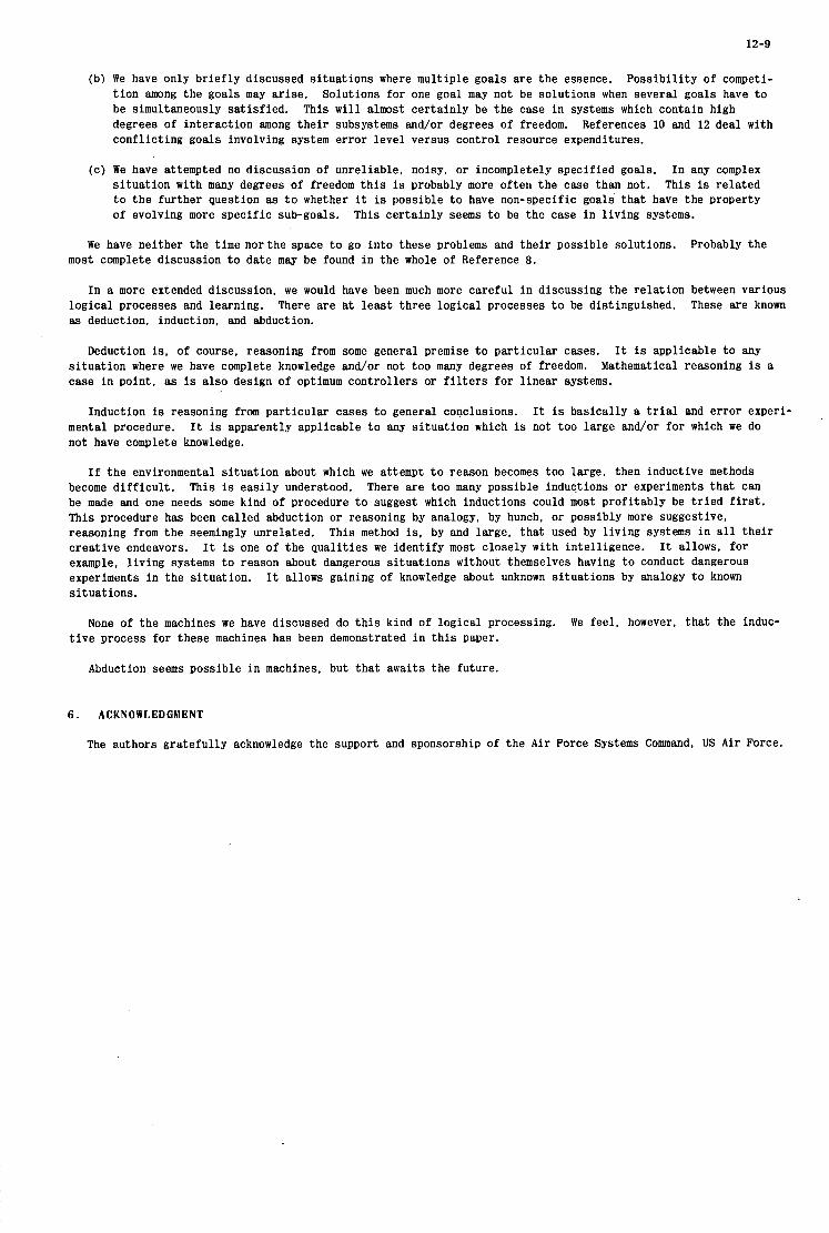
12-9
(b) We have only br ie f ly discussed s i tuat ions where multiple goals are t h e essence. t ion among the goals m a y ar ise . Solutions fo r one goal may not be solutions when several goals have t o be simultaneously sat isf ied. This w i l l almost cer ta inly be the case in systems which contain high degrees of interaction among the i r subsystems and/or degrees of freedom. References 10 and 12 deal with confl ic t ing goals involving system error level versus control resource expenditures.
Poss ib i l i ty of competi-
(c) We have attempted no discussion of unreliable, noisy, or incompletely specified goals. In any complex s i tua t ion with many degrees of freedom t h i s is probably more often t h e case than not. This is related t o the fur ther question as t o whether it is possible t o have non-specific goals t ha t have the property of evolving more specif ic sub-goals. This cer ta inly seems t o be the case i n l iving systems.
We have neither the time nor the space t o go in to these problems and the i r possible solutions. Probably the most complete discussion t o date may be found in the whole of Reference 8.
In a more extended discussion, we would have been much more careful i n discussing the relat ion between various These are known logical processes and learning.
as deduction, induction, and abduction. There are at least three logical processes t o be distinguished.
Deduction i s , of course, reasoning from some general premise t o par t icular cases. I t i s applicable t o any s i tua t ion where we have complete knowledge and/or not too many degrees of freedom. case i n point, as is a lso design of optimum control lers or f i l t e r s fo r l inear systems.
Mathematical reasoning is a
Induction is reasoning from part icular cases t o general conclusions. It is basically a t r i a l and error experi- mental procedure. not have complete knowledge.
I t is apparently applicable t o any s i tua t ion which is not too large and/or fo r which we do
I f t h e environmental s i tuat ion about which we attempt t o reason becomes too large, then inductive methods become d i f f i cu l t . This is eas i ly understood. There are too many possible inductions or experiments t ha t can be made and one needs some kind of procedure t o suggest which inductions could most profitably be t r i e d f i r s t . This procedure has been cal led abduction o r reasoning by analogy, by hunch, or possibly more suggestive, reasoning from the seemingly unrelated. creat ive endeavors. I t allows, for example, l iving systems t o reason about dangerous s i tuat ions without themselves having t o conduct dangerous experiments i n the si tuation. s i tuat ions.
This method is, by and large, t ha t used by l iving systems i n a l l t he i r It is one of the qua l i t i es we identify most closely with intell igence.
I t allows gaining of knowledge about unknown si tuat ions by analogy t o known
None of the machines we have discussed do t h i s kind of logical processing. We feel , however, t ha t the induc- t i v e process for these machines has been demonstrated i n t h i s paper.
Abduction seems possible i n machines, but t ha t awaits the future.
6 . ACKNOWLEDGMENT
The authors grateful ly acknowledge the support and sponsorship of the Air Force Systems Command, US A i r Force.
12- 10
REFERENCES
1. Gwinn, C.W.
2. Wiener, N. e t al.
3. Wiener, N.
4. Ashby. W.R.
5. Ashby, W.R.
6. Eddington, A.S.
7. Rosen, R.
8. Beer, S.
9. Barron. R.L.
10. Barron, R.L.
11. Barron, R.L.
12. Barron, R.L.
13. McKechnie, R.M. I11 Barron. R.L.
14.
15. Barron, R.L. Cleveland, D. et al .
16. Bi l l ig , L.O.
17. Mucciardi, A.N. Barron, R.L. e t al.
18. Cleveland, D. Barron, R.L. e t al.
7he Scope and Methods of Engineering Bionics. Scientia, Vol. 100, No. 246, 1965.
Behaviour, Purpose, and Teleology in Modern Systems Research for Behavioral Scientists. W.Buckley, Ed., Aldine Publ. Co., 1968, pp. 221-226.
Cybernetics. MIT Press, 1948.
Design for a Brain. Wiley, 1952.
Introduction to Cybernetics. Wiley, 1956.
Fundamental Theory. Cambridge Univ. Press, 1948. p. 30.
Optimality Principles in Biology. Butterworths. 1967, Chap. 11.
Decision and Control. Wiley, 1966.
Self-organizing and Learning Control Systems in Cybernetic Problems in Bionics. (H. L. Oestreicher and D. R. Moore, Eds. ) , Gordon and Breach, 1968, pp. 147-203.
Adaptive Flight Control Systems. Brussels, September 1968.
Paper presented at NATO AGARD Bionics Symposium,
Self-Organizing Control: The Next Generation of Controllers. Part I - The Elementary m. Part - TheGenerol Purpose x. Control Engineering. Vol. 15, Nos. 2 and 3, February 1968, pp. 70-74, March 1968, pp. 69-74.
Analysis and Synthesis of Advanced Self-organizing Control Systems - II. ronics. Inc. f i n a l technical report under Contract F33615-67-C-1681 with US Air Force Avionics Laboratory, AFAL TR-68-236. September 1968.
Adapt-
Design Principles for Self-organizing Control System Flight Hardware. Proc. 19th Ann. NAECON, 1967, pp.465-473.
Design, Fabrication, and Flight Testing of Self-organizing Flight Control System. Adaptronics. Inc. f ina l technical report under Contract AF 33(615)-5141 with U S A i r Force Flight Dynamics and Avionics Laboratories, May 1970.
Self-Organizing Control of Advanced Turbine Engines. Adaptronics Inc. f i n a l technical report under Contract F33615-68-C-1606 with US A i r Force Aero Propulsion Laboratory, August 1969.
Adaptive Controls. Part I: A Survey. Part II: Self-organizing Systems. and Control Systems, Vol. 42, September 1969, pp. 147-152, October 1969, pp. 126-131.
Adoptive Optimization System for Maximizing Performance of Variable-Geometry Turbojet Compressor with Unknown Surge Boundaries. Adaptronics, Inc. proprietary technical report #2 under P ra t t 8: Whitney Aircraft Division, United Aircraft Corp.. Purchase Order F191275, April 1970.
Instruments
Research and Development on Self-organizing Control Systems for Air-Launched Missiles. Adaptronics, Inc. f i n a l technical report under Contract N00019-69-C- 0106 with US Naval A i r Systems Command, November 1969.

12-11
x-
yc-
C o n t r o l l e r
SOC
P l a n t
I, I- I ( P o s i t i o n Sensors) -
Coo r d i na t e S y s tern
C .
Fig. 1 Illustrative SOC application
e
V x
P X
PA 1
ACL 2
C o n f i g u r a t i o n A :
1 CL 2 U2
C o n f i g u r a t i o n 6 :
X \/ 1
e Y it
ACL 3
1
I Y
Fig.2 Alternative SOC configurations for illustrative application
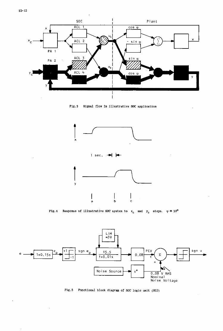
12- 12
e 1+0.15s
P l a n t I I so c
I
c 15.5 1+0.01 s P+% sgn ep *
Fig. 3
I X
t Y
I
Signal flow i n i l lus tra t ive SOC application
1 sec. +
4
a I I b C
Fig.4 Response of i l l u s t r a t i v e SOC system t o xc and y, steps. cp 30'
0.08 V RMS Nominal
Noise Source S a
Noise Vo l tage
Fig.5 Functional block diagram of SOC l og ic unit (SLU)
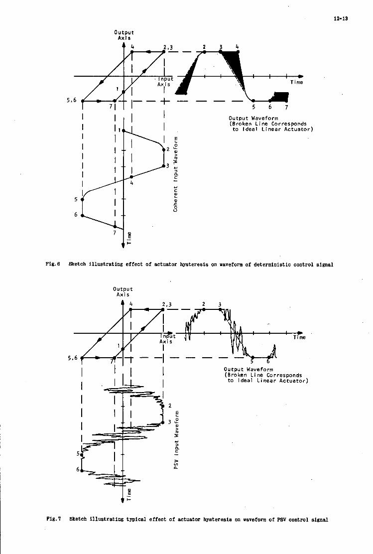
la-is
o u t p u t A x i s
- Time
71 I I I 5 6 7 I I
2z 0 U
5
6
7 g .- I-
Output Wave f o r m (Broken Line Corresponds to Ideal Linear Actuator)
Fig .6 Sketch i l lus tra t ing e f f e c t of actuator hysteres is on waveform of deterministic control s ignal
output Axis
4 4 2 . 3 2 3 --
a *
Time
I I .w I I
I I I
2 E
3 : L 3 Y 3 Q C
> v)
- a.
0 u t pu t Waveform (Broken Line Corresponds
to Ideal Linear Actuator)
Fig .7 Sketch i l l u s t r a t i n g typical e f f e c t of actuator hysteres is on waveform of PSV control s ignal
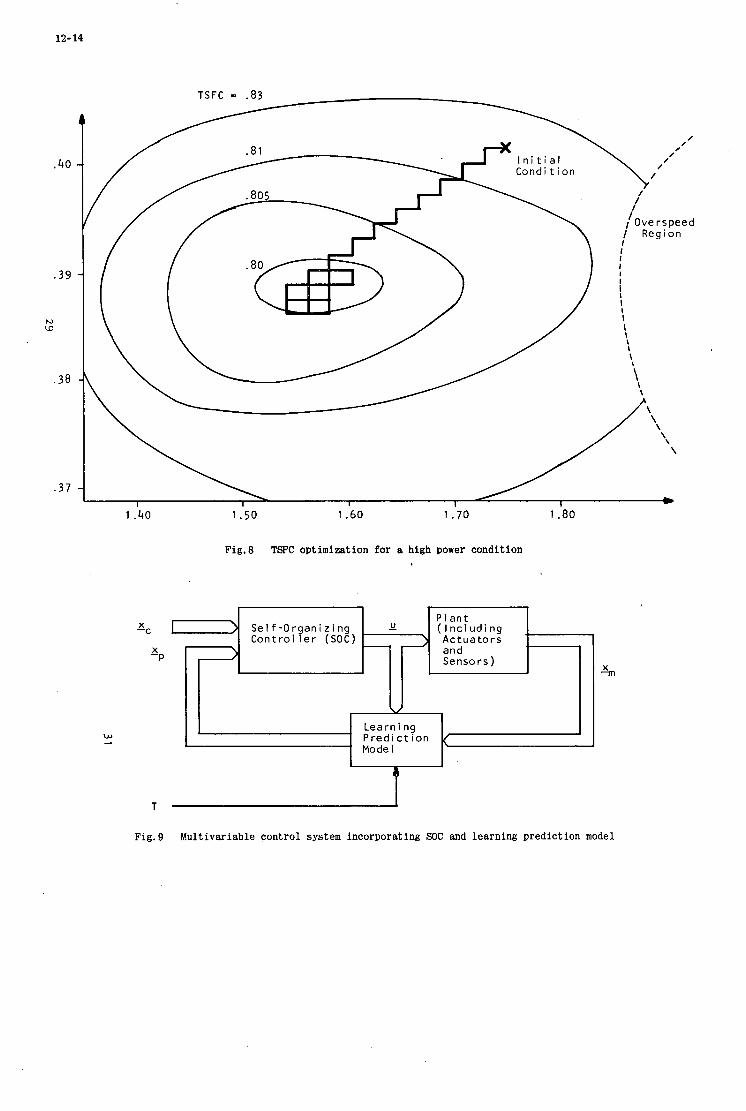
12- 14
X -C
X -P
Fig.8 TSFC optimization for a high power condition
Fig.9 Multivariable control system incorporating SOC and learning prediction model
13
HIGH INTEGRITY DIGITAL FLIGHT CONTROL
by
J. F. Meredi th and K. A. Helps
Smiths Indus t r ies Limited, Aviation Division, Cheltenham, England.

13

13-1
HIGH INTEGRITY DIGITAL FLIGHT CONTROL
J. F. Meredi th and K. A. Helps
1. INTRODUCTION
The t r end f r o m analogue toward digital implementat ion of flight cont ro l s y s t e m s i s being caused by s e v e r a l f a c t o r s , some concerned with the rapidly developing digital technology and o the r s which r e l a t e t o ce r t a in inherent difficult ies in providing high integri ty operat ion with analogue s y s t e m s . One of the m o r e impor tan t of this l a t t e r c l a s s i s the consequence of the var ia t ion in per formance of nominally ident ical p ieces of equipment. Thus in a mult iplex s y s t e m each analogue sub-channel has a ce r t a in des ign t r ans fe r function which is approximate ly achieved in prac t ice by the u s e of one o r m o r e ampl i f ie rs of finite gain together with var ious smoothing and s tab i l i s ing f i l t e r s . var ia t ion of component values within the i r to le rance band. These d iscrepancies in t r ans fe r function m a y affect the s igna ls which a r e being p r o c e s s e d , in a way which is indis t inguishable f r o m ce r t a in fault conditions. d i screpancy above which the s y s t e m de tec ts a fault mus t be made higher than the leve l which may leg i t imate ly be caused by component value var ia t ions . The s y s t e m in tegr i ty is thus compromised because i t a l lows the ex is tence of a s e t of fault conditions which cannot be de tec ted .
Discrepancies between sub-channels will a r i s e because of the legi t imate
In prac t ice this means that the leve l of the threshold of s ignal
F u r t h e r m o r e the effective use of automatic tes t ing p r o c e d u r e s , which with the increas ing complexi ty of a i r c r a f t control s y s t e m s , a r e of considerable benefit in t e r m s of reduced t u r n - round t ime and i n c r e a s e d availabil i ty, is made m o r e difficult by the p r e s e n c e of the analogue s y s t e m to le rances .
It is upon such problems as these that a digital high integri ty s y s t e m may make a s ignif icant impact .
2. INTEGRITY
If the pilot is r e g a r d e d a s the m a n a g e r of the a i r c r a f t , then serv ing him he has var ious spec ia l uni ts which a r e control l ing par t icu lar a spec t s of the aeroplane per formance . He i s providing the command to engage this par t icu lar cont ro l mode o r to p e r f o r m that pa r t i cu la r manoeuvre and is then delegat ing the responsibi l i ty to the par t icu lar unit t o co r rec t ly c a r r y out the operat ion.
Now some cont ro l modes a r e m o r e c r i t i ca l t o the immedia te sa fe ty of the a i r c r a f t than a r e o the r s . effective r e m e d i a l ac t ion a f t e r a s y s t e m fa i lure has been de tec ted , i s in some c i r c u m s t a n c e s z e r o and in all c a s e s l e s s than a few seconds . t o such a c r i t i ca l m a n o e u v r e h e m u s t make the dec is ion that the probabi l i ty of s y s t e m fa i lure is acceptab le low.
Pa r t i cu la r ly in the landing manoeuvre the t ime avai lable for the c r e w to take any
Thus before the pilot c a n commi t the aeroplane
T'he evidence which al lows him t o make this dec is ion a r i s e s in two s t ages . F i r s t l y , the des ign of the equipment and the quality of the components used have a s s u r e d h i m , o r his r ep resen ta t ive , tha t provided the equipment s t a r t s f r o m a defined s t a t e , then the probability of f a i lu re within s o m e specif ied t ime in t e rva l i s l e s s than s o m e acceptable f igure . This evidence i s c l ea r ly not dependent upon any pa r t i cu la r f l ight and so secondly he m u s t be informed of the c u r r e n t s t a t e of the equipment , that is whether i t i s in the des ign s t a t e for which the a p r i o r i probabi l i ty f igure m a y be appl ied, o r whether ce r t a in faults o r defec ts have been detected which will lead to a higher probabi l i ty of fa i lure in subsequent u s e .
The a t t r i bu te of the s y s t e m which i s respons ib le fo r that d e g r e e of self ana lys i s and information t r ans fe r which al lows the s y s t e m to warn the pilot of any malfunction, e i the r total o r incipient, i s the s y s t e m integrity. flight tes t ing and in p a r t by the s y s t e m self examinat ion and warning c a r r i e d out during the flight.
The to ta l s y s t e m integri ty i s achieved in p a r t by p r e -
A f igure of m e r i t fo r a s y s t e m c la iming a level of integir ty can be provided by the following rat io: -
Conditional Probabi l i ty of Sys tem fa i lu re given that no warning has o c c u r r e d Probabi l i ty of Sys tem fa i lu re I =
This i s unity f o r a s y s t e m with no integri ty pre tens ions and will tend to z e r o a s the integri ty of the s y s t e m i n c r e a s e s . sufficient deg ree of i n t e rna l se l f -checking to provide a warning of any s y s t e m defect which could r e s u l t in s y s t e m fa i lu re .
Thus in o r d e r t o achieve a high integri ty the s y s t e m mus t be designed to have a
3 . DIGITAL SYSTEMS
In the achievement of this a i m digi ta l s y s t e m s provide both advantages and p rob lems . To make best u se of the advantages , which de r ive principally f r o m the d i s c r e t e na tu re of in format ion within a digi ta l machine and the consequently finite probabili ty of equality between two numbers ; while a t the s a m e t ime minimis ing the p rob lems , which involve the l a r g e numbers of definable s t a t e s within a computer and the consequent imposs ib i l i ty of complete tes t ing in any reasonable t ime per iod, i t i s n e c e s s a r y to provide a s y s t e m s t r u c t u r e which allows effective checking of the p r o g r a m m e being pe r fo rmed .
Consider a multiplexed s y s t e m in which the individual computers a r e per forming the sub- channel functions. occurance ; in t ime because the independence of the compute r s will demand s e p a r a t e clocks and in magnitude because the s e n s o r information will in gene ra l be sampled a t sl ightly different t i m e s . In consequence the t a sk of checking between these independent sub-channels is m a d e m o r e difficult and l e s s effective than i s poss ib le by cons t ra in ing them to ope ra t e in ways desc r ibed below.
The outputs of the sub-channels will dif fer both in magnitude and t ime of
F i r s t l y a s e t of independent sub-channel compute r s can be held in a sufficient s t a t e of synchronisa t ion to allow the f r e e exchange of data between them, while s t i l l re ta ining independent c locks. of communication. F ig . 1 shows the p r e f e r r e d a r r angemen t . Data to be t r a n s f e r r e d is placed by the sending computer in a f ron t i e r s t o r e , which i s pa r t i cu la r to information t r a n s f e r in this direct ion between these two sub-channels , f r o m this s t o r e i t may be picked up by the intended recipient a t a t ime de te rmined by i t ' s own p r o g r a m m e and clock. Toeenable this f o r m of t r a n s f e r the deg ree of synchronisa t ion requi red i s only that n e c e s s a r y to e n s u r e that the c o r r e c t data i s taken up without too g r e a t a penalty in t ime ; that is individual sub-channel compute r s need only be synchronised to the extent of being within one o r two word cyc les of each o the r .
The r equ i r emen t of sub-channel independence prohibits the use of i n t e r rup t a s a means
This da t a exchange p r o c e s s which is enabled by the synchronisa t ion between the compute r s can i tself be used in o r d e r to effect the synchronisa t ion p r o c e s s . t ime of r ece ip t of a t iming s ignal f r o m each of the o ther si ib-channels with the t ime at which it i s s u e s i t s t iming s ignal to the o the r s . Given this information each sub-channel can independently make a n a s s e s s m e n t of i t s t iming relat ive to that of the o the r s and take a n appropr i a t e length path through a de lay routine. c a r r i e d out once per cycle of the ma in computer p r o g r a m m e .
Each computer can compare the
This synchronisa t ion p r o c e s s can be an en t i r e ly sof tware routine and
The data exchange paths provide a phys ica l l ink between the individual sub-channels ; c l ea r ly the i r unidirect ional na tu re is e s sen t i a l if the possibil i ty of common faul ts is to be avoided. of f i b re optic techniques m a y provide the u l t imate deg ree of isolation between the sub-channels but t he i r use i s by no means e s sen t i a l .
The u s e
Using the facil i ty fo r data exchange between the individual sub-channels the s y s t e m can be opera ted in such a way that each sub-channel is provided with ident ical r a t h e r than s i m i l a r s e n s o r data . digi ta l numbers can be exchanged a c r o s s the f ron t i e r s s o that each sub-channel i s in posses s ion of a n ident ical s e t of s enso r da t a . If then each produces a n amalgamated r e s u l t by the s a m e sof tware p rocess then the calculations can begin in each sub-channel with ident ical numbers and consequently the numbers a t any subsequent stage of the calculations will be ident ical . This means that subsequent c r o s s checking between the sub-channels , which is aga in enabled by the data exchange l inks, can take place a t any des i r ed s tage and the non identity of the s ignals f r o m these sepa ra t e sub-channels is sufficient evidence f o r the ex is tence of a faul t . S imi l a r ly if a computer fault leads to a route change the subsequent l o s s of synchron i sm gives indication of the occur rence .
If each sub-channel inputs s e n s o r data through the A / D in t e r f aces (Fig. 2 ) then the resul t ing
We have the re fo re the possibil i ty of a s e t of independent sub-channels each of which is continuously forming a n a s s e s s m e n t of the s y s t e m s t a t e by s e n s o r ana lys i s , by compar i son
13-3
between the computers f o r both magnitude and t ime d i sc repanc ie s . warning the pilot if i t s e e s any d iscrepancy and f r o m the warnings the pilot i s able to decide whether the safe ty of the a i r c r a f t can be en t rus ted to the equipment.
Any sub-channel is capable of
In o r d e r to m a k e such a scheme successfu l , the p r o g r a m m e s of the individual sub-channels m u s t be m a d e to include a subs tan t ia l body of checking rout ines . the c o r r e c t functioning of the p r o g r a m which is being pe r fo rmed in the c u r r e n t c i r c u m s t a n c e but a l s o that which wil l be p e r f o r m e d in the event of a fault occur r ing e l sewhere in the s y s t e m . m a n n e r la ten t fau l t s in the s y s t e m a r e exposed.
This checking m u s t t e s t not only
In this
4. LATENT COMPUTER FAULTS
The concept of a latent fault i s e s sen t i a l to a n apprec ia t ion of the p rac t i ca l difficult ies of achieving high in tegr i ty . the s y s t e m until another fault occu r s . but if i t does then the s y s t e m will behave a s though it w e r e undergoing a double fault . t o cope with s imultaneous faults is something that should be minimized; i t cannot be avoided a l toge ther by a non-dis t r ibuted computer because a s ingle ha rdware fau l t will often mani fes t itself as a mult iple opera t iona l fault .
A latent fault in a s y s t e m is a fault tha t h a s no effect on the outputs of
The need When another fault occurs . i t m a y o r m a y not r e v e a l i tself ,
The t a s k of minimizing latent faults m a y be s e e n as the t a sk of ensur ing that contingency plans incorpora ted i n the p r o g r a m c a n be achieved by every computer which r e m a i n s operat ional . Such contingency plans a r e :
(1) col leagues.
(2)
( 3 )
(4) autolanding) .
Isolat ing the s y s t e m f r o m a computer that is reckoned to be faulty by i t s
Ignoring a s e n s o r that i s a g r e e d by the computers to be faulty.
Giving pilot warnings (e. g. of s y s t e m s ta te ) .
Obeying a p r o g r a m assoc ia t ed with a subsequent and c r i t i c a l f l ight t a sk (e. g.
The impor tance of detect ing la ten t fau l t s i s par t icu lar ly acute in duplex s y s t e m s which have a r e v e r s i o n t o a s imple non-digital cont ro l in the event of unexpected computer d i s a g r e e m e n t , cut out being effected whenever e i the r computer de tec ts a d i screpancy . in such a s y s t e m could undermine i t s integrity. But la ten t faults can s t i l l be damaging to both t r ip lex and moni tored duplex s y s t e m s . la ten t fau l t s , it will be aggrava ted by long per iods of switch off.
A s ingle la ten t fault
However acute o r mi ld the lo s s of integri ty caused by
5. CONVENTIONAL COMPUTER CHECKS
T h e r e are wel l es tab l i shed techniques for ca r ry ing out checksum, a r i t hme t i c and logic t e s t s , and fo r re la t ing these t e s t s t o the computer ' s s t ruc tu re to avoid excess ive duplication of checking or untested a r e a s of hardware . Because of the l a rge proport ion of ha rdware fau l t s which a r e sufficiently context dependent t o avoid being detected in this way, one i s forced to cons ider other methods fo r reducing the number of possible la ten t fau l t s . (It should be noted i n pass ing that any number sens i t ive o r context sens i t ive fault i. e . any fault which might s l i p through the m e s h of a well devised conventional check out s c h e m e , m a y be thought of as a la ten t fault) .
L
An impor tan t tac t ic fo r achieving the s t ra tegy of minimiz ing possible la ten t fau l t s , is t o p r o g r a m the computers t o run frequent ly and r egu la r ly through impor tan t la ten t p r o g r a m zones.
6. SYSTEMATIC AD HOC CHECKING
It i s impor tan t t o check that each c r i t i ca l p r o g r a m branch is in fac t capable of per forming i t s function co r rec t ly . F ig . 3 disp lays a s imple technique f o r doing this and the p rogramming pa t te rn shown is one which o c c u r s repeatedly in a high in tegr i ty digital flight cont ro l s y s t e m that does not ignore the possibi l i ty of la ten t faults. accompanying fau l t ana lys i s , a t the super f ic ia l l eve l where number sens i t ive fau l t s a r e ignored, a possible la ten t fau l t can be removed a t the expense of ex t r a p r o g r a m and t ime.(This is a n a r e a where h a r d w a r e rea l iza t ion of the s a m e a d hoc checking pr inciple m a y prove a n effective method). The contingency exit r e f e r r e d to in fig. 3 would normal ly lead to a to ta l o r pa r t i a l channel cut out in the c a s e of a duplex r e v e r s i o n a r y o r monitored duplex s y s t e m . In the case of a t r ip lex s y s t e m the p rogramming tends to be m o r e interwoven because of the th ree way compar isons and m a j o r i t y dec is ions . But the s a m e pr inciple appl ies in gene ra l , that a t each key p r o g r a m branch to emergency ac t ion , i f the e m e r g e n c y is not p r e s e n t the p r o g r a m s imula t e s a n emergency and s e t s a t e s t ind ica tor , and the branch i s passed again, leading th i s t ime to the beginning of the emergency ac t ion , which in t u r n will be abor ted because the t e s t indicator has been se t .
As will be s e e n f r o m the f igure and the
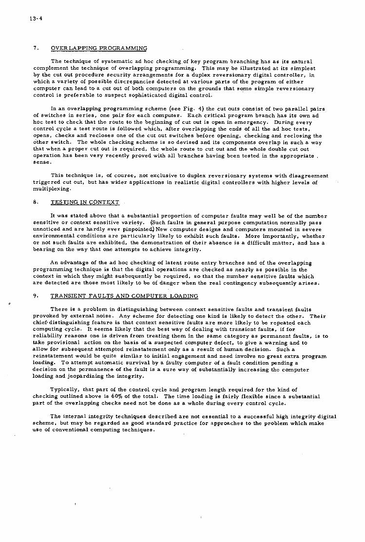
13-4
7. OVERLAPPING PROGRAMMING
The technique of s y s t e m a t i c a d hoc checking of key p r o g r a m branching has as i t s na tu ra l complement the technique of overlapping p rogramming . This may be i l lus t ra ted a t i t s s imp les t by the cut out procedure secu r i ty a r r a n g e m e n t s fo r a duplex r e v e r s i o n a r y d ig i ta l con t ro l l e r , in which a va r i e ty of possible d i s c r e p a n c i e s detected a t var ious p a r t s of the p r o g r a m of e i the r computer can lead to a cut out of both computers on the grounds that s o m e s imple r e v e r s i o n a r y cont ro l is preferab le to suspec t sophis t icated digital control .
In a n overlapping p rogramming scheme (see F ig . 4) the cut outs cons i s t of two pa ra l l e l pairs of switches in s e r i e s . one pa i r fo r each computer . hoc t e s t to check that the route to the beginning of cu t out is open in emergency . cont ro l cycle a t e s t rou te is followed which, a f t e r overlapping the ends of all the a d hoc t e s t s , opens, checks and r ec loses one of the cu t out switches before opening, checking and rec los ing the o ther switch. The whole checking scheme i s so devised and i t s components o v e r l a p in such a way that when a proper cut out i s r equ i r ed , the whole route to cut out and the whole double cut out operat ion has been v e r y recent ly proved with a l l b ranches having been tes ted in the appropr ia te . sense .
E a c h c r i t i ca l p r o g r a m branch has i t s own a d During e v e r y
This technique is, of cour se , not exclusive to duplex r e v e r s i o n a r y s y s t e m s with d i s a g r e e m e n t t r i gge red cut out, but has wider appl icat ions in r ea l i s t i c digital con t ro l l e r s with higher leve ls of multiplexing.
8. TESTING IN CONTEXT .
It was s ta ted above that a subs tan t ia l proport ion of computer fau l t s m a y wel l be of the number sens i t ive o r context sens i t ive var ie ty . (Such fau l t s in gene ra l purpose computation normal ly p a s s unnoticed and a r e hard ly e v e r pinpointed) New computer des igns and computers mounted in s e v e r e envi ronmenta l conditions a r e par t icu lar ly likely to exhibit such faults. More impor tan t ly , whether o r not such fau l t s are exhibited, the demonst ra t ion of the i r absence is a difficult m a t t e r , and has a bear ing on the way that one a t tempts to achieve integrity.
An advantage of the a d hoc checking of la ten t route en t ry branches and of the overlapping p rogramming technique i s that the digital operat ions a r e checked as near ly as possible in the context in which they might susbequent ly be requi red , so that the number sens i t ive faults which a r e detected are those m o s t l ikely to be of danger when the r e a l contingency subsequent ly a r i s e s .
9. TRANSIENT FAULTS AND COMPUTER LOADING
T h e r e i s a p rob lem in dis t inguishing between context sens i t ive fau l t s and t r ans i en t fau l t s provoked by ex terna l noise . Any scheme for detect ing one kind is l ikely to de t ec t the o ther . chieft dis t inguishing f ea tu re is that context sens i t ive fau l t s a r e m o r e l ikely to be repea ted e a c h computing cycle . It s e e m s likely that the bes t way of deal ing with t r ans i en t fau l t s , if f o r reliabil i ty r e a s o n s one is dr iven f r o m t rea t ing them in the s a m e ca tegory as pe rmanen t fau l t s , is to take provis ional act ion on the bas i s of a suspec ted compute r defect , t o give a warning and to allow fo r subsequent a t tempted re ins ta tement only as a r e su l t of human decis ion. re ins ta tement would be quite s i m i l a r t o in i t ia l engagement and need involve no g r e a t e x t r a p r o g r a m loading. dec is ion on the pe rmanence of the fault is a s u r e way of substant ia l ly increas ing the computer loading and jeopardizing the integrity.
0
T h e i r
Such a
T o a t tempt automatic su rv iva l by a faulty computer of a fault condition pending a
Typical ly , that p a r t of the cont ro l cycle and p r o g r a m length r e q u i r e d f o r the kind of checking outlined above is 60% of the total . p a r t of the overlapping checks need not be done as a whole dur ing e v e r y cont ro l cycle .
The t ime loading is f a i r ly flexible s ince a subs tan t ia l
The in t e rna l integri ty techniques d e s c r i b e d a r e not e s sen t i a l to a success fu l high in tegr i ty digital s c h e m e , but m a y be r e g a r d e d as good s tandard prac t ice fo r approaches to the p rob lem which make u s e of conventional computing techniques.
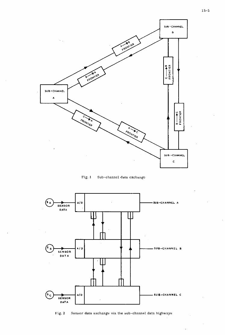
1 3 - 5
SUB -CHANNEL
~
SUB -CHANNEL.
1L
I
- 1
SUB -CHANNEL
C
Fig. 1 Sub-channel data exchange
L v A I D
SENSOR DATA
L1 1 L "
r i I
SENSOR
' D A T A
A I D
t9 Fig. 2 Sensor data exchange via the sub-channel data highways
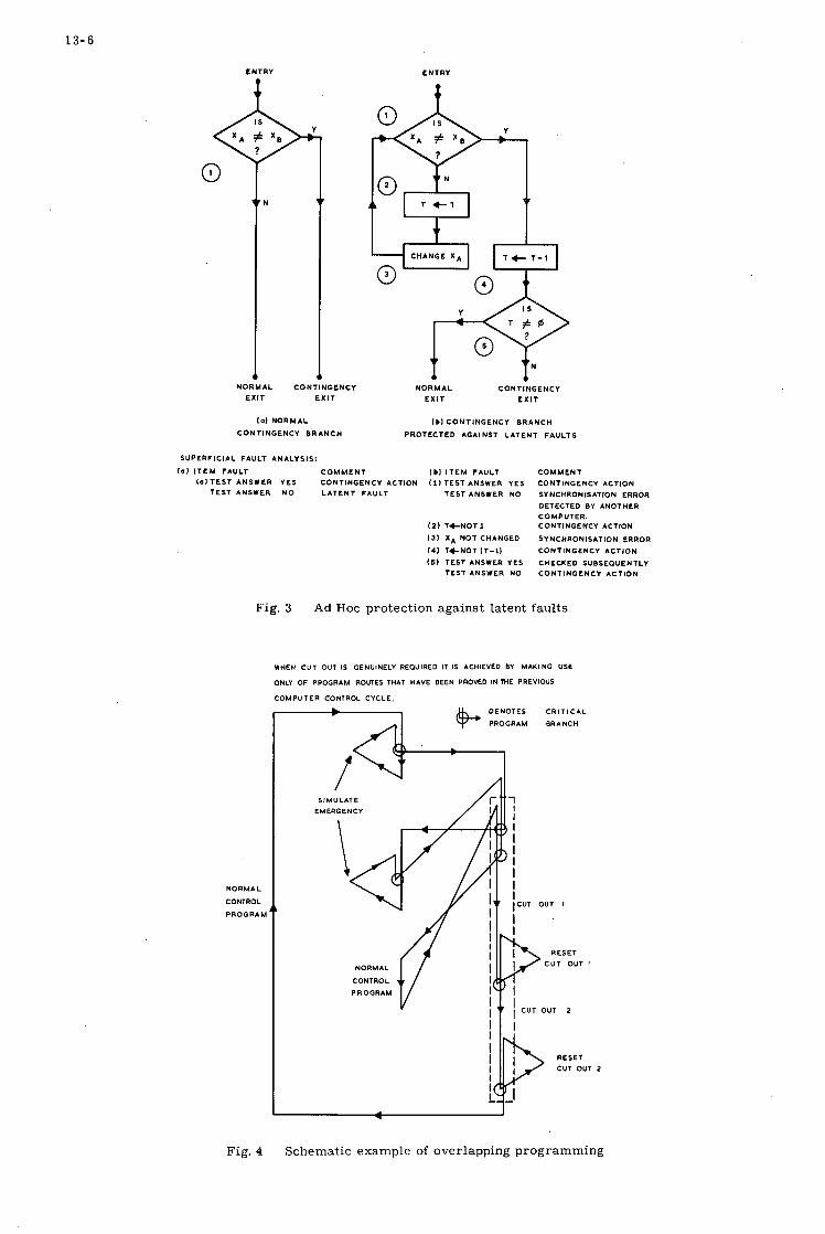
13-6
ENTRY +
l a1 NORMAL
CONTINGENCY BRANCH
SUPERFICIAL FAULT ANALYSIS:
ENTRY +
YJ T 4- 1-1
NORMAL CONTINGENCY EXIT E X I T
I b l CONTINGENCY BRANCH
PROTECTED AGAINST LATENT FAULTS
l b l I T E M FAULT COMMENT l a1 I T E M FAULT COMMENT I a I T E S T ANSWER YES CONTINGENCY ACTION 111 TEST ANSWER YES
TEST ANSWER NO TEST ANSWER N O LATENT FAULT
121 14-NOT1
I31 X A NOT CHANGED
I41 T+NOT IT-11
(51 TEST ANSWER YES TEST ANSWER NO
CONTINGENCY ACTION SYNCHRONISATION ERROR
DETECTED 0Y ANOTHER COMPUTER. CONTINGENCY ACTION
SYNCHRONISATION ERROR CONTINGENCY ACTION
CHECKED SUBSEQUENTLY CONTINGENCY ACTION
NORMAL
CONTROL
PROGRAh
Fig. 4
Fig. 3 Ad Hoc protect ion aga ins t latent fau l t s
WHEN CUT OUT IS GENUINELY REQUIRED IT IS ACHIEVED BY MAKING USE
ONLY OF PROGRAM ROUTES THAT HAVE BEEN PROVED IN THE PREVIOUS
COMPUTER CONTROC CYCLE.
S I MU LAT E
CR I T 1 CAL
BRANCH
CUT OUT I
RESET CUT OUT I
CUT OUT 2
RESET CUT OUT 2
Schematic example of overlapping p rogramming

14
REALISATION OF NONLINEAR CONTROL METHODS WITH DIGITAL CONTROL U N I T S
b y
W.Sobot ta and H.J.Eerger

14
S u m m a r y
F i r s t l y , some c h a r a c t e r i s t i c d i sadvantages o f l i n e a r c o n t r o l methods used i n convent iona l c o n t r o l u n i t s f o r a t t i t u d e s t a b i l i z a t i o n of V T O L - A i r c r a f t w i l l be d iscussed .
I n o r d e r t o avoid t h e s e d isadvantages , d i f f e r e n t non- l inear c o n t r o l methods have been developed.
A s p e c i a l non- l inear SAS w a s s u c c e s s f u l l y t e s t e d on t h e " f l y i n g bedstead" SG 1 2 6 2 of VFW, Bremen, i n o r d e r t o o b t a i n informat ion on t h e improvement of handl ing q u a l i t i e s i n V T O L - A i r c r a f t . According h e r e t o , it i s advantageous when t h e response t i m e i s about p ropor t iona l t o t h e p i l o t commands. This does not on ly s i g n i f y a more r e p i d response of t h e aircraft at s m a l l commands, however, a b e t t e r r e d u c t i n g t h e i n f l u e n c e s of d i s tu rbances , too .
'
A d i g i t a l c o n t r o l u n i t was developed which at given sampling t i m e and g iven maximum c o n t r o l power y i e l d s a response t i m e p ropor t iona l t o t h e command about greater commands. About smaller commands response t i m e i s cons t an t .
By choosing t h i s proper c o n t r o l c h a r a c t e r i s t i c t h e f a t i g u e of t h e engine d e l i v e r i n g c o n t r o l power can be made as s m a l l as poss ib l e .
The c o n t r o l a lgo r i thms have been combined i n such manner t h a t bo th t h e commands and t h e d i s tu rbances are optimized. The c o n t r o l u n i t s are d i s t i n g u i s h e d by t h e r e l a t i v e simple s e t u p wi th few d i g i t a l computer elements.
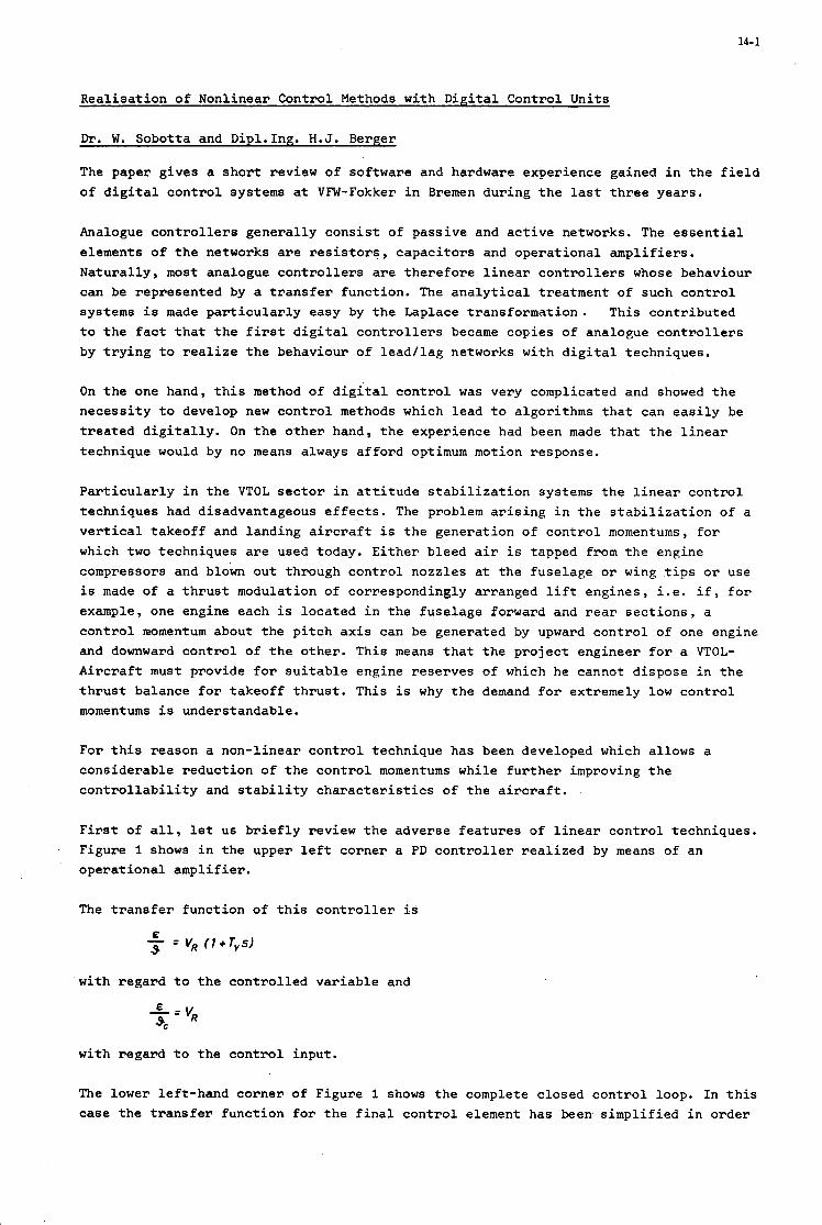
14-1
R e a l i s a t i o n of Nonlinear Cont ro l Methods wi th D i g i t a l Cont ro l Uni t s
Dr. W. Sobot ta and Dipl.Ing. H . J . Berger
The paper g ives a s h o r t review of sof tware and hardware exper ience gained i n t h e f i e l d o f d i g i t a l c o n t r o l systems at VFW-Fokker i n Bremen dur ing t h e las t t h r e e years .
Analogue controllers g e n e r a l l y c o n s i s t o f pas s ive and a c t i v e networks. The e s s e n t i a l elements of t h e networks are r e s i s t o r s , c a p a c i t o r s and o p e r a t i o n a l a m p l i f i e r s . Na tu ra l ly , most analogue c o n t r o l l e r s are t h e r e f o r e l i n e a r c o n t r o l l e r s whose behaviour can be r ep resen ted by a t r a n s f e r func t ion . The a n a l y t i c a l t r ea tmen t of such c o n t r o l systems i s made p a r t i c u l a r l y easy by t h e Laplace t r a n s f o r m a t i o n . T h i s con t r ibu ted t o t h e fact t h a t t h e first d i g i t a l c o n t r o l l e r s became cop ies o f analogue c o n t r o l l e r s by t r y i n g t o r e a l i z e t h e behaviour o f l e a d / l a g networks wi th d i g i t a l t echniques .
On t h e one hand, t h i s method of d i g i t a l c o n t r o l w a s very complicated and showed t h e n e c e s s i t y t o develop new c o n t r o l methods which l e a d t o a lgor i thms t h a t can e a s i l y be t r e a t e d d i g i t a l l y . On t h e o t h e r hand, t h e exper ience had been made t h a t t h e l i n e a r technique would by no means always a f f o r d optimum motion response.
P a r t i c u l a r l y i n t h e VTOL s e c t o r i n a t t i t u d e s t a b i l i z a t i o n systems t h e l i n e a r c o n t r o l techniques had disadvantageous effects. The problem a r i s i n g i n t h e s t a b i l i z a t i o n of a v e r t i c a l t a k e o f f and l and ing aircraft i s t h e gene ra t ion o f c o n t r o l momentums, f o r which two techniques are used today. E i t h e r b leed a i r i s tapped from t h e engine compressors and blown o u t through c o n t r o l nozz le s a t t h e f u s e l a g e or wing t i p s o r use i s made of a t h r u s t modulation of cor respondingly a r ranged l i f t eng ines , i . e . i f , f o r example, one engine each is l o c a t e d i n t h e f u s e l a g e forward and rear s e c t i o n s , a c o n t r o l momentum about t h e p i t c h a x i s can be genera ted by upward c o n t r o l of one engine and downward c o n t r o l of t h e o the r . This means t h a t t h e p r o j e c t eng inee r f o r a VTOL- Aircraft must provide f o r s u i t a b l e engine r e s e r v e s of which he cannot d i spose i n t h e t h r u s t ba lance for t a k e o f f t h r u s t . This i s why the demand fo r extremely low c o n t r o l momentums i s understandable.
For t h i s reason a non- l inea r c o n t r o l technique has been developed which a l lows a cons ide rab le r educ t ion o f t h e c o n t r o l momentums while f u r t h e r improving t h e c o n t r o l l a b i l i t y and s t a b i l i t y c h a r a c t e r i s t i c s of t h e aircraft .
F i r s t of a l l , l e t us b r i e f l y review t h e adve r se f e a t u r e s of l i n e a r c o n t r o l techniques . Figure 1 shows i n t h e upper l e f t co rne r a PD c o n t r o l l e r r e a l i z e d by means of an o p e r a t i o n a l a m p l i f i e r .
The t r a n s f e r f u n c t i o n of t h i s c o n t r o l l e r is
with r ega rd t o t h e c o n t r o l l e d v a r i a b l e and
wi th r ega rd t o t h e c o n t r o l
The lower le f t -hand c o r n e r case t h e t r a n s f e r f u n c t i o n
inpu t .
o f F igure 1 shows t h e complete c losed c o n t r o l loop. I n t h i s for t h e f i n a l c o n t r o l element has been s i m p l i f i e d i n o r d e r
14-2
t o f ac i l i t a t e t h e a n a l y s i s of t h e problem.
On t h e r i g h t t h e t r a n s i e n t response of t h e aircraft a t t i t u d e on s t e p s t i c k commands from t h e p i l o t are p l o t t e d versus t i m e . This f i g u r e i l l u s t r a t e s t h e very c h a r a c t e r i s t i c feature o f a l l l inear c o n t r o l techniques , namely t h a t t h e t r a n s i t i o n t i m e tg5 i s independent from t h e amount of t h e commanded a t t i t u d e changes. The f i r s t t i m e w e experienced t h e disadvantageous effect of t h i s phenomenon on f l i g h t c o n t r o l c h a r a c t e r i s t i c s was dur ing f l i g h t tests when w e wanted t o determine i n f l i g h t t h e most favourable response times.
Whenever t h e p i l o t considered t h e response time fo r small a t t i t u d e changes t o be c o r r e c t , t h e y were t o o r a p i d f o r l a r g e a t t i t u d e changes; whenever t h e y were a l l r i g h t for l a r g e a t t i t u d e changes, t h e p i l o t considered them t o be t o o slow i n t h e case o f small changes. So what t h e p i l o t wanted was a progress ive a l t e r a t i o n of t h e response t i m e p r o p o r t i o n a l t o t h e commanded a t t i t u d e changes.
The low s t a b i l i t y r e s e r v e represented t h e second disadvantage. I f , fo r i n s t a n c e , t h e c o n t r o l momentums are l i m i t e d t o 0.2 r a d / s e c 2 corresponding t o a maximum a n g u l a r a c c e l e r a t i o n i n t h e s tandard ized form used, t h e n t h e c o n t r o l l e r o p e r a t e s for major commanded a t t i t u d e changes l i k e an on-off c o n t r o l l e r , i .e . it i s a t i t s s t o p s fo r most of t h e t ime (F igure 2 ) . If t h e c o n t r o l l e r i s opt imized f o r t h e l i n e a r r a n g e , i n c r e a s i n g l y l a r g e r command q u a n t i t i e s r e s u l t i n h e a v i e r overshoot c o n d i t i o n s . This process can be shown t o t h e c o n t r o l engineer very c l e a r l y i n t h e phase plane. I n t h e phase plane t h e change of t h e c o n t r o l l e d v a r i a b l e i n t h i s case, t h e angular v e l o c i t y o f t h e aircraft i s p l o t t e d versus t h e c o n t r o l l e d v a r i a b l e , i .e . t h e a i rc raf t a t t i t u d e . If w e d e f l e c t t h e system t o 1 r a d a t t i t u d e displacement and l e a v e it t o t h e c o n t r o l l e r , t h e t r a j e c t o r y d e s c r i b i n g t h e s t a t e of t h e system fol lows a parabola which i s given by t h e maximum c o n t r o l momentum i n t h e r e l a t i o n t o t h e momentum o f i n e r t i a . During t h i s time t h e c o n t r o l l e r i s a t t h e s t o p and a c c e l e r a t e s t h e system. The l i n e a r range of t h e c o n t r o l l e r i s descr ibed by t h e p l o t t e d s t r a i g h t l i n e . This range i s passed very r a p i d l y and t h e n t h e c o n t r o l l e r d e c e l e r a t e s t h e system, a process which r e s u l t s i n cons iderable over- shoot ing. From t h i s p o i n t t h e process r e p e a t s i t s e l f u n t i l t h e system se t t l e s t o a s t e a d y state. The upper le f t -hand corner of Figure 2 shows t h e percentage overshoot a g a i n s t t h e command q u a n t i t y a t d i f f e r e n t momentum l i m i t a t i o n s . A t p resent we o p e r a t e i n t h e range of Smax = 0 . 6 r a d / s e c . However, it w i l l be shown i n t h e fo l lowing how t o g e t i n t o s m a l l e r ranges without having t o put up with an overshoot o f 50 p e r c e n t .
2
The t h i r d disadvantage of t h e l i n e a r technique was t h a t by f i x i n g t h e response t imes, t h e c losed loop ga in was f i r m l y f i x e d , t o o , and wi th it t h e r e s i d u a l e r r o r of t h e system i n t h e case of cons tan t d i s t u r b a n c e momentums. I n t h i s case t h e r e s i d u a l error is equal t o t h e d i s t u r b a n c e d iv ided by t h e closed-loop gain.
I n o r d e r t o f i n d o u t how t h e s e disadvantages can be removed by means of a non-l inear c o n t r o l technique , f i r s t a paramet r ic s tudy w a s c a r r i e d o u t . The r e s u l t of t h i s s tudy i s shown i n Fig. 3. I n t h i s case, t h e c o n t r o l parameters TV and V K of t h e PD c o n t r o l loop shown i n Fig. 1 were var ied over wide ranges and t h e i r e f f e c t on t h e form of t h e t r a n s i e n t response f u n c t i o n w a s observed. The t r a n s i e n t response i s descr ibed fo r a s p e c i f i c V K and TV each. We r e a l i z e t h a t t h e form of t h e t r a n s i e n t f u n c t i o n does not change a long c e r t a i n hyperbolas whereas t h e t r a n s i t i o n times do. In o t h e r words, r e l a t i v e damping of t h e system remains c o n s t a n t a long t h i s l i n e , w h i l e t h e t r a n s i t i o n t i m e i n c r e a s e s w i t h a decreas ing closed-loop ga in V K and a growing l e a d t i m e c o n s t a n t TV. Higher response times r e q u i r e lower c o n t r o l momentums. So t h i s r e s u l t proves how t h e c o n t r o l l e r parameters must be changed as a f u n c t i o n of t h e error i n o r d e r t o o b t a i n
14-3
progressive response times with acckptable transient behaviour.
With reference to the analogue controller this means that the resistor or capacitors forming the external networks of the operational amplifier must be changed in relation to the error. In the present case we have changed the input resistors of the operational amplifierlinearly with the error, so that actually a hyperbolic dependence TV and VK resulted. This correlation led to the non-linear differential equation for the closed loop behaviour.
+ RzC, 5 R2 9 = 0 + R,+R'I x I
The variation of the resistors as a function of the error was realized by means of special multipliers, which, of course, made the controller considerably more complicated.
Fig. 5 shows the effect achieved. In the top right-hand corner it can be seen how the area in which the final control element operates in the linear range is bent over towards the x-axis. As the center line of this area represents the 0' isoclinic line it is seen how, by means of the parameter variations, the maximum rate of attitude change cannot be increased, even in the case of larger attitude changes, as opposed to linear control techniques. The difference is also illustrated by the trajectories in the two left-hand diagrams. Whereas the maximum velocities in the linear system (bottom) constantly increase, they remain constant, even with increasing attitude changes, for the non-linear procedure. The trajectories fall within the linear operating range of the final control element as defined by the momentum limitations and therefore overshoot conditions are not possible any more. In the bottom right-hand corner of Fig. 5 the transient functions of the attirud; angle are shown for different step commands and from this it can. clearly be seen how the transition time changes between 0.5 to 1.5 seconds. Flight testing of the controller was carried out on the basis of these settings. Pilot evaluation was excellent.
Encouraged by the successful tests, we then attempted to actually realize the non-linear behaviour in a digital controller in order to arrive performance and complexity comparison. In doing this we have tried not to copy the analogue controller but to find out the most suitable method for the digital system.
The solution is shown in Fig. 6 in the form of a block diagram. The command signal is supplied to a digital command computer. The latter computes a control sequence in such a way thzt the process falls in time - suboptimally with the command signal value, in a similar way to the analogue controller, without overshoot or steady-state error. The computer must be informed of the state of the system to be controlled at the time of command signal lock-on. The effect of disturbances acting upon the controlled-system is determined by comparing the state variables of the controlled system with those of a model system not affected by the disturbance. The resulting difference signals are passed to a special digital disturbance computer applying to the controlled process additional singals
8,
En which compensate the influence of the disturbances.
The algorithm of the command signal computer has to take into account the characteristic of the controlled system if the command behaviour is to correspond to the requirements indicated. In developing the calculation rule, the difference equation of the system to be controlled forms a good basis. Provided the controlled-system input is constant within specified intervals, the sampling intervals, then

14-4
where ~f [kTJ i t h e n-dim ion 1 s ta te v e c t o r of t h e con t ro l1 d system a t t h e t i m e kT,
4 a n x n ma t r ix , h a n x 1 matrix. @ and depend on t h e system parameters and t h e sampling t i m e selected.
When t h e system i s i n t h e i n i t i a l s ta te xo a t t = 0 , t h e s o l u t i o n i s found success ive ly from equa t ion (1).
-
Provided t h e c o n t r o l l e r ou tput i s not res t r ic ted , a system of n-th o r d e r can be brought i n n-s teps i n t o any desired s t a b l e end s ta te predetermined by t h e command s i g n a l . From equa t ion ( 2 ) with t ransponding t h e sum w e o b t a i n
This equat ion r e so lved i n accordance with E r e s u l t s i n n d e f i n i t i o n equa t ions f o r n c o n t r o l q u a n t i t i e s .
If t h e system cannot be brought t o a se t t led s t eady s ta te c o n d i t i o n i n n-s teps because o f a given c o n t r o l q u a n t i t y l i m i t a t i o n , c o n t r o l can be achieved ove r s e v e r a l pe r iods wi th cons t an t E . The elements o f t h e m a t r i x 2 w i l l t h e n be composed of s e p a r a t e sums.
c
Calcu la t ion of t h e d i s tu rbance c q n t r o l l e r i s based on t h e v a r i a b l e s of t h e c o n t r o l l e d system are known and t h a t t h e compensated i n n-steps. Af t e r every sampling s t e p t h e d i s
( 6 )
assumption t h a t a l l s t a t e d i s tu rbances can be urbance c o n t r o l l e r i s t o lock
on a s i g n a l & : , composed of t h e l i n e a r combination of t h e s t a t e v a r i a b l e and dependent on t h e d i s tu rbance a c t i n g upon it.
t o t h e c o n t r o l l e d system, i n a d d i t i o n t o t h e command s i g n a l , which i s
Assuming t h e d i s tu rbance t o be cons t an t and a c t i n g from t h e c o n t r o l l e d system i n p u t , t h e fo l lowing equa t ion system can be set up:
In 1 E,[TI = aI S, = F; + . . . + 6. x,, [TI
E, [n- 1) T ] = an -, S,(")=F; xI , (n- 1) T + . . . + 5 x,, [(n - I I T]
E , ~ T ] =a,Sn(n' = q x l n [ n f l + . . . + % x n n [nT]
With t h e last but one equat ion t h e system must pass over i n t o a s t eady state. If a l l t h e fo l lowing i n t e r v a l s are c o n t r o l l e d wi th t h e las t equa t ion , t h e system remains i n t h e s t eady state. The equat ion system w r i t t e n i n mat r ix n o t a t i o n r e s u l t s i n
The ma t r ix X I n can be set up wi th t h e a i d of equa t ion ( 2 ) . It i s dependent on 9 and and each element con ta ins t h e va lue S;! Therefore , from equa t ion ( 7 ) w e o b t a i n

14-5
The unknown matrix g final state. Thus, the disturbance controller constants f can be determined from equation ( 8 1.
can be computed from equation ( 2 ) on the basis of the steady
For reasons of simplification the above described method will now be applied to the controlled system F ( s ) = -$ as given, for example, by VTOL-Aircraft. The resulting control system is shown in fig. 7. The disturbance controller constants are represented by the quantities F1 = - and F2 = 2. Transient response functions for different command signals and an asgociated cont& momentum such as the control law are shown in Fig. 8. On the basis of the equations 5 and 6 the command algorithm was modified in such a way that a selected minimum response time (TE = 1 sec) must be reached in every instance. If for a larger commands the control momentum required for the specified response time becomes too high, the response time is correspondingly increased.
2
Fig. 9 shows transition events in the case of disturbances being encountered. A steady- state error proportional to T~ results.
As from its concept the control system is also adaptive, disturbances occuring within the system to be controlled or system changes that cannot be covered are corrected, too, without the command or disturbance controller algorithms having to be changed. Fig. 10 shows a comparison of a transient response function, with a command algorithm exactly adapted to the controlled system, and a transition trend in the case of aontrolled-system gain by 40 per cent.
From the explanation you can see, that the digital controller has the same performance as the analogous non-linear controller. By varying of the minimal response time and of the limited controlmomentum you can also have any degressive controller-characteristics. As the system is adaptiv too, the plant must not be exactly known.
The constructional costs - in view of the standard of digital techniques - are not higher than those of the analogous non-linear controller.
It is also important, that the here developed theory is very simple and therefore easy to use for general systems of n-th order.
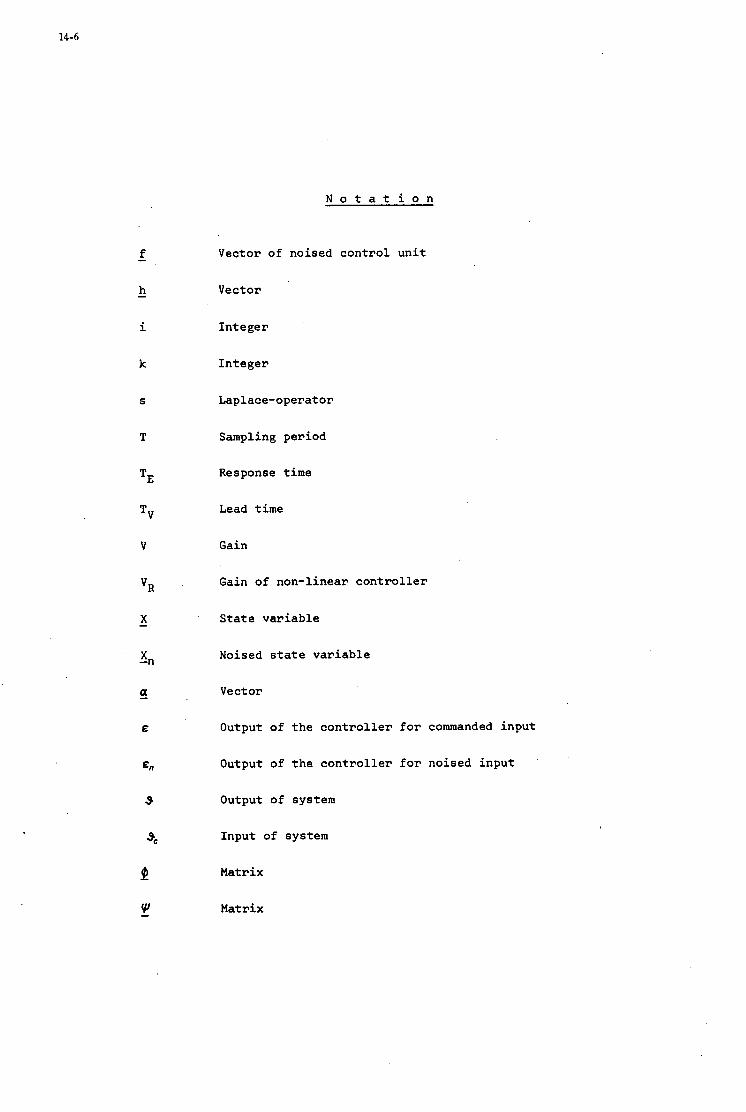
N o t a t i o n
k
S
T
TE
TV
V
VR
X -
' X -n
a E
En
9
Vector of noi sed c o n t r o l u n i t
Vector
Integer
I n t e g e r
Laplace-operat or
Sampling period
Response t i m e
Lead t i m e
Gain
Gain of non-l inear c o n t r o l l e r
State var iab le
Noised state v a r i a b l e
Vector
Output of t h e c o n t r o l l e r f o r commanded input
Output of t h e c o n t r o l l e r for noi sed input
Output of system
Input of system
Matrix
Matrix
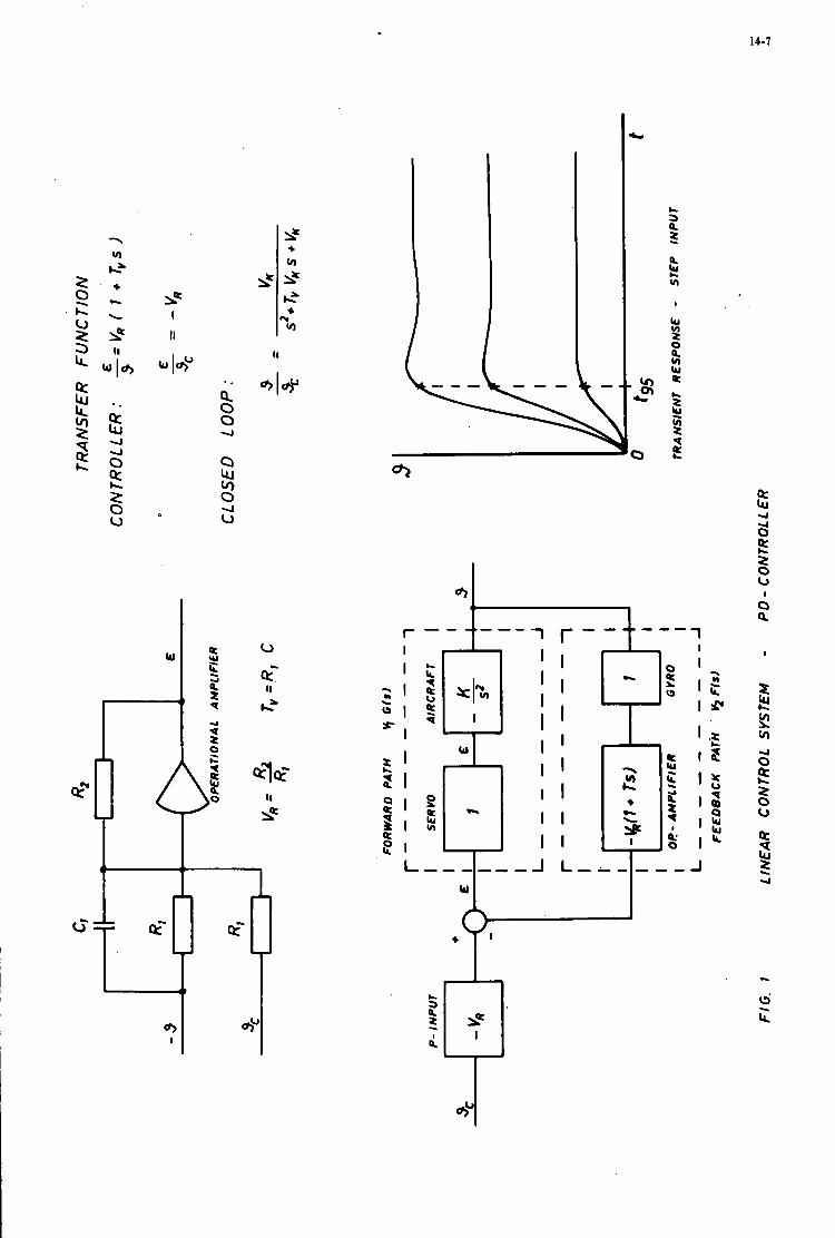
4
a 2 0 c, 4
)r
8 c
3
c- 3
:"'
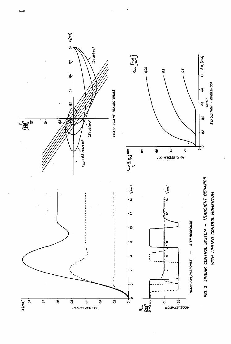
14-8
0 0'
U U
ry Q
x: e
2. I
I,
w
8 I !
!
1ndll)O N31SAS
0 -4
0 8 s -4
1OOHS83AO 'XVN
c I
NO11 V831333V

14-9
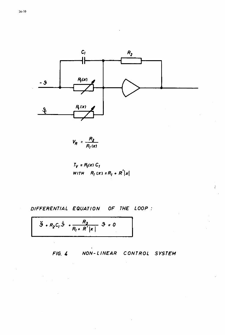
14- 10
DIFFERENTIAL EQUATION OF THE LOOP :
FIG. 4 NON- LINEAR CONTROL SYSTEM

14-11
II z
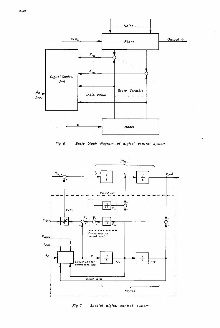
14-12
I I kc;*.
I 7 + - b l - 34- &
Control unit for x z v A cornrnandrd input
I I I I
. , . . . Noise . . . . . . .
W I X I V
P lant
L Input
1- xvn Digital Control
Unit
Initial Value 1 1 Model
.,
Fig. 6 Basic block diagram of digital control system
I I I I
I E"":'+
I Control unit for I
ECmax I noirod input - .- .
I Initial valuo I \
V #
Mode I L - - - - - - - - - - - - - - - - -
,Fig. 7 Special digital control system
- I I I I
I I I I I I 1
I I
I I I I
I
-
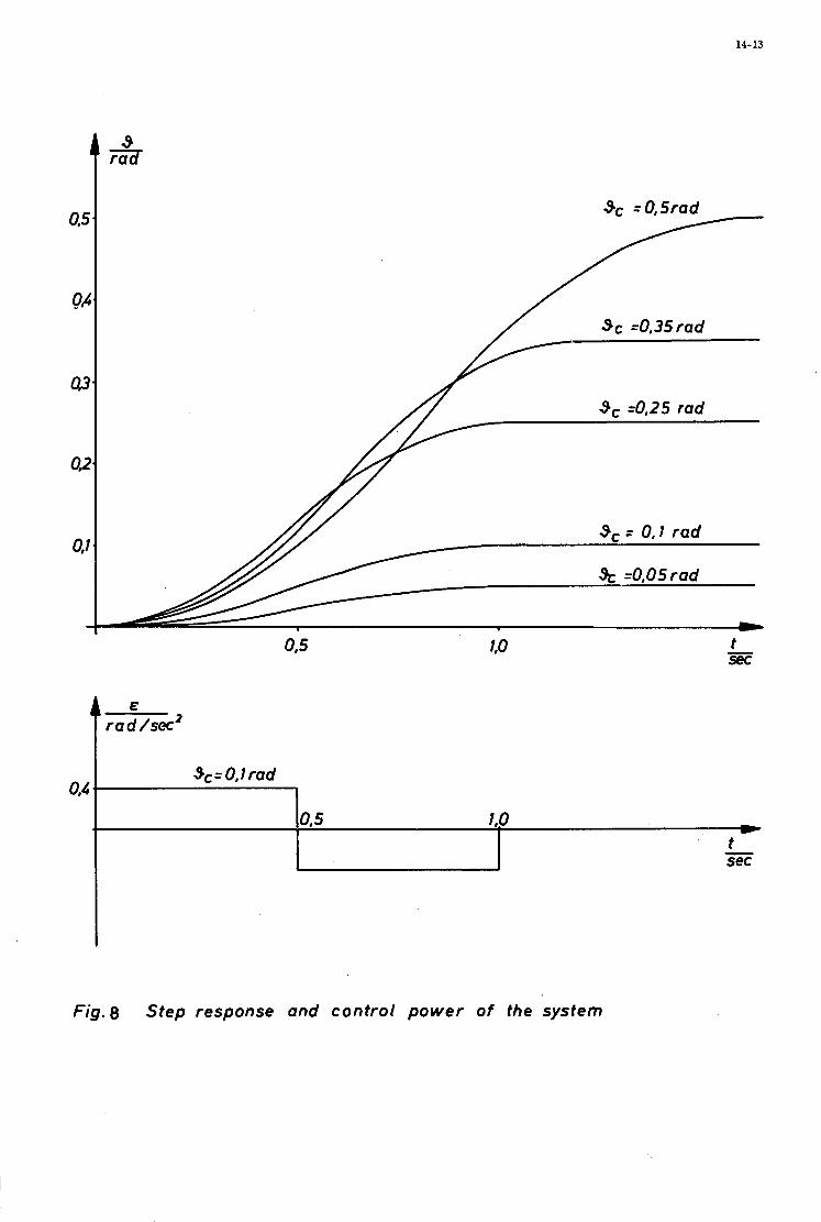
14-13
Sc =0,35rad
3, =0,25 rad
3, = 0.1 rad
S, =0,05rad
t
Sc =0,35rad
3, =0,25 rad
3, = 0.1 rad
S, =0,05rad
& rad /sec2
Fig.8 Step response and control power of the system
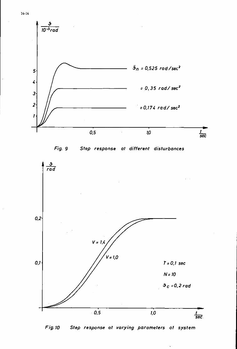
14-14
5
4
3
2
1
-
0,;
0.1
-
3, = 0.525 rad/sec’
= 0,35 rad/sec’
= 0,174 r a d / sec2
L
Fig. 9 Step response at different disturbances
0.5
T = O , l sec
N = 10
SC =O,Zrad
t - sec
Fig.10 Step response at varying parameters of system
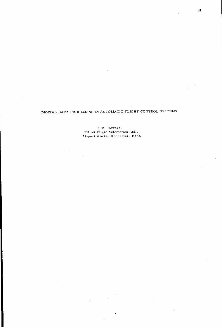
15
DIGITAL DATA PROCESSING IN AUTOMATIC FLIGHT CONTROL SYSTEMS
R. W. Howard. El l io t t F l igh t Automation Ltd . ,
A i r p o r t Works, Roches t e r , Kent.

15
SUMMARY
Digital data process ing i s examined a s another technique fo r the des igner of automatic fl ight control s y s t e m s . It i s d i scussed in re la t ion to three genera l a spec t s of all AFCS, those of inner loop, outer loop and execut ive functions. Various types of modern a i r c r a f t s y s t e m a r e compared in a s s e s s i n g the impact of digital techniques and i t is concluded that although i t is not cos t effective fo r a l l computing r e q u i r e m e n t s a t p resent , i t will p r o g r e s s i v e l y rep lace analogue flight control computing in the future . A warning is given aga ins t adopting cen t r a l computing techniques a s a means of speeding th i s p rocess .
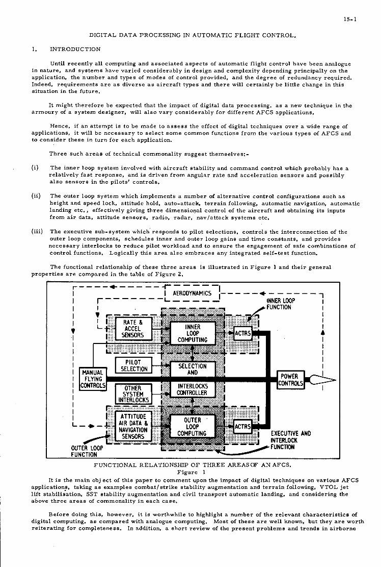
15- 1
DIGITAL DATA PROCESSING IN AUTOMATIC FLIGHT CONTROL.
1. INTRODUCTION
Until recent ly all computing and a s soc ia t ed a spec t s of automatic fl ight control have been analogue in nature , and s y s t e m s have var ied cons iderably i n des ign and complexi ty depending pr incipal ly on the application. the number and types of modes of control provided, and the d e g r e e of redundancy required. Indeed, r e q u i r e m e n t s a r e a s d ive r se a s a i r c r a f t types and t h e r e will ce r t a in ly be l i t t le change i n this s i tuat ion i n the future .
It might t he re fo re be expected that the impact of digital data process ing , a s a new technique i n the a r m o u r y of a s y s t e m des igner , will a l s o v a r y cons iderably f o r different AFCS appl icat ions.
Hence, if a n a t tempt is to be made to a s s e s s the effect of digital techniques over a wide range of appl icat ions, i t will be n e c e s s a r y to se l ec t s o m e common funct ions f r o m the var ious types of AFCS and to cons ider these in turn f o r each application.
T h r e e such a r e a s of technical commonal i ty suggest themselves:-
The inner loop s y s t e m involved with a i r c r a f t s tab i l i ty and command control which probably has a re la t ive ly f a s t response , and is dr iven f r o m angular r a t e and acce le ra t ion s e n s o r s and possibly a l s o s e n s o r s i n the pilots ' controls .
(i)
(ii) The outer loop s y s t e m which implements a number of a l te rna t ive control configurat ions such as height and speed lock, att i tude hold, auto-at tack, t e r r a i n following, automatic navigation, automatic landing etc. , effect ively giving th ree dimensional control of the a i r c r a f t and obtaining i t s inputs f r o m air data, at t i tude senso r s , radio. r a d a r , navla t tack s y s t e m s etc.
(iii) The execut ive sub-sys tem which' responds to pilot select ions, cont ro ls the interconnect ion of the outer loop components, schedules inner and outer loop ga ins and t i m e constants , and provides n e c e s s a r y in te r locks to reduce pilot workload and to e n s u r e the engagement of safe combinat ions of cont ro l functions. Logical ly this a r e a a l s o e m b r a c e s any in tegra ted se l f - tes t function.
The functional re la t ionship of these th ree a r e a s is i l lus t ra ted i n F i g u r e 1 and the i r genera l p rope r t i e s a r e compared i n the table of F i g u r e 2 .
1 I r---- +----- 7-- - - -
I I AERODYNAMICS 1- - - - - + - - - - - - I r------ -L--,,,. INNER LOOP I
. -..-..-.. FUNCTIONAL RELATIONSHIP O F THREE AREASOF AN AFCS.
F i g u r e 1 It is the m a i n obj ec t of th i s paper t o comment upon the impact of digital techniques on var ious AFCS
application;, taking as examples combat / s t r i ke stabil i ty augmentat ion and t e r r a i n following, VTOL j e t l i f t stabil isation. SST s tab i l i ty augmentat ion and civil t r anspor t automatic landing, and consider ing the above t h r e e a r e a s of commonal i ty i n each case .
Before doing this, however, i t is worthwhile to highlight a number of the re levant cha rac t e r i s t i c s of Most of t hese a r e well known, but they a r e worth
In addition. a shor t rev iew of the p r e s e n t p rob lems and t r ends i n a i r b o r n e digital computing, as compared with analogue computing. r e i t e r a t ing f o r completeness .
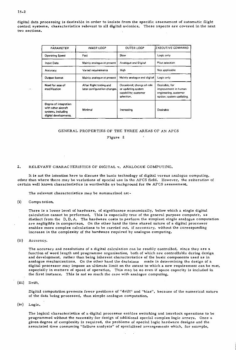
15-2
INNER LOOP
Fast
digital da ta process ing is des i r ab le i n o r d e r t o i so la te f r o m the specif ic a s s e s s m e n t of automatic flight control s y s t e m s , c h a r a c t e r i s t i c s re levant t o all digital avionics. two sect ions.
These a spec t s a r e covered i n the next
OUTER LOOP EXECUTIVE COMMAND
Slow Logic only
PARAMETER
Operating Speed
I Input Data
modification
Degree of integration with other aircraft systems, including digital developments.
Mainly analogue at present I Analogue and Digital 1 Pilot selection
Varied requirements I High I Not applicable
Mainly analogue at present
After flight testing and later configuration changes
Minimal
Mainly analogue and digital
Occasional; change of role or updating system capability; customer selection.
Logic only
Desirable, for improvement in human engineering, customer option; system updating.
Increasing Desirable
GENERAL PROPERTIES O F THE THREE AREAS O F AN AFCS
F i g u r e 2
2. RELEVANT CHARACTERISTICS O F DIGITAL v. ANALOGUE COMPUTING.
It is not the intention h e r e t o d i scuss the bas i c technology of digital v e r s u s analogue computing, other than where t h e r e may be var ia t ions of spec ia l u s e i n the AFCS field. ce r t a in well known c h a r a c t e r i s t i c s is worthwhile a s background f o r tk AFCS a s s e s s m e n t .
However, the r e i t e r a t ion of
The re levant c h a r a c t e r i s t i c s may be s u m m a r i s e d as:-
(iii)
(iv)
Computation.
T h e r e is a lower leve l of hardware , of s ignif icance economically, below which a s ingle digital calculat ion cannot be per formed. This is espec ia l ly t rue of the gene ra l purpose computer , as d is t inc t f r o m the D. D. A. are negligible i n comparison. On the other hand the t ime s h a r e d na ture of a digital p r o c e s s o r enables m o r e complex calculat ions to be c a r r i e d out, if necessary . without the cor responding inc rease i n the complexity of the ha rdware r e q u i r e d by analogue computing.
The hardware cos t s t o p e r f o r m the s imples t s ingle analogue computation.
Accuracy.
The a c c u r a c y and reso lu t ions of a digital calculat ion can be readi ly control led, s ince they a r e a function of word length and p r o g r a m m e organisat ion, both of which a r e control lable during des ign and development, r a t h e r than being inherent cha rac t e r i s t i c s of the bas i c components used as in analogue mechanisat ions. digital p r o c e s s o r may impose a n ul t imate l i m i t on the extent t o which a new r e q u i r e m e n t c a n be met , espec ia l ly i n m a t t e r s of speed of operation. the f i r s t instance.
On the other hand the decis ions made in determining the des ign of a
This may be S O even if s p a r e capaci ty i s included i n This is not BO much the c a s e with analogue computing.
Drift.
Digital computation p r e s e n t s fewer p rob lems of "drift ' l and "bias", because of the numer ica l na ture of the data being processed , than s imple analogue computation.
Logic.
The logical cha rac t e r i s t i c s of a digital p r o c e s s o r enables switching and in te r lock opera t ions to be p r o g r a m m e d without the necess i ty f o r design of additional spec ia l complex logic a r r a y s . given d e g r e e of complexi ty is requi red , the problems of spec ia l logic ha rdware des igns and the a s soc ia t ed t ime consuming " fa i lure analysis" of spec ia l i sed a r r a n g e m e n t s which, f o r example,
Once a

15-3
a r e inherent in analogue fl ight control s y s t e m s c a n be reduced. connect ions and logic design ex terna l to the computer a r e compatible.
S torage
This a s s u m e s that any in t e r -
In t e r m s of cos t effective hardware , digital computer s to rage devices a r e much m o r e efficient than analogue s to rage devices. On the other hand the digital p r o c e s s o r , by i t s nature , gene ra t e s i t s own s to rage r e q u i r e m e n t s , and expands the s i ze of this e lement in a control system. Never the less , t h e r e is undoubtedly a n advantage for digital computers i n this respec t .
F u t u r e Development.
Digital compute r e lements , i n var ious s tandard m i c r o c i r c u i t f o r m s , a r e being widely applied and used in v e r y l a r g e numbers . computers , and hopefully improvemen t s in re l iab i l i ty and functional capability. The compar i son with analogue equivalents i s a continuously changing activity, but the g r e a t e r p r e s s u r e on digital components is undoubtedly causing a rap id movement to the m o r e extensive u s e of th i s technology.
This m a k e s fo r d r a m a t i c reduct ions i n cos t and s i ze of fu ture
These a r e then the bas i c c h a r a c t e r i s t i c s which m u s t be a s s e s s e d when consider ing the impact of digital technology on automatic fl ight cont ro l sys tems. computing will not be the pa.nacea which will e l iminate all of our problems, and ca re fu l balancing of all avai lable technologies, including this newer one, i s n e c e s s a r y to e n s u r e the bes t , m o s t cos t effective solution fo r any r e q u i r e m e n t a t any time.
3.
Like all new technological developments , digital
CURRENT PROBLEMS AND TRENDS IN AIRBORNE DIGITAL DATA PROCESSING.
Digital techniques a r e now being used widely i n ce r t a in a i r b o r n e appl icat ions and the c u r r e n t exper ience is of i n t e r e s t i n a s s e s s i n g the probable u s e s i n automatic fl ight control sys tems.
The p rob lem probably revolves around four ma in aspec ts . These a r e : -
- - Data t r a m m i s s i o n . - Checking and monitoring. - Interfacing with analogue devices .
S torage d e v i c e s have up t i l l now been the a r e a of the computer m o s t r e s i s t a n t t o p r i c e reduct ion and have presented a l a r g e number of problems. Consider ing f i r s t of all a conventional c o r e stack, a typical p r i c e is of the o r d e r of 10 U. S . cents /b i t . In addition, m e m o r y cor rupt ion c a n take place due to power supply t rans ien ts , lightning s t r ikes , etc. F o r high in tegr i ty a fixed ppogram m e m o r y is thus r e q u i r e d and until recent ly the rope c o r e m e m o r y has been the b e s t method avai lable and the cos t /b i t of th i s method is about 3 U. S. cents /b i t . t o achieve the full potential of these devices a compatible random a c c e s s m e m o r y is required. This enables p rogramming to be c a r r i e d out readi ly i n development and be fixed i n production. gate M. 0. S . random a c c e s s m e m o r y ce l l gives u s the r e q u i r e d compatibi l i ty and these combinat ions will enable m o r e economical s to rage to be achieved.
The cos t and in tegr i ty of memor ie s .
M. 0. S. read-only m e m o r i e s p r o m i s e to take over th i s ro l e but
The s i l icon
I t is poss ib le conveniently physical ly to sepa ra t e p r o c e s s o r s to rage into f ixed p r o g r a m memory , "a l te rab le constant" m e m o r y and working space fo r in te rmedia te products , and t o take spec ia l s t eps to p ro tec t the volati le workspace m e m o r y f r o m t r ans i en t corrupt ion. In fac t , the fu ture holds out g r e a t p r o m i s e f o r a number of compat ible s torage techniques with a wide va r i e ty of convenient proper t ies . par t icu lar , s e v e r a l methods f o r e a s y r e - p r o g r a m m i n g of non-volatile med ia a r e rap id ly being developed.
In
New methods of using c u r r e n t semi-conductor ma te r i a l s , m o r e effective methods of des ign and m a s s product ion applied to read-only m e m o r i e s , and development i n amorphous semiconductors all offer p r o m i s e i n cheaply-al tered non-volatile s torage.
Digital data t r a n s m i s s i o n p r e s e n t s p rob lems in a high in tegr i ty environment again l a r g e l y due to
However the imposi t ion of
Sealed opt ical data links m a y offer cons iderable advantages i n
noise cor rupt ion of the data. mult iple redundant digital data t r a n s m i s s i o n is the only p rac t i ca l solution. such a solution on all data handled by a sys tem may esca l a t e the cos t and weight of a complete ins ta l la t ion to a n unreasonable degree. integrity, due to the i r l ack of suscept ibi l i ty and genera t ion of e lec t romagnet ic in te r fe rence , but the u s e of such a technique is i n i t s infancy and again a mult iple sys tem would probably be required.
P a r i t y checks enable some of these e r r o r s t o be detected, but essent ia l ly
'
Speaking genera l ly the checking and monitoring of continuous on-line opera t ions using digital computing a p p e a r s t o be no s i m p l e r than with analogue computers , desp i te e a r l y hopes to the cont ra ry . The concept of a computer which "checks i tself during a spa re moment" turned out t o be a compute r with a g rea t ly i n c r e a s e d m e m o r y and a sof tware problem m o r e extensive than the ha rdware on which self- monitor ing is r e q u i r e d to overcome.
More specifically, the problem of self-monitor ing a digital compute r t o a leve l r e q u i r e d f o r automatic landing r e q u i r e s a self checking capabi l i ty of a t l e a s t 99.99%. and to achieve this r e q u i r e s

15-4
e x t r e m e l y extensive ha rdware and sof tware so tha t the cos t of the compute r and its p r o g r a m i n the w o r s t c a s e c a n a l m o s t double. p r o g r a m s and ex t r a organizat ional sof tware) and p r o g r a m cycle time.
The p r i ce which h a s to be paid is in additional s t o r e capaci ty ( for monitor
F ina l ly t h e r e is the problem of interfacing with analogue input and output devices. This c a n have In automatic fl ight the m o s t cr ippl ing effect on the cos t effect iveness of digital computing in any system.
c o n t r o l s y s t e m s i n the r ecen t p a s t the preponderance of analogue pe r iphe ra l devices h a s had such a n influence tha t fo r ce r t a in c a s e s it has r a r e l y been sens ib le even t o examine the introduct ion of digital computing. Fortunately, a g r e a t deal of p r e s s u r e is now being applied t o the development of digital- output s e n s o r s which do not r e l y upon expensive A to D c o n v e r t e r s and th i s should cons iderably improve the viabil i ty of fu ture applications.
4. INNER LOOP CONTROL FUNCTION
The inner loop control funct ions of a n AFCS a r e c h a r a c t e r i eed gene ra l ly by:
- - Relat ively high bandwidth. - - -
Close involvement with a i r c r a f t flying cha rac t e r i s t i c s .
Predominant ly analogue outputs f r o m a i r c r a f t motion s e n s o r s - at the p r e s e n t t ime anyway. A demand f o r high integrity. Minimal r e q u i r e m e n t s f o r changes of mode or r e s p o n s e cha rac t e r i s t i c s .
All of t hese a spec t s apply, f o r example, t o the high speed c o m b a t / s t r i k e a i r c r a f t which may employ mult iple ax i s s tab i l i ty augmentation. a l s o be mult iple redundant. e labora te s t ruc tu ra l f i l t e r ing m a y be r e q u i r e d to avoid the exci ta t ion of dangerous s t ruc tu ra l osc i l la tory modes. weighing around 1$ lbs. p e r ax i s of control. i. e. a four axis s imple s y s t e m might weigh around 6 lbs. and a four ax i s duplex or self-monitored s y s t e m might weigh around 12 lbs. au tos tab i l i se r , including self t e s t and r a t e gyros , weighs 5$ lbs. )
If this is requi red over a wide range of i t s f l ight envelope it m a y The a i r c r a f t sho r t per iod f requences m a y v a r y f r o m 0 . 5 t o 3 Hz and
The s imples t c u r r e n t analogue s y s t e m s m a y achieve the r e q u i r e m e n t with computing h a r d w a r e
(c. f. a two axis H a r r i e r
We now wish to s e e how the c o m b a t / s t r i k e s tab i l i ty augmentat ion t a s k could be p e r f o r m e d digitally. If we cons ider a compute r with a n a v e r a g e ins t ruc t ion t ime of 4 US a p rac t i ca l four ax is p r o g r a m (pitch r a t e , ro l l r a t e , yaw ra te , height r a t e ) will take 4. 5 m S p e r i teration, Stability ana lys i s ind ica tes tha t f r o m cons idera t ion of phase l ag and ampli tude shape of notch f i l t e r s , a n i t e r a t ion per iod of 10 m S m u s t not be exceeded. 370 words of s to rage a r e r e q u i r e d and such a "four axis" computer might weigh 15 lbs. If the compute r is r e q u i r e d to be se l f - monitored, using exis t ing techniques, the t ime p e r i t e ra t ion might eas i ly i n c r e a s e to 15 m S, and a s t o r e 3 t i m e s l a r g e r might be required. redundant computers if fa i l - sa fe ty is required. and th i s hard ly c o m p a r e s with the 12 lbs. in the analogue f o r m - and in te r face a s p e c t s have yet t o be included.
Hence, the t a sk is feas ib le digitally f r o m timing considerat ions.
It is the re fo re c l e a r l y a be t t e r approach at p r e s e n t t o u s e sepa ra t e However we a l r e a d y have then 30 lbs. of digital computing
T h e r e is a l s o the problem that t o make the a s s e s s m e n t as reasonable as possible , one compute r is a s s u m e d to handle concurren t ly 4 sepa ra t e a x e s of control. Detai led ana lys i s of the ac tua l implementat ion will. however, probably show th is t o be qui te unacceptable , as a s ingle p r o c e s s o r f a i lu re will put out of act ion 4 control- a x e s a t a t ime. would be s ta r t l ing , if not dangerous.
Even if adequate dupl icate redundancy w e r e involved, such a fa i lu re
Hence integrity, weight and cos t r e m a i n the over r id ing f ac to r s , not computing per formance capability. The s i tuat ion is l ike ly to change, of course , as digital components become cheaper , but desp i te the con- s iderable d e c r e a s e i n component cos t s over the pas t y e a r the "cross-over" point when au tos tab i l i sa t ion becomes cheaper using digital techniques is probably s t i l l s o m e way off. fu r the r advances i n au tos t ab i l i s e r capabi l i ty will be r ea l i s ed as digital v e r s i o n s will have an a c c u r a c y and s e n s e of f r eedom f r o m computer genera ted d r i f t which will g rea t ly enhance a i r c r a f t p e r f o r m a n c e capabi l i ty and allow high safe ty as a r e s u l t of low interchannel d i spa r i t i e s i n redundant combinations.
When th i s does happen, even
S imi l a r conclusions w e r e d rawn f r o m a recen t invest igat ion of VTOL je t l i f t stabil isation, with the difference tha t the problem is even m o r e difficult t o solve f r o m the in tegr i ty viewpoint. using analogue e lec t ronic hardware , re l iab i l i t i es w e r e n e a r to acceptable fo r mi l i t a ry VTOL types, but probably still unacceptable f o r c iv i l t r anspor t types.
Specifically,
The SST autostabi l isat ion problem is s i m i l a r t o the c o m b a t / s t r i k e one, except that i n g e n e r a l much m o r e redundancy is required. Again, the analogue solution m u s t be the be t t e r at the p r e s e n t t i m e f o r the ac tua l cont ro l loop. However, exper ience is showing tha t var ia t ions is ga in scheduling, espec ia l ly l a t e in a development p r o g r a m might w a r r a n t a m o r e sophis t icated t r e a t m e n t than at p r e s e n t provided by spec ia l i sed in te rna l d i s c r e t e switching a r r a y s . More is sa id about t h i s i n Section 5.
The inne r loop na tura l f requencies i n a civil t r anspor t automatic landing s y s t e m a r e a n o r d e r lower than f o r a c o m b a t / s t r i k e au tos tab i l i se r sys tem and i t might, therefore , be expected that such cont ro l p r e s e n t s no bas i c t iming problem to a digital computer . In fac t invest igat ions of such s y s t e m s have been

15-5
conducted a round a n exis t ing computer having a4000word s t o r e and using i t e r a t ion r a t e s of 40 p e r second. The p r o g r a m takes about 3000 words and with a n add t ime of 3 microseconds the compute r is about 70% utilised. This is without monitor ing, and as was d iscussed i n Sect ion 3, monitor ing i n c r e a s e s the p r o g r a m length and t ime r e q u i r e m e n t s considerably, espec ia l ly consider ing the confidence leve ls r e q u i r e d f o r a l l -weather landing. automatic landing is not cos t effective as the computer r e q u i r e d uould involve at l e a s t double the ha rdware of exis t ing analogue devices.
It is the re fo re concluded tha t a t th i s t i m e digital inner loop control during
I t appears . therefore , tha t the u s e of non-t ime-shared digital p r o c e s s o r s a r e ger .eral ly v e r y una t t rac t ive a t p r e s e n t fo r inner - loop-a i rc raf t control functions, and even with t i m e shar ing, for m o r e complex s y s t e m s , p rac t i ca l cons idera t ions of in tegr i ty will a l s o still ove r r ide the i r use. Also, a t present . the predominance of analogue s e n s o r s and ac tua to r s m a x i m i s e s the in te r face problem. the re fo re tha t digital computing will provide the b e s t solut ion f o r inner loops i n the n e a r future .
It s e e m s unlikely
5. O U T E R L O O P C O N T R O L F U N C T I O N
The outer loop control funct ions of a n AFCS a r e c h a r a c t e r i s e d in gene ra l by
- Rela t ive ly low bandwidth - Inputs f r o m s e n s o r s many of which a r e cu r ren t ly digital (air data, automatic navigation) and many of which may be digital a t negligible cos t differential (VOR, rad io a l t ime te r ) Var ied demands for high in tegr i ty Requ i remen t s t o opera te i n a l a r g e number of different modes i n different p h a s e s of flight, with cont ro l of response c h a r a c t e r i s t i c s according to aerodynamic p a r a m e t e r s .
- -
The c o m b a t / s t r i k e a i r c r a f t , having a n autopilot s y s t e m of modera t e complexi ty (i. e. heading la& with t u r n coordination, height lock autothrot t le and Nav / a t t ack coupling) using, as i n the prev ious example of sec t ion 4, a compute r with a n average ins t ruc t ion t ime of 4 U S will take, according to our ana lys i s , 2 mS p e r i t e ra t ion , or 18 mS if completely self-monitored. be to le ra ted , so i t is c l ea r ly poss ib le to have a much s lower compute r f r o m timing cons idera t ions alone. In fac t a change f r o m the no rma l pa ra l l e l to a s e r i a l a r i t hme t i c unit and var ious s t o r e modifications ( so l id s t a t e ins tead of c o r e ) c a n be contemplated. These ac t ions might lengthen the a v e r a g e ins t ruc t ion t ime to say 30 US but th i s might s t i l l be tolerable . whether digital computing is economical ly sens ib le fo r a given application, and if so, whether s epa ra t e computing is feas ib le , o r whether in tegra t ion with other computing funct ions is m o r e des i rab le . autocontrol in tegr i ty r e q u i r e m e n t s will ru l e aga ins t integrat ion, but th i s c a n be tempting if the t a sk is s im pl e.
Stabil i ty ana lys i s ind ica tes that 200 mS would
Such cons idera t ions a r e worthwhile i n a s s e s s i n g f i r s t
Norma l ly
Invest igat ions show tha t using a s low speed spec ia l t o purpose computer , digital and analogue des igns fo r c o m b a t / s t r i k e r e q u i r e m e n t s a r e roughly comparable i n reliabil i ty, cos t and weight.
When the r e q u i r e m e n t s a r e extended to include a b r o a d e r control envelope such as is demanded by the hover mode addi t ions of VTOL att i tude demand cont ro l o r s i m i l a r command functions, the slow speed special- to-purpose digital compute r will undoubtedly have some advantages over analogue designs.
In f a c t once computers i n the two technologies a r e comparable in weight, cos t and re l iab i l i ty and f r o m the t iming viewpoint, the bas i c accuracy , low d r i f t and o ther des i r ab le f e a t h r e s of digital computation c a n consol idate overa l l advantages.
The p r o b l e m s i n development of SST flight control s y s t e m s , and other civil t r anspor t s employing v e r y complex outer loop control s y s t e m s such as automatic landing should be g rea t ly reduced by the u s e of digital technique s.
Those who a r e involved in the AFCS b u s i n e s s will know without conducting any invest igat ion o r ana lys i s of the pas t that the p r o b l e m s which dwarf a l l o the r s in cos t and complexi ty a r e the modification and r e t ro f i t p r o g r a m s jus t p r i o r t o o r a f t e r a n a i r c r a f t goes into serv ice . This a lone can consume 25 to 40% of the total cos t of the development p r o g r a m f o r a complex equipment l ike fa i lure-surv iva l civil automatic landing. VTOL j e t l i f t t r anspor t type, if p r e s e n t day s y s t e m s and a i rc raf t ' cont ro l des ign methods w e r e adopted, m a y be insurmountable .
The s a m e appl ies t o c o m b a t / s t r i k e types and the potent ia l p rob lems on a i r c r a f t of the
The fundamental difficulty a r i s e s f r o m the c lose dependence of a n AFCS on a i r c r a f t per formance and flying cont ro ls c h a r a c t e r i s t i c s which may not be adequately known until l a t e i n a fl ight t e s t o r c e r - t if ication proving program. "handling" c r i t e r i a the s i tuat ion will not change. themselves extensively through the detai led des ign of a sys tem and the p rob lem of acquir ing the n e c e s s a r y m a t e r i a l s f o r modif icat ions c a n a lane c a u s e cons iderable cos t i n c r e a s e s or substant ia l delays.
Indeed until a i r c r a f t des igns a r e configured a round "control" r a t h e r than L a s t minute d i scove r i e s in flight tes t ing c a n re f lec t
T h e r e i s cons iderable evidence that this s i tuat ion c a n be improved by using digital techniques which c a n be made to l ean m o r e heavi ly on sof tware r a t h e r than h a r d w a r e when the modification c r i s i s a r r i v e s . In the s a m e way the inevi table modifications which AFCS undergo during the i r s e rv i ce l ife, fo r a

15-6
multitude of reasons, can more easily be handled if a gaod relationship i s established in the basic design between hardware and software aspects. production for Head Up Displays which has just this sor t of capability. memory incorporates the complete definition of display symbology, seconds to change completely the display characterist ics. but is very much more complex to achieve.
Figure 3 shows a digital computer, currently in large scale A plug in 2000 word read-only
Alternatives can be inserted in a few This i s possible a lso with an analogue computer,
Electronic Unit for Head Up Display System 2048 word, 18 bit store 1 U sec cycle time. in very large quantity production.
Now
Figure 3
This potential for simplifying major modification programs must undoubtedly be rated a s the greatest potential advantage which digital techniques can offer a t the present time. with very complex systems and should be a major consideration at the design stage along with normal performance, environmental and other assessments.
The advantage a r i s e s mainly
Although for outer loop controls in complex systems such a s automatic landing, the digital processor looks feasible from weight, cost and timing considerations. there is still the problem of integrity. great deal of work has been devoted over the las t decade to the development of safe redundant analogue systems and i t is not c lear that the results of this will be directly transferable.
A
However, we may usefully compare the techniques used in modern analogue systems with their related concepts in digital systems. analogue solutions in current use, which a r e a dual-dual configuration with changeover (Figure 4A). a triplex voting arrangement(Figure 433) and a duplicate self-monitored arrangement (Figure 4C).
For a single-failure fail-operative requirement there a r e three main
[+=-+=- COMPARATOR -1 I
REDUNDANT * A 1 OR
MONITORED SENSOR INPUTS L v
SELF <
I
I i
DUAL-D UAL WITH CHANGEOVER
Figure 4A

15-7
OUTPUT DEMAND
L A N E 3
TRIPLEX VOTER
F i g u r e 4B
r - - - - - - - - - - - 1 I I I I I
I
MONITOR L A N E I
REDUNDANT SENSOR I N P U T S
R E D U NO ANT
OUTPUT MONITORED DEMAND
SENSOR I INPUTS - J
MONITOR L A N E 2
DUPLICATE SELF-MONITORED
F i g u r e 4C Both the dual-dual and t r ip l ex a r r a n g e m e n t s should offer p e r f o r m a n c e advantages i n digital f o r m over the i r analogue equivalents as the i n c r e a s e d a c c u r a c y and low d r i f t inherent i n c o r r e c t l y appl ied digital computing should give v e r y low " m i s s e d fault ' ' and "nuisance disconnect" probability.
In the s e a r c h f o r the s implext f a i lu re surv iva l ha rdware configurat ions using digital on-line con t ro l l e r s t h e r e is a l s o the th i rd option of a dupl icate-monitored s y s t e m using only two self-monitored p r o c e s s o r s . Techniques of combined sof tware and h a r d w a r e self-monitor ing are genera l ly able t o achieve a high d e g r e e of confidence i n detect ing p r o c e s s o r faults, however to date the re is l i t t le evidence as indicated i n sec t ion 3, tha t t h i s c a n be achieved economical ly if confidence l eve l s much above 99% are requi red , and th i s is ce r t a in ly n e c e s s a r y f o r appl icat ions l ike civil automatic landing,
Recent a s s e s s m e n t of typical ou ter loop cont ro l t a sks a l s o ind ica tes tha t with p r e s e n t component techniques a monitored p r o c e s s o r is b e s t implemented as a pa ra l l e l machine w h e r e a s a non s e l f -monitored p r o c e s s o r is m o r e cheaply made using s e r i a l techniques, provided t h e r e is adequate speed margin. I t a p p e a r s t ha t a non-time-sharing incrementa l machine is uneconomic f o r such a t a sk and of c o u r s e m a y a l s o l o s e i n its inabjl i t y t o eas i ly accommodate changes i n control p a r a m e t e r s .
F r o m these cons idera t ions it the re fo re a p p e a r s tha t s imple r epe t i t i ve redundancy m a y offer the m o s t a t t r ac t ive solut ion f o r the first genera t ion of all-digital autopi lots and the s i m p l e s t of these, f o r a s ingle f a i lu re surv iva l capabi l i ty is the combinat ion of t h r e e unmonitored s e r i a l p r o c e s s o r s i n a voting config- uration. Despi te the improved a c c u r a c y and d r i f t s o m e cross-vot ing of data will be requi red , but th i s potent ia l ly dangerous p r o c e s s c a n now be conducted with v e r y high in tegr i ty by opt ical means.
A block d i a g r a m of such a s y s t e m is shown i n F i g u r e 5.
To achieve val id channel c o m p a r i s o n at t h e voter i t is n e c e s s a r y to e n s u r e tha t ident ical information is fed t o e a c h p r o c e s s o r (the da ta m u s t not be unequally s t a l e ) and that the p r o c e s s o r s opera te in t i m e synchronisat ion. This will involve opt ical c r o s s f e e d a l s o of t iming s igna ls probably a t p r o g r a m in t e r rup t leve l (not i l l u s t r a t ed ) and al lows voting by e i the r sof tware techniques of compar ison , or hardware c r o s s - examiqat ion of the s e r i a l outputs of the p r o c e s s o r s . sc ra tch-pad data, if th i s becomes cor rupted i n any one p r o c e s s o r the c o r r e c t t ime h i s to ry is lost .
It a l s o al lows the gxchange between computers of
The box labe l led "consolidated digital input data" is de l ibera te ly not detai led to avoid undue
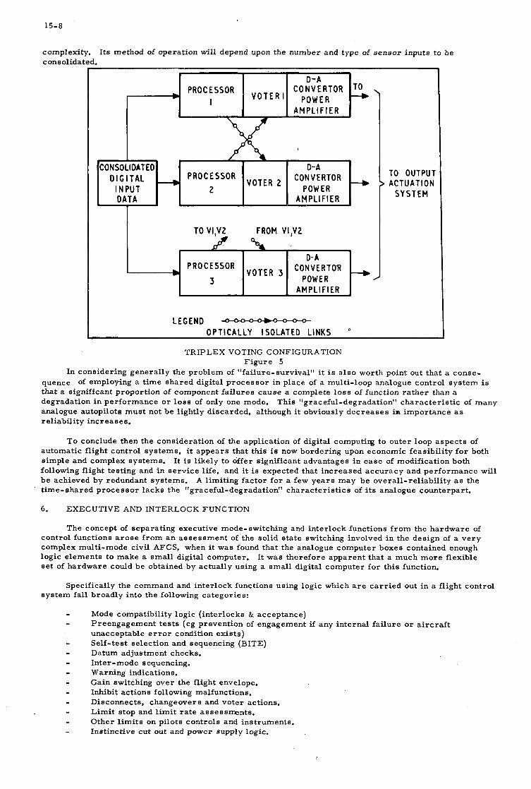
15-8
complexity. consolidated.
I t s method of operat ion will depend upon the number and type of s e n s o r inputs t o be
r
PROCESSOR POWER
AMPLIF IER
CONSOLIOATEO D-A PROCESSOR CONVERTOR
I N PUT 2 POW ER OATA AMPLlFl ER
VOTER D I G I T A L
TO V1.W FROM VI.V2
PROCESSOR V O T E R CON V E R T OR
AMPLl F l ER POWER I
TO OUTPUT ACTUATION
S Y S T E M
LEGEND OPTICALLY ISOLATED LINKS
TRIPLEX VOTING CONFIGURATION F i g u r e 5
In consider ing genera l ly the problem of "fai lure-survival" i t is a l s o wor th point out tha t a conse- quence of employing a t i m e s h a r e d digital p r o c e s s o r in place of a multi- loop analogue control sys tem is tha t a s ignif icant propor t ion of component f a i lu re s c a u s e a complete l o s s of function r a t h e r than a degradat ion i n pe r fo rmance o r l o s s of only one mode. analogue autopi lots m u s t not be l ightly d iscarded , although i t obviously d e c r e a s e s in impor tance as re l iab i l i ty inc r ea s e S.
This "graceful-degradat ion" cha rac t e r i s t i c of many
To conclude then the cons idera t ion of the appl icat ion of digital computirg to outer loop a spec t s of automatic fl ight control s y s t e m s , i t a p p e a r s tha t this is now border ing upon economic feas ib i l i ty f o r both s imple and complex sys tems. following fl ight tes t ing and i n se rv i ce l ife, and i t is expected tha t i n c r e a s e d a c c u r a c y and p e r f o r m a n c e will be achieved by redundant sys tems. t ime-shared p r o c e s s o r l acks the "graceful-degradat ion" cha rac t e r i s t i c s of its analogue counterpar t .
6. EXECUTIVE AND INTERLOCK FUNCTION
It is l ike ly to offer s ignif icant advantages i n e a s e of modification both
A l imit ing f ac to r f o r a few y e a r s m a y be overa l l - re l iab i l i ty a s the
The concept of separa t ing executive mode- switching and in te r lock funct ions f r o m the h a r d w a r e of control funct ions a r o s e f r o m a n a s s e s s m e n t of the sol id s t a t e switching involved i n the des ign of a v e r y complex mult i -mode civil AFCS, when i t was found tha t the analogue computer boxes contained enough logic e lements to make a s m a l l digital computer . It was the re fo re apparent tha t a much m o r e flexible s e t of h a r d w a r e could be obtained by ac tua l ly using a s m a l l digital computer fo r t h i s function.
Specifically the command and in te r lock functions using logic which a r e c a r r i e d out i n a fl ight control sys tem fall broadly into the following ca tegor ies :
Mode compatibi l i ty logic ( in te r locks & acceptance) P reengagemen t t e s t s (eg prevent ion of engagement if any in te rna l f a i lu re o r a i r c r a f t unacceptable e r r o r condition ex i s t s ) Se l f - tes t select ion and sequencing (BITE) Datum adjustment checks. In te r - m ode sequencing. Warning indications. Gain switching over the flight envelope. Inhibit act ions following malfunctions. Disconnects , changeovers and voter actions. L i m i t s top and l i m i t r a t e assessments . Other l i m i t s on pilots cont ro ls and ins t ruments . Inst inct ive cu t out and power supply logic.
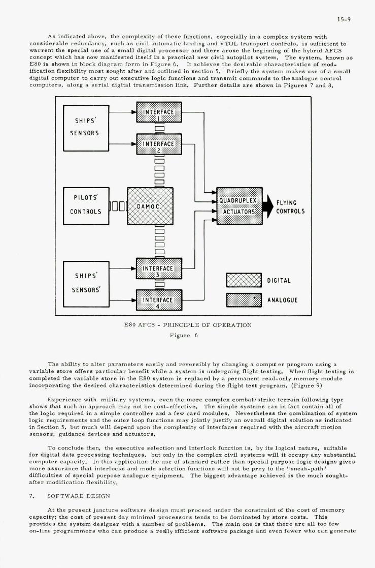
15-9
As indicated above, the complexity of these functions. especially in a complex system with considerable redundancy. such a s civil automatic landing and VTOL transport controls, is sufficient to warrent the special use of a small digital processor and there arose the beginning of the hybrid AFCS concept which has now manifested itself in a practical new civil autopilot system. E80 is shown in block diagram form in Figure 6. ification flexibility most sought after and outlined in section 5. digital computer to car ry out executive logic functions and transmit commands to the analogue control computers. along a serial digital transmission link. Further details a r e shown in Figures 7 and 8.
The system. known a s It achieves the desirable characteristics of mod-
Briefly the system makes use of a s m d l
SHIPS '
SENSORS
0 0 0
SHIPS'
SENSORS' DIGITAL
E80 A F C S - PRINCIPLE OF OPERATION
Figure 6
The ability to alter parameters easily and reversibly by changing a complt e r program using a variable store offers particular benefit while a system i s undergoing flight testing. completed the variable store in the E80 system is replaced by a permanent read-only memory module incorporating the desired characteristics determined during the flight test program. (Figure 9)
When flight testing is
Experience with military systems. even the more complex combatlstrike terrain following type The simple systems can in fact contain all of shows that such an approach may not be cost-effective.
the logic required in a simple controller ami a few card modules. logic requirements and the outer loop functions may jointly justify an overall digital solution a s indicated in Section 5, but much will depend upon the complexity of interfaces required with the aircraft motion sensor8, guidance devices and actuators.
Neverthelese the combination of system
To conclude then, the executive selection and interlock function is, by i t a logical nature, suitable for digital data processing techniques, but only in the complex civil systems will it occupy any substantial computer capacity. In this application the use of standard rather than special purpose logic designs gives more assurance that interlocks and mode selection functions will not be prey to the "sneak-path" difficulties of special purpose analogue equipment. after modification flexibility.
The biggest advantage achieved is the much sought-
7. SOFTWARE DESIGN
At the present juncture Boftware design must proceed under the constraint of the cost of memory capacity; the cost of present day minimal processors tends to be dominated by store costs. provides the system designer with a number of problems. on-line programmers who can produce a really efficient software package and even fewer who can generate
This The main one is that there a r e all too few
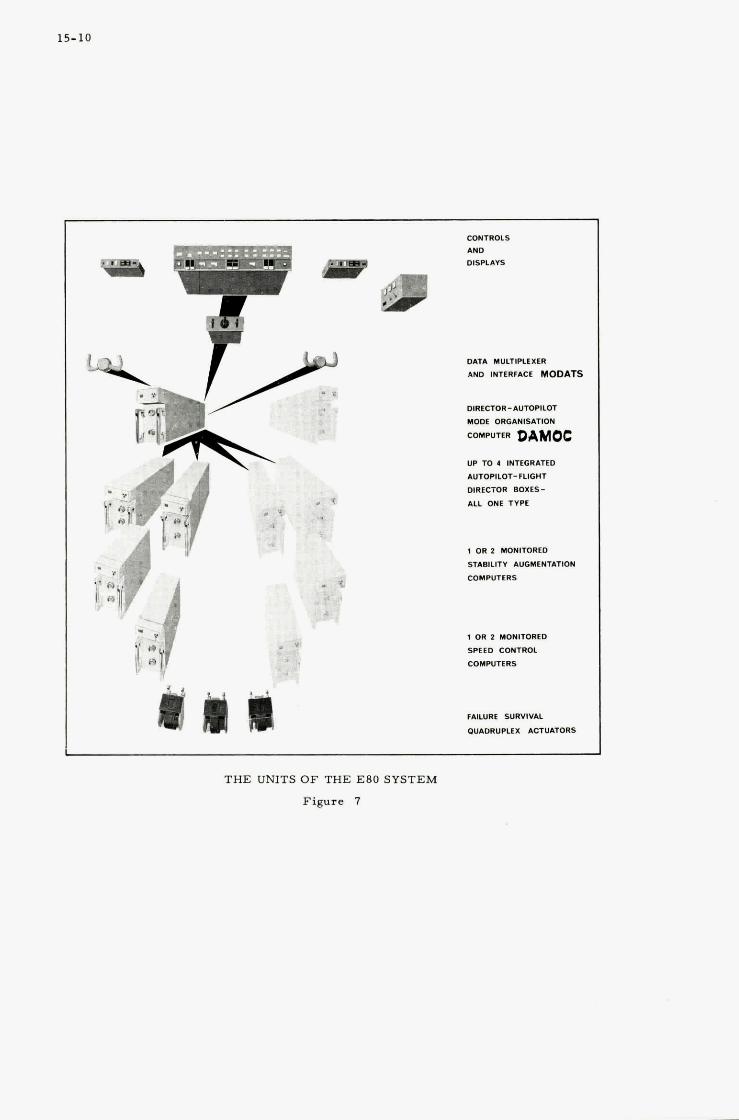
15-10
,
CONTROLS AND DISPLAIS
DATA MULTIPLfXER
AN0 INTERFACE MODATS
DIRECTOR-AUTOPILOT
MODE ORGANISATION
COMPUTER DAMOC UP TO 4 INTEGRATED
AUTOPILOT- FLIGHT
DlRfCTOR BOXfS-
ALL ONE TVPE
1 OR 2 MONITORED
ST&BILITV AUGMENTATION
COMPUTERS
1 OR 2 MONITORED
SPEfD CONTROL
COMPUTERS
FAILURE SURVIVAL
OUAORUPLfX ACTUATORS
THE UNITS O F THE E80 SYSTEM
Figure 7

Analogue Interface Unit (illustrating thermal
design)
/
Directox/ Aueopilot Mode Organizatiod Computer DAMOC (Covers removed)
- . . , ~
DAMOC
covers replaced
E 80 PACKAGES
Figure 8
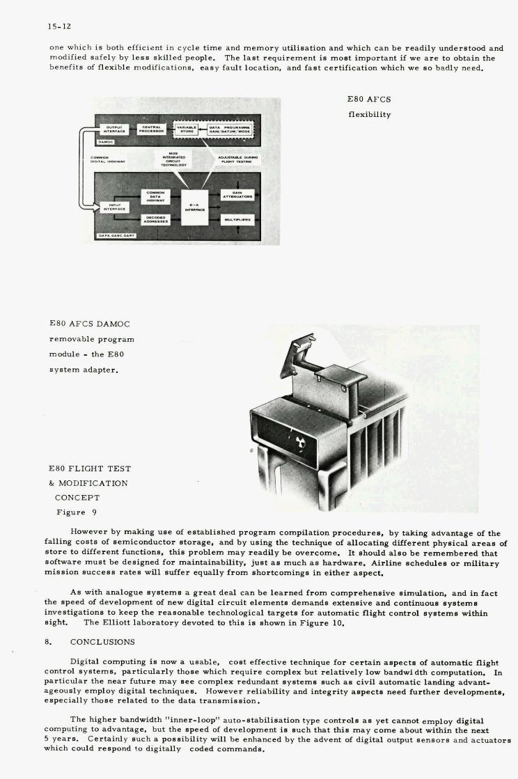
15-12
one which in both efficient in cycle time and memory utilination and which can be readily understood and modified safely by less skilled people. benefits of flexible modifications. easy fault location, and fast certification which we so badly need.
The l a s t requirement is mont important if we a r e to obtain the
E80 AFCS
flexibility
E80 AFCS DAMOC
removable program
module - the E80
system adapter.
E80 FLIGHT TEST
& MODIFICATION
CONCEPT
Figure 9
However by making use of established program compilation proceduren, by taking advantage of the falling costs of nemiconductor ntorage, and by uning the technique of allocating different physical arean of s tore to different functionn, thin problem may readily be overcome. It should alno be remembered that software must he designed for maintainability, just a n much an hardware. Airline nchadulen or mili tary mission nuccenn raten will suffer equally from nhortcomingn in either aspect.
As with analogue nyntemn a great deal can be learned f rom comprehennive simulation, and i n fact the speed of development of new digital circuit elementn demands extensive and continuous nystemn inventigationn to keep the reasonable technological targets for automatic flight control syntemn within night.
8. CONCLUSIONS
The Elliott laboratory devoted to thin i n shown in Figure 10.
Digital computing i n now a usable, cont effective technique for cer ta in aspect. of automatic flight control systems, particularly those which require complex hut relatively low bandwidth computation. In particular the near future may nee complex redundant systems such an civil automatic landing advant- ageously employ digital techniquen. However reliability and integrity anpects need fur ther developmento. especially those related to the data transmianion.
The higher bandwidth "inner-loop" auto-ntabilisation type control. as yet cannot employ digital computing to advantage, but the npeed of development is such that thin may come about within the next 5 yearn. which could renpond to digitally
Certainly such a ponnibility will be enhanced by the advent of digital output nennorm and actuator. coded eommandn.

15-13
THE ELLIOTT DIGITAL AUTOPILOT DEVELOPMENT LABORATORY Figure 10
Selective Digital Data Processing can certainly be employed now in automatic flight control systems and one example is the Elliott E80 series which incorporates a digital computer to organise autopilot modes and schedule gains.
The pressure towards system integration to produce more cost-effective avionic system complexes should he treated with great caution. a eingle system complex may encourage designers to overlook the widely different requirements for system integrity. plausible one of "let u s take advantage of the GP computer's power and spare capacity to do all these things a s well". machines themselves. Digital computing is another technique now ayailable to use or not to use. according to system. not computer, requirements.
This brings dangers in that the attraction of sharing tasks within
Few ideas have led to more wasted time and in some cases failed programmes, that the
The "systems separation" philosophy in airborne inntallations is as old a s flying
With regard to automatic flight control systems we can sum up the probable trend in the next generations a s progressively greater use of digital data processing.
Acknowledgement.
Acknowledgement is made to the many members of the engineering staff of Elliott Flight Automation Ltd., on whose very detailed work the general comments in this paper a re based.

16
THE USE OF A DIGITAL COMPUTER FOR THE ELDO INERTIAL GUIDANCE SYSTEM
by
M. J. W. Gage
Space Department, Royal Aircraft Establishment, Farnborough, Hants., England

16
SUMMARY
The projected ELDO Inertial Guidance System employs a small digital computer.
Those systems of a typical qatellite launch vehicle that are suitable for mechanisation on such an on-board digital computer are listed, and details given for the case of the ELDO vehicle. for the choice of the computer and its role in the system are explained together with some details of the formulation and programming of the guidance law subsystem.
The reasons

16.1
1 INTRODUCTION
The task of placing a satellite in an Earth orbit is at present accomplished by the use of a rocket launch vehicle (a launcher). In order to achieve the right orbit with as large a payload as possible, the launcher must follow the trajectory that minimises the fuel consumption. If the launcher was not subject to any unpredictable forces and if its performance was known exactly, it could be guided along this optimum trajectory by the use of a stored precomputed steering program. In practice such perturba- tions do occur, and so in order to still achieve an accurate injection into the required orbit, an active guidance system has to be employed. A requirement for this guidance system to be self-contained on-board the launcher, then leads to the need for an on-board computer. also be employed on other tasks such as flight sequencing, vehicle control, and data handling.
Once such a computer is available it can
This paper is divided into three sections. Firstly a brief description is given of the systems involved in the guidance of a launch vehicle, and those systems suitable for mechanisation on an on-board digital computer are listed. guidance system (IGS). MCS920M) is discussed, with an explanation of the reasons for its choice and of its IGS role. Lastly an outline is given of the derivation of an explicit guidance law, suitable for evaluation on the 920M, and its application to the ELDO vehicle. within the confines of a small on-board computer.
Details are given for the case of the ELDO vehicle and its inertial Secondly the performance of the computer chosen for the ELDO vehicle (Elliott
The paper explains the steps taken to provide a versatile system
2 THE GUIDANCE OF A SATELLITE LAUNCHER
A launcher is basically a tool for accelerating a satellite from an initial position and velocity on the Earth's surface to a position and velocity corresponding to some required Earth orbit. necessary thrust is generated as momentum reaction from a controlled chemical explosion, a rocket motor. In order to'waste as little energy as possible accelerating unwanted structure, most vehicles are made up of a number of stages (3 in the case of the ELDO vehicle). Each stage is a separate rocket (fuel tanks, engines, etc.) that is discarded when burnt out.
The
The task of guiding such a satellite launch vehicle into a specified Earth orbit can be separated into three,main problem areas, state determination, guidance philosophy, and steering execution. State determination is the navigation problem of computing the current state variables (position and velocity) of the launcher. conjunction with the state variables corresponding to the required orbit and the expected vehicle performance (in terms of thrust levels, etc.), to generate a program of steering demands that, if followed, would guide the vehicle into this orbit. Once the necessary guidance demands have been derived they are applied to the engines of the launcher through a control system; the steering execution problem.
Guidance philosophy is the problem of how to utilise this navigation information, in
State determination
Two main alternative methods are at present employed for determining the information needed in order to calculate the current state variables of the vehicle. optical tracking or on-board inertial sensing. A combination of these techniques, plus others, could be used; however such schemes are usually more applicable to long term space missions rather than the brief launch phase. firings to date (1970). Future firings (from Kourou, French Guiana, rather than Woomera, Australia) will adopt, the latter on-board inertial technique.
There is either ground-based radar/
The former method plus a radio link with the vehicle has been used for all ELDO
For a typical IGS, such as that for the ELDO vehicle (l), the state determination subsystems may be listed as: an inertial platform (space fixed) to provide an attitude reference for the vehicle, inertial accelerometers to measure the impressed acceleration (that due to forces other than gravity), and navigation equations to transform this information into some appropriate set of state variables. evaluation of these navigation equations forms one of the main tasks of the on-board computer.
Guidance philosophy
The
The guidance philosophy subsystems may be listed as: a guidance law, the implementation of any constraints, the sequencing of various events, and the output of required event signals. main classes of guidance laws; firstly implicit guidance, in which the steering commands are generated by reference to the departures of the current state variables of the vehicle from some pre-computed nominal trajectory; secondly explicit guidance, in which the steering commands are directly derived from the relation of the current state variables to those required for the orbital injection.
There are two
The guidance law (2) that forms part of the ELDO IGS is an explicit scheme based on the principle of in-flight optimisation. It was formulated to meet the requirements of high injection accuracy, fuel optimality, minimum pre-computed data, and high mission flexibility. At the same time the law also had to be suitable for real time evaluation on the 920M computer.
Steering execution
For a launch vehicle, steering is usually effected in terms of demanded attitude. The major part of the thrust is directed along the axis of the vehicle through its centre of mass, and is hence aligned with the so called attitude of the vehicle. torque to change this attitude (usually either by deflecting the main thrust or by the employment of small extra thrusters). The vehicle is then steered by controlling the engines to null any existing errors between the current vehicle attitude and the demanded attitude. control equations, autopilots, motor actuators, and rocket motors.
A small amount of thrust is available for exercising a
The subsystems involved are
16.2
The guidance configuration for the,,ELDO vehicle computer
For the ELDO vehicle under inertial guidance the systems incorporated into the 920M computer are, the navigation subsystem, the guidance law subsystem, some event sequencing, the output of motor cut-off signals, the implementation of attitude rate constraints at staging, and data telemetry to the ground for post flight analysis. not directly affected by the change from radio to inertial guidance, for example the autopilots.
Flight sequence
This choice was of course influenced by the decision to retain all the systems
The basic flight sequence of the ELDO vehicle is as follows. Stage 1 (carrying stage 2 and stage 3) is controlled to follow a pre-computed attitude program, designed mainly to allow it to pass safely through the atmosphere. After stage 1 has burnt out and been discarded, stage 2 (carrying stage 3) is controlled to follow the inertial guidance demands until it in turn burns out and is discarded. stage 3 is inertially guided up to orbital injection into a low parking orbit. This is in fact accomplished in two phases. Firstly, for the 3A phase, stage 3 is guided under main thrust (about 23000 N) until a certain set of state variables is achieved, when the guidance law issues a command to cut the main motor. Secondly, for the 3B phase, stage 3 is then guided under vernier thrust (about 800 N) up to the injection state variable, when the guidance law issues a further command to cut the verncer motors. free fall motion round the parking orbit, which is terminated by the separation of the PAS spacecraft from stage 3. The PAS spacecraft (perigee apogee system) then transfers the satellite to a synchronous orbit using.a two impulse Hohmann transfer from the initial low orbit.
Finally
The final task of the computer is to navigate and provide attitude control during a period of
3 THE COMPUTER SYSTEM
The choice of an on-board computer for the ELDO IGS was dictated by a number of requirements. First and most obviously it had to be of a suitable mass and volume. operation in the launch environment and compatible (in terms of power levels, etc.) with launch vehicle facilities. demands for accurate guidance of the vehicle into a near-Earth orbit. This last requirement was established by the U.K. firm Elliott Brothers (London) Ltd. (now Elliott Space and Guided Weapon Division) for their 920M computer, by means of a study (3) done under a contract from the then U.K. Ministry of Aviation. Royal Aircraft Establishment, Farnborough, was given the task of making a study of alternative guidance laws and then supplying their chosen law to Elliott for programing on the 920M.
Secondly it had to be capable of
Thirdly it had to be capable of being programmed to provide navigation data and guidance
Elliott was appointed prime contractor for the development of the IGS on 1 January 1967. The
The Elliott MCS920M is a microminiature digital computer ( 4 ) that is capable of operation in the 3 launch vehicle environment.
an average power consumption of 45 W. The 920M is constructed in three sections, a control unit, an arithmetic unit, and a ferrite core store. In each section the logic modules are clamped together to form a thermally conductive block. This enables the heat generated during operation to be conducted to the side panels of the aluminium casting, which act as heat exchangers. The computer is designed to operate under an ambient temperature range of -1OOC to +5SoC, all store circuits being 'worst case
designed' to work over the range -2OOC to +lOO°C. Other operational limits are, vibration t75 m/s for 0-2000 Hz, shock 250 m/s for 10 ms, and linear acceleration 150 m/s .
The 920M is available with either a 5 p s or a 2 us store cycle time, the 5 p s version giving gross
Numerical data is represented as 18 bit fixed point binary fractions, employing a 2's comple-
The volume of the central processor is 0.012 m with a mass of 15.2 kg and
2 2 2
operation times of 19 p s for addition, 21 us for subtraction, 38 p s for multiplication, and 39 p s for division. ment representation of negative numbers. The core store has a capacity of 8192 of the 18 bit words. The 920M has an explicit order code of 16 instructions which covers all basic arithmetic, lcgic, and transfer operations. operations. basis. being obeyed is temporarily suspended and the higher level program entered. higher level program, the computer then continues the lower level program from the point of interruption.
Double length working with a resolution of 35 bits is available for certain Provision is made for 4 program priority levels which are arranged to operate on an interrupt
Upon receipt of an interrupt signal for a higher priority level program, the program currently Upon completion of this
Application to the ELDO IGS
A schematic diagram of the IGS is shown in Fig.1. the attitude reference for the vehicle. angles of the vehicle and this information is fed into the computer via a synchro to digital converter, in the form of 12-bit digital quantities. mounted on the platform cluster, measure the impressed acceleration of the vehicle. integrated by analogue means in an accelerometer encoder (three channels) and fed into the 920M in the form of pulses, each pulse representing 1 m/s.
A Ferranti FE 610 inertial platform provides Synchros on the gimbals of the platform measure the attitude
Three single axis force feedback accelerometers, orthogonally This information is
The computer accumulates this integrated impressed acceleration (which is in effect the true
The difference impressed velocity rounded down to thqnearest m/s) and implements the navigation program to determine current state variables, and the guidance program to generate a demanded attitude. between this demanded attitude, expressed in gimbal angles, and the current vehicle attitude is output, via a decoder, as an analogue error signal to the autopilots. gyros) is also input to the autopilots for control purposes. the main and vernier engines of the third stage and to initiate the PAS separation sequencer. various tasks of the computer are executed on a priority basis by assignment to one of the four priority levels. pulses derived from the telemetry clock.
Vehicle rates information (from rate The computer outputs signals to cut-off
The
The use of the levels is synchronised by triggering the interrupt facilities using timing
16.3
Use of priority levels
The fourth and lowest level is allocated to a self check program. This operates asynchronously whenever none of the higher levels is operating and checks the correct functional performance of the computer and the integrity of the overall program.
The third priority level is entered every 200 ms. The accumulated impressed velocity is extra- polated (using the three times from the receipt of the last increment in each channel, the current nominal acceleration magnitude and the current vehicle attitude) to obtain the current impressed velocity more accurately than to the nearest m/s. inertial (space fixed) axes used for navigation. The navigation program then includes the effect of gravity (from a model of the gravitational field of the Earth) to form the true current velocity of the vehicle. The equation used is
This is then resolved from the platform axes into the set of
where X is the position vector, V the impressed velocity vector, and &(&) a function representing the acceleration of the vehicle dueto gravity. B
This function is derived from a gravitational potential chosen to provide results well within the ELDO specification on navigation accuracy.
e
(2)
where p is the gravitational constant of the Earth, J2 the largest zonal harmonic coefficient, D the equatorial radius of the Earth, the geocentric latitude of the launcher.
r the distance of the launcher from the Earth's centre, and X
For the guidance of stage 2 and stage 3 the current vehicle state variables are resolved from the navigation axes into the guidance axes and fed into the guidance sub-program. variables, in conjunction with those corresponding to the required orbit, are used to generate an optimum demanded attitude. This is then resolved back into the navigation axes and in turn expressed as demanded gimbal angles. The variable matrix for the transformation from platform to vehicle body axes is also computed.
Here these state
The current impressed acceleration level is monitored in order to detect the stage 1 and stage 2 burn-outs and initiate the program sequencing to ensure that, corresponding to the current stage, the correct part of the program is being exercised. as part of the guidance law. Level three is also used to assemble the telemetry as 48 words, each of 8 bits. made as the result of a detailed accuracy analysis that concluded that the cycle time (and therefore the navigation step length) had negligible affect on the computation accuracy provided it was not greater than 400 ms.
The times for the stage 3A and 3B cut-offs are computed
The choice of a 5 Hz navigation and guidance iteration cycle frequency (cycle time 200 ms) was
The second priority level is entered every 12.5 ms. The integrated acceleration from the encoders is read and accumulated. use in the level 3 extrapolation. The program also reads the current vehicle attitude, as measured by the synchros, and forms the difference between this and the current demanded attitude, obtained from the guidance in level 3 during the second and third stage flight or from a pre-computed program in level 2 during the first stage flight. body axes and output to the autopilots via a digital to analogue decoder.
The three times of receipt of the last increment in each channel are stored for
This difference is resolved into pitch, yaw and roll errors in the vehicle
The high iteration rate (80 Hz) for this level was chosen to avoid any interaction with any of the autopilot loops; for example the critical frequencies of the first stage autopilot range up to 30 Hz. effects of the introduction of the digital element into the existing analogue autopilot loops (5) were evaluated by detailed simulation. output error signals and the 5 Hz and 80 Hz iteration rates. A problem was encountered with the attitude bit size leading to limit cycling which, for the first stage, could have interacted with rigid body and fuel sloshing frequencies. This problem was successfully overcome by the insertion of 112.5 Hz sinusoidal dither (as an analogue signal) before the encoders and the inclusion of output modulation (in the computer) before the decoder.
The
The important factors were the quantisation of the input attitude and
The first and highest level is used to output the 48 words, assembled in level 3 , to the telemetry, and is entered on demand when the telemetry requires data. the computer, plus other basic parameters, are made available for post flight analysis. the times spent in each program level during one 200 ms cycle are shown in Fig.2.
By this means all the inputs and outputs to The details of
Programming details
The 920M is basically a fixed point machine and although higher language compilers are available, for its real time on-line task in the IGS the flight program (6) was written directly in machine code. This enabled each sequence of operations to be programed in an optimal manner. found to be adequate for the IGS task (the flight program other than the self check routines occupying 50% of the available capacity), hence the main requirement was for the reduction of the operating time. In fact (as shown in Fig.2) the flight program other than the self check routines occupies 51X of the 200 ms cycle.
The storage capacity was
16.4
For the IGS application the range of parameter variation, although large, is well determined and so A detailed error analysis no major difficulties were encountered due to the use of the fixed point mode.
showed that the accuracy of the computation was fundamentally related to the resolution of the input data, and that to minimise errors full use must be made of this data. A s the resolution (i.e. bit size) available in floating point arithmetic is dependent on the magnitude of. each parameter it becomes difficult to control the overall accuracy. control over numerical representation and the full utilisation of input data.
The selected scaling gives basic bit sizes of 64 m for position, 5/64 m/s for velocity, and
The preferred solution of fixed point scaling enables total
6.25 ms for time. provided by one 18-bit word. using a trapezoidal routine that employs double length working.
Certain specific areas of the program do however require greater accuracy than can be For example the integrations of the navigation equations are performed
4 THE GUIDANCE LAW
In principle the best and most flexible solution to the guidance problem is to carry out periodically in flight a complete optimisation of the future flight using an accurate mathematical model of the vehicle's motion. generated purely from a knowledge of the vehicle's current and required state variables plus a knowledge of the vehicle's likely performance and the Earth's gravitational field. However this optimisation does involve a considerable amount of computation as a result of the non-linear nature of the equations involved. Hence for a real-time application on a small computer it is necessary to simplify this basic concept in such a way that the computational effort necessary is compatible with the computing perform- ance available.
This then forms an explicit guidance scheme, the required steering commands being
In order to overcome the computational complexities connected with optimisation in the gravitational field of the Earth, use has been made of the fact that the optimum steering angles in a constant uni- directional force field can be expressed as a comparatively simple analytical formula. simplification solution (7) is to substitute this formula back into the accurate mathematical model of the vehicle's translational motion and to solve for the required current guidance demand. still involves extensive computation, in particular numerical integration, and so in order to derive a closed form analytical solution further simplifications are made. This second order of simplification solution (8) is to substitute the optimum steering formula into a simplified mathematical model of the vehicle's translational motion, chosen so as to lead eventually to such a closed form solution.
A first order of
This solution
As a typical constant thrust launcher vehicle requires only two control parameters (corresponding to pitch and yaw steering), the trajectory generated using the simple model (referred to as a flat Earth; hence the name FE guidance) can be made similar in its essential features to the accurate optimum trajectory by the inrroduction of two correction quantities, and e, into the flat Earth equations of motion. g and e are chosen in such a way that they not only correct for the transformation from the accurate model to the flat Earth model but also allow for further simplifications to the flat Earth equations.
The guidance equations are most simply formulated in spherical polar coordinates, as the motion The cut-off boundary conditions assume their takes place in what is primarily a central force field.
simplest form relative to these axes, and thus any guidance law involving these conditions will have its simplest formulation when employing these coordinates. Pu is parallel to the plane of the required orbit n, Pw is Earth centre pointing, and Pv completes the right-handed orthogonal triad through the vehicle. OXY2 are the navigation axes, the 2 coordinate measuring the distance of the vehicle from the plane TT. x and $ are the steering angles, x being the angle between the demanded attitude and the Puv plane (local horizontal) and $ the angle between the pro- jection of this attitude on the Puv plane and the Pu axis.
The axes are shown in Fig.3.
For a launch vehicle with constant fuel mass flow rate the cost function to be minimised can be taken as the flight time. If S(t) is the vehicle's state vector at time t, the problem is to find the X(t) and $(t> that minimise (T - t ) subject to the constraints
- S(tc) = vehicle's state vector at current time tC (3)
- S(T) = state vector required ,at cut-off time T (4)
where this last equation forms an accurate description of the translational motion of the vehicle. and T are parameters describing the thrust perfomnce of the vehicle, the impressed acceleration a being given by
I
where I is the exhaust speed and T = (mo/m) + to, m the total mass of the vehicle at time t and m the fuel mass flow rate.

16.5
The flat Earth solution is obtained by replacing Eq. (5) by
where f is a simplified form of 1 and g a constant accounting for gravity. The optimum X(t) and $(t) fFr this problem can be shown to have the form
sec J, tan x = At + B , tan J, = Ct + D (8)
where A, E, C, D (all constants) and T are determined by the 5 constraints represented by Eq. (4). These are Sinnumber as they correspond to the case of injection into a circular orbit velocity, r, 2 position, all constrained).
(U, v, w
Two constants and e are now introduced into Eq. (7) so that in Eq. (8) X(t) -will become dependent on ( E in fact merely replaces g) and $(t) on e. These quantities g and e can then be chosen to match X(t ) and $(t ) to the accurate current optimum steering angles. For each
new integration interval from a new tC, g and e will assume new values. Comparison of the equations repreqented by Eq. (5) and Eq. (7) suggested taking
c -
where U and v are current velocity components and r the current raiial position. For all optimum launch trajectories studied, g in fact takes values close to g and e close to 1, where g, although taken as a constant for each integration, is a function of the state variables at correction functions angles, form in principle the o ~ l y data that needs precomputation. jectories studied, the use of g = g and e = 1 leads to only a few kg loss in mass into orbit.
tc. These - and e, that enable the FE guidance demands to be matched to the true optisun
In fact for all optimum launch tra-
To appreciate the basic structure of the FE guidance equations-it is useful to consider their form in the neighbourhood of injection defined by the requirement that equations'simplify to
Iu/II 4 1. Under this condition the
3 T'] - 6a [" - r + 0.5 (w + W) T' tan x(t,> = [" - 1 ' -2 U
-
1 - 2) + 0.5 (v + V) T' tan $(t,) = [YJ- 6a[e (zT -2
(10)
(11)
- T' = T - t c = -u/a (12).
- where U - U - UR/r, the U velocity-to-go; U, v, w, r, 2 are the state variables of the vehicle at time tc; U, V, W, R, ZT are those required at cut-off; a is the nominal vehicle impressed acceleration; and T is the predicted cut-off time. It can be seen that Eq. (10) and Eq. (11) both consist of two components, the first controlling the velocity error at cut-off and the second the corresponding position error.
The FE guidance law aims to achieve the required cut-off conditions exactly (i.e. no tolerances on the injection state variables) and so will attempt to correct even very small injection errors. vehicle performance perturbations are present they can result in large steering angles being commanded in an attempt at 'last minute' manoeuvres. The vehicle can therefore be forced by the guidance law to perform violent steering manoeuvres in order to remove only small errors at injection. avoid these unnecessary and perhaps harmful commands it is advisable to relax the stringent injection requirements somewhat. A s very small position (r and 2) errors are unimportant in practice, shortly before cut-off the FE equations are replaced by a guidance law formulated without the position con- straints. This is accomplished by removing the second components of Eq. (10) and Eq. (ll), leaving the so called injection guidance equations
If
In order to
v - v tan $(t,) E - - . U
The equations have so far been formulated for 5 terminal boundary constraints corresponding to the case of injection into a circular orbit. opportunity for a slight modification to the equations to allow for the case of injection into an
This change to the injection guidance equations provides the
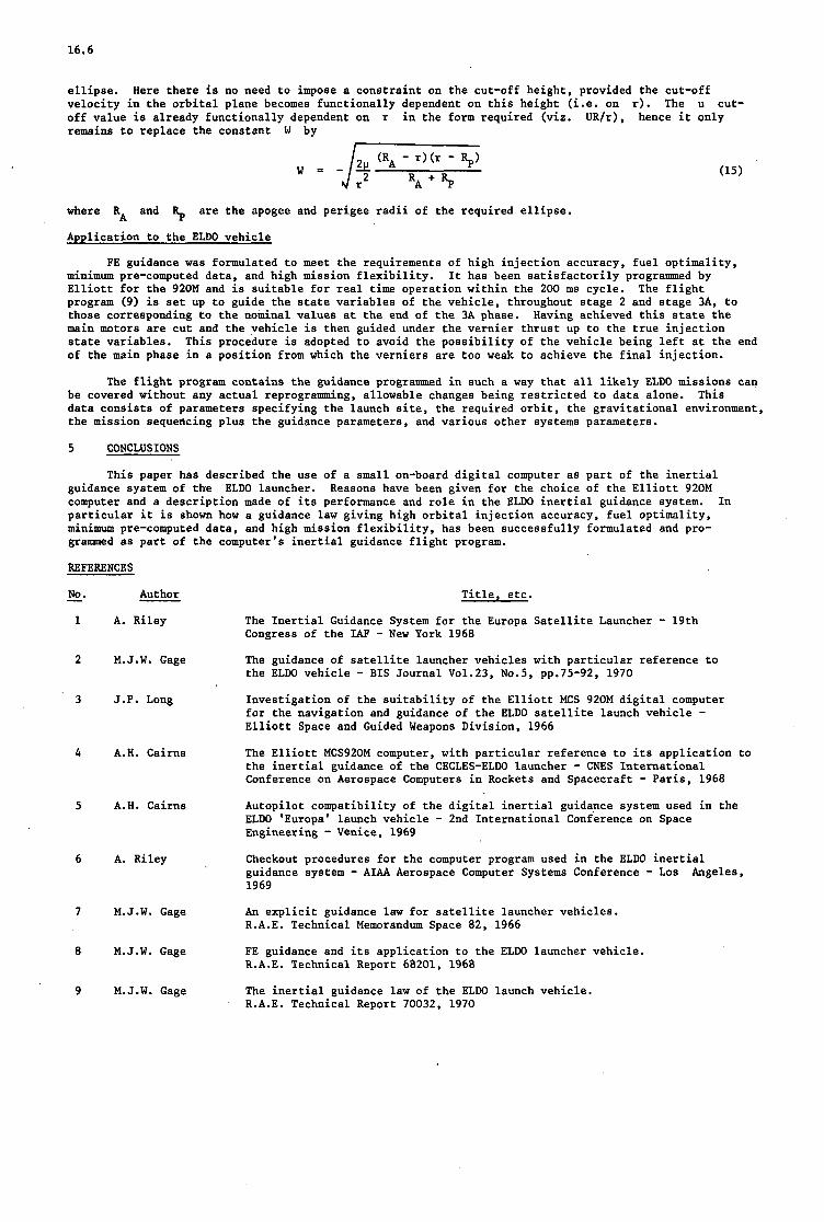
16.6
ellipse. velocity in the orbital plane becomes functionally dependent on this height ..e. on r). The U cut- off value is already functionally dependent on r in the form required (viz. UR/r), hence it only remains to replace the constant W by
Here there is no need to impose a constraint on the cut-off height provided the cut-off
1
where RA and % are the apogee and perigee radii of the required ellipse.
Application to the ELDO vehicle
FE guidance was formulated to meet the requirements of high injection accuracy, fuel optimality, minimum pre-computed data, and high mission flexibility. Elliott for the 920M and is suitable for real time operation within the 200 ms cycle. program (9) is set up to guide the state variables of the vehicle, throughout stage 2 and stage 3A, to those corresponding t o the nominal values at the end of the 3A phase. main motors are cut and the vehicle is then guided under the vernier thrust up to the true injection state variables. of the main phase in a position from which the verniers are too weak to achieve the final injection.
It has been satisfactorily programmed by The flight
Having achieved this state the
This procedure is adopted to avoid the possibility of the vehicle being left at the end
The flight program contains the guidance programmed in such a way that all likely ELDO missions can be covered without any actual reprogramming, allowable changes being restricted to data alone. data consists of parameters specifying the launch site, the required orbit, the gravitational environment, the mission sequencing plus the guidance parameters, and various other systems parameters.
This
5 CONCLUSIONS
This paper has described the use of a small on-board digital computer as part of the inertial guidance system of the Reasons have been given for the choice of the Elliott 920M computer and a description made of its performance and role in the ELDO inertial guidance system. particular it is shown how a guidance law giving high orbital injection accuracy, fuel optimality, minimum pre-computed data, and high mission flexibility, has been successfully formulated and pro- grammed as part of the computer's inertial guidance flight program.
ELDO launcher. In
REFERENCES
No.
1
-
2
3
4
5
6
7
8
9
Author
A. Riley
M.J.W. Gage
J.P. Long
A.H. Cairns
A.H. Cairns
A. Riley ,
M.J.W. Gage
M.J.W. Gage
M.J.W. Gage
Title, etc.
The Inertial Guidance System for the Europa Satellite Launcher - 19th Congress of the IAF - New York 1968 The guidance of satellite launcher vehicles with particular reference to the ELDO vehicle - BIS Journal Vo1.23, No.5, pp.75-92, 1970
Investigation of the suitability of the Elliott MCS 920M digital computer for the navigation and guidance of the ELDO satellite launch vehicle - Elliott Space and Guided Weapons Division, 1966
The Elliott MCS920M computer, with particular reference to its application to the inertial guidance of the CECLES-ELDO launcher - CNES International Conference on Aerospace Computers in Rockets and Spacecraft - Paris, 1968 Autopilot compatibility of the digital inertial guidance system used in the ELDO 'Europa' launch vehicle - 2nd International Conference on Space Engineering - Venice, 1969 Checkout procedures for the computer program used in the ELDO inertial guidance system - AIAA Aerospace Computer Systems Conference - Los 1969
An explicit guidance law for satellite launcher vehicles. R.A.E. Technical Memorandum Space 82, 1966
FE guidance and its application to the ELDO launcher vehicle. R.A.E. Technical Report 68201, 1968
The inertial guidance law of the ELDO launch vehicle. R.A.E. Technical Report 70032, 1970
Angeles,

16-7
Tekmetry clock pulses -1 r - - - --- _ _ - - - - - - - - -
920 M computer 7 r-- -- - - - -- --
Synchro t o digital
converter - I I
FE guidance f o r stage 2 and stage 3
I
I Coordinate change I 1
Demanded Euler
attitude angles
PI atfor m axes
Attitude .errors IVe hi c I e Coordinate
I -
I I 1 Motor cut-of
I signal I I I I I I I I
f
Fig.1 Eldo inertial guidance system
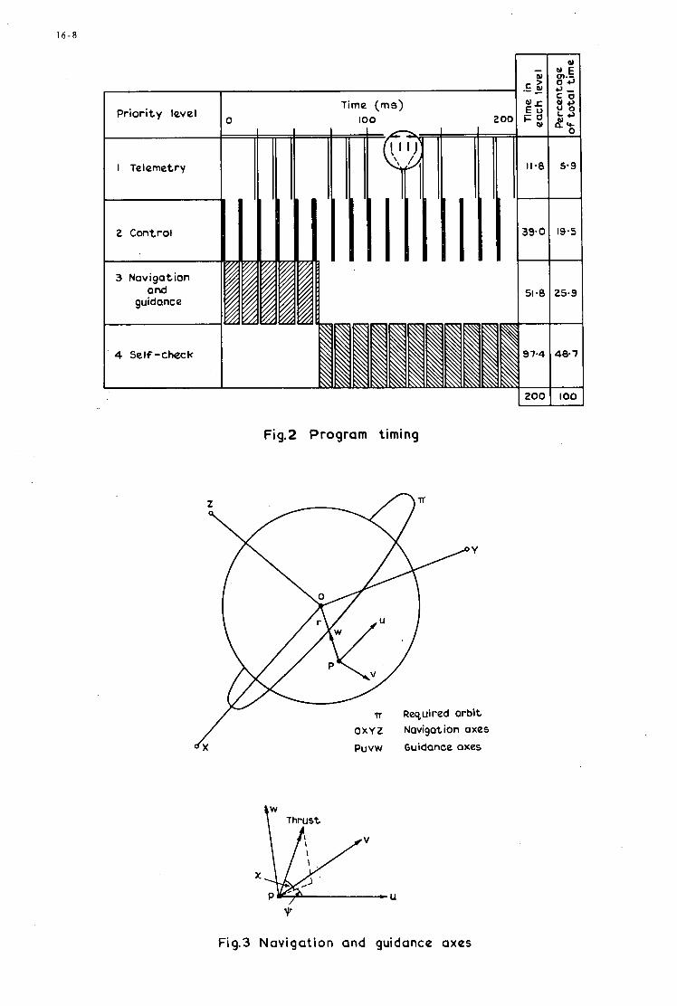
1 6 - 8
I Telemetry
2 Control
4 Self-check
Time (ms) 100 2
I m 51.8 25.9
Fig.2 Program timing
O X Y Z Navigation axes
puvw Guidance axes
\” Thrust
Fig.3 Navigat ion and guidance axes
17
THE STAR COMPUTER: A SELF-TESTING-AND-RING COMPUTW
FOR SPACECRAFI GUIDANCE, CONTROL, AND AUTOMATIC M A I " A N &
Dr . Algirdas Avikienist , Member of Technical Staff Pasadena, California , USA
Jet Propulsion Iaboratory, California Institute of Technology
* This paper presents the results of one phase of research carried aut at the Jet Propulsion laboratory, California Institute of Technology, under Contract No. NAS 7-100, sponsored by the National Aeronautics and Space Administration.
tAlso, Associate Professor, Computer Science Department, School of Engi- neering and Applied Science, University of California, Los Angeles, California, USA.

17
SUMMARY
The success of long-term missions of unmanned spacecraft in the explor-
Missions of up to 12 years duration ation of the solar system depends on the survival of the spscecraft during long intervals of interplanetary flight. are being considered for the "Grand Tour" multiple-planet flyby opportunity in the late 1970's. communication distances impose immense reliability requirements on the on- board digital computer which performs the guidance and control computations. The development of such a computer has been the objective of a research and advanced dwelopment project which was initiated in 1961 and is continuing with an increasing scope at the Astrionics Mvision of the Jet Propulsion Iaboratory. maintenance features is described in this paper. The computer is called the STAR (Self -Testing-And-Repairing) canputer. The hardware, the software, and the estimation of reliability of the STAR computer are discussed. An exten- sion of the STAR concepts to automatic maintenance of other systems of an unmanned Interplanetary spacecraft is also considered.
The long unattended life requirement and the extreme
An experimental aerospace computer with built-in automatic
1 7 - 1
1. INTRODUCTION
Successful planetary exploration missions have been completed by unmanned Mariner spacecraft, which were designed at the Jet Propulsion Laboratory. December 14, 1962. This mission was followed by the flyby of Mars and return of 21,historic photographs of its surface by Mariner IV in July 1965. F’urther successful missions followed: Mariner V to Venus in 1967, Mariners VI and VI1 to Mars in 1969. In all of these missions, a Central Computer and Sequencer onboard the spacecraft was used to provide on-board control functions, although complete ground backup was also available.
Mariner I1 completed a 109-day flyby mission to Venus on
At the present time attention is being directed towards the unmanned exploration of the outer planets Jupiter, Saturn, Uranus, Neptune, and Pluto [l]. ment during the years 1976-80. the use of the gravitational field of Jupiter to deflect and accelerate the spacecraft toward Saturn, and from there toward Uranus and Neptune, or toward Pluto. planets under theee conditions, and launch vehicles that would be limited to Jupiter missions can be employed for the entire “Grand Tour.“ mission times of 18-40 years.
These planets will reach an unusually favorable align- This alignment, which will not be repeated for about 170 years, permits
Much less energy is required to reach the outer
Mission times of 8-12 years become available, as opposed to direct
Even with the favorable alignment of the outer planets, the mission times exceed by on order of magnitude or more the successful nine-month Mariner missions to Mars. An autonomously operating on-board digital computer becomes an absolute necessity because of three factors. makes continual ground support economically unfeasible. Second, the extreme communication distances (for example, 4 hours one-way time for a message from Neptune) require self-contained response to failures and abnormal conditions, the mission progresses and to adapt to partial failures of the spacecraft system. the final encounter decisions to be made a few days before arrival at a planet. programs can then be devised during the years-long cruise to the next planet.
First, the length of the mission
Third, f u l l reprogrammability is needed to make best use of information gained as The computer permits
A completely new set of
The unattended survival requirement for an 8 to 12 year period calls for a computer which possesses a self-test and self-repair function. “automatic repainan” for the entire spacecraft. &en as the first Mariner spacecraft was being readied in 1960-61, it became evident that its modest sequencer would have to be succeeded by a self-maintaining computer as more and more ambitious missions would follow in the future. A research effort intended to lead to the development of a Self-Testing-And-Repairing (STAR) spacecraft computer was initiated in the Flight Computers and Sequencers section at the Jet Propulsion Laboratory in early 1961 and has been con- tinued with increasing levels of effort until the present.
Only a computer of this type can serve as both the “pilot” and the
The first four years of the STAR effort (1961-1964) were devoted to theoretical studies of protective redundancy and to preliminary designs to evaluate competitive schemes of fault-tolerance. The conclusions strongly favored a replacement system, and beginning with 1965 the work was concentrated on the develop- ment of a spacecraft guidance and control computer with provisions for the detection of transient and permanent (simple as well as catastrophic or multiple) faults and with spare unpowered functional units for repair of permanent damage [2]. The construction of an experimental laboratory model (“breadboard”) of the STAR computer was initiated in 1967, and the first program was successfully carried out in March 1969 by a subset of the complete system. At the present time the STAR computer is in limited operation, and additional functional units are being constructed and added. present a general treatment of the problems of fault-tolerant computers, followed by a discussion of the hardware,software, and reliability assessment of the STAR computer. The paper is concluded with some considerations of the extension of automatic maintenance to the entire spacecraft.
The following sections of this paper
2. FAULT-TOLeRANT DIGITAL COMPUTERS
The idealized or ”perfect” digital computer can serve as a reference point in the discussion of fault
The logic design of the computer specifies how these circuits are intercon- tolerance. blocks of a digital computer. nected and which one of the two possible logic values (“true“ and “false“, most frequently designated by ”1” and “0” respectively), will exist at the input and output points of every logic circuit at every defined instant of time. The “perfect“ computer always functions according to the specifications of its logic design. It has been observed, however, that digital computers occasionally deviate from the design specifications. specified value(s). The deviation of a logic variable from its prescribed value is called a logic fault, or more concisely, a fault. in the program being executed by the computer: either an instruction is not executed correctly, o r an incorrect result is computed. may be caused at once by some faults. or a temporary (transient) malfunction of one or more components (resistors, transistors, connections, etc.) o r the computer is the cause.
Two-state logic circuits (storage elements and operator elements) are the elementary building
The logic value(s) at one or more points of the computer logic become opposite to the
Most faults will cause an Both types of errors
The exact nature of a fault depends on whether a permanent failure,
Transient faults are temporary deviations of logic values from design specifications. Two main causes of transient faults are intermittent component malfunctions and external interference with the operation of the computer. Such interference is caused by irregularities of the power supplv, stray elec- tromagnetic radiation, severe environments, and similar events. Transient faults cause errors in computa- tion without leaving a permanent record, and their occurrence will not be detected by the periodic checkouts of the computer, that are sufficient to detect the presence of permanent faults. caused by permanent component failures. As a result the logic value at a certain point remains constant (“stuck on zero“, o r “stuck on one”) regardless Of design specification. occasionally an indeterminate (or “stuck on X”) permanent fault may occur, in which the logic value varies between “1” and “0” but not according to the design. values and similar phenomena. Independent, or s, faults affect only one logic circuit in the computer. random failures of the components. Related, or catastrophic, faults simultaneously affect two or more logic circuits.
Permanent faults are
Beside such determinate faults,
Such faults can be caused by drift of component Logic faults also differ as to the extent to which they affect the computer.
They are caused usually by
They are very likely to occur in the case of physical damage or external interference to

17-2
t h e computer. c lose placement of l og ic c i r c u i t s and make re la ted f a u l t s more probable t h a n is the case when d i sc re t e components a r e used.
The recent advances i n the la rge-sca le in tegra t ion of e lec t ronic c i r c u i t s lead t o very
The preceding discussion of l og ic f a u l t s now permits the de f in i t i on of a f au l t - to l e ran t computer. It is a computer t ha t can car ry out e r ro r - f r ee programs i n the presence of l og ic f a u l t s L2]. f a u l t s t h a t a r e to l e ra t ed and the p a r t s of the computer i n which they may occur must be iden t i f i ed i n every claim of fault to le rance . redundancy. -petition of operations ( t i m e redundancy), and addi t iona l c i r c u i t s (hardware redundancy), t h a t a r e not needed i n the "perfect" computer, but serve t o provide f a u l t tolerance i n the physical implementa- t i on of the same log ic design. a f a u l t has been detected. request) t o t e s t a l l log ic c i r c u i t s of the computer f o r the presence of permanent includes the r epe t i t i on of a program o r a segment of a program a f t e r a f a u l t has been detected o r suspected. Repetition of programs t o compare the r e su l t s , t he inclusion of duplicate in s t ruc t ions , and the "reason- ableness checks" a l s o f i t i n t o t h i s category.
The c lasses of
Fgult tolerance i n d i g i t a l computers is a t t a ined by means of pro tec t ive In t h i s repor t , p ro tec t ive redundancy is defined as a l l addi t iona l programs (software redun-
Software redundancy includes emergency ac t ion programs t h a t a re used when Also included a r e diagnostic programs t h a t a r e executed (per iodica l ly o r upon
f a u l t s . Time redundancy
Hardware redundancx includes the components and/or c i r c u i t s t h a t serve t o provide f a u l t tolerance. Two d i s t i n c t approaches t o the use of hardware redundancy are masking and recovery. s t a t i c , approach uses a "massive" rep l ica t ion of each component o r c i r c u i t t o two or more copies. copies a r e permanently connected and receive power. presence of o ther copies of the same item. however, i f t he f a u l t is not suscept ib le t o masking and causes an e r ro r , a delayed recovery i s not possible in the masking scheme. The two most used var ian ts of masking a r e component quadding f o r individual e l ec - t ron ic components (Fig. 1) and t r i p l e modular redundancy (TMR) with voting (Fig. 2 ) f o r log ic c i r c u i t s o r l a rge r pa r t s of a computer. found p rac t i ca l because of various drawbacks (excessive cos t and lack of p rac t i ca l ly r ea l i zab le spec ia l components). The recovery, o r dynamic, approach i n hardware redundancy requires two consecutive ac t ions . The presence of a f a u l t i s f irst detected, then a recovery ac t ion e i t h e r eliminates the f a u l t o r cor rec ts the e r r o r which was caused. fashian. checks, duplication, and comparison of c r i t i c a l functions. cable t o the e r r o r de tec t ion . an er ror -cor rec t ing code, o r the replacement of a f au l ty part by a spare.
The masking, o r All
The f a u l t masking occurs instantaneously and automatically; Component f a i l u r e s o r l og ic f a u l t s a r e masked by the
Several other var ian ts of masking redundancy have been studied but were not
The redundancy i s usually introduced i n a se l ec t ive , r a the r than massive, The means of e r r o r detection a r e e r ror -de tec t ing codes, monitoring c i r c u i t s , synchronization
Software and t i m e redundancy a re a l s o app l i - The recovery may be a r epe t i t i on of a program segment, the appl ica t ion of
The reconfiguration of a computer i n t o a new system without t he f a i l e d part has a l s o been inves t i - gated. therefore the f a u l t has been only p a r t i a l l y to l e ra t ed . f au l t - to l e ran t " and, therefore , not su i t ab le in appl ica t ions t h a t requi re a constant computing capacity for a prescribed time.
It must, however, be recognized here t h a t t he computing capacity of t he system has been reduced, Such computers can be designated as "pa r t i a l ly
3 . APPLICATION OF FAULT-TOLERANCE I N AEROSPACE COWTERS
The discussion is now di rec ted t o the spec ia l problems of introducing f a u l t tolerance i n t o aerospace computers t ha t carry out computations required f o r t h e guidance and cont ro l of a i r c r a f t , spacecraft , and r e l a t ed vehicles. of telemetry and s c i e n t i f i c da ta , a s well as t o monitor t he performance of various o ther subsystems. choice among the meth-ods of f a u l t tolerance is strongly a f fec ted by these requirements and by the con- s t r a i n t s imposed by the ove ra l l system design.
On many occasions, the seme computer i s programmed t o perform t h e reduction and storage The
Ground-based d i g i t a l computer i n s t a l l a t i o n s depend on extensive diagnostic programs and on the ava i l - a b i l i t y of maintenance experts t o r e s to re proper functioning a f t e r a f a u l t has been detected. where a longer in te r rupt ion cannot be to le ra ted , a second computer is held i n readiness w i t h the same s e t of programs as the f irst . Intermediate r e s u l t s of computation a r e per iodica l ly t ransfer red from the p r i - mary t o the backup computer memory. A s long as the primary computer functions cor rec t ly , t he backup u n i t performs aux i l i a ry computing. When an e r r o r is tne primary u n i t is detected, the backup u n i t assumes the ro l e of the primary u n i t . frequent comparisons a r e used f o r e r r o r detection. Telephone i s a good example of a real-t ime, special-purpose computer with duplication and extensive diag- nos t i c programs. ground based i n s t a l l a t i o n . A human maintenance s p e c i a l i s t is not ava i lab le during an ac tua l mission ( the in t e rva l of time 0 s t 5 T during which the computer must remain opera t iona l ) nor is storage f o r l a rge diagnostic programs ava i lab le . Computing a t the f u l l Capacity and speed i s required a t c r i t i c a l times during the mission, w i t h one of these times usually coming near the mission's end. weight, and volume cons t ra in ts t o be observed i n t h i s environment. a r e encountered i s i n the computer aboard an unmanned space vehic le intended f o r the exploration of the outer p lane ts of the s o l a r system.
In cases
I n real-t ime operation, both computers carry out t he primary programs, and The Electronic Switching System (ESS) No. 1 of Bel l
The typ ica l aerospace computer operates i n a more constrained environment than the
There a r e s t r i c t power, An example where a l l of these l i m i t s
The first extensive application of pro tec t ive redundancy (of the masking type) in an aerospace com-
Discrete e lec t ronic components were used i n t h i s p ro jec t , which w a s i n i t i a t e d i n 1960. puter i s found i n the Primary Processor and Data StoragejUnit of t he Orbiting Astronomical Observatory (OAO) [3). individual components of each log ic c i r c u i t a r e replaced by two o r four copies each, arranged i n p a r a l l e l , s e r i e s , o r "quad" (Fig. 1) arrays . r ep l i ca t ion i s p rac t i ca l . f o r one year (8760 h ) operation i n space and a 15-minute launch in t e rva l during wnich f a i l u r e r a t e s a r e assumed t o be 1000 times higher than during ac tua l operations i n space, and on the known f a i l u r e r a t e s of t he components. A pre-launch period of 3240 h was added subsequently t o the spec i f ica t ion . r e l i a b i l i t y prediction was about 0.75 f o r t he e n t i r e period of operation (including da ta s to rage ) . complete Primarv Processor and Data Storage u n i t contains approximately 70,000 component parts and approxi- matelv 212,000 magnetic cores f o r data s torage . cornnand words (256 loca t ions ) and i n duplicate f o r data words (8192 loca t ions) .
The
This approach uses s t r u c t u r a l redundancy a t the lowest l e v e l a t which The choice of t h i s method vas based on the init ial r e l i a b i l i t y goal of 0.95
The r e su l t i ng The
The Data Storage Unit uses storage i n quadruplicate f o r Storage redundancy i s
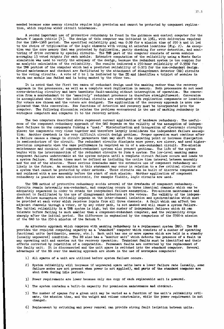
1 7 - 3
needed because some memory c i r c u i t s require high precis ion and cannot be protected by component rep l ica- t ion , which requires wider c i r c u i t tolerances.
A second important use of protect ive redundancy is found i n t h e guidance and control computer f o r the Saturn V launch vehicle [4]. f o r the 1964-1968 period. t o t h e choice of t r i p l i c a t i o n of the l o g i c elements with vot ing a t se lec ted loca t ions (Fig. 2). An excep- t i o n was t h e core memory t h a t was protected by dupi icat ion, p a r i t y checking f o r e r r o r detect ion, and moni- to r ing of dr ive currents by spec ia l c i r c u i t s . averaging 1.3 voted outputs f o r each module. Extensive computation of t h e r e l i a b i l i t y using a Monte Carlo simulation was used t o ver i fy the adequacy of the design, because the redundant system is too complex f o r an a n a l y t i c calculat ion of the r e l i a b i l i t y . The r e s u l t s indicated a 250-hour r e l i a b i l i t y of 0.9992 f o r the TMR portion of the computer which had a predicted r e l i a b i l i t y of 0.973 f o r the non-redundant design. Ground maintenance and checkout a r e f a c i l i t a t e d by the attachment of disagr$ement de tec tor (DD) c i r c u i t s t o t h e vot ing c i r c u i t s . which one module has f a i l e d and i s being masked by the other two.
The design of t h i s computer was i n i t i a t e d in 1961, with de l iver ies required The specif ied r e l i a b i l i t y goal was 0.99 f o r a mission time of 250 h and it led
The !CMR part of the computer cons is t s of seven modules
A vote of 2 t o 1 is indicated by the DD and i d e n t i f i e s a t r i p l e t of modules in
It is noted t h a t the f i r s t two cases of redundant design used the masking ra ther than the r ecwery approach i n the processors, as w e l l as a complete word rep l ica t ion in memory. error-detect ing c i r c u i t r y and have immediate fault-masking without in te r rupt ion of operation. s ion from a nonredundant t o t h e "massively" redundant processor is therefore s t ra ightforward. is accomplished when e i t h e r the individual c i r c u i t s a r e redesigned with rep l ica t ion components o r locat ions f o r voters are chosen and the voters are designed. p l ica ted than t h i s conversion. computer. aerospace computers and compares it t o the recovery method.
Both processors do not need The conver- Conversion
The appl ica t ion of the recovery approach is more com- New functions of detect ion and recovery must be incorporated i n t o the
The following discussion r e l a t e s t h e problems encountered i n the use of masking redundancy i n
The two computers described above represent current appl icat ion of hardware redundancy. The useful- ness of the component redundancy approach of the OAO depends on the v a l i d i t y of the assumption of indepen- dent f a i l u r e s i n the components forming a "quad." Miniaturization and in tegra t ion of e lec t ronic c i r c u i t r y places t h e components very close together and therefore la rge ly inva l ida tes t h e independent f a i l u r e assump- t ion . Proper operation must continue a f t e r a f a i l u r e causes a change i n c i r c u i t parameters t h a t may s h i f t the operating point o r increase d iss ipa t ion i n semiconductors of the c i r c u i t . precis ion components when the same performance is required as is of a non-redundant c i r c u i t . Pre-mission maintenance and checkout of component-redundant systems also present problems. begins with the interconnection of the redundant c i r c u i t s t o form a system. The low-level masking makes component f a i l u r e s undetectable a t the system outputs u n t i l a complete c i r c u i t f a i l u r e occurs and leads t o a system f a i l u r e . Mission times must be defined as including the e n t i r e time i n t e r v a l between assembly and the end of t h e mission. These ser ious drawbacks make the extensive use of component redundancy un- l i k e l y i n the fu ture . An exception t o t h i s statement may occur i n r e l a t i o n t o a few c r i t i c a l c i r c u i t s of a system t h a t cannot be protected by o ther methods. These c i r c u i t s can be b u i l t of d i s c r e t e components and replaced with a new assembly before the start of each mission. redundancy i s possible when non-electronic, f o r example f l u i d i c , l o g i c c i r c u i t s a r e used.
Another drawback is the very d i f f i c u l t c i r c u i t design problem.
The redundant c i r c u i t s d i s s i p a t e more power, a r e slower, and need higher-
The l i f e of the system
Another appl icat ion of component
The TMfi method of pro tec t ive redundancy avoids severa l of the drawbacks of component redundancy. Ci rcu i t s remain i n t e r n a l l y non-redundant, and computing occurs i n three i d e n t i c a l channels which can be adequately separated i n order t o r e t a i n the independent f a i l u r e assumption. he -mis s ion maintenance and checkout i s f a c i l i t a t e d by t h e use of disagreement de tec tors a t the voters . The v a l i d i t y of the indepen- dent f a i l u r e assumption c r i t i c a l l y depends on t h e inter-channel i s o l a t i o n and synchronization which must be proirided a t each voter which receives inputs from a l l th ree channels. adjacent channels through a voter , o r by any other path, is not masked and w i l l cause a system f a i l u r e . The i n i t i a l r e l i a b i l i t y i n a TMR system i s high, b u t the number of independent f a i l u r e s which i f . c a n t o l e r a t e before f a i l i n g i s much smaller than a component-redundant computer, and t h e r e l i a b i l i t y drops sharply a f t e r the initial period. of the OAO t o the 250-h mission of t h e Saturn V.
A fault which can a f f e c t two
The difference i s emphasized by the comparison of the 8760-h mission
An a l t e r n a t e approach which competes with masking redundancy is a replacement system (RS). The RS provides t h e required computing capacity as a "standard" canputer which cons is t s of a number of operating funct ional u n i t s (ar i thmetic , memory, e t c . ) . (usual ly unpowered) condition. The RS a l s o has a "monitor u n i t " which de tec ts t h e presence of a f a u l t in any operating u n i t and c a r r i e s out the r ecwery operation. Transient faults must be i d e n t i f i e d and t h e i r e f f e c t s corrected by r e p e t i t i o n of a computation. the f a u l t y u n i t . advantages of the RS w e r t h e masking approach a r e shown i n the use of aerospace computers:
Each u n i t has one o r more spares which a r e held in a standby
Permanent f a u l t s are corrected by the replacement of It i s disconnected and the u n i t spare i s switched i n t o the standard computer. Several
1) A l l spares of a u n i t a r e u t i l i z e d before system f a i l u r e occurs.
2 ) System r e l i a b i l i t y w i l l increase i f unpowered spare u n i t s have a lower f a i l u r e r a t e (usually, some failure modes are not present when power is not appl ied) , and parts of the etandard. computer are shut d a m during i d l e periods.
Power requirements a r e lower because only one copy of each replaceable u n i t i s powered.
The system contains a b u i l t - i n capacity f o r premission maintenance and checkout.
The number of spares f o r a given u n i t may be varied as a function of the u n i t ' s r e l i a b i l i t y e s t i - mate, the mission t i m e , and t h e weight and volume cons t ra in ts , while the power requirement is not changed.
Replacement by switching and power removal can provide s t rong f a u l t i s o l a t i o n between u n i t s .
3)
4)
5 )
6 )

17 - 4
7) The automatic maintenance !atures o t he RS can be extende e n t i r e aerospace system which contains the computer.
from the computer t o sen, :e the
All of the above l i s t e d advantageE a r e based on the existence of t he monitor u n i t (often ca l led the "hard core") which ca r r i e s out fault detection and recovery operations with a su f f i c i en t ly high r e l i a b i l - i t y and without causing in to le rab ly long in t e r rup t s i n the current computation. has been the main reason why the advantages of t h e RS have not been rea l ized i n cur ren t aerospace computers.
4. ARcBITECl'URE OF THE C m
The lack of such monitors
The advantages of a replacement system a r e v i t a l t o t h e unmanned spacecraft with the mission of ex- ploring the outer p lane ts of t he s o l a r system. which were presented i n the preceding sec t ion led t o the design and construction of a Laboratory model ("breadboard") of a fault - to le ran t computer ca l led the s e l f -zesting-&d- Repairing (abbreviated "STAR") computer [ S i . a t i on of func t iona l subsystems with the required computing capacity. with one o r more spares of each subsystem. replace operating un i t s when a permanent f a u l t is discovered. which a r e used t o impletment e r r o r diagnosib: and recovery a r e l i s t e d below:
These advantages and the l imi t a t ions of masking redundancy
The STAR computer i s a replacement system which provides t o the user one standard configur- The standard computer is supplemented
The spares a r e held i n an unpowered s t a t e and a r e used t o The pr inc ipa l fea tures of the STAR system
1) A l l machine words (data and in s t ruc t ions ) a r e encoded i n e r ror -de tec t ing codes t o provide concur- r en t f a u l t diagnosis, i . e . , f a u l t detection occurs concurrently w i t h t he execution of the programs.
2) The computer i s subdivided i n t o a number of replaceable func t iona l u n i t s containing t h e i r own operation code decoders, and sequence generators. This decent ra l iza t ion of t he system allows simple f a u l t location procedures and s impl i f ies system in te r faces .
Fault detection, recovery, and replacement a r e car r ied out primarily by spec ia l purpose hardware. In the case of memory damage, software is used t o augment the recovery hardware.
Transient faults a r e iden t i f i ed and t h e i r e f f e c t s are corrected by the r epe t i t i on of a segment of the current program; permanent f a u l t s a r e eliminated by the replacement of f a u l t y func t iona l u n i t s .
The replacement i s implemented by power switching: connected by turning power on. the busses through i so l a t ing c i r cu i t s ; u-?powered u n i t s produce only log ic ''zero" outputs.
The error-detecting codes a r e supplemented by monitoring c i r c u i t s which serve t o ve r i fy the pro- per synchronization and in t e rna l operation of the functional un i t s .
The "hard core" test-and-repair hardware i s held t o a small s i z e and protected by complete r e p l i - cation and immediate replacement.
3 )
4 )
5 ) un i t s a r e removed by turning power o f f , and The informat im l i n e s of a l l units a r e permanently connected t o
6 )
7 )
The block diagram of the STAR computer i s shorn i n Fig. 3. The replaceable u n i t s of the system a r e shown i n a c i r cu la r arrangement. the Memory-Out (MO) Bus, and the Memory-In ( M I ) Bus. ing uni t s :
Communication between the u n i t s i s car r ied out on two four-wire busses: The th ree - l e t t e r abbreviations designate the follow-
COP - t h e Control Processor - contains t h e location counter and index r eg i s t e r s and performs modi- f i c a t i o n of i n s t ruc t ion addresses before execution.
t he Logic grocessoi - performs log ica l operations on data words (two copies a r e powered).
t he g i n Arithmetic Processor --performs ar i thmet ic operations on data words.
LOP
MAP
ROM - t he Read only hjemory, 16384 permanently stored words.
- -
RWM - a Eead-Write h&mory unit with 4096 words of storage ( a t least two copies always powered, twelve u n i t s a r e d i r e c t l y addressable).
the &nput/$tput @ocessor - contains a t r ans fe r r e g i s t e r and per iphera l u n i t buf fer r eg i s t e r s .
t h e g t e r p p i : Processor - provides communication l i n k s with systems outside the computer.
t he ziming Processor - a c t s as an interrupt-generating in t e rva l timer.
IOP
IRP
TIP
The choice of the func t iona l un i t s represents a typ ica l s e t of functions required i n an aerospace
- - -
computer. purpose computers t i e d together by the MI and MO (4-wire) information busses. a r e transmitted on these two busses a s 8 bytes of 4 b i t s each. Test-And-Repair Processor (TARP) through the 3-wire Control Bus t o synchronize the operations 3f the func t iona l u n i t s .
The func t iona l un i t s of t i e STAR computer may be thought of as a co l lec t ion of small spec ia l
Three cont ro l s igna ls are sent from the Computer words of 32 b i t s
Otherwise the func t iona l u n i t s operate autonomously.
The monitor of t he STAR system is shown i n the center of the c i r c l e i n Fig. 3 and i s designated a s TARP (Test-And-Repair-Processor). The TARP monitors t he operation of the STAR computer by two methods. In the f i rs t method, an er ror -de tec t ing code has been applied t o a l l data and in s t ruc t ion words which a r e t ransmi t ted on the M I Bus and MO Bus. v a l i d i t y of i t s code. In the second method, a four-wire un i t s t a t u s code is received on the S ta tus Lines from each powered u n i t . "Complete"), repor t "Special" conditions and a l s o i s sue " In te rna l l%ult" warnings detected by monitoring c i r c u i t s within the u n i t .
The TARP contains two "Bus Checkers", which t e s t every word f o r
The u n i t s t a t u s codes ind ica te the operational s t a t u s of the u n i t ( "On" , "Active",
By recording the current ins t ruc t ion and i t s loca t ion , the TARP in t e rna l ly

1 7 - 5
reconstructs the proper s t a t u s f o r each u n i t . normal computing and an entry i n t o the recovery mode.
A deviation from normal operation causes an in te r rupt ion of
Unless otherwise noted, one copy of each u n i t is powered a t any given time. The decentralized or- ganization allows a simple standard in te r face between each unit and the remainder of the computer. This organization also s impl i f ies the control of the other u n i t s by the TARP and provides simple e r r o r detect ion procedures. These wires i n both a c t i v e and spare u n i t s a r e permanently connected t o t h e i r respect ive computer system busses, but a r e i so la ted i n such a fashion t h a t removal of power from a given u n i t removes i t s a b i l i t y t o a f f e c t the busses. The ex terna l connections of a t y p i c a l unit a r e shown i n Mg. 4. The four "Input" and four "Output" l i n e s a r e connected t o t h e information ( M I and MO) busses. They receive and send coded machine words i n four -b i t bytes . The three "Control" input signals are: CMCK, 8 1 mHz timing input; SYNC, a per iodic synchronization s ignal ; and RESET, a s igna l which forces the funct ional u n i t i n t o a standard i n i t i a l s t a t e . s igna ls t o the TARP. s igna ls received from the powered funct ional u n i t s and from the Bus Checkers of the system. u n i t is autonomous and contains i ts own sequence generator as wel l a s s torage f o r the current operation code, operands, and r e s u l t s . as long a s the in te r fac ing spec i f ica t ions a r e observed.
Each STAR computer u n i t in te r faces with the computer by the means of 16 wires.
The SWITCH ON command input c loses the power switch.
The "Unit S ta tus" l i n e s supply the u n i t s t a t u s The TARF' i n i t i a t e s a l l recovery and replacement ac t ions on the basis of the s t a t u s
Each funct ional
The i n t e r n a l design of a u n i t may be a l t e r e d without a f fec t ing other u n i t s
All numeric operand words and ins t ruc t ion words i n the STAR computer a r e encoded with error-detect ing codes, as shown i n Fig. 5. The numeric operand words a r e represented as 32-bit residue-coded numbers con- s i s t i n g of seven 4-bit bytes (b(0) through b (6 ) ) , which is the binary representation of the word b, plus a 4-b i t check byte c (b) . The check byte is establ ished by
c ( b ) 15 - (15 I b )
where "15 I b" means "the modulo 15 residue of the number b." This check byte r e s u l t s i n the complete 32- b i t word being a mult iple of 1 5 . modulo 1 5 residue of the wor0. A zero residue, represented by "1111" indica tes a cor rec t word; a l l other values of the residue ind ica te a f a u l t . a 20-bit residue-coded address part. l u s 15. c ( a ) = 15 - (15 I a ) . numeric operand words. i n a "two-out-of-four'' code which allows byte-wise detect ion of op-code e r r o r s . binat ions f o r every four -b i t byte, o r a t o t a l of 216 var ian ts of op-codes.
Checking of a numeric operand word i s accomplished by computing the
A 32-bit ins t ruc t ion word consis ts of a 12-bi t operation code and The address part is encoded i n the residue code with the check modu-
The address part cons is t s of a 16-bit binary number a and a 4-bit check symbol c ( a ) such that The address part is checked using the same checking algorithm t h a t is appl ied t o
The operation code is divided i n t o 3 bytes of 4 b i t s each. Each byte is encoded There a r e s i x v a l i d com-
Residue codes were chosen f o r e r r o r detect ion i n the STAR com2uter because they have the property
An e a r l i e r version of t h a t the residue check byte can be operated upon independently i n ar i thmetic operations. coding can be used t o check ar i thmet ic processing a s wel l as data transmission. the ar i thmetic u n i t employed a product code y = 15x f o r operand words. The residue code was subs t i tu ted because of i t s more convenient double-precision algorithms. An extensive study of ar i thmetic codes pre- ceded the design and demonstrated that these codes need only a very simple Bus Checker f o r val idat ion and have f u l l y s a t i s f a c t o r y e r r o r detect ion propert ies [ 63.
The residue
5 . OPERATION AND RECOVERY PROCEDLTRE
The STAR computer has two modes of operation: the working mode and the recovery mode. &ring the working mode the s tored programs a r e carr ied out . s i g n a l and the SYNC s i g n a l which occurs when a new s t e p is i n i t i a t e d i n the execution of an ins t ruc t ion . One standard ins t ruc t ion cycle i s executed i n three s teps . t ion is sent from the Location Counter i n the COP t o the Memory (ROM and RWM) units. the addressed Memory u n i t broadcasts on the MO bus the operation code and address of the ins t ruc t ion t o a l l funct ional units. The appropriate u n i t s recognize t h e operation code, s t o r e the address, and i n i t i a t e execution. I n the t h i r d s t e p t h e ins t ruc t ion is executed, an operand is placed on the appropriate bus and accepted by the dest ina- t i o n u n i t . The Bus Checkers t e s t every word transmitted on the busses f o r proper encoding. cycle omits the f i r s t s tep . &ring t h e second s t e p an ins t ruc t ion i s broadcast by the in te r rupt ing u n i t (IRP o r TARP). "step-code'' byte is issued t o the information bus by the TARP simultaneously with the SYNC s i g n a l a t the beginning of each s tep .
The Read-Only Memory (RCM) contains the permanent programs and the associated constants f o r a given
The TARP processor issues the pr inc ipa l 1 mHz CLOCK
In the f i r s t s tep , the address of the ins t ruc- In the second s tep ,
The address i s indexed i n t h e COP which transmits it t o t h e M I bus i f necessary.
An in te r rupt
In order t o d is t inguish between "standard" and " in te r rupt" cycles, a 2-out-of-4 encoded
mission. age of binary information. Memory (RUM) u n i t has two modes of operation. u n i t address. another ("main") u n i t . The relocated u n i t s t o r e s and reads out the same words as its main u n i t . i n t e r n a l l y compares i t s readout t o the word appearing on the MO bus. In case of a disagreement, a SPECIAL s t a t u s s i g n a l is sent t o the TARP which a l s o receives the Checker r e s u l t and i d e n t i f i e s the RWM u n i t sup- plying a damaged word. The relocated mode provides dupl icate o r t r i p l i c a t e s torage f o r c r i t i c a l data . I n t h e case of f a i l u r e of a RUM module, i ts replacement u n i t can be assigned the same address, avoiding a d i s - cont inui ty i n addresses. Assignment and cancel la t ion of re located mode is performed under program control; t h i s provision allows f o r e f f i c i e n t memory u t i l i z a t i o n a s w e l l as f o r se lec t ive redundancy of s torage. record of RWM module assignment is re tained ( in non-volat i le s torage) i n each copy of the TARP.
P r o c e s s o r m ? f w h e n a f a u l t is indicated by t h e Bus Checkers o r by the "Unit S ta tus" inputs . Then t h e TARP i s sues an unconditional t r a n s f e r ins t ruc t ion and a segment of the current program is repeated. t h e f a u l t recurs , the f a u l t y u n i t is replaced with a spare. only one o r a sequence of ins t ruc t ions need t o be repeated.
The experimental model uses a "braid" assembly of transformers and wires f o r the pennanent s t o r -
In t h e standard mode a RWM u n i t recognizes i t s own wired-in Complete rep l icas of the memory are used a s replacements. Each Read-Write
I n t h e relocated mode, a RWM u n i t records and from then on responds t o the u n i t address of Esch u n i t
A
The recove m o d e of operation is i n i t i a t e d by the RESET signal t o a l l u n i t s from the Test-And-Repair
If A f a u l t requires one of two procedures: To provide recovery in the l a t t e r case the
e i t h e r

17 - 6
STAR computer has an instruction which stores a "rollback" address in the TARP. At the time of setting the "rollback" register all computer words which will be needed by the-program in the future must be in nonvolatile and redundant storage (at least two separate RWM-memory modules). The TARP also has registers for the storage of the following data which is needed to decide whether all units operate when required: the present instruction, its location, RWM module assignments, and the source and type of an observed fault. "Disaster Restart" procedure which begins with all other units in unpowered condition.
For cases of temporary power loss and irresolvable fault conditions, the TARP contains a wired-in
The TARP is the "hard core" of the system. Three fully powered copies of the TARP are operated at All outputs of the TARP are decided by a two-out-of-(n +3)
When one powered TARP disagrees with a voted output, it is immediately returned to the all times together with n standby spares. threshold vote. standby condition and one of the standby units receives full power and joins the powered triplet. removed one is kept as a standby unit and reuse is attempted when other spares are exhausted. ceeds if previous removal had been caused by a transient fault. Because of the three unit requirement, design effort has been concentrated on reducing the TARP to the least possible complexity. design. ing. bus. The number of switches is reduced to one per unit, power is conserved and strong isolation is pro- vided for catastrophic failures. power supply and designed to open for most internal failures. manently connected to the busses through isolation circuits. inputs from the units. design for protection against fatal "shorting" failures.
6.
The Reuse suc-
Two spares (n = 2) are used presently.
Experience with the present model is expected to lead to modifications of the
It offers several advantages over the switching of information lines which connect the units to the The replacement of faulty units is commanded by the TARP vote and i s implemented by power switch-
Magnetic power switches have been developed which are part of each unit's The information lines of each unit are per- The signal on the bus is the logic OR of all
The power switch and the busses utilize component redundancy and careful electronic
COMPUTEB SOFTWARE AND RELIABILITY ASSESSMENT
Two major software research and development efforts were initiated concurrently with the design and First, a software effort was initiated in 1967 and is construction of the STAR computer breadboard [TI.
presently well under way; the completed systems programs include an assembly program, loader, and func- tional simulator. cessfully carried out its first program in March of 1969. STAR-like fault-tolerant replacement systems is nearing completion. The study has led to the development of the CARE (@mputer-Aided Reliability Estimation) program, which can be used for interactive evaluation of various fault-tolerant designs.
The operating system is presently being designed. A subset of the STAR breadboard suc- Second, a study of reliability estimation for
The STAR Computer Software System is partitioned into two separate subsystems. The first subsystem, the programming subsystem, consists of three modules: an assembler, a loader, and a functional simulator. The second subsystem, the operating subsystem, consists of two modules: the resident executive module and the applications programs module. The modules of the programming subsystem are static in nature: they are complete they require little change. These modules are being developed on the UNIVAC 1108 system of the Scientific Computing Facility at JPL. An executive program has also been developed to facilitate coordinated use of the assembler, loader, and simulator. The modules of the operating subsystem are dyna- mic in nature: The modules for a typicalspacemission would consist of a resident executive module and a module comprised of several applications programs, each of which would perform the computation for a particular aspect of the mission. Facilities are included in the operating subsystem which implement the timekeeDing functions required-on a spacecraft computer.
once
they will be constantly changed as the STAR computer hardware-software system is developed.
The first module of the STAR Computer Software System is SCAP: the STAR computer &sembly progmm. Programs for the STAR cmputer are written in SCAL: SCAP consists of a source program written in SCAL; the output consists of binary card images in an inter- mediate language used as input to the loader. machine instructions, pseudo-operations, macro facilities, and a unique COMPILE pseudo-operation which implements autmatic compilation of simple arithmetic statements by the assembler. For instance, on a single-address machine like the STAR computer, incrementing a counter usually requires three instructions: a load or clear-and-add type, an add, and a store. piled by writing COMP Y = Y + 1 in SCAL. Any valid statement involving =, +, -, *, f , and parentheses is allowed. The second module of the STAR Computer Software System is LOAD: that it is the only phase programed on two different computers. camputer as the assembler and simulator (the UNIVAC 1108). interface between the assembler and the simulator. so that various binary decks (and possibly patches) may be put together and loaded immediately into the STAR computer without an additional run on the 1108. puter programmer: by the 1108 ready for immediate use by the STAR computer; or programs may be assembled by the 1108 and loaded by the STAR computer. simulator. The STAR computer is being constructed as a breadboard to permit experimentation with the self- testing-and-repairing features and the associated algorithms. the programing subsystem so that programs may be developed for the STAR computer before hardware construc- tion is completed. computer: hardware debugging of the camputer can be simplified.
the STAR Eomputer Assembly @nguage. The input to
SCAP is a traditional two-pass assembler incorporating
These three instructions could be automatically com-
This pseudo-operation is a powerful feature of the STAR Computer Assembly Language. the STAR Computer E r . This phase is unique in
Initially LOAD is written for the same
LOAD is also programmed for the STAR computer itself This is essential since the loader is the
Thus two alternatives are available to the STAR com- programs may be assembled and loaded onto a binary magnetic tape or binary punched cards
The third module of the STAR Computer Software System is the functional
A functional simulator is being included in
F'urthermore, by using the simulator to debug programs before they are run on the STAR
An executive program has been developed for coordinated use of the assembler, loader, and simulator. Using this executive, source and relocatable binary decks can be cmbined to form a load module for the STAR computer. This load module may be written on tape, punched on cards, and input to the simulator for simulated execution. Thus, all modules of the programing system can be utilized during a single run on the 1108 computer. The modules of the operating subsystem of the STAR Computer Software System, consisting of the resident executive module and applications programs module, are currently being developed. The fourth module of the STAR Computer Software System is the resident executive module.
Control cards may be included in the input deck to select the various options available.
The most important function of this

1 7 - 7
module i s t o provide software required t o implement program resumption after e r r o r de tec t ion . t i o n s implemented i n t h i s module a r e scheduling, input-output control, i n t e r rup t processing, and diagnos- t i c s . The f i f t h module of t he STAR Computer Software System is t he appl ica t ions programs module. Common mathematical subroutines such a s f loa t ing-poin t , double-precision, sine, cosine, square root, e tc . , may be recorded i n STAR computer read-only memory. on the STAR computer. It is ant ic ipa ted that guidance and cont ro l programs can be wr i t ten and run on the STAR computer by simulating sensor and cont ro l s igna l s a t the STAR Cmputer Input-Output Processor.
Other func-
The read-write memory w i l l be used f o r developing programs
The projected in te rp lane tary mission requirements f o r d i g i t a l computers designed t o perform i n space environment a r e i n the order of t en or more years. a b i l i t y of STAR-like configurations, t he methodolo first t o be developed. Since the current methods gased e i t h e r on simulation or on p a r t s count) of mea- suring the expected r e l i a b i l i t y of a computer system do not cover a l l aspec ts of t he STAR computer organi- za t ion , a r e l i a b i l i t y estircation study was i n i t i a t e d f o r t he STAR pro jec t . This study i s concerned with severa l i n t e r r e l a t ed tasks . One i s the development of r e l i a b i l i t y equations which represent the r e l i a b i l i t y of STAR-like f au l t - to l e ran t configurations. The second i s t o analyze with respect t o s ign i f i can t parameters the various redundancy techniques which have been u t i l i z e d . dancy techniques which a r e ava i lab le and determines f igures of merit and guidelines for t h e i r optimum usage. These tasks lead t o the development of a mathematical r e l i a b i l i t y model of generalized STAR-like computers which w i l l permit t h e ana ly t i c evaluation of t he s ign i f i can t r e l i a b i l i t y parameters [a). r e l i a b i l i t y study l ed t o the development of a r e l i a b i l i t y design t o o l ca l led the CARE! (@mputer-&ided Re l i ab i l i t y Estimation) program. computer system a t JPL. cu la t e h i s r e l i a b i l i t y estimates. by queries on the various r e l i a b i l i t y parameters of i n t e r e s t and t h e i r behavior w i t h respect t o mission time, fault-coverage, f a i l u r e r a t e s , dormancy f ac to r s , a l loca ted spares, and cos t i n hardware. The CARE subroutines a r e per iodica l ly updated t o r e f l e c t refinements made on ex i s t ing r e l i a b i l i t y models and enlarged as fu r the r data becomes ava i lab le .
In order t o determine, evaluate, and compare the r e l i - f o r r e l i a b i l i t y evaluation of such systems needed
Third c r i t i c a l l y compares the various redun-
The foregoing
CARE is a software package currently being developed on the UNIVAC 1108 CARE may be in t e rac t ive ly accessed by a designer from a te le type console t o ca l -
The input i s i n the form of a system configuration descr ip t ion followed
The preliminary r e l i a b i l i t y estimates of t he STAR computer were based on the following r e l i a b i l i t y model. estimation. with a number of spares. spares. meters t o r e f l e c t dormancy e f f e c t s of the spare u n i t s . t i e s of the STAR computer and a non-redundant computer having the same computational capabi l i ty a s the STAR. of no f a i l u r e s of t h e spares (upper bound) and equal f a i l u r e r a t e s f o r spare and ac t ive units (lower bound) f o r t he STAR computer with an a l loca t ion of th ree spares f o r each processor. which these r e s u l t s a r e based are undergoing fu r the r refinement t o r e f l e c t t he r e l i a b i l i t y of the STAR computer with grea te r exacti tude. t o be considered as a f i r s t - c u t estimate.
7. AUTWIC SPACECRAFT MAINTENANCE: EX"SI0NS OF TECHNIQUES
of the ground checkout equipment t o a spec ia l func t iona l u n i t (an expanded TARP) which contains programs f o r t he checkout of a l l copies of the STAR function u n i t s . sion is a l s o readi ly implemented by an on-board program. matic mintenance ( t e s t i n g and replacement) of subsystems may be extended beyond the computer t o include o ther parts of t he spacecraf t . Sensors and o ther pa r t s of t he guidance system, communication equipment, and s c i e n t i f i c instruments can be monitored, per iodica l ly tes ted , and replaced by spares (using power switching) following the techniques used f o r t he replaceable processor and s torage un i t s of the STAR c m - puter. The f au l t - to l e ran t STAR computer can be w e d as the monitor and "automatic repairman" f o r t he e n t i r e spacecraf t . Its memory u n i t s contain the ca l ibra t ion , diagnosis and emergency ac t ion programs f o r t he maintenance of t h e e n t i r e spacecraf t . subsystems o f fe r s very important advantages over o ther types of redundancy. a r e not increased by the introduction of redundancy. f a i l u r e rate whenever add i t iona l f a i l u r e modes a r e introduced by the presence of power in a subsystem. Both proper t ies a r e exceptionally important In t he missions t o t h e outer planets of t he so l a r system, which requi re a very long surv iva l of t he spacecraft (over 10 years ) , and which a r e subjec t t o very s t r i c t parer cons t ra in ts [ 1.1.
The func t iona l processors comprising the STAR a r e considered t o be i n s e r i e s f o r t h e i r r e l i a b i l i t y The TAFtp unit which is t he "hard-core" of t h e STAR organization is a t r i p l i c a t e d configuration
The remaining func t iona l processors a r e i n a replacement mode u t i l i z i n g standby The r e l i a b i l i t y model r e f l ec t ing t h i s organization was extended by incorporating add i t iona l para-
Figure 6 shars t he comparative surv iva l probabi l i -
The bounds on the r e l i a b i l i t y versus mission time ( in yea r s ) a r e shown corresponding t o the cases
The mathematical models on
For the above reasons the computer f igu res provided a t t h i s time a r e
A n immediate consequence of t he automatic maintenance provided i n the STAR computer i s the reduction
Periodic checkout of spare u n i t s during a m i s - These fea tures lead t o t h e conclusion t h a t auto-
The redundancy provided by unpowered spare copies of spacecraft F i r s t , the power requirements
Second, t he unpowered spare copies w i l l have a lower
The p rac t i ca l implementation of automatic checkout and continuous i n - f l i g h t maintenance of the e n t i r e spacecraft poses severa l addi t iona l requirements on t h e designers. t i o n which a r e most e f f ec t ive f o r each 'black box" subsystem of the spacecraft must be incorporated within the subsystem. Second, a standard in t e r f ace with the STAR computer ( i . e . , i ts In t e r rup t Processor and I/O Processor) must be devised, which w i l l permit t he STAR computer t o perform the necessary monitoring and t e s t operations. Third, power switching must be adapted f o r each "black box." Fourth, t e s t and ca l ibra- t i o n procedures must be devised and t e s t programs must be writ ten of t he STAR computer f o r each one of t he maintainable (replaceable) parts of the spacecraf t . noted that a l l of t he above functions (except power switching) a r e presently implemented by ground checkout e q u i p e n t which is used t o prepare the spacecraft f o r i t s mission, and t h a t t h i s accumulated experience is applicable t o the development of i n - f l i g h t t e s t i n g and replacement. A study of the automatic i n - f l i gh t maintenance of the spacecraft i s presently under way, and severa l promising appl ica t ions have already been iden t i f i ed .
First, methods of i n t e rna l f a u l t detec-
and s tored i n the Read-Only Memory u n i t It must be
To i l l u s t r a t e the appl ica t ion of automatic maintenance pr inc ip les , we consider the monitoring of the propulsion system performance i n a spacecraft . the pressures i n the f u e l l i n e , the oxidizer l i n e and i n the combustion chamber, a s well as the combustion chamber temperature. and an a l t e r n a t e valve i s operated.
The sensors which provide data t o the computer ind ica te
I f an abnonnal f u e l or oxidizer flow condition is detected, t he motor is shut down A record of the event i s stored f o r fu tu re reference and f o r telemetry.
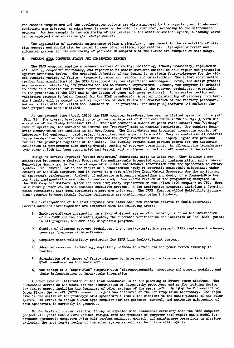
1 7 - 8
The chamber temperature and the accelerometer outputs are a150 monitored by the computer, and if abnormal conditions are detected, an adjustment is made or the motor is shut down, according to the maintenance program. can be employed when excessive gas leakage occurs.
Another example is the monitoring of gas leakage in the attitude-control system; a standby valve
The application of automatic maintenance offers a significant improvement in the expectation of mie- sion success and should also be useful in many other critical applications. automated systems for the monitoring of patients in hospitals of the future are examples of this usage.
8. PRESENT COMPUTER STATUS AND CONTINUING EIPM)RTS
High-speed aircraft and
The STAR computer employ5 a balanced mixture of coding, monitoring, standby redundancy, replication with voting, component redundancy, and repetition to attain hardware-controlled self-repair and protection against transient faults. The principal objective of the design is to attain fault-tolerance for the wid- est possible variety of faults: transient, permanent, random, and catastrophic. The actual construction (rather than simulation) of the STAR breadboard has two significant advantages. Mrst, the design process has uncovered interesting new problems and led to numerous improvements. Second, the computer is intended to serve as a vehicle for further experimentation and refinement of the recovery techniques, (especially in the protection of the TARP and in the design of buses and parer switches). validation program is being planned for the STAR breadboard. sient faults will be sought by actual injection of such faults and observation of the recovery procedure. Automatic test data collection and reduction will be provided. this purpose has been initiated.
An extensive testing and A better understanding of recovery from tran-
The design of hardware and software for
At the present time (April 1970) the STAR computer breadboard has been in limited operation for a year (Fig. 7). exception of the Timing Processor (TIP). mode of operation; the hardware to control the "recovery" mode is nearing completion. Write Memory units are included in the breadboard. laboratory If0 equipment: for pulse-by-pulse operation have been provided for every functional unit. for all the principal registers of the units. collection of performance data during dynamic testing of recovery operations. type power switch has been constructed and tested; work continues on further refinements of the switch.
The present breadboard contains one complete set of functioml units shown in Fig. 3, with the The TARP contains a subset of parts which control the "working"
Two complete Read- The Input-Output and Interrupt processors consist of
card reader, typewriter, and magnetic tape unit. Very extensive manual controls Display lights are provided
The display outputs also provide points for the automatic An all-magnetic transformer-
Design of several improved "second generation" functional units is under way. They include a new Arithmetic Processor, a Control Processor for medium-scale integrated circuit implementation, and a "shared" Read-Write Memory module for the storage of automatic maintenance information from the spacecraft telemetry system. The "shared" RWM is the result of a concentrated study of automatic spacecraft maintenance under control of the STAR computer, and it serves as a very effective InputfOutput Processor for the monitoring of spacecraft performance. Analysis of automatic maintenance algorithms and design of a CommandfDsta bus for their implementation are under intensive study. the STAR Computer Software System has been completely implemented on the UNIVAC 1108 computer at JPL. is currently under way on the resident executive program. point subroutine, have been completed; others are under way. tion) program is operational; further refinements are continuously being introduced.
The second version of the programing subsystem in Work
A few application programs, including a floating The CARE (gomputer-&ided Reliability Estima-
The investigations of the STAR computer have stimulated new research efforts in fault tolerance. Current advanced investigations are concerned with the following areas:
1) Hardware-software interaction in a fault-tolerant system with recovery, such as the interaction of the TARP and the operating system, the automatic verification and insertion of "rollback" points in all programs, and auxiliary diagnostic programs.
Studies of advanced recovery techniques, i.e., post-catastrophic restart, TARP replacement schemes, recovery from massive interference.
Computer-aided reliability prediction for STAR-like fault-tolerant systems.
Advanced component technology, especially methods to attain bus and power switch immunity to faults.
Formulation of a theory of fault-tolerance by interpretation of extensive experiments with the STAR breadboard as the instrument.
The design of a "Super-STAR" computer with "microprogrammable" processor and storage modules, and their implementation by large-scale integration.
2)
3 )
4 )
5 )
6 )
Another area of utilization of the STAR breadboard is in the planning of future space missions. breadboard serves as the model for the construction of flighworthy prototypes and as the training device for future users, including the designers of other systems of the spacecraft. Outer Planet Spacecraft (TOPS) research project was initiated at the Jet Propulsion Laboratory. Its objec- tive is the design of the prototype of a spacecraft suitable for missions to the outer planets of the solar system. this spacecraft is currently in progress.
The
In 1969 the Thermoelectric
An effort to design a STAR-type computer for the guidance, control, and automatic maintenance of
On the basis of current results, it may be expected with reasonable certainty that the STAR computer project will yield both a more refined insight into the problems of computer self-repair and a model for advanced spacecraft computers which will perform guidance, control, and maintenance operations on missions exploring the most remote realms of the solar system as well as the interstellar space.
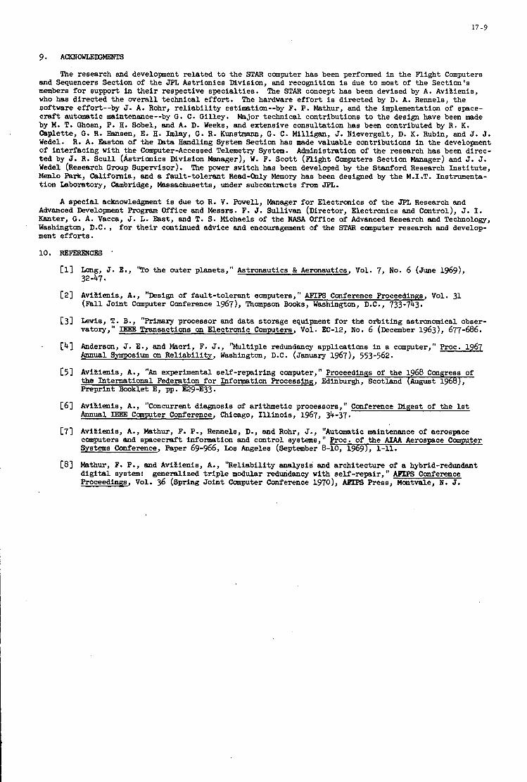
17-9
9. ACKNOWLEEWEWl'S
The research and development related to the STAR computer has been performed in the Flight Computers and Sequencers Section of the JPL Astrionics mvision, and recognition is due to most of the Section's members for support in their respective specialties. The STAR concept has been devised by A. Aviltienis, who has directed the overall technical effort. software effort--by J. A. Rohr, reliability estimation--by F. P. Mathur, and the implementation of space- craft automatic maintenance--by G . C. Gilley. Major technical contributions to the design have been made by M . T. Ghosn, P. H. Sobel, and A. D. Weeks, and extensive consultation has been contributed by R . K. Caplette, G. R. Hansen, E. H. Imlay, G . R . Kunstmann, G . C. Milligan, J. Nievergelt, D. K. Rubin, and J. J. Wedel. R . A. Easton of the Dsta Handling System Section has made valuable contributions in the development of interfacing with the Computer-Accessed Telemetry System. Administration of the research has been direc- ted by J. R . Scull (Astrionics Mvision Manager), W. F. Scott (Flight Computers Section Manager) and J. J. Wedel (Research Group Supervisor). The power switch has been developed by the Stanford Research Institute, Menlo Park, California, and a fault-tolerant Read-only Memory has been designed by the M.I.T. Instnunente- tion Laboratory, Cambridge, Massachusetts, under subcontracts from JPL.
A special acknowledgment is due to R . V. Powell, Manager for Electronics of the JPL Research and Advanced Development Program Office and Messrs. F. J. Sullivan (Director, Electronics and Control), J. I. Kanter, G. A. Vacca, J. L. East, and T. S. Michaels of the NASA Office of Advanced Research and Technology, Washington, D.C., for their continued advice and encouragement of the STAR oomputer research and develop- ment efforts.
The hardware effort is directed by D. A. Rennels, the
c11
C21
C31
. c41
C51
[61
c73
CBI
Long, J. E., "To the outer planets," Astronautics & Aeronautics, Vol. 7, No. 6 (June 1969), 32-47.
Avitlenis, A., "Design of fault-tolerant oomputers, " AFIPS Conference Proceedings, Vol. 31 (Fall Joint Computer Conference 1967), Thompson Books, Washington, D.C., 733-743.
Lewis, T. B., "Primary processor and data storage equipment for the orbiting astronomical obser- vatory," IEEE Transactions on Electronic Computers, Vol. EC-12, No. 6 (December 1963), 677-686.
Anderson, J. E., and Macri, F. J., "Multiple redundancy applications in a computer," Proc. 1961 Annual Symposium on Reliability, Washington, D.C. (January 1967), 553-562.
Aviltienis, A., "An experimental self -repairing computer, I t Proceedinas of the 1968 Congress of the International Federation for Information Processing, Edinburgh, Scotland (August 1968), Preprint Booklet E, pp. E29-E33.
Avikienis, A., "Concurrent diagnosis of arithmetic processors, " Conference Digest of the 1st Annual IEEE Camputer Conference, Chicago, Illinois, 1967, 34-37.
Aviltienis, A., Mathur, F. P., Rennels, D., and Rohr, J., "Automatic maintenance of aerospace computers and spacecraft information and control systems," Proc. of the AIAA Aerospace Computer Systems Conference, Paper 69-966, Los Angeles (September 8-10, 1969), 1-11.
Mathur, F. P., and Aviaienis, A., "Reliability analysis and architecture of a hybrid-redundant digital system: generalized triple modular redundancy with self -repair, AFLPS Conference Proceedings, Vol. 36 (Spring Joint Computer Conference 1970), AETPS Press, Montvale, N. J.
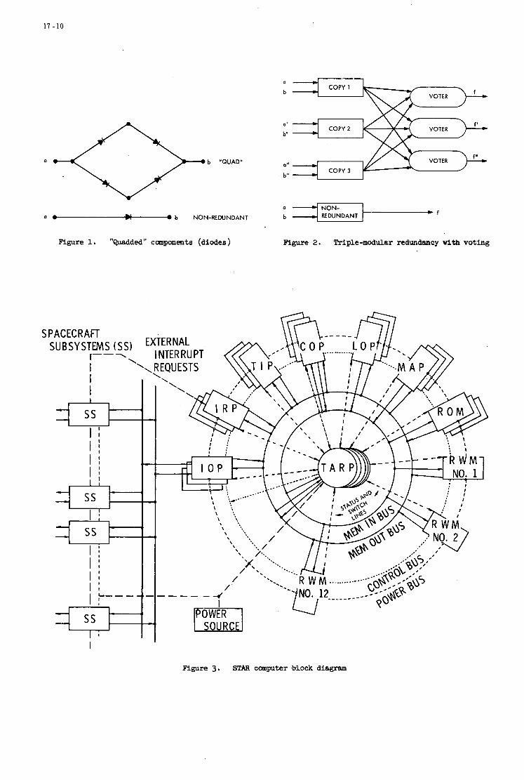
17-10
a b "QUAD"
a COPY I
VOTER b
01
b' COPY 2 VOTER
VOTER a"
b" COPY 3
a
a * U -1 ,f
NON- 0 b NON-REDUNDANT b REDUNDANT
Figure 1. "Quadded" cmponents (diodes) Figure 2. Triple-modular redundancy w i t h voting
Figure 3. STAR computer WAO& diagram

1 7 - 1 1
c(bJ
MAIN POWER
b6 I b5 b4 b3 I b2 I b l I M) CONTROL 'I -1 1
OPERATION
12 B ITS 4 e+ CODE -1 ADDRESS PART
20 BITS
INPUT FROM INFO BUS
-SWITCH ON COMMAND FROM TARP
FUNCTIONAL UNIT
(b) INSTRUCTION WORD
M R E E "2-OUT-OF-4" CODED BYTES RESIDUECODE: c(a) = 15 - lal15
Figure 4. Typical STAR funct ional u n i t Figure 5 . STAR cunputer words
1.0
0.8
0.6
0.4
0.0 0 2 4 6 8 10 12
TIME, YEARS
Figure 6. Upper and lower bounds on the r e l i a b i l i t y of STAR computer (3 spares)
Mgure 7. STAR computer breadboard

18
SENSITIVITY ANALYSIS OF APPROXIMATE OPTIMUM GUIDANCE
PROCEDURES FOR ON-LINE OPERATION
Eveline Gottzein and Helmut Bittner
Meperschmitt-B8lkow-Blohm GmbH O t t obr unn, Germany

18
SUMMARY
The paper is concerned with simplified guidance computation schemes f o r on-line operation. Under the aspect of onboard or ground s ta t ion computer organisation expl ic i t and implicit guidance methods are discussed. Based on computational requirements. poss ib i l i t i es for approximate expl ic i t guidance procedures are compared.
18-1
S E N S I T I V I T Y A N A L Y S I S . O F A P P R O X I M A T E OPTIMUM G U I D A N C E P R O C E D U R E S F O R O N - L I N E O P E R A T I O N
Eveline Gottzein and Helmut Bittner
1 . I N T R O D U C T I O N
The fast progress i n the development of low-weight, high-speed d i g i t a l computers already achieved and still continuing has caused new aspects t o become a t t rac t ive f o r t h e application i n space and missile guidance and control tasks. The fundamental s i tua t ions t o be encountered i n practice are schematically indicated i n the block diagrams of Figure 1. The simplest method of guiding a vehicle on its t ra jectory uses a precalculated nominal a t t i tude program, which is often suf f ic ien t f o r the first stage f l i g h t of a multistage vehicle. In order t o t ransfer maximum payload in to a given o rb i t and t o ensure suff ic ient injection accuracy in the presence of perturbations, closed loop guidance procedures have t o be applied, a t l e a s t fo r the f l i gh t phases of the upper stages. Depending on whether the guidance and control problems t o be solved can be local ly separated from each other or have t o be solved a t the same place i .e. on board of the vehicle, e i ther radio guidance or i n e r t i a l guidance may be used (see Figure 1). The f i r s t possibi l i ty allows for a big and f a s t guidance computer but is heavily res t r ic ted by t h e geographical conditions i . e . the ava i lab i l i ty of a point on the ear th surface within the v i s i b i l i t y range of the most important part of the trajectory. question, i f a mobile launching point is required. The i n e r t i a l guidance case does not suffer from these r e s t r i c t i v e conditions but entrains obviously l imitat ions on computer s i ze and storage capacity.
This way is completely out of the
Advanced vehicle concepts and the complex onboard systems associated with them ca l l fo r the implementation of a d i g i t a l processor f o r various reasons. Once it is decided t h a t a d i g i t a l computer is t o be instal led on board of t h e vehicle there are a large number of tasks t o be performed conveniently by the computer apart from the navigation (purely i n e r t i a l or hybrid) and guidance aspects. Disregarding fo r the moment its application within the prelaunch phase for
- platform alignment - check-out assistance and - propellant loading control,
t h e ava i lab i l i ty of an onboard d i g i t a l computer may be taken advantage of during the actual f l i gh t phase t o solve the following problems:
- a t t i tude control
- auxiliary a t t i tude control - navigation, guidance and optimization - d i g i t a l f i l t e r i n g of the measured values of the i n e r t i a l measurement system, estimation of vehicle
- control of th rus t and propellant feed system - coordination of guidance and control systems - f l i g h t sequencing - sequencing of data t ransfer - data compression and preliminary data analysis fo r telemetry.
parameters
In order t o cope with these tasks it is required t o reduce the computational e f for t s f o r each of these From the following we are going t o discuss the aspect of guidance problems by convenient approximations.
computation schemes sui ted fo r on-line computer operation.
2. G E N E R A L R E Q U I R E M E N T S
Let us f i r s t state i n general form what requirements have t o be met i n order t o f i t the guidance procedure into the on-board computer organisation. The guidance procedure is expected t o perform the following tasks:
- evaluation of the optimal a t t i tude law based on the knowledge of the present s t a t e vector and the
- prediction of the time t o go in order t o provide the engine cut-off signals. inject ion point t o be achieved.
Figure 2 shows a block diagram of the EUROPA 2 i n e r t i a l guidance system and its interlinkage with the vehicle a t t i tude control. The vehicle is equipped wi th an i n e r t i a l platform providing three Euler angles fo r a t t i tude

18-2
control purposes and three acceleration components i n space fixed axes. the analog accelerometer signals are integrated t o velocity increments and converted in to d i g i t a l form within the acceleration encoder and then fed i n t o the onboard computer. t i on due t o a l l external forces except the gravitational force, the velocity increments due t o gravitation have t o be calculated from posit ion and added within the computer integration routine. velocity of t he vehicle is converted into a coordinate system suited for guidance computations. discussion of t he EUROPA 2 ine r t i a l guidance system is given in Reference 4.
For the particular example considered,
Since the accelerometers measure the accelera-
The result ing position and A detailed
When establishing guidance procedures, the following general aspects have t o be taken into account from the computer point of view:
- The tasks l i s t e d i n Section 1 have t o be performed i n real time. The various s igna ls t o be processed demand d i f fe ren t sampling r a t e s and computer resolution.
The computer therefore has t o be equipped with input and output capabili ty of d i f fe ren t levels l ike Output Control Pulses, Sense Lines, Pr ior i ty Interrupts besides the data communication. The provision of these above mentioned control signals allows for the necessary multiprogramming scheme of different p r io r i ty levels. calculated at a very low p r io r i ty level.
The guidance signals having a low bandwidth only w i l l obviously have t o be
- Each of the individual tasks has t o be performed within fixed frame times and i n order not t o waste compu- t a t ion time the duration of the various operations should be predetermined as f a r as possible and only subjected t o very small variations. ent p r io r i ty levels and frame times is given.
In Figure 3 a typica l diagram for onboard computer timing with d i f f e r -
- The storage requirements for the essent ia l program par t s should s tay within l imits , since for reasons of r e l i a b i l i t y it is advisable t o s tore t h i s information twice i n d i f fe ren t memory banks.
- A reasonable compromise as for computer wordlength has t o be found since the various tasks of Section 1 require d i f fe ren t computer resolution. While f o r some tasks two or even one b i t is suf f ic ien t and the control tasks require 7 - 8 b i t s , only, insufficient computer resolution for navigation and guidance might prodace guidance noise at c r i t i c a l frequencies and excite the vehicle. This d i f f i cu l ty could be coped with by using multiple wordlength of course but only on cost of longer computation time.
A word length of 18 -24 b i t s seem appropriate.
3 . P O S S I B L E S O L U T I O N S OF THE GUIDANCE PROBLEM
From the following the methods commonly used t o solve the optimal guidance problem w i l l be br ie f ly character- ized and t h e i r advantages as well as t h e i r p rac t ica l l imitations w i l l be illuminated. t ha t irrespective of the par t icu lar coordinate system chosen t o mathematically describe the motion of the vehicle, the injection conditions have t o be expressed by a suitable set of invariant o rb i t a l parameters. formulations of the problem w i l l therefore use coordinate systems which ensure simple relations between s t a t e variables and o rb i t a l parameters.
It is t o be understood,
Convenient
3.1 Explicit Guidance
The exact optimal guidance conditions represent a nonlinear two-point boundary value problem, which is t o be solved a t any instant of vehicle f l i g h t , where guidance commands are t o be calculated. optimality conditions involved are too complicated t o allow f o r an analytical solut ion, an i t e r a t ive procedure is required. In general t h i s is an elaborate and time consuming task. It implies, t ha t the simultaneous non- l inear d i f f e ren t i a l equations of state variables and adjoint variables have t o be integrated several times over t he whole time of f l i g h t for i n i t i a l conditions of the adjoint variables altered i n turn. From the variations of the end points of t he state variables as a function of variations of the adjoint variables at the current time a sens i t i v i ty matrix can be constructed which allows t o evaluate corrections of the i n i t i a l values of the adjoint variables. Functional relationships of the adjoint variables determine the optimal a t t i t ude programme. The most c r i t i c a l drawbacks of t h i s i t e r a t ive procedure f o r on-line computations of the optimal guidance commands i n view of the requirement of a fixed frame time are:
Since the necessary
- variable time of integration depending on the current s t a t e of the vehicle with respect t o the injection
- t he number of reoptimization cycles required t o calculate the optimal a t t i t ude commands is not predeter-
- the computation time needed for each reoptimization step is f a i r l y high.
point
mined
The advantages of t he expl ic i t guidance method t o solve the two-point boundary value problem are:
- t he computer storage capacity required is small
- the guidance scheme is t o a f a r extent independent of the par t icu lar orb i t o r mission - t he guidance procedure is f lex ib le with respect t o changes i n the launch s i t e
- t he guidance method is f a i r l y insensit ive t o deviations of vehicle parameters from nominal so t h a t in most cases no updating of t he vehicle model is necessary
18-3
- precalculations are only required t o adjust the i n i t i a l values of the adjoint variables.
Explicit guidance w i l l be deal t with i n more d e t a i l i n Section 4.
3.2 Impl i c i t Guidance
4. APPROXIMATE E X P L I C I T G U I D A N C E SCHEMES
From the discussion of t h e previous chapter expl ic i t guidance procedures are more a t t rac t ive for i n e r t i a l guidance applications mainly from the f l e x i b i l i t y and storage capacity point of view, provided it were possible t o f i t the on-line computations required into a fixed frame time of reasonable length by introducing sui table approximations.
4 . 1 Flat Ear th Guidance
In order t o circumvent the computational d i f f i c u l t i e s involved in solving the nonlinear two point boundary value problem, i n the f l a t ear th guidance procedure some simplifying approximations are made, which allow t h e d i f fe ren t ia l equations representing t h e necessary conditions fo r optimality t o be solved pa r t ly analytically‘. The characteristic features are:
- the optimizb.tion problem is formulated i n spherical polar coordinates, a rotat ing coordinate system w i t h the or igin i n the centre of gravity of the vehicle one axis pointing to the gravitation centre, the second being parallel t o the nominal o rb i t plane pointing into the “forward direction” and t h e th i rd pointing out of the o rb i t plane. In these coordinates the cut-off boundary conditions assume a very simple form.
- the motion is assumed t o take place i n a unidirectional - hence the name “f la t .ear th” - and constanc force f ie ld . Under t h i s assumption the d i f fe ren t ia l equations of s ta te variables and adjoint variables are not coupled with each other, the adjoint system can be integrated analyt ical ly and t h e optimal control law (steering angles) can be formulated i n terms of the integration constants of the adjoint system.
In the case of implicit guidance the nominal optimal t ra jectory is precalculated by means of some expl ic i t guidance procedure. evaluated under the assumption tha t i n the v ic in i ty of the optimal t ra jectory the corrections of the optimal a t t i tude commands o r ra ther the adjoint variables and time t o go are l inear functions of the state variables (expressed i n sui table o r b i t a l parameters). t ra jectory da ta (o rb i t a l parmeters) , nominal adjoint variables and correction matrices are stored in the computer f o r on-line operation.
For a cer ta in number of points along t h i s optimal t ra jectory correction matrices are
Associated s e t s of numerical values of f l i gh t time, nominal
The actual computations t o be performed i n r e a l time are reduced i n t h i s guidance procedure t o t h e following l inear algebraic operations:
- evaluation of the deviation of actual from nominal t ra jectory (expressed i n orb i ta l parameters e.g. oscula- t ing e l l ipse)
- select ion of “adjacent” yorrection matrices on the basis of f l i gh t time and computation of a proper in t e r - polation factor
- adjustment of the adjoint variables stored i n the adjacent correction matrices by means of t h e deviations of actual from nominal t ra jectory
- l inear interpolation between t h e adjusted adjoint variables, computation of associated optimal a t t i tude cpmmand and corrected time t o go.
In Figure 4 the a t t i tude angle as derived from such an implici t guidance procedure has been plotted. The corner points marked by arrows represent the moments fo r which guidance correction matrices have been stored and the bows i n between are due t o the l inear approximation used. As is obvious from t.his f igure the number of correction matrices required depends on the l inear i ty range which decreases towards injection‘.
The dynamic behaviour of t h e c a r r i e r vehicle represented by a detailed hybrid simulation model under the influence of such implicit guidance comdlands is shown i n Figure 5. a t t i tude i n pi tch 8 and yaw $ have been recorded as well as body-fixed t ranslat ioual acceleration (ax,By,az) over the optimal guided t ra jectory of the 3rd stage of EUROPA 1 carrier vehicle. included i n the simulation of the p i t ch plane and the associated vehicle accelerations show up in the a,-component.
Commanded (Wo,W4) and actual vehicle
Fuel sloshing has only been
In the yaw plane the e f fec t of the r i g i d body l i m i t cycle ($-component) can be observed.
Coming back t o the coaputational aspects of t h e implicit guidance procedure, t h e great advantage of t h i s method is - a very short time required f o r on-line computations. following drawbacks:
This advantage must be paid for by ,the
- large storage capacity is required
- extensive precalculations are necessary fo r changes i n o rb i t and mission
- the guidance scheme is not f lex ib le with respect t o changes i n t h e launch s i t e (equivalent t o a change in mission).
18-4
- by means of su i tab le corrective functions the integration constants of the f l a t earth optimal control law are matched t o the curved earth optimal control law such as t o s a t i s f y the i n i t i a l and terminal boundary conditions of the curved earth optimal t ra jectory.
The above mentioned corrective functions have t o be precalculated and stored i n the computer. are not only used t o correct for the assumption of a constant unidirectional instead of a cent ra l inverse square distance force f i e l d but a lso t o additionally make t h e on-line computations as simple as possible.
Commonly they
The f l a t earth guidance law meets the requirements for onboard computer applications. It has been successfully implemented for instance i n the Apollo space program6. sonable frame time and t h e procedure is f a i r l y insensit ive t o perturbations, though not independent from the mission and changes i n the launching si te.
The guidance computations can be performed within a rea-
4.2 I t e r a t ive Procedures
Comments on computer mechanisation:
In t h i s section it w i l l be shown how the most cr i t ical drawbacks of i t e r a t ive expl ic i t guidance procedures can be eliminated. The means t o achieve t h i s a re the following:
(a) Sizable computation time required f o r each integration cycle of Euler-Lagrange equations: This drawback can be coped w i t h by:
- proper choice of numerical integration procedure, e.g. Adams, - normalisation of state variables using the desired nominal orb i t parameters as reference conditions, - l inearisation around t h e injection point, - approximation of trigonometrical functions of a t t i t ude angles, by assuming small variations of these
- approximation of trigonometrical functions of a t t i tude angles by f i r s t order functions.
0
angles i n cer ta in f l i g h t phases,
(b) Variable time requirements for integrating t h e t ra jec tory between the present state and t h e desired end s t a t e : In order t o cope with t h i s drawback the usefullness of integration s tep control was investi- gated. Instead of using a varying number of intervals of fixed time length, a fixed number of integra- t i on steps of varying time length was chosen. Three integration steps were suf f ic ien t i n the following examples: - Injection of an upper stage of a three stage vehicle in to 200 km and 550 km c i rcu lar orb i t s ,
- injection of the upper stage of a two stage vehicle i n t o an e l l ip t ica l orbi t of 200 km perigee and
.
36,000 km apogee.
(c) Undetermined number of reoptimization cycles for each updating of a t t i tude commands: Updating of the a t t i t ude law during the f l i g h t becomes necessary for two reasons: - Disturbances (external o r caused by the system) such as wind, turbulence, start-up and cut-off of
engines, staging, je t t i soning of fa i r ings etc.
I n order t o cope with these disturbances, reoptimization would be required only shortly a f t e r t h e par t icu lar event. T h i s type of disturbance occurs only a t special instances. It would be suf f ic ien t t o reoptimize f i v e or ten times during a f l i g h t of 500 t o 700 seconds.
regard t o injection accuracy and payload i n orbi t . shorter time intervals is required, e.g. two t o f ive times a second. parameters a re thrus t magnitude, th rus t misalignment, mass flow ra te and i n i t i a l mass. It is under- stood tha t the convergence of an expl ic i t guidance procedure is improved, i . e . the number of reoptimi- zation cycles is reduced i f the vehicle model used i n t h e equations of motion is close t o rea l i ty . Updating of the m s t cr i t ical system parameters i n f l i g h t from the i n e r t i a l measurement data by means of appropriate parameter estimation techniques (Kalman f i l t e r ) is therefore very useful and i n many cases demanded anyway from other considerations l i k e performance optimization and analysis.
- perturbations of system parameters from the assumed nominal values. These are more cr i t ical with Therefore updating of t h e a t t i t ude law i n much
The most c i i t i ca l vehicle
Demonstration of iterative e x p 1 ic i t guidance:
In order t o demonstrate how the i t e r a t ive expl ic i t guidance procedure works, an example is given i n the Appendix. The symbols and the coordinate systems used can be understood from Figure 6 and Equations (1). Equations (2) describe the motion of t he vehicle. Equations (3) and (4) describe how rationalized r e l a t ive coordinates are introduced for t he case of injection i n t o a c i rcu lar orbi t . o rb i t parameters, t h e equations of motion take the form of Equations (6 ) . Equations (7) are the d i f fe ren t ia l equations of t h e associated adjoint variables.
Using t h i s normalisation and substi tuting the nominal
The optimal th rus t program is given i n Equations (8 ) .
The optimization procedure is i l l u s t r a t ed by Figure 7 for a motion i n the orb i t plane. of the Euler-Lagrange equations w a s performed using a f a s t logic controlled analogue program. accuracy at injection even w i t h analogue components was achieved by use of rationalized re la t ive coordinates. The i t e r a t ive updating of the i n i t i a l conditions of adjoint variables was done d ig i ta l ly . updating the adjoint variables Pi is given i n Equation (9) . the motion of the centre of gravity of the vehicle.
Here the integration Sufficient
The matrix used for The d i g i t a l computer was a l so used t o calculate

18-5
In the simplified case of Figure 7 (motion in the nominal orbi t plane) the three s t a t e variables, radial distance R, , rad ia l velocity V, and tangential velocity VO describe the system completely. Figure 7 shows t h e deviations of the s t a t e variables (AR,, AVO) from t h e i r nominal values i n rationalized re la t ive coordinates. The spikes t o be noticed arise from f a s t integrations of the Euler-Lagrange equations i n the logic controlled analogue program. The f i r s t spike i n each group of three integrations represents a tes t run with estimated i n i t i a l conditions of adjoint variables. conditions. I f the injection point is not achieved w i t h t h e required accuracy, the integration of the Euler- Lagrange equations has t o be repeated twice i n order t o construct the updating matrix (2nd and 3rd spike). The i n i t i a l conditions of the adjoint variables have t o be systematically varied fo r t h i s purpose. used f o r the computation of the p a r t i a l derivatives of t h e updating matrix are l i s t e d under Equations (11) . The use of the runs of Equation (11) for the construction of the approximated updating matrix can be seen from matrix No. 12.
The adjoint variables determine the optimal thrust program.
A t the end of t h i s t e s t run the inject ion point achieved is compared with the desired injection
The formulae
The partial derivatives are constructed from t h e deviations, which occur i n the s ta te variables at injection,
The optimization cycle described has resul t ing from a systematic var ia t ion of the i n i t i a l conditions of adjoint variables. used t o improve the i n i t i a l conditions of adjoint variables by i terat ion. t o be repeated u n t i l the tes t run (first spike) del ivers state variables which meet the desired injection accuracy.
The updating matrix is
From t h e i n i t i a l conditions of adjoint variables thus determined the optimal a t t i tude law t o guide the launch vehicle is derived. path mainly due t o perturbations. a t t i tude law. t o disturbances originating from other stages, separation and s tar t -up of the engines. optimization cycles are required t o cope with the perturbations i n vehicle parameters. thrust direct ion and truncation errors . ) Reduction of the reoptimization cycles required from 3 t o 1 can be obtained by updating the parameters of the vehicle model used i n the optimization procedure as w a s already mentioned.
After a time interval At t h e launch vehicle deviates from the predicted optimal f l i g h t Therefore reoptimization is required i n order t o determine a new optimal
In Figure 7 f ive optimization cycles are necessary a t the beginning of the upper stage f l i gh t due Afterwards only three (Here thrust magnitude,
Integration s t e p control:
In Figure 9 the efficiency of integration s tep control is demonstrated fo r the inject ion of the upper stage of a three stage launch vehicle into a 550 km c i rcu lar o rb i t f o r the nominal case as well as for perturbed cases. In Figure 9 . 1 the resu l t s obtained by integration of the Euler-Lagrange equations with fixed s tep size of At = 5 sec nei ther i n a t t i tude law nor i n performance (time t o go) is t o be noticed. In Figures 9 . 2 and 9 . 3 perturbations in thrust direct ion and thrus t magnitude were investigated. It is t o be noticed, t h a t perturbations i n thrust direct ion mainly influence t h e a t t i tude law and not so much the performance ( t o t a l mission time tg). i n thrust magnitude of course influence the t o t a l time of f l i g h t but not so much the a t t i tude law. In Figures 9 . 2 and 9 . 3 the demanded a t t i tude changes very rapidly towards the end. T h i s phenomenon is avoided by changing weighting factors of inject ion conditions i n the f i n a l f l i g h t phase (or omitting a l l position constraints l i ke radial distance).
and by integration s tep control with 3 steps are compared for the nominal case. No difference
Deviations
Simp 1 if icat ion of Euler-Lagrange equations:
In Figure 8 approximations used i n order t o s implify the Euler-Lagrange equations are l is ted. simplifications computation time requirements on the onboard computer were relieved. simplifications proposed do not lead t o any sizable increase i n time t o go f o r the nominal case. and 11 show the a t t i tude laws t o be expected.
By these
Figures 10 Figure 8 shows t h a t the
Figure 8; No.7: z , p << 1 The equations of motion can therefore be linearised around t h e desired end conditions. Figure 10.1.
Figure 8; No.8: An end law is used 40 seconds before injection i n order t o avoid rapid changes i n a t t i tude demands towards the end (see Figure 1 0 . 1 ) .
Attitude law see
z , p << 1 ; &, << 1
Figure 8; No.9: Attitude law see Figure 10.2.
Figure 8; N0.10: Corresponds t o the above No.9 except fo r the additional assumption t h a t form (see Figure 1 0 . 2 ) .
z , p << 1 ; &, << 1 ; A$, << 1
No end law w a s used i n order t o smooth out the f i n a l a t t i tude demands.
p, is constant i n the linearised
Figure 8; No.11: Corresponds t o No.10 except f o r t h e use of an end law i n order t o reduce bandwidth requirements near injection (see Figure 10 .2 ) .
Figure 8; No.12: In t h i s case t h e solut ion of t h e d i f fe ren t ia l eguations of adjoint variables w a s eliminated by approximating cos$, = K , , t K 1 2 7 ; sin$, = K , , t K 2 , 7 .
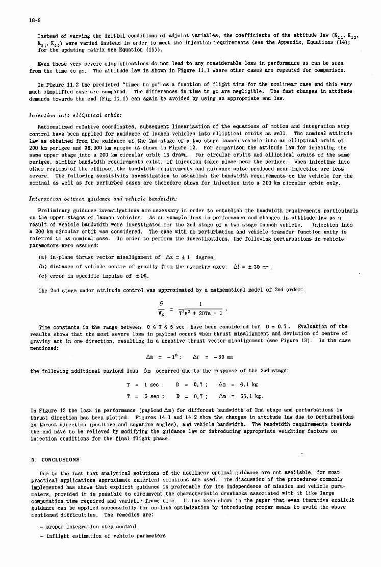
18-6
Instead of varying the i n i t i a l conditions of adjoint variables, the coeff ic ients of the a t t i tude law (K,,, K,,, K,,, K,*) were varied instead i n order t o meet the injection requirements (see the Appendix, Equations (14); f o r the updating matrix see Equation (15)).
Even these very severe simplifications do not lead t o any considerable loss i n performance as can be seen The a t t i t u d e law is shown i n Figure 11.1 where other cases are repeated f o r comparison. from the time t o go.
In Figure 11.2 the predicted “times t o go” as a function of f l i g h t time f o r the nonlinear case and t h i s very The differences i n time t o go are negligible. The f a s t changes i n a t t i tude much simplified case are compared.
demands towards the end (Fig. l l .1) can again be avoided by using an appropriate end law.
Injection into elliptical orbit:
Rationalized re la t ive coordinates, subsequent l inear isat ion of the equations of motion and integration s tep control have been applied f o r guidance of launch vehicles into e l l i p t i c a l o rb i t s as well. law as obtained from the guidance of the 2nd stage of a two stage launch vehicle into an e l l i p t i c a l o rb i t of 200 km perigee and 36.000 km apogee is shown i n Figure 12. For comparison the a t t i tude law f o r inject ing the same upper stage .into a 200 km c i rcu lar o rb i t is drawn. For c i rcu lar orb i t s and e l l i p t i c a l o rb i t s of the same perigee, similar bandwidth requirements ex i s t , i f injection takes place near the perigee. When inject ing i n t o other regions of the e l l i p se , the bandwidth requirements and guidance noise produced near injection are l e s s severe. nominal as well as fo r perturbed cases are therefore shown f o r inject ion into a 200 km c i rcu lar o rb i t only.
The nominal a t t i tude
The following sens i t iv i ty investigation t o es tabl ish the bandwidth requirements on the vehicle for the
Interaction between guidance and vehicle bandwidth:
Preliminary guidance investigations a r e necessary in order t o es tabl ish the bandwidth requirements par t icular ly on the upper stages of launch vehicles. A s an example loss i n performance and changes i n a t t i tude law as a r e su l t of vehicle bandwidth were investigated f o r the 2nd stage of a two stage launch vehicle. a 200 km circular o rb i t w a s considered. referred t o as nominal case. parameters were assumed:
Injection in to The case with no perturbation and vehicle t ransfer function unity is
In order t o perform the investigations, the following perturbations i n vehicle
(a) in-plane thrus t vector misalignment of & = 5 1 degree,
(b) distance of vehicle centre of gravity from the symmetry axes:
(c) e r ror i n specif ic impulse of f l % .
A1 = f 30 m m ,
The 2nd stage under a t t i tude control was approximated by a mathematical model of 2nd order:
e 1 - - WO - T 2 s 2 -k 2DTs + 1 ’
Time constants i n the range between 0 < T ,< 5 sec have been considered f o r D = 0 . 7 . Evaluation of the resu l t s shows tha t the most severe loss i n payload occurs when thrus t misalignment and deviation of centre of gravity act in one direction, resul t ing i n a negative thrust vector misalignment (see Figure 13). mentioned:
Aa = - l o ; A1 = -30 mm
In the case
the following additional payload loss Am occurred due t o the response of the 2nd stage:
T = 1 sec ; D = 0,7 ; Am = 6 , l kg
T = 5 sec ; D = 0,7 ; Am = 65 , l kg.
In Figure 13 the loss i n performance (payload Am) for different bandwidth of 2nd stage and perturbations i n thrus t direct ion has been plotted. i n th rus t direct ion (posit ive and negative angles), and vehicle bandwidth. The bandwidth requirements towards the end have t o be relieved by modifying the guidance law or introducing appropriate weighting factors on injection conditions fo r the f i n a l f l ight , phase.
Figures 14.1 and 14.2 show the changes i n a t t i tude law due t o perturbations
5 . CONCLUSIONS
Due t o the fact tha t analyt ical solutions of the nonlinear optimal guidance are not available, for most prac t ica l applications approximate numerical solutions are used. implemented has shown t h a t expl ic i t guidance i s preferable fo r its independence of mission and vehicle para- meters, provided it is possible t o circumvent the character is t ic drawbacks associated with it l i k e large computation time required and variable frame time. guidance can be applied successfully f o r on-line optimization by introducing proper means t o avoid the above mentioned d i f f i c u l t i e s . The remedies are:
The discussion of the procedures commonly
It has been shown i n the paper t h a t even i t e r a t i v e expl ic i t
- proper integration s tep control
- in f l igh t estimation of vehicle parameters

18-7
- use of rationalized re la t ive coordinates referred t o the injection point
- subsequent l inear i sa t ion of the Euler-Lagrange equations - piecewise approximation of trigonometrical functions of the a t t i tude angles by f i r s t order equations, the
coefficients of which are i te ra ted in order t o meet the desired injection conditions.
ACKNOWLEDGEMENT
The authors a re indepted t o Col.K.P.Davies of ELDO who promoted systematic studies of the ELDO launch vehicles i n the closed guidance loop and t o R.Cosaert of ELDO fo r f r u i t f u l discussions.
REFERENCES
1. Vigneron, M.
2. Polack M.
3. Albery, J. W .
4. Gage, M . J . W .
5. Mattin, R.B.
6, Haeusserman, W.
7. Riley, A.
8. Cosaert, R. Gottzein, E.
9. Cosaert, R.
10. Cosaert, R. Gottzein. E.
La Station de Guidage ELDO. Revue MBLEhrol. IX, No. 1 (10e annke).
Lanceur de Satellite ELDO - Calcul de Guidage et de Localisation. SEREB report.
Assessment of the Performance of the ELDO First Program Attitude Reference Unit in an Inertial Role. Royal Aircraft Establishment, Technical Report No.66314.
FE-Guidance and its Application to the ELDO Launcher Vehicle. Establishment, Technical Report No.68201.
Royal Aircraft
Inertial Guidance for ELDOLauncher. ELDO TM 109 (E 28/10)
Survey paper, 3rd IFAC-Symposium on Automatic Control in Space, Toulouse, March 2nd - 6th. 1970.
The Inertial Guidance System for the EUROPA Satellite Launcher. of the International Astronautical Federation, New York, 1968.
19th Congress
Closed Loop Simulation of Optimum Guidance of +ace Vehicles by Means of Analogue Computer Techniques. ELDO Technical Review 1966 1, pp. 191-231.
On the Optimwn Guidance Law for Both ?bust-Coast-Thrust and Continuous Thrust Transfer to Orbit of a Space Vehicle. Part 1 and 2, Report No.37, pp.5-13,14.
Regelung uon Tragerraketen. Lecture VDI Deutscher Ingenieurtag Braunschweig 1969.

18-8
APPENDIX
Definitions and Coordinate System
Unity vectors #, ,ua ,it,
Equations of Motion
- de = e = Vrtt,+Van,+Vzn3 dt
subst
q1vas
= v, dR dt -
dz dt "z - =
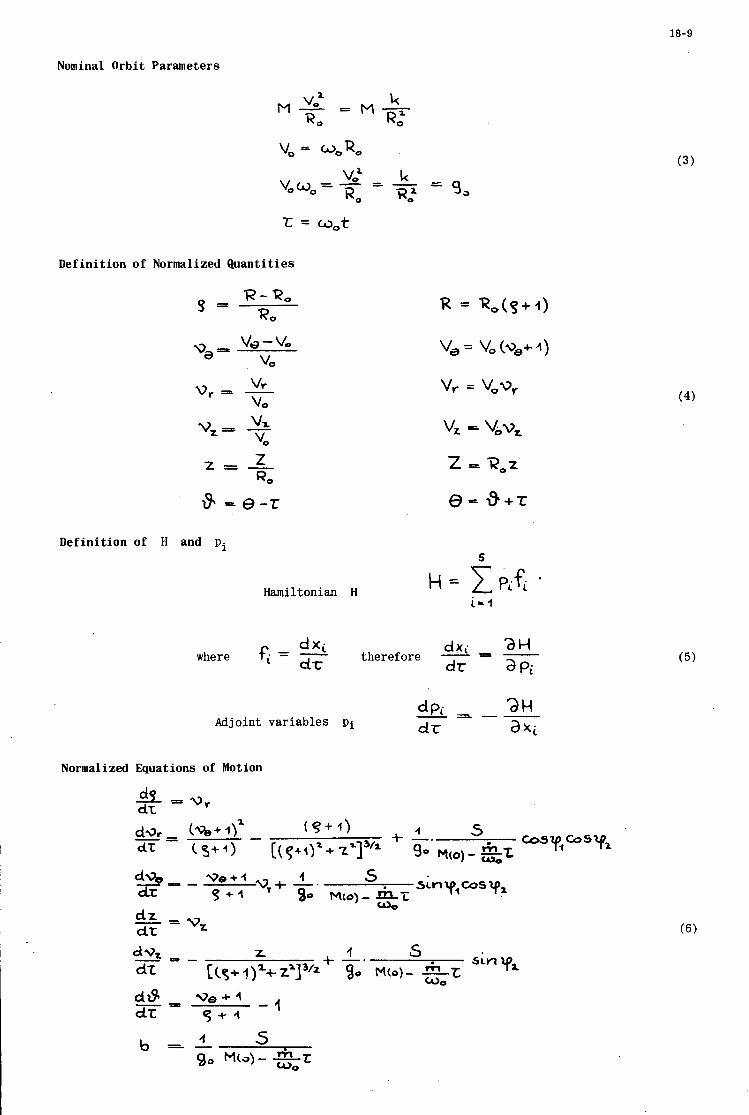
18-9
Nominal Orbit Parameters
t = w,t
Definition of Normalized Quantities
R - R, R, 9 -
V, v r = - VO
v,=P - VZ VO Z z = - RO
8 - 0 - t
vr = V*vr
Definition of H and pi 5
Hamiltonian H
d x i dx. where fi = -&- therefore = -
d r a Pi
dPi - 2 H dr a x i - _ - -
Adjoint variables p i
Normalized Equations of Motion
(4)
(5)
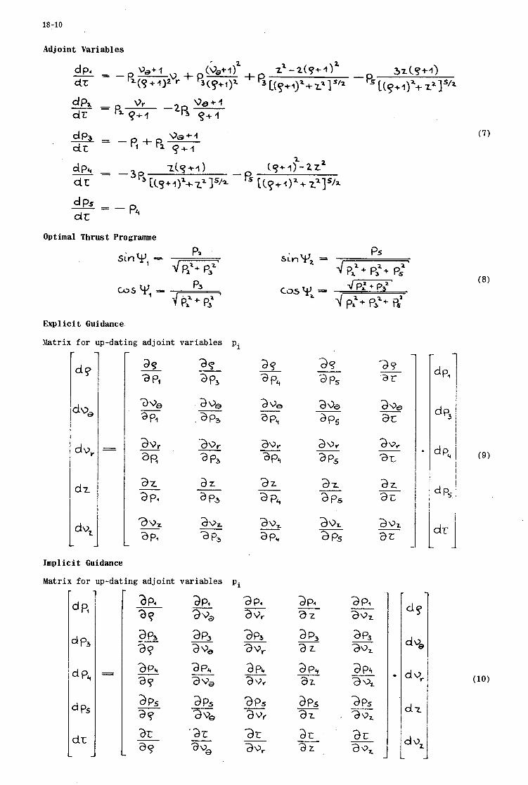
18-10
Adj oint Variables
Optimal Thrust Programme
P2 SinW, -
Explicit Guidance
Matrix f o r up-da t ing a d j o i n t v a r i a b l e s Pi
a9
at
Imp1 ici t Guidance
Matrix f o r up-dating a d j o i n t v a r i a b l e s P i
a P4 - az
a2 .
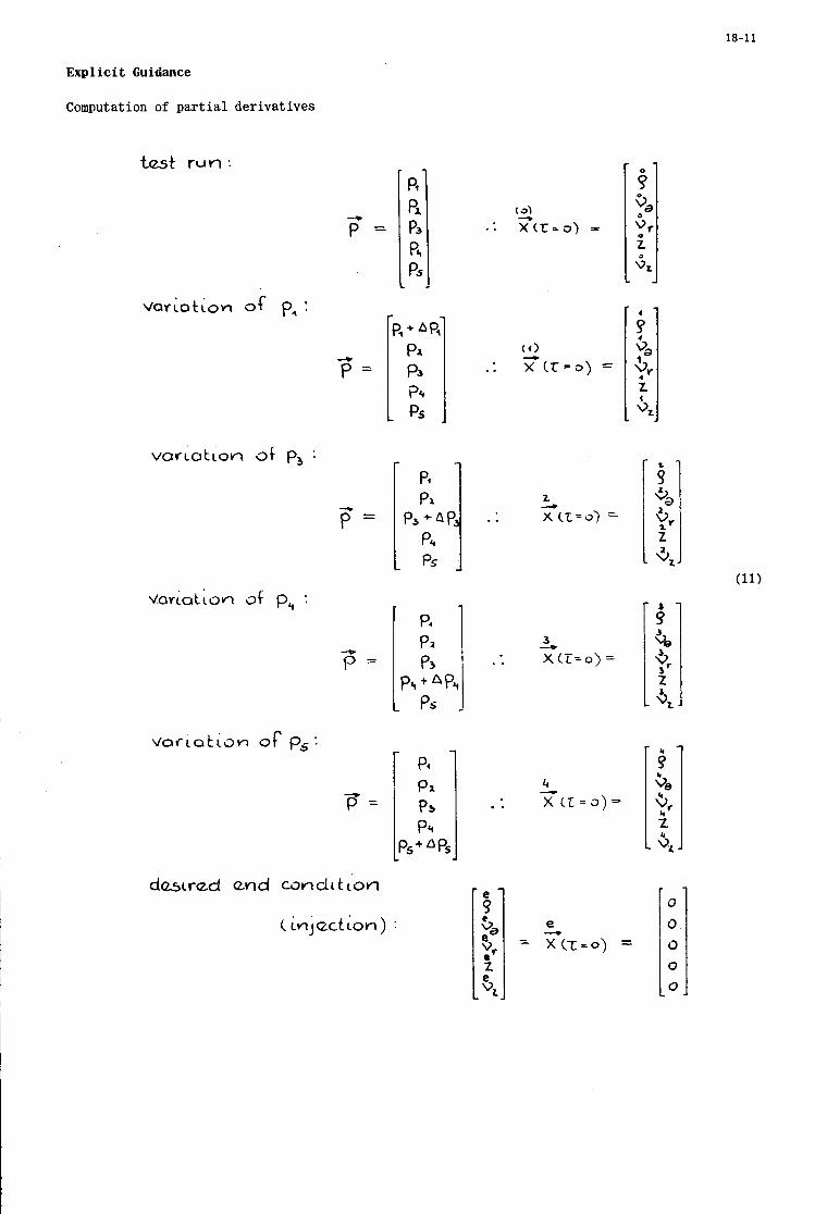
18-11
Explicit Guidance
Computation of par t ia l d e r i v a t i v e s
test run
* P =
3
P =
..
..
. .
..
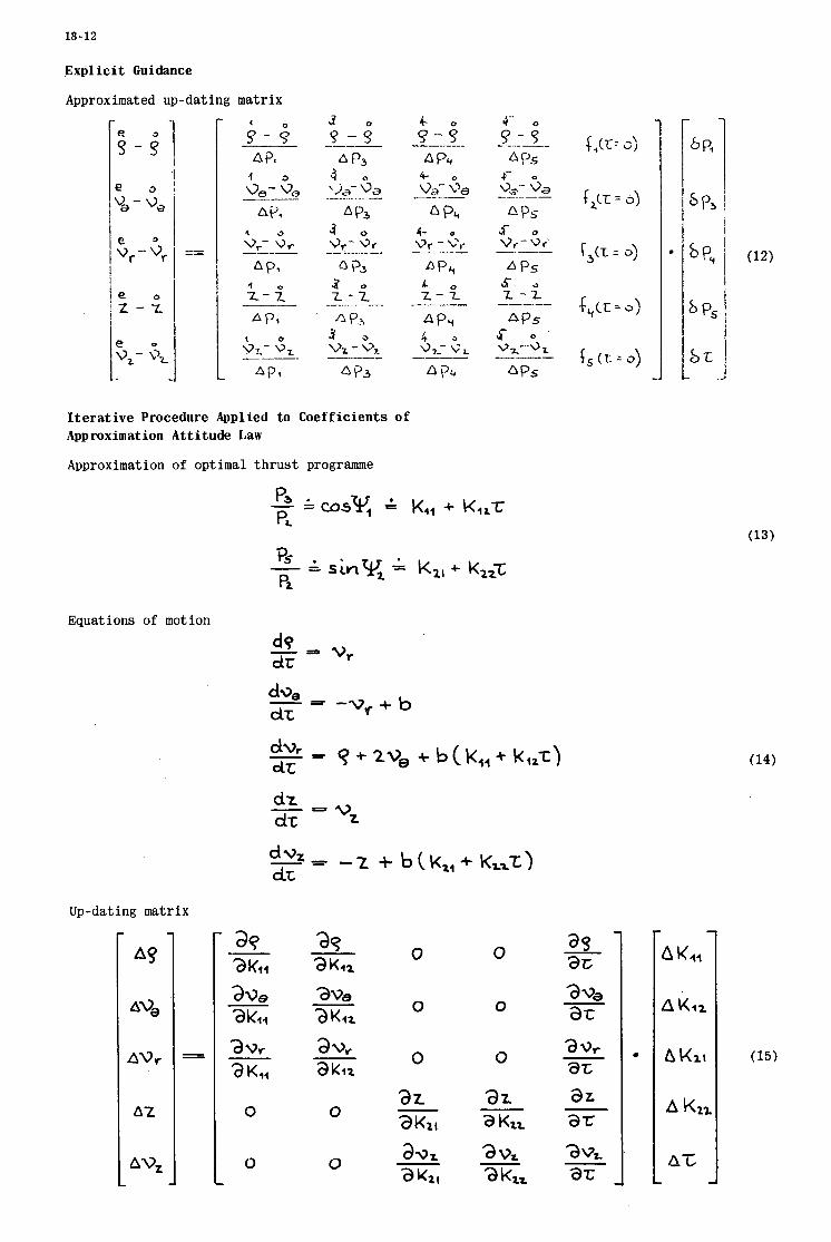
18-12
Explicit Guidance
Approximated up-dating matrix
Iterative Procedure Applied to Coefficients of Approximation Attitude Law
Approximation of optimal thrust programme
Equations of motion
dz dt vz -=
Up-dating matrix
0 0
0 0
0 0
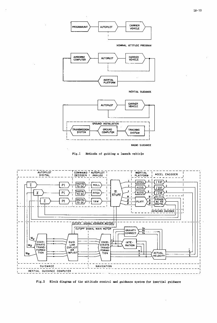
18- 13
PROGRAMUNIT CARRIER VEHICLE AUTOPILOT
NOMINAL ATTITUDE PROGRAM
- CARRIER VEHICLE AUTOPILOT AIRBORNE
COMPUTER
I
INERTIAL PLATFORM
INERTIAL GUIDANCE
GROUND COMPUTER
CARRIER VEHICLE AUTOPILOT
TRACKING I SYSTEM I
I
CUTOFF SIGNAL VERNIER MOTOR
Fig.1 Methods of guiding a launch vehicle
1
I I I I
I I I I I I , L-- I I I I I I- - I I I I I I I I I I I I I
I I
I
I
I .. I >+-i I
COOR- GUID. COOR- DINATE
TRANS- EXPLICIT TRANS. FORMA- O R FORMA,
TlON IMPLICIT TION
I
1 ~<L~ITITLLI,&TA
INTE- RATION
W V ACTUAL h VELOCITY
U U
I I I I I I I I I I I I I I I I I I I I I I I I I I
' I I
Fig.2 Block diagram of the attitude control and guidance system for inert ial guidance

18- 14
Prooram Levels
I . Scqucnzer + Timing
11. Telemetry
111. Attitude Control
Iv. Onboard System Control
v. rilterinq, rlaviga t ion + C o i d a n c c
VI. Self-check
t e
I I I I I I I I I I
I
I I I
I I I I I I I I I l l
I I I I I I I
F i g . 3 Typical example of program timing
b 100 200 300
F ig .4 Attitude law for an implicit guidance procedure
200
t ms
Fig. 5 Vehicle behaviour under i m p l i c i t guidance

18- 15 I
TIME .c
0 -
NORTH
Fig.6 Inertial and nominal orbit plane coordinates
?I ILI I I I I . ! 1 . 1 I I 1 . 1 I L L 1 . 1 1.1.L.I l.U.I..L.l I 1 1 . 1 I.,
ANALOG
FAST SLOW
PROGRAM : p = 1000 p = 10
Fig.7 Iterative guidance procedures
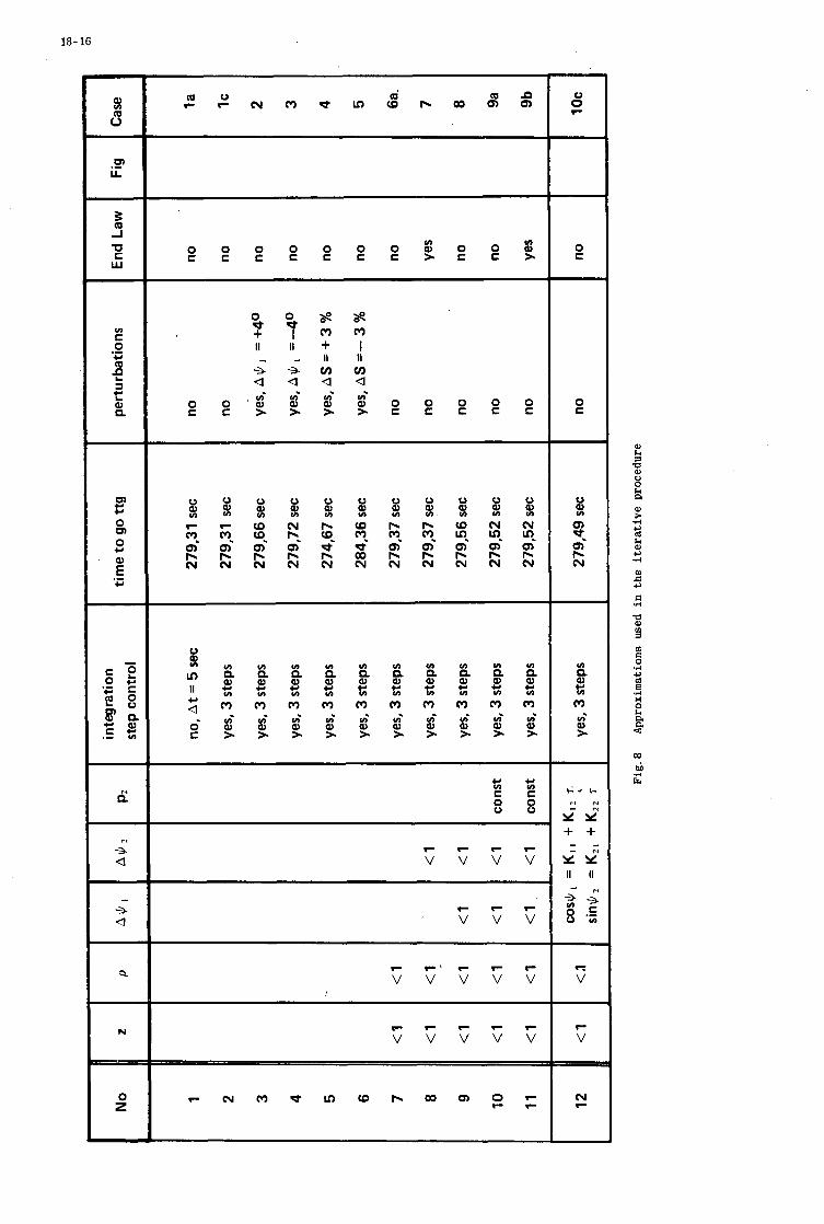
18- 16
C I c , V I - c c 8 8
r r r r v v v v
r r r v v v
r r a r r r v v v v v
/
r r r r r v v v v v
V
a h
a 8 0 0 & a
CO
4 i E
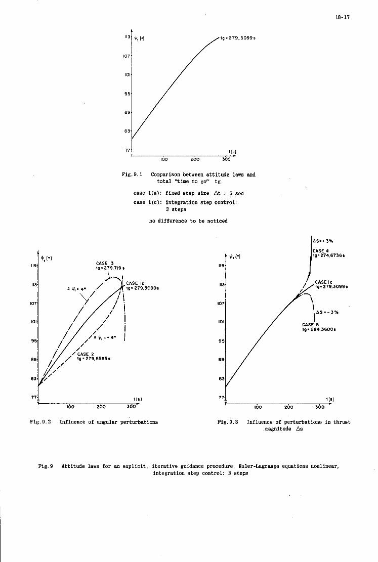
18- 17
A
119.
J: ['I
113
107
101.
CASE 3 tg = 279,719 s
\
771 t Is1 I c IO0 200 300
Fig. 9.1 Comparison between a t t i tude laws and t o t a l "time t o go'' t g
case l ( a ) : fixed s tep s i z e A t = 5 sec
case l ( c ) : integrat ion s tep control: 3 s teps
no difference t o be noticed
771 t [SI
100 2bo 360 /
Fig.9.2 Influence of angular perturbations
$1 ('1 119.
113
107.
101.
CASE 4 t o = 274.6736s I
CASE 5 tg - 284.3600s
77i ' 81 - 100 200 300
Fig.9.3 Influence of perturbations i n thrus t magnitude As
Fig.9 Attitude laws for an expl ic i t , i t e r a t i v e guidance procedure, Euler-Lagrange equations nonlinear, integration s tep control: 3 s teps

18- 18
119
11:
107
IO
9:
8 9
e?
77
CASE 7 tg= 279,3711
\CASE 60 . tg=279,3677s
t [SI 100 200 3 0 0
Fig. 10.1 Comparison of a t t i tude laws and t o t a l “time t o go” for
case 6(a): z < 1 , p < 1
case 7: z ’ < 1 , p < 1 , A$,<<I
119
I13
107
101
9 5
89
83
7 7
,END L A W CASE 8
/ 1 [SI -
I00 200 300
Fig.10.2 Comparison of a t t i t u d e laws and t o t a l “time t o go” for
case 6(a): see Fig. 10.1
case 8:
case 9:
z , p < 1 ; A$,, A$, << 1
z , p < 1 ; A$, , A$, << 1 , p, = const.
Fig.10 Attitude laws f o r an approximated i t e r a t i v e guidance procedure, Euler-Lagrange equations l inear ised around the end conditions, integrat ion s tep control: 3 s teps
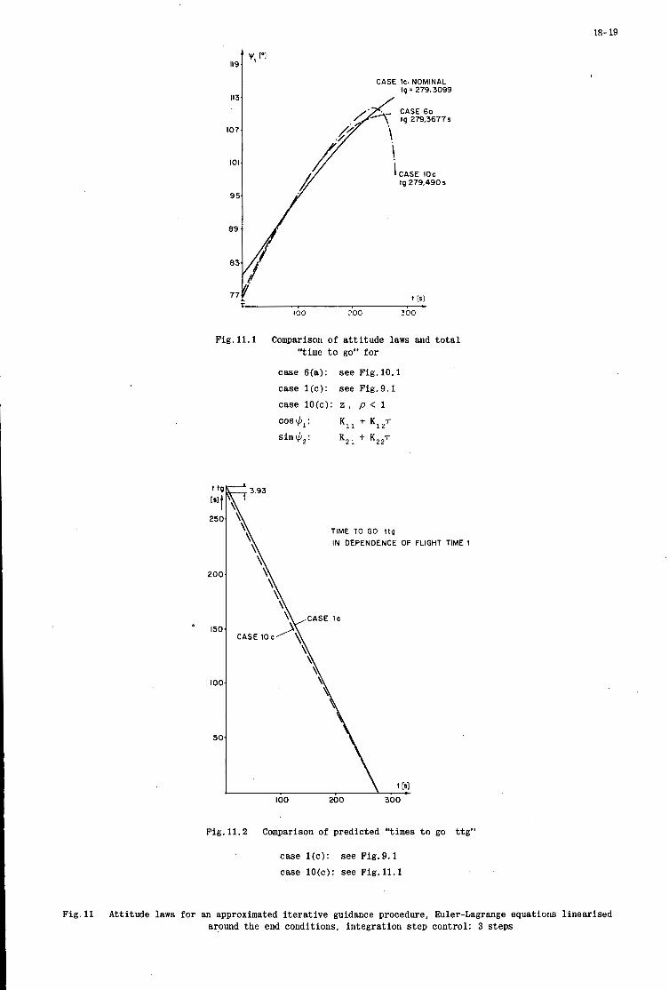
18- 19
IlC
11:
107
IO
9!
89
8:
77
v, [‘I
CASE IC. NOMINAL 1g = 279.3099
CASE 60 tg 279,3677s
CASE IOc tg 279.490s
I00 200 300
Fig. 11.1 Comparison of a t t i t u d e laws and t o t a l “time t o go” f o r
case 6(a): see Fig.lO.1
case l ( c ) : s ee Fig.9.1
case lO(c): z , p < 1
cos $, : Kl, -!- K1zr
sin$,: KZl -!- K*27
t 11
[SI(
2%
20c
’ 15c
IOC
50
TIME TO GO t t g
IN DEPENDENCE OF FLIGHT TIME t
Fig. 11.2 Comparison of predicted “times t o go t t g ”
case l ( c ) : see Fig.9.1
case lO(c): s ee Fig. 11.1
Fig.11 Att i tude laws for an approximated i t e r a t i v e guidance procedure, Euler-Lagrange equations l i nea r i sed around t h e end condi t ions, i n t eg ra t ion s t e p control : 3 s t e p s

18- 20
PITCH ANGLE 1'1
200 300 400 500
Fig.12 Nominal attitude law for:
A) 200 km circular orbit B) 200/36000 km elliptical orbit
t AM [KG]
100
50
A )
Cl
I
T PEcJ 0 '
0 1 2 3 4 5 6
Fig.13 Payload loss for different bandwidth of 2nd stage and for perturbations in thrust direction
A) A a = + 1' ; AZ = 30 yn B) A a = - 1' ; A2 = -30 mm C) Perturbations
2nd order vehicle model: T-variable; D = 0.7

18-21
I r I
v) t-
t - t - 0
0 0 0 I I
II II II P p a p . .
N
d
M 4 E
4
._ .. ._ i I P
.. 0 0 4 d + + + r l m m
II II II 0
{ Z 2 M
B - a a a 0 2 3 6 8
.. .. .. Q O C d % %
.a d II II I 1
2 ' 8 6 6 6
rl a h + + +
B f i

19
REAL-TIME DATA PROCESSING AND ORBIT
DETERMINATION ON THE APOLLO TRACKING SHIPS
Dr. Frederick C . Johnson Boeing S c i e n t i f i c Research Laboratories
P . O . Box 3981 Seatt le , Washington 98124
19
SUMMARY
The Apollo Instrumentat ion Ships (AIS) a r e used du r ing an Apollo l u n a r mission t o provide r a d a r and te lemetry coverage during c r i t i c a l mission even t s t h a t gene ra l ly cannot be seen by t h e land-based p o r t i o n of t h e Apollo t r ack ing network. I n t h i s paper we w i l l d i s c u s s t h e t r ack ing and o r b i t determinat ion func t ions of t hese s h i p s and t h e instrumentat ion hardware and real- t ime sof tware t h a t support t hese func t ions . The gene ra l philosophy and design concepts of t h e real- t ime a c q u i s i t i o n and t r ack ing program i n use on t h e A I S is d i scussed as w e l l a s t h e procedures t h a t were used t o minimize the problems a s soc ia t ed with t h e development and test phases of t h e program.
The design and programming e f f o r t covered i n t h i s paper w a s performed by t h e au tho r and h i s col leagues while t h e au tho r was a s soc ia t ed wi th DBA Systems, I n c . , Lanham, Maryland. This e f f o r t was supported by t h e Goddard Space F l i g h t Center , Greenbel t , Maryland, under c o n t r a c t NAS 5-9922.

19-1
C-BAND - C-BAND DATA BUFFER
S-BAND S-BAND DATA BUFFER
I, INTRODUCTION
LOCAL - DISPLAY 4--b
During an Apollo luna r mission t h e i n s e r t i o n of t h e s p a c e c r a f t i n t o e a r t h o r b i t and subsequent i n j e c t -
The Apollo Instrumentat ion Ships ( the USNS Vanguard, USNS Mercury, i on i n t o t r a n s l u n a r o r b i t g e n e r a l l y occur ou t of s i g h t of t h e r a d a r coverage provided by t h e land-based p o r t i o n of t h e Apollo t r ack ing network. and USNS Redstone) were designed and implemented t o provide a means f o r ob ta in ing supplemental r a d a r , and communication coverage du r ing these c r i t i c a l events . Appendix I.
A photograph of t h e USNS Redstone is given i n
I n o rde r t o b e s t provide f l e x i b l e and t imely support f o r an Apollo luna r mission, t h e r a d a r d a t a is processed onboard t h e AIS and real- t ime o r b i t determinat ions obtained. The r e s u l t s are then t r ansmi t t ed t o t h e Apollo Mission Control Center a t t h e Manned Spacecraf t Center i n Houston, Texas, where the f i n a l GOINO-GO d e c i s i o n s f o r t he mission a r e made. t r ack ing and o r b i t de t e rmina t ion . func t ions of t h e AIS are discussed i n Sec t ion 11. Sec t ion I11 covers t h e requirements t h a t t h e AIS m u s t s a t i s f y during a n Apollo mission. Sec t ion I V g i v e s an o u t l i n e o f t h e r e a l - time a c q u i s i t i o n and t r ack ing program used on t h e AIS. a r e covered i n Sec t ion V , and concluding remarks a r e given i n Sect ion V I .
11. HARDWARE SYSTEMS ON THE AIS
The hardware systems on t h e AIS which support t h e r a d a r
The development and v e r i f i c a t i o n of t h i s program
The fol lowing systems a r e t h e major hardware components which p e r t a i n t o t h e t r ack ing and o r b i t determinat ion func t ions of t h e AIS.
Tracking System. A. Two independent r ada r systems a r e c a r r i e d on t h e AIS, a C-band system and a Unif ied S-band system. sh ip .
Both systems measure range, e l e v a t i o n and bear ing of t h e t a r g e t r e l a t i v e t o t h e The d a t a r a t e of t hese systems i s 40 p o i n t s p e r second (pps) .
B. Ships P o s i t i o n and A t t i t u d e Measuring System (SPAMS). The primary source of s h i p p o s i t i o n , a t t i t u d e and v e l o c i t y d a t a is an i n e r t i a l nav iga t iona l system. This system measures t h e l a t i t u d e and long i tude of t h e s h i p , t h e p i t c h , heading and r o l l of t h e s h i p , and t h e n o r t h and e a s t components of t h e v e l o c i t y of t h e ship., I n case of f a i l u r e of t h e i n e r t i a l n a v i g a t i o n a l system, t h e AIS a l s o c a r r y a gyro- compass as a backup system f o r a t t i t u d e d a t a and an electromagnet ic log a s a backup system f o r v e l o c i t y da t a .
A f l e x u r e monitor system is a l s o included i n SPAMS. This system measures the amount of s t r u c t u r a l t w i s t i n g t h a t t h e s h i p experiences between t h e b innac le of t h e i n e r t i a l n a v i g a t i o n a l system and t h e r ada r pedes t a l s . The output of t h i s system c o n s i s t s of t h ree f l e x u r e ang le s f o r each r a d a r platform.
With t h e except ion of t h e f l e x u r e monitor system, t h e da t a r a t e of SPAMS is 10 pps. The d a t a r a t e of t h e f l e x u r e monitor system is 40 pps.
C. Communication System. Communication between t h e AIS and t h e Mission Control Center i n Houston is accomplished v i a a high-speed l i n k using a communications s a t e l l i t e and a low-speed t e l e t y p e l i n k . t ransmission t o and from t h e communications s a t e l l i t e uses a s e p a r a t e s t e e r a b l e antenna, t he Satcom antenna.
Data
D. Cent ra l Data Processing System (CDPS). A s i m p l i f i e d block diagram of t h e CDPS is given i n Figure 1. The major component of t h e CDPS i s a Univac 1230 gene ra l purpose computer on which t h e real- t ime
INTERFACE BUFFERS
DISCRETE CONTROL PANEL
t
UNIVAC
1230
FIGURE 1
19-2
programs a r e run. second c y c l e t ime and a c o n t r o l memory c o n s i s t i n g of 120 30-bit words wi th a 400 nanosecond c y c l e time.
The Univac 1230 has a main memory c o n s i s t i n g of 32,608 30-bit words wi th a two micro-
I n a d d i t i o n t o t h e Univac 1230, t h e CDPS con ta ins t h e fol lowing dev ices :
I n t e r f a c e Buffers . The i n t e r f a c e b u f f e r s provide t h e hardware i n t e r f a c e between t h e Univac 1230 and t h e in s t rumen ta t ion systems of t h e AIS.
Raw Data Recorder. magnetic t a p e by t h e raw d a t a r eco rde r a s i t is t r ansmi t t ed t o t h e 1230. The r a w d a t a r eco rde r a l s o ope ra t e s i n a playback mode, a most important f e a t u r e f o r system t e s t i n g and check-out.
D i s c r e t e Control Panel.
A l l d a t a from t h e i n t e r f a c e b u f f e r s is s imultaneously recorded on one-inch
The d i s c r e t e c o n t r o l pane l c o n s i s t s of a set of 58 switches. The s e t t i n g of t hese switches provides t h e primary means of ope ra to r c o n t r o l o f t h e real- t ime program dur ing a mission.
1/0 Console. The 1/0 console provides ope ra to r c o n t r o l bo th during real-time and b a t c h mode program execution. The I/O conso le c o n s i s t s of a keyboard and a paper tape r eade r .
Local Display. Several output devices a r e used f o r real-time d i s p l a y of parameters during a mission. These inc lude a high-speed l i n e p r i n t e r , p l o t boards, brush r eco rde r s , and d i g i t a l d i s p l a y windows.
Magnetic Tape Units . S ix s t anda rd (1/2 inch) magnetic t ape u n i t s are a v a i l a b l e f o r use by t h e 1230.
111. MISSION REQUIREMENTS
During an Apollo mission, t h e program which executes on t h e Univac 1230 is t h e real-time Acqu i s i t i on and Tracking (ACQ/TRK) program. The fol lowing items are t h e major requirements t h a t t h i s program must meet.
A. Po in t ing Data. P r i o r t o a c q u i s i t i o n of t h e s p a c e c r a f t by t h e shipboard r a d a r s , a c q u i s i t i o n messages are t r ansmi t t ed t o t h e AIS. is computed f o r t h e r a d a r systems. has been acquired. lock-on is l o s t f o r some reason.
These messages a r e processed i n real-t ime and i n i t i a l po in t ing d a t a Radar po in t ing d a t a is a l s o cont inuously generated a f t e r t h e s p a c e c r a f t
This provides a means f o r r a p i d r e a c q u i s i t i o n of t h e s p a c e c r a f t i n t h e even t t h a t t a r g e t Radar po in t ing d a t a is generated a t a 40 pps r a t e .
I n a d d i t i o n t o t h e r a d a r po in t ing d a t a , po in t ing d a t a must a l s o b e generated f o r t h e Satcom antenna. Satcom po in t ing d a t a is generated a t a 10 pps r a t e .
B. O r b i t Determination. Once t h e t a r g e t has been acquired and v a l i d t r ack ing d a t a is a v a i l a b l e , independent o r b i t determinat ions must be made based upon t h e d a t a from each r a d a r system. c r a f t is i n powered f l i g h t a new p a i r of o r b i t determinat ions must b e computed every second. f r e e - f l i g h t phases of t h e mission a new p a i r of o r b i t determinat ions must be computed once every two seconds.
When the space- During t h e
C. Parameter Computation. F l i g h t dynamic and mission s t a t u s parameters must be computed and updated f o r output t o l o c a l d i s p l a y dev ices during a l l phases o f t h e mission. t hese devices va ry , w i th a maximum rate of 10 pps f o r t h e p l o t boards and brush r eco rde r s .
The output r a t e requirements f o r
D. Data Transmission. Data i s reformatted and t r ansmi t t ed t o t h e Mission Control Center a t Houston a t a r a t e of two messages pe r second v i a t h e high-speed Satcom l i n k and a t a r a t e of one message every s i x seconds v i a t h e t e l e t y p e l i n k .
It is t h e r e s p o n s i b i l i t y of t h e ACQ/TRK program t o i n s u r e t h a t t h e above mission requirements are m e t . The l o g i c of t h e ACQ/TRK program is covered i n t h e fol lowing s e c t i o n .
I V . THE ACQ/TRK PROGRAM
The ACQ/TRK program c o n s i s t s of t h ree major components: t h e Master Executive Module (MEM), t h e Real- MEM i s t h e master c o n t r o l module f o r t he ACQ/ T ime Executive Monitor (RTEM), and t h e ACQ/TRK t a s k agenda.
TRK program. When ope ra t ing i n real- t ime mode, t h e primary t a s k of MEM is t o p rocess e x t e r n a l i n t e r r u p t s and perform 1/0 ope ra t ions on t h e s t anda rd 1230 p e r i p h e r a l equipment ( the magnetic tape u n i t s , t h e l i n e p r i n t e r , and t h e 1 / 0 console) . a t t h i s l e v e l , is t o se rve a s t h e o v e r a l l system monitor, i n batch mode as w e l l as real- t ime mode. This a s p e c t of MEM is covered i n Sect ion V.
The major r o l e of MEM, 2nd t h e reason why these 1/0 func t ions a r e included
The requirements t h a t t h e ACQ/TRK program must s a t i s f y , as ou t l ined i n Sect ion 111, a r e a l l c y c l i c i n n a t u r e wi th a minimum c y c l e time of 25 mi l l i s econds . That is t o say, c e r t a i n t a s k s , such a s the o u t p u t t i n g of r a d a r po in t ing d a t a , m u s t be performed a t a 40 pps r a t e , i .e . , once every 25 mi l l i s econds . A second s e t of t a s k s must be performed once every 100 mi l l i s econds , another s e t once every 500 mi l l i s econds , and so f o r t h . The c y c l i c n a t u r e of t h e va r ious t a s k s , t oge the r w i th t h e d i f f e r e n c e s i n cyc le times (from 25 mi l l i s econds t o 6 seconds) l ed t o t h e development of a m u l t i l e v e l t a s k o r i en ted p rocesso r which would permit t h e more f r equen t ly executed t a s k s t o i n t e r r u p t t h e execut ion of t hose t a s k s t h a t a r e performed less f r equen t ly .
The a l l o c a t i o n of processing t i m e t o t h e va r ious t a s k s is con t ro l l ed i n RTEM by the t a s k processor . This processor ope ra t e s on a t a s k agenda which c o n s i s t s of t h e coding f o r t h e t a s k s and a c o n t r o l block which s p e c i f i e s t h e frequency requirements f o r t h e va r ious t a s k s i n t h e agenda.
The b a s i c philosophy of t h e t a s k processor is i l l u s t r a t e d i n Figure 2 . I n t h i s example t h e agenda c o n s i s t s of a 25 mil l isecond t a s k ( a t a s k t h a t must b e executed once every 25 mi l l i s econds ) , a 50 m i l l i - second t a s k and a 100 mil l isecond task. The b a s i c c y c l e t i m e of a t a s k agenda is t h e cyc le time of t h e most f r equen t ly executed t a sk . b a s i c cyc le time.
A l l o the r t a s k s must have a c y c l e t i m e t h a t is an i n t e g e r m u l t i p l e of t h e

19-3
125 ms I I A 1001 ms
I I I 175 m s
FIGURE 2
The ope ra t ion of t h e t a s k processor is as f o l l m s . S t a r t i n g a t t ime zero t h e 25 mil l isecond t a s k is executed t o completion. The remaining t i m e of t h i s 25 mi l l i s econd c y c l e is then a l l o c a t e d by t h e t a s k processor t o t h e processing of t h e 50 mil l isecond t a sk . A t t h e end of t h e f i r s t 25 mi l l i s econd c y c l e , t h e execut ion of t h e 50 mi l l i s econd t a s k is i n t e r r u p t e d , and t h e 25 mi l l i s econd t a s k is again executed t o completion. rupt ion. The processing of t h e 100 mil l isecond t a s k is no t s t a r t e d u n t i l t h e 50 mil l isecond t a s k has executed t o completion.
A t t h i s t ime t h e processing of t h e 50 mil l isecond t a s k is continued from t h e p o i n t of i n t e r -
The t a s k p rocesso r cont inues t o func t ion i n t h e above f a sh ion u n t i l t h e 100 mil l isecond t a s k has A t t h e s tar t of t h e next 25 mil l isecond c y c l e , t h e processing of t h e agenda is executed t o completion.
i n i t i a t e d aga in s t a r t i n g a t t h e beginning. Thus, every 100 mi l l i s econds t h e 25 mil l isecond t a sk is executed 4 t i m e s , t h e 50 mi l l i s econd t a s k is executed twice and t h e 100 mi l l i s econd t a s k is executed once. It is t h e programmer's r e s p o n s i b i l i t y t o i n s u r e t h a t t h e t o t a l time requ i r ed f o r processing t h i s agenda t akes less than 100 mi l l i s econds .
I I n a d d i t i o n t o t a s k processing, RTEM a l s o provides i n t e r r u p t handl ing f o r t h e r ea l - t ime 'da t a sources . A l l d a t a from t h e real- t ime sources are t r e a t e d as f r e e running asynchronous i n p u t s by RTEM. I n o t h e r words, whenever an e x t e r n a l d a t a ready i n t e r r u p t i s received by t h e 1230 from t h e i n t e r f a c e b u f f e r s RTEM w i l l i n t e r r u p t t h e t a s k processor and i n i t i a t e d a t a t r a n s f e r from t h e i n t e r f a c e b u f f e r t o an i n t e r n a l c o r e b u f f e r in t h e 1230. Once t h i s d a t a t r a n s f e r has been i n i t i a t e d , c o n t r o l is r e tu rned t o t h e t a s k processor . The d a t a t r a n s f e r i t s e l f then occurs i n p a r a l l e l w i th t h e agenda p rocess ing by t h e t a s k processor . A l l i npu t a r e a s i n c o r e a r e double buffered i n t h e sense t h a t one set of i npu t d a t a is processed by t h e ACQ/TRX agenda wh i l e a new set of d a t a is be ing brought i n t o t h e 1230 by t h e i n t e r r u p t p rocesso r of RTEM. I n a c t u a l f a c t then, even though MEN is t h e master execut ive f o r t h e system, RTEM provides primary program c o n t r o l du r ing real- t ime execut ion.
The ACQ/TRK t a s k agenda c o n s i s t s of s i x t a s k l e v e l s : 25 mi l l i s econd , 100 mi l l i s econd , 500 m i l l i - second, 1 second, 2 second, and 6 second. A s i rnpl i f ied flow c h a r t of t hese t a s k s is given i n F igu re 3. The paragraph numbers i n t h e flow c h a r t commentary below correspond t o t h e numbers i n t h e f i g u r e .
25 Mil l isecond Task
1. The r a d a r d e s i g n a t e d a t a i s computed i n t h e 100 mi l l i s econd t a s k and i s i n t e r p o l a t e d t o a 40 pps rate i n t h e 25 mil l isecond t a sk . The i n t e r p o l a t e d d a t a is then sca l ed and formatted, and output t o t h e i n t e r f a c e b u f f e r s is i n i t i a t e d .
2. A l og t a p e of a l l d a t a inpu t is w r i t t e n on a s t anda rd t ape u n i t by t h e ACQ/TRK program. This tape i s completely independent of t h e r a w d a t a r eco rde r tape. A s d i scussed i n t h e nex t s e c t i o n , t h e log t ape a l s o p l a y s an important r o l e i n t h e check-out phase of t h e program.
100 Mil l isecond Task
1. Although t h e inpu t d a t a rate from t h e r a d a r and f l e x u r e monitor systems is 40 pps, i t is u t i l - i z e d a t a 10 pps r a t e by t h e ACQ/TRK program. bad d a t a p o i n t s a t t h i s time.
A l l i npu t d a t a is s c a l e d , formatted and e d i t e d t o e l i m i n a t e
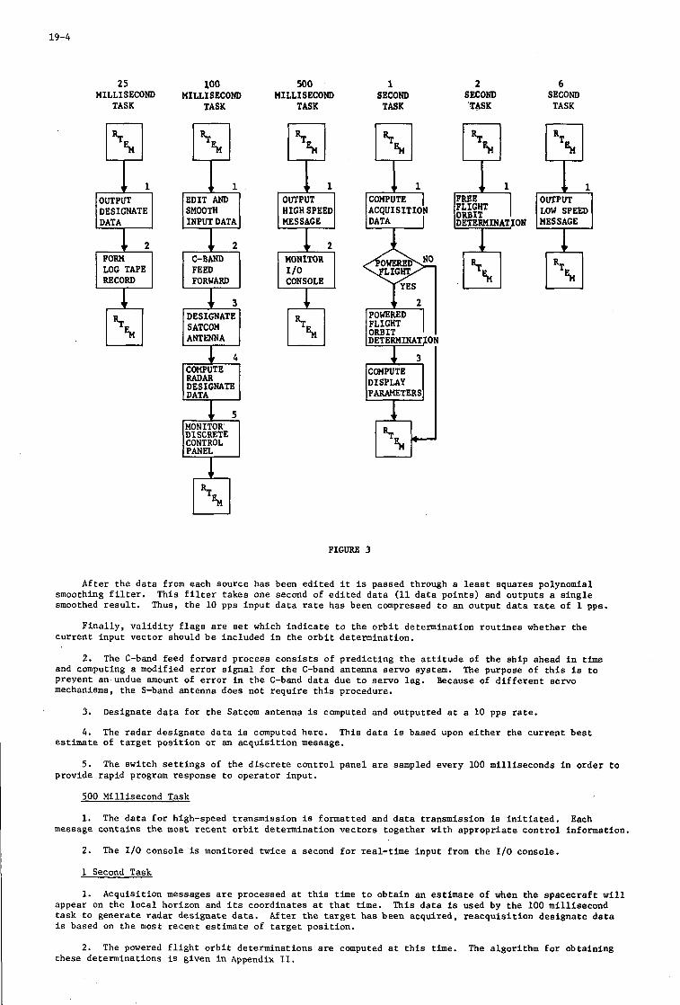
19-4
25 100 MILLISECOND MILLISECOND
TASK TASK
1111 DESIGNATE
INPUT DATA
LOG TAPE RECORD FORWARD
DESIGNATE SATCOM ANTENNA
DESIGNATE
DISCRETE CONTROL
500 1 2 6 MILLISECOND SECOND SECOND SECOND
TASK TASK ‘TASK TASK
HIGH SPEED MESSAGE
MONITOR
CONSOLE
I ACQUISITION
YES
POWERED FLIGHT ORBIT
9 @ DETERHINAT ON L O W S P E m
FIGURE 3
Afte r t h e d a t a from each source has been e d i t e d i t i s passed through a l e a s t squares polynomial This f i l t e r takes one second of e d i t e d d a t a (11 d a t a p o i n t s ) and ou tpu t s a s i n g l e smoothing f i l t e r .
smoothed r e s u l t . Thus, t h e 10 pps i n p u t d a t a rate has been compressed t o an output d a t a rate of 1 pps.
F i n a l l y , v a l i d i t y f l a g s a r e set which i n d i c a t e t o t h e o r b i t determinat ion r o u t i n e s whether t h e c u r r e n t i npu t v e c t o r should b e included i n t h e o r b i t determinat ion.
2. The C-band feed forward process c o n s i s t s of p r e d i c t i n g t h e a t t i t u d e of t he s h i p ahead i n time and computing a modified e r r o r signal f o r t h e C-band antenna se rvo system. prevent an undue amount of e r r o r i n t h e C-band d a t a due t o se rvo l a g . mechanisms, t h e S-band antenna does no t r e q u i r e t h i s procedure.
3.
4. estimate of t a r g e t p o s i t i o n o r an a c q u i s i t i o n message.
5.
The purpose o f t h i s is t o Because of d i f f e r e n t s e rvo
Designate d a t a f o r t h e Satcom antenna is computed and ou tpu t t ed a t a 10 pps r a t e .
The r a d a r des igna te d a t a is computed here . This d a t a i s based upon e i t h e r t h e c u r r e n t b e s t
The switch s e t t i n g s of t h e d i s c r e t e c o n t r o l pane l a r e sampled every 100 mi l l i s econds i n o r d e r t o provide r ap id program response t o ope ra to r i npu t .
500 Mil l isecond Task
1. The d a t a f o r high-speed t ransmission i s formatted and d a t a t ransmission is i n i t i a t e d , Each message con ta ins t h e most r e c e n t o r b i t determinat ion v e c t o r s t oge the r w i th a p p r o p r i a t e c o n t r o l information.
2.
1 Second Task
1.
The I10 console is monitored twice a second f o r real- t ime i n p u t from t h e I/O console.
Acqu i s i t i on messages a r e processed a t t h i s time t o o b t a i n an estimate of when the s p a c e c r a f t w i l l appear on t h e l o c a l horizon and i ts coord ina te s a t t h a t t i m e . t a sk t o gene ra t e r ada r d e s i g n a t e d a t a . is based on t h e most r e c e n t estimate of t a r g e t p o s i t i o n .
This d a t a is used by t h e 100 mi l l i s econd Af te r t h e t a r g e t h a s been acquired, r e a c q u i s i t i o n des igna te d a t a
2. The powered f l i g h t o r b i t determinat ions a r e computed a t t h i s time. The a lgo r i thm f o r ob ta in ing these determinat ions is given i n Appendix 11.

19-5
AGPREP
3. The mission parameters f o r l o c a l d i s p l a y a r e computed a f t e r t h e o r b i t determinat ions have been obtained.
BATCH PROCESSING RTEM SYSTEM
2 Second Task
1. The algori thm f o r ob ta in ing o r b i t determinat ions during f r e e - f l i g h t is a l s o given i n Appendix 11. A f t e r t h e o r b i t determinat ions have been obtained, t h e f r e e - f l i g h t mission parameters f o r l o c a l d i s p l a y are computed.
6 Second Task
1. The low-speed message is formatted and t ransmission is i n i t i a t e d . This message c o n t a i n s only one p o s i t i o n vec to r of t h e s p a c e c r a f t ( e i t h e r C-band or S-band, under ope ra to r c o n t r o l ) and no velo 'c i ty da t a .
V. PROGRAM DEVELOPMENT AND CHECK-OUT
The development and t e s t phases of t h e ACQ/TRK program were g r e a t l y f a c i l i t a t e d by t h e use of a con- s o l i d a t e d sof tware system approach. t h a t would have: (1) a batch processing system f o r program development and i n i t i a l t e s t i n g ; ( 2 ) ' a n agenda p repa ra t ion system f o r gene ra t ing real- t ime agendas; and (3) a real- t ime ope ra t ing system.
The components of t h e r e s u l t i n g system and t h e i r r e l a t i o n s h i p s are shown i n Figure 4.
The g o a l of t h i s approach was t o develop a u n i f i e d ope ra t ing system
The primary t a s k of t h e Master Executive Module is t o se rve a s a system b o o t s t r a p f o r loading i n subexecutive systems. MEM a l s o , con ta ins t h e 1/0 procedures f o r t h e s tandard 1230 p e r i p h e r a l equipment. a r e a v a i l a b l e t o a l l subexecut ives i n t h e system. ,
Thus, t hese procedures
l-7 ASSEMBLER
FIGURE 4
COMPILER
The batch ope ra t ing system was government furnished. It con ta ins a FORTRAN compiler and an assembly
This system permits t h e 1230 t o assemble, compile, language processor t oge the r w i th an ope ra t ing system f o r b a t c h processing. s l i g h t l y so t h a t i t would run under t h e c o n t r o l of MEM. and execute programs a s i n any t y p i c a l ba t ch o p e r a t i o n a l environment.
The system was modified
AGPREP p repa res real- t ime agendas t h a t w i l l be run by t h e t a sk processor of RTEM. These programs a r e l i nked toge the r by AGPREP i n t o one module which
The inpu t t o AGPREP c o n s i s t s of a set of o b j e c t programs. a l s o con ta ins t h e necessary t a s k c o n t r o l information. tape.
The r e s u l t i n g agenda is s t o r e d on a system agenda Several o t h e r agendas may be s t o r e d on t h e same agenda tape.
A s p rev ious ly mentioned, RTEM is t h e execu t ive program f o r real- t ime ope ra t ion . Af t e r RTEM has been
Af te r t h e agenda has been loaded, c o n t r o l is t r a n s f e r r e d t o t h e t a s k processor s e c t i o n of RTEM and loaded i n t o c o r e by MEM, i t s e l e c t s t h e requested agenda from t h e system agenda t ape and loads it i n t o core . real- t ime execut ion of t h e agenda is begun.
I n a d d i t i o n t o t h e obvious advantages of working under a un i f i ed system r a t h e r than s e v e r a l d i s j o i n t systems, t h e above approach o f f e r s a g r e a t d e a l of o p e r a t i o n a l f l e x i b i l i t y . I n p a r t i c u l a r , program modifi- c a t i o n s can be speed i ly implemented and a new agenda c rea t ed with a minimum of delay. u s e f u l i n modifying t h e ACQ/TRK agenda whenever changes t o t h e real- t ime system o p e r a t i o n a l requirements occurred.
This proved extremely
A few words about t h e use of t h e FORTRAN language i n t h e ACQ/TRK program perhaps are now i n o rde r . Since a 25 mill isecond t a s k i n an agenda executes f o r t y t imes every second, i t i s evident t h a t execut ion t i m e cons ide ra t ions are much more c r u c i a l f o r t h i s t a s k than f o r a 1 second t a s k . The 1 second t a s k , however, may very w e l l b e s u i t a b l e f o r FORTRAN programming. I n t h e ACQITRK program a l l of t h e mathematical a lgori thms a s soc ia t ed with o r b i t determinat ion, a c q u i s i t i o n message processing and r ada r des igna t ion i n t h e 1 and 2 second t a s k s are w r i t t e n i n FORTRAN. program was w r i t t e n i n FORTRAN. The r e s u l t s of t iming t e s t s i nd ica t ed t h a t .1 and .5 seconds, r e s p e c t i v e l y ,
I n t o t a l , almost f i f t y pe rcen t of t he f i n a l ve r s ion of t he
19-6
are required t o perform t h e o r b i t determinat ion c a l c u l a t i o n s i n powered f l i g h t and f r e e - f l i g h t . e a s i l y s a t i s f i e d t h e o v e r a l l t iming requirements f o r t h i s p o r t i o n of t h e agenda. The use of FORTRAN g r e a t l y enhanced both the development and t e s t phases of t h e ACQ/TRK program, and i t s use imposed no seve re p e n a l t i e s i n execut ion time o r s t o r a g e requirements.
This
The development and prel iminary t e s t i n g of t h e ACQ/TRK program w a s c a r r i e d ou t on a government furnished Univac 1230 test f a c i l i t y i d e n t i c a l t o t h e 1230 i n s t a l l a t i o n s on t h e AIS. v a l i d a t i o n of t h e ACQITRI: program w a s conducted i n s e v e r a l phases. were developed and t e s t e d i n batch mode. A s imula t ion program was w r i t t e n which dup l i ca t ed t h e i n p u t s t h a t t hese programs r ece ive i n real- t ime, and i t was p o s s i b l e t o completely t e s t t h e l o g i c of t hese programs i n batch mode. tape. t a s k t e s t e d i n a s imulated environment.
The t e s t i n g and F i r s t , t h e FORTRAN a n a l y s i s programs
While t h i s test phase was i n process , o t h e r t a s k s were t e s t e d by means of t h e log A s an example, a log t ape w a s read by a s p e c i a l 100 mil l isecond test program and t h e l o g i c of t h i s
The most important phase of t h e v a l i d a t i o n process a t t h e test f a c i l i t y was a complete real- t ime s imulat ion using raw d a t a t apes and a b u f f e r s imulator . which d u p l i c a t e s a t t h e test f a c i l i t y t h e ope ra t ion of t h e i n t e r f a c e b u f f e r s . t e s t a raw d a t a t ape is played back a t t h e same speed a t which it w a s recorded. decodes t h e d a t a on t h e t ape and f i l l s a complete s e t of i n t e r f a c e b u f f e r s with t h i s da t a . then gene ra t e i n t e r r u p t s i n t h e 1230 i n t h e same fash ion a s t h e a c t u a l i n t e r f a c e b u f f e r s on the AIS. a very c l o s e r econs t ruc t ion of t h e a c t u a l even t s of a mission can be obtained a t t h e test f a c i l i t y . b u f f e r s imulator a l s o has a copy of t h e d i s c r e t e c o n t r o l pane l so t h a t i t is poss ib l e t o t e s t t h e r e a c t i o n of t h e ACQ/TFlK program t o any ope ra to r i n t e r v e n t i o n . thorough t e s t i n g of t h e ACQ/TFX program be fo re t h e program was taken t o t h e s h i p s f o r f i n a l i n t e g r a t i o n and t e s t i n g .
The b u f f e r s imula to r i s a s p e c i a l hardware dev ice During a b u f f e r s imula to r
The b u f f e r s imula to r These b u f f e r s
Thus, The
The use of t h e b u f f e r s imulator permit ted a very
The b u f f e r s imula to r cont inues t o p l ay a very important r o l e i n t h e maintenance of t h e ACQITRK program and t h e AIS hardware. Whenever anomalies occur during a mission o r a s e a t r i a l , t h e raw d a t a t a p e can be used t o r e c r e a t e t h e problem cond i t ions a t t he t e s t f a c i l i t y , and an a n a l y s i s performed t o determine t h e cause of t h e anomaly. I n a d d i t i o n , t h e raw d a t a t ape can b e played back onboard t h e AIS so t h a t t e s t i n g and a n a l y s i s can be done the re . F i n a l l y , s i n c e t h e ope ra t ing system con ta ins a l l t h e system subexecut ives , changes t o t h e sof tware program can a l s o be made on t h e s h i p s . This is p a r t i c u l a r l y u s e f u l when a hardware anomaly occurs , and i t is expedient t o make a temporary program patch t o accommodate the anomaly.
V I . CONCLUDING RENARKS
The system approach ou t l ined above r e s u l t e d i n t h e on-time completion of t he ACQ/TRK program.
I n
The f i n a l ve r s ion of t h e ACQ/TRK program has been used on t h e s h i p s beginning with t h e AS-205 Apollo mission. The program has performed without malfunct ion o r anomaly during a l l real- t ime mission support . p a r t i c u l a r , t h e Apollo l u n a r landing missions, Apollo 11 and 12 , were s u c c e s s f u l l y supported. A l l t h r e e Apollo Instrumentat ion Ships provided support f o r t h e Apollo 11 mission. Due t o the r e l i a b i l i t y and accuracy of t h e nav iga t iona l equipment onboard t h e Apollo s p a c e c r a f t , and as an economy measure, the USNS Vanguard a lone supported t h e Apollo 12 mission. s e r t i o n of t h e s p a c e c r a f t i n t o near-ear th o r b i t . t he succeeding Apollo missions.
The r o l e of t h e Vanguard is t o provide support du r ing in- The Vanguard w i l l con t inue t o provide t h i s support f o r
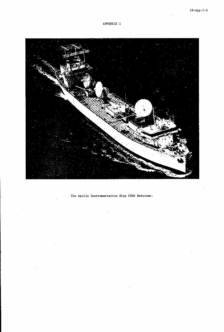
19-App.1-1
APPENDIX I
The Apollo Instrumentation Ship USNS Redstone.
APPENDIX I1
A. Powered F l i g h t Orb i t Determination
The i n p u t t o t h e powered f l i g h t o r b i t determinat ion program c o n s i s t s of t h e smoothed d a t a p o i n t s from t h e 100 mil l isecond t a sk . The fol lowing i n p u t d a t a is received each second:
range, e l e v a t i o n and bea r ing of t h e t a r g e t from t h e C-band antenna, i)
i i )
iii)
i v )
v ) r o l l , p i t c h and heading of t h e s h i p ,
v i ) l a t i t u d e and long i tude of t h e s h i p ,
v i i ) t h e t i m e of t h e measurement s e t .
The o r b i t determinat ion procedures f o r C-band d a t a and S-band d a t a a r e i d e n t i c a l .
range, e l e v a t i o n and bea r ing of t h e t a r g e t from t h e S-band antenna,
t h e t h r e e f l e x u r e ang le s f o r t h e C-band antenna,
t h e t h r e e f l e x u r e angles f o r t h e S-band antenna,
The fol lowing is an o u t l i n e of t h e o r b i t determinat ion algori thm using C-band da ta . The p o s i t i o n vec to r of t h e s p a c e c r a f t i n i n e r t i a l coo rd ina te s is obtained by f i r s t t ransforming t h e C-band REB v e c t o r t o Car t e s i an coord ina te s i n a coord ina te system centered a t t h e r ada r pedes t a l . Next, t h i s xyz vec to r is r o t a t e d through the C-band f l e x u r e angles and t r a n s l a t e d t o a deck Car t e s i an system cen te red a t t h e i n e r t i a l b innac le . This v e c t o r is then r o t a t e d through t h e p i t c h , heading and r o l l ang le s i n t o a coord ina te system t h a t is a l s o cen te red a t t h e i n e r t i a l b innac le bu t has i t s xy plane tangent t o t h e e a r t h . F i n a l l y , t h i s vec to r is r o t a t e d through t h e l a t i t u d e and long i tude of t h e s h i p and t h e r o t a t i o n of t h e e a r t h is taken i n t o account. vec to r g ives the p o s i t i o n of t h e s p a c e c r a f t i n an ear th-centered i n e r t i a l Ca r t e s i an system.
The r e s u l t i n g
The most r ecen t 11 i n e r t i a l p o s i t i o n v e c t o r s a r e passed through a second o rde r l e a s t squares polynomial f i l t e r . This f i l t e r is then evaluated and d i f f e r e n t i a t e d a t t h e mid-point of t h e d a t a span. The r e s u l t i n g p o s i t i o n and v e l o c i t y v e c t o r is t h e estimate of t h e o r b i t of t h e s p a c e c r a f t during powered f l i g h t .
B. Free-Flight Orb i t Determination
The i n p u t d a t a s e t t o t h e f r e e - f l i g h t o r b i t determinat ion algori thm is i d e n t i c a l t o t h e inpu t given However, a s u b s t a n t i a l l y more complex algori thm is used t o e s t ima te t h e o r b i t of t h e space- i n A above.
c r a f t i n f r e e - f l i g h t than i n powered f l i g h t . The reason f o r t h i s is t h a t under normal cond i t ions GO/NO-GO dec i s ions f o r t h e near-ear th po r t ions of an Apollo mission are based on f r e e - f l i g h t r a t h e r than powered f l i g h t da t a .
During f r e e - f l i g h t , a modified form of a Kalman f i l t e r is used t o o b t a i n o r b i t determinat ions of t he spacec ra f t . A s i n powered f l i g h t , a n i d e n t i c a l procedure is used f o r bo th C-band d a t a and S-band da ta . The modif icat ion t o t h e Kalman f i l t e r c o n s i s t s of t h e a d d i t i o n of an age weighting parameter t o t h e f i l t e r . The purpose of t h i s parameter is t o have t h e f i l t e r p l ace more weight on r e c e n t d a t a and l e s s weight on o l d e r da t a . mination problem is a non l inea r problem, t h e l i n e a r i z a t i o n s involved i n t h e Kalman f i l t e r make i t d e s i r a b l e t o deweight o lde r da t a . A complete d i scuss ion of t h e a c t u a l equat ions of t h e modified Kalman f i l t e r may be found i n t h e paper "A Real-Time Kalman F i l t e r f o r t h e Apollo Tracking Ships", by F. C . Johnson, prcsented a t The Seventh Semi-Annual Astrodynamics Conference, Goddard Space F l i g h t Center, A p r i l , 1968.
The c l a s s i c a l Kalman f i l t e r p l a c e s equa l weight on a l l d a t a . However, s i n c e t h e o r b i t de t e r -
20
DISPLAY AND IN!CERFACB I?APLICATIONS IN "HE USE OF DIGITAL CO-
W J. G. Cam
Royal' Airoraft Bstabllshment, Farnborough, Hampehim
British Crown Copyrlght, mproduoed with the pelaiesion of the Controlle Stationery Office.
. .__
Her Brltannio Majesty's
20
I
I n introducing the management type of digi ta l oomputer i n t o aircraft, there am tha t between the man and the computer and that two important interfaoes t o oonsider;
between the a i r o r a f t system and the computer.
The most ve r sa t i l e means of commullication between the man and the computer available at present is the Cathode Rey !Cube o r ort i n association with a Programed Function Keyboard o r pfk.
The crt displey may use oumive, alpha-numeric, p io to r i a l and Tv types of presentation and this enables all the conventional display fonaats, together with in te res t ing n e w ones, t o be presented as requimd an the ort by se lec t ion on the pfko
The pfk is 8 multi-finction keyboard whioh is linked t o the oomputer i n suoh a way tha t the function of each key and the l abe l associated with it, changes a c c o r d i q t o the mode selected. These keys enable, f o r example; the appropriate fonnat t o be selected, or the answers t o a number of standard questions t o be displayed, o r data t o be inser ted i n t o the computer using the keyboard as a typewriter and the ort t o veriPy the da ta before insertion.
The infonuation being processed i n the management oomputer originates i n sensors i n various par t s of the a i rc raf t and m a y be i n one of maw analogue o r d i g i t a l fonns. This paper b r i e f ly discusses the conversion of signals i n t o a oommon d i g i t a l fonn and t h e i r transmission by time division multiplexing along e i t h e r 8 wire oable o r a ' f i b re opt ic oable'.
The f i n a l section of the paper b r i e f ly desorlbes how a Comet 4 a i r c r a f t has been f i t t e d cu t as a f ly ing laboratory at the RAE, and deaoribea the par t this a i r c r a f t d l p l w i n the evaluation and fu r the r development of the techniques discussed.
20-1
1. INTRODUCTION
Airborne general purpose d i g i t a l computers have reached a s tage o f development where they surpass analogue devices on four major oounts - accuracy, f l e x i b i l i t y , v e r s a t i l i t y and reliabil i ty. they are being used t o a g r e a t e r ex ten t i n modern a i r c r a f t , bo th c i v i l and military. the e x i s t i n g sensors and users of sensor d a t a are e s s e n t i a l l y ana lowe i n funot ion and therefore present i n t e r f a c e problems when working with a d i g i t a l computer. The aircrew themselves are major users of data and the i n t e r f a c e between t h e computer and t h e crew i s the subjec t of a great d e a l of research and development a t the pmsent time.
2. AIXCRAFP SYSTBMS/COMPUTER INTERFACE
Consequently, However, most of
Computers s u i t a b l e for t h e management role have binarg words of a t least 16 b i t and usua l ly 18 or 2lt b i t l engths and therefore , i n pr inoiple , q u a n t i t i e s oan be represented t o a t least 0.002 p e r oent. This i s much more accuracy than i s needed f o r a representa t ion of analogue q u a n t i t i e s where 0.1 per cent i s ample f o r most purposes, and t h e m are a number of d i g i t a l t o analogue and analogae t o digital conversion methods which are capable of this accuracy. For economic and l o g i s t i c a l reasons, computers tend t o be b u i l t i n modular form. For example, the processor, which i s common t o a l l vers ions of the computer, and the input/output u n i t which i tself may be modular but i s s p e c i a l t o a given appl icat ion. This la t ter u n i t w i l l contain the r e q u i s i t e number o f A t o D, D t o A synchro t o digital converters, etc, and t h e l o g i c circuitry necessary t o pass the d i g i t a l da ta , s u i t a b l y l a b e l l e d and time sequenced, d o n g a common d ig i t a l highway t o and from this processor. Even when t h e o r i g i n a l data is i n d i g i t a l form a n i n t e r f a o e i s required t o convert the data t o t h e cor rec t l o g i c l e v e l s and t o time sequence it i n t o t h e computer processor. information i s t o be handled may be incorporated i n t o t h e same u n i t as t h e processor. one incent ive t o produce t h e o r i g i n a l data i n d i g i t a l form, another one being t h e inherent advantame8 of d i g i t a l l y processing t h e raw sensor data, mentioned earlier. or synchro-type signals can be provided t o operate conventional instnrments, though if a numerio instrument i s s a t i s f a c t o r y i t is mom economic t o provide a binarg coded decimal or bcd output t o dr ive
I n this case, t h e i n t e r f a c e i s much s impler and where only digi ta l This i s therefore
On the output s ide, ac or dc vol tages
such a d i s p l w .
A management computer, receives da ta from end transmits d a t a t o a number of s e n ~ o r s , o t h e r computers, displays, e t o i n var ious p a r t s of t h e aircraft with a l l t h e a t tendant problem o f cable weight, i n t e g r i t y of c i r c u i t s , e tc . Techniques are being inves t iga ted w h i c h should reduce these problems. A d ig i t a l computer i s e s s e n t i a l l y a time shar ing device; performed i n sequence using t h e same b i t s of hardwarn over and over again. because of t h e very high speed a t which oa lcu la t ions am performed. represent ing a given parameter is only u p d a t e d once p e r program cycle t h i s occurs so f requent ly that for most p r a c t i c a l purposes the output is continuous. for handling data within t h e computer can a l s o be extended t o t h e d ig i ta l transmission of data f r o m point t o point within the a i r c r a f t . saving i n cable weight. by t h e b i t rate and t h e frequency of up-dating required. thoroughly inves t iga ted before suoh multiplexing is adopted on any wide scale. For example, ( a ) t h e n e c e s s a ~ y e l e c t r o n i c s will have t o be carefu l ly miniatur ised otherwise the m i g h t saving, due t o the fewer cables mquired, could e a s i l y be swallowed up by t h e weight of the boxes required at each end for coding and decoding t h e s igna ls ; ( b ) the data highway could be e i t h e r i n t h e form of a r i n g main, l i n k i n g all t h e data sources and sinks t o t h e computer or a network connecting each source or s i n k ind iv idua l ly t o t h e computer. more sensors , bu t may introduce a r i s k o f common mode f a i l u r e . the i n t e g r i t y problem i s not so great.
the p a r t s of t h e program are This is only possible
Thus, although t h e output
This same pr inc ip le of time sharing which is used
The d a t a transmission cables can be time shared with a consequent
There am many aspec ts which w i l l have t o be The number of s i g n a l s that can be t ransmit ted doan one cable is only limitea
The r i n g main has the advantage o f being raadily extended t o include Radial connection is less f l e x i b l e but
An i n t e r e s t i n g development on which a number of UK aompanies am working i s t h e use of a f i b r e o p t i c data transmission l i n k i n place of conventional wires. This idea has severa l a t t r a c t i v e fea tures ; t h e i n f o m a t i o n i s t ransmit ted along t h e glass f i b r e cables as pulses of light and is therefore unaffected by e l e c t r i c a l in te r fe rence rad ia ted by o t h e r equipment, and a t t h e same time gives good electrical i s o l a t i o n between t h e equipment and each end of t h e l i n k . rate and the number of d a t a channels avai lable can be increased considerably without danger of r a d i a t i n g in te r fe rence which i s what limits the pulse rate on conventional cables. problems t o be solved i n areas such as the mechanical oonstruct ion of the f ib re o p t i c l i n k , t h e coding and decoding u n i t s and t h e l i e h t t ransducere a t each end, bu t t h e advantages mentioned make this development well worth pursuing.
The bandwidth and hence t h e b i t
There are technical
If d i g i t a l data t ransmission within the aircraft t o a standard code were adopted this should mean t h a t sensore. and receptors a t each end of a d i g i t a l link could be changed without rewiflng the a i r c r a f t . and therefore i t s avionics fit may change considerably during i t s l i f e , but it a l s o a f f e c t s all airoraft during t h e development phase when i t is so diff ' icul t t o def ine the wiring. a few address cards than t o modify t h e cable loom.
3. AIRCREW/COMPUTGR -ACE
The widespread use of d i g i t a l computers i n aircraft can, i f properly engineered, ntduce t h e work-
This could be p a r t i c u l a r l y valuable f o r militam aircraft where the r o l e of a given airframe
It i s much easier t o change
load of the crew considerably. or, a t l e a s t , t h a t t h e crew t h a t are required need less expensive t ra in ing . In militarg a i r c r a f t , t h e c r e w should be able t o undertake more complex tasks more e f f i c i e n t l y . However, man st i l l has a number of d i s t i n o t advantages over the b e s t and most c a r e f u l l y programmed computer.
I n c i v i l aircraft, this could mean that fewer c r e w members are required
Although the machine i s

20-2
more accurate and handles data mom quickly, man has the a b i l i t y t o respond t o a wide var ie ty of s t imul i , recall l a r g e amounts of da ta and cope with unexpected s i t u a t i o n s b e t t e r than t h e machine and t h i s must be taken f u l l account of as systems become progressively more automated.
The computer i s capable of performing quickly and accurately a l l the necessary rout ine calculat ions and processing the data i n t o t h e most convenient form f o r use by the crew, but i t must then be displayed i n some c l e a r , unambiguous manner. diagrammatically and o thers numerically. m i l i t a r y a i r c r a f t , i s an example of a p i c t o r i a l presentat ion. RAE, a projected image of a map o r char t i a dr iven from navigation information, such that t h e pos i t ion of an a i r c r a f t symbol on the map image represents the a i r c r a f t pos i t ion m l a t i v e t o the ground. crew are thus aware of t h e i r pos i t ion r e l a t i v e t o t h e surrounding t e r r a i n and, i f a computer dr iven t r a c k l i n e i s a l s o superimposed, can examine t e r r a i n f e a t u r e s t h a t l i e ahead. If the topographical display i s dr iven by p o s i t i o n information suppl ied by a d i g i t a l computer and a l s o t h e map oo-ordinates are t ransmit ted back t o t h e computer from t h e display, the d isp lay can be operated i n "closed loop" and this br ings o ther advantages. For example, the co-ordinates of the way poin ts and f ixed poin ts s tored as p a r t of the f l i g h t p lan can be checked by allowing the d isp lay t o s e t i t se l f to-each one i n turn. Similar ly , the co-oxfiinates of addi t iona l points can be i n s e r t e d i n t o the computer by dr iv ing the map t o t h e se lec ted point. This i s a quick way of i n s e r t i n g the co-ordinates of a t a r g e t o f opportunity or of a v i s u a l fix.
Some q u a n t i t i e s are b e t t e r displayed p i c t o r i a l l y o r A topographical display, which i s f i t tea t o a number of
I n the type which was developed a t the
The
However, there are many o ther pieces of information t o display, which are not appropriate t o t h e
When a c r t I s driven from a d i g i t a l computer it i s capable of showing, by topographical display and f o r these t h e most v e r s a t i l e instrument, a t t h e present time, i s the cathode ray tube or c r t d i sp lay (1). software changes only, a n almost inf ini te v a r i e t y of formats both alpha-numeric and diagrammatic, and some tubes can a l s o show TV-type p i c t u r e s e i t h e r separa te ly o r superimposedlon the alpha-mmerio information. day cockpits by a few time shared c r t displays and t o present t h e crew with s u i t a b l y processed d a t a f o r immediate use. However, l i t t l e would be gained by exchanging a multitude of separate instruments f o r one c r t and a mult i tude of s e l e c t o r switches and so, again, there i s the opportunity f o r time shar ing t h e switches i n so1118 form of multi-function keyboard. types of c rz d isp lay and multi-function keyboard and Figs 1-10 i l l u s t r a t e some of t h e arrangements being t r ied . Essent ia l ly , the multi-function keyboard of mfk (sometimes c a l l e d a programmed f i n c t i o n keyboard o r pfk) i s l inked t o the computer i n such a way that t h e f'unction o f each key and the l a b e l assoc ia ted with i t changes according t o t h e mode selected. I n F ig 1, one experimental model which has been f l i g h t t e s t e d i s shown. Twelve o f the but tons can each have one of eleven d i f f e r e n t funct ions, making ava i lab le 132 indiv idua l ly i d e n t i f i a b l e switch funct ions i n a panel about 5 inches x 6 inchea. The remaining switches are of more frequent use and have a f ixed function. I n t h e model i l l u s t r a t e d , the i l luminated ewltoh l a b e l s above each but ton are of the d i g i t a l in- l ine type, which use miniature lamps and pro jec ted f i l m images. We hope that these w i l l eventual ly be replaced by small addressable 6 t o 10 l e t t e r matrix l a b e l s using e i t h e r electroluminescent, plasma, o r l i q u i d c r y s t a l techniques.
Thus, i t is possible t o replace most, i f not all, of t h e c l u t t e r of instruments i n present
A t the RA6 we are experimenting with varioua
One other method, which i s already widespread, uses p a r t of the c r t face itself f o r displaying
When the wire i s touched by t h e f inger , the a c t i o n ind ica ted by the l a b e l above the l a b e l s and the flswitchesn take the form of pieces o f wire on the face of the tube below t h e l a b e l - a touch-wire system. it i s i n i t i a t e d . However, RAF are experimenting with l a b e l s w r i t t e n on the face of the tube i n assoc ia t ion with a n adjacent mw of miniature push-buttons - Fig 2. below an 84 inch diagonal c r t , on which en-route waypoints am displayed: 'Set Numbers' has been se lec ted and t h e twelve but tons a m assoc ia ted with numbers 0 t o 9; ' c lear ' and 'minus'. If more space were avai lab le it woulrl be preferable t o have I 4 o r 1 5 multi-label but tons so t h a t 'NSEW' could be included with 0 t o 9 and i n addi t ion t h e complete a lphabet would need o n l y two s e t s of labels. 15 f ixed o r dual funct ion keys could then be reduced t o 120
This method i s not favoured f o r a i r c r a f t use, where gloves are normally worn.
I n t h i s figure there am twelve such b u t t o m shown
The
Most, i f not a l l , instrument scanning i s t o determine e i t h e r whether a parameter i s between
Only i f values are outs ide these limits do t h e c e r t a i n l i m i t s o r whether i t s r a t e of change i s between c e r t a i n l i m i t s . i d e a l l y s u i t e d t o t h e l o g i c of a digi ta l . computer. crew need t o know t h e i r a c t u a l values. a ler ted. sure t h a t the r i g h t information i s presented t o the man i n a form t o which he can reac t quickly i n an emergency. It i s no good saying nothing u n t i l something goes wrong - t h e man would probably be a s l s e p by then anyway - his a t t s n t i o n must be re ta ined and t h i s i s d i f f i c u l t if he normally has nothing t o do. This br ings us t o the idea of disp lay modes. s i t u a t i o n a t each phase of the f l i gh t and t h e i r use can be i l l u s t r a t e d with reference t o t h e d isp lay of navigation information. i l l u s t r a t e d i n Figs 2-40. I n Figure 2, the mode se lec ted i s 'en-route waypoints' and i n this mode t h e keyboard has been arranged s o t h a t it can be used as a niimerioal typewri ter f o r the i n s e r t i o n of revised information i n t o the t a b l e of co-oniinntes. funct ions become ava i lab le as shown i n Figure 3 along the bottom edge of the c r t . taken from l e f t t o r i g h t s tand f o r : Before take off'and Climb; Navigate; Descent; Howgoeit (Fuel, Range); En-route Waypoints; Tac t ica l Waypoints; Weather Report; Weather Radar. I n figure 3 "Tact ical waypoints" has been s e l e c t e d and the c r t showa a l i s t of the co-ordinates of the waypoints t h a t have been fed i n t o t h e computer as p a r t of t h e f l i g h t plan; t h i s d i sp lay a l s o shows estimated f u e l and estimated t i n e of a r r i v a l . Figures 2 and 3 both show information which would be s tored i n the computer as p a r t of t h e f l i e h t plan. appropriate t o a supersonic t ranspor t i s an estimate of the optimum climb p r o f i l e determined by t h e
Both these decis ions are
They could then be displeyed automatical ly ann' the crew However, there i s d a n m r i n t h i s philosophy i f c a r r i e d t o extremes. One problem i s t o be
A second problem i s t o r e t a i n the man's confidence t h a t all. i s wel l when i t is.
These aFe display formats which keep the crew appraised of the t o t a l f l ight
We divide a t y p i c a l f l i g h t i n t o a number of phases; some of which are
If now t h e 'Modes' but ton i s pressed, a s e l e c t i o n of The abbreviat ions
A f u r t h e r p iece of information which would be p a r t i c u l a r l y
20-3
computer P r o m a howledge of weather conditions, weight of a i r c r a f t , etc. might be displayed diagrammatically. The AiLl curve i s the optimum height versus distance prof i le for the predicted temperature and the dotted curves, on e i the r side, indicate the var ia t ion appropriate t o a departure of plus o r minus 5 degrees from this. t o Air Traffic Control, the r e s t r i c t ions of height and time which they would l i k e t o impose can be typed i n t o the computer v ia the keyboard i n t o the box below the graph. are, "Pass through Way Point 1 a t f l i g h t l eve l 320, ( i e at 32,000 Pt), three minutes l a t e r than the or ig ina l f l i g h t plan". display (Figure 5) which shows t h a t the p i l o t should l eve l out a t f l i g h t l eve l 220 until he is within 62 miles of Way Point I and then resume n o m 1 climb i n order t o meet these res t r ic t ions . new climb p ro f i l e i s acceptable t o both Air Traffic Control and the p i l o t it can be entered i n t o the computer by pressing the ' Inser t ' button. This can now be used as a dynamic display, showing the progress of the f l i g h t along t h i s profile. The small a i r c r a f t symbol on the l e f t of the display can be made t o follow the actual height prof i le a s time progresses so t h a t the p i l o t 0a.n see whether or not he i s succeeding i n keeping t o the planned profile.
very closely the conventional horizontal s i t ua t ion ind ica tor but M s r e 6 shows an a l te rna t ive t h a t m a y be used. across t rack e r r o r and t rack angle error; co-ordinates of the next stage point - No 3; the expected time of a r r i v a l a t t h a t stage point and the distanoe t o go i n naut ica l miles. f igure the switch l abe l s have changed t o ind ica te a fu r the r range of f a c i l i t i e s that are available during the c m i s e phase of the flight. Flgure 7); Attack; Ver t ica l Navigation; \Trite ( f o r typing up messages for storage o r trammission); Pr in t ( f o r making a hard copy of messages transmitted o r received); Divert ( i l l u s t r a t e d i n Figure 8). The next f igure - Figure 7 - i s the ' f i x 1 display and shows i n both numerical form and diagrammatic form the present position, a s determined by the various navigation sensom on board this a i r c ra f t . This i s a par t icu lar ly well equipped a i r c r a f t with an i n e r t i a l navigator, an a l te rna t ive dead reckoning system and shor t range arid long range radio navigation aids. a manual or map f i x a s indicated by 'Mb" and by the lower s e t of l a t long figures. t o use the information f r o m the i n e r t i a l mviga tor t o feed t o the au topi lo t and the posit ion as determined by t h i s sensor i s represented by the a i r c r a f t symbol i n the centre of the circle. differences between the posit ions a s determined by the other sensors and the i n e r t i a l navigator a re shown i n tabular form on the l e f t and i n diagrammatic form i n the c i r c l e of 10 nautical miles diameter. This diagram enables the p i l o t t o see a t a glance whether there a re aqy serious discrepancies between the four o r f ive versions of present posit iono Figure 8 i s the 'Diversion' fonnat and shows the fuel margin tha t the p i l o t has f o r reaching e i t h e r his destination or one of the three a l te rna t ive diverdone. It a l s o ind ica tes the change of track t h a t w i l l be necessary t o reach each of these alternatives. Figures 9 and 10 i l l u s t r a t e the 'Howgosit' mode and show an a i r l i n e p i l o t ' s suggestion of an a l te rna t ive way of showing much the same information as Figure 8. fue l remaining against distance and pmdicting range on the bas i s of present f u e l consumption rate. The l e t t e r s along the horieontal axis represent the destination (D) and en-route (B1 B2) and a r r i v a l AI, A2, A3) a l t e rna t ives etc. planned a t supersonic speed, whereas the dotted l i n e i n Figure I O predicts what would happen i f the f l i g h t had t o be continued at subsonic speed. enough fue l t o reach a l te rna t ive No 3.
Figure 4 suggests how this
If now for some mason this p ro f i l e i s not acceptable
I n the example the r e s t r i c t ions
When the 'Restrict ' button i s pressed the computer then comes back with a
If now, this
It is possible t o produce a display f o r use during the cruise phase of f ly ing which resembles
This display gives, both numerically and diagrammatically, an indication of the a i r c r a f t ground speed and d r i f t ;
This i s of course j u s t one of m a q j possible ways of conveying the same information. On t h i s
Fix ( i l l u s t r a t e d i n They are, Navigate (which is Fimm 6);
There i s a l so the f a o i l i t y f o r inser t ing The p i l o t has chosen
The
This i s a dynamic display continuously p lo t t i ng
Figure 9 shows the predicted performance i f the f l i g h t continues as
"he display shows that i n this case them would not be
As well as showing how the de t a i l s of individual mode formats m i g h t be arranged, Figums 1-10 i l l u s t r a t e two mora general pointsr
a. The v e r s a t i l i t y and f l e x i b i l i t y of the c r t display when used i n conjunction with a d i g i t a l computer . The way that the multi-function keyboard and c r t display facil i tate two-way oommunication between the craw and the computer.
b.
These i l l u s t r a t i o n s have a l l been of the cursive writ ing type of c r t displeying navigation type information. and f u e l gauges and i f the a b i l i t y t o operate i n the Tv r a s t e r mode is included the scope is even widero A TV picture of the outside world might assist i n landing and taJIying and Boeing have oarried out s o w experiments i n this area. picture being relayed t o the aockpit display by closed c i r cu i t TV from a modified topographical display i n s t a l l e d i n the equipment bey.
These can a l so be used t o replace m a n y other types of instruments such as engine instnunents
A t RAE we are experimenting with the TV presentation of maps or ohartss a
This idea again, economises on valuable instrument panel space i n the cockpit.
4. EKPERIMENTAC PROGRAHME
I n a ourrent RAE Navigation Sys tem Exercise, examples of all the types of navigation aid
"he outputs from all the sensors a re fed i n t o R cent ra l computer (using 3.n soam oases currently i n use are ins t a l l ed i n a Comet a i r c r a f t and made available for combination i n t o hybrid system (2). experimental multiplexing techniques) so t ha t new systems may be conf'igumd by software changes only-
In the preliminaxy experiments i n the Comet 2 a i r c r a f t , outputs from Doppler and oompass and i n e r t i a l navigator, Decoa navigator, Omega navigator, VOR and TACAN have been prooessed i n an A r ~ s 400

20-4
computer, recorded on punched paper tape, magnetic tape or t e l ep r in t e r and outputs provided t o drive a topographical display and a c r t display. This work w i l l be continued and extended i n the Comet 4 a i rc raf t which has been specially r e f i t t e d for the purpose. w i l l be confined t o the oabin of the airoraft but proviaion has a l s o been made for the f i t t i n g of two head-dorm and two head-up art displays i n the cockpit i n the second p i l o t ' s position. Laboratory work continues on displays formats and techniques, multifunction keyboards, high speed ort printers, and aomputer software f o r integrated systems.
I n the first place the displays' experiments
REFERENCIS
1. Treadgold M G and Waltera D J The Presentation of Navigational Infomation. J o u d of Ins t i t u t e of Navigation Pol 22 No 2 April 1969 page 184.
Can- J G and St r inger P S A Cornentory upon Airoraft Navigation System Proceedings of the UK Symposium on Electronics f o r Civil Aviationo
2.
Paper No 35. London September 1969.
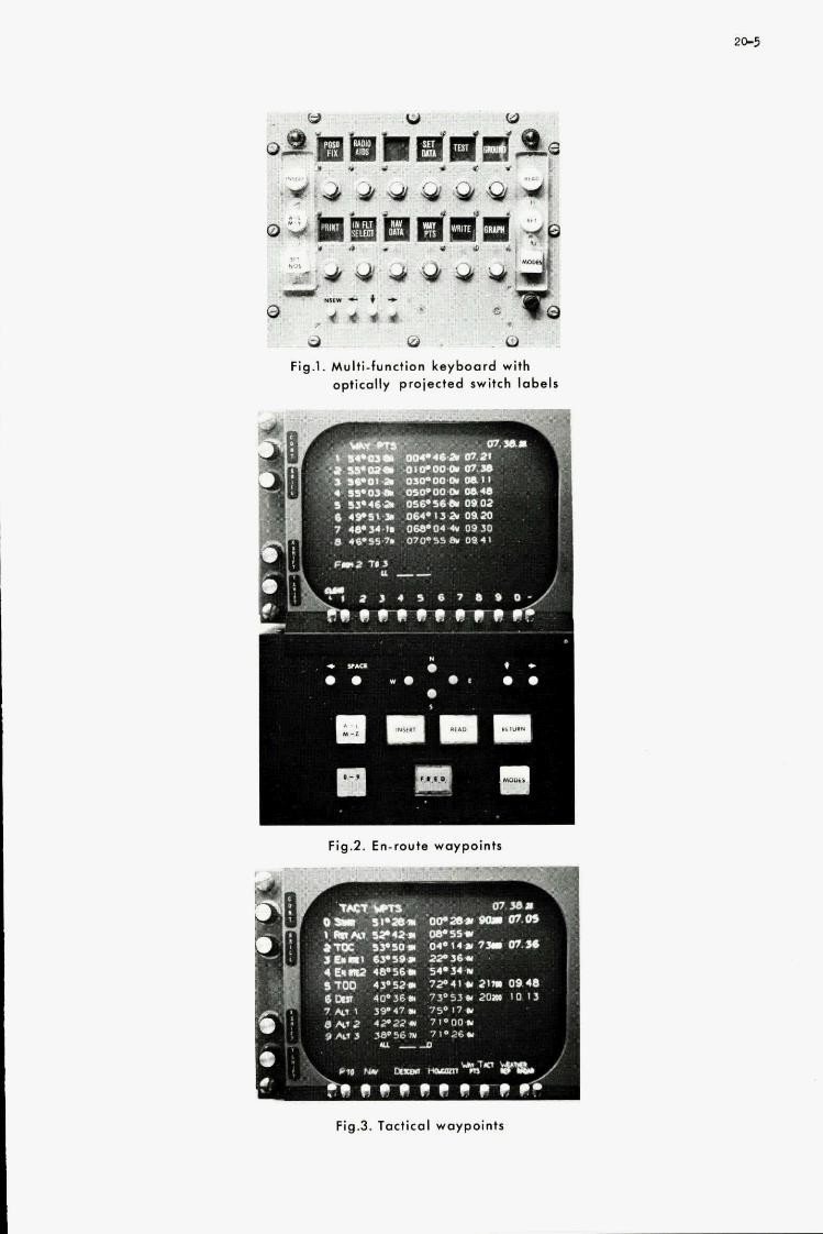
w W W
3 0 0 Fig.1. Multi-function keyboard with
optically projected switch labels
I = Fig.2. En-route waypoints
Fig.3. Tactical waypoints
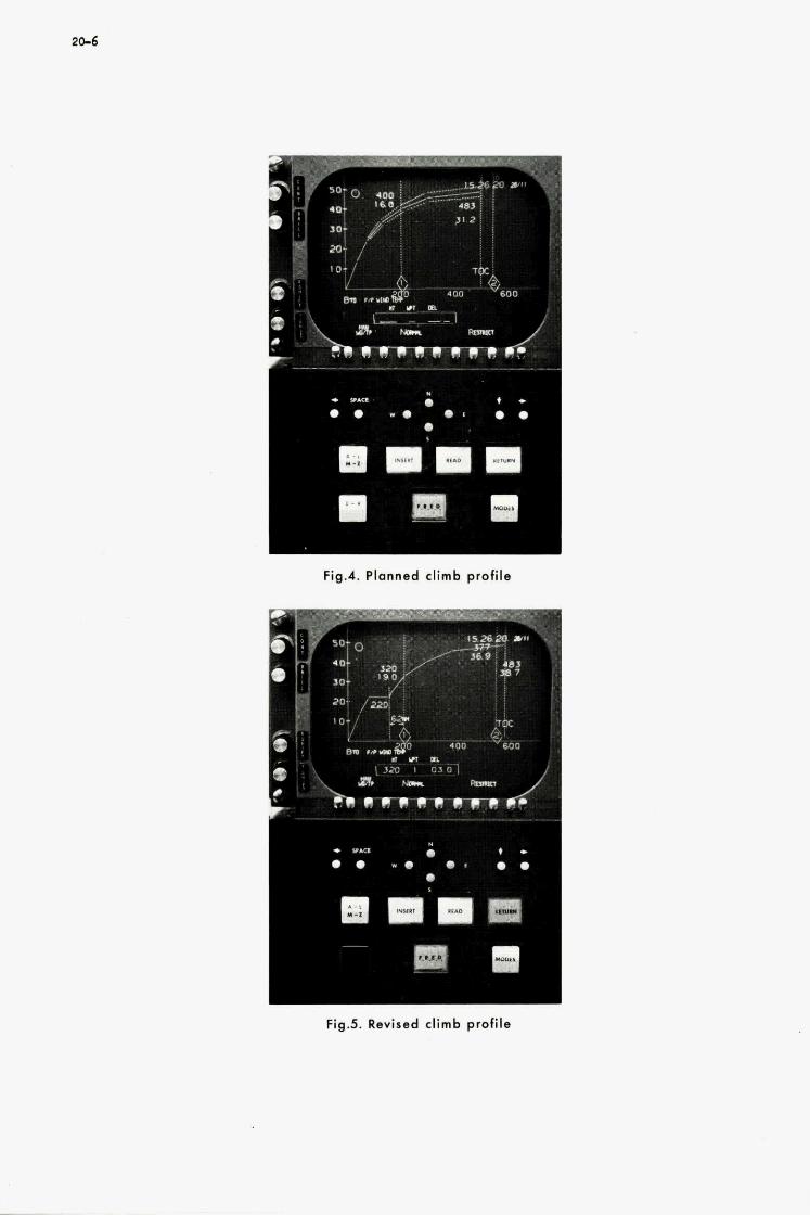
20-6
Fig.4. Planned climb profile
* *Am
0 .
81 I 111 rn
Fig.5. Revised climb protile

I
r
Fig.6. Navigation display during cruise
Fig.7. Position f ix ing
L
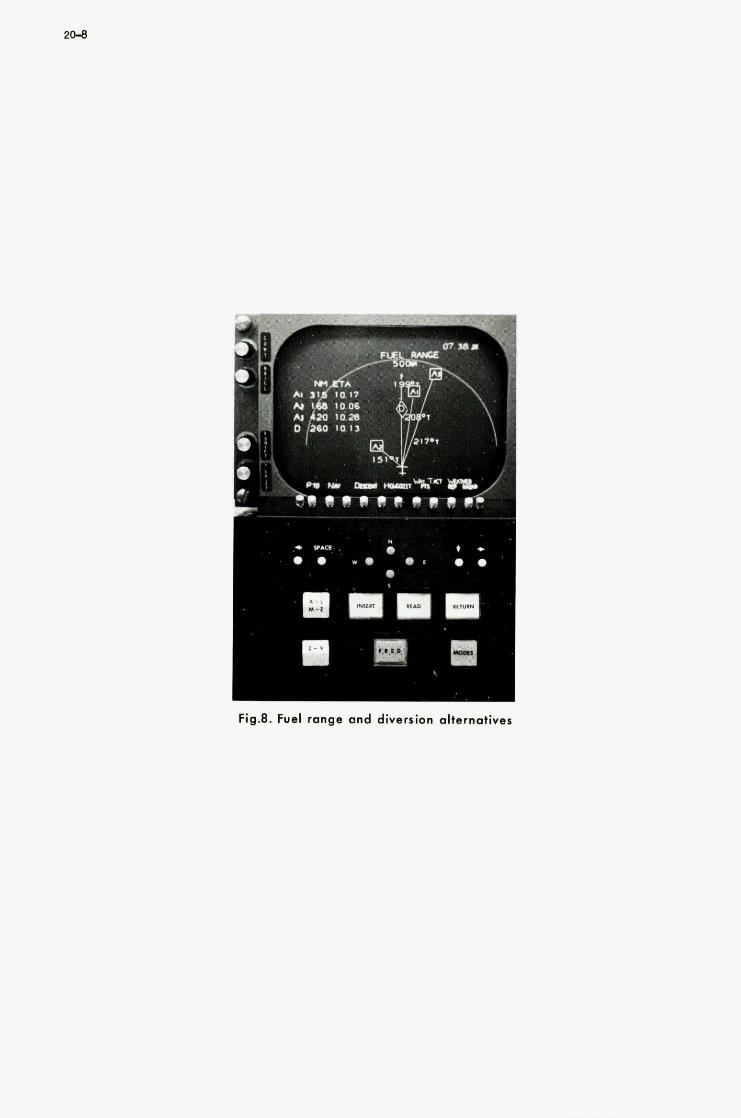
I
Fig.8. Fuel range and diversion alternatives
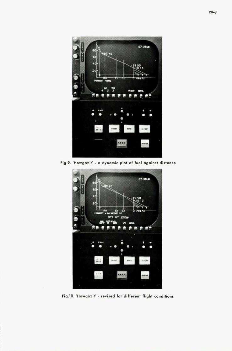
m
Fig.9. 'Howgozit' - o dynamic plot of fuel against distance
I
Fig.10. 'Howgozit' - revised for different flight conditions

2 1
THE TESTING OF COMPUTER-EQUIPPED GUIDANCE AND NAVIGATION SYSTEMS.
Martin G. Jaenke
Central Inertial Guidance Tes t Facil i ty (CIGTF) Holloman Ai r F o r c e Base, New Mexico, USA
21
SUMMARY
The use of computers in aided navigation systems to make optimum estimates of the systems state or to perform the coordinate transfor- mation function in strapdown systems, involves the evaluation of complex computer software in the test process: Two approaches a r e being used for this purpose. h the first, the evaluation is based on the analysis of the recorded test outputs of the systems computer. In the second, re- corded or reconstructed subsystems test outputs a r e input to a ground- based cornputer and used to "re-run" the test a s frequently a s desired with a variety of computer algorithms. In this way, optimization of the algorithm under actual test conditions can be achieved efficiently. Examples a re given for both approaches and the digital test data collection process i s described.
21-1
THE TESTLNG OF COMPUTER-EQUIPPED GUIDANCE AND NAVIGATION SYSTEMS
Martin G. Jaenke
I. INTRODUCTION
Computers have always been an integral part of inertial navigation and guidance systems. In addition to computing velocity and position from the indicated acceleration, they determine com- mands for platform stabilization, and signals to compensate for deterministic errors . Besides these quantities, which a re a prerequisite to the functioning of the inertial unit, they compute the information necessary to implement the guidance concept of the vehicle and the resulting control commands.
Originally, these basic functions were performed by analog computers. However, digital computers have been increasingly employed and their inherent accuracy has contributed signifi- cantly to the remarkable performance improvement of inertial systems during the last two decades, Now, digital technology has developed explosively during the last few years, leading to computer performance characteristics in terms of size, speed, reliability and cost which go far beyond what could have been reasonably expected even 10 years ago, size, high speed and capacity, and high reliability makes it possible not only to perform a large variety of avionics and astrionics functions, but also provides basically new features which lead to significant improvements of the inertial sys- tem. of this paper.
The availability of computers of small
checkout, self-test and other general vehicle tasks,
These features and their implications with respect to inertial systems testing a r e the topic
a
The features of primary concern which will be discussed a r e two-fold:
The first is the capability, provided by the computer, to make in real time optimum estimates of the true values of the quantities of interest, namely the position, velocity and heading of the guided vehicle. This estimation process makes optimum use of all information sources which a r e available. Besides using the outputs of the inertial unit itself, it incorporates measurements derived from Doppler radar and position fix devices such as Loran or Navigation Satellites. In combining these information sources, the process continually accounts and compensates for all known deterministic and correlated random errors and it weighs the contribution of each infor- mation source in accordance with the best knowledge of its statistical uncertainty. Thus, the process achieves results which a r e better than those obtainable from a mere superposition of the various measurements. In this way, the computation process reduces the performance requirements on actual physical hardware, a factor which is of economical significance. The process is well known as "Kalman Filtering" and will be referred to as such in this paper.
The other improvement made possible by increased computer capacity, reliability and speed is strapdown technology. Again, the computational process of transforming the accelerometer outputs into another defined coordinate system in accordance with observed gyro outputs replaces mechani- cal hardware, in this case the gimballed platform. Thus, a definite advantage in systems size, initial cost and maintainability is realized. While the shortcomings of strapdown systems a re fully recognized, this advantage is significant enough to reserve an important place in future inertial technology for strapdown systems.
In both the Kalman Filter and strapdown system algorithm areas, the computer software is immensely more complex than in the conventional computer application for inertial gimballed systems. ment in which the inertial system will have to operate and needs a thorough understanding of the influence of this environment on the e r rors of the system. However, this knowledge and under-
In both cases, the analyst-programmer must have an intimate knowledge of the environ-
2 -2
standing can never be perfect and it must be backed up by test results to avoid erroneous conclu- sions. evaluate computer software. Here, besides "debugging" the program, the purpose is to determine whether the assumptions made with respect to the structure of the operational environment and its effects on the systems. errors were correct and comprehensive. Furthermore, it must be deter- mined whether these effects a r e considered in the program in an optimum way and, if not, corres- ponding improvements must be made. Thus, the test process becomes a part of the development process. Since software can be changed much easier than hardware, it can be seen that the trans- fer of systems tasks from the mechanical hardware to the computer software contributes to the flexibility and adaptability of the system.
Thus evolves a new aspect for the testing of such systems. That is the necessity to
To meet these test goals, the test environment must be identical to, or if this is not possibIe for practical reasons, a s similar as possible to the operational environment for which the system under test is being developed. tional" test procedures which a r e available a t Holloman AFB. aircraft such as the C-130 or similar test beds on aircraft navigation systems, and the sled tests on the Holloman High-speed Track, performed on missile guidance systems. Both techniques a r e well established and have been used successfully for many years.
This requirement lends new and increased emphasis to the "opera- These a r e the tests performed in
Aircraft testing provides a wide variety of test trajectories which a r e flown over the White Sands Missile Range and its vicinity and use its precision radars as reference instrumentation. They a r e designed to exercise specific e r ror terms. with turn-arounds every 42 minutes, designed to excite the Schuler cycle and coupling terms. In addition, long-range transcontinental trajectories a re used which a re specifically designed for the testing of aided navigation systems. a r e shown in Fig. 1. They use existing range instrumentation on Government ranges to the widest extent possible and provide a large number of precisely surveyed check points for reference and position updating purposes. Besides providing long-range E-W, N-S and 45 flight paths, they include instrumented over-water flights to determine Doppler radar e r ror due to ocean surface motions. And they extend into areas of the eastern United States where Loran coverage is available to evaluate aided inertial navigation systems which use Loran for position updating.
A prominent example is a SE-NW trajectory
Such trajectories which a r e presently in use and in preparation
0
To reduce the cost of an operational test program for aircraft navigation systems, a van test capability has been established. Such a test van i s essentially a moving laboratory which provides the means to check out and "debug" a system under moving conditions before it is submitted to the relatively expensive tests in aircraft. The van provides a substitute for Doppler radar in the form of a fifth wheel which very accurately measures the velocity of the vehicle and provides information which can be used for velocity updating of the system under test. Position updating is achieved by accurately surveyed check points along the route the van is taking. Thus, by a flexible combination of pre-flight bench tests, van and aircraft tests, highly meaningful and cost effective operational test programs for aircraft navigation systems can be performed. (1)
Another method of operational testing, the Holloman high-speed, precision test track, is used extensively for the testing of the boost phase guidance systems of ballistic missiles and space vehicles. (2) course flight phase of strategic missiles and of the non-inertial seeker systems of their terminal phase. (3) A high-g capability is in preparation, suitable for testing systems under re-entry con- ditions. Figs. 2a and 2b.
It is now being used increasingly f u r the testing of inertial systems for the mid-
Representative sled trajectory characteristics for these various purposes a r e shown in
The availability of these operational test methods provides a unique capability for testing, evaluating and optimizing the computer software of guidance and navigation systems. ing sections will be concerned with describing the methods used and experiences collected with the software of Kalman Filters of aided aircraft navigation systems and of the strapdown algorithms of missile guidance systems.
U. APPROACHES TO SOFTWARE EVALUATION
The follow-
The task of testing, evaluating and optimizing complex software is a relatively new item in a guidance test program. A systematic and comprehensive body of theory and experience for this purpose is not yet in existence. However, the analysis efforts conducted in the past on various test programs show trends which a r e promising for developing such a unified body of theory and practice. Essentially, these trends a r e two-fold
The first trend is based on the recorded output data of the systems computer, i.e. on the in- formation which the system as a whole derives from the test. The analyst who compares this in- formation with the reference instrumentation data must use the resulting e r ror functions to inter- pret observed deficiencies with respect to their cause and to propose corresponding improvements. This is not easy in view of the complexity of the computer programs involved and in general re- quires the availability of a simulation program. validity of the hypotheses made concerning the cause of observed deficiencies and to test the
Simulation provides the capability to test the

21-3
efficiency of proposed improvements. Generally, such a simulation program is available, mostly a t the plant of the contractor who developed the guidance system under test. actual test conditions is judiciously used. to update the simulation program, a realistic and efficient tool for system evaluation and optimization can be obtained. Consequently, availability of such a simulation program at the test agency is desirable to allow an unbiased and critical evaluation of the system under test.
If the knowledge about
The other evaluation trend is based on the recorded output data of the subsystems under test, primarily of the inertial unit and of aiding devices such as Doppler radar. Having these subsystem data available, it is then possible to run them through the systems computer algorithm, mechanized on a ground computer, in the post-flight analysis. If this algorithm is not fully satisfactory, it is relatively easy to change the computer program and to "re-run" the test on the ground until a fully optimized algorithm is achieved, without actually conducting a new test. The number of actual test flights necessary to confirm the validity of the proposed optimization in the algorithm is then re- latively small.
A version of this approach is to reconstruct subsystem output data if they a re not available in an unperturbed form. performs physical corrections on the subsystem itself. rections a r e recorded and properly considered in the process.
This is the case if a closed loop Kalman filter is employed, i.e. if the filter The reconstruction is possible if these cor-
None of the approaches described above is inherently superior. Their usefulness depends on the characteristics of the individual test program. For example, in some cases strapdown systems had to be tested without a systems computer being made available for the test. In this case, the evaluation approach based on the recorded subsystems output was for all practical purposes the only possible one. On the other hand, in the tests of aided aircraft navigation systems the approach based on the recorded systems computer outputs is normally preferred. The reason for this is that these data a r e digital in nature and thus lend themselves to post-flight analysis in a ground- based digital computer with a minimum of instrumentation and data processing time requirements. The reconstruction approach mentioned above was also successfully employed in the evaluation of an aided navigation system.
Thus, the most appropriate evaluation approach must be found in each individual test case. For the evaluation of aided aircraft navigation systems in general it is felt that the most promising and efficient approach is one based on systems computer output data, and which reconstructs as many as possible of the subsystems data and uses all this information to update a ground-based, post-flight computer simulation process. This in turn can then be used to determine sources of e r ror and to optimize the systems computer algorithm by re-running the test on the ground computer as f re- quently as desired. In this way, a highly cost-effective test program can be achieved.
U. EVALUATION OF AIDED AIRCRAFT NAVIGATION SYSTEMS
The majority of aircraft navigation systems employ Kalman filters which serve the purpose of establishing optimum estimates of the true value of such quantities a s aircraft position, velocity and heading. These optimum estimates a re based on additional information derived fnom "aiding" sources such as Doppler radar for velocity updating and Loran, Navigation Satellites and check points for position updating. The filter must know the deterministic and statistical e r rors of these various information sources and it must properly apply this knowledge to establish truly optimum estimates. The filter designer uses the best available a priori information about these e r ror sources when he programs the filter algorithm and he normally achieves remarkable success when he uses his filter in a computer simulation run. However, reality may look quite different from what was assumed in the simulation process and this is why the testing and evaluation of such filter-equipped systems in a test environment which is a s closely identical as possible to the actual future operational en- vironment is of such significant importance.
To fully appreciate the difficulty of the task of filter evaluation, it is necessary to obtain an understanding of the status and trends, and of the complexity of filter design.
Filter designers must strive to minimize computer capacity requirements in view of the many other tasks which the central computer has to meet. A typical compromise is to make the com- puter available to the filtering process for about 20% of the total time. filter algorithm under these restrictions, the following factors have to be considered.
To obtain an effective
The quantity which primarily influences the complexity of the filter is the state vector. It is now general practice to use a s the state quantities which a re to be estimated by the filter the e r ror of the outputs of the inertial system and not the outputs themselves. (4) This leads to the esti- mation approach which is shown in Fig. 3. This approach reduces computer requirements because the model of the systems errors , which has to be mechanized in the algorithm, is simpler than the model of the system itself. Furthermore, the cycling rate of the filter, i.e. the rate a t which measurements have to be taken and the estimates recomputed and updated is lower because the e r rors of the systems outputs fluctuate a t a slower rate than the outputs themselves.

21-4
Of significant importance is the dimension, n, of the state vector because the matrices which have to be manipulated a r e of order n. The memory location requirements a re roughly proportional to n2 and computer time requirements to complete an estimation cycle a r e proportional to n3. A minimum figure for n is about 5. In this case the filter would only estimate the quantities of direct interest (two horizontal positions and velocities, and heading). Since in this case the filter would not make use of the predictability of deterministic error sources and of random sources with long correlation times, its value would be highly questionable. A maximum for n is about 20 and typical values used in practical systems a re about 15. ment would be about 1000 word locations and the cycle time about 8 sec. , a figure which is valid for a not overly fast computer with floating point hardware. a r e typically within 1 to 3 minutes, sufficient computer capacity is left for other purposes.
For such a state vector the a r ray storage require-
Since the updating time requirements
To make fullest possible use of all available information sources, aircraft navigation systems a r e usually required to operate in various modes. Typical examples of such modes are: Ground align, Normal Navigation (using the inertial system and all available aiding sources), Inertial only, Doppler only, or other "degraded" modes in which only a part of the navigation subsystem is being used. In practical cases, up to 25 modes and sub-modes have been observed. Mode switching can be automatic or manual, depending on certain criteria. In either case, the computer routine must provide the appropriate initial conditions at each mode transition. This is important because the Kalman filter routine usually is different for each mode. In particular, in modes where the inertial unit is not available, the definition of the state vector in terms of e r ror states is no longer appli- cable and a new definition in terms of the navigation states themselves must be formulated.
As mentioned before, in most of the tests performed a t Holloman on aided aircraft navigation systems, the Kalman filter was evaluated by using the recorded systems computer output data to determine deficiencies by inspection and with the help of a simulation routine. Table I summarizes and classifies the observed deficiencies.
TABLE I
Observed Deficiencies of Kalman Filter Algorithms
Type of Deficiency Comments
Inadequate modeling See example of Fig. 4. Note wide discre- pancy between predicted and actual perfor- mance in early flight, 4a, and improvement in later flight due to better modeling, 4b.
Insufficient word length
Programming assumptions
Timing and scheduling problems
Reasonableness criteria
See example of Fig. 5. The estimate of gyro drift was significantly improved by applying double-precision arithmetic. This in turn improved estimate of position errors.
A reduction in position e r ror by a factor of 5 was achieved by making the updating of transition and measurement matrix co- incide in time. Before that, the measure- ment matrix was updated throughout the Kalman cycle and the transition matrix only a t the s tar t of the cycle.
In one case, improvements were achieved by: (a) Changing the time of entry of Magnetic Variation information, (b) Changing the time spot of Radar Antenna stabilization to the inertial unit.
The programming of this cri teria for position fixes had to be changed during test series to avoid rejection of an accurate position update.
The "reconstruction" approach to filter evaluation was also investigated and the results were published. (5) As will be recalled from section 11, the approach consists of reconstructing the out- puts of the subsystems as they would have been without the influence of the Kalman filter. Then these unfiltered outputs a re fed into a ground-based simulation of the system Kalman filter during the post-flight analysis and the test re-run on the computer as frequently as necessary to debug and optimize the Kalman routine. F ig . 6 shows the system er ror observed during a test flight as published in Ref. (5) . Figures 7 and 8 show the reconstructed outputs of the inertial and Doppler unit, respectively. As can be seen, the large longitude e r ror is attributable to the inertial unit and the large latitude error to the Doppler.
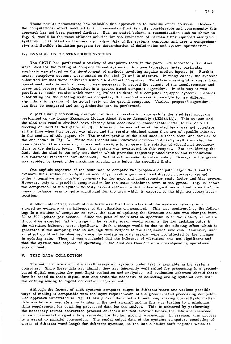
21-5
These results demonstrate how valuable this approach is to localize error sources. However, the computational effort involved in such reconstructions i s quite considerable and consequently this approach has not been pursued further. But, as stated before, a reconstruction such as shown in Fig. 9, would be the most efficient solution for the evaluation of Kalman filter equipped navigation systems. It is based on the recorded output data of the systems computer and uses a comprehen- sive and flexible simulation program for determination of deficiencies and system optimization,
IV. EVALUATION OF STRAPDOWN SYSTEMS
The CIGTF has performed a variety of strapdown tests in the past. Its laboratory facilities were used for the testing of components and systems. emphasis was placed on the development of methods involving angular motion inputs. (6) more, strapdown systems were tested on the sled (7) and in aircraft. submitted for test were delivered without a systems computer. operational tests in such a case, it was necessary to record the outputs of the accelerometer and gyros and process this information in a ground-based computer algorithm. In this way it was possible to obtain results which were equivalent t o those of a computer equipped system. Besides substituting for the missing systems computer, this method makes it possible to use different algorithms in re-runs of the actual tests on the ground computer. Various proposed algorithms can thus be compared and an optimization can be performed.
In these laboratory tests, particular Further-
In many cases, the systems To obtain meaningful answers from
A particularly interesting example for such an evaluation approach is the sled test program performed on the Lunar Excursion Module Ahort Sensor Assembly (LEM/ASA). This system and the sled test results obtained have already been described in considerable detail to the AGARD Meeting on Inertial Navigation in (8). However, the evaluation of the sled tests was not complete at the time when that report was given and the results obtained since then a r e of specific interest in the context of this paper. (9) The motion profile of the sled used in these tests was similar to the one shown in Fig. 2. true operational environment, it was not possible to suppress the rotation of vibrational accelera- tions t o the desired level. Thus, the system was overtested in this respect. But considering the facts that the sled is the only test device which provides trajectory acceleration and translational and rotational vibrations simultaneously, this is not necessarily detrimental. Damage to the gyros was avoided by keeping the maximum angular rate below the specified limit.
While the translational vibration environment fairly well simulated the
One explicit objective of the tests was t o compare two proposed computer algorithms and t o evaluate their influence on systems accuracy. order integration and provided compensation for gyro and accelerometer scale factor and bias errors. However, only one provided compensation for the mass unbalance term of the gyros. Fig. 10 shows the comparison of the system velocity errors obtained with the two algorithms and indicates that the mass unbalance term is quite significant for the gyro which is exposed to the high trajectory acce- leration.
Both algorithms used direction cosines, second
Another interesting result of the tests was that the analysis of the systems velocity error showed no evidence of an influence of the vibration environment. ing: In a number of computer re-runs, the rate of updating the direction cosines was changed from 20 to 200 updates per second. Since the peak of the vibration spectrum is in the vicinity of 20 Hz it could be expected that a change in the velocity e r ror would occur a t the low updating rates if the vibration influence were significant. Such a change would be due to the aliasing effect which is generated if the sampling rate i s not high with respect to the frequencies involved. However, such an effect could not be observed since the system velocity e r rors were not affected by the changes in updating rate. Thus., it was concluded that the influence of vibrations was not significant and that the system was capable of operating in the sled environment or a corresponding operational environment.
V. TEST DATA COLLECTION
This was confirmed by the follow-
The output information of aircraft navigation systems under test is available in the systems computer. based digital computer for post-flight evaluation and analysis. fore be based on these digital data and avoid the necessity of collecting analog systems data with the ensuing analog t o digital conversion requirement.
Since these data a r e digital, they a r e inherently well suited for processing in a ground- All evaluation schemes should there-
Although the format of each systems computer output is different there a r e various possible ways of making it compatible with the input requirements of the ground-based processing computer. The approach illustrated in Fig. 11 has proven the most efficient one, making correctly-formatted data available immediately on landing of the test aircraft and in this way leading to a minimum time requirement for obtaining processed data for the analyst. This is achieved by performing the necessary format conversion process on-board the test aircraft before the data a re recorded on an incremental magnetic tape recorder for further ground processing. is a serial to parallel conversion. words of different word length for different systems, is fed into a 48-bit shift register which is
In essence, this process The serial output data of the systems computer, consisting of
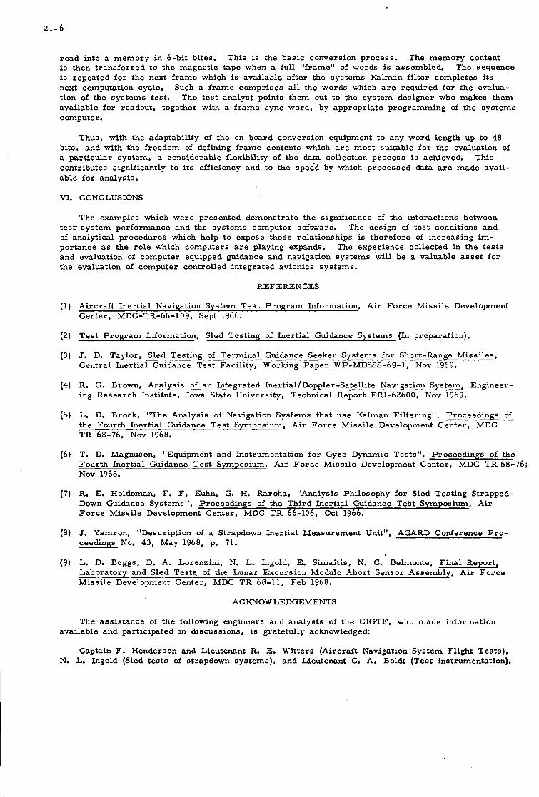
21-6
read into a memory in 6-bit bites. is then transferred to the magnetic tape when a full "frame" of words is assembled. The sequence is repeated for the next frame which is available after the systems Kalman filter completes its next computation cycle. Such a frame comprises all the words which a r e required for the evalua- tion of the systems test. The test analyst points them out to the system designer who makes them available for readout, together with a frame sync word, by appropriate programming of the systems computer.
This is the basic conversion process. The memory content
Thus, with the adaptability of the on-board conversion equipment to any word length up to 48 bits, and with the freedom of defining frame contents which a r e most suitable for the evaluation of a particular system, a considerable flexibility of the data collection process is achieved. This contributes significantly to its efficiency and to the speed by which processed data a r e made avail- able for analysis.
VL CONCLUSIONS
The examples which were presented demonstrate the significance of the interactions between test system performance and the systems computer software. The design of test conditions and of analytical procedures which help to expose these relationships is therefore of increasing im- portance a s the role which computers a r e playing expands. The experience collected in the tests and evaluation of computer equipped guidance and navigation systems will be a valuable asset for the evaluation of computer controlled integrated avionics systems.
REFERENCES
(1) Aircraft Inertial Navigation System Test Program Information, Air Force Missile Development Center, MDC-TR-66-109, Sept 1966.
( 2 ) Test Program Information, Sled Testing of Inertial Guidance Systems (In preparation).
(3) J. D. Taylor, Sled Testing of Terminal Guidance Seeker Systems for Short-Range Missiles, Central Inertial Guidance Test Facility, Working Paper WP-MDSSS-69-1, Nov 1969.
(4) €2. G. Brown, Analysis of an Integrated Inertial/Doppler -Satellite Navigation System, Engineer - ing Research Institute, Iowa State University, Technical Report ERI-62600, Nov 1969.
( 5 ) L. D. Brock, "The Analysis of Navigation Systems that use Kalman Filtering", Proceedings of the Fourth Inertial Guidance Test Symposium, Air Force Missile Development Center, MDC TR 68-76, NOV 1968.
( 6 ) T. D. Magnuson, "Equipment and Instrumentation for Gyro Dynamic Tests", Proceedings of the Fourth Inertial Guidance Test Symposium, Ai r Force Missile Development Center, MDC TR 68-76; Nov 1968.
(7) R. E. Holdeman, F. F. Kuhn, G. H. Raroha, "Analysis Philosophy for Sled Testing Strapped- Down Guidance Systems", Proceedings of the Third Inertial Guidance Test Symposium, Air Force Missile Development Center, MDC TR 66-106, Oct 1966.
(8) J. Yamron, "Description of a Strapdown Inertial Measurement Unit", AGARD Conference Pro- ceedings No. 43, May 1968, p. 71.
(9) L. D. Beggs, D. A. Lorenzini, N. L. Ingold, E. Simaitis, N. C. Belmonte, Final Report, Laboratory and Sled Tests of the Lunar Excursion Module Abort Sensor Assembly, Air Force Missile Development Center, MDC TR 68-11, Feb 1968.
ACKNOWLEDGEMENTS
The assistance of the following engineers and analysts of the CIGTF, who made information available and participated in discussions, is gratefully acknowledged:
Captain F. Henderson and Lieutenant R. E. Witters (Aircraft Navigation System Flight Tests), N. L. Ingold (Sled tests of strapdown systems), and Lieutenant C. A. Boldt (Test instrumentation).

2 1 - 7

2 1 - 8
+ 30
+ 20
+lo--, - z +
O K w -I
2 w
-10
-20
, -30
2400
2000
1600
1200
800
400
0
--- 7
_ _ 6
_ _ 5
t g--4 - Y
* 0 U
2 a
n 0 - - 3
-- 2
_- 1
-- 0
30 -
ACCELERATION
0 8
2500 I--
16 24 32 40 48
TIME FROM FIRST MOTION (SEC)
FIG. 2a SLED TRAJECTORY
BOOST PHASE SYSTEM TESTING
2000
x v) . k 1500
> c 0
- s
1000
500
0 ~
TIME FROM FIRST MOTION (SEC1
\ I 8
fifi
B
FIG. 2b PROPOSED SLED TRAJECTORY
HIGH - g TESTING

2 1 - 9
AIDING SYSTEM
(DOPPLER, NAV. SAT.)
n
OPTIMUM ESTIMATE OF
INERTIAL ERRORS
TRUE VALUES +
AIDING SYSTEM
OPTIMUM ESTIMATE OF
TRUE VALUES + INERTIAL ERRORS INERTIAL SYSTEM
A
+ KALMAN FILTER
- MEASURED
e RADIAL POSITION
ERROR 0
om ). 0
m e
0 0
0 0 0
0
0 ) ,, 0 6
0
0
I I 1
1 I 1 I I I
1 4 5 6 HRS 1 2 3
(a) AT FIRST FLIGHT IN TEST SERIES
-PREDICTED BY FILTER
RADIAL POSITION ERROR
* e - - * ACTUALLY OBSERVED IN FLIGHT
e .eoo e
. e ' a
0
6.8. ' 0
1 2 3 4 5 6 HRS
(b) AT LAST FLIGHT IN TEST SERIES
FIG. 4 EFFECTS OF INADEQUATE MODELING
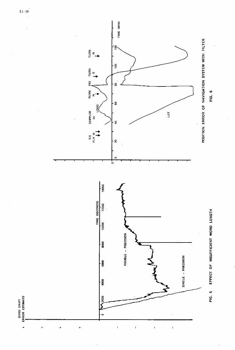
w
E f
0
N 8 s-
8 z 0
0
8
8
0 0 0 0
0
U1
+ + + + I I I I
U 0
I c 0 z w J
K n
I- z Y 0 U U 3 v) z U 0 + 0 w U U W
ln
B U
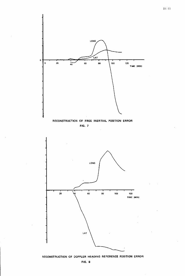
2 1 - 1 1
RECONSTRUCTION OF FREE INERTIAL POSITION ERROR
FIG. 7
1 , 1 1 1 1
60 80 100 120
\ TIME fMIN)
RECONSTRUCTION OF DOPPLER HEADING REFERENCE POSITION ERROR
FIG. 8

21- 12
Po= - FLIGHT ANALYSIS
ACTUAL SYSTEM ERROR FORMAT
CONVERSION
RECORDER
RECONSTRUCTION
SUBSYSTEM OUTPUTS
SIMULATION
ERROR 1 FIG. 9 RECOMMENDED EVALUATION APPROACH
FIRST MO(1ON TUT WATER BRAKE LAST MOTION
I I
J 10 20 30 40 50 Bo 70
TIME IN SECONDS
FIG. 10 CROSS TRACK VELOCITY ERROR
MASS UNBALANCE COMPENSATION 1 WITH
2 WITHOUT
I V N D E R I RECORDING IPROCESSING - I
M R M A T CONVERSION
I SYSTEM
TEST I I
I IRlG TIME GENERATOR I I
FIG. 11 DATA COLLECTION FLOW CHART
22
0
F A U L T ISOLATION
I N A
DIGITAL GUIDANCE & CONTROL C O M P U T E R
BY
DR. DAVID H. BLAUVELT' C H I E F ENGINEER
T H E BENDIX CORPORATION NAVIGATION & CONTROL DIVISION
T E T E R B O R O , NEW J E R S E Y U. S. A.
22
SUMMARY
The capabilities of a general purpose digital computer used in a Guidance and Control application can be used to realize an optimum fault isolation capability for the system. If proper attention is given to the functional partitioning of the computer, self test and self diagnostic programs can be written which will determine that faults have occurred and will isolate them to the replaceable card level. accomplished with virtually no additional flight hardware and a re la- tively simple test console which allows maintenance personnel to communicate with the computer in question. with relatively unskilled personnel.
.
This can be
This can be accomplished
2 2
INTRODUCTION
The utilization of a general purpose digital computer to replace an analog computer or a special purpose digital computer in implementing guidance and control computations introduces the possibility of a new approach to the problem of maintaining the system in the field. of a general purpose digital computer is such that the arithmetic and decision making capability necessary to implement the guidance and control function can also be used to perform a maintenance and fault isolation function without any significant increase in computer hardware.
The nature
The maintainability philosophy should be designed so that the full advantage of the capa- bilities of the general purpose digital computer can be achieved. ability requirements is as follows. self test program which is designed to exercise most of the hardware in the computer and to provide a specific s e t of results. computer is removed from the vehicle. The computer is then taken to a test station where i t can be tied into a computer operated test console. control the operation of the computer under test manually o r automatically. exhaustive self test program is fed into the computer. the computer to confirm the limited self tes t results and to print out those tes ts that the computer is failing. card assembly. program is designed such that i t sequentially exercises sections of the computer starting with steps which utilize only a very limited amount of hardware. Each succeeding step of the program is then designed to exercise some slightly expanded amount of hardware until all of the computer hardware is exercised. The results of each step in the program are compared to precomputed results and any discrepancy in the comparison would indicate that the increment of hardware f i r s t exercised in that program step is not properly operating,
One such approach to the maintain- The digital computer operational program includes a small
If these results a r e not achieved then a fault indication is given and the
This console is designed such that an operator can At this point a more
This test is designed to completely exercise
The next step in the maintenance procedure is to isolate the failure to a replaceable This is f i rs t attempted by means of a self diagnostic program. The self diagnostic
U the self-diagnostic program can not isolate the failure to a single card, then a computer The approach here aided tes t system can be utilized to attempt to isolate the fault to a single card.
is to utilize a tes t system which can apply selected logic level stimuli to specified test points and measure logic level responses a t corresponding test points. isolated i t will be replaced and the self tes t program rerun to insure proper operation of the computer.
Again when the failed card has been

22
I
22- 1
Test Console
The tes t console consists of a control and display panel which enables the operator to communicate manually with the computer under test and a digital computer which is used to auto- matically control portions of the test and fault isolation procedures.
The control and display panel consists of a multiplexed readout device which is capable of displaying the contents of a 16 bit register in octal format; a selector switch which determines whether the information on the display is the contents of any selected memory location or the contents of any selected computer register; an input keyboard; a set of control buttons which can cause the computer to run, halt , egecute a single instruction, execute a single instruction phase, or to run to some preselected location in program memory; and control logic which gives the console access to the 1/0 data bus, to the memory address bus, and to cri t ical timing and control lines within the computer. This control and display panel enables the operator to hand load short programs directly into memory or into the computer regis ters , to execute these programs one instruction at a t ime, to run through selected portions of the programs, to observe the state of any computer register or memory location and in general get a detail status of the computer operation for software or hardware debugging.
The test console also contains its own operating general purpose digital computer. computer can be used to generate special test stimuli which can be sent to the computer under test through the test connector and in return receive response signals back through the test connector. means of self diagnostic programs. The console computer can also be used to ass is t in the self diagnostics if desired as well as performing external diagnostics. be utilized to analyze the results of the various tests performed and to print out diagnostic reports through a teletype system.
This
This can be utilized to test those component failures which cannot be isolated by
This computer can also
Fault Isolation Approach and Procedure
The fault isolation procedure to be followed in order to isolate failures on replaceable subassemblies is depicted in the flow chart of Figure 1. of external and self diagnostics which tests all of the hardware. while allowing testing to be done in dynamic operating modes without dependence on flight opera- tional software. for self-test and for exercising various parts of the computer.
This procedure is a balanced combination It provides total external control
It also makes maximum use of the general-purpose nature of the central processor
Fault isolation is based on a ' signal testing' concept, whether external or self diagnostic procedures a re employed. examination (ei ther directly or indirectly) , and equating their failure with a printed circuit card. Tests a r e performed on a pyramidal basis , using tested and verified hardware to test other hardware; this pyramid testing is of pr imary importance in the deduction of which card is to be replaced.
This concept involves choosing key signals within the computer for
Ground Rules
In preparation of the diagnostics of fault isolation, the following ground rules were observed.
1. A single failure - It is assumed that only one failure exists in the computer. While the pyramid testing concept attempts to check out all hardware before i t is used for testing other hardware, certain areas (particularly in CPU self diagnostics) require that once an e r r o r is found, no other e r r o r s exist.
2. The computer under test has been operating prior to the failure. would cause improper call outs of failed printed circuit cards.
Wiring e r r o r s
Computer Self Test Procedures
The limited self test program is a short program, which is interlaced with the guidance and control operational program, and is continuously exercised when the computer is being used. It generally involves solving a fixed known problem and comparing the results with precomputed stored answers. Although a program of this length cannot exercise all possible conditions of the hardware within the computer it can be utilized to detect 95% of the computer failures. of the types of programs which may be in a self tes t of this type are:
Examples
1. A memory s u m check on the fixed program to insure that program memory has not been altered.
2. A memory operability test which exercises all memory locations verifies their proper operation.

22-2
Limited Operational Self Tes t
Remove From System On Failure
1 Apply Power to
Computer a t Tes t Console
4
i
Power Supply Fault Isolation Procedure
Measure a l l AC & DC Voltages Fault Isolate to Bad Module
Check 1/0 Bus Measure Communication Bus
Fault on Card # -
Check Oscillator
No Fault on Card # -
Check Clock
Fault on Card U -
)Yes 1 Pre l iminary Arithmetic Test ; I
I I ' .Load and Display a l l reg is te rs with al l ones and a l l zeros I Fault Isolate to Arithmetic Cards 1
I
Memory Test ; Load & Display Memory with self-diagnostic tes t
No Par t ia l Memory c Fault
Isolation Procedure ILoad &Execute Detail 1
Self Tes t Program
Run program with interrupts disarmed. Indication of bad
card i s program counter when computer hal ts .
1/0 T e s t and Fault Isolation 1/0 tes t s performed using tes t
programs in conjunction with tes t s e t s t imuli , measurements and
control.
1.
2.
3. Output Discretes , Sample &Hold
Analog Tes t - Input Signal Conditioners & Multiplexers
Input Discretes and A/D Converter ( t h i s tes t s mos t of I/O Controller)
Circui ts , and D/A Converter
Fault Isolate to Bad Card I Figure 1
Fault Isolation Overall Flow Chart
22-3
3. An arithmetic and control test which exercises all computer instructions in a fixed solution problem.
4. A tail biting D-A, A-D converter test to verify operation of the major part of the 1/0 section.
After the limited self test program indicates a computer failure the computer is removed
The function of the test console is to enable the operator to take control over the operation Before attempting to operate the computer with the console, however, certain
from the system and taken to the test area. point. of the computer. tests are made to insure that there have been no catastrophic failures. the oscillator and the computer clock a re checked. to insure they a r e operational.
The computer is tied into the test console at this
A l l power supply voltages, The computer data input lines a r e also checked
After these preliminary steps a r e taken the next step is to determine if the test console can successfully communicate with the computer under test. The procedure is to load each of the operating regis ters of the computer with an all zero pattern and then an all ones pattern. loading, each register should be displayed on the test console. Any discrepancy between the data loaded into the registers and the data displayed on the test console indicates a failure in the ari th- metic section or the control section of the computer. onto printed circuit cards and the combination of specific discrepancies in the display can be logically analyzed to determine which card has failed. the computer along functional lines in the design phase can greatly simplify the fault isolation process at this point. If no discrepancies a r e noted then proper operation of the 1 / 0 bus, each of the computer regis ters , and the adder can be assumed, and this fact can be used to form the basis for further tests. value and to load a data word in that memory location by means of the console. Display the memory location to insure that the memory was properly loaded. Manually set a load accumulator instruction into a second memory location and manually execute that instruction. instruction to a s tore instruction and execute this instruction. add instruction and execute this instruction. commands from the central processor should be checked. is in the memory. cards , or in the memory and the exact status can be deduced from the specific failures.
After
Knowledge of the partitioning of the computer
It should be noted that ca re in partitioning
The next test is to set the memory address register to some preselected
Change the load Change the s tore instruction to an
If all these procedures fail the read and write If they a r e properly generated the fault
If only certain of these steps fail the fault can be on one of the central processor
The next step is to insure that the computer memory is completely operational. This is accomplished by loading a memory test program from a tape reader utilizing a hard wired bootstrap loader. The loader can also be utilized to verify that the proper information got into memory by reading the tape a second time and comparing the inputs from the tape with the information stored in memory on the f i rs t pass. If this validation fails one of the instructions used in the bootstrap loader may be inoperative. The bootstrap program should then be stepped through one step at a time and all affected registers should be examined to determine i f that instruction was properly executed. be used to isolate the faulty card.
This is continued until the faulty instruction is located. The nature of the fault can then
If the memory test program is properly loaded i t is then run. This program sequentially goes to each memory location, reads out the data and transfers it to a temporary location in memory. to the accumulator. This is followed by an all ones pattern, an alternate one zero pattern, an alternate zero one pattern and the location address. If any of the comparisons fail the computer is halted indicating a fault at that location. If the comparisons all pass,the data originally located at that address is restored and the program moves on to the next memory address where the process is repeated. is halted by the operator.
Next an all zero pattern is stored at the test location which is then read out and compared
The program will continue to cycle through all memory lochtions until the program At this point proper memory operation is assured.
After memory operation is verified a detailed self-test is loaded into memory and executed. the machine.
This test exhaustively exercises all of the hardware and all the capabilities built into This test is used to confirm the original failure indication.
The next step is to load and run the central processor self-diagnostic program. program is designed to exercise all the functions in the central processor in a sequential manner such that with each step of the program some additional section of hardware is verified to be operative. verified to be operating properly: memory; memory buffer register; adder; and the load accumula- tor, s tore accumulator, add, and halt instructions. self-diegnostic is as follows.
This
The self-diagnostic programs assume that the following functions have been previously
The general philosophy utilized in writing the
The preliminary manual exercising of the computer through the console established that In addition the add, all of the regis ters were operational and that data could be loaded into them.
load, and s tore instructions were established as being operational. This means that those control
22-4
signals and gates needed to execute these three instructions a r e properly operating. Using these known facts an instruction utilizing that hardware already verified and one untested control signal can be exercised. a r e verified. either the control signal o r to the gating. which utilizes the questioned control signal. is isolated. operating and the fault is isolated. all control signals and all instructions have been determined to be operational. isolated at this point the self tes t failure print out should either be given to a troubleshooter and he should attempt to isolate the fault manually, or the tes t console computer should be used to card tes t one o r m o r e selected cards as suggested by the nature of the self tes t failure print out.
If the self tes t o r the self-diagnostic program determines that there is a fault but is not
If i t operates properly then the new control signal and the associated gating If the instruction does not operate properly then the failure must be isolated to
This can be accomplished by choosing another instruction If it operates properly the fault is in the gating and
If the second instruction does not operate properly then the control signal is not
If no fault is This process can be repeated until the fault is isolated o r until
able to isolate the fault to a single card, the tes t console and its computer can then be used to apply more specific tes ts to each of the potentially failed cards. the tes t console computer to supply selected stimuli in a sequential fashion to the suspected cards by means of the tes t connector and measuring responses at corresponding points also brought out to the t e s t connector. stimuli and to determine if the suspected card is operating properly.
This is accomplished by utilizing
The tes t console computer is then used to evaluate the responses to the
This s ame tes t console computer can also readily be used as a card tes ter if a suitable adapter is provided. then be removed from the computer and tested by i tself , its failure confirmed, and the actual failed integrated circuit located exactly o r narrowed down to a few possible integrzted circuits which can then be replaced in order to res tore the card and the computer to i ts operational status.
After the fault isolation procedure has located the failed card that card can
The detailed self-test program can then be rerun in order to confirm the computer has been restored to proper operational status. .
The fault isolation of the I/O section of the computer varies because the 1/0 requirements for each specific requirement will differ. to digital converter, a multiplexed digital to analog converter, a digital data link and some means for sending and receiving discretes.
However, most systems will contain a multiplexed analog
The proper design of the A-D and D-A converter and multiplexer can greatly simplify the fault isolation of this hardware. of the multiplexed output channels is connected to one of the multiplexed input channels, then a diagnostic program can be written which will generate a digital output from the central processor which is converted to an analog voltage by the D-A converter. This analog voltage is then multi- plexed after passive scaling to the input multiplexor of the A-D converter, where i t is converted back into a digital number. This digital number is then inputted into the central processor where the resul t is compared to the known correct value. of different voltages to determine the proper operation of the converters o r to isolate the failure to this card.
If this hardware is all packaged on a single card and if one
This process can be repeated for a number
The fault isolation of the digital input output link can also be simplified by having this entire function on a single card. to send a simulated message to the computer under tes t and then having this s ame message re- transmitted back to the t e s t console computer. associated hardware can be exercised and either validated o r fault isolated.
The tes t can be implemented by using the tes t console computer
By properly choosing the test message all the
This same general approach can also be utilized to fault isolate the discrete input output section of the computer provided that a l l the associated hardware is packaged on the s a m e card.
Any other 1/0 functions which may be in a specific computer application can generally be fault isolated in a manner s imilar to that described above as long as a functional approach is taken in the partitioning of the cards in the 1/0 section of the computer.
SPACEBORNE COMPUTER FOR ATTITUDE CONTROL
AND DATA HANDLING
P.van Otterloo
Philips Research Laboratories
Eindhoven (Netherlands)

23
SUMMARY
In the ANS (Astronomical Netherlands Satellite) which is planned to be launched in 1974, an on board computer is foreseen, This computer will consist of two parts, the computer proper and the data-memory.
The computer, which will be reprogrammable by ground command, will serve as a direct digital controllbr for the attitude control of the satellite and as a data processor for reduction of the experiment data.
The data memory serves as a buffer for storage of separate experiment and housekeeping data f o r a period of 12 hours. Both the computer and the data memory have to be designed to serve weight and power limitation.
23
INTRODUCTION
The computer to be discussed here is designed as a sub- system of the ANS (astronomical netherlands satellite). As long as no acronym has been found it shall be referred to as OBC (on board computer) which is the subsystem name. The ANS is a semi polar orbit (500 km) satellite with high pointing accuracy ( -+ 1 1 ) intedded to'perform astronomical W and X ray measurements. It is a joint U.S./Netherlands effort to be launched in 1974 by a SCOUT launcher. Due to the limited performance of this launcher low weight and power consumption are stringent requirements. Because the satellites orbit is polar, ground contact with a station at the latitude of the Netherlands is possible only once every 12 hours during 7 minutes. This means that experiment data have to be stored on board as well as commands stating the measurements to be performed in at least one 12 hour period. So in the 7 minutes contact time not only all experiment data have to be extracted from the satellite, but also new commands have to be transmitted for the next 12 hour period. A digital memory for which a core memory has been chosen is unavoidable because of the inherent unreliability of taperecordei+s as well as the unrealistic record/play back ratio required. Telemetry subsystems are working digitally too, this favouring digital ionboard information storage. Experiment data are all of a digital nafure and need some reworking in order to limit storage space and transmission time. This requires a digital computer. The attitude control subsystem required calculations which for various reasons (integration, logical decisions) can only be performed by a digital computer. An analog system built to calculate these signals would not only be very complicated, heavy and highly power consumptive but would also frequently need adjustment. The above mentioned requirements still do not express a clear preference for fixed program o r stored program machines. The initially performed work went in the direction of a fixed program machine. Soon however, it became apparent that a lot of changes can be expected in the program up to the time that the flightmodel is ready for launch. Also different formats are required for on board storage of data while different modes of operation made the data handling of the experiments more and more complicated. This led to the conclusion that the computer should have a stored program. This automatically brings up the question whether program changes were to be done only on the ground o r also in orbit. Since the operation of the satellite depends on the possibility of transmitting 5000 bits in one o r two minutes to the satellite every 12 hours (star measurements program) and reading about 400 000 bits out of it, it was decided that sending up and verifying a part of the program was not more difficult and therefore quite well realizable. The limited space on the satellite made impossible to build the complete subsystem in one box. In order to put the interface at a convenient spot, it was decided to split the memory in two parts. The biggest one will be used only for data storage awaiting later transmission to the ground. The capacity will be about 400 000 bits. The rest, 6 4 k bits, will bhare its box with the central processor and the 1/0 unit and serve as computer program spsce, working space and command storage. Both boxes shall weigh no more than 4 kg and consume no more than 4 Watt of power each.

23

23-1
In the control unit the instructions are decoded and transformed in machine control pulses while the addresses are, depending on the instruction, routed to the corresponding registers. As will be discussed later, one word of the program has 16 bits. Of these 6 are used to indicate the instruction, allowing for 64 different instructions,and 10 which can have different meaning, depending on the instruction to which they are coupled, They can be: - a number to be added to or to replace another number (address modification etc.) - an address in the memory - a register The 10 bits available are not sufficient to address the whole memory, which will have 4k words. The additional bits are again generated in this control unit. Finally this is also the unit where the clock is built in. This has to be the most reliable part of the OBC since it also delivers clock pulses to the rest of the satellite and since it makes sense to keep supplying these signals once the complete OBC failed.
I
COMPUTER I In fig. -1 a schematic diagram of the computer is presented. The following parts can be found -arithmetical unit -control unit -memory -input/output unit
These units will be detailed further below. This will however not lead to a complete description as the design is not yet complete. Attention however is asked for the program given in the next section on computer software, which should give an impression of the capabilities of the subsystem.
by the sampling time'of the attitude control subsystem for which the computer performs the calculations.
I Speed can be relatively low since the program repetition time is 1 sec. dictated
I ARITHMETICAL UNIT I This is the unit where the actual calculations take place. The only possible calculations are adding, multiplication by powers of 2 (:shifting) and inverting. All other calculations have to be programmed. It has not been decided yet but the hardware calculations will probably be performed in series. This decision will depend on the length of the program and its execution time.
CONTROL UNIT
INPUT/OUTPUT UNIT I This unit consists of an address register with decoding used to open the gates to the requested input or output as well as some logic to feed shift and transfer pulses to these inputs..ar outputs, A standard computer output (SCO) interface and a standard computer input interface (SCI) has been specified (fig.2) All units wishing to communicate with the OBC can do s o via these interfaces. In order to limit the number of interface units and wiring, subcommutation of the experiments is performed. The OBC supplies them via SCO with an adress, allows for transfer from the register indicated by the adress to the SCI and then reads the SCX.
MEMORY I A 4k 16 bits memory module indentical to the blocks of the data memory has been chosen, as a first order approximation,. at the same time hoping to reduce 'the number of spare parts and easeing for suppliers the qualification of items. It is thought to be divided into 4 parts of lk each of which 2 are not used and saved for redundancy. Of the other two parts 1000 words are used to store the program and the remaining 1000 words will serve as a working space for the computer.and at the same time as storage space for the commands.
The two redundant parts normally are not used. The redundant program part will be filled with an emergency program for a start and later on, when the program in use appears to be reliable, can be used to put new programs in . The advantage is that during transmission of the new program, which takes several minutes, the old one is still available for attitude control, The redundant working space cannot be used to store more program as long as there is no emergency requiring its use, because upon occurrence of this failure in the normal working immediate switchover must be possible. This means that defined memory is required to be available.

2 3-2
COMPUTER SOFTWARE
Tasks of the program
The tasks of the computer program can be divided into several parts: a) The attitude sensor data are gathered, processed according to the observation
program, and the resulting set-points are given to the attitude actuators, i.c. the reaction wheels: also attitude data are stored in the data memory.
b) The experiment data are gathered, processed and stored in the data memory.
c) Commands are transmitted to the experiments according to the observation program and the status of the experiments.
d) A selection is made from the information available at the housekeeping encoder and this selection is transmitted to the data memory.
e) A selection is made from the experiment and attitude data and transmitted to the housekeeping encoder.
f) A series of clock pulses is generated and distributed.
In order to perform this task a very limited number of standard instructions will be made available. These instructions serve as building blocks for the program.
Operations
The program consists of a number of instructions. Each instruction consists of a 16 bit word; stored at a certain location of the computer memory. Of these 16 bits 6 are the instruction part: these refer to a certain operation to be performed by the computer. The other 10 bits are the address part and indicate a certain location in the memory. In the first part of each computer operation the content of the operation counter is increased by 1 . The content then is transferred to the memory address register. (see fig.-1) The contents 'of the addressed is transferred to the M register and from these to the instruction register. The second half consists of the execution of the instruction called from the memory in the first half of the operation.
Instructions
The instructions foreseen in this stage of the project are:
Read X into A ( I A / X ) The word at address X is read from the memory into M, from where it is transferred to A and at the same time rewritten in the memory at the location X .
Read X into A, negative ( I A - / X ) The same, but the sign is reversed before transfer to A.
Read X into A , destructive ( I A D / X ) The same as I A / X but without the rewrite operation.
Read X into M , (IM/X) The word at address X is read into M , and rewritten into location X . After that it is added to the word in A . The result appears in D. Storage in M cannot be used as such in the program, because register M is used in the next operation for transfer of the instruction word.
Read X into M, negative ( IM- /X)
Read X into M, destructive (IMD/X)
. Read X into M, negative, destructiee (IMD-/X)
Wri$e D into X (OD/X) The word in the D-register is transferrred to M and from these written into the memory at location X .
Write D into X , negative (OD-/X) The same, but with sign reversed.

23-3
Jump to L (TO/L) In this case the address part of the instruction contains the number L - 1 . This is transferred to the operation counter from the instruction register. In the next operation the program proceeds at instruction number L.
Set flip-flop if D positive (SIFD) This instruction, which has no address part, sets a flip-flop if the content of the D register is positive.
Jump to L, if the flip-flop is set (IFTO/L) If the flip-flop is set, the operation is the same as in TO/L, after which the flip-flop is reset. Otherwise nothing is performed, so that the program proceeds with the next step.
Shift N steps from register P to register Q (SHN/PQ) The instruction part here consists of 2 bits indicating that the instruction is of the SHN type, and 4 bits giving the numbers from 1 to 1 6 . The address part consists of two 5 bit words, each of which indicates one of up to 32 possible registers, either in the computer arithmetic and control unit or in the input-output unit. The effect of this instruction is to shift the indicated number of bits from P to Q. P and Q may be identical: Q may be zero, in this case the information is shifted only out of P.
Statements
In order to ease the task of programming the computer a simplified FORTRAN language will be designed, where each FORTRAN-statement consists of a small number of instructions. This makes it possible to translate the programs used for simulation in a straight foryard way into machine language. The following statements have been considered.
X = Y transfer to X of Y
X = Y + Z
X = Y - z
GOT0 L
IF ( X ) L
IF ( X - Y ) L
N Y = X w 2
READ ( P ) X
WRITE ( P ) X
CALL K(A, B)
IA IM OD
IA IM OD
IA- IM OD
TO
if X>O Goto L IA IM
if X O proceed with SI FD next statement IF TO
IA- 0 IM
SI FD IF TO
subroutine calling sequence :
IA S HI IM OD
s H 1 6 OD
IA s H 1 6
IA IM OD IM
' OD
OD TO
s H 1 6
0 Y X
2 Y X
Z Y X
L
0 X
L
Y X
L
X A, 0 0 Y
p , D X
X A, p
0 A P B Q oc , D MAIN K
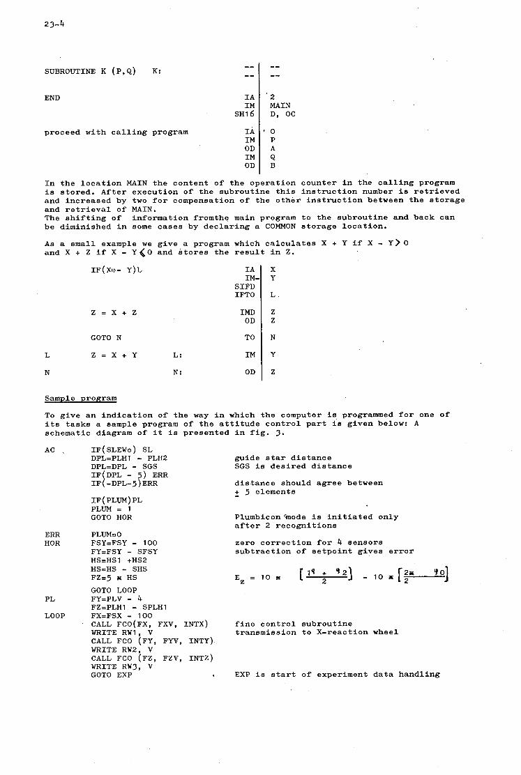
23-4
IA IM
~ ~ 1 6
SUBROUTINE K (P,Q) K:
'2 MAIN D, OC
END
proceed with calling program In IM OD IM OD
' 0 P A Q B
IA IM-
SIFD IFTO
IMD OD
IF(XI:.- Y)L X Y
L .
Z Z
z = x + z
GOTO N TO
L Z = X + Y L: IM
N N: OD
N
Y
z
Sample program
To give an indication of the way in which the computer is programmed for one of its tasks a sample program of the attitude control part is given below: A schematic diagram of it is presented in fig. 3.
AC \ IF(SLEWO) SL DPL=PLHl - PLH2 DPL=DPL - SGS - 5) ERR IF ( PLUM) PL PLUM = 1 GOTO HOR
ERR PLUM=O HOR FSY=FSY - 100
FY=FSY - SFSY HS=HSl +HS2 HS=HS - SHS FZ=5 w HS GOTO LOOP
PL FY=PLV - 4 FZZPLH1 - SPLHl
LOOP FXFFSX - 100 CALL FCO(FX, FXV, INTX) WRITE RW1, V CALL FCO (FY, FYV, INTY) WRITE RW2, V CALL FCO (FZ, FZV, INTZ) WRITE RW3, V GOTO EXP
guide star distance SGS is desired distance
distance should agree between + 5 elements - Plumbicon%ode is initiated only after 2 recognitions
zero correction for 4 sensors subtraction of setpoint gives error
fine control subroutine transmission to X-reaction wheel
EXP is start of experiment data handling
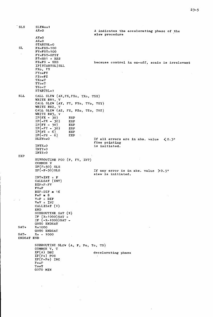
SLS SLEWo= 1 AX=O A indicates the accelerating phase o f .the
slew procedure
because control in on-off, scale is irrelevant
If all errors are in abs. value (0.30 fine pointing is initiated.
AY=O AZ=O STARTSL=O
SL FX=FXS-100 FY=FSY-100 FYzFSY-SFSY FZ=HSl + US2 FZ=FS - SHS IF(STARTSL)SLL FXo, FX FYo=FY FZo=FZ TXO=T TYo=T TZo=T STARTSLz 1
SLL CALL SLEW (AX,FX,FXo, TXo, TSX) WRITE RW1, V CALL SLEW (AY, FY, FYo, TYo, TSY) WRITE RW2, V CALL SLEW (AZ, FZ, FZo, TZo, TSZ) WRITE RW3, V IF(FX - 30) EXP
IF(FY - 30) EXP IF(-FY - 30) EXP
EXP IF -FZ - - 6, 6) EXP SLEWo=O
INTX=O INTY=O INTZ=O
IF(-FX - 30) EXP
EXP SUBROUTINE FCO (F, FV, INT)
IF(F-~O) SLS COMMON V
IF(-F-sO)SLS If any error is in abs. value > O slew is initiated.
INT=INT + F CALLSAT (INT) DIF=F-FV FV=F DIF-DIF I 16 P=F I 8 V=P + DIF V=V + INT CALLISAT (V) END SUBROUTINE SAT (X) IF X-lOO0)SAT + IF I -X-1OOO)SAT - GOTO ENDSAT
GOTO ENDSAT SAT+ X=lOOO
SAT- X= - 1000 ENDSAT END
SUBROUTINE SLEW (A, F, Fo, To, TS) COMMON V, T IF A) DEC decelerating phase IF Fo) POS IF i F-FO) INC Fo=F To=T GOTO MIN
5 O

23-6
INC
POS
INC2
DEC
ENDSL
POS 1
. PLUS
MIN LAST
F=F + F IF(F - FO) MIN TS=T - TO TS=TS+TS A= 1 GOTO PLUS IF(F-Fo)INC2 Fo=F To=T GOTO PLUS F=F + F IF(F-FO) PLUS TS=T - TO TS= TS + TS GOTO MIN
TSl=TS + TO
Fo=F To=T AZO
GOTO PLUS TSt=TS + TO
GOTO ENDSL v = 1000 GOTO LAST v =-loo0 END
IF(FO) POS 1
IF(TSI - T) PLUS
IF ( FO ) MIN
IF(TSI - T) MIN
The length of this part of the program is about 120 FORTRAN-statements so that in the real program about 350 - 500 lines will be required.
Overall program
The overall program is not yet completed but it will consist of the following blocks:
First the time is updated by the statement T = T + 1. Next a test is performed whether new measurement setpoints are required by IF(TM-T)AC. As long as T TM the program proceeds with attitude control; otherwise new setpoints are transferred from the observation program part of the memory to their working addresses (SHS, SPLH, TM etc.). The stored commands are transmitted to the command control unit. The following part is attitude control, described above. At statement EXP the processing of experiment data starts, consisting e.g. of fixed-to-floating conversion, integrltion etc. The last part of the program controls the transfer of experiment and attitude data to the data memory, as well as transfer of these data to the encoder and of housekeeping data from the encoder to the cornpater and from there to the data memory. This transfer is controlled by the statements:
WRITE DM(N), X N= 1 to 6. The word at address X is transferred to the N-th block of the data memory.
WRITE ENCADD, N N= 1 to 16. This statement causes the N-th 8 bit word, available each second at the encoder to be stored in the encoder output buffer register.
READ ENC X. The computer reads the word at the output buffer of the encoder and stores it at address X.
WRITE ENC X. The last 8 bits of the world X are transferred to the encoder input register.
23-7
In the original concept it was envisaged to have a tape recorder on board to store the information flow from experiments to housekeeping. The expected number of bits was 2 or 3.10 . Due to a reduction in the number of experiments as well reduced by a factor of 10. During this study an experiment was added and $he housekeeping as well as experiment data increasesd agairi.
Instead of giving every experiment its maximum storage space and adding these together to get an overall storage space requirement, another policy was followed. The computer is being used now not only to handle thedatabut also to select data for transmission to the memory. This selection is made by a computer program that easily can be changed to adopt the system to various environments, requirements and situations by reading in another one. This works of course only under the assumption lhat maximum storage space is asked by only user at a time. For example during dynamic attitude control measurements nearly all storage space is used for storing the sensor data so no experiments and very little housekeeping data can be written in the memory, while during pulse and measurements the x-ray experiments will fill all available memory space in 90 minutes. In this way the memory size needed
Because of this reduction in the number of bits the tape recorder was not the only solution anymore. It was actually immediatelY rejected because the required record to play-back ratio was very unfavourable. The record time being 12 hours and the play-back time of a few minutes brought this ratio in the order of 1:200. A recorder with this feature is not commercially available and would have to be developed. This, added to the fact that tape recorders for space application are still rather un- reliable, made that such a recorder as a data memory was rejected.
6
1 as in the number of bits per experiment a i s was at start of the feasibility study
1
is in the order of magnitude of 400 K bits.
DATA MEMORY I
23-8
Since the power consumption in the stack can be neglected, no precautions have to be taken for cooling. This means that the heat conducting strips can be cancelled and the weight of the stack is decreased, Since the stack determines for the most part the weight, the weight of the memory can be made very low by using low weight material for the remaining part of the stack.
Yet another requirement is a restriction in size in order to have everything fit in a box with outside dimensions of 13 x 16 cm. This can probably only be accomplished with the core size of 20 mils. The configuration chosen is shown in fig. 4-. Three printed circuit boards carry one block. The first two boards carry on both sides 4 matrices of 4 K bits, while on the third one the selection diodes are mounted.
As the whole informatinn can be written in series, the address register is a simple counter. A high realiability has been achieved by making a good and simple design and using reliable components as well as by aliowing for gentle degradation. The whole memory consists of 6 separate memory blocks. In the case of a failure in one of the blocks that particular block can be rejected and skipped. In this way not only high reliability but also high flexibility can be obtained. At the same time the number of spare parts can be redueed. A similar 4 K 16 bits memory unit will be used kn the computer to serve as working, program and command memory. The 6 blocks required to get the 384 K storage space are fully independent but in order to keep the inlJerfaces and cabling to an absolute minimum, they arc? not connected to the computer. In stead a separate switching mechanism is used to route the information to the proper block. This device can be used to skip a damaged block but may also be programmed from the computer to send for instance housekeeping and experiment data to different blocks to speed up ground handling of the data. However, it will be a fairly simple and straight forward piece of hardware and is therefore not described here.
In fig.5 a block diagram of one memory block is shown. The information that must be stored in the memory is applied to shiftregister I. The register can store 16 bits. The number of bits of one set of information can be 8 or 16. In the case of 8 bits a write pulse is given after two times 8 bits. The applied information is accompanied by an equal number of trigger pulses applied to the trigger input of the register. At the same time a pulse with a duration time of 8 bits is applied to the timing. In the case of a read pulse the tele-command delivers 16 trigger pulses to shift the shiftregister. After the 16 trigger pulses all the flip-flops of the shiftregister are reset. This means that only the set-inputs are connected with the outputs of the read amplifiers.
Timing
At the end of the pulse accompaning the first 8 information pulses a flip-flop is set and at the end of a second pulse the flip-flop is reset again.
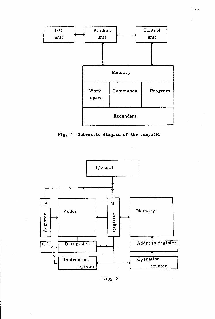
2 3 - 9
110 unit
4
, Arithm. Control
< > unit unit i
Adder
A
I)- register >
A
W w
r Memory
Work Commands space
Address register c=
Program
In st ruct ion register
Operation c >
counter A
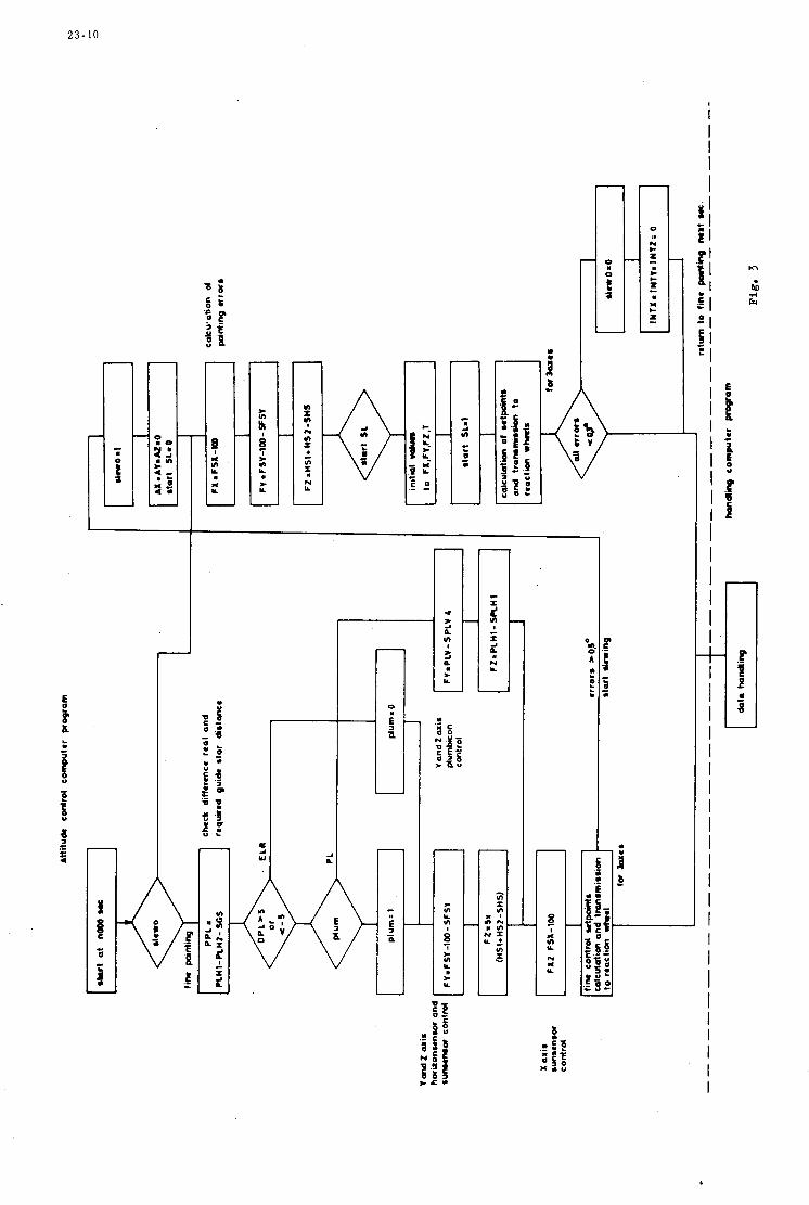
2 3 - 1 0
I
I I I I I
E l .P ' E l :
- 1 i l
HI 21 f l ? I
I I I I I I I I I I I I I I I
[ Y L
[ Y Y * I
.P H
0
a A U
I I I I I I I I I I I I I I I I I I I I I I
o s 2 it? E E - Ih : a!
r [ I Y) Y n x
Y .- t c
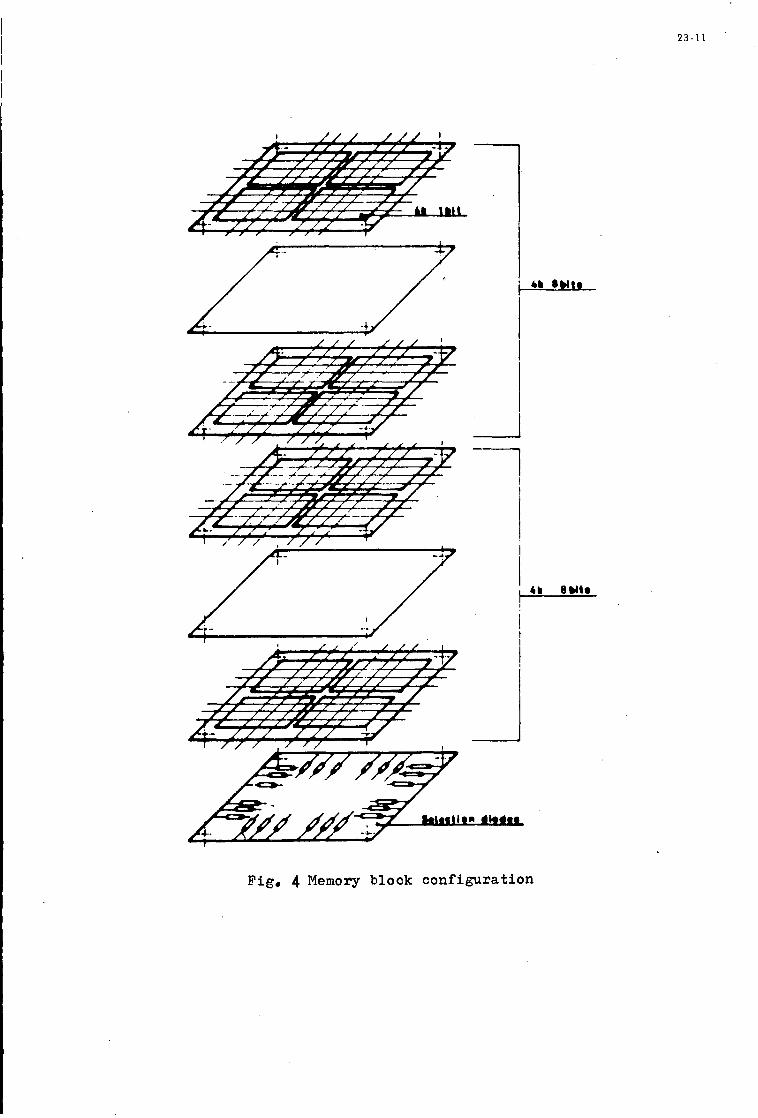
2 3 - 1 1
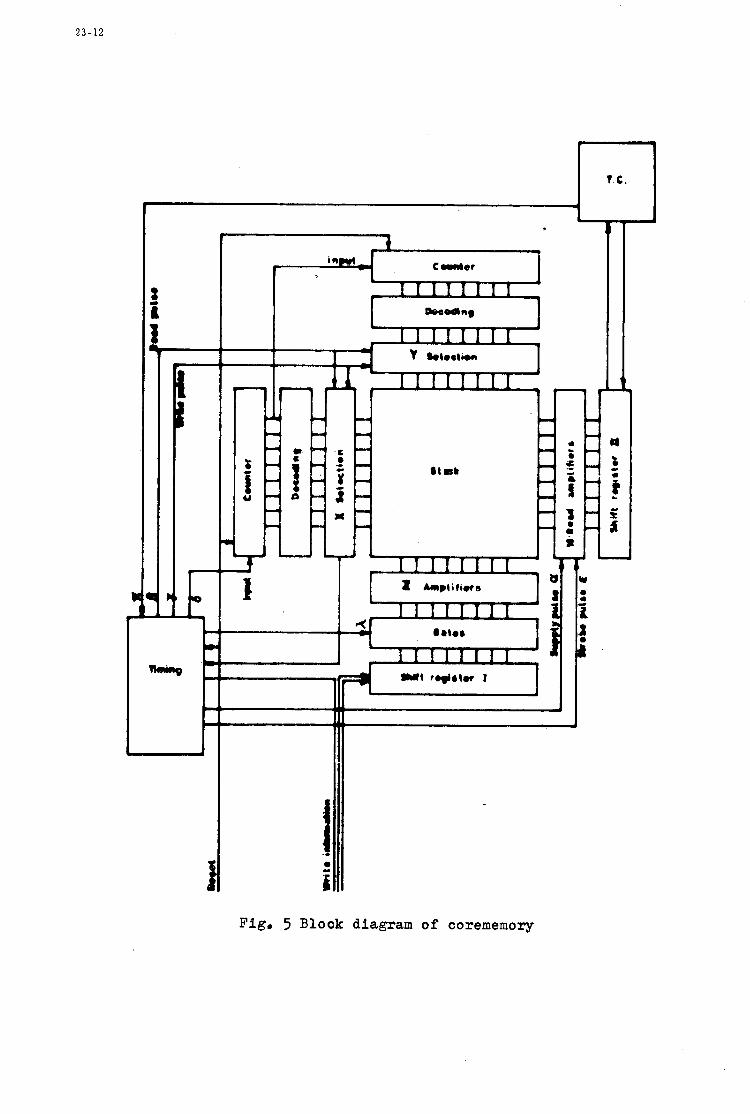
2 3 - 1 2
i- I I
Fig, 5 Block diagram of corememory


In 0
t-' Q) N W
N .. m
m W
3
In 0
t-
3 m W
In 0
P-
8 W
N .. m
cc, W
d
In 0 t-
Q) N W
N m 3
W m


In 0
e-
N W N
m .. m
m d
W
v) 0
e- m N W
N m .-I m W
In 0 e-
hl W
N m d CO W
m
In 0 t- m N W
N m d
m W

I

N A T I ' O N A L D I S T R I B U T I O N C E N T R E S F O R U N C L A S S I F I E D A G A R D P U B L I C A T I O N S - - - -
Unclass i f ied AGARD pub l i ca t ions a r e d i s t r i b u t e d t o NAM Member Nations through the unc la s s i f i ed National D i s t r ibu t ion Centres l i s t e d below
BELGIUM General J. DELhYE Coordinateur AGARD - V. S.L. E t a t Major Forces Adriennes Caserne Pr ince Baudouin P lace Da i l ly , Bruxelles 3
Direc tor o f S c i e n t i f i c Information Se rv ices Defence Research Board Department of National Defence - 'A' Buil'ding Ottawa, Ontar io
Danish Defence Research Board Osterbrogades Kaserne Copenhagen d
0. N. E. R. A. (Di rec t ion) 29, Avenue de l a Division Lec le rc 92. Chiitillon-sous-Bagneux
CANADA
DENMARK
FRANCE
GERMANY Z e n t r a l s t e l l e fur Luftfahrtdokumentation und Information Maria-Theresia Str. 21 8 Miinchen 2'7 Attn: Dr Ing. H. J. RAUTENBERG
Hel len ic Armed Forces Command D Branch, .Athens
Direc tor of Aviation c/o Flugrad Reykjavik
GREECE
ICELAND
UNITED STATES
ITALY Aeronautica Militare Uf f i c io del Delegato Nazionale all' AGARD 3, P. l e d e l Turismo Roma/Eur
LUXEMBOURG Obtainable through BELGIUM
Netherlands Delegation to AGARD National Aerospace Laboratory, NLR Attn: Mr A.H.GEUDEKER P.O. Box 126 Del f t
Norwegian Defense Research Establishment Main Library , c / o W P.L.MERN P.O. Box 25 N-2007 K j e l l e r
Direccao do Servico de Mater ia l da Forca Aerea Rua de Escola P o l i t e c n i c a 42 Lisboa Attn: Brig. General Jose de Sousa OLIVEIRA
Turkish General S t a f f (ARGE) Ankara
Ministry of Technology Reports Centre S ta t ion Square House St. Mary Cray Orpington, Kent BR5 3RE
NETHERLANDS
NORWAY
PORTUGAL
TURKEY
UNITED KINGDOM
National Aeronautics and Space Administration (NASA) Langley F ie ld , Vi rg in ia 23365 Attn: Report D i s t r ibu t ion and Storage Unit
* * *
I f copies o f t he o r i g i n a l publ ica t ion a r e not ava i l ab le at these cent res , t he following may be purchased from:
Micrqfiche or Photocopy Microfiche Clearinghouse f o r Federa l ESRO/ELDO Space S c i e n t i f i c and Technical Documentation Serv ice In formation (CFSTI) European Space Spr ingf ie ld Research Organization Virg in ia 22151, USA 114, Avenue de Neuilly
92, Neuilly- sur-Seine, France
Microfiche
Ministry o f Technology Reports Centre S ta t ion Square House St. Mary Cray Orpington. Kent BR5 3RE England
The request fo r microfiche o r photocopy of an AGARD document should inc- ide the AGARD serial number, t i t l e ,
Fbll b ib l iographica l re ferences and abs t r ac t s of t he newly i ssued AGARD pub l i ca t ions a re given in the following
author o r ed i to r , and publ ica t ion date. Requests t o CFSTI should include the NASA accession repor t number.
bi-monthly a b s t r a c t j ou rna l s with indexes:
S c i e n t i f i c and Technical Aerospace Reports (STAR) United S t a t e s Government Research and Development published b NASA, Report Index (USGDRI), published b t he Clearinghouse S c i e n t i f i c and Technical Information F a c i l i t y , f o r Federal S c i e n t i f i c and Technical Information, P.O. Box 33, College Park, Spr ingf ie ld , Vi rg in ia 22151, USA Maryland 20740. USA
P r i n t e d b y Technical E d i t i n g and Reproduct ion L t d Harford House, 7-9 C h a r l o t t e S t . London. WIP IHD