แนวคิดเกี่ยวกับคำบุพบทในภาษาไทย (The concepts of prepositions in Thai)
Upload
khangminh22Category
view
0download
0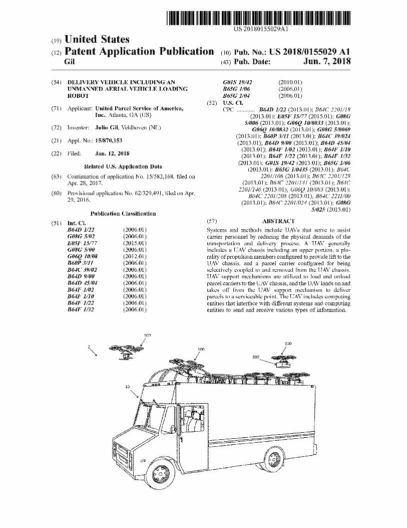
THAI MAITINIMO U DU COMMUNIT HINI TANITIM US 20180155029A1 ( 19 ) United States ( 12 ) Patent Application Publication ( 10 ) Pub . No . : US 2018 / 0155029 A1
Gil ( 43 ) Pub . Date : Jun . 7 , 2018
( 54 ) DELIVERY VEHICLE INCLUDING AN UNMANNED AERIAL VEHICLE LOADING ROBOT
( 52 ) ( 71 ) Applicant : United Parcel Service of America ,
Inc . , Atlanta , GA ( US )
( 72 ) Inventor : Julio Gil , Veldhoven ( NL ) ( 21 ) Appl . No . : 15 / 870 , 153 ( 22 ) Filed : Jan . 12 , 2018
GOIS 19 / 42 ( 2010 . 01 ) B65G 106 ( 2006 . 01 ) B65G 1 / 04 ( 2006 . 01 ) U . S . CI . CPC . . . . . . . . . . . B640 1 / 22 ( 2013 . 01 ) ; B64C 2201 / 18
( 2013 . 01 ) ; E05F 15 / 77 ( 2015 . 01 ) ; G08G 5 / 006 ( 2013 . 01 ) ; G060 10 / 0833 ( 2013 . 01 ) ;
G060 10 / 0832 ( 2013 . 01 ) ; GO8G 5 / 0069 ( 2013 . 01 ) ; B60P 3 / 11 ( 2013 . 01 ) ; B64C 39 / 024 ( 2013 . 01 ) ; B64D 9 / 00 ( 2013 . 01 ) ; B64D 45 / 04
( 2013 . 01 ) ; B64F 1 / 02 ( 2013 . 01 ) ; B64F 1 / 10 ( 2013 . 01 ) ; B64F 1 / 22 ( 2013 . 01 ) ; B647 1 / 32
( 2013 . 01 ) ; GOIS 19 / 42 ( 2013 . 01 ) ; B65G 1 / 06 ( 2013 . 01 ) ; B65G 1 / 0435 ( 2013 . 01 ) ; B64C
2201 / 108 ( 2013 . 01 ) ; B64C 2201 / 128 ( 2013 . 01 ) ; B64C 2201 / 141 ( 2013 . 01 ) ; B64C
2201 / 146 ( 2013 . 01 ) ; G06Q 10 / 083 ( 2013 . 01 ) ; B64C 2201 / 208 ( 2013 . 01 ) ; B64C 2211 / 00
( 2013 . 01 ) ; B64C 2201 / 024 ( 2013 . 01 ) ; G08G 57025 ( 2013 . 01 )
Related U . S . Application Data ( 63 ) Continuation of application No . 15 / 582 , 168 , filed on
Apr . 28 , 2017 ( 60 ) Provisional application No . 62 / 329 , 491 , filed on Apr .
29 , 2016 Publication Classification
( 51 ) Int . Cl . B640 1 / 22 ( 2006 . 01 ) GO8G 5 / 02 ( 2006 . 01 ) E05F 15 / 77 ( 2015 . 01 ) G08G 5 / 00 ( 2006 . 01 ) G060 10 / 08 ( 2012 . 01 ) B60P 3 / 11 ( 2006 . 01 ) B64C 39 / 02 ( 2006 . 01 ) B640 9 / 00 ( 2006 . 01 ) B64D 45 / 04 ( 2006 . 01 ) B64F 1 / 02 ( 2006 . 01 ) B64F 1 / 10 ( 2006 . 01 ) B64F 1 / 22 ( 2006 . 01 ) B64F 1 / 32 ( 2006 . 01 )
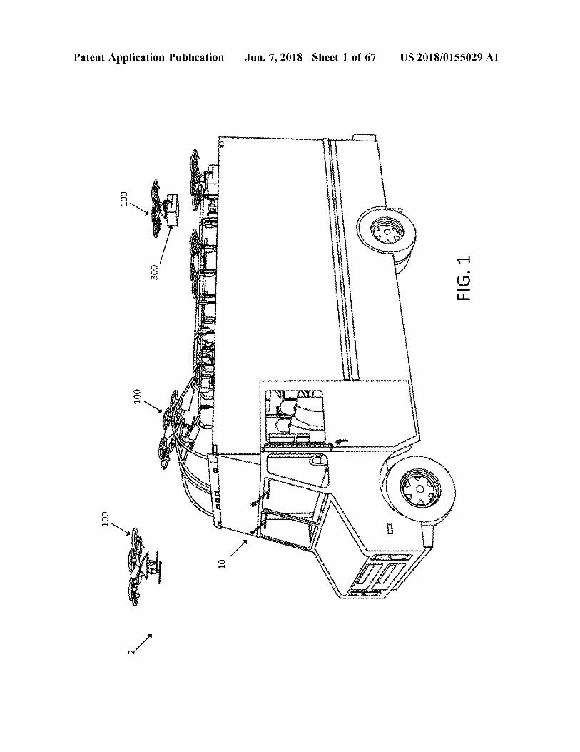
( 57 ) ABSTRACT Systems and methods include UAVs that serve to assist carrier personnel by reducing the physical demands of the transportation and delivery process . A UAV generally includes a UAV chassis including an upper portion , a plu rality of propulsion members configured to provide lift to the UAV chassis , and a parcel carrier configured for being selectively coupled to and removed from the UAV chassis . UAV support mechanisms are utilized to load and unload parcel carriers to the UAV chassis , and the UAV lands on and takes off from the UAV support mechanism to deliver parcels to a serviceable point . The UAV includes computing entities that interface with different systems and computing entities to send and receive various types of information .
100
100 100
300
1 instant
www www . Am . 10
Xwewe want within
ww
w
wwwwwww AYY wwwwwwwwwwwwwwww
Patent Application Publication Jun . 7 , 2018 Shet 1 of 67 US 2018 / 0155029 A1
MR + 4
?
00T
14
( 006 00E MMMMENTENTRAPHANNAAAAAAMAMAHAMMAYAMAMAMAHAPP FIG . 1
? HAHAMMANMAN?NANADAMAMAHA 001
werenter 18HHTTPP? ? ?????????Aprisshite - lassilitatte - AAAAME?? M + 4 + AAAAY9 ? SAMMENMAHAMAH
????? ??NANAAN Tour??? ??
100 MENTRAMAHNH ?
?
10
??HTHH WITTAYA Than T
US 2018 / 0155029 A1
2011 wwwwww White
Jun . 7 , 2018 Sheet 2 of 67
OOZ watabase
OPEN
ZOT
*
???
Viewer
pription
attitude
Antonio WWW waitinimo
si
wwwwww
ZOT
w
wwwww
Konto Moot
Patent Application Publication
na autech
wah 70
Jensuite
ZOL
OTI OIT
ansionsomni
ZOT
001
105 ZOT 100
other 1024 We 108 den will
108 point 108 kissessionist where 102 W There not intended detailierten
wwttu * * * * * - u skintisi within With * * * * linistit SOI SOI istin portret
tatistiliselt 103 b *
statisticheS Mini this things that * * * * * * * * * o risterin GRAU 1 i
hi
tomotoreste * A Yesto
* * * RAKA maintaining outuu Wakennon 808 * * * * * $ $ $ $ 44445
* * * i 108 Corinthisto toiminnasta trisha w Post c .
Thanh Mini Mi Mi Mai terite in
inistritiitlist Working remontas 102 e
With iis tte With simit m * * *
within Waniti siis s
* * * * * * * * * * 108 * SOI with niti * * * *
108 . tettoni te a with - 105
T 4664 103 102 w * * * Limiti * * trimit TOT
FIG . 3 105
US 2018 / 0155029 A1 Jun . 7 , 2018 Sheet 3 of 67 Patent Application Publication
US 2018 / 0155029 A1
FIG . 4
Z
TOT
130
117
AM
118
6TI
Wande
internet
102
?????????????????????????? ??? ??? ?????? *
www
Jun . 7 , 2018 Sheet 4 of 67
tepung
interest
tri
- 116
e
weerman hentet
CÁ
HN
.
posti
W Printimitate hatri
* * * * *
soft Aterim
porn
amery 114
ww
w
wwwwwwwwwwww * * * *
wwwwwwww
w
ww
tiesimepri
w wwwwwwwwwwwwwwwwww intowwwww
AMAT
e
w
understanding
102
102
ithin
wa
removed in the
Awwwww
fit
wand new * *
Patent Application Publication
100
h them
import
t
Wi
102
102
100
102
_ 102 102
_ cor _
???????? ???????????????????????????????????? 84 ?????????????????????????? ????????????????????????????????????????
Patent Application Publication
????????????????? ? ???? % 288
????????????????????????????????????????????? ? ?????????????????
/
??????????
116 - £
8ff ??? ??????????????????????????? ????????????????????????
??????????????????????? ititiarum ????????????? Matthew
???????? 200
_ 220
x
230
???????????????????? 229 229 _
230
14 ° _ 214
232
?????????????????? * *
Jun . 7 , 2018 Sheet 5 of 67
?????????????????????????????????????????????? Ridi u is
?????????? ?
?????????????????????? ????????? li ??????? 8
???????????????????????? ????????????????????????????????? ?
234
wwkjfwijk @
scidimirrortreenlawrmm w
?? wwhitewe ??
234
?
236
???????
236 236
236
inwalnum t
?? : androwdocsligh
? 250 ? 250
236 ? 236 _
236
. 236
?????????
_ US 2018 / 015502941
235
FIG . 5
9 914
US 2018 / 0155029 A1
t oong
icecomitions and concorso Mosco
Co
* * * * *
stotinaio Stohoto
00€ ?? :
Jun . 7 , 2018 Sheet 6 of 67
siistimine
sko
Wwwwwwwwwwwwwwwwwwwwww
o nmootoriga
Kriminal
* * * * * * * * * * * * * *
foods or conosodicooooooooo
Stwoscos ontana
www tichepherd hiijiskiaschinen Schi di M
think
Wikinti
ZOT
MWA
* *
historia yang ada sini
TOT
dering
the
intritt
cencia
wwwp owy
citito * *
r
* * * inni
ii
smo
MAANA
A
zót
ittar du internet
contigerite
h
ugisisiting
* * * * *
Smoottorin
abitationem
k
articom
h
oooooo
KAW
Wicants
fashio www . i
k kaukceMaKAKKINCARCARAK KOTAK
* *
* * * *
*
*
*
* * * * * * * * *
291 291
with
i
n
Patent Application Publication
the
g
WASTA
SASA
: W
WW * 440
A
ndris
ZOT
ZOT
OTI
291
ZOT
ZOT
001
hoitot ime in OLT 120 oi the
moni riting distintos * * * * * * * * * * * * * * * * * *
W
FIG . 7
Postdoc . booooooooooooooooooooooooooooooooooooooooooooooooooooooooooooooooooooooooooooooooooooooooooooooooooooooo WWWWWWWWWWWWWWWWWWWWWWWWWWWWWWWWWWWWWWWWWWWWWWWWWWW mormowooooooooooooooooorromonomorenoconcorronomorronorowymnonown 120 SAMMEN
bankinn antik berlaku
ta ini a n beri
Karimov 200 210 istenen ikke 120
US 2018 / 0155029 A1 Jun . 7 , 2018 Sheet 7 of 67 Patent Application Publication
Patent Application Publication Jun . 7 , 2018 Sheet 8 of 67 US 2018 / 0155029 A1
FIG . 8
121
_
120
118 .
FIG . 9
US 2018 / 0155029 A1
310
intestiging isang sistema
iness * * * * * * * * *
236
www
intentionatininggeristics
/
235
w
e
r i
€
nsisting is strigasinin isto
i
Wintert
- OSZ
N
* * * * * * * * * *
236 itt
atsioon immun
Postcondition is insisti
236
312
M
Jun . 7 , 2018 Sheet 9 of 67
kalitatea
i tetin
090 230
in Share this im
* * * * *
og omegn
wiwtitiimi
* *
Waheng ini menaw
ge ketika kita kenal dengan
with the entire
i
Wiki
ii Wii
kikirikiana
*
isimasis Washine
Wi
234
en on
300
W
posteriore
asioitsistotis kiitissimististamin
w
iteit
1
232
229
212
eittimet
213
230
210
Patent Application Publication
214
200
220
100
Patent Application Publication
110
102 102
102 102
1
102
102
4
66151
WWWWWWWW wwwwwwwwwwwwwwwwww
Wowowin
n
own
bosh
Hai
that See
isti
Phone
Homes
22QQ dette ting
wwwww
w
wwwwwwww
???????????????
www .
w
wwwwwwwwwwwwwwwwwwwwwwwwwwwwwwwwwwwwwwwww * * *
Jun . 7 , 2018 Sheet 10 of 67
164
,
166 168
tri mit * * * * * * * *
230
200
230
a li w minimum winninn minn minna
wwws
Shing
US 2018 / 0155029 A1
FIG . 10
Patent Application Publication Jun . 7 , 2018 Sheet 11 of 67 US 2018 / 0155029 A1
163
102
801 108 FIG . 11
www 102 - 300 302
escue
108
102 17
- N MAN womes -
se restritamenyanander - - - to ? iepteniment come WIN757 more to
100
80T
102 Why 102
108
163
162
150
- - - - - - - - - - - - - -
- - - - - - -
w
. . .
.
.
.
.
. .
ww
. . . .
. . . . . .
. . . . . . .
- - - - - - - - - - - - -
808
- -
-
-
-
-
-
-
- 162
-
GROUND LANDING SENSORS
Patent Application Publication
-
-
-
-
-
-
-
wwwwwwwwwwwwwwwwwwwwwwwwwwwwwwwwwwwww
PROCESSING COMPONENT
Il
902
164
events were senses -
906
VEHICLE LANDING SENSORS
- .
wwwwwwwwwwwwwwwwwwwwwwwwww
- - -
-
-
1111111111
VOLATILE MEMORY
NON - VOLATILE MEMORY
166
-
FLIGHT GUIDANCE SENSORS
-
.
-
906
11
-
- ??
168 L
-
1
COMMUNICATIONS COMPONENT
CAMERAS
???
Jun . 7 , 2018 Sheet 12 of 67
908 7
-
???
-
-
-
-
-
-
169 169
GPS GPS
-
- -
-
1
- -
-
- -
-
-
-
-
-
-
-
-
-
-
-
-
- -
- -
-
-
-
- -
-
-
-
-
-
-
- -
-
- -
-
-
-
US 2018 / 0155029 A1
FIG . 12
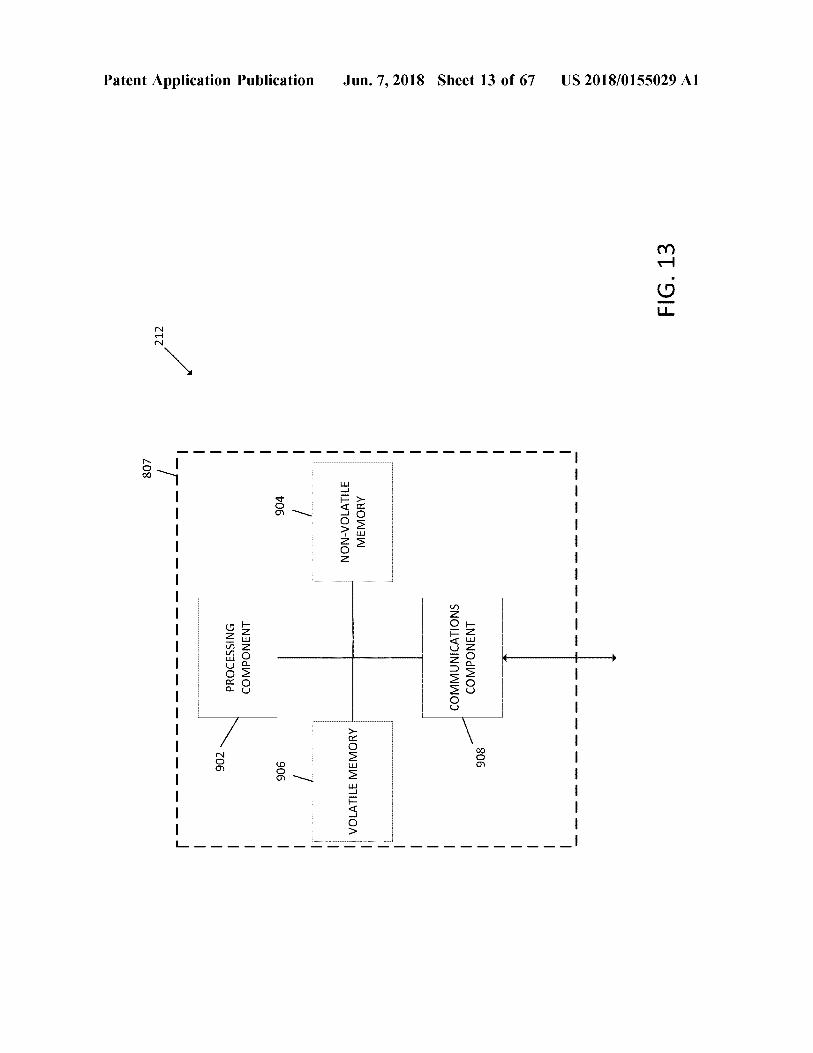
807
212
-
-
-
-
-
-
-
-
-
-
-
-
-
-
-
-
L -
-
Patent Application Publication
-
-
902
-
-
PROCESSING COMPONENT
-
- -
906
904
-
- - -
VOLATILE MEMORY
NON - VOLATILE MEMORY - - - - -
Jun . 7 , 2018 Sheet 13 of 67
-
—
COMMUNICATIONS COMPONENT
—
908
-
-
-
-
-
e
es concerne leveren
d
n een inte somme
e
com
concerned seves dade
nse content
sement se
US 2018 / 0155029 A1
FIG . 13
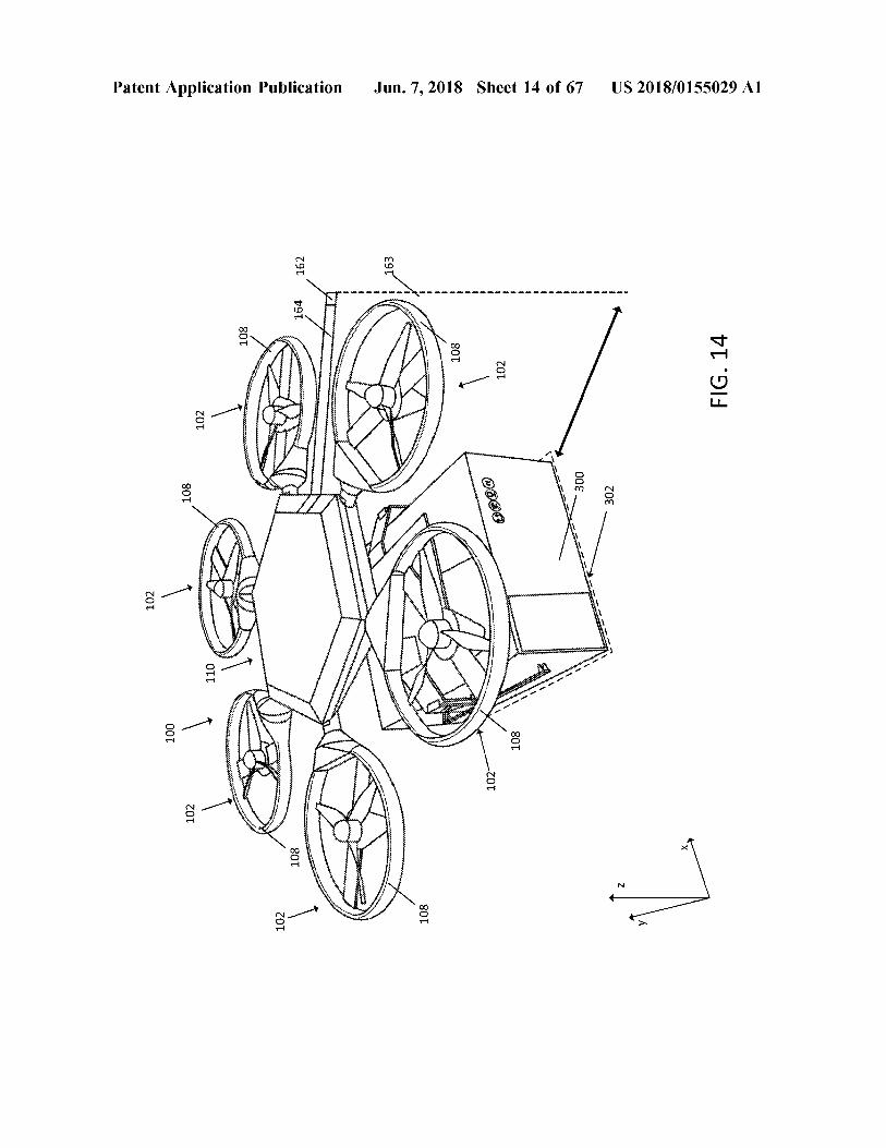
102
OOT
102
801 801
102
110
-
Patent Application Publication
108
mim
S
ZOI
108
164
162
isionist
163
108
WWW 801
R
owerte !
Jun . 7 , 2018 Sheet 14 of 67
102
090
102
108
ontwikkelen
00€ 00€ ammo 20€ 20€ ~
US 2018 / 0155029 A1
FIG . 14
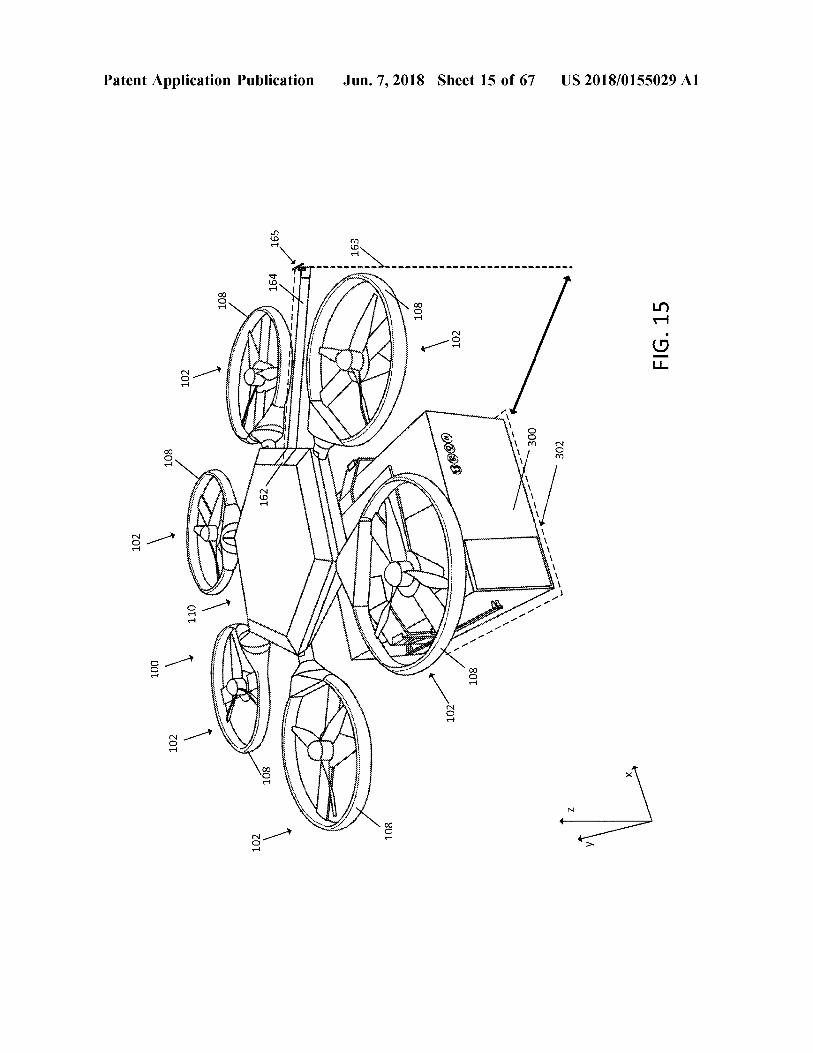
102
100
102
108
102
Patent Application Publication
108
102
Wenn
108
162
164
165
ibar
PARA
163
108
108
ra
Jun . 7 , 2018 Sheet 15 of 67
Phehehe
102
w
000
ww . AN
helping
102
108
more words - - -
- -
300
- -
302
US 2018 / 0155029 A1
FIG . 15
e shthurjerisi Sapiehytte tingalis i
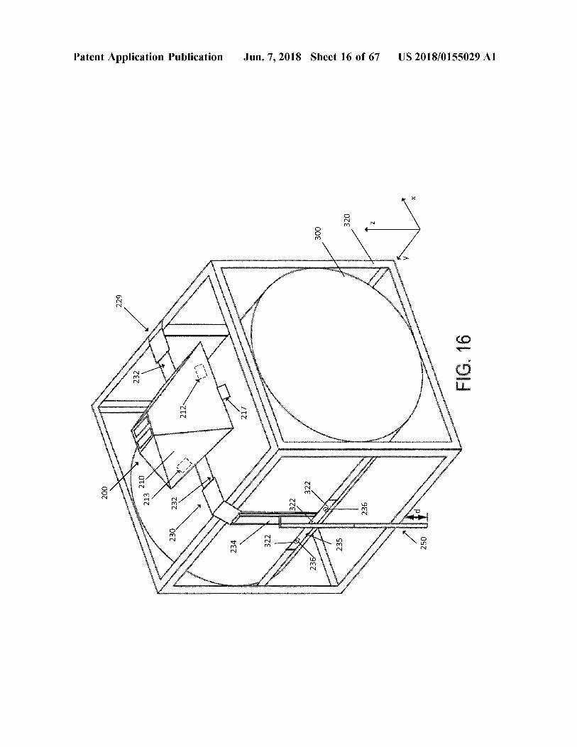
200
uasisisisitishisisitions distrimin ichigit pangingitisistinguis
pisiminimimiliminimicininininkai minum minimali
229
Wwwwwwww
v ises
ng
insiden
organising this singingitigasitii listasi ginting the engine reinig
for Settings statisti
rintah
232
213 210
st
Patent Application Publication
230
232 232
!
estesenter
res Alt
e finitura ett 2
N
ustest
inwinwirbime
t frihetewwabinawianie
Aktrimate
tortures
w
Shelistesti
Essensating sa isang lights belonging together
wwwer
n dige betinget interest
Viuda
* * * * * * * * *
wwwwwwww
* * *
* * *
brista
234
timaisten s tigasiting timesbarkeit design
format
21 posissimistingimustantine istitisies tumshushice
insistisigning the thing is simplementarnetingimis
??????????????????????????????????????????????????????????????????????????
Ayuh att
were
Maritime i
onen
* * * this
??????iniiriiiiiiiii?????????
minimithi
hihiiiiiiiiiiiiiiiiiiiiwwwwwwwwwwwwwwwwwwwwwwwwwwwwwww
? ?????????????????????????????????????????????????? : ?
236
Jun . 7 , 2018 Sheet 16 of 67
300
lerini instigingstabel
recibir
W
320
unte
write ? ????? ??iiiiiiiiiiiiiiiiiiiiii
www
. twinmunewitter Setter What ' s nutrimentum
? ??
236
wwinyi kimimining
wiwinihinihina
min
ithin erumisesti y
arih
sisteminin tigingsinstelling
usi pensiesini isteri yang
g stit
t
Wit
?????????????????????????????????????????????????????????? ?
250
weitere
n
institutining e
institutionististi sensibilitigasisitingastarpin s
higit pang itiniging
49kuni
w ithin
the
US 2018 / 0155029 A1
liometrihutters
FIG . 16
Patent Application Publication Jun . 7 , 2018 Sheet 17 of 67 US 2018 / 0155029 A1
300
Within accessibilitat FIG . 17
232 9220 212 ististen 210 Whi 200 Whittistini og institucioni non corrisponde alimentatie si
OTE u tohtori III Jos precisamiaisiais p
olisi others shining the prioriteringer
di titi r nigainsistitatis
* * * * * B Mai Nissau khi ti?ng
c? * *
* * * * h * internetist * *
214 * * * * * within istoista osasto bratiti 238
232 SALE
230 sowania Watch
229 234 250
How wird
ntingsih
FIG . 18
i
US 2018 / 0155029 A1
song
K1 T *
this W
- - - - - - -
WW
- - - - - -
250V mi
- - - - - - - - - - - -
- 27
n
isterijih * * * *
Jun . 7 , 2018 Sheet 18 of 67
Wittis .
stycje
wimmittimiin este parti
ezizan
N
1
- - - - - - - - - - -
987 gèz -
tourism internet
in good
00?
???
212
daar 2137 229 230
Wanneer Damen HTZ
OTT
n
Patent Application Publication
303
win
hin particulate with the
200
wit * * *
Patent Application Publication Jun . 7 , 2018 Sheet 19 of 67 US 2018 / 0155029 A1
250 - 229 - 360
wwwwwwwwwwwwwwwwwwww
212 99€
wwwww www
214 200 - 213 361 200 - within FIG . 19
364 362
S
370
tatistiky g
Patent Application Publication
229
200
360
na wwwwwwwwwwwwwwwwwwww
enetiesioginigingsminnesme
OTZ -
214 -
Sensationalitete 214 AT
- 212 212
talentier
como por 213
meiten
Hier with
SALLE
t ehni
99€
Cortes
364
sivim borligining the interesting this
presiding isministeeriumin
000
KRKA
menonton
362
wwwwwwwwwwwwwwwwwwwwwwwwwwwwwwwwwwwwww
i strowitan
yan
A
INTELE
Jun . 7 , 2018 Sheet 20 of 67
rt
250
AAAAAAAAAAAAAAAAAAAAAAAALALALALALALALALALALA
diensten Wat het minimerit
372
in
e kniirid
werden
US 2018 / 0155029 A1
intimitetin
FIG . 20
360
360
Patent Application Publication
200
200
370
V
362
370
300
362
366
wwwwwwwwwwwwwwwwwwwwwwwwwwwwwwwww wwwwwwwwwwww
366
300
w wwwwwwwwwwwwww
w ynwwwwwww
Win
250
250
Jun . 7 , 2018 Sheet 21 of 67
364
372
372
364
361
podpihnilar
KAZI / IZZZZZZZZ
Az
FIG . 21A
FIG . 21B
US 2018 / 0155029 A1
US 2018 / 0155029 A1
0??
T7 913 27 . 914
sconossa cosmo . com
immut
ti
KAASA
ten
asis
CTE ZTE
WWWMWWWW
c tion
conne
with
obrotor
XXXXXXXXXXXXXXXXXX
conosconomico con * * * *
Hosti ni
Jun . 7 , 2018 Sheet 22 of 67
* *
00€
0?
*
svo Goronnan
Ot
w
W
Antonio
ith this categorii i
ien th
hindi
stretch chichochschuiverysingin kaupunturi
coincisaccionamiento dungeowwwmon
WANINI Mint
hac
W
tangan pangkalan .
per
ort
A HAHAHAAHornstranit Ahme A
et stort
insights W
w
DA
Pi
within
How
1300ccm * *
rochining kilicho ini
Podok rino
TALABALAR
institut
neigings
n tasiasticissitsiside
niin
Fa
ter
Procurandom
annattaa
220
RAWA N
NATAMANNS
Antioche
Sexch
a nykaninacion
AxiMANA
WWIKOWNIKITUMBUIKSIKK anche
Machining
rencontre
tron
-
i
W
nten
ritim
KARAOKrincicije
kimy
coccanico scconi moriscos
Patent Application Publication
A
s conscious
OD OTT
001
? 110
100
??? ??????????????????????????????????????????????????? ????????????
???????????????????????????????? 7 | 11
c
21 ?? 200
5 ?
/
130
Patent Application Publicati0ll
14
? 220
5
FIG . 23A
230
f
? 110
? 100
??????
Jul . 7 , 2018 Sheet 23 0f 67
v vv ?
???????????????????? 130
114
270
271
272
116
?
116 2005
FIG . 238
230
???????????????????????????????????????????? ??????????????????????
US 2018 / 0155029A1
US 2018 / 0155029 A1 Jun , 7 , 2018 Sheet 24 of 67 Patent Application Publication
FIG . 24 10
??????? - 12
???? ? ?????? ??????????????
??? 410
400 ??
???? ??? ??????? ????? ????????? ???
?????????????????????????? ????? ??? ?? ?? ?? ? ??? ?? ??? ?? ? ? . ? ? ?? 400 ; ?? ?? ?? ?? ?? ??
410 ???? . ?? ?? ??? ?? ?? : ? ?? ?? ?????????????????????????????? ?????? ???????? ????? ??? ???????????????????? ?? ? ???
??? ?? 404 * ?????? ??? ?? ??? ???
? ? ???????? ????? 81 ???? ? ? ?? ??? ? ??
* ??
??
? ???? ?
? ???? PL * 406 9L
??? ???? ????? ??????? ????????????? # ?????????? ?? ?? ??? ?? ??? ? ?? ??? ???? . ?? ? ??? ?? ??
?? ? ??? ??? ??? ?? ?? ?? ?? ??? ??? ?
??????? ????????????? ??? ? ??? ?? ????? ?? ??? ??? . ???? : ?? ? ?? ?? ?? ?? ?? ???????? ?
?
???????? ??????????????? ? ??? ?? ???
???????????????????????????????????? * 407 ??????? ??
# ???????????? ???? rr ???? ?? ????????????? ??????? ???? terface ????????????????????
? ????? # # ???? ?????????????????????
hummhuettafi t ??????? ?? ?????? nstan
?????????????????????????????? ?????????????????? f ?????????????????????????????????? ?????????? * 408 ???????????????????????????????????????????? ?????????? ???????????????????????????????????????????????????? ?????? ww ? ??????? ???
?????
???????????? - 402
400
OT
402
400 402
Patent Application Publication
26A
450a
408
Doma 12
14
450
Jun . 7 , 2018 Sheet 25 of 67
450
18
- 404
406
4506
N
US 2018 / 0155029 A1
FIG . 25
445
412
410a
Patent Application Publication
1444
442
414
FIG . 26B
400
0Tt
440
416 416
416
Jun , 7 , 2018 Sheet 26 of 67
9Tf
416
416
\
????
???????????????????????
????? ?????
?????? ???
????
????????? ???????????????????????
?????? ??????
???? ????
??????????????????????????
? ?????????????
???????????????????
? ????? ???????????????????????????????????? ????
?????
??? ??????? ???
??????????????????????????????? ?????? ?????
?
?????????????? ???????
US 2018 / 0155029 A1
?
FIG . 26A
Patent Application Publication Jun . 7 , 2018 Sheet 27 of 67 US 2018 / 0155029 A1
FIG . 27
. . . . . . . . . . . . . . . . . . . . . . . . . . . . . . . . . . . . . . . . . . . . . . . . . . . . . . . . . . . . . . . . . . . . . . . .
460 462 464
, 466 wwwwwwwwwwwwwwwwwwwwwwwwwwwwwwwwwwwwwwwwwwwwwwwwwwwwwwwwwwwwwwwww PROCESSING COMPONENT MOTOR COMMUNICATIONS COMPONENT - - - -
430 430
400 400
Patent Application Publication
410
$
434
434
432
420 422
432 432
W anything instantin barbati
in
p
404
emate dahit
PRAthabiti
milionih
* *
*
hitterett
for
* * * * * *
. * * *
mutta
.
:
. . . . .
.
-
g . - -
* * * What trips
*
testit Within
HATIMA wiiiiiiiii
manorum
Jun . 7 , 2018 Sheet 28 of 67
. .
COSTICK
.
TAXI
. . . . . . . .
YYYNTYTWT .
wwwwwwwwwwww
Hu
441
TWT
. . .
the
440
Wengi Within
www
w www wwwindow
www . in
. wwwwwwwwwwwwww FIG . 28
US 2018 / 0155029 A1
Patent Application Publicati0ll Jul . 7 , 2018 Sheet 29 Of 67 US 2018 / 0155029A1
441
. 400
FIG . 29
???? 400 441
30
???????
500500
? 10
500
500
Patent Application Publication
sistening
Within ngentot
I
I
trikikimik
502
r
18
ikiwand
toiminta
i
insistiriitaisiin Monissimosios
hanya
impression that it is
atiewe ebwiteite mitmeniniti
sti
WA
* * * multimii an
listiche
W
ABF ational
time it rigtige hittashington
NE
502
Jun . 7 , 2018 Sheet 30 of 67
hat this
the latest hit song this can be achieving
www
i närheten
istinitosti instrumentos de the thing that best this time their business dating in
is in the ligger
* * * * W
e territorin tesirlitetits rather things shining
* * * * * * *
cithin this thing
iftitim
*
Xf
s
* *
* * * * * w
its in this thesis
cittadini
W Mwisttechnik HAWAN
* * * * * * * W
statististisch
* * * *
* * * * * * titiittiä
* *
* *
instansi
US 2018 / 0155029 A1
FIG . 30
Patent Application Publication Jun . 7 , 2018 Sheet 31 of 67 US 2018 / 0155029 A1
FIG . 31
522 524
PROCESSING COMPONENT COMMUNCIATIONS COMPONENT 520
MEMORY COMPONENT –
521 521
612 612
009
“ ???????
Patent Application Publication
620
613 ?
2010 200
610
MAN
• 200
- Carove assw ???????
in
??????
632 632 630
S
- - PayPPLEAF F FFFFFFr?? Perrieffer WAFFFww
?
ternationarticly? ,
o rd - www . mmmmmmy AWA
writioname = %
??
MWSWIMMY
??????AXY
ttttw wwptt???? tttttttttttti . . . . . trititu PAHHHHHHHww
622
. wreturenwan 44448with
weetiersayHerms
A4AA - WHWRHn
2 .
S
?
Jun . 7 , 2018 Sheet 32 of 67
ENT Array PHP / MPANY SWY - TP : / / hpix?
?? “
HTTPPYGAME
StyleMMYPLAY HANNAMERRYah ?
HYTHMAPTWISErrrrrrrenwrt - Playes12 Ferrary???A . HTTP :
,
* * *
* * * * * * *
*
* * Y
FYPVP / P E
WWW . 55
300
PPTT ??re - en ,
Piew / PHP , PPTT -
?ping
NAVIANTHAT ALine .
HYAMAHA , CLAINTERunnersirWish
300
SHANER
III
300
200 300
Shawnmansyes
??
SHEEiritist = Artism
30
00
006 z900E ?
un
PHPWITTAWNTP ,
Tere ” ? ????
: Per * * * * *
TTP # ?
H
?
?????
/ ? ?
:
P
? ? ” ” : : " # " PPTER Persace * * * * * * * , ????FTTTTTTT
APPYPE = Verror PHP PET - A - 1 PHP “
US 2018 / 0155029 Al
FIG . 32
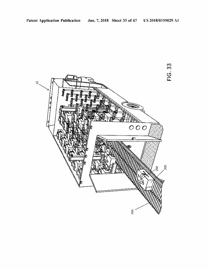
Patent Application Publication Jun . 7 , 2018 Sheet 33 of 67 US 2018 / 0155029 A1
FIG . 33
AU
wwwww KIN
w you to the growwwwwwwwwwww w wwwwwwwwwwgong ng pangunahingungen
* * * * *
200 300
w
700
t? ' 912
US 2018 / 0155029 A1
Wittritiittisismul 48 444 446 444
44 .
riitti
ZOL
nightwittwriteittritish histutteriteret t i l
innertsititiktiritsikri teatri
o
listritrilttitrat iritsiipi
Miris ting to the
# * *
Strasboboiboy chisinis rigting in this int
t?
estiga
* * *
inheritief
MNAMAI khá khai giá 4 gi? gia tivi sam # l4l -
i
Shitetti Sh with tittar
in
tushirishterimittiteiten Writrittskriterierileri
ittihintritti gsinriktigt
bir
Hi
wwww
jaring trainiititi
Higashining
OIS
r
itari
i
t
Miripiiritish
ochiliitrittiliitritrittiliitettiin
in riyaret
Wawilidtränidistrib
W
hii
Kaitiakhitami
HIMANOWA
ution tihti eriti
teritori
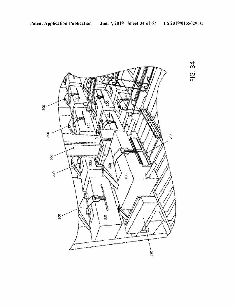
Jun . 7 , 2018 Sheet 34 of 67
Prishtina
00€
tittarit tirir
Bohur presentation
in wingi
A
r Ain tritripa
INAWiniti
n
osseries h??ng
007
00€
00€
estice
S
wywinii ritirurgih , *
ngo?i t
00€
. . .
cimetrisch
IM
HVITET
00€
Wittrup
00€
we
n swirtsassaringan tunnin
Senio ÁBANGAN
a
istumusicismo
A
t TATA
s
k
ributing
o bstetrica tosissimo
L
wwwww
R
Patent Application Publication
einik
OOC
CAMMINA
007
OOS
007
00Z
500
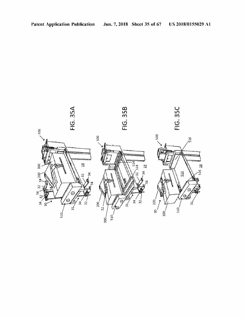
34 324 32 34 200 300
39
WiWinterberg
510 510
bikini
Patent Application Publication
shington
institutions historiniscono
wa
stingrossing atimti toistings shingotsinginginigingskärsia www
pi
c ia
*
incontinen
31 l
FIG . 35A
- 32
18
cong
32
o
H
in
34
Shine 24
200
500
32
the
300
Here
ht
510 _
wie
ww
Terengganusionate somente
uttissimististatistieken the business play
layers in
FIG . 35B
* * * * *
cono
r anisering is p
it
Jun . 7 , 2018 Sheet 35 of 67
b
5143 32 514
w g
or
32
ill
34 34 18 18
30
200
500
300
mm
Superiodini Wein
researching more
Fredposer
os
510
FIG . 35C
512
mirifiuti
ngishining institutashingto
US 2018 / 0155029 A1
m
Moon
516 18
100
Patent Application Publication
10
402
F
440
100
* * *
37 37
400 400
408
440
liberi
407 _
LLLLLLLLL
Jun . 7 , 2018 Sheet 36 of 67
for
406
in
420
410
hiper
404
400
nderson
Witaminy
US 2018 / 0155029 A1
Witam
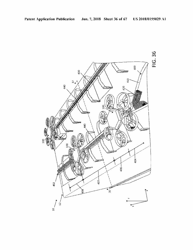
FIG . 36
Patent Application Publication Jun . 7 , 2018 Sheet 37 of 67 US 2018 / 0155029 A1
ZOT FIG . 37
wwwww
102
www wwwwwwwwwwwwwwwwwwwwwwwwwwwwwwwwwwwwwwwwwwwwwwwwwwwwwwwwwwwwwwwwwwwwwwwwwwwwwwwww * * * * * * *
00000wwwwwwwwwwww OOT
wwww 115
wwwwwwwww 110 118
114 116 412 lei
440 wwwwwwwwwwwwww
hotelentante della domanda dan bantua n
huwwww www
. vvvvv 102
www
102
?
006
MMMMM . 1 mmmmmmmmmmmm
% ? 7 %
???????? ?? ???????????
Ser?
US 2018 / 0155029 A1
spresigneserver ?
086 9?
005
L CHACCEPT
?OLS
SHAWAYMeerianger the Preserview
100? 8
mentHerer
ST
THEREN
WWEREMENT OIT OOT
AMAH79F
Jun . 7 , 2018 Sheet 38 of 67
MAHA FRANSHENNHENRY HEATHE hy ht =
986 91
?
intectoreaserverspenRicentegenewspanoratory ?
OLS
MAMA
TEPHA - 64696
Amasheer
F
MAMA
rans
006
AMrtM WAH
005
00776 8
Airit
?
??????? ?? XHHX
i on syster HAMAHAHAHAMAHAHA ??
V8E911
Patent Application Publication
earchinessageneratoresourserv? MARCservationstaure serveyoney - secreatePointer s
?
?APP
9 ots
Airiti AM
| ?ostsssuu
Sease ?
LG
005 ?
TS
~ 00Z
Patent Application Publication Jun . 7 , 2018 Sheet 39 of 67 US 2018 / 0155029 A1
??? ??? 402
001 u Wh wwhhh
??? 001 A LI
??? 408
FIG . 39 vt
100
OOT
400
4
US 2018 / 0155029A1
0 ' 5ls
8 ?????? » wwwHwyw ?????? ????????????????????????
??????????????????? ????
907
707
??????????????????????????????
??????????????????????????????????????? ????
????????????????????????????????????????????????????? ????????????
?
?????????????????????????????????????????????????????????????????????????????????????? ???????
HwyxXA ?????? w
$ w
??????
???????????????????????????? ; ter ????????????
???????????????????????????????????? fericrwHwrwarMNIMMrrity ??? ???????????
Jul . 7 , 2018 Sheet 40 Of 67
?????? MMMMMMMMMMMM ???? ???????????????
????????????????????????????
rdwkKwwHNIM ???????????? ) dytyrwtdwd ??? wyxyrHydyMN
??????????? www
modi
0EN
\
cet tcr
€ "
99T v9f
891
00
timrtrcuy ???????? fat ?? ?
???????? ????? ?????
E ???
????????????????????? ? ?
ori ???????? ????? 8 ? 8
???????? www .
riveroke ?????
????????? wwwwaw
Patent Application Publicati0ll
z61
_ z6
/ 00Z
c0r
_ Cor _
FIG . 41
US 2018 / 0155029 A1
440
Ss
118
kW WOXXWWW
420
* * * * * * * * ht
* * * * * * * * * * * * *
wwwwwwwwwwwww
* * *
wwwwwwwwwwww
www
wwwwww
sentitet
wi
w
$ *
* *
W
t hin
/ 410
W
istinskim
tituste
1 :
torio
.
* * * * * * * *
Distri
W
*
W
*
* * * * * * * *
*
Jun . 7 , 2018 Sheet 41 of 67
at toetseeritud
* * * * * * * * *
00 +
terist Wi
When Abriftir
is
ZE?? * * * * *
* * * * * ITTENTI
wie
iske ting
t o
432
*
* * * * * * * *
t
ww
A
tril
mi inda
100ood
der
hin
E
written
* *
thing
fritid
rärritur
* * *
initi
anderen testen
the limiti
434
Whois wwwtwin
M
#
sw
a
aaaaaa
a
stering
Kielishining school in
pertstettestere
* * * * * * * * *
With * * *
lithibiti
Martinus
turpiti?le !
om
Auwwwww Rain
kes *
WHAT D
% 784 "
?? ???????????????? ????????
2
kihisicament intele
"
PAKOVA
ATANA
wr wwwwwwwwwwww wwwwwwwwwwww Writish Lingerie
with
103
Marilyn
sertti
TOT y
kattadini * * * * * * *
102
itettiin * * *
* * * trytriftiti !
atsigri mari
Histoire
OL
W
om
NIKKA
triini * * * *
*
Wence :
Patent Application Publication
103
103
100
102
ZOT
US 2018 / 0155029 A1
500
Wwwwwwwwwwww * * * * * * * * *
@ 510 /
FIG . 42B
Kuw ait Euronewwwwwwwwwmasterkini *
Kucos hi
407 440
wie
Adrediidiraporti Birgissinichisconsistorsisition
Sise cha jumanjikan
ooze
badan
hihin
r
in
riikkeihi n
with the
Jun . 7 , 2018 Sheet 42 of 67
90v tI
OOT
OLT
400
w
csstudos cascos pingvin
m
y
sco
FIG . 42A
130 LN 500 500
407 440
Printimitathibitkil occiosas e
rin
dilihat
Patent Application Publication
htt "
onica
14 406
wowww
100
OTT
400
10
Patent Application Publication
Suriyeli
W
hat 1
Norweg
then
i stadiging sensation in highlights
with
Tiimipirtosigheshigining histori Smaging kasiyahingoisting solutions instituzioni simptotining
ditemui
a giging
itutsiyashirishing that the standing p
KO
tikiniai inst
right
show that their
Wola
tagsantrenathing inting to t
Jun . 7 , 2018 Sheet 43 of 67
hrase hi
highest
Modelowanie
p
g
ighetsrecision initialisering
istinittingthentische hot sunting digitalningsinstitutinishin
*
*
AWEI
kill
Without
i
internetishtirishni
W
riitti
ITM * * * * * * * * * *
r inspiration this booking
30
istintimitet
.
osting cho chi minh h?a
y histutti i tretter
F
niet erwater
5 ngan H
US 2018 / 0155029 A1
FIG . 43
Patent Application Publication Jun . 7 , 2018 Sheet 44 of 67 US 2018 / 0155029 A1
* * * * * * * * * * * *
WWW FIG . 44
non
100
444446666Sidi www 03 ) 03 AK
VAAKUMBU WEBLIKUWA 66
diligencia A toot 001
N ASWENTO si
tre
400 WWWXX
ma BBC 10
100
US 2018 / 0155029 A1
3 ) OAX will humbuhan Son
Hyy
r
* *
wyyya
wwwwwww
ww . * * * *
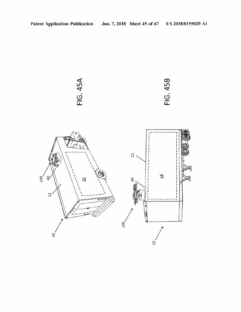
* 44444444461KGWYPYCH wwwwwwwwwwwwwwwwwwwwwwwwwwwwwwwwwwwwwwwww FIG . 45B
WWWWWWWWWWYYYYY
WWW
wim
18
ww
-
we own heran www
w
w
were
wome
t
r
awwwwwwwwwwwwww w
wwwwwwrrrrr * * *
constant Lucieniowanie
Jun . 7 , 2018 Sheet 45 of 67
12
40
100
-
- -
wwwwwww
-
pa -
18
FIG . 45A
- er mere end
- - -
- -
- -
Beve come moremo come out -
Patent Application Publication
Mary 40 40
12
100
Patent Application Publication Jun , 7 , 2018 Sheet 46 of 67 US 2018 / 0155029 A1
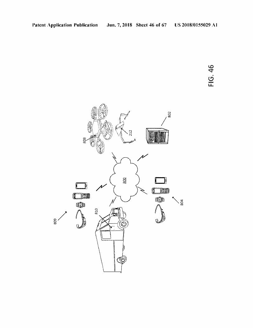
FIG . 46
?????? ??? ??? ??
????? ?? ???
??? ??????? 802 ?
?
?? ???? ????
?? ?? ? ???? ???? ???? ???????????????? 12 ???? ??
808 E ?????? ???? ????
?? 800 ?? Bu
804 810
608
????????????
802
146
mw . w
wwwwwwwwwwwwwwwwwwwwwwwwwwwwwwwwwwwwwwwwww
www . www . wwwwwwwwwwwwwwwwwwwwwwwwwwwwwwwwwwwwwwwwwwwwwwwwwwwwwwwwwwwwwwwwww . . www . ww www www www ww . . ww . mu www ww . www
CM *
M . M .
902 www
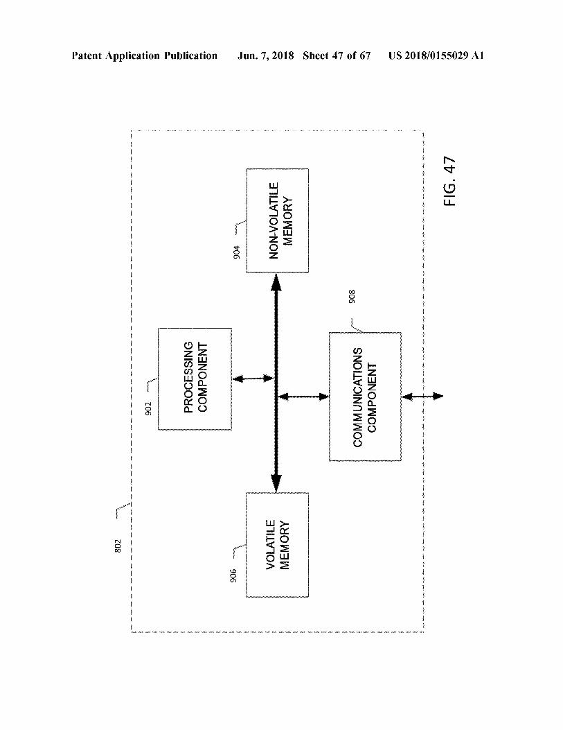
Patent Application Publication
:
0000000
0
00 000cene
w
*
what
- 5 - -
it www . we Mh Moh MX
PROCESSING COMPONENT
- .
WYKONYWNER
906
904
'
MMA MMA MMA
HAHAHAHAHHHHHHHHHHHHHHHHHHHHH . *
M
. *
A
VOLATILE MEMORY
-
NON - VOLATILE MEMORY
- -
MA
. - *
Jun . 7 , 2018 Sheet 47 of 67
YVINVWKRWAWWWWWYKRWAWYWHWAVE
wwwwwrrrrrrwin N
rwerywwwwwwwwwwwwww
MA M
. * . * 154
A
wwwwwwwwwwww wwwwwwwwwwwwwwwwwwww
55 56 5 : 4
-
806 806
5 .
COMMUNICATIONS COMPONENT
5
MA MAMA MM MM MMR - sho wa w
5 4 4 4 4
MMA AME Am
45
17
r . 1945 - * *
*
* *
* 7
VF
7F4 ,
+
51
447 974
1974 177
kr . * * *
* * * * * * * *
* *
* * * * * ) .
41 , 4 + :
Fn
481 . * *
* * * * * * * * * * * *
* Fr .
14 :
40
* * . * * * *
* * *
*
* * * * * * *
* * *
Fr .
: * * *
*
* *
*
* * * *
* , * * *
- * *
.
: * * * x
+ + , Yr : 1977 - * * . * 1 - * * *
F #
F # r . * *
US 2018 / 0155029 A1
FIG . 47
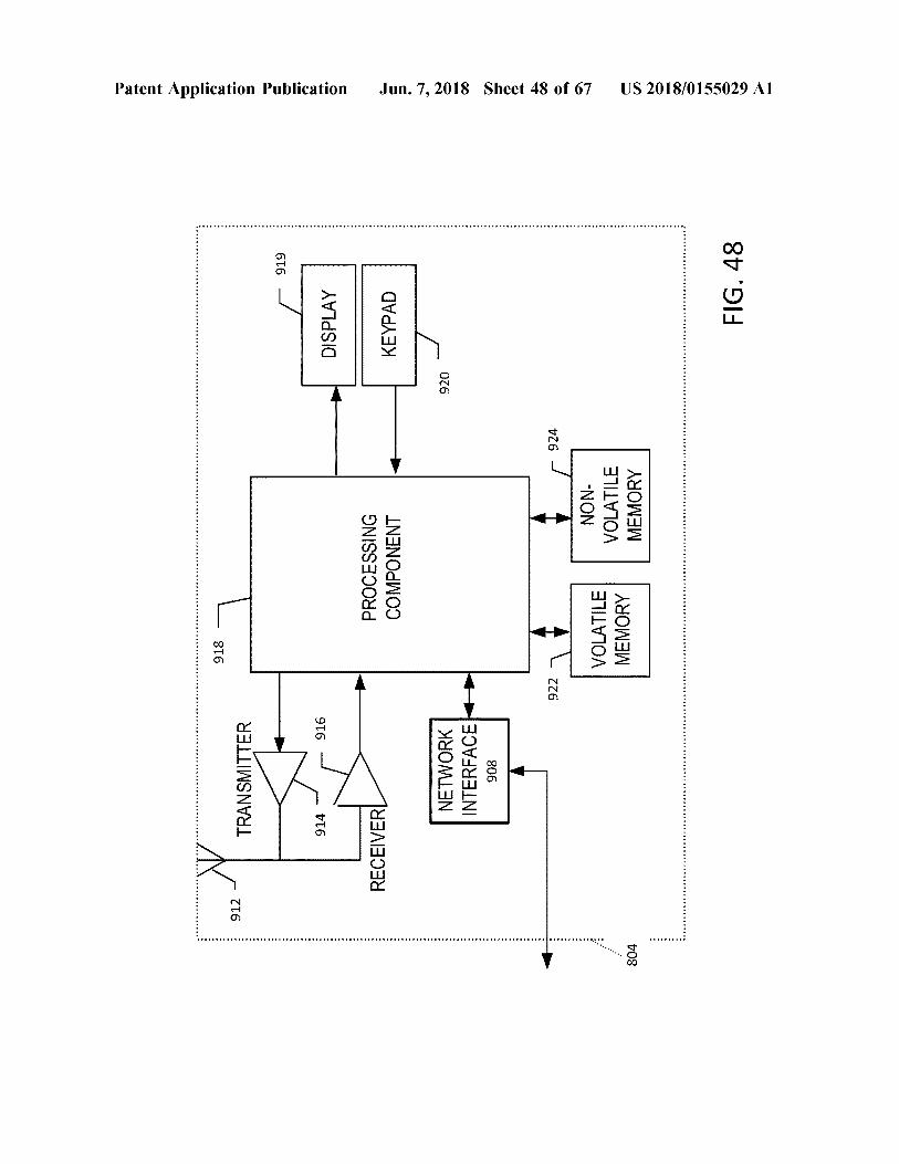
FIG . 48
US 2018 / 0155029 A1
*
#
#
* #
#
* * # # +
* *
+
+ + + + .
. . + +
+
+
+ * +
+ *
+
+ + +
* . * * * .
.
*
.
. E . +
# * #
* + +
+ + *
+ + +
+ * +
+ *
+ +
+ +
* +
. .
. . *
.
. *
. * . *
E * +
* + + * +
+
* + +
+ +
* + +
* +
+ + +
804
MEMORY VOLATILE MEMORY VOLATILE
- NON
* + + + *
924
922 1
#
Jun . 7 , 2018 Sheet 48 of 67
908 INTERFACES NETWORK
*
920
t + + + +
KEYPAD
+
COMPONENT PROCESSING
RECEIVERL
+ + + +
DISPLAY +
916
914 -
+ + + + + +
616 -
+ + + + + + * *
TRANSMITTER
Patent Application Publication
912 -
918
#
#
#
#
#
#
#
#
#
#
#
#
#
#
#
#
#
#
#
#
#
#
#
#
#
#
#
#
#
#
#
#
#
#
#
#
#
#
#
#
#
#
#
#
#
#
#
#
#
#
#
#
#
#
#
#
#
#
#
#
#
#
#
#
#
#
#
#
#
#
#
#
#
#
#
#
#
#
#
#
#
#
#
#
#
#
#
#
#
#
#
#
#
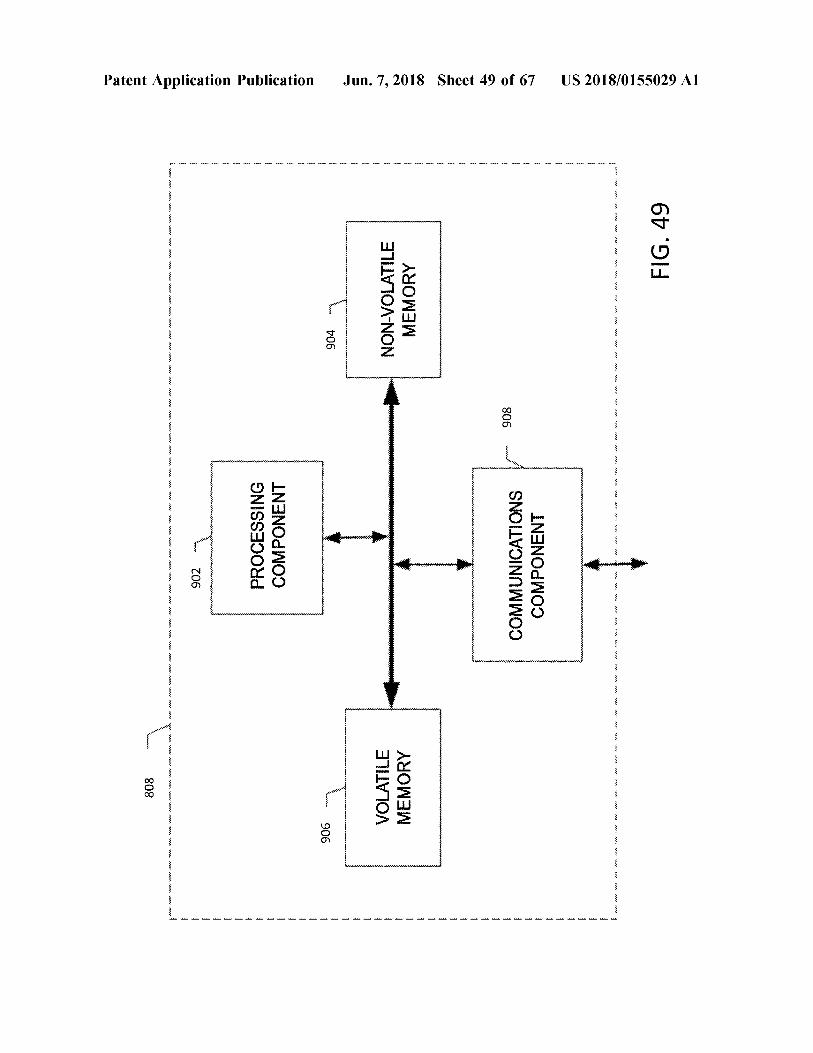
808
mm
M . www .
www www . W
www . M . Mww
.
w
ww . www . www
. wwwwwwwwwwwwwwwwwwwwwwwwwwwwwwww ' M AW . . . www .
w
ww
. wwwwwwwwwwwwwwwwww . .
WALA NA
???? ??? ???? . ???
902 902
AA SAA
Patent Application Publication
wwwwwwwwwwwwwwwwww ww wwwwwwwwwwwwwwwwwww
???
WAA AAA AAA Witt
???? ??? ???? ??? . ??? . ???? ???
PROCESSING COMPONENT
AA AU ut # AA . Att
???? ???? . ??? . ??
906
wwwwwwwwwwww
w
wwwwwwwwwww
904
West Auto
*
*
* * * *
*
* *
*
*
*
WALA . WALA DA WALA .
VOLATILE MEMORY
T
NON - VOLATILE MEMORY
A
???? . ??? . ??? ???? ??? ??? ? ???? ???? . ??? . ??? . ??? ??? ???? ???
WAA VAHVA
Jun . 7 , 2018 Sheet 49 of 67
WAKALA WALA . WAA ' ALA WA WALA WA
.
.
908
COMMUNICATIONS COMPONENT
??? ??? ???? ??? ???? ??? . ??? . ???? ???? ???? ???
tutte ! A . Aut " Aut . With A
??????
? ????????????
Ahutud . SALAM Ath !
*
* * * *
* *
* * *
* *
* * * * * * * * * * * *
* * *
* * * * * * * * * * *
* *
* * * * * *
* * * * * * * *
* *
* * * *
* * , * * *
* * *
* * *
* *
* * *
*
* * *
* *
*
* *
* *
* * * *
* * * *
viri * * *
* *
*
* * * *
* *
* * * *
*
* *
* * *
,
* * *
* * * *
* * *
*
* * *
* * *
- * * 71 . 5 * *
* * *
* * *
* *
fi
* * : *
*
US 2018 / 0155029 A1
FIG . 49
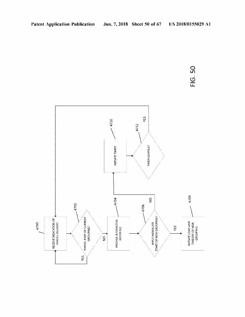
4700 RECEIVE INDICATION OF PARCEL DELIVERY
Patent Application Publication
4702
YES
PARCEL PART OF CURRENT GROUPING ? NO
- 4710
4704
INITIATE TIMER
PROVIDE INTERACTIVE INTERFACE
Jun . 7 , 2018 Sheet 50 of 67
4712
4706
YES YES
TIMER ELAPSED ?
NO
INPUT INDIDICATE START OF NEW GROUPING ? YES
-
4708
INITIATE LOAD AND TAKEOFF OF NEW GROUPING
FIG . 50
US 2018 / 0155029 A1
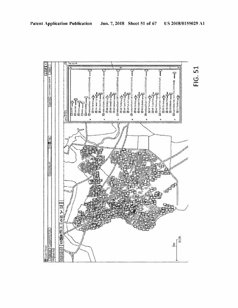
FIG . 51
US 2018 / 0155029 A1
t utetit
* * *
444444444444444444444444444444444 4 444444444444444444444444444
ny
Siloa
po SKD
WWWWW
* * * * * * * * * * * * * * * * * * * * * * wwwwwwwwwwwwwwwww
wwww
cercerai
nxx
ti
x
ww
ins et
w
D
ester
kan en bonum
WA eeeeee
,
Baina Um
inim
REWW . R
w mine for BWSX . window women va muiko salas
m
mastoi 8XYUKUR maintenant
t ervenit
idi
samtidig
Jun . 7 , 2018 Sheet 51 of 67
WWWWWWWWWWWWWWWWWWWWWWWWWWWWW
winien W WWWWWWWWWWWWWWWWWWWWWWWWWWWWWWWWWWWWWWWWWWWWWWWWWWWWWW * * * * * * * * * * *
n
?
Api
b
e
ipid * * * * t
i
XXXKKOWIE UMUHOW TO OM B
BESKY
khi se
KB
hibu
henwinnen we were
mwen wa
fentent
UX
PACHE * * * SIERA Lettis *
hor
*
kurit
*
*
Why me
* PARAF
* *
indys
fone 8620
INA
" ' to
wwwwwwwwwwwwwwwww cum 0414494ecrarundem4440 - w
wwww 14444444eure H e re ?????????????????????????????????????????????????????????????????????????????????????????????????????????????????????????????????????????????????????????????????
Antepr i
m
ariini
pia
Patent Application Publication
12 033920 | DDD
felettentheter * * * *
?
? ?????????????????????????????
?
??????????????????????? ??? - ?? - ???????? - ????????????? - ?????????????????????????????????????????????????????????????? ????
? M
wwwwwwwwwwwwwwwwwwwwwwwwwwwwwww wwwwww
VYYYYY
O
M
WIEK
wwwwwwwwwwwwwwwwwwwwwwwwwwwwwwwwwwwwwwwwwwwwwwwwwwwwwwwwwwwwwwwwwwwwwwwwwwwwwwwwwwwwwwwwwwwwwwwwwwwwwwwww www DHE
H
W
* *
* * *
*
*
* *
*
*
* *
* * * *
*
*
* *
* *
*
*
* * *
* * * *
*
* *
*
*
*
*
*
*
*
* *
*
* *
*
* * * *
* * *
*
*
* *
* *
* * *
*
*
*
*
* * * *
*
* * * *
*
*
*
*
* *
*
* *
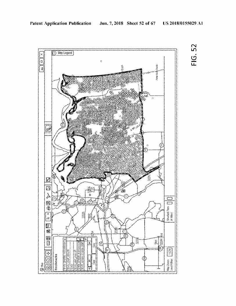
Patent Application Publication Jun . 7 , 2018 Sheet 52 of 67 US 2018 / 0155029 A1
WWWWWWWWWWWWWWWWWWWWWWWWWWWWWWWWWWWWWWWW YA
NAKUK * FIG . 52 WWWWWWWW
* * *
27 * *
RE w wwwwwwwwww *
ww
Power wwwwwwwwwwwwwwww terreyrarrettop * * *
p pederne wwvwwwwwwwwwwwwwwwwwwwwwwwwvvwvvwvvwvvwvvwvvwvvwvwwwwwwwwwwwwwwwwwwwvvwvvwvwwwvvwvwwwvwwwvvvvvvvvvvvvvvvvvvvvvvvvvvvvvvvvvvvvvvvvvwvvwvwwwvwwwvvvvvvvvvvvvvvvvvvvvvvvvvvvvvvvvvvvvvvvvvvvvvvvvvvvvvvvvvvvvvvvvvvvvvvvvvvvvvvvvvvvvvvvvvvwvvwvwwwvvwvvwvvwvvvvvvvv weit X WWWWWWWWWWWWWWWWWWWWWWWWWWWWWWWWWWWWWWWWWWWWWWWWWWWWWWWWWWWWWWWWWWWWWWWWWWWWWWWWWWWWWW * * Hut * *
* sretten * * * *
wir within H yox 9494 2204 1711
* * * * * YA Sluminate p # 426751 + 1 + 1 + * +
1612 uterte 1 * 07111 * i *
GA e * *
tti rimos LIVY w wwwwwwwwwwwwwwwwwwwwwww
@ @ WOBB68 W
end 22214 ws W
e
DXBB ?????? are 3333 YYY 23 . 24 ar
wwwwwwwwwwwwwwwwwwwwwwwwwwwwwwwwwww BUX US wwwwwwwwwwwwwwwwwwww wwwwwwwwwww Sook & K wwwrrrwwwwwwwwwwwww XXX * *
a TEKS # W
wwwvwwww ewe woning wwerkewwwwwwwwwwww w
statne MALANG Map2w 28 * * * * * * * * * * * * * * * * * * * * * * * * * * w wwww
FIG , 53
US 2018 / 0155029 Al
?????
wwwwwwwwww5www ??? wwwww
www ? wwwwwwwwwwwww ? ww
+ + + +
+
+ + + +
+
capegeeeeeeeeeeeeeeeeswo240eeeeeeeeeeeee / pogodoes eeeee
goodwo poe4eeeeeeeeeee
www
??????
????????
?? ???? ???????? ?????????????? ?????? ?????? ?????????? ?????? ?????????? ?? ?????? ?????? ??????? ??????
?????? ?????????????????? ??????????????????????????
?????????????? ???????????? ?? ???????????????????????????????? ???? ???? ??????????
???????????????????????? ?????????????????? 3
???? ?????? ? ???????? ??????????
?????? ?????????????????????????????????? ?????? ???????? ??????
???? ???????????? ???????????????? ???????? ???????? ????
???? ???????? p
??
??
?????????? ?????????????? ???????? ???????? ?????? ???????? ???? ?? ????? ?????? ??????????
?????? ?????
? ??????
???? ?? ???????? ?? ???? 2
?? . ??????
?????? ???? ???????? ?? ???? ???? ???? ????
????????????????????
???????? 2
2 ?????? ?????? ??????
?????? ?????? ?? ?? ?????? ??????
????????? ??
???????? ?????????? 2 ?????????? ?????? ?????? ?????? ?? ???? " ???? ? "
?????????????
- - ?? ?????? 2 7 ??????????
eeeee
???? / ???? ?????? * ?????????? ???????????
??? ??? ??? ???
???????? ?????? ?????? ???? ???? 72 ???????? ???? ???? ???? ??????
????
49 = = = = = = 44494444 = 444e3444 = 44444 & v = = = = 44 ?
3 $ $ 44 446A
??
???????????????????????? s ?? ???????????????????
44179 ]
4 22 22 22
??????
&
???????? ????????
??????
???????????????? 22
22 22 282
???? c ???? ???? ????
?? ?????????????? ?????? ???? ???????? ???????? ???????????? ?????? ???? ???? ???????? 62
???????????? ???????????????????????????????????????????????? ?????????????????????????????? " ?????????? ???? ??????? ???????????????? ?????????????????? ?????????? ???? ???????????? ???????????????????????????????????????? ???? ?? ???????????????????????????????? ???????????????????????????? ???????? ???? ?????? ???????? ???????????????????????????????????????????????????????????? ?????????? 3
A &
Jun . 7 , 2018 Sheet 53 of 67
??
/ . 5
???????????????? ????????????????????? ???? » » ????????? » ? ???????????????????? ???????
???????
42944 = s & s
?????? &
· ·
·
. 1 ·
????
???? ?????? ???? ??????
?????????????? ???? ??????
?? ??????????
??????????????
???????? ???????????
?
???? ???????? ???? ???? ???? ???? ?????
?? ?????? ?????? ??????
?????? ?????? ?????? ????
??????????? ??????????? ????
. . ?????????? ??????????????? ?? ???? ??????
???? ??????????
????????? ???? ???????? ???????? ?? ???? ?? ?? ???????? ?????????? ???????? o
?????? ??????????? t ? ?? ?????????
?????????? ???????? ?????? ????
???? c
? ? seu
?????????????? ww ????????????? ???????? ë ??????
?????? ?
??? ?
??????
?? ????
????????
???????????????? ?????? ,
??? , ??????????????? netwwwwwwww we
wwwwwwwwww
? ??????? ????????????????????? ??????????? g ??????????????????????????????????????????????????????????????????????????????????????? ??????????? ????????????????????????????????????????????????????????? ????????????????????????????????????????????? ?????????????????????????????????????? ???????? ?????????????????? :
bee
: ee
Ge Ehee ?? at ex e
6 ?????? 86600
9
asaw
e
eee
baaree aa
wee
we EEEE ??
eeeeeeeeeeeeeeeeeswwwwwww ?
@
uww wwwwwwwwww ? sweeeeeeeeeeeeeeeeeeeeeeeee
???? ?? ?????????????? s ?
%
wwwwwwwwwwwww
9
% 844ee85 + :
?? ????????????????????????????????
??????????????????????????
" 9Bitta = = 48 * * * * * t ???? awatiwi , ts & s
.
4 * * * fiyaiwark + ien4481ffi "
8
gl88
????????????????????
??? ??? 4444 ???? 44 ?? 9 ????????? A = sww ~ ~ ~ ~ ~
Patent Application Publication _
~ ~ ~ * * ?
?????
????? ? 060 ??????????????????????
T W ala EILEEM
Ig S M
???? ?????????? ???????? ???? ?????????? ?????? ????????????????? ?????????????????????? ?????????????? ????????????????????? ?????? ?????????? ?????????? ?????????? ?????????? ???? ???????????????? ??????????
??????? ?????? ???? ?????????? ??? ??? ?????? ?????????? ?? ????? ? ?????? ????? ????? ????? ????????? ???? ????? ???? ???????? ? ??????????? ?????? ????? ????
????? ??????? ???? ???? ??? ?????? ?????????? ????? ??? ???? ??????? ???? ?????? ??? ???? ??? ??????? ??? ??? ??? ??? ?????? ???? ????? ??????? ???? ???????? ?? ????? ??? ??? ???? ??? ??? ? ???? ????????????? ???? ????? ???????? ????? ????? ???? ??????????? ??????? ???? ???? ????? ????????
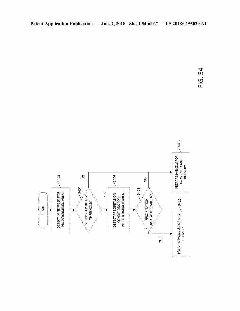
START
5402
DETECT WINDSPEED FOR PREDETERMINED AREA
Patent Application Publication
- 5404
NO
WINDSPEED BELOW THRESHOLD ? YES
5406
DETECT PRECIPITATION CONDITIONS FOR PREDETERMINED AREA
Jun . 7 , 2018 Sheet 54 of 67
- 5408
NO
PRECIPITATION BELOW THRESHOLD ?
YES PREPARE PARCELS FOR UAV DELIVERY
5410
5412
PREPARE PARCELS FOR CONVENTIONAL DELIVERY
US 2018 / 0155029 A1
FIG . 54
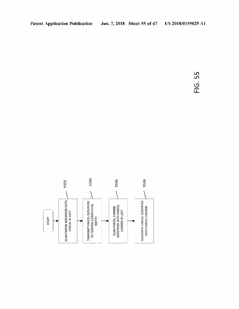
START
Patent Application Publication
Premium 5502
SCAN PARCEL IDENDIFIER WITH PARCEL ID UNIT wwwwwwwwwwwwwwwwwwwwwwwww
TRANSMIT PARCEL IDENTIFIER TO CENTRAL COMPUTING ENTITY
5504
SCAN PARCEL CARRIER IDENTIFIER WITH PARCEL CARRIER ID UNIT
5506
Jun . 7 , 2018 Sheet 55 of 67
ASSOCIATE PARCEL IDENTIFIER WITH PARCEL CARRIER
-
5508
US 2018 / 0155029 A1
FIG . 55
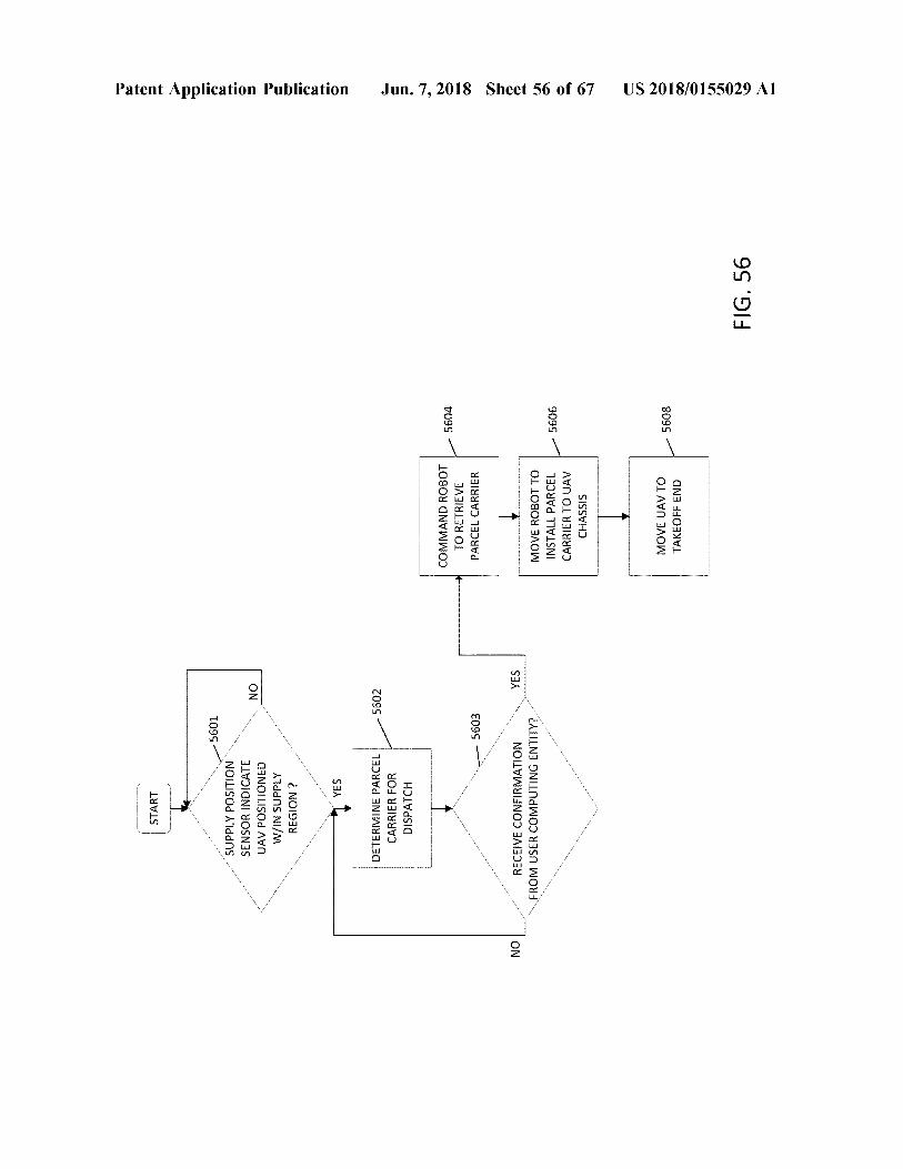
START
- 5601
SUPPLY POSITION SENSOR INDICATE UAV POSITIONED W / IN SUPPLY REGION ?
Patent Application Publication
NO
YES
5602
DETERMINE PARCEL CARRIER FOR DISPATCH
COMMAND ROBOT TO RETRIEVE PARCEL CARRIER
- 5604
5603
Jun . 7 , 2018 Sheet 56 of 67
NO
YES
RECEIVE CONFIRMATION FROM USER COMPUTING ENTITY ?
MOVE ROBOT TO INSTALL PARCEL CARRIER TO UAV CHASSIS
5606
MOVE UAV TO TAKEOFF END
5608
US 2018 / 0155029 A1
FIG . 56
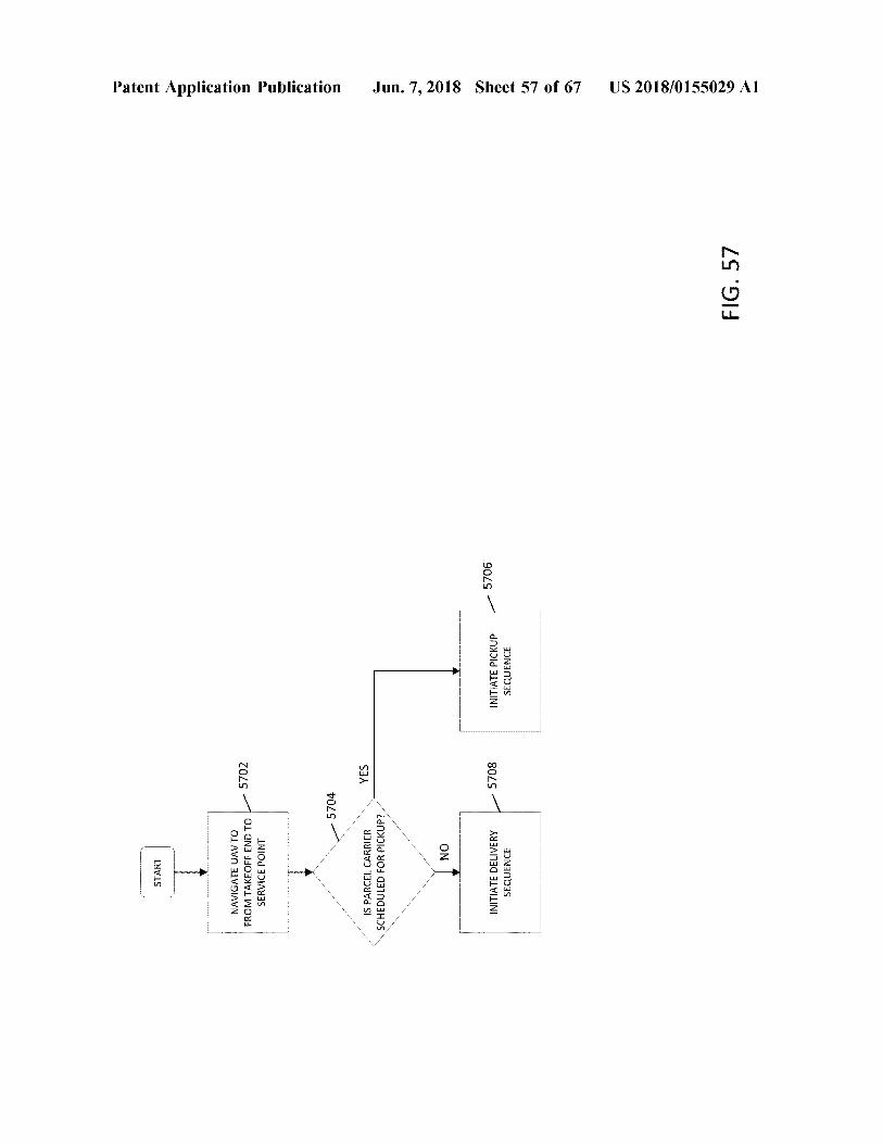
START
Patent Application Publication
NAVIGATE UAV TO FROM TAKEOFF END TO L SERVICE POINT
5702
UUMIMPIN
-
-
-
-
-
-
- - - 5704
YES
IS PARCEL CARRIER SCHEDULED FOR PICKUP ? NO
Jun . 7 , 2018 Sheet 57 of 67
- 5708
5706
INITIATE DELIVERY SEQUENCE
INITIATE PICKUP SEQUENCE
US 2018 / 0155029 A1
FIG . 57
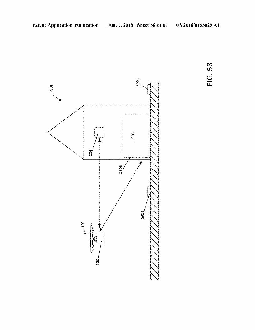
5901
Brasilientowige * Institu
Patent Application Publication
001
womeet44 *
H
ooooooooooooooooo 804
wwwwwwwwwwwwwww
300
*
*
*
*
*
*
*
*
*
*
*
*
*
*
*
*
*
*
*
WY
5908
wwwwwwwwwwwwwwwwwwwwwwwwwwwwwwwwwwwwwwwwwwwwwwwwwwwwwwww
wir wi
v
.
.
. . - . . * *
* *
* *
* * * *
, ??? ????
5906
??? ?? ??? ?
* * * * * * * *
5904
5902
Jun . 7 , 2018 Sheet 58 of 67
? ?????? ??????? ????? ????? ? ??? ? ? ????
wwwwwwwwwww
With
|
mertettetett
ntreeck E
* # * * * *
ALILIT AMXX
waarinecen !
tittastsitatea
tre
UVUVI
RUTASUSTASIASANA
ZIIIIIIIIIIII
utilici
toteutettu
att
1 . MESASULATA
AKT W
US 2018 / 0155029 A1
FIG . 58
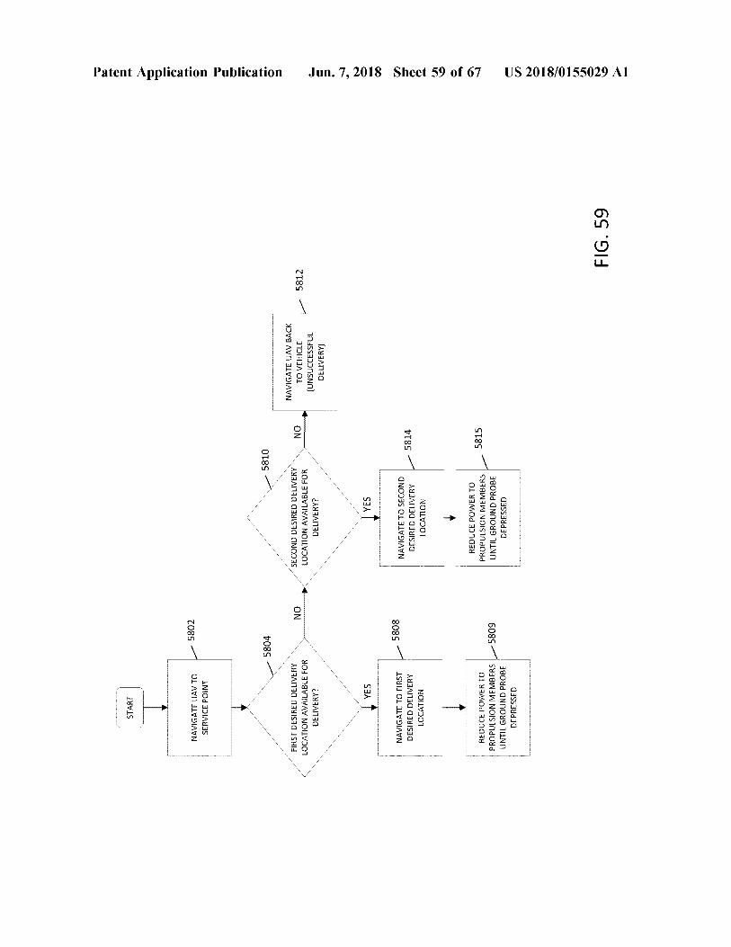
START - - 5802
NAVIGATE UAV TO SERVICE POINT
Patent Application Publication
5804
5810
????????????????????????????????????
NO
NO
812
FIRST DESIRED DELIVERY LOCATION AVAILABLE FOR DELIVERY ?
SECOND DESIRED DELIVERY LOCATION AVAILABLE FOR DELIVERY ?
NAVIGATE UAV BACK TO VEHICLE ( UNSUCCESSFUL DELIVERY )
YES
YES
- 5808
NAVIGATE TO FIRST DESIRED DELIVERY LOCATION
Jun . 7 , 2018 Sheet 59 of 67
NAVIGATE TO SECOND DESIRED DELIVERY LOCATION
- 5814
-
5815
REDUCE POWER TO PROPULSION MEMBERS UNTIL GROUND PROBE DEPRESSED
5809
REDUCE POWER TO PROPULSION MEMBERS UNTIL GROUND PROBE DEPRESSED
US 2018 / 0155029 A1
FIG . 59
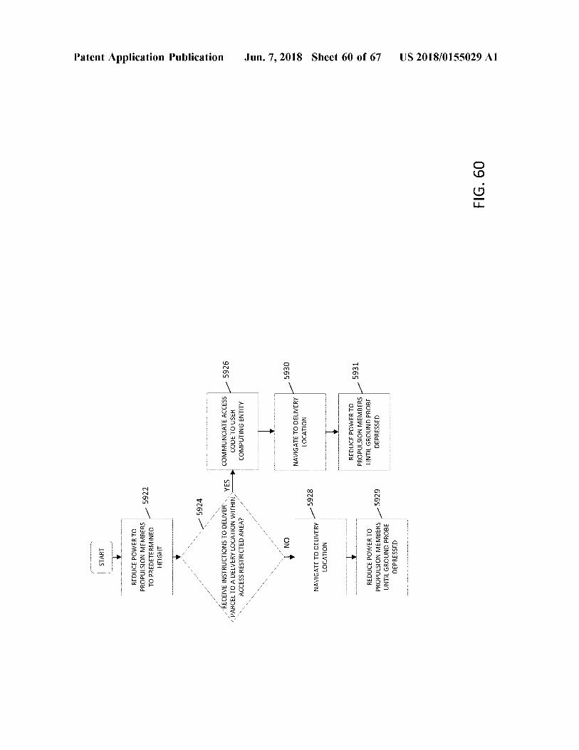
START REDUCE POWER TO PROPULSION MEMBERS TO PREDETERMINED HEIGHT
5922
Patent Application Publication
5924 ves
- 5926
RECEIVE INSTRUCTIONS TO DELIVER PARCEL TO A DELVERY LOCATION WITHIN ACCESS RESTRICTED AREA ?
COMMUNCIATE ACCESS CODE TO USER COMPUTING ENTITY
NO
5930
NAVIGATE TO DELIVERY LOCATION
5928
NAVIGATE TO DELIVERY LOCATION
Jun . 7 , 2018 Sheet 60 of 67
5931
REDUCE POWER TO PROPULSION MEMBERS UNTIL GROUND PROBE DEPRESSED 5929
REDUCE POWER TO PROPULSION MEMBERS UNTIL GROUND PROBE DEPRESSED
US 2018 / 0155029 A1
FIG . 60
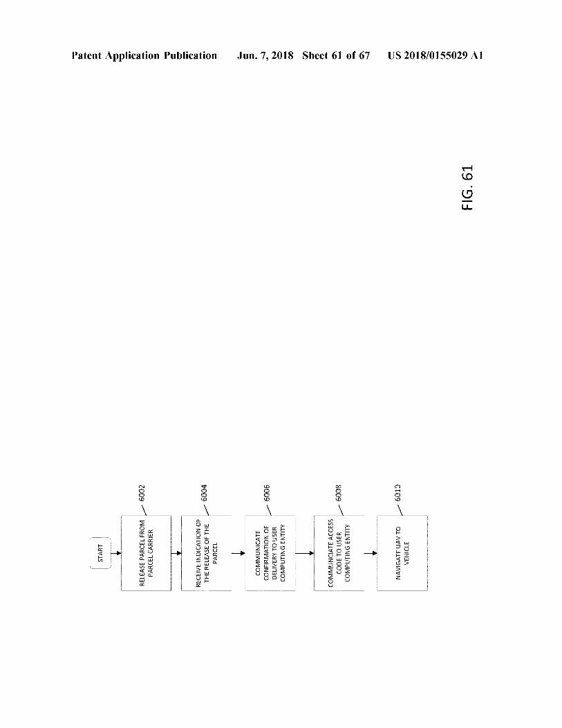
START RELEASE PARCEL FROM PARCEL CARRIER
6002
Patent Application Publication
RECEIVE INDICATION OF THE RELEASE OF THE PARCEL
6004 - 6006
COMMUNICATE CONFIRMATION OF DELIVERY TO USER COMPUTING ENTITY
Jun . 7 , 2018 Sheet 61 of 67
COMMUNCIATE ACCESS CODE TO USER COMPUTING ENTITY
- 6008
NAVIGATE UAV TO VEHICLE
6010
US 2018 / 0155029 A1
FIG . 61
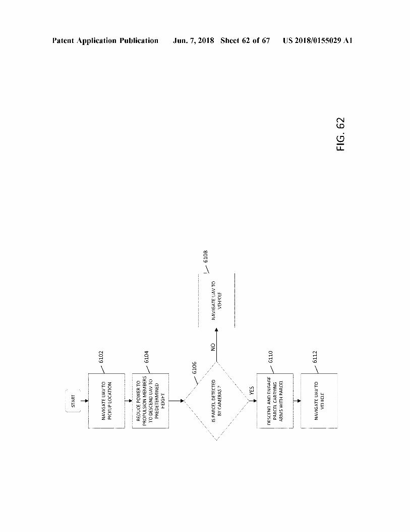
START
16102 NAVIGATE UAV TO PICKUP LOCATION
Patent Application Publication
-
INI - I
I
- I
I
- IV -
- 1 - 19 - 19 - 19 - 19 - 19 - 19 - IY - I -
-
-
6104
REDUCE POWER TO PROPULSION MEMBERS TO DESCEND UAV TO PREDETERMINED HEIGHT
6106
6108
NO
IS PARCEL DETECTED BY CAMERAS ?
NAVIGATE UAV TO VEHICLE
Jun . 7 , 2018 Sheet 62 of 67
YES
- 6110
DESCEND AND ENGAGE PARCEL CARRYING ARMS WITH PARCEL
6112
NAVIGATE UAV TO VEHICLE
US 2018 / 0155029 A1
FIG . 62
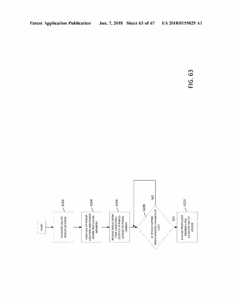
START
Patent Application Publication
NAVIGATE UAV TO PICKUP LOCATION
6202 - LAND UAV AT PICKUP LOCATION AND POWER DOWN PROPULSION MEMBERS
6204 6206
RECEIVE SIGNAL FROM USER COMPUTING ENTITY THAT PARCEL LOADED TO PARCEL CARRIER
Jun . 7 , 2018 Sheet 63 of 67
6208 NO
IS VEHICLE WITHIN PREDETERMINED DISTANCE OF UAV ? YES
ENGAGE PROPULSION MEMBERS AND NAVIGATE UAV TO VEHICLE
- 6210
US 2018 / 0155029 A1
FIG . 63
START
Patent Application Publication
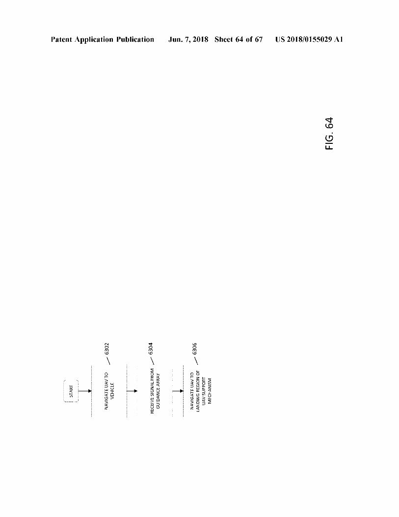
6302
NAVIGATE UAV TO VEHICLE
6304
RECEIVE SIGNAL FROM GUIDANCE ARRAY
- 6306
NAVIGATE UAV TO LANDING REGION OF UAV SUPPORT MECHANISM
Jun . 7 , 2018 Sheet 64 of 67 US 2018 / 0155029 A1
FIG . 64
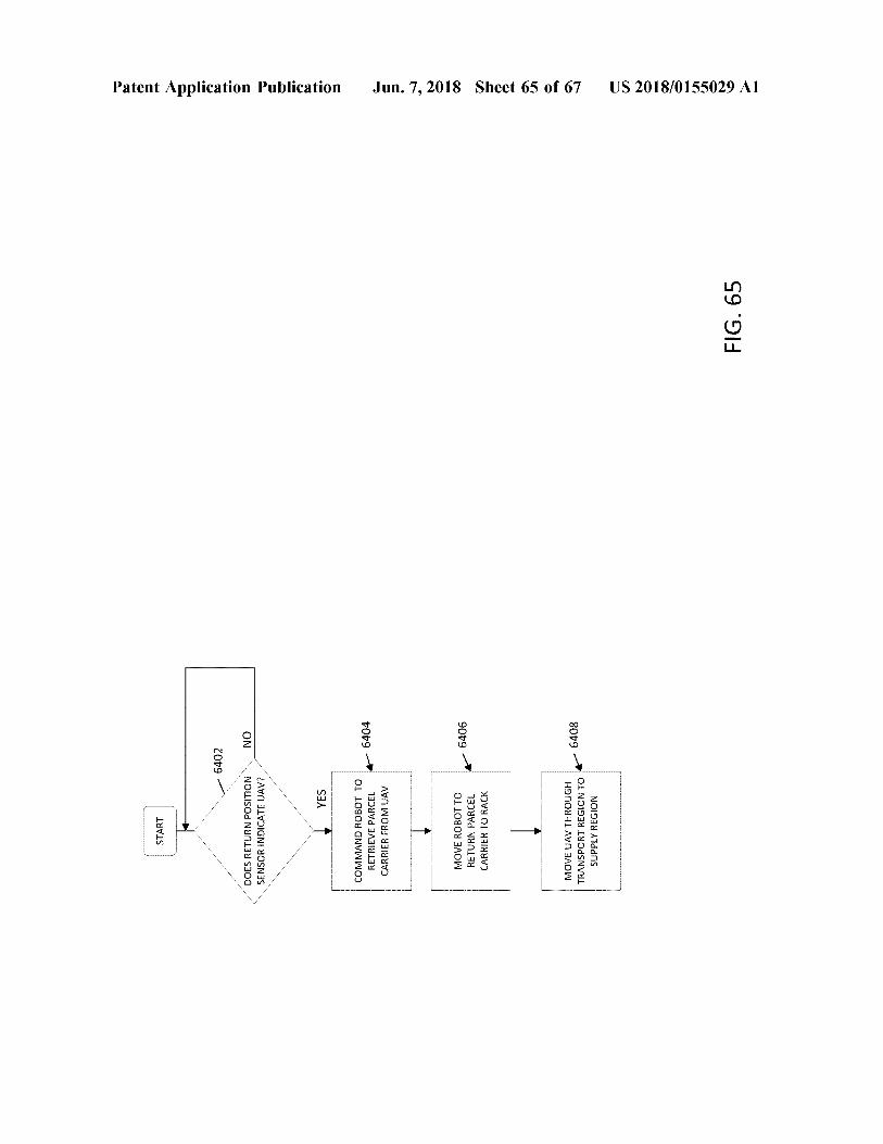
START
6402
Patent Application Publication
NO
DOES RETURN POSITION SENSOR INDICATE UAV ? YES
COMMAND ROBOT TO RETRIEVE PARCEL CARRIER FROM UAV
+ 6404 6406
MOVE ROBOT TO RETURN PARCEL CARRIER TO RACK
Jun . 7 , 2018 Sheet 65 of 67
6408
MOVE UAV THROUGH TRANSPORT REGION TO SUPPLY REGION
US 2018 / 0155029 A1
FIG . 65
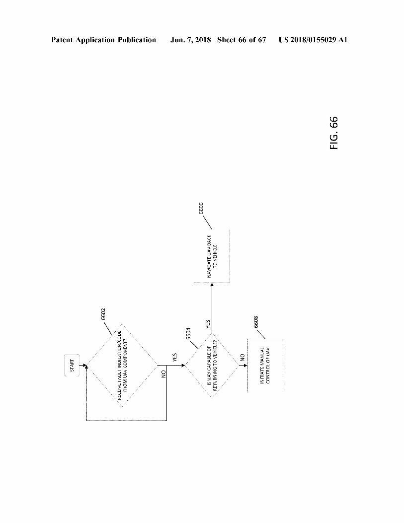
START
6602
Patent Application Publication
RECEIVE FAULT INDICATION / CODE FROM UAV COMPONENT ? NO
YES
6604
6606
YES
IS UAV CAPABLE OF RETURNING TO VEHICLE ?
NAVIGATE UAV BACK TO VEHICLE
Jun . 7 , 2018 Sheet 66 of 67
NO
6608
INITIATE MANUAL CONTROL OF UAV
US 2018 / 0155029 A1
FIG . 66
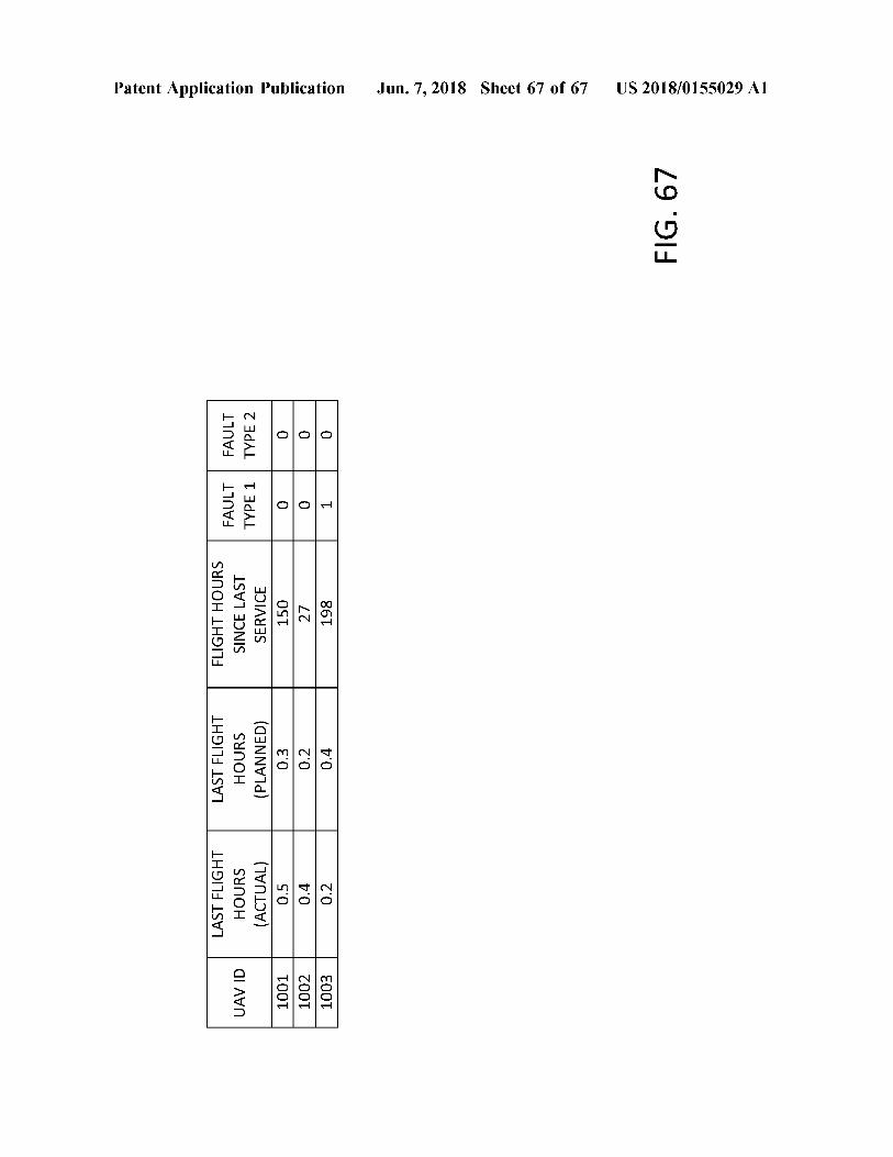
UAV ID
LAST FLIGHT HOURS ( PLANNED ) 0 . 3
FAULT TYPE 1
LAST FLIGHT HOURS ( ACTUAL ) 0 . 5 0 . 4 0 . 2
FAULT TYPE 2
FLIGHT HOURS SINCE LAST SERVICE 150 27 27 198
Patent Application Publication
1001 1002 1003
0 0
0 . 2
Tool
0 . 4
Jun . 7 , 2018 Sheet 67 of 67
FIG . 67
US 2018 / 0155029 A1
US 2018 / 0155029 A1 Jun . 7 , 2018
DELIVERY VEHICLE INCLUDING AN UNMANNED AERIAL VEHICLE LOADING
ROBOT
CROSS - REFERENCE TO RELATED APPLICATIONS
[ 0001 ] The present application is a continuation of U . S . patent application Ser . No . 15 / 582 , 168 , filed on Apr . 28 , 2017 , which claims the benefit of U . S . Provisional Patent Application 62 / 329 , 491 , filed on Apr . 29 , 2016 , the contents each of which are hereby incorporated by reference .
BACKGROUND [ 0002 ] Parcel transportation between an origin and a des tination is traditionally a labor - intensive process . For short distance , “ local ” deliveries , an item ( e . g . , parcel ) may be transported by a delivery person between the origin and the destination . For example , the delivery person may drive a vehicle to transport the item between the origin and the destination , and may ensure that the item is properly picked up and / or delivered according to delivery instructions . For longer - distance deliveries , transportation of an item may involve a number of delivery personnel , who may individu ally perform one or more steps for picking up an item , sorting the item one or more times , transporting the item from a final sort location to a final delivery destination , and / or delivering the item from the delivery vehicle to the final destination address ( e . g . , serviceable point ) . Because of the labor - intensive nature of this process , various attempts have been made to assist carrier personnel by reducing the physical demands required in the transportation and delivery process ; however , prior attempts have faced substantial difficulties in ensuring that various aspects of the transpor tation and delivery process are properly performed . For example , attempts have been made to utilize unmanned vehicles , such as Unmanned Aerial Vehicles ( UAVs ) to transport items from a final sort location to an intended delivery destination . However , such concepts are generally limited by the effective range of the UAVs , as well as the number of available UAVs that may be utilized to deliver items to locations a substantial distance away from the final sort location . [ 0003 ] Accordingly , a need exists for additional systems and methods to assist carrier personnel and thereby reduce the physical demands of the transportation and delivery process .
[ 0005 ] In another embodiment , a UAV for delivering a parcel includes a UAV chassis including an upper portion including a plurality of propulsion members configured to provide lift to the UAV chassis . The UAV chassis further includes a lower portion positioned below the upper portion in a vertical direction . A parcel carrier is selectively coupled to and removable from the UAV chassis , the parcel carrier including an engagement housing configured for being secured to the lower portion of the UAV chassis . A parcel carrying mechanism of the parcel carrier is coupled to the engagement housing and positioned below the engagement housing , where the parcel carrying mechanism is configured to engage a parcel . [ 0006 ] In yet another embodiment , a UAV for delivering a parcel includes a UAV chassis includes a plurality of pro pulsion members configured to provide lift to the UAV chassis and a UAV electrical interface electrically coupled to the plurality of propulsion members . The UAV further includes a parcel carrier selectively coupled to and remov able from the UAV chassis , the parcel carrier including an engagement housing configured for being secured to the UAV chassis . The engagement housing includes a carrier electrical interface configured for being electrically coupled to the UAV electrical interface when the parcel carrier is coupled to the UAV chassis . A parcel carrying mechanism of the parcel carrier is coupled to the engagement housing , where the parcel carrying mechanism is configured to engage a parcel , and a power source of the parcel carrier is electrically coupled to the carrier electrical interface and configured for powering the plurality of propulsion members when the parcel carrier is coupled to the UAV chassis . [ 0007 ] In one embodiment , an enhanced parcel delivery system includes a UAV having a UAV chassis including an upper portion and a plurality of propulsion members con figured to provide lift to the UAV chassis . The UAV chassis includes a lower portion positioned below the upper portion in a vertical direction , the lower portion defining an internal cavity . A first parcel carrier is selectively coupled to and removable from the UAV chassis , the first parcel carrier including a first engagement housing configured to be at least partially inserted within the internal cavity of the lower portion of the UAV chassis . The first parcel carrier includes a first power source positioned within the first engagement housing and configured to be electrically coupled to the plurality of propulsion members . A first parcel carrying mechanism of the first parcel carrier is coupled to and positioned below the first engagement housing , where the first parcel carrying mechanism is configured to engage a first parcel . The system further includes a second parcel carrier selectively coupled to and removable from the UAV chassis , the second parcel carrier including a second engage ment housing configured to be at least partially inserted within the internal cavity of the lower portion of the UAV chassis . The second parcel carrier includes a second power source positioned within the second engagement housing and configured to be electrically coupled to the plurality of propulsion members . A second parcel carrying mechanism of the second parcel carrier is coupled to and positioned below the second engagement housing , where the second parcel carrying mechanism is configured to engage a second parcel . [ 0008 ] In another embodiment , a UAV for delivering a parcel includes a UAV chassis including an upper portion having an upper portion width evaluated in a lateral direc
BRIEF SUMMARY [ 0004 ] In one embodiment , a UAV for delivering a parcel includes a UAV chassis including an upper portion having a plurality of propulsion members configured to provide lift to the UAV chassis . The UAV chassis further includes a lower portion positioned below the upper portion in a vertical direction , the lower portion defining an internal cavity . A parcel carrier of the UAV is configured for being selectively coupled to and removed from the UAV chassis , the parcel carrier including an engagement housing configured for being at least partially inserted within the internal cavity of the lower portion of the UAV chassis and thereby secured to the UAV chassis . The parcel carrier has a parcel carrying mechanism coupled to and positioned below the engagement housing , where the parcel carrying mechanism is configured for engaging and holding the parcel .
US 2018 / 0155029 A1 Jun . 7 , 2018
tion , where the upper portion includes a tapered shape such that the upper portion width decreases moving downward along the upper portion in the vertical direction . The UAV chassis includes a plurality of propulsion members config ured to provide lift to the UAV chassis and a lower portion positioned below the upper portion in a vertical direction . The lower portion of the UAV chassis includes a lower portion width evaluated in the lateral direction , and the UAV chassis includes a reduced width portion positioned between the upper portion and the lower portion , the reduced width portion having a width evaluated in the lateral direction , where the width of the reduced width portion is less than the upper portion width and the lower portion width . The UAV further includes a parcel carrying mechanism coupled to the lower portion , where the parcel carrying mechanism is configured to engage a parcel . 10009 ] . In yet another embodiment , a UAV for delivering a parcel includes a UAV chassis including an upper portion having an upper portion width evaluated in a lateral direc tion and a plurality of propulsion members configured to provide lift to the UAV chassis . The UAV chassis further includes a reduced width portion positioned below the upper portion , the reduced width portion having a width evaluated in the lateral direction , where the width of the reduced width portion is less than the upper portion width . A parcel carrier of the UAV is selectively coupled to the UAV chassis , the parcel carrier including an engagement housing selectively coupled to the reduced width portion of the UAV chassis . A parcel carrying mechanism of the parcel carrier is coupled to the engagement housing , where the parcel carrying mecha nism is configured to engage a parcel . [ 0010 ] In yet another embodiment , an enhanced parcel delivery system for delivering parcels via a UAV includes a UAV support mechanism having a pair of opposing rails extending in a longitudinal direction , where the opposing rails are spaced apart from one another in a lateral direction that is transverse to the longitudinal direction . The opposing rails define a landing region , a takeoff region positioned opposite the landing region , a transport region positioned between the takeoff region and the landing region . The system further includes at least one UAV including a UAV chassis having an upper portion having an upper portion width evaluated in a lateral direction . A lower portion of the UAV chassis is positioned below the upper portion in a vertical direction , the lower portion having a lower portion width evaluated in the lateral direction . A reduced width portion of the UAV chassis is positioned between the upper portion and the lower portion , the reduced width portion having a width evaluated in the lateral direction . The width of the reduced width portion is less than the upper portion width and the lower portion width , and where the reduced width portion is configured to engage the pair of opposing rails of the UAV support mechanism . [ 0011 ] In one embodiment , a primary delivery vehicle configured for delivering parcels via a UAV includes an interior compartment , and a roof panel defining a portal , where the interior compartment is accessible through the portal . The vehicle includes a UAV support mechanism positioned on the roof panel of the vehicle and configured for providing a landing surface for the UAV , the UAV support mechanism including a pair of opposing rails extending in a longitudinal direction and positioned above the portal , where the opposing rails are spaced apart from one another in a lateral direction that is transverse to the
longitudinal direction . The opposing rails define a landing region , a takeoff region positioned opposite the landing region , and a transport region positioned between the takeoff region and the landing region . [ 0012 ] In another embodiment , a primary delivery vehicle configured for delivering parcels via a UAV includes an interior compartment , a roof panel defining a supply portal and a return portal spaced apart from the supply portal , where the interior compartment is accessible through the supply portal and the return portal . The vehicle further includes a UAV support mechanism including a pair of opposing rails extending in a longitudinal direction , where the opposing rails are spaced apart from one another in a lateral direction that is transverse to the longitudinal direc tion . The opposing rails define a landing region , a supply region positioned over the supply portal of the roof panel , a return region positioned over the return portal of the roof panel , and a transport region positioned between the supply region and the return region . [ 0013 ] In yet another embodiment , a primary delivery vehicle configured for delivering parcels via a UAV includes an interior compartment , a roof panel defining a supply portal , where the interior compartment is accessible through the supply portal , a loading robot positioned within the interior compartment . The loading robot includes a robot controller including at least one processor and at least one memory including program code , the at least one memory and the program code configured to , with the processor , cause the loading robot to at least engage a parcel carrier , move the parcel carrier to a supply portal , and engage the parcel carrier with a UAV positioned above the supply portal . [ 0014 ] In yet another embodiment , a primary delivery vehicle configured for delivering parcels via a UAV includes an interior compartment , and a roof panel defining a return portal , where the interior compartment is accessible through the return portal . A loading robot is positioned within the interior compartment , the loading robot including a robot controller including at least one processor and at least one memory including program code , the at least one memory and the program code configured to , with the processor , cause the loading robot to at least engage a parcel carrier coupled to a UAV positioned above the return portal , remove the parcel carrier from a UAV chassis of the UAV , move the parcel carrier from the return portal to a rack positioned in the interior compartment , and engage the parcel carrier with the rack of the interior compartment . [ 0015 ] In yet another embodiment , a method for loading unloading a parcel carrier to a UAV includes receiving a parcel to be delivered by a UAV and engaging a parcel carrying mechanism of a parcel carrier with the parcel , the parcel carrying mechanism being configured to engage and secure the parcel to the parcel carrier . The method further includes moving the parcel carrier and parcel toward a UAV chassis of the UAV , and securing an engagement housing of the parcel carrier to the UAV chassis of the UAV , where the engagement housing of the parcel carrier is coupled to and positioned above the parcel carrying mechanism of the parcel carrier . [ 0016 ] In one embodiment , a method for loading / unload ing a parcel carrier to a UAV includes engaging a parcel with a parcel carrier , the parcel carrier including an engagement housing and a parcel carrying mechanism coupled to and positioned below the engagement housing , where the parcel
US 2018 / 0155029 A1 Jun . 7 , 2018
is engaged with the parcel carrying mechanism . The method further includes moving the parcel carrier toward a UAV chassis positioned on a UAV support mechanism , moving an engagement member of the UAV chassis from an extended position into a retracted position , engaging the engagement housing of the parcel carrier with a UAV chassis . The method further includes moving the engagement member of the UAV chassis from the retracted position into the extended positon , securing the engagement housing to the UAV chassis . [ 0017 ] In yet another embodiment , a method for deliver ing parcels via a UAV includes securing a first parcel to a first parcel carrier , and at a loading point , securing the first parcel carrier to a chassis of a UAV for delivery of the first parcel . The method further includes navigating the UAV from the loading point to a serviceable point , and at the serviceable point , releasing the first parcel from a parcel carrying mechanism of the first parcel carrier . The method further includes navigating the UAV from the serviceable point to the loading point , and at the loading point , removing the first parcel carrier from the UAV chassis and securing a second parcel carrier that is coupled to a second parcel to the chassis of the UAV for delivery of the second parcel . [ 0018 ] In another embodiment , a method for accessing a restricted access area by a UAV includes electronically storing , by a computing entity of the UAV , an access code associated with a restricted access area , where ( a ) the restricted access area is at a serviceable point , ( b ) a user computing entity at the serviceable point is configured to selectively allow access to the restricted access area in response to receipt of the access code , and ( c ) the UAV includes the UAV computing entity . The method further includes , after navigation of the UAV proximate the restricted access area at the serviceable point , communicat ing , by the computing entity of the UAV , the access code to the user computing entity , where ( a ) a parcel is selectively coupled to a UAV chassis of the UAV , and ( b ) the user computing entity allows entry into the restricted access area responsive to receiving the access code . After the user computing entity allows entry into the restricted access area , the method further includes navigating , by the computing entity of the UAV , the UAV into the restricted access area of the serviceable point . [ 0019 ] In yet another embodiment , a UAV computing entity includes at least one processor and at least one memory including program code , the at least one memory and the program code configured to , with the processor , cause the UAV computing entity to at least electronically store an access code associated with a restricted access area , where ( a ) the restricted access area is at a serviceable point , ( b ) a user computing entity at the serviceable point is configured to selectively allow access to the restricted access area in response to receipt of the access code , and ( c ) a UAV includes the UAV computing entity . After navigation of the UAV proximate the restricted access area at the serviceable point , the UAV computing entity is configured to commu nicate the access code to the user computing entity , where ( a ) a parcel is selectively coupled to a UAV chassis of the UAV , and ( b ) the user computing entity allows entry into the restricted access area responsive to receiving the access code . After the user computing entity allows entry into the restricted access area , the UAV computing entity is config ured to navigate the UAV into the restricted access area of the serviceable point .
[ 0020 ] In one embodiment , a method for picking up a parcel via a UAV includes navigating a UAV to a serviceable point , the UAV including a UAV chassis , a parcel carrier coupled to the UAV chassis , the parcel carrier including an engagement housing selectively coupled to the UAV chassis , and parcel carrying arms positioned below the engagement housing . The method further includes detecting a parcel at the serviceable point with a camera of the UAV , navigating the UAV to a position over the parcel and reducing power to propulsion members of the UAV to descend the UAV over the parcel . The method further includes depressing a ground probe of the parcel carrier , engaging the parcel carrying arms of the parcel carrier with the parcel , and navigating the UAV from the serviceable point to a UAV support mechanism . [ 0021 ] In another embodiment , a method for picking up a parcel via a UAV includes navigating a UAV to a serviceable point , the UAV including a UAV chassis , a parcel carrier coupled to the UAV chassis , the parcel carrier including an engagement housing selectively coupled to the UAV chassis , and a parcel carrying mechanism positioned below the engagement housing . The method further includes landing the UAV at the serviceable point and turning off propulsion members of the UAV , receiving , via a UAV computing entity , a notification that a parcel is engaged with the engagement housing of the parcel carrier , and engaging the propulsion members of the UAV and navigating the UAV from the serviceable point to a UAV support mechanism . [ 0022 ] In yet another embodiment , an enhanced parcel delivery system for delivering parcels via a UAV includes a primary delivery vehicle , a UAV support mechanism coupled to the primary delivery vehicle , the UAV support mechanism configured for supporting one or more UAVs . A plurality of UAVs of the system each include a UAV chassis including a plurality of propulsion members configured to provide lift to the UAV chassis , and a parcel carrier includ ing an engagement housing configured for being secured to the UAV chassis . Each parcel carrier includes a parcel carrying mechanism coupled to and positioned below the engagement housing , where the parcel carrying mechanism is configured for engaging and holding a parcel for delivery . [ 0023 ] In yet another embodiment , a method for providing a notification regarding delivery of a parcel by a UAV including after navigating a UAV to a serviceable point , establishing , via a UAV computing entity , a direct commu nications link between the UAV computing entity and a user computing entity , where ( a ) a UAV includes the UAV computing entity , a UAV chassis , and a parcel carrier coupled to the UAV chassis , ( b ) the parcel carrier includes an engagement housing selectively coupled to the UAV chassis , ( c ) a parcel carrying mechanism is engaged with and securing a parcel to the engagement housing , and ( d ) the user computing entity is associated with the serviceable point . The method further includes releasing the parcel from the parcel carrying mechanism of the parcel carrier , and after releasing the parcel from the parcel carrying mechanism of the parcel carrier , providing , via the UAV computing entity , a notification to the user computing entity through the direct communications link , where the notification includes infor mation indicative of the release of the parcel at the service able point . [ 0024 ] In one embodiment , a UAV computing entity includes at least one processor and at least one memory including program code , the at least one memory and the program code configured to , with the processor , cause the
US 2018 / 0155029 A1 Jun . 7 , 2018
including ( a ) a second logical grouping identifier corre sponding to a second logical grouping with which each of the second plurality of parcels is associated and ( b ) a respective parcel identifier for each of the second plurality of parcels . The system is further configured to electronically set a current logical grouping identifier to the first logical grouping identifier , responsive to receiving an indication that a first parcel from the second plurality of parcels is to be delivered by the carrier , determine whether the logical grouping identifier for the first parcel is the same as the current logical grouping identifier . Responsive to determin ing the logical grouping identifier for the first parcel is not the same as the current logical grouping identifier , the system is further configured to initiate delivery of a second parcel from the second plurality of parcels by an unmanned aerial vehicle .
UAV computing entity to at least , after navigating a UAV to a serviceable point , establish a communication link between the UAV computing entity and a user computing entity , where ( a ) a UAV includes the UAV computing entity , a UAV chassis , and a parcel carrier coupled to the UAV chassis , ( b ) the parcel carrier includes an engagement housing selec tively coupled to the UAV chassis , ( c ) a parcel carrying mechanism is engaged with and securing a parcel to the engagement housing , and ( d ) the user computing entity is associated with the serviceable point , release the parcel from the parcel carrying mechanism of the parcel carrier . After releasing the parcel from the parcel carrying mechanism of the parcel carrier , the UAV computing entity is configured to provide a notification to the user computing entity through the communication link , where the notification includes information indicative of the release of the parcel at the serviceable point . [ 0025 ] In another embodiment , a method for landing an unmanned aerial ( UAV ) on a UAV support mechanism includes navigating a UAV toward a UAV support mecha nism , receiving a signal from a guidance array of the UAV support mechanism , and navigating the UAV to a landing region of a UAV support mechanism . The method further includes guiding a reduced width portion of the UAV between opposing rails of the UAV support mechanism and engaging the UAV with the UAV support mechanism , and moving the UAV from the landing region toward a return region of the UAV support mechanism . [ 0026 ] In one embodiment , a method for initiating deliv ery of a parcel via an unmanned aerial vehicle includes , for each of a first plurality of parcels to be delivered by a carrier , electronically storing parcel data including ( a ) a first logical grouping identifier corresponding to a first logical grouping with which each of the first plurality of parcels is associated and ( b ) a respective parcel identifier for each of the first plurality of parcels . The method further includes , for each of a second plurality of parcels to be delivered by the carrier , electronically storing parcel data including ( a ) a second logical grouping identifier corresponding to a second logical grouping with which each of the second plurality of parcels is associated and ( b ) a respective parcel identifier for each of the second plurality of parcels . The method further includes electronically setting a current logical grouping identifier to the first logical grouping identifier , responsive to receiving an indication that a first parcel from the second plurality of parcels is to be delivered by the carrier , determining whether the logical grouping identifier for the first parcel is the same as the current logical grouping identifier , and responsive to determining the logical grouping identifier for the first parcel is not the same as the current logical grouping identifier , initiating delivery of a second parcel from the second plurality of parcels by an unmanned aerial vehicle . [ 0027 ] In another embodiment , a system includes at least one processor and at least one memory including program code , the at least one memory and the program code configured to , with the processor , cause the system to at least , for each of a first plurality of parcels to be delivered by a carrier , electronically store parcel data including ( a ) a first logical grouping identifier corresponding to a first logical grouping with which each of the first plurality of parcels is associated and ( b ) a respective parcel identifier for each of the first plurality of parcels . For each of a second plurality of parcels to be delivered by the carrier , the system is further configured to electronically store parcel data
BRIEF DESCRIPTION OF THE SEVERAL VIEWS OF THE DRAWINGS
[ 0028 ] Reference will now be made to the accompanying drawings , which are not necessarily drawn to scale , and wherein : [ 0029 ] FIG . 1 schematically depicts a vehicle and a plu rality of associated UAVs according to one embodiment shown and described herein ; [ 0030 ] FIG . 2 schematically depicts a perspective view of the UAV of FIG . 1 and associated parcel carrier according to one embodiment shown and described herein ; [ 0031 ] FIG . 3 schematically depicts a top view of the UAV of FIG . 1 according to one embodiment shown and described herein ; [ 0032 ] FIG . 4 . schematically depicts a bottom perspective view of the UAV chassis of the UAV of FIG . 1 according to one embodiment shown and described herein ; [ 0033 ] FIG . 5 schematically depicts an exploded perspec tive view of the UAV and parcel carrier of FIG . 2 according to one embodiment shown and described herein ; [ 0034 ] FIG . 6 schematically depicts a bottom perspective view of the UAV and parcel carrier of FIG . 2 according to one embodiment shown and described herein ; 0035 FIG . 7 schematically depicts a bottom view of the UAV chassis and parcel carrier of FIG . 2 according to one embodiment shown and described herein ; [ 0036 ] FIG . 8 schematically depicts a cross - sectional view of the UAV chassis ' retaining member assembly according to one embodiment shown and described herein ; [ 0037 ] FIG . 9 schematically depicts a perspective view of the parcel carrier of FIG . 5 and a parcel according to one embodiment shown and described herein ; [ 0038 ] FIG . 10 schematically depicts a front view of the UAV of FIG . 1 and various sensors according to one embodiment shown and described herein ; [ 0039 ] FIG . 11 schematically depicts a top perspective view of the UAV of FIG . 1 and ground landing sensors according to one embodiment shown and described herein ; 10040 ] FIG . 12 schematically depicts a UAV control sys tem according to one embodiment shown and described herein ; [ 0041 ] FIG . 13 schematically depicts a parcel carrier con troller according to one embodiment shown and described herein ; 10042 ] FIG . 14 schematically depicts a top perspective view of the UAV of FIG . 1 and ground landing sensors according to one embodiment shown and described herein ;
US 2018 / 0155029 A1 Jun . 7 , 2018
10043 ] FIG . 15 schematically depicts a top perspective view of the UAV of FIG . 1 and ground landing sensors according to one embodiment shown and described herein ; 10044 ] FIG . 16 schematically depicts perspective view of a parcel according to one embodiment shown and described herein ; [ 0045 ] FIG . 17 schematically depicts a perspective view of a parcel carrier and a parcel according to one embodiment shown and described herein ; [ 0046 ] FIG . 18 schematically depicts a perspective view of a parcel carrier and a parcel according to one embodiment shown and described herein ; [ 0047 ] FIG . 19 schematically depicts a perspective view of a parcel carrier and a parcel housing according to one embodiment shown and described herein ; [ 0048 ] FIG . 20 schematically depicts a perspective view of a parcel carrier and another parcel housing according to one embodiment shown and described herein ; [ 0049 ] FIG . 21A schematically depicts a side view of the parcel housing of FIG . 20 in a closed position according to one embodiment shown and described herein ; [ 0050 ] FIG . 21B schematically depicts a side view of the parcel housing of FIG . 20 in a closed position according to one embodiment shown and described herein ; [ 0051 ] FIG . 22 schematically depicts a bottom perspective view of a UAV including landing arms according to one embodiment shown and described herein ; [ 0052 ] FIG . 23A schematically depicts a front view of another UAV chassis and parcel carrier according to one embodiment shown and described herein ; [ 0053 ] FIG . 23B schematically depicts a front view of another UAV chassis and parcel carrier according to one embodiment shown and described herein ; [ 0054 ] FIG . 24 schematically depicts a rear perspective view of the vehicle of FIG . 1 including a UAV support mechanism according to one embodiment shown and described herein ; [ 0055 ] FIG . 25 schematically depicts a perspective view of the UAV support mechanism of FIG . 24 according to one embodiment shown and described herein ; [ 0056 ] FIG . 26A schematically depicts a section view of the UAV support mechanism of FIG . 25 along section 26A - 26A according to one embodiment shown and described herein ; [ 0057 ] FIG . 26B schematically depicts an enlarged section view of the UAV support mechanism of FIG . 26A according to one embodiment shown and described herein ; 10058 ] FIG . 27 schematically depicts a conveyor control ler according to one embodiment shown and described herein ; [ 0059 ] FIG . 28 schematically depicts a front view of opposing rails of the UAV support mechanism of FIG . 24 according to one embodiment shown and described herein ; 100601 FIG . 29 schematically depicts a rear perspective view of the vehicle of FIG . 1 including racks according to one embodiment shown and described herein ; [ 0061 ] FIG . 30 schematically depicts a rear perspective view of the vehicle of FIG . 1 including robots according to one embodiment shown and described herein ; 10062 ] FIG . 31 schematically depicts a robot controller according to one embodiment shown and described herein ; [ 0063 ] FIG . 32 schematically depicts a perspective view of an automated parcel carrier / parcel connection system according to one embodiment shown and described herein ;
[ 0064 ] FIG . 33 schematically depicts a rear perspective view of the vehicle of FIG . 1 and a parcel conveyor according to one embodiment shown and described herein ; f0065 ] FIG . 34 schematically depicts the parcel conveyor of FIG . 33 and the robot of FIG . 30 according to one embodiment shown and described herein ; [ 0066 ] FIG . 35A schematically depicts a perspective view of a robot loading a parcel and parcel carrier to the rack of FIG . 29 according to one embodiment shown and described herein ; [ 0067 ] FIG . 35B schematically depicts a perspective view of a robot loading a parcel and parcel carrier to the rack of FIG . 29 according to one embodiment shown and described herein ; [ 0068 ] FIG . 35C schematically depicts a perspective view of a robot loading a parcel and parcel carrier to the rack of FIG . 29 according to one embodiment shown and described herein ; [ 0069 ] FIG . 36 schematically depicts a perspective view of the UAV support mechanism of FIG . 25 including UAVs according to one embodiment shown and described herein ; 10070 ] FIG . 37 schematically depicts a section view of the UAV support mechanism of FIG . 36 along section 37 - 37 according to one embodiment shown and described herein ; [ 0071 ] FIG . 38A schematically depicts a parcel being loaded to a UAV chassis with the robot of FIG . 30 according to one embodiment shown and described herein ; [ 0072 ] FIG . 38B schematically depicts a parcel being loaded to a UAV chassis with the robot of FIG . 30 according to one embodiment shown and described herein ; [ 0073 ] FIG . 38C schematically depicts a parcel being loaded to a UAV chassis with the robot of FIG . 30 according to one embodiment shown and described herein ; [ 0074 ] FIG . 39 schematically depicts a rear perspective view of the vehicle of FIG . 1 and the UAV support mecha nism of FIG . 24 according to one embodiment shown and described herein ; [ 0075 ] FIG . 40 schematically depicts a side view of the UAV and the UAV support mechanism of FIG . 24 according to one embodiment shown and described herein ; [ 0076 ] FIG . 41 schematically depicts a front view of the opposing rails of FIG . 28 and a UAV according to one embodiment shown and described herein ; [ 0077 ] FIG . 42A schematically depicts a perspective view of the robot of FIG . 30 removing a parcel carrier from a UAV chassis and moving the parcel carrier to the rack according to one embodiment shown and described herein ; 10078 ] FIG . 42B schematically depicts a perspective view of the robot of FIG . 30 removing a parcel carrier from a UAV chassis and moving the parcel carrier to the rack according to one embodiment shown and described herein ; [ 0079 ] FIG . 43 schematically depicts a rear perspective view of another vehicle including racks according to one embodiment shown and described herein ; 100801 FIG . 44 schematically depicts a front perspective view of another vehicle including the UAV support mecha nism of FIG . 24 according to one embodiment shown and described herein ; [ 0081 ] FIG . 45A schematically depicts a rear perspective view of a vehicle including a landing pad according to one embodiment shown and described herein ; [ 0082 ] FIG . 45B schematically depicts a front perspective view of another vehicle including a landing pad according to one embodiment shown and described herein ;
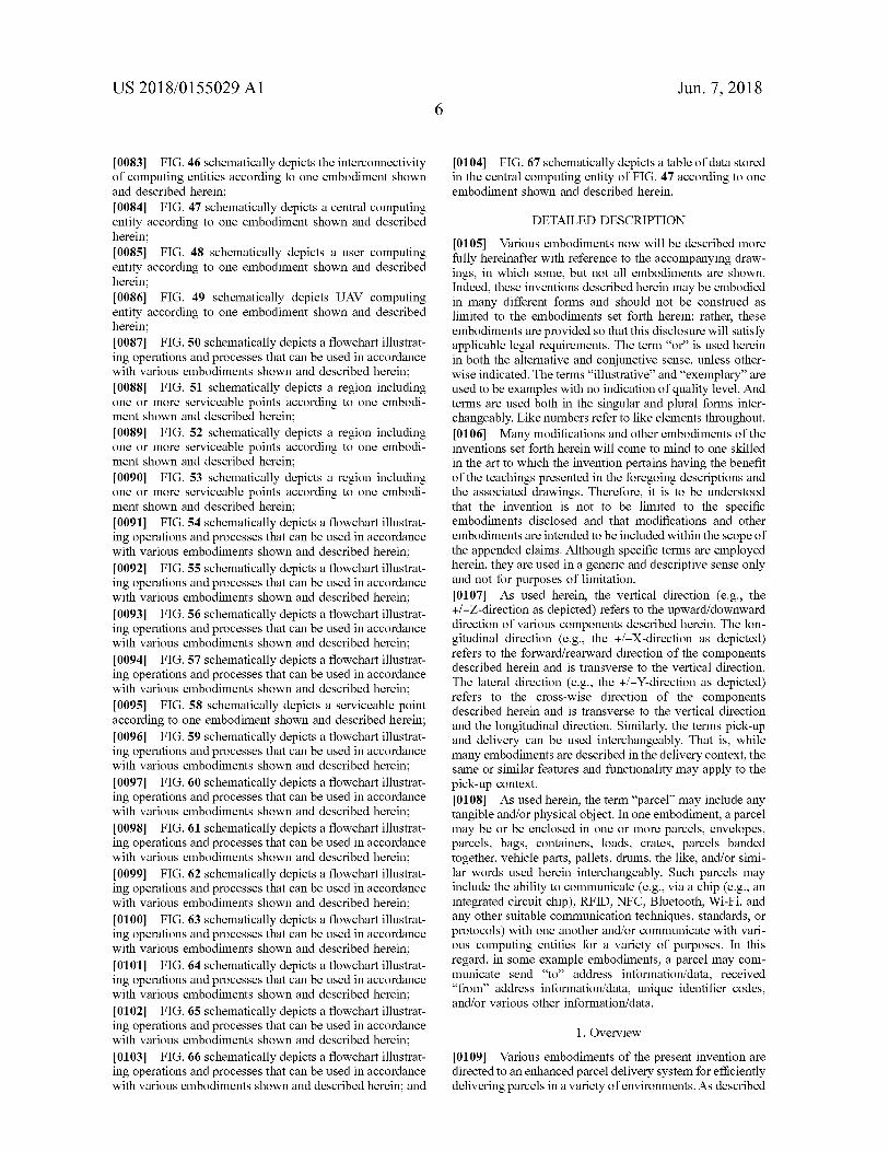
US 2018 / 0155029 A1 Jun . 7 , 2018
[ 0104 ] FIG . 67 schematically depicts a table of data stored in the central computing entity of FIG . 47 according to one embodiment shown and described herein .
DETAILED DESCRIPTION
[ 0083 ] FIG . 46 schematically depicts the interconnectivity of computing entities according to one embodiment shown and described herein ; [ 0084 ] FIG . 47 schematically depicts a central computing entity according to one embodiment shown and described herein ; 10085 ) FIG . 48 schematically depicts a user computing entity according to one embodiment shown and described herein [ 0086 ] FIG . 49 schematically depicts UAV computing entity according to one embodiment shown and described herein ; [ 0087 ] FIG . 50 schematically depicts a flowchart illustrat ing operations and processes that can be used in accordance with various embodiments shown and described herein ; [ 0088 ] FIG . 51 schematically depicts a region including one or more serviceable points according to one embodi ment shown and described herein ; [ 0089 ] FIG . 52 schematically depicts a region including one or more serviceable points according to one embodi ment shown and described herein ; [ 0090 ] FIG . 53 schematically depicts a region including one or more serviceable points according to one embodi ment shown and described herein ; [ 0091 ] FIG . 54 schematically depicts a flowchart illustrat ing operations and processes that can be used in accordance with various embodiments shown and described herein ; [ 0092 ] FIG . 55 schematically depicts a flowchart illustrat ing operations and processes that can be used in accordance with various embodiments shown and described herein ; [ 0093 ] FIG . 56 schematically depicts a flowchart illustrat ing operations and processes that can be used in accordance with various embodiments shown and described herein ; [ 0094 ] FIG . 57 schematically depicts a flowchart illustrat ing operations and processes that can be used in accordance with various embodiments shown and described herein ; [ 0095 ] FIG . 58 schematically depicts a serviceable point according to one embodiment shown and described herein ; [ 0096 ] FIG . 59 schematically depicts a flowchart illustrat ing operations and processes that can be used in accordance with various embodiments shown and described herein ; [ 0097 ] FIG . 60 schematically depicts a flowchart illustrat ing operations and processes that can be used in accordance with various embodiments shown and described herein ; [ 0098 ] FIG . 61 schematically depicts a flowchart illustrat ing operations and processes that can be used in accordance with various embodiments shown and described herein ; 10099 ] FIG . 62 schematically depicts a flowchart illustrat ing operations and processes that can be used in accordance with various embodiments shown and described herein ; [ 0100 ] FIG . 63 schematically depicts a flowchart illustrat ing operations and processes that can be used in accordance with various embodiments shown and described herein ; [ 0101 ] FIG . 64 schematically depicts a flowchart illustrat ing operations and processes that can be used in accordance with various embodiments shown and described herein ; [ 0102 ] FIG . 65 schematically depicts a flowchart illustrat ing operations and processes that can be used in accordance with various embodiments shown and described herein ; [ 0103 ] FIG . 66 schematically depicts a flowchart illustrat ing operations and processes that can be used in accordance with various embodiments shown and described herein ; and
[ 0105 ] Various embodiments now will be described more fully hereinafter with reference to the accompanying draw ings , in which some , but not all embodiments are shown . Indeed , these inventions described herein may be embodied in many different forms and should not be construed as limited to the embodiments set forth herein ; rather , these embodiments are provided so that this disclosure will satisfy applicable legal requirements . The term “ or ” is used herein in both the alternative and conjunctive sense , unless other wise indicated . The terms “ illustrative ” and “ exemplary ” are used to be examples with no indication of quality level . And terms are used both in the singular and plural forms inter changeably . Like numbers refer to like elements throughout . f0106 ] Many modifications and other embodiments of the inventions set forth herein will come to mind to one skilled in the art to which the invention pertains having the benefit of the teachings presented in the foregoing descriptions and the associated drawings . Therefore , it is to be understood that the invention is not to be limited to the specific embodiments disclosed and that modifications and other embodiments are intended to be included within the scope of the appended claims . Although specific terms are employed herein , they are used in a generic and descriptive sense only and not for purposes of limitation . [ 0107 ] As used herein , the vertical direction ( e . g . , the + / - Z - direction as depicted ) refers to the upward / downward direction of various components described herein . The lon gitudinal direction ( e . g . , the + / - X - direction as depicted ) refers to the forward / rearward direction of the components described herein and is transverse to the vertical direction . The lateral direction ( e . g . , the + / - Y - direction as depicted ) refers to the cross - wise direction of the components described herein and is transverse to the vertical direction and the longitudinal direction . Similarly , the terms pick - up and delivery can be used interchangeably . That is , while many embodiments are described in the delivery context , the same or similar features and functionality may apply to the pick - up context . [ 0108 ] As used herein , the term “ parcel ” may include any tangible and / or physical object . In one embodiment , a parcel may be or be enclosed in one or more parcels , envelopes , parcels , bags , containers , loads , crates , parcels banded together , vehicle parts , pallets , drums , the like , and / or simi lar words used herein interchangeably . Such parcels may include the ability to communicate ( e . g . , via a chip ( e . g . , an integrated circuit chip ) , RFID , NFC , Bluetooth , Wi - Fi , and any other suitable communication techniques , standards , or protocols ) with one another and / or communicate with vari ous computing entities for a variety of purposes . In this regard , in some example embodiments , a parcel may com municate send “ to ” address information / data , received " from " address information / data , unique identifier codes , and / or various other information / data .
1 . Overview
[ 0109 ] Various embodiments of the present invention are directed to an enhanced parcel delivery system for efficiently delivering parcels in a variety of environments . As described
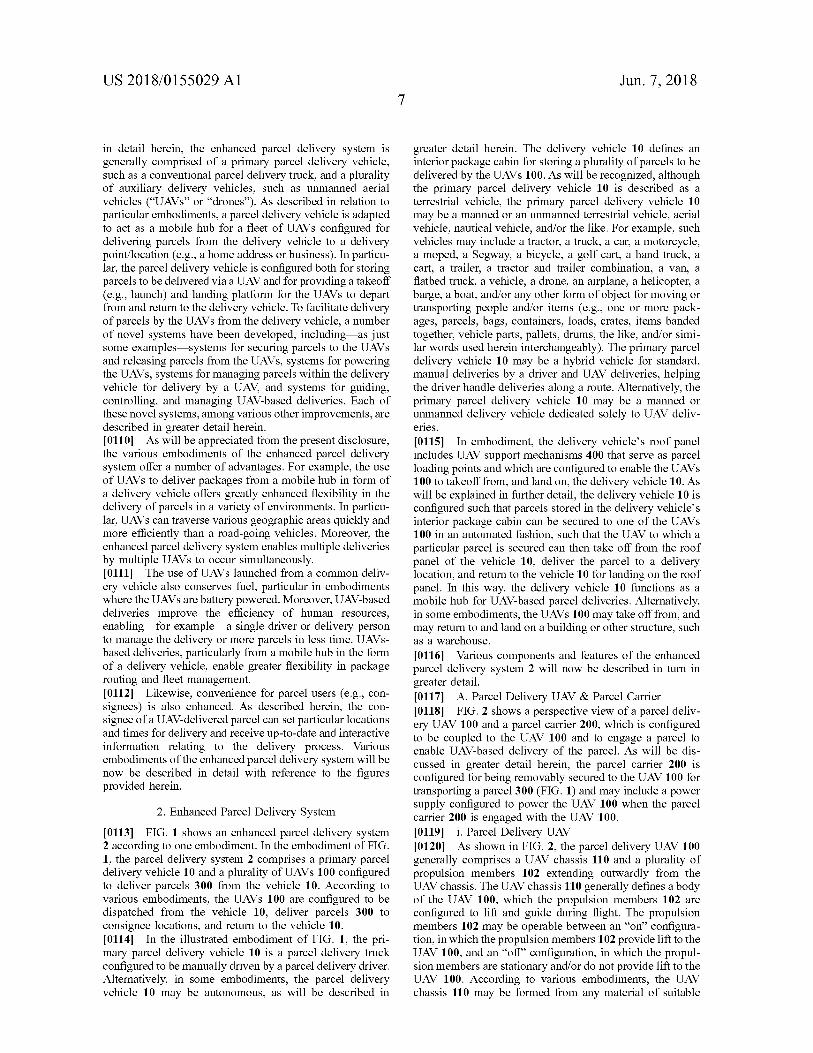
US 2018 / 0155029 A1 Jun . 7 , 2018
in detail herein , the enhanced parcel delivery system is generally comprised of a primary parcel delivery vehicle , such as a conventional parcel delivery truck , and a plurality of auxiliary delivery vehicles , such as unmanned aerial vehicles ( “ UAVs " or " drones ” ) . As described in relation to particular embodiments , a parcel delivery vehicle is adapted to act as a mobile hub for a fleet of UAVs configured for delivering parcels from the delivery vehicle to a delivery point / location ( e . g . , a home address or business ) . In particu lar , the parcel delivery vehicle is configured both for storing parcels to be delivered via a UAV and for providing a takeoff ( e . g . , launch ) and landing platform for the UAVs to depart from and return to the delivery vehicle . To facilitate delivery of parcels by the UAVs from the delivery vehicle , a number of novel systems have been developed , including — as just some examples systems for securing parcels to the UAVs and releasing parcels from the UAVs , systems for powering the UAVs , systems for managing parcels within the delivery vehicle for delivery by a UAV , and systems for guiding , controlling , and managing UAV - based deliveries . Each of these novel systems , among various other improvements , are described in greater detail herein . [ 0110 ] As will be appreciated from the present disclosure , the various embodiments of the enhanced parcel delivery system offer a number of advantages . For example , the use of UAVs to deliver packages from a mobile hub in form of a delivery vehicle offers greatly enhanced flexibility in the delivery of parcels in a variety of environments . In particu lar , UAVs can traverse various geographic areas quickly and more efficiently than a road - going vehicles . Moreover , the enhanced parcel delivery system enables multiple deliveries by multiple UAVs to occur simultaneously . [ 0111 ] The use of UAVs launched from a common deliv ery vehicle also conserves fuel , particular in embodiments where the UAVs are battery powered . Moreover , UAV - based deliveries improve the efficiency of human resources , enabling — for example a single driver or delivery person to manage the delivery or more parcels in less time . UAVS based deliveries , particularly from a mobile hub in the form of a delivery vehicle , enable greater flexibility in package routing and fleet management . [ 0112 ] Likewise , convenience for parcel users ( e . g . , con signees ) is also enhanced . As described herein , the con signee of a UAV - delivered parcel can set particular locations and times for delivery and receive up - to - date and interactive information relating to the delivery process . Various embodiments of the enhanced parcel delivery system will be now be described in detail with reference to the figures provided herein .
greater detail herein . The delivery vehicle 10 defines an interior package cabin for storing a plurality of parcels to be delivered by the UAVs 100 . As will be recognized , although the primary parcel delivery vehicle 10 is described as a terrestrial vehicle , the primary parcel delivery vehicle 10 may be a manned or an unmanned terrestrial vehicle , aerial vehicle , nautical vehicle , and / or the like . For example , such vehicles may include a tractor , a truck , a car , a motorcycle , a moped , a Segway , a bicycle , a golf cart , a hand truck , a cart , a trailer , a tractor and trailer combination , a van , a flatbed truck , a vehicle , a drone , an airplane , a helicopter , a barge , a boat , and / or any other form of object for moving or transporting people and / or items ( e . g . , one or more pack ages , parcels , bags , containers , loads , crates , items banded together , vehicle parts , pallets , drums , the like , and / or simi lar words used herein interchangeably ) . The primary parcel delivery vehicle 10 may be a hybrid vehicle for standard , manual deliveries by a driver and UAV deliveries , helping the driver handle deliveries along a route . Alternatively , the primary parcel delivery vehicle 10 may be a manned or unmanned delivery vehicle dedicated solely to UAV deliv eries . [ 0115 ] In embodiment , the delivery vehicle ' s roof panel includes UAV support mechanisms 400 that serve as parcel loading points and which are configured to enable the UAVs 100 to takeoff from , and land on , the delivery vehicle 10 . As will be explained in further detail , the delivery vehicle 10 is configured such that parcels stored in the delivery vehicle ' s interior package cabin can be secured to one of the UAVs 100 in an automated fashion , such that the UAV to which a particular parcel is secured can then take off from the roof panel of the vehicle 10 , deliver the parcel to a delivery location , and return to the vehicle 10 for landing on the roof panel . In this way , the delivery vehicle 10 functions as a mobile hub for UAV - based parcel deliveries . Alternatively , in some embodiments , the UAVs 100 may take off from , and may return to and land on a building or other structure , such as a warehouse . [ 0116 ] Various components and features of the enhanced parcel delivery system 2 will now be described in turn in greater detail . [ 0117 ] A . Parcel Delivery UAV & Parcel Carrier [ 0118 ] FIG . 2 shows a perspective view of a parcel deliv ery UAV 100 and a parcel carrier 200 , which is configured to be coupled to the UAV 100 and to engage a parcel to enable UAV - based delivery of the parcel . As will be dis cussed in greater detail herein , the parcel carrier 200 is configured for being removably secured to the UAV 100 for transporting a parcel 300 ( FIG . 1 ) and may include a power supply configured to power the UAV 100 when the parcel carrier 200 is engaged with the UAV 100 . [ 0119 ] i . Parcel Delivery UAV [ 0120 ] As shown in FIG . 2 , the parcel delivery UAV 100 generally comprises a UAV chassis 110 and a plurality of propulsion members 102 extending outwardly from the UAV chassis . The UAV chassis 110 generally defines a body of the UAV 100 , which the propulsion members 102 are configured to lift and guide during flight . The propulsion members 102 may be operable between an " on " configura tion , in which the propulsion members 102 provide lift to the UAV 100 , and an “ off ” configuration , in which the propul sion members are stationary and / or do not provide lift to the UAV 100 . According to various embodiments , the UAV chassis 110 may be formed from any material of suitable
2 . Enhanced Parcel Delivery System [ 0113 ] FIG . 1 shows an enhanced parcel delivery system 2 according to one embodiment . In the embodiment of FIG . 1 , the parcel delivery system 2 comprises a primary parcel delivery vehicle 10 and a plurality of UAVs 100 configured to deliver parcels 300 from the vehicle 10 . According to various embodiments , the UAVs 100 are configured to be dispatched from the vehicle 10 , deliver parcels 300 to consignee locations , and return to the vehicle 10 . [ 0114 ] In the illustrated embodiment of FIG . 1 , the pri mary parcel delivery vehicle 10 is a parcel delivery truck configured to be manually driven by a parcel delivery driver . Alternatively , in some embodiments , the parcel delivery vehicle 10 may be autonomous , as will be described in
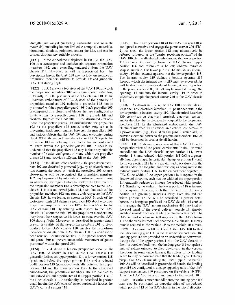
US 2018 / 0155029 A1 Jun . 7 , 2018
strength and weight ( including sustainable and reusable materials ) , including but not limited to composite materials , aluminum , titanium , polymers , and / or the like , and can be formed through any suitable process . [ 0121 ] In the embodiment depicted in FIG . 2 , the UAV 100 is a hexacopter and includes six separate propulsion members 102 , each extending outwardly from the UAV chassis 110 . However , as will be appreciated from the description herein , the UAV 100 may include any number of propulsion members suitable to provide lift and guide the UAV 100 during flight . [ 0122 ] FIG . 3 shows a top view of the UAV 100 , in which the propulsion members 102 are again shown extending outwardly from the perimeter of the UAV chassis 110 . In the illustrated embodiment of FIG . 3 , each of the plurality of propulsion members 102 includes a propeller 103 that is positioned within a propeller guard 108 . Each propeller 103 is comprised of a plurality of blades that are configured to rotate within the propeller guard 108 to provide lift and facilitate flight of the UAV 100 . In the illustrated embodi ment , the propeller guards 108 circumscribe the propellers 103 as the propellers 103 rotate , which may assist in preventing inadvertent contact between the propellers 103 and various objects that the UAV 100 may encounter during flight . While the embodiment depicted in FIG . 3 depicts the propellers 103 as including three blades that are configured to rotate within the propeller guards 108 , it should be understood that the propellers 103 may include any suitable number of blades configured to rotate within the propeller guards 108 and provide sufficient lift to the UAV 100 . [ 0123 ] In the illustrated embodiment , the propulsion mem bers 102 are electrically powered ( e . g . , by an electric motor that controls the speed at which the propellers 103 rotate ) . However , as will be recognized , the propulsion members 102 may be powered by internal combustion engines driving an alternator , hydrogen fuel - cells , and / or the like . Each of the propulsion members 102 is pivotally coupled to the UAV chassis 110 at a motorized joint 104 , such that each of the propulsion members 102 may rotate with respect to the UAV chassis 110 . In particular , as shown in FIG . 3 , each of the motorized joints 104 defines a joint axis 105 about which its respective propulsion member 102 rotates relative to the UAV chassis 110 . By rotating with respect to the UAV chassis 110 about the axis 105 , the propulsion members 102 may direct their respective lift forces to maneuver the UAV 100 during flight . Moreover , as described in greater detail herein , the ability of the propulsion members 102 to pivot relative to the UAV chassis 110 enables the propulsion members to maintain the UAV chassis 110 in a constant or near constant orientation relative to the parcel carrier 200 and parcel 300 to prevent undesirable movement of goods positioned within the parcel 300 . [ 0124 ] FIG . 4 shows a bottom perspective view of the UAV 100 . As shown in FIG . 4 , the UAV chassis 110 generally defines an upper portion 114 , a lower portion 118 ( positioned below the upper portion 114 ) , and a reduced width portion 115 ( positioned vertically between the upper portion 114 and the lower portion 118 ) . In the illustrated embodiment , the propulsion members 102 are coupled to and extend around a perimeter of the upper portion 114 of the UAV chassis 110 . Additionally , as described in greater detail herein , the UAV chassis ' upper portion 114 houses the UAV ' s control system 150 .
[ 0125 ] The lower portion 118 of the UAV chassis 110 is configured to receive and engage the parcel carrier 200 ( FIG . 2 ) . As such , the lower portion 118 may alternatively be referred to herein as the “ carrier receiving portion " of the UAV 100 . In the illustrated embodiment , the lower portion 118 extends downwardly from the UAV chassis ' upper portion 114 and resembles a hollow , oblique pyramid shaped member . The lower portion 118 defines an internal cavity 119 that extends upward into the lower portion 118 . The internal cavity 119 defines a bottom opening 117 through which the internal cavity 119 may be accessed . As will be described in greater detail herein , at least a portion of the parcel carrier 200 ( FIG . 2 ) may be inserted through the opening 117 and into the internal cavity 119 in order to selectively couple the parcel carrier 200 to the UAV chassis 110 . [ 0126 ] As shown in FIG . 4 , the UAV 100 also includes at least one UAV electrical interface 130 positioned within the lower portion ' s internal cavity 119 . The electrical interface 130 comprises an electrical terminal , electrical contact , and / or the like , that is electrically coupled to the propulsion members 102 . In the illustrated embodiment , the UAV electrical interface 130 provides an electrical connection to a power source ( e . g . , located in the parcel carrier 200 ) to provide electrical power to the propulsion members 102 , as will be described in greater detail herein . [ 0127 ] FIG . 5 shows a side - view of the UAV 100 and a perspective view of the parcel carrier 200 . In the illustrated embodiment , the UAV chassis ' upper portion 114 , lower portion 118 , and reduced width portion 115 define a gener ally hourglass shape . In particular , the upper portion 114 and the lower portion 118 have a greater width ( evaluated in the lateral and / or the longitudinal direction ) as compared to the reduced width portion 115 . In the embodiment depicted in FIG . 5 , the width of the upper portion 114 is tapered in the downward direction , such that the width of the upper portion 114 gradually reduces as it meets the reduced width portion 115 . Similarly , the width of the lower portion 118 is tapered in the upward direction , such that the width of the lower portion 118 gradually increases away from the reduced width portion 115 . As will be described in greater detail herein , the hourglass - profile of the UAV chassis 110 enables it to engage the UAV support mechanism 400 provided on the roof panel of the parcel delivery vehicle 10 , thereby enabling takeoff from and landing on the vehicle ' s roof . The UAV support mechanism 400 may secure the UAV chassis 110 to the vehicles roof such that the UAV chassis 110 may remain secured to the vehicle 10 as the vehicle 10 moves . [ 0128 ] As shown in FIGS . 4 and 5 , the UAV 100 further includes landing gear 116 . In the illustrated embodiment , the landing gear 116 are provided on an underside or downward facing side of the upper portion 114 of the UAV chassis . In the illustrated embodiment , the landing gear 116 comprise a pair of rollers oriented to face downward in the vertical direction . In some embodiments , the rollers of the landing gear 116 may be powered such that the landing gear 116 may propel the UAV chassis along the UAV support mechanism 400 . As will be described in greater detail herein , the landing gear 116 are configured to engage opposing rails of the UAV support mechanism 400 positioned on the vehicle 10 ( FIG . 1 ) as the UAV 100 takes off and lands to the vehicle 10 . [ 0129 ] In various other embodiments , the landing gear 116 may also be positioned on opposite sides of the reduced width portion 115 of the UAV chassis in the lateral direction
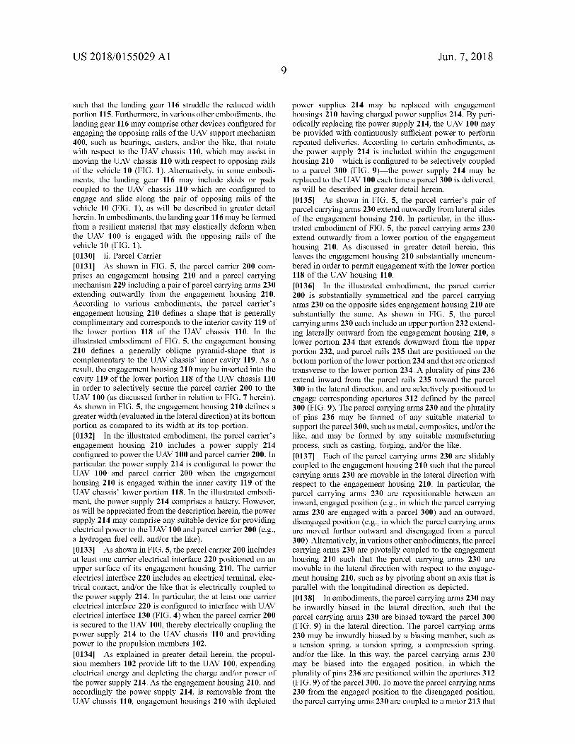
US 2018 / 0155029 A1 Jun . 7 , 2018
such that the landing gear 116 straddle the reduced width portion 115 . Furthermore , in various other embodiments , the landing gear 116 may comprise other devices configured for engaging the opposing rails of the UAV support mechanism 400 , such as bearings , casters , and / or the like , that rotate with respect to the UAV chassis 110 , which may assist in moving the UAV chassis 110 with respect to opposing rails of the vehicle 10 ( FIG . 1 ) . Alternatively , in some embodi ments , the landing gear 116 may include skids or pads coupled to the UAV chassis 110 which are configured to engage and slide along the pair of opposing rails of the vehicle 10 ( FIG . 1 ) , as will be described in greater detail herein . In embodiments , the landing gear 116 may be formed from a resilient material that may elastically deform when the UAV 100 is engaged with the opposing rails of the vehicle 10 ( FIG . 1 ) . [ 0130 ] ii . Parcel Carrier [ 0131 ] As shown in FIG . 5 , the parcel carrier 200 com prises an engagement housing 210 and a parcel carrying mechanism 229 including a pair of parcel carrying arms 230 extending outwardly from the engagement housing 210 . According to various embodiments , the parcel carrier ' s engagement housing 210 defines a shape that is generally complimentary and corresponds to the interior cavity 119 of the lower portion 118 of the UAV chassis 110 . In the illustrated embodiment of FIG . 5 , the engagement housing 210 defines a generally oblique pyramid - shape that is complementary to the UAV chassis ' inner cavity 119 . As a result , the engagement housing 210 may be inserted into the cavity 119 of the lower portion 118 of the UAV chassis 110 in order to selectively secure the parcel carrier 200 to the UAV 100 ( as discussed further in relation to FIG . 7 herein ) . As shown in FIG . 5 , the engagement housing 210 defines a greater width ( evaluated in the lateral direction ) at its bottom portion as compared to its width at its top portion . [ 0132 ] In the illustrated embodiment , the parcel carrier ' s engagement housing 210 includes a power supply 214 configured to power the UAV 100 and parcel carrier 200 . In particular , the power supply 214 is configured to power the UAV 100 and parcel carrier 200 when the engagement housing 210 is engaged within the inner cavity 119 of the UAV chassis ' lower portion 118 . In the illustrated embodi ment , the power supply 214 comprises a battery . However , as will be appreciated from the description herein , the power supply 214 may comprise any suitable device for providing electrical power to the UAV 100 and parcel carrier 200 ( e . g . , a hydrogen fuel cell , and / or the like ) . [ 0133 ] As shown in FIG . 5 , the parcel carrier 200 includes at least one carrier electrical interface 220 positioned on an upper surface of its engagement housing 210 . The carrier electrical interface 220 includes an electrical terminal , elec trical contact , and / or the like that is electrically coupled to the power supply 214 . In particular , the at least one carrier electrical interface 220 is configured to interface with UAV electrical interface 130 ( FIG . 4 ) when the parcel carrier 200 is secured to the UAV 100 , thereby electrically coupling the power supply 214 to the UAV chassis 110 and providing power to the propulsion members 102 . [ 0134 ] As explained in greater detail herein , the propul sion members 102 provide lift to the UAV 100 , expending electrical energy and depleting the charge and / or power of the power supply 214 . As the engagement housing 210 , and accordingly the power supply 214 , is removable from the UAV chassis 110 , engagement housings 210 with depleted
power supplies 214 may be replaced with engagement housings 210 having charged power supplies 214 . By peri odically replacing the power supply 214 , the UAV 100 may be provided with continuously sufficient power to perform repeated deliveries . According to certain embodiments , as the power supply 214 is included within the engagement housing 210 — which is configured to be selectively coupled to a parcel 300 ( FIG . 9 ) — the power supply 214 may be replaced to the UAV 100 each time a parcel 300 is delivered , as will be described in greater detail herein . [ 0135 ] As shown in FIG . 5 , the parcel carrier ' s pair of parcel carrying arms 230 extend outwardly from lateral sides of the engagement housing 210 . In particular , in the illus trated embodiment of FIG . 5 , the parcel carrying arms 230 extend outwardly from a lower portion of the engagement housing 210 . As discussed in greater detail herein , this leaves the engagement housing 210 substantially unencum bered in order to permit engagement with the lower portion 118 of the UAV housing 110 . [ 0136 ] In the illustrated embodiment , the parcel carrier 200 is substantially symmetrical and the parcel carrying arms 230 on the opposite sides engagement housing 210 are substantially the same . As shown in FIG . 5 , the parcel carrying arms 230 each include an upper portion 232 extend ing laterally outward from the engagement housing 210 , a lower portion 234 that extends downward from the upper portion 232 , and parcel rails 235 that are positioned on the bottom portion of the lower portion 234 and that are oriented transverse to the lower portion 234 . A plurality of pins 236 extend inward from the parcel rails 235 toward the parcel 300 in the lateral direction , and are selectively positioned to engage corresponding apertures 312 defined by the parcel 300 ( FIG . 9 ) . The parcel carrying arms 230 and the plurality of pins 236 may be formed of any suitable material to support the parcel 300 , such as metal , composites , and / or the like , and may be formed by any suitable manufacturing process , such as casting , forging , and / or the like . [ 0137 ] Each of the parcel carrying arms 230 are slidably coupled to the engagement housing 210 such that the parcel carrying arms 230 are movable in the lateral direction with respect to the engagement housing 210 . In particular , the parcel carrying arms 230 are repositionable between an inward , engaged position ( e . g . , in which the parcel carrying arms 230 are engaged with a parcel 300 ) and an outward , disengaged position ( e . g . , in which the parcel carrying arms are moved further outward and disengaged from a parcel 300 ) . Alternatively , in various other embodiments , the parcel carrying arms 230 are pivotally coupled to the engagement housing 210 such that the parcel carrying arms 230 are movable in the lateral direction with respect to the engage ment housing 210 , such as by pivoting about an axis that is parallel with the longitudinal direction as depicted . [ 0138 ] In embodiments , the parcel carrying arms 230 may be inwardly biased in the lateral direction , such that the parcel carrying arms 230 are biased toward the parcel 300 ( FIG . 9 ) in the lateral direction . The parcel carrying arms 230 may be inwardly biased by a biasing member , such as a tension spring , a torsion spring , a compression spring , and / or the like . In this way , the parcel carrying arms 230 may be biased into the engaged position , in which the plurality of pins 236 are positioned within the apertures 312 ( FIG . 9 ) of the parcel 300 . To move the parcel carrying arms 230 from the engaged position to the disengaged position , the parcel carrying arms 230 are coupled to a motor 213 that
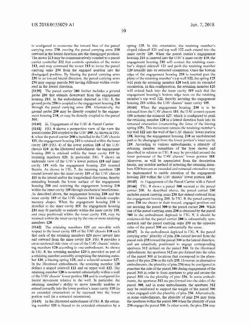
US 2018 / 0155029 A1 Jun . 7 , 2018
is configured to overcome the inward bias of the parcel carrying arms 230 , moving the parcel carrying arms 230 outward in the lateral direction into the disengaged position . The motor 213 may be communicatively coupled to a parcel carrier controller 212 that controls operation of the motor 213 , and may command the motor 213 to move the parcel carrying arms 230 from the engaged position into the disengaged position . By biasing the parcel carrying arms 230 in an inward lateral direction , the parcel carrying arms 230 may engage parcels 300 having different widths evalu ated in the lateral direction . [ 0139 ] The parcel carrier 200 further includes a ground probe 250 that extends downward from the engagement housing 210 . In the embodiment depicted in FIG . 5 , the ground probe 250 is coupled to the engagement housing 210 through the parcel carrying arms 230 . Alternatively , the ground probe 250 may be directly coupled to the engage ment housing 210 , or may be directly coupled to the parcel 300 . [ 0140 ] iii . Engagement of the UAV & Parcel Carrier [ 0141 ] FIG . 6 shows a perspective view of the view the parcel carrier 200 coupled to the UAV 100 . As shown in FIG . 6 , when the parcel carrier 200 is installed to the UAV chassis 110 , the engagement housing 210 is retained within the inner cavity 119 ( FIG . 4 ) of the lower portion 118 of the UAV chassis 110 . In the illustrated embodiment , the engagement housing 210 is retained within the inner cavity 119 by retaining members 120 . In particular , FIG . 7 shows an underside view of the UAV ' s lower portion 118 and inner cavity 119 with the engagement housing 210 inserted therein . As shown in FIG . 7 , the retaining members 120 extend inward into the inner cavity 119 of the UAV chassis 110 in the lateral and / or the longitudinal directions , thereby extending beneath the lower surface of the engagement housing 210 and retaining the engagement housing 210 within the inner cavity 119 through mechanical interference . As described above , the engagement housing 210 and the inner cavity 119 of the UAV chassis 110 include comple mentary shapes . When the engagement housing 210 is installed to the inner cavity 119 , the engagement housing 210 may fit partially or entirely within the inner cavity 119 , and once positioned within the inner cavity 119 , may be retained within the inner cavity by the one or more retaining members 120 . 10142 ] The retaining members 120 are movable with respect to the inner cavity 119 of the UAV chassis 110 such that each of the retaining members 120 move inward into and outward from the inner cavity 119 . FIG . 8 provides a cross - sectional side view of one of the UAV chassis ' retain ing members 120 according to one embodiment . As shown in FIG . 8 , the retaining member 120 is provided as part of a retaining member assembly comprising the retaining mem ber 120 , a biasing spring 125 , and a solenoid actuator 127 . In the illustrated embodiment , the retaining member 120 defines a sloped sidewall 121 and an upper wall 122 . The retaining member 120 is mounted substantially within a wall of the UAV chassis ' lower portion 118 and is configured for lateral movement relative to the wall . In particular , the retaining member ' s ability to move laterally enables to extend inwardly into the lower portion ' s inner cavity 119 ( in an extended orientation ) or be recessed into the lower portion wall ( in a retracted orientation ) . [ 0143 ] In the illustrated embodiment of FIG . 8 , the retain ing member 120 is biased to its extended orientation by a
spring 125 . In this orientation , the retaining member ' s sloped sidewall 121 and top wall 122 each extend into the inner cavity 119 . When the parcel carrier ' s engagement housing 210 is inserted into the UAV ' s inner cavity 119 , the engagement housing 210 will contact the retaining mem ber ' s sloped sidewall 121 and push the retaining member 120 laterally into its retracted orientation . Once the bottom edge of the engagement housing 210 is inserted past the plane of the retaining member ' s top wall 122 , the spring 125 will push the retaining member 120 back into its extended orientation . In this configuration , the retaining member 120 will extend back into the inner cavity 119 such that the engagement housing ' s bottom edge rests on the retaining member ' s top wall 122 , thereby securing the engagement housing 210 within the UAV chassis ' inner cavity 119 . [ 0144 ] When the engagement housing 210 is to be released from the UAV chassis 110 , the UAV control system 150 actuates the solenoid 127 , which is configured to push the retaining member 120 in a lateral direction back into its retracted orientation ( overcoming the force of the biasing spring 125 ) . This movement retracts the retaining member ' s top wall 122 into the wall of the UAV chassis ' lower portion 118 , leaving the engagement housing 210 an unobstructed path to be disengaged from the lower portion ' s inner cavity 119 . According to various embodiments , a plurality of retaining member assemblies of the type shown and described in relation to FIG . 8 may be provided around the inner perimeter of the UAV chassis ' lower portion 118 . Moreover , as will be appreciated from the description herein , any suitable method of actuating the retaining mem bers 120 between an extended and retracted orientation may be implemented to enable retention of the engagement housing 210 within the UAV chassis ' lower portion 118 . [ 0145 ] iv . Engagement of the Parcel Carrier with a Parcel 10146 ] FIG . 9 shows a parcel 300 secured to the parcel carrier 200 . As described above , the parcel carrier 200 includes parcel carrying arms 230 that extend outward from the engagement housing 210 . In FIG . 9 , the parcel carrying arms 230 are shown in their inward , engaged position and are securing the parcel 300 to the parcel carrier 200 . While one of the parcel carrying arms 230 is obscured by the parcel 300 in the embodiment depicted in FIG . 9 , it should be understood that the parcel carrier 200 is substantially sym metrical and the parcel carrying arms 230 on the opposite sides of the parcel 300 are substantially the same . [ 0147 ] In the embodiment depicted in FIG . 9 , the parcel carrying arms ' plurality of pins 236 extend inward from the parcel rails 235 toward the parcel 300 in the lateral direction , and are selectively positioned to engage corresponding apertures 312 defined on the parcel 300 . In the illustrated embodiment , the apertures 312 are pre - formed into the sides of the parcel 300 at locations that correspond to the place ment of the pins 236 on the rails 235 . However , in alternative embodiments , the plurality of pins 236 may be configured to puncture the side of the parcel 300 during engagement of the parcel 300 in order to form apertures to grip and secure the parcel 300 via the plurality of pins 236 . In some embodi ments , the apertures 312 are pre - formed into the sides of the parcel 300 , and in some embodiments , the apertures 312 may be reinforced to support the weight of the parcel 300 when engaged with the plurality of pins 236 . Alternatively , in some embodiments , the plurality of pins 236 may form the apertures within the parcel 300 when the plurality of pins 236 engage the parcel 300 . In other words , the pins 236 may
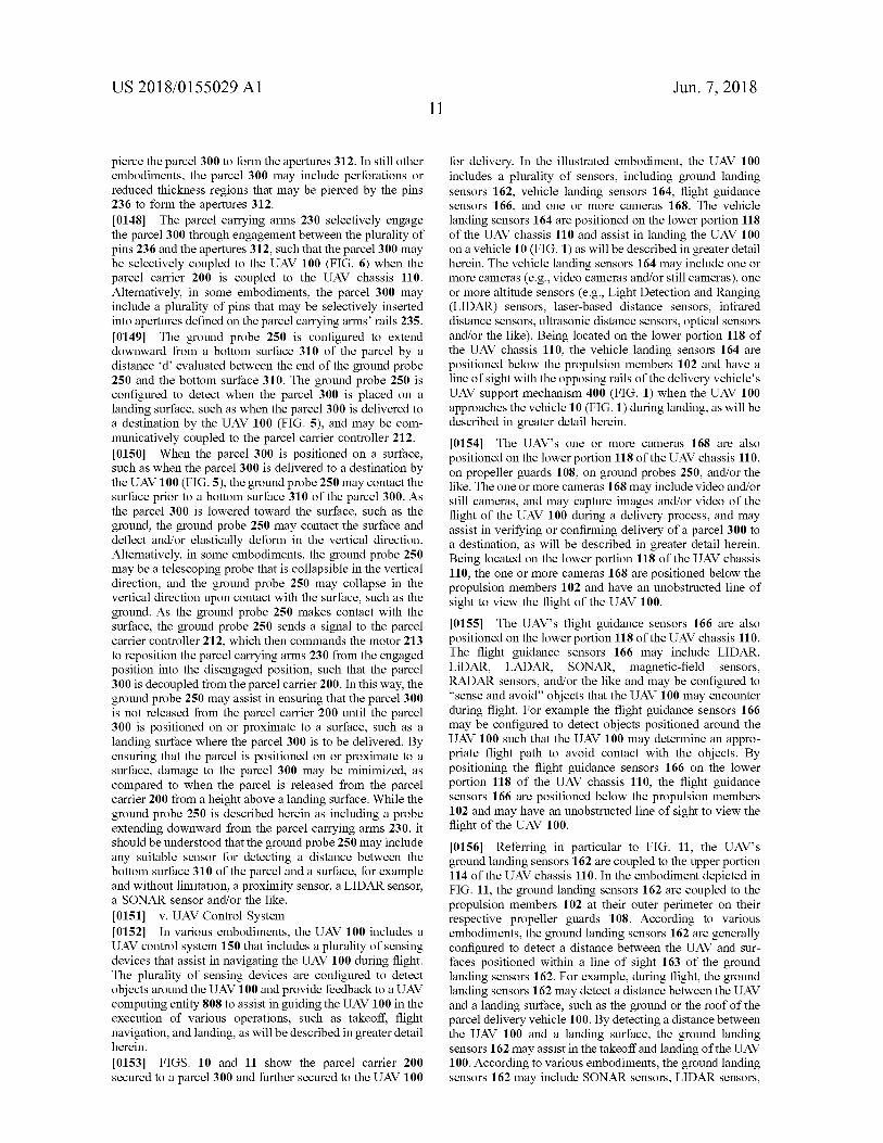
US 2018 / 0155029 A1 Jun . 7 , 2018
pierce the parcel 300 to form the apertures 312 . In still other embodiments , the parcel 300 may include perforations or reduced thickness regions that may be pierced by the pins 236 to form the apertures 312 . [ 0148 ] The parcel carrying arms 230 selectively engage the parcel 300 through engagement between the plurality of pins 236 and the apertures 312 , such that the parcel 300 may be selectively coupled to the UAV 100 ( FIG . 6 ) when the parcel carrier 200 is coupled to the UAV chassis 110 . Alternatively , in some embodiments , the parcel 300 may include a plurality of pins that may be selectively inserted into apertures defined on the parcel carrying arms ' rails 235 . [ 0149 ] The ground probe 250 is configured to extend downward from a bottom surface 310 of the parcel by a distance d ' evaluated between the end of the ground probe 250 and the bottom surface 310 . The ground probe 250 is configured to detect when the parcel 300 is placed on a landing surface , such as when the parcel 300 is delivered to a destination by the UAV 100 ( FIG . 5 ) , and may be com municatively coupled to the parcel carrier controller 212 . [ 0150 ] When the parcel 300 is positioned on a surface , such as when the parcel 300 is delivered to a destination by the UAV 100 ( FIG . 5 ) , the ground probe 250 may contact the surface prior to a bottom surface 310 of the parcel 300 . As the parcel 300 is lowered toward the surface , such as the ground , the ground probe 250 may contact the surface and deflect and / or elastically deform in the vertical direction . Alternatively , in some embodiments , the ground probe 250 may be a telescoping probe that is collapsible in the vertical direction , and the ground probe 250 may collapse in the vertical direction upon contact with the surface , such as the ground . As the ground probe 250 makes contact with the surface , the ground probe 250 sends a signal to the parcel carrier controller 212 , which then commands the motor 213 to reposition the parcel carrying arms 230 from the engaged position into the disengaged position , such that the parcel 300 is decoupled from the parcel carrier 200 . In this way , the ground probe 250 may assist in ensuring that the parcel 300 is not released from the parcel carrier 200 until the parcel 300 is positioned on or proximate to a surface , such as a landing surface where the parcel 300 is to be delivered . By ensuring that the parcel is positioned on or proximate to a surface , damage to the parcel 300 may be minimized , as compared to when the parcel is released from the parcel carrier 200 from a height above a landing surface . While the ground probe 250 is described herein as including a probe extending downward from the parcel carrying arms 230 , it should be understood that the ground probe 250 may include any suitable sensor for detecting a distance between the bottom surface 310 of the parcel and a surface , for example and without limitation , a proximity sensor , a LIDAR sensor , a SONAR sensor and / or the like . [ 0151 ] v . UAV Control System [ 0152 ] In various embodiments , the UAV 100 includes a UAV control system 150 that includes a plurality of sensing devices that assist in navigating the UAV 100 during flight . The plurality of sensing devices are configured to detect objects around the UAV 100 and provide feedback to a UAV computing entity 808 to assist in guiding the UAV 100 in the execution of various operations , such as takeoff , flight navigation , and landing , as will be described in greater detail herein . [ 0153 ] FIGS . 10 and 11 show the parcel carrier 200 secured to a parcel 300 and further secured to the UAV 100
for delivery . In the illustrated embodiment , the UAV 100 includes a plurality of sensors , including ground landing sensors 162 , vehicle landing sensors 164 , flight guidance sensors 166 , and one or more cameras 168 . The vehicle landing sensors 164 are positioned on the lower portion 118 of the UAV chassis 110 and assist in landing the UAV 100 on a vehicle 10 ( FIG . 1 ) as will be described in greater detail herein . The vehicle landing sensors 164 may include one or more cameras ( e . g . , video cameras and / or still cameras ) , one or more altitude sensors ( e . g . , Light Detection and Ranging ( LIDAR ) sensors , laser - based distance sensors , infrared distance sensors , ultrasonic distance sensors , optical sensors and / or the like ) . Being located on the lower portion 118 of the UAV chassis 110 , the vehicle landing sensors 164 are positioned below the propulsion members 102 and have a line of sight with the opposing rails of the delivery vehicle ' s UAV support mechanism 400 ( FIG . 1 ) when the UAV 100 approaches the vehicle 10 ( FIG . 1 ) during landing , as will be described in greater detail herein . [ 0154 ] The UAV ' s one or more cameras 168 are also positioned on the lower portion 118 of the UAV chassis 110 , on propeller guards 108 , on ground probes 250 , and / or the like . The one or more cameras 168 may include video and / or still cameras , and may capture images and / or video of the flight of the UAV 100 during a delivery process , and may assist in verifying or confirming delivery of a parcel 300 to a destination , as will be described in greater detail herein . Being located on the lower portion 118 of the UAV chassis 110 , the one or more cameras 168 are positioned below the propulsion members 102 and have an unobstructed line of sight to view the flight of the UAV 100 . ( 0155 ] The UAV ' s flight guidance sensors 166 are also positioned on the lower portion 118 of the UAV chassis 110 . The flight guidance sensors 166 may include LIDAR , LiDAR , LADAR , SONAR , magnetic - field sensors , RADAR sensors , and / or the like and may be configured to “ sense and avoid ” objects that the UAV 100 may encounter during flight . For example the flight guidance sensors 166 may be configured to detect objects positioned around the UAV 100 such that the UAV 100 may determine an appro priate flight path to avoid contact with the objects . By positioning the flight guidance sensors 166 on the lower portion 118 of the UAV chassis 110 , the flight guidance sensors 166 are positioned below the propulsion members 102 and may have an unobstructed line of sight to view the flight of the UAV 100 . [ 0156 ] Referring in particular to FIG . 11 , the UAV ' s ground landing sensors 162 are coupled to the upper portion 114 of the UAV chassis 110 . In the embodiment depicted in FIG . 11 , the ground landing sensors 162 are coupled to the propulsion members 102 at their outer perimeter on their respective propeller guards 108 . According to various embodiments , the ground landing sensors 162 are generally configured to detect a distance between the UAV and sur faces positioned within a line of sight 163 of the ground landing sensors 162 . For example , during flight , the ground landing sensors 162 may detect a distance between the UAV and a landing surface , such as the ground or the roof of the parcel delivery vehicle 100 . By detecting a distance between the UAV 100 and a landing surface , the ground landing sensors 162 may assist in the takeoff and landing of the UAV 100 . According to various embodiments , the ground landing sensors 162 may include SONAR sensors , LIDAR sensors ,
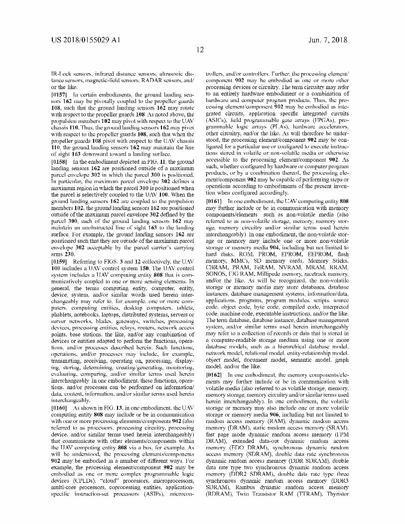
US 2018 / 0155029 A1 Jun . 7 , 2018 12
IR - Lock sensors , infrared distance sensors , ultrasonic dis tance sensors , magnetic field sensors , RADAR sensors , and / or the like . [ 0157 ] In certain embodiments , the ground landing sen sors 162 may be pivotally coupled to the propeller guards 108 , such that the ground landing sensors 162 may rotate with respect to the propeller guards 108 . As noted above , the propulsion members 102 may pivot with respect to the UAV chassis 110 . Thus , the ground landing sensors 162 may pivot with respect to the propeller guards 108 , such that when the propeller guards 108 pivot with respect to the UAV chassis 110 , the ground landing sensors 162 may maintain the line of sight 163 downward toward a landing surface . [ 0158 ] In the embodiment depicted in FIG . 11 , the ground landing sensors 162 are positioned outside of a maximum parcel envelope 302 in which the parcel 300 is positioned . In particular , the maximum parcel envelope 302 defines a maximum region in which the parcel 300 is positioned when the parcel is selectively coupled to the UAV 100 . When the ground landing sensors 162 are coupled to the propulsion members 102 , the ground landing sensors 162 are positioned outside of the maximum parcel envelope 302 defined by the parcel 300 , each of the ground landing sensors 162 may maintain an unobstructed line of sight 163 to the landing surface . For example , the ground landing sensors 162 are positioned such that they are outside of the maximum parcel envelope 302 acceptable by the parcel carrier ' s carrying arms 230 . [ 0159 ] Referring to FIGS . 3 and 12 collectively , the UAV 100 includes a UAV control system 150 . The UAV control system includes a UAV computing entity 808 that is com municatively coupled to one or more sensing elements . In general , the terms computing entity , computer , entity , device , system , and / or similar words used herein inter changeably may refer to , for example , one or more com puters , computing entities , desktop computers , tablets , phablets , notebooks , laptops , distributed systems , servers or server networks , blades , gateways , switches , processing devices , processing entities , relays , routers , network access points , base stations , the like , and / or any combination of devices or entities adapted to perform the functions , opera tions , and / or processes described herein . Such functions , operations , and / or processes may include , for example , transmitting , receiving , operating on , processing , display ing , storing , determining , creating / generating , monitoring , evaluating , comparing , and / or similar terms used herein interchangeably . In one embodiment , these functions , opera tions , and / or processes can be performed on information / data , content , information , and / or similar terms used herein interchangeably . [ 0160 ] As shown in FIG . 13 , in one embodiment , the UAV computing entity 808 may include or be in communication with one or more processing elements / components 902 ( also referred to as processors , processing circuitry , processing device , and / or similar terms used herein interchangeably ) that communicate with other elements / components within the UAV computing entity 808 via a bus , for example . As will be understood , the processing elements / components 902 may be embodied in a number of different ways . For example , the processing element / component 902 may be embodied as one or more complex programmable logic devices ( CPLDs ) , “ cloud ” processors , microprocessors , multi - core processors , coprocessing entities , application specific instruction - set processors ( ASIPs ) , microcon
trollers , and / or controllers . Further , the processing element / component 902 may be embodied as one or more other processing devices or circuitry . The term circuitry may refer to an entirely hardware embodiment or a combination of hardware and computer program products . Thus , the pro cessing element / component 902 may be embodied as inte grated circuits , application specific integrated circuits ( ASICs ) , field programmable gate arrays ( FPGAs ) , pro grammable logic arrays ( PLAS ) , hardware accelerators , other circuitry , and / or the like . As will therefore be under stood , the processing element / component 902 may be con figured for a particular use or configured to execute instruc tions stored in volatile or non - volatile media or otherwise accessible to the processing element / component 902 . As such , whether configured by hardware or computer program products , or by a combination thereof , the processing ele ment / component 902 may be capable of performing steps or operations according to embodiments of the present inven tion when configured accordingly . [ 0161 ] In one embodiment , the UAV computing entity 808 may further include or be in communication with memory components / elements — such as non - volatile media ( also referred to as non - volatile storage , memory , memory stor age , memory circuitry and / or similar terms used herein interchangeably ) . In one embodiment , the non - volatile stor age or memory may include one or more non - volatile storage or memory media 904 , including but not limited to hard disks , ROM , PROM , EPROM , EEPROM , flash memory , MMCs , SD memory cards , Memory Sticks , CBRAM , PRAM , FeRAM , NVRAM , MRAM , RRAM , SONOS , FJG RAM , Millipede memory , racetrack memory , and / or the like . As will be recognized , the non - volatile storage or memory media may store databases , database instances , database management systems , information / data , applications , programs , program modules , scripts , source code , object code , byte code , compiled code , interpreted code , machine code , executable instructions , and / or the like . The term database , database instance , database management system , and / or similar terms used herein interchangeably may refer to a collection of records or data that is stored in a computer - readable storage medium using one or more database models , such as a hierarchical database model , network model , relational model , entity - relationship model , object model , document model , semantic model , graph model , and / or the like . [ 0162 ] In one embodiment , the memory components / ele ments may further include or be in communication with volatile media ( also referred to as volatile storage , memory , memory storage , memory circuitry and / or similar terms used herein interchangeably ) . In one embodiment , the volatile storage or memory may also include one or more volatile storage or memory media 906 , including but not limited to random access memory ( RAM ) , dynamic random access memory ( DRAM ) , static random access memory ( SRAM ) , fast page mode dynamic random access memory ( FPM DRAM ) , extended data - out dynamic random access memory ( EDO DRAM ) , synchronous dynamic random access memory ( SDRAM ) , double data rate synchronous dynamic random access memory ( DDR SDRAM ) , double data rate type two synchronous dynamic random access memory ( DDR2 SDRAM ) , double data rate type three synchronous dynamic random access memory ( DDR3 SDRAM ) , Rambus dynamic random access memory ( RDRAM ) , Twin Transistor RAM ( TTRAM ) , Thyristor
US 2018 / 0155029 A1 Jun . 7 , 2018 13
RAM ( T - RAM ) , Zero - capacitor ( Z - RAM ) , Rambus in - line memory module ( RIMM ) , dual in - line memory module ( DIMM ) , single in - line memory module ( SIMM ) , video random access memory ( VRAM ) , cache memory ( including various levels ) , flash memory , register memory , and / or the like . As will be recognized , the volatile storage or memory media may be used to store at least portions of the databases , database instances , database management systems , informa tion / data , applications , programs , program modules , scripts , source code , object code , byte code , compiled code , inter preted code , machine code , executable instructions , and / or the like being executed by , for example , the processing element / component 902 . Thus , the databases , database instances , database management systems , information / data , applications , programs , program modules , scripts , source code , object code , byte code , compiled code , interpreted code , machine code , executable instructions , and / or the like may be used to control certain aspects of the operation of the UAV computing entity 808 with the assistance of the pro cessing element / component 902 and operating system . 10163 ] As indicated , in one embodiment , the central com puting entity 802 may also include one or more communi cations components / elements 908 for communicating with various computing entities , such as by communicating infor mation / data , content , information , and / or similar terms used herein interchangeably that can be transmitted , received , operated on , processed , displayed , stored , and / or the like . Such communication may be executed using a wired data transmission protocol , such as fiber distributed data interface ( FDDI ) , digital subscriber line ( DSL ) , Ethernet , asynchro nous transfer mode ( ATM ) , frame relay , data over cable service interface specification ( DOCSIS ) , or any other wired transmission protocol . Similarly , the central computing entity 802 may be configured to communicate via wireless external communication networks using any of a variety of protocols , such as general packet radio service ( GPRS ) , Universal Mobile Telecommunications System ( UMTS ) , Code Division Multiple Access 2000 ( CDMA2000 ) , CDMA2000 1x ( 1xRTT ) , Wideband Code Division Mul tiple Access ( WCDMA ) , Global System for Mobile Com munications ( GSM ) , Enhanced Data rates for GSM Evolu tion ( EDGE ) , Time Division - Synchronous Code Division Multiple Access ( TD - SCDMA ) , Long Term Evolution ( LTE ) , Evolved Universal Terrestrial Radio Access Network ( E - UTRAN ) , Evolution - Data Optimized ( EVDO ) , High Speed Packet Access ( HSPA ) , High - Speed Downlink Packet Access ( HSDPA ) , IEEE 802 . 11 ( Wi - Fi ) , Wi - Fi Direct , 802 . 16 ( WiMAX ) , ultra wideband ( UWB ) , infrared ( IR ) proto cols , near field communication ( NFC ) protocols , Wibree , Bluetooth protocols , wireless universal serial bus ( USB ) protocols , and / or any other wireless protocol . [ 0164 ] In embodiments , each of the ground landing sen sors 162 , the vehicle landing sensors 164 , the flight guidance sensors 166 , and the one or more cameras 168 are commu nicatively coupled to a UAV computing entity 808 , and in particular the processing component 902 of the UAV com puting entity 808 . The UAV computing entity 808 may send signals to and receive signals from the ground landing sensors 162 , the vehicle landing sensors 164 , the flight guidance sensors 166 , and the one or more cameras 168 . The UAV computing entity 808 is also communicatively coupled to the propulsion members 102 and may command the propulsion members 102 to rotate , and / or may command the
motorized joints 104 to pivot the propulsion members 102 to rotate about the joint axis 105 . [ 0165 ] Moreover , the UAV 100 may include GPS sensors and / or other satellite system sensors for detecting a current location of the UAV relative to an intended travel destination ( e . g . , a destination location and / or a vehicle ) . In various embodiments , the UAV control system 150 may comprise a communications port ( e . g . , 3G , 4G , 5G communication ports ) such that the UAV control system 150 may commu nicate with one or more additional computing entities . [ 0166 ] Referring to FIGS . 9 and 13 , collectively the parcel carrier controller 212 is schematically depicted . The parcel carrier controller 212 generally includes parcel carrier com puting entity 807 comprising a processing component 902 , a volatile memory 906 , a non - volatile memory 904 , and a communications component 908 , as described above with respect to the UAV computing entity 808 . As described above , the parcel carrier controller 212 is communicatively coupled to the motor 213 of the parcel carrier 200 , for example via the communications component 908 , and con trols operation of the motor 213 to move the parcel carrying arms 230 between the engaged position and the disengaged position . The parcel carrier controller 212 is also commu nicatively coupled to the ground probe 250 , for example via the communications component 908 , and may receive sig nals from the ground probe 250 indicating that the ground probe 250 has contacted a surface , such as a landing surface . Furthermore , the parcel carrier computing entity 807 may communicate with the UAV computing entity 808 via the communications component 908 and may exchange data / information with the UAV computing entity 808 , for example , a state of charge of the power supply 214 of the parcel carrier 200 . [ 0167 ] As described above , the communications compo nent 908 may include for communicating with various computing entities , such as by communicating information / data , content , information , and / or similar terms used herein interchangeably that can be transmitted , received , operated on , processed , displayed , stored , and / or the like . Such com munication may be executed using a wired data transmission protocol , such as FDDI , DSL , ATM , frame relay , DOCSIS , or any other wired transmission protocol . Similarly , the central computing entity 802 may be configured to commu nicate via wireless external communication networks using any of a variety of protocols , such as GPRS , UMTS , CDMA2000 , 1xRTT , WCDMA , GSM , EDGE , TD - SCDMA , LTE , E - UTRAN , EVDO , HSPA , HSDPA , Wi - Fi , Wi - Fi Direct , WiMAX , UWB , IR protocols , NFC protocols , Wibree , Bluetooth protocols , wireless USB pro tocols , and / or any other wireless protocol . [ 0168 ] vi . Further Embodiments of the UAV , Parcel Car rier , and Parcel [ 0169 ] As can be understood , various modifications and changes to the UAV 100 , the parcel carrier 200 , and the parcel 300 as described above in FIGS . 1 - 13 are contem plated . Description will now be made to various alternative embodiments for the UAV 100 , the parcel carrier 200 , and the parcel 300 . [ 0170 ] In some embodiments , the UAV 100 may include an independent UAV power source that provides power to the propulsion members 102 , and the parcel carrier 200 is used to couple the parcel 300 to the UAV chassis 110 . In other words , in some embodiments , the parcel carrier 200 may not include the power supply 214 and / or the power
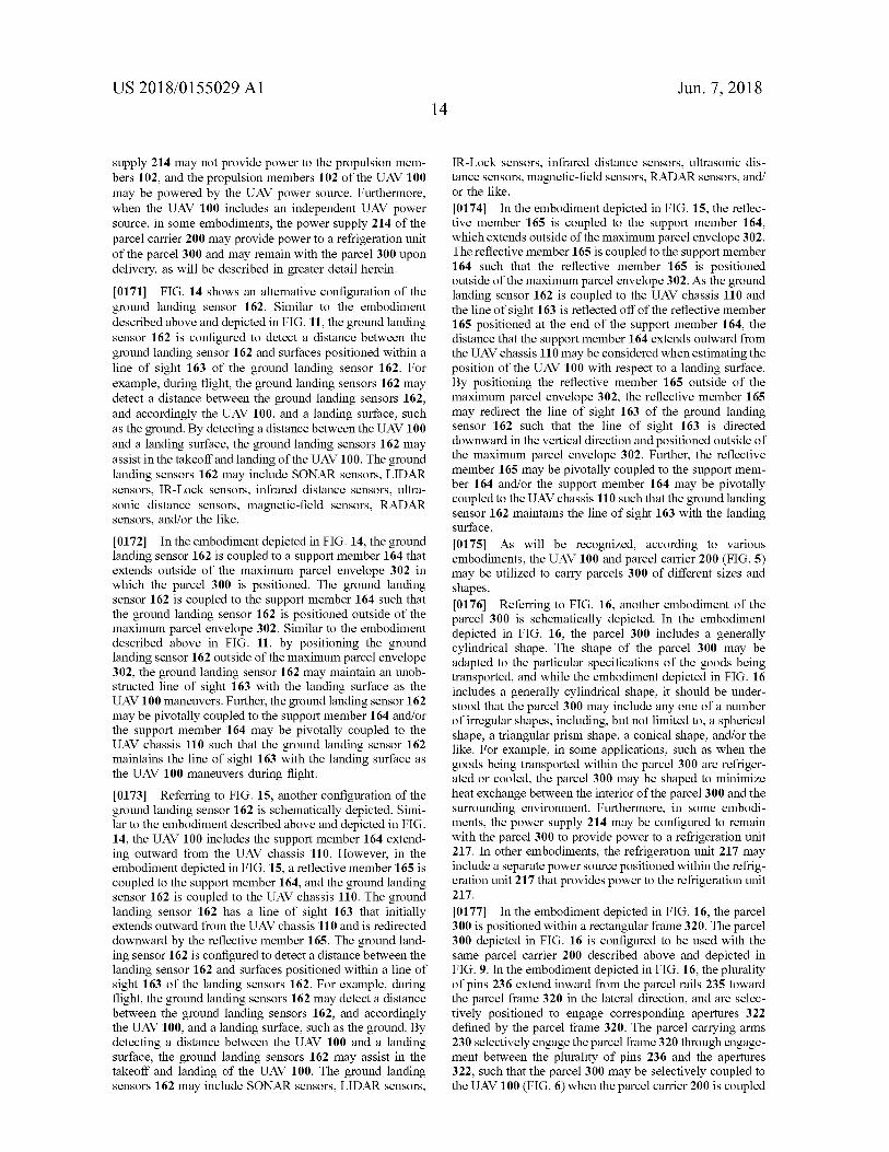
US 2018 / 0155029 A1 Jun . 7 , 2018 14
IR - Lock sensors , infrared distance sensors , ultrasonic dis tance sensors , magnetic - field sensors , RADAR sensors , and / or the like . [ 0174 ] In the embodiment depicted in FIG . 15 , the reflec tive member 165 is coupled to the support member 164 , which extends outside of the maximum parcel envelope 302 . The reflective member 165 is coupled to the support member 164 such that the reflective member 165 is positioned outside of the maximum parcel envelope 302 . As the ground landing sensor 162 is coupled to the UAV chassis 110 and the line of sight 163 is reflected off of the reflective member 165 positioned at the end of the support member 164 , the distance that the support member 164 extends outward from the UAV chassis 110 may be considered when estimating the position of the UAV 100 with respect to a landing surface . By positioning the reflective member 165 outside of the maximum parcel envelope 302 , the reflective member 165 may redirect the line of sight 163 of the ground landing sensor 162 such that the line of sight 163 is directed downward in the vertical direction and positioned outside of the maximum parcel envelope 302 . Further , the reflective member 165 may be pivotally coupled to the support mem ber 164 and / or the support member 164 may be pivotally coupled to the UAV chassis 110 such that the ground landing sensor 162 maintains the line of sight 163 with the landing surface . 101751 . As will be recognized , according to various embodiments , the UAV 100 and parcel carrier 200 ( FIG . 5 ) may be utilized to carry parcels 300 of different sizes and shapes .
supply 214 may not provide power to the propulsion mem bers 102 , and the propulsion members 102 of the UAV 100 may be powered by the UAV power source . Furthermore , when the UAV 100 includes an independent UAV power source , in some embodiments , the power supply 214 of the parcel carrier 200 may provide power to a refrigeration unit of the parcel 300 and may remain with the parcel 300 upon delivery , as will be described in greater detail herein . [ 0171 ] FIG . 14 shows an alternative configuration of the ground landing sensor 162 . Similar to the embodiment described above and depicted in FIG . 11 , the ground landing sensor 162 is configured to detect a distance between the ground landing sensor 162 and surfaces positioned within a line of sight 163 of the ground landing sensor 162 . For example , during flight , the ground landing sensors 162 may detect a distance between the ground landing sensors 162 , and accordingly the UAV 100 , and a landing surface , such as the ground . By detecting a distance between the UAV 100 and a landing surface , the ground landing sensors 162 may assist in the takeoff and landing of the UAV 100 . The ground landing sensors 162 may include SONAR sensors , LIDAR sensors , IR - Lock sensors , infrared distance sensors , ultra sonic distance sensors , magnetic - field sensors , RADAR sensors , and / or the like .
[ 0172 ] In the embodiment depicted in FIG . 14 , the ground landing sensor 162 is coupled to a support member 164 that extends outside of the maximum parcel envelope 302 in which the parcel 300 is positioned . The ground landing sensor 162 is coupled to the support member 164 such that the ground landing sensor 162 is positioned outside of the maximum parcel envelope 302 . Similar to the embodiment described above in FIG . 11 , by positioning the ground landing sensor 162 outside of the maximum parcel envelope 302 , the ground landing sensor 162 may maintain an unob structed line of sight 163 with the landing surface as the UAV 100 maneuvers . Further , the ground landing sensor 162 may be pivotally coupled to the support member 164 and / or the support member 164 may be pivotally coupled to the UAV chassis 110 such that the ground landing sensor 162 maintains the line of sight 163 with the landing surface as the UAV 100 maneuvers during flight . [ 0173 ] Referring to FIG . 15 , another configuration of the ground landing sensor 162 is schematically depicted . Simi lar to the embodiment described above and depicted in FIG . 14 , the UAV 100 includes the support member 164 extend ing outward from the UAV chassis 110 . However , in the embodiment depicted in FIG . 15 , a reflective member 165 is coupled to the support member 164 , and the ground landing sensor 162 is coupled to the UAV chassis 110 . The ground landing sensor 162 has a line of sight 163 that initially extends outward from the UAV chassis 110 and is redirected downward by the reflective member 165 . The ground land ing sensor 162 is configured to detect a distance between the landing sensor 162 and surfaces positioned within a line of sight 163 of the landing sensors 162 . For example , during flight , the ground landing sensors 162 may detect a distance between the ground landing sensors 162 , and accordingly the UAV 100 , and a landing surface , such as the ground . By detecting a distance between the UAV 100 and a landing surface , the ground landing sensors 162 may assist in the takeoff and landing of the UAV 100 . The ground landing sensors 162 may include SONAR sensors , LIDAR sensors ,
[ 0176 ] Referring to FIG . 16 , another embodiment of the parcel 300 is schematically depicted . In the embodiment depicted in FIG . 16 , the parcel 300 includes a generally cylindrical shape . The shape of the parcel 300 may be adapted to the particular specifications of the goods being transported , and while the embodiment depicted in FIG . 16 includes a generally cylindrical shape , it should be under stood that the parcel 300 may include any one of a number of irregular shapes , including , but not limited to , a spherical shape , a triangular prism shape , a conical shape , and / or the like . For example , in some applications , such as when the goods being transported within the parcel 300 are refriger ated or cooled , the parcel 300 may be shaped to minimize heat exchange between the interior of the parcel 300 and the surrounding environment . Furthermore , in some embodi ments , the power supply 214 may be configured to remain with the parcel 300 to provide power to a refrigeration unit 217 . In other embodiments , the refrigeration unit 217 may include a separate power source positioned within the refrig eration unit 217 that provides power to the refrigeration unit 217 . [ 0177 ] In the embodiment depicted in FIG . 16 , the parcel 300 is positioned within a rectangular frame 320 . The parcel 300 depicted in FIG . 16 is configured to be used with the same parcel carrier 200 described above and depicted in FIG . 9 . In the embodiment depicted in FIG . 16 , the plurality of pins 236 extend inward from the parcel rails 235 toward the parcel frame 320 in the lateral direction , and are selec tively positioned to engage corresponding apertures 322 defined by the parcel frame 320 . The parcel carrying arms 230 selectively engage the parcel frame 320 through engage ment between the plurality of pins 236 and the apertures 322 , such that the parcel 300 may be selectively coupled to the UAV 100 ( FIG . 6 ) when the parcel carrier 200 is coupled
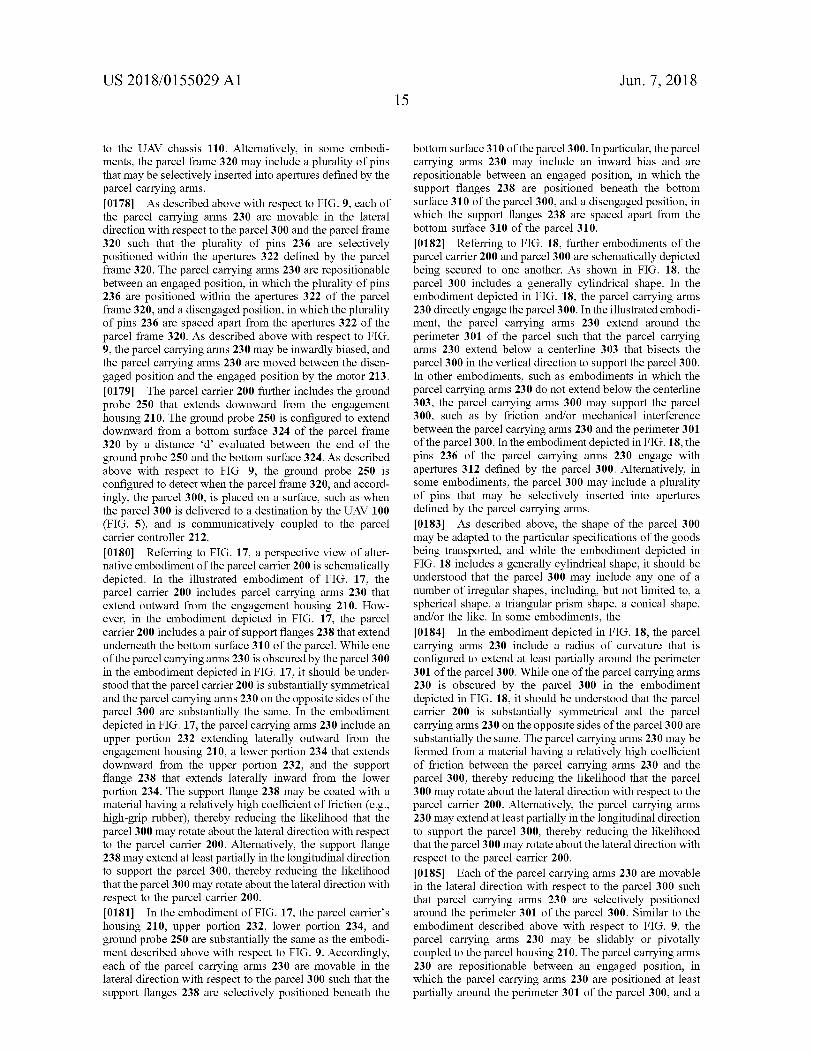
US 2018 / 0155029 A1 Jun . 7 , 2018
to the UAV chassis 110 . Alternatively , in some embodi - ments , the parcel frame 320 may include a plurality of pins that may be selectively inserted into apertures defined by the parcel carrying arms . [ 0178 ] As described above with respect to FIG . 9 , each of the parcel carrying arms 230 are movable in the lateral direction with respect to the parcel 300 and the parcel frame 320 such that the plurality of pins 236 are selectively positioned within the apertures 322 defined by the parcel frame 320 . The parcel carrying arms 230 are repositionable between an engaged position , in which the plurality of pins 236 are positioned within the apertures 322 of the parcel frame 320 , and a disengaged position , in which the plurality of pins 236 are spaced apart from the apertures 322 of the parcel frame 320 . As described above with respect to FIG . 9 , the parcel carrying arms 230 may be inwardly biased , and the parcel carrying arms 230 are moved between the disen gaged position and the engaged position by the motor 213 . [ 0179 ] The parcel carrier 200 further includes the ground probe 250 that extends downward from the engagement housing 210 . The ground probe 250 is configured to extend downward from a bottom surface 324 of the parcel frame 320 by a distance d ' evaluated between the end of the ground probe 250 and the bottom surface 324 . As described above with respect to FIG . 9 , the ground probe 250 is configured to detect when the parcel frame 320 , and accord ingly , the parcel 300 , is placed on a surface , such as when the parcel 300 is delivered to a destination by the UAV 100 ( FIG . 5 ) , and is communicatively coupled to the parcel carrier controller 212 . [ 0180 ] Referring to FIG . 17 , a perspective view of alter native embodiment of the parcel carrier 200 is schematically depicted . In the illustrated embodiment of FIG . 17 , the parcel carrier 200 includes parcel carrying arms 230 that extend outward from the engagement housing 210 . How ever , in the embodiment depicted in FIG . 17 , the parcel carrier 200 includes a pair of support flanges 238 that extend underneath the bottom surface 310 of the parcel . While one of the parcel carrying arms 230 is obscured by the parcel 300 in the embodiment depicted in FIG . 17 , it should be under stood that the parcel carrier 200 is substantially symmetrical and the parcel carrying arms 230 on the opposite sides of the parcel 300 are substantially the same . In the embodiment depicted in FIG . 17 , the parcel carrying arms 230 include an upper portion 232 extending laterally outward from the engagement housing 210 , a lower portion 234 that extends downward from the upper portion 232 , and the support flange 238 that extends laterally inward from the lower portion 234 . The support flange 238 may be coated with a material having a relatively high coefficient of friction ( e . g . , high - grip rubber ) , thereby reducing the likelihood that the parcel 300 may rotate about the lateral direction with respect to the parcel carrier 200 . Alternatively , the support flange 238 may extend at least partially in the longitudinal direction to support the parcel 300 , thereby reducing the likelihood that the parcel 300 may rotate about the lateral direction with respect to the parcel carrier 200 . [ 0181 ] In the embodiment of FIG . 17 , the parcel carrier ' s housing 210 , upper portion 232 , lower portion 234 , and ground probe 250 are substantially the same as the embodi ment described above with respect to FIG . 9 . Accordingly , each of the parcel carrying arms 230 are movable in the lateral direction with respect to the parcel 300 such that the support flanges 238 are selectively positioned beneath the
bottom surface 310 of the parcel 300 . In particular , the parcel carrying arms 230 may include an inward bias and are repositionable between an engaged position , in which the support flanges 238 are positioned beneath the bottom surface 310 of the parcel 300 , and a disengaged position , in which the support flanges 238 are spaced apart from the bottom surface 310 of the parcel 310 . [ 0182 ] Referring to FIG . 18 , further embodiments of the parcel carrier 200 and parcel 300 are schematically depicted being secured to one another . As shown in FIG . 18 , the parcel 300 includes a generally cylindrical shape . In the embodiment depicted in FIG . 18 , the parcel carrying arms 230 directly engage the parcel 300 . In the illustrated embodi ment , the parcel carrying arms 230 extend around the perimeter 301 of the parcel such that the parcel carrying arms 230 extend below a centerline 303 that bisects the parcel 300 in the vertical direction to support the parcel 300 . In other embodiments , such as embodiments in which the parcel carrying arms 230 do not extend below the centerline 303 , the parcel carrying arms 300 may support the parcel 300 , such as by friction and / or mechanical interference between the parcel carrying arms 230 and the perimeter 301 of the parcel 300 . In the embodiment depicted in FIG . 18 , the pins 236 of the parcel carrying arms 230 engage with apertures 312 defined by the parcel 300 . Alternatively , in some embodiments , the parcel 300 may include a plurality of pins that may be selectively inserted into apertures defined by the parcel carrying arms . [ 0183 ] As described above , the shape of the parcel 300 may be adapted to the particular specifications of the goods being transported , and while the embodiment depicted in FIG . 18 includes a generally cylindrical shape , it should be understood that the parcel 300 may include any one of a number of irregular shapes , including , but not limited to , a spherical shape , a triangular prism shape , a conical shape , and / or the like . In some embodiments , the [ 0184 ] In the embodiment depicted in FIG . 18 , the parcel carrying arms 230 include a radius of curvature that is configured to extend at least partially around the perimeter 301 of the parcel 300 . While one of the parcel carrying arms 230 is obscured by the parcel 300 in the embodiment depicted in FIG . 18 , it should be understood that the parcel carrier 200 is substantially symmetrical and the parcel carrying arms 230 on the opposite sides of the parcel 300 are substantially the same . The parcel carrying arms 230 may be formed from a material having a relatively high coefficient of friction between the parcel carrying arms 230 and the parcel 300 , thereby reducing the likelihood that the parcel 300 may rotate about the lateral direction with respect to the parcel carrier 200 . Alternatively , the parcel carrying arms 230 may extend at least partially in the longitudinal direction to support the parcel 300 , thereby reducing the likelihood that the parcel 300 may rotate about the lateral direction with respect to the parcel carrier 200 . [ 0185 ] Each of the parcel carrying arms 230 are movable in the lateral direction with respect to the parcel 300 such that parcel carrying arms 230 are selectively positioned around the perimeter 301 of the parcel 300 . Similar to the embodiment described above with respect to FIG . 9 , the parcel carrying arms 230 may be slidably or pivotally coupled to the parcel housing 210 . The parcel carrying arms 230 are repositionable between an engaged position , in which the parcel carrying arms 230 are positioned at least partially around the perimeter 301 of the parcel 300 , and a
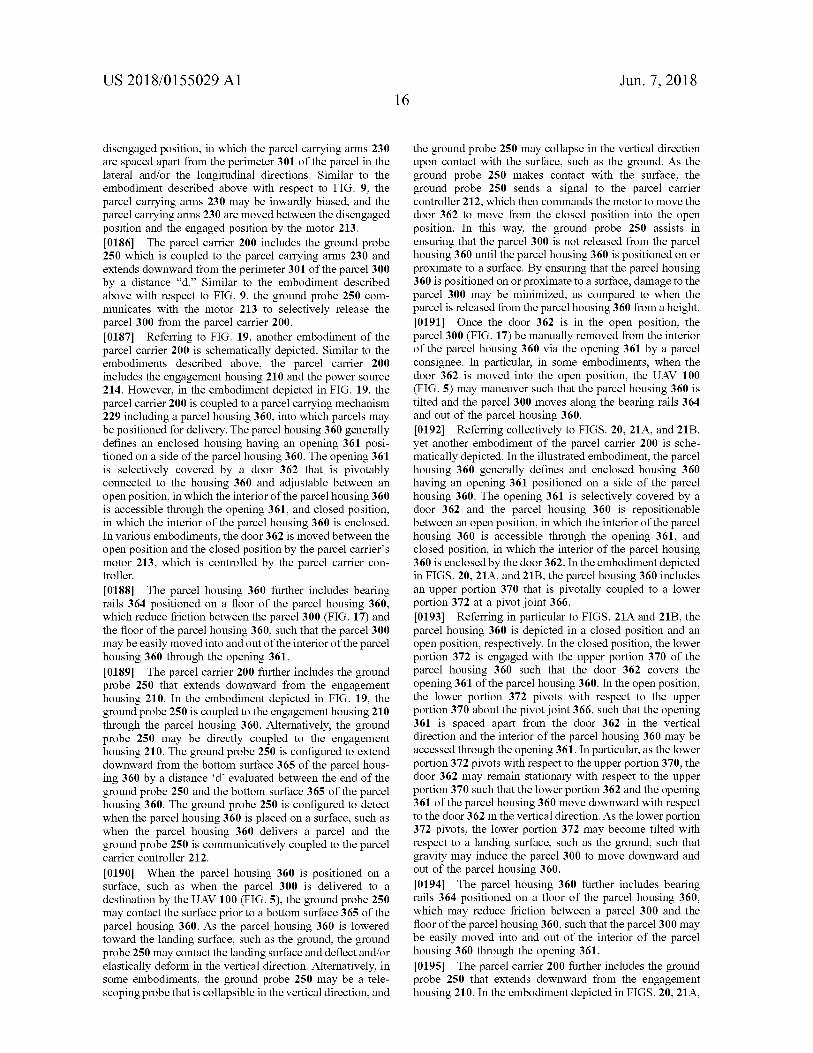
US 2018 / 0155029 A1 Jun . 7 , 2018
disengaged position , in which the parcel carrying arms 230 are spaced apart from the perimeter 301 of the parcel in the lateral and / or the longitudinal directions . Similar to the embodiment described above with respect to FIG . 9 , the parcel carrying arms 230 may be inwardly biased , and the parcel carrying arms 230 are moved between the disengaged position and the engaged position by the motor 213 . [ 0186 ] The parcel carrier 200 includes the ground probe 250 which is coupled to the parcel carrying arms 230 and extends downward from the perimeter 301 of the parcel 300 by a distance “ d . ” Similar to the embodiment described above with respect to FIG . 9 , the ground probe 250 com - municates with the motor 213 to selectively release the parcel 300 from the parcel carrier 200 . [ 0187 ] Referring to FIG . 19 , another embodiment of the parcel carrier 200 is schematically depicted . Similar to the embodiments described above , the parcel carrier 200 includes the engagement housing 210 and the power source 214 . However , in the embodiment depicted in FIG . 19 , the parcel carrier 200 is coupled to a parcel carrying mechanism 229 including a parcel housing 360 , into which parcels may be positioned for delivery . The parcel housing 360 generally defines an enclosed housing having an opening 361 posi tioned on a side of the parcel housing 360 . The opening 361 is selectively covered by a door 362 that is pivotably connected to the housing 360 and adjustable between an open position , in which the interior of the parcel housing 360 is accessible through the opening 361 , and closed position , in which the interior of the parcel housing 360 is enclosed . In various embodiments , the door 362 is moved between the open position and the closed position by the parcel carrier ' s motor 213 , which is controlled by the parcel carrier con troller . [ 0188 ] The parcel housing 360 further includes bearing rails 364 positioned on a floor of the parcel housing 360 , which reduce friction between the parcel 300 ( FIG . 17 ) and the floor of the parcel housing 360 , such that the parcel 300 may be easily moved into and out of the interior of the parcel housing 360 through the opening 361 . [ 0189 ] The parcel carrier 200 further includes the ground probe 250 that extends downward from the engagement housing 210 . In the embodiment depicted in FIG . 19 , the ground probe 250 is coupled to the engagement housing 210 through the parcel housing 360 . Alternatively , the ground probe 250 may be directly coupled to the engagement housing 210 . The ground probe 250 is configured to extend downward from the bottom surface 365 of the parcel hous ing 360 by a distance ' d ' evaluated between the end of the ground probe 250 and the bottom surface 365 of the parcel housing 360 . The ground probe 250 is configured to detect when the parcel housing 360 is placed on a surface , such as when the parcel housing 360 delivers a parcel and the ground probe 250 is communicatively coupled to the parcel carrier controller 212 . [ 0190 ] When the parcel housing 360 is positioned on a surface , such as when the parcel 300 is delivered to a destination by the UAV 100 ( FIG . 5 ) , the ground probe 250 may contact the surface prior to a bottom surface 365 of the parcel housing 360 . As the parcel housing 360 is lowered toward the landing surface , such as the ground , the ground probe 250 may contact the landing surface and deflect and / or elastically deform in the vertical direction . Alternatively , in some embodiments , the ground probe 250 may be a tele - scoping probe that is collapsible in the vertical direction , and
the ground probe 250 may collapse in the vertical direction upon contact with the surface , such as the ground . As the ground probe 250 makes contact with the surface , the ground probe 250 sends a signal to the parcel carrier controller 212 , which then commands the motor to move the door 362 to move from the closed position into the open position . In this way , the ground probe 250 assists in ensuring that the parcel 300 is not released from the parcel housing 360 until the parcel housing 360 is positioned on or proximate to a surface . By ensuring that the parcel housing 360 is positioned on or proximate to a surface , damage to the parcel 300 may be minimized , as compared to when the parcel is released from the parcel housing 360 from a height . [ 0191 ] Once the door 362 is in the open position , the parcel 300 ( FIG . 17 ) be manually removed from the interior of the parcel housing 360 via the opening 361 by a parcel consignee . In particular , in some embodiments , when the door 362 is moved into the open position , the UAV 100 ( FIG . 5 ) may maneuver such that the parcel housing 360 is tilted and the parcel 300 moves along the bearing rails 364 and out of the parcel housing 360 . [ 0192 ] Referring collectively to FIGS . 20 , 21A , and 21B , yet another embodiment of the parcel carrier 200 is sche matically depicted . In the illustrated embodiment , the parcel housing 360 generally defines and enclosed housing 360 having an opening 361 positioned on a side of the parcel housing 360 . The opening 361 is selectively covered by a door 362 and the parcel housing 360 is repositionable between an open position , in which the interior of the parcel housing 360 is accessible through the opening 361 , and closed position , in which the interior of the parcel housing 360 is enclosed by the door 362 . In the embodiment depicted in FIGS . 20 , 21A , and 21B , the parcel housing 360 includes an upper portion 370 that is pivotally coupled to a lower portion 372 at a pivot joint 366 . [ 0193 ] Referring in particular to FIGS . 21A and 21B , the parcel housing 360 is depicted in a closed position and an open position , respectively . In the closed position , the lower portion 372 is engaged with the upper portion 370 of the parcel housing 360 such that the door 362 covers the opening 361 of the parcel housing 360 . In the open position , the lower portion 372 pivots with respect to the upper portion 370 about the pivot joint 366 , such that the opening 361 is spaced apart from the door 362 in the vertical direction and the interior of the parcel housing 360 may be accessed through the opening 361 . In particular , as the lower portion 372 pivots with respect to the upper portion 370 , the door 362 may remain stationary with respect to the upper portion 370 such that the lower portion 362 and the opening 361 of the parcel housing 360 move downward with respect to the door 362 in the vertical direction . As the lower portion 372 pivots , the lower portion 372 may become tilted with respect to a landing surface , such as the ground , such that gravity may induce the parcel 300 to move downward and out of the parcel housing 360 . [ 0194 ] The parcel housing 360 further includes bearing rails 364 positioned on a floor of the parcel housing 360 , which may reduce friction between a parcel 300 and the floor of the parcel housing 360 , such that the parcel 300 may be easily moved into and out of the interior of the parcel housing 360 through the opening 361 . [ 0195 ] The parcel carrier 200 further includes the ground probe 250 that extends downward from the engagement housing 210 . In the embodiment depicted in FIGS . 20 , 21A ,
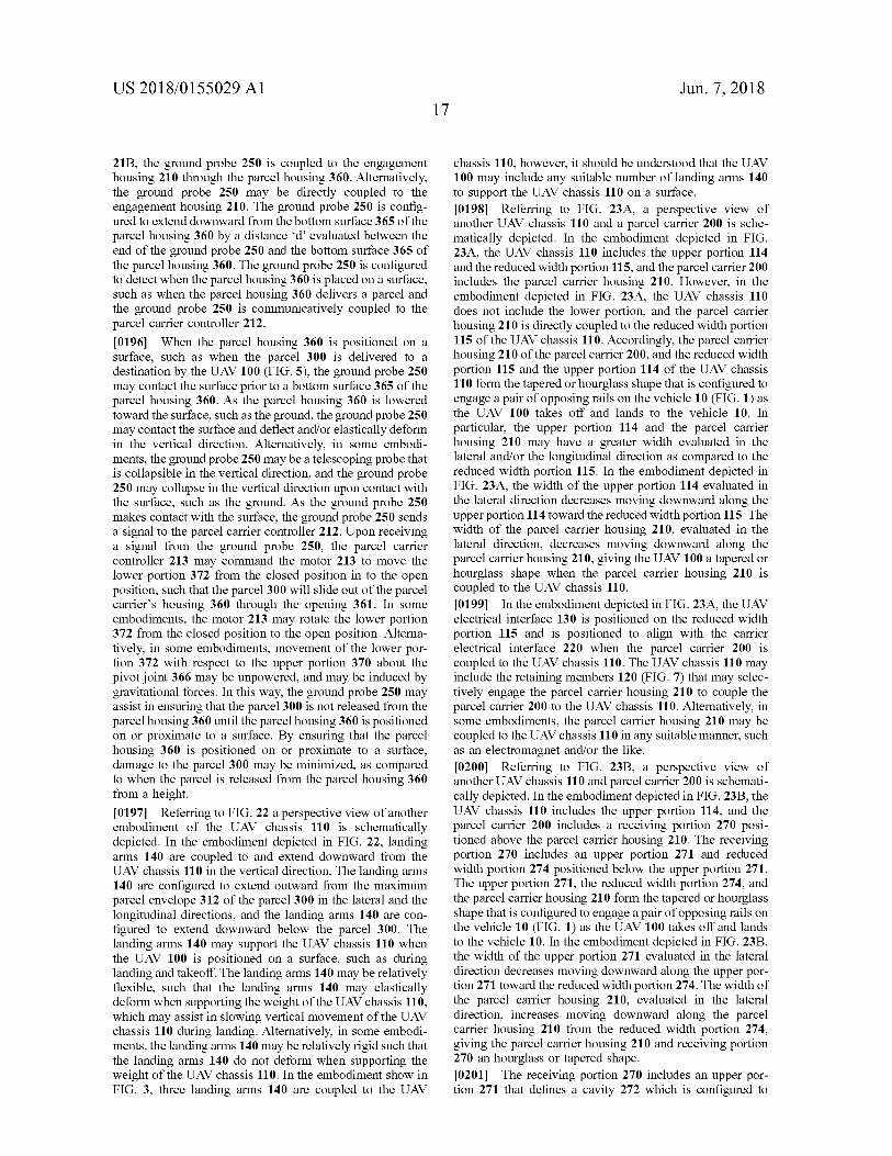
US 2018 / 0155029 A1 Jun . 7 , 2018 17
21B , the ground probe 250 is coupled to the engagement housing 210 through the parcel housing 360 . Alternatively , the ground probe 250 may be directly coupled to the engagement housing 210 . The ground probe 250 is config ured to extend downward from the bottom surface 365 of the parcel housing 360 by a distance ' d ' evaluated between the end of the ground probe 250 and the bottom surface 365 of the parcel housing 360 . The ground probe 250 is configured to detect when the parcel housing 360 is placed on a surface , such as when the parcel housing 360 delivers a parcel and the ground probe 250 is communicatively coupled to the parcel carrier controller 212 . [ 0196 ] When the parcel housing 360 is positioned on a surface , such as when the parcel 300 is delivered to a destination by the UAV 100 ( FIG . 5 ) , the ground probe 250 may contact the surface prior to a bottom surface 365 of the parcel housing 360 . As the parcel housing 360 is lowered toward the surface , such as the ground , the ground probe 250 may contact the surface and deflect and / or elastically deform in the vertical direction . Alternatively , in some embodi ments , the ground probe 250 may be a telescoping probe that is collapsible in the vertical direction , and the ground probe 250 may collapse in the vertical direction upon contact with the surface , such as the ground . As the ground probe 250 makes contact with the surface , the ground probe 250 sends a signal to the parcel carrier controller 212 . Upon receiving a signal from the ground probe 250 , the parcel carrier controller 213 may command the motor 213 to move the lower portion 372 from the closed position in to the open position , such that the parcel 300 will slide out of the parcel carrier ' s housing 360 through the opening 361 . In some embodiments , the motor 213 may rotate the lower portion 372 from the closed position to the open position . Alterna tively , in some embodiments , movement of the lower por tion 372 with respect to the upper portion 370 about the pivot joint 366 may be unpowered , and may be induced by gravitational forces . In this way , the ground probe 250 may assist in ensuring that the parcel 300 is not released from the parcel housing 360 until the parcel housing 360 is positioned on or proximate to a surface . By ensuring that the parcel housing 360 is positioned on or proximate to a surface , damage to the parcel 300 may be minimized , as compared to when the parcel is released from the parcel housing 360 from a height . [ 0197 ] Referring to FIG . 22 a perspective view of another embodiment of the UAV chassis 110 is schematically depicted . In the embodiment depicted in FIG . 22 , landing arms 140 are coupled to and extend downward from the UAV chassis 110 in the vertical direction . The landing arms 140 are configured to extend outward from the maximum parcel envelope 312 of the parcel 300 in the lateral and the longitudinal directions , and the landing arms 140 are con figured to extend downward below the parcel 300 . The landing arms 140 may support the UAV chassis 110 when the UAV 100 is positioned on a surface , such as during landing and takeoff . The landing arms 140 may be relatively flexible , such that the landing arms 140 may elastically deform when supporting the weight of the UAV chassis 110 , which may assist in slowing vertical movement of the UAV chassis 110 during landing . Alternatively , in some embodi ments , the landing arms 140 may be relatively rigid such that the landing arms 140 do not deform when supporting the weight of the UAV chassis 110 . In the embodiment show in FIG . 3 , three landing arms 140 are coupled to the UAV
chassis 110 , however , it should be understood that the UAV 100 may include any suitable number of landing arms 140 to support the UAV chassis 110 on a surface . [ 0198 ] Referring to FIG . 23A , a perspective view of another UAV chassis 110 and a parcel carrier 200 is sche matically depicted . In the embodiment depicted in FIG . 23A , the UAV chassis 110 includes the upper portion 114 and the reduced width portion 115 , and the parcel carrier 200 includes the parcel carrier housing 210 . However , in the embodiment depicted in FIG . 23A , the UAV chassis 110 does not include the lower portion , and the parcel carrier housing 210 is directly coupled to the reduced width portion 115 of the UAV chassis 110 . Accordingly , the parcel carrier housing 210 of the parcel carrier 200 , and the reduced width portion 115 and the upper portion 114 of the UAV chassis 110 form the tapered or hourglass shape that is configured to engage a pair of opposing rails on the vehicle 10 ( FIG . 1 ) as the UAV 100 takes off and lands to the vehicle 10 . In particular , the upper portion 114 and the parcel carrier housing 210 may have a greater width evaluated in the lateral and / or the longitudinal direction as compared to the reduced width portion 115 . In the embodiment depicted in FIG . 23A , the width of the upper portion 114 evaluated in the lateral direction decreases moving downward along the upper portion 114 toward the reduced width portion 115 . The width of the parcel carrier housing 210 , evaluated in the lateral direction , decreases moving downward along the parcel carrier housing 210 , giving the UAV 100 a tapered or hourglass shape when the parcel carrier housing 210 is coupled to the UAV chassis 110 . [ 0199 ] In the embodiment depicted in FIG . 23A , the UAV electrical interface 130 is positioned on the reduced width portion 115 and is positioned to align with the carrier electrical interface 220 when the parcel carrier 200 is coupled to the UAV chassis 110 . The UAV chassis 110 may include the retaining members 120 ( FIG . 7 ) that may selec tively engage the parcel carrier housing 210 to couple the parcel carrier 200 to the UAV chassis 110 . Alternatively , in some embodiments , the parcel carrier housing 210 may be coupled to the UAV chassis 110 in any suitable manner , such as an electromagnet and / or the like . [ 0200 ] Referring to FIG . 23B , a perspective view of another UAV chassis 110 and parcel carrier 200 is schemati cally depicted . In the embodiment depicted in FIG . 23B , the UAV chassis 110 includes the upper portion 114 , and the parcel carrier 200 includes a receiving portion 270 posi tioned above the parcel carrier housing 210 . The receiving portion 270 includes an upper portion 271 and reduced width portion 274 positioned below the upper portion 271 . The upper portion 271 , the reduced width portion 274 , and the parcel carrier housing 210 form the tapered or hourglass shape that is configured to engage a pair of opposing rails on the vehicle 10 ( FIG . 1 ) as the UAV 100 takes off and lands to the vehicle 10 . In the embodiment depicted in FIG . 23B , the width of the upper portion 271 evaluated in the lateral direction decreases moving downward along the upper por tion 271 toward the reduced width portion 274 . The width of the parcel carrier housing 210 , evaluated in the lateral direction , increases moving downward along the parcel carrier housing 210 from the reduced width portion 274 , giving the parcel carrier housing 210 and receiving portion 270 an hourglass or tapered shape . [ 0201 ] The receiving portion 270 includes an upper por tion 271 that defines a cavity 272 which is configured to
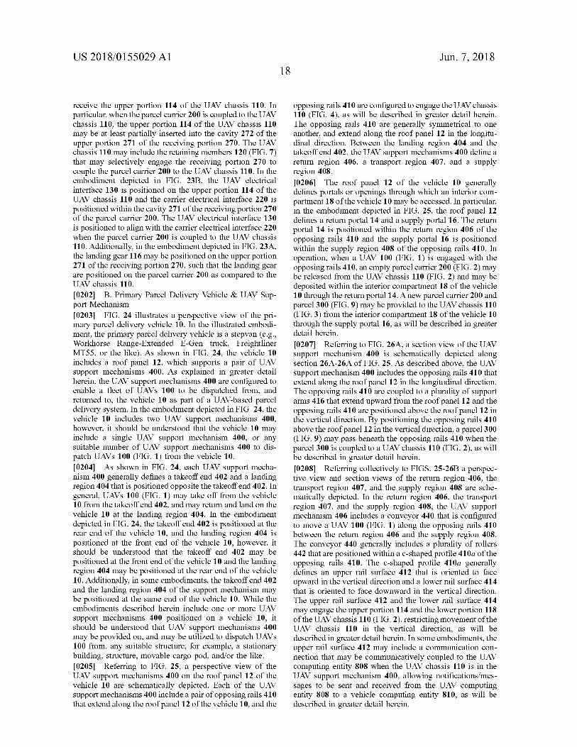
US 2018 / 0155029 A1 Jun . 7 , 2018
receive the upper portion 114 of the UAV chassis 110 . In particular , when the parcel carrier 200 is coupled to the UAV chassis 110 , the upper portion 114 of the UAV chassis 110 may be at least partially inserted into the cavity 272 of the upper portion 271 of the receiving portion 270 . The UAV chassis 110 may include the retaining members 120 ( FIG . 7 ) that may selectively engage the receiving portion 270 to couple the parcel carrier 200 to the UAV chassis 110 . In the embodiment depicted in FIG . 23B , the UAV electrical interface 130 is positioned on the upper portion 114 of the UAV chassis 110 and the carrier electrical interface 220 is positioned within the cavity 271 of the receiving portion 270 of the parcel carrier 200 . The UAV electrical interface 130 is positioned to align with the carrier electrical interface 220 when the parcel carrier 200 is coupled to the UAV chassis 110 . Additionally , in the embodiment depicted in FIG . 23A , the landing gear 116 may be positioned on the upper portion 271 of the receiving portion 270 , such that the landing gear are positioned on the parcel carrier 200 as compared to the UAV chassis 110 . [ 0202 ] B . Primary Parcel Delivery Vehicle & UAV Sup port Mechanism [ 0203 ] FIG . 24 illustrates a perspective view of the pri mary parcel delivery vehicle 10 . In the illustrated embodi ment , the primary parcel delivery vehicle is a stepvan ( e . g . , Workhorse Range - Extended E - Gen truck , Freightliner MT55 , or the like ) . As shown in FIG . 24 , the vehicle 10 includes a roof panel 12 , which supports a pair of UAV support mechanisms 400 . As explained in greater detail herein , the UAV support mechanisms 400 are configured to enable a fleet of UAVs 100 to be dispatched from , and returned to , the vehicle 10 as part of a UAV - based parcel delivery system . In the embodiment depicted in FIG . 24 , the vehicle 10 includes two UAV support mechanisms 400 , however , it should be understood that the vehicle 10 may include a single UAV support mechanism 400 , or any suitable number of UAV support mechanisms 400 to dis patch UAVs 100 ( FIG . 1 ) from the vehicle 10 . [ 0204 ] As shown in FIG . 24 , each UAV support mecha nism 400 generally defines a takeoff end 402 and a landing region 404 that is positioned opposite the takeoff end 402 . In general , UAVs 100 ( FIG . 1 ) may take off from the vehicle 10 from the takeoff end 402 , and may return and land on the vehicle 10 at the landing region 404 . In the embodiment depicted in FIG . 24 , the takeoff end 402 is positioned at the rear end of the vehicle 10 , and the landing region 404 is positioned at the front end of the vehicle 10 , however , it should be understood that the takeoff end 402 may be positioned at the front end of the vehicle 10 and the landing region 404 may be positioned at the rear end of the vehicle 10 . Additionally , in some embodiments , the takeoff end 402 and the landing region 404 of the support mechanism may be positioned at the same end of the vehicle 10 . While the embodiments described herein include one or more UAV support mechanisms 400 positioned on a vehicle 10 , it should be understood that UAV support mechanisms 400 may be provided on , and may be utilized to dispatch UAVs 100 from , any suitable structure , for example , a stationary building , structure , movable cargo pod , and / or the like . [ 0205 ] Referring to FIG . 25 , a perspective view of the UAV support mechanisms 400 on the roof panel 12 of the vehicle 10 are schematically depicted . Each of the UAV support mechanisms 400 include a pair of opposing rails 410 that extend along the roof panel 12 of the vehicle 10 , and the
opposing rails 410 are configured to engage the UAV chassis 110 ( FIG . 4 ) , as will be described in greater detail herein . The opposing rails 410 are generally symmetrical to one another , and extend along the roof panel 12 in the longitu dinal direction . Between the landing region 404 and the takeoff end 402 , the UAV support mechanisms 400 define a return region 406 , a transport region 407 , and a supply region 408 . [ 0206 ] The roof panel 12 of the vehicle 10 generally defines portals or openings through which an interior com partment 18 of the vehicle 10 may be accessed . In particular , in the embodiment depicted in FIG . 25 , the roof panel 12 defines a return portal 14 and a supply portal 16 . The return portal 14 is positioned within the return region 406 of the opposing rails 410 and the supply portal 16 is positioned within the supply region 408 of the opposing rails 410 . In operation , when a UAV 100 ( FIG . 1 ) is engaged with the opposing rails 410 , an empty parcel carrier 200 ( FIG . 2 ) may be released from the UAV chassis 110 ( FIG . 2 ) and may be deposited within the interior compartment 18 of the vehicle 10 through the return portal 14 . A new parcel carrier 200 and parcel 300 ( FIG . 9 ) may be provided to the UAV chassis 110 ( FIG . 3 ) from the interior compartment 18 of the vehicle 10 through the supply portal 16 , as will be described in greater detail herein . [ 0207 ] Referring to FIG . 26A , a section view of the UAV support mechanism 400 is schematically depicted along section 26A - 26A of FIG . 25 . As described above , the UAV support mechanism 400 includes the opposing rails 410 that extend along the roof panel 12 in the longitudinal direction . The opposing rails 410 are coupled to a plurality of support arms 416 that extend upward from the roof panel 12 and the opposing rails 410 are positioned above the roof panel 12 in the vertical direction . By positioning the opposing rails 410 above the roof panel 12 in the vertical direction , a parcel 300 ( FIG . 9 ) may pass beneath the opposing rails 410 when the parcel 300 is coupled to a UAV chassis 110 ( FIG . 2 ) , as will be described in greater detail herein . 10208 ] Referring collectively to FIGS . 25 - 26B a perspec tive view and section views of the return region 406 , the transport region 407 , and the supply region 408 are sche matically depicted . In the return region 406 , the transport region 407 , and the supply region 408 , the UAV support mechanism 406 includes a conveyor 440 that is configured to move a UAV 100 ( FIG . 1 ) along the opposing rails 410 between the return region 406 and the supply region 408 . The conveyor 440 generally includes a plurality of rollers 442 that are positioned within a c - shaped profile 410a of the opposing rails 410 . The c - shaped profile 410a generally defines an upper rail surface 412 that is oriented to face upward in the vertical direction and a lower rail surface 414 that is oriented to face downward in the vertical direction . The upper rail surface 412 and the lower rail surface 414 may engage the upper portion 114 and the lower portion 118 of the UAV chassis 110 ( FIG . 2 ) , restricting movement of the UAV chassis 110 in the vertical direction , as will be described in greater detail herein . In some embodiments , the upper rail surface 412 may include a communication con nection that may be communicatively coupled to the UAV computing entity 808 when the UAV chassis 110 is in the UAV support mechanism 400 , allowing notifications / mes sages to be sent and received from the UAV computing entity 808 to a vehicle computing entity 810 , as will be described in greater detail herein .
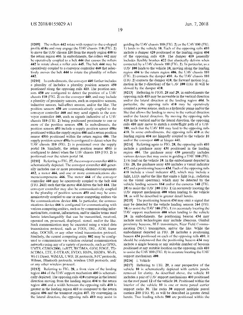
US 2018 / 0155029 A1 Jun . 7 , 2018 19
[ 0209 ] The rollers 442 rotate with respect to the c - shaped profile 410a and may engage the UAV chassis 110 ( FIG . 2 ) to move the UAV chassis 110 from the supply region 408 to the return region 406 . In embodiments , the rollers 442 may be operatively coupled to a belt 444 that causes the rollers 442 to rotate about a roller axis 445 . The belt 444 may be operatively coupled to a conveyor controller 460 that selec tively moves the belt 444 to rotate the plurality of rollers 442 . [ 0210 ] In embodiments , the conveyor 440 further includes a plurality of includes a plurality position sensors 450 positioned along the opposing rails 410 . The position sen sors 450 are configured to detect the position of a UAV chassis 110 ( FIG . 2 ) on the conveyor 440 , and may include a plurality of proximity sensors , such as capacitive sensors , inductive sensors , hall - effect sensors , and / or the like . The position sensors 450 are communicatively coupled to the conveyor controller 460 and may send signals to the con veyor controller 460 , such as signals indicative of a UAV chassis 110 ( FIG . 2 ) being positioned proximate to one or more of the position sensors 450 . In embodiments , the position sensors 450 include a supply position sensor 450a positioned within the supply region 408 and a return position sensor 450b positioned within the return region 406 . The supply position sensor 450a is configured to detect when the UAV chassis 110 ( FIG . 2 ) is positioned over the supply portal 16 . Similarly , the return position sensor 450b is configured to detect when the UAV chassis 110 ( FIG . 2 ) is positioned over the return portal 14 . [ 0211 ] Referring to FIG . 27 , the conveyor controller 460 is schematically depicted . The conveyor controller 460 gener ally includes one or more processing elements / components 462 , a motor 464 , and one or more communications ele ments / components 466 . The motor 464 of the conveyor controller 460 may be operatively coupled to the belt 444 ( FIG . 26B ) such that the motor 464 drives the belt 444 . The conveyor controller may also be communicatively coupled to the plurality of position sensors 450 and may be com municatively coupled to one or more computing entities via the communications device 466 . In particular , the commu nications device 466 is configured for communicating with various computing entities , such as by communicating infor mation / data , content , information , and / or similar terms used herein interchangeably that can be transmitted , received , operated on , processed , displayed , stored , and / or the like . Such communication may be executed using a wired data transmission protocol , such as FDDI , DSL , ATM , frame relay , DOCSIS , or any other wired transmission protocol . Similarly , the central computing entity 802 may be config ured to communicate via wireless external communication networks using any of a variety of protocols , such as GPRS , UMTS , CDMA2000 , 1xRTT , WCDMA , GSM , EDGE , TD SCDMA , LTE , E - UTRAN , EVDO , HSPA , HSDPA , Wi - Fi , Wi - Fi Direct , WiMAX , UWB , IR protocols , NFC protocols , Wibree , Bluetooth protocols , wireless USB protocols , and / or any other wireless protocol . [ 0212 ] Referring to FIG . 28 , a front view of the landing region 404 of the UAV support mechanism 400 is schemati cally depicted . The opposing rails 410 converge in the lateral direction moving from the landing region 404 to the return region 406 and a width between the opposing rails 410 is greater in the landing region 410 as compared to the return region 406 and the transport region 407 . By converging in the lateral direction , the opposing rails 410 may assist in
guiding the UAV chassis 110 ( FIG . 2 ) as the UAV 100 ( FIG . 1 ) lands to the vehicle 10 . Each of the opposing rails 410 include a damper 420 positioned at the landing region 404 of the opposing rails 410 . The damper 410 generally includes flexible brushes 422 that elastically deform when contacted by a UAV chassis 110 ( FIG . 2 ) . In particular , as a UAV 100 lands to the vehicle 10 , moving along the landing region 404 to the return region 406 , the UAV chassis 110 ( FIG . 2 ) contacts the damper 410 . As the UAV chassis 110 ( FIG . 2 ) contacts the damper 410 , the forward motion ( e . g . , motion in the y - direction ) of the UAV 100 ( FIG . 1 ) will be slowed by the damper 410 . [ 0213 ] Referring to FIGS . 28 and 29 , in embodiments the opposing rails 410 may be moveable in the vertical direction and / or the lateral direction at the landing region 404 . In particular , the opposing rails 410 may be operatively coupled a power source , such as a hydraulic pump and / or the like that allows the landing to move in the vertical direction and / or the lateral direction . By moving the opposing rails 410 in the vertical and / or the lateral direction , the opposing rails 410 may move to match a route / flight path of a UAV 100 , such that the UAV 100 may land to the opposing rails 410 . In some embodiments , the opposing rails 410 at the landing region 404 are hingedly coupled to the vehicle 10 and / or the conveyor 440 at hinges 441 . [ 0214 ] Referring again to FIG . 28 , the opposing rails 410 include a guidance array 430 positioned in the landing region 404 . The guidance array 430 generally includes various devices that may assist in guiding a UAV 100 ( FIG . 1 ) to land on the vehicle 10 . In the embodiment depicted in FIG . 28 , the guidance array 430 includes a visual indicator 432 and a positioning beacon 434 . Each of the opposing rails 410 include a visual indicator 432 , which may include a light , LED , and / or the like that emits a light ( e . g . , radiation on the visual spectrum ) , which may be detected by the vehicle landing sensors 164 and / or the cameras 168 ( FIG . 10 ) to assist the UAV 100 ( FIG . 1 ) in accurately locating the UAV support mechanism 400 when landing to the vehicle 10 , as will be described in greater detail herein . [ 0215 ] The positioning beacon 434 may emit a signal that may be detected by the vehicle landing sensors 164 ( FIG . 10 ) to assist the UAV 100 ( FIG . 1 ) in accurately locating the UAV support mechanism 400 when landing to the vehicle 10 . In embodiments , the positioning beacon 434 may include such technologies may include iBeacons , Gimbal proximity beacons , BLE transmitters , Near Field Commu nication ( NFC ) transmitters , and / or the like . While the embodiment depicted in FIG . 28 includes a positioning beacon 434 positioned on each of the opposing rails 410 , it should be understood that the positioning beacon 434 may include a single beacon or any suitable number of beacons positioned at any suitable location on the opposing rails 410 to assist the UAV 100 ( FIG . 1 ) in accurate locating the UAV support mechanism 400 . [ 0216 ) i . Vehicle [ 0217 ] Referring to FIG . 29 , a rear perspective of the vehicle 10 is schematically depicted with certain panels removed for clarity . As described above , the vehicle 10 includes a pair of UAV support mechanisms 400 positioned on the roof panel 12 of the vehicle 10 . Positioned within the interior of the vehicle 10 is one or more parcel carrier support racks 30 . The racks 30 support multiple parcel carriers 200 ( FIG . 9 ) , as will be described in greater detail herein . Two loading robots 500 are positioned within the
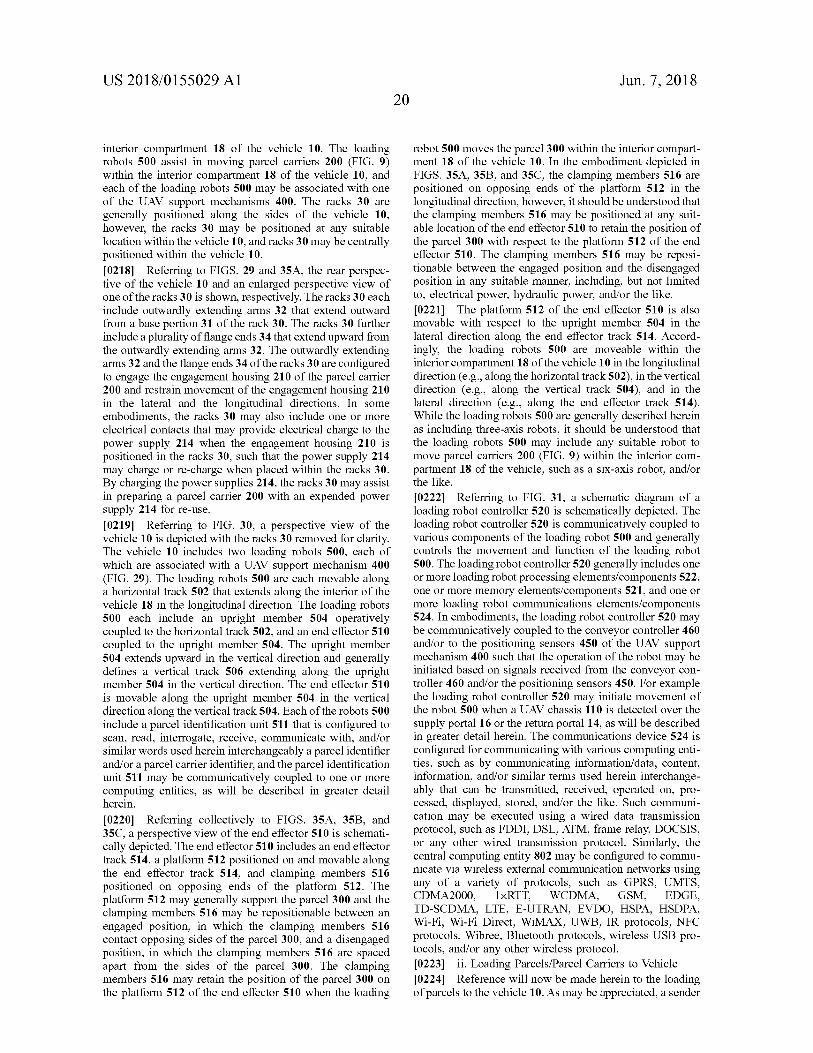
US 2018 / 0155029 A1 Jun . 7 , 2018
interior compartment 18 of the vehicle 10 . The loading robots 500 assist in moving parcel carriers 200 ( FIG . 9 ) within the interior compartment 18 of the vehicle 10 , and each of the loading robots 500 may be associated with one of the UAV support mechanisms 400 . The racks 30 are generally positioned along the sides of the vehicle 10 , however , the racks 30 may be positioned at any suitable location within the vehicle 10 , and racks 30 may be centrally positioned within the vehicle 10 . [ 0218 ] Referring to FIGS . 29 and 35A , the rear perspec tive of the vehicle 10 and an enlarged perspective view of one of the racks 30 is shown , respectively . The racks 30 each include outwardly extending arms 32 that extend outward from a base portion 31 of the rack 30 . The racks 30 further include a plurality of flange ends 34 that extend upward from the outwardly extending arms 32 . The outwardly extending arms 32 and the flange ends 34 of the racks 30 are configured to engage the engagement housing 210 of the parcel carrier 200 and restrain movement of the engagement housing 210 in the lateral and the longitudinal directions . In some embodiments , the racks 30 may also include one or more electrical contacts that may provide electrical charge to the power supply 214 when the engagement housing 210 is positioned in the racks 30 , such that the power supply 214 may charge or re - charge when placed within the racks 30 . By charging the power supplies 214 , the racks 30 may assist in preparing a parcel carrier 200 with an expended power supply 214 for re - use . [ 0219 ] Referring to FIG . 30 , a perspective view of the vehicle 10 is depicted with the racks 30 removed for clarity . The vehicle 10 includes two loading robots 500 , each of which are associated with a UAV support mechanism 400 ( FIG . 29 ) . The loading robots 500 are each movable along a horizontal track 502 that extends along the interior of the vehicle 18 in the longitudinal direction . The loading robots 500 each include an upright member 504 operatively coupled to the horizontal track 502 , and an end effector 510 coupled to the upright member 504 . The upright member 504 extends upward in the vertical direction and generally defines a vertical track 506 extending along the upright member 504 in the vertical direction . The end effector 510 is movable along the upright member 504 in the vertical direction along the vertical track 504 . Each of the robots 500 include a parcel identification unit 511 that is configured to scan , read , interrogate , receive , communicate with , and / or similar words used herein interchangeably a parcel identifier and / or a parcel carrier identifier , and the parcel identification unit 511 may be communicatively coupled to one or more computing entities , as will be described in greater detail herein . [ 0220 ] Referring collectively to FIGS . 35A , 35B , and 35C , a perspective view of the end effector 510 is schemati cally depicted . The end effector 510 includes an end effector track 514 , a platform 512 positioned on and movable along the end effector track 514 , and clamping members 516 positioned on opposing ends of the platform 512 . The platform 512 may generally support the parcel 300 and the clamping members 516 may be repositionable between an engaged position , in which the clamping members 516 contact opposing sides of the parcel 300 , and a disengaged position , in which the clamping members 516 are spaced apart from the sides of the parcel 300 . The clamping members 516 may retain the position of the parcel 300 on the platform 512 of the end effector 510 when the loading
robot 500 moves the parcel 300 within the interior compart ment 18 of the vehicle 10 . In the embodiment depicted in FIGS . 35A , 35B , and 35C , the clamping members 516 are positioned on opposing ends of the platform 512 in the longitudinal direction , however , it should be understood that the clamping members 516 may be positioned at any suit able location of the end effector 510 to retain the position of the parcel 300 with respect to the platform 512 of the end effector 510 . The clamping members 516 may be reposi tionable between the engaged position and the disengaged position in any suitable manner , including , but not limited to , electrical power , hydraulic power , and / or the like . 0221 ] The platform 512 of the end effector 510 is also movable with respect to the upright member 504 in the lateral direction along the end effector track 514 . Accord ingly , the loading robots 500 are moveable within the interior compartment 18 of the vehicle 10 in the longitudinal direction ( e . g . , along the horizontal track 502 ) , in the vertical direction ( e . g . , along the vertical track 504 ) , and in the lateral direction ( e . g . , along the end effector track 514 ) . While the loading robots 500 are generally described herein as including three - axis robots , it should be understood that the loading robots 500 may include any suitable robot to move parcel carriers 200 ( FIG . 9 ) within the interior com partment 18 of the vehicle , such as a six - axis robot , and / or the like 10222 ] Referring to FIG . 31 , a schematic diagram of a loading robot controller 520 is schematically depicted . The loading robot controller 520 is communicatively coupled to various components of the loading robot 500 and generally controls the movement and function of the loading robot 500 . The loading robot controller 520 generally includes one or more loading robot processing elements / components 522 , one or more memory elements / components 521 , and one or more loading robot communications elements / components 524 . In embodiments , the loading robot controller 520 may be communicatively coupled to the conveyor controller 460 and / or to the positioning sensors 450 of the UAV support mechanism 400 such that the operation of the robot may be initiated based on signals received from the conveyor con troller 460 and / or the positioning sensors 450 . For example the loading robot controller 520 may initiate movement of the robot 500 when a UAV chassis 110 is detected over the supply portal 16 or the return portal 14 , as will be described in greater detail herein . The communications device 524 is configured for communicating with various computing enti ties , such as by communicating information / data , content , information , and / or similar terms used herein interchange ably that can be transmitted , received , operated on , pro cessed , displayed , stored , and / or the like . Such communi cation may be executed using a wired data transmission protocol , such as FDDI , DSL , ATM , frame relay , DOCSIS , or any other wired transmission protocol . Similarly , the central computing entity 802 may be configured to commu nicate via wireless external communication networks using any of a variety of protocols , such as GPRS , UMTS , CDMA2000 1xRTT , WCDMA , GSM , EDGE , TD - SCDMA , LTE , E - UTRAN , EVDO , HSPA , HSDPA , Wi - Fi , Wi - Fi Direct , WiMAX , UWB , IR protocols , NFC protocols , Wibree , Bluetooth protocols , wireless USB pro tocols , and / or any other wireless protocol . [ 0223 ] ii . Loading Parcels / Parcel Carriers to Vehicle [ 0224 ] Reference will now be made herein to the loading of parcels to the vehicle 10 . As may be appreciated , a sender
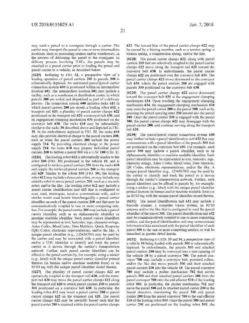
US 2018 / 0155029 A1 Jun . 7 , 2018
may send a parcel to a consignee through a carrier . The carrier may transport the parcel to one or more intermediate locations , such as processing centers and / or warehouses , in the process of delivering the parcel to the consignee . In delivery process involving UAVs , the parcels may be attached to a parcel carrier prior to loading the parcel and parcel carrier to a vehicle , as described below . [ 0225 ] Referring to FIG . 32 , a perspective view of a loading operation of parcel carriers 200 to parcels 300 is schematically depicted . An automated parcel / parcel carrier connection system 600 is positioned within an intermediate location 601 . The intermediate location 601 may include a facility , such as a warehouse or distribution center , in which parcels 300 are sorted and dispatched as part of a delivery process . The connection system 600 includes racks 610 in which parcel carriers 200 are stored , a loading robot 612 , a transport rail 620 , a plurality of parcel carrier clamps 622 positioned on the transport rail 620 , a conveyor belt 630 , and an engagement clamping mechanism 634 positioned on the conveyor belt 630 . The racks 610 may be substantially similar to the racks 30 described above and depicted in FIG . 29 . In the embodiment depicted in FIG . 32 , the racks 610 may also provide electrical charge to the parcel carriers 200 , such as when the parcel carriers 200 include the power supply 214 . By providing electrical charge to the power supply 214 , the racks 610 may prepare individual parcel carriers 200 to deliver a parcel 300 via a UAV 100 ( FIG . 1 ) . [ 0226 ] The loading robot 612 is substantially similar to the robot 500 ( FIG . 30 ) positioned in the vehicle 10 , and is configured to retrieve parcel carriers 200 from the racks 610 and supply the retrieved parcel carriers 200 to the transport rail 620 . Similar to the robots 500 ( FIG . 30 ) , the loading robot 612 may include a three - axis robot , or may include any suitable robot to move parcel carriers 200 , such as a six - axis robot , and / or the like . The loading robot 612 may include a parcel carrier identification unit 613 that is configured to scan , read , interrogate , receive , communicate with , and / or similar words used herein interchangeably a parcel carrier identifier on each of the parcel carriers 200 and that may be communicatively coupled to one or more computing enti ties . For example , the parcel carrier 200 may include a parcel carrier identifier , such as an alphanumeric identifier or machine readable identifier . Such parcel carrier identifiers may be represented as text , barcodes , tags , character strings , Aztec Codes , MaxiCodes , Data Matrices , Quick Response ( QR ) Codes , electronic representations , and / or the like . A unique parcel identifier ( e . g . , 123456789 ) may be used by the carrier and may be associated with a parcel identifier and / or a UAV identifier to identify and track the parcel carrier as it moves through the carrier ' s transportation network . Further , such parcel carrier identifiers can be affixed to the parcel carriers by , for example , using a sticker ( e . g . , label ) with the unique parcel carrier identifier printed thereon ( in human and / or machine readable form ) or an RFID tag with the unique parcel identifier stored therein . [ 0227 ] The plurality of parcel carrier clamps 622 are operatively coupled to the transport rail 620 , and the trans port rail 620 may move the parcel carrier clamps 622 along the transport rail 620 to attach parcel carriers 200 to parcels 300 positioned on a conveyor belt 630 . In particular , the loading robot 612 may insert a parcel carrier 200 to parcel carrier clamps 622 on the transport rail 620 . The parcel carrier clamps 622 may be inwardly biased such that the parcel carrier 200 is retained within the parcel carrier clamps
622 . The inward bias of the parcel carrier clamps 622 may be caused by a biasing member , such as a tension spring , a torsion spring , a compression spring , and / or the like . [ 0228 ] The parcel carrier clamps 622 , along with parcel carriers 200 that are selectively coupled to the parcel carrier clamps 622 move along the transport rail 620 toward the conveyor belt 630 . In embodiments , the parcel carrier clamps 622 are positioned over the conveyor belt 630 . The parcel carrier clamps 622 move downward to the conveyor belt 630 , where the parcel carriers 200 are engaged with parcels 300 positioned on the conveyor belt 630 . [ 0229 ] The parcel carrier clamps 622 move downward toward the conveyor belt 630 at the engagement clamping mechanism 634 . Upon reaching the engagement clamping mechanism 634 , the engagement clamping mechanism 634 may mate the parcel carrier 200 to the parcel 300 , such as by pressing the parcel carrying arms 230 inward into the parcel 300 . Once the parcel carrier 200 is engaged with the parcel 300 , the parcel carrier clamps 622 may disengage with the parcel carrier 200 , and continue moving along the transport rail 620 . [ 0230 ] The parcel / parcel carrier connection system 600 may further include a parcel identification unit 632 that may communicate with a parcel identifier of the parcels 300 that are positioned on the conveyor belt 630 . For example , each parcel 300 may include a parcel identifier , such as an alphanumeric identifier or machine readable identifier . Such parcel identifiers may be represented as text , barcodes , tags , character strings , Aztec Codes , MaxiCodes , Data Matrices , QR Codes , electronic representations , and / or the like . A unique parcel identifier ( e . g . , 123456789 ) may be used by the carrier to identify and track the parcel as it moves through the carrier ' s transportation network . Further , such parcel identifiers can be affixed to parcels by , for example , using a sticker ( e . g . , label ) with the unique parcel identifier printed thereon ( in human and / or machine readable form ) or an RFID tag with the unique parcel identifier stored therein . [ 0231 ] The parcel identification unit 632 may include a barcode scanner , a computer vision system , an RFID antenna and / or the like that is configured to read the parcel identifier of the parcel 300 . The parcel identification unit 632 may be communicatively coupled to one or more computing entities , and the parcel identification unit may communicate information / data associated with the parcel identifier of each parcel 300 to the one or more computing entities , as will be described in greater detail herein . [ 0232 ] Referring to FIGS . 33 and 34 , a perspective view of a vehicle 10 being loaded with parcels 300 is schematically depicted . In embodiments , the parcels 300 and attached parcel carriers 200 may be conveyed into a rear opening of the vehicle 10 by a parcel conveyor 700 . The parcel con veyor 700 may include a conveyor belt , powered rollers , and / or the like that move parcels 300 and their attached parcel carriers 200 into the vehicle 10 . The parcel conveyor 700 may include a pusher mechanism 702 that moves parcels 300 and their attached parcel carriers 200 from the parcel conveyor 700 onto the end effector 510 of the loading robot 500 . In particular , the pusher mechanism 702 may move the parcel 300 and its attached parcel carrier 200 in the lateral direction , transferring the parcel 300 and parcel carrier 200 from the parcel conveyor 700 to the end effector 510 of the loading robot 500 . Once the parcel 300 and parcel carrier 200 are positioned on the loading robot 500 , the
US 2018 / 0155029 A1 Jun . 7 , 2018
loading robot 500 moves the parcel 300 and the parcel carrier 200 to the rack 30 positioned within the vehicle 10 . [ 0233 ] For example and referring to FIG . 35A , the loading robot 500 may move the parcel 300 and the parcel carrier 200 proximate to an available pair of outwardly extending arms 32 of the rack 30 ( e . g . , a pair of outwardly extending arms 32 that are not engaged with a parcel carrier 200 / parcel 300 ) . The loading robot 500 may move the parcel 300 and attached parcel carrier 200 in the vertical direction such that an underside of the parcel carrier 200 is generally aligned with the outwardly extending arms 32 of the rack 30 in the vertical direction . [ 0234 ] Referring to FIG . 35B , upon aligning the underside of the parcel carrier 200 with the outwardly extending arms 32 of the rack 30 , the platform 512 of the loading robot 500 moves toward the outwardly extending arms 32 in the lateral direction along the end effector track 514 . The loading robot 500 moves the platform 512 toward the outwardly extending arms 32 until the outwardly extending arms 32 are posi tioned between the parcel carrier 200 and the parcel 300 in the vertical direction . [ 0235 ] Referring to FIG . 35C , once the outwardly extend ing arms 32 are positioned between the parcel carrier 200 and the parcel 300 in the vertical direction , the clamping members 516 of the end effector 510 move from the engaged position to the disengaged position , such that the clamping members 516 are spaced apart from the parcel 300 in the longitudinal direction . The parcel 300 and the parcel carrier 200 may be supported by the outwardly extending arms 32 , and in particular , the bottom surface of the parcel carrier 200 may be positioned on the outwardly extending arms 32 with the parcel 300 positioned below the outwardly extending arms 32 in the vertical direction . Movement of the parcel carrier 200 and the parcel 300 with respect to the outwardly extending arms 32 may be restricted by the flange ends 34 . [ 0236 ] Once the parcel 300 and the parcel carrier 200 are positioned on the outwardly extending arms 32 , the platform 512 moves along the end effector track 514 towards the upright member 504 of the loading robot 500 , such that the loading robot 500 is prepared to retrieve another parcel 300 and parcel carrier 200 from the conveyor 700 ( FIG . 34 ) . [ 0237 ] iii . Loading / Unloading to UAV Chassis [ 0238 ] Once the vehicle 10 is loaded with parcels 300 their associated parcel carriers 200 , the vehicle 10 may be dis patched to deliver the parcels 300 , for example as part of a delivery route . When delivering the parcels 300 , the UAVs 100 ( FIG . 1 ) are loaded with parcels 300 and their associated parcel carriers 200 , as described below . [ 0239 ] Referring collectively to FIGS . 36 and 37 , UAV chassis 110 are positioned on the UAV support mechanisms 400 of the vehicle 10 . Within the return region 406 , the transport region 407 , and the supply region 408 , the UAV support mechanism 400 , the UAV chassis 110 are engaged with the conveyor 440 . In particular , the landing gear 116 contact and engage with the upper surface 412 of the opposing rails 410 , and the reduced width portion 115 of the UAV chassis 110 is positioned between the opposing rails 410 in the lateral direction . Furthermore , the upper portion 114 of the UAV chassis 110 is positioned above the opposing rails 410 and the lower portion 118 of the UAV chassis 110 is positioned below the opposing rails 410 . In embodiments , the width of the upper portion 114 and the width of the lower portion 118 evaluated in the lateral direction are both greater than a width ‘ w ' between the opposing rails 410 evaluated
in the lateral direction . As the upper portion 114 and the lower portion 118 of the UAV chassis 110 have a greater width than the width between the opposing rails 410 , the UAV chassis 110 , the UAV chassis 110 is restrained in the vertical direction when positioned in the conveyor 440 . [ 0240 ] The conveyor 440 moves the UAV chassis 110 , such as through the rollers 442 , ( and / or the landing gear 116 when the landing gear 116 includes powered rollers ) in the longitudinal direction through the transport region 407 and into the supply region 408 of the conveyor 440 . Once in the supply region 408 , the rollers 442 may stop rotating once the UAV chassis 110 is positioned over the supply portal 16 . The conveyor controller 460 ( FIG . 25 ) may detect when the UAV chassis 110 is positioned over the supply portal 16 , such as through the supply position sensor 450a ( FIG . 25 ) . Once the UAV chassis 110 is positioned over the supply portal 16 , a parcel 300 and attached parcel carrier 200 may be retrieved from the interior compartment 18 of the vehicle 10 and attached to the UAV chassis 110 to load the UAV chassis 110 for flight . [ 0241 ] Referring to FIG . 38A , to retrieve a parcel 300 and associated parcel carrier 200 from the interior compartment 18 of the vehicle 10 , the loading robot 500 positions the end effector 510 of the loading robot 500 below a parcel 300 on the rack 30 . In particular , the platform 512 of the end effector 510 is positioned below the parcel 300 , and the clamping members 516 may engage the sides of the parcel 300 . [ 0242 ] Referring to FIG . 38B , with the end effector 510 engaged with the parcel 300 , the loading robot 500 lifts the parcel 300 and the attached parcel carrier 200 upward in the vertical direction , such that the parcel carrier 200 is disen gaged from the rack 30 . [ 0243 ] Referring to FIG . 38C , the loading robot 500 then moves the parcel 300 and attached parcel carrier 200 away from the rack 30 , and moves the parcel 300 and attached parcel carrier 200 toward the supply portal 16 . The loading robot 500 positions the parcel 300 and the parcel carrier 200 under the UAV chassis 110 such that the parcel carrier 200 may be inserted within the lower portion 118 of the UAV chassis 110 . The loading robot 500 moves upward in the vertical direction and inserts the parcel carrier 200 within the lower portion 118 of the UAV chassis 110 , and the parcel carrier 200 may be retained within the lower portion 118 , such as by the retaining members 120 ( FIG . 7 ) . Upon inserting the parcel carrier 200 within the lower portion 118 of the UAV chassis 110 , the clamping members 516 of the end effector 510 move into the disengaged position , and the end effector 510 may separate from the parcel 300 . [ 0244 ] Referring to FIG . 39 , once the parcel 300 and the parcel carrier 200 are selectively coupled to the UAV chassis 110 , the UAV 100 is prepared to deliver the parcel 300 to a destination , and the conveyor 440 moves the UAV 100 from the supply region 408 to the takeoff end 402 . Once at the takeoff end 402 , the propulsion members 102 of the UAV 100 may power up , and the propellers 103 of the propulsion members 102 begin to rotate such that the UAV 100 may take off from the takeoff end 402 to deliver the parcel 300 to a destination . 102451 . As will be described in greater detail herein , the UAV 100 may deliver the parcel 300 to a destination at a serviceable point 5901 . Upon successful delivery of the parcel 300 to the destination at a serviceable point 5901 , the UAV 100 returns to the vehicle 10 with the empty parcel carrier 200 , where it may be re - supplied with another parcel
US 2018 / 0155029 A1 Jun . 7 , 2018
300 and parcel carrier 200 . As will be recognized , the UAV 100 may also pick up one or more parcels 300 after delivery of one or more parcels 300 at one or more serviceable points 5901 ( e . g . , a multi - stop pick - up and / or delivery ) . [ 0246 ] Referring to FIG . 40 , a UAV 100 is depicted initiating a landing on the vehicle 10 , such as when the UAV 100 is returning to the vehicle 10 after successful delivery of a parcel 300 . In embodiments , the vehicle landing sensors 164 of the UAV 100 detect one or more components of the guidance array 430 such that the UAV 100 may locate the opposing rails 410 of the UAV support system 400 . For example in some embodiments , the vehicle landing sensors 164 may detect the position of the visual indicator 432 and / or the positioning beacon 434 of the UAV support mechanism 400 . By detecting the position of the visual indicator 432 and / or the positioning beacon 434 , the vehicle landing sensors 164 may provide the UAV 100 with an accurate estimate of the position of the opposing rails 410 such that the UAV 100 may navigate toward the landing region 404 of the opposing rails 410 . [ 0247 ] In various embodiments , the UAV 100 may be configured to only land on the vehicle 10 while the vehicle 10 is stopped . For example , for human - operated vehicles , the UAV 100 may be incapable of predicting the movement of the vehicle 10 , and accordingly the UAV 100 may only land to the UAV support mechanism 400 when the move ment of the vehicle 10 can be accurately predicted , such as when the vehicle 10 is stationary . In such embodiments , the UAVs 100 may be configured to follow the vehicle 10 at a predetermined distance while it moves until the vehicle 10 comes to a stop . [ 0248 ] In various embodiments , the UAV 100 may be configured to land on the vehicle 10 when the vehicle 10 is in motion . For example , when the vehicle 10 includes an autonomous vehicle , the vehicle 10 may predictably move along a predetermined / configurable route , such that the movement of the vehicle 10 can be accurately predicted . In these embodiments , the UAV 100 may land on the vehicle 10 while the vehicle 10 is in motion . [ 0249 ] Referring to FIG . 41 , a perspective view of the UAV 100 landing on the UAV support mechanism 400 . Upon accurately locating the opposing rails 410 , such as through the guidance array 430 , the UAV 100 navigates such that the upper portion 114 of the UAV chassis 110 is positioned above the opposing rails 410 and the lower portion 118 of the UAV chassis 110 is positioned below the opposing rails 410 in the vertical direction . The tapered shape of the upper portion 114 and the lower portion 118 of the UAV chassis 110 may assist in guiding the UAV 100 such that the upper portion 114 is positioned above the opposing rails 410 and the lower portion 118 is positioned below the opposing rails 410 . With the upper portion 114 positioned above the opposing rails 410 and the lower portion 118 positioned below the opposing rails 410 , the UAV 100 moves rearward in the longitudinal direction as the opposing rails 410 converge in the lateral direction . The UAV 100 may move rearward in the longitudinal direction under the power of the propulsion members 102 until the UAV 100 reaches the conveyor 440 positioned rearward of the landing region 404 . [ 0250 ] Once the UAV 100 has landed to the UAV support mechanism 400 and has engaged with the conveyor 440 , the propulsion members 102 of the UAV may power down , such
that the propellers 103 stop rotating . The conveyor 440 then may move the UAV 100 to the return region 406 . [ 0251 ] Referring to FIG . 42A , the conveyor 440 moves the UAV 100 to the return portal 14 . The conveyor controller 460 ( FIG . 25 ) may detect when the UAV chassis 110 is positioned over the return portal 14 , such as through the return position sensor 450b ( FIG . 25 ) . At the return portal 14 , the loading robot 500 may engage the now empty parcel carrier 200 with the end effector 510 , and the parcel carrier 200 may be selectively de - coupled from the UAV chassis 110 . Upon the parcel carrier 200 being de - coupled from the UAV chassis 110 , the loading robot 500 may lower the end effector 510 , and accordingly the parcel carrier from the UAV chassis 110 . [ 0252 ] Referring to FIG . 42B , the loading robot 500 may position the empty parcel carrier 200 from the UAV chassis 110 to the rack 30 within the interior compartment 18 of the vehicle 10 . With the empty parcel carrier 200 removed from the UAV chassis 110 , the conveyor 440 moves the UAV chassis 110 from the return region 406 , and through the transport region 407 to the supply region 408 ( FIG . 36 ) , where the UAV chassis 110 may be re - supplied with a new parcel carrier 200 and parcel 300 , as described above . 0253 ] Referring now to FIG . 43 , a perspective view of an alternative interior compartment 18 of the vehicle 10 is schematically depicted . In the embodiment depicted in FIG . 43 , the interior compartment 18 of the vehicle 10 includes the racks 30 for use with the parcel carriers 200 ( FIG . 17 ) configured to be delivered by UAV 100 ( FIG . 1 ) , as well as racks 41 for conventional parcels 300 that may be delivered manually by a delivery employee . In particular , in such embodiments , the vehicle 10 may deliver parcels 300 via UAV 100 , while simultaneously delivering parcels 300 through conventional methods ( e . g . , by a delivery employee ) . [ 0254 ] Referring to FIG . 44 a perspective view of an alternative vehicle 10 is schematically depicted . In the embodiment depicted in FIG . 44 , the vehicle 10 includes a trailer , such as a trailer that may be selectively coupled to a semi - truck . The vehicle 10 includes the UAV support mechanism 400 as described above from which the UAVs 100 may take off and land , and may include one or more robots configured to load and unload parcel carriers 200 from the UAVs 100 . In such embodiments , the vehicle 10 may be moved to a certain location to deliver parcels 300 and may remain stationary at that location while the UAVs 100 deliver parcels 300 from the vehicle 10 . The vehicle 10 may remain in place at the location while the UAVs 100 deliver the parcels 300 from the vehicle 10 until all of the parcels 300 have been delivered from the vehicle 10 , or until a delivery has been attempted for each of the parcels 300 within the vehicle 10 , at which time the vehicle 10 may be picked up and returned to a serviceable point 5901 . Such vehicles may assist in delivering parcels 300 during periods of high - volume , such as during holiday delivery season , supplementing other delivery methods . 10255 ] Referring to FIGS . 45A and 45B , another embodi ment of vehicles 10 are schematically depicted . In the embodiment depicted in FIGS . 45A and 45B , the UAV support mechanism 400 includes a landing pad 40 posi tioned on the roof panel 12 of the vehicle 10 . In such embodiments , the UAVs 100 may land to landing pad 40 , as compared to the UAV support mechanism 400 described above . The landing pad 40 is configured to support the UAV
US 2018 / 0155029 A1 Jun . 7 , 2018 24
100 , and includes a portal through which the interior com partment 180 of the vehicle 10 may be accessed . The vehicle 10 may include the robots 500 ( FIG . 30 ) and the racks 30 ( FIG . 29 ) , and may be similarly configured to provide parcel carriers 200 to the UAV 100 at the landing pad 40 , as compared to the supply portal 16 and the return portal 14 , as described above . [ 0256 ] Reference will now be made to the interconnectiv ity of various components of the enhanced parcel delivery system .
3 . Computer Program Products , Methods , and Computing Entities
[ 0257 ] Embodiments described herein may be imple mented in various ways , including as computer program products that comprise articles of manufacture . Such com puter program products may include one or more software elements / components including , for example , software objects , methods , data structures , and / or the like . A software component may be coded in any of a variety of program ming languages . An illustrative programming language may be a lower - level programming language such as an assembly language associated with a particular hardware architecture and / or operating system platform . A software component comprising assembly language instructions may require conversion into executable machine code by an assembler prior to execution by the hardware architecture and / or platform . Another example programming language may be a higher - level programming language that may be portable across multiple architectures . A software component com prising higher - level programming language instructions may require conversion to an intermediate representation by an interpreter or a compiler prior to execution . [ 0258 ] Other examples of programming languages include , but are not limited to , a macro language , a shell or command language , a job control language , a script lan guage , a database query or search language , and / or a report writing language . In one or more example embodiments , a software component comprising instructions in one of the foregoing examples of programming languages may be executed directly by an operating system or other software component without having to be first transformed into another form . A software component may be stored as a file or other data storage construct . Software elements / compo nents of a similar type or functionally related may be stored together such as , for example , in a particular directory , folder , or library . Software elements / components may be static ( e . g . , pre - established or fixed ) or dynamic ( e . g . , cre ated or modified at the time of execution ) . [ 0259 ] A computer program product may include a non transitory computer - readable storage medium storing appli cations , programs , program modules , scripts , source code , program code , object code , byte code , compiled code , interpreted code , machine code , executable instructions , and / or the like ( also referred to herein as executable instruc tions , instructions for execution , computer program prod ucts , program code , and / or similar terms used herein inter changeably ) . Such non - transitory computer - readable storage media include all computer - readable media ( including vola tile and non - volatile media ) . [ 0260 ] In one embodiment , a non - volatile computer - read able storage medium may include a floppy disk , flexible disk , hard disk , solid - state storage ( SSS ) ( e . g . , a solid state drive ( SSD ) , solid state card ( SSC ) , solid state module
( SSM ) , enterprise flash drive , magnetic tape , or any other non - transitory magnetic medium , and / or the like . A non volatile computer - readable storage medium may also include a punch card , paper tape , optical mark sheet ( or any other physical medium with patterns of holes or other optically recognizable indicia ) , compact disc read only memory ( CD - ROM ) , compact disc - rewritable ( CD - RW ) , digital versatile disc ( DVD ) , Blu - ray disc ( BD ) , any other non - transitory optical medium , and / or the like . Such a non - volatile computer - readable storage medium may also include read - only memory ( ROM ) , programmable read - only memory ( PROM ) , erasable programmable read - only memory ( EPROM ) , electrically erasable programmable read - only memory ( EEPROM ) , flash memory ( e . g . , Serial , NAND , NOR , and / or the like ) , multimedia memory cards ( MMC ) , secure digital ( SD ) memory cards , Smart Media cards , CompactFlash ( CF ) cards , Memory Sticks , and / or the like . Further , a non - volatile computer - readable storage medium may also include conductive - bridging random access memory ( CBRAM ) , phase - change random access memory ( PRAM ) , ferroelectric random - access memory ( Fe RAM ) , non - volatile random - access memory ( NVRAM ) , magnetoresistive random - access memory ( MRAM ) , resis tive random - access memory ( RRAM ) , Silicon - Oxide - Ni tride - Oxide - Silicon memory ( SONOS ) , floating junction gate random access memory ( FJG RAM ) , Millipede memory , racetrack memory , and / or the like . [ 0261 ] In one embodiment , a volatile computer - readable storage medium may include RAM , DRAM , SRAM , FPM DRAM , EDO DRAM , SDRAM , DDR SDRAM , DDR2 SDRAM , DDR3 SDRAM , RDRAM , TTRAM , T - RAM , Z - RAM , RIMM , DIMM , SIMM , VRAM , cache memory , register memory , and / or the like . It will be appreciated that where embodiments are described to use a computer - read able storage medium , other types of computer - readable storage media may be substituted for or used in addition to the computer - readable storage media described above . [ 0262 ] As should be appreciated , various embodiments of the present invention may also be implemented as methods , apparatus , systems , computing devices , computing entities , and / or the like . As such , embodiments of the present inven tion may take the form of an apparatus , system , computing device , computing entity , and / or the like executing instruc tions stored on a computer - readable storage medium to perform certain steps or operations . Thus , embodiments of the present invention may also take the form of an entirely hardware embodiment , an entirely computer program prod uct embodiment , and / or an embodiment that comprises combination of computer program products and hardware performing certain steps or operations . [ 0263 ] Embodiments of the present invention are described below with reference to block diagrams and flowchart illustrations . Thus , it should be understood that each block of the block diagrams and flowchart illustrations may be implemented in the form of a computer program product , an entirely hardware embodiment , a combination of hardware and computer program products , and / or apparatus , systems , computing devices , computing entities , and / or the like carrying out instructions , operations , steps , and similar words used interchangeably ( e . g . , the executable instruc tions , instructions for execution , program code , and / or the like ) on a computer - readable storage medium for execution . For example , retrieval , loading , and execution of code may be performed sequentially such that one instruction is
US 2018 / 0155029 A1 Jun . 7 , 2018 25
retrieved , loaded , and executed at a time . In some exemplary embodiments , retrieval , loading , and / or execution may be performed in parallel such that multiple instructions are retrieved , loaded , and / or executed together . Thus , such embodiments can produce specifically - configured machines performing the steps or operations specified in the block diagrams and flowchart illustrations . Accordingly , the block diagrams and flowchart illustrations support various com binations of embodiments for performing the specified instructions , operations , or steps .
4 . Exemplary System Architecture [ 0264 ] FIG . 46 provides an illustration of an exemplary embodiment of the present invention . As shown in FIG . 46 , this particular embodiment may include one or more central computing entities 802 , one or more networks 800 , one or more user computing entities 804 , one or more mobile carrier computing entities 806 , one or more UAV computing entities 808 , one or more parcel carrier computing entities 212 , one or more delivery vehicle computing entities 810 , and / or the like . Each of these components , entities , devices , systems , and similar words used herein interchangeably may be in direct or indirect communication with , for example , one another over the same or different wired or wireless networks . Additionally , while FIG . 43 illustrates the various system entities as separate , standalone entities , the various embodiments are not limited to this particular architecture . [ 0265 ] A . Exemplary Central Computing Entity [ 0266 ] FIG . 47 provides a schematic of a central comput ing entity 802 according to one embodiment of the present invention . The central computing entity 802 can be operated by a variety of entities , including carriers . As will be recognized , a carrier may be a traditional carrier , such as United Parcel Service ( UPS ) , FedEx , DHL , courier services , the United States Postal Service ( USPS ) , Canadian Post , freight companies ( e . g . truck - load , less - than - truckload , rail carriers , air carriers , ocean carriers , etc . ) , and / or the like . However , a carrier may also be a nontraditional carrier , such as Coyote , Amazon , Google , Airbus , Uber , ride - sharing services , crowd - sourcing services , retailers , and / or the like . [ 0267 ] As indicated , in one embodiment , the central com puting entity 802 may also include one or more communi cations elements / components 908 for communicating with various computing entities , such as by communicating infor mation / data , content , information , and / or similar terms used herein interchangeably that can be transmitted , received , operated on , processed , displayed , stored , and / or the like . 10268 ] As shown in FIG . 47 , in one embodiment , the central computing entity 802 may include or be in commu nication with one or more processing elements / components 902 ( also referred to as processors , processing circuitry , processing device , and / or similar terms used herein inter changeably ) that communicate with other elements / compo nents within the central computing entity 802 via a bus , for example . As will be understood , the processing elements / components 902 may be embodied in a number of different ways . For example , the processing element / component 902 may be embodied as one or more CPLDs , “ cloud ” proces sors , microprocessors , multi - core processors , coprocessing entities , ASIPs , microcontrollers , and / or controllers . Further , the processing element / component 902 may be embodied as one or more other processing devices or circuitry . The term circuitry may refer to an entirely hardware embodiment or a combination of hardware and computer program products .
Thus , the processing element / component 902 may be embodied as integrated circuits , ASICs , FPGAs , PLAs , hardware accelerators , other circuitry , and / or the like . As will therefore be understood , the processing element / com ponent 902 may be configured for a particular use or configured to execute instructions stored in volatile or non - volatile media or otherwise accessible to the processing element / component 902 . As such , whether configured by hardware or computer program products , or by a combina tion thereof , the processing element / component 902 may be capable of performing steps or operations according to embodiments of the present invention when configured accordingly . [ 0269 ] In one embodiment , the central computing entity 802 may further include or be in communication with memory components / elements such as non - volatile media ( also referred to as non - volatile storage , memory , memory storage , memory circuitry and / or similar terms used herein interchangeably ) . In one embodiment , the non - volatile stor age or memory may include one or more non - volatile storage or memory media 904 , including but not limited to hard disks , ROM , PROM , EPROM , EEPROM , flash memory , MMCs , SD memory cards , Memory Sticks , CBRAM , PRAM , FeRAM , NVRAM , MRAM , RRAM , SONOS , FJG RAM , Millipede memory , racetrack memory , and / or the like . As will be recognized , the non - volatile storage or memory media may store databases , database instances , database management systems , information / data , applications , programs , program modules , scripts , source code , object code , byte code , compiled code , interpreted code , machine code , executable instructions , and / or the like . The term database , database instance , database management system , and / or similar terms used herein interchangeably may refer to a collection of records or data that is stored in a computer - readable storage medium using one or more database models , such as a hierarchical database model , network model , relational model , entity - relationship model , object model , document model , semantic model , graph model , and / or the like . [ 0270 ] In one embodiment , the memory components / ele ments may further include or be in communication with volatile media ( also referred to as volatile storage , memory , memory storage , memory circuitry and / or similar terms used herein interchangeably ) . In one embodiment , the volatile storage or memory may also include one or more volatile storage or memory media 906 , including but not limited to RAM , DRAM , SRAM , FPM DRAM , EDO DRAM , SDRAM , DDR SDRAM , DDR2 SDRAM , DDR3 SDRAM , RDRAM , TTRAM , T - RAM , Z - RAM , RIMM , DIMM , SIMM , VRAM , cache memory , register memory , and / or the like . As will be recognized , the volatile storage or memory media may be used to store at least portions of the databases , database instances , database management systems , informa tion / data , applications , programs , program modules , scripts , source code , object code , byte code , compiled code , inter preted code , machine code , executable instructions , and / or the like being executed by , for example , the processing element / component 902 . Thus , the databases , database instances , database management systems , information / data , applications , programs , program modules , scripts , source code , object code , byte code , compiled code , interpreted code , machine code , executable instructions , and / or the like may be used to control certain aspects of the operation of the
US 2018 / 0155029 A1 Jun . 7 , 2018
central computing entity 802 with the assistance of the processing element / component 902 and operating system . [ 0271 ] As indicated , in one embodiment , the central com puting entity 802 may also include one or more communi cations components / elements 908 for communicating with various computing entities , such as by communicating infor mation / data , content , information , and / or similar terms used herein interchangeably that can be transmitted , received , operated on , processed , displayed , stored , and / or the like . Such communication may be executed using a wired data transmission protocol , such as FDDI , DSL , ATM , frame relay , DOCSIS , or any other wired transmission protocol . Similarly , the central computing entity 802 may be config ured to communicate via wireless external communication networks using any of a variety of protocols , such as GPRS , UMTS , CDMA2000 , 1xRTT , WCDMA , GSM , EDGE , TD SCDMA , LTE , E - UTRAN , EVDO , HSPA , HSDPA , Wi - Fi , Wi - Fi Direct , WiMAX , UWB , IR protocols , NFC protocols , Wibree , Bluetooth protocols , wireless USB protocols , and or any other wireless protocol . [ 0272 ] Although not shown , the central computing entity 802 may include or be in communication with one or more input components / elements , such as a keyboard input , a mouse input , a touch screen / display input , motion input , movement input , audio input , pointing device input , joystick input , keypad input , and / or the like . The central computing entity 802 may also include or be in communication with one or more output elements / components ( not shown ) , such as audio output , video output , screen / display output , motion output , movement output , and / or the like . [ 0273 ] As will be appreciated , one or more of the central computing entity ' s 802 elements / components may be located remotely from other central computing entity 802 components / elements , such as in a distributed system . That is , the term " central ” is used in the generic sense and is not intended to necessarily indicate a central location . Further more , one or more of the elements / components may be combined and additional elements / components performing functions described herein may be included in the central computing entity 802 . Thus , the central computing entity 802 can be adapted to accommodate a variety of needs and circumstances . As will be recognized , these architectures and descriptions are provided for exemplary purposes only and are not limiting to the various embodiments . [ 0274 ] B . Exemplary User Computing Entity [ 0275 ] A user may be an individual , a family , a company , an organization , an entity , a department within an organiza tion , a representative of an organization and / or person , and / or the like . Thus , as will be recognized , in certain embodiments , users may be consignors and / or consignees . To do so , a user may operate a user computing entity 804 that includes one or more elements / components that are functionally similar to those of the central computing entity 802 . [ 0276 ] FIG . 48 provides an illustrative schematic repre sentative of a user computing entity 804 that can be used in conjunction with embodiments of the present invention . In general , the terms device , system , computing entity , entity , and / or similar words used herein interchangeably may refer to , for example , one or more computers , computing entities , desktop computers , mobile phones , tablets , phablets , note books , laptops , distributed systems , smart home entities , kitchen appliances , Google Home , Amazon Echo , garage door controllers , cameras , imaging devices , thermostats ,
security systems , networks , gaming consoles ( e . g . , Xbox , Play Station , Wii ) , watches , glasses , iBeacons , proximity beacons , key fobs , RFID tags , ear pieces , scanners , televi sions , dongles , cameras , wristbands , wearable items / de vices , items / devices , vehicles , kiosks , input terminals , serv ers or server networks , blades , gateways , switches , processing devices , processing entities , set - top boxes , relays , routers , network access points , base stations , the like , and / or any combination of devices or entities adapted to perform the functions , operations , and / or processes described herein . As shown in FIG . 45 , the user computing entity 804 can include communication components / ele ments , such as an antenna 912 , a transmitter 914 ( e . g . , radio ) , and a receiver 916 ( e . g . , radio ) . Similarly , the user computing entity 804 can include a processing element / component 918 ( e . g . , CPLDs , microprocessors , multi - core processors , cloud processors , coprocessing entities , ASIPs , microcontrollers , and / or controllers ) that provides signals to and receives signals from communication elements / compo nents . [ 0277 ] The signals provided to and received from the transmitter 914 and the receiver 916 , respectively , may include signaling information / data in accordance with air interface standards of applicable wireless systems . In this regard , the user computing entity 804 may be capable of operating with one or more air interface standards , commu nication protocols , modulation types , and access types . More particularly , the user computing entity 804 may oper ate in accordance with any of a number of wireless com munication standards and protocols , such as those described above with regard to the central computing entity 802 . In a particular embodiment , the user computing entity 804 may operate in accordance with multiple wireless communica tion standards and protocols , such as UMTS , CDMA2000 , 1xRTT , WCDMA , GSM , EDGE , TD - SCDMA , LTE , E - UTRAN , EVDO , HSPA , HSDPA , Wi - Fi , Wi - Fi Direct , WiMAX , UWB , IR , NFC , Bluetooth , USB , and / or the like . Similarly , the user computing entity 804 may operate in accordance with multiple wired communication standards and protocols , such as those described above with regard to the central computing entity 802 via a network interface 908 . [ 0278 ] Via these communication standards and protocols , the user computing entity 804 can communicate with vari ous other entities using concepts such as Unstructured Supplementary Service Data ( USSD ) , Short Message Ser vice ( SMS ) , Multimedia Messaging Service ( MMS ) , Dual Tone Multi - Frequency Signaling ( DTMF ) , and / or Sub scriber Identity Module Dialer ( SIM dialer ) . The user computing entity 804 can also download changes , add - ons , and updates , for instance , to its firmware , software ( e . g . , including executable instructions , applications , program modules ) , and operating system . [ 0279 ] According to one embodiment , the user computing entity 804 may include location determining elements / com ponents , aspects , devices , modules , functionalities , and / or similar words used herein interchangeably . For example , the user computing entity 804 may include outdoor positioning aspects , such as a location module adapted to acquire , for example , latitude , longitude , altitude , geocode , course , direction , heading , speed , universal time ( UTC ) , date , and / or various other information / data . In one embodiment , the location module can acquire information / data , sometimes known as ephemeris information / data , by identifying the number of satellites in view and the relative positions of
US 2018 / 0155029 A1 Jun . 7 , 2018 27
those satellites ( e . g . , using global positioning systems ( GPS ) ) . The satellites may be a variety of different satellites , including Low Earth Orbit ( LEO ) satellite systems , Depart ment of Defense ( DOD ) satellite systems , the European Union Galileo positioning systems , the Chinese Compass navigation systems , Global Navigation Satellite System ( GLONASS ) , Indian Regional Navigational satellite sys tems , and / or the like . This information / data can be collected using a variety of coordinate systems , such as the Decimal Degrees ( DD ) ; Degrees , Minutes , Seconds ( DMS ) ; Univer sal Transverse Mercator ( UTM ) ; Universal Polar Stereo graphic ( UPS ) coordinate systems ; and / or the like . Alterna tively , the location information data can be determined by triangulating the user computing entity ' s 804 position in connection with a variety of other systems , including cel lular towers , Wi - Fi access points , and / or the like . Similarly , the user computing entity 804 may include indoor position ing aspects , such as a location module adapted to acquire , for example , latitude , longitude , altitude , geocode , course , direction , heading , speed , time , date , and / or various other information / data . Some of the indoor systems may use various position or location technologies including RFID tags , indoor beacons or transmitters , Wi - Fi access points , cellular towers , nearby computing devices ( e . g . , smart phones , laptops ) and / or the like . For instance , such tech nologies may include the iBeacons , Gimbal proximity bea cons , Bluetooth Low Energy ( BLE ) transmitters , Bluetooth Smart , NFC transmitters , and / or the like . These indoor positioning aspects can be used in a variety of settings to determine the location of someone or something to within inches or centimeters . [ 0280 ] The user computing entity 804 may also comprise a user interface ( that can include a display 919 coupled to a processing element / component 918 ) and / or a user input interface ( coupled to a processing element / component 918 ) . For example , the user interface may be a user application , browser , user interface , interface , and / or similar words used herein interchangeably executing on and / or accessible via the user computing entity 804 to interact with and / or cause display of information data from the central computing entity 802 , as described herein . The user input interface can comprise any of a number of devices or interfaces allowing the user computing entity 804 to receive information / data , such as a keypad 920 ( hard or soft ) , a touch display , voice / speech or motion interfaces , or other input device . In embodiments including a keypad 920 , the keypad 920 can include ( or cause display of ) the conventional numeric ( 0 - 9 ) and related keys ( # , * ) , and other keys used for operating the user computing entity 804 and may include a full set of alphabetic keys or set of keys that may be activated to provide a full set of alphanumeric keys . In addition to providing input , the user input interface can be used , for example , to activate or deactivate certain functions , such as screen savers and / or sleep modes . [ 0281 ] The user computing entity 804 can also include memory elements / components such as volatile storage or memory 922 and / or non - volatile storage or memory 924 , which can be embedded and / or may be removable . For example , the non - volatile memory may be ROM , PROM , EPROM , EEPROM , flash memory , MMCs , SD memory cards , Memory Sticks , CBRAM , PRAM , FRAM , NVRAM , MRAM , RRAM , SONOS , FJG RAM , Millipede memory , racetrack memory , and / or the like . The volatile memory may be RAM , DRAM , SRAM , FPM DRAM , EDO
DRAM , SDRAM , DDR SDRAM , DDR2 SDRAM , DDR3 SDRAM , RDRAM , TTRAM , T - RAM , Z - RAM , RIMM , DIMM , SIMM , VRAM , cache memory , register memory , and / or the like . The volatile and non - volatile storage or memory can store databases , database instances , database management systems , information / data , applications , pro grams , program modules , scripts , source code , object code , byte code , compiled code , interpreted code , machine code , executable instructions , and / or the like to implement the functions of the user computing entity 804 . As indicated , this may include a user application that is resident on the entity or accessible through a browser or other user interface for communicating with the central computing entity 802 , mobile carrier computing entity 806 , UAV computing entity 808 , delivery vehicle computing entity 810 , and / or various other computing entities . [ 0282 ] In another embodiment , the user computing entity 804 may include one or more elements / components or functionality that are the same or similar to those of the central computing entity 802 , as described in greater detail above . As will be recognized , these architectures and descriptions are provided for exemplary purposes only and are not limiting to the various embodiments . [ 0283 ] C . Exemplary UAV Computing Entity [ 0284 ] FIG . 49 provides an illustrative schematic repre sentative of the UAV computing entity 808 that can be used in conjunction with embodiments of the present invention . As described above , the elements / components of the UAV computing entity 808 may be similar to those described with regard to the central computing entity 802 , the user com puting entity 804 , and / or the mobile carrier computing entity 806 . In one embodiment , the UAV computing entity 808 may also include and / or be associated with one or more control elements / components ( not shown ) for controlling and operating the UAV 100 as described herein . As shown in FIG . 49 , the UAV computing entity 808 can include communication elements / components 908 , such as those described above with regard to the central computing entity 802 and / or the user computing entity 804 . For example , the UAV computing entity 808 may operate in accordance with any of a number of wireless communication standards , such as UMTS , CDMA2000 , 1xRTT , WCDMA , GSM , EDGE , TD - SCDMA , LTE , E - UTRAN , EVDO , HSPA , HSDPA , Wi - Fi , Wi - Fi Direct , WiMAX , UWB , IR , NFC , Bluetooth , BLE , Wibree , USB , and / or the like . Similarly , the UAV computing entity 808 may operate in accordance with mul tiple wired communication standards and protocols , such as those described with regard to the central computing entity 802 , the user computing entity 804 , and / or the like via the communication elements / components . Thus , the UAV 100 ( e . g . , the UAV computing entity 808 ) may be able to communicate with various computing entities including user computing entities 804 ( e . g . , smart home entity ) to , for example , provide an instruction to open a garage door , provide a notification / message and / or the like . The UAV computing entity 808 may also include one or more pro cessing elements / components 405 , including those described with regard to the central computing entity 802 and / or the user computing entity 804 . [ 0285 ] As indicated , a UAV 100 ( e . g . , the UAV computing entity 808 ) may have the ability to operate in accordance with multiple long - range and short - range communication standards and protocols and use multiple wireless carriers ( e . g . , China Mobile , Vodafone , Telefonica , T - Mobile , Veri
US 2018 / 0155029 A1 Jun . 7 , 2018 28
zon , AT & T , and Qtel ) . For example , in a single geographic area ( e . g . , country , region , state , county , city , or town ) , there may be multiple wireless carriers providing wireless ser vices . Similarly , in communicating with a primary parcel delivery vehicle 10 ( or various other computing entities ) , a UAV computing entity 808 may have the ability to use long - range and short - range communication standards and protocols depending the UAV ' s 100 proximity to the pri mary parcel delivery vehicle 10 and / or the UAV ' s 100 operational state ( e . g . , if the propulsion members 102 active or inactive ) . [ 0286 ] In one embodiment , a central computing entity 802 can manage the access of the UAV computing entity 808 to the plurality of wireless carriers in one or more geographic areas and / or use of the long - range and short - range commu nication standards and protocols . For example , a UAV 100 associated with the various geographic areas can be acti vated with the various wireless carriers . Activating a UAV computing entity 808 with wireless carriers may include registering each UAV computing entity 808 with the wire less carriers from which services are desired ( e . g . , based on the UAV ' s 100 operating area ) . With numerous UAV 100 to manage , the central computing entity 802 may provide for an automated activation process . In certain embodiments , it may not be practical for a UAV 100 in a given geographic area to be configured to operate with more than a few wireless carriers . For instance , in one embodiment , it may be sufficient for the UAV 100 to be activated on two wireless carriers : a primary wireless carrier and a secondary wireless carrier . In other embodiments , a third or fourth activation may be justified based on the available wireless services and actual coverage patterns in the geographic area in which a UAV 100 will be used . [ 0287 ] In addition to activating the UAV computing entity 808 , the central computing entity 802 may be used to configure the UAV computing entity 808 to use the wireless services of wireless carriers and / or the various long - range and short - range communication standards and protocols . To do so , the central computing entity 802 may create and provide a configuration ( e . g . , a configuration file ) for all UAVs 100 operating within a specific geographic area , such as a country , region , state , county , city , town , or other area . The configuration may also provide an order in which the wireless carriers should be accessed and / or the states or proximity to a primary parcel delivery vehicle 10 in which the long - range and short - range communication standards and protocols should be used . [ 0288 ] In one embodiment , the central computing entity 802 may create and provide a UAV - type configuration for each type of UAV computing entity 808 used by an enter prise . For example , an enterprise may have different types of UAV computing entities 808 , each using different hardware , firmware , and software . Thus , the different configurations may be rather extensive and be customized down to , for example , the individual UAV computing entity 808 . In one embodiment , UAV - type configurations may be used to pro vide the UAV computing entity 808 with , for instance , tuning parameters with build - time embedded default values , such as the number of occurrences of a failed carrier dial - up would be permitted before changing the current wireless carrier ( e . g . , changing from a primary wireless carrier to a secondary wireless carrier ) . 10289 ] As indicated , the configurations may identify a primary wireless carrier and one or more secondary wireless
carriers to use for wireless services . In one embodiment , the primary wireless carrier may be the wireless carrier the UAV computing entity 808 should use under normal conditions . The one or more secondary wireless carriers may be the wireless carriers the UAV computing entity 808 can use in the event of communication issues , for example , with the primary wireless carrier . For instance , the UAV computing entity 808 may switch from the primary wireless carrier to a secondary wireless when , for instance , something fails and is not recoverable by establishing a new session with the primary wireless carrier . Identifying the appropriate second ary wireless carrier to be used may be based on a variety of factors , including location , coverage availability , signal strength , and / or the like . [ 0290 ] Similarly , the configurations may identify a pri mary long - range standard / protocol and a secondary short range standard / protocol . In one embodiment , the primary long - range standard / protocol ( e . g . , LTE , GSM ) may be the wireless standard / protocol the UAV computing entity 808 should use when its operational state is on or active ( e . g . , when the propulsion members 102 of the UAV 100 are active ) . The secondary short - range standard / protocol ( e . g . , BLE , UWB ) may be the wireless standard / protocol the UAV 100 should use when its operational state is off or inactive ( e . g . , its propulsion members 102 inactive ) . Using the sec ondary wireless standard / protocol may also be determined based on the UAV ' s 100 proximity to the primary parcel delivery vehicle 10 . For instance , when the UAV 100 is within 100 feet of the primary parcel delivery vehicle 10 , the UAV may use a short - range standard / protocol or a dual - band approach until its operational state changes . [ 0291 ] In one embodiment , by using multiple technologies and a common control mechanism ( e . g . , software ) , the UAV computing entity 808 can manage communications with multiple wireless carriers , using various standards / protocols , and drive the network connections . This may include path switching ( e . g . , software path switching ) accomplished at build - time where different hardware is to be used and / or at run - time where it makes sense to act in different ways over time based on the actual conditions identified . Generally , path switching may refer to branching of software , for example , to address the needs of a specific UAV computing entity 808 . Moreover , to adapt to different UAV computing entities 808 , conditional compile - time switches can be used to enable blocks of code suitable for a specific UAV com puting entity 808 . [ 0292 ] According to one embodiment , the UAV comput ing entity 808 may include location determining elements / components , aspects , devices , modules , functionalities , and / or similar words used herein interchangeably . As previously describe , such outdoor positioning aspects may include a location module adapted to acquire , for example , latitude , longitude , altitude , geocode , course , direction , heading , speed , UTC , date , and / or various other information / data . In one embodiment , the location module can acquire informa tion / data , sometimes known as ephemeris information / data , by identifying the number of satellites in view and the relative positions of those satellites ( e . g . , GPS ) . The satel lites may be a variety of different satellites , including LEO satellite systems , GLONASS satellite systems , DOD satel lite systems , the European Union Galileo positioning sys tems , the Chinese Compass navigation systems , Indian Regional Navigational satellite systems , and / or the like . This information / data can be collected using a variety of coordi
US 2018 / 0155029 A1 Jun . 7 , 2018
nate systems , such as the DD ; DMS ; UTM ; UPS coordinate systems ; and / or the like . Alternatively , the location infor mation / data can be determined by triangulating the user computing entity ' s 804 position in connection with a variety of other systems , including cellular towers , Wi - Fi access points , and / or the like . Similarly , the UAV computing entity 808 may include indoor positioning aspects , such as a location module adapted to acquire , for example , latitude , longitude , altitude , geocode , course , direction , heading , speed , time , date , and / or various other information / data . Some of the indoor systems may use various position or location technologies including RFID tags , indoor beacons or transmitters , Wi - Fi access points , cellular towers , nearby computing devices ( e . g . , smartphones , laptops ) and / or the like . For instance , such technologies may include the iBea cons , Gimbal proximity beacons , BLE transmitters , Blu etooth Smart , NFC transmitters , and / or the like . These indoor positioning aspects can be used in a variety of settings to determine the location of someone or something to within inches or centimeters . [ 0293 ] The UAV computing entity 808 can also include one or memory elements / components 915 , which can be embedded and / or may be removable . For example , the non - volatile memory may be ROM , PROM , EPROM , EEPROM , flash memory , MMCs , SD memory cards , Memory Sticks , CBRAM , PRAM , FRAM , NVRAM , MRAM , RRAM , SONOS , FJG RAM , Millipede memory , racetrack memory , and / or the like . The volatile memory may be RAM , DRAM , SRAM , FPM DRAM , EDO DRAM , SDRAM , DDR SDRAM , DDR2 SDRAM , DDR3 SDRAM , RDRAM , TTRAM , T - RAM , Z - RAM , RIMM , DIMM , SIMM , VRAM , cache memory , register memory , and / or the like . The volatile and non - volatile storage or memory can store databases , database instances , database management systems , information / data , applications , programs , program modules , scripts , source code , object code , byte code , com piled code , interpreted code , machine code , executable instructions , and / or the like to implement the functions of the UAV computing entity 808 . [ 0294 ] As indicated , the UAV computing entity 808 may include and / or be associated with one or more sensing elements / components , modules , and / or similar words used herein interchangeably . In embodiments , the one or more sensing elements / components include the ground landing sensors 162 , the vehicle landing sensors 164 , the route / flight guidance sensors 166 , and the cameras 168 . The UAV computing entity 808 may include sensing elements / com ponents , such as motor / engine , fuel , battery , speed , route / flight time , altitude , barometer , air telemetry , ground telem etry , gyroscope , pressure , location , weight , emissions , temperature , magnetic , current , tilt , motor / engine intake , motor / engine output , and / or carrier sensors . The sensed information / data may include , but is not limited to , air speed information / data , ground speed information / data , emissions information / data , RPM information / data , acceleration infor mation / data , tilt information / data , oil pressure information / data , pressure information / data , rotational information / data , distance information / data , fuel information / data , idle infor mation / data , weight information / data , and / or the like ( which may be referred to as telematics information / data ) . The sensing elements / components may include environmental sensors , such as air quality , chemical , precipitation , tem perature sensors , and / or the like . Thus , the sensed informa tion / data may also include carbon monoxide ( CO ) , nitrogen
oxides ( NOx ) , sulfur oxides ( SOx ) , Ethylene Oxide ( EtO ) , ozone ( 03 ) , hydrogen sulfide ( H2S ) and / or ammonium ( NH4 ) information / data , temperature information / data , pressure information / data , and / or meteorological informa tion / data ( which may be referred to as weather or atmo spheric information / data ) . [ 0295 ] As described above , the ground landing sensors 162 and the vehicle landing sensors 164 may include one or more sonar sensors , light sensors ( e . g . , LIDAR , LIDAR , and LADAR ) , magnetic - field sensors , radio wave sensors ( e . g . , RADAR ) , thermals sensors , infrared sensors , image sensors , and / or the like . Further , the vehicle landing sensors 164 and the cameras 168 may include one or more image sensors for capturing , collecting , and / or recording image information / data ( e . g . , sensed information data ) . The image information data can be captured and stored in a variety of formats . For example , the image information / data ( including 360° video ) can be captured in or converted to a variety of formats , such as Joint Photographic Experts Group ( JPEG ) , Motion JPEG ( MJPEG ) , Moving Picture Experts Group ( MPEG ) , Graph ics Interchange Format ( GIF ) , Portable Network Graphics ( PNG ) , Tagged Image File Format ( TIFF ) , bitmap ( BMP ) , H . 264 , H . 263 , Flash Video ( FLV ) , Hypertext Markup Lan guage 5 ( HTML5 ) , VP6 , VP8 , 4K , and / or the like . Such sensed information / data can be captured , collected , and / or or recorded using a variety of techniques and approaches for various purposes ( e . g . , takeoff , landing , delivery , collision avoidance , routing , and / or the like ) . [ 0296 ] D . Exemplary Delivery Vehicle Computing Entity [ 0297 ] Referring again to FIG . 46 , the one or more deliv ery vehicle computing entities 810 may be attached , affixed , disposed upon , integrated into , or part of a primary parcel delivery vehicle 10 . The delivery vehicle computing entity 810 may collect telematics information / data ( including loca tion information / data ) and transmit / send the information data to various other computing entities via one of several communication methods . [ 0298 ] In one embodiment , the delivery vehicle comput ing entity 810 may include , be associated with , or be in wired or wireless communication with one or more process ing elements / components , location determining elements / components , one or more communication elements / compo nents , one or more sensing elements / components , one or more memory location determining elements / components , one or more power sources , and / or the like . Such elements / components may be similar to those described with regard to the central computing entity 802 , the user computing entity 804 , the mobile carrier computing entity 806 , and / or the UAV computing entity 808 . [ 0299 ] In one embodiment , the one or more location determining elements / components may be one of several components in wired or wireless communication with or available to the delivery vehicle computing entity 810 . Moreover , the one or more location determining elements / components may be compatible with various satellite or navigation systems , coordinate systems , and / or the like . Thus , the one or more location determining elements / com ponents may be used to receive latitude , longitude , altitude , heading or direction , geocode , course , position , time , and / or speed information / data ( e . g . , referred to herein as telematics information / data and further described herein below ) . The one or more location determining elements / components may also communicate with the central computing entity 802 , the

US 2018 / 0155029 A1 Jun . 7 , 2018 30
delivery vehicle computing entity 810 , mobile carrier com puting entity 806 , and / or similar computing entities . [ 0300 ] As indicated , in addition to the one or more ele ments / components , the delivery vehicle computing entity 810 may include and / or be associated with one or more sensing elements / components , modules , and / or similar words used herein interchangeably . For example , the sensing elements / components may include vehicle sensors , such as motor / engine , fuel , odometer , hubometer , tire pressure , loca tion , weight , emissions , door , and speed sensors . The sensed information / data may include , but is not limited to , speed information / data , emissions information / data , RPM infor mation / data , tire pressure information / data , oil pressure information / data , seat belt usage information / data , distance information / data , fuel information / data , idle information / data , and / or the like ( which may be referred to as telematics information / data ) . The sensing elements / components may include environmental sensors , such as air quality sensors , temperature sensors , and / or the like . Thus , the sensed infor mation / data may also include CO , NOX , SOX , Eto , O3 , H2S , and / or NH4 information / data , and / or meteorological information / data ( which may be referred to as weather , environmental , and / or atmospheric information / data ) . [ 0301 ] In one embodiment , the delivery vehicle comput ing entity 810 may further be in communication with a vehicle control module or system . The vehicle control module or system , which may be a scalable and subservient device to the delivery vehicle computing entity 810 , may have information / data processing capability to decode and store analog and digital inputs from vehicle systems and sensors . The vehicle control module or system may further have information data processing capability to collect and present telematics information / data to the J - Bus ( which may allow transmission to the delivery vehicle computing entity 810 ) , and output standard vehicle diagnostic codes when received from a vehicle ' s J - Bus - compatible onboard con trollers and / or sensors . [ 0302 ] As will be recognized , the delivery vehicle com puting entity 810 can include communication elements / components , such as those described with regard to the central computing entity 802 , UAV computing entity 808 , and / or user computing entity 804 . Furthermore the delivery vehicle computing entity 810 may be communicatively coupled to the robot processor 522 and the conveyor con troller 460 and may control operation of the robot 500 and the conveyor 440 , as will be described in greater detail herein . [ 0303 ] E . Exemplary Parcel Carrier Computing Entity [ 0304 ] In one embodiment , a parcel carrier computing entity 212 may include one or more elements / components that are functionally similar to those of the central comput ing entity 802 , user computing entity 804 , UAV computing entity 808 , and / or delivery vehicle computing entity 810 . For example , in one embodiment , each parcel carrier com puting entity 212 may include one or more processing elements / components ( e . g . , CPLDs , microprocessors , multi core processors , cloud processors , coprocessing entities , ASIPs , microcontrollers , and / or controllers ) , one or more display device / input devices ( e . g . , including user interfaces ) , volatile and non - volatile storage or memory elements / com ponents , and / or one or more communications elements / components . For example , the user interface may be a user application , browser , user interface , interface , and / or similar words used herein interchangeably executing on and / or
accessible via the parcel carrier computing entity 212 to interact with and / or cause display of information / data from the central computing entity 802 , as described herein . This may also enable the parcel carrier computing entity 212 to communicate with various other computing entities , such as the UAV computing entity 808 , and / or various other com puting entities . As will be recognized , these architectures and descriptions are provided for exemplary purposes only and are not limiting to the various embodiments . [ 0305 ] F . Exemplary Mobile Carrier Computing Entity [ 0306 ] . In one embodiment , a mobile carrier computing entity 806 may include one or more elements / components that are functionally similar to those of the central comput ing entity 802 , user computing entity 804 , UAV computing entity 808 , and / or delivery vehicle computing entity 810 . For example , in one embodiment , each mobile carrier com puting entity 806 may include one or more processing elements / components ( e . g . , CPLDs , microprocessors , multi core processors , cloud processors , coprocessing entities , ASIPs , microcontrollers , and / or controllers ) , one or more display device / input devices ( e . g . , including user interfaces ) , volatile and non - volatile storage or memory elements / com ponents , and / or one or more communications elements / components . For example , the user interface may be a user application , browser , user interface , interface , and / or similar words used herein interchangeably executing on and / or accessible via the mobile carrier computing entity 806 to interact with and / or cause display of information / data from the central computing entity 802 , as described herein . This may also enable the mobile carrier computing entity 806 to communicate with various other computing entities , such as user computing entities 804 , and / or various other computing entities . As will be recognized , these architectures and descriptions are provided for exemplary purposes only and are not limiting to the various embodiments . [ 0307 ] Reference will now be made to delivery methods for delivering parcels 300 via the UAVs 100 . In various embodiments , the UAVs 100 may be dispatched based on logical groupings , geofencing , and the like . [ 0308 ] G . Geographic Information / Data Database [ 0309 ] In one embodiment , each computing entity may include or be in communication with one or more geo graphic information / data database ( not shown ) configured to access , process , provide , manipulate , store , and / or the like map information / data . For example , the geographic infor mation / data database may include or have access to a map information / data database that includes a variety of data ( e . g . , map information / data ) utilized for displaying a map , constructing a route / flight or navigation path , and / or other map related functions for terrestrial , nautical , and / or aerial vehicles . For example , the geographic information / data database may communicate with or comprise a geographic information / data database comprising map information / data provided by a map provider computing entity . For example , a geographic information / data database may include node data , waypoint records , street / flight / route segment records , point of interest ( POI ) data records , event of interest data records , serviceable point 5901 data records , and other data records . In one embodiment , the other data records include cartographic ( “ carto " ) data records , routing data records ( e . g . , for routing and navigating vehicles to particular points ) , and / or the like . For example , the geographic infor mation / data database may comprise map information / data including boundary , location , and attribute information / data
US 2018 / 0155029 A1 Jun . 7 , 2018 31
corresponding to the various serviceable points 5901 , POIs , events of interest , and / or the like . [ 0310 ] One or more portions , components , areas , layers , features , text , and / or symbols of the POI or event data can be stored in , linked to , and / or associated with one or more of these data records . For example , one or more portions of the POI , event data , or recorded route / flight information can be matched with respective map or geographic records via position or GNSS and / or GPS ) data associations ( such as using known or future map matching , geo - coding , and / or reverse geo - coding techniques ) , for example . As will be recognized , the map information / data can be stored using a variety of formats , layers , and / or the like including shape files , ArcMaps , geodatabases , coverages , imagery , rasters , computer - aided drafting ( CAD ) files , other storage formats , and / or the like . For instance , the geographic information / data database can appropriately store / record map informa tion / data as a part of a digital map , e . g . , as part of a feature layer , raster layer , service layer , geoprocessing layer , basemap layer , service are layer , constituent area layer , and / or the like . [ 0311 ] In an example embodiment , the street / flight / route segment data records are segments representing roads , streets , flight paths , paths , and / or the like . The node data records are end points corresponding to the respective links or segments of the street / flight / route segment data records . The street / flight / route segment data records and the node data records represent a road networks or flight paths , used by various types of vehicles . Alternatively , the geographic information / data database can contain path segments and node data records or other data that represent pedestrian paths or areas in addition to or instead of the street / flight / route segment data records , for example . The object or data structure of the street / flight / route segments and other records may comprise a variety of information / data associated with each map element . In some examples , this information / data may include a consignee name , pick - up or delivery identi fier , primary delivery point ( e . g . , first desired delivery point / location 5902 ) , secondary delivery point , street name , street number , street prefix , street suffix , street type , city , state , province , territory , country , postal code , residential or com mercial indicator , street classification , directionals ( e . g . , one way < specific to which way > or both ways ) , longitude and latitude , geocode , location identifier , and / or the like . For example , in one embodiment , a map element may be rep resented by and / or associated with a longitude and latitude , a geocode , a nearest street / flight / route segment , an address , and / or the like . Similarly , street / flight / route segments may be represented by or associated with a name , a segment identifier , a connecting node , an address or address range , a series of longitude and latitude coordinates , and / or the like that define the overall shape and location of the street / flight / route segment . As will be recognized , a variety of other approaches and techniques can be used to adapt to various needs and circumstances . [ 0312 ] The street / flight / route segments and nodes can be associated with attributes , such as geographic coordinates ( e . g . , latitude and longitude ) , names or identifiers , street names , address ranges , speed limits , turn restrictions at intersections , and other navigation related attributes , as well as serviceable points , events of interest , and / or POIs , such as gasoline stations , hotels , restaurants , museums , stadiums , offices , waypoints , automobile dealerships , auto repair shops , buildings , stores , parks , etc . For example , serviceable
points 5901 , events of interest , and / or POIs can be repre sented in digital maps as being accessible by one or more street networks or street segments of a street network . Serviceable points 5901 , events of interest , POIs , street networks , and / or the like can be represented in digital maps as navigable / traversable / travelable segments or points for traveling to and / or from serviceable points 5901 , waypoints , events of interest , and / or POIS . [ 0313 ] The geographic information / data database can include data about the serviceable points 5901 , events of interest , and / or POIs and their respective locations in the serviceable points 5901 , events of interest , and / or POI data records . The geographic information / data database can also include data about places , such as cities , towns , or other communities , and other geographic features , such as bodies of water , mountain ranges , etc . Such place or feature data can be part of the POI data or can be associated with POIS or POI data records ( such as a data point used for displaying or representing a position of a city ) . In addition , the geo graphic information / data database can include and / or be associated with event information / data ( e . g . , traffic inci dents , constructions , scheduled events , unscheduled events , etc . ) associated with the POI data records or other records of the geographic information / data database . For example , in one embodiment , a serviceable point 5901 , event of interest , and / or POI may be represented by and / or associated with a longitude and latitude , a geocode , a nearest street / flight / route segment , an address , and / or the like . As will be recognized , a variety of other approaches and techniques can be used to adapt to various needs and circumstances . [ 0314 ] In one embodiment , the geographic information / data database may store digital maps . In another embodi ment , the geographic information / data database may be in communication with or associated with one or more map or content provider computing entities ( e . g . , mapping websites / servers / providers / databases , including providers such as maps . google . com , bing . com / maps , mapquest . com , Tele Atlas® , NAVTEQ® , and / or the like ) that provide map information / data ( or other content ) of digital maps to a variety of users and / or entities . Using the digital maps , an appropriate computing entity can provide map information / data , for example , about serviceable points 5901 , events of interest , and / or POIs ( e . g . , their locations , attributes , and / or the like ) and / or their corresponding street networks based on map information / data . [ 0315 ] The geographic information / data database can be maintained by the map or content provider ( e . g . , a map developer ) in association with the services platform . By way of example , the map developer can collect geographic data to generate and enhance the geographic information / data database . There can be different ways used by the map developer to collect data . These ways can include obtaining data from other sources , such as municipalities or respective geographic authorities . The geographic information / data database can be a master geographic information / data data base stored in a format that facilitates updating , mainte nance , and development . For example , the master geo graphic information / data database or data in the master geographic information / data database can be in an Oracle spatial format , . kml , SQL , PostGIS , or other spatial format , such as for development or production purposes . The Oracle spatial format or development / production database can be compiled into a delivery format , such as a geographic data files ( GDF ) format . The data in the production and / or
US 2018 / 0155029 A1 Jun . 7 , 2018 32
delivery formats can be compiled or further compiled to form geographic information / data database products or data bases , which can be used in end user computing entities or systems .
Opera 5 . Additional Features , Functionality , and
Operations [ 0316 ] A . Parcel Information / Data [ 0317 ] In one embodiment , the process may begin by the central computing entity 802 generating and / or receiving parcel information / data for one or more parcels 300 . For example , a user may initiate the transportation process by entering identifying information / data into the central com puting entity 802 . In various embodiments , the user ( e . g . , a user or user representative operating a user computing entity 804 ) may access a webpage , application , dashboard , browser , or portal of a carrier . After the user is identified ( e . g . , based on his or her profile ) , the user may initiate a parcel 300 . In various embodiments , the central computing entity 802 may then provide or be in communication with a user interface ( e . g . , browser , dashboard , application ) for the user to provide parcel information / data which includes cer tain details regarding the parcel 300 . In various embodi ments , the parcel information / data may include a name , street address , city , state , postal code , country , telephone number , and / or the like for both the consignor and the consignee . In various embodiments , the user interface may comprise a fillable form with fields including ship - from information / data and ship - to information / data . In various embodiments , some of the information / data fields may be pre - populated . For example , if the user logged into a regis tered account / profile , the address information / data entered during registration may be pre - populated in certain infor mation / data fields . In some embodiments , the user may also have a digital address book associated with the account comprising address information / data for possible ship - to and / or ship - from information / data . The user may be able to select certain ship - to and / or ship - from information / data from the address book for the associated parcel 300 . [ 0318 ] In one embodiment , after the central computing entity 802 receives the ship - to and / or ship - from information data from the user , the central computing entity 802 may perform one or more validation operations . For example , the central computing entity 802 may determine whether the primary address ( and / or other addresses ) in the specified country or postal code is eligible for a pick - up or delivery . The central computing entity 802 may also determine whether the primary address ( and / or other secondary addresses ) is valid , e . g . , by passing the primary address through one or more address cleansing or standardization systems . The central computing entity 802 may perform a variety of fraud prevention measures as well , such as deter mining whether the users ( or one of the delivery addresses ) have been “ blacklisted ” from user pick - up and / or delivery . As will be recognized , a variety of other approaches and techniques can be used to adapt to various needs and circumstances . [ 0319 ] In addition to ship - to and / or ship - from informa tion / data , the parcel information / data may also include ser vice level information / data . The service level options may be , for example , Same Day UAV , Same Day Ground , Next Day UAV , Next Day Ground , Overnight , Express , Next Day Air Early AM , Next Day Air Saver , Jetline , Sprintline , Secureline , 2nd Day Air , Priority , 2nd Day Air Early AM , 3
Day Select , Ground , Standard , First Class , Media Mail , SurePost , Freight , and / or the like . [ 0320 ] In one embodiment , the central computing entity 802 ( a ) may be provided parcel 300 characteristics and attributes in the parcel information / data and / or ( b ) may determine parcel 300 characteristics and attributes from the parcel information / data . The characteristics and attributes may include the dimensions , weight , transportation classi fications , planned movements in the carrier ' s transportation and logistics network , planned times , and / or the like for various parcels 300 . For example , the length , width , height , base , radius , and weight can be received as input informa tion / data and / or can be determined or collected by various carrier systems . For example , sensors or cameras may be positioned to capture or determine the length , width , height , and weight ( including dimensional weight ) of a parcel 300 as it moves along the conveyor , moves in or out of loading bay , is carried by a lift truck , is transported through the carrier ' s transportation and logistics network , and / or the like . [ 0321 ] In one embodiment , with such information / data , the central computing entity 802 can determine / identify the cube / volume for each parcel 300 . The units of measurement for the equations may be established so that the size pro duced by the determinations is in cubic feet , or cubic inches , or any other volumetric measure . In one embodiment , after determining the cube / volume for a parcel 300 ( and / or mak ing various other determinations ) , the central computing entity 802 can apply a classification to the parcel 300 based at least in part on the cube / volume . The classifications may include ( 1 ) size category one parcels 300 , ( 2 ) size category two parcels 300 , ( 3 ) size category three parcels 300 , and / or ( 4 ) size category four parcels 300 . By way of example , ( 1 ) size category one parcels 300 may be defined as being within > O and s2 cubic feet , ( 2 ) size category two parcels 300 may be defined as being within > 2 and 54 cubic feet , ( 3 ) size category three parcels 300 may be defined as being within > 4 and s6 cubic feet , and / or ( 4 ) size category four parcels 300 may be defined as being over > 6 cubic feet . As will be recognized , a variety of other approaches and techniques can be used to adapt to various needs and circumstances . This can facilitate determining the types of delivery options that are available for a parcel , such as UAV delivery or primary parcel 300 delivery vehicle delivery 10 . [ 0322 ] In one embodiment , the central computing entity 802 may assign or associate one or more planned times for each parcel 300 — along with a planned time for specific activities for the parcel 300 , each stop of a route / flight , each route / flight , and / or the like . A planned time may be the time for handling ( e . g . , sorting , re - wrapping , loading , unloading , inspecting , picking up , delivering , labeling , over - labeling , engaging , disengaging , and / or the like ) a parcel 300 . In one embodiment , each parcel 300 , each activity , each stop of a route / flight , each route / flight , and / or the like may have or be associated with total planned times and / or additive planned times . The planned times may be based on historical infor mation / data , such as average planned times . [ 0323 ] As indicated , a planned time may comprise a total planned time for a parcel 300 , an activity , a stop of a route / flight , a route / flight , and / or the like . The total planned time may comprise various additive planned times ( both of which are referred to herein interchangeably as planned times ) . The planned times may be based on a variety of factors or parameters . For example , the planned time may be
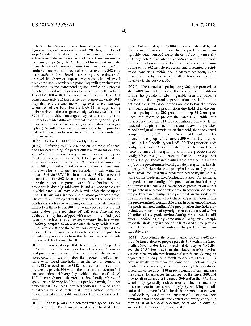
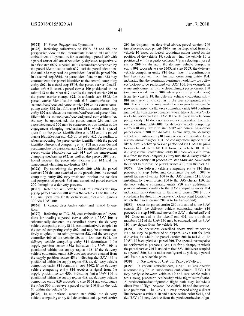
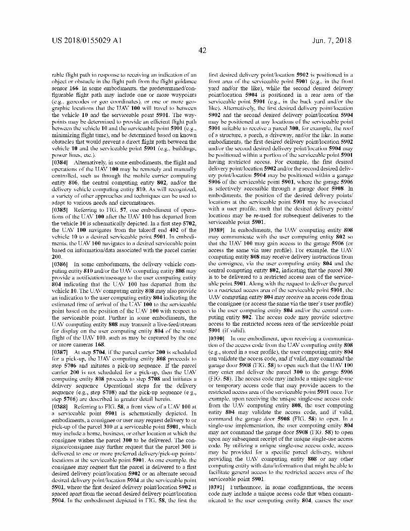
Copyright © 2022 FDOKUMEN